INVITATION TO BID - Naples, Florida
633
INVITATION TO BID CITY OF NAPLES PURCHASING DIVISION CITY HALL, 735 8 TH STREET SOUTH NAPLES, FL 34102 PH: 239-213-7100 FX: 239-213-7105 PLEASE NOTE THE FOLLOWING: > This page must be completed and returned with your bid. > Bids must be submitted in a sealed envelope, marked with bid number & closing date. > Bids received after the above closing date and time will not be accepted. > If you do not have an email address and you want a copy of the Bid Tab, please enclose a stamped, self- addressed envelope with your bid. NOTIFICATION DATE: 09/27/13 TITLE PUBLIC WORKS PUMP STATION IMPROVEMENTS NUMBER: 049-13 OPENING DATE & TIME: 10/28/13 2:00 PM PRE-BID DATE, TIME AND LOCATION: Non-mandatory Pre-Bid Meeting held October 9, 2013; 10:00 AM local time; 295 Riverside Circle, Naples FL, 34102 NAME OF PARTNERSHIP, CORPORATION OR INDIVIDUAL: MAILING ADDRESS: CITY-STATE-ZIP: PH: FX: EMAIL: WEB ADDRESS: I certify that this bid is made without prior understanding, agreement, or connection with any corporation, firm, or person submitting a bid for the same materials, supplies, or equipment and is in all respects fair and without collusion or fraud. I agree to abide by all conditions of this bid and certify that I am authorized to sign this bid for the bidder. In submitting a bid to the City of Naples the bidder offers and agrees that if the bid is accepted, the bidder will convey, sell, assign or transfer to the City of Naples all rights, title, and interest in and to all causes of action it may now or hereafter acquire under the Anti-trust laws of the United States and the State of FL for price fixing relating to the particular commodities or services purchased or acquired by the City of Naples. At the City's discretion, such assignment shall be made and become effective at the time the City tenders final payment to the bidder. FEI/EIN Number __________________ AUTHORIZED SIGNATURE DATE PRINTED NAME/TITLE Please initial by all that apply I acknowledge receipt / review of the following addendum _____Addendum #1 _____Addendum #2 _____Addendum #3 _____Addendum #4 1
-
Upload
khangminh22 -
Category
Documents
-
view
1 -
download
0
Transcript of INVITATION TO BID - Naples, Florida

INVITATION TO BID CITY OF NAPLES
PURCHASING DIVISION CITY HALL, 735 8TH STREET SOUTH
NAPLES, FL 34102 PH: 239-213-7100 FX: 239-213-7105
PLEASE NOTE THE FOLLOWING:
> This page must be completed and returned with your bid. > Bids must be submitted in a sealed envelope, marked with bid number & closing date. > Bids received after the above closing date and time will not be accepted. > If you do not have an email address and you want a copy of the Bid Tab, please enclose a stamped, self-
addressed envelope with your bid.
NOTIFICATION DATE:
09/27/13
TITLE
PUBLIC WORKS PUMP STATION IMPROVEMENTS
NUMBER:
049-13
OPENING DATE & TIME:
10/28/13 2:00 PM
PRE-BID DATE, TIME AND LOCATION: Non-mandatory Pre-Bid Meeting held October 9, 2013; 10:00 AM local time; 295 Riverside Circle, Naples FL, 34102
NAME OF PARTNERSHIP, CORPORATION OR INDIVIDUAL:
MAILING ADDRESS:
CITY-STATE-ZIP:
PH:
FX:
EMAIL:
WEB ADDRESS:
I certify that this bid is made without prior understanding, agreement, or connection with any corporation, firm, or person submitting a bid for the same materials, supplies, or equipment and is in all respects fair and without collusion or fraud. I agree to abide by all conditions of this bid and certify that I am authorized to sign this bid for the bidder. In submitting a bid to the City of Naples the bidder offers and agrees that if the bid is accepted, the bidder will convey, sell, assign or transfer to the City of Naples all rights, title, and interest in and to all causes of action it may now or hereafter acquire under the Anti-trust laws of the United States and the State of FL for price fixing relating to the particular commodities or services purchased or acquired by the City of Naples. At the City's discretion, such assignment shall be made and become effective at the time the City tenders final payment to the bidder.
FEI/EIN Number __________________
AUTHORIZED SIGNATURE DATE PRINTED NAME/TITLE
Please initial by all that apply I acknowledge receipt / review of the following addendum
_____Addendum #1 _____Addendum #2 _____Addendum #3 _____Addendum #4
1

GENERAL CONDITIONS
TO INSURE ACCEPTANCE OF THE BID, PLEASE FOLLOW THESE INSTRUCTIONS. ANY AND ALL SPECIAL CONDITIONS, ATTACHED HERETO, HAVE PRECEDENCE. 1. SEALED BID: All bids must be submitted in a sealed envelope. The face of the envelope shall contain the bid name and bid number. Bids not submitted on attached bid form shall be rejected. All bids are subject to the conditions specified herein. Those which do not comply with these conditions are subject to rejection. 2. EXECUTION OF BID: Bid must contain a manual signature of authorized representative in the proposal section. Bid must be typed or printed in ink. Use of erasable ink is not permitted. All corrections made by bidder to his bid must be initialed. 3. NO BID: If not submitting a bid, respond by returning the Statement of No Bid and explain the reason in the spaces provided. Failure to respond 3 times in succession without justification shall be cause for removal of the supplier's name from the bid mailing list. NOTE: To qualify as a respondent, bidder must submit a "NO BID," and it must be received no later than the stated bid opening date and hour. 4. BID OPENING: Shall be public, on the date and at the time specified on the bid form. It is the bidder's responsibility to assure that his bid is delivered at the proper time and place of the bid opening. Bids which for any reason are not so delivered will not be considered. Offers by telegram; telephone; or fax are not acceptable. Bid files may be examined during normal working hours. 5. WITHDRAWAL OF BIDS: Withdrawal of a bid within sixty (60) days after the opening of bids is subject to suspension or debarment in accordance with Section 2-668 of the City Code for up to three years. 6. PRICES, TERMS and PAYMENT: Firm Prices include all packing, handling, shipping charges and delivery to the destination shown herein. Bidder is encouraged to offer cash discount for prompt invoice payment. Terms of less than 20 days will not be considered.
A. TAXES: The City of Naples does not pay Federal Excise and Sales taxes on direct purchases of tangible personal property. See exemption number on face of purchase order. This exemption does not apply to purchases of tangible personal property made by contractors who use the tangible personal property in the performance of contracts for the improvement of City-owned real property.
B. MISTAKES: Bidders are expected to examine the specifications, delivery schedule, bid prices, extensions, and all instructions pertaining to supplies and services. Failure to do so will be at bidder's risk. In case of mistake in extension, the unit price will govern.
C. CONDITION AND PACKAGING: It is understood and agreed that any item offered or shipped as a result of this bid shall be a new, current standard production model available at the time of this bid. All containers shall be suitable for storage or shipment, and all prices shall include standard commercial packaging.
D. SAFETY STANDARDS: Unless otherwise stipulated in the bid, all manufactured items and fabricated assemblies shall comply with applicable requirements of Occupational Safety and Health Act and any standards there under.
E. UNDERWRITERS' LABORATORIES: Unless otherwise stipulated in the bid, all manufactured items and fabricated assemblies shall carry U.L. approval and re-examination listing where such has been established.
F. PAYMENT: Payment will be made by the buyer after the items awarded to a vendor have been received, inspected, and found to comply with award specifications, free of damage or defect and properly invoiced. All invoices shall bear the purchase order number. Payment for partial shipments shall not be made unless specified in the bid. Failure to follow these instructions may result in delay in processing invoices for payment. In addition, the purchase order number must appear on bills of lading, packages, cases, delivery lists and correspondence. 7. DELIVERY: Unless actual date of delivery is specified (or if specified delivery cannot be met), show number of days required to make delivery after receipt of purchase order in space provided. Delivery time may become a basis for making an award (see Special Conditions). Delivery shall be within the normal working hours of the user, Monday through Friday, unless otherwise specified.
2
8. MANUFACTURERS' NAMES AND APPROVED EQUIVALENTS: Any manufacturers' names, trade names, brand names, information and/or catalog numbers listed in a specification are for information and not intended to limit competition. The bidder may offer any brand for which he is an authorized representative, which meets or exceeds the specification for any item(s). If bids are based on equivalent products, indicate on the bid form the manufacturer's name and number. Bidder shall submit with his proposal, cuts, sketches, and descriptive literature, and/or complete specifications. Reference to literature submitted with a previous bid will not satisfy this provision. The bidder shall also explain in detail the reason(s) why the proposed equivalent will meet the specifications and not be considered an exception thereto. Bids which do not comply with these requirements are subject to rejection. Bids lacking any written indication of intent to quote an alternate brand will be received and considered in complete compliance with the specifications as listed on the bid form. 9. INTERPRETATIONS: Any questions concerning conditions and specifications shall be directed in writing to this office for receipt no later than ten (10) days prior to the bid opening. Inquiries must reference the date of bid opening and bid number. Failure to comply with this condition will result in bidder waiving his right to dispute the bid. 10. CONFLICT OF INTEREST: All bid awards are subject to Section 2-973 Conflict of Interest, City of Naples Code of Ordinances, which states: "No public officer or employee shall have or hold any employment or contractual relationship with any business entity or any agency which is subject to the regulation of or is doing business with the city; nor shall an officer or employee have or hold any employment or contractual relationship that will create a continuing or frequently recurring conflict between his private interests and the performance of his public duties or that would impede the full and faithful discharge of his public duties. Any member of the city council or any city officer or employee who willfully violates this section shall be guilty of malfeasance in office or position and shall forfeit his office or position. Violation of this section with the knowledge, express or implied, of the person or corporation contracting with or making a sale to the city shall render the contract or sale voidable by the city manager or the city council." 11. AWARDS: As the best interest of the City may require, the right is reserved to make award(s) by individual item, group of items, all or none, or a combination thereof; to reject any and all bids or waive any minor irregularity or technicality in bids received. 12. ADDITIONAL QUANTITIES: For a period not exceeding ninety (90) days from the date of acceptance of this offer by the buyer, the right is reserved to acquire additional quantities up to but not exceeding those shown on bid at the prices bid in this invitation. If additional quantities are not acceptable, the bid sheets must be noted "BID IS FOR SPECIFIED QUANTITY ONLY." (THIS PARAGRAPH DOES NOT APPLY FOR A TERM CONTRACT.) 13. SERVICE AND WARRANTY: Unless otherwise specified, the bidder shall define any warranty service and replacements that will be provided during and subsequent to this contract. Bidders must explain on an attached sheet to what extent warranty and service facilities are provided. 14. SAMPLES: Samples of items, when called for, must be furnished free of expense, on or before bid opening time and date, and if not destroyed may, upon request, be returned at the bidder's expense. Each individual sample must be labeled with bidder's name, manufacturer's brand name and number, bid number and item reference. Request for return of samples shall be accompanied by instructions which include shipping authorization and name of carrier and must be received with your bid. If instructions are not received within this time, the commodities shall be disposed of by the City of Naples. 15. BID PROTEST: The city has formal bid protest procedures that are available on request. 16. INSPECTION, ACCEPTANCE AND TITLE: Inspection and acceptance will be at destination unless otherwise provided. Title and risk of loss or damage to all items shall be the responsibility of the contract supplier until accepted by the ordering agency, unless loss or damage results from negligence by the ordering 17. DISPUTES: In case of any doubt or difference of opinion as to the items to be furnished hereunder, the decision of the buyer shall be final and binding on both parties.
3

18. GOVERNMENTAL RESTRICTIONS: In the event any governmental restrictions may be imposed which would necessitate alteration of the material, quality, workmanship or performance of the items offered on this proposal prior to their delivery, it shall be the responsibility of the successful bidder to notify the buyer at once, indicating in his letter the specific regulation which required an alteration. The City reserves the right to accept any such alteration, including any price adjustments occasioned thereby, or to cancel the contract at no expense to the City. 19. LEGAL REQUIREMENTS: Applicable provision of all Federal, State, county and local laws, and of all ordinances, rules, and regulations shall govern development submittal and evaluation of all bids received in response hereto and shall govern any and all claims and disputes which may arise between person(s) submitting a bid response hereto and the City of Naples by and through its officers, employees and authorized representatives, or any other person, natural or otherwise; and lack of knowledge by any bidder shall not constitute a cognizable defense against the legal effect thereof. 20. PATENTS AND ROYALTIES: The bidder, without exception, shall indemnify and save harmless the City of Naples and its employees from liability of any nature or kind, including cost and expenses for or on account of any copyrighted, patented, or unpatented invention, process, or article manufactured or used in the performance of the contract, including its use by the City of Naples. If the bidder uses any design, device, or materials covered by letters, patent or copyright, it is mutually agreed and understood without exception that the bid prices shall include all royalties or cost arising from the use of such design, device, or materials in any way involved in the work. 21. ADVERTISING: In submitting a bid, bidder agrees not to use the results there from as a part of any commercial advertising. 22. ASSIGNMENT: Any Purchase Order issued pursuant to this bid invitation and the monies which may become due hereunder are not assignable except with the prior written approval of the buyer. 23. LIABILITY: The supplier shall hold and save the City of Naples, its officers, agents, and employees harmless from liability of any kind in the performance of this contract. 24. PUBLIC ENTITY CRIMES: A person or affiliate who has been placed on the convicted vendor list following a conviction for a public entity crime may not submit a bid on a contract to provide any goods or services to a public entity, may not submit a bid on a contract with a public entity for the construction or repair of a public building or public work, may not submit bids on leases of real property to a public entity, may not be awarded or perform work as a contractor, supplier, subcontractor, or consultant under a contract with any public entity, and may not transact business with any public entity in excess of the threshold amount provided in Section 287.017, for CATEGORY TWO for a period of 36 months from the date of being placed on the convicted vendor list. 25. DISCRIMINATION: An entity or affiliate who has been placed on the discriminatory vendor list may not submit a bid on a contract to provide goods or services to a public entity, may not submit a bid on a contract with a public entity for the construction or repair of a public building or public work, may not submit bids on leases of real property to a public entity, may not award or perform work as a contractor, supplier, subcontractor, or consultant under contract with any public entity, and may not transact business with any public entity. 26. COUNTY TAXES: No proposal shall be accepted from and no contract will be awarded to any person, firm or corporation that is in arrears to the government of Collier County, Florida. 27. OFFER EXTENDED TO OTHER GOVERNMENTAL ENTITIES: The City of Naples encourages and agrees to the successful bidder/proposer extending the pricing, terms and conditions of this solicitation or resultant contract to other governmental entities at the discretion of the successful bidder/proposer.
IF THIS BID IS FOR A TERM CONTRACT, THE FOLLOWING CONDITIONS SHALL ALSO APPLY 28. ELIGIBLE USERS: All departments of the City of Naples are eligible to use this term contract. Such purchases shall be exempt from the competitive bid requirements otherwise applying to their purchases.
4

29. PRICE ADJUSTMENTS: Any price decrease effectuated during the contract period by reason of market change shall be passed on to City of Naples. Price increases are not acceptable. 30. CANCELLATION: All contract obligations shall prevail for at least one hundred eighty (180) days after effective date of contract. After that period, for the protection of both parties, this contract may be cancelled in whole or in part by either party by giving thirty (30) days prior written notice to the other party. 31. RENEWAL: The City of Naples reserves the option to renew the period of this contract, or any portion thereof for up to two (2) additional periods. Renewal of the contract period shall be by mutual agreement in writing. 32. ABNORMAL QUANTITIES: While it is not anticipated, should any unusual or abnormal requirements arise, the City reserves the right to solicit separate bids thereon. 33. FISCAL NON-FUNDING CLAUSE: In the event sufficient funds are not budgeted for a new fiscal period, the City shall notify the contractor of such occurrence and the contract shall terminate on the last day of the current fiscal year without penalty or expense to the City.
IF THIS BID IS FOR PERFORMING A SERVICE, THE FOLLOWING CONDITIONS SHALL ALSO APPLY
34. ALTERNATIVE BIDS: Bidders offering service delivery methods other than those permitted by the scope of work may submit a separate envelope clearly marked "ALTERNATIVE BID". Alternative bids will be deemed non-responsive and will not be considered for award. All such responses will, however, be examined prior to award. Such examination may result in cancellation of all bids received to permit rewriting the scope of work to include the alternative method, or the alternative method may be considered for future requirements of the City of Naples. 35. ANTITRUST: By entering into a contract, the contractor conveys, sells, assigns and transfers to the City of Naples all rights, titles and interest it may now have or hereafter acquire under the antitrust laws of the United States and the State of Florida that relate to the particular goods or services purchased or acquired by the City of Naples under said contract. 36. BIDDER INVESTIGATIONS: Before submitting a bid, each bidder shall make all investigations and examinations necessary to ascertain all site conditions and requirements affecting the full performance of the contract and to verify any representations made by the City of Naples upon which the bidder will rely. If the bidder receives an award as a result of its bid submission, failure to have made such investigations and examinations will in no way relieve the bidder from its obligation to comply in every detail with all provisions and requirements of the contract documents, nor will a plea of ignorance of such conditions and requirements be accepted as a basis for any claim whatsoever by the contractor for additional compensation. 37. CERTIFICATES AND LICENSES: The Contractor, at time of proposal, shall possess the correct occupational licenses, all professional licenses or other authorizations necessary to carry out and perform the work required by the City of Naples and Collier County for this project pursuant to all applicable Federal, State and Local Laws, Statues, Ordinances, and rules and regulations of any kind. 38. CHANGE IN SCOPE OF WORK: The City of Naples may order changes in the work consisting of additions, deletions or other revisions within the general scope of the contract. No claims may be made by the contractor that the scope of the project or of the contractor's services has been changed, requiring changes to the amount of compensation to the contractor or other adjustments to the contract unless such changes or adjustments have been made by written amendment to the contract signed by the City of Naples and the contractor. If the contractor believes that any particular work is not within the scope of the project, is a material change, or will otherwise require more compensation to the contractor, the contractor must immediately notify the City in writing of this belief. If the City believes that the particular work is within the scope of the contract as written, the contractor will be ordered to and shall continue with the work as changed and at the cost stated for the work within the scope. 39. CONTRACTOR PERSONNEL: The City of Naples shall, throughout the life of the contract, have the right of reasonable rejection and approval of staff or subcontractors assigned to the work by the contractor. If the City
5

reasonably rejects staff or subcontractors, the contractor must provide replacement staff or subcontractors satisfactory to the City in a timely manner and at no additional cost to the City. The day-to-day supervision and control of the contractor’s employees and sub-contractors is the responsibility solely of the contractor. 40. COST REIMBURSEMENT: The contractor agrees that all incidental costs, including allowances for profit and tools of the trade, must be included in the bid proposal rates. If an arrangement is made between the contractor and the City to reimburse the contractor for the cost of materials provided in the performance of the work, the contractor shall be reimbursed in the following manner: The City shall reimburse the contractor on completion and acceptance of each assigned job, only for those materials actually used in the performance of the work that is supported by invoices issued by the suppliers of the contractor describing the quantity and cost of the materials purchased. No surcharge shall be added to the supplier's invoices or included in the contractor's invoice submitted to the City that would increase the dollar amount indicated on the supplier's invoice for the materials purchased for the assigned job. 41. EXCEPTIONS: Bidders taking exception to any part or section of the solicitation shall indicate such exceptions on the bid form. Failure to indicate any exception will be interpreted as the bidder's intent to comply fully with the requirements as written. Conditional or qualified bids, unless specifically allowed, shall be subject to rejection in whole or in part. 42. FAILURE TO DELIVER: In the event of the contractor to fail to deliver services in accordance with the contract terms and conditions, the City, after due oral or written notice, may procure the services from other sources and hold the contractor responsible for any resulting purchase and administrative costs. This remedy shall be in addition to any other remedies that the City may have. 43. FAILURE TO ENFORCE: Failure by the City at any time to enforce the provisions of the contract shall not be construed as a waiver of any such provisions. Such failure to enforce shall not affect the validity of the contract or any part thereof or the right of the City to enforce any provision at any time in accordance with its terms. 44. FORCE MAJEURE: The contractor shall not be held responsible for failure to perform the duties and responsibilities imposed by the contract due to legal strikes, fires, riots, rebellions and acts of God beyond the control of the contractor, unless otherwise specified in the contract. 45. INDEPENDENT CONTRACTOR: The contractor shall be legally considered an independent contractor and neither the contractor nor its employees shall, under any circumstances, be considered servants or agents of the City of Naples and the City of Naples shall be at no time legally responsible for any negligence or any wrongdoing by the contractor, its servants or agents. The City of Naples shall not withhold from the contract payments to the contractor any federal income taxes, Social Security tax, or any other amounts for benefits to the contractor. Further, the City shall not provide to the contractor any insurance coverage or other benefits, including Workers' Compensation normally provided by the City for its employees. 46. ORAL STATEMENTS: No oral statement of any person shall modify or otherwise affect the terms, conditions or specifications stated in this contract. All modifications to the contract must be made in writing by the City of Naples. 47. QUALIFICATIONS OF BIDDERS: The bidder may be required, before the award of any contract, to show to the complete satisfaction of the City of Naples that it has the necessary facilities, ability, and financial resources to provide the service specified therein in a satisfactory manner. The bidder may also be required to give a past history and references in order to satisfy the City in regard to the bidder's qualifications. The City may make reasonable investigations deemed necessary and proper to determine the ability of the bidder to perform the work, and the bidder shall furnish to the City all information for this purpose that may be requested. The City reserves the right to reject any bid if the evidence submitted by, or investigation of, the bidder fails to satisfy the City that the bidder is properly qualified to carry out the obligations of the contract and to complete the work described therein. Evaluation of the bidder's qualifications shall include: > The ability, capacity, skill and financial resources to perform the work or service. > The ability to perform the work service promptly or within the time specified, without delay. > The character, integrity, reputation, judgment, experience, and efficiency of the bidder. > The quality of performance of previous contracts or services.
6

48. QUALITY CONTROL: The contractor shall institute and maintain throughout the contract period a properly documented quality control program designed to ensure that the services are provided at all times and in all respects in accordance with the contract. The program shall include providing daily supervision and conducting frequent inspections of the contractor's staff and ensuring that accurate records are maintained describing the disposition of all complaints. The records so created shall be open to inspection by the City. 49. RECOVERY OF MONEY: Whenever, under the contract, any sum of money shall be recoverable from or payable by the contractor to the City, the same amount may be deducted from any sum due to the contractor under the contract or under any other contract between the contractor and the City. The rights of the City are in addition and without prejudice to any other right the City may have to claim the amount of any loss or damage suffered by the City on account of the acts or omissions of the contractor. 50. REQUIREMENTS CONTRACT: During the period of the contract, the contractor shall provide all the services described in the contract. The contractor understands and agrees that this is a requirements contract and that the City shall have no obligation to the contractor if no services are required. Any quantities that are included in the scope of work reflect the current expectations of the City for the period of the contract. The amount is only an estimate and the contractor understands and agrees that the City is under no obligation to the contractor to buy any amount of services as a result of having provided this estimate or of having any typical or measurable requirement in the past. The contractor further understands and agrees that the City may require services in excess of the estimated annual contract amount and that the quantity actually used whether in excess of, or less than, the estimated annual contract amount and that the quantity actually used shall not give rise to any claim for compensation other than the total of the unit prices in the contract for the quantity actually used. 51. TERMINATION FOR CONVENIENCE: The performance of work under the contract may be terminated by the City in whole or in part whenever the City determines that termination is in the City's best interest. Any such termination shall be effected by the delivery to the contractor of a written notice of termination of at least seven (7) days before the date of termination, specifying the extent to which performance of the work under the contract is terminated and the date upon which such termination becomes effective. After receipt of a notice of termination, except as otherwise directed, the contractor shall stop work on the date of the receipt of the notice or other date specified in the notice; place no further orders or subcontracts for materials, services or facilities except as necessary for completion of such portion of the work not terminated; terminate all vendors and subcontracts; and settle all outstanding liabilities and claims. 52. TERMINATION FOR DEFAULT: The City of Naples reserves the right to terminate the contract if the City determines that the contractor has failed to perform satisfactorily the work required, as determined by the City. In the event the City decides to terminate the contract for failure to perform satisfactorily, the City shall give to the contractor at least seven (7) days written notice before the termination takes effect. The seven-day period will begin upon the mailing of notice by the City. If the contractor fails to cure the default within the seven (7) days specified in the notice and the contract is terminated for failure to perform satisfactorily, the contractor shall be entitled to receive compensation for all reasonable, allocable and allowable contract services satisfactorily performed by the contractor up to the date of termination that were accepted by the City prior to the termination. In the event the City terminates the contract because of the default of the contractor, the contractor shall be liable for all excess costs that the City is required to expend to complete the work under contract. 53. STATE AND FEDERAL EMPLOYMENT LAWS: Contractors providing service to the City are required to comply with all state and federal employment laws. This includes, but is not limited to, laws resulting from the Immigration and Reform and Control Act of 1986, wherein all employers are required to verify the identity and employment eligibility of all employees. The Department of Homeland Security, U.S. Citizenship and Immigration Services require employees and employers to complete Form I-9 and the employer must examine evidence of identity and employment eligibility within three business days of the date employment begins. Non compliant contractors will be subject to contract sanctions, up to and including contract termination. 54. CERTIFICATION REGARDING DEBARMENT, SUSPENSION, INELIGIBILITY, AND VOLUNTARY EXCLUSION: The contractor agrees to comply with Executive Order 12549 “Debarment and Suspension” and 2 CFR 180 “OMB Guidelines to Agencies on Government wide Debarment and Suspension.”
7

These rules require all contractors using federal funds not be debarred or suspended from doing business with the Federal Government. This includes sub-recipients and lower tier participant for covered transactions. Signing and submitting this document certified the organization and its principals are not presently debarred, suspended, proposed for debarment, declared ineligible, or voluntarily excluded from participation in this transaction by any federal department or agency, and further have not within the preceding three-year period been convicted of or had a civil judgment rendered against them for commission of fraud or a criminal offense in connection with obtaining, attempting to obtain, or performing a public (Federal, State or local) transaction.
THE CITY OF NAPLES IS AN EQUAL OPPORTUNITY EMPLOYER
8

GENERAL INSURANCE REQUIREMENTS
The Contractor shall not commence work until he has obtained all the insurance required under this heading, and until such insurance has been approved by the Owner, nor shall the Contractor allow any subcontractor to commence work until all similar insurance required of the subcontractor has also been obtained and approved by the Owner. Certificates of insurance must be issued by an authorized representative of the insurance company at the request and direction of the policyholder and must include sufficient information so as to identify the coverage and the contract for Owner's improvements for which they are issued. Certificates of insurance must be issued by a nationally recognized insurance company with a Best's Rating of no less than B+VII, satisfactory to the Owner, and duly licensed to do business in the state of said Contract. The Contractor shall procure and maintain, during the life of this Contract, Worker’s Compensation Insurance for all of his employees to be engaged in work under this Contract, and he shall require any subcontractor similarly to provide Worker’s Compensation Insurance for all of the latter's employees to be engaged in such work, unless such employees are covered by the protection afforded by the Contractor's insurance. In case any employees are to be engaged in hazardous work under this Contract, and are not protected under this Worker’s Compensation statute, the Contractor shall provide, and shall cause each subcontractor to provide, adequate coverage for the protection of such employees. It is acceptable to use a State-approved Worker’s Compensation Self-Insurance fund. The Contractor shall take out and maintain during the life of this Contract, Public Liability and Property Damage and shall include Contractual Liability, Personal Injury, Libel, Slander, False Arrest, Malicious Prosecution, Wrongful Entry or Eviction, Broad Form Property Damage, Products, Completed Operations and XCU Coverage to be included on an occurrence basis, and to the full extent of the Contract to protect him, the Owner, and any subcontractor performing work covered by this Contract from damages for personal injury, including accidental death, as well as from claims for property damage, which may arise from operations under this contract, whether such operations be by himself or by a subcontractor, or by anyone directly or indirectly employed by either of them. The Contractor shall also maintain automobile liability insurance including "non-owned and hired" coverage. The entire cost of this insurance shall be borne by the Contractor. The amount of such insurance shall be no less than $1,000,000 annual aggregate for bodily injury and property damage combined per occurrence. The City of Naples must be named as Additional Insured on the insurance certificate and the following must also be stated on the certificate. "This coverage is primary to all other coverage the City possesses for this contract only." The City of Naples shall be named as the Certificate Holder. The Certificate Holder shall read as follows:
The City of Naples 735 Eighth Street South Naples, Florida 34102
No City Division, Department, or individual name should appear on the Certificate.
No other format will be acceptable. The Certificate must state the proposal number and title. When using the "Accord"- 25 Certificate of Insurance only the most current version will be accepted. The City of Naples requires a copy of a cancellation notice in the event the policy is cancelled. The City of Naples shall be expressly endorsed onto the policy as a cancellation notice recipient.
9

STATEMENT OF NO BID
If you will not be bidding on this product/service, please help us by completing and returning only this page to: City of Naples, Purchasing Division City Hall, 735 8th Street South Naples, FL 34102 Fax 239-213-7105 Bid #_____ and Description: __________________________________ We, the undersigned, decline to proposal on the above project for the following reason(s): ___ We are not able to respond to the Invitation to Bid or Request for Proposals by the specified deadline. ___ Our Company does not offer this product or service. ___ Our current work schedule will not permit us to perform the required services. ___ Specifications are incomplete or information is unclear (Please explain below). _____________________________________________________________ _____________________________________________________________ ___ Other (Please specify below) _____________________________________________________________ ______________________________________________________________ Company Name______________________________ PH ______________ Name and Title of individual completing this form: _____________________________________________________________ (Printed Name) (Title) _____________________________________________________________ (Signature) (Date)
10

REFERENCES
THIS SHEET MUST BE COMPLETED AND RETURNED WITH BID PROVIDE AT LEAST THREE REFERENCES FOR WHOM YOUR COMPANY HAS PROVIDED SAME OR SIMILAR SERVICES WITHIN THE LAST 2 YEARS. COMPANY NAME: ADDRESS: TELEPHONE: CONTACT PERSON: CONTACT E-MAIL ADDRESS: _______________________________________ COMPANY NAME: ADDRESS: TELEPHONE: CONTACT PERSON: CONTACT E-MAIL ADDRESS: ______________________________________ COMPANY NAME: ADDRESS: TELEPHONE: CONTACT PERSON: CONTACT E-MAIL ADDRESS: _______________________________________
11

CONSTRUCTION SPECIAL CONDITIONS
A. TERMS OF CONTRACT
The resulting contract will commence on award and be in effect until completion of the project. B. PROHIBITION OF CONTACT
Under no circumstances should any prospective organization or individual, or anyone acting for or on behalf of a prospective organization or individual, seek to influence or gain the support of any member of the City Council, public official or City staff favorable to the interest of any prospective organization or individual. Likewise, contact with City Council, any public official or city staff against the interests of other prospective organization (s) and or individual(s) is prohibited. Any such activities will result in the exclusion of the prospective organization or individual from consideration by the City.
C. REFERENCES
Bidder must submit a minimum of three references on the form provided. Additionally, a signed and dated IRS W-9 form with EIN is required from all vendors.
D. STATEMENT OF NO BID
If you will not be bidding on this producer/service, please help us by completing and returning the Statement of No Bid.
E. BID FORMAT The Contract, if awarded, will be awarded on the basis of material and equipment illustrated and described on the Drawings or specified in the Specification. If a substitution or an “or equal”: item is proposed, Proposer must submit this information to the City of Naples Purchasing Department ten (10) days prior to the Proposal Date for evaluation as an acceptable substitution or an “or equal” item. If the substitution or the “or equal” item is accepted, the City of Naples will issue an Addendum to all Proposers listing the allowable substitution or the “or equal” item. The cost of changes in related work, additional drawings which may be required to illustrate or define the substitute or “or equal” equipment and its relationship to the other parts or portions of the Work shall be paid by the Contractor. No change will be made in the amount of time in which to complete the Work or in the liquidated damages.
F. BID SECURITY / BID BOND It is the policy of the City of Naples to require a Bid Bond for all construction-related sealed bids estimated to be in excess of $125,000. A bid bond or equivalent financial security in the amount of five (5) percent of the bid price shall be required and must accompany all bids. The Bid Bond is to be provided by a surety company authorized to do business in the State of Florida or otherwise supplied in a form satisfactory to the City. The bid bond must be submitted with the bid. When the invitation for bids requires a bid bond, noncompliance will result in rejection of the bid. Note that failure or refusal of the awarded bidder to enter into a contract within twenty (20) calendar days after receipt of said contract will result in damages to the City and bid bond will be forfeited to the City as liquidated damages.
12

G. PROPOSAL CONSTRUCTION PERFORMANCE & PAYMENT BONDS A Performance and Payment Bond will be required of the Awarded Proposer for any contract that is in excess of $125,000.00 dollars and will be in an amount equal to 100 (%) percent of the price specified in the Contract. The bond(s) shall be executed by a surety company authorized to do business in the State of Florida, or otherwise secured in a manner satisfactory to the City for the protection of all persons supplying labor and material to the contractor or its subcontractors for the performance of the work provided for in the contract. Proof of insurance from the successful proposer is required at the time of issuance and award of a contract.
H. QUESTIONS Questions regarding this proposer packet must be received in writing in the Purchasing Division, NO LATER THAN TEN CALENDAR DAYS PRIOR TO THE PROPOSAL CLOSING DATE TO ENSURE AN ANSWER IS PROVIDED PRIOR TO CLOSING.
Direct all questions to:
Gerald “Jed” Secory, MBA / CPPO / CPM Purchasing Manager
City of Naples, Purchasing Division 735 8th Street South
Naples, Florida 34102 PH: (239) 213-7102 FX: (239) 213-7105
13

SUBMISSION CHECKLIST
CHECKLIST ELEMENTS INCLUDED • Submit one (1) original signature and one (1) copy of your original
bid proposal / document AND a Windows© compatible PDF of the original document on a CD that is clearly labeled.
• Include any required drawings; descriptive literature; qualifications; schedules; product compliance / exceptions; alternatives; questionnaire; references, forms, tabs, pricing/cost; and any information required of the proposer identified in the text of the bid including information for bid evaluation.
• Include any delivery information.
• Provide a IRS W-9 form with your submission that is signed, dated and containing EIN.
• Have an authorized individual sign the appropriate pages including the Cover Sheet with any bid addendums initialed. Also, examples of vendor contracts used by the City can be found on the Naples Purchasing web site and should be reviewed by the vendor.
• Bid proposal / document needs to be received by the OPENING DATE & TIME indicated on the Cover Sheet. The mailing envelope must be addressed to:
City of Naples Purchasing Division 735 8th Street South Naples, Florida 34102
The mailing envelope should be sealed and marked with: BID Number:
BID Title: BID Opening Date:
ALL COURIER DELIVERED PROPOSALS MUST HAVE THE BID NUMBER AND TITLE ON THE OUTSIDE OF THE COURIER PACKET. At the discretion of the Purchasing Manager, bids or proposals with minor irregularities may be accepted and allowed to be corrected when in
the best interest of the City.
14

PROJECT MANUAL
CITY OF NAPLES PUBLIC WORKS PUMPING STATION IMPROVEMENTS
BID # 049-13
Project Manager: Dawn Jakiela, P.E. Project Director: Ronald Cavalieri, P.E
Project Engineer: John Reed, P.E.
September 2013
AECOM Technical Services, Inc.
ISSUED FOR BID
15

This page intentionally left blank
16

CITY OF NAPLES PUBLIC WORKS PUMP STATION IMPROVEMENTS
TABLE OF CONTENTS
Front End:
Legal Invitation to Bid and Bidder’s Certification RETURN WITH BID City’s General Conditions
General Insurance Requirements Statement of No Bid References RETURN WITH BID Special Conditions SECTION TITLE DIVISION 00 – PROCUREMENT AND CONTRACTING REQUIREMENTS 001000 Detailed Invitation to Bid 002000 Instruction to Bidders 003000 Bid Proposal Form with Bid Schedule RETURN WITH BID 003010 Statement of Bidders Qualifications RETURN WITH BID 003020 List of Subcontractors RETURN WITH BID 003030 Material Manufacturers RETURN WITH BID 004100 Bid Proposal Bond RETURN WITH BID 004200 Corporate Resolution RETURN WITH BID 004500 Notice of Award Form 004700 Drug-Free Work Place Certification RETURN WITH BID 004750 Schedule of Cost for Major Structures RETURN WITH BID
and/or Areas of Work 004800 Non-Collusion Affidavit RETURN WITH BID 004900 Trench Safety Affidavit RETURN WITH BID 005000 City Agreement/Contract 006200 Construction Payment Bond Form 006300 Construction Performance Bond Form 006500 Certificate of Insurance Requirements 007000 Standard General Conditions of Construction 008420 Notice to Proceed Form 008430 Contractor’s Application For Payment Form 008440 Change Order Form 008450 Schedule of Values 008460 Materials Stored on Site Form 008480 Certificate of Substantial Completion Form 008500 Field Order Form 008510 Contractor Request for Information Form
September 2013 1 17

CITY OF NAPLES PUBLIC WORKS PUMP STATION IMPROVEMENTS
TABLE OF CONTENTS (continued)
008520 Construction Accident From 008530 Pressure Test Form 008610 Work Directive Form 008620 Daily Construction Report From 008630 Change Proposal Summary Form 008640 Request for Proposed Change Form 008650 Check-Out Form 008660 Certificate of Completed Demonstration Form 009800 Contractor’s Release of Lien Form
DIVISION 01 – GENERAL REQUIREMENTS 010100 Summary of Work 010500 Request for Information (RFI) Procedures 011100 Coordination of Work, Permits, and Regulations 012000 Measurements and Payments 013000 Administrative Requirements 013216 CPM Construction Schedule Requirements 013233 Pre-Construction Audio-Video Documentation 013300 Submittals 014210 General Abbreviations 015070 Traffic Regulations 015100 Construction Facilities and Temporary Controls 016400 Owner Furnished Equipment 017410 Cleaning During Construction and Final Cleaning 019310 Operation and Maintenance Manual DIVISION 02 – EXISTING CONDITIONS 020120 Protecting Existing Underground Utilities 024100 Equipment, Piping, and Materials Demolition DIVISION 03 – CONCRETE 032100 Concrete Reinforcement 033000 Cast-In-Concrete 036000 Grout September 2013 2 18

CITY OF NAPLES PUBLIC WORKS PUMP STATION IMPROVEMENTS
TABLE OF CONTENTS (continued)
DIVISION 05 – METALS 055200 Aluminum Railings 055300 Aluminum Grating DIVISION 09 – FINISHES 099000 Painting and Coating 099761 Fusion-Bonded Epoxy Linings and Coatings DIVISION 26 – ELECTRICAL 260500 General Electric Requirements 260519 Wires and Cables Less than 600 Volts 260526 Grounding and Bonding 260534 Conduits, Boxes, and Fittings 260573 Protective Device Coordination Study and Arc-Flash Hazard Analysis 260590 Miscellaneous Electrical Devices 262419 Low-Voltage Motor Control 262650 Electric Motors 262923 Variable Frequency Drive (VFD) 264313 Surge Protection Devices (SPD) DIVISION 28 282318 Remote Video Surveillance System DIVISION 31 – EARTHWORK 311100 Clearing, Stripping and Grubbing 312300 Earthwork and Trenching DIVISION 32 – EXTERIOR IMPROVEMENTS 320116 Pavement Removal and Restoration 321116 Compacted Sub-Base 321123 Limerock Base Course 321213 Prime and Tack Coats 321215 Asphalt Pavement
September 2013 3 19
CITY OF NAPLES PUBLIC WORKS PUMP STATION IMPROVEMENTS
TABLE OF CONTENTS (continued)
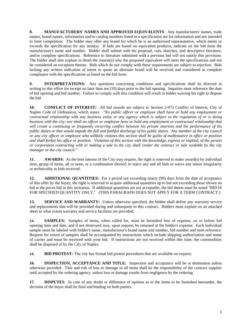
DIVISION 40 – PROCESS INTEGRATION 400500 General Piping Requirements 400515 Pressure Testing of Piping 400520 Manual, Check, and Process Valves 400570 Globe Pattern Control Valves 400580 Fabricated Stainless Steel Slide Gates 400775 Equipment, Piping, Duct, and Valve Identification 402040 Ductile Iron Pipe 402078 Stainless Steel Tubing 402090 PVC Pipe, 3 Inches and Smaller 402097 HDPE Pipe and Fittings 402713 Corporation Stops and Service Saddles 405000 Process Control and Instrumentation System (PCIS) General Requirements 405020 Instrumentation Equipment 405040 Programmable Logic Control System 405050 Remote Terminal Unit (RTU) System 409510 Package Equipment Electrical Panels DIVISION 41 – MATERIAL PROCESSING AND HANDLING EQUIPMENT 412123 Screenings Belt Conveyors DIVISION 43 – PROCESS GAS AND LIQUID HANDLING, PURIFICATION, AND STORAGE EQUIPMENT 432102 Mechanical Seals and Packing for Pumps 432140 Submersible Raw Wastewater Pump 432150 Vertical Turbine Pumps RETURN WITH BID DIVISION 44 – POLLUTION CONTROL EQUIPMENT 443331 Motorized Self Cleaning Strainers 443333 Mechanically Cleaned Vertical Bar Screen
September 2013 4 20

This page intentionally left blank
21

DIVISION 00 – PROCUREMENT AND CONTRACTING REQUIREMENTS 001000 Detailed Invitation to Bid 002000 Instruction to Bidders 003000 Bid Proposal Form with Bid Schedule 003010 Statement of Bidders Qualifications 003020 List of Subcontractors 003030 Material Manufacturers 004100 Bid Proposal Bond 004200 Corporate Resolution 004500 Notice of Award Form 004700 Drug-Free Work Place Certification 004750 Schedule of Cost for Major Structures and/or Areas of Work 004800 Non-Collusion Affidavit 004900 Trench Safety Affidavit 005000 City Agreement/Contract 006200 Construction Payment Bond Form 006300 Construction Performance Bond Form 006500 Certificate of Insurance Requirements 007000 Standard General Conditions of Construction 008420 Notice to Proceed Form 008430 Contractor’s Application for Payment Form 008440 Change Order Form 008450 Schedule of Values 008460 Materials Stored on Site Form 008480 Certificate of Substantial Completion Form 008500 Field Order Form 008510 Contractor Request for Information Form 008520 Construction Accident From 008530 Pressure Test Form 008610 Work Directive Form 008620 Daily Construction Report From 008630 Change Proposal Summary Form 008640 Request for Proposed Change Form 008650 Check-Out Form 008660 Certificate of Completed Demonstration Form 009800 Contractor’s Release of Lien Form
22

This page intentionally left blank
23
Detailed Invitation to Bid 001000-1 60289240 - 24 Sep 2013 (SECTION001000 - NEW DATES NEEDED)
SECTION 001000 - DETAILED INVITATION TO BID
PUBLIC WORKS PUMP STATION IMPROVEMENTS
CITY OF NAPLES, BID # 049-13
Separate sealed bid proposals from Contractors will be received for the for City of Naples, Public Works Pump Station Improvements, addressed to Mr. Gerald “Jed” Secory, Purchasing Manager, City of Naples, 735 8th Street South, Naples, FL, 34102 until 2:00 PM LOCAL TIME, on the 28th day of October 2013, at which time all bids will be publicly opened and read aloud. Any bids received after the time and date specified will not be accepted and shall be returned unopened to the Bidder. A mandatory pre-bid conference shall be held at the Streets and Stormwater Conference Room, 295 Riverside Circle, Naples, FL at 10:00 AM. LOCAL TIME on the 9th day of October 2013, at which time all prospective Bidders may visit the project site and have questions answered regarding the Bidding Documents for this Project. All technical questions after the pre-bid meeting shall be submitted in writing no later than ten (10) days before the bid date for possible addendum to the contract documents.
The Work is briefly described as follows: The work shall include but not be limited to: replace two new mechanically cleaned vertical bar screens and one conveyor, replace three existing pumps, add three new VFD drives, new instrumentation and control, and new security cameras. A bid alternate will provide the following work: one new submersible pump, yard piping, two pressure strainers, and force main to ASR No.2 well head.
Sealed envelopes containing one (1) original signature, one (1) copies of the original
bid documents, and one (1) PDF of the original bid documents on a CD shall be marked or endorsed "Bid Proposal for City of Naples, PUBLIC WORKS PUMP STATION IMPROVEMENTS PROJECT, Bid # 049-13, and Bid Opening Date of October 28, 2013. The Bid Proposal documents shall be removed from the Project Manual prior to submittal.
One contract may be awarded for all work. Bidding Documents may be examined at City of Naples Purchasing Department, 735 8th Street South, Naples, FL; and the City of Naples web site. Bidders may download the full bid package from the City of Naples Web Site. The Bid Documents will also be posted on DemandStar. All procedural questions regarding the intended work shall be directed to Gerald “Jed” Secory, Purchasing Manager at 239-213-7100. All questions regarding the project shall be submitted in writing to the Purchasing Manager no later than 10 days before bid date for possible inclusion and response in an addendum.
It is the policy of the City of Naples to require a Bid Bond for all construction-related sealed bids estimated to be in excess of $125,000. A bid bond or equivalent financial security in the amount of five (5%) percent of the bid price shall be required and must accompany all bids. The Bid Bond is to be provided by a surety company authorized to do business in the State of Florida or otherwise supplied in a form satisfactory to the City. The bid bond must be submitted
24

Detailed Invitation to Bid 001000-2 60289240 - 24 Sep 2013 (SECTION001000 - NEW DATES NEEDED)
with the bid. When the invitation for bids requires a bid bond, noncompliance will result in rejection of the bid. The successful Bidder shall be required to furnish the necessary Payment and Performance Bonds, as prescribed in the Project Manual. All Bid Bonds, Payment and Performance Bonds, Insurance Contracts and Certificates of Insurance shall be either executed by or countersigned by a licensed resident agent of the surety or insurance company having its place of business in the State of Florida. Further, the said surety or insurance company shall be duly licensed and qualified to do business in the State of Florida. Attorneys-in-fact that sign Bid Bonds or Payment and Performance Bonds must file with each bond a certified and effective dated copy of their Power of Attorney. In order to perform public work, the successful Bidder shall, as applicable, hold or obtain such contractor's and business licenses, certifications and registrations as required by State statutes, County & City ordinances.
Before a contract will be awarded for the work contemplated herein, the City shall conduct such investigations as it deems necessary to determine the performance record and ability of the apparent low Bidder to perform the size and type of work specified in the Bidding Documents. Upon request, the Bidder shall submit such information as deemed necessary by the City to evaluate the Bidder's qualifications. The Successful Bidder shall be required to Substantially Complete all Work within 270 calendar days from and after the Commencement Date specified in the Notice to Proceed; and Final Completion of all Work within 330 calendar days from and after the Commencement Date specified in the Notice to Proceed.
The City reserves the right to reject all Bids or any Bid not conforming to the intent and purpose of the Bidding Documents, and to postpone the award of the contract for a period of time which, however, shall not extend beyond ninety (90) days from the bid opening date.
The City reserves the right to award all, part, or none of the defined sections of the
project. The extent of the award will be dependent on the level of funding for this fiscal year, at the time of award.
END OF SECTION 001000 - DETAILED INVITATION TO BID
25

DIVISION 00 - SECTION 002000
INSTRUCTIONS TO BIDDERS
TABLE OF CONTENTS Section Description
1 - Definitions 2 - Preparation of Bids 3 - Bid Deposit Requirements 4 - Right to Reject Proposals 5 - Signing of Bids 6 - Withdrawal of Proposals 7 - Late Bids 8 - Interpretation of Contract Documents 9 - Examination of Site and Contract Documents
10 - Material Requirements 11 - Award of Contract 12 - Sales Tax 13 - City Permit Costs in Bid Prices 14 - Use of Subcontractors 15 - Prohibitions of Gifts 16 - Copies of Bidding Documents 17 - Qualifications of Bidders 18 - Qualifications Submittals 19 - Substitutive Material and Equipment 20 - Bonds and Insurance 21 - Contract Time 22 - Liquidated Damages and Indemnity 23 - Required Disclosure 24 - Public Bid Disclosure Act 25 - Compliance with Occupation Safety and Health Act (O.S.H.A.) 26 - Employment of Apprentices and Trainees 27 - Discrimination 28 - Organization of Bid Documents – Project Manual and Drawings
Instruction to Bidders 002000-1 60289240 - 13 Sep 2013 (SECTION002000.DOC)
26

This page intentionally left blank
27

DIVISION 00 - SECTION 00200 INSTRUCTIONS TO BIDDERS
Section 1. Definitions
1.1 The term "Owner" used herein refers to the City of Naples, Florida, a municipal
corporation, or its duly authorized representative. 1.2 The term "Project Manager" used herein refers to the Owner's duly authorized
representative and shall mean a Department Director acting directly or through duly authorized representatives.
1.3 The term "Design Professional" refers to the licensed professional engineer who represents
the Owner for the purpose of designing and/or monitoring the construction of the project. Any or all duties of the Engineer (Design Professional) referenced under this Agreement may be assumed at any time by the Project Manager on behalf of the Owner. Conversely, the Project Manager may formally assign any of his/her duties specified in this agreement to the Engineer (Design Professional).
1.4 The term "Bidder" used herein means one who submits a bid directly to the Owner in
response to this solicitation. 1.5 The term "Successful Bidder" means the lowest qualified, responsible and responsive
Bidder who is awarded the contract by the City of Naples, on the basis of the Owner's evaluation, to be in the best interest of the City.
1.6 The term "Bidding Documents" includes the Legal Advertisement, these Instructions to
Bidders, the Bid Proposal & Schedule and the Contract Documents as defined in the Agreement.
1.7 The term "Bid" shall mean a completed Bid Proposal & Schedule, bound in the Bidding
Documents, properly signed, providing the Owner a proposed cost for providing the services required in the Bidding Documents.
Section 2. Preparation of Bids
2.1 The bids must be submitted on the prescribed Invitation to Bid and Bid Proposal forms
furnished herein by the Owner. The Bidder shall complete the Bid Proposal in ink or by typewriter and shall sign the Bid correctly. The Bid may be rejected if it contains any omission, alteration of form, conditional bid or irregularities of any kind. The Bid shall contain one (1) original signature, four (4) copies of the original bid documents, and one (1) PDF of the original bid documents on a CD must be submitted in sealed envelopes, marked with the Bid Number, Project Name and Bid opening Date and Time, and shall be addressed to Mr. Gerald “Jed” Secory, Purchasing Manager,
Instruction to Bidders 002000-3 60289240 - 13 Sep 2013 (SECTION002000.DOC)
28
City of Naples, 735 8th Street South, Naples, FL, 34102. If forwarded by mail, the sealed envelope containing the Bid must be enclosed in another sealed envelope addressed as above. Bids received at the location specified herein after the time specified for bid opening will be returned to the bidder unopened and shall not be considered.
Section 3. Bid Deposit Requirements
3.1 No Bid shall be considered or accepted unless at the time of Bid filing the same shall be
accompanied by a cashiers check, a certified check payable to Owner on some bank or trust company located in the State of Florida insured by the Federal Deposit Insurance Corporation, or Bid Bond, in an amount not less than 5% of the bidder's maximum possible award (base bid, unit price proposals, alternates plus all addenda) (collectively referred to herein as the "Bid Deposit"). The Bid Deposit shall be retained by Owner as liquidated damages if the successful Bidder fails to execute and deliver to the City Purchasing Manager the Agreement, or fails to deliver the required Performance and Payment Bonds or Certificates of Insurance, all within ten (10) calendar days after receipt of the Notice of Award. Bid Bonds shall be executed by a corporate surety licensed under the laws of the State of Florida to execute such bonds, with conditions that the surety will, upon demand, forthwith make payment to Owner upon said bond. Bid Deposits of the Bidders shall be held until the Agreement has been executed by the Successful Bidder and same has been delivered to Owner together with the required bonds and insurance, after which all Bid Deposits shall be returned to the respective Bidders. All other Bid Deposits shall be released within ten (10) working days of the Bid Opening. If a Bid is not accepted within said time period it shall be deemed rejected and the Bid Deposit shall be returned to Bidder. In the event that the Owner awards the contract prior to the expiration of the 90 day period without selecting any or all alternates, the Owner shall retain the right to subsequently award said alternates at a later time but no later than 270 days from opening unless otherwise authorized by the Purchasing Manager.
3.2 The Successful Bidder shall execute three (3) copies of the Agreement and deliver same to
Owner within the time period noted above. The Owner shall execute all copies and return two fully executed copies of the Agreement to Successful Bidder within thirty (30) working days after receipt of the executed Agreement from Successful Bidder unless any governmental agency having funding control over the project requires additional time, in which event the Owner shall have such additional time to execute the Agreement as may be necessary.
Section 4. Right to Reject Proposals
4.1 The Owner reserves the right to reject any and all Bids with or without cause and waive
any and all formalities; and, to award the bid that it determines to be in the best interest of the City of Naples.
4.2 The Owner does not discriminate on the basis of race, color, national origin, sex, religion,
age and handicapped status in employment or provision of service. Instruction to Bidders 002000-4 60289240 - 13 Sep 2013 (SECTION002000.DOC)
29

Section 5. Signing of Bids
5.1 Bids submitted by a corporation must be executed in the corporate name by the president
or a vice president, and a corporate seal must be affixed and attested to by the secretary or assistant secretary of the corporation. The corporate address and state of incorporation must be shown below the signature.
5.2 Bid proposals by a partnership must be executed in the partnership name and signed by a
general partner whose title must appear under the signature and the official address of the partnership must be shown below said signature.
5.3 If Bidder is an individual, its signature shall be inscribed. 5.4 If signature is by an agent or other than an officer of corporation or general partner of
partnership, a properly notarized power of attorney must be submitted with the Bid. 5.5 All Bids shall have names typed or printed below all signatures. 5.6 All Bids shall state the Bidder's contractor license number, issue location, expiration date,
and description. 5.7 Failure to follow the provisions of this section shall be grounds for rejecting the Bid as
irregular or unauthorized.
Section 6. Withdrawal of Proposals Any Bid may be withdrawn at any time prior to the hour fixed in the Legal Advertisement for the opening of Bids, provided that the withdrawal is requested in writing, properly executed by the Bidder and received by Owner prior to Bid Opening. The withdrawal of a Bid will not prejudice the right of a Bidder to file a new Bid prior to the time specified for Bid opening.
Section 7. Late Bids No Bid shall be accepted that fails to be submitted prior to the time specified in the Legal Advertisement.
Section 8. Interpretation of Contract Documents 8.1 No interpretation of the meaning of the plans, specifications or other Bidding Documents
shall be made to a Bidder orally. Any such oral or other interpretations or clarifications shall be without legal effect. All requests for interpretations or clarifications shall be submitted in writing, addressed to the City of Naples, Purchasing Manager or via facsimile (239) 213-7015, to be given consideration. All such requests for interpretations or clarification must be received at least ten (10) calendar days prior to the Bid opening date.
Instruction to Bidders 002000-5 60289240 - 13 Sep 2013 (SECTION002000.DOC)
30

Questions received less than ten (10) calendar days prior to the bid opening date will not be answered. Any and all such interpretations and supplemental instructions shall be in the form of written addenda which, if issued, shall be sent by mail, email, or fax to all known Bidders at their respective addresses furnished for such purposes no later than seventy two (72) hours prior to the time fixed for the opening of Bids. Such written addenda shall be binding on Bidder and shall become a part of the Bidding Documents.
8.2 It shall be the responsibility of each Bidder to ascertain, prior to submitting its Bid that it
has received all addenda issued and it shall acknowledge same in its Bid. 8.3 As noted in the Legal Advertisement, attendance by all bidders at the Pre-Bid Conference
is non-mandatory.
Section 9. Examination of Site and Contract Documents 9.1 By executing and submitting its Bid, each Bidder certifies that it has:
a. Examined all Bidding Documents thoroughly; b. Visited the site to become familiar with local conditions that may in any manner
affect performance of the Work; c. Become familiar with all federal, state and local laws, ordinances, rules, and
regulations affecting performance of the Work; and d. Correlated all of its observations with the requirements of bidding documents. e. Review the City of Naples standard Contract/Agreement at the Purchasing
Department located at 270 Riverside Circle. No plea of ignorance of conditions or difficulties that may exist or conditions or difficulties that may be encountered in the execution of the Work pursuant to these Bidding Documents as a result of failure to make the necessary examinations and investigations shall be accepted as an excuse for any failure or omission on the part of the Successful Bidder, nor shall they be accepted as a basis for any claims whatsoever for extra compensation or for an extension of time.
Section 10. Material Requirements It is the intention of these Bidding Documents to identify standard materials. When space is provided on the Bid Schedule, Bidders shall specify the materials which they propose to use in the Project. The Owner may declare any Bid non-responsive or irregular if such materials are not specifically named by Bidder.
Section 11. Award of Contract
Instruction to Bidders 002000-6 60289240 - 13 Sep 2013 (SECTION002000.DOC)
31
Any prospective bidder who desires clarification on any aspect(s) or provision(s) of the bid invitation shall file his request with the City Purchasing Manager in writing 10 days prior to the time of the bid opening. Award of contract will be made by the City Council or the City Manager depending on the amount of contract after it is determined to be in the best interest of the City of Naples. The Owner may reject all bids proposing the use of any subcontractors who have been disqualified or de-certified for bidding purposes by any public contracting entity, or who has exhibited an inability to perform through any other means. When the contract is awarded by Owner, such award shall be evidenced by a Notice of Award, signed by the Purchasing Manager of Owner and delivered to the intended awardee or mailed to awardee at the business address shown in the Bid. Any bidder who desires to formally protest the contract award shall file a written notice to the Purchasing Manager explaining in detail the nature of the protest and the grounds it is based within 48 hours of the City’s declaration of intent to award. If the Purchasing Manager can not resolve the dispute within two days the information will be forwarded to the City Attorney who will hand down a written decision within 10 business days. If the Protest is forwarded to the City Attorney, a protest bond in the form of a cashiers check, certified check or money order made payable to the City of Naples in not less than 5% of the bid amount but not to exceed $7,500.00 shall be required to accompany the protest. For Bidders who may wish to receive copies of Bids after the Bid opening, the City of Naples reserves the right to recover all costs associated with the printing and distribution of such copies.
Section 12. Sales Tax The Contractor shall pay all applicable sales, consumer, use and other similar taxes required by law. The Contractor is responsible for reviewing the pertinent State statutes involving the sales tax and complying with all requirements. If the City deems that it is in its best interest to pursue the option of a Direct Materials Purchase for any large equipment and/or material purchases; the successful bidder shall coordinate and provide all necessary documentation to the City for the smooth procurement of such materials and/or equipment by the City.
Section 13. City Permit Cost in Bid Prices 13.1 Bidders shall include the cost of all necessary City, County and State permits as required
by this project.
Section 14. Use of Subcontractors
Instruction to Bidders 002000-7 60289240 - 13 Sep 2013 (SECTION002000.DOC)
32

14.1 To ensure the work contemplated by this contract is performed in a professional and timely manner, all subcontractors shall be “qualified”, meaning a person or entity that has the capability in all respects to perform fully the contract requirements and has the integrity and reliability to assure good faith performance. A subcontractor’s disqualification from bidding by the Owner, or other public contracting entity within the past twelve months shall be considered by the Owner when determining whether the subcontractors are “qualified.”
14.2 The Owner may consider the past performance and capability of a subcontractor when
evaluating the ability, capacity and skill of the Bidder and its ability to perform the contract within the time required. Owner reserves the right to disqualify a Bidder who includes subcontractors in its bid offer which are not “qualified” or who do not meet the legal requirements applicable to and necessitated by this Contract.
Section 15. Prohibition of Gifts
No organization or individual shall offer or give, either directly or indirectly, any favor, gift, loan, fee, service or other item of value to any City of Naples employee, as set forth in Chapter 112, Part III, Florida Statutes. Violation of this provision may result in one or more of the following consequences: a). Prohibition by the individual, firm, and/or any employee of the firm from contact with City of Naples staff for a specified period of time; b). Prohibition by the individual and/or firm from doing business with the City of Naples for a specified period of time, including but not limited to: submitting bids, RFP, and/or quotes; and, c). immediate termination of any contract held by the individual and/or firm for cause.
Section 16 - Copies of Bidding Documents 16.1 For complete sets of Bidding Documents, Bidders may download the documents from the
City of Naples Web Site. Full size drawings (if applicable) and/or scaled drawings (if applicable) shall be requested through the Engineer at the bidder’s expense. This amount represents reproduction costs and is non-refundable. Bidder must register as a document holder with the Engineer.
16.2 Complete sets of full size Bidding Documents (Drawings) are recommended in preparing
Bids; neither Owner nor Engineer assume any responsibility for errors or misinterpretations resulting from the use of incomplete sets of Bidding Documents.
16.3 Owner and Engineer, in making copies of Bidding Documents available on the above
terms, do so only for the purpose of obtaining Bids on the Work and do not confer a license or grant for any other use.
Section 17 – Qualifications of Bidders
17.1 Each Bid must contain Bidder's license number to do business in the State of Florida. Instruction to Bidders 002000-8 60289240 - 13 Sep 2013 (SECTION002000.DOC)
33
17.2 To demonstrate qualifications to perform the Work, each Bidder must complete and submit with the bid the Experience History Form contained in these bid documents. The City may request additional post-bid information including, but not limited to, the qualifications submittals set forth in Section 18 of these Instructions to Bidders, evidence of authority to conduct business in the jurisdiction where the Project is located. Submittals requested pursuant to this paragraph shall be referred to as the Qualifications Submittals and are in addition to those required elsewhere.
17.3 Bidders will be evaluated with respect to having successfully completed projects of a
similar size, nature and time frame.
Section 18 - Qualifications Submittals 18.1 It is the intention of the Owner to award this contract to a Bidder competent to perform
and complete the Work in a satisfactory manner. Accordingly, Owner will require the Apparent Low Bidder to submit, within seven (7) days after bid opening, information including, but not limited to, the following, l) evidence of Bidder's certification and license to perform the Work and services; 2) experience with references; 3) financial statement; 4) subcontractor listing, 5) Preliminary Progress Schedule; and 6) Preliminary Schedule of Values all as set forth below, to allow Owner to conduct qualifications investigations.
18.2 The experience and financial statement shall provide data additional to that information
provided in the Bid Form pertaining to Contractor's financial resources, adequacy of plant and equipment, manpower, organization, and prior experience with references and a list of all previous or on-going construction contracts over the last five (5) years. Said information shall be certified by a Certified Public Accountant, and shall be submitted on the Associated General Contractors of America Form "Standard Questionnaires and Financial Statement for Bidders," available from AGC, 1975 "E" Street, NW Washington, DC 20006. The Owner at its discretion may require any or all of the above listed information from any other Bidder.
18.3 The Preliminary Progress Schedule shall consist of three (3) copies of a diagram and a
narrative in accordance with appropriate formats set forth in Section 013216; Progress Schedules, incorporated by reference herein. Activities in the diagram shall show the order in which the Apparent Low Bidder proposes to perform the Work within the constraints and sequencing conditions set forth in the specifications and shall indicate starting and completion dates for key milestones and work pertaining to each Division of the Specifications within each major structure or geographical area of work. Activities shall further identify significant submittals/approvals, major equipment deliveries; equipment testing, Owner's responsibilities, and those of affected utilities and other similarly involved third parties.
Instruction to Bidders 002000-9 60289240 - 13 Sep 2013 (SECTION002000.DOC)
34

18.4 The Preliminary Schedule of Values shall consist of an itemization of the Bid by major structures or areas of Work for each Division of the Contract Documents from Division 0 through 44.
18.5 The Apparent Low Bidder and his surety, if any, hereby agree that any delays within
Bidder's control in the delivery of these Qualifications Submittals will require a written request by Bidder for an extension of the time during which the Bid shall remain open for the Owner's acceptance. Should Owner agree to such extension, Bidder will be required to comply with this Submittal Requirement within five (5) additional calendar days. At the Owner's option, failure by the Apparent Low Bidder to deliver these Qualifications Submittals within the extended period will void evaluation of the Bid and will constitute proof that the Apparent Bidder has abandoned his Bid; his Bid Security shall be declared forfeited to the Owner as liquidated damages, and the Work shall be awarded to another Bidder.
18.6 If upon receipt and evaluation of the submittals the Apparent Low Bidder does not pass
the evaluations to Owner's satisfaction, Owner reserves the right to reject the Bid.
Section 19 – Substitutive Material and Equipment 19.1 The Contract, if awarded, will be awarded on the basis of material and equipment
illustrated and described on the Drawings or specified in the Specifications. If a substitution or an “or equal” item is proposed, Bidder must submit this information to the City of Naples Purchasing Department ten (10) days prior to the Bid Date for evaluation as an acceptable substitution or an “or equal” item. If the substitution or the “or equal” item is accepted, the City of Naples will issue an Addendum to all Bidders listing the allowable substitution or the “or equal” item. The cost of changes in related work, additional drawings which may be required to illustrate or define the substitute or "or equal" equipment and its relationship to the other parts or portions of the Work shall be paid by the Contractor. No change will be made in the amount of time in which to complete the Work or in the liquidated damages. If Bidder fails to circle one of the listed manufacturers then the manufacturer identified as "A" shall be furnished.
Section 20 – Bonds and Insurance
20.1 The City’s General Insurance Requirements listed on Page 7 Herein sets forth City’s
requirement as to Bonds and Insurance. When the Successful Bidder delivers the executed Agreement to City, it shall be accompanied by the required Bonds, Insurance Certificates and Endorsements.
Section 21 - Contract Time
21.1 All work included in the Contract Documents shall be substantially complete within
Two Hundred and Seventy (270) days and finally complete within Three Hundred and Thirty (330) days after the date when Contract Times commence to run.
Instruction to Bidders 002000-10 60289240 - 13 Sep 2013 (SECTION002000.DOC)
35

Section 22 - Liquidated Damages and Indemnity
22.1 Contractor shall pay Owner one thousand five hundred dollars ($1500) per day for each
day that expires after the specified Contract Time. 22.2 All Bidders must state in the Bid Form the amount of consideration required by the
Bidder in return for the Bidder's promise of indemnity contained in the City’s General Conditions, General Insurance Requirements, and 725.06 of Florida Statutes. The amount to be stated shall be no less than $1,000.
Section 22 – Required Disclosure
23.1 Public Entity Crimes: UNDER SECTION 287,133(2)(a), FLORIDA STATUTES, a
person or affiliate who has been placed on the convicted vendor list following a conviction for a public entity crime may not submit a bid on a contract to provide any goods or services to a public entity, may not submit a bid on a contract with a public entity for the construction or repair of a public building or public work, may not submit bids on leases of real property to a public entity, may not be awarded or perform work as a contractor, supplier, subcontractor, or consultant under a contract with any public entity, and may not transact business with any pubic entity in excess of the threshold amount provided in Section 287.017, for Category two for a period of 36 months from the date of being placed on the convicted vendor list.
23.2 At its sole discretion, the Owner may reject any Bidder it finds to lack, or whose present
or former executive employees, officers, directors, stockholders, partners or owners are found by the Owner to lack honesty, integrity, or moral responsibility. The discretion of the Owner may be exercised based on the disclosure required herein, the Owner's own investigation, public records, or any other reliable sources of information. The Owner may also reject any Bidder failing to make the disclosure required herein. By submitting a Bid, Bidder recognizes and accepts that the Owner may reject the Bid based upon the exercise of its sole discretion and Bidder waives any claim it might have for damages or other relief resulting from the rejection of its Bid based on these grounds.
Section 24 – Public Bid Disclosure Act 24.1 This section may be cited as the Public Bid Disclosure Act, F.S. 218.80. 24.2 Florida Law requires the City to disclose all of its permits or fees, including, but not
limited to, all license fees, impact fees or inspection fees, payable by the Contractor to the unit of the City that issues the Bid or other request for proposals, unless such permit of fees are disclosed in the Bidding Documents or other request for proposal for the project at the time that project was let for Bid. Florida Law also prohibits the City from halting construction to collect any undisclosed permits or fees which were not disclosed or
Instruction to Bidders 002000-11 60289240 - 13 Sep 2013 (SECTION002000.DOC)
36

included in the Bidding Documents or other request for proposal for the project at the time the project was let for Bid.
24.3 Bidding Documents or other request for proposal issued for Bids by the City, or any
public Contract entered into between the City and a Contractor shall disclose each permit or fee which the Contractor will have to pay before or during construction and shall include the dollar amount or the percentage method or the unit method of all permits or fee which may be required by the City as part of the Contract. If the request for proposal does not require the response to include a final fix price, the City is not required to disclose any fees or assessments in the request for proposal. However, at least ten (10) days prior to requiring the Contractor to submit a final fixed price for the project, the city shall make the disclosures required in this section. Any City permits or fees which are not disclosed in the Bidding Documents, other request for proposal, or a Contractor between the City and the Contractor shall not be assessed or collected after the Contract is let. The City shall not halt construction or delay completion of the Contract in order to collect any permit or fees which were not provided for or specified in the Bidding Documents, other request for proposal, or the Contract.
24.4 This section does not require disclosure in the Bidding Documents of any permits or fees
imposed as a result of a Change Order or a modification to the Contract. The local government shall disclose all permits or the fees imposed as a result of a Change Order or a modification to the Contract, prior to the date the Contractor is required to submit a price for the Change Order or modification.
24.5 The Contractor is required to apply for and obtain any necessary permits from the City
and the City will pay for said permits.
Section 25 – Compliance with Occupation Safety and Health Act (O.S.H.A.)
25.1 In instances where such is applicable due to the nature of the Work with which this Bid is concerned; all materials, equipment, services, etc., as proposed and offered by Bidders must meet and conform to all O.S.H.A. requirements. The Bidder's signature upon the Bid Form (Section 003000) is considered certification of conformance to such requirements.
Section 26 – Employment of Apprentices and Trainees
26.1 Bidder’s attention is directed towards Florida Statutes Chapter 446 regarding
employment of apprentices and trainees. Bidders must comply with all applicable provisions of Florida Law.
Section 27 - Discrimination
27.1 An entity or affiliate who has been placed on the discriminatory vendor list may not
submit a bid on a contract to provide goods or services to a public entity, may not submit Instruction to Bidders 002000-12 60289240 - 13 Sep 2013 (SECTION002000.DOC)
37
a bid on a contract with a public entity for the construction or repair of a public building or public work, may not submit bids on leases of real property to a public entity, may not award or perform work as a contractor, supplier, subcontractor, or a consultant under contract with any public entity, and may not transact business with any public entity.
Section 28 – Organization of Bid Documents - Project Manual and Drawings
28.1 Bid Documents - Project Manual and Drawings for the Work are incorporated as follows: A. The Bid Documents - Project Manual and Drawings have been bound separately.
END OF SECTION 002000 – INSTRUCTIONS TO BIDDERS
Instruction to Bidders 002000-13 60289240 - 13 Sep 2013 (SECTION002000.DOC)
38

This page intentionally left blank
39

Bid Proposal 003000-1 60289240 - 20 Sep 2013 (SECTION003000.DOC)
DIVISION 00 - SECTION 003000
BID PROPOSAL BID NO.: 049-13
PUBLIC WORKS PUMPING STATION IMPROVEMENTS PROJECT
CITY OF NAPLES Full Name of Bidder Main Business Address Place of Business Telephone No. Fax No. Contractor's License #: ______________ Type:___________ Issue Location: _______________ To: CITY OF NAPLES, Purchasing Division, 735 8th Street South, Naples, Naples, FL
34102 (hereinafter called the Owner) The undersigned, as Bidder declares that the only person or parties interested in this Proposal as principals are those named herein, that this Proposal is made without collusion with any other person, firm or corporation; that it has carefully examined the location of the proposed work, the proposed forms of Agreement and Bonds, and the Contract Drawings and Specifications, including Addenda issued thereto and acknowledges receipt below: Addendum Number Date Issued Contractor's Initials Bidder proposes, and agrees if this Proposal is accepted, Bidder will contract with the Owner in the form of the copy of the Agreement included in these Contract Documents, to provide all necessary machinery, tools, apparatus and other means of construction, including utility and transportation services necessary to do all the Work, and furnish and install all the materials and equipment specified or referred to in the Contract Documents in the manner and time herein prescribed and according to the requirements of the Owner as therein set forth, furnish the specified Contractor's Bonds and Insurance specified in the General Conditions of the Contract, and to do all other things required of the Contractor by the Contract Documents, and that it will take full payment the sums set forth in the following Bid Schedule: NOTE: If you choose to bid, please submit one (1) original signature, four (4) copies of the original bid documents, and one (1) PDF of the original bid documents on a CD of your bid proposal package on this form.
40
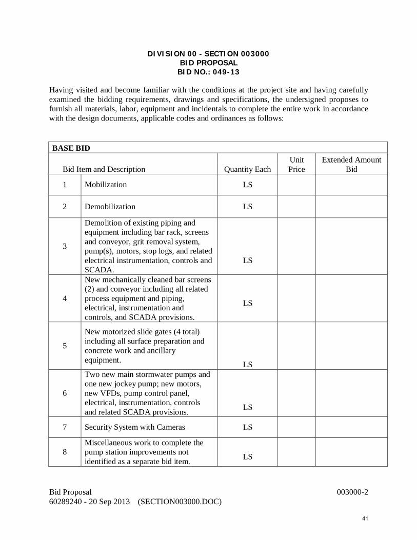
Bid Proposal 003000-2 60289240 - 20 Sep 2013 (SECTION003000.DOC)
DIVISION 00 - SECTION 003000 BID PROPOSAL
BID NO.: 049-13 Having visited and become familiar with the conditions at the project site and having carefully examined the bidding requirements, drawings and specifications, the undersigned proposes to furnish all materials, labor, equipment and incidentals to complete the entire work in accordance with the design documents, applicable codes and ordinances as follows: BASE BID
Bid Item and Description Quantity Each Unit Price
Extended Amount Bid
1 Mobilization LS
2 Demobilization LS
3
Demolition of existing piping and equipment including bar rack, screens and conveyor, grit removal system, pump(s), motors, stop logs, and related electrical instrumentation, controls and SCADA.
LS
4
New mechanically cleaned bar screens (2) and conveyor including all related process equipment and piping, electrical, instrumentation and controls, and SCADA provisions.
LS
5
New motorized slide gates (4 total) including all surface preparation and concrete work and ancillary equipment.
LS
6
Two new main stormwater pumps and one new jockey pump; new motors, new VFDs, pump control panel, electrical, instrumentation, controls and related SCADA provisions.
LS
7 Security System with Cameras LS
8 Miscellaneous work to complete the pump station improvements not identified as a separate bid item.
LS
41

Bid Proposal 003000-3 60289240 - 20 Sep 2013 (SECTION003000.DOC)
9 Subtotal Items No.1 through No.8 Subtotal
10 Allowances for additional work as directed by the Owner; 5% of Line No.9
ALLOWANCE
TOTAL AMOUNT BASE BID (Add Items No.9 & No.10) ______________________________________________________________________________
______________________________________________________________________________
(Total base bid price in words) ALTERNATE BID
1
ASR pump and screen filter system, HDPE force main, and mounting equipment (pump and VFD owner furnished)
LS
TOTAL (BASE BID PLUS ALTERNATE BID)
(Grand total bid price in words) THE DETERMINATION OF THE LOWEST RESPONSIBLE BIDDER WILL BE BASED SOLELY ON THE BASE BID. THE FOLLOWING DOCUMENTS MUST BE COMPLETED AND SUBMITTED WITH THE BID. THESE DOCUMENTS ARE ATTACHED TO AND MADE A CONDITION OF THIS BID: ___ Invitation for Bid (Front Page) ___ References (Page 9) ___ Section 003000 - Bid Proposal with Bid Schedule ___ Section 003010 - Statement of Bidder’s Qualifications ___ Section 003020 - List of Subcontractors ___ Section 003030 – Material Manufacturers ___ Section 004100 – Bid Proposal Bond ___ Section 004200 – Corporate Resolution ___ Section 004700 – Drug-Free Work Place Certification ___ Section 004750 – Schedule of Costs for Major Structures and/or Areas of Work ___ Section 004800 – Non-Collusion Affidavit ___ Section 004900 – Trench Safety Affidavit (Required by State Law) ___ Section 432150 – Include pump warranty information
42

Bid Proposal 003000-4 60289240 - 20 Sep 2013 (SECTION003000.DOC)
Bidder agrees to submit Application for Payment on prescribed Application for Payment form and submit specified Release of Liens and Affidavit Forms for payment under this contract. Ten (10) percent shall be withheld from each payment until satisfactory completion of Punch List corrections and acceptance by Engineer and Owner and the Work is certified Substantially Complete by Engineer/Project Manager. NOTE: Please return this bid form to the above address. NO OTHER BID FORM WILL BE ACCEPTED. The service to be furnished by us is hereby declared and guaranteed to be in conformance with the project drawings and specifications. In submitting this bid, the Bidder makes all representations required by the Invitation to Bid and Instructions to Bidders and further warrants and represents the following:
1. Bidder is aware of the general nature of Work to be performed by Owner and others at the site as it relates to this Work indicated in the contract documents.
2. Bidder has given Engineer/Project Manager/Owner notice of all conflicts, errors, ambiguities or discrepancies that Bidder has discovered in the Contract Documents and the written resolution thereof by Engineer is acceptable to Bidder and the Contract Documents are sufficient to indicate and convey understanding of all terms and conditions for performing and furnishing the Work for which this bid is submitted.
Upon receipt of written notice of conditional acceptance of this Bid, Bidder will execute the formal Contract attached within ten (10) calendar days and deliver Insurance as required by the Contract Documents. If awarded a contract under this Proposal, the undersigned agrees to provide all required documentation within 7 calendar days from commencement date stipulated in the written “Notice to Proceed” and/or Official City of Naples Purchase Order, unless the Project Manager, in writing, subsequently notifies Contractor of a modified (later) commencement date. Respectfully Submitted: State of Florida County of Collier , being first duly sworn on oath deposes and says that the Bidder on the above Proposal is organized as indicated and that all statements herein made are made on behalf of such Bidder and that this deponent is authorized to make them. , also deposes and says that it has examined and carefully prepared its Bid Proposal from the Contract Drawings and Specifications and has checked the same in detail before submitting this Bid; that the statements contained herein are true and correct.
43

Bid Proposal 003000-5 60289240 - 20 Sep 2013 (SECTION003000.DOC)
(a) Corporation The Bidder is a corporation organized and existing under the laws of the State of _______________, which operates under the legal name of ______________________________________________, and the full names of its officers are as follows: President Secretary Treasurer Manager and it (does) or (does not) have a corporate seal. The __________________________________ is authorized to sign construction proposals and contracts for the company by action of its Board of Directors taken _____________________________, a certified copy of which is hereto attached (strike out this last sentence if not applicable). (b) Co-Partnership The Bidder is a co-partnership consisting of individual partners whose full names are as follows: The co-partnership does business under the legal name of: (c) Individual The Bidder is an individual whose full name is ______________________________________, and if operating under a trade name, said trade name is ________________________________________. DATED Legal entity BY: Witness Name of Bidder (Typed) Witness Signature
44

Bid Proposal 003000-6 60289240 - 20 Sep 2013 (SECTION003000.DOC)
Title
[Corporate Seal] Telephone and e-mail address: / STATE OF FLORIDA COUNTY OF COLLIER The foregoing instrument was acknowledged before me this _____ day of ________________, 20__, by ___________________________________________, as ___________________________ of ____________________________________, a _______________ corporation, on behalf of the corporation. He/she is personally known to me or has produced _____________________________ ___________________________ as identification and did (did not) take an oath. My Commission Expires: (Signature of Notary) NAME: (Legibly Printed) (AFFIX OFFICIAL SEAL) Notary Public, State of
Commission No.:
RETURN WITH BID
END OF SECTION 003000 – BID PROPOSAL
45

DIVISION 00 – SECTION 003010 STATEMENT OF BIDDER’S QUALIFICATIONS
PUBLIC WORKS PUMP STATION IMPROVEMENTS
Consideration of the bid requires certain experience qualifications. The bidder must identify below direct experience over the last six years with the successful installation of at least five circular clarifier mechanisms in wastewater treatment facilities of a diameter of 65 feet or larger. Installation by a subcontractor shall not satisfy this requirement unless that same subcontractor is listed as the installing subcontractor for this project. Failure to strictly satisfy these qualifications will result in bid disqualification. Submission of the bidder’s qualifications must include the following information and format as a minimum. The bidder shall prepare his qualifications on separate sheets and attach to the bid when submitted. Sample of required information and format to be submitted for each project: Project Owner: _________________________________________________________ Project Name: _________________________________________________________ Size and Number of Circular Clarifiers: ______________________________________ Manufacturer of Clarifier Mechanisms: ______________________________________ Date Completed: _______________________________________________________ Installation by own forces: Yes / No Installation by subcontractor: Yes / No Owner or Engineer Contact (Name, phone and email): __________________________ ______________________________________________________________________ Signed ____________________________ Name of Bidder _____________________
Statement of Bidder’s Qualifications 003010-1 60289240 - 6 Sep 2013 (SECTION003010.DOC)
46

RETURN WITH BID
END OF SECTION 003010 – STATEMENT OF BIDDER’S QUALIFICATIONS
Statement of Bidder’s Qualifications 003010-2 60289240 - 6 Sep 2013 (SECTION003010.DOC)
47

DIVISION 00 – SECTION 003020 LIST OF SUBCONTRACTORS
The undersigned states that the following is a full and complete list of the proposed subcontractors on this Project and the class of work to be performed by each, and that such list will not be added to nor altered without written consent of the Project Manager. The undersigned further acknowledges its responsibility for ensuring that the subcontractors listed herein meet all legal requirements applicable to and necessitated by this Agreement, including, but not limited to proper licenses, certifications, registrations and insurance coverage. The City reserves the right to disqualify any bidder who includes non-compliant or non-qualified subcontractors in his/her bid offer. Further, the City may direct the bidder/contractor to remove/replace any subcontractor that is found to be non-compliant with this requirement subsequent to award of the contract at no additional cost to the City. THIS LIST MUST BE COMPLETED OR BID WILL BE DEEMED NON-RESPONSIVE. (Attach additional sheets as needed). BIDDER’S STATEMENT OF PROPOSED SUBCONTRACTOR FOR PUBLIC WORKS PUMPING STATION IMPROVEMENTS
The bidder identifies the following firm as the proposed installation subcontractor of the replacement clarifier mechanisms. Name of Firm: _________________________________________________________ Address and Phone: ____________________________________________________ Contact Person: ________________________________________________________ Other Subcontractor and Address Specialty 1. 2. 3. Signed ____________________________ Name of Bidder _____________________
List of Subcontractors 003020-1 60289240 - 6 Sep 2013 (SECTION003020.DOC)
48

RETURN WITH BID
END OF SECTION 003020 – LIST OF SUBCONTRACTORS
List of Subcontractors 003020-2 60289240 - 6 Sep 2013 (SECTION003020.DOC)
49
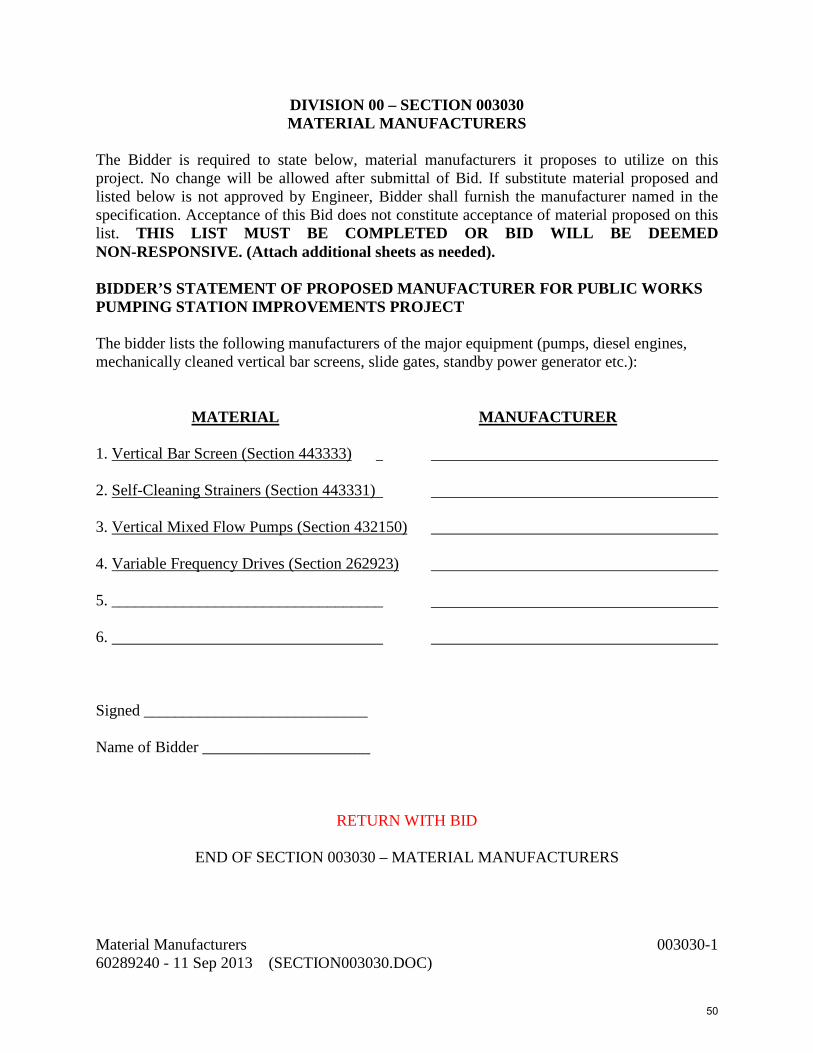
DIVISION 00 – SECTION 003030 MATERIAL MANUFACTURERS
The Bidder is required to state below, material manufacturers it proposes to utilize on this project. No change will be allowed after submittal of Bid. If substitute material proposed and listed below is not approved by Engineer, Bidder shall furnish the manufacturer named in the specification. Acceptance of this Bid does not constitute acceptance of material proposed on this list. THIS LIST MUST BE COMPLETED OR BID WILL BE DEEMED NON-RESPONSIVE. (Attach additional sheets as needed). BIDDER’S STATEMENT OF PROPOSED MANUFACTURER FOR PUBLIC WORKS PUMPING STATION IMPROVEMENTS PROJECT The bidder lists the following manufacturers of the major equipment (pumps, diesel engines, mechanically cleaned vertical bar screens, slide gates, standby power generator etc.): MATERIAL MANUFACTURER 1. Vertical Bar Screen (Section 443333) 2. Self-Cleaning Strainers (Section 443331) 3. Vertical Mixed Flow Pumps (Section 432150) 4. Variable Frequency Drives (Section 262923) 5. __________________________________ 6. Signed ____________________________ Name of Bidder _____________________
RETURN WITH BID
END OF SECTION 003030 – MATERIAL MANUFACTURERS
Material Manufacturers 003030-1 60289240 - 11 Sep 2013 (SECTION003030.DOC)
50

This page intentionally left blank
51

DIVISION 00 - SECTION 004100 BID PROPOSAL BOND
RETURN IN DUPLICATE WITH BID (AS APPLICABLE)
NOT TO BE FILLED OUT IF A CERTIFIED CHECK IS SUBMITTED. KNOW ALL MEN BY THESE PRESENTS: That we, the undersigned, _________________________________________________ as Principal, and ______________________________________________ as Surety are held and firmly bound unto the City of Naples, Florida, in the sum of $___________________________________________ for the payment of which, will and truly to be made, we hereby jointly and severally bind ourselves, our heirs, executors, administrators, successors and assigns. The condition of the above obligation is such that if the attached Proposal of Principal and Surety for work specified as: PUBLIC WORKS PUMP STATION IMPROVEMENTS CITY OF NAPLES, FLORIDA BID # 049-13 all as stipulated in said Proposal, by doing all work incidental thereto, in accordance with the plans and specifications provided heretofore, all within Collier County, is accepted and the bidder shall within ten (10) days after notice of said award, enter into a contract, in writing, and furnish the required Performance Bond with surety or sureties to be approved by the Director of Purchasing, this obligation shall be void; otherwise the same shall be in full force and virtue by law and the full amount of this Proposal Bond will be paid to the City as stipulated or liquidated damages. Signed this ________ day of ______________________, 2013. _________________________________________________________ Principal Surety Principal must indicate whether corporation, partnership, company, or individual. The person signing shall, in his own handwriting, sign the Principal's name, his own name, and his title. The person signing for a corporation must, by affidavit, show his authority to bind the corporation.
END OF SECTION 004100 – BID PROPOSAL BOND
Bid Proposal Bond 004100-1 60289240 - 11 Sep 2013 (SECTION004100.DOC)
52

This page intentionally left blank
53

DIVISION 00 - SECTION 004200 CORPORATE RESOLUTION
I, ______________________, Secretary of__________________________, a corporation
organized and existing under the laws of the State of _______, hereby certify that at a meeting of
the Board of Directors of the Corporation duly called and held on __________, 20__, at which a
quorum was present and acting throughout, the following resolutions were adopted and are now
in full force and effect:
RESOLVED that the following individuals of this corporation are authorized to execute
on behalf of this corporation a Bid and Agreement to ______________ for the construction
Of ____________________________________________________________.
I further certify that the names of the officers of this corporation and any other persons
authorized to act under this resolution and their official signatures are as follows:
NAME OFFICER OFFICIAL SIGNATURE
_______________________, ____________________, _____________________ _______________________, ____________________, _____________________ _______________________, ____________________, _____________________ _______________________, ____________________, _____________________
IN WITNESS WHEREOF, I have hereunto subscribed my name as Secretary and affixed
the seal of the corporation this __ day of______, 20__.
RETURN WITH BID
Corporate Resolution 004200-1 60289240 - 6 Sep 2013 (SECTION004200.DOC)
54

END OF SECTION 004200 – CORPORATE RESOLUTION
Corporate Resolution 004200-2 60289240 - 6 Sep 2013 (SECTION004200.DOC)
55

DIVISION 00 – SECTION 004500 NOTICE OF AWARD
Date: ____________________ Contractor: ________________________________ Project: __________________________________ Date of Bid Opening: ________________________ You are hereby notified that you are the apparent successful Bidder on the Project noted above. Upon compliance with the conditions precedent to be fulfilled by you within the time specified, the Agreement will be executed and delivered to you. The OWNER expects to award you a contract for: ______________________________________________________________($_____________)_______________________________________________________________________________________________________________________________________________________________________________
(Indicate total Work, Alternates or Sections of Work Awarded)
The Contract Price of your contract is:
($________________). Enclosed are the following: No. of Copies Item 3 Agreement between Owner and Contractor 3 Performance Bond 3 Payment Bond 3 Certificate of Insurance and Endorsement 3 Notice of Award Please take the following actions on all copies of the above documents.
1. Execute the Agreement and seal. 2. Have your insurance company complete Bond Forms and attach Notarized
Acknowledgment of Authorized Representative. 3. Have your insurance company complete Certificates of Insurance and attach
Acknowledgment of Authorized Representative 4. Return all 3 copies of Agreement, bonds and insurance certificates within ten (10) days of
this Notice of Award to: City of Naples Purchasing Department 735 8th Street South Naples, FL 34102
004500-1 Notice of Award 60289240 - 11 Sep 2013 (SECTION004500.DOC)
56

Attention: Purchasing Director A fully executed copy of the Contract Documents shall be returned to you along with a Notice to Proceed. BY: Purchasing Manager City of Naples Date:_______________________
END OF SECTION 004500 – NOTICE OF AWARD FORM
004500-2 Notice of Award 60289240 - 11 Sep 2013 (SECTION004500.DOC)
57

DIVISION 00 – SECTION 004700 DRUG-FREE WORKPLACE CERTIFICATION
Preference shall be given to businesses with drug-free workplace programs. Whenever two or more bids which are equal with respect to price, quality, and service are received by the State or by any political subdivision for the procurement of commodities or contractual services, a bid received from a business that certifies that it has implemented a drug-free workplace program shall be given preference in the award process. Established procedures for processing tie bids will be followed if none of the tied bidders have a drug-free workplace program. In order to have a drug-free workplace program, a business certifies the following: The undersigned bidder, in accordance with Florida Statute 287.087, hereby certifies that does: Name of Business 1. Publish a statement notifying employees that the unlawful manufacture, distribution,
dispensing, possession, or use of a controlled substance is prohibited in the workplace and specifying the actions that will be taken against employees for violations of such prohibition.
2. Inform employees about the dangers of drug abuse in the workplace, the business’s
policy of maintaining a drug-free workplace, any available drug counseling, rehabilitation, employee assistance programs and the penalties that may be imposed upon employees for drug abuse violations.
3. Give each employee engaged in providing the commodities or contractual services that
are under bid a copy of the statement specified in Paragraph 1. 4. In the statement specified in Paragraph 1, notify the employees that, as a condition of
working on the commodities or contractual services that are under bid, the employee will abide by the terms of the statement and will notify the employer of any conviction of, or plea of guilty or nolo contendere to, any violation of Chapter 893 or of any controlled substance law of the United States or any state, for any violation occurring in the workplace, no later than five (5) days after such conviction.
5. Impose a sanction on, or require the satisfactory participation in a drug abuse assistance or rehabilitation program, if such is available in the employee’s community, by any employee who is so convicted.
6. Make a good faith effort to continue to maintain a drug-free workplace through
implementation of Paragraphs 1 through 5.
As the person authorized to sign this statement, I certify that this firm complies fully with the above requirements.
Drug-Free Workplace Certification 004700-1 60289240 - 6 Sep 2013 (SECTION004700.DOC)
58

Bidder’s Signature Date
RETURN WITH BID
END OF SECTION 004700 – DRUG-FREE WORK PLACE CERTIFICATION
Drug-Free Workplace Certification 004700-2 60289240 - 6 Sep 2013 (SECTION004700.DOC)
59
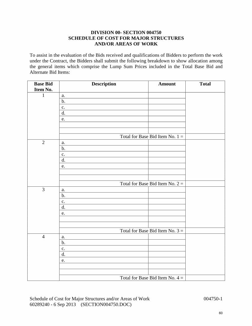
DIVISION 00- SECTION 004750 SCHEDULE OF COST FOR MAJOR STRUCTURES
AND/OR AREAS OF WORK To assist in the evaluation of the Bids received and qualifications of Bidders to perform the work under the Contract, the Bidders shall submit the following breakdown to show allocation among the general items which comprise the Lump Sum Prices included in the Total Base Bid and Alternate Bid Items:
Base Bid Item No.
Description Amount Total
1 a. b. c. d. e.
Total for Base Bid Item No. 1 = 2 a.
b. c. d. e.
Total for Base Bid Item No. 2 =
3 a. b. c. d. e.
Total for Base Bid Item No. 3 =
4 a. b. c. d. e.
Total for Base Bid Item No. 4 =
Schedule of Cost for Major Structures and/or Areas of Work 004750-1 60289240 - 6 Sep 2013 (SECTION004750.DOC)
60

Base Bid Item No.
Description Amount Total
5 a. b. c. d. e.
Total for Base Bid Item No. 5 = 6 a.
b. c. d. e.
Total for Base Bid Item No. 6 = 7 a.
b. c. d. e.
Total for Base Bid Item No. 7 = 8 a.
b. c. d. e.
Total for Base Bid Item No. 8 = 9 a.
b. c. d. e.
Total for Base Bid Item No. 9 =
Schedule of Cost for Major Structures and/or Areas of Work 004750-2 60289240 - 6 Sep 2013 (SECTION004750.DOC)
61

Base Bid Item No.
Description Amount Total
10 a. b. c. d. e.
Total for Base Bid Items No. 10 = 11 a.
b. c. d. e.
Total for Base Bid Items No. 11 =
Alternate Bid Item No.
Description Amount Total
1 a. b. c. d. e.
Total for Alternate Bid Item No. 1 = 2 a.
b. c. d. e.
Total for Alternate Bid Item No. 2 = 3 a.
b. c. d. e.
Total for Alternate Bid Item No. 3 = Schedule of Cost for Major Structures and/or Areas of Work 004750-3 60289240 - 6 Sep 2013 (SECTION004750.DOC)
62

Notes:
1) It is understood that the allocations of prices listed above which compromise the LUMP SUM prices in the Base Bid and Alternate Bid Items are part of the Bid and will be used in evaluation of the Successful Bidder’s Bid and are binding upon the Contractor.
2) The Lump Sum Bids shall be Bid F.O.B. installed with full freight allowed.
RETURN WITH BID END OF SECTION 004750 – SCHEDULE OF COST FOR MAJOR STRUCTURES AND/OR
AREAS OF WORK
Schedule of Cost for Major Structures and/or Areas of Work 004750-4 60289240 - 6 Sep 2013 (SECTION004750.DOC)
63

DIVISION 00 - SECTION 004800 NON-COLLUSION AFFIDAVIT
STATE OF COUNTY OF _________________________________, being first duly sworn deposes and says that:
1. He (it) is the __________________________________________________________, of
________________________________, the Bidder that has submitted the attached Bid; 2. He is fully informed respecting the preparation and contents of the attached Bid and of all
pertinent circumstances respecting such Bid; 3. Such Bid is genuine and is not a collusive or sham Bid; 4. Neither the said Bidder nor any of its officers, partners, owners, agents, representatives,
employees, or parties in interest, including this affidavit, have in any way, colluded, conspired, connived or agreed, directly or indirectly, with any other Bidder, firm or person to submit a collusive or sham Bid in connection with the Contract for which the attached Bid has been submitted; or to refrain from bidding in connection with such Contract; or have in any manner, directly or indirectly, sought by agreement or collusion, or communication, or conference with any Bidder, firm, or person to fix the price or prices in the attached Bid or of any other Bidder, or to fix any overhead, profit, or cost elements of the Bid price or the Bid price of any other Bidder, or to secure through any collusion, conspiracy, connivance, or unlawful agreement any advantage against (Recipient), or any person interested in the proposed Contract;
5. The price or prices quoted in the attached Bid are fair and proper and are not tainted by any
collusion, conspiracy, connivance, or unlawful agreement on the part of the Bidder or any other of its agents, representatives, owners, employees or parties in interest, including this affidavit.
By Sworn and subscribed to before me this _____ day of _______________, 20___, in the
State of
_______________, County of _______________.
______________________________ Notary Public
My Commission Expires: _______________
Non-Collusion Affidavit 004800-1 60289240 - 6 Sep 2013 (SECTION004800.DOC)
64

RETURN WITH BID
END OF SECTION 004800 – NON-COLLUSION AFFIDAVIT
Non-Collusion Affidavit 004800-2 60289240 - 6 Sep 2013 (SECTION004800.DOC)
65

DIVISION 00- SECTION 004900 TRENCH SAFETY AFFIDAVIT
Trench excavations on this Project are expected to be in excess of 5 feet deep. The Occupational Safety and Health Administration excavation safety standards, 29 CFR 1926.650 Subpart P trench safety standards will be in effect during the period of construction of the Project. Bidder acknowledges that included in the Bid Price are costs for complying with the Florida Trench Safety Act (90-096, Laws of FL) effective October 1, 1990, and hereby gives assurance that, if awarded the Contract, the Contractor or Subcontractor performing trench excavation work on the Project will comply with the applicable trench safety standards. The Bidder further identifies the costs as follows: Trench Safety Item (Description) Cost A. _______________________________________________________________________ _______________________________________________________________________ (Cost in Words) TOTAL $ _________________________________ FAILURE TO COMPLETE THE ABOVE SHALL RESULT IN THE BID BEING DECLARED NON-RESPONSIVE COMPANY NAME: ________________________ DATE: _________________ BY: ______________________________________
RETURN WITH BID
END OF SECTION 004900 - TRENCH SAFETY AFFIDAVIT
Trench Safety Affidavit 004900-1 60289240 - 6 Sep 2013 (SECTION004900.DOC)
66

This page intentionally left blank
67

DIVISION 00 - SECTION 005000 CITY OF NAPLES, FLORIDA
AGREEMENT
(PROFESSIONAL SERVICES) Bid/Proposal No.: 049-13 Contract No. ________ Project Name: PUBLIC WORKS PUMPING STATION IMPROVEMENTS THIS AGREEMENT (the “Agreement”) is made and entered into this…... th day of …., 2013, by and between the City of Naples, a Florida municipal corporation, (the "CITY") and Company , a Florida corporation (or other entity), Address _ , (the "CONTRACTOR"). W I T N E S S: WHEREAS, the CITY desires to obtain the services of the CONTRACTOR concerning certain services specified in this Agreement (referred to as the "Project"); and WHEREAS, the CONTRACTOR has submitted a proposal for provision of those services; and WHEREAS, the CONTRACTOR represents that it has expertise in the type of professional services that will be required for the Project. NOW, THEREFORE, in consideration of the mutual covenants and provisions contained herein, the parties hereto agree as follows: ARTICLE ONE CONTRACTOR'S RESPONSIBILITY 1.1. The Services to be performed by CONTRACTOR are generally described as provide equipment improvements to the City of Naples Public Works Pump Station, and may be more fully described in the Scope of Services [if any], attached as Exhibit(s) _____ and made a part of this Agreement. 1.2. The CONTRACTOR agrees to obtain and maintain throughout the period of this Agreement all such licenses as are required to do business in the State of Florida, the City of Naples, and in Collier County, Florida, including, but not limited to, all licenses required by the respective state boards and other governmental agencies responsible for regulating and licensing the professional services to be provided and performed by the CONTRACTOR pursuant to this Agreement.
Agreement (Professional Services) 005000-1 60289240 - 11 Sep 2013 (SECTION005000.DOC)
68

1.3. The CONTRACTOR agrees that, when the services to be provided hereunder relate to a professional service which, under Florida Statutes, requires a license, certificate of authorization or other form of legal entitlement to practice such services, it shall employ or retain only qualified personnel to provide such services. 1.4. CONTRACTOR agrees to employ and designate, in writing, within 5 calendar days after receiving its Notice to Proceed, or other directive from the CITY, a qualified licensed professional to serve as the CONTRACTOR's project manager (the "Project Manager"). The Project Manager shall be authorized and responsible to act on behalf of the CONTRACTOR with respect to directing, coordinating and administering all aspects of the services to be provided and performed under this Agreement. 1.5. The CONTRACTOR has represented to the CITY that it has expertise in the type of professional services that will be required for the Project. The CONTRACTOR agrees that all services to be provided by CONTRACTOR pursuant to this Agreement shall be subject to the CITY's review and approval and shall be in accordance with the generally accepted standards of professional practice in the State of Florida, as may be applied to the type of services to be rendered, as well as in accordance with all published laws, statutes, ordinances, codes, rules, regulations and requirements of any governmental agencies which regulate or have jurisdiction over the Project or the services to be provided and performed by CONTRACTOR. In the event of any conflicts in these requirements, the CONTRACTOR shall notify the CITY of such conflict and utilize its best professional judgment to advise CITY regarding resolution of the conflict. 1.6. The CONTRACTOR agrees not to divulge, furnish or make available to any third person, firm or organization, without CITY's prior written consent, or unless incident to the proper performance of the CONTRACTOR's obligations hereunder, or in the course of judicial or legislative proceedings where such information has been properly subpoenaed, any non-public information concerning the services to be rendered by CONTRACTOR hereunder, and CONTRACTOR shall require all of its employees, agents, subconsultants and subcontractors to comply with the provisions of this paragraph. However, the CONTRACTOR shall comply with the Florida Public Records laws. 1.7 The CONTRACTOR agrees not to employ or offer to employ any Elected Officer or City Managerial Employee of the CITY who in any way deals with, coordinates on, or assists with, the professional services provided in this Agreement, for a period of 2 years after termination of all provisions of this Agreement. For purposes of this paragraph, the term "Elected Officer" shall mean any member of the City Council. For purposes of this paragraph, the term "City Managerial Employee" shall mean the City Manager, the Assistant City Manager, the City Clerk, and any City department head or director. If the CONTRACTOR violates the provisions of this paragraph, the CONTRACTOR shall be required to pay damages to the CITY in an amount equal to any and all compensation which is received by the former Elected Officer or City Managerial Employee of the CITY from or on behalf of the contracting person or entity, or an amount equal to the former Elected Officer's or City Managerial Employee's last 2 years of gross compensation from the CITY, whichever is greater.
Agreement (Professional Services) 005000-2 60289240 - 11 Sep 2013 (SECTION005000.DOC)
69

1.8 The CONTRACTOR agrees not to provide services for compensation to any other party other than the CITY on the same subject matter, same project, or scope of services as set forth in this Agreement without approval from the City Council of the CITY. 1.9. Except as otherwise provided in this Agreement, the CONTRACTOR agrees not to disclose or use any information not available to members of the general public and gained by reason of the CONTRACTOR's contractual relationship with the CITY for the special gain or benefit of the CONTRACTOR or for the special gain or benefit of any other person or entity. ARTICLE TWO CITY'S RESPONSIBILITIES 2.1. The CITY shall designate in writing a project coordinator to act as the CITY's representative with respect to the services to be rendered under this Agreement (the "Project Coordinator"). The Project Coordinator shall have authority to transmit instructions, receive information, interpret and define the CITY's policies and decisions with respect to the CONTRACTOR's services for the Project. However, the Project Coordinator is not authorized to issue any verbal or written orders or instructions to the CONTRACTOR that would have the effect, or be interpreted to have the effect, of modifying or changing in any way whatever: (a) The scope of services to be provided and performed by the CONTRACTOR; (b) The time the CONTRACTOR is obligated to commence and complete all such services; or (c) The amount of compensation the CITY is obligated or committed to pay the CONTRACTOR. Any such modifications or changes ((a) (b) or (c)) shall only be made by or upon the authorization of the CITY’s city manager as authorized by city council in the enabling legislation or in the CITY’s procurement policies. 2.2. The Project Coordinator shall: (a) Review and make appropriate recommendations on all requests submitted by the CONTRACTOR for payment for services and work provided and performed in accordance with this Agreement; (b) Arrange for access to and make all provisions for the CONTRACTOR to enter the Project site to perform the services to be provided by the CONTRACTOR under this Agreement; and (c) Provide notice to the CONTRACTOR of any deficiencies or defects discovered by the CITY with respect to the services to be rendered by the CONTRACTOR hereunder.
Agreement (Professional Services) 005000-3 60289240 - 11 Sep 2013 (SECTION005000.DOC)
70
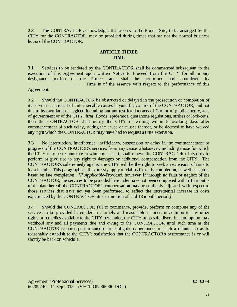
2.3. The CONTRACTOR acknowledges that access to the Project Site, to be arranged by the CITY for the CONTRACTOR, may be provided during times that are not the normal business hours of the CONTRACTOR.
ARTICLE THREE TIME 3.1. Services to be rendered by the CONTRACTOR shall be commenced subsequent to the execution of this Agreement upon written Notice to Proceed from the CITY for all or any designated portion of the Project and shall be performed and completed by _______________________. Time is of the essence with respect to the performance of this Agreement. 3.2. Should the CONTRACTOR be obstructed or delayed in the prosecution or completion of its services as a result of unforeseeable causes beyond the control of the CONTRACTOR, and not due to its own fault or neglect, including but not restricted to acts of God or of public enemy, acts of government or of the CITY, fires, floods, epidemics, quarantine regulations, strikes or lock-outs, then the CONTRACTOR shall notify the CITY in writing within 5 working days after commencement of such delay, stating the cause or causes thereof, or be deemed to have waived any right which the CONTRACTOR may have had to request a time extension. 3.3. No interruption, interference, inefficiency, suspension or delay in the commencement or progress of the CONTRACTOR's services from any cause whatsoever, including those for which the CITY may be responsible in whole or in part, shall relieve the CONTRACTOR of its duty to perform or give rise to any right to damages or additional compensation from the CITY. The CONTRACTOR's sole remedy against the CITY will be the right to seek an extension of time to its schedule. This paragraph shall expressly apply to claims for early completion, as well as claims based on late completion. [If Applicable-Provided, however, if through no fault or neglect of the CONTRACTOR, the services to be provided hereunder have not been completed within 18 months of the date hereof, the CONTRACTOR's compensation may be equitably adjusted, with respect to those services that have not yet been performed, to reflect the incremental increase in costs experienced by the CONTRACTOR after expiration of said 18 month period.] 3.4. Should the CONTRACTOR fail to commence, provide, perform or complete any of the services to be provided hereunder in a timely and reasonable manner, in addition to any other rights or remedies available to the CITY hereunder, the CITY at its sole discretion and option may withhold any and all payments due and owing to the CONTRACTOR until such time as the CONTRACTOR resumes performance of its obligations hereunder in such a manner so as to reasonably establish to the CITY's satisfaction that the CONTRACTOR's performance is or will shortly be back on schedule.
Agreement (Professional Services) 005000-4 60289240 - 11 Sep 2013 (SECTION005000.DOC)
71

ARTICLE FOUR
COMPENSATION 4.1. The total compensation to be paid the CONTRACTOR by the CITY for all Services shall not exceed $_____________ and shall be paid in the manner set forth in the "Basis of Compensation" [if any], which is attached as Exhibit B and made a part of this Agreement. ARTICLE FIVE MAINTENANCE OF RECORDS 5.1. The CONTRACTOR will keep adequate records and supporting documentation which concern or reflect its services hereunder. The records and documentation will be retained by the CONTRACTOR for a minimum of five 5 years from the date of termination of this Agreement or the date the Project is completed, whichever is later. The CITY, or any duly authorized agents or representatives of the CITY, shall have the right to audit, inspect and copy all such records and documentation as often as they deem necessary during the period of this Agreement and during the 5 year period noted above; provided, however, such activity shall be conducted only during normal business hours. If the CONTRACTOR desires to destroy records prior to the minimum period, it shall first obtain permission from the CITY in accordance with the Florida Public Records laws. ARTICLE SIX INDEMNIFICATION 6.1. The CONTRACTOR agrees to indemnify and hold harmless the City from liabilities, damages, losses and costs, including, but not limited to, reasonable attorneys' fees, to the extent caused by the negligence, recklessness, or intentional wrongful misconduct of the CONTRACTOR and persons employer or utilized by the CONTRACTOR in the performance of the Contract. ARTICLE SEVEN INSURANCE 7.1. CONTRACTOR shall obtain and carry, at all times during its performance under this Agreement, insurance of the types and in the amounts set forth in the document titled General Insurance Requirements, which is attached as Exhibit C and made a part of this Agreement.
ARTICLE EIGHT SERVICES BY CONTRACTOR'S OWN STAFF 8.1. The services to be performed hereunder shall be performed by the CONTRACTOR's own staff, unless otherwise authorized in writing by the CITY. The employment of, contract with, or use of the services of any other person or firm by the CONTRACTOR, as independent contractor or otherwise, shall be subject to the prior written approval of the CITY. No provision of this Agreement shall, however, be construed as constituting an agreement between the CITY and any
Agreement (Professional Services) 005000-5 60289240 - 11 Sep 2013 (SECTION005000.DOC)
72

such other person or firm. Nor shall anything contained in this Agreement be deemed to give any such party or any third party any claim or right of action against the CITY beyond such as may otherwise exist without regard to this Agreement. ARTICLE NINE WAIVER OF CLAIMS 9.1. The CONTRACTOR's acceptance of final payment shall constitute a full waiver of any and
all claims, except for insurance company subrogation claims, by it against the CITY arising out of this Agreement or otherwise related to the Project, except those previously made in writing and identified by the CONTRACTOR as unsettled at the time of the final payment. Neither the acceptance of the CONTRACTOR's services nor payment by the CITY shall be deemed to be a waiver of any of the CITY's rights against the CONTRACTOR.
ARTICLE TEN TERMINATION OR SUSPENSION 10.1. The CONTRACTOR shall be considered in material default of this Agreement and such default will be considered cause for the CITY to terminate this Agreement, in whole or in part, as further set forth in this section, for any of the following reasons: (a) failure to begin work under the Agreement within the times specified under the Notice(s) to Proceed, or (b) failure to properly and timely perform the services to be provided hereunder or as directed by the CITY, or (c) the bankruptcy or insolvency or a general assignment for the benefit of creditors by the CONTRACTOR or by any of the CONTRACTOR's principals, officers or directors, or (d) failure to obey laws, ordinances, regulations or other codes of conduct, or (e) failure to perform or abide by the terms or spirit of this Agreement, or (f) for any other just cause. The CITY may so terminate this Agreement, in whole or in part, by giving the CONTRACTOR at least 3 calendar days’ written notice. 10.2. If, after notice of termination of this Agreement as provided for in paragraph 10.1 above, it is determined for any reason that the CONTRACTOR was not in default, or that its default was excusable, or that the CITY otherwise was not entitled to the remedy against the CONTRACTOR provided for in paragraph 10.1, then the notice of termination given pursuant to paragraph 10.1 shall be deemed to be the notice of termination provided for in paragraph 10.3 below and the CONTRACTOR's remedies against the CITY shall be the same as and limited to those afforded the CONTRACTOR under paragraph 10.3 below. 10.3. The CITY shall have the right to terminate this Agreement, in whole or in part, without cause upon 7 calendar day’s written notice to the CONTRACTOR. In the event of such termination for convenience, the CONTRACTOR's recovery against the CITY shall be limited to that portion of the fee earned through the date of termination, together with any retainage withheld and any costs reasonably incurred by the CONTRACTOR that are directly attributable to the termination, but the CONTRACTOR shall not be entitled to any other or further recovery against the CITY, including, but not limited to, anticipated fees or profits on work not required to be performed.
Agreement (Professional Services) 005000-6 60289240 - 11 Sep 2013 (SECTION005000.DOC)
73

ARTICLE ELEVEN CONFLICT OF INTEREST 11.1. The CONTRACTOR represents that it presently has no interest and shall acquire no interest, either direct or indirect, which would conflict in any manner with the performance of services required hereunder. The CONTRACTOR further represents that no persons having any such interest shall be employed to perform those services. ARTICLE TWELVE MODIFICATION 12.1. No modification or change in this Agreement shall be valid or binding upon the parties unless in writing and executed by the party or parties intended to be bound by it.
ARTICLE THIRTEEN NOTICES AND ADDRESS OF RECORD 13.1. All notices required or made pursuant to this Agreement to be given by the CONTRACTOR to the CITY shall be in writing and shall be delivered by hand or by United States Postal Service Department, first class mail service, postage prepaid, return receipt requested, addressed to the following CITY's address of record: City of Naples 735 Eighth Street South Naples, Florida 34102-3796 Attention: A. William Moss, City Manager 13.2. All notices required or made pursuant to this Agreement to be given by the CITY to the CONTRACTOR shall be made in writing and shall be delivered by hand or by the United States Postal Service Department, first class mail service, postage prepaid, return receipt requested, addressed to the following CONTRACTOR's address of record: _________________________ _________________________ _________________________ Attn: ________________________ 13.3. Either party may change its address of record by written notice to the other party given in
accordance with requirements of this Article.
ARTICLE FOURTEEN MISCELLANEOUS 14.1. The CONTRACTOR, in representing the CITY, shall promote the best interest of the CITY and assume towards the CITY a duty of the highest trust, confidence, and fair dealing.
Agreement (Professional Services) 005000-7 60289240 - 11 Sep 2013 (SECTION005000.DOC)
74

14.2. No modification, waiver, suspension or termination of the Agreement or of any terms thereof shall impair the rights or liabilities of either party. 14.3. This Agreement is not assignable, in whole or in part, by the CONTRACTOR without the prior written consent of the CITY. 14.4. Waiver by either party of a breach of any provision of this Agreement shall not be deemed to be a waiver of any other breach and shall not be construed to be a modification of the terms of this Agreement. 14.5. The headings of the Articles, Exhibits, Parts and Attachments as contained in this Agreement are for the purpose of convenience only and shall not be deemed to expand, limit or change the provisions in such Articles, Exhibits, Parts and Attachments. 14.6. This Agreement constitutes the entire agreement between the parties hereto and shall supersede, replace and nullify any and all prior agreements or understandings, written or oral, relating to the matter set forth herein, and any such prior agreements or understanding shall have no force or effect whatever on this Agreement. Sec. 14. 7. The CONTRACTOR shall comply fully with all provisions of state and federal law, including without limitation all provisions of the Immigration Reform and Control Act of 1986 (“IRCA”) as amended, as well as all related immigration laws, rules, and regulations pertaining to proper employee work authorization in the United States. The CONTRACTOR shall execute the Certification of Compliance with Immigration Laws, attached hereto as Exhibit “D”.
ARTICLE FIFTEEN APPLICABLE LAW 15.1. Unless otherwise specified, this Agreement shall be governed by the laws, rules, and regulations of the State of Florida, and by the laws, rules and regulations of the United States when providing services funded by the United States government. Any suit or action brought by either party to this Agreement against the other party relating to or arising out of this Agreement must be brought in the appropriate Florida state court in Collier County, Florida. IN WITNESS WHEREOF, the parties hereto have executed this Agreement for the day and year first written above. Agreement (Professional Services) 005000-8 60289240 - 11 Sep 2013 (SECTION005000.DOC)
75

ATTEST: CITY: CITY OF NAPLES, FLORIDA, A Municipal Corporation By: ____________________________________ By: ________________________________ Patricia L. Rambosk, City Clerk A. William Moss, City Manager Approved as to form and legal sufficiency: By: ____________________________________ Robert D. Pritt, City Attorney CONTRACTOR: ________________________________ A Florida Corporation [or other entity] By: ____________________________________ __________________________________ Witness Its ______________________________ (CORPORATE SEAL)
END OF SECTION 005000 – CITY AGREEMENT CONTRACT General Contract (not Architects/Engineer)
Agreement (Professional Services) 005000-9 60289240 - 11 Sep 2013 (SECTION005000.DOC)
76

77

DIVISION 00 - SECTION 006200 CONSTRUCTION PAYMENT BOND FORM
KNOW ALL MEN BY THESE PRESENTS: THAT ____________________________________________________, Corporation, as Principal, hereinafter called Contractor; and_______________________________________, a corporation of the State of____________________, as surety, hereinafter called Surety, are held and firmly bound unto the City of Naples as Obligee, hereinafter called the City, in the amount of ($________________)______________________________________________ Dollars, for the payment whereof Contractor and Surety bind themselves, their heirs, executors, administrators, successors, and assigns, jointly and severally, firmly by these presents. WHEREAS, Contractor has by written agreement dated the ________day of ____________________, 20__, entered into a Contract with the City for the following described project: PUBLIC WORKS PUMP STATION IMPROVEMENTS CITY OF NAPLES, FLORIDA, BID # 049-13 which contract is by reference incorporated herein and made a part hereof, and is hereinafter referred to as the Contract. NOW, THEREFORE, THE CONDITION OF THIS OBLIGATION is such that if Contractor shall promptly make payments to all persons supplying Contractor labor, materials and supplies, used directly or indirectly by the said Contractor or Subcontractors in the prosecution of the work provided for in said Contract, then this obligation shall be null and void; otherwise it shall remain in full force and effect. PROVIDED FURTHER, that the said Surety for value received hereby stipulates and agrees that no change, extension of time, alteration or addition to the terms of the Contract or to the work to be performed hereunder or the Specifications accompanying the same shall in anywise affect its obligation on this Bond, and it does hereby waive notice of any such change, extension of time, alteration or addition to the terms of the Contract or to the work or to the Specifications. PROVIDED FURTHER, that this Bond is issued pursuant to Section 255.05, Florida Statutes, and reference is hereby made to the notice and time limitations in said statute for making claims against this Bond. PROVIDED FURTHER, that any suit under this Bond must be instituted before the expiration of one (1) year from the performance of the labor or completion of delivery of the materials or supplies. PROVIDED FURTHER, no right of action shall accrue on this Bond to or for the use of any person or corporation other than the City named herein and those persons or corporations provided for by Section 255.05, Florida Statutes, their heirs, executors, administrators, successors or assigns.
Construction Payment Bond 006200-1 60289240 - 11 Sep 2013 (SECTION006200.DOC)
78

SIGNED AND SEALED this ________ day of ________________________, A.D., 2009. IN THE PRESENCE OF: CONTRACTOR ___________________________ BY:_____________________________ INSURANCE COMPANY BY:_______________________________ Agent and Attorney in Fact
END OF SECTION 006200 - CONSTRUCTION PAYMENT BOND FORM
Construction Payment Bond 006200-2 60289240 - 11 Sep 2013 (SECTION006200.DOC)
79

DIVISION 00 - SECTION 006300 CONSTRUCTION PERFORMANCE BOND FORM
KNOW ALL MEN BY THESE PRESENTS: THAT ___________________________________________________ Corporation, as Principal, hereinafter called Contractor; and _______________________________, as surety, hereinafter called Surety, are held and firmly bound unto the City of Naples as Obligee, hereinafter called the City, in the amount of ($ ____________) ______________________________________ Dollars, for the payment whereof Contractor and Surety bind themselves, their heirs, executors, administrators, successors, and assigns, jointly and severally, firmly by these presents. WHEREAS, Contractor has by written agreement dated the _______ day of _______________, 20__, entered into a contract with the City for the following described project: PUBLIC WORKS PUMP STATION IMPROVEMENTS CITY OF NAPLES, FLORIDA BID # 049-13 which contract is by reference incorporated herein and made a part hereof, and is hereinafter referred to as the contract. NOW, THEREFORE, THE CONDITION OF THIS OBLIGATION is such that if the Contractor shall promptly and faithfully perform the Contract during the original term thereof and any extensions thereof which may be granted by the City with or without notice to the Surety and during any guarantee or warranty period, including the obligation to correct any latent defects not discovered until after acceptance of the project by the City, and if he shall satisfy all claims and demands incurred under said Contract and shall fully indemnify and save harmless the City, its agents, Engineer and employees from all losses, damages, expenses, costs and Attorney's Fees, including appellate proceedings which it may suffer by reason of failure to do so, and shall reimburse and repay the City all outlay and expense which the City may incur in making good any default, then this obligation shall be null and void; otherwise it shall remain in full force and effect. PROVIDED FURTHER, whenever Contractor shall be, and declared by the City to be in default under the Contract, the City having performed is obligations hereunder, the Surety may promptly remedy the default or shall promptly: (1) Complete the Contract in accordance with its terms and conditions; or (2) Obtain a bid or bids for submission to the City for completing the Contract in accordance with its terms and conditions and upon determination by the City and Surety of the lowest responsible bidder, arrange for a contract between such bidder and City and make available as work progresses (even though there should be a default or a succession of defaults under the Contract or Contracts of completion arranged under this paragraph) sufficient funds to pay the cost of completion, less the balance of the contract price; but not exceeding, including other costs and damages for which the Surety may be liable hereunder, the amount set forth in the first paragraph hereof. The term
Construction Performance Bond Form 006300-1 60289240 - 11 Sep 2013 (SECTION006300.DOC)
80
"balance of the contract price" as used in this paragraph, shall mean the total amount payable by the City to Contractor under the Contract and any amendments thereto, less the amount properly paid by the City to the Contractor. PROVIDED FURTHER, the Surety, for value received, hereby stipulates and agrees that no change, extension of time, alteration or addition to the terms of the Contract or to the work to be performed hereunder or the contract documents accompanying the same shall in any waive notice of any such change, extension of time, alteration or addition to the terms of the Contract or to the work or to the contract documents. PROVIDED FURTHER, any suit under this bond must be instituted before the expiration of two (2) years from the date on which final payment under the Contract falls due; except that, when the action involves a latent defect, suit must be instituted within four (4) years from the time the defect is discovered or should have been discovered with the exercise of due diligence. PROVIDED FURTHER, no right of action shall accrue on this bond to or for the use of any person or corporation other than the City, its successors or assigns. SIGNED AND SEALED this ________ day of ____________________, A.D., 20__. IN THE PRESENCE OF: CONTRACTOR ____________________________ BY:___________________________ INSURANCE COMPANY BY:___________________________ Agent and Attorney in Fact
END OF SECTION 006300 - CONSTRUCTION PERFORMANCE BOND FORM
Construction Performance Bond Form 006300-2 60289240 - 11 Sep 2013 (SECTION006300.DOC)
81

DIVISION 00 - SECTION 006500 CERTIFICATE OF INSURANCE REQUIREMENTS
A. INSURANCE REQUIREMENTS
1. Contractor shall purchase and maintain such comprehensive general liability and other insurance as required by the General Conditions, Special Conditions and General Insurance Requirements.
B. CERTIFICATE OF INSURANCE
1. The Certificate of Insurance submitted to the Owner on the Insurance Company’s form with a format similar to the popular ACCORD Corporation form.
2. The Certificate of Insurance shall indicate the Owner’s Name and address. Should
any of the required policies be canceled before the expiration date, the issuing company shall provide written notice to each additional insured 30 day prior to cancellation.
3. The Owner’s project name and project number shall be shown on the Certificate. 4. Submit five (3) copies of the Certificate with the executed Contract Agreement and
Performance and Payment Bonds.
END SECTION 006500 - CERTIFICATE OF INSURANCE REQUIREMENTS
Certification of Insurance Requirements 006500-1 60289240 - 6 Sep 2013 (SECTION006500.DOC)
82

This page intentionally left blank
83

DIVISION 0 – SECTION 007000 STANDARD GENERAL CONDITIONS
OF THE CONSTRUCTION PROJECT DOCUMENTS & TECHNICAL SPECIFICATIONS FOR PUBLIC WORKS
PUMP STATION IMPROVEMENTS
TABLE OF CONTENTS
ARTICLE 1 - DEFINITIONS AND TERMINOLOG0Y .......................................................................................... 7000-5 1.01 Defined Terms ......................................................................................................................... 7000-5 1.02 Terminology ............................................................................................................................ 7000-7
ARTICLE 2 - PRELIMINARY MATTERS ............................................................................................................... 7000-7 2.01 Delivery of Bonds .................................................................................................................... 7000-7 2.02 Copies of Documents .............................................................................................................. 7000-7 2.03 Commencement of Contract Times; Notice to Proceed ......................................................... 7000-7 2.04 Starting the Work .................................................................................................................... 7000-8 2.05 Before Starting Construction .................................................................................................. 7000-8 2.06 Preconstruction Conference ................................................................................................... 7000-8 2.07 Initial Acceptance of Schedules .............................................................................................. 7000-8
ARTICLE 3 - CONTRACT/PROJECT DOCUMENTS: INTENT, AMENDING, REUSE.................................... 7000-8 3.01 Intent ........................................................................................................................................ 7000-8 3.02 Reference Standards ............................................................................................................... 7000-8 3.03 Reporting and Resolving Discrepancies ................................................................................ 7000-9 3.04 Amending and Supplementing Contract/Project Documents ................................................ 7000-9 3.05 Reuse of Documents ................................................................................................................ 7000-9 3.06 Electronic Data ....................................................................................................................... 7000-9
ARTICLE 4 - AVAILABILITY OF LANDS; SUBSURFACE AND PHYSICAL CONDITIONS; REFERENCE POINTS ......................................................................................................................... 7000-10 4.01 Availability of Lands ............................................................................................................... 7000-10 4.02 Subsurface and Physical Conditions ...................................................................................... 7000-10 4.03 Differing Subsurface or Physical Conditions ........................................................................ 7000-10 4.04 Underground Facilities .......................................................................................................... 7000-11 4.05 Reference Points ..................................................................................................................... 7000-11 4.06 Hazardous Environmental Condition at Site ......................................................................... 7000-11
ARTICLE 5 - BONDS AND INSURANCE ............................................................................................................... 7000-12 5.01 Performance, Payment, and Other Bonds .............................................................................. 7000-12 5.02 Licensed Sureties and Insurers ............................................................................................... 7000-13 5.03 Certificates of Insurance ......................................................................................................... 7000-13 5.04 CONTRACTOR’s Liability Insurance .................................................................................... 7000-13 5.05 OWNER’s Liability Insurance ................................................................................................ 7000-13 5.06 Property Insurance ................................................................................................................. 7000-13 5.07 Waiver of Rights ...................................................................................................................... 7000-14 5.08 Receipt and Application of Insurance Proceeds .................................................................... 7000-15 5.09 Acceptance of Bonds and Insurance; Option to Replace....................................................... 7000-15 5.10 Partial Utilization, Acknowledgment of Property Insurer ..................................................... 7000-15
Standard General Conditions 007000-1 60289240 - 11 Sep 2013 (SECTION007000.DOC)
84

ARTICLE 6 - CONTRACTOR’S RESPONSIBILITIES .......................................................................................... 7000-15 6.01 Supervision and Superintendence ........................................................................................... 7000-15 6.02 Labor; Working Hours ........................................................................................................... 7000-15 6.03 Services, Materials, and Equipment ....................................................................................... 7000-15 6.04 Progress Schedule ................................................................................................................... 7000-16 6.05 Substitutes and “Or-Equals .................................................................................................... 7000-16 6.06 Concerning Subcontractors, Suppliers, and Others .............................................................. 7000-17 6.07 Patent Fees and Royalties ...................................................................................................... 7000-17 6.08 Permits .................................................................................................................................... 7000-18 6.09 Laws and Regulations ............................................................................................................. 7000-18 6.10 Taxes........................................................................................................................................ 7000-18 6.11 Use of Site and Other Areas ................................................................................................... 7000-18 6.12 Recorde Documents ................................................................................................................ 7000-18 6.13 Safety and Protection .............................................................................................................. 7000-19 6.14 Safety Representative .............................................................................................................. 7000-19 6.15 Hazard Communication Programs ........................................................................................ 7000-19 6.16 Emergencies ............................................................................................................................ 7000-19 6.17 Shop Drawings and Samples .................................................................................................. 7000-19 6.18 Continuing the Work ............................................................................................................... 7000-20 6.19 CONTRACTOR’s General Warranty and Guarantee ........................................................... 7000-20 6.20 Indemnification ....................................................................................................................... 7000-21 6.21 Delegation of Professional Design Services .......................................................................... 7000-21
ARTICLE 7 - OTHER WORK .................................................................................................................................... 7000-21 7.01 Related Work at Site ............................................................................................................... 7000-21 7.02 Coordination ........................................................................................................................... 7000-22 7.03 CLegal Relationships .............................................................................................................. 7000-22
ARTICLE 8 - OWNER’S RESPONSIBILITIES ....................................................................................................... 7000-22 8.01 Communications to Contractor .............................................................................................. 7000-22 8.02 Replacement of ENGINEER ................................................................................................... 7000-22 8.03 Furnish Data ........................................................................................................................... 7000-22 8.04 Pay Promptly When Due ........................................................................................................ 7000-22 8.05 Lands and Easements; Reports and Tests .............................................................................. 7000-22 8.06 Insurance ................................................................................................................................. 7000-22 8.07 Change Orders ........................................................................................................................ 7000-22 8.08 Inspections, Tests, and Approvals .......................................................................................... 7000-22 8.09 Limitations on OWNER’s Responsibilities ............................................................................. 7000-22 8.10 Undisclosed Hazardous Environmental Condition Condition .............................................. 7000-22 8.11 Evidence of Financial Arrangements ..................................................................................... 7000-22
ARTICLE 9 - ENGINEER’S STATUS DURING CONSTRUCTION ..................................................................... 7000-23 9.01 OWNER’S Representative ...................................................................................................... 7000-23 9.02 Visits to Site ............................................................................................................................. 7000-23 9.03 Project Representative ............................................................................................................ 7000-23 9.04 Clarifications and Interpretations .......................................................................................... 7000-23 9.05 Rejecting Defective Work ....................................................................................................... 7000-23 9.06 Shop Drawings, Change Orders and Payments..................................................................... 7000-23 9.07 Determinations for Unit Price Work ...................................................................................... 7000-23 9.08 Decisions on Requirements of Contract/Project Documents and Acceptability of
Work ........................................................................................................................................ 7000-23 9.09 Limitations on ENGINEER’s Authority and Responsibilities ............................................... 7000-24
Standard General Conditions 007000-2 60289240 - 11 Sep 2013 (SECTION007000.DOC)
85

ARTICLE 10 - CHANGES IN THE WORK; CLAIMS ............................................................................................ 7000-24 10.01 Authorized Changes in the Work ............................................................................................ 7000-24 10.02 Unauthorized Changes in the Work ....................................................................................... 7000-24 10.03 Execution of Change Orders .................................................................................................. 7000-24 10.04 Notification to Surety .............................................................................................................. 7000-24 10.05 Claims ..................................................................................................................................... 7000-24
ARTICLE 11 - COST OF THE WORK; CASH ALLOWANCES; UNIT PRICE WORK ..................................... 7000-25 11.01 Cost of the Work ...................................................................................................................... 7000-25 11.02 Allowances .............................................................................................................................. 7000-26 11.03 Unit Price Work ...................................................................................................................... 7000-27
ARTICLE 12 - CHANGE OF CONTRACT PRICE; CHANGE OF CONTRACT TIMES .................................... 7000-27 12.01 Change of Contract Price ....................................................................................................... 7000-27 12.02 Change of Contract Times ...................................................................................................... 7000-27 12.03 Delays ...................................................................................................................................... 7000-27
ARTICLE 13 - TESTS AND INSPECTIONS; CORRECTION, REMOVAL OR ACCEPTANCE OF DEFECTIVE WORK ............................................................................................................................ 7000-28 13.01 Notice of Defects ..................................................................................................................... 7000-28 13.02 Access to Work ........................................................................................................................ 7000-28 13.03 Tests and Inspections .............................................................................................................. 7000-28 13.04 Uncovering Work .................................................................................................................... 7000-28 13.05 OWNER May Stop the Work................................................................................................... 7000-29 13.06 Correction or Removal of Defective Work ............................................................................. 7000-29 13.07 Correction Period ................................................................................................................... 7000-29 13.08 Acceptance of Defective Work ................................................................................................ 7000-29 13.09 OWNER May Correct Defective Work ................................................................................... 7000-30
ARTICLE 14 - PAYMENTS TO CONTRACTOR AND COMPLETION .............................................................. 7000-30 14.01 Schedule of Values .................................................................................................................. 7000-30 14.02 Progress Payments ................................................................................................................. 7000-30 14.03 CONTRACTOR’s Warranty of Title ....................................................................................... 7000-31 14.04 Substantial Completion ........................................................................................................... 7000-31 14.05 Partial Utilization ................................................................................................................... 7000-32 14.06 Final Inspection ...................................................................................................................... 7000-32 14.07 Final Payment ........................................................................................................................ 7000-32 14.08 Final Completion Delayed ...................................................................................................... 7000-33 14.09 Waiver of Claims..................................................................................................................... 7000-33
ARTICLE 15 - SUSPENSION OF WORK AND TERMINATION ......................................................................... 7000-33 15.01 OWNER May Suspend Work ................................................................................................ 7000-33 15.02 OWNER May Terminate for Cause ........................................................................................ 7000-33 15.03 OWNER May Terminate For Convenience ............................................................................ 7000-34 15.04 CONTRACTOR May Stop Work or Terminate ...................................................................... 7000-34
ARTICLE 16 - DISPUTE RESOLUTION ................................................................................................................. 7000-34 16.01 Methods and Procedures ........................................................................................................ 7000-34
ARTICLE 17 - MISCELLANEOUS ........................................................................................................................... 7000-35 17.01 Giving Notice .......................................................................................................................... 7000-35 17.02 Computation of Times ............................................................................................................. 7000-35
Standard General Conditions 007000-3 60289240 - 11 Sep 2013 (SECTION007000.DOC)
86

17.03 Cumulative Remedies .............................................................................................................. 7000-35 17.04 Survival of Obligations ........................................................................................................... 7000-35 17.05 Controlling Law ...................................................................................................................... 7000-35 17.06 Headings ................................................................................................................................. 7000-35
Standard General Conditions 007000-4 60289240 - 11 Sep 2013 (SECTION007000.DOC)
87

ARTICLE 1 - DEFINITIONS AND TERMINOLOGY 1.01 Defined Terms
A. Wherever used in the Contract/Project Documents and printed with initial or all capital letters, the terms listed below will have the meanings indicated which are applicable to both the singular and plural thereof. 1. Addenda -- Written or graphic instruments issued prior to the opening of Bids which clarify, correct, or change the
Bidding Requirements or the Contract/Project Documents. 2. Agreement -- The written instrument which is evidence of the agreement between OWNER and CONTRACTOR
covering the Work. 3. Application for Payment -- The form acceptable to ENGINEER and OWNER which is to be used by CONTRACTOR
during the course of the Work in requesting progress or final payments and which is to be accompanied by such supporting documentation as is required by the Contract/Project Documents.
4. Asbestos -- Any material that contains more than one percent asbestos and is friable or is releasing asbestos fibers into the air above current action levels established by the United States Occupational Safety and Health Administra-tion.
5. Bid -- The offer or proposal of a bidder submitted on the prescribed form setting forth the prices for the Work to be performed.
6. Bidding Documents -- The Bidding Requirements and the proposed Contract/Project Documents, Project Manual, Plans & Specifications (including all Addenda issued prior to receipt of Bids).
7. Bidding Requirements -- The Advertisement or Invitation to Bid, Instructions to Bidders, Bid security form, if any, and the Bid form with any supplements.
8. Bonds -- Performance and payment bonds and other instruments of security. 9. Change Order -- A document recommended by ENGINEER which is signed by CONTRACTOR and OWNER and
authorizes an addition, deletion, or revision in the Work or an adjustment in the Contract Price or the Contract Times, issued on or after the Effective Date of the Agreement.
10. Claim -- A demand or assertion by OWNER or CONTRACTOR seeking an adjustment of Contract Price or Contract Times, or both, or other relief with respect to the terms of the Contract. A demand for money or services by a third party is not a Claim.
11. Contract -- The entire and integrated written agreement between the OWNER and CONTRACTOR concerning the Work. The Contract supersedes prior negotiations, representations, or agreements, whether written or oral.
12. Contract/Project Documents -- The Contract/Project Documents establish the rights and obligations of the parties and include the Agreement, Addenda (which pertain to the Contract/Project Documents), CONTRACTOR’s Bid (including documentation accompanying the Bid and any post Bid documentation submitted prior to the Notice of Award) when attached as an exhibit to the Agreement, the Notice to Proceed, the Bonds, these Standard General Conditions, the Supplementary Conditions, the Specifications and the Drawings as the same are more specifically identified in the Agreement, together with all Written Amendments, Change Orders, Work Change Directives, Field Orders, and ENGINEER’s written interpretations and clarifications issued on or after the Effective Date of the Agree-ment. Approved Shop Drawings and the reports and drawings of subsurface and physical conditions are not Contract/Project Documents. Only printed or hard copies of the items listed in this paragraph are Contract/Project Documents. Files in electronic media format of text, data, graphics, and the like that may be furnished by OWNER to CONTRACTOR are not Contract/Project Documents.
13. Contract Price -- The moneys payable by OWNER to CONTRACTOR for completion of the Work in accordance with the Contract/Project Documents as stated in the Agreement (subject to the provisions of paragraph 11.03 in the case of Unit Price Work).
14. Contract Times -- The number of days or the dates stated in the Agreement to: (i) Milestones if any, (ii) achieve Substantial Completion; and (iii) complete the Work so that it is ready for final payment as evidenced by ENGINEER’s written recommendation of final payment.
15. CONTRACTOR -- The individual or entity with whom OWNER has entered into the Agreement. 16. Cost of the Work -- See paragraph 11.01.A for definition. 17. Drawings -- That part of the Contract/Project Documents prepared or approved by ENGINEER which graphically
shows the scope, extent, and character of the Work to be performed by CONTRACTOR. Shop Drawings and other CONTRACTOR submittals are not Drawings as so defined.
18. Effective Date of the Agreement -- The date indicated in the Agreement on which it becomes effective, but if no such date is indicated, it means the date on which the Agreement is signed and delivered by the last of the two parties to sign and deliver.
19. ENGINEER -- The individual or entity named as such in the Agreement. 20. ENGINEER's Consultant -- An individual or entity having a contract with ENGINEER to furnish services as ENGINEER’s
independent professional associate or consultant with respect to the Project and who is identified as such in the Supplementary Conditions.
21. Field Order -- A written order issued by ENGINEER which requires minor changes in the Work but which does not involve a change in the Contract Price or the Contract Times.
22. General Requirements -- Sections of Division 1 of the Specifications. The General Requirements pertain to all sections of the Specifications.
23. Hazardous Environmental Condition -- The presence at the Site of Asbestos, PCBs, Petroleum, Hazardous Waste, or Radioactive Material in such quantities or circumstances that may present a substantial danger to persons or property exposed thereto in connection with the Work.
Standard General Conditions 007000-5 60289240 - 11 Sep 2013 (SECTION007000.DOC)
88

24. Hazardous Waste -- The term Hazardous Waste shall have the meaning provided in Section 1004 of the Solid Waste Disposal Act (42 USC Section 6903) as amended from time to time.
25. Laws or Regulations -- Any and all applicable laws, rules, regulations, ordinances, codes, and orders of any and all governmental bodies, agencies, authorities, and courts having jurisdiction.
26. Liens -- Charges, security interests, or encumbrances upon Project funds, real property, or personal property. 27. Milestone -- A principal event specified in the Contract/Project Documents relating to an intermediate completion
date or time prior to Substantial Completion of all the Work. 28. Notice of Award -- The written notice by OWNER to the apparent successful bidder stating that upon timely
compliance by the apparent successful bidder with the conditions precedent listed therein, OWNER will sign and deliver the Agreement.
29. Notice to Proceed -- A written notice given by OWNER to CONTRACTOR fixing the date on which the Contract Times will commence to run and on which CONTRACTOR shall start to perform the Work under the Contract/Project Documents.
30. OWNER -- The individual, entity, public body, or authority with whom CONTRACTOR has entered into the Agreement and for whom the Work is to be performed.
31. Partial Utilization -- Use by OWNER of a substantially completed part of the Work for the purpose for which it is intended (or a related purpose) prior to Substantial Completion of all the Work.
32. PCBs -- Polychlorinated biphenyls. 33. Petroleum -- Petroleum, including crude oil or any fraction thereof which is liquid at standard conditions of
temperature and pressure (60 degrees Fahrenheit and 14.7 pounds per square inch absolute), such as oil, petroleum, fuel oil, oil sludge, oil refuse, gasoline, kerosene, and oil mixed with other non-Hazardous Waste and crude oils.
34. Progress Schedule--A schedule, prepared and maintained by Contractor, describing the sequence and duration of the activities comprising the Contractor’s plan to accomplish the Work within the Contract Times.
35. Project -- The total construction of which the Work to be performed under the Contract/Project Documents may be the whole, or a part as may be indicated elsewhere in the Contract/Project Documents.
36. Project Manual -- The bound documentary information prepared for bidding and constructing the Work. A listing of the contents of the Project Manual, which may be bound in one or more volumes, is contained in the table(s) of contents.
37. Radioactive Material -- Source, special nuclear, or byproduct material as defined by the Atomic Energy Act of 1954 (42 USC Section 2011 et seq.) as amended from time to time.
38. Related Entity -- An officer, director, partner, employee, agent, consultant, or subcontractor. 39. Resident Project Representative -- The authorized representative of ENGINEER who may be assigned to the Site or
any part thereof. 40. Samples -- Physical examples of materials, equipment, or workmanship that are representative of some portion of
the Work and which establish the standards by which such portion of the Work will be judged. 41. Schedule of Submittals--A schedule, prepared and maintained by Contractor, of required submittals and the time
requirements to support scheduled performance of related construction activities. 42. Schedule of Values--A schedule, prepared and maintained by Contractor, allocating portions of the Contract Price to
various portions of the Work and used as the basis for reviewing Contractor’s Applications for Payment. 43. Shop Drawings -- All drawings, diagrams, illustrations, schedules, and other data or information which are
specifically prepared or assembled by or for CONTRACTOR and submitted by CONTRACTOR to illustrate some portion of the Work.
44. Site -- Lands or areas indicated in the Contract/Project Documents as being furnished by OWNER upon which the Work is to be performed, including rights-of-way and easements for access thereto, and such other lands furnished by OWNER which are designated for the use of CONTRACTOR.
45. Specifications -- That part of the Contract/Project Documents consisting of written technical descriptions of materials, equipment, systems, standards, and workmanship as applied to the Work and certain administrative details applicable thereto.
46. Subcontractor -- An individual or entity having a direct contract with CONTRACTOR or with any other Subcontractor for the performance of a part of the Work at the Site.
47. Substantial Completion -- The time at which the Work (or a specified part thereof) has progressed to the point where, in the opinion of ENGINEER, the Work (or a specified part thereof) is sufficiently complete, in accordance with the Contract/Project Documents, so that the Work (or a specified part thereof) can be utilized for the purposes for which it is intended. The terms “substantially complete” and “substantially completed” as applied to all or part of the Work refer to Substantial Completion thereof.
48. Successful Bidder--The Bidder submitting a responsive Bid to whom Owner makes an award. 49. Supplementary Conditions -- That part of the Contract/Project Documents which amends or supplements these
General Conditions. 50. Supplier -- A manufacturer, fabricator, supplier, distributor, material-man, or vendor having a direct contract with
CONTRACTOR or with any Subcontractor to furnish materials or equipment to be incorporated in the Work by CONTRACTOR or any Subcontractor.
51. Underground Facilities -- All underground pipelines, conduits, ducts, cables, wires, manholes, vaults, tanks, tunnels, or other such facilities or attachments, and any encasements containing such facilities, including those that convey electricity, gases, steam, liquid petroleum products, telephone or other communications, cable television, water, wastewater, storm water, other liquids or chemicals, or traffic or other control systems.
Standard General Conditions 007000-6 60289240 - 11 Sep 2013 (SECTION007000.DOC)
89

52. Unit Price Work -- Work to be paid for on the basis of unit prices. 53. Work -- The entire completed construction or the various separately identifiable parts thereof required to be
provided under the Contract/Project Documents. Work includes and is the result of performing or providing all labor, services, and documentation necessary to produce such construction, and furnishing, installing, and incorporating all materials and equipment into such construction, all as required by the Contract/Project Documents.
54. Work Change Directive -- A written statement to CONTRACTOR issued on or after the Effective Date of the Agreement and signed by OWNER and recommended by ENGINEER ordering an addition, deletion, or revision in the Work, or responding to differing or unforeseen subsurface or physical conditions under which the Work is to be performed or to emergencies. A Work Change Directive will not change the Contract Price or the Contract Times but is evidence that the parties expect that the change ordered or documented by a Work Change Directive will be incorporated in a subsequently issued Change Order following negotiations by the parties as to its effect, if any, on the Contract Price or Contract Times.
55. Written Amendment -- A written statement modifying the Contract/Project Documents, signed by OWNER and CONTRACTOR on or after the Effective Date of the Agreement and normally dealing with the non-engineering or non-technical rather than strictly construction-related aspects of the Contract/Project Documents.
1.02 Terminology The following words or terms are not defined but, when used in the Bidding Requirements or Contract/Project Documents, have the following meaning. A. Intent of Certain Terms or Adjectives
1. Whenever in the Contract/Project Documents the terms “as allowed,” “as approved,” or terms of like effect or import are used, or the adjectives “reasonable,” “suitable,” “acceptable,” “proper,” “satisfactory,” or adjectives of like effect or import are used to describe an action or determination of ENGINEER as to the Work, it is intended that such action or determination will be solely to evaluate, in general, the completed Work for compliance with the require-ments of and information in the Contract/Project Documents and conformance with the design concept of the com-pleted Project as a functioning whole as shown or indicated in the Contract/Project Documents (unless there is a specific statement indicating otherwise). The use of any such term or adjective shall not be effective to assign to ENGINEER any duty or authority to supervise or direct the performance of the Work or any duty or authority to undertake responsibility contrary to the provisions of paragraph 9.10 or any other provision of the Contract/Project Documents.
B. Day 1. The word “day” shall constitute a calendar day of 24 hours measured from midnight to the next midnight.
C. Defective 1. The word “defective,” when modifying the word “Work,” refers to Work that is unsatisfactory, faulty, or deficient in
that it does not conform to the Contract/Project Documents or does not meet the requirements of any inspection, reference standard, test, or approval referred to in the Contract/Project Documents, or has been damaged prior to ENGINEER’s recommendation of final payment (unless responsibility for the protection thereof has been assumed by OWNER at Substantial Completion in accordance with paragraph 14.04 or 14.05).
D. Furnish, Install, Perform, Provide 1. The word “furnish,” when used in connection with services, materials, or equipment, shall mean to supply and
deliver said services, materials, or equipment to the Site (or some other specified location) ready for use or installation and in usable or operable condition.
2. The word “install,” when used in connection with services, materials, or equipment, shall mean to put into use or place in final position said services, materials, or equipment complete and ready for intended use.
3. The words “perform” or “provide,” when used in connection with services, materials, or equipment, shall mean to furnish and install said services, materials, or equipment complete and ready for intended use.
4. When “furnish,” “install,” “perform,” or “provide” is not used in connection with services, materials, or equipment in a context clearly requiring an obligation of CONTRACTOR, “provide” is implied.
E. Unless stated otherwise in the Contract/Project Documents, words or phrases which have a well-known technical or construction industry or trade meaning are used in the Contract/Project Documents in accordance with such recognized meaning.
ARTICLE 2 - PRELIMINARY MATTERS 2.01 Delivery of Bonds
A. When CONTRACTOR delivers the executed Agreements to OWNER, CONTRACTOR shall also deliver to OWNER such Bonds as CONTRACTOR may be required to furnish.
2.02 Copies of Documents A. OWNER shall furnish to CONTRACTOR up to ten copies of the Contract/Project Documents. Additional copies will be
furnished upon request at the cost of reproduction. 2.03 Commencement of Contract Times; Notice to Proceed
A. The Contract Times will commence to run on the thirtieth day after the Effective Date of the Agreement or, if a Notice to Proceed is given, on the day indicated in the Notice to Proceed. A Notice to Proceed may be given at any time within 30 days after the Effective Date of the Agreement. In no event will the Contract Times commence to run later than the sixtieth day after the day of Bid opening or the thirtieth day after the Effective Date of the Agreement, whichever date is earlier.
2.04 Starting the Work
Standard General Conditions 007000-7 60289240 - 11 Sep 2013 (SECTION007000.DOC)
90

A. CONTRACTOR shall start to perform the Work on the date when the Contract Times commence to run. No Work shall be done at the Site prior to the date on which the Contract Times commence to run.
2.05 Before Starting Construction A. CONTRACTOR’s Review of Contract/Project Documents: Before undertaking each part of the Work, CONTRACTOR shall
carefully study and compare the Contract/Project Documents and check and verify pertinent figures therein and all applicable field measurements. CONTRACTOR shall promptly report in writing to ENGINEER any conflict, error, ambiguity, or discrepancy which CONTRACTOR may discover and shall obtain a written interpretation or clarification from ENGINEER before proceeding with any Work affected thereby; however, CONTRACTOR shall not be liable to OWNER or ENGINEER for failure to report any conflict, error, ambiguity, or discrepancy in the Contract/Project Documents unless CONTRACTOR knew or reasonably should have known thereof.
B. Preliminary Schedules: Within ten days after the Effective Date of the Agreement (unless otherwise specified in the General Requirements), CONTRACTOR shall submit to ENGINEER for its timely review: 1. a preliminary progress schedule indicating the times (numbers of days or dates) for starting and completing the
various stages of the Work, including any Milestones specified in the Contract/Project Documents; 2. a preliminary schedule of Shop Drawing and Sample submittals which will list each required submittal and the times
for submitting, reviewing, and processing such submittal; and 3. a preliminary schedule of values for all of the Work which includes quantities and prices of items which when added
together equal the Contract Price and subdivides the Work into component parts in sufficient detail to serve as the basis for progress payments during performance of the Work. Such prices will include an appropriate amount of overhead and profit applicable to each item of Work.
C. Evidence of Insurance: Before any Work at the Site is started, CONTRACTOR and OWNER shall each deliver to the other, with copies to each additional insured identified in the Supplementary Conditions, certificates of insurance (and other evidence of insurance which either of them or any additional insured may reasonably request) which CONTRACTOR and OWNER respectively are required to purchase and maintain in accordance with Article 5.
2.06 Preconstruction Conference A. Before any Work at the Site is started, a conference attended by CONTRACTOR, ENGINEER, OWNER, and others as
appropriate will be held to establish a working understanding among the parties as to the Work and to discuss the schedules referred to in paragraph 2.05.B, procedures for handling Shop Drawings and other submittals, processing Applications for Payment, and maintaining required records.
2.07 Initial Acceptance of Schedules A. Unless otherwise provided in the Contract/Project Documents, at least ten days before submission of the first Application
for Payment a conference attended by CONTRACTOR, ENGINEER, and others as appropriate will be held to review for acceptability to ENGINEER as provided below the schedules submitted in accordance with paragraph 2.05.B. CONTRAC-TOR shall have an additional ten days to make corrections and adjustments and to complete and resubmit the schedules. No progress payment shall be made to CONTRACTOR until acceptable schedules are submitted to ENGINEER. 1. The progress schedule will be acceptable to ENGINEER if it provides an orderly progression of the Work to comple-
tion within any specified Milestones and the Contract Times. Such acceptance will not impose on ENGINEER responsibility for the progress schedule, for sequencing, scheduling, or progress of the Work nor interfere with or relieve CONTRACTOR from CONTRACTOR’s full responsibility therefore.
2. CONTRACTOR’s schedule of Shop Drawing and Sample submittals will be acceptable to ENGINEER if it provides a workable arrangement for reviewing and processing the required submittals.
3. CONTRACTOR’s schedule of values will be acceptable to ENGINEER as to form and substance if it provides a reasonable allocation of the Contract Price to component parts of the Work.
ARTICLE 3 - CONTRACT/PROJECT DOCUMENTS: INTENT, AMENDING, REUSE 3.01 Intent
A. The Contract/Project Documents are complementary; what is called for by one is as binding as if called for by all. B. It is the intent of the Contract/Project Documents to describe a functionally complete Project (or part thereof) to be
constructed in accordance with the Contract/Project Documents. Any labor, documentation, services, materials, or equip-ment that may reasonably be inferred from the Contract/Project Documents or from prevailing custom or trade usage as being required to produce the intended result will be provided whether or not specifically called for at no additional cost to OWNER.
C. Clarifications and interpretations of the Contract/Project Documents shall be issued by ENGINEER as provided in Article 9. 3.02 Reference Standards
A. Standards, Specifications, Codes, Laws, and Regulations 1. Reference to standards, specifications, manuals, or codes of any technical society, organization, or association, or to
Laws or Regulations, whether such reference be specific or by implication, shall mean the standard, specification, manual, code, or Laws or Regulations in effect at the time of opening of Bids (or on the Effective Date of the Agreement if there were no Bids), except as may be otherwise specifically stated in the Contract/Project Documents.
Standard General Conditions 007000-8 60289240 - 11 Sep 2013 (SECTION007000.DOC)
91

2. No provision of any such standard, specification, manual or code, or any instruction of a Supplier shall be effective to change the duties or responsibilities of OWNER, CONTRACTOR, or ENGINEER, or any of their subcontractors, consul-tants, agents, or employees from those set forth in the Contract/Project Documents, nor shall any such provision or instruction be effective to assign to OWNER, ENGINEER, or any of ENGINEER’s Consultants, agents, or employees any duty or authority to supervise or direct the performance of the Work or any duty or authority to undertake responsibility inconsistent with the provisions of the Contract/Project Documents.
3.03 Reporting and Resolving Discrepancies A. Reporting Discrepancies
1. Contractor’s Review of Contract/Project Documents Before Starting Work: Before undertaking each part of the Work, Contractor shall carefully study and compare the Contract/Project Documents and check and verify pertinent figures therein and all applicable field measurements. Contractor shall promptly report in writing to Engineer any conflict, error, ambiguity, or discrepancy which Contractor may discover and shall obtain a written interpretation or clarification from Engineer before proceeding with any Work affected thereby.
2. Contractor’s Review of Contract/Project Documents During Performance of Work: If, during the performance of the Work, Contractor discovers any conflict, error, ambiguity, or discrepancy within the Contract/Project Documents or between the Contract/Project Documents and any provision of any Law or Regulation applicable to the performance of the Work or of any standard, specification, manual or code, or of any instruction of any Supplier, Contractor shall promptly report it to Engineer in writing. Contractor shall not proceed with the Work affected thereby (except in an emergency as required by Paragraph 6.16.A) until an amendment or supplement to the Contract/Project Documents has been issued by one of the methods indicated in Paragraph 3.04.
3. Contractor shall not be liable to Owner or Engineer for failure to report any conflict, error, ambiguity, or discrepancy in the Contract/Project Documents unless Contractor knew or reasonably should have known thereof.
B. Resolving Discrepancies 1. Except as may be otherwise specifically stated in the Contract/Project Documents, the provisions of the
Contract/Project Documents shall take precedence in resolving any conflict, error, ambiguity, or discrepancy between the provisions of the Contract/Project Documents and: a. the provisions of any standard, specification, manual, code, or instruction (whether or not specifically
incorporated by reference in the Contract/Project Documents); or b. the provisions of any Laws or Regulations applicable to the performance of the Work (unless such an
interpretation of the provisions of the Contract/Project Documents would result in violation of such Law or Regulation).
3.04 Amending and Supplementing Contract/Project Documents A. The Contract/Project Documents may be amended to provide for additions, deletions, and revisions in the Work or to
modify the terms and conditions thereof in one or more of the following ways: (i) a Written Amendment; (ii) a Change Order; or (iii) a Work Change Directive.
B. The requirements of the Contract/Project Documents may be supplemented and minor variations and deviations in the Work may be authorized, by one or more of the following ways: (i) a Field Order; (ii) ENGINEER’s approval of a Shop Drawing or Sample (Subject to the provisions of Paragraph 6.17.D.3); or (iii) ENGINEER’s written interpretation or clarification.
3.05 Reuse of Documents A. CONTRACTOR and any Subcontractor or Supplier or other individual or entity performing or furnishing any of the Work
under a direct or indirect contract with OWNER: (i) shall not have or acquire any title to or ownership rights in any of the Drawings, Specifications, or other documents (or copies of any thereof) prepared by or bearing the seal of ENGINEER or ENGINEER’s Consultant, including electronic media editions; and (ii) shall not reuse any of such Drawings, Specifications, other documents, or copies thereof on extensions of the Project or any other project without written consent of OWNER and ENGINEER and specific written verification or adaptation by ENGINEER. This prohibition will survive final payment, completion, and acceptance of the Work, or termination or completion of the Contract. Nothing herein shall preclude CONTRACTOR from retaining copies of the Contract/Project Documents for record purposes.
3.06 Electronic Data A. Copies of data furnished by Owner or Engineer to Contractor or Contractor to Owner or Engineer that may be relied upon
are limited to the printed copies (also known as hard copies). Files in electronic media format of text, data, graphics, or other types are furnished only for the convenience of the receiving party. Any conclusion or information obtained or derived from such electronic files will be at the user’s sole risk. If there is a discrepancy between the electronic files and the hard copies, the hard copies govern.
B. Because data stored in electronic media format can deteriorate or be modified inadvertently or otherwise without authorization of the data’s creator, the party receiving electronic files agrees that it will perform acceptance tests or procedures within 60 days, after which the receiving party shall be deemed to have accepted the data thus transferred. Any errors detected within the 60-day acceptance period will be corrected by the transferring party.
C. When transferring documents in electronic media format, the transferring party makes no representations as to long term compatibility, usability, or readability of documents resulting from the use of software application packages, operating systems, or computer hardware differing from those used by the data’s creator.
Standard General Conditions 007000-9 60289240 - 11 Sep 2013 (SECTION007000.DOC)
92
ARTICLE 4 - AVAILABILITY OF LANDS; SUBSURFACE AND PHYSICAL CONDITIONS; REFERENCE POINTS 4.01 Availability of Lands
A. OWNER shall furnish the Site. OWNER shall notify CONTRACTOR of any encumbrances or restrictions not of general application but specifically related to use of the Site with which CONTRACTOR must comply in performing the Work. OWNER will obtain in a timely manner and pay for easements for permanent structures or permanent changes in existing facilities. If CONTRACTOR and OWNER are unable to agree on entitlement to or on the amount or extent, if any, of any adjustment in the Contract Price or Contract Times, or both, as a result of any delay in OWNER’s furnishing the Site, CONTRACTOR may make a Claim therefore as provided in paragraph 10.05.
B. Upon reasonable written request, OWNER shall furnish CONTRACTOR with a current statement of record legal title and legal description of the lands upon which the Work is to be performed and OWNER’s interest therein as necessary for giving notice of or filing a mechanic's or construction lien against such lands in accordance with applicable Laws and Regulations.
C. CONTRACTOR shall provide for all additional lands and access thereto that may be required for temporary construction facilities or storage of materials and equipment.
4.02 Subsurface and Physical Conditions A. Reports and Drawings: The Supplementary Conditions identify:
1. those reports of explorations and tests of subsurface conditions at or contiguous to the Site that ENGINEER has used in preparing the Contract/Project Documents; and
2. those drawings of physical conditions in or relating to existing surface or subsurface structures at or contiguous to the Site (except Underground Facilities) that ENGINEER has used in preparing the Contract/Project Documents.
B. Limited Reliance by CONTRACTOR on Technical Data Authorized: CONTRACTOR may rely upon the general accuracy of the “technical data” contained in such reports and drawings, but such reports and drawings are not Contract/Project Documents. Such “technical data” is identified in the Supplementary Conditions. Except for such reliance on such “technical data,” CONTRACTOR may not rely upon or make any Claim against OWNER, ENGINEER, or any of ENGINEER’s Consultants with respect to: 1. the completeness of such reports and drawings for CONTRACTOR’s purposes, including, but not limited to, any
aspects of the means, methods, techniques, sequences, and procedures of construction to be employed by CONTRACTOR, and safety precautions and programs incident thereto; or
2. other data, interpretations, opinions, and information contained in such reports or shown or indicated in such draw-ings; or
3. any CONTRACTOR interpretation of or conclusion drawn from any "technical data" or any such other data, interpre-tations, opinions, or information.
4.03 Differing Subsurface or Physical Conditions A. Notice: If CONTRACTOR believes that any subsurface or physical condition at or contiguous to the Site that is uncovered
or revealed either: 1. is of such a nature as to establish that any “technical data” on which CONTRACTOR is entitled to rely as provided in
paragraph 4.02 is materially inaccurate; or 2. is of such a nature as to require a change in the Contract/Project Documents; or 3. differs materially from that shown or indicated in the Contract/Project Documents; or 4. is of an unusual nature, and differs materially from conditions ordinarily encountered and generally recognized as
inherent in work of the character provided for in the Contract/Project Documents; then CONTRACTOR shall, promptly after becoming aware thereof and before further disturbing the subsurface
or physical conditions or performing any Work in connection therewith (except in an emergency as required by paragraph 6.16.A), notify OWNER and ENGINEER in writing about such condition. CONTRACTOR shall not further disturb such condition or perform any Work in connection therewith (except as aforesaid) until receipt of written order to do so.
B. ENGINEER’s Review: After receipt of written notice as required by paragraph 4.03.A, ENGINEER will promptly review the pertinent condition, determine the necessity of OWNER's obtaining additional exploration or tests with respect thereto, and advise OWNER in writing (with a copy to CONTRACTOR) of ENGINEER’s findings and conclusions.
C. Possible Price and Times Adjustments 1. The Contract Price or the Contract Times, or both, will be equitably adjusted to the extent that the existence of such
differing subsurface or physical condition causes an increase or decrease in CONTRACTOR’s cost of, or time required for, performance of the Work; subject, however, to the following: a. such condition must meet any one or more of the categories described in paragraph 4.03.A; and b. with respect to Work that is paid for on a Unit Price Basis, any adjustment in Contract Price will be subject to
the provisions of paragraphs 9.08 and 11.03. 2. CONTRACTOR shall not be entitled to any adjustment in the Contract Price or Contract Times if:
a. CONTRACTOR knew of the existence of such conditions at the time CONTRACTOR made a final commitment to OWNER in respect of Contract Price and Contract Times by the submission of a Bid or becoming bound under a negotiated contract; or
b. the existence of such condition could reasonably have been discovered or revealed as a result of any examination, investigation, exploration, test, or study of the Site and contiguous areas required by the Bidding Requirements or Contract/Project Documents to be conducted by or for CONTRACTOR prior to CONTRACTOR's making such final commitment; or
c. CONTRACTOR failed to give the written notice within the time and as required by paragraph 4.03.A.
Standard General Conditions 007000-10 60289240 - 11 Sep 2013 (SECTION007000.DOC)
93
3. If OWNER and CONTRACTOR are unable to agree on entitlement to or on the amount or extent, if any, of any adjustment in the Contract Price or Contract Times, or both, a Claim may be made therefore as provided in paragraph 10.05. However, OWNER, ENGINEER, and ENGINEER’s Consultants shall not be liable to CONTRACTOR for any claims, costs, losses, or damages (including but not limited to all fees and charges of engineers, architects, attorneys, and other professionals and all court or arbitration or other dispute resolution costs) sustained by CONTRACTOR on or in connection with any other project or anticipated project.
4.04 Underground Facilities A. Shown or Indicated: The information and data shown or indicated in the Contract/Project Documents with respect to
existing Underground Facilities at or contiguous to the Site is based on information and data furnished to OWNER or ENGINEER by the owners of such Underground Facilities, including OWNER, or by others. Unless it is otherwise expressly provided in the Supplementary Conditions: 1. OWNER and ENGINEER shall not be responsible for the accuracy or completeness of any such information or data;
and 2. the cost of all of the following will be included in the Contract Price, and CONTRACTOR shall have full responsibility
for: a. reviewing and checking all such information and data, b. locating all Underground Facilities shown or indicated in the Contract/Project Documents, c. coordination of the Work with the owners of such Underground Facilities, including OWNER, during construc-
tion, and d. the safety and protection of all such Underground Facilities and repairing any damage thereto resulting from
the Work. B. Not Shown or Indicated
1. If an Underground Facility is uncovered or revealed at or contiguous to the Site which was not shown or indicated, or not shown or indicated with reasonable accuracy in the Contract/Project Documents, CONTRACTOR shall, prompt-ly after becoming aware thereof and before further disturbing conditions affected thereby or performing any Work in connection therewith (except in an emergency as required by paragraph 6.16.A), identify the owner of such Under-ground Facility and give written notice to that owner and to OWNER and ENGINEER. ENGINEER will promptly review the Underground Facility and determine the extent, if any, to which a change is required in the Contract/Project Documents to reflect and document the consequences of the existence or location of the Under-ground Facility. During such time, CONTRACTOR shall be responsible for the safety and protection of such Underground Facility.
2. If ENGINEER concludes that a change in the Contract/Project Documents is required, a Work Change Directive or a Change Order will be issued to reflect and document such consequences. An equitable adjustment shall be made in the Contract Price of Contract Times, or both, to the extent that they are attributable to the existence or location of any Underground Facility that was not shown or indicated or not shown or indicated with reasonable accuracy in the Contract/Project Documents and that CONTRACTOR did not know of and could not reasonably have been expected to be aware of or to have anticipated. If OWNER and CONTRACTOR are unable to agree on entitlement to or on the amount or extent, if any, of any such adjustment in Contract Price or Contract Times, OWNER or CONTRACTOR may make a Claim therefore as provided in paragraph 10.05.
4.05 Reference Points A. OWNER shall provide engineering surveys to establish reference points for construction which in ENGINEER’s judgment
are necessary to enable CONTRACTOR to proceed with the Work. CONTRACTOR shall be responsible for laying out the Work, shall protect and preserve the established reference points and property monuments, and shall make no changes or relocations without the prior written approval of OWNER. CONTRACTOR shall report to ENGINEER whenever any reference point or property monument is lost or destroyed or requires relocation because of necessary changes in grades or locations, and shall be responsible for the accurate replacement or relocation of such reference points or property monuments by professionally qualified personnel.
4.06 Hazardous Environmental Condition at Site A. Reports and Drawings: Reference is made to the Supplementary Conditions for the identification of those reports and
drawings relating to a Hazardous Environmental Condition identified at the Site, if any, that have been utilized by the ENGINEER in the preparation of the Contract/Project Documents.
B. Limited Reliance by CONTRACTOR on Technical Data Authorized: CONTRACTOR may rely upon the general accuracy of the “technical data” contained in such reports and drawings, but such reports and drawings are not Contract/Project Documents. Such “technical data” is identified in the Supplementary Conditions. Except for such reliance on such “technical data,” CONTRACTOR may not rely upon or make any Claim against OWNER, ENGINEER or any of ENGINEER’s Consultants with respect to: 1. the completeness of such reports and drawings for CONTRACTOR’s purposes, including, but not limited to, any
aspects of the means, methods, techniques, sequences and procedures of construction to be employed by CONTRACTOR and safety precautions and programs incident thereto; or
2. other data, interpretations, opinions and information contained in such reports or shown or indicated in such drawings; or
3. any CONTRACTOR interpretation of or conclusion drawn from any “technical data” or any such other data, interpretations, opinions or information.
C. CONTRACTOR shall not be responsible for any Hazardous Environmental Condition uncovered or revealed at the Site which was not shown or indicated in Drawings or Specifications or identified in the Contract/Project Documents to be within the scope of the Work. CONTRACTOR shall be responsible for a Hazardous Environmental Condition created with
Standard General Conditions 007000-11 60289240 - 11 Sep 2013 (SECTION007000.DOC)
94

any materials brought to the Site by CONTRACTOR, Subcontractors, Suppliers, or anyone else for whom CONTRACTOR is responsible.
D. If CONTRACTOR encounters a Hazardous Environmental Condition or if CONTRACTOR or anyone for whom CONTRACTOR is responsible creates a Hazardous Environmental Condition, CONTRACTOR shall immediately: (i) secure or otherwise isolate such condition; (ii) stop all Work in connection with such condition and in any area affected thereby (except in an emergency as required by paragraph 6.16); and (iii) notify OWNER and ENGINEER (and promptly thereafter confirm such notice in writing). OWNER shall promptly consult with ENGINEER concerning the necessity for OWNER to retain a qualified expert to evaluate such condition or take corrective action, if any.
E. CONTRACTOR shall not be required to resume Work in connection with such condition or in any affected area until after OWNER has obtained any required permits related thereto and delivered to CONTRACTOR written notice: (i) specifying that such condition and any affected area is or has been rendered safe for the resumption of Work; or (ii) specifying any special conditions under which such Work may be resumed safely. If OWNER and CONTRACTOR cannot agree as to entitlement to or on the amount or extent, if any, of any adjustment in Contract Price or Contract Times, or both, as a result of such Work stoppage or such special conditions under which Work is agreed to be resumed by CONTRACTOR, either party may make a Claim therefore as provided in paragraph 10.05.
F. If after receipt of such written notice CONTRACTOR does not agree to resume such Work based on a reasonable belief it is unsafe, or does not agree to resume such Work under such special conditions, then OWNER may order the portion of the Work that is in the area affected by such condition to be deleted from the Work. If OWNER and CONTRACTOR cannot agree as to entitlement to or on the amount or extent, if any, of an adjustment in Contract Price or Contract Times as a result of deleting such portion of the Work, then either party may make a Claim therefore as provided in paragraph 10.05. OWNER may have such deleted portion of the Work performed by OWNER’s own forces or others in accordance with Article 7.
G. To the fullest extent permitted by Laws and Regulations, OWNER shall indemnify and hold harmless CONTRACTOR, Subcontractors, ENGINEER, ENGINEER’s Consultants and the officers, directors, partners, employees, agents, other consultants, and subcontractors of each and any of them from and against all claims, costs, losses, and damages (including but not limited to all fees and charges of engineers, architects, attorneys, and other professionals and all court or arbitration or other dispute resolution costs) arising out of or relating to a Hazardous Environmental Condition, provided that such Hazardous Environmental Condition: (i) was not shown or indicated in the Drawings or Specifications or identified in the Contract/Project Documents to be included within the scope of the Work, and (ii) was not created by CONTRACTOR or by anyone for whom CONTRACTOR is responsible. Nothing in this paragraph 4.06.E shall obligate OWNER to indemnify any individual or entity from and against the consequences of that individual’s or entity’s own negli-gence.
H. To the fullest extent permitted by Laws and Regulations, CONTRACTOR shall indemnify and hold harmless OWNER, ENGINEER, ENGINEER’s Consultants, and the officers, directors, partners, employees, agents, other consultants, and subcontractors of each and any of them from and against all claims, costs, losses, and damages (including but not limited to all fees and charges of engineers, architects, attorneys, and other professionals and all court or arbitration or other dispute resolution costs) arising out of or relating to a Hazardous Environmental Condition created by CONTRACTOR or by anyone for whom CONTRACTOR is responsible. Nothing in this paragraph 4.06.F shall obligate CONTRACTOR to indemnify any individual or entity from and against the consequences of that individual’s or entity’s own negligence.
I. The provisions of paragraphs 4.02, 4.03, and 4.04 are not intended to apply to a Hazardous Environmental Condition uncovered or revealed at the Site.
ARTICLE 5 - BONDS AND INSURANCE 5.01 Performance, Payment, and Other Bonds
A. CONTRACTOR shall furnish performance and payment Bonds, each in an amount at least equal to the Contract Price as security for the faithful performance and payment of all CONTRACTOR’s obligations under the Contract/Project Documents. These Bonds shall remain in effect at least until one year after the date when final payment becomes due, except as provided otherwise by Laws or Regulations or by the Contract/Project Documents. CONTRACTOR shall also furnish such other Bonds as are required by the Contract/Project Documents.
B. All Bonds shall be in the form prescribed by the Contract/Project Documents except as provided otherwise by Laws or Regulations, and shall be executed by such sureties as are named in the current list of “Companies Holding Certificates of Authority as Acceptable Sureties on Federal Bonds and as Acceptable Reinsuring Companies” as published in Circular 570 (amended) by the Financial Management Service, Surety Bond Branch, U.S. Department of the Treasury. All Bonds signed by an agent must be accompanied by a certified copy of such agent’s authority to act.
C. If the surety on any Bond furnished by CONTRACTOR is declared bankrupt or becomes insolvent or its right to do business is terminated in any state where any part of the Project is located or it ceases to meet the requirements of paragraph 5.01.B, CONTRACTOR shall within 20 days thereafter substitute another Bond and surety, both of which shall comply with the requirements of paragraphs 5.01.B and 5.02.
Standard General Conditions 007000-12 60289240 - 11 Sep 2013 (SECTION007000.DOC)
95

5.02 Licensed Sureties and Insurers
A. All Bonds and insurance required by the Contract/Project Documents to be purchased and maintained by OWNER or CONTRACTOR shall be obtained from surety or insurance companies that are duly licensed or authorized in the jurisdiction in which the Project is located to issue Bonds or insurance policies for the limits and coverage’s so required. Such surety and insurance companies shall also meet such additional requirements and qualifications as may be provided in the Supplementary Conditions.
5.03 Certificates of Insurance A. Contractor shall deliver to Owner, with copies to each additional insured identified in the Supplementary Conditions,
certificates of insurance (and other evidence of insurance requested by Owner or any other additional insured) which Contractor is required to purchase and maintain.
B. Owner shall deliver to Contractor, with copies to each additional insured identified in the Supplementary Conditions, certificates of insurance (and other evidence of insurance requested by Contractor or any other additional insured) which Owner is required to purchase and maintain.
5.04 CONTRACTOR’s Liability Insurance A. Contractor shall purchase and maintain such liability and other insurance as is appropriate for the Work being performed
and as will provide protection from claims set forth below which may arise out of or result from Contractor’s performance of the Work and Contractor’s other obligations under the Contract/Project Documents, whether it is to be performed by Contractor, any Subcontractor or Supplier, or by anyone directly or indirectly employed by any of them to perform any of the Work, or by anyone for whose acts any of them may be liable: 1. claims under workers’ compensation, disability benefits, and other similar employee benefit acts; 2. claims for damages because of bodily injury, occupational sickness or disease, or death of Contractor’s employees; 3. claims for damages because of bodily injury, sickness or disease, or death of any person other than Contractor’s
employees; 4. claims for damages insured by reasonably available personal injury liability coverage which are sustained:
a. by any person as a result of an offense directly or indirectly related to the employment of such person by Contractor, or
b. by any other person for any other reason; 5. claims for damages, other than to the Work itself, because of injury to or destruction of tangible property wherever
located, including loss of use resulting there-from; and 6. claims for damages because of bodily injury or death of any person or property damage arising out of the
ownership, maintenance or use of any motor vehicle. B. The policies of insurance required by this Paragraph 5.04 shall:
1. with respect to insurance required by Paragraphs 5.04.A.3 through 5.04.A.6 inclusive, include as additional insured (subject to any customary exclusion regarding professional liability) Owner and Engineer, and any other individuals or entities identified in the Supplementary Conditions, all of whom shall be listed as additional insureds, and include coverage for the respective officers, directors, partners, employees, agents, consultants and subcontractors of each and any of all such additional insureds, and the insurance afforded to these additional insureds shall provide primary coverage for all claims covered thereby;
2. include at least the specific coverage’s and be written for not less than the limits of liability provided in the Supplementary Conditions or required by Laws or Regulations, whichever is greater;
3. include completed operations insurance; 4. include contractual liability insurance covering Contractor’s indemnity obligations under Paragraphs 6.11 and 6.20; 5. contain a provision or endorsement that the coverage afforded will not be canceled, materially changed or renewal
refused until at least 30 days prior written notice has been given to Owner and Contractor and to each other addi-tional insured identified in the Supplementary Conditions to whom a certificate of insurance has been issued (and the certificates of insurance furnished by the Contractor pursuant to Paragraph 5.03 will so provide);
6. remain in effect at least until final payment and at all times thereafter when Contractor may be correcting, removing, or replacing defective Work in accordance with Paragraph 13.07; and
7. with respect to completed operations insurance, and any insurance coverage written on a claims-made basis, remain in effect for at least two years after final payment. a. Contractor shall furnish Owner and each other additional insured identified in the Supplementary Conditions, to
whom a certificate of insurance has been issued, evidence satisfactory to Owner and any such additional insured of continuation of such insurance at final payment and one year thereafter.
5.05 OWNER’s Liability Insurance A. In addition to the insurance required to be provided by CONTRACTOR under paragraph 5.04, OWNER, at OWNER’s
option, may purchase and maintain at OWNER’s expense OWNER’s own liability insurance as will protect OWNER against claims which may arise from operations under the Contract/Project Documents.
5.06 Property Insurance A. Unless otherwise provided in the Supplementary Conditions, OWNER shall purchase and maintain property insurance
upon the Work at the Site in the amount of the full replacement cost thereof (subject to such deductible amounts as may be provided in the Supplementary Conditions or required by Laws and Regulations). This insurance shall: 1. include the interests of OWNER, CONTRACTOR, Subcontractors, ENGINEER, ENGINEER’s Consultants, and any other
individuals or entities identified in the Supplementary Conditions, and the officers, directors, partners, employees, agents, and other consultants and subcontractors of each and any of them, each of whom is deemed to have an insurable interest and shall be listed as an additional insured;
Standard General Conditions 007000-13 60289240 - 11 Sep 2013 (SECTION007000.DOC)
96

2. be written on a Builder’s Risk “all-risk” or open peril or special causes of loss policy form that shall at least include insurance for physical loss or damage to the Work, temporary buildings, false work, and materials and equipment in transit, and shall insure against at least the following perils or causes of loss: fire, lightning, extended coverage, theft, vandalism and malicious mischief, earthquake, collapse, debris removal, demolition occasioned by enforcement of Laws and Regulations, water damage, and such other perils or causes of loss as may be specifically required by the Supplementary Conditions;
3. include expenses incurred in the repair or replacement of any insured property (including but not limited to fees and charges of engineers and architects);
4. cover materials and equipment stored at the Site or at another location that was agreed to in writing by OWNER prior to being incorporated in the Work, provided that such materials and equipment have been included in an Application for Payment recommended by ENGINEER;
5. allow for partial utilization of the Work by OWNER; 6. include testing and startup; and 7. be maintained in effect until final payment is made unless otherwise agreed to in writing by OWNER, CONTRACTOR,
and ENGINEER with 30 days written notice to each other additional insured to whom a certificate of insurance has been issued.
B. OWNER shall purchase and maintain such boiler and machinery insurance or additional property insurance as may be required by the Supplementary Conditions or Laws and Regulations which will include the interests of OWNER, CONTRACTOR, Subcontractors, ENGINEER, ENGINEER’s Consultants, and any other individuals or entities identified in the Supplementary Conditions, each of whom is deemed to have an insurable interest and shall be listed as an insured or additional insured.
C. All the policies of insurance (and the certificates or other evidence thereof) required to be purchased and maintained in accordance with paragraph 5.06 will contain a provision or endorsement that the coverage afforded will not be canceled or materially changed or renewal refused until at least 30 days prior written notice has been given to OWNER and CON-TRACTOR and to each other additional insured to whom a certificate of insurance has been issued and will contain waiver provisions in accordance with paragraph 5.07.
D. OWNER shall not be responsible for purchasing and maintaining any property insurance specified in this paragraph 5.06 to protect the interests of CONTRACTOR, Subcontractors, or others in the Work to the extent of any deductible amounts that are identified in the Supplementary Conditions. The risk of loss within such identified deductible amount will be borne by CONTRACTOR, Subcontractors, or others suffering any such loss, and if any of them wishes property insurance coverage within the limits of such amounts, each may purchase and maintain it at the purchaser’s own expense.
E. If CONTRACTOR requests in writing that other special insurance be included in the property insurance policies provided under paragraph 5.06, OWNER shall, if possible, include such insurance, and the cost thereof will be charged to CONTRACTOR by appropriate Change Order or Written Amendment. Prior to commencement of the Work at the Site, OWNER shall in writing, advise the CONTRACTOR whether or not such other insurance has been procured by OWNER.
5.07 Waiver of Rights A. OWNER and CONTRACTOR intend that all policies purchased in accordance with paragraph 5.06 will protect OWNER,
CONTRACTOR, Subcontractors, ENGINEER, ENGINEER’s Consultants, and all other individuals or entities identified in the Supplementary Conditions to be listed as insured’s or additional insured’s (and the officers, directors, partners, employees, agents, and other consultants and subcontractors of each and any of them) in such policies and will provide primary coverage for all losses and damages caused by the perils or causes of loss covered thereby. All such policies shall contain provisions to the effect that in the event of payment of any loss or damage the insurers will have no rights of recovery against any of the insured’s or additional insured’s there-under. OWNER and CONTRACTOR waive all rights against each other and their respective officers, directors, partners, employees, agents, and other consultants and subcontractors of each and any of them for all losses and damages caused by, arising out of or resulting from any of the perils or causes of loss covered by such policies and any other property insurance applicable to the Work; and, in addi-tion, waive all such rights against Subcontractors, ENGINEER, ENGINEER’s Consultants, and all other individuals or entities identified in the Supplementary Conditions to be listed as insured’s or additional insured’s (and the officers, directors, partners, employees, agents, and other consultants and subcontractors of each and any of them) under such policies for losses and damages so caused. None of the above waivers shall extend to the rights that any party making such waiver may have to the proceeds of insurance held by OWNER as trustee or otherwise payable under any policy so issued.
B. OWNER waives all rights against CONTRACTOR, Subcontractors, ENGINEER, ENGINEER’s Consultants, and the officers, directors, partners, employees, agents, and other consultants and subcontractors of each and any of them for: 1. loss due to business interruption, loss of use, or other consequential loss extending beyond direct physical loss or
damage to OWNER’s property or the Work caused by, arising out of, or resulting from fire or other peril whether or not insured by OWNER; and
2. loss or damage to the completed Project or part thereof caused by, arising out of, or resulting from fire or other insured peril or cause of loss covered by any property insurance maintained on the completed Project or part thereof by OWNER during partial utilization pursuant to paragraph 14.05, after Substantial Completion pursuant to paragraph 14.04, or after final payment pursuant to paragraph 14.07.
C. Any insurance policy maintained by OWNER covering any loss, damage or consequential loss referred to in paragraph 5.07.B shall contain provisions to the effect that in the event of payment of any such loss, damage, or consequential loss, the insurers will have no rights of recovery against CONTRACTOR, Subcontractors, ENGINEER, or ENGINEER’s Consul-tants and the officers, directors, partners, employees, agents, and other consultants and subcontractors of each and any of them.
Standard General Conditions 007000-14 60289240 - 11 Sep 2013 (SECTION007000.DOC)
97

5.08 Receipt and Application of Insurance Proceeds A. Any insured loss under the policies of insurance required by paragraph 5.06 will be adjusted with OWNER and made
payable to OWNER as fiduciary for the insured’s, as their interests may appear, subject to the requirements of any applicable mortgage clause and of paragraph 5.08.B. OWNER shall deposit in a separate account any money so received and shall distribute it in accordance with such agreement as the parties in interest may reach. If no other special agreement is reached, the damaged Work shall be repaired or replaced, the moneys so received applied on account thereof, and the Work and the cost thereof covered by an appropriate Change Order or Written Amendment.
B. OWNER as fiduciary shall have power to adjust and settle any loss with the insurers unless one of the parties in interest shall object in writing within 15 days after the occurrence of loss to OWNER’s exercise of this power. If such objection be made, OWNER as fiduciary shall make settlement with the insurers in accordance with such agreement as the parties in interest may reach. If no such agreement among the parties in interest is reached, OWNER as fiduciary shall adjust and settle the loss with the insurers and, if required in writing by any party in interest, OWNER as fiduciary shall give bond for the proper performance of such duties.
5.09 Acceptance of Bonds and Insurance; Option to Replace A. If either OWNER or CONTRACTOR has any objection to the coverage afforded by or other provisions of the Bonds or
insurance required to be purchased and maintained by the other party in accordance with Article 5 on the basis of non-conformance with the Contract/Project Documents, the objecting party shall so notify the other party in writing within 10 days after receipt of the certificates (or other evidence requested) required by paragraph 2.05.C. OWNER and CONTRACTOR shall each provide to the other such additional information in respect of insurance provided as the other may reasonably request. If either party does not purchase or maintain all of the Bonds or insurance required of such party by the Contract/Project Documents, such party shall notify the other party in writing of such failure to purchase prior to the start of the Work, or of such failure to maintain prior to any change in the required coverage. Without prejudice to any other right or remedy, the other party may elect to obtain equivalent Bonds or insurance to protect such other party's interests at the expense of the party who was required to provide such coverage, and a Change Order shall be issued to adjust the Contract Price accordingly.
5.10 Partial Utilization, Acknowledgment of Property Insurer A. If OWNER finds it necessary to occupy or use a portion or portions of the Work prior to Substantial Completion of all the
Work as provided in paragraph 14.05, no such use or occupancy shall commence before the insurers providing the property insurance pursuant to paragraph 5.06 have acknowledged notice thereof and in writing effected any changes in coverage necessitated thereby. The insurers providing the property insurance shall consent by endorsement on the policy or policies, but the property insurance shall not be canceled or permitted to lapse on account of any such partial use or occupancy.
ARTICLE 6 - CONTRACTOR’S RESPONSIBILITIES 6.01 Supervision and Superintendence
A. CONTRACTOR shall supervise, inspect, and direct the Work competently and efficiently, devoting such attention thereto and applying such skills and expertise as may be necessary to perform the Work in accordance with the Contract/Project Documents. CONTRACTOR shall be solely responsible for the means, methods, techniques, sequences, and procedures of construction, but CONTRACTOR shall not be responsible for the negligence of OWNER or ENGINEER in the design or specification of a specific means, method, technique, sequence, or procedure of construction which is shown or indicated in and expressly required by the Contract/Project Documents. CONTRACTOR shall be responsible to see that the completed Work complies accurately with the Contract/Project Documents.
B. At all times during the progress of the Work, CONTRACTOR shall assign a competent resident superintendent thereto who shall not be replaced without written notice to OWNER and ENGINEER except under extraordinary circumstances. The superintendent will be CONTRACTOR’s representative at the Site and shall have authority to act on behalf of CONTRACTOR. All communications given to or received from the superintendent shall be binding on CONTRACTOR.
6.02 Labor; Working Hours A. CONTRACTOR shall provide competent, suitably qualified personnel to survey, lay out, and construct the Work as
required by the Contract/Project Documents. CONTRACTOR shall at all times maintain good discipline and order at the Site.
B. Except as otherwise required for the safety or protection of persons or the Work or property at the Site or adjacent thereto, and except as otherwise stated in the Contract/Project Documents, all Work at the Site shall be performed during regular working hours, and CONTRACTOR will not permit overtime work or the performance of Work on Saturday, Sunday, or any legal holiday without OWNER’s written consent (which will not be unreasonably withheld) given after prior written notice to ENGINEER.
6.03 Services, Materials, and Equipment A. Unless otherwise specified in the Contract/Project Documents, Contractor shall provide and assume full responsibility for
all services, materials, equipment, labor, transportation, construction equipment and machinery, tools, appliances, fuel, power, light, heat, telephone, water, sanitary facilities, temporary facilities, and all other facilities and incidentals necessary for the performance, testing, start-up, and completion of the Work.
B. All materials and equipment incorporated into the Work shall be as specified or, if not specified, shall be of good quality and new, except as otherwise provided in the Contract/Project Documents. All special warranties and guarantees required by the Specifications shall expressly run to the benefit of Owner. If required by Engineer, Contractor shall furnish satisfactory evidence (including reports of required tests) as to the source, kind, and quality of materials and equipment.
Standard General Conditions 007000-15 60289240 - 11 Sep 2013 (SECTION007000.DOC)
98

C. All materials and equipment shall be stored, applied, installed, connected, erected, protected, used, cleaned, and conditioned in accordance with instructions of the applicable Supplier, except as otherwise may be provided in the Contract/Project Documents.
6.04 Progress Schedule A. CONTRACTOR shall adhere to the progress schedule established in accordance with paragraph 2.07 as it may be adjusted
from time to time as provided below. 1. CONTRACTOR shall submit to ENGINEER for acceptance (to the extent indicated in paragraph 2.07) proposed
adjustments in the progress schedule that will not result in changing the Contract Times (or Milestones). Such adjustments will conform generally to the progress schedule then in effect and additionally will comply with any provisions of the General Requirements applicable thereto.
2. Proposed adjustments in the progress schedule that will change the Contract Times (or Milestones) shall be submitted in accordance with the requirements of Article 12. Such adjustments may only be made by a Change Order or Written Amendment in accordance with Article 12.
6.05 Substitutes and “Or-Equals” A. Whenever an item of material or equipment is specified or described in the Contract/Project Documents by using the
name of a proprietary item or the name of a particular Supplier, the specification or description is intended to establish the type, function, appearance, and quality required. Unless the specification or description contains or is followed by words reading that no like, equivalent, or “or-equal” item or no substitution is permitted, other items of material or equipment or material or equipment of other Suppliers may be submitted to ENGINEER for review under the circum-stances described below. 1. “Or-Equal” Items: If in ENGINEER’s sole discretion an item of material or equipment proposed by CONTRACTOR is
functionally equal to that named and sufficiently similar so that no change in related Work will be required, it may be considered by ENGINEER as an “or-equal” item, in which case review and approval of the proposed item may, in ENGINEER’s sole discretion, be accomplished without compliance with some or all of the requirements for approval of proposed substitute items. For the purposes of this paragraph 6.05.A.1, a proposed item of material or equipment will be considered functionally equal to an item so named if: a. in the exercise of reasonable judgment ENGINEER determines that: (i) it is at least equal in quality, durability,
appearance, strength, and design characteristics; (ii) it will reliably perform at least equally well the function imposed by the design concept of the completed Project as a functioning whole, and;
b. CONTRACTOR certifies that: (i) there is no increase in cost to the OWNER; and (ii) it will conform substantially, even with deviations, to the detailed requirements of the item named in the Contract/Project Documents.
2. Substitute Items a. If in ENGINEER’s sole discretion an item of material or equipment proposed by CONTRACTOR does not qualify
as an “or-equal” item under paragraph 6.05.A.1, it will be considered a proposed substitute item. b. CONTRACTOR shall submit sufficient information as provided below to allow ENGINEER to determine that the
item of material or equipment proposed is essentially equivalent to that named and an acceptable substitute therefore. Requests for review of proposed substitute items of material or equipment will not be accepted by ENGINEER from anyone other than CONTRACTOR.
c. The procedure for review by the ENGINEER will be as set forth in paragraph 6.05.A.2.d, as supplemented in the General Requirements and as ENGINEER may decide is appropriate under the circumstances.
d. CONTRACTOR shall first make written application to ENGINEER for review of a proposed substitute item of material or equipment that CONTRACTOR seeks to furnish or use. The application shall certify that the proposed substitute item will perform adequately the functions and achieve the results called for by the general design, be similar in substance to that specified, and be suited to the same use as that specified. The appli-cation will state the extent, if any, to which the use of the proposed substitute item will prejudice CONTRACTOR’s achievement of Substantial Completion on time, whether or not use of the proposed substitute item in the Work will require a change in any of the Contract/Project Documents (or in the provisions of any other direct contract with OWNER for work on the Project) to adapt the design to the proposed substitute item and whether or not incorporation or use of the proposed substitute item in connection with the Work is subject to payment of any license fee or royalty. All variations of the proposed substitute item from that specified will be identified in the application, and available engineering, sales, maintenance, repair, and replacement services will be indicated. The application will also contain an itemized estimate of all costs or credits that will result directly or indirectly from use of such substitute item, including costs of redesign and claims of other con-tractors affected by any resulting change, all of which will be considered by ENGINEER in evaluating the proposed substitute item. ENGINEER may require CONTRACTOR to furnish additional data about the proposed substitute item.
B. Substitute Construction Methods or Procedures: If a specific means, method, technique, sequence, or procedure of construction is shown or indicated in and expressly required by the Contract/Project Documents, CONTRACTOR may furnish or utilize a substitute means, method, technique, sequence, or procedure of construction approved by ENGINEER. CONTRACTOR shall submit sufficient information to allow ENGINEER, in ENGINEER’s sole discretion, to determine that the substitute proposed is equivalent to that expressly called for by the Contract/Project Documents. The procedure for review by ENGINEER will be similar to that provided in subparagraph 6.05.A.2.
Standard General Conditions 007000-16 60289240 - 11 Sep 2013 (SECTION007000.DOC)
99

C. Engineer’s Evaluation: ENGINEER will be allowed a reasonable time within which to evaluate each proposal or submittal
made pursuant to paragraphs 6.05.A and 6.05.B. ENGINEER will be the sole judge of acceptability. No “or-equal” or substitute will be ordered, installed or utilized until ENGINEER’s review is complete, which will be evidenced by either a Change Order for a substitute or an approved Shop Drawing for an “or equal.” ENGINEER will advise CONTRACTOR in writing of any negative determination.
D. Special Guarantee: OWNER may require CONTRACTOR to furnish at CONTRACTOR’s expense a special performance guarantee or other surety with respect to any substitute.
E. ENGINEER’s Cost Reimbursement: ENGINEER will record time required by ENGINEER and ENGINEER’s Consultants in evaluating substitute proposed or submitted by CONTRACTOR pursuant to paragraphs 6.05.A.2 and 6.05.B and in making changes in the Contract/Project Documents (or in the provisions of any other direct contract with OWNER for work on the Project) occasioned thereby. Whether or not ENGINEER approves a substitute item so proposed or submitted by CON-TRACTOR, CONTRACTOR shall reimburse OWNER for the charges of ENGINEER and ENGINEER’s Consultants for evaluat-ing each such proposed substitute.
F. CONTRACTOR’s Expense: CONTRACTOR shall provide all data in support of any proposed substitute or “or-equal” at CONTRACTOR’s expense.
6.06 Concerning Subcontractors, Suppliers, and Others A. CONTRACTOR shall not employ any Subcontractor, Supplier, or other individual or entity (including those acceptable to
OWNER as indicated in paragraph 6.06.B), whether initially or as a replacement, against whom OWNER may have reason-able objection. CONTRACTOR shall not be required to employ any Subcontractor, Supplier, or other individual or entity to furnish or perform any of the Work against whom CONTRACTOR has reasonable objection.
B. If the Supplementary Conditions require the identity of certain Subcontractors, Suppliers, or other individuals or entities to be submitted to OWNER in advance for acceptance by OWNER by a specified date prior to the Effective Date of the Agreement, and if CONTRACTOR has submitted a list thereof in accordance with the Supplementary Conditions, OWNER’s acceptance (either in writing or by failing to make written objection thereto by the date indicated for acceptance or objection in the Bidding Documents or the Contract/Project Documents) of any such Subcontractor, Supplier, or other individual or entity so identified may be revoked on the basis of reasonable objection after due investigation. CON-TRACTOR shall submit an acceptable replacement for the rejected Subcontractor, Supplier, or other individual or entity, and the Contract Price will be adjusted by the difference in the cost occasioned by such replacement, and an appropriate Change Order will be issued or Written Amendment signed. No acceptance by OWNER of any such Subcontractor, Supplier, or other individual or entity, whether initially or as a replacement, shall constitute a waiver of any right of OWNER or ENGINEER to reject defective Work.
C. Contractor shall be fully responsible to Owner and Engineer for all acts and omissions of the Subcontractors, Suppliers, and other individuals or entities performing or furnishing any of the Work just as Contractor is responsible for Contractor’s own acts and omissions. Nothing in the Contract/Project Documents: 1. shall create for the benefit of any such Subcontractor, Supplier, or other individual or entity any contractual relation-
ship between Owner or Engineer and any such Subcontractor, Supplier or other individual or entity, nor 2. shall anything in the Contract/Project Documents create any obligation on the part of Owner or Engineer to pay or to
see to the payment of any moneys due any such Subcontractor, Supplier, or other individual or entity except as may otherwise be required by Laws and Regulations.
D. CONTRACTOR shall be solely responsible for scheduling and coordinating the Work of Subcontractors, Suppliers, and other individuals or entities performing or furnishing any of the Work under a direct or indirect contract with CONTRAC-TOR.
E. CONTRACTOR shall require all Subcontractors, Suppliers, and such other individuals or entities performing or furnishing any of the Work to communicate with the ENGINEER through CONTRACTOR.
F. The divisions and sections of the Specifications and the identifications of any Drawings shall not control CONTRACTOR in dividing the Work among Subcontractors or Suppliers or delineating the Work to be performed by any specific trade.
G. All Work performed for CONTRACTOR by a Subcontractor or Supplier will be pursuant to an appropriate agreement between CONTRACTOR and the Subcontractor or Supplier which specifically binds the Subcontractor or Supplier to the applicable terms and conditions of the Contract/Project Documents for the benefit of OWNER and ENGINEER. Whenever any such agreement is with a Subcontractor or Supplier who is listed as an additional insured on the property insurance provided in paragraph 5.06, the agreement between the CONTRACTOR and the Subcontractor or Supplier will contain provisions whereby the Subcontractor or Supplier waives all rights against OWNER, CONTRACTOR, ENGINEER, ENGINEER’s Consultants, and all other individuals or entities identified in the Supplementary Conditions to be listed as insureds or additional insureds (and the officers, directors, partners, employees, agents, and other consultants and subcontractors of each and any of them) for all losses and damages caused by, arising out of, relating to, or resulting from any of the perils or causes of loss covered by such policies and any other property insurance applicable to the Work. If the insurers on any such policies require separate waiver forms to be signed by any Subcontractor or Supplier, CONTRACTOR will obtain the same.
6.07 Patent Fees and Royalties A. CONTRACTOR shall pay all license fees and royalties and assume all costs incident to the use in the performance of the
Work or the incorporation in the Work of any invention, design, process, product, or device which is the subject of patent rights or copyrights held by others. If a particular invention, design, process, product, or device is specified in the Contract/Project Documents for use in the performance of the Work and if to the actual knowledge of OWNER or ENGINEER its use is subject to patent rights or copyrights calling for the payment of any license fee or royalty to others, the existence of such rights shall be disclosed by OWNER in the Contract/Project Documents.
Standard General Conditions 007000-17 60289240 - 11 Sep 2013 (SECTION007000.DOC)
100

B. To the fullest extent permitted by Laws and Regulations, CONTRACTOR shall indemnify and hold harmless OWNER, ENGINEER, ENGINEER’s Consultants, and the officers, directors, partners, employees or agents, and other consultants of each and any of them from and against all claims, costs, losses, and damages (including but not limited to all fees and charges of engineers, architects, attorneys, and other professionals and all court or arbitration or other dispute resolution costs) arising out of or relating to any infringement of patent rights or copyrights incident to the use in the performance of the Work or resulting from the incorporation in the Work of any invention, design, process, product, or device not specified in the Contract/Project Documents.
6.08 Permits A. Unless otherwise provided in the Supplementary Conditions, CONTRACTOR shall obtain and pay for all construction
permits and licenses. OWNER shall assist CONTRACTOR, when necessary, in obtaining such permits and licenses. CONTRACTOR shall pay all governmental charges and inspection fees necessary for the prosecution of the Work which are applicable at the time of opening of Bids, or, if there are no Bids, on the Effective Date of the Agreement. CONTRACTOR shall pay all charges of utility owners for connections to the Work, and OWNER shall pay all charges of such utility owners for capital costs related thereto, such as plant investment fees.
6.09 Laws and Regulations A. CONTRACTOR shall give all notices and comply with all Laws and Regulations applicable to the performance of the Work.
Except where otherwise expressly required by applicable Laws and Regulations, neither OWNER nor ENGINEER shall be responsible for monitoring CONTRACTOR’s compliance with any Laws or Regulations.
B. If CONTRACTOR performs any Work knowing or having reason to know that it is contrary to Laws or Regulations, CONTRACTOR shall bear all claims, costs, losses, and damages (including but not limited to all fees and charges of engineers, architects, attorneys, and other professionals and all court or arbitration or other dispute resolution costs) arising out of or relating to such Work; however, it shall not be CONTRACTOR’s primary responsibility to make certain that the Specifications and Drawings are in accordance with Laws and Regulations, but this shall not relieve CON-TRACTOR of CONTRACTOR’s obligations under paragraph 3.03.
C. Changes in Laws or Regulations not known at the time of opening of Bids (or, on the Effective Date of the Agreement if there were no Bids) having an effect on the cost or time of performance of the Work may be the subject of an adjustment in Contract Price or Contract Times. If OWNER and CONTRACTOR are unable to agree on entitlement to or on the amount or extent, if any, of any such adjustment, a Claim may be made therefore as provided in paragraph 10.05.
6.10 Taxes A. CONTRACTOR shall pay all sales, consumer, use, and other similar taxes required to be paid by CONTRACTOR in
accordance with the Laws and Regulations of the place of the Project which are applicable during the performance of the Work.
6.11 Use of Site and Other Areas A. Limitation on Use of Site and Other Areas
1. CONTRACTOR shall confine construction equipment, the storage of materials and equipment, and the operations of workers to the Site and other areas permitted by Laws and Regulations, and shall not unreasonably encumber the Site and other areas with construction equipment or other materials or equipment. CONTRACTOR shall assume full responsibility for any damage to any such land or area, or to the owner or occupant thereof, or of any adjacent land or areas resulting from the performance of the Work.
2. Should any claim be made by any such owner or occupant because of the performance of the Work, CONTRACTOR shall promptly settle with such other party by negotiation or otherwise resolve the claim by arbitration or other dispute resolution proceeding or at law.
3. To the fullest extent permitted by Laws and Regulations, CONTRACTOR shall indemnify and hold harmless OWNER, ENGINEER, ENGINEER’s Consultant, and the officers, directors, partners, employees, agents, and other consultants of each and any of them from and against all claims, costs, losses, and damages (including but not limited to all fees and charges of engineers, architects, attorneys, and other professionals and all court or arbitration or other dispute resolution costs) arising out of or relating to any claim or action, legal or equitable, brought by any such owner or occupant against OWNER, ENGINEER, or any other party indemnified hereunder to the extent caused by or based upon CONTRACTOR's performance of the Work.
B. Removal of Debris During Performance of the Work: During the progress of the Work CONTRACTOR shall keep the Site and other areas free from accumulations of waste materials, rubbish, and other debris. Removal and disposal of such waste materials, rubbish, and other debris shall conform to applicable Laws and Regulations.
C. Cleaning: Prior to Substantial Completion of the Work CONTRACTOR shall clean the Site and make it ready for utilization by OWNER. At the completion of the Work CONTRACTOR shall remove from the Site all tools, appliances, construction equipment and machinery, and surplus materials and shall restore to original condition all property not designated for alteration by the Contract/Project Documents.
D. Loading Structures: CONTRACTOR shall not load nor permit any part of any structure to be loaded in any manner that will endanger the structure, nor shall CONTRACTOR subject any part of the Work or adjacent property to stresses or pressures that will endanger it.
6.12 Record Documents A. CONTRACTOR shall maintain in a safe place at the Site one record copy of all Drawings, Specifications, Addenda, Written
Amendments, Change Orders, Work Change Directives, Field Orders, and written interpretations and clarifications in good order and annotated to show changes made during construction. These record documents together with all approved Samples and a counterpart of all approved Shop Drawings will be available to ENGINEER for reference. Upon completion of the Work, these record documents, Samples, and Shop Drawings will be delivered to ENGINEER for OWNER.
6.13 Safety and Protection
Standard General Conditions 007000-18 60289240 - 11 Sep 2013 (SECTION007000.DOC)
101

A. CONTRACTOR shall be solely responsible for initiating, maintaining and supervising all safety precautions and programs in connection with the Work. CONTRACTOR shall take all necessary precautions for the safety of, and shall provide the necessary protection to prevent damage, injury or loss to: 1. all persons on the Site or who may be affected by the Work; 2. all the Work and materials and equipment to be incorporated therein, whether in storage on or off the Site; and 3. other property at the Site or adjacent thereto, including trees, shrubs, lawns, walks, pavements, roadways,
structures, utilities, and Underground Facilities not designated for removal, relocation, or replacement in the course of construction.
B. CONTRACTOR shall comply with all applicable Laws and Regulations relating to the safety of persons or property, or to the protection of persons or property from damage, injury, or loss; and shall erect and maintain all necessary safeguards for such safety and protection. CONTRACTOR shall notify owners of adjacent property and of Underground Facilities and other utility owners when prosecution of the Work may affect them, and shall cooperate with them in the protection, removal, relocation, and replacement of their property.
C. All damage, injury, or loss to any property referred to in paragraph 6.13.A.2 or 6.13.A.3 caused, directly or indirectly, in whole or in part, by CONTRACTOR, any Subcontractor, Supplier, or any other individual or entity directly or indirectly em-ployed by any of them to perform any of the Work, or anyone for whose acts any of them may be liable, shall be remedied by CONTRACTOR (except damage or loss attributable to the fault of Drawings or Specifications or to the acts or omissions of OWNER or ENGINEER or ENGINEER’s Consultant, or anyone employed by any of them, or anyone for whose acts any of them may be liable, and not attributable, directly or indirectly, in whole or in part, to the fault or negligence of CONTRACTOR or any Subcontractor, Supplier, or other individual or entity directly or indirectly employed by any of them).
D. CONTRACTOR’s duties and responsibilities for safety and for protection of the Work shall continue until such time as all the Work is completed and ENGINEER has issued a notice to OWNER and CONTRACTOR in accordance with paragraph 14.07.B that the Work is acceptable (except as otherwise expressly provided in connection with Substantial Completion).
6.14 Safety Representative A. CONTRACTOR shall designate a qualified and experienced safety representative at the Site whose duties and
responsibilities shall be the prevention of accidents and the maintaining and supervising of safety precautions and programs.
6.15 Hazard Communication Programs A. CONTRACTOR shall be responsible for coordinating any exchange of material safety data sheets or other hazard
communication information required to be made available to or exchanged between or among employers at the Site in accordance with Laws or Regulations.
6.16 Emergencies A. In emergencies affecting the safety or protection of persons or the Work or property at the Site or adjacent thereto,
CONTRACTOR is obligated to act to prevent threatened damage, injury, or loss. CONTRACTOR shall give ENGINEER prompt written notice if CONTRACTOR believes that any significant changes in the Work or variations from the Contract/Project Documents have been caused thereby or are required as a result thereof. If ENGINEER determines that a change in the Contract/Project Documents is required because of the action taken by CONTRACTOR in response to such an emergency, a Work Change Directive or Change Order will be issued.
6.17 Shop Drawings and Samples A. Contractor shall submit Shop Drawings and Samples to Engineer for review and approval in accordance with the
acceptable Schedule of Submittals (as required by Paragraph 2.07). Each submittal will be identified as Engineer may require. 1. Shop Drawings
a. Submit number of copies specified in the General Requirements. b. Data shown on the Shop Drawings will be complete with respect to quantities, dimensions, specified perfor-
mance and design criteria, materials, and similar data to show Engineer the services, materials, and equipment Contractor proposes to provide and to enable Engineer to review the information for the limited purposes required by Paragraph 6.17.D.
2. Samples: Contractor shall also submit Samples to Engineer for review and approval in accordance with the acceptable schedule of Shop Drawings and Sample submittals. a. Submit number of Samples specified in the Specifications. b. Clearly identify each Sample as to material, Supplier, pertinent data such as catalog numbers, the use for which
intended and other data as Engineer may require to enable Engineer to review the submittal for the limited purposes required by Paragraph 6.17.D.
B. Where a Shop Drawing or Sample is required by the Contract/Project Documents or the Schedule of Submittals any related Work performed prior to Engineer’s review and approval of the pertinent submittal will be at the sole expense and responsibility of Contractor.
C. Submittal Procedures 1. Before submitting each Shop Drawing or Sample, Contractor shall have determined and verified:
a. all field measurements, quantities, dimensions, specified performance and design criteria, installation require-ments, materials, catalog numbers, and similar information with respect thereto;
b. the suitability of all materials with respect to intended use, fabrication, shipping, handling, storage, assembly, and installation pertaining to the performance of the Work;
c. all information relative to Contractor’s responsibilities for means, methods, techniques, sequences, and proce-dures of construction, and safety precautions and programs incident thereto; and
Standard General Conditions 007000-19 60289240 - 11 Sep 2013 (SECTION007000.DOC)
102

d. shall also have reviewed and coordinated each Shop Drawing or Sample with other Shop Drawings and Samples and with the requirements of the Work and the Contract/Project Documents.
2. Each submittal shall bear a stamp or specific written certification that Contractor has satisfied Contractor’s obligations under the Contract/Project Documents with respect to Contractor’s review and approval of that submittal.
3. With each submittal, Contractor shall give Engineer specific written notice of any variations, that the Shop Drawing or Sample may have from the requirements of the Contract/Project Documents. This notice shall be both a written communication separate from the Shop Drawing’s or Sample Submittal; and, in addition, by a specific notation made on each Shop Drawing or Sample submitted to Engineer for review and approval of each such variation.
D. Engineer’s Review 1. Engineer will provide timely review of Shop Drawings and Samples in accordance with the Schedule of Submittals
acceptable to Engineer. Engineer’s review and approval will be only to determine if the items covered by the submittals will, after installation or incorporation in the Work, conform to the information given in the Contract/Project Documents and be compatible with the design concept of the completed Project as a functioning whole as indicated by the Contract/Project Documents.
2. Engineer’s review and approval will not extend to means, methods, techniques, sequences, or procedures of construction (except where a particular means, method, technique, sequence, or procedure of construction is specifically and expressly called for by the Contract/Project Documents) or to safety precautions or programs incident thereto. The review and approval of a separate item as such will not indicate approval of the assembly in which the item functions.
3. Engineer’s review and approval shall not relieve Contractor from responsibility for any variation from the require-ments of the Contract/Project Documents unless Contractor has complied with the requirements of Paragraph 6.17.C.3 and Engineer has given written approval of each such variation by specific written notation thereof incorporated in or accompanying the Shop Drawing or Sample. Engineer’s review and approval shall not relieve Contractor from responsibility for complying with the requirements of Paragraph 6.17.C.1.
E. Re-submittal Procedures 1. Contractor shall make corrections required by Engineer and shall return the required number of corrected copies of
Shop Drawings and submit, as required, new Samples for review and approval. Contractor shall direct specific attention in writing to revisions other than the corrections called for by Engineer on previous submittals.
F. Re-submittal Procedures 1. CONTRACTOR shall make corrections required by ENGINEER and shall return the required number of corrected
copies of Shop Drawings and submit as required new Samples for review and approval. CONTRACTOR shall direct specific attention in writing to revisions other than the corrections called for by ENGINEER on previous submittals.
6.18 Continuing the Work A. CONTRACTOR shall carry on the Work and adhere to the progress schedule during all disputes or disagreements with
OWNER. No Work shall be delayed or postponed pending resolution of any disputes or disagreements, except as permitted by paragraph 15.04 or as OWNER and CONTRACTOR may otherwise agree in writing.
6.19 CONTRACTOR’s General Warranty and Guarantee A. Contractor warrants and guarantees to Owner that all Work will be in accordance with the Contract/Project Documents
and will not be defective. Engineer and its Related Entities shall be entitled to rely on representation of Contractor’s warranty and guarantee.
B. Contractor’s warranty and guarantee hereunder excludes defects or damage caused by: 1. abuse, modification, or improper maintenance or operation by persons other than Contractor, Subcontractors,
Suppliers, or any other individual or entity for whom Contractor is responsible; or 2. normal wear and tear under normal usage.
C. Contractor’s obligation to perform and complete the Work in accordance with the Contract/Project Documents shall be absolute. None of the following will constitute an acceptance of Work that is not in accordance with the Contract/Project Documents or a release of Contractor’s obligation to perform the Work in accordance with the Contract/Project Documents: 1. observations by Engineer; 2. recommendation by Engineer or payment by Owner of any progress or final payment; 3. the issuance of a certificate of Substantial Completion by Engineer or any payment related thereto by Owner; 4. use or occupancy of the Work or any part thereof by Owner; 5. any review and approval of a Shop Drawing or Sample submittal or the issuance of a notice of acceptability by
Engineer; 6. any inspection, test, or approval by others; or 7. any correction of defective Work by Owner.
Standard General Conditions 007000-20 60289240 - 11 Sep 2013 (SECTION007000.DOC)
103

6.20 Indemnification
A. To the fullest extent permitted by Laws and Regulations, Contractor shall indemnify and hold harmless Owner and Engineer, and the officers, directors, partners, employees, agents, consultants and subcontractors of each and any of them from and against all claims, costs, losses, and damages (including but not limited to all fees and charges of engineers, architects, attorneys, and other professionals and all court or arbitration or other dispute resolution costs) arising out of or relating to the performance of the Work, provided that any such claim, cost, loss, or damage is attributable to bodily injury, sickness, disease, or death, or to injury to or destruction of tangible property (other than the Work itself), including the loss of use resulting there-from but only to the extent caused by any negligent act or omission of Contractor, any Subcontractor, any Supplier, or any individual or entity directly or indirectly employed by any of them to perform any of the Work or anyone for whose acts any of them may be liable.
B. In any and all claims against Owner or Engineer or any of their respective consultants, agents, officers, directors, partners, or employees by any employee (or the survivor or personal representative of such employee) of Contractor, any Subcontractor, any Supplier, or any individual or entity directly or indirectly employed by any of them to perform any of the Work, or anyone for whose acts any of them may be liable, the indemnification obligation under Paragraph 6.20.A shall not be limited in any way by any limitation on the amount or type of damages, compensation, or benefits payable by or for Contractor or any such Subcontractor, Supplier, or other individual or entity under workers’ compensation acts, disability benefit acts, or other employee benefit acts.
C. The indemnification obligations of Contractor under Paragraph 6.20.A shall not extend to the liability of Engineer and Engineer’s officers, directors, partners, employees, agents, consultants and subcontractors arising out of: 1. the preparation or approval of, or the failure to prepare or approve, maps, Drawings, opinions, reports, surveys,
Change Orders, designs, or Specifications; or 2. giving directions or instructions, or failing to give them, if that is the primary cause of the injury or damage.
6.21 Delegation of Professional Design Services A. Contractor will not be required to provide professional design services unless such services are specifically required by the
Contract/Project Documents for a portion of the Work or unless such services are required to carry out Contractor’s responsibilities for construction means, methods, techniques, sequences and procedures. Contractor shall not be required to provide professional services in violation of applicable law.
B. If professional design services or certifications by a design professional related to systems, materials or equipment are specifically required of Contractor by the Contract/Project Documents, Owner and Engineer will specify all performance and design criteria that such services must satisfy. Contractor shall cause such services or certifications to be provided by a properly licensed professional, whose signature and seal shall appear on all drawings, calculations, specifications, certifications, Shop Drawings and other submittals prepared by such professional. Shop Drawings and other submittals related to the Work designed or certified by such professional, if prepared by others, shall bear such professional’s written approval when submitted to Engineer.
C. Owner and Engineer shall be entitled to rely upon the adequacy, accuracy and completeness of the services, certifications or approvals performed by such design professionals, provided Owner and Engineer have specified to Contractor all performance and design criteria that such services must satisfy.
D. Pursuant to this Paragraph 6.21, Engineer’s review and approval of design calculations and design drawings will be only for the limited purpose of checking for conformance with performance and design criteria given and the design concept expressed in the Contract/Project Documents. Engineer’s review and approval of Shop Drawings and other submittals (except design calculations and design drawings) will be only for the purpose stated in Paragraph 6.17.D.1.
E. Contractor shall not be responsible for the adequacy of the performance or design criteria required by the Contract/Project Documents.
ARTICLE 7 - OTHER WORK 7.01 Related Work at Site
A. OWNER may perform other work related to the Project at the Site by OWNER’s employees, or let other direct contracts therefore, or have other work performed by utility owners. If such other work is not noted in the Contract/Project Documents, then: 1. written notice thereof will be given to CONTRACTOR prior to starting any such other work; and 2. if OWNER and CONTRACTOR are unable to agree on entitlement to or on the amount or extent, if any, of any
adjustment in the Contract Price or Contract Times that should be allowed as a result of such other work, a Claim may be made therefore as provided in paragraph 10.05.
B. CONTRACTOR shall afford each other contractor who is a party to such a direct contract and each utility owner (and OWNER, if OWNER is performing the other work with OWNER’s employees) proper and safe access to the Site and a reasonable opportunity for the introduction and storage of materials and equipment and the execution of such other work and shall properly coordinate the Work with theirs. Unless otherwise provided in the Contract/Project Documents, CON-TRACTOR shall do all cutting, fitting, and patching of the Work that may be required to properly connect or otherwise make its several parts come together and properly integrate with such other work. CONTRACTOR shall not endanger any work of others by cutting, excavating, or otherwise altering their work and will only cut or alter their work with the written consent of ENGINEER and the others whose work will be affected. The duties and responsibilities of CONTRACTOR under this paragraph are for the benefit of such utility owners and other contractors to the extent that there are comparable provisions for the benefit of CONTRACTOR in said direct contracts between OWNER and such utility owners and other contractors.
Standard General Conditions 007000-21 60289240 - 11 Sep 2013 (SECTION007000.DOC)
104

C. If the proper execution or results of any part of CONTRACTOR’s Work depends upon work performed by others under this
Article 7, CONTRACTOR shall inspect such other work and promptly report to ENGINEER in writing any delays, defects, or deficiencies in such other work that render it unavailable or unsuitable for the proper execution and results of CONTRACTOR’s Work. CONTRACTOR’s failure to so report will constitute an acceptance of such other work as fit and proper for integration with CONTRACTOR’s Work except for latent defects and deficiencies in such other work.
7.02 Coordination A. If OWNER intends to contract with others for the performance of other work on the Project at the Site, the following will
be set forth in Supplementary Conditions: 1. the individual or entity who will have authority and responsibility for coordination of the activities among the various
contractors will be identified; 2. the specific matters to be covered by such authority and responsibility will be itemized; and 3. the extent of such authority and responsibilities will be provided.
B. Unless otherwise provided in the Supplementary Conditions, OWNER shall have sole authority and responsibility for such coordination.
7.03 Legal Relationships A. Paragraphs 7.01.A and 7.02 are not applicable for utilities not under the control of Owner. B. Each other direct contract of Owner under Paragraph 7.01.A shall provide that the other contractor is liable to Owner and
Contractor for the reasonable direct delay and disruption costs incurred by Contractor as a result of the other contractor’s actions or inactions.
C. Contractor shall be liable to Owner and any other contractor for the reasonable direct delay and disruption costs incurred by such other contractor as a result of Contractor’s action or inactions.
ARTICLE 8 - OWNER’S RESPONSIBILITIES 8.01 Communications to Contractor
A. Except as otherwise provided in these General Conditions, OWNER shall issue all communications to CONTRACTOR through ENGINEER.
8.02 Replacement of ENGINEER A. In case of termination of the employment of ENGINEER, OWNER shall appoint an engineer to whom CONTRACTOR
makes no reasonable objection, whose status under the Contract/Project Documents shall be that of the former ENGINEER.
8.03 Furnish Data A. OWNER shall promptly furnish the data required of OWNER under the Contract/Project Documents.
8.04 Pay Promptly When Due A. OWNER shall make payments to CONTRACTOR promptly when they are due as provided in paragraphs 14.02.C and
14.07.C. 8.05 Lands and Easements; Reports and Tests
A. OWNER’s duties in respect of providing lands and easements and providing engineering surveys to establish reference points are set forth in paragraphs 4.01 and 4.05. Paragraph 4.02 refers to OWNER’s identifying and making available to CONTRACTOR copies of reports of explorations and tests of subsurface conditions and drawings of physical conditions in or relating to existing surface or subsurface structures at or contiguous to the Site that have been utilized by ENGINEER in preparing the Contract/Project Documents.
8.06 Insurance A. OWNER’s responsibilities, if any, in respect to purchasing and maintaining liability and property insurance are set forth in
Article 5. 8.07 Change Orders
A. OWNER is obligated to execute Change Orders as indicated in paragraph 10.03. 8.08 Inspections, Tests, and Approvals
A. OWNER’s responsibility in respect to certain inspections, tests, and approvals is set forth in paragraph 13.03.B. 8.09 Limitations on OWNER’s Responsibilities
A. The OWNER shall not supervise, direct, or have control or authority over, nor be responsible for, CONTRACTOR’s means, methods, techniques, sequences, or procedures of construction, or the safety precautions and programs incident thereto, or for any failure of CONTRACTOR to comply with Laws and Regulations applicable to the performance of the Work. OWNER will not be responsible for CONTRACTOR’s failure to perform the Work in accordance with the Contract/Project Documents.
8.10 Undisclosed Hazardous Environmental Condition A. OWNER’s responsibility in respect to an undisclosed Hazardous Environmental Condition is set forth in paragraph 4.06.
8.11 Evidence of Financial Arrangements A. If and to the extent OWNER has agreed to furnish CONTRACTOR reasonable evidence that financial arrangements have
been made to satisfy OWNER’s obligations under the Contract/Project Documents, OWNER’s responsibility in respect thereof will be as set forth in the Supplementary Conditions.
Standard General Conditions 007000-22 60289240 - 11 Sep 2013 (SECTION007000.DOC)
105

ARTICLE 9 - ENGINEER’S STATUS DURING CONSTRUCTION 9.01 OWNER’S Representative
A. ENGINEER will be OWNER’s representative during the construction period. The duties and responsibilities and the limitations of authority of ENGINEER as OWNER’s representative during construction are set forth in the Contract/Project Documents and will not be changed without written consent of OWNER and ENGINEER.
9.02 Visits to Site A. ENGINEER will make visits to the Site at intervals appropriate to the various stages of construction as ENGINEER deems
necessary in order to observe as an experienced and qualified design professional the progress that has been made and the quality of the various aspects of CONTRACTOR’s executed Work. Based on information obtained during such visits and observations, ENGINEER, for the benefit of OWNER, will determine, in general, if the Work is proceeding in accordance with the Contract/Project Documents. ENGINEER will not be required to make exhaustive or continuous inspections on the Site to check the quality or quantity of the Work. ENGINEER’s efforts will be directed toward providing for OWNER a greater degree of confidence that the completed Work will conform generally to the Contract/Project Documents. On the basis of such visits and observations, ENGINEER will keep OWNER informed of the progress of the Work and will endeavor to guard OWNER against defective Work.
B. ENGINEER’s visits and observations are subject to all the limitations on ENGINEER’s authority and responsibility set forth in paragraph 9.10, and particularly, but without limitation, during or as a result of ENGINEER's visits or observations of CONTRACTOR's Work ENGINEER will not supervise, direct, control, or have authority over or be responsible for CONTRACTOR’s means, methods, techniques, sequences, or procedures of construction, or the safety precautions and programs incident thereto, or for any failure of CONTRACTOR to comply with Laws and Regulations applicable to the performance of the Work.
9.03 Project Representative A. If OWNER and ENGINEER agree, ENGINEER will furnish a Resident Project Representative to assist ENGINEER in
providing more extensive observation of the Work. The responsibilities and authority and limitations thereon of any such Resident Project Representative and assistants will be as provided in paragraph 9.10 and in the Supplementary Conditions. If OWNER designates another representative or agent to represent OWNER at the Site who is not ENGINEER’s Consultant, agent or employee, the responsibilities and authority and limitations thereon of such other individual or entity will be as provided in the Supplementary Conditions.
9.04 Clarifications and Interpretations A. Engineer may authorize minor variations in the Work from the requirements of the Contract/Project Documents which do
not involve an adjustment in the Contract Price or the Contract Times and are compatible with the design concept of the completed Project as a functioning whole as indicated by the Contract/Project Documents. These may be accomplished by a Field Order and will be binding on Owner and also on Contractor, who shall perform the Work involved promptly. If Owner or Contractor believes that a Field Order justifies an adjustment in the Contract Price or Contract Times, or both, and the parties are unable to agree on entitlement to or on the amount or extent, if any, of any such adjustment, a Claim may be made therefore as provided in Paragraph 10.05.
9.05 Rejecting Defective Work A. Engineer will have authority to reject Work which Engineer believes to be defective, or that Engineer believes will not
produce a completed Project that conforms to the Contract/Project Documents or that will prejudice the integrity of the design concept of the completed Project as a functioning whole as indicated by the Contract/Project Documents. Engineer will also have authority to require special inspection or testing of the Work as provided in Paragraph 13.04, whether or not the Work is fabricated, installed, or completed.
9.06 Shop Drawings, Change Orders and Payments A. In connection with Engineer’s authority, and limitations thereof, as to Shop Drawings and Samples, see Paragraph 6.17. B. In connection with Engineer’s authority, and limitations thereof, as to design calculations and design drawings submitted
in response to a delegation of professional design services, if any, see Paragraph 6.21. C. In connection with Engineer’s authority as to Change Orders, see Articles 10, 11, and 12. D. In connection with Engineer’s authority as to Applications for Payment, see Article 14.
9.07 Determinations for Unit Price Work A. Engineer will determine the actual quantities and classifications of Unit Price Work performed by Contractor. Engineer will
review with Contractor the Engineer’s preliminary determinations on such matters before rendering a written decision thereon (by recommendation of an Application for Payment or otherwise). Engineer’s written decision thereon will be final and binding (except as modified by Engineer to reflect changed factual conditions or more accurate data) upon Owner and Contractor, subject to the provisions of Paragraph 10.05.
9.08 Decisions on Requirements of Contract/Project Documents and Acceptability of Work A. Engineer will be the initial interpreter of the requirements of the Contract/Project Documents and judge of the
acceptability of the Work there-under. All matters in question and other matters between Owner and Contractor arising prior to the date final payment is due relating to the acceptability of the Work, and the interpretation of the requirements of the Contract/Project Documents pertaining to the performance of the Work, will be referred initially to Engineer in writing within 30 days of the event giving rise to the question.
B. Engineer will, with reasonable promptness, render a written decision on the issue referred. If Owner or Contractor believe that any such decision entitles them to an adjustment in the Contract Price or Contract Times or both, a Claim may be made under Paragraph 10.05. The date of Engineer’s decision shall be the date of the event giving rise to the issues referenced for the purposes of Paragraph 10.05.B.
Standard General Conditions 007000-23 60289240 - 11 Sep 2013 (SECTION007000.DOC)
106

C. Engineer’s written decision on the issue referred will be final and binding on Owner and Contractor, subject to the provisions of Paragraph 10.05.
D. When functioning as interpreter and judge under this Paragraph 9.08, Engineer will not show partiality to Owner or Contractor and will not be liable in connection with any interpretation or decision rendered in good faith in such capacity.
9.09 Limitations on Engineer’s Authority and Responsibilities A. Neither Engineer’s authority or responsibility under this Article 9 or under any other provision of the Contract/Project
Documents nor any decision made by Engineer in good faith either to exercise or not exercise such authority or respon-sibility or the undertaking, exercise, or performance of any authority or responsibility by Engineer shall create, impose, or give rise to any duty in contract, tort, or otherwise owed by Engineer to Contractor, any Subcontractor, any Supplier, any other individual or entity, or to any surety for or employee or agent of any of them.
B. Engineer will not supervise, direct, control, or have authority over or be responsible for Contractor’s means, methods, techniques, sequences, or procedures of construction, or the safety precautions and programs incident thereto, or for any failure of Contractor to comply with Laws and Regulations applicable to the performance of the Work. Engineer will not be responsible for Contractor’s failure to perform the Work in accordance with the Contract/Project Documents.
C. Engineer will not be responsible for the acts or omissions of Contractor or of any Subcontractor, any Supplier, or of any other individual or entity performing any of the Work.
D. Engineer’s review of the final Application for Payment and accompanying documentation and all maintenance and operat-ing instructions, schedules, guarantees, bonds, certificates of inspection, tests and approvals, and other documentation required to be delivered by Paragraph 14.07.A will only be to determine generally that their content complies with the requirements of, and in the case of certificates of inspections, tests, and approvals that the results certified indicate compliance with the Contract/Project Documents.
E. The limitations upon authority and responsibility set forth in this Paragraph 9.09 shall also apply to, the Resident Project Representative, if any, and assistants, if any.
ARTICLE 10 - CHANGES IN THE WORK; CLAIMS 10.01 Authorized Changes in the Work
A. Without invalidating the Contract and without notice to any surety, Owner may, at any time or from time to time, order additions, deletions, or revisions in the Work by a Change Order, or a Work Change Directive. Upon receipt of any such document, Contractor shall promptly proceed with the Work involved which will be performed under the applicable conditions of the Contract/Project Documents (except as otherwise specifically provided).
B. If Owner and Contractor are unable to agree on entitlement to, or on the amount or extent, if any, of an adjustment in the Contract Price or Contract Times, or both, that should be allowed as a result of a Work Change Directive, a Claim may be made therefore as provided in Paragraph 10.05.
10.02 Unauthorized Changes in the Work A. Contractor shall not be entitled to an increase in the Contract Price or an extension of the Contract Times with respect to
any work performed that is not required by the Contract/Project Documents as amended, modified, or supplemented as provided in Paragraph 3.04, except in the case of an emergency as provided in Paragraph 6.16 or in the case of uncovering Work as provided in Paragraph 13.04.B.
10.03 Execution of Change Orders A. Owner and Contractor shall execute appropriate Change Orders recommended by Engineer covering:
1. changes in the Work which are: (i) ordered by Owner pursuant to Paragraph 10.01.A, (ii) required because of acceptance of defective Work under Paragraph 13.08.A or Owner’s correction of defective Work under Paragraph 13.09, or (iii) agreed to by the parties;
2. changes in the Contract Price or Contract Times which are agreed to by the parties, including any undisputed sum or amount of time for Work actually performed in accordance with a Work Change Directive; and
3. changes in the Contract Price or Contract Times which embody the substance of any written decision rendered by Engineer pursuant to Paragraph 10.05; provided that, in lieu of executing any such Change Order, an appeal may be taken from any such decision in accordance with the provisions of the Contract/Project Documents and applicable Laws and Regulations, but during any such appeal, Contractor shall carry on the Work and adhere to the Progress Schedule as provided in Paragraph 6.18.A.
10.04 Notification to Surety A. If notice of any change affecting the general scope of the Work or the provisions of the Contract/Project Documents
(including, but not limited to, Contract Price or Contract Times) is required by the provisions of any bond to be given to a surety, the giving of any such notice will be Contractor’s responsibility. The amount of each applicable bond will be adjusted to reflect the effect of any such change.
10.05 Claims A. Engineer’s Decision Required: All Claims, except those waived pursuant to Paragraph 14.09, shall be referred to the
Engineer for decision. A decision by Engineer shall be required as a condition precedent to any exercise by Owner or Contractor of any rights or remedies either may otherwise have under the Contract/Project Documents or by Laws and Regulations in respect of such Claims.
Standard General Conditions 007000-24 60289240 - 11 Sep 2013 (SECTION007000.DOC)
107
B. Notice: Written notice stating the general nature of each Claim, shall be delivered by the claimant to Engineer and the
other party to the Contract promptly (but in no event later than 30 days) after the start of the event giving rise thereto. The responsibility to substantiate a Claim shall rest with the party making the Claim. Notice of the amount or extent of the Claim, with supporting data shall be delivered to the Engineer and the other party to the Contract within 60 days after the start of such event (unless Engineer allows additional time for claimant to submit additional or more accurate data in support of such Claim). A Claim for an adjustment in Contract Price shall be prepared in accordance with the provisions of Paragraph 12.01.B. A Claim for an adjustment in Contract Time shall be prepared in accordance with the provisions of Paragraph 12.02.B. Each Claim shall be accompanied by claimant's written statement that the adjustment claimed is the entire adjustment to which the claimant believes it is entitled as a result of said event. The opposing party shall submit any response to Engineer and the claimant within 30 days after receipt of the claimant’s last submittal (unless Engineer allows additional time).
C. Engineer’s Action: Engineer will review each Claim and, within 30 days after receipt of the last submittal of the claimant or the last submittal of the opposing party, if any, take one of the following actions in writing: 1. deny the Claim in whole or in part, 2. approve the Claim, or 3. notify the parties that the Engineer is unable to resolve the Claim if, in the Engineer’s sole discretion, it would be
inappropriate for the Engineer to do so. For purposes of further resolution of the Claim, such notice shall be deemed a denial.
D. In the event that Engineer does not take action on a Claim within said 30 days, the Claim shall be deemed denied. E. Engineer’s written action under Paragraph 10.05.C or denial pursuant to Paragraphs 10.05.C.3 or 10.05.D will be final and
binding upon Owner and Contractor, unless Owner or Contractor invoke the dispute resolution procedure set forth in Article 16 within 30 days of such action or denial.
F. No Claim for an adjustment in Contract Price or Contract Times will be valid if not submitted in accordance with this Paragraph 10.05.
ARTICLE 11 - COST OF THE WORK; ALLOWANCES; UNIT PRICE WORK 11.01 Cost of the Work
A. Costs Included: The term Cost of the Work means the sum of all costs, except those excluded in Paragraph 11.01.B, necessarily incurred and paid by Contractor in the proper performance of the Work. When the value of any Work covered by a Change Order or when a Claim for an adjustment in Contract Price is determined on the basis of Cost of the Work, the costs to be reimbursed to Contractor will be only those additional or incremental costs required because of the change in the Work or because of the event giving rise to the Claim. Except as otherwise may be agreed to in writing by Owner, such costs shall be in amounts no higher than those prevailing in the locality of the Project, shall include only the following items, and shall not include any of the costs itemized in Paragraph 11.01.B. 1. Payroll costs for employees in the direct employ of Contractor in the performance of the Work under schedules of
job classifications agreed upon by Owner and Contractor. Such employees shall include, without limitation, superin-tendents, foremen, and other personnel employed full time at the Site. Payroll costs for employees not employed full time on the Work shall be apportioned on the basis of their time spent on the Work. Payroll costs shall include, but not be limited to, salaries and wages plus the cost of fringe benefits, which shall include social security contributions, unemployment, excise, and payroll taxes, workers’ compensation, health and retirement benefits, bonuses, sick leave, vacation and holiday pay applicable thereto. The expenses of performing Work outside of regular working hours, on Saturday, Sunday, or legal holidays, shall be included in the above to the extent authorized by Owner.
2. Cost of all materials and equipment furnished and incorporated in the Work, including costs of transportation and storage thereof, and Suppliers’ field services required in connection therewith. All cash discounts shall accrue to Contractor unless Owner deposits funds with Contractor with which to make payments, in which case the cash discounts shall accrue to Owner. All trade discounts, rebates and refunds and returns from sale of surplus materials and equipment shall accrue to Owner, and Contractor shall make provisions so that they may be obtained.
3. Payments made by Contractor to Subcontractors for Work performed by Subcontractors. If required by Owner, Contractor shall obtain competitive bids from subcontractors acceptable to Owner and Contractor and shall deliver such bids to Owner, who will then determine, with the advice of Engineer, which bids, if any, will be acceptable. If any subcontract provides that the Subcontractor is to be paid on the basis of Cost of the Work plus a fee, the Subcontractor’s Cost of the Work and fee shall be determined in the same manner as Contractor’s Cost of the Work and fee as provided in this Paragraph 11.01.
4. Costs of special consultants (including but not limited to Engineers, architects, testing laboratories, surveyors, attorneys, and accountants) employed for services specifically related to the Work.
5. Supplemental costs including the following: a. The proportion of necessary transportation, travel, and subsistence expenses of Contractor’s employees
incurred in discharge of duties connected with the Work. b. Cost, including transportation and maintenance, of all materials, supplies, equipment, machinery, appliances,
office, and temporary facilities at the Site, and hand tools not owned by the workers, which are consumed in the performance of the Work, and cost, less market value, of such items used but not consumed which remain the property of Contractor.
Standard General Conditions 007000-25 60289240 - 11 Sep 2013 (SECTION007000.DOC)
108
c. Rentals of all construction equipment and machinery, and the parts thereof whether rented from Contractor or
others in accordance with rental agreements approved by Owner with the advice of Engineer, and the costs of transportation, loading, unloading, assembly, dismantling, and removal thereof. All such costs shall be in accordance with the terms of said rental agreements. The rental of any such equipment, machinery, or parts shall cease when the use thereof is no longer necessary for the Work.
d. Sales, consumer, use, and other similar taxes related to the Work, and for which Contractor is liable, imposed by Laws and Regulations.
e. Deposits lost for causes other than negligence of Contractor, any Subcontractor, or anyone directly or indirectly employed by any of them or for whose acts any of them may be liable, and royalty payments and fees for permits and licenses.
f. Losses and damages (and related expenses) caused by damage to the Work, not compensated by insurance or otherwise, sustained by Contractor in connection with the performance of the Work (except losses and damages within the deductible amounts of property insurance established in accordance with Paragraph 5.06.D), provided such losses and damages have resulted from causes other than the negligence of Contractor, any Subcontractor, or anyone directly or indirectly employed by any of them or for whose acts any of them may be liable. Such losses shall include settlements made with the written consent and approval of Owner. No such losses, damages, and expenses shall be included in the Cost of the Work for the purpose of determining Contractor’s fee.
g. The cost of utilities, fuel, and sanitary facilities at the Site. h. Minor expenses such as telegrams, long distance telephone calls, telephone service at the Site, expresses, and
similar petty cash items in connection with the Work. i. The costs of premiums for all bonds and insurance Contractor is required by the Contract/Project Documents to
purchase and maintain. B. Costs Excluded: The term Cost of the Work shall not include any of the following items:
1. Payroll costs and other compensation of Contractor’s officers, executives, principals (of partnerships and sole proprietorships), general managers, safety managers, engineers, architects, estimators, attorneys, auditors, accountants, purchasing and contracting agents, expediters, timekeepers, clerks, and other personnel employed by Contractor, whether at the Site or in Contractor’s principal or branch office for general administration of the Work and not specifically included in the agreed upon schedule of job classifications referred to in Paragraph 11.01.A.1 or specifically covered by Paragraph 11.01.A.4, all of which are to be considered administrative costs covered by the Contractor’s fee.
2. Expenses of Contractor’s principal and branch offices other than Contractor’s office at the Site. 3. Any part of Contractor’s capital expenses, including interest on Contractor’s capital employed for the Work and
charges against Contractor for delinquent payments. 4. Costs due to the negligence of Contractor, any Subcontractor, or anyone directly or indirectly employed by any of
them or for whose acts any of them may be liable, including but not limited to, the correction of defective Work, disposal of materials or equipment wrongly supplied, and making good any damage to property.
5. Other overhead or general expense costs of any kind and the costs of any item not specifically and expressly included in Paragraphs 11.01.A and 11.01.B.
C. Contractor’s Fee: When all the Work is performed on the basis of cost-plus, Contractor’s fee shall be determined as set forth in the Agreement. When the value of any Work covered by a Change Order or when a Claim for an adjustment in Contract Price is determined on the basis of Cost of the Work, Contractor’s fee shall be determined as set forth in Paragraph 12.01.C.
D. Documentation: Whenever the Cost of the Work for any purpose is to be determined pursuant to Paragraphs 11.01.A and 11.01.B, Contractor will establish and maintain records thereof in accordance with generally accepted accounting practices and submit in a form acceptable to Engineer an itemized cost breakdown together with supporting data.
11.02 Allowances A. It is understood that Contractor has included in the Contract Price all allowances so named in the Contract/Project
Documents and shall cause the Work so covered to be performed for such sums and by such persons or entities as may be acceptable to Owner and Engineer.
B. Cash Allowances 1. Contractor agrees that:
a. the cash allowances include the cost to Contractor (less any applicable trade discounts) of materials and equipment required by the allowances to be delivered at the Site, and all applicable taxes; and
b. Contractor’s costs for overhead, profit, and other expenses contemplated for the cash allowances have been included in the Contract Price and not in the allowances, and no demand for additional payment on account of any of the foregoing will be valid.
C. Contingency Allowance 1. Contractor agrees that a contingency allowance, if any, is for the sole use of Owner to cover unanticipated costs.
D. Prior to final payment, an appropriate Change Order will be issued as recommended by Engineer to reflect actual amounts due Contractor on account of Work covered by allowances, and the Contract Price shall be correspondingly adjusted.
Standard General Conditions 007000-26 60289240 - 11 Sep 2013 (SECTION007000.DOC)
109

11.03 Unit Price Work
A. Where the Contract/Project Documents provide that all or part of the Work is to be Unit Price Work, initially the Contract Price will be deemed to include for all Unit Price Work an amount equal to the sum of the unit price for each separately identified item of Unit Price Work times the estimated quantity of each item as indicated in the Agreement.
B. The estimated quantities of items of Unit Price Work are not guaranteed and are solely for the purpose of comparison of Bids and determining an initial Contract Price. Determinations of the actual quantities and classifications of Unit Price Work performed by Contractor will be made by Engineer subject to the provisions of Paragraph 9.07.
C. Each unit price will be deemed to include an amount considered by Contractor to be adequate to cover Contractor’s overhead and profit for each separately identified item.
D. Owner or Contractor may make a Claim for an adjustment in the Contract Price in accordance with Paragraph 10.05 if: 1. the quantity of any item of Unit Price Work performed by Contractor differs materially and significantly from the
estimated quantity of such item indicated in the Agreement; and 2. there is no corresponding adjustment with respect any other item of Work; and 3. Contractor believes that Contractor is entitled to an increase in Contract Price as a result of having incurred addi-
tional expense or Owner believes that Owner is entitled to a decrease in Contract Price and the parties are unable to agree as to the amount of any such increase or decrease.
ARTICLE 12 - CHANGE OF CONTRACT PRICE; CHANGE OF CONTRACT TIMES 12.01 Change of Contract Price
A. The Contract Price may only be changed by a Change Order. Any Claim for an adjustment in the Contract Price shall be based on written notice submitted by the party making the Claim to the Engineer and the other party to the Contract in accordance with the provisions of Paragraph 10.05.
B. The value of any Work covered by a Change Order or of any Claim for an adjustment in the Contract Price will be determined as follows: 1. where the Work involved is covered by unit prices contained in the Contract/Project Documents, by application of
such unit prices to the quantities of the items involved (subject to the provisions of Paragraph 11.03); or 2. where the Work involved is not covered by unit prices contained in the Contract/Project Documents, by a mutually
agreed lump sum (which may include an allowance for overhead and profit not necessarily in accordance with Paragraph 12.01.C.2); or
3. where the Work involved is not covered by unit prices contained in the Contract/Project Documents and agreement to a lump sum is not reached under Paragraph 12.01.B.2, on the basis of the Cost of the Work (determined as provided in Paragraph 11.01) plus a Contractor’s fee for overhead and profit (determined as provided in Paragraph 12.01.C).
C. Contractor’s Fee: The Contractor’s fee for overhead and profit shall be determined as follows: 1. a mutually acceptable fixed fee; or 2. if a fixed fee is not agreed upon, then a fee based on the following percentages of the various portions of the Cost
of the Work: a. for costs incurred under Paragraphs 11.01.A.1 and 11.01.A.2, the Contractor’s fee shall be 15 percent; b. for costs incurred under Paragraph 11.01.A.3, the Contractor’s fee shall be five percent; c. where one or more tiers of subcontracts are on the basis of Cost of the Work plus a fee and no fixed fee is
agreed upon, the intent of Paragraph 12.01.C.2.a is that the Subcontractor who actually performs the Work, at whatever tier, will be paid a fee of 15 percent of the costs incurred by such Subcontractor under Paragraphs 11.01.A.1 and 11.01.A.2 and that any higher tier Subcontractor and Contractor will each be paid a fee of five percent of the amount paid to the next lower tier Subcontractor;
d. no fee shall be payable on the basis of costs itemized under Paragraphs 11.01.A.4, 11.01.A.5, and 11.01.B; e. the amount of credit to be allowed by Contractor to Owner for any change which results in a net decrease in
cost will be the amount of the actual net decrease in cost plus a deduction in Contractor’s fee by an amount equal to five percent of such net decrease; and
f. when both additions and credits are involved in any one change, the adjustment in Contractor’s fee shall be computed on the basis of the net change in accordance with Paragraphs 12.01.C.2.a through 12.01.C.2.e, inclusive.
12.02 Change of Contract Times A. The Contract Times may only be changed by a Change Order. Any Claim for an adjustment in the Contract Times shall be
based on written notice submitted by the party making the Claim to the Engineer and the other party to the Contract in accordance with the provisions of Paragraph 10.05.
B. Any adjustment of the Contract Times covered by a Change Order or any Claim for an adjustment in the Contract Times will be determined in accordance with the provisions of this Article 12.
12.03 Delays A. Where Contractor is prevented from completing any part of the Work within the Contract Times due to delay beyond the
control of Contractor, the Contract Times will be extended in an amount equal to the time lost due to such delay if a Claim is made therefore as provided in Paragraph 12.02.A. Delays beyond the control of Contractor shall include, but not be limited to, acts or neglect by Owner, acts or neglect of utility owners or other contractors performing other work as contemplated by Article 7, fires, floods, epidemics, abnormal weather conditions, or acts of God.
Standard General Conditions 007000-27 60289240 - 11 Sep 2013 (SECTION007000.DOC)
110

B. If Owner, Engineer, or other contractors or utility owners performing other work for Owner as contemplated by Article 7,
or anyone for whom Owner is responsible, delays, disrupts, or interferes with the performance or progress of the Work, then Contractor shall be entitled to an equitable adjustment in the Contract Price or the Contract Times , or both. Contractor’s entitlement to an adjustment of the Contract Times is conditioned on such adjustment being essential to Contractor’s ability to complete the Work within the Contract Times.
C. If Contractor is delayed in the performance or progress of the Work by fire, flood, epidemic, abnormal weather conditions, acts of God, acts or failures to act of utility owners not under the control of Owner, or other causes not the fault of and beyond control of Owner and Contractor, then Contractor shall be entitled to an equitable adjustment in Contract Times, if such adjustment is essential to Contractor’s ability to complete the Work within the Contract Times. Such an adjustment shall be Contractor’s sole and exclusive remedy for the delays described in this Paragraph 12.03.C.
D. Owner, Engineer and the Related Entities of each of them shall not be liable to Contractor for any claims, costs, losses, or damages (including but not limited to all fees and charges of Engineers, architects, attorneys, and other professionals and all court or arbitration or other dispute resolution costs) sustained by Contractor on or in connection with any other project or anticipated project.
E. Contractor shall not be entitled to an adjustment in Contract Price or Contract Times for delays within the control of Contractor. Delays attributable to and within the control of a Subcontractor or Supplier shall be deemed to be delays within the control of Contractor.
ARTICLE 13 - TESTS AND INSPECTIONS; CORRECTION, REMOVAL OR ACCEPTANCE OF DEFECTIVE WORK 13.01 Notice of Defects
A. Prompt notice of all defective Work of which Owner or Engineer has actual knowledge will be given to Contractor. All defective Work may be rejected, corrected, or accepted as provided in this Article 13.
13.02 Access to Work A. Owner, Engineer, their consultants and other representatives and personnel of Owner, independent testing laboratories,
and governmental agencies with jurisdictional interests will have access to the Site and the Work at reasonable times for their observation, inspecting, and testing. Contractor shall provide them proper and safe conditions for such access and advise them of Contractor’s Site safety procedures and programs so that they may comply therewith as applicable.
13.03 Tests and Inspections A. Contractor shall give Engineer timely notice of readiness of the Work for all required inspections, tests, or approvals and
shall cooperate with inspection and testing personnel to facilitate required inspections or tests. B. Owner shall employ and pay for the services of an independent testing laboratory to perform all inspections, tests, or
approvals required by the Contract/Project Documents except: 1. for inspections, tests, or approvals covered by Paragraphs 13.03.C and 13.03.D below; 2. that costs incurred in connection with tests or inspections conducted pursuant to Paragraph 13.04.B shall be paid as
provided in said Paragraph 13.04.C; and 3. as otherwise specifically provided in the Contract/Project Documents.
C. If Laws or Regulations of any public body having jurisdiction require any Work (or part thereof) specifically to be inspected, tested, or approved by an employee or other representative of such public body, Contractor shall assume full responsibility for arranging and obtaining such inspections, tests, or approvals, pay all costs in connection therewith, and furnish Engineer the required certificates of inspection or approval.
D. Contractor shall be responsible for arranging and obtaining and shall pay all costs in connection with any inspections, tests, or approvals required for Owner’s and Engineer’s acceptance of materials or equipment to be incorporated in the Work; or acceptance of materials, mix designs, or equipment submitted for approval prior to Contractor’s purchase thereof for incorporation in the Work. Such inspections, tests, or approvals shall be performed by organizations accept-able to Owner and Engineer.
E. If any Work (or the work of others) that is to be inspected, tested, or approved is covered by Contractor without written concurrence of Engineer, it must, if requested by Engineer, be uncovered for observation.
F. Uncovering Work as provided in Paragraph 13.03.E shall be at Contractor’s expense unless Contractor has given Engineer timely notice of Contractor’s intention to cover the same and Engineer has not acted with reasonable promptness in response to such notice.
13.04 Uncovering Work A. If any Work is covered contrary to the written request of Engineer, it must, if requested by Engineer, be uncovered for
Engineer’s observation and replaced at Contractor’s expense. B. If Engineer considers it necessary or advisable that covered Work be observed by Engineer or inspected or tested by
others, Contractor, at Engineer’s request, shall uncover, expose, or otherwise make available for observation, inspection, or testing as Engineer may require, that portion of the Work in question, furnishing all necessary labor, material, and equipment.
C. If it is found that the uncovered Work is defective, Contractor shall pay all claims, costs, losses, and damages (including but not limited to all fees and charges of engineers, architects, attorneys, and other professionals and all court or arbitration or other dispute resolution costs) arising out of or relating to such uncovering, exposure, observation, inspec-tion, and testing, and of satisfactory replacement or reconstruction (including but not limited to all costs of repair or replacement of work of others); and Owner shall be entitled to an appropriate decrease in the Contract Price. If the parties are unable to agree as to the amount thereof, Owner may make a Claim therefore as provided in Paragraph 10.05.
Standard General Conditions 007000-28 60289240 - 11 Sep 2013 (SECTION007000.DOC)
111

D. If, the uncovered Work is not found to be defective, Contractor shall be allowed an increase in the Contract Price or an
extension of the Contract Times, or both, directly attributable to such uncovering, exposure, observation, inspection, testing, replacement, and reconstruction. If the parties are unable to agree as to the amount or extent thereof, Contractor may make a Claim therefore as provided in Paragraph 10.05.
13.05 Owner May Stop the Work A. If the Work is defective, or Contractor fails to supply sufficient skilled workers or suitable materials or equipment, or fails
to perform the Work in such a way that the completed Work will conform to the Contract/Project Documents, Owner may order Contractor to stop the Work, or any portion thereof, until the cause for such order has been eliminated; however, this right of Owner to stop the Work shall not give rise to any duty on the part of Owner to exercise this right for the benefit of Contractor, any Subcontractor, any Supplier, any other individual or entity, or any surety for, or employee or agent of any of them.
13.06 Correction or Removal of Defective Work A. Promptly after receipt of notice, Contractor shall correct all defective Work, whether or not fabricated, installed, or
completed, or, if the Work has been rejected by Engineer, remove it from the Project and replace it with Work that is not defective. Contractor shall pay all claims, costs, losses, and damages (including but not limited to all fees and charges of engineers, architects, attorneys, and other professionals and all court or arbitration or other dispute resolution costs) arising out of or relating to such correction or removal (including but not limited to all costs of repair or replacement of work of others).
B. When correcting defective Work under the terms of this Paragraph 13.06 or Paragraph 13.07, Contractor shall take no action that would void or otherwise impair Owner’s special warranty and guarantee, if any, on said Work.
13.07 Correction Period A. If within one year after the date of Substantial Completion (or such longer period of time as may be prescribed by the
terms of any applicable special guarantee required by the Contract/Project Documents) or by any specific provision of the Contract/Project Documents, any Work is found to be defective, or if the repair of any damages to the land or areas made available for Contractor’s use by Owner or permitted by Laws and Regulations as contemplated in Paragraph 6.11.A is found to be defective, Contractor shall promptly, without cost to Owner and in accordance with Owner’s written instructions: 1. repair such defective land or areas; or 2. correct such defective Work; or 3. if the defective Work has been rejected by Owner, remove it from the Project and replace it with Work that is not
defective, and 4. satisfactorily correct or repair or remove and replace any damage to other Work, to the work of others or other land
or areas resulting there-from. B. If Contractor does not promptly comply with the terms of Owner’s written instructions, or in an emergency where delay
would cause serious risk of loss or damage, Owner may have the defective Work corrected or repaired or may have the rejected Work removed and replaced. All claims, costs, losses, and damages (including but not limited to all fees and charges of engineers, architects, attorneys, and other professionals and all court or arbitration or other dispute resolution costs) arising out of or relating to such correction or repair or such removal and replacement (including but not limited to all costs of repair or replacement of work of others) will be paid by Contractor.
C. In special circumstances where a particular item of equipment is placed in continuous service before Substantial Completion of all the Work, the correction period for that item may start to run from an earlier date if so provided in the Specifications.
D. Where defective Work (and damage to other Work resulting there-from) has been corrected or removed and replaced under this Paragraph 13.07, the correction period hereunder with respect to such Work will be extended for an additional period of one year after such correction or removal and replacement has been satisfactorily completed.
E. Contractor’s obligations under this Paragraph 13.07 are in addition to any other obligation or warranty. The provisions of this Paragraph 13.07 shall not be construed as a substitute for or a waiver of the provisions of any applicable statute of limitation or repose.
13.08 Acceptance of Defective Work A. If, instead of requiring correction or removal and replacement of defective Work, Owner (and, prior to Engineer’s
recommendation of final payment, Engineer) prefers to accept it, Owner may do so. Contractor shall pay all claims, costs, losses, and damages (including but not limited to all fees and charges of engineers, architects, attorneys, and other professionals and all court or arbitration or other dispute resolution costs) attributable to Owner’s evaluation of and determination to accept such defective Work (such costs to be approved by Engineer as to reasonableness) and the diminished value of the Work to the extent not otherwise paid by Contractor pursuant to this sentence. If any such acceptance occurs prior to Engineer’s recommendation of final payment, a Change Order will be issued incorporating the necessary revisions in the Contract/Project Documents with respect to the Work, and Owner shall be entitled to an appropriate decrease in the Contract Price, reflecting the diminished value of Work so accepted. If the parties are unable to agree as to the amount thereof, Owner may make a Claim therefore as provided in Paragraph 10.05. If the acceptance occurs after such recommendation, an appropriate amount will be paid by Contractor to Owner.
Standard General Conditions 007000-29 60289240 - 11 Sep 2013 (SECTION007000.DOC)
112

13.09 Owner May Correct Defective Work
A. If Contractor fails within a reasonable time after written notice from Engineer to correct defective Work or to remove and replace rejected Work as required by Engineer in accordance with Paragraph 13.06.A, or if Contractor fails to perform the Work in accordance with the Contract/Project Documents, or if Contractor fails to comply with any other provision of the Contract/Project Documents, Owner may, after seven days written notice to Contractor, correct or remedy any such deficiency.
B. In exercising the rights and remedies under this Paragraph 13.09, Owner shall proceed expeditiously. In connection with such corrective or remedial action, Owner may exclude Contractor from all or part of the Site, take possession of all or part of the Work and suspend Contractor’s services related thereto, take possession of Contractor’s tools, appliances, construction equipment and machinery at the Site, and incorporate in the Work all materials and equipment stored at the Site or for which Owner has paid Contractor but which are stored elsewhere. Contractor shall allow Owner, Owner’s representatives, agents and employees, Owner’s other contractors, and Engineer and Engineer’s consultants access to the Site to enable Owner to exercise the rights and remedies under this Paragraph.
C. All claims, costs, losses, and damages (including but not limited to all fees and charges of engineers, architects, attorneys, and other professionals and all court or arbitration or other dispute resolution costs) incurred or sustained by Owner in exercising the rights and remedies under this Paragraph 13.09 will be charged against Contractor, and a Change Order will be issued incorporating the necessary revisions in the Contract/Project Documents with respect to the Work; and Owner shall be entitled to an appropriate decrease in the Contract Price. If the parties are unable to agree as to the amount of the adjustment, Owner may make a Claim therefore as provided in Paragraph 10.05. Such claims, costs, losses and damages will include but not be limited to all costs of repair, or replacement of work of others destroyed or damaged by correction, removal, or replacement of Contractor’s defective Work.
D. Contractor shall not be allowed an extension of the Contract Times because of any delay in the performance of the Work attributable to the exercise by Owner of Owner’s rights and remedies under this Paragraph 13.09.
ARTICLE 14 - PAYMENTS TO CONTRACTOR AND COMPLETION 14.01 Schedule of Values
A. The Schedule of Values established as provided in Paragraph 2.07.A will serve as the basis for progress payments and will be incorporated into a form of Application for Payment acceptable to Engineer. Progress payments on account of Unit Price Work will be based on the number of units completed.
14.02 Progress Payments A. Applications for Payments
1. At least 20 days before the date established in the Agreement for each progress payment (but not more often than once a month), Contractor shall submit to Engineer for review an Application for Payment filled out and signed by Contractor covering the Work completed as of the date of the Application and accompanied by such supporting documentation as is required by the Contract/Project Documents. If payment is requested on the basis of materials and equipment not incorporated in the Work but delivered and suitably stored at the Site or at another location agreed to in writing, the Application for Payment shall also be accompanied by a bill of sale, invoice, or other docu-mentation warranting that Owner has received the materials and equipment free and clear of all Liens and evidence that the materials and equipment are covered by appropriate property insurance or other arrangements to protect Owner’s interest therein, all of which must be satisfactory to Owner.
2. Beginning with the second Application for Payment, each Application shall include an affidavit of Contractor stating that all previous progress payments received on account of the Work have been applied on account to discharge Contractor’s legitimate obligations associated with prior Applications for Payment.
3. The amount of retainage with respect to progress payments will be TEN PERCENT (10%) oras stipulated in the Agreement.
B. Review of Applications 1. Engineer will, within 10 days after receipt of each Application for Payment, either indicate in writing a
recommendation of payment and present the Application to Owner or return the Application to Contractor indicating in writing Engineer’s reasons for refusing to recommend payment. In the latter case, Contractor may make the necessary corrections and resubmit the Application.
2. Engineer’s recommendation of any payment requested in an Application for Payment will constitute a representation by Engineer to Owner, based on Engineer’s observations on the Site of the executed Work as an experienced and qualified design professional and on Engineer's review of the Application for Payment and the accompanying data and schedules, that to the best of Engineer’s knowledge, information and belief: a. the Work has progressed to the point indicated; b. the quality of the Work is generally in accordance with the Contract/Project Documents (subject to an
evaluation of the Work as a functioning whole prior to or upon Substantial Completion, to the results of any subsequent tests called for in the Contract/Project Documents, to a final determination of quantities and classifications for Unit Price Work under Paragraph 9.07, and to any other qualifications stated in the recommendation); and
c. the conditions precedent to Contractor’s being entitled to such payment appear to have been fulfilled in so far as it is Engineer’s responsibility to observe the Work.
Standard General Conditions 007000-30 60289240 - 11 Sep 2013 (SECTION007000.DOC)
113

3. By recommending any such payment Engineer will not thereby be deemed to have represented that:
a. inspections made to check the quality or the quantity of the Work as it has been performed have been exhaus-tive, extended to every aspect of the Work in progress, or involved detailed inspections of the Work beyond the responsibilities specifically assigned to Engineer in the Contract/Project Documents; or
b. that there may not be other matters or issues between the parties that might entitle Contractor to be paid additionally by Owner or entitle Owner to withhold payment to Contractor.
4. Neither Engineer’s review of Contractor’s Work for the purposes of recommending payments nor Engineer’s recom-mendation of any payment, including final payment, will impose responsibility on Engineer: a. to supervise, direct, or control the Work, or b. for the means, methods, techniques, sequences, or procedures of construction, or the safety precautions and
programs incident thereto, or c. for Contractor’s failure to comply with Laws and Regulations applicable to Contractor’s performance of the
Work, or d. to make any examination to ascertain how or for what purposes Contractor has used the moneys paid on
account of the Contract Price, or e. to determine that title to any of the Work, materials, or equipment has passed to Owner free and clear of any
Liens. 5. Engineer may refuse to recommend the whole or any part of any payment if, in Engineer’s opinion, it would be
incorrect to make the representations to Owner stated in Paragraph 14.02.B.2. Engineer may also refuse to recom-mend any such payment or, because of subsequently discovered evidence or the results of subsequent inspections or tests, revise or revoke any such payment recommendation previously made, to such extent as may be necessary in Engineer’s opinion to protect Owner from loss because: a. the Work is defective, or completed Work has been damaged, requiring correction or replacement; b. the Contract Price has been reduced by Change Orders; c. Owner has been required to correct defective Work or complete Work in accordance with Paragraph 13.09; or d. Engineer has actual knowledge of the occurrence of any of the events enumerated in Paragraph 15.02.A.
C. Payment Becomes Due 1. Ten days after presentation of the Application for Payment to Owner with Engineer’s recommendation, the amount
recommended will (subject to the provisions of Paragraph 14.02.D) become due, and when due will be paid by Owner to Contractor.
D. Reduction in Payment 1. Owner may refuse to make payment of the full amount recommended by Engineer because:
a. claims have been made against Owner on account of Contractor’s performance or furnishing of the Work; b. Liens have been filed in connection with the Work, except where Contractor has delivered a specific bond
satisfactory to Owner to secure the satisfaction and discharge of such Liens; c. there are other items entitling Owner to a set-off against the amount recommended; or d. Owner has actual knowledge of the occurrence of any of the events enumerated in Paragraphs 14.02.B.5.a
through 14.02.B.5.c or Paragraph 15.02.A. 2. If Owner refuses to make payment of the full amount recommended by Engineer, Owner will give Contractor
immediate written notice (with a copy to Engineer) stating the reasons for such action and promptly pay Contractor any amount remaining after deduction of the amount so withheld. Owner shall promptly pay Contractor the amount so withheld, or any adjustment thereto agreed to by Owner and Contractor, when Contractor corrects to Owner’s satisfaction the reasons for such action.
3. If it is subsequently determined that Owner’s refusal of payment was not justified, the amount wrongfully withheld shall be treated as an amount due as determined by Paragraph 14.02.C.1.
14.03 Contractor’s Warranty of Title A. Contractor warrants and guarantees that title to all Work, materials, and equipment covered by any Application for
Payment, whether incorporated in the Project or not, will pass to Owner no later than the time of payment free and clear of all Liens.
14.04 Substantial Completion A. When Contractor considers the entire Work ready for its intended use Contractor shall notify Owner and Engineer in
writing that the entire Work is substantially complete (except for items specifically listed by Contractor as incomplete) and request that Engineer issue a certificate of Substantial Completion.
B. Promptly after Contractor’s notification, Owner, Contractor, and Engineer shall make an inspection of the Work to determine the status of completion. If Engineer does not consider the Work substantially complete, Engineer will notify Contractor in writing giving the reasons therefore.
Standard General Conditions 007000-31 60289240 - 11 Sep 2013 (SECTION007000.DOC)
114

C. If Engineer considers the Work substantially complete, Engineer will deliver to Owner a tentative certificate of Substantial
Completion which shall fix the date of Substantial Completion. There shall be attached to the certificate a tentative list of items to be completed or corrected before final payment. Owner shall have seven days after receipt of the tentative certificate during which to make written objection to Engineer as to any provisions of the certificate or attached list. If, after considering such objections, Engineer concludes that the Work is not substantially complete, Engineer will within 14 days after submission of the tentative certificate to Owner notify Contractor in writing, stating the reasons therefore. If, after consideration of Owner’s objections, Engineer considers the Work substantially complete, Engineer will within said 14 days execute and deliver to Owner and Contractor a definitive certificate of Substantial Completion (with a revised tentative list of items to be completed or corrected) reflecting such changes from the tentative certificate as Engineer believes justified after consideration of any objections from Owner.
D. At the time of delivery of the tentative certificate of Substantial Completion, Engineer will deliver to Owner and Contractor a written recommendation as to division of responsibilities pending final payment between Owner and Contractor with respect to security, operation, safety, and protection of the Work, maintenance, heat, utilities, insurance, and warranties and guarantees. Unless Owner and Contractor agree otherwise in writing and so inform Engineer in writing prior to Engineer’s issuing the definitive certificate of Substantial Completion, Engineer’s aforesaid recommendation will be binding on Owner and Contractor until final payment.
E. Owner shall have the right to exclude Contractor from the Site after the date of Substantial Completion subject to allowing Contractor reasonable access to complete or correct items on the tentative list.
14.05 Partial Utilization A. Prior to Substantial Completion of all the Work, Owner may use or occupy any substantially completed part of the Work
which has specifically been identified in the Contract/Project Documents, or which Owner, Engineer, and Contractor agree constitutes a separately functioning and usable part of the Work that can be used by Owner for its intended purpose without significant interference with Contractor’s performance of the remainder of the Work, subject to the following conditions. 1. Owner at any time may request Contractor in writing to permit Owner to use or occupy any such part of the Work
which Owner believes to be ready for its intended use and substantially complete. If and when Contractor agrees that such part of the Work is substantially complete, Contractor will certify to Owner and Engineer that such part of the Work is substantially complete and request Engineer to issue a certificate of Substantial Completion for that part of the Work.
2. Contractor at any time may notify Owner and Engineer in writing that Contractor considers any such part of the Work ready for its intended use and substantially complete and request Engineer to issue a certificate of Substantial Completion for that part of the Work.
3. Within a reasonable time after either such request, Owner, Contractor, and Engineer shall make an inspection of that part of the Work to determine its status of completion. If Engineer does not consider that part of the Work to be substantially complete, Engineer will notify Owner and Contractor in writing giving the reasons therefore. If Engineer considers that part of the Work to be substantially complete, the provisions of Paragraph 14.04 will apply with respect to certification of Substantial Completion of that part of the Work and the division of responsibility in respect thereof and access thereto.
4. No use or occupancy or separate operation of part of the Work may occur prior to compliance with the requirements of Paragraph 5.10 regarding property insurance.
14.06 Final Inspection A. Upon written notice from Contractor that the entire Work or an agreed portion thereof is complete, Engineer will promptly
make a final inspection with Owner and Contractor and will notify Contractor in writing of all particulars in which this inspection reveals that the Work is incomplete or defective. Contractor shall immediately take such measures as are necessary to complete such Work or remedy such deficiencies.
14.07 Final Payment A. Application for Payment
1. After Contractor has, in the opinion of Engineer, satisfactorily completed all corrections identified during the final inspection and has delivered, in accordance with the Contract/Project Documents, all maintenance and operating instructions, schedules, guarantees, bonds, certificates or other evidence of insurance certificates of inspection, marked-up record documents (as provided in Paragraph 6.12), and other documents, Contractor may make application for final payment following the procedure for progress payments.
2. The final Application for Payment shall be accompanied (except as previously delivered) by: a. all documentation called for in the Contract/Project Documents, including but not limited to the evidence of
insurance required by Paragraph 5.04.B.7; b. consent of the surety, if any, to final payment; c. a list of all Claims against Owner that Contractor believes are unsettled; and d. complete and legally effective releases or waivers (satisfactory to Owner) of all Lien rights arising out of or
Liens filed in connection with the Work.
Standard General Conditions 007000-32 60289240 - 11 Sep 2013 (SECTION007000.DOC)
115

3. In lieu of the releases or waivers of Liens specified in Paragraph 14.07.A.2 and as approved by Owner, Contractor
may furnish receipts or releases in full and an affidavit of Contractor that: (i) the releases and receipts include all labor, services, material, and equipment for which a Lien could be filed; and (ii) all payrolls, material and equipment bills, and other indebtedness connected with the Work for which Owner or Owner's property might in any way be responsible have been paid or otherwise satisfied. If any Subcontractor or Supplier fails to furnish such a release or receipt in full, Contractor may furnish a bond or other collateral satisfactory to Owner to indemnify Owner against any Lien.
B. Engineer’s Review of Application and Acceptance 1. If, on the basis of Engineer’s observation of the Work during construction and final inspection, and Engineer’s review
of the final Application for Payment and accompanying documentation as required by the Contract/Project Documents, Engineer is satisfied that the Work has been completed and Contractor’s other obligations under the Contract/Project Documents have been fulfilled, Engineer will, within ten days after receipt of the final Application for Payment, indicate in writing Engineer’s recommendation of payment and present the Application for Payment to Owner for payment. At the same time Engineer will also give written notice to Owner and Contractor that the Work is acceptable subject to the provisions of Paragraph 14.09. Otherwise, Engineer will return the Application for Payment to Contractor, indicating in writing the reasons for refusing to recommend final payment, in which case Contractor shall make the necessary corrections and resubmit the Application for Payment.
C. Payment Becomes Due 1. Thirty days after the presentation to Owner of the Application for Payment and accompanying documentation, the
amount recommended by Engineer, less any sum Owner is entitled to set off against Engineer’s recommendation, including but not limited to liquidated damages, will become due and , will be paid by Owner to Contractor.
14.08 Final Completion Delayed A. If, through no fault of Contractor, final completion of the Work is significantly delayed, and if Engineer so confirms,
Owner shall, upon receipt of Contractor’s final Application for Payment (for Work fully completed and accepted) and recommendation of Engineer, and without terminating the Contract, make payment of the balance due for that portion of the Work fully completed and accepted. If the remaining balance to be held by Owner for Work not fully completed or corrected is less than the retainage stipulated in the Agreement, and if bonds have been furnished as required in Paragraph 5.01, the written consent of the surety to the payment of the balance due for that portion of the Work fully completed and accepted shall be submitted by Contractor to Engineer with the Application for such payment. Such payment shall be made under the terms and conditions governing final payment, except that it shall not constitute a waiver of Claims.
14.09 Waiver of Claims A. The making and acceptance of final payment will constitute:
1. a waiver of all Claims by Owner against Contractor, except Claims arising from unsettled Liens, from defective Work appearing after final inspection pursuant to Paragraph 14.06, from failure to comply with the Contract/Project Documents or the terms of any special guarantees specified therein, or from Contractor’s continuing obligations under the Contract/Project Documents; and
2. a waiver of all Claims by Contractor against Owner other than those previously made in accordance with the requirements herein and expressly acknowledged by Owner in writing as still unsettled.
ARTICLE 15 - SUSPENSION OF WORK AND TERMINATION 15.01 Owner May Suspend Work
A. At any time and without cause, Owner may suspend the Work or any portion thereof for a period of not more than 90 consecutive days by notice in writing to Contractor and Engineer which will fix the date on which Work will be resumed. Contractor shall resume the Work on the date so fixed. Contractor shall be granted an adjustment in the Contract Price or an extension of the Contract Times, or both, directly attributable to any such suspension if Contractor makes a Claim therefore as provided in Paragraph 10.05.
15.02 Owner May Terminate for Cause A. The occurrence of any one or more of the following events will justify termination for cause:
1. Contractor’s persistent failure to perform the Work in accordance with the Contract/Project Documents (including, but not limited to, failure to supply sufficient skilled workers or suitable materials or equipment or failure to adhere to the Progress Schedule established under Paragraph 2.07 as adjusted from time to time pursuant to Paragraph 6.04);
2. Contractor’s disregard of Laws or Regulations of any public body having jurisdiction; 3. Contractor’s disregard of the authority of Engineer; or 4. Contractor’s violation in any substantial way of any provisions of the Contract/Project Documents.
B. If one or more of the events identified in Paragraph 15.02.A occur, Owner may, after giving Contractor (and surety) seven days written notice of its intent to terminate the services of Contractor: 1. exclude Contractor from the Site, and take possession of the Work and of all Contractor’s tools, appliances,
construction equipment, and machinery at the Site, and use the same to the full extent they could be used by Contractor (without liability to Contractor for trespass or conversion),
2. incorporate in the Work all materials and equipment stored at the Site or for which Owner has paid Contractor but which are stored elsewhere, and
3. complete the Work as Owner may deem expedient.
Standard General Conditions 007000-33 60289240 - 11 Sep 2013 (SECTION007000.DOC)
116

C. If Owner proceeds as provided in Paragraph 15.02.B, Contractor shall not be entitled to receive any further payment until
the Work is completed. If the unpaid balance of the Contract Price exceeds all claims, costs, losses, and damages (including but not limited to all fees and charges of engineers, architects, attorneys, and other professionals and all court or arbitration or other dispute resolution costs) sustained by Owner arising out of or relating to completing the Work, such excess will be paid to Contractor. If such claims, costs, losses, and damages exceed such unpaid balance, Contractor shall pay the difference to Owner. Such claims, costs, losses, and damages incurred by Owner will be reviewed by Engineer as to their reasonableness and, when so approved by Engineer, incorporated in a Change Order. When exercising any rights or remedies under this Paragraph Owner shall not be required to obtain the lowest price for the Work performed.
D. Notwithstanding Paragraphs 15.02.B and 15.02.C, Contractor’s services will not be terminated if Contractor begins within seven days of receipt of notice of intent to terminate to correct its failure to perform and proceeds diligently to cure such failure within no more than 30 days of receipt of said notice.
E. Where Contractor’s services have been so terminated by Owner, the termination will not affect any rights or remedies of Owner against Contractor then existing or which may thereafter accrue. Any retention or payment of moneys due Contractor by Owner will not release Contractor from liability.
F. If and to the extent that Contractor has provided a performance bond under the provisions of Paragraph 5.01.A, the termination procedures of that bond shall supersede the provisions of Paragraphs 15.02.B, and 15.02.C.
15.03 Owner May Terminate For Convenience A. Upon seven days written notice to Contractor and Engineer, Owner may, without cause and without prejudice to any
other right or remedy of Owner, terminate the Contract. In such case, Contractor shall be paid for (without duplication of any items): 1. completed and acceptable Work executed in accordance with the Contract/Project Documents prior to the effective
date of termination, including fair and reasonable sums for overhead and profit on such Work; 2. expenses sustained prior to the effective date of termination in performing services and furnishing labor, materials,
or equipment as required by the Contract/Project Documents in connection with uncompleted Work, plus fair and reasonable sums for overhead and profit on such expenses;
3. all claims, costs, losses, and damages (including but not limited to all fees and charges of engineers, architects, attorneys, and other professionals and all court or arbitration or other dispute resolution costs) incurred in settlement of terminated contracts with Subcontractors, Suppliers, and others; and
4. reasonable expenses directly attributable to termination. B. Contractor shall not be paid on account of loss of anticipated profits or revenue or other economic loss arising out of or
resulting from such termination. 15.04 Contractor May Stop Work or Terminate
A. If, through no act or fault of Contractor, (i) the Work is suspended for more than 90 consecutive days by Owner or under an order of court or other public authority, or (ii) Engineer fails to act on any Application for Payment within 30 days after it is submitted, or (iii) Owner fails for 30 days to pay Contractor any sum finally determined to be due, then Contractor may, upon seven days written notice to Owner and Engineer, and provided Owner or Engineer do not remedy such suspension or failure within that time, terminate the Contract and recover from Owner payment on the same terms as provided in Paragraph 15.03.
B. In lieu of terminating the Contract and without prejudice to any other right or remedy, if Engineer has failed to act on an Application for Payment within 30 days after it is submitted, or Owner has failed for 30 days to pay Contractor any sum finally determined to be due, Contractor may, seven days after written notice to Owner and Engineer, stop the Work until payment is made of all such amounts due Contractor, including interest thereon. The provisions of this Paragraph 15.04 are not intended to preclude Contractor from making a Claim under Paragraph 10.05 for an adjustment in Contract Price or Contract Times or otherwise for expenses or damage directly attributable to Contractor’s stopping the Work as permitted by this Paragraph.
ARTICLE 16 - DISPUTE RESOLUTION 16.01 Methods and Procedures
A. Either Owner or Contractor may request mediation of any Claim submitted to Engineer for a decision under Paragraph 10.05 before such decision becomes final and binding. The mediation will be governed by the Construction Industry Mediation Rules of the American Arbitration Association in effect as of the Effective Date of the Agreement. The request for mediation shall be submitted in writing to the American Arbitration Association and the other party to the Contract. Timely submission of the request shall stay the effect of Paragraph 10.05.E.
B. Owner and Contractor shall participate in the mediation process in good faith. The process shall be concluded within 60 days of filing of the request. The date of termination of the mediation shall be determined by application of the mediation rules referenced above.
C. If the Claim is not resolved by mediation, Engineer’s action under Paragraph 10.05.C or a denial pursuant to Paragraphs 10.05.C.3 or 10.05.D shall become final and binding 30 days after termination of the mediation unless, within that time period, Owner or Contractor: 1. elects in writing to invoke any dispute resolution process provided for in the Supplementary Conditions, or 2. agrees with the other party to submit the Claim to another dispute resolution process, or 3. gives written notice to the other party of their intent to submit the Claim to a court of competent jurisdiction located
in Collier County, Florida.
Standard General Conditions 007000-34 60289240 - 11 Sep 2013 (SECTION007000.DOC)
117

ARTICLE 17 - MISCELLANEOUS 17.01 Giving Notice
A. Whenever any provision of the Contract/Project Documents requires the giving of written notice, it will be deemed to have been validly given if: 1. delivered in person to the individual or to a member of the firm or to an officer of the corporation for whom it is
intended, or 2. delivered at or sent by registered or certified mail, postage prepaid, to the last business address known to the giver
of the notice. 17.02 Computation of Times
A. When any period of time is referred to in the Contract/Project Documents by days, it will be computed to exclude the first and include the last day of such period. If the last day of any such period falls on a Saturday or Sunday or on a day made a legal holiday by the law of the applicable jurisdiction, such day will be omitted from the computation.
17.03 Cumulative Remedies A. The duties and obligations imposed by these General Conditions and the rights and remedies available hereunder to the
parties hereto are in addition to, and are not to be construed in any way as a limitation of, any rights and remedies avail-able to any or all of them which are otherwise imposed or available by Laws or Regulations, by special warranty or guarantee, or by other provisions of the Contract/Project Documents. The provisions of this Paragraph will be as effective as if repeated specifically in the Contract/Project Documents in connection with each particular duty, obligation, right, and remedy to which they apply.
17.04 Survival of Obligations A. All representations, indemnifications, warranties, and guarantees made in, required by, or given in accordance with the
Contract/Project Documents, as well as all continuing obligations indicated in the Contract/Project Documents, will survive final payment, completion, and acceptance of the Work or termination or completion of the Contract or termination of the services of Contractor.
17.05 Controlling Law A. This Contract is to be governed by the law of the state in which the Project is located.
17.06 Headings A. Article and paragraph headings are inserted for convenience only and do not constitute parts of these General Conditions.
END OF SECTION 007000
Standard General Conditions 007000-35 60289240 - 11 Sep 2013 (SECTION007000.DOC)
118

BID NUMBER: 003-09R BID OPEN DATE: 01/08/2009 REPLACE CLARIFIERS – NAPLES WRF CITY PROJ. NO. 09M0A HM Project No. 2008.060
119
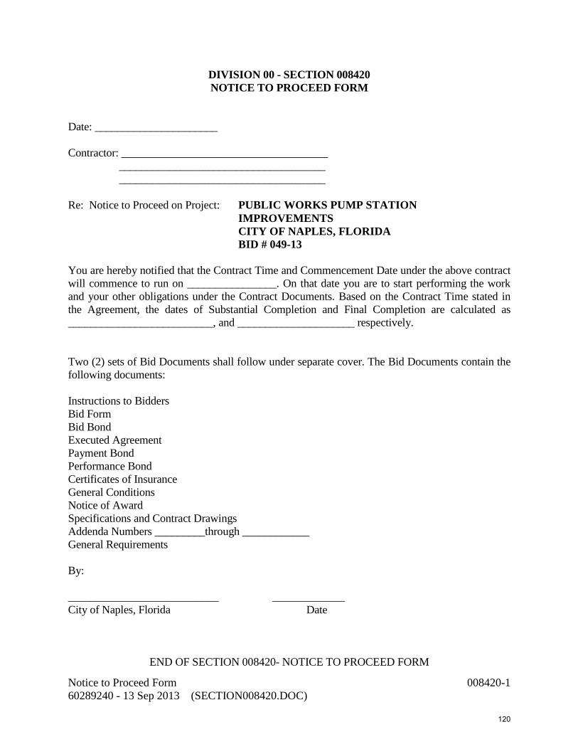
DIVISION 00 - SECTION 008420 NOTICE TO PROCEED FORM
Date: ______________________ Contractor: _____________________________________ _____________________________________ _____________________________________ Re: Notice to Proceed on Project: PUBLIC WORKS PUMP STATION IMPROVEMENTS CITY OF NAPLES, FLORIDA BID # 049-13 You are hereby notified that the Contract Time and Commencement Date under the above contract will commence to run on ________________. On that date you are to start performing the work and your other obligations under the Contract Documents. Based on the Contract Time stated in the Agreement, the dates of Substantial Completion and Final Completion are calculated as __________________________, and _____________________ respectively. Two (2) sets of Bid Documents shall follow under separate cover. The Bid Documents contain the following documents: Instructions to Bidders Bid Form Bid Bond Executed Agreement Payment Bond Performance Bond Certificates of Insurance General Conditions Notice of Award Specifications and Contract Drawings Addenda Numbers _________through ____________ General Requirements By: ___________________________ _____________ City of Naples, Florida Date
END OF SECTION 008420- NOTICE TO PROCEED FORM
Notice to Proceed Form 008420-1 60289240 - 13 Sep 2013 (SECTION008420.DOC)
120

Notice to Proceed Form 008420-2 60289240 - 13 Sep 2013 (SECTION008420.DOC)
121

DIVISION 00 -SECTION 008430
CONTRACTOR’S APPLICATION FOR PAYMENT FORMS
EJCDC document N0. C-620 (2007 Edition) (Document not attached. Available after bid award)
END OF SECTION 008430 - CONTRACTOR’S APPLICATION FOR PAYMENT FORMS
Contractor’s Application for Payment Forms 008430-1 60289240 - 6 Sep 2013 (SECTION008430.DOC)
122

This page intentionally left blank
123

DIVISION 00 – SECTION 008440 CHANGE ORDER FORM
Change Order Exhibit E No. ____________ Date of Issuance: ______________ Effective Date: _______________________ Project: ______________________ Owner: _____________________ Owner’s Contract No.: _________________ Contact: _____________________ Date of Contract: _____________________ Contractor: ___________________ Engineer’s/Owner’s Project No.: _________ The Contract Documents are modified as follows upon execution of this Change Order: Description: Attachments: (List documents supporting change): _____________________________________________________________
CHANGE IN CONTRACT PRICE: CHANGE IN CONTRACT TIMES: Original Contract Price: Original Contract Times: Working Days Calendar Days Substantial completion (days or date): ____________________ $_____________________________ Ready for final payment (days or date: ____________________ [Increase] [Decrease] from previously approved Change Orders NO. ____________ to NO. _____________
[Increase] [Decrease] from previously approved Change Orders NO. ____________ to NO. _____________
Substantial Completion (days): _________ ________________ $_____________________________ Ready for final payment (days): _________ _______________ Contract price prior to Change Order: Contract times prior to this Change Order: Substantial Completion (days): _________ ________________ $_____________________________ Ready for final payment (days): _________ _______________ [Increase] [Decrease] of this Change Order: [Increase] [Decrease] of this Change Order: Substantial Completion (days): _________ ________________ $_____________________________ Ready for final payment (days): _________ _______________ Contract price incorporating this Change Order: Contact Times with all approved Change Orders: Substantial Completion (days): _________ ________________ $_____________________________ Ready for final payment (days): _________ _______________ RECOMMENDED: ACCEPTED: ACCEPTED: By: __________________________ By: ______________________________ By: __________________________ Owner (Authorized Signature) Date: ___________________ _____ Date: ___________________ _____ Date: ___________________ _____
Engineer (Authorized Signature) Contractor(Authorized Signature) Approved by Funding Agency (if applicable): _____________________________________ Date: ___________________ _____
Change Order Form 008440-1 60289240 - 6 Sep 2013 (SECTION008440.DOC)
124

Change Order Instructions
A. GENERAL INFORMATION This document was developed to provide a uniform format for handling contract changes that affect Contract Price or Contract Times. Changes that have been initiated by a Work Change Directive must be incorporated into a subsequent Change Order if they affect Price or Times. Changes that affect Contract Price or Contract Times should be promptly covered by a Change Order. The practice of accumulating Change Orders to reduce the administrative burden may lead to unnecessary disputes.
If Milestones have been listed in the Agreement, any effect of a Change Order thereon should be addressed.
For supplemental instructions and minor changes not involving a change in the Contract Price or Contract Times, a Field Order should be used.
B. COMPLETING THE CHANGE ORDER FORM
Engineer normally initiates the form, including a description of the changes involved and attachments based upon documents and proposals submitted by Contractor, or requests from Owner, or both. Once Engineer has completed and signed the form, all copies should be sent to Owner or Contractor for approval, depending on whether the Change Order is a true order to the Contractor or the formalization of a negotiated agreement for a previously performed change. After approval by one contracting party, all copies should be sent to the other party for approval. Engineer should make distribution of executed copies after approval by both parties. If a change only applies to price or to times, cross out the part of the tabulation that does not apply.
END OF SECTION 008440 – CHANGE ORDER FORM
Change Order Form 008440-2 60289240 - 6 Sep 2013 (SECTION008440.DOC)
125

DIVISION 00- SECTION 008450 SCHEDULE OF VALUES
Pay Estimate No. ____________________ Project:__________________________ For Period Ending _____________ Prepared by: _________________ Page ____ of ____
A B C D E F G H I
Item
Description
Bid Quantity
Units
Unit Price
Bid
Amount
Complete Through
Last Period
Complete Through
This Period
Value of Items
Completed Qty. % Qty. %
Subtotals
END OF SECTION 008450 - SCHEDULE OF VALUES
Schedule of Values 008450-1 60289240 - 6 Sep 2013 (SECTION008450.DOC)
126

This page intentionally left blank
127
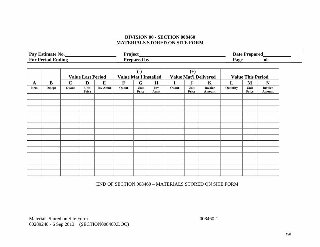
DIVISION 00 - SECTION 008460
MATERIALS STORED ON SITE FORM
Pay Estimate No. Project Date Prepared For Period Ending Prepared by Page of
Value Last Period
(-) Value Mat'l Installed
(+) Value Mat'l Delivered
Value This Period
A B C D E F G H I J K L M N Item Descpt Quant Unit
Price Inv Amnt Quant Unit
Price Inv
Amnt Quant Unit
Price Invoice Amount
Quantity Unit Price
Invoice Amount
END OF SECTION 008460 – MATERIALS STORED ON SITE FORM
Materials Stored on Site Form 008460-1 60289240 - 6 Sep 2013 (SECTION008460.DOC)
128

This page intentionally left blank
129
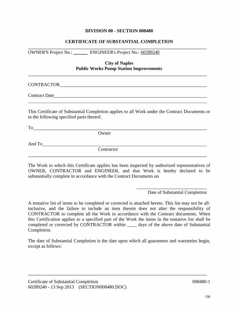
DIVISION 00 - SECTION 008480
CERTIFICATE OF SUBSTANTIAL COMPLETION OWNER'S Project No.: ______ ENGINEER's Project No.: 60289240
City of Naples Public Works Pump Station Improvements
CONTRACTOR Contract Date This Certificate of Substantial Completion applies to all Work under the Contract Documents or to the following specified parts thereof. To Owner And To Contractor The Work to which this Certificate applies has been inspected by authorized representatives of OWNER, CONTRACTOR and ENGINEER, and that Work is hereby declared to be substantially complete in accordance with the Contract Documents on ______________________________ Date of Substantial Completion A tentative list of items to be completed or corrected is attached hereto. This list may not be all-inclusive, and the failure to include an item therein does not alter the responsibility of CONTRACTOR to complete all the Work in accordance with the Contract documents. When this Certification applies to a specified part of the Work the items in the tentative list shall be completed or corrected by CONTRACTOR within ____ days of the above date of Substantial Completion. The date of Substantial Completion is the date upon which all guarantees and warranties begin, except as follows:
Certificate of Substantial Completion 008480-1 60289240 - 13 Sep 2013 (SECTION008480.DOC)
130

The responsibilities between OWNER and CONTRACTOR for security, operation, safety, maintenance, heat, utilities and insurance shall be as follows: RESPONSIBILITIES: OWNER CONTRACTOR The following documents are attached to and made a part of this Certificate: This certificate does not constitute an acceptance of Work not in accordance with the Contract Documents nor is it a release of CONTRACTOR'S obligation to complete the Work in accordance with the Contract Documents. Executed by ENGINEER on _________________________, 20__. (Engineer) By The CONTRACTOR accepts this Certificate of Substantial Completion on: ________________, 20__. (Contractor) By Certificate of Substantial Completion 008480-2 60289240 - 13 Sep 2013 (SECTION008480.DOC)
131

END OF SECTION 008480 – CERTIFICATE OF SUBSTANTIAL COMPLETION
Certificate of Substantial Completion 008480-3 60289240 - 13 Sep 2013 (SECTION008480.DOC)
132

This page intentionally left blank
133

DIVISION 00 - SECTION 008500 FIELD ORDER FORM
[ ] OWNER: ___________ No. Copies ______ [ ] ENGINEER: ___________ No. Copies ______ [ ] ARCHITECT: ___________ No. Copies ______ FIELD ORDER [ ] CONTRACTOR: ___________ No. Copies ______ NO. _______ [ ] FIELD: ___________ No. Copies ______ [ ] OTHER: ___________ No. Copies ______
PROJECT DATA CONTRACT DATA NAME: ____________________ NUMBER: _____________________ LOCATION: ____________________ DATE: _______________________ OWNER: ____________________ DRAWING NO.: ________________ OTHER: ____________________ SPECIFICATION SECTION: _______ To: (Contractor)
You are hereby directed to execute promptly this Field Order which interprets the Contract Documents or orders minor changes in the Work without change in Contract Sum or Contract Time. If you consider that a change in Contract Sum or Contract Time is required, please submit your itemized proposal to the Engineer immediately and before proceeding with this Work. If your proposal is found to be satisfactory and in proper order, this Field Order will in that event be superseded by a Change Order. Description (of interpretation or change): _____________________________________
Field Order Form 008500-1 60289240 - 6 Sep 2013 (SECTION008500.DOC)
134

Attachments (listing of attached documents that support description): 1. Contractor Request for information No.: _______________________________________ 2. 3. 4. 5. City of Naples – Utilities Department Project No.: ______ BY: ______________________________ DATE: __________________
END OF SECTION 008500 – FIELD ORDER FORM
Field Order Form 008500-2 60289240 - 6 Sep 2013 (SECTION008500.DOC)
135

DIVISION 00 - SECTION 008510
CONTRACTOR REQUEST FOR INFORMATION FORM [ ] OWNER: ________________ No. Copies ____ [ ] ENGINEER: No. Copies ____ CONTRACTOR [ ] ARCHITECT: ________________ No. Copies ____ REQUEST FOR [ ] CONTRACTOR: ________________ No. Copies ____ INFORMATION [ ] FIELD: ________________ No. Copies ____ NO. [ ] OTHER: ________________ No. Copies ____ PROJECT DATA CONTRACT DATA NAME: __________________ NUMBER: LOCATION: __________________ DATE: OWNER: __________________ DRAWING NO: OTHER: __________________ SPECIFICATION SECTION: QUESTION: BY: DATE: REPLY: BY: DATE:
END OF SECTION 008510 – CONTRACTOR REQUEST FOR INFORMATION FORM
Contractor Request for Information 008510-1 60289240 - 6 Sep 2013 (SECTION008510.DOC)
136

This page intentionally left blank
137

DIVISION 00 - SECTION 008520
CONSTRUCTION ACCIDENT REPORT FORM [ ] OWNER: ________________ No. Copies ____ [ ] ENGINEER: No. Copies ____ CONSTRUCTION [ ] ARCHITECT: ________________ No. Copies ____ ACCIDENT [ ] CONTRACTOR: ________________ No. Copies ____ REPORT [ ] FIELD: ________________ No. Copies ____ NO. [ ] OTHER: ________________ No. Copies ____ PROJECT DATA NAME: CONTRACTOR: LOCATION: SUBCONTRACTOR: OWNER: OTHER: ENGINEER: ACCIDENT INFORMATION Accident Date: Time: Name(s) of Injured or Deceased: Describe what occurred: NOTE: Use other side or attach additional sheets as required. Names & Address of Witnesses: Employer's Name & Address: Where treated (Name & Address): (Attach sketch if applicable) Send original to Project Manager in charge of Construction immediately. Signed
END OF SECTION 0085200 – CONSTRUCTION ACCIDENT REPORT FORM
Construction Accident Form 008520-1 60289240 - 6 Sep 2013 (SECTION008520.DOC)
138

This page intentionally left blank
139

DIVISION 00 - SECTION 008530
PRESSURE TEST FORM [ ] OWNER: No. Copies [ ] ENGINEER: No. Copies PRESSURE [ ] ARCHITECT: No. Copies TEST [ ] CONTRACTOR: No. Copies NUMBER [ ] FIELD: No. Copies [ ] OTHER: No. Copies PROJECT DATA: Name: Owner: Location: Contractor: Number: Subcontractor: Date: LOCATION OF TEST: COMPUTATION FOR MEASURED LEAKAGE: Time-End of Test Pressure-End of Test (psi) Time-Start of Test Pressure-Start of Test (psi) Test Time (Hours) Average Test Pressure (psi) Pipe Material Quantity of Water Required to Return to Original Pressure (gals.) Computation for Allowable Leakage (for Ductile Iron Pipe): D = Size of Line Tested: Diameter (inches) S = Length of Pipe Tested: (feet) T = Test Time: (hours) P = Average Test Pressure: (psi)
Q = Allowable Leakage: S x D x P x T
133,200 (gal. ) Per AWWA Std. C600
Allowable Leakage for PVC pipe shall be 90% of value calculated above. Pressure Test Form 008530-1 60289240 - 6 Sep 2013 (SECTION008530.DOC)
140

REMARKS: THE ABOVE TEST (DOES) (DOES NOT) MEET THE SPECIFICATIONS TEST WITNESS by Contractor by Subcontractor
END OF SECTION 008530 – PRESSURE TEST FORM
Pressure Test Form 008530-2 60289240 - 6 Sep 2013 (SECTION008530.DOC)
141

DIVISION 00 - SECTION 008610
WORK DIRECTIVE FORM [ ] OWNER: No. Copies WORK [ ] ENGINEER: No. Copies DIRECTIVE [ ] ARCHITECT: No. Copies NO. [ ] CONTRACTOR: No. Copies [ ] FIELD: No. Copies [ ] OTHER: No. Copies PROJECT DATA: CONTRACT DATA NAME: NUMBER: LOCATION: DATE: OWNER: DRAWING NO.: CONTRACTOR: SPECIFICATION SECTION: TO: (Contractor) You are directed to proceed promptly with the following change(s): Description: Purpose of Work Directive Change: If a claim is made that the above changes(s) have affected Contract Price or Contract Time, any claim for a Change Order based thereon will involve one of the following methods of determining the effect of the change(s). Method of determining change Method of determining change in Contract Price: in Contract Time: [ ] Time and materials [ ] Contractor's records [ ] Unit prices [ ] Engineer's records [ ] Cost plus fixed fee [ ] Other [ ] Other
Work Directive Form 008610-1 60289240 - 6 Sep 2013 (SECTION008610.DOC)
142
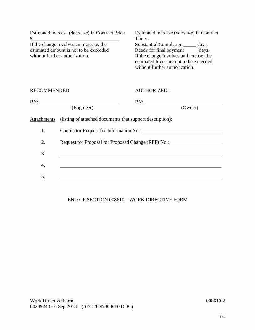
Estimated increase (decrease) in Contract Price. Estimated increase (decrease) in Contract $ Times. If the change involves an increase, the Substantial Completion _____ days; estimated amount is not to be exceeded Ready for final payment _____ days. without further authorization. If the change involves an increase, the estimated times are not to be exceeded without further authorization. RECOMMENDED: AUTHORIZED: BY: BY: (Engineer) (Owner) Attachments (listing of attached documents that support description): 1. Contractor Request for Information No.: 2. Request for Proposal for Proposed Change (RFP) No.: 3. 4. 5.
END OF SECTION 008610 – WORK DIRECTIVE FORM
Work Directive Form 008610-2 60289240 - 6 Sep 2013 (SECTION008610.DOC)
143
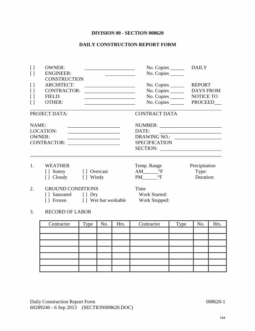
DIVISION 00 - SECTION 008620
DAILY CONSTRUCTION REPORT FORM [ ] OWNER: No. Copies DAILY [ ] ENGINEER: No. Copies CONSTRUCTION [ ] ARCHITECT: No. Copies REPORT [ ] CONTRACTOR: No. Copies DAYS FROM [ ] FIELD: No. Copies NOTICE TO [ ] OTHER: No. Copies PROCEED PROJECT DATA: CONTRACT DATA NAME: NUMBER: LOCATION: DATE: OWNER: DRAWING NO.: CONTRACTOR: SPECIFICATION SECTION: 1. WEATHER Temp. Range Precipitation [ ] Sunny [ ] Overcast AM______°F Type: [ ] Cloudy [ ] Windy PM______°F Duration: 2. GROUND CONDITIONS Time [ ] Saturated [ ] Dry Work Started: [ ] Frozen [ ] Wet but workable Work Stopped: 3. RECORD OF LABOR
Contractor Type No. Hrs. Contractor Type No. Hrs.
Daily Construction Report Form 008620-1 60289240 - 6 Sep 2013 (SECTION008620.DOC)
144

4. EQUIPMENT
Contractor Type Model Hrs. Use
5. MATERIAL RECEIVED
Received By Type Quantity Supplier Use
6. DESCRIPTION OF WORK PERFORMED
END OF SECTION 008620 – DAILY CONSTRUCTION REPORT FORM
Daily Construction Report Form 008620-2 60289240 - 6 Sep 2013 (SECTION008620.DOC)
145

DIVISION 00 - SECTION 008630
CHANGE PROPOSAL SUMMARY FORM [ ] OWNER: No. Copies [ ] ENGINEER: No. Copies CHANGE [ ] ARCHITECT: No. Copies PROPOSAL [ ] CONTRACTOR: No. Copies SUMMARY [ ] FIELD: No. Copies NO. [ ] OTHER: No. Copies PROJECT DATA: CONTRACT DATA NAME: NUMBER: LOCATION: DATE: OWNER: DRAWING NO.: CONTRACTOR: SPECIFICATION SECTION: REFERENCE: Work Directive No.___________ RFP No. Field Order No.______________ Other DESCRIPTION: PRICING INFORMATION 1. DIRECT LABOR Skill/Trade Manhours Rate Cost 1.A Production Labor 1.B. Supervision [ ] Foreman [ ] Superintendent 1.C Field Engineering 1.D Expenses Subtotal(1)
Change Proposal Summary Form 008630-1 60289240 - 6 Sep 2013 (SECTION008630.DOC)
146

2. MATERIALS & EQUIPMENT Description Quantity Unit Price Cost 2.A Incorporated in Work 2.B Consumed in Performance 2.C Equipment 2.D Direct Costs 2.E Bonds, Insurance Subtotal(2) 3. TOTAL LABOR, MATERIALS & EQUIPMENT + = Subtotal (1) Subtotal (2) Total
END OF SECTION 008630 – CHANGE PROPOSAL SUMMARY FORM
Change Proposal Summary Form 008630-2 60289240 - 6 Sep 2013 (SECTION008630.DOC)
147

DIVISION 00 - SECTION 008640
REQUEST FOR PROPOSAL FOR PROPOSED CHANGE FORM [ ] OWNER: No. Copies REQUEST FOR [ ] ENGINEER: No. Copies PROPOSAL [ ] ARCHITECT: No. Copies FOR PROPOSED [ ] CONTRACTOR: No. Copies CHANGE (RFP) [ ] FIELD: No. Copies NO. [ ] OTHER: No. Copies PROJECT DATA: CONTRACT DATA NAME: NUMBER: LOCATION: DATE: OWNER: DRAWING NO.: CONTRACTOR: SPECIFICATION SECTION: TO: (Contractor) Provide the undersigned a proposal for the following change in the work within seven (7) calendar days after receipt of this request. The written proposal must clearly delineate the scope of the proposed change in work providing an itemized estimate of time and all material and labor (by trade), subcontract and overhead costs and fees. Any amount claimed for subcontracts must be similarly supported. Description of change in work:
Request for Proposal for Proposed Change Form 008640-1 60289240 - 6 Sep 2013 (SECTION008640.DOC)
148

Change Order Type: (Deletion) (Addition) (Revision) Constraints of Change: Initiated by: Proposal must be received by: ______ (7 days from date below) Attachments (listing of attached documents that support description): 1. Contractor Request for Information No.: 2. 3. 4. 5. PROJECT NO.: Issued By: DATE:
END OF SECTION 008640 – REQUEST FOR PROPOSAL FOR PROPOSED CHANGE FORM
Request for Proposal for Proposed Change Form 008640-2 60289240 - 6 Sep 2013 (SECTION008640.DOC)
149

DIVISION 00 - SECTION 008650
CHECK OUT FORM [ ] OWNER: No. Copies [ ] ENGINEER: No. Copies CHECK-OUT [ ] ARCHITECT: No. Copies [ ] CONTRACTOR: No. Copies MEMO NO. [ ] FIELD: No. Copies [ ] OTHER: No. Copies PROJECT DATA: CONTRACT DATA NAME: NUMBER: LOCATION: DATE: OWNER: DRAWING NO.: CONTRACTOR: SPECIFICATION SECTION: Name of equipment checked: Name of manufacturer of equipment: 1. The equipment furnished by us has been checked on the job by us. We have reviewed
(where applicable) the performance verification information submitted to us by the Contractor.
2. The equipment is properly installed, except for items noted on page 008650-2. 3. The equipment is operating satisfactorily, except for items noted on page 008650-2. 4. The written operating and maintenance information (where applicable) has been
presented to the Contractor, and gone over with him in detail. Five (5) copies of all applicable operating and maintenance information and parts lists have been furnished to him.
Checked By: Name of Manufacturer's Rep. Name of General Contractor Address and Phone # of Rep. Authorized Sign./Title/Date Sig./Title/Person Making Check Name of Subcontractor Date Checked Authorized Sig./Title/Date
Check Out Form 008650-1 60289240 - 6 Sep 2013 (SECTION008650.DOC)
150
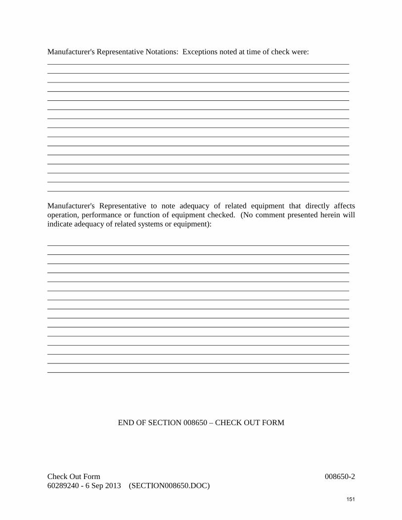
Manufacturer's Representative Notations: Exceptions noted at time of check were: Manufacturer's Representative to note adequacy of related equipment that directly affects operation, performance or function of equipment checked. (No comment presented herein will indicate adequacy of related systems or equipment):
END OF SECTION 008650 – CHECK OUT FORM
Check Out Form 008650-2 60289240 - 6 Sep 2013 (SECTION008650.DOC)
151
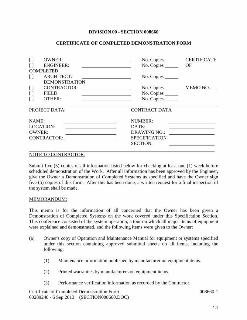
DIVISION 00 - SECTION 008660
CERTIFICATE OF COMPLETED DEMONSTRATION FORM [ ] OWNER: No. Copies CERTIFICATE [ ] ENGINEER: No. Copies OF COMPLETED [ ] ARCHITECT: No. Copies DEMONSTRATION [ ] CONTRACTOR: No. Copies MEMO NO. [ ] FIELD: No. Copies [ ] OTHER: No. Copies PROJECT DATA: CONTRACT DATA NAME: NUMBER: LOCATION: DATE: OWNER: DRAWING NO.: CONTRACTOR: SPECIFICATION SECTION: NOTE TO CONTRACTOR: Submit five (5) copies of all information listed below for checking at least one (1) week before scheduled demonstration of the Work. After all information has been approved by the Engineer, give the Owner a Demonstration of Completed Systems as specified and have the Owner sign five (5) copies of this form. After this has been done, a written request for a final inspection of the system shall be made. MEMORANDUM: This memo is for the information of all concerned that the Owner has been given a Demonstration of Completed Systems on the work covered under this Specification Section. This conference consisted of the system operation, a tour on which all major items of equipment were explained and demonstrated, and the following items were given to the Owner: (a) Owner's copy of Operation and Maintenance Manual for equipment or systems specified
under this section containing approved submittal sheets on all items, including the following:
(1) Maintenance information published by manufacturer on equipment items.
(2) Printed warranties by manufacturers on equipment items.
(3) Performance verification information as recorded by the Contractor.
Certificate of Completed Demonstration Form 008660-1 60289240 - 6 Sep 2013 (SECTION008660.DOC)
152

(4) Check-Out Memo on equipment by manufacturer's representative. (5) Written operating instructions on any specialized items.
(6) Explanation of guarantees and warranties on the system. (b) Prints showing actual "As-Built" conditions. (c) A demonstration of the System in Operation and of the maintenance procedures which
will be required. (Name of General Contractor) By: (Authorized Signature, Title & Date) (Name of Subcontractor) By: (Authorized Signature, Title & Date) Operations and Maintenance Manual, Instruction Prints, Demonstration & Instruction in Operation Received: (Name of Owner) By: (Authorized Signature, Title & Date)
END OF SECTION 008660 – CERTIFICATE OF COMPLETED DEMONSTRATION FORM
Certificate of Completed Demonstration Form 008660-2 60289240 - 6 Sep 2013 (SECTION008660.DOC)
153

DIVISION 00 - SECTION 009800 CONTRACTOR'S RELEASE OF LIEN
Before me, the undersigned authority in said County and State, appeared _________________________________, who being first duly sworn, deposes and says that he is__________________________ of _____________________________________ a company and/or corporation authorized to do business under the laws of Florida, which is the contractor on Project known as City of Naples,______________________________________________________., Bid No.________, located in the City of Naples, County of Collier, Florida, under contract with the City of Naples, dated the ______ day of _______________, 20__ , that the said deponent is duly authorized to make this affidavit by resolution of the Board of Directors of said company and/or corporation; that deponent knows of his own knowledge that said contract has been complied with in every particular by said contractor and that all parts of the work have been approved by the City Engineer; that there are no bills remaining unpaid for labor, material or otherwise, in connection with said contract and work, and that there are no suits pending against the undersigned as contractor or anyone in connection with the work done and materials furnished or otherwise, under said contract. Deponent further says that the final estimate which has been submitted to the City simultaneously with the making of this affidavit, constitutes all claims and demands against the City on account of said contract or otherwise, and that acceptance of the sum specified in said final estimate will operate as a full and final release and discharge of the City from any further claims, demands or compensation by contractor under the above contract. Deponent further agrees that all guarantees under this contract shall start and be in full force from the date of this release as spelled out in the contract documents. Signature:________________________________ Printed Name:_____________________________ STATE OF FLORIDA COUNTY OF ___________________________ Signed before me this ______ day of ________________, 20_, by___________________________________________ who is personally known to me or has produced ____________________________ as identification. ______________________________ Notary Public
Contractor’s Release of Lien 009800-1 60289240 - 6 Sep 2013 (SECTION009800.DOC)
154

My Commission Expires: Commission Number: WE, the ___________________________________, having heretofore executed a performance bond and a payment bond for the above named contractor covering project and section as described above in the sum of ($_______________)___________________________ Dollars, hereby agree that the Owner may make full payment of the final estimate, including the retained percentage, to said contractor. IT IS fully understood that the granting of the right to make the payment of the final estimate to said contractor and/or his assigns, shall in no way relieve this surety company of its obligations under its bonds, as set forth in the specifications, contract, and bonds pertaining to the above project. IN WITNESS WHEREOF, the ________________________________has caused this instrument to be executed on its behalf by its________________________________, and/or its duly authorized attorney in fact, and its corporate seal to be hereunto affixed, all on this ________ day of ____________________, A.D., 200__. __________________________________ Surety Company __________________________________ Attorney in Fact Power of Attorney must be attached if executed by Attorney in Fact. STATE OF FLORIDA ) COUNTY OF ) BEFORE ME, the undersigned authority, appeared ________________ ____________________________who is personally known to me or has produced _________________________________________as identification, and who executed the foregoing instrument in the name of ____________________________________ as its ___________________and the said _________________________ acknowledged that he executed said instrument in the name of ____________________________________as its ___________________ and/or______________________, for the purpose therein expressed and that he had due and legal authority to execute the same on behalf of said __________________________, a corporation.
Contractor’s Release of Lien 009800-2 60289240 - 6 Sep 2013 (SECTION009800.DOC)
155

IN WITNESS WHEREOF, I have hereunto set my hand and official seal at ________________________ this _____ day of _______________, 200__. __________________________________ Notary Public My Commission Expires: Commission Number:
END OF SECTION 009800 – CONTRACTOR’S RELEASE OF LEIN
Contractor’s Release of Lien 009800-3 60289240 - 6 Sep 2013 (SECTION009800.DOC)
156

This page intentionally left blank
157

DIVISION 01 – GENERAL REQUIREMENTS 010100 Summary of Work 010500 Request for Information (RFI) Procedures 011100 Coordination of Work, Permits, and Regulations 012000 Measurement and Payment 013000 Administrative Requirements 013216 CPM Construction Schedule Requirements 013233 Preconstruction Audio-Video Documentation 013300 Submittals 014210 General Abbreviations 015070 Traffic Regulations 015100 Construction Facilities and Temporary Controls 016400 Owner-Furnished Equipment 017000 Contract Closeout 017410 Cleaning During Construction and Final Cleaning 019310 Operation and Maintenance Manual
158

This page intentionally left blank
159

SECTION 010100 SUMMARY OF WORK PART 1 - GENERAL
1.01 Work Under This Contract
1. Work under this contract includes the following:
a. The intent of the project is to replace two existing catenary bar screens and one conveyor system with new mechanically cleaned vertical bar screens and conveyor system; replace the existing stop logs with new stainless steel motorized slide gates; replace the existing stormwater jockey pump with a new vertical mixed flow jockey pump and VFD; provide two new main stormwater pumps and VFD’s; provide and install new pump control panel, electrical and instrumentation systems, and SCADA upgrades.
b. As a bid alternate a new owner furnished submersible pump and VFD will be installed and a screening filter system (strainers) and twelve inch diameter HDPE force main to ASR well #2 will be constructed.
2. The principal components of this project include the followings:
a. Complete demolition work including, but not limited to, existing mechanical bar screens, manual bar rack, conveyor system, grit removal system, stop logs, jockey pump, control panels, RTU and antenna, and related electrical as indicated.
b. Furnish and install two new mechanically cleaned bar screens, conveyor system and related electrical, controls and instrumentation, and SCADA provisions.
c. Furnish and install four new motorized slide gates within influent channels.
d. Replace the existing stormwater pumps with two new main stormwater pumps and one new jockey pump; furnish and install new pump control panel, electrical, control and instrumentation systems, and SCADA upgrades.
e. Furnish and install security video cameras, DVR system, and security alarm system.
f. Complete miscellaneous work as required to complete the pump station upgrades.
g. As a bid alternate, install a new submersible ASR pump and VFD (pump and VFD to be owner furnished), and furnish and install a new screening filter system (two strainers) and twelve inch diameter force main to ASR well.
Summary of Work 010100-1 60289240 - 12 Sep 2013 (S010100.DOC) 160

1.02 Sequence of Construction
1. The Public Works Pumping Station shall remain in service at all times. Continued operation of the pump station is required during construction of the improvements. There are three areas of construction as follows:
a. Replacement of the pumping equipment, electrical and controls.
b. Installation of the automatically cleaned bar screens, conveyor, electrical and controls and slide gates.
c. Installation of the ASR pump, screening filter system (strainers) and discharge main as a bid alternate.
2. There is no limitation on the sequence of these main areas of construction and construction sequencing will be the responsibility of the contractor. However, there are limitations on the progression of work within each area of construction. The limitations are described below.
3. Replacement of Existing Pumping Equipment and Controls – Both main stormwater pumps must stay online throughout the duration of the project; only one pump can be taken out of service at a time when the replacement pump is ready to be installed. Two of the three pumps must be operational at all times. To accomplish this, the contractor shall install the new electric service, pump control panel, VFDs and RTU prior to removal of any pumping equipment. The contractor shall install and successfully test each pump before moving to the next pump replacement. The existing pump controls will be removed once all the pumps have been installed. Temporary shutdowns for up to 3 days weather permitting will be permitted for removal of existing pumps and installation of new pumps in the wet well. A temporary shutdown will be permitted for each pump. The contractor shall submit to the Engineer/Owner for review a detailed sequence of construction two weeks before the planned shutdown. These shutdowns must be coordinated with the Engineer and the City at least 48 hours in advance. As an alternative the Contractor shall provide provisions for bypass pumping at no additional cost to Owner.
4. Installation of Automatically Cleaned Bar Screens and Slide Gates – The existing manual bar rack must remain in place until the two new mechanical screens are fully installed. Since there are two influent channels and bar screens, the Contractor will be permitted to work on only one mechanical bar screen at a time. The existing stop logs will be used to isolate the existing mechanical bar screens if feasible. The first screen will be removed and a new screen installed along with conveyor system. The Contractor shall try to limit the time period required for the bar screen to be offline, however no specific restrictions are needed since flow is maintained through the second channel. Upon completing installation, start-up and testing, the second bar screen will be replaced.
Summary of Work 010100-2 60289240 - 12 Sep 2013 (S010100.DOC) 161

The existing stop logs will be replaced with mechanically operated slide gates one channel at a time. Since two influent channels are available no specific restrictions are needed, however the Contractor should limit the period of time each channel is offline.
5. Installation of ASR Pump, Filtration Units, and Discharge Main (Bid Alternate) – The existing grit pump/removal system must be demolished in order to accommodate the new ASR pump. A temporary shutdown of up to 3 days weather permitting will be allowed for this demolition work. This shutdown must be coordinated with the Engineer and City at least 48 hours in advance. Only the work within the wet well has specific restrictions for maintain flows through the pump station. In addition, the screening filter system must be fully installed, tested and operational before allowing any flows to the ASR Well.
1.03 Coordination
1. Coordinate with Owner during construction of the project. Normal operation of the existing systems will remain uninterrupted during the construction until the project is completed and accepted by the Owner.
2. Coordinate with all permitting authorities, acquire inspections and meet permit requirements.
3. Coordinate with utility companies in connection with providing the various utility services to the project.
4. The City of Naples is pre-purchasing various equipment associated with this project. The Contractor shall be responsible for coordinating with the City to have this equipment available for installation per the project schedule.
1.04 Special Procedures
1. The Contractor shall be responsible for the following:
a. Locating, before excavation, blocking and protecting, all underground utilities including pipelines, conduit, duct cables, tanks, etc.
b. Keeping a record of the locations of all valves, fittings, etc. which are installed as part of the work, or which are discovered
1.05 Disturbed Areas
1. Restore all areas disturbed by construction to a condition at least equal to the pre-construction condition including, but not limited to, all landscaping, driveways, roads, fences, traffic control devices, and other improvements. Maintain ingress and egress to all properties adjacent to the construction and minimize inconvenience to abutting property occupants.
Summary of Work 010100-3 60289240 - 12 Sep 2013 (S010100.DOC) 162

1.06 Contractor’s Superintendent
1. The Contractor shall have a superintendent on site at all times while work is being performed by the Contractor or subcontractor(s). The superintendent does not have to be on site during maintenance of the Contractor’s equipment. The Contractor’s superintendent shall have at least 5 years experience with this type of work and speak fluent English.
1.07 Storage and Protection
1. All materials, supplies, and equipment intended for use in the work shall be suitably stored by the Contractor to prevent damage from exposure, admixture with foreign substances, vandalism, or other cause. Manufactured items shall be stored in a manner as recommended by the manufacturer.
PART 2 – PRODUCTS (NOT USED) PART 3 – EXECUTION (NOT USED)
END OF SECTION
Summary of Work 010100-4 60289240 - 12 Sep 2013 (S010100.DOC) 163

SECTION 010500 REQUEST FOR INFORMATION (RFI) PROCEDURES
PART 1 - GENERAL
1.01 SUMMARY
1. Section Includes
a. Requests for Information (RFI) procedures.
2. Related Section
a. Section 007000 – General Conditions.
b. Applicable provisions of Division 1 shall govern all work under this Section.
3. Definitions
a. Drawing/Plan Clarification: Answer from Engineer, on behalf of Owner, in response to inquiry from Contractor, intended to make some requirement(s) of Drawings clearly understood. Drawing clarifications may be sketches, drawings, or in narrative form and will not change any requirements of Drawings. Responses to Contractor inquiries shall be as outlined in "Requests for Information" as specified herein.
b. Non-Conformance Notice: Notice issued by Engineer, on behalf of Owner, documenting that the Work or some portion thereof has not been performed in accordance with requirements of the Contract Documents. Payment shall not be made on any portion of the Work for which a Non-Conformance Notice has been issued and the Work not corrected to satisfaction of Engineer and Owner.
Upon receipt of Non-Conformance Notice, Contractor shall provide a written Response to Non-Conformance Notice within five (5) working days after receipt of Notice. Contractor response shall detail either (a) why they believe that the work was performed in accordance with the Contract Documents or (b) what corrective action they intend to take, at their sole expense, to correct non-conforming work.
If Contractor disputes issuance of Non-Conforming Notice, Engineer, on behalf of Owner, has five (5) working days to respond by either (a) withdrawing Non-Conformance Notice or (b) directing Contractor to correct such Work. Such determination by Engineer, on behalf of Owner, shall be final and conclusive.
Request for Information (RFI Procedures) 010500-1 60289240 - 6 Sep 2013 (010500.DOC) 164

c. If directed to correct the Work, Contractor shall do so within five (5) working days after receipt of such direction from Engineer, on behalf of Owner, or such other time as may be agreed to.
d. Project Communications: Routine written communications between Engineer, Owner, and Contractor which are in letter, field memo, or fax format. Such communications shall not be identified as Requests for Information nor shall they substitute for any other written requirement pursuant to the provisions of these Contract Documents.
e. Requests for Information: Request from Contractor or subcontractor, to Engineer, on behalf of Owner, seeking interpretation or clarification of some requirement of the Contract Documents. Contractor shall clearly and concisely set forth issue for which it seeks clarification or interpretation and why a response is needed. Contractor shall, in written request, set forth its interpretation or understanding of Contract requirements with reasons why it has reached such an understanding.
PART 2 - PRODUCTS NOT USED
PART 3 - EXECUTION
3.01 REQUESTS FOR INFORMATION
1. If Contractor or subcontractor, at any tier, determines that some portion of Drawings, Specifications, or other Contract Documents requires clarification or interpretation, Contractor shall submit a Request for Information in writing. Only Prime Contractor shall submit Requests for Information and submitted on Request for Information form provided.
a. Contractor shall clearly and concisely set forth issue for which clarification or interpretation is sought and why a response is needed. In Request for Information, Contractor shall set forth an interpretation or understanding of requirement along with reasons why such an understanding was reached.
2. Engineer, on behalf of Owner, will review all Requests for Information to determine whether they are Requests for Information as defined in the Contract Documents. If it is determined that document is not an RFI, it will be returned to Contractor, un-reviewed as to content, for re-submittal on proper form in proper manner.
3. Responses to Requests for Information shall be issued within five (5) working days of receipt of request from Contractor, unless Engineer determines that a longer time is needed to provide an adequate response. If a longer time is deemed necessary by
Request for Information (RFI Procedures) 010500-2 60289240 - 6 Sep 2013 (010500.DOC) 165

Engineer, then Engineer shall, within five (5) working days of receipt of request, notify Contractor of anticipated response time.
a. If Contractor submits a Request for Information on an activity with five (5) working days or less of float on current project schedule, Contractor shall not be entitled to any time extension due to time it takes Engineer, on behalf of Owner, to respond to request provided that Engineer responds within five (5) working days set forth above.
4. Responses from Engineer, on behalf of Owner, will not change any requirements of the Contract Documents. In the event that Contractor believes response to a Request for Information will cause a change to requirements of the Contract Documents, Contractor shall immediately give written notice that Contractor considers response to be a Change Order. Failure to give such written notice immediately shall waive Contractor's right to seek additional time or cost under provisions set forth in the General Conditions.
END OF SECTION
Request for Information (RFI Procedures) 010500-3 60289240 - 6 Sep 2013 (010500.DOC) 166

This page intentionally left blank
167

SECTION 011100 COORDINATION OF WORK, PERMITS, AND REGULATIONS
PART 1 - GENERAL
1.01 Description
This section generally describes the project and includes work sequence and schedule, Contractor's use of premises, Owner occupancy, maintenance and operation of existing facilities, permits, and regulations.
1.02 General Nature of Work
The intent of this project is to install two new mechanically cleaned vertical bar screens and conveyor system, replace two existing stormwater pumps and motors and provide new VFDs, instrumentation and controls. Replace existing jockey pump with new pump/motor, VFD, instrumentation and controls. Furnish and install new (owner furnished) submersible ASR pump, screening filter system (strainers) and twelve inch diameter HDPE force main to ASR Well #2 as a bid alternate (ADD).
1.02.1 Location of Project Site
The project site is located at 355 Riverside Circle. Which is located at the intersection of 3rd Avenue North, 13th Street North, and the entrance to the City of Naples WWTP.
1.04 Possible Sequence and Progress of Work
Per Specification Section 010100 – Summary of Work.
1.05 Maintenance and Operation of Existing Facilities
The pump station must be operational all the time during the construction of the project.
1.06 Permits
1. Obtain and pay the fees for the following permits:
Name or Type of Permit Name and Telephone Number of Permitting Agency
City of Naples Building Permit
City of Naples
Dewatering Permit Southwest Florida Water Management District
2. Contact the permitting agencies listed above for current fees associated with each permit.
Coordination of Work, Permits and Regulations 011100-1 60289240 - 12 Sep 2013 (011100.DOC) 168

PART 2 - MATERIALS
Not used PART 3 - EXECUTION
Not used
END OF SECTION
Coordination of Work, Permits and Regulations 011100-2 60289240 - 12 Sep 2013 (011100.DOC) 169

SECTION 012000 MEASUREMENT AND PAYMENT
PART 1 - GENERAL
1.01 Payment
1. Work under this contract will be paid for on a unit price or lump sum basis as outlined on the Bid Proposal (Section 003000) for the quantity of work installed. The amount of payment will be as defined in the Standard form of Agreement between Owner and Contractor.
2. The quotations for the work are intended to establish a total price cost for completing the work in its entirety.
3. Additions, deletions, modifications or changes to the work as defined by this contract will be performed by change order according to the General Conditions and will be paid for on the basis of the Cost of the Work.
1.02 General
1. All work under this contract shall be included in the pay items listed on the Bid Proposal (Section 003000). Any items for which a specific pay item is not included shall be included in the price of the item to which it pertains or is associated. The items establish the value of work for determining partial and final payments. The Owner reserves the right to determine the value of partially completed work and when work is complete, in accordance with terms of the Contract.
2. Any items not shown or omitted that are required for a complete installation shall be furnished and installed by the Contractor at no additional cost to the Owner.
3. The prices shall include all labor, materials, tools, equipment required to complete the work.
4. No additional payment will be made for well pointing or other methods of dewatering excavations.
5. Thrust blocks or mechanical restraints are not separate pay items.
6. Payment for repair and replacement of existing utilities will be included in the unit price or lump sum bid amount for the related new construction bid item.
7. Payment for lump sum items shall be on a percentage of completion of the particular item basis.
Measurement and Payment 012000-1 60289240 - 13 Sep 2013 (012000.DOC) 170
1.03 Partial Pay Request
1. The installation of pipe and fittings includes backfilling, compacting, hydrostatic testing, fine grading, property restoration, clean up, and placing the facilities in operation. When measurements of the amount of work constructed each month are made, for the purpose of partial payment, the following will be considered.
a. For unit price items, the Contractor shall be paid for the actual amount of work installed and accepted during the period of construction. After the Work is completed and before final payment is made, the Owner’s Representative shall make final measurements to determine the actual quantities of the various items of work installed and accepted as the basis of final payment for the unit priced item less retained amounts.
b. For lump sum items, the Contractor shall be paid in accordance with the progress schedule and schedule of values on the basis of actual work installed and accepted until the work item is completed. Upon completion of the item, 100% of the lump sum price may be paid, less retained amounts.
c. Prior to submitting any Application for Payment, the Contractor’s superintendent of other authorized representative of the Contractor shall meet with the Owner’s Representative and determine the quantities of unit price and/or lump sum price work accomplished and/or completed during the period for which the Application for Payment is being submitted.
d. Once a month the Contractor will prepare and sign an Application for Payment, and submit the original and five (5) copies for review and signature of the Owner’s Representative. These completed forms will provide the basis upon which payment will be made to the Contractor.
e. Payment to the Contractor will be made for the actual work completed and accepted in accordance with the Contract Documents.
f. No payment of any Application for Payment or of any retained percentage shall relieve the Contractor of his obligation to repair or replace any defective parts of the construction or to be responsible for all damage due to such defects during the construction period or the one-year correction period.
g. Partial payments shall be made monthly as the work progresses. All partial invoices and payment shall be subject to correction in the final Application for Payment.
h. No payment shall be made for materials delivered and not installed, unless specifically agreed upon by the Owner prior to delivery of such materials.
Measurement and Payment 012000-2 60289240 - 13 Sep 2013 (012000.DOC) 171

2. No less than 2% of the contract price shall be retained until the record drawings, specifications, addenda, modifications, and shop drawings are delivered and reviewed by the Engineer.
3. Mobilization and demobilization shall be paid at no more than a total of 5% of the subtotal of all other bid items.
1.04 Description of Pay Items- Base Bid
Described below is a brief summary of the work to be accomplished for the pay items in the Bid Form and the way to measure for payment purposes. Each pay item will include clean-up, testing, and placing in operation. The summary is not intended to describe all items in detail, but to clarify the items on which the price is to be based. The summary does not relieve the Contractor of his responsibility to supply all items complete. The Base Bid includes the following items:
1. Mobilization
Measurement and payment of the lump sum price shall be full compensation for furnishing all labor, materials, equipment, and incidentals required to obtain the necessary bonds, insurance, permits, mobilize to the site, set up temporary offices (if necessary), and prepare for commencement of work onsite.
2. Demobilization
Measurement and payment of the lump sum price shall be full compensation for closeout activities at the completion of construction, including closing out permits, returning temporary offices and discontinuing on-site presence.
3. Demolition of Existing Piping and Equipment
Measurement and payment of the lump sum price shall be full compensation for furnishing all labor, materials, equipment, removal, salvage, stockpiling, hauling, disposal, repair, restoration, and incidentals required to complete demolition of existing piping, pumps, motors, mechanical screens and conveyor, grit removal system, stop logs, and related electrical, instrumentation and controls and SCADA provisions.
4. New Mechanically Cleaned Bar Screens (2 each)
Measurement and payment of the lump sum price shall be full compensation for furnishing and installing all components of mechanically cleaned vertical bar screens and conveyor, including all process equipment and piping, electrical, instrumentation, controls and SCADA provisions.
Measurement and Payment 012000-3 60289240 - 13 Sep 2013 (012000.DOC) 172

5. New Motorized Slide Gates
Measurement and payment of the lump sum price shall be full compensation for all labor, materials, equipment, and incidentals to furnish and install new motorized slide gates (4) located within the influent channels. Work includes surface preparation, concrete repairs and related work.
6. Two New Main Stormwater Pumps and One New Jockey Pump
Measurement and payment of lump sum price shall be full compensation for furnishing all labor, materials, equipment and incidentals to provide two new stormwater pumps (21,000 gpm) and one new jockey pump (5625 gpm) with new motors, VFDs, pump control panel, electrical, instrumentation, controls and related SCADA provisions.
7. Security System with Cameras
Measurement and payment of the lump sum price shall be full compensation for furnishing all labor, materials, equipment, and incidentals to furnish and install a new security system.
8. Miscellaneous Work
Measurement and payment of the lump sum price shall be full compensation for furnishing all labor, materials, equipment, and incidentals to complete the civil, mechanical, structural, electrical, instrumentation and controls; and SCADA improvements as noted in the contract documents which have not been specified as a bid item elsewhere. Work includes but is not limited to, new stairs, new security system, civil/site restoration work, and other miscellaneous work.
9. A subtotal for bid items 1 to 8 shall be calculated for the purposes of establishing an allowance.
10. Allowance for Additional Work as Specified by Owner
An allowance in the amount of 5% of bid items 1-8 has been established for additional work as directed by the Owner. The Contractor shall furnish all labor, materials, equipment, and incidentals to complete the additional work requested by the Owner or other changes approved by the Owner. The Owner is not obligated to utilize any of the funds allocated to this pay item. Proposals for allowance work shall be submitted to Engineer for approval prior to initiating work. Final invoices, and other supporting documentation shall be submitted for final payment of work.
1.05 Description of Alternate Bid Items
Described below is a summary of the work to be accomplished for the Bid Alternates in the Bid Form and the way to measure for payment purposes. Each pay item will include clean-up, testing, and placing in operation. The summary is not intended to describe all
Measurement and Payment 012000-4 60289240 - 13 Sep 2013 (012000.DOC) 173

items in detail, but to clarify the items on which the price is to be based. The summary does not relieve the Contractor of his responsibility to supply all items complete. The Bid Alternates will include the following items:
1. ASR Pump, Screening Filter System, HDPE Force Main
Measurement and payment of the lump sum price shall be full compensation for furnishing all labor, materials, equipment, and incidentals to install owner furnished submersible pump and owner furnished VFD, and furnishing and installing screening filter system and new 12” HDPE force main. Work includes new piping electrical, controls and instrumentation, and related SCADA provision for new process equipment. Work also includes all clearing, dewatering, excavation, hauling, stockpiling, backfilling, exploratory excavations, compaction, pavement repairs and new site restoration work.
END OF SECTION 012000
Measurement and Payment 012000-5 60289240 - 13 Sep 2013 (012000.DOC) 174

This page intentionally left blank
175
SECTION 013000 ADMINISTRATIVE REQUIREMENTS
PART 1 - GENERAL
1.01 SUMMARY
1. Section Includes:
a. Coordination and project conditions.
b. Preconstruction meeting.
c. Progress meetings.
d. Equipment electrical characteristics and components.
e. Cutting and patching.
f. Special procedures.
2. Related Sections:
a. Applicable provisions of Division 1 shall govern all work under this Section.
1.02 COORDINATION AND PROJECT CONDITIONS
1. Coordinate scheduling, submittals, and Work of various sections of Project Manual to ensure efficient and orderly sequence of installation of interdependent construction elements, with provisions for accommodating items installed later.
2. Verify utility requirements and characteristics of operating equipment are compatible with building utilities. Coordinate work of various sections having interdependent responsibilities for operating equipment installation, connection, and start-up.
3. Coordinate space requirements, supports, and installation of mechanical and electrical Work indicated diagrammatically on Drawings. Follow routing shown for pipes, ducts, and conduit, as closely as practicable; place runs parallel with lines of building. Utilize spaces efficiently to maximize accessibility for other installations, for maintenance, and for repairs.
4. Coordinate completion and clean-up of Work of separate sections in preparation for Substantial Completion and for portions of Work designated for Owner's occupancy.
Administrative Requirements 013000-1 60289240 - 6 Sep 2013 (013000.DOC) 176

5. After Owner occupancy of premises, coordinate access to site for correction of defective Work and Work not in accordance with Contract Documents, to minimize disruption of Owner's activities.
1.03 PRECONSTRUCTION MEETING
1. Owner will administer pre-construction conference for execution of Owner-Contractor Agreement and exchange of preliminary submittals, clarification of Owner and Contractor responsibilities in use of site and for review of administrative procedures.
2. Required attendance shall include representatives of the Contractor including the superintendent(s) designated for the project, representative of major subcontractors, resident project representative, and representatives of the Owner.
1.04 PROGRESS MEETINGS
1. Schedule and administer Project meetings throughout progress of the Work twice each month, called meetings, and pre-installation conferences.
2. Make physical arrangements for meetings, prepare agenda with copies for participants, preside at meetings, record minutes, and distribute copies within two (2) days to Owner, Engineer, participants, and those affected by decisions made at meetings.
3. Attendance: Job superintendent, major Subcontractors and suppliers, resident project representative, Owner and Engineer as appropriate to agenda topics for each meeting.
4. Suggested Agenda: Review of Work progress, work during next period, status of progress schedule and adjustments thereto, delivery schedules, submittals, maintenance of quality standards, pending changes and substitutions, and other items affecting progress of Work.
PART 2 - PRODUCTS
2.01 EQUIPMENT ELECTRICAL CHARACTERISTICS AND COMPONENTS
1. Motors: Specific motor type is specified in individual specification sections.
2. Wiring Terminations: Furnish terminal lugs to match branch circuit conductor quantities, sizes, and materials indicated. Include lugs for terminal box.
3. Cord and Plug: Furnish minimum six (6) foot cord and plug including grounding connector for connection to electric wiring system. Cord of longer length is specified in individual specification sections.
Administrative Requirements 013000-2 60289240 - 6 Sep 2013 (013000.DOC) 177

PART 3 - EXECUTION
3.01 CUTTING AND PATCHING
1. Employ skilled and experienced installer to perform cutting and patching.
2. Submit written request in advance of cutting or altering elements affecting:
a. Structural integrity of element.
b. Integrity of weather-exposed or moisture-resistant elements.
c. Efficiency, maintenance, or safety of element.
d. Work of Owner.
3. Perform cutting, fitting, and patching ,including excavation and fill, to complete Work, and to:
a. Fit the several parts together, to integrate with other Work.
b. Remove and replace defective and non-conforming Work.
c. Remove samples of installed Work for testing.
d. Provide openings in elements of Work for penetrations of electrical Work.
4. Execute Work by methods to avoid damage to other Work, and to provide proper surfaces to receive patching and finishing.
5. Cut masonry and concrete materials using masonry saw or core drill.
6. Restore Work with new products in accordance with requirements of Contract Documents.
7. Maintain integrity of wall, ceiling, or floor construction; completely seal voids.
8. Refinish surfaces to match adjacent finishes. For continuous surfaces, refinish to nearest intersection; for assembly, refinish entire unit.
9. Identify hazardous substances or conditions exposed during the Work to Engineer for decision or remedy.
3.02 SPECIAL PROCEDURES
1. Materials: As specified in product sections; match existing with new products for patching and extending work.
2. Employ skilled and experienced installer to perform alteration work.
Administrative Requirements 013000-3 60289240 - 6 Sep 2013 (013000.DOC) 178

3. Cut, move, or remove items as necessary for access to alterations and renovation Work. Replace and restore at completion.
4. Remove unsuitable material not marked for salvage, including rotted wood, corroded metals, and deteriorated masonry and concrete. Replace materials as specified for finished Work.
5. Remove debris and abandoned items from area and from concealed spaces.
6. Remove, cut, and patch Work in manner to minimize damage and to permit restoring products and finishes to original condition.
7. Refinish existing visible surfaces to remain in renovated rooms and spaces, to specified condition for each material, with neat transition to adjacent finishes.
8. Where new Work abuts or aligns with existing, provide smooth and even transition. Patch Work to match existing adjacent Work in texture and appearance.
9. When finished surfaces are cut so that smooth transition with new Work is not possible, terminate existing surface along straight line at natural line of division and submit recommendation to Engineer for review.
10. Patch or replace portions of existing surfaces that are damaged, lifted, discolored, or showing other imperfections.
11. Finish surfaces as specified in individual product sections.
END OF SECTION
Administrative Requirements 013000-4 60289240 - 6 Sep 2013 (013000.DOC) 179
SECTION 013216 CPM CONSTRUCTION SCHEDULE REQUIREMENTS
PART 1 - GENERAL
1.01 Description
1. This section covers the requirements for submittal of a critical path method (CPM) construction schedule and an associated schedule of values.
2. Development of the schedule, the cost loading of the schedule, monthly payment requisitions, and project status reporting requirements of the contract shall employ computerized CPM scheduling. The CPM schedule shall be cost loaded based on the schedule of values or unit bid prices or combination thereof.
1.02 Initial Schedule Submittals
1. Submit two short-term schedule documents at the preconstruction conference and as described in the subsection on “Submittals” which shall serve as the Contractor's plan of operation for the initial 60-day period of the contract time and to identify the manner in which the Contractor intends to complete all work within the contract time. Submit (1) a 60-day narrative plan of operation, describing in detail narrative how contract operations will be conducted, and (2) a project overview bar-chart type plan for all work as indicated below.
a. 60-Day Narrative Plan of Operation: During the initial 60 days of the contract time, conduct contract operations in accordance with the 60-day detail narrative and bar chart plan of operation. The bar chart shall show the accomplishment of the Contractor's early activities (mobilization items, permits, submittals necessary for early material and equipment procurement, submittals necessary for long lead equipment procurement, CPM submittals, initial site work, and other submittals and activities required in the first 60 days).
b. Comprehensive Project Overview Bar Chart: The comprehensive overview bar chart shall indicate the major components of the project work and the sequence relations between major components and subdivisions of major components. The overview bar chart shall indicate the relationships and time frames in which the various components of the work will be substantially complete and placed into service in order to meet the project milestones. Sufficient detail shall be included for the identification of subdivisions of major components into such activities as potholing, excavation, bedding and pipe installation, backfilling, surface restoration, tunneling, structures, relocations, improvements, and other important work for each major facility within the overall project scope. Indicate planned durations and start dates for each work item subdivision. Plot each major component and subdivision
CPM Construction Schedule Requirement 013216-1 60289240 - 6 Sep 2013 (013216.DOC) 180

component on time scale sheets not to exceed 24 inches by 36 inches in size. Do not use more than four sheets to represent this overview information.
2. The Owner’s Representative and the Contractor shall meet to review and discuss the narrative 60-day plan of operations and project overview bar chart within 7 days after they have been submitted to the Owner’s Representative. The Owner’s Representative’s review and comment on the schedules shall be limited to contract conformance (with the sequencing and interim duration requirements as stated in Section 011100). Make corrections to the schedules necessary to comply with the contract requirements, and adjust the schedules to incorporate any missing information requested by the Owner’s Representative.
3. Satisfactory incorporation of the Owner’s Representative’s comments shall be a condition for progress payments.
1.03 CPM Program
Use PRIMAVERA (R) P-3 or 4, or an equivalent computer software for the CPM schedule, as approved by the Owner’s Representative. If software other than one of the programs named above is used, provide licensed copy and training to Owner’s Representative.
1.04 Submittals
1. Within seven calendar days of the bid opening, submit a written statement of CPM capability, verifying that the Contractor has qualified in-house personnel capable of using the CPM technique or that the Contractor employs a qualified CPM consultant. The statement shall identify the individuals who will perform the CPM scheduling and provide those individuals’ detailed resumes. Capability shall be verified by detailed description of construction projects and references on which the individuals have successfully applied computerized CPM and shall include at least two projects of similar nature, scope, and value not less than one-half the total bid price of this project. The statement shall also provide the contact persons for the referenced projects with current telephone and address information.
2. Submit an initial schedule within 15 days of the date of Notice to Proceed. If revisions are required to this initially submitted schedule, resubmit a revised schedule within seven calendar days after the Contractor receives the returned copy.
3. Submit graphic network diagram and tabulated schedules within 30 days of the Notice to Proceed.
4. Within 10 days after the conclusion of Owner's Representative's review, revise the network diagram and resubmit the network diagram and a tabulated schedule produced therefrom. The revised network diagram and tabulated schedule will be reviewed and accepted or rejected by Owner's Representative within 15 days after receipt. The network diagram and tabulated schedule when accepted by Owner's Representative shall constitute the project work schedule unless a revised schedule
CPM Construction Schedule Requirement 013216-2 60289240 - 6 Sep 2013 (013216.DOC) 181

is required due to substantial changes in the work or a change in contract time, delinquency by Contractor requiring a recovery schedule, or as otherwise provided herein below. Activities not occurring as scheduled are delinquent if they begin after early start or they finish after early finish.
5. Submit a copy of the schedule, clearly showing progress made and actual "S" curves, on a monthly basis along with the Application for Payment.
6. Schedule submittals to the Owner's Representative shall include 10 hard copies and one electronic copy of a CPM-type construction schedule, generally as outlined in the Associated General Contractors publication The Use of CPM in Construction.
7. Submit a preliminary schedule of values for the major components of the work within three days of the Notice to Proceed and at the preconstruction conference.
8. Prepare and submit a detailed schedule of values to the Owner’s Representative within 30 days from the date of Notice to Proceed.
1.05 Project Information
Each network diagram and report tabulation shall be prefaced with the following summary data:
1. Project name.
2. Contractor.
3. Type of tabulation (initial or updated).
4. Project duration.
5. Project contract completion date.
6. Projected completion date.
7. Variance analysis per activity.
1.06 Graphic Network Diagram and Tabulated Schedules
1. The completed schedule shall include a graphic network and tabulated schedules with the graphic network displayed on a sheet with a minimum size of 11 inches by 17 inches and a maximum size of 24 inches by 36 inches. The graphic network shall be the precedence diagram method (PDM). It may be divided into two or more sheets, if necessary, provided that all sheets are properly referenced. Notation on each activity arrow shall include a brief work description and an estimate of the time duration of the work. Show a calendar along the full length of each sheet. Plot each activity so that the beginning and completion dates can be readily determined by comparison to the calendar scale. Show activities using symbols and/or color that
CPM Construction Schedule Requirement 013216-3 60289240 - 6 Sep 2013 (013216.DOC) 182

clearly designate whether it is a critical path or noncritical activity. Noncritical path activities shall show estimated work time and free float time.
2. Float Time:
a. Definition: Unless otherwise provided herein, float as referenced in these documents is total float. Total float is the period of time measured by the number of working days each noncritical path activity may be delayed before it and its succeeding activities become part of the critical path. If a noncritical path activity is delayed beyond its float period, that activity then becomes part of the critical path and controls the end date of the project. Thus, the delay of the noncritical path activity beyond its float period will cause delay to the project itself.
b. Float Ownership: Neither the Owner nor the Contractor owns the float time. The project owns the float time. As such, liability for delay of the project completion date rests with the party actually causing delay to the project completion date. For example, if Party A uses some but not all of the float time and Party B later uses the remainder of the float time as well as additional time beyond the float time, Party B shall be liable for the costs associated with the time that represents a delay to the project's completion date. Party A would not be responsible for any costs since it did not consume all of the float time and additional float time remained; therefore, the project's completion date was unaffected.
3. Display time at the top of the schedule, reading left to right, with no greater than weekly divisions.
4. The schedule shall indicate dates for important activities including:
a. A logical succession of work from start to finish. This logical succession, when accepted, is the Contractor's work plan and is only designated as early start to accommodate standard computerized systems.
b. Detailed definition of each activity.
c. A logical flow of work crews/equipment (crews are to be defined by labor category and labor hours; equipment by type and hours).
d. Shop drawing submittals and reviews.
e. Decisions.
f. Product procurement and delivery.
g. Beginning and completion of each element of construction.
h. Critical coordination dates.
CPM Construction Schedule Requirement 013216-4 60289240 - 6 Sep 2013 (013216.DOC) 183

i. Submittal of record drawings and equipment manuals.
j. Cleanup, final inspection, etc.
k. Any project milestones or phases of work that affect important dates, such as other parallel contracts.
5. Submit:
a. Activity sort by early start, organized by related elements.
b. Activity sort by float, organized by related elements.
c. Activity sort by predecessor/successor.
d. Narrative description of the logic and reasoning of the schedule.
e. Resource allocation by activity.
f. List of cost-loaded activities that identifies specific cost amount for each activity in the CPM schedule.
6. Show constraints between interrelated activities.
7. The initial schedule shall include the following minimum data for each activity:
a. Activity numbers.
b. Estimated duration.
c. Activity description.
d. Early start date (calendar dated).
e. Early finish date (calendar dated).
f. Status (whether critical).
g. Float.
h. Cost of activity.
i. Other resources including equipment hours by type, labor by craft or crew, and materials by units.
8. Where float time exists in activities, show the activities with early start/early finish times.
CPM Construction Schedule Requirement 013216-5 60289240 - 6 Sep 2013 (013216.DOC) 184
9. The schedule shall include a title block with the project title, the Contractor's business name, the date of submittal or revision, and the signature of the Contractor's authorized representative attesting to his review and accuracy of the submittal.
10. The duration indicated for each activity shall be in calendar days and shall represent the single best time considering the scope of the work and resources planned for the activity including time for inclement weather. Except for certain non-labor activities, such as curing concrete or delivering materials, activity durations shall not exceed 14 days, be less than one day, or exceed $200,000 in value unless otherwise accepted by the Owner's Representative.
1.08 Construction Schedule Progress
If the Contractor's progress has fallen behind the accepted construction schedule, the Contractor shall take such steps as may be required, including increasing the number of personnel, shifts, overtime operations, days of work, and amount of construction equipment until such time as the work is back on schedule. Increased costs of any accelerated work program shall be paid for by the Contractor. Submit such recovery schedule within 10 days upon written request by Owner’s Representative.
1.09 Acceptance
1. The finalized schedule will be acceptable to the Owner's Representative when it provides an orderly progression of the Work to completion in accordance with the contract requirements, adequately defines the Contractor's work plan, provides a workable arrangement for processing the submittals in accordance with the project specification requirements, and properly allocates resources (labor, equipment, and costs) to each activity (free of unbalances in resources). When the network diagram and tabulated schedule have been accepted, submit to Owner's Representative six copies of the time-scaled network diagram; six copies of a computerized, tabulated schedule in which the activities have been sequenced by activity numbers; and six copies of all reports required by this specification.
2. Also submit a 100-megabyte Zip disk that contains all of the schedule submittal information. The disk shall contain data compatible with the specified CPM program to generate network diagrams and schedule reports identical to the hard copies submitted.
3. Review of the Contractor's project schedule is for conformance to the requirements of the contract documents only. Review by the Owner’s Representative of the Contractor's project schedule does not relieve the Contractor of any of its responsibility whatsoever for the accuracy or feasibility of the project schedule, or of the Contractor's ability to meet the interim milestone date(s) and the contract completion date, nor does such review and acceptance imply or expressly warrant, acknowledge, or admit the reasonableness of the logic, durations, labor, or equipment loading of the Contractor's project schedule.
CPM Construction Schedule Requirement 013216-6 60289240 - 6 Sep 2013 (013216.DOC) 185

1.10 Revisions or Updates to Construction Schedule
1. Submit a revised or updated construction schedule by the third day of each month. The data date shall be the 25th of the preceding month. Revise or update the schedule upon the occurrence of any of the following:
a. When delay in completion of any activity or group of activities indicates an overrun of the contract time or control point requirement by 10 working days or 10% of the remaining duration, whichever is less.
b. Delays in submittals, deliveries, or work stoppage are encountered which make replanning or rescheduling of the work necessary.
c. The schedule does not represent the actual prosecution and progress of the project as being performed in the field and progress for any activity is five working days behind the current schedule.
d. The Contractor will be performing work at an earlier date than is shown on the schedule and the work will require additional inspection and/or testing personnel.
2. In the event of any change to the contract, submit a time analysis of the effect on the critical path. If the Contractor maintains there is no impact, submit a statement to that effect.
3. The cost of revisions to the construction schedule resulting from Owner-initiated contract changes shall be included in the cost for the change in the work and shall be paid as part of the total cost of the change through the contract allowable percentages for changed work.
4. The cost of revisions to the construction schedule not resulting from authorized changes in the work shall be the responsibility of the Contractor.
5. Submittal of the updated construction shall be a condition for approval of the progress payment.
1.11 Preliminary Schedule of Values
The preliminary schedule of values listing shall include, at a minimum, the proposed value for the following major work components:
1. Mobilization.
2. The total value of access road and site construction inclusive of clearing and grubbing, stripping, excavation, fill construction, paving, road removal, site restoration, and all incidental work associated with access roads. This total value shall be broken down into separate values for each access road.
CPM Construction Schedule Requirement 013216-7 60289240 - 6 Sep 2013 (013216.DOC) 186

3. The total value of pipeline construction work inclusive of fabrication, excavation, pipe installation, pipe structures (air-release valves, blowoff valves, and vents), backfilling, testing, site restoration, and all incidental work associated with pipeline construction. The total value shall be broken down into separate values for each pipeline section.
4. The total value of spoil disposal site work inclusive of clearing and grubbing, stripping, fill placement, erosion control, site restoration, and all incidental work associated with spoil disposal. The total value shall be broken down into separate values for each spoil disposal site.
5. The total value of reinforced concrete work by structure and building inclusive of all excavation, dewatering, subgrade preparation, backfill, and incidental work for all new structures. Additionally, this total value shall be broken down into separate values for each new structure constructed as a part of the work. Miscellaneous and minor concrete work may be listed as one item in this breakdown.
6. The total value of electrical work.
7. The total value of instrumentation and control work including fiber-optic cable system.
8. The total value of all other work not specifically included in the above items.
9. The Contractor and Owner's Representative shall meet and jointly review the preliminary schedule of values and make any adjustments in value allocations if, in the opinion of the Owner's Representative, these are necessary to establish fair and reasonable allocation of values for the major work components. Front-end loading will not be permitted. The Owner's Representative may require reallocation of major work components from items in the above listing if, in the opinion of the Owner's Representative, such reallocation is necessary. This review and any necessary revisions shall be completed within 15 days from the date of the notification of the required reallocation.
1.12 Detailed Schedule of Values
1. Base the detailed schedule of values on the accepted preliminary schedule of values for major work components. Because the ultimate requirement is to develop a detailed schedule of values sufficient to determine appropriate monthly progress payment amounts through cost loading of the CPM schedule activities, provide sufficient detailed breakdown to meet this requirement. The Owner's Representative shall be the sole judge of acceptable numbers, details, and description of values established. If, in the opinion of the Owner's Representative, a greater number of schedule of values items than proposed by the Contractor is necessary, the Contractor shall add the additional items so identified by the Owner's Representative as a condition to processing the payment requests.
CPM Construction Schedule Requirement 013216-8 60289240 - 6 Sep 2013 (013216.DOC) 187

2. The minimum detail of breakdown of the major work components is indicated below.
a. Mobilization shall be broken down to indicate mobilization items for pipelines, structures, treatment processes, site work, piping, instrumentation and control work, ductwork, electrical work, road construction. Include costs of bonds and insurance. Provide list of major equipment costs, including lease rates. Mobilization shall not exceed 10% of contract bid amount.
b. Access road and site construction shall be broken down by clearing and grubbing, stripping, excavation, full construction, erosion control, paving, paving removal, site restoration, and any other items determined to be necessary for the establishment of pay and schedule activity items.
c. Pipeline construction work shall be broken down separately by pipeline segment, which shall not exceed 500-foot-long sections of the pipeline. Each pipeline segment shall be broken down into excavation, pipe fabrication (by wall thickness), pipe installation, pipe structures (air-release valves, blowoff valves, and vents), backfilling, testing, site restoration, and any other items determined to be necessary for the establishment of pay and schedule activity items.
d. Spoil disposal shall be broken down separately for each spoil disposal site. Each site shall be broken down into clearing and grubbing, stripping, fill placement, erosion control, site restoration, and any other items determined to be necessary for the establishment of pay and schedule activity items.
e. Concrete structures and buildings shall be broken down by structure into excavation, subgrade preparation, and appurtenant prefoundation work; concrete foundation construction; slabs on grade; walls/columns; miscellaneous metalwork; and backfill.
f. Mechanical (HVAC and plumbing) work shall be broken down to identify individual piping and ductwork and equipment installation and equipment testing.
g. Piping, valve, and equipment work shall be broken down to identify individual piping systems, equipment installation by equipment (including valves, actuators, etc.), name and number, and equipment testing and checkout.
h. Electrical work shall be broken down by structure into conduit and raceway installation, cable and wire installation, electrical equipment installation, terminations, and lighting. Yard facilities shall be broken down by duct bank designation and substations.
CPM Construction Schedule Requirement 013216-9 60289240 - 6 Sep 2013 (013216.DOC) 188

i. Instrumentation and control work shall be broken down by pull boxes, duct, fiber-optic cable, and installation and testing.
j. Equipment testing and start-up broken down for completion milestones for each.
3. Other work not specifically included in the above items shall be broken down as necessary for establishment of pay and schedule activity items.
4. The Contractor and Owner's Representative shall meet and jointly review the detailed schedule of values within 35 days from the date of Notice to Proceed. The value allocations and extent of detail shall be reviewed to determine any necessary adjustments to the values and to determine if sufficient detail has been proposed to provide cost loading of the CPM schedule activities. Make any adjustments deemed necessary to the value allocation or level of detail, and submit a revised detailed schedule of values within 10 days from the date of the review meeting.
5. Following acceptance of the detailed schedule of values, incorporate the values into the cost loading portion of the CPM schedule. The CPM activities and logic shall have been developed concurrent with development of the detailed schedule of values; however, it shall be necessary to adjust the detailed schedule of values to correlate to individual schedule activities. It is anticipated that instances will occur, due to the independent but simultaneous development of the schedule of values and the CPM schedule activities, where interfacing these two documents will require changes to each document. Schedule activities may need to be added to accommodate the detail of the schedule of values. Schedule of value items may need to be added to accommodate the detail of the CPM schedule activities. Where such instances arise, the Contractor shall propose changes to the schedule of values and to the CPM schedule activities to satisfy the CPM schedule cost loading requirements.
1.13 Incorporation of Schedule of Values into CPM Schedule
1. In conjunction with each submittal of the construction schedule, submit a cash flow projection indicating estimated earnings by month during the entire contract period and a schedule of values of the work using the "Schedule of Values" described above, including quantities and prices. The aggregate of these extended prices shall equal the contract price. Costs shall include all materials, labor, equipment, and appurtenant items necessary to accomplish the work in accordance with the contract documents. This schedule shall be satisfactory in form and substance to the Owner's Representative and shall subdivide the work into the specified component parts. Upon review by the Owner's Representative, incorporate the schedule into the form for Application for Payment. The Owner reserves the right to delete (or add) items of work from the contract and the total contract amount shall be reduced (or increased) by the total amount shown in the schedule of values.
CPM Construction Schedule Requirement 013216-10 60289240 - 6 Sep 2013 (013216.DOC) 189

2. Develop the schedule of values (lump-sum price breakdown) and incorporate into the cost loading function of the CPM schedule. Determine monthly progress payment amounts from the monthly progress updates of the CPM schedule activities. Develop the schedule of values independent but simultaneous with the development of the CPM schedule activities and logic.
1.14 Cross-Reference Listing
1. To assist in the correlation of the schedule of values and the CPM schedule, provide a cross-reference listing, furnished in two parts. The first part shall list each scheduled activity with the breakdown of the respective valued items making up the total cost of the activity. The second part shall list the valued item with the respective scheduled activity or activities that make up the total cost indicated. In the case where a number of schedule items make up the total cost for a valued item (shown in the schedule of values), the total cost for each scheduled item should be indicated.
2. Update and submit these listings in conjunction with each CPM monthly submittal.
3. Incorporate executed change orders reflected in the CPM schedule into the schedule of values as a single unit identified by the change order number.
1.15 Changes to Schedule of Values
1. Changes to the CPM schedule which add activities not included in the original schedule but are included in the original work (schedule omissions) shall have values assigned as reviewed by the Owner's Representative. Other activity values shall be reduced to provide equal value adjustment increases for added activities as approved by the Owner's Representative.
2. In the event that the Contractor and Owner's Representative agree to make adjustments to the original schedule of values because of inequities discovered in the original accepted detailed schedule of values, increases and equal decreases to values for activities may be made.
END OF SECTION
CPM Construction Schedule Requirement 013216-11 60289240 - 6 Sep 2013 (013216.DOC) 190

This page intentionally left blank
191

SECTION 013233 PRECONSTRUCTION DIGITAL AUDIO-VIDEO DOCUMENTATION
PART 1 - GENERAL
1.01 DESCRIPTION
This section includes materials and performance for preconstruction digital audio-video documentation and generally defines Contractor's responsibilities, unless otherwise stated, for the following:
A. Equipment.
B. Submittals.
C. Technique.
D. Quality assurance.
1.02 VIDEO AND AUDIO QUALITY
A. Documentation shall be performed by a responsible commercial firm skilled and regularly engaged in the preparation of preconstruction color audio-video DVD documentation acceptable to the Owner.
B. Completed documentation shall reproduce bright, sharp pictures with accurate colors and shall be free from distortion or any other significant picture imperfection. The audio portion of the recording shall reproduce the commentary of the camera operator with proper volume, clarity, and be free of distortion.
C. The Owner’s Representative will accompany the commercial firm in performing the audio-video documentation. One person will accompany the commercial firm to observe the documentation effort. The accompanying personnel may direct the commercial firm to record certain features observed. Notify the Owner’s Representative seven days in advance so that the accompanying personnel can be scheduled.
D. Construction shall not proceed until the Owner and Owner’s Representative have reviewed the documentation and notified the Contractor of its acceptability. It is anticipated that such review will be completed within 10 days after submittal.
1.03 MEASUREMENT AND PAYMENT
No separate payment item is provided for this work. The cost of performing this work shall be incorporated into the bid item for mobilization.
PRECONSTRUCTION DIGITAL AUDIO-VIDEO DOCUMENTATION 013233-1 60289240 - 6 Sep 2013 (S013233.DOC) 192
PART 2 - MATERIALS
2.01 RECORDING EQUIPMENT
Utilize a high-resolution digital video camera with extended still frame capability.
2.02 RECORDING MEDIA
Utilize new, color DVD having:
A. High resolution.
B. Extended still frame capability.
C. American TV Standard DVD playback capability.
PART 3 - EXECUTION
3.01 COVERAGE
A. Record coverage of surface features located in the construction’s zone of influence including, but not limited to:
1. Roadways, driveways, sidewalks, bicycle paths, and railroads.
2. Buildings, walls, retaining walls, and seawalls.
3. Ponds, culvert ends, and drainage structures.
4. Landscaping, trees, shrubbery, fences, and irrigation heads.
B. Record the individual features of each item with particular attention being focused upon the existence of any existing faults, fractures, or defects.
C. Control pan rate, rate of travel, camera height, and zoom rate to maintain a steady clear view.
D. Limit recorded coverage to one side of any street at any one time.
E. Create a single, continuous, unedited recording which begins and ends within each portion of a particular construction area. The recording shall proceed in the direction of ascending baseline stationing.
3.02 AUDIO CONTENT
A. Simultaneously record audio content during videotaping.
PRECONSTRUCTION DIGITAL AUDIO-VIDEO DOCUMENTATION 013233-2 60289240 - 6 Sep 2013 (S013233.DOC) 193

B. Audio recording shall assist in viewer orientation and in any needed identification, clarification, or description of features being recorded.
C. Audio recording shall only consist of camera operator commentary.
3.03 INDEXING
A. Permanently label each DVD with a sequential number and the project name.
B. Index each DVD with a digital record of the time and date of the recording which is continuously displayed as the DVD is played.
C. Prepare a written log which describes the contents of each DVD including:
1. Names of streets or easements.
2. Coverage begin/end station and location.
3. Recording date.
3.04 CONDITIONS
A. Record coverage during dry, clear weather and during daylight hours only.
B. Record coverage when the area is free of debris or obstructions.
C. Record coverage no more than 21days prior to mobilization at the site.
END OF SECTION
PRECONSTRUCTION DIGITAL AUDIO-VIDEO DOCUMENTATION 013233-3 60289240 - 6 Sep 2013 (S013233.DOC) 194

This page intentionally left blank
195

SECTION 013300 SUBMITTALS
PART 1 - GENERAL
1.01 Related Work Specified Elsewhere
1. CPM Construction Schedule Requirements: 013216.
2. Product Code Compliance (Florida): 013313.
3. Preconstruction audio-video documentation: 013233.
4. Operation and Maintenance Manuals: 019310.
1.02 Shop Drawings
1. Submit shop drawings in accordance with the General Conditions and Section 013300.
2. The use of contract drawing reproductions for shop drawings is subject to rejection.
3. Submit six copies of shop drawings. The Owner's Representative will keep four copies and return two copies. If the Contractor desires more than two copies. If the contractor desires more than two copies, he/she shall transfer the Owner's Representative's comments onto additional copies at his/her own expense. Clearly indicate the equipment tag or identification number, specification section, and drawing number to which each shop drawing is referenced.
4. If the Contractor submits shop drawings of equipment by manufacturers other than those listed in the specifications, provide the following information with the submittal:
a. The name and address of at least three companies or agencies that are currently using the equipment.
b. The name and telephone number of at least one person at each of the above companies or agencies whom the Owner's Representative may contact.
c. A description of the equipment that was installed at the above locations. The description shall be in sufficient detail to allow the Owner's Representative to compare it with the equipment that is proposed to be installed in this project.
5. For materials originating outside of the United States for which tests are required, provide recertification and retesting by an independent domestic testing laboratory.
Submittals 013300-1 60289240 - 6 Sep 2013 (013300.DOC) 196

1.03 Samples
1. Furnish samples of the various materials, together with the finish thereon, as specified for and intended to be used on or in the work. Send samples to the office of the Owner's Representative, carriage prepaid.
2. Submit samples before purchasing, fabricating, applying, or installing such materials and finishes.
3. Submit samples, other than field samples, in duplicate. A cover letter shall accompany the sample and shall list all items being transmitted, designating their particular usage and location in the project. One sample marked "Resubmittal Not Required" will be returned to the Contractor; rejected samples will not be returned.
4. Samples shall be submitted and resubmitted until acceptable. Materials, finishes, and workmanship in the completed project shall be equal in every respect to that of the samples so submitted and accepted.
5. Samples shall conform to materials, fixtures, equipment, surface textures, colors, etc., as required by drawings and specifications or as requested by the Owner's Representative.
6. Identify sample as to product, color, manufacturer, trade name, lot, style, model, etc., location of use, and contract document reference, as well as the names of the Contractor, supplier, project, and Owner's Representative.
7. Samples shall be 8 inches by 10 inches in size and shall be limited in thickness to a minimum consistent with sample presentation. In lieu thereof, submit the actual full-size item.
8. Samples of value may be returned to the Contractor for use in the project after review, analysis, comparison, and/or testing as may be required by the Owner's Representative.
9. Furnish one 8-inch by 10-inch sample of the finally reviewed materials, colors, or textures to the Owner's Representative for final record. Such material samples shall carry on the back all identification as previously described including, if paint sample, manufacturer, mix, proportion, name of color, building, Contractor, subcontractor, and surfaces to which applied.
1.04 Submittal Register
1. Designate in a submittal register/schedule, coordinated with the construction schedule and the CPM Schedule required in Section 013216, the date for submission and the date the reviewed shop drawings, product data, and samples will be needed. The submittal register shall be on 8-1/2-inch by 11-inch or 11-inch by 17-inch sheets in a format acceptable to the Owner’s Representative. The submittal
Submittals 013300-2 60289240 - 6 Sep 2013 (013300.DOC) 197

register shall include the submittal description, specification section, date to be submitted, date reviewed, and date acceptable submittal is required.
1.05 Submittal Requirements
1. Make submittals promptly in accordance with the submittal register/schedule and in such sequence as to cause no delay in the work. Schedule submission a minimum of 30 calendar days before reviewed submittals will be needed.
2. Submittals shall contain:
a. The date of submission and the dates of any previous submissions.
b. The project title and number.
c. Contract identification.
d. The names of:
1) Contractor.
2) Supplier.
3) Manufacturer.
e. Identification of the product, with the specification section number.
f. Field dimensions, clearly identified as such.
g. Relationship to adjacent or critical features of the work or materials.
h. Identification of deviations from contract documents.
i. Identification of revisions on resubmittals.
j. A 5-inch by 5-inch blank space for Engineer’s stamps.
k. Contractor’s stamp, initialed or signed, shall certify Contractor’s review of submittal, verification of products, field measurements and field construction criteria, and coordination of the information within the submittal that the product meets the requirements of the work and of the contract documents.
1.06 Submittal Format
1. Each submittal shall have a transmittal form. A sample transmittal form is included at the end of this section. Every page in a submittal shall be numbered in sequence. Each copy of a submittal shall be collated and stapled or bound, as appropriate. Copies not collated will be rejected.
Submittals 013300-3 60289240 - 6 Sep 2013 (013300.DOC) 198

2. Where product data from a manufacturer is submitted, clearly mark which model is proposed, with all pertinent data, capacities, dimensions, clearances, diagrams, controls, connections, anchorage, and supports. Present a sufficient level of detail for assessment of compliance with the contract documents.
3. Each submittal shall be assigned a unique number. Submittals shall be numbered sequentially. The submittal numbers shall be clearly noted on the transmittal. Original submittals shall be assigned a numeric submittal number. Resubmittals shall bear an alphanumeric system which consists of the specification section number assigned to the original submittal for that item followed by a letter of the alphabet to represent that it is a subsequent submittal of the original. For example, if Submittal 25 requires a resubmittal, the first resubmittal will bear the designation ”25-A” and the second resubmittal will bear the designation “25-B” and so on.
4. Disorganized submittals that do not meet the requirements above will be returned without review.
1.07 Resubmittals
1. Resubmittal of submittals will be reviewed and returned in the same review period as for the original submittal. It is considered reasonable that the Contractor shall make a complete and acceptable submittal by the second submission of a submittal item. The Owner’s Representative reserves the right to withhold monies due to the Contractor to cover additional costs of any review beyond the second submittal.
1.08 Contractor's Jobsite Drawings
1. Provide and maintain on the jobsite one complete set of prints of all drawings which form a part of the contract. Immediately after each portion of the work is installed, indicate all deviations from the original design shown in the drawings either by additional sketches or ink thereon. Upon completion of the job, deliver this record set to the Owner's Representative.
Submittals 013300-4 60289240 - 6 Sep 2013 (013300.DOC) 199

SHOP DRAWING SUBMITTAL NO. ________
AECOM 4415 Metro Parkway Suite 404 Fort Myers, FL 33916
ATTN: _______________________
PROJECT
AECOM PROJECT NO. OWNER PROJECT NO. CONTRACTOR PROJECT NO.
ITEM
NO.
COPIES
DESCRIPTION
PREVIOUS
SUBMITTAL NO.
SPEC. SECTI
ON NO.
PLAN
SHEET NO.
SUBMITTED BY: CONTRACTOR DATE
SUBMITTAL RETURN (TO BE COMPLETED BY ENGINEER)
ITEM
RESUBMIT
NO. COPIES
YES NO COMMENTS
Submittals 013300-5 60289240 - 6 Sep 2013 (013300.DOC) 200
COPY: RETURNED BY: ENGINEER DATE
END OF SECTION
Submittals 013300-6 60289240 - 6 Sep 2013 (013300.DOC) 201

SECTION 014210 GENERAL ABBREVIATIONS
PART 1 - GENERAL
1.01 General
Interpret abbreviations used in the drawings and in the specifications as tabulated below. If an abbreviation on a drawing is not explained below, it shall be as explained in ANSI Y1.1. The interpretation of abbreviations shall consider the context or discipline in which they are used, for example:
1. FF usually means "finish floor" when referring to a floor slab.
2. FF usually means "flat face" when referring to a pipe flange.
1.02 List of General Abbreviations
Abbreviation Term A
A Ampere/Area AA Aluminum Association AABC Associated Air Balance Council AAMA Architectural Aluminum Manufacturer's Association AAS Airport Advisory Service AASHTO American Association of State Highway and Transportation
Officials AATCC American Association of Textile Chemists and Colorists AB Anchor Bolt/Aggregate Base ABAN Abandoned ABC Asphalt Base Course ABS Acrylonitrile-Butadiene-Styrene ABT About AC Acre/Asphaltic Concrete/Alternating Current/Air Conditioning ACCU Air Cooled Condensing Unit ACGIH American Conference of Governmental Industrial Hygienists ACI American Concrete Institute ACP Asbestos-Cement Pipe ACU Air Conditioning Unit AD Access Door
General Abbreviations 014210-1 60289240 - 18 Sep 2013 (014210.DOC) 202

Abbreviation Term ADA Americans with Disabilities Act ADDL Additional ADJ Adjacent AE Architect-Engineer AF Air Filter/Ampere Frame AFB Air Force Base AFBMA Anti-Friction Bearing Manufacturer's Association AGA American Gas Association AGMA American Gear Manufacturer's Association AHD Ahead AHU Air Handling Unit AI The Asphalt Institute AIA American Institute of Architects AICS Amperes Interrupting Capacity, Symmetrical AIEE American Institute of Electrical Engineers AISC American Institute of Steel Construction AISI American Iron and Steel Institute AL Aluminum ALIGN Alignment ALM Alarm ALTN Alternate AMB Ambient AMCA Air Movement and Control Association AMP Ampere ANCH Anchor ANG Angle ANSI American National Standards Institute API American Petroleum Institute APPROX Approximate APWA American Public Works Association ARCH Architecture/Architectural AREA American Railway Engineering Association ARI Air Conditioning and Refrigeration Institute ARV Air-Release Valve
General Abbreviations 014210-2 60289240 - 18 Sep 2013 (014210.DOC) 203

Abbreviation Term ARVV Air-Release/Vacuum Valve ASCE American Society of Civil Engineers ASHRAE American Society of Heating, Refrigerating, and Air Conditioning
Engineers ASME American Society of Mechanical Engineers ASPH Asphalt ASSY Assembly ASTM American Society of Testing and Materials ATS Automatic Transfer Switch AVE Avenue AVG Average AWG American Wire Gauge AWPA American Wood Preservers Association AWPB American Wood Preservers Bureau AWS American Welding Society AWWA American Water Works Association
B BB Back-to-Back BC Beginning of Curve/Back of Curve/Bolt Circle BCR Begin Curb Return BEG Begin BEP Best Efficiency Point BETW Between BF Blind Flange BHP Brake Horsepower BK Back/Brake BKR Breaker BL Base Line BLDG Building BLK Block BM Bench Mark/Beam BO Blowoff BOCA Building Officials Code Administration International, Inc. BOD Biochemical Oxygen Demand
General Abbreviations 014210-3 60289240 - 18 Sep 2013 (014210.DOC) 204

Abbreviation Term BOT Bottom BP Baseplate BR Bronze/Branch BRG Bearing BTN Button BTU British Thermal Unit BUR CBL Buried Cable BV Butterfly Valve BVC Begin Vertical Curve BW Block Wall
C C Conduit/Celsius CAB Crushed Aggregate Base CANTIL Cantilevered CAP Capacity CATV Cable Television CB Catch Basin/Circuit Breaker CC Cooling Coil C-C Center-to-Center CCB Concrete Block CCP Concrete Cylinder Pipe CCS Central Control Station CCTV Closed-Circuit Television CD Cross Drain/Condensate Drain/Ceiling Diffuser CEM Cement CF Cubic Feet/Curb Face CFH Cubic Feet Per Hour CFM Cubic Feet Per Minute CFS Cubic Feet Per Second CG Ceiling Grill C & G Curb and Gutter CGA Compressed Gas Association CH Chiller CHG Change
General Abbreviations 014210-4 60289240 - 18 Sep 2013 (014210.DOC) 205

Abbreviation Term CHKD PL Checkered Plate CI Cast Iron CIP Cast in Place/Cast-Iron Pipe CIPP Cured-in-Place Pipe CISP Cast- Iron Soil Pipe CISPI Cast-Iron Soil Pipe Institute CJ Construction Joint CL Centerline/Class/Clearance CLR Clear CMAA Crane Manufacturer's Association of America CMC Cement-Mortar Coated or Coating CML Cement-Mortar Lined or Lining CMLCSP Cement-Mortar Lined and Coated Steel Pipe CMP Corrugated Metal Pipe CMPA Corrugated Metal Pipe Arch CMU Concrete Masonry Unit CO Cleanout/Conduit Only COL Column COMM Communication COMP Composite COMPL Complete CONC Concrete CONN Connection CONST Construct or Construction CONT Continuous CONTR Contractor COORD Coordinate/Coordinated COP Copper COR Corner CPLG Coupling CPU Central Processing Unit CRES Corrosion-Resistant Steel CRI Carpet and Rug Institute CRSI Concrete Reinforcing Steel Institute
General Abbreviations 014210-5 60289240 - 18 Sep 2013 (014210.DOC) 206
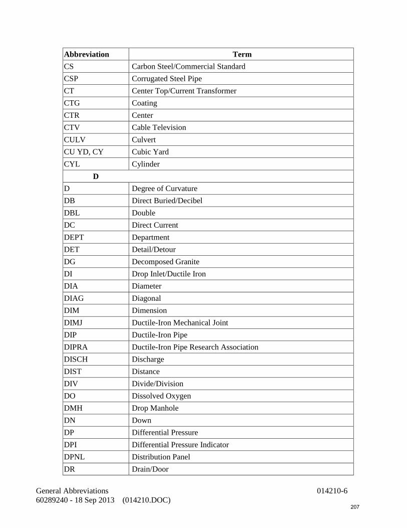
Abbreviation Term CS Carbon Steel/Commercial Standard CSP Corrugated Steel Pipe CT Center Top/Current Transformer CTG Coating CTR Center CTV Cable Television CULV Culvert CU YD, CY Cubic Yard CYL Cylinder
D D Degree of Curvature DB Direct Buried/Decibel DBL Double DC Direct Current DEPT Department DET Detail/Detour DG Decomposed Granite DI Drop Inlet/Ductile Iron DIA Diameter DIAG Diagonal DIM Dimension DIMJ Ductile-Iron Mechanical Joint DIP Ductile-Iron Pipe DIPRA Ductile-Iron Pipe Research Association DISCH Discharge DIST Distance DIV Divide/Division DO Dissolved Oxygen DMH Drop Manhole DN Down DP Differential Pressure DPI Differential Pressure Indicator DPNL Distribution Panel DR Drain/Door
General Abbreviations 014210-6 60289240 - 18 Sep 2013 (014210.DOC) 207
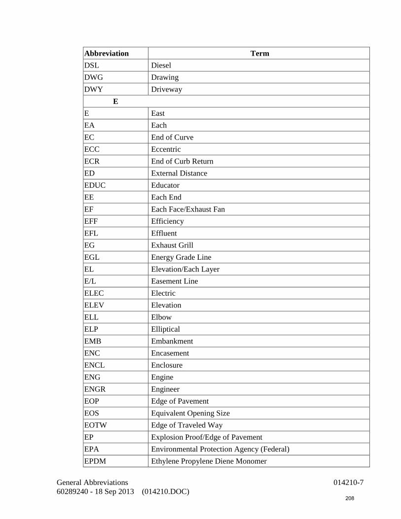
Abbreviation Term DSL Diesel DWG Drawing DWY Driveway
E E East EA Each EC End of Curve ECC Eccentric ECR End of Curb Return ED External Distance EDUC Educator EE Each End EF Each Face/Exhaust Fan EFF Efficiency EFL Effluent EG Exhaust Grill EGL Energy Grade Line EL Elevation/Each Layer E/L Easement Line ELEC Electric ELEV Elevation ELL Elbow ELP Elliptical EMB Embankment ENC Encasement ENCL Enclosure ENG Engine ENGR Engineer EOP Edge of Pavement EOS Equivalent Opening Size EOTW Edge of Traveled Way EP Explosion Proof/Edge of Pavement EPA Environmental Protection Agency (Federal) EPDM Ethylene Propylene Diene Monomer
General Abbreviations 014210-7 60289240 - 18 Sep 2013 (014210.DOC) 208

Abbreviation Term EPR Ethylene-Propylene Rubber EQ Equation EQL Equal ESMT Easement EST Estimate or Estimated ETC And so Forth ETM Elapsed Time Meter EVAP Evaporator EVC End Vertical Curve EW Each Way EWC Electric Water Cooler EXC Excavate or Excavation EXP Expansion EXST Existing EXT Exterior/Extension
F F Fahrenheit/Floor FAA Federal Aviation Administration FAB Fabricate FBC Florida Building Code FBRBD Fiberboard FC Foot-Candle FCC Filter Control Console FCO Floor Cleanout FCV Flow Control Valve FD Floor Drain FDN Foundation FDOT Florida Department of Transportation FE Flanged End FF Finished Floor/Flat Face FG Finished Grade FHY Fire Hydrant F&I Furnish and Install FIG Figure
General Abbreviations 014210-8 60289240 - 18 Sep 2013 (014210.DOC) 209

Abbreviation Term FIN Final FIT Fitting FL Floor/Flow Line FLEX Flexible/Flexure FLG Flange FLT Float FLUOR Fluorescent FM Force Main/Factory Mutual FMH Flexible Metal Hose FNSH Finish FOC Face of Concrete FOS Face of Stud FPC Flexible Pipe Coupling FPM Feet Per Minute FPS Feet Per Second FPT Female Pipe Thread FRP Fiberglass-Reinforced Plastic FS Finished Surface/Floor Sink/Federal Specifications FSTNR Fastener FT Feet or Foot FTG Footing FUT Future FWY Freeway FX Fire Extinguisher
G G Gas GA Gauge GAL Gallon GALV Galvanized GAS Gasoline GB Grade Break GDR Guard Rail GE Grooved End GEN Generator
General Abbreviations 014210-9 60289240 - 18 Sep 2013 (014210.DOC) 210

Abbreviation Term GENL General GFI Ground Fault Interrupter GM Gas Main GMAW Gas Metal Arc Welding GMT Greenwich Mean Time GND Ground GPD Gallons Per Day GPM Gallons Per Minute GR Grade GRTG Grating GSKT Gasket GUT Gutter GV Gate Valve GWB Gypsum Wallboard GWBX Gypsum Wallboard, Fire Rated GYP Gypsum
H H Humidistat HARN Harness HB Hose Bibb HC Heating Coil HD Heavy Duty HDPE High Density Polyethylene HEPA High Efficiency Particulate Air HGL Hydraulic Grade Line HID High Intensity Discharge HOA Hand-Off-Automatic HOR Hand-Off-Remote HORIZ Horizontal HP Horsepower/High Pressure HPS High Pressure Sodium HPT High Point HR Hour/Handrail HS High Strength
General Abbreviations 014210-10 60289240 - 18 Sep 2013 (014210.DOC) 211

Abbreviation Term HT Height HTG Heating HTR Heater HV Hose Valve HVAC Heating, Ventilating, and Air Conditioning HVY Heavy HW Headwall/Hot Water HWL High Water Level HWY Highway HYDR Hydraulic HZ Hertz (cycles per second)
I I Intersection Angle ICBO International Conference of Building Officials ID Inside Diameter IE Invert Elevation IEEE Institute of Electrical and Electronics Engineers IN Inches INCAND Incandescent INCL Include INL Inlet INS Insulating INSTL Install or Installation INTR Interior/Intersection INV Invert IP Iron Pipe IPS Iron Pipe Size IPT Iron Pipe Thread IRR Irrigation ISA Instrument Society of America
J J Joist JB Junction Box JCT Junction
General Abbreviations 014210-11 60289240 - 18 Sep 2013 (014210.DOC) 212

Abbreviation Term JIC Joint Industrial Council JN Join JT Joint
K KG Kilogram KM Kilometer KIPS Thousands of Pounds KV Kilovolt KVA Kilovolt-Ampere KW Kilowatt KWH Kilowatt-Hour KWHM Kilowatt-Hour Meter
L L Length of Curve/Long/Left LATL Lateral LAV Lavatory LB Pound LBR Lumber LCL Local LF Linear Foot LG Long LGTH Length LI Level Indicator LLO Long Leg Outstanding LOC Location/Locate LONGIT Longitudinal LOS Lockout Stop LP Light Pole LPT Low Point LR Long Radius LS Lift Station LT Left/Light LTG Lighting LWC Lightweight Concrete
General Abbreviations 014210-12 60289240 - 18 Sep 2013 (014210.DOC) 213

Abbreviation Term LWIC Lightweight Insulating Concrete LWL Low Water Level
M MA Milliampere MAG Magnet/Magnetic MATL Material MAX Maximum MB Machine Bolt/Megabyte/Millibars MBH Thousand BTU Per Hour MECH Mechanical MC Metal Channel MCC Motor Control Center MCM Thousand Circular Mils MCP Motor Circuit Protector MD Motorized Damper MFR Manufacturer MG Million Gallons/Milligram MGD Million Gallons Per Day MG/L Milligrams Per Liter MH Manhole MHZ Megahertz MI Malleable Iron/Mile MIL Military Specifications MIN Minimum MISC Miscellaneous MLSS Mixed Liquor Suspended Solids MLVSS Mixed Liquor Volatile Suspended Solids MJ Mechanical Joint MMA Monorail Manufacturer's Association MO Motor Operator/Motor Operated/Masonry Opening MOD Modification MON Monument MOT Motor MPT Male Pipe Thread
General Abbreviations 014210-13 60289240 - 18 Sep 2013 (014210.DOC) 214

Abbreviation Term MSL Mean Sea Level MSS Manufacturer's Standardization Society MTD Mounted
N N North/Neutral/Nitrogen NA Not Applicable NAAMM National Association of Architectural Metal Manufacturers NBFU National Board of Fire Underwriters NBS National Bureau of Standards N & C Nail and Cap NC Normally Closed NDT Nondestructive Testing NE Northeast NEC National Electrical Code NEMA National Electrical Manufacturers Association NFC National Fire Code NH National Hose NIC Not in Contract NIP Nipple NMTBA National Machine Tool Builders Association NO Number/Normally Open NOM Nominal NPT National Pipe Taper NRS Nonrising Stem NSF National Sanitation Foundation NTS Not to Scale NTU Nephelometric Turbidity Unit NW Northwest NWL Normal Water Level
O OA Overall/Outside Air OC On Center/Overcurrent OD Outside Diameter ODP Open Dripproof
General Abbreviations 014210-14 60289240 - 18 Sep 2013 (014210.DOC) 215

Abbreviation Term OE Or Equal OF Outside Face OPER Operator OPNG Opening OPP Opposite ORIG Original OSA Outside Air OSHA Occupational Safety and Health Administration O TO O Out to Out OVFL Overflow OVHD Overhead
P P Pole PARA Paragraph PB Push Button/Pull Box PC Point of Curvature/Programmable Controller PCA Portland Cement Association PCC Point of Compound Curvature/Portland Cement Concrete PDI Plumbing and Drainage Institute PE Plain End/Polyethylene/Professional Engineer PEN Penetration PERF Perforated PF Power Factor PG Pressure Gauge PI Point of Intersection PJTN Projection PKWY Parkway PL Plate/Property Line PLATF Platform PLC Programmable Logic Controller PLF Pounds Per Lineal Foot PNL Panel POB Point of Beginning POC Point of Connection
General Abbreviations 014210-15 60289240 - 18 Sep 2013 (014210.DOC) 216
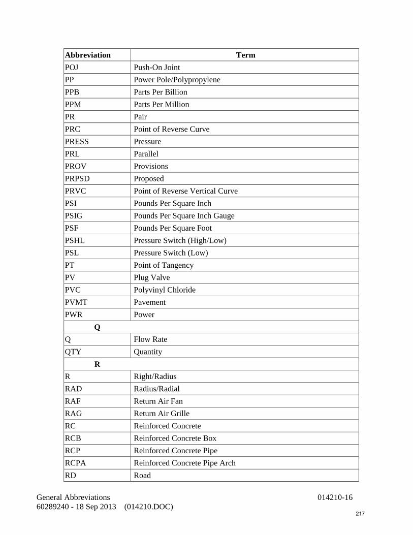
Abbreviation Term POJ Push-On Joint PP Power Pole/Polypropylene PPB Parts Per Billion PPM Parts Per Million PR Pair PRC Point of Reverse Curve PRESS Pressure PRL Parallel PROV Provisions PRPSD Proposed PRVC Point of Reverse Vertical Curve PSI Pounds Per Square Inch PSIG Pounds Per Square Inch Gauge PSF Pounds Per Square Foot PSHL Pressure Switch (High/Low) PSL Pressure Switch (Low) PT Point of Tangency PV Plug Valve PVC Polyvinyl Chloride PVMT Pavement PWR Power
Q Q Flow Rate QTY Quantity
R R Right/Radius RAD Radius/Radial RAF Return Air Fan RAG Return Air Grille RC Reinforced Concrete RCB Reinforced Concrete Box RCP Reinforced Concrete Pipe RCPA Reinforced Concrete Pipe Arch RD Road
General Abbreviations 014210-16 60289240 - 18 Sep 2013 (014210.DOC) 217
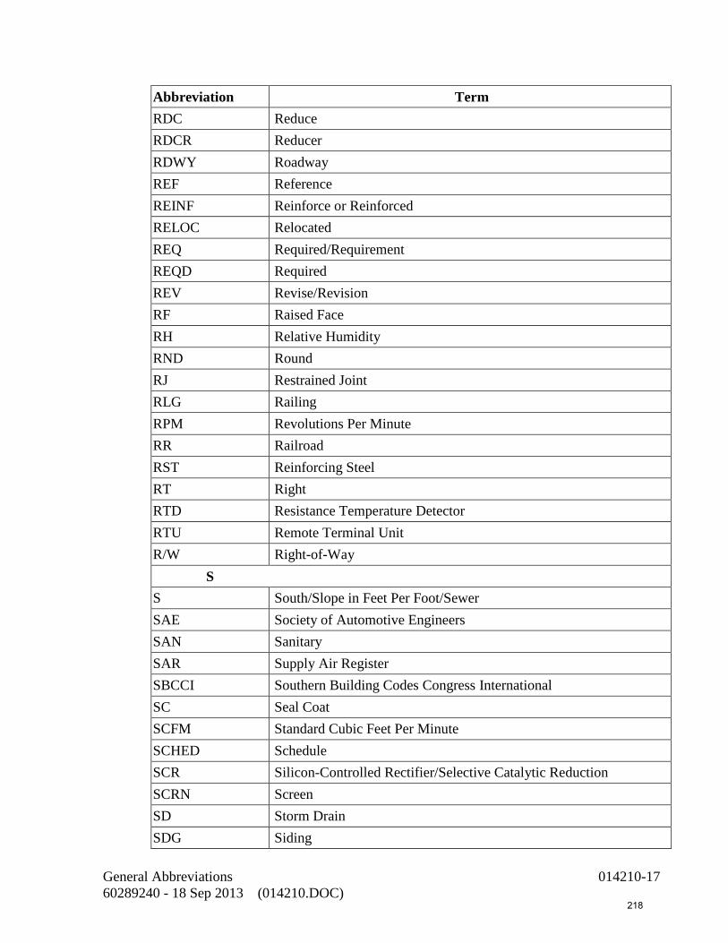
Abbreviation Term RDC Reduce RDCR Reducer RDWY Roadway REF Reference REINF Reinforce or Reinforced RELOC Relocated REQ Required/Requirement REQD Required REV Revise/Revision RF Raised Face RH Relative Humidity RND Round RJ Restrained Joint RLG Railing RPM Revolutions Per Minute RR Railroad RST Reinforcing Steel RT Right RTD Resistance Temperature Detector RTU Remote Terminal Unit R/W Right-of-Way
S S South/Slope in Feet Per Foot/Sewer SAE Society of Automotive Engineers SAN Sanitary SAR Supply Air Register SBCCI Southern Building Codes Congress International SC Seal Coat SCFM Standard Cubic Feet Per Minute SCHED Schedule SCR Silicon-Controlled Rectifier/Selective Catalytic Reduction SCRN Screen SD Storm Drain SDG Siding
General Abbreviations 014210-17 60289240 - 18 Sep 2013 (014210.DOC) 218

Abbreviation Term SDI Steel Deck Institute SDWK Sidewalk SE Southeast SECT Section SF Square Feet SGL Single SH Sheet/Sheeting/Shielded SIM Similar SLP Slope SLV Sleeve SM Sheet Metal SMACNA Sheet Metal and Air Conditioning Contractors National Association SMAW Shielded Metal Arc Welding SOL Solenoid SOV Solenoid-Operated Valve SP Space/Steel Pipe/Static Pressure/Spare SPCG Spacing SPEC Specification SPLC Splice SPRT Support SQ Square SQ FT Square Feet SR Short Radius SS Sanitary Sewer SSPC Steel Structures Painting Council SST Stainless Steel ST Street STA Station STBY Standby STC Sound Transmission Class STD Standard STK Stake STL Steel STR Straight
General Abbreviations 014210-18 60289240 - 18 Sep 2013 (014210.DOC) 219
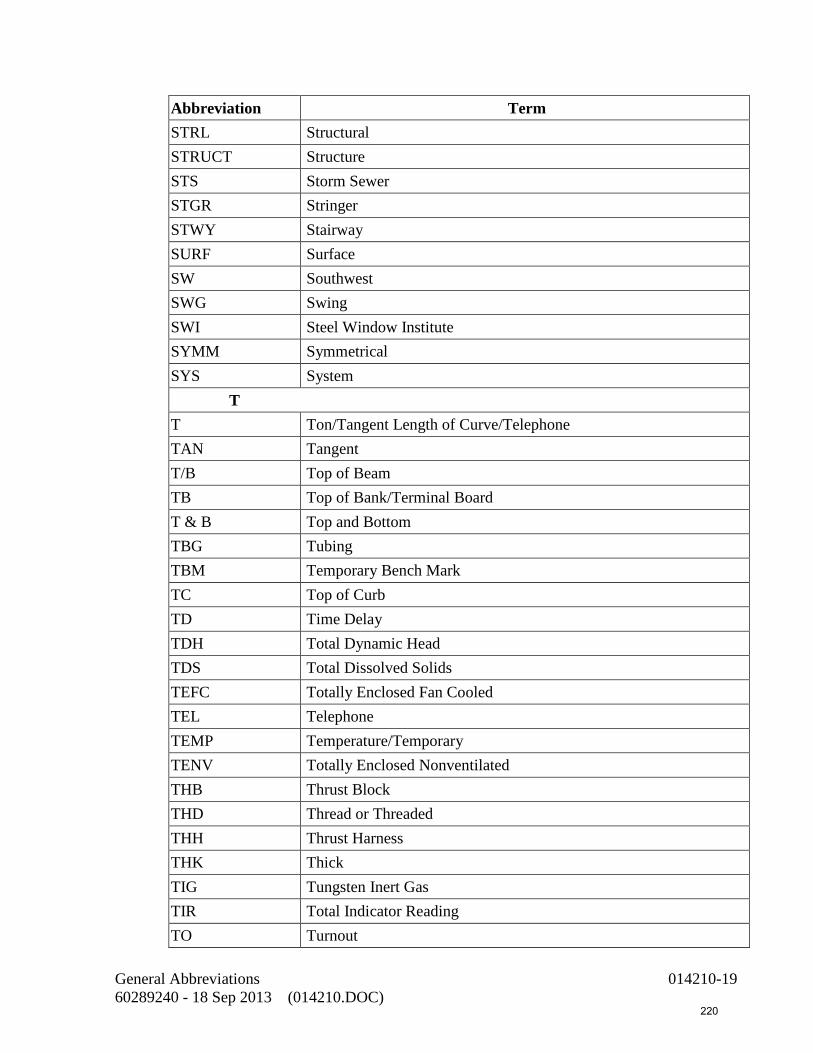
Abbreviation Term STRL Structural STRUCT Structure STS Storm Sewer STGR Stringer STWY Stairway SURF Surface SW Southwest SWG Swing SWI Steel Window Institute SYMM Symmetrical SYS System
T T Ton/Tangent Length of Curve/Telephone TAN Tangent T/B Top of Beam TB Top of Bank/Terminal Board T & B Top and Bottom TBG Tubing TBM Temporary Bench Mark TC Top of Curb TD Time Delay TDH Total Dynamic Head TDS Total Dissolved Solids TEFC Totally Enclosed Fan Cooled TEL Telephone TEMP Temperature/Temporary TENV Totally Enclosed Nonventilated THB Thrust Block THD Thread or Threaded THH Thrust Harness THK Thick TIG Tungsten Inert Gas TIR Total Indicator Reading TO Turnout
General Abbreviations 014210-19 60289240 - 18 Sep 2013 (014210.DOC) 220

Abbreviation Term T/O Top of TOC Top of Concrete TOS Top of Slab/Top of Steel TOT Total TP Telephone Pole TRD Tread TRA Tie Rod Assembly TS Tube Steel TV Television TYP Typical
U UBC Uniform Building Code UD Underdrain UG Underground UH Unit Heater UHMW Ultra High Molecular Weight UL Underwriters' Laboratories, Inc. ULT Ultimate UNO Unless Noted Otherwise UPS Uninterruptible Power Supply UR Urinal USGS United States Geological Survey UTC Underground Telephone Cable UTR Up Through Roof UV Ultraviolet
V V Vent/Valve/Volt VAC Vacuum/Volts, Alternating Current VC Vertical Curve VCP Vitrified Clay Pipe VEL Velocity VERT Vertical VFD Variable Frequency Drive VOL Volume
General Abbreviations 014210-20 60289240 - 18 Sep 2013 (014210.DOC) 221

Abbreviation Term VPC Vertical Point of Curve VPI Vertical Point of Intersection VPT Vertical Point of Tangency VSS Volatile Suspended Solids VTR Vent Through Roof
W W West/Watt/Wide/Water W/ With WC Water Closet WCO Wall Cleanout WG Water Gauge WH Wall Hydrant WL Waterline WLD Welded WM Water Meter/Water Main W/O Without WP Waterproof/Working Point WRGWB Water-Resistant Gypsum Wallboard WSE Water Surface Elevation WSP Water Stop WT Weight WTR Water WWF Welded Wire Fabric (same as WWR) WWM Woven Wire Mesh (same as WWR) WWR Welded Wire Reinforcement
X XFMR Transformer XFR Transfer
Y YCO Yard Cleanout YD Yard YP Yield Point YR Year YS Yield Strength
General Abbreviations 014210-21 60289240 - 18 Sep 2013 (014210.DOC) 222

Abbreviation Term Z
END OF SECTION
General Abbreviations 014210-22 60289240 - 18 Sep 2013 (014210.DOC) 223

SECTION 015070 TRAFFIC REGULATIONS
PART 1
1.01 Description
This section describes procedures for traffic regulation during construction in public streets and highways.
1.02 Standard Specifications
Wherever reference is made to the State Specifications and Plans, such reference shall mean the State of Florida, Department of Transportation, Design Standards, 2014 edition.
1.03 Submittals
The Contractor shall submit a traffic control plan for work proposed in the travel-ways. No work shall begin involving or requiring alternate traffic control until a traffic control plan is approved by the city.
1.04 General
1. Provide safe and continuous passage for pedestrian and vehicular traffic at all times.
2. Control traffic at those locations indicated and in conformance with the approved traffic control plans and specifications.
3. Furnish, construct, maintain, and remove detours, road closures, traffic signal equipment, lights, signs, barricades, fences, K-rail, flares, solar-powered flashing arrow signs, miscellaneous traffic devices, flagmen, drainage facilities, paving, and such other items and services as are necessary to adequately safeguard the public from hazard and inconvenience. All such work shall comply with the ordinances, directives, and regulations of authorities with jurisdiction over the public roads in which the construction takes place and over which detoured traffic is routed by the Contractor. After devices have been installed, maintain and keep them in good repair and working order until no longer required. Replace such devices that are lost or damaged, to such an extent as to require replacement, regardless of the cause of such loss or damage.
4. Prior to the start of construction operations, notify the police and fire department in whose jurisdiction the project lies, giving the expected starting date, completion date, and the names and telephone numbers of two responsible persons who may be contacted at any hour in the event of a condition requiring immediate emergency service to remove, install, relocate, and maintain warning devices. In the event these persons do not promptly respond or the authority deems it
TRAFFIC REGULATION 015070-1 60289240 - 13 Sep 2013 (S015070.DOC) 224

necessary to call out other forces to accomplish emergency service, the Contractor will be held responsible for the cost of such emergency service.
5. Provide a minimum of 72 hours' notice to the City for any work which may affect signal loops, equipment, or devices. In the event that any underground utilities, traffic devices, pipes, or conduits are damaged and require emergency repair by the City, all costs incurred by the city in making such repairs, plus 15 for administration costs, shall be paid by the Contractor.
6. Post temporary "No Parking - Tow Away" signs 48 hours prior to work in areas where parking is normally permitted. The City Police Department shall be notified 48 hours prior to the posting of any temporary parking restrictions along the pipeline route.
7. Coordinate the relocation of public bus and school bus routes, bus stops, and trash collection services with the agencies listed on the plans in advance of construction activity.
8. Post the construction information signs along force main alignment at least two weeks prior to construction.
9. Notify each postal address at least two working days prior to restricting parking along the project route via first class United States mail of the nature and duration of the parking restriction.
1.05 Traffic Control Devices and Signs
1. Traffic control devices and temporary striping shall conform to the 2003 edition of the Manual of Uniform Traffic Control Devices (MUTCD). Construction signs shall conform to the latest edition of the FHA publication “Standard Highway Signs”.
2. The placement of construction signing, striping, barricades, and other traffic control devices used for handling traffic and public convenience shall conform to the MUTCD and the State of Florida, Department of Transportation, Design Standards 2006.
3. Signs shall be illuminated when they are used during hours of darkness. Cones and portable delineators used for night lane closures shall have reflective sleeves. Equip barricades used in the diversion of traffic with flashers if in place during hours of darkness.
4. During the duration of a detour, cover existing signs not in accordance with the traffic control plan. Relocate existing signs that are in force to provide visibility from all relocated traffic lanes.
TRAFFIC REGULATION 015070-2 60289240 - 13 Sep 2013 (S015070.DOC) 225
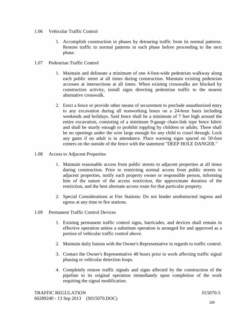
1.06 Vehicular Traffic Control
1. Accomplish construction in phases by detouring traffic from its normal patterns. Restore traffic to normal patterns in each phase before proceeding to the next phase.
1.07 Pedestrian Traffic Control
1. Maintain and delineate a minimum of one 4-foot-wide pedestrian walkway along each public street at all times during construction. Maintain existing pedestrian accesses at intersections at all times. When existing crosswalks are blocked by construction activity, install signs directing pedestrian traffic to the nearest alternative crosswalk.
2. Erect a fence or provide other means of securement to preclude unauthorized entry to any excavation during all nonworking hours on a 24-hour basis including weekends and holidays. Said fence shall be a minimum of 7 feet high around the entire excavation, consisting of a minimum 9-gauge chain-link type fence fabric and shall be sturdy enough to prohibit toppling by children or adults. There shall be no openings under the wire large enough for any child to crawl through. Lock any gates if no adult is in attendance. Place warning signs spaced on 50-foot centers on the outside of the fence with the statement "DEEP HOLE DANGER."
1.08 Access to Adjacent Properties
1. Maintain reasonable access from public streets to adjacent properties at all times during construction. Prior to restricting normal access from public streets to adjacent properties, notify each property owner or responsible person, informing him of the nature of the access restriction, the approximate duration of the restriction, and the best alternate access route for that particular property.
2. Special Considerations at Fire Stations: Do not hinder unobstructed ingress and egress at any time to fire stations.
1.09 Permanent Traffic Control Devices
1. Existing permanent traffic control signs, barricades, and devices shall remain in effective operation unless a substitute operation is arranged for and approved as a portion of vehicular traffic control above.
2. Maintain daily liaison with the Owner's Representative in regards to traffic control.
3. Contact the Owner's Representative 48 hours prior to work affecting traffic signal phasing or vehicular detection loops.
4. Completely restore traffic signals and signs affected by the construction of the pipeline to its original operation immediately upon completion of the work requiring the signal modification.
TRAFFIC REGULATION 015070-3 60289240 - 13 Sep 2013 (S015070.DOC) 226

5. Traffic Control Detection Loops: Completely replace traffic control detection loops which are cut, removed, or otherwise disturbed for construction of the pipeline to the original position or as directed by the Owner's Representative immediately after the specific stage affecting loops is completed. Check new loops for continuity from the traffic signal cabinet to assure splicing and signal operation is correct.
6. Replace traffic signal conduits damaged to the nearest pull box, including new wire, back to the terminal, and/or back to the signal controller to the satisfaction of the owning agency before proceeding to the next construction stage. Splicing is not permitted. Report all such damage immediately to the Owner's Representative.
7. Restriping of Streets: Permanent restriping shall be in accordance with the requirements of the agencies having jurisdiction. Place and remove temporary striping required for traffic control during construction by sandblasting. Temporary striping includes any striping required on any pavement replaced prior to the final surface course. Replace any damaged or obliterated raised pavement markers in accordance with the standards of the agency having jurisdiction.
END OF SECTION
TRAFFIC REGULATION 015070-4 60289240 - 13 Sep 2013 (S015070.DOC) 227

SECTION 015100 CONSTRUCTION FACILITIES AND TEMPORARY CONTROLS
PART 1 – GENERAL
1.01 Construction Water
1. Related Work Specified Elsewhere:
a. Earthwork and Trenching: 312300
b. Concrete: 033000.
c. Pressure Testing of Piping: 400515.
2. The Contractor shall make his own arrangements for developing water sources and supply labor and equipment to collect, load, transport, and apply water as necessary for compaction of materials, concrete construction operations, testing, pipeline disinfection, dust control, and other construction use.
3. Develop sources of water supply or obtain water from private sources. Payment for costs connected with utilization of the source shall be made by the Contractor. Water shall be clean and free from objectionable deleterious amounts of acids, alkalies, salts, or organic materials.
4. Include the cost of construction water in the appropriate bid item to which it is appurtenant. The cost shall include full compensation for furnishing all labor, materials, tools, and equipment and doing all the work necessary to develop a sufficient water supply and furnishing the necessary equipment for applying the water as described in these specifications.
1.02 Electrical Power--Construction Phase
1. Provide for the purchase of power or provide portable power for the construction of the project where existing outlets are not available. Provide for the extension of utility lines to the point of usage. The cost of power shall be included in the appropriate bid items to which it is appurtenant and shall include full compensation for furnishing all labor, materials, tools, and equipment required to obtain and distribute power for construction purposes.
1.03 Dust Control
Perform dust control operations to prevent construction operations from producing dust in amounts harmful to persons or causing a nuisance to persons living nearby or occupying buildings in the vicinity of the work. Use water or dust preventative to control dust.
Construction Facilities and Temporary Controls 015100-1 60289240 - 11 Sep 2013 (015100.DOC) 228

1.04 Construction Solid Waste Disposal
Provide a roll-off container for construction debris for the duration of the construction contract.
1.05 Fire Danger
Minimize fire danger in the vicinity of and adjacent to the construction site. Provide labor and equipment to protect the surrounding private property from fire damage resulting from construction operations.
1.06 Temporary Sanitary Facilities
1. Provide temporary toilet facilities separate from the job office. Maintain these during the entire period of construction under this Contract for the use of all construction personnel on the job. Provide enough chemical toilets to conveniently serve the needs of all personnel.
2. Chemical toilets and their maintenance shall meet the requirements of the State and
local health regulations and ordinances. Any facilities or maintenance methods failing to meet these requirements shall be corrected immediately.
1.07 Construction Staking
The Contractor shall provide all construction staking for the Work.
1.08 Access Roads and Parking Areas
1. Access to project site is from Goodlette-Frank Road North and Riverside Circle. Keep the existing parking spaces accessible at all times for the Owner and general public.
2. The Contractor and his employees will be permitted to park their vehicles on the Owner’s property. The Owner will designate a location for the Contractor and employee parking.
1.09 Security
Full time watchmen will not be required as a part of the contract, but the contractor shall inspect the area daily and take whatever measures are necessary to protect the safety of the public, workmen, materials, and provide for the site, both day and night.
1.10 Drainage, Erosion, Dust, and Mud Control
1. Provide Erosion and Sedimentation Control per State and Federal requirements.
Construction Facilities and Temporary Controls 015100-2 60289240 - 11 Sep 2013 (015100.DOC) 229

2. Provide for the drainage of stormwater as may rain or flow onto or be discharged from the site in performance of the work. Drainage facilities shall be adequate to prevent damage to the work, the site, and adjacent property.
3. Existing drainage channels and conduits shall be cleaned, enlarged or supplemented as permitted by drainage control agencies to carry all runoff attributable to Contractor's operations. Dikes shall be constructed to divert runoff from entering adjacent property (except in natural channels), to protect County’s facilities and the Work, and to direct water to drainage channels or conduits. Ponding shall be provided to prevent downstream flooding and waterway contamination.
4. Install silt barriers, turbidity curtains and screens for capturing sediments-solids from erosion and liquids from temporary pumping and dewatering activities.
5. Prevent erosion of soil on the site and adjacent property resulting from his construction activities. Effective measures shall be initiated prior to the commencement of clearing, grading, excavation, or other operation that will disturb the natural protection. Install silt barriers or screens for capturing sediments/solids from erosion and dewatering activities.
6. Work shall be scheduled to expose areas subject to erosion for the shortest possible time, and natural vegetation preserved to the greatest extent practicable. Temporary storage and construction buildings shall be located, and construction traffic routed, to minimize erosion. Temporary fast growing vegetation or other suitable ground cover shall be provided as necessary to control runoff.
7. Perform dust and mud control operations to prevent construction operations from producing dust and mud in amounts harmful to persons or causing a nuisance to persons living nearby or occupying buildings in the vicinity of the work. Use water or dust preventative to control dust during dry weather. Take necessary steps to prevent the tracking of mud onto adjacent streets and highways.
1.11 Project Sign(s)
Provide and erect one sign near the project site as directed by the Owner. Construct each sign of 3/4-inch exterior grade plywood with 4-inch by 4-inch posts. Brace each sign with at least 2-inch x 4-inch lumber.
END OF SECTION
Construction Facilities and Temporary Controls 015100-3 60289240 - 11 Sep 2013 (015100.DOC) 230

This page intentionally left blank
231

SECTION 016400 OWNER-FURNISHED EQUIPMENT
1.01 GENERAL
The Owner will furnish the following items of equipment:
Item Quantity Variable Frequency Drive 88hp (262923) 1 each Submersible Pump 88hp (432140) 1 each
1.02 DELIVERY DATES FOR OWNER-FURNISHED EQUIPMENT
The Contractor shall coordinate with the Owner regarding the delivery dates for the owner furnished equipment.
1.03 RELATED WORK SPECIFIED ELSEWHERE
A. Installation of Variable Frequency Drives: Section 262923 Part 3
B. Installation of Submersible Raw Water Pump: Section 432140 Part 3
1.04 CUSTODY
The Contractor shall assume custody of the above equipment when it is delivered to the project site and shall assume liability for damage to the equipment thereafter. The Owner will not accept title to the equipment until the project is substantially complete in accordance with the General Conditions.
1.05 INSPECTION
Upon transferal of the Owner-furnished equipment to the Contractor, the Contractor and the Owner shall make a joint inspection of the condition of each piece of equipment and shall note, in writing, the defects in said equipment. Damage or loss of equipment and materials after the date of their transfer to the Contractor shall be repaired or replaced at the Contractor's expense.
1.06 DELIVERY OF EQUIPMENT
A. The Owner will deliver the pump and VFD to the project site. The Contractor shall provide a crane and labor to unload the equipment.
1.07 EQUIPMENT STORAGE--GENERAL
Provide storage facilities for the equipment in an environmentally controlled structure having a temperature range of 40°F to 90°F.
OWNER-FURNISHED EQUIPMENT 016400-1 60289240 - 13 Sep 2013 (S016400.DOC) 232

1.08 STORAGE OF PUMPS
Store and protect pumps per API 686 (first edition), Chapter 3, paragraphs 1.4 through 1.9, 1.15, 1.16, 1.17, 1.18, 1.20, and 1.21.
1.09 STORAGE OF VALVES HAVING ELECTRIC MOTOR ACTUATORS
If electric motorized actuators are stored or installed outside or in areas subject to temperatures below 40°F or are exposed to the weather prior to permanent installation, provide the manufacturer’s recommended procedures for extended storage. Provide temporary covers over the actuator electrical components. Provide temporary conduits, wiring, and electrical supply to space heaters. Exercise each actuator from its fully open to fully closed position at least once every seven days. Inspect electrical contacts before start-up.
1.10 STORAGE OF ELECTRIC MOTORS
If electric motors are stored or installed outside or in areas subject to temperatures below 40°F or are exposed to the weather prior to permanent installation, provide the manufacturer’s recommended procedures for extended storage. Provide temporary covers over the motor electrical components. Provide temporary conduits, wiring, and electrical supply to space heaters. Inspect electrical contacts during installation.
1.11 OWNER-FURNISHED TECHNICAL ASSISTANCE
A. A field service representative from the manufacturers of the following Owner-furnished equipment will be available to provide technical direction and certain other services:
Item Name of Manufacturer
Variable Frequency Drive
Square D
Submersible Pump Flygt
B. Contractor will be responsible for coordinating with manufacturer's representative for providing necessary services.
C. The representative of the Owner-furnished equipment manufacturers will provide the following services at no cost to the Contractor as noted in Section 432140 and 262923.
END OF SECTION
OWNER-FURNISHED EQUIPMENT 016400-2 60289240 - 13 Sep 2013 (S016400.DOC) 233

SECTION 017000 CONTRACT CLOSEOUT PART 1 1.01 Clean-Up Operations
1. Thoroughly clean the project site at the completion of the Work. Clean-up operations shall consist of the removal and legal disposal of all broken concrete, wood scraps, wire, packaging materials, forms, debris, scaffolds, and other objectionable rubble created during construction operations; cleaning of spilled mortar, concrete, and metalwork; and removal of all temporary manufacturer's labels from and washing of all equipment.
2. Remove excess dust and mud created by the construction project from all sidewalks,
streets and highways.
1.02 Closeout Submittals
1. Upon completion of the project, or portions thereof, and prior to final payment, the Contractor shall transfer to the Owner all applicable items accumulated throughout construction. These include, but are not limited to, the following items:
a. Service manuals, installation instructions, and oper-ation and maintenance
manuals. b. Spare parts and special tools ordered as part of this Contract. c. Manufacturers' guarantees, bonds, and letters of coverage extending them
beyond the time limitations of the Contractors' guarantee. d. Salvaged materials or materials and equipment borrowed from the Owner. e. Record documents of completed facilities. f. All keys to all doors, gates, and equipment. g. Statements from the manufacturer's representatives as called for in the Contract
Documents. h. Releases of lien. General release from Contractor plus copies of releases from
subcontractors and material suppliers.
2. The closeout requirements of this section are in addition to the requirements of the Standard General Conditions and Supplementary Conditions.
END OF SECTION
CONTRACT CLOSEOUT 017000-1 60289240 - 6 Sep 2013 (S017000.DOC) 234

This page intentionally left blank
235
SECTION 017410 CLEANING DURING CONSTRUCTION AND FINAL CLEANING
PART 1 - GENERAL
1.01 General
1. This section includes cleaning during construction and final cleaning on completion of the work.
2. At all times maintain areas covered by the contract and adjacent properties and public access roads free from accumulations of waste, debris, and rubbish caused by construction operations.
3. Conduct cleaning and disposal operations to comply with local ordinances and antipollution laws. Do not burn or bury rubbish or waste materials on project site. Do not dispose of volatile wastes, such as mineral spirits, oil, or paint thinner, in storm or sanitary drains. Do not dispose of wastes into streams or waterways.
4. Use only cleaning materials recommended by manufacturer of surface to be cleaned.
1.02 Cleaning During Construction
1. During execution of work, clean site, adjacent properties, and public access roads and dispose of waste materials, debris, and rubbish to assure that buildings, grounds, and public properties are maintained free from accumulations of waste materials and rubbish.
2. Wet down dry materials and rubbish to lay dust and prevent blowing dust.
3. Provide containers for collection and disposal of waste materials, debris, and rubbish.
4. Cover or wet excavated material leaving and arriving at the site to prevent blowing dust. Clean the public access roads to the site of any material falling from the haul trucks.
1.03 Final Cleaning
1. At the completion of work and immediately prior to final inspection, clean the entire project site as follows.
2. Clean, sweep, wash, and polish all work and equipment including finishes.
3. Remove grease, dust, dirt, stains, labels, fingerprints, and other foreign materials from sight-exposed interior and exterior finished surfaces; polish surfaces.
4. Repair, patch, and touch up marred surfaces to match adjacent surfaces.
Cleaning During Construction and Final Cleaning 017410-1 60289240 - 6 Sep 2013 (07410.DOC)
236

5. Broom clean paved surfaces; rake clean landscaped areas.
6. Remove from the site temporary structures and materials, equipment, and appurtenances not required as a part of, or appurtenant to, the completed work.
END OF SECTION
Cleaning During Construction and Final Cleaning 017410-2 60289240 - 6 Sep 2013 (07410.DOC)
237

SECTION 019310 OPERATION AND MAINTENANCE MANUALS
PART 1 - GENERAL
1.01 General
Submit six copies of all manufacturer's operation and maintenance manuals and data pertinent to equipment supplied for the project. Prepare and organize the material in three-ring binders with divider tabs and labels. Include a table of contents.
1.02 Submittals
1. Submittals shall include:
a. List of equipment furnished for project with name, address, and telephone number of each vendor.
b. List of serial numbers of equipment furnished.
c. A copy of shop drawings for mechanical, electrical, and instrument equipment in final form.
d. Manufacturer's operation and maintenance instructions and parts lists.
e. Tabulation of motor nameplate horsepower, nameplate current, field-measured current, overload relay setting, and catalog number for polyphase motors.
f. List of fuses, lamps, seals, and other expendable equipment and devices. Specify size, type, and ordering description. List name, address, e-mail address, fax number, and telephone number of vendor.
g. Submit a tabulation of maintenance schedules separate from the operation and maintenance manuals.
2. Provide manuals for each piece of equipment including individual components and subsystems of complete assemblies. Line out nonapplicable text and illustrations. The section of the manual on operation shall describe the functions and limitations of each component and its relationship to the system of which it is a part. Where several models, options, or styles are described, the manual shall identify the items actually provided.
3. Each manual shall contain the following:
a. Manufacturer's identification, including order number, model, and serial number.
b. Blue line prints or reviewed shop drawings and diagrams of all systems, including temperature control system.
Operation and Maintenance Manuals 019310-1 60289240 - 18 Sep 2013 (019310.DOC) 238

c. Certified equipment drawings or reviewed shop drawing data clearly marked for equipment furnished.
d. Complete operating and maintenance instructions for each and every item of equipment, setting forth in detail and step-by-step the procedure for starting, stopping, operating, and maintaining the entire system as installed. Include a schedule of recommended maintenance intervals.
e. Complete parts list of replaceable parts, their part numbers, and the name and address of their nearest vendor.
f. A complete valve tag list including the name and function of the pipe in which the valve is mounted.
g. Any special emergency operating instruction and a list of service organizations (including addresses and telephone numbers) capable of rendering emergency service to the various parts of the system.
h. Copy of manufacturer's equipment guarantees and warranties.
4. Brochures shall be loose leaf with durable plastic or fiberboard covers. Each sheet shall be reinforced to prevent tearing from continued use, and each brochure shall have the following information clearly printed on its cover:
a. Project name, name of Owner, and address.
b. Name and address of Owner's Representative.
c. Name and addresses of contractors and subcontractors and department to contact.
d. Telephone number of contractors, including night and emergency numbers.
e. Major equipment vendors' names and telephone numbers.
5. Submit complete manuals at least four weeks before the date of the instructions required by the subsections on "Manufacturer's Services" in the various specification sections.
6. Operation and maintenance manuals specified herein are in addition to any operation, maintenance, or installation instructions required by the Contractor to install, test, and start up equipment.
1.03 Equipment Data Sheets
Provide six sets of equipment data sheets, bound in three-ring binders, summarizing the equipment manufacturer's maintenance instructions and recommendations. A blank data sheet and a sample data sheet are attached.
Operation and Maintenance Manuals 019310-2 60289240 - 18 Sep 2013 (019310.DOC) 239

Preventive Maintenance and Operating Requirement Sheets
Preventive Maintenance Program Equipment Record Number
EQUIPMENT DESCRIPTION ELECTRICAL OR MECHANICAL DATA
Name:
Size:
Serial No.: Model:
Vendor:
Vendor Address:
Type:
Mfr.:
Vendor Rep: Voltage: Amps:
Phone: Phase: rpm:
Maintenance Work to be Done Frequency*
OPERATING REQUIREMENTS AND REFERENCE *D - Daily; W - Weekly; B - Biweekly; M - Monthly; Q - Quarterly; S - Semiannually; A - Annually.
Operation and Maintenance Manuals 019310-3 60289240 - 18 Sep 2013 (019310.DOC) 240

SAMPLE
Preventive Maintenance and Operating Requirement Sheets
Preventive Maintenance Program Equipment Record Number
EQUIPMENT DESCRIPTION ELECTRICAL OR MECHANICAL DATA
Name: Influent Pump No. 1 Tag No.: P01-1
Size: 15 hp
Serial No.: 123456ABC
Vendor: ABC Pump Co.
Model: 140T Frame Serial No. 987654ZY Class F Insulation W/Space Heater
Vendor Address: Type:
1111 Pump Circle Newport Beach, CA 92663
Mfr.: DEF Motors, Inc.
Vendor Rep: XYZ Equipment, Inc. Voltage: 460 Amps: 20
Phone: 714/752-0505 Phase: 3 rpm: 1,800
Maintenance Work to be Done Frequency*
1. Operate all valves and check such things as a) bearing temperature, b) changes in running sound, c) suction and discharge gauge readings, d) pump discharge rate, and e) general condition of the drive equipment.
2. Check packing.
3. Checking pumping unit for any dust, dirt, or debris.
(Continued on attached sheet)
D
D
W
OPERATING REQUIREMENTS AND REFERENCE
For manufacturer's instructions regarding installation, operation, maintenance, and trouble shooting of this equipment, see Volume ____, Section ______. *D - Daily; W - Weekly; B - Biweekly; M - Monthly; Q - Quarterly; S - Semiannually; A - Annually.
Operation and Maintenance Manuals 019310-4 60289240 - 18 Sep 2013 (019310.DOC) 241

SAMPLE
Preventive Maintenance and Operating Requirement Sheets
Preventive Maintenance Program Equipment Record Number
EQUIPMENT DESCRIPTION ELECTRICAL OR MECHANICAL DATA
Name:
Size:
Serial No.: Model:
Vendor:
Vendor Address:
Type:
Mfr.:
Vendor Rep: Voltage: Amps:
Phone: Phase: rpm:
Maintenance Work to be Done Frequency*
4. Lubricate bearing frame and motor bearings (consult manufacturer's instructions for type of grease or oil).
5. Disassemble and change or repair the following: a) impeller, b) shafts, c) shaft sleeve, d) rotary seals, and e) sleeve bearings.
Q
A
OPERATING REQUIREMENTS AND REFERENCE
*D - Daily; W - Weekly; B - Biweekly; M - Monthly; Q - Quarterly; S - Semiannually; A - Annually.
Operation and Maintenance Manuals 019310-5 60289240 - 18 Sep 2013 (019310.DOC) 242

END OF SECTION
Operation and Maintenance Manuals 019310-6 60289240 - 18 Sep 2013 (019310.DOC) 243

DIVISION 02 – EXISTING CONDITIONS 020120 Protecting Existing Underground Utilities 024100 Equipment, Piping, and Materials Demolition
244

This page intentionally left blank
245

SECTION 020120 PROTECTING EXISTING UNDERGROUND UTILITIES
PART 1 - GENERAL
1.01 DESCRIPTION
This section includes materials and procedures for protecting existing underground utilities.
PART 2 - MATERIALS
2.01 REPLACEMENT IN KIND
Except as indicated below or as specifically authorized by the Owner's Representative, reconstruct utilities with new material of the same size, type, and quality as that removed.
2.02 VITRIFIED CLAY SEWER PIPE AND COUPLINGS
For sewer pipe 8 inches and less in diameter, replacement shall consist of plain-end pipe conforming to ASTM C700. Compression couplings shall conform to ASTM C594, band seal couplings or equal. Use at least two lengths of pipe in crossing the trench section or as shown on the details in the drawings.
PART 3 - EXECUTION
3.01 GENERAL
A. Replace in kind street improvements, such as curbs and gutters, barricades, traffic islands, signalization, fences, signs, etc., that are cut, removed, damaged, or otherwise disturbed by the construction.
B. Where utilities are parallel to or cross the construction but do not conflict with the permanent work to be constructed, follow the procedures given below and as indicated in the drawings. Notify the utility owner 48 hours in advance of the crossing construction and coordinate the construction schedule with the utility owner's requirements. For utility crossings not shown in the drawings, refer to the General Conditions and the instructions of the Owner's Representative for guidance.
C. Determine the true location and depth of utilities and service connections which may be affected by or affect the work. Determine the type, material, and condition of these utilities. In order to provide sufficient lead-time to resolve unforeseen conflicts, order materials and take appropriate measures to ensure that there is no delay in work.
PROTECTING EXISTING UNDERGROUND UTILITIES 020120-1 60289240 - 6 Sep 2013 (S020120.DOC) 246

3.02 PROCEDURES
A. Protect in Place: Protect utilities in place, unless abandoned, and maintain the utility in service, unless otherwise specified in the drawings or in the specifications.
B. Cut and Plug Ends: Cut abandoned utility lines and plug the ends. Plug storm drains and sewers with an 8-inch wall of brick and mortar. Cap waterlines with a cast-iron cap or install a 3-foot-long concrete plug. Dispose of the cut pipe as unsuitable material.
C. Remove and Reconstruct: Where so indicated in the drawings or as required by the Owner's Representative, remove the utility and, after passage, reconstruct it with new materials. Provide temporary service for the disconnected utility.
3.03 COMPACTION
A. Utilities Protected in Place: Backfill and compact under and around the utility so that no voids are left.
B. Utilities Reconstructed: Prior to replacement of the utility, backfill the trench and compact to an elevation 1 foot above the top of the ends of the utility. Excavate a cross trench of the proper width for the utility and lay, backfill, and compact.
C. Alternative Construction--Sand-Cement Slurry: Sand-cement slurry consisting of one sack (94 pounds) of portland cement per cubic yard of sand and sufficient moisture for workability may be substituted for other backfill materials to aid in reducing compaction difficulties. Submit specific methods and procedures for the review of the Owner's Representative prior to construction.
3.04 SPECIAL CONSTRUCTION
A. Reinforced Concrete Beam: Where indicated in the drawings or as determined by the Owner's Representative, support utilities by a reinforced concrete beam as shown on the utility support details in the drawings. The primary purpose of the beam is to prevent settlement of the utility line after construction. The Contractor is responsible for the protection of the utility during construction and shall incorporate the beam as part of the protection.
B. Concrete Support Wall: Where indicated in the drawings or as determined by the Owner's Representative, support the utilities by a concrete support wall as shown on the utility support details in the drawings. The purpose of the concrete support wall is to prevent settlement of the utility line after construction. The Contractor is responsible for the protection of the utility during construction.
3.05 THRUST BLOCKS ON WATERLINES
A. The Contractor's attention is called to thrust blocks for waterlines throughout the project whose thrust is in the direction of the new excavation and, therefore, may be affected by the construction. These waterlines are owned and operated by the Owner. Protect thrust
PROTECTING EXISTING UNDERGROUND UTILITIES 020120-2 60289240 - 6 Sep 2013 (S020120.DOC) 247

blocks in place or shore to resist the thrust by a means approved by the Owner's water division superintendent and reconstruct. If the thrust blocks are exposed or rendered to be ineffective in the opinion of the Owner's Representative, reconstruct them to bear against firm unexcavated or backfill material.
B. Provide firm support by backfilling that portion of the trench for a distance of 2 feet on each side of the thrust block to be reconstructed from the pipe bedding to the pavement subgrade, with either:
1. Sand-cement slurry (94 pounds of cement per cubic yard).
2. The native material compacted to a relative compaction of 95%.
C. Then excavate the backfill material for construction of the thrust block.
D. Test compaction of the backfill material before pouring any concrete thrust block. Use Class A concrete per Section 033000 for reconstruction.
END OF SECTION
PROTECTING EXISTING UNDERGROUND UTILITIES 020120-3 60289240 - 6 Sep 2013 (S020120.DOC) 248

This page intentionally left blank
249

SECTION 024100 - EQUIPMENT, PIPING, AND MATERIALS DEMOLITION
PART 1 - GENERAL
1.01 DESCRIPTION
This section describes demolition and removal, replacement of existing process and mechanical and electrical equipment and piping.
PART 2 - MATERIALS
Refer to other sections of these specifications for material to be used as replacements for removal or abandoned equipment.
PART 3 - EXECUTION
3.01 GENERAL
Perform removal, replacement, and demolition work specified and indicated in the drawings. Prepare remaining surfaces to receive new scheduled and specified materials and finishes or finish to match adjacent surfaces if no additional work is scheduled or indicated.
3.02 SALVAGE
The City shall have the option to salvage all equipment. Equipment salvaged from the premises is the property of the Owner. Carefully remove and handle the equipment. Leave the property free of debris and material. All equipment identified by the City to be salvaged shall be stockpiled at City’s Riverside Circle yard. Remaining materials to be removed shall be disposed of by Contractor.
3.03 SHUTDOWNS OF EXISTING PIPING AND ELECTRICAL UTILITIES
Shut off or disconnect utilities affecting demolition work. Schedule shutdowns with the Owner; notify the Owner three working days in advance of any shutdown that is required to perform the work.
3.04 TEMPORARY SUPPORT OF EXISTING EXPOSED PIPING
A. Provide temporary supports for existing piping that must be kept in service during demolition of adjacent piping or other existing work in the project. Do not block access to the adjacent valves, equipment, or access door and stairways with the temporary supports.
EQUIPMENT, PIPING, AND MATERIALS DEMOLITION 024100-1 60289240- 13 Sep 2013 (S024100.DOC) 250

3.05 PLUGGING ABANDONED PIPING
Plug buried pipes 6 inches and larger to be abandoned. Plug pipes of all sizes to be abandoned under structures. Plug by placing a 3-foot-long concrete plug in the open ends.
3.06 REMOVAL OR RELOCATION OF ELECTRICAL MATERIALS AND EQUIPMENT
A. Unless otherwise noted, remove existing electrical materials and equipment from areas indicated for demolition or where equipment is to be relocated. Disconnect circuits at their source. Remove materials no longer used, such as studs, straps, and conduits. Remove or cut off concealed or embedded conduit, boxes, or other materials and equipment to a point at least 3/4 inch below the final finished surface. Remove existing unused wires.
B. Repair affected surfaces to conform to the type, quality, and finish of the surrounding surface.
3.07 ELECTRICAL DISCHARGE LIGHTING BALLASTS
A. Electrical discharge lighting ballasts manufactured before 1974 that will be removed under this contract contain polychlorinated biphenyls (PCBs).
B. Electrical discharge lighting ballasts manufactured after 1973 may contain PCBs.
C. It is the Contractor's responsibility to identify the presence of PCBs and to dispose of them in compliance with all local, state, and federal laws, regulations, and ordinances.
3.08 TRANSFORMERS AND OTHER ELECTRICAL APPARATUS
Transformers, switches, capacitors, resistors, and/or other liquid-filled electrical apparatus that will be removed under this contract may contain PCBs. It is the Contractor's responsibility to identify the presence of PCBs and to dispose of them in compliance with all local, state, and federal laws, regulations, and ordinances.
3.09 PATCHING
A. Patching shall mean the restoration of a surface or item to a condition as near as practicable to match the existing adjoining surfaces unless otherwise noted, detailed, or specified.
B. When patching involves painting, special coating, vinyl fabric, or other applied finish, refinish the entire surface plane (i.e., wall or ceiling), unless complete refinishing of the entire space is scheduled or specified.
C. Patching includes cleaning of soiled surfaces.
EQUIPMENT, PIPING, AND MATERIALS DEMOLITION 024100-2 60289240- 13 Sep 2013 (S024100.DOC) 251
3.10 DEMOLITION
A. Existing buildings, structures, boxes, pipes, pavements, curbs, and other items are to be removed, altered, salvaged, and disposed of as specified herein or indicated in the drawings. Remove and dispose of all portions of these items that interfere with project construction.
B. Remove and dispose offsite facilities to be demolished in their entirety including belowground footings, foundations, and other associated appurtenances, as shown in the drawings or as specified herein. Backfill and compact all site areas disturbed by demolition work with earth backfill or gravel material in accordance with Section 312300.
C. Perform the work in a manner that will not damage parts of the structure not intended to be removed or to be salvaged for the Owner. If, in the opinion of the Owner's Representative, the method of demolition used may endanger or damage parts of the structure or affect the satisfactory operation of the facilities, promptly change the method when so notified by the Owner's Representative. No blasting will be permitted.
D. Equipment, material, and piping, except as specified to be salvaged for the Owner, or removed by others, within the limits of the demolition, excavations, and backfills, will become the property of the Contractor and shall be removed from the project site. The salvage value of this equipment, materials, and piping shall be reflected in the contract price of the demolition work.
E. Do not reuse material salvaged from demolition work on this project, except as specifically shown.
END OF SECTION
EQUIPMENT, PIPING, AND MATERIALS DEMOLITION 024100-3 60289240- 13 Sep 2013 (S024100.DOC) 252

This page intentionally left blank
253

DIVISION 03 – CONCRETE 032100 Concrete Reinforcement 033000 Cast-In-Place Concrete 036000 Grout
254

This page intentionally left blank
255
SECTION 032100 CONCRETE REINFORCING
PART 1 - GENERAL
1.01 DESCRIPTION:
Provide concrete reinforcement as indicated and in compliance with Contract Documents:
1. Section Includes:
a. Reinforcement bars.
b. Welded wire reinforcement.
c. Reinforcement accessories.
1.02 REFERENCES:
A. American Society for Testing and Materials International (ASTM):
1. A82: Standard Specification for Steel Wire, Plain, for Concrete Reinforcement.
2. A184: Standard Specification for Fabricated Deformed Steel Bar Mats for Concrete Reinforcement.
3. A1064/A1064M: Standard Specification for Steel Welded Wire Reinforcement, Plain, for Concrete.
4. A496: Standard Specification for Steel Wire, Deformed, for Concrete Reinforcement.
5. A497: Standard Specification for Steel Welded Wire Reinforcement, Deformed, for Concrete Reinforcement.
6. A615: Standard Specification for Deformed and Plain Billet-Steel Bars for Concrete Reinforcement.
7. A616: Standard Specification for Rail-Steel Deformed and Plain Bars for Concrete Reinforcement.
8. A617: Standard Specification for Axle-Steel Deformed and Plain Bars for Concrete Reinforcement.
9. A706: Standard Specification for Low-Alloy Steel Deformed and Plain Bars for Concrete Reinforcement.
CONCRETE REINFORCING 032100-1 60289240 - 6 Sep 2013 (032100.DOC) 256
10. A767: Standard Specification for Zinc-Coated (Galvanized) Steel Bars for Concrete Reinforcement.
B. American Concrete Institute (ACI):
1. 301: Standard Specification for Structural Concrete.
2. 315: Details and Detailing of Concrete Reinforcement.
3. 318: Building Code Requirements for Structural Concrete.
4. 350: Building Code Requirements for Environmental Engineering Concrete Structures
5. SP-66: ACI Detailing Manual.
6. Concrete Reinforcing Steel Institute (CRSI):
7. Manual of Standard Practice.
8. Placing Reinforcing Bars.
C. Where reference is made to one of the above standards, the version in effect at the time of bid opening shall apply.
1.03 SUBMITTALS:
A. Each submittal shall include reinforcement only for the individual structure to which it pertains.
B. Shop Drawings:
1. Submit bar lists and placing drawings for all reinforced concrete structures in accordance with Section 013300.
2. Detail reinforcement in conformance with ACI SP-66.
3. Clearly indicate bar sizes, spacings, locations and quantities of reinforcement steel and wire reinforcement, bending schedules, and supporting and spacing devices. Show joints, with applicable joint reinforcement.
4. Coordinate bar splicing and placement with Contractor’s concrete placing schedule and joint locations. Do not add or delete joints without permission from the Engineer.
5. Show location and size of all penetrations greater than 12-inches in diameter or least dimension of the opening with the corresponding added reinforcement around the penetrations.
CONCRETE REINFORCING 032100-2 60289240 - 6 Sep 2013 (032100.DOC) 257
6. Clearly show marking for each reinforcement item.
7. Indicate locations of reinforcement bar cut-offs, splices and development lengths.
1.04 QUALITY ASSURANCE:
A. Do not fabricate reinforcement until shop and placement drawings have been reviewed and accepted by the Engineer.
B. Perform concrete reinforcement work in accordance with CRSI Manual of Practice.
1.05 INSPECTION AND TESTING:
A. In no case shall any reinforcement steel be covered with concrete until the installation of the reinforcement has been observed by the Engineer and the Engineer’s authorization to proceed with the concreting has been obtained. The Engineer shall be given 48 hours minimum prior notice of the readiness of placed reinforcement for observation. The forms shall be kept open until the Engineer has finished observations of the reinforcement steel.
1.06 DELIVERY STORAGE AND HANDLING:
A. Keep reinforcement steel free from mill scale, rust, dirt, grease or other foreign matter.
B. Ship and store reinforcement steel with bars of the same size and shape fastened in bundles with durable tags, marked in a legible manner with waterproof markings showing the same "mark" designations as those shown on the submitted placing drawings.
C. Store reinforcement steel off the ground, protected from moisture and kept free from dirt, oil or other injurious contaminants.
PART 2 - PRODUCTS
2.01 REINFORCEMENT STEEL:
A. Reinforcement Steel: ASTM A615/A615M, 60 ksi yield grade.
B. Welded Wire Reinforcement:
1. Provide welded wire reinforcement conforming to ASTM A1064 in flat sheets
2. Provide support bars and reinforcement bar supports as specified herein to obtain the concrete cover indicated.
3. Provide welded wire reinforcement in flat sheets. Unless otherwise noted, welded wire reinforcement shall be 6x6-W2.9xW2.9.
CONCRETE REINFORCING 032100-3 60289240 - 6 Sep 2013 (032100.DOC) 258

2.02 ACCESSORY MATERIALS:
A. Tie Wire: Minimum 16 gage annealed type.
B. Chairs, Bolsters, Bar Supports, and Spacers: sized and shaped for strength and support of reinforcement during concrete placement including load bearing pad on bottom of base slabs and slabs on grade to prevent puncturing the vapor retarder.
C. Special Chairs, Bolsters, Bar Supports, and Spacers Adjacent to Weather Exposed Concrete Surfaces: plastic coated steel.
D. Provide 3-inch by 3-inch plain precast concrete blocks for support of bottom reinforcement in foundation mats. Provide block thickness to produce concrete cover of reinforcement as indicated.
E. Provide epoxy adhesive for grouting reinforcement dowel bars into existing concrete.
2.03 FABRICATION:
A. Fabricate concrete reinforcement in accordance with CRSI Manual of Standard Practice.
B. Locate reinforcement splices not indicated on Drawings, at point of minimum stress.
C. Cold bend bars. Do not straighten or rebend bars.
D. Do not heat reinforcement steel to bend or straighten.
E. Bend bars around a revolving collar having a diameter of not less than that recommended by the ACI 318.
PART 3 - EXECUTION
3.01 INSTALLATION:
A. Place, support and secure reinforcement against displacement. Do not deviate from required position. Place reinforcement a minimum of 2 inches clear of any metal pipe or fittings.
B. Tack welding of reinforcement is prohibited.
C. Welding of reinforcing bars is not permitted.
D. Do not displace or damage vapor retarder.
E. Position dowels accurately. Rigidly support, align and securely tie dowels normal to the concrete surface before concrete placement. Setting dowels into wet concrete is prohibited.
CONCRETE REINFORCING 032100-4 60289240 - 6 Sep 2013 (032100.DOC) 259
F. Position wall dowels projecting from base slabs on grade with templates or guides held in place above the concrete placement line. Position the templates to obtain the required clearance between the dowels and the face of the walls.
G. Bars additional to those indicated that may be found necessary or desirable by the Contractor for the purpose of securing reinforcement in position shall be provided by the Contractor at no additional cost to the Owner.
H. Provide additional reinforcement bars to support top reinforcement in slabs. Do not shift reinforcement bars from positions in upper layers to positions in lower layers as a substitute for additional support bars.
I. Support reinforcement steel in accordance with CRSI “Placing Reinforcement Bars” with maximum spacing of 4 feet-0 inches.
J. Tie reinforcement steel at intersections in accordance with CRSI “Placing Reinforcement Bars”:
1. Maximum tie spacing: every third intersection or 3 feet-0 inches.
2. Tie a minimum of 25 percent of all intersecting bars.
3. Secure all dowels in place before placing concrete.
4. Tie wires shall be bent away from the forms and from finished concrete surfaces in order to provide the required concrete coverage.
K. Locate reinforcement to avoid interference with items drilled in later, such as concrete anchors.
L. Extend welded wire reinforcement to within 2 inches of edges of slab or section. Lap sheets at least 12 inches or two wire spaces, whichever is greater, at ends and edges and wire tightly together. Stagger end laps.
M. Unless shown otherwise on Drawings, place welded wire reinforcement in slabs on grade between the upper third point and mid-point of slab. Placing welded wire reinforcement on the subgrade and pulling it up during concrete placement is not permitted.
N. Support welded wire reinforcement placed over the ground on wired concrete blocks (dobies) spaced not more than 3 feet on centers in any direction.
O. Support welded wire reinforcement placed over horizontal forms on slab bolsters spaced not more than 30 inches on center.
P. Securely support and tie reinforcement steel to prevent movement during concrete placement.
CONCRETE REINFORCING 032100-5 60289240 - 6 Sep 2013 (032100.DOC) 260

Q. Do not bend reinforcement bars that project from in-place concrete.
R. Reinforcement shall be clean and free from loose mill scale, dirt, grease, oil, form release agent, dried concrete or any material reducing bond with concrete.
S. Setting bars and welded wire reinforcement on layers of fresh concrete as the work progresses or adjusting reinforcement during the placement of concrete is prohibited.
T. Provide and place safety caps on all exposed ends of vertical reinforcement that pose a danger to injury or life safety.
3.02 CONCRETE COVER OVER REINFORCEMENT BARS:
A. Maintain clear cover as noted on drawings. Tolerances shall be in accordance with ACI 117 and ACI 318 unless otherwise noted.
3.03 SPLICING OF REINFORCEMENT:
A. Make reinforcement continuous through construction joints.
B. Reinforcement may be spliced at construction joints provided that entire lap is placed within only one concrete placement.
3.04 ACCESSORIES:
A. Provide accessories such as chairs, chair bars and the like in sufficient quantities and strength to adequately support the reinforcement and prevent its displacement during the erection of the reinforcement and the placement of concrete.
B. Use precast concrete blocks where the reinforcement steel is to be supported over soil.
C. Do not use metal chairs, ferrous clips, nails, etc. that extend to the surfaces of the concrete. Do not use stones, brick or wood block supports.
3.05 FIELD QUALITY CONTROL:
A. Remove reinforcement with kinks or bends not shown on shop or placement drawings. Remove such reinforcement from job site and replace with new fabricated steel. Do not field bend reinforcement.
B. Protect reinforcement from rusting, deforming, bending, kinking and other injury. Clean in-place reinforcement that has rusted, or been splattered with concrete using sand or water blasting prior to incorporation into the Work.
END OF SECTION
CONCRETE REINFORCING 032100-6 60289240 - 6 Sep 2013 (032100.DOC) 261

SECTION 033000 CAST-IN-PLACE CONCRETE
PART 1 - GENERAL
1.01 DESCRIPTION:
A. Provide cast-in-place concrete as indicated and in compliance with Contract Documents.
1.02 REFERENCES:
A. American Concrete Institute (ACI):
1. 117: Specifications for Tolerances for Concrete Construction and Materials and Commentary.
2. 211.1: Standard Practice for Selecting Proportions for Normal, Heavyweight, and Mass Concrete
3. 214R: Recommended Practice for Evaluation of Strength Test Results of Concrete
4. 301: Standard Specifications for Structural Concrete
5. 304R: Guide for Measuring, Mixing, Transporting and Placing Concrete
6. 304.2R: Placing Concrete by Pumping Methods
7. 305R: Hot Weather Concreting
8. 306R: Cold Weather Concreting
9. 308: Standard Practice for Curing Concrete
10. 309R: Guide for Consolidation of Concrete
11. 311.4R: Guide for Concrete Inspection
12. 318: Building Code Requirements for Structural Concrete
13. 350: Code Requirements For Environmental Engineering Concrete Structures
B. American Society for Testing and Materials International (ASTM):
1. C31: Standard Practice for Making and Curing Concrete Test Specimens in the Field
2. C33: Standard Specification for Concrete Aggregates
CAST- IN- PLACE CONCRETE 033000-1 60289240 - 6 Sep 2013 (033000.DOC)
262

3. C39: Standard Test Method for Compressive Strength of Cylindrical Concrete Specimens
4. C40: Standard Test Method for Organic Impurities in Fine Aggregates for Concrete
5. C87: Standard Test Method for Effect of Organic Impurities in Fine Aggregate on Strength of Mortar
6. C88: Standard Test Method for Soundness of Aggregates by Use of Sodium Sulfate or Magnesium Sulfate
7. C94: Standard Specification for Ready-Mixed Concrete
8. C136: Standard Test Method for Sieve Analysis of Fine and Coarse Aggregates
9. C138: Standard Test Method for Unit Weight, Yield, and Air Content (Gravimetric) of Concrete
10. C150: Standard Specification for Portland Cement
11. C171: Standard Specification for Sheet Materials for Curing Concrete
12. C172: Standard Practice for Sampling Freshly Mixed Concrete
13. C192: Standard Practice for Making and Curing Concrete Test Specimens in the Laboratory
14. C231: Standard Test Method for Air Content of Freshly Mixed Concrete by the Pressure Method
15. C260: Standard Specification for Air-Entraining Admixtures for Concrete
16. C289: Standard Test Method for Potential Alkali-Silica Reactivity of Aggregates (Chemical Method)
17. C309: Standard Specification for Liquid Membrane-Forming Compounds for Curing Concrete
18. C311: Standard Test Methods for Sampling and Testing Fly Ash or Natural Pozzolans for Use as a Mineral Admixture in Portland Cement Concrete
19. C494: Standard Specification for Chemical Admixtures for Concrete
20. C618: Standard Specification for Coal Fly Ash and Raw or Calcined Natural Pozzolan for Use as a Mineral Admixture in Portland Cement Concrete
CAST- IN- PLACE CONCRETE 033000-2 60289240 - 6 Sep 2013 (033000.DOC)
263

21. C881: Standard Test Method for Epoxy Resin Base Bonding Systems for Concrete
22. C882: Standard Test Method for Bond Strength of Epoxy Resin Systems Used with Concrete by Slant Shear
23. C1017: Standard Specification for Chemical Admixtures for Use in Producing Flowing Concrete
24. C1064: Standard Test Method for Temperature of Freshly Mixed Portland Cement Concrete
25. C1107: Standard Specification for Packaged Dry, Hydraulic-Cement Grout (Nonshrink)
26. C1116: Standard Specification for Fiber Reinforced Concrete
27. C1240: Standard Specification for Silica Fume for Use as a Mineral Admixture in Hydraulic-Cement Concrete, Mortar, and Grout
28. D75: Standard Practice for Sampling Aggregates
29. E154: Test Methods for Water Vapor Retarders Used in Contact with Earth Under Concrete Slabs, on Walls, or as Ground Cover
30. E1745: Standard Specification for Water Vapor Retarders Used in Contact with Soil or Granular Fill under Concrete Slabs
31. E329: Standard Specification for Agencies Engaged in the Testing and/or Inspection of Materials used in Construction
1.03 TOLERANCES
A. Conform to ACI 117.
1.04 SUBMITTALS:
A. Submit the following shop drawings in accordance with Section 013300.
B. Product Data:
1. Manufacturer's specifications and instructions including Material safety Data Sheets (MSDS) for admixtures and curing materials. Manufacturer’s certification of compatibility of all admixtures.
C. Shop Drawings:
CAST- IN- PLACE CONCRETE 033000-3 60289240 - 6 Sep 2013 (033000.DOC)
264

1. Provide certificate that cement used complies with ASTM C150 and these specifications.
2. Provide certificates that aggregates comply with ASTM. Submit gradation analysis with concrete mix designs.
3. Provide certificate of compliance with these specifications from the manufacturer of the concrete admixtures.
4. For each formulation of concrete proposed, prepare mix designs in accordance with ACI 318, Chapters 4 and 5, except as modified herein. Submit mix design for review by the Engineer at least 15 days before placing of any concrete.
5. Proposed special procedures for protection of concrete under wet weather placement conditions.
6. Proposed special procedures for protection and curing of concrete under hot and cold weather conditions.
D. Manufacturers' Instructions
1. Provide epoxy bonding compound manufacturer's specific instructions for use. Provide manufacturer's data sheets as to suitability of product to meet job requirements with regard to surface, pot life, set time, vertical or horizontal application, and forming restrictions.
E. Field Quality Control Submittals
1. Provide delivery tickets for ready-mix concrete or weighmasters certificate per ASTM C94, including weights of cement and each size aggregate and amount of water added at the plant and record of pours. Record the amount of water added on the job on the delivery ticket. Water added at the plant shall account for moisture in both coarse and fine aggregate.
1.05 QUALITY ASSURANCE:
A. Plant Certification: Plant or concrete supplier shall comply with requirements of National Ready Mixed Concrete Association (NRMCA) certification plan as regards material storage and handling, batching equipment, central mixer, truck mixers with counters, agitators, non-agitating units, and ticketing system.
B. Unless otherwise indicated, materials, workmanship, and practices shall conform to the following standards:
1. FBC.
2. ACI 301, "Structural Concrete for Buildings.”
CAST- IN- PLACE CONCRETE 033000-4 60289240 - 6 Sep 2013 (033000.DOC)
265

3. ACI 318, "Building Code Requirements for Reinforced Concrete.”
4. ACI 350, “Code Requirements For Environmental Engineering Concrete Structures.”
C. Where provisions of pertinent codes and standards conflict with this specification, the more stringent provisions govern.
D. Concrete not meeting the minimum specified 28-day design strength shall be cause for rejection and removal from the work.
E. Perform concrete work in conformance with ACI 301 unless otherwise specified.
F. Do not use admixtures, including calcium chloride, which will cause accelerated setting of cement in concrete.
G. Do not place concrete until design mix, material tests and trial concrete batch mix compression test results are accepted by the Engineer.
H. Employ an independent testing laboratory, acceptable to the Engineer, to develop concrete mix designs and testing. Concrete testing shall be performed by an ACI Concrete Field Technician, Grade I or equivalent.
I. Methods of Sampling and Testing:
1. Fresh Concrete Sampling: ASTM C172
2. Specimen Preparation: ASTM C31
3. Compressive Strength: ASTM C39
4. Air Content: ASTM C231
5. Slump: ASTM C143
6. Temperature: ASTM C1064
7. Unit Weight: ASTM C138
8. Obtaining Drilled Cores: ASTM C42
J. Acceptance of Structure: Acceptance of completed concrete work requires conformance with dimensional tolerances, appearance and strength as indicated or specified.
K. Hot weather concrete to conform to ACI 305R and as specified herein.
L. Cold weather concrete to conform to ACI 306R and as specified herein.
CAST- IN- PLACE CONCRETE 033000-5 60289240 - 6 Sep 2013 (033000.DOC)
266

M. Reject concrete delivered to job site that exceeds the time limit or temperature limitations specified.
N. Do not place concrete in water or on frozen or un-compacted ground.
O. Workability
1. Concrete shall be of such consistency and composition that it can be worked readily into the forms and around the reinforcement without excessive vibrating and without permitting the materials to segregate or free water to collect on the surface.
2. Adjust the proportions to secure a plastic, cohesive mixture, and one that is within the specified slump range.
3. To avoid unnecessary changes in consistency, obtain the aggregate from a source with uniform quality, moisture content, and grading. Handle materials to minimize variations in moisture content that would interfere with production of concrete of the established degree of uniformity and slump.
1.06 DELIVERY, STORAGE, AND HANDLING:
A. Deliver concrete to discharge locations in watertight agitator or mixer trucks without altering the specified properties of water-cement ratio, slump, air entrainment, temperature and homogeneity.
B. Reject concrete not conforming to specification, unsuitable for placement, exceeding the time or temperature limitations or not having a complete delivery batch ticket.
1.07 SITE CONDITIONS:
A. Do not place concrete until conditions and facilities for making and curing control test specimens are in compliance with ASTM C 31 and as specified herein.
PART 2 - PRODUCTS
2.01 MATERIALS:
A. Cement:
1. Portland Cement, ASTM C150, Type I or Type II.
2. Shall be one brand from one source. Use no cement that has become damaged, partially set, lumpy, or caked. Reject the entire contents of the sack or container that contains such cement. Use no salvaged or reclaimed cement.
CAST- IN- PLACE CONCRETE 033000-6 60289240 - 6 Sep 2013 (033000.DOC)
267
1. Maximum tricalcium aluminate shall not exceed 8 percent. The maximum percent alkalies shall not exceed 0.6 percent.
B. Fly Ash:
1. Provide fly ash conforming to the following requirements:
a. Class F or Class C fly ash conforming to ASTM C 618 for chemical and physical properties.
b. Supplemental requirements in percent:
(1) Maximum carbon content: 3 percent
(2) Maximum sulfur trioxide (SO3) content: 4 percent
(3) Maximum loss on ignition: 3 percent
(4) Maximum water requirement (as a percent of control): 100 percent
(5) Fineness, maximum retained on No. 325 sieve: 25 percent
C. Fine Aggregates:
1. Clean, sharp, natural sand conforming to requirements of ASTM C33 with a fineness modulus between 2.50 and 3.0.
2. Coarse Aggregate:
3. Well graded crushed stone, natural rock conforming to requirements of ASTM C33.
4. Limit deleterious substances in accordance with ASTM C33, Table 3, Severe Weathering Regions, limit clay lumps not to exceed 1.0 percent by weight, and limit loss when tested for soundness using magnesium sulfate to 12 percent.
D. Water and Ice:
1. Use water and ice free from injurious amounts of oil, acid, alkali, salt, organic matter or other deleterious substances and conforms to requirements of ASTM C94.
2. Water shall not contain more than 500 mg/L of chlorides nor more than 500 mg/L of sulfate.
3. Heat or cool water to obtain concrete temperatures specified, and in conformance with ACI 305R and ACI 306R.
CAST- IN- PLACE CONCRETE 033000-7 60289240 - 6 Sep 2013 (033000.DOC)
268

E. Color Additive for Exterior Electrical Duct Encasement:
1. For exterior electrical duct concrete encasements, use a color additive for identification purposes.
F. Concrete Admixtures:
1. Maintain compressive strength and maximum water-cement ratios specified in Table 03300-1 when using admixtures. Include admixtures in solution form in the water-cement ratio calculations.
2. Do not use any admixture that contains chlorides or other corrosive elements in any concrete. Admixtures shall be nontoxic after 30 days. Use admixtures in compliance with the manufacturer’s printed instructions. The manufacturer shall certify the compatibility of multiple admixtures used in the same mix. Do not use admixtures in greater dosages than recommended by manufacturer.
3. Air Entrainment:
a. Class A concrete; an air-entraining admixture conforming to ASTM C260.
b. Products:
(1) BASF Corporation; MB-AE 90.
(2) Sika Corporation, AER.
c. Adjust the admixture content to accommodate fly ash or pozzolan requirements, and other admixtures when used, in order to obtain the specified air content.
4. Water Reducing:
a. Class A concrete; a water-reducing admixture conforming to ASTM C494, Type A and compatible with the air-entraining admixtures. The amount of admixture added to the concrete shall be in accordance with the manufacturer's recommendations.
b. Products:
(1) BASF Corporation; Polyheed Series
(2) Sika Corporation, Plastocrete 161
(3) WR Grace & Co.;Darex II-AEA
(4) Euclid Chemical Company; Eucon NW
CAST- IN- PLACE CONCRETE 033000-8 60289240 - 6 Sep 2013 (033000.DOC)
269
5. Water Reducing and Retarding:
a. Class A concrete; a water-reducing and retarding admixture conforming to ASTM C494, Type D and compatible with the air-entraining admixtures. The amount of admixture added to the concrete shall be in accordance with the manufacturer's recommendations.
b. Products:
(1) BASF Corporation; Pozzolith Series
(2) Sika Corporation; Plastiment
(3) Euclid Chemical company; Eucon WR-91
6. High-Range Water-Reducing Admixture (Superplasticizer):
a. Class A concrete; a High-Range water-reducing admixture conforming to ASTM C494, Type F or ASTM C1017, Type I.
b. Products:
(1) BASF Corporation; Glenium Series
(2) WR Grace & Co.; Daracem 100
(3) Euclid Chemical company; Eucon SPC
G. Fiber Reinforcement:
1. Concrete noted as Class B concrete topping on Drawings shall be fiber reinforced.
2. Fiber reinforcing shall conform to ASTM C 1116, Type III.
3. Fibers shall be macro fibers. Micro fibers are prohibited.
4. Fibers shall be 100 percent virgin polypropylene fibrillated fibers containing no reprocessed olefin materials and specifically manufactured to an optimum gradation for use as concrete secondary reinforcement
5. Volume of fibers shall be a minimum of 1-1/2 pounds per cubic yard.
6. Physical Characteristics:
a. Specific gravity: 0.91
b. Tensile strength: 40,000 to 110,000 psi
c. Fiber length: 1/2-inch] to [3/4-inch CAST- IN- PLACE CONCRETE 033000-9 60289240 - 6 Sep 2013 (033000.DOC)
270
7. Fibrous concrete reinforcement materials provided in this section shall produce concrete conforming to the requirements for strength of concrete specified.
H. Epoxy Bonding Agent:
1. Epoxy bonding agent shall conform to ASTM C881 Type I, II, IV or V; Grade 2 for epoxy resin adhesives. The class of epoxy bonding agent shall be suitable for ambient and substrate temperatures.
2. Products:
a. Sika Corp.; Sikadur 32
b. Euclid Chemical Company; Duralcrete
c. BASF Corporation, Concresive Liquid LPL
3. Vapor Retarder: 10 mil polyethylene sheet conforming to ASTM E1745.
I. Curing Compound:
1. Liquid form, which will form impervious membrane over, exposed surface of concrete when applied to fresh concrete by means of spray gun. Compound shall not inhibit future bond of floor covering or concrete floor treatment. Use Type I-D compound with red fugitive dye, Class B, having 18 percent minimum solids conforming to ASTM C309.
2. Products:
a. BASF Building Systems; Kure 1315.
b. Euclid Chemical Company; Super Diamond Clear VOX.
c. W. R. Meadows, Inc.; VOCOMP-30.
d. Dayton Superior Corp; Safe Cure and Seal 30 percent.
J. Sisal-Kraft Paper and Polyethylene Sheets for Curing:
1. Conform to ASTM C171.
2.02 MIXES:
A. Conform to ASTM C94, except as modified by these specifications.
B. Air content as determined by ASTM C231:
1. 3 ± 1-1/2 percent for.
CAST- IN- PLACE CONCRETE 033000-10 60289240 - 6 Sep 2013 (033000.DOC)
271

C. Provide concrete with the following compressive strengths at 28 days and proportion it for strength and quality requirements in accordance with ACI 318. The resulting mix shall not conflict with limiting values specified in Table 03300-1.
Table 0003300-1
Class Type of Work
28-Day Minimum
Compressive Strength
(psi)
Minimum Cementitous Content (lbs
per C.Y.)
Maximum Water/ Cement Ratio
A Concrete for all structures and concrete not otherwise specified. Concrete fill at structure foundations, cradle, supports across pipe trenches, and reinforced pipe encasement.
4,000
560
0.44
B Pavement, concrete topping, pipe encasement 3,000 500 0.54
C Miscellaneous unreinforced concrete 2,500 376 0.60
D. Measure slump in accordance with ASTM C143:
1. Proportion and produce the concrete to have a maximum slump of 3±1 inches.
2. Mixes containing water reducers shall have a maximum slump of 6 inches after the addition of a mid-range water reducer and maximum slump of 8 inches after the addition of a high range water reducer.
E. Pozzolan Content:
1. Water to cementitious ratio shall not exceed water to cement ratio given on table.
2. Fly Ash: Use of is optional. Combine fly ash with cement at rate of 1.0 lb fly ash/lb reduction of cement. Fly ash shall not be less than 15 percent nor more than 20 percent of the total cementitious content given in table.
F. Aggregate Size:
1. Aggregate size shall be 3/4-inch maximum unless noted otherwise. Aggregate size for floor topping shall be 3/8-inch maximum.
2. Combined aggregate grading shall be as shown in the following table:
CAST- IN- PLACE CONCRETE 033000-11 60289240 - 6 Sep 2013 (033000.DOC)
272

Table 033000-2 Maximum Aggregate Size 3/4-inch 3/8-inch Aggregate Grade per ASTM C33 67 8
PART 3 - EXECUTION
3.01 INSPECTION:
A. Examine the subgrade and the conditions under which work is to be performed and notify the Engineer in writing of unsatisfactory conditions. Do not proceed with the work until unsatisfactory conditions are corrected to comply with specified subgrade conditions in a manner acceptable to the Engineer.
3.02 MIXING AND TRANSPORTING CONCRETE:
A. General: Conform to concreting procedures set forth in ASTM C94, ACI 304R and as specified herein.
1. Transport concrete to discharge locations without altering the specified properties of water-cement ratio, slump, air entrainment, temperature and homogeneity.
2. Discharge concrete into forms within 1-1/2 hours after cement has entered mixing drum or before the drum has revolved 300 revolutions after the addition of water, whichever occurs first.
3. Do not add water at the jobsite.
4. Keep a record showing time and place of each pour of concrete, together with transit-mix delivery slips certifying the contents of the pour.
5. Discharge of concrete shall be completed within the limits set out in Table 033300-3.
Table 033000-3
Maximum Time to Concrete Discharge Concrete Temperature Limit
Over 90 Degree F Remove concrete from jobsite and discard concrete
86 to 90 Degree F 45 minutes 81 to 85 Degree F 60 minutes 70 to 80 Degree F 75 minutes Below 70 Degree F 90 minutes
CAST- IN- PLACE CONCRETE 033000-12 60289240 - 6 Sep 2013 (033000.DOC)
273
3.03 CONCRETE ACCEPTANCE:
A. Accept or reject each batch of concrete delivered to the point of agitator or mixer truck discharge. Sign delivery batch tickets to indicate concrete acceptance.
B. Reject concrete delivered without a complete concrete delivery batch ticket as specified herein. The concrete supplier will furnish copies of the signed batch ticket to the Contractor and Engineer.
C. The testing agency shall perform field tests at the point of agitator or mixer truck discharge. Accept or reject concrete on the basis of conformity with slump, air content and temperature specified. Slump and air content of pumped concrete will be tested at pipe discharge.
D. The testing agency shall inspect concrete transit truck's barrel revolution counter and gauge for measuring water added to the concrete. Reject concrete that exceeds the maximum barrel revolution of 300, the time limits in Table 033000-3 or concrete that has water content exceeding the specified water-cement ratio.
E. Reject concrete not conforming to specification before discharging into the forms.
3.04 PREPARATION AND COORDINATION:
A. Contractor shall notify the Engineer of readiness to place concrete in any portion of the work a minimum of 5 working days prior to concrete placement. Failure to provide this notification could be cause for delay in placing concrete.
B. Reinforcement, installation of waterstop, positioning of embedded items, and condition of formwork will be observed by the prior to concrete placement.
C. Coordinate the sequence of placement such that construction joints will occur only as designed.
D. Schedule sufficient equipment for continuous concrete placing. Provide for backup equipment and procedures to be taken in case of an interruption in placing. Provide backup concrete vibrators at the project site. Test concrete vibrators the day before placing concrete.
E. Compact the subgrade and/or bedding. Saturate the subgrade approximately eight hours before placement and sprinkle ahead of the placement of concrete in areas where vapor barrier is not used. Remove standing water, mud, and foreign matter before concrete is deposited.
F. Where concrete is required to be placed and bonded to existing concrete, coat the contact surfaces with epoxy bonding agent. The method of preparation and application of the bonding agent shall conform to the manufacturer's recommendations.
CAST- IN- PLACE CONCRETE 033000-13 60289240 - 6 Sep 2013 (033000.DOC)
274

3.05 CONCRETE PLACEMENT:
A. Placement shall conform to ACI 304R as modified by these specifications.
B. Do not place concrete until free water has been removed or has been diverted by pipes or other means and carried out of the forms, clear of the work. Do not deposit concrete underwater, and do not allow free water to rise on any concrete until the concrete has attained its initial set. Do not permit free or storm water to flow over surfaces of concrete so as to injure the quality or surface finish.
C. Do not place concrete during inclement weather. Protect concrete placed from inclement weather. Keep sufficient protective covering ready at all times for this purpose.
D. Deposit concrete at or near its final position to avoid segregation caused by re-handling or flowing. Do not deposit concrete in large quantities in one place to be worked along the forms with a vibrator.
E. Deposit concrete continuously and in level layers. Place in lifts not exceeding 24 inches. Avoid inclined layers and cold joints. Place concrete at lower portion of slope first on sloping surfaces.
F. Do not deposit partially hardened concrete in forms. Re-tempering of partially hardened concrete is not permitted. Remove partially hardened concrete from site at no additional compensation.
G. Do not allow concrete to fall freely in forms to cause segregation (separation of coarse aggregate from mortar). Limit maximum free fall of concrete to 4 feet. Do not move concrete horizontally more than four feet from point of discharge. Space points of deposit not more than eight feet apart.
H. Consolidate concrete using mechanical vibrators operated within the mass of concrete and/or on the forms conforming to procedures set forth in ACI 309R and as specified herein.
I. Conduct vibration to produce concrete of uniform texture and appearance, free of honeycombing, streaking, cold joints or visible lift lines.
J. Conduct vibration in a systematic manner with regularly maintained vibrators. Use vibrators having minimum frequency of 8,000 vibrations per minute and of sufficient amplitude to consolidate concrete.
K. Insert and withdraw vibrator vertically at a uniform spacing over the entire area of placement. Space distances between insertions such that spheres of influence of each insertion overlap.
L. Use additional vibration with pencil vibrators on vertical surfaces and on exposed concrete to bring full surface of mortar against the forms so as to eliminate air voids, bug
CAST- IN- PLACE CONCRETE 033000-14 60289240 - 6 Sep 2013 (033000.DOC)
275
holes and other surface defects. Employ the following additional procedures for vibrating concrete as necessary to maintain proper consolidation of concrete:
1. Reduce distance between internal vibration insertions and increase time for each insertion.
2. Insert vibrator as close to face of form as possible without contacting form or reinforcement.
3. Thoroughly vibrate area immediately adjacent to waterstops without damaging the waterstop.
4. Use spading as a supplement to vibration where particularly difficult conditions exist.
M. Pumping Concrete:
1. Conform to the recommendations of ACI 304.2R except as modified herein.
2. Base pump size on rate of concrete placement, length of delivery pipe or hose, aggregate size, mix proportions, vertical lift, and slump of concrete.
3. Use pipe with inside diameter of at least three times the maximum coarse aggregate size, but not less than 2 inches.
4. Do not use aluminum pipes for delivery of concrete to the forms.
3.06 CURING AND PROTECTION:
A. General:
1. Protect concrete from premature drying, hot or cold temperatures, and mechanical injury, beginning immediately after placement and maintain concrete with minimal moisture loss at relatively constant temperature.
2. Comply with curing procedures set forth in ACI 301, ACI 308 and as specified herein.
3. Perform hot weather concreting in conformance with ACI 305R and as specified herein when the ambient atmospheric temperature is 90 degrees F or above.
4. Perform cold weather concreting in conformance with ACI 306R.
5. Concrete required to be moist cured shall remain moist for the entire duration of the cure. Repeated wetting and drying cycles of the curing process will not be allowed.
B. Curing Duration:
CAST- IN- PLACE CONCRETE 033000-15 60289240 - 6 Sep 2013 (033000.DOC)
276

1. Start initial curing after placing and finishing concrete as soon as free moisture has disappeared from unformed concrete surfaces. Initial curing starts as soon as concrete achieves final set. Forms left tightly in place are considered as part of the curing system, provided that wooden forms are kept continuously moist. Keep continuously moist for not less than 72 hours.
2. Begin final curing procedures immediately following initial curing and before the concrete has dried. Continue final curing for at least 7 days and in accordance with ACI 301 procedures for a total curing period, initial plus final, of at least 10 days.
3. Avoid rapid drying at the end of the final curing period
C. Curing Requirements:
1. Unformed Surfaces: Cover and cure entire surface of newly placed concrete immediately after completing finishing operations and water film has evaporated from surface or as soon as marring of concrete will not occur. Protect finished slabs from direct rays of the sun to prevent checking, crazing and plastic shrinkage.
2. Formed Surfaces: Minimize moisture loss for formed surfaces exposed to heating by the sun by keeping forms wet until safely removed. Keep surface continuously wet by warm water spray or warm water saturated fabric immediately following form removal unless otherwise permitted by the Engineer.
3. Other concrete: Moist cure by moisture-retaining cover curing, or by the use of curing compound.
D. Curing Methods:
1. Sealing Materials:
a. Use common sealing materials such as plastic film or waterproofing (kraft) paper.
b. Lap adjacent sheets a minimum of 12 inches. Seal edges with waterproof tape or adhesive. Use sheets of sufficient length to cover sides of concrete member.
c. Place sheet materials only on moist concrete surfaces. Wet concrete surface with fine water spray if the surface appears dry before placing sheet material.
d. The presence of moisture on concrete surfaces at all times during the prescribed curing period is proof of acceptable curing using sheet material.
2. Membrane Curing Compound:
CAST- IN- PLACE CONCRETE 033000-16 60289240 - 6 Sep 2013 (033000.DOC)
277

a. Apply membrane-curing compound uniformly over concrete surface by means of roller or spray at a rate recommended by the curing compound manufacturer, but not less than 1 gallon per 150 sq. ft. of surface area. Agitate curing material in supply container immediately before transfer to distributor and thoroughly agitate it during application for uniform consistency and dispersion of pigment.
b. Do not use curing compounds on construction and expansion joints or on surfaces to receive liquid hardener, dust-proofer/sealer, concrete paint, tile, concrete fills and toppings or other applications requiring positive bond.
c. Reapply membrane-curing compound to concrete surfaces that have been subjected to wetting within 3 hours after curing compound has been applied by method for initial application.
E. Protection from environmental conditions: Maintain the concrete temperature above 50 degrees F continuously throughout the curing period. Make arrangements before concrete placing for heating, covering, insulation or housing to maintain the specified temperature and moisture conditions continuously for the curing period.
1. When the atmospheric temperature is 90 degrees F and above, or during other climatic conditions which will cause too rapid drying of the concrete, make arrangements before the start of concrete placing for the installation of wind breaks or shading, and for fog spraying, wet sprinkling, or moisture-retaining covering.
2. Protect the concrete continuously for the entire curing period.
3. Maintain concrete temperature as uniformly as possible, and protect from rapid atmospheric temperature changes.
4. Avoid temperature changes in concrete that exceed 5 degrees F in any one hour and 50 degrees F in any 24-hour period.
F. Protection from physical injury: Protect concrete from physical disturbances such as shock and vibration during curing period. Protect finished concrete surfaces from damage by construction equipment, materials, curing procedures and rain or running water. Do not load concrete in such a manner as to overstress concrete.
G. Protection from Deicing Agents: Do not apply deicing chemicals to concrete.
3.07 FIELD QUALITY CONTROL:
A. Hot Weather Requirements
1. During hot weather, give proper attention to ingredients, production methods, handling, placing, protection, and curing to prevent excessive concrete
CAST- IN- PLACE CONCRETE 033000-17 60289240 - 6 Sep 2013 (033000.DOC)
278

temperatures or water evaporation in accordance with ACI 305R and the following.
2. When the weather is such that the temperature of the concrete as placed would exceed 90 degrees F, use ice or other means of cooling the concrete during mixing and transportation so that the temperature of the concrete as placed will not exceed 90 degrees F.
3. Take precautions when placing concrete during hot, dry weather to eliminate early setting of concrete. This includes protection of reinforcing from direct sunlight to prevent heating of reinforcing, placing concrete during cooler hours of the day, and the proper and timely application of specified curing methods.
4. There will be no additional reimbursement to the Contractor for costs incurred for placing concrete in hot weather.
B. Cold Weather Requirements
1. Provide adequate equipment for heating concrete materials and protecting concrete during freezing or near-freezing weather in accordance with ACI 306R and the following.
2. When the temperature of the surrounding atmosphere is 40 degrees F or is likely to fall below this temperature, use heated mixing water not to exceed 140 degrees F. Do not allow the heated water to come in contact with the cement before the cement is added to the batch.
3. When placed in the forms during cold weather, maintain concrete temperature at not less than 55 degrees F. Materials shall be free from ice, snow, and frozen lumps before entering the mixer.
4. Maintain the air and the forms in contact with the concrete at temperatures above 40 degrees F for the first five days after placing, and above 35 degrees F for the remainder of the curing period. Provide thermometers to indicate the ambient temperature and the temperature 2 inches inside the concrete surface.
5. There will be no additional reimbursement made to the Contractor for costs incurred for placing concrete during cold weather.
C. Backfill
1. Do not place backfill until the concrete has obtained a compressive strength equal to the specified 28-day compressive strength. Where backfill is to be placed on both sides, place the backfill uniformly on both sides.
D. Concrete Testing
CAST- IN- PLACE CONCRETE 033000-18 60289240 - 6 Sep 2013 (033000.DOC)
279

1. Concrete quality testing will be performed on the concrete by independent testing agency retained by the Contractor.
2. The testing agency will use concrete samples provided by the Contractor at the point of agitator or mixer truck discharge to perform slump (per ASTM C143) , air content (per ASTM C231), and temperature tests (per ASTM C1064) and for field control test specimens.
3. The testing agency will submit test reports of concrete field measurements specified above to the Contractor and to the Engineer.
4. Provide and maintain facilities for safe storage and proper curing of concrete test specimens on the project site, as required by ASTM C31.
5. Concrete Quality Test Specimen:
a. Perform sampling and curing of test specimen in accordance with ASTM C31.
b. Testing agency personnel will record truck and load number from the delivery batch ticket, the concrete placement location of each specimen, the date, concrete strength, slump, air content and temperature.
c. The testing agency will cast a minimum of one set of 6 test specimens, each 46 inch diameter by 8 inch long cylinders, for each 50 cubic yard of each mix design of concrete but not less than once a day.
d. Test cylinders in accordance with ASTM C39. Test one cylinder at 7 days for information; test three cylinders at 28 days for acceptance; and hold two reserve cylinders for verification. Strength acceptance will be based on the average of the strengths of the three cylinders tested at 28 days. If one cylinder of a 28-day test manifests evidence of improper sampling, molding, or testing, other than low strength, discard it and use a reserve cylinder for the test result
6. Concrete acceptance shall be based on the requirements of ACI.
7. Field cured cylinders conforming to ASTM C31 will be required to determine field compressive strength of concrete. Laboratory cured cylinders for concrete quality testing shall not be used for determining field compressive strength.
8. Concrete Coring:
a. When the concrete quality test specimen compression tests fail to be in compliance with the Contract Documents or when the Engineer detects deficiencies in the concrete, the Contractor will take concrete cores at least 2 inches in diameter from the structure in conformance with ASTM C 42 at locations determined by the Engineer.
CAST- IN- PLACE CONCRETE 033000-19 60289240 - 6 Sep 2013 (033000.DOC)
280

b. Obtain at least three representative cores from each member or area of concrete that is considered potentially deficient.
c. Obtain additional cores to replace cores that show evidence of having been damaged subsequent to or during removal from the structure.
d. The testing agency shall compression test the cores taken from the structure in conformance with ASTM C39 and submit test strength test results of cores specified above to the Contractor and to the Engineer.
e. All costs associated with coring and testing of cores will be borne by the Contractor at no additional cost to the Owner.
END OF SECTION
CAST- IN- PLACE CONCRETE 033000-20 60289240 - 6 Sep 2013 (033000.DOC)
281

SECTION 036000 GROUT
PART 1 - GENERAL
1.01 DESCRIPTION:
A. Furnish all labor, materials, equipment, and incidentals required, and install grout complete as shown on the Drawings and as indicated and in compliance with Contract Documents.
1.02 SUMMARY:
A. Section Includes:
1. Material for grouting under bearing plates.
2. Materials for grouting under equipment.
3. Materials for miscellaneous grouting including but not limited to railing posts, equipment guides, bollards and supports etc.
1.03 REFERENCE STANDARDS:
A. American Association of State Highway and Transportation Officials (AASHTO):
1. M182: Burlap Cloth made from Jute or Kenaf
B. American Petroleum Institute (API):
1. RP 686: Recommended Practice for Machinery Installation and Installation Design
C. American Society for Testing and Materials International (ASTM):
1. C33: Standard Specification for Concrete Aggregates
2. C150: Standard Specification for Portland Cement
3. C1107: Standard Specification for Packaged Dry, Hydraulic, Cement Grout (Non-shrink)
D. U.S. Army Corps of Engineers Standard (CRD):
1. C621: Corps of Engineers Specification for Non-shrink Grout
GROUT 036000-1 60289240 - 6 Sep 2013 (036000.DOC)
282

1.04 DESIGN REQUIREMENTS:
A. Design grout and related anchorage systems in accordance with the design loads as required by the equipment manufacturer.
B. The design and selection of the grout and grouting system shall be based on the duration and magnitude of the load and the frequency of application. The use of a grout for a specific application shall be verified by the manufacturer of the grout.
1.05 SUBMITTALS:
A. Submit the following shop drawings.
B. Product Data:
a. Include catalogue cuts, technical data, storage requirements, product life, working time after mixing, temperature considerations, conformity to referenced ASTM standards, and Material Safety Data Sheet.
1.06 QUALITY ASSURANCE:
A. Qualifications
1. Grout manufacturer to have a minimum of 5 years experience in the production and use of the type of grout proposed for the Work.
1.07 DELIVERY, STORAGE, AND HANDLING:
A. Deliver materials to the jobsite in original, unopened packages, clearly labeled with the manufacturer's name, product identification, batch numbers, and printed instructions.
B. Store materials in accordance with the manufacturer's recommendations. Total storage time from date of manufacture to date of installation shall be limited to six months or the manufacturer's recommended storage time, whichever is less.
C. Reject material that becomes damp, lumpy or otherwise unacceptable and immediately remove from the site and replace with acceptable material at no cost to the Owner.
D. Deliver non-shrink cement based grouts as pre-blended, prepackaged mixes requiring only the addition of water.
E. Deliver non-shrink epoxy grouts as premeasured, prepackaged, three component systems requiring only blending as directed by the manufacturer.
GROUT 036000-2 60289240 - 6 Sep 2013 (036000.DOC)
283

PART 2 - PRODUCTS
2.01 GENERAL:
A. Provide materials produced by one manufacturer or supplier in order to provide standardization of appearance.
2.02 APPLICATION:
A. Unless indicated otherwise, provide grouts as listed below:
Table 03 60 0003600-1 Type of Grout Application
Patching Mortar Surface repairs Non-Shrink Grout Storage tanks and other equipment.
Filling block-out spaces for embedded items such as railing posts, gate guide frames, etc.
2.03 MATERIALS:
A. Non-shrink Grout:
1. Non-shrink Class I Grout shall have a minimum 28-day compressive strength of 5000 psi, when mixed at a fluid consistency.
2. Non-shrink Class I grout shall meet the requirements of ASTM C1107, Grade B or C, when mixed to fluid, flowable and plastic consistencies.
3. Products:
a. Sika Corp.; SikaGrout 212.
b. Master Builders, Inc.; Construction Grout.
c. The Euclid Chemical Co.; Euco NS.
B. Patching Mortar:
1. Products:
a. Sika Corp.; Sikatop.
b. Master Builders, Inc.; HB2 Repair Mortar.
2. Polymer modified cementitious system consisting of 2 comopnents.
GROUT 036000-3 60289240 - 6 Sep 2013 (036000.DOC)
284

a. Component A: Liquid polymer emulsion of acrylic copolymer base and additives.
b. Component B: Blend of selected Portland cements, specially graded aggregates, organic accelerator, and admixtures for controlling setting time, water reducers for workability, and corrosion inhibitor.
c. System shall not contain chlorides, nitrates, added gypsum, added lime or high alumina cements. System shall be noncombustible, before or after cure.
d. Color: Concrete gray.
e. Minimum Compressive Strength: 5,000 psi.
f. Bond Strength: 100% concrete substrate failure (pull off method), minimum 400 psi.
g. System shall not produce vapor barrier, shall be thermally compatible with concrete, and freeze-thaw resistant.
PART 3 - EXECUTION
3.01 GENERAL:
A. Grout shall not be placed until base concrete has attained its design strength, unless authorized otherwise by the Engineer.
B. Contact the grout manufacturer's representative for assistance on hot and cold weather grouting techniques and precautions if applicable.
3.02 PREPARATION:
A. Clean grout contact surfaces of oil, grease, scale, and other foreign matter. Chip away unsound concrete leaving surface level but rough.
B. Underside of base plates and bolts shall be free of grease, oil, dirt or coatings.
3.03 MIXING AND PLACING:
A. Mix and place in accordance with manufacturer’s written instructions.
B. Provide sealing materials where necessary to retain grout until hardened.
C. Work grout from one side to the other.
D. Remove plastic anchor bolt sleeve tops where used, and fill with grout at same time base plates are grouted.
GROUT 036000-4 60289240 - 6 Sep 2013 (036000.DOC)
285

3.04 CURING:
A. Cure as recommended by material manufacturer.
END OF SECTION
GROUT 036000-5 60289240 - 6 Sep 2013 (036000.DOC)
286

This page intentionally left blank
287

DIVISION 05 – METALS 055200 Aluminum Railings 055300 Aluminum Grating
288

This page intentionally left blank
289
SECTION 055200 ALUMINUM RAILINGS
PART 1 - GENERAL
1.01 DESCRIPTION:
A. Design, furnish and install handrails, guardrails and railing systems, including connectors, fasteners, and system required accessories.
1.02 REFERENCES:
A. Aluminum Association (AA):
1. Aluminum Association Designation System for Aluminum Finishes
2. AAMA 607.1: Voluntary Guide Specification and Inspection Methods for Clear Anodic Finishes for Architectural Aluminum
B. American Society of Civil Engineers (ASCE):
1. 7: Minimum Design Loads for Buildings and Other Structures.
C. American Society for Testing and Materials (ASTM):
1. B210: Standard Specification for Aluminum and Aluminum-Alloy Drawn Seamless Tubes
2. B221/B221M: Standard Specification for Aluminum and Aluminum-Alloy Extruded Bars, Rods, Wire, Profiles, and Tubes.
3. B241: Standard Specification for Aluminum and Aluminum-Alloy Seamless Pipe and Seamless Extruded Tube
4. B429: Standard Specification for Aluminum-Alloy Extruded Structural Pipe and Tube
5. C1107: Standard Specification for Packaged Dry, Hydraulic-Cement Grout (Nonshrink)
6. E935: Standard Test Methods for Performance of Permanent Metal Railing Systems and Rails for Buildings
7. E985: Standard Specification for Permanent Metal Railing Systems and Rails for Buildings
D. American Welding Society (AWS):
1. C5.6: Recommended Practices for Gas Metal Arc Welding
ALUMINUM RAILINGS 055200-1 60289240 - 6 Sep 2013 (055200.DOC) 290
2. D1.1-1.17: Structural Welding Code.
E. Florida building Code (FBC).
F. National Ornamental & Miscellaneous Metals Association (NOMMA):
1. Guideline 1: Joint Finishes.
2. Metal Rail Manual.
1.03 PERFORMANCE/ DESIGN CRITERIA:
A. Design and provide handrail and guardrail system to meet FBC, OSHA and the criteria specified herein. Railing shall be capable of withstanding the following loads without exceeding design allowable stress of materials for handrails, railing anchors and connections.
1. Top rail:
a. Uniform load of 50 pounds per foot applied in any direction.
b. Concentrated load of 200 pounds applied in any direction at any point.
c. Uniform and concentrated loads above need not be assumed to act concurrently.
2. Intermediate rail:
a. Uniform load of 50 pounds per foot applied in any direction. Uniform load above need not be assumed to act concurrently with loads acting on top rail.
B. Thermal movements: Provide adequate expansion within the system to allow for thermal expansion and contraction caused by a temperature change of 120 degrees F to -10 degrees F without buckling or warping, opening of joints, overstressing of components, failure of connections and other detrimental effects.
C. Control of corrosion: Prevent galvanic action and other forms of corrosion by insulating metals and other materials from direct contact with incompatible materials.
1.04 SUBMITTALS:
A. Submit the following shop drawings.
1. Show fabrication and installation of handrails and railings assembled from standard components. Include plans, elevations, component details, materials, finishes, connection and joining methods, and mounting details to adjoining work.
2. Identify location and type indicated.
ALUMINUM RAILINGS 055200-2 60289240 - 6 Sep 2013 (055200.DOC) 291

3. Shop drawings shall be stamped by Professional Engineer registered in the State of Florida.
B. Product Data:
1. Manufacture’s literature.
2. Assembly and installation instructions.
C. Certificates:
1. Submit certification that the railing system is in compliance with FBC and OSHA
D. Operation and Maintenance Data:
1. Manufacturer’s instructions describing procedures for maintaining including cleaning materials, application methods, and precautions as to use of materials which may be detrimental to finish when improperly used.
1.05 QUALITY ASSURANCE:
A. Obtain field measurements prior to preparation of shop drawings and fabrication.
B. Handrails provided shall be end products of one manufacturer to achieve standardization for appearance, maintenance and replacement.
C. Manufacturer shall have minimum ten years experience specializing in manufacturing products specified in the section.
D. Welding Qualification and Certification:
1. Each welder and welding operator shall be certified by test to perform type of work required in conformance with AWS Structural Welding Code. Testing shall be conducted, and witnessed by an independent testing laboratory.
1.06 DELIVERY STORAGE AND HANDLING:
A. Deliver, store and handle materials in manner preventing damage to finished surfaces.
B. Store materials in a dry, well ventilated, weather tight place away from uncured concrete or masonry.
1.07 SITE CONDITIONS.
A. Field verify measurements prior to fabrication and indicate measurements in shop drawings.
ALUMINUM RAILINGS 055200-3 60289240 - 6 Sep 2013 (055200.DOC) 292

PART 2 - PRODUCTS
2.01 ALUMINUM RAILING SYSTEM AND COMPONENTS:
A. Material: ASTM B429, alloy 6063-T6, Schedule 40, 1-1/2 inch diameter minimum extruded structural pipe or tube rails and schedule 80 posts.
B. Railings at open-side construction shall consist of two members with posts. Locate intermediate rails between top rail and finish floor as indicated on Drawings.
C. Provide 1/4 inch thick by 4 inch high or “S” type toe plate except on stairs and where concrete curb provided. Provide 1/4inch clearance above floor level.
D. Fabrication:
1. Angles, offsets, other changes in alignment, and joining of posts and rails shall be made with welded or mechanically fastened connections. Miter and weld joints by fitting post to top rail and intermediate rail to post, mitering corners, groove welding joints, and grinding smooth. Run top rails continuously over post.
2. Rail splices shall be butted and reinforced by tight fitting interior sleeve not less than 6 inch long.
3. Space posts not more than 5 feet on center. Erect posts plumb in each direction.
4. Fabricate joints which will be exposed to weather so as to exclude water. Provide weep holes at the lowest possible point on all railing system posts.
E. Anchorage;
1. Railings: Provide concrete anchorage for posts by means of base flange welded to post and anchored to concrete with minimum of with minimum of 4 stainless steel concrete anchors.
2. For posts set on stair or platform stringers, provide base flange welded to post and bolted to stringer with minimum of two 1/2 inch stain less bolts, or weld post to stringer.
F. Finishes:
1. Aluminum Association Finish Designation: AA-M12A41 Mechanical finish, nonspecular, anodic coating, architectural Class I, clear coating 0.7 mil complying with AAMA 607.1 on exposed surfaces.
a. Extruded Components: 0.7 mil anodized.
b. Cast Components: 0.4 mil anodized.
ALUMINUM RAILINGS 055200-4 60289240 - 6 Sep 2013 (055200.DOC) 293
2.02 DISSIMILAR METAL:
1. Keep surfaces of dissimilar metal from direct contact by coating the dissimilar metal with a heavy coat of a two part epoxy.
2. Keep surfaces of aluminum components from direct contact with cement or mortar by coating with a heavy coat of a two part epoxy.
2.03 GROUT AND ANCHORING CEMENT:
A. Nonshrink, nonmetallic, nonstaining and noncorrosive grout premixed and factory packaged. Provide grout conforming to requirements of ASTM C 1107.
PART 3 - EXECUTION
3.01 INSTALLATION:
A. Install as shown on Drawings and accepted Shop Drawings.
B. Set posts plumb and aligned in each direction to within 1/4 inch in 12 feet.
C. Set rails horizontal or parallel to rake of steps to within 1/4 inch in 12 feet.
D. Fit exposed connections together to form tight, hairline joints.
E. Provide anchorage devices and fasteners for securing handrails and railings and for transferring loads structures.
F. Provide mechanical joints for permanently connecting railing components at nonwelded connections.
3.02 CLEANING:
A. Wash thoroughly using clean water and soap, rinse with clean water.
B. Do not use acid solution, steel wool or other harsh abrasive.
C. When stain remains after washing, remove finish and restore in accordance with manufacturer’s instructions.
3.03 PROTECTION:
A. Protect surfaces of completed installations to prevent damage during construction activities.
ALUMINUM RAILINGS 055200-5 60289240 - 6 Sep 2013 (055200.DOC) 294

3.04 REPAIR OF DEFECTIVE WORK:
A. Remove stained or otherwise defective work and replace with no additional cost to Owner.
END OF SECTION
ALUMINUM RAILINGS 055200-6 60289240 - 6 Sep 2013 (055200.DOC) 295

SECTION 055300 ALUMINUM GRATING
PART 1 - GENERAL
1.01 DESCRIPTION:
A. Provide metal grating as indicated and in compliance with Contract Documents.
B. Furnish all labor, materials, equipment and incidentals necessary to install the products specified.
1.02 REFERENCES:
A. American Society for Testing and Materials International (ASTM):
1. B26: Specification for Aluminum-Alloy Sand Castings.
2. B209: Specification for Aluminum and Aluminum-Alloy Sheet and Plate.
3. B221: Specification for Aluminum-Alloy Extruded Bars, Rods, Wire, Shapes, and Tubes.
4. B247: Specification for Aluminum and Aluminum-Alloy Die Forgings, Hand Forgings and Rolled Ring Forgings.
B. American Welding Society (AWS):
1. D1.2: Structural Welding Code - Aluminum.
C. National Association of Architectural Metal Manufacturers (NAAMM):
1. MBG 531: Metal Bar Grating Manual.
2. MBG 533: Welding Specifications for Fabrication of Steel, Aluminum and Stainless Bar Grating.
D. Aluminum Association:
1. Aluminum Association Designation System for Aluminum Finishes
2. AAMA 607.1: Voluntary Guide Specification and Inspection Methods for Clear Anodic Finishes for Architectural Aluminum
1.03 DESIGN CRITERIA:
A. Grating
ALUMINUM GRATING 055300-1 60289240 - 13 Sep 2013 (055300.DOC) 296

1. Provide grating of minimum depth shown on contract drawings, not exceeding manufacturer’s maximum recommended span, and meeting the following load and deflection criteria.
a. 100psf uniform live load or 300 pounds concentrated live load, whichever produces maximum stress.
b. 1/4 inch maximum deflection under uniform live load of 100 psf.
c. 12,000 psi maximum flexural stress.
1.04 SUBMITTALS:
A. Submit the following shop drawings.
1. Detail shop drawings indicating:
a. Dimensions.
b. Sectional assembly.
c. Location and identification mark.
d. Connections and fastening methods.
e. Size and location of supporting frames required.
f. Materials of construction.
g. Installation instructions.
2. Catalog data and design tables showing limits for span length and deflection under load.
1.05 QUALITY ASSURANCE:
A. Obtain field measurements prior to preparation of shop drawings and fabrication.
B. Aluminum:
1. Weld with gas metal arc (GMA) or gas tungsten arc (GTA) processes in accordance with manufacturer's recommendations as accepted and in accordance with recommendations of AWS D1.2.
1.06 DELIVERY STORAGE AND HANDLING:
A. Store to avoid damage.
B. Remove material that has become damaged as to be unfit for use.
ALUMINUM GRATING 055300-2 60289240 - 13 Sep 2013 (055300.DOC) 297
C. Identify and match-mark all materials, items, and fabrications for installation and field assembly.
1.07 FIELD MEASUREMENTS:
A. Verify dimensions and make any field measurements necessary and be fully responsible for accuracy and layout of the work.
B. Review the Contract Drawings and report any discrepancies to the Engineer for clarification prior to starting fabrication.
PART 2 - PRODUCTS
2.01 ALUMINUM BAR GRATING:
A. Manufacturers:
1. IKG Borden Metal Products Co.; Type B.
2. Ohio Gratings, Inc.; Type SG Series.
3. McNichols Co.; GAL Series.
B. Provide shop-fabricated grating in accordance with latest edition of Metal Bar Grating Manual.
C. Provide aluminum alloy 6063-T6 or alloy 6063-T1 grating material.
D. Provide accessories such as frames, support angles, and fasteners to complete work.
E. Provide bearing bars spaced 1-3/16-inch center to center with cross bars pressure locked on 4 inch centers.
F. Apply bearing bar banding at ends of grating sections and at fixture or pipe openings where two or more bearing bars are cut.
G. Anchor grating to support members using stainless steel saddle clips or G-Clips. Minimum of 4 per panel.
H. Provide trim banding or load carrying banding on edges and cutouts. Bearing bar ends not resting on support shall have load carrying banding sized to span opening. Minimum banding thickness shall match bearing bars. Banding shall be flush with top of grating. Banding depth shall be 1/4 inch less than the depth of bearing bar. Weld banding to grating in accordance with NAAMM requirements.
I. Panels shall have minimum bearing equal to depth of bearing bar, but not less than 1 inch, including removal panels after being offset between support angles or other restraints.
ALUMINUM GRATING 055300-3 60289240 - 13 Sep 2013 (055300.DOC) 298

J. Minimum bearing bar sizes shall be as noted:
K. Maximum Clearances:
1. 1/4 inch from vertical metal section.
2. 1/2 inch from concrete.
3. 1/4 inch between sections and at ends.
PART 3 - EXECUTION
3.01 EXAMINATION:
A. Upon receipt of material at job site, inspect all materials for shipping damage. Damaged items shall be replaced at no cost to Owner.
B. Examine supports for size, layout and alignment. Surface shall be free of debris.
C. Correct defects considered detrimental to proper installation.
3.02 PROTECTION:
A. Coat aluminum surfaces to be embedded or which come in contact with concrete with a heavy coat of two part epoxy.
3.03 INSTALLATION:
A. Install and make connections in accordance with accepted submittals and manufacturer’s written instructions.
B. Install materials accurately in location and elevation, level and plumb. Field fabricate as necessary for accurate fit.
C. Coordinate and furnish anchorages, including concrete inserts, sleeves, anchor bolts, and miscellaneous items having integral anchors that are to be embedded in concrete or masonry construction.
Maximum Clear Span (feet-inch)
Minimum Bar Size (inch)
3-8 1 x 3/16 4-4 1-1/4 x 3/16 4-11 1-1/2 x 3/16 6-1 2 x 3/16 7-3 2-1/2 x 3/16
ALUMINUM GRATING 055300-4 60289240 - 13 Sep 2013 (055300.DOC) 299

END OF SECTION
ALUMINUM GRATING 055300-5 60289240 - 13 Sep 2013 (055300.DOC) 300

This page intentionally left blank
301

DIVISION 09 – FINISHES 099000 Painting and Coating 099761 Fusion-Bonded Epoxy Linings and Coatings
302

This page intentionally left blank
303
SECTION 099000 PAINTING AND COATING
PART 1 - GENERAL
1.01 DESCRIPTION
This section includes materials and application of painting and coating systems for the following surfaces:
A. Submerged metal.
B. Exposed metal.
C. Buried metal.
D. PVC
E. Fusion-bonded epoxy coated steel.
1.02 SUBMITTALS
A. Submit shop drawings in accordance with the General Conditions, Section 013300, and the following.
B. Submit manufacturer’s data sheets showing the following information:
1. Percent solids by volume.
2. Minimum and maximum recommended dry-film thickness per coat for prime, intermediate, and finish coats.
3. Recommended surface preparation.
4. Recommended thinners.
5. Statement verifying that the specified prime coat is recommended by the manufacturer for use with the specified intermediate and finish coats.
6. Application instructions including recommended equipment and temperature limitations.
7. Curing requirements and instructions.
C. Submit color swatches.
D. Submit certificate and supplier’s data sheets identifying the type and gradation of abrasives used for surface preparation. The certificate or data sheets shall specifically
PAINTING AND COATING 099000-1 60289240 - 18 Sep 2013 (S099000.DOC) 304

identify that the abrasives comply with federal and state of Florida regulations for materials to be used for abrasive blasting for surface preparation for paints and coatings.
E. Submit material safety data sheets for each coating.
PART 2 - MATERIALS
2.01 PAINTING AND COATING SYSTEMS
The following index lists the various painting and coating systems by service and generic type:
PAINT COATINGS SYSTEM INDEX
No. Title Generic Coating Submerged Metal Coating Systems 1. Submerged Metal, Raw Water (Non-potable) or
Raw Sewage Epoxy
6. Submerged Metal, Raw Sewage or Grit Slurries Epoxy resin/ceramic 7. Submerged Metal, Potable or Non-potable Water Epoxy Exposed Metal Coating Systems 10. Exposed Metal, Corrosive Environment High-build epoxy (two-coat
system) with polyurethane topcoat
Buried Metal Coating Systems 21. Buried Metal Epoxy PVC, CPVC, and FRP Coating Systems 41. PVC, CPVC, and FRP, Ultraviolet Exposure Polyurethane
These systems are specified in detail in the following paragraphs. For each coating, the required surface preparation, prime coat, intermediate coat (if required), topcoat, and coating thicknesses are described. Mil thicknesses shown are minimum dry-film thicknesses.
2.02 SUBMERGED METAL COATING SYSTEMS
A. System No. 1--Submerged Metal—Raw Water (Non-potable) or Raw Sewage:
Type: Epoxy having a minimum volume solids of 80%.
Service Conditions: For use with metal pipes or structures (such as scum troughs, sluice gates, or piping) alternately submerged in raw sewage or raw water (nonpotable) and
PAINTING AND COATING 099000-2 60289240 - 18 Sep 2013 (S099000.DOC) 305
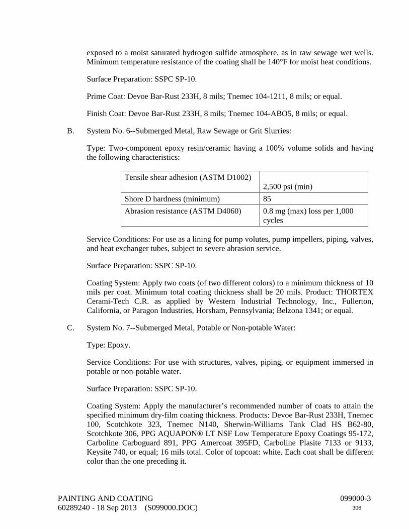
exposed to a moist saturated hydrogen sulfide atmosphere, as in raw sewage wet wells. Minimum temperature resistance of the coating shall be 140°F for moist heat conditions.
Surface Preparation: SSPC SP-10.
Prime Coat: Devoe Bar-Rust 233H, 8 mils; Tnemec 104-1211, 8 mils; or equal.
Finish Coat: Devoe Bar-Rust 233H, 8 mils; Tnemec 104-ABO5, 8 mils; or equal.
B. System No. 6--Submerged Metal, Raw Sewage or Grit Slurries:
Type: Two-component epoxy resin/ceramic having a 100% volume solids and having the following characteristics:
Tensile shear adhesion (ASTM D1002)
2,500 psi (min) Shore D hardness (minimum) 85 Abrasion resistance (ASTM D4060) 0.8 mg (max) loss per 1,000
cycles
Service Conditions: For use as a lining for pump volutes, pump impellers, piping, valves, and heat exchanger tubes, subject to severe abrasion service.
Surface Preparation: SSPC SP-10.
Coating System: Apply two coats (of two different colors) to a minimum thickness of 10 mils per coat. Minimum total coating thickness shall be 20 mils. Product: THORTEX Cerami-Tech C.R. as applied by Western Industrial Technology, Inc., Fullerton, California, or Paragon Industries, Horsham, Pennsylvania; Belzona 1341; or equal.
C. System No. 7--Submerged Metal, Potable or Non-potable Water:
Type: Epoxy.
Service Conditions: For use with structures, valves, piping, or equipment immersed in potable or non-potable water.
Surface Preparation: SSPC SP-10.
Coating System: Apply the manufacturer’s recommended number of coats to attain the specified minimum dry-film coating thickness. Products: Devoe Bar-Rust 233H, Tnemec 100, Scotchkote 323, Tnemec N140, Sherwin-Williams Tank Clad HS B62-80, Scotchkote 306, PPG AQUAPON® LT NSF Low Temperature Epoxy Coatings 95-172, Carboline Carboguard 891, PPG Amercoat 395FD, Carboline Plasite 7133 or 9133, Keysite 740, or equal; 16 mils total. Color of topcoat: white. Each coat shall be different color than the one preceding it.
PAINTING AND COATING 099000-3 60289240 - 18 Sep 2013 (S099000.DOC) 306

2.03 EXPOSED METAL COATING SYSTEMS
A. System No. 10--Exposed Metal, Corrosive Environment:
Type: High-build epoxy intermediate coat having a minimum volume solids of 60%, with an inorganic zinc prime coat and a pigmented polyurethane finish coat having a minimum volume solids of 52%.
Service Conditions: For use with metal structures or pipes subjected to water condensation; chemical fumes, such as hydrogen sulfide; salt spray; and chemical contact.
Surface Preparation: SSPC SP-10.
Prime Coat: Self-curing, two-component inorganic zinc-rich coating recommended by the manufacturer for over-coating with a high-build epoxy finish coat. Minimum zinc content shall be 12 pounds per gallon. Apply to a thickness of 3 mils. Products: Tnemec 90E-92, Devoe Catha-Coat 304 or 304V, International Interzinc 22HS, PPG Dimetcote 9HS, Carboline Carbozinc 11 or 11HS, Sherwin-Williams Zinc-Clad II Plus, PPG METALHIDE® 28 Inorganic Zinc-Rich Primer 97-672, or equal.
Intermediate Coat: Tnemec 104, Devoe Devran 224HS or 231, International Interseal 670HS, PPG Amercoat 385, Carboline Carboguard 890, Sherwin-Williams Macropoxy 646 B58-600, PPG PITT-GUARD® Direct-to-Rust Epoxy Mastic Coating 97-145 series, or equal; 5 mils.
Finish Coat: Two-component pigmented acrylic or aliphatic polyurethane recommended by the manufacturer for overcoating a high-build epoxy coating. Apply to a thickness of at least 2 mils. Products: Tnemec Series 1075, Devoe Devthane 379, International Interline 990HS, PPG Amercoat 450HS, Carboline 133HB or 134HG, Sherwin-Williams Hi-Solids Polyurethane B65-300, PPG PITTHANE® Ultra Gloss Urethane Enamel 95-812 series, or equal.
2.04 BURIED METAL COATING SYSTEMS
A. System No. 21--Buried Metal:
Type: High solids epoxy or phenolic epoxy having a minimum volume solids of 80% (ASTM D2697).
Service Conditions: Buried metal, such as valves, flanges, bolts, nuts, structural steel, and fittings.
Surface Preparation: SSPC SP-10.
Coating System: Apply three or more coats of PPG Amerlock 400 or 400VOC, Tnemec 104HS or 80, Devoe Bar-Rust 233H, Carboline 890LT, Sherwin-Williams Tank Clad
PAINTING AND COATING 099000-4 60289240 - 18 Sep 2013 (S099000.DOC) 307

HS B62-80 series, or equal; 30 mils total. Maximum thickness of an individual coating shall not exceed the manufacturer’s recommendation.
System No. 22 may be substituted for System No. 21.
B. System No. 22--Buried Metal:
Type: Two-component polyurethane having the following characteristics:
1. Coatings shall contain no tar or hydrocarbon additives or solvent.
2. Hardness (ASTM D2240, Shore “D”): 65 to 85.
3. Abrasion Resistance (ASTM D4060, Taber CS-17): 20 mg (maximum) loss per 1,000 cycles or a maximum loss of 65 mg per ASTM C501.
Service Conditions: Buried metal, such as valves, flanges, bolts, nuts, structural steel, and fittings.
Surface Preparation: SSPC SP-10.
Coating System: Madison Chemical Industries, Inc. Corrocote II TX or Futura Coatings, Inc., Futura-Thane 527, Corrocote Plus (CM) or equal. Apply to a total thickness of 50 mils.
2.05 PVC COATING SYSTEM
A. System No. 41—PVC Ultraviolet Exposure or Color Coding:
Type: Epoxy primer with a minimum volume solids of 54% and a pigmented polyurethane enamel having a minimum volume solids of 52%.
Service Conditions: Color coding of PVC exposed to sunlight.
Surface Preparation: SSPC SP-1. Then lightly abrade the surface with medium-grain sandpaper.
Prime Coat: One coat of Tnemec Series N69 Epoxoline, International 7510, PPG Amercoat 385, Devoe Devran 224HS, Sherwin-Williams Macropoxy 646 B58 series, Carboline 888 or 890, PPG PITT-GUARD® Direct-to-Rust Epoxy Mastic Coating 97-145 series, or equal. Apply to a minimum dry-film thickness of 4 mils.
Finish Coat: One coat of Tnemec Series 1075, International Interthane 990HS, PPG Amercoat 450HS, Devoe Devran 379, Carboline 133HB or 134HG, Sherwin-Williams Hi-Solids Polyurethane B65-300 series, PPG PITTHANE® Ultra Gloss Urethane Enamel 95-812 series, or equal. Apply to a minimum dry-film thickness of 3 mils.
PAINTING AND COATING 099000-5 60289240 - 18 Sep 2013 (S099000.DOC) 308

2.06 ABRASIVES FOR SURFACE PREPARATION
A. Abrasives used for preparation of ferrous (excluding stainless steel) surfaces shall be one of the following:
1. 16 to 30 or 16 to 40 mesh silica sand or mineral grit.
2. 20 to 40 mesh garnet.
3. Crushed iron slag, 100% retained on No. 80 mesh.
4. SAE Grade G-40 or G-50 iron or steel grit.
B. In the above gradations, 100% of the material shall pass through the first stated sieve size and 100% shall be retained on the second stated sieve size.
2.07 ORGANIC ZINC PRIMER FOR FIELD TOUCH-UP AND SHOP COATING
Where shop-applied inorganic zinc primers cannot be used because of volatile organic compound (VOC) regulations, the organic zinc primer described in System No. 18 may be substituted for the specified inorganic zinc primers.
PART 3 - EXECUTION
3.01 WEATHER CONDITIONS
A. Do not paint in the rain, wind, snow, mist, and fog or when steel or metal surface temperatures are less than 5°F above the dew point.
B. Do not apply paint when the relative humidity is above 85%.
C. Do not paint when temperature of metal to be painted is above 120°F.
D. Do not apply alkyd, inorganic zinc, silicone aluminum, or silicone acrylic paints if air or surface temperature is below 40°F or expected to be below 40°F within 24 hours.
E. Do not apply epoxy, acrylic latex, and polyurethane paints on an exterior or interior surface if air or surface temperature is below 60°F or expected to drop below 60°F in 24 hours.
3.02 SURFACE PREPARATION PROCEDURES
A. Remove oil and grease from metal surfaces in accordance with SSPC SP-1. Use clean cloths and cleaning solvents and wipe dry with clean cloths. Do not leave a film or greasy residue on the cleaned surfaces before abrasive blasting.
B. Remove weld spatter and weld slag from metal surfaces and grind smoothly rough welds, beads, peaked corners, and sharp edges including erection lugs in accordance
PAINTING AND COATING 099000-6 60289240 - 18 Sep 2013 (S099000.DOC) 309

with SSPC SP-2 and SSPC SP-3. Grind 0.020 inch (minimum) off the weld caps on pipe weld seams. Grind outside sharp corners, such as the outside edges of flanges, to a minimum radius of 1/4 inch.
C. Do not abrasive blast or prepare more surface area in one day than can be coated in one day; prepare surfaces and apply coatings the same day. Remove sharp edges, burrs, and weld spatter.
D. Do not abrasive blast PVC piping or equipment. Do not abrasive blast epoxy- or enamel-coated pipe that has already been factory coated, except to repair scratched or damaged coatings.
E. For carbon steel, do not touch the surface between the time of abrasive blasting and the time the coating is applied. Apply coatings within two hours of blasting or before any rust bloom forms.
F. Surface preparation shall conform with the SSPC specifications as follows:
Solvent Cleaning SP-1 Hand Tool Cleaning SP-2 Power Tool Cleaning SP-3 White Metal Blast Cleaning SP-5 Commercial Blast Cleaning SP-6 Brush-Off Blast Cleaning SP-7 Pickling SP-8 Near-White Blast Cleaning SP-10 Power Tool Cleaning to Bare Metal SP-11 Surface Preparation and Cleaning of Steel and Other Hard Materials by High- and Ultrahigh-Pressure Water Jetting Prior to Recoating
SP-12
Surface Preparation of Concrete SP-13
G. Wherever the words “solvent cleaning,” “hand tool cleaning,” “wire brushing,” or “blast cleaning” or similar words are used in these specifications or in paint manufacturer’s specifications, they shall be understood to refer to the applicable SSPC (Society for Protective Coatings), surface preparation specifications listed above.
H. Dust blasting is defined as cleaning the surface through the use of very fine abrasives, such as siliceous or mineral abrasives, 80 to 100 mesh. Apply a fine etch to the metal surface to clean the surface of any contamination or oxide and to provide a surface profile for the coating.
I. Brush-off blasting of concrete and masonry surfaces is defined as opening subsurface holes and voids and etching the surface for a coating to bond.
PAINTING AND COATING 099000-7 60289240 - 18 Sep 2013 (S099000.DOC) 310
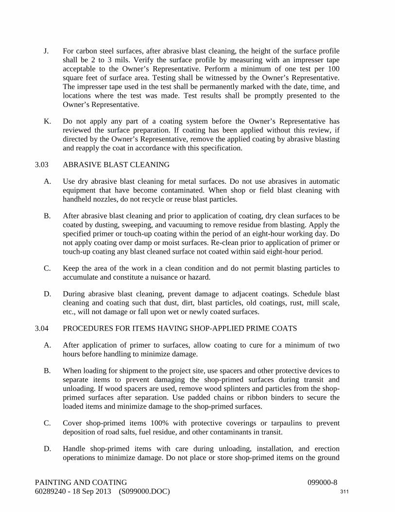
J. For carbon steel surfaces, after abrasive blast cleaning, the height of the surface profile shall be 2 to 3 mils. Verify the surface profile by measuring with an impresser tape acceptable to the Owner’s Representative. Perform a minimum of one test per 100 square feet of surface area. Testing shall be witnessed by the Owner’s Representative. The impresser tape used in the test shall be permanently marked with the date, time, and locations where the test was made. Test results shall be promptly presented to the Owner’s Representative.
K. Do not apply any part of a coating system before the Owner’s Representative has reviewed the surface preparation. If coating has been applied without this review, if directed by the Owner’s Representative, remove the applied coating by abrasive blasting and reapply the coat in accordance with this specification.
3.03 ABRASIVE BLAST CLEANING
A. Use dry abrasive blast cleaning for metal surfaces. Do not use abrasives in automatic equipment that have become contaminated. When shop or field blast cleaning with handheld nozzles, do not recycle or reuse blast particles.
B. After abrasive blast cleaning and prior to application of coating, dry clean surfaces to be coated by dusting, sweeping, and vacuuming to remove residue from blasting. Apply the specified primer or touch-up coating within the period of an eight-hour working day. Do not apply coating over damp or moist surfaces. Re-clean prior to application of primer or touch-up coating any blast cleaned surface not coated within said eight-hour period.
C. Keep the area of the work in a clean condition and do not permit blasting particles to accumulate and constitute a nuisance or hazard.
D. During abrasive blast cleaning, prevent damage to adjacent coatings. Schedule blast cleaning and coating such that dust, dirt, blast particles, old coatings, rust, mill scale, etc., will not damage or fall upon wet or newly coated surfaces.
3.04 PROCEDURES FOR ITEMS HAVING SHOP-APPLIED PRIME COATS
A. After application of primer to surfaces, allow coating to cure for a minimum of two hours before handling to minimize damage.
B. When loading for shipment to the project site, use spacers and other protective devices to separate items to prevent damaging the shop-primed surfaces during transit and unloading. If wood spacers are used, remove wood splinters and particles from the shop-primed surfaces after separation. Use padded chains or ribbon binders to secure the loaded items and minimize damage to the shop-primed surfaces.
C. Cover shop-primed items 100% with protective coverings or tarpaulins to prevent deposition of road salts, fuel residue, and other contaminants in transit.
D. Handle shop-primed items with care during unloading, installation, and erection operations to minimize damage. Do not place or store shop-primed items on the ground
PAINTING AND COATING 099000-8 60289240 - 18 Sep 2013 (S099000.DOC) 311

or on top of other work unless ground or work is covered with a protective covering or tarpaulin. Place shop-primed items above the ground upon platforms, skids, or other supports.
3.05 FIELD TOUCH-UP OF SHOP-APPLIED PRIME COATS
A. Remove oil and grease surface contaminants on metal surfaces in accordance with SSPC SP-1. Use clean rags wetted with a degreasing solution, rinse with clean water, and wipe dry.
B. Remove dust, dirt, salts, moisture, chalking primers, or other surface contaminants that will affect the adhesion or durability of the coating system. Use a high-pressure water blaster or scrub surfaces with a broom or brush wetted with a solution of trisodium phosphate, detergent, and water. Before applying intermediate or finish coats to inorganic zinc primers, remove any soluble zinc salts that have formed by means of scrubbing with a stiff bristle brush. Rinse scrubbed surfaces with clean water.
C. Remove loose or peeling primer and other surface contaminants not easily removed by the previous cleaning methods in accordance with SSPC SP-7. Take care that remaining primers are not damaged by the blast cleaning operation. Remaining primers shall be firmly bonded to the steel surfaces with blast cleaned edges feathered.
D. Remove rust, scaling, or primer damaged by welding or during shipment, storage, and erection in accordance with SSPC SP-10. Take care that remaining primers are not damaged by the blast cleaning operation. Areas smaller than 1 square inch may be prepared per SSPC SP-11. Remaining primers shall be firmly bonded to the steel surfaces with cleaned edges feathered.
E. Use repair procedures on damaged primer that protects adjacent primer. Blast cleaning may require the use of lower air pressure, smaller nozzles, and abrasive particle sizes, short blast nozzle distance from surface, shielding, and/or masking.
F. After abrasive blast cleaning of damaged and defective areas, remove dust, blast particles, and other debris by dusting, sweeping, and vacuuming; then apply the specified touch-up coating.
G. Surfaces that are shop primed with inorganic zinc primers shall receive a field touch-up of organic zinc primer cover scratches or abraded areas.
H. Other surfaces that are shop primed shall receive a field touch-up of the same primer used in the original prime coat.
3.06 PAINTING SYSTEMS
A. All materials of a specified painting system, including primer, intermediate, and finish coats, shall be produced by the same manufacturer. Thinners, cleaners, driers, and other additives shall be as recommended by the paint manufacturer for the particular coating system.
PAINTING AND COATING 099000-9 60289240 - 18 Sep 2013 (S099000.DOC) 312

B. Deliver paints to the jobsite in the original, unopened containers.
3.07 PAINT STORAGE AND MIXING
A. Store and mix materials only in areas designated for that purpose by the Owner’s Representative. The area shall be well-ventilated, with precautionary measures taken to prevent fire hazards. Post “No Smoking” signs. Storage and mixing areas shall be clean and free of rags, waste, and scrapings. Tightly close containers after each use. Store paint at an ambient temperature from 50°F to 100°F.
B. Prepare multiple-component coatings using all of the contents of the container for each component as packaged by the paint manufacturer. Do not use partial batches. Do not use multiple-component coatings that have been mixed beyond their pot life. Provide small quantity kits for touch-up painting and for painting other small areas. Mix only the components specified and furnished by the paint manufacturer. Do not intermix additional components for reasons of color or otherwise, even within the same generic type of coating.
3.08 PROCEDURES FOR THE APPLICATION OF COATINGS
A. Conform to the requirements of SSPC PA-1. Follow the recommendations of the coating manufacturer including the selection of spray equipment, brushes, rollers, cleaners, thinners, mixing, drying time, temperature and humidity of application, and safety precautions.
B. Stir, strain, and keep coating materials at a uniform consistency during application. Power mix components. For multiple component materials, premix each component before combining. Apply each coating evenly, free of brush marks, sags, runs, and other evidence of poor workmanship. Use a different shade or tint on succeeding coating applications to indicate coverage where possible. Finished surfaces shall be free from defects or blemishes.
C. Do not use thinners unless recommended by the coating manufacturer. If thinning is allowed, do not exceed the maximum allowable amount of thinner per gallon of coating material. Stir coating materials at all times when adding thinner. Do not flood the coating material surface with thinner prior to mixing. Do not reduce coating materials more than is absolutely necessary to obtain the proper application characteristics and to obtain the specified dry-film thicknesses.
D. Remove dust, blast particles, and other debris from blast cleaned surfaces by dusting, sweeping, and vacuuming. Allow ventilator fans to clean airborne dust to provide good visibility of working area prior to coating applications. Remove dust from coated surfaces by dusting, sweeping, and vacuuming prior to applying succeeding coats.
E. Apply coating systems to the specified minimum dry-film thicknesses as determined per SSPC PA-2.
PAINTING AND COATING 099000-10 60289240 - 18 Sep 2013 (S099000.DOC) 313
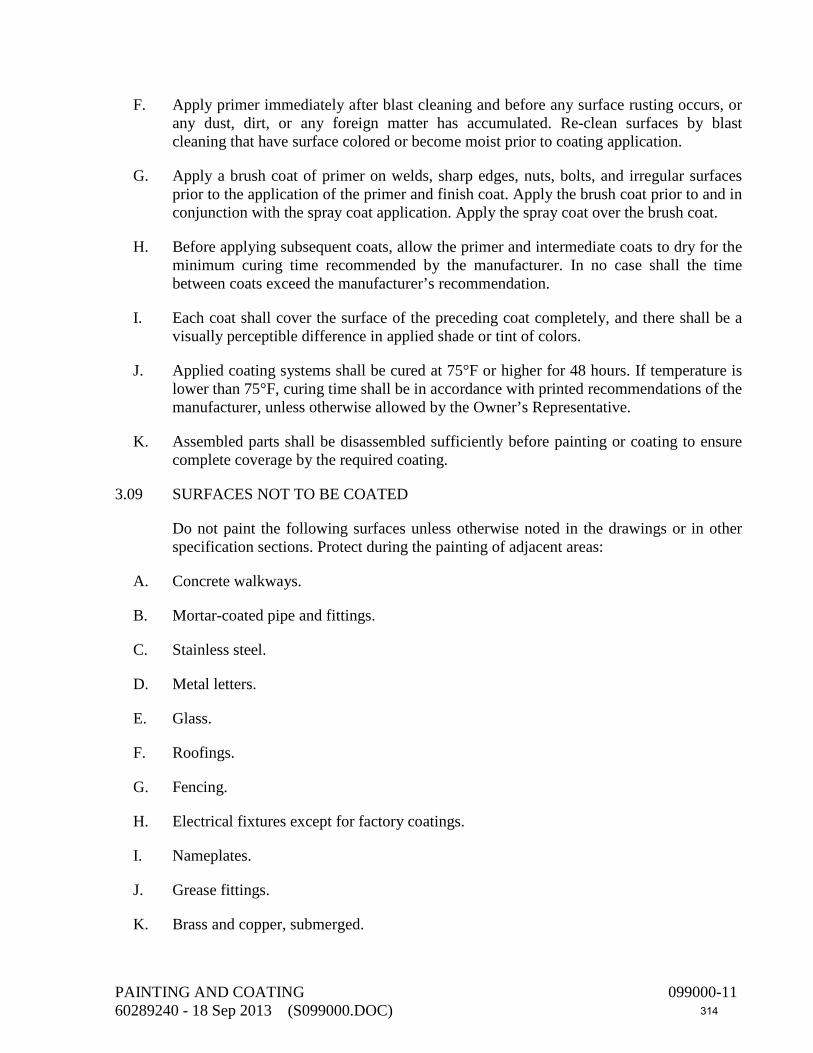
F. Apply primer immediately after blast cleaning and before any surface rusting occurs, or any dust, dirt, or any foreign matter has accumulated. Re-clean surfaces by blast cleaning that have surface colored or become moist prior to coating application.
G. Apply a brush coat of primer on welds, sharp edges, nuts, bolts, and irregular surfaces prior to the application of the primer and finish coat. Apply the brush coat prior to and in conjunction with the spray coat application. Apply the spray coat over the brush coat.
H. Before applying subsequent coats, allow the primer and intermediate coats to dry for the minimum curing time recommended by the manufacturer. In no case shall the time between coats exceed the manufacturer’s recommendation.
I. Each coat shall cover the surface of the preceding coat completely, and there shall be a visually perceptible difference in applied shade or tint of colors.
J. Applied coating systems shall be cured at 75°F or higher for 48 hours. If temperature is lower than 75°F, curing time shall be in accordance with printed recommendations of the manufacturer, unless otherwise allowed by the Owner’s Representative.
K. Assembled parts shall be disassembled sufficiently before painting or coating to ensure complete coverage by the required coating.
3.09 SURFACES NOT TO BE COATED
Do not paint the following surfaces unless otherwise noted in the drawings or in other specification sections. Protect during the painting of adjacent areas:
A. Concrete walkways.
B. Mortar-coated pipe and fittings.
C. Stainless steel.
D. Metal letters.
E. Glass.
F. Roofings.
G. Fencing.
H. Electrical fixtures except for factory coatings.
I. Nameplates.
J. Grease fittings.
K. Brass and copper, submerged.
PAINTING AND COATING 099000-11 60289240 - 18 Sep 2013 (S099000.DOC) 314
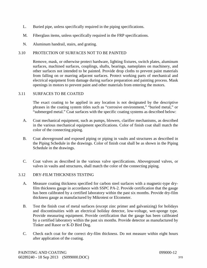
L. Buried pipe, unless specifically required in the piping specifications.
M. Fiberglass items, unless specifically required in the FRP specifications.
N. Aluminum handrail, stairs, and grating.
3.10 PROTECTION OF SURFACES NOT TO BE PAINTED
Remove, mask, or otherwise protect hardware, lighting fixtures, switch plates, aluminum surfaces, machined surfaces, couplings, shafts, bearings, nameplates on machinery, and other surfaces not intended to be painted. Provide drop cloths to prevent paint materials from falling on or marring adjacent surfaces. Protect working parts of mechanical and electrical equipment from damage during surface preparation and painting process. Mask openings in motors to prevent paint and other materials from entering the motors.
3.11 SURFACES TO BE COATED
The exact coating to be applied in any location is not designated by the descriptive phrases in the coating system titles such as “corrosive environment,” “buried metal,” or “submerged metal.” Coat surfaces with the specific coating systems as described below:
A. Coat mechanical equipment, such as pumps, blowers, clarifier mechanisms, as described in the various mechanical equipment specifications. Color of finish coat shall match the color of the connecting piping.
B. Coat aboveground and exposed piping or piping in vaults and structures as described in the Piping Schedule in the drawings. Color of finish coat shall be as shown in the Piping Schedule in the drawings.
C. Coat valves as described in the various valve specifications. Aboveground valves, or valves in vaults and structures, shall match the color of the connecting piping.
3.12 DRY-FILM THICKNESS TESTING
A. Measure coating thickness specified for carbon steel surfaces with a magnetic-type dry-film thickness gauge in accordance with SSPC PA-2. Provide certification that the gauge has been calibrated by a certified laboratory within the past six months. Provide dry-film thickness gauge as manufactured by Mikrotest or Elcometer.
B. Test the finish coat of metal surfaces (except zinc primer and galvanizing) for holidays and discontinuities with an electrical holiday detector, low-voltage, wet-sponge type. Provide measuring equipment. Provide certification that the gauge has been calibrated by a certified laboratory within the past six months. Provide detector as manufactured by Tinker and Rasor or K-D Bird Dog.
C. Check each coat for the correct dry-film thickness. Do not measure within eight hours after application of the coating.
PAINTING AND COATING 099000-12 60289240 - 18 Sep 2013 (S099000.DOC) 315
D. For metal surfaces, make five separate spot measurements (average of three readings) spaced evenly over each 100 square feet of area (or fraction thereof) to be measured. Make three readings for each spot measurement of either the substrate or the paint. Move the probe or detector a distance of 1 to 3 inches for each new gauge reading. Discard any unusually high or low reading that cannot be repeated consistently. Take the average (mean) of the three readings as the spot measurement. The average of five spot measurements for each such 100-square-foot area shall not be less than the specified thickness. No single spot measurement in any 100-square-foot area shall be less than 80%, nor more than 120%, of the specified thickness. One of three readings which are averaged to produce each spot measurement may underrun by a greater amount as defined by SSPC PA-2.
E. Perform tests in the presence of the Owner’s Representative.
3.13 REPAIR OF IMPROPERLY COATED SURFACES
If the item has an improper finish color or insufficient film thickness, clean and topcoat the surface with the specified paint material to obtain the specified color and coverage. Sandblast or power-sand visible areas of chipped, peeled, or abraded paint, feathering the edges. Then prime and finish coat in accordance with the specifications. Work shall be free of runs, bridges, shiners, laps, or other imperfections.
3.14 CLEANING
A. During the progress of the work, remove discarded materials, rubbish, cans, and rags at the end of each day’s work.
B. Thoroughly clean brushes and other application equipment at the end of each period of use and when changing to another paint or color.
C. Upon completion of painting work, remove masking tape, tarps, and other protective materials, using care not to damage finished surfaces.
END OF SECTION
PAINTING AND COATING 099000-13 60289240 - 18 Sep 2013 (S099000.DOC) 316

This page intentionally left blank
317
SECTION 099761 FUSION-BONDED EPOXY LININGS AND COATINGS
PART 1 - GENERAL
1.01 DESCRIPTION
This section includes materials, application, and testing of one-part, fusion-bonded, heat-cured, thermosetting, 100% solids epoxy linings and coatings on steel, cast-iron, and ductile-iron equipment, such as valves, flexible pipe couplings, slide gates, and structural steel, and steel pipe.
1.02 SUBMITTALS
A. Submit shop drawings in accordance with the General Conditions, Section 013300, and the following.
B. Submit manufacturer's catalog literature and product data sheets, describing the physical and chemical properties of the epoxy coating. Describe application and curing procedure.
C. Submit coating application test records for measuring coating thickness and holiday detection for each item or pipe section and fitting. Describe repair procedures used.
PART 2 - MATERIALS
2.01 PIPING AND EQUIPMENT SURFACES
A. The Contractor shall require the equipment suppliers to provide equipment that is free of salts, oil, and grease to the coating applicator.
B. The Contractor shall require pipe suppliers to provide bare pipe that is free of salts, oil, and grease to the coating applicator.
2.02 SHOP-APPLIED EPOXY LINING AND COATING
Lining and coating shall be a 100% solids, thermosetting, fusion-bonded, dry powder epoxy resin: Scotchkote 134 or 206N, Valspar "Pipeclad 1500 Red," or equal. Epoxy lining and coating shall meet or exceed the following requirements:
FUSION-BONDED EPOXY LININGS AND COATINGS 099761-1 60289240 - 6 Sep 2013 (S099761.DOC) 318

Hardness (minimum) Barcol 17 (ASTM D2583)
Rockwell 50 ("M" scale) Abrasion resistance (maximum value)
1,000 cycles: 0.05 gram removed 5,000 cycles: 0.115 gram removed ASTM D1044, Tabor CS 17 wheel, 1,000-gram weight
Adhesion (minimum) 3,000 psi (Elcometer) Tensile strength 7,300 psi (ASTM D2370) Penetration 0 mil (ASTM G17) Adhesion overlap shear, 1/8-inch steel panel, 0.010 glue line
4,300 psi, ASTM D1002
Impact (minimum value) 100 inch-pounds (Gardner 5/8-inch diameter tup)
2.03 FIELD-APPLIED EPOXY COATING FOR PATCHING
Use a minimum 80% solids liquid epoxy resin, such as Scotchkote 306 or 323.
2.04 PAINTING AND COATING OF GROOVED-END AND FLEXIBLE PIPE COUPLINGS
Line and coat couplings the same as the pipe. Color shall match the color of the pipe fusion epoxy coating.
PART 3 - EXECUTION
3.01 SHOP APPLICATION OF FUSION-BONDED EPOXY LINING AND COATING--GENERAL
A. Grind surface irregularities, welds, and weld spatter smooth before applying the epoxy. The allowable grind area shall not exceed 0.25 square foot per location, and the maximum total grind area shall not exceed 1 square foot per item or piece of equipment. Do not use any item, pipe, or piece of equipment in which these requirements cannot be met.
B. Remove surface imperfections, such as slivers, scales, burrs, weld spatter, and gouges. Grind outside sharp corners, such as the outside edges of flanges, to a minimum radius of 1/4 inch.
C. Uniformly preheat the pipe, item, or piece of equipment prior to blast cleaning to remove moisture from the surface. The preheat shall be sufficient to ensure that the surface temperature is at least 5°F above the dew point temperature during blast cleaning and inspection.
FUSION-BONDED EPOXY LININGS AND COATINGS 099761-2 60289240 - 6 Sep 2013 (S099761.DOC) 319
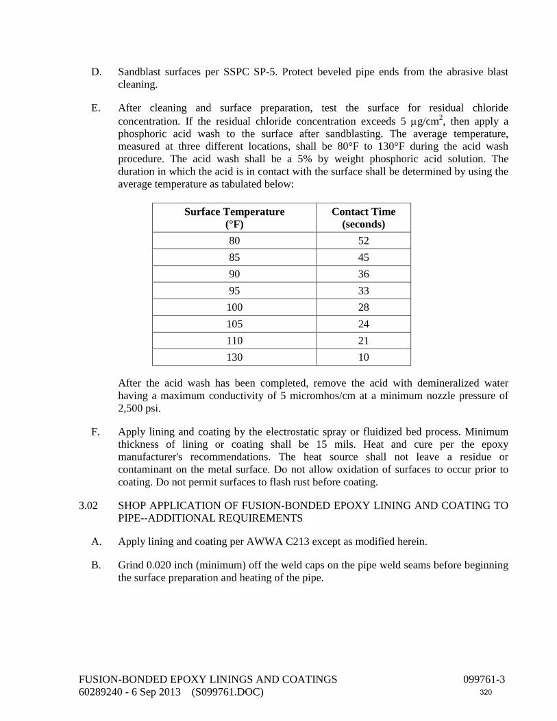
D. Sandblast surfaces per SSPC SP-5. Protect beveled pipe ends from the abrasive blast
cleaning.
E. After cleaning and surface preparation, test the surface for residual chloride concentration. If the residual chloride concentration exceeds 5 µg/cm2, then apply a phosphoric acid wash to the surface after sandblasting. The average temperature, measured at three different locations, shall be 80°F to 130°F during the acid wash procedure. The acid wash shall be a 5% by weight phosphoric acid solution. The duration in which the acid is in contact with the surface shall be determined by using the average temperature as tabulated below:
Surface Temperature
(°F) Contact Time
(seconds) 80 52 85 45 90 36 95 33 100 28 105 24 110 21 130 10
After the acid wash has been completed, remove the acid with demineralized water having a maximum conductivity of 5 micromhos/cm at a minimum nozzle pressure of 2,500 psi.
F. Apply lining and coating by the electrostatic spray or fluidized bed process. Minimum thickness of lining or coating shall be 15 mils. Heat and cure per the epoxy manufacturer's recommendations. The heat source shall not leave a residue or contaminant on the metal surface. Do not allow oxidation of surfaces to occur prior to coating. Do not permit surfaces to flash rust before coating.
3.02 SHOP APPLICATION OF FUSION-BONDED EPOXY LINING AND COATING TO PIPE--ADDITIONAL REQUIREMENTS
A. Apply lining and coating per AWWA C213 except as modified herein.
B. Grind 0.020 inch (minimum) off the weld caps on the pipe weld seams before beginning the surface preparation and heating of the pipe.
FUSION-BONDED EPOXY LININGS AND COATINGS 099761-3 60289240 - 6 Sep 2013 (S099761.DOC) 320

3.03 SHOP APPLICATION OF FUSION-BONDED EPOXY LINING AND COATING TO
JOINT AREAS OF DUCTILE-IRON AND CAST-IRON FITTINGS--ADDITIONAL REQUIREMENTS
Limit the protective coating thickness in the joints of ductile-iron and cast-iron fittings to maintain a leak-proof joint. However, the coating thickness in the joint area shall not be less than 4 mils.
3.04 QUALITY OF LINING AND COATING APPLICATIONS
The cured lining or coating shall be smooth and glossy, with no graininess or roughness. The lining or coating shall have no blisters, cracks, bubbles, underfilm voids, mechanical damage, discontinuities, or holidays.
3.05 FACTORY TESTING OF COATING--GENERAL
A. Test linings and coatings with a low-voltage wet sponge holiday detector. Test pipe linings and coatings per AWWA C213, Section 5.3.3. If the number of holidays or pinholes is fewer than one per 20 square feet of coating surface, repair the holidays and pinholes by applying the coating manufacturer's recommended patching compound to each holiday or pinhole and retest. If the number of pinholes and holidays exceeds one per 20 square feet of coating surface, remove the entire lining or coating and recoat the item or pipe.
B. Measure the coating thickness at three locations on each item or piece of equipment or pipe section using a coating thickness gauge calibrated at least once per eight-hour shift. Record each measured thickness value. Where individual measured thickness values are less than the specified minimum thickness, measure the coating thickness at three additional points around the defective area. The average of these measurements shall exceed the specified minimum thickness value, and no individual thickness value shall be more than 2 mils below or 3 mils above the specified minimum value. If a section of the pipe, item, or piece of equipment does not meet these criteria, remove the entire lining or coating and recoat the entire item or piece of equipment.
3.06 FACTORY INSPECTION OF LINING AND COATING OF PIPE--ADDITIONAL REQUIREMENTS
Check for coating defects on the weld seam centerlines. There shall be no porous blisters, craters, or pimples lying along the peak of the weld crown.
3.07 SHIPPING, STORAGE, AND HANDLING
A. When loading piping, fittings, couplings, or other coated items for shipment to the project site, use spacers and other protective devices to separate pipes or other coated items to prevent damaging the coated surfaces during transit and unloading. If wood spacers are used, remove wood splinters and particles from the coated surfaces after separation. Use padded chains or ribbon binders to secure the loaded pipe or other coated items and minimize damage.
FUSION-BONDED EPOXY LININGS AND COATINGS 099761-4 60289240 - 6 Sep 2013 (S099761.DOC) 321

B. Do not load or unload pipe, fittings, couplings, or other coated items by inserting forklift
tines or lifting chains inside the pipe or item. Use nonmetallic slings, padded chains, or padded forklift tines to lift pipe or other coated items.
C. Cover piping or other coated items 100% with protective coverings or tarpaulins to prevent deposition of road salts, fuel residue, and other contaminants in transit.
D. Provide stulls, braces, and supports for piping during shipping and storage such that out-of-roundness or deflection does not exceed 0.5% of the pipe diameter.
E. Handle piping and other coated items with care during the unloading, installation, and erection operations to minimize damage. Do not place or store pipe or other coated items on the ground or on top of other work unless ground or work is covered with a protective covering or tarpaulin. Place pipe or other coated items above the ground upon platforms, skids, or other supports.
F. Store piping or other coated items at the site on pallets to prevent direct contact with ground or floor. Cover pipe or coated items during storage with protective coverings or tarpaulins to prevent deposition of rainwater, salt air, dirt, dust, and other contaminants.
G. Do not allow piping or other coated items to contact metal, concrete, or other surfaces during storage, handling, or installation and erection at the site that could damage or scratch the coating.
3.08 FIELD REPAIRS
Patch scratches and damaged areas incurred while installing fusion-bonded epoxy coated items with a two-component, 80% solids (minimum), liquid epoxy resin. Wire brush or sandblast the damaged areas per SSPC SP-10. Lightly abrade or sandblast the coating or lining on the sides of the damaged area before applying the liquid epoxy coating. Apply an epoxy coating to defective linings and coatings to areas smaller than 20 square inches. Patched areas shall overlap the parent or base coating a minimum of 0.5 inch. If a defective area exceeds 20 square inches, remove the entire lining and coating and recoat the entire item or piece of equipment. Apply the liquid epoxy coating to a minimum dry-film thickness of 15 mils.
END OF SECTION
FUSION-BONDED EPOXY LININGS AND COATINGS 099761-5 60289240 - 6 Sep 2013 (S099761.DOC) 322

This page intentionally left blank
323

DIVISION 26 – ELECTRICAL 260500 General Electric Requirements 260519 Wires and Cables Less than 600 Volts 260526 Grounding and Bonding 260534 Conduits, Boxes, and Fittings 260573 Protective Device Coordination Study and Arc-Flash Hazard Analysis 260590 Miscellaneous Electrical Devices 262419 Low-Voltage Motor Control 262650 Electric Motors 262923 Variable Frequency Drive (VFD) 264313 Surge Protective Devices (SPD)
324

This page intentionally left blank
325
SECTION 260500 GENERAL ELECTRICAL REQUIREMENTS
PART 1 - GENERAL
1.01 DESCRIPTION
This section includes materials, installation, and testing of the electrical system.
1.02 SUBMITTALS
A. Submit shop drawings in accordance with the General Conditions and Section 013300.
B. In submitted catalog cuts, cross out items shown that are not pertinent to this project. Where catalog cuts list manufacturer’s standard options, cross out those options not intended to be provided and clearly highlight those options that are to be provided.
C. Submit electrical service changes work procedure.
1.03 REGULATORY AGENCIES AND STANDARDS
A. See General Conditions.
B. Electrical work shall comply with the NEC and local city code where applicable.
1.04 QUALITY CONTROL
Materials, appliances, equipment, and devices shall conform to the applicable UL standards. The label of, or listing by, UL is required for all electrical equipment.
1.05 UTILITY COMPANY REQUIREMENTS AND FEES
A. There are no utility company interfaces, requirements, or fees.
1.06 ELECTRICAL SERVICE CHANGES
A. These specifications and drawings delineate the remodeling of an existing structure and/or the addition to an existing structure. While the existing structure is occupied, keep the present services intact until the new construction, facilities, or equipment is installed.
B. Prior to making revisions to the existing service, make certain that every item is thoroughly prepared. Do the actual work at an off-peak time, or overtime, as arranged with the Owner or as hereinafter specified. Once the work is started, vigorously prosecute it to completion to keep downtime to a minimum. Be prepared to temporarily serve the existing service or discontinue the necessary revisions in the event of an emergency or other condition which makes it impossible to finish the scheduled work on time.
GENERAL ELECTRICAL REQUIREMENTS 260500-1 60289240 - 6 Sep 2013 (S260500 GENERAL ELECTRICAL REQUIREMENTS.DOC) 326

C. Prepare a work procedure for work-interrupting service to the Owner's equipment. Include a step-by-step procedure that will be followed in the performance of this work and the time involved in each step. Submit this procedure to the Owner's Representative for review two weeks in advance of the performance of the work.
1.07 POWER FOR CONSTRUCTION
Provide for or purchase power for construction in accordance with Section 015100.
1.08 OPERATION AND MAINTENANCE MANUALS
Submit operation and maintenance manuals in accordance with Section 019310.
1.09 LOCATIONS
A. General: Use equipment, materials, and wiring methods suitable for the types of locations in which they are located as defined below.
B. Definitions of Types of Locations:
1. Dry Locations: Indoor areas which do not fall within the definitions below for wet, damp, hazardous, or corrosive locations and which are not otherwise designated in the drawings.
2. Wet Locations: Locations exposed to the weather, whether under a roof or not, unless otherwise designated in the drawings.
3. Damp Locations: Spaces wholly or partially underground or having a wall or ceiling forming part of a channel or tank, unless otherwise designated in the drawings.
4. Hazardous Locations: Areas identified in drawings.
5. Corrosive Locations: Areas identified in drawings.
PART 2 - MATERIALS
2.01 GENERAL
A. Similar materials and equipment shall be the product of a single manufacturer.
B. Provide only products which are new, undamaged, and in the original cartons or containers.
C. Materials and equipment shall be the standard products of manufacturers regularly engaged in the production of such material and shall be the manufacturer's current design.
GENERAL ELECTRICAL REQUIREMENTS 260500-2 60289240 - 6 Sep 2013 (S260500 GENERAL ELECTRICAL REQUIREMENTS.DOC) 327

D. Materials and equipment shall be suitable for storage, installation, and operation at an ambient temperature of 0°C to 40°C except where more stringent conditions are stated in individual equipment specifications.
E. Electrical equipment and panels shall be factory finished with manufacturer's standard primer and enamel topcoats, unless stated otherwise in the individual equipment specifications. Provide 1 pint of the equipment manufacturer's touchup paint per 500 square feet of painted surface for repair of damaged enamel topcoats.
PART 3 - EXECUTION
3.01 INSTALLATION
A. The drawings indicate connections for typical equipment only. If the equipment furnished is different from what is shown, provide the modifications necessary for a safe and properly operating installation in accordance with the equipment manufacturer's recommendations.
B. The drawings diagrammatically indicate the desired location and arrangement of outlets, conduit runs, equipment, and other items. Field determine exact location based on physical size and arrangement of equipment, finished elevations, and obstructions.
C. Work or equipment not indicated or specified which is necessary for the complete and proper operation of the electrical systems shall be accomplished without additional cost to the Owner.
D. Review demolition methods with Owner's Representative prior to cutting or removing existing architectural and/or structural items or equipment. Repair damage to match existing.
E. Accomplish work required to pierce any waterproofing after the part piercing the waterproofing has been set in place. Seal and make watertight the openings made for this purpose.
F. Install equipment and material piercing fire walls and fire-resistant or fire-stopped walls, partitions, ceilings, and floors in a manner so the rating remains equivalent.
G. Seal weathertight equipment or components exposed to the weather.
H. Protect equipment outlets and conduit openings with factory-made plugs or caps whenever work is not in progress at that point.
3.02 REMOVAL OR RELOCATION OF MATERIALS AND EQUIPMENT
A. Unless otherwise noted, remove existing electrical materials and equipment from areas indicated for demolition or where equipment is relocated. Remove materials no longer used, such as studs, straps, and conduits. Remove or cut off concealed or embedded
GENERAL ELECTRICAL REQUIREMENTS 260500-3 60289240 - 6 Sep 2013 (S260500 GENERAL ELECTRICAL REQUIREMENTS.DOC) 328

conduit, boxes, or other materials and equipment to a point at least 3/4 inch below the final finished surface. Remove existing unused wires.
B. Repair affected surfaces to conform to the type, quality, and finish of the surrounding surface.
C. Removal shall comply with Section 024100.
3.03 NAMEPLATES
A. Mark each individual panelboard, motor controller, variable frequency drive, disconnect switch, timer, relay, and contactor to identify each item with its respective service or function.
B. Provide a nameplate inside the door of each panelboard listing its designation, voltage, and feeder circuit number.
C. Provide a nameplate on each transformer listing its designation, voltage, feeder number, and load served.
D. Provide nameplates with engraved lettering not less than 1/4 inch high. Use black-on-white laminated plastic, attached with rivets or sheet metal screws. Do not use embossed plastic adhesive tape.
3.04 WARNING SIGNS
A. Install markings, identifications, warning, caution, or instruction signs where required by NEC, NFPA 70E, and NFPA 79 paragraph 4.5.1, where indicated, or where reasonably required to assure safe operation and maintenance of electrical systems and of the items to which they connect.
B. The design of safety signs and labels shall conform to ANSI Z535.4. Switchgear, panelboards, industrial control panels, motor control center, and VFD shall be field marked to warn qualified persons of potential electric arc hazards. The marking shall be located so as to be clearly visible to qualified persons before examination, adjustment, servicing, or maintenance of the equipment, in conformance with NEC 2005 Article 110.16.
C. Install engraved plastic-laminated instruction signs with approved legend where instructions or explanations are needed for system or equipment operation. Install butyrate signs with metal backing for outdoor items.
END OF SECTION
GENERAL ELECTRICAL REQUIREMENTS 260500-4 60289240 - 6 Sep 2013 (S260500 GENERAL ELECTRICAL REQUIREMENTS.DOC) 329
SECTION 260519 WIRES AND CABLES LESS THAN 600 VOLTS
PART 1 - GENERAL
1.01 DESCRIPTION
This section describes materials and installation of wires and cables rated 600 volts and below.
1.02 SUBMITTALS
A. Submit shop drawings in accordance with the General Conditions and Section 260500.
B. Submit material list for each conductor type. Indicate insulation material, conductor material, voltage rating, manufacturer, and other data pertinent to the specific cable, such as shielding, number of pairs, and applicable standards.
PART 2 - MATERIALS
2.01 LOW-VOLTAGE BUILDING WIRE
A. Conductor material shall be copper.
B. Low-voltage building wire for use at 600 volts or less shall be 600-volt insulated, Type XHHW or THWN, and rated for continuous operation at 75°C.
C. Use No. 12 AWG minimum conductor size for power and lighting circuits.
D. Use No. 14 AWG minimum conductor size for control circuits.
E. Conductors for lighting and receptacle circuits that are No. 10 AWG and smaller shall be solid. All other conductors shall be stranded.
2.02 TWISTED-SHIELDED CABLE
A. Single-pair cables shall be two No. 18 AWG and single triads shall be three No. 18 AWG stranded tinned-copper conductors individually insulated with fully color-coded PVC rated at 300 volts; insulated conductors twisted together and shielded with a spiral-wound metal foil tape overlapped for 100% shielding. Outer jacket shall be PVC.
B. Multiple-pair cables shall have number of pairs specified with each pair being two No. 18 AWG stranded tinned-copper conductors individually insulated with PVC rated at 300 volts. Conductor pairs shall have insulation pigmented black and white with white conductor numerically printed for group identification. Each pair and its No. 20 AWG stranded tinned-copper drain wire shall be twisted together and shielded with an aluminum-polyester tape overlapped for 100% shielding. Provide a cable shield of 2.35-
WIRES AND CABLES LESS THAN 600 VOLTS 260519-1 60289240 - 6 Sep 2013 (S260519 WIRES AND CABLES LESS THAN 600 VOLTS.DOC) 330

mil aluminum-polyester tape overlapped to provide 100% shielding and a No. 18 AWG copper drain wire. Provide a flame-retardant PVC jacket per UL 13, 105°C temperature rating.
2.03 GROUNDING CONDUCTORS--BARE COPPER
Refer to Section 260526 for bare copper grounding conductors.
2.04 CONDUCTOR TAGS
Provide adhesive-type markers. Brady, Thomas & Betts, or equal.
2.05 PLASTIC ADHESIVES
Plastic adhesives for color coding shall be 7-mil minimum thick, flame-retardant, weather-resistant tape, resisting abrasion, UL rays, moisture, alkalies, solvents, and acids. Adhesives shall meet the requirements of UL 510 and CSA C22.2.
PART 3 - EXECUTION
3.01 LOW-VOLTAGE BUILDING WIRE INSTALLATION
A. Install wiring and cable in conduit and terminate unless otherwise noted.
B. To reduce pulling tension in long runs, coat cables with pulling compound recommended by the cable manufacturer before being pulled into conduits.
C. Remove debris and moisture from the conduits, boxes, and cabinets prior to cable installation.
D. Group conductors No. 1/0 and smaller in panelboards, cabinets, pull boxes, motor control centers, and switchboard wireways; tie with plastic ties; and fan out to terminals. Lace conductors No. 2/0 and larger with marline.
3.02 IDENTIFICATION
A. Color Coding of Low-Voltage Building Wire: Provide color coding throughout the entire network of feeders and circuits as follows:
Phase 240/120 Volts 208/120 Volts 480/277 Volts
Phase A Black Black Brown Phase B Red Red Orange Phase C --- Blue Yellow Neutral White White Gray Ground Green Green Green
WIRES AND CABLES LESS THAN 600 VOLTS 260519-2 60289240 - 6 Sep 2013 (S260519 WIRES AND CABLES LESS THAN 600 VOLTS.DOC) 331

B. Phase conductors No. 10 AWG and smaller and neutral/ground conductors No. 6 and smaller shall have factory color coding with solid color insulation. Do not use onsite coloring of ends of conductors or apply colored plastic adhesives in lieu of factory color coding. Larger conductors may have onsite application of colored plastic adhesives at ends of conductors and at each splice.
C. Control wires shall have colored insulation. Separate color codes for each wire shall be provided in each conduit that has up to seven wires. Conduits with more than seven wires shall have at least seven types of colored insulation.
D. Tagging of Conductors: Tag control wires and instrument cables in panels, pull boxes, wireways, and at control device. Tag control wires and instrument cables with same wire numbers as on the shop drawing submittals. Tag power wires in pull boxes and wireways where there is more than one circuit. Tag power conductors with motor control center or panelboard number and circuit numbers.
3.03 LOW-VOLTAGE WIRE SPLICES
A. Solid Conductors: Use 3M "Scotchlok," Ideal "Super Nut," Buchanan B-Cap, or equal. Seal splices in underground handholes and pull boxes and in light poles with individual sealing packs of Scotchcast Brand 400 Resin or equal.
B. Stranded Conductors No. 8 and Larger: Use T & B "Locktite" connectors, Burndy Versitaps and heavy-duty connectors, O.Z. solderless connectors, or equal.
C. Stranded Conductors No. 10 and Smaller: Use crimp connectors with tools by same manufacturer and/or UL listed for connectors of all stranded conductors.
D. Retighten bolt-type connectors 24 to 48 hours after initial installation and before taping. Tape connections made with non-insulated-type connectors with rubber-type tape, one and one-half times the thickness of the conductor insulation, then cover with Scotch 33 tape.
3.04 LOW-VOLTAGE WIRE TERMINATIONS
A. Terminate wires and cables at each end.
B. Provide ring tongue, nylon- or vinyl-insulated copper crimp terminals for termination on screw-type terminals, except for light switches and receptacles. Utilize installation tools recommended by the crimp manufacturer.
C. Terminal lugs shall be electro-tin plated copper compression type or spring compression type with a corrosion protection coating. Provide color-coded system on terminal and die sets to provide the correct number and location of crimps. Permanent die index number shall be embossed on completed crimp for inspection purposes.
D. Tighten screws to the value recommended by the manufacturer.
WIRES AND CABLES LESS THAN 600 VOLTS 260519-3 60289240 - 6 Sep 2013 (S260519 WIRES AND CABLES LESS THAN 600 VOLTS.DOC) 332
3.05 FIELD TESTING
A. Perform insulation resistance test on all circuits and feeders with No. 10 size conductors and larger. Utilize a 1,000-volt d-c megohmmeter for 600-volt insulated conductors.
B. Test each complete circuit prior to energizing. Insulation resistance between conductors and between each conductor and ground shall not be less than 25 megohms. Repair or replace wires or cables in circuits that do not pass this test and repeat the test.
C. Evaluate ohmic values by comparison with conductors of same length and type.
D. Inspect shielded cables for proper shield grounding, proper terminations, and proper circuit identifications.
E. Inspect control cables for proper termination and proper circuit identification.
F. In cables terminated through window-type CTs, verify that neutrals and grounds are terminated for correct operation of protective devices.
END OF SECTION
WIRES AND CABLES LESS THAN 600 VOLTS 260519-4 60289240 - 6 Sep 2013 (S260519 WIRES AND CABLES LESS THAN 600 VOLTS.DOC) 333
SECTION 260526 GROUNDING AND BONDING
PART 1 - GENERAL
1.01 DESCRIPTION
This section includes materials, testing, and installation of electrical grounding.
1.02 SUBMITTALS
A. Submit shop drawings in accordance with the General Conditions and Section 260500.
B. Submit material list for all grounding materials and equipment. Indicate size, material, and manufacturer.
C. Submit test results. Indicate overall resistance to ground and resistance of each electrode.
1.03 PERFORMANCE REQUIREMENTS
A. Grounding System Resistance:
1. Separately Derived Sources (as Defined by NEC 250) Grounding Electrode: 10 ohms.
2. Grounds Not Covered Above: 25 ohms.
PART 2 - MATERIALS
2.01 GROUND RODS
Ground rods shall be copper-clad steel, 3/4 inch in diameter, minimum 30 feet long, with hardened steel points.
2.02 CONNECTIONS
A. Ground Clamps: Clamps for connection of ground wire to ground rod shall be bronze.
B. Exothermic Connections: Provide Cadweld or equal.
2.03 CONDUCTORS
A. Equipment Ground: Conductors shall be low-voltage building-wire type as specified in Section 260519.
B. Bare Copper Conductors: Annealed bare copper, conforming to ASTM B3 and B8.
GROUNDING AND BONDING 260526-1 60289240 - 6 Sep 2013 (S260526 GROUNDING AND BONDING.DOC) 334

PART 3 - EXECUTION
3.01 EQUIPMENT GROUNDING
A. Ground raceways and noncurrent-carrying parts of electrical equipment in accordance with NEC Article 250. Use the metallic conduit system for equipment and enclosure grounding.
B. Additionally, all circuits shall carry one ground conductor for equipment grounding. Ground conductor shall be in excess of grounding through the metallic conduit system.
3.02 CONNECTIONS
Exothermic weld all underground connections.
3.03 TESTS
Before making connections to the ground electrode, measure the resistance of the electrode to ground using a ground resistance tester specifically designed for ground resistance testing. Perform testing in accordance with test instrument manufacturer's recommendations using fall-of-potential method. Perform the test not less than two days after the most recent rainfall and in the afternoon after any ground condensation (dew) has evaporated. If a resistance less than the performance requirements is not obtained, provide a ground rod driven 6 inches below grade spaced 10 feet away from the ground electrode and connect with No. 4 AWG bare copper wire and repeat the test. If the performance requirements are still not obtained, inform the Owner for resolution.
END OF SECTION
GROUNDING AND BONDING 260526-2 60289240 - 6 Sep 2013 (S260526 GROUNDING AND BONDING.DOC) 335

SECTION 260534 CONDUITS, BOXES, AND FITTINGS
PART 1 - GENERAL
1.01 DESCRIPTION
This section includes material, installation, and testing for conduit, boxes, fittings, and cabinets.
1.02 SUBMITTALS
A. Submit shop drawings in accordance with the General Conditions and Section 260500.
B. Submit product data for the following:
1. Conduit and fittings for each type specified.
2. Boxes and cabinets.
1.03 QUALITY CONTROL
A. NEMA Compliance: Comply with NEMA standards pertaining to conduits and components.
B. UL Compliance and Labeling: Comply with requirements of UL standards pertaining to electrical conduits and components. Provide conduits and components listed and labeled by UL.
PART 2 - MATERIALS
2.01 RIGID ALUMINUM CONDUIT AND FITTINGS
A. Conduit:
1. Extruded from 6063 alloy in Temper Designation T-1 with maximum 0.1% copper content and conforming to ASME C80.5 and UL 6.
B. Fittings:
1. Locknuts: Copper-free (less than 0.5% copper) aluminum.
2. Bushings: Threaded type, of copper-free (less than 0.5% copper) aluminum, with 105°C rated plastic insulated throat. Plastic bushings with a temperature rating of 105°C may be used for conduits 1 inch and smaller.
CONDUITS, BOXES, AND FITTINGS 260534-1 60289240 - 6 Sep 2013 (S260534 CONDUITS, BOXES, AND FITTINGS.DOC) 336

3. Box Connectors for Damp and Wet Locations: Provide a watertight cast aluminum threaded hub on enclosure consisting of sealing fitting with tapered conduit thread, neoprene O-ring, and 105°C rated insulating throat with grounding and bonding lug.
4. Couplings: Threaded, made of conduit material.
5. Conduit Bodies: Use copper-free (0.4% maximum) cast aluminum conduit bodies equipped with threaded covers or gasketed covers secured with at least two captive screws.
C. Long-Radius Elbows (90 Degrees):
Conduit Size
(inches) Minimum Radius
(inches) 3/4 through 1 1/4 12 2 and 2 1/2 15 3 and 3 1/2 18 4 30
2.02 RIGID NONMETALLIC CONDUIT (PVC) AND FITTINGS
A. Conduit: PVC Schedule 40, 90°C rise rating, conforming to NEMA TC-2 Type EC-40 and UL 651.
B. Long-Radius Elbows (90 Degrees): PVC-coated rigid steel conduit of the same dimension as specified for aluminum conduit.
C. Couplings, Adapters, End Bells, Expansion Couplings, Elbows, and Turns of 30 Degrees: Factory-made in accordance with NEMA TC-2 and TC-3.
D. Joint Cement: As recommended by manufacturer as suitable for the climate, furnished with instructions to achieve watertight joints.
E. Manufacturers: Carlon, Condux, or equal.
2.03 LIQUID-TIGHT FLEXIBLE METAL CONDUIT AND FITTINGS
A. Conduit: Steel, UL 360 listed, PVC jacketed.
B. Fittings:
1. Conform to ASME C33.84, UL listed for use with the conduit.
CONDUITS, BOXES, AND FITTINGS 260534-2 60289240 - 6 Sep 2013 (S260534 CONDUITS, BOXES, AND FITTINGS.DOC) 337

2. In sizes 1 1/4 inches and less, UL listed for grounding.
3. Made of steel or malleable iron, zinc plated, 105°C insulated throat, grounding and bonding lug.
2.04 CONDUIT BODIES
A. Provide types, shapes, and sizes to suit individual applications. Provide matching gasketed covers, secured with at least two captive corrosion-resistant screws.
B. Bodies connecting to rigid conduit shall be of the same material and material coating as the conduit, with metal threaded hubs. Provide with threaded covers or gasketed covers secured with at least two corrosion-resistant captive screws.
C. Bodies connecting to nonmetallic conduit shall be nonmetallic conduit bodies conforming to UL 514B.
2.05 SPECIALTY CONDUIT FITTINGS
A. Expansion/Deflection Fittings for Rigid Metal Conduit: Weatherproof with an internal bonding arrangement. Provide for 3/4-inch movement in all directions. Where used for angular movement, allow for a 30-degree deflection from normal in any direction.
B. Expansion Fittings for Rigid Nonmetallic Conduit: O-ring type with at least two rings, allowing for a minimum conduit movement of 6 inches.
2.06 OUTLET BOXES
A. Exposed Boxes:
1. Cast iron or aluminum, with threaded hubs.
2. Conduit bodies may be used instead of boxes except where boxes contain devices.
2.07 JUNCTION AND PULL BOXES
A. Provide factory-made standard sizes, and shop fabricate when nonstandard size boxes are shown or are required. Comply with UL and NEMA standards.
B. NEMA 1: Sheet steel, hot-dipped galvanized after fabrication. Finish with one coat of metal primer and one coat of primer sealer.
C. NEMA Type 4X: Type 304 stainless steel or fiberglass, with gasketed covers and Type 304 stainless steel bolts or screws.
D. Junction boxes shall be manufactured by Hoffman, Wiegmann, or equal.
CONDUITS, BOXES, AND FITTINGS 260534-3 60289240 - 6 Sep 2013 (S260534 CONDUITS, BOXES, AND FITTINGS.DOC) 338
2.08 HAZARDOUS LOCATIONS
A. Conform to NEC Articles 501 and 502 for areas identified as "Hazardous Areas."
B. Provide threaded cast boxes and fittings for junction boxes and pull boxes in Class I areas. Unless otherwise indicated, boxes and fittings shall be UL listed for installation in Class I, Groups A, B, C, and D.
C. Use EYS-type sealing fittings suitable for Class I, Division 1 areas. Use EYD-type drain sealing fittings suitable for Class I, Division 1 areas where shown in the drawings. Use sealing fiber and compound approved for Class I, Division 1 areas.
2.09 CONDUIT SEALANT
A. Moisture Barrier Types: Sealant shall be a nontoxic, non-shrink, non-hardening, putty-type hand-applied material providing an effective barrier under submerged conditions.
B. Fire-Retardant Types: Fire stop material shall be a reusable, nontoxic, asbestos-free, expanding, putty-type material with a three-hour rating in accordance with UL 35L4.
PART 3 - EXECUTION
3.01 CONDUIT USAGE SCHEDULE
Install the following types of conduits and fittings in locations listed, unless otherwise noted in the drawings. Definitions and requirements of NEC apply unless specifically modified below. Refer to Section 260500 for definitions of locations.
A. Exterior, Exposed:
1. Material: Rigid aluminum conduit.
2. Minimum Size: 3/4 inch.
B. Exposed, Where Area is Indicated as Corrosive Location:
1. Material: Rigid nonmetallic conduit.
2. Minimum Size: 3/4 inch.
C. Interior, Exposed, Dry, Wet, and Damp Locations:
1. Material: Rigid aluminum conduit.
2. Minimum Size: 3/4 inch.
D. Interior, Concealed, Dry Locations: Typical for spaces above suspended ceilings:
CONDUITS, BOXES, AND FITTINGS 260534-4 60289240 - 6 Sep 2013 (S260534 CONDUITS, BOXES, AND FITTINGS.DOC) 339

1. Material: Rigid aluminum conduit.
2. Minimum Size: 3/4 inch.
E. In Earth, Below Concrete Slabs or Underground:
1. Material: Rigid nonmetallic conduit (PVC).
2. Minimum Size: 1 inch.
3. Conduit Stub-Ups: Provide PVC-coated rigid steel conduit long-radius elbows for stub-ups which connect to underground rigid PVC conduit. Extensions from elbows above grade shall be PVC-coated rigid steel for a minimum of 6 inches above grade.
F. Final Connections to Motors, Transformers, Vibrating Equipment, or Instruments:
1. Material: Liquid-tight flexible conduit.
2. Minimum Size: 3/4 inch.
3. Length of liquid-tight flexible conduit shall be 5 feet or less, unless field conditions require longer lengths.
G. Final Connections to Motors, Transformers, Vibrating Equipment, or Instruments in Hazardous locations:
1. Material: Liquid-tight flexible conduit suitable for hazardous locations.
2. Minimum Allowable Size: 3/4 inch.
H. Hazardous (NEC-Classified) Locations:
1. Material: Rigid aluminum conduit.
2. Minimum Allowable Size: 3/4 inch.
3.02 JUNCTION AND PULL BOXES--USAGE SCHEDULE
Install the following type of boxes in locations listed, unless otherwise noted in the drawings. Refer to Section 260500 for definitions of locations:
A. Exterior: NEMA 4X.
B. Interior, Dry: NEMA 1.
C. Interior, Damp: NEMA 4X.
D. Corrosive: NEMA 4X.
CONDUITS, BOXES, AND FITTINGS 260534-5 60289240 - 6 Sep 2013 (S260534 CONDUITS, BOXES, AND FITTINGS.DOC) 340

3.03 CONDUIT FILL
For runs that are not sized in drawings, compute the maximum conduit fill using NEC requirements for Type THW conductors (larger if applicable), although the actual wiring may be with types of conductors having smaller cross-sections.
3.04 CONDUIT INSTALLATION, GENERAL
A. Install conduit concealed unless specifically noted otherwise.
B. Run exposed conduits parallel and perpendicular to surface or exposed structural members and follow surface contours as much as practicable to provide a neat appearance.
C. Make right-angle bends in conduit runs with long-radius elbows or conduits bent to radii not less than those specified for long-radius elbows.
D. Make bends and offsets so that the inside diameter of conduit is not effectively reduced. Unless otherwise indicated, keep the legs of a bend in the same plane and the straight legs of offsets parallel.
E. Cap all conduits immediately after installation to prevent entrance of foreign matter.
F. Do not use diagonal runs except when specifically noted in the drawings.
G. Route exposed conduit to preserve headroom, access space, and work space.
H. Conduit Terminations:
1. Terminate conduits with locknuts and bushings except where threaded hubs are specified.
2. Install conduits squarely to the box and provide one locknut outside the box and one locknut and bushing inside the box.
3. Install locknuts with dished side against the box.
4. When terminating in threaded hubs, screw the conduit or fitting tight into the hub so that the end bears against the fire protection shoulder.
5. When chase nipples are used, install conduits and coupling square to the box and tighten the chase nipple leaving no exposed threads.
I. Install exposed, parallel, or banked conduits together. Make bends in parallel or banked runs from the same centerline so that the bends are parallel. Factory elbows may be used in banked runs only where they can be installed parallel.
J. Provide expansion fittings for conduits crossing expansion joints in structures and in exposed straight runs exceeding 100 feet.
CONDUITS, BOXES, AND FITTINGS 260534-6 60289240 - 6 Sep 2013 (S260534 CONDUITS, BOXES, AND FITTINGS.DOC) 341

K. Conduit runs are shown schematically. Supports, pull boxes, junction boxes, and other ancillary equipment are not usually shown in drawings. If not shown, provide as required by NEC except that there shall not be more than the equivalent of three quarter bends (270 degrees) total between underground pull points. Provide additional boxes to permit pulling of wires without damage to the conductors or insulation.
L. The distance between pull boxes shall not exceed 150 feet.
M. Locations of conduit stub-ups shown in the drawings are schematic. Coordinate these locations with conduit entries of actual equipment served.
3.05 REQUIREMENTS FOR RIGID NONMETALLIC (PVC) CONDUIT
A. Comply with the installation provisions of NEMA TC-2, except as modified below.
B. Make cuts with a fine tooth handsaw. For sizes 2 inches and larger, use a miter box or similar saw guide to assure a square cut.
C. Use factory-made couplings for joining conduit.
D. Cementing and joining operation shall not exceed 20 seconds. Do not disturb joint for 5 minutes, longer (up to 10 minutes) at lower temperatures. Make joints watertight. Joining procedure shall conform to the procedures of ASTM D2855.
E. Install expansion fittings. Expansion fittings are required when the conduit is left exposed in trenches for a period of time during which the conduit's temperature can vary more than 2 degrees. Install expansion fittings near the fixed end of the run and 100 feet on center.
F. Where PVC conduit is installed above ground, provide expansion fittings and nylon or Type 316 stainless steel supports at spacings recommended by the raceway manufacturer.
3.06 CONDUIT SEALING
A. Seal conduit entries with conduit sealant as follows:
1. When conduit leaves an area identified as corrosive.
2. Conduits exiting buildings and underground structures.
3. Where indicated in the drawings.
3.07 GROUNDING
A. Provide grounding in accordance with Section 260526.
B. Use grounding bushings for all conduits carrying a grounding conductor.
CONDUITS, BOXES, AND FITTINGS 260534-7 60289240 - 6 Sep 2013 (S260534 CONDUITS, BOXES, AND FITTINGS.DOC) 342
C. Provide a grounding conductor in flexible conduit, size conforming to NEC Article 250.
3.08 CONDUITS EMBEDDED IN CONCRETE AND BELOW SLABS
A. Install conduits and sleeves passing through slabs, walls, columns, or beams so as not to impair the strength of construction. Secure conduit to prevent sagging or shifting during concrete pour.
B. Conduits and sleeves may be installed without specific permission, provided:
1. They are 1 1/2 inches or less in diameter, are spaced not less than three diameters on centers, and conform to paragraph 2 or 3 below.
2. Conduits, including fittings, which are embedded within a column, do not displace more than 4% of the cross-sectional area on which structural strength is calculated.
3. Conduits and sleeves, embedded within a wall, slab, or beam, are not larger in the outside dimension than one-third the overall thickness of wall, slab, or beam in which they are embedded.
4. There is a minimum of 1 1/2 inches between the conduit and reinforcement for slab and wall penetrations.
C. Install conduits in slabs other than slabs-on-grade as close to the middle of the slabs as practical without disturbing the reinforcement. Outside diameter of the conduit shall not exceed one-third times the slab thickness. Do not space parallel runs of conduit closer than three diameters on centers, except at cabinet and outlet box locations.
D. Conduits shown in or under slab-on-grade construction shall be installed below the floor slab and under curing or damp-proofing membranes. An exception may be made for conduit with an outside diameter not larger than 25% of the slab thickness, in which case, standards applying to slabs other than slab-on-grade may be used.
E. Install expansion fittings at expansion joints.
3.09 CONDUITS UNDERGROUND
A. Where PVC conduit is installed underground in locations other than under concrete slab, provide 24-inch minimum cover. Provide 3-inch minimum sand above and below conduits as specified in Section 312316. Maintain a 12-inch minimum separation between conduit and other systems. Pitch conduit to drain away from buildings.
B. Provide 6-inch-wide warning tape 12 inches above conduits.
3.10 CONDUIT SUPPORTS
A. Support conduit at intervals and at locations as required by the NEC. Do not use perforated strap or plumber’s tape for conduit supports.
CONDUITS, BOXES, AND FITTINGS 260534-8 60289240 - 6 Sep 2013 (S260534 CONDUITS, BOXES, AND FITTINGS.DOC) 343

B. Aluminum Conduit on Concrete or Masonry: Use one-hole aluminum clamps with pipe spacers (clamp backs) or 6063-T3 extruded aluminum preformed channels. Coat aluminum surfaces which are in contact with concrete or masonry per Section 099000, System No. 51 before installation. Anchor with Type 304 stainless steel expansion anchors and screws or Type 304 stainless steel preset inserts. Use preset inserts in prestressed concrete.
C. Conduit on Wood: Use two-hole galvanized steel straps and wood screws.
D. Suspended Conduit, Exposed Locations: Use Type 304 stainless steel pipe hangers with Type 304 stainless steel threaded suspension rods sized for the weight to be carried (minimum 3/8-inch diameter); Unistrut, Kin-Line, or equal. For grouped conduits, construct racks with Type 304 stainless steel rods and 6063-T6 extruded aluminum preformed channel cross members. Construct channel to limit deflection to 1/200 of span. Conduit clamps shall be aluminum. Provide Type 304 stainless steel bolts and nuts.
E. Supports at Structural Steel Members: Use Type 304 stainless steel beam clamps in exposed locations. Drilling or welding may be used only where indicated in the drawings.
F. Where area or room is identified as "Corrosive Location," supports, hangers, preformed channels, and clamps shall be Type 304 stainless steel. Bolts and nuts for stainless steel support systems shall be Type 304 stainless steel.
3.11 CONDUIT PENETRATIONS
A. Unless otherwise indicated, dry-pack around conduits which penetrate concrete walls, floors, or ceilings.
B. Conduits passing vertically through concrete slabs and through structural beams shall be sleeved, except where sealing and expansion/deflection fittings are required. Pack sleeves through floors and fire-rated walls with fire-rated packing. Nonrated penetrations may be packed with non-shrink grout.
C. Where underground conduits penetrate a structure through a concrete roof or a membrane waterproofed wall or floor, provide a malleable iron, watertight, entrance sealing device. When there is no raceway concrete encasement, provide the device with sealing assembly at each end with pressure bushings that may be tightened at any time. For concrete-encased raceway penetrations, provide with pressure bushing on the accessible side.
D. Install conduits passing through building sidewalls or through beams below grade with expansion/deflection fittings.
E. Maintain the integrity of damp-proofing and waterproofing membranes that are penetrated by conduits and boxes.
CONDUITS, BOXES, AND FITTINGS 260534-9 60289240 - 6 Sep 2013 (S260534 CONDUITS, BOXES, AND FITTINGS.DOC) 344
F. Buried conduit shall penetrate surface at right angle.
G. Conduits transitioning from underground to an existing building shall stub up adjacent to the building, run exposed vertically to ceiling height and penetrate wall using an LB fitting.
3.12 DAMAGED CONDUIT
A. Repair or replace conduit damaged during or after installation.
B. Replace crushed or clogged conduit or any conduit whose inner surface is damaged or not smooth.
3.13 EMPTY CONDUIT
A. Provide 200-pound strength pull cord in all empty conduits or cord of higher strength if so required by the utility for which the conduit is intended.
B. Provide a waterproof label on each end of the pull cords to indicate the destination of the other end.
3.14 OUTLETS FOR GENERAL WIRING
A. Install outlets and boxes securely and support them substantially.
3.15 EQUIPMENT SUPPORTS
Support wall-mounted junction boxes, pull box enclosures, and panels in damp, wet, and corrosive locations with Type 304 stainless steel preformed channels and Type 304 stainless steel concrete anchors.
3.16 HAZARDOUS LOCATIONS
A. Provide conduit sealing fittings in Class I, Divisions 1 and 2 locations within 18 inches of each conduit entering an enclosure containing electrical devices, except for hermetically sealed switches and receptacles which are UL labeled for the purpose.
B. Provide a conduit sealing fitting for each conduit leaving the hazardous location.
C. Flexible connections to motors and other vibrating equipment in Class I, Division 1 locations shall be made with flexible fittings approved for Class I locations.
3.17 ADJUSTING AND CLEANING
Upon completion of installation of conduits and boxes, inspect interiors of conduits and boxes; clear blockages; and remove burrs, dirt, and construction debris.
CONDUITS, BOXES, AND FITTINGS 260534-10 60289240 - 6 Sep 2013 (S260534 CONDUITS, BOXES, AND FITTINGS.DOC) 345
3.18 CONDUIT IDENTIFICATION
Identify each conduit using the conduit number shown in the drawings by means of a stamped brass tag at each end and at junction boxes, pull boxes, manholes, handholes, etc. Stencil exposed conduits for identification at least once in each room.
END OF SECTION
CONDUITS, BOXES, AND FITTINGS 260534-11 60289240 - 6 Sep 2013 (S260534 CONDUITS, BOXES, AND FITTINGS.DOC) 346

This page intentionally left blank
347

SECTION 260573 SHORT-CIRCUIT, PROTECTIVE DEVICE COORDINATION, AND ARC-FLASH STUDY
PART 1 - GENERAL
1.01 DESCRIPTION
This section describes the requirements for furnishing a short-circuit and protective device coordination study and arc-flash hazard analysis.
1.02 SUBMITTALS
Submit six copies of the study in accordance with the General Conditions and Section 013300.
PART 2 - MATERIALS
2.01 ARC FLASH LABEL
A. Arc flash labels shall identify the following as a minimum (distances indicated shall be in inches):
1. Flash Hazard Boundary: Threshold at which burn level exceeds 1.2 cal/cm2.
2. Calculated incident energy at indicated working distance (18 inches).
3. Hazard risk category and personal protective equipment (PPE) description.
4. Equipment rated voltage.
5. Required electrical glove class.
6. Shock Hazard Boundaries: Limited approach, restricted approach, and prohibited approach (based on equipment rated voltage).
7. Location (name of board).
8. Name of organization that performed the analysis, contact information, and date analysis was performed.
B. Labels shall carry either a “DANGER” or “WARNING” header, depending on whether an accident will or can result in injury or death, as stated in ANSI Z534.4.f. Header shall also include the following: “QUALIFIED WORKERS ONLY – PPE REQUIRED.”
C. Labels shall carry a footer that reads “Warning: Changes in equipment settings or system configuration will invalidate the calculated values and PPE requirements.”
SHORT-CIRCUIT, PROTECTIVE DEVICE COORDINATION, 260573-1 AND ARC-FLASH STUDY 60289240 - 6 Sep 2013 (S260573 PROTECTIVE DEVICE COORDINATION AND ARC FLASH STUDIES.DOC) 348

D. Labels shall be approximately 6 inches long by 4 inches wide, die-cut and shall come on industrial-quality adhesive-backed vinyl.
PART 3 - EXECUTION
3.01 GENERAL
A. Perform study using commercially available computer software, such as Power Tools for Windows by SKM Systems Analysis, Inc.; ETAP by Operation Technology, Inc.; or equal.
B. Perform study under the supervision of and signed by a registered professional electrical engineer.
C. The study shall include scope, results, comments, and suggestions. Evaluation procedures shall follow applicable ANSI, NEMA, IEEE, and UL standards.
D. Obtain referenced or required characteristics and data from pertinent equipment manufacturers for existing as well as new equipment and from serving utility company, as applicable. Collect any field data of existing equipment needed for the study.
E. Do not perform study based on assumptions for lack of data.
3.02 SHORT-CIRCUIT STUDY
A. Short-circuit study shall provide calculations for the maximum short-circuit currents produced by balanced 3-phase and unbalanced faults at each bus shown in the single line diagrams. Short-circuit study shall be performed for system connected to utility.
B. Motor contributions to short circuit shall be included, except for those motors controlled by VFDs with no bypass starters. Actual motor subtransient reactances shall be used for motors larger than 50 horsepower. Subtransient reactances of smaller motors may be assumed to be 17%.
C. Evaluation shall include status (pass/fail), calculated short circuit current, short circuit rating of device, ratio of calculated short-circuit current to short-circuit rating of device in percent.
D. Where fuses or current limiting circuit breakers are provided to reduce short-circuit levels at existing equipment that would otherwise have underrated protective devices, study shall include current limiting characteristics superimposed on time-current curves of the existing protective devices to verify compliance with NEC 240.86(A).
3.03 PROTECTIVE DEVICE COORDINATION STUDY
A. Provide time-current curves graphically indicating the coordination proposed for the system, centered on conventional, full-size log-log forms. Include with each curve sheet
SHORT-CIRCUIT, PROTECTIVE DEVICE COORDINATION, 260573-2 AND ARC-FLASH STUDY 60289240 - 6 Sep 2013 (S260573 PROTECTIVE DEVICE COORDINATION AND ARC FLASH STUDIES.DOC) 349
a complete title and single-line diagram with legend identifying the specific portion of the system covered by that particular curve sheet. Include a detailed description of each protective device identifying its type, function, manufacturer, and time-current characteristics. Tabulate recommended device tap, time dial, pick up, instantaneous, and time delay settings.
B. Provide device coordination studies for both normal and standby source protection devices. Protective device settings shall optimize protection of equipment and, as much as practical, assure that downstream protective devices open prior to upstream protective devices.
C. Include the following on the curve sheets:
1. Motor protection devices for all motors 100 horsepower and larger.
2. Trip device characteristics of low-voltage equipment main protective devices. Exclude systems below 480 volts.
3. Pertinent motor starting and generator characteristics.
4. Characteristics of other system load protective devices.
5. Show transformer full load current and 125%, 250%, 400%, or 600% full load currents as applicable to the selected primary and secondary protective devices. In addition, show transformer magnetizing inrush and ANSI transformer withstand parameters.
6. Include all adjustable setting ground fault protective devices. Terminate device characteristic curves at a point reflecting the maximum symmetrical fault current as shown in the drawings. Ground fault settings of main disconnecting device shall comply with NEC-230.95(A).
7. Include cable damage curves.
D. Highlight protective devices that could not be coordinated and provide recommendation.
E. Identify where cables may not be protected against high short circuits, and make necessary recommendations for correction of problems. Statements such as “Using larger cables or changing the breaker size or type, in most instances, will resolve this problem” are not acceptable.
F. Adjust protective device settings in accordance with values established by the study.
3.04 ARC-FLASH HAZARD ANALYSIS AND EQUIPMENT LABELING
Perform an arc-flash hazard analysis in compliance with the latest edition of NEC 110.16 and NFPA 70E 110.8(B)(1) for the electrical equipment in accordance with Annex D of NFPA 70E and IEEE 1584 to identify:
SHORT-CIRCUIT, PROTECTIVE DEVICE COORDINATION, 260573-3 AND ARC-FLASH STUDY 60289240 - 6 Sep 2013 (S260573 PROTECTIVE DEVICE COORDINATION AND ARC FLASH STUDIES.DOC) 350

A. The arc-flash protection boundaries, defined in Article 130.3(A) as "an approach limit at a distance from exposed live parts within which a person could receive a second-degree burn if an electrical arc flash were to occur."
B. The shock hazard boundaries.
C. The PPE and protective clothing necessary, based on the incident energy present at the working distance for the task to be performed, as described in Article 130.3(B) and Article 130.7.
D. Switchboards, panelboards, industrial control panels, stand-alone VFDs, motor control centers, individually mounted starters, and instrument control panels shall be included in the study and shall be provided with arc flash labels. Labels shall be provided for each section of switchboard, VFD, and motor control center. Arc flash study shall not exclude equipment exempted by NFPA 70(E) and IEEE 1585, which allow exclusion of equipment that operates at 240 volts maximum and is fed from a transformer smaller than 125 kVA.
3.05 REEVALUATION OF ANALYSIS
Owner will have the right to request reevaluation of any part of the coordination and arc flash analysis to improve coordination or to reduce arc flash risk category or to eliminate cable protection inadequacy. Owner reserves the right to contact the individual who performed the study or to witness the actual reevaluation at the premises of the organization performing the study and shall be allowed to make suggestions. All of these services shall be provided at no extra cost.
END OF SECTION
SHORT-CIRCUIT, PROTECTIVE DEVICE COORDINATION, 260573-4 AND ARC-FLASH STUDY 60289240 - 6 Sep 2013 (S260573 PROTECTIVE DEVICE COORDINATION AND ARC FLASH STUDIES.DOC) 351
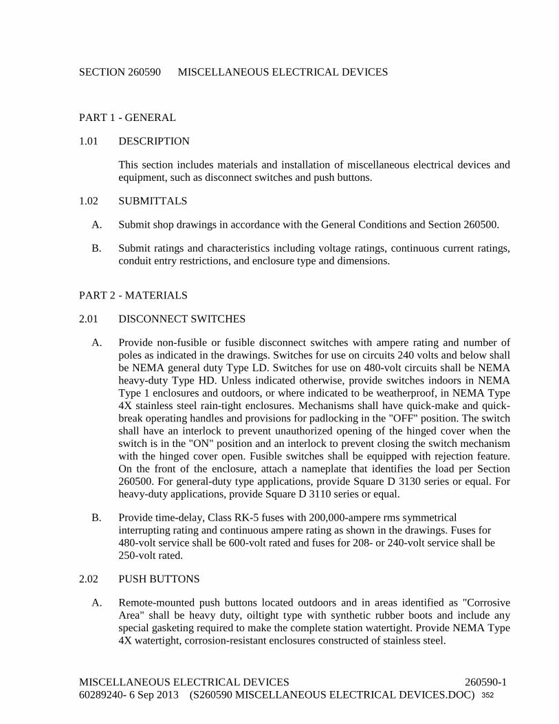
SECTION 260590 MISCELLANEOUS ELECTRICAL DEVICES
PART 1 - GENERAL
1.01 DESCRIPTION
This section includes materials and installation of miscellaneous electrical devices and equipment, such as disconnect switches and push buttons.
1.02 SUBMITTALS
A. Submit shop drawings in accordance with the General Conditions and Section 260500.
B. Submit ratings and characteristics including voltage ratings, continuous current ratings, conduit entry restrictions, and enclosure type and dimensions.
PART 2 - MATERIALS
2.01 DISCONNECT SWITCHES
A. Provide non-fusible or fusible disconnect switches with ampere rating and number of poles as indicated in the drawings. Switches for use on circuits 240 volts and below shall be NEMA general duty Type LD. Switches for use on 480-volt circuits shall be NEMA heavy-duty Type HD. Unless indicated otherwise, provide switches indoors in NEMA Type 1 enclosures and outdoors, or where indicated to be weatherproof, in NEMA Type 4X stainless steel rain-tight enclosures. Mechanisms shall have quick-make and quick-break operating handles and provisions for padlocking in the "OFF" position. The switch shall have an interlock to prevent unauthorized opening of the hinged cover when the switch is in the "ON" position and an interlock to prevent closing the switch mechanism with the hinged cover open. Fusible switches shall be equipped with rejection feature. On the front of the enclosure, attach a nameplate that identifies the load per Section 260500. For general-duty type applications, provide Square D 3130 series or equal. For heavy-duty applications, provide Square D 3110 series or equal.
B. Provide time-delay, Class RK-5 fuses with 200,000-ampere rms symmetrical interrupting rating and continuous ampere rating as shown in the drawings. Fuses for 480-volt service shall be 600-volt rated and fuses for 208- or 240-volt service shall be 250-volt rated.
2.02 PUSH BUTTONS
A. Remote-mounted push buttons located outdoors and in areas identified as "Corrosive Area" shall be heavy duty, oiltight type with synthetic rubber boots and include any special gasketing required to make the complete station watertight. Provide NEMA Type 4X watertight, corrosion-resistant enclosures constructed of stainless steel.
MISCELLANEOUS ELECTRICAL DEVICES 260590-1 60289240- 6 Sep 2013 (S260590 MISCELLANEOUS ELECTRICAL DEVICES.DOC) 352

B. Remote-mounted push buttons located indoors shall be heavy duty, oiltight type with NEMA Type 12 enclosures.
C. Remote-mounted push buttons located in areas identified as "Hazardous Areas" shall be heavy-duty type with NEMA Type 7/9 enclosure.
D. Install provisions for locking push buttons in the OFF position wherever lockout provisions are indicated.
E. Provide Allen-Bradley Bulletin 800H; Square D Class 9001, Type SK; or equal.
PART 3 - EXECUTION
3.01 SPARES
Provide six spare fuses of each type and ampere rating installed.
3.02 FIELD TESTING
A. Operate each disconnect switch three times, under load, and verify that all phases of the load are disconnected each time.
B. Operate push buttons and verify that the equipment controlled operates per the drawings or other sections of these specifications.
END OF SECTION
MISCELLANEOUS ELECTRICAL DEVICES 260590-2 60289240- 6 Sep 2013 (S260590 MISCELLANEOUS ELECTRICAL DEVICES.DOC) 353

SECTION 262419 LOW-VOLTAGE MOTOR CONTROL
PART 1 - GENERAL
1.01 DESCRIPTION
This section describes materials, testing, and installation of feeder circuit breakers added to an existing low-voltage motor control center.
1.02 SUBMITTALS
A. Submit shop drawings in accordance with the General Conditions and Section 013300.
B. Submit manufacturer's descriptive and technical literature.
C. Submit manufacturer's descriptive data including ratings, single-line diagrams, three-line diagrams, dimensional data, weights, and conduit entry restrictions.
1.03 OPERATION AND MAINTENANCE MANUALS
Submit operation and maintenance manuals in accordance with Section 260500.
1.04 RATINGS
Motor horsepower ratings and enclosures shown are minimum expected. This does not limit the equipment size. When motors furnished differ from the minimum ratings indicated, make the necessary adjustments to wiring, conduit, disconnect devices, branch circuit protection, and other affected material or equipment to accommodate the motors actually installed, at no additional cost to the Owner.
PART 2 - MATERIALS
2.01 CIRCUIT BREAKERS ADDED TO EXISTING MCC
A. Existing MCC is General Electric 8000 line. Provide feeder circuit breakers compatible with this MCC model.
B. Remove reduced-voltage and across-the-line motor starters from the existing motor control center as indicated in the drawings. Remove all ancillary components associated with starters including relays, control transformers, push buttons, selector switches, indicating lights, and terminal strips. Remove all associated control wiring. Disconnect motor power conductors from load side of starters and reuse by splicing to new VFD output conductors. Provide new conductors from load sides of new feeder circuit breakers to new VFD inputs.
LOW-VOLTAGE MOTOR CONTROL 262419-1 60289240- 6 Sep 2013 (S262419 LOW-VOLTAGE MOTOR CONTROL.DOC) 354

C. Provide individual compartments separated by steel barriers and with separate hinged doors for each new feeder circuit breaker. Locate equipment to enable termination of field wiring from front without equipment removal. Provide blank front covers for empty compartments remaining after starters are replaced with feeder circuit breakers.
D. Mechanically interlock circuit breaker doors so doors cannot be opened with unit energized. Provide defeater mechanism to allow intentional access while circuit breaker is energized. Make provisions for padlocking external disconnect handles in the off position.
E. Do not mount components or terminals on the sides of cubicles. Only mounting on back panels or front panels is acceptable.
F. Mount devices without obstruction, to be readily accessible.
G. Feeder circuit breakers shall be molded-case thermal-magnetic or electronic type. Provide quick-make and quick-break toggle mechanism, inverse-time trip characteristics, and trip-free operation on overload or short circuit. Automatic tripping shall be indicated by a handle position between the manual off and on positions. Provide trip ratings and number of poles as indicated in the drawings.
H. Each revised compartment shall have nameplates indicating new usage as specified in Section 260500.
PART 3 - EXECUTION
3.01 FIELD TESTS
A. Operate each breaker and verify that all phases of each load are disconnected.
B. Set adjustable trip circuit breakers two settings above the setting that causes the breaker to trip during motor starting. Do not adjust the setting above 1,300% of the motor nameplate current rating.
C. Set feeder circuit breaker adjustable set points, and time delays in accordance with the recommended values from the protective device coordination study in Section 260573.
END OF SECTION
LOW-VOLTAGE MOTOR CONTROL 262419-2 60289240- 6 Sep 2013 (S262419 LOW-VOLTAGE MOTOR CONTROL.DOC) 355

SECTION 262650 ELECTRIC MOTORS
PART 1 - GENERAL
1.01 DESCRIPTION
This section describes materials, installation, and testing of induction motors and applies to motors that are provided as part of equipment specified in other sections. When it applies, this section is referenced in those other sections.
1.02 SUBMITTALS
A. Submit shop drawings in accordance with the General Conditions and Section 013300.
B. Show complete nameplate data, ratings, characteristics, mounting arrangements, size and location of conduit entry, location and size of grounding lug, and coatings.
C. For premium-efficiency motors (Suffix E), provide percent efficiency data at full, 75%, and 50% load.
D. Submit factory test results for each motor.
1.03 FACTORY TESTS
A. For each integral horsepower motor provide routine (short commercial) test data. Tests shall comply with NEMA MG 1-12.55.
1.04 CONTROLLER COORDINATION
When motors furnished differ from the ratings indicated, notify controller manufacturer to make the necessary adjustments to wiring, conduit, disconnect devices, motor starters, branch circuit protection, and other affected material or equipment.
1.05 QUALITY CONTROL
A. NEMA Compliance: Unless otherwise indicated, comply with NEMA MG 1.
B. UL Listing: Motors for applications in hazardous locations shall bear the UL label listing its use in accordance with the NEC.
PART 2 - MATERIALS
2.01 GENERAL MOTOR DESIGN REQUIREMENTS
A. Unless otherwise specified or specifically required by the manufacturer of the equipment to be driven, a-c motors shall be single speed, squirrel cage induction type. Small and
ELECTRIC MOTORS 262650-1 60289240 - 6 Sep 2013 (S262650 ELECTRIC MOTORS.DOC) 356

medium size motors per NEMA MG 1, Section II shall be NEMA Design B. Large size motors per NEMA MG 1, Section III shall be standard torque type. Motors 15 horsepower and larger shall be NEMA Starting Code F or G. Motors smaller than 15 horsepower may have manufacturer's standard starting characteristics.
B. Stator windings shall be copper.
C. If motors are subjected to overhanging loads, they shall be designed for such loads. The magnitude of the overhanging load shall not exceed the recommendations of the motor manufacturer.
D. The connected load (maximum horsepower required) of each motor shall not exceed its nameplate horsepower rating (exclusive of service factor) under any operating condition.
E. Size motors to start and accelerate the design load of the driven equipment without exceeding any of the specified design requirements. Replace or repair any motor failing these requirements with a motor that will meet the specifications and requirements.
F. Connection box shall be cast metal with gaskets between the box and housing and between the box and cover. Provide a grounding terminal in the connection box.
G. Conduit opening at the motor connection box shall be coordinated with the incoming conduit sizes and provided accordingly. If a set of parallel conductors are shown in the drawings, Contractor may optionally provide a pull box at the conduit stub-up, sized per the NEC, and continue with a single conduit, sized per the NEC, to carry the parallel set of conductors to the motor connection box.
H. Open dripproof and weather-protected motors shall have a service factor of 1.15 on sinusoidal power and 1.0 on inverter power, such as power from a VFD. Totally enclosed motors shall have a service factor of 1.0, unless a higher service factor is standard for the operating duty.
I. Unless otherwise noted, motors shall be rated for continuous duty at an ambient temperature of 40°C and at an elevation of 3,300 feet.
J. Open drip-proof and weather-protected motors 7.5 horsepower and larger shall have stainless steel screens over openings.
K. For motors controlled by VFDs, the critical vibration speed of the motor/load combination shall either not fall within the operating range of the VFD or such frequency shall be blocked with the VFD critical speed avoidance circuit.
2.02 BEARINGS
A. Horizontal Motors:
1. Bearings for motors up to 1 horsepower shall be sealed, permanently lubricated ball bearings.
ELECTRIC MOTORS 262650-2 60289240 - 6 Sep 2013 (S262650 ELECTRIC MOTORS.DOC) 357

2. Bearings for motors 1 horsepower and larger shall be shielded open-type ball bearings installed in labyrinth sealed end bells with pipe plugs, or shielded type. Bearings shall be regreasable and have provisions for purging old grease.
B. Vertical Motors:
1. Design vertical motors for vertical operation and shall have thrust bearings with a rated L-10 life of 40,000 hours as defined by AFBMA.
2. Thrust bearings for motors 75 horsepower and larger shall be oil lubricated. Guide bearings may be antifriction, grease lubricated, or oil lubricated.
3. Equip grease-lubricated bearings with fittings in each bearing housing. Fittings shall be accessible without removal of any covers or guards. Provide drains to prevent over-lubrication.
4. Bearings of motors controlled by VFDs shall be insulated and shafts suitably grounded for protection against shaft voltages that cause current to flow through the bearings.
2.03 INSULATION AND TEMPERATURE RISE
Unless otherwise noted, provide Class B or F insulation with Class B rise requirements, per NEMA MG 1-12.43, at the specified service factor.
2.04 VOLTAGE
Unless otherwise noted, provide a-c motors 1/3 horsepower and smaller at 115 volts, single phase, 60 hertz, and motors 1/2 horsepower and larger at 460 volts, 3 phase, 60 hertz.
2.05 COATING
A. Do not coat cast aluminum frame motors.
B. Motors housed within equipment enclosures, such as exhaust fans, air-handling units, and air conditioners, may have factory's standard prime and finish coats.
C. Coat cast-iron frame motors. Apply prime coat at the factory which shall be compatible with field-applied finish coat(s).
D. Field apply finish coat(s) specified in the applicable equipment section.
2.06 NOISE LEVELS
Unless quieter type motors are specified, motors shall have no-load sound power levels not to exceed the values specified in NEMA MG 1, Section I, Part 9.
ELECTRIC MOTORS 262650-3 60289240 - 6 Sep 2013 (S262650 ELECTRIC MOTORS.DOC) 358

2.07 EFFICIENCY
Unless otherwise specified, motors 1 horsepower and larger shall be classified as “Energy Efficient” and shall have minimum guaranteed full load efficiencies in accordance with NEMA MG 1-12.59. The efficiency shall be determined in accordance with NEMA MG 1-12.58.
2.08 MOTOR TYPES
Motor designations consist of type number and suffix letter. The number and letter are intended to be compatible and the motor shall meet the requirements of both.
A. Type 1: Vertical weather-protected Type 1, NEMA WP-1.
B. Type 4: Totally enclosed, fan cooled.
C. Type 6: Horizontal, heavy duty, totally enclosed, fan cooled (General Electric "Severe Duty," Westinghouse "Mill and Chemical Service," Reliance "XT," or equal) and shall have the following features:
1. Nonhygroscopic insulation.
2. Extra dips and bakes of insulating varnish for moisture protection of windings.
3. Gasketed cast-iron conduit box halves and moisture seal between conduit box and motor frame.
4. Weep holes to vent enclosure and drain condensation.
5. Chemically inert fan.
D. Type 7: Totally enclosed, explosionproof, suitable for use in Class 1, Division 1, Group D hazardous locations, with UL label.
E. Suffix A: Motor shall be rated for continuous duty at an ambient temperature of 65°C with temperature rise as hereinbefore specified.
F. Suffix E: Motors shall be classified as “Premium Efficient” and shall have minimum guaranteed full load efficiencies in accordance with NEMA MG 1-12.60. The efficiency shall be determined by IEEE 112 Method B using sine wave power for motors up to 300 horsepower. Efficiency shall be listed on the nameplate in accordance with NEMA MG 1-12.58.2.
G. Suffix H: Motor shall have 120-volt heating elements.
H. Suffix M: Motor windings shall be moisture sealed and shall be capable of passing the tests listed in MG 1-12.62. Motors with form-wound coils shall have vacuum-pressure impregnated windings. Critical mechanical parts of the motor shall be plated or treated with a paint primer to provide additional protection in corrosive atmospheres. Provide
ELECTRIC MOTORS 262650-4 60289240 - 6 Sep 2013 (S262650 ELECTRIC MOTORS.DOC) 359

General Electric "Polyseal," U.S. Motors "Everseal," or equal insulation system. Provide with stainless steel nameplates.
I. Suffix N: Provide motor with a guaranteed maximum sound power level of 72 dBA, measured per IEEE 85, when running at no-load connected to sine wave power.
J. Suffix R: Equip motor with a nonreversing ratchet.
K. Suffix S: Motor shall have manufacturer's standard tropical protection and stainless steel nameplate.
L. Suffix T: Equip motor with thermal protection in accordance with NEMA MG 1. Control leads shall be color-coded, brought out to the motor conduit box or a separate terminal box for connection.
1. Provide three series-connected, normally closed switches, one in each winding.
M. Suffix V: Motor shall be inverter rated in accordance with NEMA MG-1.31 and shall be suitable for use with a pulse width modulated VFD with nonfiltered output. Design the motor to limit temperature rise to within the specified requirement at a 1.0 service factor when powered from the drive. Provide a nameplate on the motor stating that it is rated for VFD applications. Provide bearing insulation and properly grounded shaft as specified under paragraph 2.02 of this section.
2.09 MANUFACTURER
Motors shall be manufactured in the United States by Toshiba, U.S. Motors, Weg Motors, GE Motors, or equal.
PART 3 - EXECUTION
3.01 STORAGE
A. Protect motors from exposure of elements for which they are not designed. Install and energize temporary electrical service to motors with electrical heaters (Suffix H).
B. Store motors in an air-conditioned, ventilated, or protected environment similar to or better than the environment in their final location.
3.02 FIELD OPERATING TESTS
A. Perform NETA a-c induction motor acceptance tests. Exclude optional tests.
B. Run each motor with its control as nearly as possible under operating conditions to demonstrate correct rotation direction, alignment, wiring size, proper overload relay sizing, speed, and satisfactory operation. Test interlocks and control features to verify correct wiring and operation.
ELECTRIC MOTORS 262650-5 60289240 - 6 Sep 2013 (S262650 ELECTRIC MOTORS.DOC) 360
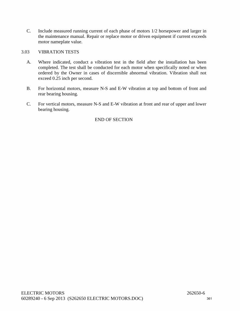
C. Include measured running current of each phase of motors 1/2 horsepower and larger in the maintenance manual. Repair or replace motor or driven equipment if current exceeds motor nameplate value.
3.03 VIBRATION TESTS
A. Where indicated, conduct a vibration test in the field after the installation has been completed. The test shall be conducted for each motor when specifically noted or when ordered by the Owner in cases of discernible abnormal vibration. Vibration shall not exceed 0.25 inch per second.
B. For horizontal motors, measure N-S and E-W vibration at top and bottom of front and rear bearing housing.
C. For vertical motors, measure N-S and E-W vibration at front and rear of upper and lower bearing housing.
END OF SECTION
ELECTRIC MOTORS 262650-6 60289240 - 6 Sep 2013 (S262650 ELECTRIC MOTORS.DOC) 361

SECTION 262923 VARIABLE FREQUENCY DRIVE (VFD)
PART 1 - GENERAL
1.01 DESCRIPTION
This section describes materials, testing, and installation of VFDs for pumping applications.
1.02 SUBMITTALS
A. Submit shop drawings in accordance with the General Conditions and Section 260500.
B. Submit manufacturer's descriptive data including ratings, performance and operational features, dimensional data, conduit entry restrictions, and heat dissipation to ambient.
C. Submit a schematic diagram for each drive showing field devices, wire numbers, terminal numbers, and interface with other panels.
D. Submit harmonic analysis.
E. Submit certified factory test report.
F. Submit a confirmation of appropriate coordination with motor manufacturer regarding adequate mitigation against bearing damage caused by currents that may flow in the bearings due to shaft voltages imposed by the VFD controller.
1.03 OPERATION AND MAINTENANCE MANUALS
Submit operation and maintenance manuals in accordance with Section 260500.
1.04 MANUFACTURER'S SERVICES
Provide equipment manufacturer's services at the jobsite for the minimum labor days listed below, travel time excluded, for a certified technical representative:
A. Three labor days to check the installation, calibrate the drives, and advise during start-up and testing of the drives.
B. One labor day to instruct the Owner's personnel in the operation and maintenance of the equipment.
1.05 SERVICE ORGANIZATION QUALIFICATIONS
A. The service organization office shall be located within 100 miles of the jobsite.
VARIABLE FREQUENCY DRIVE (VFD) 262923-1 60289240 - 6 Sep 2013 (S262923 VARIABLE FREQUENCY DRIVE (VFD).DOC) 362

B. The service organization must have been an authorized service organization of the equipment manufacturer for the past 12 months. Service engineers or technicians must be factory trained.
C. Maintain a spare parts inventory of 100% of the controller components.
1.06 RATINGS
Motor horsepower ratings shown are minimum expected. This does not limit the equipment size. When motors furnished differ from the minimum ratings indicated, make the necessary adjustments to wiring, conduit, disconnect devices, VFD sizes, branch circuit protection, and other affected material or equipment to accommodate the motors actually installed, at no additional cost to the Owner.
1.07 MAINTENANCE CONTRACT
For services outside of the warranty, a maintenance contract shall be offered to the Owner that includes the following:
A. Provide for maintenance, including new parts, repair of parts, and the installation of same, and make adjustments required to keep the entire system in peak operating condition.
B. Maintain and restock the spares inventory.
PART 2 - MATERIALS
2.01 GENERAL
A. VFDs shall consist of variable frequency controller, input circuit breaker, harmonic suppression equipment, output filters, and controls. Each drive shall operate as a simplex unit with no interaction with other drives. Horsepower rating of each drive shall be sufficient to drive the motor as shown in the drawings or the motors actually provided, whichever is larger, under the specified operating conditions.
B. All components shall be integral to the VFD lineup, factory wired, and tested as a complete system.
C. Design equipment to operate under the following operating conditions:
1. Elevation to 1,000 feet above sea level.
2. Ambient 0°C to 40°C.
3. Noncondensing relative humidity to 95%.
4. A-C line frequency variation of ±3 hertz.
VARIABLE FREQUENCY DRIVE (VFD) 262923-2 60289240 - 6 Sep 2013 (S262923 VARIABLE FREQUENCY DRIVE (VFD).DOC) 363

D. VFD shall maintain a 0.95 minimum true power factor throughout the entire speed range.
E. VFD shall be suitable for use with any standard NEMA-B squirrel-cage induction motor having a 1.15 service factor. Provide equipment for proper operation of motor and drive when required due to motor feeder length.
F. Equipment shall comply with the requirements of ANSI, IEEE, and NEMA. The electrical equipment, design, and construction shall comply with the provisions of the NEC. The complete drive shall be UL listed.
G. All drives shall be supplied by one manufacturer.
H. VFDs shall be manufactured by Square D.
2.02 ENCLOSURES
A. Equipment enclosure shall be floor standing, unless otherwise noted in the drawings, completely front accessible, ventilated NEMA 12. Enclosures shall be suitable for mounting against a wall or back-to-back with other equipment.
B. Provide separate enclosures for each variable frequency controller. Locate harmonic suppression equipment and controls within the variable frequency controller enclosure.
C. Verify that overall equipment dimensions are within the dimensions indicated in the drawings. If larger equipment is required, submit a proposed room layout showing arrangement of electrical equipment. Provide working clearances in accordance with the NEC. Any costs due to rearrangement of equipment shall be borne by the Contractor with no additional expense to the Owner.
2.03 VARIABLE FREQUENCY CONTROLLERS
A. Controllers for the 125 HP storm water pump motors shall each consist of an input rectifier-grade phase-shifting transformer with 18-pulse minimum converter section, output inverter utilizing IGBT technology, and output filters for compatibility with the existing non-inverter duty rated motors.
B. Controller for the 88 HP ASR pump motor shall consist of an input rectifier-grade phase-shifting transformer with 18-pulse minimum converter section and output inverter utilizing IGBT technology.
C. Controller for the 25 HP jockey pump motor shall consist of an input line reactor, six-pulse converter section, and output inverter utilizing IGBT technology.
D. Controller shall be pulse width modulated design.
E. Controller shall be variable voltage/variable frequency (constant volts per hertz).
VARIABLE FREQUENCY DRIVE (VFD) 262923-3 60289240 - 6 Sep 2013 (S262923 VARIABLE FREQUENCY DRIVE (VFD).DOC) 364

F. The controller shall include the following features:
1. 460-volt a-c, +10%, -10% (at rated load), 3-phase, 3-wire, 60-hertz input power.
2. 460-volt a-c, 3-phase, 3-wire, ungrounded output power.
3. Equipment fault current rating of 65,000 symmetrical amperes fault current.
4. Input power surge protector.
5. 20- to 60-hertz continuous operating range.
6. 110% overload rating for 60 seconds, 100% rated current continuous.
7. Output current limit, 50% to 110% adjustable. Limits motor inrush current during start-up.
8. Regulation ±3% of base speed.
9. Voltage Dip Ride-Through: Controller shall be capable of sustaining continued operation with a 40% dip in nominal line voltage. Output speed may decline only if current limit rating of the controller is exceeded.
10. Power Loss Ride-Through: Controller shall be capable of a minimum three-cycle power loss ride-through without fault activation.
11. Separately adjustable acceleration and deceleration rates.
12. Maximum and minimum speed adjustments.
13. 120-volt a-c control power for run/stop circuits.
14. Blower cooled, with thermal switch cutout.
15. Comprehensive microprocessor-based digital diagnostic system that monitors its own control functions and displays faults and operating conditions in plain English without the use of codes. The digital keypad and display shall be a membrane keypad with integral 24-character minimum LCD display capable of controlling the VFD and setting drive parameters. Include self-test software program to verify proper keypad operations. A fault log shall record, store, display, and print, upon demand, the following for the 15 or more most recent events:
a. VFD mode (auto/manual).
b. Elapsed time (since previous fault) or fault time.
c. Type of fault.
16. The following digital indications shall be possible to be selectively displayed:
VARIABLE FREQUENCY DRIVE (VFD) 262923-4 60289240 - 6 Sep 2013 (S262923 VARIABLE FREQUENCY DRIVE (VFD).DOC) 365

a. Speed called for by incoming process signal in percent of full speed.
b. Output current in amperes.
c. Output frequency in hertz.
d. Input voltage.
e. Output voltage.
f. Total 3-phase kilowatts.
g. Kilowatt-hour.
h. Elapsed time.
i. rpm.
j. D-C bus voltage.
17. Password security shall be available to protect drive parameters from unauthorized personnel.
18. Provide a plain English user menu in software in nonvolatile memory as a guide to parameter setting.
19. VFD parameters, fault log, and diagnostic log shall be downloadable via RS-232 as well as line-by-line on the keypad display.
G. Minimum controller efficiency shall be 95% at 100% speed and 100% torque and 88% at 50% speed and 25% torque based on nominal 1,800-rpm motor with load horsepower to vary as cube of speed.
H. The controller shall include protective circuitry that initiates an orderly shutdown of the inverter without component failure. The controller shall shut down and require manual reset for the following fault conditions:
1. Motor inverse time overload.
2. Instantaneous overcurrent.
3. Inverter fault.
4. Over-frequency.
5. D-C link overvoltage.
6. Ground fault.
VARIABLE FREQUENCY DRIVE (VFD) 262923-5 60289240 - 6 Sep 2013 (S262923 VARIABLE FREQUENCY DRIVE (VFD).DOC) 366

I. The controller shall ride through or shut down for the following fault conditions.
1. Incorrect phase sequence.
2. Loss of an input phase.
J. The controller shall shut down for input under-voltage. The controller shall automatically restart upon a cleared fault condition.
K. The controller shall have not less than five restart capabilities. If the drive reaches the limits of restart, the restart circuit shall lock out and shall provide a fault signal.
L. Provide a common failure contact for remote indication of fault conditions previously listed.
M. The power circuit design shall be such that the following fault conditions can occur without damage to the power circuit components:
1. Single-phase fault or 3-phase short circuit on VFD output terminals.
2. Failure to commutate inverter transistor due to severe overload or other conditions.
3. Disconnecting motor during VFD operation.
4. Loss of input power due to opening of VFD input disconnect device or utility power failure during VFD operation.
5. Loss of one phase of input power.
N. VFD shall have integral Ethernet TCP/IP communication capability.
O. Phase-shift transformers shall be ventilated, dry type with 80°C temperature rise.
P. Provide a critical speed avoidance circuit for selection of a critical speed with a rejection band centered on that speed. The drive shall ignore any speed signals requiring drive operation within the rejection band.
Q. The VFD controller shall operate satisfactorily when connected to a bus subject to a total harmonic voltage distortion caused by other sources of up to 10% and commutation notches of up to 36,500 microsecond-volts.
2.04 INPUT CIRCUIT BREAKER
A. Circuit breaker shall be molded-case or insulated-case type, mechanically interlocked with the enclosure door to provide positive disconnect of incoming a-c power.
B. Make provisions for padlocking external disconnect handles in the off position.
VARIABLE FREQUENCY DRIVE (VFD) 262923-6 60289240 - 6 Sep 2013 (S262923 VARIABLE FREQUENCY DRIVE (VFD).DOC) 367
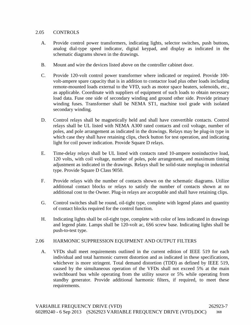
2.05 CONTROLS
A. Provide control power transformers, indicating lights, selector switches, push buttons, analog dial-type speed indicator, digital keypad, and display as indicated in the schematic diagrams shown in the drawings.
B. Mount and wire the devices listed above on the controller cabinet door.
C. Provide 120-volt control power transformer where indicated or required. Provide 100-volt-ampere spare capacity that is in addition to contactor load plus other loads including remote-mounted loads external to the VFD, such as motor space heaters, solenoids, etc., as applicable. Coordinate with suppliers of equipment of such loads to obtain necessary load data. Fuse one side of secondary winding and ground other side. Provide primary winding fuses. Transformer shall be NEMA ST1, machine tool grade with isolated secondary winding.
D. Control relays shall be magnetically held and shall have convertible contacts. Control relays shall be UL listed with NEMA A300 rated contacts and coil voltage, number of poles, and pole arrangement as indicated in the drawings. Relays may be plug-in type in which case they shall have retaining clips, check button for test operation, and indicating light for coil power indication. Provide Square D relays.
E. Time-delay relays shall be UL listed with contacts rated 10-ampere noninductive load, 120 volts, with coil voltage, number of poles, pole arrangement, and maximum timing adjustment as indicated in the drawings. Relays shall be solid-state nonplug-in industrial type. Provide Square D Class 9050.
F. Provide relays with the number of contacts shown on the schematic diagrams. Utilize additional contact blocks or relays to satisfy the number of contacts shown at no additional cost to the Owner. Plug-in relays are acceptable and shall have retaining clips.
G. Control switches shall be round, oil-tight type, complete with legend plates and quantity of contact blocks required for the control function.
H. Indicating lights shall be oil-tight type, complete with color of lens indicated in drawings and legend plate. Lamps shall be 120-volt ac, 6S6 screw base. Indicating lights shall be push-to-test type.
2.06 HARMONIC SUPPRESSION EQUIPMENT AND OUTPUT FILTERS
A. VFDs shall meet requirements outlined in the current edition of IEEE 519 for each individual and total harmonic current distortion and as indicated in these specifications, whichever is more stringent. Total demand distortion (TDD) as defined by IEEE 519, caused by the simultaneous operation of the VFDs shall not exceed 5% at the main switchboard bus while operating from the utility source or 5% while operating from standby generator. Provide additional harmonic filters, if required, to meet these requirements.
VARIABLE FREQUENCY DRIVE (VFD) 262923-7 60289240 - 6 Sep 2013 (S262923 VARIABLE FREQUENCY DRIVE (VFD).DOC) 368

B. Submit a harmonic analysis showing compliance with the above requirement including all voltages and current harmonics up to the 49th.
C. Base harmonic analysis of the system operating from the utility source on a short-circuit kva available at the main switchboard of 30,000 kva. Base harmonic analysis of the system operating from the standby generator on the short-circuit kva available from the generator at the main switchboard.
D. Provide filters on the output of the VFD where required to protect motor insulation and to allow the use of standard low-voltage building wires to motors fed from VFDs. If selected filters cannot provide cable insulation protection due to excessive cable lengths, use VFD cables.
E. Output filters shall also protect motor bearings from damage due to currents that may flow in the bearings created by shaft voltages imposed by the VFD controller. Coordinate with motor manufacturer to determine the appropriate filters required.
2.07 FACTORY TESTING
A. Subject the VFDs to a complete functionality test and a full-load operational test prior to shipment. Simulate remote inputs and outputs and verify correct operation. Submit certified factory test report.
B. Set adjustable set points of the drives at motor manufacturer’s recommended values. Coordinate with motor manufacturer and obtain recommended set point values in writing. Document information in O&M manual.
PART 3 - EXECUTION
3.01 INSTALLATION
A. Secure drives rigidly to floors or mounting pads with anchor bolts or Phillips Drill Company concrete anchors. Anchor bolts or concrete anchors shall be carbon steel per ASTM A307, Grade B. Installation shall be in accordance with manufacturer's installation instructions.
B. Provide the services of a qualified factory-trained manufacturer’s representative to assist in installation of the equipment specified under this section. The manufacturer’s representative shall provide technical direction and assistance to the Contractor in general assembly of the equipment, connections, and adjustments.
C. Perform the following minimum work under the technical direction of the manufacturer’s service representative:
1. Rig the drive assembly into final location and install on level surface.
2. Check removable cells and starter units for easy removal and insertion.
VARIABLE FREQUENCY DRIVE (VFD) 262923-8 60289240 - 6 Sep 2013 (S262923 VARIABLE FREQUENCY DRIVE (VFD).DOC) 369
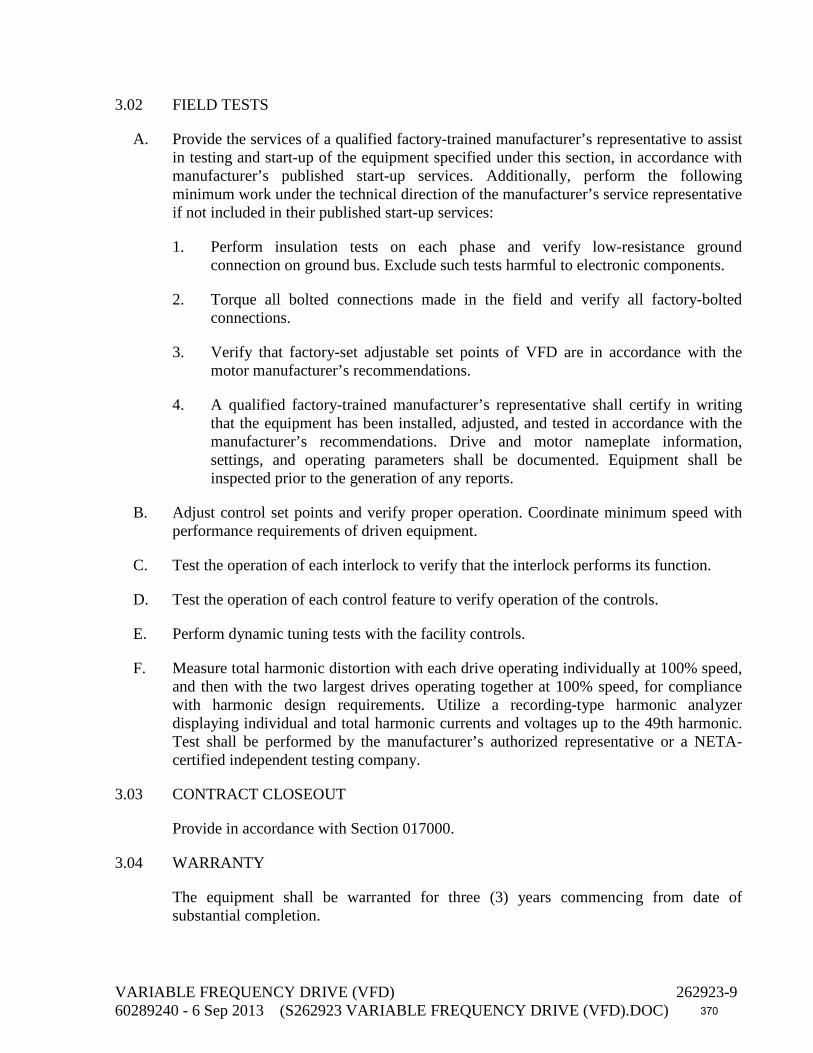
3.02 FIELD TESTS
A. Provide the services of a qualified factory-trained manufacturer’s representative to assist in testing and start-up of the equipment specified under this section, in accordance with manufacturer’s published start-up services. Additionally, perform the following minimum work under the technical direction of the manufacturer’s service representative if not included in their published start-up services:
1. Perform insulation tests on each phase and verify low-resistance ground connection on ground bus. Exclude such tests harmful to electronic components.
2. Torque all bolted connections made in the field and verify all factory-bolted connections.
3. Verify that factory-set adjustable set points of VFD are in accordance with the motor manufacturer’s recommendations.
4. A qualified factory-trained manufacturer’s representative shall certify in writing that the equipment has been installed, adjusted, and tested in accordance with the manufacturer’s recommendations. Drive and motor nameplate information, settings, and operating parameters shall be documented. Equipment shall be inspected prior to the generation of any reports.
B. Adjust control set points and verify proper operation. Coordinate minimum speed with performance requirements of driven equipment.
C. Test the operation of each interlock to verify that the interlock performs its function.
D. Test the operation of each control feature to verify operation of the controls.
E. Perform dynamic tuning tests with the facility controls.
F. Measure total harmonic distortion with each drive operating individually at 100% speed, and then with the two largest drives operating together at 100% speed, for compliance with harmonic design requirements. Utilize a recording-type harmonic analyzer displaying individual and total harmonic currents and voltages up to the 49th harmonic. Test shall be performed by the manufacturer’s authorized representative or a NETA-certified independent testing company.
3.03 CONTRACT CLOSEOUT
Provide in accordance with Section 017000.
3.04 WARRANTY
The equipment shall be warranted for three (3) years commencing from date of substantial completion.
VARIABLE FREQUENCY DRIVE (VFD) 262923-9 60289240 - 6 Sep 2013 (S262923 VARIABLE FREQUENCY DRIVE (VFD).DOC) 370

3.05 CERTIFICATION
Provide a written certification from the equipment manufacturer that each pumping system has been properly installed according to the Contract Documents and the manufacturer’s recommendations, and that the equipment is operating normally. Make all necessary corrections and adjustments including but not limited to parts, labor, or freight at no additional cost to the Owner.
END OF SECTION
VARIABLE FREQUENCY DRIVE (VFD) 262923-10 60289240 - 6 Sep 2013 (S262923 VARIABLE FREQUENCY DRIVE (VFD).DOC) 371

SECTION 264313 SURGE PROTECTIVE DEVICES (SPD)
PART 1 - GENERAL
1.01 DESCRIPTION
This section includes materials and installation of SPD for the protection of electrical and electronic circuits and equipment.
1.02 SUBMITTALS
A. Submit shop drawings in accordance with the General Conditions and Section 013300.
B. Submit product data on each suppressor type, indicating component values, part numbers, and conductor sizes. Include dimensional drawing for each, showing mounting arrangements.
C. Submit manufacturer's UL certified test data and nameplate data for each SPD.
D. Provide copy of extended warranty.
1.03 QUALITY ASSURANCE
A. UL Compliance and Labeling:
1. For power and signal circuits, SPD devices shall comply with UL 1449 3rd Edition and UL 1283 as an electromagnetic interference filter. Provide units that are listed and labeled by UL.
B. ANSI Compliance: Use SPD devices that comply with ANSI/IEEE C62.41 and ANSI/IEEE C62.33.
C. NEC Compliance: Use SPD devices that comply with NEC Article 285.
1.04 EXTENDED WARRANTY
Provide written warranty, signed by the manufacturer, agreeing to replace any surge suppressor which fails in service within one year following the guarantee period specified in the General Conditions.
PART 2 - MATERIALS
2.01 GENERAL
A. SPD devices for power circuits shall be the product of a single manufacturer.
SURGE PROTECTIVE DEVICES (SPD) 264313-1 60289240 - 6 Sep 2013 (S264313 SURGE PROTECTIVE DEVICES (SPD).DOCX) 372

B. SPD devices shall be capable of performance at ambient temperatures between 40°C and 60°C, at relative humidity ranging from 0% to 95%, and at elevations ranging from sea level to 3,000 feet.
C. SPD devices shall be fused to disconnect the suppressor from the electrical source should the suppressor fail. The fusing shall allow full surge handling capabilities and afford safety protection from thermal overloads and short circuits.
D. Design SPD devices for the specific type and voltage of the electrical service. Single-phase systems shall have L-N, L-G, and N-G protection.
2.02 MANUFACTURER
SPD devices shall be products of one of the following manufacturers:
A. Advanced Protection Technologies.
B. Current Technology, Inc.
C. Atlantic Scientific Corporation.
2.03 SPD
A. Provide SPD meeting ANSI/IEEE C62.41.
B. Maximum single impulse current rating shall be not less than 80 kA.
C. Suppressor shall be in an enclosure that has the same NEMA rating as the panel it protects or the SPD may be integral to a panelboard.
D. UL 1449 maximum clamp voltage shall not be more than:
System Voltage Phase L-L or L-N Clamp Voltage 120 1 500
2.04 SHORT-CIRCUIT RATING
A. Provide SPD with short-circuit rating permanently marked on the enclosure.
B. Provide SPD with the same or greater short-circuit rating as the equipment with which they are installed.
PART 3 - EXECUTION
3.01 APPLICATION REQUIREMENTS
A. Install SPD as indicated and:
SURGE PROTECTIVE DEVICES (SPD) 264313-2 60289240 - 6 Sep 2013 (S264313 SURGE PROTECTIVE DEVICES (SPD).DOCX) 373

1. Power supply to instrumentation and control system cabinets.
2. Install SPD for circuits sensing, powering, and controlling devices located or mounted external to a building.
3.02 GENERAL INSTALLATION REQUIREMENTS
A. Install suppressors according to manufacturer's recommendations.
B. Install suppressors directly to the cabinet which houses the circuit to be protected so that the suppressor leads are straight and short, with all conductors laced, running directly to the point of connection within the panel, without loops or bends. If bends are unavoidable, no bend may exceed 90 degrees and bending radius may not be less than 6 inches.
C. Provide at least 3 inches of separation between line-side and load-side connecting wires. Do not bundle line-side and load-side conductors together or run them in the same raceway.
D. Field installed conductors shall be the same as specified for building wire, not smaller than No. 8 AWG. Device leads shall not be longer than the length recommended by the manufacturer, unless specifically reviewed and approved by the manufacturer.
3.03 SPARE PARTS
A. Provide six fuses of each type and rating installed.
END OF SECTION
SURGE PROTECTIVE DEVICES (SPD) 264313-3 60289240 - 6 Sep 2013 (S264313 SURGE PROTECTIVE DEVICES (SPD).DOCX) 374

This page intentionally left blank
375

DIVISION 28 – ELECTRONIC SAFETY AND SECURITY 282318 Remote Video Surveillance System
376

This page intentionally left blank
377

SECTION 282318 REMOTE VIDEO SURVEILLANCE SYSTEM
PART 1 - GENERAL
1.01 DESCRIPTION
This section includes design, materials, and installation of a remote video surveillance or closed-circuit television (CCTV) camera monitoring system including copper networks, interface hardware, and software. From remote locations via the COMCAST system, the system shall provide viewing via IP video security technology.
1.02 RELATED WORK SPECIFIED ELSEWHERE
NONE
1.03 SUBMITTALS
A. Submit shop drawings in accordance with the General Conditions.
B. Submit product data for each type of product specified. Product data shall include:
1. Corresponding specifications item.
2. Manufacturer’s name and model number.
3. Manufacturer’s specification sheet.
C. Submit wiring diagrams detailing wiring for power, signal, and control differentiating clearly between manufacturer-installed wiring and field-installed wiring. Identify terminal numbers and wiring color codes to facilitate installation, operation, and maintenance.
D. Submit equipment enclosure elevation drawings, including equipment designation, manufacturer’s name, and model number.
E. Submit complete scaled floor plans indicating all equipment and wiring, completely identified, including cable and device designations and locations.
1.04 OPERATION AND MAINTENANCE MANUALS
Operation and maintenance manuals shall include:
A. Manufacturer’s Instruction Manuals: Submit brochures, manuals, and service sheets published by the manufacturers of the components, devices, and equipment provided. Include instructions for operating and maintaining the system and source information for spare and replacement parts.
Remote Video Surveillance System 282318-1 60289240- 13 Sep 2013 (S282318.DOC)
378

B. Performance, Test, and Adjustment Data: Include comprehen3sive documentation of performance verification and correction procedures and measurements.
C. Wiring diagrams and floor plans.
1.05 INSTALLER QUALIFICATION
A. The Contractor shall require that this work be performed by a CCTV systems specialist having at least five years’ direct experience with devices, equipment, and systems of the type and scope specified herein, maintaining a fully staffed and equipped maintenance and repair facility within 100 miles of the jobsite.
B. Supervisors shall have at least five years’ direct experience in similar work.
C. Installation, adjustment, and testing personnel shall have at least three years’ direct experience in similar work.
1.06 MANUFACTURER’S SERVICES
Provide equipment manufacturer’s services at the jobsite for the minimum labor days listed below, travel time excluded:
A. One-half labor day to check the installation and advise during start-up, testing, and adjustment of the equipment.
B. One-half labor day to instruct the Owner’s personnel in the operation and maintenance of the equipment.
PART 2 - MATERIALS
2.01 SURVEILLANCE SYSTEM
The remote video surveillance system shall be the Digital Watchdog VMAXHD4 or equal. This remote video surveillance system is hereinafter referred to as the RVSS.
A. The RVSS system shall incorporate the following hardware and software:
1. Digital Video Recorder (DVR): Integrated hardware and software unit for capturing and transmitting video streams.
2. Remote Personal Computer (RPC): Hardware and software for live video monitoring, playback, and remote configuration.
Remote Video Surveillance System 282318-2 60289240- 13 Sep 2013 (S282318.DOC)
379

B. The system shall incorporate the following operational features and characteristics:
1. The system shall provide the collection, analysis, and storage of video images locally with remote backup capability via internet.
2. The system shall include hardware and software to interface with fixed network cameras, pan/tilt/zoom network cameras, digital inputs.
3. The system shall provide the following hardware characteristics:
a. 4 channel HD-SDI camera video inputs.
b. Four digital inputs NO/NC. One channel output.
c. Permanent storage of 8 Terabytes.
4. The system shall provide for the transfer of video, event, and configuration information between the DVR system and the RPC via internet communications network. The network interface shall be Ethernet rj-45, 10/100/1000Base-T, PTZ, Auto MDI/MDIX.
5. The DVR shall have these specification.
a. Video Input:
(1) Channel Input Level: 4 channel 2.1 Megapixels (1920 x 1080) at 30fps
b. Video Output:
(1) Main Monitor: HDMI (1280 x 720)
(2) Sub Monitor: VGA (1280 x 720)
(3) CVBS: 1
c. Audio:
(1) Input: 4 channel Line Input
(2) Output: 1 channel Line Output
(3) Audio Code; G.711
d. Alarm:
(1) Sensor Inputs: 4 channel, NO/NC Selectable Remote Video Surveillance System 282318-3 60289240- 13 Sep 2013 (S282318.DOC)
380

(2) Alarm Out: 1 channel out by Sensor, Motion and Video Loss
e. Pentaplex Operations: Live/record/Playback/Backup/Network
f. Live digital Zoom of specific area, 3 ~ 60 second Channel Sequencing.
g. Recording: Event clip generation around the detection of security events.
(1) Video Compression H.264
(2) Resolution up to 1920 x 1080
(3) Recoding Quality Grade on 5 levels
(4) Recording Mode: Continuous, Schedule, Motion, Sensor, Manual
(5) Motion Detection shall be Setup by Grid
(6) Pre-recording: Minimum 15 seconds, Maximum 20 minutes
(7) Post-recording: 1-~20 seconds
h. Playback shall digital zoom specific area.
(1) Fast Forward Speeds: x1/4, x1/2, x2, x4, x8, x16, and x32
(2) Fast Reverse Speeds: x1, x2, x4, x8, x16, and x32
(3) Search Mode: Timeline, Event, Archive, Log, Specific Time
i. Backup shall consist of:
(1) File Format: JPEG/Proprietary Format
(2) Media: USB/External HDD/Network
(3) Built-in Viewer
j. Network:
(1) Dual Live Streaming @ 1280 x 720 / 640 x 360, 120/100fps
(2) Playback shall codec H.264 HD 120/100fps
(3) Streaming formats: RTP/RTPS/RTCP
(4) Protocols: HTTP, DDNS, NTP, SMTP
k. Storage:
Remote Video Surveillance System 282318-4 60289240- 13 Sep 2013 (S282318.DOC)
381

(1) HDD Data Storage
(a) Interface: SATA, e-SATA
(b) Maximum Capacity: 2TB
(c) Maximum Internal HDD’s: Four (4)
External Storage Data: (1) e-SATA for RAID (redundant array of independent disks)
(2) File System shall be Self Developed, Reliable and Stable File System
(3) S.M.A.R.T. criteria for HDD error check and reporting
l. User Menus shall be Graphic User interface
m. Interface Input Method: Front Buttons, IR Remote Control, Mouse, and Keyboard Controller
n. Serial Ports: POS (1) RS-232C, PTZ & Controller (2) RS-485
o. Network
(1) Connection by Ethernet, RJ-45, 10/100/1000Base-T, Auto MDI/MDIX
(2) Access (Live, Search/playback, Backup, remote Setup/Upgrade
(a) Web Viewer
(b) Single-Site monitoring Software
(c) Multi- Sites monitoring Software
p. Features to include:
(1) (DST) Daylight Savings Time,
(2) Internal Beep (by video loss or HDD error)
(3) Software Upgrade (by USB, Network Remote Upgrade)
(4) Watermarking
(5) 3G Mobile (iPhone, Android)
q. General:
(1) Operation Temperature: 0 ~ 104 F
Remote Video Surveillance System 282318-5 60289240- 13 Sep 2013 (S282318.DOC)
382
(2) Operating Humidity: 20% ~ 80%
(3) Power: 120 VAC, 60Hz
6. Equipment Enclosure
a. The DVR shall be in a lockable wall mounted enclosure equal to Middle Atlantic Products Model DLBX, with pair of wall mount brackets DLBX-WM, Front Security Kit DLBX-FSK, Proportional Speed Thermostatic Fan Control with (2) 15-ampere receptacle outlets.
2.02 PAN/TILT/ZOOM NETWORK DOME CAMERA
Each camera shall meet the following requirements:
A. Functions: BLC (Back Light Compression), AGC (Automatic Gain Control), WDR (Wide Dynamic Range), AWB (Auto White Balance), Mirror, Privacy Zone, 3D-DNR (3 Dimensional-Digital Noise Reduction), HME, Digital Zoom, RS-485, TDN with IR cut filter, (True Day/Night), Auto Zoom, Mirror image, DSS (Data Security Standard)
B. General: The dome camera shall:
1. Provide pan and tilt functions, containing day/night functionality, and be equipped with 1 ~ 112 digital zoom.
2. Polycarbonate dome with Aluminum housing IP68 Certified (Waterproof)
C. Hardware: The dome camera shall:
1. Range of 70ft IR-sensitive with Intelligent Camera Synchronization.
2. Be equipped with a removable IR-cut filter, providing so-called day/night functionality.
3. Be equipped with a high resolution 2.1 megapixel lens with 4.5x optical zoom.
4. Be equipped with accurate pan-tilt functionality with 360-degree endless pan range.
D. Video:
1. Resolution:
The dome camera shall be able to deliver high-quality video in at least five different resolutions up to 1920 x 1080 @ 2.1 megapixels over IP networks.
Remote Video Surveillance System 282318-6 60289240- 13 Sep 2013 (S282318.DOC)
383

2. Transmission Speed: The dome camera shall allow the transmission of images at up to 30 frames per second (NTSC) in all resolutions, using motion JPEG.
3. Image Control: The dome camera shall incorporate:
a. Automatic gain control (AGC).
b. Automatic and manual white balance.
c. Backlight compensation.
d. Components such as Active X downloaded from the dome camera shall be signed by an organization providing digital trust services, such as Verisign, Inc.
4. Protocol:
a. The dome camera shall support Protocol- NDT-AUX.
b. The dome camera shall allow for automatic detection of the dome camera based on using a PC with an operating system supporting this feature.
5. PTZ Functionality: The dome camera shall:
a. Provide Panning of 360 degrees.
b. Provide 360 degree rotation.
c. Provide 75 degree tilt.
6. Event Functionality:
a. The dome camera shall be equipped with an integrated event functionality, which can be triggered by:
(1) External inputs.
(2) Video motion detection.
(3) Preset position.
(4) Schedule.
b. Response to triggers shall include:
(1) Notification, using TCP, SMTP, or HTTP.
(2) Image upload, using FTP, SMTP, or HTTP.
Remote Video Surveillance System 282318-7 60289240- 13 Sep 2013 (S282318.DOC)
384
(3) Preset call up.
(4) Activating external output.
c. Event functions shall be configurable via the web interface.
7. Security:
a. Access to the built-in web server shall be restricted by user names and passwords.
E. Enclosure: The dome camera enclosure shall include the following:
1. An all-metal body.
2. Clear transparent cover.
F. Power Requirements: 12 VDC, maximum 20 watts.
G. Environmental: The dome camera shall:
1. Operate in a temperature range of 10°C to +50°C (14°F to +122°F).
2. Operate in a humidity range of 20% to 80% RH (noncondensing).
H. Manufacturer: The camera shall be Digital Watchdog Vandal Proof Dome Model DWC-HV421TIR Camera.
PART 3 - EXECUTION
3.01 PRELIMINARY TESTING
Upon completing installation of the system, align, adjust, and balance the system and perform complete pretesting. Determine, through pretesting, the conformance of the system to the requirements of the drawings and specifications. Correct deficiencies observed in pretesting. Replace or repair malfunctioning or damaged items, and retest until satisfactory performance and conditions are achieved. Camera lens shall provide full fixed coverage of areas being monitored. Provide proper lens at no cost to Owner to provide proper area coverage.
3.02 ACCEPTANCE TEST
Conduct acceptance test in presence of Engineer in accordance with manufacturer’s recommendations.
END OF SECTION
Remote Video Surveillance System 282318-8 60289240- 13 Sep 2013 (S282318.DOC)
385

DIVISION 31 – EARTHWORK 311100 Clearing, Stripping and Grubbing 312300 Earthwork and Trenching
386

This page intentionally left blank
387

SECTION 311100 CLEARING, STRIPPING, AND GRUBBING
PART 1 - GENERAL
1.01 DESCRIPTION
This section describes the work included in clearing, stripping, grubbing, and preparing the project site for construction operations.
1.02 CLEARING
Remove and dispose of trees, snags, stumps, shrubs, brush, limbs, sticks, branches, and other vegetative growth. Remove rocks, tiles, and lumps of concrete. Remove all evidence of their presence from the surface. Remove and dispose of trash piles, rubbish, and fencing. Protect structures and piping above and below ground, trees, shrubs, and vegetative growth and fencing which are not designated for removal.
1.03 STRIPPING
A. Remove and dispose of organic sod, grass and grass roots, and other objectionable material remaining after clearing from the areas designated to be stripped.
B. Retain topsoil material onsite for dressing backfill areas before planting.
1.04 GRUBBING
After clearing and stripping, remove and dispose of wood or root matter, including stumps, logs, trunks, roots, or root systems greater than 1 inch in diameter or thickness to a depth of 12 inches below the ground surface.
PART 2 - MATERIALS
2.01 TREES AND SHRUBBERY
Existing trees, shrubbery, and other vegetative material may not be shown in the drawings. Inspect the site as to the nature, location, size, and extent of vegetative material to be removed or preserved, as specified herein.
2.02 PRESERVATION OF TREES, SHRUBS, AND OTHER PLANT MATERIAL
A. Save and protect plant materials (trees, shrubbery, and plants) beyond the limits of clearing and grubbing from damage resulting from the work. No filling, excavating, trenching, or stockpiling of materials will be permitted within the drip line of these plant materials. The drip line is defined as a circle drawn by extending a line vertically to the ground from the outermost branches of a plant or group of plants. To prevent soil compaction within the drip line area, no equipment will be permitted within this area.
CLEARING, STRIPPING, AND GRUBBING 311100-1 60289240 - 6 Sep 2013 (S311100.DOC) 388
B. When trees are close together, restrict entry to area within drip line by fencing. In areas where no fence is erected, protect the trunks of trees 2 inches or greater in diameter by encircling the trunk entirely with boards held securely by 12-gauge wire and staples. This protection shall extend from ground level to a height of 6 feet.
C. Cut and remove tree branches where necessary for construction. Remove branches other than those required for a balanced appearance of any tree. Treat cuts with a tree sealant.
PART 3 - EXECUTION
3.01 CLEARING, STRIPPING, AND GRUBBING AREAS AND LIMITS
A. Clear, strip, and grub excavation and embankment areas associated with new structures, slabs, walks, and roadways.
B. Clear and strip stockpile areas.
C. Limits of clearing, stripping, and grubbing:
1. Excavation, Excluding Trenches: 5 feet beyond tops of cut slopes.
2. Trench excavation for piping and electrical conduits: 3 feet from edge of trench.
3. Earth Fill: 5 feet beyond toe of permanent fill as indicated in the drawings.
4. Structures: 15 feet beyond footings.
5. Streets, Roadways, and Parking Areas: 10 from toe of fill or top of cut.
6. Sidewalks: 2 feet beyond edges.
7. Landscaped Areas: 2 feet beyond areas designated to receive landscaping.
3.02 DISPOSAL OF CLEARING AND GRUBBING DEBRIS
Do not burn combustible materials. Remove cleared and grubbed material from the worksite and dispose.
3.03 DISPOSAL OF STRIPPED MATERIAL
Remove stripped material and dispose offsite.
END OF SECTION
CLEARING, STRIPPING, AND GRUBBING 311100-2 60289240 - 6 Sep 2013 (S311100.DOC) 389

SECTION 312300 EARTHWORK AND TRENCHING PART 1 - GENERAL 1.01 Description
This section includes materials, testing, and installation of earthwork for excavations, fills, and embankments for structures, pavements, rights-of-way, and sites; and for trench excavating, backfilling, and compacting for underground pipelines and electrical raceways, wires and cables with appurtenant structures.
1.02 Standards
1. The Owner will test for compaction and relative density as described below. 2. Determine the density of soil in place by the sand cone method, ASTM D1556; by
nuclear methods, ASTM D2922; by the rubber balloon method, ASTM D2167; or by the drive-cylinder method, ASTM D2937.
3. Determine laboratory optimum moisture-density relations of cohesive and non-
cohesive soils by ASTM D1557 (modified Proctor). 4. Sample backfill materials by ASTM D75. 5. For cohesive and non-cohesive soils, "relative density" is the ratio, expressed as a
percentage, of the inplace dry density to the laboratory maximum dry density as determined by ASTM D1557 (modified Proctor).
6. Determine the relative density of cohesionless soils by ASTM D2049.
1.03. Definitions
1. Subgrade: The undisturbed material immediately below the bottom of an excavation, below an area of fill, or below a structure.
2. Excavation and Trenching: Removal of earth or buried material, either temporarily or
permanently, as specified or as necessary for construction of the project. 3. Over-excavation: Excavation exceeding that specified or shown on the plans. 4. Backfill: Earth material placed permanently in an excavated area or trench. 5. Fill: Earth material placed permanently above the existing grade. 6. Borrow: Earth material brought from off the site to be used as fill or backfill. 7. Structures: Buildings, foundations, and other man-made, stationary features above
and below ground. 8. Cables: Includes electrical raceways, wires and cables.
1.04. Submittals EARTHWORK AND TRENCHING 312300-1 60289240 - 6 Sep 2013 (S312300.DOC) 390

1. Submit six (6) copies of a certification from a testing laboratory that the material used
for all backfills, fills and structural backfills meets the specified criteria and contain less than 1% by weight asbestos.
2. Submit certification for sheeting, shoring and bracing. 3. Submit dewatering plan including disposition of groundwater.
1.05 Sequencing/Scheduling
1. Notify Engineer and Owner three (3) working days in advance of construction of a requirement to check layout.
2. Limit open track to 200 feet in advance of pipe layout, or the length of pipe that can be installed and backfilled by the end of the work day, whichever is less.
3. Contractor shall, by the end of each work day, backfill all trenches, holes, or other excavations to provide a compacted surface level with the existing ground surface at no additional cost to the Owner.
PART 2 - PRODUCTS 2.01 Backfill and Fill
1. Backfill and fill shall be excavated material or borrow that is free from clayballs larger than 2 inches in their largest dimension and contains no more than 15% by weight passing the No. 200 sieve, no more organic matter (peat, humus, leaves, and carbon compounds) than 1% by weight, and no cobbles larger than 2 inches in their largest dimension. The gradation of this sand or well graded sand and gravel mixture shall be such as to achieve the specified compaction.
2. In the event there is insufficient satisfactory material from the excavation to meet the
requirements for backfill or fill material, obtain borrow which meets the requirements for backfill material from sources secured by the Contractor.
3. All material shall contain less than 1% by weight asbestos.
2.02 Structural Backfill
1. Structural backfill shall consist of clean, fine to medium sand, contain less than 1% by weight asbestos or organic matter (peat, humus, leaves, and carbon compounds), and conform to the following gradation requirements:
Sieve Size Weight Percent Passing (Square Openings) Square Mesh Sleeves No. 4 (4.75 mm) 95 to 100 No. 10 (2.00 mm) 90 to 100 No. 40 (0.420 mm) 70 to 95 No. 60 (0.250 mm) 40 to 80
EARTHWORK AND TRENCHING 312300-2 60289240 - 6 Sep 2013 (S312300.DOC) 391

No. 100 (0.149 mm) 5 to 40 No. 200 (0.074 mm) less than 5
2. The structural backfill material may consist of either on-site granular material free of any sludge material, imported fill from sources secured by the Contractor or a blend of suitable on-site and imported fill material satisfying the requirements for structural backfill.
2.03 Flowable Backfill
Where approved for use by the Owner, flowable backfill shall be a ready-mixed material composed of cement, fly ash, fine aggregate and water to produce a flowable mixture with a 28-day compressive strength between 50 and 100 psi that does not shrink. Use materials as specified in Section 03000 and proportion them according to the following:
Pounds per Component Cubic Yard Cement, Type I 50-100 Admixture (Fly Ash) 0-600 Fine Aggregate, 3/8", maximum 2,750 Water 500
The weights for fine aggregate and water may be adjusted to yield one cubic yard and to match the cementitious content.
2.04 Backfill Material for Trenches
1. Materials for refilling over-excavations or subgrade shall meet the requirements for backfill or structural backfill and pipe backfill.
2. Pipe Bedding: From the excavation grade to a level 12 inches above the top of the
pipeline. Use material meeting the requirements for backfill and exclude material with fragments larger than the following:
Fragment Size Pipe Type (Greatest Dimension-Inches)
Concrete, steel, cast or ductile iron & corrugated metal 2 Vitrified clay 1-1/2 Plastic pipe 1 Cables 1/2
3. Trench Backfill: From the top of the First Lift to the ground surface. Use material meeting the requirements for backfill.
EARTHWORK AND TRENCHING 312300-3 60289240 - 6 Sep 2013 (S312300.DOC) 392

2.05 Water for Compaction
Water shall be free of acid, alkali, or organic materials and shall have a pH of 7.0 to 9.0. Provide all water needed for earthwork. Provide temporary piping, valves, and trucks to convey water from the source to the point of use. Provide any meters required if the water is taken from a public water system.
PART 3 - EXECUTION 3.01 Dewatering
1. Provide and operate equipment adequate to keep excavations and trenches free of water. Dewater subgrade to a minimum of 2 feet below the bottom of the excavation. Remove water during periods when concrete is being deposited, when pipe and cable are being laid, during the placing of backfill, and for proper inspection and/or testing of the exposed subgrade. These provisions shall apply during the noon hour as well as overnight. Do not drain trench water through the pipe and cable under construction. Avoid settlement or damage to adjacent property.
2. When dewatering open excavations, dewater from outside the structural limits and
from a point below the bottom of the excavation. 3. Obtain and comply with all required discharge permits from appropriate regulatory
authorities. Dispose of water in a manner that will not damage adjacent property or interfere with normal drainage.
3.02 Excavation
1. Excavate to the elevations shown on the drawings, to the bottom elevations of the slabs, structures, and foundations or the bottom of the roadway subbase (top of sub-base if only to be compacted), whichever is the lowest elevation.
2. Perform all excavation regardless of the type, nature, or condition of the material
encountered to accomplish the construction. Excavate for foundations to a point at least 3 feet horizontally beyond the outside face of footings and base mats.
3. After the excavation has been completed, the Owner or his representative will observe
the exposed subgrade to determine the need for any additional excavation beyond that specified above. It is intended that additional excavation be conducted in all areas within the influence of the structure where unacceptable subgrade materials exist at the exposed subgrade. Over-excavation shall include the removal of all such unacceptable material that exists directly beneath the hole or structure for part or the full width of the hole or structure and to a depth required to reach suitable foundation material. Refill the over-excavated areas with structural backfill. All such over-excavation and refilling for an unforeseen condition shall be executed in accordance with a change order. Payment for over-excavation and refill shall be made in accordance with the General Conditions.
4. No additional payment will be received for over-excavation or refill material used for
convenience or which is not authorized by the Owner or his representative.
EARTHWORK AND TRENCHING 312300-4 60289240 - 6 Sep 2013 (S312300.DOC) 393

5. Review and be aware of existing conditions and locate all structures and utilities within the project area in order to avoid conflicts.
6. Protect any pipes, cables, mains, footings or other underground structures encountered
in trenching/ excavating/backfilling from damage or displacement. Replace any pipes, cables, mains, footings or other structures disturbed during construction.
7. Contact all utility companies with underground utilities in the project area and obtain
their assistance in locating facilities prior to excavation. 8. Excavate sufficiently in advance of pipe laying to discover obstructions in time to
modify alignment, if necessary, to avoid the obstruction. The Owner or his representative must review such alignment modifications.
3.03 Limits of Excavation for Placing Foundations
Excavate to the depths and widths specified, shown on the plans, or necessary to accomplish the construction. Allow space for forms, working space, structural backfill, and site grading. Do not carry excavation for footings and slabs deeper than the elevations shown on the plans. Backfill over-excavations below the elevations shown to the proper elevation with compacted structural backfill material. Correct cuts below grade by similarly cutting adjoining areas and creating a smooth transition.
3.04 Preparation of Subgrade
1. Excavate, shape and compact the subgrade to line, grade, and cross section. Remove soft material encountered and replace with structural backfill. Fill holes and depressions to the required line, grade, and cross sections with structural backfill. The finished subgrade shall be within a tolerance of +0.08 feet of the grade and cross section shown, smooth and free from irregularities, and at the specified relative density.
2. Proof roll the in-situ subsoils by surface rolling with a large vibratory compactor
Dynapacca-25 or equal. Each section of the subgrade shall be subjected to overlapping coverages of the compactor, with the compactor operated at its full vibrational frequency and a travel speed not more than 2 fps. The rolling shall continue until no further settlement can be visually discerned at the subgrade surface. However, in no case shall any section of the subgrade receive less than 10 overlapping coverages with the compactor. Densification operations shall extend at least 5 feet beyond the toe of the embankment and 10 feet beyond the sides of the structures 10 feet beyond the edge of the pavement. Make observations of the subgrade during the densification process for signs of weaving and/or pumping. Should such conditions be observed, remove any compressible soils and replace with compacted backfill.
3.05 Placing Fill or Backfill
1. Remove loosened and disturbed materials at the subgrade. 2. Remove form materials and trash before placing any fill or backfill. Obtain the
specified compressive strength and finish of concrete work before backfilling.
EARTHWORK AND TRENCHING 312300-5 60289240 - 6 Sep 2013 (S312300.DOC) 394
3. Do not operate earthmoving or excavation equipment within 5 feet of existing structures or newly completed structures. Place and compact fill or backfill adjacent to concrete walls with hand-operated tampers or other equipment that will not damage the structure.
4. Fill or backfill around water-holding basins and channels only after specified leakage
tests have been conducted. 5. Use material meeting the requirements for backfill and fill, and use structural backfill
where shown on the drawings or specified.
3.06 Pipe Encasement Install concrete encasement by placing concrete on both sides, the top, and bottom of pipe with a minimum thickness of 6 inches (unless otherwise shown) in locations shown in the drawings.
3.07 Trench Widths and Utility Bedding
1. Cut trenches to a minimum width equal to the outside diameter of the pipe or cable at the joint plus eight inches for unsheeted trenches, or 12 inches for sheeted trenches. The maximum width of trench, measured at the top of the pipe or cable, shall not exceed the outside pipe barrel or cable diameter plus two feet, unless otherwise shown on the drawings.
2. Maintain vertical trench walls from the bottom of the trench to a line measured 12
inches above the top of the pipe or cable. 3. Bedding: The minimum bedding allowable shall consist of a shaped trench bottom
which provides firm bedding for the pipe or cable. Bed the pipe or cable in undisturbed firm soil of hand-shaped unyielding material, so that the pipe or cable will be in continuous contact therewith for its full length and provide a minimum bottom segment support for the pipe or cable equal to 0.6 of the outside diameter of the barrel.
4. Construct special bedding as called for on the drawings or in the contract documents. 5. Excavate bell holes at each joint to permit proper assembly and inspection of the
entire joint.
3.08 Trench Grade
1. Excavate and grade the trench to the lines and grades shown on the drawings with allowance for pipe and cable thickness and for pipe base or special bedding. Remove hard spots that would prevent a uniform thickness of bedding. Before laying each section of the pipe, check the grade with a straightedge and correct any irregularities found. The trench bottom shall form a continuous and uniform bearing and support for the pipe at every point between bell holes, except that the grade may be disturbed for the removal of lifting tackle.
2. If the trench is excavated below the required grade, refill any part of the trench
excavated below the grade at no additional cost to the Owner. Place the refilling
EARTHWORK AND TRENCHING 312300-6 60289240 - 6 Sep 2013 (S312300.DOC) 395

material over the full width of trench in compacted layers not exceeding six inches deep to the established grade with allowance for the pipe base or special bedding.
3.09 Length of Open Trench
Limit the length of open trench to 100 feet (per crew, if applicable), or the length that can be installed in one workday, whichever is less. Trenches shall not be left open over night without prior approval of the Owner.
3.10 Trench Excavation in Backfill and Fill Areas
1. Construct trench excavation for pipe(s) and cable(s) in backfill or fill areas in accordance with the following procedures:
a. Construct and compact the backfill or fill to an elevation of one foot minimum
over the top of the pipe or cable to be installed. b. Excavate trench in the compacted backfill or fill. Place pipe cable base material,
install pipe or cable, and backfill to 12 inches above the pipe or cable as specified. Compact backfill above this point to the same relative density as the adjacent embankment.
3.11 Trench Backfilling
1. Place backfill material in maximum 12 inch lifts and compact each lift to the specified relative density.
2. Backfill the trench in accordance with the following procedures:
a. After pipe or cable has been bedded, place "Pipe Bedding" material simultaneously on both sides of the pipe or cable, keeping the level of backfill the same on each side. Carefully place the material around the pipe or cable so that the barrel is completely supported and that no voids or uncompacted areas are left beneath the pipe or cable.
b. Compact material placed within 12 inches of the outer surface of the pipe or
cable by hand tamping only. c. Place "Trench Backfill" material and push the backfill material carefully onto
the backfill previously placed in the "Pipe Bedding." Do not permit free fall of the material until at least two feet of cover is provided over the top of the pipe or cable. Do not drop sharp, heavy pieces of material directly onto the pipe, cable or the tamped material around the pipe or cable.
3.12 Placing Flowable Backfill
1. Produce and deliver flowable backfill using concrete construction equipment and place by chute or pumping. Place without vibration or other means of compaction. Do not place during rain or when the ambient temperature is below 40°F. Take precautions during placement to not damage or move pipes installed in the trench.
Do not disturb the flowable backfill or open the area to traffic until it has attained a strength of 250 psi penetration resistance as measured by a handheld penetrometer.
EARTHWORK AND TRENCHING 312300-7 60289240 - 6 Sep 2013 (S312300.DOC) 396
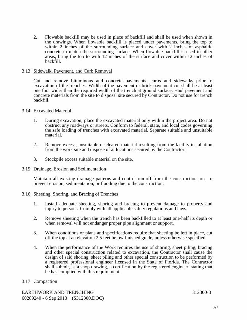
2. Flowable backfill may be used in place of backfill and shall be used when shown in
the drawings. When flowable backfill is placed under pavements, bring the top to within 2 inches of the surrounding surface and cover with 2 inches of asphaltic concrete to match the surrounding surface. When flowable backfill is used in other areas, bring the top to with 12 inches of the surface and cover within 12 inches of backfill.
3.13 Sidewalk, Pavement, and Curb Removal
Cut and remove bituminous and concrete pavements, curbs and sidewalks prior to excavation of the trenches. Width of the pavement or brick pavement cut shall be at least one foot wider than the required width of the trench at ground surface. Haul pavement and concrete materials from the site to disposal site secured by Contractor. Do not use for trench backfill.
3.14 Excavated Material
1. During excavation, place the excavated material only within the project area. Do not obstruct any roadways or streets. Conform to federal, state, and local codes governing the safe loading of trenches with excavated material. Separate suitable and unsuitable material.
2. Remove excess, unsuitable or cleared material resulting from the facility installation
from the work site and dispose of at locations secured by the Contractor. 3. Stockpile excess suitable material on the site.
3.15 Drainage, Erosion and Sedimentation
Maintain all existing drainage patterns and control run-off from the construction area to prevent erosion, sedimentation, or flooding due to the construction.
3.16 Sheeting, Shoring, and Bracing of Trenches
1. Install adequate sheeting, shoring and bracing to prevent damage to property and injury to persons. Comply with all applicable safety regulations and laws.
2. Remove sheeting when the trench has been backfilled to at least one-half its depth or
when removal will not endanger proper pipe alignment or support. 3. When conditions or plans and specifications require that sheeting be left in place, cut
off the top at an elevation 2.5 feet below finished grade, unless otherwise specified. 4. When the performance of the Work requires the use of shoring, sheet piling, bracing
and other special construction related to excavation, the Contractor shall cause the design of said shoring, sheet piling and other special construction to be performed by a registered professional engineer licensed in the State of Florida. The Contractor shall submit, as a shop drawing, a certification by the registered engineer, stating that he has complied with this requirement.
3.17 Compaction EARTHWORK AND TRENCHING 312300-8 60289240 - 6 Sep 2013 (S312300.DOC) 397

1. Unless otherwise specified or shown on the drawings, compact backfill and fill areas (except within trenches) to at least the following minimum compaction requirements:
a. Structural Backfill: 95% relative density in 6-inch maximum layers. b. Subgrade Under Fill or Backfill: 95% relative density to a depth of 12 inches. c. Subgrade Under Structural Backfill or Structures: 98% relative density to a
depth of 24 inches. d. Backfill or Fill Under Pavement and Structures: 98% relative density in 12-inch
maximum layers. e. All Other Areas: 95% relative density in 12-inch maximum layers.
2. Unless otherwise specified or shown on the drawings, compact soil in trenches to the following minimum compaction requirements:
a. Pipe Bedding: 95% relative density. b. Trench Backfill not Under Pavement and Structures: 95% relative density. c. Trench Backfill Under Pavement and Structures: 98% relative density. d. Refill for Over-excavation: 95% relative density.
3. Compact the first 2 feet of backfill over pipe either by hand-operated tamping devices or with powered equipment which will not damage the pipe. Flooding or puddling with water to consolidate backfill is not acceptable, except where sand is encountered and the specified density can be obtained using this method.
4. During the compacting operations, maintain material within +2% of optimum
moisture. Aerate material containing excessive moisture by blading, discing, or harrowing to hasten the drying process.
3.18 Site Grading
Perform earthwork to the lines and grades shown on the drawings. Round tops of banks to circular curves to not less than a 6-foot radius. Neatly and smoothly trim rounded surfaces. Shape the surface of earthwork and trenches to conform to lines, grades and cross sections that existed prior to beginning work or as shown on the drawings, within one-tenth (1/10) of a foot.
3.19 Protection of Property
1. Protect the trunks of trees adjacent to this work by enclosure with padding or wood. Operate excavating machinery and cranes with care to prevent damage to trees, particularly to overhanging branches and limbs.
2. Do not cut branches, limbs and roots unless they are within six inches of the facility
under construction. Make all necessary cuts smoothly and neatly without splitting or crushing. Neatly trim the tree at all cut or damaged portions.
EARTHWORK AND TRENCHING 312300-9 60289240 - 6 Sep 2013 (S312300.DOC) 398

3. Do not operate on paved surface any equipment with treads or wheels, which will cut or otherwise damage paved surfaces. Provide adequate protective measures to avoid damages to the paved surfaces.
4. As promptly as practicable, restore existing property or structures. Do not leave
restoration until the end of the construction period.
3.20 Testing
1. Field density tests will be made in locations reviewed by the Owner, or the representative normally in each vertical layer, and using the following approximate spacing: a. Under structures, pavements, and slabs, one per 2,500 square feet with at least
two per structure or area. b. In trenches, one (1) every 300 feet in continuous trenches under pavements or
future pavements plus one (1) at each intersection or one (1) every 500 feet in continuous trenches not under pavements, plus one (1) at each pavement or driveway crossing.
c. In all other areas, one per 7,500 square feet.
2. If any field density tests are below the specified relative density, re-compact or re-excavate, re-backfill and re-compact the area until the specific density is obtained. Make a minimum of two (2) field density tests per re-compacted and/or re-excavated area, but do not exceed the spacing specified above.
3.21 Acceptance
After the specified density tests have been successfully completed, the Owner or his representative may cross section the excavation and/or fill area to verify that the excavation or fill area conforms to the lines and grades shown on the plans and to determine quantities of material. Correct deviations from line and grade in excess of the tolerances specified at no expense to the Owner.
END OF SECTION
EARTHWORK AND TRENCHING 312300-10 60289240 - 6 Sep 2013 (S312300.DOC) 399

DIVISION 32- EXTERIOR IMPROVEMENTS 320116 Pavement Removal and Restoration 321116 Compacted Sub-Base 321123 Limerock Base Course 321213 Prime and Tack Coats 321215 Asphalt Pavement
400

This page intentionally left blank
401

SECTION 320116 PAVEMENT REMOVAL AND RESTORATION PART 1 - GENERAL 1.01 Description
The work specified in this section consists of removing and restoring pavement, curb, curb and gutter, valley gutter, sidewalks and driveways disturbed by the work. Contractor shall provide all necessary labor, materials, equipment, tools, supplies, plant and equipment.
1.02 Submittals
Submit shop drawings in accordance with Division 01 General Requirements, Section 013300, and the General Conditions.
1.03 Jurisdiction
For removals and restorations or other installation in areas not within the jurisdiction of the Owner, the Contractor shall comply with regulations and conditions of permits issued by said authority.
PART 2 - PRODUCTS 2.01 Stabilizers
See Section 321116.
2.02 Base
See Section 321123.
2.03 Prime and Tack Coat
See Section 321213.
2.04 Asphalt Pavement
See Section 321215.
2.05 Concrete
See Section 033000.
PAVEMENT REMOVAL AND RESTORATION 320116-1 60289240 - 6 Sep 2013 (S320116) 402

PART 3 - EXECUTION 3.01 Sidewalk and Driveway Restoration
A. Replace or repair all existing sidewalks and driveways removed, disturbed, or destroyed by construction. Make the finished work equal to or better than the original in all respects. Remove the sidewalk and/or driveway pavement to existing joints or saw cut, leaving pieces not less than 5 feet long (5 feet in any direction for drive-ways) to avoid leaving odd-sized sections of pavement after repairs have been made. Make all Portland cement concrete driveway repairs 6 inches in minimum thickness and Portland cement concrete sidewalks to a minimum thickness of 4 inches and 6 inches at driveways.
B. Asphalt driveways and sidewalks shall be constructed as specified in Sections 321213
and 321215.
3.02 Roadway and Pavement Restoration
A. Replace pavement or roadway surfaces cut or damaged by the Contractor in equal or better condition than the original, including stabilization, base course, surface course, or other appurtenances.
B. Asphalt roadway surface shall be constructed as specified in Sections 321213 and
321215. C. Base course shall be constructed as specified in Section 321123.
3.03 Concrete Curbs, Gutters and Valley Gutters
A. Do not disturb curbs or gutters where practical to tunnel underneath. If tunneling is not possible, remove the curb to the existing joints or sawcut, leaving pieces not less than five feet long, and replace with identical sections.
3.04 Saw-Cutting
A. Where existing pavement is to be removed, saw-cut the surface leaving a uniform and straight edge, with minimum disturbance to the remaining adjacent surfacing.
B. The width of all pavement surface cuts shall be not less than two feet greater than
width of trench in order to provide a minimum of one-foot bearing width on each side.
3.05 Temporary Surface
A. Where existing pavement is removed, provide a temporary surface according to the following:
1. Compact the backfill as specified and bring to grade to match existing roadway
surface. Within ten days after pavement removal, regrade the backfill and place, compact, and seal the subbase and base.
2. Within sixty (60) days after pavement removal, place the finished surface
course. Pavement repair shall at all times provide a smooth traffic surface so as not to create a bump or depression.
PAVEMENT REMOVAL AND RESTORATION 320116-2 60289240 - 6 Sep 2013 (S320116) 403
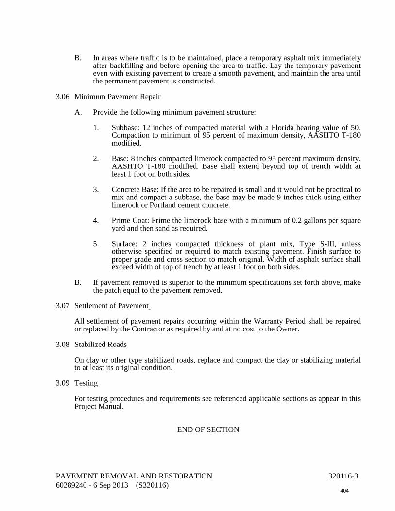
B. In areas where traffic is to be maintained, place a temporary asphalt mix immediately
after backfilling and before opening the area to traffic. Lay the temporary pavement even with existing pavement to create a smooth pavement, and maintain the area until the permanent pavement is constructed.
3.06 Minimum Pavement Repair
A. Provide the following minimum pavement structure:
1. Subbase: 12 inches of compacted material with a Florida bearing value of 50. Compaction to minimum of 95 percent of maximum density, AASHTO T-180 modified.
2. Base: 8 inches compacted limerock compacted to 95 percent maximum density,
AASHTO T-180 modified. Base shall extend beyond top of trench width at least 1 foot on both sides.
3. Concrete Base: If the area to be repaired is small and it would not be practical to
mix and compact a subbase, the base may be made 9 inches thick using either limerock or Portland cement concrete.
4. Prime Coat: Prime the limerock base with a minimum of 0.2 gallons per square
yard and then sand as required. 5. Surface: 2 inches compacted thickness of plant mix, Type S-III, unless
otherwise specified or required to match existing pavement. Finish surface to proper grade and cross section to match original. Width of asphalt surface shall exceed width of top of trench by at least 1 foot on both sides.
B. If pavement removed is superior to the minimum specifications set forth above, make
the patch equal to the pavement removed.
3.07 Settlement of Pavement
All settlement of pavement repairs occurring within the Warranty Period shall be repaired or replaced by the Contractor as required by and at no cost to the Owner.
3.08 Stabilized Roads
On clay or other type stabilized roads, replace and compact the clay or stabilizing material to at least its original condition.
3.09 Testing
For testing procedures and requirements see referenced applicable sections as appear in this Project Manual.
END OF SECTION
PAVEMENT REMOVAL AND RESTORATION 320116-3 60289240 - 6 Sep 2013 (S320116) 404

This page intentionally left blank
405
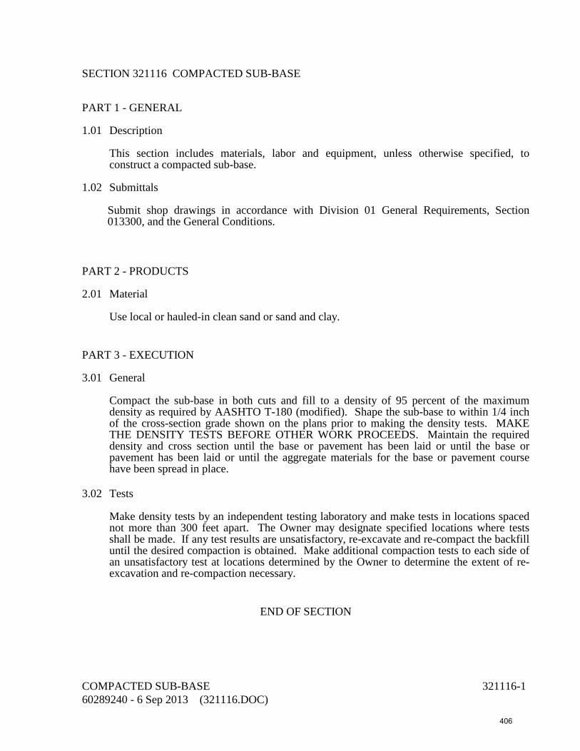
SECTION 321116 COMPACTED SUB-BASE PART 1 - GENERAL 1.01 Description
This section includes materials, labor and equipment, unless otherwise specified, to construct a compacted sub-base.
1.02 Submittals
Submit shop drawings in accordance with Division 01 General Requirements, Section 013300, and the General Conditions.
PART 2 - PRODUCTS 2.01 Material
Use local or hauled-in clean sand or sand and clay.
PART 3 - EXECUTION 3.01 General
Compact the sub-base in both cuts and fill to a density of 95 percent of the maximum density as required by AASHTO T-180 (modified). Shape the sub-base to within 1/4 inch of the cross-section grade shown on the plans prior to making the density tests. MAKE THE DENSITY TESTS BEFORE OTHER WORK PROCEEDS. Maintain the required density and cross section until the base or pavement has been laid or until the base or pavement has been laid or until the aggregate materials for the base or pavement course have been spread in place.
3.02 Tests
Make density tests by an independent testing laboratory and make tests in locations spaced not more than 300 feet apart. The Owner may designate specified locations where tests shall be made. If any test results are unsatisfactory, re-excavate and re-compact the backfill until the desired compaction is obtained. Make additional compaction tests to each side of an unsatisfactory test at locations determined by the Owner to determine the extent of re-excavation and re-compaction necessary.
END OF SECTION
COMPACTED SUB-BASE 321116-1 60289240 - 6 Sep 2013 (321116.DOC) 406

This page intentionally left blank
407

SECTION 321123 LIMEROCK BASE COURSE PART 1 - GENERAL 1.01 Description
The work specified in this section consists of the construction of a base course composed of limerock constructed on the prepared subbase in accordance with these specifications and in conformity with the lines, grades, notes, and typical cross sections shown on the plans.
1.02 Submittals
Submit shop drawings in accordance with Division 01 General Requirements, Section 013300, and the General Conditions.
PART 2 - PRODUCTS 2.01 Materials
1. Use limerock having a minimum percentage of carbonates of calcium and magnesium of 70, a maximum percentage of water-sensitive clay mineral of 3, and a liquid limit not exceeding 35. The material shall be non-plastic and contain less than 1% by weight asbestos.
2. Limerock material shall not contain cherty or other extremely hard pieces, or lumps,
balls or pockets of sand or clay size material in sufficient quantity as to be detrimental to the proper bonding, finishing, or strength of the limerock base.
3. At least 97 percent (by weight) of the material shall pass a 3-1/2 inch sieve and the
material shall be graded uniformly down to dust. The fine material shall consist entirely of dust of fracture. All crushing or breaking-up which might be necessary in order to meet such size requirements shall be done before the material is placed on the road.
4. Limerock material used in construction of limerock base shall have an average LBR
value of not less than 100.
PART 3 - EXECUTION 3.01 Transporting Limerock
Transport limerock to the point where it is to be used, over rock previously placed and dumped on the end of the preceding spread. In no case shall rock be dumped directly on the subbase.
3.02. Spreading Limerock
1. Spread limerock uniformly. Remove and replace all segregated areas of fine or coarse rock with well-graded rock.
LIMEROCK BASE COURSE 321123-1 60289240 - 6 Sep 2013 (321123) 408

2. Construct base in courses between 4 inches and 6 inches in thickness. 3. For double-course base, spread rock in two courses. Thickness of the first course shall
be approximately one-half the total thickness of the finished base, or enough additional to bear the weight of the construction equipment without disturbing the subgrade.
3.03 Compacting and Finishing Grade
1. For double-course base, blade the first course if necessary to secure a uniform base and compact to the density specified below immediately prior to spreading the second course. No other finishing of this course is required.
2. After spreading is completed, scarify the entire surface and shape to produce the
specified grade and cross section after compaction. For double-course bases, scarify-ing shall penetrate by at least 1/2-inch the surface of the first course.
3. As soon as proper moisture conditions are attained, compact the material to an
average density of 98 percent of the maximum density obtainable under AASHTO Method T-180 (modified). Take density readings after grading and cross sectioning have been completed.
4. "Hard-plane" the surface with a blade immediately prior to the application of prime
coat to remove thin-glazed or cemented surface, leaving a granular or porous condition that will allow free penetration of prime material. Remove materials planed from the base area.
5. If at any time, the subbase material becomes mixed with the base course material,
excavate and remove the mixture, reshape and compact the subbase, and replace the materials removed with clean base material, shaped and compacted as specified above.
3.04 Testing Surface
1. Check the finished surface of the base course with a template cut to the required cross section and with a 15-foot straight edge laid parallel to the center line of the road or other approved testing devices. Correct all irregularities greater than +1/4 inch by scarifying and removing or adding rock, as may be required, after which the entire areas shall be compacted as specified herein.
2. During final compacting operations, if blading of any areas is necessary to obtain the
true grade and cross section, complete the compacting operations for such areas prior to making the density tests on the finished grade.
3.05 Thickness Testing
After the base is completed, test holes or cores shall be taken by an independent testing laboratory at intervals of not more than 300 feet in roadways or 2,400 sq. ft. in area paving. The average thickness of three consecutive holes must be equal to at least the specified thickness. Where the base is more than 1/2 inch deficient in thickness, or does not meet the average thickness requirement, rework the area covered by this deficient base by scarifying to a depth of at least 3 inches and adding more base material, so that after proper com-pacting the thickness and shape will conform to the plans.
LIMEROCK BASE COURSE 321123-2 60289240 - 6 Sep 2013 (321123) 409

3.06 Density Testing
1. MAKE AT LEAST THREE DENSITY DETERMINATIONS ON EACH DAY'S FINAL COMPACTION OPERATIONS ON EACH COURSE. The density determinations shall be made at more frequent intervals if deemed necessary by the Engineer.
END OF SECTION
LIMEROCK BASE COURSE 321123-3 60289240 - 6 Sep 2013 (321123) 410

This page intentionally left blank
411

SECTION 321213 PRIME AND TACK COATS PART 1 - GENERAL 1.01 Description This section includes materials, testing and application of bituminous material on a
previously prepared base and on an existing pavement surface.
1.02 Submittals
Submit shop drawings in accordance with Division 01 General Requirements, Section 013300, and the General Conditions.
PART 2 - PRODUCTS 2.01 Prime Coat
The material used for prime coat shall be:
A. Cut-back Asphalt Grade RC-70 or RC-250 meeting the requirements of AASHTO M81 except that the penetration range shall be from 60-120 instead of 80-120.
For Grade RC-3000, in addition to the requirements shown in Table I of AASHTO M81 the following values shall be added to the requirements for Distillation Test: Distillate, percentage by volume Grade RC-3000 of total distillate to 680 deg. F. Max. to 320 deg. F 0 to 374 deg. F 10 to 437 deg. F 40 All other requirements for the distillation test (and for other properties included in the table) shall be as shown in Table I of AASHTO M81.
2.02 Cover Material for Prime Coat
A. If an emulsified asphalt is used for prime coat, the cover material shall be hot-asphalt coated (mix to contain from two to four percent asphalt-cement) to achieve a prime coat which will remain reasonably intact until the surface course is placed.
B. If material other than emulsified asphalt is used for the prime coat, the cover material
shall be either sand (bare or hot-asphalt coated) or screenings. The sand shall be nonplastic and free from any appreciable amount of silt, clay balls and root particles, and from any noticeable sticks, trash, vegetation or other organic matter. Screenings shall be Miami Oolitic rock screenings as specified in FDOT Specification Section 902-5.2.3.
PRIME AND TACK COATS 321213-1 60289240 - 6 Sep 2013 (321213) 412

2.03 Tack Coat
A. Unless a specific type or grade of material is called for in the plans or specifications, the material used for tack coat may be any of the following: Emulsified Asphalt, Grades RS-1, RS-2, CRS-2, or CRS-2H. The materials specified above shall not be diluted prior to use.
B. Emulsified asphalt (RS Type) shall meet the following requirements:
Min. Max. Tests on Emulsion: Saybolt furol viscosity at 77°F, sec. 75 -- Storage stability 24 Hr., % -- 1.0 Sieve test, % -- 0.1 Naptha content, % by volume 5 15 Residue, % 55 -- Tests on Residue:* Penetration at 77°F, 100g, 5 sec. 50 -- Viscosity at 140°F (poises) 800 -- Solubility in trichloroethylene, % 97.5 -- * Residue by distillation shall be in accordance with AASHTO T-59 except that the
maximum temperature shall be 329° + 10°F (165° + 5°C) and the sample shall be maintained at this temperature for 20 minutes.
PART 3 - EXECUTION 3.01 Equipment Pressure Distributor: The pressure distributor shall be equipped with pneumatic tires having
a sufficient width of rubber in contact with the road surface to avoid breaking the bond or forming a rut in the surface. The distance between the centers of openings of the outside nozzles of the spray bar shall be equal to the width of the application required, within an allowable variation of two inches. The outside nozzle at each end of the spray bar shall have an area of opening not less than 25 percent nor more than 75 percent, in excess of the other nozzles. All other nozzles shall have uniform openings. When the application covers less than the full width, the normal opening of the end nozzle at the junction line may remain the same as those of the interior nozzles.
3.02 Cleaning Base and Protection of Adjacent Work
A. Before any bituminous material is applied, all loose material, dust, dirt, caked clay and other foreign materials which might prevent proper bond with the existing surface shall be removed for the full width of the application. Particular care shall be taken in cleaning the outer edges of the strip to be treated, to insure that the prime or tack coat will adhere.
B. When the prime or tack coat is applied adjacent to curb and gutter, valley gutter or
any other concrete surfaces, such concrete surfaces (except where they are to be covered with a bituminous wearing course) shall be covered with heavy paper, or
PRIME AND TACK COATS 321213-2 60289240 - 6 Sep 2013 (321213) 413

otherwise protected while the prime or tack coat is being applied. Any bituminous material deposited on such concrete surfaces shall be removed.
3.03 Weather Limitations Prime and tack coats shall be applied when the air temperature, in the shade, is above 40°F,
and when all other weather conditions and the condition of the surface are suitable.
3.04 Application of Prime Coat
A. General: The surface to be primed shall be clean and the moisture content of the base shall not exceed 90 percent of the optimum moisture. The temperature of the prime material shall be between 100°F and 180°F. The actual temperature shall be that which will insure uniform distribution. The material shall be applied by means of a pressure distributor. The amount to be applied will be dependent on the character of the surface and shall be sufficient to coat the surface thoroughly and uniformly, with no excess. A prime coat is required on newly constructed limerock, shell, and sand clay bases.
B. Rate of Application
1. Limerock, Limerock Stabilized, and Local Rock Bases: For these bases, the rate of application shall be not less than 0.10 gallon per square yard.
2. Sandy-Clay, Shell and Shell Stabilized Bases: The rate of application for these
bases shall be not less than 0.15 gallon per square yard.
3. Partial Width of Application: If warranted by traffic conditions, the application may be made on only one-half of the width of the base at one time, in which case positive means shall be used to secure the correct amount of bituminous material at the joint.
4. Sanding
A If an emulsified asphalt is used to prime coat, the primed base shall be uniformly covered by an application of sand-bituminous hot mix or screenings at an approximate rate of ten pounds per square yard. The entire surface of the sand-bituminous hot mix or screenings cover material shall be rolled with a traffic roller as required to produce a reasonable dense mat.
B. If material other than emulsified asphalt is used for prime coat, the primed base
shall be covered by a light uniform application of cover material. If considered necessary for proper distribution of spread, the cover material shall be lightly dragged with a drag broom, after which it shall be rolled with a traffic roller, for at least ten passes over the entire area.
3.05 Application of Tack Coat
A. General: Where a bituminous surface is to be laid and a tack coat is required, the tack coat shall be applied as specified herein below.
B. Use a tack coat on existing pavement to be resurfaced, primed bases in areas which
have become excessively dirty and cannot be cleaned, or in areas where the prime has cured and lost its bonding effect.
PRIME AND TACK COATS 321213-3 60289240 - 6 Sep 2013 (321213) 414

C. Method of Application: The tack coat shall be applied with a pressure distributor except that, on small jobs if approved by the Engineer, application may be by other mechanical devices or by hand methods. The bituminous material shall be heated to a suitable temperature and shall be applied in a thin, uniform layer.
D. Rate of Application: The rate of application shall be between 0.02 and 0.08 gallon per
square yard. For tack coat applied on concrete pavement which is to be surfaced, the rate of application may exceed the upper limit.
E. Curing and Time of Application: The tack coat shall be applied sufficiently in
advance of the laying of the bituminous mix to permit drying but shall not be applied so far in advance that it might lose its adhesiveness as a result of being covered with dust or other foreign material.
F. Protection: The tack coat surface shall be kept free from traffic until the subsequent
layer of bituminous hot mix has been laid.
END OF SECTION
PRIME AND TACK COATS 321213-4 60289240 - 6 Sep 2013 (321213) 415

SECTION 321215 ASPHALT PAVEMENT PART 1 - GENERAL 1.01 Description
This section specifies requirements for material, testing and installation of plant mix asphalt pavement.
1.02 Rights-of-Way
County: Roadway and pavement within county rights-of-way shall be in accordance with applicable county standards and "Right-of-Way Utilization Regulations".
1.03 Submittals
A. Submit shop drawings in accordance with Division 01 General Requirements, Section 013300, and the General Conditions.
B. A design mix for the asphalt including gradation of all materials, content of mix,
Marshall stability, and laboratory density. C. Certifications showing that the materials comply with the specifications and contain
less than 1% by weight asbestos.
PART 2 - PRODUCTS 2.01 Asphaltic Concrete
A. Composition, design mix and physical properties shall meet the requirements of the following:
Bituminous Concrete Mixtures
(Gradation Design Range) Percent by Weight Total Aggregate Passing Sieves Type ______________________________________________________ 3/4 1/2 3/8 No.4 No.10 No.40 No.80 No.200 S-I 100 88-100 75-93 47-75 31-53 19-35 7-21 2-6 S-II(1) 83-98 71-87 62-78 47-63 33-49 19-35 9-18 2-6 S-III 100 88-100 60-90 40-70 20-45 10-30 2-6 Type II 100 90-100 80-100 55-90 2-12 Type III 100 80-100 65-100 40-75 20-45 10-30 2-10 ABC-2 100 55-90 0-12 ABC-3(2) 70-100 30-70 20-60 10-40 2-10 FC-1 100 55-85 2-8 FC-2 100 85-100 10-40 4-12 2-5 FC-4 100 75-90 2-6 _________________________________________________________________
ASPHALT PAVEMENT 321215-1 60289240 - 6 Sep 2013 (321215) 416

(1) 100% passing 1-1/4-inch sieve and 94-100% passing 1-inch sieve. (2) 100% passing 1-1/2-inch sieve.
Marshall Design Properties for
Bituminous Concrete Mixes Minimum Minimum Effective Marshall Minimum Air Asphalt Mix Stability Flow(1) VMA Voids Content Type (lbs.) (0.01 in.) (%) (%) (%) S-I 1500 8-14 14 3-5 5.0 S-II 1500 8-14 13 3-5 5.0 S-III 1500 8-14 15 3-7 5.5 Type II 500-750 8-16 18 5-16 6.0 Type III 750-1000 8-16 15 5-12 5.5 ABC-2 250 8-20 15 5-14 5.5 ABC-3 1000 8-20 14 3-7 5.0 FC-1 500 8-16 15 8-14 5.5 FC-2 --- ---- -- ---- --- FC-4 500 8-16 15 12-16 5.0 _________________________________________________________
(1) The maximum flow for the mix design shall be one point less than shown. The
maximum flow values shown apply only during production.
2.02 Asphaltic Concrete Type S-III
A. Type S-III shall meet the above requirements and the requirements in the following paragraphs.
B. The Asphalt Cement, Viscosity Grade AC-20 or AC-30, shall meet the following
except that no spot test is required:
AC-20 AC-30 Test Min. Max. Min. Max. Viscosity, 140°F (60°C), poises (2000 + 400) (3000 + 600) Viscosity, 275°F (135°C), Cs 300 -- 350 -- Penetration, 77°F (25°C), 100 gm, 5 Sec. 60 -- 50 -- Flash Point, COC, °F (°C) 450 -- (232) -- Solubility in Trichloroethylene, percent 99.0 -- 99.0 -- Tests on Residue from Thin Film Oven Test: Viscosity Ratio= Visc. 140°F after TFOT -- 4 -- 4 Visc. 140°F before TFOT Ductility 77°F (25°C) 5 cm per min, cm. 80 -- 50 -- Loss on Heating, % -- 0.5 -- 0.5
ASPHALT PAVEMENT 321215-2 60289240 - 6 Sep 2013 (321215) 417

C. Mineral filler shall consist of limerock dust, portland cement, slag dust or hydrated lime. It shall be thoroughly dry and free from lumps, consisting of aggregations of fine particles. The filler shall meet the following gradation requirements:
Sieve Number Total % Passing 30 100 80 95 (min) 200 65 (min) Mineral filler may be provided from process screenings from stone or slag provided that the loss in processing under the Los Angeles Abrasion Test does not exceed 45%. The gradation of this filler shall be such that all of it shall pass the No. 10 sieve, and not more than 35% shall pass the No. 200 sieve. The material passing the No. 200 sieve shall be free of organic impurities and clay minerals shall not exceed 4.0%. The plasticity index of the material passing the No. 200 sieve shall not exceed 4.
2.03 Coarse Aggregate:
A. Coarse Aggregate shall consist of gravel, rock or slag and contain less than 1% by weight asbestos. All coarse aggregate shall be washed and shall be free from disintegrated pieces, clay lumps, soft and friable particles, salt, alkali, organic matter and adherent coatings. The weight of deleterious substances shall not exceed the following percentages:
Coal and lignite . . . . . . . . . . . . . 1.00 Clay lumps . . . . . . . . . . . . . . . . 2.00 Soft and friable particles . . . . . . . . 2.00 Cinders and clinkers . . . . . . . . . . . 0.50 Free Shell . . . . . . . . . . . . . . . . 1.00 Organic matter (wet) . . . . . . . . . . . 0.03 Material passing the No. 200 Sieve . . . . 1.75 Chert . . . . . . . . . . . . . . . . . . 3.00 In addition, the sum of the percentages of all substances listed above shall not exceed ten.
B. Coarse aggregate shall have a maximum loss of 45% when subjected to the Los Angeles Abrasion Test, a maximum loss of 12% when subjected to the Soundness (Sodium Sulfate) Test and contain a maximum of 10% flat or elongated pieces.
C. Natural Stones: Coarse aggregate may be processed from gravels, granites,
limestones, dolomites, sandstones, or other naturally occurring hard, sound, durable materials meeting the requirements of this paragraph.
1) Gravel shall be composed of naturally occurring quartz. The loss when
the material is subjected to the Los Angeles Abrasion Test (AASHTO T96), shall be no more than 45%. The dry-rodded weight per cubic foot of the gravel, tested according to AASHTO T19, shall be not less than 95 pounds. Crushed gravel shall consist of 85%, by weight, of the material retained on the No. 4 sieve, having three crushed faces.
ASPHALT PAVEMENT 321215-3 60289240 - 6 Sep 2013 (321215) 418

2) Granites: Coarse aggregate produced from the crushing of granites shall be sound and durable. For granites to be used in bituminous mixtures and surface treatments, the Los Angeles Abrasion requirement is modified to permit a maximum loss up to 50 (Manual of Florida Sampling and Testing Methods FM 1-T 096). Maximum amount of mica schist permitted is 5% (AASHTO T-189).
3) Limestones, Dolomites and Sandstone: Coarse aggregates may be
produced from limestone, dolomites, sandstones, and other naturally occurring hard, durable materials meeting the requirements of this paragraph.
Pre-Cenozoic limestones and dolomites shall not be used as crushed-stone aggregates, either coarse or fine, for wearing courses of asphaltic concrete surface courses. This specifically includes materials from the Ketona Dolomite (Cambrian), Newala Limestone (Lower Ordovician), Bangor Limestone (Mississippian), and other formations of similar composition and origin occurring in central and northern Alabama and Georgia.
D. Slag shall be clean, tough and durable. It may be either air-cooled blast-furnace
slag or phosphate slag. It shall be reasonably uniform in density and quality, and free from deleterious substances. It shall contain not more than 1.5% of sulfur. The dry-rodded weight shall be not less than 70 pounds per cubic foot. The loss, when the slag is subjected to the Los Angeles Abrasion Test, shall not exceed 45%. It shall contain not more than 10% glassy particles.
E. Unless written permission from the Owner is obtained, coarse aggregates of
different types shall not be mixed, nor be used alternately in sections of less than one mile.
F Grading shall be in accordance with FDOT Specification Section 901-1.4 Table
1. G. Lightweight expanded aggregate shall be clean and durable material produced
by firing shale, clay, or slate in a rotary kiln. It shall be reasonably uniform in quality and density and free from deleterious substances, except that the term cinders and clinkers shall only apply to those particles clearly foreign to the expanded aggregate in question and the maximum percentage of material passing the No. 200 sieve shall be 3.00. The dry-loose unit weight of the material, determined in accordance with AASHTO T19, shall not be less than 33 or more than 55 pounds per cubic foot. The burning process shall be care-fully controlled. As an indication of the control of burning, the producer shall obtain and test samples of material at frequent intervals. Control shall be considered adequate if the dry-loose unit weight of such samples does not differ by more than +6% from the average weight established from the producer's quality control testing records. When subjected to the Los Angeles Abrasion Test, the loss shall not exceed 35%.
2.04 Fine Aggregate:
A. Fine aggregate shall consist of natural silica sand, screenings, or a combination thereof, composed of clean, tough, angular grains, free from clay, soft or flaky particles, salt, alkali, organic matter, loam and other foreign matter. As delivered to the mixer it shall be free from clayey lumps of loosely bonded
ASPHALT PAVEMENT 321215-4 60289240 - 6 Sep 2013 (321215) 419

aggregations and the individual particles shall be free from adhering dust. Stone of slag screenings shall be produced from material complying with the abrasion requirements specified for coarse aggregate. The weight of deleterious substances (shale, coal and lignite, cinders and clinkers, clay lumps) shall not exceed 1.0, 1.0, 0.5 and 1.0% respectively.
B. The following additional limitation shall apply for stone used as aggregate in all
asphaltic concrete used as a wearing coarse. Pre-Cenozoic limestones and dolomites shall not be used as crushed-stone aggregates, either coarse or fine, for wearing courses of asphaltic concrete surface coarses. This specifically includes materials from the Ketona Dolomite (Cambrian), Newala Limestone (Lower Ordovician), Bangor Limestone (Mississippian), and other formations of similar composition and origin in central and northern Alabama and Georgia.
C. Any screenings used in the combination of aggregate shall contain not more
than 15% of material passing the No. 200 sieve and, if necessary to meet this requirement, they shall be washed.
D. Any natural sand portion of the fine aggregate other than screenings shall be
siliceous and shall contain not more than 10% of material passing the No. 200 sieve.
E. Silica sand, when tested by means of laboratory sieves, shall meet the following
requirements:
Passing Percent Sieve by Weight No. 4 . . . . . . . . . . . . . . . . 95-100 No. 8 . . . . . . . . . . . . . . . . 85-100 No. 16 . . . . . . . . . . . . . . . . 65- 97 No. 30 . . . . . . . . . . . . . . . . 25- 70 No. 50 . . . . . . . . . . . . . . . . 5- 35 No. 100 . . . . . . . . . . . . . . . . 0- 7 No. 200 . . . . . . . . . . . . . . . . Max. 4
F. Screenings: Screenings shall be composed of hard, durable particles, either naturally occurring, such as gravel screenings, or resulting from the crushing or processing of the parent rock, to include natural rock, slags, expanded clays or shales (lightweight aggregates), or other approved inert materials with similar characteristics.
Aggregates classified as screenings shall conform to the following gradation requirements: Sieve Size Passing Percent 3/8" 100 No. 4 85 to 100 No. 200 Maximum 15
2.05 Asphaltic Concrete Type S-III
ASPHALT PAVEMENT 321215-5 60289240 - 6 Sep 2013 (321215) 420

1. Type S-III shall meet the requirements of paragraphs 2A and 2B as modified by the following:
A. Not more than 25% by weight of the total aggregate used shall be local sand. In
addition to the local sand, a portion not to exceed 15% by weight of the total aggregate may be commercial washed sand. The commercial washed sand must be in conformance with the requirements of fine aggregates for Asphaltic Concrete Type S-1.
B. When tested at the cold elevator in the combination to be used, the aggregate
shall contain not more than 10%, by weight, of material passing the No. 200 sieve. Any screenings used in the combination of aggregate shall not contain more than 15% of material passing the No. 200 sieve. When two screenings are blended to produce the screenings component of the aggregate, any component of such screenings may contain up to 18% of material passing the No. 200 sieve. Screenings may be washed to meet these requirements and shall be free from lumps and foreign matter.
2.06 Herbicide
Use a herbicide specifically recommended by the manufacturer for killing weeds on asphalt roadways, that will not harm or reduce the life of the pavement and meets the local, state and federal rules and regulations for use as a weed killer.
PART 3 - EXECUTION 3.01 Hot Bituminous Mixtures
A. Plant operations shall not begin unless all weather conditions are suitable for the laying operations.
B. The mixture shall be spread only when the surface upon which it is to be laid has been
previously prepared, is intact, firm and properly cured, and is dry. No mixture shall be spread that cannot be finished and compacted during daylight hours. The mixture shall be spread only when the air temperature (the temperature in the shade away from artificial heat) is above 40°F for layers greater than one inch (100 lbs per square yard) in thickness and 45°F and above for layers one inch (100 lbs per square yard) or less in thickness (this includes leveling courses). No mixture shall be placed when there is evidence of a frozen base. The mixture shall not be spread when the wind is blowing to such an extent that proper and adequate compaction cannot be maintained or when sand, dust, etc., are being deposited on the surface being paved, to the extent that the bond between layers will be diminished.
C. Mixing at the asphalt plant shall be sufficient to produce a thoroughly and uniformly
coated mixture. The ingredients of the mix shall be heated and combined in such a manner as to produce a mixture, which shall be at a temperature, when discharged from the pugmill or surge bin, within the range of 230°F to 310°F and within the tolerance shown in the following table:
Temperature Tolerance From Job Mix Formula
_______________________________________
ASPHALT PAVEMENT 321215-6 60289240 - 6 Sep 2013 (321215) 421

Any Single Measurement . . . . . . . . . . . . . +25°F Average of Any Five Consecutive Measurements . . +15°F __________________________________________________ However, the temperature of the mixture, in all cases, shall be such that will yield an asphalt Kinematic viscosity within the range of 280 and 150 centistokes. The mix temperature will be taken at the plant on the first five loads each day and on an average of once every five loads thereafter. Take corrective action if the temperature fails to fall within the specified tolerance.
D. The maximum time that any mix may be kept in a hot storage or surge bin is 72 hours. Produce a homogeneous mixture, free from moisture and with no segregated materials, that meets all requirements of the specifications for the mixture, including compliance with the design limits. These requirements shall apply also to all mixes produced by the drum mixer process and all mixes processed through a hot storage or surge bin, both before and after storage.
E. The mixture shall be transported in tight vehicles previously cleaned of all foreign material and each load shall be covered. The inside surface of the truck bodies shall be thinly coated with soapy water or an emulsion containing not over 5% of oil. Kerosene, gasoline or similar products shall not be used. After the truck bodies are coated and before any mixture is placed therein, they shall be raised so that all excess liquids will be drained out.
F. Prior to the laying of the mixture, the surface of the base or pavements to be covered
shall be cleaned of all loose and deleterious material by the use of power brooms or blowers, supplemented by hand brooming where necessary.
G. Where a surface course is constructed on an existing pavement or old base which is
irregular, and wherever so indicated in the plans, the existing surface shall be brought to proper grade and cross section by the application of patching or leveling courses. A tack coat shall be required on existing pavements to be overlaid with an asphalt mix and between successive layers of all asphalt mixes, or whenever freshly primed bases have cured to the point of which the asphaltic pavement may not bond adequately. Apply herbicide (weed killer) to the existing surface prior to placing [leveling] [pavement] at the rate recommended by the manufacturer and for the full length and width of roadways and parking areas.
H. All asphaltic concrete mixtures (including leveling courses), other than adjacent to
curb and gutter or other true edges, shall be laid by the string-line method, to assure the obtaining of an accurate, uniform alignment of the pavement edge. The temperature of the mix at the time of spreading shall be within +25°F of the actual mix temperature. The minimum frequency for taking mix temperatures on the road will be an average of one per five trucks. Take corrective action if the temperature range fails to fall within the specified tolerance range. Any mixture caught in transit by a sudden rain may be laid at risk. Should such mixture prove unsatisfactory, it shall be removed and replaced with satisfactory mixture at no additional expense to the Owner. In no case shall the mixture be laid while rain is falling or when there is water on the surface to be covered. The forward speed of the spreader shall be as established by the manufacturer of the equipment and sufficient for an even application. For each paving machine being operated, a separate crew will be required; each crew operating as a full unit. The depth of each layer shall be checked at frequent intervals of approximately 25 feet. Any deviation below the design thickness as shown on the
ASPHALT PAVEMENT 321215-7 60289240 - 6 Sep 2013 (321215) 422
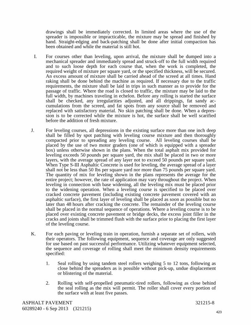
drawings shall be immediately corrected. In limited areas where the use of the spreader is impossible or impracticable, the mixture may be spread and finished by hand. Straight-edging and back-patching shall be done after initial compaction has been obtained and while the material is still hot.
I. For courses other than leveling, upon arrival, the mixture shall be dumped into a
mechanical spreader and immediately spread and struck-off to the full width required and to such loose depth for each course that, when the work is completed, the required weight of mixture per square yard, or the specified thickness, will be secured. An excess amount of mixture shall be carried ahead of the screed at all times. Hand raking shall be done behind the machine as required. If necessary due to the traffic requirements, the mixture shall be laid in trips in such manner as to provide for the passage of traffic. Where the road is closed to traffic, the mixture may be laid to the full width, by machines traveling in echelon. Before any rolling is started the surface shall be checked, any irregularities adjusted, and all drippings, fat sandy ac-cumulations from the screed, and fat spots from any source shall be removed and replaced with satisfactory material. No skin patching shall be done. When a depres-sion is to be corrected while the mixture is hot, the surface shall be well scarified before the addition of fresh mixture.
J. For leveling courses, all depressions in the existing surface more than one inch deep
shall be filled by spot patching with leveling course mixture and then thoroughly compacted prior to spreading any leveling course. All leveling courses shall be placed by the use of two motor graders (one of which is equipped with a spreader box) unless otherwise shown in the plans. When the total asphalt mix provided for leveling exceeds 50 pounds per square yard, the mix shall be placed in two or more layers, with the average spread of any layer not to exceed 50 pounds per square yard. When Type S-III Asphaltic Concrete is used for leveling, the average spread of a layer shall not be less than 50 lbs per square yard nor more than 75 pounds per square yard. The quantity of mix for leveling shown in the plans represents the average for the entire project; however, the rate of application may vary throughout the project. When leveling in connection with base widening, all the leveling mix must be placed prior to the widening operation. When a leveling course is specified to be placed over cracked concrete pavement (including existing concrete pavement covered with an asphaltic surface), the first layer of leveling shall be placed as soon as possible but no later than 48 hours after cracking the concrete. The remainder of the leveling course shall be placed in the normal sequence of operations. Where a leveling course is to be placed over existing concrete pavement or bridge decks, the excess joint filler in the cracks and joints shall be trimmed flush with the surface prior to placing the first layer of the leveling course.
K. For each paving or leveling train in operation, furnish a separate set of rollers, with
their operators. The following equipment, sequence and coverage are only suggested for use based on past successful performance. Utilizing whatever equipment selected, the sequence and coverage of rolling shall meet the minimum density requirements specified:
1. Seal rolling by using tandem steel rollers weighing 5 to 12 tons, following as
close behind the spreaders as is possible without pick-up, undue displacement or blistering of the material.
2. Rolling with self-propelled pneumatic-tired rollers, following as close behind
the seal rolling as the mix will permit. The roller shall cover every portion of the surface with at least five passes.
ASPHALT PAVEMENT 321215-8 60289240 - 6 Sep 2013 (321215) 423

3. Final rolling with the 8- to 12-ton tandem steel rollers, to be done after the seal
rolling and pneumatic-tired rolling have been completed, but before the internal pavement temperature has dropped below 175°F.
L. The initial rolling shall be longitudinal. Where the lane being placed is adjacent to a
previously placed lane, the center joint shall be pinched or rolled, prior to the rolling of the rest of the lane. After the rolling or pinching of the center joint, the rolling shall continue across the mat by overlapping each previous roller path by at least one-half the width of the roller wheel. The motion of the roller shall be slow enough to avoid displacement of the mixture, and any displacement shall be corrected at once by the use of rakes, and the addition of fresh mixture if required. Final rolling shall be continued until all roller marks are eliminated. Rolling with the self-propelled, pneu-matic-tired rollers shall proceed at a speed of 6 to 10 miles per hour, and the area covered by each roller shall not be more than 4,000 square yards per hour, except that for Type S Asphaltic Concrete, this maximum rate of coverage shall be 3,000 square yards per hour.
1. A sufficient number of self-propelled pneumatic-tired rollers shall be used such
that the rolling of the surface for the required number of passes will not delay any other phase of the laying operation nor result in excessive cooling of the mixture before the rolling is complete. In the event that the rolling falls behind, the laying operation shall be discontinued until the rolling operations are sufficiently caught up.
2. Areas which are inaccessible to a roller (such as areas adjacent to curbs,
headers, gutters, bridges, manholes, etc.) shall be compacted by the use of hand tamps or other satisfactory means.
3. Self-propelled pneumatic-tired rollers shall be used for the rolling of all
patching and leveling courses. Where the initial leveling course is placed over broken concrete pavement, the pneumatic-tired roller shall weigh at least 15 tons. For Type S-III Asphaltic Concrete leveling courses, the use of a steel-wheel roller, to supplement the traffic rollers, will be required. On other leveling courses, the use of a steel-wheeled roller will be required on all passes after the first.
4. The rollers shall not be allowed to deposit gasoline, oil or grease onto the
pavement, and any areas damaged by such deposits shall be removed and replaced. While rolling is in progress, the surface shall be tested continuously and all discrepancies corrected to comply with the surface requirements. All drippings, fat or lean areas and defective construction of any description shall be removed and replaced. Depressions which develop before the completion of the rolling shall be remedied by loosening the mixture and adding new mixture to bring the depressions to a true surface. Should any depression remain after the final compaction has been obtained, the full depth of the mixture shall be removed and replaced with sufficient new mixture to form a true and even surface. All high spots, high joints and honeycomb shall be corrected. Any mixture remaining unbonded after rolling shall be removed and replaced. Any mixture which becomes loose or broken, mixed or coated with dirt or in any way defective, prior to laying the wearing course shall be removed and replaced with fresh mixture which shall be immediately be compacted to conform with the surrounding area. Areas of defective surface may be repaired by the use of indirect heat. No method of repair involving open-flame heaters shall be used.
ASPHALT PAVEMENT 321215-9 60289240 - 6 Sep 2013 (321215) 424
M. Shoulder pavements wider than 5-1/2 feet shall be compacted by the use of
equipment of the type required for other asphaltic concrete pavements. Compaction of asphaltic concrete 5-1/2 feet or less in width, shall be done by the use of tandem steel rollers not exceeding 12 tons in weight. Other compaction in such restricted widths shall be by the use of rubber-tired equipment.
N. The density of a completed course shall be at least 94% of the laboratory density. O. Placing of the mixture shall be as continuous as possible and the roller shall not pass
over the unprotected end of the freshly laid mixture except when the laying operation is to be discontinued long enough to permit the mixture to become chilled. When the laying operation is thus interrupted, a transverse joint shall be constructed by cutting back on the previous run to expose the full depth of the mat.
P. Where only a portion of the width of pavement is to be laid and opened to traffic,
longitudinal joints shall be formed by rolling the exposed edge of the strip first laid. When the adjacent strip is constructed, the Engineer may require the edge of the mixture in place to be trimmed back to expose an unsealed or granular vertical surface. Where the strip first laid is closed to traffic, the edge shall not be sealed but shall be left vertical and the adjacent strip placed against it without trimming.
Q. When fresh mixture is laid against the exposed edges of joints (trimmed or formed as
provided above), it shall be placed in close contact with the exposed edge so that an even, well-compacted joint will be produced after rolling.
R. The finished surface shall be of uniform texture and compaction and shall be smooth.
The surface shall have no pulled, torn, or loosened portions and shall be free of segregation, sand streaks, sand spots, or ripples. Any area of the surface which does not meet the foregoing requirements shall be corrected.
S. All pavements (both intermediate and final courses), intersections, acceleration lanes,
deceleration lanes, tapers, crossovers, transitions at beginning and end of project, and similar areas shall be tested with a straightedge for surface tolerance. Any individual surface irregularity in these areas in excess of 3/16-inch as determined by a 15-foot straightedge shall be corrected and retested. Provide a 15-foot manual straightedge at the job site at all times during the paving operation for checking joints and surface irregularities.
T. If the Owner elects to waive corrections, the appropriate pay quantity for Asphaltic
Concrete shall be reduced by the equivalent quantity of materials which would have been removed and replaced if the correction had been made.
1. Where the pay quantity is in square yards, the reduction is based on the area
which would have been removed multiplied by the ratio of the layer thickness to the total thickness of the type of mix specified.
2. Where the pay quantity is in tons, the reduction is based on the volume which
would have been removed (length x lane width x layer thickness) multiplied by the laboratory density for the mix.
3. Where the project is a lump sum pay quantity based on amount completed, the
appropriate reduction in percent complete shall be calculated based on the total amount of paving.
ASPHALT PAVEMENT 321215-10 60289240 - 6 Sep 2013 (321215) 425

U. Select one of the following correction methods unless overlaying is prohibited.
1. Removing and Replacing: If correction is made by removing and replacing the pavement, the removal must be for the full depth of the course and extend at least 50 feet on either side of the defective area, for the full width of the paving lane.
2. Overlaying: If correction is made by overlaying, the overlaying shall cover the
length of the defective area and taper uniformly to a featheredge thickness at a minimum distance of 50 feet on either side of the defective area. The overlay shall extend full width of the roadway. Care shall be taken to maintain the specified cross and lengthwise slopes.
V. All corrective work, either by removing and replacing or by overlaying, including the
bituminous material, shall be provided at no additional cost to the Owner. W. Sections of newly compacted asphaltic concrete which are to be covered by additional
courses shall be kept clean until the successive course is laid. X. Blade graders operating adjacent to the pavement during shoulder construction shall
have a 2-inch by 8-inch (or larger) board (or other attachment providing essentially the same results) attached to their blades in such manner that it extends below the blade edge, in order to protect the pavement surface from damage by the grader blade.
Y. Vehicular traffic shall not be permitted on any pavement which has not hardened
sufficiently to prevent rutting or other distortion. Z. The specified thickness and density is the minimum to be supplied and any
deficiency(s) shall be corrected either by replacing the full thickness for a length extending at least 50 feet from each end of the deficient area, or (when permitted by the Owner) by overlaying with a minimum thickness of 75% of the specified thickness.
3.02 Saw-Cutting
Where existing pavement is to be removed, except brick, sawcut the surface leaving a uniform and straight edge with minimum disturbance to the remaining adjacent surface.
3.03 Settlement of Pavement
All settlement of pavement repairs occurring within the Warranty Period shall be repaired or replaced as required by and at no cost to the Owner.
3.04 Testing
A. Unless otherwise stipulated on the plans, the following tests will be made by an independent testing laboratory.
1. Extraction of the asphaltic concrete and sieve analysis of the aggregate. 2. Determination of bitumen content of the asphaltic concrete.
ASPHALT PAVEMENT 321215-11 60289240 - 6 Sep 2013 (321215) 426
3. Core borings (approximately every 200 feet) to determine thickness and density. 4. Marshall stability.
3.05 Repairs
Repair holes made to test the finished asphalt.
END OF SECTION
ASPHALT PAVEMENT 321215-12 60289240 - 6 Sep 2013 (321215) 427

DIVISION 40 – PROCESS INTEGRATION 400500 General Piping Requirements 400515 Pressure Testing of Piping 400520 Manual, Check, and Process Valves 400560 Air Release and Vacuum Relief-Valves 400570 Globe Pattern Control Valves (AWWA C530) 400580 Fabricated Stainless Steel Slide Gates 400775 Equipment, Piping, Duct, and Valve Identification 402040 Ductile-Iron Pipe 402076 Stainless Steel Pipe 402078 Stainless Steel Tubing 402090 PVC Pipe, 3 Inches and Smaller 402097 HDPE Pipe and Fittings 402713 Corporation Stops and Service Saddles 405000 Process Control and Instrumentation System (PCIS) General Requirements 405020 Instrumentation Equipment 405040 Programmable Logic Control System 405050 Remote Terminal Unit (RTU) System 409210 Electric Motor Actuators for Slide Gates 409510 Packaged Equipment Electrical Panels
428

This page intentionally left blank
429

SECTION 400500 GENERAL PIPING REQUIREMENTS
PART 1 - GENERAL
1.01 DESCRIPTION
This section describes the general requirements for selecting piping materials; selecting the associated bolts, nuts, and gaskets for flanges for the various piping services in the project; and miscellaneous piping items.
1.02 SUBMITTALS
A. Submit shop drawings in accordance with the General Conditions, Section 013300, and the following.
B. Submit affidavit of compliance with referenced standards (e.g., AWWA, ANSI, ASTM, etc.).
C. Submit certified copies of mill test reports for bolts and nuts, including coatings if specified. Provide recertification by an independent domestic testing laboratory for materials originating outside of the United States.
D. Submit manufacturer's data sheet for gaskets supplied showing dimensions and bolting recommendations.
1.03 DEFINITIONS OF BURIED AND EXPOSED PIPING
A. Buried piping is piping buried in the soil, commencing at the wall or beneath the slab of a structure. Where a coating is specified, provide the coating up to the structure wall. Unless detailed otherwise, coating shall penetrate wall no less than 1 inch. Piping encased in concrete is considered to be buried. Do not coat encased pipe.
B. Exposed piping is piping in any of the following conditions or locations:
1. Above ground.
2. Inside buildings, vaults, or other structures.
3. In underground concrete trenches or galleries.
1.04 PIPING SERVICE
Piping service is determined by the fluid conveyed, regardless of the pipe designation. For example, pipes designated "Air Low Pressure," "Air High Pressure," and "Air" are all considered to be in air service.
GENERAL PIPING REQUIREMENTS 400500-1 60289240 - 18 Sep 2013 (S400500.DOC) 430

1.05 DEFAULT PIPING MATERIALS
If no material is shown in the drawings or in the Piping Schedule, use the following piping materials:
Service Size Range
(inches) Material Specification
Section Buried 3 and smaller PVC 402090 4 and larger HDPE 402097 Exposed 3 and smaller PVC 402090 4 and larger DIP 402040
PART 2 - MATERIALS
2.01 MATERIALS SELECTION AND ALTERNATIVE MATERIALS
A. The Piping Schedule in the drawings lists the material and specification for each piping service in the project. In locations where the piping material referenced on the Piping Schedule is not appropriate, the piping material is indicated in the drawings. Materials called out in the drawings shall govern over materials stated in the Piping Schedule.
B. The Piping Schedule in the drawings may show alternative piping materials for certain services. In such cases, the same pipe material shall be used for all pipe sizes in all locations for the given piping service. Do not intermix piping materials.
2.02 THREAD FORMING FOR STAINLESS STEEL BOLTS
Form threads by means of rolling, not cutting or grinding.
2.03 BOLTS AND NUTS FOR FLANGES FOR STEEL AND DUCTILE-IRON PIPING
A. Bolts and nuts for Class 125 or 150 flanges (including AWWA C207, Class D) located indoors, shall be carbon steel, ASTM A307, Grade B, hot-dipped galvanized per ASTM F2329.
B. Bolts and nuts for buried or submerged Class 125 or 150 flanges and Class 125 or 150 flanges located outdoors above ground or in vaults and structures shall be Type 316 stainless steel conforming to ASTM A193, Grade B8M for bolts and ASTM A194, Grade 8M for nuts.
C. Hex head machine bolts for use with lugged valves shall comply with ASTM A193, Grade B7.
D. Fit shall be Classes 2A and 2B per ASME B1.1 when connecting to cast-iron valves having body bolt holes.
GENERAL PIPING REQUIREMENTS 400500-2 60289240 - 18 Sep 2013 (S400500.DOC) 431
E. Bolts for AWWA C207 Classes E and F flanges and ASME B16.5 and B16.47 Class 300 flanges located indoors, outdoors above ground and in vaults and structures shall conform to ASTM A193, Grade B7, with nuts conforming to ASTM A194, Grade 2H.
F. Bolts and nuts for buried or submerged Class 300 flanges and Class 300 flanges located outdoors above ground or in vaults and structures shall be Type 316 stainless steel conforming to ASTM A193, Grade B8M, Class 2, for bolts and ASTM A194, Grade 8M, for nuts.
G. Bolts used in flange insulation kits shall conform to ASTM A193 (Grade B7). Nuts shall conform to ASTM A194 (Grade 2H).
H. Provide washers for each nut. Washers shall be of the same material as the nuts.
2.04 BOLTS AND NUTS FOR FLANGES FOR PVC PIPE
A. Bolts and nuts for flanges located indoors, shall be carbon steel, ASTM A307, Grade B, hot-dipped galvanized per ASTM F2329.
B. Bolts and nuts for buried and submerged flanges and flanges located outdoors above ground or in vaults and structures shall be Type 316 stainless steel conforming to ASTM A193, Grade B8M for bolts and ASTM A194, Grade 8M for nuts.
2.05 ANTI-SEIZE FOR STAINLESS STEEL BOLTS AND NUTS
Anti-seize shall be nickel grade meeting MIL Spec MIL-A-907D; apply to all steel and stainless steel nuts and bolts.
2.06 GASKETS FOR FLANGES FOR DUCTILE-IRON PIPING AND FITTINGS IN WATER SERVICE
Gaskets shall be full face, 1/8-inch thick, cloth-inserted rubber, with a Shore "A" hardness of 75 to 85. Gaskets shall be suitable for a water pressure of 200 psi at a temperature of 180°F. Gaskets shall have "nominal" pipe size inside diameters not the inside diameters per ASME B16.21. Products: Garlock Style 19 or equal.
2.07 GASKETS FOR FLANGES FOR PVC PIPING
Gaskets for flanged joints shall be full faced, 1/8-inch thick, having a hardness of 50 to 70 durometer A. Gasket material shall be EPR.
2.08 THREADED CAPS FOR PROTECTION OF NUTS AND BOLT THREADS
Caps shall be high-density polyethylene, color orange. The caps shall be filled with an anticorrosive lubricant to prevent nuts and bolts from rusting and corroding. Lubricant shall be suitable for use in potable water. Caps shall withstand temperatures from -40°F to 200°F. Caps shall be suitable to use in exposed, buried, and submerged service
GENERAL PIPING REQUIREMENTS 400500-3 60289240 - 18 Sep 2013 (S400500.DOC) 432
conditions. Products: Sap-Seal Products, Inc.; Advance Products and Systems, Inc., "Radolid"; or equal.
2.09 MOLDABLE FILLER TAPE FOR PIPE SURFACE TRANSITION AREAS
A. Filler tape shall be a 100% solids mastic-like butyl-rubber filler designed to fill and smooth the transition areas between adjacent coating surfaces such as step-down weld areas, surface irregularities beneath heat-shrink sleeves, pipefittings, and exothermic welds for cathodic protection bonding wire connections. Characteristics:
1. Thickness per ASTM D1000: 1/8 inch minimum.
2. Peel adhesion to primed pipe: 300 ounces per inch minimum.
3. Elongation: 600% minimum.
B. Products: Tapecoat “Moldable Sealant,” Polyken No. 939 Filler Tape, or equal.
PART 3 - EXECUTION
3.01 INSTALLING PIPE SPOOLS IN CONCRETE
Install pipes in walls and slabs before placing concrete.
3.02 RAISED FACE AND FLAT FACE FLANGES
Where a raised face flange connects to a flat-faced flange, remove the raised face of the flange.
3.03 INSTALLING ABOVEGROUND OR EXPOSED PIPING
A. Provide pipe hangers and supports as detailed in the drawings.
B. Install pipe without springing, forcing, or stressing the pipe or any adjacent connecting valves or equipment.
3.04 INSTALLING FLANGED PIPING
A. Set pipe with the flange bolt holes straddling the pipe horizontal and vertical centerline. Install pipe without springing, forcing, or stressing the pipe or any adjacent connecting valves or equipment. Before bolting up, align flange faces to the design plane within 1/16 inch per foot measured across any diameter. Align flange bolt holes within 1/8-inch maximum offset.
B. Inspect each gasket to verify that it is the correct size, material, and type for the specified service and that it is clean and undamaged. Examine bolts or studs, nuts, and washers for defects such as burrs or cracks and rust and replace as needed.
GENERAL PIPING REQUIREMENTS 400500-4 60289240 - 18 Sep 2013 (S400500.DOC) 433

C. Clean flanges by wire brushing before installing flanged fittings. Clean flange bolts and nuts by wire brushing, lubricate carbon steel bolts with oil and graphite, and tighten nuts uniformly and progressively.
D. Bolt lengths shall extend completely through their nuts. Any that fail to do so shall be considered acceptably engaged if the lack of complete engagement is not more than one thread.
E. Do not use more than one gasket between contact faces in assembling a flanged joint.
F. Tighten the bolts to the manufacturer’s specifications, using the recommended cross bolt pattern in multiple steps of increasing torque, until the final torque requirements are achieved. Do not over torque.
G. If flanges leak under pressure testing, loosen or remove the nuts and bolts, reset or replace the gasket, reinstall or retighten the bolts and nuts, and retest the joints. Joints shall be watertight.
H. Install threaded nut and bolt thread protection caps after completing the bolt, nut, and gasket installation. Install on buried piping.
3.05 INSTALLING BLIND FLANGES
A. At outlets not indicated to be connected to valves or to other pipes and to complete the installed pipeline hydrostatic test, provide blind flanges with bolts, nuts, and gaskets.
B. Coat the inside face of blind flanges per Section 099000, System No. 7.
3.06 INSTALLING GROOVED-END PIPING
A. Install grooved-end pipe and fittings in accordance with the coupling manufacturer's recommendations and the following.
B. Clean loose scale, rust, oil, grease, and dirt from the pipe or fitting groove before installing coupling. Apply the coupling manufacturer's gasket lubricant to the gasket exterior including lips, pipe ends, and housing interiors.
C. Fasten coupling alternately and evenly until coupling halves are seated. Use torques as recommended by the coupling manufacturer.
D. Provide separate hangers and supports at both sides of flexible joints.
3.07 INSTALLATION OF STAINLESS STEEL BOLTS AND NUTS
Prior to assembly, coat threaded portions of stainless steel bolts and nuts with lubricant.
END OF SECTION
GENERAL PIPING REQUIREMENTS 400500-5 60289240 - 18 Sep 2013 (S400500.DOC) 434

This page intentionally left blank
435

SECTION 400515 - PRESSURE TESTING OF PIPING
PART 1 - GENERAL
1.01 DESCRIPTION
This section specifies the cleaning and hydrostatic and leakage testing of pressure piping for pumping stations, water piping systems.
1.02 SUBMITTALS
A. Submit shop drawings in accordance with the General Conditions, Section 013300, and the following.
B. Submit test bulkhead locations and design calculations, pipe attachment details, and methods to prevent excessive pipe wall stresses.
C. Submit six copies of the test records to the Owner's Representative upon completion of the testing.
1.03 TEST PRESSURES
Test pressures for the various services and types of piping are shown in the Piping Schedule in the drawings.
1.04 TESTING RECORDS
Provide records of each piping installation during the testing. These records shall include:
A. Date and times of test.
B. Identification of process, pipeline, or pipeline section tested or retested.
C. Identification of pipeline material.
D. Identification of pipe specification.
E. Test fluid.
F. Test pressure at low point in process, pipeline, or pipeline section.
G. Remarks: Leaks identified (type and location), types of repairs, or corrections made.
H. Certification by Contractor that the leakage rate measured conformed to the specifications.
PRESSURE TESTING OF PIPING 400515-1 60289240 - 6 Sep 2013 (S400515.DOC) 436
PART 2 - MATERIALS
2.01 VENTS AND DRAINS FOR ABOVEGROUND PIPING
Install vents on the high points of aboveground piping, whether shown in the drawings or not. Install drains on low points of aboveground piping, whether shown in the drawings or not. Provide a valve at each vent or drain point. Valves shall be 3/4 inch for piping 3 inches and larger and 1/2 inch for piping smaller than 3 inches. Valves shall be as specified in Section 400520, Type 300, unless otherwise shown in the drawings.
2.02 MANUAL AIR-RELEASE VALVES FOR BURIED PIPING
Provide temporary manual air-release valves for pipeline test. Construct the pipe outlet in the same manner as for a permanent air valve and after use, seal with a blind flange, pipe cap, or plug and coat the same as the adjacent pipe.
2.03 TESTING FLUID
A. Testing fluid shall be water.
B. For potable water pipelines, obtain and use only potable water for hydrostatic testing.
C. Submit request for use of water from waterlines of Owner 48 hours in advance.
D. The Contractor may obtain the water from the Owner at the Owner's rate of charges.
2.04 TESTING EQUIPMENT
Provide calibrated pressure gauges, pipes, bulkheads, pumps, chart recorder, and meters to perform the hydrostatic testing.
PART 3 - EXECUTION
3.01 TESTING PREPARATION
A. Pipes shall be in place, backfilled, and anchored before commencing pressure testing.
B. Conduct pressure tests on exposed and aboveground piping after the piping has been installed and attached to the pipe supports, hangers, anchors, expansion joints, valves, and meters.
C. For buried piping, the pipe may be partially backfilled and the joints left exposed for inspection during an initial leakage test. Perform the final pressure test, however, after completely backfilling and compacting the trench.
D. Provide any temporary piping needed to carry the test fluid to the piping that is to be tested. After the test has been completed and demonstrated to comply with the specifications, disconnect and remove temporary piping. Do not remove exposed vent
PRESSURE TESTING OF PIPING 400515-2 60289240 - 6 Sep 2013 (S400515.DOC) 437

and drain valves at the high and low points in the tested piping; remove any temporary buried valves and cap the associated outlets. Plug taps or connections to the existing piping from which the test fluid was obtained.
E. Provide temporary drain lines needed to carry testing fluid away from the pipe being tested. Remove such temporary drain lines after completing the pressure testing.
F. Prior to starting the test, the Contractor shall notify the Owner's Representative.
3.02 CLEANING
A. Before conducting hydrostatic tests, flush pipes with water to remove dirt and debris. Maintain a flushing velocity of at least 3 fps for water testing. Flush pipes for time period as given by the formula
T = 2L 3
in which:
T = flushing time (seconds) L = pipe length (feet)
3.03 TESTING AND DISINFECTION SEQUENCE FOR POTABLE WATER PIPING
A. Perform required disinfection after hydrostatic testing, except when pipeline being tested is connected to a potable waterline.
B. Locate and install test bulkheads, valves, connections to existing pipelines, and other appurtenances in a manner to provide an air gap separation between existing potable water pipelines and the pipeline being tested. Disinfect water and pipeline being tested before hydrostatic testing when connected to a potable waterline.
3.04 LENGTH OF TEST SECTION FOR BURIED PIPING
The maximum length of test section for buried pipe of 12 inches or smaller in diameter is 3,500 feet; for buried pipe larger than 12 inches, 1 mile. Provide intermediate test bulkheads where the pipeline length exceeds these limits.
3.05 INITIAL PIPELINE FILLING FOR HYDROSTATIC TESTING
Maximum rate of filling shall not cause water velocity in pipeline to exceed 1 fps. Filling may be facilitated by removing automatic air valves and releasing air manually.
3.06 TESTING NEW PIPE WHICH CONNECTS TO EXISTING PIPE
Prior to testing new pipelines that are to be connected to existing pipelines, isolate the new line from the existing line by means of test bulkheads, spectacle flanges, or blind
PRESSURE TESTING OF PIPING 400515-3 60289240 - 6 Sep 2013 (S400515.DOC) 438

flanges. After successfully testing the new line, remove test bulkheads or flanges and connect to the existing piping.
3.07 HYDROSTATIC TESTING OF ABOVEGROUND OR EXPOSED PIPING
A. Open vents at high points of the piping system to purge air while filling the pipe with water. Venting during system filling may also be provided by temporarily loosening flanges.
B. Subject the piping system to the test pressure indicated on the Piping Schedule in the drawings. Maintain the test pressure for a minimum of four hours. Examine joints, fittings, valves, and connections for leaks. The piping system shall show zero leakage or weeping. Correct leaks and retest until zero leakage is obtained.
3.08 HYDROSTATIC TESTING OF BURIED PIPING
A. Where any section of the piping contains concrete thrust blocks or encasement, do not perform the pressure test until at least 10 days after placing the concrete. When testing mortar-lined, PVC, or HDPE piping, fill the pipe to be tested with water and allow it to soak for at least 48 hours to absorb water before conducting the pressure test.
B. Apply and maintain the test pressure by means of a positive displacement hydraulic force pump.
C. Maintain the test pressure for the following duration by restoring it whenever it falls an amount of 5 psi:
Pipe Diameter
(inches)
Hours 18 and less 4 20 to 36 8 Greater than 36 24
D. After the test pressure is reached, use a meter to measure the additional water added to maintain the pressure. This amount of water is the loss due to leakage in the piping system. The allowable leakage volume is defined by the formula
L = HND(P)1/2
C
in which:
PRESSURE TESTING OF PIPING 400515-4 60289240 - 6 Sep 2013 (S400515.DOC) 439
L = allowable leakage (gallons) H = specified test period (hours) N = number of rubber-gasketed joints in the pipe tested D = diameter of the pipe (inches) P = specified test pressure (psig) C = 7,400
E. The allowable leakage for buried piping having threaded, brazed, or welded (including solvent welded) joints shall be zero.
F. Repair and retest any pipes showing leakage rates greater than that allowed in the above criteria.
3.09 REPETITION OF TEST
If the actual leakage exceeds the allowable, locate and correct the faulty work and repeat the test. Restore the work and all damage resulting from the leak and its repair. Eliminate visible leakage.
3.10 BULKHEAD AND TEST FACILITY REMOVAL
After a satisfactory test, remove the testing fluid, remove test bulkheads and other test facilities, and restore the pipe coatings.
END OF SECTION
PRESSURE TESTING OF PIPING 400515-5 60289240 - 6 Sep 2013 (S400515.DOC) 440

This page intentionally left blank
441

SECTION 400520 MANUAL, CHECK, AND PROCESS VALVES
PART 1 - GENERAL
1.01 DESCRIPTION
This section includes materials, testing, and installation of manually operated valves, check valves, and process valves including gate, knife gate, butterfly, ball, hose bibbs, globe, angle, needle, eccentric plug, lubricated plug, nonlubricated plug, diaphragm, check, pinch, solenoid, pet cocks, mud valves, vacuum breakers, deluge valves, flap valves, balancing valves, gauge valves, instrument valve manifolds, and telescoping valves.
1.02 SUBMITTALS
A. Submit shop drawings in accordance with the General Conditions, Section 013300, and the following.
B. Submit manufacturer's catalog data and detail construction sheets showing all valve parts. Describe each part by material of construction, specification (such as AISI, ASTM, SAE, or CDA), and grade or type. Identify each valve by tag number to which the catalog data and detail sheets pertain.
C. Show valve dimensions including laying lengths. Show port sizes. Show dimensions and orientation of valve actuators, as installed on the valves. Show location of internal stops for gear actuators. State differential pressure and fluid velocity used to size actuators. For worm-gear actuators, state the radius of the gear sector in contact with the worm and state the handwheel diameter.
D. Show valve linings and coatings. Submit manufacturer's catalog data and descriptive literature.
E. Submit six copies of a report verifying that the valve interior linings and exterior coatings have been tested for holidays and lining thickness. Describe test results and repair procedures for each valve. Do not ship valves to project site until the reports have been returned by the Owner's Representative and marked "Resubmittal not required."
F. For butterfly and eccentric plug valves, show the clear diameter or size of the port. Show the actual area of the port as a percentage of the area as calculated for the nominal valve size.
1.03 PROOF OF DESIGN TEST FOR ECCENTRIC PLUG VALVES (TYPES 500, 510, 520, AND 525)
A. The Contractor shall require the valve manufacturer to furnish six certified copies of reports covering the design tests for the eccentric plug valves as described in AWWA
MANUAL, CHECK, AND PROCESS VALVES 400520-1 60289240 - 6 Sep 2013 (S400520.DOC) 442
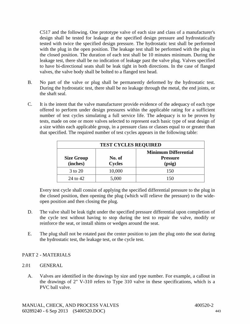
C517 and the following. One prototype valve of each size and class of a manufacturer's design shall be tested for leakage at the specified design pressure and hydrostatically tested with twice the specified design pressure. The hydrostatic test shall be performed with the plug in the open position. The leakage test shall be performed with the plug in the closed position. The duration of each test shall be 10 minutes minimum. During the leakage test, there shall be no indication of leakage past the valve plug. Valves specified to have bi-directional seats shall be leak tight in both directions. In the case of flanged valves, the valve body shall be bolted to a flanged test head.
B. No part of the valve or plug shall be permanently deformed by the hydrostatic test. During the hydrostatic test, there shall be no leakage through the metal, the end joints, or the shaft seal.
C. It is the intent that the valve manufacturer provide evidence of the adequacy of each type offered to perform under design pressures within the applicable rating for a sufficient number of test cycles simulating a full service life. The adequacy is to be proven by tests, made on one or more valves selected to represent each basic type of seat design of a size within each applicable group, in a pressure class or classes equal to or greater than that specified. The required number of test cycles appears in the following table:
TEST CYCLES REQUIRED
Size Group
(inches)
No. of Cycles
Minimum Differential Pressure
(psig) 3 to 20 10,000 150 24 to 42 5,000 150
Every test cycle shall consist of applying the specified differential pressure to the plug in the closed position, then opening the plug (which will relieve the pressure) to the wide-open position and then closing the plug.
D. The valve shall be leak tight under the specified pressure differential upon completion of the cycle test without having to stop during the test to repair the valve, modify or reinforce the seat, or install shims or wedges around the seat.
E. The plug shall not be rotated past the center position to jam the plug onto the seat during the hydrostatic test, the leakage test, or the cycle test.
PART 2 - MATERIALS
2.01 GENERAL
A. Valves are identified in the drawings by size and type number. For example, a callout in the drawings of 2" V-310 refers to Type 310 valve in these specifications, which is a PVC ball valve.
MANUAL, CHECK, AND PROCESS VALVES 400520-2 60289240 - 6 Sep 2013 (S400520.DOC) 443
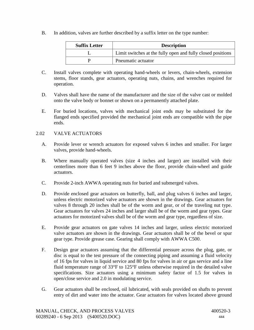
B. In addition, valves are further described by a suffix letter on the type number:
Suffix Letter Description L Limit switches at the fully open and fully closed positions P Pneumatic actuator
C. Install valves complete with operating hand-wheels or levers, chain-wheels, extension stems, floor stands, gear actuators, operating nuts, chains, and wrenches required for operation.
D. Valves shall have the name of the manufacturer and the size of the valve cast or molded onto the valve body or bonnet or shown on a permanently attached plate.
E. For buried locations, valves with mechanical joint ends may be substituted for the flanged ends specified provided the mechanical joint ends are compatible with the pipe ends.
2.02 VALVE ACTUATORS
A. Provide lever or wrench actuators for exposed valves 6 inches and smaller. For larger valves, provide hand-wheels.
B. Where manually operated valves (size 4 inches and larger) are installed with their centerlines more than 6 feet 9 inches above the floor, provide chain-wheel and guide actuators.
C. Provide 2-inch AWWA operating nuts for buried and submerged valves.
D. Provide enclosed gear actuators on butterfly, ball, and plug valves 6 inches and larger, unless electric motorized valve actuators are shown in the drawings. Gear actuators for valves 8 through 20 inches shall be of the worm and gear, or of the traveling nut type. Gear actuators for valves 24 inches and larger shall be of the worm and gear types. Gear actuators for motorized valves shall be of the worm and gear type, regardless of size.
E. Provide gear actuators on gate valves 14 inches and larger, unless electric motorized valve actuators are shown in the drawings. Gear actuators shall be of the bevel or spur gear type. Provide grease case. Gearing shall comply with AWWA C500.
F. Design gear actuators assuming that the differential pressure across the plug, gate, or disc is equal to the test pressure of the connecting piping and assuming a fluid velocity of 16 fps for valves in liquid service and 80 fps for valves in air or gas service and a line fluid temperature range of 33°F to 125°F unless otherwise required in the detailed valve specifications. Size actuators using a minimum safety factor of 1.5 for valves in open/close service and 2.0 in modulating service.
G. Gear actuators shall be enclosed, oil lubricated, with seals provided on shafts to prevent entry of dirt and water into the actuator. Gear actuators for valves located above ground
MANUAL, CHECK, AND PROCESS VALVES 400520-3 60289240 - 6 Sep 2013 (S400520.DOC) 444

or in vaults and structures shall have hand-wheels. The actuators for valves in exposed service shall contain a dial indicating the position of the valve disc or plug. Gear actuators for buried or submerged valves shall have 2-inch-square AWWA operating nuts.
H. For buried or submerged service or valves installed in buried vaults, provide watertight shaft seals and watertight valve and actuator cover gaskets. Provide totally enclosed actuators designed for buried or submerged service.
I. Traveling nut and worm and gear actuators shall be of the totally enclosed design so proportioned as to permit operation of the valve under full differential pressure rating of the valve with a maximum pull of 40 pounds on the hand-wheel or crank. Provide stop limiting devices in the actuators in the open and closed positions. Actuators shall be of the self-locking type to prevent the disc or plug from creeping. Design actuator components between the input and the stop-limiting devices to withstand without damage a pull of 200 pounds for hand-wheel or chain-wheel actuators and an input torque of 300 foot-pounds for operating nuts when operating against the stops.
J. Hand-wheel diameters for traveling nut actuators shall not exceed 8 inches for valves 12 inches and smaller and shall not exceed 12 inches for valves 20 inches and smaller.
K. Self-locking worm gear shall be a one-piece design of gear bronze material (ASTM B427; or ASTM B84, Alloy C86200), accurately machine cut. Actuators for eccentric and lubricated plug valves may use ductile-iron gears provided the gearing is totally enclosed with spring-loaded rubber lip seals on the shafts. The worm shall be hardened alloy steel (ASTM A322, Grade G41500 or G41400; or ASTM A148, Grade 105-85), with thread ground and polished. Support worm-gear shaft at each end by ball or tapered roller bearings. The reduction gearing shall run in a proper lubricant. The hand-wheel diameter shall be no more than twice the radius of the gear sector in contact with the worm. Worm-gear actuators shall be Limitorque Model HBC, EIM Series W, or equal.
L. Design actuators on buried valves to produce the required torque on the operating nut with a maximum input of 150 foot-pounds.
M. Valve actuators, hand-wheels, or levers shall open by turning counterclockwise.
2.03 CAST-IRON VALVE BOXES WITH DEBRIS CAPS FOR BURIED VALVES
A. Valve boxes shall be two-piece sliding type, cast iron, with extension shafts. Units shall be as manufactured by Tyler Pipe, Geneco, Star Pipe Products, or equal. Extension pipes shall be cast iron.
B. Debris cap shall be comprised of a hollow member having a cylindrical outer surface, a closure for one end, and three resilient contact pads projecting from the outer surface. Stainless steel springs under each contact pad shall hold the debris cap in position against the interior of the extension pipe or valve box. Provide handle to allow the contact pads to be extended and retracted. The cap shall have a flexible skirt providing an outward seal preventing debris from passing the cap. The cap shall withstand, without
MANUAL, CHECK, AND PROCESS VALVES 400520-4 60289240 - 6 Sep 2013 (S400520.DOC) 445

slipping, a minimum vertical force of 50 pounds when the contact pads are extended against the wall of the extension pipe or valve box. The cap shall be made of molded ABS plastic material. Color of handle shall be yellow. The cap shall have retaining prongs to retain a copper locating wire coil. Manufacturer: SW Services, Phoenix, Arizona, or equal.
C. Coat buried cast-iron pieces per Section 099000, System No. 21 or with fusion-bonded epoxy per Section 099761.
2.04 EXTENSION STEMS FOR BURIED AND SUBMERGED VALVE ACTUATORS
A. Where the depth of the valve is such that its centerline is more than 4 feet below grade, provide operating extension stems to bring the operating nut to a point 6 inches below the surface of the ground and/or box cover. Where the valve is submerged, provide operating extension stems to bring the operating nut to 6 inches above the water surface. Extension stems shall be Type 316 stainless steel, solid core, and shall be complete with 2-inch-square operating nut. The connections of the extension stems to the operating nuts and to the valves shall withstand without damage a pull of 300 foot-pounds.
B. Extension stem diameters shall be as tabulated below:
Valve Size
(inches)
Minimum Extension Stem Diameter
(inches) 2 3/4 3, 4 7/8 6 1 8 1 1/8 10, 12 1 1/4 14 1 3/8 16, 18 1 1/2 20, 24, 30, 36 1 3/4 42, 48, 54 2
2.05 FLOOR STANDS, EXTENSION STEMS, AND EXTENSION STEM SUPPORT BRACKETS
A. When required by the installations, provide floor stands and extension stems for operation of valves. Floor stands shall be of the non-rising stem, indicating type, complete with steel extension stems, couplings, hand-wheels, stem guide brackets, and special yoke attachments as required by the valves and recommended and supplied by the stand manufacturer. Floor stands shall be cast-iron base type: Clow, Figure F-5515; Bingham and Taylor; Stockham; or equal. Hand-wheels shall turn counterclockwise to open the valves.
MANUAL, CHECK, AND PROCESS VALVES 400520-5 60289240 - 6 Sep 2013 (S400520.DOC) 446

B. Provide Type 316 stainless steel anchor bolts.
C. Provide Type 316 stainless steel extension stems for valves in exposed service. Provide Type 316 stainless steel stems for valves in submerged service.
D. Provide adjustable stem guide brackets for extension stems. The bracket shall allow valve stems to be set over a range of 2 to 36 inches from walls. Provide bushings drilled to accept up to 2-inch-diameter stems. Base, arm, and clamp shall be Type 316 stainless steel. Coat ductile iron components with fusion-bonded epoxy per Section 099761. Bushing shall be bronze (ASTM B584, Alloy C86400 or C83600). Bolts, nuts, screws, and washers (including wall anchor bolts) shall be Type 316 stainless steel. Provide slots in the bracket to accept 3/4-inch bolts for mounting the bracket to the wall. Products: Trumbull Industries, Inc., Adjustable Stem Guide or equal.
2.06 CHAINWHEELS AND GUIDES
Chain-wheels and guides shall be Clow Figure F-5680, DeZurik Series W or LWG, Stockham, or equal. Chain-wheels and guides shall be galvanized iron or steel. Chains shall extend to within 4 feet of the operating floor. Chains shall be Type 316 stainless steel.
2.07 VALVE TAGGING AND IDENTIFICATION
Provide identifying valve tags per Section 400775.
2.08 BOLTS AND NUTS FOR FLANGED VALVES
Bolts and nuts for flanged valves shall be as described in Section 400500.
2.09 GASKETS FOR FLANGES
Gaskets for flanged end valves shall be as described in Section 400500.
2.10 PAINTING AND COATING
A. Coat metal valves located above ground or in vaults and structures the same as the adjacent piping. If the adjacent piping is not coated, then coat valves per Section 099000, System No. 10. Apply the specified prime and intermediate coat at the place of manufacture. Apply finish coats in field. Finish coat shall match the color of the adjacent piping. Coat hand-wheels the same as the valves.
B. Coat buried metal valves at the place of manufacture per Section 099000, System No. 21.
C. Coat submerged metal valves, stem guides, extension stems, and bonnets at the place of manufacture per Section 099000, System No. 1.
MANUAL, CHECK, AND PROCESS VALVES 400520-6 60289240 - 6 Sep 2013 (S400520.DOC) 447

D. Line the interior metal parts of metal valves 4 inches and larger, excluding seating areas and bronze and stainless steel pieces, per Section 099000, System No. 7. Apply lining at the place of manufacture.
E. Alternatively, line and coat valves with fusion-bonded epoxy per Section 099761.
F. Coat floor stands per Section 099000, System No. 10.
G. Test the valve interior linings and exterior coatings at the factory with a low-voltage (22.5 to 80 volts, with approximately 80,000-ohm resistance) holiday detector, using a sponge saturated with a 0.5% sodium chloride solution. The lining shall be holiday free.
H. Measure the thickness of the valve interior linings per Section 099000. Repair areas having insufficient film thickness per Section 099000.
2.11 PACKING, O-RINGS, AND GASKETS
Unless otherwise stated in the detailed valve specifications, packing, O-rings, and gaskets shall be one of the following non-asbestos materials:
A. Teflon.
B. Kevlar aramid fiber.
C. Acrylic or aramid fiber bound by nitrile. Products: Garlock "Bluegard," Klinger "Klingersil C4400," or equal.
D. Buna-N (nitrile).
2.12 RUBBER SEATS
Rubber seats shall be made of a rubber compound that is resistant to free chlorine and monochloramine concentrations up to 10 mg/L in the fluid conveyed.
2.13 VALVES
A. Gate Valves:
1. Type 190—Cast-Iron Solid Wedge Gate Valves 2 through 24 Inches:
Solid wedge gate valves for water, sludge, and raw sewage service shall be of the bolted bonnet design. Exposed valves shall be of the rising stem design with outside screw and yoke. Buried valves shall be of the non-rising stem design with 2-inch AWWA operating nut. Stem bronze shall have a minimum tensile strength of 60,000 psi, a minimum yield strength of 30,000 psi, a minimum of 10% elongation in 2 inches, and shall contain no more than 2% aluminum nor more that 7% zinc (Alloy C87600 or C99500) or conform to ASTM B584, Alloy C87500 or ASTM B16. Materials of construction for other components shall be as follows:
MANUAL, CHECK, AND PROCESS VALVES 400520-7 60289240 - 6 Sep 2013 (S400520.DOC) 448
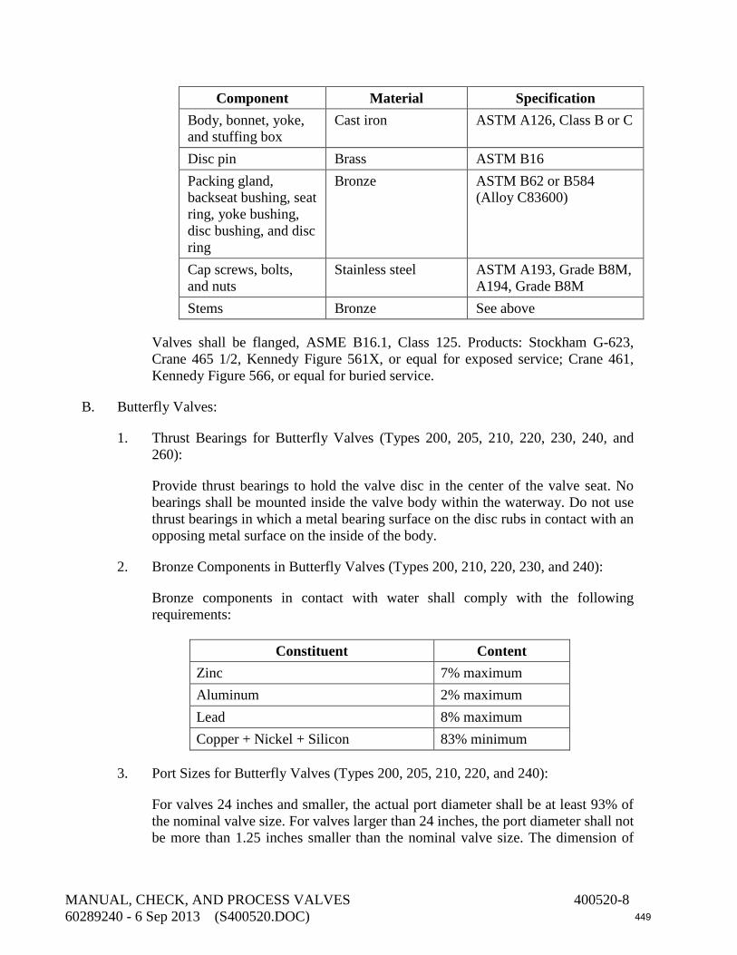
Component Material Specification Body, bonnet, yoke, and stuffing box
Cast iron ASTM A126, Class B or C
Disc pin Brass ASTM B16 Packing gland, backseat bushing, seat ring, yoke bushing, disc bushing, and disc ring
Bronze ASTM B62 or B584 (Alloy C83600)
Cap screws, bolts, and nuts
Stainless steel ASTM A193, Grade B8M, A194, Grade B8M
Stems Bronze See above
Valves shall be flanged, ASME B16.1, Class 125. Products: Stockham G-623, Crane 465 1/2, Kennedy Figure 561X, or equal for exposed service; Crane 461, Kennedy Figure 566, or equal for buried service.
B. Butterfly Valves:
1. Thrust Bearings for Butterfly Valves (Types 200, 205, 210, 220, 230, 240, and 260):
Provide thrust bearings to hold the valve disc in the center of the valve seat. No bearings shall be mounted inside the valve body within the waterway. Do not use thrust bearings in which a metal bearing surface on the disc rubs in contact with an opposing metal surface on the inside of the body.
2. Bronze Components in Butterfly Valves (Types 200, 210, 220, 230, and 240):
Bronze components in contact with water shall comply with the following requirements:
Constituent Content
Zinc 7% maximum Aluminum 2% maximum Lead 8% maximum Copper + Nickel + Silicon 83% minimum
3. Port Sizes for Butterfly Valves (Types 200, 205, 210, 220, and 240):
For valves 24 inches and smaller, the actual port diameter shall be at least 93% of the nominal valve size. For valves larger than 24 inches, the port diameter shall not be more than 1.25 inches smaller than the nominal valve size. The dimension of
MANUAL, CHECK, AND PROCESS VALVES 400520-8 60289240 - 6 Sep 2013 (S400520.DOC) 449
the port diameter shall be the clear waterway diameter plus the thickness of the rubber seat.
4. Corrosion-Resistant Materials in Butterfly Valves (Types 200, 210, 220, 230, and 240):
Where AWWA C504 requires “corrosion resistant” material, such material shall be one of the following:
a. Bronze as described above.
b. Type 304 or 316 stainless steel.
c. Monel (UNS N04400).
d. Synthetic nonmetallic material.
5. Seating Surfaces in Butterfly Valves (Types 200, 210, 220, and 240):
Seating surfaces in valves having motorized actuators shall be stainless steel or nickel-copper per AWWA C504 or nickel-chromium alloy containing a minimum of 72% nickel and a minimum of 14% chromium.
6. Factory Leakage Testing (Types 200, 205, 210, 220, and 240):
Perform factory leakage tests per AWWA C504 on both sides of the seat.
7. Type 200—Flanged, Rubber-Seated Butterfly Valves 4 Through 72 Inches, Class 150B:
Butterfly valves shall be short body, flanged type for exposed valves and valves in vaults or structures, and either flanged or mechanical joint for buried valves. Valve shall conform to AWWA C504, Class 150B. Minimum working differential pressure across the valve disc shall be 150 psi. Flanged ends shall be Class 125, ASME B16.1. Valve shafts shall be stub shaft or one-piece units extending completely through the valve disc. Materials of construction shall be as follows:
MANUAL, CHECK, AND PROCESS VALVES 400520-9 60289240 - 6 Sep 2013 (S400520.DOC) 450

Component Material Specification Body Cast iron or ductile
iron AWWA C504
Exposed body cap screws and bolts and nuts
Stainless steel ASTM A276, Type 316
Discs Cast iron, ductile iron, or Ni-Resist
AWWA C504
Shafts, disc fasteners, seat retention segments, and seat fastening devices
Stainless steel ASTM A276, Type 316
Seat material Buna-N —
Where the rubber seat is applied to the disc, it shall be bonded to a stainless steel seat retaining ring which is clamped to the disc by Type 304 or 316 stainless steel screw fasteners or secured to a stainless steel seat by a combination of cap screws, a serrated disc retaining ring, and molded shoulders in the seat mating with machined registers in the disc. The rubber valve seat shall be secured to or retained in the valve body. Valves shall be Pratt, DeZurik Series BAW, M&H, Val-Matic, or equal.
C. Ball Valves:
1. Type 307—Bronze Ball Valve Curb Stops, 2 Inches and Smaller, for Water Service:
Ball valve curb stops shall be bronze with male inlet iron pipe threads and female outlet iron pipe threads and shall conform to AWWA C800. Components in contact with water shall be bronze (ASTM B584, Alloys C89833 or C89836). Components not in contact with water shall be bronze (ASTM B62 or ASTM B584, Alloys C83600, C89833, or C89836). Bronze alloys having a maximum lead content of 0.25%, a maximum zinc content of 7.0%, and a minimum copper content of 80% may be substituted for the bronze alloys specified above. Minimum pressure rating shall be 300 psi. Stops shall be Ford Ball Valve Curb Stop B81-777 or equal.
2. Type 308—Bronze Ball/Corporation Stops, 2 Inches and Smaller, for Water Service:
Corporation stops shall be bronze with male inlet iron pipe threads and female outlet iron pipe threads and shall conform to AWWA C800. Components in contact with water shall be bronze (ASTM B584, Alloys C89833 or C89836). Components not in contact with water shall be bronze (ASTM B62 or ASTM B584, Alloys C83600, C89833, or C89836). Bronze alloys having a maximum
MANUAL, CHECK, AND PROCESS VALVES 400520-10 60289240 - 6 Sep 2013 (S400520.DOC) 451

lead content of 0.25%, a maximum zinc content of 7.0%, and a minimum copper content of 80% may be substituted for the bronze alloys specified above. Minimum pressure rating shall be 300 psi. Stops shall be Ford Ballcorp Type FB 1700, James Jones J-1931, or equal. Stops shall have an outlet fitting to adapt from iron pipe thread to copper tubing.
3. Type 320—Regular Port Threaded Stainless Steel Ball Valves 2 Inches and Smaller:
Stainless steel ball valves, 2 inches and smaller, for water service shall be rated at a minimum pressure of 1,500 psi WOG at a temperature of 100°F. Valve body, ball, and stem shall be Type 316 stainless steel, ASTM A276 or A351. Seat and seals shall be reinforced Teflon. Valves shall have lever actuators, plastic coated. Valves shall have threaded ends (ASME B1.20.1) and non-blowout stems. Valves shall be McCanna Figure M402, Worcester Series 48, Stockham Figure SD 2120-SSMO-R-T, Apollo 76-100 Series, or equal.
4. Type 322—Nut-and-Ferrule Stainless Steel Ball Valves (Straight Pattern), 3/4 Inch and Smaller:
Stainless steel ball valves, 3/4 inch and smaller, for water and chemical service shall be straight pattern and rated at a minimum pressure of 2,500 psi at a temperature of 150°F. Adjust valves for an operating pressure of 1,000 psi at a temperature of 70°F. Valve body, ball, stem, side rings, disc rings, and packing bolt shall be Type 316 stainless steel (ASTM A276, A351, or A479). Upper and lower packing shall be Teflon. Provide lever actuators with plastic handle. Provide end connections of the nut-and-ferrule type for connection to tubing. Products: Whitey Series 40 or equal.
D. Check Valves:
1. Type 790—Silent Check Valve 3 Inches and Larger:
Silent check valves, 3 inches and larger, shall be bronze mounted globe style. The seat and plug shall be hand replaceable in the field. Provide resilient seat. Flow area through valve shall be equal to or greater than the cross sectional area of the equivalent pipe size. Valve plug shall be center guided with a through integral shaft and spring loaded for silent shutoff operation. Ends shall be flanged, Class 125, per ASME B16.1. Minimum pressure rating shall be 150 psi. Materials of construction shall be as follows:
MANUAL, CHECK, AND PROCESS VALVES 400520-11 60289240 - 6 Sep 2013 (S400520.DOC) 452

Component Material Specification Body Cast iron or Ductile
iron ASTM A48, Class 30, or ASTM A126, Class B
Plug and seal Bronze ASTM B62 or B584 (Alloys C83600 or C87600)
Spring Stainless steel or Monel
Type 316 stainless or UNS N04400
Seating Buna-N or EPDM —
Valve shall be APCO Series 600 or equal.
E. Solenoid Valves:
1. Design and construct solenoid valves such that they can be used in both horizontal and vertical piping.
2. Type 900—Metallic Solenoid Valves 1 1/2 Inches and Smaller:
Solenoid valves of sizes 1/4 through 1 1/2 inches for water and air service shall have 304 stainless steel bodies with Teflon main seats. Internal plunger, core tube, plunger spring, and cage assembly shall be stainless steel (Types 302, 304, or 305). Solenoid enclosures shall be NEMA 4, except where explosion-proof is noted in the drawings. Valve actuators shall be 120-volt a-c. Seals shall be Teflon. Valves shall have a maximum operating pressure and a maximum differential pressure of 125 psi. Solenoid valves shall be energized to open. Valves shall be ASCO "Redhat" Model, or equal.
PART 3 - EXECUTION
3.01 VALVE SHIPMENT AND STORAGE
A. Provide flanged openings with metal closures at least 3/16-inch thick, with elastomer gaskets and at least four full-diameter bolts. Install closures at the place of valve manufacture prior to shipping. For studded openings, use all the nuts needed for the intended service to secure closures. Alternatively, ship flanged valves 3 inches and smaller in separate sealed cartons or boxes.
B. Provide threaded openings with steel caps or solid-shank steel plugs. Do not use nonmetallic (such as plastic) plugs or caps. Install caps or plugs at the place of valve manufacture prior to shipping. Alternatively, ship valves having threaded openings or end connections in separate sealed cartons or boxes.
MANUAL, CHECK, AND PROCESS VALVES 400520-12 60289240 - 6 Sep 2013 (S400520.DOC) 453

C. Store resilient seated valves in sealed polyethylene plastic enclosures with a minimum of one package of desiccant inside. Store resilient seated valves in the open or unseated position. Valves with adjustable packing glands shall have the packing gland loosened prior to storage. Inspect valves at least once per week, replace desiccant if required and repair damaged storage enclosures. Do not store valves with resilient seats near electric motors or other electrical equipment.
D. Inspect valves on receipt for damage in shipment and conformance with quantity and description on the shipping notice and order. Unload valves carefully to the ground without dropping. Use forklifts or slings under skids. Do not lift valves with slings or chain around operating shaft, actuator, or through waterway. Lift valves with eyebolts or rods through flange holes or chain hooks at ends of valve parts.
E. Protect the valve and actuators from weather and the accumulation of dirt, rocks, and debris. Do not expose rubber seats to sunlight or ozone for more than 30 days. Also, see the manufacturer’s specific storage instructions.
F. Make sure flange faces, joint sealing surfaces, body seats, and disc seats are clean. Check the bolting attaching the actuator to the valve for loosening in transit and handling. If loose, tighten firmly. Open and close valves having manual or power actuators to make sure the valve operates properly and that stops or limit switches are correctly set so that the valve seats fully. Close valve before installing.
3.02 FACTORY PRESSURE TESTING
A. Hydrostatically test the valve pressure-containing parts at the factory per the valve specification or per the referenced standard. If no testing requirement is otherwise specified or described in the referenced standards, then test with water for 30 minutes minimum at a pressure of 1.5 times the rated pressure but not less than 20 psig. Test shall show zero leakage. If leaks are observed, repair the valve and retest. If dismantling is necessary to correct valve deficiencies, then provide an additional operational test and verify that the valve components function.
B. The chloride content of liquids used to test austenitic stainless steel materials shall not exceed 50 ppm. To prevent deposition of chlorides as a result of evaporative drying, remove residual liquid from tested parts at the conclusion of the test.
3.03 INSTALLING VALVES—GENERAL
A. Remove covers over flanged openings and plugs from threaded openings, after valves have been placed at the point to which the valves will be connected to the adjacent piping. Do not remove valves from storage cartons or boxes until they are ready to be installed.
B. Handle valves carefully when positioning, avoiding contact or impact with other equipment, vault or building walls, or trench walls.
MANUAL, CHECK, AND PROCESS VALVES 400520-13 60289240 - 6 Sep 2013 (S400520.DOC) 454

C. Clean valve interiors and adjacent piping of foreign material prior to making up valve to pipe joint connection. Prepare pipe ends and install valves in accordance with the pipe manufacturer’s instructions for the joint used. Do not deflect pipe-valve joint. Do not use a valve as a jack to pull pipe into alignment. The installation procedure shall not result in bending of the valve/pipe connection with pipe loading.
D. Make sure valve ends and seats are clean. Check exposed bolting for loosening in transit and handling and tighten to manufacturer’s recommendations. Open and close the valve to make sure it operates properly and that stops or limit switches are correctly set so that the vane, ball, gate, needle, diaphragm, disc, plug, or other seating element seats fully. Close the valve before installing. Check coatings for damage and repair. Handle valves carefully when positioning, avoiding contact or impact with other equipment or structures.
E. Prior to assembly, coat threaded portions of stainless steel bolts and nuts with lubricant.
3.04 INSTALLING EXPOSED VALVES
A. Unless otherwise indicated in the drawings, install valves in horizontal runs of pipe having centerline elevations 4 feet 6 inches or less above the floor with their operating stems vertical. Install valves in horizontal runs of pipe having centerline elevations between 4 feet 6 inches and 6 feet 9 inches above the floor with their operating stems horizontal.
B. Install valves on vertical runs of pipe that are next to walls with their stems horizontal, away from the wall. Valves on vertical runs of pipe that are not located next to walls shall be installed with their stems horizontal, oriented to facilitate valve operation.
3.05 INSTALLING BURIED VALVES
A. Connect the valve, coat the flanges, and place and compact the backfill to the height of the valve stem.
B. Place block pads under the extension pipe to maintain the valve box vertical during backfilling and repaving and to prevent the extension pipe from contacting the valve bonnet.
C. Mount the upper slip pipe of the extension in mid-position and secure with backfill around the extension pipe. Pour the concrete ring allowing a depression so the valve box cap will be flush with the pavement surface.
D. In streets without concrete curbs and in open areas, install the valve box as for a paved area with concrete curb except include a marker post. Cut the marker post from 4-inch by 4-inch dense structural grade Southern Pine No. 2 surfaced on four sides to a length of 5 feet. Chamfer the top. Set the post in concrete, 2 feet into the ground, away from traffic, and to the side of the pipeline. Coat with a seal and finish coat of white alkyd exterior paint. On the side facing the valve, letter in black the word "VALVE" and the distance in feet from the marker post to the valve box cap.
MANUAL, CHECK, AND PROCESS VALVES 400520-14 60289240 - 6 Sep 2013 (S400520.DOC) 455

E. Install debris cap as close as possible under the cast-iron cover without interfering with the cover operation. Trim flexible skirt to provide a smooth contact with the interior or the extension pipe.
3.06 FIELD COATING BURIED VALVES
A. Coat flanges of buried valves and the flanges of the adjacent piping, and the bolts and nuts of flanges and mechanical joints, per Section 099000, System No. 21.
3.07 INSTALLING ECCENTRIC PLUG VALVES
A. Unload, store, and install in accordance with AWWA C517, Appendix A and the following. Unload valves carefully to the ground without dropping. On valves larger than 12 inches, use forklifts or slings under skids. On smaller valves, do not lift valves with slings or chain around actuator or through waterway. Lift these valves with eyebolts or rods through flange holes or chain hooks at the ends of valve parts. If it is not practical to store the valve indoors, protect the valve and actuators from weather and the accumulation of dirt, rocks, and debris.
B. Install such that the rotation of the plug is about a horizontal axis. Install such that the plug stores in the top when the valve is open.
C. Orient the valve such that the seat is opposite the high-pressure side.
3.08 ASSEMBLING JOINTS
A. Bolt holes of flanged valves shall straddle the horizontal and vertical centerlines of the pipe run to which the valves are attached. Clean flanges by wire brushing before installing flanged valves. Clean flange bolts and nuts by wire brushing, lubricate threads with oil and graphite, and tighten nuts uniformly and progressively. If flanges leak under pressure testing, loosen or remove the nuts and bolts, reseat or replace the gasket, reinstall or retighten the bolts and nuts, and retest the joints. Joints shall be watertight.
B. Clean threaded joints by wire brushing or swabbing. Apply Teflon joint compound or Teflon tape to pipe threads before installing threaded valves. Joints shall be watertight.
C. Install lug-type valves with separate hex head machine bolts at each bolt hole and each flange (two bolts per valve bolt hole).
D. Install grooved-end couplings for valves in accordance with Section 400500.
3.09 INSTALLING EXTENSION STEM GUIDE BRACKETS
Install at 6- to 8-foot centers. Provide at least two support brackets for stems longer than 10 feet, with one support near the bottom of the stem and one near the top.
MANUAL, CHECK, AND PROCESS VALVES 400520-15 60289240 - 6 Sep 2013 (S400520.DOC) 456

3.10 MOUNTING GEAR ACTUATORS
The valve manufacturer shall select and mount the gear actuator and accessories on each valve and stroke the valve from fully open to fully closed prior to shipment.
3.11 FIELD INSTALLATION OF GEAR ACTUATOR
Provide the actuator manufacturer's recommended lubricating oil in each actuator before commencing the field testing.
3.12 VALVE FIELD TESTING
A. Test valves for leakage at the same time that the connecting pipelines are hydrostatically tested. See Section 400515 for pressure testing requirements. Protect or isolate any parts of valves, actuators, or control and instrumentation systems whose pressure rating is less than the pressure test. Valves shall show zero leakage. Repair or replace any leaking valves and retest.
B. Operate manual valves through three full cycles of opening and closing. Valves shall operate from full open to full close without sticking or binding. Do not backfill buried valves until after verifying that valves operate from full open to full closed. If valves stick or bind, or do not operate from full open to full closed, repair or replace the valve and repeat the tests.
C. Gear actuators shall operate valves from full open to full close through three cycles without binding or sticking. The pull required to operate hand-wheel or chain-wheel operated valves shall not exceed 40 pounds. The torque required to operate valves having 2-inch AWWA nuts shall not exceed 150 ft-lbs. If actuators stick or bind or if pulling forces and torques exceed the values stated previously, repair or replace the actuators and repeat the tests. Operators shall be fully lubricated in accordance with the manufacturer's recommendations prior to operating.
END OF SECTION
MANUAL, CHECK, AND PROCESS VALVES 400520-16 60289240 - 6 Sep 2013 (S400520.DOC) 457
SECTION 400560 AIR-RELEASE AND VACUUM-RELIEF VALVES
PART 1 - GENERAL
1.01 DESCRIPTION
This section includes materials and installation of air and vacuum valves, air-release valves, combination air-release valves, slow-closing air and vacuum valves, vacuum-relief valves, and slow-closing combination air-release valves for water and sewage service. These valves are designated in the drawings as Types 1200 through 1240. Two types of valves are allowed:
A. Type B: A cylindrical body containing a series of HDPE floats having air-release orifices within them.
1.02 SUBMITTALS
A. Submit shop drawings in accordance with the General Conditions, Section 013300, and the following.
B. Submit manufacturer's catalog data and detail drawings showing all valve parts and described by material of construction, specification (such as AISI, ASTM, SAE, or CDA), and grade or type. Show linings and coatings. Identify each valve by tag number to which the catalog data and detail sheets pertain.
PART 2 - MATERIALS
2.01 VALVE IDENTIFICATION
Valves are identified in the drawings by size and type number. For example, a callout in the drawings of a 1" V-1201 refers to a Type 1201 valve in these specifications, which is a 150-psi air-release valve.
2.02 VALVE TAGGING AND IDENTIFICATION
Provide identifying valve tags per Section 400775.
2.03 BOLTS, NUTS, AND GASKETS FOR FLANGED VALVES
See Section 400500 and specification for the pipe to which the valve is attached.
2.04 TYPE B: VALVE DESIGN AND OPERATION
A. The air-release and vacuum-relief valve shall be of a single chamber design with solid cylindrical HDPE control floats housed in a tubular stainless steel body with stainless steel ends secured by means of stainless steel tie rods or by a flanged connection. The
AIR-RELEASE AND VACUUM-RELIEF VALVES 400560-1 60289240 - 6 Sep 2013 (S400560.DOC) 458

valve shall have an integral orifice mechanism that shall operate automatically to limit transient pressure rise or shock induced by closure to twice valve rated working pressure. Provide a double (small and large) orifice design.
B. The intake orifice area shall be equal to the nominal size of the valve. The large orifice sealing shall be affected by the flat face of the control float seating against a nitrile rubber O-ring housed in dovetail groove circumferentially surrounding the orifice. Discharge of pressurized air shall be controlled by the seating and unseating of a small orifice nozzle on a natural rubber seal affixed into the control float. The nozzle shall have a flat seating land surrounding the orifice.
C. Provide a 1/4-inch NPT test/bleed cock.
D. Prior to the ingress of liquid into the valve chamber, as when the pipeline is being filled, valves shall vent through the large orifice. At higher water approach velocities, the valve shall automatically discharge air through the orifice mechanism and reduce water approach velocity.
E. Valve shall not exhibit leaks or weeping of liquid past the large orifice seal at operating pressures of 7 psi to twice rated working pressure.
F. Valves shall respond to the presence of air by discharging it through the small orifice at any pressures within the specified design range and shall remain leak tight in the absence of air.
G. Valves shall react immediately to pipeline drainage or water column separation by the full opening of the large orifice so as to allow unobstructed air intake at the lowest possible negative internal pipeline pressure.
2.05 TYPE B: MATERIALS OF CONSTRUCTION
A. Materials of construction for air-release valves/air and vacuum-relief valves for sewage service shall be as follows:
AIR-RELEASE AND VACUUM-RELIEF VALVES 400560-2 60289240 - 6 Sep 2013 (S400560.DOC) 459

Item Material Specification Top flange, lower flange, screen mesh, bolts, nuts, connecting screws, float screw, and assembly screws
Stainless steel AISI Type 304
Top cover ABS plastic – Barrel Stainless steel AISI Type 304L Floats HDPE – Air-release nozzle or orifice mechanism
Stainless steel AISI Type 304
Nozzle seal and seat Natural rubber – Nozzle seal retaining plate Stainless steel AISI Type 304 Tie rod assembly and support fasteners
Stainless steel AISI Type 304
Float O-ring seals Nitrile rubber –
2.06 VALVE END CONNECTIONS
A. Valves 2 inches and smaller shall have threaded ends. Valves 3 inches and larger shall have flanged ends.
B. Threaded ends shall comply with ASME B1.20.1.
2.07 VALVES
A. Type 1230--Sewage Air-Release Valves, 2 Through 4 Inches, Class 150: After entraining air escapes through the orifice, the orifice shall be closed by a float which buoys to close the orifice by seating against the top cover to prevent the escape of sewage. The orifice shall remain closed until more gas accumulates and the cycle automatically repeats. Valve shall seat to prevent sewage from leaking through the valve at any pressure. Valves shall have an operating pressure of at least 175 psi. Venting capacity shall be at least 100 scfm. Valves shall be Vent-O-Mat Series RGX, or equal.
PART 3 - EXECUTION
3.01 SERVICE CONDITIONS
A. Valves shall seat drip-tight at the specified seating pressure.
3.02 FACTORY TESTING
A. Test each valve per AWWA C512, Section 5 and the following.
AIR-RELEASE AND VACUUM-RELIEF VALVES 400560-3 60289240 - 6 Sep 2013 (S400560.DOC) 460
B. Hydrostatically test the pressure-containing parts at the factory with water for 30 minutes minimum at a pressure of 1.5 times the rated pressure but not less than 20 psig. Test shall show zero leakage. If leaks are observed, repair the valve and retest. If dismantling is necessary to correct valve deficiencies, provide an additional operational test per AWWA C512, Section 5 for each affected valve.
C. The chloride content of liquids used to test austenitic stainless steel materials shall not exceed 50 ppm. To prevent deposition of chlorides as a result of evaporative drying, remove residual liquid from tested parts at the conclusion of the test.
3.03 PAINTING AND COATING
A. Do not coat seating areas and plastic, bronze, stainless steel, or other high alloy parts.
3.04 SHIPMENT AND STORAGE
A. Identify the equipment with item and serial numbers and project equipment tag numbers. Material shipped separately shall be identified with securely affixed, corrosion-resistant metal tags indicating the item and serial number and project equipment tag numbers of the equipment for which it is intended. In addition, ship crated equipment with duplicate packing lists, one inside and one on the outside of the shipping container.
B. Pack and ship one copy of the manufacturer’s standard installation instructions with the equipment. Provide the instructions necessary to preserve the integrity of the storage preparation after the equipment arrives at the jobsite and before start-up.
C. Provide flanged openings with metal closures at least 3/16-inch thick, with elastomer gaskets and at least four full-diameter bolts. Provide closures at the place of pump manufacture prior to shipping. For studded openings, use all the nuts needed for the intended service to secure closures.
D. Provide threaded openings with steel caps or solid-shank steel plugs. Do not use nonmetallic (such as plastic) plugs or caps. Provide caps or plugs at the place of pump manufacture prior to shipping.
E. Clearly identify lifting points and lifting lugs on the valves. Identify the recommended lifting arrangement on boxed equipment.
3.05 INSTALLATION
A. Clean flanges by wire brushing before installing flanged valves. Clean flange bolts and nuts by wire brushing, lubricate threads with oil and graphite, and tighten nuts uniformly and progressively. If flanges leak under pressure testing, loosen or remove the nuts and bolts, reseat or replace the gasket, reinstall or retighten the bolts and nuts, and retest the joints. Joints shall be watertight.
B. Clean threaded joints by wire brushing or swabbing. Apply Teflon® joint compound or Teflon® tape to pipe threads before installing threaded valves. Joints shall be watertight.
AIR-RELEASE AND VACUUM-RELIEF VALVES 400560-4 60289240 - 6 Sep 2013 (S400560.DOC) 461

C. Do not use duct tape and plastic for covering the ends of pipe flanges. Use a solid metal cover with rubber gasket to cover flange openings during installation. These metal covers shall remain in place until the piping is connected to the valves.
D. Do not spring flanges of connecting piping into position. Separately work connecting piping systems into position to bring the piping flanges into alignment with the matching valve flanges. Do not move valves to achieve piping alignment. Do not use electrical heating stress relieving to achieve piping alignment.
E. Line up pipe flange bolt holes with valve nozzle bolt holes within 1/16 inch maximum offset from the center of the bolt hole to permit insertion of bolts without applying any external force to the piping.
F. Flange face separation shall be within the gasket spacing ±1/16 inch. Use only one gasket per flanged connection.
3.06 VALVE FIELD PRESSURE TESTING
Test valves at the same time that the connecting pipelines are pressure tested. See Section 400515 for pressure testing requirements. Protect or isolate any parts of valves, operators, or control and instrumentation systems whose pressure rating is less than the test pressure.
END OF SECTION
AIR-RELEASE AND VACUUM-RELIEF VALVES 400560-5 60289240 - 6 Sep 2013 (S400560.DOC) 462

This page intentionally left blank
463

SECTION 400570 GLOBE PATTERN CONTROL VALVES
PART 1 - GENERAL
1.01 DESCRIPTION
This section includes materials and installation of globe pattern diaphragm-actuated and piston-actuated control valves acting as pump control valves, pressure-reducing valves, pressure-relief valves, pressure-sustaining valves, flow control valves, and altitude control valves.
1.02 SUBMITTALS
A. Submit shop drawings in accordance with the General Conditions, Section 013300, and the following.
B. Submit dimensional drawings for each size and type of valve provided.
C. Provide listing of materials of construction, with ASTM reference and grade. Show valve lining and paint primer coating with coating manufacturer and coating system number or designation.
D. Submit manufacturer's recommended maximum operating pressure and maximum recommended flow.
1.03 MANUFACTURERS' SERVICES
Provide equipment manufacturers' services at the jobsite for the minimum labor days listed below, travel time excluded:
One labor day to check the installation and advise during start-up, testing, and adjustment of the valves and instruct the Owner's personnel in the operation and maintenance of the valves.
PART 2 - MATERIALS
2.01 VALVE IDENTIFICATION
A. Valves are identified in the drawings by size and type number. For example, a callout in the drawings of 8" V-1300 refers to a Type 1300 valve in these specifications, which is a Class 125 pressure-reducing valve.
GLOBE PATTERN CONTROL VALVES (AWWA C530) 400570-1 60289240- 13 Sep 2013 (S400570.DOC) 464

2.02 MANUFACTURERS
A. Diaphragm-actuated control valves shall be manufactured by Cla-Val Company, Newport Beach, California; Bermad, Anaheim, California; Watts Automatic Control Valve, Houston, Texas; or equal.
2.03 VALVE DESIGN--DIAPHRAGM ACTUATED
A. Valves shall be hydraulically actuated diaphragm type complying with AWWA C530 except as modified herein. The valve body shall be formed from individual cast metal components and shall not include welding or other fabrication techniques during manufacture of the valve body. The body shall contain a removable seat insert. A resilient rubber disc shall form a drip-tight seal with the valve seat when pressure is applied above the diaphragm. The diaphragm assembly shall form a sealed chamber in the upper portion of the valve, separating operating pressure from line pressure.
B. All major components of the pilot control system shall be manufactured by the same company that manufactures the main valve. The main valve diaphragm shall either be vulcanized at the stem hole to ensure against wicking of the product within the diaphragm or the diaphragm shall utilize an FDA-approved nonwicking material and an elastomeric insert seal at the stem hole.
C. Provide guides at both ends of the stem or provide a center-guided stem. For design utilizing guides at both ends of the stem, provide a bearing in the valve cover and an integral bearing in the valve seat. Provide valve position indicator. Repairs and modifications other than the replacement of the main valve body shall be possible without removing the main valve from the line.
2.04 MATERIALS OF CONSTRUCTION--DIAPHRAGM-ACTUATED VALVES
A. Materials of construction for Class 125 and Class 250 valves larger than 1 inch in size shall be as follows:
Item Material
Main valve body and cover Ductile iron, ASTM A536, Grade 65-45-12
Main valve trim, seat, disc guide, and cover bearings
Type 316 stainless steel, ASTM A276, A 351, or A 743
Diaphragm washer and disc retainer Epoxy coated cast iron Pilot control system Bronze pilots Pilot piping, valves, and tubing Type 303 or 316 stainless steel per
ASTM A269
GLOBE PATTERN CONTROL VALVES (AWWA C530) 400570-2 60289240- 13 Sep 2013 (S400570.DOC) 465
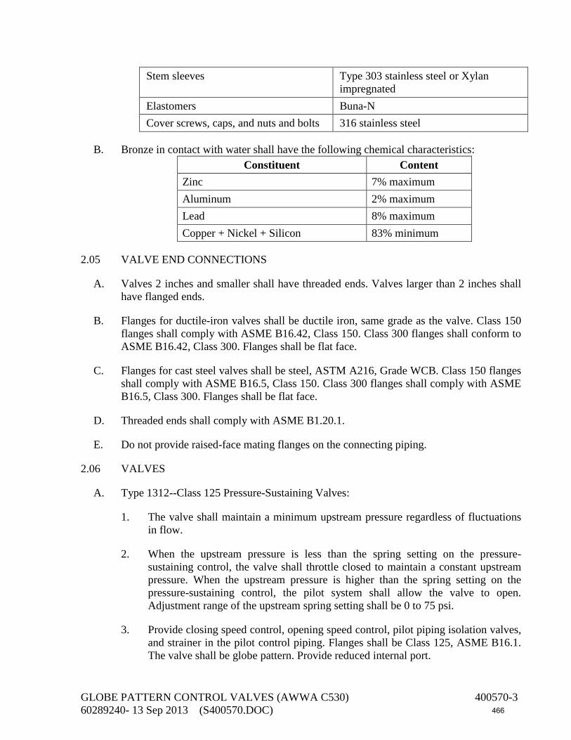
Stem sleeves Type 303 stainless steel or Xylan impregnated
Elastomers Buna-N Cover screws, caps, and nuts and bolts 316 stainless steel
B. Bronze in contact with water shall have the following chemical characteristics: Constituent Content
Zinc 7% maximum Aluminum 2% maximum Lead 8% maximum Copper + Nickel + Silicon 83% minimum
2.05 VALVE END CONNECTIONS
A. Valves 2 inches and smaller shall have threaded ends. Valves larger than 2 inches shall have flanged ends.
B. Flanges for ductile-iron valves shall be ductile iron, same grade as the valve. Class 150 flanges shall comply with ASME B16.42, Class 150. Class 300 flanges shall conform to ASME B16.42, Class 300. Flanges shall be flat face.
C. Flanges for cast steel valves shall be steel, ASTM A216, Grade WCB. Class 150 flanges shall comply with ASME B16.5, Class 150. Class 300 flanges shall comply with ASME B16.5, Class 300. Flanges shall be flat face.
D. Threaded ends shall comply with ASME B1.20.1.
E. Do not provide raised-face mating flanges on the connecting piping.
2.06 VALVES
A. Type 1312--Class 125 Pressure-Sustaining Valves:
1. The valve shall maintain a minimum upstream pressure regardless of fluctuations in flow.
2. When the upstream pressure is less than the spring setting on the pressure-sustaining control, the valve shall throttle closed to maintain a constant upstream pressure. When the upstream pressure is higher than the spring setting on the pressure-sustaining control, the pilot system shall allow the valve to open. Adjustment range of the upstream spring setting shall be 0 to 75 psi.
3. Provide closing speed control, opening speed control, pilot piping isolation valves, and strainer in the pilot control piping. Flanges shall be Class 125, ASME B16.1. The valve shall be globe pattern. Provide reduced internal port.
GLOBE PATTERN CONTROL VALVES (AWWA C530) 400570-3 60289240- 13 Sep 2013 (S400570.DOC) 466
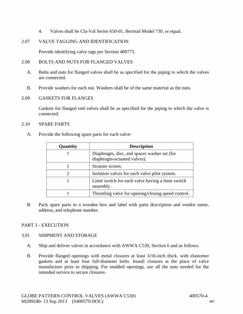
4. Valves shall be Cla-Val Series 650-01, Bermad Model 730, or equal.
2.07 VALVE TAGGING AND IDENTIFICATION
Provide identifying valve tags per Section 400775.
2.08 BOLTS AND NUTS FOR FLANGED VALVES
A. Bolts and nuts for flanged valves shall be as specified for the piping to which the valves are connected.
B. Provide washers for each nut. Washers shall be of the same material as the nuts.
2.09 GASKETS FOR FLANGES
Gaskets for flanged end valves shall be as specified for the piping to which the valve is connected.
2.10 SPARE PARTS
A. Provide the following spare parts for each valve:
Quantity Description 1 Diaphragm, disc, and spacer washer set (for
diaphragm-actuated valves). 1 Strainer screen. 2 Isolation valves for each valve pilot system. 1 Limit switch for each valve having a limit switch
assembly. 1 Throttling valve for opening/closing speed control.
B. Pack spare parts in a wooden box and label with parts description and vendor name, address, and telephone number.
PART 3 - EXECUTION
3.01 SHIPMENT AND STORAGE
A. Ship and deliver valves in accordance with AWWA C530, Section 6 and as follows.
B. Provide flanged openings with metal closures at least 3/16-inch thick, with elastomer gaskets and at least four full-diameter bolts. Install closures at the place of valve manufacture prior to shipping. For studded openings, use all the nuts needed for the intended service to secure closures.
GLOBE PATTERN CONTROL VALVES (AWWA C530) 400570-4 60289240- 13 Sep 2013 (S400570.DOC) 467

C. Provide threaded openings with steel caps or solid-shank steel plugs. Do not use nonmetallic (such as plastic) plugs or caps. Install caps or plugs at the place of valve manufacture prior to shipping.
D. Inspect valves on receipt for damage in shipment and conformance with quantity and description on the shipping notice and order. Unload valves carefully to the ground without dropping. Use forklifts or slings under skids. Do not lift valves with slings or chain around valve bonnet, pilot housing, or through waterway. Lift valves with eyebolts or rods through flange holes or chain hooks at ends of valve parts.
E. Protect the valve and pilot system from weather and the accumulation of dirt, rocks, and debris. Also, see the manufacturer’s specific storage instructions.
F. Make sure flange faces, joint sealing surfaces, body seats, and disc seats are clean. Check the bolting attaching the bonnet or pilot housing to the valve for loosening in transit and handling. If loose, tighten firmly.
G. If the valves and associated actuators are stored or installed outside or in areas subject to temperatures below 40°F or are exposed to the weather prior to permanent installation, provide the manufacturer’s recommended procedures for extended storage.
3.02 LINING AND COATING
A. Coat exteriors of valves in accordance with Section 099000, System No. 10. Apply the specified prime coat at the place of manufacture. Apply intermediate and finish coats in field. Finish coat shall match the color of the adjacent piping.
B. Line interiors of valves per Section 099000, System No. 7 or with 12 mils of fusion-bonded epoxy per Section 099761.
C. Alternatively, valve bodies and ductile/cast iron internal parts shall be coated internally and externally with fusion-bonded epoxy per Section 099761 at the factory.
D. Do not coat seating areas and bronze or stainless steel pieces.
3.03 VALVE SERVICE CONDITIONS
A. Valve service conditions shall be as shown below.
B. Valve Tag Number: PCV-1
Valve Connection Size 10 inch Maximum flow 1400 gpm Minimum flow 1000 gpm Maximum upstream pressure 51 psi Minimum upstream pressure 34 psi
GLOBE PATTERN CONTROL VALVES (AWWA C530) 400570-5 60289240- 13 Sep 2013 (S400570.DOC) 468

Maximum downstream pressure 38 psi Minimum downstream pressure 21 psi Upstream pressure setting 30 psi
3.04 VALVE INSTALLATION
A. Remove covers over flanged openings and plugs from threaded openings, after valves have been lifted off the truck and placed at the point to which it will be connected to the adjacent piping.
B. Bolt holes of flanged valves shall straddle the horizontal and vertical centerlines of the pipe run to which the valves are attached. Clean flanges by wire brushing before installing flanged valves. Clean flange bolts and nuts by wire brushing, lubricate threads as specified in the piping specifications, and tighten nuts uniformly and progressively. If flanges leak under pressure testing, loosen or remove the nuts and bolts, reseat or replace the gasket, reinstall or retighten the bolts and nuts, and retest the joints. Joints shall be watertight.
C. Clean threaded joints by wire brushing or swabbing. Apply Teflon joint compound or Teflon tape to pipe threads before installing threaded valves. Joints shall be watertight.
D. Handle valves carefully when positioning, avoiding contact or impact with other equipment or vault or building walls.
E. Clean valve interiors and adjacent piping of foreign material prior to making up valve to pipe joint connection. Prepare pipe ends and install valves in accordance with the pipe manufacturer’s instructions for the joint used. Do not deflect pipe-valve joint. Do not use a valve as a jack to pull pipe into alignment. The installation procedure shall not result in bending of the valve/pipe connection with pipe loading.
F. Prior to assembly, coat threaded portions of stainless steel bolts and nuts with lubricant.
3.05 VALVE PRESSURE TESTING
Test valves at the same time that the connecting pipelines are pressure tested. See Section 400515 for pressure testing requirements. Protect or isolate any parts of valves, operators, or control and instrumentation systems whose pressure rating is less than the test pressure.
END OF SECTION
GLOBE PATTERN CONTROL VALVES (AWWA C530) 400570-6 60289240- 13 Sep 2013 (S400570.DOC) 469

SECTION 400580 FABRICATED STAINLESS STEEL SLIDE GATES
PART 1 - GENERAL
1.01 DESCRIPTION
This section includes materials, installation, and testing of fabricated stainless steel slide and weir gates, open channel or wall mounted conforming to AWWA C561 and as supplemented herein.
1.02 SUBMITTALS
A. Submit shop drawings in accordance with the General Conditions, Section 013300, and the following.
B. Submit dimensional drawings.
C. Submit manufacturer’s catalog data and detail drawings showing slide gate parts and described by material of construction, specification (such as AISI, ASTM, SAE, or CDA), and grade or type. Show coatings. Identify each slide gate by tag number to which the catalog data and detail sheets pertain.
D. Submit calculations to show that gates, stems, and lifts meet the specifications.
E. Submit manufacturer's installation instructions.
1.03 MANUFACTURER'S SERVICES
Provide equipment manufacturer's services at the jobsite for the minimum labor days listed below, travel time excluded:
A. Two labor days to check the installation and advise during start-up, testing, and adjustment of the equipment.
B. One labor day to instruct the Owner's personnel in the operation and maintenance of the equipment.
PART 2 - MATERIALS
2.01 MANUFACTURERS AND MODELS
A. Type 4 slide gates shall be of the self-contained upward opening type designed to mount on the face of concrete channels. Type 4 slide gates shall be Rodney Hunt Series 761, Whipps Series 900, or equal.
FABRICATED STAINLESS STEEL SLIDE GATES 400580-1 60289240 - 18 Sep 2013 (S400580.DOC) 470
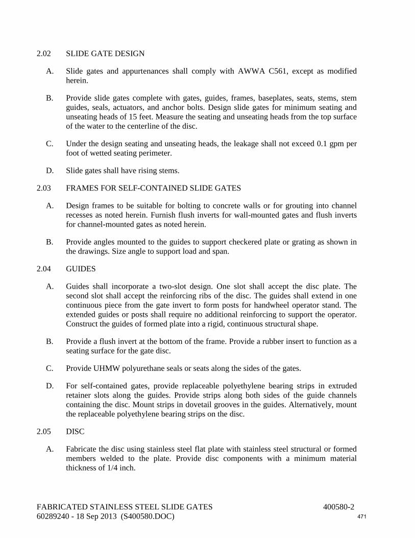
2.02 SLIDE GATE DESIGN
A. Slide gates and appurtenances shall comply with AWWA C561, except as modified herein.
B. Provide slide gates complete with gates, guides, frames, baseplates, seats, stems, stem guides, seals, actuators, and anchor bolts. Design slide gates for minimum seating and unseating heads of 15 feet. Measure the seating and unseating heads from the top surface of the water to the centerline of the disc.
C. Under the design seating and unseating heads, the leakage shall not exceed 0.1 gpm per foot of wetted seating perimeter.
D. Slide gates shall have rising stems.
2.03 FRAMES FOR SELF-CONTAINED SLIDE GATES
A. Design frames to be suitable for bolting to concrete walls or for grouting into channel recesses as noted herein. Furnish flush inverts for wall-mounted gates and flush inverts for channel-mounted gates as noted herein.
B. Provide angles mounted to the guides to support checkered plate or grating as shown in the drawings. Size angle to support load and span.
2.04 GUIDES
A. Guides shall incorporate a two-slot design. One slot shall accept the disc plate. The second slot shall accept the reinforcing ribs of the disc. The guides shall extend in one continuous piece from the gate invert to form posts for handwheel operator stand. The extended guides or posts shall require no additional reinforcing to support the operator. Construct the guides of formed plate into a rigid, continuous structural shape.
B. Provide a flush invert at the bottom of the frame. Provide a rubber insert to function as a seating surface for the gate disc.
C. Provide UHMW polyurethane seals or seats along the sides of the gates.
D. For self-contained gates, provide replaceable polyethylene bearing strips in extruded retainer slots along the guides. Provide strips along both sides of the guide channels containing the disc. Mount strips in dovetail grooves in the guides. Alternatively, mount the replaceable polyethylene bearing strips on the disc.
2.05 DISC
A. Fabricate the disc using stainless steel flat plate with stainless steel structural or formed members welded to the plate. Provide disc components with a minimum material thickness of 1/4 inch.
FABRICATED STAINLESS STEEL SLIDE GATES 400580-2 60289240 - 18 Sep 2013 (S400580.DOC) 471

B. The disc shall be a one-piece plate, reinforced with ribs so that the disc will not deflect more than 1/720 the gate span when the upstream side of the gate is subjected to the specified seating head and the downstream side of the gate contains no liquid. Design the disc to limit deflection to a maximum of 1/8 inch when the disc is subjected to the maximum specified unseating head. Attach reinforcing ribs to disc by welding; do not use bolting. Reinforcing ribs shall extend into the guides such that they overlap the seating surface of the guide. Design the disc so that all surfaces are free of metal-to-metal contact with the frames.
2.06 ACTUATOR SUPPORT YOKE FOR SELF-CONTAINED SLIDE GATES
Attach the actuator support yoke to the extensions of the guides. Provide two angles or structural channels bolted to opposite sides of the guide extensions. Mount the actuator on a plate bolted to the support yoke. Maximum deflection of the yoke shall not exceed 1/4 inch when subjected to a load induced by an 40-pound pull on the actuator or 1/360 span when subjected to a load induced by a 40-pound pull on the actuator, whichever is less.
2.07 STEMS AND STEM GUIDES
A. Lifting stems shall be one piece, with a minimum diameter of 1 1/2 inches. The stem shall withstand an actuator effort of 80 pounds without buckling, assuming the critical buckling load as determined by using the Euler Column Formula with C = 2.0. Support the stems with stem guides such that the L/R ratio for the unsupported part of the stem does not exceed 200.
B. The stem connection to the disc shall be either the clevis type, with structural members welded to the slide and containing a bolt to act as a pivot pin, or a threaded and bolted or keyed thrust nut supported in a welded nut pocket. The pocket shall be capable of withstanding a load of 80 pounds on the actuator.
C. Provide tandem stems and actuators when the gate width is more than twice the gate height.
2.08 MATERIALS OF CONSTRUCTION
Materials of construction shall conform to the requirements listed below:
FABRICATED STAINLESS STEEL SLIDE GATES 400580-3 60289240 - 18 Sep 2013 (S400580.DOC) 472

Component Material Specification Guides Stainless steel ASTM A240 or A276, Type 304
or 304L 316 or 316L Disc, yoke Stainless steel ATSM A240 or A276, Type 304
or 304L 316 or 316L Stems, stem guides, bushings, pivot pin
Stainless steel ASTM A276, Type 304 or 303
Bolts, fasteners (including anchor bolts)
Stainless steel ASTM A193, F593 or F594; Grade B8M
Lift nut Bronze ASTM B62 or ASTM B584, Alloys C83600, C83800, or C86500
J-bulb seals, flush bottom seals
Rubber or UHMW polyurethane
ASTM D2000, Grades BC610, BC611, BC612, BC613, BC614, or BC615 or ASTM D4020
2.09 ACTUATORS
A. Provide motor actuators as specified in Section 409210.
B. The bench stand actuator shall be a minimum of 36 inches and a maximum of 48 inches above finished floor. If above 48 inches, a remote drive shaft system shall be utilized to position the actuator 36 inches above finished floor.
C. Provide a graduated clear plastic stem cover to show the gate position in increments of 1/4 inch. Provide vent holes to prevent condensation.
2.10 SPARE PARTS
A. Provide the following spare parts for each size of slide or weir gate:
Quantity Description 2 Lift nuts 4 Stem guides of each type and size 2 Pivot pins
1 set Sealing strips
B. Pack spare parts in a wooden box; label with the manufacturer's name and local representative's name, address, and telephone number; and attach list of materials contained within.
FABRICATED STAINLESS STEEL SLIDE GATES 400580-4 60289240 - 18 Sep 2013 (S400580.DOC) 473
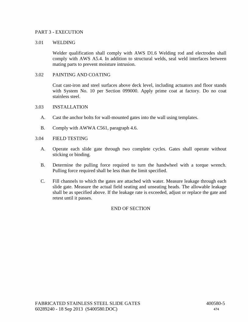
PART 3 - EXECUTION
3.01 WELDING
Welder qualification shall comply with AWS D1.6 Welding rod and electrodes shall comply with AWS A5.4. In addition to structural welds, seal weld interfaces between mating parts to prevent moisture intrusion.
3.02 PAINTING AND COATING
Coat cast-iron and steel surfaces above deck level, including actuators and floor stands with System No. 10 per Section 099000. Apply prime coat at factory. Do no coat stainless steel.
3.03 INSTALLATION
A. Cast the anchor bolts for wall-mounted gates into the wall using templates.
B. Comply with AWWA C561, paragraph 4.6.
3.04 FIELD TESTING
A. Operate each slide gate through two complete cycles. Gates shall operate without sticking or binding.
B. Determine the pulling force required to turn the handwheel with a torque wrench. Pulling force required shall be less than the limit specified.
C. Fill channels to which the gates are attached with water. Measure leakage through each slide gate. Measure the actual field seating and unseating heads. The allowable leakage shall be as specified above. If the leakage rate is exceeded, adjust or replace the gate and retest until it passes.
END OF SECTION
FABRICATED STAINLESS STEEL SLIDE GATES 400580-5 60289240 - 18 Sep 2013 (S400580.DOC) 474

This page intentionally left blank
475

SECTION 400775 EQUIPMENT, PIPING, DUCT, AND VALVE IDENTIFICATION
PART 1 - GENERAL
1.01 DESCRIPTION
This section includes materials and installation of markers, labels, and signs for pipes, ducts, and valves; for mechanical equipment; for hazardous materials warnings; and for miscellaneous plant services.
1.02 SUBMITTALS
A. Submit shop drawings in accordance with the General Conditions, Section 013300, and the following.
B. Submit manufacturer's catalog data and descriptive literature describing materials, colors, letter size, and size of labels.
PART 2 - MATERIALS
2.01 LABELS FOR EXPOSED PIPING
A. Labels for piping shall bear the full piping system name as shown in the Piping Schedule in the drawings. Provide separate flow directional arrows next to each label. Color, size, and labeling shall conform to ANSI A13.1 and Z535.1. Labels for piping inside buildings shall be vinyl cloth: W. H. Brady Co. B-500 vinyl cloth, Seton Name Plate Corporation Pipe Markers, or equal. Labels for piping located outdoors shall be weather- and UV-resistant acrylic plastic and shall be W. H. Brady Co. B-946, Seton Name Plate Corporation Pipe Markers, or equal.
B. Alternatively, provide preprinted, semirigid, snap-on, color-coded pipe markers. Color, size, and labeling shall conform to ANSI A13.1 and Z535.1. Label shall cover 360 degrees (minimum). Labels shall be fabricated of weather- and UV-resistant acrylic plastic. Labels shall be Seton Nameplate Corporation SetMark pipe marks or equal.
2.02 LABELS FOR EXPOSED VALVES
Provide each valve of size 4 inches and larger with an identification tag. Tag shall be 2-inch-square or circular aluminum or 1/16-inch-thick fiberglass: W. H. Brady B-60, Seton Name Plate Corp. Series SVT, or equal. Aluminum tags shall have black-filled letters. Tag shall show the valve tag number and/or name or designation as given in the drawings.
EQUIPMENT, PIPING, DUCT & VALVE IDENTIFICATION 400775-1 60289240 - 6 Sep 2013 (S400775.DOC) 476

2.03 HOSE BIBB SIGNS--UNSAFE WATER
Provide a rigid sign labeled "CAUTION--UNSAFE WATER--DO NOT DRINK" for each hose bibb. Size and lettering shall conform to OSHA and ANSI Z535.2 requirements. Signs shall be Seton Nameplate Company 20-gauge baked enamel, minimum size 7 inches by 3 inches; Brady B-120 Fiber-Shield fiberglass, minimum size 7 inches by 3 inches, 1/8 inch thick; or equal.
2.04 LABELS FOR MECHANICAL EQUIPMENT
Provide a label for each pump, blower, compressor, tank, feeder, flocculator, flash mixer, clarifier mechanism, or other piece of mechanical equipment. Label shall show the equipment name and tag number as shown in the drawings. Labels shall be 1 1/2 inches (minimum) by 4 inches (minimum) brass, aluminum, or 1/8-inch-thick fiberglass tags: Brady B-120 Fiber-Shield, Seton Style 2065, or equal.
2.05 LABELS FOR EXPOSED TANKS
Signs shall be weather and UV-resistant. Labels shall be Brady B-946, Seton Name Plate Corporation PSPL, or equal. Minimum size shall be 7 inches by 10 inches. Provide a sign on each tank bearing the tank tag number and the name of the liquid stored.
2.06 LAMINATED PLASTIC WALL SIGNS
Wall signs shall be 1 1/2 inches by 4 inches (minimum dimensions), 1/16-inch-thick satin-surfaced material conforming to ASTM D709 (Grades ES-1, ES-2, or ES-3). Lettering shall be 1/2-inch-high white letters on black background. Do not provide mounting holes. Legends shall be as shown in the drawings.
2.07 LABELS FOR AUTOMATIC START/STOP EQUIPMENT
Provide a sign reading "CAUTION--EQUIPMENT STARTS AND STOPS AUTOMATICALLY" on each piece of equipment listed below. Signs shall be pressure-sensitive vinyl with adhesive for application to equipment. Signs mounted on adjacent walls are also acceptable. Size shall be 10 inches by 7 inches minimum. Products: Seton, Brady, or equal.
2.08 UNDERGROUND PLASTIC WARNING TAPE FOR METALLIC PIPE
Provide permanent, bright-colored, continuous-printed plastic tape, intended for direct burial service, not less than 6 inches wide by 3.5 mils thick. Provide tape with printing which most accurately indicates type of service of buried pipe. Provide the following colored tape for the various piping services:
EQUIPMENT, PIPING, DUCT & VALVE IDENTIFICATION 400775-2 60289240 - 6 Sep 2013 (S400775.DOC) 477

Service Color Cable TV Orange Chemical Yellow Electric Red Fuel Oil, Gasoline Yellow Gas Yellow Reclaimed Water Violet Sewer Green Telephone Orange Water Blue
2.09 UNDERGROUND DETECTABLE METALLIC PIPE WARNING TAPE FOR NONMETALLIC PIPE
Provide permanent, bright-colored, continuous-printed tape consisting of an aluminum or steel foil sheathed in a plastic laminate, not less than 2 inches wide by 3 mils thick. Provide tape with printing which most accurately indicates type of buried service. Provide the following colored tape for the various piping services:
Service Color
Cable TV Orange Chemical Yellow Electric Red Fuel Oil, Gasoline Yellow Gas Yellow Reclaimed Water Violet Sewer Green Telephone Orange Water Blue
PART 3 - EXECUTION
3.01 INSTALLING PIPE LABELS
A. Provide label and flow arrow at each connection to pumps or other mechanical equipment, at wall boundaries, at tees and crosses, and at 20-foot centers on straight runs of piping.
B. On piping having external diameters less than 6 inches (including insulation, if any), provide full-band pipe markers, extending 360 degrees around pipe at each location.
EQUIPMENT, PIPING, DUCT & VALVE IDENTIFICATION 400775-3 60289240 - 6 Sep 2013 (S400775.DOC) 478

C. On piping having external diameters of 6 inches and larger (including insulation, if any), provide either full-band or strip-type pipe markers but not narrower than three times letter height (and of required length), fastened by one of the following methods:
1. Laminated or bonded application of pipe marker to pipe or insulation.
2. Strapped-to-pipe or insulation application of semirigid type with Type 304 or 305 stainless steel bands.
3.02 INSTALLING VALVE AND EQUIPMENT LABELS
A. Attach labels to the valve or piece of equipment with Type 304 or 316 stainless steel chains or wires.
B. Attach valve labels to the valve handwheels. If the valve has no handwheel, attach the label to the valve by tying the tag wire or chain around the operating shaft or nut.
3.03 INSTALLING HOSE BIBB SIGNS
Install signs for hose bibs on the adjacent wall for hose bibs installed on water supply lines running on walls. Install signs on the risers of hose bibs installed outdoors or on the exterior casing pipe or top stock of yard and post hydrants.
3.04 INSTALLING MISCELLANEOUS SIGNS
Attach per sign manufacturer's recommendations and per OSHA requirements.
3.05 INSTALLING WALL AND DOOR SIGNS
Attach to walls and doors using epoxy adhesive.
3.06 INSTALLING LABELS FOR AUTOMATIC START/STOP EQUIPMENT AND HAZARDOUS MATERIALS WARNING SIGNS FOR EQUIPMENT
A. Attach signs for exposed equipment directly to the equipment.
B. Attach signs for sump pumps on the adjacent wall.
3.07 INSTALLING UNDERGROUND PLASTIC WARNING TAPE FOR METAL PIPE
During backfilling of each exterior underground piping system, install continuous underground-type plastic line marker, located directly over buried line at 6 to 8 inches above the top of the pipe. Where multiple small lines are buried in common trench and do not exceed overall width of 16 inches, install single line marker.
EQUIPMENT, PIPING, DUCT & VALVE IDENTIFICATION 400775-4 60289240 - 6 Sep 2013 (S400775.DOC) 479

3.08 INSTALLING UNDERGROUND DETECTABLE METALLIC PIPE WARNING TAPE
Install tape 4 to 6 inches below finished ground surface, located directly over buried pipelines. Where multiple small pipelines are buried in a common trench and do not exceed an overall width of 16 inches, install a single marker tape.
END OF SECTION
EQUIPMENT, PIPING, DUCT & VALVE IDENTIFICATION 400775-5 60289240 - 6 Sep 2013 (S400775.DOC) 480

This page intentionally left blank
481

SECTION 402040 DUCTILE-IRON PIPE
PART 1 - GENERAL
1.01 DESCRIPTION
This section describes materials, testing, and installation of ductile-iron pipe and fittings 54 inches and smaller.
1.02 SUBMITTALS
A. Submit shop drawings in accordance with the General Conditions, Section 013300, and the following.
B. Provide an affidavit of compliance with standards referenced in this specification, e.g., AWWA C151. Submit copy of report of pressure tests for qualifying the designs of all sizes and types of AWWA C153 fittings that are being used in the project. The pressure test shall demonstrate that the minimum safety factor described in AWWA C153, Section 5.5 is met.
C. Provide the following information:
1. Mortar lining thickness.
2. Wall thickness.
3. Material test data for this project.
4. Show deflections at push-on and mechanical joints.
5. Submit joint and fitting details and manufacturer’s data sheets.
D. Submit calculations and test data proving that the proposed restrained joint arrangement can transmit the required forces with a minimum safety factor of 1.5.
E. Submit certificate that cement for mortar lining complies with ASTM C150, designating type.
F. Submit test report on physical properties of rubber compound used in the gaskets.
G. Submit drawing or manufacturer's data sheet showing flange facing, including design of facing serrations.
H. Submit weld procedure specification, procedure qualification record, and welder's qualifications prior to any welding to ductile-iron pipe.
DUCTILE-IRON PIPE 402040-1 60289240 - 6 Sep 2013 (S402040.DOC) 482

PART 2 - MATERIALS
2.01 PIPE
Pipe shall be cast ductile (nodular) iron, conforming to AWWA C151.
2.02 PIPE WALL THICKNESS
A. Minimum wall thicknesses for pipe having grooved-end joints shall be as shown in the following table:
Pipe and Fitting Sizes
(inches) Wall Thickness* 16 and smaller Special Class 53 18 Special Class 54 20 Special Class 55 24 to 36 Special Class 56
*Special Class and Pressure Class per AWWA C151.
B. Minimum wall thickness for pipe having push-on or mechanical joints, restrained joints, plain ends, or cast flange ends shall be Class 200, unless otherwise shown in the drawings.
C. Minimum wall thickness for pipe having threaded flanges shall be Special Class 53 or Pressure Class 350.
D. Minimum pipe wall thickness required for corporation stops and tapped outlets shall be in accordance with Table A.1 of AWWA C151 for three full threads for design pressures up to 250 psi and four full threads for design pressures over 250 to 350 psi.
2.03 FITTINGS
A. Fittings 48 inches and smaller shall conform to AWWA C110 with a minimum pressure rating of 250 psi. Material shall be cast or ductile iron. Flanges shall be flat faced.
B. Mechanical joint fittings conforming to AWWA C153 may be used in lieu of AWWA C110 fittings. Mechanical joint ductile-iron fittings 18 through 48 inches conforming to AWWA C110 (except for laying length) with a minimum pressure rating of 250 psi may also be used.
C. Grooved-end fittings shall conform to AWWA C110 with grooved ends conforming to AWWA C606, radius cut rigid joints. Fitting material shall conform to ASTM A48, Class 30; ASTM A126, Class B; or ASTM A536, Grade 65-42-10. Wall thickness of ductile-iron (ASTM A536) fittings shall conform to AWWA C110 or C153; wall thickness of cast-iron fittings shall conform to AWWA C110. Fittings and couplings shall be furnished by the same manufacturer.
DUCTILE-IRON PIPE 402040-2 60289240 - 6 Sep 2013 (S402040.DOC) 483

D. Material for fittings with welded-on bosses shall have a Charpy notch impact value of minimum 10 ft-lbs under the conditions defined in AWWA C151. Test completed welds by the liquid penetrant method per ASTM E165.
2.04 FLANGES
A. Flanges shall be solid back, Class 125 per AWWA C115. Flanges on pipe shall be either cast or threaded. Material shall be ductile iron.
B. Flanged pipe and fittings shall be shop fabricated, not field fabricated. Threaded flanges shall comply with AWWA C115. Flanges shall be individually fitted and machine tightened in the shop, then machined flat and perpendicular to the pipe barrel. Flanges shall be backfaced parallel to the face of flange. Prior to assembly of the flange onto the pipe, apply a thread compound to the threads to provide a leak-free connection. There shall be zero leakage through the threads at a hydrostatic test pressure of 250 psi without the use of the gasket.
2.05 PIPE LINING
A. Line the interior of the following pipe and fittings with an amine cured novalac epoxy containing at least 20 percent by volume of ceramic quartz pigment, Protecto 401 ceramic epoxy.
B. Before application of the lining, prepare the pipe surfaces in accordance with the applicator’s recommendations. Apply the lining to a thickness of 40 mils nominal dry film thickness. Do not line the face of flanges.
C. For bell sockets and spigot ends, coat the gasket area and spigot end up to 6 inches back from the end of the spigot with 6 mils nominal, 10 mils maximum of Protecto Joint Compound. Apply the joint compound with a brush without causing excess buildup in the gasket seat or on the spigot ends.
D. Test lining thickness using a magnetic film thickness gauge. Conduct testing in accordance with SSPC-PA-2, Film Thickness Rating. Test for pinholes with a non-destructive 2,500 volt test. Repair all defects prior to shipment.
E. Line fittings per Section 099000, System No. 7.
F. Alternatively, fittings may be lined and coated with fusion-bonded epoxy per Section 099761.
G. Line blind flanges per Section 099000, System No. 7.
2.06 GROOVED-END COUPLINGS
A. Grooved-end pipe couplings shall be ductile iron, ASTM A536 (Grade 65-45-12). Gaskets shall be halogenated butyl rubber or EPDM and shall conform to ASTM D2000.
DUCTILE-IRON PIPE 402040-3 60289240 - 6 Sep 2013 (S402040.DOC) 484

B. Bolts in exposed service shall conform to ASTM A193, Grade B8, Class 2. Bolts in buried or submerged service shall be ASTM A193, Grade B8, Class 2.
C. Couplings for pipe 24 inches and smaller shall conform to AWWA C606 for flexible radius ductile-iron pipe, except where rigid radius couplings are required to connect to fittings. Couplings for pipe sizes 30 and 36 inches shall be in accordance with the coupling manufacturer's published literature for tolerances and dimensions for flexible and rigid radius cut joints. Couplings shall be Victaulic Style 31, Gustin-Bacon No. 500, or equal.
D. Couplings for pipe larger than 36 inches shall conform to AWWA C606 for shouldered end pipe. Couplings shall be Victaulic Style 44 or equal.
E. Grooved-end adapter flanges for piping 24 inches and smaller having an operating pressure of 150 psi and less shall be Victaulic Style 341 or 342 or equal. Flange dimensions shall conform to ASME B16.1, Class 125.
F. Grooved-end transition couplings for connecting ductile-iron pipe 12 inches and smaller to steel pipe shall be Victaulic Style 307 or equal.
2.07 GASKETS FOR FLANGES
See Section 400500.
2.08 GASKETS FOR MECHANICAL, PUSH-ON, AND RESTRAINED JOINTS
Synthetic rubber in accordance with AWWA C111.
2.09 BOLTS AND NUTS FOR FLANGES
See Section 400500.
2.10 OUTLETS AND NOZZLES
A. Provide outlets 2 inches and smaller by tapping the pipe and attaching a service clamp as or use a threaded welded-on boss..
B. For outlets larger than 2 inches in exposed piping, use a tee with a flanged outlet.
C. For outlets larger than 2 inches in buried piping, use a tee with a restrained joint outlet.
2.11 JOINTS
A. Joints in aboveground or submerged piping or piping located in vaults and structures shall be grooved end or flanged.
B. Joints in buried piping shall be of the restrained push-on or mechanical-joint type per AWWA C111 except where flanged joints are required to connect to valves, meters, and other equipment.
DUCTILE-IRON PIPE 402040-4 60289240 - 6 Sep 2013 (S402040.DOC) 485

C. Restrained joints for piping 6 inches and larger shall be American Cast Iron Pipe "Lok-Ring" or "Flex-Ring," U.S. Pipe "TR-Flex," or equal. Weldments for restrained joints shall be tested by the liquid penetrant method per ASTM E165. Restrained joints for field closures shall be “Megalug” by EBAA Iron.
D. Restrained joints in 4-inch-diameter buried piping shall be American Cast Iron Pipe Company “Fast-Grip,” U.S. Pipe Field-lok gasket within Tyton joint pipe and fittings, or equal. Joint restraint shall be certified to four times rated pressure of 200 psi by Factory Mutual.
E. Where thrust restraint is called for in the drawings, provide pipe with restrained joints capable of transmitting 1.5 times the thrust, as calculated by the following equation:
T = 1.5 * (0.785 * P * D2)
where:
P = Pressure class of pipe in psi. D = Outside diameter of pipe in inches. T = Thrust in pounds.
2.12 MECHANICAL JOINT RESTRAINT SYSTEM USING FOLLOWER RING AND WEDGES
The restraining mechanism shall consist of a follower gland having a seal gasket and individually actuated wedges that increase their resistance to pullout as pressure or external forces increase. The system manufacturer shall provide all the components (follower ring, wedges, and gaskets) for the restraining device. The device shall be capable of full mechanical joint deflection during assembly, and the flexibility of the joint shall be maintained after burial. The joint restraint ring and its wedging components shall be constructed of ductile iron conforming to ASTM A536, Grade 60-42-10. The wedges shall be ductile iron, heat-treated to a minimum hardness of 370 BHN. Dimensions of the gland shall be such that it can be used with mechanical joint bells conforming to AWWA C111 and AWWA C153. The design shall use torque limiting twist-off nuts to provide actuation of the restraining wedges. The mechanical joint restraint shall be available in the size range of 3 through 48 inches. Minimum rated pressure shall be 350 psi for sizes 16 inches and smaller and 250 psi in sizes 18 inches and larger. Products: Megalug Series 1100 as manufactured by EBAA Iron, Inc., or equal.
2.13 DUCTILE-IRON PIPE WELDMENTS
A. All welding to ductile-iron pipe, such as for bosses, joint restraint, and joint bond cables, shall be done at the place of manufacture of the pipe. Perform welding by skilled welders experienced in the method and materials to be used. Welders shall be qualified under the standard qualification procedures of the ASME Boiler and Pressure Vessel Code, Section IX, Welding Qualifications.
DUCTILE-IRON PIPE 402040-5 60289240 - 6 Sep 2013 (S402040.DOC) 486
B. Welds shall be of uniform composition, neat, smooth, full strength, and ductile. Completely grind out porosity and cracks, trapped welding flux, and other defects in the welds in such a manner that will permit proper and complete repair by welding.
C. Completed welds shall be inspected at the place of manufacture by the liquid penetrant method. Conform to the requirements specified in ASTM E165, Method A, Type I or Type II. The materials used shall be water washable and nonflammable.
2.14 TELESCOPING SLEEVES
Telescoping sleeves where shown in the drawings shall be U.S. Pipe "TR FLEX" or equal. Do not use telescoping sleeves where design pressure exceeds 200 psi.
PART 3 - EXECUTION
3.01 DELIVERY, UNLOADING, AND TEMPORARY STORAGE OF PIPE AT SITE
A. Use unloading and installation procedures that avoid cracking of the lining. If necessary, use plastic sheet bulkheads to close pipe ends and keep cement-mortar lining moist.
B. Deliver the pipe alongside the pipelaying access road over which the pipe trailer-tractors can travel under their own power. Place the pipe in the order in which it is to be installed and secure it from rolling.
C. Do not move pipe by inserting any devices or pieces of equipment into the pipe barrel. Field repair linings damaged by unloading or installation procedures.
3.02 SANITATION OF PIPE INTERIOR
A. During laying operations, do not place tools, clothing, or other materials in the pipe.
B. When pipe laying is not in progress, close the ends of the installed pipe by a child- and vermin-proof plug.
3.03 INSTALLING FLANGED PIPE AND FITTINGS
Install in accordance with Section 400500. Cut the bore of the gaskets such that the gaskets do not protrude into the pipe when the flange bolts are tightened.
3.04 INSTALLING GROOVED-END PIPE AND FITTINGS
See Section 400500.
3.05 INSTALLING BURIED PIPING
A. Install in accordance with AWWA C600, Section 312300, and as follows.
DUCTILE-IRON PIPE 402040-6 60289240 - 6 Sep 2013 (S402040.DOC) 487
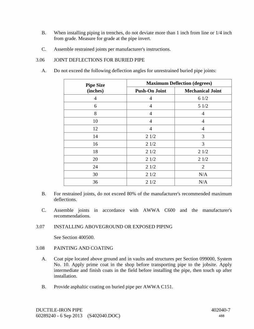
B. When installing piping in trenches, do not deviate more than 1 inch from line or 1/4 inch from grade. Measure for grade at the pipe invert.
C. Assemble restrained joints per manufacturer's instructions.
3.06 JOINT DEFLECTIONS FOR BURIED PIPE
A. Do not exceed the following deflection angles for unrestrained buried pipe joints:
Pipe Size (inches)
Maximum Deflection (degrees) Push-On Joint Mechanical Joint
4 4 6 1/2 6 4 5 1/2 8 4 4 10 4 4 12 4 4 14 2 1/2 3 16 2 1/2 3 18 2 1/2 2 1/2 20 2 1/2 2 1/2 24 2 1/2 2 30 2 1/2 N/A 36 2 1/2 N/A
B. For restrained joints, do not exceed 80% of the manufacturer's recommended maximum deflections.
C. Assemble joints in accordance with AWWA C600 and the manufacturer's recommendations.
3.07 INSTALLING ABOVEGROUND OR EXPOSED PIPING
See Section 400500.
3.08 PAINTING AND COATING
A. Coat pipe located above ground and in vaults and structures per Section 099000, System No. 10. Apply prime coat in the shop before transporting pipe to the jobsite. Apply intermediate and finish coats in the field before installing the pipe, then touch up after installation.
B. Provide asphaltic coating on buried pipe per AWWA C151.
DUCTILE-IRON PIPE 402040-7 60289240 - 6 Sep 2013 (S402040.DOC) 488

C. Coat buried flanges and buried mechanical and restrained joint bolts, nuts, and glands per Section 099000, System No. 21.
D. Coat submerged pipe per Section 099000, System No. 1 or with fusion-bonded epoxy per Section 099761.
E. Line and coat exposed grooved-end couplings with fusion-bonded epoxy per Section 099761.
F. Line and coat submerged and buried grooved-end couplings with fusion-bonded epoxy per Section 099761 or per Section 099000, System No. 7.
3.09 INTERIOR JOINT RECESSES FOR BURIED PIPING 30 INCHES AND LARGER
A. Point interior joint recesses of 30-inch and larger nominal diameter pipes with cement-mortar. Do not point interior joints until after backfilling the pipe section.
B. Working inside the pipe, remove foreign substances from joint recesses and pack with cement-mortar. Finish the surface with a steel trowel to match adjoining pipe.
3.10 CLEANING PIPE
After interior joints have been pointed and mortar has hardened, sweep pipe clean of all dirt and debris. If hardened mud exists in the pipe, remove with the use of pressurized water hoses.
3.11 FIELD HYDROSTATIC TESTING
Test pressures are shown in the Piping Schedule in the drawings. Test in accordance with Section 400515.
3.12 PIPE LABELING
Label exposed pipe above grade or in buried vaults per Section 400775.
3.13 BURIED WARNING AND IDENTIFICATION TAPE
Provide detectable warning tape per Section 400775. Warning and identification shall read “CAUTION BURIED WATER PIPING BELOW” or similar wording.
END OF SECTION
DUCTILE-IRON PIPE 402040-8 60289240 - 6 Sep 2013 (S402040.DOC) 489
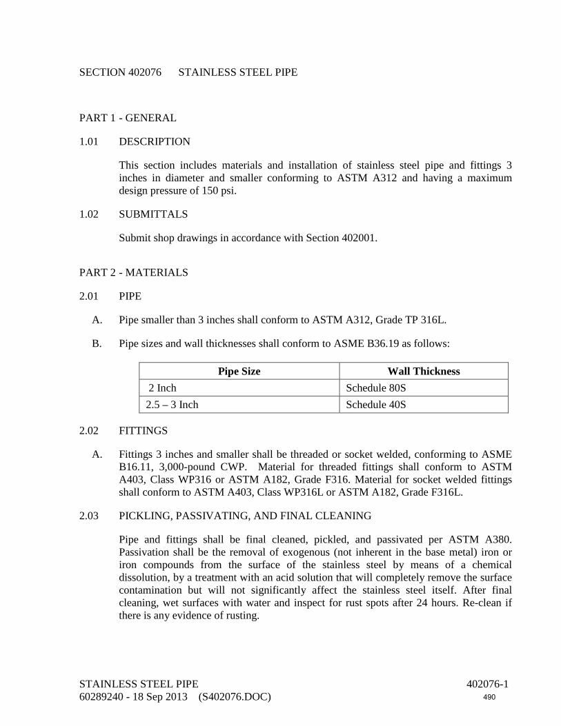
SECTION 402076 STAINLESS STEEL PIPE
PART 1 - GENERAL
1.01 DESCRIPTION
This section includes materials and installation of stainless steel pipe and fittings 3 inches in diameter and smaller conforming to ASTM A312 and having a maximum design pressure of 150 psi.
1.02 SUBMITTALS
Submit shop drawings in accordance with Section 402001.
PART 2 - MATERIALS
2.01 PIPE
A. Pipe smaller than 3 inches shall conform to ASTM A312, Grade TP 316L.
B. Pipe sizes and wall thicknesses shall conform to ASME B36.19 as follows:
Pipe Size Wall Thickness 2 Inch Schedule 80S 2.5 – 3 Inch Schedule 40S
2.02 FITTINGS
A. Fittings 3 inches and smaller shall be threaded or socket welded, conforming to ASME B16.11, 3,000-pound CWP. Material for threaded fittings shall conform to ASTM A403, Class WP316 or ASTM A182, Grade F316. Material for socket welded fittings shall conform to ASTM A403, Class WP316L or ASTM A182, Grade F316L.
2.03 PICKLING, PASSIVATING, AND FINAL CLEANING
Pipe and fittings shall be final cleaned, pickled, and passivated per ASTM A380. Passivation shall be the removal of exogenous (not inherent in the base metal) iron or iron compounds from the surface of the stainless steel by means of a chemical dissolution, by a treatment with an acid solution that will completely remove the surface contamination but will not significantly affect the stainless steel itself. After final cleaning, wet surfaces with water and inspect for rust spots after 24 hours. Re-clean if there is any evidence of rusting.
STAINLESS STEEL PIPE 402076-1 60289240 - 18 Sep 2013 (S402076.DOC) 490
2.04 QUALITY CONTROL
Include the "Hydrostatic Test" and "Flattening Test" requirements described in ASTM A999. A nondestructive electric test per ASTM A999 may be substituted for the hydrostatic test.
2.05 UNIONS
Unions shall be 3,000-pound WOG forged stainless steel, with dimensions conforming to MSS SP-83. Ends shall be threaded per ASME B1.20.1 or socket-welded type. Material shall conform to ASTM A182, Grade F316 for threaded end unions and F316L for socket-welded type.
2.06 JOINTS
A. Joints for pipes 3 inches and smaller shall be threaded or socket welded, same material as specified for fittings, 3,000-pound WOG, conforming to ASME B16.11.
2.07 THREAD LUBRICANT
Use Teflon thread lubricating compound or Teflon tape.
2.08 BOLTS AND NUTS FOR FLANGES
See Section 400500.
2.09 LUBRICANT FOR STAINLESS STEEL BOLTS AND NUTS
See Section 400500.
2.10 GASKETS FOR FLANGES
See Section 400500.
2.11 WYE STRAINERS
Strainers 2 inches and smaller shall be stainless steel, wye pattern, with minimum pressure rating of 300-psi WOG. Material shall conform to ASTM A351 or A743, Grade CF8M. Screen shall be 20 mesh and same material as the strainer. Provide pet cock of the same material as the strainer body in the blowoff connection. Ends shall be threaded conforming to ASME B1.20.1. Provide one spare screen for each strainer. Strainers shall be Sarco Type 316, Muessco No. 861, or equal.
2.12 PROTECTIVE END CAPS
Provide protective end caps on each piece of pipe or fabricated section, completely sealing the piece from contamination during shipment and storage. Provide the same type of seals on each fitting, or ship and store fittings in sealed boxes or containers.
STAINLESS STEEL PIPE 402076-2 60289240 - 18 Sep 2013 (S402076.DOC) 491

2.13 OXYGEN INDICATOR FOR WELDING OPERATIONS
Use an oxygen indicator to determine the oxygen level in the purged atmosphere (rest oxygen) in the welding area. The oxygen indicator shall be of the zirconium cell type having a range of 1- to 100-ppm oxygen. Products: Intercon Enterprises Pro-2 or equal.
PART 3 - EXECUTION
3.01 SHIPPING, STORAGE, AND HANDLING
A. Ship, store, and handle piping (including both pipe and fittings) per AWWA C220, Section 6.2 and AWWA C226, Section 6.3 and the following.
B. When loading piping for shipment to the project site, use spacers and other protective devices to separate pipes to prevent damaging the surfaces during transit and unloading. If wood spacers are used, remove wood splinters and particles from the pipe surfaces after separation. Use padded chains or ribbon binders to secure the loaded pipe and minimize damage.
C. Cover piping 100% with protective coverings or tarpaulins to prevent deposition of road salts, fuel residue, and other contaminants in transit.
D. Provide stulls, braces, and supports during shipping and storage such that out-of-roundness or deflection does not exceed 0.5% of the pipe diameter.
E. Handle piping with care during unloading, installation, and erection operations to minimize damage. Do not place or store pipe on the ground or on top of other work unless ground or work is covered with a protective covering or tarpaulin. Place pipe above the ground upon platforms, skids, or other supports.
F. Store piping at the site on pallets to prevent direct contact with ground or floor. Cover pipe during storage with protective coverings or tarpaulins to prevent deposition of rainwater, salt air, dirt, dust, and other contaminants.
G. Do not allow piping to contact carbon steel surfaces during storage, handling, or installation and erection at the site.
3.02 FABRICATION, ASSEMBLY, AND ERECTION
A. See Section 402001. Use an inert or shielding gas welding method. Do not use oxygen fuel welding. Purge the interior of the pipe with inert gas prior to the root pass. The oxygen content in the purged atmosphere in the welded area shall not exceed 30 ppm during welding operations. Use an oxygen indicator to verify oxygen levels during welding. Provide written documentation of the welding procedure before and during the oxygen purging process, showing the oxygen levels attained during the purging and welding operations.
STAINLESS STEEL PIPE 402076-3 60289240 - 18 Sep 2013 (S402076.DOC) 492

B. Welded butt joints (both longitudinal and circumferential) shall comply with AWWA C220 and AWWA C226, Section 4. Do not use backing rings. Provide full penetration and smooth internal diameters for the root bead of welds. Grind the inside weld of socket welds flush with the pipe internal diameter. Welds shall be of smooth finish. Use anti-spatter compounds specifically formulated or designed for use with stainless steel. Do not allow heat tint to form in the heat-affected zone or remove heat tint completely from the heat-affected zone of the finished weld. The maximum depth of grinding or abrasive blasting to remove defects shall not exceed 10% of the wall thickness. Do not perform abrasive blasting with steel shot, grit, or sand.
C. No iron or steel surfaces shall come into contact with the stainless steel. This includes placing on steel tables, racks, pipe supports, etc. Do not use carbon steel wire brushes or grinders.
D. Welding electrodes shall comply with AWS A5.4. Bare wire shall comply with AWS A5.9. Use electrodes as follows:
Pipe Material Welding Electrode Material Type 304 E 308 Type 304L E 347 Type 316 E 316 Type 316L E 318
3.03 SHOP TESTING OF FABRICATED OR WELDED COMPONENTS
See Section 402001.
3.04 INSTALLING THREADED PIPING
Ream, clean, and remove burrs from threaded piping before making up joints. Apply thread lubricant to threaded ends before installing fittings, couplings, unions, or joints.
3.05 INSTALLING FLANGED PIPING
See Section 400500.
3.06 INSTALLATION OF STAINLESS STEEL BOLTS AND NUTS
See Section 400500.
3.07 INSTALLING UNIONS
Provide unions on exposed piping 3 inches and smaller as follows:
A. At every change in direction (horizontal and vertical).
B. 6 to 12 inches downstream of valves.
STAINLESS STEEL PIPE 402076-4 60289240 - 18 Sep 2013 (S402076.DOC) 493

C. Every 40 feet in straight piping runs.
D. Where shown in the drawings.
3.08 INSTALLING ABOVEGROUND OR EXPOSED PIPING
See Section 400500.
3.09 FIELD HYDROSTATIC TESTING
A. See Section 400515.
3.10 PAINTING AND COATING
A. Do not coat stainless steel.
END OF SECTION
STAINLESS STEEL PIPE 402076-5 60289240 - 18 Sep 2013 (S402076.DOC) 494

This page intentionally left blank
495
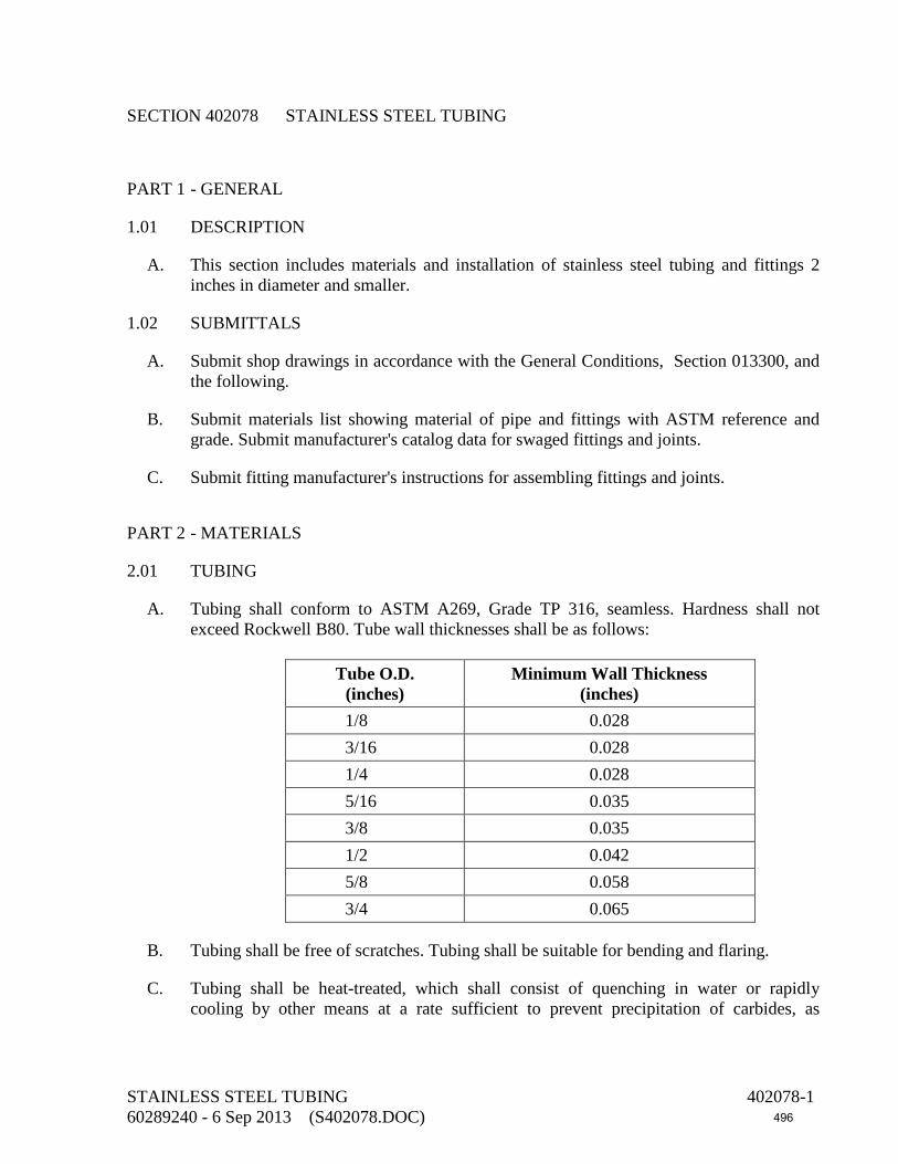
SECTION 402078 STAINLESS STEEL TUBING
PART 1 - GENERAL
1.01 DESCRIPTION
A. This section includes materials and installation of stainless steel tubing and fittings 2 inches in diameter and smaller.
1.02 SUBMITTALS
A. Submit shop drawings in accordance with the General Conditions, Section 013300, and the following.
B. Submit materials list showing material of pipe and fittings with ASTM reference and grade. Submit manufacturer's catalog data for swaged fittings and joints.
C. Submit fitting manufacturer's instructions for assembling fittings and joints.
PART 2 - MATERIALS
2.01 TUBING
A. Tubing shall conform to ASTM A269, Grade TP 316, seamless. Hardness shall not exceed Rockwell B80. Tube wall thicknesses shall be as follows:
Tube O.D.
(inches) Minimum Wall Thickness
(inches) 1/8 0.028 3/16 0.028 1/4 0.028 5/16 0.035 3/8 0.035 1/2 0.042 5/8 0.058 3/4 0.065
B. Tubing shall be free of scratches. Tubing shall be suitable for bending and flaring.
C. Tubing shall be heat-treated, which shall consist of quenching in water or rapidly cooling by other means at a rate sufficient to prevent precipitation of carbides, as
STAINLESS STEEL TUBING 402078-1 60289240 - 6 Sep 2013 (S402078.DOC) 496

demonstrated by the capability of passing practice ASTM A262, Practice E (Supplementary Requirement S4 in ASTM A269).
2.02 FITTINGS AND JOINTS
A. Fittings and joints shall be of the SWAGELOK type as manufactured by Crawford Fitting Company, utilizing a nut and dual ferrule design to connect to tubing. Fitting and joint material shall comply with ASTM A479, Type 316, or ASTM A182, Grade F316. End connections shall be of the union type.
B. Joints connecting two straight tubes together shall be of the nut and ferrule union type.
2.03 PROTECTIVE END CAPS
Provide protective end caps on each piece of tubing, completely sealing the piece from contamination during shipment and storage. Provide the same type of seals on each fitting, or ship and store fittings in sealed boxes or containers.
2.04 OUTLETS AND NOZZLES
Use a tee with nut and ferrule union ends to connect to the tubing and with an outlet to match the connecting valve or instrument.
2.05 CONNECTIONS TO THREADED-END VALVES
When connecting tubing to threaded-end valves, provide tube to female NPT connectors. Provide a threaded Schedule 80S Type 316 stainless steel nipple (ASTM A312, seamless) between the connector and the valve end.
2.06 SPARE PARTS
A. Provide the following spare parts:
Quantity Description 6 Nuts of each size used on the project 2 Hydraulic swaging units
B. Pack the spare parts in a wooden box; label with the manufacturer's name and local representative's name, address, and telephone number; and attach list of materials contained therein.
PART 3 - EXECUTION
3.01 INSTALLING TUBING
A. Do not drag tubing out of tube racks. Do not drag tubing across any surface that could scratch it.
STAINLESS STEEL TUBING 402078-2 60289240 - 6 Sep 2013 (S402078.DOC) 497

B. Keep tube cutters and saws sharp. Do not cut too deeply with each turn of the cutter or motion of the saw.
C. Deburr tube ends before inserting into fittings and joints. Clean both the inside and outside of fitting and pipe ends before making up joints. Do not miter joints for elbows or notch straight runs of pipe for tees. Do not kink tubing.
D. Bends in tubing shall be long sweep. Provide the straight length of tubing recommended by the fitting and joint manufacturer to allow the tube to be inserted into the fitting. Shape bends with shaping tools. Form bends without flattening, buckling, or thinning the tubing wall at any point. Do not use bends to make turns greater than 45 degrees. Use fittings to make turns greater than 45 degrees.
3.02 INSTALLING EXPOSED TUBING
A. Install tubing without springing, forcing, or stressing the tubing or any adjacent connecting valves or equipment.
3.03 INSTALLING FITTINGS AND JOINTS
A. Follow the manufacturer's instructions for installing fittings and joints.
B. For fittings and joints larger than 1 inch, use the manufacturer's hydraulic swaging unit to make up the connections.
3.04 FIELD HYDROSTATIC TESTING
A. The allowable leakage for tubing shall be zero.
END OF SECTION
STAINLESS STEEL TUBING 402078-3 60289240 - 6 Sep 2013 (S402078.DOC) 498

This page intentionally left blank
499

SECTION 402090 PVC PIPE, 3 INCHES AND SMALLER
PART 1 - GENERAL
1.01 DESCRIPTION
This section includes materials, installation, and testing of PVC pipe and fittings of size 3 inches and smaller for use in process piping having a maximum design pressure of 150 psi and having a maximum design temperature of 105°F.
1.02 SUBMITTALS
A. Submit shop drawings in accordance with the General Conditions, Section 013300, and the following.
B. Submit materials list showing materials of pipe and fittings with ASTM reference and grade. Submit manufacturer's certification of compliance with referenced standards, e.g., ASTM D1784, D1785, and D2467. Show wall thickness of pipe and fittings. Show fitting dimensions.
C. Submit data sheets for solvent cement demonstrating compliance with ASTM D2564 and F656.
PART 2 - MATERIALS
2.01 PIPE
Pipe shall be Schedule 80, Type I, Grade 1 (Class 12454-B), conforming to ASTM D1784 and D1785.
2.02 PVC PIPE COLORING AND MARKING FOR RECLAIMED WATER SERVICE
PVC pipe shall be purple (Pantone 522) and shall be marked on both sides of the pipe with the wording "CAUTION: RECLAIMED WATER--DO NOT DRINK." The lettering shall be minimum 1 inch high, black, and shall be repeated at intervals not exceeding 60 inches. The purple coloring shall be achieved by adding pigment to the PVC material as the pipe is being manufactured.
2.03 FITTINGS
Fittings shall be Schedule 80 and shall conform to ASTM D2464 for threaded fittings and ASTM D2467 for socket-type fittings.
PVC PIPE, 3 INCHES AND SMALLER 402090-1 60289240 - 6 Sep 2013 (S402090.DOC) 500

2.04 FLANGES
PVC flanges shall be of the one-piece solid socket design and shall be made of the same material as the pipe. Pressure rating shall be at least 150 psi at a temperature of 73°F. Minimum burst pressure shall be 500 psi. Flanges shall match the dimensions of ASME B16.5, Class 150, steel flanges for outside diameter, bolt circle, and bolt holes. Do not use Van Stone flanges.
2.05 UNIONS
A. Unions shall have socket-type ends, Viton O-rings, and shall be Schedule 80. Material shall be Type I, Grade 1 PVC, per ASTM D1784.
B. Union connections to other metal piping materials shall comply with MSS SP-107. The fitting end for connection to PVC pipe shall be a female socket. Provide wrought or cast copper tailpieces for connection to copper piping and tubing. Provide Type 316 stainless steel tailpieces for connection to steel piping.
2.06 JOINTS
Pipe and fitting joints shall be socket welded except where threaded and flanged joints are required to connect to valves and equipment.
2.07 SOLVENT CEMENT
Solvent cement for socket joints shall comply with ASTM D2564 and F656.
2.08 GASKETS FOR FLANGES
See Section 400500.
2.09 BOLTS AND NUTS FOR FLANGES
See Section 400500.
2.10 LUBRICANT FOR STAINLESS STEEL BOLTS AND NUTS
See Section 400500.
2.11 WYE STRAINERS
PVC wye strainers shall be manufactured of the same material as the pipe, with 30-mesh screens and Viton seals. Connecting ends shall be the socket type, solvent welded. Provide one spare screen for each strainer.
PVC PIPE, 3 INCHES AND SMALLER 402090-2 60289240 - 6 Sep 2013 (S402090.DOC) 501

PART 3 - EXECUTION
3.01 GENERAL
A. Do not install PVC pipe when the temperature is below 40°F or above 90°F. Store loose pipes on racks with a maximum support spacing of 3 feet. Provide shades for pipe stored outdoors or installed outdoors until the pipe is filled with water.
B. Store fittings indoors in their original cartons.
C. Store solvent cement indoors or, if outdoors, shade from direct sunlight exposure. Do not use solvent cements that have exceeded the shelf life marked on the storage container.
D. Before installation, check pipe and fittings for cuts, scratches, gouges, buckling, kinking, or splitting on pipe ends. Remove any pipe section containing defects by cutting out the damaged section of pipe.
E. Do not drag PVC pipe over the ground, drop it onto the ground, or drop objects on it.
3.02 SOLVENT-WELDED JOINTS
A. Prior to solvent welding, remove fittings and couplings from their cartons and expose them to the air at the same temperature conditions as the pipe for at least one hour.
B. Cut pipe ends square and remove all burrs, chips, and filings before joining pipe or fittings. Bevel solvent-welded pipe ends as recommended by the pipe manufacturer.
C. Wipe away loose dirt and moisture from the inside and outside of the pipe end and the inside of the fitting before applying solvent cement. Clean the surfaces of both pipes and fittings that are to be solvent welded with a clean cloth moistened with acetone or methylethyl ketone. Do not apply solvent cement to wet surfaces.
D. The pipe and fitting socket shall have an interference fit. Perform a dry fit test at each joint before applying solvent cement. The pipe shall enter the fitting socket between one-third and two-thirds of the full socket depth when assembled by hand.
E. Make up solvent-welded joints per ASTM D2855. Application of cement to both surfaces to be joined and assembly of these surfaces shall produce a continuous bond between them with visual evidence of cement at least flush with the outer end of the fitting bore around the entire joint perimeter.
F. Allow at least eight hours of drying time before moving solvent-welded joints or subjecting the joints to any internal or external loads or pressures.
G. Acceptance criteria for solvent-welded joints shall be as follows:
1. Unfilled Areas in Joint: None permitted.
2. Unbonded Areas in Joint: None permitted.
PVC PIPE, 3 INCHES AND SMALLER 402090-3 60289240 - 6 Sep 2013 (S402090.DOC) 502

3. Protrusion of Material into Pipe Bore, Percent of Pipe Wall Thickness: Cement, 50%.
3.03 FLANGED JOINTS
A. Lubricate carbon steel bolt threads with graphite and oil before installation.
B. Tighten bolts on PVC flanges by tightening the nuts diametrically opposite each other using a torque wrench. Complete tightening shall be accomplished in stages and the final torque values shall be as shown in the following table:
Pipe Size (inches)
Final Torque (foot-pounds)
1/2 to 1 1/2 10 to 15 2 to 3 20 to 30
3.04 INSTALLATION OF STAINLESS STEEL BOLTS AND NUTS
See Section 400500.
3.05 ASSEMBLING THREADED JOINTS
A. Cut threaded ends on PVC to the dimensions of ASTM F1498. Ends shall be square cut. Follow the pipe manufacturer's recommendations regarding pipe hold-down methods, saw cutting blade size, and saw cutting speed. Gauges, gauge tolerances, and gauging procedures shall comply with ASTM F1498, Sections 7 and 8. Perform field gauging on every field-cut threaded connection.
B. Pipe or tubing cutters shall be specifically designed for use on PVC pipe. Use cutters manufactured by Reed Manufacturing Company, Ridge Tool Company, or equal.
C. If a hold-down vise is used when the pipe is cut, insert a rubber sheet between the vise jaws and the pipe to avoid scratching the pipe.
D. Thread cutting dies shall be clean and sharp and shall not be used to cut materials other than plastic.
E. Apply Teflon® thread compound or Teflon® tape lubricant to threads before screwing on the fitting.
F. Assemble threaded flanges and fittings per ASTM F1498, Sections 4, 7, and 8. Do not tighten threaded connections more than two turns past finger tightness for both internal and external threads.
3.06 INSTALLING UNIONS
Provide unions on exposed piping 3 inches and smaller as follows:
PVC PIPE, 3 INCHES AND SMALLER 402090-4 60289240 - 6 Sep 2013 (S402090.DOC) 503

A. At every change in direction (horizontal and vertical).
B. 6 to 12 inches downstream of valves.
C. Every 40 feet in straight pipe runs.
D. Where shown in the drawings.
3.07 INSTALLING BURIED PIPE
A. Trench bottom shall be continuous, smooth, and free of rocks. See the details in the drawings for trench dimensions, pipe bedding, and backfill.
B. After the pipe has been solvent-welded and the joints have set, snake the pipe in the trench per the pipe manufacturer's recommendations in order to allow for thermal expansion and contraction of the pipe.
C. Do not backfill the pipe trench until the solvent-welded joints have set. Support the pipe uniformly and continuously over its entire length on firm, stable soil. Do not use blocking to change pipe grade or to support pipe in the trench.
D. Install buried PVC pipe in accordance with ASTM D2774 and the pipe manufacturer's recommendations. Backfill materials in the pipe zone shall be imported sand per Section 312316.
3.08 INSTALLING ABOVEGROUND OR EXPOSED PIPING
A. See Section 400500.
B. Fill empty piping with water and provide temporary shading or other means to keep the surface temperature of the pipe below 100°F.
3.09 PAINTING AND COATING
Coat piping per Section 099000, System No. 41.
3.10 HYDROSTATIC TESTING
Perform hydrostatic testing for leakage in accordance with Section 400515.
END OF SECTION
PVC PIPE, 3 INCHES AND SMALLER 402090-5 60289240 - 6 Sep 2013 (S402090.DOC) 504

This page intentionally left blank
505

SECTION 402097 HDPE PIPE AND FITTINGS
PART 1 - GENERAL
1.01 DESCRIPTION
This section includes materials, installation and testing of PE4710 high-density, very high molecular weight polyethylene pipe and fittings having a hydrostatic design basis of 1,600 psi at a temperature of 73°F. Pipe diameter basis is IPS, with dimension ratio (DR) as shown in the drawings.
1.02 SUBMITTALS
A. Submit shop drawings in accordance with the General Conditions, Section 013300, and the following.
B. Submit materials list for review.
C. Submit manufacturer's recommended method of installing HDPE pipe including procedures for butt-fusing joints and manufacturer's recommended method for electro-fusing joints.
D. The polyethylene pipe manufacturer shall provide certification that stress regression testing has been performed on the specific product. Certification shall include a stress life curve per ASTM D2837.
E. Provide certification that the material is listed by the Plastics Pipe Institute in PPI TR-4 with a 73°F hydrostatic design stress rating of 800 psi and a 140°F hydrostatic design stress rating of 400 psi. The PPI listing shall be in the name of the pipe manufacturer and shall be based on ASTM D2837 and PPI TR-3 testing and validation of samples of the pipe manufacturer's production pipe.
F. The manufacturer's certification shall state that the pipe was manufactured from one specific resin in compliance with these specifications. The certificate shall state the specific resin used, its source, and list its compliance to these specifications.
G. Submit certified lab data to verify specified physical properties. Certify that tests are representative of pipe supplied for this project.
H. Submit affidavit of compliance with referenced standards (e.g., AWWA C906, ASTM F714, etc.).
I. Submit qualification certificates for operators of heat fusion and electro-fusion equipment.
J. Submit record of each fused joint demonstrating compliance with manufacturer’s written fusion recommendations.
HDPE PIPE AND FITTINGS 402097-1 60289240 - 6 Sep 2013 (S402097.DOC) 506

PART 2 - MATERIALS
2.01 PIPE
A. Pipe and fittings shall conform to AWWA C906 and ASTM F714 and the following requirements.
B. Pipe shall have a nominal IPS outside diameter.
C. The minimum wall thickness (inches) for pipe shall be in accordance with for the DR shown in the drawings. If no DR is shown in the drawings, use a DR of 11, minimum. Produce the pipe to the dimensions and tolerances specified in ASTM F714.
D. The pipe shall be homogeneous throughout and free of visible cracks, holes, voids, foreign inclusions, or other deleterious defects and shall be identical in color, density, melt index, and other physical properties throughout.
E. Pipe shall have a minimum hydrostatic design basis (HDB) of 1,600 psi, as determined in accordance with ASTM D2837.
F. Pipe Material:
1. Materials used for the manufacture of polyethylene pipe and fittings shall be very high molecular weight, high-density ethylene/hexene copolymer PE 4710 polyethylene resin meeting the physical property and pipe performance requirements listed below.
Property Specification Units Minimum
Values Material Designation PPI/ASTM --- PE4710 Material Classification ASTM D1248 --- III C 5 P34 Cell Classification ASTM D3350 --- 445574C Hardness ASTM D2240 Shore "D" 64 Compressive Strength (Yield) ASTM D695 psi 1,600 Tensile Strength @ Yield (Type IV Spec.)
ASTM D638 (2"/min)
psi 3,200
Elongation @ Yield ASTM D638 %, min. 8 Tensile Strength @ Break (Type IV Spec.)
ASTM D638 psi 3,500 psi
Elongation @ Break ASTM D638 %, min. 600 Modulus of Elasticity ASTM D638 psi 110,000 ESCR:
(Cond A, B, C: Mold. Slab) ASTM D1693 Fo, Hrs Fo>5,000
HDPE PIPE AND FITTINGS 402097-2 60289240 - 6 Sep 2013 (S402097.DOC) 507

Property Specification Units Minimum
Values (Compressed Ring Pipe) ASTM F1248 F50, Hrs F50>1,000
Slow Crack Growth Battelle Method Days to Failure
Fo>32
Impact Strength (IZOD) (0.125-Inch Thick)
ASTM D256 (Method A)
in-lb/in Notch
42
Linear Thermal Expansion Coefficient
ASTM D696 in/in/°F 1.2 x 10⁻⁴
Thermal Conductivity ASTM C177 BTU, in/ Ft2/hrs/°F
2.7
Brittleness Temp. ASTM D746 °F <-180°F Vicat Soft. Temp. ASTM D1525 °F 257 NSF Listing Standard 14 --- "Listed"
*Standard deviation 0.01.
2. The pipe shall be extruded from precompounded resin. In-plant re-blending of resin is unacceptable.
3. Color shall be black.
2.02 NIPPLES AND FLANGED STUB ENDS
Short nipples, flange adapters, bulkheads and stub ends shall be of the same material as the pipe.
2.03 FITTINGS
Fittings up to 8-inch shall be molded polyethylene fabricated per AWWA C901/C906. Fittings 10-inch to 24-inch shall be fabricated fittings per AWWA C906. Fittings 26-inch and larger shall be manufacturer by Independent Pipe Products, Inc or equal. All fitting shall meet the requirements of the pipe and have a SDR that matches the mating pipe.
HDPE PIPE AND FITTINGS 402097-3 60289240 - 6 Sep 2013 (S402097.DOC) 508
2.04 JOINTS
A. Join sections of polyethylene pipe into continuous lengths on the jobsite above ground. The joining method shall be the butt fusion method performed in accordance with the pipe manufacturer's recommendations. Butt fusion joining shall result in a joint weld strength equal to or greater than the tensile strength of the pipe. Socket fusion shall not be used. Extrusion welding or hot gas welding of HDPE shall not be used.
B. The butt fusion equipment used in the joining procedures shall be capable of meeting all jobsite and material conditions as recommended by the pipe manufacturer.
C. Flanges, unions, grooved-couplers, electro-fusion transition fittings, and some ductile iron mechanical couplers may be used to connect HDPE pipe mechanically without butt fusion where shown in the drawings.
2.05 BOLTS, NUTS, AND GASKETS FOR FLANGES
See Section 40 05 00.
2.06 LUBRICANT FOR STAINLESS STEEL BOLTS AND NUTS
See Section 40 05 00.
PART 3 - EXECUTION
3.01 SHIPPING, STORAGE, AND HANDLING
A. Limit onsite pipe storage to a maximum of one week.
B. Transport pipe to the jobsite on padded bunks with nylon tie-down straps or padded bonding to protect the pipe. Protect the pipe from sharp objects. Anchor pipe securely to prevent slippage.
C. Store pipe on earth berms or timber cradles adjacent to the trench or lay-down area for pullback. When the pipe is received, visually inspect to verify that the correct product was received. Check for damage that may have occurred during transit. Examine for fractures, kinking, gouges, or cuts. Remove and dispose off-site pipe with gouges or cuts in excess of 10% of the nominal pipe wall thickness.
D. Cover pipe 100% with protective coverings or tarpaulins to prevent deposition of road salts, diesel smoke, fuel residue, and other contaminants while in transit.
E. Hook lifting equipment, such as cranes, extension boom cranes, and side boom tractors, to wide web choker slings that are secured around the load or to lifting lugs on the fitting. Use only wide web slings. Do not use wire rope slings or chains which can damage pipe and fittings. Use spreader bars when lifting pipe or fittings longer than 20 feet.
HDPE PIPE AND FITTINGS 402097-4 60289240 - 6 Sep 2013 (S402097.DOC) 509

F. Unload large fabrications using a wide web choker sling and lifting equipment such as an extension boom crane, crane, or lifting boom. Do not use stub outs, outlets, or fittings as lifting points, and avoid placing slings where they will bear against outlets or fittings.
G. Protect the pipe from stones and sharp objects.
H. Store fittings in their original cartons.
3.02 HANDLING PIPE DURING INSTALLATION
B. Lift pipes with handling beams or wide belt slings near the middle of joints as recommended by the pipe manufacturer. Do not use cable slings, chains, or hooks.
C. Before installation, check pipe and fittings for cuts or scratches exceeding 5% of the pipe wall thickness, gouges, buckling, kinking, or splitting. Remove and dispose off-site such defective pipe.
3.03 SANITATION OF PIPE INTERIOR
A. During fusion operations and laying operations, do not place tools, clothing, or other materials in the pipe.
B. When pipelaying is not in progress, including the lunch hour, close the ends of the pipe by a vermin- and child-proof plug.
3.04 QUALIFICATION OF FUSION OPERATORS
Each operator performing fusion joining shall be qualified in the use of the manufacturer's recommended fusion procedure(s) by the following:
A. Appropriate training or experience in the use of the fusion procedure.
B. Making a sample joint according to the procedure that passes the following inspections and tests:
1. The joint shall be visually examined during and after joining and found to have the same appearance as a photograph or sample of an acceptable joint that was joined in accordance with the procedure; and
2. Test or examine the joint by one of the following methods:
(a) Pressure and tensile test as described in 49 CFR 192.283;
(b) Ultrasonic inspection and found to be free of flaws that would cause failure; or
(c) Cut into at least three longitudinal straps, each of which is:
HDPE PIPE AND FITTINGS 402097-5 60289240 - 6 Sep 2013 (S402097.DOC) 510

(1) Visually examined and found to be free of voids or unbonded areas on the cut surface of the joint, and
(2) Deformed by bending, torque, or impact and if failure occurs, it must not initiate in the joint area.
3. Each operator shall be re-qualified under the procedure, if, during any 12-month period he:
(a) Does not make any joints under the procedure; or
(b) Has three joints or three percent of the joints he has made, whichever is greater, that are found unacceptable by testing under 49 CFR 192.513.
3.05 HEAT FUSION
A. Comply with ASTM F2620, except as modified below.
B. Use fusion equipment specially designed for heat fusion of HDPE such as offered by McElroy Manufacturing, Inc., Tulsa, Oklahoma or equal. The equipment utilized shall be regulated for the different melt strength materials. Compatibility fusion techniques shall be used when polyethylenes of different melt indexes are fused together.
C. Maintain the proper temperature of the heater plate as recommended by the pipe manufacturer. Check it with a tempilstik or pyrometer for correct surface temperature.
D. Clean pipe ends inside and outside with a clean cotton cloth to remove dirt, water, grease, and other foreign materials.
E. Square (face) the pipe ends using facing tool of the fusion machine. Remove burrs, chips, and filings before joining pipe or fittings.
F. Check line-up of pipe ends in fusion machine to see that pipe ends meet squarely and completely over the entire surface to be fused. Make sure the clamps are tight so that the pipe does not slip during the fusion process.
G. Insert clean heater plate between aligned ends and bring ends firmly in contact with plate but do not apply pressure while achieving melt pattern. Allow pipe ends to heat and soften.
H. Carefully move the pipe ends away from the heater plate and remove the plate (if the softened material sticks to the heater plate, discontinue the joint, clean heater plate, resquare pipe ends, and start over).
I. Bring melted ends together rapidly. Do not slam. Apply enough pressure to form a double roll-back bead to the body of the pipe around the entire circumference of the pipe about 1/8- to 3/16-inch wide. Pressure is necessary to cause the heated material to flow together.
HDPE PIPE AND FITTINGS 402097-6 60289240 - 6 Sep 2013 (S402097.DOC) 511

J. Allow the joint to cool and solidify properly prior to release of pressure. After the fused joint is cool to the touch, remove the pipe from the clamps and inspect the joint appearance.
K. Use a data logging device with the hydraulic joining equipment to record fusion parameters of pressure, temperature, and time for each joint.
L. Fusion joint shall produce a joint weld with strength equal to or greater than the tensile strength of the pipe itself.
3.06 SIDEWALL FUSION
A. Accomplish side fusion procedure for HDPE in the field using 2- through 12-inch McElroy (or equal) fusion units and proper heater plate adapters. Where branch outlets are larger than 12 inches in outside diameter, accomplish sidewall fusion in a fitting fabrication shop.
B. Clean the pipe with a clean cotton cloth. Prepare surface of pipe (main) by roughing with 60 grit or coarser utility cloth.
C. Prepare the base of the branch by roughing with 60 grit or coarser utility cloth.
D. Align branch on the main and tighten clamp.
E. Check branch for square alignment.
F. Retract moveable clamp, roll in, and center heater plate with adapter between base of branch and main.
G. For all sizes, apply a strong, firm, continuous pressure until complete melt bead can be seen on main. Release pressure to light pressure. Continue heat soak cycle on branch and main. Watch base of branch for:
Main Sizes
(inches) Heat Soak Cycle Fitting Base Bead
1-1/4 and smaller 1/16-inch Melt Bead 2 1/8-inch Melt Bead 3 and Larger 1/8- to 3/16-inch Melt Bead
H. Retract moveable clamp and cleanly remove heater plate.
I. Bring melted surfaces together rapidly. Do not slam. Apply continuous progressive pressure until proper fusion bead is formed. Maintain pressure until joint has cooled.
HDPE PIPE AND FITTINGS 402097-7 60289240 - 6 Sep 2013 (S402097.DOC) 512

3.07 COMPATIBILITY FUSION
A. Manufacturer of pipe shall provide technical personnel to instruct and demonstrate the fusion procedure for joining dissimilar HDPE materials.
B. Compatibility heat fusion and sidewall fusion shall be accomplished in the same manner as described above except that to achieve proper melt pattern, insert the heater plate and place a compatibility insulator between the heater plate and the lower melt material. After the higher melt achieves proper melt, then remove the insulator and bring the heater plate in contact with the lower melt material for proper melt. Continue heating both surfaces until proper melt develops. For manually operated fusion equipment, form a double roll-back bead as previously described in the fusion procedures.
3.08 COLD-BENDING OF CURVED SEGMENTS
HDPE may be cold-bent to a minimum radius of no less than 30 times the pipe diameter as it is installed along curved alignment. The minimum bending radius that can be applied to the pipe without kinking it varies with the diameter and wall thickness of the pipe and shall not exceed the recommendations of the manufacturer. If adequate space is not available for the required radius, fuse a fitting of the required angle into the piping system to obtain the necessary change in direction.
3.09 ELECTRO-FUSION SADDLES (LOW PRESSURE APPLICATIONS)
Use electro-fusion saddles to install branch saddles on larger diameter host pipe. Electro-fusion saddles shall be rated by the manufacturer at the pressure rating or greater of the pipe to which it joins. Electro-fusion saddle shall be designed to match the melt index of the adjacent pipe to which it is joined.
3.10 SERVICE SADDLES (HIGH PRESSURE APPLICATIONS)
Provide JCM model #404 service saddle with double stainless steel straps. Coordinate outlet size with service size from drawings. Apply sufficient torque evenly to the bolts to prevent leaks. After initial installation and tightening, allow the connections to set for at least two days. Then conduct a final tightening of the bolts.
3.11 STATIC ELECTRICITY DISCHARGING
A. Static electricity charges are generated on polyethylene pipe by friction, particularly during the handling of pipe in storage, shipping, and installation. The flow of air or gas containing dust or scale will also build up significant static charges, as will the flow of dry materials through the pipe. These charges are a safety hazard, particularly in areas where there is leaking gas or an explosive atmosphere.
B. Plastic pipe is a nonconductor of electricity and the static charge will remain in place until some grounding device comes close enough to allow it to discharge.
C. The discharge of these static electric charges is the responsibility of the Contractor.
HDPE PIPE AND FITTINGS 402097-8 60289240 - 6 Sep 2013 (S402097.DOC) 513

D. Do not drag HDPE pipe over the ground, drop it onto the ground, or drop objects on it.
3.12 FLANGED CONNECTIONS
A. Accomplish mechanical joining to other piping materials (fittings, valves, tanks, pumps, etc.) with factory-made flange adapters and stainless steel backup flanges.
B. Flange adapters shall be pressure rated the same as the pipe. Flange adapters shall be heat fused to the pipe as specified in the heat fusion section.
C. Use gaskets between the polyethylene flange adapters only when recommended by the HDPE pipe manufacturer. Apply sufficient torque evenly to the bolts to prevent leaks. After initial installation and tightening, allow the connections to set for at least two days. Then conduct a final tightening of the bolts.
D. Lubricate nuts and bolts with oil or graphite prior to installation.
E. Wrap buried flanges, bolts, and metal with the sheet polyethylene film or tape specified for the valves and equipment. Extend the wrap or tape over the flanges and bolts and secure it around the adjacent pipe circumference with tape.
F. Check operation of valves connected to molded stub end flange adapters. Insert polyethylene spacer if recommended by pipe manufacturer for clearance.
3.13 MJ CONNECTIONS
A. Accomplish mechanical joining to other piping materials with factory-made mechanical joint adapters.
B. MJ adapters shall be pressure rated the same as the pipe. MJ adapters shall have the same DR and size of the pipe. MJ adapters shall be heat fused to the pipe as specified in the heat fusion section.
C. Use gaskets between the polyethylene flange adapters recommended by the HDPE pipe manufacturer. Apply sufficient torque evenly to the bolts to prevent leaks. After initial installation and tightening of flanged connections, allow the connections to set for at least two days. Then conduct a final tightening of the bolts.
D. Lubricate nuts and bolts with oil or graphite prior to installation.
E. Wrap buried adapter, bolts, and metal with the sheet polyethylene film or tape specified for the valves and equipment. Extend the wrap or tape over the joint and bolts and secure it around the adjacent pipe circumference with tape.
F. Check operation of valves connected to molded stub end adapters. Insert polyethylene spacer if recommended by pipe manufacturer for clearance.
HDPE PIPE AND FITTINGS 402097-9 60289240 - 6 Sep 2013 (S402097.DOC) 514

3.14 THREADED CONNECTIONS
A. Provide IPS Male Threaded Transition Fitting manufactured by ISCO. Threaded material shall be stainless steel.
3.15 PNEUMATIC PRESSURE TESTING
B. Perform Pneumatic Pressure Testing prior to burying and hydrostatic pressure testing of fused pipe.
C. Perform pressure and visual test on the pipe with an air test to 5 psi and not exceeding 10 psi.
D. Compressed air shall be used for the test medium. The test medium shall be non-flammable and non-toxic.
E. Build and release pressure slowly.
F. Hold pressure for 10 to 60 minutes but not longer than 60 minutes.
G. Ambient temperature shall be above 32 degrees F for air test.
H. Detect leaks with mild soap solution (avoid strong detergents) or other non-deleterious leak detecting fluids applied to the joint. Bubbles indicate leakage. Rinse soap solution from pipe surface with clean water after leak testing.
3.16 HYDROSTATIC TESTING
A. Perform hydrostatic testing for leakage in accordance with ASTM F2164 and Section 400515. The test period and allowable leakage rate shall be as defined in ASTM F2164, Section 9.
B. Allow the water, pipe, and soil to thermally stabilize. Fill the pipeline, vent the air, and allow the filled pipeline to sit overnight (in above freezing weather) to thermally stabilize.
C. Examine exposed pipe or fittings carefully during the leak test for damage. Repair any damaged or defective pipe, fittings, valves, or hydrants discovered during the leak test and repeat the test. During the test period, add makeup water to keep the pressure constant.
D. The total time for initial pressurization and time at test pressure shall not exceed eight hours at 1.5 times the system pressure rating. If the test is not completed because of leakage, equipment failure, or any other reason within this total time, depressurize the test section and allow the pipe to “relax” for at least eight hours before starting the next testing sequence.
END OF SECTION
HDPE PIPE AND FITTINGS 402097-10 60289240 - 6 Sep 2013 (S402097.DOC) 515

SECTION 402713 CORPORATION STOPS AND SERVICE SADDLES
PART 1 - GENERAL
1.01 DESCRIPTION
This section includes materials and installation of service saddles and corporation stops.
1.02 SUBMITTALS
A. Submit shop drawings in accordance with the General Conditions, Section 013300, and the following.
B. Submit manufacturer's catalog data and descriptive literature showing dimensions and materials of construction by ASTM reference and grade. Show coatings.
PART 2 - MATERIALS
2.01 CORPORATION STOPS
Corporation stops shall comply with AWWA C800 with inlets and outlets as tabulated below:
Type Inlet
Connection Outlet
Connection Manufacturer and Model 1 Outside I.P. Inside I.P. Less than 1 1/2 inches: Jones J-50,
Mueller H-10046 For sizes 1 1/2 and 2 inches: Ford FB-1700
2 Outside Corp. Stop (AWWA taper thread)
Inside I.P. Less than 1 1/2 inches: Jones J-51, Mueller H-10045 For sizes 1 1/2 and 2 inches: Ford FB-1600
3 Outside Corp. Stop (AWWA taper thread)
Outside Coupling Thread
Mueller H-9971, Ford F-200
4 Outside I.P. Outside I.P. Less than 1 1/2 inches: Mueller H-10013 For sizes 1 1/2 and 2 inches: Ford FB-500
5 Outside I.P. Copper Tubing Less than 1 1/2 inches: Mueller H-15025 For sizes 1 1/2 and 2 inches: Ford FB-700
6 Outside Corp. Stop (AWWA taper thread)
Copper Tubing Less than 1 1/2 inches: Mueller H-15050 For sizes 1 1/2 and 2 inches: Ford FB-600
CORPORATION STOPS AND SERVICE SADDLES 402713-1 60289240- 6 Sep 2013 (S402713.DOC) 516

7 Outside I.P. Outside I.P. For sizes 1 1/4 inches and smaller: Mueller H-10013. Provide full bore.
2.02 SERVICE SADDLES FOR DUCTILE-IRON, STEEL, AND PVC (AWWA C900 AND C909) PIPE
A. Service saddles shall be of the double-strap type. Bodies shall be malleable iron (ASTM A47 or A197). Straps shall be bronze or silicon bronze. Tap sizes on the outlet shall be 3/4 inch through 2 inches to accommodate the connecting piping or corporation stops. Service saddles shall be Dresser Style 91, Smith-Blair Type 313, or equal.
2.03 SERVICE SADDLES FOR SCHEDULE 40 AND 80 PVC PIPE
Service saddles shall be malleable iron (ASTM A47 or A197) or bronze (ASTM B61 or B62), using interlocking lugs and a single bolt to hold the saddle in place. Tap sizes on the outlet shall be 3/4 inch or 1 inch to accommodate the connecting piping or corporation stops. Service saddles shall be Dresser Style 194, Smith-Blair Models 395 or 397, or equal.
PART 3 - EXECUTION
3.01 INSTALLATION OF SERVICE SADDLES
Install service saddles with the gaskets seated on the pipe so that zero leakage is obtained. Tighten bolts to the torque recommended by the manufacturer.
3.02 INSTALLATION OF CORPORATION STOPS
A. Use a smooth-jawed adjustable wrench that fully and evenly engages the stop wrenching flats. Place the wrench only on the stop body wrench flats. Do not use the rounded areas of the stop body for tightening into the main or saddle. When connecting the outlet service line, use two wrenches to make the connection. Use one wrench to support the corporation stop and/or curb stop and the other wrench to tighten the service connection.
B. Backfill and compact soil carefully around the corporation stop, curb stop, and service line to prevent ground settling and damage to the valve or service line.
3.03 FIELD PRESSURE TESTING OF CORPORATION STOPS AND SERVICE SADDLES
A. Perform service line pressure testing prior to backfilling of buried service saddles and corporation stops.
B. External leakage through the corporation stop body is not allowed. During testing of ground key stops, the outlet may be capped to eliminate leakage through the stop’s closed port opening. Test pressures shall not exceed 150% of the maximum working pressure specified in AWWA C800. Cap stop outlets and test in the open position. When
CORPORATION STOPS AND SERVICE SADDLES 402713-2 60289240- 6 Sep 2013 (S402713.DOC) 517
testing a water main, if capping the corporation stop is impractical, test to the curb stop with the corporation stop in the open position.
C. Test pressures on service saddles for attachment to plastic pipe should be limited to 150% of the lower-rated component.
3.04 PAINTING AND COATING OF SERVICE SADDLES
A. Coat buried service saddles per Section 099000, System No. 21.
B. Coat service saddles located above ground or in vaults and structures per Section 099000, System No. 10. Apply prime coat at factory. Color of finish coat shall match the color of the pipe to which the service saddle is connected.
END OF SECTION
CORPORATION STOPS AND SERVICE SADDLES 402713-3 60289240- 6 Sep 2013 (S402713.DOC) 518

This page intentionally left blank
519

SECTION 405000 PROCESS CONTROL AND INSTRUMENTATION SYSTEM (PCIS)
GENERAL REQUIREMENTS
PART 1 - GENERAL
1.01 Description
1. This section of the specifications includes materials, testing, and installation of process control and instrumentation system as specified herein and indicated on the drawings.
2. These specifications shall not be interpreted as permission or direction to violate any governing code or ordinance. Equipment, materials, and workmanship shall comply with the latest revisions of the following codes and standards:
a. Instrumentation: ISA - The International Society of and Automation.
b. Wiring: NFPA 70 National Electrical Code (NEC), ISA S5.3 (Graphic symbols for Distributed Control/Shared display instrumentation, Logic and Computer Systems), and S5.4 (Instrument Loop Diagrams).
c. Control Panels: NEMA Standards Publication 250-2003.
d. Control Logic: NFPA 79.
1.02 Scope of Work
1. The work involves furnishing all hardware, programming, installation, labor, material, equipment, and engineering in strict compliance with the contract documents for the City of Naples Public Works Pump Station, for interfacing with the existing SCADA system.
1.03 Submittals
1. Detailed System Drawings and Data: The submittal shall consist of six sets of detailed drawings and data prepared and organized by the Contractor. All drawings, schematics, layouts, and diagrams shall be done on 11" x 17" sheets utilizing AutoCAD. Two sets of submittals will be returned to the Contractor.
2. Submit these drawings and data as a complete package at the same time.
3. Submittals shall be in three-ring hardcover binders and arranged for convenient use including tab sheets, all indexed, and cross referenced with a separate index for each item.
Process Control & Instrumentation System (PCIS) Requirements 405000-1 60289240 - 13 Sep 2013 (S405000.DOC)
520

4. Provide manufacturers cut sheets and manuals for all hardware to be provided.
5. Provide ISA type instrumentation data sheets for each component, together with a technical product brochure or bulletin. The data sheets, as a minimum, shall show:
a. Instrument tag designation.
b. Component name.
c. Manufacturer's model number.
d. Calibrated range.
e. Instrument location.
f. Input and output characteristics.
g. Scale range and units (if any) and multiplier (if any).
h. Requirements for electric supply.
6. Group the data sheets together in the submittal by type. Provide individual data sheets for each instrument with one brochure or bulletin to cover all identical uses of that component.
7. The detailed construction drawing submittal shall include, as a minimum, the following types of drawings and diagrams required for the construction of this project:
a. Legend, Symbols, and Index.
b. System Block Diagrams.
c. Power Distribution Diagrams.
d. Instrument Control Panel Layouts/Construction Drawings/Details. The drawings shall include the following:
1) Dimensions
2) Location of all components
3) Identification of all components
4) Bill of Materials
5) Conduit entry area.
Process Control & Instrumentation System (PCIS) Requirements 405000-2 60289240 - 13 Sep 2013 (S405000.DOC)
521

e. PLC/RTU Rack Elevation Drawing.
f. Internal Panel Wiring Diagrams.
g. Digital I/O Module Wiring Diagrams.
h. Analog I/O Module Wiring Diagrams.
i. Detailed NFPA 79-style Ladder Diagrams (for discrete wiring) to meet the following minimum requirements:
1) Each subassembly shall be shown as a rectangle in the diagram with all external terminals identified. Terminals unknown at the time of the submittal shall be left blank, to be filled later. Single contacts internal to the subassemblies shall be shown in the rectangle connected to their terminal points.
2) Where the internal wiring diagrams of subassemblies are furnished on separate sheets, they shall be shown as a rectangle in the schematic diagram with all external points identified and cross-referenced to the separate sheets of the control circuit. Coils and contacts internal to the subassemblies shall be shown in the rectangle connected to their terminal points.
3) Show unique rung numbers on left side of each rung. A cross-referencing system shall be used in conjunction with each relay coil so that associated contacts may be readily located on the diagram. The contacts shall be referenced to coils as well, so that associated coils may be readily located on the diagram. Where a relay contact appears on a sheet separate from the one on which the coil is shown, the purpose of the contact shall be described on the same sheet. Spare contacts shall be shown.
4) Contacts of multiple contact devices, e.g., selector switches, shall be shown on the line of the schematic diagram where they are connected in a circuit. A mechanical connection between the multiple contacts shall be indicated by a dotted line or arrow. This does not apply to control relays, starters, or contactors. Additional charts or diagrams may be used to indicate the position of multiple contact devices such as drum, cam, and selector switches.
5) The purpose or function of all switches shall be shown adjacent to the symbols. The purpose or function of controls such as relays, starters, contactors, subassemblies, and timers on the diagram shall be shown adjacent to their respective symbols.
Process Control & Instrumentation System (PCIS) Requirements 405000-3 60289240 - 13 Sep 2013 (S405000.DOC)
522

j. Detailed Loop Interconnection Wiring Diagrams (per ISA S5.3 and S5.4) for the entire system showing all control equipment, instrumentation, electrical equipment, components, wiring, routing, boxes (pull, junction, and terminal junction), terminations, wire tags, and wire colors. The diagrams shall show the detailed interconnection of all electrical equipment, instrumentation, panels, enclosures, components and the like provided under this contract.
k. Installation, mounting, and anchoring details for all field instruments and panel mounted components.
l. An instrument list including all instruments provided under this project.
m. An I/O List for each PLC/RTU in the project.
8. Complete detailed bills of material: Detailed bill of material for all components shall be provided including complete manufacturers name and model number, quantity to be provided, and cross references to data sheet sections.
9. Operation, Maintenance, and Repair Manuals (OMM):
a. The organization of the initial submittal required above shall be compatible to eventual inclusion as one volume of the operation, maintenance, and repair manuals.
b. Operation manuals shall be prepared and submitted to the Owner's Representative for preliminary review in six copies. When the Owner's Representative is satisfied that these are complete and properly prepared, six final sets shall be delivered to the Owner's Representative.
c. The complete OMM shall contain the following:
1) All the information included in the preliminary equipment submittal, the detailed installation submittal, and the additional information required herein, all bound in hard-cover binders and arranged for convenient use including tab sheets, all indexed and cross referenced with a separate index for each item.
2) All final “as-built” drawings with the AutoCAD electronic files.
3) Electronic files for all PLCs, and Operator Interfaces.
4) Calibration and maintenance instructions.
5) Trouble-shooting instructions.
6) Instructions for ordering replacement parts.
Process Control & Instrumentation System (PCIS) Requirements 405000-4 60289240 - 13 Sep 2013 (S405000.DOC)
523

1.04 Qualifications and Responsibility of Contractor
1. The Contractor shall furnish and install all proposed hardware as shown on the drawings and as specified herein. The PLC system installation and wiring connections to peripheral equipment and instruments shall be the responsibility of the system supplier using qualified personnel possessing the necessary equipment and having experience in making similar installations. Evidence of such qualification, as well as notification of the system supplier assuming unit responsibility, shall be furnished to the Owner in writing prior to commencement of the work.
2. Qualification Evidence: The qualification evidence shall include the following:
a. Verification that the system supplier shall have had a minimum of five years' experience with the installation and programming of industrial control systems similar in type to those to be installed in this project.
b. A list of completed similar installations including name, address, and telephone number of the owner, name of project, and date of completion.
3. Under this section, the Contractor shall furnish the following:
a. Instrumentation equipment (Section 405020).
b. PLC and UPS (Section 405040).
c. Special tools and test equipment required by the supplier.
d. Installation, integration and testing.
e. Documentation.
f. Operator training.
g. Warranty (one year).
h. Shipping and receiving.
4. All calibration and final checkout of the process control and instrumentation system shall be witnessed by the Owner's Representative to determine if the system complies with the contract documents.
5. The Contractor shall be responsible for coordinating and interfacing with equipment supplied under these contract documents, which are an integral part of the system. Interfacing shall be incorporated in the detailed systems drawings and data section of the contract documents.
Process Control & Instrumentation System (PCIS) Requirements 405000-5 60289240 - 13 Sep 2013 (S405000.DOC)
524

6. The system supplier shall be experienced in the design, programming, and service of this type of equipment. In the event of a dispute as to the acceptability of the system supplier, the Owner's Representative shall make the final determination.
1.05 Guarantee
1. The Contractor shall repair or replace defective components, rectify malfunctions, correct faulty workmanship, all at no additional cost to the Owner during the guarantee.
2. To fulfill this obligation, he shall utilize technical service personnel designated by the Contractor who was originally assigned project responsibility. Services shall be performed within five calendar days after notification by the Owner's Representative.
PART 2 - MATERIALS
2.01 Designations of Components
1. In these specifications and on the plans, all systems, and other elements are represented schematically and are designated by numbers, as derived from criteria in Instrument Society of America Standards. The nomenclature and numbers designated herein and on the plans shall be employed exclusively throughout shop drawings, data sheets, and the like. Any other symbols, designations, and nomenclature unique to a manufacturer's standard methods shall not replace those prescribed above, as used herein, and on the plans.
2.02 Instrument System Power
1. Power provided for the instrument system at the facility shall be 120-volt a-c, single phase, 60 Hz.
2. Where d-c power supplies are not furnished integral with any one instrument system loop, then provide separate solid-state power supplies.
PART 3 - EXECUTION
3.01 Uniformity of Components
1. Components, which perform the same or similar functions, shall, to the greatest degree possible, be of the same or similar type, the same manufacture, the same grade of construction, the same size, and the same appearance.
Process Control & Instrumentation System (PCIS) Requirements 405000-6 60289240 - 13 Sep 2013 (S405000.DOC)
525

3.02 Mounting of Equipment and Accessories
1. Coordinate the installation of the electrical service to components related to the system to assure a compatible and functionally correct system. All accessories shall be coordinated and installation supervised by the Contractor.
2. Test the completed system after installation to assure that all components are operating with the specified range and all interlocks are functioning properly.
3.03 Calibration
1. Each instrument requiring factory calibration shall be furnished with calibration data. The calibration data shall be factory certified.
2. Calibrate systems after installation in conformance with the component manufacturer's instructions. This shall provide that those components having adjustable features are set carefully for the specific conditions and applications of this installation and that the components and/or systems are within the specified limits of accuracy. Defective elements, which cannot achieve proper calibration or accuracy, either individually or within a system, shall be replaced. Accomplish this calibration work by a technical field representative of the single instrument supplier. He shall certify in writing to the Owner’s Representative that all calibrations have been made and that all systems are ready to operate.
3.04 Field Testing
1. Exercise systems through field tests in the presence of the Owner and Engineer in order to demonstrate achievement of the specified performance.
2. Coordinate field tests dependent upon completion of work specified elsewhere. Schedule tests among all parties involved so that the tests may proceed without delays or disruption by uncompleted work.
3.05 Operator Training
1. Provide the training sessions at the Owner's facilities and on the equipment furnished under this contract. The education and instruction of operating personnel shall be by a qualified instructor familiar with the requirements for this project.
END OF SECTION
Process Control & Instrumentation System (PCIS) Requirements 405000-7 60289240 - 13 Sep 2013 (S405000.DOC)
526

This page intentionally left blank
527

SECTION 405020 INSTRUMENTATION EQUIPMENT
PART 1 - GENERAL
1.01 Designations of Components
In these specifications and on the plans, all systems, meters, instruments, and other elements are represented schematically and are designated by numbers, as derived from criteria in ISA standards. The nomenclature and numbers designated herein and on the plans shall be employed exclusively throughout shop drawings, data sheets, and the like. Any other symbols, designations, and nomenclature unique to a manufacturer's standard methods shall not replace those prescribed above, as used herein, and on the plans.
1.02 Signal Characteristics
Wherever possible and feasible, components shall be of electronic solid-state design and systems shall utilize the same signal characteristics throughout each and all of the several systems; transmission signals shall be 4 mA to 20 mA. The combined power supply and transmitter loops shall, when tested with appropriate precision resistors, present a voltage signal of 1- to 5-volt DC. Signal isolators shall be provided where required.
PART 2 - MATERIALS
2.01 Liquid Level Transmitter--Submersible
1. The submersible all-titanium pressure transmitter shall provide an electrical 2-wire d-c current signal proportional to the pressure applied to the unit's diaphragm-sensing element. The pressure sensing element shall be diffused silicon semiconductor with a process media operating temperature range of –4 °F to 140 °F. Provide the pressure transmitter with the following features:
a. Waterproof cable with internal vent to atmosphere rated for transmitter suspension up to 300 feet.
b. Conduit adapter, cable/conduit junction box.
c. Cable strain relief, clamp.
d. Internally adjustable span.
e. Anti-clog attachment.
f. A separate suspension cable for transmitters suspended over 20 feet.
Instrumentation Equipment 405020-1 60289240 - 13 Sep 2013 (S405020.DOC) 528
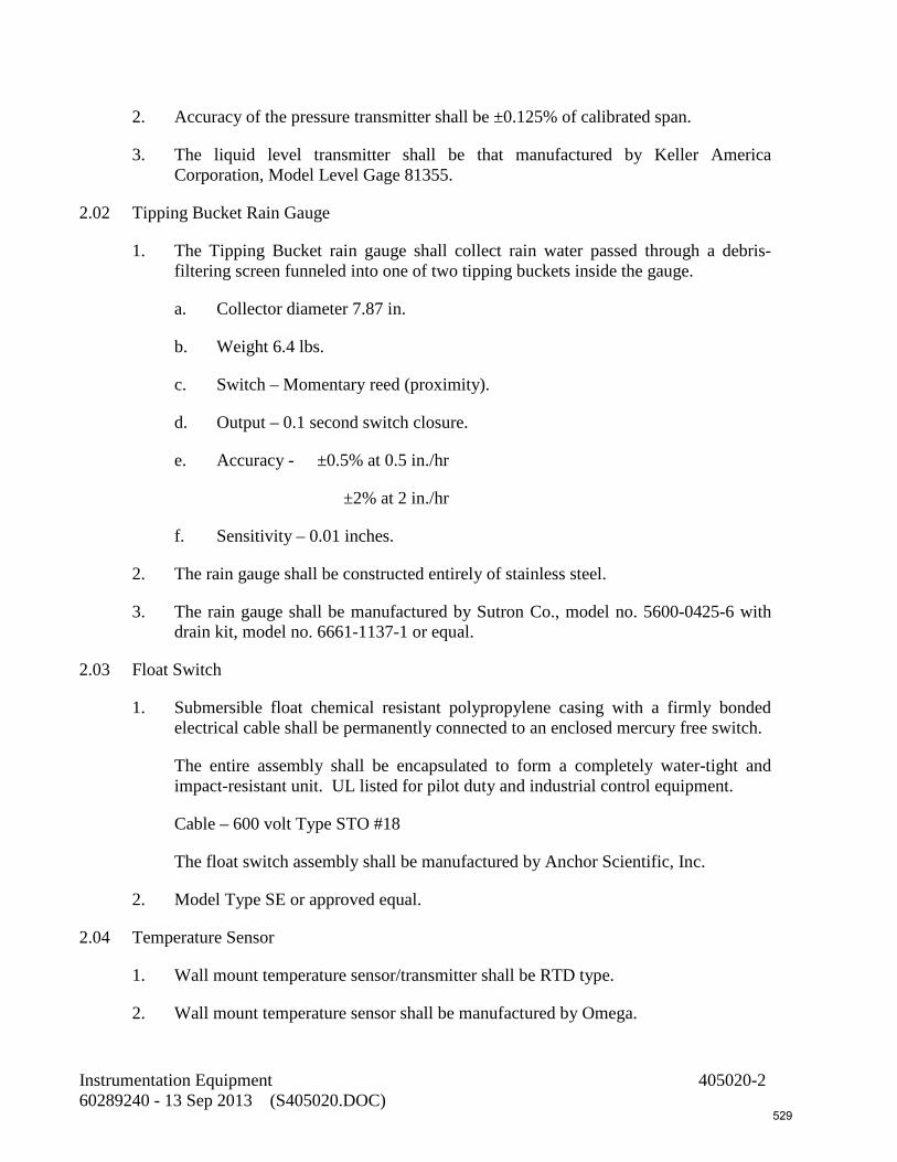
2. Accuracy of the pressure transmitter shall be ±0.125% of calibrated span.
3. The liquid level transmitter shall be that manufactured by Keller America Corporation, Model Level Gage 81355.
2.02 Tipping Bucket Rain Gauge
1. The Tipping Bucket rain gauge shall collect rain water passed through a debris-filtering screen funneled into one of two tipping buckets inside the gauge.
a. Collector diameter 7.87 in.
b. Weight 6.4 lbs.
c. Switch – Momentary reed (proximity).
d. Output – 0.1 second switch closure.
e. Accuracy - ±0.5% at 0.5 in./hr
±2% at 2 in./hr
f. Sensitivity – 0.01 inches.
2. The rain gauge shall be constructed entirely of stainless steel.
3. The rain gauge shall be manufactured by Sutron Co., model no. 5600-0425-6 with drain kit, model no. 6661-1137-1 or equal.
2.03 Float Switch
1. Submersible float chemical resistant polypropylene casing with a firmly bonded electrical cable shall be permanently connected to an enclosed mercury free switch.
The entire assembly shall be encapsulated to form a completely water-tight and impact-resistant unit. UL listed for pilot duty and industrial control equipment.
Cable – 600 volt Type STO #18
The float switch assembly shall be manufactured by Anchor Scientific, Inc.
2. Model Type SE or approved equal.
2.04 Temperature Sensor
1. Wall mount temperature sensor/transmitter shall be RTD type.
2. Wall mount temperature sensor shall be manufactured by Omega.
Instrumentation Equipment 405020-2 60289240 - 13 Sep 2013 (S405020.DOC) 529

3. Model no. EWS-RTD with EWS-TX wall mount temperature transmitter.
4. Provide Conduit box mounting bracket/wall plate adaptor kit model no. WES-MB and PSR-24S Power Supply.
2.05 Diesel Fuel Oil Tank Level Sensor/Transmitter
1. Level sensor/transmitter shall replace existing clock gauge on top of existing tank.
a. Stem material – 316 stainless steel.
b. Mounting Material – 316 stainless steel.
c. Operating Temperature – 40°F to +230°F.
d. Length – To suit depth of tank.
e. Input Voltage 10 – 40 VDC.
f. Output signal 4 – 20 mA.
2. Level sensor shall be manufactured by Gems Sensors. Model no. XT-800, Type 3 mounting, Float model no. 156790 or approved equal.
2.06 Door Alarm Security
1. Contractor shall provide building entrance with an intrusion alarm system.
a. Surface mounted magnetic door contact to alarm on entry.
b. Alpha numeric key pad to arm/disarm.
c. All equipment shall be NEMA 1 rated.
d. Contractor shall provide complete system as required to suit by a qualified security system contractor and approved by engineer.
2.07 Pressure Switch
1. Pressure switches shall be Type 316 stainless steel bourdon tube type actuating an enclosed, metal contact snap-action switch. Switch shall have separate set point and reset point adjustments. Adjustment of the switch set points and viewing of the set point indicator shall be accomplished without having to gain access to the interior of the unit. Pressure switch range and number of switch contacts shall be as indicated in the drawings. [Provide cleanout-type, continuous-duty type diaphragm seals.] Enclosure shall be watertight NEMA 4. Provide Ashcroft pressure switch Model B4-64-S-XHX-600# or equal.
Instrumentation Equipment 405020-3 60289240 - 13 Sep 2013 (S405020.DOC) 530
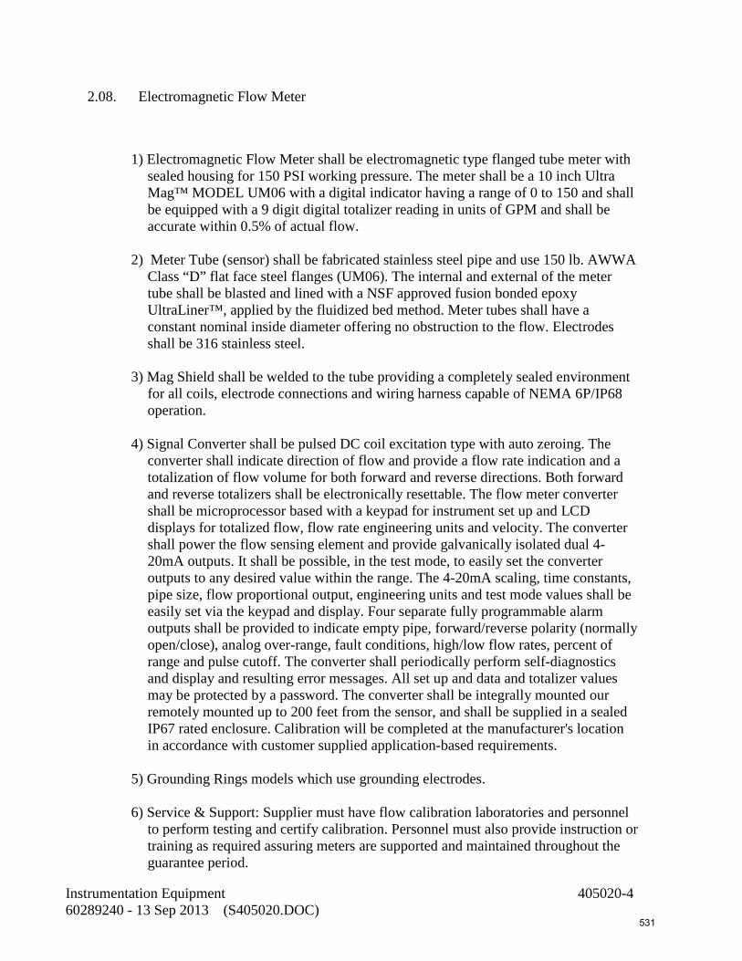
2.08. Electromagnetic Flow Meter
1) Electromagnetic Flow Meter shall be electromagnetic type flanged tube meter with
sealed housing for 150 PSI working pressure. The meter shall be a 10 inch Ultra Mag™ MODEL UM06 with a digital indicator having a range of 0 to 150 and shall be equipped with a 9 digit digital totalizer reading in units of GPM and shall be accurate within 0.5% of actual flow.
2) Meter Tube (sensor) shall be fabricated stainless steel pipe and use 150 lb. AWWA
Class “D” flat face steel flanges (UM06). The internal and external of the meter tube shall be blasted and lined with a NSF approved fusion bonded epoxy UltraLiner™, applied by the fluidized bed method. Meter tubes shall have a constant nominal inside diameter offering no obstruction to the flow. Electrodes shall be 316 stainless steel.
3) Mag Shield shall be welded to the tube providing a completely sealed environment
for all coils, electrode connections and wiring harness capable of NEMA 6P/IP68 operation.
4) Signal Converter shall be pulsed DC coil excitation type with auto zeroing. The
converter shall indicate direction of flow and provide a flow rate indication and a totalization of flow volume for both forward and reverse directions. Both forward and reverse totalizers shall be electronically resettable. The flow meter converter shall be microprocessor based with a keypad for instrument set up and LCD displays for totalized flow, flow rate engineering units and velocity. The converter shall power the flow sensing element and provide galvanically isolated dual 4-20mA outputs. It shall be possible, in the test mode, to easily set the converter outputs to any desired value within the range. The 4-20mA scaling, time constants, pipe size, flow proportional output, engineering units and test mode values shall be easily set via the keypad and display. Four separate fully programmable alarm outputs shall be provided to indicate empty pipe, forward/reverse polarity (normally open/close), analog over-range, fault conditions, high/low flow rates, percent of range and pulse cutoff. The converter shall periodically perform self-diagnostics and display and resulting error messages. All set up and data and totalizer values may be protected by a password. The converter shall be integrally mounted our remotely mounted up to 200 feet from the sensor, and shall be supplied in a sealed IP67 rated enclosure. Calibration will be completed at the manufacturer's location in accordance with customer supplied application-based requirements.
5) Grounding Rings models which use grounding electrodes. 6) Service & Support: Supplier must have flow calibration laboratories and personnel
to perform testing and certify calibration. Personnel must also provide instruction or training as required assuring meters are supported and maintained throughout the guarantee period.
Instrumentation Equipment 405020-4 60289240 - 13 Sep 2013 (S405020.DOC) 531

7) Volumetric Testing of all meters must be performed and approved prior to shipment. The
complete meter assembly and signal converter must be wet accuracy tested and calibrated. The test facility must be rigorously traceable to an accuracy of ±0.15% with the National Institute of Standards and Technology. If desired, the test shall be witnessed by the customer or their selected agent. A copy of the certified accuracy test record must be furnished at no charge to the customer.
8) One Manufacturer shall make all meter sizes and styles required for this contract. The
meters shall be manufactured and tested in the U.S.A.
END OF SECTION
Instrumentation Equipment 405020-5 60289240 - 13 Sep 2013 (S405020.DOC) 532

This page intentionally left blank
533

SECTION 405040 PROGRAMMABLE LOGIC CONTROL SYSTEM
PART 1 - GENERAL
1.01 Description
This section includes requirements for materials, testing, and installation of a control system.
The PLC control system shall operate in accordance with the Control and Instrumentation diagram in the bid drawings. An overview of this operation is offered here for clarification. The Pump Controller Panel, which will herein be referred to as PCP will use a programmable logic controller to operate the pumping system controlled by wet well levels using analog signals from the level transmitter specified herein located in the pump station wet well.
The PCP will control the operation of four pumps; Main Pumps No.1 and No.2, Jockey Pump, and ASR Pump (P-1, P-2, P-3, and P-4); installed in the pump station. This system will operate on an ASR, Jockey, lead, lag, cycle and the PCP shall alternate pumps P-1 and P-2 on each cycle.
As the wet well level increases to above a set depth, the ASR pump (P-4) will turn on and will operate through a variable frequency drive to maintain an operator set flow rate to ASR Well No.2. As the level continues to rise above a second depth setpoint, the jockey pump (P-3) will turn on and will operate through a variable frequency drive to maintain a constant level in the wet well. Further as the level continues to rise a third depth setpoint, the main pump (P-1 or P-2) will turn on and will operate through a variable frequency drive to maintain an operator set speed. Further as the level continues to rise a fourth depth setpoint, the second main pump (P-1 or P-2) will turn on and will operate through a variable frequency drive to maintain an operator set speed.
The ASR pump only can run when ASR Well No.2 is in recharge mode, a pump run signal will be provide from Golden Gate WWTRF via Comcast.
If both Strainers fault (FLT-1 and FLT-2), shutdown ASR pump (P-4).
When a second main pump is called to run, shutdown and lockout the Jockey and ASR (if running) pumps prior to starting the second main pump.
The PCP shall provide discrete output to the RTU for monitoring. The entire schedule list of inputs for the VFD shall be translated into a common input which must be communicated back to the RTU unit along with indication for each pump. The PCP must also communicate to all the VFD’s to provide a speed command.
Programmable Control System 405040-1 60289240 - 13 Sep 2013 (S405040.DOC) 534

The PCP shall also provide pump running status to the bar screen control panel as indicated in the Control and Instrumentation diagram so that the bar screen and conveyor system shall be running at all times that any of the pumps in the system are running.
The PCP will incorporate an incoming power surge protector manufactured by EDCO Model HSP121-bt.
Incoming & outgoing analog signals shall use EDCO 642 signal surge protector
1.02 Backup Relay Control Logic System Description
Control system shall have a float back up system consisting of (2) floats, relay logic and timing as necessary to perform a systematic start up of (2) pumps 1 & pump 2 in case of PLC, Level Indication Transducer, and/or other failures. Upon activation of the high level float, the back-up relay control logic will signal the VFD for pump 1 & pump 2 to actuate pump 1 immediately and initiate an adjustable timer. Upon time-out of this setting, pump #2 will turn on. Both pumps shall remain on until the low float off level of the wet well has been reached.
1.03 Quality Assurance
Control system shall be manufactured by GS Phillips or Approved Equal.
PART 2 - MATERIALS
2.01 Designations of Components
In these specifications and on the plans, all systems and other elements designated by numbers, as derived from criteria in ISA standards. The nomenclature and numbers designated herein and on the plans shall be employed exclusively throughout shop drawings, data sheets, and the like. Any other symbols, designations, and nomenclature unique to a manufacturer's standard methods shall not replace those prescribed above, as used herein, and on the plans.
2.02 Programmable Logic Control System
1. A fully integrated programmable logic control system shall be furnished as specified in this section. The programmable logic control system hardware shall be intelligent process control units with analog and discrete I/O for process interface.
2. The a-c power of the control system will be 120-volt +/-10% a-c, 60 hertz, single phase derived from line power. The system shall be designed to operate satisfactorily from 0 °C to 60 °C ambient temperatures for the PLC.
Programmable Control System 405040-2 60289240 - 13 Sep 2013 (S405040.DOC) 535

2.03 Programmable Logic Controller (PLC)
The PLC shall be a 16-bit programmable logic controller microprocessor-based stand-alone device. It shall be a process and logic controller designed for industrial environments. It shall be capable of a mix of logic, timing, counting, computation, library of preprogrammed subroutines, and PID loop control capabilities necessary for the unit process application.
The PLC shall come complete with chassis, central processor, memory, power supply, interconnecting cables, and discrete and analog I/O interfaces.
The logic and variable memory shall be read/write RAM. All RAM shall have integral battery backup that will maintain the memory for a minimum of six months upon a utility power failure. The logic and variable memory shall have a sufficient ladder logic location for programming all specified functions plus 25% spare memory.
The PLC shall have the following features:
1. Logic Control: The PLC shall be capable of performing the same functions as conventional logic systems including on delay timers, off delay timers, counters, and drum sequencers.
2. Compare Function: The PLC shall perform the compare function that compares two integers or floating point numbers for less than, equal to, greater than, and not equal to. The programmed function shall energize when true and de-energize it when false.
3. Move Function: The PLC function shall move an integer or floating point value from one memory location to another memory location when an internal permissive is enabled.
4. Math Function: The PLC shall be capable of performing addition, subtraction, multiplication, and division on integer or floating point numbers.
5. Analog Controllers: The PLC processor shall perform all the functions of the conventional three-mode (PID) analog controller. The controller shall perform proportional only control, proportional plus reset, and proportional plus reset plus derivative and integral only control. The controller shall be the conventional three-mode controller.
The PLC shall be able to generate PID loops with a minimum sample time of 1.0 seconds. PID tuning constants shall have the following adjustable range:
Proportional Gain 0.0% to 99.99%
Reset Time 0.01 to 999.99 Programmable Control System 405040-3 60289240 - 13 Sep 2013 (S405040.DOC) 536
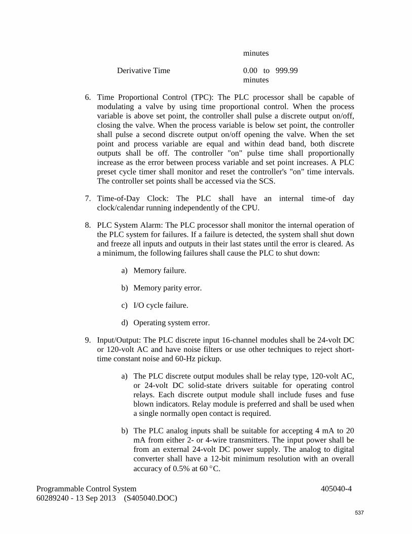
minutes
Derivative Time 0.00 to 999.99 minutes
6. Time Proportional Control (TPC): The PLC processor shall be capable of modulating a valve by using time proportional control. When the process variable is above set point, the controller shall pulse a discrete output on/off, closing the valve. When the process variable is below set point, the controller shall pulse a second discrete output on/off opening the valve. When the set point and process variable are equal and within dead band, both discrete outputs shall be off. The controller "on" pulse time shall proportionally increase as the error between process variable and set point increases. A PLC preset cycle timer shall monitor and reset the controller's "on" time intervals. The controller set points shall be accessed via the SCS.
7. Time-of-Day Clock: The PLC shall have an internal time-of day clock/calendar running independently of the CPU.
8. PLC System Alarm: The PLC processor shall monitor the internal operation of the PLC system for failures. If a failure is detected, the system shall shut down and freeze all inputs and outputs in their last states until the error is cleared. As a minimum, the following failures shall cause the PLC to shut down:
a) Memory failure.
b) Memory parity error.
c) I/O cycle failure.
d) Operating system error.
9. Input/Output: The PLC discrete input 16-channel modules shall be 24-volt DC or 120-volt AC and have noise filters or use other techniques to reject short-time constant noise and 60-Hz pickup.
a) The PLC discrete output modules shall be relay type, 120-volt AC, or 24-volt DC solid-state drivers suitable for operating control relays. Each discrete output module shall include fuses and fuse blown indicators. Relay module is preferred and shall be used when a single normally open contact is required.
b) The PLC analog inputs shall be suitable for accepting 4 mA to 20 mA from either 2- or 4-wire transmitters. The input power shall be from an external 24-volt DC power supply. The analog to digital converter shall have a 12-bit minimum resolution with an overall accuracy of 0.5% at 60 °C.
Programmable Control System 405040-4 60289240 - 13 Sep 2013 (S405040.DOC) 537

c) Discrete PLC I/O modules shall have individual LED status lights for each I/O point. All discrete and analog modules shall have terminal blocks for termination of the I/O wires. Individual I/O points shall be capable of withstanding low energy common mode transients to 1,500 volts. Each PLC mounting base shall provide a minimum capability of 16 analog I/O and 64 discrete I/O. The PLC shall be capable of communicating with up to 1,000 remote I/O points on a single 15,000-foot data link.
10. Unused I/O: Provide PLCs with the following minimum unused pre-wired I/O for future facility expansion:
a) Analog Inputs: 3.
b) Analog Outputs: 2.
c) Discrete Inputs: 15.
d) Discrete Outputs: 5
11. I/O Termination: provide a pre-fabricated cable and interface module for each I/O module wiring. The system shall be by the PLC manufacturer.
12. Each PLC shall be able to communicate to an Ethernet network.
13. The PCP PLC shall contain an Industrial 5 – 8 point Ethernet switch.
14. The PLC shall be Automation Direct, 205 Series.
2.04 Media Converter
1. The Fiber-to-Copper Ethernet media converter shall convert 10BaseT to 10BaseFX. Media converter shall be in full compliance with standards set forth by IEEE 802.3.
2. Media converter shall meet the following specific requirements:
a) Operation: Full and Half Duplex, Auto-Negotiation, Autocross and Link Pass Through
b) Interface (hardwire): RJ-45 10BaseT port
c) Interface (fiber): Duplex ST-type 10BaseFX port
d) Operating Temperature: 0°C to 50°C (-25°C to 65°C for field units)
e) Operating Humidity: 5% to 95% (non condensing)
f) Fiber Segment Length: 1.2 miles Programmable Control System 405040-5 60289240 - 13 Sep 2013 (S405040.DOC) 538

g) Fiber Wave Length: 850 nm
h) MTBF: 54,000 hours minimum (tested per MIL-HDBK-217F) or 130,000 hours minimum (tested per Telcordia SR-332, Issue 1). All tests include power supplies.
3. Field Converters: Provide an AC/DC power supply for each converter, as required. Media converter shall be a Model E-TBT-FRL-05 (HT) as manufactured by Transition Networks Inc, or equal.
4. Media converters for interfacing with PLCs supplied with the packaged systems will be furnished by WWTP SCADA Contractor. The converters will be installed by package suppliers. The “packaged” PLCs are as follows:
a) PLC-1 in MultiDisc Fine Screen – Section 444332.
b) PLC-3 in ACTIFLO System – Section 444337.
2.05 Ethernet Switch (Field Cabinets)
1. Ethernet switch shall be DIN-rail mountable. Ethernet switch shall be in full compliance with standards set forth by IEEE 802.3. Switch shall have five Ethernet ports, as minimum. LEDs on each port shall indicate link data rate and activity status. A power LED shall indicate that power is applied to the.
2. Ethernet Switch shall meet the following specific requirements:
a) Operation: 10/100 Mbps, Full and Half Duplex, Auto-Negotiation
b) Switching Properties: Store & Forward
c) Number of MAC addresses: 1024
d) Up to 1.0 Gb/s Maximum Throughput
e) Minimum of 64K of message memory
f) Interface: RJ-45 10/100BaseTX ports
g) MDIX Auto Cable Sensing
h) Operating Temperature: -20 °C to 60 °C
i) Operating Humidity: 10% to 95% (non condensing)
j) MTBF: 100,000 hours minimum
Programmable Control System 405040-6 60289240 - 13 Sep 2013 (S405040.DOC) 539

3. The Ethernet switch shall be Contemporary Control Systems Mod. EISK5-100T, B&B Electronics Mod. IASW5P, Moxa Technologies Mod. EDS-205, or equal.
2.06 Operator Interface (OI)
1. An operator interface shall be a panel mounted electronic assembly that allows bi-directional communication between the programmable logic controller and the operator interface device.
2. Screens shall be configured using an off-line PC based software package that runs in the Windows environment. Each display screen shall consist of graphic representations of legend plates, push buttons, pilot lights, numeric data displays, numeric data entry buttons, bar graphs, time displays, text displays, selector switches, illuminated push buttons, counter/timer numeric preset and increment/decrement buttons. In addition, the unit shall be capable of displaying bit map graphics. Graphics can be created using any software that produces standard .bmp files. Applications shall be downloaded to the operator interface device and stored in flash memory.
3. The unit shall be capable of displaying text messages that can be triggered by the status or values of bits or numeric variables in the programmable logic controller. In addition, the unit shall be capable of accepting and displaying text messages that are stored in programmable controller as ASCII strings.
4. The unit shall have the following features:
a) Resolution: 800 x 600 pixels and 16-bit color graphics.
b) Display: 10-inch
c) Communications: Ethernet and serial ports
5. A communications driver shall be provided with the editing software.
6. All cables for communication between the unit and the PLC shall be provided along with a cable for serially interfacing the device with a personal computer.
7. The operator interface device shall be a C-More 10” color, TFT, 64K, NEMA 4X, IP 65 with Ethernet and USB as manufactured by Automation Direct, or equal pre-approved at least 2 weeks prior to bid time.
2.07 Level Transmitters – Submersible
1. The control supplier shall be responsible for providing (5) five liquid level transmitters by KELLER AMERICA or pre-approved equal as specified below.
Programmable Control System 405040-7 60289240 - 13 Sep 2013 (S405040.DOC) 540

2. The submersible all-titanium pressure transmitter shall provide an electrical 2-wire d-c current signal proportional to the pressure applied to the unit's diaphragm-sensing element. The pressure sensing element shall be diffused silicon semiconductor with a process media operating temperature range of –4 °F to 140 °F. Provide the pressure transmitter with the following features:
a) Waterproof cable with internal vent to atmosphere rated for transmitter suspension up to 300 feet.
b) Conduit adapter, cable/conduit junction box.
c) Cable strain relief, clamp.
d) Internally adjustable span.
e) Anti-clog attachment.
f) A separate suspension cable for transmitters suspended over 20 feet.
3. Accuracy of the pressure transmitter shall be ±0.125% of calibrated span.
4. The pressure transmitter shall be that manufactured by Keller America, Level Gage model no. 81355.
2.08 Spare Parts
1. The Contractor shall furnish to the Owner all necessary spare parts of components required to maintain the system. Prior to final acceptance of work, the Contractor shall provide a spare parts listing of all necessary spare parts and quantities for review by the Owner's Representative. The spare parts shall include the following minimum requirements:
Part Description Quantity
a) PLC Power Supply 1 each
b) CPU and Memory Module 1 each
c) Analog Input Module 1 of each type
d) Discrete Input Module 1 of each type
e) Analog Output Module 1 of each type
f) Discrete Output Module 1 of each type
Programmable Control System 405040-8 60289240 - 13 Sep 2013 (S405040.DOC) 541

2. The Contractor shall deliver to the Owner all the required spare parts upon final acceptance of the work. The spare parts shall not be used as replacement parts during the guarantee period.
2.09 Enclosures
1. The PCP/PLC enclosure shall be NEMA 4X 304 stainless steel.
2. Enclosures shall be suitable for mounting against a wall.
PART 3 - EXECUTION
Refer to Section 405000.
END OF SECTION
Programmable Control System 405040-9 60289240 - 13 Sep 2013 (S405040.DOC) 542

This page intentionally left blank
543

SECTION 405050 REMOTE TERMINAL UNIT (RTU) SYSTEM
PART 1 - GENERAL 1.01 SCOPE OF WORK
A. Work includes engineering, furnishing, installing, testing, documenting and placing in
operation the instrumentation Remote Terminal Unit (RTU). Training of the OWNER’S personnel is also included. The work is specified in this section and as further specified in the following sections:
1. Section 260500: General Electrical Requirements
2. Section 260519: Wires and Cables Less than 600 Volts 3. Section 260534: Conduits, Boxes, and Fittings
B. The specific attention of the contractor is directed to the fact that the Owner has an
existing TAC II SCADA System manufactured by Data Flow Systems (DFS) of Melbourne, Florida (321) 259-5009. For compatibility purposes, the bidder is required to obtain the Remote Terminal Unit (RTU) as specified herein from DFS.
C. The Contractor shall replace existing antenna and cabling. A complete radio survey shall be conducted to verify antenna requirements.
D. These specifications are intended to cover the furnishing, the shop testing, the delivery, complete installation and field testing of all equipment and appurtenances for the complete RTU system herein specified, whether specifically mentioned in the Specifications or not. This includes all discrete and analog signal isolation necessary for interfacing with the Owner’s existing telemetry system.
E. For all units there shall be furnished and installed all necessary and desirable accessory
equipment and auxiliaries whether specifically mentioned in these specifications or not. This installation shall include field-testing of the entire installation and instruction of the regular operating personnel in the care, operation, and maintenance of all equipment.
PART 2 - PRODUCTS 2.01 REMOTE TERMINAL UNIT
A. The Remote Terminal Unit (RTU) shall be properly sized to accommodate all modules. The configuration of RTU I/O and HMI screens in the existing SCADA HMI shall be provided by the owner. The RTU shall incorporate a Radio Transceiver compatible with the owner’s existing frequency and Input / Output (I/O) function modules required to meet the monitor and control requirements. Function module card connectors shall be gold-over-nickel plated to inhibit corrosion. The RTU shall be capable of operating in a temperature ranging from -10 to 60 Degrees Celsius (14 to 140 Degrees Fahrenheit).
B. SERVICE PORT
Remote Terminal User (RTU) System 405050-1 60289240 - 13 Sep 2013 (S405050.DOC)
544

The RTU shall support a local serial interface service port for access to all the functions of the unit and local monitoring of the radio communications link. The RTU shall support an automatic antenna alignment function utilizing the local serial interface.
C. POWER SUPPLY MODULE All function modules in the RTU shall run off DC voltage from +7.5 volts to +13 volts. The Power Supply Module (PSM) shall supply +12 volts. A battery backup shall be provided to operate the system in event of power failure. The PSM shall be surge protected. The PSM shall be short circuit protected by current limiting. Normal operation shall automatically resume when the short circuit overload is removed. The PSM shall be sized to operate the system with the battery removed. The PSM shall provide a battery backed, isolated bias voltage source. The circuit breaker for the PSM shall be part of the module. Neither the use of tools nor the disconnection of any wires shall be required to replace the PSM.
D. SURGE PROTECTION Multiple staged surge protection shall be provided for all power supply and power monitoring circuits. This design shall provide a very high level of non-destructive transient immunity. With the exception of a direct lightning strike, the device shall protect the RTU power supply and power monitoring circuits from damage due to voltage transients. The unit shall provide circuit protection to withstand multiple transients in excess of 6,500 volts, 3,250 amps, without damage. Damage shall be limited to a blown fuse when exposed to larger transients. The device shall be transient-tested to ANSI standard C62.41. The unit shall be the Transient Filter Shield TFS001 as manufactured by Data Flow Systems. The AC power input protection shall be the Single Phase Suppresser, SPS001 as manufactured by Data Flow Systems. All surge protection shall be UL Listed.
E. BACKUP BATTERY The RTU shall have the uninterruptible power supply (UPS) function built in. The unit’s internal power supply module shall keep the battery at a float charge. The battery shall not be damaged by deep discharges.
F. RADIO INTERFACE MODULE The RTU shall require one radio interface module (RIM). The RIM shall control the terminal radio during the polling sequence. The RIM shall have a service port to provide communications link monitoring. The service port shall also provide the capability to directly monitor and/or control each module in the RTU. The RIM utilized at the RTU shall be interchangeable with the RIM at the central site. All radio communications shall be in ASCII and utilize an error detecting data transfer protocol. Each RIM shall have an FM radio transceiver mounted to it. Replacement of the RIM shall trigger an automatic configuration of the new module to accommodate the site address and function (plug & play).
G. FUNCTION MODULES The function modules shall be designed so they do not have configuration switches or straps. The function modules shall be designed with surge suppression on all inputs and outputs. Replacement of a function module shall not require the use of tools or the removal of any interface wires. There shall be no components associated with the function module mounted to the motherboard (passive backplane). The function modules shall be backward compatible with all older modules of same type. All the
Remote Terminal User (RTU) System 405050-2 60289240 - 13 Sep 2013 (S405050.DOC)
545

function modules shall support central site computer access to the revision level of the module over the radio communications link.
H. DIGITAL MONITOR MODULE The digital monitor module (DMM) shall accept 12 on/off or pulsed inputs of 12 to 30 volts AC or DC. Other AC or DC voltages shall be accommodated with the use of an inline voltage converter device. Status reporting of the digital inputs shall have an accuracy of +- 2 seconds to the time the event occurred at the RTU. The DMM shall have LEDs to indicate: the status of each input point; receive communications; transmit communications; CPU fault; and power status. The configuration of the monitor points as alarm points, monitor points (pump run time monitors), or pulsed input points shall be operator changeable at the central site. The custom configuration of the DMM shall not require any software or firmware changes in the RTU. Replacement of the DMM shall trigger an automatic configuration of the new module by the central site (plug & play).
I. DIGITAL CONTROL MODULE The digital control module (DCM) shall be available in two configurations, providing eight (8) digital outputs and four (4) digital inputs, or four (4) digital outputs and eight (8) digital inputs. Each control point shall accommodate 60 to 280 volt AC devices. Each control point shall be capable of driving a 0.5 amp load @ 280 volts AC (140 VA), with inrush current of 5 amps. Any discrete control point shall have the capability of being automatically controlled by any discrete monitor point, at the same RTU or at any other RTU. This shall be accomplished during configuration at the central site and shall be available for an unlimited number of control points. Each input shall accept ON/OFF inputs of 12 to 30 volts AC or DC. Other AC or DC voltages shall be accommodated with the use of an inline voltage converter device. Status reporting of the digital inputs shall have an accuracy of +- 2 seconds to the time the event occurred at the RTU. The configuration of the monitor points as alarm points or monitor points (pump run time monitors) shall be operator selectable. The configuration shall not require any software of firmware changes in the system. The DCM shall have LEDs to indicate: the status of each output point; receive communications; transmit communications; CPU fault; and power status. Replacement of the DCM shall trigger an automatic configuration of the new module by the central site (plug & play).
J. ANALOG MONITOR MODULE The analog monitor module (AMM) shall monitor up to 4 analog inputs, each capable of accepting 4-20 ma or 0-5 VDC. The analog input shall provide 12-bit accuracy. The analog inputs shall be individually optically isolated. The AMM shall have support-configurable reporting granularity and alarm thresholds. All configurable parameters shall be operator-controlled. The AMM shall have LEDs to indicate: the status of receive communications; transmit communications; CPU fault; and power status. The AMM shall be capable of supplying 24 VDC power source for 4-20 ma transmitters. Replacement of the AMM shall trigger an automatic configuration of the new module by the central site (plug & play).
K. ANALOG CONTROL MODULE The analog control module (ACM) shall control up to 4 analog outputs, each capable of producing 4-20 ma output driving a 0 to 1000 ohm load. The analog output shall have 12-bit accuracy. Each analog control shall have configurable engineering units. All configurable parameters shall be operator controlled. ACM shall have LEDs to indicate: receive communications; transmit communications; CPU fault; and power
Remote Terminal User (RTU) System 405050-3 60289240 - 13 Sep 2013 (S405050.DOC)
546

status. Any analog control point shall have the capability of being automatically controlled by any analog monitor point, at the same RTU or at any other RTU. This shall be accomplished during configuration at the central site and shall be available for an unlimited number of control points. The ACM shall be capable of supplying 24 VDC power source for 4-20 ma transmitters. Replacement of the analog control module shall trigger an automatic configuration of the new module by the central site computer (plug & play).
L. ENCLOSURE The RTU shall be housed in a NEMA 4X 316 stainless steel enclosure. The enclosure shall be sized to accommodate the backplanes and functions modules needed to meet the requirements. All mounting hardware utilized shall be stainless steel. The enclosure shall be capable of being locked.
M. ANTENNA SUBSYSTEM A new antenna system shall replace the existing equipment. Contractor shall perform a radio path analysis. The path analysis shall provide a minimum of 15 dB of fade margin. The 15 dB fade margin shall be demonstrated by inserting a 15 dB pad into the RTU coax cable, and thereafter maintaining communications with the central site. A high gain directional antenna shall be used to transmit and receive data at the RTU. The directional antenna shall have all welded aluminum elements, and a single radiator element connected to a type N female connector. The antenna shall be the RTA series as provided by Data Flow Systems, Inc. The antenna mast/pole shall be hot dipped galvanized for corrosion protection. All mounting hardware shall be made of stainless steel. The coax cable shall be the type that utilizes an inert semi-liquid compound to flood the copper braid. The coax cable shall be of the RG-8 construction type and have the RF-loss characteristic of foam flex. The coax cable shall be RTC 400 as supplied by Data Flow Systems, Inc. Type N connectors shall be utilized at both ends of the coax. The Type N connectors shall be sealed with 3-inch sections of Alpha FIT321-1-0 sealant shrink-tubing. The coax cable shall be secured to the mast/pole with EVA-coated 316 stainless steel cable ties. The cable ties shall be AE112 cable ties manufactured by Band-It. The RTU shall be protected from electrical surge or transients entering through the coaxial cable by use of a coaxial cable surge protector. The coaxial cable surge protector shall be IS-B50LN-C2 manufactured by Polyphaser.
2.02 TAC II SCADA SYSTEM UPDATE (EXISTING) A. The existing TAC II SCADA System shall be modified to incorporate a new graphical
HMI screen for this new station. Provided by owner. Contractor shall provide assistance and information as required.
PART 3 – EXECUTION
3.01 INSTALLATION A. The Contractor shall install and place into operation a complete new RTU System at the
site. This work shall include the new antenna system, all interconnecting wiring, conduit, and circuitry necessary to provide the owner with a fully operable control system/RTU. The configuration of RTU I/O and HMI screens in the existing SCADA HMI shall be
Remote Terminal User (RTU) System 405050-4 60289240 - 13 Sep 2013 (S405050.DOC)
547

provided by the owner. B. The Contractor shall install the equipment in accordance with the Contract Documents,
manufacturer’s instructions and shop drawings. Rigidly support and mount equipment level and plumb, and in such a manner as to provide accessibility; protection from damage; isolation from heat, shock, and vibration; and freedom from interference with other equipment, piping, and electrical components.
C. Include the services of a factory trained and qualified employee of the equipment manufacturer to inspect the complete equipment installation to assure that it is installed in accordance with the manufacturer’s recommendations, make all adjustments necessary to place the system into trouble-free operation and instruct the operating personnel in the proper care and operation of the equipment furnished. Provide services at both the field installation site as well as the central site.
D. All workmanship utilized in the manufacture and installation of this system shall be of the highest quality and performed in a manner consistent with all accepted industry practices.
3.02 FIELD TESTS AND ACCEPTANCE
A. Field tests shall consist of installation check-out, and a field acceptance test, in sequence. Each stage of testing shall not be commenced until the preceding stage is substantially complete as determined by the Engineer.
B. Field Test: When the facility is complete and ready for operation, the RTU and associated components shall be inspected and tested for compliance with the Contract Documents. Testing of the equipment shall be made by the Contractor in the presence of the Owner, Engineer, the Electrical Subcontractor, the Instrumentation Subcontractor, and the equipment manufacturer’s representative. The test shall include, but not be limited to the following: 1. Electrical: Contractor shall record readings of the voltage and amperage on all
electrical components at start and at steady state operating conditions. The results of the tests, including the serial number of the accessories tested, shall be given to the engineer.
2. Inspection: A thorough inspection of all mechanical and electrical equipment and controls, fittings, brackets, mountings, seals, conduit, painting, components, and features shall be made while the facility is being tested to determine performance and compliance with design requirements and specifications.
3. Repairs, Adjustments, and Replacements: The Contractor shall make any and all necessary repairs, adjustments, and replacements until performance has been demonstrated to the satisfaction of the Engineer. The Contractor shall bear the cost of any repair, adjustment, and replacement.
3.03 WARRANTY
A. The RTU manufacturer shall warrant all hardware and software provided under this contract against all defects in material and workmanship for a period of one year from owner acceptance. The I/O function modules, RIM, PSM, and PLC shall carry an additional 2-year return-to-factory warranty. The I/O function modules, RIM, PSM, and PLC shall be warranted against lightning and surge damage the entire three year period.
Remote Terminal User (RTU) System 405050-5 60289240 - 13 Sep 2013 (S405050.DOC)
548

3.04 SERVICE A. The RTU manufacturer shall offer full factory support and service of the installed
product through the use of factory employees. Service representatives who are not direct employees of the manufacturer, or who are not specifically trained in the service of the owner’s existing SCADA System shall be unacceptable. The customer shall have 24 hour per day access to service personnel through the use of a pager and/or cell phone.
B. Furnish the services of a manufacturer’s representative onsite during start-up and system commissioning.
3.05 SPARES RTU PARTS
A. One spare RIM, PSM, PLC and each type of I/O Function Module utilized in the RTU shall be supplied to the owner.
END OF SECTION 405050
Remote Terminal User (RTU) System 405050-6 60289240 - 13 Sep 2013 (S405050.DOC)
549

SECTION 409210 ELECTRIC MOTOR ACTUATORS FOR SLIDE GATES
PART 1 - GENERAL
1.01 DESCRIPTION
This section includes materials and installation of electric motor actuators for slide gates.
1.02 SUBMITTALS
A. Submit shop drawings in accordance with the General Conditions, Section 013300, and the following.
B. Submit manufacturer's catalog data showing motor actuator parts and materials of construction, referenced by AISI, ASTM, SAE, or CDA specification and grade. Show motor actuator dimensions and weights. Identify each valve and actuator combination by tag number to which the catalog data and detail sheets pertain. Show coatings.
C. Show the maximum torque required to open and close each motor-actuated slide gate.
D. Submit certified factory performance test records.
E. Submit motor data including nameplate data, insulation type, duty rating, and torque output at duty rating.
F. Submit electrical schematic drawings and wiring diagrams showing physical locations of components.
PART 2 - MATERIALS
2.01 ACTUATOR IDENTIFICATION
A. Motorized slide gates with actuators are identified in the drawings.
B. Motor actuators shall have the name of the manufacturer cast or molded onto the actuator body or shown on a permanently attached plate in raised letters.
2.02 ACTUATOR TAGGING
Provide identifying tags for electric motor-actuated slide gates per Section 400775. Show slide gate actuator tag number, name or designation as shown in the drawings. Attach tags to actuators by means of stainless steel wire.
ELECTRIC MOTOR ACTUATORS FOR SLIDE GATES 409210-1 60289240 - 6 Sep 2013 (S409210.DOC) 550

2.03 ACTUATOR DESIGNATIONS AND DESIGNS
Actuator designations consist of a type number 1. Type 1 actuators shall meet the following requirements:
Suffix Description
None (basic design) 15-minute duty cycle (Type 1 actuators); minimum 75% duty cycle; NEMA 4X enclosure (motor, controls, push buttons); open-stop-close operation; 480-volt, 60-hertz, 3-phase power supply (Type 1 actuators); gate to remain in last position upon loss of control signal.
2.04 ACTUATOR TORQUE REQUIREMENTS
A. The rated output torque of the motor actuator shall be at least 1.5 times the maximum torque required to open or close the slide gate at any position including seating and unseating conditions when subjected to the most severe operating condition including any mechanical friction and/or other restrictive conditions that are inherent in the slide gate assembly. Do not include hammer-blow effect in sizing the actuator to comply with this torque requirement. Coordinate with the slide gate manufacturer to assure that the motor actuator stall torque output does not exceed the torque limits of the slide gate operating stem or shaft.
B. Maximum torque shall include seating or unseating torque, bearing torque, dynamic torque, and hydrostatic torque. Assume that the differential pressure across the slide gate is equal to the pressure or head rating of the slide gate.
C. Assume a maximum channel fluid velocity of 2 fps with the gate fully open, unless a higher velocity is specified in the detailed valve specification.
2.05 DESIGN OF TYPE 1 ELECTRIC MOTOR ACTUATORS
A. Actuators shall comply with AWWA C542, except as modified herein. Output capacity of motors shall be sufficient to open or close the valve against the maximum differential pressure when the voltage is 10% above or below normal at the specified service conditions. Motors shall have Class F or H insulation system. Provide motor with torque output (at duty rating) that exceeds the requirements of the following paragraphs including safety factor.
B. Design the actuator to move valves from fully closed to fully open in the time specified in the subsection on “Service Conditions.”
C. Design actuators mounted on slide gates to move the gates from fully open to fully closed in five minutes or less at a rise rate of 12 inches per minute.
D. Provide a reversing starter, three overloads (one in each ungrounded leg) or two motor thermal cutouts, 120-volt control power transformer, local-off-remote selector switch,
ELECTRIC MOTOR ACTUATORS FOR SLIDE GATES 409210-2 60289240 - 6 Sep 2013 (S409210.DOC) 551

stop-open-close push buttons, and open and closed indicator lights. Provide magnetic starters in actuators for open/close operation and solid-state starters in actuators for modulating operation. Provide dry contact for remote indication of the actuator mode of operation. The contact shall be closed when the local-off-remote selector switch is in the remote position and the internal control power exists.
E. Provide a separate (remote) NEMA 4X enclosure with local/remote selector switch, stop-open-close push buttons, and open and closed indicator lights for motor actuators over 6 feet 6 inches above floor or deck in lieu of integral controls.
F. Do not use external conduit for wiring any components within the actuator.
G. Gear actuators shall be totally enclosed and factory-grease packed or oil lubricated. The power gearing shall consist of helical gears of heat-treated steel. Worm gears shall be alloy bronze accurately cut with a hobbing machine. Worm shall be hardened steel alloy. Design gears for 24-hour continuous service with an AGMA rating of 1.50.
H. Position switches shall be integrally geared to the actuator and shall be adjustable and capable of actuation at any point between fully opened and fully closed positions. The position switches shall operate while the actuator is either in manual or in motor operation. Provide motor actuators with position switches capable of being separately used to provide remote indication of end of travel in each direction and to stop motion at the end of travel in each direction.
I. Provide two individually adjustable torque switches to protect the slide gate and motor against overload in the opening and closing directions. To prevent hammering, the torque switch shall not reclose until the slide gate is made to travel in the opposite direction.
J. Provide a manually operated handwheel that shall not rotate during electrical operation. In the event electrical power is interrupted, handwheel operation shall be activated by a hand lever attached to the mechanism. While the slide gate is being operated manually, the motor shall not rotate. Upon restoration of electrical power, the handwheel shall automatically disengage. Design the handwheel diameter such that hand operation will not damage the slide gate. Provide a 2-inch-square nut configured to allow the use of a portable electric actuator.
K. The position switch and torque switch contacts shall be capable of interrupting at least 0.2-ampere inductive load at 125-volt dc or 6-ampere inductive load at 120-volt ac.
L. Provide a lost motion device for open/close operation to permit the motor to reach full speed before the load is applied. Provide lost motion action for manual operation also. Do not provide lost motion device for modulating applications.
M. Provide minimum 10-watt space heater mounted in the actuator housing to prevent condensation and maintain the temperature in the actuator housing 5 degrees above the ambient temperature in the structure. Heater shall be on at all times.
ELECTRIC MOTOR ACTUATORS FOR SLIDE GATES 409210-3 60289240 - 6 Sep 2013 (S409210.DOC) 552

N. Motor shall de-energize in the event of a stall when attempting to unseat a jammed valve.
O. Provide a time delay to prevent instant reversal of the actuator motor.
P. Provide terminal connections for external remote controls fed from an internal 24-volt or 120-volt supply.
Q. Provide two separate 1/2-inch conduit connections for control and power wiring.
R. Electric motor actuators shall be Limitorque Model SMB or L120, EIM, Rotork "Syncropak" or “IQ,” AUMA Series SA, or equal. Type 1 actuators on the project shall be of one manufacturer.
PART 3 - EXECUTION
3.01 FACTORY PERFORMANCE TESTING OF MOTOR ACTUATOR
Test each actuator prior to shipment in accordance with AWWA C542, Section 5.3. The application torque shall be the maximum torque required to open or close the slide gate at any position including seating and unseating conditions.
3.02 PAINTING AND COATING
Coat electric motor actuator with System No. 10 per Section 099000; or with fusion-bonded epoxy per Section 099761. Apply the specified prime, intermediate, and finish coats at the place of manufacture. Color of finish coat shall be light gray.
3.03 SHIPMENT, STORAGE, AND TEMPORARY INSTALLATION BEFORE START-UP
A. Prepare equipment for shipment per AWWA C542, Section 6.2 and the following. The preparation shall make the equipment suitable for six months of outdoor storage from the time of shipment, with no disassembly required before operation, except for inspection of bearings and seals.
B. Identify the equipment with item and serial numbers and project equipment tag numbers. Material shipped separately shall be identified with securely affixed, corrosion-resistant metal tags indicating the item and serial number and project equipment tag numbers of the equipment for which it is intended. In addition, ship crated equipment with duplicate packing lists, one inside and one on the outside of the shipping container.
C. Pack and ship one copy of the manufacturer’s standard installation instructions with the equipment. Provide the instructions necessary to preserve the integrity of the storage preparation after the equipment arrives at the jobsite and before start-up.
ELECTRIC MOTOR ACTUATORS FOR SLIDE GATES 409210-4 60289240 - 6 Sep 2013 (S409210.DOC) 553

D. Provide flanged openings with metal closures at least 3/16-inch thick, with elastomer gaskets and at least four full-diameter bolts. Provide closures at the place of manufacture prior to shipping. For studded openings, use all the nuts needed for the intended service to secure closures.
E. Provide threaded openings with steel caps or solid-shank steel plugs. Do not use nonmetallic (such as plastic) plugs or caps. Provide caps or plugs at the place of manufacture prior to shipping.
F. Clearly identify lifting points and lifting lugs on the equipment or equipment package. Identify the recommended lifting arrangement on boxed equipment.
G. If actuators are stored or installed outside or in areas subject to temperatures below 40°F or are exposed to the weather prior to permanent installation, provide the manufacturer’s recommended procedures for extended storage. Provide temporary covers over the actuator electrical components. Provide temporary conduits, wiring, and electrical supply to space heaters. Exercise each actuator from its fully open to fully closed position at least once every seven days. Inspect electrical contacts before start-up.
3.04 FLOOR STANDS AND EXTENSION STEMS
Where shown in the drawings, mount the electric motor actuators on floor stands with extension stems as specified in Section 400520.
3.05 ATTACHING ELECTRIC ACTUATORS
The slide gate manufacturer shall mount the electric motor actuator and accessories on each slide gate and stroke the slide gate prior to shipment. Adjust limit switch positions and torque switches.
3.06 FIELD INSTALLATION
Install the valve and actuator as indicated in the drawings in accordance with the manufacturer's instructions. Keep units dry, closed, and sealed to prevent internal moisture damage during construction. Provide additional hangers and supports for actuators which are not mounted vertically over the valve or which may impose an eccentric load on the piping system.
3.07 FIELD TESTING OF MOTOR ACTUATORS
A. Test motor actuators as installed by measuring the current drawn (in amperes) by each motor for unseating, seating, and running conditions. The measured current shall not exceed the current measurement recorded during the factory performance test.
B. If the measured current drawn exceeds the above value, provide a larger motor or gear drive or adjust the actuator so that the measured amperage does not exceed the value.
ELECTRIC MOTOR ACTUATORS FOR SLIDE GATES 409210-5 60289240 - 6 Sep 2013 (S409210.DOC) 554

C. Assure that limit switches are placed at their correct settings. Open and close slide gates twice and assure that limit switches function.
END OF SECTION
ELECTRIC MOTOR ACTUATORS FOR SLIDE GATES 409210-6 60289240 - 6 Sep 2013 (S409210.DOC) 555

SECTION 409510 PACKAGED EQUIPMENT ELECTRICAL PANELS
PART 1 - GENERAL
1.01 DESCRIPTION
This section includes materials and installation of electrical power and control panels for packaged equipment systems including mechanically cleaned vertical bar screens (includes conveyor), motorized self-cleaning strainers, and other process equipment.
1.02 SUBMITTALS
A. Submit shop drawings in accordance with the General Conditions, Section 013300, and the following.
B. Submit shop drawings for the control panels as part of the submittal for the associated equipment.
C. Submit a complete list of equipment, materials, and any details required to demonstrate that the equipment will function properly as a unit. This material shall include:
1. System configuration with single-line diagrams.
2. Detailed descriptions of equipment including weights, dimensions, installation requirements, and heat dissipation.
3. Internal panel layouts indicating spacing and dimensions.
4. Panel front layouts.
5. Catalog cuts of devices and types of wiring used.
6. Control schematics, ladder diagrams, and interconnection drawings.
7. NEMA rating and UL listing
8. Nameplates.
PART 2 - MATERIALS
2.01 SYSTEM RESPONSIBILITY
The equipment manufacturer shall provide the control panel as part of a complete control system for the particular equipment. The panel shall include wiring, circuit breakers, motor starters, overload relays, switches, and controls.
PACKAGED EQUIPMENT ELECTRICAL PANELS 409510-1 60289240 - 6 Sep 2013 (S409510.DOC) 556

2.02 ELECTRICAL CONTROL PANEL ENCLOSURE (OUTDOORS)
A. Mount motor branch components and electrical control components in one enclosure constructed in conformance with NEMA Type 4X electrical enclosures unless indicated otherwise. Fabricate enclosure of Type 316 stainless steel having a minimum thickness of 0.075 inch (14 gauge) or aluminum having a minimum thickness of 12 gauge (aluminum for indoors only). Seams shall be continuously welded and shall be free of burrs and voids. There shall be no holes through the external walls of the enclosure for mounting the enclosure or any components contained within the enclosure.
B. Swing Panel: Equip enclosure with a removable inner swing panel with a minimum horizontal swing of 90 degrees, held closed with straight slot screws. Panel shall completely cover wiring and components on the back panel and shall accommodate the mounting of controls, switches, and indicators.
C. Back Panel: Provide enclosure with a removable back panel, fabricated of the same material as the enclosure and having a thickness of not less than 12 gauge. Secure to the enclosure with collar studs.
D. Doors: Provide enclosure with an outer door mounted on a continuous stainless steel hinge and sealed around its perimeter to be completely weatherproof. Door shall be held closed with a three-point latching mechanism provided with a watertight, keyed lock. Door shall have a horizontal swing of not less than 165 degrees; provide door kit to hold door in open position.
E. Labeling of Controls and Instruments: Clearly label controls and instruments to indicate function.
F. Fabricate panel and label per the NEC, Article 409. Short-circuit current rating (SCCR) of panel shall be equal to or greater than the relevant value indicated in the electrical drawings.
2.03 ELECTRICAL CONTROL PANEL ENCLOSURE (INDOORS)
A. Mount motor branch components and electrical control components in one enclosure.
B. Equipment enclosure shall be floor standing, unless otherwise noted in the drawings, completely front accessible, ventilated NEMA 12. Enclosures shall be suitable for mounting against a wall or back-to-back with other equipment. Fabricate enclosure of aluminum having a minimum thickness of 12 gauge.
C. Labeling of Controls and Instruments: Clearly label controls and instruments to indicate function.
D. Fabricate panel and label per the NEC, Article 409. Short-circuit current rating (SCCR) of panel shall be equal to or greater than the relevant value indicated in the electrical drawings.
PACKAGED EQUIPMENT ELECTRICAL PANELS 409510-2 60289240 - 6 Sep 2013 (S409510.DOC) 557

2.04 COMPONENT GENERAL REQUIREMENTS
Components described or listed in the following sections shall comply with Section 262923.
2.05 MOTOR BRANCH COMPONENTS
A. Mounting: Operating coils of a-c control devices shall be rated for 120 volts and shall be suitable for use in a voltage range of 108 to 132 volts, 60 hertz. Securely fasten components to a removable back panel with screws and lockwashers. Tap the back panel to accept mounting screws.
B. Circuit Breaker and Operating Mechanism: Provide a main thermal-magnetic air circuit breaker and motor circuit protector type breakers for each pump motor. Manufacturer shall seal circuit breakers after calibration to prevent tampering.
C. Motor Starters: Provide an open frame, across-the-line, NEMA rated 480-volt, 3-phase, magnetic or solid-state motor starter for each motor. Design starters of NEMA size 1 and above for addition of at least two front-mounted auxiliary contacts. Power contacts shall be double-break and made of cadmium oxide silver. Equip motor starters to provide under voltage release and overload protection on all three phases. Locate overload reset push buttons on the exterior of the control panel in such a manner as to permit resetting the overload relays without opening the control panel.
D. Overload Relays: Overload relays shall be of block type, utilizing melting alloy type spindles, and shall have visual trip indication with trip-free operation. Overload relays shall be manual reset only.
E. Combination motor starter shall be circuit-breaker type equipped with adjustable magnetic-trip circuit breaker (motor circuit protector). The short-circuit rating shall be at least 65,000 amperes symmetrical at 480 volts.
2.06 CONTROL TRANSFORMER
Provide 120-volt control circuit transformer. Fuse one side of secondary winding and ground other side. Provide primary winding fuses. Control transformer shall conform to Section 262923.
2.07 RELAYS, SWITCHES, LIGHTS, CONTROL DEVICES, TERMINAL BLOCKS, CIRCUIT BREAKERS, AND CONTROL POWER TRANSFORMERS
See Section 262923.
2.08 WIRING
A. The equipment package as furnished by the manufacturer shall be completely wired, except for the power feeder lines and final connections to remote alarm devices. Wiring,
PACKAGED EQUIPMENT ELECTRICAL PANELS 409510-3 60289240 - 6 Sep 2013 (S409510.DOC) 558

workmanship, and schematic wiring diagrams shall be in compliance with the JIC, NMTBA, and NEC.
B. Control circuit wiring inside the panel, with the exception of wiring for solid-state electronics circuitry, shall be 14 gauge minimum, Type MTW or THW, 600 volts. Wiring in conduit shall be 12-gauge minimum.
C. Terminate unshielded wires extending from components mounted on door on a terminal block mounted on the back panel. Do not use splices and solder-type lugs on any wires in the panel enclosure. Wiring outside the panel shall be in conduit.
2.09 CONTROL PANELS
A. Pump Control Panel:
Description: Pump Control Panel Location: Indoors – Electrical Room Equipment Operated Tag Numbers P-1, P-2, P-3, and P-4 Equipment specification section: 405040 Functional control description: See equipment specification
B. Bar Screen Control Panel:
Description: Mechanically Cleaned Vertical Bar Screen and Screening Belt Conveyor
Location: Indoors – Electrical Room Equipment Operated Tag Numbers SCR-1, SCR-2, and CNV-1 Equipment specification section: 412123 and 443333 Functional control description: See equipment specifications
C. Strainer Control Panel:
Description: Motorized Self Cleaning Strainers Location: Outdoors – At Strainers Equipment Operated Tag Numbers FLT-1 and FLT-2 Equipment specification section: 443331 Functional control description: See equipment specification
PACKAGED EQUIPMENT ELECTRICAL PANELS 409510-4 60289240 - 6 Sep 2013 (S409510.DOC) 559

PART 3 - EXECUTION
3.01 PANEL MOUNTING
Provide wall or floor mounted for indoor located panels. Provide floor mounted for outdoor located panels.
END OF SECTION
PACKAGED EQUIPMENT ELECTRICAL PANELS 409510-5 60289240 - 6 Sep 2013 (S409510.DOC) 560

This page intentionally left blank
561

DIVISION 41 – MATERIAL PROCESSING AND HANDLING EQUIPMENT 412123 Belt Conveyors (Straight Type)
562

This page intentionally left blank
563

SECTION 412123 BELT CONVEYORS (STRAIGHT TYPE)
PART 1 - GENERAL
1.01 DESCRIPTION
This section includes materials and installation of belt conveyors, both reversible and nonreversible. The bar screen supplier/manufacturer is also responsible for design and operation of the screens belt conveyor. Both bar screens, screenings belt conveyor, and control panel shall be furnished by a single supplier. The mechanically cleaned vertical bar screen is specified in Section 443333.
1.02 SUBMITTALS
A. Submit shop drawings in accordance with the General Conditions, Section 013300, and the following.
B. Submit dimensional drawings. Show relationship between conveyors and the equipment feeding them, such as screens, and other items.
C. Submit manufacturer’s catalog data and detail drawings showing all conveyor parts and described by material of construction, specification (such as AISI, ASTM, SAE, or CDA), and grade or type. Show coatings. Identify each conveyor by tag number to which the catalog data and detail sheets pertain.
1.03 MANUFACTURER'S SERVICES
Provide equipment manufacturer's services at the jobsite for the minimum labor days listed below, travel time excluded:
A. Two labor days to check the installation and advise during start-up, testing, and adjustment of the equipment.
B. One labor day to instruct the Owner's personnel in the operation and maintenance of the equipment.
PART 2 - MATERIALS
2.01 MANUFACTURERS
Conveyor units shall be manufactured by the Custom Conveyor Corporation or engineer approved equal.
BELT CONVEYORS (STRAIGHT TYPE) 412123-1 60289240 - 13 Sep 2013 (S412123.DOC) 564
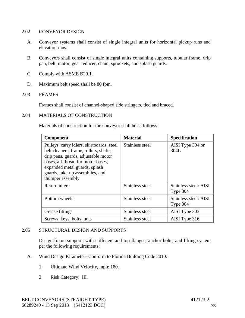
2.02 CONVEYOR DESIGN
A. Conveyor systems shall consist of single integral units for horizontal pickup runs and elevation runs.
B. Conveyors shall consist of single integral units containing supports, tubular frame, drip pan, belt, motor, gear reducer, chain, sprockets, and splash guards.
C. Comply with ASME B20.1.
D. Maximum belt speed shall be 80 fpm.
2.03 FRAMES
Frames shall consist of channel-shaped side stringers, tied and braced.
2.04 MATERIALS OF CONSTRUCTION
Materials of construction for the conveyor shall be as follows:
Component Material Specification Pulleys, carry idlers, skirtboards, steel belt cleaners, frame, rollers, shafts, drip pans, guards, adjustable motor bases, all-thread for motor bases, expanded metal guards, splash guards, take-up assemblies, and thumper assembly
Stainless steel AISI Type 304 or 304L
Return idlers Stainless steel Stainless steel: AISI Type 304
Bottom wheels Stainless steel Stainless steel: AISI Type 304
Grease fittings Stainless steel AISI Type 303 Screws, keys, bolts, nuts Stainless steel AISI Type 316
2.05 STRUCTURAL DESIGN AND SUPPORTS
Design frame supports with stiffeners and top flanges, anchor bolts, and lifting system per the following requirements:
A. Wind Design Parameter--Conform to Florida Building Code 2010:
1. Ultimate Wind Velocity, mph: 180.
2. Risk Category: III.
BELT CONVEYORS (STRAIGHT TYPE) 412123-2 60289240 - 13 Sep 2013 (S412123.DOC) 565

3. Exposure Category: C.
B. Weight, W: Weight of conveyor system plus 60 pounds per linear foot load on belt.
C. An unreinforced concrete housekeeping pad above the reinforced concrete structural slab shall not be considered to have structural value in the design of the anchor bolts. Tension and shear values for drilled or epoxied anchor shall be FBC approved.
2.06 PULLEYS
A. Head pulleys shall be minimum 16 inches diameter, 304 SS construction with tapered compression type hubs mounted on 304 SS shafting supported by 2 3/16” diameter min. self aligning bearings. The head pulley will have 3/8” thick vulcanized neoprene legging to prevent belt slip.
B. The tail pulley shall be 14” minimum diameter 304 SS construction with tapered compression type hubs mounted on 1 15/16” diameter 304 SS shafting supported by protected screw take-ups with 12” take up length minimum. The take ups will include stainless steel adjusting rods with brass bearing capture nuts.
2.07 IDLERS
A. Belt will be supported on the carrying run by CEMA, 20 degrees troughed idlers on 4'-0" centers except at the load points on 1'-6" centers, and return runs on CEMA idlers at maximum spacing of 10'-0".
B. Idler rolls are to be 304 SS construction and supported from the frame by 304 SS brackets.
C. Idlers will include 3/4" diameter shafts and tapered roller bearings with controlled greasing. Shaft seals will be multi-passage labyrinth with a positive wiper and an outer shield constructed as established by CEMA
2.08 FRAME
Belt conveyor frames and supports will be constructed of 304SS structural members with spreaders, sized as required to limit deflection to 1/250 at the longest support span. Top of the channel frames will be covered with 3/16” nominal “Fiberglass Reinforced Plastic” return belt cover to prevent product spillage onto the return run of the belt
2.09 SKIRTING
Conveyor will be provided with continuous 10 gauge 304 SS skirt with an adjustable 3/8” thick neoprene seal strip at the belt to guide and control the product and 10 gauge 304SS splash plates at load areas
BELT CONVEYORS (STRAIGHT TYPE) 412123-3 60289240 - 13 Sep 2013 (S412123.DOC) 566

2.10 BELTING & SPLICE
A. Provide two-ply nylon or polyester carcass belting with minimum 1/8-inch-thick top and minimum 1/16-inch bottom. Belt shall have a minimum overall width of 24 inches. Design the belt for a minimum working tension of 220 pounds per inch of width.
B. Belt shall be vulcanized endless in the shop
C. Connect belt ends with a mechanical splice. With the exception of the connecting pin, install the fastener kit prior to shipment. Metallic components of the belting shall be Type 316 stainless steel.
2.11 BELT TAKE-UP
Provide a screw-type take-up at the foot terminal of the conveyor, with 12-inch travel, designed to provide proper belt tension. The take-up shall be guided to maintain take-up shaft normal to belt centerline. Furnish expanded metal guards around take-up.
2.12 BELT CLEANER
Provide belt scraper at discharge end of nonreversing conveyors.
2.13 GUARDS
Furnish Conveyor with OSHA style guards at all "nip points" and motor driven rotating components, specifically including motor drive and tail pulley and head pulley guards. Guards will be constructed of epoxy coated steel. (OSHA Safety Yellow).
2.14 DRIP PAN
Return run of the belt will be provided with a 14 gauge 304 SS drip pan 6" wider than overall belt width with water tight flanged connections in 10'-0" maximum lengths. 3” dia nipple drain will be located as shown on the drawings. The drip pan will be installed to serve as a guard for the return run of belting.
2.15 MOTOR
Provide a motor and gear reducer to drive the belt. Motor shall be nonreversing for pickup and discharge units. Motor shall be 3Hp, 3 ph, 60 Hz, 460V as listed in the subsection on "Service Conditions."
2.16 GEAR REDUCER
A. AGMA, Class II, helical gear shaft mount reducer assembly with V-belt and sheave reducer input drive to provide 80 FPM belt speed. Complete with FRP OSHA style V-belt guard. The thermal rating shall equal or exceed the mechanical rating. Spiral bevels shall be heavy-duty, right-angle construction, using only case-hardened, matched, and
BELT CONVEYORS (STRAIGHT TYPE) 412123-4 60289240 - 13 Sep 2013 (S412123.DOC) 567

lapped gears. Spiral bevels shall be manufactured to AGMA Quality 10 level per AGMA 2009 and 2011.
B. Drive housings shall be either steel (ASTM A36 or A108) or cast iron (ASTM A48, Class 30 or higher) and shall be fully stress relieved prior to machining. Drive housings shall be pressure tested. Drives shall be test run at the factory for one hour while filled with oil.
C. Minimum AGMA rating shall be 1.5 for continuous 24-hour-per-day service.
D. Provide two antifriction bearing assemblies. One assembly shall be free to float within the frame to carry radial thrust only. Design the other bearing assembly to carry both radial and axial thrust. Bearings may be either ball or tapered roller type. Bearing life shall be a minimum of 20,000 hours per the AFBMA B-10 rating.
E. Bearings shall be oil lubricated.
2.17 DRIVE OVERLOAD CONTROL SYSTEM
A. Provide each drive with a shear pin and slip clutch to protect the drive in the event of overloading.
B. Provide a torque overload switch.
C. Provide a zero speed switch, NEMA 7, 120V, 5 amp magnetic disc and sensor with mounting hardware for location at the non driven pulley.
2.18 SAFETY SWITCH
Provide cable-operated safety stop switch equipped with positive safety lock complete with 3/32-inch orange vinyl coated, 7x7 preformed stainless steel aircraft-type cable on all accessible sides of conveyor belt.
2.19 AUTOMATIC LUBRICATION SYSTEM
A. Belt conveyor manufacturer shall provide one (1) centralized lubrication system for all lubrication points located within the limits of the belt conveyor. The lubrication system shall be manufactured by SKF Model KFGS or equal. The lubrication system shall include 316 SST flexible grease lines and 120VAC NEMA 4X stainless steel control panel. Conveyor manufacturer shall determine the pump capacity and number of grease points.
B. Provide dry contact for a general fault alarm.
C. Mount automatic lubrication system near conveyor with 304 SST unistrut.
2.20 SPARE PARTS
A. Provide the following spare parts for each conveyor unit:
BELT CONVEYORS (STRAIGHT TYPE) 412123-5 60289240 - 13 Sep 2013 (S412123.DOC) 568
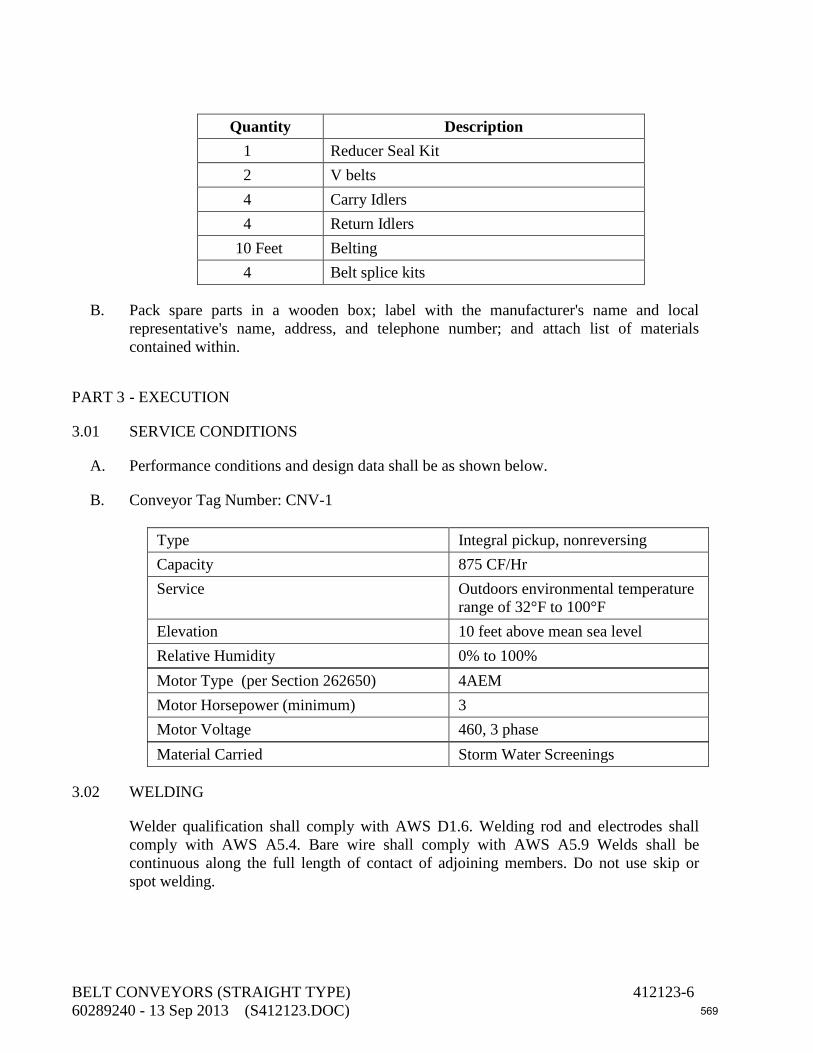
Quantity Description
1 Reducer Seal Kit 2 V belts 4 Carry Idlers 4 Return Idlers
10 Feet Belting 4 Belt splice kits
B. Pack spare parts in a wooden box; label with the manufacturer's name and local representative's name, address, and telephone number; and attach list of materials contained within.
PART 3 - EXECUTION
3.01 SERVICE CONDITIONS
A. Performance conditions and design data shall be as shown below.
B. Conveyor Tag Number: CNV-1
Type Integral pickup, nonreversing Capacity 875 CF/Hr Service Outdoors environmental temperature
range of 32°F to 100°F Elevation 10 feet above mean sea level Relative Humidity 0% to 100% Motor Type (per Section 262650) 4AEM Motor Horsepower (minimum) 3 Motor Voltage 460, 3 phase Material Carried Storm Water Screenings
3.02 WELDING
Welder qualification shall comply with AWS D1.6. Welding rod and electrodes shall comply with AWS A5.4. Bare wire shall comply with AWS A5.9 Welds shall be continuous along the full length of contact of adjoining members. Do not use skip or spot welding.
BELT CONVEYORS (STRAIGHT TYPE) 412123-6 60289240 - 13 Sep 2013 (S412123.DOC) 569

3.03 PAINTING AND COATING
Coat motor, gear drive, and guards per Section 099000, System No. 10. Apply the specified prime at the place of manufacture. Apply intermediate and finish coats in field. Color of finish coat shall be grey. Do not coat stainless steel.
3.04 FIELD TESTING
Operate the belt conveyor for a minimum of 24 consecutive hours to assure proper installation. Check for binding, sticking, and overloading, and repair all malfunctions. Simulate conditions to initiate automatic screen operation, and verify that the controls are operating normally. Test motor per Section 262650.
3.05 CONTRACT CLOSEOUT
Provide in accordance with Section 017000.
3.06 WARRANTY
The equipment shall be warranted for three (3) years commencing from date of substantial completion.
3.07 CERTIFICATION
Provide a written certification from the equipment manufacturer that each pumping system has been properly installed according to the Contract Documents and the manufacturer’s recommendations, and that the equipment is operating normally. Make all necessary corrections and adjustments including but not limited to parts, labor, or freight at no additional cost to the Owner.
END OF SECTION
BELT CONVEYORS (STRAIGHT TYPE) 412123-7 60289240 - 13 Sep 2013 (S412123.DOC) 570

This page intentionally left blank
571

DIVISION 43 – PROCESS GAS AND LIQUID HANDLING, PURIFICATION, AND STORAGE EQUIPMENT 432102 Mechanical Seals and Packing for Pumps 432140 Submersible Raw Wastewater Pumps 432150 Vertical Turbine Pumps
572

This page intentionally left blank
573

SECTION 432102 MECHANICAL SEALS AND PACKING FOR PUMPS
PART 1 - GENERAL
1.01 DESCRIPTION
This section includes materials, application, and installation of mechanical seals and packing for pumps. See the detailed pump specifications for the specific type of seal or packing to be provided.
1.02 SUBMITTALS
A. Submit shop drawings in accordance with the General Conditions, Section 013300, and the following.
B. Submit manufacturer’s catalog data and detail drawings showing packing type and material and mechanical seal design and parts. Describe material of construction by specification (such as AISI, ASTM, SAE, or CDA) and grade or type. Identify each mechanical seal and type of packing by the tag number of the associated pump to which the catalog data and detail sheets pertain.
PART 2 - MATERIALS
2.01 TYPE “F”: MECHANICAL SPLIT SEAL SYSTEM FOR CLEAR WATER SERVICE
A. Seal Type: The seal shall be of a nondestructive (non-fretting) type requiring no wearing sleeve for the shaft. Provide shafts for pumps specified with mechanical seals with no reduction in size through the seal area. Mechanical seals shall be the split type, requiring no field assembly, other than assembly around the shaft and insertion into the pump. Non-shaft O-rings shall be of ball-and-socket type requiring no gluing. Initial installation at the factory shall be with non-split faces, with all spare seals and spare kits to have split faces. For clear water services and solids concentrations up to 1/2% by weight, the face combination shall be hard/soft.
B. Seal Materials:
1. Metals: Type 316 stainless steel for loaded parts over 0.060-inch cross-section. For thinner parts (springs), use Hastelloy-C, Alloy 20, AMS5876 (Elgiloy), or other alloy that is not vulnerable to chloride stress corrosion.
2. Elastomers: Fluorocarbon (Viton).
3. Faces: Faces shall be of homogeneous construction. Do not use surface treatments and plated faces. Acceptable hard face materials include self-sintered silicon
MECHANICAL SEALS AND PACKING FOR PUMPS 432102-1 60289240 - 6 Sep 2013 (S432102.DOC) 574
carbide or reaction bonded silicon carbide. Acceptable soft face is carbon-graphite, either Union Carbide 658RC or Purecarbon P8412.
C. Seal shall be hydraulically balanced and designed for the range of 28-inch Hg vacuum to 400-psig service or 200% of sealing area pressure, whichever is higher, at the design rotating speed, shaft diameter, temperature, and liquid of the pump for the service.
D. Products: Self-aligning, self-centering, single, Chesterton 442, or equal.
2.02 TYPE “H”: MECHANICAL SEALS FOR SUBMERSIBLE PUMPS
A. Seal Types: Tandem, inside, shaft-mounted seal, with hard/hard or hard/soft faces inboard at the seal manufacturer’s discretion, hard/soft faces outboard. Design shall be elastomer bellows, metal bellows, or pusher design with a dynamic O-ring that slides over a clean surface, not the shaft/sleeve, when the faces wear.
B. Seal Materials:
1. Metals: Type 316 stainless steel minimum for loaded parts over 0.060-inch cross-section. For thinner parts (springs and bellows capsules), use Hastelloy-C, Alloy 20, or other alloy that is not vulnerable to chloride stress corrosion.
2. Elastomers: Fluorocarbon (Viton).
3. Faces: Faces shall be of homogeneous construction. Do not use surface treatments and plated faces. Acceptable hard face materials include nickel-bound tungsten carbide, self-sintered silicon carbide, reaction bonded silicon carbide, or graphitized silicon carbide. Acceptable soft face material is carbon-graphite, either Union Carbide 658RC or Purecarbon P8412.
C. Design seal for 200-psig service or the sealing area pressure, whichever is higher, at the design rotating speed, shaft diameter, temperature, and liquid of the pump for the service.
D. Environmental Controls:
1. The area between the inboard and outboard seals on the tandem shall be flooded with lubricating oil. It is not required that the buffer oil be pressurized, but if it is, the pressure shall be kept at 15 to 30 psig above the design box pressure inside the pump.
2. Provide a positive means of venting the stuffing box area prior to start-up. This can be either an automated vent valve or a pipeline to suction (if box pressure is higher than suction).
E. The setting of the two component seals composing the tandem seal arrangement shall not require any setting distance measurement by maintenance personnel. Provide a positive
MECHANICAL SEALS AND PACKING FOR PUMPS 432102-2 60289240 - 6 Sep 2013 (S432102.DOC) 575

stop for the ends of the seal collars. This can be a snap ring, collar, or shoulder on the shaft/sleeve at the manufacturer’s discretion.
PART 3 - EXECUTION
3.01 INSTALLATION OF MECHANICAL SEALS
Install per API 610 (tenth edition), Section 5, paragraphs 5.8.4 through 5.8.11.
3.02 SEAL CHAMBER FACE RUNOUT
Comply with API 682 (third edition), paragraph 6.1.2.13.
3.03 CARTRIDGE SEAL SLEEVES
Comply with API 682 (third edition), paragraphs 6.1.3.2 through 6.1.3.9.
END OF SECTION
MECHANICAL SEALS AND PACKING FOR PUMPS 432102-3 60289240 - 6 Sep 2013 (S432102.DOC) 576

This page intentionally left blank
577

SECTION 432140 SUBMERSIBLE RAW WASTEWATER PUMPS
PART 1 - GENERAL
1.01 DESCRIPTION
This section includes materials, installation, and testing of submersible raw wastewater pumps designed to operate in a wet well under submerged conditions.
1.02 SUBMITTALS
A. Submit shop drawings in accordance with the General Conditions, Section 013300, and the following.
B. Submit dimensional drawings.
C. Submit manufacturer's catalog data and detail drawings showing all pump parts and describe by material of construction, specification (such as AISI, ASTM, SAE, or CDA), and grade or type. Show linings and coatings. Show outline dimensions and weights of pumps, bases, and motors. Identify each pump by tag number to which the catalog data and detail sheets pertain.
D. Submit pump curves from manufacturer's catalog data on which the specified operating points are marked. Show efficiency, brake horsepower, and NPSH required for the selected pump curve for each specified operating point. Show maximum operating speed.
E. Show impeller diameter, eye area, sphere size, and number of vanes.
F. Submit setting drawings. Show anchor bolt layout and anchor bolt dimensions.
G. Submit manufacturer's reports on hydrostatic tests and performance tests.
H. Submit manufacturer's sample form for reporting the performance test results. Submit at least two weeks before the tests. The test form shall contain the data presented in the sample form in Section 6 of ASME PTC 8.2 or ANSI/HI 1.6 or API 610, Annex M.
I. Submit manufacturer's certified performance curves for review at least two weeks prior to shipping the units from the factory.
1.03 DEFINITIONS
Terms shall be as defined in ANSI/HI 11.6-2001 and ASME PTC 8.2. If there is a discrepancy in definitions between the two publications, the definitions given in ANSI/HI 11.6-2001 shall govern.
SUBMERSIBLE RAW WASTEWATER PUMPS 432140-1 60289240 - 6 Sep 2013 (S432140.DOC) 578
1.04 MANUFACTURER'S SERVICES
Provide equipment manufacturer's services at the jobsite for the minimum labor days listed below, travel time excluded:
A. One labor days for each service listed in the subsection on “Service Conditions” to check the installation and advise during start-up, testing, and adjustment of the pumps.
B. One labor day to instruct the Owner's personnel in the operation and maintenance of the pumps.
PART 2 - MATERIALS
2.01 PUMP DESIGN
A. The Contractor shall assign unit responsibility to the pump supplier for the complete pump system, including motors and cooling system control assembly.
B. Each pump shall be of the vertical, non-clog, single-suction, centrifugal type and shall be suitable for pumping unscreened raw sewage.
C. The pump, with its appurtenances and electric cable, shall be capable of continuous submergence under water without loss of watertight integrity to a minimum depth of 65 feet.
D. Design the casing to withstand a hydrostatic test of at least 150% of the pump discharge pressure (suction pressure plus pump differential pressure) at shutoff.
E. Each pump shall be capable of at least a 5% head increase at normal operating conditions by installing a larger impeller or an impeller of different hydraulic design.
F. Pump curve shall be continuously rising and shall be free of dips and valleys from the design point to the shutoff head. The shutoff head shall be at least 110% of the head that occurs at the design point.
G. The NPSH required shall be at least 5 feet less than the minimum NPSH available at all points on the pump curve up to 120% of the flow at the BEP.
H. Design the pump and its components to operate continuously over a flow range of 70% to 120% of the flow at the BEP.
2.02 DISCHARGE CONNECTIONS
A. Suction and discharge connections shall be flanged, ASME B16.1, Class 125. Flanges shall be flat faced. Bolt holes shall straddle the horizontal and vertical centerlines.
B. The pump shall be automatically connected to the discharge connection elbow when lowered into place and shall be easily removed for inspection or service. Sealing of the
SUBMERSIBLE RAW WASTEWATER PUMPS 432140-2 60289240 - 6 Sep 2013 (S432140.DOC) 579

pumping unit to the discharge elbow shall be accomplished by a simple linear downward motion of the pump. A sliding guide bracket shall be an integral part of the pump unit. The entire weight of the pump unit shall be guided by no less than two stainless steel guide bars or stainless steel guide wire pressed tightly against the discharge connection elbow. No portion of pump shall bear directly on the floor of the sump.
2.03 POWER SUPPLY
Power supply will be 480 volts, 60 hertz, 3 phase.
2.04 VIBRATION AND RESIDUAL UNBALANCE
A. The maximum vibration level shall not exceed that shown in Figure 11.6.16B in ANSI/HI 11.6-2001.
B. Maximum residual unbalance in impellers shall not exceed that shown in Figure 9.6.4.15B in ANSI/HI 9.6.4.
2.05 VOLUTE CASING
Volute casing shall be of a single piece, nonconcentric design with smooth fluid passages at all points to pass any size solids which can pass through the impeller. Casing shall be accurately machined to fit the mechanical seal and suction cover assemblies. Fit the bottom of the volute with a Type 316 or 420 stainless steel or rubber-lined carbon steel replacement wear ring. The volute shall have a center discharge nozzle. Provide a 3/4-inch drain with plug in the volute.
2.06 IMPELLER
A. Impeller shall be enclosed type with a maximum of two or three vanes. Each impeller shall be cast in one piece and shall be statically and dynamically balanced, double-shrouded thrulet with smooth water passage to prevent clogging by stringy or fibrous materials and other matter found in normal raw wastewater applications.
B. Each impeller shall be keyed to the shaft, and the fastening of the impeller to the shaft shall be made by a locking device. The locking device shall be sealed from the liquid by means of an O-ring and covered and secured to the end face of the shaft by a single bolt.
C. Fit each impeller with a replaceable wear ring for pumps.
2.07 SHAFTS
A. Pump shaft diameter shall be such that it will not deflect more than 0.002-inch at the mechanical seal face with the largest impeller installed while operating at the maximum pump speed. Tolerance on the shaft diameter shall not exceed 0.002 inch. Dynamic shaft deflection at the stuffing box face shall not exceed 0.002 inch.
SUBMERSIBLE RAW WASTEWATER PUMPS 432140-3 60289240 - 6 Sep 2013 (S432140.DOC) 580
B. The first lateral critical speed of the rotating assembly shall be at least 120% of the maximum pump operating speed.
C. Surface finish of the shafts or sleeves through the mechanical seal and at the rubbing contact-bearing housing seals shall not exceed a roughness of 32 microinches.
D. If a carbon steel shaft is used, provide Type 420 stainless steel shaft sleeves having a minimum hardness of 450 Brinell.
2.08 PUMP SEAL
A. Provide each pump with a tandem mechanical shaft seal system. The upper of the tandem set of seals shall operate in an oil chamber located just below the stator housing. This set shall contain one stationary tungsten carbide or cast chromium ring and one positively driven rotating carbon ring functioning as an independent secondary barrier between the pumped liquid and the stator housing. The lower of the tandem set of seals shall function as the primary barrier between the pumped liquid and the stator housing. This set shall consist of a stationary ring and a positively driven rotating ring, both of which shall be tungsten carbide.
B. Each interface shall be held in contact by its own spring system supplemented by external liquid pressures. The seals shall require neither maintenance nor adjustment but shall be easily inspected and replaceable.
C. Shaft seals without positively driven rotating members or conventional double mechanical seals with a common single or double spring acting between the upper and lower units requiring a substantial pressure differential to offset external pressure and effect sealing shall not be considered acceptable or equal to the dual independent seal system specified.
D. The shaft sealing system shall be capable of operating submerged to depths of or pressures equivalent to a minimum of 65 feet. No seal damage shall result from operating the pumping unit out of its liquid environment. The seal system shall not rely upon the pumped media for lubrication.
2.09 OIL CHAMBER
Provide each pump with an oil chamber for the shaft sealing system. Design the oil chamber to assure that air is left in the oil chamber to absorb the expansion of the oil due to temperature variations. The drain and inspection plug, with positive anti-leak seal, shall be easily accessible from the outside.
2.10 BEARINGS
A. Each pump shaft shall rotate on two permanently lubricated bearings. The upper bearing, providing for radial thrust, shall be a single row, roller bearing. The lower bearing shall consist of one double row or two single row angular contact bearing(s) for combined axial and radial loads.
SUBMERSIBLE RAW WASTEWATER PUMPS 432140-4 60289240 - 6 Sep 2013 (S432140.DOC) 581
B. Pump bearings shall be of the antifriction type designed to give 40,000 hours minimum life by L-10 calculations at maximum speed and operating load in continuous operation.
2.11 CABLE ENTRY
Each cable entry shall be comprised of a single cylindrical elastomer grommet, flanked by stainless steel washers, all having a close tolerance fit against the cable outside diameter and the entry inside diameter and compressed by the entry body containing a strain relief function, separate from the function of sealing the cable. The assembly shall bear against a shoulder in the pump top. The cable entry system shall utilize one of the two designs specified below.
A. The cable entry junction chamber and motor shall be separated by two terminal boards, which shall isolate the motor interior from foreign material gaining access through the pump top. Both the terminal boards shall be bolted to the interior of the motor housing and sealed by O-rings.
B. Provide cast-iron, pressure-tight cable entry gland, which shall be sealed by a nitrile rubber ring and compression gland. Design the compression gland to conform to the allowable bending radius of the power cable. In addition, cast each individual conductor wire in resin in such a manner to avoid any water leakage into the motor through capillary action, because of external cable damage or other causes.
2.12 MATING SURFACES
A. Machine and fit mating surfaces of major parts with nitrile O-rings where watertight sealing is required. Machining and fitting shall be such that sealing is accomplished by automatic compression in two planes and O-ring contact made on four surfaces, without the requirement of a specific torque limit. Rectangular cross-sectioned gaskets requiring specific torque limits to achieve compression shall not be considered adequate or equal.
B. Tolerances of parts shall be such that they allow replacement of any part without additional machining required to ensure sealing as described above. No secondary sealing compounds, greases, or other devices shall be used.
2.13 COOLING SYSTEM
A. Pumps equipped with water-cooling system consisting of a water jacket are also acceptable. The water-cooling jacket system shall encircle the stator housing. Provide the water jacket with a separate circulation of the pumped liquid. Cooling water shall enter the cooling jacket by way of the pumping vanes, integral with the impeller design, and exit with the pumping media. Cooling media channels and ports shall be non-clogging by virtue of their dimensions. Provide a separate, clear, external water source for motor cooling as well as lower seal flushing. Alternatively, ambient cooling of the motor may be utilized.
SUBMERSIBLE RAW WASTEWATER PUMPS 432140-5 60289240 - 6 Sep 2013 (S432140.DOC) 582

2.14 ELECTRIC MOTORS
A. Each pump shall be driven by a vertical, submersible squirrel cage induction motor, shell type design, housed in an air-filled, watertight chamber. The stator winding and stator leads shall be insulated with moisture-resistant Class F insulation which will resist a temperature of 155°C, 40°C ambient plus 115°C rise, and designed for continuous duty, capable of sustaining a minimum of 10 starts per hour.
B. The stator shall be dipped and baked three times in Class F varnish and shall be shrink-fitted into the stator housing. The use of bolts, pins, or other fastening devices requiring penetration of the stator housing shall be rejected.
C. The motor shall be sized to be non-overloading when the pump is operated at any point on the pump performance characteristic curve drawn through the design point and shall have a minimum service factor of 1.10. Motor service factor shall not be used in satisfying pumping requirement.
D. Equip the stator with three sensors or thermistors embedded in the end coils of the stator winding to monitor stator temperature. Provide one sensor or thermistor in each stator phase, to switch off the unit if a winding temperature of 285°F is exceeded.
E. If the pump manufacturer uses thermistors in the motor windings, the pump manufacturer shall provide the motor winding thermistor relay and any motor bearing thermistor relays and shall arrange for their installation in the pump motor starter. Both relays shall operate in a 120-volt control circuit and have contacts as shown in the electrical drawings. Adjust and arrange relays to properly respond to the thermistors mounted within the pump-motor housing.
F. Each pump motor shall have a sensor system to monitor moisture in the stator cavity and temperature sensors within the motor stator windings. Provide a supervision relay for connection to the pump motor drive to trip an alarm if moisture content indicates a failure of the outer mechanical seal or if high temperature is detected in the stator. Supervision relay system shall be Flygt MiniCAS II or equal.
G. Connect sensors and thermistor relays to the pump motor starter in such a manner that their signal can actuate an alarm or provide for immediate shutdown or both.
2.15 MOTOR CABLES
Pump motor power cables installed shall be made of a Hypalon or Protolon synthetic rubber-jacketed, Type SPC multiconductor cable, suitable for submersible pump applications and heavy mechanical stresses. The power cable shall also be sized according to NEC and ICEA standards and also meet with P-MSHA approval or equivalent. Use a separate Hypalon or Protolon synthetic rubber-jacketed, Type SPC cable for temperature and moisture pilot protection signals. The total length of each cable shall be a minimum of 40 feet.
SUBMERSIBLE RAW WASTEWATER PUMPS 432140-6 60289240 - 6 Sep 2013 (S432140.DOC) 583

2.16 MATERIALS OF CONSTRUCTION
A. Materials of construction shall be as listed below:
Component Material Specification Casing, volute, suction and discharge elbows
Cast iron ASTM A48, Class 30 (minimum)
Impeller Cast iron ASTM A48, Class 35B Shaft Stainless steel AISI 420 Impeller wear ring Stainless steel ASTM A743, Grade CF8M Drain and vent plugs Malleable iron ASTM A197 Cap screws, bolts, and nuts
Stainless steel AISI Type 316
Any bronze components in contact with water
See paragraph C below
B. Do not construct the impeller wear ring and case wear ring of the same material. Impeller and bowl wear ring materials shall have a minimum Brinell hardness difference of 50 unless both the stationary and the rotating wear surfaces have Brinell hardness numbers of at least 50.
C. Bronze shall have the following chemical characteristics:
Constituent Content Zinc 7% maximum Aluminum 2% maximum Lead 8% maximum Copper + Nickel + Silicon 83% minimum
2.17 GUIDE ASSEMBLY:
A. Provide Schedule 40 Type 316L stainless steel guide rails or Type 316 cables for each pump discharge assembly.
1. Guide Rail: Pump manufacturer’s standard size but not less than 1.25-inch diameter.
B. Provide Type 316L stainless steel intermediate supports for guide rails with a maximum spacing of 10 feet between supports.
SUBMERSIBLE RAW WASTEWATER PUMPS 432140-7 60289240 - 6 Sep 2013 (S432140.DOC) 584

C. Provide Type 316L stainless steel top guide rail retainer brackets to support the guide rails or cables. Bracket to be attached to top slab of wet well.
D. Provide Type 316 stainless steel chain of sufficient length, to reach from pump to top of wet well plus 10 feet and of strength for lifting pump and motor. Provide chain designed for attachment to lifting bail provided on motor and to the guide rail retainer bracket.
2.18 PUMP LIFTING/DOCKING DEVICE
A. Provide a chain and latch mechanism to allow the pumps and motors to be removed in one pull without re-rigging the system. Provide a device that is lowered along the guide cables or rails and can be remotely latched to the pump lifting bail without the need to enter the wet well.
B. Materials:
1. Lifting Bail: Stainless Steel
2. Hook, Shackle, Counterweight and Chain: Stainless Steel
3. Guide Ropes: Stainless Steel
4. Latch Operating Rope: Polyamide
C. Mechanism Lifting Capacity to be suitable for equipment provided.
2.19 ACCESS COVER
A. Provide a stainless steel, H-20 rated access hatch manufactured by Syracuse Castings or equal. Hatch shall be equipped with slam lock and key, open arm, and lifting handle. The access hatch shall be properly sized to allow the removal of the submersible pump.
2.20 ANCHOR BOLTS, NUTS, AND WASHERS
A. Anchor bolts, nuts, and washers for pumps shall be stainless steel.
2.21 SPARE PARTS
A. Provide the following spare parts for each model or size of pump:
SUBMERSIBLE RAW WASTEWATER PUMPS 432140-8 60289240 - 6 Sep 2013 (S432140.DOC) 585

Quantity Description 1 Set of wear rings for impeller and volute 1 Complete set of seals, primary and secondary 2 Sets of radial bearings 2 Sets of thrust bearings 1 Complete set of O-rings or gaskets, whichever applies to the
supplied pump unit
B. Pack spare parts in a wooden box; label with the manufacturer’s name and local representative’s name, address, and telephone number; and attach list of materials contained within.
PART 3 - EXECUTION
3.01 SERVICE CONDITIONS
A. Pump hydraulic performance conditions and design data shall be as shown below.
B. Pump Tag Numbers: P-4
Location Public Works Pump Station Liquid pumped Storm Water Service Outdoors environmental temperature
range of 32°F to 100°F Altitude 10 feet above mean sea level Relative humidity 0% to 100% Fluid temperature range 50°F to 100°F
Pump Data
Capacity (gpm)
Pump Total Head (feet)
Minimum Pump Efficiency
(%) 0 220 0
1,392* 148 65 2,400 104 65
*Design point.
Maximum pump speed 1725 rpm Minimum NPSH available Flooded
SUBMERSIBLE RAW WASTEWATER PUMPS 432140-9 60289240 - 6 Sep 2013 (S432140.DOC) 586

Motor horsepower (minimum) 88 Motor Type Inverter Rated Discharge nozzle size 8 inches Impeller Diameter 335 mm Manufacturers and models Flygt Model CP 3300
HT 464
C. The specified impeller shall be capable of passing a 3-inch sphere.
3.02 FACTORY PERFORMANCE TESTING
A. Each pumping unit shall be subjected to a non-witnessed laboratory performance test. Conduct tests in accordance with the ASME PTC 8.2 or ANSI/HI 1.6, using the actual job driver. The performance test shall be equivalent to Level "A" per ANSI/HI 1.6.
B. No motor overload above nameplate rating will be allowed at any flow up to 120% of the flow at the BEP.
C. Perform an NPSHR test on one pump of each size or model specified.
D. Deviations and fluctuations of test readings shall conform to ASME PTC 8.2, 1.11 (Type A), or ANSI/HI 1.6, paragraph 1.6.5.4.2.
E. Measure flow by the "Capacity Measurement by Weight," the "Capacity Measurement by Volume," or the "Capacity Measurement by Venturi Meter, Nozzle, or Thin Plate Orifice" methods in ASME PTC 8.2 or ANSI/HI 1.6.
F. For pumps in variable speed service, conduct a test at each operating speed necessary to attain the design points described in the subsection on “Service Conditions.”
G. Perform tests and record data, including head, flow rate, speed, and power, at a minimum of seven points. These points shall include shutoff, minimum flow, midway between minimum flow and design flow, design flow, 120% of design flow, and maximum flow.
H. Perform a hydrostatic test on pump pressure-containing components per ANSI/HI 1.6, paragraph 1.6.4.
3.03 PAINTING AND COATING
A. Coat submerged or immersed pumps and motors with ITT Flygt Duasolid Epoxy. Apply the coating at the factory.
B. Line volute and interior wetted surfaces and coat impeller per System No. 6, apply the lining at the factory.
C. System No. 6--Submerged Metal, Raw Sewage or Grit Slurries:
SUBMERSIBLE RAW WASTEWATER PUMPS 432140-10 60289240 - 6 Sep 2013 (S432140.DOC) 587

Type: Two-component epoxy resin/ceramic having a 100% volume solids and having the following characteristics:
Tensile shear adhesion (ASTM D1002)
2,500 psi (min) Shore D hardness (minimum) 85 Abrasion resistance (ASTM D4060) 0.8 mg (max) loss per 1,000
cycles
Service Conditions: For use as a lining for pump volutes, pump impellers, piping, valves, and heat exchanger tubes, subject to severe abrasion service.
Surface Preparation: SSPC SP-10.
Coating System: Apply two coats (of two different colors) to a minimum thickness of 10 mils per coat. Minimum total coating thickness shall be 20 mils. Product: THORTEX Cerami-Tech C.R. as applied by Western Industrial Technology, Inc., Fullerton, California, or Paragon Industries, Horsham, Pennsylvania; Belzona 1341; or equal.
3.04 SHIPMENT AND STORAGE
A. Prepare equipment for shipment including blocking of the rotor when necessary. Identify blocked rotors by means of corrosion-resistant tags attached with stainless steel wire. The preparation shall make the equipment suitable for six months of outdoor storage from the time of shipment, with no disassembly required before operation, except for inspection of bearings and seals.
B. Identify the equipment with item and serial numbers and project equipment tag numbers. Material shipped separately shall be identified with securely affixed, corrosion-resistant metal tags indicating the item and serial number and project equipment tag numbers of the equipment for which it is intended. In addition, ship crated equipment with duplicate packing lists, one inside and one on the outside of the shipping container.
C. Pack and ship one copy of the manufacturer’s standard installation instructions with the equipment. Provide the instructions necessary to preserve the integrity of the storage preparation after the equipment arrives at the jobsite and before start-up.
D. Store and protect pumps per API 686 (first edition), Chapter 3, paragraphs 1.4 through 1.9, 1.15, 1.16, 1.20, and 1.21 and as described below.
E. Coat exterior machined surfaces with a rust preventative.
F. The interior of the equipment shall be clean and free from scale, welding spatter, and foreign objects.
G. Provide flanged openings with metal closures at least 3/16-inch thick, with elastomer gaskets and at least four full-diameter bolts. Provide closures at the place of pump
SUBMERSIBLE RAW WASTEWATER PUMPS 432140-11 60289240 - 6 Sep 2013 (S432140.DOC) 588

manufacture prior to shipping. For studded openings, use all the nuts needed for the intended service to secure closures.
H. Provide threaded openings with steel caps or solid-shank steel plugs. Do not use nonmetallic (such as plastic) plugs or caps. Provide caps or plugs at the place of pump manufacture prior to shipping.
I. Clearly identify lifting points and lifting lugs on the equipment or equipment package. Identify the recommended lifting arrangement on boxed equipment.
J. Wrap exposed shafts and shaft couplings with waterproof, moldable waxed cloth or volatile-corrosion-inhibitor paper. Seal the seams with oil-proof adhesive tape.
K. If electric motors are stored or installed outside or in areas subject to temperatures below 40°F or are exposed to the weather prior to permanent installation, provide the manufacturer’s recommended procedures for extended storage. Provide temporary covers over the motor electrical components.
3.05 INSTALLING TENSIONING SYSTEM
A. Attach cable bracket to the lip of the equipment opening. Use epoxy stainless steel bolts.
B. Attach the flange discharge elbow to the floor of the wet well using epoxy stainless steel anchor bolts.
C. Install the guide cable/rail per manufacturer's recommendations.
D. Provide and attach the stainless steel lift chain or cable.
3.06 FIELD TESTING
A. The contractor shall provide temporary recirculation piping downstream of the pressure sustaining valve connected to the wet well.
B. Bump motor to ensure that motor has been connected for proper rotation.
C. Perform field tests for 24 consecutive hours on each pump. Measure flows at the following head points:
1. Tag Numbers:
2. Location:
3. Service:
4. Maximum rpm:
5. Test Points (Feet):
SUBMERSIBLE RAW WASTEWATER PUMPS 432140-12 60289240 - 6 Sep 2013 (S432140.DOC) 589

D. If the measured flows at the above-tabulated pump heads are more than 5% below the flows obtained on the laboratory or factory test, adjust the impellers or provide new impellers or otherwise repair or replace the pumps or calibrate meters or pressure gauges.
E. Operate each pump one at a time. Manually adjust the speed for each pump (one at a time) via the respective speed control unit such that the pump output is 30%, 40%, 50%, 60%, 80%, and 100% of the maximum capacity specified. The duration at each flow rate shall be at least one hour.
F. Assure that in the automatic mode each pump responds to its flow signal. Assure that each pump operates at a steady rate (±5% of set point) at any given flow for 30%, 40%, 50%, 60%, 80%, and 100% of the maximum capacity specified.
G. Demonstrate that the pumping units, motors, and control system meet the following requirements:
1. The pumping units operate as specified without excessive noise, cavitation, vibration, and without overheating of the bearings.
2. Automatic and manual controls function in accordance with the specified requirements.
3. Drive equipment operates without being overloaded.
3.07 CONTRACT CLOSEOUT
Provide in accordance with Section 017000.
3.08 WARRANTY
The equipment shall be warranted for three (3) years commencing from date of substantial completion.
3.09 CERTIFICATION
Provide a written certification from the equipment manufacturer that each pumping system has been properly installed according to the Contract Documents and the manufacturer’s recommendations, and that the equipment is operating normally. Make all necessary corrections and adjustments including but not limited to parts, labor, or freight at no additional cost to the Owner.
END OF SECTION
SUBMERSIBLE RAW WASTEWATER PUMPS 432140-13 60289240 - 6 Sep 2013 (S432140.DOC) 590

This page intentionally left blank
591

SECTION 432150 VERTICAL TURBINE PUMPS
PART 1 - GENERAL
1.01 DESCRIPTION
This section includes materials, testing, and installation of propeller or mixed flow pumps in sumps for water service.
1.02 SUBMITTALS
A. Submit shop drawings in accordance with the General Conditions, Section 013300, and the following.
B. Submit dimensional drawings.
C. Submit manufacturer's catalog data and detail drawings showing all pump parts and described by material of construction, specification (such as AISI, ASTM, SAE, or CDA), and grade or type. Show linings and coatings. Identify each pump by tag number to which the catalog data and detail sheets pertain.
D. Submit pump manufacturer ISO-9001 certification per Article 2.01A. As an alternative, provide a letter from the pump manufacturer accepting warranty responsibility for the entire pump, motor, and baseplate unit.
E. Show shaft diameter and bearing spacing. Submit calculations showing shaft critical frequency and determination of bearing spacings. Show calculated bearing life.
F. Submit pump curves on which the specified operating points are marked. Show efficiency and brake horsepower for the selected pump curve. Include moment of inertia of the complete pump unit including driver, impeller, and liquid pumped. Show required submergence and NPSH.
G. Submit descriptions of casting repairs and repair procedures that will be used to repair casting defects in bowls, diffusion vanes, suction bells, and impellers. Do not proceed with repairs until the Owner's Representative has reviewed the proposed repairs and repair procedures. After the repairs have been performed, submit report describing the repairs for record purposes.
H. As part of the field test procedure for the pumps, record measurements for impeller adjustment at the top of shaft and total radial shaft deflection (shaft runout) above the stuffing box or seal chamber.
I. Submit manufacturer's sample form for reporting performance test results at least two weeks before the tests. The test form should contain the data presented in the sample form in Section 6 of the ASME PTC 8.2 or ANSI/HI 2.6 or API 610, Annex M.
VERTICAL TURBINE PUMPS 432150-1 60289240 - 13 Sep 2013 (S432150.DOC) 592

J. The pump shall be tested with job motor, do not correct test results for speed.
K. Submit manufacturer's certified performance curves for review at least two weeks prior to shipping the units from the factory. Show pump total head, torque, brake horsepower, pump efficiency, required submergence, and required NPSH. Provide copies of the data recorded during the test and methods of data reduction for determining certified test results.
L. Submit report on results of factory resonance test and modal shape signature results.
M. Submit motor data per Section 262650.
N. Submit manufacturer's requirements for pump alignment limits.
O. Submit a finite element analysis (FEA) lateral dynamic analysis and torsional dynamic analysis per ANSI/HI 9.6.4-2000, paragraph 9.6.4.2.2. Include the effects of the pumped liquid per ANSI/HI 9.6.4, paragraph 9.6.4.2.1.
P. Submit detailed drawings and data showing the following information for each size and model of pump:
1. Design, dimensions, configuration, and wall thicknesses of nozzles.
2. Connection details of nozzles to discharge head.
3. Wall thickness of pump discharge heads. Include designs and dimensions of supporting or reinforcing gussets, if used.
4. Design and dimensions of discharge baseplate, including plate thickness and method of attachment of baseplate to discharge head.
5. Wall thickness and diameter of pump column.
6. Dimensions and thicknesses of bowls.
7. Pump column lengths between flanges or couplings.
8. Shaft diameters and support spacings.
9. Size of motor and method of mounting to pump discharge head.
10. Weights of the above-mentioned components.
1.03 DEFINITIONS
A. Terms shall be as defined in ANSI/HI 2.1-2.5 for vertical pumps and API 610, tenth edition, Section 3. If there is a discrepancy in definitions between the two publications, the definitions given in ANSI/HI 2.1-2.5 shall govern.
VERTICAL TURBINE PUMPS 432150-2 60289240 - 13 Sep 2013 (S432150.DOC) 593

B. Additional terms are defined below:
Submergence: Vertical distance in feet between the pumping water level and the bottom of the suction bell.
1.04 MANUFACTURER'S SERVICES
Provide equipment manufacturer's services at the jobsite for the minimum labor days listed below, travel time excluded:
A. Four labor days for each service listed in the subsection on "Service Conditions" to check the installation and advise during start-up, testing, and adjustment of the equipment.
B. One labor day to instruct the Owner's personnel in the operation and maintenance of the equipment.
PART 2 - MATERIALS
2.01 PUMP DESIGN
A. Equipment for the pumps, including discharge heads, shafting, columns, motors, bases, and anchor bolts, shall be provided as a complete unit by the pump manufacturer in an ISO 9001 certified facility or by a pump manufacturer accepting warranty responsibility for the complete pump unit. Pump units assembled by entities other than the pump manufacturer will not be acceptable.
B. Each pump shall be capable of at least a 10% head increase at normal operating conditions by installing a larger impeller or an impeller of different hydraulic design.
C. Pump curve shall be continuously rising and shall be free of dips and valleys from the design point to the shutoff head. The shutoff head shall be at least 120% of the head that occurs at the design point.
D. The NPSH required shall be at least 10 feet less than the minimum NPSH available at all points on the pump curve up to 120% of the flow at the BEP.
E. Design the pump and its components to operate continuously over a preferred operating range (POR, as defined in ANSI/HI 9.6.3-1997) of 70% to 120% of the flow at the BEP.
2.02 MOTORS
A. Motors shall be vertical high thrust, solid shaft. Motors shall be as further described in the subsection on "Service Conditions." For pumps with mechanical seals and hollow shaft motors, provide steady bushings.
VERTICAL TURBINE PUMPS 432150-3 60289240 - 13 Sep 2013 (S432150.DOC) 594

B. The driver motor thrust bearing loading shall include the total pump lineshaft downthrust. Design the motor bearings to withstand any momentary total upthrust equivalent to at least 30% of the maximum downthrust developed.
2.03 COUPLINGS AND COUPLING GUARDS
A. For solid shaft motors, comply with API 610 (tenth edition), paragraphs 6.2.2, 6.2.3, 6.2.6, 6.2.7, 6.2.14, and 8.3.8.2. Provide four-piece flanged adjustable spacer type couplings between the motor and pump shafts. Coupling shall be steel. The spacer shall be of sufficient length to permit the removal of the seal and sleeve without disturbing the driver. Provide coupling guards conforming to OSHA requirements.
2.04 DISCHARGE HEADS OR MOTOR STANDS
A. Provide a fabricated steel discharge head or motor stand. The discharge head or motor stand shall have bolted register or rabbet-fit connections for the motor. Discharge head or motor stand shall have connections for the pump column and shall support the loadings which it imposes as well as contain the pump pressure.
B. Equip the discharge head for enclosed lineshaft pumps with a tube tensioning device to apply and maintain proper tension to the shaft enclosing tube. Apply tension to the shaft enclosing tube through internal or external threads in the top tube.
C. Design columns and discharge heads for 150% of the pump discharge pressure (suction pressure plus pump differential pressure) at shutoff.
D. Access to the seal chamber or stuffing box or tube tension device shall be through windows placed 90 degrees from the discharge. Fit handholes and/or windows with Type 316 stainless steel expanded metal guards per OSHA requirements. Provide hinged or removable Type 316 stainless steel guards.
E. Design fabricated steel discharge head or motor stands to be aesthetically compatible with the mounted motor and with adjacent pumping units. Where the motor is smaller in horizontal dimension than the discharge pipe, shape a skirt to transition between the two masses. Where the motor is larger than the discharge head or motor stands, a skirt of approximately motor diameter dimension shall enclose the discharge head or motor stands so as to provide an adequate-appearing support.
F. The discharge shall be flanged, having a pressure rating as shown in the subsection on "Service Conditions."
1. Class 125 or 150 flanges shall comply with AWWA C207, Class D.
2. Class 300 flanges 48 inches and smaller shall comply with AWWA C207, Class F.
3. Class 300 flanges larger than 48 inches shall be fabricated to the dimensions of ASME B16.1, Class 250.
VERTICAL TURBINE PUMPS 432150-4 60289240 - 13 Sep 2013 (S432150.DOC) 595

4. Flanges shall be flat face.
5. Groove welds shall be full penetration welds. Fabricated flanges shall be welded both inside and out.
G. Provide for lifting the heads by means of lifting eyes that are capable of sustaining the weight of the complete unit less the motor.
2.05 SEAL CHAMBERS OR STUFFING BOXES FOR OPEN LINESHAFT PUMPS
The design of the seal chambers or stuffing boxes shall provide space and clearance for removal and service for any of the following types of packing or seals per Section 432102 without moving or disconnecting the motor: A, B, D, E, F, G, I.
2.06 LUBRICATION
A. Pumps shall have enclosed lineshafts as shown in the subsection on "Service Conditions." Enclosed lineshaft pumps shall have external potable water lubrication connections and supply lines for the lineshaft bearings. Provide leakage collection receptacle in the pump head. Provide 1-inch, standard weight (ASME B36.10) steel drain line to drain the water from the collection receptacle to a 1-inch threaded connection on the pump base back into the sump or can.
B. Shaft enclosing tube shall be Schedule 80 with 5-foot maximum length sections. Design enclosing tube such that it protects the lineshaft, supports the shaft bearings, and provides watertight gravity lubrication to each lineshaft bearing.
2.07 COLUMN PIPE
A. The column pipe joints shall be flanged and bolted to the discharge head or motor stand and to the pump bowl assembly and shall have register fits at each end. Material shall be as listed in the subsection on "Pump Materials of Construction." Provide enclosing tube retainers fabricated into the top of each column section at a maximum spacing of 5’ intervals.
B. Top and bottom column pipe sections shall not exceed 5-foot length.
C. Column pipe joints shall be flanged for columns 6 inches and larger and threaded or flanged for smaller sizes.
2.08 SHAFTS AND BEARINGS
A. Support the shafting by bearings at intervals so that the first natural frequency of the rotating assembly is at least 30% above the maximum operating speed. Calculate and size the shaft diameter for the pump shutoff head and the maximum horsepower conditions.
VERTICAL TURBINE PUMPS 432150-5 60289240 - 13 Sep 2013 (S432150.DOC) 596
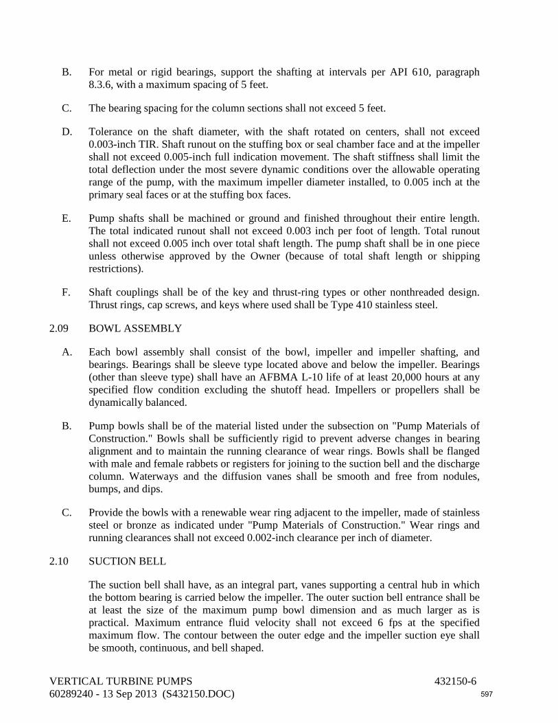
B. For metal or rigid bearings, support the shafting at intervals per API 610, paragraph 8.3.6, with a maximum spacing of 5 feet.
C. The bearing spacing for the column sections shall not exceed 5 feet.
D. Tolerance on the shaft diameter, with the shaft rotated on centers, shall not exceed 0.003-inch TIR. Shaft runout on the stuffing box or seal chamber face and at the impeller shall not exceed 0.005-inch full indication movement. The shaft stiffness shall limit the total deflection under the most severe dynamic conditions over the allowable operating range of the pump, with the maximum impeller diameter installed, to 0.005 inch at the primary seal faces or at the stuffing box faces.
E. Pump shafts shall be machined or ground and finished throughout their entire length. The total indicated runout shall not exceed 0.003 inch per foot of length. Total runout shall not exceed 0.005 inch over total shaft length. The pump shaft shall be in one piece unless otherwise approved by the Owner (because of total shaft length or shipping restrictions).
F. Shaft couplings shall be of the key and thrust-ring types or other nonthreaded design. Thrust rings, cap screws, and keys where used shall be Type 410 stainless steel.
2.09 BOWL ASSEMBLY
A. Each bowl assembly shall consist of the bowl, impeller and impeller shafting, and bearings. Bearings shall be sleeve type located above and below the impeller. Bearings (other than sleeve type) shall have an AFBMA L-10 life of at least 20,000 hours at any specified flow condition excluding the shutoff head. Impellers or propellers shall be dynamically balanced.
B. Pump bowls shall be of the material listed under the subsection on "Pump Materials of Construction." Bowls shall be sufficiently rigid to prevent adverse changes in bearing alignment and to maintain the running clearance of wear rings. Bowls shall be flanged with male and female rabbets or registers for joining to the suction bell and the discharge column. Waterways and the diffusion vanes shall be smooth and free from nodules, bumps, and dips.
C. Provide the bowls with a renewable wear ring adjacent to the impeller, made of stainless steel or bronze as indicated under "Pump Materials of Construction." Wear rings and running clearances shall not exceed 0.002-inch clearance per inch of diameter.
2.10 SUCTION BELL
The suction bell shall have, as an integral part, vanes supporting a central hub in which the bottom bearing is carried below the impeller. The outer suction bell entrance shall be at least the size of the maximum pump bowl dimension and as much larger as is practical. Maximum entrance fluid velocity shall not exceed 6 fps at the specified maximum flow. The contour between the outer edge and the impeller suction eye shall be smooth, continuous, and bell shaped.
VERTICAL TURBINE PUMPS 432150-6 60289240 - 13 Sep 2013 (S432150.DOC) 597

2.11 IMPELLERS
Pump impellers shall be of the enclosed or semi-open or mixed flow type impeller or propeller type made of the material listed in the subsection on "Pump Materials of Construction" and shall be cast in one piece. Machine impellers to fit the contour of the bowl and hand file in the waterways. Attach impellers to the shaft in such a manner that they cannot become loose under any operating condition or under reverse rotation. Provide for adjustment of the axial position of the impeller at the spacer coupling connection so that proper clearance between bowls and impellers may be maintained.
2.12 VIBRATION AND RESIDUAL UNBALANCE
A. The maximum vibration levels shall not exceed those shown in Figures 9.6.4.13 and 9.6.4.14 in ANSI/HI 9.6.4-2000. Maximum residual unbalance in rotors shall not exceed that shown in Figure 9.6.4.15B in ANSI/HI 9.6.4.
B. At any operating speed, the ratio of the pump’s natural reed frequency to the pump’s rotating speed (f/N) shall be less than 0.8 and greater than 1.3. A factory resonance test shall demonstrate the motor/discharge head structure’s natural reed frequency. Obtain a modal shape signature with an FFT analyzer and submit to Owner’s Representative for review.
C. The Contractor shall require that the pump manufacturer determine whether the infinite mass and rigidity described in ANSI/HI 9.6.4-2000, paragraph 9.6.4.5.2 is applicable to the service conditions in this project and to select the appropriate analytical method to determine the critical speed and resonant frequencies of the pump system. At a minimum, the pump system shall include the bowls, impellers, lineshaft diameters, lineshaft bearing spacing, column diameter and wall thickness, the design of the discharge stand or motor stand with discharge nozzle, and the baseplate and soleplate dimensions (length, width, and thickness).
2.13 TORSIONAL ANALYSIS
Perform a finite element torsional analysis per API 610 (tenth edition), Section 5.9, on pumps having: (1) an electric motor driver 600 horsepower and larger, (2) an engine driver 300 horsepower and larger, or (3) any variable speed pump having a driver 75 horsepower and larger. For the purposes of design, a dangerous critical speed shall be defined as one that produces a torsional stress exceeding 3,500 psi.
2.14 PUMP MATERIALS OF CONSTRUCTION
A. Materials of construction shall conform to the requirements listed below. Materials of construction for components not listed below shall conform to API 610, Annex H, Material Class I-2.
Component Material
VERTICAL TURBINE PUMPS 432150-7 60289240 - 13 Sep 2013 (S432150.DOC) 598

Pump shafts and couplings Stainless steel, ASTM A276, UNS Grade S410 couplings, with ASTM A582, UNS Grade S416 shafting
Bowl wear rings Stainless steel, ASTM A276, Type 410. Bearing enclosing tube retainers (fabricated integral)
Carbon steel, ASTM A283, Grade B.
Tube bearings Bronze; see paragraph B below. Tube bearing Bronze; see paragraph B below. Propellers Aluminum Bronze, ASTM B148, Grade 958 Pump bowls and suction bell Cast iron, ASTM A48, Class 30 or ductile
iron, ASTM A536. Bowl bearings Bronze; see paragraph B below. All parts made of fabricated steel including discharge head or motor stand
Carbon steel, ASTM A283, Grade B or C; ASTM A36; or ASTM A53, Grade B.
Column pipe and shaft enclosing tube
Carbon steel, ASTM A283, Grade B or C, or ASTM A53, Grade A or B.
Mounting plate Carbon steel, ASTM A283, Grade A or B or ASTM A36.
Flanges ASTM A105, A181, or A182. Bolts and nuts for discharge heads, column pipe flanges, and bowl flanges.
Bolts shall be Type 316 stainless steel conforming to ASTM A193, Grade B8M. Nuts shall be Type 316 stainless steel conforming to ASTM A194, Grade 8M.
Stuffing box gland parts Bronze; see paragraph B below. Gland bolts and nuts Stainless steel, Type 316. Any bronze components in contact with water
See paragraph B below.
B. Bronze shall have the following chemical characteristics:
Constituent Content Zinc 7% maximum Aluminum 2% maximum Lead 8% maximum Copper + Nickel + Silicon 83% minimum
VERTICAL TURBINE PUMPS 432150-8 60289240 - 13 Sep 2013 (S432150.DOC) 599
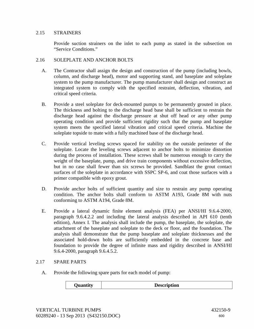
2.15 STRAINERS
Provide suction strainers on the inlet to each pump as stated in the subsection on “Service Conditions.”
2.16 SOLEPLATE AND ANCHOR BOLTS
A. The Contractor shall assign the design and construction of the pump (including bowls, column, and discharge head), motor and supporting stand, and baseplate and soleplate system to the pump manufacturer. The pump manufacturer shall design and construct an integrated system to comply with the specified restraint, deflection, vibration, and critical speed criteria.
B. Provide a steel soleplate for deck-mounted pumps to be permanently grouted in place. The thickness and bolting to the discharge head base shall be sufficient to restrain the discharge head against the discharge pressure at shut off head or any other pump operating condition and provide sufficient rigidity such that the pump and baseplate system meets the specified lateral vibration and critical speed criteria. Machine the soleplate topside to mate with a fully machined base of the discharge head.
C. Provide vertical leveling screws spaced for stability on the outside perimeter of the soleplate. Locate the leveling screws adjacent to anchor bolts to minimize distortion during the process of installation. These screws shall be numerous enough to carry the weight of the baseplate, pump, and drive train components without excessive deflection, but in no case shall fewer than six screws be provided. Sandblast the grout contact surfaces of the soleplate in accordance with SSPC SP-6, and coat those surfaces with a primer compatible with epoxy grout.
D. Provide anchor bolts of sufficient quantity and size to restrain any pump operating condition. The anchor bolts shall conform to ASTM A193, Grade 8M with nuts conforming to ASTM A194, Grade 8M.
E. Provide a lateral dynamic finite element analysis (FEA) per ANSI/HI 9.6.4-2000, paragraph 9.6.4.2.2 and including the lateral analysis described in API 610 (tenth edition), Annex I. The analysis shall include the pump, the baseplate, the soleplate, the attachment of the baseplate and soleplate to the deck or floor, and the foundation. The analysis shall demonstrate that the pump baseplate and soleplate thicknesses and the associated hold-down bolts are sufficiently embedded in the concrete base and foundation to provide the degree of infinite mass and rigidity described in ANSI/HI 9.6.4-2000, paragraph 9.6.4.5.2.
2.17 SPARE PARTS
A. Provide the following spare parts for each model of pump:
Quantity Description
VERTICAL TURBINE PUMPS 432150-9 60289240 - 13 Sep 2013 (S432150.DOC) 600

One Bowl wear liner Two sets Bowl bearings Two sets Enclosing tube line bearings One Shaft coupling Two Mechanical seals (for pumps specified to have mechanical
seals)
B. Pack spare parts in wooden boxes; label with manufacturer’s name and local representative’s name, address, and telephone number; and attach list of materials contained therein.
PART 3 - EXECUTION
3.01 SERVICE CONDITIONS
A. Pump hydraulic performance characteristics shall be as shown below.
B. Pump Tag Numbers: P-1 and P-2 (Main Pumps)
Location Public Work Pump Station Type of discharge Surface Service Outdoors environmental temperature range
of 32°F to 100°F Elevation 10 feet above mean sea level Relative humidity 0% to 100% Fluid temperature range 50°F to 100°F
Pump Data
Capacity (gpm)
Pump Total Head (feet)(1)
Minimum Bowl Efficiency
(%) 16,000 23 82
21,000(2) 17 89 24,000 12.5 84
(1)Pump manufacturer to add for pump internal friction losses, such as in columns and discharge heads. (2)Design point.
Liquid pumped Storm Water
VERTICAL TURBINE PUMPS 432150-10 60289240 - 13 Sep 2013 (S432150.DOC) 601

Maximum pump speed 505 rpm Minimum submergence available 11 feet Motor horsepower (maximum) 125 Motor type 4AEHMTV Variable speed drive required per Section 262923
Yes
Minimum shaft diameter 2.44 inches Maximum enclosing tube diameter 4.0 inches Pump lubrication Enclosed lineshaft Minimum discharge connection size
36 inches
Minimum column size 36 inches Minimum column wall thickness 0.375 inch Discharge flange rating Grooved End Type of packing or seals per Section 432102
F
Bearing lubrication Water Suction strainer No Antivortex suction bell Yes Pump manufacturers and models Peerless Hydro-Foil 36 MF-1;
Fairbank Morse; or Engineer approved equal
C. Pump Tag Numbers: P-3 (Jockey Pump)
Location Public Work Pump Station Type of discharge Surface Service Outdoors environmental temperature range
of 32°F to 100°F Elevation 10 feet above mean sea level Relative humidity 0% to 100% Fluid temperature range 50°F to 100°F
Pump Data
VERTICAL TURBINE PUMPS 432150-11 60289240 - 13 Sep 2013 (S432150.DOC) 602

Capacity (gpm)
Pump Total Head (feet)(1)
Minimum Bowl Efficiency
(%) 4,500 16 74
5,625(2) 11 80 6,750 5 60
(1)Pump manufacturer to add for pump internal friction losses, such as in columns and discharge heads. (2)Design point.
Liquid pumped Storm Water Maximum pump speed 1180 rpm Minimum submergence available 11 feet Motor horsepower (maximum) 25 Motor type (per Section 262650) 4AEHMTV Variable speed drive required per Section 262923
Yes
Minimum shaft diameter 1.5 inches Pump lubrication Enclosed lineshaft Minimum discharge connection size
16 inches
Minimum column size 16 inches Minimum column wall thickness 0.375 inch Discharge flange rating Grooved End Type of packing or seals per Section 432102
F
Bearing lubrication Water Suction strainer No Antivortex suction bell Yes Pump manufacturers and models Peerless Hydro-Foil 18 PL;
Fairbank Morse; or Engineer approved equal
VERTICAL TURBINE PUMPS 432150-12 60289240 - 13 Sep 2013 (S432150.DOC) 603

3.02 WELDING PROCEDURE AND WELDER QUALIFICATIONS FOR PUMP CONSTRUCTION
Welding shall comply with the ASME Boiler and Pressure Vessel Code, Section IX. Provide full penetration welds. Open seam butt welds are not permitted.
3.03 CASTINGS FOR BOWLS, DIFFUSION VANES, SUCTION BELLS, AND IMPELLERS
A. Surfaces of steel, stainless steel, iron, and bronze castings shall be free of adhering sand, scale, cracks, and hot tears as determined by visual examination. Other surface discontinuities shall meet the requirements of MSS SP-55-2006, Table 1 and Annex A. Mould-parting fins and remains of gates and risers shall be chipped, filed, or ground flush.
B. If the visual examination reveals defects, repair the castings or provide new castings. Defects may be repaired by welding, provided the welder qualification and welding procedures are in accordance with the ASME Boiler and Pressure Vessel Code, Section IX. Provide post-weld heat treatment per the cited material specification or per the ASME Boiler and Pressure Vessel Code, Section VIII.
C. Iron castings may be repaired by plugging within the limits of the cited material specification. The holes for plugs shall be carefully examined, using liquid penetrant, to determine that all defective material has been removed.
3.04 FACTORY PERFORMANCE TESTS
A. Each pumping unit shall be subjected to an Owner (and/or Owner’s representative) witnessed laboratory performance test; travel and accommodations shall be paid by Contractor. Conduct tests in accordance with the ASME PTC 8.2 or ANSI/HI 2.6, using the actual job driver. The performance test shall be equivalent to ANSI/HI 2.6.
B. No motor overload above nameplate rating will be allowed at any flow up to 120% of the flow at the BEP.
C. Deviations and fluctuations of test readings shall conform to ASME PTC 8.2, 1.11 (Type A) or ANSI/HI 2.6, paragraph 2.6.5.4.1.
D. Measure flow by the “Capacity Measurement by Weight,” the “Capacity Measurement by Volume,” or the “Capacity Measurement by Venturi Meter, Nozzle, or Thin Plate Orifice” methods in ASME PTC 8.2 or ANSI/HI 2.6.
E. For pumps in variable speed service, conduct a test manually adjusting the speed for each pump such that the pump output is 50%, 60%, 80%, and 100% of the maximum capacity specified..
VERTICAL TURBINE PUMPS 432150-13 60289240 - 13 Sep 2013 (S432150.DOC) 604

F. Perform tests and record data, including head, flow rate, speed, and power at a minimum of seven points. These points shall include shutoff, minimum flow, midway between minimum flow and design flow, design flow, 120% of design flow, and maximum flow.
G. Take vibration readings at design flow at each test speed.
H. Performance tests shall be “full-scale.” The complete pump, including column and discharge elbow, shall be used. Measuring devices shall have been calibrated within the previous year.
I. Conduct tests preferably at the same minimum submergence that will be realized in the field.
J. Locate the pressure tap for head measurement not less than 10 pipe diameters downstream from the discharge elbow of the test pump.
K. Should results of the full-scale tests indicate, in the opinion of the Owner’s Representative, that the pumps will fail to meet any of the specified requirements, the Owner’s Representative will notify the Contractor of such failure. The manufacturer shall thereupon, at no expense to the Owner, make such modifications and perform additional tests as may be necessary to comply with these specifications.
L. Perform a hydrostatic test on discharge head and column per ANSI/HI 2.6, paragraph 2.6.4.
3.05 PAINTING AND COATING
A. Line and coat interiors and exteriors of pump columns, shaft enclosing tube, discharge heads, bowl assemblies, and suction bells with fusion-bonded epoxy per Section 099761. Apply coating at factory. Do not coat stainless steel or bronze pieces.
B. Color of coating shall be light gray.
3.06 SHIPMENT AND STORAGE
A. Prepare equipment for shipment including blocking of the rotor when necessary. Identify blocked rotors by means of corrosion-resistant tags attached with stainless steel wire. The preparation shall make the equipment suitable for six months of outdoor storage from the time of shipment, with no disassembly required before operation, except for inspection of bearings and seals.
B. Identify the equipment with item and serial numbers and project equipment tag numbers. Material shipped separately shall be identified with securely affixed, corrosion-resistant metal tags indicating the item and serial number and project equipment tag numbers of the equipment for which it is intended. In addition, ship crated equipment with duplicate packing lists, one inside and one on the outside of the shipping container.
VERTICAL TURBINE PUMPS 432150-14 60289240 - 13 Sep 2013 (S432150.DOC) 605

C. Pack and ship one copy of the manufacturer’s standard installation instructions with the equipment. Provide the instructions necessary to preserve the integrity of the storage preparation after the equipment arrives at the jobsite and before start-up.
D. Store and protect pumps per API 686 (first edition), Chapter 3, paragraphs 1.4 through 1.9, 1.15, 1.17, 1.20, and 1.21 and as described below.
E. Coat exterior machined surfaces with a rust preventative.
F. The interior of the equipment shall be clean and free from scale, welding spatter, and foreign objects.
G. Provide flanged openings with metal closures at least 3/16-inch thick, with elastomer gaskets and at least four full-diameter bolts. Install closures at place of pump manufacture prior to shipping. For studded openings, use all the nuts needed for the intended service to secure closures.
H. Provide threaded openings with steel caps or solid-shank steel plugs. Do not use nonmetallic (such as plastic) plugs or caps. Install plugs at place of pump manufacture prior to shipping.
I. Clearly identify lifting points and lifting lugs on the equipment or equipment package. Identify the recommended lifting arrangement on boxed equipment.
J. Wrap exposed shafts and shaft couplings with waterproof, moldable waxed cloth or volatile-corrosion-inhibitor paper. Seal the seams with oil-proof adhesive tape.
K. If electric motors are stored or installed outside or in areas subject to temperatures below 40°F or are exposed to the weather prior to permanent installation, provide the manufacturer’s recommended procedures for extended storage. Provide temporary covers over the motor electrical components. Provide temporary conduits, wiring, and electrical supply to space heaters. Inspect electrical contacts before start-up.
3.07 PUMP INSTALLATION
A. Install equipment horizontal and vertical within 0.002” per foot tolerance and according to the manufacturer's written instructions and the contract documents. Confirm that pumps are set to meet the vertical alignment requirements established by the manufacturer.
B. Check to ensure that pump baseplates or soleplates have been provided with vertical leveling screws, as opposed to shims or wedges. Do not use shims and wedges.
C. Provide the manufacturer's recommended lubricants and operating fluids and verify that each piece of equipment contains the amount recommended by the manufacturer.
D. Provide threaded caps for protection of nuts and bolt threads per Section 400500 on the bolts and nuts of the column pipe flanges and bowl flanges.
VERTICAL TURBINE PUMPS 432150-15 60289240 - 13 Sep 2013 (S432150.DOC) 606

E. Verify that the installed pump is fully self-supporting before bolting pipe flanges, so that no strain is imparted on the flanges, pipes, or pipe supports from the pump assembly. Adjust the position of the pump assembly so that the pump discharge flanges are plumb and aligned with the adjacent pipe flanges. Do not use temporary shims or jacking nuts for leveling, aligning, or supporting equipment. Provide final grouting of the pump assembly base according to Section 036000.
F. When the alignment is correct, tighten the foundation bolts evenly but not too firmly. Then grout the unit to the foundation. The leveling pieces may be grouted in place. Do not tighten foundation bolts until the grout is hardened a minimum of 48 hours after pouring.
G. Provide continuous protection of the installed equipment from the elements, dust, debris, paint spatter, or other conditions that will adversely affect the unit's operation until such time as the equipment is scheduled for start-up testing.
H. Pump supplier’s startup technician shall sign a Certificate of Proper Installation (COPI) after a site visit to confirm tolerances have been met after pump installation. Startup shall begin until contractor submits signed COPI form in to the engineer and owner for their approval to move forward with startup.
3.08 MOUNTING AND ALIGNMENT OF VERTICAL SOLID SHAFT DRIVERS
A. Before mounting the driver on the discharge head/driver stand, check the register fit, if furnished, and the mounting face on the driver for acceptable tolerance on runout and squareness, respectively, using a dial indicator mounted on the driver shaft. See ANSI/NEMA MG-1. Next, check the squareness of the face of the driver coupling half, mounted on the shaft with a tight fit and seated against a split ring, using a dial indicator on a firm base.
B. With the driver bolted to the discharge head, mount a dial indicator on the driver shaft above the coupling half and sweep the bore of the stuffing box. If excess runout exists, some adjustment can be made at the driver mounting fit and the stuffing box mounting fit. Before installing any additional coupling parts, check the driver for correct rotation, as given in the manufacturer’s installation instructions.
C. Next, mount the pump half coupling, shaft adjusting nut, and coupling spacer if applicable, and raise the impeller in accordance with the manufacturer’s instructions. Then secure the coupling bolts. Make a final check of the shaft runout below the pump half coupling with a dial indicator. If the runout is within acceptable tolerances, check the tightness of the driver hold-down bolts. If dowels are used to secure the driver location, then redoweling is required after disassembly/reassembly, since tolerance buildup in the multiple vertical joints results in alignment variation.
3.09 FIELD TESTING
A. Bump motor to ensure that motor has been connected for proper rotation prior to coupling pump.
VERTICAL TURBINE PUMPS 432150-16 60289240 - 13 Sep 2013 (S432150.DOC) 607
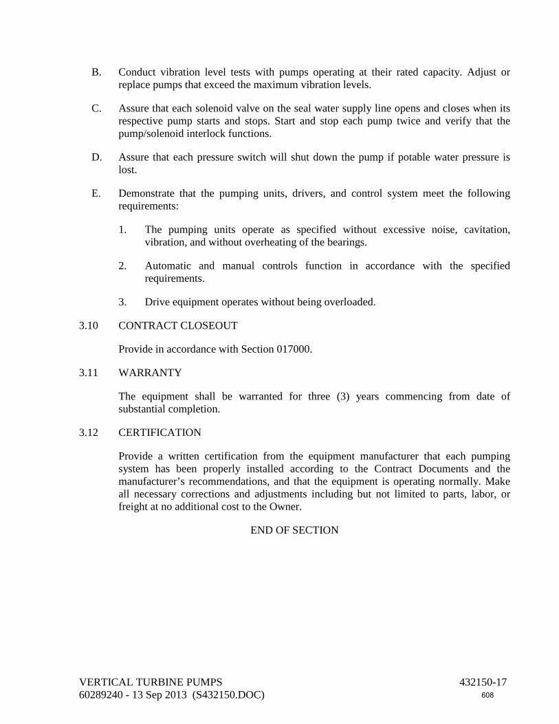
B. Conduct vibration level tests with pumps operating at their rated capacity. Adjust or replace pumps that exceed the maximum vibration levels.
C. Assure that each solenoid valve on the seal water supply line opens and closes when its respective pump starts and stops. Start and stop each pump twice and verify that the pump/solenoid interlock functions.
D. Assure that each pressure switch will shut down the pump if potable water pressure is lost.
E. Demonstrate that the pumping units, drivers, and control system meet the following requirements:
1. The pumping units operate as specified without excessive noise, cavitation, vibration, and without overheating of the bearings.
2. Automatic and manual controls function in accordance with the specified requirements.
3. Drive equipment operates without being overloaded.
3.10 CONTRACT CLOSEOUT
Provide in accordance with Section 017000.
3.11 WARRANTY
The equipment shall be warranted for three (3) years commencing from date of substantial completion.
3.12 CERTIFICATION
Provide a written certification from the equipment manufacturer that each pumping system has been properly installed according to the Contract Documents and the manufacturer’s recommendations, and that the equipment is operating normally. Make all necessary corrections and adjustments including but not limited to parts, labor, or freight at no additional cost to the Owner.
END OF SECTION
VERTICAL TURBINE PUMPS 432150-17 60289240 - 13 Sep 2013 (S432150.DOC) 608

END OF SECTION
VERTICAL TURBINE PUMPS 432150-18 60289240 - 11 Sep 2013 (S432150.DOC) 609

DIVISION 44 – POLLUTION CONTROL EQUIPMENT 443331 Motorized Self-Cleaning Strainers 444333 Mechanically Cleaned Vertical Bar Screen
610

This page intentionally left blank
611

SECTION 443331 MOTORIZED SELF-CLEANING STRAINERS
PART 1 - GENERAL
1.01 DESCRIPTION
This section includes materials and installation of pressurized, in-line, motorized, automatic self-cleaning strainers.
1.02 SUBMITTALS
A. Submit shop drawings in accordance with the General Conditions, Section 013300, and the following.
B. Submit manufacturer’s catalog data and descriptive literature for equipment. Submit dimensional and system layout drawings. Show materials of construction described by specification (such as AISI, ASTM, SAE, or CAA) and grade or type. Include connection points with orientation, coatings, appurtenances, anchor bolts, and tie-down equipment and hardware. Identify each strainer by tag number to which the catalog data and detail sheets pertain.
C. Submit electrical schematic and wiring diagrams showing wiring, controls, interlocks, and terminals. Label each terminal, showing which control or electrical power wire connects to which terminal. Submit manufacturer's catalog data for electrical equipment and enclosures.
D. Manufacturer's Services
Provide equipment manufacturer's services at the jobsite for the minimum labor days listed below, travel time excluded:
1. Two labor days to check the installation and advise during testing, start-up, and adjustment of the equipment.
2. One labor day to instruct the Owner's personnel in the operation and maintenance of the equipment.
PART 2 - MATERIALS
2.01 MANUFACTURERS
Strainer shall be as manufactured by Amiad Filtration Systems, S.P. Kinney, R.P. Adams, or Engineer pre-approved equal.
MOTORIZED SELF-CLEANING STRAINERS 443331-1 602892240 - 18 Sep 2013 (S443331.DOC) 612

2.02 STRAINER DESIGN AND OPERATION
A. The automatic strainer design shall be for the continuous straining of water with internal intermittent backwash that is performed while water continues to pass downstream. When backwash is required, a backwash valve opens and an internal mechanism is engaged to perform the backwashing function. During backwash, a reverse flow of a portion of the strained water dislodges and transports the collected solids to the backwash outlet. The volume and pressure of the reverse water flow required and the duration of backwashing per cycle shall be clearly documented in order to determine a total backwash water quantity per cycle. The internal mechanism shall be driven by an electrical gear motor which slowly rotates a cleaning arm, a drum, or suction scanning device to backwash the entire straining tube, media, or screen.
B. A differential pressure switch and/or backwash initiation timer shall signal the locally-mounted control panel to initiate the backwash cycle. The differential switch shall also provide visual indication of strainer condition, or else inlet and discharge gauges shall be included to provide a visual indication of strainer condition. The local control panel shall also provide a means of manually initiating a backwash cycle for test and maintenance purposes.
2.03 MATERIALS OF CONSTRUCTION
A. Materials for the filter design, and shop fabrication and inspection, shall be selected such that the maximum allowable working pressure shall be at least 100 psi. Perform hydrostatic test in shop to ensure filter body meets this criteria. Test pressure shall be 130% of the design pressure defined in the performance data for this application, or the MAWP defined above, whichever is greater.
B. Provide one 8-inch (minimum) flanged access hole in the side of the filter to allow for removal of large debris during routine maintenance. If alternative methods of large solids removal are utilized, manufacturer shall document the method by which these solids can be removed.
C. Materials of construction shall be as follows:
Component Material Body Carbon steel Screen or Strainer Media Type 316L stainless steel Cleaning Mechanism Type 316L stainless steel Shaft Type 316 stainless steel Seals Synthetic Rubber, Teflon
MOTORIZED SELF-CLEANING STRAINERS 443331-2 602892240 - 18 Sep 2013 (S443331.DOC) 613

2.04 BACKWASH
A. As the flushing valve opens, a reversal of flow shall occur, flushing the suspended particles from the screen. This reversal of flow shall be caused only by a pressure differential between the interior of the strainer body and atmosphere.
B. The flow reversal shall be focused on a limited portion of the straining media such that the entire surface area of the straining media is not backwashing at one time. Strainer design shall include features which increase the effectiveness of the flow reversal on the focused backwash. These features shall be documented and highlighted in the equipment submittal.
C. Strainer sizing shall be such that normal intermittent backwashing shall occur at the manufacturer’s recommended intervals, but shall not be designed for continuous backwashing under normal conditions.
2.05 INLET AND OUTLET FLANGES
Strainer inlet and outlet flanges shall conform to ASME B16.1 (Class 125) or B16.5 (Class 150). Provide flat-face flanges.
2.06 DRAIN OPENINGS
Provide a drain outlet on both the “clean” and “dirty” sides of the screen.
2.07 DRIVE GEAR
A. Provide manufacturer’s standard worm-style reducing gear drive system. Motor and drive shall be provided as a matched unit. All strainer units of the same size shall utilize the same manufacturer and size of gear drive system and motor.
B. Do not use shear pin protection for overloading of the motor or reducing gear assembly.
2.08 BOLTS, NUTS, AND GASKETS FOR FLANGES
Fasteners shall be shall be Type 316 stainless steel conforming to ASTM A193, Grade B8M, Class 2, for bolts and ASTM A194, Grade 8M, for nuts.
2.09 CONTROL PANEL AND CONTROLS
A. Control panel and controls shall be in accordance with Section 409510. The strainer supplier shall furnish a local control panel complete with all hand switches and local indicators. If strainer supplier’s standard control panel materially meets the intent of the above specification section, then differences shall be identified and highlighted during submittal for review by the Engineer. If strainer supplier’s standard control panel does
MOTORIZED SELF-CLEANING STRAINERS 443331-3 602892240 - 18 Sep 2013 (S443331.DOC) 614

not materially comply with the above named specification section, then a control panel that meets the above specification section shall be supplied.
B. The strainer supplier shall be responsible for a complete working filter system that can be operated automatically and manually from the local control panel. Strainer supplier shall demonstrate that they can provide ongoing support for all components included in the complete working filter system, including the local control panel, backwash valve, and strainer instrumentation (such as switches and gauges.
C. The control panel supplied as part of a complete control system for the strainer system shall include internal wiring, circuit breakers, motor starters, overload relays, switches, and controls. The strainer system shall come from the manufacturer completely wired and ready for installation, subject only to individual connections between the local control panel and the strainer equipment. Sufficient termination means such as terminal boxes or junction boxes shall be provided on the strainer equipment to facilitate electrical connection between the local control panel and the strainer equipment.
D. Mount all electrical control components into one local control panel for both strainers. Local control panel enclosure shall be constructed in conformance with NEMA Type 4X electrical enclosures unless indicated otherwise. Fabricate enclosure of Type 316 stainless steel having a minimum thickness of 0.075 inch (14 gauge). Operator interface may be provided on the enclosure door or on an internal deadfront door. Alarm and indicator lights shall be visible on or from the outside of the enclosure door.
E. Control panel logic shall be relay based, using appropriate mounting techniques for relays, timers, and other devices (such as DIN rail and sockets). PLC’s and proprietary microprocessor-based controllers shall not be utilized. Provide two dry-contacts for a general fault signal (one for each strainer).
PART 3 - EXECUTION
3.01 SERVICE CONDITIONS
A. Strainer performance conditions and design data shall be as shown below.
B. Equipment Tag Number: FLT-1 and FLT-2
Location Public Works Pump Station Service Outdoors environmental temperature range
of 32°F to 100°F Elevation 10 feet above mean sea level Relative humidity 0% to 100% Fluid temperature range 50°F to 100°F Strainer Inlet/Outlet Size 10 inch
MOTORIZED SELF-CLEANING STRAINERS 443331-4 602892240 - 18 Sep 2013 (S443331.DOC) 615

Screen Size 200 micron Motor Horsepower (Minimum) 0.5 Motor Type per Section 262650 4AEM Motor Voltage 460, 3 phase Design Pressure 100 psig Water Rate of Flow, Minimum/Maximum 1,000 to 1,340 gpm
Maximum Pressure Loss at Maximum Flow
<1 psi (clean screen) 7 psi (triggers backwash)
Manufacturers and Models Amiad EBS 10000 , S.P. Kinney, R.P. Adams, or equal
3.02 FABRICATION, ASSEMBLY, AND ERECTION OF AUTOMATIC STRAINERS – GENERAL REQUIREMENTS
A. Strainers shall come from the factory preassembled and tested, ready for installation by the Contractor. Any items shipped loose that must be field-mounted (such as the gear drive system) shall require only standard tools and construction installation techniques. Assembly instructions, drawings, and details shall be included with the shipment.
B. Any proprietary or special installation requirements unique to the strainer equipment shall be performed by the equipment manufacturer’s representative under the supervision of the Contractor, and shall be coordinated with the Contractor.
3.03 SHOP HYDROSTATIC PRESSURE TESTING
A. After completion of fabrication, pressure test each strainer as outlined in paragraph 2.03.A above. The duration of the test shall be at least one hour. When subjected to the above hydrostatic test pressure, the strainer shall show no leaks.
B. Repair any leaks or other defects in strainers, after which the entire strainer shall again be tested until it shows no leaks or other defects.
C. Provide documentation from the manufacturer that certifies that each strainer unit passed the hydrostatic test.
3.04 PAINTING AND COATING
A. Line the interior of carbon steel bodies per Section 099000, System No. 7.
B. Coat the exterior of carbon steel bodies per Section 099000, System No. 10.
C. Alternatively, line and coat bodies with fusion-bonded epoxy per Section 099761.
MOTORIZED SELF-CLEANING STRAINERS 443331-5 602892240 - 18 Sep 2013 (S443331.DOC) 616

3.05 SHIPMENT AND STORAGE
A. Prepare equipment for shipment including blocking of the shaft or drum when necessary. Identify blocked shafts or drums by means of corrosion-resistant tags attached with stainless steel wire. The preparation shall make the equipment suitable for six months of outdoor storage from the time of shipment, with no disassembly required before operation, except for inspection of bearings and seals.
B. Identify the equipment with item and serial numbers and project equipment tag numbers. Material shipped separately shall be identified with securely affixed, corrosion-resistant metal tags indicating the item and serial number and project equipment tag numbers of the equipment for which it is intended. In addition, ship crated equipment with duplicate packing lists, one inside and one on the outside of the shipping container.
C. Pack and ship one copy of the manufacturer’s standard installation instructions with the equipment. Provide the instructions necessary to preserve the integrity of the storage preparation after the equipment arrives at the jobsite and before start-up.
D. Coat exterior machined surfaces with a rust preventative.
E. The interior of the equipment shall be clean and free from scale, welding spatter, and foreign objects.
F. Provide exposed flanged openings (on uncrated or open-crated equipment) with metal closures at least 3/16-inch thick, with elastomer gaskets and at least four full-diameter bolts. Provide closures at the place of manufacture prior to shipping. For studded openings, use all the nuts needed for the intended service to secure closures.
G. Provide exposed threaded openings (on uncrated or open-crated equipment)with steel caps or solid-shank steel plugs. Do not use nonmetallic (such as plastic) plugs or caps. Provide caps or plugs at the place of manufacture prior to shipping.
H. Clearly identify lifting points and lifting lugs on the equipment or equipment package. Identify the recommended lifting arrangement on boxed equipment.
I. Wrap exposed ferrous shafts and shaft couplings with waterproof, moldable waxed cloth or volatile-corrosion-inhibitor paper. Seal the seams with oil-proof adhesive tape.
J. If electric motors are stored or installed outside or in areas subject to temperatures below 40°F or are exposed to the weather prior to permanent installation, provide the manufacturer’s recommended procedures for extended storage. Provide temporary covers over the motor electrical components. Provide temporary conduits, wiring, and electrical supply to space heaters. Inspect electrical contacts before start-up.
MOTORIZED SELF-CLEANING STRAINERS 443331-6 602892240 - 18 Sep 2013 (S443331.DOC) 617

3.06 EQUIPMENT INSTALLATION
A. Do not install unsupported piping and conduits on the strainers. Install piping and conduit hangers and supports as shown in the drawings to minimize piping-applied strain on the equipment.
B. Ensure that fluid passages of strainers are free from dirt, foreign objects, and other contamination.
C. Do not use duct tape and plastic for covering the ends of pipe flanges. Use a solid metal cover with rubber gasket to cover flanged openings during installation. These metal covers shall remain in place until the piping is connected to the equipment.
D. Verify that the installed equipment is fully self-supporting before bolting pipe flanges, so that no strain is imparted on the flanges, pipes, or pipe supports from the equipment. Adjust the position of the equipment so that the flanges are plumb and aligned with the adjacent pipe flanges. Do not use temporary shims or wedges for leveling, aligning, or supporting equipment.
E. Provide continuous protection of the equipment from the elements, dust, debris, paint spatter, or other conditions that will adversely affect the unit's operation until such time as the equipment is scheduled for start-up testing.
F. Provide the manufacturer's recommended lubricants in the drive units, bearings, and other mechanical equipment.
3.07 FIELD TESTING
A. Operate each motorized strainer for 24 hours during which time no repairs shall be required. Verify that strainer drive mechanism functions without binding or sticking. Verify that the drum rotates smoothly without binding or vibrating.
B. Measure the amperage drawn by each motor. The amperage shall not exceed the rated amperage stated on the motor data plate. Repair, replace, or realign motors and drives if the motors or drives bind, stick, or overload.
C. Actuate the backwash system at least three times during the test period. Verify that the backwash mechanism backwashes the straining media completely through each cycle. Verify that the backwash piping system does not clog or overflow during repeated backwashes.
3.08 LABELING AND MARKING
Provide a tag for each unit bearing the tag number. See Section 400775.
3.01 CONTRACT CLOSEOUT
Provide in accordance with Section 017000.
MOTORIZED SELF-CLEANING STRAINERS 443331-7 602892240 - 18 Sep 2013 (S443331.DOC) 618

3.02 WARRANTY
The equipment shall be warranted for three (3) years commencing from date of substantial completion.
3.03 CERTIFICATION
Provide a written certification from the equipment manufacturer that each strainer system has been properly installed according to the Contract Documents and the manufacturer’s recommendations, and that the equipment is operating normally. Make all necessary corrections and adjustments including but not limited to parts, labor, or freight at no additional cost to the Owner.
END OF SECTION
MOTORIZED SELF-CLEANING STRAINERS 443331-8 602892240 - 18 Sep 2013 (S443331.DOC) 619

SECTION 444333 MECHANICALLY CLEANED VERTICAL BAR SCREENS
PART 1 - GENERAL
1.01 DESCRIPTION
This section includes materials, installation, and testing of mechanically cleaned vertical bar screens. The bar screen supplier/manufacturer is also responsible for design and operation of the screens belt conveyor. Both bar screens, screenings belt conveyor, and control panel shall be furnished by a single supplier. The screenings belt conveyor is specified in Section 412123.
1.02 SUBMITTALS
A. Submit shop drawings in accordance with the General Conditions, Section 013300, and the following.
B. Submit dimensional drawings. Show relationship between the conveyor belts to which the screens will feed. Submit shop drawings for screens and associated conveyors together as a package.
C. Submit manufacturer's catalog data and detail drawings showing all screen parts and described by material of construction, specification (such as AISI, ASTM, SAE, or CDA), and grade or type. Show linings and coatings. Identify each screen by tag number to which the catalog data and detail sheets pertain.
D. Submit head loss calculations.
E. Submit installation drawings. Show dimensions and locations of base plates and anchor bolts.
F. Submit calculations for the design of the support legs, anchors, anchor bolts, and other structural elements.
1.03 MANUFACTURER’S SERVICES
Provide equipment manufacturer's services at the jobsite for the minimum labor days listed below, travel time excluded.
A. Three labor days to check the installation and advise during start-up, testing, and adjustments of the equipment.
B. One labor day to instruct the Owner's personnel in the operation and maintenance of the equipment.
MECHANICALLY CLEANED VERTICAL BAR SCREENS 444333-1 60289240 - 13 Sep 2013 (444333.DOC) 620

PART 2 - MATERIALS
2.01 MANUFACTURER
Screens shall be John Meunier "Lock-Chain Cont-Flow" or Engineer approved equal.
2.02 BAR SCREEN DESCRIPTIONS
A. The screening unit shall consist essentially of a bar rack, counter-current, back clean rake mechanism and chain drive, structural frame and shall be factory-assembled and tested prior to its delivery. Testing shall be Owner (and/or Owner’s Representative) inspected at the manufacturing facility; airfare and accommodations shall be included in the bid. Ready for installation in its channel, it shall not require field assembly of any components such as chain drive, reducer, or gears, except where partial disassembly is required by transportation regulations or for protection of components.
B. Each screen shall provide continuous removal of materials in the influent stream. The screening mechanism shall continuously carry material to the top of the device where it shall fall off or be removed from the screen onto a belt conveyor. Each screen shall be automatically self-cleaning by mechanical means without requiring any water to remove captured material from the screen surface.
2.03 BAR SCREEN STRUCTURE
A. The bar screen structure shall consist of the structural frame, the housing, and the structure leveling bolts.
B. Structural Frame: The vertical structural frame shall be fabricated of 1/4" thick minimum steel, forming a frame width of 29". It shall be bolted to a 5/8” thick base plate and a 3/8" thick head frame. The structural frame shall be designed to be of the monobloc and self-standing type.
C. The side frames may also serve as guide rails for the carriage and rake guide wheels and the positive movement of the chains. All these guides shall be designed to positively push the rake entry through the bar rack. The frame shall be covered with steel material formed to strengthen the monobloc.
D. The chain must be guided in a minimum ¼” thick channel through at least 180 degrees of the turn made at the drive sprocket. The interior chain guide channel must extend on both above the screen frame by at least 2 inches to eliminate gap where chain can bind under sprocket.
MECHANICALLY CLEANED VERTICAL BAR SCREENS 444333-2 60289240 - 13 Sep 2013 (444333.DOC) 621

E. The chain guide must have a slanted entrance on the back side of the screen to ease the chain into the guide and depress any kinks before as the chain is entering the guide channel.
F. The screen frame shall be recessed into the channel bottom. It shall also be firmly anchored to the channel sides and bottom.
G. Housing: 18 gauge metal sheeting shall be used to cover the front and sides top sections (and the sides at the intermediate level). The rake and wiper guards shall be made of the same material. The housing shall be bolted to the screen.
H. Leveling Bolts: All leveling bolts shall be supplied with the equipment and shall be of sufficient size to support the total screen weight.
2.04 BAR, RACK AND CLEANING MECHANISM
A. The bar screen cleaning mechanism shall consist of the bar rack, the rake with rake arm, shafts and drive system, the wiper, if required, and the chute.
B. Bar Rack: The free standing bar rack shall consist of equally spaced parallel 304 Stainless steel bars 1 inches wide by 4 inches deep, welded on a bottom support plate only. The bars shall rise vertically and extend 180 inches above the channel invert with clear openings of 1 inch between bars. The jam-proof "LAS" type bar rack shall be easily removable and shall be capable of withstanding a full differential. A bar guide shall be installed near the top end of the rack to support the bars. The bar guide shall be hinged and shall rotate away from the bar rack to allow the rake to travel past it. The bar rack shall sit on a 6 inch high spool.
C. Rake Mechanism: The rake mechanism shall remove the screenings from the bar rack and raise them vertically out of the liquid up to the trash chute. Only the rake mechanism during the cleaning cycle shall be allowed to enter the water flow.
The rake teeth shall be fabricated from ¾ inch thick 304 stainless steel plates. The
teeth shall be profiled in such a way to easily swing through the retained screenings; and designed to allow the lifting of round objects up to 6-inches in diameter (coconuts) without falling off. They shall also prevent the screenings from falling behind the bar rack. The rake shall provide a minimum shelf capacity of 8 inches. The teeth support steel plate of ¾ inch minimum thickness. It shall be bolted to the rake arm structural steel 4 inch x 4 inch x ¼ inch min. reinforced member.
The rake arms shall be attached by a shaft to the carriage driven by the electric gear
motor and traveling up and down the screen at a speed of 18.8 feet/min. The adjustable rake movement shall be regulated by means of an adjustable shock absorber and counter weight system to minimize the wear and noise and extend the life of the unit.
MECHANICALLY CLEANED VERTICAL BAR SCREENS 444333-3 60289240 - 13 Sep 2013 (444333.DOC) 622
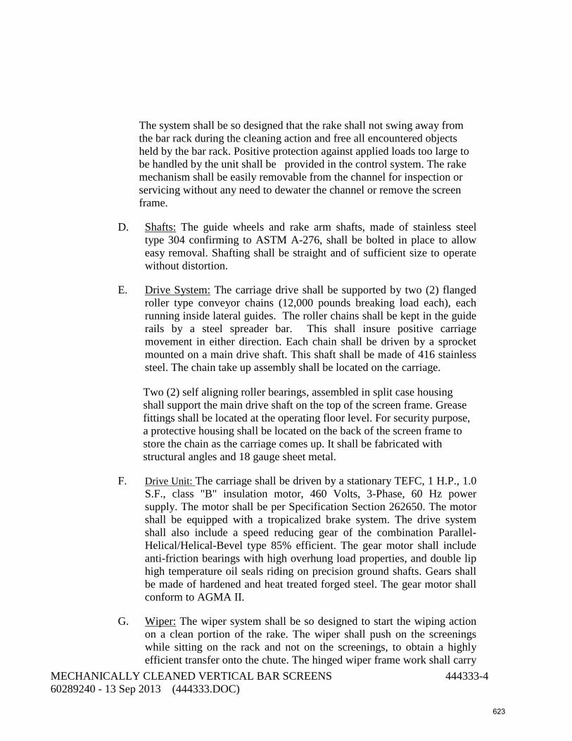
The system shall be so designed that the rake shall not swing away from
the bar rack during the cleaning action and free all encountered objects held by the bar rack. Positive protection against applied loads too large to be handled by the unit shall be provided in the control system. The rake mechanism shall be easily removable from the channel for inspection or servicing without any need to dewater the channel or remove the screen frame.
D. Shafts: The guide wheels and rake arm shafts, made of stainless steel type 304 confirming to ASTM A-276, shall be bolted in place to allow easy removal. Shafting shall be straight and of sufficient size to operate without distortion.
E. Drive System: The carriage drive shall be supported by two (2) flanged roller type conveyor chains (12,000 pounds breaking load each), each running inside lateral guides. The roller chains shall be kept in the guide rails by a steel spreader bar. This shall insure positive carriage movement in either direction. Each chain shall be driven by a sprocket mounted on a main drive shaft. This shaft shall be made of 416 stainless steel. The chain take up assembly shall be located on the carriage.
Two (2) self aligning roller bearings, assembled in split case housing
shall support the main drive shaft on the top of the screen frame. Grease fittings shall be located at the operating floor level. For security purpose, a protective housing shall be located on the back of the screen frame to store the chain as the carriage comes up. It shall be fabricated with structural angles and 18 gauge sheet metal.
F. Drive Unit: The carriage shall be driven by a stationary TEFC, 1 H.P., 1.0 S.F., class "B" insulation motor, 460 Volts, 3-Phase, 60 Hz power supply. The motor shall be per Specification Section 262650. The motor shall be equipped with a tropicalized brake system. The drive system shall also include a speed reducing gear of the combination Parallel-Helical/Helical-Bevel type 85% efficient. The gear motor shall include anti-friction bearings with high overhung load properties, and double lip high temperature oil seals riding on precision ground shafts. Gears shall be made of hardened and heat treated forged steel. The gear motor shall conform to AGMA II.
G. Wiper: The wiper system shall be so designed to start the wiping action on a clean portion of the rake. The wiper shall push on the screenings while sitting on the rack and not on the screenings, to obtain a highly efficient transfer onto the chute. The hinged wiper frame work shall carry
MECHANICALLY CLEANED VERTICAL BAR SCREENS 444333-4 60289240 - 13 Sep 2013 (444333.DOC) 623

a replaceable polyethylene and leather blade. The wiper blade shall terminate its cycle at least 1 1/2" away from the rake teeth.
H. Chute: The chute fabricated of reinforced N° 11 GAUGE metal sheets shall be mounted so as to fall under the rake at a 55° angle, prior to the wiping action. The collected screenings shall discharge off the chute at an elevation of 48” above the operating floor. The rake teeth span a minimum of 4" over the discharge chute.
2.05 MATERIALS OF CONSTRUCTION Concerning part other than the major drive components described before, the materials of construction shall be as follows:
Bar Rack : 304L SS plates and bars Rake : 304L SS plates Rake arm : 304L SS structural tubing and plates Wiper : 304L SS angle, leather & polyethylene Carriage : 304L SS plates Trash Chute : 304L SS stainless steel sheet Structure: Sides (left and right) : 304L SS channels, angles and plates Back : 304L SS plates Base : 304L SS plates Top : 304L SS plates and angles Chain housing frame : 304 SS angles, bars and plates Housing: Front (above chute) : 304L SS sheets Sides (upper level) : 304L SS sheets (left & right) Sides (lower level) : 304L SS sheets (left & right) Chain housing : 304L SS sheets Screws, bolts and anchors : 304L SS Shafts (wheels, rake arm) : 304L SS Wheels : Pe Vo-Lon or equal Conveyor chain : 304 Stainless Steel Sprockets : 304 SS
MECHANICALLY CLEANED VERTICAL BAR SCREENS 444333-5 60289240 - 13 Sep 2013 (444333.DOC) 624

All stainless steel plate, sheet, bars, and shapes shall conform to ASTM A240 or ASTM A276.
2.06 CONTROL PANEL AND CONTROLS
A. Control Panel and controls shall be in accordance with Section 409510. The Screen supplier shall furnish one local control panel complete with all hand switches and local indicators. The bar screen control panel shall also integrate screenings belt conveyor operation and control features. The control panel shall be able to receive or send at least seven input and out alarms to the RTU.
B. Limit Switches: The bar screen shall include the following frame mounted rake travel limit switches:
1. One NEMA 4X Top travel limit stop out of flow switch.
2. One NEMA 4X Bottom travel limit switch
3. One NEMA 4X Over-travel top limit switch.
4. The switches shall meet the applicable restrictions according to the environmental conditions of the installation.
5. All the above switches shall be pre-wired to a 304 SS NEMA 4X terminal junction box located on the side of the screen frame. The inter-connecting wires mounted on the frame shall be located in 304 SS electrical conduit.
C. The rake mechanism shall automatically initiate its cleaning cycle upon receipt of a start signal from the pump controller. The screenings belt conveyor shall also start when rake mechanism starts operation. The rake mechanism shall begin its downward travel after a pause of 3 seconds. During the descent, the rake arm shall be set backward in loaded position.
D. When the bottom switch is reached the motor shall stop. The motor direction shall then be reversed after another 3 second pause. The upward travel shall begin with the rake arm now in normal front position. During the upward travel, the rake shall pass the chute position. The chute shall tilt forward and fall back in the discharge position. Then, the wiper shall clean the rake from its load. At the top, the switch activation shall stop the motor thus ending the cycle. The rake mechanism and screenings belt conveyor stops when all pumps are stopped as signaled by the pump controller.
E. Reversing Memory Relay:
1. The printed board control circuit shall incorporate a 3 Amp (min) latching relay. It shall ensure the proper rake travel direction when
MECHANICALLY CLEANED VERTICAL BAR SCREENS 444333-6 60289240 - 13 Sep 2013 (444333.DOC) 625

the mode selector is on "AUTO" or "MAN. TEST". The latch relay shall memorize the last travel direction prior to a power shutdown.
F. Thermal protection:
1. When the mode selector switch is on "AUTO" or on "MANUAL", this protection circuit shall cut the power off to the motor and to the control circuit of the motor starter should the following conditions occur:
(1) Overheat of the motor;
(2) Short circuiting;
(3) Single phasing.
2. An overload/over-travel indicating light shall be provided. The overload protection shall be sized according to the motor nameplate full load rating. This component shall be equipped with a manual reset and pad-lockable stop button.
G. Jamming protection:
1. A current metering system shall protect the mechanism against jamming. A continuous current reading (CMT) on all phases shall be monitored by an adjustable relay (CMR). The motor starting current being higher than the setting of the CMR, the jamming protection shall be put out of service by a time delay relay (TCM), for a predetermined adjustable motor start period, long enough to allow the current to fall below the CMR setting when it reaches its normal full load level.
2. Should this system be energized, the over-travel/overload light shall be activated. This system shall be reset manually by a push button.
3. When the bypass selector switch is used, the following items shall be ALL OUT OF SERVICE:
(1) jamming protection,
(2) over-travel switch,
(3) timers,
(4) control circuits,
MECHANICALLY CLEANED VERTICAL BAR SCREENS 444333-7 60289240 - 13 Sep 2013 (444333.DOC) 626
4. Power shall be applied directly to the drive unit. Only the thermal overload and travel limit switches shall remain in service.
5. The bypass selector switch shall have a spring return to the AUTO position.
H. Over-travel Protection:
The screen shall be provided with an upper over-travel protection switch. When this switch is activated, the automatic control power shall be cut off and the motor shall stop. The over-travel/overload light shall be activated. This circuit shall be reset by a push button.
I. Control Panel
The following basic components shall be assembled in a NEMA 4X enclosure, pre-wired to identified terminal blocks. Panel hook up and installation shall be made on site by the contractor. The power supply shall be 460 Volts, 3-Phase, 60 Hz. The panel will be located in the electrical room.
1. Main breaker / fuse circuit switch sized for the application with front mounted operating handle and door interlock. 250 VA control transformer with secondary side breaker / fuse protection.
2. Reversing magnetic starter with thermal and magnetic overload protection.
3. Magnetic starter with thermal and magnetic overload protection, relays, timers, control circuitry for the conveyor belt.
4. Printed circuit board, relays and timers to operate the rake mechanism and stop it at the top of the unit after each cycle.
5. Timer: Interval timer shall causes the rake system to go through one complete cleaning cycle at pre-determined adjustable time intervals ranging from 8 to 180 minutes. This timer is only in service as long as the mode selector is in "AUTO".
6. Submersible Level Transmitter: Two submersible level transducers/transmitters shall be provided for each bar screen. One is to measure screen upstream water level. The second one is to measure water level downstream of the bar screen. The upstream and downstream water levels for each bar screen shall be sent to RTU via bar screen control panel. Submersible level transmitter shall be per Section 405020.
MECHANICALLY CLEANED VERTICAL BAR SCREENS 444333-8 60289240 - 13 Sep 2013 (444333.DOC) 627

7. Excessive load and jamming protection device operating through a 3-phase amp monitor control circuit and over-travel limit protection. Rake upper limit over-travel protection circuit.
8. N.O. run and general alarm dry contacts. N.O. dry contact start signal for the compactor.
9. Door mounted MAINTENANCE BYPASS - OFF - AUTOMATIC/MAN. TEST selector switch and MAN. TEST button. The mode selector switch shall provide a cycle test position. When turned and held for a few seconds to the "MANUAL TEST" position, it shall produce a start signal, energizing the mechanism for one cleaning cycle only. This position of the selector shall be spring loaded, so that the selector can return to AUTO position after release.
10. Door mounted alarm relay RESET push button.
11. Door mounted FORWARD-OFF-REVERSE (jog) selector switch for manual bypass operation with spring loaded return to OFF position for maintenance purposes.
12. Status light: "SCREEN-UP", "SCREEN DOWN". Alarm light: OVERTRAVEL/OVERLOAD alarm.
13. Status light: "SCREENINGS BELT CONVEYOR-ON", "SCREENINGS BELT CONVEYOR OFF". Alarm light: GENERAL/MALFUCTION alarm
14. Lamp test: A common lamp test circuit with single push to test button shall be provided.
15. Elapsed Time Meter: This meter shall record the total time the drive unit has been in operation.
16. Ammeter: This single phase meter shall indicate the motor current drawn. It shall be provided with a range of 0 to 5 Amp.
17. Heater & Thermostat: The control panel shall include a 60 W space heater with thermostat to eliminate the formation of condensation, increase the life of the control components and ensure the best operating efficiency.
18. Provide upstream and downstream level inputs to RTU unit for monitoring.
19. Provide a door mounted Hand-Off-Auto selector switch for the conveyor belt. In the Auto position, the conveyor shall automatically start when a bar screen is called to run; provide a time delayed stop after bar screen stop. Provide “Running” and “Stop” door mounted lights. Provide a motor overload, over torque, and zero speed lights and reset button.
MECHANICALLY CLEANED VERTICAL BAR SCREENS 444333-9 60289240 - 13 Sep 2013 (444333.DOC) 628

2.07 ANCHORAGE AND SUPPORTS
Design support legs, anchors, anchor bolts, and other structural elements per the following requirements:
A. Design the anchorage system and lifting system per the Florida Building Code 2010:
1. Ultimate Wind Velocity, mph: 180.
2. Risk Category: III.
3. Exposure Category: C
B. An unreinforced concrete housekeeping pad above the reinforced concrete structural slab shall not be considered to have structural value in the design of the anchor bolts. Tension and shear values for drilled or epoxied anchor shall be FBC approved.
C. Anchor Bolts – Provide Type 316 stainless steel anchor bolts, nuts, and washers; wedge anchor bolt shall be Kwik Bolt TZ or equal.
2.08 AUTOMATIC LUBRICATION SYSTEM
A. Screen manufacturer shall provide two (2) centralized lubrication system for all lubrication for each vertical screen, one for the chains and one for the bearings. The lubrication system shall be manufactured by SKF Model KFGS or approved equal. The lubrication system shall include 316 SST flexible supply lines, nozzle or brush applicators for chains, and 120VAC NEMA 4X stainless steel control panel. Screen manufacturer shall determine the pump capacity and number of application points.
B. Provide dry contacts for a general fault alarm.
C. Mount automatic lubrication system adjacent to screens with 304 SST unistrut.
2.09 MACHINERY LUBRICATION
A. Grease and/or oil in contact with water shall be food grade lubrication and be NSF H1 registered.
2.10 SPARE PARTS
B. Provide the following spare parts for each size or model of screen:
MECHANICALLY CLEANED VERTICAL BAR SCREENS 444333-10 60289240 - 13 Sep 2013 (444333.DOC) 629

Quantity Description 10 Complete chain links 2 Limit switches 2 Wiper blades
18 of each size Snap rings (sizes 3/4 inch and smaller) 8 of each size Snap rings (sizes larger than 63/64 inch)
2 Shaft bearings 2 Rake wheels 4 Carriage wheels 8 Guide bearings
C. Pack the spare parts in a wooden box; label with the manufacturer's name and local representative's name, address, and telephone number; and attach list of materials contained therein.
2.11 FACTORY TESTING
A. An Owner and Engineer witnessed shop testing of the actual screens at the manufacturer's plant shall be performed to determine acceptability of the screens and be included in the manufacturing cost. The screens shall be tested for: general operation of the bar cleaning mechanisms, operation of the excessive load and jamming protection device, complete control panel operation, with indicator lights, timers, selection switches, tester, and auto lubrication systems. Screens will also be evaluated for conformance to materials specifications and other requirements of the Contract Documents. Tests shall be conducted in accordance with the test codes of the ASME and the IEEE.
B. The results of the shop tests shall be considered official and conclusive for the purpose of determining whether or not the equipment is in accordance with the performance requirements as specified.
C. No such equipment shall be shipped to the work until the Owner notifies the Contractor in writing that the results of such tests are acceptable. When the Detailed Specifications required witnessed shop tests at the point of manufacture, or other approved facility, the only tests which will be accepted are those made in the presence of the Owner or his representative.
D. The Contractor shall notify the Owner in writing forty-five consecutive calendar days in advance of the time when the equipment will be ready for witness shop tests or for required inspections. This notification shall
MECHANICALLY CLEANED VERTICAL BAR SCREENS 444333-11 60289240 - 13 Sep 2013 (444333.DOC) 630

include the following information which will be subject to the approval of the Owner and Engineer: 1. A diagram of the proposed testing arrangement. 2. A description of the proposed manufacturer's inspection and
testing facilities and procedures. 3. A list of all instruments and manufacturer proposes to use for
the tests with initial and last calibration reports certified by an approved independent testing laboratory. (All instruments shall be of ranges suitable for the quantities to be measured.)
4. Sample test data sheets. 5. Sample calculations. 6. Descriptive matter on the testing equipment which shall contain
illustrative photographs, drawings, and such other matter as may be requested by the Owner and Engineer.
E. Should the equipment or instrumentation not be ready, as per prior submitted approved data, the witness will return to the home office. The cost of the additional trip will be borne by the Contractor or manufacturer.
F. Six copies of inspection and shop test data and interpreted results thereof accompanied by a certificate of authenticity sworn to, before a notary, by an officer of the manufacturing company shall be forwarded to the Owner for review and approval as required.
G. The Contractor shall, for one representative of the Owner, be responsible for the costs of all transportation, lodging and miscellaneous travel expenses for each witness shop test or inspection required by the Contract Documents. These costs shall be included in his total bid price for the Contract. The Contractor shall make all travel, lodging and local transportation arrangements and pay such expenses directly, in advance. Contractor shall also reimburse City for the costs of all meals associated with the witness shop test, upon presentation of receipts for same.
H. If a retest is required, the cost shall be borne by the Contractor.
I. All equipment and material to be witness shop tested shall be identified with serial numbers and/or approved permanent type identification marks.
PART 3 - EXECUTION
3.01 INSTALLATION
A. Install per manufacturer’s instructions.
MECHANICALLY CLEANED VERTICAL BAR SCREENS 444333-12 60289240 - 13 Sep 2013 (444333.DOC) 631

3.02 PAINTING AND COATING
A. Coat submerged metal and metal under the concrete deck per Section 099000, System No. 1. Do not coat stainless steel.
B. Coat ferrous metal above the concrete deck per Section 099000, System No. 10. Apply prime coat at factory. Color finish coat shall be light gray.
3.03 SERVICE CONDITIONS
The design criteria for the screens shall be as follows:
Peak design flow (clear water): 21,000 gpm Head loss at peak design flow, 50% blinded (clear water): 9 inches Channel width: 54 inches Channel depth (invert to top of deck): 19’-10”* Lift from invert to discharge point: 23’-5”* Maximum downstream water depth: 14’-10” Minimum downstream water depth: 8’- 4” Screen opening: 1 inch Bar height 180 inches Angle of screen inclination from horizontal: Vertical Motor type (per Section 262650): 4AEM Motor horsepower (minimum): 1 H.P. Motor Voltage 460, 3 phase Liquid screened: Stormwater
* Contractor shall confirm dimensions prior to ordering equipment.
3.04 FIELD TESTING
Operate each bar screen for 30 consecutive days and adjust the equipment. Assure that the automatic sequencing and control system interconnecting the screens, conveyors, and other equipment are functioning correctly. Each day, during this 30-day period, start the screen system and demonstrate that the system functions as designed. Assure that gear reducers operate without binding or sticking. Assure that components within the screens are aligned so that screen teeth are not damaged during operation.
3.05 LABELING AND MARKING
Provide a tag bearing the tag number for the unit. See Section 400775.
3.06 CONTRACT CLOSEOUT
MECHANICALLY CLEANED VERTICAL BAR SCREENS 444333-13 60289240 - 13 Sep 2013 (444333.DOC) 632

Provide in accordance with Section 017000.
3.07 WARRANTY
The equipment shall be warranted for four (4) years commencing from date of substantial completion.
3.08 CERTIFICATION
A. Provide a written certification from the equipment manufacturer that each pumping system has been properly installed according to the Contract Documents and the manufacturer’s recommendations, and that the equipment is operating normally. Make all necessary corrections and adjustments including but not limited to parts, labor, or freight at no additional cost to the Owner.
B. Screen manufacturers service technician shall verify that the vertical and horizontal alignment on the screen frame is within manufacturer’s tolerance above and below the wet well floor of no more than 0.002” per foot. Alignment shall be verified using a plumb bob for vertical alignment check. Certificate of proper installation must be signed by the screen manufacturer before startup can occur.
END OF SECTION
MECHANICALLY CLEANED VERTICAL BAR SCREENS 444333-14 60289240 - 13 Sep 2013 (444333.DOC) 633