Invitation-to-Bid-for-the-Procurement-of-Various-Catering ...
Upload
khangminh22Category
view
1download
0
1
Invitation to Bid Design & Build of 20m³/d Septage Treatment Plant for Carmona Water District at Mayor’s Boulevard,
Brgy. Maduya, Carmona, Cavite
BIDDING DOCUMENTS
CWD-ENG-BID-2021-001
January 2021

TABLE OF CONTENTS
Section I. Invitation to Bid ................................................................................................................................. 4
Section II. Instructions to Bidders ...................................................................................................................... 6
1. Scope of Bids ........................................................................................................................................ 6
2. Funding Information ............................................................................................................................ 6
3. Bidding Requirements .......................................................................................................................... 6
4. Corrupt, Fraudulent, Collusive, Coercive, and Obstructive Practices ................................................... 6
5. Eligible Bidders ..................................................................................................................................... 7
6. Origin of Goods and Services................................................................................................................ 7
7. Subcontracts ........................................................................................................................................ 7
a. Subcontracting is not allowed. ............................................................................................................. 7
9. Clarification and Amendment of Bidding Documents .......................................................................... 7
10. Documents Comprising the Bid: Eligibility and Technical Components................................................ 8
11. Documents Comprising the Bid: Financial Component ........................................................................ 8
12. Alternative Bids .................................................................................................................................... 9
13. Bid Prices .............................................................................................................................................. 9
14. Bid and Payment Currencies ................................................................................................................ 9
15. Bid Security .......................................................................................................................................... 9
16. Sealing and Marking of Bids ................................................................................................................. 9
17. Deadline for Submission of Bids ......................................................................................................... 10
18. Opening and Preliminary Examination of Bids ................................................................................... 10
19. Detailed Evaluation and Comparison of Bids ..................................................................................... 10
20. Post Qualification ............................................................................................................................... 10
21. Signing of the Contract ....................................................................................................................... 11
SECTION III. BID DATA SHEET ................................................................................................. 12
SECTION IV. GENERAL CONDITIONS OF CONTRACT ......................................................... 15
1. Scope of Contract ............................................................................................................................... 15
2. Sectional Completion of Works .......................................................................................................... 15
2
3. Possession of Site ............................................................................................................................... 15
5. Performance Security ......................................................................................................................... 16
6. Site Investigation Reports .................................................................................................................. 16
8. Liability of the Contractor .................................................................................................................. 16
9. Termination for Other Causes ............................................................................................................ 16
11. Program of Work ................................................................................................................................ 17
12. Instructions, Inspections and Audits .................................................................................................. 17
13. Advance Payment .............................................................................................................................. 17
14. Progress Payments ............................................................................................................................. 17
15. Operating and Maintenance Manuals ................................................................................................ 18
SECTION V. SPECIAL CONDITIONS OF CONTRACT ............................................................ 19
SECTION VI. TECHNICAL SPECIFICATIONS............................................................................. 21
SECTION VII. DRAWINGS ........................................................................................................... 55
SECTION VIII. BILL OF QUANTITIES ........................................................................................ 59
SECTION IX. CHECKLIST OF TECHNICAL AND FINANCIAL DOCUMENTS .................... 66
3

4
Section I. Invitation to Bid
Invitation to Bid for the Design & Build of 20m³/d Septage Treatment Plant for
Carmona Water District at Mayor’s Boulevard, Brgy. Maduya, Carmona, Cavite
1. Carmona Water District, through the Corporate Budget Approved by the Board for FY 2021 intends to apply the sum of Forty Five Million Pesos & 00/100 (PHP 45,000,000.00) being the Approved Budget for the Contract (ABC) to payments under the contract for CWD-ENG-BID-2021-001 - Design and Build of 20m³/d Septage Treatment Plant for Carmona Water District at Mayor’s Boulevard, Brgy. Maduya, Carmona, Cavite. Bids received in excess of the ABC shall be automatically rejected at bid opening.
2. Carmona Water District now invites bids for the above Procurement Project.
Completion of the Works is required Three Hundred Sixty Five (365) calendar days. Bidders should have completed a contract similar to the Project. The description of an eligible bidder is contained in the Bidding Documents, particularly, in Section II (Instructions to Bidders)
3. Bidding will be conducted through open competitive bidding procedures using non-
discretionary “pass/fail” criterion as specified in the 2016 Revised Implementing Rules and Regulations (IRR) of Republic Act 9184 (RA 9184).
Bidding is restricted to Filipino citizens/sole proprietorships, partnerships, or organizations with at least sixty percent (60%) interest or outstanding capital stock belonging to citizens of the Philippines, and to citizens or organizations of a country the laws or regulations of which grant similar rights or privileges to Filipino citizens, pursuant to RA No. 5183.
4. Interested bidders may obtain further information from Carmona Water District and
inspect the Bidding Documents at the address given below from 8:00 a.m. to 5:00 p.m. except holidays.
5. A complete set of Bidding Documents may be acquired by interested bidders on
November 20, 2020 to December 14, 2020 from the address below and website(s) below and upon payment of the applicable fee for the Bidding Documents, pursuant to the latest Guidelines issued by the GPPB, in the amount of Twenty Five Thousand Pesos & 00/100 (Php 25,000.00).
A. Carmona Water District
B8 L8 Joy St. Cityland Subdivision Mabuhay, Carmona, Cavite 4116 Website: carmonawd.gov.ph

B. PhilGEPS website
Carmona Water District shall allow the bidder to present its proof of payment for the fees through emailing a copy of the official receipt at [email protected] or [email protected] or presentation of the official receipt in person.
6. The Carmona Water District will hold a Pre-Bid Conference on November 27, 2020 @ 2:00 p.m. at Block 8, Lot 8, Joy St., Cityland Subdivision, Brgy. Mabuhay, Carmona, Cavite, or if applicable through videoconferencing/webcasting, which shall be open to prospective bidders.
7. Bids must be duly received by the BAC Secretariat at the address below on or
before December 14, 2020 at 2:00 PM. Late bids shall not be accepted. Carmona Water District
B8 L8 Joy St. Cityland Subdivision Mabuhay, Carmona, Cavite 4116
8. All bids must be accompanied by a bid security in any of the acceptable forms and
in the amount stated in ITB Clause 15.
9. Bid opening shall be on December 14, 2020 2:00 PM at Carmona Water District Office, Block 8, Lot 8, Joy St., Cityland Subdivision, Brgy. Mabuhay, Carmona, Cavite. Bids will be opened in the presence of the bidders’ representatives who choose to attend the activity.
10. The Carmona Water District reserves the right to reject any and all bids, declare
a failure of bidding, or not award the contract at any time prior to contract award in accordance with Sections 35.6 and 41 of the 2016 revised Implementing Rules and Regulations (IRR) of RA No. 9184, without thereby incurring any liability to the affected bidder or bidders.
11. For further information, please refer to:
ERICK JEFFEN O. ESTRELLA BAC Secretariat Bids and Awards Committee Carmona Water District
B8 L8 Joy St. Cityland Subdivision Mabuhay, Carmona, Cavite 4116
Tel. No. (046) 430-0832, Fax No. (046) 430-1705 [email protected] [email protected]
MS. ROCELISA G. MAULANIN BAC Chairman
5

Section II. Instructions to Bidders
1. Scope of Bids
1.1 Carmona Water District invites bids for the construction of works Design & Build of 20m³/d Septage Treatment Plant for Carmona Water District at Mayor’s Boulevard, Brgy. Maduya, Carmona, Cavite with Project Identification Number CWD-BID-ENG-2001-001.
1.2 The Procurement Project (referred to herein as “Project”) is for the construction of Works, as described in Section VI (Specifications).
2. Funding Information
2.1 The GOP through the proposed Corporate Operating Budget for FY 2021 in the amount of Forty Five Million Pesos & 00/100 (Php45,000,000.00).
3. Bidding Requirements
3.1 The Bidding for the Project shall be governed by all the provisions of RA No. 9184 and its 2016 revised IRR, including its Generic Procurement Manual and associated policies, rules and regulations as the primary source thereof, while the herein clauses shall serve as the secondary source thereof.
3.2 Any amendments made to the IRR and other GPPB issuances shall be applicable only to the ongoing posting, advertisement, or invitation to bid by the BAC through the issuance of a supplemental or bid bulletin.
3.3 The Bidder, by the act of submitting its Bid, shall be deemed to have inspected the site, determined the general characteristics of the contracted Works and the conditions for this Project, such as the location and the nature of the work; (b) climatic conditions; (c) transportation facilities; (c) nature and condition of the terrain, geological conditions at the site communication facilities, requirements, location and availability of construction aggregates and other materials, labor, water, electric power and access roads; and (d) other factors that may affect the cost, duration and execution or implementation of the contract, project, or work and examine all instructions, forms, terms, and project requirements in the Bidding Documents.
4. Corrupt, Fraudulent, Collusive, Coercive, and Obstructive
Practices 4.1 The Procuring Entity, as well as the Bidders and Contractors, shall observe the
highest standard of ethics during the procurement and execution of the contract. They or through an agent shall not engage in corrupt, fraudulent, collusive, coercive, and obstructive practices defined under Annex “I” of the 2016 revised IRR of RA No. 9184 or other integrity violations in competing for the Project.
6

5. Eligible Bidders 5.1 Only Bids of Bidders found to be legally, technically, and financially capable
will be evaluated.
5.2 The Bidder must have an experience of having completed a Single Largest Completed Contract (SLCC) that is similar to this Project, equivalent to at least fifty percent (50%) of the ABC adjusted, if necessary, by the Bidder to current prices using the PSA’s CPI, except under conditions provided for in Section 23.4.2.4 of the 2016 revised IRR of RA No. 9184.
5.3 A contract is considered to be “similar” to the contract to be bid if it has the major categories of work stated in the BDS.
5.4 For Foreign-funded Procurement, the Procuring Entity and the foreign government/foreign or international financing institution may agree on another track record requirement, as specified in the Bidding Document prepared for this purpose.
5.5 The Bidders shall comply with the eligibility criteria under Section 23.4.2 of the 2016 IRR of RA No. 9184.
6. Origin of Goods and Services 6.1 There is no restriction on the origin of Goods other than those prohibited by a
decision of the UN Security Council taken under Chapter VII of the Charter of the UN.
7. Subcontracts
7.1 The Bidder may subcontract portions of the Project to the extent allowed by
the Procuring Entity as stated herein, but in no case more than fifty percent (50%) of the Project. The Procuring Entity has prescribed that:
a. Subcontracting is not allowed.
8. Pre-Bid Conference
8.1 The Procuring Entity will hold a pre-bid conference for this Project on
November 27, 2020 @ 2:00 p.m. at Block 8, Lot 8, Joy St., Cityland Subdivision, Brgy. Mabuhay, Carmona, Cavite, and/or through videoconferencing/webcasting if applicable, as indicated in paragraph 6 of the IB.
9. Clarification and Amendment of Bidding Documents 9.1 Prospective bidders may request for clarification on and/or interpretation of
any part of the Bidding Documents. Such requests must be in writing and received by the Procuring Entity, either at its given address or through
7

electronic mail indicated in the IB, at least ten (10) calendar days before the deadline set for the submission and receipt of Bids.
10. Documents Comprising the Bid: Eligibility andTechnical Components
10.1 The first envelope shall contain the eligibility and technical documents of the
Bid as specified in Section IX. Checklist of Technical and Financial Documents.
10.1.1 If the eligibility requirements or statements, the bids, and all
other documents for submission to the BAC are in foreign language other than English, it must be accompanied by a translation in English, which shall be authenticated by the appropriate Philippine foreign service establishment, post, or the equivalent office having jurisdiction over the foreign bidder’s affairs in the Philippines. For Contracting Parties to the Apostille Convention, only the translated documents shall be authenticated through an apostille pursuant to GPPB Resolution No. 13-2019 dated 23 May 2019. The English translation shall govern, for purposes of interpretation of the bid.
10.1.2 A valid PCAB License is required, and in case of joint
ventures, a valid special PCAB License, and registration for the type and cost of the contract for this Project. Any additional type of Contractor license or permit shall be indicated in the BDS.
10.1.3 A List of Contractor’s key personnel (e.g., Project Manager,
Project Engineers, Materials Engineers, and Foremen) assigned to the contract to be bid, with their complete qualification and experience data shall be provided. These key personnel must meet the required minimum years of experience set in the BDS.
10.1.4 A List of Contractor’s major equipment units, which are owned, leased, and/or under purchase agreements, supported by proof of ownership, certification of availability of equipment from the equipment lessor/vendor for the duration of the project, as the case may be, must meet the minimum requirements for the contract set in the BDS.
10.1.5 Preliminary Conceptual Design Plans in accordance with the degree of details specified by the procuring entity (refer to Bid Data Sheet)
10.1.6 Design and Construction Methods ( in narrative form)
11. Documents Comprising the Bid: Financial Component
8
11.1 The second bid envelope shall contain the financial documents for the Bid as specified in Section IX. Checklist of Technical and Financial Documents.
11.2 Any bid exceeding the ABC indicated in paragraph 1 of the IB shall not be
accepted.
11.3 For Foreign-funded procurement, a ceiling may be applied to bid prices provided the conditions are met under Section 31.2 of the 2016 revised IRR of RA No. 9184.
12. Alternative Bids
12.1 Bidders shall submit offers that comply with the requirements of the Bidding
Documents, including the basic technical design as indicated in the drawings and specifications. Unless there is a value engineering clause in the BDS, alternative Bids shall not be accepted.
13. Bid Prices
13.1 All bid prices for the given scope of work in the Project as awarded shall be
considered as fixed prices, and therefore not subject to price escalation during contract implementation, except under extraordinary circumstances as determined by the NEDA and approved by the GPPB pursuant to the revised Guidelines for Contract Price Escalation guidelines.
14. Bid and Payment Currencies
14.1 Bid prices may be quoted in the local currency or tradable currency accepted
by the BSP at the discretion of the Bidder. However, for purposes of bid evaluation, Bids denominated in foreign currencies shall be converted to Philippine currency based on the exchange rate as published in the BSP reference rate bulletin on the day of the bid opening.
14.2 Payment of the Price shall be made in Philippine Pesos.
15. Bid Security
15.1 The Bidder shall submit a Bid Securing Declaration or any form of Bid
Security in the amount indicated in the BDS, which shall be not less than the percentage of the ABC in accordance with the schedule in the BDS.
15.2 The Bid and bid security shall be valid until 120 days from opening of bids.
Any bid not accompanied by an acceptable bid security shall be rejected by the Procuring Entity as non-responsive.
16. Sealing and Marking of Bids 16.1 Bidder shall submit one copy of the first and second components of its Bid.
9

16.2 The Procuring Entity may request additional hard copies and/or electronic copies of the Bid. However, failure of the Bidders to comply with the said request shall not be a ground for disqualification.
16.3 If the Procuring Entity allows the submission of bids through online submission to the given website or any other electronic means, the Bidder shall submit an electronic copy of its Bid, which must be digitally signed. An electronic copy that cannot be opened or is corrupted shall be considered non-responsive and, thus, automatically disqualified.
17. Deadline for Submission of Bids
17.1 The Bidders shall submit on the specified date and time and either at its
physical address or through online submission as indicated in paragraph 7 of the IB.
18. Opening and Preliminary Examination of Bids
18.1 The BAC shall open the Bids in public at the time, on the date, and at the
place specified in paragraph 9 of the IB. The Bidders’ representatives who are present shall sign a register evidencing their attendance. In case videoconferencing, webcasting or other similar technologies will be used, attendance of participants shall likewise be recorded by the BAC Secretariat.
18.2 In case the Bids cannot be opened as scheduled due to justifiable reasons, the
rescheduling requirements under Section 29 of the 2016 revised IRR of RA No. 9184 shall prevail.
19. Detailed Evaluation and Comparison of Bids
19.1 The Procuring Entity’s BAC shall immediately conduct a detailed evaluation
of all Bids rated “passed” using non-discretionary pass/fail criteria. The BAC shall consider the conditions in the evaluation of Bids under Section 32.2 of 2016 revised IRR of RA No. 9184.
19.2 If the Project allows partial bids, all Bids and combinations of Bids as
indicated in the BDS shall be received by the same deadline and opened and evaluated simultaneously so as to determine the Bid or combination of Bids offering the lowest calculated cost to the Procuring Entity. Bid Security as required by ITB Clause 15 shall be submitted for each contract (lot) separately.
19.3 In all cases, the NFCC computation pursuant to Section 23.4.2.6 of the 2016 revised IRR of RA No. 9184 must be sufficient for the total of the ABCs for all the lots participated in by the prospective Bidder.
20. Post Qualification
20.1 Within a non-extendible period of five (5) calendar days from receipt by the
10

Bidder of the notice from the BAC that it submitted the Lowest Calculated Bid, the Bidder shall submit its latest income and business tax returns filed and paid through the BIR Electronic Filing and Payment System (eFPS), and other appropriate licenses and permits required by law and stated in the BDS.
21. Signing of the Contract
21.1 The documents required in Section 37.2 of the 2016 revised IRR of RA No.
9184 shall form part of the Contract. Additional Contract documents are indicated in the BDS.
11
Section III. Bid Data Sheet
ITB Clause
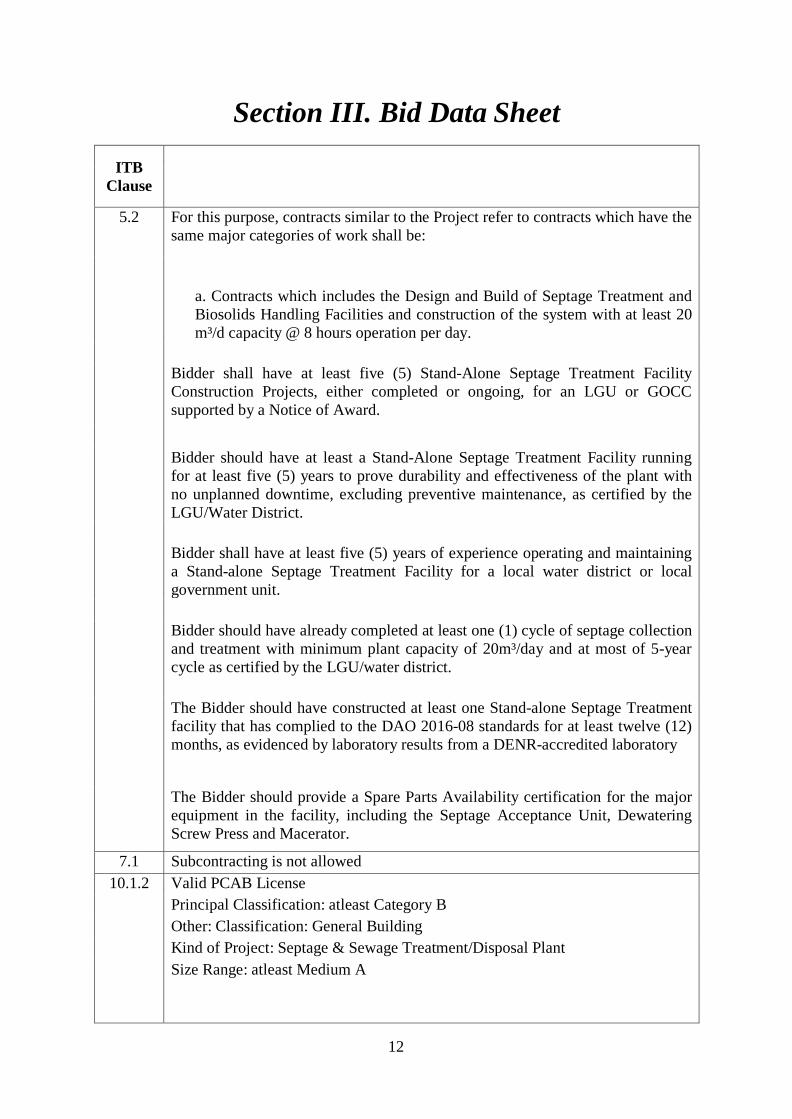
5.2 For this purpose, contracts similar to the Project refer to contracts which have the
same major categories of work shall be:
a. Contracts which includes the Design and Build of Septage Treatment and Biosolids Handling Facilities and construction of the system with at least 20 m³/d capacity @ 8 hours operation per day.
Bidder shall have at least five (5) Stand-Alone Septage Treatment Facility Construction Projects, either completed or ongoing, for an LGU or GOCC supported by a Notice of Award. Bidder should have at least a Stand-Alone Septage Treatment Facility running for at least five (5) years to prove durability and effectiveness of the plant with no unplanned downtime, excluding preventive maintenance, as certified by the LGU/Water District. Bidder shall have at least five (5) years of experience operating and maintaining a Stand-alone Septage Treatment Facility for a local water district or local government unit. Bidder should have already completed at least one (1) cycle of septage collection and treatment with minimum plant capacity of 20m³/day and at most of 5-year cycle as certified by the LGU/water district. The Bidder should have constructed at least one Stand-alone Septage Treatment facility that has complied to the DAO 2016-08 standards for at least twelve (12) months, as evidenced by laboratory results from a DENR-accredited laboratory
The Bidder should provide a Spare Parts Availability certification for the major equipment in the facility, including the Septage Acceptance Unit, Dewatering Screw Press and Macerator.
7.1 Subcontracting is not allowed 10.1.2 Valid PCAB License
Principal Classification: atleast Category B Other: Classification: General Building Kind of Project: Septage & Sewage Treatment/Disposal Plant Size Range: atleast Medium A
12

ITB Clause
10.1.3 The key personnel must meet the required minimum years of experience set
below: Key Personnel General Experience Project Manager/Engineer Project Engineer/Architect Electrical Engineer Mechanical Engineer Sanitary Engineer Foreman Safety Officer
10.1.5 The following technical documents shall also be submitted: Project Brief, comprehensively describing the Preliminary Conceptual Design Plans of the Septage Treatment Facility to be use including the process flow chart such as collection, acceptance, treatment and disposal. The Plant Lay Out showing the location of the Septage Treatment Plant including the area for the laboratory room, storage room, control room, power house and washing bay/motor pool (in size A3).
10.1.6 Design and construction methods NOTE: Emphasis shall be made on the construction methods that best befit the cost and compressed duration of the project. Additional documents to include: Design and Construction Methods (in PERT/CPM, Gantt Chart and S-Curve formats Design and Construction Schedule (in Gantt Chart and S-Curve format in size A3)
15.1 The bid security shall be in the form of a Bid Securing Declaration or any of the following forms and amounts:
1. The amount of not less than Nine Hundred Thousand Pesos and 00/100 (Php900,000.00) (2% of ABC), if bid security is in cash, cashier’s/manager’s check, bank draft/guarantee or irrevocable letter of credit;
2. The amount of not less than Two Million Two Hundred Fifty Thousand Pesos and 00/100 (Php2,250,000.00) (5% of ABC), if bid security is in Surety Bond.
13

16.2 Bidders shall submit one (1) electronic copy of the bid documents (scanned) in a USB sealed in an envelope.
19.2 Partial bid is not allowed. The infrastructure project is packaged in a single lot and the lot shall not be divided into sub-lots for the purpose of bidding, evaluation, and contract award.
20 Only tax returns filed and taxes paid through the BIR Electronic Filing and Payment System (EFPS) shall be accepted.
Note: The latest income and business tax returns are those within the last six months preceding the date of bid submission.
21 The winning bidder shall submit within ten (10) days from the receipt of Notice of Award (NOA) additional contract documents relevant to the Project such as: 1. Two copies of duly signed GANTT Chart with Cash Flow and S-curve; 2. Two copies of duly signed PERT/CPM;
3. 2- copies of duly signed List of Manpower with Manpower Deployment Schedule;
4. 2- copies of duly signed List of Equipment with Equipment Utilization Schedule;
5. 2- copies of duly signed Design and Construction Methodology in narrative form;
6. 2- copies of Construction Safety and Health Program approved by the DOLE;
7. Contractor's All Risk Insurance Policy.
14

Section IV. General Conditions of Contract
1. Scope of Contract 1.1 This Contract shall include all such items, although not specifically
mentioned, that can be reasonably inferred as being required for its completion as if such items were expressly mentioned herein. All the provisions of RA No. 9184 and its 2016 revised IRR, including the Generic Procurement Manual, and associated issuances, constitute the primary source for the terms and conditions of the Contract, and thus, applicable in contract implementation. Herein clauses shall serve as the secondary source for the terms and conditions of the Contract.
1.2 This is without prejudice to Sections 74.1 and 74.2 of the 2016 revised IRR of
RA No. 9184 allowing the GPPB to amend the IRR, which shall be applied to all procurement activities, the advertisement, posting, or invitation of which were issued after the effectivity of the said amendment.
2. Sectional Completion of Works
2.1 If sectional completion is specified in the Special Conditions of Contract
(SCC), references in the Conditions of Contract to the Works, the Completion Date, and the Intended Completion Date shall apply to any Section of the Works (other than references to the Completion Date and Intended Completion Date for the whole of the Works).
3. Possession of Site
3.1 The Procuring Entity shall give possession of all or parts of the Site to the
Contractor based on the schedule of delivery indicated in the SCC, which corresponds to the execution of the Works. If the Contractor suffers delay or incurs cost from failure on the part of the Procuring Entity to give possession in accordance with the terms of this clause, the Procuring Entity’s Representative shall give the Contractor a Contract Time Extension and certify such sum as fair to cover the cost incurred, which sum shall be paid by Procuring Entity.
3.2 If possession of a portion is not given by the above date, the Procuring Entity
will be deemed to have delayed the start of the relevant activities. The resulting adjustments in contract time to address such delay may be addressed through contract extension provided under Annex “E” of the 2016 revised IRR of RA No. 9184.
4. The Contractor’s Obligations
4.1 The Contractor shall employ the key personnel named in the Schedule of Key
Personnel indicating their designation, in accordance with ITB Clause 10.3 and specified in the BDS, to carry out the supervision of the Works.
15

4.2 The Procuring Entity will approve any proposed replacement of key personnel only if their relevant qualifications and abilities are equal to or better than those of the personnel listed in the Schedule.
5. Performance Security
5.1 Within ten (10) calendar days from receipt of the Notice of Award from the Procuring Entity but in no case later than the signing of the contract by both parties, the successful Bidder shall furnish the performance security in any of the forms prescribed in Section 39 of the 2016 revised IRR.
5.2 The Contractor, by entering into the Contract with the Procuring Entity,
acknowledges the right of the Procuring Entity to institute action pursuant to RA No. 3688 against any subcontractor be they an individual, firm, partnership, corporation, or association supplying the Contractor with labor, materials and/or equipment for the performance of this Contract.
6. Site Investigation Reports
6.1 The Contractor, in preparing the Bid, shall rely on any Site Investigation
Reports referred to in the SCC supplemented by any information obtained by the Contractor.
7. Warranty
7.1 In case the Contractor fails to undertake the repair works under Section 62.2.2
of the 2016 revised IRR, the Procuring Entity shall forfeit its performance security, subject its property(ies) to attachment or garnishment proceedings, and perpetually disqualify it from participating in any public bidding. All payables of the GOP in his favor shall be offset to recover the costs.
7.2 The warranty against Structural Defects/Failures, except that occasioned-on
force majeure, shall cover the period from the date of issuance of the Certificate of Final Acceptance by the Procuring Entity. Specific duration of the warranty is found in the SCC.
8. Liability of the Contractor
8.1 Subject to additional provisions, if any, set forth in the SCC, the Contractor’s
liability under this Contract shall be as provided by the laws of the Republic of the Philippines.
8.2 If the Contractor is a joint venture, all partners to the joint venture shall be
jointly and severally liable to the Procuring Entity.
9. Termination for Other Causes 4.1 Contract termination shall be initiated in case it is determined prima facie by
the Procuring Entity that the Contractor has engaged, before, or during the implementation of the contract, in unlawful deeds and behaviors relative to
16

contract acquisition and implementation, such as, but not limited to corrupt, fraudulent, collusive, coercive, and obstructive practices as stated in ITB Clause 4.
10. Dayworks 10.1 Subject to the guidelines on Variation Order in Annex “E” of the 2016 revised
IRR of RA No. 9184, and if applicable as indicated in the SCC, the Dayworks rates in the Contractor’s Bid shall be used for small additional amounts of work only when the Procuring Entity’s Representative has given written instructions in advance for additional work to be paid for in that way.
11. Program of Work
11.1 The Contractor shall submit to the Procuring Entity’s Representative for
approval the said Program of Work showing the general methods, arrangements, order, and timing for all the activities in the Works. The submissions of the Program of Work are indicated in the SCC.
11.2 The Contractor shall submit to the Procuring Entity’s Representative for
approval an updated Program of Work at intervals no longer than the period stated in the SCC. If the Contractor does not submit an updated Program of Work within this period, the Procuring Entity’s Representative may withhold the amount stated in the SCC from the next payment certificate and continue to withhold this amount until the next payment after the date on which the overdue Program of Work has been submitted.
12. Instructions, Inspections and Audits
12.1 The Contractor shall permit the GOP or the Procuring Entity to inspect the
Contractor’s accounts and records relating to the performance of the Contractor and to have them audited by auditors of the GOP or the Procuring Entity, as may be required.
13. Advance Payment
13.1 The Procuring Entity shall, upon a written request of the Contractor which
shall be submitted as a Contract document, make an advance payment to the Contractor in an amount not exceeding fifteen percent (15%) of the total contract price, to be made in lump sum, or at the most two installments according to a schedule specified in the SCC, subject to the requirements in Annex “E” of the 2016 revised IRR of RA No. 9184.
14. Progress Payments
14.1 The Contractor may submit a request for payment for Work accomplished.
Such requests for payment shall be verified and certified by the Procuring Entity’s Representative/Project Engineer. Except as otherwise stipulated in the SCC, materials and equipment delivered on the site but not completely
17

put in place shall not be included for payment. 15. Operating and Maintenance Manuals
15.1 If required, the Contractor will provide “as built” Drawings and/or operating
and maintenance manuals as specified in the SCC. 15.2 If the Contractor does not provide the Drawings and/or manuals by the dates
stated above, or they do not receive the Procuring Entity’s Representative’s approval, the Procuring Entity’s Representative may withhold the amount stated in the SCC from payments due to the Contractor.
18

Section V. Special Conditions of Contract
GCC Clause
1.1 The Intended Completion Date is within three hundred sixty five (365) calendar days which will commence within seven calendar days from receipt of the Notice to Proceed. The Works shall be those that are stated in Section VI. Technical Specifications. The Works consist of the provision of a detailed preliminary engineering design, detailed engineering requirements, actual construction, testing and commissioning and process proving of the Septage Treatment Plant based on the final detailed engineering design, to be reviewed by the Technical Working Group (TWG) / Design and Build Committee (DBC) and to be approved by HOPE conformably with the minimum standards set forth in the National Building Code of the Philippines, Fire Code of the Philippines, Electric Code of the Philippines, Mechanical Code of the Philippines, Sanitary/Plumbing Code of the Philippines, LLDA standards, DENR standards and applicable local regulations and ordinances. The contractor shall be responsible for obtaining all necessary information as to risks, contingencies and other circumstances which may affect the works and shall prepare and submit all necessary documents specified by the Carmona Water District to meet all regulatory approvals as specified in the contract documents. 2 Not applicable
3.1 The Procuring Entity shall give possession of all parts of the Site to the Contractor after a pre-construction meeting between authorized representatives of the Procuring Entity and the Contractor.
6.1 The Contractor shall employ the following Key Personnel: Design and Construction: 1) Project Manager/Engineer 2) Project Engineer/Architect 3) Electrical Engineer 4) Mechanical Engineer 5) Sanitary Engineer 6) Foreman 7) Safety Officer
19

7.2 In case of permanent structures, such as buildings of types 4 and 5 as classified under the National Building Code of the Philippines and other structures made of steel, iron, or concrete which comply with relevant structural codes (e.g., DPWH Standard Specifications), such as, but not limited to, steel/concrete bridges, flyovers, aircraft movement areas, ports, dams, tunnels, filtration and treatment plants, sewerage systems, power plants, transmission and communication towers, railway system, and other similar permanent structures: Fifteen (15) years.
10 No dayworks are applicable to the contract. 11.1 The Contractor shall submit the detailed Program of Work to the
Procuring Entity’s Representative within fifteen (15) calendar days of delivery of the Notice of Award for approval by the Carmona Water District that shall include, among others: (i) The order in which it intends to carry out the work including
anticipated timing for each stage of design/detailed engineering and construction;
(ii) Periods for review of specific outputs and any other submissions and approvals;
(iii) Sequence of timing for inspections and tests as specified in the contract documents;
(iv) General description of the design and construction methods to be adopted;
(v) List of equipment required on site for each major stage of the work;
Description of the quality control system to be utilized for the project.
11.2 The period between Program of Work updates is thirty (30) days. The amount to be withheld for late submission of an updated Program of Work is five percent 5% of the progress payment due.
13 The amount of the advance payment is fifteen percent (15%) of the Contract price to be made in lump sum upon submission to and acceptance by the CWD of an irrevocable standby letter of credit of equivalent value from a commercial bank, a bank guarantee or a surety bond callable upon demand issued by a surety or insurance company duly licensed by the insurance commission and confirmed by the CWD.
14 Materials and equipment delivered on the site but not completely put in place shall not be included for payment.
15.1 Before the issuance of the certificate of completion, operating and maintenance manuals and as built drawings is required thirty (30) days after completion of works.
15.2 The amount to be withheld for failing to produce “as built” drawings and/or operating and maintenance manuals by the date required is three percent 3% of the Total Contract Price.
20

Section VI. Technical Specifications
TECHNICAL SPECIFICATIONS FOR THE SEPTAGE TREATMENT PLANT (SpTP) 1. SCOPE OF WORK
1.1. GENERAL
The Philippine Clean Water Act (CWA) of 2004 is a landmark piece of legislation that mandates the preparation of a National Sewerage and Septage Management Program (NSSMP) and requires highly urbanized cities (HUCs) to provide sewerage and septage services to minimize the adverse impacts of domestic wastewater discharges on water quality and water resources in general. The SpTP shall treat septage collected from the Carmona Water District (WD) service area and other contingent areas designated by Carmona WD within the catchment area. All processes and facilities of the SpTP shall be designed to meet operational performance requirements. In particular, the plant must be operated in automatic mode consisting of a programmable logic controller (PLC), a motor center, and a control panel. The PLC shall be able to manage all activities of the process equipment. To meet other performance requirements such as flexibility, maintenance, and reliability, the connections between equipment, processes, support systems, and other structures must be an integrated approach. The SpTP works shall include but not be limited to the following:
• The design and construction of the SpTP for ten (10) months, two (2) months of which should be dedicated for the detailed engineering design phase
• Installation and performance testing of equipment and the facility including operations and maintenance during the commissioning period of two (2) months and the process proving period of two (2) months
• All other works needed to obtain a complete and correctly functioning plant including the provision of process manuals and training of operators
• Any civil works not required by the equipment or treatment facility i.e. site development is excluded.
It is the intent of this scope of works that the SpTP shall be suitable in every way for the service required. It follows that the Contractor shall supply all materials, labor, equipment, and works - which may be reasonably implied as required - at no additional cost to Carmona WD.
21
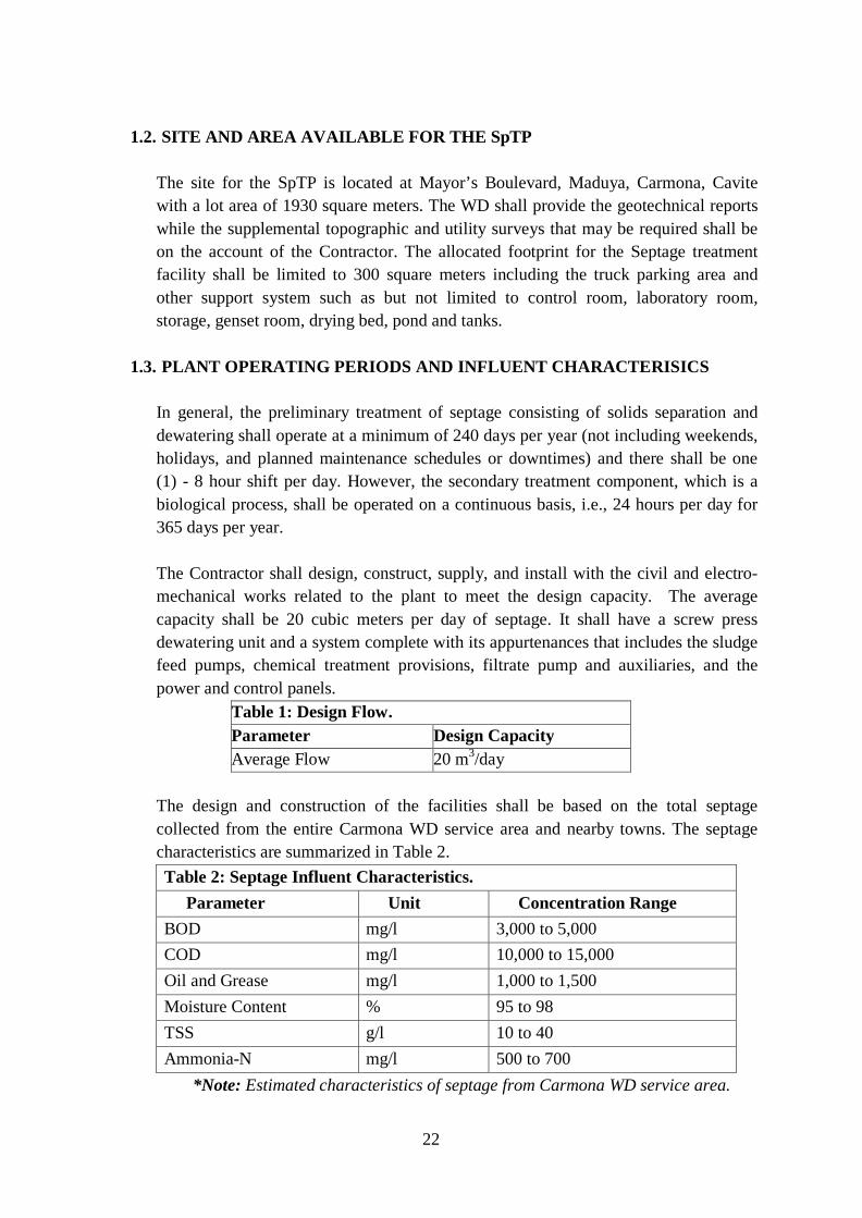
1.2. SITE AND AREA AVAILABLE FOR THE SpTP
The site for the SpTP is located at Mayor’s Boulevard, Maduya, Carmona, Cavite with a lot area of 1930 square meters. The WD shall provide the geotechnical reports while the supplemental topographic and utility surveys that may be required shall be on the account of the Contractor. The allocated footprint for the Septage treatment facility shall be limited to 300 square meters including the truck parking area and other support system such as but not limited to control room, laboratory room, storage, genset room, drying bed, pond and tanks.
1.3. PLANT OPERATING PERIODS AND INFLUENT CHARACTERISICS
In general, the preliminary treatment of septage consisting of solids separation and dewatering shall operate at a minimum of 240 days per year (not including weekends, holidays, and planned maintenance schedules or downtimes) and there shall be one (1) - 8 hour shift per day. However, the secondary treatment component, which is a biological process, shall be operated on a continuous basis, i.e., 24 hours per day for 365 days per year.
The Contractor shall design, construct, supply, and install with the civil and electro-mechanical works related to the plant to meet the design capacity. The average capacity shall be 20 cubic meters per day of septage. It shall have a screw press dewatering unit and a system complete with its appurtenances that includes the sludge feed pumps, chemical treatment provisions, filtrate pump and auxiliaries, and the power and control panels.
Table 1: Design Flow. Parameter Design Capacity Average Flow 20 m3/day
The design and construction of the facilities shall be based on the total septage collected from the entire Carmona WD service area and nearby towns. The septage characteristics are summarized in Table 2. Table 2: Septage Influent Characteristics.
Parameter Unit Concentration Range BOD mg/l 3,000 to 5,000 COD mg/l 10,000 to 15,000 Oil and Grease mg/l 1,000 to 1,500 Moisture Content % 95 to 98 TSS g/l 10 to 40 Ammonia-N mg/l 500 to 700
*Note: Estimated characteristics of septage from Carmona WD service area.
22

1.4. REQUIRED TREATMENT PLANT PERFORMANCE
1.4.1. The SpTP shall produce an effluent complying to ALL national government standards (i.e. for Class C Inland Water). The SpTP should also comply with both the LLDA Effluent Discharge and DENR Effluent Quality Guidelines. Some effluent quality limits are shown in Table 3a and 3b.
1.4.2. The SpTP plant shall produce dewatered sludge within an average dry solids content range of 15 to 20% and sludge cakes conforming with the USEPA standards of Class B biosolids shown in Table 3c.
Table 3a: Effluent Quality Limits (DENR DAO 2016-08). Parameter Units Effluent Limits
pH 6.5 to 9 COD mg/L 100 5-day 20ºC BOD mg/L 50 Total Suspended Solids mg/L 100 Oil and Grease mg/L 5 Phenolic Substances mg/L 0.10 Total Coliforms MPN/100 ml 10,000 Ammonia mg/L 0.5 Chloride mg/L 450 Nitrate (as NO3-N) mg/L 14 Phosphate mg/L 1 Sulfate mg/L 550
Table 3b: Effluent Quality for Water Re-Use (USEPA 2004) Parameter Units Effluent Limits
pH - 6.5 to 9 5-day 20ºC BOD mg/L <10 Turbidity NTU <2 Fecal Coliform MPN/100mL 0 Residual Chlorine mg/L 1
Table 3c: Sludge Cake Requirements (USEPA 2004) Classification Requirement Class B Fecal coliform density must meet 2.0 x 10⁶
MPN/g total solids or less than 2.0 x 10⁶ colony forming units (CFU)/g total solids
1.4.3. The plant itself shall be free from discernible odor and noise. It must meet the
DENR standards on noise levels (ambient and source-specific standards)
23

presented in Table 4. In case of non-compliance, the Contractor shall make changes on their design to meet the requirements without additional cost to Carmona WD.
1.4.4. It must be designed to resume its normal operations after a power interruption, even if unmanned, without causing damage to or undue shortening on the economic life of the electric motors.
Table 4: Maximum Allowable Noise Levels in General Areas. Morning Category of Area Day Time (5 am – 9 am) and Evening (9 am – 6 pm) Midnight (6 pm – 10 pm) (10 pm – 5 am)
A 55 Db 50 dB 45 B
Notes: See IRR of Chapter 18 of P.D. 856 – Sanitation Code of the Philippines Section 8.7.4 for more clarifications
1.4.5. The various components of the SpTP shall be designed within the limits of the parameters specified in this specification. However, if it can be shown that significant savings can be attained outside the limits of the design parameters, such conditions may be considered.
1.5. MINIMUM DESIGN PROVISIONS
1.5.1. General Requirements 1.5.1.1. The SpTP must be designed to meet a maximum of four (4) hours total
shutdown time for maintenance every week. 1.5.1.2. Plant structures shall be designed to withstand pressures and seismic
loading. For structural concrete, the 28-day compressive strength shall not be less than 24 MPa for general and water-retaining structures.
1.5.1.3. The electrical/instrumentations control system shall include main and branch circuit breakers, starters, contactors, variable speed drives and reset buttons selector switches, push buttons and pilot lights, circuit control items for electrical control, liquid level control of the respective components, and all necessary wiring and conduits.
1.5.1.4. All electrical/instrumentations controls shall be wired such that the equipment can be operated either manually or automatically using PLC to achieve the intended sequence of operation and for remote monitoring purposes. All electrical controls for all processes shall be located at the Control Room.
1.5.1.5. Electrical components of mechanical equipment and systems shall be provided as needed for complete and operable systems. Interconnecting wiring for factory-wired components shall be provided as an integral part of the plant.
24

1.5.1.6. The SpTP finished ground elevation shall be one (1) meter above the maximum flood level on the basis of a ten (10) year period.
1.5.1.7. Sump tanks and chemical mixing tanks must be covered.
1.6. SPECIFIC DESIGN PROVISIONS FOR THE SEPTAGE PLANT The following provisions cover the main components but do not preclude provision of other facilities that may be required in attaining the required SpTP performance requirements:
1.6.1. Equipment All equipment shall be installed indoors or have provisions for cover to prevent them from getting wet during rainy seasons and potentially shorten their usable lives.
1.6.2. Flow Measurement Flow meters shall be installed in the following locations:
• Full bore magnetic flowmeter for septage acceptance port – after the macerator, before the sludge acceptance units and sludge inlet of the dewatering unit o The flowmeter display in the control station should show flow rate
and total volume flow. The same information should be displayed at the loading bay and visible to the operating staff. Resetting of total volume flow by the plant operators should be possible.
• Water meter for effluent discharge o It shall display total volume reading for reporting.
1.6.3. Preliminary Treatment Unit The SpTP shall have an automatic screening, compacting, and washing system to remove solid wastes, trash, and other floating debris prior further treatment. It shall also have a sand, grit, fat, oil and grease removal system that will allow smooth operations of the downstream processes.
1.6.4. Secondary Treatment Unit
Using a combination of anaerobic and aerobic process, the SpTP shall be made with an accelerated anoxic treatment and sequential batch reactor.
1.6.5. Tertiary Treatment Unit
Physico-chemical treatment process of chemical precipitation, oxidation, charge neutralization, sedimentation and filtration. Final disinfection using chlorine dioxide so as not to induce chloramine build up at the receiving body of water of the plant’s discharge
1.6.6. Water Re-Use The treated effluent shall be used at the septage receiving area to wash the recovered solid wastes before collection in bags and also for the wash cycle of the
25

sludge dewatering unit. The treated effluent may also be used for other applications within the SpTP.
1.6.7. Process Flow Diagram
The Contractor shall indicate the directions of flow (inlet and outlet), chemical dosing lines, and wastages or by-products. In a separate sheet, all specifications of major equipment (pumps, blowers, etc.) must be clearly indicated in the process diagram.
1.7. PROCESS PERFORMANCE TEST AND GUARANTEE 1.7.1. Prior acceptance of the SpTP, the Contractor shall demonstrate that the
completed SpTP is capable of treating septage for sixty (60) consecutive days and in compliance with Table 3 with the initial septage loading. This is the process-proving period of two (2) months and shall start upon completion of the commissioning period.
1.7.2. During the process-proving period, the Contractor shall: • perform daily influent and effluent monitoring • Submit the following data:
� Process-related (e.g. flow, influent and effluent COD, and other treatment criteria) including actual laboratory results
� Inputs and outputs (power, chemical dosages, fuel consumptions, etc.) � Manpower deployment, including janitorial and security � Reactive and preventive maintenance records � Operating expenses (OPEX) � Daily incidents
• Undertake at least bi-weekly effluent sampling and analysis with a third party DENR-accredited laboratory. The schedule and manner of sampling shall be determined by Carmona WD.
• Operate in compliance to environmental requirements and on the operations and maintenance manuals.
• Carry out all routine, preventive, and breakdown maintenance activities. Maintain all assets to retain their functionality in “as new” condition until turnover.
• Supply all materials, spare parts, chemicals, water, generator fuel, and consumables required to operate and maintain the plant during the process-proving period.
• Supply all labor to undertake operation and maintenance with the exception of six operators who will be employed by Carmona WD but work under the direction of the Contractor during the process proving period. Carmona WD will pay all normal wages for these operators and the Contractor shall only pay the wages for any overtime worked under their supervision.
26

1.7.3 The Contractor may modify and test the SpTP until it achieves the projected levels of plant performance and operating costs within sixty (60) calendar days after the first test period. Any modification should be pre-approved by Carmona WD and all costs associated will be on the account of the Contractor.
1.7.4 The Contractor will not be responsible if the SpTP is not meeting the specified level of efficiency due to any excess plant loading more than the specified volume or if the influent quality is higher than those given in Table 2.
1.8 CONSTRUCTION AND SHOP DRAWINGS
1.8.1 The drawings shall show the complete layout of the plant with all components, equipment, and parts, each with an assigned number corresponding to the plant spare parts list. The layout shall also indicate the relative location with respect to the boundaries of the lot allocated for the SpTP.
1.8.2 The drawings shall show construction details for each component, equipment, support structures, and access facilities.
1.8.3 The construction drawings shall be size A1 and shall show the complete construction and assembly of the plant with all its identified components.
1.9 BID DRAWINGS
1.9.1 The drawings to be submitted with the bid shall be in size A3 (folded to size A4) and shall show the complete assembly of the plant with all components, equipment, and parts, each with an assigned number corresponding to the plant parts list. The layout shall also indicate the land area required and its relative location with respect to the boundaries of the lot allocated for the SpTP.
1.10 SECONDARY TREATMENT PLANT DESIGN PARAMETERS 1.10.1 The fully-mechanized secondary treatment equipped with a compact aerated
biological treatment system or equivalent shall be designed based on the limits and parameters shown in Table 5. Nonetheless, the Contractor shall assume full responsibility for the appropriateness of all design parameters applied in the project.
1.10.2 Aeration tanks shall be designed within the limits of the standard design parameters shown in Table 7.
1.10.3 Settling tanks shall be proportioned within the limiting dimension ratios shown in Table 8.
1.10.4 The Upflow Anaerobic Sludge Blanket (UASB) reactor shall be designed using an upflow velocity ranging from 0.6 to 0.9 m/h.
Table 5: Design Parameters for Aerated Biological Processes. Process Modification
Mean Cell Residence Time,
F/M Ratio
Volumetric loading, (kg BOD5/
MLSS, (mg/L)
Qr/Q
27
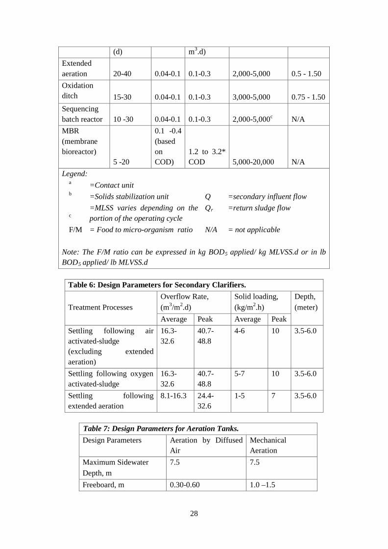
(d) m3.d) Extended aeration 20-40 0.04-0.1 0.1-0.3 2,000-5,000 0.5 - 1.50 Oxidation ditch 15-30 0.04-0.1 0.1-0.3 3,000-5,000 0.75 - 1.50 Sequencing batch reactor 10 -30 0.04-0.1 0.1-0.3 2,000-5,000c N/A MBR (membrane bioreactor)
5 -20
0.1 -0.4 (based on COD)
1.2 to 3.2* COD 5,000-20,000 N/A
Legend: a =Contact unit b =Solids stabilization unit Q =secondary influent flow
c =MLSS varies depending on the portion of the operating cycle
Qr =return sludge flow
F/M = Food to micro-organism ratio N/A = not applicable Note: The F/M ratio can be expressed in kg BOD5 applied/ kg MLVSS.d or in lb BOD5 applied/ lb MLVSS.d
Table 6: Design Parameters for Secondary Clarifiers. Treatment Processes
Overflow Rate, (m3/m2.d)
Solid loading, (kg/m2.h)
Depth, (meter)
Average Peak Average Peak Settling following air activated-sludge (excluding extended aeration)
16.3-32.6
40.7-48.8
4-6 10 3.5-6.0
Settling following oxygen activated-sludge
16.3-32.6
40.7-48.8
5-7 10 3.5-6.0
Settling following extended aeration
8.1-16.3 24.4-32.6
1-5 7 3.5-6.0
Table 7: Design Parameters for Aeration Tanks. Design Parameters Aeration by Diffused
Air Mechanical Aeration
Maximum Sidewater Depth, m
7.5 7.5
Freeboard, m 0.30-0.60 1.0 –1.5
28

Length to width ratio* 4:1 - 5:1 per to the power rating
Width to depth ratio 1:1 – 2.2:1 1:1 – 2.2:1
Table 8: Limiting Dimension Ratios for Settling Tanks. Tank Shape Limiting Dimension Ratio Circular tank radius not greater than 5 times the Sidewater
depth Rectangular length not greater than 15 times the Sidewater depth Plate/Lamella Indicate Number of plates and the effective height
1.11 OPERATION AND MAINTENANCE MANUALS 1.11.1 GENERAL
1.11.1.1 The Contractor shall prepare and submit a draft Operation and Maintenance Manuals with lists of Spare Parts for all the equipment of the SpTP, one (1) week prior to the scheduled date of commissioning.
1.11.1.2 Supply completed Operation and Maintenance Manuals within two weeks of receiving review comments in the form of two digital copies on CD and four hard copies. Produce digital copies using the latest versions of Word and AutoCAD with supplementary drawing and image files in .pdf format.
1.11.1.3 Assemble manuals in metric, A4 three ring binders with durable hard covers and of sufficient size for the information contained.
1.11.1.4 Drawings shall be assembled between metric A3 size covers and held together using three removable brass male/female screws. Produce all drawings in A3 size.
1.11.1.5 The Operation and Maintenance Manuals shall: • Cover all aspects of the works. • Provide ‘General Principles of Operation’ for the plant prepared by the
designers and include the necessary information for operators to effectively operate and maintain the works.
• Incorporate safety, environmental and quality issues. • Be specifically prepared for the Carmona WD SpTP. • Have detailed indexes and cross referencing.
1.11.2 OPERATION MANUAL
A single operation manual shall be provided for the operation of the plant. The contents of the manual shall include but not be limited to:
• Title Page: Project Name, Employer and Contractor information (names, addresses, contact details)
29
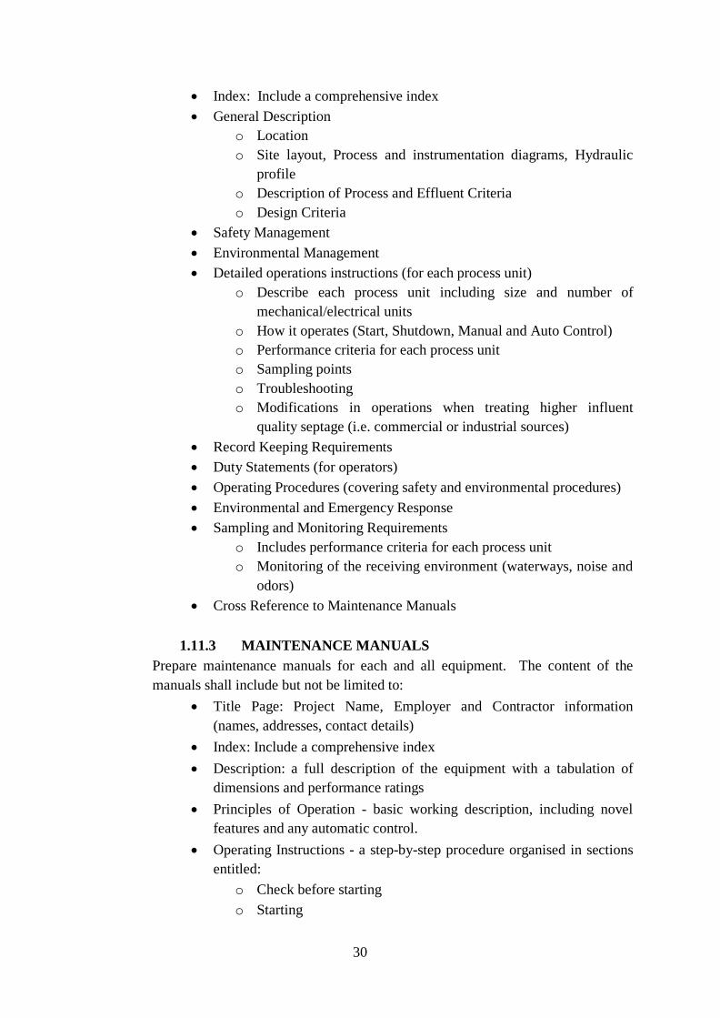
• Index: Include a comprehensive index • General Description
o Location o Site layout, Process and instrumentation diagrams, Hydraulic
profile o Description of Process and Effluent Criteria o Design Criteria
• Safety Management • Environmental Management • Detailed operations instructions (for each process unit)
o Describe each process unit including size and number of mechanical/electrical units
o How it operates (Start, Shutdown, Manual and Auto Control) o Performance criteria for each process unit o Sampling points o Troubleshooting o Modifications in operations when treating higher influent
quality septage (i.e. commercial or industrial sources) • Record Keeping Requirements • Duty Statements (for operators) • Operating Procedures (covering safety and environmental procedures) • Environmental and Emergency Response • Sampling and Monitoring Requirements
o Includes performance criteria for each process unit o Monitoring of the receiving environment (waterways, noise and
odors) • Cross Reference to Maintenance Manuals
1.11.3 MAINTENANCE MANUALS
Prepare maintenance manuals for each and all equipment. The content of the manuals shall include but not be limited to:
• Title Page: Project Name, Employer and Contractor information (names, addresses, contact details)
• Index: Include a comprehensive index • Description: a full description of the equipment with a tabulation of
dimensions and performance ratings • Principles of Operation - basic working description, including novel
features and any automatic control. • Operating Instructions - a step-by-step procedure organised in sections
entitled: o Check before starting o Starting
30

o Continuous operation o Stopping o Emergency stopping o Abnormal operation (if applicable)
• Installation and Commissioning Instructions - details of standards and procedures for transporting and installing the equipment. Including a step by step procedure for mounting or erecting, wiring and lubricating the equipment. Alignment tolerances and check requirements shall be stated.
• The commissioning instructions shall include step by step procedures for checks before the first start, checks after starting and operational tests.
• Routine Maintenance - step by step procedure for preventive maintenance work carried out at intervals of two weeks or less.
• Periodic Maintenance - step by step procedure for fault correction and preventive maintenance carried out at intervals in excess of two weeks, involving replacement of consumables. A list of any necessary special tools shall be included.
• Repair, Overhauling, and Dismantling - step by step procedures to extract, fully dismantle, re-assemble and re-install the equipment.
• Test Data and Troubleshooting - instructions to qualified tradesmen for assessing the operational performance of the equipment.
• Spare Parts List - illustrations and schedules for identification and specifications of all parts of the equipment. Exploded diagrams are required. The recommended spare parts stock must be indicated.
2 PLANT DESCRIPTION AND REQUIRED FACILITIES 2.1 GENERAL
All processes and facilities shall be designed to meet the performance requirements of the SpTP. As envisioned, the SpTP shall contain the following Main Process Systems, Support Systems and Facilities:
Main Process Systems
• Septage Tanker Unloading Bay • Rock Trap • Macerator • Packaged Treatment Unit with trash,
grit, oil and grease removal system • Sludge Holding Tanks with
Hyperbolic Mixer • Dewatering Feed Pumps • Chemical Treatment Unit
Support Systems • Potable Water Storage System (5m3) • Treated Water Storage System (5m3) • Electrical and Control System • Generator Set
Facilities • Control and Instrumentation Room • Structural provisions for Receiving
and Dewatering Units
31

• Sludge Dewatering Unit/Dewatering Press
• Scum Trap System • Equalization Tank • Anoxic Treatment Tank (ATT) • Secondary Treatment System • Tertiary treatment • Transfer Pumps • Filtration Systems • Clarifier Systems • Flow Meters
• Sludge Cake Storage (Drying bed) • GenSet / Powerhouse Room • Chemical and Supplies Storage Room • Laboratory Room • Pond
2.2 MAIN PROCESS SYSTEMS 2.2.1 Septage Tanker Unloading Facilities
Each septage unloading bay shall have at least one (1) unloading point for connection of vacuum tanker discharge hoses. The unloading points shall:
• Feature Cam-lock quick-connection fittings with non-return valves, flow metering and control, for the connection of vacuum tanker discharge hoses.
• Have a spill pit with grating and properly designed grit and trash trap constructed underneath to ensure efficient collection of spillage during unloading. Collected spillage shall be conveyed to a holding tank with sufficient capacity and pumped to the desired process stage.
• Have sufficient roofing to protect personnel from rain when connecting/disconnecting the hoses to the ports.
• Be connected to one (1) sludge acceptance unit and shall feature quick connection couplings, flow metering, and control
• Have couplings installed at a suitable height for accessibility during operations
2.2.2 Rock trap
A rock trap system should be connected to the couplings at the unloading point. This allow the settling of heavy objects like stones, rebar, gravel that might damage equipment down the line. The unloading operation shall use the discharge pump from the tankers or by gravity for larger trucks.
2.2.3 Macerator
A macerator will grind the trash not sorted by the rock trap system. It shall have a separate control panel with PLC to control rotation or reverse in case hard material gets caught in the equipment.
32

A full-bore magnetic flow meter shall be installed after each Macerator to allow simultaneous vacuum trucks unloading. The display shall be included at the control station for two functions:
• Instantaneous flow rate in l/s • Total volume unloaded
Total unloading volume read by the flowmeter shall be noted for recording and billing purposes.
2.2.4 Packaged Treatment Unit
2.2.4.1 General Provide a Packaged Treatment Unit (PTU) to perform the preliminary treatment of the raw septage. It should:
• Be a completely sealed unit and placed in an area with sufficient ventilation.
• Have an instantaneous capacity of at least 10LPS to cater a quick sludge discharge from one tanker truck.
• Have its main parts including the conveyor systems (when applicable) made of stainless steel with a minimum grade of Type 304.
• Have a compaction screw made of special alloy steel. • Have components like gear motor drives with proven reliability and
lifetime under set operational conditions. • Discharge compacted and washed screenings via enclosed discharge
chutes into an enclosed and inclined conveyor into separate industrial bags or sacks.
• Discharge screened and de-gritted septage by gravity pipework into a Holding Tank
• Shall have provisions for upgrade with electronic card readers or recording of truck offloading information to be connected with its electrical controls and flow metering capability.
• Consist of mechanically-cleaned screen, screw type screenings compactor with washing, grit trap, grit classifier, oil and grease skimming system, flowmeter, trash and grit chute, air blower, integrated supports, pipe lines and conduits, electrical switchboard, and control panel.
2.2.4.2 Mechanically-Cleaned Screen with Screenings
Compaction Incorporate a continuous and automatic mechanical screen cleaning in the unit with perforation or spacing range of 5mm – 8mm. It should:
o Have an integrated inclined screw screenings press capable of a screenings removal rate of approximately 2 cubic meters per hour on a continuous basis with a dry solids content of 40%.
33

o Provide a discharge system and chutes to accurately discharge screenings to the screenings bags.
o Not allow free fall of screenings on the unit exterior or the escape of screenings. 2.2.4.3 Grit Trap Tank
Provide a grit trap tank section in the PTU with volume capacity enough to allow settling of sand and grit. It should:
o Be capable of removing at least 95% of grit equivalent to sand of 0.3 mm diameter and at maximum flow.
o Be incorporated with an air diffuser agitation system for continuous agitation to prevent septage from manually operated drain at the lowest point of the unit. 2.2.4.4 Grit Conveyor and Extractor
Incorporate an inclined screw grit classifier capable of a grit removal rate of at least 0.3 cubic meters per hour on a continuous basis with a dry solids content of 4%. It should:
o Have a discharge system and chutes to accurately discharge grit to the grit bags
o Not allow free fall of grit on the unit exterior or the escape of grit 2.2.4.5 Integrated Supports
Fabricate the PTU to fit with an integrated system of support brackets and foundation legs that will enable it to stay on a concrete surface. The supports shall:
o Be manufactured with the same material as the body of the acceptance units.
o Allow transport and movement of the acceptance units without the need for disassembly or additional bracing
o Have provisions for control of vibration and for electrical grounding. 2.2.4.6 Pipelines and Conduits
Include all pipelines and conduits needed for a correctly functioning PTU. o Locate the pipelines associated with the tanker unloading
system above ground. o Locate all other pipelines below ground with connections to the
PTU. o Design pipelines with sufficient grade and with accessibility for
maintenance.
34

o Include fittings to allow routine sampling of septage both before and after the acceptance units.
o Pipelines shall be color-coded and properly labelled. o Provide electrical conduits below ground linking the main
switchboard, the PTU, and the local control stations. o Terminate the electrical conduits within the area of the
integrated supports for the PTU. o Include water supply standpipes with hoses within the building
and in close proximity to the acceptance units for maintenance. o The concrete floor under the PTU shall be a grated sump tank
with a grit/sand trap and connected to the septage transfer pump or directly to the septage holding tank. 2.2.4.7 Electrical Switchboards and Control Panel
Provide a single electrical switchboard and control panel for and located near each PTU. The panel should meet the following requirements:
o Provide all power, control, and instrumentation requirements for the functionality of the PTU
o Include provision for automatic and manual operation o Should have suitable push-buttons and displays to enable
checking of functions, identification of faults, manual operation, flowmeter displays, and links to the overall plant control system.
o Should be in a protective and waterproofed enclosure that will allow routine cleaning or maintenance operations with water
2.2.5 Sludge Holding Tanks 2.2.5.1 Provide two (2) holding tanks for the screened septage
ready for dewatering and other one is for receiving of the hauling for the day, each with an active volume of at least 20 cubic meters. The tanks are for storage and mixing of screened and de-gritted sludge and of any waste sludge from the biological treatment.
2.2.5.2 Under normal conditions, tanks shall be operated alternately with one tank fully mixed and supplying feed to the sludge dewatering system and one tank in settlement mode receiving septage sludge and waste activated sludge.
2.2.5.3 Construct the tanks from concrete and finish the internal surfaces by smooth plastering to eliminate areas for solids to deposit.
2.2.5.4 Install at least one electrically driven shafted hyperbolic mixers to each tank to completely mix the tank contents and provide homogeneous feed to the dewatering system. Size the mixers to ensure suspension of settled material
35

following any period of interruption to mixer operation. Mount the mixers at the center of the tank. Suspended shaft should be stainless steel 304.
2.2.5.5 Equip the tanks with manhole large enough to accommodate the passage of the hyperbolic impeller if servicing is needed.
2.2.5.6 A decanter pump should be in-place to allow withdrawal of supernatant liquid in the event the septage hauled is watery or below 1% solids content.
2.2.5.7 Include suitable arrangements for level control within the tanks using any non-contact or ultrasonic instruments. Use the level controllers to assist the operation of the sludge transfer pumps, the sludge dewatering pumps, and the waste activated sludge pumps Display the tank levels at ground level near the tanks.
2.2.5.8 Provide pipework with valves at ground level to allow a full range of functions and protection for the tanks. Include the following:
• inlets from the septage transfer pumps and the filtrate pumping station;
• interconnecting pipework to allow series operation, outlets to the sludge dewatering system;
• inlets for waste activated sludge from the biological treatment system;
• outlets for clear wastewater discharge to the biological treatment system;
• scour outlets from the lowest point of the floors and overflows. 2.2.5.9 Prevent odor nuisance from the tanks. Provide air suction
pipework above top of tank or ensure sufficient ventilation.
2.2.6 Sludge Dewatering System 2.2.6.1 General
2.2.6.1.1 Provide a Screw Press Type of dewatering unit or approved equal with a minimum of 2 m3/hr capacity. It shall be a compact and complete system to perform the separation of mixed septage from the PTU and the intermittent activated sludge wastes from the SBR System. It should consist of:
• Dewatering pumps • Chemical dosing pipework • Flocculation Reactor • Sludge Dewatering unit • Filtrate recycle system
36

• Integrated supports • Pipe lines and conduits • Electrical switchboard and control panel
2.2.6.1.2 It shall have the capacity to produce sludge cake from the incoming septage and waste activated sludge. It shall produce sludge cakes with dryness or solid content not lower than fifteen percent (15%).
2.2.6.1.3 Discharge dewatered sludge to the solids stabilization system. Provide a standby bagging system with sufficient stock of bags for one month of operation at full plant capacity.
2.2.6.1.4 Fabricate casings, frames, pipelines and all components from stainless steel, generally of grade 316 but with a minimum of grade 304 for certain small components.
2.2.6.1.5 Enclose the system in a secured area and place a barrier between the units and the sludge cake handling area. Provide normally locked double hinged gates for access to plant and equipment and single gates for operator access.
2.2.6.2 Dewatering Feed Pumps
2.2.6.2.1 Provide a dewatering feed pump system suitable for handling septage and sludge with two pumps (1 Duty, 1 Standby) allocated specifically for the sludge dewatering unit. Install slow speed positive displacement progressive cavity type pumps for consistent flow rate regardless of solids content of the sludge. Locate the pumps inside a secured area.
2.2.6.2.2 Design individual pump capacity to suit each sludge dewatering unit. Equip pumps with variable frequency drivers to control the flow rates using the plant control system. Interlock operation of the pumps with the holding tanks level and the dewatering unit. Use motors with suitable electrical protection to allow direct application of water from hoses as a minimum.
2.2.6.3 Chemical Dosing Pipework
37

2.2.6.3.1 Provide pipework between the dewatering feed pumps and the flocculation reactor tank leading to the sludge dewatering unit. Incorporate fittings for isolation, measurement of flow, dosing of polyelectrolyte solution, injection of filtrate return flow, and sampling. Ensure sufficient length of pipework to allow proper chemical dispersion and flow measurement.
2.2.6.3.2 Measure flow using full-bore magnetic flowmeters. Include display at the control station for two functions:
• An instantaneous flow rate L/s • Total Flow in liters for the particular
dewatering unit
2.2.6.4 Flocculation Static Mixer 2.2.6.4.1 Provide a flocculation static mixer at the
head of the dewatering unit to achieve adequate contact and mixing time between the sludge and chemicals.
2.2.6.4.2 Ensure adequate size, sufficient freeboard and overflow arrangements to prevent surge or spillage on start and stop of dewatering feed pumps. Include a scour outlet.
2.2.6.5 Sludge Dewatering Unit
2.2.6.5.1 Incorporate a Screw Press dewatering unit or approved equal capable of removing all sludge solids generated by the plant in no more than 80 hours per week. Produce sludge cake with dry solids content in the range of 15% to 25% and with polyelectrolyte consumption not exceeding 10kg/kg of dry sludge.
2.2.6.5.2 Provide a discharge system and chutes to accurately discharge sludge to the solids stabilization system. Do not allow free fall of sludge on the unit exterior or escape any liquids or solids.
2.2.6.6 Filtrate Scum Trap
38

Provide a system for the capture of scum and other wastes going through with the filtrate. Provide easy access and removal of accumulated scum by overflowing via gravity or using a skimmer pump that returns to the sludge holding tank. Construct a minimum of 3 compartment-baffled tanks that can handle 30% more on the total dewatering capacity.
2.2.6.7 Integrated Supports
The sludge dewatering units shall fit with an integrated system of support brackets and foundations that enable anchoring to a concrete surface. The supports shall:
• Be manufactured with the same material as the body of the acceptance units.
• Allow transport and movement of the acceptance units without the need for disassembly or additional bracing Have provisions for control of vibration and for electrical grounding.
2.2.6.8 Pipelines and Conduits
Include all pipelines and conduits needed to form a complete and correctly functioning sludge dewatering system.
• Locate pipelines generally below ground with connections to the dewatering units and neatly at appropriate points.
• Design pipelines with sufficient grade and to allow access for maintenance. Include fittings to allow routine sampling of sludge and filtrate both before and after the dewatering units.
• Provide electrical conduits below ground linking the main switchboard, the dewatering units and the local control stations. Terminate the electrical conduits within the area of the integrated supports for the acceptance units.
• Include water supply standpipes with hoses within the building and in close proximity to the dewatering units for maintenance. Grade the concrete floor of the dewatering unit area to a grated sump with a trapped outlet to the sludge transfer sump.
2.2.6.9 Electrical Switchboard and Control Panel
39

Provide a single electrical switchboard and control panel for each sludge dewatering unit. Locate the panel near the dewatering unit.
• Arrange for the panel to provide all power, control and instrumentation requirements for the complete functioning of the sludge dewatering system.
• Include provision for automatic and manual operation, suitable push-buttons and displays on the front of the station to enable checking of functions, identification of faults and manual operation, flowmeter displays and links to the overall plant control system.
• Supply the panel in a protective enclosure that will allow water from hoses to be directed onto the cabinet during maintenance cleaning operations.
2.2.7 Anoxic Treatment Tank and Equalization tank
2.2.7.1 Provide a filtrate pumping station to collect filtrate from the sludge dewatering system and deliver it to the biological treatment system if cascading tank orientation is not possible.
2.2.7.2 Design the pumping station with a concrete wet well and external valve chamber suitable for the installation of submersible sewage pumps.
2.2.7.3 Provide two pumps arranged on a duty/standby/parallel basis complete with lower mounting bends and grade 316 stainless steel guide bars and lifting chains. Match the wet well and pump capacities to avoid excessive numbers of starts for the pumps.
2.2.7.4 Include a permanent lifting davit able to conveniently withdraw the pumps and raise them to ground level. Provide sufficient electric cable to allow removal to ground level without the need to disconnect. Locate a standpipe and hose near the pumping station for maintenance.
2.2.7.5 For the anoxic treatment tank, un-aerated mixing should be made possible. A Hyperbolic mixer shall be used for anoxic treatment mixing to effectively agitate the filtrate. For equalization tank, aerated mixing should be possible. Suitable air diffusers shall be installed for aerated mixing use. Arrange the control system for both options not to be operated simultaneously.
2.2.7.6 Include aerated and un-aerated mixing options available. A hyperbolic mixer shall be used for anoxic
40
treatment mixing to effectively agitate the filtrate. Suitable air diffusers shall be installed for aerated mixing use. Arrange the control system for both options not to be operated simultaneously.
2.2.7.7 Include suitable arrangements for level control within the pumping station using non-contact ultrasonic instruments.
2.2.7.8 Provide an emergency overflow at high level in the pumping station with a pipeline discharging to the receiving waterway adjacent to the plant.
2.2.8 Secondary Treatment (Biological Treatment System)
2.2.8.1 Provide a complete Sequencing Batch Reactor biological treatment system to receive filtrate from septage treatment as well as sewage and process overflows from the plant site. It shall produce final treated wastewater effluent meeting the specified DENR Class C discharge quality criteria.
2.2.8.2 Base the design of the biological treatment system on an activated sludge process as prescribed in Table 8. Construct the reactors in concrete.
2.2.8.3 Equip the reactors with automatically operated inlet pipe arrangements, aeration systems, and waste activated sludge removal systems.
2.2.8.4 Include facilities for scum suppression and withdrawal for disposal with the waste activated sludge. Construct metalwork from grade 316 stainless steel.
2.2.8.5 Provide at least two waste activated sludge pumps arranged on a duty/standby/parallel basis. Ensure sufficient range of capacities to allow withdrawal of waste activated sludge during either the aeration or settlement phases of the biological process.
2.2.8.6 Equip the facility with walkways, platforms, handrails and cages to allow safe access to the structures for operations staff. Locate standpipes and hoses on the walkways for maintenance.
2.2.9 Tertiary Treatment
2.2.9.1 Provide an effluent disinfection system to receive flow from the biological treatment system and disinfect the treated effluent to meet the required effluent discharge criteria.
2.2.9.2 Provide concrete disinfection contact tanks. Include sufficient detention volume and freeboard to prevent
41

escape of insufficiently disinfected effluent, with a minimum detention time of one hour.
2.2.9.3 Provide separate chemical dosing tanks, mixers, and dosing pumps for nutrient removal methods such as pH adjustment, flocculation, and other similar processes.
2.2.9.4 Provide a pipeline with a suitable outlet structure to convey the final treated effluent to the receiving water adjacent to the plant. Measure the flow of final effluent and display the instantaneous flow in L/s at the contact tanks.
2.2.9.5 Equip the tanks with, walkways, platforms, handrails and cages to allow safe access to the structures for operations staff. Equip with standpipes and hoses on the walkways for maintenance.
2.2.9.6 Supply and install all equipment necessary for disinfection using a chlorine dioxide solution. Place the chemical dosing system in a separate building. Include a storage tank for bulk delivery of Chlorine Dioxide with a storage capacity equal to at least one week of chemical consumption required for full plant capacity.
2.2.9.7 Recommend the required safety features and practices in consideration of the chemicals to be handled during operations. Safety features including but not limited to safety shower, eyewash, warnings, and safety signs should be included in the engineering designs.
2.2.9.8 Recommend sampling and test equipment and identify the consumables required for the daily testing of total and residual chlorine.
2.2.9.9 An alternative disinfection system based on the use of chlorine gas or sodium hypochlorite may be proposed.
2.2.9.10 For purposes of water re-use for plant irrigation, toilet flushing, and vehicles wash, the quality of the re-use water shall comply with the effluent quality requirement as defined in Table 3b - Effluent Quality for Water Re-Use (USEPA 2004).
2.2.9.11 The filtration system shall consist of a two-stage process consisting of sand and activated carbon filters.
2.2.9.12 Clarification systems shall form part of the treatment process prior effluent discharge for the removal of residual solids and treatment chemicals still present in the effluent.
2.3 SUPPORT SYSTEMS
2.3.1 Potable Water Supply System
42

2.3.1.1 Provide polyethylene tanks if possible with a roof and sufficient elevation to flood the suction of booster pumps. Connect the tank to the chlorine contact tank to ensure disinfection of supplies as needed.
2.3.1.2 Include a tanker discharge point with a permanently installed booster pump at the base of the potable water tank to receive supplementary deliveries of potable water should the need arise. Include overflow and scour pipelines directed to the plant storm water drainage system.
2.3.1.3 Include suitable arrangements for level control within the potable water tank using non-contact ultrasonic instruments or an external sight board for visual indication of level.
2.3.1.4 Equip the tank with internal and external ladders, walkways, platforms, handrails and cages to allow safe access to the structures for operations staff.
2.3.1.5 Connect the pipe reticulation network to all areas of the plant. Include provisions for below-ground fire hydrants at suitable locations with appropriate signage, pavement markings and reflectors. Provide signs at outlets from the system in close proximity to outlets from the service water system.
2.3.2 Non-Potable Water Supply System
2.3.2.1 Provide polyethylene tanks if possible with a roof and sufficient elevation to flood the suction of booster pumps. Connect the tank to the chlorine contact tank to ensure disinfection of supplies as needed.
2.3.2.2 Provide a tanker discharge point with permanently installed booster pump at the base complete service water system for process, washing and landscaping use around the plant.
2.3.2.3 Equip the system to obtain chlorinated final effluent from the treated effluent holding tank and distribute service water around the plant in a dedicated reticulation network. Use materials suitable for the chlorinated effluent.
2.3.2.4 Install one high pressure pumps in a duty/standby/parallel configuration with an automatically backwashed filter and pressure storage tank. Use 220 V single-phase motors.
2.3.3 Water recovery system
43

2.3.3.1 Direct backwash water to the filtrate pumping station. Interlock faults in the system to protect the sludge acceptance and dewatering units.
2.3.3.2 Provide a pressure storage tank to initiate and sustain flow in the system. Ensure capability to allow immediate system response on operation of any outlet from the system without large pressure variations or water hammer and with a minimum capacity of 30 seconds storage at full flow for the system.
2.3.3.3 Distribute service water to all areas of the plant in a reticulation pipework system. System should feature adequate pipe sizes required to sustain discharge pressures by at least the PTU and sludge dewatering units.
2.3.3.4 Ensure signage complying with international codes to identify recycled water and select hydrants and all other types of fittings to prevent cross-connection of potable water fittings. Color-code all items with the recognized color for recycled water. Provide hoses, sprays and any other items needed to allow maintenance of the plant, equipment, and landscaped areas.
2.3.4 Electrical and Control System
2.3.4.1 Provide a complete electrical and control system description and design.
2.3.5 Other Engineering Designs
2.3.5.1 Provide a complete plant layout of the SpTP with the equipment in place and with provisions for the following facilities:
• Structural provisions for receiving and Dewatering units • GenSet and Power Room • Chemical Storage Room • Control and Instrumentation Room • Motorpool /parking area • Laboratory Room • Sludge Cake Storage (Drying Bed) • Pond
44

Architectural Finishes Interior Finish Exterior Finish Remarks Dewatering area Colored epoxy flooring
(hardened), plain cement plaster painted finish wall
1. Paint truss members for room(s) with no ceiling,
2. Use enamel paint for PVC doors. If steel door was used, paint it with epoxy primer base
3. The quality of paint to be used shall withstand with all chemicals or polymers to be used in the treatment facility.
Genset and Power Room
Colored (hardened) flooring, plain cement plaster painted finish wall
Painted finish, provide roof insulation
Control & Instrumentation Room
Colored epoxy flooring (hardened), plain cement plaster painted finish wall
Painted finish, provide roof insulation
Motorpool/parking area Colored epoxy hardened flooring Laboratory Room Tile finish floor, plain
cement plaster painted finish wall
Painted finish, provided ceiling finish & roof insulation, with provision for exhaust, airconditioning or ventilation system
Sludge Cake Storage Colored hardened flooring Provide roof insulation
45

2.3.6 Laboratory Requirements 2.3.6.1 The laboratory room should be able to have sufficient
space and provision for installation (if applicable) of the following minimum equipment:
• pH meter • Turbidity meter • Dissolved oxygen meter • Conductivity or TDS meter • Halogen moisture analyzer
2.3.6.2 The contractor shall also provide recommended specifications for the abovementioned equipment.
3 ODOR CONTROL AND MANAGEMENT
3.0 Septage treatment facility shall be operated with controlled odor nuisance around its perimeter. In case of any complaints during process proving, the Contractor shall perform site investigation to determine the cause and take necessary action to eliminate the source of foul odor. MATERIALS SPECIFICATION OF THE 20CMD TREATMENT
FACILITY
ITEM DESCRIPTION STATEMENT OF COMPLIANCE
MAIN PROCESS SYSTEMS • Septage Tanker Unloading Bay • Rock Trap System (30 liters capacity
slim type, with removable basket, quick opening cover, 4” diameter leading pipe with cam-lock, 2” tank drain port, all components Stainless steel 304)
• Macerator (min. flow: 20cu.m/hr, carbide blades cutting elements)
• Packaged Treatment Unit (5 lps capacity 3” cam-lock and 6” flange connection)
• Trash removal (shiftless, 168mm spiral screen zone diameter, brusher mounted spiral screen cleaning, perforated mesh and stainless steel plate)
• Grit removal system (shaftless with 145mm extraction screw diameter)
• Oil and Grease skimmer – 0.25 kw gear motor, 440v, 60Hz, blower with 1.1kw capacity, Air flotation system with 1” connection with manual valve and SS perforated pipe inside
• Septage Holding Tanks (2 units)
46

• Hyperbolic Mixer (0.4Kw, 220V, 60hz, 3 phase, 58 rpm impeller speed, 55.7 Nm Torque, epoxy coated shaft, 500 mm glass fiber reinforcement plastic (GRP) impeller, with submersible pump 130l/min min. flow and 10 meters max. Head)
• Chemical tank with mixer (drive motor: 0.4kw, 4 poles, 3 phase, 220 V, 60 Hz, 1750 RPM, IP 44, 250 RPM output with reduction ratio equivalent to 7, 1cu.m PE tank with ports for drain and outlet)
• Polymer dosing pump(7.2L/min capacity, motor rating: 0.15 kw, 4 pole, 3 phase, 220 V 60 Hz)
• Dewatering Feed Pumps • Chemical Treatment Unit • Sludge Dewatering Unit/Dewatering
press (screw press with 2” diameter inlet and overflow pipe, conical shaft, 15-20% dewatered sludge dryness, 1.7lps water consumption, VFD ready gear motor, 0.55kw, 400V, 60Hz)
• Sludge Tank • Scum Trap System (3 compartments) • Equalization Tank • Anoxic treatment tank with mixer (non-
clog type, 200L/min min capacity, submersible, 0.75 kw, 200 V single phase, 22 cu.m/hr submersible aerators, with 58 rpm impeller speed anoxic tank mixer)
• Sequencing Batch Reactor System (with sub submersible aerators 22 cu.m/hr air volume, with non-clog submersible decanter pump 350L/min)
• Tertiary Treatment (3cu.m/hr capacity chemical treatment tanks for pH adjustment, coagulation, flocculation and clarification, polycarbonate corrugated sheet settlers, epoxy coated 4mm MS plate with angle bars supports, 1750rpm pH adjustment tank agitator, 14-16L/hr pH adjuster dosing pump, 100 rpm coagulation tank agitator, 7.8 L/hr coagulation dosing pump and mixer, 1750 rpm flocculation tank agitator, 7.8 L/hr flocculation dosing pump and
47

mixer) • Clarifier Systems • Filtration Systems (sand filter and
activated carbon filter, 350L/min filetr feed pump, 7.2L/hr chlorine dosing pump)
• Chlorine dioxide generator (50-150 grams/hr capacity with online oxidant level, automatic dosing based on actual oxidant level, 220V, 60Hz)
• Flow Meters (standard water meters for 4” pipe diameter)
SUPPORT SYSTEMS • Potable Water Storage System (5cu.m) • Treated Water Storage System (5cu.m) • Civil Works
1. Primary, Secondary and Tertiary area, SBR, Holding Tank, Chemical Tanks
2. Piping process, recycle, potable water lines a. Inlet connections – camlock
type Aluminium construction. Coupled to SS304 pipe via threaded connection with end flange connections.
b. Pipelines – for raw septage and screened septage, all are conveyed through PVC Gray Pipe Sch. 80. Joints are cement-bonded and connections for 8” diameter and 4” diameter pipe to isolation valves and to related equipment area flange connected. Smaller 2” diameter pipes for sludge dewatering unit in-feed, over flow and tank transfer lines are PVC Gray Pipe Schedule 80. Treated water lines for recycling and to be used for washings at the process equipment will be 1” diameter PVC Gray Schedule 80. Potable water and recycled water lines for washing are on ¾” diameter PVC Blue Schedule 40.
c. Compressed air pipeline – is
48

multi-materials. Header line going to distribution line is mild steel. Downpipe from distribution line going to the air diffuser loop is stainless steel 304. The diffuser loop is 4” diameter PVC Gray Pipe Schedule 80. Air diffuser is High Density Polyethylene constructed with EPDM membrane.
d. Isolation valves – for the raw septage section is a full bore ball valve type secured in place via flanged connections. This eliminates clogging. Valves for the screened septage section is of butterfly type also in flanged connection. Smaller 2” diameter pipe utilizes true-union ball valves to allow disassembly during maintenance.
e. Brackets, hangers, and supports – fully submerged and wetted areas will be stainless steel 34 anchored using stainless steel 316 anchor bolts. Not wetted area will be epoxy coated mild steel materials.
f. Chutes for screenings, grit, and sludge cake are constructed from stainless steel 304 fabricated in accordance with correct positioning. Final surface finish is hairline like.
g. Hydro test for pressure lines and leak test for non-pressurized lines.
h. Vibration test during dry run and add additional support/brackets when necessary.
• Electrical and Control System 1. Electrical Controls at Primary and
Secondary Treatment and Automation at SBR (Control panels (primary, secondary, remote, MCB, lightings, CO) a. Fabrication, supply and
installation of main control
49

panel. The control panel cabinet material is powder coated steel for durability. The cabinet is accessible via two-weather tight door split opening. Control knobs and light indicators on one door and monitoring/ controller displays are mounted on the other. Wirings are color-coded, two (2) colors for single phase control power and three (3) colors for three phase load lines.
b. Fabrication, supply, and installation of remote control panel. The control panel cabinet material is stainless steel 304 with weather tight single door.
c. Fabrication of lay-outing and mounting powder-coated cable tray. Connections of rigid conduit from cable tray to each motor location. Connection of flexible conduit from the end of rigid conduit connected via cable glands for the submersible pump connections.
d. Lay-outing and wiring from MCP to remote control.
e. Lay-outing and wiring from MCP to each motor.
f. Lay-outing and wiring liquid level controls, limit switch, pressure switch, reversing switch, sensor, etc.
g. Lay-outing and wiring from lighting and C.O.
h. Terminating and commissioning of all loads.
i. Insulation testing of each wiring. j. Testing and dry running of each
motor loads. • Generator Set (Supply, Delivery,
Installation, Commissioning of Generator Set : 90 KVA stand-by duty 220/440 volts, silent type, 3 phase, 60 hz, 1800 rpm @ 80 % power factor with Control Panel)
FACILITIES The following facilities shall be constructed and
50

properly placed in strategic locations. • Control and Instrumentation Room • Structural Provisions for Receiving and
Dewatering Units • Sludge Cake Storage (Drying Bed) • Generator Set / Powerhouse Room • Chemical and Supplies Storage Room • Laboratory Room • Pond
The building design/facade shall adopt design concept for industries. It shall adopt economical design without compromising the allowable factor of safety for structural design. Supplier shall provide brochures, swatches, or actual sample, if possible, of all materials and/or auxiliaries to be installed in the above rooms.
4 VACUUM TRUCKS
The material, design, fabrication, and supply of vacuum trucks shall conform to the manufacturer’s specification which are derived from engineering principles, industry experiences, and the aforementioned standards specification. All materials shall be new, previously unused, and in first class condition. Steel materials of unidentified analysis may be used provided they are tested and properly certified by a qualified testing laboratory. Bidders must state either “Comply” or “Not Comply” against each of the specifications stating the corresponding performance parameter of the equipment offered. Statements of “Comply” or “Not Comply” must be supported by evidence in a Bidders Bid and cross-referenced to that evidence. Evidence shall be in the form of manufacturer’s un-amended sales literature, unconditional statements of specification and compliance issued by the manufacturer, samples, independent test data etc., as appropriate.
A statement that is not supported by evidence or is subsequently found to be contradicted by the evidence presented will render the Bid under evaluation liable for rejection. A statement either in the Bidders statement of compliance or the supporting evidence that is found to be false either during Bid evaluation, post-qualification or the execution of the Contract may be regarded as fraudulent and render the Bidder or supplier liable for prosecution subject to the provisions of ITB Clause 3.1(a)(ii) and/or GCC Clause 2(a)(11).
51

4.1 Specification of 5 cu.m. Vacuum Truck
Item Specification Statement of Compliance 1 VACUUM TRUCK a. Minimum effective capacity of 5,000
liters (5 cubic meters)
b. Body and rear door material: steel c. Provided with suction and discharge
ports both with stainless ball valves and quick hose connector
d. Tank material: Carbon steel, steel, or any corrosion-resistant metal with rustproofed interiors
e. All pipes, fittings and valves shall be made of stainless steel including internal suction pipe
2 VACUUM PUMP a. Provided with 4-way valve operated for
suction/discharge change over.
b. One-year warranty for parts and services
c. Maximum vacuum: 28" Hg; Continuous Vacuum: 24” Hg
d. Maximum pressure: 29 psig e. Power required at 15" of vacuum: at
least 10hp
f. Power required at maximum pressure: max 35 hp
g. Min. rotation speed: 950 rpm h. Oil tank capacity: 1.2 US gal i. Oil consumption: 0.063 US gal/h j. Sound Pressure a 7m/60% Vacuum:
Less than 86 dB
3 TRUCK SPECIFICATION a. Diesel powered, Euro 4 Compliant,
PTO-ready
b. Minimum of 4 cylinders, four cycles, turbocharged and intercooled Direct Injection, with adequate horsepower for the gross vehicle weight rating
c. Minimum payload: 6,000 kgs d. Size of unit is approximately to be
(6.50m x 2.3m x 2.4 m), length, width and height respectively.
e. Power steering, Air conditioned, air over hydraulic brake system
f. Six tires g. Safety belts h. Side mirrors (Left and Right) with blind
52

spot mirror (Right) 4 OTHER ITEMS a. Should have provisions for installation
of a 200-liter capacity clean water tank
b. Should have provisions for hose and hose container
c. Spiral hose – at least 3 inches diameterand at least 200 feet length at 100 feet segment with cam-locks coupling
d. Provide 4 pcs securing rope for spiral hose when storing in hose bed
e. Should include basic tools: tire wrench and heavy duty jack
4.2 Specification of 3.5 cu.m. Vacuum Truck
Item Specification Statement of Compliance
1 VACUUM TRUCK a. Minimum effective capacity of 3,500
liters (3.5 cubic meters)
b. Body and rear door material: steel c. Provided with suction and discharge
ports both with stainless ball valves and quick hose connector
d. Tank material: Carbon steel, steel, or any corrosion-resistant metal with rustproofed interiors
e. All pipes, fittings and valves shall be made of stainless steel including internal suction pipe
2 VACUUM PUMP a. Provided with 4-way valve operated for
suction/discharge change over.
b. One-year warranty for parts and services
c. Maximum vacuum: 28" Hg; Continuous Vacuum: 24” Hg
d. Maximum pressure: 29 psig e. Power required at 15" of vacuum: at
least 10hp
f. Power required at maximum pressure: max 35 hp
g. Min. rotation speed: 950 rpm h. Oil tank capacity: 1.2 US gal i. Oil consumption: 0.063 US gal/h j. Sound Pressure a 7m/60% Vacuum:
Less than 86 dB
3 TRUCK SPECIFICATION a. Diesel powered, Euro 4 Compliant, 129
53

HP engine b. Minimum of 4 cylinders, four cycles,
turbocharged and intercooled Direct Injection, with adequate horsepower for the gross vehicle weight rating
c. Minimum payload: 3,000 kgs d. Size of unit is approximately to be
(6.90m x 2.30m x 2.55 m), length, width and height respectively.
e. Power steering, Air conditioned, pneumatic braking, clutch booster, PTO-ready, SCR system
f. Four tires 7.50R16 g. Safety belts h. Side mirrors (Left and Right) with blind
spot mirror (Right)
4 OTHER ITEMS a. Should have provisions for installation
of at least100-liter capacity clean water tank and installation of a cleaning system
b. Should have provisions for hose and hose container
c. Should include basic tools: tire wrench and heavy duty jack
54
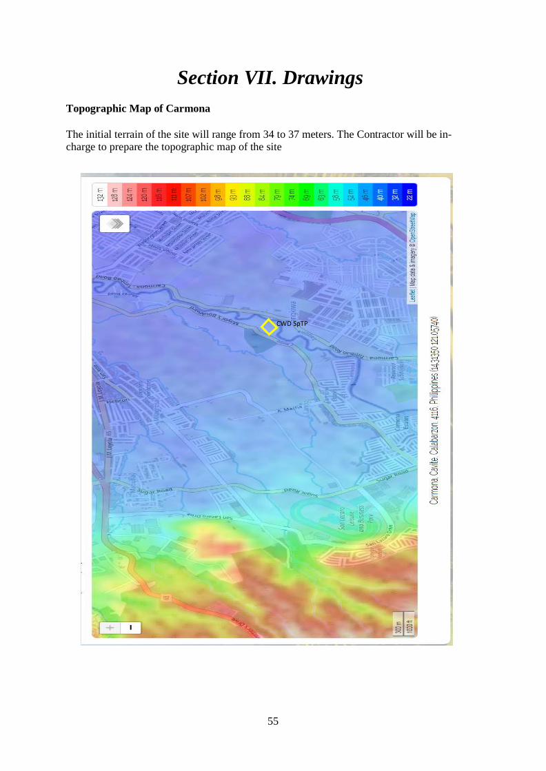
55
Section VII. Drawings Topographic Map of Carmona The initial terrain of the site will range from 34 to 37 meters. The Contractor will be in-charge to prepare the topographic map of the site
CWD SpTP

56
CWD SpTP PLANT LAYOUT (maximum plant footprint of 300 square meters)

57

58
Preliminary CWD SpTP Process Flow Diagram

Section VIII. Bill of Quantities A.1 FINANCIAL PROPOSAL Contract ID: _________________ Contract Name: Design, Build and Maintenance of 20 cmd Septage Treatment Plant Location: Mayor’s Boulevard, Brgy. Maduya, Carmona, Cavite
ITEM DESCRIPTION QUANTITY BID PRICE
I. PRE-CONSTRUCTION PHASE I.A. GENERAL REQUIREMENTS
• STP Treatment Process Flow Sheet • Structural Plans • Electrical Plans • Mechanical Plans • Mobilization (including but not limited
to billboard/signage posting, temporary facility, application and/or arrangement for power and water supply)
• Permits and Licenses • Bonds and Insurances • Safety Requirement • Temporary Requirement • Geotechnical Investigation • Topo Maps (Site)
1 lot
II. CONSTRUCTION PHASE II.A. MAIN PROCESS SYSTEMS
• Septage Tanker Unloading Bay • Rock Trap System (30 liters capacity
slim type, with removable basket, quick opening cover, 4” diameter leading pipe with cam-lock, 2” tank drain port, all components Stainless steel 304)
• Macerator (min. flow: 20cu.m/hr, carbide blades cutting elements)
• Packaged Treatment Unit (5 lps capacity 3” cam-lock and 6” flange connection)
• Trash removal (shiftless, 168mm spiral screen zone diameter, brusher mounted spiral screen cleaning, perforated mesh and stainless steel plate)
• Grit removal system (shaftless with 145mm extraction screw diameter)
• Oil and Grease skimmer – 0.25 kw gear motor, 440v, 60Hz, blower with 1.1kw
1 lot
59

capacity, Air flotation system with 1” connection with manual valve and SS perforated pipe inside
• Septage Holding Tanks (2 units) • Hyperbolic Mixer (0.4Kw, 220V, 60hz,
3 phase, 58 rpm impeller speed, 55.7 Nm Torque, epoxy coated shaft, 500 mm glass fiber reinforcement plastic (GRP) impeller, with submersible pump 130l/min min. flow and 10 meters max. Head)
• Chemical tank with mixer (drive motor: 0.4kw, 4 poles, 3 phase, 220 V, 60 Hz, 1750 RPM, IP 44, 250 RPM output with reduction ratio equivalent to 7, 1cu.m PE tank with ports for drain and outlet)
• Polymer dosing pump(7.2L/min capacity, motor rating: 0.15 kw, 4 pole, 3 phase, 220 V 60 Hz)
• Dewatering Feed Pumps • Chemical Treatment Unit • Sludge Dewatering Unit/Dewatering
press (screw press with 2” diameter inlet and overflow pipe, conical shaft, 15-20% dewatered sludge dryness, 1.7lps water consumption, VFD ready gear motor, 0.55kw, 400V, 60Hz)
• Sludge Tank • Scum Trap System (3 compartments) • Equalization Tank • Anoxic treatment tank with mixer (non-
clog type, 200L/min min capacity, submersible, 0.75 kw, 200 V single phase, 22 cu.m/hr submersible aerators, with 58 rpm impeller speed anoxic tank mixer)
• Sequencing Batch Reactor System (with sub submersible aerators 22 cu.m/hr air volume, with non-clog submersible decanter pump 350L/min)
• Tertiary Treatment (3cu.m/hr capacity chemical treatment tanks for pH adjustment, coagulation, flocculation and clarification, polycarbonate corrugated sheet settlers, epoxy coated 4mm MS plate with angle bars supports, 1750rpm pH adjustment tank agitator, 14-16L/hr pH adjuster dosing pump, 100
60

rpm coagulation tank agitator, 7.8 L/hr coagulation dosing pump and mixer, 1750 rpm flocculation tank agitator, 7.8 L/hr flocculation dosing pump and mixer)
• Clarifier Systems • Filtration Systems (sand filter and
activated carbon filter, 350L/min filetr feed pump, 7.2L/hr chlorine dosing pump)
• Chlorine dioxide generator (50-150 grams/hr capacity with online oxidant level, automatic dosing based on actual oxidant level, 220V, 60Hz)
• Flow Meters (standard water meters for 4” pipe diameter)
II.B. SUPPORT SYSTEMS • Potable Water Storage System • Treated Water Storage System • Civil Works
3. Primary, Secondary and Tertiary area, SBR, Holding Tank, Chemical Tanks
4. Piping process, recycle, potable water lines i. Inlet connections – camlock
type Aluminium construction. Coupled to SS304 pipe via threaded connection with end flange connections.
j. Pipelines – for raw septage and screened septage, all are conveyed through PVC Gray Pipe Sch. 80. Joints are cement-bonded and connections for 8” diameter and 4” diameter pipe to isolation valves and to related equipment area flange connected. Smaller 2” diameter pipes for sludge dewatering unit in-feed, over flow and tank transfer lines are PVC Gray Pipe Schedule 80. Treated water lines for recycling and to be used for washings at the process equipment will be 1” diameter PVC Gray Schedule 80. Potable water and recycled
5 m³ 5 m³
61

water lines for washing are on ¾” diameter PVC Blue Schedule 40.
k. Compressed air pipeline – is multi-materials. Header line going to distribution line is mild steel. Downpipe from distribution line going to the air diffuser loop is stainless steel 304. The diffuser loop is 4” diameter PVC Gray Pipe Schedule 80. Air diffuser is High Density Polyethylene constructed with EPDM membrane.
l. Isolation valves – for the raw septage section is a full bore ball valve type secured in place via flanged connections. This eliminates clogging. Valves for the screened septage section is of butterfly type also in flanged connection. Smaller 2” diameter pipe utilizes true-union ball valves to allow disassembly during maintenance.
m. Brackets, hangers, and supports – fully submerged and wetted areas will be stainless steel 34 anchored using stainless steel 316 anchor bolts. Not wetted area will be epoxy coated mild steel materials.
n. Chutes for screenings, grit, and sludge cake are constructed from stainless steel 304 fabricated in accordance with correct positioning. Final surface finish is hairline like.
o. Hydro test for pressure lines and leak test for non-pressurized lines.
p. Vibration test during dry run and add additional support/brackets when necessary.
• Electrical and Control System 2. Electrical Controls at Primary and
Secondary Treatment and Automation at SBR (Control panels
62

(primary, secondary, remote, MCB, lightings, CO) k. Fabrication, supply and
installation of main control panel. The control panel cabinet material is powder coated steel for durability. The cabinet is accessible via two-weather tight door split opening. Control knobs and light indicators on one door and monitoring/ controller displays are mounted on the other. Wirings are color-coded, two (2) colors for single phase control power and three (3) colors for three phase load lines.
l. Fabrication, supply, and installation of remote control panel. The control panel cabinet material is stainless steel 304 with weather tight single door.
m. Fabrication of lay-outing and mounting powder-coated cable tray. Connections of rigid conduit from cable tray to each motor location. Connection of flexible conduit from the end of rigid conduit connected via cable glands for the submersible pump connections.
n. Lay-outing and wiring from MCP to remote control.
o. Lay-outing and wiring from MCP to each motor.
p. Lay-outing and wiring liquid level controls, limit switch, pressure switch, reversing switch, sensor, etc.
q. Lay-outing and wiring from lighting and C.O.
r. Terminating and commissioning of all loads.
s. Insulation testing of each wiring. t. Testing and dry running of each
motor loads. • Generator Set (Supply, Delivery,
Installation, Commissioning of Generator Set : 90 KVA stand-by duty 220/440 volts, silent type, 3 phase, 60
63

hz, 1800 rpm @ 80 % power factor with Control Panel)
II.C. FACILITIES The following facilities shall be constructed and properly placed in strategic locations.
• Control and Instrumentation Room • Structural Provisions for Receiving and
Dewatering Units • Sludge Cake Storage (Drying Bed) • Generator Set / Powerhouse Room • Chemical and Supplies Storage Room • Laboratory Room • Pond
1 lot
III. COMMISSIONING PHASE • Introduction of Seed Sludge • Training of Operators • Laboratory Testing Fees • Operation and Maintenance Manuals • Assistance in the Acquisition of
Discharge Permit • Commissioning and Process Proving
1 lot
V. VACUUM TRUCKS • 5 cu.m. capacity • 3.5 cu.m. capacity
1 unit 1 unit
PROJECT COST Contractor’s Tax TOTAL PROJECT COST
Contract Duration: ________________ Calendar Days Submitted by: Name _________________________, in the capacity as __________________________ Signed ________________________, Date _______________________ Duly authorized to sign the Bid for and on behalf of ______________________________
64

A.2 DETAILED ESTIMATES
DETAILED ESTIMATES PROJECT: Design, Build and Maintenance of 20 cmd Septage Treatment Plant DATE: LOCATION: Mayor’s Boulevard, Brgy. Maduya, Carmona, Cavite REV. NO.
MA
TER
IALS
NO. NAME AND SPECIFICATIONS OF MATERIALS QTY UNIT UNIT RATE COST
TOTAL FOR MATERIALS NO. NAME AND CAPACITY OF EQUIPMENT/TOOLS NO. OF
UNIT/S NO. OF DAY/S
DAILY RATE
COST
EQU
IPM
ENT
TOTAL FOR EQUIPMENT NO. DESIGNATION OF PERSONNEL NO. OF
UNIT/S NO. OF DAY/S
DAILY RATE
COST
LAB
OR
TOTAL FOR LABOR ESTIMATED DIRECT COST (EDC) OVERHEAD CONTINGENCIES & MISCELLANEOUS _____% (OCM) CONTRACTOR’S PROFIT ______% (CP) VALUE ADDED TAX ______% (EDC+OCM+CP) ESTIMATED INDIRECT COST TOTAL COST UNIT COST ADJUSTED TOTAL COST
Submitted by: ________________________________ (Name and Signature of Representative) ___________________________ (Company)
B. WARRANTY All supplied equipments are originally made and covered by five (5) years warranty against factory defect. After-sales service on parts should be available locally. C. CONSULTANCY SERVICES Five (5) year free consultancy services.
65

Section IX. Checklist of Technical and Financial Documents
I. TECHNICAL COMPONENT ENVELOPE
Class “A” Documents
Legal Documents • Valid PhilGEPS Certificate of Registration and Membership in accordance with Section 8.5.2 of the IRR, except for foreign bidders participating in the procurement by a Philippine Foreign Service Office or Post, which shall submit their eligibility documents under Section 23.1 of the IRR, provided, that the winning bidder shall register with the PhilGEPS in accordance with Section 37.1.4 of the IRR; • Registration certificate from Securities and Exchange Commission (SEC), Department of Trade and Industry (DTI) for sole proprietorship, or Cooperative Development Authority (CDA) for cooperatives or its equivalent document;
• Mayor’s or Business permit issued by the city or municipality where the principal place of business of the prospective bidder is located, or the equivalent document for Exclusive Economic Zones or Areas;
• Tax clearance per E.O. No. 398, s. 2005, as finally reviewed and approved by the Bureau of Internal Revenue (BIR).
Technical Documents • Statement of the prospective bidder of all its completed and ongoing government and private contracts, including contracts awarded but not yet started, if any, whether similar or not similar in nature and complexity to the contract to be bid; • Statement of the bidder’s Single Largest Completed Contract (SLCC) similar to the contract to be bid, except under conditions provided under the rules;
The two statements required shall indicate for each contract the following:
a. name of the contract; b. date of the contract; c. contract duration; d. owner’s name and address; e. nature of work; f. contractor’s role (whether sole contractor, subcontractor, or partner in a
JV) and percentage of participation; g. total contract value at award; h. date of completion or estimated completion time;
66

i. total contract value at completion, if applicable; j. percentages of planned and actual accomplishments, if applicable; and k. value of outstanding works, if applicable.
The statement of the Bidder’s SLCC shall be supported by the Notice of Award and/or Notice to Proceed, Project Owner’s Certificate of Final Acceptance issued by the Owner other than the Contractor or the Constructors Performance Evaluation System (CPES) Final Rating, which must be at least satisfactory. In case of contracts with the private sector, an equivalent document shall be submitted; • Philippine Contractors Accreditation Board (PCAB) License or in case of Joint Ventures, a Special PCAB License and registration for the type and cost of the contract to be bid;
• Original copy of Bid Security. If in the form of a Surety Bond, submit also a certification issued by the Insurance Commission or Original copy of Notarized Bid Securing Declaration;
• Project Requirements, which shall include the following:
a. Organizational chart for the contract to be bid;
b. List of contractor’s key personnel (e.g., Project Manager, Project Engineers, Materials Engineers, and Foremen), to be assigned to the contract to be bid, with their complete qualification, Professional Regulation Commission (PRC) licenses for design professionals and experience data;
c. List of contractor’s major equipment units, which are owned, leased,
and/or under purchase agreements, supported by proof of ownership or certification of availability of equipment from the equipment lessor/vendor for the duration of the project, as the case may be;
• Original duly signed Omnibus Sworn Statement (OSS); • if applicable, Original Notarized Secretary’s Certificate in case of a corporation, partnership, or cooperative; or Original Special Power of Attorney of all members of the joint venture giving full power and authority to its officer to sign the OSS and do acts to represent the Bidder.
Financial Documents • The prospective bidder’s audited financial statements, showing, among others, the prospective bidder’s total and current assets and liabilities, stamped “received” by the BIR or its duly accredited and authorized institutions, for the preceding calendar year which should not be earlier than two (2) years from the date of bid submission; and
• The prospective bidder’s computation of Net Financial Contracting Capacity (NFCC).
67

Class “B” Documents • If applicable, duly signed joint venture agreement (JVA) in accordance with RA No. 4566 and its IRR in case the joint venture is already in existence; or • Duly notarized statements from all the potential joint venture partners stating that they will enter into and abide by the provisions of the JVA in the instance that the bid is successful.
II. FINANCIAL COMPONENT ENVELOPE
• Original of duly signed and accomplished Financial Bid Form; and
• Original of duly signed Bid Prices in the Bill of Quantities; and • Duly accomplished Detailed Estimates Form, including a summary sheet indicating the unit prices of construction materials, labor rates, and equipment rentals used in coming up with the Bid; and
• Cash Flow by Quarter.
68

Bid Form
Date:
IB1
No:
To: [name and address of PROCURING ENTITY] Address: [insert address]
We, the undersigned, declare that:
(a) We have examined and have no reservation to the Bidding Documents, including Addenda, for the Contract [insert name of contract];
(b) We offer to execute the Works for this Contract in accordance with the Bid and Bid
Data Sheet, General and Special Conditions of Contract accompanying this Bid;
The total price of our Bid, excluding any discounts offered below is: [insert information];
The discounts offered and the methodology for their application are: [insert information];
(c) Our Bid shall be valid for a period of [insert number] days from the date fixed for
the Bid submission deadline in accordance with the Bidding Documents, and it shall remain binding upon us and may be accepted at any time before the expiration of that period;
(d) If our Bid is accepted, we commit to obtain a Performance Security in the amount
of [insert percentage amount] percent of the Contract Price for the due performance of the Contract;
(e) Our firm, including any subcontractors or suppliers for any part of the Contract,
have nationalities from the following eligible countries: [insert information];
(f) We are not participating, as Bidders, in more than one Bid in this bidding process, other than alternative offers in accordance with the Bidding Documents;
(g) Our firm, its affiliates or subsidiaries, including any subcontractors or suppliers for
any part of the Contract, has not been declared ineligible by the Funding Source; 1 If ADB, JICA and WB funded projects, use IFB.
(h) We understand that this Bid, together with your written acceptance thereof included in your notification of award, shall constitute a binding contract between us, until a formal Contract is prepared and executed; and
69

(i) We understand that you are not bound to accept the Lowest Calculated Bid or any other Bid that you may receive.
(j) We likewise certify/confirm that the undersigned, is the duly authorized representative
of the bidder, and granted full power and authority to do, execute and perform any and all acts necessary to participate, submit the bid, and to sign and execute the ensuing contract for the [Name of Project] of the [Name of the Procuring Entity].
(k) We acknowledge that failure to sign each and every page of this Bid Form, including
the Bill of Quantities, shall be a ground for the rejection of our bid.
Name:
In the capacity of:
Signed:
Duly authorized to sign the Bid for and on behalf of:
Date:
70

Form of Contract Agreement
THIS AGREEMENT, made this [insert date] day of [insert month], [insert year] between [name and address of PROCURING ENTITY] (hereinafter called the“Entity”) and [name and address of Contractor] (hereinafter called the “Contractor”).
WHEREAS, the Entity is desirous that the Contractor execute [name and
identification number of contract] (hereinafter called “the Works”) and the Entity has accepted the Bid for [insert the amount in specified currency in numbers and words] by the Contractor for the execution and completion of such Works and the remedying of any defects therein.
NOW THIS AGREEMENT WITNESSETH AS FOLLOWS:
1. In this Agreement, words and expressions shall have the same meanings as
are respectively assigned to them in the Conditions of Contract hereinafter referred to.
2. The following documents shall be attached, deemed to form, and be read
and construed as integral part of this Agreement, to wit:
(a) General and Special Conditions of Contract; (b) Drawings/Plans; (c) Specifications; (d) Invitation to Bid; (e) Instructions to Bidders; (f) Bid Data Sheet; (g) Addenda and/or Supplemental/Bid Bulletins, if any; (h) Bid form, including all the documents/statements contained in the
Bidder’s bidding envelopes, as annexes, and all other documents submitted (e.g., Bidder’s response to request for clarifications on the bid), including corrections to the bid, if any, resulting from the Procuring Entity’s bid evaluation;
(i) Eligibility requirements, documents and/or statements; (j) Performance Security; (k) Notice of Award of Contract and the Bidder’s conforme thereto; (l) Other contract documents that may be required by existing laws
and/or the Entity.
3. In consideration of the payments to be made by the Entity to the Contractor as hereinafter mentioned, the Contractor hereby covenants with the Entity to execute and complete the Works and remedy any defects therein in conformity with the provisions of this Contract in all respects.
71
4. The Entity hereby covenants to pay the Contractor in consideration of the execution and completion of the Works and the remedying of defects wherein, the Contract Price or such other sum as may become payable under the provisions of this Contract at the times and in the manner prescribed by this Contract.
IN WITNESS whereof the parties thereto have caused this Agreement to be executed the day and year first before written.
Signed, sealed, delivered by the (for the Entity)
Signed, sealed, delivered by the (for the
Contractor).
Binding Signature of Procuring Entity
Binding Signature of Contractor
[Addendum showing the corrections, if any, made during the Bid evaluation should be attached with this agreement]
72

Omnibus Sworn Statement
REPUBLIC OF THE PHILIPPINES ) CITY/MUNICIPALITY OF ) S.S.
AFFIDAVIT
I, [Name of Affiant], of legal age, [Civil Status], [Nationality], and residing at [Address of Affiant], after having been duly sworn in accordance with law, do hereby depose and state that:
1. Select one, delete the other:
If a sole proprietorship: I am the sole proprietor or authorized representative of [Name of Bidder] with office address at [address of Bidder];
If a partnership, corporation, cooperative, or joint venture: I am the duly authorized and designated representative of [Name of Bidder] with office address at [address of Bidder];
2. Select one, delete the other:
If a sole proprietorship: As the owner and sole proprietor or authorized representative of [Name of Bidder], I have full power and authority to do, execute and perform any and all acts necessary to participate, submit the bid, and to sign and execute the ensuing contract for [Name of the Project] of the [Name of the Procuring Entity] [insert “as shown in the attached duly notarized Special Power of Attorney” for the authorized representative];
If a partnership, corporation, cooperative, or joint venture: I am granted full power and authority to do, execute and perform any and all acts necessary to participate, submit the bid, and to sign and execute the ensuing contract for [Name of the Project] of the [Name of the Procuring Entity], accompanied by the duly notarized Special Power of Attorney, Board/Partnership Resolution, or Secretary’s Certificate, whichever is applicable;
3. [Name of Bidder] is not “blacklisted” or barred from bidding by the
Government of the Philippines or any of its agencies, offices, corporations, or Local Government Units, foreign government/foreign or international financing institution whose blacklisting rules have been recognized by the Government Procurement Policy Board;
4. Each of the documents submitted in satisfaction of the bidding requirements is
an authentic copy of the original, complete, and all statements and information provided therein are true and correct;
73
5. [Name of Bidder] is authorizing the Head of the Procuring Entity or its duly
authorized representative(s) to verify all the documents submitted;
6. Select one, delete the rest:
If a sole proprietorship: The owner or sole proprietor is not related to the Head of the Procuring Entity, members of the Bids and Awards Committee (BAC), the Technical Working Group, and the BAC Secretariat, the head of the Project Management Office or the end-user unit, and the project consultants by consanguinity or affinity up to the third civil degree;
If a partnership or cooperative: None of the officers and members of [Name of Bidder] is related to the Head of the Procuring Entity, members of the Bids and Awards Committee (BAC), the Technical Working Group, and the BAC Secretariat, the head of the Project Management Office or the end-user unit, and the project consultants by consanguinity or affinity up to the third civil degree;
If a corporation or joint venture: None of the officers, directors, and controlling stockholders of [Name of Bidder] is related to the Head of the Procuring Entity, members of the Bids and Awards Committee (BAC), the Technical Working Group, and the BAC Secretariat, the head of the Project Management Office or the end-user unit, and the project consultants by consanguinity or affinity up to the third civil degree;
7. [Name of Bidder] complies with existing labor laws and standards; and
8. [Name of Bidder] is aware of and has undertaken the following responsibilities as a Bidder:
a) Carefully examine all of the Bidding Documents;
b) Acknowledge all conditions, local or otherwise, affecting the implementation of the Contract;
c) Made an estimate of the facilities available and needed for the contract to be bid, if any; and
d) Inquire or secure Supplemental/Bid Bulletin(s) issued for the [Name of the Project].
9. [Name of Bidder] did not give or pay directly or indirectly, any commission, amount, fee, or any form of consideration, pecuniary or otherwise, to any person or official, personnel or representative of the government in relation to any procurement project or activity.
74

IN WITNESS WHEREOF, I have hereunto set my hand this __ day of ___, 20__ at ____________, Philippines.
Bidder’s Representative/Authorized Signatory
SUBSCRIBED AND SWORN to before me this day of [month] [year] at [place of execution], Philippines. Affiant/s is/are personally known to me and was/were identified by me through competent evidence of identity as defined in the 2004 Rules on Notarial Practice (A.M. No. 02-8-13-SC). Affiant/s exhibited to me his/her [insert type of government identification card used], with his/her photograph and signature appearing thereon, with no. and his/her Community Tax Certificate No. issued on at .
Witness my hand and seal this day of [month] [year].
NAME OF NOTARY PUBLIC Serial No. of Commission Notary Public for until Roll of Attorneys No. PTR No. [date issued],[place issued] IBP No. [date issued],[place issued]
Doc. No. Page No. Book No. Series of
* This form will not apply for WB funded projects.
75

(REPUBLIC OF THE PHILIPPINES) CITY OF ) S.S. x ------------------------------------------------------ x
Invitation to Bid [Insert reference number]
To: [Insert name and address of the Procuring Entity]
I/We, the undersigned, declare that:
1. I/We understand that, according to your conditions, bids must be supported by a Bid Security, which may be in the form of a Bid-Securing Declaration.
2. I/We accept that: (a) I/we will be automatically disqualified from bidding for any
contract with any procuring entity for a period of two (2) years upon receipt of your Blacklisting Order; and, (b) I/we will pay the applicable fine provided under Section 6 of the Guidelines on the Use of Bid Securing Declaration, within fifteen (15) days from receipt of written demand by the procuring entity for the commission of acts resulting to the enforcement of the bid securing declaration under Sections 23.1(b), 34.2, 40.1 and 69.1, except 69.1 (f), of the IRR of RA 9184; without prejudice to other legal action the government may undertake.
3. I/We understand that this Bid-Securing Declaration shall cease to be valid on the
following circumstances:
a. Upon expiration of the bid validity period, or any extension thereof pursuant to your request;
b. I am/we are declared ineligible or post-disqualified upon receipt of your notice to such effect, and (i) I/we failed to timely file a request for reconsideration or (ii) I/we filed a waiver to avail of said right;
c. I am/we are declared as the bidder with the Lowest Calculated Responsive Bid, and I/we have furnished the performance security and signed the Contract.
IN WITNESS WHEREOF, I/We have hereunto set my/our hand/s this day of [month] [year] at [place of execution].
[Insert NAME OF BIDDER’S AUTHORIZED REPRESENTATIVE] [Insert signatory’s legal capacity]
Bid-Securing Declaration
76
Affiant
SUBSCRIBED AND SWORN to before me this day of [month] [year] at [place of execution], Philippines. Affiant/s is/are personally known to me and was/were identified by me through competent evidence of identity as defined in the 2004 Rules on Notarial Practice (A.M. No. 02-8-13-SC). Affiant/s exhibited to me his/her [insert type of government identification card used], with his/her photograph and signature appearing thereon, with no. .
Witness my hand and seal this day of [month] [year].
NAME OF NOTARY PUBLIC
Serial No. of Commission Notary Public for until Roll of Attorneys No. PTR No. , [date issued], [place issued] IBP No. , [date issued], [place issued] Doc. No. Page No. Book No. Series of.
77

OUTLINE NARRATIVE DESCRIPTION OF PLAN, APPROACH AND METHODOLOGY
1. INTRODUCTION
2. BRIEF DESCRIPTION OF CONTRACT WORKS
State general features of contract works.
3. METHODOLOGY AND PROCEDURES
• Methodology or General Approach
State general approach or any special techniques, methods or procedures to ensure completion on time and quality of construction financing the project, etc.
• Project Understanding, Substance and Completeness
Identify and clarify the study objectives to coincide with the Performance Specifications; identify the consequences that could affect the objectives.
• Scope and Program of Work and Services
CPM, Progress Bar Schedule and Development Schedule submitted.
• Work Plan and Manning Schedule
State specific activities, including number of staff assigned per activity and the number of hours or days per week spent for each activity; detail the activities and progress indicators that will guide project implementation during the project duration; manning schedule for each activity.
• Financial Program
Cash flow schedules, provision for working capital, schedule of receipts, etc; include detailed project budget for the entire duration of the project prepared on the basis of periodic work plan and including any monitoring and evaluation requirements to effectively measure project performance during the targeted project completion.
• Risks and Suggested Solution
78

Contract Name : Design and Build of 20m³/d Septage Treatment Plant for Carmona Water District
Location : Brgy. Maduya, Carmona, Cavite
CASH FLOW BY QUARTER AND PAYMENT SCHEDULE
PARTICULAR % WT.
1ST QUARTER
2ND QUARTER
3RD QUARTER
4TH QUARTER
ACCOMPLISHMENT
CASH FLOW
CUMULATIVE ACCOMPLISHMENT
CUMULATIVE CASH FLOW
Submitted by:
Name of the Bidder’s Representative: _________________________ Date: _______________ Position: ______________________________ Name of the Bidder: _______________________
Note: One of the requirements from the bidder to be included in its Financial Envelope is the cash flow by quarter and payment schedule.
79

37
80
Copyright © 2022 FDOKUMEN