EMERGENCY SHELTER RENOVATION - McMullen County
524
MCMULLEN COUNTY TILDEN, TEXAS EMERGENCY SHELTER RENOVATION PROJECT MANUAL AND TECHNICAL SPECIFICATIONS DEBRA J. DOCKERY, ARCHITECT, P.C. 118 BROADWAY, SUITE 516 SAN ANTONIO, TEXAS 78205 (210) 225-6130 JUNE 2019
-
Upload
khangminh22 -
Category
Documents
-
view
0 -
download
0
Transcript of EMERGENCY SHELTER RENOVATION - McMullen County

MCMULLEN COUNTY TILDEN, TEXAS
EMERGENCY SHELTER RENOVATION
PROJECT MANUAL AND TECHNICAL SPECIFICATIONS
DEBRA J. DOCKERY, ARCHITECT, P.C. 118 BROADWAY, SUITE 516
SAN ANTONIO, TEXAS 78205 (210) 225-6130
JUNE 2019

MCMULLEN COUNTY APRIL 2019 EMERGENCY SHELTER RENOVATION
Texas Registered Engineering Firm F-1008 TOC - 1
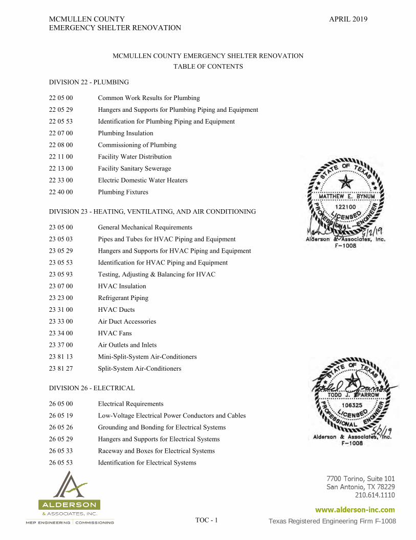
MCMULLEN COUNTY EMERGENCY SHELTER RENOVATION TABLE OF CONTENTS
DIVISION 22 - PLUMBING 22 05 00 Common Work Results for Plumbing
22 05 29 Hangers and Supports for Plumbing Piping and Equipment
22 05 53 Identification for Plumbing Piping and Equipment
22 07 00 Plumbing Insulation
22 08 00 Commissioning of Plumbing
22 11 00 Facility Water Distribution
22 13 00 Facility Sanitary Sewerage
22 33 00 Electric Domestic Water Heaters
22 40 00 Plumbing Fixtures
DIVISION 23 - HEATING, VENTILATING, AND AIR CONDITIONING 23 05 00 General Mechanical Requirements
23 05 03 Pipes and Tubes for HVAC Piping and Equipment
23 05 29 Hangers and Supports for HVAC Piping and Equipment
23 05 53 Identification for HVAC Piping and Equipment
23 05 93 Testing, Adjusting & Balancing for HVAC
23 07 00 HVAC Insulation
23 23 00 Refrigerant Piping
23 31 00 HVAC Ducts
23 33 00 Air Duct Accessories
23 34 00 HVAC Fans
23 37 00 Air Outlets and Inlets
23 81 13 Mini-Split-System Air-Conditioners
23 81 27 Split-System Air-Conditioners
DIVISION 26 - ELECTRICAL 26 05 00 Electrical Requirements
26 05 19 Low-Voltage Electrical Power Conductors and Cables
26 05 26 Grounding and Bonding for Electrical Systems
26 05 29 Hangers and Supports for Electrical Systems
26 05 33 Raceway and Boxes for Electrical Systems
26 05 53 Identification for Electrical Systems
MCMULLEN COUNTY APRIL 2019 EMERGENCY SHELTER RENOVATION
Texas Registered Engineering Firm F-1008 TOC - 2
26 08 00 Commissioning of Electrical
26 09 43 Network Lighting Controls
26 24 16 Panelboards
26 27 26 Wiring Devices
26 28 13 Fuses
26 28 19 Enclosed Switches
26 43 13 Surge Protection Devices
26 51 00 Interior Lighting
26 52 00 Emergency Lighting
26 56 00 Exterior Lighting
END OF SECTION

MCMULLEN COUNTY JUNE 2019 EMERGENCY SHELTER RENOVATION
REQUEST FOR PROPOSALS Page 1 of 1
REQUEST FOR PROPOSALS FOR CONSTRUCTION SERVICES
McMullen County requests proposals from qualified general contractors for the McMullen County Emergency Shelter Renovation, located at 401 Main Street, Tilden, Texas, 78072. Electronic documents may be obtained from the county’s website: www.mcmullencounty.org, www.civcastusa.com, or at the office of Debra J. Dockery, Architect, P.C., 118 Broadway, Suite 516, San Antonio, Texas 78205, (210) 225-6130. From the architect’s office each general contractor proposer may receive a disk with the drawings and project manual in pdf format. There is no charge for the disk. Subcontractors and material suppliers may receive the documents on disk for a non-refundable deposit of $25.00 per disk. Proposers are to use the proposal forms included in the project manual, including the proposal form, required certifications, and further materials describing their capabilities and experience in the format prescribed in the Request for Proposals. PROPOSALS MUST BE RECEIVED NO LATER THAN 3:00 PM, CDT, ON THURSDAY, AUGUST 1, 2019 at the Project Manager’s Office, McMullen County Courthouse, 501 River Street, Tilden, Texas 78072. No faxed or emailed proposals will be accepted. Any proposal received after such time will not be considered and will be returned unopened. A pre-proposal conference to discuss the project and tour the site will be held at 1:30 PM on Monday, July 22, 2019 at the McMullen County Facility located at 401 Main Street, Tilden, Texas, 78072. Any requests for interpretation, clarification, or substitutions shall be received no later than 5:00 PM, Wednesday, July 24, 2019. Submit questions to Debra J. Dockery, FAIA at [email protected]. McMullen County will select the offeror that offers the best value based on the proposed monetary amount, the Contractor’s past performance and other criteria, provided the proposals do not exceed the amount budgeted. The Owner and its Architect may discuss with the selected offeror options for a scope or time modification and any price change associated with the modification. If the Owner is unable to negotiate an agreement with the selected offeror, negotiations will be ended with that offeror and the negotiation process will begin with the second offeror. This process shall continue until an agreement has been negotiated with an offeror or the Owner rejects all proposals for this project. By submitting a Proposal, each offeror agrees to waive any claim it has or may have against the Owner, the Architect, the Architect’s consultants, and their respective trustees, agents, employees, and any reference sources, arising out of or in connection with the administration, evaluation, or recommendation of any proposal; waiver of any requirements under the proposal documents; acceptance or rejection of any proposal, and award of the Contract. McMullen County shall have no contractual obligation to any offeror, nor will any offeror have any property interest or other right in the contract or Work being proposed unless and until the contract is unconditionally executed and delivered by all parties, and all conditions to be fulfilled by the offeror have been so fulfilled. Bid bonds in the amount of 5% of the greatest amount bid are required with the proposal. The successful proposer shall provide payment and performance bonds and insurance in the kinds and amounts described in the contract documents.

MCMULLEN COUNTY JUNE 2019 EMERGENCY SHELTER RENOVATION
INSTRUCTIONS TO PROPOSERS PAGE 1 OF 5
INSTRUCTIONS TO PROPOSERS INVITATION FOR COMPETITIVE SEALED PROPOSALS FOR CONSTRUCTION SERVICES: McMullen County will receive proposals at the Project Manager’s office in the McMullen County Courthouse, 501 River Street, Tilden, Texas 78072 until the time and date specified in the Request for Proposals for Construction Services for the McMullen County Emergency Shelter Renovation. CONTRACT DOCUMENTS: A compact disk with the Contract Documents in electronic format may be obtained by Proposers from the office of Debra J. Dockery, Architect, P.C. The disk is at no charge to general contractors. Subcontractors and material suppliers may obtain a disk for a non-refundable deposit of $25.00. Contract Documents may be examined at the following locations:
San Antonio Builders Exchange, 4047 Naco Perrin, San Antonio, Texas 78265
F. W. Dodge Corporation, 401 Isom Road, San Antonio, Texas 78216 PRE-PROPOSAL CONFERENCE: The Architect will hold a Pre-Proposal Conference to discuss the Project, answer questions, and tour the project site. The meeting will be held at the time and place stipulated in the Request for Proposals for Construction Services. QUALIFICATIONS STATEMENTS: Proposals are to include the information requested in the Form of the Qualifications Statement of this Request for Competitive Sealed Proposals in the sequence and format prescribed. McMullen County will select a construction contractor from the respondents to this request for proposals, or reject all proposals. In determining which proposal provides the best value, the County will consider all responses to the questions set forth in Form of the Qualifications Statement of this document, as well as the factors described in the Request for Proposals. PROPOSALS:
A. Identification of Proposals: Complete proposals shall be submitted in sealed envelopes clearly marked with the name of the project as it appears on the cover page of the Project Manual and with the name and address of the Proposer.
B. Proposal Requirements: See the Proposal Packet Checklist included in this Project Manual for a listing of the information required of each proposer.
C. In the event the proposal is mailed, it is the responsibility of the proposer to allow enough time in transit for the bid to be received by the County prior to the date and hour of proposal opening. Proposals may be delivered by hand to the McMullen County prior to proposal opening.
MCMULLEN COUNTY JUNE 2019 EMERGENCY SHELTER RENOVATION
INSTRUCTIONS TO PROPOSERS PAGE 2 OF 5
Faxed, emailed or telephone proposals will not be accepted.
D. Proposals received prior to the advertised hour of opening will be kept securely sealed. The Owner’s representative whose duty is to open the proposals will decide when the specified time has arrived and no proposal received thereafter will be considered. The Owner or the Owner’s representatives will not be responsible for premature opening of, or the failure to open, a proposal not properly addressed or identified.
E. In case of ambiguity or lack of clearness in the stated price in the proposal, the Owner will adopt the price written in words.
ACCURACY OF PROPOSAL It is specifically understood and provided that a proposal represents a true and correct statement of such proposal and contains no clause for claim of omission or error. WITHDRAWAL OF PROPOSAL: A Proposer may withdraw his proposal, either personally or by written request at any time prior to the scheduled closing time for the receipt of proposals. After the proposal closing time, proposals may not be withdrawn for a period of forty-five (45) days after the closing time for the receipt of proposals. AWARD OF CONTRACT(S): The Owner will award a Contract to the Proposer offering the best value to the McMullen County as described in the Request for Proposals for Construction Services. EXAMINATION OF SITE: Prior to the submittal of proposals, each Proposer shall make, and will be deemed to have made, a thorough examination of the site of the Work and all conditions existing herein. EXAMINATION OF CONTRACT DOCUMENTS: Before submitting proposals, Proposers shall carefully examine the complete Contract Documents, including the Drawings and Specifications, and shall bring any discrepancies to the attention of the Architect for clarification. CONDITION OF THE WORK: Each Proposer shall inform himself fully of the conditions relating to construction of the project and the employment of labor thereon. Failure to do so will not relieve a successful Proposer of his obligation to furnish all materials and labor necessary to carry out the provisions of the Contract. LAWS AND REGULATIONS: The Proposer's attention is directed to the fact that all applicable State laws, ordinances, and the rules and regulations of all authorities having jurisdiction over the construction of the project shall apply to the Contract throughout and they will be deemed to be included in the Contract the same as if written therein
MCMULLEN COUNTY JUNE 2019 EMERGENCY SHELTER RENOVATION
INSTRUCTIONS TO PROPOSERS PAGE 3 OF 5
in full. INTERPRETATION OF CONTRACT DOCUMENTS: Prospective Proposers requiring further information or interpretation of the Contract Documents (Drawings and Specifications) shall request such information in writing from the Architect. Only written responses including additional information shall be considered by Prospective Proposers when submitting a proposal. ADDENDA: Answers to all questions, inquiries, or requests for additional information will be issued in the form of Addenda, and copies of each Addendum will be issued to all prospective Proposers. Also, prospective Proposers may, during the proposal period, be advised by Addendum of additions to, deletions from, or changes in the requirements of the Contract Document. The Architect and the Owner will not be responsible for the authenticity or correctness of oral interpretations of the Contract Documents or for information obtained in any other manner than through the media of Addenda. Receipt of each Addendum shall be acknowledged by Proposers in their proposal form and each Addendum shall be considered a part of the Contract Documents. Failure to acknowledge receipt of any addendum issued may invalidate a proposal as unresponsive. TIME OF COMPLETION: Time is of the essence of the Contract. Immediately after the "Notice to Proceed" has been issued, the Contractor shall start the work and complete the project within the Contract Time allowed and upon the dates stipulated. The project shall be completed in the time stated in Specification Section 011000 Summary of Work. If the Contractor shall fail to complete the work within the Contract Time, or extensions of time granted by the Architect, then the Contractor will pay to the Owner the amount of Liquidated Damages, all as outlined in the Owner / Contractor Agreement. Furthermore, no payment will be made on account of the Contract after the Completion Dates set out in the Notice to Proceed other than final payment at completion of the work. CERTIFICATES OF INSURANCE: The Contractor shall provide Certificates of Insurance, and Payment and Performance Bonds. The bonds and insurance coverage must be approved in all respects by the Owner's Insurance Counselor and shall provide that written notice must be furnished to the Owner 30 days prior to any cancellation of the insurance coverage required by the Contract Documents. The required kinds and amounts of insurance are listed in the Supplementary General Conditions, Article 11 included in this project manual. PERFORMANCE AND PAYMENT BONDS: Performance and Payment Bonds will be required on this project. The Successful Proposer must deliver to the Owner fully executed Performance and Payment Bonds in the amount of 100 percent (100%) of the accepted proposal as security for the faithful performance of the contract and payment of all persons
MCMULLEN COUNTY JUNE 2019 EMERGENCY SHELTER RENOVATION
INSTRUCTIONS TO PROPOSERS PAGE 4 OF 5
performing labor and furnishing material in connection with this contract. The Payment and Performance Bonds shall meet the requirements of Texas Government Code Chapter 2253. All bonds shall be issued by a surety company licensed, listed and authorized to issue bonds in the State of Texas by the Texas Department of Insurance. The surety company may be required by the McMullen County to have a rating of not less than "B" in the latest edition of Best's Insurance Reports, Property Casualty. The surety company shall also provide the requested information necessary to document net worth, stability, total bonding capacity, other projects under coverage and shall provide proof to establish adequate financial capacity for this project. Should the bond amount be in excess of ten percent (10%) of the surety company's capital and surplus, the surety company issuing the bond shall certify that the surety company has acquired reinsurance, in a form and amount acceptable to the Owner, to reinsure the portion of the risk that exceeds ten percent (10%) of the surety company's capital and surplus with one or more reinsurers who are duly authorized and admitted to do business in Texas and that amount reinsured by an reinsurer does not exceed ten percent (10%) of the reinsurer's capital and surplus. SUBSTITUTION REQUESTS FOR MATERIALS AND EQUIPMENT (shall be 7 days prior to proposal due date): Each Proposer represents that his bid is based upon the materials and equipment described in the contract documents. Only material and equipment listed in the contract documents or approved by addenda shall be included in the proposal form. The Contractor may propose alternate or non-approved manufacturers, material or equipment under question I. (2) of the Form of Qualifications Statement to include any monetary amounts to be deducted from the Contractor=s base proposal should the manufacturer, material, or equipment be accepted after the opening of proposals. Substitution requests for approval by addenda will not be considered unless a written request has been submitted to the Architect for review and consideration at least seven days prior to the date for receipt of proposals. Each such request shall include a complete description of the proposed substitute, the name of the material or equipment for which it is to be substituted, drawings, cut sheets, performance and test data, and any other data or information necessary for a complete evaluation. Incomplete substitution requests will not be acted upon by the Architect.
A. Do not substitute materials, equipment, or procedures unless a substitution request has been specifically accepted by addenda for this project by the Architect.
B. Where the phrase "or equal" or "equal as accepted by the Architect" occurs in the Contract Documents, do not assume that the materials, equipment, or procedures will be acceptable as equal unless the item has been specifically accepted for this project by the Architect.
C. Substitution requests for "or equal" consideration: Requests for inclusion in the Contract Documents for an "or equal" material, item, or procedure shall be submitted in writing as a "Substitution Request" to the Architect for consideration by the above listed deadline. If granted, the Architect's acceptance to use the material, item, or procedure as a basis of bids will be in writing and a copy will be forwarded to all bidders in the form of an addendum.
D. Should a Proposer wish to propose a manufacturer whose product differs in some way from the requirements of the Contract Documents, such proposal shall be done through the substitution process described in the above paragraphs. All deviations from the specified product shall be
MCMULLEN COUNTY JUNE 2019 EMERGENCY SHELTER RENOVATION
INSTRUCTIONS TO PROPOSERS PAGE 5 OF 5
specifically listed and any effect upon other work shall be clearly described.
E. The decision of the Architect on any substitution request shall be final.
F. Inclusion of items as a basis of bids will be conditional, subject to compliance with the Contract Documents. Should the substitution request material, item, or procedure be inferior, incomplete, not compatible or inappropriate for use on the project or with other associated specified items, the Contractor shall provide the originally specified material, item, or procedure at no additional cost to the Owner.
G. No substitutions will be accepted after the award of the Contract.
END OF INSTRUCTIONS TO PROPOSERS
MCMULLEN COUNTY JUNE 2019 EMERGENCY SHELTER RENOVATION
PROPOSAL PACKET CHECKLIST Page 1 OF 1
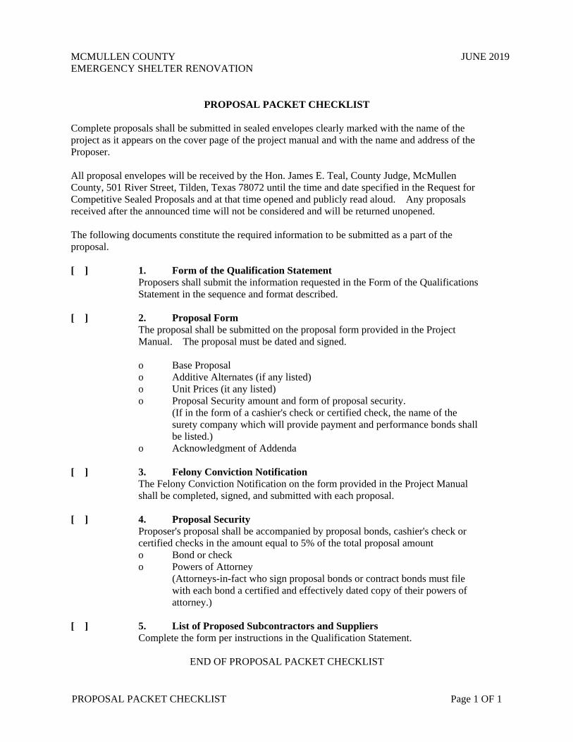
PROPOSAL PACKET CHECKLIST Complete proposals shall be submitted in sealed envelopes clearly marked with the name of the project as it appears on the cover page of the project manual and with the name and address of the Proposer. All proposal envelopes will be received by the Hon. James E. Teal, County Judge, McMullen County, 501 River Street, Tilden, Texas 78072 until the time and date specified in the Request for Competitive Sealed Proposals and at that time opened and publicly read aloud. Any proposals received after the announced time will not be considered and will be returned unopened. The following documents constitute the required information to be submitted as a part of the proposal.
[ ] 1. Form of the Qualification Statement
Proposers shall submit the information requested in the Form of the Qualifications Statement in the sequence and format described.
[ ] 2. Proposal Form
The proposal shall be submitted on the proposal form provided in the Project Manual. The proposal must be dated and signed.
o Base Proposal o Additive Alternates (if any listed) o Unit Prices (it any listed) o Proposal Security amount and form of proposal security.
(If in the form of a cashier's check or certified check, the name of the surety company which will provide payment and performance bonds shall be listed.)
o Acknowledgment of Addenda [ ] 3. Felony Conviction Notification
The Felony Conviction Notification on the form provided in the Project Manual shall be completed, signed, and submitted with each proposal.
[ ] 4. Proposal Security
Proposer's proposal shall be accompanied by proposal bonds, cashier's check or certified checks in the amount equal to 5% of the total proposal amount o Bond or check o Powers of Attorney
(Attorneys-in-fact who sign proposal bonds or contract bonds must file with each bond a certified and effectively dated copy of their powers of attorney.)
[ ] 5. List of Proposed Subcontractors and Suppliers
Complete the form per instructions in the Qualification Statement.
END OF PROPOSAL PACKET CHECKLIST

MCMULLEN COUNTY JUNE 2019 EMERGENCY SHELTER RENOVATION
QUALIFICATIONS Page 1 of 3
FORM OF THE QUALIFICATIONS STATEMENT INFORMATION TO BE PROVIDED BY OFFERORS Please provide the following information concerning your firm: A. Offeror Information
1. Name of Firm 2. Business Address 3. Telephone Number 4. Type of Organization (Individual, Partnership, Corporation, Association) 5. Number of Permanent Employees. (Employees hired for the duration of a
specific project or under a fixed-term contract are not considered permanent employees for purposes of this proposal). i. Home Office ii. Field
6. Primary Contact Person 7. Email address of Primary Contact 8. Main Office Location (if different than above) 9. Describe any substantial changes in ownership of your firm during the past five
years. 10. How many years has your firm operated under its current form of business
organization? 11. List all professional or industry organizations in which your firm or its principals
are members. B. Personnel Information Provide brief resumes (1 page limit per resume) for the persons listed below:
1. Principals/ Corporate Officers: i. President ii. Vice President iii. Partners
2. Project Management Candidates i. Project Manager ii. Superintendent
For the Project Manager and Superintendent Candidates, please provide a list of the principal duties and responsibilities you anticipate assigning to the Project Manager and to the Superintendent. C. Representative Past Projects – 5 pages maximum List a maximum of five projects completed within the past ten years of similar scope and size to this proposed project, and for each project list:

MCMULLEN COUNTY JUNE 2019 EMERGENCY SHELTER RENOVATION
QUALIFICATIONS Page 2 of 3
1. Project Owner 2. Brief description of the project with completed project photos 3. Client, Client Contact Person, and Telephone Number 4. Date Construction Completed 5. Managing Principal 6. Project Architect or Engineer 7. Original contract amount 8. Final contract amount 9. Number of change orders
E. Organization – 2 pages maximum
1. List the classifications of work or trades which you anticipate performing with in-house forces.
2. Summarize your company’s quality control measures.
3. Summarize your company’s safety policy and safety plan.
4. Describe your firm's concepts for teaming with all project members including Owner,
Architect, Engineers, and Sub-contractors.
6. Explain your firm’s warranty response program. F. Claims and Litigation
1. Identify any claims or suits, if any, brought against your firm, or a firm of which you were previously a principal within the past 10 years.
2. Describe all instances in which your firm, or a firm of which you were previously a
principal within the past 10 years, was unable to complete the work under a contract.
3. Identify any judgments, claims arbitration proceedings or suits pending or outstanding against your firm or its officers.
4. Identify all claims, arbitration proceedings or suits initiated by your firm, or a firm of
which you were previously a principal within the last ten years and the outcome or status of pending proceedings.
G. Current Work Load
Provide the following information for the five largest projects you currently have under
contract
1. Project Name 2. Location
MCMULLEN COUNTY JUNE 2019 EMERGENCY SHELTER RENOVATION
QUALIFICATIONS Page 3 of 3
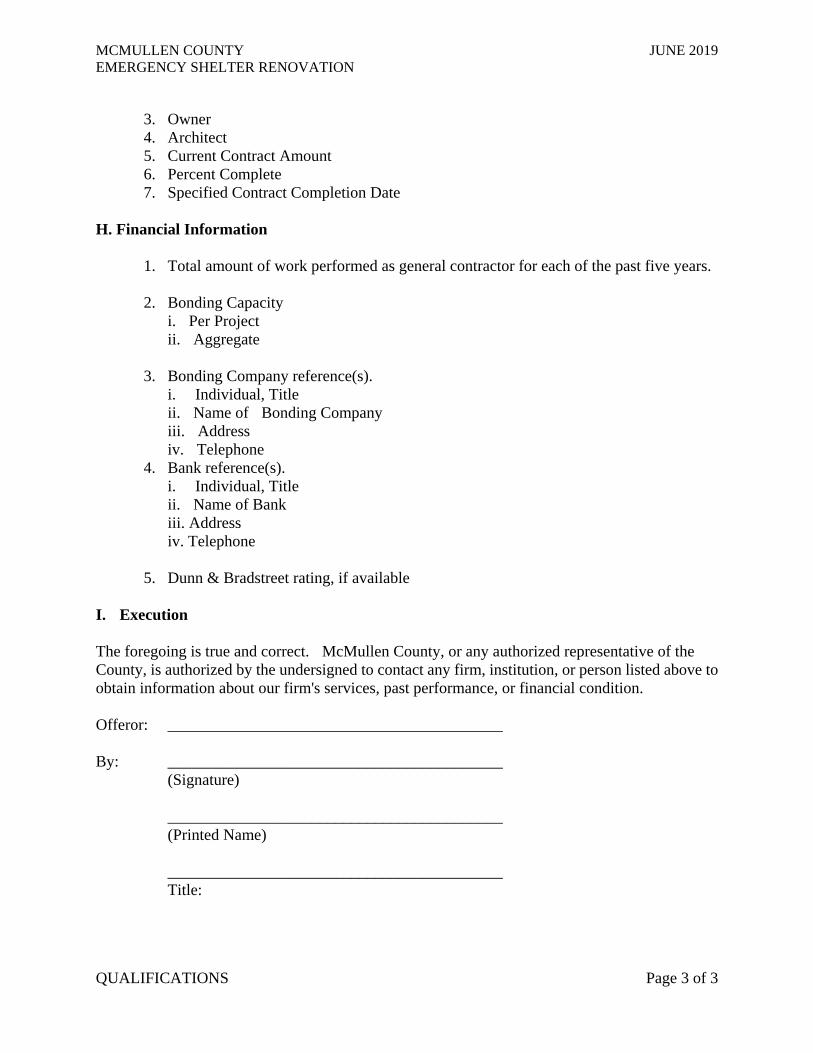
3. Owner 4. Architect 5. Current Contract Amount 6. Percent Complete 7. Specified Contract Completion Date
H. Financial Information
1. Total amount of work performed as general contractor for each of the past five years.
2. Bonding Capacity i. Per Project ii. Aggregate
3. Bonding Company reference(s).
i. Individual, Title ii. Name of Bonding Company iii. Address iv. Telephone
4. Bank reference(s). i. Individual, Title ii. Name of Bank iii. Address iv. Telephone
5. Dunn & Bradstreet rating, if available
I. Execution The foregoing is true and correct. McMullen County, or any authorized representative of the County, is authorized by the undersigned to contact any firm, institution, or person listed above to obtain information about our firm's services, past performance, or financial condition. Offeror: __________________________________________ By: __________________________________________
(Signature)
__________________________________________ (Printed Name)
__________________________________________ Title:
MCMULLEN COUNTY JUNE 2019 EMERGENCY SHELTER RENOVATION f
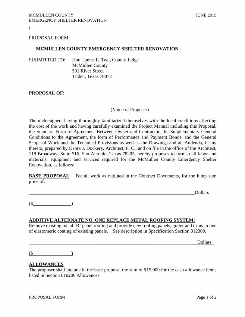
PROPOSAL FORM Page 1 of 2
PROPOSAL FORM: MCMULLEN COUNTY EMERGENCY SHELTER RENOVATION SUBMITTED TO: Hon. James E. Teal, County Judge McMullen County 501 River Street Tilden, Texas 78072 PROPOSAL OF: ________________________________________________________________ (Name of Proposer) The undersigned, having thoroughly familiarized themselves with the local conditions affecting the cost of the work and having carefully examined the Project Manual including this Proposal, the Standard Form of Agreement Between Owner and Contractor, the Supplementary General Conditions to the Agreement, the form of Performance and Payment Bonds, and the General Scope of Work and the Technical Provisions as well as the Drawings and all Addenda, if any thereto, prepared by Debra J. Dockery, Architect, P. C., and on file in the office of the Architect, 118 Broadway, Suite 516, San Antonio, Texas 78205, hereby proposes to furnish all labor and materials, equipment and services required for the McMullen County Emergency Shelter Renovation, as follows: BASE PROPOSAL: For all work as outlined in the Contract Documents, for the lump sum price of: _____________________________________________________________________Dollars ($________________) ADDITIVE ALTERNATE NO. ONE REPLACE METAL ROOFING SYSTEM: Remove existing metal ‘R’ panel roofing and provide new roofing panels, gutter and trims in lieu of elastomeric coating of existing panels. See description in Specification Section 012300. ______________________________________________________________________Dollars ($________________) ALLOWANCES The proposer shall include in the base proposal the sum of $15,000 for the cash allowance items listed in Section 010200 Allowances.

MCMULLEN COUNTY JUNE 2019 EMERGENCY SHELTER RENOVATION f
PROPOSAL FORM Page 2 of 2
TIME: The undersigned agrees to complete the work in the total consecutive calendar days stipulated below: TIME OF COMPLETION: One Hundred Twenty (120) Consecutive Calendar Days from Notice to Proceed. ADDENDA: The undersigned hereby acknowledges receipt of the following Addenda to the Contract Documents, all of the provisions and requirements of the Addenda listed below have been taken into consideration in the preparation of the foregoing proposal: ADDENDA NUMBER: DATE ISSUED: _____________________________________________________________________________ ______________________________________________________________________________ _____________________________________________________________________________ RESPECTFULLY SUBMITTED, (PROPOSERS FILL IN:) __________________________________________________________ (Legal Name of Proposing Firm) __________________________________________________________ (Address) __________________________________________________________ (City, State, Zip Code) __________________________________________________________ (Telephone) __________________________________________________________ (Typed Name and Title of Authorized Officer) __________________________________________________________ (Signature of Officer) __________________________________________________________ (Date)
MCMULLEN COUNTY JUNE 2019 EMERGENCY SHELTER RENOVATION
FELONY CONVICTION NOTIFICATION PAGE 1 OF 1
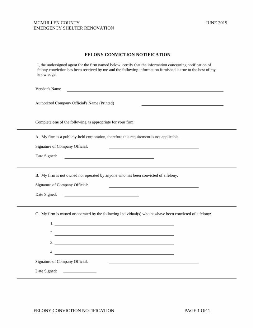
FELONY CONVICTION NOTIFICATION
I, the undersigned agent for the firm named below, certify that the information concerning notification of felony conviction has been received by me and the following information furnished is true to the best of my knowledge.
Vendor's Name Authorized Company Official's Name (Printed) Complete one of the following as appropriate for your firm: A. My firm is a publicly-held corporation, therefore this requirement is not applicable. Signature of Company Official: Date Signed: B. My firm is not owned nor operated by anyone who has been convicted of a felony. Signature of Company Official: Date Signed: C. My firm is owned or operated by the following individual(s) who has/have been convicted of a felony:
1.
2. 3.
4.
Signature of Company Official: Date Signed: ________________

MCMULLEN COUNTY JUNE 2019 EMERGENCY SHELTER RENOVATION
LIST OF SUBCONTRACTORS AND SUPPLIERS Page 1 of 1
LIST OF PROPOSED SUBCONTRACTORS AND SUPPLIERS SUBCONTRACTING AREA NAME Selection Demolition / Concrete Saw-cuts Cast-in-Place Concrete Work Metal Fabrications and Railings
Cabinetry
Thermal and Sound Attenuation Insulation Metal Wall Panels Elastomeric Roof Coating Metal Roof Panels Aluminum Windows Toilet Accessories and Specialties Metal Doors and Frames Door Hardware Gypsum Board / Drywall Work Tiling Acoustical Panel Ceilings Resilient Flooring and Base Painting Plumbing Mechanical Electrical Asphalt Paving Concrete Paving
Other (list):
List the work the general contractor will self perform:
MCMULLEN COUNTY JUNE 2019 EMERGENCY SHELTER RENOVATION
GENERAL CONDITIONS CONTRACT STATEMENT Page 1 of 1
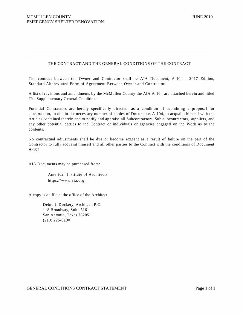
THE CONTRACT AND THE GENERAL CONDITIONS OF THE CONTRACT The contract between the Owner and Contractor shall be AIA Document, A-104 - 2017 Edition, Standard Abbreviated Form of Agreement Between Owner and Contractor.
A list of revisions and amendments by the McMullen County the AIA A-104 are attached herein and titled The Supplementary General Conditions.
Potential Contractors are hereby specifically directed, as a condition of submitting a proposal for construction, to obtain the necessary number of copies of Documents A-104, to acquaint himself with the Articles contained therein and to notify and appraise all Subcontractors, Sub-subcontractors, suppliers, and any other potential parties to the Contract or individuals or agencies engaged on the Work as to the contents.
No contractual adjustments shall be due or become exigent as a result of failure on the part of the Contractor to fully acquaint himself and all other parties to the Contract with the conditions of Document A-104.
AIA Documents may be purchased from:
American Institute of Architects
https://www.aia.org A copy is on file at the office of the Architect.
Debra J. Dockery, Architect, P.C. 118 Broadway, Suite 516 San Antonio, Texas 78205 (210) 225-6130

SUPPLEM ENTARY GENERAL CONDITIONS PAGE 1 OF 4
MCMULLEN COUNTY JUNE 2019 EMERGENCY SHELTER RENOVATION
SUPPLEM ENTARY GENERAL CO NDITIONS
Amendments to AIA Document A104
The following provisions amend, supplement, and/or replace the standard provisions of AIA Document A104 (2017), Standard Abbreviated Form of Agreement Between Owner and Contractor, and control such provisions to the extent of any conflict:
Article 2 2.1 The Date of Commencement shall be fixed in a written notice to proceed. 2.3 The Contractor shall achieve Substantial Completion of the entire work not later
than one hundred twenty (120) consecutive calendar days from Date of Commencement. If the Substantial Completion date is not met per the General Conditions of the Owner / Contractor Agreement, the Contractor agrees to pay the Owner the sum of $500.00 per calendar day for each day that the work remains incomplete after the expiration of the time period set forth as a fixed, agreed liquidated damages.
Article 3 3.1 The Contract Sum shall be stipulated price. (Delete Paragraphs 3.3 and 3.4)
3.5 If the Substantial Completion date is not met per the General Conditions of the Owner / Contractor Agreement, the Contractor agrees to pay the Owner the sum of $300.00 per calendar day for each day that the work remains incomplete after the expiration of the time period set forth as a fixed, agreed liquidated damages.
Article 4 4.1.2 Request for partial payment on completed work shall be submitted no sooner than once per month. Retainage of 5% will be withheld from each payment
application. The retainage will be released upon completion of all the work, including punch list items, the delivery to the Owner of all close-out manuals and record drawings, the submission of release of liens by the General Contractor and all sub-contractors and material suppliers, and the execution of the Consent of Surety to Final Payment form.
4.1.3 Applications shall be received not later than the first day of the month. The Owner will
make payment not later than the last day of the month. 4.1.4 Retainage of 5% will be withheld from each payment application. The retainage will be
released upon completion of all the work, including punch list items, the delivery to the Owner of all close-out manuals and record drawings, the submission of release of liens by the General Contractor and all sub-contractors and material suppliers, and the execution of the Consent of Surety to Final Payment form.
Add to 4.2.1
.4 a Consent of Surety to Final Payment is submitted by the Contractor.
.5 all inspections required by the authorities having jurisdiction have been passed and any required certificates or approvals by the authorities have been issued.
Article 5 5.1 For any claim subject to, but not resolved by, mediation pursuant to Section 21.3, the method of binding dispute resolution shall be litigation in a court of competent jurisdiction. The venue shall be McMullen County, Texas.
SUPPLEM ENTARY GENERAL CONDITIONS PAGE 2 OF 4
MCMULLEN COUNTY JUNE 2019 EMERGENCY SHELTER RENOVATION
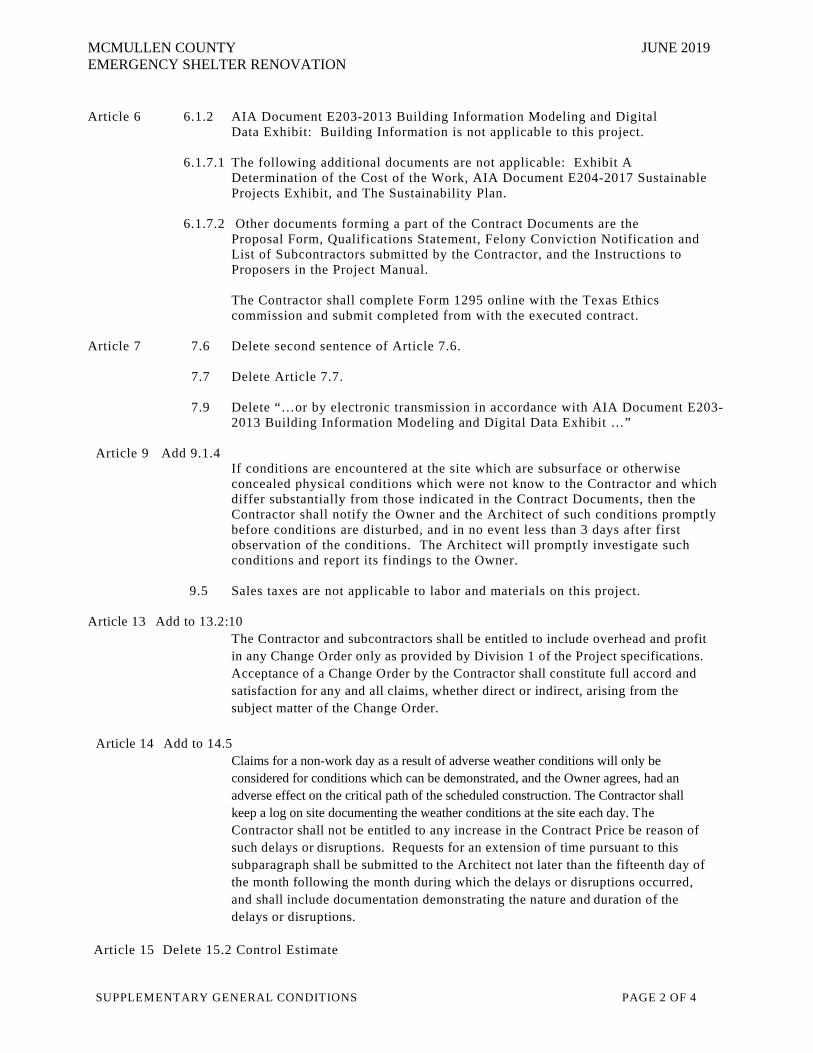
Article 6 6.1.2 AIA Document E203-2013 Building Information Modeling and Digital Data Exhibit: Building Information is not applicable to this project.
6.1.7.1 The following additional documents are not applicable: Exhibit A
Determination of the Cost of the Work, AIA Document E204-2017 Sustainable Projects Exhibit, and The Sustainability Plan.
6.1.7.2 Other documents forming a part of the Contract Documents are the
Proposal Form, Qualifications Statement, Felony Conviction Notification and List of Subcontractors submitted by the Contractor, and the Instructions to Proposers in the Project Manual.
The Contractor shall complete Form 1295 online with the Texas Ethics commission and submit completed from with the executed contract.
Article 7 7.6 Delete second sentence of Article 7.6. 7.7 Delete Article 7.7. 7.9 Delete “…or by electronic transmission in accordance with AIA Document E203-
2013 Building Information Modeling and Digital Data Exhibit …” Article 9 Add 9.1.4 If conditions are encountered at the site which are subsurface or otherwise
concealed physical conditions which were not know to the Contractor and which differ substantially from those indicated in the Contract Documents, then the Contractor shall notify the Owner and the Architect of such conditions promptly before conditions are disturbed, and in no event less than 3 days after first observation of the conditions. The Architect will promptly investigate such conditions and report its findings to the Owner.
9.5 Sales taxes are not applicable to labor and materials on this project.
Article 13 Add to 13.2:10 The Contractor and subcontractors shall be entitled to include overhead and profit
in any Change Order only as provided by Division 1 of the Project specifications. Acceptance of a Change Order by the Contractor shall constitute full accord and satisfaction for any and all claims, whether direct or indirect, arising from the subject matter of the Change Order.
Article 14 Add to 14.5 Claims for a non-work day as a result of adverse weather conditions will only be
considered for conditions which can be demonstrated, and the Owner agrees, had an adverse effect on the critical path of the scheduled construction. The Contractor shall keep a log on site documenting the weather conditions at the site each day. The Contractor shall not be entitled to any increase in the Contract Price be reason of such delays or disruptions. Requests for an extension of time pursuant to this subparagraph shall be submitted to the Architect not later than the fifteenth day of the month following the month during which the delays or disruptions occurred, and shall include documentation demonstrating the nature and duration of the delays or disruptions.
Article 15 Delete 15.2 Control Estimate
SUPPLEM ENTARY GENERAL CONDITIONS PAGE 3 OF 4
MCMULLEN COUNTY JUNE 2019 EMERGENCY SHELTER RENOVATION
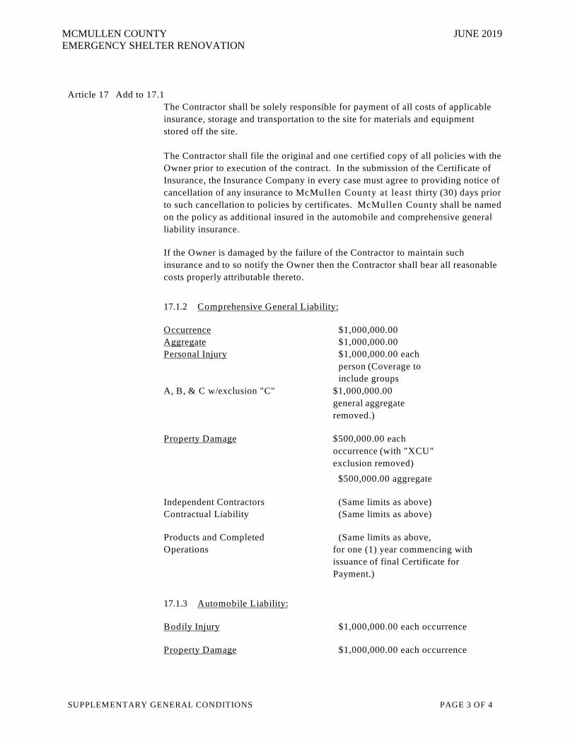
Article 17 Add to 17.1 The Contractor shall be solely responsible for payment of all costs of applicable
insurance, storage and transportation to the site for materials and equipment stored off the site.
The Contractor shall file the original and one certified copy of all policies with the Owner prior to execution of the contract. In the submission of the Certificate of Insurance, the Insurance Company in every case must agree to providing notice of cancellation of any insurance to McMullen County at least thirty (30) days prior to such cancellation to policies by certificates. McMullen County shall be named on the policy as additional insured in the automobile and comprehensive general liability insurance.
If the Owner is damaged by the failure of the Contractor to maintain such insurance and to so notify the Owner then the Contractor shall bear all reasonable costs properly attributable thereto.
17.1.2 C o m p rehensive G eneral L iab ility:
O ccurrence $1,000,000.00 A ggregate $1,000,000.00 P erso nal Injury $1,000,000.00 each
person (Coverage to include groups
A, B, & C w/exclusion "C" $1,000,000.00 general aggregate removed.)
P ro p erty D am age $500,000.00 each occurrence (with "XCU" exclusion removed)
$500,000.00 aggregate Independent Contractors (Same limits as above) Contractual Liability (Same limits as above) Products and Completed (Same limits as above, Operations for one (1) year commencing with
issuance of final Certificate for Payment.)
17.1.3 A uto m o b ile L iab ility:
B o d ily Injury $1,000,000.00 each occurrence
P ro p erty D am age $1,000,000.00 each occurrence

SUPPLEM ENTARY GENERAL CONDITIONS PAGE 4 OF 4
MCMULLEN COUNTY JUNE 2019 EMERGENCY SHELTER RENOVATION
Delete 17.1.4 and replace as follows:
Provide the following in addition to other coverages required.
U m b rella o r E xcess Liab ility $2,000,000.00
17.1.5 The Contractor shall provide an endorsement to the Worker's Compensation policy which grants waiver of subrogation in favor of McMullen County. McMullen County shall be listed as additional insured on the Contractor's General Liability Coverage. The Contractor shall provide Builders Risk Coverage for the amount of their improvements.
Worker’s Compensation: Statutory (Including Waiver of Subrogation Endorsement)
17.1.6 Employer’s Liability: $100,000.00
Add to 17.1.10:
The required insurance must be written by a company licensed to do business in Texas at the time the policy is issued. In addition, the company must be acceptable to the Owner. The Owner's Representative will contact the State Board of Insurance to confirm that the issuing companies are admitted and authorized to issue such bonds in the State of Texas.
Replace 17.2.2.1 with the following:
The Contractor shall purchase and maintain Builder’s Risk and Extended Coverage insurance upon the entire Work at the site in the amount of 100% of the value of construction. Such insurance shall be in a company or companies against which the Owner has no reasonable objection. This insurance shall include the interests of the Owner, the Contractor, Subcontractors, and Sub- subcontractors in the Work and shall include “all risk” insurance for physical loss or damage including, without duplication, theft, vandalism, malicious mischief, collapse, and water damage.
If this insurance is written with stipulated amounts deductible under the terms of the policy, the contractor shall pay the difference attributable to deductions in any payments made by the insurance carrier on claims paid by this insurance.
Add to 17.3.1:
The Contractor is required, as a condition precedent to the execution of the Contract, to execute a PERFORM ANCE BOND (AIA Form No. A312: December 1984 Edition), in an amount equal to ONE HUNDRED PERCENT (100%) of the total combined accepted bid(s).
The Contractor is required, as a condition precedent to the execution of the Contract, to execute a PAYM ENT BOND in the form required by TEXAS STATUTES, in the amount equal to ONE HUNDRED PERCENT (100%) of the total bid as security for payment of all persons performing labor and furnishing materials in connection with this Contract. (Bonding Company is to furnish such forms)
SUPPLEM ENTARY GENERAL CONDITIONS PAGE 5 OF 4
MCMULLEN COUNTY JUNE 2019 EMERGENCY SHELTER RENOVATION
All bonds shall be issued by a surety company licensed, listed and authorized to issue bonds in the State of Texas by the Texas Department of Insurance. The surety company may be required by McMullen County to have a rating of not less than "B" in the latest edition of Best's Insurance Reports, Property-Casualty. The surety company shall provide, if requested, information on bonding capacity, other projects under coverage and shall provide proof to establish adequate financial capacity for this project.
If the Owner is damaged by the failure of the Contractor to maintain such insurance and to so notify the Owner then the Contractor shall bear all reasonable costs properly attributable thereto.
Article 21 Delete paragraphs 21.6, 21.7 and 21.9 Add 21.12: Venue for any mediation or lawsuit arising under this contract shall be in McMullen
County, Texas.

MCMULLEN COUNTY JUNE 2019 EMERGENCY SHELTER RENOVATION
SUMMARY OF WORK 010100 - Page 1 of 17
SECTION 010100 - SUMMARY OF WORK PART 1 GENERAL 1.1 SPECIFICATION FORMAT: Note that these Specifications are written in the imperative mood, in
streamlined form, and are therefore understood to be addressed directly to the General Contractor of this Project.
1.2 THE OWNER: Direct all business of the "Owner", as used in this Manual, to the appointed representatives
of McMullen County.
A. Owner's Representative: Hon. James E. Teal, County Judge Dale Patterson, Project Manager
B. Note that the Specifications may sometimes direct attention to the "Owner" or "Owner's
Representative", which shall be understood to mean the appointed officials or Architect/Engineer acting on behalf of the appointed representatives of McMullen County.
1.3 THE ARCHITECT: Direct all business of the "Architect", as used in this Manual, to the officers of Debra
J. Dockery, Architect, PC, 118 Broadway, Suite 516, San Antonio Texas 78205.
A. Attention: Ms. Debra J. Dockery, President, (210) 225-6130. 1.4 THE PROJECT: Note that "Project", as used in this Manual, shall mean all activities associated with the
"McMullen County Emergency Shelter Renovation”. 1. Project Location: 401Main Street Tilden, Texas 78072 1.5 WORK OF THIS CONTRACT: Note that the "Work", as used in this Manual, shall mean the construction
activities described by the Drawings and Project Manual of this Contract, produced and issued by the Architect named above, and collectively expressed as the “Contract Documents”, or “Documents”, or “Contract”.
A. Scope: See Table of Contents of this Manual for a summary listing of the related work groups
involved. 1.6 WORK SEQUENCE: Execute the Work of this Contract so that progress occurs in a logical and sequential
manner in accordance with the terms of the Contract.
A. Immediately upon issuance of a written notice to proceed with the work, begin the construction of the project.
1.7 OWNER'S USE OF THE PROPERTY: Know that the Owner will be occupying this facility during the
construction and will be occupying and operating the other existing facilities on the property throughout the construction period, and that the Premises will be open to the public.
A. Operations: Conduct the Work in a manner so as not to interfere with access of the Owner’s
employees, or the public to existing operating facilities, or to interfere with scheduled programs and events that may occur throughout the course of construction.

MCMULLEN COUNTY JUNE 2019 EMERGENCY SHELTER RENOVATION
SUMMARY OF WORK 010100 - Page 2 of 17
B. Separate Contracts: Reserve to the Owner the right to occupy parts of the Premises, and the adjacent grounds, for the purpose of conducting their own work or to have work performed for them through separate contracts.
1. Assist Owner in developing concurrent work routines so that the Work of this Contract is not delayed by opposing efforts.
C. Final Acceptance: Bear in mind that, in no case, shall any work of the Owner constitute acceptance of
the total or any part of the Work except by prior written agreement. 1.8 CONTRACTOR'S USE OF PROPERTY: Know that the staging and storage of materials are limited to the
work areas shown on the drawings.
A. Public Safety: Provide and maintain appropriate code-compliant barriers, barricades, visual and audible warning signs, protected walkways, or other devices designed to preserve the safety and welfare of the public.
B. Operations: Conduct the Work in a manner so as not to interfere with access to the surrounding
facilities, or to interfere with programs and events.
1. Limit construction activities within the property boundaries shown on the Drawings for the work.
C. Deliveries: Instruct vendors, suppliers, and services to limit their transport method and delivery loads
to the physical constraints of the local roadways.
1. Schedule deliveries to minimize storage space on the Property, and provide lockable containers to protect valuable goods and equipment.
D. Access: Keep public roads, walks, and easements clear and accessible at all times, and restrict worker
parking to areas designated on the drawings.
E. Cleanliness: Conduct daily policing of trash and construction litter, and place refuse into covered containers sized for the expected storage cycle.
1. Use a licensed garbage disposal service to routinely haul the collected refuse off the Property, but in no case shall the period exceed 1 calendar week.
2. Sweep adjacent public walks and roadways when soiled by construction traffic, and inspect these areas at least once each week or sooner if the situation warrants.
3. Prohibit burning, or burying, of any material on the Property, and allow no explosives to be used in the Work.
1.9 PROTECTION AND REPAIRS: Use reliable and code-compliant techniques throughout the construction
period to protect against damage to the Property and completed Work on the Premises.
A. Repairs: Make good any damage caused by use or abuse of any construction activity, or caused by the lack of using reasonable precautions, at no additional cost to the Owner.
B. Site Repairs: Repair site grading and landscape plant material damaged by the work of this contract,
or as required by site grading specified on the drawings. All lawn areas shall be repaired with solid sod of a species matching existing. Contractor shall be responsible for maintaining new plant materials for 30 days after substantial completion to include necessary hand watering.

MCMULLEN COUNTY JUNE 2019 EMERGENCY SHELTER RENOVATION
SUMMARY OF WORK 010100 - Page 3 of 17
1.10 TIME OF COMPLETION: Project shall be commenced on the date specified in a written Notice to Proceed
to be issued to the successful Bidder by the Owner.
A. The total project shall be completed and ready for Owner's beneficial occupancy within ONE HUNDRED TWENTY (120) CONSECUTIVE CALENDAR DAYS.
1. Claims for a non-work day as a result of adverse weather conditions will only be considered for conditions which can be demonstrated, and the Owner agrees, had an adverse effect on the critical path of the scheduled construction. The Contractor shall keep a log on site documenting the weather conditions at the site each day.
1.11 SUPERINTENDENCE AND WORK FORCE DISCIPLINE:
A. The Contractor or his designated Superintendent shall be on site at all times during the performance of this contract.
B. The Contractor shall maintain discipline by his workers, his subcontractors and subcontractors'
workers on site. There shall be no abusive or offensive language or harassment of any person on site by the Contractor, his workers, subcontractors or any person for which the Contractor is legally responsible.
C. Shirts shall be worn by all construction personnel at all times while on the Owner’s property.
D. Smoking is not allowed inside the facility or within 20 feet of any entrance.
1.12 CONTRACT CONSIDERATIONS A. Cost Breakdown: See the various Contract Conditions for instructions in preparing and submitting a
cost breakdown schedule of the Work.
1. Guide: Use the Table of Contents of this Project Manual as a guide to establish the general categories of the Work.
a. Subdivide the general headings into labor and material for each unit task or system of work which can be tracked against the Construction Schedule.
b. Round decimal amounts off to the nearest whole dollar, except that the Total shall equal the Contract Sum.
2. Format: Use forms provided by the Owner.
B. Partial Payments: See the various Contract Conditions for preparing and submitting periodic
applications for partial payments of the completed Work.
1. Format: Use forms furnished by the Owner. C. Changes and Extra Work: See the various Contract Conditions for processing and executing
changes in the Work, to include extra work approved by the Owner.
1. Format: Use forms furnished by the Owner, and confirm format in the Preconstruction Conference.

MCMULLEN COUNTY JUNE 2019 EMERGENCY SHELTER RENOVATION
SUMMARY OF WORK 010100 - Page 4 of 17
D. Proposal Requests: Recognize these as inquiries for information to a proposed change or extra work, and which are anticipated to affect Contract Sum or Time, or both.
1. Note that such requests are not approved directives to stop work in progress or to execute any change.
2. Submit additional information, if requested, to substantiate unspecified quantities or amounts.
E. Overhead and Profit: Fee to be added by Subcontractors or by General Contractor when performing
work with his own forces to actual cost of any Change Order Work shall be a mutually acceptable percentage fee varying with amount of the actual cost, not to exceed eighteen percent (18%). General Contractor fee for any Change Order Work performed by subcontractors shall not exceed fifteen percent (15%). The Sub-Contractor’s or General Contractor’s fee shall be compensation to cover the cost of supervision (field and home office), overhead, profit, labor burden, additional cost of payment and performance bond premiums, small tools, and any other general expense.
F. Audit Privileges: Reserve to the Owner the right to establish the actual quantity of work-in-place by
independent quantity survey, measure, or count. 1.13 COORDINATION
A. Require installers to inspect substrates and conditions to which their work will be applied, and have deficiencies corrected to the satisfaction of specified tolerances or to respective manufacturer's preparation procedures.
B. Deliveries: Inspect products and materials immediately upon delivery, and again prior to installation, for
proper specification requirements.
C. Storage/Handling: Use appropriate means and methods to protect materials against damage or deterioration throughout their storage period.
D. Temporary Enclosures: Coordinate with required inspections and tests to minimize the necessity of
uncovering completed construction for that purpose.
E. Tolerances: Have installers recheck measurements and dimensions before starting each installation. F. Supervision: Supervise construction activities to ensure that no part of the construction, completed or
in progress, is subject to harmful, dangerous, damaging, or deleterious exposure during the construction period.
G. Protection: Have installers apply protective coverings to areas of finished work to ensure protection
against damage or deterioration, and maintain such coverings until time of Substantial Completion and acceptance by the Owner and Architect.
H. Coordination: Contractor shall be responsible for the proper fitting of all work and for the coordination
of the operations of all trades, other contractors, subcontractors, and material suppliers engaged upon on in connection with the work, as well as those of his own employees.
I. Field Measurements: Contractor shall verify all existing grades, lines, levels and dimensions at job site.
Before ordering any materials or doing any work, the contractor shall verify all measurements and shall be responsible for their correctness. Any differences between actual dimensions and conditions on the site and those indicated on the drawings shall be submitted to the Architect for instructions and consideration before proceeding with the work.

MCMULLEN COUNTY JUNE 2019 EMERGENCY SHELTER RENOVATION
SUMMARY OF WORK 010100 - Page 5 of 17
1.14 PROJECT MEETINGS
A. General: Each meeting shall occur during normal business hours. Follow up each meeting with a thorough written report of the business covered.
1. Proceedings: Record all critical decisions and resolutions concerning the Work, to include unresolved business from previous meetings, and identify critical activities which require immediate attention. 2. Report: Transmit a typed memo of the proceedings to all attendees and other responsible individuals, to include the Owner and Architect.
B. Preconstruction Conference: Owner will conduct on date, time, and place confirmed by the Owner and immediately preceding the official notice to proceed with the Work.
1. Attendees: Owner, Architect, Contractor, Field Superintendent, and major Subcontractors.
2. Agenda: Review schedules, communications, and problem areas, and resolve the following, but not-all-inclusive, topics:
a. Correspondence procedures b. Payments to Contractor and changes to the Work c. Subcontractors, vendors, and suppliers d. Tentative construction schedule e. Coordination of projected progress f. Saturday, Sunday, holiday, and night-work considerations g. Documents required under the Contract h. Submittals, project data, shop drawings, and samples i. Technical review of Contract Documents j. Maintenance of quality and work standards k. Other business relating to the Work
C. Progress Meetings: Architect will conduct monthly progress meetings during the life of the Project, and
review matters pertaining to progress of the Work of this Contract.
1. Attendees: Shall include the Architects Representative, Contractor and Contractor’s Field Superintendent and affected Subcontractors, and affected Consulting Engineers. The Owner may attend.
2. Agenda: Provide information requested by the Architect for review and clarification or coordination, and resolve the following, but not-all-inclusive, topics:
a. Approval of previous meeting's minutes b. Review of work progress and safety c. Field observation, problems, and decisions d. Identification of problems impeding progress
e. Review of submittals schedule, status of submittals f. Maintenance of progress schedule g. Corrective measures to regain projected schedules h. Planned progress during succeeding work period i. Coordination of project progress j. Maintenance of quality and work standards
MCMULLEN COUNTY JUNE 2019 EMERGENCY SHELTER RENOVATION
SUMMARY OF WORK 010100 - Page 6 of 17
k. Effect of proposed changes on progress schedule l. Other business relating to the Work
D. Pay Application Review Meeting: At the monthly progress meeting, the Contractor shall review a
preliminary request for payment with the architect, engineers, and owner to review:
1. Past month’s work and application for payment. 2. Work anticipated to be completed during next month. 3. Updated progress/completion schedules; shop drawings submittals; other required paper work. 4. Requests for information and other coordination questions. 5. Record set of documents (contractor and subs shall record as-built conditions, dimensions, location of utilities, notes, etc. onto the record set on a daily basis).
1.15 CONSTRUCTION FACILITIES AND TEMPORARY CONTROLS
A. Limitations: Limit use of Owner's Property and services only to the Work of the Project, and instruct all trades to exercise prudence and care in their treatment and handling of furnished resources.
B. Conditions of Use: Keep facilities clean and neat, operated in a safe and efficient manner, and maintain
all necessary fire prevention measures.
1. Avoid operations or practices which would overload, overheat, or clog utilities, and examine appropriate utility beforehand when an activity is suspected of creating an overload condition.
2. Prohibit any act, or lack of an act, which would interfere with progress of the Work, or which would allow a hazardous, dangerous, or unsanitary condition to exist, or which would manifest itself as a public nuisance.
C. Field Office Building, Storage, and Sanitation Facilities:
1. Field Office Building: The Contractor may designate an area with the work zone for a field office.
2. Storage Sheds: The contractor may store materials within the work zone. All materials
delivered to the job site shall be properly stored and handled.
3. Sanitation Facilities: The Contractor may not use existing restrooms in the facility. The Contractor shall provide suitable temporary toilets and maintain in cleanly condition.
4. Telephone Service: The Contractor’s Field Superintendent shall be accessible by cellular phone during all normal working hours for the duration of this contract.
D. Temporary Fire Protection: Comply with all governing laws, codes, and regulations to maintain
required protection at all times. Include proper and adequate back up protection at all times. Include proper adequate back up protection during any "shut down" or normal protection systems.
E. Construction Fencing and Temporary Barriers: Furnish, install and maintain, fencing and other
suitable barriers and protective devices as required to prevent injury to persons and the protect facilities.
1. Construction fencing shall be erected prior to any work of this contract being performed on the site.
2. Comply with Federal, State, County, and other local codes and regulations as applicable.

MCMULLEN COUNTY JUNE 2019 EMERGENCY SHELTER RENOVATION
SUMMARY OF WORK 010100 - Page 7 of 17
3. Install facilities neatly, reasonably uniform, and structurally adequate for required purposes.
4. Maintain facilities throughout construction work. Relocate facilities as required by construction progress.
5. Remove when no longer needed, or at completion of work.
6. Materials for fencing and barriers may be new or used if they are suitable for intended purposes, reasonably clean, uniform in appearance and to not violate requirements of governing codes and standards.
F. Personnel Protection: Initiate, maintain, and supervise all safety programs for the safety and
protection of personnel and the public.
G. Dust: Provide measures and means to keep Work and adjoining properties reasonably free of dust. H. Site Access and Traffic: Plan and control site access and use in coordination with the Owner and
other contractors working around the Property boundaries.
1. Coordinate any required traffic lane closures for material deliveries with the McMullen County.
2. Routes: Confine access to the Property through routes and drives approved by the Owner.
3. Fire Lanes: Maintain access for fire-fighting vehicles, and restrict worker parking to areas designated by the Fire Marshal, or Owner.
I. Temporary Controls: Maintain day-by-day cleanup practices, and promptly remove hazardous
accumulations of debris. J. Removal of Temporaries: Remove all temporary services, materials, and equipment before the
Punch List Inspection conducted at the time of Substantial Completion. 1.16 MATERIAL AND EQUIPMENT A. Delivery, Storage, and Handling: Deliver, store, and handle products in accordance with
manufacturer's published recommendations, except when Sections of this Manual specify more stringent requirements.
1. Staging: Schedule deliveries to minimize extended storage at Site, and to ensure minimum holding time for sensitive or perishable items.
a. Inspect products upon delivery to ensure compliance with the Contract Documents, and to ensure that products are intact and undamaged.
b. Return damaged or incorrect goods to the manufacturer or vendor, and replace with specified items, at no additional cost to the Owner.
2. Visual Accounting: Store products at the Site in a manner that will facilitate inspection and measurement of quantity or counting of units.
a. Follow manufacturer's published instructions for protecting products against deleterious effects of dust, temperature, and humidity.

MCMULLEN COUNTY JUNE 2019 EMERGENCY SHELTER RENOVATION
SUMMARY OF WORK 010100 - Page 8 of 17
B. Specified Products: Provide products that comply with the Contract Documents, and are undamaged
and unused at the time of installation.
1. Single Sources: Provide products of the same kind, from a single source to the fullest extent possible.
2. Include all accessories needed for a complete installation and use.
C. Installation: Follow manufacturer's published instructions and recommendations for installation of
their proprietary products, except when the Drawings or Sections of this Manual specify more stringent requirements.
1.17 SUBMITTALS A. Description of Requirements:
1. The types of submittal requirements specified in this section include shop drawings, product data, samples, mock-ups and miscellaneous work-related submittals. Individual submittal requirements are specified in applicable sections for each unit of work.
B. General Submittal Requirements:
1. Coordination and Sequencing: Coordinate preparation and processing of submittals with performance of the work so that the work will not be delayed by submittals. Coordinate and sequence different categories of submittals for same work and for interfacing units of work so that one will not be delayed for coordination of A/E’s review with another.
2. Preparation of Submittals: Provide permanent marking on each submittal to identify project, date, Contractor, Subcontractor, Supplier and consecutively number all submittals using the specification section of the particular item as a prefix, i.e. 071000-1; 071000-2; 071000-3, etc.
a. Show Contractor’s executed review and approval marking (contractor’s stamp must specifically note contractor’s review and approval of submittal). b. Submittals which are received from sources other than through General Contractor’s office will be returned by architect/engineer without review. Submittals which are not submitted through the Architect’s office and submitted directly to the Architect’s Sub-consultants will be returned without review. c. Shop Drawings: Submit newly prepared information, drawn to accurate scale. Highlight, encircle, or otherwise indicate deviations from the Contract Documents. Do not reproduce Contract Documents or copy standard information as the basis of Shop Drawings. Standard information prepared without specific reference to the Project is not considered Shop Drawings.
C. Staff Roster: Prepare a list of major personnel staff assignments, showing their title and authority along with their percentage of contact time with this Contract.
1. Filing: Submit no later than Preconstruction Conference.
2. Phone Contacts: List working phone number where personnel can be reached during business hours, and special phone numbers for off-time or emergency situations.
MCMULLEN COUNTY JUNE 2019 EMERGENCY SHELTER RENOVATION
SUMMARY OF WORK 010100 - Page 9 of 17
D. List of Subcontractors: Prepare and submit a list of proposed subcontractors and Suppliers/Distributors for the Work.
1. Filing: Submit no later than Preconstruction Conference.
E. Construction Progress Schedule: See the Contract Conditions for preparing and submitting a
Construction Progress Schedule of the Work, to include the following:
1. Format: Submit the Schedule as a graphical bar chart, prepared on reproducible media of sufficient size to show data in legible form for the entire construction period.
a. Provide each activity with its duration, early start and finish date, late start and finish date, and any float time if appropriate.
F. Submittals Schedule: See the Contract Conditions for preparing and transmitting compliance
submittals, to include the following:
1. Format: Prepare the Schedule in chronological order and coordinate its preparation with the cost breakdown schedule, Construction Progress Schedule, and the List of Subcontractors.
G. Compliance Submittals: Coordinate submittal preparation with performance of construction activities
and procurement requirements, and prepare and transmit submittals in accordance with the Contract Conditions.
1. Product Data: Submit manufacturer's proprietary literature of their manufactured goods, describing specifications, technical data, details, and installation and maintenance procedures.
a. Include certifications of performance requirements when such application is common to the nature of the product and its performance.
2. Shop Drawings: Submit vendor's typical and special drawings detailing adaptation of standard manufactured systems to the Work, to include assembly, dimensions, tolerances, anchorage, finishes, specifications, schedules, and integration with other work.
3. Samples: Submit actual full-size copies or complete scale mock-up of the product as specified in each Section, and transmit in a manner which will facilitate handling, inspection, and processing.
H. Architect's Review Action: Architect/Engineer will review submittal and mark with comments as noted
below. Observe the following statements of the Architect's action stamp when they appear on returned submittals, and as they apply to the part of the Work covered by the submittal:
1. "Furnish as Submitted": Means no objections are observed or detected on the submittal, but does not mean a release of responsibility from compliance with all other Contract Documents.
2. "Furnish as Corrected" - (Submit File Copy): Means minor objections are observed or detected on the submittal, and that such remarks shall be incorporated into the performance of the work, to include compliance with all other Contract Documents.
3. “Submit Specific Item”: Means minor or serious objections are observed or detected on one item of the submittal, and that the remarks shall be incorporated into a revised version of that item, then reissued, before acceptance can be granted for compliance with Contract Documents.

MCMULLEN COUNTY JUNE 2019 EMERGENCY SHELTER RENOVATION
SUMMARY OF WORK 010100 - Page 10 of 17
4. "Revise and Resubmit": Means serious objections are observed or detected, and that the remarks shall be incorporated into a revised version, then reissued, before acceptance can be granted for compliance with Contract Documents.
5. "Rejected": Means an unacceptable issue, indicating such a substantial variance from the Contract Documents that reevaluation is needed before a resubmittal by the Contractor may be executed.
6. "Reviewed - See Engineer's Comments": Means review and compliance is subject to Consultants' remarks and associated action stamps, to include compliance with all other Contract Documents.
7. “See Comment Sheet”: Means additional comments are attached in a comment sheet issued by the Architect or Engineers.
I. Resubmittals: Repeat submittal process as often as necessary until an appropriate release is obtained by
the Architect's action stamp. Work requiring submittal and review of shop drawings, product data, or similar submittals shall not be performed until the respective submittal has been approved by the Architect.
1.18 PROJECT CLOSEOUT A. Substantial Completion: Before requesting inspection for certification of Substantial Completion,
complete the following:
1. Submit punchlist of items not complete. Architect and Owner will perform walk-through to substantiate punchlist and add items as they deem incomplete or unacceptable to the Standards of the Contract.
2. Submit specific warranties, workmanship bonds, maintenance agreements, final certifications and similar documents.
3. Submit record drawings, maintenance manuals, final project photographs, damage or settlement survey, property survey, and similar record information.
4. Complete final clean up. Touch-up and repair and restore marred exposed finishes.
B. Inspection Procedures: On receipt of a request for inspection, the Architect will proceed or advise the
Contractor of unfilled requirements. The Architect will prepare the Certificate of Substantial Completion following inspection, or advise the Contractor of construction that must be completed or corrected before the certificate will be issued.
1. The Architect will repeat inspection when requested and assured that the Work has been substantially completed.
2. Re-inspection required due to incomplete work will be made at the Contractor's expense.
C. Final Acceptance: Before requesting inspection for certification of final acceptance and final payment,
complete the following:
1. Submit final payment request with releases.
2. Submit a copy of the final inspection list stating that each item has been completed or otherwise resolved for acceptance.
MCMULLEN COUNTY JUNE 2019 EMERGENCY SHELTER RENOVATION
SUMMARY OF WORK 010100 - Page 11 of 17
3. Submit consent of surety to final payment.
4. Submit evidence of continuing insurance coverage complying with insurance requirements.
5. Contractor shall have a maximum of fourteen (14) calendar days after substantial completion to complete all items of work including punch list, submittals, as-builts, warranties, release of liens, and all other required paper work for final completion of project Contractor shall reimburse owner for all architect’s fees for time and expenses incurred in providing architectural/engineering services for completion and closeout of project occurring in excess of fourteen (14) calendar days after substantial completion.
D. Record Specifications: Maintain one copy of the Project Manual, including addenda. Mark to show
variations in actual Work performed in comparison with the Specifications and modifications. Give particular attention to substitutions, selection of options, and similar information on elements that are concealed or cannot be readily discerned later by direct observation. Note related record drawing information and Product Data.
1. Upon completion of the Work, submit record Project Manual to the Architect for the Owner's records.
E. Record Drawings: Maintain a clean, undamaged set of hardcopy prints of Contract Drawings and Shop
Drawings. Mark-up these drawings to show the actual installation. Mark whichever drawing is most capable of showing conditions accurately. Give particular attention to concealed elements that would be difficult to measure and record at a later date. Attach addenda and sketches issued during the course of bidding and construction to the face of the document to which they apply most directly.
1. Mark the Documents to show all changes made in the Work, including accepted Alternates and work of Change Orders.
2. Mark the Documents to record existing conditions which have affected changes in the Work.
3. Organize record drawing sheets into manageable sets, bind with durable paper cover sheets, and print suitable titles, dates, and other identification on the cover.
F. Final Cleaning: Conduct an inspection of the Premises and perform a thorough level of cleaning
comparable to what skilled persons could perform using professional techniques and commercial-quality products.
G. Site Cleaning: Sweep all paved areas about the Premises and all public paved areas directly adjacent to
the Site, magnet-sweep lawns and planted areas for nails and screws, and patrol grounds to pick up trash and litter.
1. Timing: Schedule Final Cleaning to the approval of the Architect and in a manner which will provide the Owner a completely clean Project Premises.
H. Removal of Protection: Remove temporary protection and facilities. I. Compliance: Comply with regulations of authorities having jurisdiction and safety standards for
cleaning. Remove waste materials form the site and dispose of in a lawful manner. 1.19 REFERNCE STANDARDS A. Abbreviations and Names: Where such acronyms or abbreviations are used in the Specifications or
other Contract Documents, they mean the recognized name of the trade association,

MCMULLEN COUNTY JUNE 2019 EMERGENCY SHELTER RENOVATION
SUMMARY OF WORK 010100 - Page 12 of 17
standards-generating organization, authority having jurisdiction, or other entity applicable to the context of the text provision. Refer to the "Encyclopedia of Associations," published by Gale Research Co., available in most libraries.
B. Reference Standards: For products or workmanship specified by association, trade, or Federal
Standards, comply with requirements of the standard except when more rigid requirements are specified or are required by applicable code.
1. The date of the standard is that in effect as of the Bid date, except when a specific publication date is specified.
2. When required by individual Specifications section, obtain copy of standard. C. Schedule of References:
ACI American Concrete Institute Box 19150, Redford Station 22400 W. Seven Mile Road Detroit, MI 48219-0150 AGC Associated General Contractors of America 1957 E. Street, N.W. Washington, D.C. 20006 AISC American Institute of Steel Construction 1 E. Wacker Dr., Suite 3100 Chicago, IL 60601-2001 AISI American Iron and Steel Institute 1101 17th Street, N.W. Washington, D.C. 20036 ANSI American National Standards Institute 1 W. 42nd Street New York, NY 10036 APA American Plywood Association (APA) Box 1170 Tacoma, WA 98411 ASTM American Society for Testing and Materials 1916 Race Street Philadelphia, PA 19103 AWS American Welding Society 550 LeJeune Road Miami, FL 33135 FM Factory Mutual System 1151 Boston-Providence Turnpike P.O. Box 688 Norwood, MA 02062 FS Federal Specification

MCMULLEN COUNTY JUNE 2019 EMERGENCY SHELTER RENOVATION
SUMMARY OF WORK 010100 - Page 13 of 17
General Services Administration Specifications and Consumer Information Distribution Section (WFSIS) Washington Navy Yard, Bldg. 197 Washington, D.C. 20407 NCMA National Concrete Masonry Association 2302 Horse Pen Road Herndon, VA 22071 NEMA National Electrical Manufacturer Association 2101 L Street, N.W. Washington, D.C. 20037 PCA Portland Cement Association 5420 Old Orchard Road Skokie, IL 60077 SMACNA Sheet Metal and Air Conditioning Contractors' National Association 8224 Old Court House Road Vienna, VA 22180 SSPC Steel Structures Painting Council 4400 Fifth Avenue Pittsburgh, PA 15213 TCA Tile Council of America P.O. Box 326 Princeton, NJ 08542-0326 UL Underwriters' Laboratories, Inc. 333 Pfingston Road Northbrook, IL 60062
D. DEFINITIONS: Basic Contract definitions are included in the Conditions of the Contract.
1. Indicated refers to graphic representations, noted or schedules on the Drawings; Paragraphs or Schedules in the Specifications; and similar requirements in the Contract Documents. Where terms such are "shown," "noted," "scheduled," and "specified" are used, it is to help locate the reference.
2. Directed: Terms such as "directed," "requested," "authorized," "selected," "approved," "required,"
and "permitted" mean "directed by the Architect," "requested by the Architect," and similar phrases.
3. Approve, used in conjunction with action on submittals, applications, and requests, is limited to the Architect's duties and responsibilities as stated in the Conditions of the Contract.
4. Regulation includes laws, ordinances, statutes, and lawful orders issued by authorities having jurisdiction, and rules, conventions, and agreements within the construction industry that control performance of the Work.
5. Furnish means "supply and deliver, ready for unloading, unpacking, assembly, installation, and similar operations."

MCMULLEN COUNTY JUNE 2019 EMERGENCY SHELTER RENOVATION
SUMMARY OF WORK 010100 - Page 14 of 17
6. Install describes operations at site including "unloading, unpacking, assembly, erection, anchoring, applying, working to dimension, protecting, cleaning, and similar operations.
7. Provide means "furnish and install, complete and ready for use."
8. Installer: "Installer" is the Contractor or an entity engaged by the Contractor, as an employee, subcontractor, or contractor of lower tier for performance of a particular construction activity, including installation, erection, application, and similar operations. Installers are required to be experienced in the operations they are engaged to perform.
E. Schedule of Abbreviations:
& AND @ AT o DEGREE # POUND OR NUMBER +/- FIELD VERIFY DIMENSIONS A.B. ANCHOR BOLT AFF. ABOVE FINISHED FLOOR ACOUST ACOUSTICAL ALUM ALUMINUM APPROX APPROXIMATE ARCH ARCHITECT/ARCHITECTURAL ADH ADHESIVE ALT ALTERNATE BD BOARD B.P. BASE PLATE B.L. BUILDING LINE BLDG BUILDING BLK BLOCKING BM BEAM BOT BOTTOM BRG BEARING BTWN BETWEEN BSMT BASEMENT B.U.R. BUILT-UP ROOF B.W. BOTH WAYS CANT CANTILEVER C.I.P. CAST-IN-PLACE CER CERAMIC C.H. CEILING HEIGHT C.J. CONSTRUCTION JOINT CLG CEILING CLR CLEAR CMU CONCRETE MASONRY UNITS COL COLUMN CONC CONCRETE CONN CONNECTION CONST CONSTRUCTION CONT CONTINUOUS CONTR CONTRACTOR C.T. CERAMIC TILE DEMO DEMOLITION

MCMULLEN COUNTY JUNE 2019 EMERGENCY SHELTER RENOVATION
SUMMARY OF WORK 010100 - Page 15 of 17
D.F. DRINKING FOUNTAIN DET DETAIL DIA DIAMETER DIAG DIAGONAL DIM DIMENSION D.L. DEAD LOAD DN DOWN DR DOOR DWG DRAWING DWL DOWEL EA EACH E.F. EACH FACE E.J. EXPANSION JOINT ELEC ELECTRICAL ELEV ELEVATION EQ EQUAL EQUIP EQUIPMENT E.W. EACH WAY E.W.C. ELECTRIC WATER COOLER E.W.H. ELECTRIC WATER HEATER E, EX, OR EXIST EXISTING EXP EXPANSION EXT EXTERIOR F.D. FLOOR DRAIN FDN FOUNDATION F.E. FIRE EXTINGUISHER F.E.C. FIRE EXTINGUISHER CABINET F.S. FAR SIDE FIN FINISH FLD FIELD FLR FLOOR FT FOOT OR FEET FTG FOOTING GA GAUGE GALV GALVANIZED GL GLASS GR GRADE GYP GYPSUM G.W.B. GYPSUM WALLBOARD H.B. HOSE BIBB H.C.A. HEAD CONCRETE ANCHOR H.C. HOLLOW CORE HDWD HARDWOOD HDWR HARDWARE HGT HEIGHT HK HOOK H.M. HOLLOW METAL HORZ HORIZONTAL H.S. HIGH STRENGTH I.D. INSIDE DIAMETER IN INCH INSUL INSULATION INT INTERIOR

MCMULLEN COUNTY JUNE 2019 EMERGENCY SHELTER RENOVATION
SUMMARY OF WORK 010100 - Page 16 of 17
INV INVERTED JAN JANITOR JST JOIST JT JOINT K KIP (THOUSAND POUNDS) L ANGLE LAM LAMINATE LAV LAVATORY LBS POUND L.F. LINEAR FOOT LG LONG L.L.H. LONG LEG HORIZONTAL LT LIGHT L.L.V. LONG LEG VERTICAL MAX MAXIMUM MAS MASONRY MH MANHOLE MECH MECHANICAL MEP MECHANICAL, ELECTRICAL, AND PLUMBING MET METAL MEZZ MEZZANINE MFR MANUFACTURER MID MIDDLE MIN MINIMUM MISC MISCELLANEOUS MO MASONRY OPENING MTD MOUNTED N.I.C. NOT IN CONTRACT NOM NOMINAL N.S. NEAR SIDE N.T.S. NOT TO SCALE O.C. ON CENTER O.D. OUTSIDE DIAMETER O.H. OPPOSITE HAND OPNG OPENING OPP OPPOSING P/C PRECAST PREFAB PREFABRICATED P.S.F. POUND PER SQUARE FOOT P.S.I. POUND PER SQUARE INCH PL PLATE P.LAM. PLASTIC LAMINATE PLAS PLASTER PR PAIR R RISER RAD RADIUS R.D. ROOF DRAIN REF REFERENCE REINF REINFORCING/REINFORCED REFG REFRIGERATOR REQD REQUIRED RM ROOM R.O. ROUGH OPENING
MCMULLEN COUNTY JUNE 2019 EMERGENCY SHELTER RENOVATION
SUMMARY OF WORK 010100 - Page 17 of 17
S.C. SOLID CORE SCHED SCHEDULE SECT SECTION SHT SHEET SIM SIMILAR SL SLOPE SPAC SPACES/SPACING SPEC SPECIFICATION SQ SQUARE STD STANDARD STIFF STIFFENERS STIR STIRRUPS STL STEEL STOR STORAGE STR STAIR STRL STRUCTURAL STRUCT STRUCTURE SUSP SUSPENDED SYM SYMMETRICAL T TREAD T&B TOP AND BOTTOM T.D.H. TEXAS DEPT OF HEALTH T.O.C. TOP OF CURB\CONCRETE T.O.J. TOP OF JOIST T.O.S. TOP OF STEEL T.O.W. TOP OF WALL TEL TELEPHONE TEMP TEMPERED THK THICK TYP TYPICAL U.N.O. UNLESS NOTED OTHERWISE VERT VERTICAL W/ WITH WC WATERCLOSET WD WOOD WWF WELDED WIRE FABRIC W/O WITHOUT W.P. WORK POINT W.W.F. WELDED WIRE FABRIC WT WEIGHT
PART 2 PRODUCTS (Part Not Used) PART 3 EXECUTION 3.1 GENERAL: Comply with the administrative and procedural duties of this and other Sections of Division 1,
for all Sections of this Manual. END OF SECTION

MCMULLEN COUNTY JUNE 2019 EMERGENCY SHELTER RENOVATION
ALLOWANCES 012100 - Page 1 of 2
SECTION 012100 - ALLOWANCES
PART 1 - GENERAL
1.1 SUMMARY
A. Section includes administrative and procedural requirements governing allowances.
B. Types of allowances include the following: 1. Contingency allowances.
C. Submit proposals for purchase of products or systems included in allowances, in the form specified for Change Orders.
1.2 INFORMATIONAL SUBMITTALS
A. Submit invoices or delivery slips to show actual quantities of materials delivered to the site for use in fulfillment of each allowance.
B. Submit time sheets and other documentation to show labor time and cost for installation of allowance items that include installation as part of the allowance.
C. Coordinate and process submittals for allowance items in same manner as for other portions of the Work.
1.3 COORDINATION
A. Coordinate allowance items with other portions of the Work. Furnish templates as required to coordinate installation.
1.4 CONTINGENCY ALLOWANCES
A. Use the contingency allowance only as and when directed by Architect for Owner's purposes and only by Change Orders that indicate amounts to be charged to the allowance.
B. Contractor's overhead, profit, and related costs for products and equipment ordered by Owner under the contingency allowance are included in the allowance and are not part of the Contract Sum. These costs include delivery, installation, insurance, equipment rental, and similar costs.
C. Change Orders authorizing use of funds from the contingency allowance will include Contractor's related costs and reasonable overhead and profit margins as stipulated in the Owner-Contractor Agreement.
D. At Project closeout, credit unused amounts remaining in the contingency allowance to Owner by Change Order.
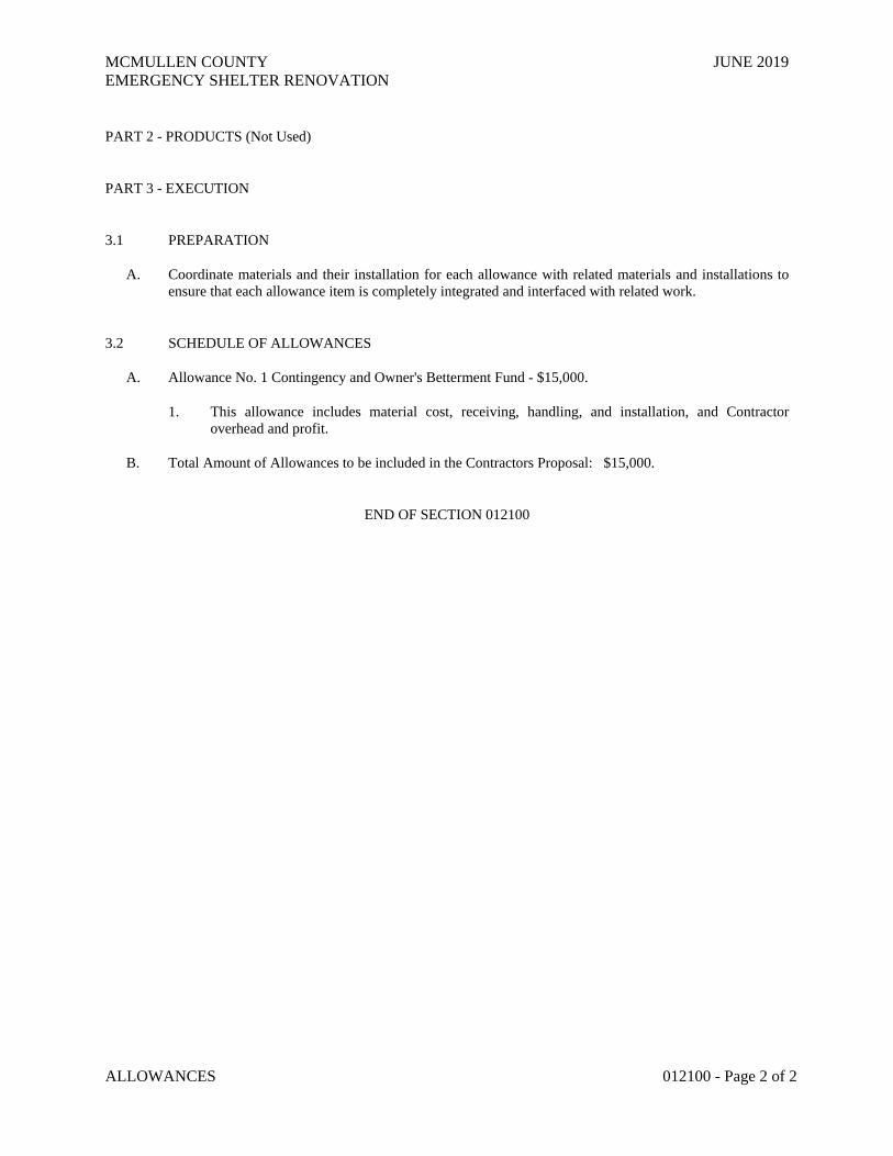
MCMULLEN COUNTY JUNE 2019 EMERGENCY SHELTER RENOVATION
ALLOWANCES 012100 - Page 2 of 2
PART 2 - PRODUCTS (Not Used)
PART 3 - EXECUTION
3.1 PREPARATION
A. Coordinate materials and their installation for each allowance with related materials and installations to ensure that each allowance item is completely integrated and interfaced with related work.
3.2 SCHEDULE OF ALLOWANCES
A. Allowance No. 1 Contingency and Owner's Betterment Fund - $15,000.
1. This allowance includes material cost, receiving, handling, and installation, and Contractor overhead and profit.
B. Total Amount of Allowances to be included in the Contractors Proposal: $15,000.
END OF SECTION 012100
MCMULLEN COUNTY JUNE 2019 EMERGENCY SHELTER RENOVATION
ALTERNATES 012300 - Page 1 of 2
SECTION 012300 - ALTERNATES
PART 1 - GENERAL
1.1 SUMMARY
A. Section includes administrative and procedural requirements for alternates.
1.2 DEFINITIONS
A. Alternate: An amount proposed by bidders and stated on the Bid Form for certain work defined in the bidding requirements that may be added to or deducted from the base bid amount if Owner decides to accept a corresponding change either in the amount of construction to be completed or in the products, materials, equipment, systems, or installation methods described in the Contract Documents.
1. Alternates described in this Section are part of the Work only if enumerated in the Agreement. 2. The cost or credit for each alternate is the net addition to or deduction from the Contract Sum to
incorporate alternate into the Work. No other adjustments are made to the Contract Sum.
1.3 PROCEDURES
A. Coordination: Revise or adjust affected adjacent work as necessary to completely integrate work of the alternate into Project.
1. Include as part of each alternate, miscellaneous devices, accessory objects, and similar items incidental to or required for a complete installation whether or not indicated as part of alternate.
B. Notification: Immediately following award of the Contract, notify each party involved, in writing, of the status of each alternate. Indicate if alternates have been accepted, rejected, or deferred for later consideration. Include a complete description of negotiated revisions to alternates.
C. Execute accepted alternates under the same conditions as other work of the Contract.
D. Schedule: A schedule of alternates is included at the end of this Section. Specification Sections referenced in schedule contain requirements for materials necessary to achieve the work described under each alternate.
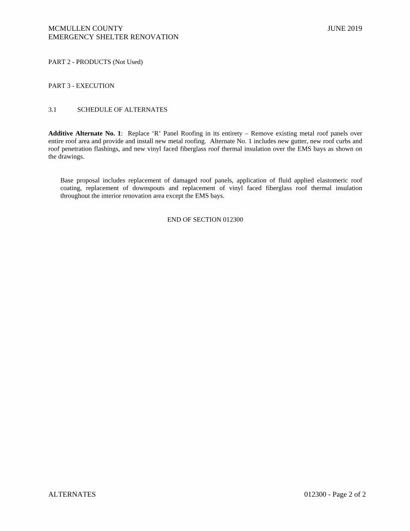
MCMULLEN COUNTY JUNE 2019 EMERGENCY SHELTER RENOVATION
ALTERNATES 012300 - Page 2 of 2
PART 2 - PRODUCTS (Not Used)
PART 3 - EXECUTION
3.1 SCHEDULE OF ALTERNATES
Additive Alternate No. 1: Replace ‘R’ Panel Roofing in its entirety – Remove existing metal roof panels over entire roof area and provide and install new metal roofing. Alternate No. 1 includes new gutter, new roof curbs and roof penetration flashings, and new vinyl faced fiberglass roof thermal insulation over the EMS bays as shown on the drawings.
Base proposal includes replacement of damaged roof panels, application of fluid applied elastomeric roof coating, replacement of downspouts and replacement of vinyl faced fiberglass roof thermal insulation throughout the interior renovation area except the EMS bays.
END OF SECTION 012300

MCMULLEN COUNTY JUNE 2019 EMERGENCY SHELTER RENOVATION
SELECTIVE DEMOLITION 024119 - Page 1 of 6
SECTION 024119 - SELECTIVE DEMOLITION
PART 1 - GENERAL
1.1 RELATED DOCUMENTS
A. Drawings and general provisions of the Contract, including General and Supplementary Conditions and Division 01 Specification Sections, apply to this Section.
1.2 SUMMARY
A. Section Includes:
1. Demolition and removal of selected portions of building or structure. 2. Demolition and removal of selected site elements. 3. Salvage of existing items to be reused or recycled.
B. Related Requirements:
1. Section 010100 "Summary of Work" for restrictions on the use of the premises, Owner-occupancy requirements, and phasing requirements.
1.3 DEFINITIONS
A. Remove: Detach items from existing construction and legally dispose of them off-site unless indicated to be removed and salvaged or removed and reinstalled.
B. Remove and Salvage: Carefully detach from existing construction, in a manner to prevent damage, and deliver to Owner.
C. Remove and Reinstall: Detach items from existing construction, prepare for reuse, and reinstall where indicated.
D. Existing to Remain: Existing items of construction that are not to be permanently removed and that are not otherwise indicated to be removed, removed and salvaged, or removed and reinstalled.
1.4 MATERIALS OWNERSHIP
A. Unless otherwise indicated, demolition waste becomes property of Contractor.
B. Historic items, relics, antiques, and similar objects including, but not limited to, cornerstones and their contents, commemorative plaques and tablets, and other items of interest or value to Owner that may be uncovered during demolition remain the property of Owner.
1. Carefully salvage in a manner to prevent damage and promptly return to Owner.

MCMULLEN COUNTY JUNE 2019 EMERGENCY SHELTER RENOVATION
SELECTIVE DEMOLITION 024119 - Page 2 of 6
1.5 INFORMATIONAL SUBMITTALS
A. Proposed Protection Measures: Submit report, including drawings, that indicates the measures proposed for protecting individuals and property, for environmental protection, for dust control and, for noise control. Indicate proposed locations and construction of barriers.
B. Inventory: Submit a list of items to be removed and salvaged and deliver to Owner prior to start of demolition.
C. Pre-demolition Photographs or Video: Submit before Work begins.
1.6 CLOSEOUT SUBMITTALS
A. Inventory: Submit a list of items that have been removed and salvaged.
B. Landfill Records: Indicate receipt and acceptance of hazardous wastes by a landfill facility licensed to accept hazardous wastes.
1.7 QUALITY ASSURANCE
A. Refrigerant Recovery Technician Qualifications: Certified by an EPA-approved certification program.
1.8 FIELD CONDITIONS
A. Conditions existing at time of inspection for bidding purpose will be maintained by Owner as far as practical. Before selective demolition, Owner will remove furniture, stored items and non-fixed equipment in existing rooms affected by this scope of work. The existing building will be occupied and operational throughout the work of this contract.
B. Notify Architect of discrepancies between existing conditions and Drawings before proceeding with selective demolition.
C. Hazardous Materials: A hazardous material investigation is not known to exist.
D. Storage or sale of removed items or materials on-site is not permitted.
E. Utility Service: Maintain existing utilities indicated to remain in service and protect them against damage during selective demolition operations.
PART 2 - PRODUCTS
2.1 PEFORMANCE REQUIREMENTS
A. Regulatory Requirements: Comply with governing EPA notification regulations before beginning selective demolition. Comply with hauling and disposal regulations of authorities having jurisdiction.
B. Standards: Comply with ANSI/ASSE A10.6 and NFPA 241.

MCMULLEN COUNTY JUNE 2019 EMERGENCY SHELTER RENOVATION
SELECTIVE DEMOLITION 024119 - Page 3 of 6
PART 3 - EXECUTION
3.1 EXAMINATION
A. Verify that utilities have been disconnected and capped before starting selective demolition operations.
B. Review record documents of existing construction provided by Owner. Owner does not guarantee that existing conditions are same as those indicated in record documents.
C. Survey existing conditions and correlate with requirements indicated to determine extent of selective demolition required.
D. When unanticipated mechanical, electrical, or structural elements that conflict with intended function or design are encountered, investigate and measure the nature and extent of conflict. Promptly submit a written report to Architect.
E. Perform an engineering survey of condition of building to determine whether removing any element might result in structural deficiency or unplanned collapse of any portion of structure or adjacent structures during selective building demolition operations.
1. Perform surveys as the Work progresses to detect hazards resulting from selective demolition activities.
F. Survey of Existing Conditions: Record existing conditions by use of preconstruction photographs or preconstruction videotapes. 1. Inventory and record the condition of items to be removed and salvaged. Provide photographs or
video of conditions that might be misconstrued as damage caused by salvage operations. 2. Before selective demolition or removal of existing building elements that will be reproduced or
duplicated in final Work, make permanent record of measurements, materials, and construction details required to make exact reproduction.
3.2 UTILITY SERVICES AND MECHANICAL/ELECTRICAL SYSTEMS
A. Existing Services/Systems to Remain: Maintain services/systems indicated to remain and protect them against damage.
1. Comply with requirements for existing services/systems interruptions specified in Section 0101000 "Summary of Work."
B. Existing Services/Systems to Be Removed, Relocated, or Abandoned: Locate, identify, disconnect, and seal or cap off indicated utility services and mechanical/electrical systems serving areas to be selectively demolished. 1. If services/systems are required to be removed, relocated, or abandoned, provide temporary
services/systems that bypass area of selective demolition and that maintain continuity of services/systems to other parts of building.
2. Disconnect, demolish, and remove plumbing, and HVAC systems, equipment, and components indicated to be removed.
a. Piping to Be Removed: Remove portion of piping indicated to be removed and cap or plug remaining piping with same or compatible piping material.
b. Piping to Be Abandoned in Place: Drain piping and cap or plug piping with same or compatible piping material.
MCMULLEN COUNTY JUNE 2019 EMERGENCY SHELTER RENOVATION
SELECTIVE DEMOLITION 024119 - Page 4 of 6
c. Equipment to Be Removed: Disconnect and cap services and remove equipment. d. Equipment to Be Removed and Reinstalled: Disconnect and cap services and remove,
clean, and store equipment; when appropriate, reinstall, reconnect, and make equipment operational.
e. Equipment to Be Removed and Salvaged: Disconnect and cap services and remove equipment and deliver to Owner.
f. Ducts to Be Removed: Remove portion of ducts indicated to be removed and plug remaining ducts with same or compatible ductwork material.
g. Ducts to Be Abandoned in Place: Cap or plug ducts with same or compatible ductwork material.
C. Refrigerant: Remove refrigerant from mechanical equipment to be selectively demolished according to 40 CFR 82 and regulations of authorities having jurisdiction.
3.3 PREPARATION
A. Site Access and Temporary Controls: Conduct selective demolition and debris-removal operations to ensure minimum interference with roads, streets, walks, walkways, and other adjacent occupied and used facilities.
B. Temporary Facilities: Provide temporary barricades and other protection required to prevent injury to people and damage to adjacent buildings and facilities to remain.
1. Provide protection to ensure safe passage of people around selective demolition area and to and from occupied portions of building.
2. Provide temporary weather protection, during interval between selective demolition of existing construction on exterior surfaces and new construction, to prevent water leakage and damage to structure and interior areas.
3. Protect walls, ceilings, floors, and other existing finish work that are to remain or that are exposed during selective demolition operations.
4. Cover and protect furniture, furnishings, and equipment that have not been removed.
C. Temporary Shoring: Provide and maintain shoring, bracing, and structural supports as required to preserve stability and prevent movement, settlement, or collapse of construction and finishes to remain, and to prevent unexpected or uncontrolled movement or collapse of construction being demolished.
1. Strengthen or add new supports when required during progress of selective demolition.
3.4 SELECTIVE DEMOLITION, GENERAL
A. General: Demolish and remove existing construction only to the extent required by new construction and as indicated. Use methods required to complete the Work within limitations of governing regulations and as follows:
1. Proceed with selective demolition systematically, from higher to lower level. Complete selective demolition operations above each floor or tier before disturbing supporting members on the next lower level.
2. Neatly cut openings and holes plumb, square, and true to dimensions required. Use cutting methods least likely to damage construction to remain or adjoining construction. Use hand tools or small power tools designed for sawing or grinding, not hammering and chopping, to minimize disturbance of adjacent surfaces. Temporarily cover openings to remain.

MCMULLEN COUNTY JUNE 2019 EMERGENCY SHELTER RENOVATION
SELECTIVE DEMOLITION 024119 - Page 5 of 6
3. Cut or drill from the exposed or finished side into concealed surfaces to avoid marring existing finished surfaces.
4. Do not use cutting torches until work area is cleared of flammable materials. At concealed spaces, such as duct and pipe interiors, verify condition and contents of hidden space before starting flame-cutting operations. Maintain fire watch and portable fire-suppression devices during flame-cutting operations.
5. Maintain adequate ventilation when using cutting torches. 6. Remove decayed, vermin-infested, or otherwise dangerous or unsuitable materials and promptly
dispose of off-site. 7. Remove structural framing members and lower to ground by method suitable to avoid free fall and
to prevent ground impact or dust generation. 8. Locate selective demolition equipment and remove debris and materials so as not to impose
excessive loads on supporting walls, floors, or framing. 9. Dispose of demolished items and materials promptly.
B. Removed and Salvaged Items:
1. Clean salvaged items. 2. Pack or crate items after cleaning. Identify contents of containers. 3. Store items in a secure area until delivery to Owner. 4. Transport items to Owner's storage area designated by Owner. 5. Protect items from damage during transport and storage.
C. Removed and Reinstalled Items:
1. Clean and repair items to functional condition adequate for intended reuse. 2. Pack or crate items after cleaning and repairing. Identify contents of containers. 3. Protect items from damage during transport and storage. 4. Reinstall items in locations indicated. Comply with installation requirements for new materials
and equipment. Provide connections, supports, and miscellaneous materials necessary to make item functional for use indicated.
D. Existing Items to Remain: Protect construction indicated to remain against damage and soiling during selective demolition. When permitted by Architect, items may be removed to a suitable, protected storage location during selective demolition and cleaned and reinstalled in their original locations after selective demolition operations are complete.
3.5 SELECTIVE DEMOLITION PROCEDURES FOR SPECIFIC MATERIALS
A. Concrete: Demolish in small sections. Using power-driven saw, cut concrete to a depth of at least 3/4 inch (19 mm) at junctures with construction to remain. Dislodge concrete from reinforcement at perimeter of areas being demolished, cut reinforcement, and then remove remainder of concrete. Neatly trim openings to dimensions indicated.
B. Masonry: Demolish in small sections. Cut masonry at junctures with construction to remain, using power-driven saw, then remove masonry between saw cuts.
C. Concrete Slabs-on-Grade: Saw-cut perimeter of area to be demolished, then break up and remove.
D. Resilient Floor Coverings: Remove floor coverings and adhesive according to recommendations in RFCI's "Recommended Work Practices for the Removal of Resilient Floor Coverings." Do not use methods requiring solvent-based adhesive strippers.
MCMULLEN COUNTY JUNE 2019 EMERGENCY SHELTER RENOVATION
SELECTIVE DEMOLITION 024119 - Page 6 of 6
E. Roofing: Protect existing building interior from damage during removal and replacement of roofing and decking.
3.6 DISPOSAL OF DEMOLISHED MATERIALS
A. General: Except for items or materials indicated to be recycled, reused, salvaged, reinstalled, or otherwise indicated to remain Owner's property, remove demolished materials from Project site and legally dispose of them in an EPA-approved landfill.
1. Do not allow demolished materials to accumulate on-site. 2. Remove and transport debris in a manner that will prevent spillage on adjacent surfaces and areas.
B. Burning: Do not burn demolished materials.
C. Disposal: Transport demolished materials off Owner's property and legally dispose of them.
3.7 CLEANING
A. Clean adjacent structures and improvements of dust, dirt, and debris caused by selective demolition operations. Return adjacent areas to condition existing before selective demolition operations began.
END OF SECTION 024119
MCMULLEN COUNTY JUNE 2019 EMERGENCY SHELTER RENOVATION
CAST-IN-PLACE CONCRETE 033000 - Page 1 of 14
SECTION 033000 - CAST-IN-PLACE CONCRETE
PART 1 - GENERAL
1.1 RELATED DOCUMENTS
A. Drawings and general provisions of the Contract, including General and Supplementary Conditions and Division 1 Specification Sections, apply to this Section.
1.2 SUMMARY
A. This Section specifies cast-in place concrete, including formwork, reinforcement, concrete materials, mix design, placement procedures, and finishes.
1.3 DEFINITIONS
A. Cementitious Materials: Portland cement alone or in combination with one or more of blended hydraulic cement, fly ash and other pozzolans, ground granulated blast-furnace slag, and silica fume.
1.4 SUBMITTALS
A. Product Data: For each type of manufactured material and product indicated.
B. Design Mixes: For each concrete mix. Include alternate mix designs when characteristics of materials, project conditions, weather, test results, or other circumstances warrant adjustments.
1. Indicate amounts of mix water to be withheld for later addition at Project site.
C. Steel Reinforcement Shop Drawings: Details of fabrication, bending, and placement, prepared according to ACI 315, "Details and Detailing of Concrete Reinforcement." Include material, grade, bar schedules, stirrup spacing, bent bar diagrams, arrangement, and supports of concrete reinforcement. Include special reinforcement required for openings through concrete structures.
D. Welding Certificates: Copies of certificates for welding procedures and personnel.
E. Material Test Reports: From a qualified testing agency indicating and interpreting test results for compliance of the following with requirements indicated, based on comprehensive testing of current materials:
F. Material Certificates: Signed by manufacturers certifying that each of the following items complies with requirements:
1. Cementitious materials and aggregates. 2. Steel reinforcement and reinforcement accessories. 3. Admixtures. 4. Curing materials. 5. Floor and slab treatments. 6. Bonding agents.

MCMULLEN COUNTY JUNE 2019 EMERGENCY SHELTER RENOVATION
CAST-IN-PLACE CONCRETE 033000 - Page 2 of 14
7. Adhesives. 8. Vapor retarders. 9. Epoxy joint filler. 10. Joint-filler strips. 11. Repair materials.
1.5 QUALITY ASSURANCE
A. Installer Qualifications: An experienced installer who has completed concrete Work similar in material, design, and extent to that indicated for this Project and whose work has resulted in construction with a record of successful in-service performance.
B. Manufacturer Qualifications: A firm experienced in manufacturing ready-mixed concrete products complying with ASTM C 94 requirements for production facilities and equipment.
1. Manufacturer must be certified according to the National Ready Mixed Concrete Association's Certification of Ready Mixed Concrete Production Facilities.
C. Testing Agency Qualifications: An independent testing agency, acceptable to authorities having jurisdiction, qualified according to ASTM C 1077 and ASTM E 329 to conduct the testing indicated, as documented according to ASTM E 548.
1. Personnel conducting field tests shall be qualified as ACI Concrete Field Testing Technician, Grade 1, according to ACI CP-1 or an equivalent certification program.
D. Source Limitations: Obtain each type or class of cementitious material of the same brand from the same manufacturer's plant, each aggregate from one source, and each admixture from the same manufacturer.
E. ACI Publications: Comply with the following, unless more stringent provisions are indicated:
1. ACI 301, "Specification for Structural Concrete." 2. ACI 117, "Specifications for Tolerances for Concrete Construction and Materials."
F. Pre-installation Conference: Conduct conference at Project site to comply with requirements in Division 1 Section "Summary of Work."
1. Before submitting design mixes, review concrete mix design and examine procedures for ensuring quality of concrete materials. Require representatives of each entity directly concerned with cast-in-place concrete to attend, including the following:
a. Contractor's superintendent. b. Independent testing agency responsible for concrete design mixes. c. Ready-mix concrete producer. d. Concrete subcontractor.
1.6 DELIVERY, STORAGE, AND HANDLING
A. Deliver, store, and handle steel reinforcement to prevent bending and damage. 1. Avoid damaging coatings on steel reinforcement.
PART 2 - PRODUCTS

MCMULLEN COUNTY JUNE 2019 EMERGENCY SHELTER RENOVATION
CAST-IN-PLACE CONCRETE 033000 - Page 3 of 14
2.1 FORM-FACING MATERIALS
A. Rough-Formed Finished Concrete: Plywood, lumber, metal, or another approved material. Provide lumber dressed on at least two edges and one side for tight fit.
B. Form-Release Agent: Commercially formulated form-release agent that will not bond with, stain, or adversely affect concrete surfaces and will not impair subsequent treatments of concrete surfaces.
C. Form Ties: Factory-fabricated, removable or snap-off metal or glass-fiber-reinforced plastic form ties designed to resist lateral pressure of fresh concrete on forms and to prevent spalling of concrete on removal.
1. Furnish units that will leave no corrodible metal closer than 1 inch (25 mm) to the plane of the exposed concrete surface.
2. Furnish ties that, when removed, will leave holes not larger than 1 inch (25 mm) in diameter in concrete surface.
3. Furnish ties with integral water-barrier plates to walls indicated to receive dampproofing or waterproofing.
2.2 STEEL REINFORCEMENT
A. Reinforcing Bars: ASTM A 615/A 615M, Grade 60 (Grade 420), deformed.
B. Low-Alloy-Steel Reinforcing Bars: ASTM A 706/A 706M, deformed.
C. Steel Bar Mats: ASTM A 184/A 184M, assembled with clips.
1. Steel Reinforcement: ASTM A 615/A 615M, Grade 60 (Grade 420), deformed bars. 2. Steel Reinforcement: ASTM A 706/A 706M, deformed bars.
D. Plain-Steel Wire: ASTM A 82, as drawn.
E. Deformed-Steel Welded Wire Fabric: ASTM A 497, flat sheet.
2.3 REINFORCEMENT ACCESSORIES
A. Bar Supports: Bolsters, chairs, spacers, and other devices for spacing, supporting, and fastening reinforcing bars and welded wire fabric in place. Manufacture bar supports according to CRSI's "Manual of Standard Practice" from steel wire, plastic, or precast concrete or fiber-reinforced concrete of greater compressive strength than concrete, and as follows:
B. Joint Dowel Bars: Plain-steel bars, ASTM A 615/A 615M, Grade 60 (Grade 420). Cut bars true to length with ends square and free of burrs.
2.4 CONCRETE MATERIALS
A. Portland Cement: ASTM C 150, Type I/II.
B. Fly Ash: ASTM C 618, Class C or F (Use Class F only at coastal regions).
C. Normal-Weight Aggregate: ASTM C 33, uniformly graded, and as follows:
MCMULLEN COUNTY JUNE 2019 EMERGENCY SHELTER RENOVATION
CAST-IN-PLACE CONCRETE 033000 - Page 4 of 14
1. Class: Moderate weathering region, but not less than 3M. 2. Nominal Maximum Aggregate Size: 1-1/2 inches (38 mm). 3. Combined Aggregate Gradation: Well graded from coarsest to finest with not more than 18
percent and not less than 8 percent retained on an individual sieve, except that less than 8 percent may be retained on coarsest sieve and on No. 50 (0.3-mm) sieve, and less than 8 percent may be retained on sieves finer than No. 50 (0.3 mm).
D. Water: Potable and complying with ASTM C 94.
2.5 ADMIXTURES
A. General: Admixtures certified by manufacturer to contain not more than 0.1 percent water-soluble chloride ions by mass of cementitious material and to be compatible with other admixtures and cementitious materials. Do not use admixtures containing calcium chloride.
B. Air-Entraining Admixture: ASTM C 260.
C. Water-Reducing Admixture: ASTM C 494, Type A.
D. High-Range, Water-Reducing Admixture: ASTM C 494, Type F.
E. Water-Reducing and Accelerating Admixture: ASTM C 494, Type E.
F. Water-Reducing and Retarding Admixture: ASTM C 494, Type D.
2.6 VAPOR RETARDERS
A. Vapor Retarder: ASTM E 1745, Class A, ASTM E154 Section 7 & ASTM E 96 Procedure B (0.025perms), five-ply, nylon- or polyester-cord-reinforced, high-density polyethylene sheet; minimum 15 mils (0.37 mm) thick. 1. Available Product: Subject to compliance with requirements, a product that may be incorporated
into the Work includes, but is not limited to, "Griffolyn 15 mil Green" by Reef Industries Inc or “Stego Wrap” by Stego Wrap Industries or “Vapor Barrier VB-350” by Barrier-Bac, Inc. or “VaporBlock 15” by Raven Industries.
2.7 CURING MATERIALS
A. Evaporation Retarder: Waterborne, monomolecular film forming, manufactured for application to fresh concrete.
B. Absorptive Cover: AASHTO M 182, Class 2, burlap cloth made from jute or kenaf, weighing approximately 9 oz./sq. yd. (305 g/sq. m) dry.
C. Moisture-Retaining Cover: ASTM C 171, polyethylene film or white burlap-polyethylene sheet.
D. Water: Potable.
E. Clear, Waterborne, Membrane-Forming Curing Compound: ASTM C 309, Type 1, Class B.
1. Evaporation Retarder:

MCMULLEN COUNTY JUNE 2019 EMERGENCY SHELTER RENOVATION
CAST-IN-PLACE CONCRETE 033000 - Page 5 of 14
a. Finishing Aid Concentrate; Burke Group, LLC (The). b. Spray-Film; ChemMasters. c. Sure Film; Dayton Superior Corporation. d. Eucobar; Euclid Chemical Co. e. E-Con; L&M Construction Chemicals, Inc. f. Confilm; Master Builders, Inc. g. Waterhold; Metalcrete Industries. h. SikaFilm; Sika Corporation. i. Finishing Aid; Symons Corporation.
2. Clear, Waterborne, Membrane-Forming Curing and Sealing Compound:
a. Klear-Kote Cure-Sealer-Hardener, 30 percent solids; Burke Group, LLC (The). b. Polyseal WB; ChemMasters. c. Lumiseal WB Plus; L&M Construction Chemicals, Inc. d. Vocomp-30; W. R. Meadows, Inc. e. Metcure 30; Metalcrete Industries.
2.8 RELATED MATERIALS
A. Joint-Filler Strips: ASTM D 1751, asphalt-saturated cellulosic fiber, or ASTM D 1752, cork or self-expanding cork.
B. Epoxy Joint Filler: Two-component, semirigid, 100 percent solids, epoxy resin with a Shore A hardness of 80 per ASTM D 2240.
C. Bonding Agent: ASTM C 1059, Type II, non-redispersible, acrylic emulsion or styrene butadiene.
2.9 CONCRETE MIXES
A. Prepare design mixes for each type and strength of concrete determined by either laboratory trial mix or field test data bases, as follows:
1. Proportion normal-weight concrete according to ACI 211.1 and ACI 301.
B. Use a qualified independent testing agency for preparing and reporting proposed mix designs for the laboratory trial mix basis.
C. Slab-on-Grade: Proportion normal-weight concrete mix as follows:
1. Compressive Strength (28 Days): 4000 psi. 2. Minimum Cementitious Materials Content: 514 lb/cu. yd. 3. Maximum Slump: 5 inches (125 mm).
D. Cementitious Materials: For concrete exposed to deicers, limit percentage, by weight, of cementitious materials other than portland cement according to ACI 301 requirements.
E. Cementitious Materials: Limit percentage, by weight, of portland cement in concrete as follows:
1. Combined Fly Ash and Pozzolan: 25 percent. 2. Silica Fume: 10 percent.

MCMULLEN COUNTY JUNE 2019 EMERGENCY SHELTER RENOVATION
CAST-IN-PLACE CONCRETE 033000 - Page 6 of 14
F. Air Content: Add air-entraining admixture at manufacturer's prescribed rate to result in concrete at point of placement having an air content of 2 to 4 percent, unless otherwise indicated.
G. Do not air entrain concrete to trowel-finished interior floors. Do not allow entrapped air content to exceed 3 percent.
H. Limit water-soluble, chloride-ion content in hardened concrete to 0.15 percent by weight of cement.
I. Admixtures: Use admixtures according to manufacturer's written instructions.
1. Use water-reducing admixture or high-range water-reducing admixture (superplasticizer) in concrete, as required, for placement and workability.
2. Use water-reducing and retarding admixture when required by high temperatures, low humidity, or other adverse placement conditions.
2.10 FABRICATING REINFORCEMENT
A. Fabricate steel reinforcement according to CRSI's "Manual of Standard Practice."
2.11 CONCRETE MIXING
A. Ready-Mixed Concrete: Measure, batch, mix, and deliver concrete according to ASTM C 94 and ASTM C 1116, and furnish batch ticket information.
1. When air temperature is between 85 and 90 deg F (30 and 32 deg C), reduce mixing and delivery time from 1-1/2 hours to 75 minutes; when air temperature is above 90 deg F (32 deg C), reduce mixing and delivery time to 60 minutes.
PART 3 - EXECUTION
3.1 FORMWORK
A. Design, erect, shore, brace, and maintain formwork, according to ACI 301, to support vertical, lateral, static, and dynamic loads, and construction loads that might be applied, until concrete structure can support such loads.
B. Construct formwork so concrete members and structures are of size, shape, alignment, elevation, and position indicated, within tolerance limits of ACI 117.
C. Limit concrete surface irregularities, designated by ACI 347R as abrupt or gradual, as follows: 1. Class B, 1/4 inch (6 mm).
D. Construct forms tight enough to prevent loss of concrete mortar.
E. Fabricate forms for easy removal without hammering or prying against concrete surfaces. Provide crush or wrecking plates where stripping may damage cast concrete surfaces. Provide top forms for inclined surfaces steeper than 1.5 horizontal to 1 vertical. Kerf wood inserts for forming keyways, reglets, recesses, and the like, for easy removal.
1. Do not use rust-stained steel form-facing material.

MCMULLEN COUNTY JUNE 2019 EMERGENCY SHELTER RENOVATION
CAST-IN-PLACE CONCRETE 033000 - Page 7 of 14
F. Set edge forms, bulkheads, and intermediate screed strips for slabs to achieve required elevations and slopes in finished concrete surfaces. Provide and secure units to support screed strips; use strike-off templates or compacting-type screeds.
G. Chamfer exterior corners and edges of permanently exposed concrete.
H. Do not chamfer corners or edges of concrete.
I. Form openings, chases, offsets, sinkages, keyways, reglets, blocking, screeds, and bulkheads required in the Work. Determine sizes and locations from trades providing such items.
J. Clean forms and adjacent surfaces to receive concrete. Remove chips, wood, sawdust, dirt, and other debris just before placing concrete.
K. Retighten forms and bracing before placing concrete, as required, to prevent mortar leaks and maintain proper alignment.
L. Coat contact surfaces of forms with form-release agent, according to manufacturer's written instructions, before placing reinforcement.
3.2 EMBEDDED ITEMS
A. Place and secure anchorage devices and other embedded items required for adjoining work that is attached to or supported by cast-in-place concrete. Use Setting Drawings, templates, diagrams, instructions, and directions furnished with items to be embedded.
1. Install anchor bolts, accurately located, to elevations required. 2. Install reglets to receive top edge of foundation sheet waterproofing and to receive through-wall
flashings in outer face of concrete frame at exterior walls, where flashing is shown at lintels, shelf angles, and other conditions.
3. Install dovetail anchor slots in concrete structures as indicated.
3.3 VAPOR RETARDERS
A. Vapor Retarder: Place, protect, and repair vapor-retarder sheets according to ASTM E 1643 and manufacturer's written instructions.
3.4 STEEL REINFORCEMENT
A. General: Comply with CRSI's "Manual of Standard Practice" for placing reinforcement.
1. Do not cut or puncture vapor retarder. Repair damage and reseal vapor retarder before placing concrete.
B. Clean reinforcement of loose rust and mill scale, earth, ice, and other foreign materials.
C. Accurately position, support, and secure reinforcement against displacement. Locate and support reinforcement with bar supports to maintain minimum concrete cover. Do not tack weld crossing reinforcing bars.
1. Shop- or field-weld reinforcement according to AWS D1.4, where indicated.
MCMULLEN COUNTY JUNE 2019 EMERGENCY SHELTER RENOVATION
CAST-IN-PLACE CONCRETE 033000 - Page 8 of 14
D. Set wire ties with ends directed into concrete, not toward exposed concrete surfaces.
E. Install welded wire fabric in longest practicable lengths on bar supports spaced to minimize sagging. Lap edges and ends of adjoining sheets at least one mesh spacing. Offset laps of adjoining sheet widths to prevent continuous laps in either direction. Lace overlaps with wire.
3.5 JOINTS
A. General: Construct joints true to line with faces perpendicular to surface plane of concrete.
B. Contraction Joints in Slabs-on-Grade: Form weakened-plane contraction joints, sectioning concrete into areas as indicated. Construct contraction joints for a depth equal to at least one-fourth of concrete thickness, as follows:
1. Grooved Joints: Form contraction joints after initial floating by grooving and finishing each edge of joint to a radius of 1/8 inch (3 mm). Repeat grooving of contraction joints after applying surface finishes. Eliminate groover tool marks on concrete surfaces.
2. Sawed Joints: Form contraction joints with power saws equipped with shatterproof abrasive or diamond-rimmed blades. Cut 1/8-inch- (3-mm-) wide joints into concrete when cutting action will not tear, abrade, or otherwise damage surface and before concrete develops random contraction cracks.
C. Dowel Joints: Install dowel sleeves and dowels or dowel bar and support assemblies at joints where indicated.
1. Use dowel sleeves or lubricate or asphalt-coat one-half of dowel length to prevent concrete bonding to one side of joint.
3.6 CONCRETE PLACEMENT
A. Before placing concrete, verify that installation of formwork, reinforcement, and embedded items is complete and that required inspections have been performed.
B. Do not add water to concrete during delivery, at Project site, or during placement, unless approved by Architect.
C. Before placing concrete, water may be added at Project site, subject to limitations of ACI 301.
1. Do not add water to concrete after adding high-range water-reducing admixtures to mix.
D. Deposit concrete continuously or in layers of such thickness that no new concrete will be placed on concrete that has hardened enough to cause seams or planes of weakness. If a section cannot be placed continuously, provide construction joints as specified. Deposit concrete to avoid segregation.
E. Deposit concrete in forms in horizontal layers no deeper than 24 inches (600 mm) and in a manner to avoid inclined construction joints. Place each layer while preceding layer is still plastic, to avoid cold joints.
1. Consolidate placed concrete with mechanical vibrating equipment. Use equipment and procedures for consolidating concrete recommended by ACI 309R.
2. Do not use vibrators to transport concrete inside forms. Insert and withdraw vibrators vertically at uniformly spaced locations no farther than the visible effectiveness of the vibrator. Place vibrators to rapidly penetrate placed layer and at least 6 inches (150 mm) into preceding layer. Do not

MCMULLEN COUNTY JUNE 2019 EMERGENCY SHELTER RENOVATION
CAST-IN-PLACE CONCRETE 033000 - Page 9 of 14
insert vibrators into lower layers of concrete that have begun to lose plasticity. At each insertion, limit duration of vibration to time necessary to consolidate concrete and complete embedment of reinforcement and other embedded items without causing mix constituents to segregate.
F. Deposit and consolidate concrete for floors and slabs in a continuous operation, within limits of construction joints, until placement of a panel or section is complete.
1. Consolidate concrete during placement operations so concrete is thoroughly worked around reinforcement and other embedded items and into corners.
2. Maintain reinforcement in position on chairs during concrete placement. 3. Screed slab surfaces with a straightedge and strike off to correct elevations. 4. Slope surfaces uniformly to drains where required. 5. Begin initial floating using bull floats or darbies to form a uniform and open-textured surface
plane, free of humps or hollows, before excess moisture or bleedwater appears on the surface. Do not further disturb slab surfaces before starting finishing operations.
G. Cold-Weather Placement: Comply with ACI 306.1 and as follows. Protect concrete work from physical damage or reduced strength that could be caused by frost, freezing actions, or low temperatures.
1. When air temperature has fallen to or is expected to fall below 40 deg F (4.4 deg C), uniformly heat water and aggregates before mixing to obtain a concrete mixture temperature of not less than 50 deg F (10 deg C) and not more than 80 deg F (27 deg C) at point of placement.
2. Do not use frozen materials or materials containing ice or snow. Do not place concrete on frozen subgrade or on subgrade containing frozen materials.
3. Do not use calcium chloride, salt, or other materials containing antifreeze agents or chemical accelerators, unless otherwise specified and approved in mix designs.
H. Hot-Weather Placement: Place concrete according to recommendations in ACI 305R and as follows, when hot-weather conditions exist:
1. Cool ingredients before mixing to maintain concrete temperature below 90 deg F (32 deg C) at time of placement. Chilled mixing water or chopped ice may be used to control temperature, provided water equivalent of ice is calculated to total amount of mixing water. Using liquid nitrogen to cool concrete is Contractor's option.
2. Cover steel reinforcement with water-soaked burlap so steel temperature will not exceed ambient air temperature immediately before embedding in concrete.
3. Fog-spray forms, steel reinforcement, and subgrade just before placing concrete. Keep subgrade moisture uniform without standing water, soft spots, or dry areas.
3.7 FINISHING FORMED SURFACES
A. Rough-Formed Finish: As-cast concrete texture imparted by form-facing material with tie holes and defective areas repaired and patched. Remove fins and other projections exceeding ACI 347R limits for class of surface specified.
B. Related Unformed Surfaces: At tops of walls, horizontal offsets, and similar unformed surfaces adjacent to formed surfaces, strike off smooth and finish with a texture matching adjacent formed surfaces. Continue final surface treatment of formed surfaces uniformly across adjacent unformed surfaces, unless otherwise indicated.
3.8 FINISHING FLOORS AND SLABS
MCMULLEN COUNTY JUNE 2019 EMERGENCY SHELTER RENOVATION
CAST-IN-PLACE CONCRETE 033000 - Page 10 of 14
A. General: Comply with recommendations in ACI 302.1R for screeding, restraightening, and finishing operations for concrete surfaces. Do not wet concrete surfaces.
B. Trowel Finish: After applying float finish, apply first trowel finish and consolidate concrete by hand or power-driven trowel. Continue troweling passes and restraighten until surface is free of trowel marks and uniform in texture and appearance. Grind smooth any surface defects that would telegraph through applied coatings or floor coverings.
1. Apply a trowel finish to surfaces indicated and to floor and slab surfaces exposed to view or to be covered with resilient flooring, carpet, ceramic or quarry tile set over a cleavage membrane, paint, or another thin film-finish coating system
2. Finish surfaces to the following tolerances, measured within 24 hours according to ASTM E 1155/E 1155M for a randomly trafficked floor surface: a. Specified overall values of flatness, F(F) 35; and levelness, F(L) 25; with minimum local
values of flatness, F(F) 24; and levelness, F(L) 17; for slabs-on-grade. b. Specified overall values of flatness, F(F) 30; and levelness, F(L) 20; with minimum local
values of flatness, F(F) 24; and levelness, F(L) 15; for suspended slabs.
C. Trowel and Fine-Broom Finish: Apply a partial trowel finish, stopping after second troweling, to surfaces indicated and to surfaces where ceramic or quarry tile is to be installed by either thickset or thin-set method. Immediately after second troweling, and when concrete is still plastic, slightly scarify surface with a fine broom.
D. Broom Finish: Apply a broom finish to exterior concrete platforms, steps, and ramps, and elsewhere as indicated.
1. Immediately after float finishing, slightly roughen trafficked surface by brooming with fiber-bristle broom perpendicular to main traffic route. Coordinate required final finish with Architect before application.
3.9 MISCELLANEOUS CONCRETE ITEMS
A. Filling In: Fill in holes and openings left in concrete structures, unless otherwise indicated, after work of other trades is in place. Mix, place, and cure concrete, as specified, to blend with in-place construction. Provide other miscellaneous concrete filling indicated or required to complete Work.
B. Curbs: Provide monolithic finish to interior curbs by stripping forms while concrete is still green and by steel-troweling surfaces to a hard, dense finish with corners, intersections, and terminations slightly rounded.
C. Equipment Bases and Foundations: Provide machine and equipment bases and foundations as shown on Drawings. Set anchor bolts for machines and equipment at correct elevations, complying with diagrams or templates of manufacturer furnishing machines and equipment.
3.10 CONCRETE PROTECTION AND CURING
A. General: Protect freshly placed concrete from premature drying and excessive cold or hot temperatures. Comply with ACI 306.1 for cold-weather protection and with recommendations in ACI 305R for hot-weather protection during curing.
B. Evaporation Retarder: Apply evaporation retarder to unformed concrete surfaces if hot, dry, or windy conditions cause moisture loss approaching 0.2 lb/sq. ft. x h (1 kg/sq. m x h) before and during finishing
MCMULLEN COUNTY JUNE 2019 EMERGENCY SHELTER RENOVATION
CAST-IN-PLACE CONCRETE 033000 - Page 11 of 14
operations. Apply according to manufacturer's written instructions after placing, screeding, and bull floating or darbying concrete, but before float finishing.
C. Formed Surfaces: Cure formed concrete surfaces, including underside of beams, supported slabs, and other similar surfaces. If forms remain during curing period, moist cure after loosening forms. If removing forms before end of curing period, continue curing by one or a combination of the following methods:
D. Unformed Surfaces: Begin curing immediately after finishing concrete. Cure unformed surfaces, including floors and slabs, concrete floor toppings, and other surfaces, by one or a combination of the following methods:
1. Moisture Curing: Keep surfaces continuously moist for not less than seven days with the following materials:
a. Water. b. Continuous water-fog spray. c. Absorptive cover, water saturated, and kept continuously wet. Cover concrete surfaces and
edges with 12-inch (300-mm) lap over adjacent absorptive covers.
2. Moisture-Retaining-Cover Curing: Cover concrete surfaces with moisture-retaining cover for curing concrete, placed in widest practicable width, with sides and ends lapped at least 12 inches (300 mm), and sealed by waterproof tape or adhesive. Cure for not less than seven days. Immediately repair any holes or tears during curing period using cover material and waterproof tape.
a. Moisture cure or use moisture-retaining covers to cure concrete surfaces to receive floor coverings.
b. Moisture cure or use moisture-retaining covers to cure concrete surfaces to receive penetrating liquid floor treatments.
c. Cure concrete surfaces to receive floor coverings with either a moisture-retaining cover or a curing compound that the manufacturer recommends for use with floor coverings.
3. Curing and Sealing Compound: Apply uniformly to floors and slabs indicated in a continuous operation by power spray or roller according to manufacturer's written instructions. Recoat areas subjected to heavy rainfall within three hours after initial application. Repeat process 24 hours later and apply a second coat. Maintain continuity of coating and repair damage during curing period.
3.11 LIQUID FLOOR TREATMENTS
A. Penetrating Liquid Floor Treatment/Sealer: See Section 071900 for water repellent sealer. Prepare, apply, and finish penetrating liquid floor treatment according to manufacturer's written instructions.
1. Remove curing compounds, sealers, oil, dirt, laitance, and other contaminants and complete surface repairs.
2. Do not apply to concrete that is less than seven days old.
3.12 JOINT FILLING
A. Prepare, clean, and install joint filler according to manufacturer's written instructions.
1. Defer joint filling until concrete has aged at least six months. Do not fill joints until construction traffic has permanently ceased.

MCMULLEN COUNTY JUNE 2019 EMERGENCY SHELTER RENOVATION
CAST-IN-PLACE CONCRETE 033000 - Page 12 of 14
B. Remove dirt, debris, saw cuttings, curing compounds, and sealers from joints; leave contact faces of joint clean and dry.
C. Install semi-rigid epoxy joint filler full depth in saw-cut joints and at least 2 inches (50 mm) deep in formed joints. Overfill joint and trim joint filler flush with top of joint after hardening.
3.13 CONCRETE SURFACE REPAIRS
A. Defective Concrete: Repair and patch defective areas when approved by Architect. Remove and replace concrete that cannot be repaired and patched to Architect's approval.
B. Patching Mortar: Mix dry-pack patching mortar, consisting of one part portland cement to two and one-half parts fine aggregate passing a No. 16 (1.2-mm) sieve, using only enough water for handling and placing.
C. Repairing Formed Surfaces: Surface defects include color and texture irregularities, cracks, spalls, air bubbles, honeycombs, rock pockets, fins and other projections on the surface, and stains and other discolorations that cannot be removed by cleaning.
1. Immediately after form removal, cut out honeycombs, rock pockets, and voids more than 1/2 inch (13 mm) in any dimension in solid concrete but not less than 1 inch (25 mm) in depth. Make edges of cuts perpendicular to concrete surface. Clean, dampen with water, and brush-coat holes and voids with bonding agent. Fill and compact with patching mortar before bonding agent has dried. Fill form-tie voids with patching mortar or cone plugs secured in place with bonding agent.
2. Repair defects on surfaces exposed to view by blending white portland cement and standard portland cement so that, when dry, patching mortar will match surrounding color. Patch a test area at inconspicuous locations to verify mixture and color match before proceeding with patching. Compact mortar in place and strike off slightly higher than surrounding surface.
3. Repair defects on concealed formed surfaces that affect concrete's durability and structural performance as determined by Architect.
D. Repairing Unformed Surfaces: Test unformed surfaces, such as floors and slabs, for finish and verify surface tolerances specified for each surface. Correct low and high areas. Test surfaces sloped to drain for trueness of slope and smoothness; use a sloped template.
1. Repair finished surfaces containing defects. Surface defects include spalls, pop-outs, honeycombs, rock pockets, crazing and cracks in excess of 0.01 inch (0.25 mm) wide or that penetrate to reinforcement or completely through unreinforced sections regardless of width, and other objectionable conditions.
2. After concrete has cured at least 14 days, correct high areas by grinding. 3. Correct localized low areas during or immediately after completing surface finishing operations by
cutting out low areas and replacing with patching mortar. Finish repaired areas to blend into adjacent concrete.
4. Correct other low areas scheduled to receive floor coverings with a repair underlayment. Prepare, mix, and apply repair underlayment and primer according to manufacturer's written instructions to produce a smooth, uniform, plane, and level surface. Feather edges to match adjacent floor elevations.
5. Correct other low areas scheduled to remain exposed with a repair topping. Cut out low areas to ensure a minimum repair topping depth of 1/4 inch (6 mm) to match adjacent floor elevations. Prepare, mix, and apply repair topping and primer according to manufacturer's written instructions to produce a smooth, uniform, plane, and level surface.
6. Repair defective areas, except random cracks and single holes 1 inch (25 mm) or less in diameter, by cutting out and replacing with fresh concrete. Remove defective areas with clean, square cuts and expose steel reinforcement with at least 3/4 inch (19 mm) clearance all around. Dampen
MCMULLEN COUNTY JUNE 2019 EMERGENCY SHELTER RENOVATION
CAST-IN-PLACE CONCRETE 033000 - Page 13 of 14
concrete surfaces in contact with patching concrete and apply bonding agent. Mix patching concrete of same materials and mix as original concrete except without coarse aggregate. Place, compact, and finish to blend with adjacent finished concrete. Cure in same manner as adjacent concrete.
7. Repair random cracks and single holes 1 inch (25 mm) or less in diameter with patching mortar. Groove top of cracks and cut out holes to sound concrete and clean off dust, dirt, and loose particles. Dampen cleaned concrete surfaces and apply bonding agent. Place patching mortar before bonding agent has dried. Compact patching mortar and finish to match adjacent concrete. Keep patched area continuously moist for at least 72 hours.
E. Perform structural repairs of concrete, subject to Architect's approval, using epoxy adhesive and patching mortar.
F. Repair materials and installation not specified above may be used, subject to Architect's approval.
3.14 FIELD QUALITY CONTROL
A. Testing Agency: Owner will engage a qualified independent testing and inspecting agency to sample materials, perform tests, and submit test reports during concrete placement. Sampling and testing for quality control may include those specified in this Article.
B. Testing Services: Testing of composite samples of fresh concrete obtained according to ASTM C 172 shall be performed according to the following requirements:
1. Testing Frequency: Obtain at least one composite sample for each 100 cu. yd. or 5,000 square feet of slab/wall area or fraction thereof of each concrete mix placed each day whichever is more.
a. When frequency of testing will provide fewer than five compressive-strength tests for each concrete mix, testing shall be conducted from at least five randomly selected batches or from each batch if fewer than five are used.
2. Slump: ASTM C 143; one test at point of placement for each composite sample, but not less than one test for each day's pour of each concrete mix. Perform additional tests when concrete consistency appears to change.
3. Air Content: ASTM C 231, pressure method, for normal-weight concrete; ASTM C 173, volumetric method, but not less than one test for each day's pour of each concrete mix.
4. Concrete Temperature: ASTM C 1064; one test hourly when air temperature is 40 deg F (4.4 deg C) and below and when 80 deg F (27 deg C) and above, and one test for each composite sample.
5. Unit Weight: ASTM C 567, fresh unit weight of structural lightweight concrete; one test for each composite sample, but not less than one test for each day's pour of each concrete mix.
6. Compression Test Specimens: ASTM C 31/C 31M; cast and laboratory cure one set of four standard cylinder specimens for each composite sample.
a. Cast and field cure one set of four standard cylinder specimens for each composite sample.
7. Compressive-Strength Tests: ASTM C 39; test two laboratory-cured specimens at 7 days and two at 28 days.
a. Test two field-cured specimens at 7 days and two at 28 days. b. A compressive-strength test shall be the average compressive strength from two specimens
obtained from same composite sample and tested at age indicated.

MCMULLEN COUNTY JUNE 2019 EMERGENCY SHELTER RENOVATION
CAST-IN-PLACE CONCRETE 033000 - Page 14 of 14
C. When strength of field-cured cylinders is less than 85 percent of companion laboratory-cured cylinders, Contractor shall evaluate operations and provide corrective procedures for protecting and curing in-place concrete.
D. Strength of each concrete mix will be satisfactory if every average of any three consecutive compressive-strength tests equals or exceeds specified compressive strength and no compressive-strength test value falls below specified compressive strength by more than 500 psi (3.4 MPa).
E. Test results shall be reported in writing to Architect, concrete manufacturer, and Contractor within 48 hours of testing. Reports of compressive-strength tests shall contain Project identification name and number, date of concrete placement, name of concrete testing and inspecting agency, location of concrete batch in Work, design compressive strength at 28 days, concrete mix proportions and materials, compressive breaking strength, and type of break for both 7-and 28-day tests.
F. Nondestructive Testing: Impact hammer, sonoscope, or other nondestructive device may be permitted by Architect but will not be used as sole basis for approval or rejection of concrete.
G. Additional Tests: Testing and inspecting agency shall make additional tests of concrete when test results indicate that slump, air entrainment, compressive strengths, or other requirements have not been met, as directed by Architect. Testing and inspecting agency may conduct tests to determine adequacy of concrete by cored cylinders complying with ASTM C 42 or by other methods as directed by Architect.
END OF SECTION 033000
MCMULLEN COUNTY JUNE 2019 EMERGENCY SHELTER RENOVATION
HYDRAULIC CEMENT UNDERLAYMENT 035416 - Page 1 of 4
SECTION 035416 - HYDRAULIC CEMENT UNDERLAYMENT
PART 1 - GENERAL
1.1 RELATED DOCUMENTS
A. Drawings and general provisions of the Contract, including General and Supplementary Conditions and Division 01 Specification Sections, apply to this Section.
1.2 SUMMARY
A. Section includes hydraulic-cement-based, polymer-modified, self-leveling underlayment for application below interior floor coverings.
1.3 ACTION SUBMITTALS
A. Product Data: For each type of product indicated.
B. Shop Drawings: Include plans indicating substrates, locations, and average depths of underlayment based on survey of substrate conditions.
1.4 INFORMATIONAL SUBMITTALS
A. Qualification Data: For qualified Installer.
B. Product Certificates: Signed by manufacturers of underlayment and floor-covering systems certifying that products are compatible.
C. Minutes of pre-installation conference.
1.5 QUALITY ASSURANCE
A. Installer Qualifications: Installer who is approved by manufacturer for application of underlayment products required for this Project.
B. Product Compatibility: Manufacturers of underlayment and floor-covering systems certify in writing that products are compatible.
1.6 DELIVERY, STORAGE, AND HANDLING
A. Store materials to comply with manufacturer's written instructions to prevent deterioration from moisture or other detrimental effects.

MCMULLEN COUNTY JUNE 2019 EMERGENCY SHELTER RENOVATION
HYDRAULIC CEMENT UNDERLAYMENT 035416 - Page 2 of 4
1.7 PROJECT CONDITIONS
A. Environmental Limitations: Comply with manufacturer's written instructions for substrate temperature, ventilation, ambient temperature and humidity, and other conditions affecting underlayment performance.
1. Place hydraulic-cement-based underlayments only when ambient temperature and temperature of substrates are between 50 and 80 deg F (10 and 27 deg C).
1.8 COORDINATION
A. Coordinate application of underlayment with requirements of floor-covering products and adhesives, to ensure compatibility of products.
PART 2 - PRODUCTS
2.1 HYDRAULIC-CEMENT-BASED UNDERLAYMENTS
A. Underlayment: Hydraulic-cement-based, polymer-modified, self-leveling product that can be applied in minimum uniform thickness of 1/4 inch (6 mm) and that can be feathered at edges to match adjacent floor elevations.
1. Products: Subject to compliance with requirements, available products that may be incorporated into the Work:
a. Ardex; K-15 Self-Leveling Underlayment Concrete. b. BASF Construction Chemicals, Inc.; Chemrex Self-Leveling Underlayment Bonsal
American, an Oldcastle company; ProSpec Level Set 200 c. L&M Construction Chemicals, Inc.; Levelex.
2. Cement Binder: ASTM C 150, portland cement, or hydraulic or blended hydraulic cement as defined by ASTM C 219.
3. Compressive Strength: Not less than 4000 psi (27.6 MPa) at 28 days when tested according to ASTM C 109/C 109M.
4. Underlayment Additive: Resilient-emulsion product of underlayment manufacturer, formulated for use with underlayment when applied to substrate and conditions indicated.
B. Aggregate: Well-graded, washed gravel, 1/8 to 1/4 inch (3 to 6 mm); or coarse sand as recommended by underlayment manufacturer.
1. Provide aggregate when recommended in writing by underlayment manufacturer for underlayment thickness required.
C. Water: Potable and at a temperature of not more than 70 deg F (21 deg C).
D. Reinforcement: For underlayment applied to wood substrates, provide galvanized metal lath or other corrosion-resistant reinforcement recommended in writing by underlayment manufacturer.
E. Primer: Product of underlayment manufacturer recommended in writing for substrate, conditions, and application indicated.
MCMULLEN COUNTY JUNE 2019 EMERGENCY SHELTER RENOVATION
HYDRAULIC CEMENT UNDERLAYMENT 035416 - Page 3 of 4
1. Primer shall have a VOC content of 200 g/L or less when calculated according to 40 CFR 59, Subpart D.
F. Corrosion-Resistant Coating: Recommended in writing by underlayment manufacturer for metal substrates.
1. Coating shall have a VOC content of 250 g/L or less when calculated according to 40 CFR 59, Subpart D.
PART 3 - EXECUTION
3.1 EXAMINATION
A. Examine substrates, with Installer present, for conditions affecting performance.
1. Proceed with application only after unsatisfactory conditions have been corrected.
3.2 PREPARATION
A. General: Prepare and clean substrate according to manufacturer's written instructions.
1. Treat nonmoving substrate cracks according to manufacturer's written instructions to prevent cracks from telegraphing (reflecting) through underlayment.
2. Fill substrate voids to prevent underlayment from leaking.
B. Concrete Substrates: Mechanically remove, according to manufacturer's written instructions, laitance, glaze, efflorescence, curing compounds, form-release agents, dust, dirt, grease, oil, and other contaminants that might impair underlayment bond.
1. Moisture Testing: Perform anhydrous calcium chloride test, ASTM F 1869. Proceed with installation only after substrates do not exceed a maximum moisture-vapor-emission rate of 3 lb of water/1000 sq. ft. in 24 hours.
C. Nonporous Substrates: For ceramic tile, quarry tile, and terrazzo substrates, remove waxes, sealants, and other contaminants that might impair underlayment bond, and prepare surfaces according to manufacturer's written instructions.
D. Adhesion Tests: After substrate preparation, test substrate for adhesion with underlayment according to manufacturer's written instructions.
3.3 APPLICATION
A. General: Mix and apply underlayment components according to manufacturer's written instructions.
1. Close areas to traffic during underlayment application and for time period after application recommended in writing by manufacturer.
2. Coordinate application of components to provide optimum underlayment-to-substrate and intercoat adhesion.
3. At substrate expansion, isolation, and other moving joints, allow joint of same width to continue through underlayment.

MCMULLEN COUNTY JUNE 2019 EMERGENCY SHELTER RENOVATION
HYDRAULIC CEMENT UNDERLAYMENT 035416 - Page 4 of 4
B. Apply primer over prepared substrate at manufacturer's recommended spreading rate.
C. Apply underlayment to produce uniform, level surface.
1. Apply a final layer without aggregate to product surface. 2. Feather edges to match adjacent floor elevations.
D. Cure underlayment according to manufacturer's written instructions. Prevent contamination during application and curing processes.
E. Do not install floor coverings over underlayment until after time period recommended in writing by underlayment manufacturer.
F. Remove and replace underlayment areas that evidence lack of bond with substrate, including areas that emit a "hollow" sound when tapped.
3.4 PROTECTION
A. Protect underlayment from concentrated and rolling loads for remainder of construction period.
END OF SECTION 035416

MCMULLEN COUNTY JUNE 2019 EMERGENCY SHELTER RENOVATION
UNIT MASONRY 042000 - Page 1 of 9
SECTION 042000 - UNIT MASONRY
PART 1 - GENERAL
1.1 RELATED DOCUMENTS
A. Drawings and general provisions of the Contract, including General and Supplementary Conditions and Division 01 Specification Sections, apply to this Section.
1.2 SUMMARY
A. Section Includes: 1. Concrete Masonry Units. 2. Mortar and grout. 3. Masonry joint reinforcement. 4. Ties and anchors. 5. Embedded flashing. 6. Miscellaneous masonry accessories.
1.3 DEFINITIONS
A. CMU(s): Concrete masonry unit(s).
B. Reinforced Masonry: Masonry containing reinforcing steel in grouted cells.
1.4 PERFORMANCE REQUIREMENTS
A. Provide unit masonry that develops indicated net-area compressive strengths at 28 days.
1. Determine net-area compressive strength of masonry from average net-area compressive strengths of masonry units and mortar types (unit-strength method) according to Tables 1 and 2 in ACI 530.1/ASCE 6/TMS 602.
2. Determine net-area compressive strength of masonry by testing masonry prisms according to ASTM C 1314.
1.5 ACTION SUBMITTALS
A. Product Data: For each type of product indicated.
B. Shop Drawings: For the following: 1. Reinforcing Steel: Detail bending and placement of unit masonry reinforcing bars. Comply with
ACI 315, "Details and Detailing of Concrete Reinforcement." 2. Fabricated Flashing: Detail corner units, end-dam units, and other special applications.
1.6 INFORMATIONAL SUBMITTALS
A. Material Certificates: For each type and size of the following:

MCMULLEN COUNTY JUNE 2019 EMERGENCY SHELTER RENOVATION
UNIT MASONRY 042000 - Page 2 of 9
1. Masonry units.
a. Include material test reports substantiating compliance with requirements.
2. Cementitious materials. Include brand, type, and name of manufacturer. 3. Pre-blended, dry mortar mixes. Include description of type and proportions of ingredients. 4. Grout mixes. Include description of type and proportions of ingredients. 5. Joint reinforcement. 6. Anchors, ties, and metal accessories.
B. Mix Designs: For each type of mortar and grout. Include description of type and proportions of ingredients.
1. Include test reports for mortar mixes required to comply with property specification. Test according to ASTM C 109/C 109M for compressive strength, ASTM C 1506 for water retention, and ASTM C 91 for air content.
2. Include test reports, according to ASTM C 1019, for grout mixes required to comply with compressive strength requirement.
C. Statement of Compressive Strength of Masonry: For each combination of masonry unit type and mortar type, provide statement of average net-area compressive strength of masonry units, mortar type, and resulting net-area compressive strength of masonry determined according to Tables 1 and 2 in ACI 530.1/ASCE 6/TMS 602.
D. Cold-Weather and Hot-Weather Procedures: Detailed description of methods, materials, and equipment to be used to comply with requirements.
1.7 QUALITY ASSURANCE
A. Source Limitations for Masonry Units: Obtain exposed masonry units of a uniform texture and color, or a uniform blend within the ranges accepted for these characteristics, from single source from single manufacturer for each product required.
B. Source Limitations for Mortar Materials: Obtain mortar ingredients of a uniform quality, including color for exposed masonry, from single manufacturer for each cementitious component and from single source or producer for each aggregate.
C. Masonry Standard: Comply with ACI 530.1/ASCE 6/TMS 602 unless modified by requirements in the Contract Documents.
1.8 DELIVERY, STORAGE, AND HANDLING
A. Store masonry units on elevated platforms in a dry location. If units are not stored in an enclosed location, cover tops and sides of stacks with waterproof sheeting, securely tied. If units become wet, do not install until they are dry.
B. Store cementitious materials on elevated platforms, under cover, and in a dry location. Do not use cementitious materials that have become damp.
C. Store aggregates where grading and other required characteristics can be maintained and contamination avoided.

MCMULLEN COUNTY JUNE 2019 EMERGENCY SHELTER RENOVATION
UNIT MASONRY 042000 - Page 3 of 9
D. Deliver pre-blended, dry mortar mix in moisture-resistant containers designed for use with dispensing silos. Store pre-blended, dry mortar mix in delivery containers on elevated platforms, under cover, and in a dry location or in covered weatherproof dispensing silos.
E. Store masonry accessories, including metal items, to prevent corrosion and accumulation of dirt and oil.
1.9 PROJECT CONDITIONS
A. Protection of Masonry: During construction, cover tops of walls, projections, and sills with waterproof sheeting at end of each day's work. Cover partially completed masonry when construction is not in progress.
B. Stain Prevention: Prevent grout, mortar, and soil from staining the face of masonry to be left exposed or painted. Immediately remove grout, mortar, and soil that come in contact with such masonry.
C. Cold-Weather Requirements: Do not use frozen materials or materials mixed or coated with ice or frost. Do not build on frozen substrates. Remove and replace unit masonry damaged by frost or by freezing conditions. Comply with cold-weather construction requirements contained in ACI 530.1/ASCE 6/TMS 602.
D. Hot-Weather Requirements: Comply with hot-weather construction requirements contained in ACI 530.1/ASCE 6/TMS 602.
PART 2 - PRODUCTS
2.1 MASONRY UNITS, GENERAL
A. Defective Units: Referenced masonry unit standards may allow a certain percentage of units to contain chips, cracks, or other defects exceeding limits stated in the standard. Do not use units where such defects will be exposed in the completed Work.
2.2 CONCRETE MASONRY UNITS
A. Shapes: Provide shapes indicated and as follows, with exposed surfaces matching exposed faces of adjacent units unless otherwise indicated.
1. Provide special shapes for lintels, corners, jambs, sashes, movement joints, headers, bonding, and other special conditions.
B. CMUs: ASTM C 90.
1. Unit Compressive Strength: Provide units with minimum average net-area compressive strength of 2800 psi.
2. Density Classification: Normal weight unless otherwise indicated. 3. Color: Natural Grey 4. Size (Width): Manufactured to dimensions 3/8 inch less than nominal dimensions.
a. Provide nominal 8" wide by 8" high by 16" long units, except where 6" wide by 8" high by 16" long or 4" wide by 8" high by 16" long units are indicated.

MCMULLEN COUNTY JUNE 2019 EMERGENCY SHELTER RENOVATION
UNIT MASONRY 042000 - Page 4 of 9
2.3 MORTAR AND GROUT MATERIALS
A. Portland Cement: ASTM C 150, Type I or II, except Type III may be used for cold-weather construction. Provide natural color or white cement as required to produce mortar color indicated.
B. Hydrated Lime: ASTM C 207, Type S.
C. Portland Cement-Lime Mix: Packaged blend of portland cement and hydrated lime containing no other ingredients.
D. Masonry Cement: ASTM C 91.
1. Products: Subject to compliance with requirements, available products that may be incorporated into the Work include, but are not limited to, the following: a. Holcim (US) Inc.; White Mortamix Masonry Cement. b. Lafarge North America Inc.; Trinity White Masonry Cement. c. Lehigh Cement Company; Lehigh White Masonry Cement.
E. Aggregate for Mortar: ASTM C 144.
1. For mortar that is exposed to view, use washed aggregate consisting of natural sand or crushed stone.
2. For joints less than 1/4 inch (6 mm) thick, use aggregate graded with 100 percent passing the No. 16 (1.18-mm) sieve.
3. White-Mortar Aggregates: Natural white sand or crushed white stone.
F. Aggregate for Grout: ASTM C 404.
G. Cold-Weather Admixture: Non-chloride, noncorrosive, accelerating admixture complying with ASTM C 494/C 494M, Type C, and recommended by manufacturer for use in masonry mortar of composition indicated.
1. Products: Subject to compliance with requirements, available products that may be incorporated into the Work include, but are not limited to, the following:
a. Euclid Chemical Company (The); Accelguard 80. b. Grace Construction Products, W. R. Grace & Co. - Conn.; Morset. c. Sonneborn Products, BASF Aktiengesellschaft; Trimix-NCA.
H. Water: Potable.
2.4 REINFORCEMENT
A. Uncoated Steel Reinforcing Bars: ASTM A 615/A 615M or ASTM A 996/A 996M, Grade 60.
B. Masonry Joint Reinforcement, General: ASTM A 951/A 951M.
1. Interior Walls: Hot-dip galvanized, carbon steel. 2. Exterior Walls: Hot-dip galvanized, carbon. 3. Wire Size for Side Rods: 0.187-inch (4.76-mm) diameter. 4. Wire Size for Cross Rods: 0.187-inch (4.76-mm) diameter. 5. Wire Size for Veneer Ties: 0.187-inch (4.76-mm) diameter. 6. Spacing of Cross Rods, Tabs, and Cross Ties: Not more than 16 inches (407 mm) o.c. 7. Provide in lengths of not less than 10 feet (3 m), with prefabricated corner and tee units.
MCMULLEN COUNTY JUNE 2019 EMERGENCY SHELTER RENOVATION
UNIT MASONRY 042000 - Page 5 of 9
C. Masonry Joint Reinforcement for Single-Wythe Masonry: Either ladder or truss type with single pair of side rods.
D. Masonry Joint Reinforcement for Multi-wythe Masonry:
1. Ladder type with 1 side rod at each face shell of hollow masonry units more than 4 inches (100 mm) wide, plus 2 side rods at each wythe of masonry 4 inches (100 mm) wide or less.
2.5 TIES AND ANCHORS
A. Materials: Provide ties and anchors specified in this article that are made from materials that comply with the following unless otherwise indicated. 1. Hot-Dip Galvanized, Carbon-Steel Wire: ASTM A 82/A 82M; with ASTM A 153/A 153M,
Class B-2 coating. 2. Galvanized Steel Sheet: ASTM A 653/A 653M, Commercial Steel, G60 (Z180) zinc coating. 3. Steel Sheet, Galvanized after Fabrication: ASTM A 1008/A 1008M, Commercial Steel, with
ASTM A 153/A 153M, Class B coating. 4. Steel Plates, Shapes, and Bars: ASTM A 36/A 36M.
B. Corrugated Metal Ties: Metal strips not less than 7/8 inch (22 mm) wide with corrugations having a wavelength of 7.6 to 12.7 mm and an amplitude of 0.06 to 0.10 inch (1.5 to 2.5 mm) made from 0.060-inch- (1.52-mm-) thick, steel sheet, galvanized after fabrication.
C. Wire Ties, General: Unless otherwise indicated, size wire ties to extend at least halfway through veneer but with at least 5/8-inch (16-mm) cover on outside face. Outer ends of wires are bent 90 degrees and extend 2 inches (50 mm) parallel to face of veneer.
D. Individual Wire Ties: Rectangular units with closed ends and not less than 4 inches (100 mm) wide.
1. Z-shaped ties with ends bent 90 degrees to provide hooks not less than 2 inches (50 mm) long may be used for masonry constructed from solid units.
2. Where wythes do not align, use adjustable ties with pintle-and-eye connections having a maximum adjustment of 1-1/4 inches (32 mm).
3. Wire: Fabricate from 1/4-inch- (6.35-mm-) diameter, hot-dip galvanized steel wire.
2.6 MISCELLANEOUS ANCHORS
A. Anchor Bolts: Headed or L-shaped steel bolts complying with ASTM A 307, Grade A (ASTM F 568M, Property Class 4.6); with ASTM A 563 (ASTM A 563M) hex nuts and, where indicated, flat washers; hot-dip galvanized to comply with ASTM A 153/A 153M, Class C; of dimensions indicated.
2.7 EMBEDDED FLASHING MATERIALS
A. Metal Flashing: Provide metal flashing complying with SMACNA's "Architectural Sheet Metal Manual", Section 076200 "Sheet Metal Flashing and Trim”.
B. Solder and Sealants for Sheet Metal Flashings: 1. Solder for Copper: ASTM B 32, Grade Sn50, 50 percent tin and 50 percent lead. 2. Elastomeric Sealant: ASTM C 920, chemically curing silicone sealant; of type, grade, class, and
use classifications required to seal joints in sheet metal flashing and trim and remain watertight.

MCMULLEN COUNTY JUNE 2019 EMERGENCY SHELTER RENOVATION
UNIT MASONRY 042000 - Page 6 of 9
C. Adhesives, Primers, and Seam Tapes for Flashings: Flashing manufacturer's standard products or products recommended by flashing manufacturer for bonding flashing sheets to each other and to substrates.
2.8 MISCELLANEOUS MASONRY ACCESSORIES
A. Compressible Filler: Pre-molded filler strips complying with ASTM D 1056, Grade 2A1; compressible up to 35 percent; of width and thickness indicated; formulated from neoprene.
B. Preformed Control-Joint Gaskets: Made from styrene-butadiene-rubber compound, complying with ASTM D 2000, Designation M2AA-805 and designed to fit standard sash block and to maintain lateral stability in masonry wall; size and configuration as indicated.
C. Bond-Breaker Strips: Asphalt-saturated, organic roofing felt complying with ASTM D 226, Type I (No. 15 asphalt felt).
2.9 MASONRY CLEANERS
A. Proprietary Acidic Cleaner: Manufacturer's standard-strength cleaner designed for removing mortar/grout stains, efflorescence, and other new construction stains from new masonry without discoloring or damaging masonry surfaces. Use product expressly approved for intended use by cleaner manufacturer and manufacturer of masonry units being cleaned.
2.10 MORTAR AND GROUT MIXES
A. General: Do not use admixtures, including pigments, air-entraining agents, accelerators, retarders, water-repellent agents, antifreeze compounds, or other admixtures, unless otherwise indicated.
1. Do not use calcium chloride in mortar or grout. 2. Use portland cement-lime mortar unless otherwise indicated. 3. Add cold-weather admixture (if used) at same rate for all mortar that will be exposed to view, regardless of weather conditions, to ensure that mortar color is consistent.
B. Pre-blended, Dry Mortar Mix: Furnish dry mortar ingredients in form of a pre-blended mix. Measure quantities by weight to ensure accurate proportions, and thoroughly blend ingredients before delivering to Project site.
C. Mortar for Unit Masonry: Comply with ASTM C 270, Property Specification. Provide the following types of mortar for applications stated unless another type is indicated. 1. For reinforced masonry, use Type S. 2. For interior load-bearing walls; for interior non-load-bearing partitions; and for other applications
where another type is not indicated, use Type N.
D. Grout for Unit Masonry: Comply with ASTM C 476.
1. Use grout of type indicated or, if not otherwise indicated, of type (fine or coarse) that will comply with Table 1.15.1 in ACI 530.1/ASCE 6/TMS 602 for dimensions of grout spaces and pour height.
2. Proportion grout in accordance with ASTM C 476, paragraph 4.2.2 for specified 28-day compressive strength indicated, but not less than 2000 psi (14 MPa).
3. Provide grout with a slump of 8 to 11 inches (203 to 279 mm).

MCMULLEN COUNTY JUNE 2019 EMERGENCY SHELTER RENOVATION
UNIT MASONRY 042000 - Page 7 of 9
PART 3 - EXECUTION
3.1 EXAMINATION
A. Examine conditions, with Installer present, for compliance with requirements for installation tolerances and other conditions affecting performance of the Work.
B. Before installation, examine rough-in and built-in construction for piping systems to verify actual locations of piping connections.
C. Proceed with installation only after unsatisfactory conditions have been corrected.
3.2 INSTALLATION, GENERAL
A. Thickness: Build single-wythe walls to actual widths of masonry units, using units of widths indicated.
B. Use full-size units without cutting if possible. If cutting is required to provide a continuous pattern or to fit adjoining construction, cut units with motor-driven saws; provide clean, sharp, un-chipped edges. Allow units to dry before laying unless wetting of units is specified. Install cut units with cut surfaces and, where possible, cut edges concealed.
3.3 TOLERANCES
A. Dimensions and Locations of Elements:
1. For dimensions in cross section or elevation do not vary by more than plus 1/2 inch (12 mm) or minus 1/4 inch (6 mm).
2. For location of elements in plan do not vary from that indicated by more than plus or minus 1/2 inch (12 mm).
3. For location of elements in elevation do not vary from that indicated by more than plus or minus 1/4 inch (6 mm) in a story height or 1/2 inch (12 mm) total.
B. Lines and Levels:
1. For bed joints and top surfaces of bearing walls do not vary from level by more than 1/4 inch in 10 feet (6 mm in 3 m), or 1/2 inch (12 mm) maximum.
2. For conspicuous horizontal lines, such as lintels, sills, parapets, and reveals, do not vary from level by more than 1/8 inch in 10 feet (3 mm in 3 m), or 1/2 inch (12 mm) maximum.
3. For vertical lines and surfaces do not vary from plumb by more than 1/4 inch in 10 feet (6 mm in 3 m), or 1/2 inch (12 mm) maximum.
4. For conspicuous vertical lines, such as external corners, door jambs, reveals, and expansion and control joints, do not vary from plumb by more than 1/8 inch in 10 feet (3 mm in 3 m), or 1/2 inch (12 mm) maximum.
5. For lines and surfaces do not vary from straight by more than 1/4 inch in 10 feet (6 mm in 3 m), or 1/2 inch (12 mm) maximum.
6. For vertical alignment of exposed head joints, do not vary from plumb by more than 1/4 inch in 10 feet (6 mm in 3 m), or 1/2 inch (12 mm) maximum.
7. For faces of adjacent exposed masonry units, do not vary from flush alignment by more than 1/16 inch (1.5 mm) except due to warpage of masonry units within tolerances specified for warpage of units.
C. Joints:

MCMULLEN COUNTY JUNE 2019 EMERGENCY SHELTER RENOVATION
UNIT MASONRY 042000 - Page 8 of 9
1. For bed joints, do not vary from thickness indicated by more than plus or minus 1/8 inch (3 mm), with a maximum thickness limited to 1/2 inch (12 mm).
2. For exposed bed joints, do not vary from bed-joint thickness of adjacent courses by more than 1/8 inch (3 mm).
3. For head and collar joints, do not vary from thickness indicated by more than plus 3/8 inch (9 mm) or minus 1/4 inch (6 mm).
4. For exposed head joints, do not vary from thickness indicated by more than plus or minus 1/8 inch (3 mm).
3.4 LAYING MASONRY WALLS
A. Lay out walls in advance for accurate spacing of surface bond patterns with uniform joint thicknesses and for accurate location of openings, movement-type joints, returns, and offsets. Avoid using less-than-half-size units, particularly at corners, jambs, and, where possible, at other locations.
B. Bond Pattern for Exposed Masonry: Unless otherwise indicated, lay exposed masonry in running bond; do not use units with less than nominal 4-inch (100-mm) horizontal face dimensions at corners or jambs.
C. Stopping and Resuming Work: Stop work by racking back units in each course from those in course below; do not tooth. When resuming work, clean masonry surfaces that are to receive mortar, remove loose masonry units and mortar, and wet brick if required before laying fresh masonry.
D. Built-in Work: As construction progresses, build in items specified in this and other Sections. Fill in solidly with masonry around built-in items.
E. Fill space between steel frames and masonry solidly with mortar unless otherwise indicated.
3.5 MORTAR BEDDING AND JOINTING
A. Tool exposed joints slightly concave when thumbprint hard, using a jointer larger than joint thickness unless otherwise indicated.
3.6 CONTROL AND EXPANSION JOINTS
A. General: Install control and expansion joint materials in unit masonry as masonry progresses. Do not allow materials to span control and expansion joints without provision to allow for in-plane wall or partition movement.
3.7 LINTELS
A. Provide minimum bearing of 8 inches (200 mm) at each jamb unless otherwise indicated.
3.8 REPAIRING, POINTING, AND CLEANING
A. Remove and replace masonry units that are loose, chipped, broken, stained, or otherwise damaged or that do not match adjoining units. Install new units to match adjoining units; install in fresh mortar, pointed to eliminate evidence of replacement.

MCMULLEN COUNTY JUNE 2019 EMERGENCY SHELTER RENOVATION
UNIT MASONRY 042000 - Page 9 of 9
B. Pointing: During the tooling of joints, enlarge voids and holes, except weep holes, and completely fill with mortar. Point up joints, including corners, openings, and adjacent construction, to provide a neat, uniform appearance. Prepare joints for sealant application, where indicated.
C. In-Progress Cleaning: Clean unit masonry as work progresses by dry brushing to remove mortar fins and smears before tooling joints.
D. Final Cleaning: After mortar is thoroughly set and cured, clean exposed masonry as follows:
1. Remove large mortar particles by hand with wooden paddles and nonmetallic scrape hoes or chisels.
2. Test cleaning methods on sample wall panel; leave one-half of panel un-cleaned for comparison purposes. Obtain Architect's approval of sample cleaning before proceeding with cleaning of masonry.
3. Protect adjacent stone and non-masonry surfaces from contact with cleaner by covering them with liquid strippable masking agent or polyethylene film and waterproof masking tape.
4. Wet wall surfaces with water before applying cleaners; remove cleaners promptly by rinsing surfaces thoroughly with clear water.
3.9 MASONRY WASTE DISPOSAL
A. Salvageable Materials: Unless otherwise indicated, excess masonry materials are Contractor's property. At completion of unit masonry work, remove from Project site.
B. Excess Masonry Waste: Remove excess masonry and legally dispose of off Owner's property.
END OF SECTION 042000
MCMULLEN COUNTY JUNE 2019 EMERGENCY SHELTER RENOVATION
COLD-FORMED METAL FRAMING 054000 - Page 1 of 7
SECTION 054000 - COLD-FORMED METAL FRAMING
PART 1 - GENERAL
1.1 RELATED DOCUMENTS
A. Drawings and general provisions of the Contract, including General and Supplementary Conditions and Division 01 Specification Sections, apply to this Section.
1.2 SUMMARY
A. Section Includes: 1. Exterior non-load-bearing wall framing.
B. Related Requirements: 1. Section 092216 "Non-Structural Metal Framing" for interior non-load-bearing, metal-stud framing
and ceiling-suspension assemblies.
1.3 ACTION SUBMITTALS
A. Product Data: For each type of cold-formed steel framing product and accessory.
B. Shop Drawings:
1. Include layout, spacings, sizes, thicknesses, and types of cold-formed steel framing; fabrication; and fastening and anchorage details, including mechanical fasteners.
2. Indicate reinforcing channels, opening framing, supplemental framing, strapping, bracing, bridging, splices, accessories, connection details, and attachment to adjoining work.
1.4 INFORMATIONAL SUBMITTALS
A. Welding certificates.
1.5 QUALITY ASSURANCE
A. Product Tests: Mill certificates or data from a qualified independent testing agency indicating steel sheet complies with requirements, including base-metal thickness, yield strength, tensile strength, total elongation, chemical requirements, and metallic-coating thickness.
B. Welding Qualifications: Qualify procedures and personnel according to the following:
1. AWS D1.1/D1.1M, "Structural Welding Code - Steel." 2. AWS D1.3/D1.3M, "Structural Welding Code - Sheet Steel."

MCMULLEN COUNTY JUNE 2019 EMERGENCY SHELTER RENOVATION
COLD-FORMED METAL FRAMING 054000 - Page 2 of 7
1.6 DELIVERY, STORAGE, AND HANDLING
A. Protect cold-formed steel framing from corrosion, moisture staining, deformation, and other damage during delivery, storage, and handling.
PART 2 - PRODUCTS
2.1 MANUFACTURERS
A. Manufacturers: Subject to compliance with requirements, available manufacturers offering products that may be incorporated into the Work: 1. Consolidated Fabricators Corp.; Building Products Division. 2. Dietrich Metal Framing; a Worthington Industries Company. 3. MarinoWARE. 4. Nuconsteel; a Nucor Company. 5. Steel Network, Inc. (The). 6. United Metal Products, Inc. 7. United Steel Manufacturing.
2.2 PERFORMANCE REQUIREMENTS
A. Structural Performance: Provide cold-formed steel framing capable of withstanding design loads within limits and under conditions indicated.
1. Design Loads: As indicated. 2. Deflection Limits: Design framing systems to withstand design loads without deflections greater
than the following: a. Exterior Non-Load-Bearing Framing: Horizontal deflection of 1/600 of the wall height.
3. Design framing systems to provide for movement of framing members located outside the insulated building envelope without damage or overstressing, sheathing failure, connection failure, undue strain on fasteners and anchors, or other detrimental effects when subject to a maximum ambient temperature change of 120 deg F (67 deg C).
4. Design framing system to maintain clearances at openings, to allow for construction tolerances, and to accommodate live load deflection of primary building structure as follows:
a. Upward and downward movement of 1/2 inch (13 mm).
5. Design exterior non-load-bearing wall framing to accommodate horizontal deflection without regard for contribution of sheathing materials.
B. Cold-Formed Steel Framing Design Standards: 1. Wall Studs: AISI S211. 2. Headers: AISI S212.
C. AISI Specifications and Standards: Unless more stringent requirements are indicated, comply with AISI S100 and AISI S200.
D. Fire-Resistance Ratings: Comply with ASTM E 119; testing by a qualified testing agency. Identify products with appropriate markings of applicable testing agency.

MCMULLEN COUNTY JUNE 2019 EMERGENCY SHELTER RENOVATION
COLD-FORMED METAL FRAMING 054000 - Page 3 of 7
1. Indicate design designations from UL's "Fire Resistance Directory" or from the listings of another qualified testing agency.
2.3 COLD-FORMED STEEL FRAMING, GENERAL
A. Recycled Content of Steel Products: Postconsumer recycled content plus one-half of pre-consumer recycled content not less than 25 percent.
B. Steel Sheet: ASTM A 1003/A 1003M, Structural Grade, Type H, metallic coated, of grade and coating weight as follows:
1. Grade: As required by structural performance. 2. Coating: G60 (Z180).
C. Steel Sheet for Vertical Deflection Drift Clips: ASTM A 653/A 653M, structural steel, zinc coated, of grade and coating as follows:
1. Grade: As required by structural performance. 2. Coating: G60 (Z180)
2.4 EXTERIOR NON-LOAD-BEARING WALL FRAMING
A. Steel Studs: Manufacturer's standard C-shaped steel studs, of web depths indicated, punched, with stiffened flanges, and as follows:
1. Minimum Base-Metal Thickness: 14 gauge locations as noted on the drawings. 2. Flange Width: 1-5/8 inches.
B. Steel Track: Manufacturer's standard U-shaped steel track, of web depths indicated, un-punched, with un-stiffened flanges, and as follows:
1. Minimum Base-Metal Thickness: Matching steel studs at each location. 2. Flange Width: 1-1/4 inches.
C. Vertical Deflection Clips: Manufacturer's standard bypass or head clips, capable of accommodating upward and downward vertical displacement of primary structure through positive mechanical attachment to stud web.
1. Manufacturers: Subject to compliance with requirements, available manufacturers offering products that may be incorporated into the Work: a. Dietrich Metal Framing; a Worthington Industries company. b. MarinoWARE. c. Steel Network, Inc. (The).
D. Double Deflection Tracks: Manufacturer's double, deep-leg, U-shaped steel tracks, consisting of nested inner and outer tracks; un-punched, with un-stiffened flanges.
1. Outer Track: Of web depth to allow free vertical movement of inner track, with flanges designed to support horizontal loads and transfer them to the primary structure, and as follows: a. Minimum Base-Metal Thickness: Matching steel studs at each location. b. Flange Width: 1 inch plus the design gap for one-story structures and 1 inch (25 mm) plus
twice the design gap for other applications.

MCMULLEN COUNTY JUNE 2019 EMERGENCY SHELTER RENOVATION
COLD-FORMED METAL FRAMING 054000 - Page 4 of 7
2. Inner Track: Of web depth indicated, and as follows:
3. Minimum Base-Metal Thickness: Matching steel studs at each location. a. Flange Width: 2 inch.
E. Drift Clips: Manufacturer's standard bypass or head clips, capable of isolating wall stud from upward and downward vertical displacement and lateral drift of primary structure through positive mechanical attachment to stud web and structure.
2.5 FRAMING ACCESSORIES
A. Fabricate steel-framing accessories from steel sheet, ASTM A 1003/A 1003M, Structural Grade, Type H, metallic coated, of same grade and coating weight used for framing members.
B. Provide accessories of manufacturer's standard thickness and configuration, unless otherwise indicated, as follows:
1. Supplementary framing. 2. Bracing, bridging, and solid blocking. 3. Web stiffeners. 4. Anchor clips. 5. End clips. 6. Foundation clips. 7. Gusset plates. 8. Stud kickers and knee braces. 9. Joist hangers and end closures. 10. Hole reinforcing plates. 11. Backer plates.
2.6 ANCHORS, CLIPS, AND FASTENERS
A. Steel Shapes and Clips: ASTM A 36/A 36M, zinc coated by hot-dip process according to ASTM A 123/A 123M.
B. Expansion Anchors: Fabricated from corrosion-resistant materials, with allowable load or strength design capacities calculated according to ICC-ES AC193 and ACI 318 greater than or equal to the design load, as determined by testing per ASTM E 488 conducted by a qualified testing agency.
C. Power-Actuated Anchors: Fastener system of type suitable for application indicated, fabricated from corrosion-resistant materials, with allowable load capacities calculated according to ICC-ES AC70, greater than or equal to the design load, as determined by testing per ASTM E 1190 conducted by a qualified testing agency.
D. Mechanical Fasteners: ASTM C 1513, corrosion-resistant-coated, self-drilling, self-tapping, steel drill screws.
1. Head Type: Low-profile head beneath sheathing, manufacturer's standard elsewhere.
E. Welding Electrodes: Comply with AWS standards.
MCMULLEN COUNTY JUNE 2019 EMERGENCY SHELTER RENOVATION
COLD-FORMED METAL FRAMING 054000 - Page 5 of 7
2.7 MISCELLANEOUS MATERIALS
A. Galvanizing Repair Paint: SSPC-Paint 20 or MIL-P-21035B.
B. Cement Grout: Portland cement, ASTM C 150, Type I; and clean, natural sand, ASTM C 404. Mix at ratio of 1 part cement to 2-1/2 parts sand, by volume, with minimum water required for placement and hydration.
C. Nonmetallic, Non-shrink Grout: Premixed, nonmetallic, noncorrosive, non-staining grout containing selected silica sands, portland cement, shrinkage-compensating agents, and plasticizing and water-reducing agents, complying with ASTM C 1107/C 1107M, with fluid consistency and 30-minute working time.
D. Shims: Load bearing, high-density multimonomer plastic, and non-leaching; or of cold-formed steel of same grade and coating as framing members supported by shims.
E. Sealer Gaskets: Closed-cell neoprene foam, 1/4 inch (6.4 mm) thick, selected from manufacturer's standard widths to match width of bottom track or rim track members.
2.8 FABRICATION
A. Fabricate cold-formed steel framing and accessories plumb, square, and true to line, and with connections securely fastened, according to referenced AISI's specifications and standards, manufacturer's written instructions, and requirements in this Section.
1. Fabricate framing assemblies using jigs or templates. 2. Cut framing members by sawing or shearing; do not torch cut. 3. Fasten cold-formed steel framing members by welding, screw fastening, clinch fastening,
pneumatic pin fastening, or riveting as standard with fabricator. Wire tying of framing members is not permitted.
a. Comply with AWS D1.3/D1.3M requirements and procedures for welding, appearance and quality of welds, and methods used in correcting welding work.
b. Locate mechanical fasteners and install according to Shop Drawings, with screw penetrating joined members by no fewer than three exposed screw threads.
4. Fasten other materials to cold-formed steel framing by welding, bolting, pneumatic pin fastening, or screw fastening, according to Shop Drawings.
B. Reinforce, stiffen, and brace framing assemblies to withstand handling, delivery, and erection stresses. Lift fabricated assemblies to prevent damage or permanent distortion.
C. Fabrication Tolerances: Fabricate assemblies level, plumb, and true to line to a maximum allowable tolerance variation of 1/8 inch in 10 feet (1:960) and as follows:
1. Spacing: Space individual framing members no more than plus or minus 1/8 inch (3 mm) from plan location. Cumulative error shall not exceed minimum fastening requirements of sheathing or other finishing materials.
2. Squareness: Fabricate each cold-formed steel framing assembly to a maximum out-of-square tolerance of 1/8 inch (3 mm).
MCMULLEN COUNTY JUNE 2019 EMERGENCY SHELTER RENOVATION
COLD-FORMED METAL FRAMING 054000 - Page 6 of 7
PART 3 - EXECUTION
3.1 EXAMINATION
A. Examine supporting substrates and abutting structural framing for compliance with requirements for installation tolerances and other conditions affecting performance of the Work.
B. Proceed with installation only after unsatisfactory conditions have been corrected.
3.2 PREPARATION
A. Install sealer gaskets at the underside of wall bottom track or rim track and at the top of foundation wall or slab at stud or joist locations.
3.3 INSTALLATION, GENERAL
A. Cold-formed steel framing may be shop or field fabricated for installation, or it may be field assembled.
B. Install cold-formed steel framing according to AISI S200 and to manufacturer's written instructions unless more stringent requirements are indicated.
C. Install shop- or field-fabricated, cold-formed framing and securely anchor to supporting structure.
1. Screw, bolt, or weld wall panels at horizontal and vertical junctures to produce flush, even, true-to-line joints with maximum variation in plane and true position between fabricated panels not exceeding 1/16 inch (1.6 mm).
D. Install cold-formed steel framing and accessories plumb, square, and true to line, and with connections securely fastened.
1. Cut framing members by sawing or shearing; do not torch cut. 2. Fasten cold-formed steel framing members by welding, screw fastening, clinch fastening, or
riveting. Wire tying of framing members is not permitted.
a. Comply with AWS D1.3/D1.3M requirements and procedures for welding, appearance and quality of welds, and methods used in correcting welding work.
b. Locate mechanical fasteners and install according to Shop Drawings, and complying with requirements for spacing, edge distances, and screw penetration.
E. Install framing members in one-piece lengths unless splice connections are indicated for track or tension members.
F. Install temporary bracing and supports to secure framing and support loads comparable in intensity to those for which structure was designed. Maintain braces and supports in place, undisturbed, until entire integrated supporting structure has been completed and permanent connections to framing are secured.
G. Do not bridge building expansion joints with cold-formed steel framing. Independently frame both sides of joints.
H. Install insulation, specified in Section 072100 "Thermal Insulation," in built-up exterior framing members, such as headers, sills, boxed joists, and multiple studs at openings, that are inaccessible on completion of framing work.

MCMULLEN COUNTY JUNE 2019 EMERGENCY SHELTER RENOVATION
COLD-FORMED METAL FRAMING 054000 - Page 7 of 7
I. Fasten hole reinforcing plate over web penetrations that exceed size of manufacturer's approved or standard punched openings.
J. Erection Tolerances: Install cold-formed steel framing level, plumb, and true to line to a maximum allowable tolerance variation of 1/8 inch in 10 feet (1:960) and as follows:
1. Space individual framing members no more than plus or minus 1/8 inch (3 mm) from plan location. Cumulative error shall not exceed minimum fastening requirements of sheathing or other finishing materials.
3.4 EXTERIOR NON-LOAD-BEARING WALL INSTALLATION
A. Install continuous tracks sized to match studs. Align tracks accurately and securely anchor to supporting structure as indicated.
B. Fasten both flanges of studs to top and bottom track unless otherwise indicated. Space studs as follows:
1. Stud Spacing: 16 inches except where specifically noted as 12 inches.
C. Set studs plumb, except as needed for diagonal bracing or required for nonplumb walls or warped surfaces and similar requirements.
D. Isolate non-load-bearing steel framing from building structure to prevent transfer of vertical loads while providing lateral support. 1. Install double deep-leg deflection tracks and anchor outer track to building structure. 2. Connect vertical deflection clips to bypassing and infill studs and anchor to building structure. 3. Connect drift clips to cold-formed metal framing and anchor to building structure.
E. Install horizontal bridging in wall studs, spaced vertically in rows indicated on Shop Drawings but not more than 48 inches (1220 mm) apart. Fasten at each stud intersection.
F. Install miscellaneous framing and connections, including stud kickers, web stiffeners, clip angles, continuous angles, anchors, and fasteners, to provide a complete and stable wall-framing system.
3.5 REPAIRS AND PROTECTION
A. Galvanizing Repairs: Prepare and repair damaged galvanized coatings on fabricated and installed cold-formed steel framing with galvanized repair paint according to ASTM A 780 and manufacturer's written instructions.
B. Provide final protection and maintain conditions, in a manner acceptable to manufacturer and Installer, that ensure that cold-formed steel framing is without damage or deterioration at time of Substantial Completion.
END OF SECTION 054000
MCMULLEN COUNTY JUNE 2019 EMERGENCY SHELTER RENOVATION
METAL FABRICATIONS 055000 - Page 1 of 10
SECTION 055000 - METAL FABRICATIONS
PART 1 - GENERAL
1.1 RELATED DOCUMENTS
A. Drawings and general provisions of the Contract, including General and Supplementary Conditions and Division 01 Specification Sections, apply to this Section.
1.2 SUMMARY
A. Section Includes: 1. Steel framing and supports for mechanical and electrical equipment. 2. Steel framing and supports for lavatory countertops and dressing room bench seats. 3. Steel framing and supports for applications where framing and supports are not specified in other
Sections. 4. Miscellaneous steel trim 5. Loose bearing and leveling plates for applications where they are not specified in other Sections. 6. Aluminum Ship’s Ladder
B. Products furnished, but not installed, under this Section:
1. Loose steel lintels. 2. Anchor bolts, steel pipe sleeves, slotted-channel inserts, and wedge-type inserts indicated to be
cast into concrete or built into unit masonry. 3. Steel weld plates and angles for casting into concrete for applications where they are not specified
in other Sections.
1.3 PERFORMANCE REQUIREMENTS
A. Thermal Movements: Allow for thermal movements from ambient and surface temperature changes acting on exterior metal fabrications by preventing buckling, opening of joints, overstressing of components, failure of connections, and other detrimental effects.
1. Temperature Change: 120 deg F (67 deg C), ambient; 180 deg F (100 deg C), material surfaces.
1.4 ACTION SUBMITTALS
A. Product Data: For the following: 1. Paint products. 2. Grout.
B. Shop Drawings: Show fabrication and installation details for metal fabrications.
1. Include plans, elevations, sections, and details of metal fabrications and their connections. Show anchorage and accessory items.

MCMULLEN COUNTY JUNE 2019 EMERGENCY SHELTER RENOVATION
METAL FABRICATIONS 055000 - Page 2 of 10
1.5 INFORMATIONAL SUBMITTALS
A. Qualification Data: For qualified professional engineer.
B. Mill Certificates: Signed by manufacturers of stainless-steel certifying that products furnished comply with requirements.
C. Welding certificates.
D. Paint Compatibility Certificates: From manufacturers of topcoats applied over shop primers certifying that shop primers are compatible with topcoats.
1.6 QUALITY ASSURANCE
A. Welding Qualifications: Qualify procedures and personnel according to AWS D1.1/D1.1M, "Structural Welding Code - Steel."
B. Welding Qualifications: Qualify procedures and personnel according to the following:
1. AWS D1.1/D1.1M, "Structural Welding Code - Steel." 2. AWS D1.2/D1.2M, "Structural Welding Code - Aluminum." 3. AWS D1.6, "Structural Welding Code - Stainless Steel."
1.7 PROJECT CONDITIONS
A. Field Measurements: Verify actual locations of walls and other construction contiguous with metal fabrications by field measurements before fabrication.
1.8 COORDINATION
A. Coordinate selection of shop primers with topcoats to be applied over them. Comply with paint and coating manufacturers' written recommendations to ensure that shop primers and topcoats are compatible with one another.
B. Coordinate installation of anchorages and steel weld plates and angles for casting into concrete. Furnish setting drawings, templates, and directions for installing anchorages, including sleeves, concrete inserts, anchor bolts, and items with integral anchors, that are to be embedded in concrete or masonry. Deliver such items to Project site in time for installation.
PART 2 - PRODUCTS
2.1 METALS, GENERAL
A. Metal Surfaces, General: Provide materials with smooth, flat surfaces unless otherwise indicated. For metal fabrications exposed to view in the completed Work, provide materials without seam marks, roller marks, rolled trade names, or blemishes.
MCMULLEN COUNTY JUNE 2019 EMERGENCY SHELTER RENOVATION
METAL FABRICATIONS 055000 - Page 3 of 10
2.2 FERROUS METALS
A. Steel Plates, Shapes, and Bars: ASTM A 36/A 36M.
B. Rolled-Steel Floor Plate: ASTM A 786/A 786M, rolled from plate complying with ASTM A 36/A 36M or ASTM A 283/A 283M, Grade C or D.
C. Steel Tubing: ASTM A 500, cold-formed steel tubing.
D. Steel Pipe: ASTM A 53/A 53M, standard weight (Schedule 40) unless otherwise indicated.
E. Slotted Channel Framing: Cold-formed metal box channels (struts) complying with MFMA-4.
1. Size of Channels: As indicated. 2. Material: Galvanized steel, ASTM A 653/A 653M, with G90 (Z275) coating;. 3. Material: Cold-rolled steel, ASTM A 1008/A 1008M, commercial steel, Type B hot-dip
galvanized after fabrication.
F. Cast Iron: Either gray iron, ASTM A 48/A 48M, or malleable iron, ASTM A 47/A 47M, unless otherwise indicated.
2.3 NONFERROUS METALS
A. Aluminum Plate and Sheet: ASTM B 209 (ASTM B 209M), Alloy 6061-T6.
B. Aluminum Extrusions: ASTM B 221 (ASTM B 221M), Alloy 6063-T6.
C. Aluminum-Alloy Rolled Tread Plate: ASTM B 632/B 632M, Alloy 6061-T6.
D. Aluminum Castings: ASTM B 26/B 26M, Alloy 443.0-F.
2.4 FASTENERS
A. General: Unless otherwise indicated, provide Type 304 stainless-steel fasteners for exterior use and zinc-plated fasteners with coating complying with ASTM B 633 or ASTM F 1941 (ASTM F 1941M), Class Fe/Zn 5, at exterior walls. Select fasteners for type, grade, and class required.
1. Provide stainless-steel fasteners for fastening aluminum. 2. Provide stainless-steel fasteners for fastening stainless steel.
B. Steel Bolts and Nuts: Regular hexagon-head bolts, ASTM A 307, Grade A (ASTM F 568M, Property Class 4.6); with hex nuts, ASTM A 563 (ASTM A 563M); and, where indicated, flat washers.
C. Steel Bolts and Nuts: Regular hexagon-head bolts, ASTM A 325, Type 3 (ASTM A 325M, Type 3); with hex nuts, ASTM A 563, Grade C3 (ASTM A 563M, Class 8S3); and, where indicated, flat washers.
D. Stainless-Steel Bolts and Nuts: Regular hexagon-head annealed stainless-steel bolts, ASTM F 593 (ASTM F 738M); with hex nuts, ASTM F 594 (ASTM F 836M); and, where indicated, flat washers; Alloy Group 1 (A1.

MCMULLEN COUNTY JUNE 2019 EMERGENCY SHELTER RENOVATION
METAL FABRICATIONS 055000 - Page 4 of 10
E. Anchor Bolts: ASTM F 1554, Grade 36, of dimensions indicated; with nuts, ASTM A 563; and, where indicated, flat washers.
1. Hot-dip galvanize or provide mechanically deposited, zinc coating where item being fastened is indicated to be galvanized.
F. Eyebolts: ASTM A 489.
G. Machine Screws: ASME B18.6.3 (ASME B18.6.7M).
H. Lag Screws: ASME B18.2.1 (ASME B18.2.3.8M).
I. Wood Screws: Flat head, ASME B18.6.1.
J. Plain Washers: Round, ASME B18.22.1 (ASME B18.22M).
K. Lock Washers: Helical, spring type, ASME B18.21.1 (ASME B18.21.2M).
L. Anchors, General: Anchors capable of sustaining, without failure, a load equal to six times the load imposed when installed in unit masonry and four times the load imposed when installed in concrete, as determined by testing according to ASTM E 488, conducted by a qualified independent testing agency.
M. Cast-in-Place Anchors in Concrete: Either threaded type or wedge type unless otherwise indicated; galvanized ferrous castings, either ASTM A 47/A 47M malleable iron or ASTM A 27/A 27M cast steel. Provide bolts, washers, and shims as needed, all hot-dip galvanized per ASTM F 2329.
N. Post-Installed Anchors: Torque-controlled expansion anchors.
1. Material for Interior Locations: Carbon-steel components zinc plated to comply with ASTM B 633 or ASTM F 1941 (ASTM F 1941M), Class Fe/Zn 5, unless otherwise indicated.
2. Material for Exterior Locations and Where Stainless Steel is Indicated: Alloy Group 1 (A1 stainless-steel bolts, ASTM F 593 (ASTM F 738M), and nuts, ASTM F 594 (ASTM F 836M).
O. Slotted-Channel Inserts: Cold-formed, hot-dip galvanized-steel box channels (struts) complying with MFMA-4, 1-5/8 by 7/8 inches (41 by 22 mm) by length indicated with anchor straps or studs not less than 3 inches (75 mm) long at not more than 8 inches (200 mm) o.c. Provide with temporary filler and tee-head bolts, complete with washers and nuts, all zinc-plated to comply with ASTM B 633, Class Fe/Zn 5, as needed for fastening to inserts.
2.5 MISCELLANEOUS MATERIALS
A. Welding Rods and Bare Electrodes: Select according to AWS specifications for metal alloy welded.
B. Shop Primers: Provide primers that comply with Section 099100 "Painting."
C. Universal Shop Primer: Fast-curing, lead- and chromate-free, universal modified-alkyd primer complying with MPI#79 and compatible with topcoat.
1. Use primer containing pigments that make it easily distinguishable from zinc-rich primer.
D. Epoxy Zinc-Rich Primer: Complying with MPI#20 and compatible with topcoat.

MCMULLEN COUNTY JUNE 2019 EMERGENCY SHELTER RENOVATION
METAL FABRICATIONS 055000 - Page 5 of 10
E. Galvanizing Repair Paint: High-zinc-dust-content paint complying with SSPC-Paint 20 and compatible with paints specified to be used over it.
F. Bituminous Paint: Cold-applied asphalt emulsion complying with ASTM D 1187.
G. Non-shrink, Metallic Grout: Factory-packaged, ferrous-aggregate grout complying with ASTM C 1107, specifically recommended by manufacturer for heavy-duty loading applications.
H. Non-shrink, Nonmetallic Grout: Factory-packaged, non-staining, noncorrosive, nongaseous grout complying with ASTM C 1107. Provide grout specifically recommended by manufacturer for interior and exterior applications.
I. Concrete: Comply with requirements in Section 033000 "Cast-in-Place Concrete" for normal-weight, air-entrained, concrete with a minimum 28-day compressive strength of 3000 psi (20 MPa).
2.6 FABRICATION, GENERAL
A. Shop Assembly: Preassemble items in the shop to greatest extent possible. Disassemble units only as necessary for shipping and handling limitations. Use connections that maintain structural value of joined pieces. Clearly mark units for reassembly and coordinated installation.
B. Cut, drill, and punch metals cleanly and accurately. Remove burrs and ease edges to a radius of approximately 1/32 inch (1 mm) unless otherwise indicated. Remove sharp or rough areas on exposed surfaces.
C. Form bent-metal corners to smallest radius possible without causing grain separation or otherwise impairing work.
D. Form exposed work with accurate angles and surfaces and straight edges.
E. Weld corners and seams continuously to comply with the following:
1. Use materials and methods that minimize distortion and develop strength and corrosion resistance of base metals.
2. Obtain fusion without undercut or overlap. 3. Remove welding flux immediately. 4. At exposed connections, finish exposed welds and surfaces smooth and blended so no roughness
shows after finishing and contour of welded surface matches that of adjacent surface.
F. Form exposed connections with hairline joints, flush and smooth, using concealed fasteners or welds where possible. Where exposed fasteners are required, use Phillips flat-head (countersunk) fasteners unless otherwise indicated. Locate joints where least conspicuous.
G. Fabricate seams and other connections that will be exposed to weather in a manner to exclude water. Provide weep holes where water may accumulate.
H. Cut, reinforce, drill, and tap metal fabrications as indicated to receive finish hardware, screws, and similar items.
I. Provide for anchorage of type indicated; coordinate with supporting structure. Space anchoring devices to secure metal fabrications rigidly in place and to support indicated loads.

MCMULLEN COUNTY JUNE 2019 EMERGENCY SHELTER RENOVATION
METAL FABRICATIONS 055000 - Page 6 of 10
1. Where units are indicated to be cast into concrete or built into masonry, equip with integrally welded steel strap anchors, 1/8 by 1-1/2 inches (3.2 by 38 mm), with a minimum 6-inch (150-mm) embedment and 2-inch (50-mm) hook, not less than 8 inches (200 mm) from ends and corners of units and 24 inches (600 mm) o.c., unless otherwise indicated.
2.7 MISCELLANEOUS FRAMING AND SUPPORTS
A. General: Provide steel framing and supports not specified in other Sections as needed to complete the Work.
B. Fabricate units from steel shapes, plates, and bars of welded construction unless otherwise indicated. Fabricate to sizes, shapes, and profiles indicated and as necessary to receive adjacent construction.
1. Fabricate units from slotted channel framing where indicated. 2. Furnish inserts for units installed after concrete is placed.
C. Fabricate supports for operable partitions from continuous steel beams of sizes indicated, or if not indicated, as recommended by partition manufacturer with attached bearing plates, anchors, and braces as indicated or as recommended by partition manufacturer. Drill or punch bottom flanges of beams to receive partition track hanger rods; locate holes where indicated on operable partition Shop Drawings.
D. Fabricate steel girders for wood frame construction from continuous steel shapes of sizes indicated.
1. Provide bearing plates welded to beams where indicated. 2. Drill or punch girders and plates for field-bolted connections where indicated. 3. Where wood nailers are attached to girders with bolts or lag screws, drill or punch holes at 24
inches (600 mm) o.c.
E. Fabricate steel pipe columns for supporting wood frame construction from steel pipe with steel baseplates and top plates as indicated. Drill or punch baseplates and top plates for anchor and connection bolts and weld to pipe with fillet welds all around. Make welds the same size as pipe wall thickness unless otherwise indicated.
1. Unless otherwise indicated, fabricate from Schedule 40 steel pipe. 2. Unless otherwise indicated, provide 1/2-inch (12.7-mm) baseplates with four 5/8-inch (16-mm)
anchor bolts and 1/4-inch (6.4-mm) top plates.
F. Galvanize miscellaneous framing and supports where indicated.
G. Prime miscellaneous framing and supports with zinc-rich primer where indicated.
2.8 MISCELLANEOUS STEEL TRIM
A. Unless otherwise indicated, fabricate units from steel shapes, plates, and bars of profiles shown with continuously welded joints and smooth exposed edges. Miter corners and use concealed field splices where possible.
B. Provide cutouts, fittings, and anchorages as needed to coordinate assembly and installation with other work.
1. Provide with integrally welded steel strap anchors for embedding in concrete or masonry construction.

MCMULLEN COUNTY JUNE 2019 EMERGENCY SHELTER RENOVATION
METAL FABRICATIONS 055000 - Page 7 of 10
C. Galvanize exterior miscellaneous steel trim.
D. Galvanize downspout guards.
2.9 LOOSE BEARING AND LEVELING PLATES
A. Provide loose bearing and leveling plates for steel items bearing on masonry or concrete construction. Drill plates to receive anchor bolts and for grouting.
B. Galvanize plates.
2.10 LOOSE STEEL LINTELS
A. Fabricate loose steel lintels from steel angles and shapes of size indicated for openings and recesses in masonry walls and partitions at locations indicated. Fabricate in single lengths for each opening unless otherwise indicated. Weld adjoining members together to form a single unit where indicated.
B. Size loose lintels to provide bearing length at each side of openings equal to 1/12 of clear span but not less than 8 inches (200 mm) unless otherwise indicated.
C. Galvanize loose steel lintels located in exterior walls. Provide prime painted lintels located within interior walls.
2.11 STEEL WELD PLATES AND ANGLES
A. Provide steel weld plates and angles not specified in other Sections, for items supported from concrete construction as needed to complete the Work. Provide each unit with no fewer than two integrally welded steel strap anchors for embedding in concrete.
2.12 ALUMINUM SHIPS LADDER
A. Precision Stair Corporation or O'Keeffe's Inc. manufactured ships ladder consisting of:
1. Stringers (side rails) of aluminum channel 5" x 2" x 3/16" minimum.
2. Treads of extruded aluminum channel 5-3/16" deep by 2'-6" wide minimum, deeply serrated treads both welded and bolted to stringer.
3. Mounting Brackets: Floor - 2" x 3" x 1/4" aluminum angle. Top - 4-3/4" x 2" x 5"L aluminum angle.
4. Handrail: 1/4" schedule 40 aluminum pipe 6000 section, with external aluminum fittings. Provide 42" handrail extensions at top of ladder.
5. Height/Angle: Height and angles as shown on drawings, 30" wide ladder.

MCMULLEN COUNTY JUNE 2019 EMERGENCY SHELTER RENOVATION
METAL FABRICATIONS 055000 - Page 8 of 10
2.13 FINISHES, GENERAL
A. Comply with NAAMM's "Metal Finishes Manual for Architectural and Metal Products" for recommendations for applying and designating finishes.
B. Finish metal fabrications after assembly.
C. Finish exposed surfaces to remove tool and die marks and stretch lines, and to blend into surrounding surface.
2.14 STEEL AND IRON FINISHES
A. Galvanizing: Hot-dip galvanize items as indicated to comply with ASTM A 153/A 153M for steel and iron hardware and with ASTM A 123/A 123M for other steel and iron products.
1. Do not quench or apply post galvanizing treatments that might interfere with paint adhesion.
B. Shop prime iron and steel items not indicated to be galvanized unless they are to be embedded in concrete, sprayed-on fireproofing, or masonry, or unless otherwise indicated.
1. Shop prime with zinc-rich primer.
C. Preparation for Shop Priming: Prepare surfaces to comply with requirements indicated below:
1. Exterior Items: SSPC-SP 6/NACE No. 3, "Commercial Blast Cleaning." 2. Items Indicated to Receive Zinc-Rich Primer: SSPC-SP 6/NACE No. 3, "Commercial Blast
Cleaning." 3. Other Items: SSPC-SP 3, "Power Tool Cleaning."
D. Shop Priming: Apply shop primer to comply with SSPC-PA 1, "Paint Application Specification No. 1: Shop, Field, and Maintenance Painting of Steel," for shop painting.
1. Stripe paint corners, crevices, bolts, welds, and sharp edges.
2.1 ALUMINUM FINISHES
A. Finish designations prefixed by AA comply with the system established by the Aluminum Association for designating aluminum finishes.
B. As-Fabricated Finish: AA-M10 (Mechanical Finish: as fabricated, unspecified).
C. Class I, Clear Anodic Finish: AA-M12C22A41 (Mechanical Finish: nonspecular as fabricated; Chemical Finish: etched, medium matte; Anodic Coating: Architectural Class I, clear coating 0.018 mm or thicker) complying with AAMA 611.
MCMULLEN COUNTY JUNE 2019 EMERGENCY SHELTER RENOVATION
METAL FABRICATIONS 055000 - Page 9 of 10
PART 3 - EXECUTION
3.1 INSTALLATION, GENERAL
A. Cutting, Fitting, and Placement: Perform cutting, drilling, and fitting required for installing metal fabrications. Set metal fabrications accurately in location, alignment, and elevation; with edges and surfaces level, plumb, true, and free of rack; and measured from established lines and levels.
B. Fit exposed connections accurately together to form hairline joints. Weld connections that are not to be left as exposed joints but cannot be shop welded because of shipping size limitations. Do not weld, cut, or abrade surfaces of exterior units that have been hot-dip galvanized after fabrication and are for bolted or screwed field connections.
C. Field Welding: Comply with the following requirements:
1. Use materials and methods that minimize distortion and develop strength and corrosion resistance of base metals.
2. Obtain fusion without undercut or overlap. 3. Remove welding flux immediately. 4. At exposed connections, finish exposed welds and surfaces smooth and blended so no roughness
shows after finishing and contour of welded surface matches that of adjacent surface.
D. Fastening to In-Place Construction: Provide anchorage devices and fasteners where metal fabrications are required to be fastened to in-place construction. Provide threaded fasteners for use with concrete and masonry inserts, toggle bolts, through bolts, lag screws, wood screws, and other connectors.
E. Provide temporary bracing or anchors in formwork for items that are to be built into concrete, masonry, or similar construction.
F. Corrosion Protection: Coat concealed surfaces of aluminum that will come into contact with grout, concrete, masonry, wood, or dissimilar metals with the following:
1. Cast Aluminum: Heavy coat of bituminous paint. 2. Extruded Aluminum: Two coats of clear lacquer.
3.2 INSTALLING MISCELLANEOUS FRAMING AND SUPPORTS
A. General: Install framing and supports to comply with requirements of items being supported, including manufacturers' written instructions and requirements indicated on Shop Drawings.
B. Anchor supports for operable partitions securely to and rigidly brace from building structure.
C. Support steel girders on solid grouted masonry, concrete, or steel pipe columns. Secure girders with anchor bolts embedded in grouted masonry or concrete or with bolts through top plates of pipe columns.
1. Where grout space under bearing plates is indicated for girders supported on concrete or masonry, install as specified in "Installing Bearing and Leveling Plates" Article.
D. Install pipe columns on concrete footings with grouted baseplates. Position and grout column baseplates as specified in "Installing Bearing and Leveling Plates" Article.
1. Grout baseplates of columns supporting steel girders after girders are installed and leveled.
MCMULLEN COUNTY JUNE 2019 EMERGENCY SHELTER RENOVATION
METAL FABRICATIONS 055000 - Page 10 of 10
3.3 INSTALLING BEARING AND LEVELING PLATES
A. Clean concrete and masonry bearing surfaces of bond-reducing materials, and roughen to improve bond to surfaces. Clean bottom surface of plates.
B. Set bearing and leveling plates on wedges, shims, or leveling nuts. After bearing members have been positioned and plumbed, tighten anchor bolts. Do not remove wedges or shims but, if protruding, cut off flush with edge of bearing plate before packing with grout.
1. Use non-shrink grout, either metallic or nonmetallic, in concealed locations where not exposed to moisture; use non-shrink, nonmetallic grout in exposed locations unless otherwise indicated.
2. Pack grout solidly between bearing surfaces and plates to ensure that no voids remain.
3.4 ADJUSTING AND CLEANING
A. Touchup Painting: Immediately after erection, clean field welds, bolted connections, and abraded areas. Paint uncoated and abraded areas with the same material as used for shop painting to comply with SSPC-PA 1 for touching up shop-painted surfaces.
1. Apply by brush or spray to provide a minimum 2.0-mil (0.05-mm) dry film thickness.
B. Galvanized Surfaces: Clean field welds, bolted connections, and abraded areas and repair galvanizing to comply with ASTM A 780.
END OF SECTION 055000

MCMULLEN COUNTY JUNE 2019 EMERGENCY SHELTER RENOVATION
PIPE AND TUBE RAILINGS 055213 - Page 1 of 7
SECTION 055213 - PIPE AND TUBE RAILINGS
PART 1 - GENERAL
1.1 RELATED DOCUMENTS
A. Drawings and general provisions of the Contract, including General and Supplementary Conditions and Division 01 Specification Sections, apply to this Section.
1.2 SUMMARY
A. Section Includes:
1. Steel pipe railing and steel tube railings, galvanized finish.
B. Related Sections:
1. Section 033000 "Cast-in-Place Concrete" for embedment of railing posts.
1.3 PERFORMANCE REQUIREMENTS
A. Control of Corrosion: Prevent galvanic action and other forms of corrosion by insulating metals and other materials from direct contact with incompatible materials.
1.4 ACTION SUBMITTALS
A. Product Data: For the following: 1. Grout, anchoring cement, and paint products.
B. Shop Drawings: Include plans, elevations, sections, details, and attachments to other work.
1.5 INFORMATIONAL SUBMITTALS
A. Welding certificates.
1.6 QUALITY ASSURANCE
A. Source Limitations: Obtain each type of railing from single source from single manufacturer.
B. Welding Qualifications: Qualify procedures and personnel according to AWS D1.1/D1.1M, "Structural Welding Code - Steel."

MCMULLEN COUNTY JUNE 2019 EMERGENCY SHELTER RENOVATION
PIPE AND TUBE RAILINGS 055213 - Page 2 of 7
1.7 PROJECT CONDITIONS
A. Field Measurements: Verify actual locations of walls and other construction contiguous with metal fabrications by field measurements before fabrication.
1.8 COORDINATION AND SCHEDULING
A. Coordinate selection of shop primers with topcoats to be applied over them. Comply with paint and coating manufacturers' written recommendations to ensure that shop primers and topcoats are compatible with one another.
B. Coordinate installation of anchorages for railings. Furnish setting drawings, templates, and directions for installing anchorages, including sleeves, concrete inserts, anchor bolts, and items with integral anchors, that are to be embedded in concrete or masonry. Deliver such items to Project site in time for installation.
C. Schedule installation so wall attachments are made only to completed walls. Do not support railings temporarily by any means that do not satisfy structural performance requirements.
PART 2 - PRODUCTS
2.1 METALS, GENERAL
A. Metal Surfaces, General: Provide materials with smooth surfaces, without seam marks, roller marks, rolled trade names, stains, discolorations, or blemishes.
B. Brackets, Flanges, and Anchors: Cast or formed metal of same type of material and finish as supported rails unless otherwise indicated.
2.2 STEEL AND IRON
A. Tubing: ASTM A 500 (cold formed) or ASTM A 513.
B. Pipe: ASTM A 53/A 53M, Type F or Type S, Grade A, Standard Weight (Schedule 40), unless another grade and weight are required by structural loads.
1. Provide galvanized finish for exterior installations and where indicated.
C. Plates, Shapes, and Bars: ASTM A 36/A 36M.
D. Cast Iron: Either gray iron, ASTM A 48/A 48M, or malleable iron, ASTM A 47/A 47M, unless otherwise indicated.
2.3 FASTENERS
A. General: Provide the following: 1. Hot-Dip Galvanized Railings: Type 304 stainless-steel or hot-dip zinc-coated steel fasteners
complying with ASTM A 153/A 153M or ASTM F 2329 for zinc coating.

MCMULLEN COUNTY JUNE 2019 EMERGENCY SHELTER RENOVATION
PIPE AND TUBE RAILINGS 055213 - Page 3 of 7
B. Fasteners for Anchoring Railings to Other Construction: Select fasteners of type, grade, and class required to produce connections suitable for anchoring railings to other types of construction indicated[ and capable of withstanding design loads.
C. Fasteners for Interconnecting Railing Components:
1. Provide concealed fasteners for interconnecting railing components and for attaching them to other work, unless otherwise indicated.
2. Provide tamper-resistant flat-head machine screws for exposed fasteners unless otherwise indicated.
D. Post-Installed Anchors: Torque-controlled expansion anchors capable of sustaining, without failure, a load equal to six times the load imposed when installed in unit masonry and four times the load imposed when installed in concrete, as determined by testing according to ASTM E 488, conducted by a qualified independent testing agency. 1. Material for Exterior or Interior Locations: Group 1 (A1) stainless-steel bolts, ASTM F 593
(ASTM F 738M), and nuts, ASTM F 594 (ASTM F 836M).
2.4 MISCELLANEOUS MATERIALS
A. Welding Rods and Bare Electrodes: Select according to AWS specifications for metal alloy welded.
B. Etching Cleaner for Galvanized Metal: Complying with MPI#25.
C. Shop Primers: Provide primers that comply with Section 099000 "Painting".
D. Universal Shop Primer: Fast-curing, lead- and chromate-free, universal modified-alkyd primer complying with MPI#79 and compatible with topcoat.
1. Use primer containing pigments that make it easily distinguishable from zinc-rich primer.
E. Shop Primer for Galvanized Steel: Primer formulated for exterior use over zinc-coated metal and compatible with finish paint systems indicated.
F. Galvanizing Repair Paint: High-zinc-dust-content paint complying with SSPC-Paint 20 and compatible with paints specified to be used over it.
G. Bituminous Paint: Cold-applied asphalt emulsion complying with ASTM D 1187.
H. Non-shrink, Nonmetallic Grout: Factory-packaged, non-staining, noncorrosive, nongaseous grout complying with ASTM C 1107. Provide grout specifically recommended by manufacturer for interior and exterior applications.
I. Anchoring Cement: Factory-packaged, non-shrink, non-staining, hydraulic-controlled expansion cement formulation for mixing with water at Project site to create pourable anchoring, patching, and grouting compound.
1. Water-Resistant Product: At exterior locations and where indicated provide formulation that is resistant to erosion from water exposure without needing protection by a sealer or waterproof coating and that is recommended by manufacturer for exterior use.
MCMULLEN COUNTY JUNE 2019 EMERGENCY SHELTER RENOVATION
PIPE AND TUBE RAILINGS 055213 - Page 4 of 7
2.5 FABRICATION
A. General: Fabricate railings to comply with requirements indicated for design, dimensions, member sizes and spacing, details, finish, and anchorage, but not less than that required to support structural loads.
B. Assemble railings in the shop to greatest extent possible to minimize field splicing and assembly. Disassemble units only as necessary for shipping and handling limitations. Clearly mark units for reassembly and coordinated installation. Use connections that maintain structural value of joined pieces.
C. Cut, drill, and punch metals cleanly and accurately. Remove burrs and ease edges to a radius of approximately 1/32 inch (1 mm) unless otherwise indicated. Remove sharp or rough areas on exposed surfaces.
D. Form work true to line and level with accurate angles and surfaces.
E. Fabricate connections that will be exposed to weather in a manner to exclude water. Provide weep holes where water may accumulate.
F. Cut, reinforce, drill, and tap as indicated to receive finish hardware, screws, and similar items.
G. Connections: Fabricate railings with welded connections unless otherwise indicated.
H. Welded Connections: Cope components at connections to provide close fit, or use fittings designed for this purpose. Weld all around at connections, including at fittings.
1. Use materials and methods that minimize distortion and develop strength and corrosion resistance of base metals.
2. Obtain fusion without undercut or overlap. 3. Remove flux immediately. 4. At exposed connections, finish exposed surfaces smooth and blended so no roughness shows after
finishing and welded surface matches contours of adjoining surfaces.
I. Form changes in direction as follows: 1. By bending or by inserting prefabricated elbow fittings.
J. Bend members in jigs to produce uniform curvature for each configuration required; maintain cross section of member throughout entire bend without buckling, twisting, cracking, or otherwise deforming exposed surfaces of components.
K. Close exposed ends of railing members with prefabricated end fittings.
L. Provide wall returns at ends of wall-mounted handrails unless otherwise indicated. Close ends of returns unless clearance between end of rail and wall is 1/4 inch (6 mm) or less.
M. Brackets, Flanges, Fittings, and Anchors: Provide wall brackets, flanges, miscellaneous fittings, and anchors to interconnect railing members to other work unless otherwise indicated.
1. At brackets and fittings fastened to plaster or gypsum board partitions, provide crush-resistant fillers, or other means to transfer loads through wall finishes to structural supports and prevent bracket or fitting rotation and crushing of substrate.

MCMULLEN COUNTY JUNE 2019 EMERGENCY SHELTER RENOVATION
PIPE AND TUBE RAILINGS 055213 - Page 5 of 7
N. Provide inserts and other anchorage devices for connecting railings to concrete or masonry work. Fabricate anchorage devices capable of withstanding loads imposed by railings. Coordinate anchorage devices with supporting structure.
O. For railing posts set in concrete, provide steel sleeves not less than 6 inches (150 mm) long with inside dimensions not less than 1/2 inch (13 mm) greater than outside dimensions of post, with metal plate forming bottom closure.
P. For removable railing posts, fabricate slip-fit sockets from steel tube or pipe whose ID is sized for a close fit with posts; limit movement of post without lateral load, measured at top, to not more than one-fortieth of post height. Provide socket covers designed and fabricated to resist being dislodged.
2.6 FINISHES, GENERAL
A. Comply with NAAMM's "Metal Finishes Manual for Architectural and Metal Products" for recommendations for applying and designating finishes.
B. Protect mechanical finishes on exposed surfaces from damage by applying a strippable, temporary protective covering before shipping.
C. Appearance of Finished Work: Variations in appearance of abutting or adjacent pieces are acceptable if they are within one-half of the range of approved Samples. Noticeable variations in the same piece are not acceptable. Variations in appearance of other components are acceptable if they are within the range of approved Samples and are assembled or installed to minimize contrast.
D. Provide exposed fasteners with finish matching appearance, including color and texture, of railings.
2.7 STEEL AND IRON FINISHES
A. Galvanized Railings:
1. Hot-dip galvanize exterior steel railings, and interior steel railings where noted on the drawings as galvanized, including hardware, after fabrication.
2. Comply with ASTM A 123/A 123M for hot-dip galvanized railings. 3. Comply with ASTM A 153/A 153M for hot-dip galvanized hardware. 4. Do not quench or apply post galvanizing treatments that might interfere with paint adhesion. 5. Fill vent and drain holes that are exposed in the finished Work, unless indicated to remain as weep
holes, by plugging with zinc solder and filing off smooth.
B. For galvanized railings, provide hot-dip galvanized fittings, brackets, fasteners, sleeves, and other ferrous components.
C. Preparing Galvanized Railings for Shop Priming: After galvanizing, thoroughly clean railings of grease, dirt, oil, flux, and other foreign matter, and treat with etching cleaner.

MCMULLEN COUNTY JUNE 2019 EMERGENCY SHELTER RENOVATION
PIPE AND TUBE RAILINGS 055213 - Page 6 of 7
PART 3 - EXECUTION
3.1 INSTALLATION, GENERAL
A. Fit exposed connections together to form tight, hairline joints.
B. Perform cutting, drilling, and fitting required for installing railings. Set railings accurately in location, alignment, and elevation; measured from established lines and levels and free of rack.
1. Do not weld, cut, or abrade surfaces of railing components that have been coated or finished after fabrication and that are intended for field connection by mechanical or other means without further cutting or fitting.
2. Set posts plumb within a tolerance of 1/16 inch in 3 feet (2 mm in 1 m). 3. Align rails so variations from level for horizontal members and variations from parallel with rake of
steps and ramps for sloping members do not exceed 1/4 inch in 12 feet (5 mm in 3 m).
C. Corrosion Protection: Coat concealed surfaces of aluminum that will be in contact with grout, concrete, masonry, wood, or dissimilar metals, with a heavy coat of bituminous paint.
D. Adjust railings before anchoring to ensure matching alignment at abutting joints.
E. Fastening to In-Place Construction: Use anchorage devices and fasteners where necessary for securing railings and for properly transferring loads to in-place construction.
3.2 RAILING CONNECTIONS
A. Non-welded Connections: Use mechanical or adhesive joints for permanently connecting railing components. Seal recessed holes of exposed locking screws using plastic cement filler colored to match finish of railings.
B. Welded Connections: Use fully welded joints for permanently connecting railing components. Comply with requirements for welded connections in "Fabrication" Article whether welding is performed in the shop or in the field.
C. Expansion Joints: Install expansion joints at locations indicated but not farther apart than required to accommodate thermal movement. Provide slip-joint internal sleeve extending 2 inches (50 mm) beyond joint on either side, fasten internal sleeve securely to one side, and locate joint within 6 inches (150 mm) of post.
3.3 ANCHORING POSTS
A. Use metal sleeves preset and anchored into concrete for installing posts. After posts have been inserted into sleeves, fill annular space between post and sleeve with non-shrink, nonmetallic grout or anchoring cement, mixed and placed to comply with anchoring material manufacturer's written instructions.
B. Form or core-drill holes not less than 5 inches (125 mm) deep and 3/4 inch (20 mm) larger than OD of post for installing posts in concrete. Clean holes of loose material, insert posts, and fill annular space between post and concrete with non-shrink, nonmetallic grout or anchoring cement mixed and placed to comply with anchoring material manufacturer's written instructions.
MCMULLEN COUNTY JUNE 2019 EMERGENCY SHELTER RENOVATION
PIPE AND TUBE RAILINGS 055213 - Page 7 of 7
C. Leave anchorage joint exposed with 1/8-inch (3-mm) buildup, sloped away from post.
D. Anchor posts to metal surfaces with oval flanges, angle type, or floor type as required by conditions, connected to posts and to metal supporting members as follows: 1. For steel pipe railings, weld flanges to post and bolt to metal supporting surfaces.
E. Install removable railing sections, where indicated, in slip-fit metal sockets cast in concrete.
3.4 ATTACHING RAILINGS
A. Anchor railing ends to metal surfaces with flanges bolted to metal surfaces and welded to railing ends.
3.5 ADJUSTING AND CLEANING
A. Touchup Shop Primer: Immediately after erection, clean field welds, bolted connections, and abraded areas of shop primer, and prime paint exposed areas with the same material as used for shop priming to comply with SSPC-PA 1 for touching up shop-painted surfaces.
1. Apply by brush or spray to provide a minimum 2.0-mil (0.05-mm) dry film thickness.
2. Paint railings as specified in Section 099100 "Painting".
3.6 PROTECTION
A. Protect finishes of railings from damage during construction period with temporary protective coverings approved by railing manufacturer.
END OF SECTION 055213
MCMULLEN COUNTY JUNE 2019 EMERGENCY SHELTER RENOVATION
ROUGH CARPENTRY 061000 - Page 1 of 7
SECTION 061000 - ROUGH CARPENTRY
PART 1 - GENERAL
1.1 RELATED DOCUMENTS
A. Drawings and general provisions of the Contract, including General and Supplementary Conditions and Division 01 Specification Sections, apply to this Section.
1.2 SUMMARY
A. Section Includes: 1. Wood blocking, cants, and nailers. 2. Wood furring and grounds. 3. Plywood backing panels.
1.3 DEFINITIONS
A. Exposed Framing: Framing not concealed by other construction.
B. Dimension Lumber: Lumber of 2 inches nominal (38 mm actual) or greater but less than 5 inches nominal (114 mm actual) in least dimension.
C. Timber: Lumber of 5 inches nominal (114 mm actual) or greater in least dimension.
D. Lumber grading agencies, and the abbreviations used to reference them, include the following:
1. NeLMA: Northeastern Lumber Manufacturers' Association. 2. NLGA: National Lumber Grades Authority. 3. RIS: Redwood Inspection Service. 4. SPIB: The Southern Pine Inspection Bureau. 5. WCLIB: West Coast Lumber Inspection Bureau. 6. WWPA: Western Wood Products Association.
1.4 ACTION SUBMITTALS
A. Product Data: For each type of process and factory-fabricated product. Indicate component materials and dimensions and include construction and application details.
1. Include data for wood-preservative treatment from chemical treatment manufacturer and certification by treating plant that treated materials comply with requirements. Indicate type of preservative used and net amount of preservative retained.
2. For products receiving a waterborne treatment, include statement that moisture content of treated materials was reduced to levels specified before shipment to Project site.
3. Include copies of warranties from chemical treatment manufacturers for each type of treatment.

MCMULLEN COUNTY JUNE 2019 EMERGENCY SHELTER RENOVATION
ROUGH CARPENTRY 061000 - Page 2 of 7
1.5 INFORMATIONAL SUBMITTALS
A. Material Certificates: For dimension lumber specified to comply with minimum allowable unit stresses. Indicate species and grade selected for each use and design values approved by the ALSC Board of Review.
B. Evaluation Reports: For the following, from ICC-ES:
1. Wood-preservative-treated wood.
1.6 DELIVERY, STORAGE, AND HANDLING
A. Stack lumber flat with spacers beneath and between each bundle to provide air circulation. Protect lumber from weather by covering with waterproof sheeting, securely anchored. Provide for air circulation around stacks and under coverings.
PART 2 - PRODUCTS
2.1 WOOD PRODUCTS, GENERAL
A. Lumber: DOC PS 20 and applicable rules of grading agencies indicated. If no grading agency is indicated, provide lumber that complies with the applicable rules of any rules-writing agency certified by the ALSC Board of Review. Provide lumber graded by an agency certified by the ALSC Board of Review to inspect and grade lumber under the rules indicated.
1. Factory mark each piece of lumber with grade stamp of grading agency. 2. Where nominal sizes are indicated, provide actual sizes required by DOC PS 20 for moisture
content specified. Where actual sizes are indicated, they are minimum dressed sizes for dry lumber.
3. Provide dressed lumber, S4S, unless otherwise indicated.
B. Maximum Moisture Content of Lumber: 15 percent for 2-inch nominal (38-mm actual) thickness or less, 19 percent for more than 2-inch nominal (38-mm actual) thickness unless otherwise indicated.
C. Engineered Wood Products: Provide engineered wood products acceptable to authorities having jurisdiction and for which current model code research or evaluation reports exist that show compliance with building code in effect for Project.
1. Allowable Design Stresses: Provide engineered wood products with allowable design stresses, as published by manufacturer, that meet or exceed those indicated. Manufacturer's published values shall be determined from empirical data or by rational engineering analysis and demonstrated by comprehensive testing performed by a qualified independent testing agency.
D. Softwood Plywood: DOC PS 1.
E. Hardboard: AHA A135.4.
F. Medium Density Fiberboard: ANSI A208.2, Grade 130 made with binder containing no urea-formaldehyde resin.
MCMULLEN COUNTY JUNE 2019 EMERGENCY SHELTER RENOVATION
ROUGH CARPENTRY 061000 - Page 3 of 7
2.2 WOOD-PRESERVATIVE-TREATED LUMBER
A. Preservative Treatment by Pressure Process: AWPA U1; Use Category UC2 for interior construction not in contact with the ground, Use Category UC3b for exterior construction not in contact with the ground, and Use Category UC4a for items in contact with the ground.
1. Preservative Chemicals: Acceptable to authorities having jurisdiction and containing no arsenic or chromium. Do not use inorganic boron (SBX) for sill plates.
B. Kiln-dry lumber after treatment to a maximum moisture content of 19 percent. Do not use material that is warped or that does not comply with requirements for untreated material.
C. Mark lumber with treatment quality mark of an inspection agency approved by the ALSC Board of Review.
D. Application: Treat items indicated on Drawings, and the following:
1. Wood cants, nailers, curbs, equipment support bases, blocking, stripping, and similar members in connection with roofing, flashing, vapor barriers, and waterproofing.
2. Wood sills, sleepers, blocking, furring, stripping, and similar concealed members in contact with masonry or concrete.
3. Wood framing and furring attached directly to the interior of below-grade exterior masonry or concrete walls.
4. Wood floor plates that are installed over concrete slabs-on-grade.
2.3 FIRE-RETARDANT-TREATED MATERIALS
A. General: Where fire-retardant-treated materials are indicated, use materials complying with requirements in this article, that are acceptable to authorities having jurisdiction, and with fire-test-response characteristics specified as determined by testing identical products per test method indicated by a qualified testing agency.
B. Fire-Retardant-Treated Lumber and Plywood by Pressure Process: Products with a flame spread index of 25 or less when tested according to ASTM E 84, and with no evidence of significant progressive combustion when the test is extended an additional 20 minutes, and with the flame front not extending more than 10.5 feet (3.2 m) beyond the centerline of the burners at any time during the test.
1. Use treatment that does not promote corrosion of metal fasteners. 2. Exterior Type: Treated materials shall comply with requirements specified above for fire-
retardant-treated lumber and plywood by pressure process after being subjected to accelerated weathering according to ASTM D 2898. Use for exterior locations and where indicated.
3. Interior Type A: Treated materials shall have a moisture content of 28 percent or less when tested according to ASTM D 3201 at 92 percent relative humidity. Use where exterior type is not indicated.
C. Kiln-dry lumber after treatment to a maximum moisture content of 19 percent. Kiln-dry plywood after treatment to a maximum moisture content of 15 percent.
D. Identify fire-retardant-treated wood with appropriate classification marking of qualified testing agency.
1. For exposed lumber indicated to receive a stained or natural finish, omit marking and provide certificates of treatment compliance issued by testing agency.
E. Application: Treat items indicated on Drawings, and the following:
MCMULLEN COUNTY JUNE 2019 EMERGENCY SHELTER RENOVATION
ROUGH CARPENTRY 061000 - Page 4 of 7
1. Plywood equipment mounting panels.
2.4 MISCELLANEOUS LUMBER
A. General: Provide miscellaneous lumber indicated and lumber for support or attachment of other construction, including the following:
1. Blocking. 2. Nailers. 3. Rooftop equipment bases and support curbs. 4. Cants. 5. Furring. 6. Grounds. 7. Utility shelving.
B. For items of dimension lumber size, provide Construction or No. 2 and the following species: 1. Mixed southern pine; SPIB. 2. Spruce-pine-fir (south); NeLMA, WCLIB, or WWPA.
C. For utility shelving, provide lumber with 15 percent maximum moisture content and any of the following species and grades: 1. Mixed southern pine; No. 1 grade; SPIB. 2. Spruce-pine-fir (south) or spruce-pine-fir; Select Merchantable or No. 1 Common grade; NeLMA,
NLGA, WCLIB, or WWPA.
D. For concealed boards, provide lumber with 15 percent maximum moisture content and any of the following species and grades:
1. Mixed southern pine; No. 2 grade; SPIB. 2. Spruce-pine-fir (south) or spruce-pine-fir; Construction or No. 2 Common grade; NeLMA,
NLGA, WCLIB, or WWPA.
E. For blocking not used for attachment of other construction, Utility, Stud, or No. 3 grade lumber of any species may be used provided that it is cut and selected to eliminate defects that will interfere with its attachment and purpose.
F. For blocking and nailers used for attachment of other construction, select and cut lumber to eliminate knots and other defects that will interfere with attachment of other work.
G. For furring strips for installing plywood or hardboard paneling, select boards with no knots capable of producing bent-over nails and damage to paneling.
2.5 PLYWOOD AND HARDBOARD PANELS
A. Equipment Backing Panels: DOC PS 1, Exterior, C-C Plugged, fire-retardant treated, in thickness indicated or, if not indicated, not less than 3/4-inch (19-mm) nominal thickness.
2.6 FASTENERS.
A. General: Provide fasteners of size and type indicated that comply with requirements specified in this article for material and manufacture.
MCMULLEN COUNTY JUNE 2019 EMERGENCY SHELTER RENOVATION
ROUGH CARPENTRY 061000 - Page 5 of 7
1. Where rough carpentry is exposed to weather, in ground contact, pressure-preservative treated, or in area of high relative humidity, provide fasteners with hot-dip zinc coating complying with ASTM A 153/A 153M.
B. Nails, Brads, and Staples: ASTM F 1667.
C. Power-Driven Fasteners: NES NER-272.
D. Wood Screws: ASME B18.6.1.
E. Lag Bolts: ASME B18.2.1 (ASME B18.2.3.8M).
F. Bolts: Steel bolts complying with ASTM A 307, Grade A (ASTM F 568M, Property Class 4.6); with ASTM A 563 (ASTM A 563M) hex nuts and, where indicated, flat washers.
G. Expansion Anchors: Anchor bolt and sleeve assembly of material indicated below with capability to sustain, without failure, a load equal to six times the load imposed when installed in unit masonry assemblies and equal to four times the load imposed when installed in concrete as determined by testing per ASTM E 488 conducted by a qualified independent testing and inspecting agency.
1. Material: Carbon-steel components, zinc plated to comply with ASTM B 633, Class Fe/Zn 5. 2. Material: Stainless steel with bolts and nuts complying with ASTM F 593 and ASTM F 594,
Alloy Group 1 or 2 (ASTM F 738M and ASTM F 836M, Grade A1 or A4).
2.7 MISCELLANEOUS MATERIALS
A. Sill-Sealer Gaskets: Closed-cell neoprene foam, 1/4 inch (6.4 mm) thick, selected from manufacturer's standard widths to suit width of sill members indicated.
B. Vapor Barrier / flexible Flashing: Composite, self-adhesive, flashing product consisting of a pliable, butyl rubber or rubberized-asphalt compound, bonded to a high-density polyethylene film, aluminum foil, or spun-bonded polyolefin to produce an overall thickness of not less than 0.025 inch (0.6 mm).
C. Water-Repellent Preservative: NWWDA-tested and -accepted formulation containing 3-iodo-2-propynyl butyl carbamate, combined with an insecticide containing chloropyrifos as its active ingredient.
PART 3 - EXECUTION
3.1 INSTALLATION, GENERAL
A. Set rough carpentry to required levels and lines, with members plumb, true to line, cut, and fitted. Fit rough carpentry to other construction; scribe and cope as needed for accurate fit. Locate furring, nailers, blocking, grounds, and similar supports to comply with requirements for attaching other construction.
B. Framing Standard: Comply with AF&PA's WCD 1, "Details for Conventional Wood Frame Construction," unless otherwise indicated.
C. Install plywood backing panels by fastening to studs; coordinate locations with utilities requiring backing panels. Install fire-retardant treated plywood backing panels with classification marking of testing agency exposed to view.
MCMULLEN COUNTY JUNE 2019 EMERGENCY SHELTER RENOVATION
ROUGH CARPENTRY 061000 - Page 6 of 7
D. Provide blocking and framing as indicated and as required to support facing materials, fixtures, specialty items, and trim.
1. Provide metal clips for fastening gypsum board or lath at corners and intersections where framing or blocking does not provide a surface for fastening edges of panels. Space clips not more than 16 inches (406 mm) o.c.
E. Sort and select lumber so that natural characteristics will not interfere with installation or with fastening other materials to lumber. Do not use materials with defects that interfere with function of member or pieces that are too small to use with minimum number of joints or optimum joint arrangement.
F. Comply with AWPA M4 for applying field treatment to cut surfaces of preservative-treated lumber.
1. Use inorganic boron for items that are continuously protected from liquid water. 2. Use copper naphthenate for items not continuously protected from liquid water.
G. Securely attach rough carpentry work to substrate by anchoring and fastening as indicated, complying with the following: 1. Table 2304.9.1, "Fastening Schedule," in ICC's International Building Code.
H. Use steel common nails unless otherwise indicated. Select fasteners of size that will not fully penetrate members where opposite side will be exposed to view or will receive finish materials. Make tight connections between members. Install fasteners without splitting wood. Drive nails snug but do not countersink nail heads unless otherwise indicated.
I. For exposed work, arrange fasteners in straight rows parallel with edges of members, with fasteners evenly spaced, and with adjacent rows staggered. 1. Use finishing nails unless otherwise indicated. Countersink nail heads and fill holes with wood
filler. 2. Use common nails unless otherwise indicated. Drive nails snug but do not countersink nail heads.
3.2 WOOD GROUND, SLEEPER, BLOCKING, AND NAILER INSTALLATION
A. Install where indicated and where required for screeding or attaching other work. Form to shapes indicated and cut as required for true line and level of attached work. Coordinate locations with other work involved.
B. Attach items to substrates to support applied loading. Recess bolts and nuts flush with surfaces unless otherwise indicated.
C. Where wood-preservative-treated lumber is installed adjacent to metal decking, install continuous flexible flashing separator between wood and metal decking.
D. Provide permanent grounds of dressed, pressure-preservative-treated, key-beveled lumber not less than 1-1/2 inches (38 mm) wide and of thickness required to bring face of ground to exact thickness of finish material. Remove temporary grounds when no longer required.
3.3 PROTECTION
A. Protect wood that has been treated with inorganic boron (SBX) from weather. If, despite protection, inorganic boron-treated wood becomes wet, apply EPA-registered borate treatment. Apply borate solution by spraying to comply with EPA-registered label.
MCMULLEN COUNTY JUNE 2019 EMERGENCY SHELTER RENOVATION
ROUGH CARPENTRY 061000 - Page 7 of 7
B. Protect rough carpentry from weather. If, despite protection, rough carpentry becomes sufficiently wet that moisture content exceeds that specified, apply EPA-registered borate treatment. Apply borate solution by spraying to comply with EPA-registered label.
END OF SECTION 061000

MCMULLEN COUNTY JUNE 2019 EMERGENCY SHELTER RENOVATION
SHEATHING 061600 - Page 1 of 4
SECTION 061600 - SHEATHING
PART 1 - GENERAL
1.1 RELATED DOCUMENTS
A. Drawings and general provisions of the Contract, including General and Supplementary Conditions and Division 01 Specification Sections, apply to this Section.
1.2 SUMMARY
A. Section Includes:
1. Wall sheathing. 2. Underlayment. 3. Sheathing joint and penetration treatment.
B. Related Requirements: 1. Section 072726 "Fluid Applied Membrane Air" for water-resistive barrier applied over wall
sheathing. 2. Section 092216 “Non-Structural Metal Framing” for wall framing.
1.3 ACTION SUBMITTALS
A. Product Data: For each type of process and factory-fabricated product. Indicate component materials and dimensions and include construction and application details. 1. For products receiving a waterborne treatment, include statement that moisture content of treated
materials was reduced to levels specified before shipment to Project site. 2. Include copies of warranties from chemical treatment manufacturers for each type of treatment.
1.4 QUALITY ASSURANCE
A. Testing Agency Qualifications: For testing agency providing classification marking for fire-retardant-treated material, an inspection agency acceptable to authorities having jurisdiction that periodically performs inspections to verify that the material bearing the classification marking is representative of the material tested.
1.5 DELIVERY, STORAGE, AND HANDLING
A. Stack panels flat with spacers beneath and between each bundle to provide air circulation. Protect sheathing from weather by covering with waterproof sheeting, securely anchored. Provide for air circulation around stacks and under coverings.
MCMULLEN COUNTY JUNE 2019 EMERGENCY SHELTER RENOVATION
SHEATHING 061600 - Page 2 of 4
PART 2 - PRODUCTS
2.1 PERFORMANCE REQUIREMENTS
A. Fire-Test-Response Characteristics: For assemblies with fire-resistance ratings, provide materials and construction identical to those of assemblies tested for fire resistance per ASTM E 119 by a testing and inspecting agency acceptable to authorities having jurisdiction.
1. Fire-Resistance Ratings: Indicated by design designations from UL's "Fire Resistance Directory."
2.2 WALL SHEATHING
A. Glass-Mat Gypsum Wall Sheathing: ASTM C 1177/1177M.
1. Products: Subject to compliance with requirements, available products that may be incorporated into the Work include, but are not limited to, the following:
a. CertainTeed Corporation; GlasRoc. b. G-P Gypsum Corporation; Dens-Glass Gold. c. National Gypsum Company; Gold Bond e(2)XP. d. Temple-Inland Inc.; GreenGlass e. United States Gypsum Co.; Securock.
2. Type and Thickness: Regular, 1/2 inch (13 mm). 3. Size: 48 by 96 inches.
2.3 FASTENERS
A. General: Provide fasteners of size and type indicated that comply with requirements specified in this article for material and manufacture.
1. For and wall sheathing, provide fasteners with hot-dip zinc coating complying with ASTM A 153/A 153M.
B. Nails, Brads, and Staples: ASTM F 1667.
C. Power-Driven Fasteners: NES NER-272.
D. Wood Screws: ASME B18.6.1.
E. Screws for Fastening Gypsum Sheathing to Cold-Formed Metal Framing: Steel drill screws, in length recommended by sheathing manufacturer for thickness of sheathing to be attached, with organic-polymer or other corrosion-protective coating having a salt-spray resistance of more than 800 hours according to ASTM B 117.
1. For steel framing less than 0.0329 inch (0.835 mm) thick, use screws that comply with ASTM C 1002.
2. For steel framing from 0.033 to 0.112 inch (0.84 to 2.84 mm) thick, use screws that comply with ASTM C 954.

MCMULLEN COUNTY JUNE 2019 EMERGENCY SHELTER RENOVATION
SHEATHING 061600 - Page 3 of 4
2.4 SHEATHING JOINT-AND-PENETRATION TREATMENT MATERIALS
A. Sealant for Glass-Mat Gypsum Sheathing: Silicone emulsion sealant complying with ASTM C 834, compatible with sheathing tape and sheathing and recommended by tape and sheathing manufacturers for use with glass-fiber sheathing tape and for covering exposed fasteners.
1. Sheathing Tape: Self-adhering glass-fiber tape, minimum 2 inches (50 mm) wide, 10 by 10 or 10 by 20 threads/inch (390 by 390 or 390 by 780 threads/m), of type recommended by sheathing and tape manufacturers for use with silicone emulsion sealant in sealing joints in glass-mat gypsum sheathing and with a history of successful in-service use.
PART 3 - EXECUTION
3.1 INSTALLATION, GENERAL
A. Do not use materials with defects that impair quality of sheathing or pieces that are too small to use with minimum number of joints or optimum joint arrangement. Arrange joints so that pieces do not span between fewer than three support members.
B. Cut panels at penetrations, edges, and other obstructions of work; fit tightly against abutting construction unless otherwise indicated.
C. Securely attach to substrate by fastening as indicated, complying with the following:
1. NES NER-272 for power-driven fasteners. 2. Table 2304.9.1, "Fastening Schedule," in ICC's "International Building Code."
D. Use common wire nails unless otherwise indicated. Select fasteners of size that will not fully penetrate members where opposite side will be exposed to view or will receive finish materials. Make tight connections. Install fasteners without splitting wood.
E. Coordinate wall sheathing installation with flashing and joint-sealant installation so these materials are installed in sequence and manner that prevent exterior moisture from passing through completed assembly.
F. Do not bridge building expansion joints; cut and space edges of panels to match spacing of structural support elements.
G. Coordinate sheathing installation with installation of materials installed over sheathing so sheathing is not exposed to precipitation or left exposed at end of the workday when rain is forecast.
3.2 GYPSUM SHEATHING INSTALLATION
A. Comply with GA-253 and with manufacturer's written instructions. 1. Fasten gypsum sheathing to cold-formed metal framing with screws. 2. Install boards with a 3/8-inch (9.5-mm) gap where non-load-bearing construction abuts structural
elements. 3. Install boards with a 1/4-inch (6.4-mm) gap where they abut masonry or similar materials that
might retain moisture, to prevent wicking.
B. Apply fasteners so heads bear tightly against face of sheathing, but do not cut into facing.

MCMULLEN COUNTY JUNE 2019 EMERGENCY SHELTER RENOVATION
SHEATHING 061600 - Page 4 of 4
C. Horizontal Installation: Install sheathing with V-grooved edge down and tongue edge up. Interlock tongue with groove to bring long edges in contact with edges of adjacent boards without forcing. Abut ends of boards over centers of studs, and stagger end joints of adjacent boards not less than one stud spacing. Attach boards at perimeter and within field of board to each steel stud.
1. Space fasteners approximately 8 inches (200 mm) o.c. and set back a minimum of 3/8 inch (9.5 mm) from edges and ends of boards.
2. For sheathing under stucco cladding, boards may be initially tacked in place with screws if overlying self-furring metal lath is screw-attached through sheathing to studs immediately after sheathing is installed.
D. Seal sheathing joints according to sheathing manufacturer's written instructions.
1. Apply elastomeric sealant to joints and fasteners and trowel flat. Apply sufficient amount of sealant to completely cover joints and fasteners after troweling. Seal other penetrations and openings.
2. Apply glass-fiber sheathing tape to glass-mat gypsum sheathing joints and apply and trowel silicone emulsion sealant to embed entire face of tape in sealant. Apply sealant to exposed fasteners with a trowel so fasteners are completely covered. Seal other penetrations and openings.
END OF SECTION 061600

MCMULLEN COUNTY JUNE 2019 EMERGENCY SHELTER RENOVATION
PLASTIC-LAMINATE-FACED ARCHITECTURAL CABINETS 064116 - Page 1 of 7
SECTION 064116 - PLASTIC-LAMINATE-FACED ARCHITECTURAL CABINETS
PART 1 - GENERAL
1.1 RELATED DOCUMENTS
A. Drawings and general provisions of the Contract, including General and Supplementary Conditions and Division 01 Specification Sections, apply to this Section.
1.2 SUMMARY
A. Section Includes:
1. Plastic-laminate-faced architectural cabinets. 2. Plastic-laminate countertops. 3. Wood furring, blocking, shims, and hanging strips for installing plastic-laminate-faced
architectural cabinets unless concealed within other construction before cabinet installation.
B. Related Requirements:
1. Section 061000 "Rough Carpentry" for wood furring, blocking, shims, and hanging strips required for installing cabinets and concealed within other construction before cabinet installation.
2. Section 064661 “Simulated Stone Counter Tops and Bench Seats”.
1.3 ACTION SUBMITTALS
A. Product Data: For each type of product, including panel products, high-pressure decorative laminate, adhesive for bonding plastic laminate, and cabinet hardware and accessories.
B. Shop Drawings: Show location of each item, dimensioned plans and elevations, large-scale details, attachment devices, and other components.
1. Show details full size. 2. Show locations and sizes of furring, blocking, and hanging strips, including concealed blocking
and reinforcement specified in other Sections. 3. Show locations and sizes of cutouts and holes for electrical switches and outlets and other items
installed in architectural plastic-laminate cabinets.
C. Samples for Initial Selection:
1. Plastic laminates. 2. Thermoset decorative panels.
1.4 INFORMATIONAL SUBMITTALS
A. Product Certificates: For the following:
1. Composite wood and agrifiber products.

MCMULLEN COUNTY JUNE 2019 EMERGENCY SHELTER RENOVATION
PLASTIC-LAMINATE-FACED ARCHITECTURAL CABINETS 064116 - Page 2 of 7
2. High-pressure decorative laminate. 3. Adhesives.
B. Evaluation Reports: For fire-retardant-treated materials, from ICC-ES.
1.5 QUALITY ASSURANCE
A. Fabricator Qualifications: Shop that employs skilled workers who custom fabricate products similar to those required for this Project and whose products have a record of successful in-service performance.
1.6 DELIVERY, STORAGE, AND HANDLING
A. Do not deliver cabinets until painting and similar operations that could damage woodwork have been completed in installation areas. If cabinets must be stored in other than installation areas, store only in areas where environmental conditions comply with requirements specified in "Field Conditions" Article.
1.7 FIELD CONDITIONS
A. Environmental Limitations: Do not deliver or install cabinets until building is enclosed, wet work is complete, and HVAC system is operating and maintaining temperature between 60 and 90 deg F (16 and 32 deg C) and relative humidity between 25 and 55 percent during the remainder of the construction period.
B. Field Measurements: Where cabinets are indicated to fit to other construction, verify dimensions of other construction by field measurements before fabrication, and indicate measurements on Shop Drawings. Coordinate fabrication schedule with construction progress to avoid delaying the Work.
1. Locate concealed framing, blocking, and reinforcements that support cabinets by field measurements before being enclosed, and indicate measurements on Shop Drawings.
C. Established Dimensions: Where cabinets are indicated to fit to other construction, establish dimensions for areas where cabinets are to fit. Provide allowance for trimming at site, and coordinate construction to ensure that actual dimensions correspond to established dimensions.
1.8 COORDINATION
A. Coordinate sizes and locations of framing, blocking, furring, reinforcements, and other related units of Work specified in other Sections to ensure that cabinets can be supported and installed as indicated.
PART 2 - PRODUCTS
2.1 PLASTIC-LAMINATE-FACED ARCHITECTURAL CABINETS
A. Quality Standard: Unless otherwise indicated, comply with the "Architectural Woodwork Standards" for grades of architectural plastic-laminate cabinets indicated for construction, finishes, installation, and other requirements.
B. Grade: Premium.

MCMULLEN COUNTY JUNE 2019 EMERGENCY SHELTER RENOVATION
PLASTIC-LAMINATE-FACED ARCHITECTURAL CABINETS 064116 - Page 3 of 7
C. Type of Construction: Face frame.
D. Cabinet, Door, and Drawer Front Interface Style: Flush overlay.
E. Reveal Dimension: 1/2 inch (13 mm).
F. High-Pressure Decorative Laminate: NEMA LD 3, grades as indicated or if not indicated, as required by woodwork quality standard.
1. Manufacturers: Subject to compliance with requirements, available manufacturers offering products that may be incorporated into the Work include, but are not limited to, the following:
a. Abet Laminati, Inc. b. Formica Corporation. c. Lamin-Art, Inc. d. Panolam Industries International, Inc. e. Wilsonart International; Div. of Premark International, Inc.
G. Laminate Cladding for Exposed Surfaces:
1. Horizontal Surfaces: Grade HGS. 2. Postformed Surfaces: Grade HGP. 3. Vertical Surfaces: Grade HGS. 4. Edges: Grade HGS, matching laminate in color, pattern, and finish. 5. Pattern Direction: Vertically for drawer fronts, doors, and fixed panels.
H. Materials for Semi-exposed Surfaces:
1. Surfaces Other Than Drawer Bodies: High-pressure decorative laminate, Grade HGS.
a. Edges of Plastic-Laminate Shelves: High-pressure decorative laminate. subparagraph below if required to provide balanced construction.
b. For semi-exposed backs of panels with exposed plastic-laminate surfaces, provide surface of high-pressure decorative laminate, Grade HGS.
2. Drawer Sides and Backs: Solid-hardwood lumber. 3. Drawer Bottoms: Hardwood plywood, shop finished.
I. Dust Panels: 1/4-inch (6.4-mm) plywood or tempered hardboard above compartments and drawers unless located directly under tops.
J. Concealed Backs of Panels with Exposed Plastic-Laminate Surfaces: High-pressure decorative laminate, NEMA LD 3, Grade BKL.
K. Drawer Construction: Fabricate with exposed fronts fastened to sub-front with mounting screws from interior of body.
1. Join sub-fronts, backs, and sides with glued rabbeted joints supplemented by mechanical fasteners or glued dovetail joints.
L. Colors, Patterns, and Finishes: As selected by Owner from manufacturer’s full range of standard offerings.

MCMULLEN COUNTY JUNE 2019 EMERGENCY SHELTER RENOVATION
PLASTIC-LAMINATE-FACED ARCHITECTURAL CABINETS 064116 - Page 4 of 7
2.2 PLASTIC-LAMINATE COUNTERTOPS
A. Grade: Custom
B. High-Pressure Decorative Laminate Grade: High-pressure decorative laminate complying with NEMA LD 3, Grade HGS.
C. Colors, Patterns, and Finishes: As selected by Owner from manufacturer’s full range of standard offerings.
D. Grain Direction: Parallel to cabinet fronts.
E. Edge Treatment: Pre-molded 4” high rolled back splash and 1-1/2” rolled front edge.
F. Core Material for Counters: Exterior-grade MDO plywood, 3/4” thick.
2.3 WOOD MATERIALS
A. Wood Products: Provide materials that comply with requirements of referenced quality standard for each type of woodwork and quality grade specified unless otherwise indicated.
1. Wood Moisture Content: 5 to 10 percent.
B. Composite Wood and Agrifiber Products: Provide materials that comply with requirements of referenced quality standard for each type of woodwork and quality grade specified unless otherwise indicated. 1. Medium-Density Fiberboard: ANSI A208.2, Grade 130, made with binder containing no urea
formaldehyde. 2. Particleboard: ANSI A208.1, Grade M-2, made with binder containing no urea formaldehyde.
3. Softwood Plywood: DOC PS 1, medium-density overlay. 4. Veneer-Faced Panel Products (Hardwood Plywood): HPVA HP-1, made with adhesive containing
no urea formaldehyde. 5. Thermoset Decorative Panels: Particleboard or medium-density fiberboard finished with
thermally fused, melamine-impregnated decorative paper and complying with requirements of NEMA LD 3, Grade VGL, for test methods 3.3, 3.4, 3.6, 3.8, and 3.10.
2.4 CABINET HARDWARE AND ACCESSORIES
A. General: Provide cabinet hardware and accessory materials associated with architectural cabinets except for items specified in Section 087111 "Door Hardware (Descriptive Specification)."
B. Butt Hinges: 2-3/4-inch (70-mm), five-knuckle steel hinges made from 0.095-inch- (2.4-mm-) thick metal, and as follows: 1. Semi-concealed Hinges for Overlay Doors: BHMA A156.9, B01521.
C. Wire Pulls: Back mounted, solid metal, 4 inches (100 mm) long, 5/16 inch (8 mm) in diameter.
D. Catches: Magnetic catches, BHMA A156.9, B03141.
E. Adjustable Shelf Standards and Supports: BHMA A156.9, B04071; with shelf rests, B04081
F. Drawer Slides: BHMA A156.9.
MCMULLEN COUNTY JUNE 2019 EMERGENCY SHELTER RENOVATION
PLASTIC-LAMINATE-FACED ARCHITECTURAL CABINETS 064116 - Page 5 of 7
1. Grade 1HD-100 and Grade 1HD-200: Side mounted; full-extension type; zinc-plated-steel ball-bearing slides.
2. For drawers more than 3 inches (75 mm) high but not more than 6 inches (150 mm) high and not more than 24 inches (600 mm) wide, provide Grade 1HD-100.
3. For drawers more than 6 inches (150 mm) high or more than 24 inches (600 mm) wide, provide Grade 1HD-200.
4. For computer keyboard shelves, provide Grade 1HD-100.
G. Door Locks: BHMA A156.11, E07121. Master key locks to Owner’s master key cylinders.
H. Drawer Locks: BHMA A156.11, E07041.
I. Door and Drawer Silencers: BHMA A156.16, L03011.
J. Grommets for cable passage through countertops: 1 inch (25mm) OD brown, molded plastic grommets with ¾-inch (19 mm) hole and brown plastic cap with slot for wire passage.
K. Coat Hooks: HEWI, Inc. #513 nylon, triple headed, rotating, ceiling mounted configuration. Provide in equal number of yellow and green color.
L. Exposed Hardware Finishes: For exposed hardware, provide finish that complies with BHMA A156.18 for BHMA finish number indicated. 1. Satin Chromium Plated: BHMA 626 for brass or bronze base; BHMA 652 for steel base.
M. For concealed hardware, provide manufacturer's standard finish that complies with product class requirements in BHMA A156.9.
2.5 MISCELLANEOUS MATERIALS
A. Furring, Blocking, Shims, and Hanging Strips: Fire-retardant-treated softwood lumber, kiln dried to less than 15 percent moisture content.
B. Anchors: Select material, type, size, and finish required for each substrate for secure anchorage. Provide metal expansion sleeves or expansion bolts for post-installed anchors. Use nonferrous-metal or hot-dip galvanized anchors and inserts at inside face of exterior walls and at floors.
C. Adhesives: Do not use adhesives that contain urea formaldehyde.
D. Adhesive for Bonding Plastic Laminate: Un-pigmented contact cement.
1. Adhesive for Bonding Edges: Hot-melt adhesive.
2.6 FABRICATION
A. Sand fire-retardant-treated wood lightly to remove raised grain on exposed surfaces before fabrication.
B. Fabricate cabinets to dimensions, profiles, and details indicated.
C. Complete fabrication, including assembly and hardware application, to maximum extent possible before shipment to Project site. Disassemble components only as necessary for shipment and installation. Where necessary for fitting at site, provide ample allowance for scribing, trimming, and fitting.

MCMULLEN COUNTY JUNE 2019 EMERGENCY SHELTER RENOVATION
PLASTIC-LAMINATE-FACED ARCHITECTURAL CABINETS 064116 - Page 6 of 7
D. Shop-cut openings to maximum extent possible to receive hardware, appliances, electrical work, and similar items. Locate openings accurately and use templates or roughing-in diagrams to produce accurately sized and shaped openings. Sand edges of cutouts to remove splinters and burrs.
E. Provide locks on all cabinet doors and drawers. All cabinet locks in each individual room shall be keyed alike.
PART 3 - EXECUTION
3.1 PREPARATION
A. Before installation, condition cabinets to average prevailing humidity conditions in installation areas.
B. Before installing cabinets, examine shop-fabricated work for completion and complete work as required.
3.2 INSTALLATION
A. Grade: Install cabinets to comply with same grade as item to be installed.
B. Assemble cabinets and complete fabrication at Project site to the extent that it was not completed in the shop.
C. Install cabinets level, plumb, true, and straight. Shim as required with concealed shims. Install level and plumb to a tolerance of 1/8 inch in 96 inches (3 mm in 2400 mm).
D. Scribe and cut cabinets to fit adjoining work, refinish cut surfaces, and repair damaged finish at cuts.
E. Anchor cabinets to anchors or blocking built in or directly attached to substrates. Secure with countersunk, concealed fasteners and blind nailing. Use fine finishing nails or finishing screws for exposed fastening, countersunk and filled flush with woodwork.
1. Use filler matching finish of items being installed.
F. Cabinets: Install without distortion so doors and drawers fit openings properly and are accurately aligned. Adjust hardware to center doors and drawers in openings and to provide unencumbered operation. Complete installation of hardware and accessory items as indicated.
1. Install cabinets with no more than 1/8 inch in 96-inch (3 mm in 2400-mm) sag, bow, or other variation from a straight line.
2. Fasten wall cabinets through back, near top and bottom, and at ends not more than 16 inches (400 mm) o.c. with No. 10 wafer-head screws sized for not less than 1-1/2-inch (38-mm) penetration into wood framing, blocking, or hanging strips.
3.3 ADJUSTING AND CLEANING
A. Repair damaged and defective cabinets, where possible, to eliminate functional and visual defects; where not possible to repair, replace woodwork. Adjust joinery for uniform appearance.
B. Clean, lubricate, and adjust hardware.
C. Clean cabinets on exposed and semi-exposed surfaces.
MCMULLEN COUNTY JUNE 2019 EMERGENCY SHELTER RENOVATION
PLASTIC-LAMINATE-FACED ARCHITECTURAL CABINETS 064116 - Page 7 of 7
END OF SECTION 064116
MCMULLEN COUNTY JUNE 2019 EMERGENCY SHELTER RENOVATION
SIMULATED STONE COUNTERTOPS AND BENCH SEATS 064661 - Page 1 of 2
SECTION 064661 - SIMULATED STONE COUNTERTOPS AND BENCH SEATS
PART 1 - GENERAL
1.1 RELATED DOCUMENTS
A. Drawings and general provisions of the Contract, including General and Supplementary Conditions and Division 01 Specification Sections, apply to this Section.
1.2 SUMMARY
A. Section Includes: 1. Solid-surface-material countertops and backsplashes. 2. Solid-surface-material bench seats.
B. Related Sections:
1. Section 055000 "Metal Fabrications" for lavatory countertop and bench steel supports. 2. Section 064116 “Plastic-Laminate-Faced Cabinets” for cabinet construction.
1.3 ACTION SUBMITTALS
A. Product Data: For countertop materials.
B. Shop Drawings: For countertops. Show materials, finishes, edge and backsplash profiles, methods of joining, and cutouts for plumbing fixtures.
C. Samples for Initial Selection: For each type of material exposed to view.
D. Samples for Verification: For the following products:
1. Countertop material, 6 inches (150 mm) square.
1.4 PROJECT CONDITIONS
A. Field Measurements: Verify dimensions of countertops by field measurements before countertop fabrication is complete.
1.5 COORDINATION
A. Coordinate locations of utilities that will penetrate countertops or backsplashes.

MCMULLEN COUNTY JUNE 2019 EMERGENCY SHELTER RENOVATION
SIMULATED STONE COUNTERTOPS AND BENCH SEATS 064661 - Page 2 of 2
PART 2 - PRODUCTS
2.1 SOLID-SURFACE-MATERIAL COUNTERTOPS
A. Configuration: Provide countertops with the following front and backsplash style:
1. Front: 1-1/2-inch (38-mm) laminated bullnose. 2. Backsplash: Straight, slightly eased at corner, 4inches high. 3. Endsplash: Matching backsplash.
B. Countertops: 1/2 -inch thick, solid surface material with front edge built up with same material].
C. Backsplashes: 1/2 -inch thick, solid surface material.
D. Fabrication: Fabricate tops in one piece with shop-applied edges and backsplashes unless otherwise indicated. Comply with solid-surface-material manufacturer's written instructions for adhesives, sealers, fabrication, and finishing.
2.2 COUNTERTOP AND BENCH SEAT MATERIALS
A. Plywood: Exterior softwood plywood complying with DOC PS 1, Grade C-C Plugged, touch sanded, 3/4 - inch thickness.
B. Adhesives: Adhesives shall not contain urea formaldehyde.
C. Solid Surface Material: Homogeneous solid sheets of filled plastic resin complying with ANSI SS1.
1. Manufacturers: Subject to compliance with requirements, available manufacturers offering products that may be incorporated into the: a. Formica Corporation. b. Wilsonart International.
2. Colors and Patterns: As selected by Owner from manufacturer’s full range of standard offerings.
PART 3 - EXECUTION
3.1 INSTALLATION
A. Install countertops level to a tolerance of 1/8 inch in 8 feet (3 mm in 2.4 m).
B. Fasten countertops by screwing through corner blocks of base units into underside of countertop. Pre-drill holes for screws as recommended by manufacturer. Align adjacent surfaces and, using adhesive in color to match countertop, form seams to comply with manufacturer's written instructions. Carefully dress joints smooth, remove surface scratches, and clean entire surface.
1. Install backsplashes and endsplashes to comply with manufacturer's written instructions for adhesives, sealers, fabrication, and finishing.
2. Seal edges of cutouts in particleboard subtops by saturating with varnish.
END OF SECTION 123661
MCMULLEN COUNTY JUNE 2019 EMERGENCY SHELTER RENOVATION
THERMAL INSULATION 072100 - Page 1 of 5
SECTION 072100 - THERMAL INSULATION
PART 1 - GENERAL
1.1 RELATED DOCUMENTS
A. Drawings and general provisions of the Contract, including General and Supplementary Conditions and Division 01 Specification Sections, apply to this Section.
1.2 SUMMARY
A. Section Includes: 1. Foam-plastic board insulation for wall assemblies. 2. Glass-fiber blanket insulation for roof, wall insulation and sound attenuation.
B. Related Requirements: 1. Section 061000 "Rough Carpentry” for wood blocking, nailers, and cover board associated with
insulations.
1.3 ACTION SUBMITTALS
A. Product Data: For each type of product indicated.
1.4 INFORMATIONAL SUBMITTALS
A. Product Test Reports: Based on evaluation of comprehensive tests performed by a qualified testing agency, for each product.
1.5 QUALITY ASSURANCE
A. Single-Source Responsibility for Insulation Products: Obtain each type of building insulation from a single source with resources to provide products complying with requirements indicated without delaying the Work.
B. Surface-Burning Characteristics: As determined by testing identical products according to ASTM E 84 by a qualified testing agency. Identify products with appropriate markings of applicable testing agency.
1.6 DELIVERY, STORAGE, AND HANDLING
A. Protect insulation materials from physical damage and from deterioration due to moisture, soiling, and other sources. Store inside and in a dry location. Comply with manufacturer's written instructions for handling, storing, and protecting during installation.

MCMULLEN COUNTY JUNE 2019 EMERGENCY SHELTER RENOVATION
THERMAL INSULATION 072100 - Page 2 of 5
PART 2 - PRODUCTS
2.1 FOAM-PLASTIC BOARD INSULATION
A. Wall Insulation - Foil-Faced, Polyisocyanurate Board Insulation: ASTM C 1289, Type I, Class 1, with maximum flame-spread and smoke-developed indexes of less than or equal to 25 and less than or equal to 450, respectively, per ASTM E 84.
1. Manufacturers: Subject to compliance with requirements, provide products by one of the following:
a. Atlas Roofing Corporation. b. Dow Chemical Company (The). c. Firestone Building Products d. Rmax, Inc.
2. Minimum Compressive Strength ≥25 psi when tested per ASTM D1621 3. Minimum Tensile Strength ≥1000 when tested per ASTM C209 4. Minimum Flexural Strength ≥40 psi when tested per ASTM C203 5. Water Vapor Transmission ≤0.03 perms per inch when tested per ASTM E96 6. Water Absorption Maximum ≤1% by volume when tested per ASTM C209 7. Dimensional Stability, Maximum ≤0.05% length and width, and ≤3.5% thickness when tested per
ASTM D2126 8. Provide in total thickness of insulation to achieve a minimum R-value of R-6.5 ci as required by
the 2015 International Energy Conservation Code, Commercial Building, Climate Zone 2A. 9. Adhesive for Bonding Insulation: Product with demonstrated capability to bond insulation
securely to substrates without damaging insulation and substrates.
2.2 GLASS-FIBER BLANKET INSULATION
A. Manufacturers: Subject to compliance with requirements, provide products by one of the following:
1. CertainTeed Corporation. 2. Johns Manville. 3. Knauf Insulation. 4. Owens Corning.
B. Unfaced, Glass-Fiber Blanket Insulation: ASTM C 665, Type I; with maximum flame-spread and smoke-developed indexes of 25 and 50, respectively, per ASTM E 84; passing ASTM E 136 for combustion characteristics. Thickness for thermal wall insulation: 5-1/2”, minimum R-value of R-13. Thickness for sound attenuation insulation: 3-1/2".
C. Metal Building Insulation: Vinyl reinforced polyester factory applied white scrim faced thermal insulation designed to be installed between steel roof purlins and under metal roofing, and between wall girts behind metal wall panels. ASTM C 991, Type II faced. Provide Type I unfaced for first layer of roof insulation. Provide thermal spacers, minimum R-3.5, meeting requirement of International Energy Conservation Code (IECC) 2009. 1. Minimum R-Value Required: a. Roof – R-11 faced over R-19 unfaced, with thermal spacers at purlins. b. Wall – R-19. 2. Faced Insulation:
a. Perm Rating: 0.02. b. Light Reflectance: 85% c. Temperature Limit: 150 deg F.

MCMULLEN COUNTY JUNE 2019 EMERGENCY SHELTER RENOVATION
THERMAL INSULATION 072100 - Page 3 of 5
d. Flame Spread: 25 e. Smoke Developed: 50 f. Thickness as required to meet minimum R-value specified. g. Roll Width: As required for continuous width between roof purlin or wall girt supports.
3. Unfaced Insulation: h. Flame Spread: 25 i. Smoke Developed: 50 j. Thickness as required to meet minimum R-value specified. k. Roll Width: As required for continuous width between roof purlin or wall girt supports.
4. Retainer Strips: 0.025-inch nominal-thickness, formed, metallic-coated steel or PVC retainer clips
colored to match insulation facing. 5. Vapor-Retarder Tape: Pressure-sensitive tape of type recommended by vapor-retarder manufacturer
for sealing joints and penetrations in vapor retarder.
2.3 INSULATION FASTENERS
A. Insulation-Retaining Washers: Self-locking washers formed from 0.016-inch- (0.41-mm-) thick galvanized-steel sheet, with beveled edge for increased stiffness, sized as required to hold insulation securely in place, but not less than 1-1/2 inches (38 mm) square or in diameter.
1. Products: Subject to compliance with requirements, provide one of the following:
a. AGM Industries, Inc.; RC150 or SC150. b. Gemco; Dome-Cap, R-150, or S-150.
B. Anchor Adhesive: Product with demonstrated capability to bond insulation anchors securely to substrates indicated without damaging insulation, fasteners, and substrates.
1. Products: Subject to compliance with requirements, provide one of the following:
a. AGM Industries, Inc.; TACTOO Adhesive. b. Gemco; Tuff Bond Hanger Adhesive.
PART 3 - EXECUTION
3.1 EXAMINATION
A. Examine substrates and conditions with Installer present, for compliance with requirements of Sections in which substrates and related work are specified and to determine if other conditions affecting performance of insulation are satisfactory. Do not proceed with installation until unsatisfactory conditions have been corrected.
3.2 PREPARATION
A. Clean substrates of substances that are harmful to insulation or vapor retarders, including removing projections capable of puncturing vapor retarders, or that interfere with insulation attachment.
B. Close off openings in cavities receiving poured-in-place insulation to prevent escape of insulation. Provide bronze or stainless-steel screens (inside) where opening must be maintained for drainage or ventilation.

MCMULLEN COUNTY JUNE 2019 EMERGENCY SHELTER RENOVATION
THERMAL INSULATION 072100 - Page 4 of 5
3.3 INSTALLATION, GENERAL
A. Comply with insulation manufacturer's written instructions applicable to products and applications indicated.
B. Install insulation that is undamaged, dry, and unsoiled and that has not been left exposed to ice, rain, or snow at any time.
C. Extend insulation to envelop entire area to be insulated. Cut and fit tightly around obstructions and fill voids with insulation. Remove projections that interfere with placement.
D. Provide sizes to fit applications indicated and selected from manufacturer's standard thicknesses, widths, and lengths. Apply single layer of insulation units to produce thickness indicated unless multiple layers are otherwise shown or required to make up total thickness.
3.4 FIBERGLASS THERMAL INSULATION INSTALLATION
A. General: Install insulation concurrently with metal panel installation, in thickness indicated to cover entire surface, according to manufacturer's written instructions. 1. Do not obstruct ventilation spaces except for firestopping. 2. Tape joints and ruptures in vapor retarder, and seal each continuous area of insulation to the
surrounding construction to ensure airtight installation. 3. Install factory-laminated, vapor-retarder-faced blankets straight and true in one-piece lengths, with
both sets of facing tabs sealed, to provide a complete vapor retarder. B. Blanket Roof Insulation: Comply with the following installation method:
1. Two-Layers-between-Purlin-with-Spacer-Block Installation: Extend insulation and vapor retarder between purlins. Carry vapor-retarder-facing tabs up and over purlin, overlapping adjoining facing of next insulation course and maintaining continuity of retarder. Install layer of filler insulation over first layer to fill space between purlins formed by thermal spacer blocks. Hold in place with bands and crossbands below insulation. a. Thermal Spacer Blocks: Where metal roof panels attach directly to purlins, install thermal
spacer blocks. 2. Retainer Strips: Install retainer strips at each longitudinal insulation joint, straight and taut,
nesting with secondary framing to hold insulation in place. C. Blanket Wall Insulation: Extend insulation and vapor retarder over and perpendicular to top flange of
secondary framing. Hold in place by metal wall panels fastened to secondary framing. 1. Retainer Strips: Install retainer strips at each longitudinal insulation joint, straight and taut,
nesting with secondary framing to hold insulation in place.
3.5 INSTALLATION OF FOAM PLASTIC WALL INSULATION
A. Install one lapped base-sheet course and adhered to substrate according to insulation manufacturer's written instructions.
B. Install insulation with long joints of insulation in a continuous straight line, with end joints staggered between rows, abutting edges and ends between boards. Fill gaps exceeding 1/4 inch (6 mm) with insulation.
1. Cut and fit insulation within 1/4 inch (6 mm) of nailers, projections, and penetrations.
C. Adhered Insulation: Install each layer of insulation and adhere to substrate as follows:
1. Prime surface with asphalt primer at rate of 3/4 gal./100 sq. ft. (0.3 L/sq. m), and allow primer to dry.

MCMULLEN COUNTY JUNE 2019 EMERGENCY SHELTER RENOVATION
THERMAL INSULATION 072100 - Page 5 of 5
2. Set each layer of insulation in a uniform coverage of full-spread insulation adhesive, firmly pressing and maintaining insulation in place.
3. Seal joints between foam-plastic insulation units by applying adhesive, mastic, or sealant to edges of each unit to form a tight seal as units are firmly set in place. Fill voids in completed installation with adhesive, mastic, or sealant as recommended by insulation manufacturer.
3.6 INSTALLATION OF INSULATION FOR FRAMED CONSTRUCTION
A. Apply insulation units to substrates by method indicated, complying with manufacturer's written instructions. If no specific method is indicated, bond units to substrate with adhesive or use mechanical anchorage to provide permanent placement and support of units.
B. Miscellaneous Voids: Install insulation in miscellaneous voids and cavity spaces where required to prevent gaps in insulation using the following materials:
1. Loose-Fill Insulation: Compact to approximately 40 percent of normal maximum volume equaling a density of approximately 2.5 lb/cu. ft. (40 kg/cu. m).
3.7 INSTALLATION OF INSULATION IN WALLS AND ON CEILINGS FOR SOUND ATTENUATION
A. Where glass-fiber blankets are indicated for sound attenuation above ceilings, install blanket insulation over entire ceiling area in thicknesses indicated. Extend insulation 48 inches (1219 mm) up either side of partitions.
B. Where glass-fiber blankets are indicated for sound attenuation in framed walls, install in cavities formed by framing members according to the following requirements:
1. Use insulation widths and lengths that fill the cavities formed by framing members. If more than one length is required to fill the cavities, provide lengths that will produce a snug fit between ends.
2. Place insulation in cavities formed by framing members to produce a friction fit between edges of insulation and adjoining framing members.
3. For metal-framed wall cavities where cavity heights exceed 96 inches (2438 mm), support unfaced blankets mechanically and support faced blankets by taping flanges of insulation to flanges of metal studs.
3.8 PROTECTION
A. Protect installed insulation and vapor retarders from damage due to harmful weather exposures, physical abuse, and other causes. Provide temporary coverings or enclosures where insulation is subject to abuse and cannot be concealed and protected by permanent construction immediately after installation.
END OF SECTION 072100
MCMULLEN COUNTY JUNE 2019 EMERGENCY SHELTER RENOVATION
FLUID-APPLIED MEMBRANE AIR BARRIERS 072726 - Page 1 of 7
SECTION 072726 - FLUID-APPLIED MEMBRANE AIR BARRIERS
PART 1 - GENERAL
1.1 RELATED DOCUMENTS
A. Drawings and general provisions of the Contract, including General and Supplementary Conditions and Division 01 Specification Sections, apply to this Section.
1.2 SUMMARY
A. Section includes fluid-applied, vapor-permeable membrane air barriers.
1.3 DEFINITIONS
A. Air-Barrier Material: A primary element that provides a continuous barrier to the movement of air.
B. Air-Barrier Accessory: A transitional component of the air barrier that provides continuity.
C. Air-Barrier Assembly: The collection of air-barrier materials and accessory materials applied to an opaque wall, including joints and junctions to abutting construction, to control air movement through the wall.
1.4 ACTION SUBMITTALS
A. Product Data: For each type of product.
1. Include manufacturer's written instructions for evaluating, preparing, and treating substrate; technical data; and tested physical and performance properties of products.
B. Shop Drawings: For air-barrier assemblies.
1. Show locations and extent of air barrier. Include details for substrate joints and cracks, counterflashing strips, penetrations, inside and outside corners, terminations, and tie-ins with adjoining construction.
2. Include details of interfaces with other materials that form part of air barrier.
1.5 INFORMATIONAL SUBMITTALS
A. Product Certificates: From air-barrier manufacturer, certifying compatibility of air barriers and accessory materials with Project materials that connect to or that come in contact with the barrier.
B. Product Test Reports: For each air-barrier assembly, for tests performed by a qualified testing agency.
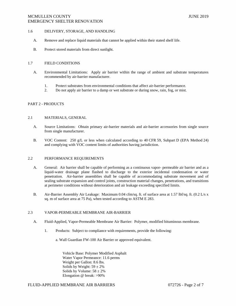
MCMULLEN COUNTY JUNE 2019 EMERGENCY SHELTER RENOVATION
FLUID-APPLIED MEMBRANE AIR BARRIERS 072726 - Page 2 of 7
1.6 DELIVERY, STORAGE, AND HANDLING
A. Remove and replace liquid materials that cannot be applied within their stated shelf life.
B. Protect stored materials from direct sunlight.
1.7 FIELD CONDITIONS
A. Environmental Limitations: Apply air barrier within the range of ambient and substrate temperatures recommended by air-barrier manufacturer.
1. Protect substrates from environmental conditions that affect air-barrier performance. 2. Do not apply air barrier to a damp or wet substrate or during snow, rain, fog, or mist.
PART 2 - PRODUCTS
2.1 MATERIALS, GENERAL
A. Source Limitations: Obtain primary air-barrier materials and air-barrier accessories from single source from single manufacturer.
B. VOC Content: 250 g/L or less when calculated according to 40 CFR 59, Subpart D (EPA Method 24) and complying with VOC content limits of authorities having jurisdiction.
2.2 PERFORMANCE REQUIREMENTS
A. General: Air barrier shall be capable of performing as a continuous vapor- permeable air barrier and as a liquid-water drainage plane flashed to discharge to the exterior incidental condensation or water penetration. Air-barrier assemblies shall be capable of accommodating substrate movement and of sealing substrate expansion and control joints, construction material changes, penetrations, and transitions at perimeter conditions without deterioration and air leakage exceeding specified limits.
B. Air-Barrier Assembly Air Leakage: Maximum 0.04 cfm/sq. ft. of surface area at 1.57 lbf/sq. ft. (0.2 L/s x sq. m of surface area at 75 Pa), when tested according to ASTM E 283.
2.3 VAPOR-PERMEABLE MEMBRANE AIR-BARRIER
A. Fluid-Applied, Vapor-Permeable Membrane Air Barrier: Polymer, modified bituminous membrane.
1. Products: Subject to compliance with requirements, provide the following:
a. Wall Guardian FW-100 Air Barrier or approved equivalent.
Vehicle Base: Polymer Modified Asphalt Water Vapor Permeance: 11.6 perms Weight per Gallon: 8.6 lbs. Solids by Weight: 59 ± 2% Solids by Volume: 58 ± 2% Elongation @ break: >90%
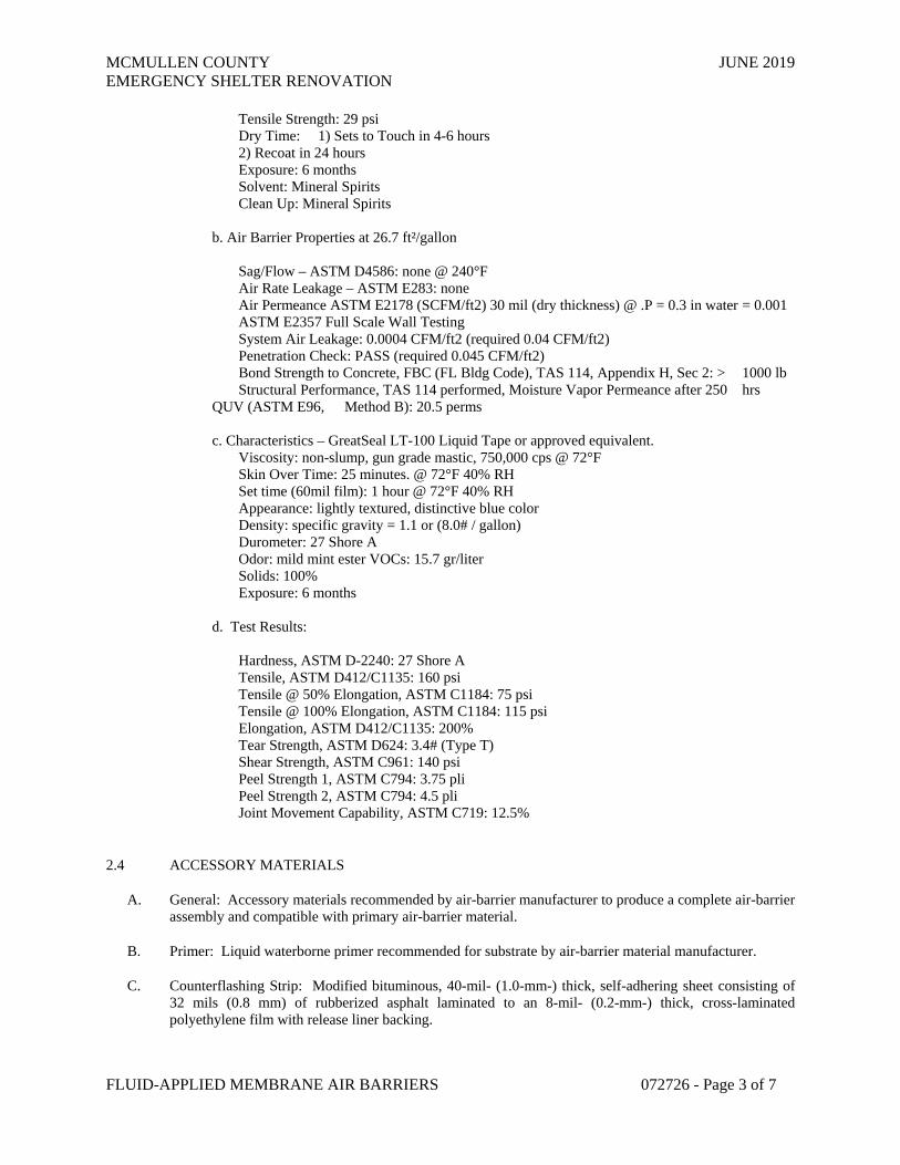
MCMULLEN COUNTY JUNE 2019 EMERGENCY SHELTER RENOVATION
FLUID-APPLIED MEMBRANE AIR BARRIERS 072726 - Page 3 of 7
Tensile Strength: 29 psi Dry Time: 1) Sets to Touch in 4-6 hours 2) Recoat in 24 hours Exposure: 6 months Solvent: Mineral Spirits Clean Up: Mineral Spirits b. Air Barrier Properties at 26.7 ft²/gallon Sag/Flow – ASTM D4586: none @ 240°F Air Rate Leakage – ASTM E283: none Air Permeance ASTM E2178 (SCFM/ft2) 30 mil (dry thickness) @ .P = 0.3 in water = 0.001 ASTM E2357 Full Scale Wall Testing System Air Leakage: 0.0004 CFM/ft2 (required 0.04 CFM/ft2) Penetration Check: PASS (required 0.045 CFM/ft2) Bond Strength to Concrete, FBC (FL Bldg Code), TAS 114, Appendix H, Sec 2: > 1000 lb Structural Performance, TAS 114 performed, Moisture Vapor Permeance after 250 hrs QUV (ASTM E96, Method B): 20.5 perms c. Characteristics – GreatSeal LT-100 Liquid Tape or approved equivalent. Viscosity: non-slump, gun grade mastic, 750,000 cps @ 72°F Skin Over Time: 25 minutes. @ 72°F 40% RH Set time (60mil film): 1 hour @ 72°F 40% RH Appearance: lightly textured, distinctive blue color Density: specific gravity = 1.1 or (8.0# / gallon) Durometer: 27 Shore A Odor: mild mint ester VOCs: 15.7 gr/liter Solids: 100% Exposure: 6 months d. Test Results: Hardness, ASTM D-2240: 27 Shore A Tensile, ASTM D412/C1135: 160 psi Tensile @ 50% Elongation, ASTM C1184: 75 psi Tensile @ 100% Elongation, ASTM C1184: 115 psi Elongation, ASTM D412/C1135: 200% Tear Strength, ASTM D624: 3.4# (Type T) Shear Strength, ASTM C961: 140 psi Peel Strength 1, ASTM C794: 3.75 pli Peel Strength 2, ASTM C794: 4.5 pli Joint Movement Capability, ASTM C719: 12.5%
2.4 ACCESSORY MATERIALS
A. General: Accessory materials recommended by air-barrier manufacturer to produce a complete air-barrier assembly and compatible with primary air-barrier material.
B. Primer: Liquid waterborne primer recommended for substrate by air-barrier material manufacturer.
C. Counterflashing Strip: Modified bituminous, 40-mil- (1.0-mm-) thick, self-adhering sheet consisting of 32 mils (0.8 mm) of rubberized asphalt laminated to an 8-mil- (0.2-mm-) thick, cross-laminated polyethylene film with release liner backing.
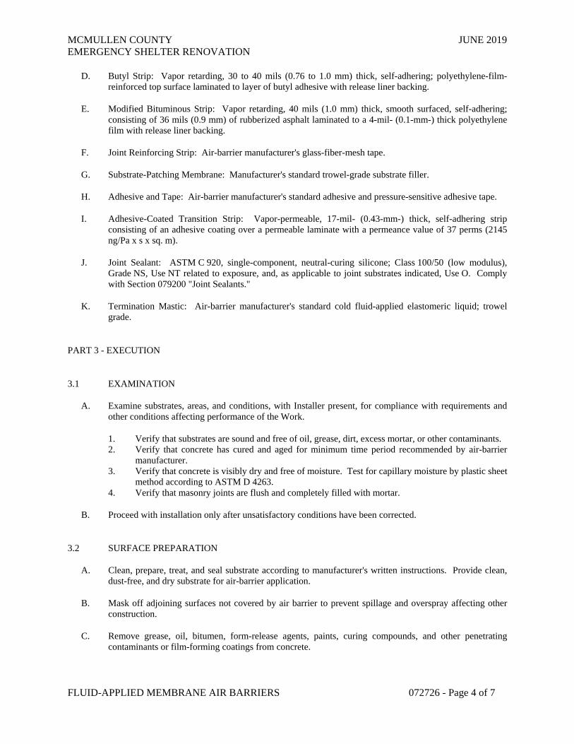
MCMULLEN COUNTY JUNE 2019 EMERGENCY SHELTER RENOVATION
FLUID-APPLIED MEMBRANE AIR BARRIERS 072726 - Page 4 of 7
D. Butyl Strip: Vapor retarding, 30 to 40 mils (0.76 to 1.0 mm) thick, self-adhering; polyethylene-film-reinforced top surface laminated to layer of butyl adhesive with release liner backing.
E. Modified Bituminous Strip: Vapor retarding, 40 mils (1.0 mm) thick, smooth surfaced, self-adhering; consisting of 36 mils (0.9 mm) of rubberized asphalt laminated to a 4-mil- (0.1-mm-) thick polyethylene film with release liner backing.
F. Joint Reinforcing Strip: Air-barrier manufacturer's glass-fiber-mesh tape.
G. Substrate-Patching Membrane: Manufacturer's standard trowel-grade substrate filler.
H. Adhesive and Tape: Air-barrier manufacturer's standard adhesive and pressure-sensitive adhesive tape.
I. Adhesive-Coated Transition Strip: Vapor-permeable, 17-mil- (0.43-mm-) thick, self-adhering strip consisting of an adhesive coating over a permeable laminate with a permeance value of 37 perms (2145 ng/Pa x s x sq. m).
J. Joint Sealant: ASTM C 920, single-component, neutral-curing silicone; Class 100/50 (low modulus), Grade NS, Use NT related to exposure, and, as applicable to joint substrates indicated, Use O. Comply with Section 079200 "Joint Sealants."
K. Termination Mastic: Air-barrier manufacturer's standard cold fluid-applied elastomeric liquid; trowel grade.
PART 3 - EXECUTION
3.1 EXAMINATION
A. Examine substrates, areas, and conditions, with Installer present, for compliance with requirements and other conditions affecting performance of the Work.
1. Verify that substrates are sound and free of oil, grease, dirt, excess mortar, or other contaminants. 2. Verify that concrete has cured and aged for minimum time period recommended by air-barrier
manufacturer. 3. Verify that concrete is visibly dry and free of moisture. Test for capillary moisture by plastic sheet
method according to ASTM D 4263. 4. Verify that masonry joints are flush and completely filled with mortar.
B. Proceed with installation only after unsatisfactory conditions have been corrected.
3.2 SURFACE PREPARATION
A. Clean, prepare, treat, and seal substrate according to manufacturer's written instructions. Provide clean, dust-free, and dry substrate for air-barrier application.
B. Mask off adjoining surfaces not covered by air barrier to prevent spillage and overspray affecting other construction.
C. Remove grease, oil, bitumen, form-release agents, paints, curing compounds, and other penetrating contaminants or film-forming coatings from concrete.

MCMULLEN COUNTY JUNE 2019 EMERGENCY SHELTER RENOVATION
FLUID-APPLIED MEMBRANE AIR BARRIERS 072726 - Page 5 of 7
D. Remove fins, ridges, mortar, and other projections and fill honeycomb, aggregate pockets, holes, and other voids in concrete with substrate-patching membrane.
E. Remove excess mortar from masonry ties, shelf angles, and other obstructions.
F. At changes in substrate plane, apply sealant or termination mastic beads at sharp corners and edges to form a smooth transition from one plane to another.
G. Cover gaps in substrate plane and form a smooth transition from one substrate plane to another with stainless-steel sheet mechanically fastened to structural framing to provide continuous support for air barrier.
3.3 JOINT TREATMENT
A. Concrete and Masonry: Prepare, treat, rout, and fill joints and cracks in substrate according to ASTM C 1193 and air-barrier manufacturer's written instructions. Remove dust and dirt from joints and cracks complying with ASTM D 4258 before coating surfaces.
1. Prime substrate and apply a single thickness of air-barrier manufacturer's recommended preparation coat extending a minimum of 3 inches (75 mm) along each side of joints and cracks. Apply a double thickness of fluid air-barrier material and embed a joint reinforcing strip in preparation coat.
B. Gypsum Sheathing: Fill joints greater than 1/4 inch (6 mm) with sealant according to ASTM C 1193 and air-barrier manufacturer's written instructions. Apply first layer of fluid air-barrier material at joints. Tape joints with joint reinforcing strip after first layer is dry. Apply a second layer of fluid air-barrier material over joint reinforcing strip.
3.4 TRANSITION STRIP INSTALLATION
A. General: Install strips, transition strips, and accessory materials according to air-barrier manufacturer's written instructions to form a seal with adjacent construction and maintain a continuous air barrier.
1. Coordinate the installation of air barrier with installation of roofing membrane and base flashing to ensure continuity of air barrier with roofing membrane.
2. Install butyl strip on roofing membrane or base flashing so that a minimum of 3 inches (75 mm) of coverage is achieved over each substrate.
B. Apply primer to substrates at required rate and allow it to dry. Limit priming to areas that will be covered by fluid air-barrier material on same day. Re-prime areas exposed for more than 24 hours.
1. Prime glass-fiber-surfaced gypsum sheathing with number of prime coats needed to achieve required bond, with adequate drying time between coats.
C. Connect and seal exterior wall air-barrier material continuously to roofing-membrane air barrier, concrete below-grade structures, floor-to-floor construction, exterior glazing and window systems, glazed curtain-wall systems, storefront systems, exterior louvers, exterior door framing, and other construction used in exterior wall openings, using accessory materials.
D. At end of each working day, seal top edge of strips and transition strips to substrate with termination mastic.

MCMULLEN COUNTY JUNE 2019 EMERGENCY SHELTER RENOVATION
FLUID-APPLIED MEMBRANE AIR BARRIERS 072726 - Page 6 of 7
E. Apply joint sealants forming part of air-barrier assembly within manufacturer's recommended application temperature ranges. Consult manufacturer when sealant cannot be applied within these temperature ranges.
F. Wall Openings: Prime concealed, perimeter frame surfaces of windows, curtain walls, storefronts, and doors. Apply elastomeric flashing sheet so that a minimum of 3 inches (75 mm) of coverage is achieved over each substrate. Maintain 3 inches (75 mm) of full contact over firm bearing to perimeter frames with not less than 1 inch (25 mm) of full contact. 1. Elastomeric Flashing Sheet: Apply adhesive to wall, frame, and flashing sheet. Install flashing
sheet and termination bars, fastened at 6 inches (150 mm) o.c. Apply lap sealant over exposed edges and on cavity side of flashing sheet.
G. Fill gaps in perimeter frame surfaces of windows, curtain walls, storefronts, and doors, and miscellaneous penetrations of air-barrier material with foam sealant.
H. Seal strips and transition strips around masonry reinforcing or ties and penetrations with termination mastic.
I. Seal top of through-wall flashings to air barrier with an additional 6-inch- (150-mm-) wide, counterflashing strip.
J. Seal exposed edges of strips at seams, cuts, penetrations, and terminations not concealed by metal counterflashings or ending in reglets with termination mastic.
K. Repair punctures, voids, and deficient lapped seams in strips and transition strips. Slit and flatten fishmouths and blisters. Patch with transition strips extending 6 inches (150 mm) beyond repaired areas in strip direction.
3.5 FLUID AIR-BARRIER MEMBRANE INSTALLATION
A. General: Apply fluid air-barrier material to form a seal with strips and transition strips and to achieve a continuous air barrier according to air-barrier manufacturer's written instructions. Apply fluid air-barrier material within manufacturer's recommended application temperature ranges.
1. Apply primer to substrates at required rate and allow it to dry. 2. Limit priming to areas that will be covered by fluid air-barrier material on same day. Re-prime
areas exposed for more than 24 hours. 3. Prime glass-fiber-surfaced gypsum sheathing with number of prime coats needed to achieve
required bond, with adequate drying time between coats.
B. Membrane Air Barriers: Apply a continuous unbroken air-barrier membrane to substrates according to the following thickness. Apply air-barrier membrane in full contact around protrusions such as masonry ties. 1. Vapor-Permeable Membrane Air Barrier: Total dry film thickness as recommended in writing by
manufacturer to meet performance requirements, but not less than 40-mil (1.0-mm) dry film thickness, applied in one or more equal coats.
C. Do not cover air barrier until it has been tested and inspected by Owner's testing agency.
D. Correct deficiencies in or remove air barrier that does not comply with requirements; repair substrates and reapply air-barrier components.
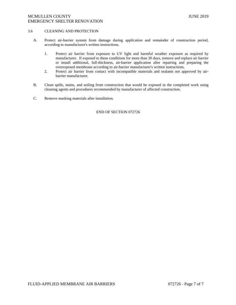
MCMULLEN COUNTY JUNE 2019 EMERGENCY SHELTER RENOVATION
FLUID-APPLIED MEMBRANE AIR BARRIERS 072726 - Page 7 of 7
3.6 CLEANING AND PROTECTION
A. Protect air-barrier system from damage during application and remainder of construction period, according to manufacturer's written instructions.
1. Protect air barrier from exposure to UV light and harmful weather exposure as required by manufacturer. If exposed to these conditions for more than 30 days, remove and replace air barrier or install additional, full-thickness, air-barrier application after repairing and preparing the overexposed membrane according to air-barrier manufacturer's written instructions.
2. Protect air barrier from contact with incompatible materials and sealants not approved by air-barrier manufacturer.
B. Clean spills, stains, and soiling from construction that would be exposed in the completed work using cleaning agents and procedures recommended by manufacturer of affected construction.
C. Remove masking materials after installation.
END OF SECTION 072726
MCMULLEN COUNTY JUNE 2019 EMERGENCY SHELTER RENOVATION
FORMED METAL ROOF PANELS 074112 - Page 1 of 9
SECTION 074112 – FORMED METAL ROOF PANELS
PART 1 - GENERAL
1.1 RELATED DOCUMENTS
A. Drawings and general provisions of the Contract, including General and Supplementary Conditions and Division 01 Specification Sections, apply to this Section.
1.2 SUMMARY
A. Section includes:
1. Lapped-seam metal roof panels (‘R’ panels) for replacement of existing damaged panels (Base Bid) and replacement of entire roofing system (Additive Bid Alternate #1).
a. Panels are installed to existing metal purlins.
b. Replace existing vinyl faced fiberglass thermal roof insulation as described on the drawings (Base Bid – all areas except EMS bays, Bid alternate #1 include replacement of insulation at EMS bays).
c. Protect all building interior during the process of replacing roof panels.
2. Sheet metal flashing and trim associated with standing seam metal roofing panels work.
a. Replacement of gutters and roof penetrations is associated with Additive Bid Alternate #1. Replacement of downspouts is Base Bid.
B. Related Sections:
1. Section 12300 “Alternates”
2. Section 072100 “Thermal Insulation
3. Section 076200 “Sheet Metal Flashing and Trim”
1.3 ACTION SUBMITTALS
A. Product Data: For each type of product.
1. Include construction details, material descriptions, dimensions of individual components and profiles, and finishes for each type of panel and accessory.
B. Shop Drawings:
MCMULLEN COUNTY JUNE 2019 EMERGENCY SHELTER RENOVATION
FORMED METAL ROOF PANELS 074112 - Page 2 of 9
1. Include fabrication and installation layouts of metal panels; details of edge conditions, joints, panel profiles, corners, anchorages, attachment system, trim, flashings, closures, and accessories; and special details.
2. Accessories: Include details of the flashing, trim, and anchorage systems, at a scale of not less than 1-1/2 inches per 12 inches (1:10).
C. Samples for Verification: For each type of exposed finish required, prepared on Samples of size indicated below.
1. Metal Panels: 12 inches (305 mm) long by actual panel width. Include clips, fasteners, closures, and other metal panel accessories.
1.4 INFORMATIONAL SUBMITTALS
A. Qualification Data: For Installer.
B. Product Test Reports: For each product, for tests performed by a qualified testing agency.
C. Field quality-control reports.
D. Sample Warranties: For special warranties.
1.5 CLOSEOUT SUBMITTALS
A. Maintenance Data: For metal panels to include in maintenance manuals.
1.6 QUALITY ASSURANCE
A. Installer Qualifications: An entity that employs installers and supervisors who are trained and approved by manufacturer.
B. UL-Certified, Portable Roll-Forming Equipment: UL-certified, portable roll-forming equipment capable of producing metal panels warranted by manufacturer to be the same as factory-formed products. Maintain UL certification of portable roll-forming equipment for duration of work.
1.7 DELIVERY, STORAGE, AND HANDLING
A. Deliver components, metal panels, and other manufactured items so as not to be damaged or deformed. Package metal panels for protection during transportation and handling.
B. Unload, store, and erect metal panels in a manner to prevent bending, warping, twisting, and surface damage.
C. Stack metal panels horizontally on platforms or pallets, covered with suitable weathertight and ventilated covering. Store metal panels to ensure dryness, with positive slope for drainage of water. Do not store metal panels in contact with other materials that might cause staining, denting, or other surface damage.
D. Retain strippable protective covering on metal panels during installation.

MCMULLEN COUNTY JUNE 2019 EMERGENCY SHELTER RENOVATION
FORMED METAL ROOF PANELS 074112 - Page 3 of 9
1.8 FIELD CONDITIONS
A. Weather Limitations: Proceed with installation only when existing and forecasted weather conditions permit assembly of metal panels to be performed according to manufacturers' written instructions and warranty requirements.
1.9 COORDINATION
A. Coordinate sizes and locations of roof curbs, equipment supports, and roof penetrations with actual equipment provided.
B. Coordinate metal panel installation with rain drainage work, flashing, trim, and other adjoining work to provide a leakproof, secure, and noncorrosive installation.
1.10 WARRANTY
A. Special Warranty: Manufacturer's standard form in which manufacturer agrees to repair or replace components of metal panel systems that fail in materials or workmanship within specified warranty period.
1. Failures include, but are not limited to, the following:
a. Structural failures including rupturing, cracking, or puncturing. b. Deterioration of metals and other materials beyond normal weathering.
2. Warranty Period: Twenty (20) years from date of Substantial Completion.
B. Special Warranty on Panel Finishes: Manufacturer's standard form in which manufacturer agrees to repair finish or replace metal panels that show evidence of deterioration of factory-applied finishes within specified warranty period.
1. Exposed Panel Finish: Deterioration includes, but is not limited to, the following:
a. Color fading more than 5 Hunter units when tested according to ASTM D 2244. b. Chalking in excess of a No. 8 rating when tested according to ASTM D 4214. c. Cracking, checking, peeling, or failure of paint to adhere to bare metal.
2. Finish Warranty Period: 20 years from date of Substantial Completion.
C. Special Weathertightness Warranty (Alternate Bid #1): Manufacturer's standard form in which manufacturer agrees to repair or replace standing-seam metal roof panel assemblies that fail to remain weathertight, including leaks, within specified warranty period.
1. Warranty Period: 20 years from date of Substantial Completion.

MCMULLEN COUNTY JUNE 2019 EMERGENCY SHELTER RENOVATION
FORMED METAL ROOF PANELS 074112 - Page 4 of 9
PART 2 - PRODUCTS
2.1 METAL ROOF PANELS
A. Tapered-Rib-Profile, Exposed-Fastener Metal Wall Panels (R-Panel): Formed with raised, trapezoidal major ribs and intermediate stiffening ribs symmetrically spaced between major ribs; designed to be installed by lapping side edges of adjacent panels and mechanically attaching panels to supports using exposed fasteners in side laps. Verify profile and width to match existing panels at this building.
1. Material: Zinc-coated galvanized, 24 gauge nominal thickness.
a. Exterior Finish: Fluoropolymer. b. Color: Match existing for replacement panels. As selected by Owner for new roofing
system.
2. Major-Rib Spacing: 12 inches o.c. 3. Panel Coverage: 36 inches. 4. Panel Height: 1.25.
B. Materials:
1. Metallic-Coated Steel Sheet: Restricted-flatness steel sheet, metallic coated by the hot-dip process and pre-painted by the coil-coating process to comply with ASTM A 755.
a. Zinc-Coated (Galvanized) Steel Sheet: ASTM A 653, G90 coating designation; structural quality.
b. Surface: Embossed finish.
C. Finishes:
1. Exposed Coil-Coated Finish:
a. Two-Coat Fluoropolymer: AAMA 621. Fluoropolymer finish containing not less than 70 percent PVDF resin by weight in color coat. Prepare, pre-treat, and apply coating to exposed metal surfaces to comply with coating and resin manufacturers' written instructions.
2. Concealed Finish: Apply pretreatment and manufacturer's standard white or light-colored acrylic or polyester backer finish, consisting of prime coat and wash coat with a minimum total dry film thickness of 0.5 mil.
2.2 MISCELLANEOUS MATERIALS
A. Miscellaneous Metal Subframing and Furring: ASTM C 645; cold-formed, metallic-coated steel sheet, ASTM A 653/A 653M, G90 (Z275 hot-dip galvanized) coating designation or ASTM A 792/A 792M, Class AZ50 (Class AZM150) coating designation unless otherwise indicated. Provide manufacturer's standard sections as required for support and alignment of metal panel system.
B. Panel Accessories: Provide components required for a complete, weathertight panel system including trim, copings, fasciae, mullions, sills, corner units, clips, flashings, sealants, gaskets, fillers, closure strips, and similar items. Match material and finish of metal panels unless otherwise indicated.

MCMULLEN COUNTY JUNE 2019 EMERGENCY SHELTER RENOVATION
FORMED METAL ROOF PANELS 074112 - Page 5 of 9
1. Closures: Provide closures at eaves and ridges, fabricated of same metal as metal panels. 2. Backing Plates: Provide metal backing plates at panel end splices, fabricated from material
recommended by manufacturer. 3. Closure Strips: Closed-cell, expanded, cellular, rubber or crosslinked, polyolefin-foam or closed-
cell laminated polyethylene; minimum 1-inch- (25-mm-) thick, flexible closure strips; cut or premolded to match metal panel profile. Provide closure strips where indicated or necessary to ensure weathertight construction.
C. Flashing and Trim: Provide flashing and trim formed from same material as metal panels as required to seal against weather and to provide finished appearance. Locations include, but are not limited to, eaves, rakes, corners, bases, framed openings, ridges, fasciae, and fillers. Finish flashing and trim with same finish system as adjacent metal panels.
D. Gutters: Formed from same material as roof panels, complete with end pieces, outlet tubes, and other special pieces as required. Fabricate in minimum 96-inch- (2400-mm-) long sections, of size and metal thickness according to SMACNA's "Architectural Sheet Metal Manual." Furnish gutter supports spaced a maximum of 36 inches (914 mm) o.c., fabricated from same metal as gutters. Provide wire ball strainers of compatible metal at outlets. 1. Finish gutters to match roof fascia and rake trim (“Galvalume”).
E. Downspouts: Formed from same material as roof panels. Fabricate in 10-foot- (3-m-) long sections, complete with formed elbows and offsets, of size and metal thickness according to SMACNA's "Architectural Sheet Metal Manual." 1. Finish flashing and trim with same finish system as adjacent metal panels.
F. Roof Curbs: Fabricated from same material as roof panels, 0.048-inch (1.2-mm)] nominal thickness; with bottom of skirt profiled to match roof panel profiles and with welded top box and integral full-length cricket. Fabricate curb subframing of 0.060-inch- (1.52-mm-) nominal thickness, angle-, C-, or Z-shaped steel sheet. Fabricate curb and subframing to withstand indicated loads of size and height indicated. Finish roof curbs to match metal roof panels.
1. Insulate roof curb with 1-inch- (25-mm-) thick, rigid insulation.
G. Panel Fasteners: Self-tapping screws designed to withstand design loads.
H. Panel Sealants: Provide sealant type recommended by manufacturer that are compatible with panel materials, are nonstaining, and do not damage panel finish.
1. Sealant Tape: Pressure-sensitive, 100 percent solids, gray polyisobutylene compound sealant tape with release-paper backing. Provide permanently elastic, nonsag, nontoxic, nonstaining tape 1/2 inch (13 mm) wide and 1/8 inch (3 mm) thick.
2. Joint Sealant: ASTM C 920; elastomeric polyurethane or silicone sealant; of type, grade, class, and use classifications required to seal joints in metal panels and remain weathertight; and as recommended in writing by metal panel manufacturer.
3. Butyl-Rubber-Based, Solvent-Release Sealant: ASTM C 1311.
2.3 FABRICATION
A. General: Fabricate and finish metal panels and accessories at the factory, by manufacturer's standard procedures and processes, as necessary to fulfill indicated performance requirements demonstrated by laboratory testing. Comply with indicated profiles and with dimensional and structural requirements.

MCMULLEN COUNTY JUNE 2019 EMERGENCY SHELTER RENOVATION
FORMED METAL ROOF PANELS 074112 - Page 6 of 9
B. On-Site Fabrication: Subject to compliance with requirements of this Section, metal panels may be fabricated on-site using UL-certified, portable roll-forming equipment if panels are of same profile and warranted by manufacturer to be equal to factory-formed panels. Fabricate according to equipment manufacturer's written instructions and to comply with details shown.
C. Provide panel profile, including major ribs and intermediate stiffening ribs, if any, for full length of panel.
D. Fabricate metal panel joints with factory-installed captive gaskets or separator strips that provide a weathertight seal and prevent metal-to-metal contact, and that minimize noise from movements.
E. Sheet Metal Flashing and Trim: Fabricate flashing and trim to comply with manufacturer's recommendations and recommendations in SMACNA's "Architectural Sheet Metal Manual" that apply to design, dimensions, metal, and other characteristics of item indicated.
1. Form exposed sheet metal accessories that are without excessive oil canning, buckling, and tool marks and that are true to line and levels indicated, with exposed edges folded back to form hems.
2. Seams for Aluminum: Fabricate nonmoving seams with flat-lock seams. Form seams and seal with epoxy seam sealer. Rivet joints for additional strength.
3. Seams for Other Than Aluminum: Fabricate nonmoving seams in accessories with flat-lock seams. Tin edges to be seamed, form seams, and solder.
4. Sealed Joints: Form nonexpansion, but movable, joints in metal to accommodate sealant and to comply with SMACNA standards.
5. Conceal fasteners and expansion provisions where possible. Exposed fasteners are not allowed on faces of accessories exposed to view.
6. Fabricate cleats and attachment devices from same material as accessory being anchored or from compatible, noncorrosive metal recommended in writing by metal panel manufacturer.
a. Size: As recommended by SMACNA's "Architectural Sheet Metal Manual" or metal panel manufacturer for application, but not less than thickness of metal being secured.
PART 3 - EXECUTION
3.1 EXAMINATION
A. Examine substrates, areas, and conditions, with Installer present, for compliance with requirements for installation tolerances, metal panel supports, and other conditions affecting performance of the Work.
1. Examine primary and secondary roof framing to verify that rafters, purlins, angles, channels, and other structural panel support members and anchorages have been installed within alignment tolerances required by metal roof panel manufacturer.
2. Examine solid roof sheathing to verify that sheathing joints are supported by framing or blocking and that installation is within flatness tolerances required by metal roof panel manufacturer.
a. Verify that air- or water-resistive barriers have been installed over sheathing or backing substrate to prevent air infiltration or water penetration.
B. Examine roughing-in for components and systems penetrating metal panels to verify actual locations of penetrations relative to seam locations of metal panels before installation.
C. Proceed with installation only after unsatisfactory conditions have been corrected.

MCMULLEN COUNTY JUNE 2019 EMERGENCY SHELTER RENOVATION
FORMED METAL ROOF PANELS 074112 - Page 7 of 9
3.2 PREPARATION
A. Miscellaneous Supports: Install sub-framing, furring, and other miscellaneous panel support members and anchorages according to ASTM C 754 and metal panel manufacturer's written recommendations.
3.3 METAL PANEL INSTALLATION
A. General: Install metal panels according to manufacturer's written instructions in orientation, sizes, and locations indicated. Install panels perpendicular to supports unless otherwise indicated. Anchor metal panels and other components of the Work securely in place, with provisions for thermal and structural movement.
1. Shim or otherwise plumb substrates receiving metal panels. 2. Flash and seal metal panels at perimeter of all openings. Fasten with self-tapping screws. Do not
begin installation until air- or water-resistive barriers and flashings that will be concealed by metal panels are installed.
3. Install screw fasteners in predrilled holes. 4. Locate and space fastenings in uniform vertical and horizontal alignment. 5. Install flashing and trim as metal panel work proceeds. 6. Locate panel splices over, but not attached to, structural supports. Stagger panel splices and end
laps to avoid a four-panel lap splice condition. 7. Align bottoms of metal panels and fasten with blind rivets, bolts, or self-tapping screws. Fasten
flashings and trim around openings and similar elements with self-tapping screws. 8. Provide weathertight escutcheons for pipe- and conduit-penetrating panels.
B. Fasteners:
1. Steel Panels: Use stainless-steel fasteners for surfaces exposed to the exterior; use galvanized-steel fasteners for surfaces exposed to the interior.
C. Anchor Clips: Anchor metal roof panels and other components of the Work securely in place, using manufacturer's approved fasteners according to manufacturers' written instructions.
D. Metal Protection: Where dissimilar metals contact each other or corrosive substrates, protect against galvanic action as recommended in writing by metal panel manufacturer.
E. Lap-Seam Metal Panels: Install screw fasteners using power tools with controlled torque adjusted to compress EPDM washers tightly without damage to washers, screw threads, or metal panels. Install screws in predrilled holes.
1. Arrange and nest side-lap joints so prevailing winds blow over, not into, lapped joints. Lap ribbed or fluted sheets one full rib corrugation. Apply metal panels and associated items for neat and weather-tight enclosure. Avoid "panel creep" or application not true to line.
F. Watertight Installation:
1. Apply a continuous ribbon of sealant or tape to seal lapped joints of metal panels, using sealant or tape as recommend by manufacturer on side laps of nesting-type panels and elsewhere as needed to make panels watertight.
2. Provide sealant or tape between panels and protruding equipment, vents, and accessories. 3. At panel splices, nest panels with minimum 6-inch (152-mm) end lap, sealed with sealant and
fastened together by interlocking clamping plates.
MCMULLEN COUNTY JUNE 2019 EMERGENCY SHELTER RENOVATION
FORMED METAL ROOF PANELS 074112 - Page 8 of 9
G. Accessory Installation: Install accessories with positive anchorage to building and weathertight mounting, and provide for thermal expansion. Coordinate installation with flashings and other components.
1. Install components required for a complete metal panel system including trim, copings, corners, seam covers, flashings, sealants, gaskets, fillers, closure strips, and similar items. Provide types indicated by metal roof panel manufacturers; or, if not indicated, types recommended by metal roof panel manufacturer.
H. Flashing and Trim: Comply with performance requirements, manufacturer's written installation instructions, and SMACNA's "Architectural Sheet Metal Manual." Provide concealed fasteners where possible, and set units true to line and level as indicated. Install work with laps, joints, and seams that will be permanently watertight and weather resistant.
1. Install exposed flashing and trim that is without buckling and tool marks, and that is true to line and levels indicated, with exposed edges folded back to form hems. Install sheet metal flashing and trim to fit substrates and achieve waterproof and weather-resistant performance.
2. Expansion Provisions: Provide for thermal expansion of exposed flashing and trim. Space movement joints at a maximum of 10 feet (3 m) with no joints allowed within 24 inches (610 mm) of corner or intersection. Where lapped expansion provisions cannot be used or would not be sufficiently weather resistant and waterproof, form expansion joints of intermeshing hooked flanges, not less than 1 inch (25 mm) deep, filled with mastic sealant (concealed within joints).
I. Gutters: Join sections with riveted and soldered or lapped and sealed joints. Attach gutters to eave with gutter hangers spaced not more than 36 inches (914 mm) o.c. using manufacturer's standard fasteners. Provide end closures and seal watertight with sealant. Provide for thermal expansion.
J. Downspouts: Join sections with telescoping joints. Provide fasteners designed to hold downspouts securely 1 inch (25 mm) away from walls; locate fasteners at top and bottom and at approximately 60 inches (1524 mm) o.c. in between.
1. Provide elbows at base of downspouts to direct water away from building. 2. Connect downspouts to underground drainage system indicated.
K. Roof Curbs: Install flashing around bases where they meet metal roof panels.
L. Pipe Flashing: Form flashing around pipe penetration and metal roof panels. Fasten and seal to metal roof panels as recommended by manufacturer.
3.4 ERECTION TOLERANCES
A. Installation Tolerances: Shim and align metal panel units within installed tolerance of 1/4 inch in 20 feet (6 mm in 6 m) on slope and location lines as indicated and within 1/8-inch (3-mm) offset of adjoining faces and of alignment of matching profiles.
3.5 FIELD QUALITY CONTROL
A. Manufacturer's Field Service: Engage a factory-authorized service representative to test and inspect metal roof panel installation, including accessories. Report results in writing.
B. Remove and replace applications of metal roof panels where tests and inspections indicate that they do not comply with specified requirements.

MCMULLEN COUNTY JUNE 2019 EMERGENCY SHELTER RENOVATION
FORMED METAL ROOF PANELS 074112 - Page 9 of 9
C. Additional tests and inspections, at Contractor's expense, are performed to determine compliance of replaced or additional work with specified requirements.
D. Prepare test and inspection reports.
3.6 CLEANING AND PROTECTION
A. Remove temporary protective coverings and strippable films, if any, as metal panels are installed, unless otherwise indicated in manufacturer's written installation instructions. On completion of metal panel installation, clean finished surfaces as recommended by metal panel manufacturer. Maintain in a clean condition during construction.
B. Replace metal panels that have been damaged or have deteriorated beyond successful repair by finish touchup or similar minor repair procedures.
END OF SECTION 074113
MCMULLEN COUNTY JUNE 2019 EMERGENCY SHELTER RENOVATION
FORMED METAL WALL PANELS 074113 - Page 1 of 7
SECTION 074113 – FORMED METAL WALL PANELS
PART 1 - GENERAL
1.1 RELATED DOCUMENTS
A. Drawings and general provisions of the Contract, including General and Supplementary Conditions and Division 01 Specification Sections, apply to this Section.
1.2 SUMMARY
A. Section includes:
1. Metal wall panels. 2. Sheet metal flashing and trim associated with metal wall panels. 3. Replace existing downspouts.
B. Related Sections:
1. Section 076200 “Sheet Metal Flashing and Trim” for sheet metal work at wall conditions.
1.3 ACTION SUBMITTALS
A. Product Data: For each type of product.
1. Include construction details, material descriptions, dimensions of individual components and profiles, and finishes for each type of panel and accessory.
B. Shop Drawings:
1. Include fabrication and installation layouts of metal panels; details of edge conditions, joints, panel profiles, corners, anchorages, attachment system, trim, flashings, closures, and accessories; and special details.
2. Accessories: Include details of the flashing, trim, and anchorage systems, at a scale of not less than 1-1/2 inches per 12 inches (1:10).
C. Verification Sample: Metal panel with factory-applied color finishes to match existing wall panels.
1. Include similar Samples of trim and accessories involving color selection.
1.4 INFORMATIONAL SUBMITTALS
A. Qualification Data: For Installer.
B. Sample Warranties: For special warranties.

MCMULLEN COUNTY JUNE 2019 EMERGENCY SHELTER RENOVATION
FORMED METAL WALL PANELS 074113 - Page 2 of 7
1.5 QUALITY ASSURANCE
A. Installer Qualifications: An entity that employs installers and supervisors who are trained and approved by manufacturer.
1.6 DELIVERY, STORAGE, AND HANDLING
A. Deliver components, metal panels, and other manufactured items so as not to be damaged or deformed. Package metal panels for protection during transportation and handling.
B. Unload, store, and erect metal panels in a manner to prevent bending, warping, twisting, and surface damage.
C. Stack metal panels horizontally on platforms or pallets, covered with suitable weathertight and ventilated covering. Store metal panels to ensure dryness, with positive slope for drainage of water. Do not store metal panels in contact with other materials that might cause staining, denting, or other surface damage.
D. Retain strippable protective covering on metal panels during installation.
1.7 FIELD CONDITIONS
A. Weather Limitations: Proceed with installation only when existing and forecasted weather conditions permit assembly of metal panels to be performed according to manufacturers' written instructions and warranty requirements.
1.8 COORDINATION
A. Coordinate sizes and locations of roof curbs, equipment supports, and roof penetrations with actual equipment provided.
B. Coordinate metal panel installation with rain drainage work, flashing, trim, construction of soffits, and other adjoining work to provide a leakproof, secure, and noncorrosive installation.
1.9 WARRANTY
A. Special Warranty: Manufacturer's standard form in which manufacturer agrees to repair or replace components of metal panel systems that fail in materials or workmanship within specified warranty period.
1. Failures include, but are not limited to, the following:
a. Structural failures including rupturing, cracking, or puncturing. b. Deterioration of metals and other materials beyond normal weathering.
2. Warranty Period: Twenty (20) years from date of Substantial Completion.
B. Special Warranty on Panel Finishes: Manufacturer's standard form in which manufacturer agrees to repair finish or replace metal panels that show evidence of deterioration of factory-applied finishes within specified warranty period.
1. Exposed Panel Finish: Deterioration includes, but is not limited to, the following:
MCMULLEN COUNTY JUNE 2019 EMERGENCY SHELTER RENOVATION
FORMED METAL WALL PANELS 074113 - Page 3 of 7
a. Color fading more than 5 Hunter units when tested according to ASTM D 2244. b. Chalking in excess of a No. 8 rating when tested according to ASTM D 4214. c. Cracking, checking, peeling, or failure of paint to adhere to bare metal.
2. Finish Warranty Period: 20 years from date of Substantial Completion.
PART 2 - PRODUCTS
2.1 METAL WALL PANELS
A. Tapered-Rib-Profile, Exposed-Fastener Metal Wall Panels (R-Panel): Formed with raised, trapezoidal major ribs and intermediate stiffening ribs symmetrically spaced between major ribs; designed to be installed by lapping side edges of adjacent panels and mechanically attaching panels to supports using exposed fasteners in side laps. 1. Material: Zinc-coated (galvanized, 24 gauge nominal thickness.
a. Exterior Finish: Fluoropolymer. b. Color: Match existing roof panel color and wall panel color, respectively.
2. Major-Rib Spacing: 12 inches o.c. 3. Panel Coverage: 36 inches. 4. Panel Height: 1.25.
B. Materials: 1. Metallic-Coated Steel Sheet: Restricted-flatness steel sheet, metallic coated by the hot-dip process
and pre-painted by the coil-coating process to comply with ASTM A 755. a. Zinc-Coated (Galvanized) Steel Sheet: ASTM A 653, G90 coating designation; structural
quality. b. Surface: Embossed finish.
C. Finishes: 1. Exposed Coil-Coated Finish:
a. Two-Coat Fluoropolymer: AAMA 621. Fluoropolymer finish containing not less than 70 percent PVDF resin by weight in color coat. Prepare, pre-treat, and apply coating to exposed metal surfaces to comply with coating and resin manufacturers' written instructions.
2. Concealed Finish: Apply pretreatment and manufacturer's standard white or light-colored acrylic or polyester backer finish, consisting of prime coat and wash coat with a minimum total dry film thickness of 0.5 mil.
2.2 MISCELLANEOUS MATERIALS
A. Miscellaneous Metal Sub-framing and Furring: ASTM C 645; cold-formed, metallic-coated steel sheet, ASTM A 653/A 653M, G90 (Z275 hot-dip galvanized) coating designation or ASTM A 792/A 792M, Class AZ50 (Class AZM150) coating designation unless otherwise indicated. Provide manufacturer's standard sections as required for support and alignment of metal panel system.
B. Panel Accessories: Provide components required for a complete, weathertight panel system including trim, copings, fasciae, mullions, sills, corner units, clips, flashings, sealants, gaskets, fillers, closure strips, and similar items. Match material and finish of metal panels unless otherwise indicated.
1. Closures: Provide closures at eaves and ridges, fabricated of same metal as metal panels. 2. Backing Plates: Provide metal backing plates at panel end splices, fabricated from material
recommended by manufacturer. 3. Closure Strips: Closed-cell, expanded, cellular, rubber or crosslinked, polyolefin-foam or closed-
cell laminated polyethylene; minimum 1-inch- (25-mm-) thick, flexible closure strips; cut or pre-

MCMULLEN COUNTY JUNE 2019 EMERGENCY SHELTER RENOVATION
FORMED METAL WALL PANELS 074113 - Page 4 of 7
molded to match metal panel profile. Provide closure strips where indicated or necessary to ensure weathertight construction.
C. Flashing and Trim: Provide flashing and trim formed from same material as metal panels as required to seal against weather and to provide finished appearance. Locations include, but are not limited to, eaves, rakes, corners, bases, framed openings, ridges, fasciae, and fillers. Finish flashing and trim with same finish system as adjacent metal panels.
D. Downspouts: Formed from same material as roof panels. Fabricate in 10-foot- (3-m-) long sections, complete with formed elbows and offsets, of size and metal thickness according to SMACNA's "Architectural Sheet Metal Manual." 1. Finish flashing and trim with same finish system as adjacent metal panels.
E. Panel Fasteners: Self-tapping screws designed to withstand design loads.
F. Panel Sealants: Provide sealant type recommended by manufacturer that are compatible with panel materials, are non-staining, and do not damage panel finish.
1. Sealant Tape: Pressure-sensitive, 100 percent solids, gray polyisobutylene compound sealant tape with release-paper backing. Provide permanently elastic, non-sag, nontoxic, non-staining tape 1/2 inch (13 mm) wide and 1/8 inch (3 mm) thick.
2. Joint Sealant: ASTM C 920; elastomeric polyurethane or silicone sealant; of type, grade, class, and use classifications required to seal joints in metal panels and remain weathertight; and as recommended in writing by metal panel manufacturer.
3. Butyl-Rubber-Based, Solvent-Release Sealant: ASTM C 1311.
2.3 FABRICATION
A. General: Fabricate and finish metal panels and accessories at the factory, by manufacturer's standard procedures and processes, as necessary to fulfill indicated performance requirements demonstrated by laboratory testing. Comply with indicated profiles and with dimensional and structural requirements.
B. On-Site Fabrication: Subject to compliance with requirements of this Section, metal panels may be fabricated on-site using UL-certified, portable roll-forming equipment if panels are of same profile and warranted by manufacturer to be equal to factory-formed panels. Fabricate according to equipment manufacturer's written instructions and to comply with details shown.
C. Provide panel profile, including major ribs and intermediate stiffening ribs, if any, for full length of panel.
D. Fabricate metal panel joints with factory-installed captive gaskets or separator strips that provide a weathertight seal and prevent metal-to-metal contact, and that minimize noise from movements.
E. Sheet Metal Flashing and Trim: Fabricate flashing and trim to comply with manufacturer's recommendations and recommendations in SMACNA's "Architectural Sheet Metal Manual" that apply to design, dimensions, metal, and other characteristics of item indicated.
1. Form exposed sheet metal accessories that are without excessive oil canning, buckling, and tool marks and that are true to line and levels indicated, with exposed edges folded back to form hems.
2. Seams for Aluminum: Fabricate nonmoving seams with flat-lock seams. Form seams and seal with epoxy seam sealer. Rivet joints for additional strength.
3. Seams for Other Than Aluminum: Fabricate nonmoving seams in accessories with flat-lock seams. Tin edges to be seamed, form seams, and solder.
4. Sealed Joints: Form non-expansion, but movable, joints in metal to accommodate sealant and to comply with SMACNA standards.
MCMULLEN COUNTY JUNE 2019 EMERGENCY SHELTER RENOVATION
FORMED METAL WALL PANELS 074113 - Page 5 of 7
5. Conceal fasteners and expansion provisions where possible. Exposed fasteners are not allowed on faces of accessories exposed to view.
6. Fabricate cleats and attachment devices from same material as accessory being anchored or from compatible, noncorrosive metal recommended in writing by metal panel manufacturer.
a. Size: As recommended by SMACNA's "Architectural Sheet Metal Manual" or metal panel manufacturer for application, but not less than thickness of metal being secured.
2.4 FINISHES
A. Protect mechanical and painted finishes on exposed surfaces from damage by applying a strippable, temporary protective covering before shipping.
B. Appearance of Finished Work: Variations in appearance of abutting or adjacent pieces are acceptable if they are within one-half of the range of approved Samples. Noticeable variations in same piece are unacceptable. Variations in appearance of other components are acceptable if they are within the range of approved Samples and are assembled or installed to minimize contrast.
C. Steel Panels and Accessories: 1. Roof Panels - Metallic Fluoropolymer: AAMA 621. Three-coat fluoropolymer finish with
suspended metallic flakes containing not less than 70 percent PVDF resin by weight in both color coat and clear topcoat. Prepare, pretreat, and apply coating to exposed metal surfaces to comply with coating and resin manufacturers' written instructions.
2. Soffit Panels - Siliconized Polyester: Epoxy primer and silicone-modified, polyester-enamel topcoat; with a dry film thickness of not less than 0.2 mil (0.005 mm) for primer and 0.8 mil (0.02 mm) for topcoat.
3. Concealed Finish: Apply pretreatment and manufacturer's standard white or light-colored acrylic or polyester backer finish consisting of prime coat and wash coat with a minimum total dry film thickness of 0.5 mil (0.013 mm).
PART 3 - EXECUTION
3.1 PREPARATION
A. Miscellaneous Supports: Install sub-framing, furring, and other miscellaneous panel support members and anchorages according to ASTM C 754 and metal panel manufacturer's written recommendations.
3.2 METAL PANEL INSTALLATION, GENERAL A. Examination: Examine primary and secondary framing to verify that structural-panel support members
and anchorages have been installed within alignment tolerances required by manufacturer. 1. Examine roughing-in for components and systems penetrating metal panels, to verify actual
locations of penetrations relative to seams before metal panel installation. B. General: Anchor metal panels and other components of the Work securely in place, with provisions for
thermal and structural movement. 1. Field cut metal panels as required for doors, windows, and other openings. Cut openings as small
as possible, neatly to size required, and without damage to adjacent metal panel finishes. a. Field cutting of metal panels by torch is not permitted unless approved in writing by
manufacturer. 2. Install metal panels perpendicular to structural supports unless otherwise indicated. 3. Flash and seal metal panels with weather closures at perimeter of openings and similar elements.
Fasten with self-tapping screws. 4. Locate and space fastenings in uniform vertical and horizontal alignment.

MCMULLEN COUNTY JUNE 2019 EMERGENCY SHELTER RENOVATION
FORMED METAL WALL PANELS 074113 - Page 6 of 7
5. Locate metal panel splices over, but not attached to, structural supports with end laps in alignment. 6. Lap metal flashing over metal panels to allow moisture to run over and off the material.
C. Lap-Seam Metal Panels: Install screw fasteners using power tools with controlled torque adjusted to compress EPDM washers tightly without damage to washers, screw threads, or metal panels. Install screws in predrilled holes. 1. Arrange and nest side-lap joints so prevailing winds blow over, not into, lapped joints. Lap ribbed
or fluted sheets one full rib corrugation. Apply metal panels and associated items for neat and weather-tight enclosure. Avoid "panel creep" or application not true to line.
D. Metal Protection: Where dissimilar metals contact each other or corrosive substrates, protect against galvanic action by painting contact surfaces with corrosion-resistant coating, by applying rubberized-asphalt underlayment to each contact surface, or by other permanent separation as recommended by metal roof panel manufacturer.
E. Joint Sealers: Install gaskets, joint fillers, and sealants where indicated and where required for weatherproof performance of metal panel assemblies. Provide types of gaskets, fillers, and sealants indicated; or, if not indicated, provide types recommended by metal panel manufacturer. 1. Seal metal panel end laps with double beads of tape or sealant the full width of panel. Seal side
joints where recommended by metal panel manufacturer. 2. Prepare joints and apply sealants to comply with requirements in Section 079200 "Joint Sealants."
3.3 METAL WALL PANEL INSTALLATION
A. General: Install metal wall panels in orientation, sizes, and locations indicated on Drawings. Install panels perpendicular to girts, extending full height of building, unless otherwise indicated. Anchor metal wall panels and other components of the Work securely in place, with provisions for thermal and structural movement. 1. Unless otherwise indicated, begin metal panel installation at corners with center of rib lined up
with line of framing. 2. Shim or otherwise plumb substrates receiving metal wall panels. 3. When two rows of metal panels are required, lap panels 4 inches minimum. 4. When building height requires two rows of metal panels at gable ends, align lap of gable panels
over metal wall panels at eave height. 5. Rigidly fasten base end of metal wall panels and allow eave end free movement due to thermal
expansion and contraction. Pre-drill panels. 6. Flash and seal metal wall panels with weather closures at eaves, rakes, and at perimeter of all
openings. Fasten with self-tapping screws. 7. Install screw fasteners in predrilled holes. 8. Install flashing and trim as metal wall panel work proceeds. 9. Apply elastomeric sealant continuously between metal base channel (sill angle) and concrete, and
elsewhere as indicated; or, if not indicated, as necessary for waterproofing. 10. Align bottom of metal wall panels and fasten with blind rivets, bolts, or self-drilling or self-
tapping screws. 11. Provide weatherproof escutcheons for pipe and conduit penetrating exterior walls.
B. Metal Wall Panels: Install metal wall panels on exterior side of girts. Attach metal wall panels to
supports with fasteners as recommended by manufacturer. C. Installation Tolerances: Shim and align metal wall panels within installed tolerance of 1/4 inch in 20,
non-accumulative, on level, plumb, and on location lines as indicated, and within 1/8-inch offset of adjoining faces and of alignment of matching profiles.
D. Accessory Installation: Install accessories with positive anchorage to building and weathertight mounting, and provide for thermal expansion. Coordinate installation with flashings and other components.
1. Install components required for a complete metal panel system including trim, copings, corners, seam covers, flashings, sealants, gaskets, fillers, closure strips, and similar items. Provide types

MCMULLEN COUNTY JUNE 2019 EMERGENCY SHELTER RENOVATION
FORMED METAL WALL PANELS 074113 - Page 7 of 7
indicated by metal roof panel manufacturers; or, if not indicated, types recommended by metal roof panel manufacturer.
E. Flashing and Trim: Comply with performance requirements, manufacturer's written installation instructions, and SMACNA's "Architectural Sheet Metal Manual." Provide concealed fasteners where possible, and set units true to line and level as indicated. Install work with laps, joints, and seams that will be permanently watertight and weather resistant.
1. Install exposed flashing and trim that is without buckling and tool marks, and that is true to line and levels indicated, with exposed edges folded back to form hems. Install sheet metal flashing and trim to fit substrates and achieve waterproof and weather-resistant performance.
2. Expansion Provisions: Provide for thermal expansion of exposed flashing and trim. Space movement joints at a maximum of 10 feet (3 m) with no joints allowed within 24 inches (610 mm) of corner or intersection. Where lapped expansion provisions cannot be used or would not be sufficiently weather resistant and waterproof, form expansion joints of intermeshing hooked flanges, not less than 1 inch (25 mm) deep, filled with mastic sealant (concealed within joints).
F. Downspouts: Join sections with telescoping joints. Provide fasteners designed to hold downspouts securely 1 inch (25 mm) away from walls; locate fasteners at top and bottom and at approximately 60 inches (1524 mm) o.c. in between.
1. Provide elbows at base of downspouts to direct water away from building. 2. Connect downspouts to underground drainage system indicated.
3.4 ERECTION TOLERANCES
A. Installation Tolerances: Shim and align metal panel units within installed tolerance of 1/4 inch in 20 feet (6 mm in 6 m) on slope and location lines as indicated and within 1/8-inch (3-mm) offset of adjoining faces and of alignment of matching profiles.
3.5 CLEANING AND PROTECTION
A. Remove temporary protective coverings and strippable films, if any, as metal panels are installed, unless otherwise indicated in manufacturer's written installation instructions. On completion of metal panel installation, clean finished surfaces as recommended by metal panel manufacturer. Maintain in a clean condition during construction.
B. Replace metal panels that have been damaged or have deteriorated beyond successful repair by finish touchup or similar minor repair procedures.
END OF SECTION 074113
MCMULLEN COUNTY JUNE 2019 EMERGENCY SHELTER RENOVATION
SHEET METAL FLASHING AND TRIM 076200 - Page 1 of 8
SECTION 076200 - SHEET METAL FLASHING AND TRIM
PART 1 - GENERAL
1.1 RELATED DOCUMENTS
A. Drawings and general provisions of the Contract, including General and Supplementary Conditions and Division 01 Specification Sections, apply to this Section.
1.2 SUMMARY
A. Section Includes: 1. Formed sheet metal fabrications.
B. Related Requirements:
1. Section 061000 "Rough Carpentry" for wood nailers, curbs, and blocking. 2. Section 074113 "Formed Metal Wall Panels" for sheet metal flashing and trim integral with metal
wall panels.
1.3 COORDINATION
A. Coordinate sheet metal flashing and trim layout and seams with sizes and locations of penetrations to be flashed, and joints and seams in adjacent materials.
B. Coordinate sheet metal flashing and trim installation with adjoining roofing and wall materials, joints, and seams to provide leakproof, secure, and noncorrosive installation.
1.4 ACTION SUBMITTALS
A. Product Data: For each type of product.
1. Include construction details, material descriptions, dimensions of individual components and profiles, and finishes for each manufactured product and accessory.
B. Shop Drawings: For sheet metal flashing and trim.
1. Include plans, elevations, sections, and attachment details. 2. Include identification of material, thickness, weight, and finish for each item and location in
Project. 3. Include details for forming, including profiles, shapes, seams, and dimensions. 4. Include details for joining, supporting, and securing, including layout and spacing of fasteners,
cleats, clips, and other attachments. Include pattern of seams. 5. Include details of connections to adjoining work. 6. Detail formed flashing and trim at scale of not less than 1-1/2 inches per 12 inches (1:10).
C. Samples for Initial Selection: For each type of sheet metal and accessory indicated with factory-applied finishes.

MCMULLEN COUNTY JUNE 2019 EMERGENCY SHELTER RENOVATION
SHEET METAL FLASHING AND TRIM 076200 - Page 2 of 8
1.5 QUALITY ASSURANCE
A. Fabricator Qualifications: Employs skilled workers who custom fabricate sheet metal flashing and trim similar to that required for this Project and whose products have a record of successful in-service performance.
B. Sheet Metal Flashing and Trim Standard: Comply with SMACNA’s “Architectural Sheet Metal Manual” unless more stringent requirements are specified or shown on Drawings.
1.6 DELIVERY, STORAGE, AND HANDLING
A. Do not store sheet metal flashing and trim materials in contact with other materials that might cause staining, denting, or other surface damage. Store sheet metal flashing and trim materials away from uncured concrete and masonry.
B. Protect strippable protective covering on sheet metal flashing and trim from exposure to sunlight and high humidity, except to extent necessary for period of sheet metal flashing and trim installation.
1.7 PROJECT CONDITIONS
A. Coordinate Work of this Section with interfacing and adjoining Work for proper sequencing of each installation. Ensure best possible weather resistance, durability of Work, and protection of materials and finishes.
PART 2 - PRODUCTS
2.1 PERFORMANCE REQUIREMENTS
A. General: Sheet metal flashing and trim assemblies shall withstand wind loads, structural movement, thermally induced movement, and exposure to weather without failure due to defective manufacture, fabrication, installation, or other defects in construction. Completed sheet metal flashing and trim shall not rattle, leak, or loosen, and shall remain watertight.
B. Sheet Metal Standard for Flashing and Trim: Comply with NRCA's "The NRCA Roofing Manual" and SMACNA's "Architectural Sheet Metal Manual" requirements for dimensions and profiles shown unless more stringent requirements are indicated.
C. Thermal Movements: Allow for thermal movements from ambient and surface temperature changes to prevent buckling, opening of joints, overstressing of components, failure of joint sealants, failure of connections, and other detrimental effects. Base calculations on surface temperatures of materials due to both solar heat gain and nighttime-sky heat loss.
1. Temperature Change: 120 deg F (67 deg C), ambient; 180 deg F (100 deg C), material surfaces.
2.2 SHEET METALS
A. General: Protect mechanical and other finishes on exposed surfaces from damage by applying
B. Metallic-Coated Steel Sheet: Provide zinc-coated (galvanized) steel sheet according to ASTM A 653/A 653M, G90 (Z275) coating designation or aluminum-zinc alloy-coated steel sheet
MCMULLEN COUNTY JUNE 2019 EMERGENCY SHELTER RENOVATION
SHEET METAL FLASHING AND TRIM 076200 - Page 3 of 8
according to ASTM A 792/A 792M, Class AZ50 (Class AZM150) coating designation, Grade 40 (Grade 275); prepainted by coil-coating process to comply with ASTM A 755/A 755M.
1. Surface: Smooth, flat. 2. Exposed Coil-Coated Finish:
a. Two-Coat Fluoropolymer: AAMA 621. Fluoropolymer finish containing not less than 70 percent PVDF resin by weight in color coat. Prepare, pretreat, and apply coating to exposed metal surfaces to comply with coating and resin manufacturers' written instructions.
3. Color: As selected by Architect from manufacturer's full range, matching metal roof panels, wall panels, soffit panels, or other adjacent surface. Multiple colors for sheet metal will be selected based on the surface against which the sheet metal is installed.
4. Concealed Finish: Pretreat with manufacturer's standard white or light-colored acrylic or polyester backer finish, consisting of prime coat and wash coat with minimum total dry film thickness of 0.5 mil (0.013 mm).
2.3 UNDERLAYMENT MATERIALS
A. Self-Adhering, High-Temperature Sheet: Minimum 40 mils (1.0 mm) thick, consisting of a slip-resistant polyethylene- or polypropylene-film top surface laminated to a layer of butyl- or SBS-modified asphalt adhesive, with release-paper backing; specifically designed to withstand high metal temperatures beneath metal roofing. Provide primer according to written recommendations of underlayment manufacturer.
1. Thermal Stability: ASTM D 1970; stable after testing at 240 deg F (116 deg C) or higher. 2. Low-Temperature Flexibility: ASTM D 1970; passes after testing at minus 20 deg F (29 deg C) or
lower.
B. Slip Sheet: Rosin-sized building paper, 3 lb/100 sq. ft. (0.16 kg/sq. m) minimum.
2.4 MISCELLANEOUS MATERIALS
A. General: Provide materials and types of fasteners, solder, protective coatings, sealants, and other miscellaneous items as required for complete sheet metal flashing and trim installation and as recommended by manufacturer of primary sheet metal or manufactured item unless otherwise indicated.
B. Fasteners: Wood screws, annular threaded nails, self-tapping screws, self-locking rivets and bolts, and other suitable fasteners designed to withstand design loads and recommended by manufacturer of primary sheet metal or manufactured item.
1. General: Blind fasteners or self-drilling screws, gasketed, with hex-washer head.
a. Exposed Fasteners: Heads matching color of sheet metal using plastic caps or factory-applied coating. Provide metal-backed EPDM or PVC sealing washers under heads of exposed fasteners bearing on weather side of metal.
b. Blind Fasteners: High-strength aluminum or stainless-steel rivets suitable for metal being fastened.
c. Spikes and Ferrules: Same material as gutter; with spike with ferrule matching internal gutter width.
2. Fasteners for Zinc-Coated (Galvanized) or Aluminum-Zinc Alloy-Coated Steel Sheet: Series 300 stainless steel or hot-dip galvanized steel according to ASTM A 153/A 153M or ASTM F 2329.

MCMULLEN COUNTY JUNE 2019 EMERGENCY SHELTER RENOVATION
SHEET METAL FLASHING AND TRIM 076200 - Page 4 of 8
C. Solder: 1. For Zinc-Coated (Galvanized) Steel: ASTM B 32, Grade Sn50, 50 percent tin and 50 percent lead
or Grade Sn60, 60 percent tin and 40 percent lead used with rosin flux.
D. Sealant Tape: Pressure-sensitive, 100 percent solids, polyisobutylene compound sealant tape with release-paper backing. Provide permanently elastic, nonsag, nontoxic, nonstaining tape 1/2 inch (13 mm) wide and 1/8 inch (3 mm) thick.
E. Elastomeric Sealant: ASTM C 920, elastomeric polyurethane polymer sealant; of type, grade, class, and use classifications required to seal joints in sheet metal flashing and trim and remain watertight.
F. Butyl Sealant: ASTM C 1311, single-component, solvent-release butyl rubber sealant; polyisobutylene plasticized; heavy bodied for hooked-type expansion joints with limited movement.
G. Epoxy Seam Sealer: Two-part, noncorrosive, aluminum seam-cementing compound, recommended by aluminum manufacturer for exterior nonmoving joints, including riveted joints.
H. Bituminous Coating: Cold-applied asphalt emulsion according to ASTM D 1187.
I. Asphalt Roofing Cement: ASTM D 4586, asbestos free, of consistency required for application.
J. Asphalt Mastic: SSPC-Paint 12. Solvent-type asphalt mastic, menially free of sulfur and containing no asbestos fibers, compounded for 15-mil (0.4 mm) dry film thickness per coat.
K. Elastomeric Self-Leveling Sealant: ASTM C9*20, Type S, Grade P, Class 25.
L. Adhesives: Type recommended by flashing sheet metal manufacturer for waterproof and weather-resistant seaming and adhesive application of flashing sheet metal.
M. Paper Slip Sheet: 05-lb/square (0.244 kg/sq. m) red rosin, sized building paper conforming to FS UU-B-790, Type 1, Style 1b.
N. Metal Accessories: Provide sheet metal clips, straps, anchoring devices, and similar accessory units as required for installation of Work, matching or compatible with material being installed; noncorrosive; size and thickness required for performance.
O. Roofing Cement: ASTM D 4586, Type I, asbestos free, asphalt based.
2.5 FABRICATION, GENERAL
A. General: Custom fabricate sheet metal flashing and trim to comply with details shown and recommendations in cited sheet metal standard that apply to design, dimensions, geometry, metal thickness, and other characteristics of item required. Fabricate sheet metal flashing and trim in shop to greatest extent possible.
B. Fabrication Tolerances: Fabricate sheet metal flashing and trim that is capable of installation to a tolerance of 1/4 inch in 20 feet (6 mm in 6 m) on slope and location lines indicated on Drawings and within 1/8-inch (3-mm) offset of adjoining faces and of alignment of matching profiles.
C. Expansion Provisions: Form metal for thermal expansion of exposed flashing and trim.
1. Space movement joints at maximum of 10 feet (3m) with no joints allowed within 24 inches (610 mm) of corner or intersection.

MCMULLEN COUNTY JUNE 2019 EMERGENCY SHELTER RENOVATION
SHEET METAL FLASHING AND TRIM 076200 - Page 5 of 8
D. Sealant Joints: Where movable, non-expansion-type joints are required, form metal to provide for proper installation of elastomeric sealant according to cited sheet metal standard.
E. Fabricate cleats and attachment devices from same material as accessory being anchored or from compatible, noncorrosive metal. 1. Size: As recommended by SMACNA manual or sheet metal manufacturer for application but
never less than thickness of metal being secured. 2. All anchors into treated wood need to be stainless steel.
F. Seams: Fabricate nonmoving seams with flat-lock seams. Form seams and seal with elastomeric sealant unless otherwise recommended by sealant manufacturer for intended use. Rivet joints where necessary for strength.
G. Do not use graphite pencils to mark metal surfaces.
2.6 MISCELLANEOUS SHEET METAL FABRICATIONS
A. Equipment Support Flashing: Fabricate from the following materials: 1. Coil-Coated Aluminum-Zinc Alloy-Coated Steel: 24 gauge
2.7 COIL-COATED GALVANIZED STEEL SHEET FINISH
A. High-Performance Organic Coating Finish: Apply the following system by coil-coating process on galvanized steel sheet as recommended by coating manufacturers and applicator as the minimum color coating finish. 1. Fluropolymer 2-Coat Coating System: Manufacturer’s standard 2-coat, thermocured system
composed of specially formulated inhibitive primer and fluropolymer color ropcoat containing not less than 70 percent polyvinylidene fluoride resin by weight; complying with AAMA 605.2. a. Color and Gloss: As selected by Architect from manufacturer’s full range of choices for
color and gloss.
PART 3 - EXECUTION
3.1 EXAMINATION
A. Examine substrates, areas, and conditions, with Installer present, for compliance with requirements for installation tolerances, substrate, and other conditions affecting performance of the Work.
1. Verify compliance with requirements for installation tolerances of substrates. 2. Verify that substrate is sound, dry, smooth, clean, sloped for drainage, and securely anchored. 3. Verify that air- or water-resistant barriers have been installed over sheathing or backing substrate
to prevent air infiltration or water penetration.
B. Proceed with installation only after unsatisfactory conditions have been corrected.
3.2 UNDERLAYMENT INSTALLATION
A. Felt Underlayment: Install felt underlayment, wrinkle free, using adhesive to minimize use of mechanical fasteners under sheet metal flashing and trim. Apply in shingle fashion to shed water, with lapped joints of not less than 2 inches (50 mm).
MCMULLEN COUNTY JUNE 2019 EMERGENCY SHELTER RENOVATION
SHEET METAL FLASHING AND TRIM 076200 - Page 6 of 8
B. Synthetic Underlayment: Install synthetic underlayment, wrinkle free, according to manufacturers' written instructions, and using adhesive where possible to minimize use of mechanical fasteners under sheet metal.
C. Self-Adhering Sheet Underlayment: Install self-adhering sheet underlayment, wrinkle free. Prime substrate if recommended by underlayment manufacturer. Comply with temperature restrictions of underlayment manufacturer for installation; use primer for installing underlayment at low temperatures. Apply in shingle fashion to shed water, with end laps of not less than 6 inches (150 mm) staggered 24 inches (600 mm) between courses. Overlap side edges not less than 3-1/2 inches (90 mm). Roll laps and edges with roller. Cover underlayment within 14 days.
D. Where recommended by manufacturer or by reference standards, apply slip sheet, wrinkle free, directly on substrate before installing sheet metal flashing and trim.
3.3 INSTALLATION, GENERAL
A. General: Unless otherwise indicated, install sheet metal flashing and trim to comply with performance requirements, manufacturer’s installation instructions, and SMACNA’s “Architectural Sheet Metal Manual.”
B. Anchor sheet metal flashing and trim and other components of the Work securely in place, with provisions for thermal and structural movement. Use fasteners, solder, protective coatings, separators, sealants, and other miscellaneous items as required to complete sheet metal flashing and trim system.
C. Metal Protection: Where dissimilar metals contact each other, or where metal contacts pressure-treated wood or other corrosive substrates, protect against galvanic action or corrosion by painting contact surfaces with bituminous coating or by other permanent separation as recommended by sheet metal manufacturer or cited sheet metal standard.
D. Expansion Provisions: Provide for thermal expansion of exposed flashing and trim. Space movement joints at maximum of 10 feet (3 m) with no joints within 24 inches (600 mm) of corner or intersection.
E. Fasteners: Use fastener sizes that penetrate wood blocking or sheathing not less than 1-1/4 inches (32 mm) for nails and not less than 3/4 inch (19 mm) for wood screws. Substrates other than wood - not less than recommended by fastener manufacturer to achieve maximum pull-out resistance.
F. Conceal fasteners and expansion provisions where possible in exposed work and locate to minimize possibility of leakage. Cover and seal fasteners and anchors as required for a tight installation.
G. Seal joints as required for watertight construction.
H. Soldered Joints: Clean surfaces to be soldered, removing oils and foreign matter. Pre-tin edges of sheets with solder to width of 1-1/2 inches (38 mm); however, reduce pre-tinning where pre-tinned surface would show in completed Work.
1. Do not solder coil-coated galvanized steel sheet. 2. Do not use torches for soldering. 3. Heat surfaces to receive solder, and flow solder into joint. Fill joint completely. Completely
remove flux and spatter from exposed surfaces.

MCMULLEN COUNTY JUNE 2019 EMERGENCY SHELTER RENOVATION
SHEET METAL FLASHING AND TRIM 076200 - Page 7 of 8
3.4 ROOF FLASHING INSTALLATION
A. General: Install sheet metal flashing and trim to comply with performance requirements, sheet metal manufacturer's written installation instructions, and cited sheet metal standard. Provide concealed fasteners where possible, and set units true to line, levels, and slopes. Install work with laps, joints, and seams that are permanently watertight and weather resistant.
B. Roof-Penetration Flashing: Coordinate installation of roof-penetration flashing with installation of roofing and other items penetrating roof. Seal with elastomeric sealant and clamp flashing to pipes that penetrate roof.
3.5 WALL FLASHING INSTALLATION
A. General: Install sheet metal wall flashing to intercept and exclude penetrating moisture according to cited sheet metal standard unless otherwise indicated. Coordinate installation of wall flashing with installation of wall-opening components such as windows, doors, and louvers.
B. Through-Wall Flashing: Installation of through-wall flashing is specified in Section 042000 "Unit Masonry."
C. Opening Flashings in Frame Construction: Install continuous head, sill, jamb, and similar flashings to extend 4 inches (100 mm) beyond wall openings.
3.6 MISCELLANEOUS FLASHING INSTALLATION
A. Equipment Support Flashing: Coordinate installation of equipment support flashing with installation of roofing and equipment. Weld or seal flashing with elastomeric sealant to equipment support member.
B. Overhead-Piping Safety Pans: Suspend pans from structure above, independent of other overhead items such as equipment, piping, and conduit, unless otherwise indicated on Drawings. Pipe and install drain line to plumbing waste or drainage system.
3.7 ERECTION TOLERANCES
A. Installation Tolerances: Shim and align sheet metal flashing and trim within installed tolerance of 1/4 inch in 20 feet (6 mm in 6 m) on slope and location lines indicated on Drawings and within 1/8-inch (3-mm) offset of adjoining faces and of alignment of matching profiles.
B. Installation Tolerances: Shim and align sheet metal flashing and trim within installed tolerances specified in MCA's "Guide Specification for Residential Metal Roofing."
3.8 CLEANING AND PROTECTION
A. Clean exposed metal surfaces of substances that interfere with uniform oxidation and weathering.
B. Clean and neutralize flux materials. Clean off excess solder.
C. Clean off excess sealants.
D. Remove temporary protective coverings and strippable films as sheet metal flashing and trim are installed unless otherwise indicated in manufacturer's written installation instructions. On completion of sheet

MCMULLEN COUNTY JUNE 2019 EMERGENCY SHELTER RENOVATION
SHEET METAL FLASHING AND TRIM 076200 - Page 8 of 8
metal flashing and trim installation, remove unused materials and clean finished surfaces as recommended by sheet metal flashing and trim manufacturer. Maintain sheet metal flashing and trim in clean condition during construction.
E. Replace sheet metal flashing and trim that have been damaged or that have deteriorated beyond successful repair by finish touchup or similar minor repair procedures.
END OF SECTION 076200
MCMULLEN COUNTY JUNE 2019 EMERGENCY SHELTER RENOVATION
ROOF ACCESSORIES 077200 - Page 1 of 3
SECTION 077200 - ROOF ACCESSORIES
PART 1 - GENERAL
1.1 RELATED DOCUMENTS
A. Drawings and general provisions of the Contract, including General and Supplementary Conditions and Division 01 Specification Sections, apply to this Section.
1.2 SUMMARY
A. Section Includes:
1. Pipe Flashing for new plumbing vents thru roof.
2. Pipe supports for conduit or pipe on roof.
1.3 PERFORMANCE REQUIREMENTS
A. General Performance: Roof accessories shall withstand exposure to weather and resist thermally induced movement without failure, rattling, leaking, or fastener disengagement due to defective manufacture, fabrication, installation, or other defects in construction.
1.4 ACTION SUBMITTALS
A. Product Data: For each type of roof accessory indicated. Include construction details, material descriptions, dimensions of individual components and profiles, and finishes.
B. Shop Drawings: For roof accessories. Include plans, elevations, keyed details, and attachments to other work. Indicate dimensions, loadings, and special conditions. Distinguish between plant- and field-assembled work.
1.5 COORDINATION
A. Coordinate layout and installation of roof accessories with roof covering to provide a leak-proof, weather--tight, secure, and noncorrosive installation.
1.6 QUALITY ASSURANCE
A. Standards: Comply with the following: 1. SMACNA’s “Architectural Sheet Metal Manual” details for fabrication of units, including flanges
and cap flashing to coordinate with type of roofing indicated. 2. NRCA’s “Roofing and Waterproofing Manual” details for installing units.

MCMULLEN COUNTY JUNE 2019 EMERGENCY SHELTER RENOVATION
ROOF ACCESSORIES 077200 - Page 2 of 3
1.7 DELIVERY, STORAGE, AND HANDLING
A. Pack, handle and ship roof accessories properly labeled in heavy-duty packaging to prevent damage.
1.8 PROJECT CONDITIONS
A. Field Measurements: Verify required openings for each type of roof accessory by field measurements before fabrication and indicate measurements on Shop Drawings.
PART 2 - PRODUCTS
2.1 MATERIALS
A. Pipe Flashing: Pre-molded, EPDM pipe collar with flexible aluminum ring bonded to base.
B. Pipe Support: 100% recycled rubber, UV resistant, MIFAB “CXP” or equivalent, 4” height, 6” width, 9.6” length, with zinc electroplated metal pipe strap clamps.
C. Bituminous Coating: Cold-applied asphalt emulsion complying with ASTM D 1187.
D. Underlayment:
1. Felt: ASTM D 226, Type II (No. 30), asphalt-saturated organic felt, non-perforated.
E. Fasteners: Roof accessory manufacturer's recommended fasteners suitable for application and metals being fastened. Match finish of exposed fasteners with finish of material being fastened. Provide non-removable fastener heads to exterior exposed fasteners. Furnish the following unless otherwise indicated:
1. Fasteners for Zinc-Coated or Aluminum-Zinc Alloy-Coated Steel: Series 300 stainless steel or hot-dip zinc-coated steel according to ASTM A 153/A 153M or ASTM F 2329.
F. Gaskets: Manufacturer's standard tubular or fingered design of neoprene, EPDM, PVC, or silicone or a flat design of foam rubber, sponge neoprene, or cork.
G. Elastomeric Sealant: ASTM C 920, elastomeric polyurethane polymer sealant as recommended by roof accessory manufacturer for installation indicated; low modulus; of type, grade, class, and use classifications required to seal joints and remain watertight.
H. Butyl Sealant: ASTM C 1311, single-component, solvent-release butyl rubber sealant; polyisobutylene plasticized; heavy bodied for expansion joints with limited movement.
I. Asphalt Roofing Cement: ASTM D 4586, asbestos free, of consistency required for application.
PART 3 - EXECUTION
3.1 EXAMINATION
A. Verify that substrate is sound, dry, smooth, clean, sloped for drainage, and securely anchored.

MCMULLEN COUNTY JUNE 2019 EMERGENCY SHELTER RENOVATION
ROOF ACCESSORIES 077200 - Page 3 of 3
3.2 INSTALLATION
A. General: Install roof accessories according to manufacturer's written instructions.
1. Install roof accessories level, plumb, true to line and elevation, and without warping, jogs in alignment, excessive oil canning, buckling, or tool marks.
2. Anchor roof accessories securely in place so they are capable of resisting indicated loads. 3. Use fasteners, separators, sealants, and other miscellaneous items as required to complete
installation of roof accessories and fit them to substrates. 4. Install roof accessories to resist exposure to weather without failing, rattling, leaking, or loosening
of fasteners and seals.
B. Seal joints with elastomeric sealant as required by roof accessory manufacturer.
3.3 REPAIR AND CLEANING
A. Clean exposed surfaces according to manufacturer's written instructions.
B. Clean off excess sealants.
C. Replace roof accessories that have been damaged or that cannot be successfully repaired by finish touchup or similar minor repair procedures.
END OF SECTION 077200

MCMULLEN COUNTY JUNE 2019 EMERGENCY SHELTER RENOVATION
JOINT SEALANTS 079200 - Page 1 of 7
SECTION 079200 - JOINT SEALANTS
PART 1 - GENERAL
1.1 RELATED DOCUMENTS
A. Drawings and general provisions of the Contract, including General and Supplementary Conditions and Division 01 Specification Sections, apply to this Section.
1.2 SUMMARY
A. Section Includes:
1. Silicone joint sealants. 2. Urethane joint sealants. 3. Preformed joint sealants.
B. Related Sections: 1. Section 088000 "Glazing" for glazing sealants. 2. Section 092900 "Gypsum Board" for sealing perimeter joints. 3. Section 093000 "Tiling" for sealing tile joints. 4. Section 095113 "Acoustical Panel Ceilings" for sealing edge moldings at perimeters with
acoustical sealant. 5. Section 321373 "Concrete Paving Joint Sealants" for sealing joints in pavements, walkways, and
curbing.
1.3 ACTION SUBMITTALS
A. Product Data: For each joint-sealant product indicated.
B. Samples for Initial Selection: Manufacturer's color charts consisting of strips of cured sealants showing the full range of colors available for each product exposed to view.
C. Joint-Sealant Schedule: Include the following information:
1. Joint-sealant application, joint location, and designation. 2. Joint-sealant manufacturer and product name. 3. Joint-sealant formulation. 4. Joint-sealant color.
1.4 QUALITY ASSURANCE
A. Installer Qualifications: Manufacturer's authorized representative who is trained and approved for installation of units required for this Project.
1.5 PROJECT CONDITIONS
A. Do not proceed with installation of joint sealants under the following conditions:
MCMULLEN COUNTY JUNE 2019 EMERGENCY SHELTER RENOVATION
JOINT SEALANTS 079200 - Page 2 of 7
1. When ambient and substrate temperature conditions are outside limits permitted by joint-sealant manufacturer.
2. When joint substrates are wet. 3. Where joint widths are less than those allowed by joint-sealant manufacturer for applications
indicated. 4. Where contaminants capable of interfering with adhesion have not yet been removed from joint
substrates.
PART 2 - PRODUCTS
2.1 MATERIALS, GENERAL
A. Compatibility: Provide joint sealants, backings, and other related materials that are compatible with one another and with joint substrates under conditions of service and application, as demonstrated by joint-sealant manufacturer, based on testing and field experience.
B. VOC Content of Interior Sealants: Sealants and sealant primers used inside the weatherproofing system shall comply with the following limits for VOC content when calculated according to 40 CFR 59, Subpart D (EPA Method 24):
1. Architectural Sealants: 250 g/L. 2. Sealant Primers for Nonporous Substrates: 250 g/L. 3. Sealant Primers for Porous Substrates: 775 g/L.
C. Stain-Test-Response Characteristics: Where sealants are specified to be non-staining to porous substrates, provide products that have undergone testing according to ASTM C 1248 and have not stained porous joint substrates indicated for Project.
2.2 SILICONE JOINT SEALANTS
A. Single-Component, Non-sag, Neutral-Curing Silicone Joint Sealant: ASTM C 920, Type S, Grade NS, Class 50, for Use NT.
1. Products: Subject to compliance with requirements, available products that may be incorporated into the Work include, but are not limited to, the following:
a. BASF Building Systems; Omniseal 50. b. Dow Corning Corporation; 795. c. GE Advanced Materials - Silicones; SilGlaze II SCS2800. d. May National Associates, Inc.; Bondaflex Sil 295. e. Pecora Corporation; 895. f. Polymeric Systems, Inc.; PSI-641. g. Sika Corporation, Construction Products Division; SikaSil-C995. h. Tremco Incorporated; Spectrem 2.
B. Single-Component, Non-sag, Neutral-Curing Silicone Joint Sealant: ASTM C 920, Type S, Grade NS, Class 25, for Use NT.
1. Products: Subject to compliance with requirements, available products that may be incorporated into the Work include, but are not limited to, the following:
a. Dow Corning Corporation; 799.

MCMULLEN COUNTY JUNE 2019 EMERGENCY SHELTER RENOVATION
JOINT SEALANTS 079200 - Page 3 of 7
b. GE Advanced Materials - Silicones; UltraGlaze SSG4000 . c. May National Associates, Inc.; Bondaflex Sil 200 GPN. d. Polymeric Systems, Inc.; PSI-631. e. Schnee-Morehead, Inc.; SM5731 Poly-Glaze Plus. f. Tremco Incorporated; Proglaze SSG..
C. Single-Component, Non-sag, Acid-Curing Silicone Joint Sealant: ASTM C 920, Type S, Grade NS, Class 25, for Use NT.
1. Products: Subject to compliance with requirements, available products that may be incorporated into the Work include, but are not limited to, the following]
a. Bostik, Inc.; Chem-Calk 1200. b. Dow Corning Corporation; 999-A. c. GE Advanced Materials - Silicones; Contractors SCS1000 d. May National Associates, Inc.; Sil 100 GC. e. Pecora Corporation; 860. f. Polymeric Systems, Inc.; PSI-601. g. Schnee-Morehead, Inc.; SM5732 Polyglaze. h. Tremco Incorporated; Proglaze.
2.3 URETHANE JOINT SEALANTS
A. Multicomponent, Non-sag, Urethane Joint Sealant: ASTM C 920, Type M, Grade NS, Class 25, for Use NT.
1. Products: Subject to compliance with requirements, available products that may be incorporated into the Work include, but are not limited to, the following:
a. BASF Building Systems; Sonolastic NP 2. b. Bostik, Inc.; Chem-Calk 500. c. May National Associates, Inc.; Bondaflex PUR 2 NS. d. Pacific Polymers International, Inc.; Elasto-Thane 227 High Shore Type II. e. Pecora Corporation; Dynatred. f. Sika Corporation, Construction Products Division; Sikaflex - 2c NS g. Tremco Incorporated; Vulkem 227.
B. Multicomponent, Non-sag, Traffic-Grade, Urethane Joint Sealant: ASTM C 920, Type M, Grade NS, Class 25, for Use T.
1. Products: Subject to compliance with requirements, available products that may be incorporated into the Work include, but are not limited to, the following.
a. BASF Building Systems; Sonolastic NP 2. b. LymTal International, Inc.; Iso-Flex 885 SG. c. May National Associates, Inc.; Bondaflex PUR 2 NS. d. Pacific Polymers International, Inc.; Elasto-Thane 227 High Shore Type II e. Pecora Corporation; Dynatred. f. Sika Corporation, Construction Products Division; Sikaflex - 2c NS. g. Tremco Incorporated; Vulkem 227.
C. Immersible Multicomponent, Pourable, Traffic-Grade, Urethane Joint Sealant: ASTM C 920. Type M, Grade P, Class 25, for Use T and I.
MCMULLEN COUNTY JUNE 2019 EMERGENCY SHELTER RENOVATION
JOINT SEALANTS 079200 - Page 4 of 7
1. Products: Subject to compliance with requirements, available products that may be incorporated into the Work include, but are not limited to, the following:
a. LymTal International, Inc.; Iso-Flex 880 GB. b. May National Associates, Inc.; Bondaflex PUR 2 SL. c. Tremco Incorporated; Vulkem 245.
2.4 PREFORMED JOINT SEALANTS
A. Preformed Silicone Joint Sealants: Manufacturer's standard sealant consisting of precured low-modulus silicone extrusion, in sizes to fit joint widths indicated, combined with a neutral-curing silicone sealant for bonding extrusions to substrates.
1. Products: Subject to compliance with requirements, available products that may be incorporated into the Work include, but are not limited to, the following:
a. Dow Corning Corporation; 123 Silicone Seal. b. GE Advanced Materials - Silicones; UltraSpan US1100. c. May National Associates, Inc.; Bondaflex Silbridge 300. d. Pecora Corporation; Sil-Span. e. Sealex, Inc.; ImmerSeal.
B. Preformed Foam Joint Sealant: Manufacturer's standard preformed, pre-compressed, open-cell foam sealant manufactured from urethane foam with minimum density of 10 lb/cu. ft. (160 kg/cu. m) and impregnated with a nondrying, water-repellent agent. Factory produce in pre-compressed sizes in roll or stick form to fit joint widths indicated; coated on one side with a pressure-sensitive adhesive and covered with protective wrapping.
1. Products: Subject to compliance with requirements, available products that may be incorporated into the Work include, but are not limited to, the following:
a. Dayton Superior Specialty Chemicals; Polytite Standard. b. EMSEAL Joint Systems, Ltd.; Emseal 25V. c. Sandell Manufacturing Co., Inc.; Polyseal. d. Schul International, Inc.; Sealtite. e. Willseal USA, LLC; Willseal 150.
2.5 JOINT SEALANT BACKING
A. General: Provide sealant backings of material that are non-staining; are compatible with joint substrates, sealants, primers, and other joint fillers; and are approved for applications indicated by sealant manufacturer based on field experience and laboratory testing.
B. Cylindrical Sealant Backings: ASTM C 1330, Type C (closed-cell material with a surface skin), Type O (open-cell material), Type B (bicellular material with a surface skin), or any of the preceding types, as approved by joint-sealant manufacturer for joint application indicated, and of size and density to control sealant depth and otherwise contribute to producing optimum sealant performance.
C. Bond-Breaker Tape: Polyethylene tape or other plastic tape recommended by sealant manufacturer for preventing sealant from adhering to rigid, inflexible joint-filler materials or joint surfaces at back of joint. Provide self-adhesive tape where applicable.
MCMULLEN COUNTY JUNE 2019 EMERGENCY SHELTER RENOVATION
JOINT SEALANTS 079200 - Page 5 of 7
2.6 MISCELLANEOUS MATERIALS
A. Primer: Material recommended by joint-sealant manufacturer where required for adhesion of sealant to joint substrates indicated, as determined from preconstruction joint-sealant-substrate tests and field tests.
B. Cleaners for Nonporous Surfaces: Chemical cleaners acceptable to manufacturers of sealants and sealant backing materials, free of oily residues or other substances capable of staining or harming joint substrates and adjacent nonporous surfaces in any way, and formulated to promote optimum adhesion of sealants to joint substrates.
C. Masking Tape: Non-staining, nonabsorbent material compatible with joint sealants and surfaces adjacent to joints.
PART 3 - EXECUTION
3.1 EXAMINATION
A. Examine joints indicated to receive joint sealants, with Installer present, for compliance with requirements for joint configuration, installation tolerances, and other conditions affecting joint-sealant performance.
B. Proceed with installation only after unsatisfactory conditions have been corrected.
3.2 PREPARATION
A. Surface Cleaning of Joints: Clean out joints immediately before installing joint sealants to comply with joint-sealant manufacturer's written instructions and the following requirements:
1. Remove all foreign material from joint substrates that could interfere with adhesion of joint sealant, including dust, paints (except for permanent, protective coatings tested and approved for sealant adhesion and compatibility by sealant manufacturer), old joint sealants, oil, grease, waterproofing, water repellents, water, surface dirt, and frost.
2. Clean porous joint substrate surfaces by brushing, grinding, mechanical abrading, or a combination of these methods to produce a clean, sound substrate capable of developing optimum bond with joint sealants. Remove loose particles remaining after cleaning operations above by vacuuming or blowing out joints with oil-free compressed air. Porous joint substrates include the following: a. Concrete. b. Masonry. c. Unglazed surfaces of ceramic tile. d. Exterior insulation and finish systems.
3. Remove laitance and form-release agents from concrete. 4. Clean nonporous joint substrate surfaces with chemical cleaners or other means that do not stain,
harm substrates, or leave residues capable of interfering with adhesion of joint sealants. Nonporous joint substrates include the following: a. Metal. b. Glass. c. Porcelain enamel. d. Glazed surfaces of ceramic tile.
MCMULLEN COUNTY JUNE 2019 EMERGENCY SHELTER RENOVATION
JOINT SEALANTS 079200 - Page 6 of 7
B. Joint Priming: Prime joint substrates where recommended by joint-sealant manufacturer or as indicated by preconstruction joint-sealant-substrate tests or prior experience. Apply primer to comply with joint-sealant manufacturer's written instructions. Confine primers to areas of joint-sealant bond; do not allow spillage or migration onto adjoining surfaces.
C. Masking Tape: Use masking tape where required to prevent contact of sealant or primer with adjoining surfaces that otherwise would be permanently stained or damaged by such contact or by cleaning methods required to remove sealant smears. Remove tape immediately after tooling without disturbing joint seal.
3.3 INSTALLATION OF JOINT SEALANTS
A. General: Comply with joint-sealant manufacturer's written installation instructions for products and applications indicated, unless more stringent requirements apply.
B. Sealant Installation Standard: Comply with recommendations in ASTM C 1193 for use of joint sealants as applicable to materials, applications, and conditions indicated.
C. Install sealant backings of kind indicated to support sealants during application and at position required to produce cross-sectional shapes and depths of installed sealants relative to joint widths that allow optimum sealant movement capability.
1. Do not leave gaps between ends of sealant backings. 2. Do not stretch, twist, puncture, or tear sealant backings. 3. Remove absorbent sealant backings that have become wet before sealant application and replace
them with dry materials.
D. Install bond-breaker tape behind sealants where sealant backings are not used between sealants and backs of joints.
E. Install sealants using proven techniques that comply with the following and at the same time backings are installed:
1. Place sealants so they directly contact and fully wet joint substrates. 2. Completely fill recesses in each joint configuration. 3. Produce uniform, cross-sectional shapes and depths relative to joint widths that allow optimum
sealant movement capability.
F. Tooling of Non-sag Sealants: Immediately after sealant application and before skinning or curing begins, tool sealants according to requirements specified in subparagraphs below to form smooth, uniform beads of configuration indicated; to eliminate air pockets; and to ensure contact and adhesion of sealant with sides of joint.
1. Remove excess sealant from surfaces adjacent to joints. 2. Use tooling agents that are approved in writing by sealant manufacturer and that do not discolor
sealants or adjacent surfaces. 3. Provide concave joint profile per Figure 8A in ASTM C 1193, unless otherwise indicated. 4. Provide flush joint profile where indicated per Figure 8B in ASTM C 1193. 5. Provide recessed joint configuration of recess depth and at locations indicated per Figure 8C in
ASTM C 1193. a. Use masking tape to protect surfaces adjacent to recessed tooled joints.
G. Installation of Preformed Silicone-Sealant System: Comply with the following requirements:
1. Apply masking tape to each side of joint, outside of area to be covered by sealant system.

MCMULLEN COUNTY JUNE 2019 EMERGENCY SHELTER RENOVATION
JOINT SEALANTS 079200 - Page 7 of 7
2. Apply silicone sealant to each side of joint to produce a bead of size complying with preformed silicone-sealant system manufacturer's written instructions and covering a bonding area of not less than 3/8 inch (10 mm). Hold edge of sealant bead 1/4 inch (6 mm) inside masking tape.
3. Within 10 minutes of sealant application, press silicone extrusion into sealant to wet extrusion and substrate. Use a roller to apply consistent pressure and ensure uniform contact between sealant and both extrusion and substrate.
4. Complete installation of sealant system in horizontal joints before installing in vertical joints. Lap vertical joints over horizontal joints. At ends of joints, cut silicone extrusion with a razor knife.
H. Installation of Preformed Foam Sealants: Install each length of sealant immediately after removing protective wrapping. Do not pull or stretch material. Produce seal continuity at ends, turns, and intersections of joints. For applications at low ambient temperatures, apply heat to sealant in compliance with sealant manufacturer's written instructions.
3.4 CLEANING
A. Clean off excess sealant or sealant smears adjacent to joints as the Work progresses by methods and with cleaning materials approved in writing by manufacturers of joint sealants and of products in which joints occur.
3.5 PROTECTION
A. Protect joint sealants during and after curing period from contact with contaminating substances and from damage resulting from construction operations or other causes so sealants are without deterioration or damage at time of Substantial Completion. If, despite such protection, damage or deterioration occurs, cut out and remove damaged or deteriorated joint sealants immediately so installations with repaired areas are indistinguishable from original work.
3.6 JOINT-SEALANT SCHEDULE
A. Joint-Sealant Application: Exterior joints in horizontal traffic surfaces: See Division 32 Section “Concrete Paving Joint Sealants”.
B. Joint-Sealant: Single Component Neutral-Curing Silicone Sealant. Color: Match Adjacent Surface. Application: 1. Window Perimeter, Frames, Storefront or Curtain Wall Assembly, 2. Door Frames / Wall Perimeters, 3. Under Thresholds 4. Intersection of dissimilar materials 5. Perimeter joints on interior side of door frames 6. Perimeter joints of door frames and other framed openings in walls 7. Open joints at penetrations through walls and ceilings 8. Joints where edge trim of gypsum board abuts irregular surfaces.
C. Joint-Sealant: Single Component Acid-Curing Silicone Sealant. Color: White. 1. Toilet Room Fixtures, Accessories, Ceramic Tile.
D. Joint Sealant: Multi-component, Non-sag, Traffic-Grade, Urethane Joint Sealant. Color: Match Adjacent Surface. Application: 1. Horizontal joints in floors.
.
END OF SECTION 079200
MCMULLEN COUNTY JUNE 2019 EMERGENCY SHELTER RENOVATION
HOLLOW METAL DOORS AND FRAMES 081113 -Page 1 of 8
SECTION 081113 - HOLLOW METAL DOORS AND FRAMES
PART 1 - GENERAL
1.1 RELATED DOCUMENTS
A. Drawings and general provisions of the Contract, including General and Supplementary Conditions and Division 01 Specification Sections, apply to this Section.
1.2 SUMMARY
A. Section includes hollow-metal work.
B. Related Requirements: 1. Section 087100 "Door Hardware" for door hardware for hollow-metal doors.
1.3 DEFINITIONS
A. Minimum Thickness: Minimum thickness of base metal without coatings according to NAAMM-HMMA 803 or SDI A250.8.
1.4 COORDINATION
A. Coordinate anchorage installation for hollow-metal frames. Furnish setting drawings, templates, and directions for installing anchorages, including sleeves, concrete inserts, anchor bolts, and items with integral anchors. Deliver such items to Project site in time for installation.
1.5 ACTION SUBMITTALS
A. Product Data: For each type of product.
1. Include construction details, material descriptions, core descriptions, fire-resistance ratings, and finishes.
B. Shop Drawings: Include the following:
1. Elevations of each door type. 2. Details of doors, including vertical- and horizontal-edge details and metal thicknesses. 3. Frame details for each frame type, including dimensioned profiles and metal thicknesses. 4. Locations of reinforcement and preparations for hardware. 5. Details of each different wall opening condition. 6. Details of anchorages, joints, field splices, and connections. 7. Details of accessories. 8. Details of moldings, removable stops, and glazing. 9. Details of conduit and preparations for power, signal, and control systems.

MCMULLEN COUNTY JUNE 2019 EMERGENCY SHELTER RENOVATION
HOLLOW METAL DOORS AND FRAMES 081113 -Page 2 of 8
C. Schedule: Provide a schedule of hollow-metal work prepared by or under the supervision of supplier, using same reference numbers for details and openings as those on Drawings. Coordinate with final Door Hardware Schedule.
1.6 INFORMATIONAL SUBMITTALS
A. Product Test Reports: For each type of hollow-metal door and frame assembly, for tests performed by a qualified testing agency.
1.7 DELIVERY, STORAGE, AND HANDLING
A. Deliver hollow-metal work palletized, packaged, or crated to provide protection during transit and Project-site storage. Do not use non-vented plastic.
1. Provide additional protection to prevent damage to factory-finished units.
B. Deliver welded frames with two removable spreader bars across bottom of frames, tack welded to jambs and mullions.
C. Store hollow-metal work vertically under cover at Project site with head up. Place on minimum 4-inch- (102-mm-) high wood blocking. Provide minimum 1/4-inch (6-mm) space between each stacked door to permit air circulation.
PART 2 - PRODUCTS
2.1 MANUFACTURERS
A. Manufacturers: Subject to compliance with requirements, available manufacturers offering products that may be incorporated into the Work include, but are not limited to, the following:
1. Amweld International, LLC. 2. Apex Industries, Inc. 3. Ceco Door Products; an Assa Abloy Group company. 4. Commercial Door & Hardware Inc. 5. Curries Company; an Assa Abloy Group company. 6. Custom Metal Products. 7. Deansteel. 8. Gensteel Doors Inc. 9. Greensteel Industries, Ltd. 10. Premier Products, Inc. 11. Republic Doors and Frames. 12. Steelcraft; an Ingersoll-Rand company.
B. Source Limitations: Obtain hollow-metal work from single source from single manufacturer.
2.1 INTERIOR DOORS AND FRAMES
A. Construct interior doors and frames to comply with the standards indicated for materials, fabrication, hardware locations, hardware reinforcement, tolerances, and clearances, and as specified.

MCMULLEN COUNTY JUNE 2019 EMERGENCY SHELTER RENOVATION
HOLLOW METAL DOORS AND FRAMES 081113 -Page 3 of 8
B. Heavy-Duty Doors and Frames: SDI A250.8, Level 2..
1. Physical Performance: Level B according to SDI A250.4. 2. Doors:
a. Type: As indicated in the Door and Frame Schedule. b. Thickness: 1-3/4 inches (44.5 mm). c. Face: Uncoated, cold-rolled steel sheet, minimum thickness of 0.042 inch (1.0 mm). d. Edge Construction: Model 2, Seamless. e. Core: Manufacturer's standard kraft-paper honeycomb, polystyrene, polyurethane,
polyisocyanurate, mineral-board, or vertical steel-stiffener core at manufacturer's discretion.
3. Frames:
a. Materials: Uncoated steel sheet, minimum thickness of 0.053 inch (1.3 mm). b. Construction: Full profile welded.
4. Exposed Finish: Prime.
2.2 EXTERIOR HOLLOW-METAL DOORS AND FRAMES
A. Construct exterior doors and frames to comply with the standards indicated for materials, fabrication, hardware locations, hardware reinforcement, tolerances, and clearances, and as specified.
B. Heavy-Duty Doors and Frames: SDI A250.8, Level 2. .
1. Physical Performance: Level B according to SDI A250.4. 2. Doors:
a. Type: As indicated in the Door and Frame Schedule. b. Thickness: 1-3/4 inches (44.5 mm.) c. Face: Metallic-coated steel sheet, minimum thickness of 0.042 inch (1.0 mm), with
minimum A40 (ZF120) coating. d. Edge Construction: Model 2, Seamless. e. Core: Manufacturer's standard kraft-paper honeycomb, polystyrene, polyurethane,
polyisocyanurate, mineral-board, or vertical steel-stiffener core at manufacturer's discretion.
1) Thermal-Rated Doors: Provide doors fabricated with thermal-resistance value (R-value) of not less than 2.1 deg F x h x sq. ft./Btu (0.370 K x sq. m/W) when tested according to ASTM C 1363.
3. Frames:
a. Materials: Metallic-coated steel sheet, minimum thickness of 0.053 inch (1.3 mm), with minimum A40 (ZF120) coating.
b. Construction: Full profile welded.
4. Exposed Finish: Prime.

MCMULLEN COUNTY JUNE 2019 EMERGENCY SHELTER RENOVATION
HOLLOW METAL DOORS AND FRAMES 081113 -Page 4 of 8
2.3 FRAME ANCHORS
A. Jamb Anchors: 1. Stud-Wall Type: Designed to engage stud, welded to back of frames; not less than 0.042 inch (1.0
mm) thick. 2. Post-installed Expansion Type for In-Place Concrete or Masonry: Minimum 3/8-inch- (9.5-mm-)
diameter bolts with expansion shields or inserts. Provide pipe spacer from frame to wall, with throat reinforcement plate, welded to frame at each anchor location.
B. Floor Anchors: Formed from same material as frames, minimum thickness of 0.042 inch (1.0 mm), and as follows:
1. Monolithic Concrete Slabs: Clip-type anchors, with two holes to receive fasteners.
2.4 MATERIALS
A. Cold-Rolled Steel Sheet: ASTM A 1008/A 1008M, Commercial Steel (CS), Type B; suitable for exposed applications.
B. Hot-Rolled Steel Sheet: ASTM A 1011/A 1011M, Commercial Steel (CS), Type B; free of scale, pitting, or surface defects; pickled and oiled.
C. Metallic-Coated Steel Sheet: ASTM A 653/A 653M, Commercial Steel (CS), Type B.
D. Frame Anchors: ASTM A 879/A 879M, Commercial Steel (CS), 04Z (12G) coating designation; mill phosphatized.
1. For anchors built into exterior walls, steel sheet complying with ASTM A 1008/A 1008M or ASTM A 1011/A 1011M, hot-dip galvanized according to ASTM A 153/A 153M, Class B.
E. Inserts, Bolts, and Fasteners: Hot-dip galvanized according to ASTM A 153/A 153M.
F. Power-Actuated Fasteners in Concrete: Fastener system of type suitable for application indicated, fabricated from corrosion-resistant materials, with clips or other accessory devices for attaching hollow-metal frames of type indicated.
G. Grout: ASTM C 476, except with a maximum slump of 4 inches (102 mm), as measured according to ASTM C 143/C 143M.
H. Mineral-Fiber Insulation: ASTM C 665, Type I (blankets without membrane facing); consisting of fibers manufactured from slag or rock wool; with maximum flame-spread and smoke-developed indexes of 25 and 50, respectively; passing ASTM E 136 for combustion characteristics.
I. Glazing: Comply with requirements in Section 088000 "Glazing."
J. Bituminous Coating: Cold-applied asphalt mastic, compounded for 15-mil (0.4-mm) dry film thickness per coat. Provide inert-type noncorrosive compound free of asbestos fibers, sulfur components, and other deleterious impurities.
2.5 FABRICATION
A. Fabricate hollow-metal work to be rigid and free of defects, warp, or buckle. Accurately form metal to required sizes and profiles, with minimum radius for metal thickness. Where practical, fit and assemble

MCMULLEN COUNTY JUNE 2019 EMERGENCY SHELTER RENOVATION
HOLLOW METAL DOORS AND FRAMES 081113 -Page 5 of 8
units in manufacturer's plant. To ensure proper assembly at Project site, clearly identify work that cannot be permanently factory assembled before shipment.
B. Hollow-Metal Doors:
1. Steel-Stiffened Door Cores: Provide minimum thickness 0.026 inch (0.66 mm), steel vertical stiffeners of same material as face sheets extending full-door height, with vertical webs spaced not more than 6 inches (152 mm) apart. Spot weld to face sheets no more than 5 inches (127 mm) o.c. Fill spaces between stiffeners with glass- or mineral-fiber insulation.
2. Vertical Edges for Single-Acting Doors: Provide beveled or square edges at manufacturer's discretion.
3. Top Edge Closures: Close top edges of doors with inverted closures, except provide flush closures at exterior doors of same material as face sheets.
4. Bottom Edge Closures: Close bottom edges of doors where required for attachment of weather stripping with end closures or channels of same material as face sheets.
5. Exterior Doors: Provide weep-hole openings in bottoms of exterior doors to permit moisture to escape. Seal joints in top edges of doors against water penetration.
6. Astragals: Provide overlapping astragal on one leaf of pairs of doors where required by NFPA 80 for fire-performance rating or where indicated. Extend minimum 3/4 inch (19 mm) beyond edge of door on which astragal is mounted or as required to comply with published listing of qualified testing agency.
C. Hollow-Metal Frames: Where frames are fabricated in sections due to shipping or handling limitations, provide alignment plates or angles at each joint, fabricated of same thickness metal as frames.
1. Sidelight and Transom Bar Frames: Provide closed tubular members with no visible face seams or joints, fabricated from same material as door frame. Fasten members at crossings and to jambs by butt welding.
2. Provide countersunk, flat- or oval-head exposed screws and bolts for exposed fasteners unless otherwise indicated.
3. Grout Guards: Weld guards to frame at back of hardware mortises in frames to be grouted. 4. Floor Anchors: Weld anchors to bottoms of jambs with at least four spot welds per anchor;
however, for slip-on drywall frames, provide anchor clips or countersunk holes at bottoms of jambs.
5. Jamb Anchors: Provide number and spacing of anchors as follows:
a. Stud-Wall Type: Locate anchors not more than 18 inches (457 mm) from top and bottom of frame. Space anchors not more than 32 inches (813 mm) o.c. and as follows:
1) Three anchors per jamb up to 60 inches (1524 mm) high. 2) Four anchors per jamb from 60 to 90 inches (1524 to 2286 mm) high. 3) Five anchors per jamb from 90 to 96 inches (2286 to 2438 mm) high. 4) Five anchors per jamb plus one additional anchor per jamb for each 24 inches (610
mm) or fraction thereof above 96 inches (2438 mm) high. b. Post-installed Expansion Type: Locate anchors not more than 6 inches (152 mm) from top
and bottom of frame. Space anchors not more than 26 inches (660 mm) o.c.
6. Head Anchors: Two anchors per head for frames more than 42 inches (1067 mm) wide and mounted in metal-stud partitions.
D. Fabricate concealed stiffeners and edge channels from either cold- or hot-rolled steel sheet.
E. Hardware Preparation: Factory prepare hollow-metal work to receive templated mortised hardware; include cutouts, reinforcement, mortising, drilling, and tapping according to SDI A250.6, the Door Hardware Schedule, and templates.
MCMULLEN COUNTY JUNE 2019 EMERGENCY SHELTER RENOVATION
HOLLOW METAL DOORS AND FRAMES 081113 -Page 6 of 8
1. Reinforce doors and frames to receive non-templated, mortised, and surface-mounted door hardware.
2. Comply with applicable requirements in SDI A250.6 and BHMA A156.115 for preparation of hollow-metal work for hardware.
F. Stops and Moldings: Provide stops and moldings around glazed lites and louvers where indicated. Form corners of stops and moldings with mitered hairline joints.
1. Single Glazed Lites: Provide fixed stops and moldings welded on secure side of hollow-metal work.
2. Multiple Glazed Lites: Provide fixed and removable stops and moldings so that each glazed lite is capable of being removed independently.
3. Provide fixed frame moldings on outside of exterior and on secure side of interior doors and frames.
4. Provide loose stops and moldings on inside of hollow-metal work. 5. Coordinate rabbet width between fixed and removable stops with glazing and installation types
indicated.
2.6 STEEL FINISHES
A. Prime Finish: Clean, pretreat, and apply manufacturer's standard primer.
1. Shop Primer: Manufacturer's standard, fast-curing, lead- and chromate-free primer complying with SDI A250.10; recommended by primer manufacturer for substrate; compatible with substrate and field-applied coatings despite prolonged exposure.
2.7 ACCESSORIES
A. Grout Guards: Formed from same material as frames, not less than 0.016 inch (0.4 mm) thick.
PART 3 - EXECUTION
3.1 EXAMINATION
A. Examine substrates, areas, and conditions, with Installer present, for compliance with requirements for installation tolerances and other conditions affecting performance of the Work.
B. Examine roughing-in for embedded and built-in anchors to verify actual locations before frame installation.
C. Prepare written report, endorsed by Installer, listing conditions detrimental to performance of the Work.
D. Proceed with installation only after unsatisfactory conditions have been corrected.
3.2 PREPARATION
A. Remove welded-in shipping spreaders installed at factory. Restore exposed finish by grinding, filling, and dressing, as required to make repaired area smooth, flush, and invisible on exposed faces.
B. Drill and tap doors and frames to receive non-templated, mortised, and surface-mounted door hardware.

MCMULLEN COUNTY JUNE 2019 EMERGENCY SHELTER RENOVATION
HOLLOW METAL DOORS AND FRAMES 081113 -Page 7 of 8
3.3 INSTALLATION
A. General: Install hollow-metal work plumb, rigid, properly aligned, and securely fastened in place. Comply with Drawings and manufacturer's written instructions.
B. Hollow-Metal Frames: Install hollow-metal frames of size and profile indicated. Comply with SDI A250.11 or NAAMM-HMMA 840 as required by standards specified.
1. Set frames accurately in position; plumbed, aligned, and braced securely until permanent anchors are set. After wall construction is complete, remove temporary braces, leaving surfaces smooth and undamaged. a. Where frames are fabricated in sections because of shipping or handling limitations, field
splice at approved locations by welding face joint continuously; grind, fill, dress, and make splice smooth, flush, and invisible on exposed faces.
b. Install frames with removable stops located on secure side of opening. c. Install door silencers in frames before grouting. d. Remove temporary braces necessary for installation only after frames have been properly
set and secured. e. Check plumb, square, and twist of frames as walls are constructed. Shim as necessary to
comply with installation tolerances. f. Field apply bituminous coating to backs of frames that will be filled with grout containing
anti-freezing agents.
2. Floor Anchors: Provide floor anchors for each jamb and mullion that extends to floor, and secure with post-installed expansion anchors.
a. Floor anchors may be set with power-actuated fasteners instead of post-installed expansion anchors if so indicated and approved on Shop Drawings.
3. Wood or Metal-Stud Partitions: Solidly pack mineral-fiber insulation inside frames. 4. Installation Tolerances: Adjust hollow-metal door frames for squareness, alignment, twist, and
plumb to the following tolerances: a. Squareness: Plus or minus 1/16 inch (1.6 mm), measured at door rabbet on a line 90
degrees from jamb perpendicular to frame head. b. Alignment: Plus or minus 1/16 inch (1.6 mm), measured at jambs on a horizontal line
parallel to plane of wall. c. Twist: Plus or minus 1/16 inch (1.6 mm), measured at opposite face corners of jambs on
parallel lines, and perpendicular to plane of wall. d. Plumbness: Plus or minus 1/16 inch (1.6 mm), measured at jambs at floor.
C. Hollow-Metal Doors: Fit hollow-metal doors accurately in frames, within clearances specified below. Shim as necessary.
1. Non-Fire-Rated Steel Doors:
a. Between Door and Frame Jambs and Head: 1/8 inch (3.2 mm) plus or minus 1/32 inch. b. Between Edges of Pairs of Doors: 1/8 inch (3.2 mm) to 1/4 inch (6.3 mm) plus or minus
1/32 inch (0.8 mm). c. At Bottom of Door: [3/4 inch (19.1 mm)] [5/8 inch (15.8 mm)] plus or minus 1/32 inch. d. Between Door Face and Stop: 1/16 inch (1.6 mm) to 1/8 inch (3.2 mm) plus or minus 1/32
inch (0.8 mm).
D. Glazing: Comply with installation requirements in Section 088000 "Glazing" and with hollow-metal manufacturer's written instructions.

MCMULLEN COUNTY JUNE 2019 EMERGENCY SHELTER RENOVATION
HOLLOW METAL DOORS AND FRAMES 081113 -Page 8 of 8
1. Secure stops with countersunk flat- or oval-head machine screws spaced uniformly not more than 9 inches (230 mm) o.c. and not more than 2 inches (51 mm) o.c. from each corner.
3.4 ADJUSTING AND CLEANING
A. Final Adjustments: Check and readjust operating hardware items immediately before final inspection. Leave work in complete and proper operating condition. Remove and replace defective work, including hollow-metal work that is warped, bowed, or otherwise unacceptable.
B. Remove grout and other bonding material from hollow-metal work immediately after installation.
C. Prime-Coat Touchup: Immediately after erection, sand smooth rusted or damaged areas of prime coat and apply touchup of compatible air-drying, rust-inhibitive primer.
D. Metallic-Coated Surface Touchup: Clean abraded areas and repair with galvanizing repair paint according to manufacturer's written instructions.
E. Factory-Finish Touchup: Clean abraded areas and repair with same material used for factory finish according to manufacturer's written instructions.
F. Touchup Painting: Cleaning and touchup painting of abraded areas of paint are specified in painting Sections.
END OF SECTION 081113
MCMULLEN COUNTY JUNE 2019 EMERGENCY SHELTER RENOVATION
ACCESS DOORS AND FRAMES 083113 - Page 1 of 3
SECTION 083113 - ACCESS DOORS AND FRAMES
PART 1 - GENERAL
1.1 RELATED DOCUMENTS
A. Drawings and general provisions of the Contract, including General and Supplementary Conditions and Division 01 Specification Sections, apply to this Section.
1.2 SUMMARY
A. Section Includes:
1. Access doors and frames for ceilings.
1.3 ACTION SUBMITTALS
A. Product Data: For each type of product.
1. Include construction details, fire ratings, materials, individual components and profiles, and finishes.
B. Shop Drawings:
1. Include plans, elevations, sections, details, and attachments to other work. 2. Detail fabrication and installation of access doors and frames for each type of substrate.
1.4 QUALITY ASSURANCE
A. Size Variations: Obtain Architect's acceptance of manufacturer's standard size units, which may vary slightly from sizes indicated.
1.5 COORDINATION
A. Verification: Determine specific locations and sizes for access doors needed to gain access to concealed equipment, and indicate on schedule specified under "Submittals" article.
PART 2 - PRODUCTS
2.1 ACCESS DOORS AND FRAMES FOR WALLS AND CEILINGS
A. Manufacturers: Subject to compliance with requirements, available manufacturers offering products that may be incorporated into the Work:
1. Alfab, Inc.
MCMULLEN COUNTY JUNE 2019 EMERGENCY SHELTER RENOVATION
ACCESS DOORS AND FRAMES 083113 - Page 2 of 3
2. Babcock-Davis. 3. Bilco Company, The 4. Cesco Products 5. J. L. Industries, Inc.; Div. of Activar Construction Products Group. 6. Karp Associates, Inc. 7. Larsen's Manufacturing Company. 8. Milcor Inc. 9. Nystrom, Inc. 10. Williams Bros. Corporation of America (The).
B. Source Limitations: Obtain each type of access door and frame from single source from single manufacturer.
C. Aluminum Flush Access Doors: 1. Assembly Description: Fabricate door to fit flush to frame. Provide manufacturer's standard-
width exposed flange, proportional to door size. 2. Locations: Interior, Non-rated, Ceiling. 3. Door Size: 24” x 24”. See drawings for locations.
4. Aluminum Sheet for Door: Nominal 0.045 inch (1.15 mm). Finish: Mill.
5. Frame Material: Same material, thickness, and finish as door. 6. Hinges: Continuous type. 7. Hardware: Latch.
2.2 MATERIALS
A. Aluminum Extrusions: ASTM B 221 (ASTM B 221M), Alloy 6063-T6.
B. Aluminum Sheet: ASTM B 209 (ASTM B 209M), alloy and temper recommended by aluminum producer and finisher for type of use and finish indicated, and with not less than strength and durability properties of Alloy 5005-H15; with minimum sheet thickness according to ANSI H35.2 (ANSI H35.2M).
C. Frame Anchors: Same type as door face.
D. Inserts, Bolts, and Anchor Fasteners: Hot-dip galvanized steel according to ASTM A 153/A 153M or ASTM F 2329.
2.3 FABRICATION
A. General: Provide access door and frame assemblies manufactured as integral units ready for installation.
B. Metal Surfaces: For metal surfaces exposed to view in the completed Work, provide materials with smooth, flat surfaces without blemishes. Do not use materials with exposed pitting, seam marks, roller marks, rolled trade names, or roughness.
C. Doors and Frames: Grind exposed welds smooth and flush with adjacent surfaces. Furnish attachment devices and fasteners of type required to secure access doors to types of supports indicated.
1. For concealed flanges with drywall bead, provide edge trim for gypsum board securely attached to perimeter of frames.
2. Provide mounting holes in frames for attachment of units to metal or wood framing.
MCMULLEN COUNTY JUNE 2019 EMERGENCY SHELTER RENOVATION
ACCESS DOORS AND FRAMES 083113 - Page 3 of 3
D. Recessed Access Doors: Form face of panel to provide recess for application of applied finish. Reinforce panel as required to prevent buckling.
1. For recessed doors with plaster infill, provide self-furring expanded metal lath attached to door panel.
E. Latching Mechanisms: Furnish number required to hold doors in flush, smooth plane when closed.
F. Extruded Aluminum: After fabrication, apply manufacturer's standard protective coating on aluminum that will come in contact with concrete.
2.4 FINISHES
A. Comply with NAAMM's "Metal Finishes Manual for Architectural and Metal Products" for recommendations for applying and designating finishes.
B. Protect mechanical finishes on exposed surfaces from damage by applying a strippable, temporary protective covering before shipping.
C. Appearance of Finished Work: Noticeable variations in same piece are not acceptable. Variations in appearance of adjoining components are acceptable if they are within the range of approved Samples and are assembled or installed to minimize contrast.
D. Aluminum Finishes: Mill finish.
PART 3 - EXECUTION
3.1 EXAMINATION
A. Examine substrates for compliance with requirements for installation tolerances and other conditions affecting performance of the Work.
B. Proceed with installation only after unsatisfactory conditions have been corrected.
3.2 INSTALLATION
A. Comply with manufacturer's written instructions for installing access doors and frames.
B. Install doors flush with adjacent finish surfaces or recessed to receive finish material.
3.3 ADJUSTING
A. Adjust doors and hardware, after installation, for proper operation.
B. Remove and replace doors and frames that are warped, bowed, or otherwise damaged.
END OF SECTION 083113
MCMULLEN COUNTY JUNE 2019 EMERGENCY SHELTER RENOVATION
ALUMINUM WINDOWS 085113 - Page 1 of 5
SECTION 085113 - ALUMINUM WINDOWS
PART 1 - GENERAL
1.1 RELATED DOCUMENTS
A. Drawings and general provisions of the Contract, including General and Supplementary Conditions and Division 01 Specification Sections, apply to this Section.
1.2 SUMMARY
A. Section includes aluminum windows for exterior locations.
B. Related Requirements:
1. Section 088000 “Glazing” for incorporating glazing.
1.3 ACTION SUBMITTALS
A. Product Data: For each type of product.
1. Include construction details, material descriptions, glazing and fabrication methods, dimensions of individual components and profiles, hardware, and finishes for aluminum windows.
B. Shop Drawings: Include plans, elevations, sections, hardware, accessories, insect screens, operational clearances, and details of installation, including anchor, flashing, and sealant installation.
C. Product Schedule: For aluminum windows. Use same designations indicated on Drawings.
1.4 INFORMATIONAL SUBMITTALS
A. Qualification Data: For manufacturer and Installer.
B. Product Test Reports: For each type of aluminum window, for tests performed by a qualified testing agency.
C. Sample Warranties: For manufacturer's warranties.
1.5 QUALITY ASSURANCE
A. Manufacturer Qualifications: A manufacturer capable of fabricating aluminum windows that meet or exceed performance requirements indicated and of documenting this performance by test reports, and calculations.
B. Installer Qualifications: An installer acceptable to aluminum window manufacturer for installation of units required for this Project.

MCMULLEN COUNTY JUNE 2019 EMERGENCY SHELTER RENOVATION
ALUMINUM WINDOWS 085113 - Page 2 of 5
1.6 WARRANTY
A. Manufacturer's Warranty: Manufacturer agrees to repair or replace aluminum windows that fail in materials or workmanship within specified warranty period.
1. Failures include, but are not limited to, the following:
a. Failure to meet performance requirements. b. Structural failures including excessive deflection, water leakage, condensation, and air
infiltration. c. Faulty operation of movable sash and hardware. d. Deterioration of materials and finishes beyond normal weathering. e. Failure of insulating glass.
2. Warranty Period:
a. Window: 10 years from date of Substantial Completion. b. Glazing Units: Five years from date of Substantial Completion. c. Aluminum Finish: 20 years from date of Substantial Completion.
PART 2 - PRODUCTS
2.1 MANUFACTURERS
A. Manufacturers: Subject to compliance with requirements, provide products by one of the following:
1. Alenco Commercial Division 2. Kawneer North America; an Alcoa company. 3. Peerless Products Inc. 4. TRACO. 5. Winco. 6. YKK AP America Inc.
B. Source Limitations: Obtain aluminum windows from single source from single manufacturer.
2.2 WINDOW PERFORMANCE REQUIREMENTS
A. Product Standard: Comply with AAMA/WDMA/CSA 101/I.S.2/A440 for definitions and minimum standards of performance, materials, components, accessories, and fabrication unless more stringent requirements are indicated.
1. Window Certification: AMMA certified with label attached to each window.
B. Performance Class and Grade: AAMA/WDMA/CSA 101/I.S.2/A440 as follows:
1. Minimum Performance Class: CW. 2. Minimum Performance Grade: 30.
C. Energy Performance: Certify and label energy performance according to NFRC as follows:
1. Thermal Transmittance (U-factor): Fixed glazing and framing areas shall have U-factor of not more than 0.45 Btu/sq. ft. x h x deg F (2.55 W/sq. m x K) as determined according to NFRC 100.
MCMULLEN COUNTY JUNE 2019 EMERGENCY SHELTER RENOVATION
ALUMINUM WINDOWS 085113 - Page 3 of 5
2. Solar Heat Gain Coefficient: Fixed glazing and framing areas shall have a solar heat gain coefficient of no greater than 0.35 as determined according to NFRC 200.
3. Condensation Resistance: Fixed glazing and framing areas shall have an NFRC-certified condensation resistance rating of no less than 15 as determined according to NFRC 500.
D. Thermal Movements: Provide aluminum windows, including anchorage, that allow for thermal movements resulting from the following maximum change (range) in ambient and surface temperatures by preventing buckling, opening of joints, overstressing of components, failure of joint sealants, failure of connections, and other detrimental effects. Base engineering calculation on surface temperatures of materials due to both solar heat gain and nighttime-sky heat loss.
1. Temperature Change: 120 deg F (67 deg C), ambient; 180 deg F (100 deg C) material surfaces.
2.3 ALUMINUM WINDOWS
A. Operating Types: Provide the following operating types in locations indicated on Drawings: 1. Fixed.
B. Frames and Sashes: Aluminum extrusions complying with AAMA/WDMA/CSA 101/I.S.2/A440.
1. Thermally Improved Construction: Fabricate frames, sashes, and muntins with an integral, concealed, low-conductance thermal barrier located between exterior materials and window members exposed on interior side in a manner that eliminates direct metal-to-metal contact, 4” depth frame.
C. Insulating-Glass Units at Exterior Windows: Comply with Section 088000 “Glazing”.
D. Glazing System: Manufacturer's standard factory-glazing system that produces weather-tight seal.
E. Hardware, General: Provide manufacturer's standard hardware fabricated from aluminum, stainless steel, carbon steel complying with AAMA 907, or other corrosion-resistant material compatible with adjacent materials; designed to smoothly operate, tightly close, and securely lock windows, and sized to accommodate sash weight and dimensions.
1. Exposed Hardware Color and Finish: As selected by Architect from manufacturer's full range.
F. Weather Stripping: Provide full-perimeter weather stripping for each operable sash unless otherwise indicated.
G. Fasteners: Noncorrosive and compatible with window members, trim, hardware, anchors, and other components.
1. Exposed Fasteners: Do not use exposed fasteners to the greatest extent possible. For application of hardware, use fasteners that match finish hardware being fastened.
2.4 ACCESSORIES
A. Sub-sills: Thermally broken, extruded-aluminum sub-sills in configurations indicated on Drawings.
B. Interior Trim: Extruded-aluminum profiles in sizes and configurations indicated on Drawings.
C. Panning Trim: Extruded-aluminum profiles in sizes and configurations indicated on Drawings.
MCMULLEN COUNTY JUNE 2019 EMERGENCY SHELTER RENOVATION
ALUMINUM WINDOWS 085113 - Page 4 of 5
D. Receptor System: Two-piece, snap-together, thermally broken, extruded-aluminum receptor system that anchors windows in place.
E. Fabricate aluminum windows in sizes indicated. Include a complete system for assembling components and anchoring windows.
F. Glaze aluminum windows in the factory.
G. Weather strip each operable sash to provide weather-tight installation.
H. Weep Holes: Provide weep holes and internal passages to conduct infiltrating water to exterior.
I. Provide water-shed members above side-hinged sashes and similar lines of natural water penetration.
J. Mullions: Provide mullions and cover plates, matching window units, complete with anchors for support to structure and installation of window units. Allow for erection tolerances and provide for movement of window units due to thermal expansion and building deflections, as indicated. Provide mullions and cover plates capable of withstanding design wind loads of window units.
K. Complete fabrication, assembly, finishing, hardware application, and other work in the factory to greatest extent possible. Disassemble components only as necessary for shipment and installation.
2.5 GENERAL FINISH REQUIREMENTS
A. Comply with NAAMM's "Metal Finishes Manual" for recommendations for applying and designating finishes.
B. Protect mechanical finishes on exposed surfaces from damage by applying a strippable, temporary protective covering before shipping.
C. Appearance of Finished Work: Variations in appearance of abutting or adjacent pieces are acceptable if they are within one-half of the range of approved Samples. Noticeable variations in the same piece are not acceptable. Variations in appearance of other components are acceptable if they are within the range of approved Samples and are assembled or installed to minimize contrast.
2.6 ALUMINUM FINISHES
A. Finish designations prefixed by AA comply with the system established by the Aluminum Association for designating aluminum finishes.
B. Class I, Clear Anodic Finish: AA-M12C22A41 (Mechanical Finish: non-specular as fabricated; Chemical Finish: etched, medium matte; Anodic Coating: Architectural Class I, clear coating 0.018 mm or thicker) complying with AAMA 611.
PART 3 - EXECUTION
3.1 EXAMINATION
A. Examine openings, substrates, structural support, anchorage, and conditions, with Installer present, for compliance with requirements for installation tolerances and other conditions affecting performance of the Work.
MCMULLEN COUNTY JUNE 2019 EMERGENCY SHELTER RENOVATION
ALUMINUM WINDOWS 085113 - Page 5 of 5
B. Verify rough opening dimensions, levelness of sill plate, and operational clearances.
C. Examine wall flashings, vapor retarders, water and weather barriers, and other built-in components to ensure weather-tight window installation.
D. Proceed with installation only after unsatisfactory conditions have been corrected.
3.2 INSTALLATION
A. Comply with manufacturer's written instructions for installing windows, hardware, accessories, and other components. For installation procedures and requirements not addressed in manufacturer's written instructions, comply with installation requirements in ASTM E 2112.
B. Install windows level, plumb, square, true to line, without distortion or impeding thermal movement, anchored securely in place to structural support, and in proper relation to wall flashing and other adjacent construction to produce weather-tight construction.
C. Install windows and components to drain condensation, water penetrating joints, and moisture migrating within windows to the exterior.
D. Separate aluminum and other corrodible surfaces from sources of corrosion or electrolytic action at points of contact with other materials.
3.3 ADJUSTING, CLEANING, AND PROTECTION
A. Adjust operating sashes and hardware for a tight fit at contact points and weather stripping for smooth operation and weather-tight closure.
B. Clean exposed surfaces immediately after installing windows. Avoid damaging protective coatings and finishes. Remove excess sealants, glazing materials, dirt, and other substances.
1. Keep protective films and coverings in place until final cleaning.
C. Remove and replace glass that has been broken, chipped, cracked, abraded, or damaged during construction period.
D. Protect window surfaces from contact with contaminating substances resulting from construction operations. If contaminating substances do contact window surfaces, remove contaminants immediately according to manufacturer's written instructions.
END OF SECTION 085113
MCMULLEN COUNTY JUNE 2019 EMERGENCY SHELTER RENOVATION
DOOR HARDWARE 087100 - Page 1 of 10
SECTION 087100 - DOOR HARDWARE
PART 1 - GENERAL
1.1 RELATED DOCUMENTS
A. Drawings and general provisions of the Contract, including General and Supplementary Conditions and Division 01 Specification Sections, apply to this Section.
1.2 SUMMARY
A. Section includes:
1. Mechanical door hardware for the following:
a. Swinging doors.
1.3 ACTION SUBMITTALS
A. Product Data: For each type of product indicated. Include construction and installation details, material descriptions, dimensions of individual components and profiles, and finishes.
B. Other Action Submittals:
1. Door Hardware Schedule: Prepared by or under the supervision of Installer, detailing fabrication and assembly of door hardware, as well as installation procedures and diagrams. Coordinate final door hardware schedule with doors, frames, and related work to ensure proper size, thickness, hand, function, and finish of door hardware. a. Format: Use same scheduling sequence and format as in the Contract Documents. b. Content: Include the following information:
1) Identification number, location, hand, fire rating, size, and material of each door and frame.
2) Locations of each door hardware set, cross-referenced to Drawings on floor plans and to door and frame schedule.
3) Complete designations, including name and manufacturer, type, style, function, size, quantity, function, and finish of each door hardware product.
4) Fastenings and other pertinent information. 5) Explanation of abbreviations, symbols, and codes contained in schedule. 6) Mounting locations for door hardware. 7) List of related door devices specified in other Sections for each door and frame.
2. Keying Schedule: Prepared by or under the supervision of Installer, detailing Owner's final keying instructions for locks. Include schematic keying diagram and index each key set to unique door designations that are coordinated with the Contract Documents.

MCMULLEN COUNTY JUNE 2019 EMERGENCY SHELTER RENOVATION
DOOR HARDWARE 087100 - Page 2 of 10
1.4 QUALITY ASSURANCE
A. Installer Qualifications: Supplier of products and an employer of workers trained and approved by product manufacturers and an Architectural Hardware Consultant who is available during the course of the Work to consult with Contractor, Architect, and Owner about door hardware and keying.
B. Means of Egress Doors: Latches do not require more than 15 lbf (67 N) to release the latch. Locks do not require use of a key, tool, or special knowledge for operation.
C. Accessibility Requirements: For door hardware on doors in an accessible route, comply with the U.S. Architectural & Transportation Barriers Compliance Board's ADA-ABA Accessibility Guidelines.
1. Provide operating devices that do not require tight grasping, pinching, or twisting of the wrist and that operate with a force of not more than 5 lbf (22.2 N).
2. Comply with the following maximum opening-force requirements:
a. Interior, Non-Fire-Rated Hinged Doors: 5 lbf (22.2 N) applied perpendicular to door. b. Fire Doors: Minimum opening force allowable by authorities having jurisdiction.
3. Bevel raised thresholds with a slope of not more than 1:2. Provide thresholds not more than 1/2 inch (13 mm) high.
4. Adjust door closer sweep periods so that, from an open position of 70 degrees, the door will take at least 3 seconds to move to a point 3 inches (75 mm) from the latch, measured to the leading edge of the door.
1.5 DELIVERY, STORAGE, AND HANDLING
A. Inventory door hardware on receipt and provide secure lock-up for door hardware delivered to Project site.
B. Tag each item or package separately with identification coordinated with the final door hardware schedule, and include installation instructions, templates, and necessary fasteners with each item or package.
C. Deliver keys to manufacturer of key control system for subsequent delivery to Owner.
1.6 COORDINATION
A. Installation Templates: Distribute for doors, frames, and other work specified to be factory prepared. Check Shop Drawings of other work to confirm that adequate provisions are made for locating and installing door hardware to comply with indicated requirements.
B. Security: Coordinate installation of door hardware, keying, and access control with Owner's security consultant.
C. Existing Openings: Where hardware components are scheduled for application to existing construction or where modifications to existing door hardware are required, field verify existing conditions and coordinate installation of door hardware to suit opening conditions and to provide proper door operation.

MCMULLEN COUNTY JUNE 2019 EMERGENCY SHELTER RENOVATION
DOOR HARDWARE 087100 - Page 3 of 10
PART 2 - PRODUCTS
2.1 SCHEDULED DOOR HARDWARE
A. Provide door hardware for each door as scheduled in Part 3 "Door Hardware Schedule" Article to comply with requirements in this Section.
1. Door Hardware Sets: Provide quantity, item, size, finish or color indicated products complying with BHMA designations referenced.
B. Designations: Requirements for design, grade, function, finish, size, and other distinctive qualities of each type of door hardware are indicated in Part 3 "Door Hardware Schedule" Article. Products are identified by using door hardware designations, as follows: 1. References to BHMA Designations: Provide products complying with these designations and
requirements for description, quality, and function.
2.2 HINGES
A. Hinges: BHMA A156.1.
2.3 MECHANICAL LOCKS AND LATCHES
A. Lock Functions: As indicated in door hardware schedule.
B. Lock Throw: Comply with testing requirements for length of bolts required for labeled fire doors, and as follows: 1. Bored Locks: Minimum 1/2-inch (13-mm) latchbolt throw. 2. Mortise Locks: Minimum 3/4-inch (19-mm) latchbolt throw. 3. Deadbolts: Minimum 1-inch (25-mm) bolt throw.
C. Lock Backset: 2-3/4 inches (70 mm), unless otherwise indicated.
D. Lock Trim: 1. Levers: Forged, commercial plain design. 2. Escutcheons (Roses): Forged. 3. Dummy Trim: Match lever lock trim and escutcheons. 4. Operating Device: Lever with escutcheons (roses).
E. Strikes: Provide manufacturer's standard strike for each lock bolt or latchbolt complying with requirements indicated for applicable lock or latch and with strike box and curved lip extended to protect frame; finished to match lock or latch.
1. Flat-Lip Strikes: For locks with three-piece antifriction latchbolts, as recommended by manufacturer.
2. Extra-Long-Lip Strikes: For locks used on frames with applied wood casing trim. 3. Aluminum-Frame Strike Box: Manufacturer's special strike box fabricated for aluminum framing. 4. Rabbet Front and Strike: Provide on locksets for rabbeted meeting stiles.
F. Bored Locks: BHMA A156.2; Grade 1; Series 4000.
G. Mortise Locks: BHMA A156.13; Operational Grade 1; stamped steel case with steel or brass parts; Series 1000.

MCMULLEN COUNTY JUNE 2019 EMERGENCY SHELTER RENOVATION
DOOR HARDWARE 087100 - Page 4 of 10
H. Push-Pull Latches: Mortise, BHMA A156.13; Grade 1; with paddle handles that retract latchbolt; capable of being mounted vertically or horizontally.
2.4 EXIT DEVICES AND AUXILIARY ITEMS
A. Exit Devices and Auxiliary Items: BHMA A156.3.
2.5 LOCK CYLINDERS
A. Lock Cylinders: Tumbler type, constructed from brass or bronze, stainless steel, or nickel silver.
1. Manufacturer: Schlage Lock Company, extra heavy duty cylindrical type with 2-3/4" backset and 9/16" throw, Series D, Lever Style Rhodes 626, ANSI A 156.2, Series 4000, Grade 1, UL Listed 3 hours rating, 6 pin tumbler. Equivalent products from Sargent Architectural Hardware acceptable.
B. Standard Lock Cylinders: BHMA A156.5; Grade 1; permanent cores that are interchangeable; face finished to match lockset.
C. Construction Cores: Provide construction cores that are replaceable by permanent cores. Provide 10 construction master keys.
2.6 KEYING
A. Keying System: Factory registered, complying with guidelines in BHMA A156.28, Appendix A. Incorporate decisions made in keying conference.
1. No Master Key System: Only change keys operate cylinder. 2. Master Key System: Change keys and a master key operate cylinders. 3. Grand Master Key System: Change keys, a master key, and a grand master key operate cylinders. 4. Great-Grand Master Key System: Change keys, a master key, a grand master key, and a great-
grand master key operate cylinders. 5. Existing System:
a. Master key or grand master key locks to Owner's existing system. b. Re-key Owner's existing master key system into new keying system.
6. Keyed Alike: Key all cylinders to same change key.
B. Keys: Brass.
1. Stamping: Permanently inscribe each key with a visual key control number and include the following notation:
a. Notation: "DO NOT DUPLICATE."
2. Quantity: In addition to one extra key blank for each lock, provide the following:
a. Cylinder Change Keys: Three. b. Master Keys: Five. c. Grand Master Keys: Five. d. Great-Grand Master Keys: Five.
MCMULLEN COUNTY JUNE 2019 EMERGENCY SHELTER RENOVATION
DOOR HARDWARE 087100 - Page 5 of 10
2.7 OPERATING TRIM
A. Operating Trim: BHMA A156.6; brass, unless otherwise indicated.
2.8 SURFACE CLOSERS
A. Surface Closers: BHMA A156.4; rack-and-pinion hydraulic type with adjustable sweep and latch speeds controlled by key-operated valves and forged-steel main arm. Comply with manufacturer's written recommendations for size of door closers depending on size of door, exposure to weather, and anticipated frequency of use. Provide factory-sized closers, adjustable to meet field conditions and requirements for opening force.
2.9 CLOSER HOLDER RELEASE DEVICES
A. Closer Holder Release Devices: BHMA A156.15; Grade 1; closer connected with separate or integral releasing and fire- or smoke-detecting devices. Door shall become self-closing on interruption of signal to release device. Automatic release is activated by smoke detection system.
2.10 MECHANICAL STOPS AND HOLDERS
A. Wall- and Floor-Mounted Stops: BHMA A156.16; polished cast brass, base metal.
2.11 DOOR GASKETING
A. Door Gasketing: BHMA A156.22; air leakage not to exceed 0.50 cfm per foot (0.000774 cu. m/s per m) of crack length for gasketing other than for smoke control, as tested according to ASTM E 283; with resilient or flexible seal strips that are easily replaceable and readily available from stocks maintained by manufacturer.
2.12 THRESHOLDS
A. Thresholds: BHMA A156.21; fabricated to full width of opening indicated.
2.13 AUXILIARY DOOR HARDWARE
A. Auxiliary Hardware: BHMA A156.16.
2.14 FABRICATION
A. Manufacturer's Nameplate: Do not provide products that have manufacturer's name or trade name displayed in a visible location except in conjunction with required fire-rated labels and as otherwise approved by Architect.
1. Manufacturer's identification is permitted on rim of lock cylinders only.
B. Base Metals: Produce door hardware units of base metal indicated, fabricated by forming method indicated, using manufacturer's standard metal alloy, composition, temper, and hardness. Furnish metals of a quality equal to or greater than that of specified door hardware units and BHMA A156.18.

MCMULLEN COUNTY JUNE 2019 EMERGENCY SHELTER RENOVATION
DOOR HARDWARE 087100 - Page 6 of 10
C. Fasteners: Provide door hardware manufactured to comply with published templates prepared for machine, wood, and sheet metal screws. Provide screws that comply with commercially recognized industry standards for application intended, except aluminum fasteners are not permitted. Provide Phillips flat-head screws with finished heads to match surface of door hardware, unless otherwise indicated.
1. Concealed Fasteners: For door hardware units that are exposed when door is closed, except for units already specified with concealed fasteners. Do not use through bolts for installation where bolt head or nut on opposite face is exposed unless it is the only means of securely attaching the door hardware. Where through bolts are used on hollow door and frame construction, provide sleeves for each through bolt.
2. Fire-Rated Applications:
a. Wood or Machine Screws: For the following:
1) Hinges mortised to doors or frames; use threaded-to-the-head wood screws for wood doors and frames.
2) Strike plates to frames. 3) Closers to doors and frames.
b. Steel Through Bolts: For the following unless door blocking is provided:
1) Surface hinges to doors. 2) Closers to doors and frames. 3) Surface-mounted exit devices.
3. Spacers or Sex Bolts: For through bolting of hollow-metal doors. 4. Fasteners for Wood Doors: Comply with requirements in DHI WDHS.2, "Recommended
Fasteners for Wood Doors." 5. Gasketing Fasteners: Provide noncorrosive fasteners for exterior applications and elsewhere as
indicated.
2.15 FINISHES
A. Provide finishes complying with BHMA A156.18 - US26D.
B. Protect mechanical finishes on exposed surfaces from damage by applying a strippable, temporary protective covering before shipping.
C. Appearance of Finished Work: Variations in appearance of abutting or adjacent pieces are acceptable if they are within one-half of the range of approved Samples. Noticeable variations in the same piece are not acceptable. Variations in appearance of other components are acceptable if they are within the range of approved Samples and are assembled or installed to minimize contrast.
PART 3 - EXECUTION
3.1 EXAMINATION
A. Examine doors and frames, with Installer present, for compliance with requirements for installation tolerances, labeled fire-rated door assembly construction, wall and floor construction, and other conditions affecting performance.

MCMULLEN COUNTY JUNE 2019 EMERGENCY SHELTER RENOVATION
DOOR HARDWARE 087100 - Page 7 of 10
B. Examine roughing-in for electrical power systems to verify actual locations of wiring connections before electrified door hardware installation.
C. Proceed with installation only after unsatisfactory conditions have been corrected.
3.2 PREPARATION
A. Steel Doors and Frames: For surface applied door hardware, drill and tap doors and frames according to ANSI/SDI A250.6.
B. Wood Doors: Comply with DHI WDHS.5 "Recommended Hardware Reinforcement Locations for Mineral Core Wood Flush Doors."
3.3 INSTALLATION
A. Mounting Heights: Mount door hardware units at heights to comply with the Texas Accessibility Standards and other governing regulations.
B. Install each door hardware item to comply with manufacturer's written instructions. Where cutting and fitting are required to install door hardware onto or into surfaces that are later to be painted or finished in another way, coordinate removal, storage, and reinstallation of surface protective trim units with finishing. Do not install surface-mounted items until finishes have been completed on substrates involved.
1. Set units level, plumb, and true to line and location. Adjust and reinforce attachment substrates as necessary for proper installation and operation.
2. Drill and countersink units that are not factory prepared for anchorage fasteners. Space fasteners and anchors according to industry standards.
C. Hinges: Install types and in quantities indicated in door hardware schedule but not fewer than the number recommended by manufacturer for application indicated or one hinge for every 30 inches (750 mm) of door height, whichever is more stringent, unless other equivalent means of support for door, such as spring hinges or pivots, are provided.
D. Lock Cylinders: Install construction cores to secure building and areas during construction period.
1. Replace construction cores with permanent cores as directed by Owner.
E. Thresholds: Set thresholds for exterior doors and other doors indicated in full bed of sealant complying with requirements specified in Section 079200 "Joint Sealants."
F. Stops: Provide floor stops for doors unless wall or other type stops are indicated in door hardware schedule. Do not mount floor stops where they will impede traffic.
G. Perimeter Gasketing: Apply to head and jamb, forming seal between door and frame.
H. Meeting Stile Gasketing: Fasten to meeting stiles, forming seal when doors are closed.
I. Door Bottoms: Apply to bottom of door, forming seal with threshold when door is closed.
MCMULLEN COUNTY JUNE 2019 EMERGENCY SHELTER RENOVATION
DOOR HARDWARE 087100 - Page 8 of 10
3.4 ADJUSTING
A. Initial Adjustment: Adjust and check each operating item of door hardware and each door to ensure proper operation or function of every unit. Replace units that cannot be adjusted to operate as intended. Adjust door control devices to compensate for final operation of heating and ventilating equipment and to comply with referenced accessibility requirements. 1. Door Closers: Adjust sweep period to comply with accessibility requirements and requirements of
authorities having jurisdiction.
3.5 CLEANING AND PROTECTION
A. Clean adjacent surfaces soiled by door hardware installation.
B. Clean operating items as necessary to restore proper function and finish.
C. Provide final protection and maintain conditions that ensure that door hardware is without damage or deterioration at time of Substantial Completion.
MCMULLEN COUNTY JUNE 2019 EMERGENCY SHELTER RENOVATION
DOOR HARDWARE 087100 - Page 9 of 10
3.6 DOOR HARDWARE SCHEDULE
SET # DESCRIPTION – DOOR NUMBERS Hardware Group 1 Single Doors – Hollow Metal Door, Metal Frame, Exterior Exit Exterior, Doors 100A, 100BA, 100C 3 ea. Butt Hinges 1 ea. Rim Cylinder and Mortise Cylinder and Trim 1 ea. Exit Device 1 ea. Door Closer 1 ea. Kick Plate 1 ea. Door Holder 1 ea. Threshold 1 set Weatherstrip 1 ea. Door Bottom Sweep 1 ea. Door Bottom Shoe 1 ea. Rain Drip @ Head Hardware Group 2 Single Doors – Hollow Metal Door, Hollow Metal Frame, Interior Interior, Doors 102 3 ea. Butt Hinges 1 ea. Rim Cylinder and Mortise Cylinder and Trim 1 ea. Exit Device 1 ea. Door Closer 1 ea. Kick Plate 1 ea. Door Holder 1 ea. Threshold 1 ea. Door Bottom Shoe ! set Smoke Gaskets Hardware Group 3 Single Door – Hollow Metal Door, Hollow Metal Frame, Interior, Office / Staff Interior, Doors 101 3 ea. Butt Hinges 1 ea. Lockset Lock Function: ANSI F81 1 ea. Door Closer 1 ea. Door Stop (Wall Mounted) 1 set Sound Seals Hardware Group 4 Single Door – Hollow Metal Door, Hollow Metal Frame, Restrooms Interior, Doors 103 and 107 3 ea. Butt Hinges 1 ea. Passage Lockset Lock Function: ANSI F75 1 ea. Door Closer 1 ea. Door Stop (Wall Mounted) 1 ea. Kick Plate 1 ea. Door Holder 3 ea. Silencers
MCMULLEN COUNTY JUNE 2019 EMERGENCY SHELTER RENOVATION
DOOR HARDWARE 087100 - Page 10 of 10
Hardware Group 5 Single Door – Hollow Metal Door, Hollow Metal Frame, Privacy Shower Interior, Doors 104, 108 3 ea. Butt Hinges 1 ea. Lockset Lock Function: ANSI F76 (push button) 1 ea. Door Closer 1 ea. Kick Plate 1 ea. Door Stop (Wall Mounted) 3 ea. Silencers Hardware Group 6 Single Doors – Hollow Metal Door, Hollow Metal Frame, Storage/Custodian/Mechanical Interior, Doors106, 109C 3 ea. Butt Hinges 1 ea. Lockset, Lock Function: ANSI F86 (storage) 1 ea. Kick Plate 1 ea. Door Stop (Wall Mounted) 3 ea Silencers Hardware Group 7 Existing Single Door – Hollow Metal Door, Hollow Metal Frame, Dorm Interior, Doors109 A, 109B Existing Butt Hinges New 1 ea. Passage Lockset Lock Function: ANSI F75 New 1 ea. Door Closer New 1 set ea Sound Seals
END OF SECTION 087100

MCMULLEN COUNTY JUNE 2019 EMERGENCY SHELTER RENOVATION
GLAZING 088000 - Page 1 of 8
SECTION 088000 - GLAZING
PART 1 - GENERAL
1.1 RELATED DOCUMENTS
A. Drawings and general provisions of the Contract, including General and Supplementary Conditions and Division 01 Specification Sections, apply to this Section.
1.2 SUMMARY
A. Section includes glazing for the following products and applications, including those specified in other Sections where glazing requirements are specified by reference to this Section:
1. Windows. 2. Doors. 3. Sidelights.
1.3 DEFINITIONS
A. Glass Manufacturers: Firms that produce primary glass, fabricated glass, or both, as defined in referenced glazing publications.
B. Glass Thicknesses: Indicated by thickness designations in millimeters according to ASTM C 1036.
C. Interspace: Space between lites of an insulating-glass unit.
1.4 PERFORMANCE REQUIREMENTS
A. General: Installed glazing systems shall withstand normal thermal movement and wind and impact loads (where applicable) without failure, including loss or glass breakage attributable to the following: defective manufacture, fabrication, or installation; failure of sealants or gaskets to remain watertight and airtight; deterioration of glazing materials; or other defects in construction.
1.5 ACTION SUBMITTALS
A. Product Data: For each glass product and glazing material indicated.
1.6 QUALITY ASSURANCE
A. Manufacturer Qualifications for Insulating-Glass Units with Sputter-Coated, Low-E Coatings: A qualified insulating-glass manufacturer who is approved by coated-glass manufacturer.
B. Glazing Publications: Comply with published recommendations of glass product manufacturers and organizations below, unless more stringent requirements are indicated. Refer to these publications for glazing terms not otherwise defined in this Section or in referenced standards.

MCMULLEN COUNTY JUNE 2019 EMERGENCY SHELTER RENOVATION
GLAZING 088000 - Page 2 of 8
C. Safety Glazing Labeling: Where safety glazing labeling is indicated, permanently mark glazing with certification label of the SGCC or another certification agency acceptable to authorities having jurisdiction. Label shall indicate manufacturer's name, type of glass, thickness, and safety glazing standard with which glass complies.
D. Insulating-Glass Certification Program: Permanently marked either on spacers or on at least one component lite of units with appropriate certification label of IGCC.
1.7 DELIVERY, STORAGE, AND HANDLING
A. Protect glazing materials according to manufacturer's written instructions. Prevent damage to glass and glazing materials from condensation, temperature changes, direct exposure to sun, or other causes.
1.8 PROJECT CONDITIONS
A. Environmental Limitations: Do not proceed with glazing when ambient and substrate temperature conditions are outside limits permitted by glazing material manufacturers and when glazing channel substrates are wet from rain, frost, condensation, or other causes.
1. Do not install glazing sealants when ambient and substrate temperature conditions are outside limits permitted by sealant manufacturer or below 40 deg F (4.4 deg C).
PART 2 - PRODUCTS
2.1 GLASS PRODUCTS, GENERAL
A. Thickness: Where glass thickness is indicated, it is a minimum. Provide glass lites in thicknesses as needed to comply with requirements indicated.
B. Strength: Where fully tempered glass is indicated, provide Kind FT heat-treated float glass.
C. Windborne-Debris-Impact Resistance: Provide exterior glazing that passes basic protection testing requirements in ASTM E 1996 for Wind Zone 1 when tested according to ASTM E 1886. Test specimens shall be no smaller in width and length than glazing indicated for use on the Project and shall be installed in same manner as glazing indicated for use on the Project.
1. Large-Missile Test: For glazing located within 30 feet (9.1 m) of grade. 2. Small-Missile Test: For glazing located more than 30 feet (9.1 m) above grade.
D. Thermal and Optical Performance Properties: Provide glass with performance properties specified, as indicated in manufacturer's published test data, based on procedures indicated below:
1. For monolithic-glass lites, properties are based on units with lites of thickness indicated. 2. For laminated-glass lites, properties are based on products of construction indicated. 3. For insulating-glass units, properties are based on units of thickness indicated for overall unit and
for each lite. 4. U-Factors: Center-of-glazing values, according to NFRC 100 and based on LBL's WINDOW 5.2
computer program, expressed as Btu/sq. ft. x h x deg F (W/sq. m x K). 5. Solar Heat-Gain Coefficient and Visible Transmittance: Center-of-glazing values, according to
NFRC 200 and based on LBL's WINDOW 5.2 computer program. 6. Visible Reflectance: Center-of-glazing values, according to NFRC 300.
MCMULLEN COUNTY JUNE 2019 EMERGENCY SHELTER RENOVATION
GLAZING 088000 - Page 3 of 8
2.2 GLASS PRODUCTS
A. Float Glass: ASTM C 1036, Type I, Quality-Q3, Class I (clear) unless otherwise indicated.
B. Heat-Treated Float Glass: ASTM C 1048; Type I; Quality-Q3; Class I (clear) unless otherwise indicated; of kind and condition indicated. 1. For uncoated glass, comply with requirements for Condition A.
C. Glass: Comply with applicable requirements in "Glass Products" Article as indicated by designations in "Laminated-Glass Types" Article.
2.3 INSULATING GLASS
A. Insulating-Glass Units: Factory-assembled units consisting of sealed lites of glass separated by a dehydrated interspace, qualified according to ASTM E 2190, and complying with other requirements specified.
1. Sealing System: Dual seal, with manufacturer's standard primary and secondary. 2. Spacer: Manufacturer's standard spacer material and construction. 3. Desiccant: Molecular sieve or silica gel, or blend of both.
B. Glass: Comply with applicable requirements in "Glass Products" Article as indicated by designations in "Insulating-Glass Types"
2.4 GLAZING GASKETS
A. Dense Compression Gaskets: Molded or extruded gaskets of profile and hardness required to maintain watertight seal, made from one of the following:
1. Neoprene complying with ASTM C 864. 2. EPDM complying with ASTM C 864. 3. Silicone complying with ASTM C 1115. 4. Thermoplastic polyolefin rubber complying with ASTM C 1115.
B. Soft Compression Gaskets: Extruded or molded, closed-cell, integral-skinned neoprene, EPDM, silicone, or thermoplastic polyolefin rubber gaskets complying with ASTM C 509, Type II, black; of profile and hardness required to maintain watertight seal.
1. Application: Use where soft compression gaskets will be compressed by inserting dense compression gaskets on opposite side of glazing or pressure applied by means of pressure-glazing stops on opposite side of glazing.
C. Lock-Strip Gaskets: Neoprene extrusions in size and shape indicated, fabricated into frames with molded corner units and zipper lock-strips, complying with ASTM C 542, black.
2.5 GLAZING SEALANTS
A. General:
1. Compatibility: Provide glazing sealants that are compatible with one another and with other materials they will contact, including glass products, seals of insulating-glass units, and glazing

MCMULLEN COUNTY JUNE 2019 EMERGENCY SHELTER RENOVATION
GLAZING 088000 - Page 4 of 8
channel substrates, under conditions of service and application, as demonstrated by sealant manufacturer based on testing and field experience.
2. Suitability: Comply with sealant and glass manufacturers' written instructions for selecting glazing sealants suitable for applications indicated and for conditions existing at time of installation.
B. Glazing Sealant: Neutral-curing silicone glazing sealant complying with ASTM C 920, Type S, Grade NS, Class 100/50, Use NT.
2.6 GLAZING TAPES
A. Back-Bedding Mastic Glazing Tapes: Preformed, butyl-based, 100 percent solids elastomeric tape; nonstaining and nonmigrating in contact with nonporous surfaces; with or without spacer rod as recommended in writing by tape and glass manufacturers for application indicated; and complying with ASTM C 1281 and AAMA 800 for products indicated below: 1. AAMA 806.3 tape, for glazing applications in which tape is subject to continuous pressure. 2. AAMA 807.3 tape, for glazing applications in which tape is not subject to continuous pressure.
B. Expanded Cellular Glazing Tapes: Closed-cell, PVC foam tapes; factory coated with adhesive on both surfaces; and complying with AAMA 800 for the following types:
1. AAMA 810.1, Type 1, for glazing applications in which tape acts as the primary sealant. 2. AAMA 810.1, Type 2, for glazing applications in which tape is used in combination with a full
bead of liquid sealant.
2.7 MISCELLANEOUS GLAZING MATERIALS
A. General: Provide products of material, size, and shape complying with referenced glazing standard, requirements of manufacturers of glass and other glazing materials for application indicated, and with a proven record of compatibility with surfaces contacted in installation.
B. Cleaners, Primers, and Sealers: Types recommended by sealant or gasket manufacturer.
C. Setting Blocks: Elastomeric material with a Shore, Type A durometer hardness of 85, plus or minus 5.
D. Spacers: Elastomeric blocks or continuous extrusions of hardness required by glass manufacturer to maintain glass lites in place for installation indicated.
E. Edge Blocks: Elastomeric material of hardness needed to limit glass lateral movement (side walking).
F. Cylindrical Glazing Sealant Backing: ASTM C 1330, Type O (open-cell material), of size and density to control glazing sealant depth and otherwise produce optimum glazing sealant performance.
G. Perimeter Insulation for Fire-Resistive Glazing: Product that is approved by testing agency that listed and labeled fire-resistant glazing product with which it is used for application and fire-protection rating indicated.
2.8 FABRICATION OF GLAZING UNITS
A. Fabricate glazing units in sizes required to fit openings indicated for Project, with edge and face clearances, edge and surface conditions, and bite complying with written instructions of product manufacturer and referenced glazing publications, to comply with system performance requirements.

MCMULLEN COUNTY JUNE 2019 EMERGENCY SHELTER RENOVATION
GLAZING 088000 - Page 5 of 8
B. Clean-cut or flat-grind vertical edges of butt-glazed monolithic lites to produce square edges with slight chamfers at junctions of edges and faces.
C. Grind smooth and polish exposed glass edges and corners.
2.9 MONOLITHIC-GLASS TYPES
A. Glass Type: Clear, fully tempered float glass, for use at all interior windows and interior door lites.
1. Thickness: ¼ inch. 2. Provide safety glazing labeling.
B. Glass Type: Fully tempered float glass, tint to match existing, for use at all exterior door lites.
1. Thickness: ¼ inch. 2. Tint to match insulating glass at windows and sidelights. 3. Provide safety glazing labeling.
2.10 INSULATING-GLASS TYPES
A. Glass Type: Low-e-coated, tinted insulating glass, for use at all exterior windows and entrance sidelights and transoms.
1. Overall Unit Thickness: 1 inch (25 mm). 2. Thickness of Each Glass Lite: ¼ inch 3. Outdoor Lite: Tinted heat-strengthened float glass (fully tempered float glass where indicated).
Tinted to match existing. 4. Interspace Content: Air, 1/2 inch air space. 5. Indoor Lite: Clear heat-strengthened float glass, fully tempered float glass. 6. Low-E Coating: Pyrolytic on second surface. 7. Visible Light Transmittance: 74% percent minimum. 8. Winter Nighttime U-Factor: 0.31 maximum. 9. Summer Daytime U-Factor: 0.30 maximum. 10. Solar Heat Gain Coefficient: 0.33 maximum. 11. Outdoor Visible Reflectance: 12 percent maximum. 12. Provide safety glazing labeling.
PART 3 - EXECUTION
3.1 EXAMINATION
A. Examine framing, glazing channels, and stops, with Installer present, for compliance with the following:
1. Manufacturing and installation tolerances, including those for size, squareness, and offsets at corners.
2. Presence and functioning of weep systems. 3. Minimum required face and edge clearances. 4. Effective sealing between joints of glass-framing members.
B. Proceed with installation only after unsatisfactory conditions have been corrected.

MCMULLEN COUNTY JUNE 2019 EMERGENCY SHELTER RENOVATION
GLAZING 088000 - Page 6 of 8
3.2 PREPARATION
A. Clean glazing channels and other framing members receiving glass immediately before glazing. Remove coatings not firmly bonded to substrates.
B. Examine glazing units to locate exterior and interior surfaces. Label or mark units as needed so that exterior and interior surfaces are readily identifiable. Do not use materials that will leave visible marks in the completed work.
3.3 GLAZING, GENERAL
A. Comply with combined written instructions of manufacturers of glass, sealants, gaskets, and other glazing materials, unless more stringent requirements are indicated, including those in referenced glazing publications.
B. Adjust glazing channel dimensions as required by Project conditions during installation to provide necessary bite on glass, minimum edge and face clearances, and adequate sealant thicknesses, with reasonable tolerances.
C. Protect glass edges from damage during handling and installation. Remove damaged glass from Project site and legally dispose of off Project site. Damaged glass is glass with edge damage or other imperfections that, when installed, could weaken glass and impair performance and appearance.
D. Apply primers to joint surfaces where required for adhesion of sealants, as determined by preconstruction testing.
E. Install setting blocks in sill rabbets, sized and located to comply with referenced glazing publications, unless otherwise required by glass manufacturer. Set blocks in thin course of compatible sealant suitable for heel bead.
F. Do not exceed edge pressures stipulated by glass manufacturers for installing glass lites.
G. Provide spacers for glass lites where length plus width is larger than 50 inches (1270 mm).
1. Locate spacers directly opposite each other on both inside and outside faces of glass. Install correct size and spacing to preserve required face clearances, unless gaskets and glazing tapes are used that have demonstrated ability to maintain required face clearances and to comply with system performance requirements.
2. Provide 1/8-inch (3-mm) minimum bite of spacers on glass and use thickness equal to sealant width. With glazing tape, use thickness slightly less than final compressed thickness of tape.
H. Provide edge blocking where indicated or needed to prevent glass lites from moving sideways in glazing channel, as recommended in writing by glass manufacturer and according to requirements in referenced glazing publications.
I. Set glass lites in each series with uniform pattern, draw, bow, and similar characteristics.
J. Set glass lites with proper orientation so that coatings face exterior or interior as specified.
3.4 TAPE GLAZING
A. Position tapes on fixed stops so that, when compressed by glass, their exposed edges are flush with or protrude slightly above sightline of stops.
MCMULLEN COUNTY JUNE 2019 EMERGENCY SHELTER RENOVATION
GLAZING 088000 - Page 7 of 8
B. Install tapes continuously, but not necessarily in one continuous length. Do not stretch tapes to make them fit opening.
C. Cover vertical framing joints by applying tapes to heads and sills first and then to jambs. Cover horizontal framing joints by applying tapes to jambs and then to heads and sills.
D. Place joints in tapes at corners of opening with adjoining lengths butted together, not lapped. Seal joints in tapes with compatible sealant approved by tape manufacturer.
E. Do not remove release paper from tape until right before each glazing unit is installed.
F. Center glass lites in openings on setting blocks and press firmly against tape by inserting dense compression gaskets formed and installed to lock in place against faces of removable stops. Start gasket applications at corners and work toward centers of openings.
3.5 GASKET GLAZING (DRY)
A. Cut compression gaskets to lengths recommended by gasket manufacturer to fit openings exactly, with allowance for stretch during installation.
B. Insert soft compression gasket between glass and frame or fixed stop so it is securely in place with joints miter cut and bonded together at corners.
C. Installation with Drive-in Wedge Gaskets: Center glass lites in openings on setting blocks and press firmly against soft compression gasket by inserting dense compression gaskets formed and installed to lock in place against faces of removable stops. Start gasket applications at corners and work toward centers of openings. Compress gaskets to produce a weathertight seal without developing bending stresses in glass. Seal gasket joints with sealant recommended by gasket manufacturer.
D. Installation with Pressure-Glazing Stops: Center glass lites in openings on setting blocks and press firmly against soft compression gasket. Install dense compression gaskets and pressure-glazing stops, applying pressure uniformly to compression gaskets. Compress gaskets to produce a weathertight seal without developing bending stresses in glass. Seal gasket joints with sealant recommended by gasket manufacturer.
E. Install gaskets so they protrude past face of glazing stops.
3.6 SEALANT GLAZING (WET)
A. Install continuous spacers, or spacers combined with cylindrical sealant backing, between glass lites and glazing stops to maintain glass face clearances and to prevent sealant from extruding into glass channel and blocking weep systems until sealants cure. Secure spacers or spacers and backings in place and in position to control depth of installed sealant relative to edge clearance for optimum sealant performance.
B. Force sealants into glazing channels to eliminate voids and to ensure complete wetting or bond of sealant to glass and channel surfaces.
C. Tool exposed surfaces of sealants to provide a substantial wash away from glass.

MCMULLEN COUNTY JUNE 2019 EMERGENCY SHELTER RENOVATION
GLAZING 088000 - Page 8 of 8
3.7 LOCK-STRIP GASKET GLAZING
A. Comply with ASTM C 716 and gasket manufacturer's written instructions. Provide supplementary wet seal and weep system unless otherwise indicated.
3.8 CLEANING AND PROTECTION
A. Protect exterior glass from damage immediately after installation by attaching crossed streamers to framing held away from glass. Do not apply markers to glass surface. Remove nonpermanent labels and clean surfaces.
B. Protect glass from contact with contaminating substances resulting from construction operations. If, despite such protection, contaminating substances do come into contact with glass, remove substances immediately as recommended in writing by glass manufacturer.
C. Examine glass surfaces adjacent to or below exterior concrete and other masonry surfaces at frequent intervals during construction, but not less than once a month, for buildup of dirt, scum, alkaline deposits, or stains; remove as recommended in writing by glass manufacturer.
D. Remove and replace glass that is broken, chipped, cracked, or abraded or that is damaged from natural causes, accidents, and vandalism, during construction period.
E. Wash glass on both exposed surfaces in each area of Project not more than four days before date scheduled for inspections that establish date of Substantial Completion. Wash glass as recommended in writing by glass manufacturer.
END OF SECTION 088000

MCMULLEN COUNTY JUNE 2019 EMERGENCY SHELTER RENOVATION
NON-STRUCTURAL METAL FRAMING 092216 - Page 1 of 6
SECTION 092216 - NON-STRUCTURAL METAL FRAMING
PART 1 - GENERAL
1.1 RELATED DOCUMENTS
A. Drawings and general provisions of the Contract, including General and Supplementary Conditions and Division 01 Specification Sections, apply to this Section.
1.2 SUMMARY
A. Section Includes:
1. Non-load-bearing steel framing systems for interior gypsum board assemblies. 2. Suspension systems for interior gypsum ceilings, soffits, and grid systems.
B. Related Sections: 1. Section 054000 "Cold-Formed Metal Framing" for exterior non-load bearing steel stud wall
framing.
1.3 ACTION SUBMITTALS
A. Product Data: For each type of product.
PART 2 - PRODUCTS
2.1 FRAMING SYSTEMS
A. Framing Members, General: Comply with ASTM C 754 for conditions indicated.
1. Steel Sheet Components: Comply with ASTM C 645 requirements for metal unless otherwise indicated.
2. Protective Coating: ASTM A 653/A 653M, G60 (Z180), hot-dip galvanized unless otherwise indicated.
B. Studs and Runners: ASTM C 645.
1. Steel Studs and Runners:
a. Minimum Base-Metal Thickness: 20 gauge. b. Depth: As indicated on Drawings.
C. Slip-Type Head Joints: Where indicated, provide the following: 1. Deflection Track: Steel sheet top runner manufactured to prevent cracking of finishes applied to
interior partition framing resulting from deflection of structure above; in thickness not less than indicated for studs and in width to accommodate depth of studs.
MCMULLEN COUNTY JUNE 2019 EMERGENCY SHELTER RENOVATION
NON-STRUCTURAL METAL FRAMING 092216 - Page 2 of 6
a. Products: Subject to compliance with requirements, available products that may be incorporated into the Work include, but are not limited to, the following:
1) Dietrich Metal Framing; SLP-TRK Slotted Deflection Track. 2) MBA Building Supplies; Slotted Deflecto Track. 3) Steel Network Inc. (The); VertiTrack VTD Series. 4) Superior Metal Trim; Superior Flex Track System (SFT). 5) Telling Industries; Vertical Slip Track II.
D. Firestop Tracks: Top runner manufactured to allow partition heads to expand and contract with movement of the structure while maintaining continuity of fire-resistance-rated assembly indicated; in thickness not less than indicated for studs and in width to accommodate depth of studs.
1. Products: Subject to compliance with requirements, available products that may be incorporated into the Work include, but are not limited to, the following:
a. Fire Trak Corp.; Fire Trak System. b. Grace Construction Products; FlameSafe FlowTrak System. c. Metal-Lite, Inc.; The System.
E. Flat Strap and Backing Plate: Steel sheet for blocking and bracing in length and width indicated.
1. Minimum Base-Metal Thickness: 0.027 inch (0.68 mm).
F. Cold-Rolled Channel Bridging: Steel, 0.053-inch (1.34-mm) minimum base-metal thickness, with minimum 1/2-inch- (13-mm-) wide flanges.
1. Depth: As indicated on Drawings. 2. Clip Angle: Not less than 1-1/2 by 1-1/2 inches (38 by 38 mm), 0.068-inch- (1.72-mm-) thick,
galvanized steel.
G. Hat-Shaped, Rigid Furring Channels: ASTM C 645.
1. Minimum Base-Metal Thickness: 0.033 inch (0.84 mm) 2. Depth: As indicated on Drawings.
H. Resilient Furring Channels: 1/2-inch- (13-mm-) deep, steel sheet members designed to reduce sound transmission.
1. Configuration: hat shaped.
I. Cold-Rolled Furring Channels: 0.053-inch (1.34-mm) uncoated-steel thickness, with minimum 1/2-inch- (13-mm-) wide flanges.
1. Depth: As indicated on Drawings. 2. Furring Brackets: Adjustable, corrugated-edge type of steel sheet with minimum uncoated-steel
thickness of 0.033 inch (0.8 mm). 3. Tie Wire: ASTM A 641/A 641M, Class 1 zinc coating, soft temper, 0.062-inch- (1.59-mm-)
diameter wire, or double strand of 0.048-inch- (1.21-mm-) diameter wire.
J. Z-Shaped Furring: With slotted or nonslotted web, face flange of 1-1/4 inches (32 mm), wall attachment flange of 7/8 inch (22 mm), minimum uncoated-metal thickness of 0.018 inch (0.45 mm), and depth required to fit insulation thickness indicated.
MCMULLEN COUNTY JUNE 2019 EMERGENCY SHELTER RENOVATION
NON-STRUCTURAL METAL FRAMING 092216 - Page 3 of 6
2.2 SUSPENSION SYSTEMS
A. Tie Wire: ASTM A 641/A 641M, Class 1 zinc coating, soft temper, 0.062-inch- (1.59-mm-) diameter wire, or double strand of 0.048-inch- (1.21-mm-) diameter wire.
B. Wire Hangers: ASTM A 641/A 641M, Class 1 zinc coating, soft temper, 0.16 inch (4.12 mm) in diameter.
C. Flat Hangers: Steel sheet, 1 by 3/16 inch (25 by 5 mm) by length indicated.
D. Carrying Channels: Cold-rolled, commercial-steel sheet with a base-metal thickness of 0.053 inch (1.34 mm) and minimum 1/2-inch- (13-mm-) wide flanges.
1. Depth: As indicated on Drawings.
E. Furring Channels (Furring Members):
1. Cold-Rolled Channels: 0.053-inch (1.34-mm) uncoated-steel thickness, with minimum 1/2-inch- (13-mm-) wide flanges, 3/4 inch (19 mm) deep.
2. Steel Studs and Runners: ASTM C 645.
a. Minimum Base-Metal Thickness: 0.027 inch (0.68 mm). b. Depth: As indicated on Drawings.
3. Hat-Shaped, Rigid Furring Channels: ASTM C 645, 7/8 inch (22 mm) deep.
a. Minimum Base-Metal Thickness: 0.033 inch (0.84 mm).
4. Resilient Furring Channels: 1/2-inch- (13-mm-) deep members designed to reduce sound transmission.
a. Configuration: hat shaped.
F. Grid Suspension System for Gypsum Board Ceilings: ASTM C 645, direct-hung system composed of main beams and cross-furring members that interlock.
1. Products: Subject to compliance with requirements, available products that may be incorporated into the Work include, but are not limited to, the following:
a. Armstrong World Industries, Inc.; Drywall Grid Systems. b. Chicago Metallic Corporation; Drywall Grid System. c. USG Corporation; Drywall Suspension System.
2.3 AUXILIARY MATERIALS
A. General: Provide auxiliary materials that comply with referenced installation standards.
1. Fasteners for Metal Framing: Of type, material, size, corrosion resistance, holding power, and other properties required to fasten steel members to substrates.
B. Isolation Strip at Exterior Walls: Provide one of the following:
1. Asphalt-Saturated Organic Felt: ASTM D 226, Type I (No. 15 asphalt felt), non-perforated.

MCMULLEN COUNTY JUNE 2019 EMERGENCY SHELTER RENOVATION
NON-STRUCTURAL METAL FRAMING 092216 - Page 4 of 6
2. Foam Gasket: Adhesive-backed, closed-cell vinyl foam strips that allow fastener penetration without foam displacement, 1/8 inch (3.2 mm) thick, in width to suit steel stud size.
PART 3 - EXECUTION
3.1 EXAMINATION
A. Examine areas and substrates, with Installer present, and including welded hollow-metal frames, cast-in anchors, and structural framing, for compliance with requirements and other conditions affecting performance of the Work.
B. Proceed with installation only after unsatisfactory conditions have been corrected.
3.2 PREPARATION
A. Suspended Assemblies: Coordinate installation of suspension systems with installation of overhead structure to ensure that inserts and other provisions for anchorages to building structure have been installed to receive hangers at spacing required to support the Work and that hangers will develop their full strength.
1. Furnish concrete inserts and other devices indicated to other trades for installation in advance of time needed for coordination and construction.
3.3 INSTALLATION, GENERAL
A. Installation Standard: ASTM C 754. 1. Gypsum Board Assemblies: Also comply with requirements in ASTM C 840 that apply to
framing installation.
B. Install supplementary framing, and blocking to support fixtures, equipment services, heavy trim, grab bars, toilet accessories, furnishings, or similar construction.
C. Install bracing at terminations in assemblies.
D. Do not bridge building control and expansion joints with non-load-bearing steel framing members. Frame both sides of joints independently.
3.4 INSTALLING FRAMED ASSEMBLIES
A. Install framing system components according to spacings indicated, but not greater than spacings required by referenced installation standards for assembly types.
1. Single-Layer Application: 16 inches (406 mm) o.c. unless otherwise indicated. 2. Multilayer Application: 16 inches (406 mm) o.c. unless otherwise indicated. 3. Tile Backing Panels: 16 inches (406 mm) o.c. unless otherwise indicated.
B. Where studs are installed directly against exterior masonry walls or dissimilar metals at exterior walls, install isolation strip between studs and exterior wall.
C. Install studs so flanges within framing system point in same direction.

MCMULLEN COUNTY JUNE 2019 EMERGENCY SHELTER RENOVATION
NON-STRUCTURAL METAL FRAMING 092216 - Page 5 of 6
D. Install tracks (runners) at floors and overhead supports. Extend framing full height to structural supports or substrates above suspended ceilings except where partitions are indicated to terminate at suspended ceilings. Continue framing around ducts penetrating partitions above ceiling.
1. Slip-Type Head Joints: Where framing extends to overhead structural supports, install to produce joints at tops of framing systems that prevent axial loading of finished assemblies.
2. Door Openings: Screw vertical studs at jambs to jamb anchor clips on door frames; install runner track section (for cripple studs) at head and secure to jamb studs.
a. Install two studs at each jamb unless otherwise indicated. b. Install cripple studs at head adjacent to each jamb stud, with a minimum 1/2-inch (13-mm)
clearance from jamb stud to allow for installation of control joint in finished assembly. c. Extend jamb studs through suspended ceilings and attach to underside of overhead
structure.
3. Other Framed Openings: Frame openings other than door openings the same as required for door openings unless otherwise indicated. Install framing below sills of openings to match framing required above door heads.
4. Fire-Resistance-Rated Partitions: Install framing to comply with fire-resistance-rated assembly indicated and support closures and to make partitions continuous from floor to underside of solid structure.
a. Firestop Track: Where indicated, install to maintain continuity of fire-resistance-rated assembly indicated.
E. Direct Furring:
1. Screw to wood framing. 2. Attach to concrete or masonry with stub nails, screws designed for masonry attachment, or
powder-driven fasteners spaced 24 inches (610 mm) o.c.
F. Z-Furring Members:
1. Erect insulation, specified in Section 072100 "Thermal Insulation," vertically and hold in place with Z-furring members spaced 24 inches o.c.
2. Except at exterior corners, securely attach narrow flanges of furring members to wall with concrete stub nails, screws designed for masonry attachment, or powder-driven fasteners spaced 24 inches (610 mm) o.c.
3. At exterior corners, attach wide flange of furring members to wall with short flange extending beyond corner; on adjacent wall surface, screw-attach short flange of furring channel to web of attached channel. At interior corners, space second member no more than 12 inches (305 mm) from corner and cut insulation to fit.
G. Installation Tolerance: Install each framing member so fastening surfaces vary not more than 1/8 inch (3 mm) from the plane formed by faces of adjacent framing.
3.5 INSTALLING SUSPENSION SYSTEMS
A. Install suspension system components according to spacings indicated, but not greater than spacings required by referenced installation standards for assembly types.
1. Hangers: 48 inches (1219 mm) o.c. 2. Carrying Channels (Main Runners): 48 inches (1219 mm) o.c. 3. Furring Channels (Furring Members): 16 inches (406 mm) o.c.
MCMULLEN COUNTY JUNE 2019 EMERGENCY SHELTER RENOVATION
NON-STRUCTURAL METAL FRAMING 092216 - Page 6 of 6
B. Isolate suspension systems from building structure where they abut or are penetrated by building structure to prevent transfer of loading imposed by structural movement.
C. Suspend hangers from building structure as follows:
1. Install hangers plumb and free from contact with insulation or other objects within ceiling plenum that are not part of supporting structural or suspension system.
a. Splay hangers only where required to miss obstructions and offset resulting horizontal forces by bracing, countersplaying, or other equally effective means.
2. Where width of ducts and other construction within ceiling plenum produces hanger spacings that interfere with locations of hangers required to support standard suspension system members, install supplemental suspension members and hangers in the form of trapezes or equivalent devices.
a. Size supplemental suspension members and hangers to support ceiling loads within performance limits established by referenced installation standards.
3. Wire Hangers: Secure by looping and wire tying, either directly to structures or to inserts, eye screws, or other devices and fasteners that are secure and appropriate for substrate, and in a manner that will not cause hangers to deteriorate or otherwise fail.
4. Flat Hangers: Secure to structure, including intermediate framing members, by attaching to inserts, eye screws, or other devices and fasteners that are secure and appropriate for structure and hanger, and in a manner that will not cause hangers to deteriorate or otherwise fail.
5. Do not attach hangers to steel roof deck. 6. Do not attach hangers to permanent metal forms. Furnish cast-in-place hanger inserts that extend
through forms. 7. Do not attach hangers to rolled-in hanger tabs of composite steel floor deck. 8. Do not connect or suspend steel framing from ducts, pipes, or conduit.
D. Fire-Resistance-Rated Assemblies: Wire tie furring channels to supports.
E. Grid Suspension Systems: Attach perimeter wall track or angle where grid suspension systems meet vertical surfaces. Mechanically join main beam and cross-furring members to each other and butt-cut to fit into wall track.
F. Installation Tolerances: Install suspension systems that are level to within 1/8 inch in 12 feet (3 mm in 3.6 m) measured lengthwise on each member that will receive finishes and transversely between parallel members that will receive finishes.
END OF SECTION 092216
MCMULLEN COUNTY JUNE 2019 EMERGENCY SHELTER RENOVATION
GYPSUM BOARD 092900 - Page 1 of 7
SECTION 092900 - GYPSUM BOARD
PART 1 - GENERAL
1.1 RELATED DOCUMENTS
A. Drawings and general provisions of the Contract, including General and Supplementary Conditions and Division 01 Specification Sections, apply to this Section.
1.2 SUMMARY
A. Section Includes:
1. Interior gypsum board. 2. Texture finishes.
B. Related Requirements: 1. Section 092216 "Non-Structural Metal Framing" for framing systems that support gypsum board
panels.
1.3 ACTION SUBMITTALS
A. Product Data: For each type of product.
1.4 QUALITY ASSURANCE
A. Mockups: Before beginning gypsum board installation, install mockups of at least 100 sq. ft. in surface area to demonstrate aesthetic effects and set quality standards for materials and execution.
1. Install mockups for the following:
a. Each level of gypsum board finish indicated for use in exposed locations. b. Each texture finish indicated.
2. Subject to compliance with requirements, approved mockups may become part of the completed Work if undisturbed at time of Substantial Completion.
1.5 DELIVERY, STORAGE AND HANDLING
A. Store materials inside under cover and keep them dry and protected against weather, condensation, direct sunlight, construction traffic, and other potential causes of damage. Stack panels flat and supported on risers on a flat platform to prevent sagging.
1.6 FIELD CONDITIONS
A. Environmental Limitations: Comply with ASTM C 840 requirements or gypsum board manufacturer's written recommendations, whichever are more stringent.

MCMULLEN COUNTY JUNE 2019 EMERGENCY SHELTER RENOVATION
GYPSUM BOARD 092900 - Page 2 of 7
B. Do not install paper-faced gypsum panels until installation areas are enclosed and conditioned.
C. Do not install panels that are wet, those that are moisture damaged, and those that are mold damaged.
1. Indications that panels are wet or moisture damaged include, but are not limited to, discoloration, sagging, or irregular shape.
2. Indications that panels are mold damaged include, but are not limited to, fuzzy or splotchy surface contamination and discoloration.
PART 2 - PRODUCTS
2.1 GYPSUM BOARD, GENERAL
A. Size: Provide maximum lengths and widths available that will minimize joints in each area and that correspond with support system indicated.
2.2 INTERIOR GYPSUM BOARD
A. Manufacturers: Subject to compliance with requirements, available manufacturers offering products that may be incorporated into the Work include, but are not limited to, the following:
1. American Gypsum. 2. CertainTeed Corp. 3. Georgia-Pacific Gypsum LLC. 4. Lafarge North America Inc. 5. National Gypsum Company. 6. PABCO Gypsum. 7. Temple-Inland. 8. USG Corporation.
B. Gypsum Wall Board and Gypsum Ceiling Board, Type X: ASTM C 1396/C 1396M.
1. Thickness: 5/8 inch (15.9 mm). 2. Long Edges: Tapered.
C. Moisture- and Mold-Resistant Gypsum Board: ASTM C 1396/C 1396M. With moisture- and mold-resistant core and paper surfaces.
1. Core: 5/8 inch (15.9 mm), Type X. 2. Long Edges: Tapered. 3. Mold Resistance: ASTM D 3273, score of 10 as rated according to ASTM D 3274.
2.3 TILE BACKING PANELS
A. Glass-Mat, Water-Resistant Backing Board: ASTM C 1178/C 1178M, with manufacturer's standard edges.
1. Products: Subject to compliance with requirements, available products that may be incorporated into the Work include, but are not limited to, the following:
a. CertainTeed Corp.; GlasRoc Tile Backer.

MCMULLEN COUNTY JUNE 2019 EMERGENCY SHELTER RENOVATION
GYPSUM BOARD 092900 - Page 3 of 7
b. Georgia-Pacific Gypsum LLC; DensShield Tile Backer.
2. Core: 5/8 inch (15.9 mm), Type X. 3. Mold Resistance: ASTM D 3273, score of 10 as rated according to ASTM D 3274.
2.4 TRIM ACCESSORIES
A. Interior Trim: ASTM C 1047.
1. Material: Galvanized or aluminum-coated steel sheet or rolled zinc. 2. Shapes:
a. Cornerbead. b. Bullnose bead. c. LC-Bead: J-shaped; exposed long flange receives joint compound. d. L-Bead: L-shaped; exposed long flange receives joint compound. e. U-Bead: J-shaped; exposed short flange does not receive joint compound. f. Expansion (control) joint.
2.5 JOINT TREATMENT MATERIALS
A. General: Comply with ASTM C 475/C 475M.
B. Joint Tape:
1. Interior Gypsum Board: Paper.
C. Joint Compound for Interior Gypsum Board: For each coat use formulation that is compatible with other compounds applied on previous or for successive coats.
1. Prefilling: At open joints, rounded or beveled panel edges, and damaged surface areas, use setting-type taping compound.
2. Embedding and First Coat: For embedding tape and first coat on joints, fasteners, and trim flanges, use setting-type taping compound.
a. Use setting-type compound for installing paper-faced metal trim accessories.
3. Fill Coat: For second coat, use setting-type, sandable topping] compound. 4. Finish Coat: For third coat, use setting-type, sandable topping compound. 5. Skim Coat: For final coat of Level 5 finish, use setting-type, sandable topping compound.
D. Joint Compound for Tile Backing Panels:
1. Glass-Mat, Water-Resistant Backing Panel: As recommended by backing panel manufacturer.
2.6 AUXILIARY MATERIALS
A. General: Provide auxiliary materials that comply with referenced installation standards and manufacturer's written recommendations.
B. Laminating Adhesive: Adhesive or joint compound recommended for directly adhering gypsum panels to continuous substrate.
MCMULLEN COUNTY JUNE 2019 EMERGENCY SHELTER RENOVATION
GYPSUM BOARD 092900 - Page 4 of 7
1. Laminating adhesive shall have a VOC content of 50 g/L or less when calculated according to 40 CFR 59, Subpart D (EPA Method 24).
C. Steel Drill Screws: ASTM C 1002, unless otherwise indicated.
1. Use screws complying with ASTM C 954 for fastening panels to steel members from 0.033 to 0.112 inch (0.84 to 2.84 mm) thick.
D. Thermal and Sound Attenuation Blankets: See Section 072100 "Thermal Insulation".
2.7 TEXTURE FINISHES
A. Primer: As recommended by textured finish manufacturer.
B. Aggregate Finish: Water-based, job-mixed, aggregated, drying-type texture finish for spray application.
1. Products: Subject to compliance with requirements, available products that may be incorporated into the Work include, but are not limited to, the following:
a. CertainTeed Corp.; ProRoc Wall and Ceiling Spray Texture. b. Georgia-Pacific Gypsum LLC; ToughRock Ceiling Textures/Vermiculite. c. USG Corporation; SHEETROCK Wall and Ceiling Spray Texture (Aggregated).
2. Texture: Light spatter.
PART 3 - EXECUTION
3.1 EXAMINATION
A. Examine areas and substrates including welded hollow-metal frames and framing, with Installer present, for compliance with requirements and other conditions affecting performance.
B. Examine panels before installation. Reject panels that are wet, moisture damaged, and mold damaged.
C. Proceed with installation only after unsatisfactory conditions have been corrected.
3.2 APPLYING AND FINISHING PANELS, GENERAL
A. Comply with ASTM C 840.
B. Install ceiling panels across framing to minimize the number of abutting end joints and to avoid abutting end joints in central area of each ceiling. Stagger abutting end joints of adjacent panels not less than one framing member.
C. Install panels with face side out. Butt panels together for a light contact at edges and ends with not more than 1/16 inch (1.5 mm) of open space between panels. Do not force into place.
D. Locate edge and end joints over supports, except in ceiling applications where intermediate supports or gypsum board back-blocking is provided behind end joints. Do not place tapered edges against cut edges or ends. Stagger vertical joints on opposite sides of partitions. Do not make joints other than control joints at corners of framed openings.
MCMULLEN COUNTY JUNE 2019 EMERGENCY SHELTER RENOVATION
GYPSUM BOARD 092900 - Page 5 of 7
E. Form control and expansion joints with space between edges of adjoining gypsum panels.
F. Cover both faces of support framing with gypsum panels in concealed spaces (above ceilings, etc.), except in chases braced internally.
1. Unless concealed application is indicated or required for sound, fire, air, or smoke ratings, coverage may be accomplished with scraps of not less than 8 sq. ft. (0.7 sq. m) in area.
2. Fit gypsum panels around ducts, pipes, and conduits. 3. Where partitions intersect structural members projecting below underside of floor/roof slabs and
decks, cut gypsum panels to fit profile formed by structural members; allow 1/4- to 3/8-inch- (6.4- to 9.5-mm-) wide joints to install sealant.
G. Isolate perimeter of gypsum board applied to non-load-bearing partitions at structural abutments, except floors. Provide 1/4- to 1/2-inch- (6.4- to 12.7-mm-) wide spaces at these locations and trim edges with edge trim where edges of panels are exposed. Seal joints between edges and abutting structural surfaces with acoustical sealant.
H. Attachment to Steel Framing: Attach panels so leading edge or end of each panel is attached to open (unsupported) edges of stud flanges first.
I. Install sound attenuation blankets before installing gypsum panels unless blankets are readily installed after panels have been installed on one side.
3.3 APPLYING INTERIOR GYPSUM BOARD
A. Install interior gypsum board in the locations and of the types as indicated on the drawings:
B. Single-Layer Application:
1. On ceilings, apply gypsum panels before wall/partition board application to greatest extent possible and at right angles to framing unless otherwise indicated.
2. On partitions/walls, apply gypsum panels vertically (parallel to framing) unless otherwise indicated or required by fire-resistance-rated assembly, and minimize end joints.
a. Stagger abutting end joints not less than one framing member in alternate courses of panels.
b. At stairwells and other high walls, install panels horizontally unless otherwise indicated or required by fire-resistance-rated assembly.
3. On Z-furring members, apply gypsum panels vertically (parallel to framing) with no end joints. Locate edge joints over furring members.
4. Fastening Methods: Apply gypsum panels to supports with steel drill screws.
3.4 APPLYING TILE BACKING PANELS
A. Glass-Mat, Water-Resistant Backing Panels: Comply with manufacturer's written installation instructions and install at locations indicated to receive tile. Install with 1/4-inch (6.4-mm) gap where panels abut other construction or penetrations.
B. Where tile backing panels abut other types of panels in same plane, shim surfaces to produce a uniform plane across panel surfaces.
MCMULLEN COUNTY JUNE 2019 EMERGENCY SHELTER RENOVATION
GYPSUM BOARD 092900 - Page 6 of 7
3.5 INSTALLING TRIM ACCESSORIES
A. General: For trim with back flanges intended for fasteners, attach to framing with same fasteners used for panels. Otherwise, attach trim according to manufacturer's written instructions.
B. Control Joints: Install control joints according to ASTM C 840 and in specific locations approved by Architect for visual effect.
C. Interior Trim: Install in the following locations:
1. Cornerbead: Use at outside corners. 2. Bullnose Bead: Use where indicated. 3. LC-Bead: Use at exposed panel edges. 4. L-Bead: Use where indicated. 5. U-Bead: Use where indicated.
3.6 FINISHING GYPSUM BOARD
A. General: Treat gypsum board joints, interior angles, edge trim, control joints, penetrations, fastener heads, surface defects, and elsewhere as required to prepare gypsum board surfaces for decoration. Promptly remove residual joint compound from adjacent surfaces.
B. Prefill open joints, rounded or beveled edges, and damaged surface areas.
C. Apply joint tape over gypsum board joints, except for trim products specifically indicated as not intended to receive tape.
D. Gypsum Board Finish Levels: Finish panels to levels indicated below and according to ASTM C 840:
1. Level 1: Ceiling plenum areas, concealed areas, and where indicated. 2. Level 2: Panels that are substrate for tile. 3. Level 4: At panel surfaces that will be exposed to view and scheduled for flat or satin paints.
4. Level 5: At panel surfaces that will be exposed to view and scheduled for semigloss or high gloss enamel paints.
5. Primer and its application to surfaces are specified in Section 099100 "Painting."
3.7 APPLYING TEXTURE FINISHES
A. Surface Preparation and Primer: Prepare and apply primer to gypsum panels and other surfaces receiving texture finishes. Apply primer to surfaces that are clean, dry, and smooth.
B. Texture Finish Application: Mix and apply finish using powered spray equipment, to produce a uniform texture matching approved mockup and free of starved spots or other evidence of thin application or of application patterns.
C. Prevent texture finishes from coming into contact with surfaces not indicated to receive texture finish by covering them with masking agents, polyethylene film, or other means. If, despite these precautions, texture finishes contact these surfaces, immediately remove droppings and overspray to prevent damage according to texture-finish manufacturer's written recommendations.

MCMULLEN COUNTY JUNE 2019 EMERGENCY SHELTER RENOVATION
GYPSUM BOARD 092900 - Page 7 of 7
3.8 PROTECTION
A. Protect adjacent surfaces from drywall compound and promptly remove from floors and other non-drywall surfaces. Repair surfaces stained, marred, or otherwise damaged during drywall application.
B. Protect installed products from damage from weather, condensation, direct sunlight, construction, and other causes during remainder of the construction period.
C. Remove and replace panels that are wet, moisture damaged, and mold damaged.
1. Indications that panels are wet or moisture damaged include, but are not limited to, discoloration, sagging, or irregular shape.
2. Indications that panels are mold damaged include, but are not limited to, fuzzy or splotchy surface contamination and discoloration.
END OF SECTION 092900

MCMULLEN COUNTY JUNE 2019 EMERGENCY SHELTER RENOVATION
TILING 093000 - Page 1 of 10
SECTION 093000 - TILING
PART 1 - GENERAL
1.1 RELATED DOCUMENTS
A. Drawings and general provisions of the Contract, including General and Supplementary Conditions and Division 01 Specification Sections, apply to this Section.
1.2 SUMMARY
A. Section Includes: 1. Ceramic wall and floor tile and trims. 2. Stone thresholds.
B. Related Sections: 1. Section 079200 "Joint Sealants" for sealing of expansion, contraction, control, and isolation joints
in tile surfaces. 2. Section 092900 "Gypsum Board" for cementitious backer units and glass-mat, water-resistant
backer board.
1.3 DEFINITIONS
A. General: Definitions in the ANSI A108 series of tile installation standards and in ANSI A137.1 apply to Work of this Section unless otherwise specified.
B. ANSI A108 Series: ANSI A108.01, ANSI A108.02, ANSI A108.1A, ANSI A108.1B, ANSI A108.1C, ANSI A108.4, ANSI A108.5, ANSI A108.6, ANSI A108.8, ANSI A108.9, ANSI A108.10, ANSI A108.11, ANSI A108.12, ANSI A108.13, ANSI A108.14, ANSI A108.15, ANSI A108.16, and ANSI A108.17, which are contained in "American National Standard Specifications for Installation of Ceramic Tile."
C. Module Size: Actual tile size plus joint width indicated.
D. Face Size: Actual tile size, excluding spacer lugs.
1.4 PERFORMANCE REQUIREMENTS
A. Static Coefficient of Friction: For tile installed on walkway surfaces, provide products with the following values as determined by testing identical products per ASTM C 1028:
1. Level Surfaces: Minimum 0.6. 2. Step Treads: Minimum 0.6. 3. Ramp Surfaces: Minimum 0.8.
B. Load-Bearing Performance: For ceramic tile installed on walkway surfaces, provide installations rated for the following load-bearing performance level based on testing assemblies according to ASTM C 627 that are representative of those indicated for this Project.

MCMULLEN COUNTY JUNE 2019 EMERGENCY SHELTER RENOVATION
TILING 093000 - Page 2 of 10
1. Extra Heavy: Passes cycles 1 through 14. 2. Heavy: Passes cycles 1 through 12.
1.5 ACTION SUBMITTALS
A. Product Data: For each type of product indicated.
B. Samples for Initial Selection: For each type of tile and grout indicated. Include Samples of accessories involving color selection.
C. Samples for Verification:
1. Full-size units of each type and composition of tile and for each color and finish required. 2. Full-size units of each type of trim and accessory for each color and finish required. 3. Stone thresholds in 6-inch (150-mm) lengths.
1.6 INFORMATIONAL SUBMITTALS
A. Qualification Data: For qualified Installer.
B. Master Grade Certificates: For each shipment, type, and composition of tile, signed by tile manufacturer and Installer.
C. Product Certificates: For each type of product, signed by product manufacturer.
D. Material Test Reports: For each tile-setting and -grouting product.
1.7 MAINTENANCE MATERIAL SUBMITTALS
A. Furnish extra materials that match and are from same production runs as products installed and that are packaged with protective covering for storage and identified with labels describing contents.
1. Tile and Trim Units: Furnish quantity of full-size units equal to 3 percent of amount installed for each type, composition, color, pattern, and size indicated.
2. Grout: Furnish quantity of grout equal to 3 percent of amount installed for each type, composition, and color indicated.
1.8 QUALITY ASSURANCE
A. Source Limitations for Tile: Obtain tile of each type and color or finish from one source or producer.
1. Obtain tile of each type and color or finish from same production run and of consistent quality in appearance and physical properties for each contiguous area.
B. Source Limitations for Setting and Grouting Materials: Obtain ingredients of a uniform quality for each mortar, adhesive, and grout component from one manufacturer and each aggregate from one source or producer.
C. Source Limitations for Other Products: Obtain each of the following products specified in this Section from a single manufacturer for each product:

MCMULLEN COUNTY JUNE 2019 EMERGENCY SHELTER RENOVATION
TILING 093000 - Page 3 of 10
1. Stone thresholds. 2. Joint sealants.
D. Mockups: Build mockups to verify selections made under sample submittals and to demonstrate aesthetic effects and set quality standards for materials and execution.
1. Build mockup of each type of floor tile installation. 2. Build mockup of each type of wall tile installation. 3. Approved mockups may become part of the completed Work if undisturbed at time of Substantial
Completion.
1.9 DELIVERY, STORAGE, AND HANDLING
A. Deliver and store packaged materials in original containers with seals unbroken and labels intact until time of use. Comply with requirements in ANSI A137.1 for labeling tile packages.
B. Store tile and cementitious materials on elevated platforms, under cover, and in a dry location.
C. Store aggregates where grading and other required characteristics can be maintained and contamination can be avoided.
D. Store liquid materials in unopened containers and protected from freezing.
E. Handle tile that has temporary protective coating on exposed surfaces to prevent coated surfaces from contacting backs or edges of other units. If coating does contact bonding surfaces of tile, remove coating from bonding surfaces before setting tile.
1.10 PROJECT CONDITIONS
A. Environmental Limitations: Do not install tile until construction in spaces is complete and ambient temperature and humidity conditions are maintained at the levels indicated in referenced standards and manufacturer's written instructions.
PART 2 - PRODUCTS
2.1 PRODUCTS, GENERAL
A. ANSI Ceramic Tile Standard: Provide tile that complies with ANSI A137.1 for types, compositions, and other characteristics indicated.
1. Provide tile complying with Standard grade requirements unless otherwise indicated.
B. ANSI Standards for Tile Installation Materials: Provide materials complying with ANSI A108.02, ANSI standards referenced in other Part 2 articles, ANSI standards referenced by TCA installation methods specified in tile installation schedules, and other requirements specified.
C. FloorScore Compliance: Tile for floors shall comply with requirements of FloorScore Standard.
D. Factory Blending: For tile exhibiting color variations within ranges, blend tile in factory and package so tile units taken from one package show same range in colors as those taken from other packages and match approved Samples.

MCMULLEN COUNTY JUNE 2019 EMERGENCY SHELTER RENOVATION
TILING 093000 - Page 4 of 10
E. Mounting: For factory-mounted tile, provide back- or edge-mounted tile assemblies as standard with manufacturer unless otherwise indicated.
1. Where tile is indicated for installation in wet areas, do not use back- or edge-mounted tile assemblies unless tile manufacturer specifies in writing that this type of mounting is suitable for installation indicated and has a record of successful in-service performance.
F. Factory-Applied Temporary Protective Coating: Where indicated under tile type, protect exposed surfaces of tile against adherence of mortar and grout by pre-coating with continuous film of petroleum paraffin wax, applied hot. Do not coat unexposed tile surfaces.
2.2 TILE PRODUCTS
A. Tile Type: Ceramic floor tile.
1. Manufacturers
DalTile or approved equivalent from the following:
a. American Olean; Division of Dal-Tile International Inc. b. Crossville, Inc. c. Interceramic. d. Lone Star Ceramics Company.
2. Composition: Glazed ceramic, DalTile “Sandalo” Color – “Acacia Beige SW91”. 3. Module Size: 12 by 12 inches. 4. Thickness: 3/8 inch. 5. Face: Plain with square or cushion edges. 6. Finish: Mat, opaque. 7. Grout Color: Laticrete #41 “Kashmir” or approved equivalent. 8. Trim Units: Coordinated with sizes and coursing of adjoining flat tile where applicable and
matching characteristics of adjoining flat tile. Provide shapes as follows, selected from manufacturer's standard shapes: a. Tapered Transition Tile: Shape designed to effect transition between thickness of tile floor
and adjoining floor finishes of different thickness, tapered to provide reduction in thickness from 1/2 to 1/4 inch (12.7 to 6.35 mm) across nominal 4-inch (100-mm) dimension.
B. Tile Type: Ceramic wall tile.
1. Manufacturers
DalTile or approved equivalent from the following:
a. American Olean; Division of Dal-Tile International Inc. b. Crossville, Inc. c. Interceramic. d. Lone Star Ceramics Company.
2. Composition: Glazed ceramic, DalTile “Sandalo” Color – “Serene White SW90”. 3. Module Size: 12 by 12 inches. 4. Thickness: 3/8 inch. 5. Face: Plain with square or cushion edges. 6. Finish: Mat, opaque. 7. Grout Color: Laticrete #23 “Antique White” or approved equivalent.

MCMULLEN COUNTY JUNE 2019 EMERGENCY SHELTER RENOVATION
TILING 093000 - Page 5 of 10
8. Trim Units: Coordinated with sizes and coursing of adjoining flat tile where applicable and matching characteristics of adjoining flat tile.
2.3 THRESHOLDS
A. General: Fabricate to sizes and profiles indicated or required to provide transition between adjacent floor finishes.
1. Bevel edges at 1:2 slope, with lower edge of bevel aligned with or up to 1/16 inch (1.5 mm) above adjacent floor surface. Finish bevel to match top surface of threshold. Limit height of threshold to 1/2 inch (12.7 mm) or less above adjacent floor surface.
B. Marble Thresholds: ASTM C 503, with a minimum abrasion resistance of 10 per ASTM C 1353 or ASTM C 241 and with honed finish.
1. Description: Uniform, fine- to medium-grained white stone with gray veining complying with Marble Institute of America’s Group A requirements for soundness.
2. Color: “White Carrera”
2.4 SETTING MATERIALS
A. Latex-Portland Cement Mortar (Thin Set): ANSI A118.4.
1. Manufacturers: Subject to compliance with requirements, available manufacturers offering products that may be incorporated into the Work:
a. Boiardi Products; a QEP company. b. Bonsal American; an Oldcastle company. c. Bostik, Inc. d. C-Cure. e. Custom Building Products. f. Jamo Inc. g. Laticrete International, Inc. h. MAPEI Corporation. i. Mer-Kote Products, Inc. j. Southern Grouts & Mortars, Inc. k. Summitville Tiles, Inc. l. TEC; a subsidiary of H. B. Fuller Company.
2. Provide prepackaged, dry-mortar mix containing dry, re-dispersible, vinyl acetate or acrylic additive to which only water must be added at Project site.
3. Provide prepackaged, dry-mortar mix combined with acrylic resin or styrene-butadiene-rubber liquid-latex additive at Project site.
4. For wall applications, provide mortar that complies with requirements for non-sagging mortar in addition to the other requirements in ANSI A118.4.
2.5 GROUT MATERIALS
A. Polymer-Modified Tile Grout: ANSI A118.7.

MCMULLEN COUNTY JUNE 2019 EMERGENCY SHELTER RENOVATION
TILING 093000 - Page 6 of 10
1. Manufacturers: Subject to compliance with requirements, available manufacturers offering products that may be incorporated into the Work include:
a. Boiardi Products; a QEP company. b. Bonsal American; an Oldcastle company. c. Bostik, Inc. d. C-Cure. e. Custom Building Products. f. Jamo Inc. g. Laticrete International, Inc. h. MAPEI Corporation. i. Southern Grouts & Mortars, Inc. j. Summitville Tiles, Inc. k. TEC; a subsidiary of H. B. Fuller Company.
2. Polymer Type: Acrylic resin or styrene-butadiene rubber in liquid-latex form for addition to prepackaged dry-grout mix.
2.6 ELASTOMERIC SEALANTS
A. General: Provide sealants, primers, backer rods, and other sealant accessories that comply with the following requirements and with the applicable requirements in Section 079200 "Joint Sealants."
B. Colors: Provide colors of exposed sealants to match colors of grout in tile adjoining sealed joints unless otherwise indicated.
C. One-Part, Mildew-Resistant Silicone Sealant: ASTM C 920; Type S; Grade NS; Class 25; Uses NT, G, A, and, as applicable to nonporous joint substrates indicated, O; formulated with fungicide, intended for sealing interior ceramic tile joints and other nonporous substrates that are subject to in-service exposures of high humidity and extreme temperatures.
1. Products: Subject to compliance with requirements, available products that may be incorporated into the Work: a. Dow Corning Corporation; Dow Corning 786. b. GE Silicones; a division of GE Specialty Materials; Sanitary 1700. c. Laticrete International, Inc.; Latasil Tile & Stone Sealant. d. Pecora Corporation; Pecora 898 Sanitary Silicone Sealant. e. Tremco Incorporated; Tremsil 600 White.
2.7 MISCELLANEOUS MATERIALS
A. Trowelable Underlayments and Patching Compounds: Latex-modified, portland cement-based formulation provided or approved by manufacturer of tile-setting materials for installations indicated.
B. Temporary Protective Coating: Product indicated below that is formulated to protect exposed surfaces of tile against adherence of mortar and grout; compatible with tile, mortar, and grout products; and easily removable after grouting is completed without damaging grout or tile. 1. Grout release in form of manufacturer's standard proprietary liquid coating that is specially
formulated and recommended for use as temporary protective coating for tile.
C. Tile Cleaner: A neutral cleaner capable of removing soil and residue without harming tile and grout surfaces, specifically approved for materials and installations indicated by tile and grout manufacturers.

MCMULLEN COUNTY JUNE 2019 EMERGENCY SHELTER RENOVATION
TILING 093000 - Page 7 of 10
D. Grout Sealer: Manufacturer's standard silicone product for sealing grout joints and that does not change color or appearance of grout.
1. Products: Subject to compliance with requirements, available products that may be incorporated into the Work include, but are not limited to, the following:
a. Bonsal American; an Oldcastle company; Grout Sealer. b. Bostik, Inc.; CeramaSeal Grout & Tile Sealer. c. C-Cure; Penetrating Sealer 978. d. Custom Building Products; Grout and Tile Sealer. e. Jamo Inc.; Matte Finish Sealer. f. MAPEI Corporation; Keraseal Penetrating Sealer for Unglazed Grout and Tile. g. Southern Grouts & Mortars, Inc.; Silicone Grout Sealer. h. Summitville Tiles, Inc.; SL-15, Invisible Seal Penetrating Grout and Tile Sealer.
2.8 MIXING MORTARS AND GROUT
A. Mix mortars and grouts to comply with referenced standards and mortar and grout manufacturers' written instructions.
B. Add materials, water, and additives in accurate proportions.
C. Obtain and use type of mixing equipment, mixer speeds, mixing containers, mixing time, and other procedures to produce mortars and grouts of uniform quality with optimum performance characteristics for installations indicated.
PART 3 - EXECUTION
3.1 EXAMINATION
A. Examine substrates, areas, and conditions where tile will be installed, with Installer present, for compliance with requirements for installation tolerances and other conditions affecting performance of installed tile.
1. Verify that substrates for setting tile are firm, dry, clean, free of coatings that are incompatible with tile-setting materials including curing compounds and other substances that contain soap, wax, oil, or silicone; and comply with flatness tolerances required by ANSI A108.01 for installations indicated.
2. Verify that concrete substrates for tile floors installed with adhesives, bonded mortar bed, or thin-set mortar comply with surface finish requirements in ANSI A108.01 for installations indicated.
a. Verify that surfaces that received a steel trowel finish have been mechanically scarified. b. Verify that protrusions, bumps, and ridges have been removed by sanding or grinding.
3. Verify that installation of grounds, anchors, recessed frames, electrical and mechanical units of work, and similar items located in or behind tile has been completed.
4. Verify that joints and cracks in tile substrates are coordinated with tile joint locations; if not coordinated, adjust joint locations in consultation with Architect.
B. Proceed with installation only after unsatisfactory conditions have been corrected.

MCMULLEN COUNTY JUNE 2019 EMERGENCY SHELTER RENOVATION
TILING 093000 - Page 8 of 10
3.2 PREPARATION
A. Fill cracks, holes, and depressions in concrete substrates for tile floors installed with thin-set mortar with trowelable leveling and patching compound specifically recommended by tile-setting material manufacturer.
B. Where indicated, prepare substrates to receive waterproofing by applying a reinforced mortar bed that complies with ANSI A108.1A and is sloped 1/4 inch per foot (1:50) toward drains.
C. Blending: For tile exhibiting color variations, verify that tile has been factory blended and packaged so tile units taken from one package show same range of colors as those taken from other packages and match approved Samples. If not factory blended, either return to manufacturer or blend tiles at Project site before installing.
D. Field-Applied Temporary Protective Coating: If indicated under tile type or needed to prevent grout from staining or adhering to exposed tile surfaces, pre-coat them with continuous film of temporary protective coating, taking care not to coat unexposed tile surfaces.
3.3 TILE INSTALLATION
A. Comply with TCA's "Handbook for Ceramic Tile Installation" for TCA installation methods specified in tile installation schedules. Comply with parts of the ANSI A108 Series "Specifications for Installation of Ceramic Tile" that are referenced in TCA installation methods, specified in tile installation schedules, and apply to types of setting and grouting materials used.
1. For the following installations, follow procedures in the ANSI A108 Series of tile installation standards for providing 95 percent mortar coverage: a. Tile floors in wet areas.
B. Extend tile work into recesses and under or behind equipment and fixtures to form complete covering without interruptions unless otherwise indicated. Terminate work neatly at obstructions, edges, and corners without disrupting pattern or joint alignments.
C. Accurately form intersections and returns. Perform cutting and drilling of tile without marring visible surfaces. Carefully grind cut edges of tile abutting trim, finish, or built-in items for straight aligned joints. Fit tile closely to electrical outlets, piping, fixtures, and other penetrations so plates, collars, or covers overlap tile.
D. Provide manufacturer's standard trim shapes where necessary to eliminate exposed tile edges.
E. Jointing Pattern: Lay tile in grid pattern unless otherwise indicated. Lay out tile work and center tile fields in both directions in each space or on each wall area. Lay out tile work to minimize the use of pieces that are less than half of a tile. Provide uniform joint widths unless otherwise indicated.
1. For tile mounted in sheets, make joints between tile sheets same width as joints within tile sheets so joints between sheets are not apparent in finished work.
2. Where adjoining tiles on floor, base, walls, or trim are specified or indicated to be same size, align joints.
3. Where tiles are specified or indicated to be whole integer multiples of adjoining tiles on floor, base, walls, or trim, align joints unless otherwise indicated.
F. Joint Widths: Unless otherwise indicated, install tile with the following joint widths:
1. Porcelain Tile: 1/16 inch (1.6 mm).

MCMULLEN COUNTY JUNE 2019 EMERGENCY SHELTER RENOVATION
TILING 093000 - Page 9 of 10
G. Expansion Joints: Provide expansion joints and other sealant-filled joints, including control, contraction, and isolation joints, where indicated. Form joints during installation of setting materials, mortar beds, and tile. Do not saw-cut joints after installing tiles.
1. Where joints occur in concrete substrates, locate joints in tile surfaces directly above them. 2. Prepare joints and apply sealants to comply with requirements in Section 079200 "Joint Sealants."
H. Stone Thresholds: Install stone thresholds in same type of setting bed as adjacent floor unless otherwise indicated.
I. Grout Sealer: Apply grout sealer to grout joints in tile floors]according to grout-sealer manufacturer's written instructions. As soon as grout sealer has penetrated grout joints, remove excess sealer and sealer from tile faces by wiping with soft cloth.
3.4 TILE BACKING PANELS
A. Treat joints in tile backing panels according to ANSI A108.11 and manufacturer's written instructions for type of application indicated. Use latex-portland cement mortar for bonding material unless otherwise directed in manufacturer's written instructions.
3.5 CLEANING AND PROTECTING
A. Cleaning: On completion of placement and grouting, clean all ceramic tile surfaces so they are free of foreign matter.
1. Remove grout residue from tile as soon as possible. 2. Clean grout smears and haze from tile according to tile and grout manufacturer's written
instructions but no sooner than 10 days after installation. Use only cleaners recommended by tile and grout manufacturers and only after determining that cleaners are safe to use by testing on samples of tile and other surfaces to be cleaned. Protect metal surfaces and plumbing fixtures from effects of cleaning. Flush surfaces with clean water before and after cleaning.
3. Remove temporary protective coating by method recommended by coating manufacturer and that is acceptable to tile and grout manufacturer. Trap and remove coating to prevent drain clogging.
B. Protect installed tile work with kraft paper or other heavy covering during construction period to prevent staining, damage, and wear. If recommended by tile manufacturer, apply coat of neutral protective cleaner to completed tile walls and floors.
C. Prohibit foot and wheel traffic from tiled floors for at least seven days after grouting is completed.
D. Before final inspection, remove protective coverings and rinse neutral protective cleaner from tile surfaces.
3.6 INTERIOR TILE INSTALLATION SCHEDULE
A. Interior Floor Installations, Concrete Subfloor:
1. Tile Installation F113: Thin-set mortar; TCA F113.
a. Tile Type: PRT-1. b. Thin-Set Mortar: Latex- portland cement mortar. c. Grout: Polymer-modified un-sanded grout.

MCMULLEN COUNTY JUNE 2019 EMERGENCY SHELTER RENOVATION
TILING 093000 - Page 10 of 10
B. Interior Wall Installations, Wood or Metal Studs or Furring/ Tile Backer Board:
1. Tile Installation W245: Thin-set mortar on coated glass-mat, water-resistant gypsum backer board; TCA W245.
a. Tile Type: CT 1-4. b. Thin-Set Mortar: Latex-portland cement mortar. c. Grout: Polymer-modified un-sanded grout.
END OF SECTION 093000

MCMULLEN COUNTY JUNE 2019 EMERGENCY SHELTER RENOVATION
ACOUSTICAL PANEL CEILINGS 095113 - Page 1 of 7
SECTION 095113 - ACOUSTICAL PANEL CEILINGS
PART 1 - GENERAL
1.1 RELATED DOCUMENTS
A. Drawings and general provisions of the Contract, including General and Supplementary Conditions and Division 01 Specification Sections, apply to this Section.
1.2 SUMMARY
A. Section includes acoustical panels and exposed suspension systems for ceilings.
B. Products furnished, but not installed under this Section, include anchors, clips, and other ceiling attachment devices to be cast in concrete.
C. Related Requirements: 1. Section 092900 "Gypsum Board" for suspended gypsum board ceilings.
1.3 ACTION SUBMITTALS
A. Product Data: For each type of product.
B. Samples: For each exposed product and for each color and texture specified, 6 inches (150 mm) in size.
C. Samples for Verification: For each component indicated and for each exposed finish required, prepared on Samples of size indicated below.
1. Acoustical Panel: Set of 6-inch- (150-mm-) square Samples of each type, color, pattern, and texture.
2. Exposed Suspension-System Members, Moldings, and Trim: Set of 6-inch- (150-mm-) long Samples of each type, finish, and color.
1.4 CLOSEOUT SUBMITTALS
A. Maintenance Data: For finishes to include in maintenance manuals.
1.5 MAINTENANCE MATERIAL SUBMITTALS
A. Furnish extra materials that match products installed and that are packaged with protective covering for storage and identified with labels describing contents.
1. Acoustical Ceiling Panels: Full-size panels equal to 2 percent of quantity installed.

MCMULLEN COUNTY JUNE 2019 EMERGENCY SHELTER RENOVATION
ACOUSTICAL PANEL CEILINGS 095113 - Page 2 of 7
1.6 DELIVERY, STORAGE, AND HANDLING
A. Deliver acoustical panels, suspension-system components, and accessories to Project site in original, unopened packages and store them in a fully enclosed, conditioned space where they will be protected against damage from moisture, humidity, temperature extremes, direct sunlight, surface contamination, and other causes.
B. Before installing acoustical panels, permit them to reach room temperature and a stabilized moisture content.
C. Handle acoustical panels carefully to avoid chipping edges or damaging units in any way.
1.7 FIELD CONDITIONS
A. Environmental Limitations: Do not install acoustical panel ceilings until spaces are enclosed and weatherproof, wet work in spaces is complete and dry, work above ceilings is complete, and ambient temperature and humidity conditions are maintained at the levels indicated for Project when occupied for its intended use.
PART 2 - PRODUCTS
2.1 PERFORMANCE REQUIREMENTS
A. Surface-Burning Characteristics: Comply with ASTM E 84; testing by a qualified testing agency. Identify products with appropriate markings of applicable testing agency.
1. Flame-Spread Index: Comply with ASTM E 1264 for Class A materials. 2. Smoke-Developed Index: 50 or less.
B. Fire-Resistance Ratings: Comply with ASTM E 119; testing by a qualified testing agency. Identify products with appropriate markings of applicable testing agency.
1. Indicate design designations from UL's "Fire Resistance Directory" or from the listings of another qualified testing agency.
2.2 ACOUSTICAL PANELS, GENERAL
A. Source Limitations:
1. Acoustical Ceiling Panel: Obtain each type from single source from single manufacturer. 2. Suspension System: Obtain each type from single source from single manufacturer.
B. Acoustical Panel Standard: Provide manufacturer's standard panels of configuration indicated that comply with ASTM E 1264 classifications as designated by types, patterns, acoustical ratings, and light reflectances unless otherwise indicated.
C. Acoustical Panel Colors and Patterns: Match appearance characteristics indicated for each product type.
1. Where appearance characteristics of acoustical panels are indicated by referencing pattern designations in ASTM E 1264 and not manufacturers' proprietary product designations, provide

MCMULLEN COUNTY JUNE 2019 EMERGENCY SHELTER RENOVATION
ACOUSTICAL PANEL CEILINGS 095113 - Page 3 of 7
products selected by Architect from each manufacturer's full range that comply with requirements indicated for type, pattern, color, light reflectance, acoustical performance, edge detail, and size.
2.3 ACOUSTICAL PANELS - STANDARD
A. Manufacturers: Subject to compliance with requirements, available manufacturers offering products that may be incorporated into the Work include, but are not limited to, the following:
1. Armstrong World Industries, Inc, 2. USG Interiors, Inc.; Subsidiary of USG Corporation
3. Classification: Provide panels complying with ASTM E 1264 for type, form, and pattern as follows:
4. Type and Form: Type III, mineral base with painted finish; Form 1, nodular. 5. Pattern: D (fissured). 6. Armstrong "Mesa #680 Fine Fissured" or approved manufacturer's equivalent product.
B. Color: White.
C. LR: Not less than 0.85.
D. NRC: Not less than 0.60.
E. CAC: Not less than 33.
F. Edge/Joint Detail: Square.
G. Thickness: 3/4 inch (15 mm).
H. Modular Size: 24 by 24 inches (610 by 610 mm)
I. Broad Spectrum Antimicrobial Fungicide and Bactericide Treatment: Provide acoustical panels treated with manufacturer's standard antimicrobial formulation that inhibits fungus, mold, mildew, and gram-positive and gram-negative bacteria and showing no mold, mildew, or bacterial growth when tested according to ASTM D 3273 and evaluated according to ASTM D 3274 or ASTM G 21.
2.4 METAL SUSPENSION SYSTEMS, GENERAL
A. Metal Suspension-System Standard: Provide manufacturer's standard direct-hung metal suspension systems of types, structural classifications, and finishes indicated that comply with applicable requirements in ASTM C 635/C 635M.
1. High-Humidity Finish: Comply with ASTM C 635/C 635M requirements for "Coating Classification for Severe Environment Performance" where high-humidity finishes are indicated.
B. Attachment Devices: Size for five times the design load indicated in ASTM C 635/C 635M, Table 1, "Direct Hung," unless otherwise indicated. Comply with seismic design requirements.
C. Wire Hangers, Braces, and Ties: Provide wires complying with the following requirements:
1. Zinc-Coated, Carbon-Steel Wire: ASTM A 641/A 641M, Class 1 zinc coating, soft temper.

MCMULLEN COUNTY JUNE 2019 EMERGENCY SHELTER RENOVATION
ACOUSTICAL PANEL CEILINGS 095113 - Page 4 of 7
2. Stainless-Steel Wire: ASTM A 580/A 580M, Type 304, nonmagnetic. 3. Nickel-Copper-Alloy Wire: ASTM B 164, nickel-copper-alloy UNS No. N04400. 4. Size: Select wire diameter so its stress at three times hanger design load (ASTM C 635/C 635M,
Table 1, "Direct Hung") will be less than yield stress of wire, but provide not less than 0.106-inch- (2.69-mm-) diameter wire.
D. Hanger Rods: Mild steel, zinc coated or protected with rust-inhibitive paint.
E. Angle Hangers: Angles with legs not less than 7/8 inch (22 mm) wide; formed with 0.04-inch- (1-mm-) thick, galvanized-steel sheet complying with ASTM A 653/A 653M, G90 (Z275) coating designation; with bolted connections and 5/16-inch- (8-mm-) diameter bolts.
F. Hold-Down Clips: Where indicated, provide manufacturer's standard hold-down clips spaced 24 inches (610 mm) o.c. on all cross tees.
G. Impact Clips: Where indicated, provide manufacturer's standard impact-clip system designed to absorb impact forces against acoustical panels.
2.5 METAL EDGE MOLDINGS AND TRIM
A. Roll-Formed, Sheet-Metal Edge Moldings and Trim: Type and profile indicated or, if not indicated, manufacturer's standard moldings for edges and penetrations that comply with seismic design requirements; formed from sheet metal of same material, finish, and color as that used for exposed flanges of suspension-system runners.
1. Provide manufacturer's standard edge moldings that fit acoustical panel edge details and suspension systems indicated and that match width and configuration of exposed runners unless otherwise indicated.
2. For lay-in panels with reveal edge details, provide stepped edge molding that forms reveal of same depth and width as that formed between edge of panel and flange at exposed suspension member.
3. For circular penetrations of ceiling, provide edge moldings fabricated to diameter required to fit penetration exactly.
B. Extruded-Aluminum Edge Moldings and Trim: Where indicated, provide manufacturer's extruded-aluminum edge moldings and trim of profile indicated or referenced by manufacturer's designations, including splice plates, corner pieces, and attachment and other clips, complying with seismic design requirements and the following:
1. Aluminum Alloy: Alloy and temper recommended by aluminum producer and finisher for type of use and finish indicated, and with not less than the strength and durability properties of aluminum extrusions complying with ASTM B 221 (ASTM B 221M) for Alloy and Temper 6063-T5.
2. Baked-Enamel or Powder-Coat Finish: Minimum dry film thickness of 1.5 mils (0.04 mm). Comply with ASTM C 635/C 635M and coating manufacturer's written instructions for cleaning, conversion coating, and applying and baking finish.
2.6 ACOUSTICAL SEALANT
A. Products: Subject to compliance with requirements, available products that may be incorporated into the Work include, but are not limited to, the following:
1. Acoustical Sealant for Exposed and Concealed Joints:
a. Pecora Corporation; AC-20 FTR Acoustical and Insulation Sealant.

MCMULLEN COUNTY JUNE 2019 EMERGENCY SHELTER RENOVATION
ACOUSTICAL PANEL CEILINGS 095113 - Page 5 of 7
b. USG Corporation; SHEETROCK Acoustical Sealant.
2. Acoustical Sealant for Concealed Joints:
a. Henkel Corporation; OSI Pro-Series SC-175 Acoustical Sound Sealant. b. Pecora Corporation; AIS-919. c. Tremco, Inc.; Tremco Acoustical Sealant.
B. Acoustical Sealant: Manufacturer's standard sealant complying with ASTM C 834 and effective in reducing airborne sound transmission through perimeter joints and openings in building construction as demonstrated by testing representative assemblies according to ASTM E 90.
1. Exposed and Concealed Joints: Non-sag, paintable, non-staining latex sealant. 2. Concealed Joints: Nondrying, non-hardening, non-skinning, non-staining, gunnable, synthetic-
rubber sealant.
PART 3 - EXECUTION
3.1 EXAMINATION
A. Examine substrates, areas, and conditions, including structural framing to which acoustical panel ceilings attach or abut, with Installer present, for compliance with requirements specified in this and other Sections that affect ceiling installation and anchorage and with requirements for installation tolerances and other conditions affecting performance of acoustical panel ceilings.
B. Examine acoustical panels before installation. Reject acoustical panels that are wet, moisture damaged, or mold damaged.
C. Proceed with installation only after unsatisfactory conditions have been corrected.
3.2 PREPARATION
A. Measure each ceiling area and establish layout of acoustical panels to balance border widths at opposite edges of each ceiling. Avoid using less-than-half-width panels at borders, and comply with layout shown on reflected ceiling plans.
3.3 INSTALLATION
A. General: Install acoustical panel ceilings to comply with ASTM C 636/C 636M and seismic design requirements indicated, according to manufacturer's written instructions and CISCA's "Ceiling Systems Handbook."
B. Suspend ceiling hangers from building's structural members and as follows:
1. Install hangers plumb and free from contact with insulation or other objects within ceiling plenum that are not part of supporting structure or of ceiling suspension system.
2. Splay hangers only where required and, if permitted with fire-resistance-rated ceilings, to miss obstructions; offset resulting horizontal forces by bracing, countersplaying, or other equally effective means.
3. Where width of ducts and other construction within ceiling plenum produces hanger spacings that interfere with location of hangers at spacings required to support standard suspension-system

MCMULLEN COUNTY JUNE 2019 EMERGENCY SHELTER RENOVATION
ACOUSTICAL PANEL CEILINGS 095113 - Page 6 of 7
members, install supplemental suspension members and hangers in form of trapezes or equivalent devices.
4. Secure wire hangers to ceiling-suspension members and to supports above with a minimum of three tight turns. Connect hangers directly either to structures or to inserts, eye screws, or other devices that are secure and appropriate for substrate and that will not deteriorate or otherwise fail due to age, corrosion, or elevated temperatures.
5. Secure flat, angle, channel, and rod hangers to structure, including intermediate framing members, by attaching to inserts, eye screws, or other devices that are secure and appropriate for both the structure to which hangers are attached and the type of hanger involved. Install hangers in a manner that will not cause them to deteriorate or fail due to age, corrosion, or elevated temperatures.
6. Do not support ceilings directly from permanent metal forms or floor deck. 7. When steel framing does not permit installation of hanger wires at spacing required, install
carrying channels or other supplemental support for attachment of hanger wires. 8. Do not attach hangers to steel deck tabs. 9. Do not attach hangers to steel roof deck. Attach hangers to structural members. 10. Space hangers not more than 48 inches (1200 mm) o.c. along each member supported directly
from hangers unless otherwise indicated; provide hangers not more than 8 inches (200 mm) from ends of each member.
11. Size supplemental suspension members and hangers to support ceiling loads within performance limits established by referenced standards and publications.
C. Secure bracing wires to ceiling suspension members and to supports with a minimum of four tight turns. Suspend bracing from building's structural members as required for hangers, without attaching to permanent metal forms, steel deck, or steel deck tabs. Fasten bracing wires into concrete with cast-in-place or post-installed anchors.
D. Install edge moldings and trim of type indicated at perimeter of acoustical ceiling area and where necessary to conceal edges of acoustical panels.
1. Apply acoustical sealant in a continuous ribbon concealed on back of vertical legs of moldings before they are installed.
2. Screw attach moldings to substrate at intervals not more than 16 inches (400 mm) o.c. and not more than 3 inches (75 mm) from ends, leveling with ceiling suspension system to a tolerance of 1/8 inch in 12 feet (3.2 mm in 3.6 m). Miter corners accurately and connect securely.
3. Do not use exposed fasteners, including pop rivets, on moldings and trim.
E. Install suspension-system runners so they are square and securely interlocked with one another. Remove and replace dented, bent, or kinked members.
F. Install acoustical panels with undamaged edges and fit accurately into suspension-system runners and edge moldings. Scribe and cut panels at borders and penetrations to provide a neat, precise fit.
1. Arrange directionally patterned acoustical panels as follows: a. Install panels in a basket-weave pattern.
2. For square-edged panels, install panels with edges fully hidden from view by flanges of suspension-system runners and moldings.
3. Paint cut edges of panel remaining exposed after installation; match color of exposed panel surfaces using coating recommended in writing for this purpose by acoustical panel manufacturer.
4. Install hold-down clips in areas indicated, in areas required by authorities having jurisdiction, and for fire-resistance ratings; space as recommended by panel manufacturer's written instructions unless otherwise indicated.
5. Protect lighting fixtures and air ducts to comply with requirements indicated for fire-resistance-rated assembly.

MCMULLEN COUNTY JUNE 2019 EMERGENCY SHELTER RENOVATION
ACOUSTICAL PANEL CEILINGS 095113 - Page 7 of 7
3.4 CLEANING
A. Clean exposed surfaces of acoustical panel ceilings, including trim, edge moldings, and suspension-system members. Comply with manufacturer's written instructions for cleaning and touchup of minor finish damage. Remove and replace ceiling components that cannot be successfully cleaned and repaired to permanently eliminate evidence of damage.
END OF SECTION 095113

MCMULLEN COUNTY JUNE 2019 EMERGENCY SHELTER RENOVATION
RESILIENT BASE AND ACCESSORIES 096513 - Page 1 of 4
SECTION 096513 - RESILIENT BASE AND ACCESSORIES
PART 1 - GENERAL
1.1 RELATED DOCUMENTS
A. Drawings and general provisions of the Contract, including General and Supplementary Conditions and Division 01 Specification Sections, apply to this Section.
1.2 SUMMARY
A. Section Includes: 1. Resilient base. 2. Resilient molding accessories.
1.3 ACTION SUBMITTALS
A. Product Data: For each type of product.
B. Samples for Verification: For each type of product indicated and for each color, texture, and pattern required in manufacturer's standard-size Samples, but not less than 12 inches (300 mm) long.
1.4 MAINTENANCE MATERIAL SUBMITTALS
A. Furnish extra materials that match products installed and that are packaged with protective covering for storage and identified with labels describing contents.
1. Furnish not less than 10 linear feet (3 linear m) for every 500 linear feet (150 linear m) or fraction thereof, of each type, color, pattern, and size of resilient product installed.
1.5 DELIVERY, STORAGE, AND HANDLING
A. Store resilient products and installation materials in dry spaces protected from the weather, with ambient temperatures maintained within range recommended by manufacturer, but not less than 50 deg F (10 deg C) or more than 90 deg F (32 deg C).
1.6 FIELD CONDITIONS
A. Maintain ambient temperatures within range recommended by manufacturer, but not less than 70 deg F (21 deg C) or more than 95 deg F (35 deg C), in spaces to receive resilient products during the following time periods:
1. 48 hours before installation. 2. During installation. 3. 48 hours after installation.
MCMULLEN COUNTY JUNE 2019 EMERGENCY SHELTER RENOVATION
RESILIENT BASE AND ACCESSORIES 096513 - Page 2 of 4
B. After installation and until Substantial Completion, maintain ambient temperatures within range recommended by manufacturer, but not less than 55 deg F (13 deg C) or more than 95 deg F (35 deg C).
C. Install resilient products after other finishing operations, including painting, have been completed.
PART 2 - PRODUCTS
2.1 PERFORMANCE REQUIREMENTS
A. FloorScore Compliance: Resilient base and stair accessories shall comply with requirements of FloorScore certification.
2.2 THERMOSET-RUBBER BASE
A. Manufacturers: Subject to compliance with requirements, available manufacturers offering products that may be incorporated into the Work:
1. Burke Mercer Flooring Products, Division of Burke Industries Inc. 2. Flexco. 3. Mannington Commercial, Inc. 4. Roppe Corporation, USA.
B. Product Standard: ASTM F 1861, Type TS (rubber, vulcanized thermoset), Group I (solid, homogeneous).
1. Style and Location: a. Style B, Cove: Provide in areas with resilient flooring.
C. Thickness: 0.125 inch (3.2 mm).
D. Height: 4 inches (102 mm).
E. Lengths: Coils in manufacturer's standard length.
F. Outside and Inside Corners: Job formed.
G. Color: As selected by Owner from manufacturer’s full range of standard offerings.
2.3 RUBBER MOLDING ACCESSORY
A. Manufacturers: Subject to compliance with requirements, available manufacturers offering products that may be incorporated into the Work: 1. Mannington Commercial, Inc. 2. Roppe Corporation, USA. 3. VPI, LLC, Floor Products Division.
B. Description: Rubber reducer strip for resilient flooring, joiner for tile and carpet, and transition strips.
C. Profile and Dimensions: Tapered with bullnose edge, 1/8” thickness, minimum1” wide by full length of transition.
MCMULLEN COUNTY JUNE 2019 EMERGENCY SHELTER RENOVATION
RESILIENT BASE AND ACCESSORIES 096513 - Page 3 of 4
D. Locations: Transition from carpet to vinyl composition tile, vinyl composition tile or carpet to existing wood flooring, or other transition from one floor material to a different material..
E. Colors and Patterns: As selected by Owner from manufacturer’s full range of standard offerings colors.
2.4 INSTALLATION MATERIALS
A. Trowelable Leveling and Patching Compounds: Latex-modified, portland cement based or blended hydraulic-cement-based formulation provided or approved by resilient-product manufacturer for applications indicated.
B. Adhesives: Water-resistant type recommended by resilient-product manufacturer for resilient products and substrate conditions indicated.
1. Adhesives shall have a VOC content of 50 g/L or less except that adhesive for rubber stair treads shall have a VOC content of 60 g/L or less.
PART 3 - EXECUTION
3.1 EXAMINATION
A. Examine substrates, with Installer present, for compliance with requirements for maximum moisture content and other conditions affecting performance of the Work.
1. Verify that finishes of substrates comply with tolerances and other requirements specified in other Sections and that substrates are free of cracks, ridges, depressions, scale, and foreign deposits that might interfere with adhesion of resilient products.
B. Proceed with installation only after unsatisfactory conditions have been corrected.
1. Installation of resilient products indicates acceptance of surfaces and conditions.
3.2 PREPARATION
A. Prepare substrates according to manufacturer's written instructions to ensure adhesion of resilient products.
B. Fill cracks, holes, and depressions in substrates with trowelable leveling and patching compound; remove bumps and ridges to produce a uniform and smooth substrate.
C. Do not install resilient products until they are the same temperature as the space where they are to be installed.
1. At least 48 hours in advance of installation, move resilient products and installation materials into spaces where they will be installed.
D. Immediately before installation, sweep and vacuum clean substrates to be covered by resilient products.

MCMULLEN COUNTY JUNE 2019 EMERGENCY SHELTER RENOVATION
RESILIENT BASE AND ACCESSORIES 096513 - Page 4 of 4
3.3 RESILIENT BASE INSTALLATION
A. Comply with manufacturer's written instructions for installing resilient base.
B. Apply resilient base to walls, columns, pilasters, casework and cabinets in toe spaces, and other permanent fixtures in rooms and areas where base is required.
C. Install resilient base in lengths as long as practical without gaps at seams and with tops of adjacent pieces aligned.
D. Tightly adhere resilient base to substrate throughout length of each piece, with base in continuous contact with horizontal and vertical substrates.
E. Do not stretch resilient base during installation.
F. On masonry surfaces or other similar irregular substrates, fill voids along top edge of resilient base with manufacturer's recommended adhesive filler material.
G. Preformed Corners: Install preformed corners before installing straight pieces.
H. Job-Formed Corners:
1. Outside Corners: Use straight pieces of maximum lengths possible and form with returns not less than 3 inches (76 mm) in length. a. Form without producing discoloration (whitening) at bends.
2. Inside Corners: Use straight pieces of maximum lengths possible and form with returns not less than 3 inches (76 mm) in length. a. Miter or cope corners to minimize open joints.
3.4 RESILIENT ACCESSORY INSTALLATION
A. Comply with manufacturer's written instructions for installing resilient accessories.
B. Resilient Molding Accessories: Butt to adjacent materials and tightly adhere to substrates throughout length of each piece. Install reducer strips at edges of floor covering that would otherwise be exposed.
3.5 CLEANING AND PROTECTION
A. Comply with manufacturer's written instructions for cleaning and protecting resilient products.
B. Perform the following operations immediately after completing resilient-product installation: 1. Remove adhesive and other blemishes from exposed surfaces. 2. Sweep and vacuum horizontal surfaces thoroughly. 3. Damp-mop horizontal surfaces to remove marks and soil.
C. Protect resilient products from mars, marks, indentations, and other damage from construction operations and placement of equipment and fixtures during remainder of construction period.
D. Cover resilient products subject to wear and foot traffic until Substantial Completion.
END OF SECTION 096513
MCMULLEN COUNTY JUNE 2019 EMERGENCY SHELTER RENOVATION
RESILIENT TILE FLOORING 096519 - Page 1 of 5
SECTION 096519 - RESILIENT TILE FLOORING
PART 1 - GENERAL
1.1 RELATED DOCUMENTS
A. Drawings and general provisions of the Contract, including General and Supplementary Conditions and Division 01 Specification Sections, apply to this Section.
1.2 SUMMARY
A. Section Includes: 1. Vinyl composition floor tile.
1.3 ACTION SUBMITTALS
A. Product Data: For each type of product.
B. Shop Drawings: For each type of floor tile. Include floor tile layouts, edges, columns, doorways, enclosing partitions, built-in furniture, cabinets, and cutouts.
1. Show details of special patterns.
C. Samples for Verification: Full-size units of each color and pattern of floor tile required.
D. Product Schedule: For floor tile. Use same designations indicated on Drawings.
1.4 INFORMATIONAL SUBMITTALS
A. Qualification Data: For Installer.
1.5 CLOSEOUT SUBMITTALS
A. Maintenance Data: For each type of floor tile to include in maintenance manuals.
1.6 MAINTENANCE MATERIAL SUBMITTALS
A. Furnish extra materials that match products installed and that are packaged with protective covering for storage and identified with labels describing contents.
1. Floor Tile: Furnish one box for every 50 boxes or fraction thereof, of each type, color, and pattern of floor tile installed.
MCMULLEN COUNTY JUNE 2019 EMERGENCY SHELTER RENOVATION
RESILIENT TILE FLOORING 096519 - Page 2 of 5
1.7 QUALITY ASSURANCE
A. Installer Qualifications: A qualified installer who employs workers for this Project who are competent in techniques required by manufacturer for floor tile installation and seaming method indicated.
1.8 DELIVERY, STORAGE, AND HANDLING
A. Store floor tile and installation materials in dry spaces protected from the weather, with ambient temperatures maintained within range recommended by manufacturer, but not less than 50 deg F (10 deg C) or more than 90 deg F (32 deg C). Store floor tiles on flat surfaces.
1.9 FIELD CONDITIONS
A. Maintain ambient temperatures within range recommended by manufacturer, but not less than 70 deg F (21 deg C) or more than 95 deg F (35 deg C), in spaces to receive floor tile during the following time periods:
1. 48 hours before installation. 2. During installation. 3. 48 hours after installation.
B. After installation and until Substantial Completion, maintain ambient temperatures within range recommended by manufacturer, but not less than 55 deg F (13 deg C) or more than 95 deg F (35 deg C).
C. Close spaces to traffic during floor tile installation.
D. Close spaces to traffic for 48 hours after floor tile installation.
E. Install floor tile after other finishing operations, including painting, have been completed.
PART 2 - PRODUCTS
2.1 PERFORMANCE REQUIREMENTS
A. Fire-Test-Response Characteristics: For resilient tile flooring, as determined by testing identical products according to ASTM E 648 or NFPA 253 by a qualified testing agency.
1. Critical Radiant Flux Classification: Class I, not less than 0.45 W/sq. cm.
B. FloorScore Compliance: Resilient tile flooring shall comply with requirements of FloorScore certification.
2.2 VINYL COMPOSITION FLOOR TILE VCT
A. Products: Subject to compliance with requirements, Manufacturers offering available products that may be incorporated into the Work: 1. Armstrong World Industries, Inc;
Or approved equivalent colors by 2. Mannington Commercial, Inc;
MCMULLEN COUNTY JUNE 2019 EMERGENCY SHELTER RENOVATION
RESILIENT TILE FLOORING 096519 - Page 3 of 5
B. Tile Standard: ASTM F 1066, Class 2, through-pattern tile.
C. Wearing Surface: Smooth.
D. Thickness: 0.125 inch.
E. Size: 12 by 12 inches.
F. Colors and Patterns:
a. Armstrong Standard Excelon, color as selected by Owner from manufacturer’s full range of standard offerings.
2.3 INSTALLATION MATERIALS
A. Trowelable Leveling and Patching Compounds: Latex-modified, Portland cement based or blended hydraulic-cement-based formulation provided or approved by floor tile manufacturer for applications indicated.
B. Adhesives: Water-resistant type recommended by floor tile and adhesive manufacturers to suit floor tile and substrate conditions indicated.
1. Adhesives shall comply with the following limits for VOC content:
a. Vinyl Composition Tile Adhesives: 50 g/L or less.
2. Adhesives shall comply with the testing and product requirements of the California Department of Public Health's "Standard Method for the Testing and Evaluation of Volatile Organic Chemical Emissions from Indoor Sources Using Environmental Chambers."
C. Floor Polish: Provide protective, liquid floor-polish products recommended by floor tile manufacturer.
PART 3 - EXECUTION
3.1 EXAMINATION
A. Examine substrates, with Installer present, for compliance with requirements for maximum moisture content and other conditions affecting performance of the Work.
1. Verify that finishes of substrates comply with tolerances and other requirements specified in other Sections and that substrates are free of cracks, ridges, depressions, scale, and foreign deposits that might interfere with adhesion of floor tile.
B. Proceed with installation only after unsatisfactory conditions have been corrected.
3.2 PREPARATION
A. Prepare substrates according to floor tile manufacturer's written instructions to ensure adhesion of resilient products.
B. Concrete Substrates: Prepare according to ASTM F 710.
MCMULLEN COUNTY JUNE 2019 EMERGENCY SHELTER RENOVATION
RESILIENT TILE FLOORING 096519 - Page 4 of 5
1. Verify that substrates are dry and free of curing compounds, sealers, and hardeners. 2. Remove substrate coatings and other substances that are incompatible with adhesives and that
contain soap, wax, oil, or silicone, using mechanical methods recommended by floor tile manufacturer. Do not use solvents.
3. Alkalinity and Adhesion Testing: Perform tests recommended by floor tile manufacturer. Proceed with installation only after substrate alkalinity falls within range on pH scale recommended by manufacturer in writing, but not less than 5 or more than 9 pH.
4. Moisture Testing: Proceed with installation only after substrates pass testing according to floor tile manufacturer's written recommendations, but not less stringent than the following:
a. Perform anhydrous calcium chloride test according to ASTM F 1869. Proceed with installation only after substrates have maximum moisture-vapor-emission rate of 3 lb of water/1000 sq. ft. (1.36 kg of water/92.9 sq. m) in 24 hours.
b. Perform relative humidity test using in situ probes according to ASTM F 2170. Proceed with installation only after substrates have a maximum 75 percent relative humidity level.
C. Fill cracks, holes, and depressions in substrates with trowelable leveling and patching compound; remove bumps and ridges to produce a uniform and smooth substrate.
D. Do not install floor tiles until they are the same temperature as the space where they are to be installed.
1. At least 48 hours in advance of installation, move resilient floor tile and installation materials into spaces where they will be installed.
E. Immediately before installation, sweep and vacuum clean substrates to be covered by resilient floor tile.
3.3 FLOOR TILE INSTALLATION
A. Comply with manufacturer's written instructions for installing floor tile.
B. Lay out floor tiles from center marks established with principal walls, discounting minor offsets, so tiles at opposite edges of room are of equal width. Adjust as necessary to avoid using cut widths that equal less than one-half tile at perimeter.
C. Match floor tiles for color and pattern by selecting tiles from cartons in the same sequence as manufactured and packaged, if so numbered. Discard broken, cracked, chipped, or deformed tiles.
1. Lay tiles with grain direction alternating in adjacent tiles (basket-weave pattern) and in pattern of colors and sizes indicated.
D. Scribe, cut, and fit floor tiles to butt neatly and tightly to vertical surfaces and permanent fixtures including built-in furniture, cabinets, pipes, outlets, and door frames.
E. Extend floor tiles into toe spaces, door reveals, closets, and similar openings. Extend floor tiles to center of door openings.
F. Maintain reference markers, holes, and openings that are in place or marked for future cutting by repeating on floor tiles as marked on substrates. Use chalk or other nonpermanent marking device.
G. Adhere floor tiles to flooring substrates using a full spread of adhesive applied to substrate to produce a completed installation without open cracks, voids, raising and puckering at joints, telegraphing of adhesive spreader marks, and other surface imperfections.
MCMULLEN COUNTY JUNE 2019 EMERGENCY SHELTER RENOVATION
RESILIENT TILE FLOORING 096519 - Page 5 of 5
3.4 CLEANING AND PROTECTION
A. Comply with manufacturer's written instructions for cleaning and protecting floor tile.
B. Perform the following operations immediately after completing floor tile installation:
1. Remove adhesive and other blemishes from exposed surfaces. 2. Sweep and vacuum surfaces thoroughly. 3. Damp-mop surfaces to remove marks and soil.
C. Protect floor tile from mars, marks, indentations, and other damage from construction operations and placement of equipment and fixtures during remainder of construction period.
D. Floor Polish: Remove soil, adhesive, and blemishes from floor tile surfaces before applying liquid floor polish.
1. Apply three coat(s).
E. Joint Sealant: Apply sealant to resilient terrazzo floor tile perimeter and around columns, at door frames, and at other joints and penetrations.
F. Cover floor tile until Substantial Completion.
END OF SECTION 096519

MCMULLEN COUNTY JUNE 2019 EMERGENCY SHELTER RENOVATION
PAINTING 099100 - Page 1 of 9
SECTION 099100 - PAINTING
PART 1 - GENERAL
1.1 RELATED DOCUMENTS
A. Drawings and general provisions of the Contract, including General and Supplementary Conditions and Division 01 Specification Sections, apply to this Section.
1.2 SUMMARY
A. Section includes surface preparation and the application of paint systems on substrates: 1. Steel. 2. Galvanized metal. 3. Unit Masonry. 4. Gypsum board. 5. Wood, painted wood.
1.3 DEFINITIONS
A. Gloss Level 1: Not more than 5 units at 60 degrees and 10 units at 85 degrees, according to ASTM D 523.
B. Gloss Level 2: Not more than 10 units at 60 degrees and 10 to 35 units at 85 degrees, according to ASTM D 523.
C. Gloss Level 3: 10 to 25 units at 60 degrees and 10 to 35 units at 85 degrees, according to ASTM D 523.
D. Gloss Level 4: 20 to 35 units at 60 degrees and not less than 35 units at 85 degrees, according to ASTM D 523.
E. Gloss Level 5: 35 to 70 units at 60 degrees, according to ASTM D 523.
F. Gloss Level 6: 70 to 85 units at 60 degrees, according to ASTM D 523.
G. Gloss Level 7: More than 85 units at 60 degrees, according to ASTM D 523.
1.4 ACTION SUBMITTALS
A. Product Data: For each type of product. Include preparation requirements and application instructions.
B. Product List: For each product indicated, include the following:
1. Cross-reference to paint system and locations of application areas. Use same designations indicated on Drawings and in schedules.
2. Printout of current "MPI Approved Products List" for each product category specified in Part 2, with the proposed product highlighted.
3. VOC content.

MCMULLEN COUNTY JUNE 2019 EMERGENCY SHELTER RENOVATION
PAINTING 099100 - Page 2 of 9
C. Samples for Initial Selection: For each type of topcoat product.
D. Samples for Verification: For each type of paint system and in each color and gloss of topcoat.
1. Submit Samples on rigid backing, 8 inches (200 mm) square. 2. Step coats on Samples to show each coat required for system. 3. Label each coat of each Sample. 4. Label each Sample for location and application area.
1.5 MAINTENANCE MATERIAL SUBMITTALS
A. Furnish extra materials, from the same product run, that match products installed and that are packaged with protective covering for storage and identified with labels describing contents.
1. Paint: 5 percent, but not less than 1 gal. of each material and color applied.
1.6 QUALITY ASSURANCE
A. Mockups: Apply mockups of each paint system indicated and each color and finish selected to verify preliminary selections made under Sample submittals and to demonstrate aesthetic effects and set quality standards for materials and execution.
1. Architect will select one surface to represent surfaces and conditions for application of each paint system specified in Part 3.
a. Vertical and Horizontal Surfaces: Provide samples of at least 100 sq. ft. b. Other Items: Architect will designate items or areas required.
2. Final approval of color selections will be based on mockups.
a. If preliminary color selections are not approved, apply additional mockups of additional colors selected by Architect at no added cost to Owner.
3. Approval of mockups does not constitute approval of deviations from the Contract Documents contained in mockups unless Architect specifically approves such deviations in writing.
4. Subject to compliance with requirements, approved mockups may become part of the completed Work if undisturbed at time of Substantial Completion.
1.7 DELIVERY, STORAGE, AND HANDLING
A. Store materials not in use in tightly covered containers in well-ventilated areas with ambient temperatures continuously maintained at not less than 45 deg F (7 deg C).
1. Maintain containers in clean condition, free of foreign materials and residue. 2. Remove rags and waste from storage areas daily.
1.8 FIELD CONDITIONS
A. Apply paints only when temperature of surfaces to be painted and ambient air temperatures are between 50 and 95 deg F (10 and 35 deg C).
MCMULLEN COUNTY JUNE 2019 EMERGENCY SHELTER RENOVATION
PAINTING 099100 - Page 3 of 9
B. Do not apply paints when relative humidity exceeds 85 percent; at temperatures less than 5 deg F (3 deg C) above the dew point; or to damp or wet surfaces.
PART 2 - PRODUCTS
2.1 MANUFACTURERS
A. Manufacturers: Subject to compliance with requirements, [provide products by the following] [provide products by one of the following] [available manufacturers offering products that may be incorporated into the Work include, but are not limited to, the following]:
1. Behr Process Corporation. 2. Benjamin Moore & Co. 3. Columbia Paint & Coatings. 4. Coronado Paint. 5. ICI Paints. 6. Kelly-Moore Paints. 7. Kwal Paint. 8. PPG Architectural Finishes, Inc. 9. Pratt & Lambert. 10. Sherwin-Williams Company (The).
2.2 PAINT, GENERAL
A. MPI Standards: Provide products that comply with MPI standards indicated and that are listed in its "MPI Approved Products List."
B. Material Compatibility:
1. Provide materials for use within each paint system that are compatible with one another and substrates indicated, under conditions of service and application as demonstrated by manufacturer, based on testing and field experience.
2. For each coat in a paint system, provide products recommended in writing by manufacturers of topcoat for use in paint system and on substrate indicated.
C. VOC Content: Products shall comply with VOC limits of authorities having jurisdiction and, for interior paints and coatings applied at Project site, the following VOC limits, exclusive of colorants added to a tint base, when calculated according to 40 CFR 59, Subpart D (EPA Method 24).
1. Flat Paints and Coatings: 50 g/L. 2. Nonflat Paints and Coatings: 150 g/L. 3. Dry-Fog Coatings: 400 g/L. 4. Primers, Sealers, and Undercoaters: 200 g/L. 5. Anticorrosive and Antirust Paints Applied to Ferrous Metals: 250 g/L. 6. Zinc-Rich Industrial Maintenance Primers: 340 g/L. 7. Pretreatment Wash Primers: 420 g/L. 8. Floor Coatings: 100 g/L. 9. Shellacs, Clear: 730 g/L. 10. Shellacs, Pigmented: 550 g/L.
D. Colors: As selected by Architect from manufacturer's full range.
MCMULLEN COUNTY JUNE 2019 EMERGENCY SHELTER RENOVATION
PAINTING 099100 - Page 4 of 9
2.3 BLOCK FILLERS
A. Block Filler, Latex, Interior/Exterior: MPI #4.
2.4 WOOD FILLERS
A. Wood Filler Paste: MPI #91.
2.5 PRIMERS/SEALERS
A. Primer Sealer, Latex, Interior: MPI #50.
B. Primer, Alkali Resistant, Water Based: MPI #3.
C. Primer Sealer, Interior, Institutional Low Odor/VOC: MPI #149.
D. Primer, Latex, for Interior Wood: MPI #39.
E. Primer Sealer, Alkyd, Interior: MPI #45.
F. Primer, Bonding, Water Based: MPI #17.
G. Primer, Bonding, Solvent Based: MPI #69.
H. Alkyd, Sanding Sealer, Clear: MPI #102.
I. Shellac: MPI #88.
2.6 METAL PRIMERS
A. Primer, Rust-Inhibitive, Water Based: MPI #107.
B. Primer, Alkyd, Anti-Corrosive, for Metal: MPI #79.
C. Primer, Alkyd, Quick Dry, for Metal: MPI #76.
D. Primer, Galvanized, Water Based: MPI #134.
2.7 WOOD PRIMERS
A. Primer, Latex for Exterior Wood:[ MPI #6.]
B. Primer, Alkyd for Exterior Wood:[ MPI #5.]
C. Primer, Oil for Exterior Wood: MPI #7.
2.8 POLYURETHANE VARNISHES
A. Varnish, Aliphatic Polyurethane, Two-Component (Gloss Level 6 or 7): MPI #78.

MCMULLEN COUNTY JUNE 2019 EMERGENCY SHELTER RENOVATION
PAINTING 099100 - Page 5 of 9
2.9 WATER-BASED PAINTS
A. Latex, Interior, (Gloss Level 3): MPI #52.
B. Latex, Interior, Semi-Gloss, (Gloss Level 5): MPI #54.
2.10 SOLVENT-BASED PAINTS
A. Alkyd, Interior, (Gloss Level 3): MPI #51.
B. Alkyd, Interior, Semi-Gloss (Gloss Level 5): MPI #47.
C. Alkyd, Quick Dry, Semi-Gloss (Gloss Level 5): MPI #81.
2.11 DRY FOG/FALL COATINGS
A. Dry Fall, Latex, Flat: MPI #118.
B. Dry Fall, Water Based, for Galvanized Steel, Flat (Gloss Level 1): MPI #133.
C. Dry Fall, Alkyd, Flat: MPI #55.
PART 3 - EXECUTION
3.1 EXAMINATION
A. Examine substrates and conditions, with Applicator present, for compliance with requirements for maximum moisture content and other conditions affecting performance of the Work.
B. Maximum Moisture Content of Substrates: When measured with an electronic moisture meter as follows:
1. Concrete: 12 percent. 2. Masonry (Clay and CMU): 12 percent. 3. Wood: 15 percent. 4. Gypsum Board: 12 percent.
C. Gypsum Board Substrates: Verify that finishing compound is sanded smooth.
D. Verify suitability of substrates, including surface conditions and compatibility with existing finishes and primers.
E. Proceed with coating application only after unsatisfactory conditions have been corrected.
1. Application of coating indicates acceptance of surfaces and conditions.
3.2 PREPARATION
A. Comply with manufacturer's written instructions and recommendations in "MPI Manual" applicable to substrates indicated.

MCMULLEN COUNTY JUNE 2019 EMERGENCY SHELTER RENOVATION
PAINTING 099100 - Page 6 of 9
B. Remove hardware, covers, plates, and similar items already in place that are removable and are not to be painted. If removal is impractical or impossible because of size or weight of item, provide surface-applied protection before surface preparation and painting.
1. After completing painting operations, use workers skilled in the trades involved to reinstall items that were removed. Remove surface-applied protection if any.
C. Clean substrates of substances that could impair bond of paints, including dust, dirt, oil, grease, and incompatible paints and encapsulants.
1. Remove incompatible primers and reprime substrate with compatible primers or apply tie coat as required to produce paint systems indicated.
D. Concrete Substrates: Remove release agents, curing compounds, efflorescence, and chalk. Do not paint surfaces if moisture content or alkalinity of surfaces to be painted exceeds that permitted in manufacturer's written instructions.
E. Masonry Substrates: Remove efflorescence and chalk. Do not paint surfaces if moisture content or alkalinity of surfaces or mortar joints exceed that permitted in manufacturer's written instructions.
F. Steel Substrates: Remove rust, loose mill scale, and shop primer, if any. Clean using methods recommended in writing by paint manufacturer but not less than the following:
1. SSPC-SP 2, "Hand Tool Cleaning." 2. SSPC-SP 3, "Power Tool Cleaning."
G. Shop-Primed Steel Substrates: Clean field welds, bolted connections, and abraded areas of shop paint, and paint exposed areas with the same material as used for shop priming to comply with SSPC-PA 1 for touching up shop-primed surfaces.
H. Galvanized-Metal Substrates: Remove grease and oil residue from galvanized sheet metal fabricated from coil stock by mechanical methods to produce clean, lightly etched surfaces that promote adhesion of subsequently applied paints.
I. Exterior Wood Substrates:
1. Scrape and clean knots, and apply coat of knot sealer before applying primer. 2. Prime edges, ends, faces, undersides, and backsides of wood.
a. For solid hide stained wood, stain edges and ends after priming. b. For varnish coated stained wood, stain edges and ends and prime with varnish. Prime
undersides and backsides with varnish.
3. Countersink steel nails, if used, and fill with putty or plastic wood filler tinted to final color. Sand smooth when dried.
J. Interior Wood Substrates:
1. Scrape and clean knots, and apply coat of knot sealer before applying primer. 2. Sand surfaces that will be exposed to view, and dust off. 3. Prime edges, ends, faces, undersides, and backsides of wood. 4. After priming, fill holes and imperfections in the finish surfaces with putty or plastic wood filler.
Sand smooth when dried.

MCMULLEN COUNTY JUNE 2019 EMERGENCY SHELTER RENOVATION
PAINTING 099100 - Page 7 of 9
J. PREPARATION OF EXISTING SURFACES: Remove all surface contamination such as oil, grease, loose
paint, mill scale, dirt, foreign matter, rust, mold mildew, mortar, efflorescence, and sealers, all to assure sound bonding.
1. General Treatment: Clean, sand, fill, or patch existing surfaces as required before application of
new painting or finish. 2. Provide and install new sealers and primers where specified or required for adhesion of new coating system. 3. Perform test area of new coating system on existing surfaces to test compatibility and performance prior to complete painting. 4. Dull glossy surfaces of old paint films before repainting. 5. Prime all bare areas with the appropriate primer.
3.3 APPLICATION
A. Apply paints according to manufacturer's written instructions and to recommendations in "MPI Manual."
1. Use applicators and techniques suited for paint and substrate indicated. 2. Paint surfaces behind movable equipment and furniture same as similar exposed surfaces. Before
final installation, paint surfaces behind permanently fixed equipment or furniture with prime coat only.
3. Paint front and backsides of access panels, removable or hinged covers, and similar hinged items to match exposed surfaces.
4. Do not paint over labels of independent testing agencies or equipment name, identification, performance rating, or nomenclature plates.
5. Primers specified in painting schedules may be omitted on items that are factory primed or factory finished if acceptable to topcoat manufacturers.
B. Tint each undercoat a lighter shade to facilitate identification of each coat if multiple coats of same material are to be applied. Tint undercoats to match color of topcoat, but provide sufficient difference in shade of undercoats to distinguish each separate coat.
C. If undercoats or other conditions show through topcoat, apply additional coats until cured film has a uniform paint finish, color, and appearance.
D. Apply paints to produce surface films without cloudiness, spotting, holidays, laps, brush marks, roller tracking, runs, sags, ropiness, or other surface imperfections. Cut in sharp lines and color breaks.
E. Painting Plumbing, HVAC, Electrical, Communication, and Electronic Safety and Security Work:
1. Paint the following work where exposed in occupied spaces:
a. Equipment, including panelboards. b. Uninsulated metal piping. c. Uninsulated plastic piping. d. Pipe hangers and supports. e. Metal conduit. f. Plastic conduit. g. Duct, equipment, and pipe insulation having cotton or canvas insulation covering or other
paintable jacket material.
2. Paint portions of internal surfaces of metal ducts, without liner, behind air inlets and outlets that are visible from occupied spaces.
MCMULLEN COUNTY JUNE 2019 EMERGENCY SHELTER RENOVATION
PAINTING 099100 - Page 8 of 9
3.4 CLEANING AND PROTECTION
A. At end of each workday, remove rubbish, empty cans, rags, and other discarded materials from Project site.
B. After completing paint application, clean spattered surfaces. Remove spattered paints by washing, scraping, or other methods. Do not scratch or damage adjacent finished surfaces.
C. Protect work of other trades against damage from paint application. Correct damage to work of other trades by cleaning, repairing, replacing, and refinishing, as approved by Architect, and leave in an undamaged condition.
D. At completion of construction activities of other trades, touch up and restore damaged or defaced painted surfaces.
3.5 EXTERIOR PAINTING SCHEDULE
A. Concrete Substrates, Non-traffic Surfaces:
1. Latex System:
a. Prime Coat: Latex, exterior, matching topcoat. b. Intermediate Coat: Latex, exterior, matching topcoat. c. Topcoat: Latex, exterior, low sheen (Gloss Level 3-4), MPI #15.
B. Steel Substrates:
1. Alkyd System:
a. Prime Coat: Primer, alkyd, anticorrosive for metal MPI #79 or shop primer specified in Section where substrate is specified.
b. Intermediate Coat: Exterior alkyd enamel matching topcoat. c. Topcoat: Alkyd, exterior, semi-gloss (Gloss Level 5), MPI #94.
C. Galvanized-Metal Substrates:
1. Alkyd System:
a. Prime Coat: Primer, galvanized metal, as recommended in writing by topcoat manufacturer for exterior use on galvanized-metal substrates with topcoat indicated.
b. Intermediate Coat: Exterior alkyd enamel matching topcoat. c. Topcoat: Alkyd, exterior, flat (Gloss Level 5), MPI #8.
3.6 INTERIOR PAINTING SCHEDULE
A. Steel Substrates:
1. Latex over Alkyd Primer System: a. Prime Coat: Primer, alkyd, anti-corrosive, for metal, MPI #79 or primer, alkyd, quick dry,
for metal, MPI #76 or shop primer specified in Section where substrate is specified. b. Intermediate Coat: Latex, interior, matching topcoat. c. Topcoat: Latex, interior, semi-gloss, (Gloss Level 5), MPI #54.

MCMULLEN COUNTY JUNE 2019 EMERGENCY SHELTER RENOVATION
PAINTING 099100 - Page 9 of 9
B. Galvanized-Metal Substrates:
1. Latex over Waterborne Primer System:
a. Prime Coat: Primer, galvanized, water based, MPI #134. b. Intermediate Coat: Latex, interior, matching topcoat. c. Topcoat: Latex, interior, semi-gloss, (Gloss Level 5), MPI #54.
C. CMU Substrates:
1. Latex System:
a. Block Filler: Block filler, latex, interior/exterior[, MPI #4. b. Intermediate Coat: Latex, interior, matching topcoat. c. Topcoat: Latex, interior, (Gloss Level 3), MPI #52.
D. Gypsum Board Substrates:
1. Latex System:
a. Prime Coat: Primer sealer, latex, interior, MPI #50. b. Intermediate Coat: Latex, interior, matching topcoat. c. Topcoat: Latex, interior, (Gloss Level 3), MPI #52.
END OF SECTION 099100

MCMULLEN COUNTY JUNE 2019 EMERGENCY SHELTER RENOVATION
PANEL SIGNAGE 101423 - Page 1 of 5
SECTION 101423 - PANEL SIGNAGE
PART 1 - GENERAL
1.1 RELATED DOCUMENTS
A. Drawings and general provisions of the Contract, including General and Supplementary Conditions and Division 01 Specification Sections, apply to this Section.
1.2 SUMMARY
A. Section Includes: 1. Restroom-identification signs with male/female and ADA pictographs and braille signage. 2. Room- identification signs with braille.
1.3 DEFINITIONS
A. Accessible: In accordance with the accessibility standard.
1.4 COORDINATION
A. Furnish templates for placement of sign-anchorage devices embedded in permanent construction by other installers.
B. Furnish templates for placement of electrical service embedded in permanent construction by other installers.
1.5 ACTION SUBMITTALS
A. Product Data: For each type of product.
B. Shop Drawings: For panel signs.
1. Include fabrication and installation details and attachments to other work. 2. Show sign mounting heights, locations of supplementary supports to be provided by others, and
accessories. 3. Show message list, typestyles, graphic elements, including raised characters and Braille, and
layout for each sign at least half size.
C. Samples for Initial Selection: For each type of sign assembly, exposed component, and exposed finish.
1. Include representative Samples of available typestyles and graphic symbols.
D. Sign Schedule: Use same designations specified or indicated on Drawings or in a sign schedule.

MCMULLEN COUNTY JUNE 2019 EMERGENCY SHELTER RENOVATION
PANEL SIGNAGE 101423 - Page 2 of 5
1.6 FIELD CONDITIONS
A. Field Measurements: Verify locations of anchorage devices embedded in permanent construction by other installers by field measurements before fabrication, and indicate measurements on Shop Drawings.
PART 2 - PRODUCTS
2.1 PERFORMANCE REQUIREMENTS
A. Accessibility Standard: Comply with applicable provisions in the U.S. Architectural & Transportation Barriers Compliance Board's ADA-ABA Accessibility Guidelines for Buildings and Facilities and ICC A117.1 for signs.
2.2 SIGNS
A. Manufacturers: Subject to compliance with requirements, available manufacturers offering products that may be incorporated into the Work include, but are not limited to, the following:
B. Basis-of-Design Product: Subject to compliance with requirements, provide product indicated or comparable product by one of the following: 1. APCO Graphics, Inc. 2. ASI Sign Systems, Inc. 3. Best Sign Systems Inc. 4. InPro Corporation. 5. Nelson-Harkins Industries. 6. Seton Identification Products. 7. Vista System. 8. Vomar Products, Inc.
C. Room-Identification Sign: Sign with smooth, uniform surfaces; with message and characters having uniform faces, sharp corners, and precisely formed lines and profiles; and as follows:
1. Laminated-Sheet Sign: Sandblasted polymer face sheet with raised graphics laminated to acrylic backing sheet to produce composite sheet.
a. Composite-Sheet Thickness: Manufacturer's standard for size of sign. b. Subsurface Graphics: Reverse etch image.
2. Sign-Panel Perimeter: Finish edges smooth.
a. Edge Condition, Beveled.. b. Corner Condition in Elevation: Rounded to radius indicated.
3. Mounting: Surface mounted to wall with adhesive. 4. Surface Finish and Applied Graphics:
a. Integral Acrylic Sheet Color: As selected by Architect from full range of industry colors. b. Painted Finish and Graphics: as selected by Architect from manufacturer's full range.
5. Text and Typeface: Accessible raised characters and Braille, Times Roman typeface. Finish raised characters to contrast with background color, and finish Braille to match background color.
6. Flatness Tolerance: Sign panel shall remain flat or uniformly curved under installed conditions as indicated and within a tolerance of plus or minus[1/16 inch (1.5 mm).
MCMULLEN COUNTY JUNE 2019 EMERGENCY SHELTER RENOVATION
PANEL SIGNAGE 101423 - Page 3 of 5
2.3 PANEL-SIGN MATERIALS
A. Acrylic Sheet: ASTM D 4802, category as standard with manufacturer for each sign, Type UVF (UV filtering).
B. Polycarbonate Sheet: ASTM C 1349, Appendix X1, Type II (coated, mar-resistant, UV-stabilized polycarbonate), with coating on both sides.
C. Paints and Coatings for Sheet Materials: Inks, dyes, and paints that are recommended by manufacturer for optimum adherence to surface and are UV and water resistant for colors and exposure indicated.
2.4 ACCESSORIES
A. Fasteners and Anchors: Manufacturer's standard as required for secure anchorage of signage, noncorrosive and compatible with each material joined, and complying with the following:
1. Use concealed fasteners and anchors unless indicated to be exposed.
B. Adhesives: As recommended by sign manufacturer and with a VOC content of 70 g/L or less for adhesives used inside the weatherproofing system and applied on-site when calculated according to 40 CFR 59, Subpart D (EPA Method 24).
C. Two-Face Tape: Manufacturer's standard high-bond, foam-core tape, 0.045 inch (1.14 mm) thick, with adhesive on both sides.
D. Hook-and-Loop Tape: Manufacturer's standard two-part tape consisting of hooked part on sign back and looped side on mounting surface.
2.5 FABRICATION
A. Surface-Engraved Graphics: Machine engrave characters and other graphic devices into panel surface indicated to produce precisely formed copy, incised to uniform depth. 1. Face-Engraved Clear Acrylic Sheet: Fill engraved copy with manufacturer's standard enamel.
Apply manufacturer's standard opaque background color coating to back face of acrylic sheet.
B. Subsurface-Engraved Graphics: Reverse engrave back face of clear face-sheet material. Fill resulting copy with manufacturer's standard enamel. Apply opaque manufacturer's standard background color coating over enamel-filled copy.
2.6 GENERAL FINISH REQUIREMENTS
A. Protect mechanical finishes on exposed surfaces from damage by applying a strippable, temporary protective covering before shipping.
B. Appearance of Finished Work: Noticeable variations in same piece are not acceptable. Variations in appearance of adjoining components are acceptable if they are within the range of approved Samples and are assembled or installed to minimize contrast.
C. Directional Finishes: Run grain with long dimension of each piece and perpendicular to long dimension of finished trim or border surface unless otherwise indicated.
MCMULLEN COUNTY JUNE 2019 EMERGENCY SHELTER RENOVATION
PANEL SIGNAGE 101423 - Page 4 of 5
D. Organic, Anodic, and Chemically Produced Finishes: Apply to formed metal after fabrication but before applying contrasting polished finishes on raised features unless otherwise indicated.
PART 3 - EXECUTION
3.1 EXAMINATION
A. Examine substrates, areas, and conditions, with Installer present, for compliance with requirements for installation tolerances and other conditions affecting performance of signage work.
B. Verify that sign-support surfaces are within tolerances to accommodate signs without gaps or irregularities between backs of signs and support surfaces unless otherwise indicated.
C. Verify that anchor inserts are correctly sized and located to accommodate signs.
D. Proceed with installation only after unsatisfactory conditions have been corrected.
3.2 INSTALLATION
A. General: Install signs using mounting methods indicated and according to manufacturer's written instructions.
1. Install signs level, plumb, true to line, and at locations and heights indicated, with sign surfaces free of distortion and other defects in appearance.
2. Install signs so they do not protrude or obstruct according to the accessibility standard. 3. Before installation, verify that sign surfaces are clean and free of materials or debris that would
impair installation.
B. Room-Identification Signs and Other Accessible Signage: Install in locations on walls as indicated and according to accessibility standard.
C. Mounting Methods: 1. Adhesive: Clean bond-breaking materials from substrate surface and remove loose debris. Apply
linear beads or spots of adhesive symmetrically to back of sign and of suitable quantity to support weight of sign after cure without slippage. Keep adhesive away from edges to prevent adhesive extrusion as sign is applied and to prevent visibility of cured adhesive at sign edges. Place sign in position, and push to engage adhesive. Temporarily support sign in position until adhesive fully sets.
2. Two-Face Tape: Clean bond-breaking materials from substrate surface and remove loose debris. Apply tape strips symmetrically to back of sign and of suitable quantity to support weight of sign without slippage. Keep strips away from edges to prevent visibility at sign edges. Place sign in position, and push to engage tape adhesive.
3. Hook-and-Loop Tape: Clean bond-breaking materials from substrate surface and remove loose debris. Apply sign component of two-part tape strips symmetrically to back of sign and of suitable quantity to support weight of sign without slippage; push to engage tape adhesive. Keep tape strips 0.250 inch (6.35 mm) away from edges to prevent visibility at sign edges when sign is initially installed or reinstalled. Apply substrate component of tape to substrate in locations aligning with tape on back of sign; push and rub well to fully engage tape adhesive to substrate.

MCMULLEN COUNTY JUNE 2019 EMERGENCY SHELTER RENOVATION
PANEL SIGNAGE 101423 - Page 5 of 5
3.3 ADJUSTING AND CLEANING
A. Remove and replace damaged or deformed signs and signs that do not comply with specified requirements. Replace signs with damaged or deteriorated finishes or components that cannot be successfully repaired by finish touchup or similar minor repair procedures.
B. Remove temporary protective coverings and strippable films as signs are installed.
C. On completion of installation, clean exposed surfaces of signs according to manufacturer's written instructions, and touch up minor nicks and abrasions in finish. Maintain signs in a clean condition during construction and protect from damage until acceptance by Owner.
END OF SECTION 101423

MCMULLEN COUNTY JUNE 2019 EMERGENCY SHELTER RENOVATION
TOILET COMPARTMENTS 102113 - Page 1 of 4
SECTION 102113 - TOILET COMPARTMENTS
PART 1 - GENERAL
1.1 RELATED DOCUMENTS
A. Drawings and general provisions of the Contract, including General and Supplementary Conditions and Division 01 Specification Sections, apply to this Section.
1.2 SUMMARY
A. Section Includes:
1. Solid-polymer toilet compartments configured as toilet enclosures.
B. Related Sections: 1. Section 061000 "Rough Carpentry for blocking and overhead support of floor-and-ceiling-
anchored compartments. 2. Section 102800 "Toilet, Bath, and Laundry Accessories" for toilet tissue dispensers, grab bars,
purse shelves, and similar accessories.
1.3 ACTION SUBMITTALS
A. Product Data: For each type of product indicated. Include construction details, material descriptions, dimensions of individual components and profiles, and finishes.
B. Shop Drawings: For toilet compartments. Include plans, elevations, sections, details, and attachments to other work.
1. Show locations of cutouts for compartment-mounted toilet accessories. 2. Show locations of centerlines of toilet fixtures. 3. Show overhead support or bracing locations.
C. Samples for Initial Selection: For each type of unit indicated. Include Samples of hardware and accessories involving material and color selection.
D. Samples for Verification: For the following products, in manufacturer's standard sizes unless otherwise indicated:
1. Each type of material, color, and finish required for units, prepared on 6-inch- (152-mm-) square Samples of same thickness and material indicated for Work.
1.4 INFORMATIONAL SUBMITTALS
A. Product Certificates: For each type of toilet compartment, from manufacturer.
MCMULLEN COUNTY JUNE 2019 EMERGENCY SHELTER RENOVATION
TOILET COMPARTMENTS 102113 - Page 2 of 4
1.5 CLOSEOUT SUBMITTALS
A. Maintenance Data: For toilet compartments to include in maintenance manuals.
1.6 PROJECT CONDITIONS
A. Field Measurements: Verify actual locations of toilet fixtures, walls, columns, ceilings, and other construction contiguous with toilet compartments by field measurements before fabrication. 1. Established Dimensions: Where field measurements cannot be made without delaying the Work,
establish dimensions and proceed with fabricating units without field measurements. Coordinate supports, adjacent construction, and fixture locations to ensure actual dimensions correspond to established dimensions.
PART 2 - PRODUCTS
2.1 MATERIALS
A. Aluminum Castings: ASTM B 26/B 26M.
B. Aluminum Extrusions: ASTM B 221 (ASTM B 221M).
C. Brass Castings: ASTM B 584.
D. Brass Extrusions: ASTM B 455.
E. Stainless-Steel Sheet: ASTM A 666, Type 304, stretcher-leveled standard of flatness.
F. Stainless-Steel Castings: ASTM A 743/A 743M.
G. Adhesives: Manufacturer's standard product that complies with the testing and product requirements of the California Department of Health Services' "Standard Practice for the Testing of Volatile Organic Emissions from Various Sources Using Small-Scale Environmental Chambers."
2.2 SOLID-POLYMER UNITS
A. Manufacturers: Subject to compliance with requirements, available manufacturers offering products that may be incorporated into the Work:
1. Accurate Partitions Corporation. 2. Bradley Corporation; Mills Partitions. 3. Capitol Partitions, Inc. 4. Global Steel Products Corp. 5. Scranton Products.
B. Toilet-Enclosure Style: Overhead rail braced.
C. Door, Panel, and Pilaster Construction: Solid, high-density polyethylene (HDPE) panel material, not less than 1 inch (25 mm) thick, seamless, with eased edges and with homogenous color and pattern throughout thickness of material.
1. Integral Hinges: Configure doors and pilasters to receive integral hinges.

MCMULLEN COUNTY JUNE 2019 EMERGENCY SHELTER RENOVATION
TOILET COMPARTMENTS 102113 - Page 3 of 4
2. Heat-Sink Strip: Manufacturer's standard continuous, stainless-steel strip fastened to exposed bottom edges of solid-polymer components to prevent burning.
3. Color and Pattern: Accurate Partition Corp #9500 Ivory Essence speckle” or approved equivalent color from approved manufacturer.
D. Pilaster Shoes and Sleeves (Caps): Manufacturer's standard design; stainless steel.
E. Brackets (Fittings): 1. Full-Height (Continuous) Type: Extruded aluminum or stainless steel continuous channel for
mounting panels to walls or pilasters.
2.3 ACCESSORIES
A. Hardware and Accessories: Manufacturer's standard design, heavy-duty operating hardware and accessories.
1. Material: Chrome-plated zamac, Clear-anodized aluminum, or Stainless steel. 2. Hinges: Manufacturer's standard integral, self-closing type that can be adjusted to hold doors open
at any angle up to 90 degrees. Provide 3 hinges per door on all doors. 3. Latch and Keeper: Manufacturer's standard surface-mounted latch unit designed for emergency
access and with combination rubber-faced door strike and keeper. Provide units that comply with regulatory requirements for accessibility at compartments designated as accessible.
4. Coat Hook: Manufacturer's standard combination hook and rubber-tipped bumper, sized to prevent in-swinging door from hitting compartment-mounted accessories.
5. Door Bumper: Manufacturer's standard rubber-tipped bumper at out-swinging doors and entrance-screen doors.
6. Door Pull: Manufacturer's standard unit at out-swinging doors that complies with regulatory requirements for accessibility. Provide units on both sides of doors at compartments designated as accessible.
B. Overhead Bracing: Manufacturer's standard continuous, extruded-aluminum head rail with anti-grip profile and in manufacturer's standard finish.
C. Anchorages and Fasteners: Manufacturer's standard exposed fasteners of stainless steel or chrome-plated steel or brass, finished to match the items they are securing, with theft-resistant-type heads. Provide sex-type bolts for through-bolt applications. For concealed anchors, use stainless steel, hot-dip galvanized steel, or other rust-resistant, protective-coated steel.
2.4 FABRICATION
A. Overhead-Braced Units: Provide manufacturer's standard corrosion-resistant supports, leveling mechanism, and anchors at pilasters to suit floor conditions. Provide shoes at pilasters to conceal supports and leveling mechanism.
B. Door Size and Swings: Unless otherwise indicated, provide 24-inch- (610-mm-) wide, in-swinging doors for standard toilet compartments and 36-inch- (914-mm-) wide, out-swinging doors with a minimum 32-inch- (813-mm-) wide, clear opening for compartments designated as accessible.

MCMULLEN COUNTY JUNE 2019 EMERGENCY SHELTER RENOVATION
TOILET COMPARTMENTS 102113 - Page 4 of 4
PART 3 - EXECUTION
3.1 INSTALLATION
A. General: Comply with manufacturer's written installation instructions. Install units rigid, straight, level, and plumb. Secure units in position with manufacturer's recommended anchoring devices.
1. Maximum Clearances:
a. Pilasters and Panels: 1/2 inch (13 mm). b. Panels and Walls: 1 inch (25 mm).
2. Stirrup Brackets: Secure panels to walls and to pilasters with no fewer than three brackets attached at midpoint and near top and bottom of panel.
a. Locate wall brackets so holes for wall anchors occur in masonry or tile joints. b. Align brackets at pilasters with brackets at walls.
B. Overhead-Braced Units: Secure pilasters to floor and level, plumb, and tighten. Set pilasters with anchors penetrating not less than 1-3/4 inches (44 mm) into structural floor unless otherwise indicated in manufacturer's written instructions. Secure continuous head rail to each pilaster with no fewer than two fasteners. Hang doors to align tops of doors with tops of panels, and adjust so tops of doors are parallel with overhead brace when doors are in closed position.
3.2 ADJUSTING
A. Hardware Adjustment: Adjust and lubricate hardware according to hardware manufacturer's written instructions for proper operation. Set hinges on in-swinging doors to hold doors open approximately 30 degrees from closed position when unlatched. Set hinges on out-swinging doors and doors in entrance screens to return doors to fully closed position.
END OF SECTION 102113

MCMULLEN COUNTY JUNE 2019 EMERGENCY SHELTER RENOVATION
TOILET, BATH, AND LAUNDRY ACCESSORIES 102800 - Page 1 of 6
SECTION 102800 - TOILET, BATH, AND LAUNDRY ACCESSORIES
PART 1 - GENERAL
1.1 RELATED DOCUMENTS
A. Drawings and general provisions of the Contract, including General and Supplementary Conditions and Division 01 Specification Sections, apply to this Section.
1.2 SUMMARY
A. Section Includes:
1. Toilet and bath accessories. 2. Under-lavatory guards. 3. Custodial accessories.
B. Related Sections: 1. Section 093000 "Tiling" for ceramic toilet and bath accessories. 2. Plumbing fixture schedule on drawings for pre-fabricated shower stalls. 3. Section 055000 “Metal Fabrications” and Section 064661 “Simulated Stone Countertops and
Bench Seats” for fabricated dressing room benches.
1.3 ACTION SUBMITTALS
A. Product Data: For each type of product indicated. Include the following:
1. Construction details and dimensions. 2. Anchoring and mounting requirements, including requirements for cutouts in other work and
substrate preparation. 3. Material and finish descriptions. 4. Features that will be included for Project. 5. Manufacturer's warranty.
1.4 CLOSEOUT SUBMITTALS
A. Maintenance Data: For toilet and bath accessories to include in maintenance manuals.
1.5 QUALITY ASSURANCE
A. Source Limitations: For products listed together in the same Part 2 articles, obtain products from single source from single manufacturer.

MCMULLEN COUNTY JUNE 2019 EMERGENCY SHELTER RENOVATION
TOILET, BATH, AND LAUNDRY ACCESSORIES 102800 - Page 2 of 6
1.6 COORDINATION
A. Coordinate accessory locations with other work to prevent interference with clearances required for access by people with disabilities, and for proper installation, adjustment, operation, cleaning, and servicing of accessories.
B. Deliver inserts and anchoring devices set into concrete or masonry as required to prevent delaying the Work.
1.7 WARRANTY
A. Special Mirror Warranty: Manufacturer's standard form in which manufacturer agrees to replace mirrors that develop visible silver spoilage defects and that fail in materials or workmanship within specified warranty period.
1. Warranty Period: 10 years from date of Substantial Completion.
PART 2 - PRODUCTS
2.1 MATERIALS
A. Stainless Steel: ASTM A 666, Type 304, 0.031-inch (0.8-mm) minimum nominal thickness unless otherwise indicated.
B. Brass: ASTM B 19, flat products; ASTM B 16/B 16M, rods, shapes, forgings, and flat products with finished edges; or ASTM B 30, castings.
C. Steel Sheet: ASTM A 1008/A 1008M, Designation CS (cold rolled, commercial steel), 0.036-inch (0.9-mm) minimum nominal thickness.
D. Galvanized-Steel Sheet: ASTM A 653/A 653M, with G60 (Z180) hot-dip zinc coating.
E. Galvanized-Steel Mounting Devices: ASTM A 153/A 153M, hot-dip galvanized after fabrication.
F. Fasteners: Screws, bolts, and other devices of same material as accessory unit and tamper-and-theft resistant where exposed, and of galvanized steel where concealed.
G. Chrome Plating: ASTM B 456, Service Condition Number SC 2 (moderate service).
H. Mirrors: ASTM C 1503, Mirror Glazing Quality, clear-glass mirrors, nominal 6.0 mm thick.
I. ABS Plastic: Acrylonitrile-butadiene-styrene resin formulation.
2.2 WASHROOM ACCESSORIES
A. Manufacturers: Except where specific product manufacturer’s are under individual product descriptions, and subject to compliance with requirements, available manufacturers offering products that may be incorporated into the Work:
1. A & J Washroom Accessories, Inc. 2. American Specialties, Inc.
MCMULLEN COUNTY JUNE 2019 EMERGENCY SHELTER RENOVATION
TOILET, BATH, AND LAUNDRY ACCESSORIES 102800 - Page 3 of 6
3. Bobrick Washroom Equipment, Inc. 4. Bradley Corporation. 5. GAMCO Specialty Accessories; a division of Bobrick Washroom Equipment, Inc. 6. McKinney Parker Washroom Accessories Corp.
B. Grab Bar T-1 (36" L) and T-2 (42"L): 1. Product: Provide one of the following or equivalent from approved manufacturers:
a. American Specialties, Inc 3500 Series b. Bobrick Washroom Equipment Inc #B-6106
2. Mounting: Flanges with concealed fasteners. 3. Material: Stainless steel, 0.05 inch (1.3 mm) thick.
a. Finish: Smooth, No. 4 finish (satin) on ends and slip-resistant texture in grip area.
4. Outside Diameter: 1-1/2 inches (38 mm). 5. Configuration and Length: Straight, 36 inches long and 42 inches long.
C. Toilet Tissue (Roll) Dispenser T-3:
1. Product: Provide the following or equivalent from approved manufacturers: a. Superior Quality Products “Calay” R-1017.
2. Description: Roll-in-reserve dispenser with hinged front secured with tumbler lockset. 3. Mounting: Surface mounted with concealed anchorage. 4. Operation: Non-control delivery with standard spindle. 5. Capacity: Designed for -4-1/2- or 5-inch- (114- or 127-mm-) or 5-inch- (127-mm-) diameter
tissue rolls. 6. Material and Finish: Enameled steel and chrome-plated zinc alloy (zamac) or steel..
D. Sanitary-Napkin Disposal Unit T-4: 1. Product: Provide one of the following or equivalent from approved manufacturers:
a. American Specialties, Inc #0852. b. Bobrick Washroom Equipment, Inc #B-270 c. Bradley Corp #4781-15.
2. Mounting: Surface mounted. 3. Door or Cover: Self-closing top cover, seamless exposed walls, locking bottom panel with
stainless steel continuous hinge, and removable, reusable receptacle. 4. Receptacle: Removable. 5. Material and Finish: Stainless steel, No. 4 finish (satin).
E. Liquid-Soap Dispenser T-5: 1. Product: Provide one of the following or equivalent from approved manufacturers:
a. American Specialties, Inc #0343 b. Bobrick Washroom Equipment, Inc #B-4112 c. Bradley Corp. #6562
2. Description: Designed for dispensing soap in liquid form, vertical tank type. 3. Mounting: Surface mounted. 4. Capacity: 40 oz. 5. Materials: Stainless steel piston, springs, and internal parts designed to dispense soap in measured
quantity by pump action, and stainless steel cover with unbreakable window type refill indicator. 6. Lockset: Tumbler type.
F. Mirror Unit T-6: 1. Product: Provide one of the following or equivalent from approved manufacturers:
a. American Specialties, Inc #0600-L.

MCMULLEN COUNTY JUNE 2019 EMERGENCY SHELTER RENOVATION
TOILET, BATH, AND LAUNDRY ACCESSORIES 102800 - Page 4 of 6
b. Bradley Corp #780-3. c. Bobrick #B165
2. Frame: Stainless-steel channel. a. Corners: Mitered, welded and ground smooth.
3. Hangers: Produce rigid, tamper- and theft-resistant installation, using method indicated below. a. Wall bracket of galvanized steel, equipped with concealed locking devices requiring a
special tool to remove. 4. Size: 18" x 36". 5. Reflective Surface: 0.25 inch (6 mm) clear laminated glass.
G. Paper Towel (Roll) Dispenser T-7:
1. Product: Provide one of the following or equivalent from approved manufacturers: a. Georgia Pacific Vista Hygienic Push Paddle Roll Dispenser #54338. b. Tork #84TR H21 system Hand Towel Roll Dispenser, lever auto transfer.
2. Description: Lever-actuated mechanism permits controlled delivery of paper rolls in preset lengths per stroke.
3. Mounting: Surface mounted. 4. Minimum Capacity: 8-inch- (203-mm-) wide, 800-foot- (244-m-) long roll. 5. Material and Finish: High impact plastic. 6. Lockset: Tumbler type.
H. Coat Hooks for Shower Room T-8:
1. Manufacturers: Subject to compliance with requirements, available manufacturers offering products that may be incorporated into the Work include, but are not limited to, the following:
A & J Washroom Accessories, Inc. American Dryer, Inc. American Specialties, Inc. Bobrick Washroom Equipment, Inc. Bradley Corporation. Excel Dryer Corporation. World Dryer Corporation.
2. Product: Provide the following or equivalent: Bobrick B-985 -provide two (2) in each shower room. a. Description: Vandal-resistant hook strip with four stainless steel hooks which snap down for safety if excessively loaded. b. Mounting: Surface mounted with tamper resistant mounting screws. c. Material and Finish: Stainless Steel.
I. T-9: See Custodial Accessories in paragraph 2.4 below.
J. Shower Curtain T-10: 1. Product: Provide one of the following or equivalent:
a. American Specialties, Inc #1200-V with 1200-SHU hooks. b. Bobrick Washroom Equipment Inc #B-204 with 204-1 hooks. c. Bradley Corporation #9533 with 9536 hooks.
2. Size: Minimum 6 inches (152 mm) than opening for openings less than 48 inches and 12 inches (305 mm) wider than openings larger than 48 inches by 72 inches (1828 mm) high.

MCMULLEN COUNTY JUNE 2019 EMERGENCY SHELTER RENOVATION
TOILET, BATH, AND LAUNDRY ACCESSORIES 102800 - Page 5 of 6
3. Material: Vinyl, minimum 0.006 inch (0.15 mm) thick, opaque, matte with hemmed edges, corrosion resistant grommets at minimum 6 inches on center through top hem and integral antibacterial agent..
4. Color: White. 5. Shower Curtain Hooks: Chrome-plated or stainless-steel, spring wire curtain hooks with snap
fasteners, sized to accommodate specified curtain rod. Provide one hook per curtain grommet. 6. Balance of shower accessories are included with pre-fabricated shower unit. See Plumbing.
K. Diaper Changing Station: T-11:
1. Product: Provide the following or equivalent. Global Industries T9A237622. 2. Description: Horizontal unit that opens by folding down from stored position and with child-
protection strap. Unit measures 35-7/8” W by 20-3/8” D. Approval will not be given for units submitted by other manufacturers as an equivalent product that exceed these dimensions.
a. Engineered to support a minimum of 250-lb (113-kg) static load when opened.
3. Mounting: Surface mounted, with unit projecting not more than 4 inches (100 mm) from wall when closed.
4. Operation: By pneumatic shock-absorbing mechanism. 5. Material and Finish: HDPE in manufacturer's standard color. 6. Liner Dispenser: Built in.
2.3 UNDERLAVATORY GUARDS
A. Manufacturers: Subject to compliance with requirements, available manufacturers offering products that may be incorporated into the Work:
1. Plumberex Specialty Products, Inc. 2. Truebro by IPS Corporation.
B. Underlavatory Guard: 1. Description: Insulating pipe covering for supply and drain piping assemblies that prevent direct
contact with and burns from piping; allow service access without removing coverings. 2. Material and Finish: Antimicrobial, molded plastic, white. 3. Provide one guard at every sink or lavatory in this project.
2.4 CUSTODIAL ACCESSORIES
A. Manufacturers: Subject to compliance with requirements, available manufacturers offering products that may be incorporated into the Work:
1. A & J Washroom Accessories, Inc. 2. American Specialties, Inc. 3. Bobrick Washroom Equipment, Inc. 4. Bradley Corporation. 5. GAMCO Specialty Accessories; a division of Bobrick Washroom Equipment, Inc. 6. Tubular Specialties Manufacturing, Inc.
B. Mop and Broom Holder T-8: 1. Description: Unit with shelf, hooks, holders, and rod suspended beneath shelf . 2. Length: 36 inches (914 mm). 3. Hooks: Three. 4. Mop/Broom Holders: Four, spring-loaded, rubber hat, cam type.

MCMULLEN COUNTY JUNE 2019 EMERGENCY SHELTER RENOVATION
TOILET, BATH, AND LAUNDRY ACCESSORIES 102800 - Page 6 of 6
5. Material and Finish: Stainless steel, No. 4 finish (satin).
a. Shelf: Not less than nominal 0.05-inch- (1.3-mm-) thick stainless steel. b. Rod: Approximately 1/4-inch- (6-mm-) diameter stainless steel.
2.5 FABRICATION
A. General: Fabricate units with tight seams and joints, and exposed edges rolled. Hang doors and access panels with full-length, continuous hinges. Equip units for concealed anchorage and with corrosion-resistant backing plates.
B. Keys: Provide universal keys for internal access to accessories for servicing and resupplying. Provide minimum of six keys to Owner's representative.
PART 3 - EXECUTION
3.1 INSTALLATION
A. Install accessories according to manufacturers' written instructions, using fasteners appropriate to substrate indicated and recommended by unit manufacturer. Install units level, plumb, and firmly anchored in locations and at heights indicated.
B. Grab Bars: Install to withstand a downward load of at least 250 lbf (1112 N), when tested according to ASTM F 446.
3.2 ADJUSTING AND CLEANING
A. Adjust accessories for unencumbered, smooth operation. Replace damaged or defective items.
B. Remove temporary labels and protective coatings.
C. Clean and polish exposed surfaces according to manufacturer's written recommendations.
END OF SECTION 102800

MCMULLEN COUNTY JUNE 2019 EMERGENCY SHELTER RENOVATION
FIRE PROTECTION CABINETS 104413 - Page 1 of 5
SECTION 104413 - FIRE PROTECTION CABINETS
PART 1 - GENERAL
1.1 RELATED DOCUMENTS
A. Drawings and general provisions of the Contract, including General and Supplementary Conditions and Division 01 Specification Sections, apply to this Section.
1.2 SUMMARY
A. Section Includes:
1. High Security Commercial Key Box (Knox Box)
2. Fire-protection cabinets for the following:
a. Portable fire extinguishers.
B. Related Requirements:
1. Section 104416 "Fire Extinguishers."
1.3 ACTION SUBMITTALS
A. Product Data: For each type of product. Show door hardware, cabinet type, trim style, and panel style. Include roughing-in dimensions and details showing recessed-, semi-recessed-, or surface-mounting method and relationships of box and trim to surrounding construction.
B. Shop Drawings: For fire-protection cabinets. Include plans, elevations, sections, details, and attachments to other work.
C. Product Schedule: For fire-protection cabinets. Indicate whether recessed, semi-recessed, or surface mounted. Coordinate final fire-protection cabinet schedule with fire-extinguisher schedule to ensure proper fit and function. Use same designations indicated on Drawings.
1.4 CLOSEOUT SUBMITTALS
A. Maintenance Data: For fire-protection cabinets to include in maintenance manuals.
1.5 COORDINATION
A. Coordinate size of fire-protection cabinets to ensure that type and capacity of fire extinguishers indicated are accommodated.
B. Coordinate sizes and locations of fire-protection cabinets with wall depths.
MCMULLEN COUNTY JUNE 2019 EMERGENCY SHELTER RENOVATION
FIRE PROTECTION CABINETS 104413 - Page 2 of 5
1.6 SEQUENCING
A. Apply decals and vinyl lettering on field-painted fire-protection cabinets after painting is complete.
PART 2 - PRODUCTS
2.1 PERFORMANCE REQUIREMENTS
A. Fire-Rated Fire-Protection Cabinets: Listed and labeled to comply with requirements in ASTM E 814 for fire-resistance rating of walls where they are installed.
2.2 FIRE-PROTECTION CABINET
A. Cabinet Type: Suitable for fire extinguisher.
1. Products: Subject to compliance with requirements, available products that may be incorporated into the Work include, but are not limited to, the following:
a. Fire-End & Croker Corporation. b. GMR International Equipment Corporation. c. Guardian Fire Equipment, Inc. d. JL Industries, Inc.; a division of the Activar Construction Products Group. e. Larsens Manufacturing Company. f. Modern Metal Products, Division of Technico Inc. g. Nystrom, Inc. h. Potter Roemer LLC. i. Strike First Corporation of America.
B. Cabinet Construction: 1-hour fire rated.
1. Fire-Rated Cabinets: Construct fire-rated cabinets with double walls fabricated from 0.043-inch- (1.09-mm-) thick cold-rolled steel sheet lined with minimum 5/8-inch- (16-mm-) thick fire-barrier material. Provide factory-drilled mounting holes.
C. Cabinet Material: Cold-rolled steel sheet.
1. Shelf: Same metal and finish as cabinet.
D. Semi-recessed Cabinet: One-piece combination trim and perimeter door frame overlapping surrounding wall surface with exposed trim face and wall return at outer edge (backbend).
1. Square-Edge Trim: 1-1/4- to 1-1/2-inch (32- to 38-mm) backbend depth. 2. Rolled-Edge Trim: 2-1/2-inch (64-mm) backbend depth.
E. Cabinet Trim Material: Steel sheet.
F. Door Material: Steel sheet.
G. Door Style: Solid opaque panel with frame.
H. Door Hardware: Manufacturer's standard door-operating hardware of proper type for cabinet type, trim style, and door material and style indicated.

MCMULLEN COUNTY JUNE 2019 EMERGENCY SHELTER RENOVATION
FIRE PROTECTION CABINETS 104413 - Page 3 of 5
1. Provide either projecting lever handle with cam-action latch or projecting door pull and friction latch.
2. Provide either continuous hinge, of same material and finish as trim, or concealed hinge. Hinge shall permit door to open 180 degrees.
I. Accessories:
1. Mounting Bracket: Manufacturer's standard steel, designed to secure fire extinguisher to fire-protection cabinet, of sizes required for types and capacities of fire extinguishers indicated, with plated or baked-enamel finish.
2. Identification: Lettering complying with authorities having jurisdiction for letter style, size, spacing, and location.
a. Identify fire extinguisher in fire-protection cabinet with the words "FIRE EXTINGUISHER."
1) Location: Applied to cabinet door. 2) Application Process: Pressure-sensitive vinyl letters. 3) Lettering Color: Red. 4) Orientation: Vertical.
J. Materials:
1. Cold-Rolled Steel: ASTM A 1008/A 1008M, Commercial Steel (CS), Type B.
a. Finish: Baked enamel or powder coat. b. Color: As selected by Architect from full range of industry colors and color densities.
2.3 HIGH SECURITY COMMERICAL KEY BOX
A. Cabinet Type: Recess Mount key box vault.
1. Product: Subject to compliance with requirements, product that may be incorporated into the Work:
a. Knox Company – Knox-Vault 4400 Series Single Lock Model.
B. Cabinet Lock: Double action rotating tumblers and hardened steel pins accessed by biased cut key. Provide with UL Listed alarm tamper switches.
C. Cabinet Material: ¼” plate steel housing, 5/8” thick steel door with interior gasket seal and stainless steel hinge. 1/8” thick stainless steel dust cover with tamper seal mounting on lock. Anti-theft re-locking mechanism and drill resistant hard plate lock protector.
D. Finish: Aluminum finish on manufacturer’s rust and corrosion protection finishing process.
E. Quantity: From fourteen (14) Knox Box located at exterior doors and gates as shown on the building code analysis drawing, or as directed by Architect or Fire Official.
2.4 FABRICATION
A. Fire-Protection Cabinets: Provide manufacturer's standard box (tub) with trim, frame, door, and hardware to suit cabinet type, trim style, and door style indicated.

MCMULLEN COUNTY JUNE 2019 EMERGENCY SHELTER RENOVATION
FIRE PROTECTION CABINETS 104413 - Page 4 of 5
1. Weld joints and grind smooth. 2. Provide factory-drilled mounting holes. 3. Prepare doors and frames to receive locks. 4. Install door locks at factory.
B. Cabinet Doors: Fabricate doors according to manufacturer's standards, from materials indicated and coordinated with cabinet types and trim styles.
1. Fabricate door frames with tubular stiles and rails and hollow-metal design, minimum 1/2 inch (13 mm) thick.
2. Fabricate door frames of one-piece construction with edges flanged. 3. Miter and weld perimeter door frames.
C. Cabinet Trim: Fabricate cabinet trim in one piece with corners mitered, welded, and ground smooth.
2.5 GENERAL FINISH REQUIREMENTS
A. Comply with NAAMM's AMP 500, "Metal Finishes Manual for Architectural and Metal Products," for recommendations for applying and designating finishes.
B. Protect mechanical finishes on exposed surfaces of fire-protection cabinets from damage by applying a strippable, temporary protective covering before shipping.
C. Finish fire-protection cabinets after assembly.
D. Appearance of Finished Work: Noticeable variations in same piece are not acceptable. Variations in appearance of adjoining components are acceptable if they are within the range of approved Samples and are assembled or installed to minimize contrast.
PART 3 - EXECUTION
3.1 EXAMINATION
A. Examine walls and partitions for suitable framing depth and blocking where semi-recessed cabinets will be installed.
B. Proceed with installation only after unsatisfactory conditions have been corrected.
3.2 PREPARATION
A. Prepare recesses for semi-recessed fire-protection cabinets as required by type and size of cabinet and trim style.
3.3 INSTALLATION
A. General: Install fire-protection cabinets in locations and at mounting heights indicated.
1. Fire-Protection Cabinets: 48 inches (1372 mm) above finished floor to handle of cabinet door.
B. Fire-Protection Cabinets: Fasten cabinets to structure, square and plumb.
MCMULLEN COUNTY JUNE 2019 EMERGENCY SHELTER RENOVATION
FIRE PROTECTION CABINETS 104413 - Page 5 of 5
3.4 ADJUSTING AND CLEANING
A. Remove temporary protective coverings and strippable films, if any, as fire-protection cabinets are installed unless otherwise indicated in manufacturer's written installation instructions.
B. Adjust fire-protection cabinet doors to operate easily without binding. Verify that integral locking devices operate properly.
C. On completion of fire-protection cabinet installation, clean interior and exterior surfaces as recommended by manufacturer.
D. Touch up marred finishes, or replace fire-protection cabinets that cannot be restored to factory-finished appearance. Use only materials and procedures recommended or furnished by fire-protection cabinet and mounting bracket manufacturers.
E. Replace fire-protection cabinets that have been damaged or have deteriorated beyond successful repair by finish touchup or similar minor repair procedures.
END OF SECTION 104413
MCMULLEN COUNTY JUNE 2019 EMERGENCY SHELTER RENOVATION
FIRE EXTINGUISHERS 104416 - Page 1 of 3
SECTION 104416 - FIRE EXTINGUISHERS
PART 1 - GENERAL
1.1 RELATED DOCUMENTS
A. Drawings and general provisions of the Contract, including General and Supplementary Conditions and Division 01 Specification Sections, apply to this Section.
1.2 SUMMARY
A. Section includes portable, fire extinguishers.
B. Related Requirements:
1. Section 104413 "Fire Protection Cabinets."
1.3 ACTION SUBMITTALS
A. Product Data: For each type of product. Include rating and classification, material descriptions, dimensions of individual components and profiles, and finishes for fire extinguisher.
B. Product Schedule: For fire extinguishers. Coordinate final fire-extinguisher schedule with fire-protection cabinet schedule to ensure proper fit and function.
1.4 INFORMATIONAL SUBMITTALS
A. Warranty: Sample of special warranty.
1.5 CLOSEOUT SUBMITTALS
A. Operation and Maintenance Data: For fire extinguishers to include in maintenance manuals.
1.6 COORDINATION
A. Coordinate type and capacity of fire extinguishers with fire-protection cabinets to ensure fit and function.
1.7 WARRANTY
A. Special Warranty: Manufacturer's standard form in which manufacturer agrees to repair or replace fire extinguishers that fail in materials or workmanship within specified warranty period.
1. Failures include, but are not limited to, the following:
a. Failure of hydrostatic test according to NFPA 10.

MCMULLEN COUNTY JUNE 2019 EMERGENCY SHELTER RENOVATION
FIRE EXTINGUISHERS 104416 - Page 2 of 3
b. Faulty operation of valves or release levers.
2. Warranty Period: Six years from date of Substantial Completion.
PART 2 - PRODUCTS
2.1 PERFORMANCE REQUIREMENTS
A. NFPA Compliance: Fabricate and label fire extinguishers to comply with NFPA 10, "Portable Fire Extinguishers."
B. Fire Extinguishers: Listed and labeled for type, rating, and classification by an independent testing agency acceptable to authorities having jurisdiction.
2.2 PORTABLE, HAND-CARRIED FIRE EXTINGUISHERS
A. Fire Extinguishers: Type, size, and capacity for each fire-protection cabinet and mounting bracket indicated.
1. Manufacturers: Subject to compliance with requirements, available manufacturers offering products that may be incorporated into the Work include, but are not limited to, the following:
a. Amerex Corporation. b. Ansul Incorporated. c. Badger Fire Protection. d. Buckeye Fire Equipment Company. e. Fire End & Croker Corporation. f. Guardian Fire Equipment, Inc. g. JL Industries, Inc.; a division of the Activar Construction Products Group. h. Larsens Manufacturing Company. i. Nystrom Building Products. j. Potter Roemer LLC. k. Pyro-Chem; Tyco Safety Products.
2. Handles and Levers: Manufacturer's standard. 3. Instruction Labels: Include pictorial marking system complying with NFPA 10, Appendix B, and
bar coding for documenting fire-extinguisher location, inspections, maintenance, and recharging.
B. Multipurpose Dry-Chemical Type in Steel Container: UL-rated 1-A:10-B:C, 2.5-lb (1.1-kg nominal capacity, with monoammonium phosphate-based dry chemical in enameled-steel container.
2.3 MOUNTING BRACKETS
A. Mounting Brackets: Manufacturer's standard galvanized steel, designed to secure fire extinguisher to wall or structure, of sizes required for types and capacities of fire extinguishers indicated, with plated or red baked-enamel finish.
B. Identification: Lettering complying with authorities having jurisdiction for letter style, size, spacing, and location. Locate as indicated by Architect.
1. Identify bracket-mounted fire extinguishers with the words "FIRE EXTINGUISHER" in red letter decals applied to mounting surface.

MCMULLEN COUNTY JUNE 2019 EMERGENCY SHELTER RENOVATION
FIRE EXTINGUISHERS 104416 - Page 3 of 3
a. Orientation: Vertical.
PART 3 - EXECUTION
3.1 EXAMINATION
A. Examine fire extinguishers for proper charging and tagging.
1. Remove and replace damaged, defective, or undercharged fire extinguishers.
B. Proceed with installation only after unsatisfactory conditions have been corrected.
3.2 INSTALLATION
A. General: Install fire extinguishers and mounting brackets in locations indicated and in compliance with requirements of authorities having jurisdiction.
1. Mounting Brackets: 48 inches (1372 mm) above finished floor to top of fire extinguisher.
B. Mounting Brackets: Fasten mounting brackets to surfaces, square and plumb, at locations indicated.
END OF SECTION 104416

MCMULLEN COUNTY JUNE 2019 EMERGENCY SHELTER RENOVATION
FOODSERVICE EQUIPMENT 114000 - Page 1 of 4
SECTION 114000 - FOODSERVICE EQUIPMENT
PART 1 - GENERAL
1.1 RELATED DOCUMENTS
A. Drawings and general provisions of the Contract, including General and Supplementary Conditions and Division 01 Specification Sections, apply to this Section.
1.2 SUMMARY
A. The following equipment is provided and installed by this contract: 1. Fabricated stainless steel sinks and work counters.
B. Related Sections: 1. Division 22 - Plumbing
1.3 RELATED WORK BY OTHERS
A. The rough-in service and the actual connection between kitchen equipment shall be furnished under Plumbing Contractors unless specifically called for in the Item Specifications. The ac-tual hardware connections and required labor to connect equipment to rough-ins shall be the entire re-sponsibility of the prospective Contractor.
B. The Plumbing Contractor shall furnish and install all tailpieces, “P” traps, line strainers, grease traps, indirect copper drain lines, check valves, backflow preventers, fittings and stops for a complete system. All connections shall be made in accordance with local codes, except where plans and specifications exceed code requirements. Final connection to kitchen equipment shall be by Plumb-ing Contractor. All faucet and pre-rinse assemblies for foodservice equipment are to be furnished by Kitchen Equipment Contractor and installed by Plumbing Contractor unless noted otherwise in item specifications.
C. Sleeves and P.V.C. tubing for syrup lines and refrigeration lines shall be furnished and installed by the Plumbing Contractor.
D. ACTION SUBMITTALS
B. Product Data: For each type of product indicated. Include the following: 1. Manufacturer's model number. 2. Accessories and components that will be included for Project. 3. Clearance requirements for access and maintenance. 4. Utility service connections for water, drainage, power, and fuel; include roughing-in dimensions.
C. Shop Drawings: For fabricated equipment. Include plans, elevations, sections, roughing-in dimensions, fabrication details, utility service requirements, and attachments to other work.
1.4 INFORMATIONAL SUBMITTALS
A. Coordination Drawings: For foodservice facilities. 1. Indicate locations of foodservice equipment and connections to utilities.

MCMULLEN COUNTY JUNE 2019 EMERGENCY SHELTER RENOVATION
FOODSERVICE EQUIPMENT 114000 - Page 2 of 4
1.5 QUALITY ASSURANCE
A. NSF Standards: Provide equipment that bears NSF Certification Mark or UL Classification Mark certifying compliance with applicable NSF standards.
1.6 COORDINATION
A. Coordinate locations and requirements of utility service connections.
PART 2 – PRODUCTS
2.1 MATERIALS
A. General: All material installed as a permanent part of the fabricated equipment shall be new and unused and of the quality specified. The material on the job shall be maintained in an undamaged condition. All items of buy-out equipment shall be of the latest model at the time of bidding.
B. Stainless steel used in the construction of the fabricated kitchen equipment to be Type 304, having a standard analysis type of 188-8. Exposed stainless steel shall be polished to a No. 4 finish. Sheet colors throughout with a uniform finish and appearance.
C. Galvanized metal shall be copper bearing galvanized steel sheets or ingot galvanized iron steel sheets equal to Armco or Toncon, re-rolled for smoothness and used in the largest possible size to facilitate as few welded joints as necessary.
D. Structural Shapes: Galvanized 1 ½” x 1 ½” x 1/8” steel angle as required for structural support of fabricated equipment.
E. Bolts, Screws and Rivets: All working surfaces shall be free of bolts, screws and rivet heads. When fasteners are required on working and/or exposed surfaces they shall be approved concealed type. All fasteners shall be of the same composition as metal to be fastened.
F. Tubing shall be seamless 1 5/8” outside diameter, 16-gauge stainless steel.
G. Sealant shall be CLEAR silicone by General Electric Co. or equal and approved by USDA for incidental food contact.
2.2 FABRICATION
A. Welding: All welds of stainless steel shall be heli-arc welded. Welds to be free of pits and flaws and ground smooth and uniform to the grain and finish of the original sheet.
B. Finishing: All exposed edges shall be deburred such that a rounded smooth edge is produced. All stainless steel shall have a No. 4 finish except for leading edges that will be highlighted to a No. 7 finish.
C. Sound Deadening: A plastic mastic sound deadening material shall be applied to underside of all counter tops, sinks and worktables to a minimum of 1/8” thickness. Excess mastic on visible part shall be cleaned. An NSF approved material shall be used. A tar base material is not acceptable.
MCMULLEN COUNTY JUNE 2019 EMERGENCY SHELTER RENOVATION
FOODSERVICE EQUIPMENT 114000 - Page 3 of 4
D. Field Joints: Field joints shall be limited only to facilitate installation and transportation. All field
joints to be continuously welded, grounded and finished smooth without buckling.
E. Hardware-Fabricated Equipment: 1. Counter Legs--Klein 222-60-S. 2. Leg Sockets--Klein 481-58 stainless steel.
F. Metal-Table and Counter Tops:
1. Working tops, unless otherwise specified, shall be 14-gauge stainless steel. All seams, corners, and end splashes shall be welded closed and
finished. All edges not adjacent to walls shall be turned down 1 ½” at 90 degrees and tight hemmed. Where tops are adjacent to other fixtures they shall be flanged straight down two (2") inches or turned up two (2") inches. Tabletops shall overhang cabinet base section on working side not less than two (2”) inches.
2. Counter top adjacent to walls shall overhang the base by 1", such that the cabinet can be adjust-ed to an irregular wall line. Return all body ends to wall. Top to be affixed to cabinet body by concealed welded studs. All backsplashes to be curved on 3/4" radius.
I. Undershelves:
1. Interior shelves of enclosed bases and overhead cabinets shall be made
on 18-gauge stainless steel unless noted otherwise. 2. All shelving shall be rigidly reinforced with angle and 1" x 4" x 1" channel
framework to prevent sagging under shelf loads. 3. Removable shelving, where called out in the Item Specifications, shall not exceed 24" sections. Front and side edges to be turned down 1" and
corners welded. Rear edge to be turned up 2" and tight hemmed. This removable shelving shall be set in a 1 1/2" x 1 1/2" x 1/8" steel angle frame. All exposed framing to be wrapped-with 24-gauge stainless steel.
J. Sinks:
1. All sinks to be constructed of 14 gauge stainless steel to the size specified, with a continuous sheet forming the back, bottom and front. All horizontal and vertical corners including ends and partitions shall have a 3/4" radius. Sink partitions to be double thickness with a 1 1/2" diameter top edge. All welds to 'be ground smooth with no pits. Solder is not acceptable. The front and side in-cluding drain boards shall have a 1 1/2" diameter 180 degree roll down. Faucet holes will be punched on 8" centers over center line of single compartment sinks and over partitions of multiple sinks. Sink assembly to be mounted at a 3” distance from rear of backsplash to wall. 2. All vats to be pitched toward a center drain. Drain to be a 3 1/2" Klein #4591-C twist handle drain with overflow heads or as specified in the Item specifications. Lever to have sanitary bracket support.
K. Sink Inserts:
1. Where sinks are to be welded into table tops they shall be fully coved, deep drawn 16 gauge stainless steel. All welding to be continuous, ground and finished smooth. See Item Specifica-tions for center drain requirements.
L. Drain boards and Dish Tables:

MCMULLEN COUNTY JUNE 2019 EMERGENCY SHELTER RENOVATION
FOODSERVICE EQUIPMENT 114000 - Page 4 of 4
1. Drain boards to be constructed of 14-gauge stainless steel welded continuously to the sink body. All drain boards shall have a 2 ½” high rim with integral 180 degree rolled edges to match sink body. All corners to be on 3/4" radius. Drain boards to be pitched a minimum of 1/8" per foot to sink or dishwasher.
2.3 MISCELLANEOUS MATERIALS
B. Installation Accessories, General: NSF certified for end-use application indicated.
C. Elastomeric Joint Sealant: ASTM C 920; silicone. Type S (single component), Grade NS (non-sag), Class 25, Use NT (non-traffic) related to exposure, and Use M, G, A, or O as applicable to joint substrates indicated.
2.4 FINISHES
D. Stainless-Steel Finishes: 1. Surface Preparation: Remove tool and die marks and stretch lines, or blend into finish. 2. Polished Finishes: Grind and polish surfaces to produce uniform finish, free of cross scratches.
a. Run grain of directional finishes with long dimension of each piece. b. When polishing is completed, passivate and rinse surfaces. Remove embedded foreign
matter and leave surfaces chemically clean. PART 3 - EXECUTION
3.1 INSTALLATION
A. Install foodservice equipment level and plumb, according to manufacturer's written instructions. 1. Connect equipment to utilities. 2. Provide cutouts in equipment, neatly formed, where required to run service lines through
equipment to make final connections.
B. Complete equipment assembly where field assembly is required. 1. Provide closed butt and contact joints that do not require a filler. 2. Grind field welds on stainless-steel equipment until smooth and polish to match adjacent finish. 3. Cut neatly around obstructions to provide sanitary conditions. Where gaps occur between
equipment, apply silicon construction sealant, or stainless steel trim molding of proper shape with concealed attachment. Use epoxy cement and/or "zee" clips wherever possible to secure trim.
C. Install equipment with access and maintenance clearances that comply with manufacturer's written installation instructions and with requirements of authorities having jurisdiction.
D. Install joint sealant in joints between equipment and abutting surfaces with continuous joint backing unless otherwise indicated. Produce airtight, watertight, vermin-proof, sanitary joints.
3.2 CLEANING AND PROTECTING
A. Protect equipment from damage during remainder of the construction period.
END OF SECTION 114000

MCMULLEN COUNTY JUNE 2019 EMERGENCY SHELTER RENOVATION
HORIZONTAL LOUVER BLINDS 122113 - Page 1 of 5
SECTION 122113 - HORIZONTAL LOUVER BLINDS
PART 1 - GENERAL
1.1 RELATED DOCUMENTS
A. Drawings and general provisions of the Contract, including General and Supplementary Conditions and Division 01 Specification Sections, apply to this Section.
1.2 SUMMARY
A. Section Includes:
1. Horizontal louver blinds with aluminum slats – provide new horizontal louver blinds at each new and existing exterior aluminum window.
B. Related Requirements:
1. Section 061000 "Rough Carpentry" for wood blocking and grounds for mounting horizontal louver blinds and accessories.
1.3 ACTION SUBMITTALS
A. Product Data: For each type of product.
B. Shop Drawings: Show fabrication and installation details for horizontal louver blinds.
C. Samples for Initial Selection: For each type and color of horizontal louver blind.
1. Include similar Samples of accessories involving color selection.
D. Window-Treatment Schedule: For horizontal louver blinds. Use same designations indicated on Drawings.
1.4 CLOSEOUT SUBMITTALS
A. Maintenance data for horizontal louver blinds to include in the operation and maintenance manual specified in Division 1. Include the following:
1. Methods for maintaining horizontal louver blinds and finishes.
2. Precautions for cleaning materials and methods that could be detrimental to finishes and performance.
1.5 QUALITY ASSURANCE
A. Single-source Responsibility: Obtain each type of horizontal louver blind from one source and by a single manufacturer.

MCMULLEN COUNTY JUNE 2019 EMERGENCY SHELTER RENOVATION
HORIZONTAL LOUVER BLINDS 122113 - Page 2 of 5
B. Mockups: Build mockups to verify selections made under Sample submittals and to demonstrate aesthetic effects and set quality standards for fabrication and installation.
1. Approval of mockups does not constitute approval of deviations from the Contract Documents contained in mockups unless Architect specifically approves such deviations in writing.
2. Subject to compliance with requirements, approved mockups may become part of the completed Work if undisturbed at time of Substantial Completion.
1.6 DELIVERY, STORAGE, AND HANDLING
A. Deliver horizontal louver blinds in factory packages, marked with manufacturer, product name, and location of installation using same designations indicated on Drawings.
1.7 FIELD CONDITIONS
A. Environmental Limitations: Do not install horizontal louver blinds until construction and wet and finish work in spaces, including painting, is complete and dry and ambient temperature and humidity conditions are maintained at the levels indicated for Project when occupied for its intended use.
B. Field Measurements: Where horizontal louver blinds are indicated to fit to other construction, verify dimensions of other construction by field measurements before fabrication and indicate measurements on Shop Drawings. Allow clearances for operating hardware of operable glazed units through entire operating range. Notify Architect of installation conditions that vary from Drawings. Coordinate fabrication schedule with construction progress to avoid delaying the Work.
C. Space Enclosure and Environmental Limitations: Do not install horizontal louver blinds until space is enclosed and weatherproof, wet-work in space is completed and nominally dry, work above ceilings is complete, and ambient temperature and humidity conditions are and will be continuously maintained at values near those indicated for final occupancy.
PART 2 - PRODUCTS
2.1 MANUFACTURERS
A. Source Limitations: Obtain horizontal louver blinds from single source from single manufacturer.
2.2 HORIZONTAL LOUVER BLINDS, ALUMINUM SLATS
A. Manufacturers: Subject to compliance with requirements, available manufacturers offering products that may be incorporated into the Work:
1. Hunter Douglas Contract. 2. Levolor Contract; a Newell Rubbermaid company. 3. Springs Window Fashions..
B. Slats: Aluminum; alloy and temper recommended by producer for type of use and finish indicated; with crowned profile and radius corners.
1. Width: 1 inch (25 mm). 2. Thickness: Not less than 0.008 inch (0.20 mm).
MCMULLEN COUNTY JUNE 2019 EMERGENCY SHELTER RENOVATION
HORIZONTAL LOUVER BLINDS 122113 - Page 3 of 5
3. Spacing: Manufacturer's standard. 4. Finish: Ionized antistatic, dust-repellent, baked polyester finish. 5. Features:
a. Lift-Cord Rout Holes: Minimum size required for lift cord and located near back (outside) edge of slat to maximize slat overlap and minimize light gaps between slats.
C. Headrail: Formed steel or extruded aluminum; long edges returned or rolled. Headrails fully enclose operating mechanisms on three sides.
1. Capacity: One blind per headrail unless otherwise indicated. 2. Ends: Capped or plugged. 3. Manual Lift Mechanism:
a. Lift-Cord Lock: Variable; stops lift cord at user-selected position within blind full operating range.
b. Operator: Extension of lift cord(s) through lift-cord lock mechanism to form cord pull.
4. Manual Tilt Mechanism: Enclosed worm-gear mechanism and linkage rod that adjusts ladders.
a. Tilt: Full. b. Operator: Clear-plastic wand. c. Over-Rotation Protection: Manufacturer's detachable operator or slip clutch to prevent
over rotation of gear.
5. Manual Lift-Operator and Tilt-Operator Lengths: Full length of blind when blind is fully closed. 6. Manual Lift-Operator and Tilt-Operator Locations: Right side and left side of headrail,
respectively.
D. Bottom Rail: Formed-steel or extruded-aluminum tube that secures and protects ends of ladders and lift cords and has plastic- or metal-capped ends.
1. Type: Bottom contoured to minimize light gaps.
E. Lift Cords: Manufacturer's standard braided cord.
F. Ladders: Evenly spaced across headrail at spacing that prevents long-term slat sag.
1. Type: Braided cord.
G. Valance: Manufacturer's standard.
H. Mounting Brackets: With spacers and shims required for blind placement and alignment indicated.
1. Type: Wall. 2. Intermediate Support: Provide intermediate support brackets to produce support spacing
recommended by blind manufacturer for weight and size of blind.
I. Hold-Down Brackets and Hooks or Pins: Manufacturer's standard.
J. Side Channels and Perimeter Light Gap Seals: Manufacturer's standard.
K. Colors, Textures, Patterns, and Gloss:
1. Slats: As selected by Architect from manufacturer's full range].

MCMULLEN COUNTY JUNE 2019 EMERGENCY SHELTER RENOVATION
HORIZONTAL LOUVER BLINDS 122113 - Page 4 of 5
2. Components: Provide rails, cords, ladders, and materials exposed to view matching or coordinating with slat color unless otherwise indicated.
2.3 HORIZONTAL LOUVER BLIND FABRICATION
A. Product Safety Standard: Fabricate horizontal louver blinds to comply with WCMA A 100.1 including requirements for corded, flexible, looped devices; lead content of components; and warning labels.
B. Unit Sizes: Fabricate units in sizes to fill window and other openings as follows, measured at 74 deg F (23 deg C):
1. Between (Inside) Jamb Installation: Width equal to jamb-to-jamb dimension of opening in which blind is installed less 1/4 inch (6 mm) per side or 1/2 inch (13 mm) total, plus or minus 1/8 inch (3.1 mm). Length equal to head-to-sill dimension of opening in which blind is installed less 1/4 inch (6 mm), plus or minus 1/8 inch (3.1 mm).
2. Outside of Jamb Installation: Width and length as indicated, with terminations between blinds of end-to-end installations at centerlines of mullion or other defined vertical separations between openings.
C. Concealed Components: Non-corrodible or corrosion-resistant-coated materials.
1. Lift-and-Tilt Mechanisms: With permanently lubricated moving parts.
D. Mounting and Intermediate Brackets: Designed for removal and reinstallation of blind without damaging blind and adjacent surfaces, for supporting blind components, and for bracket positions and blind placement indicated.
E. Installation Fasteners: No fewer than two fasteners per bracket, fabricated from metal noncorrosive to brackets and adjoining construction; type designed for securing to supporting substrate; and supporting blinds and accessories under conditions of normal use.
F. Color-Coated Finish:
1. Metal: For components exposed to view, apply manufacturer's standard baked finish complying with manufacturer's written instructions for surface preparation including pretreatment, application, baking, and minimum dry film thickness.
PART 3 - EXECUTION
3.1 EXAMINATION
A. Examine substrates, areas, and conditions, with Installer present, for compliance with requirements for installation tolerances, operational clearances, and other conditions affecting performance.
1. Proceed with installation only after unsatisfactory conditions have been corrected.
3.2 INSTALLATION
A. Install horizontal louver blinds level and plumb, aligned and centered on openings, and aligned with adjacent units according to manufacturer's written instructions.
MCMULLEN COUNTY JUNE 2019 EMERGENCY SHELTER RENOVATION
HORIZONTAL LOUVER BLINDS 122113 - Page 5 of 5
1. Locate so exterior slat edges are not closer than 1 inch (25 mm) from interior faces of glass and not closer than 1/2 inch (13 mm) from interior faces of glazing frames through full operating ranges of blinds.
2. Install mounting and intermediate brackets to prevent deflection of headrails. 3. Install with clearances that prevent interference with adjacent blinds, adjacent construction, and
operating hardware of glazed openings, other window treatments, and similar building components and furnishings. 1. Flush Mounted: Install blinds with louver edges flush with finish face of wall. 2. Jamb Mounted: Install headrail flush with face of opening jamb and head. 3. Head Mounted: Install headrail on face of opening head.
3.3 ADJUSTING
A. Adjust horizontal louver blinds to operate free of binding or malfunction through full operating ranges.
3.4 CLEANING AND PROTECTION
A. Clean horizontal louver blind surfaces after installation according to manufacturer's written instructions.
B. Provide final protection and maintain conditions in a manner acceptable to manufacturer and Installer and that ensures that horizontal louver blinds are without damage or deterioration at time of Substantial Completion.
C. Replace damaged horizontal louver blinds that cannot be repaired in a manner approved by Architect before time of Substantial Completion.
END OF SECTION 122113
MCMULLEN COUNTY JUNE 2019 EMERGENCY SHELTER RENOVATION
EXCAVATION AND FILL 312300 - Page 1 of 7
SECTION 312300 – EXCAVATION AND FILL
PART 1 - GENERAL
1.1 RELATED DOCUMENTS
A. Drawings and general provisions of the Contract, including General and Supplementary Conditions and Division 01 Specification Sections, apply to this Section.
1.2 SUMMARY A. Section Includes:
1. Preparing subgrades for walks and pavements. 2. Excavating, backfilling, sub-base and compaction for building pad. 3. Subbase course for concrete walks and pavements. 4. Excavating and backfilling trenches for utilities.
1.3 DEFINITIONS
A. Backfill: Soil material or controlled low-strength material used to fill an excavation. 1. Initial Backfill: Backfill placed beside and over pipe in a trench, including haunches to support
sides of pipe. 2. Final Backfill: Backfill placed over initial backfill to fill a trench.
B. Base Course: Aggregate layer placed between the subbase course and hot-mix asphalt paving. C. Bedding Course: Aggregate layer placed over the excavated subgrade in a trench before laying pipe. D. Borrow Soil: Satisfactory soil imported from off-site for use as fill or backfill. E. Drainage Course: Aggregate layer supporting the slab-on-grade that also minimizes upward capillary
flow of pore water. F. Excavation: Removal of material encountered above subgrade elevations and to lines and dimensions
indicated. G. Fill: Soil materials used to raise existing grades. H. Rock: Rock material in beds, ledges, un-stratified masses, conglomerate deposits, and boulders of rock
material 3/4 cu. yd. (0.57 cu. m) or more in volume that exceed a standard penetration resistance of 100 blows/2 inches (97 blows/50 mm) when tested by a geotechnical testing agency, according to ASTM D 1586.
I. Structures: Buildings, footings, foundations, retaining walls, slabs, tanks, curbs, mechanical and electrical appurtenances, or other man-made stationary features constructed above or below the ground surface.
J. Subbase Course: Aggregate layer placed between the subgrade and base course for hot-mix asphalt pavement, or aggregate layer placed between the subgrade and a cement concrete pavement or a cement concrete or hot-mix asphalt walk.
K. Subgrade: Uppermost surface of an excavation or the top surface of a fill or backfill immediately below subbase, drainage fill, drainage course, or topsoil materials.
L. Utilities: On-site underground pipes, conduits, ducts, and cables, as well as underground services within buildings.
1.4 ACTION SUBMITTALS A. Product Data: For each type of the following manufactured products required:
1. Warning tapes.
1.5 INFORMATIONAL SUBMITTALS A. Material Test Reports: For each on-site and borrow soil material proposed for fill and backfill as follows:
1. Classification according to ASTM D 2487.

MCMULLEN COUNTY JUNE 2019 EMERGENCY SHELTER RENOVATION
EXCAVATION AND FILL 312300 - Page 2 of 7
1.6 PROJECT CONDITIONS A. Traffic: Minimize interference with adjoining roads, streets, walks, and other adjacent occupied or used
facilities during earth moving operations. 1. Do not close or obstruct streets, walks, or other adjacent occupied or used facilities without
permission from Owner and authorities having jurisdiction. 2. Provide alternate routes around closed or obstructed traffic ways if required by Owner or
authorities having jurisdiction. B. Improvements on Adjoining Property: Authority for performing earth moving indicated on property
adjoining Owner's property will be obtained by Owner before award of Contract. 1. Do not proceed with work on adjoining property until directed by Architect.
C. Utility Locator Service: Notify utility locator service for area where Project is located before beginning earth moving operations.
D. Do not commence earth moving operations until temporary erosion- and sedimentation-control measures are in place.
PART 2 - PRODUCTS
2.1 SOIL MATERIALS A. General: Provide borrow soil materials when sufficient satisfactory soil materials are not available from
excavations. B. Satisfactory Soils: Soil Classification Groups GW, GP, GM, SW, SP, and SM according to
ASTM D 2487, or a combination of these groups; free of rock or gravel larger than 2 inches in any dimension, debris, waste, frozen materials, vegetation, and other deleterious matter.
C. Unsatisfactory Soils: Soil Classification [Groups GC, SC, CL, ML, OL, CH, MH, OH, and PT according to ASTM D 2487, or a combination of these groups. 1. Unsatisfactory soils also include satisfactory soils not maintained within 2 percent of optimum
moisture content at time of compaction. D. Subbase Material: Naturally or artificially graded mixture of natural or crushed gravel, crushed stone,
and natural or crushed sand; ASTM D 2940; with at least 90 percent passing a 1-1/2-inch (37.5-mm) sieve and not more than 12 percent passing a No. 200 (0.075-mm) sieve.
E. Base Course: Naturally or artificially graded mixture of natural or crushed gravel, crushed stone, and natural or crushed sand; ASTM D 2940; with at least 95 percent passing a 1-1/2-inch (37.5-mm) sieve and not more than 8 percent passing a No. 200 (0.075-mm) sieve.
F. Engineered Fill: Naturally or artificially graded mixture of natural or crushed gravel, crushed stone, and natural or crushed sand; ASTM D 2940; with at least 90 percent passing a 1-1/2-inch (37.5-mm) sieve and not more than 12 percent passing a No. 200 (0.075-mm) sieve.
G. Bedding Course: Naturally or artificially graded mixture of natural or crushed gravel, crushed stone, and natural or crushed sand; ASTM D 2940; except with 100 percent passing a 1-inch (25-mm) sieve and not more than 8 percent passing a No. 200 (0.075-mm) sieve.
H. Drainage Course: Narrowly graded mixture of washed, crushed stone, or crushed or uncrushed gravel; ASTM D 448; coarse-aggregate grading Size 57; with 100 percent passing a 1-1/2-inch (37.5-mm) sieve and 0 to 5 percent passing a No. 8 (2.36-mm) sieve.
I. Filter Material: Narrowly graded mixture of natural or crushed gravel, or crushed stone and natural sand; ASTM D 448; coarse-aggregate grading Size 67; with 100 percent passing a 1-inch (25-mm) sieve and 0 to 5 percent passing a No. 4 (4.75-mm) sieve.
J. Sand: ASTM C 33; fine aggregate. K. Impervious Fill: Clayey gravel and sand mixture capable of compacting to a dense state.
2.2 ACCESSORIES
A. Warning Tape: Acid- and alkali-resistant, polyethylene film warning tape manufactured for marking and identifying underground utilities, 6 inches (150 mm) wide and 4 mils (0.1 mm) thick, continuously inscribed with a description of the utility; colored as follows: 1. Red: Electric. 2. Yellow: Gas, oil, steam, and dangerous materials. 3. Orange: Telephone and other communications. 4. Blue: Water systems.
MCMULLEN COUNTY JUNE 2019 EMERGENCY SHELTER RENOVATION
EXCAVATION AND FILL 312300 - Page 3 of 7
5. Green: Sewer systems.
PART 3 - EXECUTION
3.1 PREPARATION A. Protect structures, utilities, sidewalks, pavements, and other facilities from damage caused by settlement,
lateral movement, undermining, washout, and other hazards created by earth moving operations. B. Protect and maintain erosion and sedimentation controls during earth moving operations. C. Protect subgrades and foundation soils from freezing temperatures and frost. Remove temporary
protection before placing subsequent materials.
3.2 DEWATERING A. Prevent surface water and ground water from entering excavations, from ponding on prepared subgrades,
and from flooding Project site and surrounding area. B. Protect subgrades from softening, undermining, washout, and damage by rain or water accumulation.
1. Reroute surface water runoff away from excavated areas. Do not allow water to accumulate in excavations. Do not use excavated trenches as temporary drainage ditches.
3.3 EXPLOSIVES
A. Explosives: Do not use explosives.
3.4 EXCAVATION, GENERAL A. Unclassified Excavation: Excavate to subgrade elevations regardless of the character of surface and
subsurface conditions encountered. Unclassified excavated materials may include rock, soil materials, and obstructions. 1. If excavated materials intended for fill and backfill include unsatisfactory soil materials and rock,
replace with satisfactory soil materials. 2. Remove rock to lines and grades indicated to permit installation of permanent construction
without exceeding the following dimensions: a. 24 inches (600 mm) outside of concrete forms other than at footings. b. 12 inches (300 mm) outside of concrete forms at footings. c. 6 inches (150 mm) outside of minimum required dimensions of concrete cast against grade. d. Outside dimensions of concrete walls indicated to be cast against rock without forms or
exterior waterproofing treatments. e. 6 inches (150 mm) beneath bottom of concrete slabs-on-grade. f. 6 inches (150 mm) beneath pipe in trenches, and the greater of 24 inches (600 mm) wider
than pipe or 42 inches (1065 mm) wide. B. Classified Excavation: Excavate to subgrade elevations. Material to be excavated will be classified as
earth and rock. 1. Earth excavation includes excavating pavements and obstructions visible on surface; underground
structures, utilities, and other items indicated to be removed; together with soil, boulders, and other materials not classified as rock or unauthorized excavation. a. Intermittent drilling; blasting, if permitted; ram hammering; or ripping of material not
classified as rock excavation is earth excavation. 2. Rock excavation includes removal and disposal of rock. Remove rock to lines and subgrade
elevations indicated to permit installation of permanent construction without exceeding the following dimensions: a. 24 inches (600 mm) outside of concrete forms other than at footings. b. 12 inches (300 mm) outside of concrete forms at footings. c. 6 inches (150 mm) outside of minimum required dimensions of concrete cast against grade. d. Outside dimensions of concrete walls indicated to be cast against rock without forms or
exterior waterproofing treatments. e. 6 inches (150 mm) beneath bottom of concrete slabs-on-grade. f. 6 inches (150 mm)] beneath pipe in trenches, and the greater of 24 inches (600 mm) wider
than pipe or 42 inches (1065 mm) wide.

MCMULLEN COUNTY JUNE 2019 EMERGENCY SHELTER RENOVATION
EXCAVATION AND FILL 312300 - Page 4 of 7
3.5 EXCAVATION FOR STRUCTURES
A. Excavate to indicated elevations and dimensions within a tolerance of plus or minus 1 inch (25 mm). If applicable, extend excavations a sufficient distance from structures for placing and removing concrete formwork, for installing services and other construction, and for inspections. 1. Excavations for Footings and Foundations: Do not disturb bottom of excavation. Excavate by
hand to final grade just before placing concrete reinforcement. Trim bottoms to required lines and grades to leave solid base to receive other work.
3.6 EXCAVATION FOR WALKS AND PAVEMENTS
A. Excavate surfaces under walks and pavements to indicated lines, cross sections, elevations, and subgrades.
3.7 EXCAVATION FOR UTILITY TRENCHES A. Excavate trenches to indicated gradients, lines, depths, and elevations. B. Excavate trenches to uniform widths to provide the following clearance on each side of pipe or conduit.
Excavate trench walls vertically from trench bottom to 12 inches (300 mm) higher than top of pipe or conduit unless otherwise indicated.
C. Trench Bottoms: Excavate and shape trench bottoms to provide uniform bearing and support of pipes and conduit. Shape subgrade to provide continuous support for bells, joints, and barrels of pipes and for joints, fittings, and bodies of conduits. Remove projecting stones and sharp objects along trench subgrade. 1. For pipes and conduit less than 6 inches (150 mm) in nominal diameter, hand-excavate trench
bottoms and support pipe and conduit on an undisturbed subgrade. 2. For pipes and conduit 6 inches (150 mm) or larger in nominal diameter, shape bottom of trench to
support bottom 90 degrees of pipe or conduit circumference. Fill depressions with tamped sand backfill.
3. For flat-bottomed, multiple-duct conduit units, hand-excavate trench bottoms and support conduit on an undisturbed subgrade.
4. Excavate trenches 6 inches (150 mm) deeper than elevation required in rock or other unyielding bearing material to allow for bedding course.
D. Trench Bottoms: Excavate trenches 4 inches (100 mm) deeper than bottom of pipe and conduit elevations to allow for bedding course. Hand-excavate deeper for bells of pipe. 1. Excavate trenches 6 inches (150 mm) deeper than elevation required in rock or other unyielding
bearing material to allow for bedding course. 3.8 SUBGRADE INSPECTION
A. Proof-roll subgrade below the building slabs and pavements to identify soft pockets and areas of excess yielding. Do not proof-roll wet or saturated subgrades. 1. Excavate soft spots, unsatisfactory soils, and areas of excessive pumping or rutting, and replace
with compacted backfill or fill as directed.
3.9 UNAUTHORIZED EXCAVATION A. Fill unauthorized excavation under foundations or wall footings by extending bottom elevation of
concrete foundation or footing to excavation bottom, without altering top elevation. Lean concrete fill, with 28-day compressive strength of 2500 psi (17.2 MPa), may be used. 1. Fill unauthorized excavations under other construction, pipe, or conduit as directed by Architect.
3.10 STORAGE OF SOIL MATERIALS A. Stockpile borrow soil materials and excavated satisfactory soil materials without intermixing. Place,
grade, and shape stockpiles to drain surface water. Cover to prevent windblown dust. 1. Stockpile soil materials away from edge of excavations. Do not store within drip line of
remaining trees.
3.11 BACKFILL A. Place and compact backfill in excavations promptly, but not before completing the following:

MCMULLEN COUNTY JUNE 2019 EMERGENCY SHELTER RENOVATION
EXCAVATION AND FILL 312300 - Page 5 of 7
1. Construction below finish grade including, where applicable, sub-drainage, dampproofing, waterproofing, and perimeter insulation.
2. Surveying locations of underground utilities for Record Documents. 3. Testing and inspecting underground utilities. 4. Removing concrete formwork. 5. Removing trash and debris. 6. Removing temporary shoring and bracing, and sheeting. 7. Installing permanent or temporary horizontal bracing on horizontally supported walls.
B. Place backfill on subgrades free of mud, frost, snow, or ice.
3.12 UTILITY TRENCH BACKFILL A. Place backfill on subgrades free of mud, frost, snow, or ice. B. Place and compact bedding course on trench bottoms and where indicated. Shape bedding course to
provide continuous support for bells, joints, and barrels of pipes and for joints, fittings, and bodies of conduits.
C. Trenches under Footings: Backfill trenches excavated under footings and within 18 inches (450 mm) of bottom of footings with satisfactory soil; fill with concrete to elevation of bottom of footings. Concrete is specified in Section 033000 "Cast-in-Place Concrete".
D. Backfill voids with satisfactory soil while removing shoring and bracing. E. Place and compact initial backfill of subbase material free of particles larger than 1 inch (25 mm) in any
dimension, to a height of 12 inches (300 mm) over the pipe or conduit. 1. Carefully compact initial backfill under pipe haunches and compact evenly up on both sides and
along the full length of piping or conduit to avoid damage or displacement of piping or conduit. Coordinate backfilling with utilities testing.
F. Controlled Low-Strength Material: Place initial backfill of controlled low-strength material to a height of 12 inches (300 mm) over the pipe or conduit. Coordinate backfilling with utilities testing.
G. Place and compact final backfill of satisfactory soil to final subgrade elevation. H. Controlled Low-Strength Material: Place final backfill of controlled low-strength material to final
subgrade elevation. I. Install warning tape directly above utilities, 12 inches (300 mm) below finished grade, except 6 inches
(150 mm) below subgrade under pavements and slabs.
3.13 SOIL FILL A. Plow, scarify, bench, or break up sloped surfaces steeper than 1 vertical to 4 horizontal so fill material
will bond with existing material. B. Place and compact fill material in layers to required elevations as follows:
1. Under grass and planted areas, use satisfactory soil material. 2. Under walks and pavements, use satisfactory soil material. 3. Under steps and ramps, use engineered fill. 4. Under building slabs, use engineered fill. 5. Under footings and foundations, use engineered fill.
C. Place soil fill on subgrades free of mud, frost, snow, or ice.
3.14 SOIL MOISTURE CONTROL A. Uniformly moisten or aerate subgrade and each subsequent fill or backfill soil layer before compaction to
within 2 percent of optimum moisture content. 1. Do not place backfill or fill soil material on surfaces that are muddy, frozen, or contain frost or ice. 2. Remove and replace, or scarify and air dry, otherwise satisfactory soil material that exceeds
optimum moisture content by 2 percent and is too wet to compact to specified dry unit weight.
3.15 COMPACTION OF SOIL BACKFILLS AND FILLS A. Place backfill and fill soil materials in layers not more than 8 inches (200 mm) in loose depth for material
compacted by heavy compaction equipment, and not more than 4 inches (100 mm) in loose depth for material compacted by hand-operated tampers.
B. Place backfill and fill soil materials evenly on all sides of structures to required elevations, and uniformly along the full length of each structure.

MCMULLEN COUNTY JUNE 2019 EMERGENCY SHELTER RENOVATION
EXCAVATION AND FILL 312300 - Page 6 of 7
C. Compact soil materials to not less than the following percentages of maximum dry unit weight according to ASTM D 1557: 1. Under structures, building slabs, steps, and pavements, scarify and re-compact top 12 inches (300
mm) of existing subgrade and each layer of backfill or fill soil material at 95 percent. 2. Under walkways, scarify and re-compact top 6 inches (150 mm) below subgrade and compact
each layer of backfill or fill soil material at 92 percent. 3. Under turf or unpaved areas, scarify and re-compact top 6 inches (150 mm) below subgrade and
compact each layer of backfill or fill soil material at 85 percent. 4. For utility trenches, compact each layer of initial and final backfill soil material at 85 percent.
3.16 GRADING A. General: Uniformly grade areas to a smooth surface, free of irregular surface changes. Comply with
compaction requirements and grade to cross sections, lines, and elevations indicated. 1. Provide a smooth transition between adjacent existing grades and new grades. 2. Cut out soft spots, fill low spots, and trim high spots to comply with required surface tolerances.
B. Site Rough Grading: Slope grades to direct water away from buildings and to prevent ponding. Finish subgrades to required elevations within the following tolerances: 1. Turf or Unpaved Areas: Plus or minus 1 inch (25 mm). 2. Walks: Plus or minus 1 inch (25 mm). 3. Pavements: Plus or minus 1/2 inch (13 mm).
C. Grading inside Building Lines: Finish subgrade to a tolerance of 1/2 inch (13 mm) when tested with a 10-foot (3-m) straightedge.
3.17 SUBBASE AND BASE COURSES UNDER PAVEMENTS AND WALKS A. Place subbase course and base course on subgrades free of mud, frost, snow, or ice. B. On prepared subgrade, place subbase course and base course under pavements and walks as follows:
1. Install separation geotextile on prepared subgrade according to manufacturer's written instructions, overlapping sides and ends.
2. Place base course material over subbase course under hot-mix asphalt pavement. 3. Shape subbase course and base course to required crown elevations and cross-slope grades. 4. Place subbase course and base course 6 inches (150 mm) or less in compacted thickness in a single
layer. 5. Place subbase course and base course that exceeds 6 inches (150 mm) in compacted thickness in
layers of equal thickness, with no compacted layer more than 6 inches (150 mm) thick or less than 3 inches (75 mm) thick.
6. Compact subbase course and base course at optimum moisture content to required grades, lines, cross sections, and thickness to not less than 95 percent of maximum dry unit weight according to ASTM D 1557.
C. Pavement Shoulders: Place shoulders along edges of subbase course and base course to prevent lateral movement. Construct shoulders, at least 12 inches (300 mm) wide, of satisfactory soil materials and compact simultaneously with each subbase and base layer to not less than 95 percent of maximum dry unit weight according to ASTM D 1557.
3.18 PROTECTION A. Protecting Graded Areas: Protect newly graded areas from traffic, freezing, and erosion. Keep free of
trash and debris. B. Repair and reestablish grades to specified tolerances where completed or partially completed surfaces
become eroded, rutted, settled, or where they lose compaction due to subsequent construction operations or weather conditions. 1. Scarify or remove and replace soil material to depth as directed by Architect; reshape and re-
compact. C. Where settling occurs before Project correction period elapses, remove finished surfacing, backfill with
additional soil material, compact, and reconstruct surfacing. 1. Restore appearance, quality, and condition of finished surfacing to match adjacent work, and
eliminate evidence of restoration to greatest extent possible.

MCMULLEN COUNTY JUNE 2019 EMERGENCY SHELTER RENOVATION
EXCAVATION AND FILL 312300 - Page 7 of 7
3.19 DISPOSAL OF SURPLUS AND WASTE MATERIALS
A. Remove surplus satisfactory soil and waste materials, including unsatisfactory soil, trash, and debris, and legally dispose of them off Owner's property.
B. Transport surplus satisfactory soil to designated storage areas on Owner's property. Stockpile or spread soil as directed by Architect. 1. Remove waste materials, including unsatisfactory soil, trash, and debris, and legally dispose of
them off Owner's property.
END OF SECTION 312000

MCMULLEN COUNTY JUNE 2019 EMERGENCY SHELTER RENOVATION
HOT-MIX ASPHALT PAVING 321216 - Page 1 of 5
SECTION 321216 – HOT-MIX ASPHALT PAVING
PART 1 - GENERAL
1.1 RELATED DOCUMENTS
A. Drawings and general provisions of the Contract, including General and Supplementary Conditions and Division 01 Specification Sections, apply to this Section.
1.2 SUMMARY
A. Section Includes:
1. Asphalt Paving Base Course.
2. Asphalt Paving Surface Course.
3. Prepared flexible base is specified in Section 32 2316, Excavation and Fill.
4. Proof rolling of prepared base is included in this Section.
5. This Section includes saw-cutting of edges of existing pavement, and other site prepa-rations required to complete paving.
B. Related Sections: 1. Section 312300 "Excavation and Fill". 2. Section 321212 “Portland Cement Concrete Paving". 3. Section 321373 "Concrete Paving Joint Sealants" for sealing joints in pavements, walkways, and
curbing. 4. Section 321713 “Parking Bumpers” 5. Section 321723 “Pavement Markings”.
1.3 ACTION SUBMITTALS A. Material Certificates and mix design signed by material producer and Contractor, certifying
that each material item and the mix design complies with or exceeds specified requirements. Submittals to include:
1. Mix design for each type asphalt material with laboratory results supporting design.
2. Prime Coat material certificate
3. Tack Coat material certificate
1.4 SITE CONDITIONS
A. Weather Limitations – Prime Coat: Apply prime coats when ambient temperature is above 60º F, or above 50° F and rising. Measure air temperature in the shade away from artificial heat. Do not ap-ply when base is wet or contains an excess of moisture.
B. Weather Limitations – Tack Coat and HMA Paving: Apply tack coat and construct hot-mixed as-phalt base and surface courses when the roadway surface temperature is at or above 60°F unless otherwise approved. Measure the roadway surface temperature with a hand-held ther-
MCMULLEN COUNTY JUNE 2019 EMERGENCY SHELTER RENOVATION
HOT-MIX ASPHALT PAVING 321216 - Page 2 of 5
mal camera or infrared thermometer. The Engineer may allow mixture placement to begin be-fore the roadway surface reaches the required temperature if conditions are such that the road-way surface will reach the required temperature within 2 hours of beginning placement opera-tions. Place mixtures only when weather conditions and moisture conditions of the roadway surface are suitable as determined by the Engineer. The Engineer may restrict the Contractor from paving if the ambient temperature is likely to drop below 32°F within 12 hours of paving.
C. Grade Control: Establish and maintain required lines and elevations. Verify subgrade, subbase, or base surface grading and design elevations prior to placing any asphalt material.
1.5 REFERENCES
A. Texas Department of Transportation (TxDOT):
1. Standard Specifications for Construction and Maintenance of Highways, Streets, and Bridges – 2014.
2. Standard Test Procedures – 100-E Series, 200-F Series, 300-D series, 400-A Series, and 500-C Series.
B. Asphalt Institute:
1. AI MS-2 - Mix Design Methods for Asphalt Concrete and Other Hot- Mix Types.
2. AI MS-19 - Basic Asphalt Emulsion Manual.
C. ASTM International:
1. ASTM D1188 - Standard Test Method for Bulk Specific Gravity and Density of Compacted Bituminous Mixtures Using Coated Samples
2. ASTM D2027 - Standard Specification for Cutback Asphalt (Medium-Curing Type).
3. ASTM D2397 - Standard Specification for Cationic Emulsified Asphalt.
4. ASTM D2726 - Standard Test Method for Bulk Specific Gravity and Density of Non-Absorptive Compacted Bituminous Mixtures.
5. ASTM D2950 - Standard Test Method for Density of Bituminous Concrete in Place by Nuclear Methods.
6. ASTM D3381 - Standard Specification for Viscosity-Graded Asphalt Cement for Use in Pavement Construction.
7. ASTM D3515 - Standard Specification for Hot-Mixed, Hot-Laid Bituminous Paving Mix-tures.
8. ASTM D3549 - Standard Test Method for Thickness or Height of Compacted Bituminous Paving Mixture Specimens.
9. ASTM D946 - Standard Specification for Penetration-Graded Asphalt Cement for Use in Pavement Construction.
PART 2 - PRODUCTS
2.1 MATERIALS, GENERAL A. General: Use locally available materials and gradations that exhibit a satisfactory record of
previous installations.
B. Asphalt Fine Grade Base Course for Streets, Roadways, and Parking Areas: The asphaltic concrete

MCMULLEN COUNTY JUNE 2019 EMERGENCY SHELTER RENOVATION
HOT-MIX ASPHALT PAVING 321216 - Page 3 of 5
base course shall be plant mixed, Hot Laid, Type B (Fine Grade Base Course) meeting the specification requirements of 2014 TxDOT Standard Specifications, Item 340. The mix shall be compacted between 91 and 96 percent of the maximum theoretical density as measured by TEX-227-F. The asphalt cement content by percent of total mixture weight should fall within a toler-ance of ±0.3 percent asphalt cement from the job-mix formula (JMF). The grade of the asphalt cement should be PG 64-22 or higher. In addition, the mix should be designed so 77 to 87 per-cent of the voids in the mineral aggregate (VMA) are filled with asphalt cement. The mix shall have at least 70 percent strength retention when tested in accordance with TEX-531-C.
C. Asphalt Fine Grade Surface Course for Streets, Roadways, and Parking Areas: The asphaltic con-crete surface course shall be plant mixed, Hot Laid, Type D (Fine Grade Surface Course) meeting the specification requirements of 2014 TxDOT Standard Specifications, Item 340. The mix shall be designed for a stability of at least 40 and shall be compacted between 91 and 96 per-cent of the maximum theoretical density as measured by TEX-227-F. The asphalt cement content by percent of total mixture weight should fall within a tolerance of ±0.3 percent asphalt cement from the specific mix. The grade of the asphalt cement should be PG 64-22. In addition, the mix should be designed so 75 to 85 percent of the voids in the mineral aggregate (VMA) are filled with asphalt cement. The mix shall have at least 70 percent strength retention when tested in accordance with TEX-531-C.
D. Prime Coat: The asphaltic material for Prime Coat shall meet the requirements for Cut-Back-Asphalt, "MC-30", Emulsified Asphalts, “AE-P”, “EAP&T”, or other asphalts or emulsions as approved by the Engineer. Asphalts and Emulsions shall conform to the requirements of Item 300, "Asphalts, Oils and Emulsions" of the TxDOT Standard Specifications.
E. Tack Coat shall be a Performance Graded Binder Asphalt (PG Binder), Emulsified Asphalt, “SS-1H”, “EAP&T”, Cationic Emulsified Asphalt, “CSS-1H”, or other asphalts or emulsions as approved by the Engineer. Asphalts and Emulsions shall conform to the requirements of Item 300, "Asphalts, Oils and Emulsions" of the TxDOT Standard Specifications.
PART 3 - EXECUTION .
3.1 MANUFACTURING QUALITY CONTROL
A. Provide plant-mixed, hot-laid asphalt-aggregate mixture complying with TxDOT Item 340, Dense Graded Hoy-Mix Asphalt and as recommended by local paving authorities to suit project conditions.
3.2 SURFACE PREPARATION A. General: Remove loose material from compacted base surface immediately before applying prime
coat. B. Proof-roll prepared base surface to check for unstable areas and areas requiring additional
compaction. C. Notify Architect/Engineer of unsatisfactory conditions. Do not begin paving work until deficient
base areas have been corrected and are ready to receive paving. D. Subgrade and flexible base areas left open for extended periods before covering or asphalting shall
be retested per Section 02300 immediately prior to covering. E. Contractor shall sawcut a straight, neat edge at all tie-ins to existing pavements. Broken or
damaged edges shall be re-sawed before paving initiation. F. Prime Coat: Apply at rate of 0.20 gal. to 0.50 gal. per sq. yd., over compacted flexible base course.
Apply material to penetrate and seal, but not flood surface. Cure and dry as long as necessary to attain penetration and evaporation of volatile, typically 24 hours minimum.
G. Tack Coat: Apply to contact surfaces of previously constructed asphalt, asphalt base course, Portland cement concrete pavement, curbs, joints, and surfaces abutting or projecting into hot-

MCMULLEN COUNTY JUNE 2019 EMERGENCY SHELTER RENOVATION
HOT-MIX ASPHALT PAVING 321216 - Page 4 of 5
mixed asphalt pavement. Distribute at a rate of 0.04 gal. to 0.10 gal. per sq. yd. of surface. Apply the tack coat in a thin, uniform manner to avoid streaks and other irregular patterns. Allow adequate time for emulsion to break completely before placing any material. Prevent splattering of tack coat when placed adjacent to curb,
1. gutter, and structures. Roll the tack coat with a pneumatic-tire roller to remove streaks and other irregular patterns when directed.
H. Allow to dry until at proper condition to receive paving. I. Exercise care in applying bituminous materials to avoid smearing of adjoining concrete surfaces.
Remove and clean damaged surfaces.
3.3 PLACING MIX A. General: Place hot-mixed asphalt mixture on prepared surface, spread, and strike off. Spread
mixture at a minimum temperature of 260º F. Place areas inaccessible to equipment by hand. B. Paver Placing: Place in strips not less than 10 feet wide, unless otherwise acceptable to
Architect/Engineer. After first strip has been placed and rolled, place succeeding strips and extend rolling to overlap previous strips.
C. Immediately correct surface irregularities in finish course behind paver. Remove excess material forming high spots with shovel or lute.
D. Joints: Make joints between old and new pavements, or between successive days' work, to ensure continuous bond between adjoining works. Construct joints to have same texture, density, and smoothness as other sections of hot-mixed asphalt course. Clean contact surfaces and apply tack coat.
3.4 ROLLING A. General: Begin rolling when mixture will bear roller weight without excessive displacement. B. Compact mixture with hot hand tampers or vibrating plate compactors in areas inaccessible to
rollers. C. Breakdown Rolling: Accomplish breakdown or initial rolling immediately following rolling of
joints and outside edge. Check surface after breakdown rolling and repair displaced areas by loosening and filling, if required, with hot material.
D. Second Rolling: Follow breakdown rolling as soon as possible, while mixture is hot. Continue second rolling until mixture has been evenly compacted.
E. Finish Rolling: Perform finish rolling while mixture is still warm enough for removal of roller marks. Continue rolling until roller marks are eliminated and course has attained at least 91 percent of laboratory density.
F. Density Testing: Verify minimum pavement density using nuclear gauge methods, TxDOT Test Specification Tx-207-F.
G. Patching: Remove and replace paving areas mixed with foreign materials and defective areas. Cut out such areas and fill with fresh, hot-mixed asphalt. Compact by rolling to specified surface density and smoothness.
H. Protection: After final rolling, do not permit vehicular traffic on pavement until it has cooled and hardened.
I. Erect barricades to protect paving from traffic until mixture has cooled enough not to become marked.
3.5 FIELD QUALITY CONTROL
A. General: Testing in-place hot-mixed asphalt courses for compliance with requirements for material temperature, compacted density, thickness, and surface smoothness will be done by Owner’s testing laboratory. Repair or remove and replace unacceptable paving as directed by Architect/Engineer.
B. Asphalt Paving Mix Temperature: Measure temperature at time of placement, acceptable range is 260° F (minimum) and 325° F (maximum). Notify Architect/Engineer if temperatures are not within the acceptable range.
MCMULLEN COUNTY JUNE 2019 EMERGENCY SHELTER RENOVATION
HOT-MIX ASPHALT PAVING 321216 - Page 5 of 5
C. Asphalt Paving - Density Field Testing: Field test freshly placed asphalt paving using nuclear gage method, TxDOT Test Specification Tex-207-F. This testing shall be performed during paving operation to ensure proper equipment and methods are utilized to achieve minimum compaction requirements. These field density tests shall be performed on each pavement layer at a rate of one test per 2,000 square feet, but no fewer than 3 tests. Compaction shall achieve 91 percent minimum and 96 percent maximum.
C. Asphalt Paving - In-Place Density Testing: After completion of asphalt paving, Testing Agency shall take core samples of each pavement layer for every 4,000 sq. ft. of pavement area, with no fewer than 3 cores taken. Compaction shall be between 91 and 96 percent of the maximum theoretical density as measured by Tex-227-F.
D. Thickness Testing: Using the core samples, Testing Agency shall measure the in-place compacted thickness of each pavement layer. Compacted thicknesses are acceptable if meeting the following tolerances: 1. Asphalt Base Course: Plus 1 ½ inches or minus 3/8 inch 2. Asphalt Surface Course: Plus ¾ inch or minus 1/8 inch.
E. Surface Smoothness: Test finished surface of hot-mixed asphalt course for smoothness, using 10-foot straightedge applied parallel with and at right angles to centerline of paved area. Surfaces will not be acceptable if exceeding the following tolerances for smoothness: 1. Roadway / Driveway and Parking Areas - Surface Course 3/16". 2. Check surface areas at intervals as directed by Architect/Engineer.
F. Remove and replace or install additional hot-mix asphalt, as directed by the Architect/Engineer, where test results or measurements indicate that it does not comply with specified requirements.
END OF SECTION 321216
MCMULLEN COUNTY JUNE 2019 EMERGENCY SHELTER RENOVATION
PORTLAND CEMENT CONCRETE PAVING 321313 - Page 1 of 8
SECTION 321313 – PORTLAND CEMENT CONCRETE PAVING PART 1 - GENERAL
1.1 RELATED DOCUMENTS
A. Drawings and general provisions of the Contract, including General and Supplementary Conditions and Division 01 Specification Sections, apply to this Section.
1.2 SUMMARY A. Section Includes:
1. Walks, curbs and ramps. B. Related Sections:
1. Section 033000 "Cast-in-Place Concrete" for building foundations of concrete. 2. Section 321373 "Concrete Paving Joint Sealants" for joint sealants in expansion and contraction
joints within concrete paving and in joints between concrete paving and asphalt paving or adjacent construction.
1.3 DEFINITIONS
A. Cementitious Materials: Portland cement alone or in combination with one or more of blended hydraulic cement, fly ash and other pozzolans, and ground granulated blast-furnace slag.
1.4 ACTION SUBMITTALS A. Product Data: For each type of product indicated. B. Other Action Submittals:
1. Design Mixtures: For each concrete paving mixture. Include alternate design mixtures when characteristics of materials, Project conditions, weather, test results, or other circumstances warrant adjustments.
1.5 INFORMATIONAL SUBMITTALS
A. Qualification Data: For qualified ready-mix concrete manufacturer. B. Material Certificates: For the following, from manufacturer:
1. Cementitious materials. 2. Steel reinforcement and reinforcement accessories. 3. Fiber reinforcement. 4. Admixtures. 5. Curing compounds. 6. Applied finish materials. 7. Bonding agent or epoxy adhesive. 8. Joint fillers.
1.6 QUALITY ASSURANCE
A. Ready-Mix-Concrete Manufacturer Qualifications: A firm experienced in manufacturing ready-mixed concrete products and that complies with ASTM C 94/C 94M requirements for production facilities and equipment. 1. Manufacturer certified according to NRMCA's "Certification of Ready Mixed Concrete
Production Facilities" (Quality Control Manual - Section 3, "Plant Certification Checklist"). B. ACI Publications: Comply with ACI 301 (ACI 301M) unless otherwise indicated.
1.7 PROJECT CONDITIONS
A. Traffic Control: Maintain access for vehicular and pedestrian traffic as required for other construction activities.

MCMULLEN COUNTY JUNE 2019 EMERGENCY SHELTER RENOVATION
PORTLAND CEMENT CONCRETE PAVING 321313 - Page 2 of 8
PART 2 - PRODUCTS
2.1 FORMS A. Form Materials: Plywood, metal, metal-framed plywood, or other approved panel-type materials to
provide full-depth, continuous, straight, and smooth exposed surfaces. 1. Use flexible or uniformly curved forms for curves with a radius of 100 feet (30.5 m) or less.
B. Form-Release Agent: Commercially formulated form-release agent that will not bond with, stain, or adversely affect concrete surfaces and that will not impair subsequent treatments of concrete surfaces.
2.2 STEEL REINFORCEMENT A. Plain-Steel Welded Wire Reinforcement: ASTM A 185/A 185M, fabricated from steel wire into flat
sheets. B. Deformed-Steel Welded Wire Reinforcement: ASTM A 497/A 497M, flat sheet. C. Epoxy-Coated Welded Wire Reinforcement: ASTM A 884/A 884M, Class A, plain steel. D. Reinforcing Bars: ASTM A 615/A 615M, Grade 60 (Grade 420); deformed. E. Galvanized Reinforcing Bars: ASTM A 767/A 767M, Class II zinc coated, hot-dip galvanized after
fabrication and bending; with ASTM A 615/A 615M, Grade 60 deformed bars. F. Epoxy-Coated Reinforcing Bars: ASTM A 775/A 775M or ASTM A 934/A 934M; with
ASTM A 615/A 615M, Grade 60 deformed bars. G. Joint Dowel Bars: ASTM A 615/A 615M, Grade 60 plain-steel bars, zinc coated (galvanized) after
fabrication according to ASTM A 767/A 767M, Class I coating. Cut bars true to length with ends square and free of burrs.
H. Epoxy-Coated, Joint Dowel Bars: ASTM A 775/A 775M; with ASTM A 615/A 615M, Grade 60, plain-steel bars.
I. Steel Bar Mats: ASTM A 184/A 184M; with ASTM A 615/A 615M, Grade 60 (Grade 420), deformed bars; assembled with clips.
J. Plain-Steel Wire: ASTM A 82/A 82M,. K. Deformed-Steel Wire: ASTM A 496/A 496M. L. Tie Bars: ASTM A 615/A 615M, Grade 60 (Grade 420), deformed. M. Hook Bolts: ASTM A 307, Grade A (ASTM F 568M, Property Class 4.6), internally and externally
threaded. Design hook-bolt joint assembly to hold coupling against paving form and in position during concreting operations, and to permit removal without damage to concrete or hook bolt.
N. Bar Supports: Bolsters, chairs, spacers, and other devices for spacing, supporting, and fastening reinforcing bars, welded wire reinforcement, and dowels in place. Manufacture bar supports according to CRSI's "Manual of Standard Practice" from steel wire, plastic, or precast concrete of greater compressive strength than concrete specified, and as follows: 1. Equip wire bar supports with sand plates or horizontal runners where base material will not
support chair legs. 2. For epoxy-coated reinforcement, use epoxy-coated or other dielectric-polymer-coated wire bar
supports. O. Epoxy Repair Coating: Liquid, two-part, epoxy repair coating, compatible with epoxy coating on
reinforcement. P. Zinc Repair Material: ASTM A 780.
2.3 CONCRETE MATERIALS
A. Cementitious Material: Use the following cementitious materials, of same type, brand, and source throughout Project: 1. Portland Cement: ASTM C 150, gray portland cement Type I. Supplement with the following:
a. Fly Ash: ASTM C 618, Class F. b. Ground Granulated Blast-Furnace Slag: ASTM C 989, Grade 100 or 120.
B. Normal-Weight Aggregates: ASTM C 33, Class 4S uniformly graded. Provide aggregates from a single source. 1. Maximum Coarse-Aggregate Size: 1-1/2 inches (38 mm). 2. Fine Aggregate: Free of materials with deleterious reactivity to alkali in cement.
MCMULLEN COUNTY JUNE 2019 EMERGENCY SHELTER RENOVATION
PORTLAND CEMENT CONCRETE PAVING 321313 - Page 3 of 8
C. Water: Potable and complying with ASTM C 94/C 94M. D. Air-Entraining Admixture: ASTM C 260. E. Chemical Admixtures: Admixtures certified by manufacturer to be compatible with other admixtures and
to contain not more than 0.1 percent water-soluble chloride ions by mass of cementitious material. 1. Water-Reducing Admixture: ASTM C 494/C 494M, Type A. 2. Retarding Admixture: ASTM C 494/C 494M, Type B. 3. Water-Reducing and Retarding Admixture: ASTM C 494/C 494M, Type D. 4. High-Range, Water-Reducing Admixture: ASTM C 494/C 494M, Type F. 5. High-Range, Water-Reducing and Retarding Admixture: ASTM C 494/C 494M, Type G. 6. Plasticizing and Retarding Admixture: ASTM C 1017/C 1017M, Type II.
2.4 FIBER REINFORCEMENT A. Synthetic Fiber: Monofilament or fibrillated polypropylene fibers engineered and designed for use in
concrete paving, complying with ASTM C 1116/C 1116M, Type III, 1/2 to 1-1/2 inches long. 2.5 CURING MATERIALS
A. Absorptive Cover: AASHTO M 182, Class 3, burlap cloth made from jute or kenaf, weighing approximately 9 oz./sq. yd. (305 g/sq. m) dry.
B. Moisture-Retaining Cover: ASTM C 171, polyethylene film or white burlap-polyethylene sheet. C. Water: Potable. D. Evaporation Retarder: Waterborne, monomolecular, film forming, manufactured for application to fresh
concrete. E. Clear, Waterborne, Membrane-Forming Curing Compound: ASTM C 309, Type 1, Class B, dissipating. F. White, Waterborne, Membrane-Forming Curing Compound: ASTM C 309, Type 2, Class B, dissipating.
2.6 RELATED MATERIALS
A. Joint Fillers: ASTM D 1751, asphalt-saturated cellulosic fiber or ASTM D 1752, cork or self-expanding cork in preformed strips.
B. Slip-Resistive Aggregate Finish: Factory-graded, packaged, rustproof, nonglazing, abrasive aggregate of fused aluminum-oxide granules or crushed emery aggregate containing not less than 50 percent aluminum oxide and not less than 20 percent ferric oxide; unaffected by freezing, moisture, and cleaning materials.
C. Bonding Agent: ASTM C 1059, Type II, non-redispersible, acrylic emulsion or styrene butadiene. D. Epoxy Bonding Adhesive: ASTM C 881/C 881M, two-component epoxy resin capable of humid curing
and bonding to damp surfaces; of class suitable for application temperature, of grade complying with requirements, and of the following types: 1. Types I and II, non-load bearing, for bonding hardened or freshly mixed concrete to hardened
concrete. E. Chemical Surface Retarder: Water-soluble, liquid, set retarder with color dye, for horizontal concrete
surface application, capable of temporarily delaying final hardening of concrete to a depth of 1/8 to 1/4 inch (3 to 6 mm).
F. Rock Salt: Sodium chloride crystals, kiln dried, coarse gradation with 100 percent passing 3/8-inch (9.5-mm) sieve and 85 percent retained on a No. 8 (2.36-mm) sieve.
G. Liquid Release Agent: Manufacturer's standard, clear, evaporating formulation designed to facilitate release of stamp mats.
2.7 CONCRETE MIXTURES
A. Prepare design mixtures, proportioned according to ACI 301 (ACI 301M), for each type and strength of normal-weight concrete, and as determined by either laboratory trial mixtures or field experience. 1. Use a qualified independent testing agency for preparing and reporting proposed concrete design
mixtures for the trial batch method. 2. When automatic machine placement is used, determine design mixtures and obtain laboratory test
results that meet or exceed requirements. B. Proportion mixtures to provide normal-weight concrete with the following properties:
1. Compressive Strength (28 Days): 3000 psi (20.7 MPa).

MCMULLEN COUNTY JUNE 2019 EMERGENCY SHELTER RENOVATION
PORTLAND CEMENT CONCRETE PAVING 321313 - Page 4 of 8
2. Maximum Water-Cementitious Materials Ratio at Point of Placement: 0.45. 3. Slump Limit: 4 inches (100 mm), plus or minus 1 inch (25 mm).
C. Add air-entraining admixture at manufacturer's prescribed rate to result in normal-weight concrete at point of placement having an air content as follows: 1. Air Content: 4 percent plus or minus 1.5 percent for 1-1/2-inch (38-mm) nominal maximum
aggregate size. D. Limit water-soluble, chloride-ion content in hardened concrete to 0.15 percent by weight of cement. E. Chemical Admixtures: Use admixtures according to manufacturer's written instructions.
1. Use water-reducing and retarding admixture or plasticizing and retarding admixture in concrete as required for placement and workability.
2. Use water-reducing and retarding admixture when required by high temperatures, low humidity, or other adverse placement conditions.
F. Cementitious Materials: Use fly ash, pozzolan, ground granulated blast-furnace slag, and silica fume as needed to reduce the total amount of portland cement, which would otherwise be used, by not less than 25 percent.
2.8 CONCRETE MIXING A. Ready-Mixed Concrete: Measure, batch, and mix concrete materials and concrete according to
ASTM C 94/C 94M. Furnish batch certificates for each batch discharged and used in the Work. 1. When air temperature is between 85 and 90 deg F (30 and 32 deg C), reduce mixing and delivery
time from 1-1/2 hours to 75 minutes; when air temperature is above 90 deg F (32 deg C), reduce mixing and delivery time to 60 minutes.
B. Project-Site Mixing: Measure, batch, and mix concrete materials and concrete according to ASTM C 94/C 94M. Mix concrete materials in appropriate drum-type batch machine mixer. 1. For concrete batches of 1 cu. yd. (0.76 cu. m) or smaller, continue mixing at least 1-1/2 minutes,
but not more than 5 minutes after ingredients are in mixer, before any part of batch is released. 2. For concrete batches larger than 1 cu. yd. (0.76 cu. m), increase mixing time by 15 seconds for
each additional 1 cu. yd. (0.76 cu. m). 3. Provide batch ticket for each batch discharged and used in the Work, indicating Project
identification name and number, date, mixture type, mixing time, quantity, and amount of wateradded.
PART 3 - EXECUTION
3.1 EXAMINATION
A. Examine exposed subgrades and subbase surfaces for compliance with requirements for dimensional, grading, and elevation tolerances.
B. Proceed with installation only after unsatisfactory conditions have been corrected.
3.2 PREPARATION A. Remove loose material from compacted subbase surface immediately before placing concrete.
3.3 EDGE FORMS AND SCREED CONSTRUCTION
A. Set, brace, and secure edge forms, bulkheads, and intermediate screed guides to required lines, grades, and elevations. Install forms to allow continuous progress of work and so forms can remain in place at least 24 hours after concrete placement.
B. Clean forms after each use and coat with form-release agent to ensure separation from concrete without damage.
3.4 STEEL REINFORCEMENT A. General: Comply with CRSI's "Manual of Standard Practice" for fabricating, placing, and supporting
reinforcement. B. Clean reinforcement of loose rust and mill scale, earth, ice, or other bond-reducing materials.

MCMULLEN COUNTY JUNE 2019 EMERGENCY SHELTER RENOVATION
PORTLAND CEMENT CONCRETE PAVING 321313 - Page 5 of 8
C. Arrange, space, and securely tie bars and bar supports to hold reinforcement in position during concrete placement. Maintain minimum cover to reinforcement.
D. Install welded wire reinforcement in lengths as long as practicable. Lap adjoining pieces at least one full mesh, and lace splices with wire. Offset laps of adjoining widths to prevent continuous laps in either direction.
E. Zinc-Coated Reinforcement: Use galvanized-steel wire ties to fasten zinc-coated reinforcement. Repair cut and damaged zinc coatings with zinc repair material.
F. Install fabricated bar mats in lengths as long as practicable. Handle units to keep them flat and free of distortions. Straighten bends, kinks, and other irregularities, or replace units as required before placement. Set mats for a minimum 2-inch (50-mm) overlap of adjacent mats.
3.5 JOINTS A. General: Form construction, isolation, and contraction joints and tool edges true to line, with faces
perpendicular to surface plane of concrete. Construct transverse joints at right angles to centerline unless otherwise indicated. 1. When joining existing paving, place transverse joints to align with previously placed joints unless
otherwise indicated. B. Construction Joints: Set construction joints at side and end terminations of paving and at locations where
paving operations are stopped for more than one-half hour unless paving terminates at isolation joints. 1. Continue steel reinforcement across construction joints unless otherwise indicated. Do not
continue reinforcement through sides of paving strips unless otherwise indicated. 2. Provide tie bars at sides of paving strips where indicated. 3. Butt Joints: Use epoxy bonding adhesive at joint locations where fresh concrete is placed against
hardened or partially hardened concrete surfaces. 4. Keyed Joints: Provide preformed keyway-section forms or bulkhead forms with keys unless
otherwise indicated. Embed keys at least 1-1/2 inches (38 mm) into concrete. 5. Doweled Joints: Install dowel bars and support assemblies at joints where indicated. Lubricate or
coat with asphalt one-half of dowel length to prevent concrete bonding to one side of joint. C. Isolation Joints: Form isolation joints of preformed joint-filler strips abutting concrete curbs, catch
basins, manholes, inlets, structures, other fixed objects, and where indicated. 1. Locate expansion joints at intervals of 50 feet (15.25 m) unless otherwise indicated. 2. Extend joint fillers full width and depth of joint. 3. Terminate joint filler not less than 1/2 inch (13 mm) or more than 1 inch (25 mm) below finished
surface if joint sealant is indicated. 4. Place top of joint filler flush with finished concrete surface if joint sealant is not indicated. 5. Furnish joint fillers in one-piece lengths. Where more than one length is required, lace or clip
joint-filler sections together. 6. During concrete placement, protect top edge of joint filler with metal, plastic, or other temporary
preformed cap. Remove protective cap after concrete has been placed on both sides of joint. D. Contraction Joints: Form weakened-plane contraction joints, sectioning concrete into areas as indicated.
Construct contraction joints for a depth equal to at least one-fourth of the concrete thickness, as follows: 1. Grooved Joints: Form contraction joints after initial floating by grooving and finishing each edge
of joint with grooving tool to a 1/4-inch (6-mm) radius. Repeat grooving of contraction joints after applying surface finishes. a. Tolerance: Ensure that grooved joints are within 3 inches (75 mm) either way from centers
of dowels. 2. Sawed Joints: Form contraction joints with power saws equipped with shatterproof abrasive or
diamond-rimmed blades. Cut 1/8-inch- (3-mm-) wide joints into concrete when cutting action will not tear, abrade, or otherwise damage surface and before developing random contraction cracks. a. Tolerance: Ensure that sawed joints are within 3 inches (75 mm) either way from centers
of dowels. 3. Doweled Contraction Joints: Install dowel bars and support assemblies at joints where indicated.
Lubricate or coat with asphalt one-half of dowel length to prevent concrete bonding to one side of joint.
MCMULLEN COUNTY JUNE 2019 EMERGENCY SHELTER RENOVATION
PORTLAND CEMENT CONCRETE PAVING 321313 - Page 6 of 8
E. Edging: After initial floating, tool edges of paving, gutters, curbs, and joints in concrete with an edging tool to a 1/4-inch (6-mm) radius. Repeat tooling of edges after applying surface finishes.
3.6 CONCRETE PLACEMENT A. Before placing concrete, inspect and complete formwork installation, steel reinforcement, and items to be
embedded or cast-in. B. Remove snow, ice, or frost from subbase surface and steel reinforcement before placing concrete. Do not
place concrete on frozen surfaces. C. Moisten subbase to provide a uniform dampened condition at time concrete is placed. Do not place
concrete around manholes or other structures until they are at required finish elevation and alignment. D. Comply with ACI 301 (ACI 301M) requirements for measuring, mixing, transporting, and placing
concrete. E. Deposit and spread concrete in a continuous operation between transverse joints. Do not push or drag
concrete into place or use vibrators to move concrete into place. F. Consolidate concrete according to ACI 301 (ACI 301M) by mechanical vibrating equipment
supplemented by hand spading, rodding, or tamping. 1. Consolidate concrete along face of forms and adjacent to transverse joints with an internal
vibrator. Keep vibrator away from joint assemblies, reinforcement, or side forms. Use only square-faced shovels for hand spreading and consolidation. Consolidate with care to prevent dislocating reinforcement, dowels and joint devices.
G. Screed paving surface with a straightedge and strike off. H. Commence initial floating using bull floats or darbies to impart an open-textured and uniform surface
plane before excess moisture or bleed water appears on the surface. Do not further disturb concrete surfaces before beginning finishing operations or spreading surface treatments.
I. Curbs and Gutters: Use design mixture for automatic machine placement. Produce curbs and gutters to required cross section, lines, grades, finish, and jointing.
J. Slip-Form Paving: Use design mixture for automatic machine placement. Produce paving to required thickness, lines, grades, finish, and jointing. 1. Compact subbase and prepare subgrade of sufficient width to prevent displacement of slip-form
paving machine during operations. K. Cold-Weather Placement: Protect concrete work from physical damage or reduced strength that could be
caused by frost, freezing, or low temperatures. Comply with ACI 306.1 and the following: 1. When air temperature has fallen to or is expected to fall below 40 deg F (4.4 deg C), uniformly
heat water and aggregates before mixing to obtain a concrete mixture temperature of not less than 50 deg F (10 deg C) and not more than 80 deg F (27 deg C) at point of placement.
2. Do not use frozen materials or materials containing ice or snow. 3. Do not use calcium chloride, salt, or other materials containing antifreeze agents or chemical
accelerators unless otherwise specified and approved in design mixtures. L. Hot-Weather Placement: Comply with ACI 301 (ACI 301M) and as follows when hot-weather
conditions exist: 1. Cool ingredients before mixing to maintain concrete temperature below 90 deg F (32 deg C) at
time of placement. Chilled mixing water or chopped ice may be used to control temperature, provided water equivalent of ice is calculated in total amount of mixing water. Using liquid nitrogen to cool concrete is Contractor's option.
2. Cover steel reinforcement with water-soaked burlap so steel temperature will not exceed ambient air temperature immediately before embedding in concrete.
3. Fog-spray forms, steel reinforcement, and subgrade just before placing concrete. Keep subgrade moisture uniform without standing water, soft spots, or dry areas.
3.7 FLOAT FINISHING
A. Float Finish: Begin the second floating operation when bleed-water sheen has disappeared and concrete surface has stiffened sufficiently to permit operations. Float surface with power-driven floats or by hand floating if area is small or inaccessible to power units. Finish surfaces to true planes. Cut down high spots and fill low spots. Refloat surface immediately to uniform granular texture.
MCMULLEN COUNTY JUNE 2019 EMERGENCY SHELTER RENOVATION
PORTLAND CEMENT CONCRETE PAVING 321313 - Page 7 of 8
1. Burlap Finish: Drag a seamless strip of damp burlap across float-finished concrete, perpendicular to line of traffic, to provide a uniform, gritty texture.
2. Medium-to-Fine-Textured Broom Finish: Draw a soft-bristle broom across float-finished concrete surface perpendicular to line of traffic to provide a uniform, fine-line texture.
3. Medium-to-Coarse-Textured Broom Finish: Provide a coarse finish by striating float-finished concrete surface 1/16 to 1/8 inch (1.6 to 3 mm) deep with a stiff-bristled broom, perpendicular to line of traffic.
3.8 SPECIAL FINISHES
A. Slip-Resistive Aggregate Finish: Before final floating, spread slip-resistive aggregate finish on paving surface according to manufacturer's written instructions and as follows: 1. Uniformly spread 25 lb/100 sq. ft. (12 kg/10 sq. m) of dampened, slip-resistive aggregate over
paving surface in two applications. Tamp aggregate flush with surface using a steel trowel, but do not force below surface.
2. Uniformly distribute approximately two-thirds of slip-resistive aggregate over paving surface with mechanical spreader, allow to absorb moisture, and embed by power floating. Follow power floating with a second slip-resistive aggregate application, uniformly distributing remainder of material at right angles to first application to ensure uniform coverage, and embed by power floating.
3. Cure concrete with curing compound recommended by slip-resistive aggregate manufacturer. Apply curing compound immediately after final finishing.
4. After curing, lightly work surface with a steel wire brush or abrasive stone and water to expose nonslip aggregate.
3.9 CONCRETE PROTECTION AND CURING
A. General: Protect freshly placed concrete from premature drying and excessive cold or hot temperatures. B. Comply with ACI 306.1 for cold-weather protection. C. Evaporation Retarder: Apply evaporation retarder to concrete surfaces if hot, dry, or windy conditions
cause moisture loss approaching 0.2 lb/sq. ft. x h (1 kg/sq. m x h) before and during finishing operations. Apply according to manufacturer's written instructions after placing, screeding, and bull floating or darbying concrete but before float finishing.
D. Begin curing after finishing concrete but not before free water has disappeared from concrete surface. E. Curing Methods: Cure concrete by moisture curing, moisture-retaining-cover curing, curing compound
or a combination of these as follows: 1. Moisture Curing: Keep surfaces continuously moist for not less than seven days with the
following materials: a. Water. b. Continuous water-fog spray. c. Absorptive cover, water saturated and kept continuously wet. Cover concrete surfaces and
edges with 12-inch (300-mm) lap over adjacent absorptive covers. 2. Moisture-Retaining-Cover Curing: Cover concrete surfaces with moisture-retaining cover, placed
in widest practicable width, with sides and ends lapped at least 12 inches (300 mm) and sealed by waterproof tape or adhesive. Immediately repair any holes or tears occurring during installation or curing period using cover material and waterproof tape.
3. Curing Compound: Apply uniformly in continuous operation by power spray or roller according to manufacturer's written instructions. Recoat areas that have been subjected to heavy rainfall within three hours after initial application. Maintain continuity of coating, and repair damage during curing period.
3.10 PAVING TOLERANCES
A. Comply with tolerances in ACI 117 and as follows: 1. Elevation: 3/4 inch (19 mm). 2. Thickness: Plus 3/8 inch (10 mm), minus 1/4 inch (6 mm). 3. Surface: Gap below 10-foot- (3-m-) long, unleveled straightedge not to exceed 1/2 inch (13 mm).

MCMULLEN COUNTY JUNE 2019 EMERGENCY SHELTER RENOVATION
PORTLAND CEMENT CONCRETE PAVING 321313 - Page 8 of 8
4. Alignment of Tie-Bar End Relative to Line Perpendicular to Paving Edge: 1/2 inch per 12 inches (13 mm per 300 mm) of tie bar.
5. Lateral Alignment and Spacing of Dowels: 1 inch (25 mm). 6. Vertical Alignment of Dowels: 1/2 inch (6 mm). 7. Alignment of Dowel-Bar End Relative to Line Perpendicular to Paving Edge: 1/2 inch per 12
inches (6 mm per 300 mm) of dowel. 8. Joint Spacing: 3 inches (75 mm). 9. Contraction Joint Depth: Plus 1/4 inch (6 mm), no minus. 10. Joint Width: Plus 1/8 inch (3 mm), no minus.
3.11 REPAIRS AND PROTECTION A. Remove and replace concrete paving that is broken, damaged, or defective or that does not comply with
requirements in this Section. Remove work in complete sections from joint to joint unless otherwise approved by Architect.
B. Drill test cores, where directed by Architect, when necessary to determine magnitude of cracks or defective areas. Fill drilled core holes in satisfactory paving areas with portland cement concrete bonded to paving with epoxy adhesive.
C. Protect concrete paving from damage. Exclude traffic from paving for at least 14 days after placement. When construction traffic is permitted, maintain paving as clean as possible by removing surface stains and spillage of materials as they occur.
D. Maintain concrete paving free of stains, discoloration, dirt, and other foreign material. Sweep paving not more than two days before date scheduled for Substantial Completion inspections.
END OF SECTION 321313

MCMULLEN COUNTY JUNE 2019 EMERGENCY SHELTER RENOVATION
CONCRETE PAVING JOINT SEALANTS 321373 - Page 1 of 3
SECTION 321373 - CONCRETE PAVING JOINT SEALANTS PART 1 - GENERAL
1.1 RELATED DOCUMENTS
A. Drawings and general provisions of the Contract, including General and Supplementary Conditions and Division 01 Specification Sections, apply to this Section.
1.2 SUMMARY A. Section Includes:
1. Cold-applied joint sealants. 2. Hot-applied joint sealants.
B. Related Sections: 1. Section 321313 "Portland Cement Concrete Paving" for constructing joints in concrete pavement.
1.3 ACTION SUBMITTALS A. Product Data: For each joint-sealant product indicated.
1.4 INFORMATIONAL SUBMITTALS
A. Product Certificates: For each type of joint sealant and accessory, from manufacturer.
1.5 QUALITY ASSURANCE A. Installer Qualifications: Manufacturer's authorized representative who is trained and approved for
installation of units required for this Project. B. Source Limitations: Obtain each type of joint sealant from single source from single manufacturer.
1.6 PROJECT CONDITIONS
A. Do not proceed with installation of joint sealants under the following conditions: 1. When ambient and substrate temperature conditions are outside limits permitted by joint-sealant
manufacturer or are below 40 deg F (5 deg C). 2. When joint substrates are wet. 3. Where joint widths are less than those allowed by joint-sealant manufacturer for applications
indicated. 4. Where contaminants capable of interfering with adhesion have not yet been removed from joint
substrates. PART 2 - PRODUCTS
2.1 MATERIALS
A. Compatibility: Provide joint sealants, backing materials, and other related materials that are compatible with one another and with joint substrates under conditions of service and application, as demonstrated by joint-sealant manufacturer based on testing and field experience.
2.2 COLD-APPLIED JOINT SEALANTS
A. Single-Component, Nonsag, Silicone Joint Sealant for Concrete: ASTM D 5893, Type NS. 1. Products: Subject to compliance with requirements, available products that may be incorporated
into the Work include, but are not limited to, the following: a. Crafco Inc., an ERGON company; RoadSaver Silicone. b. Dow Corning Corporation; 888. c. Pecora Corporation; 301 NS.
2.3 HOT-APPLIED JOINT SEALANTS
A. Hot-Applied, Single-Component Joint Sealant for Concrete and Asphalt: ASTM D 6690, Types I, II, and III. 1. Products: Subject to compliance with requirements, available products that may be incorporated
into the Work include, but are not limited to, the following: a. Meadows, W. R., Inc.; Sealtight Hi-Spec.

MCMULLEN COUNTY JUNE 2019 EMERGENCY SHELTER RENOVATION
CONCRETE PAVING JOINT SEALANTS 321373 - Page 2 of 3
b. Right Pointe; D-3405 Hot Applied Sealant.
2.4 JOINT-SEALANT BACKER MATERIALS A. General: Provide joint-sealant backer materials that are nonstaining; are compatible with joint substrates,
sealants, primers, and other joint fillers; and are approved for applications indicated by joint-sealant manufacturer based on field experience and laboratory testing.
B. Round Backer Rods for Cold- and Hot-Applied Joint Sealants: ASTM D 5249, Type 1, of diameter and density required to control sealant depth and prevent bottom-side adhesion of sealant.
C. Round Backer Rods for Cold-Applied Joint Sealants: ASTM D 5249, Type 3, of diameter and density required to control joint-sealant depth and prevent bottom-side adhesion of sealant.
D. Backer Strips for Cold- and Hot-Applied Joint Sealants: ASTM D 5249; Type 2; of thickness and width required to control joint-sealant depth, prevent bottom-side adhesion of sealant, and fill remainder of joint opening under sealant.
2.5 PRIMERS A. Primers: Product recommended by joint-sealant manufacturer where required for adhesion of sealant to
joint substrates indicated, as determined from preconstruction joint-sealant-substrate tests and field tests.
PART 3 - EXECUTION
3.1 EXAMINATION A. Examine joints indicated to receive joint sealants, with Installer present, for compliance with
requirements for joint configuration, installation tolerances, and other conditions affecting joint-sealant performance.
B. Proceed with installation only after unsatisfactory conditions have been corrected.
3.2 PREPARATION A. Surface Cleaning of Joints: Clean out joints immediately before installing joint sealants to comply with
joint-sealant manufacturer's written instructions. B. Joint Priming: Prime joint substrates where indicated or where recommended in writing by joint-sealant
manufacturer, based on preconstruction joint-sealant-substrate tests or prior experience. Apply primer to comply with joint-sealant manufacturer's written instructions. Confine primers to areas of joint-sealant bond; do not allow spillage or migration onto adjoining surfaces.
3.3 INSTALLATION OF JOINT SEALANTS A. General: Comply with joint-sealant manufacturer's written installation instructions for products and
applications indicated unless more stringent requirements apply. B. Joint-Sealant Installation Standard: Comply with recommendations in ASTM C 1193 for use of joint
sealants as applicable to materials, applications, and conditions indicated. C. Install joint-sealant backings of kind indicated to support joint sealants during application and at position
required to produce cross-sectional shapes and depths of installed sealants relative to joint widths that allow optimum sealant movement capability. 1. Do not leave gaps between ends of joint-sealant backings. 2. Do not stretch, twist, puncture, or tear joint-sealant backings. 3. Remove absorbent joint-sealant backings that have become wet before sealant application and
replace them with dry materials. D. Install joint sealants using proven techniques that comply with the following and at the same time
backings are installed: 1. Place joint sealants so they directly contact and fully wet joint substrates. 2. Completely fill recesses in each joint configuration. 3. Produce uniform, cross-sectional shapes and depths relative to joint widths that allow optimum
sealant movement capability. E. Tooling of Nonsag Joint Sealants: Immediately after joint-sealant application and before skinning or
curing begins, tool sealants according to the following requirements to form smooth, uniform beads of configuration indicated; to eliminate air pockets; and to ensure contact and adhesion of sealant with sides of joint:

MCMULLEN COUNTY JUNE 2019 EMERGENCY SHELTER RENOVATION
CONCRETE PAVING JOINT SEALANTS 321373 - Page 3 of 3
1. Remove excess joint sealant from surfaces adjacent to joints. 2. Use tooling agents that are approved in writing by joint-sealant manufacturer and that do not
discolor sealants or adjacent surfaces. F. Provide joint configuration to comply with joint-sealant manufacturer's written instructions unless
otherwise indicated.
3.4 CLEANING A. Clean off excess joint sealant or sealant smears adjacent to joints as the Work progresses, by methods and
with cleaning materials approved in writing by manufacturers of joint sealants and of products in which joints occur.
3.5 PROTECTION A. Protect joint sealants, during and after curing period, from contact with contaminating substances and
from damage resulting from construction operations or other causes so sealants are without deterioration or damage at time of Substantial Completion. If, despite such protection, damage or deterioration occurs, cut out and remove damaged or deteriorated joint sealants immediately and replace with joint sealant so installations in repaired areas are indistinguishable from the original work.
3.6 PAVEMENT-JOINT-SEALANT SCHEDULE A. Joint-Sealant Application: Joints within cement concrete pavement.
1. Joint Location: a. Expansion and isolation joints in cast-in-place concrete pavement. b. Contraction joints in cast-in-place concrete slabs.
2. Silicone Joint Sealant for Concrete: Single component, nonsag B. Joint-Sealant Application: Joints between cement concrete and asphalt pavement.
1. Joint Location: a. Joints between concrete and asphalt pavement. b. Joints between concrete curbs and asphalt pavement.
2. Hot-Applied Joint Sealant for Concrete and Asphalt: Single component.
END OF SECTION 321373
MCMULLEN COUNTY JUNE 2019 EMERGENCY SHELTER RENOVATION
PARKING BUMPERS 321713 - Page 1 of 2
SECTION 321713 - PARKING BUMPERS
PART 1 - GENERAL
1.1 RELATED DOCUMENTS
A. Drawings and general provisions of the Contract, including General and Supplementary Conditions and Division 01 Specification Sections, apply to this Section.
1.2 SUMMARY
A. Section includes wheel stops.
1.3 ACTION SUBMITTALS
A. Product Data: For each type of product.
PART 2 - PRODUCTS
2.1 PARKING BUMPERS
A. Concrete Wheel Stops: Precast, steel-reinforced, air-entrained concrete, 4000-psi minimum compressive strength, 6 inches high by 8 inches wide by 60 long minimum. Provide chamfered corners, transverse drainage slots on underside, and a minimum of three factory-formed or -drilled vertical holes through wheel stop for anchoring to substrate.
1. Surface Appearance: Free of pockets, sand streaks, honeycombs, and other obvious defects. Corners shall be uniform, straight, and sharp.
2. Mounting Hardware: Galvanized-steel spike or dowel, 3/8-inch diameter, 18-inch minimum length.
PART 3 - EXECUTION
3.1 EXAMINATION
A. Verify that pavement is in suitable condition to begin installation according to manufacturer's written instructions.
B. Proceed with installation only after unsatisfactory conditions have been corrected.
3.2 INSTALLATION
A. General: Install wheel stops according to manufacturer's written instructions unless otherwise indicated.

MCMULLEN COUNTY JUNE 2019 EMERGENCY SHELTER RENOVATION
PARKING BUMPERS 321713 - Page 2 of 2
B. Install wheel stops in bed of adhesive before anchoring.
C. Securely anchor wheel stops to pavement with hardware in each preformed vertical hole in wheel stop as recommended in writing by manufacturer. Recess head of hardware beneath top of wheel stop.
END OF SECTION 321713

MCMULLEN COUNTY JUNE 2019 EMERGENCY SHELTER RENOVATION
PAVEMENT MARKINGS 321723 - Page 1 of 3
SECTION 321723 - PAVEMENT MARKINGS
PART 1 - GENERAL
1.1 RELATED DOCUMENTS
A. Drawings and general provisions of the Contract, including General and Supplementary Conditions and Division 01 Specification Sections, apply to this Section.
1.2 SUMMARY
A. Section includes painted markings applied to asphalt and concrete pavement.
1.3 PREINSTALLATION MEETINGS
A. Pre-installation Conference: Conduct conference at Project site.
1. Review methods and procedures related to marking pavement including, but not limited to, the following:
a. Pavement aging period before application of pavement markings. b. Review requirements for protecting pavement markings, including restriction of traffic
during installation period.
1.4 ACTION SUBMITTALS
A. Product Data: For each type of product.
1. Include technical data and tested physical and performance properties.
B. Shop Drawings: For pavement markings.
1. Indicate pavement markings, colors, lane separations, defined parking spaces, and dimensions to adjacent work.
2. Indicate, with international symbol of accessibility, spaces allocated for people with disabilities.
C. Samples: For each exposed product and for each color and texture specified; on rigid backing, 8 inches (200 mm) square.
1.5 FIELD CONDITIONS
A. Environmental Limitations: Proceed with pavement marking only on clean, dry surfaces and at a minimum ambient or surface temperature of 55 deg F (12.8 deg C) for water-based materials, and not exceeding 95 deg F (35 deg C).
MCMULLEN COUNTY JUNE 2019 EMERGENCY SHELTER RENOVATION
PAVEMENT MARKINGS 321723 - Page 2 of 3
PART 2 - PRODUCTS
2.1 MANUFACTURERS
A. Manufacturers: Subject to compliance with requirements available manufacturers offering products that may be incorporated into the Work:
1. Aexcel Inc. 2. Benjamin Moore & Co. 3. Color Wheel Paints & Coatings. 4. Columbia Paint & Coatings. 5. Conco Paints. 6. Coronado Paint; Division of INSL-X Products Corporation. 7. Diamond Vogel Paints. 8. Dunn-Edwards Corporation. 9. Ennis Traffic Safety Solutions, Inc. 10. Frazee Paint. 11. General Paint. 12. Kwal Paint. 13. M.A.B. Paints. 14. McCormick Paints. 15. Miller Paint. 16. Parker Paint Mfg. Co. Inc. 17. PPG Industries. 18. Pratt & Lambert. 19. Rodda Paint Co. 20. Rohm and Haas Company; a subsidiary of The Dow Chemical Company. 21. Scott Paint Company. 22. Sherwin-Williams Company (The).
2.2 PAVEMENT-MARKING PAINT
A. Pavement-Marking Paint: Latex, waterborne emulsion, lead and chromate free, ready mixed, complying with FS TT-P-1952, Type II, with drying time of less than three minutes.
1. Color: White, Yellow, and Blue as indicated on the drawings.
B. VOC Content: Pavement markings used on building interior shall have a VOC content of 150 g/L or less.
PART 3 - EXECUTION
3.1 EXAMINATION
A. Verify that pavement is dry and in suitable condition to begin pavement marking according to manufacturer's written instructions.
B. Proceed with pavement marking only after unsatisfactory conditions have been corrected.

MCMULLEN COUNTY JUNE 2019 EMERGENCY SHELTER RENOVATION
PAVEMENT MARKINGS 321723 - Page 3 of 3
3.2 PAVEMENT MARKING
A. Do not apply pavement-marking paint until layout, colors, and placement have been verified with Architect.
B. Allow paving to age for a minimum of 30 days before starting pavement marking.
C. Sweep and clean surface to eliminate loose material and dust.
D. Apply paint with mechanical equipment to produce pavement markings, of dimensions indicated, with uniform, straight edges. Apply at manufacturer's recommended rates to provide a minimum wet film thickness of 15 mils (0.4 mm).
1. Apply graphic symbols and lettering with paint-resistant, die-cut stencils, firmly secured to pavement. Mask an extended area beyond edges of each stencil to prevent paint application beyond the stencil. Apply paint so that it cannot run beneath the stencil.
2. Broadcast glass beads uniformly into wet markings at a rate of 6 lb/gal. (0.72 kg/L).
3.3 PROTECTING AND CLEANING
A. Protect pavement markings from damage and wear during remainder of construction period.
B. Clean spillage and soiling from adjacent construction using cleaning agents and procedures recommended by manufacturer of affected construction.
END OF SECTION 321723

MCMULLEN COUNTY APRIL 2019 EMERGENCY SHELTER RENOVATION
Texas Registered Engineering Firm F-1008 TOC - 1
MCMULLEN COUNTY EMERGENCY SHELTER RENOVATION TABLE OF CONTENTS
DIVISION 22 - PLUMBING 22 05 00 Common Work Results for Plumbing
22 05 29 Hangers and Supports for Plumbing Piping and Equipment
22 05 53 Identification for Plumbing Piping and Equipment
22 07 00 Plumbing Insulation
22 08 00 Commissioning of Plumbing
22 11 00 Facility Water Distribution
22 13 00 Facility Sanitary Sewerage
22 33 00 Electric Domestic Water Heaters
22 40 00 Plumbing Fixtures
DIVISION 23 - HEATING, VENTILATING, AND AIR CONDITIONING 23 05 00 General Mechanical Requirements
23 05 03 Pipes and Tubes for HVAC Piping and Equipment
23 05 29 Hangers and Supports for HVAC Piping and Equipment
23 05 53 Identification for HVAC Piping and Equipment
23 05 93 Testing, Adjusting & Balancing for HVAC
23 07 00 HVAC Insulation
23 23 00 Refrigerant Piping
23 31 00 HVAC Ducts
23 33 00 Air Duct Accessories
23 34 00 HVAC Fans
23 37 00 Air Outlets and Inlets
23 81 13 Mini-Split-System Air-Conditioners
23 81 27 Split-System Air-Conditioners
DIVISION 26 - ELECTRICAL 26 05 00 Electrical Requirements
26 05 19 Low-Voltage Electrical Power Conductors and Cables
26 05 26 Grounding and Bonding for Electrical Systems
26 05 29 Hangers and Supports for Electrical Systems
26 05 33 Raceway and Boxes for Electrical Systems
26 05 53 Identification for Electrical Systems

MCMULLEN COUNTY APRIL 2019 EMERGENCY SHELTER RENOVATION
Texas Registered Engineering Firm F-1008 TOC - 2
26 08 00 Commissioning of Electrical
26 09 43 Network Lighting Controls
26 24 16 Panelboards
26 27 26 Wiring Devices
26 28 13 Fuses
26 28 19 Enclosed Switches
26 43 13 Surge Protection Devices
26 51 00 Interior Lighting
26 52 00 Emergency Lighting
26 56 00 Exterior Lighting
END OF SECTION

MCMULLEN COUNTY APRIL 2019 EMERGENCY SHELTER RENOVATION
COMMON WORK RESULTS FOR PLUMBING 220500 - Page 1 of 13
SECTION 220500 - COMMON WORK RESULTS FOR PLUMBING
PART 1 - GENERAL
1.1 SUMMARY A. Applicable provisions of General Conditions, Special Conditions, and Special Instructions to
Bidders govern work under this section and all of Division 22.
B. This section is in particular reference to and shall be considered a part of all Plumbing specifications sections following. It is intended that comments in this section be applicable to all parts of Division 22. Work described hereinafter shall be included as though written within each specific section of the specification.
C. The Contractor shall provide all items, articles, materials, operations, or methods listed, mentioned, or scheduled on the Drawings and/or herein, including all labor, materials, equipment, and incidentals necessary and required for their completion.
D. All work shall conform to requirements of all local construction codes, applicable sections of the National Fire Protection Association, Public Health Agencies and the Texas Accessibilities Standards, latest editions of all publications.
1.2 SECTION INCLUDES
A. Mechanical Sleeve Seal.
B. Sleeves.
C. Escutcheons.
D. Grout.
1.3 SCOPE
A. Requirements specified in this section shall govern applicable portions of all plumbing sections including paragraphs on related electrical work, whether so stated therein or not.
B. Where items specified in the specific plumbing sections conflict with requirements in this section, the former specific sections shall govern.
C. The Contractor shall furnish all labor, plant, equipment, and materials, complete in connection with the installation of the plumbing systems in strict accordance with this specification and accompanying plans. The Contractor shall submit his bid based on performing all work hereinafter specified or indicated on applicable plans. The Contractor shall furnish and install all connections and appurtenances necessary and usually furnished in connection with such work and systems even though not specifically mentioned or shown on the plans.
D. These requirements cover information, work, equipment and accessories listed under the following headings: 1. References, Definitions, Procedures 2. Permits and Fees 3. Workmanship 4. Electrical Provisions
E. Work of Other Sections: 1. Requirements given within this Section apply to the Work of all Sections of this Division.
F. Finish painting is specified in other Divisions. Prime and protective painting shall be provided under this Division.

MCMULLEN COUNTY APRIL 2019 EMERGENCY SHELTER RENOVATION
COMMON WORK RESULTS FOR PLUMBING 220500 - Page 2 of 13
G. Electrical interlock apparatus and other electrical apparatus, which is not an integral part of equipment specified under this Division, are specified under Division 26. Necessary conduit, wiring, boxes, and fittings are specified under Division 26.
1.4 REFERENCES
A. References to standards, codes, specifications and recommendations shall mean the latest edition of such publications adopted and published at date of invitation to submit Proposals.
B. References to technical societies, trade organizations and governmental agencies is made in mechanical work sections in accordance with the following abbreviations: 1. AIEE American Institute of Electrical Engineers 2. ANSI American National Standards Institute 3. ASME American Society of Mechanical Engineers 4. ASTM American Society for Testing and Materials 5. AWWA American Water Works Association 6. NFPA National Fire Protection Association 7. NBS National Bureau of Standards 8. NEC National Electrical Code (NFPA Pamphlet No. 70) 9. NEMA National Electrical Manufactures Association 10. UL Underwriters' Laboratories, Inc.
1.5 DEFINITIONS
A. Definitions of terms and expressions used in mechanical work are: 1. "Provide" shall mean "furnish and install" or "furnish labor and material required for
installation of." 2. "Herein" shall mean the contents of a particular section where this term appears. 3. "Indicated" shall mean "indicated on contract drawings." 4. "Section" shall mean one of the portions of plumbing work sections indexed in Division
22. 5. "Concealed" where used in connection with insulation and painting of piping and
accessories, shall mean that they are hidden from sight as in chases, furred spaces, or above hung ceilings.
6. "Exposed" where used in connection with insulation and painting of piping and accessories shall mean that they are not "concealed" as defined herein above.
7. "Piping" includes in addition to pipe, also fittings, valves, hangers and other accessories, which comprise a system.
B. Drawings and Instructions 1. Contract drawings for plumbing work are in part diagrammatic, intended to convey the
scope of work and indicate general arrangement of equipment, fixtures, piping and approximate sizes and locations of equipment and outlets. Plumbing trade shall follow these drawings in laying out their work, consult other trades and general construction drawings to familiarize themselves with all conditions affecting their work, and shall verify and coordinate spaces in which their work will be installed. The contract drawings shall be considered as a part of these specifications. It is intended that any Contractor making proposal to execute any work should study the drawings for his own particular trade, as well as all drawings of all other trades in order to fully understand the work he is expected to perform. As a qualification for bidding, the contractor shall visit the site and be responsible for determining all existing conditions in as far as it affects his work prior to submitting a proposal.
1.6 DRAWINGS
A. General: 1. The Drawings are schematic in nature and indicate approximate locations of the
plumbing equipment, fixtures and piping systems, except where specific locations are

MCMULLEN COUNTY APRIL 2019 EMERGENCY SHELTER RENOVATION
COMMON WORK RESULTS FOR PLUMBING 220500 - Page 3 of 13
noted and dimensioned on the Drawings. All items are shown approximately to scale. The intent is to show how these items shall be integrated into the building. Locate all items by on-the-job measurements and in accordance with the Contract Documents. Cooperate with other trades to ensure project completion as indicated.
B. Unless otherwise expressly agreed to in writing, all rights to the specifications and drawings prepared by Alderson & Associates, Inc. shall belong to Alderson & Associates, Inc. The sole exception is that the specifications and drawings may be used for construction of the project for which the specifications and drawings were prepared if all other contractual obligations have been complied with, including the payment of fees. Each page of the drawings, if prepared in whole or in part by Alderson & Associates, Inc., and all pages of specifications of Division 22 are covered by copyright and may not be reproduced, published or used in any way without the permission of Alderson & Associates, Inc.
C. Verification of Dimensions: 1. The Contractor shall be responsible for the coordination and proper relation of his work
to the building structure and to the work of all trades. The Contractor shall verify all dimensions in the field and advise the Architect/Engineer of any discrepancy before performing the work. Adjustments to the work required in order to facilitate a coordinated installation shall be made at no additional cost to the Owner.
D. Location: 1. Prior to locating plumbing fixtures and plumbing items, obtain the Architect/Engineer's
approval as to exact location. Locations shall not be determined by scaling drawings. Plumbing fixtures, shall be mounted at the heights directed by the Architect/Engineer or as required by pertinent standards, codes or regulations. Contractor shall be responsible for costs of redoing work of trades necessitated by failure to comply with this requirement.
1.7 DISCREPANCIES
A. Clarification: 1. Clarification shall be obtained before submitting a proposal for the Work under this
Division as to discrepancies or omissions from the Contract Documents or questions as to the intent thereof.
B. Contractor Agreement: 1. Consideration will not be granted for misunderstanding of the amount of work to be
performed. Tender of a proposal conveys full Contractor agreement of the items and conditions specified, shown, scheduled, or required by the nature of the project.
C. The drawings intend that all equipment and piping be arranged as shown with necessary minor rearrangements to suit the equipment approved and to comply with the requirements of the various equipment manufacturers' recommendations. Some minor rearrangements are expected to best fit the structural conditions. It shall be the responsibility of the Contractor to make known his desires in such change, by shop drawings as required, to obtain agreement of the Architect/Engineer before proceeding with any change or variation. Changes required by job conditions, equipment employed, or structural conditions of the building shall be at no cost to the Owner.
1.8 PRODUCT SUBSTITUTION PROCEDURES
A. Architect/Engineer will consider requests for Substitutions. Architect/Engineer shall receive such requests a minimum of 10 days prior to scheduled bid date.
B. Substitutions may be considered only when a product becomes unavailable through no fault of Contractor.
C. Document each request with complete data substantiating compliance of proposed Substitution with Contract Documents.

MCMULLEN COUNTY APRIL 2019 EMERGENCY SHELTER RENOVATION
COMMON WORK RESULTS FOR PLUMBING 220500 - Page 4 of 13
D. A request constitutes a representation that Bidder: 1. Has investigated proposed product and has determined that it meets or exceeds quality
level of specified product. 2. Will provide same warranty for Substitution as for specified product. 3. Will coordinate installation and make changes to other Work which may be required for
the Work to be complete with no additional cost to Owner. 4. Waives claims for additional costs or time extension which may subsequently become
apparent. 5. Will reimburse Owner and Architect/Engineer for review or redesign services associated
with re-approval by authorities having jurisdiction.
E. Substitutions will not be considered when they are indicated or implied on Shop Drawing or Product Data submittals, without separate written request, or when acceptance will require revision to Contract Documents.
F. Substitution Submittal Procedure: 1. Submit request for Substitution for consideration. Limit each request to one proposed
Substitution. 2. Submit Shop Drawings, Product Data, and certified test results attesting to proposed
product equivalence. Burden of proof is on proposer. 3. Architect/Engineer will notify Contractor in writing of decision to accept or reject
request.
1.9 GENERAL INSTALLATION
A. Lines and Grades: 1. Construct work in conformity with lines and grades as indicated, using axis lines and
bench marks provided under General Construction; verify such axis lines and bench marks.
2. Axis lines within building will be so spaced that plumbing work may be laid out with tape measure having length of 50 feet maximum.
3. Bench marks outside building will be at accessible points on building walls, from which lines and grades required for installation of plumbing work may be set.
B. Existing Services: 1. Active Services: When encountered in work, protect, brace and support existing active
piping and other services where required for proper execution of the work. If existing active services are encountered that require relocation, make request in writing for determination. Do not proceed with work until written directions are received. Do not prevent or disturb operation of active services that are to remain. Outages shall be kept to a minimum and allowed only as arranged with the Architect/Engineer.
2. Inactive Services: When encountered in work, remove, cap, or plug inactive services. 3. Interruption of Services: Where work makes temporary shutdowns of services
unavoidable, shut down at night or at such times as approved by Owner, which will cause the least interference with established operating routine. Arrange to work continuously, including overtime, if required, to assure that services will be shut down only during time actually required to make necessary connection to existing work.
C. Equipment Design and Installation: 1. Uniformity: Unless otherwise specified, equipment or material of same type or
classification, used for same purpose shall be the product of same manufacturer. 2. Design: Equipment and accessories not specifically described or identified by
manufacturer's catalog numbers shall be designed in conformity with ASME or other applicable technical standards, be suitable for maximum working pressure and shall have neat and finished appearance.
3. Installation: Erect equipment in neat and workmanlike manner; align level and adjust for satisfactory operation; install so that connecting and disconnecting of piping and
MCMULLEN COUNTY APRIL 2019 EMERGENCY SHELTER RENOVATION
COMMON WORK RESULTS FOR PLUMBING 220500 - Page 5 of 13
accessories can be made readily, and so that all parts are easily accessible for inspection, operation, maintenance and repair. Minor deviation from indicated arrangements may be made, as approved.
D. Protection of Equipment and Materials: 1. Responsibility for care and protection of plumbing work rests with the Contractor until it
has been tested and accepted. 2. After delivery, before and after installation, protect equipment and materials against theft,
injury or damage from all causes.
E. Adjustments: 1. It shall be the responsibility of the Contractor to adjust properly any and all equipment
and devices and to run reasonable operating tests together with more specific tests indicated in the separate sections of the specifications. If for some reason any piece of equipment does not function satisfactorily after the first adjustments are made, the Contractor shall continue on the job until satisfactory corrections and adjustments have been made. The Contractor is responsible for the proper performance, functioning, integration, and balance of all equipment. Where tests are required by the Architect/Engineer to ascertain equipment capacities in the installed condition, it shall be the responsibility of the Contractor to run approved tests, to provide all required instruments and apparatus and to submit certified statements of test results. All such instruments shall be in proper calibration and shall meet approval of the Architect/Engineer.
F. Completeness: 1. The Contractor shall be responsible for the absolute completeness of his work, including
all adjustments and all final balancing to obtain proper operation in all respects. Balancing is in reference to proper water flow, control calibration or balancing to eliminate objectionable vibrations, noises, or surges.
2. Each system is intended to be complete and functional in performance. All such items as piping trim, electrical work, controls, accessories, insulated condensate drains and appurtenances required shall be installed at no extra cost.
1.10 PERMITS AND FEES
A. All building permits and their required fees, and all inspection fees for all plumbing work shall be arranged and paid for by the Plumbing trade involved in the particular work for which the permit is taken, and for the pertinent inspection fee for the work involved by the Contractor.
1.11 INSPECTIONS
A. Compliance: 1. The Contractor is required to comply in every respect with all requirements of local
inspection departments, local ordinances and codes, and utility company requirements.
B. Certifications: 1. Prior to final acceptance, the Contractor shall furnish without additional charge a
certificate of acceptance from the inspection departments having jurisdiction over the work for any and all work installed under this Contract.
C. Ordinances, Rules and Regulations: 1. All installations shall comply with applicable codes; ordinances and regulations except
where drawings require a higher degree of work as indicated on the plans or specified hereinafter.
D. Installations and equipment shall comply with applicable requirements of the National Fire Protection Association, American Gas Association, Texas State Board of Insurance Underwriters, utility company, or other local, State or Federal agencies having jurisdiction. Compliance with these requirements shall be done at no additional cost to the Owner.

MCMULLEN COUNTY APRIL 2019 EMERGENCY SHELTER RENOVATION
COMMON WORK RESULTS FOR PLUMBING 220500 - Page 6 of 13
E. Any changes to the contract required by the aforementioned requirements shall be submitted to the Architect/Engineer in writing for approval prior to execution.
1.12 WORKMANSHIP
A. All materials and equipment shall be installed in accordance with the approved recommendation of the manufacturer, and workmen skilled in the trade involved shall accomplish the installation.
1.13 FLAME SPREAD PROPERTIES OF MATERIALS
A. Materials and adhesives incorporated in this project shall conform to ASTM Standard E84, "Test Method of Surface Burning Characteristics of Building Materials" and NFPA 90. The classification shall not exceed a flame spread rating of 25 for all materials, adhesives, finishes, etc., specified for each system, and shall not exceed a smoke developed rating of 50.
1.14 ASBESTOS ABATEMENT
A. In the event the Contractor encounters at the site material reasonably believed to be asbestos which has not been abated, the Contractor shall immediately stop work in the area affected and report the condition to the Owner. If in fact the material is asbestos and the asbestos has not been abated, the Contractor shall not resume the non-asbestos-related work in the affected area until the asbestos has been abated. The abatement action may be done in two ways, as the Owner may decide. The Owner may perform the abatement by its own forces, or the Owner may contract with a third party to perform the abatement.
PART 2 - PRODUCTS
2.1 MECHANICAL SLEEVE SEALS
A. Description: 1. Modular sealing element unit, designed for field assembly, to fill annular space between
pipe and sleeve. 2. Manufacturers:
a. Advance Products & Systems, Inc. b. Calpico, Inc. c. Metraflex Co. d. Pipeline Seal and Insulator, Inc.
3. Sealing Elements: EPDM or NBR interlocking links shaped to fit surface of pipe. Include type and number required for pipe material and size of pipe.
4. Pressure Plates: Carbon steel. Include two for each sealing element. 5. Connecting Bolts and Nuts: Carbon steel with corrosion-resistant coating of length
required to secure pressure plates to sealing elements. Include one for each sealing element.
2.2 SLEEVES
A. Galvanized-Steel Sheet: 1. ¼” minimum thickness; round tube closed with welded longitudinal joint.
B. Steel Pipe: 1. ASTM A 53, Type E, Grade B, Schedule 40, galvanized, plain ends.
C. Cast Iron: 1. Cast or fabricated "wall pipe" equivalent to ductile-iron pressure pipe, with plain ends
and integral waterstop, unless otherwise indicated.
D. Stack Sleeve Fittings: 1. Manufactured, cast-iron sleeve with integral clamping flange. Include clamping ring and
bolts and nuts for membrane flashing. 2. Underdeck Clamp: Clamping ring with set screws.

MCMULLEN COUNTY APRIL 2019 EMERGENCY SHELTER RENOVATION
COMMON WORK RESULTS FOR PLUMBING 220500 - Page 7 of 13
E. Molded PE: 1. Reusable, PE, tapered-cup shaped, and smooth-outer surface with nailing flange for
attaching to wooden forms.
2.3 ESCUTCHEONS
A. Description: 1. Manufactured wall and ceiling escutcheons and floor plates, with an ID to closely fit
around pipe, tube, and insulation of insulated piping and an OD that completely covers opening.
B. One-Piece, Deep-Pattern Type: 1. Deep-drawn, box-shaped brass with polished chrome-plated finish.
C. One-Piece, Cast-Brass Type with set screw. 1. Finish: Polished chrome-plated.
D. Split-Casting, Cast-Brass Type with concealed hinge and set screw. 1. Finish: Polished chrome-plated.
E. One-Piece, Floor-Plate Type: 1. Cast-iron floor plate.
2.4 GROUT
A. Description: 1. ASTM C 1107, Grade B, nonshrink and nonmetallic, dry hydraulic-cement grout. 2. Characteristics: Post-hardening, volume-adjusting, nonstaining, noncorrosive,
nongaseous, and recommended for interior and exterior applications. 3. Design Mix: 5000 psi, 28-day compressive strength. 4. Packaging: Premixed and factory packaged.
PART 3 - EXECUTION
3.1 SPACE REQUIREMENTS
A. General: 1. Determine in advance of purchase that the equipment and materials proposed for
installation will fit into the confines indicated, leaving adequate clearances for adjustment, repair or replacement.
B. Clearance: 1. Allow adequate space for clearance in accordance with the Code requirements and the
requirements of the local inspection department.
C. Responsibility: 1. Since space requirements and equipment arrangement vary for each manufacturer, the
responsibility for initial access and proper fit rests with the Contractor.
D. Review: 1. Final arrangements of equipment to be installed shall be subject to the
Architect/Engineer’s review.
E. Equipment, Spaces and Clearances: 1. All equipment and accessories shall be new and standard models of a type that has been
in satisfactory use for two (2) years. All major components of any given system shall be of the same manufacturer and shall have a manufacturer's nameplate stating address, catalog model number and capacity.
F. Materials and equipment shall be installed in accordance with manufacturers' recommendations and best standard practice for the type of work involved.
MCMULLEN COUNTY APRIL 2019 EMERGENCY SHELTER RENOVATION
COMMON WORK RESULTS FOR PLUMBING 220500 - Page 8 of 13
G. All equipment shall be continuously protected, using temporary shelters, etc., from dirt, dust, moisture, damage, etc., and will not be accepted otherwise. All necessary supports, frames and foundations shall be provided for all equipment.
H. The responsibility for the furnishing of the proper plumbing equipment rests entirely upon the Contractor who shall request advice and supervisory assistance from the representatives of specific manufacturers during the installation.
I. It shall be the responsibility of the Contractor that the combination of proposed equipment will fit into the allotted space shown on the plan with adequate clearances for maintenance and servicing.
J. Machinery Accessories: 1. Lubricating Devices: Provide oil level gages, grease gun fittings for machinery bearings
as recommended by machinery manufacturer; where these lubricating means are not easily accessible, extend to locations as directed. Furnish all grease gun fittings of uniform type.
2. Sleeve Bearings: Where sleeve bearings are specified for equipment, use self-aligning type, Randall Graphite Bearings, Inc., or approved equal.
3. Equipment Supports and Stands: Where supports, stands, suspended platforms for tanks, and other equipment are indicated or specified in plumbing work sections, perform as follows: a. Design, Construction, Location
1) Design and construct supporting structures of strength to safely withstand stresses to which they may be subjected and to distribute properly the load and impact over the building areas.
2) Conform to applicable technical societies’ standards, also to codes and regulations of agencies having jurisdiction.
K. Submit detailed shop drawings of all supports; obtain approval before fabricating or constructing.
L. Access Doors: 1. Furnish and locate for installation under General Construction, access doors for
concealed valves, cleanouts, and other parts requiring accessibility for operation and maintenance.
2. In suspended tile ceilings, use tile in place of access door; provide in such tile a button or other means for identification and easy removal when necessary.
3. Access door size shall be12” x 12” minimum. For acoustical ceilings, conform to Architect/Engineer panel pattern.
4. Unless otherwise indicated, access doors shall be hinged flush type steel framed panel, 12 gage minimum for door, 14 gage minimum for frame, with anchor straps; only narrow border shall be exposed, preferably only thickness of frame. For tile walls, provide stainless steel access doors.
5. Hinges shall be concealed type; locking devices shall be flush cam type, screwdriver operated. Access doors and frames shall have prime coat of rust inhibiting paint.
M. Install escutcheons for penetrations of walls, ceilings, and floors according to the following: 1. New Piping:
a. Piping with Fitting or Sleeve Protruding from Wall: One-piece, deep-pattern type.
b. Chrome-Plated Piping: One-piece, cast-brass type with polished chrome-plated finish.
c. Insulated Piping: One-piece, stamped-steel type with spring clips. d. Bare Piping at Wall and Floor Penetrations in Finished Spaces: One-piece, cast-
brass type with polished chrome-plated finish. e. Bare Piping at Ceiling Penetrations in Finished Spaces: One-piece or split-
casting, cast-brass type with polished chrome-plated finish. f. Bare Piping in Unfinished Service Spaces: One-piece, stamped-steel type with

MCMULLEN COUNTY APRIL 2019 EMERGENCY SHELTER RENOVATION
COMMON WORK RESULTS FOR PLUMBING 220500 - Page 9 of 13
concealed or exposed-rivet hinge and set screw or spring clips. g. Bare Piping in Equipment Rooms: One-piece, cast-brass type. h. Bare Piping in Equipment Rooms: One-piece, stamped-steel type with set screw
or spring clips. i. Bare Piping at Floor Penetrations in Equipment Rooms: One-piece, floor-plate
type.
N. Sleeves are not required for core-drilled holes.
O. Permanent sleeves are not required for holes formed by removable PE sleeves.
P. Install sleeves for pipes passing through concrete and masonry walls and concrete floor and roof slabs.
Q. Install sleeves for pipes passing through concrete and masonry walls, gypsum-board partitions, and concrete floor and roof slabs. 1. Cut sleeves to length for mounting flush with both surfaces. 2. Exception: Extend sleeves installed in floors of mechanical equipment areas or other wet
areas 2 inches above finished floor level. Extend cast-iron sleeve fittings below floor slab as required to secure clamping ring if ring is specified.
3. Install sleeves in new walls and slabs as new walls and slabs are constructed. 4. Install sleeves that are large enough to provide ¼ inch annular clear space between sleeve
and pipe or pipe insulation. Use the following sleeve materials: a. Steel Pipe Sleeves: For pipes smaller than 6 inches. b. Stack Sleeve Fittings: For pipes penetrating floors with membrane
waterproofing. Secure flashing between clamping flanges. Install section of cast-iron soil pipe to extend sleeve to 2 inches above finished floor level. Refer to Division 7 Section "Sheet Metal Flashing and Trim" for flashing. 1) Seal space outside of sleeve fittings with grout.
5. Seal annular space between sleeve and pipe or pipe insulation, using joint sealants appropriate for size, depth, and location of joint. Refer to Division 7 Section "Joint Sealants" for materials and installation.
R. Aboveground, Exterior-Wall Pipe Penetrations: 1. Seal penetrations using sleeves and mechanical sleeve seals. Select sleeve size to allow
for 1 inch annular clear space between pipe and sleeve for installing mechanical sleeve seals.
2. Install steel pipe for sleeves smaller than 6 inches in diameter. 3. Mechanical Sleeve Seal Installation: Select type and number of sealing elements required
for pipe material and size. Position pipe in center of sleeve. Assemble mechanical sleeve seals and install in annular space between pipe and sleeve. Tighten bolts against pressure plates that cause sealing elements to expand and make watertight seal.
S. Fire-Barrier Penetrations: 1. Maintain indicated fire rating of walls, partitions, ceilings and floors at pipe penetrations.
Seal pipe penetrations with firestop material. Refer to Division 7 Section “Through-Penetration Firestop systems” for materials.
T. Verify final equipment locations for roughing-in.
U. Refer to equipment specifications in other Sections of these Specifications for roughing-in requirements.
3.2 GROUTING
A. Mix and install grout for plumbing equipment base bearing surfaces, pump and other equipment base plates, and anchors.
B. Clean surfaces that will come into contact with grout.

MCMULLEN COUNTY APRIL 2019 EMERGENCY SHELTER RENOVATION
COMMON WORK RESULTS FOR PLUMBING 220500 - Page 10 of 13
C. Provide forms as required for placement of grout.
D. Avoid air entrapment during placement of grout.
E. Cure placed grout.
3.3 RELATED ELECTRICAL PROVISIONS
A. Electrical Contractor To Provide: 1. Line Voltage and hook-up to all Plumbing (Division 22) Equipment
B. Plumbing Contractor to Provide: 1. All motor starters (with heaters as required). 2. All Plumbing Equipment. 3. All relays, contactors, and switches required to start/stop Plumbing Equipment other than
switches shown on and required by Division 26.
C. The Electrical plans are based on the equipment and devices scheduled shown on the drawings or as called for in the specifications. Should any plumbing equipment or device associated devices be changed or accepted from those which are shown or noted, all electrical and/or plumbing changes shall be made at the expense of the trade or contractor initiating the change with no expense to the Owner, Engineer or their representatives.
D. All conduit and boxes for sensors shall be provided by Electrical Contractor.
E. General: 1. All electrical equipment, control components and circuits not specifically covered herein
shall conform to the requirements in Division 26, Electrical.
F. Motor driven equipment and its installation shall be provided complete with motors, wiring, motor starters, interlocks, and operating and/or safety controls. Their electrical characteristics shall conform to that indicated. Motor starters shall be provided complete with properly sized thermal-overload protection in all phases and other appurtenances necessary for motor control. Motors shall be of adequate size to drive equipment at specified capacity without exceeding nameplate rating of the motor.
G. Such items as electric control, motors, relays, terminal or limiting switches on equipment, etc., shall be furnished as part of the equipment involved. All of these electrical controls, interlocks, and devices shall be installed and wired into the system to conform to Division 26. They shall be complete with all required conduit, condulets, boxes, wire, grounds, power disconnect switches, etc. The electrical trades doing Division 26 work shall provide all power wiring of 115 volt or higher including interlocks.
H. Motors: 1. Except where otherwise specified or indicated for motors in plumbing work sections, the
following shall govern: a. Single-phase motors shall be capacitor-start, split-phase or shaded- pole type, as
approved for individual application.
I. Where motor type, horsepower, speed, or other essential data are not specified in detailed specification of individual equipment unit or indicated on schedules, obtain this information from manufacturer of equipment unit and have it approved before ordering motors.
J. Motor Controls: 1. Controls Defined: Term "Motor Controls" as used herein relation to motor-driven
equipment, shall include starting, disconnecting, actuating, protective and signal devices such as: starters, circuit breakers and disconnect switches, temperature control switches; indicating lights, alarms, relays and the like; also their enclosures.

MCMULLEN COUNTY APRIL 2019 EMERGENCY SHELTER RENOVATION
COMMON WORK RESULTS FOR PLUMBING 220500 - Page 11 of 13
2. Where motor controls are specified in general terms but individual devices are not named, furnish as many of above-mentioned devices as may be required for satisfactory operation of driven equipment, also to conform to NEC and local code requirements.
3. Protective devices shall include overload protection, and low voltage release or low voltage protection, as approved for individual application.
4. Where starter is located out of sight of motor-driven equipment, provide enclosed non-fusible disconnect switch close to motor, whether so specified or not; in such case, stencil both starter and equipment unit for identification with panel circuit.
5. When automatic control is specified, provide also required devices for manual operation, for transferring from automatic to manual control, and for "STOP" position, whether so specified or not.
6. Motor controls shall be products of Cutler-Hammer, Inc., Allen-Bradley Co., Square D Co., or General Electric Co.
K. Magnetic Motor Starter: 1. Furnish magnetic, full-voltage, non-reversing motor starters unless otherwise indicated
on the drawings. 2. Furnish each starter with ambient-compensated thermal overload relays, one per phase
leg. 3. Furnish contactors sized according to NEMA standards, size 0 or larger as shown on the
drawings. Furnish three main poles, the number and type of auxiliary contacts to perform the required functions, rated 10 amperes (NEMA contact rating designation A600). Use double break contacts of silver alloy or similar material to minimize sticking or welding. Furnished contactor coils suitable for continuous operation at 120 volts, 60 hertz.
L. Control Power Transformer: 1. In each enclosure furnish a single-phase control power transformer with a line-to-line
primary and a 120-volt secondary. 2. Fuse both the primary and secondary of the transformer. 3. Furnish NEMA1 enclosures for indoor dry locations, and NEMA 3R enclosures for all
outdoor or interior wet or damp locations, unless otherwise indicated on the drawings. 4. Furnish each starter with a three-position selector switch (H-O-A) or push button (ON-
OFF) and pilot lights as specified below: a. Selector Switches: Heavy-duty, oil-tight, maintained contact, with marked
nameplate. b. Pushbutton Units: Heavy-duty, oil-tight, momentary contact, spring return, with
marked nameplate, or maintained contact with marked nameplate. Furnish momentary contact, spring return pushbutton unless otherwise indicated on the drawings.
c. Indicating Lights: Provide red (running) and green (stopped) lenses. 5. Acceptable Manufacturers:
a. ABB b. Siemens
M. Cleaning Piping and Equipment: 1. Piping and equipment shall be thoroughly cleaned of dirt, cuttings and other foreign
substances. Should any pipe, or other part of the systems be stopped by any foreign matter, disconnect, clean and reconnect wherever necessary for purpose of locating and removing obstructions. Repair work damaged in the course of removing obstructions.
3.4 CONCRETE WORK
A. Where concrete work is indicated or specified under plumbing work, perform as follows: 1. Concrete Strength:
a. Concrete shall have compressive strength after 28 days of 2,200 pounds per square inch minimum.
MCMULLEN COUNTY APRIL 2019 EMERGENCY SHELTER RENOVATION
COMMON WORK RESULTS FOR PLUMBING 220500 - Page 12 of 13
b. Concrete mix shall consist of one-part Portland cement to 4-1/2 parts by volume of fine and coarse aggregate in dry state, with 7-1/2 gallons water maximum per sack of cement.
c. Portland cement shall be as per ASTM C 150, Type 1. d. Concrete aggregate shall be as per ASTM C 33. e. Water shall be clear, of quality suitable for domestic consumption.
3.5 TESTS
A. Following requirements are supplementary to tests specified for individual equipment or systems in plumbing work sections.
B. Notice of Tests: 1. Give written notice in ample time to all concerned of date when tests will be conducted.
C. Prior Tests: 1. Concealed or insulated work shall remain uncovered until required tests have been
completed, but if construction schedule requires it, arrange for prior tests on parts of system as approved.
D. Preliminary Tests: 1. As soon as conditions permit, conduct preliminary or "turn-over" test of certain
equipment as directed, to ascertain compliance with specified requirements. Make needed changes, adjustments or replacements as preliminary tests may indicate, prior to acceptance test.
E. Acceptance Tests: 1. Conduct pressure, performance and operating tests as specified for each system or
equipment unit, in presence of Architect/Engineer or other accredited representative of Owner, as well as representatives of agencies having jurisdiction. The Contractor shall correct all deficiencies resulting from test data and from deficiencies identified at times of site observations.
2. Domestic Water: a. Pressure test at one and one-half times the normal working pressure or 125 psig,
which ever is the greater, for 24 hours. 3. Sanitary Soil, Waste, Vents and Storm Drainage:
a. After the rough-in soil, vent and sanitary sewer, including branch laterals and storm drainage system shall be temporarily plugged or capped, and filled with water to a verifiable and visible level to 10’ above the lowest portions of the system being tested and be allowed to remain so for 24 hours. If after 24 hours the level of the water has been lowered by leakage, the leaks must be found and stopped and repeated until, after a 24-hour period, there shall be no lowering of the water level in the system being tested. Such tests shall be conducted and completed before any joints in plumbing are concealed or made inaccessible.
F. Costs: 1. Furnish labor, material, and instruments and bear other costs in connection with all tests
3.6 GUARANTEES
A. All work, including equipment, and materials, shall be guaranteed by the Contractor for a period of one (1) year after final acceptance of the work. All defects in labor and materials occurring during the one year after final acceptance of the work shall be immediately repaired or replaced by the Contractor at no additional cost to the owner.
MCMULLEN COUNTY APRIL 2019 EMERGENCY SHELTER RENOVATION
COMMON WORK RESULTS FOR PLUMBING 220500 - Page 13 of 13
3.7 CERTIFICATION
A. Certification shall be furnished by the authorized manufacturer's representative stating equipment is installed in accordance with the manufacturer's recommendation and is eligible for specified warranties.
3.8 OPERATING INSTRUCTIONS
A. The Contractor shall turn over the following to the Owner at completion of contract. 1. Operating instructions together with wiring diagrams. 2. Approved drawings, equipment submittals, as-built control diagrams, etc. 3. All equipment guarantees and warranties together with instructions shipped with
equipment. 4. Parts list of all major items of equipment. 5. All above items shall be "punched" and bound in a loose-leaf notebook.
END OF SECTION

MCMULLEN COUNTY APRIL 2019 EMERGENCY SHELTER RENOVATION
HANGERS AND SUPPORTS FOR PLUMBING PIPING 220529 - Page 1 of 6
SECTION 220529 - HANGERS AND SUPPORTS FOR PLUMBING PIPING
PART 1 - GENERAL
1.1 RELATED DOCUMENTS A. Drawings and general provisions of the Contract, including General and Supplementary
Conditions and Division 01 Specification Sections, apply to this Section.
1.2 SUMMARY
A. Section Includes: 1. Metal pipe hangers and supports. 2. Trapeze pipe hangers. 3. Metal framing systems. 4. Thermal-hanger shield inserts. 5. Fastener systems. 6. Pipe stands.
1.3 DEFINITIONS
A. MSS: 1. Manufacturers Standardization Society of the Valve and Fittings Industry Inc.
1.4 ACTION SUBMITTALS
A. Product Data: For each type of product indicated.
1.5 INFORMATIONAL SUBMITTALS
A. Welding certificates.
1.6 QUALITY ASSURANCE
A. Structural Steel Welding Qualifications: 1. Qualify procedures and personnel according to AWS D1.1/D1.1M, "Structural Welding
Code - Steel."
PART 2 - PRODUCTS
2.1 METAL PIPE HANGERS AND SUPPORTS
A. Carbon-Steel Pipe Hangers and Supports: 1. Description: MSS SP-58, Types 1 through 58, factory-fabricated components. 2. Galvanized Metallic Coatings: Pregalvanized or hot dipped. 3. Nonmetallic Coatings: Plastic coating, jacket, or liner. 4. Padded Hangers: Hanger with fiberglass or other pipe insulation pad or cushion to support
bearing surface of piping. 5. Hanger Rods: Continuous-thread rod, nuts, and washer made of galvanized carbon steel.
2.2 TRAPEZE PIPE HANGERS
A. Description: 1. MSS SP-69, Type 59, shop- or field-fabricated pipe-support assembly made from
galvanized structural carbon-steel shapes with MSS SP-58 carbon-steel hanger rods, nuts, saddles, and U-bolts.
2.3 METAL FRAMING SYSTEMS
A. MFMA Manufacturer Metal Framing Systems: 1. Manufacturers:
a. Subject to compliance with requirements, provide products by one of the following:

MCMULLEN COUNTY APRIL 2019 EMERGENCY SHELTER RENOVATION
HANGERS AND SUPPORTS FOR PLUMBING PIPING 220529 - Page 2 of 6
1) Allied Tube & Conduit. 2) Cooper B-Line, Inc.; a division of Cooper Industries. 3) Flex-Strut Inc. 4) Thomas & Betts Corporation, A Member of the ABB Group. 5) Unistrut; an Atkore International company. 6) Wesanco, Inc.
2. Description: Shop- or field-fabricated pipe-support assembly for supporting multiple parallel pipes.
3. Standard: MFMA-4. 4. Channels: Continuous slotted steel channel with inturned lips. 5. Channel Nuts: Formed or stamped steel nuts or other devices designed to fit into channel
slot and, when tightened, prevent slipping along channel. 6. Hanger Rods: Continuous-thread rod, nuts, and washer made of carbon steel. 7. Retain one of four subparagraphs below for coating. 8. Metallic Coating: Hot-dipped galvanized.
2.4 THERMAL-HANGER SHIELD INSERTS
A. Manufacturers: 1. Subject to compliance with requirements, provide products by one of the following:
a. Carpenter & Paterson, Inc. b. National Pipe Hanger Corporation. c. PHS Industries, Inc. d. Pipe Shields Inc.
B. Insulation-Insert Material for Cold Piping: 1. ASTM C 552, Type II cellular glass with 100-psig or ASTM C 591, Type VI, Grade 1
polyisocyanurate with 125-psig minimum compressive strength and vapor barrier.
C. Insulation-Insert Material for Hot Piping: 1. ASTM C 552, Type II cellular glass with 100-psig or ASTM C 591, Type VI, Grade 1
polyisocyanurate with 125-psig minimum compressive strength.
D. For Trapeze or Clamped Systems: 1. Insert and shield shall cover entire circumference of pipe.
E. For Clevis or Band Hangers: 1. Insert and shield shall cover lower 180 degrees of pipe.
F. Insert Length: 1. Extend 2 inches beyond sheet metal shield for piping operating below ambient air
temperature.
2.5 FASTENER SYSTEMS
A. Mechanical-Expansion Anchors: 1. Insert-wedge-type, stainless- steel anchors, for use in hardened portland cement concrete;
with pull-out, tension, and shear capacities appropriate for supported loads and building materials where used.
2.6 PIPE STANDS
A. Low-Type, Single-Pipe Stand: 1. One-piece stainless-steel base unit with plastic roller, for roof installation without
membrane penetration.
2.7 MISCELLANEOUS MATERIALS
A. Structural Steel: 1. ASTM A 36/A 36M, carbon-steel plates, shapes, and bars; black and galvanized.

MCMULLEN COUNTY APRIL 2019 EMERGENCY SHELTER RENOVATION
HANGERS AND SUPPORTS FOR PLUMBING PIPING 220529 - Page 3 of 6
B. Grout: 1. ASTM C 1107, factory-mixed and -packaged, dry, hydraulic-cement, non-shrink and
nonmetallic grout; suitable for interior and exterior applications. 2. Properties: Nonstaining, noncorrosive, and nongaseous. 3. Design Mix: 5000-psi, 28-day compressive strength.
PART 3 - EXECUTION
3.1 HANGER AND SUPPORT INSTALLATION
A. Metal Pipe-Hanger Installation: 1. Comply with MSS SP-69 and MSS SP-89. Install hangers, supports, clamps, and
attachments as required to properly support piping from the building structure.
B. Metal Trapeze Pipe-Hanger Installation: 1. Comply with MSS SP-69 and MSS SP-89. Arrange for grouping of parallel runs of
horizontal piping, and support together on field-fabricated trapeze pipe hangers. 2. Pipes of Various Sizes: Support together and space trapezes for smallest pipe size or install
intermediate supports for smaller diameter pipes as specified for individual pipe hangers. 3. Field fabricate from ASTM A 36/A 36M, galvanized carbon-steel shapes selected for loads
being supported. Weld steel according to AWS D1.1/D1.1M.
C. Metal Framing System Installation: 1. Arrange for grouping of parallel runs of piping, and support together on field-assembled
metal framing systems.
D. Thermal-Hanger Shield Installation: 1. Install in pipe hanger or shield for insulated piping.
E. Fastener System Installation: 1. Install mechanical-expansion anchors in concrete after concrete is placed and completely
cured. Install fasteners according to manufacturer's written instructions.
F. Pipe Stand Installation:
1. Assemble components and mount on smooth roof surface. Do not penetrate roof membrane.
G. Install hangers and supports complete with necessary attachments, inserts, bolts, rods, nuts, washers, and other accessories.
H. Install hangers and supports to allow controlled thermal movement of piping systems, to permit freedom of movement between pipe anchors, and to facilitate action of expansion.
I. Install building attachments within concrete slabs or attach to structural steel. Install additional attachments at concentrated loads, including valves, and at changes in direction of piping.
J. Load Distribution: 1. Install hangers and supports so that piping live and dead loads and stresses from movement
will not be transmitted to connected equipment.
K. Pipe Slopes: 1. Install hangers and supports to provide indicated pipe slopes and to not exceed maximum
pipe deflections allowed by ASME B31.9 for building services piping.
L. Insulated Piping: 1. Attach clamps and spacers to piping.
a. Piping Operating above Ambient Air Temperature: Clamp may project through insulation.
b. Piping Operating below Ambient Air Temperature: Use thermal-hanger shield insert with clamp sized to match OD of insert.
MCMULLEN COUNTY APRIL 2019 EMERGENCY SHELTER RENOVATION
HANGERS AND SUPPORTS FOR PLUMBING PIPING 220529 - Page 4 of 6
c. Do not exceed pipe stress limits allowed by ASME B31.9 for building services piping.
2. Install MSS SP-58, Type 39, protection saddles if insulation without vapor barrier is indicated. Fill interior voids with insulation that matches adjoining insulation. a. Option: Thermal-hanger shield inserts may be used. Include steel weight-distribution
plate for pipe NPS 4 and larger if pipe is installed on rollers. 3. Install MSS SP-58, Type 40, protective shields on cold piping with vapor barrier. Shields
shall span an arc of 180 degrees. a. Option: Thermal-hanger shield inserts may be used. Include steel weight-distribution
plate for pipe NPS 4 and larger if pipe is installed on rollers. 4. Shield Dimensions for Pipe: Not less than 12 inches long and 0.048 inches thick. 5. Thermal-Hanger Shields: Install with insulation same thickness as piping insulation.
3.2 METAL FABRICATIONS
A. Cut, drill, and fit miscellaneous metal fabrications for trapeze pipe hangers and equipment supports.
B. Fit exposed connections together to form hairline joints. Field weld connections that cannot be shop welded because of shipping size limitations.
C. Field Welding: 1. Comply with AWS D1.1/D1.1M procedures for shielded, metal arc welding; appearance
and quality of welds; and methods used in correcting welding work; and with the following: a. Use materials and methods that minimize distortion and develop strength and
corrosion resistance of base metals. b. Obtain fusion without undercut or overlap. c. Remove welding flux immediately. d. Finish welds at exposed connections so no roughness shows after finishing and so
contours of welded surfaces match adjacent contours.
3.3 ADJUSTING
A. Hanger Adjustments: 1. Adjust hangers to distribute loads equally on attachments and to achieve indicated slope of
pipe.
B. Trim excess length of continuous-thread hanger and support rods to 1-1/2 inches.
3.4 PAINTING
A. Touchup: 1. Clean field welds and abraded areas of shop paint. Paint exposed areas immediately after
erecting hangers and supports. Use same materials as used for shop painting. Comply with SSPC-PA 1 requirements for touching up field-painted surfaces.
2. Apply paint by brush or spray to provide a minimum dry film thickness of 2.0 mils.
B. Galvanized Surfaces: 1. Clean welds, bolted connections, and abraded areas and apply galvanizing-repair paint to
comply with ASTM A 780.
3.5 HANGER AND SUPPORT SCHEDULE
A. Comply with MSS SP-69 for pipe-hanger selections and applications that are not specified in piping system Sections.
B. Use hangers and supports with galvanized metallic coatings for piping and equipment that will not have field-applied finish.
C. Use nonmetallic coatings on attachments for electrolytic protection where attachments are in direct contact with copper tubing.

MCMULLEN COUNTY APRIL 2019 EMERGENCY SHELTER RENOVATION
HANGERS AND SUPPORTS FOR PLUMBING PIPING 220529 - Page 5 of 6
D. Use galvanized carbon-steel pipe hangers and supports or metal trapeze pipe hangers attachments for general service applications.
E. Use copper-plated pipe hangers for copper piping and tubing.
F. Use thermal-hanger shield inserts for insulated piping and tubing.
G. Horizontal-Piping Hangers and Supports: 1. Unless otherwise indicated and except as specified in piping system Sections, install the
following types: a. Adjustable, Steel Clevis Hangers (MSS Type 1): For suspension of noninsulated or
insulated, stationary pipes NPS 1/2 to NPS 30.
H. Vertical-Piping Clamps: 1. Unless otherwise indicated and except as specified in piping system Sections, install the
following types: a. Extension Pipe or Riser Clamps (MSS Type 8): For support of pipe risers. b. Carbon- or Alloy-Steel Riser Clamps (MSS Type 42): For support of pipe risers
NPS 3/4 to NPS 24 if longer ends are required for riser clamps.
I. Hanger-Rod 1. Attachments: Unless otherwise indicated and except as specified in piping system Sections,
install the following types: a. Steel Clevises (MSS Type 14): For 120 to 450 deg F piping installations. b. Malleable-Iron Sockets (MSS Type 16): For attaching hanger rods to various types
of building attachments.
J. Building Attachments: 1. Unless otherwise indicated and except as specified in piping system Sections, install the
following types: a. Top-Beam C-Clamps (MSS Type 19): For use under roof installations with bar-joist
construction, to attach to top flange of structural shape. b. Side-Beam or Channel Clamps (MSS Type 20): For attaching to bottom flange of
beams, channels, or angles. c. Center-Beam Clamps (MSS Type 21): For attaching to center of bottom flange of
beams. d. C-Clamps (MSS Type 23): For structural shapes. e. Top-Beam Clamps (MSS Type 25): For top of beams if hanger rod is required
tangent to flange edge. f. Side-Beam Clamps (MSS Type 27): For bottom of steel I-beams. g. Malleable-Beam Clamps with Extension Pieces (MSS Type 30): For attaching to
structural steel. h. Welded-Steel Brackets: For support of pipes from below or for suspending from
above by using clip and rod. Use one of the following for indicated loads: 1) Light (MSS Type 31): 750 lb.
i. Side-Beam Brackets (MSS Type 34): For sides of steel or wooden beams.
K. Saddles and Shields: 1. Unless otherwise indicated and except as specified in piping system Sections, install the
following types: a. Steel-Pipe-Covering Protection Saddles (MSS Type 39): To fill interior voids with
insulation that matches adjoining insulation. b. Protection Shields (MSS Type 40): Of length recommended in writing by
manufacturer to prevent crushing insulation. c. Thermal-Hanger Shield Inserts: For supporting insulated pipe.
L. Comply with MSS SP-69 for trapeze pipe-hanger selections and applications that are not specified in piping system Sections.

MCMULLEN COUNTY APRIL 2019 EMERGENCY SHELTER RENOVATION
HANGERS AND SUPPORTS FOR PLUMBING PIPING 220529 - Page 6 of 6
M. Comply with MFMA-103 for metal framing system selections and applications that are not specified in piping system Sections.
N. Use mechanical-expansion anchors instead of building attachments where required in concrete construction.
END OF SECTION

MCMULLEN COUNTY APRIL 2019 EMERGENCY SHELTER RENOVATION
IDENTIFICATION FOR PLUMBING PIPING AND EQUIPMENT 220553 - Page 1 of 2
SECTION 220553 - IDENTIFICATION FOR PLUMBING PIPING AND EQUIPMENT
PART 1 - GENERAL
1.1 SUMMARY
A. Section Includes: 1. Nameplates. 2. Pipe markers. 3. Ceiling tacks.
1.2 REFERENCES
A. American Society of Mechanical Engineers: 1. ASME A13.1 - Scheme for the Identification of Piping Systems.
1.3 SUBMITTALS
A. Section 01 33 00 - Submittal Procedures: Submittal procedures.
B. Product Data: 1. Submit manufacturers catalog literature for each product required.
C. Manufacturer's Installation Instructions: 1. Indicate installation instructions, special procedures, and installation.
D. Manufacturer's Certificate: 1. Certify products meet or exceed specified requirements.
1.4 CLOSEOUT SUBMITTALS
A. Section 01 70 00 - Execution and Closeout Requirements: Closeout procedures.
1.5 QUALITY ASSURANCE
A. Conform to ASME A13.1 for color scheme for identification of piping systems and accessories.
1.6 QUALIFICATIONS
A. Manufacturer: 1. Company specializing in manufacturing products specified in this section with minimum
three years experience.
1.7 FIELD MEASUREMENTS
A. Verify field measurements prior to fabrication.
PART 2 - PRODUCTS
2.1 NAMEPLATES
A. Manufacturers: 1. Craftmark Identification Systems. 2. Safety Sign Co. 3. Seton Identification Products.
B. Product Description: 1. Laminated three-layer plastic with engraved black letters on light contrasting background
color.
2.2 PIPE MARKERS
A. Color and Lettering: Conform to ASME A13.1.
MCMULLEN COUNTY APRIL 2019 EMERGENCY SHELTER RENOVATION
IDENTIFICATION FOR PLUMBING PIPING AND EQUIPMENT 220553 - Page 2 of 2
B. Plastic Pipe Markers: 1. Manufacturers:
a. Seton Identification Products. 2. Factory fabricated, flexible, semi-rigid plastic, preformed to fit around pipe or pipe
covering with direction of flow arrows. Larger sizes may have maximum sheet size with spring fastener.
3. Flexible, vinyl film tape with pressure sensitive adhesive backing and printed markings with direction of flow arrows.
2.3 CEILING TACKS
A. Manufacturers: 1. Seton Identification Products.
B. Description: 1. Steel with 3/4 inch diameter color-coded head.
C. Color code as follows: 1. Plumbing valves: Green.
PART 3 - EXECUTION
3.1 PREPARATION
A. Degrease and clean surfaces to receive adhesive for identification materials.
3.2 INSTALLATION
A. Install identifying devices after completion of coverings and painting.
B. Install plastic nameplates with corrosive-resistant mechanical fasteners, or adhesive.
C. Install labels with sufficient adhesive for permanent adhesion.
D. Identify piping, concealed or exposed, with plastic pipe markers. Identify service and flow direction. Install in clear view and align with axis of piping. Locate identification not to exceed 20 feet on straight runs including risers and drops, adjacent to each valve and tee, at each side of penetration of structure or enclosure, and at each obstruction.
E. Provide ceiling tacks to locate valves above T-bar type panel ceilings. Locate in corner of panel closest to equipment.
END OF SECTION

MCMULLEN COUNTY APRIL 2019 EMERGENCY SHELTER RENOVATION
PLUMBING INSULATION 220700 - Page 1 of 3
SECTION 220700 - PLUMBING INSULATION
PART 1 - GENERAL
1.1 SUMMARY A. Section Includes:
1. Plumbing piping insulation, jackets and accessories.
1.2 SUBMITTALS A. Section 01 33 00 - Submittal Procedures: Submittal procedures. B. Product Data:
1. Submit product description, thermal characteristics and list of materials and thickness for each service, and location.
C. Manufacturer's Certificate: 1. Certify products meet or exceed specified requirements.
1.3 QUALITY ASSURANCE A. Test pipe insulation for maximum flame spread index of 25 and maximum smoke developed index
of not exceeding 50 in accordance with ASTM E84. B. Pipe insulation manufactured in accordance with ASTM C585 for inner and outer diameters. C. Factory fabricated fitting covers manufactured in accordance with ASTM C450.
1.4 QUALIFICATIONS A. Manufacturer:
1. Company specializing in manufacturing products specified in this section with minimum three years experience.
B. Applicator: 1. Company specializing in performing Work of this section with minimum three years
experience.
1.5 DELIVERY, STORAGE, AND HANDLING A. Section 01 60 00 - Product Requirements: Requirements for transporting, handling, storing, and
protecting products. B. Accept materials on site in original factory packaging, labeled with manufacturer's identification,
including product density and thickness. C. Protect insulation from weather and construction traffic, dirt, water, chemical, and damage, by
storing in original wrapping.
1.6 ENVIRONMENTAL REQUIREMENTS A. Section 01 60 00 - Product Requirements: Environmental conditions affecting products on site. B. Install insulation only when ambient temperature and humidity conditions are within range
recommended by manufacturer. C. Maintain temperature before, during, and after installation for minimum period of 24 hours.
PART 2 - PRODUCTS
2.1 MANUFACTURER A. Manufacturers for Glass Fiber and Mineral Fiber Insulation Products:
1. CertainTeed. 2. Knauf. 3. Johns Manville. 4. Owens-Corning.
B. Manufacturers for Closed Cell Elastomeric Insulation Products: 1. Aeroflex. Aerocell. 2. Armacell, LLC. Armaflex. 3. Nomaco. K-flex.

MCMULLEN COUNTY APRIL 2019 EMERGENCY SHELTER RENOVATION
PLUMBING INSULATION 220700 - Page 2 of 3
2.2 PIPE INSULATION A. TYPE P-1: ASTM C547, molded glass fiber pipe insulation.
1. Thermal Conductivity: 0.23 at 75 degrees F. 2. Operating Temperature Range: 0 to 850 degrees F. 3. Vapor Barrier Jacket: ASTM C1136, Type I, factory applied reinforced foil kraft with
self-sealing adhesive joints. 4. Jacket Temperature Limit: minus 20 to 150 degrees F.
B. TYPE P-2: ASTM C534, Type I, flexible, closed cell elastomeric insulation, tubular. 1. Thermal Conductivity: 0.27 at 75 degrees F. 2. Operating Temperature Range: Range: Minus 70 to 180 degrees F.
2.3 PIPE INSULATION JACKETS A. PVC Plastic Pipe Jacket:
1. Product Description: ASTM D1785, One piece molded type fitting covers and sheet material, off-white color.
2. Thickness: 15 mil. 3. Connections: Brush on welding adhesive or pressure sensitive color matching vinyl tape.
2.4 PIPE INSULATION ACCESSORIES A. Piping 1-1/2 inches diameter and smaller:
1. Galvanized steel insulation protection shield. MSS SP-69, Type 40. Length: Based on pipe size and insulation thickness.
B. Piping 2 inches diameter and larger: 1. Wood insulation saddle, hard maple. Inserts length: not less than 6 inches long, matching
thickness and contour of adjoining insulation. C. Closed Cell Elastomeric Insulation Pipe Hanger:
1. Polyurethane insert with single piece construction with self adhesive closure. Thickness to match pipe insulation.
D. Adhesives: 1. Compatible with insulation.
PART 3 - EXECUTION
3.1 EXAMINATION A. Section 01 30 00 - Administrative Requirements: Coordination and project conditions. B. Verify piping has been tested before applying insulation materials. C. Verify surfaces are clean and dry, with foreign material removed.
3.2 INSTALLATION - PIPING SYSTEMS A. Piping Exposed to View in Finished Spaces:
1. Locate insulation and cover seams in least visible locations. B. Continue insulation through penetrations of building assemblies or portions of assemblies having
fire resistance rating of one hour or less. Provide intumescent firestopping when continuing insulation through assembly. Finish at supports, protrusions, and interruptions. Refer to Section 07 84 00 for penetrations of assemblies with fire resistance rating greater than one hour.
C. Hot Piping Systems less than or equal to 140 degrees F: 1. Furnish factory-applied or field-applied standard jackets. Secure with outward clinch
expanding staples or pressure sensitive adhesive system on standard factory-applied jacket and butt strips or both.
2. Insulate fittings, joints, and valves with insulation of like material and thickness as adjoining pipe. Finish with glass cloth and adhesive or PVC fitting covers.
3. Do not insulate unions at equipment, but bevel and seal ends of insulation at such locations.
D. Inserts and Shields: 1. Piping 1-1/2 inches Diameter and Smaller: Install galvanized steel shield between pipe
hanger and insulation.

MCMULLEN COUNTY APRIL 2019 EMERGENCY SHELTER RENOVATION
PLUMBING INSULATION 220700 - Page 3 of 3
2. Piping 2 inches Diameter and Larger: Install insert between support shield and piping and under finish jacket. a. Insert Configuration: Minimum 6 inches long, of thickness and contour
matching adjoining insulation; may be factory fabricated. b. Insert Material: Compression resistant insulating material suitable for planned
temperature range and service. E. Closed Cell Elastomeric Insulation:
1. Push insulation on to piping. 2. Miter joints at elbows. 3. Seal seams and butt joints with manufacturer’s recommended adhesive. 4. When application requires multiple layers, apply with joints staggered. 5. Insulate fittings and valves with insulation of like material and thickness as adjacent pipe.
F. Pipe Exposed in Mechanical Equipment Rooms or Finished Spaces (less than 10 feet above finished floor): 1. Finish with PVC jacket and fitting covers.
3.3 SCHEDULES Piping System Insulation Type Pipe Size Insulation Thickness
(inches) Domestic Hot Water Supply and Recirculation
P-1 ¾” and smaller 1” and larger
0.5 1.0
Domestic Cold Water P-1 or P-2 All Sizes 0.5
END OF SECTION

MCMULLEN COUNTY APRIL 2019 EMERGENCY SHELTER RENOVATION
FACILITY WATER DISTRIBUTION 221100 - Page 1 of 5
SECTION 221100 - FACILITY WATER DISTRIBUTION
PART 1 - GENERAL
1.1 SUMMARY A. Section Includes:
1. Domestic water piping, above grade. 2. Unions and flanges. 3. Valves. 4. Water hammer arrestors. 5. Pressure gage taps. 6. Thermometers. 7. In-Line circulator pumps.
1.2 REFERENCES A. American Society of Mechanical Engineers:
1. ASME B16.18 - Cast Copper Alloy Solder Joint Pressure Fittings. 2. ASME B16.22 - Wrought Copper and Copper Alloy Solder Joint Pressure Fittings. 3. ASME B31.9 - Building Services Piping. 4. Qualifications.
B. American Society of Sanitary Engineering: 1. ASSE 1010 - Performance Requirements for Water Hammer Arresters. 2. ASSE 1011 - Performance Requirements for Hose Connection Vacuum Breakers. 3. ASSE 1019 - Performance Requirements for Vacuum Breaker Wall Hydrants, Freeze
Resistant, Automatic Draining Type. C. American Welding Society:
1. AWS A5.8 - Specification for Filler Metals for Brazing and Braze Welding. D. Manufacturers Standardization Society of the Valve and Fittings Industry:
1. MSS SP 67 - Butterfly Valves. 2. MSS SP 80 - Bronze Gate, Globe, Angle and Check Valves. 3. MSS SP 110 - Ball Valves Threaded, Socket-Welding, Solder Joint, Grooved and Flared
Ends. E. Plumbing and Drainage Institute:
1. PDI WH201 - Water Hammer Arrester Standard.
1.3 SUBMITTALS A. Section 01 33 00 - Submittal Procedures: Submittal procedures. B. Product Data:
1. Piping: Submit data on pipe materials, fittings, and accessories. Submit manufacturer's catalog information.
2. Valves: Submit manufacturers catalog information with valve data and ratings for each service.
3. Domestic Water Specialties: Submit manufacturers catalog information, component sizes, rough-in requirements, service sizes, and finishes.
C. Manufacturer's Certificate: 1. Certify products meet or exceed specified requirements. 2. Certify that pipe, fittings, valves, solder and flux comply with the Reduction of Lead in
Drinking Water Act, effective January 4, 2014.
1.4 CLOSEOUT SUBMITTALS A. Section 01 70 00 - Execution and Closeout Requirements: Closeout procedures. B. Project Record Documents:
1. Record actual locations of valves and equipment. C. Operation and Maintenance Data:

MCMULLEN COUNTY APRIL 2019 EMERGENCY SHELTER RENOVATION
FACILITY WATER DISTRIBUTION 221100 - Page 2 of 5
1. Submit spare parts list, exploded assembly views and recommended maintenance intervals.
1.5 QUALITY ASSURANCE A. For drinking water service, provide valves complying with NSF 61, lead free. B. Perform Work in accordance with 2015 International Plumbing Code. C. Lead Free: All wetted surface of pipe, fittings and fixture in potable systems shall have a weighted
average lead content equal to or less than 0.25% per Safe Drinking Water Act as amended January 4, 2014. 1. NSF Compliance: NSF/ANSI 61 and/or NSF/ANSI 372 for valve materials for potable
water service. Values for domestic water must be third party certified. D. All pipe fittings shall be domestically manufactured (Foreign pipe will not be acceptable).
1.6 QUALIFICATIONS A. Manufacturer:
1. Company specializing in manufacturing products specified in this section with minimum five years experience.
B. Installer: 1. Company specializing in performing Work of this section with minimum five years.
1.7 DELIVERY, STORAGE, AND HANDLING A. Section 01 60 00 - Product Requirements: Product storage and handling requirements. B. Accept valves and equipment on site in shipping containers with labeling in place. Inspect for
damage. C. Provide temporary end caps and closures on piping and fittings. Maintain in place until
installation. D. Protect piping systems from entry of foreign materials by temporary covers, completing sections
of the Work, and isolating parts of completed system.
1.8 ENVIRONMENTAL REQUIREMENTS A. Section 01 60 00 - Product Requirements.
1.9 FIELD MEASUREMENTS A. Verify field measurements prior to fabrication.
1.10 EXTRA MATERIALS A. Section 01 70 00 - Execution and Closeout Requirements: Spare parts and maintenance products. B. Furnish one packing kits for each size valve, two loose keys for outside hose bibs.
PART 2 - PRODUCTS
2.1 DOMESTIC WATER PIPING, ABOVE GRADE A. Copper Tubing: ASTM B88, Type K, drawn.
1. Fittings: ASME B16.18, cast copper alloy or ASME B16.22, wrought copper and bronze. 2. Joints: Brazed, AWS A5.8 BCuP silver/phosphorus/copper alloy with melting range 1190
to 1480 degrees F. or ProPress fittings with Smart Connect feature.
2.2 UNIONS AND FLANGES A. Unions for Pipe 2 inches and Smaller:
1. Copper Piping: Class 150, bronze unions with brazed or pressed joints. 2. Dielectric Connections: Union with galvanized or plated steel threaded end, copper solder
end, water impervious isolation barrier.
B. Flanges for Pipe 2-1/2 inches and Larger: 1. Copper Piping: Class 150, slip-on bronze flanges. 2. Gaskets: 1/16 inch thick preformed neoprene gaskets.

MCMULLEN COUNTY APRIL 2019 EMERGENCY SHELTER RENOVATION
FACILITY WATER DISTRIBUTION 221100 - Page 3 of 5
2.3 BALL VALVES A. Manufacturers:
1. Crane Valve, North America 2. Hammond Valve 3. Milwaukee Valve Company 4. NIBCO, Inc. 5. Stockham Valves & Fittings
B. 2 inches and Smaller: MSS SP 110, Class 150, bronze, two piece body, type 316 stainless steel ball, full port, teflon seats, blow-out proof stem, solder, threaded or pressed ends, extended lever handle for insulated piping and with balancing stops for hot water recirculation balancing.
2.4 BUTTERFLY VALVES A. Manufacturers:
1. Crane Valve, North America 2. Hammond Valve 3. Milwaukee Valve Company 4. NIBCO, Inc. 5. Stockham Valves & Fittings
B. 2-1/2 inches and Larger: MSS SP 67, Class 150. 1. Body: Cast or ductile iron, lug ends, stainless steel stem, extended neck. 2. Disc: Nickel-plated ductile iron. 3. Seat: Resilient replaceable EPDM. 4. Handle and Operator: 10 position lever handle.
2.5 CHECK VALVES A. Horizontal Swing Check Valves:
1. Manufacturers: a. Crane Valve, North America b. Hammond Valve c. Milwaukee Valve Company d. NIBCO, Inc. e. Stockham Valves & Fittings
B. 2 inches and Smaller: MSS SP 80, Class 150, bronze body and cap, bronze seat, Buna-N disc, solder, threaded or pressed ends.
2.6 WATER HAMMER ARRESTORS A. Manufacturers:
1. Mifab. 2. Sioux Chief. 3. Watts.
B. ASSE 1010; copper construction, piston type sized in accordance with PDI WH-201, designed to provide continuous protection, without maintenance, and compatible with press-fitting systems.
C. Pre-charged suitable for operation in temperature range 34 to 250 degrees F and maximum 150 psi working pressure.
2.7 PRESSURE GAGE TAPS A. Manufacturers:
1. Trerice. 2. Weksler.
B. Ball Valve: 1. Brass, 1/4 inch NPT for 250 psi.
C. Pulsation Damper: 1. Pressure snubber, brass with 1/4 inch NPT connections.
2.8 STEM TYPE THERMOMETERS A. Manufacturers:

MCMULLEN COUNTY APRIL 2019 EMERGENCY SHELTER RENOVATION
FACILITY WATER DISTRIBUTION 221100 - Page 4 of 5
1. Trerice. 2. Weksler.
B. Thermometer: ASTM E1, adjustable angle, red appearing fluid, lens front tube, cast aluminum case with enamel finish, cast aluminum adjustable joint with positive locking device. 1. Size: 9 inch scale. 2. Window: Clear Lexan. 3. Stem: Brass, 3/4 inch NPT, 3-1/2 inch long. 4. Accuracy: 2 percent. 5. Calibration: Degrees F.
2.9 STRAINERS A. Manufacturers:
1. Bell and Gossett 2. Keckley 3. Watts
B. 2 inch and Smaller: Class 150 threaded bronze body 300 psi CWP, Y pattern with 1/32 inch stainless steel perforated screen.
2.10 IN-LINE CIRCULATOR PUMPS A. Manufacturers:
1. Armstrong. 2. Bell & Gossett. 3. Grundfos. 4. Taco.
B. Casing: Bronze rated for 125 psig working pressure with stainless steel rotor assembly. C. Impeller: Bronze. D. Shaft: Alloy steel with integral thrust collar and two, oil lubricated bronze sleeve bearings. E. Seal: Carbon rotating against stationary ceramic seat. F. Drive: Flexible Coupling. G. Unit shall be provided with Aquastat to control pump.
PART 3 - EXECUTION
3.1 EXAMINATION A. Section 01 30 00 - Administrative Requirements: Coordination and project conditions.
3.2 PREPARATION A. Ream pipe and tube ends. Remove burrs. B. Remove scale and dirt, on inside and outside, before assembly.
3.3 INSTALLATION - ABOVE GROUND PIPING A. Install non-conducting dielectric connections wherever jointing dissimilar metals. B. Route piping in orderly manner and maintain gradient. Route parallel and perpendicular to walls. C. Install piping to maintain headroom without interfering with use of space or taking more space
than necessary. D. Group piping whenever practical at common elevations. E. Slope piping and arrange systems to drain at low points. F. Install piping to allow for expansion and contraction without stressing pipe, joints, or connected
equipment. G. Provide access where valves and fittings are not accessible. H. Where pipe support members are welded to structural building framing, scrape, brush clean, and
apply one coat of zinc rich primer to welding. I. Install domestic water piping in accordance with ASME B31.9. J. Sleeve pipes passing through partitions, walls and floors. K. Install firestopping at fire rated construction perimeters and openings containing penetrating
sleeves and piping.
MCMULLEN COUNTY APRIL 2019 EMERGENCY SHELTER RENOVATION
FACILITY WATER DISTRIBUTION 221100 - Page 5 of 5
L. Install unions downstream of valves and at equipment or apparatus connections. M. Install valves with stems upright or horizontal, not inverted. N. Install brass male adapters each side of valves in copper piped system. Solder adapters to pipe. O. Install ball or butterfly valves for shut-off and to isolate equipment, part of systems, or vertical
risers. P. Install ball or butterfly valves for throttling, bypass, or manual flow control services. Q. Provide flow controls in water circulating systems as indicated on Drawings. R. Pipe relief from valves, back-flow preventers and drains to nearest floor drain. S. Install water hammer arrestors complete with accessible isolation valve on hot and cold water
supply piping to flush valve urinals, flush valve water closets, and service sinks.
3.4 FIELD QUALITY CONTROL A. Section 01 40 00 - Quality Requirements and 01 70 00 - Execution and Closeout Requirements:
Field inspecting, testing, adjusting, and balancing. B. Test domestic water piping system in accordance with local authority having jurisdiction.
3.5 CLEANING A. Section 01 70 00 - Execution and Closeout Requirements: Requirements for cleaning. B. Prior to starting work, verify system is complete, flushed and clean. C. Verify pH of water to be treated is between 7.4 and 7.6 by adding alkali (caustic soda or soda ash)
or acid (hydrochloric). D. Inject disinfectant, free chlorine in liquid, powder and tablet or gas form, throughout system to
obtain residual from 50 to 80 mg/L. E. Bleed water from outlets to obtain distribution and test for disinfectant residual at minimum 15
percent of outlets. F. Maintain disinfectant in system for 24 hours. G. When final disinfectant residual tests less than 25 mg/L, repeat treatment. H. Flush disinfectant from system until residual concentration is equal to incoming water or 1.0
mg/L. I. Take samples no sooner than 24 hours after flushing, from 5 percent of outlets and from water
entry, and analyze in accordance with AWWA C651.
3.6 INSTALLATION - THERMOMETERS AND GAGES A. Install one pressure gage for each pump, locate taps before strainers and on suction and discharge
of pump; pipe to gage. B. Install gage taps in piping. C. Install thermometers in piping systems in sockets in short couplings. Enlarge pipes smaller than 2-
1/2 inches for installation of thermometer sockets. Allow clearance from insulation. D. Provide instruments with scale ranges selected according to service with largest appropriate scale. E. Install gages and thermometers in locations where they are easily read from normal operating
level. Install vertical to 45 degrees off vertical. F. Adjust gages and thermometers to final angle, clean windows and lenses, and calibrate to zero.
END OF SECTION

MCMULLEN COUNTY APRIL 2019 EMERGENCY SHELTER RENOVATION
FACILITY SANITARY SEWERAGE AND STORM DRAINAGE 221300 - Page 1 of 3
SECTION 221300 - FACILITY SANITARY SEWERAGE AND STORM DRAINAGE
PART 1 - GENERAL
1.1 SUMMARY A. Section Includes:
1. Sanitary sewer piping buried within 5 feet of building. 2. Sanitary sewer piping above grade. 3. Floor drains. 4. Cleanouts.
1.2 REFERENCES A. ASTM International:
1. ASTM D2564 - Standard Specification for Solvent Cements for Poly (Vinyl Chloride) (PVC) Plastic Piping Systems.
2. ASTM D2729 - Standard Specification for Poly (Vinyl Chloride) (PVC) Sewer Pipe and Fittings.
3. ASTM D2855 - Standard Practice for Making Solvent-Cemented Joints with Poly (Vinyl Chloride) (PVC) Pipe and Fittings.
B. Cast Iron Soil Pipe Institute 1. CISPI 301 – Standard specification for Hubless Cast Iron Soil Pipe and Fittings for
Sanitary and Storm Drain, Waste, and Vent Piping Applications. 2. CISPI 310 – Specification for Coupling for use in Connection with Hubless Cast Iron
Soil Pipe and Fittings for Sanitary and Storm Drain, Waste, and Vent Piping Applications.
1.3 SUBMITTALS A. Section 01 33 00 - Submittal Procedures: Submittal procedures. B. Product Data:
1. Piping: Submit data on pipe materials, fittings, and accessories. Submit manufacturers catalog information.
2. Sanitary Drainage Specialties: Submit manufacturers catalog information, component sizes, rough-in requirements, service sizes, and finishes.
C. Manufacturer's Installation Instructions: 1. Submit installation instructions for material and equipment.
D. Manufacturer's Certificate: 1. Certify products meet or exceed specified requirements.
1.4 CLOSEOUT SUBMITTALS A. Section 01 70 00 - Execution and Closeout Requirements: Closeout procedures. B. Project Record Documents:
1. Record actual locations of equipment and clean-outs. C. Operation and Maintenance Data:
1. Submit maintenance procedures for acid neutralization tanks.
1.5 QUALIFICATIONS A. Manufacturer:
1. Company specializing in manufacturing products specified in this section with minimum five years experience.
B. Installer: 1. Company specializing in performing Work of this section with minimum five years
experience.
1.6 DELIVERY, STORAGE, AND HANDLING A. Section 01 60 00 - Product Requirements: Product storage and handling requirements.
MCMULLEN COUNTY APRIL 2019 EMERGENCY SHELTER RENOVATION
FACILITY SANITARY SEWERAGE AND STORM DRAINAGE 221300 - Page 2 of 3
B. Protect piping systems from entry of foreign materials by temporary covers, completing sections of the Work, and isolating parts of completed system.
1.7 FIELD MEASUREMENTS A. Verify field measurements prior to fabrication.
1.8 WARRANTY A. Section 01 70 00 - Execution and Closeout Requirements: Product warranties and product bonds.
1.9 EXTRA MATERIALS A. Section 01 70 00 - Execution and Closeout Requirements: Spare parts and maintenance products.
PART 2 - PRODUCTS
2.1 SANITARY SEWER AND VENT PIPING, BURIED WITHIN 5 FEET OF BUILDING A. PVC Pipe:
1. ASTM D2665, polyvinyl chloride (PVC) material, bell and spigot solvent sealed ends. 2. Fittings: PVC, ASTM D2665. 3. Joints: ASTM D2855, solvent weld with ASTM F656 purple primer and D2564 solvent
cement.
2.2 SANITARY SEWER AND VENT PIPING, ABOVE GRADE A. Cast Iron Pipe: CISPI 301, hub-less service weight.
1. Fittings: Cast Iron, CISPI 301. 2. Joints: CISPI 310, neoprene gaskets and stainless steel clamp-and-shield assemblies.
2.3 FLOOR DRAINS A. Manufacturers:
1. Mifab. 2. Wade. 3. Zurn.
B. Finished Area: Basis of Design: Mifab #F10005-6-3 lacquered cast iron floor drain with anchor flange, weepholes, and standard heavy duty 6” polished stainless steel strainer. (For membrane floors use F1000C-6-3).
C. Equipment Room: Basis of Design: Mifab #F1100-C-EF lacquered cast iron area drain with anchor flange, clamping collar, weepholes and medium duty 5” round nickel bronze grate.
2.4 CLEANOUTS A. Manufacturers:
1. Mifab. 2. Wade. 3. Zurn.
B. Exterior Surfaced Areas: 1. Round cast nickel bronze access frame and non-skid cover.
C. Interior Finished Floor Areas: 1. Lacquered cast iron body with anchor flange, reversible clamping collar, threaded top
assembly, and round scored cover with gasket in service areas and square depressed cover with gasket to accept floor finish in finished floor areas.
D. Interior Unfinished Accessible Areas: 1. Calked or threaded type.
PART 3 - EXECUTION
3.1 EXAMINATION A. Section 01 30 00 - Administrative Requirements: Coordination and project conditions.
3.2 PREPARATION A. Ream pipe and tube ends. Remove burrs.

MCMULLEN COUNTY APRIL 2019 EMERGENCY SHELTER RENOVATION
FACILITY SANITARY SEWERAGE AND STORM DRAINAGE 221300 - Page 3 of 3
B. Remove scale and dirt, on inside and outside, before assembly. C. Keep open ends of pipe free from scale and dirt. Protect open ends with temporary plugs or caps.
3.3 INSTALLATION - ABOVE GROUND PIPING A. Establish invert elevations, slopes for drainage to 1/4 inch per foot (2 percent) minimum. Maintain
gradients. B. Extend cleanouts to finished floor or wall surface. Lubricate threaded cleanout plugs with mixture
of graphite and linseed oil. Provide clearances at cleanout for snaking drainage system. C. Encase exterior cleanouts in concrete flush with grade. D. Install floor cleanouts at elevation to accommodate finished floor. E. Route piping in orderly manner and maintain gradient. Route parallel and perpendicular to walls. F. Install piping to maintain headroom. Do not spread piping, conserve space. G. Group piping whenever practical at common elevations. H. Install piping to allow for expansion and contraction without stressing pipe, joints, or connected
equipment. Refer to Section 21 05 16. I. Provide clearance in hangers and from structure and other equipment for installation of insulation. J. Install piping penetrating roofed areas to maintain integrity of roof assembly. K. Install bell and spigot pipe with bell end upstream. L. Sleeve pipes passing through partitions, walls and floors. M. Install 1” thick Type P-1 plumbing pipe insulation on all PVC piping exposed to the return air
plenum. See Section 22 07 00.
3.4 FIELD QUALITY CONTROL A. Section 01 40 00 - Quality Requirements and 01 70 00 - Execution and Closeout Requirements:
Field inspecting, testing, adjusting, and balancing. B. Test sanitary waste and vent piping system in accordance with Section 22 05 00.
END OF SECTION

MCMULLEN COUNTY APRIL 2019 EMERGENCY SHELTER RENOVATION
ELECTRIC DOMESTIC WATER HEATERS 223300 - Page 1 of 2
SECTION 223300 - ELECTRIC DOMESTIC WATER HEATERS
PART 1 - GENERAL
1.1 SUMMARY A. Section Includes:
1. Commercial electric water heaters.
1.2 REFERENCES A. American Society of Heating, Refrigerating and Air-Conditioning Engineers:
1. ASHRAE 90.1 - Energy Standard for Buildings Except Low-Rise Residential Buildings. B. American Society of Mechanical Engineers:
1. ASME PTC 25 - Pressure Relief Devices. 2. ASME Section VIII - Boiler and Pressure Vessel Code - Pressure Vessels.
1.3 SUBMITTALS A. Section 01 33 00 - Submittal Procedures: Submittal procedures. B. Shop Drawings: Indicate heat exchanger dimensions, size of taps, and performance data. Indicate
dimensions of tanks, tank lining methods, anchors, attachments, lifting points, taps, and drains. C. Product Data: Submit dimensioned drawings of water heaters indicating components and
connections to other equipment and piping. Submit electrical characteristics and connection locations.
D. Manufacturer's Installation Instructions: Submit mounting and support requirements. E. Manufacturer's Certificate: Certify products meet or exceed specified requirements.
1.4 CLOSEOUT SUBMITTALS A. Section 01 70 00 - Execution and Closeout Requirements: Closeout procedures. B. Operation and Maintenance Data: Submit replacement part numbers and availability.
1.5 QUALITY ASSURANCE A. Conform to ASME Section VIII for construction of water heaters. Provide boilers registered with
National Board of Boiler and Pressure Vessel Inspectors. B. Water Heater Performance Requirements: Equipment efficiency not less than prescribed by
ASHRAE 90.1.
1.6 QUALIFICATIONS A. Manufacturer: Company specializing in manufacturing products specified in this section with
minimum three years experience. B. Installer: Company specializing in performing Work of this section with minimum three years
experience.
1.7 PRE-INSTALLATION MEETINGS A. Section 01 30 00 - Administrative Requirements: Pre-installation meeting. B. Convene minimum one week prior to commencing work of this section.
1.8 DELIVERY, STORAGE, AND HANDLING A. Section 01 60 00 - Product Requirements: Products storage and handling requirements. B. Accept water heaters on site in original labeled cartons. Inspect for damage. C. Protect tanks with temporary inlet and outlet caps. Maintain caps in place until installation.
1.9 FIELD MEASUREMENTS A. Verify field measurements prior to fabrication.
1.10 WARRANTY A. Section 01 70 00 - Execution and Closeout Requirements: Product warranties and product bonds. B. Furnish five year manufacturer warranty for domestic water heaters and water storage tanks.
MCMULLEN COUNTY APRIL 2019 EMERGENCY SHELTER RENOVATION
ELECTRIC DOMESTIC WATER HEATERS 223300 - Page 2 of 2
PART 2 - PRODUCTS
2.1 COMMERCIAL ELECTRIC WATER HEATERS A. Manufacturers:
1. A.O. Smith. 2. Lochinvar.
B. Type: Factory-assembled and wired, electric, vertical storage. C. Tank: Glass lined welded steel; 4 inch diameter inspection port, thermally insulated with
minimum 2 inches glass fiber or polyurethane encased in corrosion-resistant steel jacket; baked-on enamel finish.
D. Controls: Automatic immersion water thermostat; externally adjustable temperature range from 60 to 180 degrees F, flanged or screw-in nichrome elements, high temperature limit thermostat.
E. Accessories: Brass water connections and dip tube, drain valve, magnesium anode, and ASME rated temperature and pressure relief valve.
F. Controls: Ventilated control cabinet, factory-wired with solid state progressive sequencing step controller, fuses, magnetic contactor, control transformer, pilot lights indicating main power and heating steps, control circuit toggle switch, electronic low-water (probe-type) cut-off, high temperature limit thermostat, flush-mounted temperature and pressure gages.
G. Heating Elements: Flange-mounted immersion elements; individual elements sheathed with Incoloy corrosion-resistant metal alloy, rated less than 75 Watts per square inch.
PART 3 - EXECUTION
3.1 INSTALLATION A. Maintain manufacturer's recommended clearances around and over water heaters. B. Connect domestic hot water and domestic cold water piping to supply and return water heater
connections. C. Install the following piping accessories.
1. On supply: a. Thermometer well and thermometer. b. Strainer. c. Pressure gage. d. Shutoff valve.
2. On return: a. Thermometer well and thermometer. b. Pressure gage. c. Shutoff valve.
D. Install discharge piping from relief valves and drain valves to nearest floor drain. E. Install water heater trim and accessories furnished loose for field mounting. F. Install electrical devices furnished loose for field mounting. G. Install control wiring between water heater control panel and field mounted control devices.
END OF SECTION
MCMULLEN COUNTY APRIL 2019 EMERGENCY SHELTER RENOVATION
PLUMBING FIXTURES 224000 - Page 1 of 3
SECTION 224000 - PLUMBING FIXTURES PART 1 - GENERAL
1.1 SUMMARY A. Section Includes:
1. Water closets. 2. Lavatories. 3. Sinks. 4. Mop sinks. 5. Electric drinking fountains. 6. Lavatory and sink insulation kits.
1.2 SUBMITTALS A. Section – Shop Drawings, Product Data and Samples: Submittal procedures. B. Product Data:
1. Submit catalog illustrations of fixtures, sizes, rough-in dimensions, utility sizes, trim, and finishes.
C. Manufacturer's Certificate: 1. Certify products meet or exceed specified requirements.
1.3 CLOSEOUT SUBMITTALS A. Section - Execution and Section - Closeout Procedures: Closeout procedures. B. Operation and Maintenance Data:
1. Submit fixture, trim, exploded view and replacement parts lists. 1.4 QUALITY ASSURANCE
A. Provide products requiring electrical connections listed and classified by Underwriters Laboratories Inc., as suitable for purpose specified and indicated.
B. Provide plumbing fixture fittings in accordance with ASME A112.18.1 that prevent backflow from fixture into water distribution system.
1.5 QUALIFICATIONS A. Manufacturer:
1. Company specializing in manufacturing products specified in this section with minimum five years experience.
B. Installer: 1. Company specializing in performing Work of this section with minimum five years
experience. 1.6 DELIVERY, STORAGE, AND HANDLING
A. Section - Product Requirements: Product storage and handling requirements. B. Accept fixtures on site in factory packaging. Inspect for damage. C. Protect installed fixtures from damage by securing areas and by leaving factory packaging in place
to protect fixtures and prevent use. 1.7 WARRANTY
A. Section - Execution and Section - Closeout Procedures: Product warranties and product bonds. 1.8 EXTRA MATERIALS
A. Section - Execution and Section Closeout Procedures: Spare parts and maintenance products.
MCMULLEN COUNTY APRIL 2019 EMERGENCY SHELTER RENOVATION
PLUMBING FIXTURES 224000 - Page 2 of 3
PART 2 - PRODUCTS 2.1 GENERAL
A. Plumbing fixture types, manufacturer, style and other pertinent information is provided on the drawings. Alternate manufacturers from those identified on the drawings will be considered by the Engineer but must be submitted prior to bid for consideration and approval.
2.2 CHROME FINISH A. All exposed fixture trim, including (but not limited to) p-trap, supplies, riser supports, flex tube
risers, etc. shall have a polished chrome finish. Furnish all polished chrome finished nipples, extension pieces, escutcheons, etc. required to meet this requirement.
2.3 ACCEPTABLE MANUFACTURES A. Water Closets, Lavatories:
1. American Standard 2. Kohler
B. Trim: 1. American Standard 2. Chicago Faucet 3. Elkay 4. Kohler 5. McGuire 6. T&S Brass 7. Sloan
C. Water Closet Seats: 1. Bemis 2. Beneke 3. Church 4. Zurn 5. Kohler 6. American Standard
D. Mop Sinks: 1. Stern-Williams 2. Zurn 3. Fiat 4. Acorn
E. Drinking Fountains: 1. Elkay 2. Halsey Taylor 3. Haws 4. Oasis 5. Sunroc.
F. Stainless Steel Sinks: 1. Elkay 2. Griffin 3. Just 4. Kohler 5. Zurn
G. Point-of-Use Thermostatic Mixing Valves: 1. Leonard 2. Powers 3. Symmons.
MCMULLEN COUNTY APRIL 2019 EMERGENCY SHELTER RENOVATION
PLUMBING FIXTURES 224000 - Page 3 of 3
2.4 LAVATORY AND SINK INSULATION KIT A. Manufacturers:
1. McGuire Manufacturing, Inc. 2. Truebro.
B. Product Description: 1. Where Lavatories and Sinks are noted to be insulated for ADA compliance, furnish the
following: Safety Covers conforming to ANSI A177.1 and consisting of insulation kit of molded closed cell vinyl construction, 3/16 inch thick, white, for insulating tailpiece, P-trap, valves and supply piping. Furnish with weep hole and angle valve access covers.
PART 3 - EXECUTION 3.1 EXAMINATION
A. Section - Administrative Requirements: Coordination and project conditions. B. Verify walls and floor finishes are prepared and ready for installation of fixtures. C. Verify electric power is available and of correct characteristics. D. Confirm millwork is constructed with adequate provision for installation of counter top lavatories
and sinks. 3.2 PREPARATION
A. Rough-in fixture piping connections in accordance with minimum sizes indicated in fixture rough-in schedule for particular fixtures.
3.3 INSTALLATION A. Install each fixture with trap, easily removable for servicing and cleaning. B. Provide chrome plated rigid or flexible supplies to fixtures with loose key stops, reducers, and
escutcheons. C. Install components level and plumb. D. Install and secure fixtures in place with wall carriers and bolts. E. Seal fixtures to wall and floor surfaces with sealant. F. Solidly attach water closets to floor with lag screws. Lead flashing is not intended hold fixture in
place. G. For ADA accessible water closets, install flush valve with handle to wide side of stall.
3.4 INTERFACE WITH OTHER PRODUCTS A. Review millwork shop-drawings. Confirm location and size of fixtures and openings before rough
in and installation. 3.5 ADJUSTING
A. Adjust stops or valves for intended water flow rate to fixtures without splashing, noise, or overflow.
3.6 CLEANING A. Section - Execution and Section - Closeout Procedures: Final cleaning. B. Clean plumbing fixtures and equipment.
3.7 PROTECTION OF INSTALLED CONSTRUCTION A. Section - Execution and Section - Closeout Procedures: Protecting installed construction. B. Do not permit use of fixtures before final acceptance.
END OF SECTION
MCMULLEN COUNTY APRIL 2019 EMERGENCY SHELTER RENOVATION
GENERAL MECHANICAL REQUIREMENTS 230500 - Page 1 of 16
SECTION 230500 - GENERAL MECHANICAL REQUIREMENTS
PART 1 - GENERAL
1.1 SUMMARY A. Applicable provisions of General Conditions, Special Conditions, and Special Instructions to
Bidders in addition to the requirements of Division One specifications govern work under this section and all of Division 23.
B. This section is in particular reference to and shall be considered a part of all Mechanical specifications sections following. It is intended that comments in this section be applicable to all parts of Division 23. Work described hereinafter shall be included as though written within each specific section of the specification.
C. The Contractor shall provide all items, articles, materials, operations, or methods listed, mentioned, or scheduled on the Drawings and/or herein, including all labor, materials, equipment, and incidentals necessary and required for their completion.
D. All work shall conform to requirements of all local construction codes, applicable sections of the National Fire Protection Association, and the Public Health Agency.
1.2 SCOPE A. Requirements specified in this section shall govern applicable portions of all mechanical sections
including paragraphs on related electrical work, whether so stated therein or not. B. Where items specified in the specific mechanical sections conflict with requirements in this
section, the specific sections shall govern. C. The Contractor shall furnish all labor, plant, equipment, and materials, complete in connection
with the installation of the heating, air conditioning, ventilating, controls, utilities and systems in strict accordance with this specification and accompanying plans. The Contractor shall submit his bid based on performing all work hereinafter specified or indicated on applicable plans. The Contractor shall furnish and install all connections and appurtenances necessary and usually furnished in connection with such work and systems even though not specifically mentioned or shown on the plans.
D. These requirements cover information, work, equipment and accessories listed under the following headings: 1. References, Definitions, Procedures 2. Permits and Fees 3. Utility Connections and Inspections 4. Workmanship 5. Plumbing Provisions 6. Mechanical Provisions 7. Electrical Provisions
E. Work of Other Sections: 1. Requirements given within this Section apply to the Work of all Sections of this Division.
F. Finish painting is specified in other Divisions. Prime and protective painting shall be provided under this Division.
G. Electrical interlock apparatus and other electrical apparatus, which is not an integral part of equipment specified under this Division, are specified under Division 26. Necessary conduit, wiring, boxes, and fittings are specified under Division 26.
1.3 REFERENCES

MCMULLEN COUNTY APRIL 2019 EMERGENCY SHELTER RENOVATION
GENERAL MECHANICAL REQUIREMENTS 230500 - Page 2 of 16
A. References to standards, codes, specifications and recommendations shall mean the latest edition of such publications adopted and published at date of invitation to submit Proposals.
B. References to technical societies, trade organizations and governmental agencies is made in mechanical work sections in accordance with the following abbreviations: 1. AFI Air Filter Institute 2. AGA American Gas Association 3. AIEE American Institute of Electrical Engineers 4. ANSI American National Standards Institute 5. ASHRAE American Society of Heating, Refrigeration, and Air Conditioning
Engineers 6. ASME American Society of Mechanical Engineers 7. ASTM American Society for Testing and Materials 8. AWWA American Water Works Association 9. CMA Convector Manufactures Association 10. CSD Commodity Standards Division U.S. Department of Commerce 11. HPACCNA Heating, Piping & Air Conditioning Contractors National Association 12. IBR Institute of Boiler & Radiator Manufacturers 13. IUHA Industrial Unit Heater Association 14. NAFM National Association of Fan Manufacturers 15. NFPA National Fire Protection Association 16. NBS National Bureau of Standards 17. NEC National Electrical Code (NFPA Pamphlet No. 70) 18. NEMA National Electrical Manufactures Association 19. SBI Steel Boiler Institute 20. UL Underwriters' Laboratories, Inc.
1.4 DEFINITIONS A. Definitions of terms and expressions used in mechanical work are:
1. "Provide" shall mean "furnish and install" or "furnish labor and material required for installation of."
2. "Herein" shall mean the contents of a particular section where this term appears. 3. "Indicated" shall mean "indicated on contract drawings." 4. "Section" shall mean one of the portions of mechanical work sections indexed in Division
23. 5. "Concealed" where used in connection with insulation and painting of piping, ducts and
accessories, shall mean that they are hidden from sight as in trenches, chases, furred spaces, pipe shafts or hung ceilings.
6. "Exposed" where used in connection with insulation and painting of piping, ducts, and accessories shall mean that they are not "concealed" as defined herein above.
7. "Piping" includes in addition to pipe, also fittings, valves, hangers and other accessories, which comprise a system.
B. Drawings and Instructions

MCMULLEN COUNTY APRIL 2019 EMERGENCY SHELTER RENOVATION
GENERAL MECHANICAL REQUIREMENTS 230500 - Page 3 of 16
1. Contract drawings for mechanical work are in part diagrammatic, intended to convey the scope of work and indicate general arrangement of equipment, fixtures, ducts, interlocks, piping and approximate sizes and locations of equipment and outlets. Mechanical trades shall follow these drawings in laying out their work, consult other trades and general construction drawings to familiarize themselves with all conditions affecting their work, and shall verify and coordinate spaces in which their work will be installed. The contract drawings shall be considered as a part of these specifications. It is intended that any Contractor making proposal to execute any work should study the drawings for his own particular trade, as well as all drawings of all other trades in order to fully understand the work he is expected to perform. As a qualification for bidding, the contractor shall visit the site and be responsible for determining all existing conditions in as far as it affects his work prior to submitting a proposal.
1.5 DRAWINGS A. General:
1. The Drawings are schematic in nature and indicate approximate locations of the heating, ventilating, air conditioning systems, and piping systems, except where specific locations are noted and dimensioned on the Drawings. All items are shown approximately to scale. The intent is to show how these items shall be integrated into the building. Locate all items by on-the-job measurements and in accordance with the Contract Documents. Cooperate with other trades to ensure project completion as indicated.
B. Unless otherwise expressly agreed to in writing, all rights to the specifications and drawings prepared by Alderson & Associates, Inc. shall belong to Alderson & Associates, Inc. The sole exception is that the specifications and drawings may be used for construction of the project for which the specifications and drawings were prepared if all other contractual obligations have been complied with, including the payment of fees. Each page of the drawings, if prepared in whole or in part by Alderson & Associates, Inc., and all pages of specifications of Division 23 are covered by copyright and may not be reproduced, published or used in any way without the permission of Alderson & Associates, Inc.
C. Location: 1. Prior to locating diffusers and grilles, obtain the Architect/Engineer's approval as to exact
location. Locations shall not be determined by scaling drawings. Contractor shall be responsible for costs of redoing work of trades necessitated by failure to comply with this requirement.
1.6 DISCREPANCIES A. Clarification:
1. Clarification shall be obtained before submitting a proposal for the Work under this Division as to discrepancies or omissions from the Contract Documents or questions as to the intent thereof.
B. Contractor Agreement: 1. Consideration will not be granted for misunderstanding of the amount of work to be
performed. Tender of a proposal conveys full Contractor agreement of the items and conditions specified, shown, scheduled, or required by the nature of the project.
C. The drawings intend that all equipment and piping be arranged as shown with necessary minor rearrangements to suit the equipment approved and to comply with the requirements of the various equipment manufacturers' recommendations. Some minor rearrangements are expected to best fit the structural conditions. It shall be the responsibility of the Contractor to make known his desires in such change, by shop drawings as required, to obtain agreement of the Architect/Engineer before proceeding with any change or variation. Changes required by job conditions, equipment employed, or structural conditions of the building shall be at no cost to the Owner or Architect/ Engineer.

MCMULLEN COUNTY APRIL 2019 EMERGENCY SHELTER RENOVATION
GENERAL MECHANICAL REQUIREMENTS 230500 - Page 4 of 16
1.7 SUBMITTALS - GENERAL A. Submittal Procedures: Division 01 - Requirements in addition to the following:
1. Submittal Preparation: a. Minimum of six (6) copies are required, complete (all items submitted at one
time), index to each Section of Specifications and include the following information and action taken. 1) Project Name 2) Date 3) Name and Address of Architect 4) Name and Address of Engineer 5) Name, Address and Telephone Number of Contractor and Sub-
contractors. 6) Name, Address and Telephone number of major equipment
manufacturer’s local representatives. 7) Manufacturer's Name 8) Published ratings or capacity data 9) Detailed equipment drawing for fabricated items 10) Wiring diagrams 11) Installation instructions 12) Other pertinent data 13) All required submittals and data, bound together, submitted at one time.
b. Where literature is submitted covering a group or series of similar items, the applicable items must be clearly indicated on each copy with a highlighter pen, or other means of identification clearly legible.
c. Data and shop drawings shall be coordinated and included in a single submission. Multiple submissions are not acceptable except where prior approval has been obtained from the Architect/Engineer. In such cases, a list of data to be submitted later shall be included with the first submission. Failure to submit shop drawings that meet the requirements of the Drawings and Specifications in ample time for review shall not entitle the Contractor to an extension of contract time, and no claim for extension by reason of such Contractor default shall be allowed.
B. Submittal Organization: 1. Organize all required data in a 3-ring black (in color) binder of sufficient size with index
tabs with number and appropriate title of specification section. C. Provide a cover sheet and an index sheet listing all items submitted. D. The second and third sheet shall be blank for stamping of submittals. All submittals are to be
processed at same date; partial submittals are not acceptable and will not be reviewed. E. Show any revisions to equipment layout required by use of selected equipment. The Engineer shall
receive submittals no later than thirty (30) working days from contract date with General Contractor and Owner. Allow two weeks (10 working days) for review process.
F. The Engineer's review of submittals is only for confirmation of adherence to design of project and does not relieve the Contractor of final responsibility for furnishing all materials required for a complete working system and in complying with the Contract Documents in all respects.
1.8 FABRICATION AND SHOP DRAWINGS, DESCRIPTIVE DATA

MCMULLEN COUNTY APRIL 2019 EMERGENCY SHELTER RENOVATION
GENERAL MECHANICAL REQUIREMENTS 230500 - Page 5 of 16
A. As soon as practical and within thirty days after the official award of contract and before any materials and equipment are purchased, the Contractor shall submit to the Architect/Engineer, for review, six (6) copies of the complete list of all materials and equipment identified and referenced to specification paragraphs together with applicable fabrication and shop drawings. In addition, the names and addresses of the manufacturers, their catalog data, numbers, and trade names shall be furnished. Published performance data indicating pressure drops, pump curves, balance points, etc., shall be furnished to indicate compliance with scheduled performance. For all fans and pumps, provide the “family” of curves, not just the selected performance point (minimum size 8 ½” x 11”). This data will be marked "Reviewed" by the Engineer, dated and distributed to the several parties involved, with three (3) copies returned to the Contractor. The data shall include the following: 1. Equipment-room layouts drawn to ¼” scale, including equipment, piping, accessories, to
show clearances for operating and servicing. 2. Equipment and materials as indicated in each Section. 3. Automatic control system and sequence of control together with all data on components.
In no case will wire-to-wire or terminal type of wiring diagrams for control system be included or checked as submittal; they shall be included as information only.
4. Wiring diagrams, control panelboards, motor test data, motor starters and controls for electrically operated equipment furnished by mechanical trades.
5. Composite coordination drawings of crowded locations where there is a possibility of conflict among trades. Indicate exact locations and elevations of pipes, ducts, and conduits, obtained from field measurements, after consultation and agreement among trades involved.
6. See also Section 23 31 00. B. Verification of Dimensions:
1. The Contractor shall be responsible for the coordination and proper relation of his work to the building structure and to the work of all trades. The Contractor shall verify all dimensions in the field and advise the Architect/Engineer of any discrepancy before performing the work. Adjustments to the work required in order to facilitate a coordinated installation shall be made at no additional cost to the Owner or Architect/Engineer.
C. Equipment other than that shown should be used in bids only when approved by the Engineer prior to bidding. Those models and manufacturers identified in drawings and specifications were selected to provide minimum acceptable performance. These models are used in sake of brevity to establish a basis of quality, weights, performance, capacities, etc., required. Any such alternate proposals must include all necessary changes and additions to the work occasioned by such substitution including but not limited to foundations, supports, electrical work, connections, piping, etc. which shall be paid for by the Contractor. In the event that the Contractor submits for approval any material, equipment, etc., that are not in conformity with the specifications, the Architect/Engineer reserves the right to reject this equipment, and the Contractor shall submit data on other equipment which meets the requirements of the specifications for approval.
D. Installation Directions: 1. Obtain manufacturer's printed installation directions to aid in properly executing work
on equipment requiring such directions. Submit such directions to Architect/Engineer prior to time of installation for use in review of the work.
E. Operating Instructions, Charts: 1. Furnish manufacturer's printed operating and maintenance instruction for equipment and
systems, which, in opinion of Architect/Engineer, require such instructions; see also requirements for owner’s manuals at the end of this section.

MCMULLEN COUNTY APRIL 2019 EMERGENCY SHELTER RENOVATION
GENERAL MECHANICAL REQUIREMENTS 230500 - Page 6 of 16
F. When so specified or instructed, mount operating instructions laminated or in approved frame with glass over; locate where directed.
1.9 GENERAL INSTALLATION A. Lines and Grades:
1. Construct work in conformity with lines and grades as indicated, using axis lines and bench marks provided under General Construction; verify such axis lines and bench marks.
2. Axis lines within building will be so spaced on each floor level that mechanical work may be laid out with tape measure having length of 50 feet maximum.
3. Bench marks outside building will be at accessible points on building walls, from which lines and grades required for installation of mechanical and electrical work may be set.
B. Existing Services: 1. Active Services: When encountered in work, protect, brace and support existing active
sewers, gas, piping and other services where required for proper execution of the work. If existing active services are encountered that require relocation, make request in writing for determination. Do not proceed with work until written directions are received. Do not prevent or disturb operation of active services that are to remain. Outages shall be kept to a minimum and allowed only as arranged with the Architect/Engineer.
2. Inactive Services: When encountered in work, remove, cap, or plug inactive services. 3. Interruption of Services: Where work makes temporary shutdowns of services
unavoidable, shut down at night or at such times as approved by Owner, which will cause the least interference with established operating routine. Arrange to work continuously, including overtime, if required, to assure that services will be shut down only during time actually required to make necessary connection to existing work.
C. Objectionable Noise and Vibration: 1. Mechanical equipment shall operate without objectionable noise or vibration. 2. If such objectionable noise or vibration should be produced and transmitted to occupied
portions of building apparatus, piping, ducts or other parts of mechanical work, make necessary changes and additions, as approved, without extra cost to Owner. The completed installation shall result in a noise level below the Noise Criteria Curves from ASHRAE Guide and Data books established for each type of space.
D. Equipment Design and Installation: 1. Uniformity: Unless otherwise specified, equipment or material of same type or
classification, used for same purpose shall be the product of same manufacturer. 2. Design: Equipment and accessories not specifically described or identified by
manufacturer's catalog numbers shall be designed in conformity with ASME, AIEE or other applicable technical standards, be suitable for maximum working pressure and shall have neat and finished appearance.
3. Installation: Erect equipment in neat and workmanlike manner; align, level and adjust for satisfactory operation. Install duct and pipe straight and parallel to building lines, with any required slopes. Install so that connecting and disconnecting of duct, piping and accessories can be made readily, and so that all parts are easily accessible for inspection, operation, maintenance and repair. Minor deviation from indicated arrangements may be made, as approved.
E. Protection of Equipment and Materials: 1. Responsibility for care and protection of mechanical and electrical work rests with the
Contractor until it has been tested and accepted.

MCMULLEN COUNTY APRIL 2019 EMERGENCY SHELTER RENOVATION
GENERAL MECHANICAL REQUIREMENTS 230500 - Page 7 of 16
2. After delivery, before and after installation, protect equipment and materials against theft, injury or damage from all causes.
F. Adjustments: 1. It shall be the responsibility of the Contractor to adjust properly any and all equipment
and devices and to run reasonable operating tests together with more specific tests indicated in the separate sections of the specifications. If for some reason any piece of equipment does not function satisfactorily after the first adjustments are made, the Contractor shall continue on the job until satisfactory corrections and adjustments have been made. The Contractor is responsible for the proper performance, functioning, integration, and balance of all equipment. Where tests are required by the Architect/Engineer to ascertain equipment capacities in the installed condition, it shall be the responsibility of the Contractor to run approved tests, to provide all required instruments and apparatus and to submit certified statements of test results. All such instruments shall be in proper calibration and shall meet approval of the Architect/Engineer.
G. Completeness: 1. The Contractor shall be responsible for the absolute completeness of his work, including
all adjustments and all final balancing to obtain proper operation in all respects. Balancing is in reference to proper airflow and water flow, control calibration, refrigerant flow, or balancing to eliminate objectionable vibrations, noises, or surges.
2. Each system is intended to be complete and functional in performance. All such items as
piping trim, electrical work, controls, accessories, insulated condensate drains and appurtenances required shall be installed at no extra cost.
1.10 PERMITS AND FEES A. All building permits and their required fees, extension of utilities together with applicable meters,
and all inspection fees for all mechanical work shall be arranged and paid for by the Mechanical trade involved in the particular work for which the permit is taken, and for the pertinent inspection fee for the work involved by the Contractor.
B. The Mechanical Contractor shall assist the Owner and Engineer in the application process for any utility rebate that might apply, including scheduling of pre-inspection visits required by the utility, providing information and invoices, and any other requirements.
1.11 WORKMANSHIP A. All materials and equipment shall be installed in accordance with the approved recommendation
of the manufacturer, and workmen skilled in the trade involved shall accomplish the installation. 1.12 FLAME SPREAD PROPERTIES OF MATERIALS
A. Materials and adhesives incorporated in this project shall conform to ASTM Standard E84, "Test Method of Surface Burning Characteristics of Building Materials" and NFPA 90. The classification shall not exceed a flame spread rating of 25 for all materials, adhesives, finishes, etc., specified for each system, and shall not exceed a smoke developed rating of 50.
1.13 ASBESTOS ABATEMENT A. In the event the Contractor encounters at the site material reasonably believed to be asbestos
which has not been abated, the Contractor shall immediately stop work in the area affected and report the condition to the Owner. If in fact the material is asbestos and the asbestos has not been abated, the Contractor shall not resume the non-asbestos-related work in the affected area until the asbestos has been abated. The abatement action may be done in two ways, as the Owner may decide. The Owner may perform the abatement by its own forces, or the Owner may contract with a third party to perform the abatement.
PART 2 - PRODUCTS – NOT USED
MCMULLEN COUNTY APRIL 2019 EMERGENCY SHELTER RENOVATION
GENERAL MECHANICAL REQUIREMENTS 230500 - Page 8 of 16
PART 3 - EXECUTION
3.1 SPACE REQUIREMENTS A. General:
1. Determine in advance of purchase that the equipment and materials proposed for installation will fit into the confines indicated, leaving adequate clearances for adjustment, repair or replacement.
B. Clearance: 1. Allow adequate space for clearance in accordance with the Code requirements and the
requirements of the local inspection department, and manufacturer’s requirement. C. Responsibility:
1. Since space requirements and equipment arrangement vary for each manufacturer, the responsibility for initial access and proper fit rests with the Contractor.
D. Review: 1. Final arrangements of equipment to be installed shall be subject to the
Architect/Engineer’s review. E. Equipment, Spaces and Clearances:
1. All equipment and accessories shall be new and standard models of a type that has been in satisfactory use for a minimum of three (3) years. All major components of any given system shall be of the same manufacturer and shall have a manufacturer's nameplate stating address, catalog model number and capacity.
F. Materials and equipment shall be installed in accordance with manufacturers' recommendations and best standard practice for the type of work involved.
G. All equipment and materials shall be continuously protected, using temporary shelters, etc., from dirt, dust, moisture, damage, etc., and will not be accepted otherwise. All necessary supports, frames and foundations shall be provided for all equipment.
H. The responsibility for the furnishing of the proper mechanical and electrical equipment rests entirely upon the Contractor who shall request advice and supervisory assistance from the representatives of specific manufacturers during the installation.
I. It shall be the responsibility of the Contractor that the combination of proposed equipment will fit into the allotted space shown on the plan with adequate clearances for maintenance and servicing.
J. Any apparatus, which is too large to permit access through stairways, doorways, shaft, etc., shall be delivered to the job and set in place prior to constructing the mechanical room enclosures.
K. Machinery Drive: 1. For motor and other power-driven equipment specified in mechanical work sections, the
following shall apply: a. Couplings: Where couplings are specified for direct drive, use all-steel flexible
type, Falk Corp. "Type F Steelflex," Farrel-Birmingham Co. Inc., "Gearflex," or approved equal.
b. Belt Drive: Where V-belt drive is specified, design for overload as per manufacturer's recommendation for type of service intended but in any case not less than 125 percent of motor horsepower rating, of dimensions and number of belts to transmit required power with 95 percent minimum efficiency; use machined cast iron or steel sheaves designed for this type of drive. Belts and sheaves shall be of same manufacture; "Gates Rubber Co., "Vulco Ropes & Sheaves," or approved equal.
L. Machinery Accessories:

MCMULLEN COUNTY APRIL 2019 EMERGENCY SHELTER RENOVATION
GENERAL MECHANICAL REQUIREMENTS 230500 - Page 9 of 16
1. Lubricating Devices: Provide oil level gages, grease gun fittings for machinery bearings as recommended by machinery manufacturer; where these lubricating means are not easily accessible, extend to locations as directed. Furnish all grease gun fittings of uniform type.
2. Sleeve Bearings: Where sleeve bearings are specified for equipment, use self-aligning type, Randall Graphite Bearings, Inc., or approved equal.
3. Belt Guards: Provide guards to enclose belt, pulleys and sheaves on belt-driven equipment. Construct of galvanized expanded or perforated sheet steel, or 1-inch mesh wire screen, in angle frame with steel angle or channel mounting supports; make guard easily removable for access to belt, pulley or sheave and allow for tachometer. Conform to codes or regulation of agencies having jurisdiction. Paint prime and finish coats as directed.
4. Guard Railing: Where guard railings are required for machinery hazard or roof edge protection, provide galvanized pipe railing with special railing fittings, galvanized malleable iron, Grinnell Co., Inc., Fig. 1181, or approved equal; fasten, brace as directed. Where required provide suitable hinged and latched gate. Conform to codes or regulations of agencies having jurisdiction. Paint prime and finish coats as directed. (Note that roof mounted equipment has been located a minimum of 10’ from the roof edge to preclude requirement for roof edge safety railings. If this distance cannot be met, provide such railing at no additional cost).
5. Equipment Supports, Foundations, Stands: Where supports, foundations, stands, suspended platforms for machinery, tanks or vessels, and other equipment are indicated or specified in mechanical work sections, perform as follows: a. Design, Construction, Location
1) Design and construct supporting structures of strength to safely withstand stresses to which they may be subjected and to distribute properly the load and impact over the building areas.
2) Conform to applicable technical societies' standards, also to codes and regulations of agencies having jurisdiction.
3) Locate supports for vessels to avoid undue strain on shell and interference with pipe connections to vessel outlets.
4) For vessels containing tubes, check support locations for clearance to pull tubes.
5) Where saddles are indicated or specified for vessel supports, use cast iron or welded-steel saddles of curvature to fit vessel.
6) Mount power-driven equipment on common base with driver unless otherwise indicated, specified or approved.
7) Submit detailed shop drawings of all supports; obtain approval before fabricating or constructing.
M. Smoke Duct Detectors and Shut Down: 1. Fire Alarm Contractor shall furnish and Mechanical Contractor shall install smoke duct
detectors in all units providing 2,000 CFM or greater and/or in units serving corridors of egress and/or units having smoke/fire dampers. Interlock with air handler to turn unit off in the event of detection of smoke. Provide and install smoke duct detectors in units smaller than 2,000 CFM if these units supply a contiguous space served by multiple units with a total airflow equal or greater than 2,000 CFM. In this case, provide a smoke duct detector in all units serving this space, regardless of CFM. Comply with the requirements of the authority having jurisdiction.
2. In buildings with existing fire alarm systems, coordinate with fire alarm contractor to

MCMULLEN COUNTY APRIL 2019 EMERGENCY SHELTER RENOVATION
GENERAL MECHANICAL REQUIREMENTS 230500 - Page 10 of 16
install smoke duct detector compatible with fire alarm system. Upon initiation of detections, air handling systems shall shut down and fire alarm system alarmed.
3.2 RELATED ELECTRICAL PROVISIONS A. Electrical Contractor To Provide (coordinate with electrical contractor):
1. Line Voltage and hook-up to all HVAC (Division 23) Equipment 2. All Conduits into accessible attic space for thermostats and sensors. 3. Junction Boxes (Standard Two Gang) required for mechanical and controls contractors
(coordinate locations as required). 4. One TVSS power outlet at each energy management control panel located by project
controls contractor. B. Mechanical Contractor to Provide:
1. All motor starters (with motor overload protection, including heaters or solid state devices sized for actual motor amperage as required).
2. All thermostats. 3. All HVAC Equipment. 4. All relays, contactors, and switches required to start/stop Mechanical Equipment other
than switches shown on electrical drawings and required by Division 26. C. Controls Contractor to Provide, or Mechanical Contractor if no Controls Subcontractor:
1. All required relays. 2. All Sensors. 3. All conduit required above ceiling. 4. All control wiring.
D. The Electrical plans are based on the equipment and devices scheduled shown on the drawings or as called for in the specifications. Should any mechanical equipment or associated devices be changed from those which are shown or noted, all electrical and/or mechanical changes shall be made at the expense of the trade or contractor initiating the change with no expense to the Owner, Engineer or their representatives.
E. All Conduit and boxes for thermostats and/or sensors shall be provided by mechanical contractor. A thermostat or sensor junction box and 3/4" conduit to accessible attic and/or to corridor shall be provided for each room served with HVAC equipment. All control conduits required in attic, clear spaces, or on roof shall be by the Mechanical or Controls Contractor.
F. General Electrical Coordination: 1. All electrical equipment, control components and circuits not specifically covered herein
shall conform to the requirements in Division 26, Electrical. 2. Mechanical contractor shall coordinate with Electrical trade to confirm that electrical
service, including voltage, phase, overcurrent protection, conductors and terminations are compatible with equipment requirements. Any discrepancies shall be called to the attention of the Engineer during submittals.
3. Mechanical contractor shall also coordinate carefully to ensure all electrical starters, disconnects, and accessories are covered appropriately and are correct voltage. Review electrical drawings and equipment wiring schedules.
G. Motor driven equipment and its installation shall be provided complete with motors, wiring, motor starters, interlocks, and operating and/or safety controls. Their electrical characteristics shall conform to that indicated. Motor starters shall be provided complete with properly sized thermal-overload protection in all phases and other appurtenances necessary for motor control. Motors shall be of adequate size to drive equipment at specified capacity without exceeding

MCMULLEN COUNTY APRIL 2019 EMERGENCY SHELTER RENOVATION
GENERAL MECHANICAL REQUIREMENTS 230500 - Page 11 of 16
nameplate rating of the motor. H. Such items as electric control, motors, relays, thermostats, terminal or limiting switches on
equipment, etc., shall be furnished as part of the equipment involved. All of these electrical controls, interlocks, and devices shall be installed and wired into the system to conform to Division 26. They shall be complete with all required conduit, condulets, boxes, wire, grounds, power disconnect switches, etc. The electrical trades doing Division 26 work shall provide all power wiring of 115 volt or higher including interlocks. All temperature control wiring shall be the responsibility of the mechanical trades, who shall furnish all wiring and diagrams.
I. Motors: 1. Except where otherwise specified or indicated for motors in mechanical and electrical
work sections, the following shall govern: a. Motors 1/2 - horsepower and smaller shall be single phase, 115 - volt; 3/4 -
horsepower and larger shall be three phase; exceptions will be made, as approved, in case of fractional horsepower motor-driven equipment units furnished by manufacturer with integral motor to suit their standard design.
b. Single-phase motors shall be ECM, capacitor-start, split-phase or shaded- pole type, as approved for individual application.
J. Polyphase motors shall be squirrel-cage induction, or wound-rotor induction type, of NEMA Design B, according to starting torque and current characteristics, as approved for individual application. Motors with variable frequency drives shall have insulation rated for that service.
K. Where motor type, horsepower, speed, or other essential data are not specified in detailed specification of individual equipment unit or indicated on schedules, obtain this information from manufacturer of equipment unit and have it approved before ordering motors.
L. Manufacture: Motors furnished under mechanical work shall not be the product of more than two manufacturers. Exceptions will be made as approved, in cases of fractional horsepower motor, or when motor is furnished integral with driven equipment unit as manufacturer's standard.
M. Design, Performance: 1. NEMA standards shall be taken as minimum requirements for motor design and
performance, except where otherwise specified. N. Motors shall be suitable for load, duty, voltage, frequency and hazard, for service and location
intended. O. NEMA classification of motor enclosures shall apply when motor types are specified as open, drip
proof, splash proof, totally enclosed and the like. P. Motors shall have ball or roller type bearings with pressure grease lubrication; exceptions will be
made, as approved, in special cases for sleeve type bearings with approved method of oil lubrication.
Q. Motors shall be quiet operating. R. Motors shall be rated for continuous duty and under full load; maximum rise in temperature shall
not exceed current standards. S. Motors shall be capable of withstanding momentary overloads of 50 percent, without injurious
overheating. T. Motors for belt drive shall have adjustable bases with set screws to maintain belt tension; motors
for direct drive with coupling shall be doweled to base plate at two points. U. Motors shall have nameplates giving manufacturer's name, shop number, horsepower, rpm, and
current characteristics. V. Motor Tests:
1. For motors 75 - horsepower or smaller, check tests against complete tests of similar

MCMULLEN COUNTY APRIL 2019 EMERGENCY SHELTER RENOVATION
GENERAL MECHANICAL REQUIREMENTS 230500 - Page 12 of 16
motor will be accepted. 2. Test for following:
a. Determine motor load performance in accordance with ANSI Standard C-50, for insulation resistance, dielectric strength, efficiency, and power factor and temperature rise.
b. Determine efficiency and power factor for 50 percent, 75 percent and 100 percent of rated horsepower; for motors 100 horsepower and larger, include also 125 percent rating.
c. Perform temperature-rise test at rated horsepower for rated time interval or until temperature becomes constant.
W. Motor Starters: 1. System Description
a. Single Phase Starter: Starters for 115VAC single phase motors less than 1 HP shall be capable of both manual and automatic operation. Refer to Section W.2 for single phase starter requirements.
b. Combination Starters: Provide combination magnetic starters for all motors requiring branch circuit protection or a line-of-sight disconnect. Refer to Section W.3 for combination magnetic starter requirements.
2. Enclosed Full Voltage Non-Reversing (FVNR) Single Phase Starter a. Single Phase Motor Starter Control: The single phase motor starter shall consist
of a manually operated quick-make toggle mechanism lockable in the “Off” position which shall also function as the motor disconnect. Additionally, the starter shall provide thermal overload protection, run status pilot light and fault pilot light. The starter must include the capability to operate in both manual and automatic control modes. In automatic mode, the starter shall have the capability to integrate with a building automation system by providing terminals for run input, run status output and fault output. All control terminals shall be integrated in the starter. At a minimum, each single phase starter shall include an interposing run relay and current sensing status output relay. Single phase motor starter shall be in a surface mount enclosure.
b. Approved manufacturer: Franklin Control Systems. 3. Enclosed Full Voltage Non-Reversing (FVNR) Combination Starter.
a. Magnetic Motor Starters with disconnects shall be enclosed in a general purpose electrical enclosure with the appropriate environmental rating. NEMA 1 for indoor installation and NEMA 3R for outdoor installation
b. Starters shall consist of a horsepower rated magnetic contactor with a minimum of 2NO and 2NC auxiliary contacts and solid state electronic overload relay.
c. Overload relay shall protect all three phases with a wide range 1-40 amp current setting and trip class to allow field adjustment for specific motor FLA. Interchangeable heater elements are not acceptable.
d. Overload relay shall incorporate SmartStart Technology, or the following protective functions: 1) Out of calibration protection (if the FLA on the overload is set outside
acceptable range, overload will trip to indicate fault event) 2) Stall protection 3) Max time to start 4) Locked Rotor

MCMULLEN COUNTY APRIL 2019 EMERGENCY SHELTER RENOVATION
GENERAL MECHANICAL REQUIREMENTS 230500 - Page 13 of 16
5) Phase Unbalance 6) Phase loss 7) Cycle Fault
e. Starter shall be field selectable for manual or auto reset to restore normal operation after a trip or fault condition. Manual pushbutton shall be accessible without removing or opening cover on starter.
f. In the event of a power failure, starter shall restart in last mode by default. Starter shall also be capable of restart with 10 second delay, or restart in “off” mode.
g. All starters must be provided with a universal power supply capable of a 208 to 600 volt input range. The power supply must accept the available line voltage and the control voltage shall not exceed 24V.
h. Installed accessories shall include Hand-Off-Auto operation pushbutton keypad. Include LED pilot light indicators for Hand, Off, Auto, Run and Overload conditions.
i. The starter shall include remote run terminals which accept both a voltage input signal and a contact closure. The voltage run input shall accept both AC and DC signals from 12-250V to allow direct connection of the transistorized automation signal to the starter.
j. Starter must contain an integral current sensor with NO contact which closes to
indicate motor run status as well as a NO contact which closes when an overload trip condition occurs.
k. The starter must provide a voltage output to operate the actuator to open the damper or valve without closing the motor circuit. The starter will only close the motor circuit and start the motor after it has received a contact closure from a limit or end switch confirming the damper or valve position.
l. The starter shall include a dedicated voltage input for Fireman’s Override operation. When activated, the starter run the motor in any mode (Hand, Off or Auto) regardless of other inputs or lack of inputs either manual or auto. The purpose of the Fireman’s Override input is to act as a smoke purge function. Fireman’s Override has priority over the Emergency Shutdown input.
m. The starter shall include an Emergency Shutdown input which will disable the starter from operating in either Hand or Auto mode regardless of other inputs either manual or auto.
n. Manufacturer shall provide and install tags with engraved white lettering to designate equipment served
o. All disconnects shall include a lock-out mechanism when in the off position. p. Motor circuit protectors (MCP) shall be provided as the acceptable form of
disconnecting means. The MCP shall be a UL listed 508 current limiting manual motor starter with magnetic trip elements only. The MCP shall carry a UL 508F rating (up to 100A frame size) which provides for coordinated short circuit rating for use with the motor contactor and provides a minimum interrupting rating of 30,000 AIC for the combination starter.
q. Approved manufacturer: Franklin Control Systems. X. Motor Control Enclosure for individual Motor:
1. Enclosure shall be furnished by manufacturer of control devices, of size and design to suit each application; with operating and resetting device operable from outside; hinged

MCMULLEN COUNTY APRIL 2019 EMERGENCY SHELTER RENOVATION
GENERAL MECHANICAL REQUIREMENTS 230500 - Page 14 of 16
door with padlock; NEMA Type 1 for general purpose indoor application, other types for special applications, as approved.
3.3 EXCAVATION, BACKFILLING, AND CUTTING A. Boring, excavating, backfilling and cutting shall not be undertaken without receiving approval of
the Architect/Engineer before starting same. Cutting through masonry on concrete shall be made with masonry saws or core drills. This approval is required where the work may interfere with the work of other trades or where it may weaken the structure in any way.
B. Excavation: 1. All excavation of every description and of whatever substances encountered, to the depth
indicated on the drawings and/or required for the installation of piping, utility system, etc., shall be performed. All exterior lines shall be installed with a minimum cover of 24 inches unless otherwise indicated. Concrete encase all sewer lines under streets with less than 30 inches of cover. Generally, more cover shall be provided if grade will permit. All excavated materials not required for backfill or fill shall be removed and wasted as acceptable to the Architect/Engineer. All grading in the vicinity of excavations shall be controlled to prevent surface ground water from flowing into the excavation. During excavation, material suitable for backfilling shall be stacked in an orderly manner sufficient distance back from edges of trenches to avoid overloading and prevent slide or cave-ins. Any water accumulated in the excavations shall be removed by pumping or other approved method. All shoring and sheeting required to perform and protect the excavations and to safeguard employees shall be performed. Excavate as required under the building in order that all piping, ductwork, etc. shall clear the ground a minimum of 12 inches for a distance of 24 inches on either side. Edges of such excavation shall slope at an angle of not over 45 degrees with the horizontal unless otherwise approved by the Architect/Engineer. The bottom of such excavation shall be graded to drain in a manner acceptable to the Architect/Engineer.
C. Backfilling: 1. The trenches shall not be backfilled until all required tests are performed and until the
piping, conduits, utilities systems, etc., as installed, conform to the specified requirements. The trenches shall be carefully backfilled with the excavated materials approved for backfilling, consisting of earth, loam, sandy clay, sand and gravel, soft shale, or other approved materials free from larger clods of earth or stone, deposited in thoroughly and carefully rammed 6 inches layers, until the pipe has a cover of not less than 1 foot. The remainder of the material shall be backfilled after moistening and then tamped in place using 1-foot layers. Blasted rock, broken concrete or pavement, and large boulders shall not be used as backfill material. Any trenches improperly backfilled, or where settlement occurs, shall be reopened to the depth required for proper compaction, be refilled and mounded over and smoothed off. Unless otherwise indicated open trenches across roadways or other areas to be paved shall be backfilled as specified above, except that entire depth of trench shall be backfilled in 6 inch layers, each layer moistened and compacted to a density at least equal to that of the adjacent level in such manner as to permit the rolling and compaction of the filled trench together with the adjoining earth to provide the required bearing valve, so that paving of the area can proceed immediately after backfilling is completed. Where an area has been prepared for pavement prior to excavation, backfilled shall be of such materials and installed as to comply with the paving requirements for preparation of subgrade and stabilized courses as specified in other sections of the specifications. Along all other portions of the trenches, the ground shall be graded to a reasonable uniformity and the mounding over the trenches left in a uniform and neat condition. Backfill under concrete slab on fill shall be as specified above, shall be select fill, or shall be such other materials more suitable for the application. Installation and compaction shall be as required for compatibility with adjacent materials.

MCMULLEN COUNTY APRIL 2019 EMERGENCY SHELTER RENOVATION
GENERAL MECHANICAL REQUIREMENTS 230500 - Page 15 of 16
D. Opening and Closing Pavement and Lawns: 1. Where excavation requires the opening of existing walks, streets, drives, other existing
pavement or lawns, such surfaces shall be cut as required to install new lines and to make new connections to existing lines. The sizes of the cut shall be held to minimum, consistent with the work to be accomplished. After the installation of the new work is completed and the excavation has been backfilled, paved areas shall be reinstalled to match existing paving and lawn areas shall be re-sodded.
3.4 CONCRETE WORK A. Where concrete work is indicated, or specified under mechanical work, as for foundations, piers,
pedestals, tank encasement, cradles or saddles for tanks or pipes, manholes, pits, and catch basins, perform as follows: 1. Concrete Strength:
a. Concrete shall have compressive strength after 28 days of 2,200 pounds per square inch minimum.
b. Concrete mix shall consist of one part Portland cement to 4-1/2 parts by volume of fine and coarse aggregate in dry state, with 7-1/2 gallons water maximum per sack of cement.
c. Portland cement shall be as per ASTM C 150, Type 1. d. Concrete aggregate shall be as per ASTM C 33. e. Water shall be clear, of quality suitable for domestic consumption.
3.5 MISCELLANEOUS A. Cleaning Piping, Ducts, Equipment:
1. Piping, ducts, and equipment shall be thoroughly cleaned of dirt, cuttings and other foreign substances. Should any pipe, duct or other part of the systems be stopped by any foreign matter, disconnect, clean and reconnect wherever necessary for purpose of locating and removing obstructions. Repair work damaged in the course of removing obstructions.
B. Provide refrigerant circuit access ports located outdoors with locking-type tamper-resistant caps.
3.6 TESTS A. Following requirements are supplementary to tests specified for individual equipment or systems
in mechanical and electrical work sections. B. Notice of Tests:
1. Give written notice in ample time to all concerned of date when tests will be conducted. C. Prior Tests:
1. Concealed or insulated work shall remain uncovered until required tests have been completed, but if construction schedule requires it, arrange for prior tests on parts of system as approved.
D. Preliminary Tests: 1. As soon as conditions permit, conduct preliminary or "turn-over" test of certain
equipment as directed, to ascertain compliance with specified requirements. Make needed changes, adjustments or replacements as preliminary tests may indicate, prior to acceptance test.
E. Acceptance Tests: 1. Conduct pressure, performance and operating tests as specified for each system or
MCMULLEN COUNTY APRIL 2019 EMERGENCY SHELTER RENOVATION
GENERAL MECHANICAL REQUIREMENTS 230500 - Page 16 of 16
equipment unit, in presence of Architect/Engineer or other accredited representative of Owner, as well as representatives of agencies having jurisdiction. The Contractor shall correct all deficiencies resulting from test data and from deficiencies identified at times of site observations.
F. Costs: 1. Furnish labor, material, and instruments and bear other costs in connection with all tests.
3.7 GUARANTEES A. All work, including mechanical, equipment, and materials, shall be guaranteed by the Contractor
for a period of one (1) year after final acceptance of the work. All defects in labor and materials occurring during the one year after final acceptance of the work shall be immediately repaired or replaced by the Contractor at no additional cost to the Owner.
B. See also individual sections for further requirements.
3.8 CERTIFICATION A. Certification shall be furnished by the authorized manufacturer's representative stating equipment
is installed in accordance with the manufacturer's recommendation and is eligible for specified warranties.
3.9 OWNERS MANUALS A. The Contractor shall turn over the following to the Owner at completion of contract.
1. Operating instructions together with wiring diagrams. 2. Approved drawings, equipment submittals, as-built control diagrams, etc. 3. All equipment guarantees and warranties together with instructions shipped with
equipment. 4. Parts list of all major items of equipment. 5. List of all local suppliers with contact information 6. Copy of final Test, Adjust and Balance Report. 7. Certificates of acceptance by local inspection departments having jurisdiction. 8. Comply with the requirements of Division One in providing “As-built” Mechanical
Drawings in a format acceptable to the Owner. Unless otherwise instructed, provide a clean, marked-up set of prints showing as-installed conditions to the Engineer for processing.
9. All above items shall be "punched" and bound in a loose-leaf notebook.
END OF SECTION

MCMULLEN COUNTY APRIL 2019 EMERGENCY SHELTER RENOVATION
PIPES AND TUBES FOR HVAC PIPING AND EQUIPMENT 230503 - Page 1 of 2
SECTION 230503 - PIPES AND TUBES FOR HVAC PIPING AND EQUIPMENT PART 1 - GENERAL
1.1 SUMMARY A. Section Includes: Pipe and pipe fittings for the following systems:
1. Condensate drain piping. B. Related Sections:
1. Section 23 05 29 - Hangers and Supports for HVAC Piping and Equipment: Product requirements for pipe hangers and supports for placement by this section.
2. Section 23 07 00 - HVAC Insulation: Product requirements for piping insulation for placement by this section.
1.2 REFERENCES A. American Society of Mechanical Engineers:
1. ASME B16.18 - Cast Copper Alloy Solder Joint Pressure Fittings. 2. ASME B16.22 - Wrought Copper and Copper Alloy Solder Joint Pressure Fittings. 3. ASME B16.26 - Cast Copper Alloy Fittings for Flared Copper Tubes.
B. ASTM International: 1. ASTM B32 - Standard Specification for Solder Metal. 2. ASTM B88 - Standard Specification for Seamless Copper Water Tube.
C. American Welding Society: 1. AWS A5.8 - Specification for Filler Metals for Brazing and Braze Welding.
1.3 SUBMITTALS A. Section 23 05 00 – General Mechanical Requirements: Submittal procedures. B. Product Data:
1. Submit data on pipe materials and fittings. Submit manufacturers catalog information. 1.4 DELIVERY, STORAGE, AND HANDLING
A. Section 23 05 00 – General Mechanical Requirements: Requirements for transporting, handling, storing, and protecting products.
B. Furnish temporary end caps and closures on piping and fittings. Maintain in place until installation.
C. Protect piping from entry of foreign materials by temporary covers, completing sections of the Work, and isolating parts of completed system.
1.5 FIELD MEASUREMENTS A. Verify field measurements prior to fabrication.
1.6 COORDINATION A. Coordinate with refrigerant piping and electrical and mechanical trades.
1.7 WARRANTY A. Section 23 05 00 – General Mechanical Requirements: Guarantees.
PART 2 - PRODUCTS 2.1 CONDENSATE DRAIN PIPING
A. Copper Tubing: ASTM B88, Type L, OR DWV.

MCMULLEN COUNTY APRIL 2019 EMERGENCY SHELTER RENOVATION
PIPES AND TUBES FOR HVAC PIPING AND EQUIPMENT 230503 - Page 2 of 2
1. Fittings: ASME B16.22, wrought copper. 2. Joints: ASTM B32, Alloy Grade Sb5 tin-antimony, or Alloy Grade Sn95 tin-silver, lead
free solder. PART 3 - EXECUTION 3.1 PREPARATION
A. Ream pipe and tube ends. Remove burrs. B. Remove scale and dirt on inside and outside before assembly. C. Prepare piping connections to equipment with flanges or unions. D. Keep open ends of pipe free from scale and dirt. Protect open ends with temporary plugs or caps.
3.2 INSTALLATION A. Route piping in orderly manner and maintain gradient. Route parallel and perpendicular to walls.
Coordinate with refrigerant piping, electrical and mechanical trades. B. Install piping to maintain headroom without interfering with use of space or taking more space
than necessary. C. Sleeve pipe passing through partitions, walls and floors. Refer to Section 23 05 29. D. Provide clearance in hangers and from structure and other equipment for installation of insulation
and access to fittings. E. Provide capped cleanouts at changes of direction and at maximum of 50’ on straight runs F. Install non-conducting dielectric connections wherever jointing dissimilar metals. G. Establish invert elevations, slopes for drainage to 1/8 inch per foot (one percent) minimum.
Maintain gradients. H. Protect piping systems from entry of foreign materials by temporary covers, completing sections
of the Work, and isolating parts of completed system. I. Insulate piping where located within the building envelope. Refer to Section 23 07 00.
END OF SECTION
MCMULLEN COUNTY APRIL 2019 EMERGENCY SHELTER RENOVATION
HANGERS AND SUPPORTS FOR HVAC PIPING AND EQUIPMENT 230529 - Page 1 of 7
SECTION 23 0529 - HANGERS AND SUPPORTS FOR HVAC PIPING AND EQUIPMENT PART 1 - GENERAL
1.1 SUMMARY A. Section Includes:
1. Pipe hangers and supports. 2. Hanger rods. 3. Flashing. 4. Sleeves. 5. Mechanical sleeve seals. 6. Formed steel channel. 7. Firestopping relating to HVAC work. 8. Firestopping accessories. 9. Equipment bases and supports.
B. Related Sections: 1. Section 23 05 03 - Pipes and Tubes for HVAC Piping and Equipment: Execution
requirements for placement of hangers and supports specified by this section. 1.2 REFERENCES
A. American Society of Mechanical Engineers: 1. ASME B31.1 - Power Piping. 2. ASME B31.5 - Refrigeration Piping. 3. ASME B31.9 - Building Services Piping.
B. ASTM International: 1. ASTM E119 - Standard Test Methods for Fire Tests of Building Construction and
Materials. 2. ASTM E814 - Standard Test Method for Fire Tests of Through Penetration Fire Stops. 3. ASTM F708 - Standard Practice for Design and Installation of Rigid Pipe Hangers. 4. ASTM E1966 - Standard Test Method for Fire-Resistive Joint Systems.
C. American Welding Society: 1. AWS D1.1 - Structural Welding Code - Steel.
D. FM Global: 1. FM - Approval Guide, A Guide to Equipment, Materials & Services Approved By
Factory Mutual Research For Property Conservation. E. Manufacturers Standardization Society of the Valve and Fittings Industry:
1. MSS SP 58 - Pipe Hangers and Supports - Materials, Design and Manufacturer. 2. MSS SP 69 - Pipe Hangers and Supports - Selection and Application. 3. MSS SP 89 - Pipe Hangers and Supports - Fabrication and Installation Practices.
F. Underwriters Laboratories Inc.: 1. UL 263 - Fire Tests of Building Construction and Materials. 2. UL 723 - Tests for Surface Burning Characteristics of Building Materials. 3. UL 1479 - Fire Tests of Through-Penetration Firestops.

MCMULLEN COUNTY APRIL 2019 EMERGENCY SHELTER RENOVATION
HANGERS AND SUPPORTS FOR HVAC PIPING AND EQUIPMENT 230529 - Page 2 of 7
4. UL 2079 - Tests for Fire Resistance of Building Joint Systems. 5. UL - Fire Resistance Directory.
G. Intertek Testing Services (Warnock Hersey Listed): 1. WH - Certification Listings.
1.3 DEFINITIONS A. Firestopping (Through-Penetration Protection System): Sealing or stuffing material or assembly
placed in spaces between and penetrations through building materials to arrest movement of fire, smoke, heat, and hot gases through fire rated construction.
1.4 SYSTEM DESCRIPTION A. Firestopping Materials: ASTM E814 to achieve fire ratings of adjacent construction in accordance
with UL Design Numbers. B. Firestop interruptions to fire rated assemblies, materials, and components.
1.5 PERFORMANCE REQUIREMENTS A. Firestopping: Conform to applicable code for fire resistance ratings and surface burning
characteristics. B. Firestopping: Provide certificate of compliance from authority having jurisdiction indicating
approval of materials used. 1.6 SUBMITTALS
A. Section 23 05 00 – General Mechanical Requirements: Submittal procedures. B. Shop Drawings: Indicate system layout with location including critical dimensions, sizes, and pipe
hanger and support locations and detail of trapeze hangers. C. Product Data:
1. Hangers and Supports: Submit manufacturers catalog data including load capacity. 2. Firestopping: Submit data on product characteristics, performance and limitation
criteria. D. Firestopping Schedule: Submit schedule of opening locations and sizes, penetrating items, and
required listed design numbers to seal openings to maintain fire resistance rating of adjacent assembly.
E. Design Data: Indicate load carrying capacity of trapeze, multiple pipe, and riser support hangers. Indicate calculations used to determine load carrying capacity of trapeze, multiple pipe, and riser support hangers.
F. Manufacturer's Installation Instructions: 1. Hangers and Supports: Submit special procedures and assembly of components. 2. Firestopping: Submit preparation and installation instructions.
G. Manufacturer's Certificate: Certify products meet or exceed specified requirements. H. Engineering Judgements: For conditions not covered by UL or WH listed designs, submit
judgements by licensed professional engineer suitable for presentation to authority having jurisdiction for acceptance as meeting code fire protection requirements.
1.7 QUALITY ASSURANCE A. Through Penetration Firestopping of Fire Rated Assemblies: ASTM E814 with 0.10 inch water
gage minimum positive pressure differential to achieve fire F-Ratings and temperature T-Ratings as indicated on Drawings, but not less than 1-hour. 1. Wall Penetrations: Fire F-Ratings as indicated on Drawings, but not less than 1-hour. 2. Floor Penetrations: Fire F-Ratings and temperature T-Ratings as indicated on Drawings,
but not less than 1-hour.

MCMULLEN COUNTY APRIL 2019 EMERGENCY SHELTER RENOVATION
HANGERS AND SUPPORTS FOR HVAC PIPING AND EQUIPMENT 230529 - Page 3 of 7
a. Floor Penetrations Within Wall Cavities: T-Rating is not required. B. Through Penetration Firestopping of Non-Fire Rated Floor Assemblies: Materials to resist free
passage of flame and products of combustion. 1. Noncombustible Penetrating Items: Noncombustible materials for penetrating items
connecting maximum of three stories. 2. Penetrating Items: Materials approved by authorities having jurisdiction for penetrating
items connecting maximum of two stories. C. Fire Resistant Joints in Fire Rated Floor, Roof, and Wall Assemblies: UL 2079 to achieve fire
resistant rating as indicated on Drawings for assembly in which joint is installed. D. Fire Resistant Joints Between Floor Slabs and Exterior Walls: ASTM E119 with 0.10 inch water
gage minimum positive pressure differential to achieve fire resistant rating as indicated on Drawings for floor assembly.
E. Surface Burning Characteristics: Maximum 25/50 flame spread/smoke developed index when tested in accordance with ASTM E84.
F. Perform Work in accordance with AWS D1.1 for welding hanger and support attachments to building structure.
1.8 QUALIFICATIONS A. Manufacturer: Company specializing in manufacturing Products specified in this section with
minimum three years experience. B. Installer: Company specializing in performing Work of this section with minimum 3 years
experience. 1.9 DELIVERY, STORAGE, AND HANDLING
A. Section 23 05 00 – General Mechanical Requirements: Requirements for transporting, handling, storing, and protecting products.
B. Accept materials on site in original factory packaging, labeled with manufacturer's identification. C. Protect from weather and construction traffic, dirt, water, chemical, and damage, by storing in
original packaging. 1.10 ENVIRONMENTAL REQUIREMENTS
A. Do not apply firestopping materials when temperature of substrate material and ambient air is below 60 degrees F.
B. Maintain this minimum temperature before, during, and for minimum 3 days after installation of firestopping materials.
C. Provide ventilation in areas to receive solvent cured materials. 1.11 FIELD MEASUREMENTS
A. Verify field measurements prior to fabrication. 1.12 WARRANTY
A. Section 23 05 00 – General Mechanical Requirements: Guarantees. PART 2 - PRODUCTS 2.1 PIPE HANGERS AND SUPPORTS
A. Refrigerant and Condensate Piping: 1. Conform to MSS SP58, MSS SP69, MSS SP89. 2. Hangers for Pipe Sizes 1/2 to 1-1/2 inch: Carbon steel, adjustable swivel, split ring. 3. Hangers for Pipe Sizes 2 inches and Larger: Carbon steel, adjustable, clevis. 4. Multiple or Trapeze Hangers: Steel channels with welded spacers and hanger rods.
MCMULLEN COUNTY APRIL 2019 EMERGENCY SHELTER RENOVATION
HANGERS AND SUPPORTS FOR HVAC PIPING AND EQUIPMENT 230529 - Page 4 of 7
5. Wall Support for Pipe Sizes 3 inches and Smaller: Cast iron hook. 6. Wall Support for Pipe Sizes 4 inches and Larger: Welded steel bracket and wrought
steel clamp. 7. Vertical Support: Steel riser clamp. 8. Floor/Roof Support: PHP Model SS8-R or approved equivalent. 9. Copper Pipe Support: Copper-plated carbon-steel ring.
2.2 ACCESSORIES A. Hanger Rods: Mild steel threaded both ends, threaded on one end, or continuous threaded.
2.3 FLASHING A. Metal Flashing: 26 gage thick galvanized steel. B. Metal Counter-flashing: 22 gage thick galvanized steel. C. Lead Flashing:
1. Waterproofing: 5 lb./sq. ft sheet lead. 2. Soundproofing: 1 lb./sq. ft sheet lead.
D. Caps: Steel, 22 gage minimum; 16 gage at fire resistant elements. 2.4 SLEEVES
A. Sleeves for Pipes Through Non-fire Rated Floors: 18 gage thick galvanized steel. B. Sleeves for Pipes Through Non-fire Rated Beams, Walls, Footings, and Potentially Wet Floors:
Steel pipe or 18 gage thick galvanized steel. C. Sleeves for Round Ductwork: Galvanized steel. D. Sleeves for Rectangular Ductwork: Galvanized steel. E. Sealant: Acrylic.
2.5 MECHANICAL SLEEVE SEALS A. Manufacturers:
1. Thunderline Link-Seal, Inc. 2. Substitutions: As approved by Engineer prior to bid date.
B. Product Description: Modular mechanical type, consisting of interlocking synthetic rubber links shaped to continuously fill annular space between object and sleeve, connected with bolts and pressure plates causing rubber sealing elements to expand when tightened, providing watertight seal and electrical insulation.
2.6 FORMED STEEL CHANNEL A. Product Description: Galvanized 12 gage thick steel. With holes 1-1/2 inches on center.
2.7 FIRESTOPPING A. Product Description: Different types of products by multiple manufacturers are acceptable as
required to meet specified system description and performance requirements; provide only one type for each similar application. 1. Silicone Firestopping Elastomeric Firestopping: Single component silicone elastomeric
compound and compatible silicone sealant. 2. Foam Firestopping Compounds: Single component foam compound. 3. Formulated Firestopping Compound of Incombustible Fibers: Formulated compound
mixed with incombustible non-asbestos fibers. 4. Fiber Stuffing and Sealant Firestopping: Composite of mineral fiber stuffing insulation
with silicone elastomer for smoke stopping.
MCMULLEN COUNTY APRIL 2019 EMERGENCY SHELTER RENOVATION
HANGERS AND SUPPORTS FOR HVAC PIPING AND EQUIPMENT 230529 - Page 5 of 7
5. Mechanical Firestopping Device with Fillers: Mechanical device with incombustible fillers and silicone elastomer, covered with sheet stainless steel jacket, joined with collars, penetration sealed with flanged stops.
6. Intumescent Firestopping: Intumescent putty compound which expands on exposure to surface heat gain.
7. Firestop Pillows: Formed mineral fiber pillows. B. Color: Dark gray.
2.8 FIRESTOPPING ACCESSORIES A. Primer: Type recommended by firestopping manufacturer for specific substrate surfaces and
suitable for required fire ratings. B. Dam Material: Permanent:
1. Sheet metal. C. Installation Accessories: Provide clips, collars, fasteners, temporary stops or dams, and other
devices required to position and retain materials in place. D. General:
1. Furnish UL listed products. 2. Select products with rating not less than rating of wall or floor being penetrated.
E. Non-Rated Surfaces: 1. Stamped steel, chrome plated, hinged, split ring escutcheons or floor plates or ceiling
plates for covering openings in occupied areas where piping is exposed. 2. For exterior wall openings below grade, furnish mechanical sealing device to
continuously fill annular space between piping and cored opening or water-stop type wall sleeve.
PART 3 - EXECUTION 3.1 EXAMINATION
A. Verify openings are ready to receive sleeves. B. Verify openings are ready to receive firestopping.
3.2 PREPARATION A. Clean substrate surfaces of dirt, dust, grease, oil, loose material, or other matter affecting bond of
firestopping material. B. Remove incompatible materials affecting bond. C. Install damming materials to arrest liquid material leakage. D. Obtain permission from Architect/Engineer before using powder-actuated anchors. E. Do not drill or cut structural members.
3.3 INSTALLATION - PIPE HANGERS AND SUPPORTS A. Install in accordance with MSS SP 89. B. Support horizontal piping as scheduled. C. Install hangers with minimum 1/2 inch space between finished covering and adjacent work. D. Place hangers within 12 inches of each horizontal elbow. E. Use hangers with 1-1/2 inch minimum vertical adjustment. F. Support vertical piping at every floor. G. Where piping is installed in parallel and at same elevation, provide multiple pipe or trapeze
hangers.
MCMULLEN COUNTY APRIL 2019 EMERGENCY SHELTER RENOVATION
HANGERS AND SUPPORTS FOR HVAC PIPING AND EQUIPMENT 230529 - Page 6 of 7
H. Support riser piping independently of connected horizontal piping. I. Provide copper plated hangers and supports for copper piping. J. Design hangers for pipe movement without disengagement of supported pipe. K. Prime coat exposed steel hangers and supports. Hangers and supports located in crawl spaces,
pipe shafts, and suspended ceiling spaces are not considered exposed. L. Provide clearance in hangers and from structure and other equipment for installation of insulation.
Refer to Section 23 07 00. 3.4 INSTALLATION - EQUIPMENT BASES AND SUPPORTS
A. Provide 5-1/2” thick concrete housekeeping pads for all equipment located on the building exterior. Pad shall extend 6.0 inches on all sides of equipment.
3.5 INSTALLATION - FLASHING A. Provide flexible flashing and metal Counterflashing where piping and ductwork penetrate weather
or waterproofed walls, floors, and roofs. B. Provide acoustical flashing around ducts and pipes penetrating equipment rooms for sound
control. 3.6 INSTALLATION - SLEEVES
A. Interior and Exterior Building Element Penetrations: Seal with mechanical sleeve seals. B. Set sleeves in position in forms. Provide reinforcing around sleeves. C. Size sleeves large enough to allow for movement due to expansion and contraction. Provide for
continuous insulation wrapping. D. Extend sleeves through floors 1 inch above finished floor level. Caulk sleeves. E. Where piping or ductwork penetrates floor, ceiling, or wall, close off space between pipe or duct
and adjacent work with firestopping insulation and caulk airtight. Provide close fitting metal collar or escutcheon covers at both sides of penetration.
F. Install chrome plated steel escutcheons at finished surfaces. 3.7 INSTALLATION - FIRESTOPPING
A. Install material at fire rated construction perimeters and openings containing penetrating sleeves, piping, ductwork, and other items requiring firestopping.
B. Apply primer where recommended by manufacturer for type of firestopping material and substrate involved, and as required for compliance with required fire ratings.
C. Apply firestopping material in sufficient thickness to achieve required fire and smoke rating. D. Place intumescent coating in sufficient coats to achieve rating required. E. Fire Rated Surface:
1. Seal opening as follows: a. Install sleeve through opening and extending beyond minimum of 1 inch on both
sides of building element. b. Size sleeve allowing minimum of 1 inch void between sleeve and building
element. c. Pack void with backing material. d. Seal ends of sleeve with UL listed fire resistive silicone compound to meet fire
rating of structure penetrated. 2. Where cable tray, bus, cable bus, conduit, wireway or trough, penetrates fire rated
surface, install firestopping product in accordance with manufacturer's instructions. F. Non-Rated Surfaces:
MCMULLEN COUNTY APRIL 2019 EMERGENCY SHELTER RENOVATION
HANGERS AND SUPPORTS FOR HVAC PIPING AND EQUIPMENT 230529 - Page 7 of 7
1. Seal openings through non-fire rated building members as follows: a. Install sleeve through opening and extending beyond minimum of 1 inch on both
sides of building element. b. Size sleeve allowing minimum of 1 inch void between sleeve and building
element. c. Install type of firestopping material recommended by manufacturer.
2. Install escutcheons where conduit, penetrates non-fire rated surfaces in occupied spaces. Occupied spaces include rooms with finished ceilings and where penetration occurs below finished ceiling.
3. Exterior wall openings below grade: Assemble rubber links of mechanical sealing device to size of piping and tighten in place, in accordance with manufacturer's instructions.
4. Interior partitions: Seal all pipe penetrations at all interior walls. Apply acoustical sealant to both sides of penetration to completely fill annular space between sleeve and wall. Additionally, apply acoustical sealant to both sides of penetration to completely fill annular space between piping and sleeve.
3.8 FIELD QUALITY CONTROL A. Section 01 70 00 - Execution and Closeout Requirements: Field inspecting, testing, adjusting, and
balancing. B. Inspect installed firestopping for compliance with specifications and submitted schedule.
3.9 CLEANING A. Clean adjacent surfaces of firestopping materials.
3.10 PROTECTION OF FINISHED WORK A. Protect adjacent surfaces from damage by material installation.
END OF SECTION

MCMULLEN COUNTY APRIL 2019 EMERGENCY SHELTER RENOVATION
IDENTIFICATION FOR HVAC PIPING AND EQUIPMENT 230553 - Page 1 of 2
SECTION 230553 - IDENTIFICATION FOR HVAC PIPING AND EQUIPMENT PART 1 - GENERAL
1.1 SUMMARY A. Section Includes:
1. Nameplates. 2. Pipe markers.
1.2 REFERENCES A. American Society of Mechanical Engineers:
1. ASME A13.1 - Scheme for the Identification of Piping Systems. 1.3 SUBMITTALS
A. Section 23 05 00 – General Mechanical Requirements: Submittal procedures. B. Product Data:
1. Submit manufacturers catalog literature for each product required. C. Shop Drawings:
1. Submit list of wording, symbols, letter size, and color coding for mechanical identification.
D. Manufacturer's Installation Instructions: 1. Indicate installation instructions, special procedures, and installation.
E. Manufacturer's Certificate: 1. Certify products meet or exceed specified requirements.
1.4 CLOSEOUT SUBMITTALS A. Section 23 05 00 – General Mechanical Requirements: Closeout procedures.
1.5 QUALITY ASSURANCE A. Conform to ASME A13.1 for color scheme for identification of piping systems and accessories.
1.6 QUALIFICATIONS A. Manufacturer:
1. Company specializing in manufacturing products specified in this section with minimum three years documented experience.
B. Installer: 1. Company specializing in performing Work of this section with minimum three years
documented experience. 1.7 FIELD MEASUREMENTS
A. Verify field measurements prior to fabrication. PART 2 - PRODUCTS 2.1 NAMEPLATES
A. Product Description: 1. Laminated three-layer plastic with engraved white letters on black contrasting
background color. 2.2 PIPE MARKERS
A. Color and Lettering:

MCMULLEN COUNTY APRIL 2019 EMERGENCY SHELTER RENOVATION
IDENTIFICATION FOR HVAC PIPING AND EQUIPMENT 230553 - Page 2 of 2
1. Conform to ASME A13.1. 2. Flexible, vinyl film tape with pressure sensitive adhesive backing and printed markings.
Provide continuous banding tape with directional arrows around circumference at each end of markers.
PART 3 - EXECUTION 3.1 PREPARATION
A. Degrease and clean surfaces to receive adhesive for identification materials. 3.2 INSTALLATION
A. Install identifying devices after completion of coverings and painting. B. Install plastic nameplates with corrosive-resistant mechanical fasteners, or adhesive. C. Identify control panels and major control components outside panels with plastic nameplates. D. Identify all automatic controls, motor starters, instruments, and relays with plastic nameplates.
Key to control schematic. E. Identify condensate and suction refrigerant pipes, concealed or exposed, with plastic tape pipe
markers. Identify service, flow direction. Install in clear view and align with axis of piping. Locate identification not to exceed 20 feet on straight runs including risers and drops, adjacent to each valve and tee, at each side of penetration of structure or enclosure, and at each obstruction.
F. Identify rooftop units and fans with nameplates. G. Stenciled identification is not acceptable for identifying any piping or equipment.
END OF SECTION

MCMULLEN COUNTY APRIL 2019 EMERGENCY SHELTER RENOVATION
TESTING, ADJUSTING AND BALANCING FOR HVAC 230593 - Page 1 of 6
SECTION 230593 - TESTING, ADJUSTING AND BALANCING FOR HVAC PART 1 - GENERAL
1.1 SUMMARY A. Section Includes:
1. Testing, adjusting and balancing (TAB) of air systems. 2. Testing, adjusting and balancing of refrigerating systems. 3. Measurement of final operating condition of HVAC systems.
1.2 REFERENCES A. Associated Air Balance Council:
1. AABC MN-1 - National Standards for Testing and Balancing Heating, Ventilating, and Air Conditioning Systems.
B. American Society of Heating, Refrigerating and Air-Conditioning Engineers: 1. ASHRAE 111 - Practices for Measurement, Testing, Adjusting and Balancing of
Building Heating, Ventilation, Air-Conditioning and Refrigeration Systems. C. Natural Environmental Balancing Bureau:
1. NEBB - Procedural Standards for Testing, Adjusting, and Balancing of Environmental Systems.
1.3 SUBMITTALS A. Section 23 05 00 – General Mechanical Requirements: Submittal procedures. B. Within 60 days of notice to proceed submit firm’s name and proposed personnel to be used on the
project; provide copies of current NEBB or AABC certificates. C. Test Reports:
1. Indicate data on AABC or NEBB Report forms. D. Field Reports:
1. Indicate deficiencies preventing proper testing, adjusting, and balancing of systems and equipment to achieve specified performance.
E. Submit draft copies of report for review prior to final acceptance of Project. Submit proof of latest calibration date of each instrument, no more than 1 year from date of test.
F. Furnish reports in 3-ring binder manuals, complete with table of contents page and indexing tabs, with cover identification at front and side. Include set of reduced (xerox, 11x17) drawings with air outlets and equipment identified to correspond with data sheets, and indicating actual thermostat/sensor locations. (Schematic sketch or diagram will not be acceptable.)
1.4 CLOSEOUT SUBMITTALS A. Operation and Maintenance Data:
1. Furnish final copy of testing, adjusting, and balancing report included in operating and maintenance manuals.
1.5 QUALITY ASSURANCE A. Perform Work in accordance with AABC and NEBB standards.
1.6 QUALIFICATIONS A. Acceptable Agencies:
1. Engineered Air Balance Co., Inc.

MCMULLEN COUNTY APRIL 2019 EMERGENCY SHELTER RENOVATION
TESTING, ADJUSTING AND BALANCING FOR HVAC 230593 - Page 2 of 6
2. PHI Service Agency, Inc. 3. Professional Test and Balance Services, Inc. 4. Testing Specialties, Inc. 5. Substitutions: As approved by Engineer prior to bid date.
B. Perform Work under supervision of AABC or NEBB Certified Testing, Balancing and Adjusting Supervisor.
1.7 PRE-TEST MEETINGS A. Convene minimum one week prior to commencing work of this section. Review procedures to be
used, stage of construction required, list of personal and subcontractors required. B. Coordinate with Mechanical Contractor and Controls Contractors to ensure readiness for TAB.
1.8 SEQUENCING A. Sequence balancing between completion of systems tested and Date of Substantial Completion.
PART 2 PRODUCTS – NOT USED PART 3 EXECUTION 3.1 EXAMINATION
A. Verify systems are complete and operable before commencing work. Verify the following: 1. Systems are started and operating in safe and normal condition. 2. Temperature control systems are installed complete and operable. 3. Proper thermal overload protection is in place for electrical equipment. 4. Final filters are clean and in place. If required, install temporary media in addition to final
filters. 5. Duct systems are clean of debris. 6. Fans are rotating correctly. 7. Volume dampers are in place and open. 8. Air coil fins are cleaned and combed. 9. Access doors are closed and duct end caps are in place. 10. Air outlets are installed and connected. 11. Service valves are open.
3.2 PREPARATION A. Furnish instruments required for testing, adjusting, and balancing operations. B. Make instruments available to Architect/Engineer to facilitate spot checks during review of
testing. 3.3 INSTALLATION TOLERANCES
A. Air Handling Systems: 1. Adjust to within plus or minus 5 percent of design.
B. Air Outlets and Inlets: 1. Adjust total to within plus 10 percent and minus 5 percent of design to space. Adjust
outlets and inlets in space to within plus or minus 10 percent of design. 3.4 ADJUSTING
A. Verify recorded data represents actual measured or observed conditions. B. Permanently mark settings of valves, dampers, and other adjustment devices allowing settings to
be restored. Set and lock memory stops.

MCMULLEN COUNTY APRIL 2019 EMERGENCY SHELTER RENOVATION
TESTING, ADJUSTING AND BALANCING FOR HVAC 230593 - Page 3 of 6
C. After adjustment, take measurements to verify balance has not been disrupted. If disrupted, verify correcting adjustments have been made.
D. Report defects and deficiencies noted during performance of services, preventing system balance. (Present on summary page near front of report.)
E. Leave systems in proper working order, replacing belt guards, closing access doors, closing doors to electrical switch boxes, and restoring thermostats to specified settings. At final inspection, recheck random selections of data recorded in report. Recheck points or areas as selected and witnessed by Owner/Engineer using same instruments as during TAB.
3.5 AIR SYSTEM PROCEDURE A. Adjust air handling and distribution systems to obtain required or design supply, return, outside
and exhaust air quantities. Where required, replace sheaves on belt drive fans to meet design airflows at no additional cost to the Owner.
B. Make air quantity measurements in main ducts by Pitot tube traverse of entire cross sectional area of duct.
C. Measure air quantities at air inlets and outlets. D. Adjust distribution system to obtain uniform space temperatures free from objectionable drafts and
noise. E. Use volume control devices to regulate air quantities only to extent adjustments do not create
objectionable air motion or sound levels. Effect volume control by using volume dampers located in ducts.
F. Vary total system air quantities by adjustment of fan speeds via VFD. Vary branch air quantities by damper regulation.
G. Provide system HVAC floor plans (11x17 fold-out) with required and actual air quantities recorded at each outlet or inlet.
H. Measure static air pressure conditions on air supply units, including filter and coil pressure drops, and total pressure across fan. Make allowances for 50 percent loading of filters.
I. Adjust outside air automatic dampers, outside air, return air, and exhaust dampers for design conditions.
J. Measure temperature conditions across outside air, return air, and exhaust dampers as a check on leakage.
K. At modulating damper locations, take measurements and balance at extreme conditions. Balance variable volume systems at maximum airflow rate, full cooling, and at minimum airflow rate, full heating.
L. Measure building static pressure and adjust supply, return, outside and exhaust air systems to obtain required relationship between each to maintain approximately 0.05 inches positive static pressure near building entries.
M. For variable air volume units set volume controller to airflow setting indicated. Confirm connections properly made and confirm proper operation for automatic variable-air-volume temperature control.
3.6 SCHEDULES A. Equipment Requiring Testing, Adjusting, and Balancing:
1. Air Cooled Condensing Units. 2. Indoor Air Handling Units. 3. Fans. 4. Air Inlets and Outlets.
B. Report Forms

MCMULLEN COUNTY APRIL 2019 EMERGENCY SHELTER RENOVATION
TESTING, ADJUSTING AND BALANCING FOR HVAC 230593 - Page 4 of 6
1. Title Page: a. Name of Testing, Adjusting, and Balancing Agency b. Address of Testing, Adjusting, and Balancing Agency c. Telephone and facsimile numbers of Testing, Adjusting, and Balancing Agency d. Project name e. Project location f. Project Architect g. Project Engineer h. Project Contractor i. Project altitude j. Report date
2. Summary Comments: a. Design versus final performance b. Notable characteristics of system c. Description of systems operation sequence d. Summary of outdoor and exhaust flows to indicate building pressurization e. Nomenclature used throughout report f. Test conditions
3. Instrument List: a. Instrument b. Manufacturer c. Model number d. Serial number e. Range f. Calibration date
4. Electric Motors: a. Manufacturer b. Model/Frame c. HP/BHP and kW d. Phase, voltage, amperage; nameplate, actual, no load e. RPM f. Service factor g. Starter size, rating, heater elements h. Sheave Make/Size/Bore
5. Air Cooled Condensing Units: a. Identification/number b. Location c. Manufacturer d. Model number e. Serial number
MCMULLEN COUNTY APRIL 2019 EMERGENCY SHELTER RENOVATION
TESTING, ADJUSTING AND BALANCING FOR HVAC 230593 - Page 5 of 6
f. Entering DB air temperature, design and actual g. Leaving DB air temperature, design and actual h. Number of compressors
6. Cooling Coil Data: a. Identification/number b. Location c. Service d. Manufacturer e. Air flow, design and actual f. Entering air DB temperature, design and actual g. Entering air WB temperature, design and actual h. Leaving air DB temperature, design and actual i. Leaving air WB temperature, design and actual j. Saturated suction temperature, design and actual k. Air pressure drop, design and actual
7. Heating Coil Data: a. Identification/number b. Location c. Service d. Manufacturer e. Air flow, design and actual f. Entering air temperature, design and actual g. Leaving air temperature, design and actual h. Air pressure drop, design and actual
8. Air Moving Equipment: a. Location b. Manufacturer c. Model number d. Serial number e. Arrangement/Class/Discharge f. Air flow, specified and actual g. Return air flow, specified and actual h. Outside air flow, specified and actual i. Total static pressure (total external), specified and actual j. Inlet pressure k. Discharge pressure l. Fan RPM
9. Outside Air Data: a. Identification/location b. Design air flow

MCMULLEN COUNTY APRIL 2019 EMERGENCY SHELTER RENOVATION
TESTING, ADJUSTING AND BALANCING FOR HVAC 230593 - Page 6 of 6
c. Actual air flow d. Design return air flow e. Actual return air flow f. Design outside air flow g. Actual outside air flow h. Return air temperature i. Outside air temperature j. Required mixed air temperature k. Actual mixed air temperature
10. Exhaust Fan Data: a. Location b. Manufacturer c. Model number d. Serial number e. Air flow, specified and actual f. Total static pressure (total external), specified and actual g. Fan RPM
11. Duct Traverse: a. System zone/branch b. Duct size c. Area d. Design velocity e. Design air flow f. Test velocity g. Test air flow h. Duct static pressure i. Air temperature j. Air correction factor
12. Air Distribution Test Sheet: a. Air device number b. Room number/location c. Device type d. Device size e. Area factor f. Design velocity g. Design air flow h. Test (final) velocity i. Test (final) air flow j. Percent of design air flow
END OF SECTION
MCMULLEN COUNTY APRIL 2019 EMERGENCY SHELTER RENOVATION
HVAC INSULATION 230700 - Page 1 of 5
SECTION 230700 - HVAC INSULATION PART 1 - GENERAL
1.1 SUMMARY A. Section Includes:
1. HVAC piping insulation, jackets and accessories. 2. HVAC ductwork insulation, jackets, and accessories.
1.2 REFERENCES A. ASTM International:
1. ASTM B209 - Standard Specification for Aluminum and Aluminum-Alloy Sheet and Plate.
2. ASTM C450 - Standard Practice for Fabrication of Thermal Insulating Fitting Covers for NPS Piping, and Vessel Lagging.
3. ASTM C534 - Standard Specification for Preformed Flexible Elastomeric Cellular Thermal Insulation in Sheet and Tubular Form.
4. ASTM C585 - Standard Practice for Inner and Outer Diameters of Rigid Thermal Insulation for Nominal Sizes of Pipe and Tubing (NPS System).
5. ASTM C1071 - Standard Specification for Thermal and Acoustical Insulation (Glass Fiber, Duct Lining Material).
6. ASTM C1136 - Standard Specification for Flexible, Low Permeance Vapor Retarders for Thermal Insulation.
7. ASTM C1290 - Standard Specification for Flexible Fibrous Glass Blanket Insulation Used to Externally Insulate HVAC Ducts.
8. ASTM E96/E96M - Standard Test Methods for Water Vapor Transmission of Materials. 9. ASTM E162 - Standard Test Method for Surface Flammability of Materials Using a
Radiant Heat Energy Source. B. Sheet Metal and Air Conditioning Contractors’:
1. SMACNA - HVAC Duct Construction Standard - Metal and Flexible. 1.3 SUBMITTALS
A. Section 23 05 00 – General Mechanical Requirements: Requirements for submittals. B. Product Data:
1. Submit product description, thermal characteristics and list of materials and thickness for each service, and location.
C. Manufacturer's Installation Instructions: 1. Submit manufacturers published literature indicating proper installation procedures.
D. Manufacturer's Certificate: 1. Certify products meet or exceed specified requirements.
1.4 QUALITY ASSURANCE A. Test pipe insulation for maximum flame spread index of 25 and maximum smoke developed index
of not exceeding 50 in accordance with ASTM E84. B. Pipe insulation manufactured in accordance with ASTM C585 for inner and outer diameters. C. Factory fabricated fitting covers manufactured in accordance with ASTM C450. D. Duct insulation, Coverings, and Linings:

MCMULLEN COUNTY APRIL 2019 EMERGENCY SHELTER RENOVATION
HVAC INSULATION 230700 - Page 2 of 5
1. Maximum 25/50 flame spread/smoke developed index, when tested in accordance with ASTM E84, using specimen procedures and mounting procedures of ASTM E 2231.
1.5 QUALIFICATIONS A. Manufacturer:
1. Company specializing in manufacturing products specified in this section with minimum three years documented experience.
B. Applicator: 1. Company specializing in performing Work of this section with minimum three years
documented experience. 1.6 DELIVERY, STORAGE, AND HANDLING
A. Accept materials on site in original factory packaging, labeled with manufacturer's identification, including product density and thickness.
B. Protect insulation from weather and construction traffic, dirt, water, chemical, and damage, by storing in original wrapping.
1.7 ENVIRONMENTAL REQUIREMENTS A. Install insulation only when ambient temperature and humidity conditions are within range
recommended by manufacturer. 1.8 FIELD MEASUREMENTS
A. Verify field measurements prior to fabrication. 1.9 WARRANTY
A. Section 23 05 00 – General Mechanical Requirements: Submittal procedures. PART 2 - PRODUCTS 2.1 MANUFACTURER
A. Manufacturers for Glass Fiber Insulation Products: 1. CertainTeed. 2. Knauf. 3. Johns Manville. 4. Owens-Corning. 5. Substitutions: None Permitted.
B. Manufacturers for Closed Cell Elastomeric Insulation Products: 1. Aeroflex. 2. Aerocell. 3. Armacell, LLC. 4. Armaflex. 5. Nomaco. 6. K-flex. 7. Substitutions: None Permitted.
2.2 PIPE INSULATION A. TYPE P-1: ASTM C534, Type I, flexible, non-halogen, closed-cell elastomeric insulation, tubular.
1. Thermal Conductivity: 0.27 at 75 degrees F. 2. Maximum Service Temperature: 250 degrees F. 3. Operating Temperature Range: Range: Minus 290 to 250 degrees F. 4. Water Vapor Permeability: 0.08 perm.
2.3 PIPE INSULATION JACKETS A. Aluminum Pipe Jacket:
MCMULLEN COUNTY APRIL 2019 EMERGENCY SHELTER RENOVATION
HVAC INSULATION 230700 - Page 3 of 5
1. ASTM B209. 2. Thickness: 0.016 inch thick sheet. 3. Finish: Embossed. 4. Joining: Longitudinal slip joints and 2 inch laps. 5. Fittings: 0.016 inch thick die shaped fitting covers with factory attached protective liner.
2.4 PIPE INSULATION ACCESSORIES A. Covering Adhesive Mastic:
1. Compatible with insulation. B. Piping 1-1/2 inches diameter and smaller:
1. Galvanized steel insulation protection shield. MSS SP-69, Type 40. Length: Based on pipe size and insulation thickness.
C. Piping 2 inched and larger: 1. Galvanized steel protection shield (saddle) and insulation insert. Inserts length: not less
than 6 inches long, matching thickness and contour of adjoining insulation. High density phenolic or foamglass insert with all service jacket single piece construction with self-adhesive closure. Thickness to match pipe insulation.
D. Adhesives: 1. Compatible with insulation.
2.5 DUCTWORK INSULATION A. TYPE D-2: ASTM C612, Type IA or IB, rigid glass fiber, with factory applied foil scrim kraft
facing meeting ASTM C1136, Type II. 1. Thermal Conductivity: 0.23 at 75 degrees F. 2. Density: 3.0 pound per cubic foot.
2.6 DUCTWORK INSULATION JACKETS A. Vapor Retarder Jacket:
1. Kraft paper with glass fiber yarn and bonded to aluminized film. 2. Water Vapor Permeance: ASTM E96/E96M; 0.02 perms. 3. Secure with vapor retarder lap adhesive.
2.7 DUCTWORK INSULATION ACCESSORIES A. Vapor Retarder Lap Adhesive:
1. Compatible with insulation, equal to Fosters 30 series, with 0.02 perm rating or better, low VOC.
B. Adhesive: 1. Waterproof, ASTM E162 fire-retardant type.
C. Liner Fasteners: 1. Galvanized steel, welded with integral head.
D. Tie Wire: 1. 0.048 inch stainless steel with twisted ends on maximum 12 inch centers.
E. Impale Anchors: 1. Galvanized steel, 12 gage self-adhesive pad.
F. Adhesives: 1. Compatible with insulation.
G. Membrane Adhesives:

MCMULLEN COUNTY APRIL 2019 EMERGENCY SHELTER RENOVATION
HVAC INSULATION 230700 - Page 4 of 5
1. As recommended by membrane manufacturer. PART 3 - EXECUTION 3.1 EXAMINATION
A. Verify surfaces are clean and dry, with foreign material removed. 3.2 INSTALLATION - PIPING SYSTEMS
A. Piping Systems Conveying Fluids Below Ambient Temperature: 1. Insulate entire system including fittings, valves, unions, flanges, strainers, flexible
connections and expansion joints. 2. Insulate fittings, joints, and valves with molded insulation of like material and thickness
as adjacent pipe. Finish with vapor retarder adhesive. B. Inserts and Shields:
1. Piping 1-1/2 inches diameter and smaller: Install galvanized steel shield between pipe hanger and insulation.
2. Piping Supported by Roller Type Pipe Hangers: Install galvanized steel shield between roller and inserts.
C. Closed Cell Elastomeric Insulation: 1. Push insulation on to piping. 2. Miter joints at elbows. 3. Seal seams and butt joints with manufacturer’s recommended adhesive. 4. When application requires multiple layers, apply with joints staggered. 5. Insulate fittings and valves with insulation of like material and thickness as adjacent pipe.
D. Insulated Piping Exterior to Building: 1. Insulate all exposed refrigerant piping whether new or existing on systems modified as
part of the scope of work. The joints, and valves with insulation of like material and thickness as adjoining pipe, and finish with glass mesh reinforced vapor retarder cement. Cover with aluminum jacket with seams located at 3 or 9 o’clock position on side of horizontal piping with overlap facing down to shed water or on bottom side of horizontal piping.
3.3 INSTALLATION - DUCTWORK SYSTEMS A. Duct dimensions indicated on Drawings are finished inside dimensions. B. Insulated ductwork conveying air below ambient temperature:
1. Provide insulation with vapor retarder jackets. 2. Finish with vapor retarder jacket. 3. Continue insulation through walls, sleeves, hangers, and other duct penetrations. 4. Insulate entire system including fittings, joints, flanges, fire dampers, flexible
connections, and expansion joints. C. Insulated ductwork conveying air above ambient temperature:
Provide with standard vapor retarder jacket. 1. Insulate fittings and joints. Where service access is required, bevel and seal ends of
insulation. D. External Glass Fiber Duct Insulation:
1. Secure insulation with vapor retarder with wires and seal jacket joints with vapor retarder adhesive to match jacket. The use of pressure sensitive foil tape is unacceptable.

MCMULLEN COUNTY APRIL 2019 EMERGENCY SHELTER RENOVATION
HVAC INSULATION 230700 - Page 5 of 5
2. Install without sag on underside of ductwork. Use adhesive or mechanical fasteners where necessary to prevent sagging. Lift ductwork off trapeze hangers and insert spacers.
3. Seal vapor retarder penetrations by mechanical fasteners with vapor retarder adhesive. The use of pressure sensitive foil tape is unacceptable.
4. Stop and point insulation around access doors and damper operators to allow operation without disturbing wrapping.
3.4 SCHEDULES A. Cooling Services Piping Insulation Schedule:
PIPING SYSTEM
INSULATION TYPE
PIPE DIAMETER inches
INSULATION THICKNESS
inches
Condensate Piping from Cooling Coils located within building envelope
P-1 Less than 1-1/2” 1-1/2”- 4”
0.5 1.0
Refrigerant Liquid and Suction P-1 Less than 1-1/2” 1-1/2”-4”
0.5 1.0
B. Standard Ductwork Insulation Schedule:
DUCTWORK SYSTEM
INSULATION TYPE
INSTALLED R-VALUE
(INSULATION THICKNESS
Inches)
Return Ducts (internally insulated) D-2 (2.0)
Supply Ducts & Outside Air Ducts (externally insulated) D-1 R-6.0
Exhaust Ducts Within 10 feet of Exterior D-1 R-6.0
Transfer Air Ducts (internally insulated) D-2 (2.0)
END OF SECTION
MCMULLEN COUNTY APRIL 2019 EMERGENCY SHELTER RENOVATION
REFRIGERANT PIPING 232300 - Page 1 of 3
SECTION 232300 - REFRIGERANT PIPING PART 1 - GENERAL 1.1 SCOPE
A. This section contains specifications for all Refrigerant piping for this project. Included are the following topics: 1. Part 1 - General
a. Scope b. Related Work c. Reference d. Reference Standards e. Shop Drawings f. Quality Assurance g. Delivery, Storage, and Handling h. Design Criteria
2. Part 2 - Products a. Refrigerant Piping
3. Part 3 - Execution a. Preparation b. Erection c. Refrigerant Piping d. Construction Verification Items
1.2 RELATED WORK A. Section 23 05 29 - Hangers and Supports for HVAC Piping and Equipment B. Section 23 07 00 - HVAC Insulation
1.3 REFERENCE A. Applicable provisions of Division 1 govern work under this section.
1.4 REFERENCE STANDARDS A. ANSI B16.22 Wrought Copper and Wrought Copper Alloy Solder Joint Pressure Fittings B. ASTM B88 Seamless Copper Water Tube C. ASTM B280 Seamless Copper Tube for Air Conditioning and Refrigeration Field Service D. ASHRAE 15 Safety Code for Mechanical Refrigeration E. ASME B31.5 Refrigeration Piping and Heat Transfer Components F. UL 207 Refrigerant-Containing Components and Accessories, Nonelectrical
1.5 SHOP DRAWINGS A. Section 23 05 00 – General Mechanical Requirements: Submittal procedures. B. Contractor shall submit schedule indicating the ASTM specification number of the pipe being
proposed along with its type and grade and sufficient information to indicate the type and rating of fittings for each service.
1.6 QUALITY ASSURANCE A. Order all copper refrigeration tube with each shipping unit marked with the metal or alloy
designation, temper, size, and name of supplier; with soft straight lengths or coils identified with a
MCMULLEN COUNTY APRIL 2019 EMERGENCY SHELTER RENOVATION
REFRIGERANT PIPING 232300 - Page 2 of 3
tag indicating that the product was manufactured in accordance with ASTM B280; and with each hard temper straight length identified throughout its length by a blue colored marking not less than 3/16 inch in height and a legend at intervals of not greater than three feet that includes the designation "ACR" and pipe outside diameter.
B. Any installed material not meeting the specification requirements must be replaced with material that meets these specifications without additional cost to the Owner.
1.7 DELIVERY, STORAGE, AND HANDLING A. Promptly inspect shipments to ensure that the material is undamaged and complies with
specifications. B. Cover pipe to eliminate rust and corrosion while allowing sufficient ventilation to avoid
condensation. Do not store materials directly on grade. Protect pipe, tube, and fitting ends so they are not damaged. Where end caps are provided or specified, take precautions so the caps remain in place. If end caps are not present on tube bearing the "ACR" designation, clean and re-cap in accordance with ASTM B280. Protect fittings, flanges, and unions by storage inside or by durable, waterproof, above ground packaging.
C. Offsite storage agreements will not relieve the contractor from using proper storage techniques. D. Storage and protection methods must allow inspection to verify products.
1.8 DESIGN CRITERIA A. Use only new material, free of defects and scale, and meeting the latest revision of ASTM
specifications as listed in this specification. B. Where ASTM B88, type L hard temper copper tubing is specified, ASTM B88, Type K hard
temper copper tubing may be substituted at Contractor's option. PART 2 - PRODUCTS 2.1 REFRIGERANT PIPING
A. ASTM B88 type L hard drawn copper tube, cleaned and capped in accordance with ASTM B280, and marked "ACR", with ANSI B16.22 wrought copper or forged brass solder-type fittings.
PART 3 - EXECUTION 3.1 PREPARATION
A. Remove all foreign material from interior and exterior of pipe and fittings. 3.2 ERECTION
A. Install all piping parallel to building walls and ceilings and at heights which do not obstruct any portion of a window, doorway, stairway, or passageway. Where interferences develop in the field, offset or reroute piping as required to clear such interferences. In all cases, consult drawings for exact location of pipe spaces, ceiling heights, door and window openings, or other architectural details before installing piping.
B. Do not route piping through transformer vaults, elevator equipment rooms, or above transformers, panel boards, or switchboards, including the required service space for this equipment, unless the piping is serving this equipment. Coordinate with condensate drain piping, and electrical and mechanical trades. Prepare coordination drawings for field use.
3.3 REFRIGERANT PIPING A. Refrigeration piping to be installed by firms who are experienced in installation of such piping. B. All joints to be brazed and have a melting point greater than 1,125 degrees F. Filler impurities
shall not exceed 0.15%. Tubing to be new and delivered to the job site with the original mill end caps in place. Purge all lines with nitrogen during brazing. Provide manual shut-off and check valves as required.

MCMULLEN COUNTY APRIL 2019 EMERGENCY SHELTER RENOVATION
REFRIGERANT PIPING 232300 - Page 3 of 3
C. No refrigerant is to be vented directly to the atmosphere except that which may escape through leaks in the system during leak testing. During evacuation procedures, use equipment designed to recover and allow recycling of the refrigerant.
D. Leak test the system by charging the system to a pressure of 10 psig with an HFC refrigerant, with the compressor suction and discharge valves closed and with all other system valves open. Increase pressure to 300 psig with dry nitrogen. Rap all joints with a mallet and check for leaks with an electric leak detector having a certified sensitivity of at least one ounce per year. Seal any leaks that may be found and retest.
E. After completion of the leak test, evacuate the system with a vacuum pump to an absolute pressure not exceeding 1500 microns while the system ambient temperature is above 60°F. Break the vacuum to 2 psig with the refrigerant to be used in the system. Repeat the evacuation process, again breaking the vacuum with refrigerant. Install a drier of the required size in the liquid line, open the compressor suction and discharge valves, and evacuate to an absolute pressure not exceeding 500 microns. Leave the vacuum pump running for not less than two hours without interruption. Raise the system pressure to 2 psig with refrigerant and remove the vacuum pump.
F. Charge refrigerant directly from original drums through a combination filter-drier. Each drier may be used for a maximum of three cylinders of refrigerant and then must be replaced with a fresh drier. Charge the system by means of a charging fitting in the liquid line. Weigh the refrigerant drum before charging so that an accurate record can be kept of the weight of refrigerant put in the system. If refrigerant is added to the system through the suction side of the compressor, charge in vapor form only.
END OF SECTION

MCMULLEN COUNTY APRIL 2019 EMERGENCY SHELTER RENOVATION
HVAC DUCTS 233100 - Page 1 of 5
SECTION 233100 - HVAC DUCTS PART 1 - GENERAL
1.1 SUMMARY A. Section Includes:
1. Duct Materials. 2. Insulated flexible ducts. 3. Single wall spiral round ducts. 4. Transverse duct connection system. 5. Ductwork fabrication. 6. Duct cleaning.
B. Related Sections: 1. Section 23 05 29 - Hangers and Supports for HVAC Piping and Equipment: Product
requirements for hangers, supports and sleeves for placement by this section. 2. Section 23 07 00 – HVAC Insulation: Product requirements for duct insulation for
placement by this section. 3. Section 23 33 00 - Air Duct Accessories: Product requirements for duct accessories for
placement by this section. 1.2 REFERENCES
A. ASTM International: 1. ASTM A36/A36M - Standard Specification for Carbon Structural Steel. 2. ASTM A90/A90M - Standard Test Method for Weight Mass of Coating on Iron and Steel
Articles with Zinc or Zinc-Alloy Coatings. 3. ASTM A240/A240M - Standard Specification for Chromium and Chromium-Nickel
Stainless Steel Plate, Sheet, and Strip for Pressure Vessels and for General Applications. 4. ASTM A666 - Standard Specification for Annealed or Cold-Worked Austenitic Stainless
Steel Sheet, Strip, Plate, and Flat Bar. 5. ASTM A568/A568M - Standard Specification for Steel, Sheet, Carbon, and High-
Strength, Low-Alloy, Hot-Rolled and Cold-Rolled, General Requirements for. 6. ASTM A653/A653M - Standard Specification for Steel Sheet, Zinc-Coated (Galvanized)
or Zinc-Iron Alloy-Coated (Galvannealed) by the Hot-Dip Process. 7. ASTM A1008/A1008M - Standard Specification for Steel, Sheet, Cold-Rolled, Carbon,
Structural, High-Strength Low-Alloy and High-Strength Low-Alloy with Improved Formability.
8. A1011/A1011M-07 Standard Specification for Steel, Sheet and Strip, Hot-Rolled, Carbon, Structural, High-Strength Low-Alloy, High-Strength Low-Alloy with Improved Formability, and Ultra-High Strength
9. ASTM E84 - Standard Test Method for Surface Burning Characteristics of Building Materials.
B. National Fire Protection Association: 1. NFPA 90A - Standard for the Installation of Air Conditioning and Ventilating Systems. 2. NFPA 90B - Standard for the Installation of Warm Air Heating and Air Conditioning
Systems.
C. Sheet Metal and Air Conditioning Contractors:

MCMULLEN COUNTY APRIL 2019 EMERGENCY SHELTER RENOVATION
HVAC DUCTS 233100 - Page 2 of 5
1. SMACNA - HVAC Duct Construction Standard - Metal and Flexible. D. Underwriters Laboratories Inc.:
1. UL 181 - Factory-Made Air Ducts and Connectors. 1.3 PERFORMANCE REQUIREMENTS
A. Variation of duct configuration or sizes other than those of equivalent or lower loss coefficient is not permitted except by written permission. Size round ducts installed in place of rectangular ducts in accordance with ASHRAE table of equivalent rectangular and round ducts.
1.4 SUBMITTALS A. Section 23 05 00 – General Mechanical Requirements: Submittal procedures. B. Shop Drawings:
1. Submit duct fabrication drawings, drawn to scale not smaller than 1/4 inch equals 1 foot, on drawing sheets same size as Contract Documents, indicating: a. Fabrication, assembly, and installation details, including plans, elevations,
sections, details of components, and attachments to other work. b. Duct layout, indicating pressure classifications and sizes in plan view. c. Fittings. d. Reinforcing details and spacing. e. Seam and joint construction details. f. Penetrations through fire rated and other walls. g. Terminal unit installations. h. Hangers and supports, including methods for building attachment, vibration
isolation, and duct attachment. 1.5 CLOSEOUT SUBMITTALS
A. Project Record Documents: 1. Record actual locations of ducts and duct fittings. Record changes in fitting location and
type. Show additional fittings used. 1.6 QUALITY ASSURANCE
A. Perform Work in accordance with SMACNA - HVAC Duct Construction Standards - Metal and flexible.
B. Construct ductwork to NFPA 90A and NFPA 90B standards. 1.7 QUALIFICATIONS
A. Manufacturer: 1. Company specializing in manufacturing products specified in this section with minimum
three years documented experience. B. Installer:
1. Company specializing in performing Work of this section with minimum three years documented experience.
1.8 ENVIRONMENTAL REQUIREMENTS A. Do not install duct sealant when temperatures are less than those recommended by sealant
manufacturers. B. Maintain temperatures during and after installation of duct sealant.
MCMULLEN COUNTY APRIL 2019 EMERGENCY SHELTER RENOVATION
HVAC DUCTS 233100 - Page 3 of 5
1.9 FIELD MEASUREMENTS A. Verify field measurements prior to fabrication.
1.10 WARRANTY A. Section 23 05 00 – General Mechanical Requirements: Guarantees.
PART 2 - PRODUCTS 2.1 DUCT MATERIALS
A. Mastic/Sealants: 1. Manufacturers:
a. Hard Cast. b. Johns Manville. c. Fosters/Childers.
2. Non-hardening, water resistant, fire resistive, compatible with lining materials, liquid (fully sprayed into joints) or liquid and tape; or heavy mastic.
3. Substitutions: As approved by Engineer prior to bid date. B. Galvanized Steel Ducts:
1. ASTM A653/A653M galvanized steel sheet, lock-forming quality, having G90 (Z275) zinc coating of in conformance with ASTM A90/A90M.
C. Fasteners: 1. Rivets, bolts, or sheet metal screws.
D. Hanger Rod: 1. ASTM A36/A36M; steel, galvanized; threaded both ends, threaded one end, or
continuously threaded. 2.2 INSULATED FLEXIBLE DUCTS
A. Manufacturers: 1. FlexMaster, Series 1M. 2. Thermaflex, Series M-KE. 3. Substitutions: None permitted.
B. Product Description: UL 181, Class 1 air duct with PE inner film, mechanically locked without adhesives to a galvanized spring steel helix, fiber glass insulation; aluminized vapor barrier film. 1. Pressure Rating: 10 inches wg positive and 1.0 inches wg negative. 2. Maximum Velocity: 4000 fpm. 3. Temperature Range: -10 degrees F to 160 degrees F.
2.3 SINGLE WALL SPIRAL ROUND DUCTS A. Manufacturers:
1. Duct Direct. 2. McGill AirFlow Corporation. 3. Semco Incorporated. 4. Spiral Pipe of Texas. 5. Substitutions: As approved by Engineer prior to bid date.
B. Product Description:

MCMULLEN COUNTY APRIL 2019 EMERGENCY SHELTER RENOVATION
HVAC DUCTS 233100 - Page 4 of 5
1. UL 181, Class 1, round spiral lockseam duct constructed of galvanized steel. Provide ducts and fittings with paint grip finish.
2. Insulate ducts per specification 23 07 00. C. Construct duct with the following minimum gages:
Diameter Gauge 3 inches to 14 inches 26 15 inches to 26 inches 24 28 inches to 36 inches 22
38 inches to 50 inches 20 52 inches to 84 inches 18
D. Construct fittings with the following minimum gages:
Diameter Gauge 3 inches to 14 inches 24 15 inches to 26 inches 22 28 inches to 36 inches 20
38 inches to 50 inches 20 52 inches to 60 inches 18 62 inches to 84 inches 16
2.4 TRANSVERSE DUCT CONNECTION SYSTEM A. Manufacturers:
1. Ductmate or equivalent. B. Product Description:
1. SMACNA "E" rated rigidity class connection, interlocking angle and duct edge connection system with sealant, gasket, cleats, and corner clips.
2.5 DUCTWORK FABRICATION A. Fabricate and support rectangular ducts in accordance with SMACNA HVAC Duct Construction
Standards - Metal and Flexible and as indicated on Drawings. Provide duct material, gages, reinforcing, and sealing for operating pressures indicated.
B. Fabricate and support round ducts with longitudinal seams in accordance with SMACNA HVAC Duct Construction Standards - Metal and Flexible (Round Duct Construction Standards), and as indicated on Drawings. Provide duct material, gages, reinforcing, and sealing for operating pressures indicated.
C. Construct T's, bends, and elbows with minimum radius 1-1/2 times centerline duct width. Where not possible and where rectangular elbows are used, provide airfoil turning vanes. Where acoustical lining is indicated, furnish turning vanes of perforated metal with glass fiber insulation.
D. Increase duct sizes gradually, not exceeding 15 degrees divergence; maximum 30 degrees divergence upstream of equipment and 45 degrees convergence downstream.
E. Provide standard 45-degree lateral wye takeoffs. When space does not allow 45-degree lateral wye takeoff, use 90-degree conical tee connections.
F. Seal joints between duct sections and duct seams with welds, gaskets, mastic adhesives, or mastic plus embedded fabric systems. Tape of any kind is unacceptable for duct sealing.
G. Sealants and Mastics:

MCMULLEN COUNTY APRIL 2019 EMERGENCY SHELTER RENOVATION
HVAC DUCTS 233100 - Page 5 of 5
1. Conform to UL 181A. Provide products bearing appropriate UL 181A markings. 2. Do not provide sealing products not bearing UL approval markings.
PART 3 - EXECUTION 3.1 EXAMINATION
A. Verify sizes of equipment connections before fabricating transitions. 3.2 INSTALLATION
A. Install and seal ducts in accordance with SMACNA HVAC Duct Construction Standards - Metal and Flexible.
B. During construction, install temporary closures of metal or taped polyethylene on open ductwork to prevent construction dust from entering ductwork system.
C. Use crimp joints with or without bead or beaded sleeve couplings for joining round duct sizes 8inch and smaller.
D. Install duct hangers and supports in accordance with SMACNA & ASHRAE standards and as indicated on the drawings.
E. Use double nuts and lock washers on threaded rod supports. F. Connect flexible ducts to metal ducts with stainless steel draw bands. G. Exhaust Outlet Locations:
1. Minimum Distance from Property Lines: 3 feet. 2. Minimum Distance from Building Openings: 3 feet. 3. Minimum Distance from Outside Air Intakes: 10 feet.
3.3 INTERFACE WITH OTHER PRODUCTS A. Install openings in ductwork where required to accommodate thermometers and controllers. Install
pitot tube openings for testing of systems. Install pitot tube complete with metal can with spring device or screw to prevent air leakage. Where openings are provided in insulated ductwork, install insulation material inside metal ring.
B. Connect diffusers to low pressure ducts as indicated on drawings (see details). 3.4 SCHEDULES
A. Ductwork Material Schedule: AIR SYSTEM MATERIAL Supply/Outside Air Galvanized Steel Return Galvanized Steel General Exhaust Galvanized Steel
B. Ductwork Pressure Class Schedule: AIR SYSTEM PRESSURE CLASS Constant Volume Supply 2.0 inch w.g. regardless of velocity
Return, Relief and General Exhaust 2.0 inch w.g. regardless of velocity
END OF SECTION
MCMULLEN COUNTY APRIL 2019 EMERGENCY SHELTER RENOVATION
AIR DUCT ACCESSORIES 233300 - Page 1 of 3
SECTION 233300 - AIR DUCT ACCESSORIES PART 1 - GENERAL
1.1 SUMMARY A. Section Includes:
1. Duct access doors. 2. Volume control dampers. 3. Flexible duct connections. 4. Duct test holes.
B. Related Sections: 1. Section 23 31 00 - HVAC Ducts: Requirements for duct construction and pressure
classifications. 1.2 REFERENCES
A. Air Movement and Control Association International, Inc.: 1. AMCA 500 - Test Methods for Louvers, Dampers, and Shutters.
B. National Fire Protection Association: 1. NFPA 90A - Standard for the Installation of Air Conditioning and Ventilating Systems.
C. Sheet Metal and Air Conditioning Contractors: 1. SMACNA - HVAC Duct Construction Standard - Metal and Flexible.
1.3 SUBMITTALS A. Section 23 05 00 – General Mechanical Requirements: Submittal procedures. B. Shop Drawings: Indicate for shop fabricated assemblies including volume control dampers and
duct access doors. C. Product Data: Submit data for shop fabricated assemblies and hardware used. D. Product Data: Submit for the following. Include where applicable electrical characteristics and
connection requirements. 1. Flexible duct connections. 2. Volume control dampers. 3. Duct access doors.
E. Product Data: For fire dampers submit the following: 1. Include UL ratings, dynamic ratings, leakage, pressure drop and maximum pressure data. 2. Indicate materials, construction, dimensions, and installation details. 3. Damper pressure drop ratings based on tests and procedures performed in accordance
with AMCA 500.
F. Manufacturer's Installation Instructions: Submit for fire dampers. G. Manufacturer's Certificate: Certify products meet or exceed specified requirements.
1.4 CLOSEOUT SUBMITTALS A. Section 23 05 00 – General Mechanical Requirements: Closeout procedures. B. Project Record Documents: Record actual locations of all dampers.
1.5 QUALITY ASSURANCE A. Dampers tested, rated and labeled in accordance with the latest UL requirements.

MCMULLEN COUNTY APRIL 2019 EMERGENCY SHELTER RENOVATION
AIR DUCT ACCESSORIES 233300 - Page 2 of 3
B. Damper pressure drop ratings based on tests and procedures performed in accordance with AMCA 500.
1.6 QUALIFICATIONS A. Manufacturer: Company specializing in manufacturing products specified in this section with
minimum five years experience. 1.7 DELIVERY, STORAGE, AND HANDLING
A. Section 23 05 00 – General Mechanical Requirements: Product storage and handling requirements. B. Protect dampers from damage to operating linkages and blades. C. Delivery: Deliver materials to site in manufacturer's original, unopened containers and packaging,
with labels clearly indicating manufacturer and material. D. Storage: Store materials in a dry area indoor, protected from damage. E. Handling: Handle and lift dampers in accordance with manufacturer's instructions. Protect
materials and finishes during handling and installation to prevent damage. 1.8 FIELD MEASUREMENTS
A. Verify field measurements prior to fabrication. 1.9 COORDINATION
A. Coordinate Work where appropriate with building control Work. 1.10 WARRANTY
A. Section 23 05 00 – General Mechanical Requirements: Guarantees. PART 2 - PRODUCTS 2.1 DUCT ACCESS DOORS
A. Fabricate in accordance with SMACNA HVAC Duct Construction Standards - Metal and Flexible, and as indicated on Drawings.
B. Fabrication: Rigid and close fitting of galvanized steel with sealing gaskets and quick fastening locking devices. For insulated ductwork, furnish minimum 1.0 inch thick insulation with sheet metal cover. 1. Less than 12 inches round, spin-in type, secure with cam locks. 2. Up to 18 inches Square: Furnish two hinges and two sash locks. 3. Up to 24 x 48 inches: Three hinges and two compression latches. 4. Larger Sizes: Furnish additional hinge. 5. Access panels with sheet metal screw fasteners are not acceptable.
2.2 VOLUME CONTROL DAMPERS A. Fabricate in accordance with SMACNA HVAC Duct Construction Standards - Metal and Flexible. B. Multi-Blade Damper: Fabricate of opposed blade pattern with maximum blade sizes 8 x 72 inch.
Assemble center and edge crimped blades in prime coated or galvanized frame channel with suitable hardware.
C. End Bearings: Except in round ductwork 12 inches and smaller, furnish end bearings. On multiple blade dampers, furnish oil-impregnated nylon or sintered bronze bearings. Furnish closed end bearings on ducts having pressure classification over 2 inches wg.
D. Quadrants: 1. Furnish locking, indicating quadrant regulators on single and multi-blade dampers. For
inaccessible ceilings, remote operated quadrants shall be Rototwist M# RT-150 operable from face of the air device.
MCMULLEN COUNTY APRIL 2019 EMERGENCY SHELTER RENOVATION
AIR DUCT ACCESSORIES 233300 - Page 3 of 3
2. On insulated ducts mount quadrant regulators on standoff mounting brackets, bases, or adapters. Minimum height to be equal to insulation thickness.
3. Where rod lengths exceed 30 inches furnish regulator at both ends. E. Spin-in Type Duct Tap Fittings:
1. 24 gage G-90 galvanized construction, without scoop, with 2” damper shaft extender and locking quadrant handle.
2. Provide conical taps on branches to air terminal units; straight tap branches to air devices.
2.3 FLEXIBLE DUCT CONNECTIONS A. Fabricate in accordance with SMACNA HVAC Duct Construction Standards - Metal and Flexible. B. Connector: Fabric crimped into metal edging strip.
1. Fabric: UL listed fire-retardant neoprene coated woven glass fiber fabric conforming to NFPA 90A, minimum density 30 oz per sq yd.
2. Net Fabric Width: Approximately 3 inches wide. 3. Metal: 3 inch wide, 24 gage galvanized steel.
2.4 DUCT TEST HOLES A. Permanent Test Holes: Factory fabricated, air tight flanged fittings with screw cap. Furnish
extended neck fittings to clear insulation. PART 3 - EXECUTION 3.1 EXAMINATION
A. Section 23 05 00 – General Mechanical Requirements: Coordination and project conditions. B. Verify ducts and equipment installations are ready for accessories. C. Check location of air outlets and inlets and make necessary adjustments in position to conform to
architectural features, symmetry, and lighting arrangement. 3.2 INSTALLATION
A. Install in accordance with NFPA 90A, and follow SMACNA HVAC Duct Construction Standards - Metal and Flexible. Refer to Section 23 31 00 for duct construction and pressure class.
B. Access Doors: Install access doors at the following locations and as indicated on Drawings: 1. Spaced every 50 feet of straight duct. 2. Before and after each fire damper.
C. Access Door Sizes: Install minimum 8 x 8 inch size for hand access, 24 x 24 inch size for shoulder access, and as indicated on Drawings. Install 8 inch for balancing dampers only. Review locations prior to fabrication.
D. Install flexible duct connectors on inlets and outlets of all equipment with moving parts to minimize vibration transmission.
E. Install permanent duct test holes required for testing and balancing purposes. END OF SECTION

MCMULLEN COUNTY APRIL 2019 EMERGENCY SHELTER RENOVATION
AIR DUCT ACCESSORIES 233400 - Page 1 of 3
SECTION 233400 - HVAC FANS PART 1 - GENERAL
1.1 SUMMARY A. Section Includes:
1. In-line fans. B. Related Sections:
1. Section 23 07 00 - HVAC Insulation: Product requirements for power ventilators for placement by this section.
2. Section 23 31 00 - HVAC Ducts: Product requirements for hangers for placement by this section.
3. Section 23 33 00 - Air Duct Accessories: Product requirements for duct accessories for placement by this section.
1.2 REFERENCES A. American Bearing Manufacturers Association:
1. ABMA 9 - Load Ratings and Fatigue Life for Ball Bearings. 2. ABMA 11 - Load Ratings and Fatigue Life for Roller Bearings.
B. Air Movement and Control Association International, Inc.: 1. AMCA 99 - Standards Handbook. 2. AMCA 204 - Balance Quality and Vibration Levels for Fans. 3. AMCA 210 - Laboratory Methods of Testing Fans for Aerodynamic Performance Rating. 4. AMCA 300 - Reverberant Room Method for Sound Testing of Fans. 5. AMCA 301 - Methods for Calculating Fan Sound Ratings from Laboratory Test Data.
C. National Electrical Manufacturers Association: 1. NEMA MG 1 - Motors and Generators. 2. NEMA 250 - Enclosures for Electrical Equipment (1000 Volts Maximum).
D. Underwriters Laboratories Inc.: 1. UL 705 - Power Ventilators.
1.3 SUBMITTALS A. Section 23 05 00 – General Mechanical Requirements: Submittal procedures. B. Shop Drawings: Indicate size and configuration of fan assembly, mountings, weights, ductwork
and accessory connections. C. Product Data: Submit data on each type of fan and include accessories, fan curves with specified
operating point plotted, power, RPM, sound power levels for both fan inlet and outlet at rated capacity, electrical characteristics and connection requirements. Include family of fan curves, not just at operating condition. For laboratory fume hood fans, provide nozzle velocity, total exhaust flow and discharge plume height at specified wind velocity.
D. Manufacturer's Installation Instructions: Submit fan manufacturer’s instructions. E. Manufacturer's Certificate: Certify products meet or exceed specified requirements.
1.4 CLOSEOUT SUBMITTALS A. Section 23 05 00 – General Mechanical Requirements: Closeout procedures. B. Operation and Maintenance Data: Submit instructions for lubrication, motor and drive
replacement, spare parts list, and wiring diagrams. Also include local manufacturers representative’s name, address and phone number/contact information.
1.5 QUALITY ASSURANCE A. Performance Ratings: Conform to AMCA 210 and bear AMCA Certified Rating Seal. B. Sound Ratings: AMCA 301, tested to AMCA 300, and bear AMCA Certified Sound Rating Seal.

MCMULLEN COUNTY APRIL 2019 EMERGENCY SHELTER RENOVATION
AIR DUCT ACCESSORIES 233400 - Page 2 of 3
C. UL Compliance: UL listed and labeled, designed, manufactured, and tested in accordance with UL 705 or nationally accepted test lab.
D. Balance Quality: Conform to AMCA 204. 1.6 QUALIFICATIONS
A. Manufacturer: Company specializing in manufacturing products specified in this section with minimum three years’ experience.
B. Installer: Company specializing in performing Work of this section with minimum three years’ experience.
1.7 DELIVERY, STORAGE, AND HANDLING A. Section 23 05 00 – General Mechanical Requirements: Product storage and handling requirements. B. Protect fans, motors, shafts, bearings and all accessories from weather and construction dust.
1.8 FIELD MEASUREMENTS A. Verify field measurements prior to fabrication.
1.9 WARRANTY A. Section 23 05 00 – General Mechanical Requirements: Guarantees.
PART 2 - PRODUCTS 2.1 IN-LINE FANS
A. Manufacturers: 1. Greenheck Corp 2. Loren Cook Company 3. Penn Barry 4. Substitutions: None Permitted.
B. Centrifugal Fan Unit: 1. Direct driven with injection molded resin housing lined with 1/2 inch acoustic insulation,
resilient mounted motor, gravity backdraft damper in discharge opening, integral outlet duct collar.
C. Disconnect Switch: 1. Cord and plug in housing for thermal overload protected motor.
D. Wheel: 1. Centrifugal forward curved type constructed of injection molded or polypropylene resin.
E. Motor: 1. Open drip proof type with permanently lubricated sealed bearings and thermal overload
protection. F. Accessories:
1. Wall or roof cap with damper, round duct inlet as applicable. 2. Rubber-in-shear vibration isolators. 3. Fan speed controller. 4. Time delay relay.
G. Electrical Characteristics and Components: 1. Electrical Characteristics: In accordance with Division 26 specifications and the schedule
on drawings. PART 3 - EXECUTION 3.1 EXAMINATION
A. Section 23 05 00 – General Mechanical Requirements: Coordination and project conditions.
MCMULLEN COUNTY APRIL 2019 EMERGENCY SHELTER RENOVATION
AIR DUCT ACCESSORIES 233400 - Page 3 of 3
3.2 INSTALLATION A. Install flexible connections specified in Section 23 33 00 between fans and ductwork. Ensure
metal bands of connectors are parallel with a minimum of two inches flex between ductwork and fan while running.
B. Install in accordance with manufacturer’s instructions. C. Install backdraft dampers in in-line fan discharge.
3.3 CLEANING A. Vacuum clean inside of fan cabinets; remove debris from dampers.
3.4 ADJUSTING A. Coordinate with TAB Contractor for requirements for starting, adjusting and operational testing.
3.5 DEMONSTRATION A. Demonstrate fan operation and maintenance procedures.
3.6 PROTECTION OF FINISHED WORK A. Section 23 05 00 – General Mechanical Requirements: Requirements for protecting finished
Work. B. Do not operate fans for until ductwork is clean, bearings lubricated, and fan has been test run
under observation. 3.7 SCHEDULES – SEE DRAWINGS
END OF SECTION
MCMULLEN COUNTY APRIL 2019 EMERGENCY SHELTER RENOVATION
MINI-SPLIT-SYSTEM AIR-CONDITIONERS 238113 - Page 1 of 5
SECTION 23 81 13 - MINI-SPLIT-SYSTEM AIR-CONDITIONERS PART 1 GENERAL
1.1 SUMMARY A. Section Includes:
1. Ceiling cassette fan coil unit. 2. Condensing unit.
B. Related Sections: 1. Section 23 07 00 – HVAC Insulation: Piping insulation. 2. Section 23 08 00 - Commissioning of HVAC: Commissioning requirements. 3. Section 23 23 00 - Refrigerant Piping: Product requirements for refrigerant piping
connections to condensing units. 1.2 REFERENCES
A. Air-Conditioning, Heating and Refrigeration Institute: 1. AHRI 210/240 - Unitary Air-Conditioning and Air-Source Heat Pump Equipment. 2. AHRI 270 - Sound Rating of Outdoor Unitary Equipment. 3. AHRI 340/360 - Commercial and Industrial Unitary Air-Conditioning and Heat Pump
Equipment. 4. AHRI 365 - Commercial and Industrial Unitary Air-Conditioning Condensing Units.
B. American Society of Heating, Refrigerating and Air-Conditioning Engineers: 1. ASHRAE 52.1 - Gravimetric and Dust-Spot Procedures for Testing Air-Cleaning
Devices Used in General Ventilation for Removing Particulate Matter. 2. ASHRAE 90.1 - Energy Standard for Buildings except Low-Rise Residential Buildings.
C. ASTM International: 1. ASTM B117 - Standard Practice for Operating Salt Spray (Fog) Apparatus.
D. National Electrical Manufacturers Association: 1. NEMA MG 1 - Motors and Generators.
E. National Fire Protection Association: 1. NFPA 90A - Standard for the Installation of Air Conditioning and Ventilating Systems.
1.3 SUBMITTALS A. Section 01 33 00 - Submittal Procedures: Submittal procedures. B. Product Data:
1. Submit data indicating: a. Cooling capacities. b. Dimensions. c. Weights. d. Rough-in connections and connection requirements. e. Electrical requirements with electrical characteristics and connection
requirements. f. Controls. g. Accessories.
MCMULLEN COUNTY APRIL 2019 EMERGENCY SHELTER RENOVATION
MINI-SPLIT-SYSTEM AIR-CONDITIONERS 238113 - Page 2 of 5
C. Manufacturer's Installation Instructions: 1. Submit assembly, support details, connection requirements, and include start-up
instructions. D. Manufacturer's Certificate:
1. Certify Products meet or exceed specified requirements. E. Manufacturer’s Field Reports:
1. Submit start-up report for each unit. 1.4 CLOSEOUT SUBMITTALS
A. Section 01 77 00 - Execution and Closeout Requirements: Closeout procedures. B. Project Record Documents:
1. Record actual locations of controls installed remotely from units. C. Operation and Maintenance Data:
1. Submit manufacturer's descriptive literature, operating instructions, installation instructions, and maintenance and repair data.
1.5 QUALITY ASSURANCE A. Performance Requirements:
1. Season Energy Efficiency Rating (SEER) not less than prescribed by ASHRAE 90.1 when used in combination with compressors and evaporator coils when tested in accordance with ARI 210/240.
B. Cooling Capacity: 1. Rate in accordance with ARI 210/240.
C. Sound Rating: 1. Measure in accordance with ARI 270.
D. Insulation and adhesives: 1. Meet requirements of NFPA 90A.
1.6 QUALIFICATIONS A. Manufacturer:
1. Company specializing in manufacturing products specified in this section with minimum five years documented experience and local representation.
B. Installer: 1. Company specializing in performing Work of this section with minimum three years
experience. 1.7 DELIVERY, STORAGE, AND HANDLING
A. Section 23 05 00 - General Mechanical Requirements: Requirements for transporting, handling, storing, and protecting products.
B. Accept units and components on site in factory protective containers, with factory shipping skids and lifting lugs. Inspect for damage.
C. Comply with manufacturer's installation instruction for rigging, unloading and transporting units. D. Protect units from weather and construction traffic by storing in dry, roofed location.
1.8 COORDINATION A. Coordinate with General Contractor prior to installation of equipment. B. Coordinate installation of fan coil units with building structure.

MCMULLEN COUNTY APRIL 2019 EMERGENCY SHELTER RENOVATION
MINI-SPLIT-SYSTEM AIR-CONDITIONERS 238113 - Page 3 of 5
1.9 WARRANTY A. Coordinate with General Contractor for requirements for warranties. B. At a minimum, furnish a five year manufacturer’s warranty for compressors.
PART 2 - PRODUCTS 2.1 MANUFACTURERS:
A. Acceptable manufactures: 1. Daikin. 2. LG. 3. Mitsubishi. 4. Substitutions: None Permitted.
2.2 INDOOR UNIT (WALL MOUNTED) A. General:
1. Indoor unit, where indicated, shall be a ceiling mounted cassette fan coil unit, operable with refrigerant R-410A, equipped with an electronic expansion valve, for installation onto a wall within the conditioned space. The unit shall be equipped with a programmed drying mechanism that dehumidifies while inhibiting changes in room temperature when used with a local controller. A mildew-proof, polystyrene air filter and condensate drain pan shall be included as standard equipment.
B. Fan: 1. The fan shall be direct-drive type, statically and dynamically balanced impeller with high
and low fan speeds available. C. Coil:
1. Coils shall be of the direct expansion type constructed from copper tubes expanded into aluminum fins to form a mechanical bond.
D. Condensate Pump (if required): 1. Provide little giant condensate pump for each fan coil unit, model VCMA-20, 115V/1PH,
1.5A, 60GPH@7 ft. with ½ gallon tank, UL listing, power cord, check valve. Install in drain pan per details on drawings.
E. Electrical: 1. The unit electrical power shall be 115 volts (or 208), 1 phase, 60 hertz. Unless otherwise
noted, coordinate power with outdoor unit; indoor unit shall derive its power from the outdoor unit. Coordinate with electrician if 208 volts for indoor unit. (Note that other voltages for the indoor unit are not acceptable.)
2. The system shall be capable of satisfactory operation within 10% of nominal voltage. 3. The indoor unit shall not have any supplemental electrical heat elements.
F. Control: 1. This unit shall perform input functions necessary to operate the system, using the hard
wired controller/thermostat. The controller shall consist of a Power On-Off switch, Cool/Dry-Fan selector, Thermostat setting, Timer Mode, fan speed selector, Auto Vane selector, Test Run switching and Check Mode switching.
2. Temperature changes shall be by 2°F increments with a range of 65-87°F. 3. The system shall be capable of automatic restart when power is restored after power
interruption. System shall operate 24x7, 365 days per year, with a setpoint adjustable at the secured controller only.
4. Control system shall control the continuous operation of the air sweep louvers.

MCMULLEN COUNTY APRIL 2019 EMERGENCY SHELTER RENOVATION
MINI-SPLIT-SYSTEM AIR-CONDITIONERS 238113 - Page 4 of 5
5. Provide manufacturer’s hard-wired controller with LCD display. 2.3 OUTDOOR UNIT
A. General: 1. The units shall be equipped with a circuit board that interfaces to the indoor unit and
perform all functions necessary for operation. The unit must have a powder coated finish. The outdoor unit shall be completely factory assembled, piped and wired. Each unit must be run tested at the factory.
B. Unit Cabinet: 1. The casing shall be fabricated of galvanized steel, bonderized and finished with a powder
coated baked enamel. C. Fan:
1. The unit shall be furnished with a direct drive propeller type fan. 2. The motor shall have inherent protection, be permanently lubricated bearings. 3. The fan motor shall be mounted for quiet operation. 4. The fan shall be provided with a raised guard to prevent contact with moving parts.
D. Coil: 1. The condenser coil shall be of nonferrous construction with lanced or corrugated plate
fins on copper tubing. 2. The condenser coil shall be furnished with corrosion resistant coating capable of
withstanding salt spray test of 1,000 hours in accordance with ASTM B117, equal to E-Coat, applied by factory
3. The coil shall be protected with an integral metal guard. 4. Refrigerant flow from the condenser shall be controlled by means of an expansion valve.
E. Compressor: 1. The compressor shall be a high performance scroll, R410a. 2. A crankcase heater shall be factory mounted on the outside of the compressor. 3. The outdoor unit shall have an accumulator. 4. The compressor will be equipped with an internal thermal overload. 5. The outdoor unit shall have a high-pressure safety switch. 6. The outdoor unit must have the ability to operate with a maximum height difference of
100 feet and have refrigerant tubing length of 100 feet between indoor and outdoor units without the need for line size changes, traps or additional oil.
7. The compressor shall be mounted to avoid the transmission of vibration. 8. The outdoor unit shall be capable of operating at 0°F ambient temperature.
F. Electrical: 1. The unit electrical power shall be 208/230 volts, 1 phase, 60 hertz. 2. The unit shall be capable of satisfactory operation within voltage limits of 198 volts to
253 volts. 3. The outdoor unit shall be controlled by the microprocessor located in the indoor unit. 4. The control wiring between the indoor unit and the outdoor unit shall be shielded or in a
separate conduit. 5. Power for indoor unit shall be from the outdoor unit; provide conduit with a motor-rated
disconnect switch at indoor unit. Coordinate with electrical contractor if voltage is different.
MCMULLEN COUNTY APRIL 2019 EMERGENCY SHELTER RENOVATION
MINI-SPLIT-SYSTEM AIR-CONDITIONERS 238113 - Page 5 of 5
PART 3 - EXECUTION 3.1 EXAMINATION
A. Verify existing conditions before starting work. B. Verify concrete housekeeping pad is ready to accept equipment.
3.2 INSTALLATION – FAN COIL UNIT A. Install fan coil per manufacturer’s instructions. B. Install condensate piping without trap and route from unit to condensate drainage system. C. Install components furnished loose for field mounting. D. Install connection to electrical power wiring in accordance with manufacturer’s instructions and
Div. 26 specifications. 3.3 INSTALLATION - CONDENSING UNIT
A. Install condensing units on concrete housekeeping pads or equipment rail curbs as applicable as specified in 23 05 29.
B. Each condensing unit located on the roof shall be installed to withstand 150 MPH winds as required by IBC 2015. Coordinate exact installation requirements necessary to meet this requirement with the equipment manufacturer.
C. Install refrigerant piping from fan coil unit to condensing unit. Install refrigerant specialties furnished with unit. Install refrigerant specialties per manufacturer’s recommendations and specification 23 23 00. Provide suction line insulation and weather protection as specified in Section 23 07 00.
D. Install electrical devices furnished loose for field mounting. E. Install control wiring between fan coil unit, condensing unit, and field installed accessories. F. Install connection to electrical power wiring in accordance with manufacturer’s instructions and
Div. 26 specifications. 3.4 MANUFACTURER'S FIELD SERVICES
A. Coordinate with General Contractor to provide manufacturer’s field services. B. Furnish initial start-up and shutdown during first year of operation, including routine servicing and
checkout. 3.5 CLEANING
A. Vacuum clean coils and inside of unit cabinet. 3.6 DEMONSTRATION
A. Demonstrate fan coil unit operation and maintenance to owner. B. Demonstrate starting, maintenance, and operation of condensing unit including low ambient
temperature operation. 3.7 PROTECTION OF FINISHED WORK
A. Do not operate fan coil units until unit is clean, filters are in place and fan has been test run under observation.
3.8 SCHEDULES A. See schedule on drawings.
END OF SECTION
MCMULLEN COUNTY APRIL 2019 EMERGENCY SHELTER RENOVATION
SPLIT-SYSTEM AIR-CONDITIONERS 238127 - Page 1 of 4
SECTION 238127 – SPLIT-SYSTEM AIR-CONDITIONERS
PART 1 - GENERAL
1.1 SUMMARY A. Section Includes:
1. Air handling unit. 2. Condensing unit.
B. Related Sections: 1. Section 23 05 00 - General Mechanical Requirements.
1.2 REFERENCES A. Air-Conditioning, Heating and Refrigeration Institute:
1. AHRI 210/240 - Unitary Air-Conditioning and Air-Source Heat Pump Equipment. 2. AHRI 270 - Sound Rating of Outdoor Unitary Equipment. 3. AHRI 340/360 - Commercial and Industrial Unitary Air-Conditioning and Heat Pump
Equipment. 4. AHRI 365 - Commercial and Industrial Unitary Air-Conditioning Condensing Units.
B. American Society of Heating, Refrigerating and Air-Conditioning Engineers: 1. ASHRAE 52.1 - Gravimetric and Dust-Spot Procedures for Testing Air-Cleaning
Devices Used in General Ventilation for Removing Particulate Matter. 2. ASHRAE 90.1 - Energy Standard for Buildings Except Low-Rise Residential Buildings.
C. ASTM International: 1. ASTM B117 - Standard Practice for Operating Salt Spray (Fog) Apparatus.
D. National Electrical Manufacturers Association: 1. NEMA MG 1 - Motors and Generators.
E. National Fire Protection Association: 1. NFPA 90A - Standard for the Installation of Air Conditioning and Ventilating Systems.
1.3 SUBMITTALS A. Section 23 05 00 - General Mechanical Requirements. B. Product Data: Submit data indicating:
1. Cooling and heating capacities. 2. Dimensions. 3. Weights. 4. Rough-in connections and connection requirements. 5. Duct connections. 6. Electrical requirements with electrical characteristics and connection requirements. 7. Provide family of fan curves or tables showing entire range of fan/motor capacities, not
just the selected point. 8. Controls. 9. Accessories.
C. Manufacturer's Installation Instructions: Submit assembly, support details, connection requirements, and include start-up instructions.
1.4 CLOSEOUT SUBMITTALS A. Section 23 05 00 - General Mechanical Requirements: Closeout procedures. B. Project Record Documents: Record actual locations of controls installed remotely from units. C. Operation and Maintenance Data: Submit manufacturer's descriptive literature, operating
instructions, installation instructions, and maintenance and repair data.
1.5 QUALITY ASSURANCE A. Performance Requirements:, Energy Efficiency Rating SEER or EER not less than as indicated on
drawings when used in combination with compressors and evaporator coils when tested in accordance with AHRI 210/240 or AHRI 340/360.
B. Cooling Capacity: Rate in accordance with AHRI 210/240, AHRI 340/360 or AHRI 365.

MCMULLEN COUNTY APRIL 2019 EMERGENCY SHELTER RENOVATION
SPLIT-SYSTEM AIR-CONDITIONERS 238127 - Page 2 of 4
C. Sound Rating: Measure in accordance with AHRI 270. D. Insulation and adhesives: Meet requirements of NFPA 90A.
1.6 QUALIFICATIONS A. Manufacturer: Company specializing in manufacturing products specified in this section with
minimum five years documented experience. B. Installer: Company specializing in performing Work of this section with minimum three years
documented experience approved by manufacturer.
1.7 PRE-INSTALLATION COORDINATION A. Coordinate with General Contractor prior to equipment installation.
1.8 DELIVERY, STORAGE, AND HANDLING A. Section 23 05 00 - General Mechanical Requirements: Requirements for transporting, handling,
storing, and protecting products. B. Accept units and components on site in factory protective containers, with factory shipping skids
and lifting lugs. Inspect for damage. C. Comply with manufacturer's installation instruction for rigging, unloading and transporting units. D. Protect units from weather and construction traffic by storing in dry, roofed location.
1.9 COORDINATION A. Coordinate with General Contractor and other related trades for layout and utility connections. B. Coordinate installation of condensing units with concrete pads and disconnect switches. C. Coordinate installation of air handling units with building structure and housekeeping pads.
1.10 WARRANTY A. Coordinate with General Contractor to provide for warranties. B. Furnish five year manufacturers warranty for compressors.
1.11 MAINTENANCE MATERIALS A. Furnish one set of filters for each unit. Deliver to Owner’s representative.
PART 2 - PRODUCTS
2.1 SPLIT SYSTEM AIR CONDITIONING UNITS A. Manufacturers:
1. Aaon 2. Daikin. 3. Addison. 4. Substitutions: As approved by Engineer prior to bid date.
B. Product Description: Split system consisting of air handling unit and condensing unit including cabinet, evaporator fan, refrigerant cooling coil, compressor, refrigeration circuit, condenser, electric heating coil, air filters, controls, air handling unit accessories, condensing unit accessories, and refrigeration specialties.
2.2 AIR HANDLING UNIT A. Configuration: As indicated on Drawings. B. Cabinet:
1. Panels: Dual wall constructed of galvanized steel. 2. Access Panels: Located on one side of unit. Furnish with duct collars on inlets and
outlets. 3. Insulation: 1” pressure injected foam.
C. Evaporator Fan: Backward inclined, direct drive plenum fan. Forward curved and belts are not allowed.
D. Evaporator Coil: Constructed of copper tubes expanded onto aluminum fins. Factory leak tested under water. Removable, stainless steel construction, double-sloped drain pan.
E. Refrigeration System: Refrigeration circuits as indicated and controlled by factory installed thermal expansion valve.

MCMULLEN COUNTY APRIL 2019 EMERGENCY SHELTER RENOVATION
SPLIT-SYSTEM AIR-CONDITIONERS 238127 - Page 3 of 4
F. Electric Heating Coil: Helical nickel-chrome resistance wire coil heating elements with refractory ceramic support bushings easily accessible with automatic reset thermal cut-out, built-in contactors, galvanized steel frame, control circuit transformer and fuse, air flow proving device, load fuses. Number of stages as indicated on Drawings.
G. Air Filters: 2” inch thick glass fiber disposable media in metal frames. 25 to 30 percent efficiency based on ASHRAE 52.1.
2.3 CONDENSING UNIT A. General: Factory assembled and tested air cooled condensing units, consisting of casing,
compressors, condensers, coils, condenser fans and motors, and unit controls. B. Unit Casings: Exposed casing surfaces constructed of galvanized steel with manufacturer's
standard baked enamel finish rated for 2,500 hours of salt spray. Designed for outdoor installation and complete with weather protection for components and controls, and complete with removable panels for required access to compressors, controls, condenser fans, motors, and drives.
C. Compressor(s): Single refrigeration circuit with scroll type compressors with variable capacity motor, resiliently mounted, with positive lubrication, and internal motor overload protection.
D. Condenser Coil: Constructed of copper tubing mechanically bonded to aluminum fins, factory leak and pressure tested. Provide with metal condenser coil hail guards.
E. Controls: Furnish operating and safety controls including high and low pressure cutouts, control transformer. Furnish magnetic contactors for compressor and condenser fan motors.
F. Condenser Fans and Drives: Direct drive propeller fans statically and dynamically balanced. Wired to operate with compressor. Permanently lubricated ball bearing type EC motors with built-in thermal overload protection. EC motor’s speed to be controlled based on condensing head pressure. Provide “motor-on-top” arrangement with totally enclosed motor.
G. Condensing Unit Accessories: Furnish the following accessories: 1. Time delay relay. 2. Anti-short cycle timer. 3. Disconnect switch. 4. Steel Condenser Coil Hail Guard: Condenser and fan openings furnished with painted
steel wire safety guards. 5. Suction and discharge pressure ports.
H. Refrigeration specialties: Furnish the following for each circuit: 1. Charge of compressor oil. 2. Holding charge of refrigerant. 3. Replaceable core type filter drier. 4. Liquid line sight glass and moisture indicator. 5. Charging valve, locking type. 6. Oil level sight glass. 7. Crankcase heater.
I. Refrigerant: Furnish charge of refrigerant R-410A.
2.4 CONTROLS A. Thermostat: 7 day programmable electronic space thermostat with staged heating and cooling with
automatic changeover and heating setback and cooling setup capability. Furnish system selector switch off-heat-auto-cool and fan control switch, auto-on.
2.5 CAPACITY – See Schedule on Drawings.
2.6 ELECTRICAL CHARACTERISTICS AND COMPONENTS A. Electrical Characteristics: See schedules on Drawings.
PART 3 - EXECUTION
3.1 EXAMINATION A. Coordinate with General Contractor for verification of existing conditions before starting work.

MCMULLEN COUNTY APRIL 2019 EMERGENCY SHELTER RENOVATION
SPLIT-SYSTEM AIR-CONDITIONERS 238127 - Page 4 of 4
B. Verify concrete pads for condensing units and air handlers are ready for unit installation.
3.2 INSTALLATION - AIR HANDLING UNIT A. Connect air handling units to supply and return ductwork with flexible connections. Insulate over
flexible connections with flexible uni-cellular insulation Arma-flex or equal. B. Install condensate piping with trap and route to floor drain as indicated on drawings. C. Install components furnished loose for field mounting. D. Air handling unit shall be mounted on field fabricated return air plenum constructed of 2”x4” –
16ga. metal studs and fire rated ¾” plywood. Plenum shall be sealed completely air tight minus return air opening / damper.
3.3 INSTALLATION - CONDENSING UNIT A. Install units on concrete pad. B. Install refrigerant piping from unit to condensing unit. Install refrigerant specialties per equipment
manufacturer’s instructions. Provide suction line insulation and weather protection as specified in Section 23 07 00.
C. Evacuate refrigerant piping and install initial charge of refrigerant. D. Install electrical devices furnished loose for field mounting. E. Install control wiring between air handling unit, condensing unit, and field installed accessories.
3.4 CLEANING A. Install temporary filters during construction period. Replace with new set of filters at Substantial
Completion.
3.5 DEMONSTRATION A. Coordinate with General Contractor for demonstration and training. B. Demonstrate air handling unit operation and maintenance. C. Demonstrate starting, maintenance, and operation of split system and controls. D. Furnish services of manufacturer's technical representative for 2 hours to instruct Owner's
personnel in operation and maintenance of units. Schedule training with Owner, provide at least 7 days notice to Engineer of training date.
3.6 PROTECTION OF FINISHED WORK A. Do not operate air handling units until ductwork is clean, filters are in place, bearings lubricated,
and fan has been test run under observation.
END OF SECTION

MCMULLEN COUNTY APRIL 2019 EMERGENCY SHELTER RENOVATION
ELECTRICAL REQUIREMENTS 260500 - Page 1 of 18
SECTIONS 260500 - ELECTRICAL REQUIREMENTS
PART 1 - GENERAL
1.1 SUMMARY
A. Applicable provisions of General Conditions, Special Conditions, and Special Instructions to Bidders govern work under this section and all of electrical divisions.
B. This section is in particular reference to and shall be considered a part of all Electrical
specifications sections following. It is intended that comments in this section be applicable to all included electrical sections of Divisions 26 and 28. Work described hereinafter shall be included as though written within each specific section of the specification.
C. The Contractor shall provide all items, articles, materials, operations, or methods listed,
mentioned, or scheduled on the Drawings and/or herein, including all labor, materials, equipment, and incidentals necessary and required for their completion.
D. All work shall conform to requirements of all local construction codes, applicable sections of the
National Fire Protection Association, and the Public Health Agency.
1.2 SCOPE
A. Requirements specified in this section shall govern applicable portions of all Electrical sections including related fire protection, plumbing and mechanical work, whether so stated therein or not.
B. Where items specified in the specific Electrical sections conflict with requirements in this section,
the former specific sections shall govern. C. The Contractor shall furnish all labor, plant, equipment, and materials, complete in connection
with the installation of the Electrical systems in strict accordance with this specification and accompanying plans. The Contractor shall submit his bid based on performing all work hereinafter specified or indicated on applicable plans. The Contractor shall furnish and install all connections and appurtenances necessary and usually furnished in connection with such work and systems even though not specifically mentioned or shown on the plans.
D. These requirements cover information, work, equipment and accessories listed under the following
headings: 1. References, Definitions, Procedures 2. Permits and Fees 3. Utility Connections and Inspections 4. Workmanship 5. Mechanical Provisions 6. Electrical Provisions
E. Work of Other Sections:
1. Requirements given within this Section apply to the Work of all Sections of the electrical divisions.
F. Finish painting is specified in other Divisions. Prime and protective painting shall be provided
under this Division.
MCMULLEN COUNTY APRIL 2019 EMERGENCY SHELTER RENOVATION
ELECTRICAL REQUIREMENTS 260500 - Page 2 of 18
G. Electrical interlock apparatus and other electrical apparatus, which are not an integral part of equipment, are specified under this Division.
1.3 REFERENCES
A. References to standards, codes, specifications and recommendations shall mean the latest edition of such publications adopted and published at a date of invitation to submit Proposals.
B. References to technical societies, trade organizations and governmental agencies is made in
Electrical specification sections in accordance with the following abbreviations: 1. ANSI American National Standards Institute 2. ASTM American Society for Testing and Materials 3. CSD Commodity Standards Division U.S. Dept of Commerce 4. IEEE Institute of Electrical and Electronic Engineers 5. NFPA National Fire Protection Association 6. NBS National Bureau of Standards 7. NEC National Electrical Code (NFPA 70) 8. NEMA National Electrical Manufactures Association 9. UL Underwriters' Laboratories, Inc.
1.4 DEFINITIONS
A. Definitions of terms and expressions used in electrical work are: 1. Approval: It is understood that approval must be obtained from the Architect in writing
before proceeding with the proposed work. Approval by the Architect of any changes, submitted by the Contractor, will be considered as general only to aid the Contractor in expediting his work.
2. Directed: Terms such as directed, requested, authorized, selected, approved, required, and permitted mean directed by the Architect, requested by the Architect, and similar phrases.
3. Furnish: The term furnish means supply and deliver to the Project site, ready for unloading, unpacking, assembly, installation, and similar operations.
4. General: Basic Contract definitions are included in the Conditions of the Contract. 5. Indicated: The term indicated refers to graphic representations, notes, or schedules on the
Drawings, or other Paragraphs or Schedules in the Specifications, and similar requirements in the Contract Documents. Terms such as shown, noted, scheduled, and specified are used to help the reader locate the reference. There is no limitation on location.
6. Install: The term install describes operations at the Project site including the actual unloading, unpacking, assembly, erection, placing, anchoring, applying, working to dimension, finishing, curing, protecting, cleaning, and similar operations.
7. This Contractor: This Contractor, engaged to execute the work included in this particular section only, even though he may be technically described as a Subcontractor to the General Contractor or Managing Construction Contractor, referred to as "the Contractor". If this Contractor, engaged to execute said work, employs Sub-Contractors to perform various portions of the work included under this Section, he shall be held responsible for the execution of this work, in full conformity with Contract Document requirements. This Contractor shall cooperate at all times and shall be responsible for the satisfactory cooperation of his Subcontractors with the other Contractors on the job so that all of the various phases of the work may be properly coordinated without unnecessary delays or damage to any parts of the work of any Contractor.
8. Provide: Defined as requiring both the furnishing and installation of the item or facility indicated, complete in all respects and ready for operation unless otherwise specifically noted.

MCMULLEN COUNTY APRIL 2019 EMERGENCY SHELTER RENOVATION
ELECTRICAL REQUIREMENTS 260500 - Page 3 of 18
C. NEMA Classifications: (For complete definitions and listing see NEMA Standards) 1. Type 1 General Purpose, Indoor. 2. Type 2 Drip-proof, Non-corrosive, Indoor. 3. Type 3R Rain-proof, Outdoor. 4. Type 4 Watertight and dust-tight, non-corrosive, indoor and outdoor. 5. Type 4X Watertight and dust-tight, corrosion resistant, indoor and outdoor. 6. Type 12 Dust-tight, watertight, non-corrosive, indoor.
1.5 DRAWINGS
A. Drawings and Instructions: 1. Contract drawings for Electrical work are in part diagrammatic, intended to convey the
scope of work and indicate general arrangement of equipment, fixtures, interlocks, conduit and approximate sizes and locations of equipment and outlets. Electrical trades shall follow these drawings in laying out their work, consult other trades and general construction drawings to familiarize themselves with all conditions affecting their work, and shall verify and coordinate spaces in which their work will be installed. The contract drawings shall be considered as a part of these specifications. It is intended that any Contractor making proposal to execute any work should study the drawings for his own particular trade, as well as all drawings of all other trades in order to fully understand the work he is expected to perform. As a qualification for bidding, the contractor shall visit the site and be responsible for determining all existing conditions in as far as it affects his work prior to submitting a proposal.
B. General:
1. The Drawings are schematic in nature and indicate approximate locations of the Electrical equipment, fixtures, conduit, etc., except where specific locations are noted and dimensioned on the Drawings. All items are shown approximately to scale. The intent is to show how these items shall be integrated into the building. Locate all items by on-the-job measurements and in accordance with the Contract Documents. Cooperate with other trades to ensure project completion as indicated.
C. Unless otherwise expressly agreed to in writing, all rights to the Electrical specifications and
drawings prepared by Alderson & Associates, Inc. shall belong to Alderson & Associates, Inc. The sole exception is that the specifications and drawings may be used for construction of the project for which the specifications and drawings were prepared if all other contractual obligations have been complied with, including the payment of fees. Each page of the drawings, if prepared in whole or in part by Alderson & Associates, Inc., and all pages of these specifications of Section are covered by copyright and may not be reproduced, published or used in any way without the permission of Alderson & Associates, Inc.
D. Location:
1. Prior to locating Electrical equipment, outlets, devices, etc., obtain the Architect/Engineer's approval as to exact location. Locations shall not be determined by scaling drawings. Mounting heights shall be as directed by the Architect/Engineer or in accordance with the Texas Accessibility Standards and the A.D.A. Contractor shall be responsible for costs of redoing work of trades necessitated by failure to comply with this requirement.
1.6 DISCREPANCIES
A. Clarification: 1. Clarification shall be obtained before submitting a proposal for the Work under the
electrical divisions as to discrepancies or omissions from the Contract Documents or

MCMULLEN COUNTY APRIL 2019 EMERGENCY SHELTER RENOVATION
ELECTRICAL REQUIREMENTS 260500 - Page 4 of 18
questions as to the intent thereof. B. Contractor Agreement:
1. Consideration will not be granted for misunderstanding of the amount of work to be performed. Tender of a proposal conveys full Contractor agreement of the items and conditions specified, shown, scheduled, or required by the nature of the project.
C. The drawings intend that all equipment and conduit be arranged as shown with necessary minor
rearrangements to suit the equipment approved and to comply with the requirements of the various equipment manufacturers' recommendations. Some minor rearrangements are expected to best fit the structural conditions. It shall be the responsibility of the Contractor to make known his desires in such change, by shop drawings as required, to obtain agreement of the Architect/Engineer before proceeding with any change or variation. Changes required by job conditions, equipment employed, or structural conditions of the building shall be at no cost to the Owner.
D. Perform all work in strict accordance with the requirements and recommendations stated in the codes
and standards except when requirements are modified by the contract documents. Nothing in the Contract Documents shall be construed to permit work not conforming to these codes. When two or more codes or standards are applicable to the same work, then the stricter code or standard shall govern. The date of the code or standard is that in effect on the date of issue of the contract documents except when a particular publication date is specified. The Contractor shall be held responsible for verifying all State, Federal, NFPA, local codes and ordinances that may alter any part of the plans or specifications. The Contractor shall bear all costs for correcting the deficiencies. Where particular publication date is specified. The Contractor shall be held responsible for verifying all State, Federal, NFPA, local codes and ordinances that may alter any part of the plans or specifications. The Contractor shall bear all costs for correcting the deficiencies. Where local codes and ordinances are not in writing or on record but a local precedence has been set, the Owner shall pay for any additional cost incurred.
1.7 PRODUCT SUBSTITUTION PROCEDURES
A. Architect/Engineer will consider requests for Substitutions. Architect/Engineer shall receive such requests a minimum of 10 days prior to scheduled bid date.
B. Substitutions may be considered when a product becomes unavailable through no fault of
Contractor. C. Document each request with complete data substantiating compliance of proposed Substitution
with Contract Documents. D. A request constitutes a representation that Bidder:
1. Has investigated proposed product and has determined that it meets or exceeds quality level of specified product.
2. Will provide same warranty for Substitution as for specified product. 3. Will coordinate installation and make changes to other Work which may be required for
the Work to be complete with no additional cost to Owner. 4. Waives claims for additional costs or time extension which may subsequently become
apparent. 5. Will reimburse Owner and Architect/Engineer for review or redesign services associated
with re-approval by authorities having jurisdiction.
E. Substitutions will not be considered when they are indicated or implied on Shop Drawing or Product Data submittals, without separate written request, or when acceptance will require revision to Contract Documents.

MCMULLEN COUNTY APRIL 2019 EMERGENCY SHELTER RENOVATION
ELECTRICAL REQUIREMENTS 260500 - Page 5 of 18
F. Substitution Submittal Procedure:
1. Submit two copies of request for Substitution for consideration. Limit each request to one proposed Substitution.
2. Submit Shop Drawings, Product Data, and certified test results attesting to proposed product equivalence. Burden of proof is on proposer.
3. Architect/Engineer will notify Contractor in writing of decision to accept or reject request.
1.8 SUBMITTALS
A. Submittal Procedures: Division 1 - Requirements in addition to the following: 1. Submittal Preparation:
a. Minimum of six copies are required, complete (all items submitted at one time), index to each Section of Specifications and include the following information and action taken. 1) Project Name 2) Date 3) Name and Address of Architect 4) Name and Address of Engineer (See Division 1 of Specifications) 5) Name, Address and Telephone Number of Contractor or Sub-
contractors. 6) Manufacturer's Name 7) Published ratings or capacity data 8) Detailed equipment drawing for fabricated items 9) Wiring diagrams 10) Installation instructions 11) Other pertinent data 12) All required submittals and data, bound together, submitted at one time.
b. Where literature is submitted covering a group or series of similar items, the applicable items must be clearly indicated on each copy with a highlighter pen, or other means of identification clearly legible.
c. Data and shop drawings shall be coordinated and included in a single submission. Multiple submissions are not acceptable except where prior approval has been obtained from the Architect/Engineer. In such cases, a list of data to be submitted later shall be included with the first submission. Failure to submit shop drawings that meet the requirements of the Drawings and Specifications in ample time for review shall not entitle the Contractor to an extension of contract time, and no claim for extension by reason of such Contractor default shall be allowed.
B. Submittal Organization:
1. Organize all required data in a 3-ring black (in color) binder of sufficient size (3 inch) with index tabs with number and appropriate title of specification section.
C. Provide a cover sheet and an index sheet listing all items submitted. D. The second and third sheet shall be blank for stamping of submittals. All submittals are to be
processed at same date; partial submittals will not and are not acceptable. E. Show any revisions to equipment layout required by use of selected equipment. The Engineer shall
receive submittals no later than thirty (30) working days from contract date with General Contractor and Owner.
MCMULLEN COUNTY APRIL 2019 EMERGENCY SHELTER RENOVATION
ELECTRICAL REQUIREMENTS 260500 - Page 6 of 18
F. The Engineer's review of submittals is only for confirmation of adherence to design of project and does not relieve the Contractor of final responsibility for furnishing all materials required for a complete working system and in complying with the Contract Documents in all respects.
1.9 SHOP DRAWINGS, DESCRIPTIVE DATA
A. As soon as practical and within thirty days after the official award of contract and before any materials and equipment are purchased, the Contractor shall submit to the Architect/Engineer, for review, five (5) copies of the complete list of all materials and equipment identified and referenced to specification paragraphs together with applicable shop drawings. In addition, the names and addresses of the manufacturers, their catalog data, numbers, and trade names shall be furnished. Published performance data shall be furnished to indicate compliance with scheduled performance. This data will be marked "Reviewed" by the Engineer, dated and distributed to the several parties involved, with two (2) copies returned to the Contractor. The data shall include the following: 1. Equipment-room layouts drawn to ¼” scale, including equipment and accessories, to
show clearances for operating and servicing. 2. Equipment and materials as indicated in each Section. 3. Composite drawings of crowded locations where there is a possibility of conflict among
trades.
B. Verification of Dimensions: 1. The Contractor shall be responsible for the coordination and proper relation of his work
to the building structure and to the work of all trades. The Contractor shall verify all dimensions in the field and advise the Architect/Engineer of any discrepancy before performing the work. Adjustments to the work required in order to facilitate a coordinated installation shall be made at no additional cost to the Owner.
C. Equipment other than that shown should be used in bids only when approved by the Engineer
prior to bidding. Those models and manufacturers identified in drawings and specifications were selected to provide minimum acceptable performance. These models are used in sake of brevity to establish a basis of quality, weights, performance, capacities, etc., required. Any such alternate proposals must include all necessary changes and additions to the work occasioned by such substitution including but not limited to foundations, supports, connections, piping, etc. which shall be paid for by the Contractor. In the event that the Contractor submits for approval any material, equipment, etc., that are not in conformity with the specifications, the Architect/Engineer reserves the right to reject this equipment, and the Contractor shall submit data on other equipment which meets the requirements of the specifications for approval.
D. Installation Directions:
1. Obtain manufacturer's printed installation directions to aid in properly executing work on equipment requiring such directions.
E. Submit such directions to Architect/Engineer prior to time of installation for use in review of the
work. F. Operating Instructions, Charts:
1. Furnish manufacturer's printed operating and maintenance instruction for equipment and systems, which, in opinion of Architect/Engineer, require such instructions; obtain receipt for it.
G. When so specified or instructed, mount operating instructions in approved frame with glass over;
locate where directed.
MCMULLEN COUNTY APRIL 2019 EMERGENCY SHELTER RENOVATION
ELECTRICAL REQUIREMENTS 260500 - Page 7 of 18
1.10 GENERAL INSTALLATION
A. Lines and Grades: 1. Construct work in conformity with lines and grades as indicated, using axis lines and
bench marks provided under General Construction; verify such axis lines and bench marks.
2. Axis lines within building will be so spaced on each floor level that mechanical work may be laid out with tape measure having length of 50 feet maximum.
3. Bench marks outside building will be at accessible points on building walls, from which lines and grades required for installation of mechanical and electrical work may be set.3
B. Cutting and Patching
1. Notify the General Contractor sufficiently ahead of construction of any floors, walls, ceiling, roof, etc., of any openings that will be required for his work. The Contractor shall see that all sleeves required for his work are set at proper times so as to avoid delay of the job. All necessary cutting of walls, floors, partitions, ceilings, etc., as required for the proper installation of the work under this Contract shall be done at the Subcontractor's expense in a neat and workmanlike manner, and as approved by the Architect/Engineer. No joists, beams, girders or columns shall be cut by any Contractor without first obtaining written permission of the Architect/Engineer. The General Contractor shall provide patching of openings and/or alterations. All openings in fire walls and floors shall be completely sealed after installation for a completely air-tight installation. Sealing material shall be non-combustible and UL approved. The installed sealing assembly shall not cause the fire rating of the penetrated structure to be decreased. All openings in exterior walls shall be sealed watertight. Seal voids around conduits penetrating fire-rated assemblies and partitions using fire stopping materials and methods in accordance with NFPA and local codes.
C. Existing Services:
1. Active Services: When encountered in work, protect, brace and support existing active sewers, gas, piping and other services where required for proper execution of the work. If existing active services are encountered that require relocation, make request in writing for determination. Do not proceed with work until written directions are received. Do not prevent or disturb operation of active services that are to remain. Outages shall be kept to a minimum and allowed only as arranged with the Architect/Engineer.
2. Inactive Services: When encountered in work, remove, cap, or plug inactive services. 3. Interruption of Services: Where work makes temporary shutdowns of services
unavoidable, shut down at night or at such times as approved by Owner, which will cause the least interference with established operating routine. Arrange to work continuously, including overtime, if required, to assure that services will be shut down only during time actually required to make necessary connection to existing work.
D. Manufacturer’s Instructions: 1. All equipment and devices shall be installed in accordance with the drawings and
specifications, manufacturer's instructions and applicable codes. Where specifications call for installation of a product to be in accordance with manufacturer's instructions and/or where manufacturer's instructions are required for installation of a product, it shall be the contractor's responsibility to obtain the necessary applicable manufacturer's instructions and install the product in accordance with the manufacturer's instructions. It shall be the Contractor's responsibility to install all equipment, materials, and devices shown on the plans and as called out in these specifications even if manufacturer's instructions are absolutely unattainable.
E. Related Work:
MCMULLEN COUNTY APRIL 2019 EMERGENCY SHELTER RENOVATION
ELECTRICAL REQUIREMENTS 260500 - Page 8 of 18
1. The various specification sections for this division may or may not include related work listings.
2. All related work shall be coordinated and provided by the Electrical Contractor regardless whether specifically identified or not.
F. Electrical Wiring and Equipment for Mechanical Systems
1. Electrical Contractor To Provide: a. Line Voltage and hook-up to all HVAC Equipment b. All conduits into accessible attic space for thermostats and sensors. c. All lighting contractors, mechanically held with control relay, required coil
voltage coordinated with controls contractor. d. Junction Boxes (Standard Two Gang) required for Controls Contactor, and
coordination with controls contractor. One SPD power outlet at each energy management control panel located at project controls contractor.
e. A weatherproof receptacle within 25 feet of each piece of mechanical equipment mounted either on the roof or on the ground. This receptacle shall be GFCI type, connected to the nearest 120/208 panelboard.
2. Mechanical Contractor to Provide: a. All motor starters (with heaters as required). b. All thermostats. c. All HVAC Equipment. d. All relays, contactors, and switches required to start/stop Mechanical Equipment
other than switches shown on and required by Division 26. 3. Controls Contractor to Provide:
a. All required relays b. All Sensors c. All conduit required above ceiling. d. All control wiring.
4. The Electrical plans are based on the equipment and devices scheduled shown on the drawings or as called for in the specifications. Should any mechanical equipment or device associated devices be changed or accepted from those which are shown or noted, all electrical and/or mechanical changes shall be made at the expense of the trade or contractor initiating the change with no expense to the Owner, Architect, Engineer or their representatives.
5. All Conduit and boxes for thermostats and/or sensors shall be provided by this contractor. A thermostat or sensor junction box and 1/2" conduit to accessible attic and/or to corridor shall be provided for each room served with HVAC equipment. Coordinate with the mechanical drawings for exact locations and requirements. All control conduits required in attic, clear spaces, or on roof shall be by the Mechanical or Controls Contractor. Details on Electrical drawings showing HVAC/Mechanical/Control Equipment providing of various relays devices, wiring and other equipment shall be provided by this Contractor a directed and as required per drawing.
G. Objectionable Noise and Vibration: 1. Electrical equipment shall operate without objectionable noise or vibration. 2. If such objectionable noise or vibration should be produced and transmitted to occupied
portions of building or other parts of Electrical work, make necessary changes and additions, as approved, without extra cost to Owner.
H. Equipment Design and Installation:
1. Uniformity: Unless otherwise specified, equipment or material of same type or classification, used for same purpose shall be the product of same manufacturer.
2. Design: Equipment and accessories not specifically described or identified by manufacturer's catalog numbers shall be designed in conformity with ASME, AIEE or other
MCMULLEN COUNTY APRIL 2019 EMERGENCY SHELTER RENOVATION
ELECTRICAL REQUIREMENTS 260500 - Page 9 of 18
applicable technical standards, and shall have neat and finished appearance. 3. Installation: Erect equipment in neat and workmanlike manner; align, level and adjust for
satisfactory operation; and so that all parts are easily accessible for inspection, operation, maintenance and repair. Minor deviation from indicated arrangements may be made, as approved.
I. Protection of Equipment and Materials:
1. Responsibility for care and protection of work rests with the Contractor until it has been tested and accepted.
2. After delivery, before and after installation, protect equipment and materials against theft, injury or damage from all causes.
J. Installation:
1. Cooperation with trades of adjacent, related or affected materials or operations, and or trades performing continuations of this work under subsequent contracts is considered a part of this work in order to effect timely and accurate placing of work and to bring together, in proper and correct sequence, the work of such trades, including trade in general contractor allowance and Division 26.
2. The Electrical Contractor shall coordinate installation of the electrical system with the General Contractor, Mechanical, Plumbing, and Communications Contractors to insure a complete working system for the Owner.
3. Where required, all conduit and boxes for all systems, except mechanical controls specified otherwise, shall be provided by the Electrical Contractor, including systems in the Electrical divisions, any and all allowances shall be included. Normally low voltage wiring shall run open in accessible attic space. Coordinate with, and verify with these specifications to provide required conduit and boxes at locations and heights required.
4. All wiring shall be enclosed in conduit or raceway in all exposed areas such as gymnasium, shops, stages, or field houses.
5. Workmen skilled in their trade must perform Work. The installation must be complete whether the work is concealed or exposed.
6. Conceal electrical work in walls, floors, chases, under floors, underground and above ceilings. Branch circuits may be installed in the slab. Install in slab as directed by Structural Engineer. Coordinate the actual electrical outlets and equipment with building features and mechanical equipment as indicated on architectural, structural and mechanical drawings. Review with the Architect any proposed changes in outlet or equipment location. Relocation of outlets before installation, of up to 3 feet from the position indicated, may be directed without additional cost. Remove and relocate outlets placed in an unsuitable location when so requested by the Architect.
7. If structural sheets do not address conduits in the slab, the Contractor must get written approval from Structural Engineer prior to installation.
K. Temporary Service and Lighting 1. Electrical service to all portions of buildings at the construction site shall remain in
operation throughout construction. Provide all required temporary electrical service in the base bid to all required areas so as to satisfy OSHA requirements.
2. Temporary lighting shall be provided by a minimum of at one 100-watt lamp per 400 sq. ft. of building area and not less than one lamp per room of 150 sq. ft or more. Wiring and lamp holders shall meet all codes. Temporary systems are the responsibility of the Contractor and shall be removed before final acceptance of this project.
3. The Contractor/Managing Construction Contractor shall pay all metering and temporary electrical service charges and/or costs of utilities.
L. Project Record Documents
1. The Contractor shall keep a set of plans on the job, noting daily all changes made in

MCMULLEN COUNTY APRIL 2019 EMERGENCY SHELTER RENOVATION
ELECTRICAL REQUIREMENTS 260500 - Page 10 of 18
connection with the final installation including exact dimensioned locations of all new and existing switchgear, devices, fixtures, equipment and new or existing site utilities and lights.
2. Upon submitting his request for final payment, he shall turn over to the Architect/Engineer, record document submittals as outlined in Division 1 - General Requirements of the Specifications.
3. In addition to the above, the Contractor shall accumulate during the job's progress the following data, in duplication. Two (2) each prepared in 3-ring black in color binder neat in appearance of sufficient size and turned over to the Architect/Engineer for checking and subsequent delivery to the Owner: a. All warranties, guarantees and manufacturer's directions on equipment and
material covered by the Contract. b. All shop drawings. c. Set of operating instructions. Operating instructions shall also include
recommended maintenance and seasonal changeover procedures. d. Any and all other data and/or plans required during construction. e. Repair parts lists of all major items and equipment including name, address and
telephone number of local supplier or agent. f. The first page, or pages, shall have the names, addresses, and telephone numbers
of the following: 1) General Contractor and all sub-contractors. 2) Major Equipment Suppliers
g. Submit Megger Reading Log copies in accordance with the specifications. h. Submit ground tests methods and results in accordance with the specifications. i. Submit testing of Electrical System results in accordance with the specifications. j. Submit conductor insulation test results in accordance with the specifications. k. Submit surge suppression - switchgear mounted warranty in accordance with the
specifications.
M. Final Acceptance Review 1. It shall be the duty of this Contractor to make a careful inspection trip of the entire project,
to ensure that the work on the project is ready for final acceptance before calling upon the Architect/Engineer to make a final observation visit.
2. To avoid delay of final acceptance of the work, the Contractor shall have all necessary bonds, warranties, receipts, affidavits, etc., called for in the various articles of these specifications, prepared and signed in advance, together with a letter of transmittal, listing each paper included, and shall deliver the same to the Architect/Engineer at or before the time of said final visit. The Contractor is cautioned to check over each bond, receipt, etc., before preparing for submission to verify that the terms check with the requirements of the specifications.
3. The following will be required at time of final completion: a. Final clean-up completed. b. All systems are fully operational, all material and devices installed and tested. c. Ground tests (megger readings) performed, two copies of method used, and results
attached. d. Project Record Documents
N. Warranty 1. This Contractor shall warranty his work against defective materials and workmanship for a
period of one year from date of acceptance of the job. 2. Neither the final payment nor any provisions in Contract Documents shall relieve this
Contractor, or the Contractor, of the responsibility for faulty materials or workmanship. 3. He shall remedy any defects due thereto, and pay for any damage to other work resulting
therefrom, which shall appear within a period of one year from date of substantial completion.

MCMULLEN COUNTY APRIL 2019 EMERGENCY SHELTER RENOVATION
ELECTRICAL REQUIREMENTS 260500 - Page 11 of 18
4. The Owner shall give notice of observed defects with reasonable promptness. 5. This Warranty shall not be construed to include the normal maintenance of the various
components of the system covered by these specifications.
O. Training 1. Upon completion of the work and at a time designated by the Architect, provide a formal
training session for the Owner's operating personnel to include location, operation, and maintenance of all electrical equipment and systems.
2. See other sections in Division 26 for time requirements.
P. Additional Materials 1. Include in the Base Bid:
a. All costs to provide and install 10 additional communication outlet or signal locations, all required boxes, wire and conduit as directed by the Architect. Devices and wiring by Communications Contractor(s). Each run shall be a minimum 100 linear feet.
b. All costs to provide and install (10) 20 amp circuit breakers, 3#12 wire, 1-10# ground, ½” conduit at a length of 100 feet, 20 additional electrical outlets, all required wiring, conduit, labor and devices as directed by the Architect. All costs to provide and install 5 additional light fixtures equivalent in value to Lithonia, Model No. 2SP8-G-4-32-A12 125-GEB (voltage as required for project), all required lamps, wiring, switches, conduit, labor and devices as directed by the Architect.
c. All cost to provide and install 5 audiovisual fire alarm devices, 2 pull stations, 2 smoke detectors, 2 duct smoke detectors, 2 heat detectors complete with back boxes, conduit, wiring, terminations and programming.
Q. Adjustments:
1. It shall be the responsibility of the Contractor to adjust properly any and all equipment and devices and to run reasonable operating tests together with more specific tests indicated in the separate sections of the specifications. If for some reason any piece of equipment does not function satisfactorily after the first adjustments are made, the Contractor shall continue on the job until satisfactory corrections and adjustments have been made. The Contractor is responsible for the proper performance, functioning, integration, and balance of all equipment. Where tests are required by the Architect/Engineer to ascertain equipment capacities in the installed condition, it shall be the responsibility of the Contractor to run approved tests, to provide all required instruments and apparatus and to submit certified statements of test results. All such instruments shall be in proper calibration and shall meet approval of the Architect/Engineer.
R. Completeness:
1. The Contractor shall be responsible for the absolute completeness of his work, including all adjustments and all final balancing to obtain proper operation in all respects.
2. Each system is intended to be complete and functional in performance. All such items as trim, electrical work, and appurtenances required shall be installed at no extra cost.
3. The Contractor shall take such precautions as may be necessary to properly protect his apparatus from damage. This shall include the creation of all required temporary shelters to adequately protect any apparatus above the floor of the construction and the covering of apparatus in the completed building with tarpaulins or other protective covering. Failure to comply with the above to the satisfaction of the Owner's inspector will be sufficient cause for the rejection of the equipment in question and its complete replacement by this Contractor.

MCMULLEN COUNTY APRIL 2019 EMERGENCY SHELTER RENOVATION
ELECTRICAL REQUIREMENTS 260500 - Page 12 of 18
1.11 ELECTRICAL TESTS
A. During the progress of the work and upon completion, tests shall be made as specified herein and as required by authorities having jurisdiction; including inspectors, Owner, Architect or Engineer. Tests shall be conducted by the Contractor as part of the work of the electrical divisions and shall include the services of qualified personnel as well as all equipment, apparatus and services required. Each wiring system with devices connected must test free from short circuit and ground faults and must have an insulation resistance between conductors and ground in accordance with ANSI and IEEE standards.
B. Prior to the execution of testing, the Contractor shall submit proposed test procedures recording
forms, list of personnel and test equipment for the Engineer’s review. C. The tests shall include, but not be limited to, the following:
1. Wire and Cable Test 2. Branch Circuit Test 3. Grounding System Test 4. Feeder and Motor Circuit Test 5. Ground Fault Protection Test 6. Fire Alarm Test 7. Power Distribution Transformer Test
D. Wire and Cable Test (600 Volt Insulation) 1. Each main feeder conductor shall have its insulation resistance tested after the installation
is complete, except for connection at its source and points of termination. Tests shall be made using a Biddle Megger or equivalent test instrument at a voltage of not less than 1,000 VDC. Resistance shall be measured from conductor-to-conductor and from conductor-to-ground.
2. Insulation resistance shall not be less than the following: 3. Conductors that do not meet or exceed the insulation resistance values listed above shall
be removed, replaced and retested. 4. Prior to energization, check cable and wire for continuity of circuitry and for short
circuits. Correct malfunction when detected.
E. Branch Circuit Test 1. Operate all lighting and receptacle circuits with associated switching and controls.
F. Grounding System Test 1. Grounding systems in hospitals shall be tested in ensure that the criteria in NFPA 99 is
met. Upon completion of electrical system, including all grounding, the contractor shall test the system and make all repairs and changes required for full compliance with NFPA 99.
G. Feeder and Motor Circuit Test 1. Provide voltage and current readings for each feeder and motor circuit under maximum
operating conditions. 2. Verify phasing and direction of rotation for rotating equipment and correct as required.
H. Ground Fault Protection Test 1. After Construction is completed and prior to energizing the switchboard, the ground fault
protection system shall be field-tested and reset to the manufacturer’s recommended settings for both current and time.
MCMULLEN COUNTY APRIL 2019 EMERGENCY SHELTER RENOVATION
ELECTRICAL REQUIREMENTS 260500 - Page 13 of 18
2. Contractor shall obtain the services of an independent testing service such as General Electrical Installation and Service Engineering, Westinghouse Electric or Bath and Associates to provide a performance test in accordance with NEC 230.95.
3. The test shall consist of a low-voltage; high current test set with a cable passed through the ground sensor CTs to check the current value and time to trip in accordance with the manufacturer’s published curves.
4. Any relay that does not track the published curves shall be replaced or recalibrated as required.
5. The test shall also check and verify voltmeter, ammeter and watt-hour meter operation. 6. The testing subcontractor shall evaluate the combined operation of associated circuit
breakers or fused switches to verify coordinated protection, and operation of any shunt trip devices.
I. Fire Alarm And Communication System Test
1. Demonstration and operation test of each device and all interlocks and controls of the fire alarm and communication system, as required by and to the approval of the authorities having jurisdiction.
J. Power Distribution Transformer Test
1. Provide voltage and current readings for each phase-ground and phase-phase on the transformer secondary.
2. Verify secondary voltages are as indicated on drawings and correct as required.
K. Warranty Requirements 1. The foregoing tests shall in no way relieve the Contractor of the warranty requirements.
1.12 PERMITS AND FEES
A. All building permits and their required fees, extension of utilities together with applicable meters, and all inspection fees for all Electrical work shall be arranged and paid for by the Electrical trade involved in the particular work for which the permit is taken, and for the pertinent inspection fee for the work involved by the Contractor.
1.13 UTILITY CONNECTIONS AND INSPECTIONS
A. Extensions: 1. The Contractor shall provide or obtain and pay for all utility connections, utility
extensions, and/or relocations and shall pay all costs and inspection fees for all work included therein.
B. Compliance:
1. The Contractor is required to comply in every respect with all requirements of local inspection departments, local ordinances and codes, and utility company requirements.
C. Utilities:
1. The Contractor shall check with the various utility companies whose services are required for this project and shall provide, complete in all respects, the required utility relocations, extensions, modifications, and/or changes.
D. Certifications:
1. Prior to final acceptance, the Contractor shall furnish without additional charge a certificate of acceptance from the inspection departments having jurisdiction over the work for any and all work installed under this Contract.

MCMULLEN COUNTY APRIL 2019 EMERGENCY SHELTER RENOVATION
ELECTRICAL REQUIREMENTS 260500 - Page 14 of 18
E. Utility Locations and Elevations:
1. Locations and elevations of the various utilities included within the scope of this work have been obtained from substantially reliable sources and are offered as a general guide only, without guarantee as to accuracy. The Contractor shall examine the site, shall verify to his own satisfaction the locations, elevations, and availability of all utilities and services required, and shall adequately inform himself as to their relation to the work. The submission of bids shall be deemed evidence thereof.
F. Ordinances, rules and regulations: 1. All installations shall comply with applicable code, ordinances and regulations except
where the drawings require a higher degree of work as indicated on the plans or specified hereinafter. All installations shall comply with applicable codes, ordinances and regulations except where drawings required a higher degree of work as indicated on the plans or specified hereinafter.
G. Installations and equipment shall comply with applicable requirements of the National Fire
Protection Association, Underwriters Laboratories, National Electrical Code, utility company, or other local, State or Federal agencies having jurisdiction. Compliance with these requirements shall be done at no additional cost to the Owner.
H. Any changes to the contract required by the aforementioned requirements shall be submitted to the
Architect/Engineer in writing for approval prior to execution.
1.14 QUALITY ASSURANCE
A. Provide complete installations of and verify that all systems, comply with NFPA 70, latest edition. B. The more stringent of the N.E.C. or specifications shall apply to this project. All materials
furnished under this Contract shall be new, free from defects of any kind, of the quality and design hereinafter specified, and shall conform to the standards of Underwriter's Laboratories Inc., except for equipment which U.L. does not list or provide label service.
C. Submit a bid on the basis of a complete installation including all labor, material, delivery,
insurance, permits, inspection fees and tests required even though each and every item necessary is not specifically mentioned or shown. In case of any conflict between the specifications, plans and ordinances, the ordinances shall govern. In case of any conflict between the specifications and plans, the Architect shall make the final decision.
D. Refer to Division 1 - General Requirements: All materials and equipment shall be installed in
accordance with the approved recommendation of the manufacturer and workmen skilled in the trade involved shall accomplish the installation.
1.15 CONTRACTOR’S RESPONSIBILITY
A. Erect barricades, protective fencing, and signs as required to prevent injury to personnel on site. B. Make permanent connection to new utilities or existing lines. Determine depth and location, and
bid accordingly. C. Relocate and repair any existing lines cut by general construction work.
MCMULLEN COUNTY APRIL 2019 EMERGENCY SHELTER RENOVATION
ELECTRICAL REQUIREMENTS 260500 - Page 15 of 18
D. Pay all costs in connection with metering. Plans do not show exact location and elevations of lines. Deviate from plans as required to conform to the general construction, and provide proper grading and installation.
E. Maintain all utility services during construction to existing portions of job that remain. F. Procure and pay for all necessary permits or licenses to carry out the work.
G. Obtain and pay for all the necessary certificates of approval, which must be delivered to the
Architect before final acceptance of the work. H. Periodically remove rubbish, clean or repair all surfaces marred by the work required under this
contract. I. Protect work from damage by other trades. J. Where job conditions require changes in indicated locations and arrangement, make such changes
without extra cost to Owner. K. Exposed piping and/or other materials will not be permitted in the finished job.
L. Provide required hook-up to line voltage at all electromagnetic door holder/release, fire/smoke
dampers, and smoke dampers. See Mechanical drawings for all locations of required devices. Provide required relays and wiring to fire alarm panels and coordinate with other specified work.
M. Accomplish all demolition and remodeling work involving his trade in a manner and completeness
to provide the appearance of new construction work. N. Replace any usable equipment and/or structure damaged during demolition and remodel work.
1.16 FLAME SPREAD PROPERTIES OF MATERIALS
A. Materials and adhesives incorporated in this project shall conform to ASTM Standard E84, "Test Method of Surface Burning Characteristics of Building Materials" and NFPA 90. The classification shall not exceed a flame spread rating of 25 for all materials, adhesives, finishes, etc., specified for each system, and shall not exceed a smoke developed rating of 50.
1.17 ASBESTOS ABATEMENT
A. In the event the Contractor encounters at the site material reasonably believed to be asbestos which has not been abated, the Contractor shall immediately stop work in the area affected and report the condition to the Owner. If in fact the material is asbestos and the asbestos has not been abated, the Contractor shall not resume the non-asbestos-related work in the affected area until the asbestos has been abated. The abatement action may be done in two ways, as the Owner may decide. The Owner may perform the abatement by its own forces, or the Owner may contract with a third party to perform the abatement.
PART 2 - PRODUCTS – NOT USED
PART 3 - EXECUTION 3.1 GENERAL
A. Equipment, Spaces and Clearances:
MCMULLEN COUNTY APRIL 2019 EMERGENCY SHELTER RENOVATION
ELECTRICAL REQUIREMENTS 260500 - Page 16 of 18
1. All equipment and accessories shall be new and standard models of a type that has been in satisfactory use for two (2) years. All major components of any given system shall be of the same manufacturer and shall have a manufacturer's nameplate stating address, catalog model number and capacity.
B. Materials and equipment shall be installed in accordance with manufacturers' recommendations
and best standard practice for the type of work involved. C. All equipment shall be continuously protected, using temporary shelters, etc., from dirt, dust,
moisture, damage, etc., and will not be accepted otherwise. All necessary supports, frames and foundations shall be provided for all equipment.
D. The responsibility for the furnishing of the proper Electrical equipment rests entirely upon the
Contractor who shall request advice and supervisory assistance from the representatives of specific manufacturers during the installation.
E. It shall be the responsibility of the Contractor that the combination of proposed Electrical
equipment will fit into the allotted space shown on the plan with adequate clearances for maintenance and servicing.
F. Any apparatus, which is too large to permit access through stairways, doorways, shaft, etc., shall
be delivered to the job and set in place prior to constructing the mechanical room enclosures. G. Design and construct supporting structures of strength to safely withstand stresses to which they
may be subjected and to distribute properly the load and impact over the building areas. H. Conform to applicable technical societies' standards, also to codes and regulations of agencies
having jurisdiction. I. Submit detailed shop drawings of all supports; obtain approval before fabricating or constructing.
3.2 SPACE REQUIREMENTS
A. General: 1. Determine in advance of purchase that the equipment and materials proposed for
installation will fit into the confines indicated, leaving adequate clearances for adjustment, repair or replacement.
B. Clearance:
1. Allow adequate space for clearance in accordance with the Code requirements and the requirements of the local inspection department.
C. Responsibility: 1. Since space requirements and equipment arrangement vary for each manufacturer, the
responsibility for initial access and proper fit rests with the Contractor. D. Review:
1. Final arrangements of equipment to be installed shall be subject to the Architect/Engineer’s review.
3.3 SMOKE DUCT DETECTORS AND AIR HANDLING EQUIPMENT SHUTDOWN
A. Fire Alarm Contractor shall furnish and Mechanical Contractor shall install smoke duct detectors in all units providing 2,000 CFM greater and/or in units serving corridors of egress and/or units

MCMULLEN COUNTY APRIL 2019 EMERGENCY SHELTER RENOVATION
ELECTRICAL REQUIREMENTS 260500 - Page 17 of 18
having smoke/fire dampers. Interlock with air handler to turn unit off in the event of detection of smoke. Comply with the requirements of the authority having jurisdiction.
B. For units that are multizone units, Fire Alarm Contractor shall provide and Mechanical Contractor
shall install a duct smoke detector for each zone. For a single zone unit with duct takeoffs directly from the unit, provide multiple duct smoke detectors, one for each duct.
C. For units equal or greater than 15,000 CFM provide an additional duct detector in the return duct. D. In buildings with existing fire alarm systems, provide smoke duct detector compatible with fire
alarm system. Upon initiation of detections, air handler shall shut down and fire alarm system alarmed.
E. In buildings without fire alarm systems, interlock smoke duct detectors with smoke/fire dampers
of that air handler. In buildings with fire alarm systems, fire/smoke dampers shall be initiated by the fire alarm system from either the air systems duct detection system and/or smoke detectors in the corridor adjacent to the smoke/fire detector.
3.4 RELATED ELECTRICAL PROVISIONS
A. Such items as electric control, motors, relays, thermostats, terminal or limiting switches on equipment, etc., shall be furnished as part of the equipment involved. All of these electrical controls, interlocks, and devices shall be installed and wired into the system to conform to Division 26. They shall be complete with all required conduit, condulets, boxes, wire, grounds, power disconnect switches, etc. The electrical trades doing Division 26 work shall provide all power wiring of 115 volt or higher including interlocks. All temperature control wiring shall be the responsibility of the mechanical trades, who shall furnish all wiring and diagrams.
B. Motors: Except where otherwise specified or indicated for motors in mechanical and electrical
work sections, the following shall govern: 1. Motors ½ horsepower and smaller shall be single phase, 115 volt; ¾ horsepower and
larger shall be three phase. Exceptions will be made, as approved, in case of fractional horsepower motor-driven equipment units furnished by manufacturer with integral motor to suit a standard design.
2. Single phase motors shall be capacitor-start, split-phase or shaded-pole type, as approved for individual application.
C. Polyphase motors shall be squirrel-cage induction, or wound-rotor induction type, of NEMA
Design B, according to starting torque and current characteristics, as approved for individual application. Motors with variable frequency drives shall have insulation rated for that service.
D. Where motor type, horsepower, speed, or other essential data are not specified in detailed
specification of individual equipment unit or indicated on schedules, obtain this information from manufacturer of equipment unit and have it approved before ordering motors.
E. Manufacture:
1. Motors furnished under mechanical and electrical work shall not be the product of more than two manufacturers. Exceptions will be made as approved, in cases of fractional horsepower motor, or when motor is furnished integral with driven equipment unit as manufacturer's standard.
F. Design, Performance:
1. NEMA standards shall be taken as minimum requirements for motor design and performance, except where otherwise specified.

MCMULLEN COUNTY APRIL 2019 EMERGENCY SHELTER RENOVATION
ELECTRICAL REQUIREMENTS 260500 - Page 18 of 18
G. Cleaning Electrical Equipment:
1. Equipment shall be thoroughly cleaned of dirt, cuttings and other foreign substances.
3.5 GUARANTEES
A. All work, equipment, and materials, shall be guaranteed by the Electrical Contractor for a period of one (1) year after final acceptance of the work. All defects in labor and materials occurring during the one year after final acceptance of the work shall be immediately repaired or replaced by the Contractor at no additional cost to the Owner.
END OF SECTION
MCMULLEN COUNTY APRIL 2019 EMERGENCY SHELTER RENOVATION
LOW-VOLTAGE ELECTRICAL POWER CONDUCTORS AND CABLES 260519 - Page 1 of 5
SECTION 260519 - LOW-VOLTAGE ELECTRICAL POWER CONDUCTORS AND CABLES
PART 1 - GENERAL
1.1 SUMMARY
A. Section includes building wire and cable; nonmetallic-sheathed cable; direct burial cable; service entrance cable; armored cable; metal clad cable; and wiring connectors and connections.
B. Related Sections:
1. Section 26 05 53 - Identification for Electrical Systems: Product requirements for wire identification.
1.2 REFERENCES
A. International Electrical Testing Association: 1. NETA ATS - Acceptance Testing Specifications for Electrical Power Distribution
Equipment and Systems.
B. National Fire Protection Association: 1. NFPA 70 - National Electrical Code. 2. NFPA 262 - Standard Method of Test for Flame Travel and Smoke of Wires and Cables
for Use in Air-Handling Spaces.
C. Underwriters Laboratories, Inc.: 1. UL 1277 - Standard for Safety for Electrical Power and Control Tray Cables with
Optional Optical-Fiber Members.
1.3 SYSTEM DESCRIPTION
A. Product Requirements: Provide products as follows: 1. Solid conductor for feeders and branch circuits 10 AWG and smaller. 2. Stranded conductors for control circuits. 3. Conductor not smaller than 12 AWG for power and lighting circuits. 4. Conductor not smaller than 14 AWG for control circuits. 5. Increase wire size in branch circuits to limit voltage drop to a maximum of 3 percent.
B. Wiring Methods: Provide the following wiring methods: 1. Concealed Dry Interior Locations: Use only building wire, Type THHN/THWN
insulation, in raceway. 2. Exposed Dry Interior Locations: Use only building wire, Type THHN/THWN insulation,
in raceway. 3. Wet or Damp Interior Locations: Use only building wire, Type XHHW insulation, in
raceway. 4. Exterior Locations: Use only building wire, Type XHHW insulation, in raceway.
1.4 DESIGN REQUIREMENTS
A. Conductor sizes are based on copper.
1.5 SUBMITTALS
A. Product Data:
MCMULLEN COUNTY APRIL 2019 EMERGENCY SHELTER RENOVATION
LOW-VOLTAGE ELECTRICAL POWER CONDUCTORS AND CABLES 260519 - Page 2 of 5
1. Submit for building wire and each cable assembly type.
B. Design Data: 1. Indicate voltage drop and ampacity calculations for aluminum conductors substituted for
copper conductors.
C. Test Reports: 1. Indicate procedures and values obtained.
1.6 CLOSEOUT SUBMITTALS
A. Section 01 70 00 - Execution and Closeout Requirements: Requirements for submittals.
B. Project Record Documents: 1. Record actual locations of components and circuits.
1.7 QUALITY ASSURANCE
A. Provide wiring materials located in plenums with peak optical density not greater than 0.5, average optical density not greater than 0.15, and flame spread not greater than 5 feet (1.5 m) when tested in accordance with NFPA 262.
1.8 QUALIFICATIONS
A. Manufacturer: 1. Company specializing in manufacturing products specified in this section with minimum
three years documented experience.
1.9 FIELD MEASUREMENTS
A. Verify field measurements are as indicated on Drawings.
1.10 COORDINATION
A. Section 01 30 00 - Administrative Requirements: Requirements for coordination.
B. Where wire and cable destination is indicated and routing is not shown, determine routing and lengths required.
PART 2 - PRODUCTS
2.1 BUILDING WIRE
A. Manufacturers: 1. AETNA 2. American Insulated Wire Corp. 3. Colonial Wire 4. Encore Wire 5. General Cable Co. 6. Republic Wire 7. Rome Cable 8. Service Wire Co. 9. Southwire

MCMULLEN COUNTY APRIL 2019 EMERGENCY SHELTER RENOVATION
LOW-VOLTAGE ELECTRICAL POWER CONDUCTORS AND CABLES 260519 - Page 3 of 5
10. Superior Essex 11. Substitutions: Section 01 60 00 - Product Requirements
B. Product Description: 1. Single conductor insulated wire.
C. Conductor: Copper.
D. Insulation Voltage Rating: 600 volts.
E. Insulation Temperature Rating: 90 degrees C.
F. Insulation Material: Thermoplastic.
2.2 TERMINATIONS
A. Terminal Lugs for Wires 6 AWG and Smaller: 1. Solderless, compression type copper.
B. Lugs for Wires 4 AWG and Larger: 1. Color keyed compression type copper, with insulating sealing collars.
PART 3 - EXECUTION
3.1 EXAMINATION
A. Section 01 30 00 - Administrative Requirements: Coordination and project conditions.
B. Verify interior of building has been protected from weather.
C. Verify mechanical work likely to damage wire and cable has been completed.
D. Verify raceway installation is complete and supported.
3.2 PREPARATION
A. Completely and thoroughly swab raceway before installing wire.
3.3 EXISTING WORK
A. Remove exposed abandoned wire and cable, including abandoned wire and cable above accessible ceiling finishes. Patch surfaces where removed cables pass through building finishes.
B. Disconnect abandoned circuits and remove circuit wire and cable. Remove abandoned boxes when wire and cable servicing boxes is abandoned and removed. Install blank cover for abandoned boxes not removed.
C. Provide access to existing wiring connections remaining active and requiring access. Modify installation or install access panel.
D. Extend existing circuits using materials and methods compatible with existing electrical installations, or as specified.
E. Clean and repair existing wire and cable remaining or wire and cable to be reinstalled.

MCMULLEN COUNTY APRIL 2019 EMERGENCY SHELTER RENOVATION
LOW-VOLTAGE ELECTRICAL POWER CONDUCTORS AND CABLES 260519 - Page 4 of 5
3.4 INSTALLATION
A. Route wire and cable to meet Project conditions.
B. Neatly train and lace wiring inside boxes, equipment, and panelboards.
C. Identify and color code wire and cable under provisions of Section 26 05 53. Identify each conductor with its circuit number or other designation indicated.
D. Minimum Conductor Size – Building Wire in Raceway: 1. Minimum #14 AWG for control circuits. 2. Minimum #10 AWG for power homeruns. 3. Minimum #10 AWG for special outlets, dedicated outlets and junction boxed hard wire
connections for equipment. 4. Minimum #10 AWG for 20 ampere 120-277 volt branch circuits. The backbone of all 20
ampere lighting and power branch circuits shall be #10 AWG. Drops to individual receptacles and light fixtures may be #12 AWG.
E. Special Techniques - Building Wire in Raceway: 1. Pull conductors into raceway at same time. 2. Install building wire 4 AWG and larger with pulling equipment and lubricant.
F. Special Techniques - Cable: 1. Protect exposed cable from damage. 2. Support cables above accessible ceiling, using spring metal clips to support cables from
structure. Do not rest cable on ceiling panels. 3. Use suitable cable fittings and connectors.
G. Special Techniques - Wiring Connections: 1. Clean conductor surfaces before installing lugs and connectors. 2. Make splices, taps, and terminations to carry full ampacity of conductors with no
perceptible temperature rise. 3. Tape uninsulated conductors and connectors with electrical tape to 150 percent of
insulation rating of conductor. 4. Install split bolt connectors for copper conductor splices and taps, 6 AWG and larger. 5. Install solderless pressure connectors with insulating covers for copper conductor splices
and taps, 8 AWG and smaller. 6. Install insulated spring wire connectors with plastic caps for copper conductor splices and
taps, 10 AWG and smaller.
H. Install stranded conductors for branch circuits 10 AWG and smaller. Install crimp on fork terminals for device terminations. Do not place bare stranded conductors directly under screws.
I. Install terminal lugs on ends of 600 volt wires unless lugs are furnished on connected device, such as circuit breakers.
J. Size lugs in accordance with manufacturer’s recommendations terminating wire sizes. Install 2-hole type lugs to connect wires 4 AWG and larger to copper bus bars.
K. For terminal lugs fastened together such as on motors, transformers, and other apparatus, or when space between studs is small enough that lugs can turn and touch each other, insulate for dielectric strength of 2-1/2 times normal potential of circuit.

MCMULLEN COUNTY APRIL 2019 EMERGENCY SHELTER RENOVATION
LOW-VOLTAGE ELECTRICAL POWER CONDUCTORS AND CABLES 260519 - Page 5 of 5
3.5 WIRE COLOR
A. Phase Conductors, including Switch Legs – Color code conductors as indicated in the Wire Color Code Table below, or as per the local Authority Having Jurisdiction standards: 1. For wire sizes 10 AWG and smaller, install wire with insulation color per the table. 2. For wire sizes 8 AWG and larger, identify wire with colored tape at terminals, splices and
boxes, with color per the table.
B. Neutral Conductors - Color code conductors as indicated in the Wire Color Code Table below. When two or more neutrals are located in one conduit, individually identify each with proper circuit number. 1. For wire sizes 10 AWG and smaller, install wire with insulation color per the table. 2. For wire sizes 8 AWG and larger, identify wire with colored tape at terminals, splices and
boxes, with color per the table.
C. Ground Conductors – Color code conductors as indicated in the Wire Color Code Table below. 1. For wire sizes 10 AWG and smaller, install wire with insulation table per table. 2. For wire sizes 8 AWG and larger, identify with colored tape at terminals, splices and
boxes, with color code per the table.
3.6 FIELD QUALITY CONTROL
A. Section 01 40 00 - Quality Requirements: Field inspecting, testing, adjusting, and balancing.
B. Inspect and test in accordance with NETA ATS, except Section 4.
C. Perform inspections and tests listed in NETA ATS, Section 7.3.1.
END OF SECTION
WIRE COLOR CODE TABLE
Phase Conductor 480Y/277 3 Phase
208Y/120 3 Phase
120/240V 1 Phase
240/120V, Delta, 3 Phase
A or L1 Purple Black Black Black
B or L2 Brown Red Red Orange (High Leg)
C or L3 Yellow Blue NA Blue Neutral Gray White White White Ground Green Green Green Green Isolated Ground --- Green with
Yellow Tracer Green with
Yellow Tracer Green with
Yellow Tracer
Switch Leg Same Color as Branch Circuit
Conductor
Same Color as Branch Circuit
Conductor
Same Color as Branch Circuit
Conductor
Same Color as Branch Circuit
Conductor
MCMULLEN COUNTY APRIL 2019 EMERGENCY SHELTER RENOVATION
GROUNDING AND BONDING FOR ELECTRICAL SYSTEMS 250526 - Page 1 of 4
SECTION 260526 - GROUNDING AND BONDING FOR ELECTRICAL SYSTEMS
PART 1 - GENERAL
1.1 SUMMARY
A. Section Includes: 1. Rod electrodes. 2. Wire. 3. Mechanical connectors. 4. Exothermic connections.
1.2 REFERENCES
A. Institute of Electrical and Electronics Engineers: 1. IEEE 142 - Recommended Practice for Grounding of Industrial and Commercial Power
Systems. 2. IEEE 1100 - Recommended Practice for Powering and Grounding Electronic Equipment.
B. International Electrical Testing Association: 1. NETA ATS - Acceptance Testing Specifications for Electrical Power Distribution
Equipment and Systems.
C. National Fire Protection Association: 1. NFPA 70 - National Electrical Code.
1.3 PERFORMANCE REQUIREMENTS
A. Grounding System Resistance: 5 ohms maximum.
1.4 SUBMITTALS
A. Product Data: 1. Submit data on grounding electrodes and connections.
B. Test Reports: 1. Indicate overall resistance to ground and resistance of each electrode.
C. Manufacturer's Certificate: 1. Certify Products meet or exceed specified requirements.
1.5 CLOSEOUT SUBMITTALS
A. Section 01 70 00 - Execution and Closeout Requirements: Requirements for submittals.
1.6 QUALITY ASSURANCE
A. Provide grounding materials conforming to requirements of NEC, IEEE 142, and UL labeled.
1.7 QUALIFICATIONS
A. Manufacturer: 1. Company specializing in manufacturing Products specified in this section with minimum
three years documented experience.

MCMULLEN COUNTY APRIL 2019 EMERGENCY SHELTER RENOVATION
GROUNDING AND BONDING FOR ELECTRICAL SYSTEMS 250526 - Page 2 of 4
B. Installer: 1. Company specializing in performing work of this section with minimum three years
documented experience.
1.8 DELIVERY, STORAGE, AND HANDLING
A. Section 01 60 00 - Product Requirements: Requirements for transporting, handling, storing, and protecting products.
B. Accept materials on site in original factory packaging, labeled with manufacturer's identification.
C. Protect from weather and construction traffic, dirt, water, chemical, and mechanical damage, by storing in original packaging.
D. Do not deliver items to project before time of installation. Limit shipment of bulk and multiple-use materials to quantities needed for immediate installation.
1.9 COORDINATION
A. Section 01 30 00 - Administrative Requirements: Requirements for coordination.
PART 2 - PRODUCTS
2.1 ROD ELECTRODES
A. Manufacturers: 1. Erico, Inc. 2. O-Z Gedney Co. 3. Thomas & Betts, Electrical. 4. Substitutions: Section 01 60 00 – Product Requirements Not Permitted.
B. Product Description: 1. Material: Copper-clad steel Copper. 2. Diameter: ¾ inch (19 mm). 3. Length: 10 feet (3.0m).
2.2 WIRE
A. Material: Stranded copper.
B. Foundation Electrodes: 4 AWG.
C. Grounding Electrode Conductor: Copper conductor bare insulated.
D. Bonding Conductor: Copper conductor bare insulated.
2.3 MECHANICAL CONNECTORS
A. Manufacturers: 1. Erico, Inc. 2. ILSCO Corporation. 3. O-Z Gedney Co. 4. Thomas & Betts, Electrical. 5. Substitutions: Section 01 60 00 - Product Requirements.

MCMULLEN COUNTY APRIL 2019 EMERGENCY SHELTER RENOVATION
GROUNDING AND BONDING FOR ELECTRICAL SYSTEMS 250526 - Page 3 of 4
B. Description: 1. Bronze connectors, suitable for grounding and bonding applications, in configurations
required for particular installation.
2.4 EXOTHERMIC CONNECTIONS
A. Manufacturers: 1. Copperweld, Inc. 2. ILSCO Corporation. 3. O-Z Gedney Co. 4. Thomas & Betts, Electrical. 5. Substitutions: Section 01 60 00 - Product Requirements.
B. Product Description: 1. Exothermic materials, accessories, and tools for preparing and making permanent field
connections between grounding system components.
PART 3 - EXECUTION
3.1 EXAMINATION
A. Section 01 30 00 - Administrative Requirements: Verification of existing conditions before starting work.
3.2 PREPARATION
A. Remove surface contaminants at connection points.
3.3 INSTALLATION
A. Install in accordance with IEEE 142 or 1100.
B. Install rod electrodes at locations as indicated on Drawings. Install additional rod electrodes to achieve specified resistance to ground.
C. Install grounding and bonding conductors concealed from view.
D. Install grounding electrode conductor and connect to reinforcing steel in foundation footings as indicated on Drawings. Electrically bond steel together.
E. Equipment Grounding Conductor: Install separate, insulated conductor within each feeder and branch circuit raceway. Terminate each end on suitable lug, bus, or bushing.
F. Permanently ground entire light and power system in accordance with NEC, including service equipment, distribution panels, lighting panelboards, switch and starter enclosures, motor frames, grounding type receptacles, and other exposed non-current carrying metal parts of electrical equipment.
G. Install branch circuits feeding isolated ground receptacles with separate insulated grounding conductor, connected only at isolated ground receptacle, ground terminals, and at ground bus of serving panel.
H. Accomplish grounding of electrical system by using insulated grounding conductor installed with feeders and branch circuit conductors in conduits. Size grounding conductors in accordance with

MCMULLEN COUNTY APRIL 2019 EMERGENCY SHELTER RENOVATION
GROUNDING AND BONDING FOR ELECTRICAL SYSTEMS 250526 - Page 4 of 4
NEC. Install from grounding bus of serving panel to ground bus of served panel, grounding screw of receptacles, lighting fixture housing, light switch outlet boxes or metal enclosures of service equipment. Ground conduits by means of grounding bushings on terminations at panelboards with installed number 12 conductor to grounding bus.
I. Grounding electrical system using continuous metal raceway system enclosing circuit conductors in accordance with NEC.
J. Permanently attach equipment and grounding conductors prior to energizing equipment.
3.4 FIELD QUALITY CONTROL
A. Section 01 70 00 - Execution and Closeout Requirements: Field inspecting, testing, adjusting, and balancing.
B. Inspect and test in accordance with NETA ATS, except Section 4.
C. Grounding and Bonding: 1. Perform inspections and tests listed in NETA ATS, Section 7.13.
D. Perform ground resistance testing in accordance with IEEE 142.
E. Perform leakage current tests in accordance with NFPA 99.
F. Perform continuity testing in accordance with IEEE 142.
G. When improper grounding is found on receptacles, check receptacles in entire project and correct. Perform retest.
END OF SECTION

MCMULLEN COUNTY APRIL 2019 EMERGENCY SHELTER RENOVATION
HANGERS AND SUPPORTS FOR ELECTRICAL SYSTEM 260529 - Page 1 of 8
SECTION 260529 - HANGERS AND SUPPORTS FOR ELECTRICAL SYSTEMS PART 1 - GENERAL
1.1 SUMMARY
A. Section Includes: 1. Conduit supports. 2. Formed steel channel. 3. Spring steel clips. 4. Sleeves. 5. Firestopping relating to electrical work. 6. Firestopping accessories. 7. Equipment bases and supports.
B. Related Sections: 1. Section 03 30 00 - Cast-In-Place Concrete: Product requirements for concrete for
placement by this section.
1.2 REFERENCES
A. ASTM International: 1. ASTM E84 - Standard Test Method for Surface Burning Characteristics of Building
Materials. 2. ASTM E119 - Standard Test Methods for Fire Tests of Building Construction and
Materials. 3. ASTM E814 - Standard Test Method for Fire Tests of Through-Penetration Fire Stops. 4. ASTM E1966 - Standard Test Method for Fire-Resistive Joint Systems.
B. FM Global: 1. FM - Approval Guide, A Guide to Equipment, Materials & Services Approved By
Factory Mutual Research For Property Conservation.
C. National Fire Protection Association: 1. NFPA 70 - National Electrical Code.
D. Underwriters Laboratories Inc.: 1. UL 263 - Fire Tests of Building Construction and Materials. 2. UL 723 - Tests for Surface Burning Characteristics of Building Materials. 3. UL 1479 - Fire Tests of Through-Penetration Firestops. 4. UL 2079 - Tests for Fire Resistance of Building Joint Systems. 5. UL - Fire Resistance Directory.
E. Intertek Testing Services (Warnock Hersey Listed): 1. WH - Certification Listings.
1.3 DEFINITIONS
A. Firestopping (Through-Penetration Protection System): 1. Sealing or stuffing material or assembly placed in spaces between and penetrations
through building materials to arrest movement of fire, smoke, heat, and hot gases through fire rated construction.
MCMULLEN COUNTY APRIL 2019 EMERGENCY SHELTER RENOVATION
HANGERS AND SUPPORTS FOR ELECTRICAL SYSTEM 260529 - Page 2 of 8
1.4 SYSTEM DESCRIPTION
A. Firestopping Materials: 1. UL 1479, to achieve fire ratings of adjacent construction in accordance with FM.
B. Surface Burning: 1. UL 723 with maximum flame spread / smoke developed rating of 25/450.
C. Firestop interruptions to fire rated assemblies, materials, and components.
1.5 PERFORMANCE REQUIREMENTS
A. Firestopping: 1. Conform to applicable code FM for fire resistance ratings and surface burning
characteristics. 2. Provide certificate of compliance from authority having jurisdiction indicating approval
of materials used.
1.6 SUBMITTALS
A. Shop Drawings: 1. Indicate system layout with location and detail of trapeze hangers.
B. Product Data: 1. Hangers and Supports: Submit manufacturers catalog data including load capacity. 2. Firestopping: Submit data on product characteristics, performance and limitation criteria.
C. Firestopping Schedule: 1. Submit schedule of opening locations and sizes, penetrating items, and required listed
design numbers to seal openings to maintain fire resistance rating of adjacent assembly.
D. Design Data: 1. Indicate load carrying capacity of trapeze hangers and hangers and supports.
E. Manufacturer's Installation Instructions: 1. Hangers and Supports: Submit special procedures and assembly of components. 2. Firestopping: Submit preparation and installation instructions.
F. Manufacturer's Certificate: 1. Certify products meet or exceed specified requirements.
1.7 QUALITY ASSURANCE
A. Through Penetration Firestopping of Fire Rated Assemblies: UL 1479 with 0.10 inch water gage (24.9 Pa) minimum positive pressure differential to achieve fire F-Ratings and temperature T-Ratings as indicated on Drawings, but not less than 1-hour. 1. Wall Penetrations: Fire F-Ratings as indicated on Drawings, but not less than 1-hour. 2. Floor and Roof Penetrations: Fire F-Ratings and temperature T-Ratings as indicated on
Drawings, but not less than 1-hour. a. Floor Penetrations within Wall Cavities: T-Rating is not required.
B. Through Penetration Firestopping of Non-Fire Rated Floor and Roof Assemblies: Materials to resist free passage of flame and products of combustion.
MCMULLEN COUNTY APRIL 2019 EMERGENCY SHELTER RENOVATION
HANGERS AND SUPPORTS FOR ELECTRICAL SYSTEM 260529 - Page 3 of 8
1. Noncombustible Penetrating Items: Noncombustible materials for penetrating items connecting maximum of three stories.
2. Penetrating Items: Materials approved by authorities having jurisdiction for penetrating items connecting maximum of two stories.
C. Fire Resistant Joints in Fire Rated Floor, Roof, and Wall Assemblies: 1. UL 2079 to achieve fire resistant rating as indicated on Drawings for assembly in which
joint is installed.
D. Fire Resistant Joints between Floor Slabs and Exterior Walls: 1. ASTM E119 with 0.10 inch water gage (24.9 Pa) minimum positive pressure differential
to achieve fire resistant rating as indicated on Drawings for floor assembly.
E. Surface Burning Characteristics: 1. 25/450 flame spread/smoke developed index when tested in accordance with ASTM E84.
1.8 QUALIFICATIONS
A. Manufacturer: 1. Company specializing in manufacturing Products specified in this section with minimum
three years documented experience.
B. Installer: 1. Company specializing in performing work of this section with minimum three years
documented experience.
1.9 DELIVERY, STORAGE, AND HANDLING
A. Section 01 60 00 - Product Requirements: Requirements for transporting, handling, storing, and protecting products.
B. Accept materials on site in original factory packaging, labeled with manufacturer's identification.
C. Protect from weather and construction traffic, dirt, water, chemical, and mechanical damage, by storing in original packaging.
1.10 ENVIRONMENTAL REQUIREMENTS
A. Section 01 60 00 - Product Requirements: Environmental conditions affecting products on site.
B. Do not apply firestopping materials when temperature of substrate material and ambient air is below 60 degrees F (15 degrees C).
C. Maintain this minimum temperature before, during, and for minimum 3 days after installation of firestopping materials.
PART 2 - PRODUCTS
2.1 CONDUIT SUPPORTS
A. Manufacturers: 1. Allied Tube & Conduit Corp. 2. Electroline Manufacturing Company. 3. O-Z Gedney Co.

MCMULLEN COUNTY APRIL 2019 EMERGENCY SHELTER RENOVATION
HANGERS AND SUPPORTS FOR ELECTRICAL SYSTEM 260529 - Page 4 of 8
4. Substitutions: Section 01 60 00 - Product Requirements.
B. Hanger Rods: 1. Threaded high tensile strength galvanized carbon steel with free running threads.
C. Beam Clamps: 1. Malleable Iron, with tapered hole in base and back to accept either bolt or hanger rod.
D. Set screw: 1. Hardened steel.
E. Conduit clamps for trapeze hangers: 1. Galvanized steel, notched to fit trapeze with single bolt to tighten.
F. Conduit clamps - General Purpose: 1. One hole malleable iron for surface mounted conduits.
G. Cable Ties: 1. High strength nylon temperature rated to 185 degrees F (85 degrees C). Self locking.
2.2 FORMED STEEL CHANNEL
A. Manufacturers: 1. Allied Tube & Conduit Corp. 2. B-Line Systems. 3. Midland Ross Corporation, Electrical Products Division. 4. Unistrut Corp. 5. Kindorf. 6. Substitutions: Section 01 60 00 - Product Requirements.
B. Product Description: 1. Galvanized 12 gage (2.8 mm) thick steel. With holes 1-1/2 inches (38 mm) on center.
2.3 SLEEVES
A. Sleeves through Non-fire Rated Floors: 18 gage (1.2 mm) thick galvanized steel.
B. Sleeves through Non-fire Rated Beams, Walls, Footings, and Potentially Wet Floors: Steel pipe or 18 gage (1.2 mm) thick galvanized steel.
C. Sleeves through Fire Rated and Fire Resistive Floors and Walls, and Fire Proofing: Prefabricated fire rated sleeves including seals, UL listed.
D. Fire-stopping Insulation: Glass fiber type, non-combustible.
2.4 FIRESTOPPING
A. Manufacturers: 1. Dow Corning Corp. 2. Fire Trak Corp. 3. Hilti Corp. 4. International Protective Coating Corp. 5. 3M fire Protection Products. 6. Specified Technology, Inc.
MCMULLEN COUNTY APRIL 2019 EMERGENCY SHELTER RENOVATION
HANGERS AND SUPPORTS FOR ELECTRICAL SYSTEM 260529 - Page 5 of 8
7. Substitutions: Section 01 60 00 - Product Requirements.
B. Product Description: Different types of products by multiple manufacturers are acceptable as required to meet specified system description and performance requirements; provide only one type for each similar application. 1. Silicone Firestopping Elastomeric Firestopping: Silicone elastomeric compound and
compatible silicone sealant. 2. Foam Firestopping Compounds: Single. 3. Formulated Firestopping Compound of Incombustible Fibers: Formulated compound
mixed with incombustible non-asbestos fibers. 4. Fiber Stuffing and Sealant Firestopping: Composite of mineral fiber stuffing insulation
with silicone elastomer for smoke stopping. 5. Mechanical Firestopping Device with Fillers: Mechanical device with incombustible
fillers and silicone elastomer, covered with sheet stainless steel jacket, joined with collars, penetration sealed with flanged stops.
6. Intumescent Firestopping: Intumescent putty compound which expands on exposure to surface heat gain.
7. Firestop Pillows: Formed mineral fiber pillows.
2.5 FIRESTOPPING ACCESSORIES
A. Primer: 1. Type recommended by firestopping manufacturer for specific substrate surfaces and
suitable for required fire ratings.
B. Installation Accessories: 1. Provide clips, collars, fasteners, temporary stops or dams, and other devices required to
position and retain materials in place.
C. General: 1. Furnish UL listed products. 2. Select products with rating not less than rating of wall or floor being penetrated.
D. Non-Rated Surfaces: 1. Stamped steel, chrome plated, hinged, split ring escutcheons or floor plates or ceiling
plates for covering openings in occupied areas where conduit is exposed. 2. For exterior wall openings below grade, furnish modular mechanical type seal consisting
of interlocking synthetic rubber links shaped to continuously fill annular space between conduit and cored opening or water-stop type wall sleeve.
PART 3 - EXECUTION
3.1 EXAMINATION
A. Section 01 30 00 - Administrative Requirements: Verification of existing conditions before starting work.
B. Verify openings are ready to receive sleeves.
C. Verify openings are ready to receive firestopping.

MCMULLEN COUNTY APRIL 2019 EMERGENCY SHELTER RENOVATION
HANGERS AND SUPPORTS FOR ELECTRICAL SYSTEM 260529 - Page 6 of 8
3.2 PREPARATION
A. Clean substrate surfaces of dirt, dust, grease, oil, loose material, or other matter affecting bond of firestopping material.
B. Remove incompatible materials affecting bond.
C. Install backing materials to arrest liquid material leakage.
D. Do not drill or cut structural members.
3.3 INSTALLATION - HANGERS AND SUPPORTS
A. Anchors and Fasteners: 1. Concrete Structural Elements: Provide precast inserts, expansion anchors, powder
actuated anchors and preset inserts. 2. Steel Structural Elements: Provide beam clamps, spring steel clips, steel ramset fasteners,
and welded fasteners. 3. Concrete Surfaces: Provide self-drilling anchors and expansion anchors. 4. Hollow Masonry, Plaster, and Gypsum Board Partitions: Provide toggle bolts and hollow
wall fasteners. 5. Solid Masonry Walls: Provide expansion anchors and preset inserts. 6. Sheet Metal: Provide sheet metal screws. 7. Wood Elements: Provide wood screws.
B. Inserts: 1. Install inserts for placement in concrete forms. 2. Install inserts for suspending hangers from reinforced concrete slabs and sides of
reinforced concrete beams. 3. Provide hooked rod to concrete reinforcement section for inserts carrying pipe over 4
inches (100 mm). 4. Where concrete slabs form finished ceiling, locate inserts flush with slab surface. 5. Where inserts are omitted, drill through concrete slab from below and provide through-
bolt with recessed square steel plate and nut recessed into and grouted flush with slab.
C. Install conduit and raceway support and spacing in accordance with NEC.
D. Do not fasten supports to pipes, ducts, mechanical equipment, or conduit.
E. Install multiple conduit runs on common hangers.
F. Supports: 1. Fabricate supports from structural steel or formed steel channel. Install hexagon head
bolts to present neat appearance with adequate strength and rigidity. Install spring lock washers under nuts.
2. Install surface mounted cabinets and panelboards with minimum of four anchors. 3. In wet and damp locations install steel channel supports to stand cabinets and
panelboards 1 inch (25 mm) off wall. 4. Support vertical conduit at every other floor.
3.4 INSTALLATION - FIRESTOPPING
A. Install material at fire rated construction perimeters and openings containing penetrating sleeves, piping, ductwork, conduit and other items, requiring firestopping.

MCMULLEN COUNTY APRIL 2019 EMERGENCY SHELTER RENOVATION
HANGERS AND SUPPORTS FOR ELECTRICAL SYSTEM 260529 - Page 7 of 8
B. Apply primer where recommended by manufacturer for type of firestopping material and substrate involved, and as required for compliance with required fire ratings.
C. Apply firestopping material in sufficient thickness to achieve required fire and smoke rating, to uniform density and texture.
D. Compress fibered material to maximum 40 percent of its uncompressed size.
E. Place foamed material in layers to ensure homogenous density, filling cavities and spaces. Place sealant to completely seal junctions with adjacent dissimilar materials.
F. Place intumescent coating in sufficient coats to achieve rating required.
G. Remove dam material after firestopping material has cured.
H. Fire Rated Surface: 1. Seal opening as follows:
a. Install sleeve through opening and extending beyond minimum of 1 inch (25 mm) on both sides of building element.
b. Size sleeve allowing minimum of 1 inch (25 mm) void between sleeve and building element.
c. Pack void with backing material. d. Seal ends of sleeve with UL listed fire resistive silicone compound to meet fire
rating of structure penetrated. 2. Where cable tray, bus, cable bus, conduit, wireway, and trough, penetrates fire rated
surface, install firestopping product in accordance with manufacturer's instructions.
I. Non-Rated Surfaces: 1. Seal opening through non-fire rated surface as follows:
a. Install sleeve through opening and extending beyond minimum of 1 inch (25 mm) on both sides of building element.
b. Size sleeve allowing minimum of 1 inch (25 mm) void between sleeve and building element.
c. Install type of firestopping material recommended by manufacturer. 2. Install escutcheons or ceiling plates where conduit, penetrates non-fire rated surfaces in
occupied spaces. Occupied spaces include rooms with finished ceilings and where penetration occurs below finished ceiling.
3. Exterior wall openings below grade: Assemble rubber links of mechanical seal to size of conduit and tighten in place, in accordance with manufacturer's instructions.
4. Interior partitions: Seal pipe penetrations at clean rooms, laboratories, hospital spaces, computer rooms, telecommunication rooms. Apply sealant to both sides of penetration to completely fill annular space between sleeve and conduit.
3.5 INSTALLATION - EQUIPMENT BASES AND SUPPORTS
A. Provide housekeeping pads of concrete, minimum 3-1/2 inches (87 mm) thick and extending 6 inches (150 mm) beyond supported equipment. Refer to Section 03 30 00.
B. Using templates furnished with equipment, install anchor bolts, and accessories for mounting and anchoring equipment.
C. Construct supports of steel members. Brace and fasten with flanges bolted to structure.

MCMULLEN COUNTY APRIL 2019 EMERGENCY SHELTER RENOVATION
HANGERS AND SUPPORTS FOR ELECTRICAL SYSTEM 260529 - Page 8 of 8
3.6 INSTALLATION - SLEEVES
A. Exterior watertight entries: 1. Seal with adjustable interlocking rubber links.
B. Conduit penetrations not required to be watertight: 1. Sleeve and fill with silicon foam.
C. Set sleeves in position in forms. Provide reinforcing around sleeves.
D. Size sleeves large enough to allow for movement due to expansion and contraction. Provide for continuous insulation wrapping.
E. Extend sleeves through floors 1 inch (25 mm) above finished floor level. Caulk sleeves.
F. Where conduit or raceway penetrates floor, ceiling, or wall, close off space between conduit or raceway and adjacent work with fire stopping insulation and caulk. Provide close fitting metal collar or escutcheon covers at both sides of penetration.
G. Install chrome plated steel escutcheons at finished surfaces.
3.7 FIELD QUALITY CONTROL
A. Section 01 40 00 - Quality Requirements Field inspecting, testing, adjusting, and balancing.
B. Inspect installed firestopping for compliance with specifications and submitted schedule.
3.8 CLEANING
A. Section 01 70 00 - Execution and Closeout Requirements: Requirements for cleaning.
B. Clean adjacent surfaces of firestopping materials.
3.9 PROTECTION OF FINISHED WORK
A. Section 01 70 00 - Execution and Closeout Requirements: Requirements for protecting finished Work.
B. Protect adjacent surfaces from damage by material installation.
END OF SECTION
MCMULLEN COUNTY APRIL 2019 EMERGENCY SHELTER RENOVATION
RACEWAY AND BOXES FOR ELECTRICAL SYSTEMS 260533 - Page 1 of 8
SECTION 260533 - RACEWAY AND BOXES FOR ELECTRICAL SYSTEMS
PART 1 - GENERAL
1.1 SUMMARY
A. Section includes conduit and tubing, surface raceways, wireways, outlet boxes, pull and junction boxes, and handholes.
B. Related Sections: 1. Section 26 05 26 - Grounding and Bonding for Electrical Systems. 2. Section 26 05 29 - Hangers and Supports for Electrical Systems. 3. Section 26 05 34 - Floor Boxes for Electrical Systems. 4. Section 26 05 53 - Identification for Electrical Systems. 5. Section 26 27 26 - Wiring Devices.
1.2 REFERENCES
A. American National Standards Institute: 1. ANSI C80.1 - Rigid Steel Conduit, Zinc Coated. 2. ANSI C80.3 - Specification for Electrical Metallic Tubing, Zinc Coated. 3. ANSI C80.5 - Aluminum Rigid Conduit - (ARC).
B. National Electrical Manufacturers Association: 1. NEMA 250 - Enclosures for Electrical Equipment (1000 Volts Maximum). 2. NEMA FB 1 - Fittings, Cast Metal Boxes, and Conduit Bodies for Conduit and Cable
Assemblies. 3. NEMA OS 1 - Sheet Steel Outlet Boxes, Device Boxes, Covers, and Box Supports. 4. NEMA OS 2 - Nonmetallic Outlet Boxes, Device Boxes, Covers, and Box Supports. 5. NEMA RN 1 - Polyvinyl Chloride (PVC) Externally Coated Galvanized Rigid Steel
Conduit and Intermediate Metal Conduit. 6. NEMA TC 2 - Electrical Polyvinyl Chloride (PVC) Tubing and Conduit. 7. NEMA TC 3 - PVC Fittings for Use with Rigid PVC Conduit and Tubing.
1.3 SYSTEM DESCRIPTION
A. Raceway and boxes located as indicated on Drawings, and at other locations required for splices, taps, wire pulling, equipment connections, and compliance with regulatory requirements. Raceway and boxes are shown in approximate locations unless dimensioned. Provide raceway to complete wiring system.
B. Outdoor Locations, Above Grade: 1. Provide rigid steel conduit. Provide cast metal or nonmetallic outlet, pull, and junction
boxes.
C. Wet and Damp Locations: 1. Provide rigid steel conduit. Provide cast metal or nonmetallic outlet, junction, and pull
boxes. Provide flush mounting outlet box in finished areas.
D. Concealed Dry Locations: 1. Provide electrical metallic tubing. Provide sheet-metal boxes. Provide flush mounting
outlet box in finished areas. Provide hinged enclosure for large pull boxes.
MCMULLEN COUNTY APRIL 2019 EMERGENCY SHELTER RENOVATION
RACEWAY AND BOXES FOR ELECTRICAL SYSTEMS 260533 - Page 2 of 8
E. Exposed Dry Locations: 1. Provide rigid steel conduit electrical metallic tubing. Provide sheet-metal boxes. Provide
flush mounting outlet box in finished areas. Provide hinged enclosure for large pull boxes.
1.4 DESIGN REQUIREMENTS
A. Minimum Raceway Size: 1/2 inch (13 mm) unless otherwise specified.
1.5 SUBMITTALS
A. Product Data: Submit for the following: 1. Flexible metal conduit. 2. Liquidtight flexible metal conduit. 3. Nonmetallic conduit. 4. Flexible nonmetallic conduit. 5. Nonmetallic tubing. 6. Raceway fittings. 7. Conduit bodies. 8. Wireway. 9. Pull and junction boxes.
B. Manufacturer's Installation Instructions: 1. Submit application conditions and limitations of use stipulated by Product testing agency
specified under Regulatory Requirements. Include instructions for storage, handling, protection, examination, preparation, and installation of Product.
1.6 CLOSEOUT SUBMITTALS
A. Section 01 70 00 - Execution and Closeout Requirements: Closeout procedures.
B. Project Record Documents: 1. Record actual routing of conduits larger than 2 inch (DN50). 2. Record actual locations and mounting heights of outlet, pull, and junction boxes.
1.7 DELIVERY, STORAGE, AND HANDLING
A. Section 01 60 00 - Product Requirements: Product storage and handling requirements.
B. Protect conduit from corrosion and entrance of debris by storing above grade. Provide appropriate covering.
C. Protect PVC conduit from sunlight.
1.8 COORDINATION
A. Section 01 30 00 - Administrative Requirements: Coordination and project conditions.
B. Coordinate installation of outlet boxes for equipment connected under Section 26 05 03.
C. Coordinate mounting heights, orientation and locations of outlets mounted above counters, benches, and backsplashes.
PART 2 - PRODUCTS

MCMULLEN COUNTY APRIL 2019 EMERGENCY SHELTER RENOVATION
RACEWAY AND BOXES FOR ELECTRICAL SYSTEMS 260533 - Page 3 of 8
2.1 RIGID METAL CONDUIT
A. Manufacturers: 1. AFC Cable 2. Alflex 3. Allied Tube & Conduit 4. Anamet Electrical 5. Electri-Flex 6. Manhattan/CDT 7. Maverick Tube 8. O-Z Gedney 9. Wheatland Tube 10. Substitutions: Section 01 60 00 - Product Requirements.
B. Rigid Steel Conduit: ANSI C80.1.
C. Rigid Aluminum Conduit: ANSI C80.5.
D. Intermediate Metal Conduit (IMC): Rigid steel.
E. Fittings and Conduit Bodies: NEMA FB 1; material to match conduit.
2.2 FLEXIBLE METAL CONDUIT
A. Manufacturers: 1. AFC Cable 2. Alflex 3. Allied Tube & Conduit 4. Anamet Electrical 5. Electri-Flex 6. Manhattan/CDT 7. Maverick Tube 8. O-Z Gedney 9. Wheatland Tube 10. Substitutions: Section 01 60 00 - Product Requirements.
B. Product Description: Interlocked steel construction.
C. Fittings: NEMA FB 1.
2.3 LIQUIDTIGHT FLEXIBLE METAL CONDUIT
A. Manufacturers: 1. AFC Cable 2. Alflex 3. Allied Tube & Conduit 4. Anamet Electrical 5. Electri-Flex 6. Manhattan/CDT 7. Maverick Tube 8. O-Z Gedney 9. Wheatland Tube 10. Substitutions: Section 01 60 00 - Product Requirements.
MCMULLEN COUNTY APRIL 2019 EMERGENCY SHELTER RENOVATION
RACEWAY AND BOXES FOR ELECTRICAL SYSTEMS 260533 - Page 4 of 8
B. Product Description: Interlocked steel construction with PVC jacket.
C. Fittings: NEMA FB 1.
2.4 ELECTRICAL METALLIC TUBING (EMT)
A. Manufacturers: 1. AFC Cable 2. Alflex 3. Allied Tube & Conduit 4. Anamet Electrical 5. Electri-Flex 6. Manhattan/CDT 7. Maverick Tube 8. O-Z Gedney 9. Wheatland Tube 10. Substitutions: Section 01 60 00 - Product Requirements.
B. Product Description: ANSI C80.3; galvanized tubing.
C. Fittings and Conduit Bodies: NEMA FB 1; steel, set screw type.
2.5 PVC CONDUIT
A. Manufacturers: 1. Carlon Electric Products 2. Ethyl Corp. 3. Can-Tex Industries 4. Condux
B. Product Description: NEMA TC 2, PVC Tubing and Conduit.
C. Fittings: NEMA TC 3, PVC fittings for use with rigid PVC Conduit and Tubing.
2.6 CONDUIT REQUIREMENTS
A. Minimum size shall be ½ inch unless otherwise noted in the electrical specifications or the electrical drawings.
B. Underground installations: 1. More than five feet from foundation wall use rigid metal conduit or schedule 80 PVC
conduits. 2. Within five feet of foundation wall use rigid metal conduit. 3. Under slab on grade use PVC conduit. All conduits turned up or stubbed up through slab
shall be rigid metal conduit. 4. Minimum size, for underground conduits shall be 1 inch, unless otherwise noted in
electrical documents. C. Conduits in slab shall be rigid metal conduit of maximum size ¾ inch.
D. Outdoor locations above grade shall be rigid metal conduit.
E. Interior wet and damp locations shall be rigid metal conduit.

MCMULLEN COUNTY APRIL 2019 EMERGENCY SHELTER RENOVATION
RACEWAY AND BOXES FOR ELECTRICAL SYSTEMS 260533 - Page 5 of 8
F. Interior dry locations: 1. Concealed shall be electrical metallic tubing. 2. Exposed above 10’ AFF in mechanical rooms or in areas not subject to physical damage
shall be electrical metallic tubing. 3. Exposed below 10’ AFF in mechanical rooms or in area subject to physical damage shall
be rigid metal conduit.
G. Equipment connections shall be liquid tight flexible metal conduit for exterior equipment (5’-0” maximum length).
2.7 OUTLET BOXES
A. Manufacturers: 1. Cooper 2. Appleton 3. Erickson 4. Haffman 5. Hubbell 6. O-Z/Gedney 7. Thomas & Belts 8. Walker 9. The Wiremold Co. 10. Substitutions: Section 01 60 00 - Product Requirements.
B. Sheet Metal Outlet Boxes: NEMA OS 1, galvanized steel. 1. Luminaire and Equipment Supporting Boxes: Rated for weight of equipment supported;
furnish 1/2 inch (13 mm) male fixture studs where required. 2. Concrete Ceiling Boxes: Concrete type.
C. Nonmetallic Outlet Boxes: NEMA OS 2.
D. Cast Boxes: NEMA FB 1, Type FD, cast feralloy. Furnish gasketed cover by box manufacturer. Furnish threaded hubs.
E. Wall Plates for Finished Areas: As specified in Section 26 27 26.
F. Wall Plates for Unfinished Areas: Furnish gasketed cover.
2.8 PULL AND JUNCTION BOXES
A. Manufacturers: 1. Carlon Electrical Products. 2. Hubbell Wiring Devices 3. Thomas & Betts Corp. 4. Walker Systems Inc. 5. The Wiremold Co. 6. Substitutions: Section 01 60 00 - Product Requirements.
B. Sheet Metal Boxes: NEMA OS 1, galvanized steel.
C. Hinged Enclosures: As specified in Section 26 27 16.
D. Surface Mounted Cast Metal Box: NEMA 250, Type 4 ; flat-flanged, surface mounted junction box:
MCMULLEN COUNTY APRIL 2019 EMERGENCY SHELTER RENOVATION
RACEWAY AND BOXES FOR ELECTRICAL SYSTEMS 260533 - Page 6 of 8
1. Material: Galvanized cast iron. 2. Cover: Furnish with ground flange, neoprene gasket, and stainless steel cover screws.
E. In-Ground Cast Metal Box: NEMA 250, Type 6, inside flanged, recessed cover box for flush mounting: 1. Material: Galvanized cast iron. 2. Cover: Nonskid cover with neoprene gasket and stainless steel cover screws. 3. Cover Legend: "ELECTRIC".
F. Concrete composite Handholes: Die-molded, glass-fiber concrete composite hand holes: 1. Cable Entrance: Pre-cut 6 inch x 6 inch (150 mm x 150 mm) cable entrance at center
bottom of each side. 2. Cover: Glass-fiber concrete composite, weatherproof cover with nonskid finish.
PART 3 - EXECUTION
3.1 EXAMINATION
A. Section 01 30 00 - Administrative Requirements: Coordination and project conditions.
B. Verify outlet locations and routing and termination locations of raceway prior to rough-in.
3.2 INSTALLATION
A. Ground and bond raceway and boxes in accordance with Section 26 05 26.
B. Fasten raceway and box supports to structure and finishes in accordance with Section 26 05 29.
C. Identify raceway and boxes in accordance with Section 26 05 53.
D. Arrange raceway and boxes to maintain headroom and present neat appearance.
3.3 INSTALLATION - RACEWAY
A. Raceway routing is shown in approximate locations unless dimensioned. Route to complete wiring system.
B. Arrange raceway supports to prevent misalignment during wiring installation.
C. Support raceway using coated steel or malleable iron straps, lay-in adjustable hangers, clevis hangers, and split hangers.
D. Group related raceway; support using conduit rack. Construct rack using steel channel specified in Section 26 05 29.
E. Do not support raceway with wire or perforated pipe straps. Remove wire used for temporary supports
F. Do not attach raceway to ceiling support wires or other piping systems.
G. Construct wireway supports from steel channel specified in Section 26 05 29.
H. Route exposed raceway parallel and perpendicular to walls.
MCMULLEN COUNTY APRIL 2019 EMERGENCY SHELTER RENOVATION
RACEWAY AND BOXES FOR ELECTRICAL SYSTEMS 260533 - Page 7 of 8
I. Route raceway installed above accessible ceilings parallel and perpendicular to walls.
J. Maintain clearance between raceway and piping for maintenance purposes.
K. Maintain 12 inch (300 mm) clearance between raceway and surfaces with temperatures exceeding 104 degrees F (40 degrees C).
L. Cut conduit square using saw or pipe cutter; de-burr cut ends.
M. Bring conduit to shoulder of fittings; fasten securely.
N. Join nonmetallic conduit using cement as recommended by manufacturer. Wipe nonmetallic conduit dry and clean before joining. Apply full even coat of cement to entire area inserted in fitting. Allow joint to cure for minimum 20 minutes.
O. Install conduit hubs or sealing locknuts to fasten conduit to sheet metal boxes in damp and wet locations and to cast boxes.
P. Install no more than equivalent of three 90 degree bends between boxes. Install conduit bodies to make sharp changes in direction, as around beams. Install factory elbows for bends in metal conduit larger than 2 inch (50 mm) size.
Q. Avoid moisture traps; install junction box with drain fitting at low points in conduit system.
R. Install fittings to accommodate expansion and deflection where raceway crosses seismic control and expansion joints.
S. Install suitable pull string or cord in each empty raceway except sleeves and nipples.
T. Install suitable caps to protect installed conduit against entrance of dirt and moisture.
U. Surface Raceway: 1. Install flat-head screws, clips, and straps to fasten raceway channel to surfaces; mount
plumb and level. Install insulating bushings and inserts at connections to outlets and corner fittings.
V. Close ends and unused openings in wireway.
3.4 INSTALLATION - BOXES
A. Install wall mounted boxes at elevations to accommodate mounting heights specified in section for outlet device.
B. Adjust box location up to 10 feet (3 m) prior to rough-in to accommodate intended purpose.
C. Orient boxes to accommodate wiring devices oriented as specified in Section 26 27 26.
D. Install pull boxes and junction boxes above accessible ceilings and in unfinished areas only.
E. In Accessible Ceiling Areas: 1. Install outlet and junction boxes no more than 6 inches (150 mm) from ceiling access
panel or from removable recessed luminaire.

MCMULLEN COUNTY APRIL 2019 EMERGENCY SHELTER RENOVATION
RACEWAY AND BOXES FOR ELECTRICAL SYSTEMS 260533 - Page 8 of 8
F. Locate flush mounting box in masonry wall to require cutting of masonry unit corner only. Coordinate masonry cutting to achieve neat opening.
G. Do not install flush mounting box back-to-back in walls; install with minimum 6 inches (150 mm) separation. Install with minimum 24 inches (600 mm) separation in acoustic rated walls.
H. Secure flush mounting box to interior wall and partition studs. Accurately position to allow for surface finish thickness.
I. Install stamped steel bridges to fasten flush mounting outlet box between studs.
J. Install flush mounting box without damaging wall insulation or reducing its effectiveness.
K. Install adjustable steel channel fasteners for hung ceiling outlet box.
L. Do not fasten boxes to ceiling support wires or other piping systems.
M. Support boxes independently of conduit.
N. Install gang box where more than one device is mounted together. Do not use sectional box.
O. Install gang box with plaster ring for single device outlets.
3.5 INTERFACE WITH OTHER PRODUCTS
A. Install conduit to preserve fire resistance rating of partitions and other elements, using materials and methods in accordance with Section 07 84 00.
B. Route conduit through roof openings for piping and ductwork or through suitable roof jack with pitch pocket. Coordinate location with roofing installation specified.
C. Locate outlet boxes to allow luminaires positioned as indicated on lighting plan.
D. Align adjacent wall mounted outlet boxes for switches, thermostats, and similar devices.
3.6 ADJUSTING
A. Section 01 70 00 - Execution and Closeout Requirements: Testing, adjusting, and balancing.
B. Adjust flush-mounting outlets to make front flush with finished wall material.
C. Install knockout closures in unused openings in boxes.
3.7 CLEANING
A. Section 01 70 00 - Execution and Closeout Requirements: Final cleaning.
B. Clean interior of boxes to remove dust, debris, and other material.
C. Clean exposed surfaces and restore finish.
END OF SECTION
MCMULLEN COUNTY APRIL 2019 EMERGENCY SHELTER RENOVATION
IDENTIFICATION FOR ELECTRICAL SYSTEMS 260553 - Page 1 of 5
SECTION 260553 - IDENTIFICATION FOR ELECTRICAL SYSTEMS PART 1 - GENERAL
1.1 SUMMARY
A. Section Includes: 1. Nameplates. 2. Labels. 3. Wire markers. 4. Conduit markers. 5. Stencils. 6. Underground Warning Tape.
B. Related Sections: 1. Section 09 90 00 - Painting and Coating: Execution requirements for painting specified
by this section.
1.2 SUBMITTALS
A. Product Data: 1. Submit manufacturer’s catalog literature for each product required. 2. Submit electrical identification schedule including list of wording, symbols, letter size,
color coding, tag number, location, and function.
B. Manufacturer's Installation Instructions: 1. Indicate installation instructions, special procedures, and installation.
1.3 CLOSEOUT SUBMITTALS
A. Section 01 70 00 - Execution and Closeout Requirements: Requirements for submittals.
B. Project Record Documents: 1. Record actual locations of tagged devices; include tag numbers.
1.4 QUALIFICATIONS
A. Manufacturer: 1. Company specializing in manufacturing Products specified in this section with minimum
three years documented experience.
B. Installer: 1. Company specializing in performing Work of this section with minimum three years
documented experience.
1.5 DELIVERY, STORAGE, AND HANDLING
A. Section 01 60 00 - Product Requirements: Requirements for transporting, handling, storing, and protecting products.
B. Accept identification products on site in original containers. Inspect for damage.
C. Accept materials on site in original factory packaging, labeled with manufacturer's identification, including product density and thickness.

MCMULLEN COUNTY APRIL 2019 EMERGENCY SHELTER RENOVATION
IDENTIFICATION FOR ELECTRICAL SYSTEMS 260553 - Page 2 of 5
D. Protect insulation from weather and construction traffic, dirt, water, chemical, and mechanical damage, by storing in original wrapping.
1.6 ENVIRONMENTAL REQUIREMENTS
A. Section 01 60 00 - Product Requirements: Environmental conditions affecting products on site.
B. Install nameplates only when ambient temperature and humidity conditions for adhesive are within range recommended by manufacturer.
PART 2 - PRODUCTS
2.1 NAMEPLATES
A. Product Description: 1. Laminated three-layer plastic with engraved white letters on black contrasting
background color.
B. Letter Size: 1. 1/8 inch (3 mm) high letters for identifying individual equipment and loads. 2. 1/4 inch (6 mm) high letters for identifying grouped equipment and loads.
C. Minimum nameplate thickness: 1/8 inch (3 mm).
2.2 WIRE MARKERS
A. Description: 1. Split sleeve or tubing type wire markers.
B. Legend: 1. Power and Lighting Circuits: Branch circuit or feeder number. 2. Control Circuits: Control wire number as indicated on schematic and interconnection
diagrams.
2.3 CONDUIT AND RACEWAY MARKERS
A. Description: 1. Nameplate fastened with adhesive Labels fastened with adhesive.
B. Color: 1. Medium Voltage System: Black lettering on white background. 2. 480 Volt System: Black lettering on white background. 3. 208 Volt System: Black lettering on white background.
C. Legend: 1. Medium Voltage System: HIGH VOLTAGE. 2. 480 Volt System: 480 VOLTS. 3. 208 Volt System: 208 VOLTS.
2.4 STENCILS
A. Stencils: With clean cut symbols and letters of following size:

MCMULLEN COUNTY APRIL 2019 EMERGENCY SHELTER RENOVATION
IDENTIFICATION FOR ELECTRICAL SYSTEMS 260553 - Page 3 of 5
1. Up to 2 inches (50 mm) Outside Diameter of Raceway: 1/2 inch (13 mm) high letters. 2. 2-1/2 to 6 inches (64 to 150 mm) Outside Diameter of Raceway: 1 inch (25 mm) high
letters.
B. Stencil Paint: As specified in Section 09 90 00 semi-gloss enamel, colors conforming to the following: 1. Black lettering on white background. 2. White lettering on gray background. 3. Red lettering on white background. 4. Blue lettering on white background.
2.5 UNDERGROUND WARNING TAPE
A. Description: 1. 4 inch (100 mm) wide plastic tape, detectable type, colored red with suitable warning
legend describing buried electrical lines.
PART 3 - EXECUTION
3.1 PREPARATION
A. Degrease and clean surfaces to receive adhesive for identification materials.
B. Prepare surfaces in accordance with Section 09 90 00 for stencil painting.
3.2 INSTALLATION
A. Install identifying devices after completion of painting.
B. Nameplate Installation: 1. Install nameplate parallel to equipment lines. 2. Install nameplate for each electrical distribution and control equipment enclosure with
corrosive-resistant screw, rivets or with bolt and nut. 3. Install nameplates for each control panel and major control components located outside
panel with corrosive-resistant screws, rivets or with bolt and nut. 4. Secure nameplate to equipment front using corrosive-resistant screws, rivets or with bolt
and nut. 5. Secure nameplate to inside surface of door on recessed panelboard in finished locations. 6. Install nameplates for the following:
a. Switchboards. b. Panelboards. c. Transformers. d. Service Disconnects.

MCMULLEN COUNTY APRIL 2019 EMERGENCY SHELTER RENOVATION
IDENTIFICATION FOR ELECTRICAL SYSTEMS 260553 - Page 4 of 5
7. Name plate requirements as indicated in table below:
EQUIPMENT SIZE LETTERING INFORMATION
LOW-VOLTAGE SWITCHBOARDS
Name/Ratings Devices
1/4” / 1/8”
1/8”
Switchboard designation/ampere rating and voltage characteristics
EX: SWBD 1
Load served EX: Transformer for Panel 1LB3
PANELBOARDS
1/4” / 1/8”
Name/Ratings
1/4” / 1/8”
Panelboard designation/mpere
rating and voltage characteristics EX: 1LB3
TRANSFORMERS
1/8”
Load served and circuit number
EX: PANEL 1LB3 CKT SWBD1-1
SAFETY SWITCHES
1/8”
Load served and circuit number
EX: ELEVATOR NO. 1 CKT 1LB3 – 37,39,41
MOTOR STARTERS
1/8”
Load served and circuit number
EX: AHU-1 CKT 1LB3 – 38, 40, 42
MOTOR CONTROL DEVICES
1/8”
Load served EX: AHU-2
TIME SWITCHES OR CONTACTORS
1/8”
Load served
EX: Exterior Lights
C. Label Installation:
1. Install label parallel to equipment lines. 2. Install label for identification of individual control device stations, 3. Install labels for permanent adhesion and seal with clear lacquer.

MCMULLEN COUNTY APRIL 2019 EMERGENCY SHELTER RENOVATION
IDENTIFICATION FOR ELECTRICAL SYSTEMS 260553 - Page 5 of 5
D. Wire Marker Installation: 1. Install wire marker for each conductor at panelboard gutters, pull boxes, outlet and each
load connection. 2. Mark data cabling at each end. Install additional marking at accessible locations along the
cable run. 3. Install labels at data outlets identifying patch panel and port designation as indicated on
Drawings.
E. Conduit Marker Installation: 1. Install conduit marker for each conduit longer than 12 feet (4000 mm). 2. Conduit Marker Spacing: 20 feet (6000 mm) on center. 3. Raceway Painting: Identify conduit using field painting in accordance with Section
09 90 00. a. Paint colored band on each conduit longer than 6 feet 2000 mm). b. Paint bands 20 feet (6000 mm) on center. c. Color:
1) 480 Volt System: Blue. 2) 208 Volt System: Yellow.
F. Stencil Installation: 1. Apply stencil painting in accordance with Section 09 90 00.
G. Underground Warning Tape Installation: 1. Install underground warning tape along length of each underground conduit, raceway, or
cable 6 to 8 inches (150 to 200 mm) below finished grade, directly above buried conduit, raceway, or cable.
END OF SECTION
MCMULLEN COUNTY APRIL 2019 EMERGENCY SHELTER RENOVATION
COMMISSIONING OF ELECTRICAL 233300 - Page 1 of 4
SECTION 260800 - COMMISSIONING OF ELECTRICAL
PART 1 - GENERAL
1.1 SUMMARY
A. The purpose of this guideline is to describe the technical requirements for the application of the Commissioning Process as described in Section 01 91 13 that will verify the Electrical System achieves the Owner’s Project Requirements and are compliant with the Basis of Design.
B. Section Includes: 1. Electrical commissioning description. 2. Electrical commissioning responsibilities.
C. Related Sections: 1. Section 01 91 13: General commissioning requirements. 2. Section 23 08 00: Commissioning of HVAC. 3. Section 22 08 00: Commissioning of Plumbing.
1.2 REFERENCES
A. Institute of Electrical and Electronic Engineers (IEEE).
B. National Electric Code (NEC).
C. Others as specified.
1.3 COMMISSIONING DESCRIPTION
A. Electrical commissioning process includes the following tasks: 1. Testing and startup of Electrical equipment and systems. 2. Equipment and system readiness checklists. 3. Provide qualified personnel to assist in commissioning tests, including seasonal testing. 4. Complete and endorse functional performance test checklists provided by
Commissioning Authority to assure equipment and systems are fully operational and ready for functional performance testing.
5. Provide equipment, materials, and labor necessary to correct deficiencies found during commissioning process to fulfill contract and warranty requirements.
6. Provide operation and maintenance information and record drawings to Commissioning Authority for review verification and organization, prior to distribution.
7. Provide assistance to Commissioning Authority to develop, edit, and document system operation descriptions.
8. Provide training for systems specified in this Section with coordination by Commissioning Authority.
B. Equipment and Systems to Be Commissioned: 1. Lighting Control Systems
1.4 COMMISSIONING SUBMITTALS
A. Section 01 91 13 - Commissioning: Requirements for commissioning submittals.
MCMULLEN COUNTY APRIL 2019 EMERGENCY SHELTER RENOVATION
COMMISSIONING OF ELECTRICAL 233300 - Page 2 of 4
B. Test Reports: Indicate data on system verification form for each piece of equipment and system as specified.
C. Field Reports: Indicate deficiencies preventing completion of equipment or system verification checks equipment or system to achieve specified performance.
1.5 CLOSEOUT SUBMITTALS
A. Section 01 70 00 - Execution and Closeout Requirements: Requirements for submittals.
B. Project Record Documents: Record revisions to equipment and system documentation necessitated by commissioning.
C. Operation and Maintenance Data: Submit revisions to operation and maintenance manuals when necessary revisions are discovered during commissioning.
1.6 QUALITY ASSURANCE
A. Perform Work in accordance with specified codes, the OPR and BOD.
B. Perform Work in accordance with all governing building codes as specified in the contract documents.
1.7 COMMISSIONING RESPONSIBILITIES
A. Equipment or System Installer Commissioning Responsibilities: 1. Attend commissioning meetings. 2. Provide instructions and demonstrations for Owner's personnel. 3. Ensure subcontractors perform assigned commissioning responsibilities. 4. Ensure participation of equipment manufacturers in appropriate startup, testing, and
training activities when required by individual equipment specifications. 5. Develop startup and initial checkout plan using manufacturer’s startup procedures and
functional performance checklists for equipment and systems to be commissioned. 6. Installation Contractor, under the direction of the Construction Manager (CM), with the
Commissioning Authority (CxA) observing and documenting the results, will execute the Functional Performance Testing procedures for the various
7. systems and pieces of equipment associated with the requirements for the electrical system.
8. During verification check and startup process, execute electrical related portions of checklists for equipment and systems to be commissioned.
9. Perform and document completed startup and system operational checkout procedures, providing copy to Commissioning Authority.
7. Provide manufacturer’s representatives to execute starting of equipment. Ensure representatives are available and present during agreed upon schedules and are in attendance for duration to complete tests, adjustments and problem-solving.
8. Coordinate with equipment manufacturers to determine specific requirements to maintain validity of warranties.
9. Provide personnel to assist Commissioning Authority during equipment or System Readiness Checks (SRC’s) and Functional Performance Tests (FPT’s).
10. Prior to FPT’s, review test procedures to ensure feasibility, safety and equipment protection and provide necessary written alarm limits to be used during tests.
11. Prior to startup, inspect, check, and verify correct and complete installation of equipment and system components for verification checks included in commissioning plan. When
MCMULLEN COUNTY APRIL 2019 EMERGENCY SHELTER RENOVATION
COMMISSIONING OF ELECTRICAL 233300 - Page 3 of 4
deficient or incomplete work is discovered, ensure corrective action is taken and re-check until equipment or system is ready for startup.
12. Provide factory supervised startup services for equipment and systems. Coordinate work with manufacturer and Commissioning Authority.
13. Perform verification checks and startup on equipment and systems as specified. 14. Assist Commissioning Authority in performing FPT’s on equipment and systems as
specified. 15. Perform operation and maintenance training sessions scheduled by Commissioning
Authority. 16. Conduct electrical system orientation and inspection. 17. Perform training sessions to instruct Owner's personnel in hardware operation, software
operation, programming, and application in accordance with commissioning plan and specifications.
18. Demonstrate system performance and operation to Commissioning Authority during functional performance tests including each mode of operation.
19. Assist in performing operation and maintenance training sessions scheduled by Commissioning Authority.
1.8 COMMISSIONING MEETINGS
A. Section 01 91 13 - Commissioning: Requirements for commissioning meetings.
B. Attend initial commissioning meeting and progress commissioning meetings as required by Commissioning Authority.
1.9 SCHEDULING
A. Prepare schedule indicating anticipated start dates for the following: 1. Normal electric power. 2. Emergency electric power (if applicable). 3. Lighting control system. 4. Electrical system orientation and inspections. 5. Operation and maintenance manual submittals. 6. Training sessions.
B. Schedule seasonal tests of equipment and systems during peak weather conditions to observe full-load performance.
C. Schedule occupancy sensitive tests of equipment and systems during conditions of both minimum and maximum occupancy or use.
1.10 COORDINATION
A. Notify Commissioning Authority minimum of 5 days in advance of the following: 1. Scheduled equipment and system startups.
B. Coordinate programming of automatic temperature control system with construction and commissioning schedules.
PART 2 - PRODUCTS
Not Used.
MCMULLEN COUNTY APRIL 2019 EMERGENCY SHELTER RENOVATION
COMMISSIONING OF ELECTRICAL 233300 - Page 4 of 4
PART 3 - EXECUTION
3.1 INSTALLATION
A. Place electrical systems and equipment into full operation and continue operation during each working day of commissioning.
3.2 COMMISSIONING
A. Be responsible to participate in initial and alternate peak season test of systems required to demonstrate performance.
B. Occupancy Sensitive Functional Performance Tests: 1. Test equipment and systems affected by occupancy variations at minimum and peak
loads to observe system performance. 2. Participate in testing delayed beyond final completion to test performance with actual
occupancy conditions.
END OF SECTION

MCMULLEN COUNTY APRIL 2019 EMERGENCY SHELTER RENOVATION
NETWORK LIGHTING CONTROLS 260943 - Page 1 of 9
SECTION 260943 - NETWORK LIGHTING CONTROLS
PART 1 - GENERAL
1.1 SUMMARY
A. Section Includes: 1. Networked lighting control system and components.
B. Related Sections: 1. Section 23 09 23 - Direct-Digital Control System for HVAC: Execution requirements for
interfacing direct digital control systems with lighting control system specified in this section.
2. Section 25 50 00 - Integrated Automation Facility Controls: Execution requirements for interfacing with lighting control system specified in this section.
3. Section 26 05 03 - Equipment Wiring Connections: Execution requirements for electric connections specified by this section.
4. Section 26 05 33 - Raceway and Boxes for Electrical Systems: Product requirements for raceway and boxes for placement by this section.
5. Section 26 05 53 - Identification for Electrical Systems: Product requirements for electrical identification items for placement by this section.
6. Section 26 27 26 - Wiring Devices: Product requirements for wiring devices for placement by this section.
1.2 REFERENCES
A. Federal Communications Commission: 1. Standard for Radio Frequency Equipment.
B. Government Electronics and Information Technology Association: 1. EIA 709.1 - Control Network Protocol Specification.
C. National Electrical Manufacturers Association: 1. NEMA 250 - Enclosures for Electrical Equipment (1000 Volts Maximum).
D. National Fire Protection Association: 1. NFPA 70 - National Electrical Code. 2. NFPA 262 - Standard Method of Test for Flame Travel and Smoke of Wires and Cables
for Use in Air-Handling Spaces.
E. Underwriters Laboratories Inc.: 1. UL 50 - Enclosures for Electrical Equipment. 2. UL 67 - Panelboards. 3. UL 508 - Industrial Control Equipment. 4. UL 916 - Energy Management Equipment.
1.3 SYSTEM DESCRIPTION
A. Provide networked lighting control system consisting of components manufactured by single source.
B. Provide networked lighting control system consisting of: 1. Multiple relay panels linked over network wiring using open protocol for
communications.
MCMULLEN COUNTY APRIL 2019 EMERGENCY SHELTER RENOVATION
NETWORK LIGHTING CONTROLS 260943 - Page 2 of 9
2. Multiple relay panels linked over network wiring using open protocol for communications, and be fully compliant with EIA 709.1.
3. Relay panels and programmable switches connected together by networked wiring system extending from panel locations with single communications bus to allow switches to communicate with panels.
4. System connected to single time clock mounted in interior of relay panel at remote location.
C. Networked lighting control system performs lighting control in the following building areas: 1. Office Area #1.
1.4 SUBMITTALS
A. Section 01 33 00 - Submittal Procedures: Requirements for submittals.
B. Shop Drawings: 1. Indicate dimensioned drawings of lighting control system components and accessories. 2. One Line Diagram: Indicating system configuration indicating panels, number and type
of switches, data line, and network time clock. 3. Drawings for each panel showing hardware configuration and numbering. 4. Panel wiring schedules. 5. Include typical wiring diagrams for each component.
C. Product Data: 1. Submit manufacturer’s standard product data for each system component.
D. Manufacturer's Installation Instructions: 1. Submit for each system component.
E. Manufacturer's Certificate: 1. Certify Products meet or exceed specified requirements. Submit in writing system has
been installed, adjusted, and tested in accordance with manufacturer's recommendations.
F. Manufacturer's Field Reports: 1. Submit system startup report indicating date of completion and acknowledgment of
programming completion. Indicate acceptance of component and equipment installation, interconnecting wiring, and start-up of system software.
1.5 CLOSEOUT SUBMITTALS
A. Section 01 70 00 - Execution and Closeout Requirements: Requirements for submittals.
B. Project Record Documents: Record the following information: 1. Wiring diagrams reflecting field installed conditions with identified and numbered
system components and devices. 2. Drawings for each panel showing hardware configuration and numbering.
C. Operation and Maintenance Data: 1. Submit manufacturer’s published installation instructions, operating instructions,
programming instructions, and operator’s guide. 2. System user's guide and programmer's guide. 3. Instruction books and manufacturer’s printed materials. 4. Recommended renewal parts list.
MCMULLEN COUNTY APRIL 2019 EMERGENCY SHELTER RENOVATION
NETWORK LIGHTING CONTROLS 260943 - Page 3 of 9
1.6 QUALITY ASSURANCE
A. Provide wiring materials located in plenums with peak optical density not greater than 0.5, average optical density not greater than 0.15, and flame spread not greater than 5 feet (1.5 m) when tested in accordance with NFPA 262.
B. Comply with NFPA 70 as applicable to electrical wiring work.
C. Comply with NEMA 250 for type of electrical equipment enclosures.
D. Provide panelboards with UL listing in accordance with UL 50, UL 67, and UL 916.
E. Provide equipment complying with FCC emissions' standards in part 15 subpart J for Class A application.
F. Perform Work in accordance with State Municipality of Highways Public Work's standard.
G. Maintain one copy copies of each document on site.
1.7 QUALIFICATIONS
A. Manufacturer: 1. Company specializing in manufacturing lighting control system listed in this section, with
minimum three five years experience.
B. Installer: 1. Company specializing in performing work of this section with minimum years
documented experience approved by manufacturer.
1.8 PRE-INSTALLATION MEETINGS
A. Section 01 30 00 - Administrative Requirements: Pre-installation meeting.
B. Convene minimum one week prior to commencing work of this section.
1.9 DELIVERY, STORAGE, AND HANDLING
A. Section 01 60 00 - Product Requirements: Requirements for transporting, handling, storing, and protecting products.
B. Accept system components on site in manufacturer’s packaging. Inspect for damage.
C. Protect components by storing in manufacturer’s containers indoor protected from weather.
1.10 WARRANTY
A. Section 01 70 00 - Execution and Closeout Requirements: Requirements for warranties.
B. Furnish five year manufacturer’s warranty for each system component.
1.11 MAINTENANCE SERVICE
A. Section 01 70 00 - Execution and Closeout Requirements: Requirements for maintenance service.

MCMULLEN COUNTY APRIL 2019 EMERGENCY SHELTER RENOVATION
NETWORK LIGHTING CONTROLS 260943 - Page 4 of 9
B. Furnish service and maintenance of system for one year from Date of Substantial Completion. Include maintenance items as shown in manufacturer's operating and maintenance data, including checkout and adjustments.
C. Furnish 24-hour emergency service during working hours on breakdowns and malfunctions for this maintenance period.
D. Maintain locally, near Place of the Work, adequate stock of parts for replacement or emergency purposes. Have personnel available to ensure fulfillment of this maintenance service, with maximum 4 hour response time.
E. Perform maintenance work using competent and qualified personnel under supervision and in direct employ of manufacturer or original installer.
F. Do not assign or transfer maintenance service to agent or subcontractor without prior written consent of Owner.
1.12 EXTRA MATERIALS
A. Section 01 70 00 - Execution and Closeout Requirements: Requirements for extra materials.
B. Furnish 20 percent of total number of relays.
C. Furnish two of each switch type.
D. Furnish two of each occupancy sensor type.
E. Furnish two of each photocell type.
F. Furnish one replacement key for each locking switch panelboard.
PART 2 - PRODUCTS
2.1 NETWORKED LIGHTING CONTROL SYSTEM
A. Manufacturers: 1. General Electric. 2. Leviton. 3. Watt Stopper. 4. Lutron 5. Hubbell 6. Substitutions: Section 01 60 00 - Product Requirements Not Permitted.
B. Product Description: 1. Networked lighting control system consisting of the following components: relay panels,
network wiring, programmable network wired switches, programmable clock, software, and capability of integration into building automation system.
2.2 RELAY PANELS
A. UL listed, NEMA 250 Type 1 enclosure sized to accept up to 48 relays, or as indicated on drawings.
B. Power Supply:

MCMULLEN COUNTY APRIL 2019 EMERGENCY SHELTER RENOVATION
NETWORK LIGHTING CONTROLS 260943 - Page 5 of 9
1. Transformer assembly with two 40 VA transformers with separate secondaries. Transformers include internal overcurrent protection with automatic reset and metal oxide varistor protection against power line spikes.
C. Voltage: 277 VAC, 60 Hertz, plus or minus 10 percent.
D. Mounting: 1. Surface Flush.
E. Cover: 1. Hinged, locking configuration with wiring schedule directory card.
F. Interior: 1. Bracket and intelligence board backplane with factory mounted and tested relays.
G. Furnish with integral DIN rail mounting bar to allow for installation of system components. Furnish terminals to accept network wiring for connection of switches to system, or to allow network wiring to be run between multiple panels for network communications between panels.
H. Furnish with individual on-off switches for both panel and network wiring power.
I. Furnish 8 channels in each interior regardless of size, each with associated pushbutton to toggle channel on-off, and terminal block for separate dry contact input. Each relay in panel capable of being assigned to each channel, with overlapping allowed. Furnish each channel pushbutton with LED state indication.
J. Furnish each channel pushbutton with LED status indication.
K. Relays: 1. Type: Momentary-pulsed mechanically latching contactors rated at 20 amps, 120 to 277
VAC attached to interior by plug-in type connector. 2. Locate next to each relay individual override button and LED to indicate status - relay on,
relay off, or relay failure. 3. Furnish screw terminations for each wiring connection. 4. Furnish each channel button’s dry control contact input terminal with capability of
accepting 2 or 3 wire, maintained or momentary inputs and 2 wire toggling input. 5. Furnish each channel with isolated contact for use with status feedback or pilot light
control. 6. Relay Panel records channel wiring assignments and current status of each relay, in non-
volatile memory to prevent data loss on power failure. 7. Furnish LED status indication of power supply status. Furnish access to 24 VAC and 24
V rectified power for accessory devices within panel. 8. Interior uses relays with pilot contact to provide individual relay feedback to other
systems. Locate terminal blocks next to each relay to allow standard low voltage switching devices to control relay state. Devices can be either 2 or 3 wire, maintained or momentary inputs. Devices also accept 2 wire toggling input.
9. System to comply with EIA 709.1 lighting controller profile and furnish capability for network connecting to EIA 709.1 compliant building automation system components without use of dry contacts, gateways, protocol converters or additional devices.
2.3 NETWORK WIRING
A. Material:
MCMULLEN COUNTY APRIL 2019 EMERGENCY SHELTER RENOVATION
NETWORK LIGHTING CONTROLS 260943 - Page 6 of 9
1. 18/4 twisted conductor with shield meeting Class 2 2P requirements. Data line can be run in loop, serial, or star configuration. Minimum 1 turn for each 3 inches (76 mm); 50 picofarads/foot (0.17 picofarads/mm) maximum.
B. Maximum length: 1,500 feet (460 m).
C. Maximum number of devices: 127.
2.4 PROGRAMMABLE NETWORK WIRED SWITCHES
A. Function: 1. Allow individual overrides. Switches terminated to network wiring of each panel.
B. Configuration: 1. Single, dual, quad, or octal.
C. Switch module buttons capable of being individually programmed and assigned to each of the following four functions: 1. Control each individual relay in single panel. 2. Control each group of relays in single panel. 3. Control each of 8 channels in single panel. 4. Control similar channel letter in each chosen group of panels in system.
D. For applications requiring pattern switching, each button performs function using “on-off-not controlled” pattern of relays instead of normal “all on-all off.”
E. Features: 1. Equipped with bi-color LED pilot light for individual buttons to indicate status of
controlled relay or group of relays. 2. Equipped with locator light. 3. Furnish individual buttons with removable clear cover for labeling controlled loads. 4. Furnish single dual quad and octal switches with single master button capable of
overriding every relay controlled by individual buttons to off position or capable of restoring them to their original state. Each switch unit master button function is capable of being configured to perform desired function.
5. Furnish dip switches on back of module prevent switch from turning off lights accidentally.
6. Each module available locking version. When key is inserted, individual buttons function for five minutes.
2.5 PROGRAMMABLE CLOCK
A. From each plug-in point on network wiring, time clock can be used to: 1. Schedule each 8 channel groups in relay panel network. 2. Program network wired switches.
B. Includes user selectable functions to handle standard lighting control functions for each channel independently. Selectable functions include: 1. Scheduled on and scheduled off. 2. Manual on and scheduled off. 3. Astronomical on and astronomical off with optional offset. 4. Astronomical on and scheduled off with optional offset.
C. Each channel capable of being assigned the following:

MCMULLEN COUNTY APRIL 2019 EMERGENCY SHELTER RENOVATION
NETWORK LIGHTING CONTROLS 260943 - Page 7 of 9
1. Time delay from 1 to 256 minutes. 2. Automatic blinking of lights before turning off to allow occupants opportunity to enter
override. Time interval configurable.
D. Features: 1. Furnish clock with display and user interface. 2. Capable of being adjusted for leap year, daylight savings dates, and holidays.
2.6 SOFTWARE
A. Furnish plug-in capability for use in system commissioning, programming, monitoring, and control. Software capable of functioning with EIA 709.1 compliant network tool.
B. After programming of system parameters is completed, system allows each user-definable feature such as schedules, relay groups, switch assignments to be field modified without need for configuration software or system integration expertise.
2.7 BAS INTEGRATION
A. In addition to hardwired channel inputs, furnish system with capability for integration into building automation and control system direct digital control system without use of dry contact, gateways or protocol converters. Integration accomplished via network connections of EIA 709.1 compliant devices.
B. Refer to Section 25 50 00 23 09 23.
PART 3 - EXECUTION
3.1 INSTALLATION
A. Mount switches occupancy sensors and photocells as indicated on Drawings.
B. Label each low voltage wire clearly indicating connecting relay panel. Refer to Section 26 05 53.
C. Use only properly color coded, stranded wire. Install wire sizes as indicated on Drawings.
D. Mount relay panels as indicated on Drawings. Wire numbered relays in panel to control power to each load.
E. Identify power wiring with circuit breaker number controlling load. When multiple circuit breaker panels are feeding into relay panel, label wires to clearly indicate originating panel’s designation.
F. Terminate communication conductors and associated conduits external to factory supplied equipment.
G. Test relays and switches after installation to confirm proper operation.
H. Label each low voltage wire with relay number at each switch or sensor.
I. Install wiring schedule directory card affixed to rear of panel cover to identify circuits, relays, and loads controlled.

MCMULLEN COUNTY APRIL 2019 EMERGENCY SHELTER RENOVATION
NETWORK LIGHTING CONTROLS 260943 - Page 8 of 9
3.2 FIELD QUALITY CONTROL
A. Section 01 40 00 - Quality Requirements 01 70 00 - Execution and Closeout Requirements: Field inspecting, testing, adjusting, and balancing.
B. Test relays and switches after installation to confirm proper operation and confirm correct loads are recorded on directory card in each panel.
3.3 MANUFACTURER'S FIELD SERVICES
A. Section 01 40 00 - Quality Requirements: Requirements for manufacturer’s field services.
B. System Startup: 1. Furnish manufacturer trained, factory authorized technician to confirm proper installation
and operation of system components.
C. Furnish services of factory trained representative for minimum of one day days for factory check, test, and start-up supervision. Perform the following services: 1. Check installation of panelboards. 2. Test operation of remote controlled devices. 3. Test operation of telephone override phone lines. 4. Test operation of network connections. 5. Test operation of central operator's station and associated printer. 6. Repair or replace defective components.
D. Programming: Furnish services of factory trained representative to perform programming of system. Assist Owner’s personnel in developing control scenario for each application. Program Owner furnished control scenario. 1. Explain operation of control programs to Owner and conduct demonstration of project. 2. Provide programs on CD Rom. 3. Maintain copy of programmed information at factory.
3.4 ADJUSTING
A. Section 01 70 00 - Execution and Closeout Requirements: Requirements for starting and adjusting.
B. Furnish factory trained technicians to functionally test each system component after installation to verify proper operation.
3.5 DEMONSTRATION
A. Section 01 70 00 - Execution and Closeout Requirements: Requirements for demonstration and training.
B. Demonstrate operation of the following system components: 1. Index system to occupied cycle and unoccupied cycle. 2. Operation of switches. Demonstrate for zones. 3. Operation of each type of occupancy sensors. Demonstrate for zones. 4. Operation of each type of photocell. Demonstrate for zones.
C. Furnish services of manufacturer's technical representative for 4 8 hours to instruct Owner's personnel in operation and maintenance of system. Schedule training with Owner, provide at least 7 days notice to Architect/Engineer of training date.

MCMULLEN COUNTY APRIL 2019 EMERGENCY SHELTER RENOVATION
NETWORK LIGHTING CONTROLS 260943 - Page 9 of 9
3.6 SCHEDULES
A. Lighting Relay Panel Schedule:
Panel Name and Location
Panel Number
Relay Number R1 R2 R3 R4 R5 R6 R7 R8 R9
Panel and Circuit
Description
Switch or Sensor
Other Controls
END OF SECTION
MCMULLEN COUNTY APRIL 2019 EMERGENCY SHELTER RENOVATION
PANELBOARDS 262416 - Page 1 of 4
SECTION 262416 - PANELBOARDS
PART 1 - GENERAL
1.1 SUMMARY
A. Section includes distribution and branch circuit panelboards.
B. Related Sections: 1. Section 26 05 26 - Grounding and Bonding for Electrical Systems. 2. Section 26 05 53 - Identification for Electrical Systems.
1.2 REFERENCES
A. Institute of Electrical and Electronics Engineers: 1. IEEE C62.41 - Recommended Practice on Surge Voltages in Low-Voltage AC Power
Circuits.
B. National Electrical Manufacturers Association: 1. NEMA AB 1 - Molded Case Circuit Breakers and Molded Case Switches. 2. NEMA ICS 2 - Industrial Control and Systems: Controllers, Contactors, and Overload
Relays, Rated Not More Than 2000 Volts AC or 750 Volts DC. 3. NEMA ICS 5 - Industrial Control and Systems: Control Circuit and Pilot Devices. 4. NEMA KS 1 - Enclosed and Miscellaneous Distribution Equipment Switches (600 Volts
Maximum). 5. NEMA PB 1 - Panelboards. 6. NEMA PB 1.1 - General Instructions for Proper Installation, Operation, and Maintenance
of Panelboards Rated 600 Volts or Less.
C. International Electrical Testing Association: 1. NETA ATS - Acceptance Testing Specifications for Electrical Power Distribution
Equipment and Systems.
D. National Fire Protection Association: 1. NFPA 70 - National Electrical Code.
E. Underwriters Laboratories Inc.: 1. UL 67 - Safety for Panelboards. 2. UL 1283 - Electromagnetic Interference Filters. 3. UL 1449 - Transient Voltage Surge Suppressors.
1.3 SUBMITTALS
A. Section 01 33 00 - Submittal Procedures: Requirements for submittals.
B. Shop Drawings: 1. Indicate outline and support point dimensions, voltage, main bus ampacity, integrated
short circuit ampere rating, circuit breaker and fusible switch arrangement and sizes.
C. Product Data: 1. Submit catalog data showing specified features of standard products.

MCMULLEN COUNTY APRIL 2019 EMERGENCY SHELTER RENOVATION
PANELBOARDS 262416 - Page 2 of 4
1.4 CLOSEOUT SUBMITTALS
A. Section 01 70 00 - Execution and Closeout Requirements: Requirements for submittals.
B. Project Record Documents: 1. Record actual locations of panelboards and record actual circuiting arrangements.
C. Operation and Maintenance Data: 1. Submit spare parts listing; source and current prices of replacement parts and supplies;
and recommended maintenance procedures and intervals.
1.5 QUALIFICATIONS
A. Manufacturer: 1. Company specializing in manufacturing products specified in this section with minimum
three years experience.
1.6 MAINTENANCE MATERIALS
A. Section 01 70 00 - Execution and Closeout Requirements: Requirements for maintenance products.
B. Furnish two of each panelboard key. Panelboards keyed alike to Owner’s current keying system.
PART 2 - PRODUCTS
2.1 DISTRIBUTION PANELBOARDS
A. Manufacturers: 1. GE Electrical. 2. Siemens. 3. Square D. 4. Cutler Hammer. 5. Substitutions: Section 01 60 00 - Product Requirements.
B. Product Description: 1. NEMA PB 1, circuit breaker type panelboard.
C. Panelboard Bus: 1. Copper, current carrying components, ratings as indicated on Drawings. Furnish copper
ground bus in each panelboard.
D. Minimum integrated short circuit rating: 10,000 amperes rms symmetrical for 240 volt panelboards; 14,000 amperes rms symmetrical for 480 volt panelboards. Panelboards shall be fully rated.
E. Molded Case Circuit Breakers: 1. NEMA AB 1, circuit breakers with integral thermal and instantaneous magnetic trip in
each pole. Furnish circuit breakers UL listed as Type HACR for air conditioning equipment branch circuits.
F. Circuit Breaker Accessories: 1. Trip units and auxiliary switches as indicated on Drawings.

MCMULLEN COUNTY APRIL 2019 EMERGENCY SHELTER RENOVATION
PANELBOARDS 262416 - Page 3 of 4
G. Enclosure: NEMA PB 1, Type 1.
H. Cabinet Front: 1. Surface type, fastened with hinged door with flush lock, metal directory frame, finished
in manufacturer's standard gray enamel.
2.2 BRANCH CIRCUIT PANELBOARDS
A. Manufacturers: 1. Cutler Hammer. 2. GE Electrical. 3. Siemens. 4. Square D. 5. Substitutions: Section 01 60 00 - Product Requirements.
B. Product Description: 1. NEMA PB1, circuit breaker type, lighting and appliance branch circuit panelboard.
C. Panelboard Bus: 1. Copper, current carrying components, ratings as indicated on Drawings. Furnish copper
ground bus in each panelboard including insulated ground bus as indicated on Drawings.
D. For non-linear load applications subject to harmonics furnish 200 percent rated, plated copper, solid neutral, where indicated on the electrical drawings.
E. Minimum Integrated Short Circuit Rating: 1. 10,000 amperes rms symmetrical for 240 volt panelboards; 14,000 amperes rms
symmetrical for 480 volt panelboards or as indicated.
F. Molded Case Circuit Breakers: 1. NEMA AB 1, bolt-on type thermal magnetic trip circuit breakers, with common trip
handle for all poles, listed as Type SWD for lighting circuits, Type HACR for air conditioning equipment circuits, Class A ground fault interrupter circuit breakers as indicated on Drawings. Do not use tandem circuit breakers.
G. Enclosure: 1. NEMA PB 1, Type 1.
H. Cabinet Box: 1. 6 inches deep, 20 inches wide.
I. Cabinet Front: 1. Flush cabinet front, door-in-door, with concealed trim clamps, concealed hinge, metal
directory frame and flush lock keyed alike. Finish in manufacturer’s standard gray enamel.
PART 3 - EXECUTION
3.1 INSTALLATION
A. Install panelboards in accordance with NEMA PB 1.1.

MCMULLEN COUNTY APRIL 2019 EMERGENCY SHELTER RENOVATION
PANELBOARDS 262416 - Page 4 of 4
B. Install panelboards plumb.
C. Install recessed panelboards flush with wall finishes.
D. Height: 6 feet to top of panelboard; install panelboards taller than 6 feet with bottom no more than 4 inches above floor.
E. Install filler plates for unused spaces in panelboards.
F. Provide typed or neatly handwritten circuit directory for each branch circuit panelboard. Revise directory to reflect circuiting changes to balance phase loads.
G. Install engraved plastic nameplates in accordance with Section 26 05 53.
H. Install spare conduits out of each recessed panelboard to accessible location above ceiling. Minimum spare conduits: 5 empty, 1 inch. Identify each as SPARE.
I. Ground and bond panelboard enclosure according to Section 26 05 26. Connect equipment ground bars of panels in accordance with NFPA 70.
3.2 FIELD QUALITY CONTROL
A. Section 01 70 00 – Execution and Closeout Requirements: Field inspecting, testing, adjusting and balancing.
B. Inspect and test in accordance with NETA ATS, except Section 4.
C. Perform circuit breaker inspections and tests listed in NETA ATS, Section 7.6.
D. Perform switch inspections and tests listed in NETA ATS, Section 7.5.
E. Perform controller inspections and tests listed in NETA ATS, Section 7.16.1.
3.3 ADJUSTING
A. Section 01 70 00 - Execution and Closeout Requirements: Requirements for starting and adjusting.
B. Measure steady state load currents at each panelboard feeder; rearrange circuits in panelboard to balance phase loads to within 20 percent of each other. Maintain proper phasing for multi-wire branch circuits.
END OF SECTION

MCMULLEN COUNTY APRIL 2019 EMERGENCY SHELTER RENOVATION
WIRING DEVICES 262726 - Page 1 of 6
SECTION 262726 - WIRING DEVICES PART 1 - GENERAL 1.1 SECTION INCLUDES
A. Wall Switches
B. Wall Dimmers
C. Wall Occupancy Sensors
D. Receptacles
E. Device Plates and Decorative Box Covers
1.2 REFERENCES A. NECA - Standard of Installation.
B. NEMA WD 1 - General Requirements for Wiring Devices.
C. NEMA WD 6 - Wiring Device -- Dimensional Requirements.
D. NFPA 70 - National Electrical Code.
1.3 SUBMITTALS FOR REVIEW A. Section 16010 - Submittals: Procedures for submittals.
B. Product Data: 1. Provide manufacturer's catalog information showing dimensions, colors, and
configurations.
1.4 SUBMITTALS FOR INFORMATION A. Section 16010 - Submittals: Submittals for information.
B. Submit manufacturer's installation instructions.
1.5 QUALIFICATIONS A. Manufacturer:
1. Company specializing in manufacturing the Products specified in this section with minimum three years documented experience.
1.6 REGULATORY REQUIREMENTS A. Conform to requirements of NFPA 70.
B. Provide products listed and classified by Underwriters Laboratories, Inc., as suitable for the purpose specified and indicated.

MCMULLEN COUNTY APRIL 2019 EMERGENCY SHELTER RENOVATION
WIRING DEVICES 262726 - Page 2 of 6
1.7 EXTRA MATERIALS
A. Section 26 05 00 - Contract Closeout.
B. Furnish two of each style, size, and finish wall plate.
PART 2 - PRODUCTS
2.1 WALL SWITCHES
A. Heavy duty quiet type, color to be selected by Architect. B. Manufacturers:
1. Pass & Seymour. 2. Leviton. 3. Hubbell. 4. Arrow Hart. 5. Bryant.
C. Single Pole (S): CS120
D. Double Pole (S2): CS220
E. Three Way (S3): CS320
F. Four Way (S4): CS420
G. Lock Single Pole (SK): 20AC1-L (The use of Pass & Seymour is not acceptable)
H. Lock Double Pole (SK2): 20AC2-L (The use of Pass & Seymour is not acceptable)
I. Lock Three Way (SK3): 20AC3-L (The use of Pass & Seymour is not acceptable)
J. Lock Four Way (SK4): 20AC4-L (The use of Pass & Seymour is not acceptable)
K. Security Switch (Single Pole): 20AC1-KL
L. Security Switch (Double Pole): 20AC2-KL
M. Security Switch (Three Way): 20AC3-KL
N. Security Switch (Four Way): 20AC4-KL
O. 15A, 3P Motor (S30): 7813
P. 20A, 2P Motor (S20): 20AC2-HP
Q. 30A, 2P Motor (S30): 30AC2-HP
R. Performance: 1. Amperes: 20 amperes 2. Rated Amperage Capacity:

MCMULLEN COUNTY APRIL 2019 EMERGENCY SHELTER RENOVATION
WIRING DEVICES 262726 - Page 3 of 6
a. Lighting Loads: 100% b. Motor Loads: 80%
S. Construction: 1. Keyed Switches:
a. Two prong keys. Provide 20 extra keys. b. Security key switches. Provide 20 extra keys.
2.2 WALL DIMMERS A. Manufacturers:
1. Lutron Nova “N”. 2. Leviton 3. Hunt 4. Hubbell. 5. Douglass
B. Description: 1. NEMA WD 1; Type to match load, as indicated on drawings.
C. Body and Handle: Plastic with linear slide, color to be selected by Architect.
D. Voltage: 120-277 volts.
E. Accessory Wall Switch: Match dimmer appearance.
2.3 WALL OCCUPANCY SENSORS A. Manufacturers:
1. Provided as part of Network Lighting Controls
B. Description: 1. NEMA WD 1; Type to match load, as indicated on drawings.
C. Body and Handle: Plastic withsensor and push button, color to be selected by Architect.
D. Voltage: 120-277 volts. 2.4 RECEPTACLES
A. Manufacturers:
1. Pass & Seymour. 2. Leviton. 3. Arrow Hart. 4. Bryant. 5. Hubbell.
a. 20A, Duplex: 5322-I b. GFI: 2094-1 c. Tamper-proof – CR5362I d. Four Plex: 5352-I/PJ82-1 e. Weatherproof: Enclosure in clear Taymac. f. Isolated Ground: 5-20R, Orange, Engraved Plate "Isolated Ground" at all
computer locations or as indicated “IG”. g. Clock Receptacle: S3713-I.
MCMULLEN COUNTY APRIL 2019 EMERGENCY SHELTER RENOVATION
WIRING DEVICES 262726 - Page 4 of 6
B. Device Body: Color to be selected by Architect.
C. Configuration: NEMA WD 6, type as specified and indicated.
D. Convenience Receptacle: Type 5-20.
E. GFCI Receptacle: 1. Convenience receptacle with integral ground fault circuit interrupter to meet regulatory
requirements.
F. Voice and Data Outlet: 1. Provide standard back boxes at each voice and data outlet shown with 1" conduit stub to
above accessible ceiling.
2.5 WALL PLATES
A. All wall plates, switch plates, receptacle plates, cover plates, etc. shall be stainless steel. B. Manufacturers:
1. Leviton. 2. Hubbell. 3. Cooper. 4. Pass & Seymour.
C. Weatherproof Cover Plate: WIUC10-DC Gasketed While-In-Use clear cover.
2.6 IDENTIFICATION A. Provide identification label equal to Brother P-Touch.
B. Labels shall be over laminated with transparent plastic film labels equal to Seton Style 2089X.
PART 3 - EXECUTION
3.1 EXAMINATION A. Verify existing conditions prior to beginning work.
B. Verify that outlet boxes are installed at proper height.
C. Verify that wall openings are neatly cut and will be completely covered by wall plates.
D. Verify that floor boxes are adjusted properly.
E. Verify that branch circuit wiring installation is completed, tested, and ready for connection to wiring devices.
F. Verify that openings in access floor are in proper locations.
3.2 PREPARATION A. Provide extension rings to bring outlet boxes flush with finished surface.
MCMULLEN COUNTY APRIL 2019 EMERGENCY SHELTER RENOVATION
WIRING DEVICES 262726 - Page 5 of 6
B. Clean debris from outlet boxes.
3.3 INSTALLATION A. Install in accordance with NECA "Standard of Installation."
B. Install devices plumb and level.
C. Install switches with OFF position down.
D. Install wall dimmers to achieve full rating specified and indicated after derating for ganging as instructed by manufacturer.
E. Do not share neutral conductor on load side of dimmers.
F. Install receptacles with grounding pole on top.
G. Connect wiring device grounding terminal to branch circuit equipment grounding conductor.
H. All switch and receptacle cover plates shall be marked to indicate panel and circuit #’s using approved label maker.
I. Label each floor box, receptacle, wall switches and dimmers.
J. Engrave wall plates for control of equipment. Lettering shall be 1/8-inch high and of contrasting color. Identify panel and circuit of each receptacle.
K. All switch and receptacle cover plates shall be marked to indicate panel and circuit #’s using an approved label maker.
L. Connect wiring devices by wrapping conductor around screw terminal.
M. Use jumbo size plates for outlets installed in masonry walls.
N. Install galvanized steel plates on outlet boxes and junction boxes in unfinished areas, above accessible ceilings, and on surface mounted outlets.
3.4 INTERFACE WITH OTHER PRODUCTS
A. Coordinate locations of outlet boxes provided under Section 26 05 00 to obtain mounting heights
specified and indicated on drawings.
B. Install wall switch 44 inches form the finished floor to the center of the switch.
C. Install convenience receptacle 18 inches above finished floor.
D. Install convenience receptacle 3 inches above counter or backsplash of counter.
E. Install dimmer 44 inches from the finished floor to the center of the dimmer.
F. Install telephone jack 18 inches above finished floor.

MCMULLEN COUNTY APRIL 2019 EMERGENCY SHELTER RENOVATION
WIRING DEVICES 262726 - Page 6 of 6
G. Install telephone jack for side-reach wall telephone to position top of operable handle on telephone at 54 inches above finished floor.
H. Install telephone jack for forward-reach wall telephone to position top of telephone at 44nches above finished floor.
I. Coordinate installation of access floor boxes with access floor system.
J. Coordinate the installation of wiring devices with underfloor duct service fittings provided under Section 26 05 33.
3.5 FIELD QUALITY CONTROL
A. Section 26 05 00 - Quality Control: Field inspection, testing, adjusting, and balancing.
B. Inspect each wiring device for defects.
C. Operate each wall switch with circuit energized and verify proper operation.
D. Verify that each receptacle device is energized.
E. Test each receptacle device for proper polarity.
F. Test each GFCI receptacle device for proper operation.
G. Verify that each telephone jack is properly connected and circuit is operational.
3.6 ADJUSTING A. Section 26 05 00 - Contract Closeout: Adjusting installed work.
B. Adjust devices and wall plates to be flush and level.
3.7 CLEANING A. Section 26 05 00 - Contract Closeout: Cleaning installed work.
B. Clean exposed surfaces to remove splatters and restore finish.
END OF SECTION

MCMULLEN COUNTY APRIL 2019 EMERGENCY SHELTER RENOVATION
FUSES 262813 - Page 1 of 3
SECTION 262813 - FUSES
PART 1 - GENERAL
1.1 SUMMARY
A. Section includes fuses and spare fuse cabinet.
1.2 REFERENCES
A. National Electrical Manufacturers Association: 1. NEMA FU 1 - Low Voltage Cartridge Fuses.
1.3 DESIGN REQUIREMENTS
A. Select fuses to provide appropriate levels of short circuit and overcurrent protection for the following components: wire, cable, bus structures, and other equipment. Design system to maintain component damage within acceptable levels during faults.
B. Select fuses to coordinate with time current characteristics of other overcurrent protective elements, including other fuses, circuit breakers, and protective relays. Design system to maintain operation of device closest to fault operates.
1.4 FUSE PERFORMANCE REQUIREMENTS
A. Main Service Switches Larger than 600 amperes: Class L (time delay).
B. Main Service Switches: Class RK1 (time delay).
C. Power Load Feeder Switches: Class RK1 (time delay).
D. Motor Load Feeder Switches: Class RK5 (time delay).
E. Lighting Load Feeder Switches: Class RK1 (time delay).
F. Motor Branch Circuits: Class RK5 (time delay).
1.5 SUBMITTALS
A. Product Data: 1. Submit data sheets showing electrical characteristics, including time-current curves.
1.6 CLOSEOUT SUBMITTALS
A. Section 01 70 00 – Execution and Closeout Requirements: Closeout procedures.
B. Project Record Documents: Record actual sizes, ratings, and locations of fuses.
1.7 QUALIFICATIONS
A. Manufacturer: 1. Company specializing in manufacturing products specified in this section with minimum
three years documented experience.
MCMULLEN COUNTY APRIL 2019 EMERGENCY SHELTER RENOVATION
FUSES 262813 - Page 2 of 3
1.8 MAINTENANCE MATERIALS
A. Section 01 70 00 – Execution and Closeout Requirements: Spare parts and maintenance products.
B. Furnish one fuse pullers.
1.9 EXTRA MATERIALS
A. Section 01 70 00 – Execution and Closeout Requirements.
B. Furnish three spare fuses of each Class, size, and rating installed.
PART 2 - PRODUCTS
2.1 FUSES
A. Manufacturers: 1. Bussman. 2. Ferraz Shawmut. 3. Littleton. 4. Substitutions: Section 01 60 00 - Product Requirements.
B. Dimensions and Performance: 1. NEMA FU 1, Class as specified or as indicated on Drawings.
C. Voltage: Rating suitable for circuit phase-to-phase voltage.
2.2 CLASS RK1 (TIME DELAY) FUSES
A. Dimensions and Performance: NEMA FU 1.
B. Voltage: Rating suitable for circuit phase-to-phase voltage.
2.3 CLASS RK1 (NON-TIME-DELAY) FUSES
A. Dimensions and Performance: NEMA FU 1.
B. Voltage: Rating suitable for circuit phase-to-phase voltage.
2.4 CLASS RK5 FUSES
A. Dimensions and Performance: NEMA FU 1.
B. Voltage: Rating suitable for circuit phase-to-phase voltage.
2.5 CLASS J (TIME DELAY) FUSES
A. Dimensions and Performance: NEMA FU 1.
B. Voltage: Rating suitable for circuit phase-to-phase voltage.

MCMULLEN COUNTY APRIL 2019 EMERGENCY SHELTER RENOVATION
FUSES 262813 - Page 3 of 3
2.6 CLASS J (NON-TIME-DELAY) FUSES
A. Dimensions and Performance: NEMA FU 1.
B. Voltage: Rating suitable for circuit phase-to-phase voltage.
2.7 CLASS T FUSES
A. Dimensions and Performance: NEMA FU 1.
B. Voltage: Rating suitable for circuit phase-to-phase voltage.
2.8 CLASS L (FAST-ACTING) FUSES
A. Dimensions and Performance: NEMA FU 1.
B. Voltage: Rating suitable for circuit phase-to-phase voltage.
2.9 CLASS L (TIME DELAY) FUSES
A. Dimensions and Performance: NEMA FU 1.
B. Voltage: Rating suitable for circuit phase-to-phase voltage.
2.10 CLASS G FUSES
A. Dimensions and Performance: NEMA FU 1.
B. Voltage: Rating suitable for circuit phase-to-phase voltage.
2.11 SPARE FUSE CABINET
A. Product Description: 1. Wall-mounted sheet metal cabinet with shelves, suitably sized to store spare fuses and
fuse pullers specified.
B. Doors: Hinged, with hasp for Owner's padlock.
C. Finish: Gray enamel.
PART 3 - EXECUTION
3.1 INSTALLATION
A. Install fuse with label oriented so manufacturer, type, and size are easily read.
B. Install spare fuse cabinet in Main Electrical Room.
END OF SECTION

MCMULLEN COUNTY APRIL 2019 EMERGENCY SHELTER RENOVATION
ENCLOSED SWITCHES 262819 - Page 1 of 3
SECTION 262819 - ENCLOSED SWITCHES
PART 1 - GENERAL
1.1 SUMMARY
A. Section includes fusible and nonfusible switches.
B. Related Sections: 1. Section 26 28 13 - Fuses.
1.2 REFERENCES
A. National Electrical Manufacturers Association: 1. NEMA FU 1 - Low Voltage Cartridge Fuses. 2. NEMA KS 1 - Enclosed and Miscellaneous Distribution Equipment Switches (600 Volts
Maximum).
B. International Electrical Testing Association: 1. NETA ATS - Acceptance Testing Specifications for Electrical Power Distribution
Equipment and Systems.
1.3 SUBMITTALS
A. Product Data: 1. Submit switch ratings and enclosure dimensions.
1.4 CLOSEOUT SUBMITTALS
A. Section 01 70 00 - Execution and Closeout Requirements: Closeout procedures.
B. Project Record Documents: 1. Record actual locations of enclosed switches and ratings of installed fuses.
1.5 QUALIFICATIONS
A. Manufacturer: 1. Company specializing in manufacturing products specified in this section with minimum
three years documented experience.
PART 2 - PRODUCTS
2.1 FUSIBLE SWITCH ASSEMBLIES
A. Manufacturers: 1. GE Electrical. 2. Cutler Hammer. 3. Square D. 4. Siemens. 5. Substitutions: Section 01 60 00 - Product Requirements.
B. Product Description: 1. NEMA KS 1, Type HD enclosed load interrupter knife switch. Handle lockable in OFF
position.

MCMULLEN COUNTY APRIL 2019 EMERGENCY SHELTER RENOVATION
ENCLOSED SWITCHES 262819 - Page 2 of 3
C. Fuse clips: 1. Designed to accommodate NEMA FU 1, Class L, R, or J fuses.
D. Enclosure: NEMA KS 1, to meet conditions. Fabricate enclosure from steel finished with manufacturer's standard gray enamel. 1. Interior Dry Locations: Type 1. 2. Exterior Locations: Type 3R. 3. Industrial Locations: Type 4 or 4X as indicated on drawings.
E. Service Entrance: 1. Switches identified for use as service equipment are to be labeled for this application.
Furnish solid neutral assembly and equipment ground bar.
F. Furnish switches with entirely copper current carrying parts.
2.2 NONFUSIBLE SWITCH ASSEMBLIES
A. Manufacturers: 1. GE Electrical. 2. Cutler Hammer. 3. Square D. 4. Siemens. 5. Substitutions: Section 01 60 00 - Product Requirements.
B. Product Description: 1. NEMA KS 1, Type HD enclosed load interrupter knife switch. Handle lockable in OFF
position.
C. Enclosure: NEMA KS 1, to meet conditions. Fabricate enclosure from steel finished with manufacturer's standard gray enamel. 1. Interior Dry Locations: Type 1. 2. Exterior Locations: Type 3R. 3. Industrial Locations: Type 4 or 4X as indicated on drawings.
D. Service Entrance: 1. Switches identified for use as service equipment are to be labeled for this application.
Furnish solid neutral assembly and equipment ground bar.
E. Furnish switches with entirely copper current carrying parts.
2.3 SWITCH RATINGS
A. Switch Rating: 1. Horsepower rated for AC or DC as indicated on Drawings.
B. Short Circuit Current Rating: 1. UL listed for 10,000 rms symmetrical amperes when used with or protected by Class H or
K fuses (30-600 ampere). 200,000 rms symmetrical amperes when used with or protected by Class R or Class J fuses (30-600 ampere switches employing appropriate fuse rejection schemes). 200,000 rms symmetrical amperes when used with or protected by Class L fuses (800-1200 ampere).
PART 3 - EXECUTION
MCMULLEN COUNTY APRIL 2019 EMERGENCY SHELTER RENOVATION
ENCLOSED SWITCHES 262819 - Page 3 of 3
3.1 INSTALLATION
A. Install enclosed switches plumb. Provide supports in accordance with Section 26 05 29.
B. Height: 5 feet (1500 mm) to operating handle.
C. Install fuses for fusible disconnect switches. Refer to Section 26 28 13 for product requirements.
D. Install engraved plastic nameplates in accordance with Section 26 05 53.
E. Apply adhesive tag on inside door of each fused switch indicating NEMA fuse class and size installed.
3.2 FIELD QUALITY CONTROL
A. Section 01 40 00 - Quality Requirements.
B. Inspect and test in accordance with NETA ATS, except Section 4.
C. Perform inspections and tests listed in NETA ATS, Section 7.5.
END OF SECTION
MCMULLEN COUNTY APRIL 2019 EMERGENCY SHELTER RENOVATION
SURGE PROTECTIVE DEVICES 264313 - Page 1 of 5
SECTION 264313 - SURGE PROTECTIVE DEVICES
PART 1 - GENERAL
1.1 SECTION INCLUDES
A. Surge Protective Devices (SPDs) integrated into electrical distribution equipment.
1.2 RELATED SECTIONS
A. 26 23 00 Low Voltage Switchgear
B. 26 24 14 Low Voltage Individually Mounted Switchboards
C. 26 24 13 Low Voltage Group Mounted Switchboards
D. 26 24 16 Lighting and Appliance Panelboards
1.3 REFERENCE STANDARDS
A. The equipment and components in this specification shall be designed and manufactured according to latest revision of the following standards (unless otherwise noted).
B. ANSI/IEEE C62.41.1-2002, Guide on the Surge Environment in Low Voltage AC Power Circuits.
C. ANSI/IEEE C62.41.2-2002, Recommended Practice on Characterization of Surges in Low Voltage AC Power Circuits.
D. ANSI/IEEE C62.45-2002, Recommended Practice on Surge Testing for Equipment Connected to Low Voltage AC Power Circuits.
E. IEEE C62.62-2000, Test Specifications for Surge Protective Devices for Low Voltage AC Power Circuits.
F. Military Standard 220B, 24 January 2000 Release. Method of Insertion Loss Measurement
G. UL 1449, Third Edition – Surge Protective Devices
H. UL 1283, Electromagnetic Interference Filters
I. UL 67, Panelboards
J. UL 891, Dead-Front Switchboards
K. UL 96A Lightning Protection Systems
L. NEMA LS-1 (1992), Low Voltage Surge Protective Devices
M. NFPA 70 National Electrical Code – Article 285
1.4 SYSTEM DESCRIPTION

MCMULLEN COUNTY APRIL 2019 EMERGENCY SHELTER RENOVATION
SURGE PROTECTIVE DEVICES 264313 - Page 2 of 5
A. SPDs shall be applied at Service Entrance and Secondary Electrical Panels as indicated on drawings.
1.5 SUBMITTALS
A. Section 01 33 00 – Submittal Procedures: Requirements for submittals.
B. Product Data: Submit catalog data showing the following: 1. Maximum Single Impulse Surge Current Rating 2. Surge Life (Repetitive Surge) Rating 3. UL1449 Third Edition Voltage Protection Ratings (VPR) 4. UL1449 Third Edition Nominal Discharge Current (In)
C. Upon request, provide copies of third party lab test reports for Maximum Single Impulse Surge
Current Rating and Surge Life Rating.
1.6 INSTALLATION, OPERATION AND MAINTENANCE DATA
A. Section 01 70 00 – Execution and Closeout Requirements: Requirements for submittals.
1.7 QUALITY ASSURANCE (QUALIFICATIONS)
A. Manufacturer shall have specialized in the manufacture and assembly of surge suppression systems for 3 years.
B. SPDs shall be listed by Underwriters Laboratories in accordance with the applicable standards found in Section 1.03 of this specification. UL Type 4 assemblies are allowed, provided they have been investigated by UL for Type 1 or Type 2 Locations and are approved as suitable for use within the specified electrical panel or gear. SPDs shall not require additional UL testing or field investigation to maintain the equipment’s UL listing.
1.8 DELIVERY, STORAGE, AND HANDLING
A. Contractor shall store, protect, and handle products in accordance with recommended practices listed in manufacturer's Installation and Maintenance Manuals.
B. Contractor shall inspect and report concealed damage to carrier within 48 hours.
C. Contractor shall store in a clean, dry space. Cover with heavy canvas or plastic to keep out dirt, water, construction debris, and traffic. Heat enclosures to prevent condensation.
D. Contractor shall handle in accordance with manufacturer's recommendations to avoid damaging equipment, installed devices, and finish.
1.9 PROJECT CONDITIONS (SITE ENVIRONMENTAL CONDITIONS)
A. Follow (standards) service conditions before, during and after switchboard installation.
B. The equipment containing SPDs shall be located in well ventilated areas, free from excess humidity, dust and dirt and away from hazardous materials. Ambient temperature of area immediately surrounding the SPD shall be between minus 40 and plus 65 degrees C. Indoor locations shall be protected to prevent moisture from entering enclosure.

MCMULLEN COUNTY APRIL 2019 EMERGENCY SHELTER RENOVATION
SURGE PROTECTIVE DEVICES 264313 - Page 3 of 5
C. Operating frequency: 50 or 60 Hz.
D. Humidity: 95 percent relative humidity, non-condensing
E. Operating Altitude: 0 - 12,000 ft
1.10 WARRANTY
A. Manufacturer warrants equipment to be free from defects in materials and workmanship for 5 years from date of purchase.
PART 2 - PRODUCTS
2.1 MANUFACTURER
A. General Electric Company’s protection products have been used as the basis for design. Other manufacturers' products of equivalent quality, dimensions and operating features may be acceptable, at the Engineer's discretion; if they comply with all requirements specified or indicated in these Contract documents. The SPD and Distribution Equipment shall be manufactured by the same company.
2.2 MANUFACTURED ASSEMBLIES
A. Furnish General Electric Tranquell Series SPDs as indicated in drawings.
2.3 COMPONENTS
A. Refer to Drawings: 1. For actual layout and location of equipment and components; current ratings of devices,
bus bars, and components; voltage ratings of devices, components and assemblies; and other required details.
B. Electrical Requirements 1. Maximum Single Impulse Surge Current Rating
a. Shall be based on the testing of a complete SPD including fuses and all components that make up the SPD assembly using an IEEE C62.41, 8x20us current wave applied at the maximum, per mode rated value of the SPD. Devices that derive a per mode rating by adding test results of individual components are not acceptable.
2. Surge Life Rating a. Shall be determined by the application of an 8x20us, 10kA short circuit Category
C High test waveform across the SPD as defined by ANSI/IEEE C62.41.2-2002. The test wave shall be injected at one-minute intervals until the conclusion of the test or device failure. A failure is defined as either performance degradation or more than 10% deviation of clamping voltage at the specified surge current.
3. Surge Current Ratings shall be as follows: a. Service Entrance Locations
(1) Maximum Single Impulse Surge Current Rating: 150kA per mode. (2) UL 1449 Nominal Discharge Current Rating (In): 20kA (3) Minimum Surge Life Rating: 20,000 IEEE C62.41 C-High (C3)
impulses b. Distribution Locations

MCMULLEN COUNTY APRIL 2019 EMERGENCY SHELTER RENOVATION
SURGE PROTECTIVE DEVICES 264313 - Page 4 of 5
(1) Maximum Single Impulse Surge Current Rating: 80kA per mode. (2) UL 1449 Nominal Discharge Current Rating (In): 20kA (3) Minimum Surge Life Rating: 5,000 IEEE C62.41 C-High (C3) impulses
c. Branch and Lighting Panels (1) Maximum Single Impulse Surge Current Rating: [100] [80] [65] kA per
mode. (2) UL 1449 Nominal Discharge Current Rating (In): 20kA (3) Minimum Surge Life Rating: 5,000 IEEE C62.41 C-High (C3) impulses
4. The UL assigned Voltage Protection Rating (VPR) shall be tested in accordance with UL 1449, 3rd Edition. Where an integral disconnect is provided, the VPR shall be determined with the integral disconnect included. The VPR rating shall not exceed the values of the following tables. a. UL 1449 3rd Edition Voltage Protection Ratings (VPR) with integral disconnect.
SPD Voltage
Rating
System
Configuration L-N N-G L-G L-L
120/208-240 WYE (or) Single-Split Phase
900 900 900 1200
277/480 WYE 900 900 900 1200 347/600 WYE 1500 1500 1500 2000 240 Delta 1500 1500 1500 3000 480 Delta 1500 2000
b. UL 1449 3rd Edition Voltage Protection Ratings (VPR) without integral
disconnect.
SPD Voltage
Rating
System
Configuration L-N N-G L-G L-L
120/208-240 WYE (or) Single-Split Phase
700 700 700 1200
277/480 WYE 700 700 700 1200 347/600 WYE 1200 1200 1200 2000 240 Delta 1500 1500 1500 3000 480 Delta 900 1800
C. SPD Emission Ratings 1. Audible Noise: No Audible Noise 2. Surface Temperature: less than 55°C
D. General Performance and Design Requirements 1. SPD shall be UL witness tested to a fault current rating equal to or greater than the fault
current rating of the distribution equipment. The SPD short-circuit current (SCCR) rating shall be marked on the SPD in accordance with the requirements of UL 1449 and NEC Article 285.
2. The use of smaller, electronic grade (<40mm) MOVs is not acceptable. SPDs that use gas tubes, silicon avalanche diodes or selenium rectifiers or combinations of these components along with MOVs are not acceptable.
MCMULLEN COUNTY APRIL 2019 EMERGENCY SHELTER RENOVATION
SURGE PROTECTIVE DEVICES 264313 - Page 5 of 5
3. SPDs shall provide protection in each of the following modes: L-N, L-G, N-G, and L-L for WYE Systems. L-G and L-L for Delta Systems.
4. The Maximum Continuous Operating Voltage (MCOV) for all voltage configurations shall be at least 115% of nominal on 480/277 volt systems and 125% of nominal on 240-208/120 volt systems.
5. EMI/RFI Noise Suppression: -50 dB attenuation at 100 kHz, tested per MIL-STD 220B. 6. The SPD fusing system shall be capable of allowing the rated Maximum Single Impulse
Surge Current to pass without premature fuse operation. SPDs utilizing a fusing system that opens at or below the Maximum Single Impulse Surge Current rating are unacceptable.
7. SPDs shall include integral fusing for each suppression component. Designs that rely solely on an electrical panel’s main breaker to interrupt fault currents resulting from a shorted suppression component are not allowed.
8. The use of plug-in type suppression modules is not allowed. 9. SPDs installed in main switchgear, switchboards, or other service entrance locations shall
have an integral non-fused disconnect, independently tested to the maximum surge current rating of the device. SPDs installed in distribution or branch panel locations shall be either direct connected to the main bus or via a dedicated branch breaker.
E. Standard Monitoring Features 1. Green LED operational status indicator per each protected phase. 2. Audible alarm with Red LED alarm status indicator and test / silence switch, enabled via
a front panel pushbutton switch. 3. Dry contacts for remote monitoring purposes, 1NO & 1NC contact. Change in state
indicated on MOV failure. 4. Six-Digit Digital Surge Event Counter with battery backup.
F. SPDs shall be factory-mounted integral to the electrical distribution equipment and shall not violate the equipment manufacturer’s UL label.
PART 3 - EXECUTION
3.1 FIELD QUALITY CONTROL
A. Verify in the field that all factory made connections and terminations are torqued to manufacturer's recommended tolerances. Also, all field-made connections shall be torqued to manufacturer's recommendations using calibrated torquing tools.
3.2 CLEANING AND ADJUSTMENT
A. After completion, clean the interior and exterior of dirt, paint and construction debris.
B. Touch up paint all scratched or marred surfaces with factory furnished touch-up paint of the same color as the factory applied paint.
C. Adjust and align panelboard interior and trim in accordance with manufacturer’s recommendations, and to eliminate gaps between the two.
END OF SECTION

MCMULLEN COUNTY APRIL 2019 EMERGENCY SHELTER RENOVATION
INTERIOR LIGHTING 265100 - Page 1 of 3
SECTION 265100 - INTERIOR LIGHTING
PART 1 - GENERAL
1.1 SUMMARY
A. Section includes interior luminaires, lamps, ballasts, and accessories.
B. Related Sections: 1. Section 23 37 00 - Air Outlets and Inlets: For interface with air handling fixtures. 2. Section 26 05 26 - Grounding and Bonding for Electrical Systems. 3. Section 26 05 33 - Raceway and Boxes for Electrical Systems. 4. Section 26 52 00 - Emergency Lighting.
1.2 REFERENCES
A. American National Standards Institute: 1. ANSI C82.1 - American National Standard for Lamp Ballast-Line Frequency Fluorescent
Lamp Ballast. 2. ANSI C82.4 - American National Standard for Ballasts-for High-Intensity-Discharge and
Low-Pressure Sodium Lamps (Multiple-Supply Type).
1.3 SUBMITTALS
A. Shop Drawings: 1. Indicate dimensions and components for each luminaire not standard product of
manufacturer.
B. Product Data: 1. Submit dimensions, ratings, and performance data.
C. Samples: 1. Submit two color chips 3 x 3 inch (75 x 75 mm) in size illustrating luminaire finish color
where indicated in luminaire schedule.
1.4 QUALIFICATIONS
A. Manufacturer: 1. Company specializing in manufacturing products specified in this section with minimum
three years documented experience.
1.5 FIELD MEASUREMENTS
A. Verify field measurements prior to fabrication.
1.6 MAINTENANCE MATERIALS
A. Section 01 70 00 - Execution and Closeout Requirements: Spare parts and maintenance products.
B. Furnish two of each plastic lens type.
C. Furnish two of each ballast type.

MCMULLEN COUNTY APRIL 2019 EMERGENCY SHELTER RENOVATION
INTERIOR LIGHTING 265100 - Page 2 of 3
D. Furnish 5% of each type of lamp.
PART 2 - PRODUCTS
2.1 INTERIOR LUMINAIRES
A. Product Description: 1. Complete interior luminaire assemblies, with features, options, and accessories as
scheduled on the electrical drawings.
B. Refer to Section 01 60 00 - Product Requirements for product options.
2.2 FLUORESCENT BALLASTS
A. Manufacturers: 1. Cooper Industries Inc. 2. Duro-Test Corp. 3. General Electric Co. 4. Hubbell Lighting 5. Magnetek Inc. 6. Pass & Seymour 7. Philips Electronic North America 8. Thomas Industries, Inc. 9. Substitutions: Section 01 60 00 - Product Requirements
B. Product Description: 1. Electronic ballast less than 10 percent THD, suitable for lamps specified, with voltage to
match luminaire voltage.
2.3 FLUORESCENT LAMPS
A. Manufacturers: 1. General Electric Co. 2. Philips Electronics 3. Substitutions: Section 01 60 00 - Product Requirements
PART 3 - EXECUTION
3.1 INSTALLATION
A. Install suspended luminaires using pendants supported from swivel hangers. Install pendant length required to suspend luminaire at indicated height.
B. Support luminaires independent of ceiling framing.
C. Install surface mounted luminaires plumb and adjust to align with building lines and with each other. Secure to prevent movement.
D. Exposed Grid Ceilings: 1. Fasten surface mounted luminaires to ceiling grid members using bolts, screws, rivets, or
suitable clips. Provide additional support wire equal to support wire from fixture to structure at each corner. These wires are separate and independent of ceiling supports.
E. Install recessed luminaires to permit removal from below.
MCMULLEN COUNTY APRIL 2019 EMERGENCY SHELTER RENOVATION
INTERIOR LIGHTING 265100 - Page 3 of 3
F. Install recessed luminaires using accessories and firestopping materials to meet regulatory requirements for fire rating.
G. Install clips to secure recessed grid-supported luminaires in place.
H. Install wall-mounted luminaires at height as indicated on Drawings.
I. Install accessories furnished with each luminaire.
J. Connect luminaires to branch circuit outlets provided under Section 26 05 33 using flexible conduit.
K. Make wiring connections to branch circuit using building wire with insulation suitable for temperature conditions within luminaire.
L. Install specified lamps in each luminaire.
M. Ground and bond interior luminaires in accordance with Section 26 05 26.
3.2 FIELD QUALITY CONTROL
A. Section 01 40 00 - Quality Requirements: Field inspecting, testing, adjusting, and balancing.
B. Operate each luminaire after installation and connection. Inspect for proper connection and operation.
3.3 ADJUSTING
A. Section 01 70 00 - Execution and Closeout Requirements: Testing, adjusting, and balancing.
B. Aim and adjust luminaires as indicated on Drawings.
3.4 CLEANING
A. Section 01 70 00 - Execution and Closeout Requirements: Final cleaning.
B. Remove dirt and debris from enclosures.
C. Clean photometric control surfaces as recommended by manufacturer.
D. Clean finishes and touch up damage.
3.5 PROTECTION OF FINISHED WORK
A. Section 01 70 00 - Execution and Closeout Requirements: Protecting finished work.
B. Re-lamp luminaires having failed lamps at Substantial Completion.
END OF SECTION

MCMULLEN COUNTY APRIL 2019 EMERGENCY SHELTER RENOVATION
EMERGENCY LIGHTING 265200 - Page 1 of 4
SECTION 265200 - EMERGENCY LIGHTING
PART 1 - GENERAL
1.1 SUMMARY
A. Section includes emergency lighting units and exit signs.
B. Related Sections: 1. Section 26 05 26 - Grounding and Bonding for Electrical Systems. 2. Section 26 05 33 - Raceway and Boxes for Electrical Systems. 3. Section 26 51 00 - Interior Lighting: Exit signs.
1.2 REFERENCES
A. National Electrical Manufacturers Association: 1. NEMA WD 6 - Wiring Devices-Dimensional Requirements.
1.3 SYSTEM DESCRIPTION
A. Emergency lighting to comply with requirements.
1.4 SUBMITTALS
A. Section 01 33 00 - Submittal Procedures: Submittal procedures.
B. Product Data: 1. Submit dimensions, ratings, and performance data.
1.5 QUALIFICATIONS
A. Manufacturer: 1. Company specializing in manufacturing products specified in this section with minimum
three years experience.
1.6 MAINTENANCE MATERIALS
A. Section 01 70 00 - Execution and Closeout Requirements: Spare parts and maintenance products.
B. Furnish one replacement lamps for each type lamp installed.
C. Furnish one replacement battery for each battery type and size.
PART 2 - PRODUCTS
2.1 EMERGENCY LIGHTING UNITS
A. Manufacturers: 1. Cooper Industries 2. General Signal Corp. 3. Lithonia 4. Lightolier 5. Cooper

MCMULLEN COUNTY APRIL 2019 EMERGENCY SHELTER RENOVATION
EMERGENCY LIGHTING 265200 - Page 2 of 4
6. Substitutions: Section 01 60 00 - Product Requirements.
B. Product Description: 1. Self-contained incandescent fluorescent emergency lighting unit.
C. Battery: 1. Nickel-cadmium lead calcium type, with 1.5 hour capacity.
D. Battery Charger: 1. Dual-rate type, with sufficient capacity to recharge discharged battery to full charge
within twelve hours.
E. Lamps: 1. 12 watt minimum, sealed beam type in nickel or chrome plated steel housing.
F. Indicators: 1. Lamps to indicate AC ON and RECHARGING. Voltmeter to indicate battery voltage.
G. TEST switch: 1. Transfers unit from external power supply to integral battery supply.
H. Electrical Connection: 1. 6 foot (1800 mm) cord with plug cap, NEMA WD 6, Type 5-15 configuration.
I. Conduit connection.
J. Input Voltage: 277 volts.
2.2 EXIT SIGNS
A. Manufacturers: 1. Cooper Industries 2. Lithonia 3. Lightolier 4. Substitutions: Section 01 60 00 - Product Requirements.
B. Product Description: 1. Exit sign fixture suitable for use as emergency lighting unit.
C. Housing: 1. Precision-molded thermoplastic, impact and scratch-resistant.
D. Face: 1. Precision-molded thermoplastic stencil face with red green letters.
E. Directional Arrows: 1. Universal type for field adjustment.
F. Mounting: 1. Universal, for field selection.
MCMULLEN COUNTY APRIL 2019 EMERGENCY SHELTER RENOVATION
EMERGENCY LIGHTING 265200 - Page 3 of 4
G. Battery: 1. Nickel-cadmium lead calcium type, with 1.5 hour capacity.
H. Battery Charger: 1. Dual-rate type, with sufficient capacity to recharge discharged battery to full charge
within twelve hours.
I. Lamps: 1. LED Compact fluorescent Manufacturers standard.
J. Input Voltage: 277 volts.
2.3 FLUORESCENT LAMP EMERGENCY POWER SUPPLY
A. Manufacturers: 1. Cooper Industries 2. Substitutions: Section 01 60 00 - Product Requirements.
B. Product Description: 1. Emergency battery power supply suitable for installation in ballast compartment of
fluorescent luminaire.
C. Lamp Ratings: 1. One F40CW lamp providing 1100 lumens, minimum.
D. Battery: 1. Sealed lead calcium type, rated for 10 year life.
E. Include TEST switch and AC ON indicator light, installed to be operable and visible from outside of assembled luminaire.
PART 3 - EXECUTION
3.1 INSTALLATION
A. Install suspended exit signs using pendants supported from swivel hangers. Install pendant length required to suspend sign at indicated height.
B. Install surface-mounted emergency lighting units and exit signs plumb and adjust to align with building lines and with each other. Secure to prevent movement.
C. Install wall-mounted emergency lighting units and exit signs at height as indicated on Drawings.
D. Install accessories furnished with each emergency lighting unit and exit sign.
E. Connect emergency lighting units and exit signs to branch circuit outlets provided in Section 26 05 33 as indicated on Drawings.
F. Make wiring connections to branch circuit using building wire with insulation suitable for temperature conditions within unit.
G. Install specified lamps in each emergency lighting unit and exit sign.
MCMULLEN COUNTY APRIL 2019 EMERGENCY SHELTER RENOVATION
EMERGENCY LIGHTING 265200 - Page 4 of 4
H. Ground and bond emergency lighting units and exit signs in accordance with Section 26 05 26.
3.2 FIELD QUALITY CONTROL
A. Section 01 40 00 - Quality Requirements:
B. Operate each unit after installation and connection. Inspect for proper connection and operation.
3.3 ADJUSTING
A. Section 01 70 00 - Execution and Closeout Requirements: Testing, adjusting, and balancing.
B. Aim and adjust lamp fixtures as indicated on Drawings.
C. Position exit sign directional arrows as indicated on Drawings.
3.4 PROTECTION OF FINISHED WORK
A. Section 01 70 00 - Execution and Closeout Requirements: Protecting finished work.
B. Relamp emergency lighting units and exit signs having failed lamps at Substantial Completion.
END OF SECTION
MCMULLEN COUNTY APRIL 2019 EMERGENCY SHELTER RENOVATION
EXTERIOR LIGHTING 265600 - Page 1 of 4
SECTION 265600 - EXTERIOR LIGHTING
PART 1 - GENERAL
1.1 SECTION INCLUDES A. Exterior luminaries and accessories.
B. Poles.
1.2 RELATED SECTIONS A. Section 033000 – Cast-In-Place Concrete: Foundations for poles.
1.3 REFERENCES A. ANSI C78.379 Electric Lamps – Incandescent and High-Intensity Discharge
Reflector Lamps – Classification of Beam Patterns.
B. ANSI C82.1 Ballasts for Fluorescent Lamps – Specifications.
C. ANSI C82.4 Ballasts for High-Intensity-Discharge and Low Pressure Sodium Lamps Multiple-Supply Type).
D. ANSI 05.1 Specifications and Dimensions for Wood Poles.
E. IES RP-8 Recommended Practice for Roadway Lighting.
F. IES RP-20 Lighting for Parking Facilities.
G. NFPA 70 National Electrical Code.
1.4 SUBMITTALS FOR REVIEW A. Section 26 05 00 – Submittals: Procedures for submittals. B. Shop Drawings:
1. Indicate dimensions and components for each luminaire which is not a standard Product of the manufacturer.
C. Product Data:
1. Provide dimensions, ratings, and performance data.
1.5 SUBMITTALS FOR INFORMATION
A. Section 26 05 00 – Submittals: Submittals for information.
B. Test Reports:
1. Indicate measured illumination levels.
MCMULLEN COUNTY APRIL 2019 EMERGENCY SHELTER RENOVATION
EXTERIOR LIGHTING 265600 - Page 2 of 4
C. Submit manufacturer’s installation instructions. Indicate application conditions and limitations of use stipulated by Product testing agency specified under Regulatory Requirements. Include instructions for storage, handling, protection, examination, preparation, installation, and starting of Product.
1.6 SUBMITTALS FOR CLOSEOUT A. Section 26 05 00 – Contract Closeout: Submittals for project closeout. B. Maintenance Data: For each luminaire.
1.7 QUALIFICATIONS A. Manufacturer:
1. Company specializing in manufacturing the Products specified in this section with minimum three years experience.
1.8 REGULATORY REQUIREMENTS
A. Conform to requirements of NFPA 70. B. Products:
1. Listed and classified by Underwriters Laboratories, Inc. as suitable for the purpose specified and indicated.
1.9 DELIVERY, STORAGE, AND HANDLING
A. Section 26 05 00 – Material and Equipment: Transport, handle, store, and protect products. B. Store and handle solid wood poles in accordance with ANSI 05.1.
1.10 COORDINATION A. Section 26 05 00 – Coordination. B. Furnish bolt templates and pole mounting accessories to installer of pole foundations.
1.11 EXTRA PRODUCTS A. Section 26 05 00 – Contract Closeout. B. Furnish two of each type and wattage lamp installed. C. Furnish one gallon of touch-up paint.
PART 2 - PRODUCTS
2.1 LUMINAIRES AND ACCESSORIES A. Furnish Products as scheduled. Refer to Section 26 05 00 for substitutions and product options.

MCMULLEN COUNTY APRIL 2019 EMERGENCY SHELTER RENOVATION
EXTERIOR LIGHTING 265600 - Page 3 of 4
2.2 HIGH INTENSITY DISCHARGE (HID) BALLAST A. Description: ANSI C82.4, metal halide lamp ballast.
2.3 LAMPS A. High Intensity Discharge (HID) Lamp Manufacturers:
1. General Electric 2. Phillips
B. Section 26 05 00 – Materials and Equipment: Product options and substitutions. Not Permitted. C. Lamp Types:
1. As specified for luminaire. Refer to Section 26 05 00 for substitutions and product options.
D. Reflector Lamp Beam Patterns: ANSI C78.379.
2.4 POLES
A. Manufacturers: As scheduled. B. Material and Finish: Aluminum tapered round, finish bronze. C. Each pole shall have handhole.
D. Submit color selection samples on full manufactures cooler to architect for selection.
PART 3- EXECUTION
3.1 INSTALLATION A. Provide concrete bases for lighting poles at locations indicated, in accordance with Section 03 30
00.
B. Construction details are indicated on Structural Drawings as structural specifications. C. Install poles plumb. Provide shims and double nuts to adjust plumb. Grout around each base.
D. Install lamps in each luminaire. E. Bond luminaries, metal accessories and metal poles to branch circuit equipment grounding
conductor. Provide supplementary grounding electrode at each pole.
3.2 FIELD QUALITY CONTROL A. Section 26 05 00 – Quality Assurance. B. Operate each luminaire after installation and connection. Inspect for improper connections and
operation. C. Measure illumination levels to verify conformance with performance requirements.
MCMULLEN COUNTY APRIL 2019 EMERGENCY SHELTER RENOVATION
EXTERIOR LIGHTING 265600 - Page 4 of 4
D. Take measurements during night sky, without moon or with heavy overcast clouds effectively obscuring moon.
3.3 ADJUSTING
A. Section 26 05 00 – Contract Closeout: Adjusting installed work. B. Aim and adjust luminaries to provide illumination levels and distribution as directed.
3.4 CLEANING A. Section 26 05 00 – Contract Closeout: Cleaning installed work. B. Clean electrical parts to remove conductive and deleterious materials. C. Remove dirt and debris from enclosure. D. Clean photometric control surfaces as recommended by manufacturer. E. Clean finishes and touch up damage.
3.5 PROTECTION OF FINISHED WORK A. Section 26 05 00 – Contract Closeout: Protecting installed work. B. Relamp luminaries which have failed lamps at Substantial Completion.
END OF SECTION

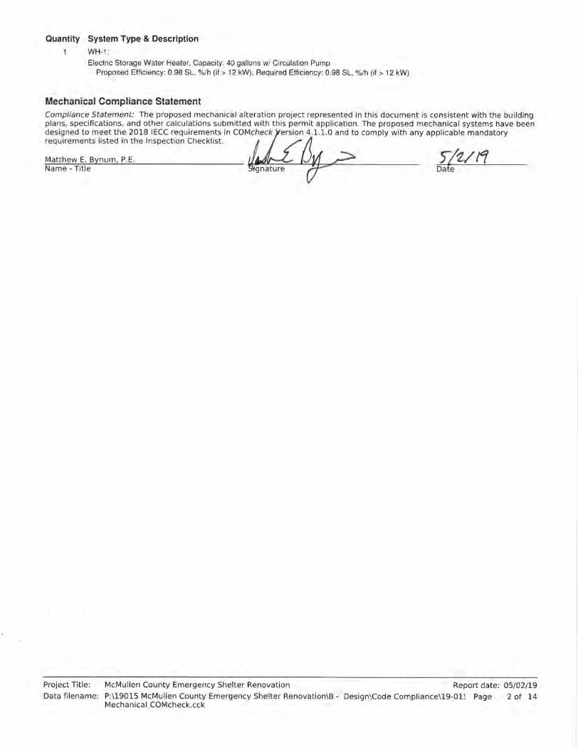

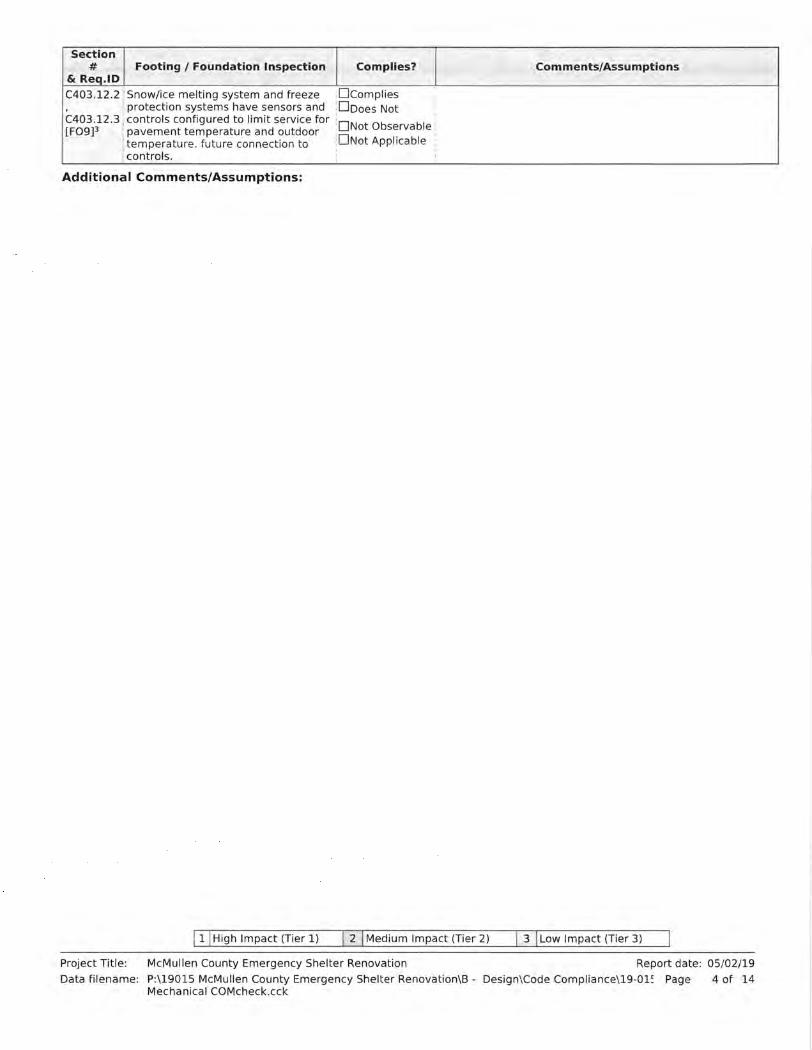

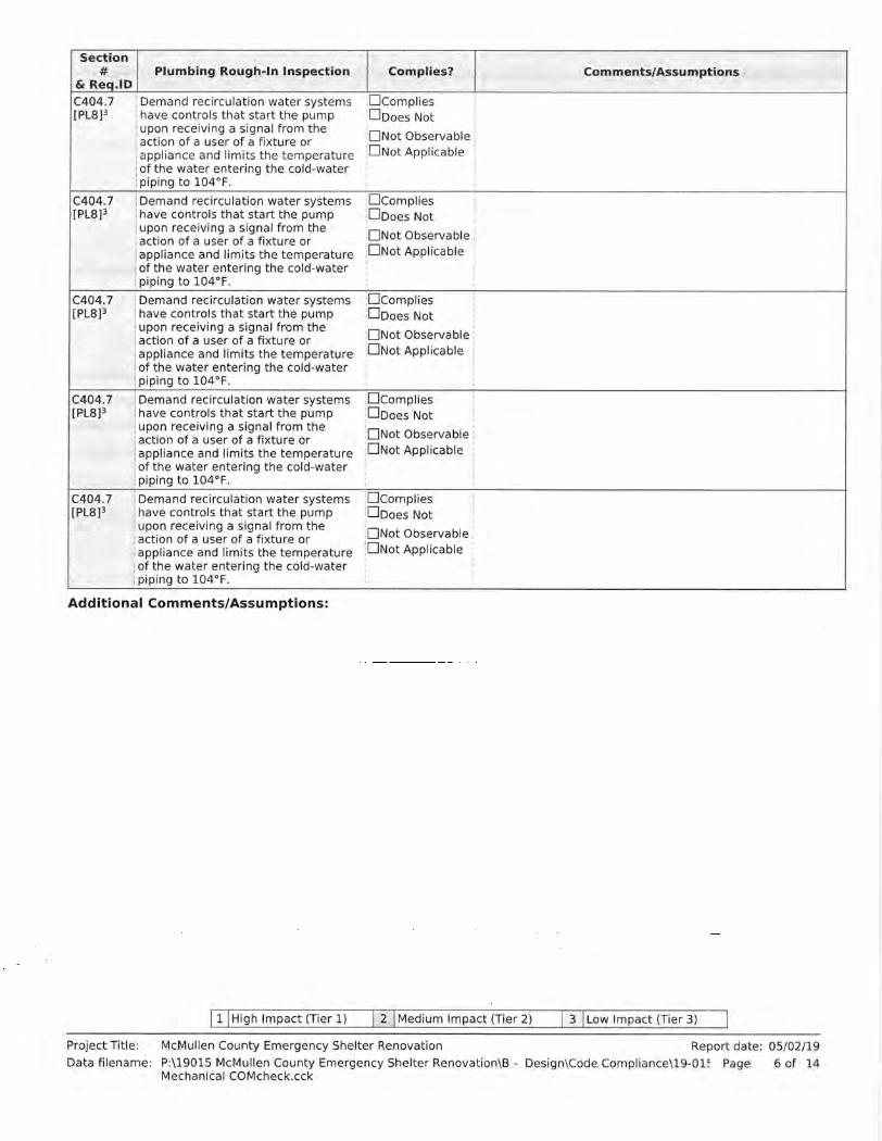


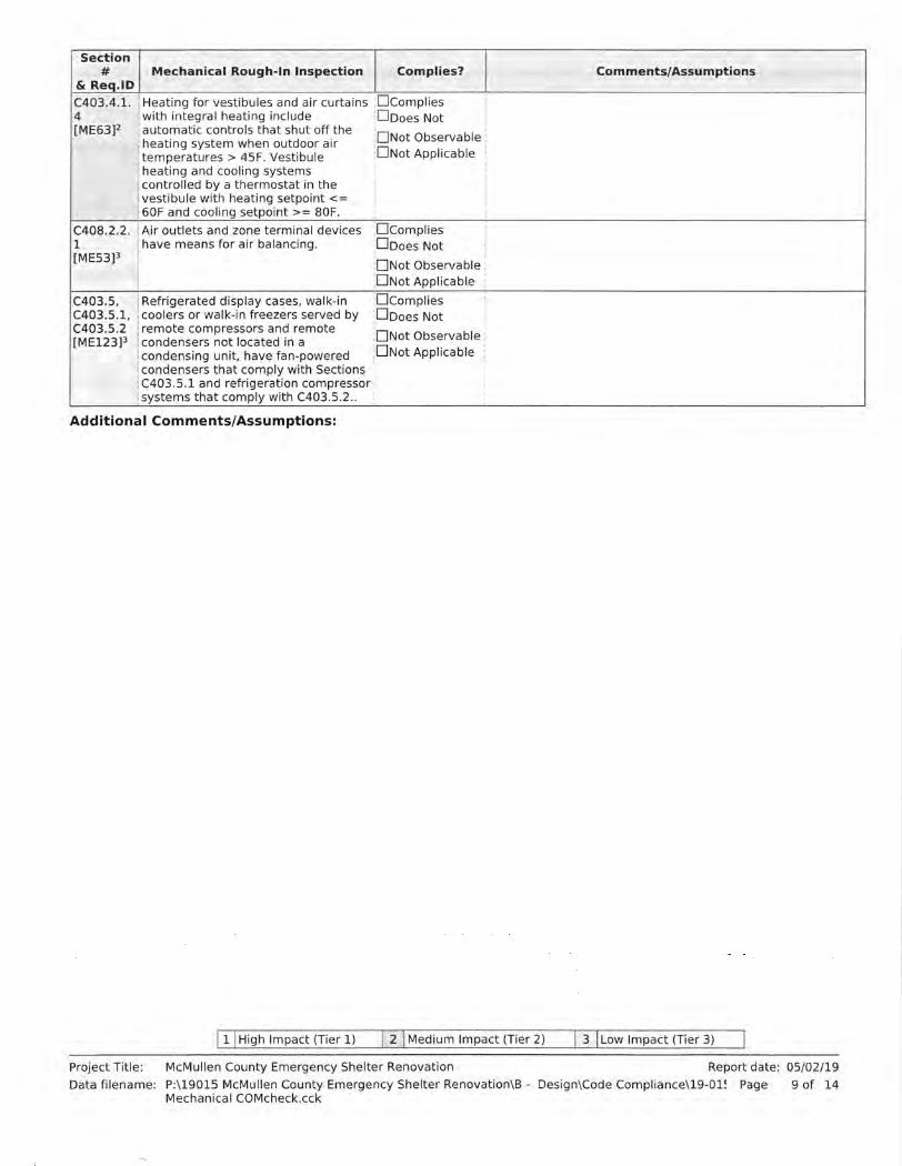

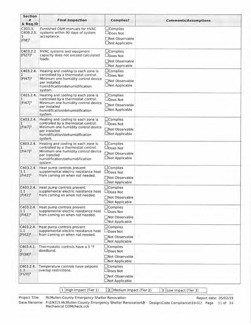

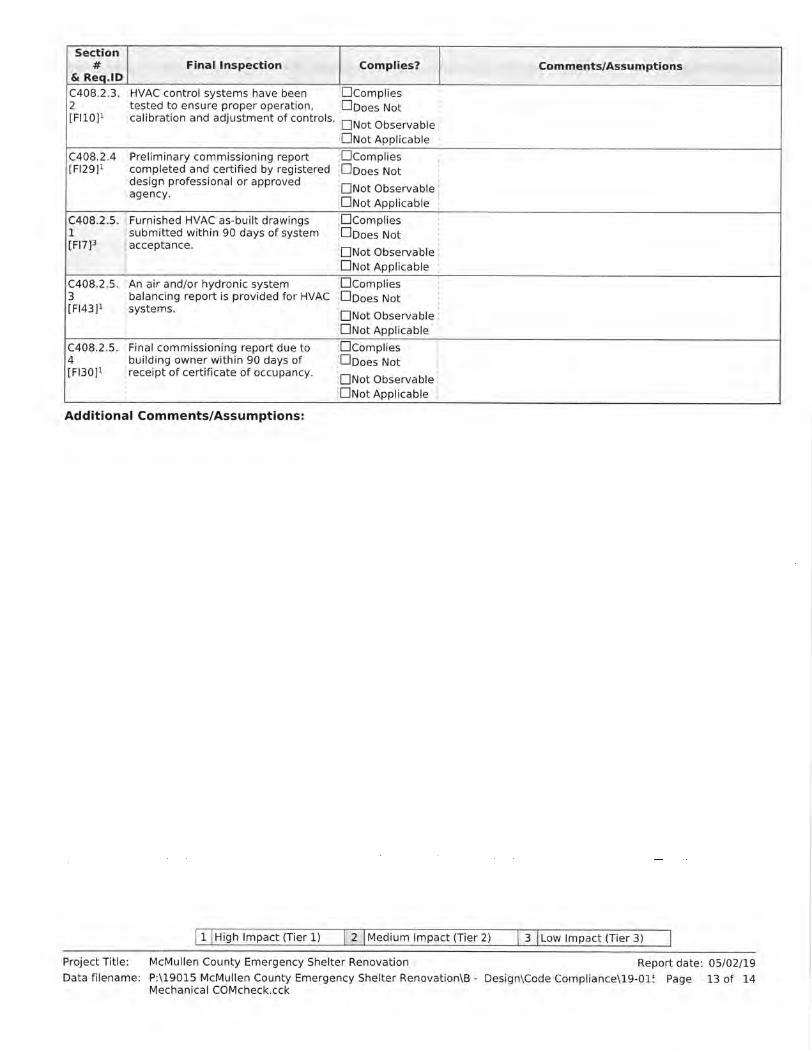


Inspection ChecklistRequirements: 0.0% were addressed directly in the COMcheck software
COMcheck Software Version 4.1.1.0
Text in the "Comments/Assumptions" column is provided by the user in the COMcheck Requirements screen. For eachrequirement, the user certifies that a code requirement will be met and how that is documented, or that an exceptionis being claimed. Where compliance is itemized in a separate table, a reference to that table is provided.
Energy Code: 2018 IECC
Section#
& Req.IDPlan Review Complies? Comments/Assumptions
C103.2[PR4]1
Plans, specifications, and/orcalculations provide all informationwith which compliance can bedetermined for the interior lightingand electrical systems and equipmentand document where exceptions tothe standard are claimed. Informationprovided should include interiorlighting power calculations, wattage ofbulbs and ballasts, transformers andcontrol devices.
CompliesDoes NotNot ObservableNot Applicable
Additional Comments/Assumptions:
1 High Impact (Tier 1) 2 Medium Impact (Tier 2) 3 Low Impact (Tier 3)
Project Title:Data filename:
McMullen County Emergency Shelter RenovationP:\19015 McMullen County Emergency Shelter Renovation\B - Design\Code Compliance\19015-Electrical COMcheck.cck
05/02/19Report date:62 ofPage

Section#
& Req.IDRough-In Electrical Inspection Complies? Comments/Assumptions
C405.2.2.2[EL22]1
Spaces required to have light-reduction controls have a manualcontrol that allows the occupant toreduce the connected lighting load ina reasonably uniform illuminationpattern >= 50 percent.
CompliesDoes NotNot ObservableNot Applicable
C405.2.1,C405.2.1.1[EL18]1
Occupancy sensors installed inclassrooms/lecture/training rooms,conference/meeting/multipurposerooms, copy/print rooms,lounges/breakrooms, enclosed offices,open plan office areas, restrooms,storage rooms, locker rooms,warehouse storage areas, and otherspaces <= 300 sqft that are enclosedby floor-to-ceiling height partitions.Reference section languageC405.2.1.2 for control function inwarehouses and section C405.2.1.3for open plan office spaces.
CompliesDoes NotNot ObservableNot Applicable
C405.2.1.2[EL19]1
Occupancy sensors control function inwarehouses: In warehouses, thelighting in aisleways and open areas iscontrolled with occupant sensors thatautomatically reduce lighting powerby 50% or more when the areas areunoccupied. The occupant sensorscontrol lighting in each aislewayindependently and do not controllighting beyond the aisleway beingcontrolled by the sensor.
CompliesDoes NotNot ObservableNot Applicable
C405.2.1.3[EL20]1
Occupant sensor control function inopen plan office areas: Occupantsensor controls in open office spaces>= 300 sq.ft. have controls 1)configured so that general lighting canbe controlled separately in controlzones with floor areas <= 600 sq.ft.within the space, 2) automatically turnoff general lighting in all control zoneswithin 20 minutes after all occupantshave left the space, 3) are configuredso that general lighting power in eachcontrol zone is reduced by >= 80% ofthe full zone general lighting powerwithin 20 minutes of all occupantsleaving that control zone, and 4) areconfigured such that any daylightresponsive control will activate spacegeneral lighting or control zonegeneral lighting only when occupancyfor the same area is detected.
CompliesDoes NotNot ObservableNot Applicable
C405.2.2,C405.2.2.1,C405.2.2.2[EL21]2
Each area not served by occupancysensors (per C405.2.1) have time-switch controls and functions detailedin sections C405.2.2.1 and C405.2.2.2.
CompliesDoes NotNot ObservableNot Applicable
1 High Impact (Tier 1) 2 Medium Impact (Tier 2) 3 Low Impact (Tier 3)
Project Title:Data filename:
McMullen County Emergency Shelter RenovationP:\19015 McMullen County Emergency Shelter Renovation\B - Design\Code Compliance\19015-Electrical COMcheck.cck
05/02/19Report date:63 ofPage

Section#
& Req.IDRough-In Electrical Inspection Complies? Comments/Assumptions
C405.2.3,C405.2.3.1,C405.2.3.2[EL23]2
Daylight zones provided withindividual controls that control thelights independent of general arealighting. See code section C405.2.3Daylight-responsive controls forapplicable spaces, C405.2.3.1 Daylightresponsive control function andsection C405.2.3.2 Sidelit zone.
CompliesDoes NotNot ObservableNot Applicable
C405.2.4[EL26]1
Separate lighting control devices forspecific uses installed per approvedlighting plans.
CompliesDoes NotNot ObservableNot Applicable
C405.2.4[EL27]1
Additional interior lighting powerallowed for special functions per theapproved lighting plans and isautomatically controlled andseparated from general lighting.
CompliesDoes NotNot ObservableNot Applicable
C405.3[EL6]1
Exit signs do not exceed 5 watts perface.
CompliesDoes NotNot ObservableNot Applicable
C405.6[EL26]2
Low-voltage dry-type distributionelectric transformers meet theminimum efficiency requirements ofTable C405.6.
CompliesDoes NotNot ObservableNot Applicable
C405.7[EL27]2
Electric motors meet the minimumefficiency requirements of TablesC405.7(1) through C405.7(4).Efficiency verified through certificationunder an approved certificationprogram or the equipment efficiencyratings shall be provided by motormanufacturer (where certificationprograms do not exist).
CompliesDoes NotNot ObservableNot Applicable
C405.8.2,C405.8.2.1[EL28]2
Escalators and moving walks complywith ASME A17.1/CSA B44 and haveautomatic controls configured toreduce speed to the minimumpermitted speed in accordance withASME A17.1/CSA B44 or applicablelocal code when not conveyingpassengers.
CompliesDoes NotNot ObservableNot Applicable
C405.9[EL29]2
Total voltage drop across thecombination of feeders and branchcircuits <= 5%.
CompliesDoes NotNot ObservableNot Applicable
Additional Comments/Assumptions:
1 High Impact (Tier 1) 2 Medium Impact (Tier 2) 3 Low Impact (Tier 3)
Project Title:Data filename:
McMullen County Emergency Shelter RenovationP:\19015 McMullen County Emergency Shelter Renovation\B - Design\Code Compliance\19015-Electrical COMcheck.cck
05/02/19Report date:64 ofPage

Section#
& Req.IDFinal Inspection Complies? Comments/Assumptions
C303.3,C408.2.5.2[FI17]3
Furnished O&M instructions forsystems and equipment to thebuilding owner or designatedrepresentative.
CompliesDoes NotNot ObservableNot Applicable
C405.4.1[FI18]1
Interior installed lamp and fixturelighting power is consistent with whatis shown on the approved lightingplans, demonstrating proposed wattsare less than or equal to allowedwatts.
CompliesDoes NotNot ObservableNot Applicable
See the Interior Lighting fixture schedule for values.
C408.1.1[FI57]1
Building operations and maintenancedocuments will be provided to theowner. Documents will covermanufacturers' information,specifications, programmingprocedures and means of illustratingto owner how building, equipment andsystems are intended to be installed,maintained, and operated.
CompliesDoes NotNot ObservableNot Applicable
C408.2.5.1[FI16]3
Furnished as-built drawings forelectric power systems within 90 daysof system acceptance.
CompliesDoes NotNot ObservableNot Applicable
C408.3[FI33]1
Lighting systems have been tested toensure proper calibration, adjustment,programming, and operation.
CompliesDoes NotNot ObservableNot Applicable
Additional Comments/Assumptions:
1 High Impact (Tier 1) 2 Medium Impact (Tier 2) 3 Low Impact (Tier 3)
Project Title:Data filename:
McMullen County Emergency Shelter RenovationP:\19015 McMullen County Emergency Shelter Renovation\B - Design\Code Compliance\19015-Electrical COMcheck.cck
05/02/19Report date:65 ofPage

Project Title:Data filename:
McMullen County Emergency Shelter RenovationP:\19015 McMullen County Emergency Shelter Renovation\B - Design\Code Compliance\19015-Electrical COMcheck.cck
05/02/19Report date:66 ofPage