Advanced and Sustainable Housing Renovation
240
-
Upload
khangminh22 -
Category
Documents
-
view
0 -
download
0
Transcript of Advanced and Sustainable Housing Renovation

������������� �������������������� ���
��������������� ����� ����� ���


April 2010
IEA Solar Heating and Cooling Programme
The International Energy Agency (IEA) is an autonomous body within the framework of the Organization for Economic Co-operation and Development (OECD) based in Paris. Established in 1974 after the first “oil shock,” the IEA is committed to carrying out a comprehensive program of energy cooperation among its members and the Commission of the European Communities. The IEA provides a legal framework, through IEA Implementing Agreements such as the Solar Heating and Cooling Agreement, for international collaboration in energy technology research and development (R&D) and deployment. This IEA experience has proved that such collaboration contributes significantly to faster technological progress, while reducing costs; to eliminating technological risks and duplication of efforts; and to creating numerous other benefits, such as swifter expansion of the knowledge base and easier harmonization of standards.
The Solar Heating and Cooling Programme was one of the first IEA Implementing Agreements to be established. Since 1977, its members have been collaborating to advance active solar and passive solar and their application in buildings and other areas, such as agriculture and industry. Current members are: Australia Finland Portugal Austria France Spain Belgium Italy Sweden Canada Mexico Switzerland Denmark Netherlands United States European Commission New Zealand Germany Norway A total of 44 Tasks have been initiated, 33 of which have been completed. Each Task is managed by an Operating Agent from one of the participating countries. Overall control of the program rests with an Executive Committee comprised of one representative from each contracting party to the Implementing Agreement. In addition to the Task work, a number of special activities—Memorandum of Understanding with solar thermal trade organizations, statistics collection and analysis, conferences and workshops—have been undertaken. To find Solar Heating and Cooling Programme publications and learn more about the Programme visit www.iea-shc.org or contact the SHC Secretariat, Pamela Murphy, e-mail: [email protected].

April 2010
Current Tasks & Working Group: Task 36 Solar Resource Knowledge Management Task 37 Advanced Housing Renovation with Solar & Conservation Task 38 Solar Thermal Cooling and Air Conditioning Task 39 Polymeric Materials for Solar Thermal Applications Task 40 Towards Net Zero Energy Solar Buildings Task 41 Solar Energy and Architecture Task 42 Compact Thermal Energy Storage Task 43 Rating and Certification Procedures Task 44 Solar and Heat Pump Systems
Completed Tasks: Task 1 Investigation of the Performance of Solar Heating and Cooling Systems Task 2 Coordination of Solar Heating and Cooling R&D Task 3 Performance Testing of Solar Collectors Task 4 Development of an Insolation Handbook and Instrument Package Task 5 Use of Existing Meteorological Information for Solar Energy Application Task 6 Performance of Solar Systems Using Evacuated Collectors Task 7 Central Solar Heating Plants with Seasonal Storage
Task 8 Passive and Hybrid Solar Low Energy Buildings Task 9 Solar Radiation and Pyranometry Studies Task 10 Solar Materials R&D Task 11 Passive and Hybrid Solar Commercial Buildings Task 12 Building Energy Analysis and Design Tools for Solar Applications Task 13 Advanced Solar Low Energy Buildings Task 14 Advanced Active Solar Energy Systems Task 16 Photovoltaics in Buildings Task 17 Measuring and Modeling Spectral Radiation Task 18 Advanced Glazing and Associated Materials for Solar and Building Applications Task 19 Solar Air Systems Task 20 Solar Energy in Building Renovation Task 21 Daylight in Buildings Task 22 Building Energy Analysis Tools Task 23 Optimization of Solar Energy Use in Large Buildings Task 24 Solar Procurement Task 25 Solar Assisted Air Conditioning of Buildings Task 26 Solar Combisystems Task 27 Performance of Solar Facade Components Task 28 Solar Sustainable Housing Task 29 Solar Crop Drying Task 31 Daylighting Buildings in the 21st Century Task 32 Advanced Storage Concepts for Solar and Low Energy Buildings Task 33 Solar Heat for Industrial Processes Task 34 Testing and Validation of Building Energy Simulation Tools Task 35 PV/Thermal Solar Systems

April 2010
Completed Working Groups: CSHPSS, ISOLDE, Materials in Solar Thermal Collectors, Evaluation of Task 13 Houses, and Daylight Research


Contributors
This handbook is produced from material developed in the course of IEA SHC Task 37 Advanced Housing Renovation by Solar and Conservation. Operating agent was Fritjof Salvesen from Norway. This venture brought together some 50 experts from 12 countries. The objective of this task was to develop a solid knowledge base how to renovate housing to a very high energy standard while providing superior comfort and sustainability and to develop strategies which support market penetration of such renovations explicitly directed towards market segments with high renovation and multipliable potentials. The task was divided in four subtasks:
- Subtask A: Marketing and Communication Strategies
Subtask Lead Country: Norway. Lead: Are Rødsjø, The Norwegian State Housing Bank,
- Subtask B: Advanced Projects Analysis
Subtask Lead Country: Switzerland. Lead: Robert Hastings, AEU GmbH, CH.
- Subtask C: Analysis and Concepts
Subtask Lead Country: Germany. Lead: Sebastian Herkel, Fraunhofer Institute, Solar Energy Systems
- Subtask D: Environmental Impact Assessment (EIA)
Subtask Lead Country: Belgium. Lead: Sophie Trachte; Architecture et Climat, Belgium

For more information: http://www.iea-shc.org/task37
This booklet is produced in Subtask D; Environmental Impact Assessment (EIA).
Main authors are Sophie Trachte and André Deherde from Architecture et Climat, Belgium Issuing date: June 2010

Table of content
Foreword
Chapter 0 : Introduction
Sheet 001: Sustainable renovation: definition and priorities
Sheet 002: From bioclimatic to sustainable architecture
Sheet 003: Some questions about housing renovation
Chapter A : Increase the comfort of life
A.1. Increase the quality of the outdoor spaces
Sheet A10: Favour social interactions
Sheet A11: Favour soft mobility
Sheet A12: Favour and reintroduce biodiversity
A.2. Increase the quality of indoor air
Sheet A20: Limiting sources of indoor pollution
Sheet A21: Optimizing the ventilation system
A.3. Acoustic comfort
Sheet A30: Basic notions
Sheet A31: Principles of acoustic insulation and correction
Sheet A32: Optimizing the acoustic comfort
Chapter B: Reduce energy consumption
B.1. Increase the thermal performances of housing
Sheet B10: Optimizing the external walls performances
Sheet B11: Optimizing the shape
Sheet B12: Additional insulation in housing renovation
Sheet B13: Improving the air tightness
Sheet B14: Reducing the thermal bridges
Sheet B15: Thermal inertia in housing renovation
Sheet B16: Optimizing the solar protections
Sheet B17: Natural nightcooling
Sheet B18: Optimizing the window conception
Sheet B19: “Passivhaus” standard in housing renovation

B.2. Reduce fossil energies consumption
Sheet B20: Optimizing the heating system
Sheet B21: Optimizing domestic hot water
Sheet B22: Heat pump for heating production
Sheet B23: Hot water production by solar energy
Sheet B24: Optimizing the lighting system
Sheet B25: Renewable energies for generating electricity
Sheet B26: Heat recovery on ventilation system
Sheet B27: Air pre-heating by airground exchanger
Chapter C: Reduce the tap water consumption
Sheet C01: Rational use of tap water
Sheet C02: Recovery and use of rainwater
Chapter D: Increase the water resources
Sheet D01: Water management on the parcel
Sheet D02: Water recycling by plants
Sheet D03: Water recycling in urban area
Chapter E: Reduce production of waste
E.1. Reduce construction and demolition waste
Sheet E10: Preventive measures to reduce waste
Sheet E11: Waste management on building site
E.2. Reduce domestic waste
Sheet E20: Preventive measures to reduce domestic waste
Chapter F: Reduce consumption of territory and resources
Sheet F01: Embodied energy consumption
Sheet F02: Construction materials
References
Table of illustrations
Appendixes

Foreword
This handbook was drafted in the context of an agreement between the Walloon Region and the Louvain-la-Neuve Catholic University on sustainable, energy efficient renovation of Walloon housing and is mainly intended for architects and architecture students. At a time when major climate change and the aspiration for sustainable economic and social development while maintaining standards of living have become major issues, the objective of this guide is to consider renovation of housing from an overall standpoint by developing guidelines not just in terms of energy performances but also in terms of comfort, quality of life, environmental impact and resource consumption. The entire guide is richly illustrated with both explanatory diagrams and photographs of examples of construction. Many graphs and tables also complete the written text. The guide provides designers with information and resources needed to renovate both individual and collective housing. The main difficulty encountered in drafting this handbook lies in the authors' decision to make the guide applicable to all Europe, from the northern countries to southern Italy. Generally speaking, the authors have taken account of the characteristics of middle European countries: Germany, Austria, Belgium, France, the Netherlands, Switzerland, ... and give details for the northern countries when necessary.

It is up to the architect or the student to consider this work as an aid and to integrate the principles it proposes into his/her own approach to design, given the local climate and the standards and/or legislation in force. The guide is divided into six chapters, each corresponding to a priority in energy efficient, sustainable renovation of housing. The first chapter deals with the quality of life of inhabitants and three factors that influence it: quality of external and collective areas, interior air quality and acoustic comfort. The second chapter, which is the largest one, concerns reduction of fossil energy consumption. It goes into two intrinsically related themes namely optimization of performances of the housing envelope to increase thermal and visual comfort of the occupant, and optimization of performances of systems and techniques installed in the housing unit. This chapter also goes into the use of renewable energy in systems such as photovoltaic solar energy, thermal solar energy, heat pumps etc. The third and fourth chapters deal with the problem of water in a housing unit, considering the following themes: reduction of consumption of drinking water, use of rainwater, treatment of rainwater and runoff water on the lot and recycling wastewater. The fifth chapter studies the question of waste, both as concerns the renovation itself and the use of the building. This chapter provides food for thought in terms of waste prevention and management. The last chapter considers the use of the territory and resources in two data sheets: one on embodied energy consumption associated with the renovation project, the other on the impact of building materials. Each theme considered in the guide is presented in the form of a data sheet several pages long. So the architect can either use the entire guide or look up certain specific information, in view of the progress of his/her project. It is important to realize that there is no standard way of achieving sustainable renovation. On the contrary, there are many ways that depend on many parameters: typology of the dwelling, quality of the existing building, type of renovation proposed, budget set aside for the renovation, quality of the context, ... It must also be stressed that energy efficient, sustainable renovation is not unaffordable. The idea is to reach a certain level of performance that is entirely accessible in renovation that will allow for better comfort – both indoors and outdoors – energy savings and reduced environmental impact.

If you think that renovation is indispensable, dare to aim for sustainable renovation! We hope you enjoy this guide.


0. INTRODUCTION
001 - Sustainable renova�on : defini�on and priori�es 002 - From bioclima�c to sustainable architecture 003 - Some ques�ons about housing renova�on
Sterrenvel renova�on - Brussel


IEA SHC TASK 37ADVANCED HOUSING RENOVATIONWITH SOLAR AND CONSERVATION
SUBTASK DENVIRONMENTAL IMPACTASSESSMENT
0. INTRODUCTION
Sustainable renova�on : defini�on and priori�es
“Sustainable development is development that meets the needs of the present without compromising the ability of future gene-ra�ons to meet their own needs. It contains within it two key concepts: the concept of ‘needs’, in par�cular the essen�al needs of the world’s poor, to which overriding priority should be given; and the idea of limita�ons imposed by the state of technology and social organiza�on on the environment’s ability to meet present and future needs. » Brundtland Report «Our common future» 1987
«Advanced» renova�on of housing – whether collec�ve or individual – is above all else based on the reduc�on of energy consump�on (heat, air-condi�oning, ven�la�on, ...).However, to be considered «sustainable», it must also correspond to the global concept defined by the Rio declara�on (1992) and the 27 principles dra�ed in applica�on of the defini�on of sustainable development proposed by Gro Harlem Brundtland.
1. THE 5 MAIN PRINCIPLES OF RIO CONVENTION (1992)
The Brundtland Report, «Our common future», was a response to a request made by the United Na�ons in 1987 to form a com-mi�ee of interna�onal experts to analyze the deteriora�on of man’s environment and natural resources, as well as the conse-quences from the economic and social standpoint. It gave an alarming picture of the state of the environment and social, eco-nomic, cultural and poli�cal development on a worldwide scale. They were considered interdependent and non-sustainable along the current trend. A new orienta�on for the development ques�on was proposed; it was referred to as «sustainable».27 principles defining this concept have been established. These principles can be summarized into five major concepts:
The principle of integra�ng environmental, social, economic and poli�cal dimensions.
Environmental capital includes the environment, comprised of biological diversity and the reserves of natural resources, both exhaus�ble and renewable. Social capital includes health, ca-paci�es, knowledge, know-how, training, culture, experience of popula�ons, and the rela�onships that a society proposes to its members. Economic capital includes financial capital as well as physical or material capital such as technical infrastructures, ma-chines, buildings, ... poli�cal capital consists of customs, laws, and various categories of ins�tu�onalized organiza�ons at diffe-rent levels of power.Sustainably renovated housing has all the usual quali�es of a dwelling (func�onality, performance, techniques, ...) but the condi�ons of its environmental, economic, and social impact are minimized in the long run:
• on all scales: from quality and comfort of indoor areas up to the planetary scale, including outdoor areas around the dwelling;
• at all �me: from extrac�on of the necessary raw materials to renova�on and demoli�on.
� Illustra�on 01: Gro Harlem Brundtland - Rio Conven�on (1992)
� Illustra�on 02 : Environmental capital� Illustra�on 03: Social capital� Illustra�on 04: Economical capital
N° of Sheet: 001Cross-references:002, 003Appendix:/

Sustainable renova�on : defini�on and priori�es0. INTRODUCTION
The principle of inter- and intra-genera�onal equity
This principle means that we must consider the en�re environ-ment and the balance between the 4 types of capital defined above as we would an inheritance: we have the right to inherit them and consequently to enjoy them equitably within our ge-nera�on, but we also have the obliga�on to transmit them to future genera�ons without dilapida�ng them, and be�er s�ll, having enriched them.
Sustainable renova�on of housing is renova�on that will take account of today’s criteria for good housing, while maintaining the capacity to sa�sfy future needs without genera�ng major environmental nuisance for current and future genera�ons.
The principle of precau�on
This principle means that hypothe�cal or poten�al risks must be limited. It goes beyond the idea of preven�on that is restricted to limi�ng proven risks. In other words, we must think about the consequences of our ac�ons – our responsibility is no longer retrospec�ve, it beco-mes prospec�ve.
Sustainable renova�on of housing is renova�on that limits risks both as concerns the health of workers, users and the overall environment, and it takes into account the various phases of the life of a dwelling: manufacture, construc�on site, use and elimi-na�on.
The principle of common responsibility
This principle affirms our common responsibility with regard to the issues of sustainable development, while maintaining that, although this responsibility is common to all, there is differen�-a�on nevertheless: Occidental countries have a greater respon-sibility for the deteriora�on of environmental and social capital, and they have the economic and poli�cal capital most apt to reverse the trends.
Sustainable renova�on of housing is renova�on that takes ac-count of the four dimensions listed above, of current and future needs, and of the various phases of the project (design, construc-�on, u�liza�on and end-of-life).A responsible designer is a designer who also limits the impact of his/her project, both on the immediate environment (biodiversi-ty, water resources, ...) and on the general environment (energy consump�on, loca�on, emission pollutants etc.).
The par�cipa�on principle
Ci�zen par�cipa�on (re)locates decisions on the scale of the mi-lieu for which they thus become players. It facilitates taking ac-count of local par�culari�es; it allows for appropria�on of choi-ces that have become collec�ve; it ensures mul�ple solu�ons and points of view.
Sustainable renova�on of housing is renova�on that cannot func�on without the ac�ve awareness and par�cipa�on of the inhabitants.
� Illustra�on 05 : Equity between peoples: color and ages
� Illustra�on 06 : Security on building site
� Illustra�on 07: Respect of human health
� Illustra�on 08: Tchernobyl disaster (1986)
� Illustra�on 09: Oil disaster
� Illustra�on 10 : «White walk» in Brussel a�er «Dutroux» case
N° of Sheet: 001Cross-references:002, 003Appendix:/
©Bene�on

Sustainable renova�on : defini�on and priori�es0. INTRODUCTION
2. DEFINITION OF SUSTAINABLE ARCHITECTURE
On the basis of the 27 principles comprising the concept of sus-tainable development, sustainable architecture can be defined as an architecture that:
Benefits from the advantages of its milieu, of all its milieusThese consist of the climac�c milieu (orienta�on, solar gains, ven�la�on, shade etc.), the geological milieu (earth, soil, al�-tude etc.), the hydric milieu (resource, treatment, distribu�on, conserva�on etc.), the vegeta�on milieu (trees, crops etc.), the ins�tu�onal milieu (ways of living together), the infrastructure milieu (networks, …), the technological milieu, the organiza�o-nal milieu (social mixity, func�onal mixity etc.), and heritage (buildings, landscapes etc.).
Protects against aggressions from the milieuThis refers to protec�on against cold, heat, rain, noise, pollu�on, the risk of flooding as well as insecurity, lack of drinking water, li-mita�on to a single genera�on or a single func�on, lack of public transport, harmful materials etc.
Gives the environment to which the project belongs the benefit of sustainable improvements Construc�ng a building which, if it were to disappear, would not take anything away from the environment in which it stands, is not erec�ng a sustainable building. Architecture should be part of a triple context: the past that it inherits, the present that it constructs, and the future that it transmits.
Protec�ng the milieu from the environmental nuisances of the construc�on itselfThese include atmospheric and hydric pollu�on associated with the manufacture of the component materials, the produc�on of waste (household waste, demoli�on etc.), sound pollu�on, ad-di�onal traffic, impermeabiliza�on of the soil, ...
3. SIX PRIORITIES FOR THE RENOVATION OF HOUSING
The objec�ve of the sustainable renova�on process is to extend the life of an exis�ng building, to give it a second life while li-mi�ng its impact on the environment. For this reason, the fol-lowing priori�es should be taken into account at each stage: de-sign, construc�on and use of the building:
• Increasing the comfort of life:- to increase the quality of outdoor areas- to increase the quality of indoor air- to increase the acous�cal comfort
• Limi�ng energy consump�on:- to increase the thermal comfort- to reduce fossil energy consump�on
• Limi�ng drinking water consump�on; • Increasing the water resources;• Limi�ng the produc�on of waste;• Limi�ng consump�on territory and resources
This set of six priori�es is defined and explained in the six chap-ters of this handbook.
� Illustra�on 11: Illustra�on of the sustainable architecture defini�on
N° of Sheet: 001Cross-references:002, 003Appendix:/

Sustainable renova�on : defini�on and priori�es0. INTRODUCTION
3.1. Increasing the comfort of life
Renova�on of buildings, and par�cularly residen�al buildings, is o�en made necessary by a lack of comfort in general.Renova�on is also an opportunity to increase both the energy efficiency of the building and the comfort of the indoor areas. Increasing the comfort of indoor areas means that an effort will be made in terms of the occupant’s thermal comfort (summer and winter), acous�c comfort, respiratory comfort and visual comfort. Further s�ll, health is a major concern in terms of quality of li-ving. Taking account of risks to health, both to workers in the building sector (toxic materials and emissions during manufac-ture and implementa�on) and to the occupants (quality of air, quality of water, choice of building materials etc.). The renova�on of an exis�ng building will not only modify the life of the occupants, it will also change the environment and the daily living context of all immediate neighbours. The buil-ding and its renova�on can be the origin of nuisance (source of noise or pollu�on, increase in traffic and parking problems, bloc-king out sunshine, ...) as well as enrichment (new shops near by, noise screen, new green area and so on).To be sustainable, the renova�on process must also be an occa-sion for improving the quality of life associated with the imme-diate surroundings (social, environment, both man-made and natural, economic aspects). And each contrac�ng authority or designer, aware of its responsibility for sustainable modifica�ons that the renova�on will impose on an exis�ng environment, may wish to go further than recommended by the urban planning rules.Increasing the comfort of the outdoor areas in the vicinity means making an effort in favour of cultural areas and green areas, pro-mo�ng both social and func�onal mingling, favouring non-mo-torized mobility and biodiversity.
3.2. Limi�ng energy consump�on
Global energy demand is expected to rise by nearly 60% over the next 20 years and the building sector represents 40% of this world’s total energy demand.Given current energy consump�on, our tradi�onal primary ener-gy reserves will be consumed in less than a century. No doubt there will s�ll be reserves as yet unknown, but the prac�cal and financial resources needed to find them and exploit them are colossal. In addi�on, given the current cost of non-renewable energies and their increase by 2020, many households with low and me-dium incomes will have to choose between their food and their hea�ng budgets. Moreover, this overconsump�on of fossil energy also has dra-ma�c consequences on the environment (global warming, acidi-fica�on of air, water and soil, forma�on of tropospheric ozone, ...) and on the health of living things (effects ranging from sim-ply ge�ng �red or headaches to respiratory disorders, allergies, bronchi�s, chronic sinusi�s or even cancer, disorders in repro-duc�ve health and foetal development and increased morta-lity).
Consequently, it has become urgent to consume LESS, BETTER AND DIFFERENTLY by applying the following principles:
• radically reduce our energy consump�on • use renewable energies insofar as possible; • promote public transport and non-motorized transport
� Illustra�on 12 : Quality of outdoor spaces: colors, ligh�ng, spaces diversity
� Illustra�on 13 : Necessity of playgrounds for the urban comfort
� Illustra�on 14: Global Warming since 1860
� Illustra�on 15 : So� mobility today
� Illustra�on 16: Renewable and clean energy
N° of Sheet: 001Cross-references:002, 003Appendix:/

Sustainable renova�on : defini�on and priori�es0. INTRODUCTION
3.3.Limi�ng consump�on of drinking water
Fresh water is an indispensable good for the survival of all eco-systems present on Earth. This precious good is not in inexhaus-�ble supply: while 70% of the Earth’s surface is under water, fresh water represents only 3% of this quan�ty of which 0.26% is directly available for human consump�on. In addi�on, during the last 50 years, the quan�ty of fresh water available on Earth has decreased by half and many countries or regions have fallen below the limit of hydric vulnerability (2000 m³/per capita/per year). In fact, we consume this precious re-source immoderately, since the average daily consump�on of drinking water per capita varies between 25 litres (developing countries) to 150 litres (Europe) and 360 litres (USA).It should also be recognized that the quality of water present in the subsoil is increasingly poor and that treatments to make it potable involve increasingly complicated and costly processes. Paradoxically for these three observa�ons, we consider that only 45% of our daily needs really require drinking water.
Consequently, preserving our drinking water resources by consu-ming LESS, BETTER AND DIFFERENTLY is becoming urgent. This entails:
• decreasing our consump�on; • having recourse to another source of water for needs that do
not require drinking water
3.4. Increasing water resources
Throughout the world, increasing urbaniza�on and growing size of towns, the growing density of built up areas and the increasing size of impermeable areas have resulted in a change if not the destruc�on of the BALANCE between built up areas and green areas with major effects on the management of rain water. In fact, enlarging impermeable areas (essen�ally in highly urban zones) causes a large increase in the flow of water to the collec-�ve sewer systems which has the following consequences:
• rapidly satura�ng the exis�ng networks and causing a risk of flooding
• increasing the volume of water to be processed • increasing the costs associated with sewers and drainage
In addi�on, shrinking green areas and permeable areas means less supply goes to water tables. Growing urbaniza�on, indus-try and large-scale agriculture induced by our organiza�on of consump�on cause rising pollu�on of our fresh water «reser-ves». Natural disasters – flooding, rivers overflowing their banks, drou-ghts, lack of water – prove that it is becoming urgent to RESTORE this indispensable balance and proper func�oning of the water cycle in towns and urban areas.
To restore this balance, each designer and contrac�ng authority should take simple, effec�ve measures to manage water on the parcel around the building to be renovated as effec�vely as pos-sible. The main factors are:
• increasing the coefficient of permeability of the lot; • equipping the lot with retaining and infiltra�on facili�es;• choosing outdoor soil coverings that are permeable to wa-ter; • trea�ng waste water, reusing it or re-infiltra�ng it into the ground.
� Illustra�on 17 : Water is essen�al good for life on Earth
� Illustra�on 18: Average water consump�on in Europe
� Illustra�on 19: Bad water consump�on habit
� Illustra�on 20 : Water ressources
N° of Sheet: 001Cross-references:002, 003Appendix:/

3.5. Reducing produc�on of waste (construc�on and domes�c waste)
3.5.1. Construc�on wasteWhile most of us agree that raw material and energy resources are dwindling, today the construc�on sector is a large consumer of both energy and raw materials, as well as a major producer of waste (40% of the total produc�on of waste). For example, the BRE in the UK es�mates that the annual produc�on of construc-�on waste amounts to 6 tonnes per inhabitant, more than ten �mes the domes�c waste.Moreover, because of popula�on growth, the growth of ci�es and par�cularly the growing number of restora�on and demo-li�on sites in large European ci�es a�er unrestrained construc-�ons in the ‘60s and ‘70s, we expect that the amount of demo-li�on and construc�on waste will increase radically in upcoming years.
Moreover, most of those waste, despite a real poten�al of re-cycling, are, from lack of infrastructures or lack of quality in the sor�ng process, treated by tradi�onal waste processing systems, namely dumping and incinera�on. Those tradi�onal waste pro-cessing systems have significant disadvantages both for the en-vironment and for the health of living beings, and that are in-creasingly subject to regula�on and control. Consequently, they are increasingly costly and sites of these ac�vi�es will be more and more limited in Europe.
Given these two observa�ons, in terms of sustainable develop-ment there are only two alterna�ves:
• producing minimum waste or if possible not producing waste at all;
• sor�ng more at the place where the waste is produced in or-der to make the most of recycling.
Producing minimum waste entails major work on preven�on in developing the renova�on project – both in the design of the project itself and in the construc�on process used in the choice of materials.Sor�ng more at source entails significant work on the way to take down a building and on waste management;
3.5.2. Domes�c wasteIn Europe, each person produces an average of 400 to 500 kg of waste per year – more than 1 kg per day. Despite the introduc-�on of the domes�c waste sor�ng, the amount of waste produ-ced is constantly rising with an increasingly high percentage of packing waste (plas�c, paperboard, paper etc.).Moreover, most of those waste are treated by tradi�onal waste processing systems, namely dumping and incinera�on. Those tradi�onal waste processing systems have significant disad-vantages both for the environment and for the health of living beings, and that are increasingly subject to regula�on and control. Consequently, they are increasingly costly and sites of these ac�vi�es will be more and more limited in Europe.
Given these two observa�ons, in terms of sustainable develop-ment there are only two alterna�ves:
• producing minimum of domes�c waste • sor�ng be�er and more at home
Producing minimum waste entails every ci�zen must become aware of his lifestyle and consump�on -- a project designer has no influence on this aspect
Sustainable renova�on : defini�on and priori�es0. INTRODUCTION
� Illustra�on 21: Sor�ng out the domes�c waste - plas�c
� Illustra�on 22: Sor�ng out the construc�on waste: container with wood
� Illustra�on 23: Specific waste bins
N° of Sheet: 001Cross-references:002, 003Appendix:/

Sustainable renova�on : defini�on and priori�es0. INTRODUCTION
� Illustra�on 24: Urban exodus towards countryside
� Illustra�on 25 : Car movings linked to this urban exodus
Sor�ng more at source entails at the �me of renova�on, the designer should set up schemes and means to encourage each occupant to sort waste.
3.6. Reducing consump�on of territory and resources
In terms of territory and consump�on of space, we must cope with two phenomena:
• Growing urbaniza�on of towns with the consequence of increasingly dense constructed zones, greater conges�on of road traffic, the decline of social rela�ons, the lack of green areas and biodiversity, impermeability of soils etc.;
• Urban exodus of residents from the centre of towns towards the suburbs and the country, to improve their quality of life and rela�on to nature, resul�ng in a waste of territory and «virgin» areas, spreading of networks, overconsump�on of energy and generaliza�on of pollu�on.
These two opposite phenomena both have drama�c conse-quences on the environment, society and culture as well as on the local and world economy. The concept of the territory is also related to exploita�on of resources and the landscape. In terms of resources, the buil-ding sector in Europe uses 50% of all resources exploited. The resources used are for the most part either renewable (mainly natural plant materials that are renewed more or less rapidly) and non-renewable (gravel, stone materials, petrochemical ma-terials and so on that have taken tens of thousands of years to form under ground).In addi�on, exploita�on of certain resources can have damaging consequences on the landscape, biodiversity and exis�ng eco-systems. This is the case for deforesta�on of wooded areas in Canada and Siberia, certain granite and stone quarries, and mi-ning of minerals or metals.
It is becoming urgent to preserve our virgin areas, our ecosys-tems, our resources and our landscapes by working simulta-neously on:
• The concept of a compact town: - by making towns and man-made zones denser; - by making public transport networks denser; - by favouring social and func�onal mixity, so as to limit tra-
vel and social segrega�on;- by working on public space and green space.
• A responsible choice of building materials: - choosing materials made from natural raw materials, ma-
terials made from recycled or renewable substances with a high rate of renewal, raw materials present in sufficient and/or unlimited quan�ty;
- choosing materials made from substances whose extrac-�on or exploita�on entails li�le or no harm for the lands-cape, the ecosystems and the environment in general.
N° of Sheet: 001Cross-references:002, 003Appendix:/
� Illustra�on 26 : Stone-pit of Clypot - Neufvilles
� Illustra�on 27 : Stone-pit in Belgium
© Carrières de la Pierre Bleue Belge
© Carrières de la Pierre Bleue Belge


IEA SHC TASK 37ADVANCED HOUSING RENOVATIONWITH SOLAR AND CONSERVATION
SUBTASK DENVIRONMENTAL IMPACTASSESSMENT
00 INTRODUCTION
From bioclima�c to sustainable architecture
“Compared to the crisis that affects the environment, any other problem, be it social, poli�cal, economic or scien�fic, seems insignificant. It is obvious the ques�ons that seem crucial today – human rights, peace in the Middle East, a vaccine for AIDS, public debt – would fade into the background if global warming, overpopula�on, pollu�on or famine and lack of water were to cause our death. ”
James Wines «The Green Architecture»
1. THE INCEPTION OF BIOCLIMATIC ARCHITECTURE
1.1. First half of the 20th century, when constraints were for-go�en
From the end of prehistory to the 18th century, Man used al-most exclusively renewable resources that came from the na-ture around him, to clothe, feed, heat and protect himself.The industrial revolu�on ini�ated by the discovery of coal, stan-dardiza�on of produc�on and construc�on processes and the possibility offered by the railways to carry products easily eve-rywhere in Europe, led to a profound change in the rela�ons that man maintained with natural resources (or materials), par-�cularly in their use, their transforma�on and their transport. This page of History marks the decline of local modes of produc-�on and construc�on adapted to local and regional climates.At the end of the 19th century, the beginning of the oil industry in Europe and the United States paved the way for the inter-nal combus�on engine leading to road-going vehicles, thermal power sta�ons, avia�on, ...
A�er the first world war, massive reconversion of chemical and mechanical industries, used to capacity for the war effort, for the produc�on of new materials filled the gap created by the loss of cra� skills, and then defini�vely took over, opening a new era in the world of construc�on.
In the period following the second world war, economic growth of industrial countries (essen�ally in the West) generalized the use of techniques in housing to ensure comfort of users in sum-mer and winter. This is the period that defini�vely saw the se-para�on of architectural design of housing, building techniques and the temperature problema�c.At the same �me, evolu�on in lifestyles led us to con�nually growing expenditure of energy, not just in housing with an in-crease in the number of heated rooms, the period during which homes were heated, and the level of indoor temperature consi-dered comfortable, but also in the way we func�on and travel.
N° of Sheet: 002Cross-references:001, 003Appendix:/
� Illustra�on 28: Colliery memory
� Illustra�on 29: Colliery of Trieu Kaisin
From bioclima�c to sustainable architecture00 INTRODUCTION
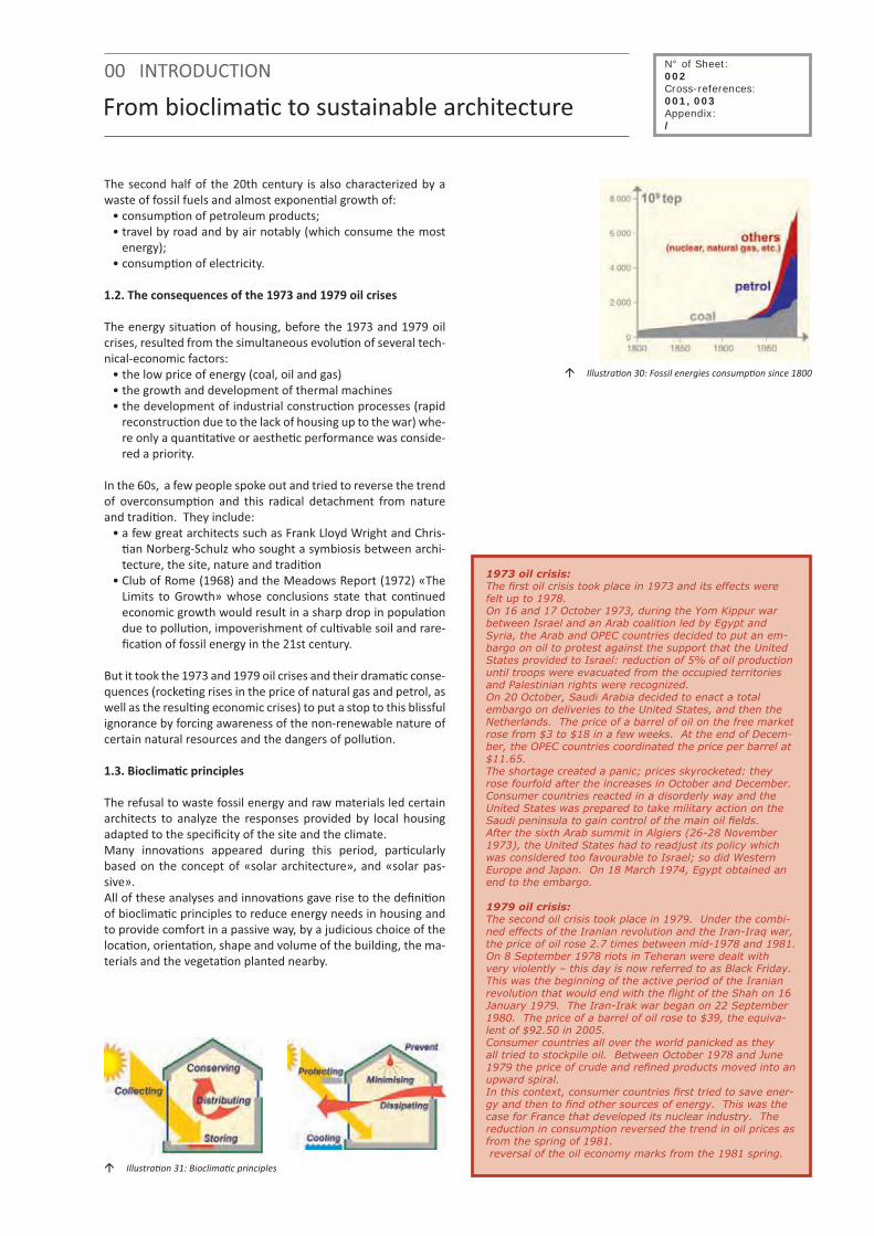
The second half of the 20th century is also characterized by a waste of fossil fuels and almost exponen�al growth of:
• consump�on of petroleum products; • travel by road and by air notably (which consume the most
energy); • consump�on of electricity.
1.2. The consequences of the 1973 and 1979 oil crises
The energy situa�on of housing, before the 1973 and 1979 oil crises, resulted from the simultaneous evolu�on of several tech-nical-economic factors:
• the low price of energy (coal, oil and gas) • the growth and development of thermal machines • the development of industrial construc�on processes (rapid
reconstruc�on due to the lack of housing up to the war) whe-re only a quan�ta�ve or aesthe�c performance was conside-red a priority.
In the 60s, a few people spoke out and tried to reverse the trend of overconsump�on and this radical detachment from nature and tradi�on. They include:
• a few great architects such as Frank Lloyd Wright and Chris-�an Norberg-Schulz who sought a symbiosis between archi-tecture, the site, nature and tradi�on
• Club of Rome (1968) and the Meadows Report (1972) «The Limits to Growth» whose conclusions state that con�nued economic growth would result in a sharp drop in popula�on due to pollu�on, impoverishment of cul�vable soil and rare-fica�on of fossil energy in the 21st century.
But it took the 1973 and 1979 oil crises and their drama�c conse-quences (rocke�ng rises in the price of natural gas and petrol, as well as the resul�ng economic crises) to put a stop to this blissful ignorance by forcing awareness of the non-renewable nature of certain natural resources and the dangers of pollu�on.
1.3. Bioclima�c principles
The refusal to waste fossil energy and raw materials led certain architects to analyze the responses provided by local housing adapted to the specificity of the site and the climate. Many innova�ons appeared during this period, par�cularly based on the concept of «solar architecture», and «solar pas-sive». All of these analyses and innova�ons gave rise to the defini�on of bioclima�c principles to reduce energy needs in housing and to provide comfort in a passive way, by a judicious choice of the loca�on, orienta�on, shape and volume of the building, the ma-terials and the vegeta�on planted nearby.
N° of Sheet: 002Cross-references:001, 003Appendix:/
� Illustra�on 30: Fossil energies consump�on since 1800
� Illustra�on 31: Bioclima�c principles
1973 oil crisis:The first oil crisis took place in 1973 and its effects were felt up to 1978.On 16 and 17 October 1973, during the Yom Kippur war between Israel and an Arab coalition led by Egypt and Syria, the Arab and OPEC countries decided to put an em-bargo on oil to protest against the support that the United States provided to Israel: reduction of 5% of oil production until troops were evacuated from the occupied territories and Palestinian rights were recognized.On 20 October, Saudi Arabia decided to enact a total embargo on deliveries to the United States, and then the Netherlands. The price of a barrel of oil on the free market rose from $3 to $18 in a few weeks. At the end of Decem-ber, the OPEC countries coordinated the price per barrel at $11.65. The shortage created a panic; prices skyrocketed: they rose fourfold after the increases in October and December. Consumer countries reacted in a disorderly way and the United States was prepared to take military action on the Saudi peninsula to gain control of the main oil fields. After the sixth Arab summit in Algiers (26-28 November 1973), the United States had to readjust its policy which was considered too favourable to Israel; so did Western Europe and Japan. On 18 March 1974, Egypt obtained an end to the embargo.
1979 oil crisis:The second oil crisis took place in 1979. Under the combi-ned effects of the Iranian revolution and the Iran-Iraq war, the price of oil rose 2.7 times between mid-1978 and 1981.On 8 September 1978 riots in Teheran were dealt with very violently – this day is now referred to as Black Friday. This was the beginning of the active period of the Iranian revolution that would end with the flight of the Shah on 16 January 1979. The Iran-Irak war began on 22 September 1980. The price of a barrel of oil rose to $39, the equiva-lent of $92.50 in 2005. Consumer countries all over the world panicked as they all tried to stockpile oil. Between October 1978 and June 1979 the price of crude and refined products moved into an upward spiral.In this context, consumer countries first tried to save ener-gy and then to find other sources of energy. This was the case for France that developed its nuclear industry. The reduction in consumption reversed the trend in oil prices as from the spring of 1981. reversal of the oil economy marks from the 1981 spring.

From bioclima�c to sustainable architecture
2. THE BIRTH OF SUSTAINABLE ARCHITECTURE
2.1. From oil crises to the coming into effect of the Kyoto pro-tocol (2005)
After growing awareness of the «finitude» of the world and its resources, as well as the increase in pollution associa-ted with the consumption of fossil energy, several stages towards sustainable development can be pinpointed:
• In June 1972, a United Na�ons conference on the human en-vironment in Stockholm par�cularly described eco-develop-ment, the interac�ons between the ecology and the econo-my, development and countries in the South and the North. Retrospec�vely this would be called the Earth Summit. It was a rela�ve failure that reached no clear compromise, but the problema�c had been described: the environment appears as a crucial world heritage that must be transmi�ed to future genera�ons.
• In 1983, the United Na�ons appointed Norwegian Prime Mi-nister Gro Harlem Brundtland to set up and preside a com-mi�ee of interna�onal experts to analyze the deteriora�on of the human environment and natural resources, and the consequences from the economic and social standpoint.
• In 1987, the Brundtland report «Our Common Future» gave an alarming picture of the state of the environment and social, economic, cultural and poli�cal development on a worldwide scale. They were considered interdependent and non-sustainable along the current trend. A new orienta�on for the development ques�on was proposed; it was referred to as «sustainable».
Alongside this report, catastrophes like famines in Africa, the pes�cides leak in a plant in Bhopal, India (1984), discovery of the hole in the ozone layer (1985) or the nuclear accident at Cherno-byl (1986) drama�cally improved public awareness of the need for radical change in our rela�ons to the social, poli�cal, econo-mic and environmental dimensions.
• In June 1992, at the second Earth Summit in Rio de Janeiro, the interna�onal community proposed 27 principles compri-sing the concept of sustainable development defined in 1987 by Gro Harlem Brundtland. The interna�onal community also set an ac�on plan for the 21st century – Agenda 21. The aim of these two major texts was to establish a framework at na�onal and interna�onal level for future nego�a�ons on the applica�on of the concept of sustainable development.
• In December 1997,at the third United Na�ons Conference on climate change in Kyoto, a protocol was established with the objec�ve of stabilizing the concentra�on of greenhouse gases in the atmosphere at a level that prevents any dan-gerous man-made disturbance of the climate system, and it was opened for ra�fica�on. This protocol proposes a �metable for reducing the six green-house gases that are considered as the main cause of global warming for the past 50 years. It includes absolute commit-ments for the reduc�on of greenhouse gases for 38 industria-lized countries, with a total reduc�on of 5.2% of carbon dioxi-de emissions by 2012, as compared to emissions in 1990.
00 INTRODUCTION N° of Sheet: 002Cross-references:001, 003Appendix:/
� Illustra�on 32: Bophal disaster - 1984
� Illustra�on 33: Tchernoby disaster - 1986
� Illustra�on 34: Oil disaster

00 INTRODUCTION
From bioclima�c to sustainable architecture
• In 2002, at the Johannesburg Earth Summit, more than 100 Heads of State and tens of thousands of government and NGO representa�ves ra�fied a treaty taking a posi�on on the conserva�on of natural resources and biodiversity.
• In 2005, the Kyoto Protocol on the reduc�on of greenhouse gases came into effect in the European Union.
Despite limited concrete ac�ons, all of these stages have:• informed everyone of the «non-sustainable» nature of our
lifestyles and consump�on, • offered a worldwide approach to environmental, social, po-
li�cal and economic issues by reconciling various scales of ac�on.
2.2. «Passivhaus» dwelling – how bioclima�c and technologi-cal principles can be combined
The Earth Summit in Rio de Janeiro in 1992 and the commit-ments made by many countries in favour of sustainable develo-pment have accelerated the process for generalizing an environ-mental approach in all economic sectors, and in par�cular in the construc�on sector. Certain industrialized countries like Germany, Austria, Switzer-land and the Scandinavian countries took measures to reinforce insula�on and air �ghtness of the outside envelope of the buil-dings, combining these with effec�ve techniques and integra-�ng techniques associated with renewable energy. In terms of design of housing, stress is on significant reduc�on of energy consump�on and the development of the so-called «renewa-ble» techniques. This determina�on, resul�ng from both industrial and poli�cal choices, gave rise to «passive» housing, which is defined by the Passivhaus Ins�tut (Darmstadt) as housing that reaches a plea-sant ambient temperature without conven�onal heat in the win-ter and without air condi�oning in the summer.
Passive housing is not a type of construc�on, but a standard for construc�on that complies with certain performance crite-ria (see informa�on sheet B19) and that reconciles increased indoor comfort for the occupant and significant reduc�on of energy consump�on.
2.2. From «Passivhaus» dwelling to «sustainable» dwelling
At this �me, all those involved in construc�on (from individuals to building companies, real estate developers, the authori�es and architects) have understood the issues associated with consuming fossil energy and are beginning to modify their way of thinking and ac�ng.However, even if this first step is extremely important for the via-bility of our planet, it is not sufficient. Other thinktanks should be organized on a global scale on a number of issues including:
• consump�on and distribu�on of drinking water;• resource consump�on;• consump�on of space;• conserva�on of biodiversity;• respect of health.
This means that a global approach defined by the concept of sustainable development (see informa�on sheet 001) must also be integrated into housing and architecture in general.
N° of Sheet: 002Cross-references:001, 003Appendix:/
� Illustra�on 35: Consump�on of tapwater
� Illustra�on 36: Consump�on of resources
� Illustra�on 37: Spaces consump�on
� Illustra�on 38: Respect of human health

IEA SHC TASK 37ADVANCED HOUSING RENOVATIONWITH SOLAR AND CONSERVATION
SUBTASK DENVIRONMENTAL IMPACTASSESSMENT
0. INTRODUCTION
Some ques�ons about housing renova�on
Even before undertaking the design of a housing renova�on project, it is essen�al to set certain energy and sustainable ob-jec�ves.The energy objec�ves will depend both on :
• the typology of the housing to be renovated (collec�ve or individual, 2 or 4 façades), • the type of renova�on (light or heavy depending on the extent of the work) that one wishes to carry out.
The sustainable objec�ves will depend essen�ally on the designer’s preference for: • working in a global way by integra�ng priori�es other than energy (water, waste, materials, ...), • working with exis�ng contexts (environment, social, economic), • having the occupants of the housing unit or units par�cipate in the renova�on process to make them more aware and
more responsible.
1. TYPOLOGY OF THE EXISTING HOUSING
In terms of sustainable renova�on, priori�es and issues are not the same when renova�ng a building with collec�ve housing units or an individual home.
1.1. Collec�ve housing
In the sustainable, global approach, renova�on of collec�ve housing should be done on two complementary levels:
• sustainably improving the performances of the building and the comfort of occupants while minimizing needs (energy, water, ...) and pollu�on;
• improving the urban context in which the building is located by promo�ng social exchanges, mul�purpose func�ons, so-cial mixity and by preserving biodiversity.
1.2. Individual housing
On an urban scale, renova�on of an individual home has a smal-ler impact on the surrounding context than renova�on of a col-lec�ve building, even if the improvements in its energy and en-vironmental performances play a role as concerns improvement of the global environment (on a worldwide scale). Two different typologies can be iden�fied:
- Typology of raw house (2 façades)The typology of a house with two façades offers land use which, without being as effec�ve as a collec�ve housing building, can easily be included in environmental and energy concepts be-cause of:
• its compact lay-out • its density (use of less area) • its proximity with exis�ng networks
- Typology of detached house (3 or 4 façades)Despite a general preference for this housing typology, a house with three or four façades corresponds to land use that consu-mes a large amount of space and energy (energy for opera�ng it, and for transport and networks) due to the fact that the lay-out
� Illustra�on 39 : Sterrenveld social housing renova�on in Brussel area
� Illustra�on 40: Deru housing renova�on - Belgium
N° of Sheet: 003Cross-references:001, 002Appendix:/
© Atelier Architecture et Développement durable - Belgium

Some ques�ons about housing renova�on0. INTRODUCTION
is not compact, and that it entails dispersion in the territory.On renova�ng this type of housing, the designer should improve not only the energy and environmental performances but also the compactness and density of this typology of housing.
2. CONSTRUCTIVE MODE AND MATERIALS
On designing renova�on, the designer must adapt to an exis�ng building, which means using a specific mode of construc�on and certain materials.Before taking thinking any further, it is important to iden�fy the-se in order to maintain, accentuate or minimize certain physical proper�es such as iner�a, installa�on, air �ghtness, the presen-ce of thermal bridges, etc.Depending on the period of construc�on, the place of construc-�on and local tradi�on, one may find different materials in the walls, including a few examples of «massive» construc�on as described below:
- Very thick massive wal (mid-Europe)This type of wall corresponds to any tradi�onal type of local construc�on (18th century to the beginning of the 20th centu-ry). The materials making up the walls are associated with local resources: Wood, earth, stone, cob, …
- Solid bricks wallThis type of wall was frequently used up to the 50s. The materials that make it up are o�en «tradi�onal» materials such as stone or terra-co�a, or «industrial» materials like steel, cast iron, concrete ...
- Hollow wall “first genera�on”This type of wall appeared between the two world wars and pre-sents the following characteris�cs:
• no insula�on in the gap• frequent connec�ons between the facing and the bearing
wall.
- Insulated hollow wallAs a consequence of the oil crisis in 1973, this type of wall be-came very frequent as from the 80s, and includes insula�on (ini-�ally par�al and then total) in the gap.
One can also men�on the various components of construc�ons made from wood, such as «solid» wood walls (�mber) or wood framed walls, insulated or no.It is important to specify that during the last century, radical changes took place in terms of the use of materials and the com-posi�on of walls:
• Industrializa�on of manufacturing processes and expansion of motor transport (or waterways and railways) ini�ated the decline in local modes of produc�on and know-how adapted to local climac�c condi�ons;
• A�er the first world war, reconversion of the chemical indus-tries promoted the emergence of new materials, par�cularly synthe�c materials such as nylon, teflon and polystyrene;
• A�er the second world war, the urgent need for housing gave rise to the development of prefabricated housing (par�cu-larly in concrete) and the glorious years (60s) marked the triumph of the separa�on of architectural design from mate-rials and techniques in buildings.
� Illustra�on 41: Vernacular massive wall
� Illustra�on 42: Hollow wall «first genera�on»
� Illustra�on 43: Insulated hollow wall
� Illustra�on 44: Wood frame work
� Illustra�on 45: Steel frame work
N° of Sheet: 003Cross-references:001, 002Appendix:/

0. INTRODUCTION
Some ques�ons about housing renova�on
3. THE CONTEXT
The word “context” comes from the La�n verb “con textere”: “to weave with”. It refers to the concepts of networks (urban network, ecological grid), rhythm, interdependence (rela�on and interdependence of the renovated dwelling with its neigh-bourhood)…In fact, the sustainable housing renova�on process (individual or collec�ve) consists of working on two scales of interven�on:
• Micro scale: improving the habitability of the dwelling (com-fort and health of the occupant) and at the same �me, its energy and environmental performance;
• Macro scale: considering the building in its immediate en-vironment, to benefit from the advantages of that environ-ment and improve its failings
The sustainable housing renova�on process consists of:• star�ng from an exis�ng building and its context• analyzing the advantages and disadvantages of the exis�ng
building and its context• improving the situa�on, with regard to:
- its rela�onship to the neighbourhood - the comfort of its indoor areas - the comfort of its outdoor areas- its energy consump�on
And it is clear that each context also has a poten�al for improve-ment which depends on:
• proximity of services (works places, schools, shops, …)• possibility of connec�on to urban networks• access to public transport• proximity of parks and places for relaxa�on
4. OCCUPANTS’ PARTICIPATION
Sustainable renova�on of an apartment building or a single-fa-mily home does not determine a new lifestyle, but it contributes to the realiza�on, more or less rapidly, that the future of the pla-net depends on a certain number of ac�ons to be undertaken, both as concerns energy and the environment.When renova�ng individual or collec�ve housing, the designer must make a certain number of choices in order to significantly improve energy and environmental performances of the hou-sing.
However, if the housing is to reach the maximum performance for which it was renovated, the occupants must understand, accept and adopt certain behaviour pa�erns, par�cularly as concerns their consump�on (heat, ligh�ng, water, …). Clearly, the acceptance of these new behaviour pa�erns – and consequently their adop�on – will be facilitated if the future oc-cupants are known and associated with the reflec�on on energy and the environment as early as possible, and also with the re-nova�on programme.
For these reasons, certain essen�al themes, like water consump-�on and sor�ng and collec�on of household waste, should be covered in an informa�on and awareness campaign during the design and renova�on phase for the housing.In addi�on, involving the occupants and explaining their respon-sibility with regard to the proper opera�on of the various sys
� Illustra�on 47: Raw houses in countryside
� Illustra�on 49: Housing in dowtown area
� Illustra�on 48: Two housing typology in suburb area
� Illustra�on 46: Old farm in countryside
N° of Sheet: 003Cross-references:001, 002Appendix:/

Some ques�ons about housing renova�on
tems and/or techniques integrated in the housing also makes it easier to require occupants to control their consump�on and to verify maintenance of the systems installed. For this reason, informa�on on the various systems and/or tech-niques integrated in the housing unit and their correct usage should be given as soon as the housing is occupied. It is also advantageous to offer occupants a guide for the use of the hou-sing, as soon as they enter it, and to give them the par�culars of a contact person should they need more technical informa�on.
5. RENOVATION STRATEGIES
In terms of sustainable development, the first ques�on that ari-ses concerns both:
• the extent of the works to be carried out;• the consump�on of energy and materials needed.
5.1. Heavy housing renova�on
The idea of heavy renova�on consists exclusively of maintaining the exis�ng structure of the building. This type of renova�on therefore implies a new design of the envelope, the lay-out of the rooms and techniques associated with comfort, but also waste management during demoli�on and renova�on works.
Heavy renova�on will require:• considerable consump�on of grey energy,• considerable consump�on of materials,• considerable produc�on of waste.
This type of renova�on is by and large associated with new construc�ons and o�en, despite the significant extent of the works to be carried out and the budget, allows for a radical im-provement of the energy and environmental performance of buildings.
5.2. Light renova�on
The concept of light housing renova�on consists of working in priority on the interior layout of the building; modifica�ons of the shell being reduced to a minimum. This type of renova�on therefore means maintaining the way the rooms are disposed, the size of the rooms, the rela�on between them and access to them.
Light renova�on entails:• li�le consump�on of grey energy;• moderate use of materials;• limited produc�on of waste.
This type of renova�on is usually associated with rehabilita�on and allows for a significant improvement in energy and envi-ronmental performance of the buildings at lower cost, without achieving the same results as a heavy renova�on, nevertheless.
0. INTRODUCTION
� Illustra�on 50 : Exemple of a large renova�on
� Illustra�on 51 : Exemple of a light renova�on (insula�on by inside)
N° of Sheet: 003Cross-references:001, 002Appendix:/

Some ques�ons about housing renova�on0. INTRODUCTION
Devices Large renova�on Light renova�on
Form and orienta�on
Building formOrienta�on
Windows surfaceWindows orienta�on
Crea�on of new window
FeasibleNot feasible
FeasibleFeasibleFeasible
Not feasible Not feasible Not feasible Not feasible Not feasible
Enveloppe performance
Frame replacementWalls insula�onRoof insula�on
Air �ghtness
FeasibleFeasibleFeasibleFeasible
FeasibleFeasibleFeasibleFeasible
Systems and technicsInstalla�on of air renewal
Improvement in heat produc�onDrinking water network and facili�es
Recovery and use of rainwaterOp�miza�on of hot water produc�on
Solar thermal and photovoltaic energy
FeasibleFeasibleFeasibleFeasibleFeasibleFeasible
Not feasible FeasibleFeasible
Not feasible FeasibleFeasible
Works on outdoor spacesManagement of rainwater on the parcel
Choice of covering materialGreenroof
FeasibleFeasibleFeasible
FeasibleFeasible
Not feasible
Quality of liveMixing func�ons
Social diversityFeasibleFeasible
Not feasible Feasible
Despite certain similari�es or recurrent systems, each renova�on project is a special case.All of the data sheets presented in this document are guidelines to be followed to reach objec�ves set in terms of consump�on (energy, water, materials) and comfort (indoors and outdoors).
These guidelines remain general and must be adapted to each product in view of its specificity to obtain the op�-mum set by the designer or the contrac�ng authority.
N° of Sheet: 003Cross-references:001, 002Appendix:/

6. ECONOMIC POINT OF VIEW
Passive, environmental, sustainable construc�on and renova�on are perceived as addi�onal financial and technical constraints, even if everyone agrees today on the importance of green, pas-sive and sustainable construc�on...It is clear and obvious that renova�ng a dwelling thoroughly in order to approach the passive concept is not easy to do econo-mically nor from the prac�cal and technical standpoints.There are several reasons for this:
• private clients’ doubts about poten�al addi�onal costs as-sociated with this type of renewal and its effects on a real increase in comfort;
• shor�alls in informa�on, training and know-how in the buil-ding sector (architects and contractors) which inevitably en-tail addi�onal costs.
However, even if one considers that renova�ng sustainably with advanced energy techniques in housing will cost about 10 to 15% more than tradi�onal renova�on, it is important to say that in the long term, this type of renova�on is financially more ad-vantageous.Indeed, in the long run, the costs associated with using the housing (heat, air condi�oning, electricity supply, drinking wa-ter supply and so on) will be reduced sharply, contrary to the various energy vectors which are going to increase in decades to come.And in the long run, the real estate value of the housing will also increase as a result of its performances.But there s�ll is a fundamental ques�on in terms of comfort, well-being and quality of life: is it really possible to put a figure on the «human» and «social» benefit of this type of renova-�on?Can one really put a price on the pleasure of seeing children playing safely in the street?Can one really put a price on cleaner air to breathe?Can one put a price on social rela�ons that we build up in our neighbourhood or our building?Can one put a price on the pleasure of going places on foot or on a bicycle safely, while taking advantage of nearby, accessible green areas?These are the kinds of ques�ons that illustrate why the poten�al «wealth» of a sustainable construc�on and renova�on is so hard to quan�fy.The economic crisis that we are going through today should be seen as a perfect opportunity to radically change the way we think and act, pu�ng Man, who is part of an environmental, so-cial and economic ecosystem, at the heart of our concerns when building and renova�ng houses.
Some ques�ons about housing renova�on0. INTRODUCTION N° of Sheet:
003Cross-references:001, 002Appendix:/
� Illustra�on 52: Economical point of view

A. INCREASE THE COMFORT OF LIFE
A.1. INCREASE THE QUALITY OF THE OUTDOOR SPACES
A.2. INCREASE THE QUALITY OF THE INDOOR AIR
A.3. THE ACOUSTIC COMFORT


A.1. INCREASE THE QUALITY OF THE OUDOOR AREAS
A10 - Favour social interac�ons A11 - Favour so� mobility A12 - Favour and reintroduce biodiversity
Picture from Sylvie Rouche


IEA SHC TASK 37ADVANCED HOUSING RENOVATIONWITH SOLAR AND CONSERVATION
SUBTASK DENVIRONMENTAL IMPACTASSESSMENT
A.1. INCREASE THE QUALITY OF THE OUTDOOR AREAS
Favour social interac�ons
One of the priori�es of sustainable renova�on is to work on the exis�ng dwellings in such a way as to encourage social �es and good rela�ons between neighbours. Indeed, many housing studies have shown that social exchanges help to reinforce solidarity and social cohesion and in so doing the forma�on of a more sustainable society.
Without having a direct role in this, the designer can improve, even reinforce, these social interac�ons in designing his or her project by working on the following three concepts:• increasing the housing density;• increasing func�onal diversity; • working on the collec�ve areas.
1. INCREASING THE DENSITY OF EXISTING DWELLINGS
Renova�on that involves increasing the housing density in-creases the opportuni�es for exchanges between neighbours and members of the community whilst mee�ng the three major objec�ves of sustainable development, namely,
- Environmental aspectIncreased density makes it possible to avoid spa�al sca�ering, to limit the buildings’ occupa�on of the land, and to economise the surrounding natural resources. It also helps to reduce energy and building material needs.
- Social and cultural aspectIncreased density helps to produce an urban network that has the advantages of proximity for pedestrians and cyclists. Indeed, studies have proven that the viability of neighbourhood shops, services, local facili�es, and mass transport depends upon there being a sufficient number of inhabitants and users in a radius that ranges from 600 metres (pedestrians) to 5 km (cyclists). This density also helps to increase social control and thus contributes to a feeling of safety.
- Economical aspectIncreased density helps to generate savings when it comes to networks and facili�es by concentra�ng and superimposing supply and disposal networks. It helps to reduce hea�ng energy needs and consump�on charges.
However, to allow the social benefits that are induced by in-creased housing density to develop fully, it is necessary to offer each inhabitant or occupant the possibility of enjoying his or her own “secret garden” through visual and acous�c indepen-dence and technical autonomy.
N° of Sheet: A10Cross-references:A11, A12Appendix:/
� Illustra�on 53: Housing and offices renova�on: 3 housing storeys added in wood frame
Picture: S.Rouche

Favour social interac�onsA.1. INCREASE THE QUALITY OF THE OUTDOOR AREAS
2. INCREASING FUNCTIONAL AND SOCIAL DIVERSITY
2.1. Func�onal diversity
When one renovates a block of flats or housing complex, it is important as well to meet the infrastructural needs that are im-plicitly linked to housing. These include neighbourhood shops, services, local collec�ve facili�es, including parks and gardens and playgrounds, and proximity to mass transport networks.
Ideally, these func�ons will be housed on the buildings’ ground floors so as to create ac�vity and anima�on in public areas.
2.2. Social diversity
When one renovates a block of flats or collec�ve housing complex, it is vital to be able to meet the different needs of the various social categories (families, couples, singles, the elderly, etc.). To do this, the designer must take care to include diffe-rent types of dwelling in the scheme, e.g.,
• one-bedroom flats on the ground floor for the elderly or people with reduced mobility;
• two- and three-bedroom flats with or without access to a garden for couples and families; and
• one-room flats for young singles.
3. SETTING UP COLLECTIVE SPACES (INTERNAL OR EXTERNAL)
When one renovates a block of flats, it is vital to work on both the common and transi�onal areas (traffic areas, common rooms, external gangways, corridors, access balconies, bal-conies, terraces, and so on) and external areas (gardens and playgrounds) that are places for relaxa�on, exchanges, and encounters between occupants.
3.1. Collec�ve spaces and middle grounds
- Collec�ve spaceEstablishing collec�ve areas, in addi�on to their func�onal use-fulness (e.g., staircases, external gangways, corridors, building laundry rooms, and so on), allows basic social exchanges to take root. This will be encouraged all the more if there exists at the same �me possibili�es for group ac�vi�es and individual appropria�on of these common shared spaces.
The appropria�on of a collec�ve space is facilitated when the space is in direct contact, whether visually or through use, with the private dwelling space, for it then becomes an extension of the private premises.
- Middle groundThe establishment of transi�onal areas or middle grounds (terraces, balconies, pocket gardens, etc.) between public and private areas, allows the development of the numerous verbal and visual interac-�ons that are the founda�ons of neighbourhood social life. These areas also increase the possibili�es for social control that help to make people feel safe.
- Collec�ve and transi�onal spaces in renova�onWhen renova�ng an individual dwelling or housing complex, the designer will take care to:
• enable people to iden�fy the various spaces clearly by
N° of Sheet: A10Cross-references:A11, A12Appendix:/
� Illustra�on 54: Place des Wallons (Louvain-la-Neuve, Belgium): shops and services on the ground floor
� Illustra�on 55: Sterrenveld renova�on : work on collec�ve circula�ons
� Illustra�on 56: Provelo renova�on: work on the collec�ve laundry room
� Illustra�on 57 : Brunner housing : Work on the terraces

A.1. INCREASE THE QUALITY OF THE OUTDOOR AREAS
Favour social interac�ons
N° of Sheet: A10Cross-references:A11, A12Appendix:/
means of architectural or plant boundaries; and• provide middle grounds for hos�ng ac�vi�es and harbou-
ring various facili�es.
3.2. Collec�ve gardens and playgrounds
In addi�on to their usefulness in fostering social cohesion, collec�ve gardens and playgrounds or areas for relaxa�on also make it possible to improve the building’s impact on the imme-diate environment considerably by working on water manage-ment (see informa�on sheet D01) and increasing biodiversity, to men�on just a few points.
- Collec�ve gardensWhen the gardens are treated and laid out so as to enable the building’s occupants to make them their own, they become true living spaces that complement the dwelling.
- Playgrounds or areas for relaxa�onIncluding playgrounds in designing the external spaces also offers opportuni�es for exchanges: The children play, their parents chat, and �es are forged.
3.3. Collec�ve spaces and sense of security
- Increased social controlHaving the common spaces, middle grounds, gardens, and playgrounds in direct visual contact with the dwellings in-creases the chances of social control, which contributes to the feeling of safety.
- Appropria�on of the spaceAppropria�on of the common spaces, middle grounds, gardens, and playgrounds by the occupants of the housing or residents of the neighbourhood:
• generates a feeling of responsibility (cleanliness, surveillan-ce, etc.) and
• increases a social presence.
These two elements increase the likelihood of social control, which will contribute to the feeling of safety.
- Ligh�ngAll too o�en s�ll considered facili�es serving the needs of mo-torists and other users of motor vehicles only, ar�ficial ligh�ng must be designed above all to meet the specific needs of “so�” modes of travel and to foster social ac�vi�es in public or collec-�ve spaces in the evening.
Despite its technical aspects, the street ligh�ng must make it possible to:
• create a feeling of safety and enhanced comfort amongst the collec�ve spaces’ users;
• foster a friendly environment and enhance the a�rac�ve-ness of collec�ve spaces at night so that they also become places for “nigh�me sociability”; and
• create links between the building, its external collec�ve spaces, and the neighbourhood or downtown area.
� Illustra�on 60: Brunner housing: work on playgrounds
� Illustra�on 59: Collec�ve housing : work on private and collec�ve spaces
� Illustra�on 58: Sterrenvel renova�on : work on private and collec�ve spaces


IEA SHC TASK 37ADVANCED HOUSING RENOVATIONWITH SOLAR AND CONSERVATION
SUBTASK DENVIRONMENTAL IMPACTASSESSMENT
A.1. INCREASE THE QUALITY OF THE OUTDOOR AREAS
Favour so� mobility
Today, in renova�on and housing start-ups alike, one can no longer limit oneself to increasing the energy performance of housing and ter�ary sector buildings without taking account of the need to op�mise the urban transport networks and “so� mobility” networks that connect them.
Indeed, car traffic is one of the main sources of annoyance and pollu�on in town: It is responsible not only for considerable noise and conges�on, but also major amounts of toxic emissions (CO2, SO2, fine par�cles, and so on). Even worse, however, car traffic has played the leading role in the deteriora�on of public spaces, decline of social interac�ons, and disappearance of the feeling of belonging to a local community, to one’s street, block, neighbourhood, and so on.
N° of Sheet: A11Cross-references:A10, A12Appendix:/
It is obvious that on the scale of a sustainable renova�on project of a block of flats or an individual home, the designer has no real influence over the management of travel on foot, by bike, or by car, nor on the efficiency of public transport services. However, the architecture of built-up and non built-up places can s�mulate, facilitate, and increase the safety of movement of pedestrians and cyclists, who play a role in urban vitality, community ac�vi�es, and the feeling of safety.
1. HOW TO REDUCE CAR USE
As says Richard Rogers in Ci�es for a Small Planet, in the middle of the 20th century there were 2.6 billion individuals on Earth for 50 million cars. Over the past fi�y years the global popula�on has doubled whereas the number of cars has increased tenfold. Over the next twenty-five years the global automobile fleet is projected to reach one billion.
The increasingly intense use of the car has had numerous impacts on both public space and social rela�ons, on the environment in general (air quality, global warming, acidifica�on, tropospheric ozone deple�on, resource deple�on, etc.), but also on the health of living beings (the combus�on of fossil fuels produces toxic emissions that have more or less severe effects on the airways in par�cular). Today, our use of the automobile must be reduced. This objec�ve cannot be achieved without:• the strong presence of mass transport;• urban ac�vi�es that are close to each other, thereby offering
opportuni�es for so� mobility (walking and cycling); and• incen�ves, be they legal or financial, to carpool.
� Illustra�on 61 : The car involved the deteriora�on of public space
� Illustra�on 62 : Brussels: trams network in exclusive right of way.
� Illustra�on 63 : Compacts areas with func�ons diversity decrease the need od displacement and create excited and sustainables districts

Favour so� mobilityA.1. INCREASE THE QUALITY OF THE OUTDOOR AREAS
2. GETTING ABOUT ON FOOT
Pedestrian is the word for a person who walks in an urban se�lement. Outside of this context one speaks rather of walkers, ramblers, or hikers. The pedestrian is thus directly linked to the town or city, as well as to the ac�vi�es that it generates.
2.1. Factors that boost ge�ng about on foot
- Distance to cover is less than 600 metresA distance of more than 600 metres becomes dissuasive for the “average” pedestrian. This distance corresponds to about a ten-minute walk. Beyond this cut-off, the other modes of travel tend to be preferred.
- Major urban ac�vityGreat urban ac�vity on the ground floors of buildings that is ac-cessible to the public and can be extended into the public space in the form of terraces is a landmark and highpoint for the pe-destrian.
- Treatment of the middle grounds (between public and private spaces)
When these spaces are not used primarily for parking vehicles but are treated in a more varied manner, they allow many social, verbal, and visual interac�ons to take place. These interac�ons are the founda�ons of a neighbourhood’s so-cial life and the feeling of safety for pedestrians.
Illustra�on 64 : Flows of the pedestrian circula�onSource: Richard Rogers, ci�es for a small planet
3. GETTING ABOUT BY BICYCLE
Ge�ng around town on a bicycle has many advantages regarding the environment and the mobility aspects (speed, flexibility, and independence), as well as regarding health (less stress and lower risks of cardiovascular disease, high blood pressure, and diabetes; increased endurance and psychological well-being).
To encourage this means of transport on a daily basis, it is vital to provide cyclists with the following:
• comfortable and safe bicycle paths linking their homes to their places of work, community services, and areas for relaxa�on;
• “bicycle garages” that are sheltered, secure, and well lit, located right next to housing and other ac�vi�es (offices, services, etc.), and in sufficient number.
� Illustra�on 65 : Brunner housing (Vienna) : bicycle sheds
N° of Sheet: A11Cross-references:A10, A12Appendix:/

Favour so� mobilityA.1. INCREASE THE QUALITY OF THE OUTDOOR AREAS N° of Sheet:
A11Cross-references:A10, A12Appendix:/
The following table presents some good and bad examples of bicycle «garages»
Good examples of bicycle «garages» Bad examples of bicycle «garages»
Source : www.provelo.org
Some technical advices for bicycle «garages» (Source : www.provelo.org)


IEA SHC TASK 37ADVANCED HOUSING RENOVATIONWITH SOLAR AND CONSERVATION
SUBTASK DENVIRONMENTAL IMPACTASSESSMENT
A.1. INCREASE THE QUALITY OF THE OUTDOOR AREAS
Favour and reintroduce biodiversity
«Vegeta�on, regardless of its form (from grass to trees, from meadow to forest), is an indispensable factor in the equilibria of the ecosystems in which we live: chemical regula�on, clima�c regula�on, water regula�on, soil conserva�on, preserva�on of the fauna and flora, …» Source : Ademe, « Qualité environnementale des bâ�ments »
Se�ng up a planted area in an urban site, which is as a rule dense and marked by a paucity of green areas and vegeta�on, makes it possible to:
• reintroduce biodiversity, that is to say, a large number of animal and plant species;• find a balance amongst the various exis�ng ecosystems;• create pleasant outdoor areas for relaxing, talking, and mee�ng people – a vital element for quality urban life; and• create a comfortable microclimate that affords protec�on from heat and wind whilst improving air quality, etc.
1. GREEN ROOFS
An effec�ve way to reintroduce biodiversity in densely se�led areas is to work with green roofs. A green roof is a flat or sli-ghtly pitched roof covered with vegeta�on and layers necessary for the vegeta�on’s good growth. There are three types of green roofs, classified according to the type of vegeta�on that they support:
• extensive green roofs: virtually self-sustaining with minimal maintenance
• semi-extensive (or semi-intensive) green roofs: greater plant diversity but light maintenance
• intensive green roofs: great plant diversity and high main-tenance
� Illustration 66: Extensive green roof
↗ Illustration 67: Intensive green roof
� Illustration 68: Intensive green roof
N° of Sheet: A12Cross-references:A10, A11Appendix:/
� Illustra�on 69: Various layers of a green roof
© www.tecmat.be © www.tecmat.be

Favour and reintroduce biodiversityA.1. INCREASE THE QUALITY OF THE OUTDOOR AREAS
Criteri of se ection Extensi e e et tion Se i-intensi e e et tion Intensi e e et tion
In renovation es st e st died difficult
Thickness et een nd nd ccordin to the p nts
Plants Mosses sed s r ss Extensi e nd s si ed intensi e e et tion
A the p nts of nor rden
Support flat roof or incliné to
flat roof or incliné to
flat roof to
Structure portante Nor st e st died st e reinforced
Overload to to
Accessibility no es es
Overcost (including struc-ture reinforcing)
ccordin to the s rf ce re
Impact on water cycle notice e i port nt i port nt
Impact on air quality notice e i port nt i port nt
Acoustical insulation edi edi reinforced
Thermal insulation e not ne i i e notice e
Implanting works si p e ore co p ex ore co p ex
Maintenance fe or not re r i port nt
1.1. Advantages of green roof
- Increased roof lifespanA green roof extends the lifespan of the roof’s water �ghtness thanks to the various layers of which it is composed and its heat-regula�ng role:
• The water�ght layer is protected from a�ack by the sun’s ultraviolet rays and the effects of inclement weather;
• The water�ght layer is subjected to smaller temperature varia�ons, which are sources of ageing.
• The water�ght layer is constantly protected from trampling and accidental impacts.
- Reinforcement of biodiversityThe green roof is an effec�ve way to reintroduce a certain amount of biodiversity into an ecosystem, especially in high-density areas such as city centres, by providing animal species with corridors and living areas (for nes�ng or other uses) and plant species with places to grow and spread.
- Rainwater managementThe green roof plays a preponderant role in rainwater ma-nagement, especially in urban areas, which are increasingly impermeable to water, since it acts like a buffer pond between the pouring rain and rainwater discharge system.
- Improved air qualityThe green roof increases air quality no�ceably, especially in high-density areas, by filtering out some of the par�cles in the air, absorbing certain heavy metals (air pollu�on) such as cad-mium, copper, lead, and zinc, and oxygena�ng the air through the process of photosynthesis. What is more, thanks to the phenomena of shading and evapotranspira�on, the green roof improves the local air’s temperature and rela�ve humidity and the surrounding microclimate.
1.2. Compara�ve table
N° of Sheet: A12Cross-references:A10, A11Appendix:/

A.1. INCREASE THE QUALITY OF THE OUTDOOR AREAS
Favour and reintroduce biodiversity
2. PRESERVING THE EXISTING PLANT BALANCE
When the building slated for renova�on is surrounded by planted areas, the designer shall take care not to upset their exis�ng equilibrium.
2.1. Respec�ng exis�ng fauna and flora
The ecosystems that exist on a renova�on site must be respec-ted by both the renova�on’s design and the work on the site. If there is a change in the planted area, the designer shall take care that this change is controlled properly so as to limit its impact on the exis�ng fauna and flora.
2.2. Respec�ng the exis�ng morphology of the plot The changes in the planted area that are linked to the renova-�on must not lead to major changes in the plot’s morphology: contour lines, types of soil in the upper layers, backfill, etc.
2.3. Respec�ng the ground water and the natural water flows
The changes in the planted area that are linked to the renova-�on must not upset the state of the ground water and natural wate flows.
3. WORKING ON PLANTED AREAS
In sustainable renova�on, when one has to renovate large complexes of dwellings surrounded by outdoor areas, it is vital to work with the la�er by proposing a variety of ambiences. Once these outdoor areas are planted and landscaped, they will provide the following func�ons:
- Protec�on from the sun and heatA judiciously placed deciduous tree will offer real protec�on from the sun in the summer whilst le�ng the sun’s radia�on through in the winter. A planted area at the foot of the façade is a source of comfort in the summer by limi�ng the dissemina-�on of radia�on towards the façade, humidifying the air, and reducing the dust concentra�on.
- Protec�on from the windA hedge that is sufficiently wide and high will be an excellent windbreak, especially if placed in front of openings or in places where eddies are likely to form.
- Water regula�onA planted area (trees, hedges, flowerbeds, etc.) will limit runoff greatly and allow rainwater to sink into the ground.
A planted area adds value to the quality of life of a building’s occupants whether from the visual or acous�c standpoint or in terms of general well-being. However, maintaining such areas can prove extremely expensive (mowing, pruning, and maintai-ning the plants), waste water (for watering), and generate huge amounts of waste. The designer will thus take care to choose the plant species according to the following criteria:
• species that can grow in the local climate• species that require li�le water• species that require limited maintenance
N° of Sheet: A12Cross-references:A10, A11Appendix:/
� Illustra�on 71 : planted area as heat protec�on
� Illustra�on 72: Planted area as solar protec�on
� Illustra�on 73 : Planted area as wind protec�on
� Illustra�on 70: Exis�ng fauna and flora - Brussels area


A.2 INCREASE THE QUALITY OF INDOOR AIR
A20 - Limi�ng sources of indoor pollu�on A21 - Op�mizing the ven�la�on system
Picture from Sylvie Rouche


IEA SHC TASK 37ADVANCED HOUSING RENOVATIONWITH SOLAR AND CONSERVATION
SUBTASK DENVIRONMENTAL IMPACTASSESSMENT
A.2. INCREASE THE QUALITY OF THE INDOOR AIR
Limi�ng sources of indoor pollu�on
“Our lungs = an area of 90 m² in contact with about 15 m³ of air every day, weighing nearly 20 kg; while daily inges�on of water is only about 2 kg and food from 1 to 2 kg” Source: Guide de l’habitat sain
The quality of air in indoor spaces can be considerably improved, in a passive way, by working on the following aspects:• The choice of building materials• The choice of the types of construc�on and details of indoor finishings• The layout of the dwelling to favour natural ven�la�on• The lifestyle of the occupants (cleansing products, maintenance of the house, etc.)
1. INDOOR AND OUTDOOR POLLUTANTS
Depending on our ac�vi�es, we spend 80 to 90% of our �me in an indoor environment (housing and work). The quality of the indoor environment of a building depends on many factors related on one hand to the building and its usage, and on the other to the quality of the exterior environment.Nevertheless, the majority of the pollutants present indoors come essen�ally from inside sources – which o�en makes the quality of indoor air less good than the quality of outdoor air.
1.1. Outdoor pollutants and penetra�on in the dwelling
Outdoor pollutants are due essen�ally to automobile traffic, in-dustry and hea�ng of housing.According to the WHO(World Health Organiza�on), the main pollutants are as follows: carbon dioxide (CO2), sulfur dioxide (SO2), carbon monoxide (CO), nitrogen oxide (NO), ozone, hy-drocarbons, heavy metals, dust. According to the Centre Scien�fique et Technique du Bâ�ment [Scien�fic and Technical Centre for the Building Sector] (Fran-ce):
• carbon monoxide CO penetrates en�rely into buildings, both in the summer and in the winter;
• the quan�ty of par�cles is reduced by 20% indoors;• indoor concentra�ons of nitrogen oxide NO are lower than
outdoors in the summer and essen�ally the same in the win-ter;
• nitrogen dioxide NO2 content is iden�cal in the winter and higher in the summer (because of reac�ons between NO and ozone);
• sulfur dioxide content SO2 is 40% lower indoors;• the ozone content O3 is 80% lower indoors.
N° of Sheet: A20Cross-references:A21Appendixes:/
�� Illustra�ons 75, 76 and 77: The external pollutants are pri-marily due to the car moving, industry and housing hea�ng
� Illustra�on 74: External pollutants

Limi�ng sources of indoor pollu�on A.2 INCREASE THE QUALITY OF THE INDOOR AIR
1.2. Indoor pollutants
There are three major families of indoor pollutants: • bio-contaminants, like mould• physical pollutants, like fibres • chemical pollutants, like VOC
It should be noted, however, that among all indoor pollutants, the most significant today is s�ll tobacco smoke. In fact, the combus�on of tobacco produces benzene and tar that have a major role in the risk of contrac�ng lung cancer.
For each pollutant, the WHO defines maximum concentra�on levels to prevent a health risk for the occupants. By and large these are expressed in «ppm» (parts per million), mg or μg/m³.
1.3. Building materials and the emission of pollutants
According to Dr. Déoux - Guide de l’habitat sain, building mate-rials can emit pollutants in several ways:
- Primary emissions of pollutants Primary emissions of materials are caused by the components of those materials. These emissions are high immediately af-ter manufacture, and decrease by 60 to 70% over the first six months. Generally they disappear within one year a�er implementa�on or use.
- Secondary emissions of pollutants Secondary emissions are caused by the ac�on on the material of:
• damp and alkaline substances • high temperature• ozone, which increases aldehyde emissions • various chemical treatments for maintenance
This type of emission can persist and even increase over �me.
1.4. Humidity and indoor pollu�on
Humidity in a dwelling can also be considered a major pollutant. In fact, again according to Dr. Déoux:
- Humidity supports an organic contamina�onThe development of microorganisms, such as mould, bacteria, mites etc. is promoted under condi�ons of «food + humidity + heat». Similarly, contamina�on by certain species increases with exces-sive humidity.
- Humidity increases the emissions of pollutantsBuilding materials can be a source of primary emissions given their specific components. The rela�ve humidity of the air in-doors increases these emissions.Humidity also causes chemical deteriora�on of building mate-rials, par�cularly, with the combined ac�on of alkaline substan-ces (example: coa�ngs and glues in contact with concrete). The-se secondary emissions can intensify and last a very long �me, and thus significantly affect the quality of indoor air.
�� Illustra�ons 79, 80, 81, 82: Toxic emissions of some building materials
� Illustra�on 78: Indoor pollutants
N° of Sheet: A20Cross-references:A21Appendixes:/
© www.Rockwool.be

Limi�ng sources of indoor pollu�on A.2 INCREASE THE QUALITY OF THE INDOOR AIR
2. LIMITING INDOOR AIR POLLUTION
Air quality in indoor areas can be considerably improved, in a passive way, by working on the following aspects:
• the choice of building materials• the choice of the means of construc�on• the lay-out of the dwelling• the lifestyle of the occupants
2.1. Choice of building materials
Choosing building materials well, essen�ally materials used for finishings in direct rela�on with the occupant and the indoor air, can both limit emissions of indoor pollutants and regulate the rate of humidity and the climate inside the dwelling.
- Minimizing emissions of indoor pollutants Choosing building materials with no or li�le pollutants has a pre-ponderant effect on air quality and the quality of the housing, since this choice will minimize indoor pollu�on of the dwelling.On choosing the materials, for a similar technical performance, the designer should select:
• finishing products or materials that limit the emission of outdoor pollutants (impact on the environment and on health): - produc�on of atmospheric pollutants (greenhouse gases,
acidifying gases, gases contribu�ng to the forma�on of ozone, and so on) in manufacture, transport, implementa-�on and demoli�on;
- emission of toxic products • finishing products or materials limi�ng emissions of indoor
pollutants (impact on health):- materials free from par�cles and fibres; - materials free from heavy metal; - materials that emit li�le or no VOC;- materials that emit li�le or no ozone and other gases;- materials that emit li�le or no radon and ionizing rays; - materials that emit li�le or no non-ionizing rays
- Working with materials that breathe (perspire) Using materials for indoor finishings that can absorb or res�tute part of the humidity in the air without deteriora�ng Examples: Clay coa�ngs, lime coa�ngs, insula�on made from wood or cel-lulose fibres, par�cle board, …
2.2. Choice of the building system
Careful, well suited implementa�on can minimize sources of in-door pollutants, par�cularly:
• Bio-contaminants: Treatment of thermal bridges and the choice and implemen-ta�on of a vapour barrier, combined with insula�on can elimi-nate or minimize the risk of condensa�on and mould.
• Physical-chemical pollutants: The use of mechanical fixa�ons (screws and nails) in finishing materials avoids the use of glues and solvents.
Some eco-labels like Natureplus label, European label and others have developed selec�on criteria, par�cularly as concerns the qua-lity of the air and components with low emission of pollutants.
N° of Sheet: A20Cross-references:A21Appendixes:/

A.2 INCREASE THE QUALITY OF THE INDOOR AIR
Limi�ng sources of indoor pollu�on
2.3. 2.3. Fi�ngs and lay-out of the interior
The fi�ngs in the interior and the distribu�on of the various rooms in the dwelling should be reconsidered in terms of ensu-ring ven�la�on in the areas where people live. To do so, adjust-ments can be made in:
- The lay-out of the dwelling The designer should work on the interior lay-out so as to create draughts. This can be done using:
• a chimney effect in one-family homes • a cross-draught effect (two facing façades) in apartments.
- The zones of the dwelling The designer should envisage zones in the dwelling so as:
• to group rooms for living on one side and rooms for services (that generate pollutants) on the other
• to limit direct communica�on between the rooms for living and areas genera�ng pollutants (garage, rubbish zone, boiler room, etc.).
2.4. Responsibility of the occupant
In terms of indoor air quality, promo�ng the occupants’ respon-sibility is crucial, given their capacity to create or not to create sources of indoor pollu�on:
• don’t smoke inside dwellings;• choose cleansing products, laundry detergents and cosme�c
products carefully;• choose «do-it-yourself» products carefully: glues, varnish,
paint, …;• pay a�en�on to the decora�on of the housing: rugs, furni-
ture, plants, …;• manage the presence of pets.
N° of Sheet: A20Cross-references:A21Appendixes:/
� Illustra�on 83 : Various type of air flows for natural ven�la�on

IEA SHC TASK 37ADVANCED HOUSING RENOVATIONWITH SOLAR AND CONSERVATION
SUBTASK DENVIRONMENTAL IMPACTASSESSMENT
A INCREASE THE UALIT O THE INDOOR AIR
Opti i in the enti tion s ste
Hygienic ven�la�on is a system for renewing air with the following func�ons:• sa�sfying the occupants’ need for oxygen • evacua�ng water vapour given off by the occupants and their ac�vi�es • limi�ng indoor pollu�on (CO2 and other indoor pollutants)• improving comfort by elimina�ng odours and smoke
Ven�la�on is par�cularly important when insula�on and air�ghtness are reinforced in a dwelling. However, hygienic ven�la-�on has high energy costs that can be as much as 50% of the energy needs of the dwelling.Consequently, in sustainable renova�on op�mizing a hygienic ven�la�on system to combine indoor air quality and energy efficiency is crucial.
N° of Sheet: A21Cross-references:A20, B27Appendixes:/
1. GENERAL
1.1. Principle
A ven�la�on system:• brings in fresh air, either naturally, or mechanically in the
rooms were people live in the dwelling (bedrooms, or living room);
• forces this air through the living areas and the service areas and through the wet rooms (kitchen, bathroom, toilet, laun-dry room, etc.);
• extracts damp, used air from the dwelling, either naturally or mechanically.
The choice of a ven�la�on system will also have an impact on energy consump�on of the building, since the ven�la�on forces renewal of indoor air (used and warm) by outdoor air (fresh but also cold).
1.2. Difference between hygienic ven�la�on, infiltra�on of air and intensive ven�la�on day and night
It is important to differen�ate between the concepts of hygie-nic ven�la�on, infiltra�on of air and intensive ven�la�on (day and night):
- Infiltra�on of air Infiltra�on of air is defined as the flow of fresh air into the building through «holes» in the outdoor envelope (slits, cracks, defects in air�ghtness, ...). These flows are not controlled (quan�ty, temperature, direc�on and dura�on) and vary considerably with the outdoor weather condi�ons. In terms of a ra�onal use of energy, the idea is to provide com-fort for the occupant while limi�ng energy consump�on.In sustainable renova�on of housing, air�ghtness of the building will be reinforced (minimizing losses), which limits the entry of fresh air to the quan�ty that is necessary and sufficient to maintain quality indoor air.
- Hygienic ven�la�onHygienic ven�la�on is renewal of air needed to ensure a healthy environment for the occupants: absence of too much humidity, absence of mould, absence of dust, odours, etc.This ven�la�on is organized to ensure a certain flow of air in each room in the dwelling.Consequently controllable air intake and evacua�on devices must be provided (adjustable openings with correct dimensions and/or a mechanical system).
- Intensive ven�la�onIntensive ven�la�on day and night is a «passive strategy for cold» which can cool a building without consuming energy.The func�on of the system and the air flows are significantly different from those in hygienic ven�la�on.
� Illustra�on 84: Principle of a ven�la�on system

Opti i in the enti tion s steA INCREASE THE UALIT O THE INDOOR AIR
1.3. Various type of ven�la�on system
In a dwelling, the combina�on of air intake and evacua�on de-vices used for ven�la�on systems is iden�fied by the le�ers A, B, C and D.This informa�on sheet simply presents the various systems and their opera�ng methods.
- System A - natural ven�la�onAir intake is generally done via the façade by adjustable grids. These grids supply the living premises (living room and be-drooms). The air goes through transfer openings (TO) cut in the doors (slits or grids) in damp rooms (kitchen, bathroom, laundry room) where it is evacuated by adjustable extrac�on vents and shi�ed to ver�cal sha�s generally ending on the roof.
- System B – simple flow ven�la�on (forced)System B, called simple flow ven�la�on, is a type of ven�la�on that is hardly used. The air intake generally comes from the façade or the roof and is forced mechanically into the living premises (living room and be-drooms) through intake vents. The air then goes through trans-fer openings cut in the doors (slits or grids) in any wet rooms (kitchen, bathroom, laundry room, etc.) where it is extracted by adjustable extrac�on vents and transferred to ver�cal sha�s ge-nerally opening on the roof.
- System C - simple flow ven�la�on (extrac�on)System C, also called simple flow ven�la�on, is a very common ven�la�on system.The air intake generally comes from the façade or adjustable in-take vents. These vents supply air in the living premises (living room and bedrooms). The air then goes through transfer ope-nings cut in the doors (slits or grids) in the wet rooms (kitchen, bathroom, laundry room, etc.) where it is evacuated mechani-cally by evacua�on vents to ver�cal ducts opening on the roof.
- System D – mechanical ven�la�on (balance)System D is fully mechanized, balance ven�la�on. The air intake generally comes from the roof. There it is forced through adjustable openings in the living premises (living room and bedrooms). The air then goes through transfer openings cut in the doors (slits or grids) in the wet premises (kitchen, bathroom, laundry room, etc.) where it is evacuated mechani-cally by evacua�on vents to ver�cal ducts opening on the roof.
This system can be combined with energy-saving devices: • A heat recovery that exchanges the heat from polluted air
to fresh air (see informa�on sheet B26) • A ground heat exchanger
1.4. Ven�la�on and regula�on in force
Each country has its own regula�on concerning hygienic ven�la-�on of housing, par�cularly in terms of the air intake per square meter or per occupant and the system of ven�la�on to be ins-talled. For this reason, the designer should be well-informed about standards in force and apply them in the renova�on project.
N° of Sheet: A21Cross-references:A20, B27Appendixes:/
� Illustra�on 85: System A: Natural ven�la�on
� Illustra�on 86: System B: Ven�la�on single flow
� Illustra�on 88: System D: Balance ven�la�on system
� Illustra�on 87: System C: Simple flow ven�la�on

Opti i in the enti tion s steA INCREASE THE UALIT O THE INDOOR AIR
2. HYGIENIC VENTILATION IN RENOVATION
In renova�on of housing, two cases are possible:
- No ven�la�on system is installed No ven�la�on system is present in the housing to be renova-ted. This is the most common case par�cularly for individual homes. A�en�on must therefore be paid to the occupants’ need for the renewal of air, possibili�es for integra�ng ducts and techni-cal zones, and so on.
- A ven�la�on system has been installed On renova�ng housing that already has an energy efficient ven-�la�on system, one must ascertain that the exis�ng ven�la�on system is suitable for the new needs, otherwise condensa�on or mould problems (due to damp) could appear and endanger the sustainability of the building and its air quality.
The exis�ng installa�on may also be ineffec�ve (noise, air flow, …) and should be improved at the �me of the renova�on to im-prove thermal comfort, acous�c comfort and air quality while limi�ng energy consump�on.
2.1. Se�ng up a ven�la�on system
Integra�ng a ven�la�on system is not easy in renova�on, and depends to a great extent on the typology of the housing. Integra�on of a ven�la�on system should be taken into account at the design stage of the project with one prerequisite – cor-rect air�ghtness of the building.For these reasons, measures should be taken at the various phases of developing and implemen�ng the renova�on project:
- Preliminary project Before choosing the type of ven�la�on to be integrated, certain preliminary measures are required:
• Calcula�ng the minimum flow to be supplied to the various parts of the building
• Ascertaining that the available technical areas are sufficiently large to integrate a dual flow ven�la�on system, par�cularly in the ver�cal sha�s and the height of the false ceilings of certain premises (halls, lobbies, …)
• Ascertaining that there is sufficient technical space to put in a heat recovery system
• Planning the size of the ducts on the basis of an airspeed of 3 m/s
The designer must be a�en�ve to:• Fire safety in the case of buildings for collec�ve housing• Outdoor air quality and the environment in terms of sound
annoyance: in a noisy polluted environment, a dual flow sys-tem is to be preferred.
The ven�la�on system should also be envisaged in view of other, addi�onal parameters:
• the performance of the envelope in terms of insula�on and air�ghtness: if the envelope is very effec�ve, a D system can be envisaged to limit losses from ven�la�on
• will the window frames be replaced or not? If the window frames are to be replaced, a system can be created with an air intake in the frames
N° of Sheet: A21Cross-references:A20, B27Appendixes:/
� Illustra�on 89: Installa�on of a ven�la�on system - pipes
� Illustra�on 90: Installa�on of a ven�la�on system - pipes
� Illustra�on 91: Installa�on of a ven�la�on system - grille
� Illustra�ons 92 and 93: Grilles for air intake in new frames

A INCREASE THE UALIT O THE INDOOR AIR
Opti i in the enti tion s ste
• coupling hea�ng with ven�la�on: in well insulated buildings, the power of the system needed for hea�ng is considerably reduced. In this case, it can be logical to think of combining the hea�ng and mechanical ven�la�on in a dual flow sys-tem.
At the �me of the renova�on of the housing, in view of the ty-pology of the building (individual home or apartment building) and the occupants’ needs, as well as the possibili�es for inte-gra�ng sha�s and ducts, one ven�la�on system or another will be chosen.
- Collec�ve housing- apartments buildingThe idea is to ensure both energy efficiency of the dwellings and effec�ve extrac�on of humidity. Consequently, the mechanical systems, C or D, will be given preference.In the case of a C or a D system, the designer must also choose between two principles:
• A centralized extrac�on group, (for all the housing units) or a decentralized group (one per apartment)
• Central heat recovery (for all the housing units) or a decen-tralized system (one per apartment) in the case of a mecha-nical dual flow ven�la�on system.
- Individual dwellingThe idea is to ensure both energy efficiency of the dwelling and the occupants’ comfort while allowing for a system that can be managed by the occupants. Consequently, mechanical systems C or D, will be given preference.
- Execu�on and supervision of the construc�on work At the �me of the design, the designer should limit fric�on losses for all air intake and extrac�on networks (max 1Pa/m of duct). To achieve this, he should:
• limit the length of ducts by placing a ven�la�on group in a central spot;
• prefer rigid, circular ducts with a large diameter, limi�ng the number of bends and connec�ons.
- MaintenanceAll the specific features of the ven�la�on system, such as the air vents (in the window frames) and the various filters should be regularly maintained in order to ensure the quality of indoor air and limit fric�on losses.
2.2. Op�miza�on of an exis�ng ven�la�on system
A�er maintaining the exis�ng installa�on (cleaning the fan and the filters), the system should be inspected to clearly iden�fy its weak points or defects.An exis�ng ven�la�on system can be op�mized during renova-�on work par�cularly with regard to the following points:
- Improving the distribu�on network
- Making the installa�on air�ght Air�ghtness of exis�ng ven�la�on networks is generally consi-dered to be very poor.On the other hand, in a renova�on project it is hard to improve air�ghtness (adhesive tape, pu�y, …) for an en�re network, even if the la�er is visible. At best, major leaks can be stopped. The ideal solu�on is to completely replace rectangular distribu
N° of Sheet: A21Cross-references:A20, B27Appendixes:/
�↗� Illustra�on 94, 95 et 96: Various possibili�es for balance ven�la�on system installa�on

�on sha�s by circular ducts with double joints at the connec-�ons.
- Rebalancing the installa�on Balancing an installa�on means ascertaining that each room has the necessary flow of air, while providing for the occupants’ comfort and the energy efficiency of the system.
- Improvement of the system of regula�on
- Management of ven�la�on on request Management of ven�la�on on request consists of modula�ng the ven�la�on air flows in view of the occupancy of the premi-ses. An interior sensor, CO2 monitor or any such device controls either the distribu�on air vents or the fan speed directly.
- Placing the air quality monitor (CO2 or VOC)CO2, carbon dioxide is hardly sensi�ve to fumes from burning tobacco. The rate of CO2 is an interes�ng barometer for regula�ng ven-�la�on and premises where occupancy is intermi�ent, because it represents the number of occupants and indirectly, the pollu-tants given off by users, such as odours. On the other hand, for premises where tobacco smoke is the main pollu�ng agent, a «Vola�le Organic Compound» (VOC) monitor is preferable.
HOW IT WORKS:The measurement of CO2 in the air is based on the fact that this gas absorbs infrared radia�on in a given wavelength. The extent of this absorp�on (and consequently CO2 content) is measured either by a microphone for an acous�c process, or by an infrared detector for the photometric process.
PLACING THE MONITOR:Some models are suitable for placing on a wall in the room, and others are meant to be placed in the outlet sha�. The second solu�on is preferable for a consistent measurement of the air. A few precau�ons should be taken, however. The monitors should not be installed either too far or too close to the outlet grid in order to avoid deposits on the sensi�ve part of the probe, to avoid the risk of water condensa�on on the monitor, and to maintain easy access. A monitor placed in the room:
• should not be too close to doors and windows (to avoid an influence of outdoor air),
• CO2 monitors in a room should not be placed too close to people (minimum 2 m),
• should not be put in corners (poor circula�on of air). These monitors should be powered con�nually. Their connec-�on to the power supply should minimize the risk of any interrup�on. CO2 monitors should be calibrated regularly. Once a year is generally recommended.
3. HYGIENIC VENTILATION AND FILTRATION OF THE AIR
3.1. Objec�ves of filtering the air
Filtra�on on the ven�la�on system eliminates pollu�ng par�cles from the air:
A INCREASE THE UALIT O THE INDOOR AIR
Opti i in the enti tion s ste
N° of Sheet: A21Cross-references:A20, B27Appendixes:/
� Illustration 97 : Sonde CO2 - procédé acoustique
� Illustration 98 : Sonde CO2 - procédé photométrique

- Filtra�on of outdoor pollutants: The outside air introduced into the dwelling is filtered either by simply passing through a filter, or by a system of re-circula�on placed inside the dwelling. Filters should be always placed in the intake or outlet of the unit otherwise dust and the pollutants will get into the ven�la�on unit.
- Filtra�on of indoor pollutants: This is done using a system for re-circula�ng the indoor air through a filter that increases dilu�on of pollutants.The filters can be placed on the intake circuits for new outdoor air, on the air outlet circuits before recycling, on the distribu�on circuits of the air in the premises or on the air outlet circuits before the heat recovery system.
3.2. Efficiency and degree of filtra�on
The efficiency of a filter is characterized precisely by a series of measurements depending on the characteris�cs of the incoming air: temperature and humidity, dust content and/or granulo-metry, type and structure of dust
- Minimum degree of filtra�on Filters that are too coarse will let dust propagate throughout the installa�on, damaging the equipment and reducing com-fort. There is a minimum level of filtra�on needed to protect the equipment from too much dust and to guarantee the qua-lity of indoor air and minimum respiratory comfort.
- Maximum degree of filtra�onFilters that are too effec�ve unnecessarily increase fric�on losses, as well as consump�on by fans for the same air supply flow.From the energy standpoint, excessive filtering is costly (significant fric�on loss, reduc�on of flows, … ). So the filter installa�on should be sized by se�ng a compromise that insures quality control of par�cles and bacteria, without energy expensive «overfiltra�on».
- Implementa�onThe effec�veness of filtra�on depends to a large extent on the air�ghtness of the assembly. The degree of filtra�on will fall by several classes if air bypasses the filters or if there are too many leaks.Par�cular a�en�on must be paid to the following three points:
• The filter must fill all of the space of the sha� in which it is inserted, air�ght panels must close any empty spac.
• When filtra�on is done by several filters side-by-side, an air�ght joint must be placed between them. This joint must be put back in place when the filters are replaced.
• When the filter is maintained in a slide, there must be as li�le play as possible.
- Choice of the type of filterTwo elements affect the cost of opera�ons associated with filtra�on:
• the average fric�on loss of the filter during opera�ng pe-riods and consequently the average electric power absor-bed by the fan to overcome it;
• the life�me of the filter, meaning the speed with which the filter reaches the maximum fric�on loss recommended by the manufacturer and must therefore be replaced.
A INCREASE THE UALIT O THE INDOOR AIR
Opti i in the enti tion s ste
N° of Sheet: A21Cross-references:A20, B27Appendixes:/

A.3. ACOUSTIC COMFORT
A30 - Basic no�ons A31 - Principles of acous�c insula�on and correc�on A32 - Op�mizing acous�c comfort
Picture from Sophie Trachte


IEA SHC TASK 37ADVANCED HOUSING RENOVATIONWITH SOLAR AND CONSERVATION
SUBTASK DENVIRONMENTAL IMPACTASSESSMENT
A.3. ACOUSTICAL COMFORT
Acous�c : basic no�ons
Acous�c comfort is an element that is o�en neglected in the layout or renova�on of indoor spaces. Nevertheless, it has a significant impact on the psychological balance and produc�vity of the occupants.Good acous�c comfort has a posi�ve influence on the quality of life every day and on rela-�ons between users of a building.Conversely, poor acous�c comfort causes nega�ve effects on health (nervousness, stress, problems sleeping, fa�gue, etc.).
1. SOUND AND NOISE
An audi�ve sensa�on is caused by the vibra�on of a solid body which makes air pressure fluctuate periodically at eardrum level. This varia�on in pressure can be represented as a sine wave that propagates in all direc�ons from the source at variable speeds depending on the milieu of propaga�on (air, water, ma�er).
Pure sound is a vibra�on in an elas�c milieu characterized by its frequency (height) and its amplitude (intensity).
Noise is a complex combina�on of pure sounds at different and mul�ple frequencies and amplitudes. Generally noise is asso-ciated with any bothersome, unpleasant or unwanted audi�ve sensa�on.
1.1. The height of the sound
The height or frequency of sound is defined by the number of vibra�ons per second.Sound can be divided into three categories depending on its fre-quency:
• A bass or low-frequency sound (frequency less than 100Hz)• A medium sound (frequency between 100Hz and 2kHz)• A sharp or high-frequency sound (frequency higher than
2kHz)
In building acous�cs, the relevant interval of frequencies is between 100Hz and 5kHz. Sensi�vity of the middle ear goes from 20Hz to 20kHz.
1.2. Intensity of sound or noise
A decibel (dB) is the unit defined to characterize the intensity of noise (sound level). A decibel is a logarithmic unit of measu-rement.The corresponding unit dB(A) is a unit characterizing the way the ear perceives frequencies in a differen�ated manner.
N° of Sheet: A30Cross-references:A31, A32Appendix:/
� Illustra�on 99: Illustra�on of various types of sound
Picture: S.Trachte

2. PERCEPTION OF NOISE
2.1. Emergence
Emergence is the quan�ty of noise that exceeds the ambiant sound level. The discomfort of emergence does not depend exclusively on the sound level, but also on the ra�o of the ambiant sound level and the level of emergent noise.
2.2. Personal sensi�vity
Whatever the source and origin of the noise, our ears perceive the vibra�ons in the air and our brain inteprets the s�muli, but the same noise will be perceived differently by two people. In fact, the percep�on of noise depends par�cularly on the state of health of the occupant (fa�gue, stress, illness, ...) and the sound ambience in which the person is living (quiet apart-ment across from a green area, apartment along a busy street, and so on).
3. TYPE OF NOISE
Airborne sound (indoor and outdoor)
Produced by a sound source. Propaga�on in the air around the source. An airborne noise can be produced outside or inside the dwelling.
Example: Conversa�on, music, airplane, traffic
Impact sound
The sound produced by an impact on an element of the building (wall, floor, ...). Propaga�on through that element and the surrounding air.
Example: Foo�alls, the sound of a blow, the sound of an object falling on the floor, etc.
Sound of equipment
Produced by a mechanical vibra�on. Propaga�on through the elements that make up the building and the surrounding air.
Example: Sound of collec�ve equipment: hea�ng, ven�la�on, li�s, rubbish shoots, … Sound of individual equipment: washing machine, toilet, faucets, …
A.3. ACOUSTICAL COMFORT
Acous�c : basic no�ons
N° of Sheet: A30Cross-references:A31, A32Appendix:/
� Illustra�on 100: Percep�on of noise

A.3. ACOUSTICAL COMFORT
Acous�c : basic no�ons
4. PROPAGATION OF NOISE
The propaga�on of a sound or noise is the path taken by the waves emi�ed by the sound source to reach our ears. The speed of propaga�on depends on the milieu in which the sound or noise is emi�ed; in air, the speed of propaga�on is 340 m/second.
When a sound reaches a surface (floor, wall, ceiling), three phenomena can take place:
• transmission of the noise through the surface (3) • reflec�on or reverbera�on of the noise on the surface (2)• absorp�on of the noise by the surface (4)
4.1. Transmission of noise
Whether it is airborne or transmi�ed by vibra�ons on the surfaces of the dwelling, a noise propagates in the dwelling according to a more or less complex path between the source and the occupant’s ear.
In the dwelling, noise can encounter obstacles that reduce its intensity or, conversely, phonic bridges («openings» in the construc�on work) that enable it to propagate more easily.
Noises are transmi�ed in the dwelling • by direct transmission: through the separa�ng surfaces
(wall, floor, ceiling)• by indirect or lateral transmission: via surfaces other than
separa�ng surfaces• by transmission of extraneous noise: via localized defects in
soundproofing
4.2. Reflec�on or reverbera�on of noise
When a noise encounters a surface, part of that noise is reflec-ted by the surface. This reflected noise then combines with the noise emi�ed in the premises.This phenomenon of reflec�on of noise is even greater when the surfaces of the premises are heavy and rigid.
The dura�on of reverbera�on is the �me -- expressed in seconds -- needed for the sound level of the premises to fall by 60dB when the sound source ends abruptly.
This is the �me it takes the sound waves to subside a�er reflec-�on on the surfaces of the premises. The dura�on of reverbera�on varies with the characteris�cs of the premises: volume, shape and materials covering the surfaces.
N° of Sheet: A30Cross-references:A31, A32Appendix:/
� Illustra�on 101: Propaga�on of noise
� Illustra�on 102 : Propaga�on of noise


IEA SHC TASK 37ADVANCED HOUSING RENOVATIONWITH SOLAR AND CONSERVATION
SUBTASK DENVIRONMENTAL IMPACTASSESSMENT
A.3. ACOUSTICAL COMFORT
Principles of acous�c insula�on and correc�on
In terms of comfort and quality of life, acous�cs play a crucial role, essen�ally in buildings of collec�ve housing units, in high density areas like town centres and in areas where noise annoyance is high (areas around an airport, a train sta�on, a motorway, ...). Consequently, on renova�ng housing it is essen�al to op�mize or improve acous�c insula�on. To do so, the designer must take care to:
• iden�fy and characterize any noise annoyance outside the housing • iden�fy and characterize any noise annoyance inside the housing • reduce the noise annoyance (inside and outside) or limit exposure to it. • insulate the housing from the external noise annoyance • act on the propaga�on of sounds in the housing itself.
1. ACOUSTIC CHARACTERISTICS OF BUILDING MATERIALS
The choice of building materials can influence sound quality in the dwelling, both as concerns sound quality in the premises and acous�c insula�on due to the characteris�cs of the materials:
1.1. Index of transmission loss of airborne noises R
The capacity of a material to prevent transmission of airborne sounds is assessed by its transmission loss index, referred to as Rw (dB). The transmission loss index is the difference in sound levels re-corded on either side of a surface or a material, between the places of emission and recep�on.The higher the transmission loss index Rw of a material, the bet-ter its capacity to dampen sound.
1.2. Absorp�on capacity
The acous�c absorp�on capacity of a material indicates the ca-pacity of a material to absorb sound vibra�ons within its own structure.This capacity is defined by a figure ranging from 0 to 1; the larger the figure, the greater the absorp�on power of the material.
1.3. Specific mass
The higher the specific mass and iner�a of a building material, the greater its capacity to insulate airborne noise.
1.4. Thermal insula�on and acous�c insula�on
Given the similarity of materials used, one could suppose that thermal insula�on also produces acous�c insula�on, but ther-mal insula�on will also be effec�ve as acous�c insula�on only if the structure shows open porosity (mineral and vegetal wool).
Coefficient of absorbency according to the frequency
M teri s
L ine in r e - densit of
Panneau fibres de bois - densit of
G in of
Source: L’isola�on phonique écologique - Matériaux et mise en oeuvre; JL Beaumier, Terre Vivante, Mens, 2006.
Index of the aerial noises attenuation R of some walls
oc de p tre - c d p isse r d
ri e cre se - c d p isse r d
Bloc de béton - 20 cm d’épaisseur avec end it ci ent
d
Source: L’isola�on phonique écologique - Matériaux et mise en oeuvre; JL Beaumier, Terre Vivante, Mens, 2006.
N° of Sheet: A31Cross-references:A30, A32Appendix:/
� Illustra�on 103 : Noise a�enua�on thanks to walls

Principles of acous�c insula�on and correc�on A.3. ACOUSTICAL COMFORT
2. PRINCIPLES OF ACOUSTIC INSULATION
The expression acous�c insula�on is used when measures are taken to limit transmission of noise through the dwelling by wor-king both on elements of the envelope and structural elements of the dwelling.
2.1. Limi�ng direct transmission
To limit direct transmission through the dwelling, essen�ally the following principles will be used:
- Principle of massUnder the law of mass, the heavier a material, the greater its power to insulate sound. The presence of mass is par�cularly effec�ve in reducing airborne noise.
- Principle of Mass - Spring - MassThis principle is the most commonly used in acous�c insula�on.It consists of using composite walls of three layers of materials having different characteris�cs in order to absorb or pick up as many different frequencies or wavelengths as possible:
• 1st layer (Mass): material with high iner�a – reflec�on of a large part of the incident wave and absorp�on of the rest
• 2nd layer (Spring): absorbent material – dispersion of part of the wave in the first material
• 3rd layer (Mass): material with high iner�a – reflec�on of part of the wave in the absorbent material
2.2. Limi�ng lateral transmission through structural elements
To limit lateral transmission through structural elements, the principle of decoupling is used.
The principle of decoupling of the structural elements prevents noises from propaga�ng by vibra�on through the exis�ng struc-ture. Resilient materials are materials that resist the propaga�on of sound between two structural elements by decoupling those elements. Materials like cork, felt made from plant fibre (cellulose-linen, hemp), foam (rubber or synthe�c) are used for this.
2.3. Limi�ng transmission of extraneous noise
To limit transmission of extraneous noise, the principle of air �-ghtness is used. A hole, a crack, the passage of pipes, a leaky joint around the window frame, any of these can destroy all efforts at acous�c in-sula�on of a surface. A�er all, if air can get in, sound can get in. Good acous�c insula�on therefore requires good air�ghtness and maximum homogeneity of surfaces. This air�ghtness must not be achieved at the expense of heal-thy ven�la�on of the dwelling, however (see informa�on sheets A21, B17).
� Illustra�on 105: Illustra�on of the Mass/Spring/Mass principle
N° of Sheet: A31Cross-references:A30, A32Appendix:/
� Illustra�on 104 : Illustra�on of the Mass principle
� Illustra�on 106 : Junc�on between slab and wall

Principles of acous�c insula�on and correc�on A.3. ACOUSTICAL COMFORT
3. PRINCIPLES OF ACOUSTIC CORRECTION
The expression acous�c correc�on is used when modifying the indoor characteris�cs of premises to treat reflec�ons of sound waves on the surfaces inside the premises where the noises are produced.Acous�c correc�on also helps improve the quality of sounds perceived (improved listening condi�ons) and the sound atmos-phere of premises without actually reducing the sound level of those premises.In acous�c correc�on, the emi�er (sound source) and the recei-ver (the ear) are considered to be in the same premises.
3.1. Rules of acous�c correc�on
The state of the surface and that of the composi�on of the walls (walls, floors, ceilings) of exis�ng space to a large extent deter-mine the acous�c characteris�cs.In view of the purpose to which premises are to be put, the acous�c characteris�cs can be improved by working on the fol-lowing principles:
- Combining reflec�ng and absorbent surfacesAccording to the des�na�on of the room, we will alternate the reflec�ve smooth walls (reached a maximum wall) and the ab-sorbing walls (against-par��on perforated with insulator). Mo-reover certain accessories also make it possible to reduce the reverbera�on of the noise: fabrics, fi�ed carpet, furniture…
- The geometry of the premises Depending on the purpose of the premises, certain propor�ons (length, width, height) will influence the acous�cs.
- Distribute the interven�on surfaces all over the room (10 x 1 m² rather than 1 x 10 m²)
Acous�c correc�on principles are essen�ally implemented in housing renova�on projects in the common areas such as halls and stairways. These principles are rarely used inside dwellings except for example for medical offices, music rooms, etc.
3.2. Acous�cal correc�on systems
Material / System Absorbed frequency Type of materialSystem diagram
Absorbing material
To reduce the reverbera�on of the sound wave by preven�ng the reflexion of this one on the wall.
High frequency
Intermediate frequency
Fibrous or porous materials According to the thickness of material
Bending panels
To rather absorb the acous�c energy of its incident by pung the panel in vibra�on than the wall
Low frequency
Insérer SCHEMA
Soundboard
Absorb the acous�c energy of its incident while pung moving the mass of the air included/understood in each hole of the panel
The spectrum varies according to the bore of the panel
Mainly low frequencies
Insérer SCHEMA
N° of Sheet: A31Cross-references:A30, A32Appendix:/


IEA SHC TASK 37ADVANCED HOUSING RENOVATIONWITH SOLAR AND CONSERVATION
SUBTASK DENVIRONMENTAL IMPACTASSESSMENT
A.3. ACOUSTICAL COMFORT
Op�mizing acous�c comfort
In terms of comfort and quality of life, acous�cs play a crucial role, essen�ally in buildings of collec�ve housing units, in high density areas like town centres and in areas where noise annoyance is high (areas around an airport, a train sta�on, a mo-torway, ...). Consequently, on renova�ng housing it is essen�al to op�mize or improve acous�c insula�on. To do so, the designer must take care to:
• iden�fy and characterize any noise annoyance outside the housing • iden�fy and characterize any noise annoyance inside the housing • reduce the noise annoyance (inside and outside) or limit exposure to it. • insulate the housing from the external noise annoyance • act on the propaga�on of sounds in the housing itself.
1. IDENTIFICATION OF SOUND ANNOYANCE
Trea�ng an acous�c problem in an exis�ng dwelling begins by a diagnosis of the situa�on, in order to understand what is per-ceived as sound annoyance, where the sound pollu�on comes from and how it propagates in the dwelling.In an individual home, it is fairly easy to tell whether the sound annoyance originates indoors or outdoors. Conversely, in collec�ve housing, iden�fica�on is not always immediate and an analysis may be needed «floor by floor». If visual and audio observa�on are not sufficient, more advan-ced inves�ga�ons by a specialist can be envisaged.
1.1. Exterior sound annoyance
In most old dwellings, the walls of the façades are generally good acous�c screens, because of their large mass. However, ineffec�ve air�ghtness can result in the propaga�on of noise in-side the dwelling.
Two weak points in the envelope of an exis�ng dwelling are:• the windows (frames and glazing) • added elements (shu�er box, ven�la�on grid, etc.)
These two elements should be verified in priority to improve acous�cs on renova�ng a dwelling in environments where the sound level is high (town centre, proximity to a railway sta�on, airport, road traffic, etc.).
1.2. Indoor sound annoyance (airborne noise or impact noise)
In old housing, acous�c weak points with regard to airborne noise and impact noise come essen�ally from:
• the door on the landing• doors inside the dwelling• shared walls and/ceilings between dwellings• rigid connec�ons between the floor and the walls
1.3. Annoyance due to technical equipment installa�ons
In old housing, acous�c weak points for equipment noise are essen�ally due to:
• shared walls and/ceilings between dwellings• rigid connec�ons between the floor and the walls• common technical sha�s (rubbish shoots, pipes, li�s, etc.)• passage of pipes or ducts through a structural element (wall,
floor, etc.)
N° of Sheet: A32Cross-references:A30, A31Appendix:/
� Illustra�on 108 : Aerial noise
� Illustra�on 107 : External noises infiltra�on by shu�er chest
� Illustra�on 109 : Noise of impact

Op�mizing acous�c comfortA.3. ACOUSTICAL COMFORT
2. INSULATING THE DWELLING FROM EXTERNAL SOUND AN-NOYANCE
2.1. Se�ng up sound screens
When housing is close to a major external sound source, the de-signers should study the possibility of pu�ng up sound screens (planted or constructed) that absorb part of the noise and re-duce the sound intensity perceived by the occupant.
- Indoor sound screen Modifying the layout of the housing by using the loca�on of ser-vice premises to provide a screen between the external sound source and the living premises.
- External sound screenFi�ng out external areas or plan�ng trees, hedges or any other plant arrangement between the sound source and the dwelling.
2.2. Treatment of the envelope
Interven�ons on the outer envelope for the reduc�on of sound annoyance mainly pertain to improving the performances of doors and windows, to improving air�ghtness of the shell and the surfaces of the façadesand to improving the acous�c insu-la�on of the roof.In sustainable renova�on, thermal comfort and acous�c comfort can be combined by working on the performance of the external envelope and carefully implemen�ng the various elements that make it up.
- Interven�ons on the façadesInterven�ons to improve the acous�cs of façades essen�ally pertain to the joinery work, entrance of air (vents and grids) and certain added elements (shu�er boxes).
However, a�en�on must also be given to the condi�on of the outer surface (coa�ng, wooden siding, ...) and defects in air�-ghtness. Whatever the improvements made, par�cularly as concerns in-sula�on (thermal and acous�c) and air�ghtness, this must under no circumstances jeopardize the ven�la�on of the dwelling.
- Frame workThe objec�ve is both to improve acous�c insula�on of the win-dow frames by making them more air�ght (elimina�ng any pas-sage of air) and to make the joints between the frame and the wall air�ght. Four solu�ons can be envisaged:
• maintaining the frames and the glazing, reinforcing the air�-ghtness of the whole (repairing the seals in the frame, impro-ving air�ghtness where the frame meets the wall, …)
• maintaining the frames (fixed and opening) and pu�ng in acous�c glazing
• pu�ng in new air�ght frames with acous�c glazing • pu�ng in a double window in the case of historical buildings
or if there are very large windows.
- Ven�la�on openings Exis�ng air intakes will be replaced by acous�c grids or openings that allow air to enter while significantly reducing the propaga-�on of airborne noise.
N° of Sheet: A32Cross-references:A30, A31Appendix:/
� Illustra�on 110 : Outdoor soundproofing screen
� Illustra�on 112 : Principle of acous�cal air entrance
� Illustra�on 111 : Rooms repar��on facing noise harmful effets

A.3. ACOUSTICAL COMFORT
Op�mizing acous�c comfort
- Shu�er boxIf there is a box for blinds inside the dwelling, the slot that lets-the blinds roll up can also let noise in, so the frame should get special acous�c reinforcement.
- Interven�on on the roofPosing thermal-acous�c insula�on under the roof can conside-rably reduce some airborne noise. However if the vibra�ons on the roof are transmi�ed to the walls and the façades, more com-plex decoupling solu�ons must be studied with a specialist.
3. ACTING ON THE PROPAGATION OF NOISE WITHIN A DWEL-LING
Noise inside a dwelling is either airborne noise or impact noise.
3.1. Refi�ng the inside of the dwelling
To limit the impact of sound annoyance inside a dwelling, the fi�ngs and lay-out should be reviewed:
• grouping wet rooms (toilet, bathroom, kitchen)• grouping technical premises (laundry room, boiler room, …) • pu�ng bedrooms far from poten�al sound
3.2. Trea�ng separa�ng elements
Depending on the diagnosis made, interven�ons should be considered:
• in collec�ve housing: on doors, par��ons on the landing and surfaces between dwellings (wall, ceiling, floor)
• in individual housing with shared walls: on the shared walls
Few interven�ons are made in individual homes (houses with 3 or 4 façades), when the occupant resides in the en�re house.
- Doors and par��ons on landingsGenerally speaking, the doors on landings will be replaced by acous�c doors.
When the diagnosis shows acous�c weakness of the par��on on the landing (separa�ng the dwelling from the landing), acous�c lining will be put on the par��on.
- Walls separa�ng dwellings Interven�ons essen�ally pertain to propaga�on of airborne noise.The interven�on consists of:
• pu�ng in acous�c lining: sound absorber + par��on • pu�ng in a resilient layer at the bo�om of the wall
- Floors and ceilings between dwellingsInterven�ons pertain both to the propaga�on of airborne noise and impact noise. Transmission of airborne noise between two dwellings is o�en favoured by gaps where pipes go through floors and by rigid connec�ons (metal rings or flanges) between pipes and floors.
The interven�ons to be made are as follows: • filling the gaps with acous�c absorbent material• decoupling rigid connec�ons
N° of Sheet: A32Cross-references:A30, A31Appendix:/
� Illustra�on 113 : Insula�on of shu�er chest
� Illustra�on 114 : Interior refing facing noise harmful effect

Op�mizing acous�c comfortA.3. ACOUSTICAL COMFORT
When airborne noise is transmi�ed directly through the ceiling/floor, the interven�on consists of pu�ng in an acous�c lining at ceiling level.
Transmission of impact noise (steps, objects falling on the floor) can be reduced by the following:
• using an absorbent floor covering (carpet, …) • pu�ng a resilient layer between the slab and the floor co-
vering
N° of Sheet: A32Cross-references:A30, A31Appendix:/
� Illustra�on 117 : Various solu�ons to insulate a room� Illustra�on 116 : Acous�cal insula�on of a floor
� Illustra�on 115 : Acous�cal insula�on of a wall

3.3. Trea�ng technical equipment and installa�ons
Here, we will simply reproduce a series of schemes that show poten�al sound annoyance associated with the loca�on of cer-tain technical equipment or installa�ons, and one or several so-lu�ons to solve the problem. For the most part, these schemes can be found in the book «Acous�que et Réhabilita�on, améliorer le confort sonore dans l’habitat existant « by Chris�ne Simonin-Adam, Eyrolles publishers.
Op�mizing acous�c comfortA.3. ACOUSTICAL COMFORT N° of Sheet:
A32Cross-references:A30, A31Appendix:/
� Illustra�on 118 : Various noise transmission in bathroom - due to equipments
� Illustra�on 120 : Solu�ons for the bath� Illustra�on 119 : Problems and solu�on for the washing machine
� Illustra�on 121 : Problems and solu�ons for pipes network


B. REDUCE ENERGY CONSUMPTION
B.1. INCREASE THE THERMAL PERFORMANCES OF HOUSING
B.2. REDUCE FOSSIL ENERGIES CONSUMPTION


B.1. INCREASE THE THERMAL PERFORMANCES OF HOUSING
B10 - Op�mizing the external walls performance B11 - Op�mizing the shape and the sunligh�ng B12 - Addi�onal insula�on in housing renova�on B13 - Improving the air �ghtness B14 - Reducing the thermal bridges B15 - Thermal iner�a in housing renova�on B16 - Op�mizing the solar protec�ons B17 - Natural nightcooling B18 - Op�mizing the window concep�on B19 - «Passivhaus» standard in housing renova�on
Picture from Architecture et Climat


IEA SHC TASK 37ADVANCED HOUSING RENOVATIONWITH SOLAR AND CONSERVATION
SUBTASK DENVIRONMENTAL IMPACTASSESSMENT
B.1. INCREASE THE THERMAL PERFORMANCES OF HOUSING
Op�mizing the external walls performances
Renovated dwellings must offer comfortable temperatures in winter and summer alike. As a rule, these no�ons of comfort are associated with hea�ng, air condi�oning, and ven�la�on techniques, all of which use energy. When it comes to sustainable energy renova�on, the first priority is to minimise these needs (for heat, cold, etc.) by designing the envelopes and interiors of the units to renovate so as to ensure energy efficiency.
To do this, one must focus first and foremost on:• a heat strategy• a cold strategy• a natural ligh�ng (dayligh�ng) strategy
N° of Sheet: B10Cross-references:B11 B1Appendix/
1. PRINCIPLE
For sustainable renova�on, op�mising the building’s envelope is a primordial issue. Indeed, the envelope is not just the boundary between the out-side world and living space. It also shields the dwelling from a changing and some�mes uncomfortable outdoor climate (wind, snow, rain, etc.) so that the indoor atmosphere remains com-fortable.
For good performance, the outer envelope must make it possi-ble to:
• take advantage of the favourable outdoor elements by wor-king on the orienta�on, loca�on, arrangement of areas (see informa�on sheet B11), and the par�cipa�on of plants; and
• protect oneself from unfavourable elements (wind, cold and frost, rain, and so on).
The op�miza�on of the envelope makes it possible to obtain an interior comfort, of day like night, summer like winter, by limi-�ng the requirements in energy. With this inten�on, the envelope must at least fulfill the fol-lowing requirements:
• reducing hea�ng needs in winter;• avoiding overhea�ng and the use of air condi�oning in sum-
mer; and• ensuring virtual energy autonomy in between.
However, in addi�on to its thermal performance, the envelope must also afford visual comfort (views and amount of daylight) and acous�c comfort (barrier against noises from outside). That is why we shall also cover dayligh�ng strategies in this in-forma�on sheet. Acous�c comfort, for its part, has its own chapter (see Chapter A3).
Illustra�ons 122, 123, 124:External walls = protec�on against the adverse climate ele-ments (rain, freeze, wind...)

Op�mizing the external walls performancesB.1. INCREASE THE THERMAL PERFORMANCES OF HOUSING
2. HEATING STRATEGY
The hea�ng strategy makes it possible to guarantee winter com-fort whilst limi�ng hea�ng needs. It is a bioclima�c principle that embraces several complementary concepts, as follows: - Capturing free heat Capturing free heat means working on both the orienta�ons and dimensions of the building’s openings. The principle is to have broad openings to the south and smaller openings in the other direc�ons.
- Storing this heat in the dwellingStoring the heat means working with large amounts of iner�a, both in the floor slabs (on the ground and upper storeys) and in the interior walls. Iner�a lets you damp the temperature peaks (of cold or warmth) and in so doing limit your energy needs (hea�ng and/or air condi�oning).
- Keeping the accumulated heat whilst ensuring good indoor air quality
Keeping the accumulated heat means that you will have to both:
• reinforce the envelope’s insula�on and air �ghtness; and • keep the thermal bridges down to a minimum.
- Distribu�ng the heat effec�vely This means working on the interior’s layout and composi�on so as to distribute the heat correctly in the dwelling.
3. COOLING STRATEGY
The cooling strategy guarantees summer comfort whilst limi�ng the use of air condi�oning. It is a bioclima�c principle that em-braces several complementary concepts, as follows:
- Protec�ng oneself from solar heat gainIn the summer, the temperature difference between the inside and outside can be great, and the contribu�ons of the sun’s rays (“solar gain”) can be considered thermally unfavourable.
One will thus try to protect oneself from them and prevent them penetra�ng inside the dwelling by placing sunscreens on the windows that face south and west. These sunscreens can be either shade plants or man-made protec�ve structures.
- Avoiding overhea�ng Avoiding overhea�ng means that one will work on the following two fronts simultaneously:
• reinforced wall insula�on so as to limit heat exchanges between the indoor and outdoor atmospheres; and
• major iner�a, both in the floor slabs (on the ground and up-per storeys) and in the interior walls so as to damp the tem-perature peaks during the ho�est �mes of the day.
- Dissipa�ng the stored heatDissipa�ng the heat that has been stored over the day means that one will work on both
• the possibility of installing intensive night ven�la�on and• the outside layout (vegeta�on) so as to cool the outdoor air
around the dwelling.
N° of Sheet: B10Cross-references:B11 B1Appendix/
� Illustra�on 125 : Principles of hea�ng strategy
� llustra�on 126 : Principles of cooling strategy
Characteristics of Northern countries:
Heating strategy orthern countries do not really need large windows facing
south After simulations they conclude that the orientation does bearly not effect on the heat load or energy needed for space heating
Cooling strategyThe use of intensive ventilation during nighttime is not nee-ded in colder climate They usually have a lower air flow rate during nighttime.

Op�mizing the external walls performancesB.1. INCREASE THE THERMAL PERFORMANCES OF HOUSING
4. DAYLIGHT STRATEGY
The no�on of comfort in the home also depends on the qua-lity of light and luminosity of the indoor areas. This quality and luminosity come from the right match between the ac�vity for which the room is designed and the quality of the light that en-ters the room.In sustainable renova�on, preference should be given to making maximum use of daylight so as to reduce the use of ar�ficial ligh�ng greatly. To do this, one must implement a dayligh�ng strategy.
The ligh�ng strategy embraces several complementary concepts, as follows:
- Capturing a maximum amount of daylightDaylight is neither fixed nor always present in the same amount, quality, and intensity. The amount of daylight that enters a buil-ding depends on numerous factors linked to the geographic lo-ca�on and physical environment of the building, the different �mes of day and seasons, but also the types of openings in the building (orienta�on, slope, and dimensions).
- Transmi�ng daylight into the dwellingTransmi�ng daylight into the dwelling means that one will try to get as much daylight as possible to enter the building. This is done by working on both
• the windows’ characteris�cs and • the interiors and layouts of the rooms.
- Distribu�ng the daylight in housingDistribu�ng the daylight in housing consists in crea�ng a good distribu�on of daylight in the dwelling.The harmonious distribu�on of daylight in a dwelling will be en-hanced by:
• the distribu�on of openings;• the arrangement of the interior walls; • the materials used for the interior finishing; and• the colours of the paint
- Protec�ng oneself from daylight Protec�ng oneself from daylight consists in blocking all or part of the incident sunlight when it interferes to a certain extent with the use of a room. In the case of visual comfort, this consists for the most part in protec�ng oneself from glare when the sun is low on the horizon and its rays penetrate deep into the room.This screening from the sun’s glare can be achieved in par�cular by interior or external blinds.
- Controlling daylightControlling daylight consists in managing the amounts and dis-tribu�on of light in a room in line with weather condi�ons and the occupant’s needs. A detailed informa�on sheet on op�mising windows is given in this guide (see informa�on sheet B18).
N° of Sheet: B10Cross-references:B11 B1Appendix/
� llustra�on 127 : Principles of daylight strategy

Op�mizing the external walls performancesB.1. INCREASE THE THERMAL PERFORMANCES OF HOUSING N° of Sheet:
B10Cross-references:B11 B1Appendix/
5. RENOVATION AND PERFORMANCE OF THE ENVELOPE
5.1. Thermal performances
When it comes to the envelope’s performance, advanced sustai-nable housing renova�on means that one aims for the passive standard, even though it will not always be achieved, so as to minimise the hea�ng and air condi�oning needs.
Generally speaking, renova�ng the outer envelope in a tempe-rate climate will have to meet the following requirements:
• for the cold period, one must promote free heat sources and reduce heat losses whilst allowing sufficient renewal of the indoor air;
• for the hot period, one must reduce the influxes of heat and promote cooling; and
• for the periods in between, the envelope must be able to adapt to what is needed through a combina�on of the requi-rements given in the first two bullet points.
To do this, to the extent that this is possible (financially and in terms of ease of implementa�on), the following rules must be observed:
• Exterior sides of the envelope (solid parts of the envelope: walls, founda�on slab, and roof) must have reinforced insu-la�on and seals that are as con�nuous as possible (see infor-ma�on sheets B12, B13 and B14);
• Openings (glazed areas of the envelope) must be redesigned and rescaled according to their orienta�on with at least low-emissivity clear double glazing and high performance frames1 (see informa�on sheets B18);
• The openings that face south, east, and west must be protec-ted effec�vely (see informa�on sheet B16);
• The founda�on and floor slabs (upper storeys) and, to a les-ser extent, the interior walls must exploit the principle of iner�a (see informa�on sheet B15);
• A hygienic ven�la�on system must be included so as to en-sure sufficient renewal of the indoor air2;
• The interior layout and finishings must ensure both good heat distribu�on and intensive ven�la�on at night (see infor-ma�on sheet B117);
5.2. Visual comfort
When it comes to visual comfort, advanced sustainable housing renova�on means that one will work with the following para-meters:
• the views of the outside;• the degree of illumina�on in the room;• the harmonious distribu�on of light;• the absence of bothersome glare and/or shading.
However, visual comfort depends on physiological and/or psy-chological parameters linked to the occupant and parameters specific to the environment in which the dwelling is located (possibili�es of views, quality of what can be seen, etc.) over which the designer has li�le or no control.
1 Note that the triple glazing is needed in the Northern Europe to achieve «the low energy consump�on» standard
2 Note that the northen countries need a ven�la�on system with a high perfor-mance heat exchanger
� llustra�on 131 : Visual comfort = harmonious repar��on of light
� llustra�on 130 : Visual comfort - inters�ng sight to outside
� llustra�on 128 : Thermal performances of triple glazing
� llustra�on 129 : Importance of the insula�on

Op�mizing the external walls performancesB.1. INCREASE THE THERMAL PERFORMANCES OF HOUSING N° of Sheet:
B10Cross-references:B11 B1Appendix/
1. DURABILITY OF MATERIALS
Renova�ng a dwelling with the aim of improving the envelope’s energy efficiency must try not only to improve and op�mise the performances of the structure’s casing (insula�ng, air �ghtness, etc.) and reduce its weak points (thermal bridges, infiltra�ons of air, etc.). It must also take account of the lifespans or durability of the materials and composi�ons that are implemented in the process.
“…laboratory ageing tests are effec�ve conducted to gauge materials’ durability, but it is much more complex to make any commitments about the durability of their performances once they are implemented under the true condi�ons of the worksite and subject to the vagaries of the places’ use…”
Source : “La concep�on Bioclima�que” S.Courgey et JP Oliva
It is important when choosing building materials to make cer-tain that they will con�nue to meet design performance levels long a�er they are implemented.Example: In some applica�ons, mineral wool insula�on can lose up to 50 % of its insula�ng ability a�er 15-20 years.
2. MEASURES CONCERNING THE QUALITY OF WORKMANSHIP
« The choice of building materials and techniques does not hinge only upon their technical and environmental performan-ces. It also depends upon the possibility of implemen�ng them appropriately. Indeed, inappropriate or sloppy placement can wipe out most of the expected effects of certain construc�on materials or techniques, create damaging disorder in the buil-ding, even jeopardise its con�nued existence.”
Source : “La concep�on Bioclima�que” S.Courgey et JP Oliva
Poor workmanship or defects in materials’ implementa�on concern for the most part:
• water �ghtness;• air �ghtness; and• insula�ng materials (breaks in the insula�on).
The general opinion is that losses due to poor workmanship in an otherwise energy-efficient building can lead to overcon-sump�on of the order of 35%. It is thus indispensable to take measures to ensure the quality and carefulness of the work that is done, for example, by means of:
• be�er training about the materials used and their interac-�ons for the various par�es involved;
• regular monitoring of the quality of the work being done; and
• suitable �metables and salaries for careful workmanship (�me and money mean quality).
However, the care that is taken in doing the work must not be limited to the placement of the various materials and compo-nents. The subsequent work of other tradespeople (plumbers, electricians, etc.) who come in close or distant contact with the materials making up the various walls of the dwelling is also concerned.
� Illustra�ons 134 and 135 : Durability and maintenance of external coa�ng
� Illustra�ons 132 and 133 : Durability of the insula�on thermal performances
� Illustra�on 136 : Importance of a good implementa�on on building site

Mentali�es thus must change and each party involved in the project must take account of and respect the other par�es’ work and feel responsible for achieving the required quality standards. This will be possible only through:
• be�er informa�on and/or training for the building trades on how the components and materials work and interact with each other;
• more regular monitoring of the quality of the work that is done; and
• a fair wage in line with the quality of work and amount of �me needed to achieve such quality.
3. THE OCCUPANT’S BEHAVIOUR AND BUILDING MAINTE-NANCE
When it comes to maintenance and the occupant’s behaviour in a sustainably renovated dwelling, the key thing is to keep the renovated building and its walls in a state that will enable the building to conserve their ini�al performance values.
By maintenance we mean a series of daily, weekly, monthly, and even yearly ac�ons to ensure the materials’ op�mal per-formances.Examples:
• cleaning the windows has an impact on light transmission and visual comfort.
• regular maintenance of the wood frames has an impact on their longevity.
• maintaining the furnace and sweeping the flues have a posi�ve impact.
It is thus vital that the occupants realise their responsibility when it comes to:
• the obliga�on to keep the dwelling and its components in good condi�on; and
• the obliga�on to replace installa�ons or components, if need be, a�er a certain number of years.
� Illustra�on 137 : Importance of the discussion between the different building actors
Op�mizing the external walls performancesB.1. INCREASE THE THERMAL PERFORMANCES OF HOUSING N° of Sheet:
B10Cross-references:B11 B1Appendix/

IEA SHC TASK 37ADVANCED HOUSING RENOVATIONWITH SOLAR AND CONSERVATION
SUBTASK DENVIRONMENTAL IMPACTASSESSMENT
B.1. INCREASE THE THERMAL PERFORMANCES OF HOUSING
Op�mizing the orienta�on and the volume
“Giving priority to great compactness means, for a fixed inhabitable volume, limi�ng the building’s surface areas of heat loss and thus, its hea�ng requirements, and the quan��es of materials required to build its envelope. These two points have a direct influence on the building’s environmental impact and cost.”
Source: Guide pra�que pour la construc�on et la rénova�on durables de pe�ts bâ�ments, IBGE, Bruxelles, 2007
1. PRINCIPLE
Depending on their orienta�on, the faces of a building or hou-sing unit’s envelope are either heat-absorbing or heat-emi�ng surfaces (southern and northern walls, respec�vely), or alterna-tely take up and give off heat (eastern and western walls and the roof).When it comes to energy performance, the op�mal form is one that meets the following three condi�ons:
• minimal heat loss; • making maximal use of the sun’s rays in the winter; and• providing maximal protec�on from the sun’s rays in the sum-
mer.
In renova�on, one must op�mise both the exis�ng volume and the orienta�ons of the façades in line with the interior layout and type of occupa�on even before working on the envelope’s performances (insula�on, air �ghtness, and thermal bridges).
2. OPTIMISING THE DWELLING’S VOLUME
Op�mising the exis�ng dwelling’s volume means working on its compactness, that is to say, minimising the surface areas of the envelope’s surfaces.
For an equivalent inhabited volume, the envelope with the smal-lest area of outer surfaces will lose the least heat.In a renova�on, the exis�ng compactness of a building can be improved by:
• increasing the building’s volume by adding a storey;• reducing overhangs and recesses in the volume; and• making maximal use of party walls.
However, op�mising a building’s compactness must be weighted by the need to have a sufficiently large area with a southern ex-posure to absorb heat from the sun’s rays1.
1 See remark about orienta�on for northern countries
N° of Sheet: B11Cross-references:B10 B1Appendix:/
or a wall with a given composition varying its compactness will change the volume s energy requirements considera-blyompactness pleads in favour of party walls and greater
housing density which helps to reduce land occupation and car use and is conducive to more social ties and urban ac-tivitiesWhat is more, a building’s compactness is also justified from an economic standpoint for the smaller amounts of mate-rials used and simple shape will lead to lower construction (or renovation) and maintenance costs
� llustra�on 138 : Rawhouses = reducing of energy, materials and space demand
Picture : Architecture et Climat

Op�mizing the orienta�on and the volumeB.1. INCREASE THE THERMAL PERFORMANCES OF HOUSING
3. OPTIMISING EXPOSURE TO SUNSHINE
In a renova�on, a building’s exis�ng orienta�on can be impro-ved by the following:
3.1. A change in the envelope
Changing the glazed areas of the envelope lets you op�mise the effects of the dwelling’s orienta�on (enhancing the winter and summer heat condi�ons) by working on the following:
- the surface area of glazing in line with the orienta�onThe surface areas proposed below make it possible to exploit the sun’s contribu�ons maximally whilst limi�ng heat loss and the risks of overhea�ng:
- the window’s height and shape For the same surface area, the windows’ lintels must be placed as high as possible; the following “depth of room/lintel height” ra�o is recommended for the mid-european countries:
bedrooms < 2
livingroom < 2.2
kitchen < 2
This type of change is not always compa�ble with an exis�ng urban dwelling, where the orienta�on is set by the layout of streets and blocks.
3.2. Organisa�on of indoor space
Occupancy of the various living spaces of a dwelling varies with the season and day. Consequently, the designer must take care to arrange them according to the incident light, needs for war-mth and/or coolness, and need for daylight as a light source:
Exposure Room
North Placement of service areas (garage, cellar, closets and pantries, entrance, bathroom, etc.). These rooms serve as buffer zones.
South Placement of living areas (living room, kitchen, office, etc.). These areas should benefit from the sun’s rays (solar gain) in the winter�me and large influxes of daylight.
East and West Placement of rooms requi-ring a temperate environ-ment (bedrooms).
Thanks to this organisa�on or heat zoning of the interior the service areas can be used as buffer zones, with major thermal transi�on and protec�on roles.
N° of Sheet: B11Cross-references:B10 B1Appendix:/
Exposure Recommended percentage of glazing in the surface area
compared with the room’s square footage
South > 15% Solar protec�on is neces-sary when the percentage
exceeds 18%.
West between 10% and 18%
East between 10% and 18%
North between 10% and 18%
� Illustra�on 140 : New windows dimensions - Sterrenveld renova�on - Brussel
� Illustra�on 139 : The surfaces presented here are suggested for the mid-european countries

IEA SHC TASK 37ADVANCED HOUSING RENOVATIONWITH SOLAR AND CONSERVATION
SUBTASK DENVIRONMENTAL IMPACTASSESSMENT
B.1. INCREASE THE THERMAL PERFORMANCES OF HOUSING
Addi�onal insula�on in housing renova�on
Insula�on plays a primordial role in renova�on because it makes it possible to achieve the performance target that one has set, i.e., “passive” or “low energy” renova�on.
Insula�ng a dwelling undergoing renova�on makes it possible • to increase the occupants’ thermal comfort in summer and winter alike;• to limit the heat losses from the dwelling’s top, bo�om, and sides;• to limit the energy requirements (hea�ng or air condi�oning); and• to limit the toxic emissions linked to combus�on (wood, gas, hea�ng oil, coal,
etc.).
1. WHY INSULATE ?
Insula�on keeps heat from escaping from inside in the winter �me and prevents the outdoor heat from invading housing’s in-teriors in the summer �me.When the air of an uninsulated dwelling is heated, the walls warm up li�le. The calories that reach the walls by convec�on and radia�on go through them by conduc�on and escape out-side. The insula�ng material’s role is to set up a barrier between the inside and outside surfaces by means of materials with the lowest possible thermal conductance.
1.1. Heat losses in winter
Heat losses are the “paths” that heat takes to escape outside in winter:
- Surface lossesThese are heat losses through the walls, be they opaque (walls, roofs, etc.) or glazed.In housing with medium energy performances (average U=0.45), the surface losses can account for up to 50 % of a dwelling’s total heat losses.
- Heat losses due to thermal bridges Thermal bridges are defects in the insula�on’s placement that allow calories to pass through, o�en at the junc�on of two walls or separate elements.Depending on the construc�on technique and insula�on system used, these losses range from 5 to 25% of a dwelling’s total heat losses.
- Heat losses due to renewal of the air These are heat losses linked to the dwelling’s indoor ven�la�on system but also to unwanted and uncontrolled infiltra�ons of air (via the woodwork, chimney flues, etc.).
N° of Sheet: B12Cross-references:B10, B13, B1 , B1Appendixes:/
«The worst heat conductor is a “void” or empty space, which allows radiant exchanges only (1). However, “empty space” is actually filled with air, and the hot surface of the air wave exchanges its calories with the cold surface [of the wall] by convec�on (2).If the air is to conserve its insula�ng proper�es, it must be mo�onless, which is achieved by enclosing it in the smallest possible alveoli (3)»
Source : Isola�on écologique, JP Oliva,
� Illustra�on 141: Explaina�on of thermal comfort
© www.rockwool.be

Addi�onal insula�on in housing renova�onB.1. INCREASE THE THERMAL PERFORMANCES OF HOUSING
Insula�on coefficient - Mid-Europe
St nd rd o ener cons ption
U x extern s W
U x roof W
U x fr e in W
U x s W
P ssi e st nd rd
U x extern s W
U x roof W
U x fr e in W
U x s W
In renova�on, when the designer wish to improve the housing insula�on, he’ll try to tend to the passive standard.
Insula�ng a dwelling in renova�on thus means:• limi�ng the surface heat losses;• limi�ng the heat losses via thermal bridges (see informa�on
sheet B14); and• limi�ng the heat losses due to the air’s renewal (see informa-
�on sheets A21 and B13).
2. A FEW DEFINITIONS
2.1. Thermal conduc�vity: coefficient λ
The thermal conductivity, λ, of a material is the heat flow that goes through 1 m² of a 1 metre thick wall when the tempera-ture difference between the two surfaces of this wall is 1°C. It is measured by the coefficient λ. The larger the value of λ, the more the material conducts and transmits heat; the smaller the value of λ, the more insulating the material is.Thermal conductivity is expressed in W/m.K or W/m.°C in the metric system.
2.2. Thermal resistance: coefficient R
The heat flow that goes through an element of the envelope or wall depends on the latter’s thickness and thermal conductivity λ. Thermal resistance, R, is the ratio of the material’s thickness over its thermal conductivity λ (R = e/λ). The greater the ther-mal resistance, R, the more insulating the material is.As a rule, a wall is composed of several materials with different thicknesses and thermal conductivities. In this case, one must sum the R values of each layer.Thermal resistance, R, is expressed in m²K/W.
2.3. Surface transmission: coefficient U
To characterise an element of the envelope or wall’s performance, one generally uses the coefficient U, which is the coefficient of surface transmission. This coefficient is the reciprocal of thermal resistance (U= 1/R) and is expressed in W/m²K.
3. INSULATION - ELEMENTS TO TAKE INTO CONSIDERATION
In renova�on it is always interes�ng to conduct an energy audit so as to reveal the thermal performances of the dwelling’s va-rious walls, floors, and roofs and the relevance of improving them. Such a study makes it possible to determine which invest-ments are the most worthwhile to make. What is more, when one wishes to improve the insula�on of the dwelling’s envelope, other points that are intrinsically linked to insula�on must also be taken into considera�on. These are:
- Thermal bridgesAdding insula�on in an exis�ng building can create or wor-sen thermal bridges. Those thermal bridges can concentrate condensa�on and humidity and lead to the prolifera�on of fungi and deteriora�on of the quality of the air. It is thus necessary to be par�cularly a�en�ve to this aspect.
- Air qualityThe addi�on of insula�on in an exis�ng building must be ac-companied by a hygienic ven�la�on system to avoid problems of condensa�on and to ensure good indoor air quality. This hygienic ven�la�on is all the more important with increasingly high performance glazing.
N° of Sheet: B12Cross-references:B10, B13, B1 , B1Appendixes:/
� Illustra�on 143 : Thermal bridges during the hea�ng season
� Illustra�on 142 : Thermal conduc�vity
Insula�on coefficient - Northern Europe
St nd rd o ener cons ption
U x extern s xx W
U x roof xx W
U x fr e in xx W
U x s xx W
P ssi e st nd rd
U x extern s xx W
U x roof xx W
U x fr e in xx W
U x s xx W

Addi�onal insula�on in housing renova�onB.1. INCREASE THE THERMAL PERFORMANCES OF HOUSING
- Water balance of the wallsThe quality of a wall will depend in par�cular on its behaviour in connec�on with the migra�on of water vapour. Given that the addi�on of insula�on modifies this behaviour, it is impera�ve to take this aspect into account.
4. HOW TO INSULATE IN RENOVATION
In renova�on, insula�ng a dwelling can be envisioned in two dif-ferent ways:
- Insula�ng the building’s envelope This is the most complete and most logical solu�on in terms of energy performance. The insula�on can be placed on the inside or the outside.
- Insula�ng certain rooms in the building It is some�mes costly to insulate the en�re outer envelope of a dwelling. What is more, the various rooms making up the dwel-ling are occupied intermi�ently and have different heat needs. In the case of renova�on one may thus consider insula�ng only the most important living areas (living room, kitchen, and be-drooms), that is to say, the rooms that are used most o�en and where the family members spend most of their �me.According to this principle, these rooms will become “retreat zo-nes” in the event of periods of cold or freezing temperatures.
4.1. Which sides of the dwelling must be insulated?
When insula�ng a dwelling that is being renovated, one must take care to insulate
• the outer surfaces of the dwelling (ground, walls, windows, and roofs) and
• the barriers between the heated volume and unheated volu-mes (walls, doors, etc.).
4.2. Various modes of insula�on
There are four different ways to insulate a dwelling that is being renovated. The choice of one insula�ng approach over another depends upon the thermal targets that have been set but also upon aesthe�c criteria, economic criteria, and ease of applica�on. The advantages and disadvantages of each of these four methods are summarised in the table below:
4.3. Insula�ng the envelope on the outside
In renova�on, if one chooses to insulate the envelope on the outside, the insula�on is applied to the façade:
• Case 1: Solid brick wall (diagram)• Case 2: Double wall with brick facing or cladding (diagram)
The insula�on must be protected by a new facing, i.e., a synthe-�c or mineral coa�ng (the cheapest solu�on), wooden cladding, or brick facing (more expensive solu�ons). This also guarantees the con�nuity of the insula�on and reduces the number of ther-mal bridges greatly. However, this is not easily done in urban se�ngs, in the cases of dwellings that give onto the street or dwellings in “listed buildings”, where the appearance of the fa-çade that is seen from the street may not be altered.
N° of Sheet: B12Cross-references:B10, B13, B1 , B1Appendixes:/
� Illustra�on 144 : Insula�on of the envelope
� Illustra�on 146 : Detail of wall insula�on
� Illustra�on 145: External insula�on of an exis�ng housing - Belgium
� Illustra�on 147 : Detail of wall insula�on
� Illustra�on 148 : Detail of wall insula�on
� Illustra�on 149 : Detail of wall insula�on

Addi�onal insula�on in housing renova�onB.1. INCREASE THE THERMAL PERFORMANCES OF HOUSING N° of Sheet:
B12Cross-references:B10, B13, B1 , B1Appendixes:/
4.4. Insula�ng the envelope on the inside
When it is not possible to insulate on the outside, one should envision insula�ng the dwelling on the inside. This is also the only technique that may be applied when the façade must be kept as is.Before beginning insula�on work on the inside, one must be absolutely certain that:
• the outer protec�ve wall is in good shape and can withstand bad weather (including freezing temperatures), since it will no longer be influenced by the indoor climate;
• the interior bearing wall is sound, dry, and protected from infiltra�ons;
• the internal placement of the window frames with regard to the bays, the ground with regard to the wall, etc., is such that thermal bridges can be controlled;
• the internal climate is normal when it comes to temperature and humidity; and
• the walls and floors have sufficient iner�a.The insula�ng system will be chosen according to the amount of space available in the rooms and above all the state of the walls’ inner surfaces:
• when the inside surface of the wall is sufficiently smooth, the insula�on may be glued on to it directly;
• otherwise, the insula�on must be placed on a trellis of slats, between the slats (but risk of thermal bridges), or even behind a masonry par��on (crea�on of internal iner�a).
- Condensa�on riskIn placing an insula�ng material on the inner face of a wall one creates a barrier between this wall and the indoor climate. The effect of this is to prevent the wall from warming up. As a result, the structure’s dew point (which is the temperature at which condensa�on forms) is shi�ed towards the inside.Steps must thus be taken to avoid allowing the water vapour to come in contact with the wall and condense between the wall and the insula�on. To do this, one will place
• the least permeable materials on the warm side of the insula�on and
• a vapour barrier between the insula�on and the interior finishing.
However, the risk of condensa�on can be reduced by an effec-�ve hygienic ven�la�on and the use of certain insula�ngmaterials such as cellulose, wood wool, etc., that can absorb large amounts of moisture without losing their thermal perfor-mance and release the moisture to the atmosphere if neces-sary. This par�cular behaviour enables them to regulate the humidity in the room.
- Risk of discon�nuity in the insula�onGenerally speaking, the insula�on and vapour barrier (if necessary) must be placed without a seam so as to avoid the risk of condensa�on, especially at the junctures with the walls, between walls and ceilings, between walls and bays, and so on.It is not always easy to achieve such con�nuity, and all of the places of junc�on must be studied in depth.
Below we give some examples of insula�on placement:• Outer wall - wooden floor junc�on• Outer wall - concrete slab junc�on• Outer wall - inner wall (par��on) junc�on• Outer wall - roof junc�on• Outer wall - founda�on slab junc�on
� Illustra�on 152: Insula�on by inside (between beam and wall)
� Illustra�on 153 : Insula�on by inside (floor and wall)
� Illustra�on 150: Insula�on by inside (between beam and wall)
� Illustra�on 151 : Insula�on by inside
� Illustra�on 154 : Condensing risk
FloorWood beamCondensing

Addi�onal insula�on in housing renova�onB.1. INCREASE THE THERMAL PERFORMANCES OF HOUSING N° of Sheet:
B12Cross-references:B10, B13, B1 , B1Appendixes:/
4.5. Mixed insula�on of the envelope
In urban se�ngs, renova�ng a dwelling with a party wall and fa-çade on the street o�en requires using the two preceding tech-niques, to wit,
• the front façade is insulated on the inside and• the back façade is insulated on the outside.
The combina�on of these two techniques must be applied whilst taking as much care as possible to avoid thermal bridges. That means that the two layers of insula�on must overlap at the pla-ces where a wall that is insulated on the outside meets a wall that is insulated on the inside.
4.6. Insula�ng the envelope by filling the cavity between two wythes
- Type of hollow wall (cavity wall) The insula�ng technique may or may not be envisioned, depen-ding on whether the hollow wall is recent or not:
• In the cavi�es of old walls, the inner and outer wythes are linked by bricks that form so many thermal bridges. It is use-less to place insula�on in the cavity in such cases. Rather, one should consider insula�ng on the outside or on the inside.
• In the cavi�es of more recent walls, the sizes of the thermal bridges must be inspected using an endoscope and, depen-ding on the findings, the decision to insulate or not to insulate the cavity is taken.
- Verifica�ons and preliminary measurementsBefore star�ng the work, one most do a preliminary examina-�on of the cavity to check the condi�on and quality of the hol-low wall. This examina�on is easy to do without taking the wall apart thanks to a specialised instrument such as an endoscope.One thus checks:
• the possibility of trea�ng the thermal bridges perpendicular to the lintels, returns of the bays, walls, feet of the walls, cor-nices, and so on.
• for the absence of debris, waste, and other materials in the cavity.
• for the correct posi�oning of the hooks between the two wy-thes of the wall.
• for the existence of correctly placed waterproofing membra-nes.
• for the presence of openings to drain the cavity placed just above the waterproofing membranes.
One must also check that:• the outer facing is not covered over by an impermeable layer
that prevents the water vapour’s diffusion and drying of the facing.
• the facing bricks are designed to withstand the greater ther-mal constraints (as they will be less influenced by the indoor temperature, thereby increasing the risk of problems in the event of freezing temperatures).
- Insula�ng techniques and materials There are ways to fill the cavity and various insula�ng materials that can be used for this purpose. As a rule, one chooses the sys-tem that consists in blowing a bulk insula�ng material into the space. The foam injec�on technique is not commonly used today. It requires accurate monitoring of the filling and the foam’s expan-sion to avoid exer�ng too much pressure and pushing the facing out of shape.
� Illustra�on 155 : Insula�on of the cavity
� Illustra�on 156 : Vermiculite
� Illustra�on 157 : Endoscope

Addi�onal insula�on in housing renova�onB.1. INCREASE THE THERMAL PERFORMANCES OF HOUSING N° of Sheet:
B12Cross-references:B10, B13, B1 , B1Appendixes:/
The insula�ng material • must be neither capillary nor hydrophilic (it must not absorb
or hold water),• must be sufficiently permeable to water vapour, and• must have enough consistency to keep it from slumping.
4.7. Advantages and disadvantages of the insula�on modes
Insula�on mode Advantages Desadvantages
Insula�on by outside Elimina�ng risks of local thermal bridgesProtec�ng the wall from freezing and fissuringProtec�ng the wall from penetra�on by driving rainImproving the external appearance in the case of a degraded external surfacingConserving thermal iner�a Conserving inside volumes and finishing
Changing the outside appearance (town planning permit applica�on – difficul�es with listed buildings and heritage sites)Costly solu�on, because it involves a new facingPossible encroachment on public ground
Insula�on by inside The external appearance is conserved (no town planning permit applica�on)The cost is generally lower than for insu-la�ng on the outside
Thermal bridges some�mes not elimina-tedPossible degrada�on of the outer wall due to its cooling and increased dampnessRisk of fissuring due to the temperature varia�ons in the outer wallNew interior finishes and smaller interior volumes (according to the insula�on’s thickness)Loss of thermal iner�aCon�nuity of the vapour barrier difficult to achieveModifica�on of water network – placing the pipes so that they are protected from freezing
Insula�on in the hollow (double wall)
Conserving thermal iner�a Simple and less costly technique than insula�ng from the outsideThe external appearance is conserved (no town planning permit applica�on)
Risk of thermal bridges at the breaks in the cavityCooling of the facing wallPrior examina�on of the cavity is indis-pensableAbility to dry out the external surface of the wall is lessened
Insula�on with a mixing of the two first systems (insisde and outside)
Idem outside insula�on and inside insu-la�on
Idem outside insula�on and inside insu-la�on

B.1. INCREASE THE THERMAL PERFORMANCES OF HOUSING
Addi�onal insula�on in housing renova�on
5. INSULATING MATERIALS
The type of insula�ng material used in the renova�on project will have an impact on not only the quality of the building’s insula�on (thermal comfort and energy consump�on), but also on the environment (emission of pollutants, use of harmful products, etc.) and human health (during its applica�on).
It is thus vital to find the best compromise amongst the three givens (energy performance, respect for the environment, and human health) in an overall concept of sustainable develop-ment.
M teri s Densitρ
Thercond cti it
λ W
Ori in of r te-
ri
E odiedEnerprod ction
M
G oW r in Potentiprod ction
CO e
Acidification Potentiprod ction
SO e
Lifesp n
e rs
Extr ded po st rene - or d
Exp nded po st rene - or d
Po reth n o rd or d
G ss oo - to UE
Miner oo - to UE
Ce r ss o rd - to UE
Exp nded per ite o rd to UE
Exp nded c UE
Wood fibersttress to UE -
Wood fibersh rd p ne - to UE -
Cellulose (flock) UE
Ce ose o rd - to UE
Cork (flock) UE -
Cor o rd - UE -
Hemp fibers (mat-tress - UE
Flax fibers (mattress) - UE
Coconut fibers (mat-tress or d
Sheep oo - UE or d -Sources: Ecobilan KBOB 2009/1 (www.ecobau.ch) - Datas base ECOSOFT (www.ibo.at) - www.catalogueconstruc�on.ch
N° of Sheet: B12Cross-references:B10, B13, B1 , B1Appendixes:/
� Illustra�ons 158 and 159: Insula�on coming from petrochemical industry : EPS and PUR
� Illustra�ons 160, 161, 162 and 163: Natural fibers insula�on : coconut fibers, wood fibers, cork and sheep wool


IEA SHC TASK 37ADVANCED HOUSING RENOVATIONWITH SOLAR AND CONSERVATION
SUBTASK DENVIRONMENTAL IMPACTASSESSMENT
B.1. INCREASE THE THERMAL PERFORMANCES OF HOUSING
Improving the air �ghtness
It is necessary to ensure good air �ghtness of a building’s envelope. Indeed, influxes of air into buildings:
• create uncomfortable draughts,• reduce the quality of the envelope’s acous�c insula�on,• generate addi�onal energy use that must not be discounted, and• can cause condensa�on inside the wythes, leading to problems of dampness and/or moul-
ding.Making a building air�ght does not mean, however, cu�ng off the intakes of fresh air. On the contrary, it is important to work on both the envelope’s air �ghtness and an effec�ve ven�la�on system
1. WEAK POINTS OF THE ENVELOPE
From the standpoint of the comfort and energy balance of hou-sing, unwanted infiltra�ons of air into a building can be conside-red a problem. Such unwanted currents of air can go both from the outside (or from unheated rooms) into the building and from inside towards the outside. The former generate energy losses and discomfort for the inhabitant, but the la�er can in addi�on generate a risk of condensa�on in the wythes (example: pier-cing the inner coa�ng of a wall inadvertently to house a power outlet) when the moist, warm air meets a colder surface.These infiltra�ons of air are due primarily to weak points in the envelope that one must strive to reduce or eliminate in the cour-se of the renova�on.The main weak points of the envelope are as follows:
- On the woodwork that closes openings• the seals between the leaves and (window and door) frames• the casings of rolling slat blinds• the flues of open fireplaces without flue covers• trapdoors in the eaves
- On the external envelope• the links between walls and woodwork• the links between walls and roofs• the cable sheaths, various connec�ons, etc.
2. QUALITY OF AIR TIGHTNESS
The quality of air �ghtness depends upon various parameters, such as
• the quality of placement of the vapour barrier and vapour-resistant layers;
• the nature and quality of the surfacings; and• the quality of the external woodwork and the quality of the
seals between the wall and woodwork
2.1. Renova�on worksite
The quality of air �ghtness depends to a great extent on the
� Illustra�on 164 : Failings of air �ghtness in the building enveloppe.
N° of Sheet: B13Cross-references:B10, B12, B1 , B1Appendix:/
Picture: T.Demeester

I pro in the ir ti htnessB.1. INCREASE THE THERMAL PERFORMANCES OF HOUSING N° of Sheet:
B13Cross-references:B10, B12, B1 , B1Appendix:/
care taken in placing the materials. It is thus indispensable:• to talk with the renova�on firm and workers so as to get top-
quality placement of the materials; and• to monitor the worksite very strictly, especially when it co-
mes �me to place the vapour barrier and/or vapour-resistant layer.
At the end of the work, a pressurisa�on trial combined with in-frared photography (in winter) may be performed to check for possible leaks and correct them. This test is compulsory to ob-tain the “passive house” label.
2.2. Na�onal regula�on of air �ghtness
The levels of air �ghtness is regulated na�onally.For example:
Belgium n50 < 3/h : if mecanichal ven�la�onn50 < 1/h : if mechanical ven�la�on with heat
recovery
Germany
Norway minimum n50 < 4/h : if mechanical ven�la�on
Sweden minimum n50 < 3/h : if mechanical ven�la�on
Switzerland n50 = 2/h : if natural ven�la�onn50 = 1/h : if mechanical ven�la�on with heat
recovery
2.3. Blower door test
The quality of a building’s air �ghtness can be analysed by the “blower door” technique. This technique consists in pressuri-sing or crea�ng nega�ve pressure in a room by means of a fan and then detec�ng the places where air passes through the en-velope. These infiltra�ons can be visualised by infra-red heat photography, an anemometer (to detect air movements); or by ar�ficial smoke.The degree of air �ghtness of the envelope is expressed as the amount of air (number of changes of air) that must be blown in to maintain a pressure difference of 50 Pa in the building. This is the “n50” value.In renova�on, one should try to reach the air �ghtness requi-red by the passive standard, that is, an n50 value that is less than 0.6 m³/hm³ in the metric system. However, in the case of a low-energy design, if the house is equipped with a double-flow ven�la�on system with recovery, an n50 value of between 1 and 3 m³/hm³ is accepted.
3. IMPROVING AIR TIGHTNESS
When renova�ng dwellings, the designer will try to eliminate or reduce radically unwanted air infiltra�ons in order to improve the occupants’ comfort and save energy. To do this, he/she will take the following measures:
3.1. Windows and openings
- Front door The front door is a weak point when it comes to a dwelling’s air �ghtness. In renova�on, the designer will take care to
• avoid placing the door on the façade that is exposed to the prevailing winds;
• provide an air-lock; and• install a system that limits the influxes of air: air�ght base-
boards, etc.
� Illustra�ons 168 and 169 : Openings details to limit the air infiltra�ons
� Illustra�on 165: Air extracted - vacuum� Illustra�on 166: Air insufflated - high pressure� Illustra�on 167: Anomometer
� Illustra�on 170: Air and water �ghtness of a frame

B.1. INCREASE THE THERMAL PERFORMANCES OF HOUSING
I pro in the ir ti htness
N° of Sheet: B13Cross-references:B10, B12, B1 , B1Appendix:/
- Window and door framesWhen the window and door frames have poor insula�ng and air �ghtness performance, they must be replaced by frames with profiles that have at least a double barrier for air and water �ghtness, i.e., a water barrier on the outside and an air barrier on the inside, located in the same plane around the frame’s en�re perimeter and separate by a drained decompres-sion chamber.
- Outer wall/frame junc�ons In the case of old frames, the outer wall and frame are usually joined by means of a cement mortar, which o�en cracks with �me and is thus insufficiently air�ght. This joint can be redone. This is done in four steps, as follows:
• you remove the exis�ng caulking (mortar or pu�y), inclu-ding the back-up material, if there is one.
• you clean and strip the lips of the joint of all grease.• you apply back-up material, for example by placing a pres-
haped packing with closed cells in the space.In the case of a solid wall, it is advisable to create a decom-pression chamber between the external re�ghtening with the building’s carcass and the interior re�ghtening:
• you apply an elas�c pu�y on top of this back-up material, taking care to ensure good contact between the lips of the joint.
3.2. Exterior walls
- Placement of a vapour barrierWhen one also wants to improve the dwelling’s insula�on, a vapour barrier or a layer that slows down the vapour’s passage that provides air �ghtness should also be placed.
- Exterior/interior finishAny cracks or fissures in the surfaces of the wythes that encase the protected volume must be plugged.The porous materials that are used in building (bricks, concrete blocks, mineral wools, etc.) are permeable to air if they are not coated. What is more, the joints in the masonry are not always correctly done. The ver�cal joints can be par�ally filled, for example, but this flaw can be hidden by the tuck-poin�ng. This will increase the permeability of the en�re masonry even more.To improve the envelope’s air �ghtness, these materials must be protected with a thin air�ght layer, e.g., a coa�ng (on the outside or inside) or correctly tuck-pointed coated plaster-board. A thick layer of paint that forms a film may also be suitable.
3.3. Roof
In renova�on, the designer will study the various connec�ons in and with frame roofs in detail (see diagram).
� Illustra�on 171 : Connec�ons between external wall and frame in old
� Illustra�on 172: External coa�ng on masonry
� Illustra�on 173: Junc�ons that must be treated with care and a�en�on


IEA SHC TASK 37ADVANCED HOUSING RENOVATIONWITH SOLAR AND CONSERVATION
SUBTASK DENVIRONMENTAL IMPACTASSESSMENT
B.1. INCREASE THE THERMAL PERFORMANCES OF HOUSING
Reducing the thermal bridges
“Thermal bridges are not only sources of major heat loss due to the leakage of calories. They are also sources of excessive energy consump�on and the seats of condensa�on that can lead to indoor air pollu�on and premature deteriora�on of the building”
Source: La concep�on bioclima�que, JP Oliva
1. DEFINITION
Thermal bridges are flaws in the design and/or construc�on of the insula�ng envelope that are characterised by local breaks in the envelope’s insula�ng ability that can lead to major heat loss.
1.1. Origins of thermal bridges
Thermal bridges occur primarily at junctures and seams (win-dow, balcony, lintel, façade/roof, etc.). They can be caused by:
- A construc�on constraint The principle of the insula�ng layer’s con�nuity was not or could not be respected in some cases in certain places. These are, for example, the anchoring or bearing points between elements located on either side of the wythe’s insula�ng layer. Given the absence of insula�on in those places, the heat flow is measurably denser in such parts of the wythe.
- A geometrical constraint This type of thermal bridge is due to the shape of the building’s envelope in a given spot, i.e., the area of its outer face is much larger than the area of its inner face. The heated surface (on the inside) is thus smaller than the coo-ling surface (exterior face).
� Illustra�on 174 : Zones with thermal bridges
N° of Sheet: B1Cross-references:B10, B12, B1Appendix:/
Picture: www.energieplus-le site.be

Reducing the thermal bridgesB.1. INCREASE THE THERMAL PERFORMANCES OF HOUSING N° of Sheet:
B1Cross-references:B10, B12, B1Appendix:/
1.2. Consequences linked to the presence of thermal bridges
Thermal bridges can have many unpleasant consequences: localised condensa�on that can lead to the growth of fungi, discomfort, health problems, excessive energy consump�on, and so on.
- Impact on energy consump�onFor a building with average insula�on, the heat loss that can be a�ributed to thermal bridges can account for 10 % of its total heat loss. The more the building is insulated, the greater the rela�ve importance of the heat losses induced by insula�on flows (up to 25% of the total heat loss).
- Impact on the occupants’ health By crea�ng cold points, thermal bridges are propi�ous areas for condensa�on of indoor humidity. Moulds can develop in these humid areas. Besides being unpleasant to look at, these moulds are proven health risks (respiratory problems, asthma, etc.) and carry a risk of early deteriora�on of the building mate-rials and products.
- Impact on the occupants’ comfort Surfaces that are located near thermal bridges are characte-rised by surface temperatures that are lower than the average temperature of the wythes. This can create the feeling of a cold wall, feeling of draught and discomfort for the occupant.
- Impact on the materials’ lifespans When the amounts of condensed water are high and cannot be eliminated daily, they soak through the surfacings and wallpaper and lead to their deteriora�on. When condensa�on occurs in wood, the wood will rot. The rate at which it rots will depend on the species of wood and its protec�ve treatment. If the degree of condensa�on is high, the wythe may become very damp through and through. The bearing structure of the building itself may deteriorate under the effect of the constant damp and, depending upon the circumstances, freezing of the materials.
2. LIMITING THERMAL BRIDGES IN RENOVATIONS
It is not easy to solve all of the thermal bridge problems that exist when renova�ng a structure, especially when the external and/or interior appearance of the building must be preserved.The designer will have to take the following approach:
• detect the various thermal bridges, or in any event the most problema�c ones and then
• study each thermal bridge and determine the best way to solve the problem.
2.1. Detec�ng a thermal bridge
The presence of a thermal bridge in an exis�ng building can be iden�fied by visual signs such as damp patches and moulds. However, visual indicators are not always reliable. It is thus highly advisable – especially if one wants to achieve the passive standard – to carry out a special study that includes an exhaus�ve search for the exis�ng thermal bridges using the appropriate tools, such as infrared thermography (infrared photography of the building during the hea�ng period), surface thermometers, and so on.
� Illustra�on 177: Infra-red photography in period of hea�ng
� Illustra�ons 175 and 176 : Impact of thermal bridges on thermal comfort

Reducing the thermal bridgesB.1. INCREASE THE THERMAL PERFORMANCES OF HOUSING
Resolving or elimina�ng all of the thermal bridges in an exis�ng dwelling may prove extremely arduous for the designer or architect. That is why certain thermal bridges are tolerated, if they are small and resolving them would be par�cularly com-plex and/or expensive.
2.2. Elimina�ng a thermal bridge
This informa�on sheet proposes a series of standard details to help the designer to resolve the various thermal bridges that he or she may encounter (see Point 3).
3. RESOLVING THERMAL BRIDGES
3.1. Solid wall insulated on the outside
Problems Possible solu�ons
Window frames
Overhangs
Gu�er
Terace It doesn t exist si p e so tion for this t pe of constr ction det i
Two typical solutions are- vacuum insulation on top (if heated space
underneath)- cut balcony and rebuild with a new indepen-
dent construction thermally separated
Source : Energie +, www.energieplus-le site.be, Guide pra�que pour la construc�on et rénova�on durable de pe�ts bâ�ments, IBGE, Bruxelles, 2007
N° of Sheet: B1Cross-references:B10, B12, B1Appendix:/

Reducing the thermal bridgesB.1. INCREASE THE THERMAL PERFORMANCES OF HOUSING
3.2. Solid wall insulated on the inside
Problems Possi e so tions
C nted
Recept c esPipes
r eLinteWindo si
Gro nds
oors
Source : Energie +, www.energieplus-le site.be, Guide pra�que pour la construc�on et rénova�on durable de pe�ts bâ�ments, IBGE, Bruxelles, 2007
N° of Sheet: B1Cross-references:B10, B12, B1Appendix:/

IEA SHC TASK 37ADVANCED HOUSING RENOVATIONWITH SOLAR AND CONSERVATION
SUBTASK DENVIRONMENTAL IMPACTASSESSMENT
B.1. INCREASE THE THERMAL PERFORMANCES OF HOUSING
Thermal iner�a in housing renova�on
The thermal iner�a of a building or wall is its ability to store heat and then give it off a�er a certain �me lag. Regardless of the season, high thermal iner�a in a dwelling will be a source of comfort for its occupants, for by helping to a�enuate the temperature fluctua�ons in the rooms it helps to avoid both overhea�ng and temperature drops, as follows:
• when combined with effec�ve solar protec�on and nocturnal ven�la�on, it helps to maintain a certain coolness inside the dwelling in summer;
• in winter it lets you store up free solar heat gains and limit hea�ng needs in the evening.
1. DEFINITION
The thermal iner�a of a wall is determined by the thermal capa-city of the materials of which it is made.
1.1. Thermal capacity (S) The thermal capacity of a material is its ability to store heat per unit of volume. It is defined by the amount of heat needed to raise the temperature of 1 m³ of the material 1°C. The material’s thermal capacity is the product of its specific heat �mes the ma-terial’s density. It is expressed in kJ/m³.°C in the metric system.It depends on the following three parameters:
- the thermal conduc�vity of the material (λ) The thermal conduc�vity of a material or λ is the “heat flow” that goes through 1 square metre of a 1 metre thick wall when the temperature difference between the two surfaces of the wall is 1°C.Thermal conduc�vity is the reciprocal of insula�ng power.
- the specific heat of the material (c) The specific heat capacity of ma�er or “specific heat” for short is expressed in J/kgK in the metric system.The specific heat of a material is its ability to store heat per unit weight. It is defined by the amount of heat necessary to raise the temperature of one kilogram of the material 1°C.
- the density of the materialDensity is expressed in kg/m³ or t/m³. Generally speaking, the heavier a material is, the higher its ther-mal capacity.
N° of Sheet: B1Cross-references:B10, B1 , B17, B1Appendix:/
� Illustra�on 178 : Thermal iner�a and overhea�ng
� Illustra�on 180: Wood frame� Illustra�on 179 : Solid wall

Thermal iner�a in housing renova�onB.1. INCREASE THE THERMAL PERFORMANCES OF HOUSING
2. WHERE AND HOW DOES ONE PLACE INERTIA?
Thermal iner�a is one of the main tools of bioclima�c housing design. It makes it possible to regulate both the free solar heat gains and the hea�ng system’s contribu�ons in winter.
2.1. The roles of the various walls
All of the walls of a room or premise do not play the same role in the premise’s thermal condi�ons:
- Thermal comfort – Winter and mid-seasonTo benefit maximally from solar heat gains in the winter or between seasons, one basically works with the iner�a of the founda�on slab and, if necessary, with the iner�a of the interior walls that get part of the sun’s radia�on (low radia�on that pe-netrates deep into the dwelling).
- Thermal comfort - SummerTo limit the risks of overhea�ng in the summer, one basically works with the iner�a of the founda�on slab, which, when sub-jected to the sun’s direct radia�on, should absorb this radia�on and re-emit as li�le as possible of this heat into the dwelling’s interior. So-called “insula�ng” ground surfaces such as wall-to-wall car-pe�ng, parquets, and, to a lesser extent, vinyl coa�ngs and lino-leums should thus be avoided.
- Intensive ven�la�on by night and thermal iner�a When one works with intensive night ven�la�on, all of the dwel-ling’s “walls” (including the founda�on slab and interior walls) have a role to play as heat buffers.
2.2. Choosing the materials
The first cen�metres of material in contact with the indoor air are the most important when it comes to iner�a. Indeed, effec-�ve heat exchanges must be created with just these first cen�-metres.
The type of finishing used in renova�ng a building will have an impact not only on the thermal quality of the iner�a (thermal comfort of the dwelling) but also on the environment (emission of pollutants, use of harmful products, etc.) and human health (that of the workers during the installa�on work and that of the occupants therea�er). In a comprehensive concept of sustai-nable renova�on it is thus vital to find the best compromise amongst these three givens.
Generally speaking, when one wants to work with iner�a, one should avoid insula�ng floor coverings such as rugs, wall-to-wall carpe�ng, and parquets.
oo fra e constructions an ther al inertia
There is a tendency for designers involved in renovations that include additions to the e isting volumes to use light building methods (wood frames)This tendency in favour of light structures is found in both renovation and new building pro ects It should be encou-raged when it is accompanied by thick insulating layers but must not be to the detriment of summer comfort The ideal approach would be to build fa ades with wood frames so as to provide great insulation and a solid inner structure with high inertia
N° of Sheet: B1Cross-references:B10, B1 , B17, B1Appendix:/
� Illustra�on 181: Coverings with high iner�a : �ling and stones
� Illustra�ons 182 and 183 : Covering with low iner�a : carpet and wood
© Carrières de la Pierre Bleue Belge

Thermal iner�a in housing renova�on B.1. INCREASE THE THERMAL PERFORMANCES OF HOUSING
3. MATERIALS AND INERTIA
The French thermal regula�on has set iner�a classes for struc-tural materials (interior walls, founda�on slab, floor slab, etc.) since 2001. These iner�a classes are given here for informa�on’s sake. In renova�ng housing, one must aim for the highest classes of iner�a whilst taking account of the structural problems that this may create.
3.1. Interior walls
Materials Iner�a category
solid or perforated concrete brick, 10 cm or more 8
solid or perforated brick of 10cm and moresolid or perforated concrete block of 7.5cm coated
7
hollow concrete block of 10cm or more coated 6
brick 15cm or more coatedcellular concrete block of 15cm coated
5
hollow brick of 5 cm or more coatedsolid gypsum �le of 6cmcellular concrete block of 7cm coated
4
coated brick of 3.5 cm 3
Gypsum board par��on 2
3.2. Groundslab
Materials Iner�a category
solid concrete floor of more than 10cm with insula�on in under-face
6
solid concrete floor of 5cm or more 5
floor of cellular concrete or alveolate concrete slab with screed of 4cm
5
3.3. Floor slab
Materials Inerti c te or
solid concrete floor of 15cm or more with or without screed
6
hollow slab of concrete, 20 cm or more with screed
6
hollow slab of concrete < 20 cm with screed
6
Reinforced cellular concrete floor, 20 cm or more with screed
5
solid concrete floor of 5cm with insula�on and wood covering
5
wood floor 1
N° of Sheet: B1Cross-references:B10, B1 , B17, B1Appendix:/
� Illustra�on185: Perforated brick
� Illustra�on 184 : Perforated concrete block
� Illustra�on 187: Rela�on between iner�a and overhea�ng:
� Illustra�on 186: Cellular concrete block
The thermal iner�a can avoid or limit the overhea�ng because it takes ad-vantage of solar contribu�ons. It stores the heat in the walls (storage) and returns it as soon as the air temperature is lower than the wall or floor. The iner�a creates a thermal delay and dampens temperatures. This pheno-menon slows the cooling at night as well as the warming during the day.
1. Instantaneous contribu�ons2. Real delayed load3. Stored heat4. Restored heat


IEA SHC TASK 37ADVANCED HOUSING RENOVATIONWITH SOLAR AND CONSERVATION
SUBTASK DENVIRONMENTAL IMPACTASSESSMENT
B.1. INCREASE THE THERMAL PERFORMANCES OF HOUSING
Op�mizing the solar protec�ons
Whilst the admission of sunlight into a dwelling in winter makes it possible to reduce hea�ng requirements, in summer and/or between the two seasons it is likely to cause overhea�ng and major discomfort for the occupants. Solar protec�on is thus of great importance when one works with a cold strategy, since it is necessary to be able to modify the dwelling’s windows’ exposures to the sun’s rays according to the season and specific needs. It also makes it possible to limit glare (thereby improving the occupants’ visual comfort) and in certain cases to ensure the occupants’ privacy or to completely black out a room.
1. THE OBJECTIVES OF SOLAR PROTECTION
The choice of solar protec�on method depends on the objec�-ves that one sets, bearing in mind that:
• the main objec�ves are to limit overhea�ng and glare; and• the secondary objec�ves are to increase the window’s insu-
la�ng power, to ensure the occupants’ privacy, to be able to black out a room, and to decorate the windows.
N° of Sheet: B1Cross-references:B10 B17Appendix:/
1.1. Main objec�ves
- Limi�ng overhea�ng During sunny periods the amounts of solar energy that is transmi�ed through the glazing can cause uncomfortably high temperatures for the occupants due to a greenhouse effect. Eastern and western exposures are o�en the ones that cause overhea�ng problems.
- Limi�ng glareGlare can perturb the occupant’s ability to work, read, and engage in other ac�vi�es in which vision plays an important part. In summer, it is due primarily to the sun’s posi�on in the sky at the start and end of the day with regard to the windows’ eastern and western exposures. In winter, in contrast, a southern exposure is likely to cause glare during the day.
1.2. Secondary objec�ves
- Increasing the window’s insula�ng capacity The use of solar protec�on changes the windows’ heat trans-mi�ng characteris�cs to various extents. Such an effect will be sought a�er in par�cular for winter nights.
- Ensuring the occupants’ privacy Many types of protec�on have another purpose in addi�on simply to improving energy performance. One of them is to guarantee a certain amount of privacy (for south-facing façades that give onto the street, for example). This is the case of rolling slat blinds and Vene�an blinds, for instance.
� Illustra�on 188: Solar protec�on with green roof
� Illustra�on 189: Solar protec�ons play also a role in the building architecture
Picture: Claude Rener, Provelo renova�on

Op�mizing the solar protec�onsB.1. INCREASE THE THERMAL PERFORMANCES OF HOUSING N° of Sheet:
B1Cross-references:B10 B17Appendix:/
2. PROTECTIVE VEGETATION
The use of surrounding deciduous trees and other vegeta�on makes it possible to modulate the sun’s contribu�ons in line with the season. The advantage of such plant screens lies in the fact that their annual growth cycles match the building’s needs:
• in summer�me: the shade that the plant screen provides is cooling and refreshing.
• in winter�me: the lack of leaves enables the sun’s rays to reach the façade.
The advantages of deciduous vegeta�on in front of a southern exposure are:
• to shade the façades,• to filter dust,• to protect from warm winds, and• to oxygenate and cool the air by evapotranspira�on.
What is more, the addi�onal living space that a garden or plan-�ngs provide par�cipates considerably to the occupant’s overall comfort, i.e., increased visual comfort, improved respiratory comfort, thermal comfort, and so on.
3. SOLAR PROTECTION
There are many types of solar protec�on:• Permanent protec�on: special window panes, auto-adhesive
films, etc;• Sta�onary protec�on: awnings, sunshades, etc.• Mobile devices: internal or external blinds, shu�ers, sliding
panels, etc.
The aim of this informa�on sheet is to propose some guidelines enabling the designer to make the best choice in line with the orienta�on and characteris�cs of the window, amongst other things.
3.1. Type of solar protec�ons
- Interior or exterior protec�on? Exterior solar protec�on devices are as a rule more effec�ve than interior ones, because they avoid the greenhouse effect that oc-curs behind the pane of glass. If the choice of interior protec�on is nevertheless made, the solar protec�on must be non-absorbing and reflec�ve in order to deal with this problem.External solar protec�on must withstand bad weather and vanda-lism (at person height). It withstands mechanical stresses be�er when it is fixed (sunshades, for example).
- Fixed or mobile protec�on ?Being able to modulate solar protec�on proves interes�ng, for the need to protect a dwelling varies in the course of the day and year in line with the structure’s orienta�on (for op�mal lu-minosity, the contribu�ons from outside should be limited in the summer and encouraged in the winter, for example). To adapt to the needs for heat and cold, one can automate the modula�on of mobile protec�on or make it the occupants’ res-ponsibility.
Fixed protec�on will prove an operable solu�on or not depen-ding on the window’s exposure and the sun’s posi�on in the course of the day or year:
� Illustra�on 190: The interest of decidous vegeta�on
� Illustra�on 191 : tree-shaded pedestrian way
� Illustra�on 192 and 193 : Two types of blind : internal or external
�� Illustra�ons 194 and 195 : Differents types of fixed solar protec�ons

Op�mizing the solar protec�onsB.1. INCREASE THE THERMAL PERFORMANCES OF HOUSING
Southern exposure Summer comfort Solar heat gains (win-ter and mid-season)
Durability
Fixed protec�on like canopy yes if the window is not to high yes yes
External mobile protec�on
yes yes
yesif automatedexcluded on groundfloor
Internal mobile protec�on no yes yes
Eastern and western exposures
Fixed protec�on like canopy no yes yes
External mobile protec�on
yes yes
yesif automatedexcluded on groundfloor
Internal mobile protec�on no yes yes
• For a southern exposure, horizontal fixed protec�on protects from glare and overhea�ng in summer and allows one to make the most of the sun’s rays in winter.
• For an eastern or western exposure, fixed protec�on is not effec�ve, whether it is ver�cal or horizontal.
In our la�tudes (temperate Europe), the probability of sunshine is less than 20 % in winter (that is, less than one day in five) and 50 % in summer (less than every other day). Consequently, permanent solar protec�on will regularly be detrimental to the occupant’s comfort (both thermal and visual comfort).
3.2. Choosing solar protec�on in renova�on
Keeping the priority objec�ves of the solar protec�on in mind, i.e., limi�ng overhea�ng and glare, one should choose solar protec�on on the following grounds:
• according to the window’s shape and orienta�on.• so as to enable the dwelling to benefit from sufficient
amounts of natural light (daylight) as much as possible.
In renova�ng housing, before even studying a solar protec�on system, one should verify:
• whether, depending on the window’s exposure, the window’s size is appropriate for the area of the room (see informa�on sheet B18);
• the glazing’s characteris�cs (light transmission and solar factor).
If exterior rolling slat blinds or shu�ers are present, one should study the possibility of keeping them whilst insula�ng them and trea�ng the window box frames to make them air�ght.
N° of Sheet: B1Cross-references:B10 B17Appendix:/
� Illustra�on 196 : The role of fixed solar protec�on
summer winter


IEA SHC TASK 37ADVANCED HOUSING RENOVATIONWITH SOLAR AND CONSERVATION
SUBTASK DENVIRONMENTAL IMPACTASSESSMENT
B.1. INCREASE THE THERMAL PERFORMANCES OF HOUSING
Natural nightcooling
Combining intensive ven�la�on with high thermal iner�a is a key way to ensure summer comfort without having to use air condi�oning. Indeed, intensive ven�la�on makes it possible to cool down the indoor air tem-peratures and masses of the rooms, primarily at night. This type of ven�la�on must not be mistaken for baseline hygienic ven�la�on, which is needed constantly to ensure good quality indoor air.
1. PRINCIPLE
In summer, it is possible to make use of the outside air to cool down a building. The possibility of establishing effec�ve intensive ven�la�on de-pends upon several parameters, i.e.:
• the exis�ng building’s architecture, which will or will not make it possible to create major air movements;
• the immediate surroundings: exposure to wind, noise, air pollu�on, etc.
As wind condi�ons and the project’s immediate surroundings are givens specific to each renova�on project, we shall speak here only of the various interior engineering strategies and openings (their size and number) allowing effec�ve intensive ven�la�on.
2. NATURAL VENTILATION SYSTEMS (not mechanical)
In renova�on, when the renovated dwelling is heavily insulated and has high iner�a, one can content oneself with pu�ng in what are known as “natural ven�la�on” systems, i.e., non-me-chanised systems that allow one to create air movements and to cool the interior volumes during the night.
Air movements in the building can be created in two ways, as follows:
2.1. 2.1. Arrangement allowing cross draughts
A cross-draught arrangement consists in laying out the dwelling between two opposite façades with, ideally, one façade exposed to the prevailing winds so as to create a draught by taking advan-tage of the wind pressure. This type of strategy should be encouraged when renova�ng collec�ve housing, for it makes it possible not only to cool the dwelling in the summer but also to take advantage of the various views and luminosi�es.
N° of Sheet: B17Cross-references:B10,B11,B1 ,B1Appendix:/
T pe of enti tion Air flow rate
h ienic enti tion - ch n e of ir per ho r
intensi e enti tion ch n es of ir per ho r in occ p ted roo s
to ch n es of ir per ho r in non occ p ted roo s
� Illustra�on 197: Type of natural ven�la�on - Air flows
Picture: S.Trachte

Natural nightcoolingB.1. INCREASE THE THERMAL PERFORMANCES OF HOUSING
2.2. Arrangement allowing a ver�cal flue (or stack) effect
The flue or stack effect, which is par�cularly effec�ve in winter and during summer nights, is the rising movement of the indoor air in a building because it is warmer and thus lighter than the outside air. Crea�ng a flue or stack effect calls for including a communica�ng structure between floors in the dwelling, which is done ideally via the staircase. This strategy should be encouraged when renova�ng individual dwellings.
2.3. Specifici�es of the openings
In both types of natural ven�la�on, the openings used for night-�me ven�la�on will have to:
• keep the risk of intruders down to a minimum;• be sufficiently sturdy to withstand high winds; and• prevent the admission of water in the case of storms or hea-
vy rain.
3. SCHEMES LINKED TO HYGIENIC VENTILATION
In cases of very high temperatures or long heat waves, non-me-chanised ven�la�on schemes are not always enough to bring indoor temperatures down to comfortable levels. That is why one can also take advantage of the hygienic ven�-la�on system (modes C and D) to discharge the heat that builds up during the day. In such a case, the ven�la�on system will have to be connected to:
• an outside temperature gauge that will trigger the system when a predefined ∆t between the indoors and outdoors is reached; and
• a clock to programme the system for a certain number of minutes or hours.
Ven�la�on mode D or the double flux mode can also be combi-ned with a ground heat exchanger. The ground heat exchanger and its connec�on to a ven�la�on system are described in infor-ma�on sheet B27.
� Illustra�on 198: Pléiade House - Louvain la Neuve - BelgiqueIntensive ven�la�on by night by chimney effect
In dwellings intensive nighttime ventilation in the summer creates indirect energy savings Indeed intensive ventila-tion coupled with high inertia and solar protection systems improves summer comfort noticeably and makes it possible to avoid relying on air conditioning which is found more and more frequently in homes
hat is more the designer must get the occupants to take responsibility for heat management to adopt the right habits e g to open windows at night in the summertime and close them during the day if the outside temperature is higher than the indoor temperature
N° of Sheet: B17Cross-references:B10,B11,B1 ,B1Appendix:/

IEA SHC TASK 37ADVANCED HOUSING RENOVATIONWITH SOLAR AND CONSERVATION
SUBTASK DENVIRONMENTAL IMPACTASSESSMENT
B.1. INCREASE THE THERMAL PERFORMANCES OF HOUSING
Op�mizing the window concep�on
Openings onto the outdoors are indispensable for in-door comfort (daylight, thermal inputs, acous�cs, and indoor/outdoor ra�o). However, windows’ surface areas are responsible for large heat losses in winter and undesirable heat gains in summer. The choice, orienta�on, and size of each window are thus the result of striking a balance amongst these pa-rameters.
1. THE WINDOW: A COMPROMISE BETWEEN VISUAL AND THERMAL COMFORT
The window plays a vital role in thermal and visual comfort. However, the window is the most cri�cal of all the elements of the envelope because of its various func�ons, for, in addi�on to its insula�ng quali�es, it must offer a view onto the outside world, be able to open and close perfectly, and, what is more, admit a maximum amount of solar energy.
1.1. Visual comfort
“Visual comfort is a subjec�ve impression linked to the amount, distribu�on, and quality of the light that enters the dwelling…”.
Source: Traité d’Architecture et d’Urbanisme bioclima�ques. This means that visual comfort depends upon a set of both quan�fiable physical parameters (ligh�ng, luminance, contrast, glare, etc.), but also physiological and/or psychological parame-ters linked to the occupant, as well as parameters specific to the dwelling’s environment (possibility of views, quality of what is seen, etc.). In sustainable renova�on, the designer can improve the occu-pant’s visual comfort considerably by working on the following parameters:
• the outdoor views that are offered to the occupant• the level of ligh�ng in the room• the harmonious distribu�on of light• a pleasant colour of light• the absence of bothersome glare and/or shadows
However, visual comfort is a subjec�ve impression that is also influenced by each individual’s culture and history.
� Illustra�on 199: «Windows is the link towards the world outside» Le Corbusier.
N° of Sheet: B1Cross-references:B10, B12, B1Appendix:/
Picture: S.Rouche

Op�mizing the window concep�onB.1. INCREASE THE THERMAL PERFORMANCES OF HOUSING
1.2. Thermal comfort
An occupant’s thermal comfort is directly linked to the thermal performance of the frame/glazing complex, to the window’s size in rela�on to the room and to the window’s orienta�on.These different parameters are described in detail in the fol-lowing paragraphs.
2. OPTIMISING WINDOWS IN RENOVATION
In lot of renova�on projects, the dimension and shape of the windows will not be changed. But in few cases, especially in case of heavy renova�on, the dimension, the shape and maybe the loca�on could be changed if those modifica�ons mean an ap-preciable improvement of thermal and visual comforts.
2.1. Preliminary verifica�ons
In renova�ng dwellings, before making any improvements one must verify:
• the distribu�on of windows on the façades;• the dimensions and shapes of the windows in rela�on to the
rooms that they light; and• the state of each frame and performance of the frame/gla-
zing complex.
- Distribu�on of windows (Mid-Europe)A distribu�on of glazed areas according to the façades’ orien-ta�ons. An unequal distribu�on has considerable influence on heat gain. Indeed, for example, the following distribu�on yields an average saving of 1500 kWh/yr over an equal distribu�on over the four façades:
• Southern façade: 50 % of the area is glazing;• Eastern and western façades: 20 % of the area is glazing;• Northern façades: 10 % of the area is glazing.
- The windows’ sizes and shapes (Mid-Europe)When the designer assesses the windows’ sizes and shapes, he/she will pay a�en�on to:
- The amount of glazing according to the façade’s orienta�onThe surface areas proposed below make it possible to make the best use of the sun’s contribu�ons whilst limi�ng heat loss and the risk of overhea�ng:
Exposure Percentage of glazing recom-mended
in rela�on to the room’s surface area:
South > 15% Solar protec�on systems will be necessary if one exceeds 18%
West between 10% and 18%
East between 10% and 18%
North between 10% and 18%
- The window’s height and shapeFor a constant surface area, the windows’ lintels must be placed as high as possible; the following “depth of room/lintel height” ra�o is recommended:
bedrooms < 2
living room < 2.2
N° of Sheet: B1Cross-references:B10, B12, B1Appendix:/
� Illustra�on 201 : Conserva�on of exis�ng openings
� Illustra�on 200 : Modifica�on of exis�ng openings

Op�mizing the window concep�onB.1. INCREASE THE THERMAL PERFORMANCES OF HOUSING
It is important, however, to point out that changing a bay may prove costly, even if it is interes�ng – even necessary in some cases – from a thermal point of view.
The change in the window’s bay may also be done whilst taking account of other important parameters of the renova�on, to wit:
• the aesthe�c composi�on of the façades• the rela�onship with the garden, if there is one• nearness to the street or public areas (management of pri-
vacy)• the occupant’s visual comfort.
- The state of the frame and performance of the frame/glazing complex
The designer will evaluate both the state of the frame and the performance of the en�re frame/glazing complex.
The state of the frame is linked to:• the maintenance and state of the frame itself (absence of
mould and fungi, absence of corrosion, absence of deforma-�on);
• the proper working of the hinges; and• the air �ghtness of the joints and gaskets.
The thermal performance of the frame/glazing complex is linked to:
• the glazing’s thermal performance (and the gas that fills the gap between the panes);
• the thermal performance of the spacer; and• the quality of workmanship in placing the frame in the wall
(con�nuity of insula�on).
Generally speaking, in renova�on,• old window frames that lack thermal breaks and are not air�-
ght will be replaced;• single glazing or “first genera�on” double glazing will be re-
placed by higher performance double glazing, even triple gla-zing.
2.2. Different renova�on choices
A�er this first analysis, we may consider two cases:
- Keeping exis�ng bays When an exis�ng bay is kept, one has two possibili�es:
• replacing the frame/glazing complex if these two elements are not very efficient; or
• keeping the frame and replacing the glazing if the frame is in good condi�on and insulates well.
- Modifying exis�ng bays Modifying an exis�ng bay will necessarily involve replacing the en�re frame/glazing complex.
N° of Sheet: B1Cross-references:B10, B12, B1Appendix:/
� Illustra�on 202: Modifica�on of exis�ng openings - Various solu�ons
� Illustra�on 203 : Conserva�on of exis�ng openings
Exis�ng opening
Solu�on 1 : external insula�on
Solu�on 2: external insula�on
Solu�on 3: internal insula�on

3. THE GLAZING
3.1. The glazing’s performance
When one replaces the glazing of a window, one must pay a�en�on to the glazing’s performance levels. This performance is defined by the heat transmission (U-value).But the glazing’s performance is not limited, however, to its insula�ng ability. One must also take account of the following no�ons:
- Solar factor (g value)The solar factor is the frac�on of incident solar energy that goes through a window and its solar protec�on, if there is one. This value actually represents the level of protec�on that the glazing and its shading offer against overhea�ng in the summer and its energy-absorbing role in the winter.
- Light transmission (LT) Light transmission is the frac�on of the solar radia�on that goes through the glazing if one considers only the visible part of the solar spectrum. This value characterises the glazing’s transparency.
When renova�ng housing, one must find a compromise amongst a high solar factor in winter, a low solar factor in sum-mer, and high light transmission throughout the year. The so-lu�on consists in choosing clear glazing with a high g-value and placing solar protec�on to avoid overhea�ng in the summer.
3.2. Type of glazing
The table below gives the characteris�cs of the main types of glazing used in housing.
T pe of in U- eW
Li ht tr ns-ission
So rf ctor
si p e ri ht
do e ri ht o e issi it
ri ht o e issi it
ins tin s
trip e o e is-si it ith r on
In renova�ng dwellings so as to achieve high envelope perfor-mance objec�ves, one will choose at least - for mid-european countries : a low emissivity clear double
glazing with an u-value of 1.1W/m ² K; - for northern countries : a low emissivity triple glazing with an
U-value below 1.0 W/m K
� Illustra�ons 204 and 205 : Solar Factor and Light transmission
Op�mizing the window concep�onB.1. INCREASE THE THERMAL PERFORMANCES OF HOUSING N° of Sheet:
B1Cross-references:B10, B12, B1Appendix:/
� Illustra�on 208 : Mobile overglazing of the exis�ng window
� Illustra�on 207 : Lining of the exis�ng frame
� Illustra�on 206 : Op�miza�on between the two factors

4. THE FRAME
4.1. Type of frame
In replacing window frames one should pay a�en�on to the following performances:
- Thermal performanceWith high-yield glazing, the frame becomes the least insulated part of the window. One should thus take care to choose a high-performance frame with a U value of at least 1.8 W/m²K.
- Acous�cal performanceWhen it comes to indoor comfort, acous�c performance becomes a priority in housing renova�on, especially in busy, high-density areas.
- Water and air �ghtnessAir and water �ghtness are important no�ons when conside-ring overall performance. Air and water �ghtness depend on the frame’s profile (number of coinings and peripheral seals).
- Environmental assessment Depending on the material used, the frame will have a greater or lesser life-cycle impact on the environment (“from cradle to grave”):
• deple�on of energy resources• deple�on of non-energy resources• greenhouse gas emissions• acidifying gas emissions• recycling poten�al• lifespan• etc.
In the sustainable renova�on of housing one must strike a balance amongst these various performances.
Material Thermal perfor-mance
Environmental assessment
Frame made in local wood 1.8 W/m²K ++
Frame made in tropical wood
1.8 W/m²K -
Frame made in wood / aluminium
1.8 W/m²K +
Frame made in aluminium 2.9 to 4.5 W/m²K -
Frame made in PVC 1.6 to 2.2 W/m²K - -
Op�mizing the window concep�onB.1. INCREASE THE THERMAL PERFORMANCES OF HOUSING N° of Sheet:
B1Cross-references:B10, B12, B1Appendix:/
� Illustra�on 215: Environmental labels for wood products
� Illustra�on 209: Frame in aluminium
� Illustra�on 210: Frame in PVC
� Illustra�on 211: Frame in steel
� Illustra�on 212: Frame in wood and aluminium
� Illustra�on 214: Frame in PUR
� Illustra�on 213 : Frame in wood and cork


IEA SHC TASK 37ADVANCED HOUSING RENOVATIONWITH SOLAR AND CONSERVATION
SUBTASK DENVIRONMENTAL IMPACTASSESSMENT
B.1. INCREASE THE THERMAL PERFORMANCES OF HOUSING
«Passivhaus» standard in housing renova�on
Given its two objec�ves, namely, to increase indoor comfort whilst limi�ng energy consump�on greatly, renova�on that aims to achieve the passive standard is the first and most important step towards sustainable renova�on. However, it is not the “ready-made” solu�on to all of the issues that revolve around sus-tainable housing renova�on, e.g., water management, waste management, environmen-tally and health friendly materials, integra�on in the socio-economic context, and so on.
We can only advise a comprehensive approach that involves both striving to achieve the passive standard and dealing with the other stakes riding on sustainable building.
1. WHAT IS THE “PASSIVE HOUSE” STANDARD
According to the Passivhaus-Ins�tut in Darmstadt, a passive building is a building that achieves a pleasant indoor tempera-ture without conven�onal hea�ng in the winter and without air condi�oning in the summer.In figures, the passive house can be described as follows:
• Hea�ng need of 15 kWh/m² per year, or 1.5 l of hea�ng oil equivalent per m² on average.
• Total energy needs (hea�ng, hot water, ven�la�on, and household electrical appliances) below 42 kWh/m²/yr.
• A primary energy expenditure index (for hea�ng, sanitary hot water, ven�la�on, and electricity) that is below 120 kWh/m² per year.
1.1. Building principles
The basic principles guiding the renova�on project towards the passive standard are to reduce heat loss on the one hand and to manage the direct contribu�ons of solar energy on the other hand. These principles can be sa�sfied by following the rules spelled out in the other informa�on sheets in this chapter and which can be summarised as follows:
- Choose a compact buildingThe choice of the ra�o surfaces /volume will affect the need for heat and the power consump�on. Indeed, more the rela-�onship between surface and volume are small, more surface to be heated is small and less the thermal losses are important.
- Have the building face southAnother measure to minimise heat loss is to have the building facing primarily south and having a large glazed surface area with a southern exposure whilst limi�ng overhea�ng by means of solar protec�on devices.These large glazed areas make it possible to capture solar energy, which will generate heat inside the dwelling once it is admi�ed inside.The glazed surfaces’ light transmission coefficients must be greater than 50 %.
N° of Sheet: B1Cross-references:B10 B1Appendix:/
� Illustra�on 216 : Energy consump�on for the systems in various types of construc�on
Source : Passi�uis pla�orm vzw, Anvers.
� Illustra�on 217 and 218: Hea�ng and cooling strategies.

«Passivhaus» standard in housing renova�onB.1. INCREASE THE THERMAL PERFORMANCES OF HOUSING
- Insulate the envelope heavilyTo minimise heat loss through thermal transmission, the pas-sive house requires an extremely well insulated envelope. (See sheet B12- table showing Uvalues)
- Limit thermal bridgesA heavily insulated passive house is very sensi�ve to thermal bridges, for the slightest defect in the envelope can generate the need for too many addi�onal calories. The objec�ve is thus to eliminate as many thermal bridges as possible.It should also be pointed out that the unresolved thermal bridges are taken into account in calcula�ng the house’s heat losses.
- Make the envelope extremely air �ghtThe envelope of a passive house must be as air�ght as possible so as to avoid ven�la�on heat losses. That is why the air �-ghtness of a passive house must be checked by the blower door technique. This is mandatory.The air �ghtness of the envelope is expressed by the amount of air (number of �mes that the indoor air is renewed) that must be blown in to keep a pressure difference of 50 Pa in the building. This is the n50 value. The n50 value required to meet the passive standard’s air �ghtness criterion must be 0.6 m³/h for a pressure difference of 50 Pa.
1.2. Basic ven�la�on and hea�ng principles
Since the envelope of a passive house is extremely insulated and air �ght, a mechanical ven�la�on system (double flow) is necessary to maintain the indoor air’s good quality. This ven�la�on system is obligatorily coupled with a high-yield heat recovery device (from 75 to 95 % of the heat is recovered) and, if necessary, a ground heat exchanger.On the other hand, a conven�onal hea�ng system is useless, as it will be overscaled, given the passive house’s very low hea�ng needs.However, a low level input is necessary in some rooms during the coldest periods. This will then be provided by the ven�la-�on system, where the back-up heat can be provided by electri-cal resistance elements, heat exchangers linked to the sanitary hot water tank, or heat pumps working with the extracted air.If necessary, a back-up wood-burning stove may be placed in a central area of the dwelling, as a rule in the si�ng room. In this case, the heat will be distributed around the house by ven�la�on.
1.3. Basic principles for sanitary hot water
In a passive house, the ques�on of a back up for hea�ng the sa-nitary hot water crops up. Indeed, since a passive house’s need for heat for space hea�ng is very limited, the need for heat for the sanitary hot water becomes propor�onately more impor-tant. In some cases, the heat need for hot water can account for 70 % of the building’s en�re need for heat. One must thus pay par�cular a�en�on to this aspect, especially since, unlike hea�ng, one needs hot water all year.The solu�on that is given priority is to install thermal solar panels, which will cover between 40 and 50 % of the needs. A back-up heat source is thus necessary. It will be either electri-cal or combined with the hea�ng system:
N° of Sheet: B1Cross-references:B10 B1Appendix:/
� Illustra�on 219 : Limi�ng thermal bridges.� Illustra�on 220 : «Blower door» test.� Illustra�on 221 : Anemometer.
�� Illustra�ons 222, 223 and 224 : In passive house, the need of hot water takes more importance.

«Passivhaus» standard in housing renova�onB.1. INCREASE THE THERMAL PERFORMANCES OF HOUSING N° of Sheet:
B1Cross-references:B10 B1Appendix:/
- A small condensa�on gas furnace The domes�c hot water is preheated by solar panels. The ad-di�onal heat is then provided by a small condensa�on furnace (maximum of 15 kW) that runs on natural gas. This furnace is connected to the boiler (in which case it works under high yield opera�ng condi�ons) or to the ven�la�on system to preheat the air that enters the house (low yield opera�ng condi�ons).
- Wood pellet stove The principle of this hea�ng system is simple: It is a specially designed stove for low power output that burns wood pellets. It heats the water in a water tank that distributes the sanitary hot water and preheats the incoming air by means of a heat exchanger. Solar panels can also help to heat the water.Wood can also be an interes�ng fuel for the following reasons:
• it is a renewable energy source that does not have a nega-�ve influence on the greenhouse effect (emission of CO2) when it burns (if the combus�on occurs correctly).
• it has a high heat capacity (5 kWh/kg). For the sake of com-parison, we can say that two kilograms of wood pellets have the same energy value as a litre of hea�ng oil.
- Air/water heat pump An air/water heat pump is coupled to the ven�la�ng system’s fan with about 80 % heat recovery. With a power ra�ng of a mere 1.5 kW, it transfers the residual heat in the waste air towards the sanitary water tank. Then, another exchanger placed between the hot water and pulsed air provides the addi�onal heat needed for the home. As the heat pump does not suffice to provide all the energy needed, a solar or electrical back-up system is also necessary.
- Air/air heat pumpIn this case, the two func�ons (hot water and hea�ng) are separate. For the hot water, solar panels heat a water tank. For the hea�ng, an air/air heat pump is coupled to the fan. It transfers the residual heat in the waste air directly to the incoming air instead of transferring it to the water tank as in the previous case.
1.4. Cultural and social aspects
- Impact on winter comfortOne of the consequences of the energy performance charac-teris�cs of a passive house’s envelope and ven�la�on system is the uniformity of the indoor temperatures, which remain around 20°C. Indeed, it is not obvious at first glance to keep a lower tempe-rature in the bedrooms than in the living room. This unifor-mity may strike certain people as a drawback and may call for adjustment.
- Impact on the summer comfortGiven their high degree of insula�on and, for the most part, low thermal mass (due to the use of a wood frame), passive houses are sensi�ve to overhea�ng as soon as spring comes around. It is thus advisable to provide for:
• solar protec�on, preferably mobile devices, on the exposed façades;
• solid interior floors so as to increase the dwelling’s iner�a;
� Illustra�on 225 : Heat recovering - Balance ven�la�on system.
� Illustra�on 226 : Heat pump - source : www.Viessmann.be.

«Passivhaus» standard in housing renova�onB.1. INCREASE THE THERMAL PERFORMANCES OF HOUSING N° of Sheet:
B1Cross-references:B10 B1Appendix:/
and• the possibility of intensive ventilation at night.
- The occupant’s responsibility in dealing with more advance technology
Building or renova�ng according to the passive standard o�en leads to the use of special advanced technology: a double-flow ven�la�on system (whether or not coupled with a ground heat exchanger), back-up hea�ng installa�on (heat pump or more tradi�onal system), back-up sanitary hot water hea�ng system by means of thermal solar panels, etc. This more advanced technology requires the occupants to invest more in their dwelling, notably when it comes to mainte-nance, but also when it comes to monitoring the installa�ons’ good working order.
2. DOING «PASSIVE HOUSE» RENOVATION
Renova�ng a dwelling to make it passive is no mean feat in terms of both the work to do and difficul�es of implementa�on that one will run across and financing (large addi�onal cost due primarily to the layers of insula�on, placement of triple glazing, installa�on of special technology, pressurisa�on test, and so on). Some exis�ng elements, such as the dwelling’s southern expo-sure, good compactness, and party walls, are elements that can help the designer reach the passive standard without too much trouble, provided that these elements are favourable for this.
Turning the dwelling into a passive house must nevertheless remain the chief objec�ve that all homeowners and designers who are conscious of energy issues must strive to a�ain.
However, this objec�ve must be incorporated into a more com-prehensive, civic-minded approach that takes account of other sustainable development criteria. Indeed, is it sustainable to renovate a house according to the passive standard and then commute to work every day by car?

B.2 REDUCE FOSSIL ENERGIES CONSUMPTION
B20 - Op�mizing the hea�ng system B21 - Op�mizing domes�c hot water B22 - Heat pump for hea�ng produc�on B23 - Hot water produc�on by solar energy B24 - Op�mizing the ligh�ng system B25- Renewable energies for genera�ng electricity B26 - Heat recovery on ven�la�on system B27 - Air pre-hea�ng by airground exchanger
Arch: modelmo architecture, Picture : Marie-Hélène Grégoire


IEA SHC TASK 37ADVANCED HOUSING RENOVATIONWITH SOLAR AND CONSERVATION
SUBTASK DENVIRONMENTAL IMPACTASSESSMENT
B.2. REDUCE FOSSIL ENERGIES CONSUMPTION
Op�mizing the hea�ng system
In temperate Europe, primary energy consump�on in housing varies depending on the energy vector between:- 18 000 and 28 000 kWh per year for apartments- 24 000 and 35 000 kWh per year for private homes The tradi�onal hea�ng systems have some disadvantages:- consump�on of fossil energies (oil, gas, electricity);- emision of atmospheric pollutants (CO2, SO2,...)
In terms of sustainable renova�on, priority should be given to a high performance envelope in order to reduce the need for heat, and if needed, an efficient hea�ng system with a limi-ted use of primary energy and emissions.
1. PRELIMINARY COMMENT
Op�mizing any exis�ng hea�ng system can only be done once the energy performance of the building envelope has been im-proved. This entails:
• reinforcing insula�on of the façades, the roof, and the floor slab;
• improving air�ghtness of all external walls; • elimina�on of thermal bridges.
In the context of sustainable renova�on, the hea�ng system should be reviewed taking into account the following aspects:
• new distribu�on of the premises and their func�ons;• energy performances of the envelope;• the general condi�on and special aspects of the hea�ng sys-
tem;• the type of fuel used.
Four elements play a role in the quality of the hea�ng installa-�on:
• the system for producing heat• the distribu�on• the emission system or the radiators• the regula�on of the system
But first of all, in housing, be it individual or collec�ve, an effec-�ve installa�on is a simple installa�on, easy to use and easy to manage by the occupant.
2. BASIC PRINCIPLES
In renova�on, when a passive standard can be achieved by wor-king on the outer walls and the interior fi�ngs, the exis�ng hea-�ng installa�on is no longer necessary. The exis�ng boiler can be maintained as a back-up for producing hot water.Conversely, when only a low-energy standard can be reached in renova�on, there is a need for energy for hea�ng of about 30 to 60 kWh/m²/year -- the current hea�ng installa�on should be maintained and op�mized in view of the new needs.
N° of Sheet: B20Cross-references:B10 B1 , B21 B23Appendix:/
� Illustra�on 227 : Principles of hea�ng strategy.
� Illustra�on 228 : Tradi�onnal radiators. � Illustra�on 229 : Radiator valve.
Remark :Some�nes, it’s difficult to make some improvements on the thermal performances of the building enveloppe , especially with the old buildings.In this case, it is much be�er to improve the hea�ng system; ma-king it really efficient and using renewable energy.
Picture from Energie+.

Op�mizing the hea�ng systemB.2. REDUCE FOSSIL ENERGIES CONSUMPTION
It is also important to iden�fy an op�mum given the typology of the housing unit or units that are to be renovated.In collec�ve housing: the choice of a centralized or decentralized installa�on will have an impact not only on the general perfor-mance, but also on the possibili�es of combining the installa�on with other «renewable» systems such as the installa�on of solar panels, cogenera�on and the like.
To op�mize the installa�on, depending on the analysis of the various factors listed above, the following can be considered:
• replacing the heat produc�on system• improving distribu�on• improving the radiators• improving or installing regula�on
3. VERIFICATION AND MAINTENANCE OF THE SYSTEM FOR PRODUCING HEAT
Before making a choice about keeping or replacing the heat pro-duc�on system, check the following aspects and/or do mainte-nance of the system:
- Improving regula�on of fuel Increasing the air supply improves combus�on efficiency. On adjus�ng the burner, the op�mum is reached by increasing the air supply to a maximum before the point when unburned resi-due appears. In the winter, as the volume of oxygen falls, one may tend to adjust the supply of air for that period and leave it there for the en�re year, but this is less efficient.
- Improving evacua�on of fumes Pu�ng in or adjus�ng the damper improves the efficiency of combus�on and prevents too much condensa�on of water va-por from the fumes in the chimney by determining the op�mum speed of the fumes.
- Adjus�ng the regula�on of the burner It is frequent to see effec�ve high-performance burners (old or new) whose advantages are not really used: not closing the motorized damper when the burner is not opera�onal and not regula�ng the cascade control system in a dual stage burner. In the first case, control of the motorized valve should be verified (if there is one) to reduce cooling losses when not in opera�on. In the second case, adjus�ng the cascade to control the two aquastats set at different temperatures (on the outlet and the return collector) keeps the burner from con�nually opera�ng at full regime.
- Reducing the power of the burnerIf the boiler is oversized (which is o�en the case in old instal-la�ons), it is interes�ng to review the burner characteris�cs to reduce hea�ng power (except for atmospheric gas burners):For fuel oil boilers: by changing the characteris�cs of the spray nozzle (flow of the nozzle / pump pressure), for gas boilers: by reducing the gas pressure.Nevertheless, this reduc�on is limited to 60-80 % of nominal power depending on the model.
- Replacing the burner Old pulse burners (for gas or fuel oil) cannot be regulated. If they are showing signs of fa�gue (frequent clogging), it is �me to think about replacing them.
N° of Sheet: B20Cross-references:B10 B1 , B21 B23Appendix:/

Op�mizing the hea�ng systemB.2. REDUCE FOSSIL ENERGIES CONSUMPTION
The first ques�on to ask when a burner is reaching the end of its service life is: should just the burner be replaced and not the boiler? There are two answers: Yes, if the idea is to improve combus�on and to ascertain that the burner will be compa�ble with a new boiler in the future; no, if the burner-boiler system is obsolete. Since boilers are developed in associa�on with a few burners only, the improvement in combus�on efficiency is limited when only the burner is replaced (about 1 to 2 %). Replacing the bur-ner also reduces cooling losses.
- Reducing the opera�ng temperature of the boiler Adjus�ng the boiler se�ng in view of the outdoor temperature (sliding temperature) reduces losses when it is not in opera�on, but this is a touchy adjustment. The manufacturer should be consulted before doing this to avoid discomfort if certain hy-draulic circuits are disturbed and condensa�on that can cause internal corrosion.
- Sealing and re-insula�ng the boiler Iden�fying any leaks and sealing them off reduces losses and im-proves the efficiency of combus�on by the addi�onal air supply. Similarly, insula�ng the cover reduces losses.
4. REMPLACING THE SYSTEM OF PRODUCTION
Heat produc�on systems differ both by the energy vector (fuel oil, gas, electricity, biomass, renewable energy) and by their ef-ficiency.
In sustainable renova�on of housing, when the demand for energy and heat is between 30 and 60 kWh/m²/year:
- The use of electric hea�ng should be avoided because of the mediocre efficiency of the genera�on network, so should the use of a fuel oil hea�ng system;
- Hea�ng using municipal gas (condensa�on boiler), wood heat, and heat pumps will be given priority;
- Connec�ng with the exis�ng network should be encouraged if that network is powered by a high-performance technology from the standpoint of the environment, like cogenera�on.
Example:Power of hea�ng: 25kW Energy needs: 40.000kWh/year Average prices of the energy vectors 0.045€/kWh for gas, 0.110€/kWh for electricity, 0.035€/kWh for wood and 0.050€/kWh for fuel
Type of produc�on Consump�onkWh_prim/year
Energy bill€/year
Global Warming Po-ten�al
kgCO2/year
Inves�ng cost€
Fuel boiler 49 159 2 458 15 190 4 000
Tradi�onnal gas boiler 49 159 2 212 12 339 4 000
Condensing gas boiler 44 778 2 015 11239 5 500
Wood boiler 56 532 1 979 2 261 11 000
Heat pump 39 672 1 658 4 553 30 750*
Source : Info fiche Eco-construc�on «Choisir le meilleur mode de produc�on de chaleur», IBGEBIM, Bruxelles, 2007. (*): There are less expansive solu�ons available. This price is an average between various systems.
� Illustra�on 230 : Working principle of a condensing gas boiler.
� Illustra�on 231 : Heat pump - source : www.viessman.be.
� Illustra�on 232 : Wood boiler - condensing or not.
N° of Sheet: B20Cross-references:B10 B1 , B21 B23Appendix:/
www.okofen.be.

Comment on the use of wood (construc�on, installa�on, fuel for heat)In terms of sustainable development, hea�ng with wood must clearly remain a minority alterna�ve on a European scale limited to highly wooded areas.
For a few years now, wood has become generally very popular: wood frame construc�ons (which can reach a good energy per-formance easily), increasing use of wood fibre and par�cle board (OSB, MDF, insula�on), interior furnishings and furniture, wood-burning heat (stove or pellet burning boiler). But this popularity, legi�mate as it may be, could have an important impact on the environment: • If used intensively (wooden frames, panels, furniture, installa-
�on, fuel), it is obvious that wood is no longer renewable as a resource. This is already the case for certain manufacturers of granulates who grow young trees as intensive crops and then cut them down to grind them;
• If the majority of families were to use wood as fuel, air pollu-�on would increase significantly, because of the emissions spe-cific to wood (CO, NOx, fine par�cles, soot) in greater quan�ty than for gas, notably;
• Wood is o�en presented as an ecological material with a neu-tral CO2 balance: the quan�ty of CO2 that it accumulates du-ring growth by photosynthesis is equivalent to the quan�ty of CO2 that is rejected when it is burned. However, the manufac-ture of par�cle board and insula�on panels requires conside-rably more energy than some tradi�onal materials.
5. IMPROVING DISTRIBUTION
Improving the distribu�on network should: • limit losses of heat between the produc�on system and the
radiators;• limit electricity consump�on of circulators.
To achieve this, it is recommended to:
• limit the length of pipes and insulate them;• choose a variable speed circulator that will cut off the sys-
tem when there is no demand for heat.
- Limi�ng the length of pipes and insula�ng themExample :Loss from 1 m of a pipe 1 inch in diameter, carrying water at 70°C is the equivalent of the consump�on of a 60 W light bulb, and insula�on can reduce this loss by 90%.
In the example above, it is easy to understand that that limi�ng and insula�ng distribu�on pipes is indispensable.In renova�on, limi�ng the length of pipes is not always possi-ble; it essen�ally depends on the rearrangement of indoor areas (case-by-case). For this reason, we will limit our discussion to insula�on of pipes. The pipes (straight sec�ons, curves and branches) to be insula-ted in an exis�ng dwelling are the following:
- All pipes in the ground, outside or in premises that are not part of the heated part of the building (boiler room, a�c, ba-sement, garage, …);
- All pipes in false ceilings, technical premises or sha�s or em-bedded in elements of the construc�on, even in the protec-ted volume of the building;
- All heat pipes with a diameter of more than DN40 going through heated premises to serve other premises.
In addi�on, if the installa�on includes accessories with a diame-ter of more than DN40, these too should be insulated.
Generally speaking, insula�on of the pipes is done using pre-shaped jackets in mineral wool or synthe�c foam (polyurethane, polystyrene, synthe�c rubber etc.). Some more ecological alter-na�ves exist, such as sleeves filled with cellulose flakes, but this type of insula�on is harder to implement.
- Reducing the flow of the circulators For the moment, there is a tendency to oversize circulators. Measurements have shown that on the average, the circulators have a flow that is 2.5 �mes too high as compared to needs. This oversizing is due to the absence or inaccuracy of the calcula�on of fric�on losses, as well as safety margins taken in the choice of equipment. To avoid oversizing the circulators, we recommend choosing an electronic circulator that can be adjusted for speed to suit the needs. A gain of 25 to 50% of consump�on of circulators can be obtained in this way.Example: for a 60 kW boiler, a gain of 180 to 350 kWh/year.In addi�on, if the opera�on of the circulators is integrated in the regula�on, their opera�ng �me can be cut in half.In renova�on, one should check whether the power of the circu-lator and the needs correspond by doing an accurate calcula�on of fric�on loss. If the circulator is oversized, and it is not integra-ted in the boiler, it should be replaced by:
• a Label A circulator with a reduc�on of electric power from 50 to 70% as compared to an average circulator;
Op�mizing the hea�ng systemB.2. REDUCE FOSSIL ENERGIES CONSUMPTION
� Illustra�on 233 : Insula�on of the distribu�on network.
N° of Sheet: B20Cross-references:B10 B1 , B21 B23Appendix:/

• a three speed circulator that will be set at the lowest nominal speed possible given the losses of pressure in the dwelling.
6. IMPROVING THE RADIATORS
Exis�ng housing by and large uses radiators. These can be of several types:
• Panel radiators with reflectors or louvres • Radiators with iden�cal elements side by side in a sufficient
number to obtain the necessary power.
In renova�on, when the work has been done to reinforce the performance of the outer walls, the exis�ng radiators are o�en too big, as compared to the needs. In this case, the water can be heated at a lower temperature, thus increasing the performance of the condensa�on boiler (gas or wood).
However, at the �me the housing is renovated, certain measures can improve the effec�veness of the radiators:
- Insula�ng the apron behind the radiatorsMost of the �me in exis�ng dwellings, the radiators are installed in front of cold, uninsulated walls which results in significant los-ses (39 litres of fuel oil for 1 m² of a 24 cm brick wall).
Consequently, it is essen�al to:• put insula�on (2 to 3 cm) between the wall and the radiator,
if the wall has not been insulated.• move radiators that stand in front of glazing.
- Uncover the radiator All elements that cover the radiator (sills, decora�ve cabinets, drapes) are obstacles to the emission of heat. As such, this does not cause addi�onal consump�on, but may create discomfort.There is always an advantage in elimina�ng any obstacle present on the radiator. The emission of a radiator will hardly be affected if the following dimensions of a niche are respected:
- Balancing the installa�on The hea�ng installa�on should be correctly balanced, meaning that the various radiators should be supplied at their nominal flow. If not, the premises at the end of the circuit may have problems of comfort that will be compensated by increasing the se�ngs and therefore causing overconsump�on of energy.
7. INSTALLING OR IMPROVING THE REGULATION OF THE SYS-TEM
In terms of energy perfomance and comfort, regula�on is an essen�al element of a hea�ng installa�on. Pu�ng regula�on on an unregulated hea�ng installa�on (one that does not slow down at night, nor offer precise control of indoor temperature) can save about 30% of the annual cost of fuel.Examples:- 1°C higher room temperature, as compared to the recommen-ded 20°C means overconsump�on of at least 7%;- the absence of intermi�ence in periods when the premises are not occupied results in overconsump�on of 5 to 30% depending on the iner�a and the level of insula�on of the building.
Op�mizing the hea�ng systemB.2. REDUCE FOSSIL ENERGIES CONSUMPTION
� Illustra�on 234 : Radiators.
� Illustra�on 235 : Radiators in front of a non insulated wall (glazed or not).
� Illustra�on 236 : Principle of a good radiator installa�on.
� Illustra�on 237 : Radiator in front of insulated wall.
N° of Sheet: B20Cross-references:B10 B1 , B21 B23Appendix:/

Op�mizing the hea�ng systemB.2. REDUCE FOSSIL ENERGIES CONSUMPTION
Quality regula�on should:• take account of the comfort perceived by the occupants; • respect recommended temperatures, independently of any
unforeseeable sources;• stop providing heat when the premises are unoccupied;• limit distribu�on and produc�on losses;• take account of rapid changes in the weather.
When renova�ng housing, two cases can exist: • the exis�ng installa�on has no regula�on;• the installa�on is regulated, but the regula�on is not effi-
cient.
- Type of regula�on in view of the size of the building and its func�ons
The system of regula�on varies with the type and the size of the building.In individual homes, when a neutral locale can be found, regula-�on of produc�on and distribu�on should be installed there, by means of a room thermostat. In larger residen�al buildings or mixed buildings (housing and services), distribu�on can be dissociated into several circuits, each of which has its own regula�on, generally depending on the outdoor temperature. This choice will depend on the dif-feren�a�on in the �mes when the various premises are used (offices or services: during the day, residen�al: morning and evening). In all cases:
• The premises should have a local thermostat to take account of addi�onal, unscheduled heat (the most common are ther-mosta�c valves)
• It should be possible to turn off the heat at different �mes in each unoccupied zone of the building by means of a clock.
- Type of regula�on depending on the type of boilerNot all boilers can use any type of regula�on: some require a minimum flow, others a con�nually high temperature. For this reason, the supplier should be asked to a�est that the type of regula�on chosen will not damage the boiler.
- Compa�bility of regula�on systems If the regula�on of produc�on and/or distribu�on is handled by a room thermostat or thermometer, a radiator in those premises cannot be equipped with thermosta�c valves. The compe��on between the two systems could mean that the boiler and/or circulator is kept in con�nual opera�on unnecessarily, with the consequent effects on energy consump�on.
Regula�on of produc�on Regula�on of distribu�on Local regula�on
Individual housing room thermostats controlled by a clock: thermosta�c valves
Collec�ve housing
temperature regula�on, corres-ponding to the most demanding
circuit
temperature regula�on for each circuit (depending on the outdoor temperature). Ac�ng on a mixing control valve and a clock. If possible, a thermostat to control intermi�ence
thermosta�c valves
� Illustra�on 241 : Principle of regula�on.
� Illustra�on 238 : Radiator thermosta�c valves.
� Illustra�ons 239 and 240 : Various types of regulator.
N° of Sheet: B20Cross-references:B10 B1 , B21 B23Appendix:/

- Managing intermi�ence Systems used to manage intermi�ence can be divided into two categories: • Systems that decrease the temperature of the water;• Systems that cut off the supply of hot water.
The second solu�on is preferable because the room temperatu-re drops faster during periods of inoccupancy with an addi�onal saving of energy that can be as high as 10%.
- Keeping regula�on simple The trend in regula�on is for sophis�cated systems: everything is possible, but paradoxically, the equipment for se�ng the pa-rameters is becoming increasingly difficult to understand and to use for an ordinary user.But if the user, who is also the occupant of the building, does not understand or is not familiar with the opera�on of the equi-pment and the systems integrated in his dwelling, even the best regula�on system can have disastrous results on energy consump�on.For this reason, on planning renova�on, the designer should always install regula�on equipment, corresponding to the occu-pants’ and/or managers’ ap�tudes. Techniques should serve the occupant, not the other way around.
6. THE RIGHT SIZE TO MEET NEEDS
The size of the technical equipment has a significant impact on energy consump�on in buildings. For example: - Losses are greater in an oversized boiler when it shuts down, the opera�ng cycles of the burner are shorter, causing greater emissions of pollutants (CO, NOx, soot, …).- An oversized circulator will consume more electricity and cause hydraulic problems in the installa�on (whistling in the valves, poorer efficiency in condensa�on boilers, …).
The size of the equipment should be determined on the basis of an assessment of needs done as accurately as possible. Rough es�mates or ra�os are not enough for the final dimensioning of the equipment; a detailed calcula�on adapted to the project should always be done (by a technician if need be).This calcula�on should be based on recognized standards in for-ce and the contrac�ng authority should require that designers and installers comply with them.
Op�mizing the hea�ng systemB.2. REDUCE FOSSIL ENERGIES CONSUMPTION
Oversized devices Jugement Impacts (comfort, consump�on, pollu�on...)
Boiler bad Higher losses on shu�ng downHigher emissions of pollutants
Circulator bad Higher electricity consump�onLoss of efficiency in condensa�on boilersDiscomfort and poor opera�on of regula�on
Air or water pipe good Lower consump�on of circulators
Radiator good Increase in the efficiency of condensa�on boilersIncreased comfort
� Illustra�on 242 : Bad and good solu�on for valve placing.
� Illustra�on 243 : Bad and good solu�on for radiator implementa�on.
� Illustra�on 244 : Bad and good solu�on for radiator implementa�on.
N° of Sheet: B20Cross-references:B10 B1 , B21 B23Appendix:/


IEA SHC TASK 37ADVANCED HOUSING RENOVATIONWITH SOLAR AND CONSERVATION
SUBTASK DENVIRONMENTAL IMPACTASSESSMENT
B.2. REDUCE FOSSIL ENERGIES CONSUMPTION
Op�mizing domes�c hot water
N° of Sheet: B21Cross-references:B20, B22, B23, C01Appendix:
� Illustra�on 245: Tap water needs - Domes�c consump�on
Picture from Architecture et Climat
� Illustra�ons 246 and 247: Hot sanitary water for baths and dishes
In a residen�al building, energy consump�on associated with producing hot water represents from 10 to 60% of the consump�on of energy of the building, depending on the energy efficiency of that building (insula�on, air�ghtness, …).But the ques�on of hot water is not limited to the consump�on of energy needed for producing or distribu�ng it. Ra�onalizing consump�on of hot water also and above all means preserving reser-ves of drinking water.
1. PRELIMINARY REMARK
On renova�ng housing, once the performance of the out-side walls has been op�mized and the need for heat has been reduced sharply, the need for hot water becomes propor�onately more important. In certain cases, in «passive» renova�on, the need for heat for hot water represents as much as 70% of the total needs of the building. Consequently, it deserves special a�en�on, par�cular-ly since, unlike hea�ng, hot water is consumed all year round. The first energy saving for hot water is to limit consump-�on; this adds saving of drinking water to energy savings.Consump�on of hot water will be reduced par�cularly by:
• the posi�on of points of supply with regard to produc-�on;
• preven�ng leaks;• the choice of appliances and points of supply.
Various aspects with a view to limi�ng consump�on of drinking water are described in detail in informa�on sheet C01.
2. OBJECTIVES
The first objec�ve is to produce hot water to meet the occupants’ needs as efficiently as possible and with a mi-nimum impact on the environment. To do this, the reno-va�on should try to approach the following situa�on:
• choice of a central posi�on for produc�on • limi�ng the distribu�on loops with maximum insula-
�on • using a source of renewable energy when this can be
done • choosing highly efficient produc�on of heat • limi�ng storage volume with maximum insula�on
In the case of any «low energy» renova�on, op�miza�on of the system for hot water will depend significantly on the exis�ng hea�ng system.

Op�mizing domes�c hot waterB.2. REDUCE FOSSIL ENERGIES CONSUMPTION
� Illustra�on 248 : Produc�on and distribu�on network
� Illustra�on 250: Insula�on of the distribu�on network
� Illustra�on 249 : Insula�on of the storage tank
N° of Sheet: B21Cross-references:B20, B22, B23, C01Appendix:
3. IMPROVING THE SYSTEM OF PRODUCTION
The various measures to be taken to improve the system for producing hot water are as follows:
3.1. Centralizing/decentralizing the produc�on of hot water
To limit losses on the distribu�on network, produc�on should be put in a central posi�on near the points of sup-ply that will also be grouped.
- Individual housingThe wet rooms – kitchen, laundry and bathroom – will be grouped, one next to the other or one above the other, near produc�on.
- Collec�ve housingIn collec�ve housing, certain points of supply will be at quite a distance from the central produc�on. In this case, two solu�ons exist:
• the first solu�on tends to favor the comfort of the oc-cupant: decentralized produc�on of hot water by local produc�on of hot water per apartment using gas flash heaters or electric accumulators;
• the second solu�on favours connec�ng the installa�on to other «renewable» systems such as the installa�on of solar panels, the installa�on of cogenera�on and so on: with centralized produc�on of hot water and insu-la�on of the pipes to reduce losses.
The second solu�on should be given preference in terms of sustainable development, since, despite the loss of heat that is inherent to the distribu�on network given the length of the pipes, it can produce hot water using renewable energy sources.
3.2. Configura�on of the tank
The larger the hot water tank, the greater the losses through the sides of the tank. In renova�on, the configu-ra�on of the tank should be improved by:
- Limi�ng the volume Former installa�ons are o�en too big as compared to needs. In renova�on, one should check whether the volu-me of storage corresponds to the needs of the occupants and the dwelling.
- Reinforcing insula�on of the sides Today, it can no longer be maintained that saving energy for hot water can be limited to simply reducing the tem-perature of the water. To avoid prolifera�on of bacteria (Legionella pneumophila) in the network, it is recommen-ded to maintain at least 60°C in the storage tanks. Correct insula�on of the storage tank reduces losses and cold spots, where bacteria can survive (bo�om of the tank).

Op�mizing domes�c hot waterB.2. REDUCE FOSSIL ENERGIES CONSUMPTION
� Illustra�on 251: Influence of a good tank stra�fica�on
� Illustra�on 252: Renewables energies for hot water produc�on
� Illustra�on 253 :
N° of Sheet: B21Cross-references:B20, B22, B23, C01Appendix:
- Improving the stra�fica�on of temperaturesIn a ver�cal storage tank, an effort will be made to install stra�fica�on of temperatures so as to draw water as hot as possible from the top of the tank. This is harder to achieve in a horizontal tank, and there is really no solu-�on for making improvements, except to insulate the pi-pes connected to the tank, preven�ng secondary thermal circula�on and, consequently, cooling of the water in the tank.
3.3. Integra�ng a priority for hot water
When the produc�on of heat and hot water are combi-ned, there may be a conflict of temperatures: a high tem-perature is needed to produce hot water (60-70 °C) whe-reas water for hea�ng in the summer (sliding temperature compared to the outdoor temperature: 43 °C on the an-nual average) could be 20 °C for example. To solve this problem, giving priority to hot water is a solu�on. In case of need, on the basis of a specific �metable, the boiler temperature will rise, and outside of these priority �mes, the temperature will fall again.
3.4. Pre-hea�ng by a thermal solar panel
Annual energy consump�on for the produc�on of hot wa-ter can be reduced by 50 to 60% in individual homes and 20 to 40% in collec�ve housing by pu�ng in a thermal solar installa�on.This alterna�ve should be studied in priority on renova-�ng housing because it saves fossil fuel as well as carbon dioxide emissions (from 150 to 400 kg of CO2 per m² of panel).Informa�on sheet B23 goes into the details of this tech-nique.
3.4. Pre-hea�ng by heat pump
Hot water can be produced by means of a heat pump. Various technologies are possible. This «free» heat is ex-tracted from a source (outdoor air, water table, ...) and is transferred to the hot water tank.Informa�on sheet B22 goes into the details of this tech-nique.
4. IMPROVING DISTRIBUTION
The longer the distribu�on circuits, the greater the losses will be, and consequently the higher the opera�ng costs. Various measures can be taken on renova�on to improve the exis�ng distribu�on of hot water:
- Ra�onalizing the number of points of supply accor-ding to needs
Certain tradi�ons or habits of «comfort» result in prolife-ra�on of the points of supply of hot water.

Op�mizing domes�c hot waterB.2. REDUCE FOSSIL ENERGIES CONSUMPTION N° of Sheet:
B21Cross-references:B20, B22, B23, C01Appendix:
Per�nence of these should be looked into. Certain uses of hot water are not necessary a priori: basin in the toi-let, faucet for cleaning, …
- Limi�ng the length of the distribu�on pipes In order to limit the length of the pipes, the wet rooms requiring hot water (kitchen, bathroom, shower and laundry room) should be grouped near the source of produc�on.
- Insula�ng the distribu�on loop All of the distribu�on pipes should be insulated as effec-�vely as the storage tank. Op�mal thicknesses of insula�on range from 3 to 6 cm and depend on the diameter of the pipe, the tempera-ture of the water (which depends on the type of regula-�on), and ambient temperature.
5. WHAT ABOUT THE OCCUPANTS’ COMFORT ?
Comfort depends on several aspects:• Stability of the desired temperature which depends on
the quality of regula�on of produc�on;• The wai�ng �me, which depends on the distribu�on
network and the loca�on of the point of supply with regard to produc�on;
• Not obtaining the temperature due to a lack of power when several faucets are supplied simultaneously from the same produc�on.
In terms of comfort, par�al or total storage is best suited to discon�nuous demand. In fact, it acts as a buffer, elimi-na�ng the temperature fluctua�ons associated with the reac�on �me of produc�on.
Conversely, flash hea�ng systems can present fluctua�ons in temperature whether the flow of supply varies.In terms of health, to prevent the risk of prolifera�on of bacteria (Legionella pneumophila), when one wants to lower the temperature to a lower regime (45°C), one so-lu�on could be providing peak temperature every week by increasing the temperature in the boiler to either:
• 60°C for 30 minutes• 70°C for 4 minutes
In every case, the na�onal rules on health have to be res-pected.
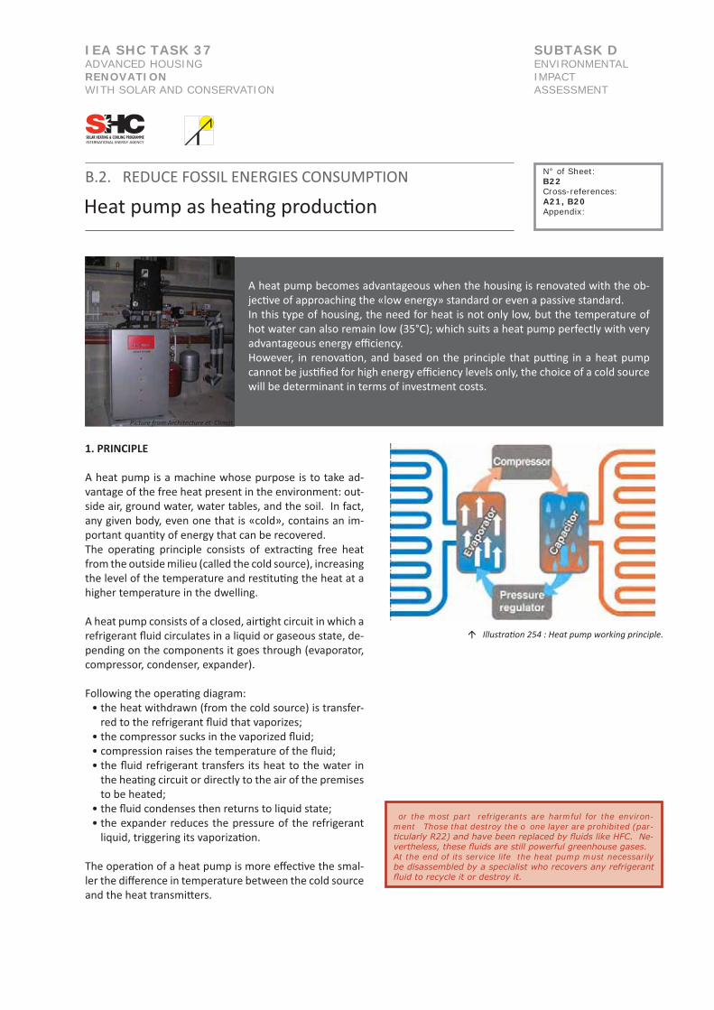
IEA SHC TASK 37ADVANCED HOUSING RENOVATIONWITH SOLAR AND CONSERVATION
SUBTASK DENVIRONMENTAL IMPACTASSESSMENT
B.2. REDUCE FOSSIL ENERGIES CONSUMPTION
Heat pump as hea�ng produc�on
A heat pump becomes advantageous when the housing is renovated with the ob-jec�ve of approaching the «low energy» standard or even a passive standard. In this type of housing, the need for heat is not only low, but the temperature of hot water can also remain low (35°C); which suits a heat pump perfectly with very advantageous energy efficiency. However, in renova�on, and based on the principle that pu�ng in a heat pump cannot be jus�fied for high energy efficiency levels only, the choice of a cold source will be determinant in terms of investment costs.
1. PRINCIPLE
A heat pump is a machine whose purpose is to take ad-vantage of the free heat present in the environment: out-side air, ground water, water tables, and the soil. In fact, any given body, even one that is «cold», contains an im-portant quan�ty of energy that can be recovered.The opera�ng principle consists of extrac�ng free heat from the outside milieu (called the cold source), increasing the level of the temperature and res�tu�ng the heat at a higher temperature in the dwelling.
A heat pump consists of a closed, air�ght circuit in which a refrigerant fluid circulates in a liquid or gaseous state, de-pending on the components it goes through (evaporator, compressor, condenser, expander).
Following the opera�ng diagram:• the heat withdrawn (from the cold source) is transfer-
red to the refrigerant fluid that vaporizes;• the compressor sucks in the vaporized fluid;• compression raises the temperature of the fluid;• the fluid refrigerant transfers its heat to the water in
the hea�ng circuit or directly to the air of the premises to be heated;
• the fluid condenses then returns to liquid state;• the expander reduces the pressure of the refrigerant
liquid, triggering its vaporiza�on.
The opera�on of a heat pump is more effec�ve the smal-ler the difference in temperature between the cold source and the heat transmi�ers.
or the most part refrigerants are harmful for the environ-ment Those that destroy the o one layer are prohibited (par-ticularly R22) and have been replaced by fluids like HFC. Ne-vertheless, these fluids are still powerful greenhouse gases. At the end of its service life the heat pump must necessarily be disassembled by a specialist who recovers any refrigerant fluid to recycle it or destroy it.
� Illustra�on 254 : Heat pump working principle.
N° of Sheet: B22Cross-references:A21, B20Appendix:
Picture from Architecture et Climat

Heat pump as hea�ng produc�onB.2. REDUCE FOSSIL ENERGIES CONSUMPTION
2. VARIOUS SYSTEMS
2.1. Different types of heat pumps
Type of heat pump Schema Cold source Hot source
Geothermal pumpWater/water heat pump
The cold source can be:• the soil (geothermal coil or probe)• the water table• groundwater
The hot sink consists of transmi�ers such as heat from the floor, convectors, a hot water ba�ery on clean incoming air, ...
Aerothermal pumpAir/water heat pump
The cold source is the outdoor air.
The hot sink consists of transmi�ers such as heat from the floor, convectors, a hot water ba�ery on clean incoming air, ...
Aerothermal pumpAir/air heat pump
The cold source can be the air extracted from the building.
The hot sink can be the air forced in.
2.2. Different types of circuits
- Direct expansion heat pumpThis is a pump consis�ng of a single circuit. The fluid refrigerant circulates in a closed circuit in the pump, the collectors and the heat transmi�ers.This type of heat pump requires a lot of refrigerant fluid.
- Mixed heat pumpThe heat pump consists of two circuits: one of a fluid refrigerant in the collectors at the heat pump, and a hot water circuit in the transmi�ers.
- Intermediary fluid heat pump This heat pump consists of three circuits: the refrigerant circuit in the heat pump, the collector circuit, where water with an�freeze circulates, and the hot water circuit in the transmi�ers.
2.3. Opera�ng modes
- Monovalent heat pumpThe heat pump is the only system for producing heat.
- Bivalent opera�ng modeThe heat pump is combined with another type of produc-�on of heat (a condensa�on boiler for instance).
� Illustra�on 255 : Heat pump Vitocal 350 by Viessmann - water/water.
� Illustra�on 256 : Heat pump Vitocal 100 by Viessmann - air/water
N° of Sheet: B22Cross-references:A21, B20Appendix:

Heat pump as hea�ng produc�onB.2. REDUCE FOSSIL ENERGIES CONSUMPTION
3. COLD SOURCE OR CALORIE COLLECTOR The temperature of the cold source should be as high as possible. The temperature and the specific power of the cold source (and their stability over the year) will be con�ngent on:
• geographic loca�on• available space and accessibility• the type of soil and subsoil
3.1. Geothermal heat pumpsThis type of pump draws calories from the earth or water in water tables, by means of collectors, probes or boreholes.The earth, water tables, groundwater, rivers maintain the cold source at a rela�vely high temperature as compared to the air. Nevertheless, the costs of studying and implemen�ng this type of cold source are high. In urban renova�on, these costs may rise sharply be-cause of the difficulty of gaining access to a garden or green area.
- Horizontal collectors in the groundHorizontal collectors are polyethylene tubes or copper tubes coated with polyethylene. They are installed in a coil buried horizontally at a shallow depth (between 60 cm and 120 cm).At this depth, the heat of the subsoil comes to a large extent from the sun’s rays.Water with an�freeze or a refrigerant fluid (depending on the technology used) circulates in a closed circuit in these coils. To prevent withdrawing too much heat from the soil and running the risk of freezing the soil and the loop, the coils must be placed with a minimum centre distance of 40 cm.
- Ver�cal collectors in the groundVer�cal collectors consist of two polyethylene tubes in a U-shape, installed in a borehole and sealed in it with cement. In most cases, several holes are drilled at least 10 m apart.Water with an�freeze circulates in a closed circuit in these tubes.The advantage of this system is to benefit from a source of heat that is more or less constant all year round.The site area is small as compared to horizontal collec-tors, but doing the drilling requires a minimum of room and good accessibility. In addi�on, the implementa�on of the system is fairly costly.
- Ver�cal collectors in the water table The water table as a cold source is advantageous becau-se the temperature of the water is stable all year round and ideal for obtaining good results.
� Illustra�on 259 : Geothermic pump - horizontal collectors.
� Illustra�on 262 : Geothermic pump - ver�cal collectors.
� Illustra�ons 257 and 258 : Horizontal (ground) and ver�cal (ground and water) collectors.
� Illustra�on 260 : Implementa�on of horizontal collectors.
� Illustra�on 261 : Implementa�on of geothermic pump - ver�cal collectors.
N° of Sheet: B22Cross-references:A21, B20Appendix:

Heat pump as hea�ng produc�onB.2. REDUCE FOSSIL ENERGIES CONSUMPTION
On the other hand, this system requires one or two bo-reholes that must be done by professionals with specific authoriza�on. There are two systems: a system with a single hole in a system with two holes (see diagrams).
- Ver�cal collectors in groundwater Groundwater as a cold source gives results that are less good because the temperatures fluctuate.Two configura�ons are possible:• direct u�liza�on by immersing the evaporator in the
river bed;• indirect u�liza�on via a heat exchanger absorbing the
calories of a strainer well dug near the river. Direct collec�on of calories in the riverbed is subject to considerable clogging of the evaporator, depends on the fluctua�ng flow of the river and is expensive to im-plement and maintain. Indirect collec�on, on the other hand, reduces the performance of the system.
3.2. Aerothermal heat pumps
Aerothermal heat pumps recover calories in the ambient air (inside or outside the dwelling).They are easy to set up and they adapt to many situa-�ons: individual homes, new or under renova�on. Air is an easily exploitable source of heat – with no collector to be installed. On the other hand, outdoor air tempe-rature varies considerably throughout the year, and as a consequence, performances of this kind of heat pump also vary. In addi�on, the system is larger, and noisier.This type of cold source could be envisaged in an urban se�ng (outdoor temperature slightly higher, reduce ac-cess to earth).
- Collec�ng the outdoor air The heat pump is installed inside or outside the dwelling and collects heat from the outdoor air.When the weather is cold, the evaporator in contact with the outdoor air may frost up, which reduces its effec�ve-ness. This type of heat pump is consequently equipped with a regula�on system that periodically reverses its opera�ons for a short �me to defrost the evaporator.This type of heat pump can be reversible and provide fresh air to the dwelling in the summer.
- Collec�ng indoor air This type of heat pump, also called a double effect ther-modynamic pump, combines dual flow mechanical ven�-la�on with a heat pump. It ensures renewal of the air supply of the dwelling and it receives that supply: the heat pump recovers the heat in the air extracted from the wet rooms (kitchen, bathroom, toilet) and preheats the new air that is forced into the li-ving premises.This device is reversible, so it can provide fresh air to the dwelling during the summer.
Reversibility of the system: By reversing the cycle of the fluid refrigerant, the heat pump draws calories from the dwelling and transfers them outdoors.This scheme can provide a moderate drop in temperature, of about 3 to 4° as compared to the outdoors, so this is really a refreshing system rather than air condi�oning.Installing a reversible system encourages consump�on of electric energy all year long, for limited comfort in the summer, whereas a heat pump used exclusively for hea�ng only consumes during cold weather.
� Illustra�on 263 : Ver�cal collectors in water.
� Illustra�on 264 : Aerothermic pump air/water.
N° of Sheet: B22Cross-references:A21, B20Appendix:

B.2. REDUCE FOSSIL ENERGIES CONSUMPTION
Heat pump as hea�ng produc�on
4. HEAT SINK OR HEAT TRANSMITTER
The temperature of the heat sink should be as low as pos-sible to obtain op�mal opera�on. This means that the transmi�ers should work at a low temperature. Heat pump systems are consequently systems that operate in very well insulated or passive dwellings, whether they are private homes or collec�ve housing, where the transmit-ter is either an underfloor hea�ng system or low tempera-ture radiators (see informa�on sheet B20).
In the case of renova�on of housing where:
- A hea�ng system is already in the floor The transfer of the heat produced to the heat pump should pose no problem. However, in a moderately insulated house, the iner�a of the floor slab is o�en very high. Reinforcement of the envelope may be incompa�ble with this type of hea�ng system. An alterna�ve would be an under floor hea�ng system with low iner�a.
- The transmi�ers are tradi�onal radiators The decrease in the temperature transmi�ed (the opera-�ng temperature drops from 80/60°C to 35/45°C) will re-duce the transmission power by about 60%. This power is theore�cally sufficient when the envelope of the housing reaches good performance. However, insula�on of the envelope reducing losses to about 3 to 5 for very low energy to passive dwellings, should mean that this transmission is theore�cally suffi-cient.
- Pu�ng in dual flow ven�la�on is planned The placement of an air-to-air heat pump will be conside-red where the cold source is the extracted air and the hot sink is the external new air.
5. ENERGY PERFORMANCES
Performances of heat pumps are expressed in coeffi-cients that take account of their efficiency given the energy they consume.
5.1. Coefficient of performance (COP)
The coefficient of energy performance COP is the diffe-rence between the quan�ty of heat produced and the electric energy consumed. This shows the performance of a heat pump in the hea�ng mode.Example:If a heat pump consumes 1 kWh electricity and transmits 3 kWh of heat, its COP is 3.
COP to reach according to the installa�on and the heat diffusion mode
Type of heat pump
Hea�ng with pulsated air
Tradi�onnal radiators
low t° transmit-ters
Air/air heat pump 1.5 to 3
Air/water heat pump 1.5 to 3 2 to 2.25 2.5 to 3
Water/water heat pump (horizontal)
2.5 to 3 2.5 to 3.5
Water/water heat pump (ver�cal)
2.5 to 3.5 3 to 4
Water/water heat pump (water table)
2.5 to 3.5 3 to 4
Source : Se chauffer autrement, Romain Claret et Jean-Michel Groult, Collec�on Habitat écologique, ULMER.
� Illustra�ons 265 and 266 : Hot sources : hea�ng in the ground or radiators.
� Illustra�on 267 : Hot source : hea�ng in the walls.
N° of Sheet: B22Cross-references:A21, B20Appendix:

B.2. REDUCE FOSSIL ENERGIES CONSUMPTION
Heat pump as hea�ng produc�on
6. PRODUCING HOT WATER WITH A HEAT PUMP
A heat pump can also be used to produce hot water. This system can be independent or joined to the system for producing heat.
- A produc�on system independent of the system pro-ducing heat
We do not recommend this system. In fact, when a heat pump operates in a monovalent mode, it may lose all of its energy efficiency, since it must raise the tem-peratures of the heat sink up to about 60°C. In addi�on, most heat pumps saturate at about 55°. Consequently, it would need back-up, either electrical (tank with an electric coil and needle), or an efficient boiler.
- A produc�on system combined with the system for pro-ducing heat
In this case, hot water is preheated up to the opera�ng tem-perature of the hea�ng system, which is about 35°C. Then an addi�onal device (condensa�on boiler, electric or solar water heater) provides the rest to reach an opera�ng temperature for hot water (about 55 to 60°C).
7. CHOOSING A HEAT PUMP IN THE CASE OF RENOVATION
In renova�on, se�ng up a new geothermal heat pump in a dense urban area (downtown) is o�en impossible. In fact, using an underground coil at 1.5 m requires:
• doing groundwork on shared walls in the yard or demo-lishing and reconstruc�ng them
• construc�on machines must have access to the yard • addi�onal costs
Generally speaking, heat pumps use a large quan�ty of electri-city. Consequently it is important to have an installa�on with a COP above 3.
- Individual housingOn renova�ng an individual home approaching low energy or passive standards, a small heat pump (as from 9 kW for exam-ple) can be used. This type of heat pump exists in an air/water or a water/water version.
- Collec�ve housingThere are several solu�ons for collec�ve housing based on one or more heat pumps. Insofar as there is access to the ground, a water/water heat pump will be preferred, considering• produc�on of heat by one or several centralized heat pumps;• produc�on of heat by an individual heat pump.
The cold sources can be of different types, although for a large housing complex, the power that can be drawn from them will be limited. Today, a few large projects provide for the use of geothermal energy from a mine sha�, the water of a river or a lake… but the renewal capacity (or regenera�on) of the cold source must be mastered.
� Illustra�on 268 : Installa�on of heat pump - Provelo renova�on - Brussel.
� Illustra�on 269 : Installa�on of heat pump - Provelo renova�on - Brussel.
N° of Sheet: B22Cross-references:A21, B20Appendix:

IEA SHC TASK 37ADVANCED HOUSING RENOVATIONWITH SOLAR AND CONSERVATION
SUBTASK DENVIRONMENTAL IMPACTASSESSMENT
B.2. REDUCE FOSSIL ENERGIES CONSUMPTION
Hot water produc�on by solar energy
N° of Sheet: B23Cross-references:B21, C01Appendix:
� Illustra�on 270 : Installa�on principle.
� Illustra�on 271 : Plane collectors. � Illustra�on 272 : Vacuum collectors.
«The solar energy that reaches the en�re surface of the earth is 10,000 �mes greater than the total energy demand of the earth’s popula�on. The solar resource is by far larger - and more sustainable - than all iden�fied reserves of fossil and nuclear energy.» Source: Installa�ons solaires thermiques, Edi�ons Le Moniteur
For a given economic op�mum, the annual consump�on of energy for heat and hot water can be reduced by 50 to 60% for individual homes and 20 to 40% for collec�ve housing by using a thermal solar installa�on. Moreover, this type of installa�on can significantly reduce CO2 emissions (between 150 and 400 kg of CO2 per m² per collector and per year).
1. PRINCIPLE
Under the ac�on of the sun’s rays, a fluid circula�ng in the solar collector heats up. Insulated pipes carry the hot fluid to the lower exchanger of a hot water tank where the heat is transmi�ed to water used in the dwelling. When there is no sunshine, tradi�onal produc�on using a boiler or electric coils acts as back-up. From the environmental standpoint, of course the electric op�on is not recommended.
There are two major categories of solar installa�ons:• Installa�ons using water with glycol;• Installa�on with a drain back system (without glycol).
Overall efficiency between the two systems stays about the same, due to important increase of electricity consump�on for pumping.
The major elements of a thermal solar installa�on are:
• The solar collectors themselves
• The distribu�on circuit
• The hot water tank with a double coil • The regulator

B.2. REDUCE FOSSIL ENERGIES CONSUMPTION
Hot water produc�on by solar energy
� Illustra�on 273 : Plane collector - principle diagram.
� Illustra�on 274 : Vacuum collectors
� Illustra�on 275 : Installa�on of storage tank.
N° of Sheet: B23Cross-references:B21, C01Appendix:
2. DESCRIPTION OF THE SYSTEM
2.1. The collectors
There are several types of collectors. The main ones are: • collector panels, the best-known and the most used • vacuum collectors
Vacuum collectors are more efficient than panels, par�cularly in the winter.Because of the vacuum around the absorber, a vacuum collector will be less influenced by the outdoor temperature. On the other hand, this type of collector is more expensive.
2.2. The storage tank
Storing the energy can compensate for the discon�nuous supply of solar energy. In renova�on, there are two possibili�es for pu�ng in a solar hea�ng system:
• Maintaining the current installa�on for hot water and pu�ng in a tank upstream of the exis�ng tank (tank with a single electric resistance or coil combined with the boiler);
• Replacing the exis�ng tank by a tank with a double coil. The upper coil is connected to the exis�ng boiler and the lower one is supplied by the solar installa�on.
- Thermal stra�fica�on of the tankIt is important to respect thermal stra�fica�on in the storage tank. For this reason, the tank should be placed ver�cally, and be as narrow and as high as possible (the ra�o of height to dia-meter being 2 to 2.5).Because of the stra�fica�on of the tank, hot water rises to the upper part of the tank, because it has lower density than cold water. When hot water is drawn, it is replaced by cold water from the bo�om of the tank. Consequently there is a superposi-�on of layers of water at different temperatures.
2.3. The distribu�on circuit
- The pipes in the circuit The distribu�on circuit links the collector or collectors to the sto-rage tank.Copper or steel tubes are used for these pipes.The pipes must be correctly insulated to limit loss of heat between the collectors and the storage tank.
- The heat conduc�ng fluid and the expansion tank The heat conduc�ng fluid is used to supply the storage tank with heat. Several fluids can be used (water, glycol, ...) but care must be taken to avoid freezing of the installa�on. A fluid that resists temperatures of 20°C will preferably be used in temperate to cold regions.
An expansion tank allows for the expansion of the heat conduc-�ng fluid and absorbs the increase in volume without too much of a rise in pressure if boiling should occur.
Remark :In case of a new tank upstream of the exis�ng tank, various solu-�ons exist to prevent the risk of prolifera�on of bacteria:
- pump for «de-stra�fica�on»: for regularly bring the water in the two balloons to a sufficient temperature;
- «dead» water tank: the risk of contamina�on will be avoided by physically separa�ng the waters of different temperatures

B.2. REDUCE FOSSIL ENERGIES CONSUMPTION
Hot water produc�on by solar energy
N° of Sheet: B23Cross-references:B21, C01Appendix:
2.4. The solar installa�on
In most thermal solar installa�ons, there is a «solar sta�on» mo-dule including the circulator, the valves and the check valves.Regula�on is generally integrated in the module.
- The circulatorThe role of the circulator is to ensure circula�on of the heat conduc�ng fluid in the distribu�on circuit.The circulator is controlled in view of the difference in tempe-rature between the fluid in the collectors and the water in the storage tank.A posi�ve differen�al of about 5°C triggers the system and heats the water in the storage tank. Conversely, a differen�al of 2°C stops hea�ng the water in the tank.
- The various valvesA number of valves are needed for the proper opera�on of the installa�on such as the safety valve to limit pressure, the drain valve, and the air elimina�ng valve.
- The regula�onThe regulator has various func�ons such as:
• op�mizing the heat in the storage tank for the solar radia�on on the collectors
• protec�ng the installa�on from overhea�ng of the collectors
2.5. Back-up
Pu�ng in a thermal solar installa�on does not necessarily mean replacing the exis�ng hea�ng system. In fact, the exis�ng instal-la�on becomes the back-up of the solar system. In the case of :
- An exis�ng boiler for hea�ngThe storage tank can be maintained, downstream of the solar tank. However, if the exis�ng tank has reached the end of its service life, it can be advantageously replaced by a double coil solar tank (the coil at the top of the tank is connected to the exis�ng boiler, and the coil at the bo�om to the solar installa�on).
- An exis�ng flash water heaterPu�ng the solar tank upstream works correctly.
- An exis�ng electric water tank Although this is not an ideal solu�on (rela�ve inefficiency of electric power plants, high price of electricity), pu�ng a solar tank upstream can be considered.
3. ELEMENTS INFLUENCING THE CHOICE
The elements to be taken into account on designing a hot water installa�on are as follows:
• geographic loca�on;• orienta�on and slope of the collector;• the type of collector.

� Illustra�on 276 : Geographical localiza�on.
� Illustra�on 277 : Influence of the slope and orienta�on on the efficiency.
B.2. REDUCE FOSSIL ENERGIES CONSUMPTION
Hot water produc�on by solar energy
N° of Sheet: B23Cross-references:B21, C01Appendix:
3.1. Geographic loca�on
Sunshine differs depending where one is in Europe. This means that to provide hot water, the area of the thermal collectors will have to be greater or smaller mainly in view of the la�tude.
3.2. Orienta�on and slope
In renova�on, the choice of orienta�on is limited, neverthe-less, the collectors should be oriented between southeast and southwest and sloped at 25 to 60° from a horizontal axis. Orien-ta�on focusing to the east or west reduces efficiency by about 20%. Finally, the risk of shadows (chimneys, nearby trees etc.) should be taken into account. For collec�ve housing, it might be worth looking into systems that «follow the sun» from east to west, although the addi�onal cost of this kind of system can be integrated into large projects only.
3.3. The type of collector
Depending on the desired applica�on, a solar panel or a vacuum tube collector will be chosen. In renova�on:When the areas envisaged for placing the collectors are small and orienta�on is poor for energy efficiency of the solar instal-la�on, then collector tubes could be used. This type of collector can be chosen when the solar installa�on is to be combined with the hea�ng system.
4. DIMENSIONS AND IMPLEMENTATION
The quality of a thermal solar installa�on depends on the quality of the collectors as well as the dimensioning of the installa�on.
4.1. Hot water consump�on
Hot water consump�on varies considerably depending on the life style of the occupant. Daily water consump�on can vary from about 30 litres to more than 400 depending on geographic loca�on and the consumers’ life style. To determine the demand for hot water, the following parame-ters must be known:
• consump�on of the dwellings in litres per day • temperature of the cold water in the public distribu�on
network (+/- 10°C);• minimum hot water temperature (+/- 45°C) ;• rate of solar cover needed or required
4.2. Area of the collector
The solar frac�on (fsol) or the rate of solar cover represents the share of hot water produced by solar energy on the average over the year, a�er deduc�ng losses. The larger the collector surface, the greater the solar cover.A solar frac�on of 30%, generally close to the economic op�-mum, takes about 1 m² of collector for 80 litres of hot water at 60°C.

Installa�on example in Belgium with a technical and economical op�mum:
Number of occupants Surface of collectors Storage volume Produced energysolar frac�on of 55%
Energy savingsupply system with an annual output
of 75%
2 to 3 persons +/- 4m² +/- 200l +/- 1200 kWh/year +/- 1600 kWh/year
4 to 5 persons +/- 5m² +/- 300l +/- 1600 kWh/year +/- 2200 kWh/year
6 to 7 persons +/- 7m² +/- 400l +/- 2300 kWh/year +/- 3100 kWh/year
Source : Guide pra�que pour la construc�on et rénova�on durables de pe�ts bâ�ments, IBGE,Bruxelles, 2007.
� Illustra�on 278 : Plane collectors in superposi�on of roof.
� Illustra�on 279 : Vacuum collectors.
B.2. REDUCE FOSSIL ENERGIES CONSUMPTION
Hot water produc�on by solar energy
N° of Sheet: B23Cross-references:B21, C01Appendix:
4.3. Dimensioning the tank
The tanks are chosen in view of the volume of water used and the maximum temperature required.A temperature of 45°C is usually sufficient for bathing, whereas maintenance needs a temperature of 50 to 60°C.The tanks are designed to deliver maximum temperatures of 80 to 90°C.
Generally speaking, and depending on the geographic loca�on, the size of the solar tank is planned for 50 to 80 litres per m² of collector area and 1.3 to 1.7 �mes the daily consump�on of hot water (30 to 60 l per day and per person on the average).
4.4. Where to put the solar collectors
The solar collectors can be installed in several ways. The most suitable will be chosen, given the type or renova�on done in the exis�ng dwelling:
- Mounted over the roof when the roof cover is maintainedThe legs are fastened directly on the frame of the roof; the panel frame and then the collectors are placed on these.
The advantage of this type of assembly is that it does not affect water �ghtness of the roof.
- Integrated in the roof when the roof covering is replaced The collectors are placed directly on the frame and replace the exis�ng roof cover.
- Mounted on a terrace or flat roof Aluminum sec�ons can �lt the collectors at 45°. These sec�ons are fastened on to the roof or weighted down with concrete blocks.A revolving system can be mounted in this way to follow the course of the sun from east to west (in large collec�ve housing complexes).


IEA SHC TASK 37ADVANCED HOUSING RENOVATIONWITH SOLAR AND CONSERVATION
SUBTASK DENVIRONMENTAL IMPACTASSESSMENT
E. REDUCE FOSSIL ENERGIES CONSUMPTION
Op�mizing the ligh�ng system
Since the appearance of the incandescent lamp designed by Edison, ar�ficial ligh�ng has developed in all sectors: ligh�ng of roads, housing and offices, decora�ve ligh�ng, etc. One of the advantages of ar�ficial lightning is that it is con�nually available as long as there is an energy supply. Whatever the hour of the day or night, various ac�vi�es can be lit: wor-king at a desk, preparing meals, ...Unfortunately, ar�ficial ligh�ng also has the disadvantage of consuming more or less electric energy, entailing nuisances, pollu�ons and exhaus�on of resources.
In terms of sustainable development, natural lightning should be preferred (see informa�on sheet B09) with efficient, energy-saving ar�ficial lightning.
1. PRELIMINARY REMARK
This en�re informa�on sheet has been dra�ed based on the Gui-de Pra�que et technique à l’éclairage des logements by B.Roisin, M.Bodart, A.Deneyer (Architecture and Climate), 2009, as part of the Minergibat-Eclos contract.
2. BASIS NOTIONS
Before presen�ng solu�ons for effec�ve ligh�ng in the hou-sing to be renovated, a few basic principles of light and ligh�ng should be explained.
- Ligh�ngLigh�ng is the quan�ty of luminous flux (light) received by a sur-face. It is measured in lux: 1 lx = 1 lm/m²
Examples:- Surface de travail dans un bureau : de 300 à 1000lx- Sol extérieur par ciel couvert : de 5000 à 20000lx- Sol extérieur par ciel clair : de 7000 à 24000lx- Surface perpendiculaire au soleil d’été : 100000lx
- BrightnessBrightness is the only real quan�ty perceived by the human eye. It corresponds to the visual sensa�on created by a source of light or a lit surface.
Examples:- Landscape by night : 10-3 cd/m²- Landscape by full moon : 10-2 à 10-1 cd/m²- Landscape by overcast : 300 à 5000 cd/m²- Moon : 2500 cd/m²- White paper : environ 25000 cd/m²- Sun : 1,5.109 cd/m²
N° of Sheet: B2Cross-references:B11, B1 , B2Appendix:/
� Illustra�on 280and 281 : Quality of natural ligh�ng
� Illustra�on 283 : Light intensity, Ligh�ng and brightness
� Illustra�on 282 : Ligh�ng defini�on
Picture from www.energieplus-lesite.be

Op�mizing the ligh�ng systemE. REDUCE FOSSIL ENERGIES CONSUMPTION
3. WHAT DOES A LIGHTING FIXTURE CONSIST OF?
A ligh�ng fixture is made up of several separate parts:
3.1. The light source
The light source or lamp is the basis of a ligh�ng fixture. Its role is to provide the light needed to light up an area, a room, a table, ...There are three main categories of light sources, referring to the means used to provide the light:
• incandescence• discharge• light emi�ng diodes (LEDs)
3.2. The auxiliaries
Some lamps need auxiliaries to func�on correctly. These can be broken down into two main categories:
• The transformer used in very low voltage halogens. Its role is to supply the lamp with lower voltage (generally 12V for a halogen) than the voltage drawn from the grid;• The starter and the ballast are used for discharge lamps. The fundamental roles of these is to light the lamp and to limit the current in the tube while it is in use, and to prevent it from being destroyed.
3.3. The luminaire
The third element in a ligh�ng fixture is the luminaire. This contains the lamp itself as well as any auxiliaries. It can have a triple role:
• The luminaire serves to direct the supply of light to the area to be lit;• It serves in certain cases to protect the lamp and any auxilia-ries from outside influences (contact, water, dust, etc.) ;• it has an esthe�c role, due to its shape, colour, materials and the way it directs light in the room.
4. CHARACTERISTICS AND TYPES OF LAMPS
In residen�al housing, the choice of a ligh�ng system is based by and large on subjec�ve esthe�c criteria, whereas in the ser-vice sector the main criteria are func�onal, economic, and so-me�mes environmental. This sec�on presents various types of lamps that can be found in residen�al buildings, with the advan-tages and disadvantages of each.
4.1. Characteris�cs of the lamps
Certain parameters determine the quality and characteris�cs of lamps. They include:
- The luminous flow and outputThe luminous flux is a source defined by the quan�ty of light radiated by a source in all direc�ons. It is expressed in lumen (lm).This is the «ligh�ng power» so to speak that a source emits.
N° of Sheet: B2Cross-references:B11, B1 , B2Appendix:/
� Illustra�on 286 : Luminous flow of a lamp
� Illustra�on 285 :
� Illustra�on 284 :

Op�mizing the ligh�ng systemE. REDUCE FOSSIL ENERGIES CONSUMPTION
The light efficacy can be derived from the luminous flux by dividing the luminous flux by the electric power of the source. Consequently, the unit is lm/W.
Example:A standard 60W incandescent light bulb has a luminous flux of about 700 lm. Its luminous efficacy is therefore 11,7 lm/W.
- The luminous intensityLuminous intensity is the luminous flux emi�ed in a single direc�on. This is expressed in candela (cd).
- The colour temperatureThe colour temperature of a lamp mainly describes the colour and light ambience given by the lamp. This is expressed in Kelvin (K).One refers to cool colours when the colour temperature is high (greater than 5000 K) and warm colours when the colour temperature is lower than 3300 K.
Example:A tradi�onal incandescent lightbulb has a colour temperature of 2700 K.A halogen lamp has a colour temperature of 3000 K.
- Colour rendering IndexThe colour rendering Index (Ra) describes the way a source res-�tutes the various wavelengths of the en�re visible spectrum, or in other words how accurately the colours of an object are «rendered» in comparison with those colours under natural light. The colour rendering index is given on a scale ranging from 0 (mediocre) to 100 (perfect).
Example:Daylight has a Ra of 100An incandescent lamp (tradi�onal and halogen) has a Ra of 100A fluorescent lamp has a Ra ranging from 60 to 90
- The lifespanThere are several defini�ons of the life span of a lamp. Ge-nerally speaking, the reference uses the average life span of a batch of lamps, that being the number of hours of opera�on of all those lamps before 50% of them are no longer operable.
The concept of non-operable can differ from one region of the world to another. In Europe, a lamp is considered non-operable when it emits only 70% (85% for incandescent bulbs) of its ini�al luminous flux. In the United States, a lamp is considered as non-operable when it no longer works.
N° of Sheet: B2Cross-references:B11, B1 , B2Appendix:/
� Illustra�on 287 : Luminous intensity
� Illustra�on 288 : Color temperature of light
� Illustra�on 289 : Energy efficiency

E. REDUCE FOSSIL ENERGIES CONSUMPTION
Op�mizing the ligh�ng system
4.2. Descrip�on of various lamps
Type of lamps Working Available capa-city
Efficiency and energy category
T° of color and color render
Lifespan
Tradi�onal incandes-cent lamps
To produce light, a tungsten filament is heated by the passage of electricity. The fila-ment is enclosed in a vacuum or gas filled globe.
from 25 W to 100 WLuminous flux varies from 200 to more than 1900 lm
Low efficacy, between 5 and 19 lm/WThe energy class varies from E to G
Warm white colour (2700 K). Excellent colour rendering (Ra=100).
Rela�vely short: 1000 h
Incandescent halogen lamps (spot lights, capsule lamps, mini tubes)
The opera�on is prac�cally iden�cal to that of tradi�onal incandescent lamps. The only difference lies in adding a halogen gas in the lamp with the effect of increasing the life span and preven�ng the lamp from darkening and thus losing luminous flux.
from 5 W to 500 WThe luminous flux varies from 50 to more than 10 000 lm
Efficacy varies from 10-12 lm/W for a standard halogen lamp to prac�cally 30 lm/W for IRC lamps.The energy class ranges G to B.
The colour of halogen lamps is 3000 K, a neutral white. Excellent colour rendering (Ra=100).
2000 to 5000 hLow voltage (12V) halogen lamps have a longer life than their equiva-lent in 230V.
Fluorescent tubes (T8 Tubes; T5 Tubes must be used with electronic ballast; Circular tubes)
Fluorescent tubes use the prin-ciple of electric discharge and a gas to create light. To operate the tube, a ballast and a starter must be used to limit, control and trigger the discharge.
Between 14 and 58 W. The length of the tubes varies with the capacity.
The luminous flux of the tubes ranges from 1300 to 5000 lm
Very good luminous efficacy. It ranges from 60 to 105 lm/W. Energy class is gene-rally A.
The colour tempe-rature varies with the power used in the tube from hot white (2700 K) to cold white (6700 K).The colour rende-ring index is not perfect, but s�ll fairly good (Ra from 80 to 95).
The life span of a fluorescent tube depends in part on the type of ballast and the type of starter; it can be as much as 20,000 h.
Compact fluorescent lamps – CFLs
Compact fluorescent lamps are in fact miniature curved fluorescent tubes, whose dimensions have been reduced to use them as a subs�tute for incandescent lamps.
The capacity range is very broad: from 3 to 23 W for lamps with integrated ballast and from 5 to more than 80 W for lamps with external ballast. The luminous flux ranges from 100 to more than 6000 lm.
Good luminous effi-cacy ranging from 35 to 80 lm/W. The energy class is generally A and in certain cases B.
The colour can range from hot white (2700 K) to cold white (6500 K). The colour rende-ring index is good, between 80 and 90.
The dura�on of compact fluo-rescent lamps with integrated ballast is about eight �mes longer than incandescent lamps (from 6000 to 10,000 hours).
Les LEDs (Light Emit-�ng Diode)
Light is created by LEDs using a third principle. A LED is in fact a semiconductor composed of a junc�on of two materials, one of which has excess elec-trons and the other a shortage. When this junc�on is submit-ted to a voltage differen�al, the excess electrons go into the shortage zone and recom-bine. This recombina�on pro-vides radia�on, whose colour depends on the elements.
Available capaci-�es on the market range from 0.007 W to 3 W.The luminous flux ranges from 1.5 lm to 200 lm.It is also true that the luminous flux varies significantly with the ambient temperature.
LEDs available on the market have effi-cacy of 20 to 30 lm/W (white light). The energy class ran-ges from D to B.
The colour tem-perature of LEDs ranges from hot (2700 K) to cold (6500 K), but rende-ring is be�er at cold temperatures. The colour rendering ranges from 50 to 80.
The life span of LEDs can be highly variable depending on the ambient temperature and the voltage applied. It can range from 5000 hours to more than 100,000 hours.
N° of Sheet: B2Cross-references:B11, B1 , B2Appendix:

E. REDUCE FOSSIL ENERGIES CONSUMPTION
Op�mizing the ligh�ng system
5. CHARACTERISTICS AND TYPES OF LUMINAIRES
5.1. Characteris�cs of luminaires
- The outputA luminaire, by its very func�on, is an obstacle to the distribu-�on of light, because it cannot totally res�tute the light supplied by the luminous source, as part of the rays are absorbed by the components of the luminaire. The output of a luminaire is a ra�o of the luminous flux emi�ed by the luminaire as compared to the luminous flux of the lamp.
- The luminous distribu�onThere are three main types of distribu�on:• Extensive where the ray of light is broad and gives rela�vely
uniform ligh�ng;• Intensive with a narrow ray of light for ligh�ng emphasis;• Asymmetrical that can be used to light ver�cal surfaces like
walls or pain�ngs.
5.2. Ligh�ng system
Depending on the luminaires used and where they are placed, various ligh�ng systems exist:
- Direct ligh�ngThe light is emi�ed directly on the surface to be lit. Efficacy of this type of ligh�ng is very good, so the power installed will be low. Conversely, there is a higher risk of glare using this system and the distribu�on of light in the premises may be fairly irregular.
- Indirect ligh�ngIndirect ligh�ng consists of using a reflec�ng surface (o�en the ceiling) to diffuse light in the premises. The advantage of this system lies in its rela�vely small risk of glare and good distribu-�on of the light in the premises.The efficacy of this system is lower than for a direct system and can even be mediocre in dark areas.
- Mixing ligh�ngFor this ligh�ng system, the two previous systems are combined with their advantages and disadvantages.
- Ligh�ng with two componentsIn this system, two luminaires are used: the first gives general ligh�ng and the second adds back-up ligh�ng where necessary.
5.3. Descrip�on of various luminaries
- Ceiling mounted luminaireCeiling-mounted luminaires are commonly used to light dwel-lings. O�en the lamps are enclosed in frosted glass that distributes the light fairly broadly in the premises. They can be used mainly for the general ligh�ng of all rooms.
N° of Sheet: B2Cross-references:B11, B1 , B2Appendix:
� Illustra�on 290 : Direct ligh�ng
� Illustra�on 291 : Indirect ligh�ng
� Illustra�on 292 : Mixing ligh�ng (direct and indirect)
� Illustra�on 293 : Ceiling light

E. REDUCE FOSSIL ENERGIES CONSUMPTION
Op�mizing the ligh�ng system
N° of Sheet: B2Cross-references:B11, B1 , B2Appendix:/
- Chandelier or hanging luminaireChandeliers and hanging luminaires generally play two roles in residen�al ligh�ng. Although some hanging luminaires can provide ligh�ng focusing on a zone, by and large they provide general ligh�ng of the en�re room. In addi�on, they are o�en an integral part of the decora�on of the premises.
- Wall-mounted light A wall-mounted light is an integral part of the decora�on of the room. It is used mainly to add a certain ambience to the general ligh�ng of the room. It is also o�en used for specific applica�ons of light such as highligh�ng mirrors etc.
- The spotlightSpotlights are generally built into the ceiling. There are also spotlights on rails that can easily add flexibility to the ligh�ng system (possibility of adding or removing spotlights, displacing them, orien�ng them etc.). These are o�en used to accentuate ligh�ng in combina�on with other luminaires. Some�mes they are used on their own, although in that case, they create major contrasts in the premises they light.
- The linear light stripA linear light strip is a simple and popular luminaire. The again, because of its very limited esthe�c presenta�on it is only used for specific applica�ons. It may be hidden behind architectural elements (wooden siding, curtain holders etc.) or by the furnitu-re (posi�on on the top of cupboards, etc.). It generally provides indirect ligh�ng (by reflec�ng off the ceiling).
- Freestanding luminaires and back-up lamps Freestanding lamps and back-up lamps provide good ligh�ng when the general ligh�ng of the room is not sufficient. Desk lamps and reading lamps fall into this category. Freestanding luminaires that can be found in homes are generally indirect halogen candelabras. These are highly appreciated for their in-direct ligh�ng and their adjustability. On the other hand, the lamps in these luminaires are generally very powerful (300 or 500 W) resul�ng in a high consump�on and opera�ng cost.
� Illustra�on 294 : Suspended luminary
� Illustra�on 295 : Wall light
� Illustra�on 296 : Spotlight
� Illustra�on 297 : linear light strip
� Illustra�on 298 : Luminary on foot

E. REDUCE FOSSIL ENERGIES CONSUMPTION
Op�mizing the ligh�ng system
6. LIGHTING MANAGEMENT
6.1. Principles of ac�on
- The switching on/offSwitching on and off is the easiest way to control lamps. The electric circuit does or does not power the lamp as needs re-quire.
- Adjus�ng the intensity This consists of controlling the luminous flux of the lamp in kee-ping with the users’ needs. This is easy to do for incandescent lamps – reducing the voltage of the power supply will reduce the luminous flux.
- Time control Time control uses a clock to produce ac�ons on the lamps. The ac�ons can be carried out at a pre-programmed �me, or a cer-tain amount of �me a�er the lamps have been lit or adjusted.
- Movement detec�on lamps Movement detec�on lamps use a sensor that detects the pre-sence (or absence) of movement in a specific zone. Two types of technology are used: PIR (Passive InfraRed) detectors and HF (High Frequency) detectors. PIR detectors operate by detec�ng a warm, moving body, whereas the HF detector uses the Oppler effect (reflec�on of various waves on a moving body) rather like a sonar. These lamps can act in three ways: coming on, switching off or in certain more rare cases, adjus�ng the intensity. In addi�on, some of them operate totally automa�cally (they switch on when they detect a presence and switch off, if not). Others, which are less standard but preferable, must be switched on manually and switch off automa�cally when they no longer detect movement. These are o�en called «absence detectors».
6.2. Controling tools
- Light swichtA light switch is the simplest tool for controlling ligh�ng. This is generally an appliance that will open or close the electric circuit mechanically and therefore provide or cut off the power supply to the lamps.
- The dimmerThe dimmer is a tool for control which allows, to modify the flow of the lamps which it controls. In general, those func�ons only for the incandescent lamps (including the halogen).
- The �me switch (�mer)A �me switch is a device that is generally mounted in the fuse box. It automa�cally stops the ligh�ng a�er a certain amount of �me that can be set by the user. This type of management is very prac�cal in circula�on zones (halls, stairways etc.) where presence is temporary.
- The detector of presenceThere are different types of presence detectors: wall-mounted and ceiling-mounted. The advantage of wall-mounted detectors is that it is easy to replace the light switch by this kind of detec-tor on renova�on. However, since the field of vision is limited in this case, the performances of these detectors are o�en less good than for ceiling-mounted detectors.
N° of Sheet: B2Cross-references:B11, B1 , B2Appendix:/
� Illustra�on 299 : Various types of dimmer

E. REDUCE FOSSIL ENERGIES CONSUMPTION
Op�mizing the ligh�ng system
7. WHICH LIGHTING FOR WHICH ROOM?
A few recommenda�ons are given below to improve exis�ng installa�ons in terms of efficacy and the quality of ligh�ng (visual comfort).A few crucial rooms of the dwelling are reviewed:
7.1. The kitchen
Ac�vi�es are diverse in the kitchen, and consequently so is the need for light. A dis�nc�on is made between the two main areas to be lit: the counters and the rest of the room.
- Ligh�ng the kitchen counterLigh�ng on the kitchen counter should be rela�vely strong to allow for precise, and some�mes dangerous, jobs (e.g. manipu-la�ng knives). Ligh�ng for the kitchen counter is generally re-commended at 300 to 500 lux. To avoid throwing a shadow on the person working on the coun-ter, the luminaires are preferably placed between eye height and the counter. To achieve this, pu�ng the luminaires under the hanging cupboards seems to be the best solu�on: light strips as well as spotlights.
- Ligh�ng of the rest of the roomLigh�ng of the rest of the room should be rela�vely well distri-buted at about 200-300 lux (at counter height). This prevents strong contrasts between the counter and the rest of the room. To provide ligh�ng in the rest of the kitchen, in prac�ce all types of luminaires can be used. The choice will be based on the occu-pants’ preferences and the size of the room.
7.2. The dining room
The principles for ligh�ng the dining room are similar to those for the kitchen. The following should be provided:
• average ligh�ng of the table at 150 to 200 lux (hanging lu-minaire)
• ligh�ng of the rest of the room at 100 to 150 lux
7.3. The living room
Ligh�ng needs in the living room can be highly variable, from about 20 to 400 lux.
- Light for readingLigh�ng for reading is generally located near the armchairs in the living room. Various solu�ons exist to provide sufficient light:
• a ceiling-mounted luminaire or a hanging luminaire• freestanding luminaires • direc�onal luminaires
- Ligh�ng of the rest of the roomDepending on the configura�on of the room and the choice of luminaires, general back-up ligh�ng (100 to 150 lux) will be nee-ded. The living room is also the favourite spot for small decora�ve table lamps. These lamps are generally more decora�ve than actually intended to provide ligh�ng to carry out a specific task. These luminaires are generally rela�vely inefficient.
N° of Sheet: B2Cross-references:B11, B1 , B2Appendix:/
� Illustra�on 300 : How to illuminate the kitchen

E. REDUCE FOSSIL ENERGIES CONSUMPTION
Op�mizing the ligh�ng system
7.4. The bedroom
Ligh�ng in the bedroom can be broken down into three parts:
- Light for reading or workingReading requires ligh�ng from 200 to 300 lux. Working needs ligh�ng from 300 to 500 lux.
- Light on night table and desk lampsLike the table lamps in the living room, lamps on the night table tend to play a decora�ve role in addi�on to providing light for reading. It is rather difficult to find efficient reading lamps on the market. At this �me, we see more and more desk lamps equipped with compact fluorescent lamps with an external ballast. These lamps give good ligh�ng for working and they are efficient. They are almost always equipped with 11W bulbs.
- Ligh�ng in the rest of the roomLigh�ng of 100 lux at counter level is sufficient. The luminaires to be used in the bedroom can be ceiling-moun-ted or wall-mounted. Various solu�ons exist to improve both energy efficiency, com-fort of ligh�ng and aesthe�cs in a ligh�ng installa�on.
8. HOW TO IMPROVE THE LIGHTING INSTALLATION IN RENO-VATION?
Various solu�ons are planned to improve the energy effec�ve-ness as well, as luminous comfort and the esthe�cs of an instal-la�on of ligh�ng.
8.1 Light renova�on
Light renova�on is an opportunity to improve visual comfort and energy efficiency of the ligh�ng installa�on without making major modifica�ons in the current installa�on, nor incurring si-gnificant costs. This renova�on consists of replacing the lamps without changing the luminaires.Replacing the lamps will bring more or less improvement in the luminous efficacy in the installa�on and visual comfort, while in-creasing the ligh�ng.
8.2. Intermediate renova�on
The construc�on work for medium renova�on will generally be more significant than in the previous sec�on: lamps and lumi-naires are replaced.Since the place for the new luminaires is predetermined, the choice may some�mes be limited. In most cases, ceiling-moun-ted or hanging luminaires will be used. As concerns the management of ligh�ng, replacing the luminai-res can be a good means to add points of control. For example, luminaires with integrated switches can be chosen for situa�ons where specific ligh�ng of a job or separate ligh�ng may be re-commended; for example a luminaire over the kitchen counter.
The heavy renova�on does not be described in this sheet be-cause it is very similar as a new construc�on.
The following table compares the intensity of incandescent lamps generally used in residen�al with the intensity of fluocompact lamps that must be used. Energy savings as well as financial benefits are also calculated for a use of 1000h per year (a li�le less than 3 hours per day) and a kWh price of 17 cents kWh
Intensity be-fore replacing
Intensity a�er replacing
Energy benefits
Financial benefits
100 W 23 W 77kWh 13€
75 W 18 W 57 kWh 10€
60W 15 W 45 kWh 8€
40W 10 W 30 kWh 5€
N° of Sheet: B2Cross-references:B11, B1 , B2Appendix:/
� Illustra�on 301 : How to illuminate the bedroom


IEA SHC TASK 37ADVANCED HOUSING RENOVATIONWITH SOLAR AND CONSERVATION
SUBTASK DENVIRONMENTAL IMPACTASSESSMENT
B.2. REDUCE FOSSIL ENERGIES CONSUMPTION
Renewable energies for genera�ng electricity
The demand for electric energy in a building can easily be reduced by a number of measures such as promo�ng natural ligh�ng, choosing energy-saving electric appliances, and so on.Once these measures have been taken, the ques�on arises as to the impact of the genera�on of electricity that is used on a day-to-day basis. This genera�on is not en�rely environment-friendly today – despite growing installa�ons of renewable systems (wind power, photovoltaic energy, cogenera�on, …) most genera�on is s�ll either nuclear or based on fossil fuels.
Given this observa�on, recent studies consider that in industrialized countries, photovoltaic energy could supply 50% of consump�on in the residen�al sector, or 10% of the total consump�on of electricity. Genera�ng electricity from an inexhaus�ble source – the sun – is an economic, industrial and environmental challenge that each country should take up, as has been done in Germany and Japan that together produce nearly 70% of the world’s solar power.
1. PRELIMINARY REMARK
At this �me, there are different sources of renewable energy to generate electricity:
• Solar energy• Wind energy• Hydraulic energy• Biomass• Cogenera�on of electricity
Developing and increasing all these sources should be promoted in a general way, but on the scale of housing and renova�on, the only two genera�on systems that can be easily integrated are:
• Photovoltaic solar energy that applies both to individual ho-mes and collec�ve housing
• Cogenera�on of electricity that today is used only for large collec�ve housing developments.
In this informa�on sheet, we will talk about genera�ng electri-city by means of solar panels, which is advantageous both finan-cially and for the environment.
N° of Sheet: B2Cross-references:B22, B2Appendix:
� Illustra�on 303 : Wind power � Illustra�on 304 : Solar energy
� Illustra�on 302 : World repar��on of solar electricty
� Illustra�on 305 : Hydro power � Illustra�on 306 : Biomass
Why switch to renewable energies? 80% of the energy used in the world is based on fossil energy sources. Most of these sources will be exhausted in a few decades and the consequence will be a significant rise in purchasing prices (due to the phenomenon of supply and demand). Moreover, many deposits of these resources are located in poli�cally unstable or hard-to-reach places which makes pro-curement difficult. This is another reason for rising cost.But even more, these fossil resources must be burned to pro-duce energy which has an impact on many pollu�on-related problems today (global warming, acidifica�on of the envi-ronment, forma�on of tropospheric ozone) and on health (respiratory problems, allergies, ...).

Renewable energies for genera�ng electricity B.2. REDUCE FOSSIL ENERGIES CONSUMPTION
2. HOW IT WORKS
2.1. Photovoltaic effect
The photovoltaic effect was discovered by Alexandre Edmond Becquerel in 1839. The photovoltaic effect is obtained by the absorp�on of photons in a semiconductor material that then generates an electric current.
2.2. How it works in the home
Direct current is generated in the cells of the solar module by the effect of the light. All of the modules connected together form the photovoltaic «generator».The direct current produced is linked to the connec�ng box on the generator and is carried to the converter.The inverter transforms the direct current into alterna�ng current (average voltage – 220 to 240V).
At this point, there are two possibili�es:• All of the alterna�ng current is supplied to the public
electricity network via a power supply meter. The receivers get the power they need from the local electric grid via a separate subscrip�on meter;
• The alterna�ng current generated is not connected to the public network and is either consumed on the spot, or is stored in accumulators.
Note that the inverter must be placed on a ver�cal support and in a ven�lated space. It must be also placed as close as possible to the panels because losses of electricity are much higher on transpor�ng direct current than for alterna�ng current.
3. GENERAL NOTIONS: SILICON PLATES – CELL – MODULE – GENERATOR
The basic material of the crystalline solar cells is a silicon plate (0.2 to 0.3 mm) called a «wafer». The photovoltaic effect takes place inside these small units.
When the various layers of the semiconductors that make up the solar cell are lit by sunlight, a difference in poten�al appears. This phenomenon can be measured externally by voltage. For silicon, it is 0.6V on the average. To be used, the voltage must be amplified by moun�ng several cells in a series.
A module generally consists of solar cells mounted in a series. The maximum number of cells (= voltage of the module) is in principle limited by the condi�ons of implementa�on of the module (weight and size).
When several modules are mounted in a series to make a photovoltaic installa�on, this is called a row or a string. All of the strings of modules combined together (even if there is only a single string) make up the generator.
� Illustra�on 307 : Installa�on diagram
� Illustra�on 308 : Concept : cell - module - photovoltaic generator
N° of Sheet: B2Cross-references:B22, B2Appendix:

Cell material Module output Needed aera for 1kW peak(mid-Europe) Part world market
Cellule monocristalline 11 - 16% 7 - 9m²
93%Cellule polycristalline (EFG) 10 - 14% 8 - 9m²
Cellule polycristalline 8 - 10% 9 - 11m²
Cellule en couches minces CdTe 6 - 8% 11 - 13m² 1.7%
Cellule amorphe 4 - 7% 16 - 20m² 4.5%
4. PHOTOVOLTAIC CELL
4.1. Type of photovoltaics cells
There are different types of photovoltaic cells, depending on the technology used. At this �me, crystalline silicon cells are most frequently used.The cells can be divided into four groups according to the basic material:
- Monocrystalline silicon cell Monocrystalline cells are manufactured by the fusion of very pure silicon. In this technology, round silicon bars are made and sliced into plates 0.2 to 0.3 mm thick. These plates are the basis of the monocrystalline cells. Although their manufacture requires more energy and �me than polycrystalline cells, effi-ciency is the highest of all types of cells.
- Polycrystalline silicon cell (or mul�-crystalline cells) Fusion is also used to manufacture polycrystalline silicon. In this process, the rough silicon is heated to a high temperature and then shaped in a mould. As it solidifies, crystals form in an irregular pa�ern. The square bars are cut in slices of 0.3 mm.The habitual blue colour results from the an�-reflec�on coa�ng applied which changes the thickness and consequently the colour.
- Thin layer cells (CIS, CdTe, GaAs) Despite their rela�vely limited yield, thin layer CIS (copper indium diselenid) cells and CdTe (cadmium telluride) cells represent a good alterna�ve thanks to the greater tolerance of shadow (elements that mask the luminous rays) and the redu-ced loss of yields due to an increase in temperature.
- Amorphous silicon cellsCells made from amorphous or nonstructured silicon that is not in crystalline form are already o�en used in calculators and watches.The yield of the cells on the averages ranges from 6 to 8%. The ac�ve semiconductor material is considerably thinner than in crystalline cells. Consequently, less material is needed for the cells than for crystalline silicon cells.
Renewable energies for genera�ng electricity B.2. REDUCE FOSSIL ENERGIES CONSUMPTION
� Source : «Le photovoltaïque pour tous, concep�on et rélaisa�on d’installa�ons», Edi�ons le Moniteur
� Illustra�on 309 : Cell with single crystal silicon
� Illustra�on 310 : Cell with polycrystal silicone
� Illustra�on 311 : Cell with amorphous silicon
N° of Sheet: B2Cross-references:B22, B2Appendix:

4.2. How a crystalline cell works
Targeted doping with unrelated atoms (generally boron and phosphorus) creates two layers in the cell with different electric proper�es:• a posi�ve layer « p »• a nega�ve layer « n »an electric field forms at the junc�on of these two layers, this is the space charge zone (SCZ). When light strikes the cell, the electric charges located in this space charge zone separate. In the electrical connec�on this generates a DC voltage of about 0.5V on the average, that depends li�le on the light provided.
4.3. Peak power
The current and electric power of a solar cell depends directly on the intensity of the luminous flux. The energy provided by the cells is at a maximum when the sky is clear and sunny. In the case of cloud cover, the luminous flux is lower and consequently there is less power.The maximum power of a cell is defined for a luminous flux of 1000 W/m² at a temperature of 25°C. This is called the peak capacity and is expressed in Wp (wa� peak).
4.4. Intensity and voltage
A solar cell is characterized by:• electric intensity: this depends on the power of the lumi-
nous flux and the size of the cell • electric voltage: this depends essen�ally on the material
that makes up the cell The only way to increase voltage is to mount several cells in a series.
4.5. Influence of temperature
A hea�ng solar cell loses its efficiency. For crystalline cells, the loss of efficiency corresponds to 0.5% per degree Celsius. For this point, thin layer cells are less sensi�ve than crystalline silicon cells. Consequently, any hea�ng should be avoided. For this reason, installa�ons that allow for ven�la�on on the back of the module should be preferred.
5. PHOTOVOLTAICS MODULE
A photovoltaic module generally consists of:• several solar cells linked together;• glazing (or stra�fied) protec�on against the weather • protec�on against overvoltage using one or several bypass
diodes • a branching device• glazing on the back• an aluminum frame
To manufacture a module, several cells are connected together electrically (in a series) to reach useful voltage and intensity at the module outlet. Each series is protected by a bypass diode that
• prevents the hea�ng of certain cells from causing a shu-tdown or deteriora�on in the case of shadow;
• limits the drop in performance resul�ng from this hea�ng of the en�re module.
� Illustra�on 312 : Working principle of a crystalline cell
� Illustra�on 313 : Impact or influence of temperature
� Illustra�on 314 : Photovoltaics module
Renewable energies for genera�ng electricity B.2. REDUCE FOSSIL ENERGIES CONSUMPTION N° of Sheet:
B2Cross-references:B22, B2Appendix:

6. CONVERTER
6.1. Type of converter
The converter transforms the con�nuous current provided by the photovoltaic generator into single-phase alterna�ve current with a nominal voltage of 230V.Depending on the photovoltaic installa�on, there are different types of converters: centralized converters, string and mul�-string converters and modular converters. A centralized converter is commonly used for individual homes where the modules all point in the same direc�on and have the same inclina�on. For a powerful generator, when the cells are par�ally shaded or when the modules present different inclina�ons and/or orienta�ons, string (mul�-string) converters for modular converters are used.
6.2. Converter and branching of modules
For a parallel connec�on, currents of the various modules add up and the voltage remains the same.For a serial connec�on, the voltages add up and the current going through them is the same.
- When do the modules have to be connected in a seriesFor individual installa�ons, without significant shadow, connec-�on in the series will be chosen as long as all the modules are oriented the same way and have the same inclina�on.
- When do the modules have to be connected in a parallel connec�on? A parallel connec�on has to be used for the modules or strings of modules if:
• part of the installa�on is in the shade• the modules do not have the same orienta�on and inclina-
�on• the voltage in the installa�on is higher than permi�ed when
a serial connec�on is used
7. INSTALLATION
7.1. Installa�on on the roof or on the façade?
Photovoltaic solar modules can be mounted in several ways according to esthe�c and financial criteria (see table on the next page)
7.2. Orienta�on and inclina�on
To maximize the genera�on of electricity in an installa�on, the modules should be oriented and inclined so as to receive as much radia�on from the sun as possible.
- Orienta�onGenerally speaking, in the Northern Hemisphere, the modules will face south or nearly south (southeast or southwest).
- SlopeAs for the inclina�on of the panels compared to a horizontal plane, the approach is based on the height of the sun in the sky. The height of the sun depends both on the la�tude of the project and the season. Solar energy received by the surface of the modules will be greater if this surfaceis perpendicular to
Renewable energies for genera�ng electricity B.2. REDUCE FOSSIL ENERGIES CONSUMPTION
� Illustra�on 316 : The solar collectors, with different orienta�on, must be connected in parallel
� Illustra�on 317 : Influence of the orienta�on and slope on the efficiency
� Illustra�on 315 : Various types of inverter installa�on
N° of Sheet: B2Cross-references:B22, B2Appendix:

Renewable energies for genera�ng electricity B.2. REDUCE FOSSIL ENERGIES CONSUMPTION
Type of assembly Advantages
Assembly detached from the slope of the roof
• Simple, quick, inexpensive moun�ng with no affect on the water �ghtness of the roof
• In renova�on, ideal installa�on on exis�ng roof• Good ven�la�on on the back on the modules to cool them• High-efficiency (if there is li�le shadow) • Easy to disassemble
Moun�ng integrated in the roof • Esthe�cally a�rac�ve• High-efficiency (if there is li�le shadow)
Moun�ng on a flat roof • Ideal orienta�on and inclina�on of the modules • Good ven�la�on on the back on the modules to cool them• Simple, quick, inexpensive moun�ng with no affect on the water �ghtness of the roof• High-efficiency (if there is li�le shadow)• Simplified disassembly, repair and maintenance
Moun�ng on a free area on the ground
• Ideal orienta�on and inclina�on of the modules • Good ven�la�on on the back on the modules to cool them• Simple, quick, inexpensive moun�ng with no affect on the
water �ghtness of the roof• Simplified disassembly, repair and maintenance
Moun�ng on the façade • Certain savings are made: the external envelope is replaced par�ally by photovoltaic modules
• Esthe�cally a�rac�ve• Large ver�cal area available Note that because of the limited slope of the modules, efficiency obtained with an assembly on the façade is significantly lower than an assembly on the roof.
the sun’s direct rays.
- Orienta�on and slope: factor of correc�on for Mid-EuropeOp�mum efficiency is reached for an orienta�on to the south with an inclina�on of 35° from a horizontal plane. Efficiency decreases on moving away from this posi�on. To put a figure on this decrease in efficiency, a correc�on factor is applied on the kWh obtained per year and per kWp. The values of this correc�on factor are given in the table below.
� Illustra�on 321: Factor of correc�on facing to orienta�on and slope
� Illustra�on 319 : Installa�on on a flat roof
� Illustra�on 318: Installa�on on a roof
� Illustra�on 320 : Installa�on on façade
N° of Sheet: B2Cross-references:B22, B2Appendix:

Renewable energies for genera�ng electricity B.2. REDUCE FOSSIL ENERGIES CONSUMPTION
- Follow-the-Sun» System
There are mobile installa�on systems that «follow the sun», providing maximum genera�on of electricity by following the sun on its daily course (in orienta�on and inclina�on).This type of installa�on increases genera�on by about 25% as compared to a fixed installa�on.On the other hand, this type of installa�on entails significant addi�onal cost, and is hard to integrate in an individual home or in a small collec�ve housing complex.
7.3. Shadow
Much more than the loss of efficiency that may occur with poor inclina�on or poor orienta�on, shadow puts a high penalty on the efficiency of photovoltaic panels. The modules are made up of cells connected in a series. This serial connec�on means that the cell with the lowest efficiency will determine and limit the power of the en�re module.Consequently, one must:
• limit shadowing of the modules to a maximum• provide for connec�ons that take account of shadowing
7.4. Protec�on from lightning
Generally speaking, if the building has a lightning protec�on de-vice, the photovoltaic installa�on should be connected to it.However, the need for protec�on against lightning is closely re-lated to the way the installa�on is mounted: • A photovoltaic installa�on when it is mounted on a sloped
roof, does not generally increase the risk of being hit by light-ning. This kind of installa�on therefore does not need special protec�on.
• In the case of an installa�on on a flat roof, the modules gene-rally go beyond the roof, and these installa�ons must be consi-dered on a case-by-case basis.
In any case, the metal components of the installa�on should be connected to the main grounding of the building.
8. DIMENSIONING OF THE INSTALLATION
The dimensioning of an installa�on essen�ally depends on: • the characteris�cs of the roof (size, inclina�on, orienta�on)• the absence of shadow or an obstacle to the sun’s rays• the available financial capacity of the investment • the technical and esthe�c requirements of the contrac�ng
authority
In general, the maximum size of the installa�on is limited by the available area of the roof. The area required for installa�on depends on the technology of the cells.
Example: a 1 kWp generator requires the following service areas:- 6-9 m² of monocrystalline cells- 7-10 m² of polycrystalline cells - 15-20 m² of amorphous cells
� Illustra�on 322: Follow-the-Sun» System
N° of Sheet: B2Cross-references:B22, B2Appendix:


IEA SHC TASK 37ADVANCED HOUSING RENOVATIONWITH SOLAR AND CONSERVATION
SUBTASK DENVIRONMENTAL IMPACTASSESSMENT
Heat recovery on ven�la�on system
The por�on of the building’s energy consump�on devoted to hea�ng new air increases with the degree of insula�on and air�ghtness of the envelope. In a well insulated building, losses from ven�la�on will be 40 to 70% of total losses (60 to 80% in an apartment in the middle of the complex). On insula�ng an exis�ng dwelling and pu�ng in structured ven�la�on, it is important to combine a means of recovering the heat of the air extracted from the building. Depending on the thermal efficiency of the recovery, energy consump�on from ven�la�on can be reduced by 50 to 95%.
1. HOW IT WORKS
A heat recovery system has a heat exchanger allowing heat transfer. The polluted air and new air go through the exchanger. The heat of the polluted air evacuated to the outside is used to preheat air coming in from outdoors. Only the heat is transferred; the two flows do not come into contact with each other. This thermal exchange considerably reduces energy consump�on needed to heat the fresh outside air to a comfortable temperature for the air supply. In fact, a heat recovery system can recover 70 to 80% (or, for the most effec�ve, even 90 to 95%) of the heat of the exhaust air and transfer it to the flow of new incoming air. For the renova�on of housing, using a heat recovery system for extracted air requires a dual flow mechanized ven�la�on system in which the extrac�on fan is located near the air supply fan.
Example:For heat recovery system with thermal efficiency of 80%: if the outside air is at 0°C and the indoor air is at 20°C, a�er going through the heat recovery system, the incoming air supply is at 16°C without requiring any consump�on of heat.
B.2. REDUCE FOSSIL ENERGIES CONSUMPTION N° of Sheet: B2Cross-referencesA20, A21, B1 , B2Appendix/
� Illustra�on 323 : Working of an heat recovery system
Picture: T. Demeester

Heat recovery on ven�la�on systemB.2. REDUCE FOSSIL ENERGIES CONSUMPTION
2. HEAT RECOVERY SYSTEM
2.1. Type of heat recovery system
- Monoblock heat recovery system For ordinary flows needed in tradi�onal homes, current heat recovery system are in monoblock units and consequently, they are mounted in the same caisson as the dual flow ven�la�on system. They essen�ally comprise:
• a mul�- or variable speed air supply fan, on the side of the new air intake;
• a mul�- or variable speed extrac�on fan, on the side of where the polluted internal air is extracted;
• 2 filters for incoming and outgoing air;• a by-pass of the heat exchanger in the new air circuit to
avoid unnecessary rehea�ng under certain weather condi-�ons.
This is par�cularly useful on summer nights, when outdoor air is o�en cooler than the air in the house.
- A separate heat recovery systemFor apartment buildings, where flows can be greater, central air treatment units may be advisable. In this case, the fans are se-parate from the heat economizer. This solu�on requires aerau-lic connec�ons between the fans and the heat recovery system that must be mutually compa�ble.
2.2. Advantages and disadvantages
A heat recovery systemr can recover up to 85% of heat from pol-luted air, which can reduce energy consump�on by 50 to 95%.On the other hand, a heat recovery system entails:
• an addi�onal investment at the �me of the renova�on;• more room for the technical installa�ons; • greater fric�on loss in the installa�on.
3. INSTALLING A HEAT RECOVERY SYSTEM
3.1. Individual housing
The space needed to install a monoblock heat recovery system in an individual home is rela�vely small. However, for renova-�ng, the installa�on of this type of system is complex. By and large, the ideal spot for the installa�on of the heat reco-very system is in an a�c, and in the least favourable case, in a technical zone in the upper storeys. If the premises where the system is installed are rela�vely poorly insulated from the outdoors:
• the external fresh air intake ducts must be insulated• the polluted air outlet ducts must be insulated to reduce the
risk of condensa�on and freezing. The heat exchanger itself is always insulated.
3.2. Collec�ve housing
- Individual heat recovery system for the fresh air supply /com-mon extrac�on
Pu�ng dual flow ven�la�on in an apartment building means fit-�ng out ver�cal technical sha�s to distribute new air and to col-lect polluted air from each apartment. A heat recovery system itself should be put in technical premises near the sha�.
� Illustra�on 324 : Working of a heat recovery system
N° of Sheet: B2Cross-referencesA20, A21, B2Appendix/
� Illustra�on 325 : Implementa�on of an heat reco-
very system in individual housing
� Illustra�on 326 : Implementa�on of heat recovery system in a collec�ve housing (1/dwelling)
It is important to say that in Northern countries and in Mid-Eu-rope, it is not possible to build or renovate according the passive standard and get such low energy levels for hea�ng without using a heat exchanger

Heat recovery on ven�la�on systemB.2. REDUCE FOSSIL ENERGIES CONSUMPTION
Distribu�on downstream from the recovery system into the apartments is more of a problem, since the air supply and extrac�on ducts have to be put in false ceilings.
(+) This system allows for local regula�on per apartment (control-ling air flows for each tenant or apartment owner). (-) More maintenance is needed.
These comments should be taken into account given the purpose of the apartments (social housing for example).
- Individual heat recovery system /common extrac�onIf the ver�cal technical sha�s are too small to house two sets of ducts, an alterna�ve is to provide for new air intake from the façade on each floor (be a�en�ve to pollu�on problems) and to reject the polluted air at roof level by means of a common ver�cal duct.
- Collec�ve heat recovery system with common vents When it is not possible to install an individual heat economizer per apartment, a collec�ve heat economizer can be placed in technical premises insofar as the distribu�on of the air supply and extrac�on to and from each apartment can be done via ver�cal sha�s.
(+) Ra�onalized maintenance.(-) Common regula�on.
3.3. Combined with a ground heat exchanger
Dual flow ven�la�on can be combined with a ground heat ex-changer (see informa�on sheet B27). If this is the case, the ven�la�on installa�on must take account of fric�on loss caused by the ground heat exchanger. The ground heat exchanger is connected at the air intake of the ven�la�on system.
It has the following advantages and disadvantages: · Preven�ng freezing of the recovery system by prehea�ng in-
coming air;· Improving comfort in the summer by cooling incoming air,
which cannot be done simply with the heat economizer;· Very expensive investment;· Most of the �me, the ground heat exchanger gives only a
marginal improvement of the energy efficiency of an installa-�on with a heat economizer (on its own the heat economizer reduces energy consump�on by 50 to 95 %);
· Problem of compensa�on and addi�onal maintenance for the ground heat exchanger.
3.4. Maintenance
In apartment buildings, maintenance of the heat recoveru sys-tems (mainly the filters) can be limited or substan�al depending on how many there are and how difficult it is to gain access to them. The filters should be cleaned and/or replaced twice a year.
� Illustra�on 327 : Implementa�on of heat recovery system in a collec�ve housing (1 for all dwellings)
N° of Sheet: B2Cross-referencesA20, A21, B2Appendix/
� Illustra�on 328: Principle of air ground exchanger

B.2. REDUCE FOSSIL ENERGIES CONSUMPTION
Heat recovery on ven�la�on system
4. ENERGY GAINS
The energy efficiency of heat recovery system should be combi-ned with limited internal fric�on losses:
• high thermal efficiency (of 90-95 %) limits consump�on due to hea�ng air;
• limited internal fric�on losses (due to filters, ducts, valves, ...) reduce electricity consump�on of fans.
Under these circumstances, as part of the energy saving measures at the �me of renova�on, it is important to choose a heat recovery system corresponding to the following criteria:
• providing the minimum level for thermal efficiency;• fans with a specific capacity.
Using a heat recovery system with thermal efficiency of more than 90%, equipped with a regula�on system allowing for a recovery throughout the en�re hea�ng season (management of de-icing) can save on the investment in post hea�ng coils and the installa�on for producing heat.
N° of Sheet: B2Cross-referencesA20, A21, B2Appendix/

IEA SHC TASK 37ADVANCED HOUSING RENOVATIONWITH SOLAR AND CONSERVATION
SUBTASK DENVIRONMENTAL IMPACTASSESSMENT
B.2. REDUCE FOSSIL ENERGIES CONSUMPTION
Air pre-hea�ng/cooling by airground exchanger
N° of Sheet: B27Cross-references:A21, B20, B2Appendix:
� Illustra�on 329 : Installa�on principle
� Illustra�on 331: Condensing evacua�on
� Illustra�on 330 : New air entrance
Picture from Architecture et Climat
In a well-insulated building, the heat losses associated with hygienic ven�la�on become the most important item for energy consump�on. Ac�on can be taken to ra�onalize this consump�on, par�cularly by prehea�ng the air supply through a ground heat exchanger.A ground heat exchanger is also presented as an advantage for comfort in the summer, because it can cool down the air before supplying it to the building.The effec�veness of a ground heat exchanger depends on its size, its depth underground, the composi�on of the soil, its shape, and the materials used.In addi�on, installing a ground heat exchanger in an exis�ng dwelling is not easy given the obvious cost of implementa�on, and available space, … so the project must be treated circumspectly on a case-by-case basis.
1. PRINCIPLE
A ground heat exchanger is a geothermal system that uses the heat in the soil to pre-heat or cool the new air for ven�la�on.The temperature of the outer air may vary from -20°C to +40°C throughout a year, but the temperature of the soil 2 metres deep is stable between 5 and 15°C on the average depending on the season.The principle is to circulate the new ven�la�on air in an underground duct before supplying it to the dwelling:
• in the winter, the air is heated as it goes through the heat exchanger, and consequently energy consump�on for rehea�ng is re-duced;
• in the summer, the outdoor air takes advantage of the cool soil to become cooler, and consequently to improve thermal comfort in the summer.

Type of ground Densitykg/m³
Heat storage capacity c
kJ/kg.K
Thermal conduc�vity
W/m.K
Minerals 2650 0.8 2.9
Sand / gravel 1700 à 2000 0.91 à 1.18 2
Clay and silt 1200 à 1800 1.67 à 2.5 1.5
Water 1000 4.2 0.25
Ice 920 2.1 0.58
Air 1250 1 2.2
Organic ma�er 1300 1.9 0.023
Source: Guide Pra�que pour la construc�on et la rénova�on durables de pe�ts bâ�ments, IBGE, Bruxelles, 2007
B.2. REDUCE FOSSIL ENERGIES CONSUMPTION
Air pre-hea�ng/cooling by airground exchanger
� Illustra�on 332: Nature of different type of grounds
N° of Sheet: B27Cross-references:A21, B20, B2Appendix:
2. DESIGN ELEMENTS
The following elements should be taken into account in desi-gning a ground heat exchanger:
2.1. The nature of the soil
The performances of the heat exchanger are directly related to the heat capacity and thermal conduc�vity of the soil.
- Thermal conduc�vity of the soilThe thermal conduc�vity of the soil depends both on its compo-si�on and on the layout and shape of the par�cles that make it up, connec�ons between these par�cles and its water content. The damper the soil, the higher its thermal conduc�vity.
- Heat capacity of the soilThe heat capacity of the soil is expressed by the weighted ave-rage of the heat capaci�es of its components: minerals, organic ma�ers, presence of air and water (see the table in Annex).
2.2. Geographic loca�on
In regions where the climate has very low temperatures in the winter and very high temperatures in the summer (>20°C diffe-rence between hot and cold), a ground heat exchanger can play an advantageous role, par�cularly since the soil temperature is constant.
2.3. Available room and cost
In renova�on, the cost of pu�ng in a ground heat exchanger is high as compared to designing one in a new construc�on, since one cannot take advantage of the earth works on the building to dig a trench for the heat exchanger. In addi�on, this can only be done if the dwelling has sufficient grounds and is accessible to civil engineering machines.
2.4. Combined ven�la�on mode
A ground heat exchanger occasions fric�on losses. Mechanical ven�la�on must be calculated to overcome these fric�on los-ses.In the case of heavy renova�on of an exis�ng building, no effi-cient mechanical ven�la�on system is designed today without combined heat recovery. This considerably reduces the energy impact of a ground heat exchanger for prehea�ng the hygienic air supply (see informa�on sheet B26).
2.5. Fric�on losses
Fric�on losses caused by the heat exchanger are essen�ally due to:
• the shape of the duct or ducts • the air speed• the material used for the duct
These fric�on losses must be overcome by the air supply fan in the ven�la�on system. To reduce energy consump�on of that system, a ground heat exchanger must be highly effec�ve. When the size is calculated well, a ground heat exchanger has a thermal efficiency that is o�en about 80% when fric�on losses are limited.

B.2. REDUCE FOSSIL ENERGIES CONSUMPTION
Air pre-hea�ng/cooling by airground exchanger
� Illustra�on 333 : Air recovering system coupling with an airground exchanger
� Illustra�on 334 : Pipes implementa�on: meandering between air entrance and housing
� Illustra�on 335 : Pipes implementa�on : circle around housing
N° of Sheet: B27Cross-references:A21, B20, B2Appendix:
Example :• t° entrance of the heat exchanger = -8°C ;• t° soil = 10°C ;• efficiency of the heat exchanger = 80 %• temperature of the outlet air: - 8 + (10 – (- 8)) * 0,8 = 6,4 °C
3. DIMENSIONING AND IMPLEMENTATION
A ground heat exchanger consists essen�ally of:• a fresh air intake• one or several underground ducts• a system for evacua�ng condensates• connec�on to the ven�la�on network
3.1. Air intake
- Air intakeThe air intake in general is an opening outdoors, far from any source of tradi�onal pollutants, allergens, or sources of odours. For this reason, pu�ng a ground heat exchanger in an urban environment is generally problema�cal. The air intake should be:
• at least 110 cm under the ground;• be protected from infiltra�on of rainwater by a cover;• be protected from intrusion by small animals with a fine
grid.
- Filters (pollens and dust)A filter is placed at the entrance of the heat exchanger to reduce the entrance of dust, pollen and par�cles.This filter should be cleaned or changed regularly so as not to increase fric�on losses and energy consump�on of the fan.
3.2. The underground duct
- Number of tubes The duct of the heat exchanger can consist of a single tube pla-ced in a loop around the building or a network of parallel tubes.
- The length of the ductThe length of the duct is calculated in view of the desired airflow, the nature of the soil, the loca�on and the type of installa�on chosen.The total length of each tube on the average is between 30 and 50 metres, to limit fric�on loss.
- Air speed and diameter of the ductTo op�mize the soil/air heat exchange, the air speed should be between 1 and 3 m/s.The diameter of the duct should be calculated based on these air speed condi�ons.
- Layout and implementa�onTo minimize fric�on loss in the duct and facilitate maintenance, the number of bends should be limited.The depth of the duct is between 1.5 and 3 metres.The duct should be at a slope (between 1 and 3%) to promote evacua�on of condensates.

B.2. REDUCE FOSSIL ENERGIES CONSUMPTION
Air pre-hea�ng/cooling by airground exchanger
� Illustra�ons 337 and 338: Two systems for condensing evacua�on
� Illustra�on 336: Installa�on of condensing evacua�on
N° of Sheet: B27Cross-references:A21, B20, B2Appendix:
- MaterialThe choice of materials is important because it has direct impact on the soil/air heat exchange. The ducts are made from synthe�c materials (PVC, polyethylene, polypropylene).The tubes can also be treated against germs (using silver salts) to prevent odours from developing.
3.3. Evacua�on of condensates
Water vapor contained in the air that circulates in the duct can condense when the air is in contact with the cold sides of the duct.To prevent this water from stagna�ng and the development of germs and bacteria that could disturb air circula�on and decrease its quality, the system must necessarily be equipped with
• a duct at a slope• a system for evacua�ng condensates
- Presence of a basementThe condensates can be recovered inside the dwelling. They are then evacuated to the collec�ve sewer by a siphon.
- In the absence of a basement An opening should be put in at the lowest part of the duct, to evacuate the condensates:
• by infiltra�on into the soil• by pumping them up
This opening should allow for visual inspec�on of the state of the duct
3.4. Fan and regula�on
- PerformanceThe size of the fan should be determined in view of the flow of air needed (see informa�on sheet A21).
- By-pass et thermostatIn the midseason when the outdoor temperature is between 10 and 20°, the use of a ground heat exchanger is not recommen-ded (outdoor air close to a comfortable temperature). It is pre-ferable to disconnect the heat exchanger by using a bypass to get a direct new air supply.The bypass is generally controlled by a servomotor connected to a thermostat located outside the building.
3.5. MaintenanceThe heat exchanger should be maintained regularly once or twice a year:
• replacing or maintaining the intake filter;• inspec�on of the duct or ducts;• evacua�on of the condensates
ENERGETICAL GAINS
A ground heat exchanger can make savings of about 20 to 25% of the energy consump�on associated with hea�ng incoming air (5 to 10% of total heat consump�on) and can provide moderate cooling in hot weather.Note that when the heat exchanger is combined with a heat reco-very system and a double flow mechanical ven�la�on system, its efficiency becomes insignificant as compared to that of the heat recovery (70 to 90%).

C. REDUCE TAP WATER CONSUMPTION
C01 - Ra�onal use of tap water C02 - Recovery and use of rainwater
Picture from Sophie Trachte


IEA SHC TASK 37ADVANCED HOUSING RENOVATIONWITH SOLAR AND CONSERVATION
SUBTASK DENVIRONMENTAL IMPACTASSESSMENT
C. REDUCE THE TAPWATER CONSUMPTION
Ra�onal use of tap water
Current consump�on of drinking water in Europe is 150 litres/day per capita on the average, but 55% of this consump�on (cleaning, toilets, rinsing systems) do not require such high quality water. Both the design of the distribu�on network and the equipment used can contribute to redu-cing consump�on of drinking water:
• Designing and installing a quality water network • Using systems that consume li�le water (appliances and faucets) • Using another source of water when possible
It should also be noted that the occupants’ behaviour plays a crucial role in poten�al reduc-�on of consump�on.
1. DESIGNING AND BUILDING AN APPROPRIATE WATER NETWORK
A well-designed installa�on is an installa�on that:• includes as short a distribu�on network as possible• includes a minimum of «risky» elements such as bends,
connec�ons etc. • can be easily located and is accessible to facilitate its mana-
gement, maintenance and supervision• does not alter the quality of the water
1.1. Detec�ng leaks
On renova�ng housing and par�cularly on renova�ng large hou-sing developments, it is crucial to be able to locate a leak very quickly, both in the collec�ve distribu�on network and in the individual network for each dwelling.Leaks that go undetected have a major impact on water consump�on (see the table on this page).
Rapid detec�on of leaks requires: • verifying the quality of the distribu�on network in terms of
water �ghtness at the �me of the renova�on• knowing the distribu�on network well as it was actually im-
plemented on the construc�on site (using graphic plans)
- Verifica�on of the distribu�on network – construc�on siteBefore the beginning of work of restora�on and at the end of the project, one will carry out, by se�ng under pressure of the distribu�on network, a checking of this one in order to: • detect the possible escapes on the exis�ng network before
the renova�on; • check the repair of the possible leakage; • check the defec�ve implementa�ons (new network or exten-
sion of the exis�ng network) being able to cause leakage.
- Knowing the distribu�on network Good knowledge of the distribu�on network is crucial in terms of managing, maintaining and supervising that network.To achieve this, designers should obtain a plan of the distribu-�on and evacua�on networks as they were implemented in the construc�on or as they were put in/modified at the �me of re-nova�on.
These plans should contain the following informa�on:• loca�on of distribu�on and evacua�on columns • stopcocks at the foot of the columns, numbered and labeled • loca�on of various sight holes• loca�on of various branches
Water leakages Quan�ty wastedAverage data given as an
example
Dripping 4 liters/hour
Thin trickle of water 16 liters/hour
Trickle of water 63 liters/hour
Leaky toilet 25 liters/hour
Source : Fiche « faire un usage ra�onnel de l’eau » Guide pour la construc�on et rénova�on de pe�ts immeubles, IBGE, 2007.
N° of Sheet: C01Cross-references:C02, B22, B2Appendixes:/
Tap water consump�on (average in Europe)
Food 5% or 7.5 liters/day
Personnal hygiene 40% or 60 liters/day
Flush system (WC) 25% or 37.5 liters/day
Cleaning 10% or 15 liters/day
Washing 20% or 30 liters/day
total 150 liters/day
� Func�ons in red do not require the quality of tap water
Picture : S.Trachte

Ra�onal use of drinkeable waterC. REDUCE THE TAPWATER CONSUMPTION
2. WATER SAVING SYSTEMS
Systems Water savings Other advantages Change the habits
Systems on distribu�on network
Leak detec�on 35 m³/year for a drip-drip
yes
Pressure reducing valve
A pressure reducer is a plumbing accessory that protects the water supply installa�on from excess pressure on the distribu�on network and minimizes noise caused by the flow of water in the pipes.
2 to 10 liters/min for a tap according to the pressure
Increase the lifespan of the installa�on and devices
no
Faucets and accessories
Dynamic flow reducerThis plumbing accessory is incorporated in the faucets and maintains the flow at a constant level independently of the pressure on the sup-ply. It automa�cally compensates varia�ons in pressure between 2 and 6 bars.
55% for an econo-mical shower
Energy saving on the hot water distribu�on-network
no
Thermosta�c valveThe faucet regulates the temperature on one hand and the flow on the other; a temperature control faucet offers greater comfort to the user and reduces the risk of geng burned.
65% Energy saving on the hot water distribu�on-network
no
Mixing valve - cold in central posi-�on A combina�on faucet that provides cold water when the knob is in the central posi�on, rather than warm water as in a tradi�onal system. Hot water is obtained by turning the knob to the le�.
20% compared to a standard mixing valve
Energy saving on the hot water distribu�on-network
no
Flushing systems
Flush with 2 controls : 3 and 6 liters 53% compared to a flush of 9 liters
Less important dilu�on of pollu�on
yes
Flush with off-on switch 50% compared to a flush of 9 liters
Less important dilu�on of pollu�on
yes
Dry toilet 100% no use of water
Pas de rejet d’eaux vannesEngrais naturels après compostage
yes
Devices
Shower in comparaison with bath 50% Energy saving on the hot water distribu�onnetwork
yes
N° of Sheet: C01Cross-references:C02, B22, B2Appendixes:/

IEA SHC TASK 37ADVANCED HOUSING RENOVATIONWITH SOLAR AND CONSERVATION
SUBTASK DENVIRONMENTAL IMPACTASSESSMENT
C. REDUCE THE TAPWATER CONSUMPTION
Recovery and use of rain water
Current consump�on of drinking water in Europe is 150 litres/day per capita on the average, but 55% of this consump�on (cleaning, toilets, rinsing systems) do not require drinking wa-ter. Where possible, rainwater should be used for the following purposes:
• supplying toilet flushes • cleaning and laundry • watering the garden
As a preven�ve measure, we recommend not using rainwater for food and hygiene.
1. PRINCIPLE
The rainwater on the roof is collected through the gu�ers and drainpipes. Then it flows through the first filter to eliminate dust and par�cles before being stored in a tank. A pump sends the stored water to the various appliances and faucets.The rainwater cistern includes:
• an overflow system; • a system for drinking water supply
The choice of the material of the cistern, its capacity, the choice of equi-pment and the area of the roofs to be connected to the cistern are elements that should be studied and assessed in view of the desired consump�on of rainwater.
N° of Sheet: C02Cross-references:B22, C01, D01Appendix:01
Tap water consump�on (average in Europe)
Food 5% or 7.5 liters/day
Personnal hygiene 40% or 60 liters/day
Flush system (WC) 25% or 37.5 liters/day
Cleaning 10% or 15 liters/day
Washing 20% or 30 liters/day
total 150 liters/day
� Illustra�on 339 : Implementa�on principle
� Func�ons in red could be supplied by rainwater � Illustra�ons 340 and 341 : Funny watertank on roof - Brussel
Picture : Sylvie Rouche

Recovery and use of rain waterC. REDUCE THE TAPWATER CONSUMPTION
� Illustra�ons 342 and 343 : Cyclon filter - Self-cleaning filter
2. FILTRATION OF RAINWATER
Thanks to the filtra�on systems, water of sufficiently high quality can be obtained to supply toilets, and for laundry and cleaning.
2.1. Pre-filter
Before arriving in the storage cistern, the rainwater goes throu-gh an ini�al filtering system whose role is to eliminate and re-tain large par�cles (dust, pebbles, leaves, debris, ...) and thus to avoid accumula�on in the cistern.There are two types of filters: self cleansing or non-self clean-sing.Because regular maintenance is required, non-self cleansing fil-ters are not recommended.Self cleansing filters require no maintenance; they consist of a fine stainless steel filter and two evacua�ons: one for filtered water leading to the cistern, and the other for the par�cles re-tained plus about 10% of the quan�ty of water.
2.2. Post-filter
To prevent any clogging (suspended par�cles), a second filter is mounted where the water is taken into the cistern. This filter is placed on the suc�on pipe.
3. RAINWATER TANK
3.1. Size of the tank
An indica�ve calcula�on of dimensioning is given in appendix 01. The size of the rainwater tank should be determined so as to meet maximum needs (80 to 90%). To achieve this, it is impor-tant to know the collec�on area, weather data, and average consump�on of drinking water.
3.2. Rainwater tank materials
Two types of materials are available for storage tanks:
Concrete tanks Plas�c tank
Heavy material.
Hard to install in the event of renova�on (requires a crane).
The walls and the bo�om must be made in a single piece.
No ballast required
Lightweight material
Easy to install
If the tank is underground, ballast is required. A layer of gravel and a layer of limestone must be pro-vided.
Concrete has the advantage of having a high mineral content that allows for the development of micro-orga-nisms (natural purifica�on of water) and neutralizing of the natural acidity in rainwater.
The layer of gravel and the layer of limestone enable micro-organisms to deve-lop (natural purifica�on of water) and neutralize the na-tural acidity in rainwater. In addi�on, they act as ballast for the tank.
� Illustra�ons 344 and 345 : Self-cleaning filter
� Illustra�on 346: Plas�c water tank
� Illus�ra�on 347 : Concrete water tank
N° of Sheet: C02Cross-references:B22, C01, D01Appendix:01

Recovery and use of rain waterC. REDUCE THE TAPWATER CONSUMPTION
3.3. Plan�ng and accessories
- Installa�onThe tank must necessarily be protected from light, heat and freezing. Preferably, it should be buried but if applicable, it could be put in a basement or a�c if the floors are sufficiently resistant.
The tank should be accessible (cleaning): • the cover of the supply pipe should be free from any vegeta-
�on or deposit;• the opening should be sufficiently large to allow a person to
go into the tank;• the floor of the tank should be sufficiently strong to bear
the weight of a ladder with a person on it.
In urban areas, the tank should be divided into two compart-ments, for the sake of maintenance and the filters:
• the first compartment should be used as a se�ling tank, with a capacity of 10 to 20% of the capacity of the second compartment; the overflow from the se�ling tank should supply the second compartment;
• the second compartment serves as the tank from which water is drawn.
- Arrival of water (in the tank)The arrival of rainwater in the tank should correspond to the diagram below.This system prevents turbulence at the bo�om of the tank where sludge deposits are formed.
- Drinking water supply (in case of dryness)In the case of a long drought, the rainwater tank can empty completely or almost completely, so a supply of drinking water is needed.A fixed connec�on between the two networks is not authori-zed, so they must be completely separated.
This can be done either manually or automa�cally:
- manually The tank can be filled by a garden hose or a con�nual filling system (filling corresponding to es�mated consump�on before the next rainfall).
- automa�callyA pump floater triggers the drinking water supply faucet when it reaches a low point; this fills the tank with enough drinking water for specific needs for one day.
- Overflow systemThe rainwater tank should be equipped with an overflow system. This will only be opera�onal about 10 �mes a year (depending on the size of the tank). In terms of sustainable development, it is recommended to connect the overflow to a system for infiltra�on in the soil, such as a diffusion well, ditch or pond so that excess rainwater seeps into the water table.When this solu�on cannot be envisaged due to technical or economic reasons, the overflow should be connected to a collec�ve network, with certain precau�ons in view of the characteris�cs of the network (check valve, siphon-shaped entrance to the overflow, …)
� Illustra�on 348 : Diagram explaining tank installa�on
N° of Sheet: C02Cross-references:B22, C01, D01Appendix:01

Recovery and use of rain waterC. REDUCE THE TAPWATER CONSUMPTION
4. PUMP SYSTEM
4.1. The pump
There are different kinds of pumps, each of which has its advan-tages and disadvantages.To make a comparison between the various pumps, the following features should be checked:
• energy consump�on• presence or absence of a run-dry safety device• sound level of the pump• corrosion resistant materials• automa�c triggering and suc�on height• power and pressure buildup
4.2. Suc�on pipe
The suc�on pipe to the pump should be located:• at a certain height above the bo�om of the tank to prevent
suc�on of sludge;• sufficiently below the level of the water surface to prevent
suc�on of air. The best system consists of fixing the suc�on pipe to a floater device so that suc�on of the water always takes place about 10 cm below the water surface (see illustra�on 348).
This system consists of a floater, a filter (post-filter) and a foot valve that prevents the suc�on pipe from opera�ng.
To prevent the pump from con�nuing to operate when the tank is dry, the system should have a run-dry safety device. The type of device depends on the type of pump installed.
5. DISTRIBUTION SYSTEM
5.1. Supply pipes
As rainwater is very so� water, it can be corrosive for certain materials used for water supply pipes. Consequently, the pipes should be made from either plas�c or stainless steel.
5.2. Collec�on points
All collec�on points for rainwater should be iden�fied by a label sta�ng «unfit for drinking «. Outdoor faucets (for watering the garden) should preferably be installed out of reach of children or be equipped with a safety device.
6. MAINTENANCE
6.1. Maintenance of the filters
The filters should be maintained once a year.
6.2. Maintenance of the tank
A correctly installed tank should be cleaned every 10 years. Cleaning of the tank consists of elimina�ng the sludge that has accu-mulated in the bo�om. In the case of a cistern with two tanks, only the se�ling tank needs cleaning. Cleaning the walls on which micro-organisms have developed over the years is NOT recommended; only sludge should be removed from the bo�om of the tank.
� Illustra�on 349 : Immersed pump and suc�on pipe
� Illustra�on 350 : Immersed pump
� Illustra�on 352 : Centrifugal pump
� Illustra�on 351 : Immersed pump
� Illustra�on 353 : Pump installa�on
© www.wilo.be
© www.wilo.be © www.wilo.be
N° of Sheet: C02Cross-references:B22, C01, D01Appendix:01

D. INCREASE THE WATER RESOURCES
D01 - Rainwater management on the parcel D02 - Water recycling by plants - extensive systems D03 - Water recycling in urban area - intensive systems
Picture from Valérie Mahaut


IEA SHC TASK 37ADVANCED HOUSING RENOVATIONWITH SOLAR AND CONSERVATION
SUBTASK DENVIRONMENTAL IMPACTASSESSMENT
D. INCREASE THE WATER RESOURCES
Rainwater management on the parcel
«Rainwater management on a lot targets compensa�ng the impermeabiliza�on of soils inherent to construc�ons and lands-cap�ng of the grounds around them. Its objec�ve is to reduce runoff and to lighten the load on the exis�ng collec�ve drainage infrastructures. It contributes to preven�ng floods and pollu�on of groundwater, and to supplying the water table»
Source: Guide pra�que à la construc�on et rénova�on durable de pe�ts bâ�ments, IBGE,2007
Several measures with proven effec�veness can be rapidly and easily put in place: • favouring the crea�on of green areas, par�cularly in the courtyards of buildings and inside city blocks; • increasing permeability of gray areas (terraces, paths, parking lots); • favouring vegeta�on on roofs (that act as a storm water tank)
1. HELPFUL INDICATORS FOR MANAGING RAINWATER
1.1. Impermeabiliza�on coefficient The impermeabiliza�on coefficient is the ra�o between the impermeable surface area and the total surface area of a lot.On renova�ng the lot, the author of the project should take care to keep this impermeabiliza�on coefficient between 0.4 and 0.2.
Performance table
C ssic Perfor nt Hi h perfor nt
to to
Source : «Qualité environnementale des bâ�ments»,Ademe
1.2. Infiltra�on coefficient of the soil
The infiltra�on coefficient of the soil corresponds to its per-meability.
Some examples:
T pe of ro nd Infiltration capacityh
S nd ith co rse- r ined
ine s nd
ine si t s nd
Thin r e
Pe t
Si t
Li ht c
ir he c
C si t
Source : “Waterwegwijzer voor architecten”, VMM, 2000
N° of Sheet: D01Cross-references:A12, C02, D02Appendix:/
� Illustra�on 354 : Clay
� Illustra�on 356 : Grass
� Illustra�on 355 : Gravel
� Illustra�on 357 : Fine sand

R in ter n e ent on the p rceD INCREASE THE WATER RESOURCES
2. VEGETATION TO BE PLANTED ON THE LOT
On renova�ng the grounds (around the housing to be reno-vated), certain measures using plants can help reten�on and infiltra�on of rainwater:
2.1. Measures using plants for reten�on and infiltra�on
- Infiltra�on basinsThese are natural systems that can be integrated in the lands-caping of large and medium-sized collec�ve housing units. They are open air facili�es designed to temporarily store runoff water and infiltrate it in the soil, so consequently the water is present only temporarily.
On the scale of a lot, infiltra�on basins can take different forms: • A dry basin that has been planted• A grassy hollow• A dip or ditch (planted or no)
- Basin or pondThese are permanent bodies of water for rainwater and runoff collected during rainfall. The size of the body of water varies with its u�lity and the volume of reten�on needed: from a li�le pond at the bo�om of the garden to a lake for water sports. The system is a natural one that can be integrated in the landscaping for large and medium-sized collec�ve housing developments or in the yard of an individual home. It has many advantages:
• li�le maintenance is needed • depollu�on of rainwater (phyto-purifica�on)• very good integra�on in the landscape• crea�on of ecosystems
- Hedge separa�ng neighbouring gardens On a smaller scale, hedges between neighbouring gardens also favour infiltra�on and reten�on of rainwater and runoff.
2.2. Plant schemes for retaining and collec�ng water
- Gu�ers and canalsThese natural systems can be integrated into the grounds of large and medium-sized collec�ve housing developments as a separa�ng element (private property and public property) and for landscaping. Wide, flat open-air canals with a slight slope can carry water instead of underground pipes so the path taken by water is made visible and accessible.
- Green roofA green roof is also an important element for managing rainwa-ter on a lot because it acts as a storm tank and consequently, in the case of heavy rain, it lightens the load on the sewer system by providing temporary storage and deferred, progressive draining.The various types of green roofs are described in sheet A12
� Illustra�on 361 : Hedge and various coverings to infiltrate rainwater
� Illustra�ons 358 and 359 : Infiltra�on basin
� Illustra�on 360 : Li�le basin in gardens
N° of Sheet: D01Cross-references:A12, C02, D02Appendix:/
� Illustra�ons 362 and 363 : Water channels
� Illustra�ons 364 : Green roof - extensive vegeta�on

D INCREASE THE WATER RESOURCES
R in ter n e ent on the p rce
3. GROUND COVER MATERIALS
On renova�ng the grounds (around housing to be renovated), the designer should give priority to the use of permeable mate-rials for access paths and parking places.
Type of covering Pictures / Schémas Descrip�on
Gravel Ground cover consis�ng of natural pebbles or rolled gravel.The thickness of the layer and its granulometry depend on the load to be carried.Simple to implement and inexpensive. Cannot bear intensive traffic.
Dolomite Ground cover consis�ng of a mixture of dolomite with a course granulometry, cement, mixing water and lime.This geotex�le prevents the layers from combining and also presents the appearance of plants or grass. Cannot bear frequent automobile traffic.
Pavement with wide joints Concrete or natural stone pavement with wide joints (2 to 3.5 cm), the joints are filled with fine gravel or coarse sand. Permeability decreases if plants grow in the joints.
Permeable pavement Perforated concrete paving stones with small water evacua-�on channels on the underside.
Grass + concrete flagstones Hollow concrete pavement stones filled with peat and grass seed. The pavement stones are installed over a sub-layer and a gravel founda�on. Depending on the model, the pavement stones grow grass on 35 to 65 % of the surface area. Pavement stones adapted for automobile traffic and car parks. Regular maintenance of the grass (fer�lizer, cu�ng etc.) is needed.
Polyethylene grass flagstones Blocks made from high density recycled polyethylene. When assembled, they make a honeycomb layer that is filled with gravel or peat and grass seed. Lightweight, sturdy systems – easy to install
Source : Fiche « faire un usage ra�onnel de l’eau » Guide pour la construc�on et rénova�on de pe�ts immeubles, IBGE, 2007
N° of Sheet: D01Cross-references:A12, C02, D02Appendix:/


IEA SHC TASK 37ADVANCED HOUSING RENOVATIONWITH SOLAR AND CONSERVATION
SUBTASK DENVIRONMENTAL IMPACTASSESSMENT
D. INCREASE THE WATER RESOURCES
Lagunage: water recycling by plants system
Preserving our water resources also means: • limi�ng pollu�on in waste water that goes down the drain• depollu�ng waste water before re-infiltra�ng it in the soil (the polluter pays principle)
There are different individual purifica�on techniques for waste water:• intensive systems: purifica�on of waste water by oxygena�on and mechanical interven�on • extensive systems: purifica�on of waste water by natural treatment without mechanical interven�on
We will talk only about the so-called extensive systems here because they are as effec�ve and adapted as the intensive systems and they have economic and ecological advantages, since they contribute to improving ecosystems and landscaping of outdoor areas, while making users responsible for their own water consump�on and detergent or cleansing products (pollutants).
1. BASIC CONCEPT
1.1. Defini�on
Lagooning or purifica�on by plants is a purifica�on technique based on the transforma�on and assimila�on of household pollutants by the aqua�c food chain. This technique allows both for organic depollu�on and micro-bian decontamina�on thanks to:
• slow, gradual ou�low of waste water into successive basins;• a biological combina�on covering an en�re food chain (ae-
robic bacteria, anaerobic bacteria, algae and phytoplankton)Lagooning treats waste water exclusively. Rainwater is excluded from the purifica�on system. Waste water consists of:
- black water or domes�c sewage Water loaded with organic material such as proteins, fats and sugars. These ma�ers are not naturally toxic, they are only pollutants because of the place where they are pumped out (too o�en in streams and rivers). - Gray water (kitchen, bathroom and wash-house) This water represents 70% of the volume of water consumed and contains tensio-ac�ve elements (*) and phosphates (**) contained in detergents and cleansing products.
1.2. Quan�ty and pollu�on of worn water
The quan�ty of waste water is about 120 to 150 litres per occupant. For this volume of water, average pollu�on is as follows:T pe of po t nts ntit He th or en iron-
ent ris
P tho enic icro-or nis s
M n i ions of
ste ter
Dise ses
S spendedtters SM
to riter
E trophi tion of ro nd ter
COD che ic ox en de nd
to riter
OD ioche ic ox en de nd
to riter
Or nic po tion of ter
Nitro eno s t-ters
to riter
E trophi tion of ro nd ter
Phosphoro stters
to riter
E trophi tion of ro nd ter
Source : « L’épura�on naturelle par LAGUNAGE, agencement de systèmes aqua�-ques recons�tués – Ch.Heyden – 2004 » et « Fosse sep�que, roseaux, bambous ? Traiter écologiquement ses eaux usées – S.Cabrit-Leclerc – Terre Vivante,2008 »
N° of Sheet: D02Cross-references:D01, C01Appendix:/
�� Illustra�ons 365 and 366: Various basins for water purifica�on

Lagunage: water recycling by plants systemD. INCREASE THE WATER RESOURCES
2. TYPE OF BASINS
2.1. Reeds on gravel bed
Area: 4 to 5 m²/userDepth of water: 60 cmSubstrate: grit, caliber 7-14 mmDepth of substrate: 70 cmPlants: reeds, swamp iris, ra�an, burr-reed, …
The en�re basin is filled with grit so that the water is at least 5 cm deep under the substrate level. Through-flow is horizontal. Reeds should occupy ¾ of the surface upstream of the lagoon, the ¼ downstream should be planted with another species.
2.2. Sand filter planted with reeds
Area: 2.5 m²/userDepth of water: /Substrate: earth, river sand, ballast 20-40 mm. Substrates used in successive layers of different thicknesses Depth of substrate: 150 cmPlants: reeds
A sand filter planted with reeds in which water flows ver�cally from top to bo�om can only be set up on a terrain that has a minimum grade of 1.5 m.The reeds prevent the filter from clogging, provide oxygen for the biomass and contribute to purifica�on by absorbing nitro-gen and phosphorus.
2.3. Recons�tuted wetland
Area: 3 to 4 m²/userSubstrate: earth, grit and Rhine sand Depth of substrate: 60 cm
Requires a buffer zone of 1.5 m³ (without substrate — depth of water 60 cm)
The lagoon itself is filled with substrate, no water is visible. Evacua�on takes place at the lower level of the lagoon
2.4. Microphyte lagoon
Area: 2 m²/userDepth of water: 60 cmSubstrate: clay soil from dredgingDepth of substrate: 75 cm
The lagoon is not planted; it is reserved for the development of plankton. Integra�on of this type of pool in the purifica�on line creates a «pond» ecosystem by recovering the purified water and storing it to be used to water the garden.
� Illustra�on 367 : Roselière on gravel bed
� Illustra�on 370 : Plankton basin
� Illustra�on 369 : Recreated wetland
� Illustra�on 368 : Sand filter planted with reeds
N° of Sheet: D02Cross-references:D01, C01Appendix:/

Lagunage: water recycling by plants systemD. INCREASE THE WATER RESOURCES
3. TYPES OF PURIFICATION SCHEMES
There are different lagoon purifica�on schemes (several basins in succession). The choice of the scheme will depend on:
• the available area on the lot • the morphology of the lot • the number of occupants
There are two types of schemes: - Single basin schemesThese are composed of a single basin with ver�cal or horizontal through-flow. The purified water must necessarily be evacuated in the soil where it will get addi�onal purifica�on (nitrates and phospha-tes). - Mul�-basin schemes Systems made up of two or three basins:
- Horizontal through-flow basin- Recons�tuted wetland
or- Horizontal through-flow basin- Microphyte lagoon - Recons�tuted wetland
4. LAGOONING INSTALLATION
4.1. A few recommenda�ons
- Preprocessing of waste waterThe waste water must be pretreated before being forwarded to the purifica�on basins:
• black water is pretreated in a sep�c tank• gray water is pretreated in a grease removal tank
- Reten�on �me of water to be purified The reten�on �me of water to be purified in the lagooning ba-sins must be more than 30 days. This corresponds to a total area of a body of water of about 5 m² per user.
- Water�ghtness of the basinsThe purifica�on basins must necessarily be water�ght to avoid any pollu�on of the ground water. Moreover, if the basins are not sufficiently water�ght, they will probably never fill with wa-ter and consequently they will not fulfil their cleansing role cor-rectly.
- The quality of the substrateThe substrate in which the aqua�c plants are rooted must pro-vide:
• good water run-off • good contact between the water to be purified and the roots
of the aqua�c plants • fixing of micro-organisms (plankton, bacteria, rotatoria, …)
- The flow and drainage of purified waterCare must be taken to ensure correct through-flow of the wa-ter between the various basins. The pipes should be insulated during freezing weather. Drainage of the purified water is done through the soil, via:
• an underground drainage bed;• a ditch;• a stream when it is not possible to use one of the first two
processes.
N° of Sheet: D02Cross-references:D01, C01Appendix:/
� Illustra�on 371 : Two basins in parallel with a ver�cal flow
� Illustra�on 372 : Installa�on of gravel layer
� Illustra�on 373 : Various plants for the purifica�on process


IEA SHC TASK 37ADVANCED HOUSING RENOVATIONWITH SOLAR AND CONSERVATION
SUBTASK DENVIRONMENTAL IMPACTASSESSMENT
D. INCREASE THE WATER RESOURCES
Water recycling in urban area: intensive systems
Instead of draining waste water directly into the sewers, it could easily be treated for reuse, par�cularly for maintenance, wa-tering and toilets. This would save about 55% of drinking water.
In a dense urban environment, it is not always easy to install lagooning, essen�ally because of the lack of room. In this case a so-called «intensive» system can be installed for recycling waste water.The techniques presented below are techniques commonly used for the purifica�on of urban waste water, in collec�ve or individual dwellings.
1. BASIC CONCEPT
1.1. Individual pretreatment of waste water
Treatment of waste water can be subdivided into three phases: pretreatment or primary purifica�on, biological or secondary purifica�on, and third stage purifica�on. There are various possiblli�es for each of the three phases.
1.2. Principle of biological purifica�on in micro-sta�ons
A�er se�ling in a first tank, the waste water flows into a second tank where biological purifica�on takes place.The bacteria present in the waste water disintegrate the organic par�cles and possibly nitrogen and phosphorus. The elimina�on of nitrogen and phosphorus is called elimina�on of nutrients; it is achieved by a combina�on of purifica�on in an oxygen-rich environment and an oxygen-poor environment. The bacteria are fixed to a medium that can be immersed or sus-pended, such as flakes in the water. A�er a certain �me, the bacteria reproduce to the point where they slough off in the form of flakes. These are separated from the water in the third tank, which acts as a second se�ling basin, and are sent to a storage tank (which by and large is the first se�ling tank that has been pumped out). The purified water can then be drained into a ditch or a stream.
N° of Sheet: D03Cross-references:C01, D01, D02Appendix:/
Pretreatment or primary purifica�on Biological purifica�on Thirth purifica�on
Se�ling tankDegraisseurSep�c tank
Micro-sta�ons
Biological disks
Secondary se�ling tankClarifica�on tank
Aerobic bacterial bed
Ac�vated sludges
Fixed biomass
Purifica�on by plants see sheet D02
1.2. Quan�ty and pollu�on of worn water
The quan�ty of waste water is about 120 to 150 litres per occupant. For this volume of water, average pollu�on is as follows:T pe of po t nts ntit He th or en iron-
ent ris
P tho enic icro-or nis s
M n i ions of
ste ter
Dise ses
S spendedtters SM
to riter
E trophi tion of ro nd ter
COD che ic ox en de nd
to riter
OD ioche ic ox en de nd
to riter
Or nic po tion of ter
Nitro eno s t-ters
to riter
E trophi tion of ro nd ter
Phosphoro stters
to riter
E trophi tion of ro nd ter
Source : « L’épura�on naturelle par LAGUNAGE, agencement de systèmes aqua�-ques recons�tués – Ch.Heyden – 2004 » et « Fosse sep�que, roseaux, bambous ? Traiter écologiquement ses eaux usées – S.Cabrit-Leclerc – Terre Vivante,2008 »

Water recycling by intensive systemsD. INCREASE THE WATER RESOURCES
2. PRE-TREATMENT OR PRIMARY PURIFICATION
This text comes, for the majority from two sources: «Guide pra-�que pour la construc�on et rénova�on durable de pe�ts bâ�-ments», IBGE, Bruxelles, 2006 and « Waterwegwijser voor archi-tecten» Vlaams Milieu Maatschappij.
2.1. Screening
This is done in a recep�on chamber equipped with one or seve-ral grids of varying coarseness to retain different size objects.The purpose of screening is to prevent the passage of «coarse» bodies into the pipes and connec�ng tubes to prevent them from clogging the pipes or disturbing the treatment in the network downstream.
2.2. Se�ling tank
This tank operates according to the se�ling principle: the weight of the heavier suspended par�cles drags them to the bo�om of the tank.To operate well, the water must be as s�ll as possible.The decanted water at the top gets further treatment in a se-cond tank. The sludge at the bo�om of the tank is removed regularly: the tank is cleaned and the sludge removed by a tank truck. This opera�on is necessary to prevent any risk of clogging the pipes.
2.3. Grease removal tank
This system is installed on the network for draining waste water from the kitchen, as close to the source as possible.Par�cles of grease and oil are lighter than water and rise to the surface where they are removed. The system requires regular maintenance.
2.4. Sep�c tank
This pre-treatment is intended to ini�ate the purifying process and to reduce the organic load and suspended ma�ers in waste water:
• Physical ac�on of se�ling and floa�ng of suspended mat-ters;
• Biological ac�on that consists of the diges�on of the pollu-�ng load by micro-organisms
The sep�c tank must be emp�ed regularly every 2 or 3 years. It must never be emp�ed totally, however: about 20% of the sludge should be maintained to trigger the con�nued ac�on. Rainwater or run-off from roofs or other surfaces must never flow into a sep�c tank.A sep�c tank tradi�onally receives water from the toilets only, but it can also pre-treat grey water from the kitchen (a�er it has first gone through grease removal) and the bathroom:
• Effec�veness of a sep�c tank (black water and grey water): 30% of the organic load
• Effec�veness of a sep�c tank (pre-treated grey water): 60 to 80% of the organic load
The tanks can be made from concrete or a synthe�c material. Par�cular care must be taken to ensure resistance of the walls that could deteriorate due to the corrosive ac�on of fermenta-�on gases.
N° of Sheet: D03Cross-references:C01, D01, D02Appendix:/
� Illustra�on 374 : Par�cles separa�on
� Illustra�on 375 : Sedimenta�on tank
� Illustra�on 376 : Grease remover
� Illustra�on 377 : Sep�c tank

Water recycling by intensive systemsD. INCREASE THE WATER RESOURCES
3. STORAGE AND DISTRIBUTION OF WATER
Waste water, once it has been treated, must be stored before being redistributed for the various func�ons it performs. Maintenance of the quality of the water a�er purifica�on de-pends essen�ally on the effec�veness of the purifica�on pro-cess: effec�ve reduc�on of the organic load, nitrogenous and phosphorous pollu�on and bacteria, etc. There are techiques to maintain the quality of water during sto-rage but these are expensive, energy consuming and/or pollu-�ng:
• techniques to oxygenize water to avoid anaerobic fermen-ta�on
• disinfec�on techniques (ultrasound, UV rays, inverse osmo-sis, …)
3.1. Characteris�cs and features of the tank
- TankThe tank and the purified water distribu�on network are similar to the tank and distribu�on network for rainwater (see informa-�on sheet C02).A�er the waste water has been treated it should be stored in a water�ght tank equipped with a sump, a level gauge or a level probe and a system for adding a supply of drinking water (dis-connected from the purified water).The tank should be accessible for maintenance:
• the cover of the supply pipe should be free of any plants or deposits;
• there should be an opening sufficiently large to let a man go down into the tank.
The tank should be made from concrete or synthe�c materials. The tank should also be equipped with an overflow system. This overflow system should have a siphon and possibly a check valve to prevent propoga�on of bad odours. The overflow is evacua-ted to the collec�ve sewer system or a temporary storage tank (reserve tank in case of maintenance or repair).
- Distribu�on networkThe distribu�on networks carrying drinking water and purified water should be clearly iden�fied and differen�ated. With this in mind, signs should be put in, including:
- an installa�on diagram iden�fying the various components; - marking and iden�fica�on of the distribu�on pipes for the
two water networks;- signs and labels sta�ng «unfit for drinking» wherever water
is drawn. Outdoor faucets should be kept out of the reach of children or equipped with a safety device. A by-pass on the pipe carrying water a�er purifica�on can be connected to the sewer network to prevent any further pollu-�on if the purifying process is not working properly.
3.2. Maintenance of the tank
The tank should be maintained regularly: cleaning and disinfec-�on should be done at least once a year and a�er any event that could alter the quality of the water in storage.The tank is emp�ed by a vacuum pump into a tank truck and cleaning is done by a high pressure cleaner and scrub brushes for the inside walls.
N° of Sheet: D03Cross-references:C01, D01, D02Appendix:/
� Illustra�on 378 : Working of the system

4. INTENSIVE TECHNIQUES FOR PURIFICATION OF WASTE WA-TER
4.1. Preliminary comment The so-called «intensive» techniques are not the most effec�ve techniques in all cases of purifica�on. In fact:
• their effec�veness is limited as concerns nitrogenous / phos-phorus pollu�on and bacteriological pollu�on;
• these techniques require more energy than the so-called «extensive» techniques (due to the use of pumps, aerators and so on)
• their maintenance requires skilled labour Because of the reasons referred to above, these techniques will be described only briefly.
4.2. Various systems
- Rota�ng biological contactorRota�ng biological contactors are used for an aerobic biological treatment process with a fixed biomass.The biological contactors use the principle of transforma�on and destruc�on of organic ma�ers by fixed micro-organisms.The micro-organisms are fixed on contactors par�ally immersed in the effluent to be treated; these rotate to ensure effec�ve mixture (effluent and micro-organisms) and oxidiza�on of the micro-organisms.The cultures of micro-organisms form a «biofilm» or purifying biological film on the collector surface.The effluent is se�led first, to prevent clogging the collectors. The sludge that flakes off is separated from the treated water by clarifica�on. The biological contactor unit consists of discs mounted on a sha� in an open air basin filled with waste water. The discs turn slowly in the basin – when they go through the waste water, the organic materials are absorbed by the biofilm fixed on the contactor. The discs thicken as a layer of sludge is formed on them due to accumula�on of biological ma�er. Oxygen is absorbed when the discs pass through open air, which promotes growth of the biomass.A�er the biomass has absorbed the organic materials, it degra-des them by aerobic fermenta�on thanks to the presence of oxygen.
- The aerobic bacterial bedAn aerobic biological filter is an aerobic, fixed-culture biological treatment process. Micro-organisms develop on the collector placed above the level of the effluent to be treated, but regularly washed by it. The collector consists of a filter made from porous or cavernous material: volcanic stone, gravel, synthe�c materials etc. on which the micro-organisms form a biofilm or biological film that can assimilate the pollu�on. The filter is constantly aired natu-rally or mechanically.The water to be treated is dispersed on the upper part of the filter using a sprinkler system. It then trickles through the filter. The pollutants are absorbed by the biological film made up of aerobic bacteria on the surface and anaerobic bacteria under the surface. The biological film essen�ally consists of bacteria, but it also hosts other more or less complex organisms integrated in the food chain (protozoans, insects, …).The byproducts and carbon dioxide normally produced by the
Water recycling by intensive systemsD. INCREASE THE WATER RESOURCES
� Illustra�on 380 : The biological discs
� Illustra�on 379 : The water purifica�on by biological discs
� Illustra�on 381 : The water purifica�on by aerobic bacterial bed
� Illustra�on 382 : The aerobic bacterial bed
N° of Sheet: D03Cross-references:C01, D01, D02Appendix:/

Water recycling by intensive systemsD. INCREASE THE WATER RESOURCES
purifica�on process are evacuated in the liquid or gaseous fluids.Surplus sludge naturally falls off the collector due to water pres-sure as the biological film thickens. The sludge is separated from the effluent by secondary se�ling (combined decan�ng-diges-�ng).
Note: The effec�veness of the system drops significantly when the outdoor temperature falls below 5°C.
- Ac�vated sludge Ac�vated sludge is an aerobic, open-air culture biological treat-ment process.In this treatment process, micro-organisms develop in a basin fed by the waste water to be treated on one hand and on the other by oxygen via an air supply. The micro-organisms suspen-ded in the water in the basin are con�nually in contact with the pollu�ng ma�ers on which they feed, and with the oxygen nee-ded for their assimila�on.Considerable aera�on is needed (major energy consump�on) to allow the ac�vity of the bacteria and the deteriora�on of the pollu�ng ma�ers.This process is used for three specific purposes:
- Elimina�ng carbonous (organic) ma�ers - Elimina�ng nitrogenous pollu�on - Elimina�ng phosphorus biologically
- Aerobic immersed biomass processThe aerobic immersed biomass process is a fixed-culture biolo-gical treatment.Micro-organisms are fixed on a collector totally immersed in the waste water and/or float on flakes. Aera�on elements under the medium provide oxygen.The micro-organisms feed par�ally on nutrients (nitrogen, phosphorus) contained in the waste water and use the carbon in the organic materials to synthesize their own ma�er. From this they can draw the energy they need to survive. Dead mi-cro-organisms form flakes that se�le out (in the form of sludge) at the bo�om of the tank.
5. SELECTIVE TREATMENT OF GRAY WATER
Unlike the processes presented above, these processes can be used only for purifica�on of grey water.
- WATER CONVERT system – recycling in cascade of gray wa-ter
A system for recovering gray water from the shower and the bath to rinse the toilet bowl, that can easily be installed when renova�ng an individual dwelling.The gray water from the bath or the shower is recovered in a small tank placed alongside the tub. This tank contains a me-chanical filter (with a bactericide addi�ve) at the pump. The tank is also equipped with an overflow connected to the sewer system. The water is automa�cally treated with a bactericide solu�on in the tank that is dosed suitably, coloured blue, and scented. The solu�on contains lime scale preven�on agents. It does not jeo-pardize opera�ons in waste water treatment sta�ons.
� Illustra�on 384 : The ac�vated sludge
� Illustra�on 383 : The water purifica�on by ac�vated sludge
� Illustra�on 385 : The water purifica�on by aerobic immersed biomass
� Illustra�on 386 : The aerobic immersed biomass
N° of Sheet: D03Cross-references:C01, D01, D02Appendix:/

Water recycling by intensive systemsD. INCREASE THE WATER RESOURCES
The pump sends the gray water to the storage tank behind the toilet. If there is not enough gray water, the tank is supplied with municipal water.The en�re system is managed electronically.
- PONTOS AQUACYCLE system (www.pontos-aquacycle.de)
This is a German system for recovering gray water from the shower and the bath and using it to rinse the toilet bowl (col-lec�ve and/or individual dwellings). The system takes up a lot of room and ideally should be put in the cellar.The system includes the following elements:
- polyethylene pre-treatment tank that is water�ght and does not allow odours to escape, for the aerobic biological treat-ment of gray water. This unit consists of a fluidized bed that can fix the biomass, with an aera�on unit that operates inter-mi�ently and adjustable, automa�c evacua�on of sludge;
- a disinfec�on unit using ultraviolet UV-C rays;- a supply of treated water: a polyethylene tank of clarified wa-
ter with a secondary supply of municipal water in compliance with standard DIN 1988 and a remote control boos�ng unit;
- automated control of the installa�on with a malfunc�oning display, regula�on of the parameters for the purifica�on pro-cess, …
The quality of the water treated corresponds to the hygiene/microbiological requirements of the EEC direc�ve on water for swimming of 8 December 1975.
N° of Sheet: D03Cross-references:C01, D01, D02Appendix:/
� Illustra�on 387 : The difference between mechanical system and plants system (intensive or extensive system)
© «Vivons l’eau» www.wwf.be

E. REDUCE THE PRODUCTION OF WASTE
E.1. REDUCE CONSTRUCTION AND DEMOLITION WASTE
E.2. REDUCE DOMESTIC WASTE


E.1. REDUCE CONSTRUCTION AND DEMOLITION WASTE
E10 - Preven�ves measures to reduce construc�on waste E11 - Waste management on the building site
Picture from Sylvie Rouche


IEA SHC TASK 37ADVANCED HOUSING RENOVATIONWITH SOLAR AND CONSERVATION
SUBTASK DENVIRONMENTAL IMPACTASSESSMENT
E.1. REDUCE CONSTRUCTION AND DEMOLITION WASTE
Preven�ve measures
Work to renovate housing will inevitably entail a volume of waste both for the demoli�on work and for the actual renova-�on.In terms of sustainable renova�on of housing, three major guidelines should consequently be used to limit the quan�ty of waste taken to the dump or incinerated:
• Preven�on – meaning limi�ng construc�on waste insofar as possible during the renova�on and with regard to the future transforma�on or demoli�on of the building by certain preven�ve measures, such as the choice of the construc�on process and the choice of the building materials;
• Promo�ng recycling and reuse of demoli�on waste by sor�ng the waste on the construc�on site;• When recycling is not possible, elimina�ng by two means: incinera�on with recovery of energy and taking waste to
the dump.
1. PREVENTIVE MEASURES IN THE DESIGN PHASE
First of all, it should be verified whether the exis�ng building is suitable for the programme and the func�ons desired in view of its specific characteris�cs: area, ceiling height, lay-out of space, lay-out of openings etc.Then, on crea�ng the design, the designer will take care to:
• imagine renova�on of housing units that will ra�onalize the use of materials
• imagine housing that can be broken down into modules over �me, so that new func�ons can be installed, the inte-rior can be restructured and/or extended without entailing a large volume of waste
Field Environment Society and economy
Rubbish dump
Emissions of pollutants due to the transport of wastePollu�on of air and soil Impact on the landscape
High management cost
Nuisances for the vicinity
Health risk by pollu�ng air and soil
Incinera�on Emissions of pollutants due to the transport of wastePollutants emission : CO2, SO2,…Impact on the landscape
High management cost
Nuisances for the vicinity
Health risk by pollu�ng air and soil
Building capacity to be adapatedThe capacity of a building to adapt to changing ways of life allows transforma�on to take place whilst containing nuisances from the construc�on process, produc�on of waste and energy required for the transforma�on.
Flexibility allows for easy indoor restructuringThis requires a flexible floor plan, fi�ngs and equipment that can be dismantled and easily accessible duc�ng
Elas�city allows for future extension (on the site, hori-zontally, ver�cally)This requires some specific thinking on the mass plan, volumetry and interior layout but also on the construc�on system and the façades
Evolvability ability to keep up with technical or way of living evolu�ons
Neutrality ability to absorb major changes in useThis requires specific work on volumetry, struc-ture and mechanical spaces
Source : «Qualité environnementale des bâ�ments», Ademe
N° of Sheet: E10Cross-references:E11, B20Appendix:/
� Illustra�on 388 : Impact of differents types of construc�on materials waste

Preven�ve measuresE.1. REDUCE CONSTRUCTION AND DEMOLITION WASTE
2. PREVENTIVE MEASURES IN BUILDING SYSTEMS
Construc�on processes and choices in construc�on should limit construc�on waste produced by the renova�on sites insofar as possible.To achieve this, the designer should take care to:
- Work with standard dimensions and prefabricated structural components
Using standard dimensions and prefabricated components in the construc�on process significantly reduces the produc�on of waste on the construc�on site. The waste associated with the manufacture is sorted directly and more easily in the workshop. This solu�on also makes implemen�ng easier (no need to take measures and cut to measure on the construc�on site) and si-gnificantly reduces the �me needed for the works.
- Using building techniques that will allow for easy disassem-bly in the future
Mechanical assembling systems (nails, screw…), contrary to the assembling systems by joining (adhesive, cement, welding…) al-low at the same �me:
• an easy disassembling of various assembled materials • a facility of sor�ng • a higher rate of recycling
3. PREVENTIVE MEASURES ON SELECTING CONSTRUCTION MA-TERIALS
The choice of building materials realized to the first steps of the life of a building will have more or less important consequences, at the end of the life�me of this one, on the quan�ty of waste and management necessary to elimina�on and the valoriza�on of this waste. In a general way:
- we will exclude materials or products from construc�on ge-nera�ng of dangerous waste;
- we will consider the re-use of certain in situ materials, wi-thout preliminary treatment.
In term of sustainable renova�on, it is advisable to carry out a choice of building materials by taking account of:
- content of recycled ma�er - capacity of building material to being recycled - the deconstruc�on capacity of the material (a�achment unit,
possibility of being separated from other related materials)
Note:Although the industry of recycling is in full expansion, it appears also important to take account of the exis�ng dies of recycling and their situa�on compared to the building site (die established in the area, the country or a country bordering).
� Illustra�ons 392 and 393 : Building materials with a high recycling poten�el
� Illustra�ons 390 and 391 : Wood frame - easy to disassembling
� Illustra�on 389 : Construc�on waste sor�ng on building site
N° of Sheet: E10Cross-references:E11, B20Appendix:/
� Illustra�ons 394 and 395 : Building materials with a high recycling poten�el

IEA SHC TASK 37ADVANCED HOUSING RENOVATIONWITH SOLAR AND CONSERVATION
SUBTASK DENVIRONMENTAL IMPACTASSESSMENT
E.1. REDUCE CONSTRUCTION AND DEMOLITION WASTE
Waste management on the building site
Effec�ve waste management makes it possible to sort more waste at source, in order to make the most of it via recycling channels. Effec�ve management of demoli�on waste on the construc�on site means working in five pha-ses:
• Iden�fying the various materials integrated in the exis�ng building that may become was-te;
• Selec�vely disassembling (not demolishing) the various materials; • Sor�ng waste in keeping with legal obliga�ons for each country or region, as local condi-
�ons and the organiza�on of the construc�on site will allow;• Choosing the valoriza�on process or if there is none, the elimina�on process; • Iden�fying possible outlets.
1. PRE-STUDIES FOR WASTE MANAGEMENT
1.1. Analysis of the site
The analysis of the site includes the following informa�on:
Analysis of the building site
Accessibility Iden�fica�on of constraints concerning evacua�on of waste and procurement of materials.
Immediate environ-ment
Iden�fica�on of the neighbourhood and ac�vi�es that could be integrated in the organiza�on and management of the construc�on site.
Space organiza�on Iden�fica�on of zones for storing waste.
1.2. Inventory of the building and the components to be disassembled
Inventory of the exis�ng building and its components that presents the following informa�on in the form of an Excel spreadsheet:
Inventory of the building and its components
type of materials Measure unit Waste quan�ty to remove
Iden�fica�on of the various materials or components, giving informa�on on the colour, material, dimension, trademark or model as well as the condi�on.In this way, the various frac�ons of waste can be determined (inert waste, metal, wood, …).
Pce, mc, m², m³
To be determined in kilograms or tonnes Consequently the costs of elimina�on or valoriza�on as well as transport costs can be calcu-lated.
This inventory should be accompanied with photographs to clearly iden�fy the components that could be reused on the construc�on site or that could interest a poten�al buyer.
N° of Sheet: E11Cross-references:E10Appendix:/
Picture : Arnaud Evrard

Waste management on the building siteE.1. REDUCE CONSTRUCTION AND DEMOLITION WASTE
1.3. Evalua�on of waste generated by the construc�on site
The building company should assess the quan�ty of waste pro-duced on the construc�on site (disassembly and construc�on) per type of material used, and the quan�ty of waste produced for the dura�on of the construc�on site itself (offices, cafeteria, ...). These data can also be set out in a spreadsheet:
E tion of ste
Type of waste Unit Quan�ty to remove
The various types of waste are as follows: - inert waste - wood waste - plas�c waste - metals - domes�c waste
pce, mc, m², m³
To be determined in kilograms or tonnesAn evalua�on of the weight of waste is needed to quan�fy the number of containers.
1.4. Analysis of various possibili�es for valoriza�on
Analysis of the various channels for valoriza�on and elimina�on will show:
- The loca�on of the various channels To limit the environmental and economic impact of transport insofar as possible, the channels closest to the construc�on site will be chosen.
- Quality required for material to be re-used
- Resale price (per m³ or per tonne)Today, certain channels for valorizing materials purchase construc�on waste. This is par�cularly the case for all the chan-nels associated with metallurgy.
- What becomes of the waste in case it is resold Traceability of waste can be established by thinking about the future of waste in the case of resale.
1.5. Es�ma�on of management costs
Along with the costs associated with the resale and transport of waste, the costs related to the management of the construc�on site itself should be es�mated:
• Handling costs• Labour costs• Cost of ren�ng pavement and length of street• Cost of ren�ng containers
1.6. Waste management plan
Before the beginning of a construc�on site, the building / renova�on company should establish a management plan based on prior studies and the chosen channels:
Waste management plan
Frac�ons Waste Quan�ty Weight(t)
Container(nbr)
Transport Fields Total
Quan�ty (t)
Price/t Total Field Price/t total
Waste ca-tegory
Type of waste
M²,mc, m³, pce
Type and necessary number
� Illustra�on 396 : plaster waste � Illustra�on 397 : Concrete waste
N° of Sheet: E11Cross-references:E10Appendix:/

E.1. REDUCE CONSTRUCTION AND DEMOLITION WASTE
Waste management on the building site
2. THE MANAGEMENT OF WASTE ON THE CONSTRUCTION SITE
2.1. Training on sor�ng on the construc�on site
Sor�ng on the construc�on site and selec�ve demoli�on can only be done correctly if all persons working on the construc-�on site are convinced that this is useful.To achieve this:
- The workers on the construc�on site should be trained, sensi�zed and involved
The workers on the site should be trained in selec�ve demo-li�on and sor�ng. A rapid training course on the construc�on site is indispensable, including the following informa�on:
• Types of frac�ons to be sorted and where the waste is to be stored;
• The opera�ng method for selec�ve demoli�on;• The signs iden�fying containers;
Subcontractors should also be involved in waste management and be encouraged to sort.
- Appoin�ng a «waste manager» on the construc�on site Appoin�ng a «waste manager» is indispensable to see that waste is sorted properly on the construc�on site. This person:
• verifies the quality of sor�ng; • does con�nual awareness work with the workers and sub-
contractors; • corrects any sor�ng errors;• supervises the level to which containers are filled;• sees to proper evacua�on and the des�na�on of the sorted
waste
2.2. Pu�ng containers in place
Management and correct loca�on of containers on the construc�on site are an indispensable aspect of good waste management and sor�ng.Preferably, there should be one container per type of waste.
- Loca�on of containers on the construc�on siteAn analysis of the construc�on site will show where space should be freed for the containers. They should be set up in the same zone as follows:
• near a road to facilitate evacua�on;• immediately alongside the construc�on site to reduce the
number of trips needed on the site;• easily accessible for all workers.
If there is li�le room, there is a number of solu�ons:• compartmen�ng containers• temporary storage inside the building, near an exit, storage
in big bags • transfer of waste to a sor�ng centre
- Packaging and signs on containers Packaging and signs on containers should facilitate sor�ng and the work of everyone on the construc�on site. The size of the container should correspond to the waste to be stored in it:
• Light waste: large containers• Heavy waste: big bags or small containers
� Illustra�on 398 : Wood waste sor�ng on building site
N° of Sheet: E11Cross-references:E10Appendix:/
� Illustra�on 399 : Container with concret waste
� Illustra�on 400 : Signpos�ng of container

E.1. REDUCE CONSTRUCTION AND DEMOLITION WASTE
Waste management on the building site
The containers should carry specific indica�ons on what they can and cannot hold:
• Iden�fica�on by informa�ve signs • Iden�fica�on by no�fying the elements accepted in the
container
- Protec�on of the containers Containers should necessarily be protected against:• unauthorized deposits of rubbish (from neighbours or other
nearby construc�on sites)• bad weather (wind, rain, …)
Either tarpaulins or closed containers should be used.
2.3. Control and follow-up of the evacua�on of waste
Sor�ng the waste on the construc�on site is not enough, the waste must reach its des�na�on and the channel for which it was sorted.
For this reason, the designer and the contrac�ng authority should make sure that the documents and specific invoices for transport and processing of waste are followed up, controlled and kept by the contractor. The contractor should keep the following informa�on:
- the order of transport: date, person responsible, shipping company, type of vehicle, was-te, des�na�on
- transport: date of transport, shipping company, type of vehicle, waste, des-�na�on, value of the invoice
- the treatment: date of recep�on, installa�on, waste, volume, type of treatment, value of the invoice
- accoun�ng: date, person responsible, date of order for payment.
The acceptance of the construc�on at the end of the works re-quires proof of controls and follow-up of the evacua�on of was-te. The contractor will give the contrac�ng authority the specific documents and invoices for transport and processing of waste.
N° of Sheet: E11Cross-references:E10Appendix:/

E.2. REDUCE DOMESTIC WASTE
E20 - Preven�ve measures to reduce domes�c waste
Picture from Sylvie Rouche


IEA SHC TASK 37ADVANCED HOUSING RENOVATIONWITH SOLAR AND CONSERVATION
SUBTASK DENVIRONMENTAL IMPACTASSESSMENT
E.2. REDUCE DOMESTIC WASTE
Preven�ve measures to reduce domes�c waste
In Europe, on the average every person produces 430 kg waste per year, more than 1 kg per day.
Despite the organiza�on of sor�ng of household waste, the quan�ty of waste produced is increasing with a growing percentage of packaging waste.Although designers cannot act directly on the occupants’ behaviour, they can encourage selec�ve sor�ng by a suitable interior design and layout.
1. PRINCIPLES FOR MANAGING DOMESTIC WASTE To sort correctly, the occupants must:
- Clearly understand sor�ng instruc�ons Direct, explicit informa�on should be preferred for this, which is not communicated exclusively by posters or signs:
• neighbourhood communica�on via a guardian, landlord or any other person close to the daily life of the occupants;
• signs on all equipment; • a sor�ng guide distributed to ¬families when they first move
into the housing development.
- Have the means to encourage sor�ng of waste at their disposal
To correctly sort their waste, the occupants need to have the following at hand:
• a sor�ng area integrated in the kitchen • a common storage area adapted to the needs of the com-
munity, well maintained and easy to access.
This is where the designer has an important role to play in the interior lay-out of the housing units and related premises.
N° of Sheet: E20Cross-references:/Appendix:/
2. SORTING AND STORAGE SPACE
A occ p nts hether the i e in n p rt ent or ho se sho d e e to sort their ste co fort in their i in re nd store it in sp ce ne r the d e in
itho t cre tin n is nces for their ife st e To chie e this n effort sho d e de pert inin to:
• the private sorting area • the common storage area
2.1. Private area used for sor�ng
In terms of sustainable renova�on and par�cularly renova-�on of collec�ve housing, when plans are being made for the interior lay-out of the apartments, designers should include an individual area to be used for sor�ng, preferably in the kitchen.The size of this area should be such that every occupant can store at least the number of rubbish bins required by the legis-la�on and regula�ons in force.This sor�ng area should be integrated a�rac�vely in the layout of the kitchen.
� Illustra�on 401: Quan�ty of domes�c waste produced by year
� Illustra�on 402: Various types of dustbins and instruc�ons
Picture : S.Rouche

Preven�ve measures to reduce domes�c wasteE.2. REDUCE DOMESTIC WASTE
2.2. Collec�ve storage area
- Number and type of storage areasA sufficient number of common storage areas should be set up in view of the needs of the building to be renovated. Basic needs are defined by the intrinsic characteris�cs of the building to be renovated, those being:
• the number of dwellings • the number of inhabitants • the flow of waste and the frequency of waste collec�on
In addi�on, the designer should also provide a storage space for oversized waste, to avoid unauthorized dumping in collec�ve storage premises or along public streets.
- Loca�on of the storage areas Loca�ng storage areas in the apartment building is an impor-tant element of good household waste management. A storage space that is too far from the housing or along an unusual path will discourage sor�ng.The common storage areas for waste should be located near the dwellings and along a usual path for the occupants, either inside the building, or immediately outside, near the public street.The storage premises for oversized waste should be set up along the public street and be easily accessible by the waste collec�on company.
- Facili�es in storage areas To facilitate maintenance, each storage area should:
• be equipped with a water supply and a drain on the floor; • preferably �led.
Each common storage area should be correctly iden�fied: pos-ters in the lobby and common areas, signs with instruc�ons for sor�ng, s�ckers on the containers or trapdoors for sacks, …
3. CONTAINERS
Clearly iden�fied, well suited material that facilitates the job of sor�ng and collec�on will encourage occupants to sort their waste.
Type of storage space Dimensions Surface au sol Fi�ng
Outdoors The o tdoor stor e pre ises sho d e s it e for the o e nd fre enc of ste co ection
The sho d e r e eno h to ho d the cont iners re ired the e is tion nd re tions in force
Co on stor e pre ises sho d have a total floor area of :• 5.5 m² + ( 0.14 x number of
occ p nts if there re fe er than 50 occupants
• 8 m² + (0.09 x number of occu-pants) if there are more than 50 occ p nts
These formulae for si es are given for waste collection twice a week The areas of and m cor-respond to the minimum needed for the circulation of the bins opening the door
The co on o tdoor stor e re sho d e oc ed oth for the p ic nd the occ p nts of the
i dinThe stor e pre ises sho d h e at least five trapdoors:• 2 for household waste• 1 for paper and cardboard• 1 for plastic• 1 for glass
The pre ises sho d e e ipped ith door th t c n e oc ed ccess sho d e i ited
Indoors The indoor stor e pre ises sho d e r e eno h for: • setting up and moving the
cont iners re ired the e is-tion or re tions in force
• moving and handling sacks by persons doin the sortin
Co on stor e pre ises sho d have a total floor area of :• 5.5 m² + ( 0.14 x number of
occ p nts if there re fe er than 50 occupants
• 8 m² + (0.09 x number of occu-pants) if there are more than 50 occ p nts
The co on indoor stor e re s sho d e:
• well lit (minimum 300 LUX)• clean• well aired• easily accessible
� Illustra�on 404: External storage space with various traps
� Illustra�on 403: Fing of storage space
N° of Sheet: E20Cross-references:/Appendix:/

Preven�ve measures to reduce domes�c wasteE.2. REDUCE DOMESTIC WASTE
3.1. Type of container
The choice of containers should be made in view of the following aspects:
• suitable for the volumes of waste and frequency of waste collec�on
• suitable for the size of the storage premises • limi�ng sor�ng errors • convenient to use for occupants (easy to handle, convenient
opening, …) • easy to maintain
It should be noted that small containers are easier to handle and to move than large ones.
3.2. Signs
Each container should be clearly iden�fied by the type of waste collected:
• the cover should be the same colour as the corresponding sacks
• a poster should be displayed on the container with instruc-�ons for sor�ng
4. AWARENESS OF OCCUPANTS
4.1. Developing communica�on locally
The contrac�ng authority should use local communica�on to improve awareness and inform occupants of the building about sor�ng their waste. If there is a housekeeper or manager for the building, that person should be trained in sor�ng waste and have a sufficient stock of informa�on sheets to be distributed as the need may arise, and par�cularly when new occupants arrive.
4.2. Clearly communica�ng instruc�ons for sor�ng The contrac�ng authority, with the help of the designer, should clearly and meaningfully communicate instruc�ons for sor�ng. This communica�on should be done by means of:
• permanent signs on all equipment used for selec�ve waste collec�on (storage premises, containers, ...)
• a sor�ng guide distributed to all new tenants when they ar-rive
• a reminder of the sor�ng instruc�ons to be posted in each kitchen
5. OUTDOOR AREAS
Household waste management should also be integrated in the green areas or landscaping around the apartment buildings.To do this, the design should take care to:
• place a sufficient number of rubbish bins around leisure areas, playgrounds and footpaths
• place rubbish bins near the entrance or entrances to the buil-ding
• use sufficiently sturdy, resistant rubbish bins, that close fairly well (to keep animals out)
• use rubbish bins that are easy to maintain and to empty for waste collec�on.
� Illustra�on 405: External storage space
� Illustra�on 406: Various types of containers
N° of Sheet: E20Cross-references:/Appendix:/


F. REDUCE CONSUMPTION OF TERRITORY AND RESOURCES
F01 - Embodied energy F02 - Construc�on materials
Picture from Architecture et Climat


IEA SHC TASK 37ADVANCED HOUSING RENOVATIONWITH SOLAR AND CONSERVATION
SUBTASK DENVIRONMENTAL IMPACTASSESSMENT
F. REDUCE CONSUMPTION OF TERRITORY AND RESOURCES
Reducing embodied energy consump�on
� Illustra�on 407: Defini�on of embodied energy
N° of Sheet: 01
Cross-references:
Appendix:
� Illustra�on 408 : Impact of construc�on materials on embodied energy consump�on (NRE - MJ-eq)
«It is currently considered in France, that the energy included in the components of a building corresponds to the equivalent of about 20 years of its consump�on of heat (based on a standard housing unit that complies with thermal regula�ons) but not more. This value increases considerably with more energy effec�ve buildings: for a low energy house, it rises to nearly 60 years and for a very low energy house, it is more than a century.Consequently, it is easy to see that, alongside the current priority (construc�ng housing that is easy to heat and does not need air condi�oning), the global energy cost of materials and buildings must be taken into account right away.» Source: La concep�on Bioclima�que, Jean-Pierre Oliva
This affirma�on is also confirmed in Switzerland, where the energy required to manufacture all the materials used to construct a building corresponds to about what it takes to heat a well insulated building for 30 or 40 years.
1. DEFINITION
Embodied energy is all energy used for the construc�on or reno-va�on of the dwelling. Embodied energy is the total energy expended at the �me of the design of a product for the material, extrac�on and transport of raw materials, processing of raw materials, manufacture and marke�ng of the product, the implementa�on of the product and treatment at the end of its service life.
2. PRINCIPLE OF REDUCING EMBODIED ENERGY
Renova�on of exis�ng housing in itself represents considerable saving of embodied energy as compared to the construc�on of new housing, since:
• it maintains at least the structure of the building, represen-�ng savings of about 626 kWh per m³ of reinforced concrete preserved;
• it takes advantage of exis�ng networks (electricity, gas, trans-port, ...);
• it limits the quan�ty of waste (as compared to complete de-moli�on and reconstruc�on).
However, embodied energy can be further reduced on renova-�on in the following way:
• by the choice of building materials and products; • by the layout and fi�ngs in the dwelling, so it can easily
adapt to future occupancy needs and transforma�ons.
3. CHOICE OF BUILDING MATERIALS
For an equivalent technical performance, it is crucial to choose a building product or material that uses li�le gray energy. To do so, the designer should use a life cycle assessment (LCA) that shows the poten�al environmental impact throughout the life cycle of a product, from mining of raw materials to produc-�on, use, and treatment at the end of its service life, recycling and discarding.

Reducing embodied energy consump�onF. REDUCE CONSUMPTION OF TERRITORY AND RESOURCES N° of Sheet:
01Cross-references:
Appendix:
Materialper kg of material
Embodied energyproduc�on process
MJ-Eq/kg
Embodied energy
elimina�on process
MJ-Eq/kg
Block of concrete (2400kg/m³) 0.616 0.201
Brick of terra co�a (1000kg/m³) 2.84 0.188
Plaster (1800kg/m³) 1.43 0.301
Sheet of steel (37% recycling) 29.8 0
MDF panels (780kg/m³) 39.2 0.164
Mineral wool (100kg/m³) 21.9 0.262
Foam of PUR (30kg/m³) 103 1.38
Embodied energy needed for material produc�on and elimina�onSource: Ecobilans KBOB 2009/1 - www.ecobau.ch
Example : Comparaison between 4 different modes of walls construc�on (embodied energy consump�on/1m² of wall)
Composi�on1. Lime plaster2. Concrete block with cement mortar3. Insula�on: wood wool panel4. Lathing in resinous wood5. Clading in resinous wood
Composi�on1. Lime plaster2. Concrete block with cement mortar3. Insula�on: EPS panel4. Air vacuum5. Brick with cement mortar
Composi�on1. Lime plaster2. Concrete block with cement mortar3. Insula�on: wood wool panel4. Mineral coa�ng (cement and lime)
Composi�on1. Wood panel (resinous)2. Lathing in resinous wood3. OSB panel4. Vapour barier5. Insula�on : cellulose in bulk
between wood frame6. Wood panel 7/8. Lathing in resinous wood9. Clading in resinous wood
0,00
50,00
100,00
150,00
200,00
250,00
300,00
350,00
kg/m²
Quantité de matière/m² paroi
Paroi 1.1. éco
Paroi 1.2 écolo
Paroi 1.3 écolo
Paroi 1.4 écolo
0,00
200,00
400,00
600,00
800,00
1000,00
1200,00
1400,00
1600,00
1800,00
MJ/m²
Energie grise/m² paroi
Paroi 1.1. éco
Paroi 1.2 écol
Paroi 1.3 écol
Paroi 1.4 écol
Embodied energy /m² of wall
WALL 1
WALL 2
WALL 3
WALL 4
Source : Results coming from construc�on materials research - Architecture et Climat(Louvain la Neuve - Belgium)
WALL 1
WALL 2
WALL 3
WALL 4
Quan�ty of construc�on materials /m² of wall
Embodied energy should always be compared on the basis of the density of the building material and the quan�ty of the ma-terial needed for quality implementa�on.
Certain tools can help a designer in this approach. They include:
- KBOB eco-reports – www.bbl.admin.ch/kbob - The LCA ECOINVENT database – www.ecoinvent.ch - LCA so�ware such as ECOSOFT, ECOBAT,…

Reducing embodied energy consump�onF. REDUCE CONSUMPTION OF TERRITORY AND RESOURCES N° of Sheet:
01Cross-references:
Appendix:
4. FITTING OUT THE INTERIOR OF THE DWELLING
4.1. General
The following text has been translated word for word from the book «Qualité environnementale des bâ�ments» (Environmen-tal quality of buildings) published by ADEME.
Any building constructed or renovated today is going to go through evolu�on, or even radical changes, in its use. Life styles, living and working habits change, as much as techniques.
The adaptability of a building refers to its capacity to adapt to these changes without altering its usage or the services it provi-des – this corresponds to a sustainable approach at the lowest possible environmental cost (waste, raw materials, energy).
- FlexibilityThe flexibility of a building is measured by the facility of reorga-niza�on of its interior areas. This supposes that there is a mo-dular plan, with interior fi�ngs that can be disassembled and possibly reused, as well as easily accessible networks.In addi�on, it should be possible to carry out these opera�ons on the site itself, with a minimum of nuisances and waste pro-duc�on.
- Elas�cityElas�city is the capacity for extension (or compression by divi-sion) of a building. The simplest and most common response consists of pu�ng an extension on the part of the grounds that has been kept for that purpose. There can also be extensions of buildings:
• horizontally: development of levels beyond the façades ini-�ally constructed
• ver�cally: eleva�on, occupancy of basements or extension of the groundwork
Elas�city entails giving special thought to the block plan, volu-metry and fi�ng out of the interior, as well as the system of construc�on and the façades.
- Capacity to evolve A building’s capacity to evolve refers to its ability to integrate evolu�on or innova�on both in the field of technical performan-ce (hea�ng, ven�la�on, ligh�ng) and in life styles (housing units) and in the concep�on of working areas (offices and services).
This entails a certain neutrality of the building (structure, enve-lope, interior fi�ngs) with regard to the technical equipment.
- NeutralityNeutrality is the capacity of the building to accept a major chan-ge in usage. This requires special work on volumes, and the tech-nical and structural cores of the building.
Means to be used to maintain the adaptability of the housing to be renovated
The means to be used are as follows: - give priority to dry techniques or techniques that can be disas-
sembled - give priority to a pa�ern or a modular approach (large housing
complexes)- give priority to mechanical fastenings to facilitate disassembly - give priority to visible techniques- overes�mate the size of some equipment


IEA SHC TASK 37ADVANCED HOUSING RENOVATIONWITH SOLAR AND CONSERVATION
SUBTASK DENVIRONMENTAL IMPACTASSESSMENT
F. REDUCE CONSUMPTION OF TERRITORY AND RESOURCES
Construc�on materials
The choice of a building technique, component or construc�on material is generally based on criteria such as func�onality, technical performance, architectural esthe�cs, economic cost, durability and maintenance.Nevertheless, this choice is never neutral from the standpoint of the consump�on of energy and non-energy resources, the environment and health.
In fact, any building material or product, at the �me of the extrac�on of the raw materials, manufacture, implementa�on and demoli�on, consumes resources and energy and creates nuisances (toxic emissions, waste, …) both for the environment in general, and for the health of living beings.
1. ENVIRONMENTAL AND HEALTH IMPACTS OF CONSTRUCTION MATERIALS
1.1. Consump�on of energy resources
- Consump�on of fossil energies
Based on our current consump�on, it is es�mated that known reserves of fossil fuels will be exhausted in less than a century.The various phases of the life of building materials, par�cularly the manufacturing process and the treatment at the end of their service life, consumes more or less energy depending on the type of material. Today, this energy is essen�ally produced from fossil fuels since the share of renewable energies in the manu-facturing process is about 5 to 15% in the best of cases.
When we speak about consump�on of energy and construc�on materials, it is important to integrate the consump�on of fossil energies related to the various types of transport used to carry the raw materials and finished products, as well as the techni-cal means used on a construc�on site (construc�on machines, cranes etc.).
- Embodied energy
Contrac�ng authori�es and designers are increasingly concerned with crea�ng high-performance buildings in terms of energy in order to reduce their consump�on sharply. This objec�ve is cru-cial, but it is also important to consider the problem of «energy» on the whole. By taking account of both the energy for use (that the building consumes when it is occupied), and gray energy or embodied energy needed to manufacture, implement and pro-cess the components and systems at the end of their lives. In fact, the be�er the building’s performance in terms of energy consump�on in use, the greater the share of gray energy in ove-rall consump�on.
� Illustra�on 409: Building life cycle by E. Dufrasnes
N° of Sheet: 02
Cross-references:
Appendix:
Picture: A.Branders

Construc�on materialsF. REDUCE CONSUMPTION OF TERRITORY AND RESOURCES N° of Sheet:
02Cross-references:
Appendix:
1.2. Consump�on of non-energy resources
- Consump�on of raw materials and water
Building materials consume more or less water and raw mate-rials depending on the type of materials and the manufacturing process.
Example: - 1 m³ (about 2400 kg) of normally heavy reinforced concrete
poured on site in Belgium requires approximately 350 kg of ce-ment, 1800 kg of aggregates (sand and other), 100 kg of rein-forcing bars and 200 litres of water.
- 1 tonne of clinker (1 m³ of cement) requires 1.7 tons of raw materials.
The raw materials used for the most part are renewable subs-tances (mainly natural plant substances that are renewed more or less rapidly) and non-renewable substances (aggregates, sto-nes, petrochemical substances and so on that have taken tens of millions of years to be formed in our subsoil).Consequently, our non-renewable resources should be saved, and we should give priority to using renewable resources with a high renewal rate.Building methods used on the construc�on site will also have an influence on the quan�ty of ma�er and the volume of water to be used.
Example: A wooden frame construc�on as compared to a tradi�onal construc�on with concrete slabs and masonry blocks.
Consequently, priority should be given to methods of construc-�on that use rela�vely li�le raw materials and water, par�cularly by favouring dry manufacture and construc�on methods.
- Poten�al of raw materials made from recycled products
The manufacture of raw materials, their implementa�on on the construc�on site, and their disassembly cause waste. This waste can either be treated in a tradi�onal way (high cost, major impact on the environment) or be valorized as a «secon-dary» raw material.The recycling or resale should of course be given priority be-cause they limit the use of our «material» resources and save energy and financial resources.
Example: Inert materials (concrete, bricks): - average price of recycling: € 8.5/tonne (source: MEDECO) - average price of dump: € 10/tonne (source: MEDECO)Manufacture of aluminium from mined raw materials: - 116.1 MJ/kg (source: ECOSOFT) Manufacture of aluminium from recycled aluminium waste: - 19.5 MJ/kg (source: ECOSOFT)
However, recycling construc�on waste for use as a secondary raw material means that it must be sorted. While sor�ng manu-facturing waste (rejects, offcuts, ...) is easy, it is less so for waste produced during implementa�on and demoli�on.
� Illustra�on 410: Stones extrac�on in Belgium
� Illustra�ons 411 and 412: Natural resources : stone and wood
��� Illustra�ons 413, 414 and 415: Materials with a high recycling poten-�al : concrete and metals

Construc�on materialsF. REDUCE CONSUMPTION OF TERRITORY AND RESOURCES N° of Sheet:
02Cross-references:
Appendix:
1.3. Impact on the environment
The impacts of materials on the environment can be of many kinds and should be considered over the en�re service life of the material.
- Air pollu�on The extrac�on of raw materials, manufacturing processes, im-plementa�on on the construc�on site, treatment at the end of the service life and the various transport phases – essen�ally using fossil fuels – are processes that emit atmospheric pollu-tants, the most important of which are carbon dioxide (CO2), sulfur dioxide (SO2), nitrogen oxides (NO), vola�le organic com-pounds (VOC), and fine to very fine par�cles.These various pollutants cause major damage to the environ-ment such as global warming, acidifica�on of the air, water and soil, reduc�on of the ozone layer and the forma�on of tropos-pheric ozone.
- Impact on the landscape and biodiversityThe use of certain raw materials or certain manufactured mate-rials can have damaging consequences on the landscape, biodi-versity and exis�ng ecosystems. This is par�cularly the case for deforesta�on of forests in Canada and Siberia, certain gravel and stone quarries, mining of minerals or metals, …
- Produc�on of wasteManufacture, implementa�on and demoli�on inevitably pro-duce waste. Most construc�on waste today has an intrinsic recycling value, but, for lack of technical means or disassembly and sor�ng, it is o�en handled through tradi�onal waste remo-val channels, in other words, it is incinerated or is sent to the dump. These tradi�onal channels for trea�ng waste have a si-gnificant impact on the environment (air pollu�on and risk of soil pollu�on or water pollu�on), they are o�en expensive, and their exploita�on will be limited in future years (under European standards).
1.4. Impact on health
The impact of materials on human health is a rela�vely new field and one that is just ge�ng started. There are s�ll many unk-nown factors, par�cularly concerning «harmful» raw materials introduced in manufacturing processes or implemented on a construc�on site, and the way they react with a given building material, the way they react to damp, in what quan�ty the subs-tances become truly harmful for health, and so on.Reliable informa�on does exist already, however, on certain substances or pollutants, and we have established criteria for choosing them on this basis.
- Use and emission of harmful substances (manufacture and implementa�on)
Primary emissions from materials are caused by the compo-nents of those materials. These emissions are high immediately a�er manufacture, they drop by 60 to 70% in the first six months and by and large disappear en�rely one year a�er they have been incorporated or used. Many toxic substances such as hea-vy metals (lead, cadmium, mercury, zinc and arsenic), biocides, fungicides, certain solvents (toluene, benzene, xylene), vola�le organic compounds (formaldehyde) and certain addi�ves (fire retardants and others) are s�ll commonly used as a raw material in manufacturing construc�on materials.
� Illustra�on 416 : Global Warming since 1860
� Illustra�on 417: Produc�on of waste on building site
� Illustra�on 418: Produc�on of waste on building site

Construc�on materialsF. REDUCE CONSUMPTION OF TERRITORY AND RESOURCES N° of Sheet:
02Cross-references:
Appendix:
These substances have significant effects on the health of living beings and the environment:- heavy metals- hydrocarbon solvents (toluene, benzene, …)- vola�le organic compounds- brominated fire retardants The people who are most exposed to substances and emissions of these substances are the workers involved in the manufac-turing process and those using these materials on construc�on sites.
- Air pollu�onThe extrac�on of all materials, manufacturing processes, imple-menta�on on the construc�on site, treatment at the end of their lives and the various transport phases – essen�ally using fossil fuels – are processes that emit atmospheric pollutants the most important of which are carbon dioxide (CO2), sulfur dioxide (SO2), nitrogen oxides (NO), vola�le organic compounds (VOC), and fine to very fine par�cles.These air pollutants not only have major impacts on the environ-ment but also have significant consequences on our health.Many interna�onal studies have shown that air pollu�on can be seriously harmful to our health, even if the consequences are not always easy to quan�fy.Several recent epidemiological studies have shown:
• that there is a rela�on between the combina�on of various air pollutants such as dust and ozone, and the number of hospitaliza�ons due to heart disease.
• that long-term exposure to fine par�cles (PM10) and very fine par�cles (PM2,5) represents the main health risk of air pollu�on. It is es�mated that this exposure results in early deteriora�on of the quality of life of 1 to 18 months.
• Pollu�on affects everyone differently depending on the de-gree of exposure to pollutants, sensi�vity, the general state of health etc. The people who are affected fastest are mostly children and the elderly.
The respiratory system is the first target of air pollutants that pe-netrate by means of the air we breathe. The effects can go from temporary disorders to permanent respiratory malfunc�oning or chronic diseases.
- Quality of indoor airDepending on our ac�vi�es, we spend 80 to 90% of our �me in an indoor environment (housing and work). The quality of the indoor environment of a building depends on many factors related to the building and its usage on one hand, and to the quality of the exterior environment on the other.Nevertheless, the majority of the pollutants present indoors come essen�ally from inside sources – o�en making the quality of indoor air less good than the quality of outdoor air.Among these we can iden�fy:
- the construc�on materials and essen�ally the finishing ma-terials in direct contact with the interior atmosphere and the occupants
- technical installa�ons, par�cularly installa�ons for producing heat and hot water
- furniture and decora�ve accessories (e.g. rugs and curtains)- human presence and human ac�vi�es - the presence of pets
As housing is increasingly insulated, pollutants as well as damp can accumulate. This concentra�on can result both in the dete-riora�on of the building and have a significant effect on o r
� Illustra�on 419 : New pictograms showing the impacts on health

Construc�on materialsF. REDUCE CONSUMPTION OF TERRITORY AND RESOURCES N° of Sheet:
02Cross-references:
Appendix:
he th disco fort f ti e he d ches er ies intoxi-c tion incre se in sth in chi dren
2. OBJECTIVES
In terms of «sustainable» construc�on, choosing a construc-�on material or product responsibly from the standpoint of ci-�zenship means taking account, for the en�re dura�on of the service life of the components, of:
• technical and/or physical performances • incidence on the environment• an energy audit• a health audit (workers and occupants)• the economic budget
Calcula�ng these five aspects is not easy to do, par�cularly for lack of objec�ve, quan�fiable data as concerns the incidence on the environment and on health. For this reason, the objec�ve of this informa�on sheet is to de-termine ac�ons and guidelines that can help limit impacts of building materials and construc�on techniques on the environ-ment and on health.
2.1. Guidelines
The main guidelines that can help the designer or the contrac-�ng authority in choosing building materials are as follows:
1. Ra�onalize the use of materialsThen, for an equivalent technical performance: 2. Choose building materials with a limited impact on the envi-
ronment 3. Choose building techniques with a limited impact on the en-
vironment 4. Choose building materials with a limited impact on health (of
workers and occupants)
2.2. Ra�onalize the use of building materials
Ra�onaliser l’usage des matériaux de construc�on signifie à la fois limiter l’usage de ceux-ci (n’u�liser les matériaux que lors-que c’est réellement nécessaire) et u�liser des matériaux ayant une durée de vie importante et demandant peu ou pas d’entre-�en.
- Ra�onalize the use of construc�on materialsThe material that has the least impact on health and the envi-ronment is a material that isn’t used.The designer should therefore take care:
• to minimize the quan��es of materials used, par�cularly by carefully sizing the structural elements;
• to prefer materials with li�le processing; • when possible, to prefer «rough» surfaces (i.e. with no fi-
nishings), such as visible bricks or concrete.
- Life cycle and maintenance of materials Each material, once it has been incorporated, has an average service life expectancy that varies with the intrinsic quality of the material, the way it was implemented and its maintenance (if it needs maintenance).The designer should prefer materials:
• that are as durable as possible:
> 15 years for finishing materials;
� Illustra�on 420 : Various stages in the material life - for life cycle analysis

> 40 years for materials in the building shell• need li�le or no maintenance;• can be implemented in a fixed, las�ng way
2.3. Choice of materials with a limited impact on the environ-ment
- Type of raw materialsThe ques�ons to be asked are as follows:
• Are the raw materials natural or have they been processed (byproducts of the petrochemical industry, the chlorine indus-try, or another)?
• Are the raw materials renewable, and to what extent? • Are the raw materials rare, available in limited, sufficient or
unlimited quan�ty? • Does extrac�on of the raw materials cause nuisances for the
environment?
The designer should give priority to:• Natural materials • Renewable materials with a sufficiently high rate of renewal
(renewal < 15 years)• Raw materials present in sufficient and/or unlimited quan-
�ty • Raw materials whose extrac�on or exploita�on causes li�le
or no nuisances for the environment.
- Origin of raw materialsThe ques�ons to be asked are as follows:
• What is the geographic origin of the raw materials or the building material role – regional, na�onal, European, world-wide?
• What means of transport is used to carry the raw materials: cargo ship, train, lorry, …?
Local materials and/or materials coming from neighbouring countries, should be given priority for the following reasons:
• these materials are o�en be�er suited to the local climate and have an op�mal service life in bad weather;
• these materials can significantly reduce the environmental impact of transport.
- Consump�on of energy resources The ques�ons to be asked are as follows:
• Does the manufacturing process of the material require a lot of energy?
• Does the manufacturing process of the material chosen use fossil energies or renewable energies?
For an equivalent technical performance, the designer should choose:
• the material whose manufacturing process uses the least gray energy
• the material whose elimina�on process uses the least gray energy
These choices can only be made in full knowledge of the ques-�on. The designer should therefore use certain tools such as the KBOB eco-reports, NIBE standards or specific so�ware like ECOBAT or ECOSOFT.
Construc�on materialsF. REDUCE CONSUMPTION OF TERRITORY AND RESOURCES N° of Sheet:
02Cross-references:
Appendix:

Construc�on materialsF. REDUCE CONSUMPTION OF TERRITORY AND RESOURCES N° of Sheet:
02Cross-references:
Appendix:
Note:It is also useful to:- prefer manufacturing processes that use renewable energies;- consider gray energy over the en�re life of the material
terra-co�a brick facing (density 1550 kg/m³):
Mineral coa�ng material (density 1500 kg/m³):
service life > 100 years service life : 20 years
gray energy (manufacture): 2.84 MJ/kg or 396 MJ/m² (for a thickness of 9 cm)
gray energy (manufacture): 1.72 MJ/kg or 52 MJ/m² (for a thickness of 2 cm)
ra�o: 0.0284 MJ/kg or 3.96 MJ/m²
ra�o: 0.0573 MJ/kg or 2.6 MJ/m²
- Emission of air pollutants (during manufacture)The ques�ons to be asked are as follows:
• What type of fossil or renewable energy is used in the manu-facturing process (diesel fuel, gas, electricity, biomass, …)?
• Does the manufacturing process for the material chosen emit air pollutants such as CO2, SO2, NO, NOX, VOC, fine to very fine par�cles?
For an equivalent technical performance, the designer should choose:
• the material whose manufacturing process emits the least pollutants;
• the material whose elimina�on process emits the least pol-lutants.
These choices can only be made in full knowledge of the ques-�on. The designer should therefore use certain tools such as the KBOB eco-reports, NIBE standards or specific so�ware like ECOBAT or ECOSOFT.Like gray energy, emissions of air pollutants should be conside-red for the en�re life of the material.
- Recycling poten�al and the recycled substances introduced in the manufacturing process
All materials produce waste at the �me of their manufacture, implementa�on and elimina�on. Today, more and more manufacturers are reusing manufacturing waste in the produc�on cycle in order to op�mize the use of re-sources and raw materials. As concerns waste produced at the �me of the implementa�on of the material, and depending on its nature and the way it is assembled on the construc�on site, this waste can be reused or recycled.
To encourage recycling channels for construc�on waste, the de-signer should take care to:
• use building materials whose produc�on process incorpora-tes a high percentage of recycled substances • use building materials with a high poten�al for recycling

2.4. Choose a building technique with a limited impact on the environment
By his choice of implementa�on of the building procedure, the designer can limit the use of resources (materials and water), reduce the produc�on of waste, reduce consump�on of energy, limit produc�on of pollutants and above all, allow disassembly and sor�ng, and consequently promote recycling.
- Building techniques
The ques�ons to be asked are the following:• Does the building method use li�le ma�er, water and ener-gy?• Does the building method favour prefabrica�on?• Does the building method reduce the dura�on of the construc-�on site? • Does the building method favour standard dimensions?• Does the implementa�on method use mechanical assem-blies?
Building methods favouring prefabrica�on should be given prio-rity for the following reasons:
• Ra�onaliza�on of resources (raw materials and water) and transport
• The construc�on site is o�en «dry» • Ease of implementa�on • Be�er waste management on the construc�on site (no off-
cuts, no joining, …)• Shorter dura�on of the construc�on site and of its disadvan-
tages
The designer should therefore take care to:• Prefer prefabrica�on; • Use materials or products in standard dimensions; this means
doing more drawings beforehand, but it can significantly re-duce waste produced on the construc�on site.
- Fastening and assembly systems
Fastening and assembly systems can have an impact on the envi-ronment and on health, and in priority they will affect the capa-city of materials to be «disassembled» and recycled or resold:
• fastening systems using glue or tar products mean that the building materials (finishings or shell work) are not easy to disassemble;
• mechanical fastening systems (using screws and nails) facili-tate separa�on of materials or components.
In addi�on, it has been clearly shown that fastenings using glue have a greater impact on health (emission of solvents, VOC, for-maldehyde, …).In addi�on, whether the structure is massive (concrete and ma-sonry blocks) or made from wood, the fastening systems (mor-tar, adhesive mortar, glue, metal parts) will have a more or less significant part in the environmental balance.
Example:For 1 m² of bearing masonry, the share of «mortar» is about 10 to 15% of the area (depending on the type of blocks of bricks) with about five units of anchoring metal hardware on the ave-rage.The choice of the type of mortar and metal used (stainless steel or galvanized steel) will influence the environmental balance.
Construc�on materialsF. REDUCE CONSUMPTION OF TERRITORY AND RESOURCES N° of Sheet:
02Cross-references:
Appendix:
� Illustra�on 421 : Masonery work
� Illustra�on 422 : Wood frame work
� Illustra�ons 423, 424, 425 and 426 : Various systems for materials assembling

Construc�on materialsF. REDUCE CONSUMPTION OF TERRITORY AND RESOURCES N° of Sheet:
02Cross-references:
Appendix:
Consequently, the designer should take care to:• Prefer fastening systems that allow for the separa�on of the materials and reversibility of the techniques so that the mate-rials can be resold or reused; • Limit the use of compound, non-dissociable materials (consis-�ng of several layers of materials, glued together).
- Quality of implementa�onThe quality of implementa�on will have a direct impact both on the service life of the materials and on the quality of the air (fi-nishing materials) and the health of the occupants. Consequently, it is crucial to collect informa�on on standards in applica�on plus recommenda�ons from professionals to avoid having to demolish what has been constructed because of inap-propriate implementa�on.
2.5. Choose a building material with a limited impact on health
- U�liza�on and emission of harmful substances (during manu-facture and implementa�on)
Manufacture and implementa�on of certain materials requires the use of substances that are harmful to health. This is par-�cularly the case for vola�le organic compounds including for-maldehyde and hydrocarbon solvents, heavy metals (lead, zinc, cadmium etc.), fungicides, biocides, and so on.
These substances are found essen�ally in the finishing materials such as wood treatment products (conserva�on and finishing), varnishes and paint, water�ghtness products and joint fillers, glues, certain coa�ngs, and certain floor coverings (carpet and vinyl for instance).In addi�on, the implementa�on of certain materials such as in-sula�on made from mineral products, can cause dispersion of fibres in the air that is inhaled. The European Union has classi-fied these in category 3 (poten�al carcinogenic effects that have been insufficiently assessed). They can cause irrita�on of the skin, the eyes and the respiratory tract (proven risk) and poten-�ally cause respiratory diseases or cancer.
The designer will consequently take care to:• prefer surface treatments (conserva�on and finishing) in
an aqueous phase or in dispersion, without vola�le organic compounds (VOC) that can easily be maintained without har-mful products;
• prefer finishing materials (floor, wall, ceiling) of natural ori-gin that can be implemented with mechanical fastenings, without allergens, without radioac�ve emissions (example: certain plasters or coa�ngs), without the presence of bio-persistent fibres (present in certain installa�ons) that can be easily maintained without harmful products;
• limit the use of fibrous materials that have a poten�al risk for the person placing them and for the user;
• prefer cer�fied materials, par�cularly for glues, paints, thin floor coverings (like carpet, linoleum or vinyl), wood treat-ment products, etc.

Construc�on materialsF. REDUCE CONSUMPTION OF TERRITORY AND RESOURCES N° of Sheet:
02Cross-references:
Appendix:
- Reac�on and sensi�vity to humidity
«Building materials, because of their components, can be a very high source of primary emissions that fall by 60 to 70% in the first six months to disappear en�rely a�er the first year of use.Rela�ve humidity in the indoor air increases these emissions. But humidity also causes chemical deteriora�on of the building material, par�cularly in combined ac�on with alkaline substan-ces (example: coverings and glues in contact with concrete). The secondary emissions produced by deteriora�on of the ma-terial can increase, last a very long �me and have a significant effect on the quality of indoor air. The development of micro-organisms, such as mould, bacteria and mites, is favoured when the condi�ons food + humidity + heat are present.»
Doctors Déoux, Guide de l’habitat sain
The designer should therefore take care to avoid finishing ma-terials that are sensi�ve to damp and could rapidly deteriorate (mould, …) with consequences on the occupants’ health;
Example: - certain materials containing decomposable organic ma�ers that provide nutrients for micro-organisms;- certain materials with a par�cularly porous surface structure
3. HELPFULL TOOLS
3.1. TOOLS «checklist»
The checklist are the following:- Norme NIBE (Netherlands)- Green Guide to Housing Specifica�ons (BRE, England)- Fiches ECOBAU, ECO-DEVIS (www.ecobau.ch, Switzerland)- Publica�on «Lei�aden fur nachhal�ges - bauen und renovie-
ren“ (www.crte.lu, Luxembourg)- Baubook - PassivHaus Bauteilkatalog – Ökologisch bewertete
konstruk�onen’’ (www.baubook.info, Austria)
3.2. TOOLS «LCA» so�ware
The «LCA» so�ware are the following: - Ecobalance KBOB (www.bbl.admin.ch/kbob , Switzerland) - Catalogue construc�on (www.bauteilkatalog.ch , Switzerland) - ECO-BAT (www.ecobat.ch, Switzerland) - ECO-SOFT (www.ibo.at, Austria)
�↗� Illustra�on 427, 428, 429, 430 and
431 : Various Checklists for materials
selec�ng

REFERENCES AND ILLUSTRATIONS
References Table of illustra�ons
Picture from Valérie Mahaut


IEA SHC TASK 37ADVANCED HOUSING RENOVATIONWITH SOLAR AND CONSERVATION
SUBTASK DENVIRONMENTAL IMPACTASSESSMENT
REFERENCES AND TABLE OF ILLUSTRATIONS
References
1. BOOKS AND PUBLICATIONS
1.1. Sustainable architecture (construc�on and renova�on)
- A.LIEBARD, A. DEHERDE, «Traité d’Architecture et d’Urbanisme Bioclima�que», Edi�ons Observ’ER, 2005, Paris, France - B.PEUPORTIER, «Eco-concep�on des bâ�ments et des quar�ers», Ecole des Mines de Paris, collec�on Sciences de la Terre et de
l’Environnement, 2008, Paris, France - Ins�tut Bruxellois pour la Ges�on de l’Environnement (IBGE), «Guide pour la construc�on et la rénova�on de pe�ts bâ�ments»,
édi�ons IBGE, 2009, Bruxelles, Belgique - Ins�tut Bruxellois pour la Ges�on de l’Environnement (IBGE), «Guide conseil pour la concep�on énergé�que et durable de loge-
ments collec�fs», édi�ons IBGE, 2006, Bruxelles, Belgique - Ademe, «La qualité environnementale des Bâ�ments, manuel à l’usage de la maîtrise d’ouvrage et des acteurs du bâ�ment»,
Ademe édi�ons, 2002, Paris, France - Centre de Ressources des Technologies pour l’Environnement (CTRE), «Guide de la construc�on et de la rénova�on durables»,
CTRE, 2008, Luxembourg 1.2. Quality of outdoor spaces
- J.CASTEX, JCH. DEPAULE et Ph. PANERAI, «Formes urbaines: de l’îlot à la barre», édi�ons Dunod, 1980, Paris, France - «Villes d’enfants, ville d’avenir», Commision européenne, DG Environnement, 2002, Bruxelles, Belgique - Ademe, «Les poli�ques locales de développement du vélo», Ademe édi�ons, 2002, Paris, France - Provelo asbl, «Sta�onnement des vélos dans les entreprises», document PDF, Provelo ASBL, 2006, Bruxelles, Belgique - Centre Scien�fique et Technique de la Construc�on (CSTC) «Note d’informa�on technique n°229 - Les toitures vertes» CSTC, 2006,
Bruxelles, Belgique - N.DUNNETT, N. KINGSBURY, « Toits et murs végétaux», édi�ons du Rouergue, 2005, Rodez, France
1.3. Quality of indoor air
- Drs S.et P. DEOUX, «Le Guide de l’Habitat sain, les effets sur la santé de chaque élément du bâ�ment», édi�ons Medieco, 2ème édi�ons, 2004, Andorre
- K. DE SCHRIJVER, G. TILBORGHS, D. WILDEMEERSCH «Wonen and gezondheid», Ministerie van de Vlaamse Gemeenschap, Adminis-tra�e Gezondheidszorg, Afdeling Preven�eve en Sociale Gezondheidszorg, 2003, Bruxelles, Belgique
- World Health Organiza�on (WHO), «Air quality Guidelines - Europe», updated 2005, WHO - Données documentées sur le site de Bruxelles-Environnement : www.bruxellesenvironnement.be - F.SIMON, JM HAUGLUSTAINE, «La ven�la�on et l’énergie, guide pra�que pour les architectes» Ministère de la Région Wallonne,
2001, Namur, Belgique
1.4. Acous�cal comfort
- Ch. SIMONIN-ADAM, «Acous�que et réhabilita�on, améliorer le confort acous�que dans l’habitat existant», édi�ons Eyrolles, 3ème �rage, 2006, Paris, France
- JL. BEAUMIER, «L’isola�on phonique écologique, matériaux et mise en oeuvre», édi�ons Terre Vivante, 2006, Mens, France
1.5. Thermal comfort and performances of housing - Passive standard renova�on
- S.COURGEY, JP. OLIVA, «La Concep�on bioclima�que, des maisons confortables et économes, en neuf et en réhabilita�on», édi-�ons Terre Vivante, 2006, Mens, France
- F.SIMON, JM HAUGLUSTAINE, «La concep�on globale de l’enveloppe et l’énergie, guide pra�que pour les architectes», Ministère de la Région Wallonne, 2006, Namur, Belgique
- F.SIMON, JM HAUGLUSTAINE, «La rénova�on et l’énergie, guide pra�que pour les architectes», Ministère de la Région Wallonne, 2006, Namur, Belgique
- F.SIMON, JM HAUGLUSTAINE, «L’isola�on thermique de la façade à structure bois, guide pra�que pour les architectes», Ministère de la Région Wallonne, 2003, Namur, Belgique
- JP. OLIVA, «L’isola�on écologique, concep�on, matériaux et mise en oeuvre», édi�ons Terre Vivante, 2ème édi�on, 2007, Mens, France

REFERENCES AND TABLE OF ILLUSTRATIONS
References
- F.SIMON, JM HAUGLUSTAINE, «La fenêtre et la ges�on de l’énergie, guide pra�que pour les architectes», Ministère de la Région Wallonne, 2002, Namur, Belgique
- A.DEHERDE, S. REITER, «L’éclairage naturel des bâ�ments», Ministère de la Région Wallonne, 2001, Namur, Belgique - C.GROBE, «Construire une maison passive, concep�on, physique de la construc�on, détails de construc�on, rentabilité», édi�ons
L’inédite, 2002, Paris, France - A.GUERRIAT, «La maison passive, introduc�on pour les architectes et les futurs maîtres d’ouvrages», éditeur A.Guerriat, 2006,
Thuin, Belgique - PassivHaus Bauteilkatalog – Ökologisch bewertete konstruk�onen
1.6. Energy
- F.ANTONY, Ch. DURSCHNER, KH. REMMERS, «Le Photovoltaïque pour tous, concep�on et réalisa�on d’installa�ons», édi�ons Observ’ER en associa�on avec Solarpraxis AG, 2006, Paris, France
- F.A. PEUSER, KH REMMERS, M. SCHNAUSS, « Installa�ons solaires thermiques, concep�on et mise en oeuvre», édi�ons Observ’ER en associa�on avec Solarpraxis AG, 2005, Paris, France
- R.NOVEMBRE, J.MEINICKE, «Le chauffage individuel au bois, comprendre, choisir et installer un chauffage écologique et perfor-mant», édi�ons Observ’ER en associa�on avec Solarpraxis AG, 2008, Paris, France
- R.CLARET, JM GROULT, « Se chauffer autrement, chauffage solaire, chauffage au bois, pompes à chaleur, etc, Principe, intérêt et mise en oeuvre»édi�ons Ulmer, collec�on Habitat écologique, 2008, Paris, France
- B.BERANGER, «Les pompes à chaleur»2ème édi�on, édi�ons Eyrolles, 2008, Paris, France - B.ROISIN, M. BODART, A.DENEYER, «Guide pra�que et technique à l’éclairage des logements» Minergibat, Eclos, 2009
1.8. Water
- M.VAN PETEGHEM, L.DE BACKER, « Water wegwijser voor architecten, een Handleiding voor duurzaam watergebruik in en om de par�culiere woning» Vlaamse Milieumaatschappij, 2000, Belgique
- CAGT, «Guide de ges�on des eaux pluviales et de ruissellement», Communauté d’Aggloméra�on du Grand Toulouse, Service Assai-nissement, 2006, Toulouse, France
- WWF-Belgique, «Vivons l’eau, guide pra�que pour une u�lisa�on ra�onnelle de l’eau», WWF, fichier téléchargeable, 2002, Bel-gique
- Ch. HEYDEN, «Vers une ges�on écologique de l’eau dans la maison», Ecologie au quo�dien asbl, 2ème édi�on, 2001, Havrenne, Belgique
- P. VAN DEN BOSSCHE, E. JANSSEUNE, P. THOELEN, «Hemel watergebruiken! Een handleiding voor gebruik van regenwater in huis», VIBE, 2002, Antwerpen, Belgique
- S. CABRIT-LECLERC, «Fosse sep�que, roseaux, bambous? Traiter écologiquement ses eaux usées», édi�ons Terre Vivante, 2008, Mens, France
- V.MAHAUT, «L’eau, le temps du paysage. Jardins d’orage et nouvelles rivières urbaines», thèse de doctorat, août 2009, Ecole Poly-technique de Louvain, Département AUCE, Unité ARCH, Belgique
1.8. Waste (construc�on and domes�c)
- S.TRACHTE, « Ges�on des déchets de chan�er, opportunité pour la Région de Bruxelles-Capitale» Travail de maîtrise, septembre 2003, Université Catholique de Louvain la Neuve, Ecole Polytechnique de Lausanne
- JM HUYGEN, « La Poubelle et l’Architecte, vers le réemploi des matériaux », édi�ons l’Impensé – Actes Sud, 2008, Arles, France
1.9. Construc�on materials
- F.KUR, «L’habitat écologique, quels matériaux choisir?» édi�ons Terre Vivante, 2001, Mens France - J. SCHWARZ, « L’écologie dans le bâ�ment, guides compara�fs pour le choix des matériaux de construc�on », Verlag Paul Haupt,
1998, Berne, Suisse - D.KULA, E.TERNAUX,« Materiology, l’essen�el sur les matériaux et technologies à l’usage des créateurs », édi�ons Birkhauser
Verlag, Frame publishers, 2009 - Publica�on du BRE « Green Guide to Housing Specifica�on », Jane ANDERSON et Nigel HOWARD - D.ANINK, Ch. BOONSTRA, J.MAK, « Handbook of sustainable building, an environmental preference method for selec�on of mate-
rials for use in construc�on and refurbishment», James & James publishers, 1993, Londres, Angleterre- O.ARUP and PARTNERS, «The Green Construc�on Handbook, A manuel for Clients and construc�on Professionals», JT Design Build,
1993

2. WEB SITES
2.1. General web sites for renova�on
- www. ibgebim.be - www.ademe.fr - www.anah.fr - www.centrumduurzaambouwen.ne - www.cstb.fr - www.cstc.be 2.2. Quality of outdoor spaces
- www.vauban.de - www.livableci�es.org - www.provelo.org - www.ibgebim.be
2.3. Quality of indoor air
- www.ecoconso.be - www.sante-environnement.be - www.bruxellesenvironnement.be - www.cstb.fr - www.air-interieur.org - www.santé-habitat.be
2.4. Acous�cal comfort
- www.anah.fr
2.5. Thermal comfort and performances of housing and Passive standard renova�on
- www.energieplus-lesite.be - www.maisonpassive.be - www.lamaisonpassive.be
2.6. Energy
- www.energieplus-lesite.be
2.6. Construc�on materials
- www.ecobau.ch - www.nibe.info - www.bre.co.uk - www.sia.ch - www.vibe.be - www.ibo.at - www.inies.fr - www.infolabel.be - www.ecolabel.be - www.marque-nf.com - www.natureplus.org - www.blauer-engel.de - www.fsc.org - www.pefc.org - www.svanen.nu/eng/ - www.milieukeur.nl - www.gut-ev.de - www.bauteilkatalog.ch - www.catalogueconstruc�on.ch
REFERENCES AND TABLE OF ILLUSTRATIONS
References

ARCHITECTURE ET CLIMATPlace du Levant 11348 Louvain la Neuvewww-climat.arch.ucl.ac.be