PROJECT GROUP REPORT - My ePortfolio@UTM
23
SEMESTER : 1 SESSION : 2017/2018 NAME IC NUMBER SIGNATURE 1. MUHAMMAD TAUFIQ BIN MAT JELANI 980819055453 2. MUHAMMAD HILMAN BIN MOHD SHARIFF 980803015713 3. MUHAMMAD RIDZUAN BIN MUHAMMAD TAUFIK 980626106357 4. NUR NAFISSA BINTI SUHAIMI 980716016136 5. NOR ZARIFAH AMIRAH BINTI MOHD ZAKAMA 980206035564 SECTION: 16 LECTURER : DR ISKANDAR SHAH BIN ISHAK Criteria Weightage (%) Evaluation Scale Score (1-10) Score (%) 1. Below Expectation (1-3) 2. Between Acceptable to Outstanding (4-7) 3. Outstanding (8-10) Introduction 10 Only one part from either of Background, Objective, Scope of study was presented Only two parts from either Background, Objective, Scope of study was presented Background, Objective, Scope of study were all presented Literature Review 20 Literature covers Some relevant aspects and without references Literature covers some relevant aspects and/or complete with references Literature covers ALL relevant aspects and complete with references Methodology 20 Some steps are missing or not sequential. Or no methodology is presented. Most of the steps are presented but lacking some details. Steps are easy-to-follow, logical and adequately detailed including Gantt chart. Results and Discussion 20 Little Discussion on the facts put forward from Literature or discusses irrelevant facts Discusses some of the facts put forward from Literature Discusses all the facts put forward from Literature Conclusion 10 Do not answer ALL the objective(s) Answers ALL the objective(s) but also include some discussion. Answers ALL the objective(s) precisely and concisely. No discussions. References 10 Sources of references poorly cited or not listed in the write-up. Fair amount of cited sources. Multiple sources of references correctly cited. Proper referencing format (B.S. or Harvard) Report Formatting 10 A lot of errors in formatting. Not following UTM Thesis guideline Some missing or inaccurate formatting Complete. Title page with appropriate format, TOC, Division of chapters, page numbering format. spacing, etc. Total Score 100 100 FOR OFFICE USE ONLY DATE OF RECEIVED : STAMP & SIGNATURE NOTE : PROJECT GROUP REPORT COURSE : Introduction to Mechanical Engineering (SKMM 1922) FACULTY OF MECHANICAL ENGINEERING
-
Upload
khangminh22 -
Category
Documents
-
view
2 -
download
0
Transcript of PROJECT GROUP REPORT - My ePortfolio@UTM

SEMESTER : 1 SESSION : 2017/2018
NAME IC NUMBER SIGNATURE
1. MUHAMMAD TAUFIQ BIN MAT JELANI 980819055453
2. MUHAMMAD HILMAN BIN MOHD SHARIFF 980803015713
3. MUHAMMAD RIDZUAN BIN MUHAMMAD TAUFIK 980626106357
4. NUR NAFISSA BINTI SUHAIMI 980716016136
5. NOR ZARIFAH AMIRAH BINTI MOHD ZAKAMA 980206035564
SECTION: 16 LECTURER : DR ISKANDAR SHAH BIN ISHAK
Criteria Weightage
(%)
Evaluation Scale Score (1-10)
Score (%)
1. Below Expectation
(1-3)
2. Between Acceptable to
Outstanding (4-7)
3. Outstanding (8-10)
Introduction
10
Only one part from either of Background, Objective, Scope of study was presented
Only two parts from either Background, Objective, Scope of study was presented
Background, Objective, Scope of study were all presented
Literature Review
20
Literature covers Some relevant aspects and without references
Literature covers some relevant aspects and/or complete with references
Literature covers ALL relevant aspects and complete with references
Methodology
20
Some steps are missing or not sequential. Or no methodology is presented.
Most of the steps are presented but lacking some details.
Steps are easy-to-follow, logical and adequately detailed including Gantt chart.
Results and Discussion
20
Little Discussion on the facts put forward from Literature or discusses irrelevant facts
Discusses some of the facts put forward from Literature
Discusses all the facts put forward from Literature
Conclusion 10
Do not answer ALL the objective(s)
Answers ALL the objective(s) but also include some discussion.
Answers ALL the objective(s) precisely and concisely. No discussions.
References
10
Sources of references poorly cited or not listed in the write-up.
Fair amount of cited sources.
Multiple sources of references correctly cited. Proper referencing format (B.S. or Harvard)
Report Formatting
10
A lot of errors in formatting. Not following UTM Thesis guideline
Some missing or inaccurate formatting
Complete. Title page with appropriate format, TOC, Division of chapters, page numbering format. spacing, etc.
Total Score 100 100
FOR OFFICE USE ONLY
DATE OF RECEIVED :
STAMP & SIGNATURE NOTE :
PROJECT GROUP REPORT
COURSE : Introduction to Mechanical Engineering (SKMM 1922)
FACULTY OF MECHANICAL ENGINEERING

2 | P a g e
ACKNOWLEDGEMENT
Assalamualaikum, first of all we want to thank to all who have supported us in
making this go-kart project from the beginning to the end of this project especially to our
lecturer, Dr. Iskandar Shah bin Ishak who have been providing us with countless information
about this project and also the spirit to make sure that this project becomes a successful
project. We also want to give our gratitude to all the laboratory staffs who play very
important and huge roles by always guiding us and also helping us in completing this massive
project. A big thanks also to all our beloved friends who always willing to lend us a hand in
any kind of aspects throughout this project and also to Faculty Of Mechanical Engineering
itself for giving us the opportunities to do this go-kart project. Without all the guidance and
information, we would not be able to complete such a great task and responsibilities that had
been given to us. Although all the difficulties and lack of time in producing this project, we
still able to complete this project on time and on high.
3 | P a g e
List of Contents ACKNOWLEDGEMENT ...................................................................................................................... 2
INTRODUCTION .................................................................................................................................. 4
1.1 History of Go-Kart ........................................................................................................................ 5
1.2 Problem statement ......................................................................................................................... 6
1.3 Project objectives .......................................................................................................................... 6
1.4 Project scope ................................................................................................................................. 6
1.5 Problem background ..................................................................................................................... 7
LITERATURE REVIEW ....................................................................................................................... 8
METHODOLOGY ................................................................................................................................. 9
3.1 Flowchart and explanation ............................................................................................................ 9
3.2 Gant chart .................................................................................................................................... 10
3.3 Manufacturing process ................................................................................................................ 11
3.3.1 Lathing ................................................................................................................................. 11
3.3.2 Milling .................................................................................................................................. 11
3.3.3 Welding ................................................................................................................................ 11
3.3.4 Places ................................................................................................................................... 12
RESULTS AND DISCUSSION ........................................................................................................... 13
4.1 Concept generation ..................................................................................................................... 13
4.2 Final design / Drawing ................................................................................................................ 14
4.2.1 Recycled materials used ....................................................................................................... 14
4.3 Process involved ......................................................................................................................... 16
4.3.1 Steering System ................................................................................................................... 19
4.4 Discussion ................................................................................................................................... 21
CONCLUSION AND RECOMMENDATION .................................................................................... 22
REFERENCES ..................................................................................................................................... 23

4 | P a g e
INTRODUCTION
Go-kart is a simple four-wheeled, single sealed racing car used mainly in United States.
They were initially created in the 1950s, where the engine mainly from discarded lawn
engine. Go-kart is a driving and racing miniature, skeleton frame, and rear engine
automobiles called karts (DiNozzi. B, 1999). A go-kart, by definition, has no suspension and
no differential. They are usually raced on scaled down tracks, but are sometimes driven as an
entertainment or as a hobby by non-professionals. Karting is commonly perceived as the
stepping shone to the higher and more expensive ranks of motor sports.
Go-kart is a non-popular sport previously, but today it has become one of the most
popular sports by multiple group age. Nowadays, racing go-karts are considered as one of the
most economic activity where a large number of people can participate. We regularly hear
about motorsports racing such as formula one, NASCAR, rally art and many more. Those
motorsport activities are out of reach of the average people because of strict regulations and
high cost. But apparently, go-kart motorsport gives chances to public to get involved in legal
racing with no restricted age and low budget needed. Seven times formula one World
Champion; Michael Schumacher started his involvement in motorsports with karting. He
joined go-kart motorsports at his hometown, Germany and won first go-kart championship
when he was 19 years old (McCauley. J, 2008).
All go-karts look alike, but the fact is go-kart have its own classes such as sprint kart,
road racing kart, indoor karting and speedway karting. In 2 addition, with small engine and
skeleton frame go-karts speed can reach up to 100 miles per hours and stand a weight up to
210 pounds. The development in karting has expanded rapidly together with advanced
technology. As this motorsport become popular among citizens, those go-karts manufactures
started to do more research and development to improve the go-kart in terms of the chassis
design, speed, braking system and transmission system. Today is go-kart frames are made
from lighter iron, chromoly and others which is more durable and it can absorb more
vibration even if it has no suspension. Designers, engineers and others have involved directly
towards new achievement in improving all aspects in the go-kart. The usage of advance
technology in manufacturing is widely utilized to invent a better go-kart.
5 | P a g e
1.1 History of Go-Kart
Go-kart technology has been widely developed since the introduction of wheels. But,
it was not fully implemented in racing activity until the past three hundred years in America.
The first go-kart was simply a cart consisting of wheels and handles jointed together as
children pushed from behind when learning to walk or a four-wheeler platform where
children can sit on it while another push the kart around.
Go-kart was invented in California by Art Ingels and Lou Borelli using 100cc mower
engines and strong steel frames. Then, newly designed karts were beginning to gain
popularity in Britain around the year 1959-1960. Go-kart has long existed in our world
whether used in sport or recreation. By definition of International Karting Commission –
Federation International Automobile(CIK-FIA), a kart is defined as a land vehicle with or
without a bodywork, with 4 non-aligned wheels in contact with the ground, two of which
control the steering while the other two transmit the power. Its main parts are the
chassis(which consists of a body frame work that is made up of a set of bent steel pipes that
are wheeled together) with an engine, four wheels and tyres attached on it.

6 | P a g e
1.2 Problem statement
To learn and to practise the use of machines involved in making the go-kart.
To improve the skill and knowledge of Mechanical engineering student in designing
and importance of project developing go-kart.
Almost all go-karts that have been produced are the same in terms of configuration so
this project allows the students to invent something new towards the go-kart by using
their creativity skills.
1.3 Project objectives
To fabricate an ideal go-kart body.
To identify which material is suitable to be used in the production of a go-kart.
To utilize the use of recycled materials in any parts of the go-kart body.
To develop creativity skills in the go-kart modification.
To design a brake system of the go-kart.
1.4 Project scope
The go-kart is able to move with the assistance of a cordless tool.
The go-kart body is mostly made of metal and timber materials.
Go-kart body should be able to bear the weight of a person.

7 | P a g e
1.5 Problem background
According to the Merriem-webster, the definition of go-kart is a small motorized
vehicle used especially for racing. The first go-kart was made in 1956 by the man named Art
Ingels also called the father of go-karts. It was made from scrap metal and a lawn mower
engine. Nevertheless, It did not take long for this fad to catch on and go-cart tracks started to
pop up all across America. By the late 1950s, an American company modified a 2-stroke
chainsaw motor and the McCulloch MC-10 became the first motor manufactured specifically
for go-cart racing. In aspects our project, the go-kart is divided into few parts from rear drive
system, body and chassis frame to control systems. In control system parts, we need to
develop adjustable handle, adjustable clamp, fork handle, headset, clamping control and arms
control. While in body and chassis frame parts, it consists of main chassis, front guard, speed
pedal, brake pedal, front sash, rear sash, pillow block, cordless support, wood backrest and
seat. However, on the last parts, it consists of cordless drill, sprocket chain, wheel shaft and
drive shaft. We are required to complete the project on week of 14 as the final week to
finalize the work.
In terms of dimensions, the control system’s width is not exceeding 600mm while the
body and chassis frame’s width and height are 871mm and 678mm respectively. Lastly, the
dimensions of rear drive systems are not exceeding 676mm. For the safety precaution, the go-
kart must be installed a brake pedal and speed control.

8 | P a g e
LITERATURE REVIEW
This project deals with the design and fabrication of go-kart body. The objectives of this
project are to fabricate an ideal go-kart body, to identify which material is suitable to be used
in the production of a go-kart, to utilize the use of recycled materials in any parts of the go-
kart body, to develop creativity skills in the go-kart modification and to design a brake
system of the go-kart. The main problems identified are since the students are still new to this
course, this project has introduced the students about all the machines involved in making
this project. Furthermore, this project improves the skill and knowledge of Mechanical
Engineering students in designing and importance of project developing go-kart. The scopes
of this project is that the students must apply the knowledge of a cordless tool in order to
motion the go-kart. The materials involved must be metal and timber materials as majority.
The go-kart should be able to bear weight of a person.

9 | P a g e
METHODOLOGY
3.1 Flowchart and explanation
Do literature
Assembly
Fabricate
Final design
Survey on the availabilities
of the materials and
machine
Do
brainstroming
Develop
concept
Study on the product
case study
Test
Competition

10 | P a g e
To build the go kart, we need to identify the case study. Then, we would do the
brainstorming to analyse the process to build the go kart. We also need to think of the design
by developing the concept. We need to choose a suitable design to fabricate the go kart that
provides many advantages. We must have the materials to build the go kart. Our faculty has
provided us the materials and we also used some recycled materials such as steering wheel,
seat and door stopper. Machines also provided by our faculty but we needed to check them
first about the availability of the machine before we could use it. Then, we had the final
design by sketching the whole part of the go kart. This would become more easier to fabricate
the go kart. We divided the tasks fairly to each one of us to complete all the parts of the go
kart. After all parts have been done, we assembled all the parts to form a go kart. We
assembled the parts by using fasteners such a bolts and nuts, screws and nails. Then, we
welded them to make sure that the bolts and nuts are fully tighten. After that, we tested the go
kart to know that either we have to repair it or not. Lastly, we joined the competition of the
go-kart on 28th
of December 2017.
3.2 Gant chart

11 | P a g e
3.3 Manufacturing process
3.3.1 Lathing
Lathing process is carried by the lathe machine. It is a tool which rotates the work
piece on its axis to perform various operation. In manufacturing the go-kart, we used lathe
machine to do the operations such as facing, turning, and also to die a thread on the
cylindrical work piece. Facing is the act of cutting a surface of a cylindrical work piece into
planar surface. Turning is the process where cutting tool, a non-rotary tool bit, describes a
helical tool path by moving more or less linearly while the work piece is rotated by the lathe
machine. We used turning process to decrease the outer diameter or to increase the inner
diameter of the cylindrical work piece. Lathing service can be found at machine syop E01.
3.3.2 Milling
Milling is the machining process where a rotary cutter is used to remove material
from a work piece. Mostly, work piece of rectangular shape, square used milling process.
Milling machine carried out variety of operations such as milling, drilling, slot making,
surface finishing and so on. Milling machine deals with multiple direction in the axis of x, y
and z. It can perform vertical milling and horizontal milling. In this project, we used milling
machine to drill hole on the work piece. Milling is one of the most common processes in
industry used to cut and machining raw material into specific shapes and sizes. Milling
machine can be found at machines syop E01.
3.3.3 Welding
Welding is fabrications which join two components permanently. It is one of the
permanent fasteners. Many different energy sources can be used for welding, including gas
flame, electric arc, a laser, an electron beam, friction and sound. Basically, in this project, we
used gas flame or electric arc. For smaller and thinner work piece, we used power source of
electric arc for smaller and quicker welding while larger and thicker work piece, technician
taught us to use the gas flame. Welding is a dangerous and unhealthy process if proper
precautions are not taken. When we were welding the work piece, we are required to wear a
heavy leather gloves and protective clothing such as leather jacket for protection to the
extreme heat and flames. Besides, a goggles and welding helmet is essential to protect us
from exposure of high brightness of weld area which will causes inflammation of the cornea
and burn the retinas of the eyes. The goggle is added with dark UV- filtering face plates.
Welding service can be found at fabrication lab P23.

12 | P a g e
3.3.4 Places
(a) Central store E07
To get the materials used in this project.
Cutting metals based on its dimension
(b) Workshop E01
Milling and drilling process used to make slot and holes on certain part by using
milling machine
Lathe process used to reduce diameter of hollow tube and also to make alignment
on its surface by using lathe machine.
(c) Fabrication Lab (P23)
Grinding process used to smoothen some of pointy edges on handle parts by using
grinding machine.
Welding process used to join certain parts of the go-kart permanently using
different technique such as MIG - Gas Metal Arc Welding (GMAW) and Stick -
Shielded Metal Arc Welding (SMAW).
Assembly process used to ensure that each part is fixed with one another and also
as last task before finishing process is done.
Finishing process is carried out. For example, removing dust and rust from each
single parts of the go-kart by rubbing them with sand paper. After that, all the parts
are sprayed. Finally, after all process are done, all part are reassemble again hence
it is complete.

13 | P a g e
RESULTS AND DISCUSSION
4.1 Concept generation
Frame Design
The main component of the frame are divided into the two major parts, main chasis for steering and
seat positions and rear sash for transmission and gear system that connects a cordless to the wheels.
Material of the main chasis has to be good in order to bear the weight of a person. Keeping the frame
as light as possible was a top priority. When power is limited, vehicle weight is a large factor in
vehicle performance. The frame is one of the largest and heaviest components of the car, and which is
why special attention was placed on the vehicles frame weight. The strategy utilized to minimize
weight consisted of determining defined goals for the chasis and employing the correct material in the
best places to accomplish those goals. Furthermore, overall frame structural rigidity is important to
enhancethe capabilities of a 4-wheeler vehicle.
Body And Composites
The seat in this kart is also designed to be very light. It is very simple made of plastic material and is
attached to the chasis. The seat can be adjusted either to be moved to the front or to the back which is
the good position of the driver body rest according to the ergonomics point of view and is kept almost
parallel to the fire wall.
Steering System
The purpose of the steering system is to provide directional control of the vehicle with minimum
input. The steering must not be very weighty in order to consider the lower support system of the
main chasis and also the handle system so that it is effortless when controlling the vehicle.
Brake System
The objective of the brakes is to stop the car safely and effectively. In order to achieve maximum
performance from the braking system, the brakes have been designed to lock up rear wheels, while
minimizing the cost and weight.
14 | P a g e
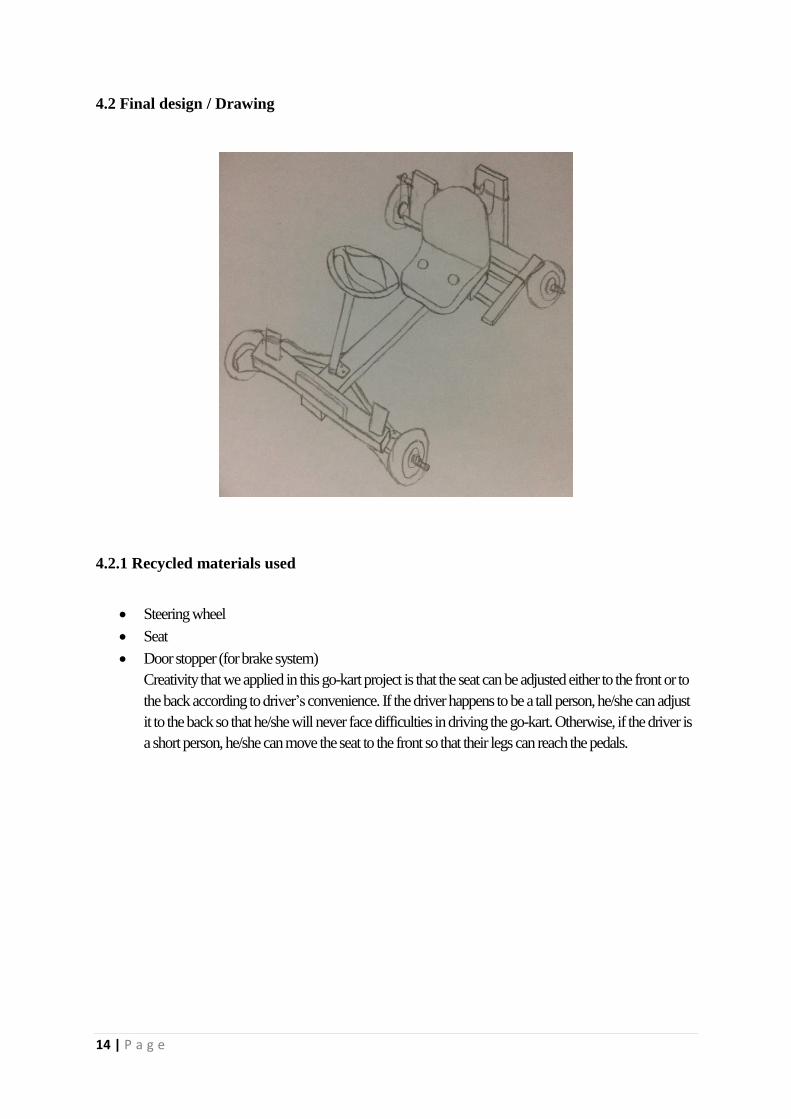
4.2 Final design / Drawing
4.2.1 Recycled materials used
Steering wheel
Seat
Door stopper (for brake system)
Creativity that we applied in this go-kart project is that the seat can be adjusted either to the front or to
the back according to driver’s convenience. If the driver happens to be a tall person, he/she can adjust
it to the back so that he/she will never face difficulties in driving the go-kart. Otherwise, if the driver is
a short person, he/she can move the seat to the front so that their legs can reach the pedals.

15 | P a g e
No Components Dimensions Quantity
1 Shaft 2
2 Steering wheel 1
3 Seat 1
4 Sprocket 2
5 Wheel 4
6 Chain 1
1. Shaft
For this project, we use two shaft which are drive shaft and also wheel shaft. The
wheel shaft is use to enable the rotation of the wheels by joint them to the wheels at both
ends. We use sprocket to transmit the rotation movement of the drive shaft which connected
to cordless drive in order to make the wheel rotate. Meanwhile, drive shaft is connected to
cordless drive to make the go-kart move.
2. Steering wheel
We use recycle steering wheel for this go-kart. Instead of using handle as a steering
wheel, we use real car steering wheel to make difference from others. The real car steering
also provide more efficiency especially in turning and cornering.
3. Seat
For seat, we also use seat from recycled material. We took this seat from recycled
places in order to cut our budget. Our seat is strong enough to support at least 75 kg driver
and also comfort enough for the driver. The biggest advantage of our seat is that the driver
able to move the seat front and backward depending on the driver’s comfort.
4. Sprocket
We use two sprockets in this project. Small sprocket is located and joint with the drive
shaft and the other one which is larger than the first one is located and joint with the wheel
shaft. The function of these two sprockets is to transmit the rotation power of the cordless to
the wheels with the help of chain.
5. Chain
Instead of using motorcycle chain which many of others contenders used, we used
bicycle chain. We had a bit of difficulties when it comes to this part. This is because, our
bicycle chain did not really fit in with those two sprocket. The chain is a little bit lose when
we try to fit in with the sprockets. To solve this problem, we adjusted the position of the
pillow block of the drive shaft to make this chain more tense.

16 | P a g e
4.3 Process involved
No Process Machine/tool Part produced Description
1 Lathing Lathe machine Shaft, fork handle To decrease the diameter
of the materials
2 Hand saw
Main chasis, rear sash, pillow
block support, front sash, front
guard
To cut the materials
based on the
measurement
3 Welding Dropped axial, clamping
control, headset, handle To assemble the parts
4 Milling
Dropped axial, arm control,
clamping control, headset,
handle
To make holes at the
body of parts (iron)
5 Drilling Drill Cordless support, pillow block
support, front sash
To make holes at the
body of parts (woods)
1. Lathing Process
Two shaft and one fork handle were produced by using llathe machine. The
measurement of shaft and fork handle is __ mm and 22 mm (diameter).
Lathing process

17 | P a g e
2. Hand Saw Tools
Main chasis, rear sash, pillow block support, front sash and front guard were produced
by using the hand saw to produce the exact measurement. The measurements for each
materials are 985mm (length),676mm (length), 280mm (length), 600mm (length) and
341mm (length).
3. Welding Process
Welding process is to joint the parts of dropped axial, clamping control, headset and
handle.
Cutting Process using Hand Saw Tool
Welding Process

18 | P a g e
4. Milling Process
Milling process is to make holes at the parts of dropped axial, arm control, clamping
control, headset and handle. The diameter of the holes are 6mm and 8mm.
5. Drilling Process
Drilling is process to make holes at parts of cordless support, pillow block support
and front sash. It usually use to drill holes at the woods. The diameter of the holes is
8mm.
Milling Process
Drilling Process

19 | P a g e
4.3.1 Steering System
Steering wheel Handle extensions
Headset Bicycle fork set
bearing
Assembly of
parts

20 | P a g e

21 | P a g e
4.4 Discussion
We have discussed about the safety of the go-kart that we need to consider while designing any parts
of the body so that we are able to produce a good quality product. Furthermore, any failure after being
evaluated could be avoided. The go-kart is an affordable product because mostly, we used materials that can
be recycled in order to make it environment-free and also to fit our budget but we confirm that it is in high and
good quality as we also made consideration in choosing the materials. Apart form that, our product is made of
steels as the support parts so that it has a broad range of long span while the other parts are made of good
quality wood materials or otherwise, if it is not in a good condition, it will easily crack or decay that will lead to
dangerous and risky product.
Why we choose this design? This is because it requires minimal framework to construct it and it
would save much time. Next, we could construct a stable product as we were not making it complex design
that needs us to put so much ideas to produce a complicated project. It is just a simple but nice go-kart project.
This project does not have to use fuel to accelerate it. To accelerate it, we use a cordless tool instead and it is
connected through sprocket and chain system to the rear wheels. The design is easy to construct and it has
safety features, it is more economical and also environmental friendly. The option that we discussed was either
to use a T-shaped handle or a steering as the control part. So, we decided to use a steering wheel because it is
effortless.
In conclusion, we have successfully produced an ideal go-kart that is suitable to everyone. The
product used up many recycled materials such as the steering wheel and the seat. Everyone also learnt about
the machines involved in making this project.

22 | P a g e
CONCLUSION AND RECOMMENDATION
We are able to build a go-kart with our engineering knowledge. We are also able to
use grinder, drilling machine hole, threading machine, welding and many more. Besides, we
also learnt how to organize task efficiently without procrastination. In addition, we produced
a creative idea with our new breaking system. Furthermore, we areable to solve and deal with
real situation of mechanical problem. Next, we have been taught to acknowledge the
mechanical industry working circumstances. We could improve our skills of working as a
teammate and also, sharpen the practical skills. Our recommendation is, after every
difficulties that we have faced while making this project, we hope that it will give us a good
result aside from the experiences that we got.

23 | P a g e
REFERENCES
http://www.monash.edu.au/lls/llonline/writing/engineering/technical-report/index.xml
https://www.scribd.com/mobile/doc/210560529/GO-KART-Design-Report-pdf
http://www.ijamejournals.com/pdf/rps161152.pdf