
ANTENNA THEORY DAN DESIGN - My ePortfolio@UTM
41
ANTENNA THEORY DAN DESIGN ASSIGNMENT 1 LECTURER NAME: DR RIJAL GROUP MEMBER: FURSAN BIN AZMAN AZRUL FAZLI BIN ZAINUDDIN
-
Upload
khangminh22 -
Category
Documents
-
view
2 -
download
0
Transcript of ANTENNA THEORY DAN DESIGN - My ePortfolio@UTM

ANTENNA THEORY DAN DESIGN
ASSIGNMENT 1
LECTURER NAME:
DR RIJAL
GROUP MEMBER:
FURSAN BIN AZMAN
AZRUL FAZLI BIN ZAINUDDIN
OBJECTIVES
Provide an understanding of the basic principles of Antennas and radiation.
Provide an overview of the fundamental characteristics and parameters of antennas

MONOPOLE ANTENNA

DESIGN USING CST SOFTWARE
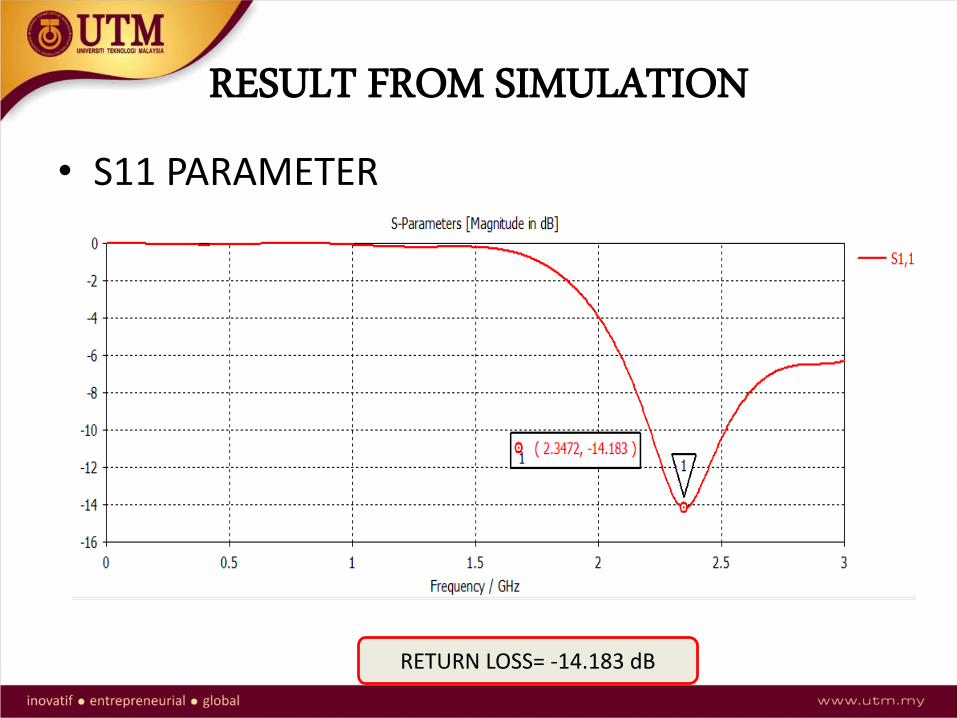
RESULT FROM SIMULATION
• S11 PARAMETER
RETURN LOSS= -14.183 dB

CONTINUED…
• Gain
GAIN=3.541dB

CONTINUED…
• E-FIELD

CONTINUED…
• H-FIELD
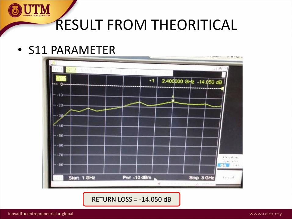
RESULT FROM THEORITICAL
• S11 PARAMETER
RETURN LOSS = -14.050 dB

CONTINUED…
• H-FIELD

CONTINUED…
• E-FIELD
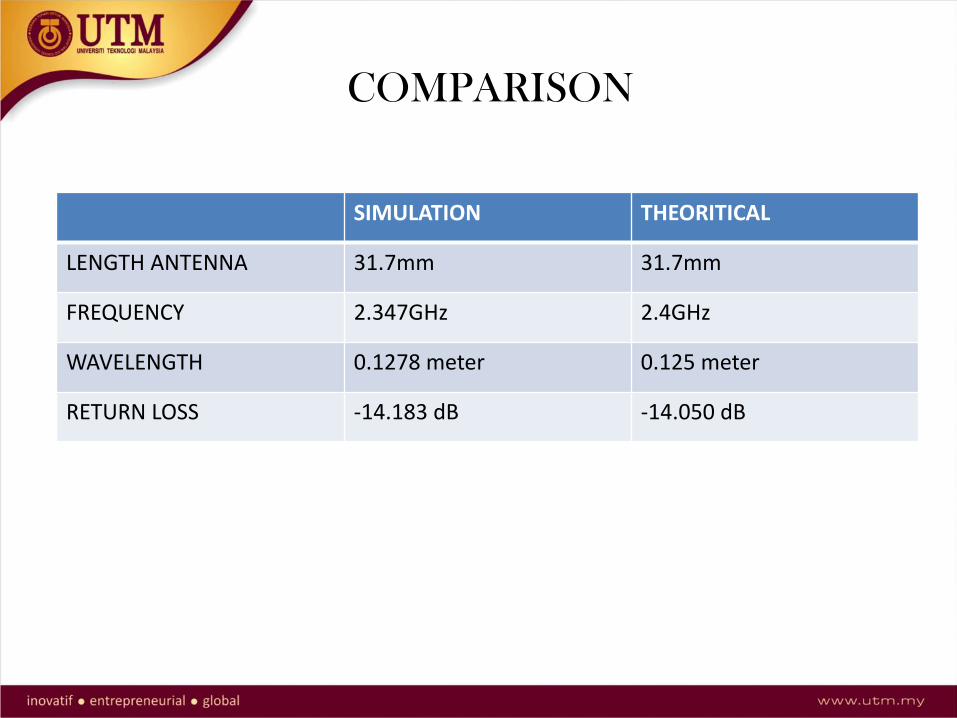
COMPARISON
SIMULATION THEORITICAL
LENGTH ANTENNA 31.7mm 31.7mm
FREQUENCY 2.347GHz 2.4GHz
WAVELENGTH 0.1278 meter 0.125 meter
RETURN LOSS -14.183 dB -14.050 dB

DISCUSSION
• Practical length and radius of antenna not accurate with the simulation design.
• Human error such as measurement process.
• Contribute the different environmental effect and equipment error.
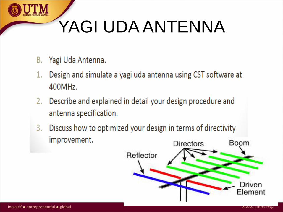
YAGI UDA ANTENNA

• By using 400 MHz frequency and we using material copper for the antenna
• and using formula λ = 𝑐/𝑓
• We get λ = 0.75 𝑚 then λ
2= 0.375 𝑚
• Dipole length = λ
2= 0.375 m
• Reflector length = λ
2+ 0.05(
λ
2)
• Reflector = 0.394 m
• Meanwhile director length = λ
2− 0.05(
λ
2) = 0.356 m
• The distance for dipole – reflector is 0.2 λ = 0.15 m• The distance for dipole – director is 0.125 λ = 0.09375• Formula from www.youtube.com/watch?v=7Dy8j5XnF6o

Yagi Udadesign
0.15m0.093m
0.394m
0.375m
0.356m

Simulation – s parameter

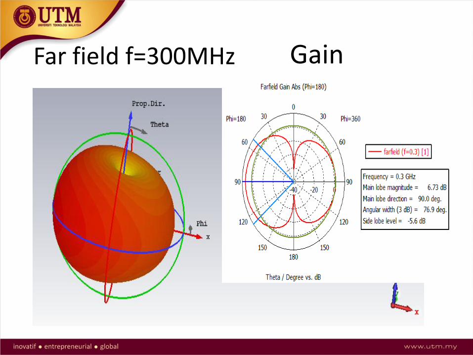
Far field f=300MHz Gain

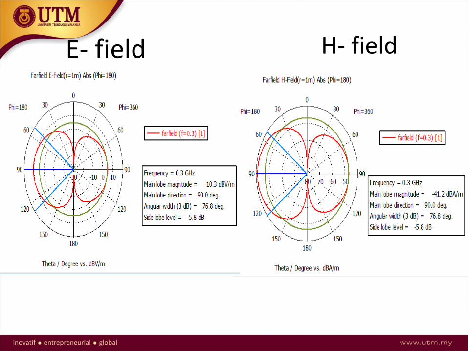
H- fieldE- field
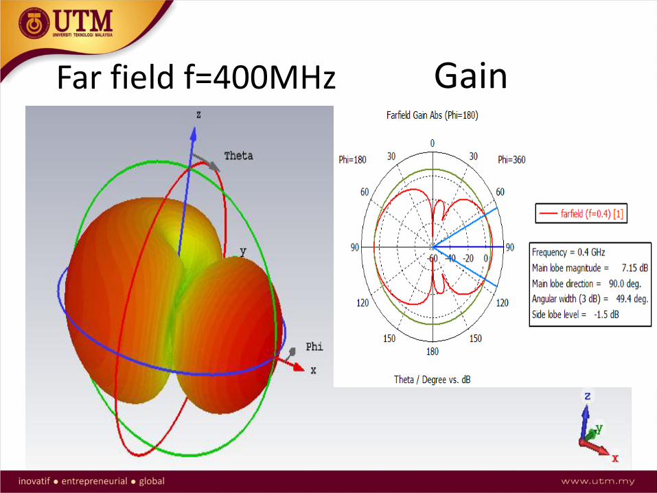
Far field f=400MHz Gain
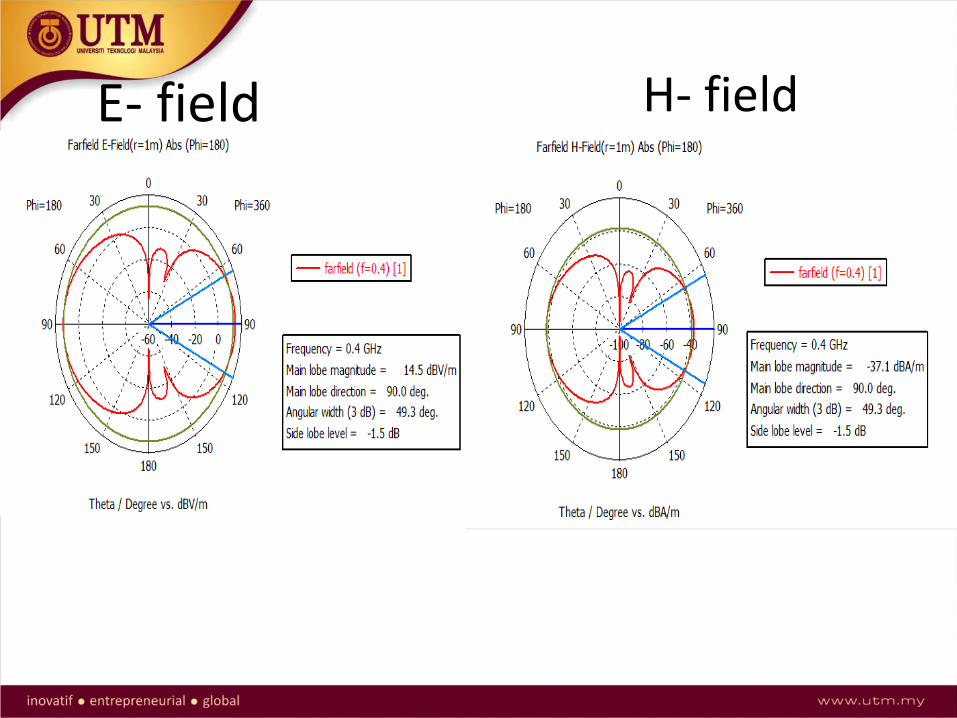
H- fieldE- field
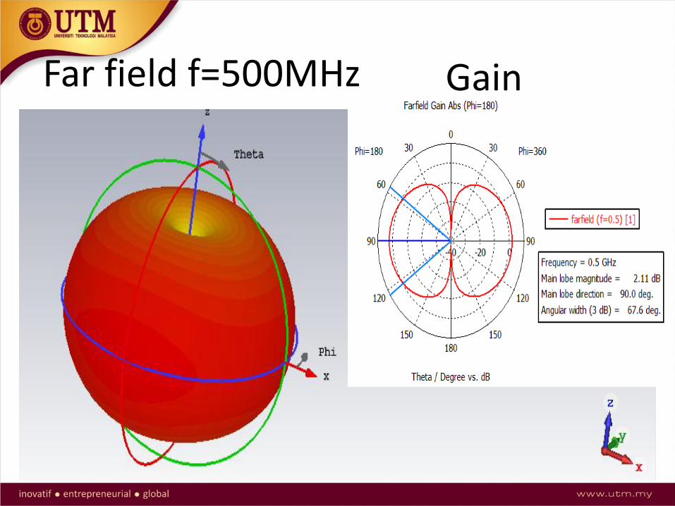
Far field f=500MHz Gain

H- fieldE- field
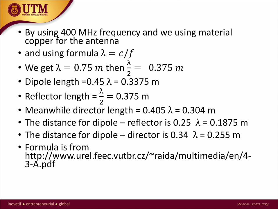
• By using 400 MHz frequency and we using material copper for the antenna
• and using formula λ = 𝑐/𝑓
• We get λ = 0.75 𝑚 then λ
2= 0.375 𝑚
• Dipole length =0.45 λ = 0.3375 m
• Reflector length = λ
2= 0.375 m
• Meanwhile director length = 0.405 λ = 0.304 m• The distance for dipole – reflector is 0.25 λ = 0.1875 m• The distance for dipole – director is 0.34 λ = 0.255 m• Formula is from
http://www.urel.feec.vutbr.cz/~raida/multimedia/en/4-3-A.pdf


Yagi Udadesign
0.1875 m
0.255 m
0.375 m
0.3375 m
0.304 m

Simulation – s parameter
Far field f=300MHz Gain
H- fieldE- field
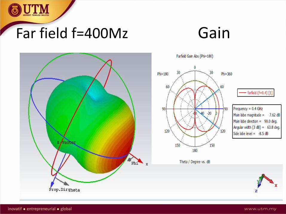
Far field f=400Mz Gain
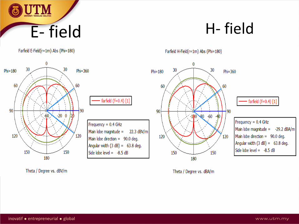
H- fieldE- field

Far field f=500MHz Gain

H- fieldE- field
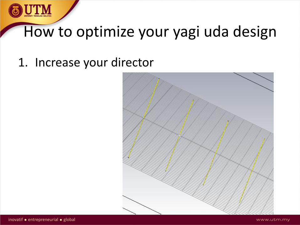
How to optimize your yagi uda design
1. Increase your director
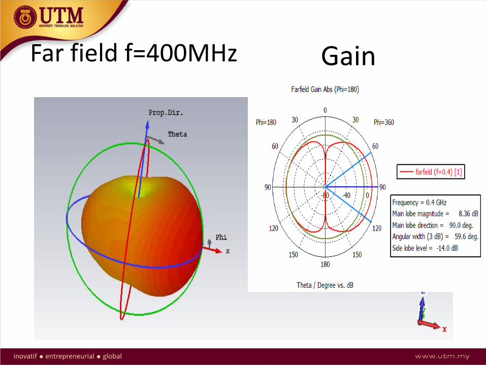
Far field f=400MHz Gain
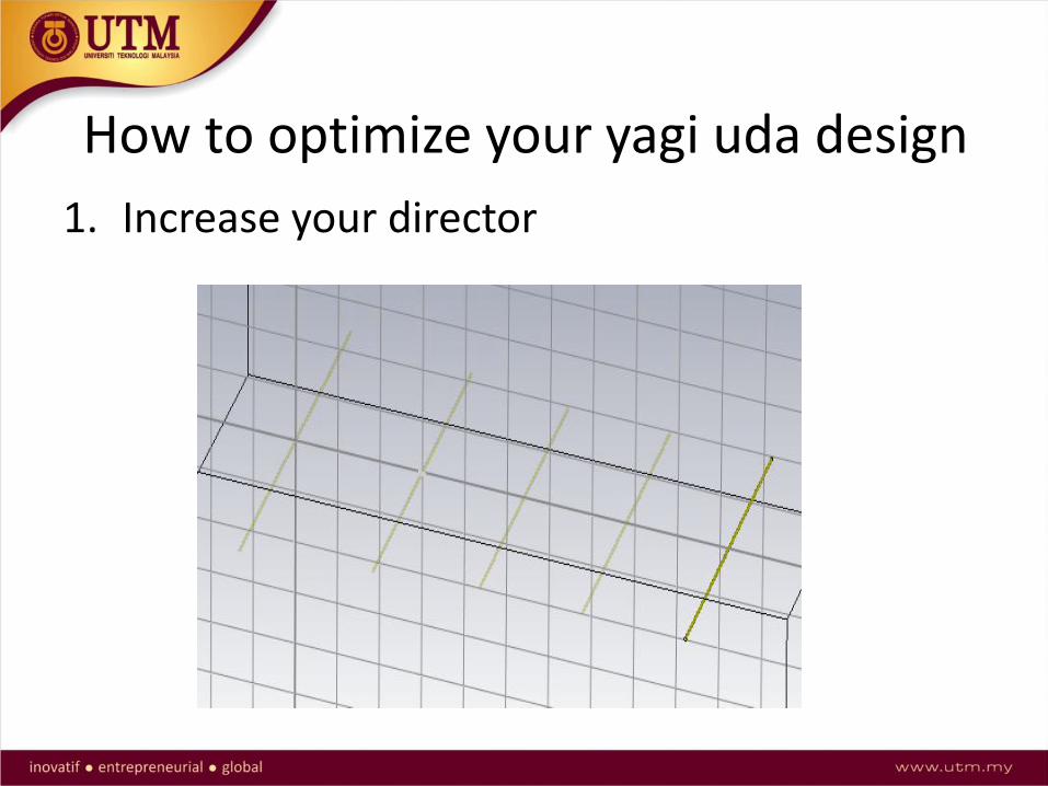
How to optimize your yagi uda design
1. Increase your director

Far field f=400MHz Gain

No of direct
or
Length(mm)
Boom Position
(mm)
Gain(dB)
1 152 270 7.62
2 152 390 8.36
3 152 510 9.05
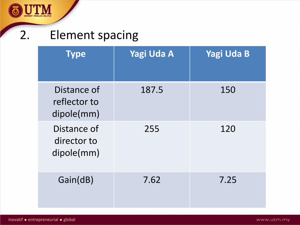
2. Element spacing
Type Yagi Uda A Yagi Uda B
Distance of reflector to dipole(mm)
187.5 150
Distance of director to
dipole(mm)
255 120
Gain(dB) 7.62 7.25
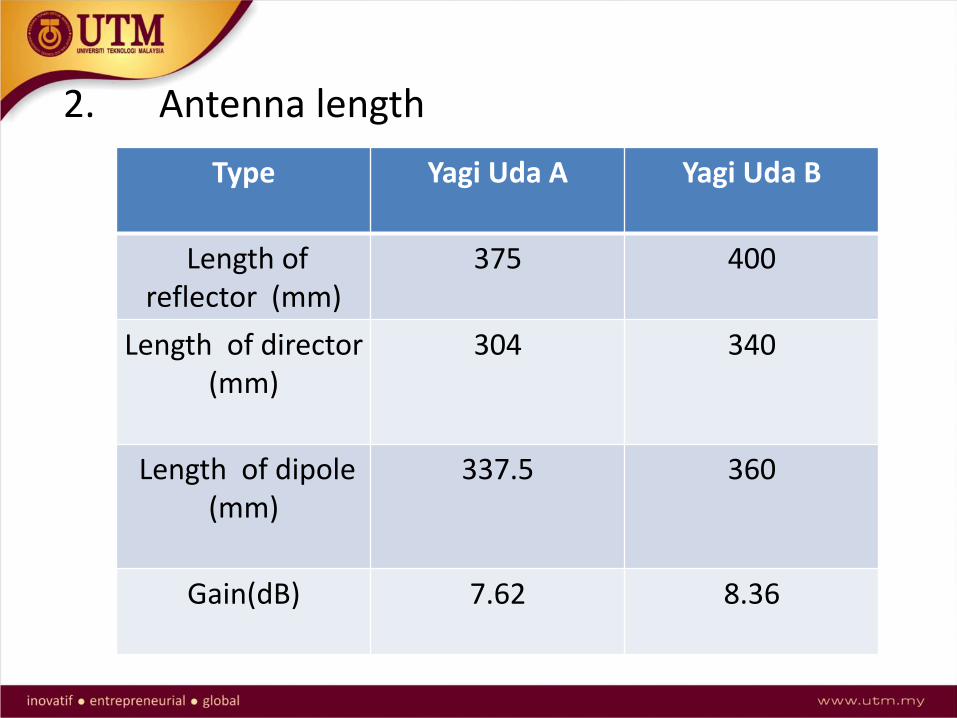
2. Antenna length
Type Yagi Uda A Yagi Uda B
Length of reflector (mm)
375 400
Length of director(mm)
304 340
Length of dipole(mm)
337.5 360
Gain(dB) 7.62 8.36

THANK YOU..