Operation Manual - UTM-100 - MRC
20
PLEASE READ THIS MANUAL CAREFULLY BEFORE OPERATION 3, Hagavish st. Israel 58817 Tel: 972 3 5595252, Fax: 972 3 5594529 [email protected] MRC.6.20 O O p p e e r r a a t t i i o o n n M M a a n n u u a a l l UTM-100 Single Column Electronic Tensile Testing Machine with Touch Controller
-
Upload
khangminh22 -
Category
Documents
-
view
2 -
download
0
Transcript of Operation Manual - UTM-100 - MRC

PLEASE READ THIS MANUAL CAREFULLY BEFORE OPERATION
3, Hagavish st. Israel 58817 Tel: 972 3 5595252, Fax: 972 3 5594529 [email protected]
MRC.6.20
OOppeerraattiioonn MMaannuuaall
UTM-100 Single Column Electronic Tensile Testing Machine with Touch Controller
1
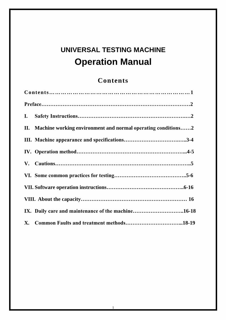
UNIVERSAL TESTING MACHINE
Operation Manual
Contents
Contents……………………………………………………………… 1
Preface…………………………………………………………………………2
I. Safety Instructions…………………………………………………….…2
II. Machine working environment and normal operating conditions……2
III. Machine appearance and specifications………………………….…..3-4
IV. Operation method……………………………………………………...4-5
V. Cautions…………………………………………………………………..5
VI. Some common practices for testing…………………………………..5-6
VII. Software operation instructions……………………………………..6-16
VIII. About the capacity…………………………………………………… 16
IX. Daily care and maintenance of the machine………………………..16-18
X. Common Faults and treatment methods…………………………...18-19

2
Preface Dear Customers:
Thank you for choosing our products, in order to help you fully appreciate and protect your
machine, we recommend that you first use, please carefully read and understand this manual,
we provide customers with one year warranty and perfect after-sale services. If in the course,
you find any problems, please contact us.
Again thank you for your trust and loyal support!
I. Safety Instructions
Please read this manual before starting this machine, allowing you to use the machine's
functions, and have a complete understanding of precautions in order to avoid
unnecessary human failure.
1. Please read this manual before starting this machine.
2. Please open the package after detailed examination of the machine there is no
transportation damage before using.
3. Users should follow the instructions provided by test method to test operation.
4. Users should be to performing operations within the parameters of the machines.
5. Any operator or other personnel due to improper operation, thus causing damage to the
machine, our company will not assume any responsibility.
6. Any operator or other personnel due to improper operation and result in personal injury,
our company will not assume any responsibility.
7. Machine after installation or long-term disabled, before power is applied, check the
insulation resistance. Machine safety ground, the control system of the contacts must
be good contact.
8. The machine fails during the warranty period, the user should immediately contact
with our company in order to obtain our products, maintenance and technical support.
II. Machine working environment and normal operating conditions
1. Working environment temperature: Within 20±15℃.
2. Working environment humidity: Within 10% to 85%, without condensation.
3. This machine should be installed on a firm, level ground, the installation level degree
should be better than 2mm/1000mm, and should be left around the space of not less
than 0.7m.
4. Indoor working environment should be kept clean, dry, and free of vibration and
corrosive gases.
5. Working environment Power supply voltage does not exceed the rated voltage of the
machine ± 10% (To ensure that your machine can be used normally and extend the
service life of the machine, we recommend that you install the power supply before using
machine).
6. Do not install the machine in the presence of a magnetic field of the environment.

3
III. Machine appearance and specifications
1. Appearance of machine :
(1) Front View

4
(2) Rear View
Note: The pictures of machine is for reference only.
2. Specifications
A. Capacity: This machine maximum test capacity is 100kgf.
B. Equipped with: testing software
C. Test force resolution: 1/100,000
D. Test force accuracy: better than ±01%.
E. Test speed: 0.5~ 500 mm/min.
F. Test stroke: 1,000 mm (not include griper).
G. Test Width: front and back 120 mm,right and left ∝
H. Weight: about 70 kg.
I. Dimensions: 750*620*1400mm (W*D*H)
J. Power: 1Ø, AC220V, 50/60HZ, 10A
IV. Operation method (Standard Operating Procedure)
↓A. Connect the power and turn on, preparing specimens.
↓B. Adjust the upper and lower griper distance and put the setting ring of upper and
lower limit switch at appropriate position (first use).
↓C. Click the Test key (Test) of software to start test.
↓D. Finish the test and record test results.
↓E. Set back griper to start position.
↓F. Execute the second test.
1. Plug the power cord on power input socket which at the rear of the machine base, and
connect to single-phase AC200 ~ 240V / 50 ~ 60Hz power source outlet, press the
power switch on.
2. Upper and lower gripers properly installed and adjust the upper and lower limits of the
safety switch setting ring, press UP or DOWN button to test the machine automatically
stop the return position and the upper and lower gripers are positioned at the
Sensor Interface
Fuse Holder
PC Connection Port
Power Interface

5
appropriate distance in order to prevent crashing machine when griper rise or fall.
Note: Upper and lower limit setting ring after setting completed, please tighten.
3. The specimen clamps on gripers. Specimen clamping process can not produce tension
to affect the test results.
4. Input the parameters of the test object (number, size, gauge, etc.) and setting
parameters of the test (Test methods, test speed, keeping force, stop percentage, access
points and units etc.).
5. Press “Test” key to start test.
6. Specimen broken or damaged the machine will automatically stop; the software will
record data and curve then output report to save.
7. The gripers back position, to executing second test.
V. Cautions
1. Set upper and lower limits of the safety switch ring, because the gripers are different,
the upper and lower limits of the safety distance adjustment are also different.
2. Operating the machine, the operators do not leave, and pay attention to upper and
lower gripers can not crash.
3. The load cell of this machine is 100 kgf, please do not over load to use.
4. This product is a precision instrument prohibits placed in dusty or high humidity areas.
5. Replace the operator when appropriate handover operation methods and precautions.
6. Load cell or machine damage due to improper operation caused by man-made, must be
made by the user (buyer) is responsible.
Warning: The load cell is not covered under warranty.
7. According to statistics: the instrument fails to function often users do not know how to
operate caused.
Recommendation: When the operator was replaced, must be put the use methods and
operating instructions included in the major transfer projects.
VI. Some common practices for testing
1. Different specimens of the test speed, clamp method, test method ... etc will be
different, should be based on CNS, JIS, ASTM, ISO ... or other standards require to
adjustment, and not within the standard specimen or a new product can be standard by
customize or according to the agreed between both of the parties.
2. The formula:
☆Peel strength: F
The maximum force values during the sample pull off the course or when
sample pull off the destructive force value.
☆Compressive Strength: F
The maximum strength values during the sample compressive process or when
sample compressive the destructive strength value.
☆Stress (pressure): P
The force per unit area P=F/A
F: Test force A: Sample Size
6
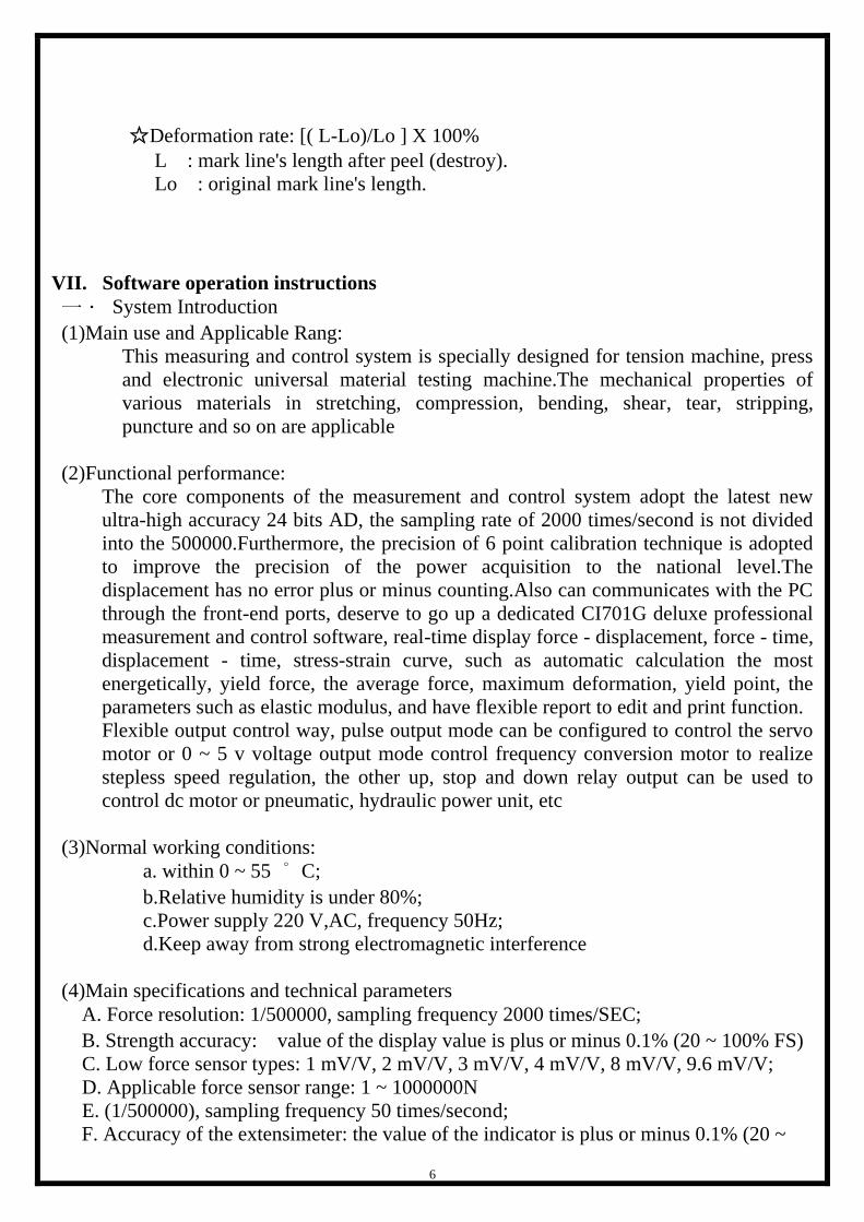
☆Deformation rate: [( L-Lo)/Lo ] X 100%
L : mark line's length after peel (destroy).
Lo : original mark line's length.
VII. Software operation instructions
一. System Introduction
(1)Main use and Applicable Rang:
This measuring and control system is specially designed for tension machine, press
and electronic universal material testing machine.The mechanical properties of
various materials in stretching, compression, bending, shear, tear, stripping,
puncture and so on are applicable
(2)Functional performance:
The core components of the measurement and control system adopt the latest new
ultra-high accuracy 24 bits AD, the sampling rate of 2000 times/second is not divided
into the 500000.Furthermore, the precision of 6 point calibration technique is adopted
to improve the precision of the power acquisition to the national level.The
displacement has no error plus or minus counting.Also can communicates with the PC
through the front-end ports, deserve to go up a dedicated CI701G deluxe professional
measurement and control software, real-time display force - displacement, force - time,
displacement - time, stress-strain curve, such as automatic calculation the most
energetically, yield force, the average force, maximum deformation, yield point, the
parameters such as elastic modulus, and have flexible report to edit and print function.
Flexible output control way, pulse output mode can be configured to control the servo
motor or 0 ~ 5 v voltage output mode control frequency conversion motor to realize
stepless speed regulation, the other up, stop and down relay output can be used to
control dc motor or pneumatic, hydraulic power unit, etc
(3)Normal working conditions:
a. within 0 ~ 55 ° C;
b.Relative humidity is under 80%;
c.Power supply 220 V,AC, frequency 50Hz;
d.Keep away from strong electromagnetic interference
(4)Main specifications and technical parameters
A. Force resolution: 1/500000, sampling frequency 2000 times/SEC;
B. Strength accuracy: value of the display value is plus or minus 0.1% (20 ~ 100% FS)
C. Low force sensor types: 1 mV/V, 2 mV/V, 3 mV/V, 4 mV/V, 8 mV/V, 9.6 mV/V;
D. Applicable force sensor range: 1 ~ 1000000N
E. (1/500000), sampling frequency 50 times/second;
F. Accuracy of the extensimeter: the value of the indicator is plus or minus 0.1% (20 ~

7
100% FS);
G. Displacement resolution: the mechanical system and the photoelectric encoder are
determined to reach 0.001 mm;
H. Accuracy of displacement measurement: error of instrument system
I. Test speed: 5mm/min ~ 500mm/min;
J. Speed accuracy: the value of the display is less than 1%;
K. Four force channels;
L. A displacement channel;
M. The output control of the output control of variable frequency motor is controlled by 0
~ 5V voltage output.
N. The pulse output mode control servo motor stepless speed regulation;O.Power: K.
GF/N/LBF;Displacement: mm/cm/in;
P. Automatic homing function;
Q. A variety of test methods including load weight and location shift
二.Operation guide
1. CI701G software installation:
To use this software for the first time on a computer that does not use the software, you
will need to install the software driver first. The software installation process is as
follows:
(1) If Windows is running other programs, close all applications.
(2) Double-click "Driver 2012 or Driver USB to RS232 CH340" folder, which shows the
following figure:
(3)Double click "driver2012_en.exe", install the installation program, start installation,
appear welcome screen, as shown below

8
(4)Click "Next > " button to enter the picture below
(5)Click "Next > " button to enter the picture below

9
(6)Go on and click on the “Install” button to start the installation process, it may take a few
minutes, please wait patiently until you enter the image below shown in the picture:
(7)Click the "Finish" button and the computer will automatically restart the installation
(8)Click “yes” to restart the computer
(9)Completion of software installation

10
(10)If in doubt, double-click “Driver Install Guide”
2. IP address setting

11

12
3.CI701G Software Operation
(1) Double click open CI701G software and enter test interface directly.
Choose the language into “English”, as below:

13
(2)Click on the “Setting” on the top of the software

14
(3)Click “calibratation ” “Calibration Other”
(4)Input password: 888888

15
(5)Click “Read From Chip” on the bottom right
(6) Click “OK” , exit interface

16
(7)Select the corresponding test methods for testing
(8)After the test is completed, click the to output testing report.
VIII. About the capacity
1. Use Capacity: Generally made based on a maximum strength value and minimum
strength value of variety test object as purchase reference, at this time you should
consider the machine model, capacity is applicable, not a test function can complete all
tests, you must consider about the measuring range problem. For example: some
manufacturers of products after testing the strength values may range from 2-500kgf,
in which case you must use two different capacity testing machine.
2. Capacity Range: The use of force sensors ranging from 1% to 90%. For example, the
capacity to 500kgf force sensor range is 5-450kgf. Less than 1% will have insufficient
resolution, higher than 90% may cause damage to force sensor.
IX. Daily care and maintenance of the machine
1. Foreword:
Our company designed and manufactured in the universal testing machine at the

17
beginning of design already take into account the cost of maintenance, so this
universal material testing machine designed as a low maintenance requirements of the
type, the operator need not be any special maintenance tools, that is able to complete
the machine routine maintenance work.
2. Machine Maintenance:
(1) Shell:
This machine has been carefully senior external sheet metal paint handling, so just
wipe with a dry cloth to remove dust, if not used for a long time, and please cover
to cover.
(2) Structure:
The structure of this machine is sheet metal and dust obscured, the state in general
use no maintenance required. Machine screw, nut, and please lubricant once every
six months.
(3) Gripers:
Gripers are attached to the machine already after plating, the state in general use
only with a dry cloth to remove dust, if not used for a long time with a clean cotton
cloth stained with a little rust oil wipe the surface of the gripers.
(4) Non-baking part of machine:
This machine non-baking part are copper, stainless steel, or by plating, not rust, it is
in general use state only with a dry cloth to remove dust, if not used for a long time
with a clean cotton stained with a little rust oil wipe the surface of non-baking part
of the machine.
3. Methods for cleaning up:
In order to ensure the appearance of the machine clean, periodically use a soft cloth to
clean the machine. For stubborn stains can be relatively soft cloth dipped in a mild
detergent to remove. Do not use strong cleaning agents such as benzene, acetone,
thinners or abrasive cleaners to avoid damage to the shell. To be safe, the best place in
the power off the machine before cleaning.
4. Maintenance Considerations:
(1) The machine's working environment and conditions shall be in full compliance
with the requirements, including temperature, relative humidity, supply voltage, the
installed base (around general requirements no vibration, no corrosive media, no
strong electromagnetic interference), while some also have special machines for the
environment requirements, should be strictly in accordance with the instruction
manual for maintenance and repair.
(2) Before and after use should be kept clean and avoid collisions.
(3) If the long-term without the use of the machine, should be regularly plug boot.
(4) Shall have a dedicated staff responsible for the machine, when the test should be
strictly in accordance with the operating rules and procedures, the machine is

18
strictly prohibited beyond the scope of testing, after the test should make the
machine back to the initial position to ensure that the next test correctly.
(5) The machine should be regularly cleaned and inspection, for the calibration of the
machine must be regularly calibrated to ensure accuracy of the instrument.
(6) When the machine is not in use, it should take appropriate protective measures, if
not been used for a long time, but once again it should be re-inspection using before
use.
(7) About calibration:
Periodic calibration: Average calibration cycle is one year.
Temporary Calibration: User found in the use, or quality management unit is found
on examination when the machine is not accurate, you should calibrate
immediately.
X. Common Faults and treatment methods
When a failure or abnormal operation occurs, please refer to the item "Troubleshooting"
to identify the cause and treatment. When the fault does not meet any of the following
items or serious failure, damaged parts, please contact us.
1. Question: No power after turning the power supply?
(1) Please check whether the power plug securely into the socket, or loose. If loose
please sure to connect.
(2) Check the emergency stop button is turned on, if it is in a depressed state, please set
it open.
(3) Check the outlet voltage is normal, if not normal, please change outlet.
(4) Check that the power switch is able to operate normally, if not normal, please
notify our company.
(5) Check the fuse behind the machine is damaged, if damaged; please replace the
original specifications of the new fuse.
(6) If everything is normal but still no power supply, please inform our company.
2. Question: When the machine operation will have abnormal vibration and noise?
(1) Please check the machine four feet if the average exposure pedestal, if not, please
adjust the feet so that the average of the four contacts.
(2) Check the power supply voltage is normal and stable, if not; replace a stable and
normal power supply.
(3) Check the machine for loose screws ministries, such as loose, insert the screws and
tighten.
(4) If everything is normal but still have abnormal vibration and noise, please inform
our company.
3. Question: The test data anomalies?
(1) Make sure the "specimen" is indeed gripping, if not, be sure grip.

19
(2) Please check the "force sensor" and "Decoder" settings are correct, if not, please
refer to the operating instructions, setup is complete.
(3) Please gently touch "force sensor" before test began and observe whether the force
display value of CI701G software have any change, if not, then the "force sensor"
may have been damaged and needs to replaced new sensor. Please contact our
company to check or replace.