Getting Started with the Device GUI on UTM Firewalls
75
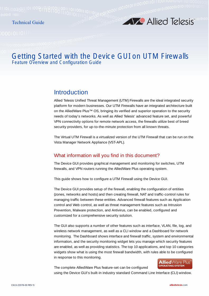
C613-22078-00 REV S alliedtelesis.com Feature Overview and Configuration Guide Technical Guide Introduction Allied Telesis Unified Threat Management (UTM) Firewalls are the ideal integrated security platform for modern businesses. Our UTM Firewalls have an integrated architecture built on the AlliedWare Plus™ OS, bringing its verified and superior operation to the security needs of today's networks. As well as Allied Telesis' advanced feature set, and powerful VPN connectivity options for remote network access, the firewalls utilize best of breed security providers, for up-to-the-minute protection from all known threats. The Virtual UTM Firewall is a virtualized version of the UTM Firewall that can be run on the Vista Manager Network Appliance (VST-APL). What information will you find in this document? The Device GUI provides graphical management and monitoring for switches, UTM firewalls, and VPN routers running the AlliedWare Plus operating system. This guide shows how to configure a UTM Firewall using the Device GUI. The Device GUI provides setup of the firewall, enabling the configuration of entities (zones, networks and hosts) and then creating firewall, NAT and traffic-control rules for managing traffic between these entities. Advanced firewall features such as Application control and Web control, as well as threat management features such as Intrusion Prevention, Malware protection, and Antivirus, can be enabled, configured and customized for a comprehensive security solution. The GUI also supports a number of other features such as interface, VLAN, file, log, and wireless network management, as well as a CLI window and a Dashboard for network monitoring. The Dashboard shows interface and firewall traffic, system and environmental information, and the security monitoring widget lets you manage which security features are enabled, as well as providing statistics. The top 10 applications, and top 10 categories widgets show what is using the most firewall bandwidth, with rules able to be configured in response to this monitoring. The complete AlliedWare Plus feature-set can be configured using the Device GUI's built-in industry standard Command Line Interface (CLI) window. Getting Started with the Device GUI on UTM Firewalls
-
Upload
khangminh22 -
Category
Documents
-
view
6 -
download
0
Transcript of Getting Started with the Device GUI on UTM Firewalls
C613-2207
Feature Overview and Configuration Guide
Technical Guide
Getting Started with the Device GUI on UTM Firewalls
IntroductionAllied Telesis Unified Threat Management (UTM) Firewalls are the ideal integrated security
platform for modern businesses. Our UTM Firewalls have an integrated architecture built
on the AlliedWare Plus™ OS, bringing its verified and superior operation to the security
needs of today's networks. As well as Allied Telesis' advanced feature set, and powerful
VPN connectivity options for remote network access, the firewalls utilize best of breed
security providers, for up-to-the-minute protection from all known threats.
The Virtual UTM Firewall is a virtualized version of the UTM Firewall that can be run on the
Vista Manager Network Appliance (VST-APL).
What information will you find in this document?
The Device GUI provides graphical management and monitoring for switches, UTM
firewalls, and VPN routers running the AlliedWare Plus operating system.
This guide shows how to configure a UTM Firewall using the Device GUI.
The Device GUI provides setup of the firewall, enabling the configuration of entities
(zones, networks and hosts) and then creating firewall, NAT and traffic-control rules for
managing traffic between these entities. Advanced firewall features such as Application
control and Web control, as well as threat management features such as Intrusion
Prevention, Malware protection, and Antivirus, can be enabled, configured and
customized for a comprehensive security solution.
The GUI also supports a number of other features such as interface, VLAN, file, log, and
wireless network management, as well as a CLI window and a Dashboard for network
monitoring. The Dashboard shows interface and firewall traffic, system and environmental
information, and the security monitoring widget lets you manage which security features
are enabled, as well as providing statistics. The top 10 applications, and top 10 categories
widgets show what is using the most firewall bandwidth, with rules able to be configured
in response to this monitoring.
The complete AlliedWare Plus feature-set can be configured
using the Device GUI's built-in industry standard Command Line Interface (CLI) window.
8-00 REV S alliedtelesis.com

ContentsIntroduction .........................................................................................................................................1
What information will you find in this document?.........................................................................1
Products and software version that apply to this guide ...............................................................3
Related documents.......................................................................................................................3
Virtual UTM Firewall documents ...................................................................................................4
Using the wizard to configure Internet and VPN connections ............................................................5
Setup an Internet connection .......................................................................................................5
Configuring a VPN connection ...................................................................................................15
What is a firewall? .............................................................................................................................18
What are entities?..............................................................................................................................18
Zones, networks, and hosts .......................................................................................................19
Using rules.........................................................................................................................................20
Configuring the firewall......................................................................................................................21
Part 1: Configure a standard 3-zone network.............................................................................21
Part 2: Configure the firewall for Update Manager .....................................................................37
Part 3: Configure free security features ......................................................................................40
Part 4: Configure licensed firewall security features...................................................................44
Part 5: Configure licensed Advanced Threat Protection (ATP) security features........................51
Updating the GUI ..............................................................................................................................56
Using the CLI to update the GUI version....................................................................................56
Using the GUI to update the GUI version ...................................................................................56
The Dashboard..................................................................................................................................58
The network map ..............................................................................................................................63
The network map features ..........................................................................................................63
Viewing node information ...........................................................................................................64
Configuring the topology view ....................................................................................................64
Customizing network node icon images.....................................................................................65
Access to device GUI by clicking on device icon.......................................................................66
Wireless management .......................................................................................................................67
Other features....................................................................................................................................68
File management ........................................................................................................................69
License management..................................................................................................................70
Logging management .................................................................................................................72
AMF Security mini on the AR4050S Series ................................................................................75
C613-22078-00 REV S Introduction | Page 2

Products and software version that apply to this guide
This guide applies to all AR-Series UTM Firewalls running version 5.4.7-x.x or 5.4.8-x.x or later.
Supported models include the AR3050S and AR4050S.
In addition, it also applies to the Virtual UTM Firewall, running version 5.5.1-2.x or later. This is
supported running on the Vista Manager Network Appliance (VST-APL).
Feature support may change in later software versions. For the latest information, see the following
documents:
The product’s Datasheet
The AlliedWare Plus Datasheet
The product’s Command Reference
These documents are available from the above links on our website at alliedtelesis.com.
Related documents
You also may find the following AlliedWare Plus Feature Overviews useful:
Firewall and Network Address Translation (NAT)
Advanced Network Protection
This document describes the Advanced Network Security features on the AR4050S, and AR3050S, how to configure them, and the logging available for:
Intrusion Prevention System
Anti-virus
Malware Protection
IP Reputation
Web Control
URL Filtering
It also provides information about: choosing a firewall and features to meet the security and performance needs of your network using Unified Threat Management (UTM) Offload with the AR4050S for sharing the processing load with a second physical or virtual device.
To configure an Allied Telesis VPN Router or switch using the Device GUI see the following guides:
Getting Started with the Device GUI for VPN Routers Guide
Getting Started with the Device GUI on Switches
For detailed documentation on wireless configuration, see:
User Guide: Wireless Management (AWC) with Vista Manager mini.
C613-22078-00 REV S Introduction | Page 3

Virtual UTM Firewall documents
The following documents contain additional information about configuring the Virtual UTM Firewall
on VST-APL.
Virtual UTM Firewall Datasheet
Vista Manager Appliance (VST-APL) Installation Guide
Virtual UTM Firewall User Guide
Virtual UTM Firewall Release Note
C613-22078-00 REV S Introduction | Page 4

Using the wizard to configure Internet and VPN connectionsThis section describes how to use the wizard to setup an Internet and VPN connection.
Setup an Internet connection
Use the wizard to setup a router's WAN interface along with creating a basic configuration for a LAN.
There are three IPv4 methods available: DHCP, Fixed IP, and PPPoE, and two IP version methods
available: IPoE and V6 Transition (IPv4 over IPv6).
Once the wizard has run, the Setup Summary page displays the current configuration. You can
change other things in the GUI after having run the setup wizard, however if you choose to go back
and run the wizard again, all your previous configuration will be removed.
The configuration steps are as follows:
Step 1: Go to Wizard > Setup
Step 2: Start the Wizard
Click the Start Wizard button.
If you don't have an Internet connection configured, you'll see a blank Setup Summary screen.
If you do have an Internet connection configured, then you’ll see those details displayed in the Setup Summary screen. Click the Start Wizard button in that same screen to reconfigure your current Internet connection settings:
C613-22078-00 REV S Using the wizard to configure Internet and VPN connections | Page 5

Step 3: Choose a connection method
Select a method to connect to the Internet.
Step 4: Configure the connection method
The following section describes the configuration settings for each connection method.
Note: If you enable a DHCP server, the range of IP addresses that the DHCP server assigns to LAN-side terminals is xxx.xxx.xxx.2 to xxx.xxx.254. Therefore, if the IP address of the LAN interface is not xxx.xxx.xxx.1/24, select OFF for DHCP Server and manually configure the DHCP server from the Network Services menu after the wizard is complete.
C613-22078-00 REV S Using the wizard to configure Internet and VPN connections | Page 6

IPv4 - DHCP Connection
Configure the IPv4 DHCP connection:
IPv4 - Fixed IP Connection
Configure the IPv4 fixed IP connection:
Field Description
WAN Interface Select the interface used to connect to the Internet, for example eth1.
DNS Servers Specify the DNS server to use for name resolution.
If you want DHCP to automatically obtain a DNS server address, use the default Auto.
If fixed settings are required, click the down arrow on the right, click + Add DNS Server, and enter the IP address of the DNS server.
DHCP Server Select:
ON to operate the DHCP server function on the LAN-side interface of the device and provide IP address etc. to the LAN-side terminals.
OFF if you do not want to use the DHCP server function.
Field Description
IP Address Enter the IP address of the WAN-side interface.
Default Gateway Enter the IP address of the default gateway used to connect to the Internet.
WAN Interface Select the interface used to connect to the Internet.
DNS Servers Specify the DNS server to use for name resolution.Click the down arrow on the right, click + Add DNS Server, and enter the IP address of the DNS server.
C613-22078-00 REV S Using the wizard to configure Internet and VPN connections | Page 7

IPv4 - PPPoE Connection
Configure the IPv4 PPPoE connection:
DHCP Server Select:
ON to operate the DHCP server function on the LAN-side interface of the device and provide IP address etc. to the LAN-side terminals.
OFF if you do not want to use the DHCP server function.
Field Description
Service Name This is the PPPoE service name. You can usually leave it blank.Enter the PPPoE service name only if your Internet service provider (ISP) has specified it.
Username PPP user name. Enter the user name for the Internet connection notified by your ISP.
Password PPP password. Enter the password for the Internet connection provided by your ISP.
WAN Interface Select the interface used to connect to the Internet.
DNS Servers Specify the DNS server to use for name resolution.
If you want IPCP to automatically obtain the DNS server address when connecting to PPPoE, you can leave it as the default.
If fixed settings are required, click the down arrow on the right, click + Add DNS Server, and enter the IP address of the DNS server.
DHCP Server Select:
ON to operate the DHCP server function on the LAN-side interface of the device and provide IP address etc. to the LAN-side terminals.
OFF if you do not want to use the DHCP server function.
Field Description
C613-22078-00 REV S Using the wizard to configure Internet and VPN connections | Page 8

IPv6 - IPoE Connection
Configure the IPv6 IPoE connection. There are two tabs in this panel, SLAAC (Stateless Address
Auto-Configuration) and DHCPv6 PD (Prefix Delegation).
1. SLAAC number (RA method)
Click the drop down arrow to select the WAN interface.
Click Next.
The following confirmation panel appears:
Click Apply to continue.
2. DHCPv6 PD (Prefix Delegation)
Field Description
WAN Interface The interface used to connect to the Internet, for example eth1.
C613-22078-00 REV S Using the wizard to configure Internet and VPN connections | Page 9
Click the drop down arrow to select the WAN interface.
Enter a Prefix Name.
Click Next
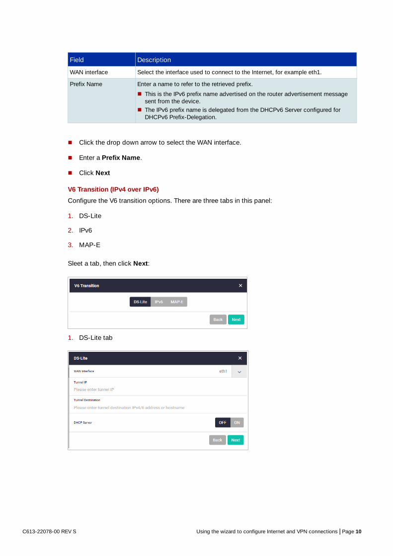
V6 Transition (IPv4 over IPv6)
Configure the V6 transition options. There are three tabs in this panel:
1. DS-Lite
2. IPv6
3. MAP-E
Sleet a tab, then click Next:
1. DS-Lite tab
Field Description
WAN interface Select the interface used to connect to the Internet, for example eth1.
Prefix Name Enter a name to refer to the retrieved prefix.
This is the IPv6 prefix name advertised on the router advertisement message sent from the device.
The IPv6 prefix name is delegated from the DHCPv6 Server configured for DHCPv6 Prefix-Delegation.
C613-22078-00 REV S Using the wizard to configure Internet and VPN connections | Page 10

2. IPv6 tab
There are two tabs here, SLAAC and DHCPv6 PD:
IPv6 - SLAAC
Configure the IPv4 connections with IPv6 IPoE connections (RA method) and IPv6 tunnels (fixed)
Field Description
WAN Interface Select the interface used to connect to the Internet.
Tunnel IP Enter the IPv4 adders for the tunnel interface.
Tunnel Destination Enter the destination address for packets sent over the tunnel.
DHCP Server Select:
ON to operate the DHCP server function on the LAN-side interface of the device and provide IP address etc. to the LAN-side terminals.
OFF if you do not want to use the DHCP server function.
C613-22078-00 REV S Using the wizard to configure Internet and VPN connections | Page 11

IPv6 - DHCPv6 PD
Configure IPv4 connections with IPv6 IPoE connections (DHCPv6 PD method) and IPv6 tunnels
(fixed).
Field Description
WAN Interface Select the interface used to connect to the Internet.
Tunnel IP Enter the address for the tunnel interface.
Tunnel Destination Enter the destination address for packets traversing the tunnel.
Suffix Enter the interface ID specified in advance by your ISP.
DDNS Server Use the dynamic DNS client feature to notify the update server of the IPv6 address updates.
DHCP Server Select:
ON to operate the DHCP server function on the LAN-side interface of the device and provide IP address etc. to the LAN-side terminals.
OFF if you do not want to use the DHCP server function
C613-22078-00 REV S Using the wizard to configure Internet and VPN connections | Page 12

3. MAP-E
Configure IPv6 IPoE and MAP-E IPv4 connections.
Field Description
WAN Interface Select the interface used to connect to the Internet.
Prefix Name Enter a name to refer to the retrieved prefix.
Tunnel IP Enter the IPv4 address that you want to configure for the tunnel interface.
Tunnel Destination Enter the end point (on-the-go device: operator router (BR)) address of the delivery packet sent from the tunnel interface.
Suffix Enter the interface ID specified in advance by your ISP.
DDNS Server Use the dynamic DNS client feature to notify the update server of IPv6 address updates.When enabled, the fields ‘DDNS update URL’, ‘DDNS user name’, and ‘DDNS password’ are displayed.
DHCP Server Select:
ON to operate the DHCP server function on the LAN-side interface of the device and provide IP address etc. to the LAN-side terminals.
OFF if you do not want to use the DHCP server function.
Field Description
WAN Interface Select the interface used to connect to the Internet, for example eth1.
Softwire Configuration Method Select the softwire method: DHCP, Proprietary, or Static
Softwire Configuration Name Enter a name to create a new soft wire configuration.
IP Phone Select:
ON to use an IP phone. When enabled, the Prefix Name field is displayed. OFF if you do not want to use the IP Phone function.
DHCP Server Select:
ON to operate the DHCP server function on the LAN-side interface of the device and provide IP address etc. to the LAN-side terminals.
OFF if you do not want to use the DHCP server function.
C613-22078-00 REV S Using the wizard to configure Internet and VPN connections | Page 13
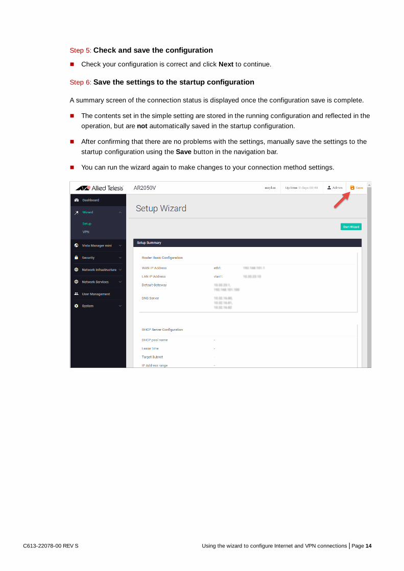
Step 5: Check and save the configuration
Check your configuration is correct and click Next to continue.
Step 6: Save the settings to the startup configuration
A summary screen of the connection status is displayed once the configuration save is complete.
The contents set in the simple setting are stored in the running configuration and reflected in the
operation, but are not automatically saved in the startup configuration.
After confirming that there are no problems with the settings, manually save the settings to the
startup configuration using the Save button in the navigation bar.
You can run the wizard again to make changes to your connection method settings.
C613-22078-00 REV S Using the wizard to configure Internet and VPN connections | Page 14

Configuring a VPN connection
To configure a secure VPN connection, first make sure you have an Internet connection, and then
use the following steps:
Step 1: Go to Wizard > VPN
Step 2: Click the Start Wizard button
If you don't have an existing VPN connection, you'll see a blank VPN Summary screen.
If you do have an existing VPN connection, then you’ll see those details displayed in the VPN
Summary screen. Click the Start Wizard button on that same screen to reconfigure your current
VPN connection settings:
Step 3: Enter the VPN connection information
C613-22078-00 REV S Using the wizard to configure Internet and VPN connections | Page 15

Step 4: Confirm VPN tunnel connection
Step 5: Review and save your settings
Check your configuration is correct and click Apply to continue.
If you click Save with a VPN connection already set up, the existing settings on the running
configuration will be erased and replaced with the newly configured content.
Step 6: Save the settings to the startup configuration
When the configuration save is complete, a summary screen of the connection status is displayed.
The contents set in the simple setting are stored in the running configuration and reflected in the
operation, but are not automatically saved in the startup configuration.
After confirming that there are no problems with the settings, manually save the settings to the
startup configuration using the Save button in the navigation bar.
Field Description
Tunnel IP Enter the IPv4 address of the tunnel interface.
Tunnel Source Select the interface for the VPN connection.
Tunnel Destination Enter the end IP address or host name of the VPN destination.
Tunnel Local Name Enter the ISAKMP IP (local ID) for the local router.
Tunnel Remote Name Enter the ISAKMP IP (remote ID) for the remote router.
Crypto Pre-shared Key
Enter the password (ISAKMP pre-shared key) for the VPN connection.
Destination LAN Enter the LAN-side IPv4 address of the destination network.
C613-22078-00 REV S Using the wizard to configure Internet and VPN connections | Page 16

You can always run the wizard again to make changes to your VPN connection settings.
C613-22078-00 REV S Using the wizard to configure Internet and VPN connections | Page 17

What is a firewall?The next sections describe the AlliedWare Plus firewall and how to configure it. A firewall, at its
simplest level, controls traffic flow between a trusted network (such as a corporate LAN) and an
untrusted or public network (such as the Internet). Previous generations of firewalls were port-based
or used packet filtering. These traditional firewalls determined whether traffic is allowed or
disallowed based on characteristics of the packets, including their destination and source IP
addresses and TCP/ UDP port numbers. However, traditional firewalls have failed to keep pace with
the increased use of modern applications and network security threats.
Allied Telesis firewalls use a Deep Packet Inspection (DPI) engine that provides real-time, Layer 7
classification of network traffic. Rather than being limited to filtering packets based on protocols and
ports, the firewall can determine the application associated with the packet, for example social
networking, instant messaging, file sharing, or streaming. This allows Enterprises to accurately
differentiate business-critical from non-critical applications, and enforce security and acceptable-
use policies for applications in ways that make sense for the business.
This comprehensive application, content, and user identification provides full visibility into network
activity, to allow intelligent control of network traffic. Visibility and control, partnered with advanced
threat protection, together provide comprehensive online security.
What are entities?Before we begin to configure the firewall, let's take a look at the building blocks that allow this
advanced control of online network activity.
When the firewall is deciding how it should treat a traffic stream, among the questions it needs to
ask are “where is the stream coming from?” and “where is it going to?”
To help answer those questions, the firewall needs to have a logical map of the network
environment, so that it can categorize the sources and destinations of the flows that it is managing.
Allied Telesis firewalls map out the network environment into regions, using three tiers of granularity.
The divisions into which it cuts up its environment are referred to collectively as entities. The three
levels of granularity in the dividing up of the environment are zones, networks, and hosts. This
hierarchy of entities empowers organizations to accurately apply security policies at company,
department, or individual level.
C613-22078-00 REV S What is a firewall? | Page 18

Zones, networks, and hosts
A zone is the highest level of division within the network, and defines a boundary where traffic is
subjected to policy restrictions as it crosses to another region of your network. A typical network
environment might contain a public (WAN) zone representing the Internet, a private (LAN) zone
behind the firewall, and a Demilitarized zone (DMZ) containing publicly accessible web servers.
Zones are divided up into networks, which in turn contain hosts.
A network is a logical grouping of hosts within a zone, for example, the sales network within the
LAN zone. Networks consist of the IP subnets and interfaces over which they are reachable. The
allocating of networks to zones is the core activity in dividing the network up into logical regions to
which different security policies apply. A zone has no real meaning in itself until it has one or more
networks allocated to it. Once networks have been allocated to a zone, the zone is then the entity
that collectively represents that set of networks. Then rules can be applied to the zone as a whole, or
to individual networks within the zone.
A host is a single node in a network, for example, the PC of a specific employee. The diagram below
shows PC Wilma is a host within the sales network within the LAN zone. Host entities are defined so
that specific rules can be applied to those particular hosts - e.g. a server to which certain types of
sessions may be initiated.
Zone-LAN
Host-FredHost-Wilma
Host-BarneyHost-Betty
Network-Sales
Network-Admin
C613-22078-00 REV S What are entities? | Page 19

Using rules Rules allow the advanced control of users, and the applications they use on the network.
Firewall rules: are used to filter traffic, allowing or denying, between any two entities. This allows for
granular control, as rules can be based on traffic sources that might be zones, networks, or hosts,
and traffic destinations that might be zones, networks, or hosts.
For example, an organization may choose to block Skype™ company-wide (i.e. from ANY zone to
ANY zone), or allow it only for the marketing department (i.e. allow Skype from the Marketing
network to ANY zone, but block it from any other network, zone, or host).
Traffic control rules: are used to control the bandwidth that applications use. For example,
Spotify™ music streaming may be allowed, but limited in bandwidth due to an acceptable use
policy ensuring company Internet connectivity is prioritized for business traffic.
Network Address Translation (NAT) rules: are used to hide private network addresses for traffic
bound for the Internet. All company traffic leaving the corporate office can share a public network
address for routing through the Internet to its destination.
The firewall supports:
NAT with IP Masquerade, where private source addresses are mapped to a public source address
with source port translation to identify the association. The single public IP address masquerades
as the source IP on traffic from the private addresses as it goes out to the Internet.
Port forwarding, to provide public access to internal servers. Port forwarding redirects traffic to a
specific host, e.g. forwarding HTTP traffic to a web server in the DMZ.
C613-22078-00 REV S Using rules | Page 20

Configuring the firewall
This section comprises five parts, and describes how to configure:
1. A standard 3-zone network scenario.
2. Rules to allow Update Manager to update the firewalls components, see page 37
3. Free security features - IPS, and Custom URL Filtering, see page 40
4. Advanced firewall features - App Control, Web control, and URL Filtering, see page 44
5. Advanced threat protection features - IP Reputation, Malware Protection, and Antivirus, see page 51
Part 1: Configure a standard 3-zone network
Step 1: Configure firewall interfaces
To use the Device GUI, you need to add an IP address to an interface over which you will connect
with a browser, once the Device GUI resource file has been loaded onto the firewall.
You will also need to add IP addresses to the other interfaces that are used in the network.
Alternatively, you can just add an IP address to the interface over which you will connect with your
browser, and then add the other two IP addresses using the GUI Interface Management page.
Note: If your physical firewall is new and unused, it will already have the GUI installed from the factory, the IP address 192.168.1.1 on VLAN1, and the HTTP service enabled. Connect to any switch port and browse to 192.168.1.1 to begin.For your virtual firewall, the IP address will be specified when you configure the Virtual UTM Firewall in VST-APL.
Host
Host
FTPHost
Web
Server
HostZone-Private
Zone-DMZ
Networ
k-LAN
Networ
k-Server
s
Networ
k-Intern
etInternet
Zone-Public
VLAN1
Eth2Eth1
C613-22078-00 REV S Configuring the firewall | Page 21

From the CLI, add the following interface addresses:
IP address for eth2:
awplus(config)# interface eth2
awplus(config-if)# ip address 128.0.0.1/24
awplus(config-if)# exit
IP address for eth1:
awplus(config-if)# interface eth1
awplus(config-if)# ip address 172.16.0.1/24
awplus(config-if)# exit
For physical devices, IP address for VLAN 1:
awplus(config)# interface vlan1
awplus(config-if)# ip address 192.168.1.1/24
awplus(config-if)# exit
Or, for Virtual UTM Firewall, IP address for eth3:
awplus(config)# interface eth3
awplus(config-if)# ip address 192.168.1.1/24
awplus(config-if)# exit
Step 2: Enable the Web server
Enable HTTP so the firewall will serve the Device GUI pages:
awplus(config)# service http
Step 3: Login to the firewall GUI
Browse to the IP address of the firewall on the interface you are connecting to - e.g. 192.168.1.1 for
VLAN1.
Note: The Device GUI currently supports the Firefox™, Chrome™, Microsoft Edge™, Internet Explorer 11™, and Apple Safari™ web browsers.
C613-22078-00 REV S Configuring the firewall | Page 22
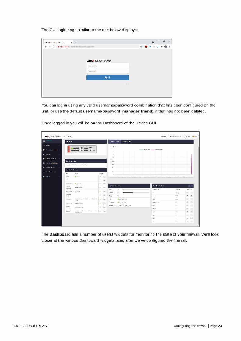
The GUI login page similar to the one below displays:
You can log in using any valid username/password combination that has been configured on the
unit, or use the default username/password (manager/friend), if that has not been deleted.
Once logged in you will be on the Dashboard of the Device GUI.
The Dashboard has a number of useful widgets for monitoring the state of your firewall. We'll look
closer at the various Dashboard widgets later, after we've configured the firewall.
C613-22078-00 REV S Configuring the firewall | Page 23

The left side of the GUI provides the Wizard, Vista Manager mini, Security, Licensed Features,
Network Infrastructure, Network Services, User Management and System menus.
C613-22078-00 REV S Configuring the firewall | Page 24
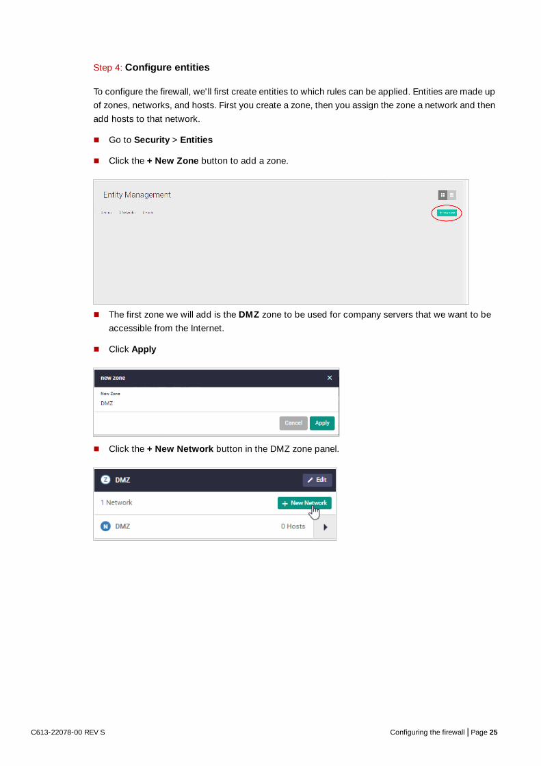
Step 4: Configure entities
To configure the firewall, we'll first create entities to which rules can be applied. Entities are made up
of zones, networks, and hosts. First you create a zone, then you assign the zone a network and then
add hosts to that network.
Go to Security > Entities
Click the + New Zone button to add a zone.
The first zone we will add is the DMZ zone to be used for company servers that we want to be
accessible from the Internet.
Click Apply
Click the + New Network button in the DMZ zone panel.
C613-22078-00 REV S Configuring the firewall | Page 25

Name the new network ‘servers’. Add an IP subnet and eth1 as the interface over which this
network will be reachable.
We can now add specific hosts (servers in this case).
Click on the arrow to add a host to the ‘servers’ network.
C613-22078-00 REV S Configuring the firewall | Page 26

Click the green +New Host button.
Add the host Name ‘ftp’ and its IP address.
Add a second host named web-server with an IP address.
The DMZ zone now contains a network named servers with two hosts:
web-server
ftp
Repeat the same steps to create private and public zones/networks with the following details:
Private zone:
Zone name = private
Network name = lan
Network subnet and interface = (IP address), VLAN1
Public zone:
Zone name = public
Network name = internet
Network subnet and interface = 0.0.0.0/0, eth2
C613-22078-00 REV S Configuring the firewall | Page 27

The Entity Management page now contains a 3-zone network.
Entity list view
To view and manage entities in list view, click on the list icon on the right side of the page. The list
view is a good option for an overall entity view.
Clicking Expand All (on the right side of the page) will display all entities and their interfaces, IP
addresses, and so on.
If you'd like to view changes as added to the firewall configuration file:
Select CLI under the System menu. This opens a CLI tab.
Type ena to access Privileged Exec mode, then use the CLI commands:
C613-22078-00 REV S Configuring the firewall | Page 28

show running-config entity and show entity.
Note the syntax that is used for identifying a network or host entity.
The syntax for naming a network entity is:
<Parent Zone Name>.<network name>
For example, private.LAN
The syntax for identifying a host entity is:
<Parent Zone name>.<Parent Network Name>.<Host Name>
For example, dmz.servers.ftp
So, the hierarchy is included in the identifier of a second-tier or bottom-tier entity.
For example, dmz.servers.web-server indicates that this host named web-server is part of the
servers network within the dmz domain.
C613-22078-00 REV S Configuring the firewall | Page 29

Step 5: Configure firewall rules
We now have a 3-zone network (Public, Private, and DMZ), so next let’s configure the firewall rules
to manage the traffic between these entities.
Go to Security > Firewall
WARNING: Don’t enable the firewall yet. Enabling the firewall with the ON/OFF switch will block all
applications between all entities by default - no traffic will flow. It is therefore important to
create firewall rules to allow application usage as desired prior to enabling the firewall.
Click + New Rule and create a rule to allow Ping traffic from the Public zone to the Private zone.
This will allow us to test connectivity through the firewall.
Note: To select an application, simply start typing in the application field. Available options will be filtered down until you select the desired application.
C613-22078-00 REV S Configuring the firewall | Page 30

You can see the new rule added to the firewall.
Create further new firewall rules with these details:
Further Ping rules to allow connectivity checking:
Permit Ping from Public to DMZ
Permit Ping from Private to DMZ
Permit Ping from DMZ to Private
Allow public traffic from the Internet to our DMZ servers:
Permit ftp from Public to dmz.servers.ftp
Permit http from Public to dmz.servers.web-server
Allow private side firewall zones to initiate traffic flows with each other and out to the Internet:
Permit Any from Private to Private
Permit Any from DMZ to DMZ
Permit Any from Private to Public
Permit Any from DMZ to Public
C613-22078-00 REV S Configuring the firewall | Page 31

We can now see these firewall rules displayed:
Now that the firewall rules are created, you can turn the firewall on using the ON/OFF button at
the top right of the Firewall page.
C613-22078-00 REV S Configuring the firewall | Page 32

Firewall rule placement
The firewall rules are displayed in the order they were created, which is also the order in which they
will be actioned by the firewall. If you need to change the order of any specific rule, click and drag it
into a new position.
There are two other options for placing new rules:
Right-click on any firewall rule and the menu gives you the option to create a new rule above or
below that rule. This allows new rules to be immediately placed in the desired location, and order
of processing.
The right-click menu also has a copy-and-paste function, so you can copy an existing rule that
is similar to the new rule you wish to create, and paste it into a different location. It can then be
edited to suit.
These right-click options are very useful when you have a large number of firewall rules. The same
right-click options are also available when creating new NAT and Traffic Control rules.
C613-22078-00 REV S Configuring the firewall | Page 33

If you'd like to see the updated firewall configuration, use the CLI window and the commands: show
firewall rule, show running-config firewall and show firewall.
Note that the firewall rules are numbered in the order in which they will be actioned (e.g. 10, 20, 30,
and so on). If a rule is dragged to a different location in the list displayed by the GUI, the rules will be
renumbered to reflect the change in order of operation.
Step 6: Configure NAT rules
Now let's configure NAT rules to manage IP address translation between the Internet and our
internal networks.
Go to Security > NAT
C613-22078-00 REV S Configuring the firewall | Page 34

We need two NAT masquerade rules for private to public address translation, which are:
Any traffic going from the Private zone out to the Public zone will have NAT applied, so that it
appears to have come from the IP address of the eth2 interface.
Any traffic going from the DMZ zone out to the Public zone will have NAT applied, so that it
appears to have come from the IP address of the eth2 interface.
Click + New Rule to create the first rule for Private to Public traffic:
Action = Masquerade, Application = any, From = Private, To = public
Click + New Rule again and create the second NAT masquerade rule in the same way for DMZ to
Public traffic with these details:
Action = Masquerade, Application = any, From = DMZ, To = public
We now need to create two NAT port-forwarding rules to enable access to the FTP and Web servers
to be delivered to the right destinations. To users in the Public zone, both servers will appear to have
the IP address that is on the eth2 interface, so sessions towards those servers will be initiated to that
address. The firewall must then forward those sessions to the actual addresses of the servers.
Click + New Rule and create the two NAT port-forward rules with the following details:
Action = Port Forward, Application = ftp, From = public, With = dmz.servers.ftp
Action = Port Forward, Application = http, From = public, With = dmz.servers.web-server
Now click the ON/OFF button at the top right of the Dashboard page to activate NAT.
C613-22078-00 REV S Configuring the firewall | Page 35

You can see the four new NAT rules:
Open the CLI window to see these new NAT rules. Enter the command show nat rule.
Step 7: Save configuration changes
The configuration we have made so far is part of the running-configuration on the firewall.
Save these configuration changes to make them part of the boot configuration, so they can be
backed up and will survive a reboot of the firewall.
Click the Save button at the top right of the GUI screen. The Save button will be orange anytime
there is unsaved configuration.
C613-22078-00 REV S Configuring the firewall | Page 36

Part 2: Configure the firewall for Update Manager
Modern security devices require regular updates to keep rule-sets and threat signature databases
up to date, ensuring effective protection for business networks. Features such as IP Reputation,
Malware Protection, and Antivirus (which we'll configure in parts 5 and 6), monitor network traffic
and detect malicious activity in real-time by comparing the threats' characteristics and patterns
against known lists and databases.
The leading security providers employed by the firewall, such as Emerging Threats, keep their
databases regularly updated with the very latest threat signatures, so security scanning of firewall
traffic catches the latest malicious threats. The firewall utilizes Update Manager to contact the
Allied Telesis update server and download the latest components at pre-defined intervals, or at
specific user request.
You must configure entities and rules to allow connectivity between Update Manager and the
Update Server.
Step 1: Create appropriate entities
Update Manager retrieves files using sessions initiated from the firewall unit itself.This means that
firewall rules are required that permit these sessions. So, a zone needs to be created that represents
the firewall itself, and the public interface of the firewall has to exist as a host within this zone.
Create zone/network/host entities for Update Manager source traffic with the following details:
Zone name = Router
Network name = External
Network subnet and interface = 192.168.52.0/24, Eth2
Host name = External_Int
Host IP address = 192.168.52.20
The updated Entity Management page will look like this:
Or in List View (with just the new zone expanded) like this:
C613-22078-00 REV S Configuring the firewall | Page 37

Step 2: Create firewall rules for the Update Manager traffic
The Update Manager uses HTTPS for secure connectivity, so we'll create a firewall rule with the
following details to allow HTTPS traffic out to the update server.
Also create a rule to allow DNS resolution of the update server's URL.
C613-22078-00 REV S Configuring the firewall | Page 38

These new rules can be seen added to the firewall rule set.
Step 3: Save configuration changes
Once again click the Save button on the GUI top bar to save the Update Manager configuration to
the boot configuration file.
C613-22078-00 REV S Configuring the firewall | Page 39

Part 3: Configure free security features
Allied Telesis firewalls have a number of security features that can be configured to manage
application and website usage, as well as provide comprehensive threat protection.
This section configures the Intrusion Prevention System (IPS) and Custom URL Filtering, which are
both free to use on the firewall. “Part 4: Configure licensed firewall security features” and “Part 5:
Configure licensed Advanced Threat Protection (ATP) security features” of the guide configures
licensed firewall and threat protection features.
Intrusion Prevention System
IPS monitors inbound and outbound traffic as the first line of defense, and identifies suspicious or
malicious traffic in real-time by comparing threats against an IPS known signature database.
Step 1: Enable IPS
Go to Security > Intrusion Prevention
Click the ON/OFF switch on the top right of the page to enable IPS.
Step 2: Configure IPS actions
Threats are grouped into categories, for example suspicious web traffic (HTTP), or email traffic
(SMTP). For any threat that is detected in each of these categories, the engine can be set to log the
threat (which is the default action), ignore, or block - drop the matching packets.
C613-22078-00 REV S Configuring the firewall | Page 40

To drop suspicious SMTP traffic, set the action to Block.
Note: You can monitor IPS matches using the Dashboard’s security monitoring widget.
Step 3: Save configuration changes
Save the IPS configuration changes to make them part of the boot configuration file.
Custom URL Filtering
URL Filtering is a fast efficient (stream-based) method to allow or block employee’s website access.
You can specify a user-defined list of websites to allow (whitelist) and/or block (blacklist) on the free-
to-use Custom URL Filtering page. You can also subscribe to the Kaspersky blacklist service if you
have the URL Filtering license installed, which is shown in "Part 4: Configure licensed firewall
security features" on page 44.
URLs are matched in this order – user-defined whitelists, user-defined backlists, Kaspersky
blacklist. Pattern checking stops as soon as the first match is found, and that action (allow or block)
is taken. If no match is found, website access will be allowed.
C613-22078-00 REV S Configuring the firewall | Page 41

Step 1: Configure custom URL filtering
Go to Security > Custom URL Filtering
You can now add user-defined whitelists of URLs to allow, and/or blacklists of URLs to block. You
can add multiple lists, and these can have a total maximum of 1000 whitelist URLs and 1000
blacklist URLs. The GUI page lets you know how many URLs are in each list and the total URLs
used.
Click on the +New list button to add a new whitelist or blacklist.
The custom URL list must be a text file (.txt). All of your .txt files in flash, USB, or SD card are shown. You can select and save them for the Custom URL Filtering feature to use.
See the URL Filtering Feature Overview Guide for more information about creating user-defined URL Filtering lists.
C613-22078-00 REV S Configuring the firewall | Page 42

Any whitelists and blacklists that have been selected are now shown on the Custom URL Filtering
page, with the entry count showing the number of URLs used:
Step 2: Enable URL Filtering
Enable URL Filtering with the ON/OFF switch at the top of the page:
The firewall will now match any website URLs that users try to browse to against the whitelist/s, then
the blacklist/s, and then the Kaspersky blacklist (if you are using the Kaspersky licensed URL
Filtering). Pattern checking stops as soon as the first match is found, and that action (allow or block)
is taken. If no match is found, website access will be allowed.
Note: You can monitor URL Filtering hits using the Dashboard’s security monitoring widget.
Step 3: Save configuration changes
Save your Custom URL Filtering changes to make them part of the boot configuration.
C613-22078-00 REV S Configuring the firewall | Page 43

Part 4: Configure licensed firewall security features
Online business activity is now based around applications that enable people to interact with
services such as collaborative document creation, social networking, video conferencing, cloud-
based storage, and much more. Organizations need to be able to control the applications that their
people use, and how they use them, as well as managing website traffic.
Allied Telesis firewalls are application aware, and so provide the visibility and control necessary to
safely navigate the increase in online applications and web traffic that are used for effective business
today.
The Advanced Firewall feature license includes Application Control, Web Control and URL
Filtering. The Advanced Firewall feature license is available in 1, 3, and 5 year subscriptions. You
can view current license status by navigating to the License page under the System menu.
Application Control
The Deep Packet Inspection (DPI) firewall engine allows fine-grained application control. Reliable
identification of the individual applications means that rules can be established to govern
application use, and to enforce security and acceptable use policies. For example, Skype chat may
be allowed company wide, while Skype video calls can only be made by the sales department.
Step 1: Configure application control
Go to Licensed Features > Application Control
Click the ON/OFF switch to enable Application Control.
Choose a Provider to ensure the latest applications are known.
C613-22078-00 REV S Configuring the firewall | Page 44

The provider options are:
Built-in - if a subscription license hasn't been purchased then the built-in application library may
be used. This supports around 200 individual applications.
Procera - the Procera Networks application visibility library identifies around 1400 individual
applications. The firewall will update the library from the Allied Telesis update server at the
specified interval to ensure the latest applications are known.
Step 2: Add rules to manage applications
You can now create firewall or traffic shaping rules to manage how applications are allowed to be
used on the network.
For example, to block the use of Spotify™ (a music streaming service) company-wide, create a
firewall rule denying the Spotify application from the Public (Internet) zone to the Private (LAN) zone.
Step 3: Add rules to manage application bandwidth
As well as using the firewall to block undesired traffic, you can also use the Traffic Control page to
manage the bandwidth that certain applications are able to use on the firewall.
For example, to limit Youtube traffic through the firewall to 10Mbps, go to the Traffic Control page
and add a new rule from the Public (Internet) zone to the Private (LAN) zone.
C613-22078-00 REV S Configuring the firewall | Page 45

You can see the new Traffic Control rule applied with a bandwidth limit of 10Mbps for the application
youtube.
Step 4: Save configuration changes
Save the Application Control configuration changes to make them part of the boot configuration.
C613-22078-00 REV S Configuring the firewall | Page 46

Web Control
Web Control provides enterprises with an easy means to monitor and control their employees' web
traffic for productivity, legal, and security purposes. The proxy-based Web Control feature uses
Digitals Arts' active rating system for comprehensive and dynamic URL coverage. Websites are
accurately assigned into around 90 categories, which can be allowed or blocked.
When a user tries to browse to a website, the http request is intercepted and sent to the classifier
engine, which queries Digital Arts constantly updated URL database for the category that the
website belongs to.
Once a particular URL has been categorized, the result is cached in the firewall so that any
subsequent requests with the same URL can be immediately processed.
Step 1: Configure Web Control
Go to Licensed Features > Web Control
Click on the ON/OFF switch to enable Web Control.
Select the Default Action - deny or permit, for web pages that do not match any specific rules,
but match a Web Control category.
Note: You can monitor URL Filtering and Web Control hits using the Dashboard’s security monitoring widget.
Step 2: Add rules to manage website categories
The Web Control feature has its own set of rules, which are separate to the firewall rules. The Web
Control rules are created on the Web Control configuration page.
C613-22078-00 REV S Configuring the firewall | Page 47

For example, to block gambling websites, create a rule that applies to the Internet network.
Click + New Rule.
You can see the new rule applied to the Internet network in the Public zone.
Step 3: Create custom categories
As well as using the predefined website categories, you can also create your own custom categories
which match text strings you enter against website URLs. These custom categories can then have
rules applied (as we did for gambling websites above).
C613-22078-00 REV S Configuring the firewall | Page 48

For example, to create a custom category called ‘Movie’ which contains the IMDB and Rotten
Tomatoes websites:
Go to the Custom Categories tab and click the + New Category button.
Create the ‘Movie’ category, and add text string matches for any website addresses containing
IMDB or Rotten Tomatoes.
Click Apply.
You can see the new category and its website matches below:
Use the Web Control Rules tab to add more rules for this category as desired.
Step 4: Save configuration changes.
Save the Web Control configuration changes to make them part of the boot configuration file.
Note: You can monitor category and rule hits using the Dashboard’s security monitoring widget.
C613-22078-00 REV S Configuring the firewall | Page 49

URL Filtering
URL Filtering is a fast efficient (stream-based) method to allow or block employee website access.
You can specify a user-defined list of websites to allow (whitelist) and/or block (blacklist) on the free-
to-use Custom URL Filtering page, as described in Part 3 of this guide.
This feature allows you to subscribe to the Kaspersky blacklist service if you have the URL Filtering
license installed. This blacklist contains approximately 64,000 URLs and it is updated regularly to
ensure protection from harmful websites.
Step 1: Configure URL Filtering
Go to Licensed Features > URL Filtering
Click the ON/OFF switch to enable URL Filtering.
Set an Update interval to contact the Update Server for updates to the Kaspersky URL Filtering
blacklist.
URLs are matched in this order – user-defined whitelists, user-defined backlists, Kaspersky
blacklist. Pattern checking stops as soon as the first match is found, and that action (allow or block)
is taken. If no match is found, website access will be allowed.
Step 2: Save configuration changes
Save your URL Filtering changes to make them part of the boot configuration.
Note: You can monitor URL Filtering hits using the Dashboard’s security monitoring widget.
C613-22078-00 REV S Configuring the firewall | Page 50

Part 5: Configure licensed Advanced Threat Protection (ATP) security features
The fundamental shift to sophisticated application use has provided businesses with increased
efficiency, and improved collaboration, along with new ways to manage customer interaction.
However, this has also opened the door for greater security concerns. Business data is potentially
vulnerable, and the rapid development of new services has introduced new types of cyber threats.
Allied Telesis firewalls provide comprehensive threat protection, utilizing security engines and threat
signature databases from the industry's leading vendors. Regular updates ensure up-to-the-minute
protection against cyber attacks.
The Advanced Threat Protection (ATP) license enables IP Reputation, Malware Protection, and
Antivirus (note that Antivirus is only available on the AR4050S).
The ATP license (like the Advanced Firewall license) is available in 1, 3, and 5 year subscriptions. You
can view current license status by navigating to the License page under the System menu.
C613-22078-00 REV S Configuring the firewall | Page 51

IP Reputation
IP Reputation provides comprehensive IP reputation lists through Emerging Threats ET
Intelligence™ (provided by Proofpoint™), which identifies and categorizes IP addresses that are
sources of Spam, viruses and other malicious activity. With real-time threat analysis, and regular
updates to reputation lists, IP Reputation keeps network protection against hazardous websites
right up to date.
Step 1: Enable IP Reputation
Go to Licensed Features > IP Reputation
Click the ON/OFF switch to enable IP Reputation.
Set an Update interval to contact the Update Server for IP Reputation list updates.
Step 2: Configure IP Reputation categories
IP Reputation uses categories to classify the nature of a host's bad reputation. For example, IP
addresses known to be sources of Spam will be added to the Spam category.
For any category, IP Reputation can be set to log the threat (which is the default action), ignore, or
block/drop the matching packets.
C613-22078-00 REV S Configuring the firewall | Page 52

To drop traffic from websites known as sources of Spam, set the Spam category to Block.
Step 3: Save configuration changes
Save the IP Reputation configuration changes to be part of the boot configuration file.
Note: You can monitor IP Reputation blocked packets using the Dashboard’s security monitoring widget.
Malware Protection
Malware Protection is a stream-based high performance technology that protects against the most
dangerous cyber threats. By considering threat characteristics and patterns with heuristics analysis,
unknown zero-day attacks can be prevented, along with server-side Malware, web-borne Malware,
and other attack types. Detection covers all types of traffic passing through the firewall, including
web, email, and instant messaging - any Malware is blocked. The Kaspersky anti-Malware signature
database is updated regularly to keep on top of the latest attack mechanisms.
C613-22078-00 REV S Configuring the firewall | Page 53

Step 1: Configure Malware protection
Go to Licensed Features > Malware Protection
Click the ON/OFF switch to enable Malware Protection.
Set an Update Interval to contact the Update Server for updates to the Malware signature
database.
Step 2: Save configuration changes
Save the Malware Protection configuration changes so they become part of the boot configuration
file.
Note: You can monitor Malware packets dropped using the Dashboard’s security monitoring widget.
Antivirus
The firewalls proxy-based Antivirus guards against threats such as viruses, Trojans, worms, spy-
ware, and adware. In addition to protecting the local network by blocking threats embedded in
inbound traffic, it also prevents compromised hosts or malicious users from launching attacks. This
is essential for protecting business reputation, and minimizing business disruption.
Using the Kaspersky Antivirus engine, the signature database containing known threat patterns is
regularly updated.
C613-22078-00 REV S Configuring the firewall | Page 54

Step 1: Configure Antivirus
Go to Licensed Features > Antivirus
Click the ON/OFF switch to enable Antivirus.
Set an Update Interval to contact the Update Server for updates to the Antivirus signature
database.
Step 2: Save configuration changes
Save the Antivirus configuration changes to make them part of the boot configuration file.
Note: You can monitor how many files have been scanned, viruses found, etc. using the Dashboard’s security monitoring widget.
C613-22078-00 REV S Configuring the firewall | Page 55

Updating the GUI As new versions of the Device GUI become available with additional functionality, they will also be
made available on the update server to be downloaded and installed on the firewall. You can update
the GUI version using the CLI or use the File Management menu in the firewall’s GUI.
Using the CLI to update the GUI version
To check if there is a new version of the Device GUI, and install it on your firewall, firstly ensure that
the firewall can contact the update server and then enter the following command from the CLI
window:
update webgui now
Using the GUI to update the GUI version
If you would like to use the GUI to update the GUI version, use the following steps:
1. Obtain the GUI file from our Software Download centre. The filename for v2.8.0 of the GUI is awplus-gui_551_23.gui.
The file is not device-specific; the same file works on all devices.
2. Log into the GUI:
Start a browser and browse to the device’s IP address, using HTTPS. You can access the GUI via any reachable IP address on any interface.
The GUI starts up and displays a login screen. Log in with your username and password.
The default username is manager and the default password is friend.
3. Go to System > File Management
4. Click Upload.
C613-22078-00 REV S Updating the GUI | Page 56
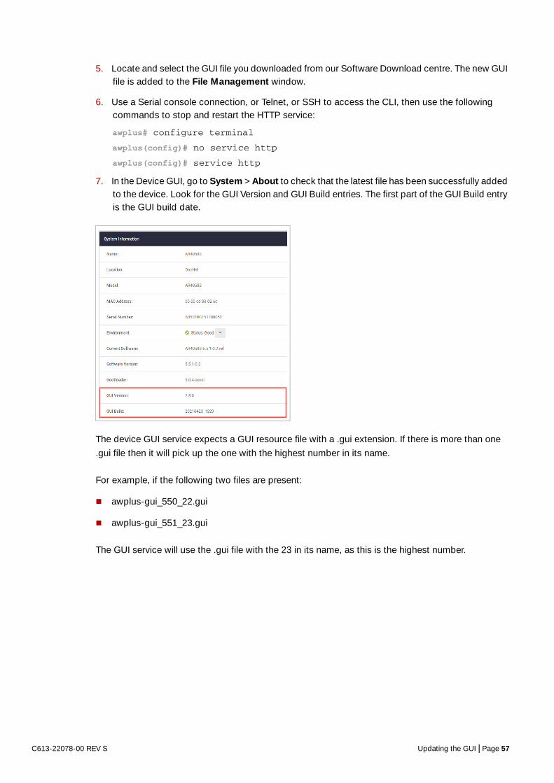
5. Locate and select the GUI file you downloaded from our Software Download centre. The new GUI file is added to the File Management window.
6. Use a Serial console connection, or Telnet, or SSH to access the CLI, then use the following commands to stop and restart the HTTP service:
awplus# configure terminalawplus(config)# no service httpawplus(config)# service http
7. In the Device GUI, go to System > About to check that the latest file has been successfully added to the device. Look for the GUI Version and GUI Build entries. The first part of the GUI Build entry is the GUI build date.
The device GUI service expects a GUI resource file with a .gui extension. If there is more than one
.gui file then it will pick up the one with the highest number in its name.
For example, if the following two files are present:
awplus-gui_550_22.gui
awplus-gui_551_23.gui
The GUI service will use the .gui file with the 23 in its name, as this is the highest number.
C613-22078-00 REV S Updating the GUI | Page 57

The DashboardNow that we have configured the firewall, application control, web control, and threat protection
features, let's take a look at the Dashboard of the GUI, and what information is provided in the
various widgets (applications).
Currently, the widgets are:
Port Status
System Information
Traffic
Security Monitoring
Top 10 Applications
Top 10 Categories
The next section provides a brief summary of their functionality.
C613-22078-00 REV S The Dashboard | Page 58

Port Status The Port Status widget displays the front panel ports of the device.
Any ports that are currently ‘up’ are shown in green. Hovering your mouse over any port that is ‘up’
displays the Port Information panel, with statistics over the last 5 minutes. The panel lists the port’s
number, speed, packet transmit and receive counts, utilization percentages, and VLAN associations.
Click on the Configure button to access port options.
From the Port Configuration panel, you can enable or disable the port, or configure its speed,
duplex mode, polarity, and aggregator status.
Click Apply to save changes.
Note: The Port Status widget is not available for the Virtual UTM Firewall.
SystemInformation
Shows CPU and memory use, as well as device health.
C613-22078-00 REV S The Dashboard | Page 59

InterfaceTraffic
Interface Traffic shows traffic passing through a chosen interface in both directions over a 24 hour
period.
Note: The Interface Traffic widget is not available for the Virtual UTM Firewall.
FirewallTraffic
Firewall Traffic shows traffic passing through the firewall over a 24 hour period.
Note: The Firewall Traffic widget is not available for the Virtual UTM Firewall.
C613-22078-00 REV S The Dashboard | Page 60

Securitymonitoring
The Security Monitoring widget shows the main security and threat protection features of the
firewall in one handy location. You can see which are currently enabled and which are not. You can
select edit to go to that features dedicated page to configure it further.
You can also see how many rules are configured for the various features, and statistics for each of
the security features, for example: URL rules hit, packets blocked, and viruses found.
Top 10Applications
The Top 10 Applications widget shows the top 10 applications using firewall bandwidth. You have
the ability to take action based on this reporting, by adding a new firewall or traffic control rule. To
add a new firewall or traffic control rule, simply click on the ‘F’ or ‘T’ Add Rule buttons.
The Top 10 Applications table shows cumulative totals, and is live, so the MB used will change and
applications will move position in the table. Clicking the reset button will zero all totals and start to
display the top used applications from that time onwards.
C613-22078-00 REV S The Dashboard | Page 61

Top 10Categories
Similar to the Top 10 Applications widget, the Top 10 Categories widget shows the top 10 Web
control website categories that are using firewall bandwidth. Click on the ‘W’ button to create a new
Web control rule from the widget in response to this reporting.
SystemPage
Further system information is available on the About page, under the System menu, such as model,
MAC address, serial number, firmware, GUI versions, and so on.
C613-22078-00 REV S The Dashboard | Page 62

The network mapUnder the Vista Manager mini menu, there is a network topology map. This map shows details of the
devices connected to the switch or firewall. You can use it to see your:
wired devices
APs
wireless deployment and coverage.
This section begins with a brief description of the network map window and the tasks you can
perform there. The section ends with a look at configuring the network topology view and
customizing node icon images.
Note that the screenshots in this section show an x930 Series switch, but the functionality is the
same for all models that include Vista Manager mini.
The network map features
The network map displays details of a network configuration. Double click on an area to see all the
nodes in that area. Use the network map to check the status of a node at a glance. Node status is
indicated by the node title background color. Abnormal is red, managed is green, and blue indicates
an unmanaged node.
From the network MAP page, you can:
customize network icon images
view individual node details
see a list of network nodes
configure the topology view
create a heat map
view stored heat maps
C613-22078-00 REV S The network map | Page 63

Viewing node information
In the network topology map view, click on a device to see information about the Hostname, Model,
MAC address, and software version.
Configuring the topology view
Vista Manager mini automatically creates a complete topology map from an AMF network of
switches, firewalls, and wireless access points (APs), showing areas and multiple levels of
connected nodes and devices.
To change the topology view settings:
In the Topology Map view, select Configure - the menu is located at top right corner.
C613-22078-00 REV S The network map | Page 64

In the Topology View Settings window, you can choose to:
limit nodes per line
collapse child nodes
select a background image
Save your changes.
Customizing network node icon images
You can customize the look of your network nodes with icon images. For example, you can add
access point, switch, and router images to make the network map easier to understand at a glance.
You can create an icon library to help store, organize, and find images.
To customize a network node icon:
1. In the Topology Map view, open the Node List (slide-out menu)
2. Click on a node’s icon image.
3. Click Edit.
C613-22078-00 REV S The network map | Page 65

4. Select an image from the library or click the ‘+’ sign to add a new one.
5. Click Save.
Access to device GUI by clicking on device icon
From version 2.5.2 onwards, you can open the GUI for a device in your network (e.g. an x230) from
the network map in the GUI of another device in your network (e.g. an AR4050S).
When you click a node icon on the Network Map, the node information is displayed. In the node
information window, click on the Open button to access the device’s GUI.
You can use the Node List to help you locate a device in the network map. Simply click the device in
the Node List to see its Information details.
C613-22078-00 REV S The network map | Page 66

Wireless managementAllied Telesis UTM Firewalls incorporate Autonomous Wave Control (AWC) wireless management,
allowing your wireless access points (APs) to be setup and managed from the Device GUI on your
security appliance. AWC uses wireless intelligence to constantly model AP location and signal
strength information. It then automatically optimizes wireless output and channel selection for
optimum performance.
Note: The Vista Manager mini settings are not available for the Virtual UTM Firewall.
The device GUI includes a Wireless Management menu, which enables you to set up your wireless
network, monitor and configure the network, and manage AWC:
The device GUI also displays heat maps for managed APs on the network map.
For more information about heat maps, AWC and how to manage wireless devices, see the User
Guide: Wireless Management (AWC) with Vista Manager mini.
C613-22078-00 REV S Wireless management | Page 67

Other featuresThe Device GUI has a number of other great features. The Network Infrastructure menu includes
interface management, VLAN management, tools. The Network Services menu allows you to
configure the firewall as a DHCP server for the network. There are configuration options for SMTP,
RADIUS, Tools, and AAA here too. These will not be detailed here, but are easy and intuitive to use.
The System menu includes information about the device’s model name, MAC address, and
firmware/software etc. You can also manage your files, licenses, and logging here.
Note: The Time settings are not available for the Virtual UTM Firewall. They are managed through the VST-APL menu.
Let’s look at a few important features:
"File management" on page 69
"License management" on page 70
"Logging management" on page 72
"AMF Security mini on the AR4050S Series" on page 75
C613-22078-00 REV S Other features | Page 68
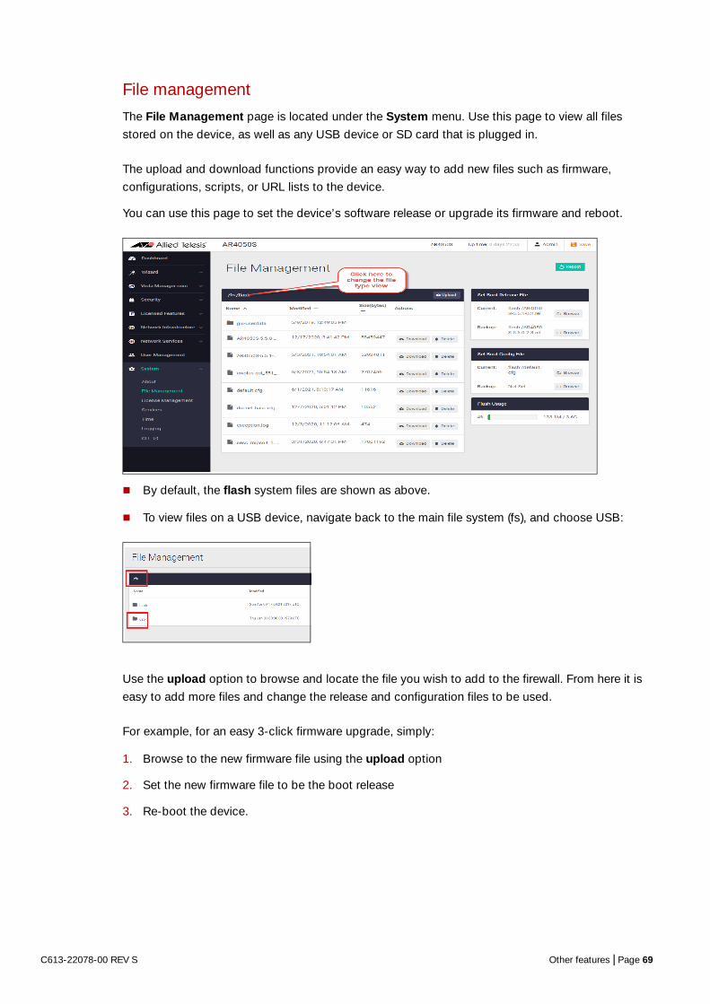
File management
The File Management page is located under the System menu. Use this page to view all files
stored on the device, as well as any USB device or SD card that is plugged in.
The upload and download functions provide an easy way to add new files such as firmware,
configurations, scripts, or URL lists to the device.
You can use this page to set the device’s software release or upgrade its firmware and reboot.
By default, the flash system files are shown as above.
To view files on a USB device, navigate back to the main file system (fs), and choose USB:
Use the upload option to browse and locate the file you wish to add to the firewall. From here it is
easy to add more files and change the release and configuration files to be used.
For example, for an easy 3-click firmware upgrade, simply:
1. Browse to the new firmware file using the upload option
2. Set the new firmware file to be the boot release
3. Re-boot the device.
C613-22078-00 REV S Other features | Page 69

Tip The Flash Usage panel provides details on the percentage used and total available flash.
License management
You can use feature licenses to unlock advanced functionality on UTM firewalls.
Licenses such as advanced firewall, and advanced threat protection, enable additional security
features as described in Part 4 on page 44 and Part 5 on page 51 of this guide. You can purchase
AMF Master and AWC wireless licenses to manage your wired and wireless network devices. All of
the licenses are available in 1 or 5-year subscriptions.
The License Management page shows the licenses you currently have on your device. You can add
new purchased licenses from this page too.
Hover your mouse over a green license bar to show its details, such as duration and other relevant
feature information.
C613-22078-00 REV S Other features | Page 70

Adding a new subscription feature license
Subscription feature license files are in the .bin file format. The .bin file format is a file that stores
data in a compressed binary format. Once you have purchased your new subscription license you
should add it to your firewall.
For example, to add a 1 year Advanced Threat Protection (ATP) subscription license:
1. Go to System > License Management
2. Click the Upload License button.
3. Browse and select the .bin file you purchased. Once selected, the .bin file will be uploaded and the subscription license added to your device.
C613-22078-00 REV S Other features | Page 71

Logging management
The Logging page shows buffered and permanent log messages stored on the device. There are
two tabs, Buffered and Permanent, the Buffered tab is displayed by default:
You can filter logs in 3 different ways to focus your view and support easy analysis:
1. sort columns in ascending or descending order.
2. select the severity of logs to display, e.g Critical, Warning, Error etc.
3. search for any text string found in the logs. e.g. ‘received’
C613-22078-00 REV S Other features | Page 72

Click the Configure Logging button to access the Logging Configuration page.
In the Logging Configuration page, you can create filters to manage which logs are stored on the
device and also set up a Syslog server(s) for remote log storage.
The Logging Configuration page has two tabs, Local and Remote (syslog server).
Use the Local tab (default) to create filters to manage the level of logs that are stored in the
buffered and permanent logs on the device. You can also delete the buffered or permanent logs
using the Clear Logs button.
C613-22078-00 REV S Other features | Page 73

To create a new log filter:
1. Click +New Filter
2. Select a Notice level: All, Emergency, Alert, Critical, Error, Warning, Notice, Info, or Debug.
3. Select the Facility and Program - a drop-down list appears when you begin typing in these fields.
4. Type in the log ‘message’.
5. Select Included or Excluded.
6. Click Apply.
This enables log storage on the device to be configured exactly as desired.
Use the Remote tab and the +New Host button to set up a syslog server to send log messages
to for storage and analysis.
Click the View Logs button to return to the Logging page.
C613-22078-00 REV S Other features | Page 74
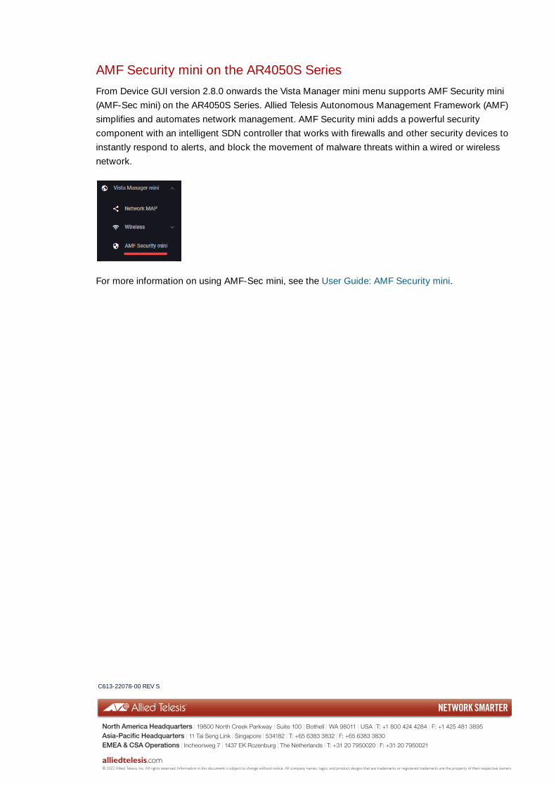
AMF Security mini on the AR4050S Series
From Device GUI version 2.8.0 onwards the Vista Manager mini menu supports AMF Security mini
(AMF-Sec mini) on the AR4050S Series. Allied Telesis Autonomous Management Framework (AMF)
simplifies and automates network management. AMF Security mini adds a powerful security
component with an intelligent SDN controller that works with firewalls and other security devices to
instantly respond to alerts, and block the movement of malware threats within a wired or wireless
network.
For more information on using AMF-Sec mini, see the User Guide: AMF Security mini.
C613-22078-00 REV S
NETWORK SMARTER
alliedtelesis.com
North America Headquarters | 19800 North Creek Parkway | Suite 100 | Bothell | WA 98011 | USA |T: +1 800 424 4284 | F: +1 425 481 3895
Asia-Pacific Headquarters | 11 Tai Seng Link | Singapore | 534182 | T: +65 6383 3832 | F: +65 6383 3830
EMEA & CSA Operations | Incheonweg 7 | 1437 EK Rozenburg | The Netherlands | T: +31 20 7950020 | F: +31 20 7950021
© 2022 Allied Telesis, Inc. All rights reserved. Information in this document is subject to change without notice. All company names, logos, and product designs that are trademarks or registered trademarks are the property of their respective owners.