Product overview 2020/2021 - Professional Control Corporation
92
Product overview 2020/2021
-
Upload
khangminh22 -
Category
Documents
-
view
0 -
download
0
Transcript of Product overview 2020/2021 - Professional Control Corporation

Product overview2020/2021

2
Our range of products and services
Switching sensors 8
Photoel. sensors / diffuse sensors, cubic housing 10
Photoel. sensors / diffuse sensors, cylindrical housing 14
Long-range sensors 15
Inductive switches 16
Capacitive sensors 18
Fiber optic sensors / ultrasonic sensors 20
Light curtains 22
Forked sensors 23
Special sensors 24
Double sheet monitoring / splice detection 25
Measuring sensors 26
Distance sensors 28
Sensors for positioning 30
3D-sensors / forked sensors 31
Sensors for compartment fine positioning 32
Light curtains / volume measurement system 33
Products for safety at work 34
Safety laser scanners 36
Safety light curtains 38
Multiple light beam safety devices 42
Protective sensor sets and accessories 44
Single light beam safety devices 46
AS-i-safety product range 48
Safety switches and safety locking devices 50
Safety proximity sensors 52
Safety command devices 53

3
Safety relays 54
Programmable safety controls 58
Machine safety services 60
Identification 62
Stationary bar code readers 64
Stationary 2D-code readers 67
RFID systems 69
Mobile code readers 70
Data transmission 72
Optical data transmission 74
Network and connection technology 76
Connection technology 78
Modular connection units 80
Industrial image processing 82
Smart cameras 84
Accessories and supplementary products 86
Signaling devices 88
Mounting systems 89
Reflectors 90

With curiosity and determination, we – the Sensor People – have been innovators for technological milestones in industrial automation for more than 50 years. The success of our customers is what drives us. Yesterday. Today. Tomorrow.
ForerunnerYesterday. Today. Tomorrow.

5

Foundation 1963
Company structure GmbH + Co. KG, wholly family-owned
Executive management Ulrich Balbach
HeadquartersOwen, Germany
Distribution companies 20
Production locations 5
Technological competence centers 3
Distributors 40
Employees > 1,200
Product range
— Switching sensors — Measuring sensors — Products for safety at work — Identification — Data transmission systems — Network and connection technology — Industrial image processing — Accessories
Focus industries
— Intralogistics — Packaging industry — Machine tools — Automotive industry — Laboratory automation
Leuze electronic GmbH + Co. KG
In der Braike 173277 OwenPhone: +49 7021 573-0Fax: +49 7021 573-199E-mail: [email protected]
In a constantly changing industry, we work together with our customers to find the best solution for their sensor applications: innovatively, precisely and efficiently.
Our companyEverything at a glance
Key figures

7
Your success is our motivation. We therefore place great value on always being personally, quickly, and easily accessible to you. We produce on four continents, allowing us to offer you reliable product availability.
Our LocationsAt work for you around the world
Technological competence centers
Production locations
Distribution companies
Distributors
Australia | Belgium | Brazil | China | Denmark / Sweden | France | Germany | Great Britain | Hong Kong | India
Italy | Mexico | the Netherlands | New Zealand | Singapore | South Korea | Spain | Switzerland | Turkey | USA / Canada

Switching sensorsDependable switching: All objects and packaging are detected stably and reliably
Using various operating principles and technologies, switching sensors detect objects reliably – at either the start or end point of the application. We offer a variety of sensors that detect an object optoelectronically, with ultrasonics, inductively or capacitively and output a stable switching signal. We meet the diverse requirements from the production and packaging industry with a large number of different light spots, operating principles, designs and sizes. The usability when aligning and adjusting the switching point is simple and intuitive for all models. The sensors output standardized switching signals, NPN/PNP as well as dual channel IO-Link data and can, thus, be integrated in all applications. Many series offer helpful additional functions to facilitate service intervals that are as long as possible.

9
Versatile miniature sensors: short response times, high degree of protection and new mounting bracket
With very long operating ranges, short response times and degrees of protection IP 67 and IP 69K, the 3C series sensors are suitable for applications in assembly, material flow and in the packaging field. The series offers operating principles and light spot variants for the reliable detection of even transparent objects. The compact sensors are extremely robust and resistant against cleaning agents. This is verified by the ECOLAB certification as well as the highest degrees of protection. There are two new mounting variants: an integrated M3 threaded sleeve for simple mounting without nuts as well as reinforced through holes.
3C series — All operating principles available
— Autocollimation with automatic sensitivity readjustment (tracking) for the smallest differences
— Best performance in this size (11 × 34 × 18 mm)
— Range of models with many light spots; switching behavior appropriate for your application
— Degrees of protection IP 67 and IP 69K and ECOLAB certification
— Diffuse reflection sensor with remote function via IO-Link (according to Smart Sensor Profile) as well as 2 independent switching outputs

NEW
10
Photoel. sensors / diffuse sensors, cubic housing
2 seriesUniversal, micro
3C seriesUniversal, mini
23 seriesStandard
Specifications
Dimensions excl. connector, W × D × H 8 × 23 × 12 mm 11 × 32 × 17 mm 11 × 32 × 17 mmOperating voltage 10 – 30 V DC 10 – 30 V DC 10 – 30 V DCSwitching outputs PNP, NPN Push-pull, PNP, NPN, IO-Link PNP, NPNConnection type Cable, cable+M8 / M12 M8, cable, cable+M8 / M12 M8, cable, cable+M8 / M12
Degree of protection IP 67 IP 67, IP 69K IP 67Certifications
CDRH C US C US
Housing Thermoelastic elastomer Plastic Plastic
Throughbeam photoelectric sensors
Operating range* 0 – 2 m 0 – 10 m 0 – 8 mLight source Red light Laser Red lightSwitching Light, dark Light, antivalent PNP, NPNSwitching frequency 385 Hz 1,000 / 3,000 Hz 500 Hz
Retro-reflective photoelectric sensors
Operating range* 0.07 – 4 m 0 – 7 / 0.02 – 5.5 / 0 – 3 m 0.1 – 4.5 mLight source Red light Red light / infrared / laser (class 1) Red lightSwitching Light, dark Light, dark, antivalent PNP, NPNSwitching frequency 700 Hz 1,000 / 1,500 / 3,000 Hz 500 Hz
Energetic diffuse sensor
Operating range* 0...0.56 mLight source Red lightSwitching PNP, NPNSwitching frequency 500 Hz
Diffuse sensors with background suppression
Operating range* Permanently set to 15 mm, 30 mm, 50 mm
5 – 600 mm 0 – 400 mm
Light source Red light Red light / laser (class 1) Red lightSwitching Light, dark Light, antivalent PNP, NPNSwitching frequency 700 Hz 1,000 / 3,000 Hz 1,000 Hz
Options
Transparent media XProtective sensors category 2/4Warning output XActivation input XActive ambient light suppression A2LS X
Properties
Pin-point LED | Powerful interfer-ence suppression | 2 inlaid metal sleeves | Sensor with a laser-like light spot | Polarized retro-reflec-tive photoelectric sensor with glass optics
ECOLAB | 2 housings: through holes with metal sleeves or threaded sleeves | Sensor with different light-spot geometry and V-configuration | Laser variants | Teach-in | Bottle detection | Contrast sensors | Detection of labels on bottles | Devices with IO-Link communication interface
The diffuse sensor is intuitively operated via multiturn potentiom-eter | Indicator LEDs with all-round visibility | Switching output with either PNP or NPN design
* Typical operating range limit

NEWNEW
11
Sw
itch
ing
sen
sors
14 × 33 × 20 mm 15 × 47 × 32 mm 15 × 43 × 30 mm 15 × 43 × 30 mm10 – 30 V DC 10 – 30 V DC 10 – 30 V DC 10 – 30 V DCPNP, NPN PNP, NPN PNP, NPN, push-pull PNP, NPNM8, cable, cable+M8 / M12
M12, cable, cable+M12 M8 / M8+snap / M12, cable, cable+M8 / M12
M12, cable, cable+M12
IP 67 IP 67 IP 67, IP 69K IP 66, IP 67
C US C US CDRH C US C US
Plastic Plastic Plastic Plastic
0 – 15 m 0 – 15 m 0 – 30 m 0 – 30 mRed light Red light, infrared Red light Red lightAntivalent Antivalent Light, dark Light, dark500 Hz 500 Hz 1,500 Hz 500 Hz
0.02 – 6 m 0.02 – 6 m 0 – 10 / 0 – 12 / 0 – 25 m 0 – 8 / 0 – 10 mRed light Red light Red light / laser Red lightAntivalent Antivalent Light, dark, antivalent Light, dark500 Hz 500 Hz 2,500 Hz 500 Hz
0 – 1 m 0 – 0.85 mRed light / infrared Red lightAntivalent Antivalent500 Hz 500 Hz
0 – 400 mm 0 – 1,200 mm / 0 – 1,300 mm 0 – 1,000 mm
Red light Red light / infrared Red light / infraredLight, dark Light, dark, antivalent Light, dark1,000 Hz 1,000 Hz / 2,500 Hz 500 Hz
X XX (type 2)X
X X X XX X X X
Simple mounting by means of integrated threaded sleeves | Flexible cable outlet to the rear or downward | Fast alignment through brightvision | Detection of semitransparent media | Teach variants available | Detection of empty bottles
Universal front- and plug-side M18-hole mounting option | Easy through-hole assembly with anti-rotation protection for mounting nuts on the housing | Fast alignment through brightvision
ECOLAB, M4 metal threaded sleeves, sensors with small and long light spot | Sensor for bay positioning / for the detection of broken containers | Focused light spot | Foreground suppression | High function reserve | For stretch-wrapped packages | Bottle detection | Laser variants | Teach-in | Dynamic reference diffuse sensor | Long-range sensor | IO-Link interface
Mechanically adjustable oper-ating range | Sensitivity adjust-ment | Retro-reflective sensor with large function reserve / for stretch-wrapped containers
28 seriesStandard, multimount
5 seriesStandard
15 seriesStandard
25C seriesUniversal

12
Photoel. sensors / diffuse sensors, cubic housing
46C seriesUniversal, long range
49C seriesUniversal current
Specifications
Dimensions excl. connector, W × D × H 19 × 75 × 43 mm 31 × 110 × 56 mm 14 × 36 × 25 mmOperating voltage 10 – 30 V DC 10 – 30 V DC / 20 – 250 V AC/DC 10 – 30 V DCSwitching outputs PNP, NPN, push-pull PNP, NPN, relay, MOSFET Push-pull, PNPConnection type M12, cable, cable+M12 Cable, terminals M8, cable+M12, cableDegree of protection IP 67, IP 69K IP 67, IP 69K IP 67, IP 69KCertifications
CDRH C US CDRH C US CDRH C US
Housing Plastic Plastic Stainless steel 316L
Throughbeam photoelectric sensors
Operating range* 0 – 150 m 0 – 20 / 0 – 100 m 0 – 10 mLight source Red light / infrared Red light / laser (class 2) Red lightSwitching Light, dark, antivalent Light, dark, antivalent AntivalentSwitching frequency 25 / 150 / 500 Hz 1,500 / 2,800 Hz 1,000 Hz
Retro-reflective photoelectric sensors
Operating range* 0.05 – 30 m 0 – 8 / 0 – 21 m 0 – 6 / 0 – 3 mLight source Red light / infrared Red light / laser (class 1) Red light / laser (class 1)Switching Light, dark, antivalent Light, dark, antivalent AntivalentSwitching frequency 25 / 150 / 500 Hz 1,500 / 2,800 Hz 1,000 / 2,000 Hz
Energetic diffuse sensor
Operating range*Light sourceSwitchingSwitching frequency
Diffuse sensors with background suppression
Operating range* 5 – 3,000 mm 5 – 3,000 mm 5 – 600 mm
Light source Red light / infrared / red light laser (class 1/2)
Red light / infrared Red light / infrared / laser (class 1)
Switching Light, dark, antivalent Light, dark, antivalent AntivalentSwitching frequency 250 Hz 25 / 150 Hz 1,000 / 2,000 Hz
Options
Transparent media XProtective sensors category 2/4 XWarning output X XActivation input X X XActive ambient light suppression A2LS X X X
Properties
Teach button | Retro-reflective photoelectric sensor with light-band for objects with openings / irregular shape | Detection of tubular bags on a conveyor belt | Can be used as muting sensor | Roller conveyor sensor | Anti-dust sensor | Parallel- operation photoelectric sensor | Extreme background suppression | Devices with IO-Link interface
Photoelectric sensors with a particularly high function reserve | Optional time function and optics heating | Terminal com-partment accessible from front | Spring terminals
WASH-DOWN design | CleanProof+ | ECOLAB | Foil detection < 20 μm | Bottle detection | Contrast sensors | Versions for Ex zone 2 and 22 | Model for detecting aqueous liquids in containers | Models with extra long light spot (XL) | Models with small light spot (S)
55 seriesStainless steel, WASH DOWN design
* Typical operating range limit

13
Sw
itch
ing
sen
sors
18B seriesMetal, detection of transparent objects
14 × 54 × 20 mm 15 × 47 × 32.5 mm 15 × 48 × 38 mm 30 × 90 × 70 mm10 – 30 V DC 10 – 30 V DC 10 – 30 V DC 18 – 30 V DC / 20 – 230 V AC/DCPush-pull, PNP PNP, NPN, analog PNP, NPN, push-pull PNP, NPN, push-pull, relayM8, cable M12, cable M12, cable M12, terminalsIP 67, IP 69K IP 67, IP 69K IP 67, IP 69K IP 67, IP 69K
CDRH C US C US CDRH C US CDRH C US
Stainless steel 316L Metal Metal, glass Metal
0 – 10 m 0 – 20 / 0 – 100 m 0 – 39 / 0 – 150 mRed light Red light / laser (class 2) Red light / infraredAntivalent Light, dark, antivalent Light, dark, antivalent1,000 Hz 1,500 / 2,800 Hz 500 Hz
0 – 5 / 0 – 3 m 0 – 6 m 0 – 8 / 0 – 21 m 0 – 28 / 0.1 – 18 mRed light / laser (class 1) Red light Red light / laser (class 1) Red light / infraredAntivalent Light, dark, antivalent Light, dark, antivalent Light, dark, antivalent1,000 / 2,000 Hz 5,000 / 1,500 Hz 1,500 / 2,800 Hz 1,000 Hz
30 – 700 / 20 – 1,200 mmRed light / infraredLight, antivalent1,000 Hz / 20 Hz
5 – 600 mm 5 – 400 mm 100 – 1,200 / 10 – 2,500 / 50 – 6,500 / 12,000 / 25,000 mm
Red light / infrared / laser (class 1)
Red light / infrared / laser (class 1/2)
Red light / infrared / red light laser (class 1/2) / infrared laser (class 1)
Antivalent Light, antivalent Light, dark, antivalent1,000 / 2,000 Hz 1,000 / 1,000 / 2,000 Hz 300 / 10 Hz
X X X XX
X X XX XX X X X
HYGIENE design | CleanProof+ | ECOLAB, EHEDG | Foil detec-tion < 20 μm | Bottle detection | Model with extra long light spot for front edge detection | Models with small light spot
Bottle detection | Foil detection < 20 μm | Target mark detection | Aligned optics | Tracking | EasyTune | User guidance | Trigger function with reduced signal jitter | IO-Link interface | Contrast sensors
Luminescence sensors | Foreground suppression | Turnable connector | Film detec-tion | Bottle detection | ECOLAB
Optics heating | Switching delay | Up to 3 switching points | Deactivation | L/D switching | Mechanically adjustable operat-ing range | Teach-in | Versions for Ex zones 2 and 22 / with window function / for collision protection / feed-through monitoring
53 seriesStainless steel, HYGIENE design
96 seriesMetal, long range
8 seriesMetal

14
Photoel. sensors / diffuse sensors, cylindrical housing
Specifications
Dimensions excl. connector, W × D × H M12 × 50 mm, M12 × 60 mm (with connector)
M18 × 46 mm, M18 × 60 mm M18 × 46 mm, M18 × 60 mm
Operating voltage 10 – 30 V DC 10 – 30 V DC 10 – 30 V DC
Switching outputs PNP, NPN PNP, NPN, push-pull PNP, NPN, push-pull
Connection type M12, cable M12, cable M12, cable
Degree of protection IP 67 IP 67 IP 67
Certifications C US CDRH C US
Housing Metal, stainless steel V2A Full metal, stainless steel, plastic Full metal, stainless steel, plastic
Throughbeam photoelectric sensors
Operating range* 0 – 10 m / 0 – 50 m 0 – 15 / 0 – 23 / 0 – 120 m 0 – 15 / 0 – 23 / 0 – 120 m
Light source Red light / laser (class 2) Red light / infrared / laser (class 1) Red light / infrared / laser (class 1)
Switching Light, dark Light, dark, antivalent Light, dark, antivalent
Switching frequency 1,000 / 5,000 Hz 500 / 1,000 / 5,000 Hz 500 / 1,000 / 5,000 Hz
Retro-reflective photoelectric sensors
Operating range* 0.02 – 1.8 m 0 – 7 / 0.02 – 6 / 0.1 – 15 m 0 – 7 / 0.02 – 6 / 0.1 – 15 m
Light source Red light Red light / laser (class 1) Red light / laser (class 1)
Switching Light, dark Light, dark, antivalent Light, dark, antivalent
Switching frequency 1,000 Hz 500 / 5,000 Hz 500 / 5,000 Hz
Energetic diffuse sensor
Operating range* 0 – 540 mm 0 – 140 / 0 – 1,000 / 0 – 300 / 0 – 280 mm
0 – 140 / 0 – 1,000 / 0 – 300 / 0 – 280 mm
Light source Red light Red light / infrared / laser Red light / infrared / laser
Switching Light, dark Light, dark, antivalent Light, dark, antivalent
Switching frequency 1,000 Hz 500 / 1,000 / 5,000 Hz 500 / 1,000 / 5,000 Hz
Diffuse sensors with background suppression
Operating range* 1 – 140 mm 1 – 140 mm
Light source Red light Red light
Switching Antivalent Antivalent
Switching frequency 1,000 Hz 1,000 Hz
Options
Transparent media X X
Protective sensors category 2 X X
Warning output
Activation input X X
Deactivation input X
Active ambient light suppression A2LS X X
Properties
360° 4-hole LED for models with M12 connector
Bracket versions | Simple alignment with omni-mount | Embedded mounting option | Models with M18 stainless steel sleeve and full-metal version | Variant available with preset range and as label sensor
Bracket versions | Simple alignment with omni-mount | Embedded mounting option | Models with M18 stainless steel sleeve and full-metal version | Variant available with preset range and as label sensor
318(B) series, 328 seriesM18, cylindrical
* Typical operating range limit
412B seriesM12, cylindrical
618 seriesM18, cylindrical

NEW
15
Sw
itch
ing
sen
sorsLong-range
sensors
Specifications
Dimensions excl. connector, W × D × H
15 × 38.9 × 28.7 mm 50 × 23 × 50 mm 25 × 65 × 55 mm
Operating voltage 10 – 30 V DC 18 – 30 V DC 18 – 30 V DC
Switching outputs PNP, NPN Push-pull Push-pull, IO-Link
Connection type M12, cable Turnable M12 connector Cable+M12, cable, turnable M12 connector
Degree of protection IP 67 IP 67, IP 69K IP 67
Certifications CDRH C US C US C US CDRH
Housing Plastic PMMA Plastic
Diffuse sensors with background suppression
Operating range* 50 – 3,500 mm 100 – 5,000 mm (WH) / 3,000 mm (BK)
50 – 8,000 mm / 25,000 mm
Light source Infrared TOF (light propagation time measurement)
Laser, red, 655 nm Red light laser (class 1)
Switching Light, dark Light Light
Switching frequency 40 / 75 Hz 250 Hz 40 Hz
Options
Transparent media
Protective sensors category 2 / 4
Warning output X
Activation input X X X
Active ambient light suppression A2LS
X
Properties
Detection of objects with low diffuse reflection > 2% | 2 teachable switching points (TOF) | Line teach and deactivation | All devices with IO-Link inter-face for configuration (including adaptation to the application) and process data transfer | Very good fading | Operating range adjust-ment via IO-Link
All devices with IO-Link interface | Turnable M12 connector | 2 switching points | Small black- white error | High repeatability | Adjustment via teach buttons | Propagation time of the radiated light (TOF)
Turnable M12 connector | All devices with IO-Link interface | Light/dark switching via teach button | Window function | Adaptation to the application by means of configurable filters and gain values | Propagation time of the radiated light (TOF)
25 LR seriesTOF, long range
10 seriesTOF, long range laser
110 seriesTOF, long range laser
16
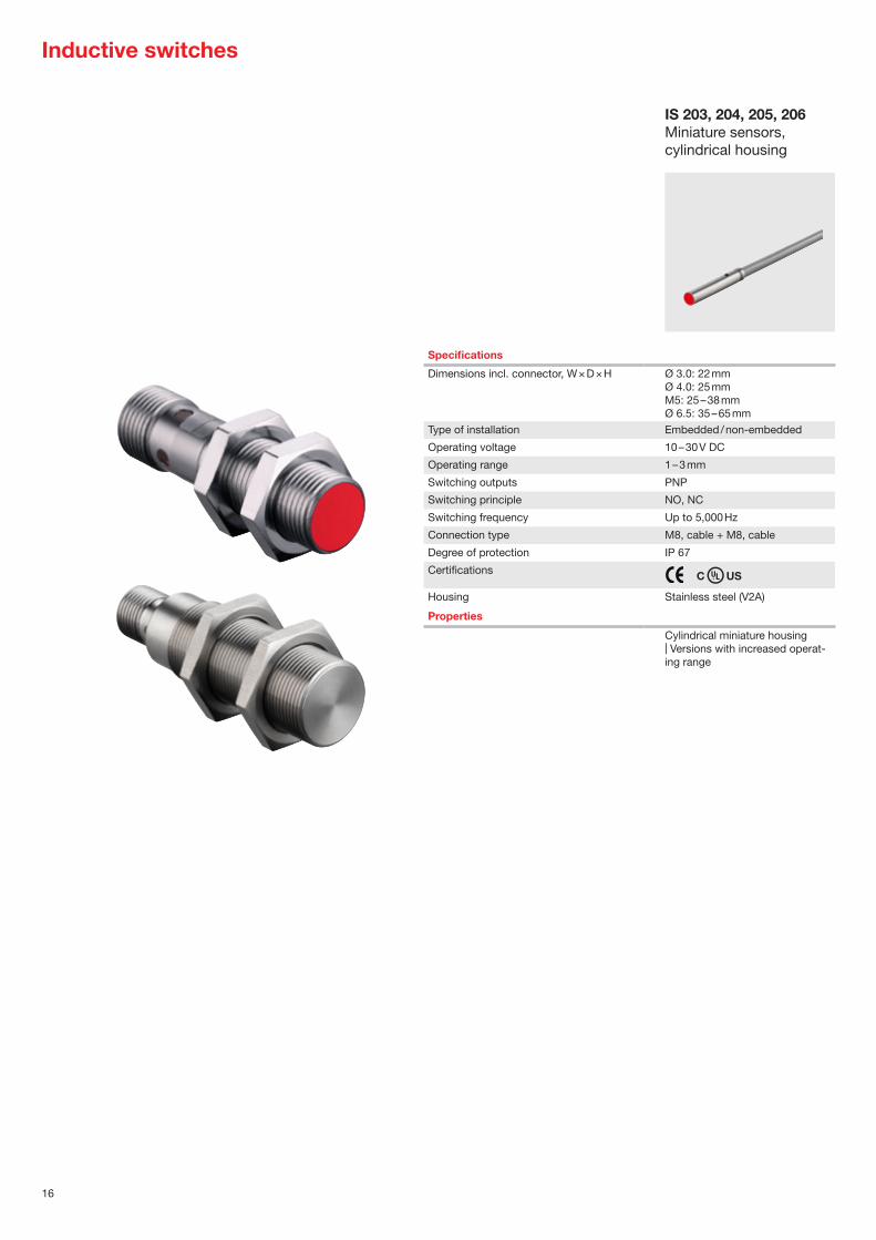
Inductive switches
IS 203, 204, 205, 206Miniature sensors, cylindrical housing
Specifications
Dimensions incl. connector, W × D × H Ø 3.0: 22 mmØ 4.0: 25 mmM5: 25 – 38 mmØ 6.5: 35 – 65 mm
Type of installation Embedded / non-embedded
Operating voltage 10 – 30 V DC
Operating range 1 – 3 mm
Switching outputs PNP
Switching principle NO, NC
Switching frequency Up to 5,000 Hz
Connection type M8, cable + M8, cable
Degree of protection IP 67
Certifications C US
Housing Stainless steel (V2A)
Properties
Cylindrical miniature housing | Versions with increased operat-ing range

17
Sw
itch
ing
sen
sors
M8: 22 – 45 mmM12: 35 – 60 mmM18: 35 – 64 mmM30: 40.6 – 73.5 mm
M8: 45 – 60 mmM12: 50 – 60 mmM18: 51 – 63.5 mmM30: 50 – 63.5 mm
5 × 5 × 25 mm8 × 8 × 40 mm8 × 8 × 59 mm
12 × 40 × 26 mm40 × 40 × 67 mm40 × 40 × 118 mm
Embedded / non-embedded Embedded / non-embedded Embedded Embedded / non-embedded
10 – 30 V DC 10 – 30 V DC 10 – 30 V DC 10 – 30 V DC
2 – 40 mm 2 – 40 mm 1.5 – 3 mm 4 – 40 mm
PNP, NPN PNP, NPN PNP, NPN PNP, NPN
NO, NC, NO + NC (antivalent) NO, NC NO, NC NO + NC (antivalent)
Up to 5,000 Hz Up to 600 Hz Up to 5,000 Hz Up to 1,400 Hz
M12, cable + M12, cable M8, M12, cable M8, cable + M8, cable M8, M12, terminal, cable
IP 67 IP 67, IP 68, IP 69 K IP 67 IP 67, IP 68, IP 69 K
C US C US C US C US
Metal All stainless steel (V2A & V4A) Metal Plastic
Different versions available: | Short housing design | Increased range | AC/DC device versions | Antivalent switching output
Full stainless steel housing from a single piece (V2A & V4A) | Resistant against vibration and pressure shocks | Mechanically resistant against impacts on the active surface | Also available as a model with 316L stainless steel (ECOLAB) suitable for use in hygienic applications | Correction factor 1 (material-independent detection)
Cubic miniature housing | Versions with increased operat-ing range
Bright status display | Antivalent switching outputs (NO+NC) | Increased ranges | M12 plug, turnable 270° and thus suitable even for angled connection cables | 360° visibility through 4-way LED indicator on the sensor head
IS 255, 288Miniature sensors, cubic housing
IS 240, 244 / ISS 244Standard, cubic
IS 208, 212, 218, 230Standard, cylindrical
IS 208, 212, 218, 230All stainless steel

18
Specifications
Dimensions M12: 53 – 75 mmM18: 73 – 88.5 mmM30: 66.5 – 79 mm / 87.3 mm
54 × 20.3 × 5.5 mm40 × 40 × 10 mm
M12: 55 – 68 mmM18: 70 – 85 mmM30: 85 – 98 mm
Type of installation Embedded / non-embedded Embedded Embedded / non-embedded
Operating voltage 10 – 30 V DC / 12 – 35 V DC 10 – 30 V DC 10 – 30 V DC
Operating range 1 – 30 mm 1 – 20 mm 1 – 30 mm
Switching outputs PNP, NPN PNP, NPN PNP, NPN
Switching principle NO (make-contact), NC (break-contact) partially reversible
NO (make-contact), NC (break-contact)
NO (make-contact), NC (break-contact)
Switching frequency 100 Hz (10 Hz with IO-Link) 100 Hz 100 Hz
Connection type M12 connector / PUR cable 2 m / PTFE cable 2 m
M12 connector / PUR cable 2 m / PUR cable 0.3 m
M12 connector / PUR cable 2 m
Degree of protection IP 67 IP 67 IP 67
Certifications C US C US
Housing Metal / plastic / Teflon (PTFE) Plastic Metal / plastic
IO-Link M18 and M30 version
Properties
Adjustable switching distances | Versions with potentiometer or teach buttons | Models with chemical-resistant PTFE housing | IO-Link interface
Switching distances adjustable by means of potentiometer | Compact and flat design
Adjustable switching distances | Versions with potentiometer
LCS-1Capacitive sensors, cylindrical
LCS-1Capacitive sensors, cubic
Capacitive sensors
LCS-2Capacitive sensors, cylindrical

19
Sw
itch
ing
sen
sors

20
Fiber optic sensors / ultrasonic sensors
LV46xFiber optic amplifiers
Specifications
Dimensions excl. connector, W × D × H
Ø 4 × 250 / 500 / 1,000 / 3,000 / 5,000 mm
Operating voltage 10 – 30 V DC
Switching outputs PNP, NPN, IO-Link
Connection type M8, cable, cable+M8, able+M12
Ø 2.2 plugged
Degree of protection IP 65 IP 65
Certifications
Housing Plastic Silicone, brass, stainless steel
Throughbeam photoelectric sensors
Operating range* 0 – 450 mm
Light source Red light, infrared Red light , infrared (with LV46x)
Switching Light, dark
Switching frequency 250 Hz ... 50 kHz
Retro-reflective photoelectric sensors
Operating range*
Light source
Switching
Switching frequency
Energetic diffuse sensor
Operating range* 0 – 80 mm
Light source Red light, infrared Red light , infrared (with LV46x)
Switching Light, dark
Switching frequency 250 Hz ... 50 kHz
Diffuse sensors with background suppression
Operating range*
Light source
Switching
Switching frequency
Options
Repeatability
Switching hysteresis
Resolution
Laser class
Properties
For glass and plastic fiber optics | High-speed or long-range amplifier | Teach-in | Sensitivity adjustment | Time functions | Multifunction input | IO-Link interface
Straight or lateral optical outlet | Multiple fiber core | Various ancillary lenses | Heat resistant, highly precise, oil and chemical resistant
GFGlass fiber optics
* Typical operating range limit

21
Sw
itch
ing
sen
sors
USS 18, 420Ultrasonic sensors, cubic
Ø 2.2 × 500 / 2,055 mm 15 × 33 × 50 mm20 × 15 × 42 mm
M18 × 46.3 / 74.3 / 77.6 mmM30 × 88.8 mm
M12 × 70 mmM18 × 51.8 / 75 / 82.8 mmM30 × 75 / 142.5 mm
10 – 30 V DC / 12 – 30 V DC 10 – 30 V DC / 12 – 30 V DC 10 – 30 V DC / 12 – 30 V DC
PNP, NPN PNP, NPN PNP, NPN
Ø 2.2 plugged M8, M12 M12 M8, M12, cable
C US C US
Plastic, models with bending protection
Metal, plastic Plastic Metal, plastic
0 – 1,700 mm 0 – 650 mm 0 – 6,000 mm
Red light , infrared (with LV46x) Ultrasonics (300 kHz) Ultrasonics (200 / 310 kHz)
NO/NC (object detected)
100 Hz 7 / 8 Hz
0 – 400 mm 0 – 300, 0 – 800, 0 – 400, 0 – 1,600 mm
Ultrasonics (290 kHz) Ultrasonics (300 / 230 kHz)
NC (object detected) NC (object detected)
20 Hz 8 / 5 / 1 Hz
0 – 270 mm
Red light , infrared (with LV46x)
10 – 200 (100 – 1,000) mm 40 – 300, 50 – 400, 80 – 1,200, 150 – 1,600, 250 – 3,500, 350 – 6,000 mm
10 – 200, 40 – 400, 25 – 400, 150 – 1,300, 300 – 3,000, 600 – 6,000 mm
Ultrasonics (240 – 400 kHz) Ultrasonics (200 / 230 / 300 kHz) Ultrasonics (200 / 310 kHz)
NO/NC (object detected) NO/NC (object detected) NO/NC (object detected)
10 / 50 Hz 1 / 2 / 5 / 8 / 10 Hz 7 / 8 / 20 / 50 Hz
Straight or lateral optical outlet | Various ancillary lenses | Arrays, V-arrangement | Various types of fiber structure, e.g., highly flexible, coax | Highly precise or heat resistant, models with bending protection
Configurable via PC | Various opening angles and sound lobes | 1 or 2 switching outputs
Configurable via PC | Teach-in | Design with angle head | 1 or 2 switching outputs | Synchroniza-tion and multiplex function | Temperature compensation
Configurable via PC | Teach-in | Design with angle head | 1 or 2 switching outputs | IO-Link interface | Synchroniza-tion and multiplex function | Temperature compensation
KFPlastic fiber optics
300 seriesUltrasonic sensors, cylindrical
400 seriesUltrasonic sensors, cylindrical

22
Light curtains
CSL 505Switching
* Guaranteed operating range** 5 mm resolution only with 58 mm housing depth
CSL 710Switching
CSR 780Switching
Specifications
Function Throughbeam principle Throughbeam principle Reflection principle
Dimensions excl. connector, W × D × H 10 × 27 × 150 … 3,180 mm12 × 58 × 120 … 480 mm
29 × 35 × 168 … 2,968 mm 28.6 × 34.2 × 142.8 … 478.8 mm
Operating voltage 24 V DC 18 – 30 V DC 18 – 30 V DC
Outputs 2x outputs / push-pull 4 I/Os (configurable) + IO-Link Push-pull
Connection type M8 M12 M12
Degree of protection IP 65 IP 65 IP 65
Certifications C US C US C US
Operating range* Up to 5 m Up to 3.5 … 7 m 700 mm
Light source Infrared Infrared Infrared
Cycle time 1 ms per beam 30 µs per beam > 2 ms (depending on measurement field length)
Measurement field length 35 – 3,100 mm 160 – 2,960 mm 96 / 432 mm
Resolution 5**, 12.5, 25, 50, 100 mm 5, 10, 20, 40 mm 1 mm
Number of beams Max. 160 Max. 592
Operation Autocalibration, configuration software, configuration by means of pin assignment
Control buttons on foil display, 5 languages, configuration software
Status displays for detection / interruption of first and last beam
Properties
2 switching ranges | Narrow profile | Through holes | Suitable for low-temperature applications down to –30 °C
8 switching ranges | Simple area splitting | 4 switching outputs + 1 IO-Link | Robust metal housing | Extremely fast cycle time | Display for diagnosis and align-ment | Suitable for low-tempera-ture applications down to –30 °C
Detection of extremely small objects (1 mm) | Warning output for contamination display | High object speed (< 3.5 m/sec for 1 × 10 × 10 mm) | Robust metal housing | Optimal setting using reference teach, indicator LED | Reflective tape as reflector

23
Sw
itch
ing
sen
sors
Specifications
Operating voltage 10 – 30 V DC / 12 – 30 V DC 10 – 30 V DC / 24 V DC 10 – 30 V DCSwitching outputs Push-pull Push-pull PNP, NPN
Connection type M8, M12, cable M8, cable, cable+M12 M8
Degree of protection IP 62 / IP 65 IP 65 IP 65
Certifications C US*1
C US*2
CDRH C US
Housing Metal Metal, plastic Metal
Throughbeam sensors
Mouth width 4 mm; 1 mm 3 mm 20 / 30 / 50 / 80 / 120 / 220 mm
Light source Ultrasonics Infrared Red light / laser (class 1)
Switching Light, dark, antivalent Light, dark, antivalent Light, dark
Switching frequency Up to 5,000 Hz 10,000 Hz 1,500 / 5,000 Hz
Options
Operation Teach Teach / potentiometer Potentiometer
Warning output X X
Properties
Detection of transparent media and paper labels | Automatic tracking of the switching threshold ALC function | Teach-in | Model with mechanical tape guide | Splice inspection | Models with easy-teach process | Models with easy-tune for man-ual adaptation of the switching threshold
Detection of paper labels | Automatic tracking of the switching threshold ALC function | Storage of up to 10 teach values in the sensor | Removable operating head on potentiometer version
Detection of small objects | Light/dark switching on device
Forked sensors
(I)GS 63B, 61Label detection, optical
(I)GSU 14D / GSU 06GK 14Label detection, ultrasonics / capacitive
GS (L) 04Optical
*1 (I)GSU 14D and GSU 06 only *2 (I)GS 63, GS 61 only

24
Special sensors
CRT 20B, 448Color sensors
KRT 20, 21, 18B, 55, 3BContrast sensors
LRT 8Luminescence sensors
Specifications
Function Contrast distinction Color evaluation Luminescence detection
Dimensions excl. connector, W × D × H 31 × 53 × 80 mm15 × 47 × 33 mm14 × 36 × 25 mm11 × 32 × 17 mm
30 × 82 × 53 mm17 × 46 × 50 mm
15 × 48 × 38 mm
Operating voltage 10 – 30 V DC / 12 – 30 V DC 10 – 30 V DC / 24 V DC / 12 – 28 V DC
10 – 30 V DC
Outputs PNP, NPN, push-pullAnalog, IO-Link
1 × PNP / 4 × PNP or 1 × NPN / 4 × NPN or 3 × PNP / 3 × NPN
PNP, NPN
Connection type M12, M8, cable+M8, cable, cable+M12
M12 M12
Degree of protection IP 67, IP 69K IP 67 IP 67
Certifications C US C US C US
Operating range* 13 – 80 mm 12 mm60 mm32 mm
0 – 400 mm
Light source LED, laser (class 1) LED LED
Switching frequency 2,500 – 50,000 Hz 6,000 / 1,500 / 500 Hz 1,500 Hz
Transmitter color RGB / white / red laser RGB / white UV / blue
Light beam gate Lateral or frontal Lateral or frontal Front
Light spot shape Round / rectangular Round / rectangular Round
Light spot orientation Lengthwise, sideways Vertical
Operation Teach-in, EasyTune, IO-Link, potentiometer
Teach-in Potentiometer
Properties
Tracking function for faded marks | Display for optimum adaptation to the application | Automatic luster suppression | Temperature compensation | Pulse stretching | Light/dark switching | Reversible switching threshold | ECOLAB | IO-Link process data | IO-Link configuration | IO-Link diagnosis | Additional function for weak contrasts
Small construction | Glass optics | Turnable M12 connector | ECOLAB
Small construction | Sensitivity adjustment | ECOLAB | Detection of any kind of luminescence | Detection of white paper | Detection of printed lumines-cence marks | Detection of luminescence marks on wood
* Typical operating range limit
25
Sw
itch
ing
sen
sors
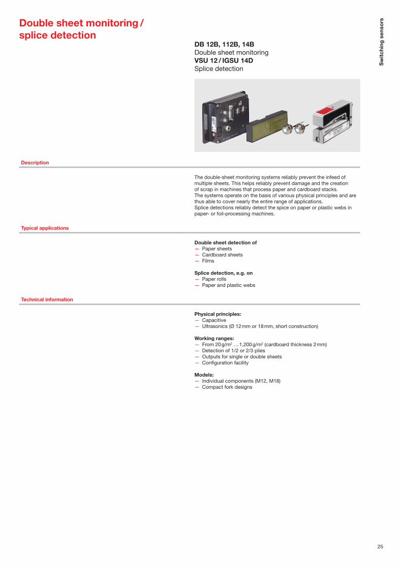
Description
The double-sheet monitoring systems reliably prevent the infeed of multiple sheets. This helps reliably prevent damage and the creation of scrap in machines that process paper and cardboard stacks. The systems operate on the basis of various physical principles and are thus able to cover nearly the entire range of applications.Splice detections reliably detect the spice on paper or plastic webs in paper- or foil-processing machines.
Typical applications
Double sheet detection of — Paper sheets — Cardboard sheets — Films
Splice detection, e.g. on — Paper rolls — Paper and plastic webs
Technical information
Physical principles: — Capacitive — Ultrasonics (Ø 12 mm or 18 mm, short construction)
Working ranges: — From 20 g/m2 … 1,200 g/m2 (cardboard thickness 2 mm) — Detection of 1/2 or 2/3 plies — Outputs for single or double sheets — Configuration facility
Models: — Individual components (M12, M18) — Compact fork designs
Double sheet monitoring / splice detection
DB 12B, 112B, 14BDouble sheet monitoringVSU 12 / IGSU 14DSplice detection

Measuring sensorsIntelligent monitoring and control through measuring sensors
Measuring sensors can actively check distances, position system parts and monitor other parameters in order to intelligently and independently initiate actions and, e.g., intervene in processes for control purposes. We offer a large selection of different sensor technologies and designs that you can use to find solutions to measuring applications. Various powerful technologies facilitate optimum adaptation of our measuring sensors to a wide range of applica-tion requirements. Depending on the application, various communication interfaces are also available, such as IO-Link, bus interfaces or Ethernet-based interfaces.

27
Forward-looking compartment fine positioning with camera-based positioning system
The camera-based IPS 200i and IPS 400i sensors are for the compartment fine positioning of the chassis and lifting unit of the high-bay storage device in front of single- or double-depth shelf compartments. Any deviations from the target reference position that occur during absolute positioning are thereby detected. The reference position is defined by simple bore holes or reflectors in the steel profiles in the shelf compartments. If the bore hole is located in the working range of the sensor, it delivers the current position relative to the reference position via the integrated Ethernet TCP/IP or PROFINET interface or via 4 digital switching outputs. When the current absolute and reference positions match, the ideal positioning of the high-bay storage device is reached. Smallest size, simple operation, configuration via the integrated web server or directly on the sensor via configuration codes are just a few of the highlights of this device.
IPS 200i / 400i series — Extremely small, camera-based positioning
sensor
— Simple commissioning through printed configuration codes located directly on the device
— Fault-free use for a working range of up to 2,400 mm
— With Ethernet and PROFINET

28
Distance sensors
ODSL 8Optical distance sensors
ODS 9Optical distance sensors
Specifications
Function Distance measurement, optical
Distance measurement, optical
Distance measurement, optical
Dimensions excl. connector, W × D × H
15 × 48 × 38 mm 21 × 50 × 50 mm 25 × 65 × 55 mm
Operating voltage 18 – 30 V DC 18 – 30 V DC (analog, IO-Link) 18 – 30 V DC (analog, IO-Link)
Outputs 4 – 20 mA1 – 10 V2 × push-pull
4 – 20 mA1 – 10 V, 0 – 10 VRS 232 / RS 485Push-pullIO-Link
4 – 20 mA1 – 10 V, 0 – 10 VPush-pullIO-Link
Connection type M12 M12 M12
Degree of protection IP 67, IP 69K IP 67 IP 67
Certifications CDRH C US CDRH C US CDRH C US
Measurement range 20 – 500 mm 50 – 650 mm
50 – 3,500 mm 50 – 8,000 mm (90 % diffuse reflection)100 – 25,000 mm on reflective tape
Measurement principle Optical / LED / laser (class 2) Optical / laser (class 1, 2) Optical / laser (class 1)
Measurement time 2 – 7 ms 2 ms 3,4 – 1,020 ms (adjustable)
Ultrasonic frequency
Resolution 0.03 – 0.5 mm 0.01 – 0.5 mm 1 mm
Operation Teach-in Potentiometer
Teach-in Control buttons on foil display or Sensor Studio
Control buttons on foil display or Sensor Studio
Properties
Compact metal housing | Turnable M12 connector | Triangulation measurement
Display for measured value display and configuration | Turnable M12 connector | Triangulation measurement | Supports the IO-Link smart sensor profile
Display for measured value display and configuration | Turnable M12 connector | All devices with IO-Link interface | Propagation time measurement (TOF)
ODS 10Optical distance sensors

29
Mea
suri
ng s
enso
rs
ODS 110Optical distance sensors
ODSL 96BOptical distance sensors
300, 400 seriesMeasuring ultrasonic sensors
Distance measurement, optical
Distance measurement, optical
Distance measurement, optical
Distance measurement, ultrasonics
50 × 23 × 50 mm 79 × 69 × 149 mm 30 × 90 × 70 mm M18 × 46.3 / 51.8 / 74.3 / 75 / 77.6 / 82.8 mm M30 × 75 / 88.8 / 142.5mm
18 – 30 V DC (analog) 10 – 30 V DC18 – 30 V DC (analog)
10 – 30 V DC18 – 30 V DC (analog, IO-Link)
10 – 30 V DC12 – 30 V DC
4 – 20 mA1 – 10 V1x push-pull
4 – 20 mA1 – 10 VRS 232 / RS 4851 × PNP, 2 × PNP, 3 × PNP
4 – 20 mA1 – 10 V, 0 – 10 VRS 232 / RS 485Push-pullIO-Link
PNP (NPN)
M12 M12, cable M12, cable M12
IP 67 IP 67 IP 67, IP 69K IP 67
C US CDRH C US CDRH C US C US
100 – 3,000 mm100 – 5,000 mm (90 % diffuse reflection)
200 – 65,000 mm
60 – 25,000 mm 25 – 400 / 50 – 400 / 80 – 1,200 / 150 – 1,300 / 250 – 3,500 / 300 – 3,000 / 350 – 6,000 / 600 – 6,000 mm
Optical / laser (class 1) Optical / laser (class 2) Optical / LED / laser (class 1, 2) Ultrasonics
4 ms 30 – 100 ms 1 – 100 ms 0.1 – 1 s
200 kHz / 310 kHz
1 mm 1 mm 0.1 – 3 mm 1 mm
Teach-in or Sensor Studio Teach-inDisplay
Teach-inConfiguration softwareDisplay
Teach-In IO-Link
All devices with IO-Link interface | Turnable M12 connector | Adjustment via teach button | Propagation time measurement (TOF)
Metal housing | Display for measured value display and configuration | M12 connector | Ex-devices are also available | Phase measurement
Robust metal housing | Display for measured value display and configuration | M12 connector | Ex devices are also available | Triangulation measurement | Propagation time measurement (TOF) | Phase measurement
3/5 operating modes | Tempera-ture-compensated | Metal/plastic housing | Small dead zone
ODSL 30Optical distance sensors

30
Sensors for positioning
BPS 300iBar code positioning systems
BPS 8Bar code positioning systems
Specifications
Function Distance measurement, optical Position detection, optical Position detection, optical
Operating range 40 / 120 / 200 / 300 m 10,000 m 10,000 m
Working range 60 … 120 mm, 80 … 140 mm 50 … 170 mm
Interfaces Integrated:PROFIBUS and SSIPROFINETPROFINET and SSIDeviceNetEtherCATEtherNet/IPCANopenEthernet TCP/IP, UDPInterbus-SRS 232, RS 422, RS 485SSI
Integrated:RS 232
Integrated:PROFINETEtherCATPROFIBUSSSIRS 422RS 232RS 485
Connectivity Via the interfaces mentioned above
With MA 200i connection unitPROFINET IO/RT, PROFIBUS,Ethernet TCP/IP, UDP, IP,EtherCAT, DeviceNet, CANopen
Functional principle Against reflector Against bar code tape Against bar code tape
Measurement value output 1.7 ms 3.3 ms 1 ms
Reproducibility ±0.9 / 1.5 / 2.1 / 3 mm (3 sigma) ±1 mm (3 sigma) ±0.15 mm (3 sigma)
Accuracy ±2 / 2 / 3 / 5 mm
Degree of protection IP 65 IP 67 IP 65
Light source Red light laser (class 2) Red light laser (class 2) Red light laser (class 1, 2)
Supply voltage 18 – 30 V DC 5 V DC(24 V DC via MA 8-01)
18 – 30 V DC
Operating temperature –5 °C … +50 °C(–30 °C … +50 °C with heating)
0 °C … +40 °C –5 °C … +50 °C(–35 °C … +50 °C with heating)
Options Speed measurement and monitoring
Customer-specific configuration facility
Speed measurement and monitoring
Certifications CDRH C US CDRH C US CDRH C US
Properties
Absolute measurement system with very high accuracy, tested by the Physikalisch Technische Bundesanstalt (German Metro-logy Institute) | Simultaneous use of the PROFIBUS and SSI; alternatively, PROFINET and SSI interface | Easy programming via extensive configuration file | Optionally with heating | Multiple language menu-driven display | Heatable reflectors available as accessories
Distance measurements of up to 10,000 m, also for curves, gradients and track switches | Curve-going, horizontally and vertically | Compact metal housing | Turnable M12 connector | Large selection of different protocols via external MA 200i connection units
Positioning on curves, gradients and track switches | Curve-going, horizontally and vertically | Metal housing | 3 selectable connection systems | Fast, secure and position-neutral installation using special mount-ing device | Extensive diagnostic options | Comfortable program-ming via GSDML/GSD or ESI files | Optionally with heating or display
AMS 300iOptical laser distance sensors

31
Mea
suri
ng s
enso
rs
LPS 36, 36 HILES 36, 36 HILRS 36Light section sensors
Specifications
Function Distance measurement, light section, optical
Distance measurement, scanner, optical
Edge/diameter measurement, optical
Dimensions excl. connector, W × D × H
56 × 74 × 160 mm 140 × 148 × 133 mm141 × 167 × 168 mm
19.4 × 81.5 × 91 mm20 × 155 × 91.5 mm
Operating voltage 18 – 30 V DC 24 V DC 10 – 30 V DC (digital)18 – 30 V DC (analog)
Outputs 4 – 20 mA1 – 10 VEthernet4 × push-pullPROFIBUS
Ethernet / RS 232 / RS 4224 × PNP, 8 reversible detection field pairs
2 × 4 – 20 mA2 × 0 – 10 VRS 232 / RS 422 / RS 4851 × PNP, 2 × PNP
Connection type M12 Sub-D, M12, M16 M12
Degree of protection IP 67 IP 65 IP 67
Certifications CDRH C US CDRH C US C US
Operating range* 200 – 800 / 200 – 600 mm 0 – 65 m
Measurement principle Optical / laser (class 2M) Optical / laser (class 1) Optical / LED
Measurement time 10 ms 20 – 40 ms/scan Min. 2.5 ms
Measurement field width / Scanning angle
Max. 600 mm / max. 140 mm 0.36° 25 mm
Resolution 0.1 – 6 mm 5 mm 14 μm
Mouth width 27 mm / 98 mm
Mouth depth 7 42 mm
Number of inspection tasks 16 7 5
Operation Configuration softwareDisplay
Configuration software Terminal program via RS 232 interface
Properties
LPS 36: light section sensor for 2D/3D object measurement | LPS 36 HI: highly precise with a resolution of 0.1 mm | LES 36: light section sensor for width/height and position measurement | LRS 36: light section sensor for object detection in up to 16 de-tection fields | Alignment aid with OLED display; inputs: activation, cascading, trigger | Optional: encoder port
Laser scanners for object measurement and detection | Version with 20 ms/scan (50 Hz) | Version with 40 ms/scan (25 Hz) | Contamination suppression | Optionally with heating
Detection of transparent media | Foil detection > 0.1 mm | Turnable M12 connector | Wide-ranging evaluation functions | Perfect for thread and fiber measurement
3D sensors / forked sensors
ROD 4 (plus)Measuring laser scanner
GS 754BCCD forked sensors
* Guaranteed operating range

NEW
32
Sensors for compartment fine positioning
IPS 200iSensors for positioning
IPS 400iSensors for positioning
Typical applications
Compartment fine positioning Single compartment depth Double compartment depth
Sensor / cameras CMOS (Global Shutter) CMOS (Global Shutter)
Resolution (pixel) 1,280 × 960 1,280 × 960
Focal point Reading distance 100 … 600 mmMarker dependent
Reading distance 250 – 2,400 mm Marker-dependent
Interface Integrated:Ethernet TCP/IP, UDPPROFINET IO/RT
Integrated:Ethernet TCP/IP, UDPPROFINET IO/RT
Digital inputs/outputs 3x IN; 5x OUT 3x IN; 5x OUT
Optional
Cables, mounting devices, reflectors, heating model to –30°C
Cables, mounting devices, reflectors, heating model to –30°C, external illumination
Number of test routines 8 8
Configuration / Operating system
Web-based configuration tool (webConfig tool)XML commands; 2x operational controls
Web-based configuration tool(webConfig tool)XML commands; 2x operational controls
Options Configuration on the device via configuration codes
Configuration on the device via configuration codes
Dimensions, W × H × D 43 × 61 × 44 mm 43 × 61 × 44 mm
Certifications C US C US
Properties
Time savings through fast commissioning via web-based configuration tool or printed configuration codes | Innovative alignment system via feedback LEDs simplifies alignment | One device for the entire region of interest from 100–600 mm | Quality score enables the early detection of a deterioration in reading performance | Can be used flexibly thanks to high-per-formance, infrared LED illumina-tion that is independent of ambi-ent light | Model with integrated heating for use to –30°C
Time savings through fast commissioning via web-based configuration tool or printed configuration codes | Innovative alignment system via feedback LEDs simplifies alignment | Quality score enables the early detection of a deterioration in reading performance | One device for double-depth work-ing range from 250 – 2,400 mm | Can be used flexibly thanks to high-performance, infrared LED illumination that is independent of ambient light | Model with inte-grated heating for use to –30°C

NEW
33
Mea
suri
ng s
enso
rsLight curtains/ volume measurement system
Specifications
Function Size / contour detection, optical
Size / contour detection, optical
Size / contour detection, optical
Dimensions excl. connector, W × D × H
29 × 35 ×168 … 2,968 mm 29 × 35 ×168 … 2,968 mm Dependent on the system configuration
Operating voltage 18 – 30 V DC 18 – 30 V DC 230 V AC
Outputs Analog, CANopen, IO-Link, PROFIBUSPROFINETRS 485 (MODBUS)
CANopen, IO-Link, 2 to 4 I/Os (configurable)
4 I/Os , Ethernet TCP/IP, PROFINET
Connection type M12 M12 M12 and Harting
Degree of protection IP 65 IP 54 IP 54 switch cabinet / IP 65 light curtain
Certifications C US
Operating range* 4.5 … 9.5 m 7 m
Light source / Measurement principle
Infrared Infrared Infrared
Cycle time / Measurement time
10 – 30 μs per beam + 0,4 ms 30 µs per beam + 0,4 ms Dependent on conveyor speed and object size
Measurement field length / Scanning angle
160 – 2,960 mm 130 – 2,870 mm L × W × H: 50 × 50 × 5 mm3 – 2,000 × 2,000 × 2,000 mm3
2,000 × 1,200 × 1,200 mm3
Resolution 5, 10, 20, 40 mm 5, 10, 20 mm 5 mm
Number of beams Max. 592 Max. 592
Mouth width
Mouth depth
Operation Control buttons on foil display, 5 languages, configuration soft-ware
Control buttons on foil display, 5 languages, configuration soft-ware
webConfig
Properties
Cycle time CML 730: 10 µs x number of beams + 0.4 ms | Cycle time CML 720: 30 µs x number of beams + 0.4 ms | Detection of transparent media | Display for diagnosis and align-ment | Standard profile for simple mounting | Robust metal housing | Suitable for low-temperature applications down to –30 °C
Cycle time: 30 µs x number of beams + 0.4 ms | Display for diagnosis and alignment | Standard profile for simple mounting | Robust metal housing
Contour measurement system for passing objects | Output of the smallest enclosing cuboid of the object | Output of object protru-sions and bulges | Output of the object position and orientation angle on the conveyor | Collection and looping through of external data from, e.g., scales, bar code readers | Easy commissioning by the customer | Total system can be ordered with one part number
CMS 700iMeasuring
CML 720i EXMeasuring
CML 700iMeasuring
* Guaranteed operating range

Products for safety at workFrom a single source: Products and services that protect the operator and facilitate efficient processes
Machine safety no longer means just personnel protection. It also makes an important contribution to the efficient and smooth flow of processes. As one of the technology leaders in the area of optoelectronic safety sensors, we offer competent and extensive consultation on the topic of safety at work. In addition to our wide range of safety sensors, we also offer safety switches and safety locking devices as well as safe control components. We provide you with well thought-out and reliable solutions for safety at work from a single source. In doing so, we place great importance on the simple and efficient integration and installation of our safety technology. Innovative connection concepts, integrated alignment aids, operating mode selection without PC and integrated gateway func-tions are just a few examples here.

35
Highly efficient safety laser scanner: clever area protection and access guarding
With the RSL 400 safety laser scanner, we have set a new standard worldwide in the supreme discipline of safety sensor technology. Thanks to our decades of experience, we have succeeded in developing a device which, through clever detailed solutions, combines reliable operation with simple configuration and installation of devices. In many cases the RSL 400 can even be used to perform tasks that previously required two safety laser scanners.
RSL 400 — Scanning angle of 270° and operating range
of 8.25 m
— Easy-to-mount, removable measuring unit for simple and quick exchange
— 2 independent protective functions in one device
— PROFINET/PROFIsafe interface for simple integration in industrial networks
— High-quality data output for navigation of automated guided vehicles and first-class safety technology in a single device

36
RSL 420, 425Safety laser scanners
RSL 410Safety laser scanners
Safety laser scanners
Specifications
Type in accordance with EN IEC 61496 Type 3 Type 3
SIL in accordance with IEC 61508 and EN IEC 62061 (SILCL)
SIL 2 SIL 2
Performance Level (PL) in accordance with EN ISO 13849-1
PL d PL d
Resolution (adjustable) 30 / 40 / 50 / 60 / 70 / 150 mm 30 / 40 / 50 / 60 / 70 / 150 mm
Operating range 3 / 4.5 / 6.25 / 8.25 m 3 / 4.5 / 6.25 / 8.25 m
Scanning angle 270° 270°
Number of field pairs / 4-field sets 1 / 1 10 / 10
Dimensions, W × H × D 140 × 149 × 140 mm 140 × 149 × 140 mm
Safety-related switching outputs 2 PNP transistor outputs 2 PNP transistor outputs
Connection type M12 connector, configuration and diagnosis via Ethernet TCP/IP and Bluetooth
Cable or connector, 16-pin, configuration and diagnosis via Ethernet TCP/IP, USB and Bluetooth
Certifications C US C US
Functions
Selectable functions: resolution, dynamic contactor monitoring (EDM), start/restart interlock (RES) | Vertical access guarding with reference boundary monitor-ing | Four-field mode
Selectable functions: resolution, dynamic contactor monitoring (EDM), start/restart interlock (RES) | Vertical access guarding with reference boundary monitoring | Four-field mode | E-stop linkage | RSL 425: measurement value output for AGV navigation
Properties
1 field pair/4-field set | Basic functions such as auto-matic start/restart, start/restart interlock (RES), contactor mon-itoring (EDM) can be selected | Optimum handling by means of separate intelligent connection unit with integrated configuration memory and large, plain-text display with integrated electronic spirit level | 3 configurable signal outputs
10 field pairs/4-field sets | Basic functions such as auto-matic start/restart, start/restart interlock (RES), contactor mon-itoring (EDM) can be selected | Optimum handling by means of separate intelligent connection unit with integrated configuration memory and large, plain-text display with integrated electronic spirit level | 4 configurable signal outputs | RSL 425: output of high-quality measurement values for distance and signal strength via UDP, angular resolution 0.1°, configurable

37
Pro
duc
ts f
or
safe
ty a
t w
ork
Type 3 Type 3 Type 3 Type 3
SIL 2 SIL 2 SIL 2 SIL 2
PL d PL d PL d PL d
30 / 40 / 50 / 60 / 70 / 150 mm 30 / 40 / 50 / 60 / 70 / 150 mm 30 / 40 / 50 / 60 / 70 / 150 mm 30 / 40 / 50 / 60 / 70 / 150 mm
3 / 4.5 / 6.25 / 8.25 m 3 / 4.5 / 6.25 / 8.25 m 3 / 4.5 / 6.25 / 8.25 m 3 / 4.5 / 6.25 / 8.25 m
270° 270° 270° 270°
10+10 / 10 100 / 50 10 / 10 100 / 50
140 × 149 × 140 mm 140 × 149 × 140 mm 140 × 169 × 140 mm 140 × 169 × 140 mm
2 x 2 PNP transistor outputs 2 x 2 PNP transistor outputs PROFIsafe, 1 protective field PROFIsafe, 4 parallel protective fields
Cable or connector, 29-pin, configuration and diagnosis via Ethernet TCP/IP, USB and Bluetooth
Cable or connector, 29-pin, configuration and diagnosis via Ethernet TCP/IP, USB and Bluetooth
3x M12 connection for 2-port switch and voltage supply, configuration also via USB and Bluetooth
3x M12 connection for 2-port switch and voltage supply, configuration also via USB and Bluetooth
C US C US C US C US
Selectable functions: resolution, dynamic contactor monitoring (EDM), start/restart interlock (RES) | Vertical access guarding with reference boundary monitoring | Four-field mode | E-stop linkage | Safe time delay, internal | Data output, configurable
Selectable functions: resolution, dynamic contactor monitoring (EDM), start/restart interlock (RES) | Vertical access guarding with reference boundary monitoring | Four-field mode | E-stop linkage | Safe time delay, internal | Data output, configu-rable | RSL 445: measurement value output for AGV navigation
Selectable functions: resolution, start/restart interlock (RES) | Vertical access guarding with reference boundary monitoring | Four-field mode
Selectable functions: resolution, start/restart interlock (RES) | Vertical access guarding with reference boundary monitoring | Four-field mode | Data output, configurable | RSL 455: measure-ment value output for AGV navigation
10+10 field pairs/4-field sets, reversible | Two independent protective functions and OSSD pairs | Basic functions such as automatic start/restart, start/restart interlock (RES) | Optimum handling by means of separate intelligent connection unit with integrated configuration memory and large, plain-text display with integrated electronic spirit level | 9 configurable signal outputs | Safe, internal switch-off delay (Stop 1)
100 field pairs / 50 4-field sets, reversible | Two independent protective functions and OSSD pairs | Basic functions such as automatic start/restart, start /restart interlock (RES), contactor monitoring (EDM) can be select-ed | Optimum handling by means of separate intelligent connection unit with integrated configuration memory and large, plain-text display with integrated electronic spirit level | Up to 10 independent sensor configurations, ideal for mobile applications | 9 config-urable signal outputs | Safe, internal switch-off delay (Stop 1) | RSL 445: output of high-quality measurement values for distance and signal strength via UDP, an-gular resolution 0.1°, configurable
Optimum handling through removable connection unit with integrated 2-port PROFINET- switch switch and integrated configuration memory | Confor-mance Class C, IRT-capable | 10 field pairs/4-field sets, reversible | Basic functions such as automatic start/restart, start/restart interlock (RES), can be selected | Large, plain-text dis-play with integrated electronic spirit level | Configuration also via Bluetooth and USB interface
Optimum handling through removable connection unit with integrated 2-port PROFINET- switch switch and integrated configuration memory | Conformance Class C, IRT-capable | 100 field pairs / 50 4-field sets, reversible | Evaluation of up to 4 protective fields | Basic functions such as automatic start/restart, start/restart interlock (RES), can be selected | Large, plain-text dis-play with integrated electronic spirit level | Configuration also via Bluetooth and USB interface | Up to 10 independent sensor configurations, ideal for mobile applications | RSL 455P: output of high-quality measurement values for distance and signal strength via UDP, angular resolu-tion 0.1°, configurable
RSL 430Safety laser scanners
RSL 420PSafety laser scanner PROFIsafe
RSL 440, 445Safety laser scanners
RSL 450P, 455PSafety laser scanner PROFIsafe

38
MLC 310Type 2 safety light curtains
Safety light curtains
MLC 320Type 2 safety light curtains
Specifications
Type in accordance with EN IEC 61496 Type 2 Type 2
SIL in accordance with IEC 61508 and EN IEC 62061 (SILCL)
SIL 1 SIL 1
Performance Level (PL) in accordance with EN ISO 13849-1
PL c PL c
Resolution 20 / 30 / 40 / 90 mm 20 / 30 / 40 / 90 mm
Operating range (depending on resolution) 15 / 10 / 20 / 20 m 15 / 10 / 20 / 20 m
Protective field height (type-dependent) 150 … 3,000 mm 150 … 3,000 mm
Profile cross section 29 × 35 mm 29 × 35 mm
Safety-related switching outputs (OSSDs) 2 PNP transistor outputs 2 PNP transistor outputs
Connection type M12 M12
Certifications
Functions
Transmission channel changeover | Range reduction
Transmission channel changeover | Range reduction | Start/restart interlock (RES) | Contactor moni-toring (EDM) | 7-segment display
Properties
Configuration by wiring – auto-matic transfer to replacement device after device exchange
Configuration by wiring – auto-matic transfer to replacement device after device exchange

39
Pro
duc
ts f
or
safe
ty a
t w
ork
MLC 510Type 4 safety light curtains
MLC 520Type 4 safety light curtains
MLC 530Type 4 safety light curtains
MLC 530 SPGType 4 safety light curtains
Type 4 Type 4 Type 4 Type 4
SIL 3 SIL 3 SIL 3 SIL 3
PL e PL e PL e PL e
14 / 20 / 30 / 40 / 90 mm 14 / 20 / 30 / 40 / 90 mm 14 / 20 / 30 / 40 / 90 mm 30 / 40 / 90 mm
6 / 15 / 10 / 20 / 20 m 6 / 15 / 10 / 20 / 20 m 6 / 15 / 10 / 20 / 20 m 10 / 20 / 20 m
150 … 3,000 mm 150 … 3,000 mm 150 … 3,000 mm 150 … 3,000 mm
29 × 35 mm 29 × 35 mm 29 × 35 mm 29 × 35 mm
2 PNP transistor outputs orAS-i Safety interface
2 PNP transistor outputs 2 PNP transistor outputs 2 PNP transistor outputs
M12 M12 M12 M12
Transmission channel change-over | Range reduction
Transmission channel changeover | Range reduction | Start/restart interlock (RES) | Contactor monitoring (EDM) | 7-segment display
Transmission channel changeover | Range reduction | Start/restart interlock (RES) | Contactor monitoring (EDM) | 7-segment display, linkage | Fixed and floating beam blanking| Reduced resolution | Timing controlled 2-sensor muting | Muting-timeout extension | Partial muting
Transmission channel changeover | Range reduction | Start/restart interlock (RES) | 7-segment display | Fixed blank-ing | Integrated muting function with control via PLC signal (no muting sensors necessary)
Configuration by wiring – auto-matic transfer to replacement device after device exchange | Extra impact-resistant models available | Models available with extra high interference rejection against ambient light
Configuration by wiring – auto-matic transfer to replacement device after device exchange | Extra impact-resistant models available
Configuration by wiring – auto-matic transfer to replacement device after device exchange | Linkage with safety devices via contact or OSSD output saves effort in downstream evaluation circuit | Multiple scanning and reduced resolution for operation which is immune to interference | Integrated muting and blanking function can be activated during operation | Extra impact-resistant models available
Configuration by wiring – auto-matic transfer to replacement device after device exchange | Efficient access guarding with-out muting sensors: high level of availability and protection against tampering with a very compact system design

40
Safety light curtains
The external MLC alignment aid is a practical tool with which the transmitter can be precisely aligned more quickly.
MLC 511 AIDAType 4 safety light curtains
Specifications
Type in accordance with EN IEC 61496 Type 4
SIL in accordance with IEC 61508 and EN IEC 62061 (SILCL)
SIL 3
Performance Level (PL) in accordance with EN ISO 13849-1
PL e
Resolution 14 / 30 mm
Operating range 6 / 10 m
Protective field height (type-dependent) 300 … 1,800 mm
Profile cross section 29 × 35 mm
Safety-related switching outputs (OSSDs) 2 PNP transistor outputs
Connection type M12
Certifications
Functions
Transmission channel changeover | Range reduction | Automatic start/restart
Properties
Plug connection with AIDA- compliant M12 pin assignment (4-pin) (Automatisierungs-Initia-tive deutscher Automobilisten (AIDA) = Automation initiative of German automobile manu-facturers) | Configuration by wiring – automatic transfer to replacement device after device exchange

41
Pro
duc
ts f
or
safe
ty a
t w
ork
Type 4 Type 4 Type 4 Type 4
SIL 3 SIL 3 SIL 3 SIL 3
PL e PL e PL e PL e
14 / 20 / 30 / 40 / 90 mm 20 / 30 mm 14 / 30 mm 14 / 24 mm
6 / 15 / 10 / 20 / 20 m 15 / 10 m 4.8 / 8 m 6 m
300 … 1,800 mm 600 … 1,500 mm 300 … 1,200 mm 150 … 1,200 mm
29 × 35 mm 29 × 35 mm Ø 52.5 mm 15,4 × 32.6 mm
2 PNP transistor outputsAS-i Safety interface
2 PNP transistor outputs 2 PNP transistor outputs 2 PNP transistor outputs
M12 M12 Cable, 15 m 160 mm cable with M12 connector
C US
Transmission channel change-over | Range reduction | Start / restart interlock (RES) | Contactor monitoring (EDM) | 7-segment display | Cascadable
Transmission channel change-over | Range reduction | Start/restart interlock (RES) | Contactor monitoring (EDM) | 7-segment display
Transmission channel change-over | Range reduction
Start/restart interlock (RES) | Contactor monitoring (EDM) | Cascadable via adapter cable
Host, middle-guest and guest devices combine point of operation guarding with area protection | Configuration by wiring – automatic transfer to replacement device after device exchange
Certified for applications in po-tentially explosive areas of group II, category 3, zone 2 (gas) and zone 22 (dust) | Configuration by wiring – automatic transfer to replacement device after device exchange
The configuration is simply performed by means of wiring | Pre-mounted in transparent, encapsulated tube
Extra slim design without dead zones | Especially fine length grid of 30 mm | Configuration by wiring – automatic transfer to replacement device after device exchange
MLC 510 IP 67/69KType 4 safety light curtains
MLC 520 EX2Type 4 safety light curtains
MLC 520 Host-GuestType 4 safety light curtains
MLC 520-S Extra slim design Type 4 safety light curtains

42
Multiple light beam safety devices
Specifications
Type in accordance with EN IEC 61496
SIL in accordance with IEC 61508 and EN IEC 62061 (SILCL)Performance Level (PL) in accordance with EN ISO 13849-1Number of beams/beam distance
Operating range
Profile cross section
Safety-related switching outputs (OSSDs)Connection type
Certifications
Functions
Properties

43
Pro
duc
ts f
or
safe
ty a
t w
ork
MLD 335, 535Type 2 / 4 multiple light beam safety devices
MLD 330, 530Type 2 / 4 multiple light beam safety devices
MLD 320, 520Type 2 / 4 multiple light beam safety devices
MLD 310, 510Type 2 / 4 multiple light beam safety devices
Type 2 / Type 4 Type 2 / Type 4 Type 2 / Type 4 Type 2 / Type 4
SIL 1 / SIL 3 SIL 1 / SIL 3 SIL 1 / SIL 3 SIL 1 / SIL 3
PL c / PL e PL c / PL e PL c / PL e PL c / PL e
2 / 500 mm 3 / 400 mm 4 / 300 mm
2 / 500 mm 3 / 400 mm 4 / 300 mm
2 / 500 mm 3 / 400 mm 4 / 300 mm
2 / 500 mm 3 / 400 mm 4 / 300 mm
0.5 ... 50 m or 20 ... 70 m (transmitter-receiver systems)0.5 ... 6/8 m (transceiver systems)
0.5 ... 50 m or 20 ... 70 m (transmitter-receiver systems)0.5 ... 6/8 m (transceiver systems)
0.5 ... 50 m or 20 ... 70 m (transmitter-receiver systems)0.5 ... 6/8 m (transceiver systems)
0.5 ... 50 m or 20 ... 70 m (transmitter-receiver systems)0.5 ... 6/8 m (transceiver systems)
52 × 65 mm 52 × 65 mm 52 × 65 mm 52 × 65 mm
2 PNP transistor outputsAS-i Safety interface
2 PNP transistor outputs 2 PNP transistor outputs 2 PNP transistor outputs
M12 M12 M12 M12
Automatic start/restart Automatic start/restart | Start / restart interlock (RES), selectable | Contactor monitoring (EDM), selectable | Configurable operat-ing modes
Start/restart interlock (RES) | Contactor monitoring (EDM), selectable | 2-sensor muting (timing controlled, sequence controlled) | Muting-timeout extension to up to 100 hours | Configurable operating modes | 7-segment display
Start/restart interlock (RES) | Contactor monitoring (EDM), selectable | 2-sensor muting (timing controlled, sequence controlled), 4-sensor muting (timing controlled) | Muting-time-out extension to up to 100 hours | Configurable operating modes | 7-segment display
Transceiver systems available in 2- or 3-beam version | Transmit-ter-receiver systems available in 2-, 3- or 4-beam version | The configuration is simply performed by means of wiring, i. e. no software, PC or DIP switch are necessary | The use at ambient temperatures as low as –30 °C is possible | Degree of protection IP 67 | Options: inte-grated laser alignment aid (with transmitter-receiver systems), integrated status indicator
Transceiver systems available in 2- or 3-beam version | Transmit-ter-receiver systems available in 2-, 3- or 4-beam version | The configuration is simply performed by means of wiring, i. e. no software, PC or DIP switch are necessary | The use at ambient temperatures as low as –30 °C is possible | Degree of protection IP 67 | Options: inte-grated laser alignment aid (with transmitter-receiver systems), integrated status indicator
Transceiver systems available in 2- or 3-beam version | Transmit-ter-receiver systems available in 2-, 3- or 4-beam version | Integrated muting function, no additional muting module is necessary | The configuration is simply performed by means of wiring, i. e. no software, PC or DIP switch are necessary | The use at ambient tempera-tures as low as –30 °C is possible | Degree of protection IP 67 | Options: integrated laser alignment aid (with transmitter- receiver systems), integrated muting and status indicator
Transceiver systems available in 2- or 3-beam version | Transmit-ter-receiver systems available in 2-, 3- or 4-beam version | Integrated muting function, no additional muting module is necessary | The configuration is simply performed by means of wiring, i. e. no software, PC or DIP switch are necessary | The use at ambient tempera-tures as low as –30 °C is possible | Degree of protection IP 67 | Options: integrated laser alignment aid (with transmitter- receiver systems), integrated muting and status indicator

44
Description
The UDC / DC device columns enable the stable, freestanding mounting of protective sensors and safety light curtains on the floor | The robust profile con-struction in high-quality design will win you over with simple device mounting and the quick vertical and axial alignment in just a few steps
By combining UMC mirror col-umns with protective sensors or safety light curtains, cost-effec-tive, multiple-side danger zone guarding can be realized | Robust design and simple handling also increase the effec-tiveness of the safety device
In addition to the MLC 500 safety light curtain as an optical pro-tective device, these sets also include device columns in which the safety sensor is pre-mounted in such a manner that it can very easily be height-adjusted.
Properties
Simple, stepless mounting and height adjustment of the installed devices by means of supplied mounting brackets | Design with closed or open top by means of simple, snap-in column cover | Protection against device contamination and damage by means of easy-to-replace protec-tive screens (PSC) | Automatic re-setting after mechanical impacts with special spring elements (UDC) | Complete mounting set for floor fixing included with delivery (UDC)
Individual mirror, adjustable sep-arately in height and alignment, for beam deflection with multiple light beam safety devices | Axially adjustable continuous mirror surface for beam deflection with safety light curtains | Automat-ic resetting after mechanical impacts with special spring elements | Complete mounting set for floor fixing included with delivery
Transmitter-receiver system with safety light curtain MLC 500 | Set for access guarding with hand / finger detection | Optimally matched mechanically; pre-mounted and pre-aligned | Device column with complete mounting kit for exact floor alignment; automatic resetting after mechanical impacts thanks to special spring elements
Protective sensor sets and accessories
UDC / DCDevice columns
MLC-UDCProtective sensor sets
UMCMirror columns

45
Pro
duc
ts f
or
safe
ty a
t w
ork
In addition to the MLD 500 multiple light beam safety device as an optical protective device, these sets also include device columns in which the safety sensor is pre-mounted in such a manner that it can very easily be height-adjusted.
The Set-AC-M muting sensor sets for protective sensors and safety light curtains simplify the setup and operation of muting solutions | The sets are optimally tailored to modern machines and systems both mechanically and electrically and through their innovative design
The MLDSET protective sensor sets offer complete solutions for access guarding in which muting functions are needed for material transport | The pre-mounted sets ensure efficient installation and quick and easy commissioning. Tailored to various muting tasks, a number of Plug & Play models are available
The M4 and M7 muting indi-cators are used for the reliable display of the muting state in safety-relevant applications | They are used in combination with protective sensors or safety light curtains
Plug & Play solutions, optionally as transceiver or transmitter- receiver system | Set for access guarding, i.e. pre-mounted transmitter / receiver or trans-ceiver / deflecting mirror in de-vice column | Optimally matched mechanically; pre-mounted and pre-aligned | Device column with complete mounting kit for exact floor alignment; automatic resetting after mechanical im-pacts thanks to special spring elements
Pre-mounted and aligned muting sensors for direct connection to the safety sensors | 2-sensor muting (timing controlled & se-quential); 4-sensor muting (timing controlled) | Simple lateral mount-ing on device columns as well as on protective sensors and safety light curtains | Optimally matched to transceiver systems through the use of retro-reflective photo-electric sensors (only one-sided wiring) | Fast start-up through immediately ready-to-use, turn-key design
Pre-mounted and aligned pro-tective sensor systems in device columns for direct integration in machine and system controls | 2-sensor muting (timing con-trolled & sequential); 4-sensor muting (timing controlled) | Simple logistical handling through individual complete solutions in a single set | Fast start-up of the complete system through immediately ready-to-use, turnkey design with pluggable connections
Simple mounting and commis-sioning, since M12 connector, interconnection cable (2 m), mounting bracket and mounting kit are included in the scope of delivery and are pre-mounted | Low risk of failure through the use of LEDs with a life expec-tancy of at least 100,000 hours | Modern design through the use of a clear housing, signal indica-tor with white continuous light | UL approval and high degree of protection IP 66
MLD-UDCProtective sensor sets
Set-AC-MMuting sensor sets
MLDSETProtective sensor sets
M4 / M7Muting indicators

46
SLS 46CType 4 single light beam safety devices
Single light beam safety devices
MLD 500Type 4 single light beam safety devices
SLS 46CType 2 single light beam safety devices
Specifications
Type in accordance with EN IEC 61496 Type 4 (self-monitoring)* Type 4 in combination with a MSI-TRM safety relay
Type 2 in combination with a safety monitoring device
Operating range 0.5 … 70 m20 … 100 m
0.25 … 40 m5 … 70 m
0.5 … 40 m5 … 70 m
Operating voltage UB +24 V DC ± 20 % 24 V DC, ± 20 % (incl. residual ripple)
24 V DC, ± 20 % (incl. residual ripple)
Operating temperature –30 … +55 °C –30 … +60 °C –30 … +60 °C
Dimensions, W × H × D 52 × 65 × 193 mm 20.5 × 77 × 44 mm 20.5 × 77 × 44 mm
Housing Metal Plastic Plastic
Light source Infrared Red light / infrared Red light / infrared
Switching outputs 2 PNP transistor outputs (OSSDs) 2 push-pull transistor outputs
2 push-pull transistor outputs
Connection type M12AS-i Safety interface
Cable 2 mM12
Cable 2 mM12
Certifications C US C US
Functions
Start/restart interlock (RES) | Contactor monitoring (EDM), selectable | 2-sensor muting (timing controlled, sequence controlled) | Muting-timeout extension to up to 100 hours | Configurable operating modes | 7-segment display
LED indicator | Activation input for test and series connection | Active ambient light suppression (A²LS) | Diagnostic output
LED indicator | Activation input for test and series connection | Active ambient light suppression (A²LS) | Diagnostic output
Properties
Integrated muting function, no additional muting module is necessary | The configuration is simply performed by means of wiring, i. e. no software, PC or DIP switch are necessary | The use at ambient tempera-tures as low as –30 °C is possible | Degree of protection IP 67
Single beam safety device with high function reserve | Compact plastic housing with degree of protection IP 67 | Clearly visible alignment indicator in the front screen | ECOLAB
Single beam safety device with high function reserve | Compact plastic housing with degree of protection IP 67 | Clearly visible alignment indicator in the front screen | ECOLAB
* For safety classification see MLD 500 multiple light beam safety device

47
Pro
duc
ts f
or
safe
ty a
t w
ork

48
AS-i-safety product range
MLC 510 / AS-iType 4 safety light curtains
Specifications
Type in accordance with EN IEC 61496 Type 4 Type 4 Type 4
SIL in accordance with IEC 61508 and EN IEC 62061 (SILCL)
SIL 3 SIL 3 SIL 3
Performance Level (PL) in accordance with EN ISO 13849-1
PL e PL e PL e
AS-i profile Safe slave Safe slave Safe slave
Slave address 1 … 31, programmable (factory setting = 0)
1 … 31, programmable (factory setting = 0)
1 … 31, programmable (factory setting = 0)
Connection type M12 M12 M12
Current consumption from AS-i circuit
50 mA (transmitter)150 mA (receiver)
50 mA (transmitter)Max. 140 mA (receiver, type-dependent)
50 mA (transmitter)Max. 140 mA (receiver, type-dependent)
Sensor response time 3 … 39 ms (type-dependent) 25 ms 25 ms
Restart delay time 100 ms or 500 ms 100 ms or 500 ms 100 ms or 500 ms
Certifications
Function extension with ASM1 / ASM1E safety monitor
Start/restart interlock | Contactor monitoring (EDM), selectable
Start/restart interlock (RES) | Contactor monitoring (EDM), selectable | 2-sensor muting (timing controlled, sequence controlled), 4-sensor muting (timing controlled) | Muting-time-out extension
Start/restart interlock (RES) | Contactor monitoring (EDM), selectable | 2-sensor muting (timing controlled, sequence controlled), 4-sensor muting (timing controlled) | Muting-time-out extension
Properties
Integrated AS-i interface for direct M12 connection to the AS-interface network | Safe data transfer of the OSSD signals via AS-interface | Device swap-out without PC via SERVICE function of the AS-i safety Monitor | Direct control without unique AS-i address possible | Also available as host/middle-guest/guest variants
Integrated AS-i interface for direct M12 connection to the AS-interface network | Safe data transfer of the OSSD signals via AS-interface | Device swap-out without PC via SERVICE function of the AS-i safety Monitor | Integrated mut-ing indicator, integrated status indicator, direct control without unique AS-i address possible
Integrated AS-i interface for direct M12 connection to the AS-interface network | Safe data transfer of the OSSD signals via AS-interface | Device swap-out without PC via SERVICE function of the AS-i safety Monitor | Direct control without unique AS-i address possible
MLD 500 / AS-iType 4 single light beam safety devices
MLD 500 / AS-iType 4 multiple light beam safety devices

49
Pro
duc
ts f
or
safe
ty a
t w
ork
ASM1 / ASM1EAS-i safety monitors category 4
ASM2 / ASM2EAS-i safety monitors category 4
Specifications
SIL in accordance with IEC 61508 and EN IEC 62061 (SILCL)
SIL 3 SIL 3
Performance Level (PL) in accordance with EN ISO 13849-1
PL e PL e
Safety category in accordance with EN ISO 13849-1
4 4
Stop category in accordance with EN IEC 60204-1
0 and 1 0 and 1
Supply voltage 24 V DC, ±15 % 24 V DC, ±15 %
System reaction time Max. 40 ms (monitor without sensor reaction time)
Max. 40 ms (monitor without sensor reaction time)
Degree of protection IP 20 IP 20
Number of safety monitors per AS-interface network
4 (with maximum 31 integrated AS-i slaves)
4 (with maximum 31 integrated AS-i slaves)
Certifications C US C US
Functions
E-Stop monitoring functions | Start/restart interlock, selectable | Dynamic contactor monitoring (EDM) | Muting | Timing controlled 2-sensor muting | Sequence controlled 4-sensor muting | 1 and 2-channel OSSD relay outputs | Status LED indicator | System signal output
E-Stop monitoring functions | Start/restart interlock, selectable | Dynamic contactor monitoring (EDM) | Muting | Timing controlled 2-sensor muting | Sequence controlled 4-sensor muting | 1 and 2-channel OSSD relay outputs | Status LED indicator | System signal output
Properties
Up to 31 safe AS-i slaves can be connected | Freely selectable assignment (Drag&Drop) of the sensors to OSSDs with “asimon” PC software | 32 logic devices (e.g. OR, AND, FLIPFLOP) and turn on/off delays can be config-ured for the monitoring devices | RS 232 interface for PC-sup-ported system configuration and system diagnosis as well as configuration data transfer to replacement device | Immediate switch-off STOP 0 and delayed switch-off STOP 1 of the re-lease circuits can be configured | Teach-in SERVICE button for automatic system integration of AS-i sensors on sensor exchange
Safe activation of safe AS-i ac-tors with the same safe AS-i ad-dress | Primary start and E-Stop functions via safe coupling of neighboring AS-i networks | 48 logic devices (e.g. OR, AND, FLIPFLOP) and turn on/off delays can be configured for the moni-toring devices | Auxiliary signals for start/restart interlock | Error reset of the AS-i actor | In addi-tion, all functions and features of the ASM1E safety monitor are available

50
Specifications
Type Type 2 interlock device without guard interlocking in acc. with EN ISO 14119
Type 1 interlock device without guard interlocking in acc. with EN ISO 14119
Housing / Degree of protection Technopolymer (S20) or metal (S200) / both IP 67
Technopolymer or metal, both IP 67
Actuators Mechanical tongue, with low coding level in accordance with EN ISO 14119
Actuated by unencoded cam in accordance with EN ISO 14119
Locking type, -force
Connection type Cable entry M20 × 1.5 (S20: optional 3-way), M12
Cable entry M20 × 1.5 (1- or 3-way), M12
Certifications C US C US
Functions
Safety switches with separate actuator are ideally suited for safeguarding points of operation by guards on machines without overrun | The coded actuator allows the machine to be started only if protective device is closed
Because of their construction design, these switches are used for the position monitoring of machines or as an alternative to hinge switches – always with the prerequisite that appropriate actuation tappets or notches can actuate the switch when friction closed
Properties
Metal or technopolymer housing | Easy mounting with standard construction | Universal use with 5 actuator approach directions | Up to 8 different actuators | Various contact blocks | 1–3 cable inlets| Versions with M12 connector | High-quality silver contacts for long life expectancy | Positive-opening contacts for integration in a safety circuit
Metal or technopolymer housing | Switching direction selectable | Universal use with individually set actuator approach directions and angles in 10° grid | Various actuators | Extremely durable / robust | Positive-opening con-tacts for integration in a safety circuit
Safety switches and safety locking devices
S300Safety position switches
S20, S200Safety switches

51
Pro
duc
ts f
or
safe
ty a
t w
ork
Type 1 interlock device without guard interlocking in acc. with EN ISO 14119
Type 2 interlock device with guard interlocking in acc. with EN ISO 14119
Type 4 interlock device with guard interlocking in acc. with EN ISO 14119
Type 4 interlock device with guard interlocking in acc. with EN ISO 14119
Metal, IP 67 / IP 69K Technopolymer or metal / both IP 67
Technopolymer IP 67 / IP 69K Metal, IP 67 / IP 69K, IP 65 for integrated operational controls
Position switch encapsulated within the hinge
Mechanical tongue, with low coding level in accordance with EN ISO 14119
Mechanical tongue with RFID- encoded actuator in accordance with EN ISO 14119; AC-L250-SCA: low, AC-L250-UCA: high
Mechanical tongue with RFID- encoded actuator in accordance with EN ISO 14119; AC-L300-SCA: low, AC-L300-UCA: high
With either quiescent current principle or open circuit current principleL100: F1max 1,100 N acc. to ISO 14119L200: F1max 2,800 N acc. to ISO 14119
With either quiescent current principle or open circuit current principleF1max 2,100 N acc. to ISO 14119
With either quiescent current principle or open circuit current principleF1max 9,750 N acc. to ISO 14119
Cable or M12, top, bottom, at wall side
Cable entry M20 × 1.5 (3-way)
M12 connector, various outgoing lines
Cable entry M20 × 1.5 (3-way), M12 (8- or 12-pin), M23 (19-pin)
C US C US C US C US
The hinge switches combine the functions of safety switch and door hinge in one compo-nent | They are used in guards and points of operation without overrun | The elegant design makes possible discreet and ef-fective integration in the system
Safety locking devices keep protective doors securely locked and thereby prevent the inadmis-sible access of people until the guarded machine no longer pos-es a danger | In addition, safety locking devices are also used for process protection
Safety locking devices keep protective doors securely locked and thereby prevent the inadmis-sible access of people until the guarded machine no longer pos-es a danger | In addition, safety locking devices are also used for process protection
Safety locking devices keep protective doors securely locked and thereby prevent the inadmis-sible access of people until the guarded machine no longer pos-es a danger | In addition, safety locking devices are also used for process protection
Metal housing (IP 67/IP 69K) | Hidden cable routing thanks to connection on rear side | High protection against tampering through encapsulated position switch | Adjustable switching point | 180 ° maximum opening angle of the protective device | Positive-opening contacts for integration in a safety circuit | Model S410 with wide fork dimension for special materials, e.g., glass | Additional hinge (without contacts)S420| Stainless steel housing (IP 67/IP 69K) | Model with OSSD safety outputs and status LED enables the maximum level of PL e / category 4 in accordance with ISO 13849-1 with just one device
Universal use with 5 actuator approach directions | Multiple heavy-duty actuators for a wide range of installation conditions | Positive-opening contacts for integration in the safety circuit | Models with escape release button (L200) | Status LED indi-cator (L200)
Compact design | Flexible mounting concept | Contactless actuation through RFID technolo-gy | OSSD safety-related switch-ing outputs | Locking force of the actuator 2,100 N | Large center opening for actuator shaft | Flexibly mounted actuator enables secure closing even with warped doors | Status LED indi-cator for fast diagnosis | Models with and without escape release button
Contactless actuation through RFID technology | OSSD safe-ty-related switching outputs | Locking force of the actuator 9,750 N | Large center open-ing for actuator shaft | Flexibly mounted actuator enables secure closing even with warped doors | Status LED indicator for fast diagnosis | Models with and without escape release button | Models with up to three integrated operational controls | Lock-out/tag-out functionality | Turnable actuator introduction for all installation positions | Optional door handle for simple mounting of switches and actuators
L10, L100, L200Safety locking devices
S400, S410, S420Safety hinge switches
L250Safety locking devices
L300Safety locking devices

52
MC 300Magnetically coded sensors
Safety proximity sensors
RD 800Safety transponders
Specifications
Type Type 4 interlock device, contact-less actuation in accordance with EN ISO 14119
Type 4 interlock device, contact-less actuation in accordance with EN ISO 14119
Category in accordance with EN IEC 13849-1
Up to 4 (depending on the number of sensors)
4
Performance Level (PL) in accordance with EN ISO 13849-1
Up to e (depending on the number of sensors)
e
Dimensions (housing) M30 × 36 mm (MC 330)36 × 26 × 13 mm (MC 336)88 × 25 × 13 mm (MC 388)
87.5 × 25 × 18 mm (sensor)45 × 25 × 18 mm (actuator)
Assured switching distances (Sao, Sar)
< 6 mm, > 14 mm (MC 330)< 3 mm, > 11 mm (MC 336)< 6 mm, > 30 mm (MC 388)
12 mm, 10 mm
Switching tolerance ± 1 mm
Contact type 2 NC or 1 NC + 1 NO OSSD safety outputs
Code type Actuator with low coding level in accordance with EN ISO 14119
Actuator with low and high coding level in accordance with EN ISO 14119
Connection type M8, M12, cable, cable+M12 M12, cable
Min. approach speed of actuator towards sensor
50 mm/s
Response time 3 ms 7 ms (typical), 12 ms (max.)
Certifications C US C US
Functions
The magnetically coded sensors are used for monitoring guards | Together with a safe evaluation unit from Leuze, a certified system up to category 4 and PL e in accordance with EN ISO 13849-1 can be realized
The sensors of the RD 800 series are used for monitoring guards | The unique encoding of the actuator, made possible through RFID technology, offers maximum protection against tampering | The sensors are equipped with redundant electronics and OSSD safety outputs
Properties
Contactless actuation without mechanical contacts | Output contacts: 2 NC or 1 NC + 1 NO | Models with additional signal contact and status LED | Models with cable, M8 or M12 connector | Various compact designs | Simple commissioning | Insensitive to soiling | Degree of protection IP 67
Long life expectancy, even with frequent operating cycles thanks to contactless actuation | Maximum protection against tampering by means of an actuator with low or high coding level in accordance with EN ISO 14119 | Redundant elec-tronics and OSSD safety outputs for the highest safety level | PL e and category 4 in accor-dance with EN ISO 13849-1 beginning with one device | Series connection possible | Status display on the sensor and signal contact | Models with cable or M12 connector | Models with additional programming input for teaching-in actuators | Degree of protection IP 67 and IP 69K

53
Pro
duc
ts f
or
safe
ty a
t w
ork
Specifications
Type E-Stop command device in accordance with EN ISO 13850, EN 60947-5-5
E-Stop command device in accordance with EN ISO 13850, EN 60947-5-5
Housing / Degree of protection Metal, IP 67 UV-resistant, impact-resistant plastic, IP 67, IP 69K
Actuators Stainless steel bolt, red, steel rope with sheathing
Button, 40 mm diameter, red, self-locking
Actuation Position-independent per rope (pull: 83 N / 235 N, slacken: 63 N / 147 N). Pull on forced separation: 90 N / 250 N.
Position-dependent, manual, per button (25 N)
Mounting Straight, angular Structure
Connection type Cable entry M20 × 1.5 (1- or 3-way), M12
Cable entry M20 × 1.5, M16 × 1.5 M12
Certifications C US
Functions
Integration in control circuits up to category 4 in accordance with EN ISO 13849-1 | Position-inde-pendent E-Stop command input | Reset function (reset button with indicator) | Rope head with align-ment indicator
Integration in control circuits up to category 4 in accordance with EN ISO 13849-1 | Position-de-pendent E-Stop command input. Reset function (via rotary knob or key)
Properties
Machine is stopped by pulling the rope or on rope breakage | Simple rope adjustment by means of switching point indica-tor | Clicks in on both sides with friction-locking contacts | Compact metal housing | Use even under difficult condi-tions | Precise bolt guide
2 safety circuits, 1 signal circuit | Either screw terminals or M12 connection | Sturdy housing | Protected screw fitting | Ergonomically optimized
Safety command devices
ESB 200E-Stop button
ERS 200E-Stop rope switch

54
Safety relays
Specifications
Device type / function Evaluation unit Evaluation unit Evaluation unit
Category / Performance Level (PL) in accordance with EN ISO 13849-1
4 / PL e 3 / PL d 4 / PL e
SIL in accordance with IEC 61508 and EN IEC 62061 (SILCL)
SIL 3 / SILCL 3 SIL 2 / SILCL 2 –
Number of release contacts (NO contact) 2 3 22
Number of signal contacts (NC contact)
1 1 1 –
Start / restart Through synchronous actuation Automatic, manual Automatic, manual
Contactor monitoring (EDM) X X XX
Regression delay 50 ms 60 ms 20 ms20 ms
Max. continuous current per path 6 A 8 A 3 A 3 A
Ambient temperature, operation –25 ... +55 °C –25 ... +55 °C 0 ... +55 °C
Dimensions with screw terminals (W × H × D)
96.5 × 22.5 × 114.1 mm 96.5 × 22.5 × 107.6 mm 96.5 × 22.5 × 113.6 mm
Certifications C US C US C US
Sensors / application
Two-hand control device type III C, EN 574
E-Stop, safety switches with relay contacts
Safety solenoid switchesInputs: 1 NC contact, 1 NO contact
Properties
MSI-SR-ES31MSI-SR-2H21 MSI-MC310

55
Pro
duc
ts f
or
safe
ty a
t w
ork
Evaluation unit Evaluation unit Evaluation unit Evaluation unit with time delay
4 / PL e 4 / PL e 4 / PL e 4 / PL e LC21: 3 / PL d for delayed contact
SIL 3 / SILCL 3 SIL 3 / SILCL 3 SIL 3 / SILCL 3 SIL 3 / SILCL 3 2 / SILCL 2 for delayed contact
2 3 3 2
LC21: 2 + 1 delayed 2 + 2 delayed
1 1 1 –
Automatic, manual Automatic (AR), manual (MR) Automatic, manual Automatic, manual
X X X X
25 ms 10 ms 10 ms LC21: 25 ms 20 ms
6 A 8 A 3 A 2 A
6 A 6 A
–25 ... +55 °C –25 ... +65 °C 0 ... +55 °C –25 ... +55 °C –20 ... +55 °C
96.5 × 22.5 × 114 mm 96.5 × 22.5 × 114 mm 99.5 × 22.5 × 111.5 mm 96.5 × 22.5 × 114 mm 96.5 × 22.5 × 111.5 mm
C US C US C US C US
E-Stop safety switches: – with relay contacts – with OSSD outputs – with reed contacts Safety light curtain Safety laser scanner
E-Stop safety switches: – with relay contacts – with OSSD outputs – with reed contacts Safety light curtain Safety laser scanner
E-Stop safety switches: – with relay contacts – with OSSD outputs – with reed contacts Safety light curtain Safety laser scanner
E-Stop safety switches: – with relay contacts – with OSSD outputs Safety light curtain Safety laser scanner
SR5: 2 inputs (1- or 2-channel) for parallel evaluation of 2 sensors
Delay 0.15 – 3 s (MSI-SR-LC21DT03) | Delay: 1.5 – 30 s (MSI-SR-LC21DT30) | Delay: 0.1 – 30 s. (MSI-DT-30)
MSI-SR-LC31ARMSI-SR-LC31MR
MSI-SR4BMSI-SR5B
MSI-SR-LC21 MSI-SR-LC21DT03MSI-SR-LC21DT30MSI-DT30

56
Safety relays
Specifications
Device type / function Output extension for OSSDs Contact extension
Category / Performance Level (PL) in accordance with EN ISO 13849-1
4 / PL e 4 / PL e
SIL in accordance with IEC 61508 and EN IEC 62061 (SILCL)
SIL 3 / SILCL 3 SIL 3 / SILCL 3
Number of release contacts (NO contact) 2 (change-over contact) 3
2 × 2
Number of signal contacts (NC contact)
1 2
2 × 1
Start / restart Automatic Automatic
Contactor monitoring (EDM)
Regression delay 10 ms 20 ms
15 ms
Max. continuous current per path 3 A 6 A
6 A
Ambient temperature, operation 0 ... +50 °C –25 ... +55 °C
–25 ... +65 °C
Dimensions (with screw terminals)
99 × 17.5 × 111.5 mm 96.5 × 22.5 × 114 mm
96.5 × 22.5 × 114 mm
Certifications C US C US
C US
Sensors / application
Safety light barrier Safety laser scanner Safety switch with OSSD outputsAdditionally for CM 32: extension for safety PLCs
Extension for safety relays and safety PLCs
Properties
2 extensions in one device
MSI-SR-CM42RMSI-RM2MSI-SR-CM32

57
Pro
duc
ts f
or
safe
ty a
t w
ork
MSI-SR-CM43
Contact extension Contact extension Evaluation unit for periodic testing Muting controller
3 / PL d 4 / PL e 4 / PL e 4 / PL e
SIL 2 / SILCL 2 SIL 3 / SILCL 3 SIL 3 / SILCL 3 SIL 3 / SILCL 3
4 5 2 OSSD pair
3 2 2 (semiconductor) –
Automatic Automatic Automatic, manual Automatic, manual
X
40 ms 20 ms 20 ms 130 ms
6 A 6 A 3 A
–25 ... +55 °C –20 ... +55 °C –30 ... +60 °C –25 ... +55 °C
–30 ... +60 °C
96.5 × 22.5 × 114 mm 96.5 × 22.5 × 114.5 mm 99 × 22.5 × 111.5 mm 225 × 60 × 37 mm
C US C US C US (in combination with SLS 46C)
C US
Extension for safety relays and safety PLCs
Extension for safety relays and safety PLCs
Testable optoelectronic protective devices of type 2 (MSI-TR1/2)Testable optoelectronic protective devices of type 4 (MSI-TRM)
Single light beam safety devicesMultiple light beam safety devicesSafety light curtains, each with muting sensors
1 or 2 input circuits, up to 3 sen-sors each | Filter time 130 ms (TR2)
MSI-TR1/2MSI-TRM
MSI-MD-FBMSI-CM52

58
MSI.designer — Easy hardware configuration — Simple logic programming — Simulation and logic analysis for testing the safety function right from a PC — Force mode for detailed function tests — Configurable report for professional and well-organized documentation — Online diagnosis for a fast state overview, including remote maintenance
Programmable safety controls
Specifications
Device type / function Safety control base module
Category / Performance Level (PL) in accordance with EN ISO 13849-1
4 / PL e
SIL in accordance with IEC 61508 orEN IEC 62061 (SILCL)
3
Inputs / outputs / Inputs or outputs, configurable
20 / 4 / –
Maximum switching power per output 4 A
Test outputs / signal generators
4 / 4
Interfaces USB mini
Fieldbus protocols
Supply voltage 16.8 … 30 V DC
Ambient temperature, operation
Dimensions 45 × 96 × 115 mm
Certifications C US
Functions
40 certified function blocks | Expandable to up to 116 safe inputs / 56 safe outputs and 2 gateway modules | F50 model with special function blocks for press control and safe movement monitoring, such as SLS, SSM, SSR acc. to EN61800-5-2
Properties
Configuration via MSI.designer configuration software (license- free): supports up to 300 function blocks in one project, integrated simulation with logic analyzer, configurable report, online diagnosis | Removable program memory in SD card format, 512 MB | Designs with screw or spring-cage terminals
MSI 410

59
Pro
duc
ts f
or
safe
ty a
t w
ork
MSI-FB-EtherCATMSI-FB-PROFIBUSMSI-FB-CANopen
MSI-EM-I8MSI-EM-I084
MSI-EM-IO84NP
Safety control base module
Safe extension module Non-safe extension module Gateway
4 / PL e 4 / PL e
3 3
16 / 4 / 4 8 / – / – 8 / 4 / –
4 / 4 / 4
4 A 4 A 0.5 A
4 / 4 8 / 2 (EM-I8)2 / 2 (EM-IO84)
USB mini, Ethernet TCP/IP
2x RJ45 socket 1x RS485 (Sub-D) screw terminal, 5-pin
MSI 430: PROFINET IO, EtherNet/IP and Modbus TCP integrated
EtherCAT PROFIBUS-DP CANopen
16.8 … 30 V DC 16.8 … 30 V DC 16.8 … 30 V DC Via base module
45 × 96 × 115 mm 22.5 × 93.7 × 120.8 mm 22.5 × 93.7 × 120.8 mm 22.5 × 96.5 × 121 mm
C US C US C US C US
40 certified function blocks | Expandable to up to 116 safe inputs / 56 safe outputs and 2 gateway modules | F50 model with special function blocks for press control and safe move-ment monitoring, such as SLS, SSM, SSR acc. to EN61800-5-2
Safe extension modules | Each base module can be expanded by up to 12 freely selectable extension modules
Non-safe extension modules for economical actuation of non-safety relevant elements (e.g., signal lights) | Each base module can be expanded by up to 12 freely selectable extension modules
Each base module can be ex-panded with up to 2 gateway modules
Configuration via MSI.designer configuration software (license- free): supports up to 300 func-tion blocks in one project, integrated simulation with logic analyzer, configurable report, online diagnosis | Removable program memory in SD card format, 512 MB | Designs with screw or spring-cage terminals
MSI 420 MSI 430

60
When designing and constructing machines, we create the safety-related concept together with you and support you in its realization. During operation, we regularly perform tests to ensure the permanent function of the safety systems. If changes are made to existing machines, we provide you with support on everything from the safety-related planning to renewed commissioning. Through our services, you benefit from our many years of experience in the area of machine safety and our extensive industry and application knowledge. Efficient safety-related solutions for every phase of a machine’s life cycle are thereby created together.
Machine Safety ServicesSustainable machine safety begins with professional planning of the safety systems and spans the entire lifecycle of a machine. Our teams of experienced and certified experts offer the appropriate support here.
Stages of a machine life cycle
Manufacturer / integrator Operating company
1. Planning
4.Disassembly, disposal & resale
3.Operation & maintenance
2.Installation & commissioning
1.Development & design
3. Installation & commissioning
2. Development& design
Modifications

61
Pro
duc
ts f
or
safe
ty a
t w
ork
Status check: ‘safety technology on machines and systems’ — Our experts analyze the safety-related condition of your machinery and check whether the current safety-related requirements are satisfied in accordance with the current state of the art. — In the event of deviations, we provide recommendations on what corrections can be performed so as to comply with legal requirements.
Risk assessment and hazard evaluationIn accordance with applicable directives, the manufacturer of a machine is required to perform a risk assessment. This also applies in the case of significant modifications or extensions of machines.
The national regulations for the operation of machines require employers to conduct a hazard evaluation before using work equipment and to update this assessment at regular intervals according to the current state of the art.
— Our experts support you in identifying the dangers, in assessing and evaluating the risks as well as in defining the risk-reducing measures.
Inspection of protective devices — Within the scope of the initial or regular inspection, we check the condition, mounting and correct function of the protective device as well as the correct integration in the safe part of the machine control — We summarize the results of the tests in a detailed report. If necessary, this includes practically oriented suggestions on how deviations can be corrected.
Stopping time measurementFor the correct placement of the protective device, the required minimum distance between protective device and dangerous movements is to be calculated. To do this, the stopping time of the machine must be known. With the stopping time measurement, we determine this value reliably.
— By measuring the stopping time within the scope of regular inspections, any wear, such in brake components, can be detected in good time.
Status check: ‘CE marking of machines’During the development of machines, the specifications from the machinery directive must be adhered to and documented by the manufacturer. This is confirmed with the Declaration of Conformity and the CE marking.
— We check the documentation for completeness and give recommendations of how any deviations can be corrected.
Conformity assessment in accordance with the European machinery directiveThe machinery directive defines the procedure for the design and construction of machines for satisfying the applicable safety and health protection requirements. This is a prerequisite for the Declaration of Conformity and the CE marking.
— We help you comply with and implement the legal requirements of the machinery directive.
Safety concept and safety designThe measures necessary for risk minimization are known from the risk analysis. The safety concept and the safety functions are developed on the basis of these requirements.
— With our extensive industry knowledge and our many years of safety-related experience, we create practi-cally oriented concept proposals for you and support you during their implementation.
Verification and validationTo avoid errors during the implementation of safety functions, both the hardware as well as the software must be checked to determine whether the requirements of the functional specification were met completely and correctly. The function test of all safety functions is to be performed according to the validation plan.
— We support you during the planning, development and execution of the function tests as well as with the creation of the required documentation.
Our service offerings

Identification
Reliably detected: Automatic bar code identification for continuous traceability
In many areas of production and logistics, goods and materials are labeled with bar codes or 2D-codes. They are used for identification in the automation process and simultaneously ensure the traceability of the production and packaging process of every single product. We offer various technologies for reading these codes: e.g. mobile hand-held scanners for bar codes, 2D-codes or DPM codes, stationary laser scanners in line or raster scanner versions as well as high-speed scanners or scanners for the deep-freeze area with integrated heating.

63
Precise bar code reader: the latest technology and numerous equipment options
For gapless product traceability, automatic identification of 1D- or 2D-codes is essential. The BCL 300i stationary bar code reader is used primarily for the reliable identification of bar codes on containers and packages. With the innovative code reconstruction technology, even soiled or damaged codes can be reliably detected. This increases system availability. Through the modular design with many equipment options, the BCL 300i can be adapted flexibly and optimally to your specific application.
BCL 300i — Modular connection technology through pluggable
connection hoods
— Integrated fieldbus interfaces, such as PROFINET or Ethernet IP
— Variants as line scanners, raster scanners, deflecting and oscillating mirrors available
— Code reconstruction technology (CRT) for reliable identification of damaged codes
— Optionally with display and heating

64
Stationary bar code readers
Specifications
Reading distance (dependent on version) 50 – 230 mm 15 – 67 mm 40 – 160 mm
Smallest resolution 0.127 mm 0.15 mm 0.125 mm
Scanning rate 330 scans/s 700 scans/s 600 / 500 scans/s
Optics models M M N, M
Reading method
Single line scanner Single line scannerDeflecting mirror
Single line scannerDeflecting mirror
Inputs/outputs 1 / 1 1 / 1 1 / 1
Interfaces
Integrated:RS 232 USB
Integrated:RS 232 USB
Integrated:RS 232
Connectivity
With MA 8 connection unit (point to point)RS 485
With MA 200i connection unitPROFINET IO/RT, PROFIBUS, Ethernet TCP/IP, UDP, Ether-net/IP EtherCAT, DeviceNet, CANopen
Supply voltage 5 V DC 5 V DC 5 V DC(10 – 30 V DC via MA)
Degree of protection IP 54 IP 40 IP 67
Network master MA 31
Certifications CDRH C US
Accessories
Optional MA-CR adapter circuit board for test purposes
MA-CR adapter circuit board for test purposes
Mounting devices BT 8
Properties
Very small construction | Configurable operating modes, including – among others – presentation mode
Output format selectable | Alignment mode | LED indicator | Large reading field even at close range
Reads all common 1D-codes including Pharmacode | Robust industrial version in a metal housing – IP 67 | M12 con-nection type or cable variant | Reference code comparison
BCL 8Bar code readers
CR 100Bar code readers
CR 50, 55Bar code readers

65
Iden
tifi
cati
on
BCL 148Bar code readers
BCL 92 / BCL 95Bar code readers
BCL 300iBar code readers
BCL 500iBar code readers
25 – 250 mm 30 – 310 mm 20 – 700 mm 200 – 2,400 mm
0.15 mm 0.127 mm 0.127 mm 0.2 mm
600 scans/s 750 scans/s 1,000 scans/s 1,000 scans/s
M Focus adjustment N, M, F, L, J N, M, F, L
Single line scannerDeflecting mirror
Single line scannerDeflecting mirror
Single line scannerRaster scannerDeflecting mirrorOscillating mirrorCode reconstruction technology
Single line scannerOscillating mirrorCode reconstruction technology
2/2 1/1 1 / 1 1 / 1 2 / 2
Integrated:RS 232
Integrated:RS 232 / 485
Integrated:RS 232 / 485 / 422multiNetPROFIBUSPROFINET IO/RTEthernet TCP/IP, UDPEthernet IPEtherCAT
Integrated:RS 232 / 485 / 422multiNetPROFIBUSPROFINET IO/RTEthernet TCP/IP, UDPEthernet IP
With MA 200i connection unitDeviceNet, CANopen
With MA 200i connection unitEtherCAT, DeviceNet, CANopen
10 – 30 V DC / 5V DC 18 – 30 V DC 18 – 30 V DC 10 – 30 V DC
IP 54 IP 65 IP 65 IP 65
MA 31 Integrated
CDRH C US CDRH C US CDRH C US CDRH C US
BT 56, BT 59, BT 300 W, BT 300 BT 56, BT 59
Reads all common 1D-codes including Pharmacode | M12 connection type or cable variant | Reference code comparison
Reads all common 1D-codes | Robust industrial version in a metal housing – IP 65 | Connection type: cable tail with connector
Integrated fieldbus connectivity | Code reconstruction technology (CRT) | Available as a front scan-ner, deflecting mirror and oscillat-ing mirror model | Simple config-uration via USB interface without additional software or GSD/GSDML file | Modular connection type via M12 hood with integrat-ed connectors, terminal hood or cable hood | Optional with dis-play and as heating model
“webConfig” software integrated in the device permits configu-ration via USB interface without additional software | Multiple language menu-driven display | M12 connection type | Integrated fieldbus connectivity for convenient fieldbus link, net-working and configuration via the GSD/GSDML file | Code recon-struction technology (CRT) for reliable identification of damaged codes | Optional heating models to –35 °C

66
BCL 600iBar code readers
BCL 900iBar code readers
Stationary bar code readers
Specifications
Reading distance (dependent on version) 300 – 1,500 mm 450 – 1,700 mm
Smallest resolution 0.25 mm 0.33 mm
Scanning rate 800 – 1,000 scans/s 1,000 scans/s
Optics models M, F M
Reading method
Single line scannerOscillating mirrorCode reconstruction technology
Single line scannerCode reconstruction technology
Inputs/outputs 2 / 2 3 / 2
Interfaces
Integrated:RS 232 / 485 / 422multiNetPROFIBUSPROFINET IO/RTEthernet TCP/IP, UDP
Integrated:RS 232 / 422 Ethernet TCP/IP, UDPEthernet IP
Connectivity With MA 200i connection unitEtherCAT, DeviceNet, CANopen
With MA 900 connection unitRS 232 / 422, Ethernet TCP/IP, UDP, Ethernet/IP,
With MA 200i connection unitPROFINET IO/RT, PROFIBUS, EtherCAT, DeviceNet, CANopen
Supply voltage 10 – 30 V DC 10 – 30 V DC
Degree of protection IP 65 IP 65
Network master Integrated MA 31
Certifications CDRH C US CDRH
Accessories
Optional Ext. parameter memory
Mounting devices BT 56, BT 59 BT 900
Properties
“webConfig” software integrated in the device permits configu-ration via USB interface without additional software | Multiple language menu-driven display | M12 connection type | Integrated fieldbus connectivity for conve-nient fieldbus link and networking | Code reconstruction technology (CRT) for reliable identification of damaged codes | Optimized for modules from 0.25 to 0.5 mm
Code reconstruction technology (CRT) | Optionally as modular scanner portal (MSP) system

67
Iden
tifi
cati
on
DCR 200iStationary 2D-code readers
Typical applications
Code reading Data Matrix, bar code, QR-Code, PDF 417, Aztec, GS1 Databar
Data Matrix, bar code, QR-Code, Pharmacode, Aztec, GS1 Databar
Data Matrix Code, bar code, Pharmacode
Sensor / cameras CMOS (Global Shutter) CMOS (Global Shutter) CMOS (Global Shutter)
Resolution (pixel) 844 × 640 1,280 × 960 752 × 480
Focal point
127 mm U optics: 50 mmN optics: 70 mmM optics: 105 mmF optics: 185 mm L optics: 285 mm
50 mm … ∞ (focal length 8 mm)75 mm … ∞ (focal length 16 mm)
Interfaces
Integrated:RS 232USB
Integrated:Ethernet TCP/IP, UDPPROFINET IO/RTRS 232RS 422
Integrated:EthernetRS 232TCP/IP , UDP
Connectivity
With MA 21 connection unitmultiNet
With MA 200i connection unitPROFINET IO/RTPROFIBUSEthernet TCP/IP, UDP, IPEtherCATDeviceNetCANopen
With MA 200i connection unitPROFIBUSEthernet TCP/IP, UDP, IPEtherCATDeviceNetCANopen
With MA 21 connection unitmultiNet
With MA 200i connection unitPROFINET IO/RTPROFIBUSEtherCATDeviceNetCANopen
Digital inputs/outputs 1 / 1 2 / 2 8, configurable
Number of test routines Memory capacity for 1 parameter set in the camera
Memory capacity for 1 parameter set in the camera
Typically 10 to 60, depending on scope of test
Configuration / Operating system
Configuration via bar code or PC with setup program
Configuration via configuration codes or via PC using standard web browser without software to be installed additionally (web-Config tool)
Configuration via PC using stan-dard Web browser without soft-ware to be installed additionally (webConfig tool)
Options
Optional: connection cables.Mounting devices: BTU 300M, BT 8-0
Optional: connection cables | Optical filters. Housing hoods | External illumination | Mounting devices: BTU 320M-D12, BT 320M. MA 150 modular connection unit
Reading of directly marked Data Matrix Codes | Multiple code reading | Display of the code content | Evaluation of the code quality of printed codes | Reference code comparison | Image memory | Optional: connection cables, optical filters | Mounting devices: BT 56, BT 59
Dimensions, W × H × D 47 × 40 × 32 mm 43 × 61 × 44 mm 75 × 113 × 55 mm75 × 113 × 106 mm
Certifications C US C US C US
Properties
Camera system for omnidirec-tional reading of bar codes and 2D-codes | Integrated illumination and decoder | Degree of protec-tion IP 65
Camera system for omnidirec-tional reading of bar codes, stacked codes and 2D-codes | Integrated illumination (type-de-pendent: red or IR) | High object speed of up to 7 m/s | Integrated teach functions for simple ad-justments via buttons | Optional robust stainless steel housing | Optional with NPN switching inputs/outputs
Camera system for omnidirec-tional reading of bar codes and 2D-codes | Integrated illumination (depends on type: white, IR or RGBW) and decoder | Degree of protection IP 65 / IP 67 | Flexible use through motor-driven focus adjustment
LSIS 422Stationary 2D-code readers (C-mount model)
Stationary 2D-code readers
LSIS 220Stationary 2D-code readers

68
Typical applications
Code reading All common 1D-codes such as EAN/UPC GS1 DataBar, Pharma-code and all common 2D-codes such as Data Matrix, QR code or Aztec
Sensor / cameras CMOS (Rolling Shutter)
Resolution (pixel) 1280 × 960
Focal point 85 mm
Interfaces Integrated:RS 232, USB (DCR 55)
Digital inputs/outputs 1 / 1
Configuration / Operating system Configuration with the “Leuze Sensor Studio” | Alternatively, via online com-mands or configuration codes
Options MA-CR adapter circuit board for test purposes
Dimensions, W × H × D 31.6 × 12.7 × 27.5 mm 31.5 × 20 × 40.3 mm
Certifications C US*
Properties
Compact code reader as module or in aluminum housing | CMOS imager and integrated decoder for all commonly used 1D and 2D codes | RS 232 or USB interface, one trigger input, one switching output, degree of protection IP 54
Stationary 2D-code readers
DCR 50, 55Stationary 2D-code readers
* only DCR 55

69
Iden
tifi
cati
on
RFM 12, 32, 62Stationary RFID read/write systems
Specifications
Working frequency 125 kHz 13.56 MHz
Max. RFID reading distance 80 mm 400 mm
Max. speed 6.0 m/s 6.0 m/s
Interfaces Integrated:RS 232
Integrated:RS 232
Connectivity With MA 21 connection unitmultiNet
With MA 200i connection unitPROFINET IO/RTPROFIBUSEthernet TCP/IP, UDPEtherCATDeviceNetEtherNet/IPCANopen
With MA 21 connection unitmultiNet
With MA 200i connection unitPROFINET IO/RTPROFIBUSEthernet TCP/IP, UDPEtherCATDeviceNetEtherNet/IPCANopen
Function RFID reading RFID reading / writing
Possible transponder types – Disc– High temperature proof up to 200 °C
– Disc– High temperature proof up to 250 °C– Smart label
Supply voltage 12 – 30 V DC 12 – 30 V DC
Degree of protection IP 65 IP 65 / IP 67
Certifications
Properties
Compact RFID reading unit | High degree of protection for tough industrial application | Mounting also in between con-veyor rollers
Compact RFID write/read unit | High degree of protection for tough industrial application | Mounting also in between conveyor rollers | RFM 32 is also available as device with Ex certification
RFID systems
RFI 32Stationary RFID readers

70
IT 1280i, IT 1910i-1D, IT 1911i-1DBar code hand-held readers
Mobile code readers
IT 1300gBar code hand-held readers
Specifications
Reading method Line imager Area imager With Bluetooth Laser/area imager
With Bluetooth
Reading distance 10 – 660 mm 18 – 400 mm 20 – 4,600 mm
Interfaces Integrated:RS 232 / USBKeyboard Wedge PS 2
Integrated:RS 232 / USBKeyboard Wedge PS 2
Integrated:RS 232 / USBKeyboard Wedge PS 2
Connectivity With MA 21 connection unitmultiNet
With MA 200i connection unitPROFINET IO/RTPROFIBUSEthernet TCP/IP, UDPEtherCATDeviceNetCANopen
With MA 21 connection unitmultiNet
With MA 200i connection unitPROFINET IO/RTPROFIBUSEthernet TCP/IP, UDPEtherCATDeviceNetCANopen
With MA 21 connection unitmultiNet
With MA 200i connection unitPROFINET IO/RTPROFIBUSEthernet TCP/IP, UDPEtherCATDeviceNetCANopen
Accessories Cable for: RS 232, USB, Keyboard-Wedge; desktop support, wall support, power supply unit
Cable for: RS 232, USB, Keyboard-Wedge; desktop support, wall support, power supply unit
Cable for: RS 232, USB, Keyboard-Wedge; desktop support, wall support, power supply unit
Supply voltage 4.5 – 5.5 V DC 4.5 – 5.5 V DC 4.5 – 5.5 V DC
Area of application Degree of protection IP 41 Degree of protection IP 41 Tough industrial useDegree of protection IP 65
Code types Bar codes Bar codes Bar codes
Certifications
Properties
Large reading field for bar code detection | Ergonomic and robust housing | Operating temperature 0 °C … +50 °C
Large reading field for bar code detection | Ergonomic and robust housing | Operating temperature 0 °C … +45 °C
Large reading field for bar code detection | Ergonomic and very robust housing for rough applications | Operating tempera-ture from –30 °C … +50 °C (IT 1280i, IT 1910i-1D) –20 °C … +50 °C (IT1911i-1D)
IT 1470g, 1472gBar code hand-held readers

71
Iden
tifi
cati
on
IT 1920iMobile 2D-code readers
IT 1950g, 1952gMobile 2D-code readers
Area imager
With Bluetooth Area imager
With Bluetooth Area imager Area imager
With Bluetooth
0 – 820 mm 25 – 16,000 mm 0 – 170 mm 0 – 147 mm
Integrated:RS 232 / USBKeyboard Wedge PS 2
Integrated:RS 232 / USBKeyboard Wedge PS 2
Integrated:RS 232 / USB Keyboard Wedge PS 2
Integrated:RS 232 / USB
With MA 21 connection unitmultiNet
With MA 200i connection unitPROFINET IO/RTPROFIBUSEthernet TCP/IP, UDPEtherCATDeviceNetCANopen
With MA 21 connection unitmultiNet
With MA 200i connection unitPROFINET IO/RTPROFIBUSEthernet TCP/IP, UDPEtherCATDeviceNetCANopen
With MA 21 connection unitmultiNet
With MA 200i connection unitPROFINET IO/RTPROFIBUSEthernet TCP/IP, UDPEtherCATDeviceNetCANopen
With MA 21 connection unitmultiNet
With MA 200i connection unitPROFINET IO/RTPROFIBUSEthernet TCP/IP, UDPEtherCATDeviceNetCANopen
Cable for: RS 232, USB, Keyboard-Wedge; holder, power supply unit, base station
Cable for: RS 232, USB, Keyboard-Wedge; holder, power supply unit, base station
Cable for: RS 232, USB; power supply unit, mounting bracket
Cable for: RS 232, USB, Keyboard-Wedge; holder, power supply unit, base station
4.5 – 5.5 V DC 4.5 – 5.5 V DC 4.5 – 5.5 V DC 4.5 – 5.5 V DC
High-contrast codesDegree of protection IP 41
Tough industrial useHigh-contrast codesDegree of protection IP 65
Reading of directly marked codes (laser or matrix printed) with low contrast Degree of protection IP 65
Tough industrial useReading of directly marked codes (laser or matrix printed) with low contrast Degree of protection IP 65, IP 67
Bar codes and 2D-codes Bar codes and 2D-codes Bar codes and directly marked 2D-codes
Bar codes and directly marked 2D-codes
Large reading field for detection of high-contrast codes | Ergonomic and robust housing | Operating temperature 0 °C … +50 °C
Large reading field for detec-tion of high-contrast codes | Ergonomic and very robust housing for rough applications | Operating temperature from –30 °C … +50 °C (IT 1910i, IT 1980i), –20 °C … +50 °C (IT 1911i, IT 1981i)
High resolution for directly marked parts (laser or matrix printed) and labels | Ergonomic and robust hous-ing | Operating temperature 30 °C … +50 °C
High resolution for directl marked codes | Display for successful reading with LED, signal tone and vibration | Ergonomic and robust housing | Operating temperature –30 °C … +50 °C (HS 6608)–20 °C … +50 °C (HS 6678)
HS 6608, HS 6678Mobile 2D-code readers
IT 1910i, 1911i IT 1980i, 1981iMobile 2D-code readers

Data transmission
Contact-free transmission of information by means of infrared light
Optical data transmission enables transparent, contact-free and wear-free transmission of industrial Ethernet protocols through light emissions. This technology is used with high-bay storage devices, side-tracking skates, electroplating plants as well as gantry cranes. We offer optical data transceivers with various operating ranges and different Ethernet networks. The sensors are characterized by their easy alignment with integrated laser alignment aid, an integrated diagnosis function as well as a bar graph indicator, thereby allowing them to be quickly put into operation.

73
Data transmission photoelectric sensor with integrated web server for remote diagnosis
With a bandwidth of 100 Mbit/s, the DDLS 500 data transmission photoelectric sensor enables contact-free communication wherever WLAN or wired transmission systems are pushed to their limits. The integrated web server, which can handle remote diagnosis, is globally unique. The DDLS 500 also stands out as a PROFINET participant with real-time data transmission over 200 meters. Models available with various operating ranges and interface protocols. Furthermore, we offer optional equipment features, such as a laser pointer for alignment or optics heating.
DDLS 500 — Pre-mounted mounting and alignment plate
— Operating ranges of 40 m, 120 m and 200 m
— Optionally with heating, web server and laser alignment aid
— Can be used for all industrial Ethernet networks as well as TCP/IP communication

74
DDLS 200Optical data transmission
DDLS 500Optical data transmission
Specifications
Operating range 120, 200, 300, 500 m 40, 120, 200 m
Light source Infrared LED Infrared laser (laser class 1)
Transmission rate 2 Mbit/s 100 Mbit/s
Interfaces PROFIBUSCANDeviceNetInterbusRockwell DH+ or RIORS 422
PROFINETEtherNet IPEtherNet TCP/IPEtherCATUDP
Degree of protection IP 65 IP 65
Supply voltage 18 – 30 V DC 18 – 30 V DC
Operating temperature –5 °C … +50 °C(–30 °C … +50 °C with heating)
–5 °C … +50 °C(–35 °C … +50 °C with heating)
Certifications C US CDRH C US
Properties
No-contact, wear-free data transmission | Integrated mounting and alignment plate | Optionally with heating
Transparent, real-time transmis-sion of all TCP/IP- and UDP-based protocols | Very simple diagnosis of the transmission technology | Pre-mounted and complete delivery of all mounting and alignment elements | Integrated laser pointer for simple alignment (available optionally) | Simple remote di-agnosis via web browser-based user interface (available optionally) | Device models as PROFINET network participants
Optical data transmission

75
Dat
a tr
ansm
issi
on

Network and connection technologyCorrectly connected: with our extensive range of connections for all areas of automation
Sensors are integrated in control and automation processes using connection technology. Depending on production conditions, the connection types have different advantages. We offer you an extensive range of connections, from the cable, to the connector and connection box to the IO-Link master for applications without primary control or hybrid solutions. The connectors and interconnection cables are available in various materials and versions for all requirements and applications in the area of automation. Our wide product range affords you maximum flexibility in the planning of your machine.

77
Flexible communication: from the field to the cloud. For applications without primary control or hybrid solutions
With the MD 700 and MD 200, we have IO-Link masters that offer an OPC-UA interface in addition to real-time-capable fieldbus protocols, making them ideal for cloud-based applications as well. The completely web-based configuration concept offers an optimum stand-alone solution.
IO-Link master with OPC UA
— PROFINET/Ethernet IP interface for simple integration in industrial networks
— Switch cabinet model and field model
— Setup of hybrid systems – the time-critical application coordinates the control – aggregated condition data flows into the cloud
— Module cloning for device exchange and extension to new devices
— Stand-alone system with completely integrated web server, no further software necessary

78
Connection cables for passive distribution boxes
Connection technology
Sensor-actuator supply cables
Specifications
Interfaces Voltage supply, CANopen, DeviceNet, SSI, Interbus-S, Ethernet, PROFIBUS DP, PROFINET
Voltage supply, CANopen, DeviceNet, SSI, Interbus-S, Ethernet, PROFIBUS DP, PROFINET
Voltage supply, signal transmission
Screw fitting Brass, nickel-plated, stainless steel
Brass, nickel-plated, stainless steel
Brass, nickel-plated, stainless steel
No. of pins 3-, 4-, 5-, 8-, 12-pin 3-, 4-, 5-, 8-pin 8-, 12-, 19-pin
Lengths 2, 5, 10 m (other lengths on request)
– 5, 10, 15 m (other lengths on request)
Shield Shielded, conducted via the knurling / unshielded
Shielded, conducted via the knurling / unshielded
Unshielded
Degree of protection (only in the screwed-down state with the corresponding mating parts)
IP 65 / 67 / 69K IP 65 / 67 IP 65 / 67 / 69K
Mechanical life time > 100 mating cycles > 100 mating cycles > 100 mating cycles
Certifications C US C US C US
Functions
Sensor-actuator voltage supply, signal transmission
Sensor-actuator voltage supply, signal transmission
Sensor-actuator voltage supply, signal transmission
Properties
Standardized product range for the connection of sensors | M8 and M12 connection cables for the connection of sensors in industrial environments | Select from 3-, 4-, 5-, 8-, 12-wire cables | Cables made of PUR, PVC, TPE and connectors with or without LED, angled or straight – high flexibility for many applications| Sensor-actuator cables satisfy the highest demands, are shock and vibration resistant, offer very bright LEDs and satisfy degrees of protection IP 65 and IP 67 (optionally IP 69K)
User-configurable connectors afford maximum flexibility when planning the machine | Individual cable lengths possible
Proper connection cable for passive distribution boxes | M12 or M23 – in 8- 12- or 19-pin version, straight or angled, cables made of PUR or PVC – high flexibility for many appli-cations
Connectors for individual cable lengths

79
Net
wo
rk a
nd c
onn
ecti
on
tech
nolo
gy
Passive distribution boxes
MD 200i, 700iIO-Link master
MD 708Ethernet switch
Specifications
Interfaces Voltage supply PROFINET IO-Link master EtherNet/IP IO-Link Master
Ethernet data interface
Screw fitting Brass, nickel-plated, stainless steel
– –
No. of pins 4-, 6-, 8-, 10-pin 4/8 ports, M128 ports, terminals, DIN rail mounting
4/8 ports, M12
Lengths 3, 5, 10 m (other lengths on request)
– –
Shield Unshielded Shielded Shielded
Degree of protection (only in the screwed-down state with the corresponding mating parts)
IP 65 / 67 IP 20, IP 65 / 67
IP 65 / 67
Mechanical life time > 100 mating cycles > 100 mating cycles > 100 mating cycles
Certifications C US C US C US
Functions
OPC UA IO-Link
Properties
Passive distribution boxes for easy bundling of sensors | Mounting holes in the middle and additional fixing holes on the side enable flexible mounting on all standard profiles and mount-ing plates | Ideal for harsh indus-trial conditions through vibration and shock resistance | Best fit accuracy of the connectors
For the connection of up to 8 IO-Link devices | Devices for field use or installation in switch cabinets | Parallel data exchange with control and the IT world | Models with OPC UA as stan-dardized model for transferring data from the field level to the cloud | Stand-alone system with completely integrated web serv-er, no further software necessary | Module cloning for device exchange and extension to new devices
Robust design for harsh con-ditions | Mounting holes in the middle and additional fixing holes on the side enable flexible mounting on all standard profiles and mounting plates | Compatible design| Unmanaged switch| Auto negotiation| Auto crossing| Full duplex

80
Modular connection units
MA 8, MA 150Point to Point
Specifications
Connection type 1 M12 connector, 5 pin2 sockets M12, 5 pin
1 connector, 4 M12 sockets
Interfaces RS 232RS 485
RS 232RS 422
Properties 1 switching input1 switching output
Decentralized distribution of the signals
Degree of protection IP 54 IP 54
Certifications C US C US
BCL 8 KB 008 / direct (MA 8 only)
BCL 300i
BCL 500i
BCL 900i
DCR 200i Direct (MA 150 only)
LSIS 222
LSIS 4x2i
RFI / RFM
ODS 96
Mobile code readers
BPS 8 KB 008 / direct (MA 8 only)
The red dots denote assignment of the connection units to the relevant devices. See catalog, for more combination possibilities.
= multiNetm

81
Net
wo
rk a
nd c
onn
ecti
on
tech
nolo
gy
MA 200iFieldbus gateway
MA 900Point to Point
MA 31multiNet master
Spring terminals, 5 PGs Spring terminals, 8 PGs Spring terminals, 5 PGs, M12 connection sets available (optional)
4x M121x plug connectionRS 232
RS 232RS 422RS 485 multiNet slave
RS 232RS 422RS 485
RS 232 – orRS 422 –, TTY – HostmultiNet master RS 485multiNet slaveService interface RS 2329 pin Sub-D
PROFIBUSPROFINET IO/RTEthernet TCP/IPEtherCATDeviceNetEtherNet/IPCANopen
1 switching input1 switching outputNetwork addressTermination
3 switching inputs4 switching outputsOptional external parameter memory
2 switching inputs2 switching outputsNetwork addressAutomatic parameter memory
Integrated switchVoltage IN/OUT1 switching input1 switching output
IP 54 IP 65 IP 65 IP 65
C US C US C US
KB JST-M12A-5P-3000 connection set
KB 301-3000 (only MA 100) m KB 301-3000-MA200
KB-500-3000-Y (only MA 100) m KB 500-3000-Y
KB 900
KB M12A-8P- MA-3000
KB M12-8P- MA-3000
KB JST
KB JST-M12A-8P- Y-3000
Direct
Direct
KB-JST-3000
KB-JST-HS-300
KB JST-M12-5P-3000
MA 100Point-to-point multiNet slave

Industrial image processingPicture-perfect connection: innovative smart-camera technology paired with our code-reading competence
The product family includes devices for bar code and 2D-code reading as well as powerful tools for volume monitoring via edge scanning or for completeness and presence control through BLOB analysis. In material processing, it is often necessary to monitor areas and processes that the system operator cannot access. Also under harsh ambient conditions. Our LCAM 408i industrial IP camera provides this insight – even in real-time. It allows individual process steps to be checked during the production of products. The LSIS 400i smart camera is used above all for object detection, position determination or quality assurance in manufacturing processes.

83
High-performance camera technology: fast identification and economical quality assurance
The LSIS 462i smart camera is used anywhere different labels must be detected and evaluated at high speed. It reads printed and directly marked 1D- or 2D-codes absolutely reliably – independent of contrast. In addition to BLOB analysis and code reading, it is now also possible to measure distances and geometric shapes such as circles, lines and edges, with a user interface. Due to the broad function range, the LSIS 462i is, in many, ways the best and most efficient solution for quality inspection, code reading and measurement tasks.
LSIS 462i — 3 functions in one device (BLOB analysis, code
reading, measurement through edge scanning)
— Fast integration via standard web browser
— Integrated display and well-structured software simplify operation
— All parameters are stored in the device and enable high availability
— Pulsed or continuous operation depending on the application
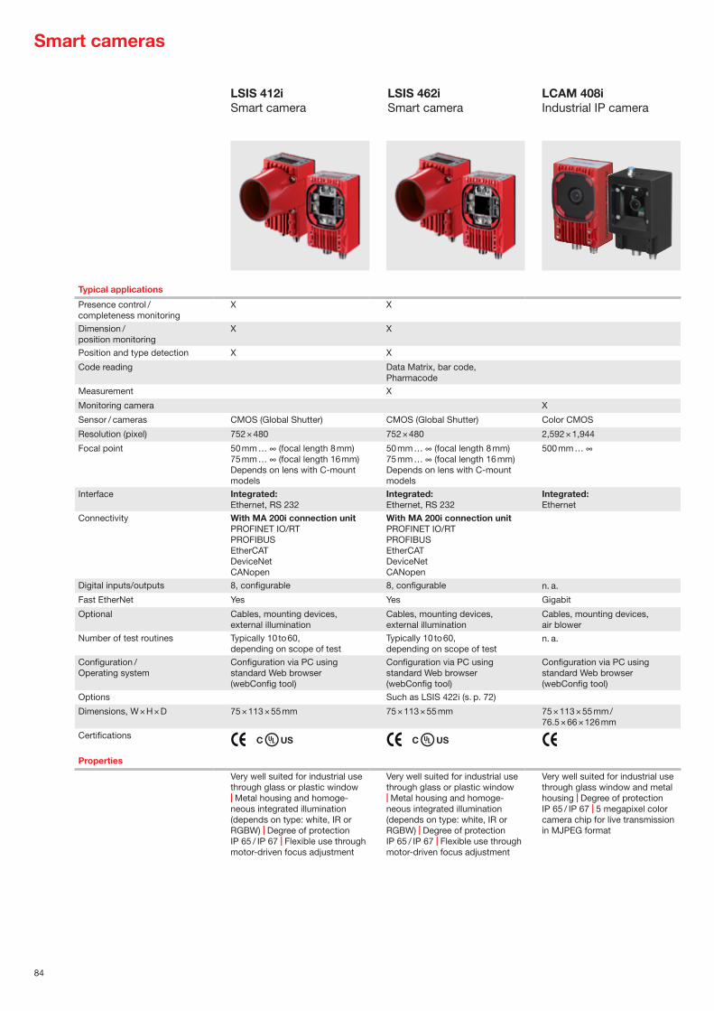
84
LSIS 462iSmart camera
Typical applications
Presence control / completeness monitoring
X X
Dimension / position monitoring
X X
Position and type detection X X
Code reading Data Matrix, bar code, Pharmacode
Measurement X
Monitoring camera X
Sensor / cameras CMOS (Global Shutter) CMOS (Global Shutter) Color CMOS
Resolution (pixel) 752 × 480 752 × 480 2,592 × 1,944
Focal point
50 mm … ∞ (focal length 8 mm)75 mm … ∞ (focal length 16 mm)Depends on lens with C-mount models
50 mm … ∞ (focal length 8 mm)75 mm … ∞ (focal length 16 mm)Depends on lens with C-mount models
500 mm … ∞
Interface Integrated:Ethernet, RS 232
Integrated:Ethernet, RS 232
Integrated:Ethernet
Connectivity
With MA 200i connection unitPROFINET IO/RTPROFIBUSEtherCATDeviceNetCANopen
With MA 200i connection unitPROFINET IO/RTPROFIBUSEtherCATDeviceNetCANopen
Digital inputs/outputs 8, configurable 8, configurable n. a.
Fast EtherNet Yes Yes Gigabit
Optional Cables, mounting devices, external illumination
Cables, mounting devices, external illumination
Cables, mounting devices, air blower
Number of test routines Typically 10 to 60, depending on scope of test
Typically 10 to 60, depending on scope of test
n. a.
Configuration / Operating system
Configuration via PC using standard Web browser (webConfig tool)
Configuration via PC using standard Web browser (webConfig tool)
Configuration via PC using standard Web browser (webConfig tool)
Options Such as LSIS 422i (s. p. 72)
Dimensions, W × H × D 75 × 113 × 55 mm 75 × 113 × 55 mm 75 × 113 × 55 mm / 76.5 × 66 × 126 mm
Certifications C US C US
Properties
Very well suited for industrial use through glass or plastic window | Metal housing and homoge-neous integrated illumination (depends on type: white, IR or RGBW) | Degree of protection IP 65 / IP 67 | Flexible use through motor-driven focus adjustment
Very well suited for industrial use through glass or plastic window | Metal housing and homoge-neous integrated illumination (depends on type: white, IR or RGBW) | Degree of protection IP 65 / IP 67 | Flexible use through motor-driven focus adjustment
Very well suited for industrial use through glass window and metal housing | Degree of protection IP 65 / IP 67 | 5 megapixel color camera chip for live transmission in MJPEG format
LSIS 412iSmart camera
Smart cameras
LCAM 408iIndustrial IP camera

85
Ind
ustr
ial i
mag
e p
roce
ssin
g

Accessories and supplementary productsSmooth running: Full performance with the right accessories and perfectly matched components
Efficient work requires more than just a sensor. Almost as important are the appropriate accessories, which allow the sensor to utilize its full functionality. No matter if you need easy mounting, uncomplicated connection or reliable signal-ing, you can easily find the right accessories for your application in our extensive product range. You can find our complete accessories range on our website at www.leuze.com/en/accessories.

87
Mounting systems
We place great emphasis on our products being easy to mount and simple to align. For this reason, you will find specially-attuned mounting systems in our product range such as mounting brackets, rod holders or device columns.
Power supply
A reliable and machine- independent power supply with 1- and 3-phase power supplies is an elementary part of an optimum and efficient sensor system. For this rea-son, we also offer load circuit monitoring modules to ensure a higher level of safeguarding against failure.
Reflectors
Just how reliably retro-reflec-tive photoelectric sensors can detect depends upon the se-lected reflector, among other things. That is why we offer various fitting solutions made of plastic, film, and glass for all conceivable conditions.
Connection units
Today, sensors, safety switch-es and cameras are linked together via active or passive sensor distribution boxes with fieldbus interfaces from our product range to ensure more flexibility and transparency during installation.
Cables
To facilitate the integration of our sensors, we offer a large variety of connection and interconnection cables with M8, M12, and M23 connectors – straight or angled, and with or without LED.
Signaling devices
For signaling in automated systems, we offer an extensive product range of single- and multi-colored transducers in order to ensure productivity and efficiency.

88
Signaling devices
Other signaling devices
Signaling column, type A
Specifications
Operating voltage 24 V DC ±10 % 24 V AC/DC, ±10% 24 V AC/DC, ±10%
Degree of protection IP 66 IP 66 IP 65
Diameter 70 mm 70 mm, 40 mm 30 / 45 / 65 mm and others
Certifications C US C US C US
Housing Plastic, PC-ABS Plastic, PC Plastic, PC
Functions
Optical & acoustic signaling for displaying machine states
Optical & acoustic signaling for displaying machine states
Optical & acoustic signaling for displaying machine states
Properties
Flexible configuration: 6 different colors (red, orange, yellow, green, blue, white) | Simple mounting: base mount-ing: 3 stand heights with plastic foot, flat mounting variant with and without M12 connector, hinged mounting variant | Module connection via bayonet lock | Position-independent – protection against interchanging | Transparent calottes / uniform clear glass optics | Single-sound & multi-sound buzzer modules (up to 105 dB) | Preassembled models & freely configurable ele-ments | Signal image: continuous light & flashing light | Multicolor with 7 different colors
6 different colors (red, orange, green, blue, white, yellow) | Base mounting, bracket mounting, horizontal mounting | Single-sound buzzer module | Preassembled models & freely configurable elements | Signal image: continuous light & flashing light
Various installation versions: signaling columns, panel-mount modules, multitone & beacon
Signaling column, type E

89
Acc
esso
ries
and
sup
ple
men
tary
pro
duc
ts
Other mounting systems
Mounting systems
Mounting bracket
Specifications
Material Galvanized steel, stainless steel Galvanized steel, stainless steel, aluminum
Galvanized steel, stainless steel, aluminum, plastic
Mounting at device Screw type Screw type Screw type or clampable
Mounting at system Screw type Clampable on rod Screw type
Functions
Mounting bracket with possibility for device alignment
Mounting bracket with flexible alignment and alignment function for the device
Fixed mounting, with limit stop in some cases
Properties
Diverse versions for various sensors
Diverse versions for various sensors and reflectors
Diverse versions for various sensors with cylindrical design
Rod mounting

90
Reflectors
Reflectors Standard reflectors, micro-triad-type reflectors
Specifications
Material PMMA PMMA Stainless steel and scratch- resistant plastics
Triple reflector size 0.3 – 4 mm 0.3 – 4 mm 0.3 – 4 mm
Functions
Various sizes, from 20 to 180 mm
Various films from 9 to 920 mm, also available as rolls of 45.7 m
Different designs available
Properties
Adhesive, pluggable and screw-type versions
Adhesive and self-adhesive versions
Adhesive, clampable and screw-type versions | Versions with increased resistance for intensive use of cleaning agents
Reflective tapes

91
Acc
esso
ries
and
sup
ple
men
tary
pro
duc
ts

Leuze electronic GmbH + Co. KGIn der Braike 1, 73277 OwenPhone +49 7021 573-0Fax +49 7021 [email protected]
Our product range at a glance
Switching sensors — Optical Sensors — Inductive Switches — Capacitive Sensors — Ultrasonic Sensors — Fiber Optic Sensors — Forked Sensors — Light Curtains — Special Sensors
Measuring sensors — Distance Sensors — Sensors for Positioning — 3D Sensors — Light Curtains — Bar Code Positioning Systems — Forked Sensors
Products for Safety at Work — Optoelectronic Safety Sensors — Safe Locking Devices, Switches and
Proximity Sensors — Safe Control Components — Machine Safety Services
Identification — Bar Code Identification — 2D-Code Identification — RF Identification
Data Transmission — Optical Data Transmission Systems
Network and connection technology — Connection Technology — Modular Connection Units
Industrial image processing — Light Section Sensors — Smart Camera
Accessories
Your contact with us
en 0
1-20
20/0
5 11
01S
ubje
ct to
mod
ifica
tions
and
err
ors