Process Lines from GEA Westfalia Separator for Processing Whey GEA Mechanical Equipment engineering...
32
Process Lines from GEA Westfalia Separator for Processing Whey GEA Mechanical Equipment engineering for a better world
Transcript of Process Lines from GEA Westfalia Separator for Processing Whey GEA Mechanical Equipment engineering...
Process Lines from GEA Westfalia Separator for Processing Whey
GEA Mechanical Equipmentengineering for a better world
4 1. 5 2.
5 2.1
6 2.2
6 2.2.1
6 2.2.2
7 2.2.3
8 2.2.4
8 2.3
8 2.3.1
10 2.3.2
10 2.3.3
11 2.3.4
12 2.3.5
12 2.3.6
14 2.3.7
15 2.3.8
17 2.4
18 2.5
19 2.6 20 3. 22 4. 22 4.1
22 4.2
22 4.2.1
22 4.2.2
22 4.2.3
ContentsIntroduction Recovering fat from raw whey General
Measuring methods for determining whey parameters
Residual fat content in separated whey
Cheese fine content
Content of free air
Separability
Function procedures
Standard process for low processing volumes
Introduction of total discharges
Further possibilities for optimization
Use of clarifiers
Optimum design of a whey processing line
Pauses whey program
Whey cream standardization WC
Determining the discharge frequency
Concentration of cheese fines
Recycling cheese fines back into the process
Cost-effectiveness analyses Skimming whey concentrate Special methods of whey processing DCP process
Further processes with centrifuges
Dephospholipidation of whey (DPL)
Alcohol from whey
Lactalbumin
3
GEA Westfalia Separator
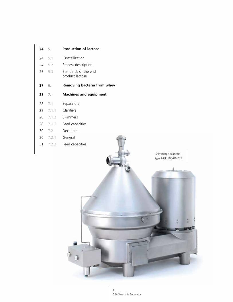
Skimming separator –
type MSE 500-01-777
24 5. 24 5.1
24 5.2
25 5.3 27 6. 28 7. 28 7.1
28 7.1.1
28 7.1.2 Skimmers
28 7.1.3 Feed capacities
30 7.2 Decanters
30 7.2.1 General
31 7.2.2 Feed capacities
Production of lactose Crystallization
Process description
Standards of the end product lactose Removing bacteria from whey Machines and equipment Separators
Clarifiers
4
GEA Westfalia Separator
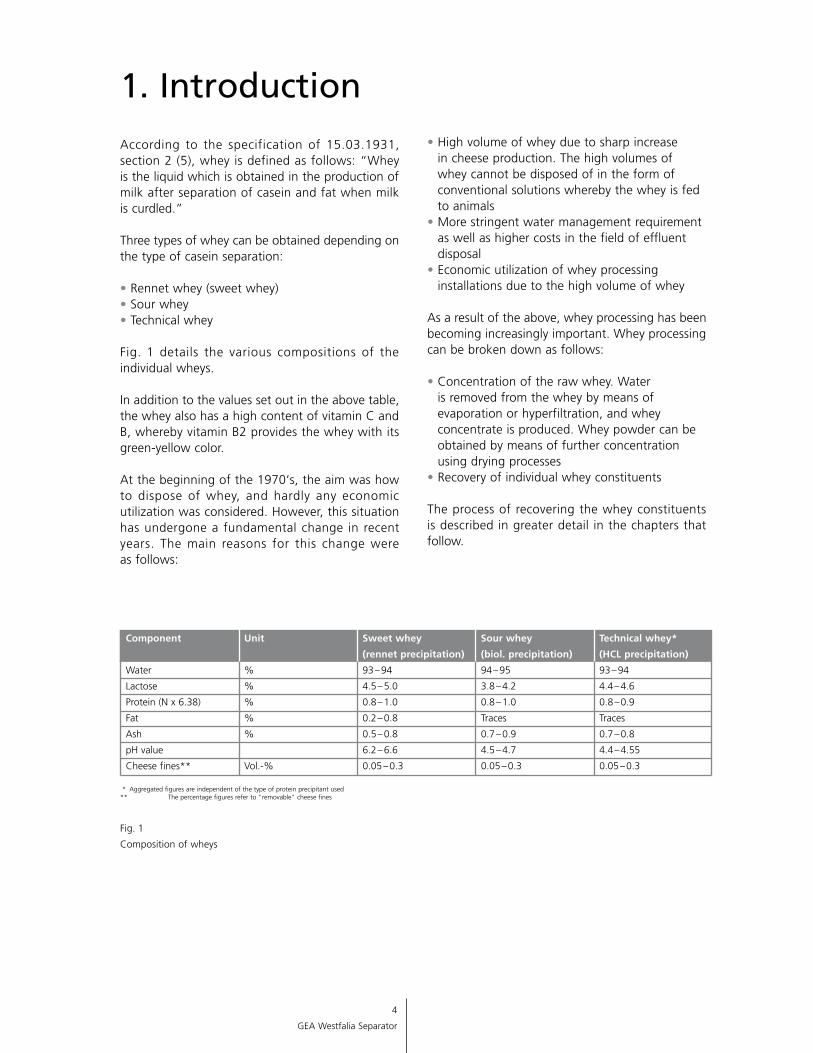
According to the specification of 15.03.1931, section 2 (5), whey is defined as follows: “Whey is the liquid which is obtained in the production of milk after separation of casein and fat when milk is curdled.”
Three types of whey can be obtained depending on the type of casein separation:
• Rennet whey (sweet whey)• Sour whey• Technical whey
Fig. 1 details the various compositions of the individual wheys.
In addition to the values set out in the above table, the whey also has a high content of vitamin C and B, whereby vitamin B2 provides the whey with its green-yellow color. At the beginning of the 1970‘s, the aim was how to dispose of whey, and hardly any economic utilization was considered. However, this situation has undergone a fundamental change in recent years. The main reasons for this change were as follows:
1. Introduction
Component Unit Sweet whey Sour whey Technical whey*
(rennet precipitation) (biol. precipitation) (HCL precipitation)
Water % 93 – 94 94 – 95 93 – 94
Lactose % 4.5 – 5.0 3.8 – 4.2 4.4 – 4.6
Protein (N x 6.38) % 0.8 – 1.0 0.8 – 1.0 0.8 – 0.9
Fat % 0.2 – 0.8 Traces Traces
Ash % 0.5 – 0.8 0.7 – 0.9 0.7 – 0.8
pH value 6.2 – 6.6 4.5 – 4.7 4.4 – 4.55
Cheese fines** Vol.-% 0.05 – 0.3 0.05 – 0.3 0.05 – 0.3
• High volume of whey due to sharp increase in cheese production. The high volumes of whey cannot be disposed of in the form of conventional solutions whereby the whey is fed to animals
• More stringent water management requirement as well as higher costs in the field of effluent disposal
• Economic utilization of whey processing installations due to the high volume of whey
As a result of the above, whey processing has been becoming increasingly important. Whey processing can be broken down as follows:
• Concentration of the raw whey. Water is re moved from the whey by means of evaporation or hyperfiltration, and whey concentrate is produced. Whey powder can be obtained by means of further concentration using drying processes
• Recovery of individual whey constituents
The process of recovering the whey constituents is described in greater detail in the chapters that follow.
* Aggregated figures are independent of the type of protein precipitant used ** The percentage figures refer to "removable" cheese fines
Fig. 1
Composition of wheys
5
GEA Westfalia Separator
2.1 General
For the purpose of separating the whey that is obtained in the cheese-making process, it is extremely important for the machines and functions to be based as precisely as possible on the whey to be treated. Accordingly, the main parameters of the raw wheys should be known before a whey processing line is designed.
In addition to the parameters set out in fig. 1, further factors also have to be taken into consideration. These include the treatment of Cheddar press whey as a result of its high fat content (up to 10 percent) as well as the processing of salt whey. Process stages while milk is being treated in cheese-making operations may also have an effect on whey separation.
Th is i s for instance appl icab le whenever homogenized milk is processed into cheese. It is also applicable if protein and fat standardization is achieved by additions to vat milk. In addition, it is generally disadvantageous if an increased concentration of “free air” enters the separator with the raw whey.
The following rule of thumb applies:
“If the content of free air in the raw whey up -stream of the separating process is greater than 0.5 percent, this will have a negative impact on separability.”
Normally 0.1 – 0.3 percent free air is expected in the raw whey at product temperatures of 77-104 °F.
It is always advantageous to have precise knowledge of the actual status if statements are to be made in advance with regard to the efficiency of new whey separating stages to be installed.
The measuring methods for measuring fat, cheese fines and free air are particularly interesting for estab lishing the whey parameters.
0.02
1
Resi
dual
fat
con
tent
Number of treatments in a test-tube centrifuge
0.01
0.03
0.04
0.05
0.06
0.07
%
3 4 5 6 7
Weight analysis as per “Roese-Gottlieb”
Volumetric measuring method as per “Gerber”
2
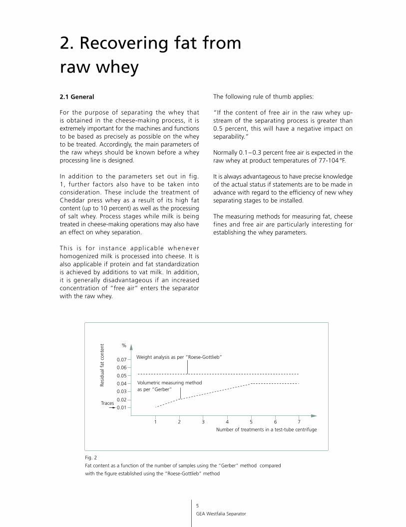
Fig. 2
Fat content as a function of the number of samples using the “Gerber” method compared
with the figure established using the “Roese-Gottlieb” method
2. Recovering fat from raw whey
Traces
6
Westfalia Separator
2.2 Measuring methods for determining whey parameters
2.2.1 Residual fat content in separated whey
The residual fat content in the whey is primarily determined by means of an FTIR measurement, e.g. with the MilkoScan FT 120 from Foss. In addition, the volumetric test method according to “Gerber” is probably also one of the most frequently applied methods for determining residual fat contents in whey. However, it is used differently in the dairies (fig. 3).
This necessarily results in different statements in conjunction with fat values which are otherwise identical.
The weight-analytical tests according to Röse-Gottlieb and Mojonnier are recognized reference methods. However, if these methods are applied in the case of unclarified whey or whey which has only been partially pre-clarified (fig. 10), the results might be misinterpreted. It is not known to what extent extremely fine cheese fines result in misinterpretations (when caked on fat globules, or vice versa).
2.2.2 Cheese fine content
The content of cheese fines in the whey can be determined by means of various methods.
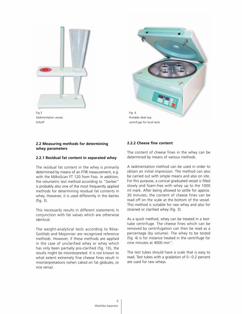
A sedimentation method can be used in order to obtain an initial impression. The method can also be carried out with simple means and also on site. For this purpose, a conical graduated vessel is filled slowly and foam-free with whey up to the 1000 ml mark. After being allowed to settle for approx. 30 minutes, the content of cheese fines can be read off on the scale at the bottom of the vessel. This method is suitable for raw whey and also for strained or clarified whey (fig. 3).
As a quick method, whey can be treated in a test-tube centrifuge. The cheese fines which can be removed by centrifugation can then be read as a percentage (by volume). The whey to be tested (fig. 4) is for instance treated in the centrifuge for nine minutes at 4000 min-1.
The test tubes should have a scale that is easy to read. Test tubes with a gradation of 0 – 0.2 percent are used for raw wheys.
Fig.3
Sedimentation vessel,
Imhoff
Fig. 4
Portable desk-top
centrifuge for local tests
7
Westfalia Separator
The washing method is a further possibility. This method can establish the absolute cheese fine content in ppm (fig. 5).
The following calculation has to be carried out in order to enable both figures to be roughly compared (fig. 7).
The factor “centrifugally dry to absolutely dry” is generally between 3 and 4 for caseins. The factor 3 has to be chosen for hard cheese whey or casein whey for instance, and the factor 4 has to be chosen for soft cheese.
1. Pour 100 ml whey into a test tube.2. The sample is subjected to centrifugal
treatment for 5 minutes (3 minutes) at n=3000 min-1.
3. The liquid is poured off.4. The test tube is filled up to 100 ml with
distilled water and is again subjected to centrifugal treatment.
The distilled water is injected directly on to the sediment by means of an “injection
bottle”, and the turbulence of the sediments results in the washing procedure.
5. Steps 2 – 4 are carried out a total of five times.6. When the liquid is poured off for the final
time, the sediment is placed on a scale. Residual sediment is “rinsed” out of the
test tube with the distilled water, and is also placed on the scale.
7. The dry matter of the sediment is established (as per method manual).
8. The figure established in this way is quoted in mg / l or g / l. It is converted into percent DM as follows:
% DM = g / l
10
Fig. 5
Establishing the cheese fine content
with the washing method
Example:
Given: 70 mg / latro = ppm
Assumption1): Centrifugally dry
= 42)
atro
Calculation3):
Removable by centrifuge = mg / latro•4
% (by vol.) 1000•
1000 100
Removable by centrifuge = g / latro
% (by vol.) 2.5
Removable by centrifuge = ppm
% (by vol.) 2500
Fig. 7
Comparison of the results of % centrifugally dried to %
absolutely dry
1) A factor between 3 and 4 has to be chosen for proteins depending on the precipitation process. 2) With factor 4, the remaining sediment in the test tube has a dry matter content of 25 percent DM. 3) A specific weight of 1 has to be assumed for the sediment for calculation purposes.
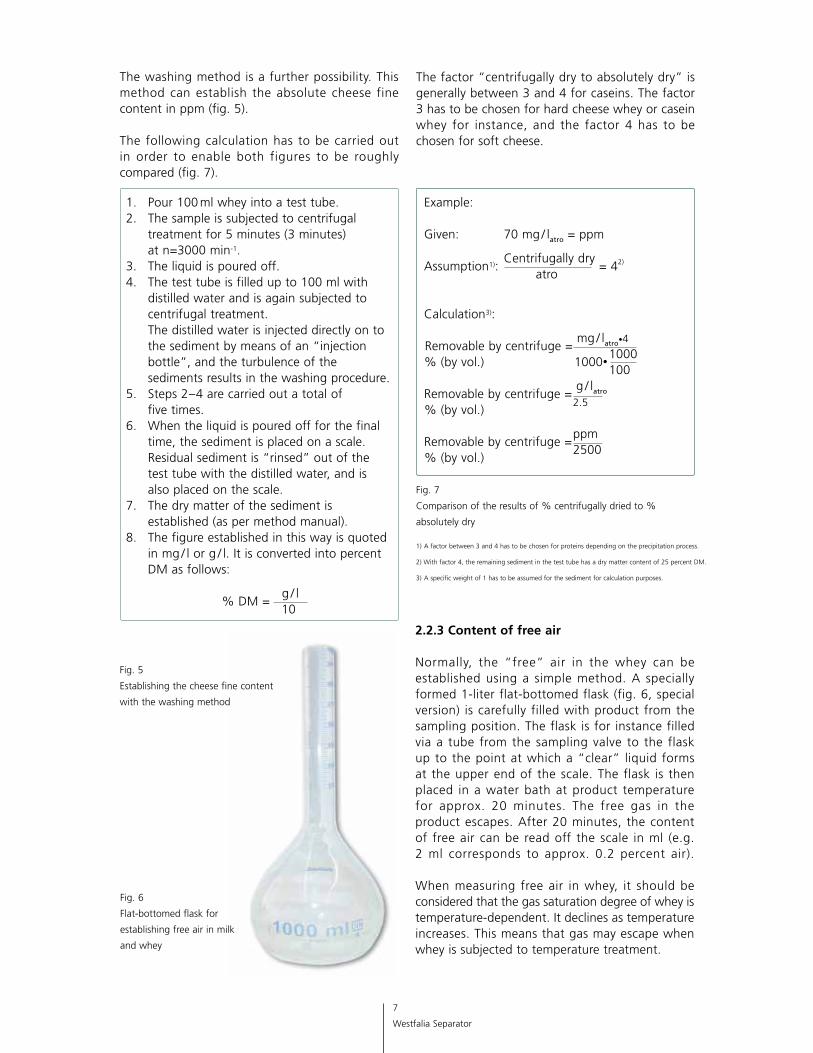
2.2.3 Content of free air Normally, the “free” air in the whey can be established using a simple method. A specially formed 1-liter flat-bottomed flask (fig. 6, special version) is carefully filled with product from the sampling position. The flask is for instance filled via a tube from the sampling valve to the flask up to the point at which a “clear” liquid forms at the upper end of the scale. The flask is then placed in a water bath at product temperature for approx. 20 minutes. The free gas in the product escapes. After 20 minutes, the content of free air can be read off the scale in ml (e.g. 2 ml corresponds to approx. 0.2 percent air). When measuring free air in whey, it should be considered that the gas saturation degree of whey is temperature-dependent. It declines as temperature increases. This means that gas may escape when whey is subjected to temperature treatment.
Fig. 6
Flat-bottomed flask for
establish ing free air in milk
and whey
8
GEA Westfalia Separator
2.2.4 Separability
The separability of raw whey can nowadays be established by auxiliary means. These auxiliary means permit a relatively precise statement to be made with regard to the separating effect. For instance, laboratory separators are able to establish meaningful values for assessing a full-scale installation. In addition, particle counting devices (ELZONE) also provide information concerning the separability of the product.
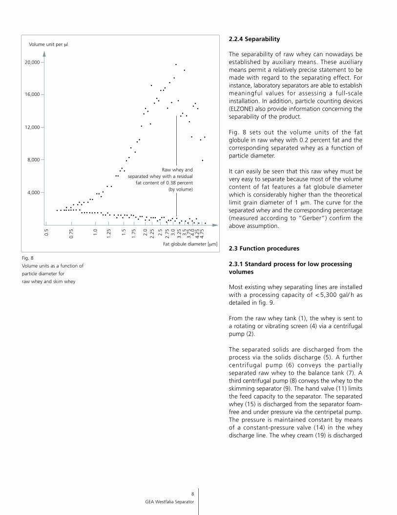
Fig. 8 sets out the volume units of the fat globule in raw whey with 0.2 percent fat and the corresponding separated whey as a function of particle diameter.
It can easily be seen that this raw whey must be very easy to separate because most of the volume content of fat features a fat globule diameter which is considerably higher than the theoretical limit grain diameter of 1 mm. The curve for the separated whey and the corresponding percentage (measured accord ing to “Gerber”) confirm the above assumption.
2.3 Function procedures 2.3.1 Standard process for low processing volumes
Most existing whey separating lines are installed with a processing capacity of < 5,300 gal/ h as detailed in fig. 9.
From the raw whey tank (1), the whey is sent to a rotating or vibrating screen (4) via a centrifugal pump (2).
The separated solids are discharged from the process via the solids discharge (5). A further centrifugal pump (6) conveys the partial ly separated raw whey to the balance tank (7). A third centrifugal pump (8) conveys the whey to the skimming separator (9). The hand valve (11) limits the feed capacity to the separator. The separated whey (15) is discharged from the separator foam-free and under pressure via the centripetal pump. The pressure is maintained constant by means of a constant-pressure valve (14) in the whey discharge line. The whey cream (19) is discharged
0.5
Volume unit per ml
Fat globule diameter [mm]
4,000
8,000
12,000
16,000
0.75 1.
0
2.5
1.25 1.
5
1.75 2.
02.
25
2.75 3.
03.
25 3.5
3.75 4.
04.
254.
75
Raw whey and separated whey with a residual
fat content of 0.38 percent (by volume)
20,000
Fig. 8
Volume units as a function of
particle diameter for
raw whey and skim whey
9
GEA Westfalia Separator
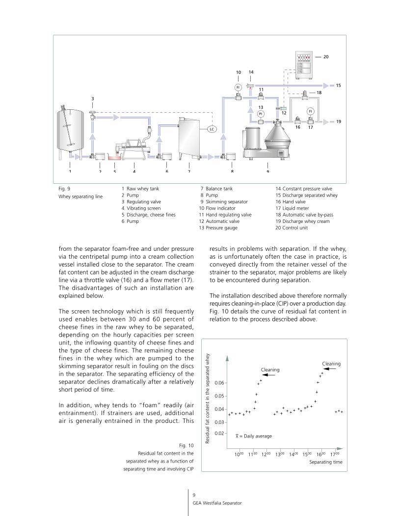
Fig. 9
Whey separating line
14 Constant pressure valve 15 Discharge separated whey 16 Hand valve 17 Liquid meter 18 Automatic valve by-pass 19 Discharge whey cream 20 Control unit
1 Raw whey tank 2 Pump 3 Regulating valve 4 Vibrating screen 5 Discharge, cheese fines 6 Pump
7 Balance tank 8 Pump 9 Skimming separator 10 Flow indicator 11 Hand regulating valve 12 Automatic valve 13 Pressure gauge
from the separator foam-free and under pressure via the centripetal pump into a cream collection vessel installed close to the separator. The cream fat content can be adjusted in the cream discharge line via a throttle valve (16) and a flow meter (17). The disadvantages of such an installation are explained below.
The screen technology which is still frequently used enables between 30 and 60 percent of cheese fines in the raw whey to be separated, depending on the hourly capacities per screen unit, the inflowing quantity of cheese fines and the type of cheese fines. The remaining cheese fines in the whey which are pumped to the skimming separator result in fouling on the discs in the separator. The separating efficiency of the separator declines dramatically after a relatively short period of time.
In addition, whey tends to “foam” readily (air entrain ment). If strainers are used, additional air is generally entrained in the product. This
results in problems with separation. If the whey, as is unfortunately often the case in practice, is conveyed directly from the retainer vessel of the strainer to the separator, major problems are likely to be encountered during separation.
The installation described above therefore normally requires cleaning-in-place (CIP) over a production day. Fig. 10 details the curve of residual fat content in rela tion to the process described above.
Fig. 10
Residual fat content in the
separated whey as a function of
separating time and involving CIP
x = Daily average
CleaningCleaning
0.02
1000
Resi
dual
fat
con
tent
in t
he s
epar
ated
whe
y
Separating time
0.03
0.04
0.05
0.06
1100 1200 1300 1400 1500 1600 1700
10
GEA Westfalia Separator
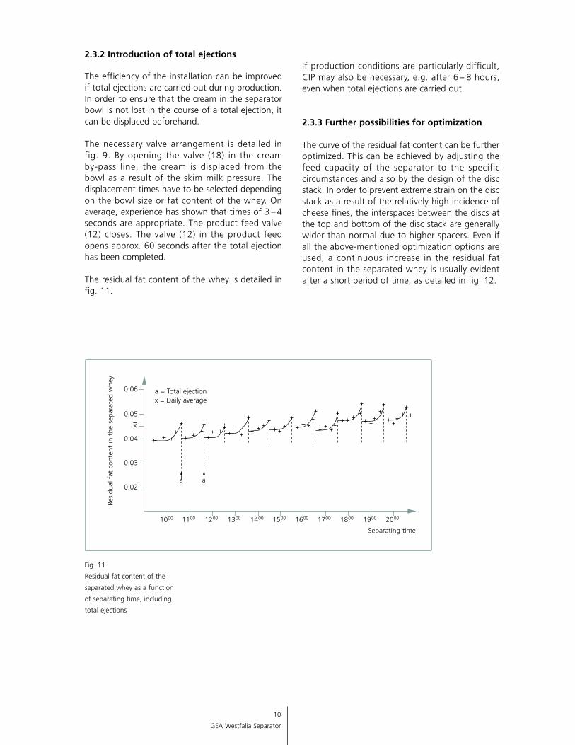
2.3.2 Introduction of total ejections
The efficiency of the installation can be improved if total ejections are carried out during production. In order to ensure that the cream in the separator bowl is not lost in the course of a total ejection, it can be displaced beforehand.
The necessary valve arrangement is detailed in fig. 9. By opening the valve (18) in the cream by-pass line, the cream is displaced from the bowl as a result of the skim milk pressure. The displacement times have to be selected depending on the bowl size or fat content of the whey. On average, experience has shown that times of 3 – 4 seconds are appropriate. The product feed valve (12) closes. The valve (12) in the product feed opens approx. 60 seconds after the total ejection has been completed.
The residual fat content of the whey is detailed in fig. 11.
If production conditions are particularly difficult, CIP may also be necessary, e.g. after 6 – 8 hours, even when total ejections are carried out.
2.3.3 Further possibilities for optimization
The curve of the residual fat content can be further optimized. This can be achieved by adjusting the feed capacity of the separator to the specific circumstances and also by the design of the disc stack. In order to prevent extreme strain on the disc stack as a result of the relatively high incidence of cheese fines, the interspaces between the discs at the top and bottom of the disc stack are generally wider than normal due to higher spacers. Even if all the above-mentioned optimization options are used, a continuous increase in the residual fat content in the separated whey is usually evident after a short period of time, as detailed in fig. 12.
Fig. 11
Residual fat content of the
separated whey as a function
of separating time, including
total ejections
1000
Resi
dual
fat
con
tent
in t
he s
epar
ated
whe
y
Separating time
x = Daily average
1100 1200 1300 1400 1500 1600 1700 1800 1900 2000
0.02
0.03
0.04
0.05
0.06
x
a = Total ejection
a a
11
GEA Westfalia Separator
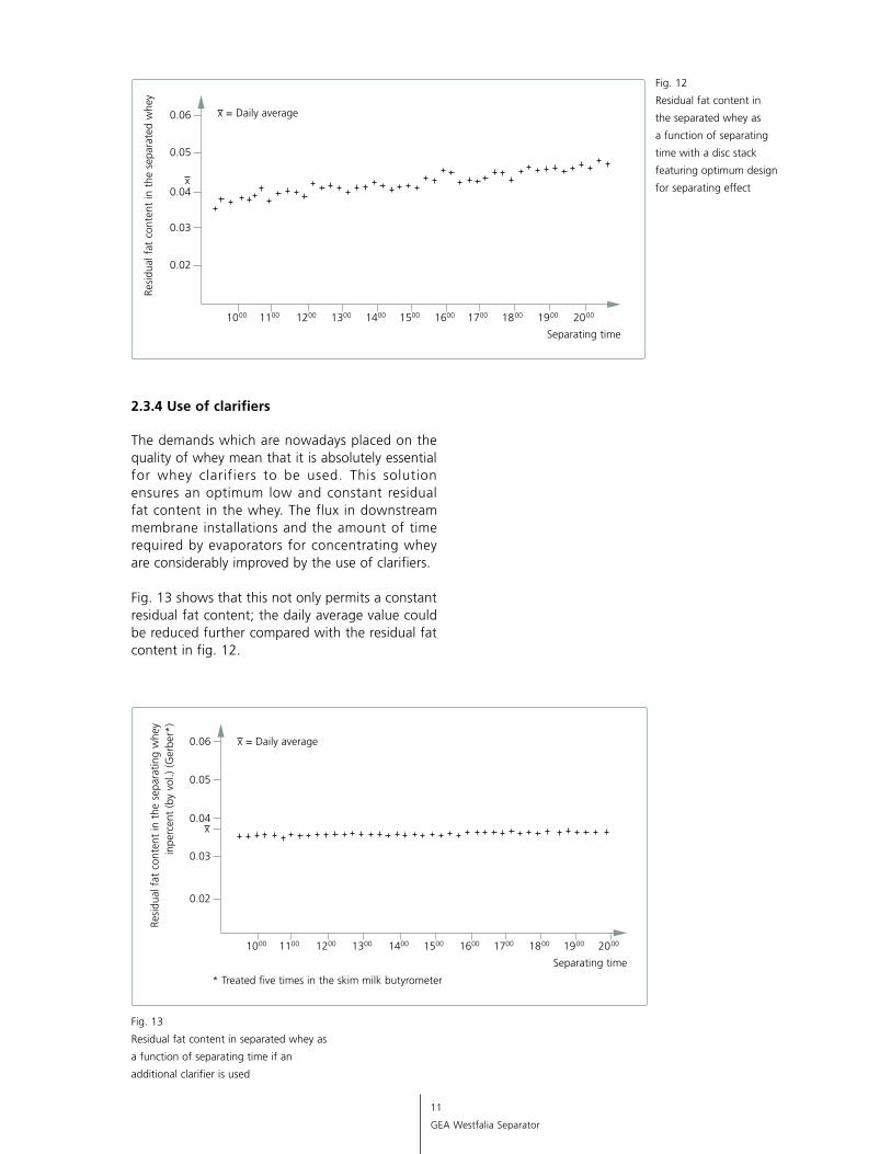
Fig. 12
Residual fat content in
the separated whey as
a function of separating
time with a disc stack
featuring optimum design
for separating effect
2.3.4 Use of clarifiers
The demands which are nowadays placed on the quality of whey mean that it is absolutely essential for whey clarifiers to be used. This solution ensures an optimum low and constant residual fat content in the whey. The flux in downstream membrane installations and the amount of time required by evaporators for concentrating whey are considerably improved by the use of clarifiers.
Fig. 13 shows that this not only permits a constant residual fat content; the daily average value could be reduced further compared with the residual fat content in fig. 12.
Fig. 13
Residual fat content in separated whey as
a function of separating time if an
additional clarifier is used
1000
Resi
dual
fat
con
tent
in t
he s
epar
ated
whe
y
Separating time
1100 1200 1300 1400 1500 1600 1700 1800 1900 2000
0.02
0.03
0.04
0.05
0.06 x = Daily average
x
1000
Resi
dual
fat
con
tent
in t
he s
epar
atin
g w
hey
inpe
rcen
t (b
y vo
l.) (
Ger
ber*
)
Separating time
1100 1200 1300 1400 1500 1600 1700 1800 1900 2000
0.02
0.03
0.04
0.05
0.06 x = Daily average
x
* Treated five times in the skim milk butyrometer
12
GEA Westfalia Separator
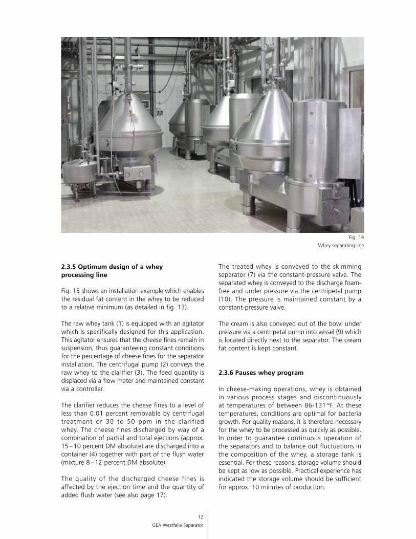
Fig. 14
Whey separating line
2.3.5 Optimum design of a whey processing line
Fig. 15 shows an installation example which enables the residual fat content in the whey to be reduced to a relative minimum (as detailed in fig. 13).
The raw whey tank (1) is equipped with an agitator which is specifically designed for this application. This agitator ensures that the cheese fines remain in suspension, thus guaranteeing constant conditions for the percentage of cheese fines for the separator installation. The centrifugal pump (2) conveys the raw whey to the clarifier (3). The feed quantity is displaced via a flow meter and maintained constant via a controller.
The clarifier reduces the cheese fines to a level of less than 0.01 percent removable by centrifugal treatment or 30 to 50 ppm in the clarified whey. The cheese fines discharged by way of a combination of partial and total ejections (approx. 15 – 10 percent DM absolute) are discharged into a container (4) together with part of the flush water (mixture 8 – 12 percent DM absolute).
The quality of the discharged cheese fines is affected by the ejection time and the quantity of added flush water (see also page 17).
The treated whey is conveyed to the skimming separator (7) via the constant-pressure valve. The separated whey is conveyed to the discharge foam-free and under pressure via the centripetal pump (10). The pressure is maintained constant by a constant-pressure valve.
The cream is also conveyed out of the bowl under pressure via a centripetal pump into vessel (9) which is located directly next to the separator. The cream fat content is kept constant.
2.3.6 Pauses whey program
In cheese-making operations, whey is obtained in various process stages and discontinuously at temperatures of between 86-131 °F. At these temperatures, conditions are optimal for bacteria growth. For quality reasons, it is therefore necessary for the whey to be processed as quickly as possible. In order to guarantee continuous operation of the separators and to balance out fluctuations in the composition of the whey, a storage tank is essential. For these reasons, storage volume should be kept as low as possible. Practical experience has indicated the storage volume should be sufficient for approx. 10 minutes of production.
13
GEA Westfalia Separator
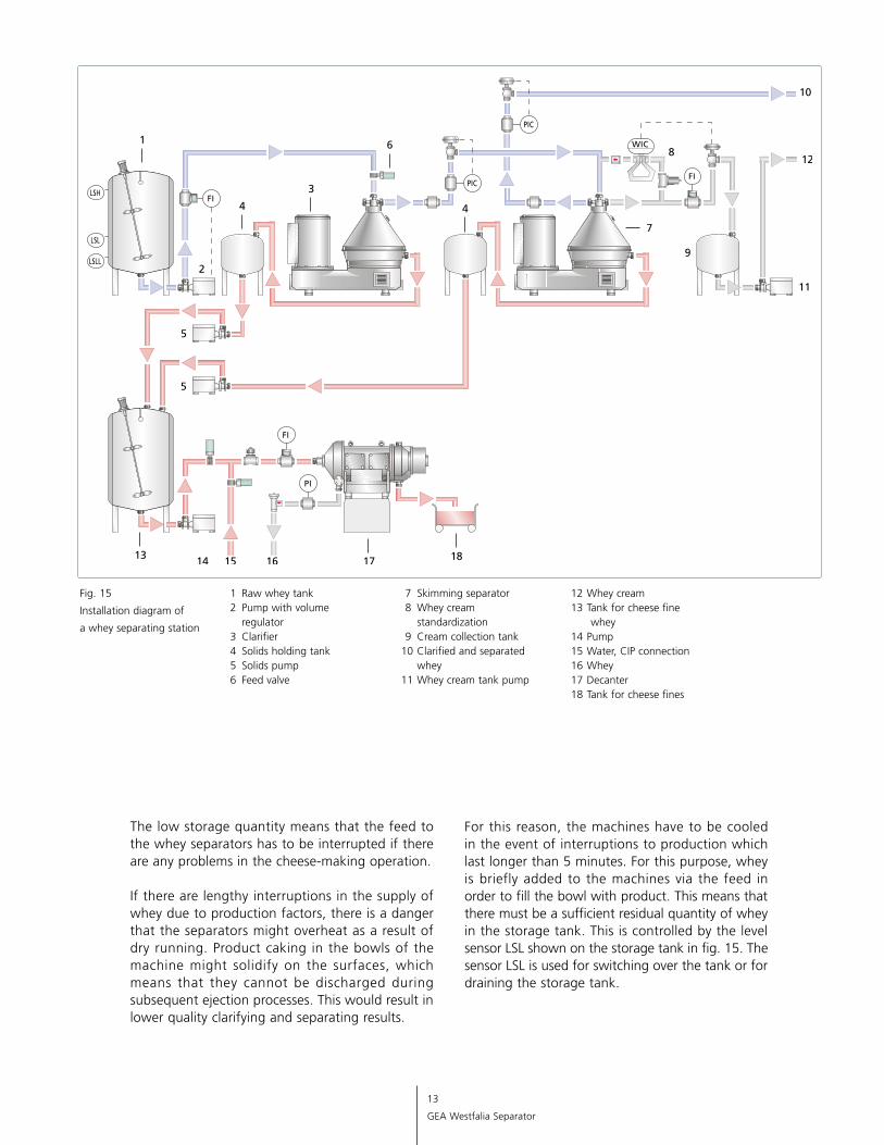
Fig. 15
Installation diagram of
a whey separating station
12 Whey cream 13 Tank for cheese fine whey 14 Pump 15 Water, CIP connection 16 Whey 17 Decanter 18 Tank for cheese fines
1 Raw whey tank 2 Pump with volume regulator 3 Clarifier 4 Solids holding tank 5 Solids pump 6 Feed valve
7 Skimming separator 8 Whey cream standardization 9 Cream collection tank 10 Clarified and separated whey 11 Whey cream tank pump
The low storage quantity means that the feed to the whey separators has to be interrupted if there are any problems in the cheese-making operation.
If there are lengthy interruptions in the supply of whey due to production factors, there is a danger that the separators might overheat as a result of dry running. Product caking in the bowls of the machine might solidify on the surfaces, which means that they cannot be discharged during subsequent ejection processes. This would result in lower quality clarifying and separating results.
For this reason, the machines have to be cooled in the event of interruptions to production which last longer than 5 minutes. For this purpose, whey is briefly added to the machines via the feed in order to fill the bowl with product. This means that there must be a sufficient residual quantity of whey in the storage tank. This is controlled by the level sensor LSL shown on the storage tank in fig. 15. The sensor LSL is used for switching over the tank or for draining the storage tank.
14
GEA Westfalia Separator
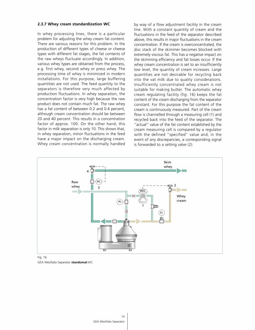
Fig. 16
GEA Westfalia Separator standomat WC
2.3.7 Whey cream standardization WC
In whey processing lines, there is a particular problem for adjusting the whey cream fat content. There are various reasons for this problem. In the production of different types of cheese or cheese types with different fat stages, the fat contents of the raw wheys fluctuate accordingly. In addition, various whey types are obtained from the process, e.g. first whey, second whey or press whey. The processing time of whey is minimized in modern installations. For this purpose, large buffering quantities are not used. The feed quantity to the separators is therefore very much affected by production fluctuations. In whey separation, the concentration factor is very high because the raw product does not contain much fat. The raw whey has a fat content of between 0.2 and 0.4 percent, although cream concentration should be between 20 and 40 percent. This results in a concentration factor of approx. 100. On the other hand, this factor in milk separation is only 10. This shows that, in whey separation, minor fluctuations in the feed have a major impact on the discharging cream. Whey cream concentration is normally handled
by way of a flow adjustment facility in the cream line. With a constant quantity of cream and the fluctuations in the feed of the separator described above, this results in major fluctuations in the cream concentration. If the cream is overconcentrated, the disc stack of the skimmer becomes blocked with extremely viscous fat. This has a negative impact on the skimming efficiency and fat losses occur. If the whey cream concentration is set to an insufficiently low level, the quantity of cream increases. Large quantities are not desirable for recycling back into the vat milk due to quality considerations. Insufficiently concentrated whey cream is not suitable for making butter. The automatic whey cream regulating facility (fig. 16) keeps the fat content of the cream discharging from the separator constant. For this purpose the fat content of the cream is continuously measured. Part of the cream flow is channelled through a meas uring cell (1) and recycled back into the feed of the separator. The “actual” value of the fat content estab lished by the cream measuring cell is compared by a regulator with the defined “specified” value and, in the event of any discrepancies, a corresponding signal is forwarded to a setting valve (2).
15
GEA Westfalia Separator
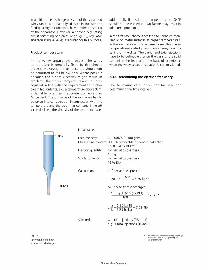
Initial values:
Feed capacity: 20,000 l / h (5,300 gal/h) Cheese fine content: 0.12 % removable by centrifugal action i.e. 0.034 % DM** Ejection quantity: for partial discharges (TE) 15 kg Solids contents: for partial discharges (TE) 15 % DM
Calculation: a) Cheese fines present 20,000•
0.034 = 6.80 kg / h
100
b) Cheese fines discharged
15 (kg / TE)•15 (% DM) = 2.25 kg / TE
100
c) a =
6.80 kg TE = 3.02 TE / h
b 2.25 h kg
Selected: 4 partial ejections (PE / hour) e.g. 3 total ejections (TE/hour)
Fig. 17
Determining the time intervals for discharges
* * The factor between removable by centrifugal action and DM is 3 – 4, depending on the type of whey.
In addition, the discharge pressure of the separated whey can be automatically adjusted in line with the feed quantity in order to achieve optimum setting of the separator. However, a second regulating circuit consisting of a pressure gauge (3), regulator and regulating valve (4) is required for this purpose.
Product temperature
In the whey separation process, the whey temperature is generally fixed by the cheese process. However, the temperature should not be permitted to fall below 77 °F where possible because the cream viscosity might result in problems. The product temperature also has to be adjusted in line with the requirement for higher cream fat contents, e.g. a temperature above 95 °F is desirable for a cream fat content of more than 40 percent. The pH value of the raw whey has to be taken into consideration in connection with the temperature and the cream fat content. If the pH value declines, the viscosity of the cream increases
additionally. If possible, a temperature of 104°F should not be exceeded. Two factors may result in additional problems.
In the first case, cheese fines tend to “adhere” more readily on metal surfaces at higher temperatures. In the second case, the sediments resulting from temperature-related precipitation may lead to caking on the discs. The partial and total ejections have to be defined either on the basis of the solid content in the feed or on the basis of experience when the whey separating station is commissioned.
2.3.8 Determining the ejection frequency
The fol lowing calculation can be used for determining the time intervals:
16
GEA Westfalia Separator
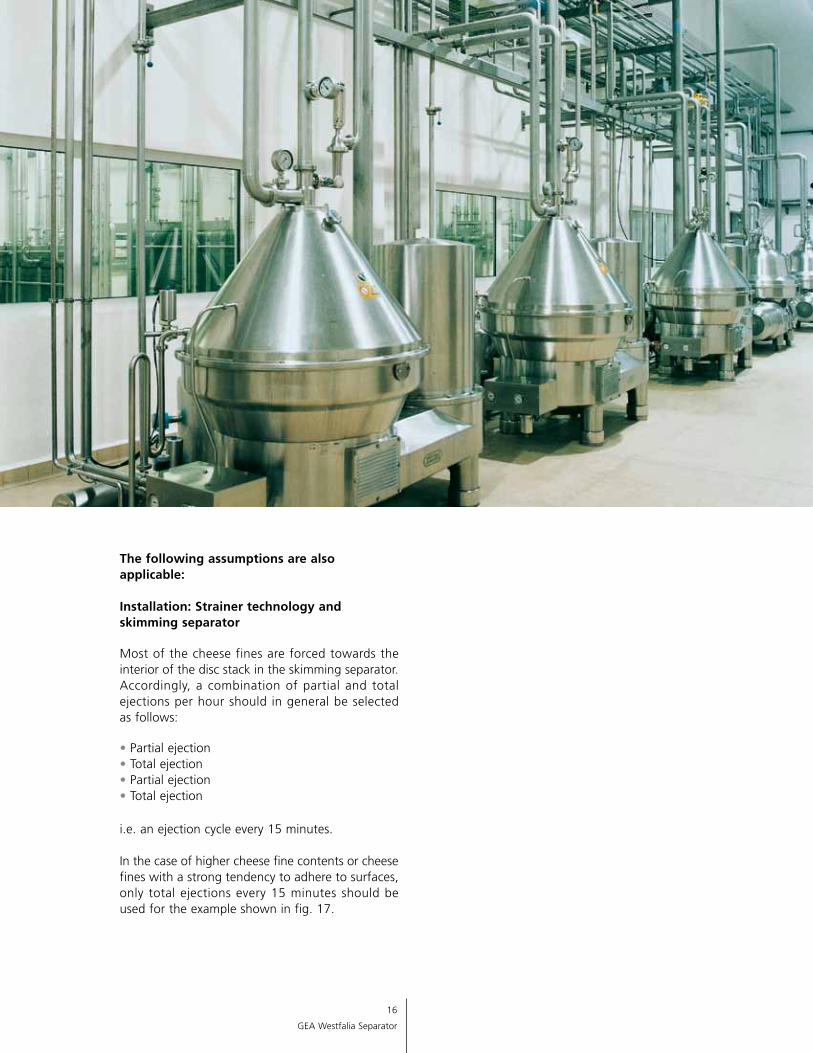
The following assumptions are also applicable: Installation: Strainer technology and skimming separator
Most of the cheese fines are forced towards the interior of the disc stack in the skimming separator. Accordingly, a combination of partial and total ejections per hour should in general be selected as follows:
• Partial ejection• Total ejection • Partial ejection • Total ejection
i.e. an ejection cycle every 15 minutes.
In the case of higher cheese fine contents or cheese fines with a strong tendency to adhere to surfaces, only total ejections every 15 minutes should be used for the example shown in fig. 17.
17
GEA Westfalia Separator
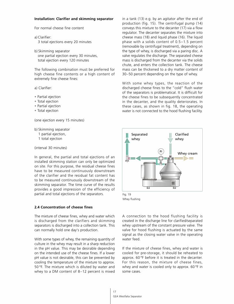
in a tank (13) e.g. by an agitator after the end of production (fig. 15). The centrifugal pump (14) conveys this mixture to the decanter (17) via a flow regulator. The decanter separates the mixture into cheese mass (18) and liquid phase (16). The liquid phase with a solids content of 0.5 – 1.5 percent (removable by centrifugal treatment), depending on the type of whey, is discharged via a paring disc. A valve regulates the discharge. The separated cheese mass is discharged from the decanter via the solids chute, and enters the collection tank. The cheese mass can be thickened to a dry matter content of 30 – 50 percent depending on the type of whey.
With some whey types, the reaction of the discharged cheese fines to the “cold” flush water of the separators is problematical. It is difficult for the cheese fines to be subsequently concentrated in the decanter, and the quality deteriorates. In these cases, as shown in fig. 18, the operating water is not connected to the hood flushing facility.
A connection to the hood flushing facility is created in the discharge line for clarified/separated whey upstream of the constant pressure valve. The valve for hood flushing is actuated by the same signal as the closing water valve in the operating water feed.
If the mixture of cheese fines, whey and water is cooled for pre-storage, it should be reheated to approx. 60 °F before it is treated in the decanter. For this reason, the mixture of cheese fines, whey and water is cooled only to approx. 60 °F in some cases.
Installation: Clarifier and skimming separator
For normal cheese fine content a) Clarifier: 3 total ejections every 20 minutes
b) Skimming separator one partial ejection every 30 minutes, total ejection every 120 minutes
The following combination must be preferred for high cheese fine contents or a high content of ex tremely fine cheese fines:
a) Clarifier: • Partial ejection• Total ejection• Partial ejection• Total ejection (one ejection every 15 minutes)
b) Skimming separator 1 partial ejection, 1 total ejection
(interval 30 minutes)
In general, the partial and total ejections of an installed skimming station can only be optimized on site. For this purpose, the residual cheese fines have to be measured continuously downstream of the clarifier and the residual fat content has to be measured continuously downstream of the skimming separator. The time curve of the results provides a good impression of the efficiency of partial and total ejections of the separators.
2.4 Concentration of cheese fines
The mixture of cheese fines, whey and water which is discharged from the clarifiers and skimming separators is discharged into a collection tank. This can normally hold one day‘s production.
With some types of whey, the remaining quantity of culture in the whey may result in a sharp reduction in the pH value. This may be desirable depending on the intended use of the cheese fines. If a lower pH value is not desirable, this can be prevented by cooling the temperature of the mixture to approx. 50 °F. The mixture which is diluted by water and whey to a DM content of 8 – 12 percent is mixed
Fig. 19
Whey flushing
18
GEA Westfalia Separator
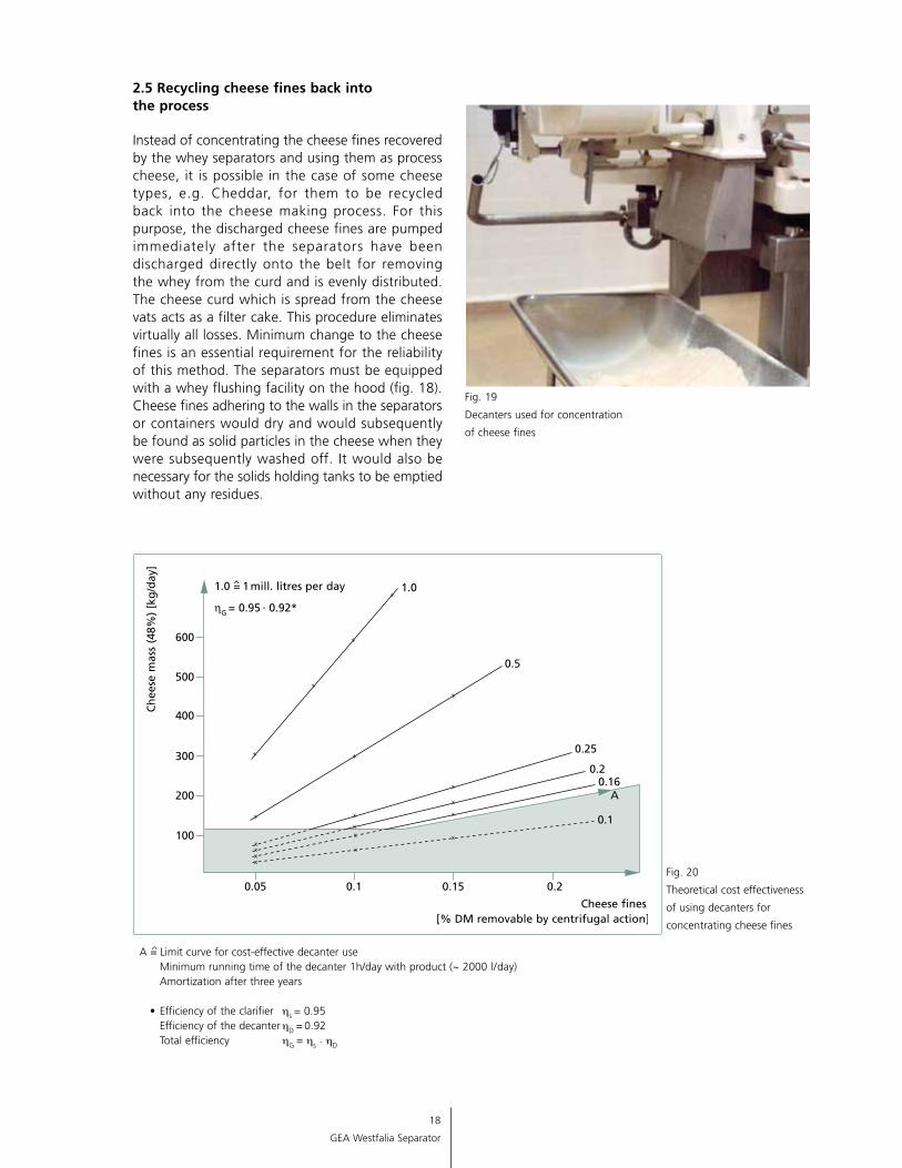
2.5 Recycling cheese fines back into the process
Instead of concentrating the cheese fines recovered by the whey separators and using them as process cheese, it is possible in the case of some cheese types, e.g. Cheddar, for them to be recycled back into the cheese making process. For this purpose, the discharged cheese fines are pumped immediately after the separators have been discharged directly onto the belt for removing the whey from the curd and is evenly distributed. The cheese curd which is spread from the cheese vats acts as a filter cake. This procedure eliminates virtually all losses. Minimum change to the cheese fines is an essential requirement for the reliability of this method. The separators must be equipped with a whey flushing facility on the hood (fig. 18). Cheese fines adhering to the walls in the separators or containers would dry and would subsequently be found as solid particles in the cheese when they were subsequently washed off. It would also be necessary for the solids holding tanks to be emptied without any residues.
A = ̂Limit curve for cost-effective decanter use Minimum running time of the decanter 1h/day with product (~ 2000 l/day) Amortization after three years • Efficiency of the clarifier hs = 0.95 Efficiency of the decanter hD = 0.92 Total efficiency hG = hs . hD
Fig. 20
Theoretical cost effectiveness
of using decanters for
concentrating cheese fines
Fig. 19
Decanters used for concentration
of cheese fines
19
GEA Westfalia Separator
2.6 Cost-effectiveness analyses
Apart from the cost-effectiveness of using clarifiers and decanters, which has to be calculated by purely theoretical means, the following aspects are particularly important:
Quality of the whey cream which is produced
When only partially clarified whey is separated, a relatively high percentage of the cheese fines enters the cream. The quality is negatively affected by the denatured casein in the cream. Compared with freshly produced cream, taste and odor are particularly affected. When centrifugally clarified whey is separated, the difference in taste and odor compared with freshly produced cream is much less significant.
• As a result of the low residual fat content in the separated whey, it is possible for valuable whey powders and protein concentrates to be produced
• When whey is “completely” clarified, subsequent processing of the separated whey, e.g. in UF installations or in evaporator installations, is affected by fewer problems than would be the case with incompletely clarified whey
The cost-effectiveness for using whey clarifiers and decanters , which can be establ i shed theoretically, must be determined separately for each individual case.
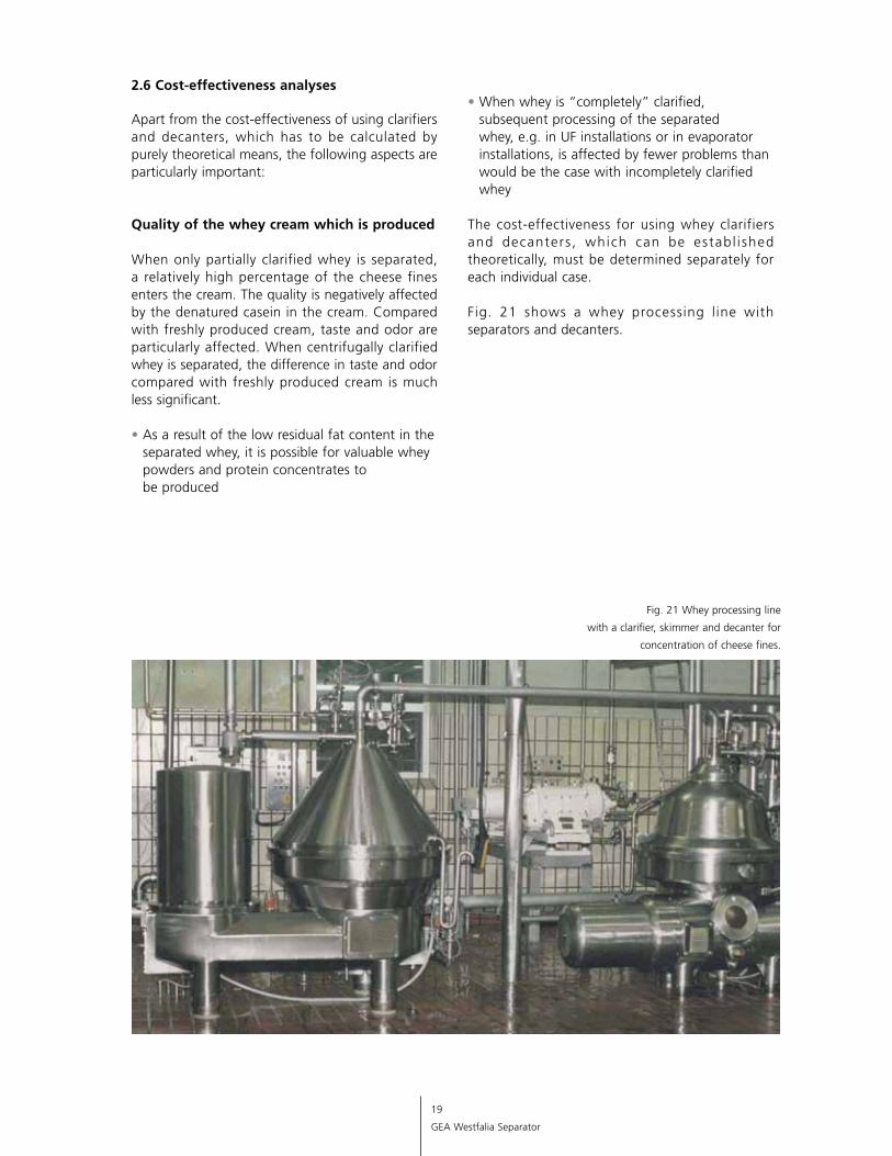
Fig. 21 shows a whey processing l ine with separators and decanters.
Fig. 21 Whey processing line
with a clarifier, skimmer and decanter for
concentration of cheese fines.
20
GEA Westfalia Separator
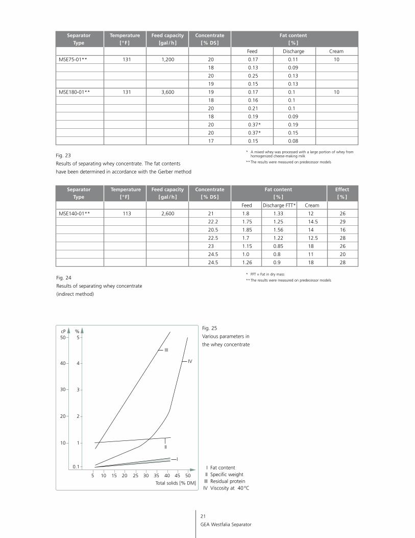
There are limits to the extent to which whey concentrate can be separated due to the concentration ratio in conjunction with the product temperature and the solids which might be capable of being removed by centrifugal action. The concentration ratio should not exceed 1:4, i.e. a dry matter of approx. 25 percent DM is the maximum limit. The separating temperature should in general be between 104-140 °F. The feed capacities of the skimmers which are used, in relation to their nominal capacity, should be between 60 – 70 percent. There may be increased levels of problems with the separation of whey concentrate. This can be due to possible whey protein precipitations or the increased number of extremely small fat globules due to concentration in the evaporator (under vacuum).
The following cases have to be distinguished for separating whey concentrate:
Case 1: In general, it is not cost-effective to separate efficiently separated raw whey after being concentrated. Efficiently separated “raw whey” is defined as whey with a residual fat content of only 0.035 to 0.045 percent before concentration (measured according to Röse-Gottlieb).
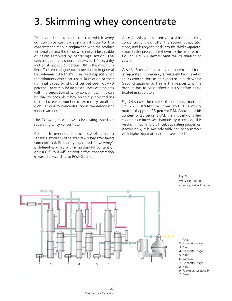
3. Skimming whey concentrateCase 2: Whey is routed via a skimmer during concentration, e.g. after the second evaporator stage, and is recycled back into the third evaporator stage. Such a procedure is shown in schematic form in fig. 22. Fig. 23 shows some results relating to case 2.
Case 3: External feed whey in concentrated form is separated. In general, a relatively high level of solids content has to be expected in such wheys (second sediment). This is the reason why the product has to be clarified directly before being treated in separators.
Fig. 24 shows the results of the indirect method. Fig. 25 illustrates the upper limit value of dry matter of approx. 25 percent DM. Above a solids content of 25 percent DM, the viscosity of whey concentrate increases dramatically (curve IV). This results in much more difficult separating properties. Accordingly, it is not advisable for concentrates with higher dry matters to be separated.
Fig. 22
Whey concentrate
skimming – direct method
1 Whey 2 Evaporator stage I 3 Pump 4 Evaporator stage II 5 Pump
6 Skimmer 7 Evaporator stage III 8 Pump 9 To evaporator stage IV 10 Cream
1
42 7
10
9
3 5 8 6
21
GEA Westfalia Separator
I Fat content II Specific weight III Residual protein IV Viscosity at 40 °C
I
Fig. 25
Various parameters in
the whey concentrate
5
Total solids [% DM]
20
10
30
40
50cP
10 15 20 25 30 35 40 45 50
1
0.1
2
3
4
5%
IV
III
II
Separator Temperature Feed capacity Concentrate Fat content Type [ ° F ] [gal / h ] [ % DS ] [ % ]
Separator Temperature Feed capacity Concentrate Fat content Effect Type [ ° F] [ gal / h ] [ % DS ] [ % ] [ % ]
Feed Discharge Cream
MSE75-01** 131 1,200 20 0.17 0.11 10
18 0.13 0.09
20 0.25 0.13
19 0.15 0.13
MSE180-01** 131 3,600 19 0.17 0.1 10
18 0.16 0.1
20 0.21 0.1
18 0.19 0.09
20 0.37* 0.19
20 0.37* 0.15
17 0.15 0.08
Feed Discharge FTT* Cream
MSE140-01** 113 2,600 21 1.8 1.33 12 26
22.2 1.75 1.25 14.5 29
20.5 1.85 1.56 14 16
22.5 1.7 1.22 12.5 28
23 1.15 0.85 18 26
24.5 1.0 0.8 11 20
24.5 1.26 0.9 18 28
* A mixed whey was processed with a large portion of whey from homogenized cheese-making milk
** The results were measured on predecessor models
* FFT = Fat in dry mass
** The results were measured on predecessor modelsFig. 24
Results of separating whey concentrate
(indirect method)
Fig. 23
Results of separating whey concentrate. The fat contents
have been determined in accordance with the Gerber method
22
GEA Westfalia Separator
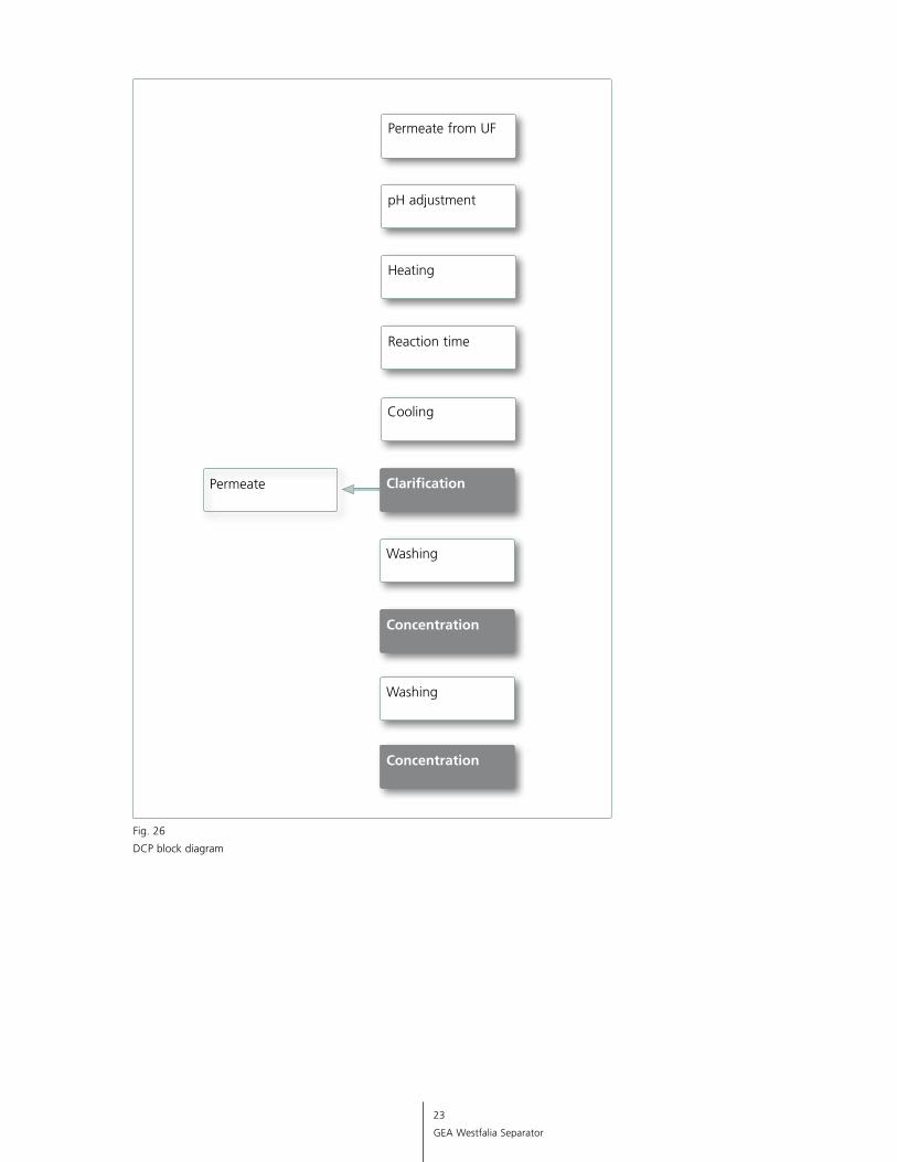
4.1 DCP process
In this process, calcium phosphate is separated from whey permeate. The purpose of this method is to obtain calcium phosphate as a food additive and also to achieve longer operating times in the concentration processes due to the effect of demineralizing the permeate.
This is a process involving chemical and heat. The calcium phosphate precipitated from the whey permeate is discharged with a self-cleaning clarifier through nozzles. The calcium phosphate is then washed and concentrated in two stages.
4.2 Further processes with centrifuges 4.2.1 Dephospholipidation of whey (DPL)
Dephospholipidation is defined as the process of separating phospholipids and lipoproteins from whey. It is a generic concept for further defatting of separated whey. The residual fat content of whey which has been efficiently separated consists of extremely small fat globules, fragments of fat globule membranes and phospholipids and lipoproteins. The latter is fat which is aggregated with phosphate acid or protein. Dephospholipidation of whey is initiated by a process involving chemical and heat. Special clarifiers are used for separating the resultant flocculate.
This process can for instance be used for achieving a lower fat value in the dry matter in the production of whey protein concentrate.
4. Special methods of whey process ing
4.2.2 Alcohol from whey
The production of alcohol from whey is a process which has been known for many years.
The permeate which is obtained during the ultrafiltration of whey still has a lactose content of approx. 4.5 percent. The whey permeate is fermented, and the lactose is converted into alcohol and CO2 by means of yeast. A clarifier is subsequently used for removing the yeast from the mash. The suspension which contains alcohol is distilled. 4.2.3 Lactalbumin
A major area of application for denatured whey protein is for it to be recycled back into the cheese making milk. The strong ability of the whey proteins to bind water means that this process is particularly interesting for cheese types with a high water content or a low fat in dry matter.
The lactalbumin process enables approx. 50 percent of the whey proteins in suspended form to be separated from whey. The process essentially consists of pH- and time-driven heat precipitation. The proteins are discharged from the whey by means of clarifiers. The whey proteins recovered in this way are then washed in order to reduce the lactose content and are further concentrated. This is also achieved with the aid of clarifiers.
23
GEA Westfalia Separator
Reaction time
Heating
pH adjustment
Permeate from UF
Washing
Permeate
Cooling
Clarification
Concentration
Washing
Concentration
Fig. 26
DCP block diagram
24
GEA Westfalia Separator
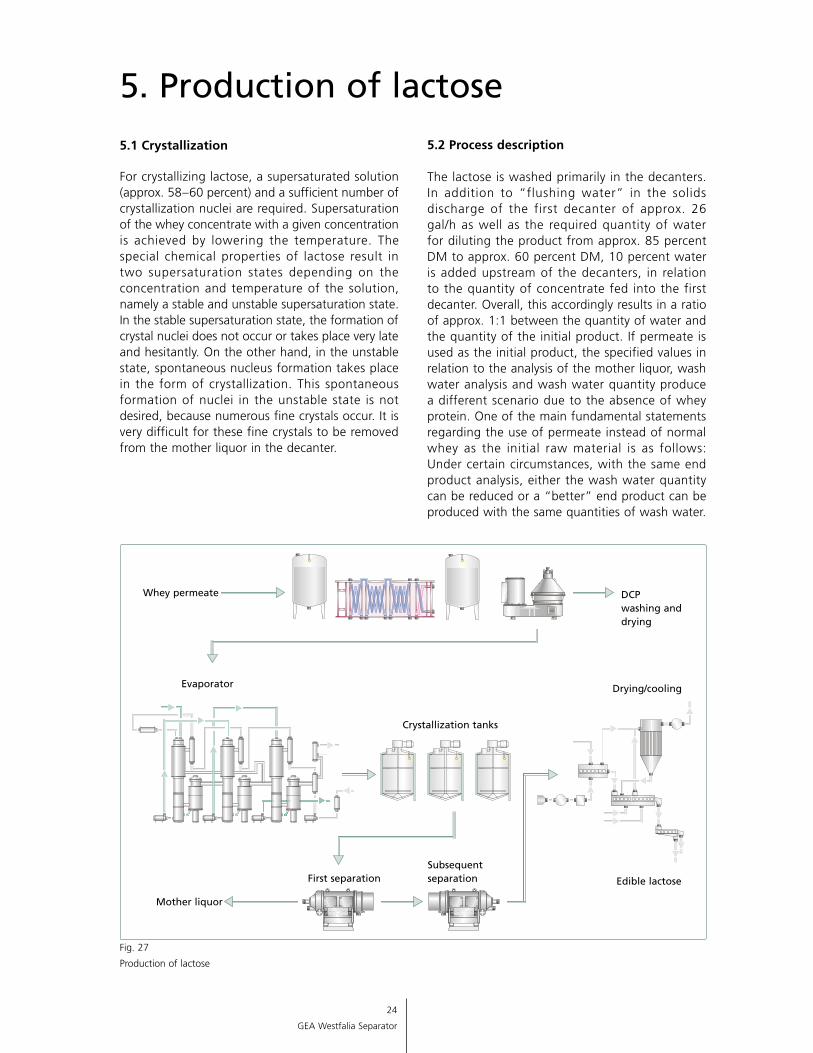
5.1 Crystallization
For crystallizing lactose, a supersaturated solution (approx. 58 – 60 percent) and a sufficient number of crystallization nuclei are required. Supersaturation of the whey concentrate with a given concentration is achieved by lowering the temperature. The special chemical properties of lactose result in two supersaturation states depending on the concentration and temperature of the solution, namely a stable and unstable supersaturation state. In the stable supersaturation state, the formation of crystal nuclei does not occur or takes place very late and hesitantly. On the other hand, in the unstable state, spontaneous nucleus formation takes place in the form of crystallization. This spontaneous formation of nuclei in the unstable state is not desired, because numerous fine crystals occur. It is very difficult for these fine crystals to be removed from the mother liquor in the decanter.
5. Production of lactose
5.2 Process description
The lactose is washed primarily in the decanters. In addition to “flushing water” in the solids discharge of the first decanter of approx. 26 gal/h as well as the required quantity of water for diluting the product from approx. 85 percent DM to approx. 60 percent DM, 10 percent water is added upstream of the decanters, in relation to the quantity of concentrate fed into the first decanter. Overall, this accordingly results in a ratio of approx. 1:1 between the quantity of water and the quantity of the initial product. If permeate is used as the initial product, the specified values in relation to the analysis of the mother liquor, wash water analysis and wash water quantity produce a different scenario due to the absence of whey protein. One of the main fundamental statements regarding the use of permeate instead of normal whey as the initial raw material is as follows: Under certain circumstances, with the same end product analysis, either the wash water quantity can be reduced or a “better” end product can be produced with the same quantities of wash water.
Fig. 27
Production of lactose
25
GEA Westfalia Separator
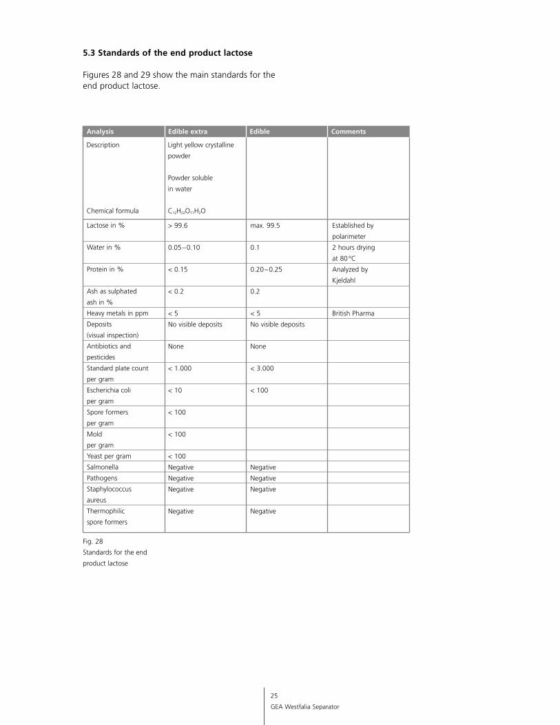
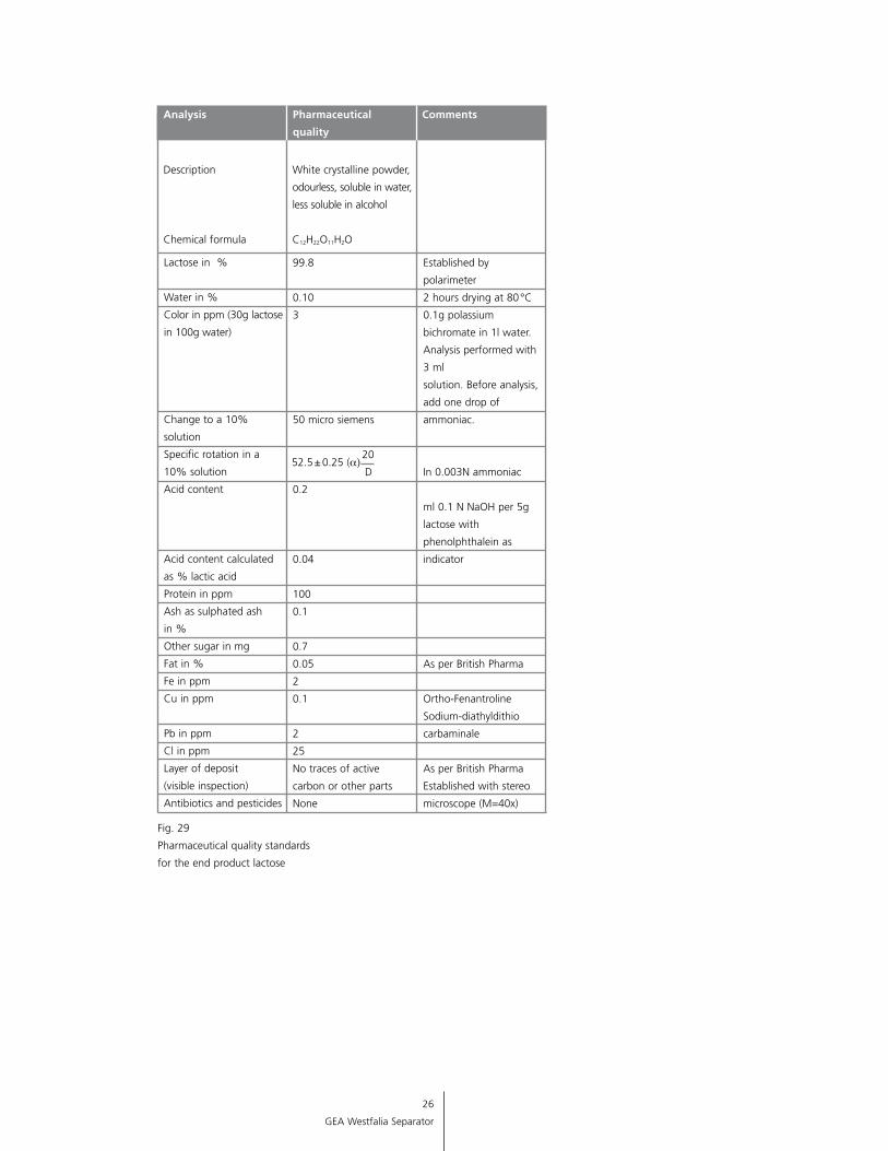
5.3 Standards of the end product lactose
Figures 28 and 29 show the main standards for the end product lactose.
Analysis Edible extra Edible Comments
Description Light yellow crystalline
powder
Powder soluble
in water
Chemical formula C12H22O11H2O
Lactose in %
Water in %
Protein in %
Ash as sulphated
ash in %
Heavy metals in ppm
Deposits
(visual inspection)
Antibiotics and
pesticides
Standard plate count
per gram
Escherichia coli
per gram
Spore formers
per gram
Mold
per gram
Yeast per gram
Salmonella
Pathogens
Staphylococcus
aureus
Thermophilic
spore formers
> 99.6
0.05 – 0.10
< 0.15
< 0.2
< 5
No visible deposits
None
< 1.000
< 10
< 100
< 100
< 100
Negative
Negative
Negative
Negative
max. 99.5
0.1
0.20 – 0.25
0.2
< 5
No visible deposits
None
< 3.000
< 100
Negative
Negative
Negative
Negative
Established by
polarimeter
2 hours drying
at 80 °C
Analyzed by
Kjeldahl
British Pharma
Fig. 28
Standards for the end
product lactose
26
GEA Westfalia Separator
Analysis Pharmaceutical Comments
quality
Description White crystalline powder,
odourless, soluble in water,
less soluble in alcohol
Chemical formula C12H22O11H2O
Lactose in %
Water in %
Color in ppm (30g lactose
in 100g water)
Change to a 10%
solution
Specific rotation in a
10% solution
Acid content
Acid content calculated
as % lactic acid
Protein in ppm
Ash as sulphated ash
in %
Other sugar in mg
Fat in %
Fe in ppm
Cu in ppm
Pb in ppm
Cl in ppm
Layer of deposit
(visible inspection)
Antibiotics and pesticides
99.8
0.10
3
50 micro siemens
20
D
0.2
0.04
100
0.1
0.7
0.05
2
0.1
2
25
No traces of active
carbon or other parts
None
Established by
polarimeter
2 hours drying at 80 °C
0.1g polassium
bichromate in 1l water.
Analysis performed with
3 ml
solution. Before analysis,
add one drop of
ammoniac.
In 0.003N ammoniac
ml 0.1 N NaOH per 5g
lactose with
phenolphthalein as
indicator
As per British Pharma
Ortho-Fenantroline
Sodium-diathyldithio
carbaminale
As per British Pharma
Established with stereo
microscope (M=40x)
Fig. 29
Pharmaceutical quality standards
for the end product lactose
52.5 ± 0.25 (a)
27
GEA Westfalia Separator
It is advisable for bacteria to be removed from whey if the whey is processed with the aim of manufacturing, e.g.:
• Whey protein concentrate• Lactose• Whey powder for baby food
The removal of bacteria from whey is particularly important when whey protein is concentrated in ultra filtration installations. The very long processing times of the retentate at temperatures of 113-131 °F, which are generally optimum for growth of bacteria, mean that it is desirable to dramatically reduce the number of bacteria in the inflowing
6. Removing bacteria from whey
product. In addition, the significant reduction of aerobic and anaerobic spores by way of bacteria removal is also becoming more important for many end products.
The bacteria removal effects in relation to CFU (colony-forming units) depends on the initial content in the whey which fluctuates significantly. In general, they are between 70 and 80 percent. The bacteria removal effect for the spores can be 95 – 98 percent. Bacteriological trials with whey are frequently very difficult. In the case of low initial contents, it is advisable for the spores that the sample material and thus the existing bacteria be concentrated in order to ensure that meaningful results are obtained.
28
GEA Westfalia Separator
7.1 Separators 7.1.1 Clarifiers
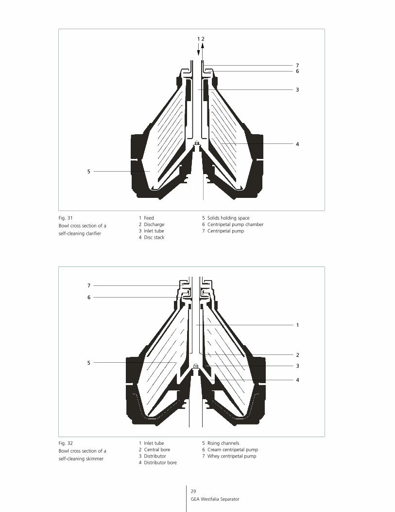
Separators with a self-cleaning bowl are used in the clarification of whey. Clarifiers with a GEA Westfalia Separator hydrosoft inlet have been developed for gentle product treatment, and also particularly for ensuring that the cheese fines, which frequently tend to pulverize, are fed into the separating chamber without being damaged. Fig. 31 shows a self-cleaning clarifier in schematic form. The whey to be clarified is fed into the disc stack (4) with a pump through the central inlet tube (3) and the distributor. The numerous individual separating chambers in parallel between the discs break down the product flow into many thin layers. The settling distance is accordingly minimized.
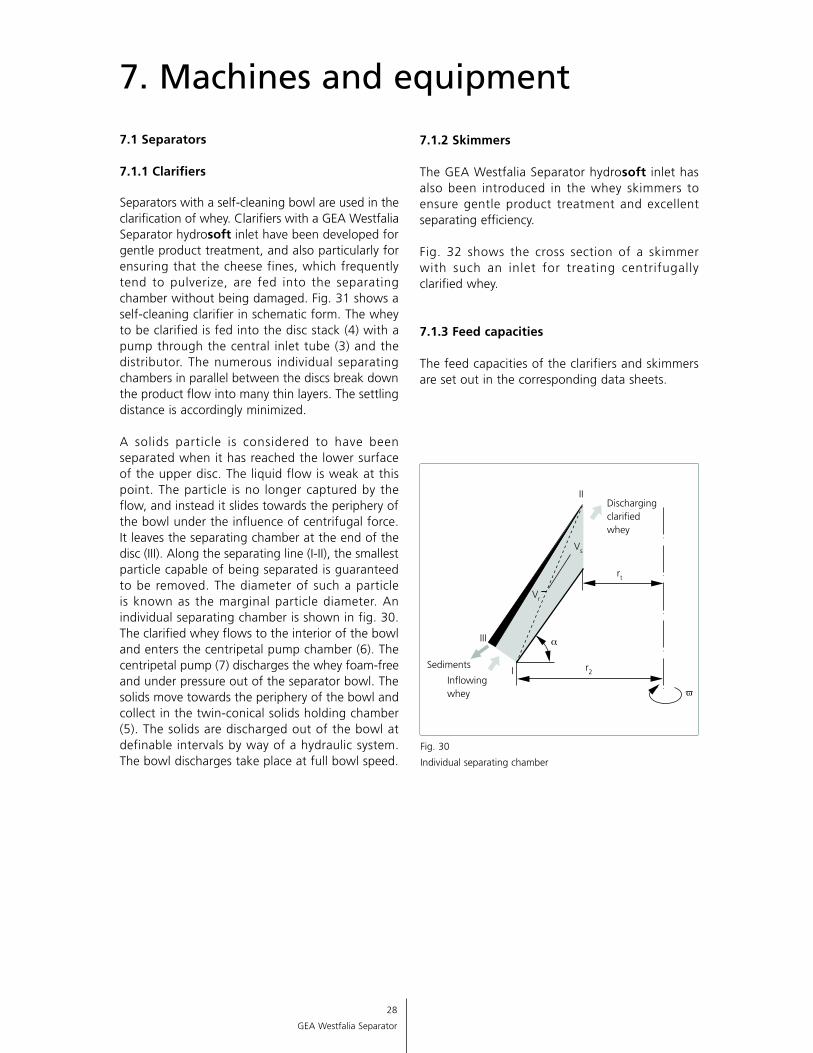
A solids particle is considered to have been separated when it has reached the lower surface of the upper disc. The liquid flow is weak at this point. The particle is no longer captured by the flow, and instead it slides towards the periphery of the bowl under the influence of centrifugal force. It leaves the separating chamber at the end of the disc (III). Along the separating line (I-II), the smallest particle capable of being separated is guaranteed to be removed. The diameter of such a particle is known as the marginal particle diameter. An individual separating chamber is shown in fig. 30. The clarified whey flows to the interior of the bowl and enters the centripetal pump chamber (6). The centripetal pump (7) discharges the whey foam-free and under pressure out of the separator bowl. The solids move towards the periphery of the bowl and collect in the twin-conical solids holding chamber (5). The solids are discharged out of the bowl at definable intervals by way of a hydraulic system. The bowl discharges take place at full bowl speed.
7. Machines and equipment
Fig. 30
Individual separating chamber
III
I
II
a
v
Sediments
Inflowing whey
Discharging clarified whey
rt
r2
Vs
Vr
7.1.2 Skimmers
The GEA Westfalia Separator hydrosoft inlet has also been introduced in the whey skimmers to ensure gentle product treatment and excellent separating efficiency.
Fig. 32 shows the cross section of a skimmer with such an inlet for treating centrifugally clarified whey.
7.1.3 Feed capacities
The feed capacities of the clarifiers and skimmers are set out in the corresponding data sheets.
29
GEA Westfalia Separator
Fig. 31
Bowl cross section of a
self-cleaning clarifier
1 Feed 2 Discharge 3 Inlet tube 4 Disc stack
5 Solids holding space 6 Centripetal pump chamber 7 Centripetal pump
Fig. 32
Bowl cross section of a
self-cleaning skimmer
1 Inlet tube 2 Central bore 3 Distributor 4 Distributor bore
5 Rising channels 6 Cream centripetal pump 7 Whey centripetal pump
30
GEA Westfalia Separator
7.2 Decanters
7.2.1 General
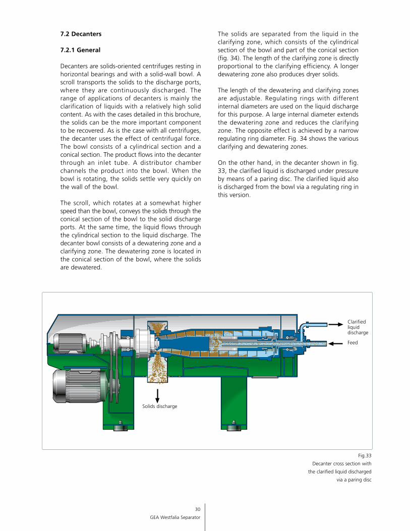
Decanters are solids-oriented centrifuges resting in horizontal bearings and with a solid-wall bowl. A scroll transports the solids to the discharge ports, where they are continuously discharged. The range of applications of decanters is mainly the clarification of liquids with a relatively high solid content. As with the cases detailed in this brochure, the solids can be the more important component to be recovered. As is the case with all centrifuges, the decanter uses the effect of centrifugal force. The bowl consists of a cylindrical section and a conical section. The product flows into the decanter through an inlet tube. A distributor chamber channels the product into the bowl. When the bowl is rotating, the solids settle very quickly on the wall of the bowl.
The scroll, which rotates at a somewhat higher speed than the bowl, conveys the solids through the conical section of the bowl to the solid discharge ports. At the same time, the liquid flows through the cylindrical section to the liquid discharge. The decanter bowl consists of a dewatering zone and a clarifying zone. The dewatering zone is located in the conical section of the bowl, where the solids are dewatered.
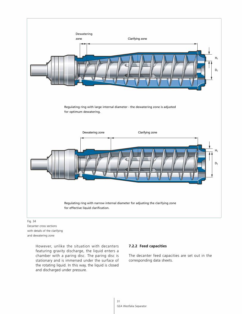
The solids are separated from the liquid in the clarifying zone, which consists of the cylindrical section of the bowl and part of the conical section (fig. 34). The length of the clarifying zone is directly proportional to the clarifying efficiency. A longer dewatering zone also produces dryer solids.
The length of the dewatering and clarifying zones are adjustable. Regulating rings with different internal diameters are used on the liquid discharge for this purpose. A large internal diameter extends the dewatering zone and reduces the clarifying zone. The opposite effect is achieved by a narrow regulating ring diameter. Fig. 34 shows the various clarifying and dewatering zones.
On the other hand, in the decanter shown in fig. 33, the clarified liquid is discharged under pressure by means of a paring disc. The clarified liquid also is discharged from the bowl via a regulating ring in this version.
Fig.33
Decanter cross section with
the clarified liquid discharged
via a paring disc
Feed
Clarified liquid discharge
Solids discharge
31
GEA Westfalia Separator
Fig. 34
Decanter cross sections
with details of the clarifying
and dewatering zone
However, unlike the situation with decanters featuring gravity discharge, the liquid enters a chamber with a paring disc. The paring disc is stationary and is immersed under the surface of the rotating liquid. In this way, the liquid is closed and discharged under pressure.
7.2.2 Feed capacities
The decanter feed capacities are set out in the corresponding data sheets.
Wes
tfal
ia a
nd W
estf
alia
Sep
arat
or a
re r
egis
tere
d tr
adem
arks
of
GEA
Wes
tfal
ia S
epar
ator
Gm
bH.
2462
GEA Mechanical Equipment US, Inc.
GEA Westfalia Separator Division
Headquarters:100 Fairway CourtNorthvale, NJ 07647201-767-3900
Midwest:725 Tollgate Road, Suite BElgin, IL 60123630-503-4700
South:4725 Lakeland Commerce Parkway, Suite 4 Lakeland, FL 33805863-603-8900
Southwest:2408 Timberloch Place, Suite C-4 The Woodlands, TX 77380281-465-7900
West Coast:Western Region Customer Support Center555 Baldwin RoadPatterson, CA 95363209-895-6300
GEA Mechanical Equipment Canada, Inc.
GEA Westfalia Separator Canada Division
835 Harrington CourtBurlington, ON L7N 3P3289-288-5500
Toll-Free: 800-722-662224-Hour Technical Help: 800-509-9299www.wsus.com
GEA Group is a global engineering company with multi-billion euro sales and operations in more than
50 countries. Founded in 1881, the company is one of the largest providers of innovative equipment and
process technology. GEA Group is listed in the STOXX® Europe 600 Index.
We live our values.Excellence • Passion • Integrity • Responsibility • GEA-versity