GEA VARICOVER® Hygienic Product Recovery Systems
80
GEA VARICOVER ® Hygienic Product Recovery Systems
-
Upload
khangminh22 -
Category
Documents
-
view
1 -
download
0
Transcript of GEA VARICOVER® Hygienic Product Recovery Systems

GEA VARICOVER® Hygienic Product Recovery Systems


· 3
Legal notice
Publication date: September 2020
The publication of specifications, technical data and information in written or electronic form does not release the user from the responsibility of checking for themselves all products delivered by us for suitability for the application(s) intended. These may be subject to change without prior notification. Errors and printing errors excepted – we assume no liability for the correctness of specifications given.
The general terms and conditions of delivery apply.
All rights reserved – copyright on all contents. The ® symbol in this catalog identifies a trademark registered in certain countries.
GEA Tuchenhagen GmbHAm Industriepark 2 – 10, 21514 Büchen, GermanyRegistered office: Büchen, Court of Registration: Lübeck, HRB 836 SBManagement office: Franz Bürmann, Frank Prescher, Hanno KussmannSales tax identification number: DE 812589019
· 3

· 5
GEA
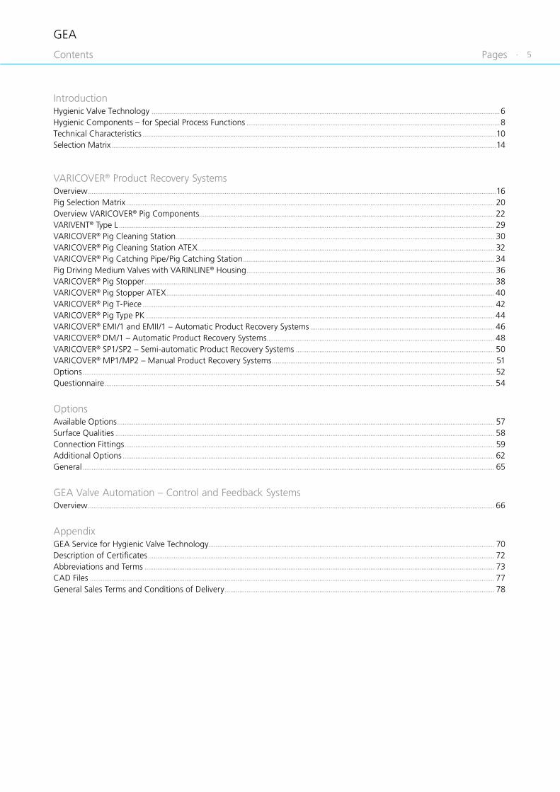
PagesContents
IntroductionHygienic Valve Technology ...............................................................................................................................................................................................6Hygienic Components – for Special Process Functions ...........................................................................................................................................8Technical Characteristics ..................................................................................................................................................................................................10Selection Matrix ...................................................................................................................................................................................................................14
VARICOVER® Product Recovery SystemsOverview ................................................................................................................................................................................................................................16Pig Selection Matrix .......................................................................................................................................................................................................... 20Overview VARICOVER® Pig Components.................................................................................................................................................................. 22VARIVENT® Type L .............................................................................................................................................................................................................. 29VARICOVER® Pig Cleaning Station ............................................................................................................................................................................... 30VARICOVER® Pig Cleaning Station ATEX ................................................................................................................................................................... 32VARICOVER® Pig Catching Pipe/Pig Catching Station .......................................................................................................................................... 34Pig Driving Medium Valves with VARINLINE® Housing ........................................................................................................................................ 36VARICOVER® Pig Stopper ................................................................................................................................................................................................ 38VARICOVER® Pig Stopper ATEX .................................................................................................................................................................................... 40VARICOVER® Pig T-Piece ................................................................................................................................................................................................. 42VARICOVER® Pig Type PK ............................................................................................................................................................................................... 44VARICOVER® EMI/1 and EMII/1 – Automatic Product Recovery Systems ..................................................................................................... 46VARICOVER® DM/1 – Automatic Product Recovery Systems............................................................................................................................. 48VARICOVER® SP1/SP2 – Semi-automatic Product Recovery Systems ............................................................................................................. 50VARICOVER® MP1/MP2 – Manual Product Recovery Systems .......................................................................................................................... 51Options .................................................................................................................................................................................................................................. 52Questionnaire ...................................................................................................................................................................................................................... 54
OptionsAvailable Options ............................................................................................................................................................................................................... 57Surface Qualities ................................................................................................................................................................................................................ 58Connection Fittings ........................................................................................................................................................................................................... 59Additional Options ............................................................................................................................................................................................................ 62General .................................................................................................................................................................................................................................. 65
GEA Valve Automation – Control and Feedback SystemsOverview ............................................................................................................................................................................................................................... 66
AppendixGEA Service for Hygienic Valve Technology ............................................................................................................................................................. 70Description of Certificates .............................................................................................................................................................................................. 72Abbreviations and Terms ................................................................................................................................................................................................ 73CAD Files .............................................................................................................................................................................................................................. 77General Sales Terms and Conditions of Delivery .................................................................................................................................................... 78

6 ·
GEA Introduction
Hygienic Valve Technology
Effi ciency delivering perfect results
Hygienic valves from GEA form the core component of matrix-piped process plants. Thanks to a pioneering valve concept that sets standards for its flexibility, as well as the latest control and automation functions, our valves offer manufacturers maximum product safety and process reliability.
All GEA hygienic valves are designed to be efficient and cost-effective for their particular applications, leading to sustainable operation and considerable savings potential.
GEA valve technology controls fl ow processes
Our hygienic valve technology ensures safe, effi cient processes wherever sensitive liquid products are manufactured. In food production, the classic application areas range from milk processing (milk, yogurt, cheese ...) to liquid foods (sauces and pastes, instant products, baby food ...) and on to the brewing of beer and production of beverages. Further signifi cant areas are biotechnology and pharmaceuticals, as well as care products and cleaning agents / detergents.
Regardless of the sector, the application or production specifi cations: Our hygienic valve technology is sure to meet the demands of our users.
GEA VARICOMP®
Hygienic expansion compensators
GEA VARIVENT® Hygienic seat valves
GEA VARIVENT® Hygienic valves
for the U.S. dairy market
GEA Hygienicbutterfl y valves

· 7
GEA Introduction
Hygienic Valve Technology
Hygienic solutions for every task
Additional components in our portfolio are available to optimize the design of any process plant – from pigging systems for the recovery of valuable products, process connections, and expansion compensators for offsetting thermal stress, to tank safety systems for securing and cleaning tanks and containers.
Supported by our Research and Development Department we regularly launch new, technologically mature products on the markets. Our customers have high standards, which we continuously and systematically meet.
GEA VARIVENT® Hygienic special
application valves
GEA VARICOVER® Hygienic product recovery systems
GEA VARINLINE® Hygienic process
connections
GEA VARITOP® Hygienic tank safety systems

8 ·
GEA
GEA VARINLINE® Process Connections
The trademark VARINLINE® includes control and measuring instruments that meet the requirement of being CIP/SIP-able, thus enabling cleaning and sterilization without the need for dismantling. The instruments can be cleaned and sterilized without any residue in automatic cleaning and sterilizing process cycles. The core piece of the in-line control and measurement technology is the process connection fi tting, the VARINLINE® housing. It is mainly an in-line housing with double vertical ports with two process connections.
The process connections in the VARINLINE® housing allow up to two control / measuring instruments, e.g. a sight glass with opposite illumination unit or diff erent measuring mountings. They are available for all pipe sizes, with the VARIVENT® process connection designed for the nominal width of the respective components to be installed. VARINLINE® housings are self draining – also in the horizontal installation orientation – and thus permit instrumentation free of dead zones. VARINLINE® housings are 3A approved, according to the DGRL and are EHEDG-certifi ed.
Special components, free of dead spaces, for your process
Every process operator who processes valuable or sensitive liquids benefi ts from our hygienic, 100 % drainable components for important special functions in the process. All components were developed on the basis of the groundbreaking and proven GEA VARIVENT® design and guarantee extraordinary reliability and functionality for trouble-free, effi cient processes.
GEA VARITOP® Tank Safety Systems
The VARITOP® tank safety system consists of a modular system and thereby forms a functional unit designed individually according to the customer’s requests.
The diverse applications of the VARITOP® system range from tank cleaning to protecting tanks against high and low pressures to gassing and degassing of tanks.
Introduction
Hygienic Components – for Special Process Functions

· 9
GEA
GEA VARINLINE® Process Connections
The trademark VARINLINE® includes control and measuring instruments that meet the requirement of being CIP/SIP-able, thus enabling cleaning and sterilization without the need for dismantling. The instruments can be cleaned and sterilized without any residue in automatic cleaning and sterilizing process cycles. The core piece of the in-line control and measurement technology is the process connection fi tting, the VARINLINE® housing. It is mainly an in-line housing with double vertical ports with two process connections.
The process connections in the VARINLINE® housing allow up to two control / measuring instruments, e.g. a sight glass with opposite illumination unit or diff erent measuring mountings. They are available for all pipe sizes, with the VARIVENT® process connection designed for the nominal width of the respective components to be installed. VARINLINE® housings are self draining – also in the horizontal installation orientation – and thus permit instrumentation free of dead zones. VARINLINE® housings are 3A approved, according to the DGRL and are EHEDG-certifi ed.
Special components, free of dead spaces, for your process
Every process operator who processes valuable or sensitive liquids benefi ts from our hygienic, 100 % drainable components for important special functions in the process. All components were developed on the basis of the groundbreaking and proven GEA VARIVENT® design and guarantee extraordinary reliability and functionality for trouble-free, effi cient processes.
GEA VARITOP® Tank Safety Systems
The VARITOP® tank safety system consists of a modular system and thereby forms a functional unit designed individually according to the customer’s requests.
The diverse applications of the VARITOP® system range from tank cleaning to protecting tanks against high and low pressures to gassing and degassing of tanks.
GEA VARICOMP® Expansion Compensators
VARICOMP® expansion compensators compensate for expansions and tensions in pipeline systems that result from temperature diff erences. Due to the dead-zone free design, they are able to be used in hygienic and aseptic processes.
GEA VARICOVER® Product Recovery Systems
VARICOVER® product recovery systems are designed for use in fully automatic operations with maximum cleaning demands. They are used to recover valuable products from pipelines – an important consideration to optimize the economic effi ciency of a process system. Pigging pushes the product from the pipes and returns it to the production cycle.
A VARICOVER® product recovery system usually comprises of a pig cleaning station, a pig catching station with propellant medium valves and a pig.
Introduction
Hygienic Components – for Special Process Functions

10 ·
GEA
Available nominal widths for valve series
Nominal width
Valve type
DN 10 15 25 40 50 65 80 100 125 150 162
OD 1" 1 ½" 2" 2 ½" 3" 4" 6"
VARICOVER® product recovery system • • • • • •
Pipe classes
The dimensions of the welding ends comply with the following standards:
Metric Inch
DNOutside diameter
according to DIN 11866, series A
ODIPS
Outside diameter based on ASME-BPE-a-2004, DIN 11866, series C
Outside diameter according to
IPS schedule 5
10 13.0 × 1.5015 19.0 × 1.5025 29.0 × 1.50 1" 25.4 × 1.6540 41.0 × 1.50 1 ½" 38.1 × 1.6550 53.0 × 1.50 2" 50.8 × 1.65 60.3 × 2.0065 70.0 × 2.00 2 ½" 63.5 × 1.6580 85.0 × 2.00 3" 76.2 × 1.65 88.9 × 2.30
100 104.0 × 2.00 4" 101.6 × 2.11 114.3 × 2.30125 129.0 × 2.00150 154.0 × 2.00 6" 152.4 × 2.77 168.2 × 2.77
Technical Characteristics
Introduction

· 11
GEA
Surfaces
The standard for surfaces in contact with the product depends on the particular nominal width standard:• Metric, inch OD, ISO: Ra ≤ 0.8 μm• Inch IPS: Ra ≤ 1.2 μm
Surfaces not in contact with the product (housing) are matte blasted or metal ground as standard. Detailed information on surface designs can be taken from the respective sections.
Materials
Components in contact with the product are produced from 1.4404 (AISI 316L), while those not in contact with the product use 1.4301 (AISI 304). Other materials, e.g. for use when handling aggressive fluids, are available on request.
For detailed information about the properties of the materials, refer to the material properties table.
Test report and inspection certificate
Optionally, the valve housings and product wetted parts can be supplied with a test report 2.2 or an inspection certificate 3.1 according to EN 10204.
If 3.1 inspection certificates are required, please notify us of this when you place the order.
Technical Characteristics
Introduction
Seal materials
Seals in contact with the product are EPDM (standard), HNBR and FKM. NBR material is used for seals not in contact with the product.
The mixing constituents of our seal materials conform to the USP class VI and are contained in the FDA White List. In this the sealings fulfill FOOD and DRUG (FDA) guidelines 21 CFR Part 177.2600 or 21 CFR 177.1550: “Rubber articles intended for repeated use”.
The resistance of the seal material depends on the type and temperature of the product being transported. The contact time with certain products can negatively affect the service life of seals.
For detailed information about the seal material properties, refer to the seal material properties table.

12 ·
GEA
Ambient conditions
The valves can also be used outdoors. However, in these application areas they must be protected against icing, or else de-iced before switching or lifting. In addition, the particular requirements on the control and feedback system must be taken into account in this case.
The product or operating temperature depends on the seal material and can be seen in the seal material properties table.
Air supply
The actuators are configured for operation with min. 4 bar and max. 8 bar air pressure. The standard actuator sizes are configured for an air supply pressure of min. 6 bar (with a product pressure of 5 bar). The quality of the air supply must meet the requirements of ISO 8573-1:2010.
ISO 8573-1:2010
Solid content Quality class 6
Particle size max. 5 μm
Particle density max. 5 mg/m³
Water content Quality class 4
Max. dew point 3 °C
A correspondingly different dew point is required for applications at high altitude or with low ambient temperatures.
Oil content Quality class 3
Max. 1 mg oil per 1 m³ air, preferably oil-free
Ambient temperatures
Product recovery systems0 °C to 45 °C
32 °F to 113 °F
Proximity switches–20 °C to 80 °C
–4 °F to 176 °F
Feedback
In the control topSee catalog GEA Valve Automation
Proximity switch holder (INA)Proximity switches of size M12 × 1 can indicate the positions “open” and/or “closed”.
For detecting the end positions by proximity switches in these valves, it is recommended to use the proximity switch holder (INA) on the actuator (see catalog GEA Valve Automation).
Introduction
Technical Characteristics
Certifi cates
Components for special process applications in the GEA Hygienic Valve Technology portfolio meet the requirements of the European Hygienic Engineering and Design Group (EHEDG) as well as those of 3-A Sanitary Standards, Inc. (3-A SSI). Numerous components have been demonstrated to off er trouble-free and effi cient cleaning ability not only in accordance with the above guidelines, but also in independent and standardized cleaning tests.
ATEX certifi cates and other additional certifi cates are available on request for many components in the GEA Hygienic Valve Technology portfolio.
· 13
GEA
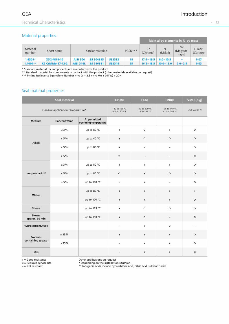
Main alloy elements in % by mass
Material number
Short name Similar materials PREN***Cr
(Chrome)Ni
(Nickel)
Mo (Molybde-
num)
C max. (Carbon)
1.4301* X5CrNi18-10 AISI 304 BS 304S15 SS2332 18 17.5 – 19.5 8.0 – 10.5 – 0.071.4404** X2 CrNiMo 17-12-2 AISI 316L BS 316S11 SS2348 25 16.5 – 18.5 10.0 – 13.0 2.0 – 2.5 0.03
Material properties
Seal material properties
Other applications on request * Depending on the installation situation ** Inorganic acids include hydrochloric acid, nitric acid, sulphuric acid
Seal material EPDM FKM HNBR VMQ (pig)
General application temperature* −40 to 135 °C−40 to 275 °F
−10 to 200 °C14 to 392 °F
−25 to 140 °C−13 to 284 °F
−50 to 200 °C
Medium ConcentrationAt permitted
operating temperature
Alkali
≤ 3 % up to 80 °C + +
≤ 5 % up to 40 °C +
≤ 5 % up to 80 °C + − −
> 5 % − −
Inorganic acid**
≤ 3 % up to 80 °C + + +
≤ 5 % up to 80 °C +
> 5 % up to 100 °C − + −
Water
up to 80 °C + + + +
up to 100 °C + + +
Steam up to 135 °C +
Steam, approx. 30 min
up to 150 °C + −
Hydrocarbons/fuels − + –
Products containing grease
≤ 35 % + + +
> 35 % − + +
Oils − + +
+ = Good resistance = Reduced service life
− = Not resistant
* Standard material for components not in contact with the product** Standard material for components in contact with the product (other materials available on request)*** Pitting Resistance Equivalent Number = % Cr + 3.3 × (% Mo + 0.5 W) + 20 N
Introduction
Technical Characteristics

14 ·
GEA
Selection Matrix
CatalogsHygienic Valve Technology
CatalogsHygienic Pump Technology
CatalogAseptic Valve Technology
CatalogCleaning Technology
GEA VARIVENT® seat valves
GEA butterfly valves
GEA VARIVENT® special application valves
GEA VARIVENT® valves for the U.S. dairy market
GEA VARITOP® tank safety systems
GEA VARINLINE® / GEA VARICOMP®
process connections and expansion compensators
GEA VARICOVER®
product recovery systems
GEA Service for hygienic valve technology
GEA valve automation –control and feedback systems

· 15
Introduction
VARICOVER® product recovery systems
Options
1
2
1
2

GEA
16 ·
VARICOVER® product recovery systems
Product recovery systems optimize the economic efficiency of a process system by recovering the valuable products from pipelines.
Pigging pushes the remaining product from the pipe and returns it to the production cycle. The thin product film is easy to remove by subsequent cleaning, so that the pre-flushing time can be reduced.
Recover the value, reduce the waste!
Special features
Design with no dead zones
CIP/SIP-able
Reduced product loss
Reduced cleaning media and water consumption
Reduced waste water load
Reduced production downtimes
Simple maintenance
VARICOVER® Product Recovery Systems
Overview

GEA
· 17
11
Application ranges
Product push-outProduct recovery systems are used for the ejection of viscous / flowing products from pipelines without mixing with any other media. This is especially required for high quality products in the food and beverages industries, as well as, pharmaceutical and personal and health care industries.
Product controlIn addition to pushing out of products from the pipelines, product recovery systems are also used for gentle filling of pipelines with sensitive and foaming products. Even vertical pipelines can be easily filled by letting the product push the pig downwards in the pipe.
Types of product recovery systems
The pigging process can be implemented with different degrees of automation. That is why the portfolio of GEA Tuchenhagen offers three different product recovery systems:
1. Automatic product recovery systemsDue to the complete automation of the process, the pig can push out and be cleaned without manual action. The entire process takes place solely in the pipeline.
2. Semi-automatic product recovery systemsIn contrast to the automatic product recovery systems, with the semi-automatic product recovery systems the pig is inserted and removed manually. Pushing out of product and returning of the pig then takes place automatically.
3. Manual product recovery systemsIn the manual product recovery system, the pig is manually inserted into the pipeline and at the end removed manually. The pig runs in only one direction.
Applications
Personal and health care industry• body care• shampoo, lotion, cream• toothpaste• cleaning media, washing agents, softeners
Food industry• yogurt, quark, cheese• fruit juice• dough, vegetable oil• sauce, ice cream
Beverage industry• concentrate• syrup
Special features
Safe operation by closed pipe systems
No pig removal required in operation
Automatic function mode and thus fully verifiable processes
Components certified to 3A (101-01)
VARICOVER® Product Recovery Systems
Overview

GEA
18 ·
Features of VARICOVER® product recovery systems
VARICOVER® product recovery systems are characterized by use in fully automatic operations at maximum cleaning demands. Safe operation is secured by a firmly installed and closed pipe system so that no dismantling of the pig cleaning station is required for operation and cleaning. That is why the automatic function mode corresponds to a process that can be validated.
Detection of the pig position via magnetically inductive proximity switch – from the outside of the pipeline – permits automatic control and cleaning (CIP) of the product recovery system.
The pig driving medium can be water, air, CO2 or N2.
Design of a product recovery system
A VARICOVER® product recovery system usually comprises of a pig cleaning station, a pig catching station with propellant medium valves, and a pig. The pig is placed in the pig cleaning station during production and cleaning. In the pig catching station, the pig is stopped mechanically after successful product push-out and the propellant medium valves are used for propellant medium supply.
The pig components can be installed either in new systems or integrated into already present process systems.
Arrangement of the components in the product recovery system EMI/1
Cross-section of the housing of the pig cleaning station
VARICOVER® Product Recovery Systems
Overview

GEA
· 19
11
Applications in process systems
Product recovery systems are used in different applications to meet the various requirements in numerous industries and processes:• From product acceptance to pre-phase tanks• From pre-phase tanks to mixers/process tanks• From mixers/process tanks to storage tanks• From storage tanks to filling machines
Prerequisites for operating of product recovery systems
• Fluid products suitable for pumping• Non-sedimenting products • No installations protruding into the pipe in the section to be pigged, such as measuring mountings
• Only piggable valves matching the geometry of the GEA Tuchenhagen double ball pig can be used
• Same interior diameter throughout the pipe system• No sharp-edged and strongly sagging welds• Connection fittings with transfers rounded on the inside can
be used• No seals protruding into the pipe permitted• Standard pipe bends with small middle radius can be used –
minimize number pf pipe bends• Use pipe bends with low ovality – Tolerances up to ± 1.5%
referring to the outside diameter across the entire bend length
Process system recommendations
The pig speed control is important for the for successful operation of a product recovery system. It must not exceed 0.5 m/s when reaching the pig station. If the arrival speed is too high, there is the danger of damage to the pig.
When using compressible media, such as air, before and behind the pig, the following applications must be avoided:• running the pig in a dry pipeline• returning the pig after pushing out water
If these applications are not observed, there is the danger of a “stick-slip effect”. Here, the pig moves jerkily through the pipeline and may reach too high of speeds. An exception of this effect are with very slippery products such as shampoo and vegetable oils that form a sufficient lubricating film between the pig and the pipe wall.
Pig stopper with pig
VARICOVER® Product Recovery Systems
Overview
VARICOVER® Product Recovery System ATEX
Even in explosion endangered areas you are able to operate GEA Product Recovery Systems. Our pigging components can be used in ATEX-relevant areas in the following nominal sizes:
• DN 40; DN 50; DN 65• OD 1 ½"; OD 2"; OD 2 ½"; OD 3"
• Authorized Ex zones inside of pipelines: 1; 2; 21; 22
• Authorized Ex zones outside of pipelines: 1; 2; 21; 22
• ATEX categories: – II 2G Ex h IIB T3…T6 Gb X – II 2D Ex h IIB T 135 °C Db X
• Suitable pig driving media: – Water – Nitrogen

GEA
20 ·
VARICOVER® product recovery systems for semi-
automatic operation
VARICOVER® product recovery
systems for automatic operation
VARICOVER® product recovery
systems for manual operation
VARICOVER® product recovery systems
VARICOVER® pig components
Pig Selection Matrix

11
SP1 (without ball valve)
SP2 (with ball valve)
Product recovery system EMII/1
Product recovery system EMI/1
Product recovery system DM/1
MP1 (without ball valves)
MP2 (with ball valves)
Pig catching pipe/pig catching station
Pig driving medium valves with VARINLINE® housing
Pig stopper
Pig T-piece
Pig
Piggable double-seat valve
Pig cleaning station
VARICOVER® Product Recovery Systems
· 21

GEA
22 ·
Function method of the pig cleaning station
The pig cleaning station, free of dead zones and completely CIP-/SIP-able, is integrated into the product path and is flexible for use as the launching or receiving station The pig retention cylinders and guidance keeps the pig firmly in position in the station during flooding with product or cleaning media. The flow direction through the station is irrelevant.
When receiving or launching the pig, the pig gripper is pushed forward. The pig is half gripped by the gripper rods, so that it securely reaches the retracted position for production or cleaning.
When the pig is flooded with product, there is a continuous product exchange in the pig station housing. The product is gently transported through the housing. This is possible since the flow area around the pig corresponds to that of the pipeline. Since the housing is free of dead zones without domes and sumps, this ensures the best cleaning with complete residual emptying.
Cleaning the pig in the pig cleaning station
During cleaning, the pig remains in the pig cleaning station. Only there can it be flooded completely. This is possible because the pig gripper moves forward and backward several times by the control of the actuator so that a gap results between the pig front and the metallic stop.
Furthermore, the pig can move between the gripper and the guidance rods, so that the pig contract points to the rods are completely cleaned.
Complete cleaning of the pig in the pig cleaning station
VARICOVER® Product Recovery Systems
Overview VARICOVER® Pig Components Pig Cleaning Station

GEA
· 23
11
Design of the pig cleaning station
1
2
3
4
5
6
1 Pig retention cylinder
The pig retention cylinders fasten the pig in the pig cleaning station in their spring-to-close position and release the pig after pneumatic activation. They are controlled via the T.VIS® feedback system.
2 Pig station housing
Product and cleaning media flood the pig firmly held in position in the pig station housing. Continuous monitoring of the pig position from outside of the housing is possible via the two magnetic sensors. Different connection fittings are available optionally.
3 Pig gripper
The pig gripper takes the pig on one side so that it will reach different positions safely.
4 Pig guidance
The pig is guided by straight rods within the pig station housing and thus cannot take an inclined position in the pig station housing which has a larger diameter than the pig.
5 Lantern
The open design of the lantern separates the actuator and product parts from one another. It permits visual inspection of the stem seal, and is also used for indicating any leakages. Furthermore, a heat transfer between the pig station housing and the pig actuator is prevented.
6 Pig actuator
The pig actuator consists of an air/air controlled actuator used for moving the pig into the production/cleaning position respectively into the launching/receiving position.
VARICOVER® Product Recovery Systems
Overview VARICOVER® Pig Components Pig Cleaning Station

GEA
24 ·
Pig catching pipe/pig catching station
In the catching pipe, the pig is stopped mechanically. It cannot be flooded with cleaning media there and leaves the station right after arriving in most applications. The mechanical pig stop which is integrated in the catching pipe is cleaned during the pipe cleaning.
The pig catching pipe can be used with or without pig driving medium valves. The standard valve unit consists of two combined ECOVENT® valves of types NL and WK. The NL valve is used for shut-off from the product pipe and the WK valve serves as a divert valve between the inlet of the pig driving medium at the upper housing and the connection to the vent at the lower housing.
This arrangement ensures a complete cleaning of the NL shut-off valve. Furthermore, mixing between the product and the pig driving medium – in case of possible leaks – is prevented by the open venting socket at the WK divert valve.
When air is used as the pig driving medium, an air throttle valve is always installed at the inlet socket of the WK divert valve. It sets the average pig speed by a hand-actuated adjustment of the flow area.
Pig catching pipe
Cross section pig catching station
Pig catching pipe with pig driving medium valves
VARICOVER® Product Recovery Systems
Pig Catching Pipe/Pig Catching StationOverview VARICOVER® Pig Components

GEA
· 25
11
Pig driving medium valves with VARINLINE® housing
The VARINLINE® housing permits, aside from the connection of the pig driving medium valves, the adaptation of a pressure gauge, or a pressure transmitter, to record the driving medium pressure during commissioning.
The standard valve unit also consists of two combined ECOVENT® valves of types NL and WK. The NL valve is used for shut-off from the product pipe and the WK valve serves as a divert valve between the inlet of the pig driving medium at the upper housing and the connection to the vent at the lower housing. This arrangement ensures a complete cleaning of the NL shut-off valve. Furthermore, mixing between the product and the pig driving medium – in case of possible leaks – is prevented by the open venting socket at the WK divert valve.
When air is used as the pig driving medium, an air throttle valve is always installed at the inlet socket of the WK divert valve. It sets the average pig speed by a hand-actuated adjustment of the flow area.
VARINLINE® housings VARINLINE® housings with pig driving medium valves
VARICOVER® Product Recovery Systems
Pig Driving Medium Valves with VARINLINE® HousingOverview VARICOVER® Pig Components

GEA
26 ·
Design pig stopper
In the spring-to-close position of the pig stopper, a rod travels over the entire pipe cross section. In it, the pig is stopped mechanically. Product or cleaning media can flow through the free cross-section around the rod.
In contrast to the closed position, the stopper rod is retracted in the air-to-open condition, so that the pig can pass the stopper.
The housing of the pig stopper is screwed to a VARIVENT® grooved flange on both sides and the pig stopper is welded into the pipeline.
Both the closed and the opened positions are monitored by proximity switches.
Function method pig stopper
The pig stopper is automatically operated and mostly used for two applications.
Filling and emptying of tanks is often performed by tee-outlets into pipelines. Pig stoppers can be placed before or behind tee-outlets and serve as precise positioning of the pigs. When a pig reaches a stopper rod, it works as a shut-off element and prevents further filling of the line.
In the product recovery system EMII/1, the product is supplied through the lateral socket of the T-piece and the pig stopper prevents the pig from leaving the launching station if any vacuum occurs.
Cross section pig stopper with pigPig stopper
Cross section pig stopper with opened stopper rod
Cross section pig stopper with closed stopper rod
VARICOVER® Product Recovery Systems
Pig StopperOverview VARICOVER® Pig Components

GEA
· 27
11
Pig T-piece
Special T-pieces in pigging lines are used as product inlet and outlet.
For the pig to be guided well in the T-piece, the pull out of the lateral socket is one nominal width smaller than the main line. This prevents canting of the pig.
The pig T-piece is used to feed product and cleaning media into the product recovery system EMII/1.
Pig in T-piece
Arrangement of the components in the product recovery system EMII/1
VARICOVER® Product Recovery Systems
Pig T-PieceOverview VARICOVER® Pig Components

GEA
28 ·
Pig
The pig is an inherently stable body made from wear- and temperature-resistant, product compatible material. Its contours allow reliable cleaning of the entire surface. The double ball shape of the pig ensures an optimal passage through small and large pipe bends as well as T-pieces with a reduced lateral pull out. Either running direction is possible.
Inside the pig, there are two stainless steel-encapsulated permanent magnets that permit detection of the pig with a magnetic sensor.
Available pig materials are Silicone and FKM (both FDA, 3A (18-03) and EU VO 1935/2004 compliant).
Separation of two different media Both running directions possible
Passage of piggable T-pieces Pigging pipe bends
VARICOVER® Product Recovery Systems
PigOverview VARICOVER® Pig Components
GEA
· 29
11
For more detailed information on the VARIVENT® valve type L, see the catalog GEA VARIVENT® Hygienic Seat Valves.
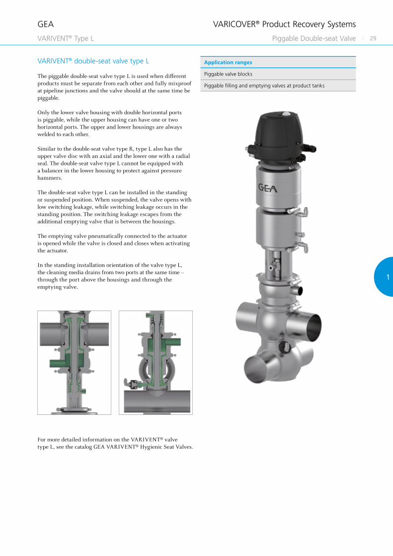
VARIVENT® double-seat valve type L
The piggable double-seat valve type L is used when different products must be separate from each other and fully mixproof at pipeline junctions and the valve should at the same time be piggable.
Only the lower valve housing with double horizontal ports is piggable, while the upper housing can have one or two horizontal ports. The upper and lower housings are always welded to each other.
Similar to the double-seat valve type R, type L also has the upper valve disc with an axial and the lower one with a radial seal. The double-seat valve type L cannot be equipped with a balancer in the lower housing to protect against pressure hammers.
The double-seat valve type L can be installed in the standing or suspended position. When suspended, the valve opens with low switching leakage, while switching leakage occurs in the standing position. The switching leakage escapes from the additional emptying valve that is between the housings.
The emptying valve pneumatically connected to the actuator is opened while the valve is closed and closes when activating the actuator.
In the standing installation orientation of the valve type L, the cleaning media drains from two ports at the same time – through the port above the housings and through the emptying valve.
VARICOVER® Product Recovery Systems
Application ranges
Piggable valve blocks
Piggable filling and emptying valves at product tanks
Piggable Double-seat ValveVARIVENT® Type L

GEA
30 ·
Pipe Housing Dimension General
Nominal width
Ø[mm]
Ødi[mm]
B[mm]
C [mm]
H1[mm]
H2[mm]
H3[mm]
X1[mm]
X2[mm]
Weight[kg]
DN 25 29.0 × 1.50 26.00 329 60 300.0 482.0 118.0 450.0 100 8.5
DN 40 41.0 × 1.50 38.00 339 90 353.0 521.0 135.0 503.0 100 14.5
DN 50 53.0 × 1.50 50.00 313 90 359.0 650.0 158.0 559.0 100 16.0
DN 65 70.0 × 2.00 66.00 323 90 367.0 692.0 170.0 597.0 100 17.0
DN 80 85.0 × 2.00 81.00 331 125 378.0 730.5 194.5 648.0 100 24.0
DN 100 104.0 × 2.00 100.00 340 125 462.0 829.0 215.0 762.0 100 37.0
OD 1" 25.4 × 1.65 22.10 329 60 298.0 477.0 115.0 448.0 100 8.5
OD 1 ½" 38.1 × 1.65 34.80 337 90 351.5 510.0 125.5 501.5 100 15.5
OD 2" 50.8 × 1.65 47.50 313 90 358.0 647.0 156.0 558.0 100 16.0
OD 2 ½" 63.5 × 1.65 60.20 320 90 364.0 689.0 170.0 594.0 100 18.0
OD 3" 76.2 × 1.65 72.90 326 125 374.0 721.0 192.0 634.0 100 22.5
OD 4" 101.6 × 2.11 97.38 340 125 461.0 829.0 216.0 761.0 100 36.0
Technical data of the standard version
Material in contact with the product 1.4404
Seal material in contact with the product EPDM (FDA)Ambient temperature 0 to 45 °CAir supply pressure 4.8 bar (69.6 psi) to 8 bar (116 psi)
Max. product pressure DN 25 – DN 80
OD 1" – OD 3"16 bar (232 psi)
DN 100
OD 4"10 bar (145 psi)
Surface in contact with the product Ra ≤ 0.8 μm
External housing surface Matte blasted
Actuator type Pneumatic actuator air/air
Actuator type of the pig retention cylinders Pneumatic actuator air/spring
Connection fittings Welding end
Identification Adhesive ID tag
Certificates
VARICOVER® Product Recovery Systems
VARICOVER® Pig Cleaning Station

GEA
· 31
11
Position Description of the order code
1 Pig cleaning station
PIG/PCS Pig cleaning station MST 3A
2 Design
G Pig cleaning station complete
A Only actuator of the pig cleaning station
M Only pig retention cylinder for the pig cleaning station
3 Nominal width
DN 25 OD 1"
DN 40 OD 1 ½"
DN 50 OD 2"
DN 65 OD 2 ½"
DN 80 OD 3"
DN 100 OD 4"
4 Seal material
1 EPDM (FDA)
2 FKM (FDA)
3 HNBR (FDA)
5 Surface quality
2 Inside Ra ≤ 0.8 μm, outside matte blasted
3 Inside Ra ≤ 0.8 μm, outside ground
6 Pig retention cylinder
0 Without pig retention cylinder
2 With pig retention cylinder
7 Proximity switches at the pig actuator (for technical specifications, see catalog GEA Valve Automation)
0 Without proximity switches
2 With proximity switches
8 Magnetic sensors at the pig station housing (for technical specifications, see catalog GEA Valve Automation)
0 Without magnetic sensors
2 With magnetic sensors
9 Connection fittingsConnection fitting on port 1 / connection fitting on port 7
N Without connection fittings TK VARIVENT® flange connection complete, grooved flange on housing
J With connection fittings TN VARIVENT® grooved flange complete, incl. O-ring and connecting parts
TF VARIVENT® plain flange
CO Clamp connection
10 Accessories
/52 Adhesive ID tag
+
11–16 Air connection/control and feedback system
00000M Metric for air hose Ø 6/4 mm
00000Z Inch for air hose Ø OD ¼" (6.35/4.35 mm)
XXXXX Order code for different control and feedback systems see catalog GEA Valve Automation
Position 1 2 3 4 5 6 7 8 9 10 11 to 16
Code PIG/PCS - - - - / / /52 +
For order codes differing from the standard version, please refer to section 2.
The code is composed as follows, depending on the chosen configuration:
VII
I
VARICOVER® Product Recovery Systems
VARICOVER® Pig Cleaning Station

GEA
32 ·
Pipe Housing Dimension General
Nominal width
Ø[mm]
Ødi[mm]
B[mm]
C [mm]
H1[mm]
H2[mm]
H3[mm]
X1[mm]
X2[mm]
Weight[kg]
DN 40 41.0 × 1.50 38.00 339 90 353.0 521.0 135.0 503.0 100 14.5
DN 50 53.0 × 1.50 50.00 313 90 359.0 650.0 158.0 559.0 100 16.0
DN 65 70.0 × 2.00 66.00 323 90 367.0 692.0 170.0 597.0 100 17.0
OD 1 ½" 38.1 × 1.65 34.80 337 90 351.5 510.0 125.5 501.5 100 15.5
OD 2" 50.8 × 1.65 47.50 313 90 358.0 647.0 156.0 558.0 100 16.0
OD 2 ½" 63.5 × 1.65 60.20 320 90 364.0 689.0 170.0 594.0 100 18.0
OD 3" 76.2 × 1.65 72.90 326 125 374.0 721.0 192.0 634.0 100 22.5
Technical data of the standard version
Material in contact with the product 1.4404
Seal material in contact with the product EPDM (FDA)Ambient temperature 0 to 45 °CAir supply pressure 4.8 bar (69.6 psi) to 8 bar (116 psi)
Max. product pressure DN 40– DN 65
OD 1 ½" – OD 2 ½"16 bar (232 psi)
OD 3" 10 bar (145 psi)
Surface in contact with the product Ra ≤ 0.8 μm
External housing surface Matte blasted
Actuator type Pneumatic actuator air/air
Actuator type of the pig retention cylinders Pneumatic actuator air/spring
Connection fittings Welding end
Identification Adhesive ID tag
Certificates
VARICOVER® Product Recovery Systems
VARICOVER® Pig Cleaning Station ATEX

GEA
· 33
11
Position Description of the order code
1 Pig cleaning station
PIG/PCS Pig cleaning station MST ATEX
2 Design
G Pig cleaning station complete
A Only actuator of the pig cleaning station
M Only pig retention cylinder for the pig cleaning station
3 Nominal width
DN 40 OD 1 ½"
DN 50 OD 2"
DN 65 OD 2 ½"
OD 3"
4 Seal material
1 EPDM (FDA)
2 FKM (FDA)
3 HNBR (FDA)
5 Surface quality
2 Inside Ra ≤ 0.8 μm, outside matte blasted
3 Inside Ra ≤ 0.8 μm, outside ground
6 Pig retention cylinder
0 Without pig retention cylinder
2 With pig retention cylinder
7 Proximity switches at the pig actuator (for technical specifications, see catalog GEA Valve Automation)
0 Without proximity switches
2 With proximity switches
8 Magnetic sensors at the pig station housing (for technical specifications, see catalog GEA Valve Automation)
0 Without magnetic sensors
2 With magnetic sensors
9 Ex-zone surrounding area Ex-zone pipework1 Gases, zone 1 1 Gases, zone 1
2 Gases, zone 2 2 Gases, zone 2
21 Dust, zone 21 21 Dust, zone 21
22 Dust, zone 22 22 Dust, zone 22
10 Connection fittingsConnection fitting on port 1 / connection fitting on port 7
N Without connection fittings TK VARIVENT® flange connection complete, grooved flange on housing
J With connection fittings TN VARIVENT® grooved flange complete, incl. O-ring and connecting parts
TF VARIVENT® plain flange
CO Clamp connection
11 Accessories
/52 Adhesive ID tag
+
12–16 Air connection/control and feedback system
00000M Metric for air hose Ø 6/4 mm
00000Z Inch for air hose Ø OD ¼" (6.35/4.35 mm)
XXXXX Order code for different control and feedback systems see catalog GEA Valve Automation
Position 1 2 3 4 5 6 7 8 9 10 11 12 to 16
Code PIG/PCS - - - - - / / /52 +
For order codes differing from the standard version, please refer to section 2.
The code is composed as follows, depending on the chosen configuration:
VII
I
VARICOVER® Product Recovery Systems
VARICOVER® Pig Cleaning Station ATEX
GEA
34 ·
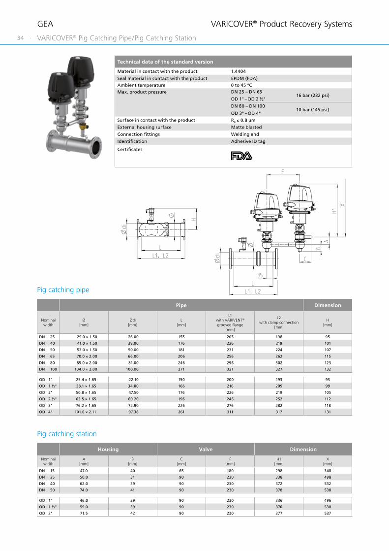
Technical data of the standard version
Material in contact with the product 1.4404
Seal material in contact with the product EPDM (FDA)Ambient temperature 0 to 45 °CMax. product pressure DN 25 – DN 65
OD 1" – OD 2 ½"16 bar (232 psi)
DN 80 – DN 100
OD 3" – OD 4"10 bar (145 psi)
Surface in contact with the product Ra ≤ 0.8 μm
External housing surface Matte blasted
Connection fittings Welding end
Identification Adhesive ID tag
Certificates
Pipe Dimension
Nominal width
Ø[mm]
Ødi[mm]
L[mm]
L1 with VARIVENT® grooved flange
[mm]
L2 with clamp connection
[mm]
H[mm]
DN 25 29.0 × 1.50 26.00 155 205 198 95
DN 40 41.0 × 1.50 38.00 176 226 219 101
DN 50 53.0 × 1.50 50.00 181 231 224 107
DN 65 70.0 × 2.00 66.00 206 256 262 115
DN 80 85.0 × 2.00 81.00 246 296 302 123
DN 100 104.0 × 2.00 100.00 271 321 327 132
OD 1" 25.4 × 1.65 22.10 150 200 193 93
OD 1 ½" 38.1 × 1.65 34.80 166 216 209 99
OD 2" 50.8 × 1.65 47.50 176 226 219 105
OD 2 ½" 63.5 × 1.65 60.20 196 246 252 112
OD 3" 76.2 × 1.65 72.90 226 276 282 118
OD 4" 101.6 × 2.11 97.38 261 311 317 131
Housing Valve Dimension
Nominal width
A[mm]
B[mm]
C[mm]
F[mm]
H1[mm]
X[mm]
DN 15 47.0 40 65 180 298 348
DN 25 50.0 31 90 230 338 498
DN 40 62.0 39 90 230 372 532
DN 50 74.0 41 90 230 378 538
OD 1" 46.0 29 90 230 336 496
OD 1 ½" 59.0 39 90 230 370 530
OD 2" 71.5 42 90 230 377 537
Pig catching pipe
Pig catching station
VARICOVER® Product Recovery Systems
VARICOVER® Pig Catching Pipe/Pig Catching Station

GEA
· 35
11
Position Description of the order code
1 Pig catching pipe
PIG/PCP Pig catching pipe
2 Nominal width of the pigging line
DN 25 OD 1"
DN 40 OD 1 ½"
DN 50 OD 2"
DN 65 OD 2 ½"
DN 80 OD 3"
DN 100 OD 4"
3 Nominal width of the driving medium valves*
0 Without driving medium valves
DN 15
DN 25 OD 1"
DN 40 OD 1 ½"
DN 50 OD 2"
4 Magnetic sensors (for technical specifications, see catalog GEA Valve Automation)
0 Without magnetic sensor
1 With magnetic sensor
5 Seal material
1 EPDM (FDA)
2 FKM (FDA)
3 HNBR (FDA)
6 Surface quality
2 Inside Ra ≤ 0.8 μm, outside matte blasted
3 Inside Ra ≤ 0.8 μm, outside ground
7 Connection fittingsConnection fitting on port 1 / connection fitting on port 2
N Without connection fittings TK VARIVENT® flange connection complete, grooved flange on housing
J With connection fittings TN VARIVENT® grooved flange complete, incl. O-ring and connecting parts
TF VARIVENT® plain flange
CO Clamp connection
8 Accessories
/52 Adhesive ID tag
For order codes differing from the standard version, please refer to section 2.
* The order codes of the driving medium valves can be taken from the catalog GEA VARIVENT® Hygienic Seat Valves. Please indicate in your request that you need valves for product recovery systems.
The code is composed as follows, depending on the chosen configuration:
Position 1 2 3 4 5 6 7 8
Code PIG/PCP - - - - / / /52
I II
VARICOVER® Product Recovery Systems
VARICOVER® Pig Catching Pipe/Pig Catching Station
GEA
36 ·
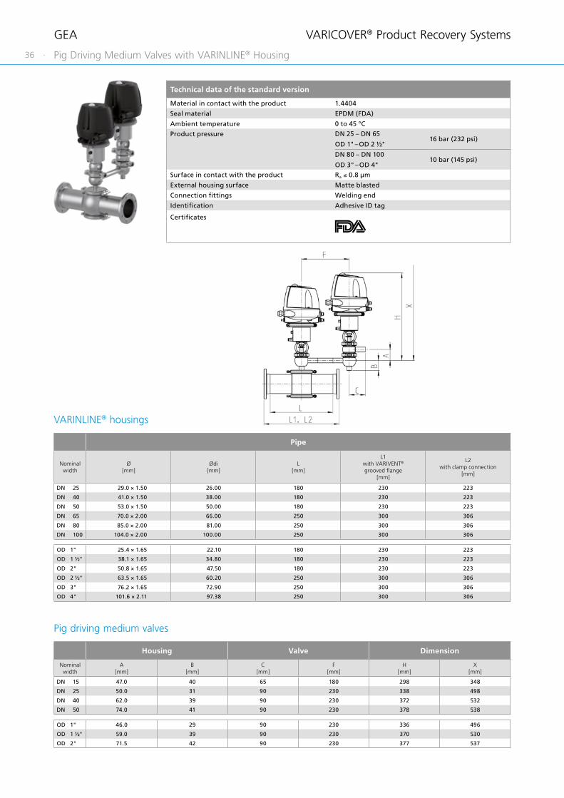
Technical data of the standard version
Material in contact with the product 1.4404
Seal material EPDM (FDA)
Ambient temperature 0 to 45 °C
Product pressure DN 25 – DN 65
OD 1" – OD 2 ½"16 bar (232 psi)
DN 80 – DN 100
OD 3" – OD 4"10 bar (145 psi)
Surface in contact with the product Ra ≤ 0.8 μm
External housing surface Matte blasted
Connection fittings Welding end
Identification Adhesive ID tag
Certificates
Pipe
Nominal width
Ø[mm]
Ødi[mm]
L[mm]
L1 with VARIVENT® grooved flange
[mm]
L2 with clamp connection
[mm]
DN 25 29.0 × 1.50 26.00 180 230 223
DN 40 41.0 × 1.50 38.00 180 230 223
DN 50 53.0 × 1.50 50.00 180 230 223
DN 65 70.0 × 2.00 66.00 250 300 306
DN 80 85.0 × 2.00 81.00 250 300 306
DN 100 104.0 × 2.00 100.00 250 300 306
OD 1" 25.4 × 1.65 22.10 180 230 223
OD 1 ½" 38.1 × 1.65 34.80 180 230 223
OD 2" 50.8 × 1.65 47.50 180 230 223
OD 2 ½" 63.5 × 1.65 60.20 250 300 306
OD 3" 76.2 × 1.65 72.90 250 300 306
OD 4" 101.6 × 2.11 97.38 250 300 306
Housing Valve Dimension
Nominal width
A[mm]
B[mm]
C[mm]
F[mm]
H [mm]
X[mm]
DN 15 47.0 40 65 180 298 348
DN 25 50.0 31 90 230 338 498
DN 40 62.0 39 90 230 372 532
DN 50 74.0 41 90 230 378 538
OD 1" 46.0 29 90 230 336 496
OD 1 ½" 59.0 39 90 230 370 530
OD 2" 71.5 42 90 230 377 537
VARINLINE® housings
Pig driving medium valves
VARICOVER® Product Recovery Systems
Pig Driving Medium Valves with VARINLINE® Housing
GEA
· 37
11
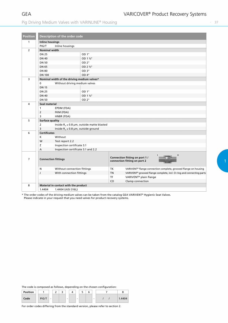
Position Description of the order code
1 Inline housings
PIG/T Inline housings
2 Nominal width
DN 25 OD 1"
DN 40 OD 1 ½"
DN 50 OD 2"
DN 65 OD 2 ½"
DN 80 OD 3"
DN 100 OD 4"
3 Nominal width of the driving medium valves*
0 Without driving medium valves
DN 15
DN 25 OD 1"
DN 40 OD 1 ½"
DN 50 OD 2"
4 Seal material
1 EPDM (FDA)
2 FKM (FDA)
3 HNBR (FDA)
5 Surface quality
2 Inside Ra ≤ 0.8 μm, outside matte blasted
3 Inside Ra ≤ 0.8 μm, outside ground
6 Certificates
K Without
W Test report 2.2
Z Inspection certificate 3.1
A Inspection certificate 3.1 and 2.2
7 Connection fittingsConnection fitting on port 1 / connection fitting on port 2
N Without connection fittings TK VARIVENT® flange connection complete, grooved flange on housing
J With connection fittings TN VARIVENT® grooved flange complete, incl. O-ring and connecting parts
TF VARIVENT® plain flange
CO Clamp connection
8 Material in contact with the product
1.4404 1.4404 (AISI 316L)
Position 1 2 3 4 5 6 7 8
Code PIG/T - - - - / / 1.4404
For order codes differing from the standard version, please refer to section 2.
The code is composed as follows, depending on the chosen configuration:
* The order codes of the driving medium valves can be taken from the catalog GEA VARIVENT® Hygienic Seat Valves. Please indicate in your request that you need valves for product recovery systems.
I II
VARICOVER® Product Recovery Systems
Pig Driving Medium Valves with VARINLINE® Housing

GEA
38 ·
Technical data of the standard version
Material in contact with the product 1.4404
Seal material in contact with the product EPDM (FDA)Ambient temperature 0 to 45 °CAir supply pressure 4.2 bar (61 psi) to 8 bar (116 psi)
Max. product pressure DN 25 – DN 65
OD 1" – OD 2 ½"16 bar (232 psi)
DN 80 – DN 100
OD 3" – OD 4"10 bar (145 psi)
Surface in contact with the product Ra ≤ 0.8 μm
External housing surface Ground
Actuator type Pneumatic actuator air/spring
Connection fittings VARIVENT® grooved flange (welding end)
Identification Adhesive ID tag
Certificates
Pipe Housing Actuator Dimension General
Nominal width
Ø[mm]
Ødi[mm]
B[mm]
L1[mm]
L2[mm]
D1[mm]
H[mm]
X[mm]
Weight[kg]
Stroke[mm]
DN 25 29.0 × 1.50 26.00 37.0 75 125 68 328 358 6.0 32.0
DN 40 41.0 × 1.50 38.00 41.0 75 125 68 334 364 6.5 44.0
DN 50 53.0 × 1.50 50.00 51.0 75 125 139 377 407 11.0 59.0
DN 65 70.0 × 2.00 66.00 58.0 75 125 139 385 415 12.0 75.0
DN 80 85.0 × 2.00 81.00 65.0 75 125 139 392 422 12.5 90.0
DN 100 104.0 × 2.00 100.00 79.5 75 125 139 402 432 14.5 109.0
OD 1" 25.4 × 1.65 22.10 35.0 75 125 68 326 356 6.0 28.0
OD 1 ½" 38.1 × 1.65 34.80 39.5 75 125 68 333 368 6.5 41.0
OD 2" 50.8 × 1.65 47.50 49.5 75 125 139 376 406 11.0 56.5
OD 2 ½" 63.5 × 1.65 60.20 55.0 75 125 139 382 412 11.5 69.0
OD 3" 76.2 × 1.65 72.90 61.0 75 125 139 388 418 12.0 82.0
OD 4" 101.6 × 2.11 97.38 78.0 75 125 139 401 431 14.0 106.5
VARICOVER® Product Recovery Systems
VARICOVER® Pig Stopper

GEA
· 39
11
Position Description of the order code
1 Pig stopper
PIG/PS Pig stopper
2 Nominal width
DN 25 OD 1"
DN 40 OD 1 ½"
DN 50 OD 2"
DN 65 OD 2 ½"
DN 80 OD 3"
DN 100 OD 4"
3 Proximity switches at the actuator (for technical specifications, see catalog GEA Valve Automation)
0 Without proximity switches
2 With proximity switches
4 Design
S Pig stopper (complete)
A Actuator as spare part
5 Seal material
1 EPDM (FDA)
2 FKM (FDA)
3 HNBR (FDA)
6 Surface quality
3 Inside Ra ≤ 0.8 μm, outside ground
7 Connection fittingsConnection fitting on port 1 / connection fitting on port 2
N Without connection fittings TN VARIVENT® grooved flange complete, incl. O-ring and connecting parts
J With connection fittings
8 Accessories
/52 Adhesive ID tag
+
9–14 Air connection/control and feedback system
00000M Metric for air hose Ø 6/4 mm
00000Z Inch for air hose Ø OD ¼" (6.35/4.35 mm)
XXXXX Order code for different control and feedback systems see catalog GEA Valve Automation
For order codes differing from the standard version, please refer to section 2.
The code is composed as follows, depending on the chosen configuration:
Position 1 2 3 4 5 6 7 8 9 to 14
Code PIG/PS - - - 3 - / / /52 +
I II
VARICOVER® Product Recovery Systems
VARICOVER® Pig Stopper

GEA
40 ·
Technical data of the standard version
Material in contact with the product 1.4404
Seal material in contact with the product EPDM (FDA)Ambient temperature 0 to 45 °CAir supply pressure 4.2 bar (61 psi) to 8 bar (116 psi)
Max. product pressure DN 40 – DN 65
OD 1 ½" – OD 2 ½"16 bar (232 psi)
OD 3" 10 bar (145 psi)
Surface in contact with the product Ra ≤ 0.8 μm
External housing surface Ground
Actuator type Pneumatic actuator air/spring
Connection fittings VARIVENT® grooved flange (welding end)
Identification Adhesive ID tag
Certificates
Pipe Housing Actuator Dimension General
Nominal width
Ø[mm]
Ødi[mm]
B[mm]
L1[mm]
L2[mm]
D1[mm]
H[mm]
X[mm]
Weight[kg]
Stroke[mm]
DN 40 41.0 × 1.50 38.00 41.0 75 125 68 334 364 6.5 44.0
DN 50 53.0 × 1.50 50.00 51.0 75 125 139 377 407 11.0 59.0
DN 65 70.0 × 2.00 66.00 58.0 75 125 139 385 415 12.0 75.0
OD 1 ½" 38.1 × 1.65 34.80 39.5 75 125 68 333 368 6.5 41.0
OD 2" 50.8 × 1.65 47.50 49.5 75 125 139 376 406 11.0 56.5
OD 2 ½" 63.5 × 1.65 60.20 55.0 75 125 139 382 412 11.5 69.0
OD 3" 76.2 × 1.65 72.90 61.0 75 125 139 388 418 12.0 82.0
VARICOVER® Product Recovery Systems
VARICOVER® Pig Stopper ATEX

GEA
· 41
11
Position Description of the order code
1 Pig stopper
PIG/PS Pig stopper ATEX
2 Nominal width
DN 40 OD 1 ½"
DN 50 OD 2"
DN 65 OD 2 ½"
OD 3"
3 Proximity switches at the actuator (for technical specifications, see catalog GEA Valve Automation)
0 Without proximity switches
2 With proximity switches
4 Design
S Pig stopper (complete)
A Actuator as spare part
5 Seal material
1 EPDM (FDA)
2 FKM (FDA)
3 HNBR (FDA)
6 Surface quality
3 Inside Ra ≤ 0.8 μm, outside ground
7 Ex-zone surrounding area Ex-zone pipework
1 Gases, zone 1 1 Gases, zone 1
2 Gases, zone 2 2 Gases, zone 2
21 Dust, zone 21 21 Dust, zone 21
22 Dust, zone 22 22 Dust, zone 22
8 Connection fittingsConnection fitting on port 1 / connection fitting on port 2
N Without connection fittings TN VARIVENT® grooved flange complete, incl. O-ring and connecting parts
J With connection fittings
9 Accessories
/52 Adhesive ID tag
+
10–15 Air connection/control and feedback system
00000M Metric for air hose Ø 6/4 mm
00000Z Inch for air hose Ø OD ¼" (6.35/4.35 mm)
XXXXX Order code for different control and feedback systems see catalog GEA Valve Automation
For order codes differing from the standard version, please refer to section 2.
The code is composed as follows, depending on the chosen configuration:
I II
VARICOVER® Product Recovery Systems
VARICOVER® Pig Stopper ATEX
Position 1 2 3 4 5 6 7 8 9 10 to 15
Code PIG/PS - - - 3 - - / / /52 +

GEA
42 ·
Technical data of the standard version
Material in contact with the product 1.4404
Seal material in contact with the product EPDM (FDA)Ambient temperature 0 to 45 °CMax. product pressure DN 25 – DN 65
OD 1" – OD 2 ½"16 bar (232 psi)
DN 80 – DN 100
OD 3" – OD 4"10 bar (145 psi)
Surface in contact with the product Ra ≤ 0.8 μm
External housing surface Matte blasted
Connection fittings Welding end
Identification Adhesive ID tag
Certificates
Pipe Dimension
Nominal width
Ø[mm]
Ødi[mm]
L[mm]
L1 with VARIVENT® grooved flange
[mm]
L2 with clamp connection
[mm]
H[mm]
H1with VARIVENT® grooved flange
[mm]
H2 with clamp connection
[mm]
DN 25 29.0 × 1.50 26.00 100 150 143 31.5 56.5 53.0
DN 40 41.0 × 1.50 38.00 120 170 163 39.5 64.5 61.0
DN 50 53.0 × 1.50 50.00 140 190 183 51.5 76.5 73.0
DN 65 70.0 × 2.00 66.00 160 210 216 61.5 86.5 89.5
DN 80 85.0 × 2.00 81.00 180 230 236 72.5 97.5 100.5
DN 100 104.0 × 2.00 100.00 200 250 256 89.0 114.0 117.0
OD 1" 25.4 × 1.65 22.10 100 150 143 29.7 54.7 51.2
OD 1 ½" 38.1 × 1.65 34.80 120 170 163 41.1 66.1 62.6
OD 2" 50.8 × 1.65 47.50 140 190 183 48.4 73.4 69.9
OD 2 ½" 63.5 × 1.65 60.20 160 210 216 58.8 83.8 86.8
OD 3" 76.2 × 1.65 72.90 180 230 236 64.1 89.1 92.1
OD 4" 101.6 × 2.11 97.38 200 250 256 89.3 114.3 117.3
VARICOVER® Product Recovery Systems
VARICOVER® Pig T-Piece

GEA
· 43
11
Position Description of the order code
1 Pig T-piece
PIG/TEE Pig T-piece
2 Nominal width
DN 25 OD 1"
DN 40 OD 1 ½"
DN 50 OD 2"
DN 65 OD 2 ½"
DN 80 OD 3"
DN 100 OD 4"
3 Seal material
1 EPDM (FDA)
2 FKM (FDA)
3 HNBR (FDA)
4 Surface quality
2 Inside Ra ≤ 0.8 μm, outside matte blasted
3 Inside Ra ≤ 0.8 μm, outside ground
5 Connection fittingsConnection fitting on port 1 /Connection fitting on port 2 /connection fitting on port 7
N Without connection fittings TK VARIVENT® flange connection complete, grooved flange on housing
J With connection fittings TN VARIVENT® grooved flange complete, incl. O-ring and connecting parts
TF VARIVENT® plain flange
CO Clamp connection
6 Accessories
/52 Adhesive ID tag
Position 1 2 3 4 5 6
Code PIG/TEE - - - / / /52
For order codes differing from the standard version, please refer to section 2.
The code is composed as follows, depending on the chosen configuration:
I II
VII
VARICOVER® Product Recovery Systems
VARICOVER® Pig T-Piece

GEA
44 ·
Technical data of the standard version
Material in contact with the product VMQ (Silicone), FKM
Ambient temperature −5 to 130 °C
Certificates
Dimensions Article number
Nominal width
L1[mm]
L2[mm]
ØD[mm]
Material
VMQ FKM
DN 25 On request On request On request On request On request
DN 40 80 42 > 38.00 228-163.24 228-163.23
DN 50 99 48 > 50.00 228-163.27 228-163.26
DN 65 127 60 > 66.00 228-163.30 228-163.29
DN 80 158 76 > 81.00 228-163.33 228-163.32
DN 100 192 91 > 100.00 228-163.36 228-163.35
OD 1" On request On request On request On request On request
OD 1 ½" 67 32 > 34.80 228-263.12 228-263.11
OD 2" 93 45 > 47.50 228-263.03 228-263.02
OD 2 ½" 119 58 > 60.20 228-263.15 228-263.14
OD 3" 144 70 > 72.90 228-263.18 228-263.17
OD 4" 181 83 > 97.38 228-263.06 228-263.05
VARICOVER® Product Recovery Systems
VARICOVER® Pig Type PK

11

GEA
46 ·
Functional description
ProductionThe pig is firmly held in position in the launching station and flooded with product.
Product push-outThe pig is pushed through the pipeline by means of the driving medium and pushes the residual product towards the receiving station.
Pig returnWhen reaching the receiving station, the pig is immediately returned to the launching station.
CleaningThe pig stations are cleaned during the pipe cleaning. The pig is fully flooded in the launching station and cleaned.
Selection criteria for the product recovery system EMI/1
The product recovery system is automatically operated and the pig is cleaned in the launching station. The pig is removed from the pipeline for inspection.
Preferred combination of the pig driving mediaLaunching station: WaterReceiving station: AirAt least one liquid medium is before or behind the pig in each pig run.
Combination of the pig driving mediaLaunching station: AirReceiving station: AirThis is only possible with very slippery products such as shampoo and vegetable oils that form a sufficient lubricating film between the pig and the pipe wall. Not applicable for products that do not lubricate, so to avoid the “Stick-slip effect”.
The pipeline can be fully self-drained after cleaning.
Product/CIP
Product/CIP
Pig driving medium
Launching station
Receiving station
Pig driving medium
VARICOVER® Product Recovery Systems
VARICOVER® EMI/1 Automatic Product Recovery Systems
GEA
· 47
11
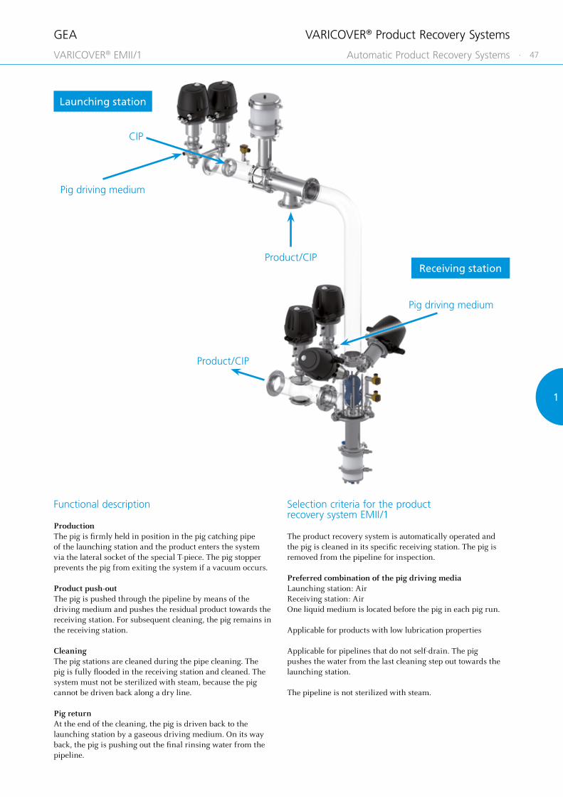
Functional description
ProductionThe pig is firmly held in position in the pig catching pipe of the launching station and the product enters the system via the lateral socket of the special T-piece. The pig stopper prevents the pig from exiting the system if a vacuum occurs.
Product push-outThe pig is pushed through the pipeline by means of the driving medium and pushes the residual product towards the receiving station. For subsequent cleaning, the pig remains in the receiving station.
CleaningThe pig stations are cleaned during the pipe cleaning. The pig is fully flooded in the receiving station and cleaned. The system must not be sterilized with steam, because the pig cannot be driven back along a dry line.
Pig returnAt the end of the cleaning, the pig is driven back to the launching station by a gaseous driving medium. On its way back, the pig is pushing out the final rinsing water from the pipeline.
Selection criteria for the product recovery system EMII/1
The product recovery system is automatically operated and the pig is cleaned in its specific receiving station. The pig is removed from the pipeline for inspection.
Preferred combination of the pig driving mediaLaunching station: AirReceiving station: AirOne liquid medium is located before the pig in each pig run.
Applicable for products with low lubrication properties
Applicable for pipelines that do not self-drain. The pig pushes the water from the last cleaning step out towards the launching station.
The pipeline is not sterilized with steam.
CIP
Product/CIP
Product/CIP
Pig driving medium
Pig driving medium
Launching station
Receiving station
VARICOVER® Product Recovery Systems
VARICOVER® EMII/1 Automatic Product Recovery Systems

GEA
48 ·
Product/CIP
Pig driving mediumPig station S1
Pig station S2
Pig driving medium
Product/CIP
VARICOVER® Product Recovery Systems
VARICOVER® DM/1 Automatic Product Recovery Systems

GEA
· 49
11
Selection criteria for the product recovery system DM/1
The product recovery system is automatically operated and the pigs are cleaned in the pig station. The pigs are removed from the pipeline for inspection.
Three possible applications:• Product push-out optionally in two directions• Product filling with slope
– particularly when having foaming products• Operation with one pig
– benefit as compared to EMII/1: Product infeed without T-piece
All combinations of driving media can be used if at least one liquid medium is located before or behind the pig in each pig run.
Functional description
1. Product push-out optionally in two directions
ProductionThe pig stations have one pig firmly held in position each. Both are flooded with product in their stations.
Product push-outAfter the production end, the residual product may be pushed out in the desired direction using the driving medium. The pig moves to the opposite pig of the receiving station for this.
Pig returnWhen reaching the receiving station, the pig is immediately returned to the launching station.
CleaningThe pig stations are cleaned during the pipe cleaning. The pigs are fully flooded in their specific stations and cleaned.
2. Product filling with slope
If the product is filled into empty and descending pipelines, product and air may mix and produce foam.
This incident can be avoided using the product recovery system DM/1. For this purpose, pig S2 is driven against pig S1 prior to production start. Afterwards pig S2 is pushed back with product into its station and serves as a separator between product and air. All further process steps are the same as described before under section 1.
3. Operation with one pig
Only one pig is used in the system. The function method is the same as for the product recovery system EMII/1. In contrast to the EMII/1, no T-piece is used for product infeed. The product enters directly via the launching station and floods the pig firmly held in position.
VARICOVER® Product Recovery Systems
VARICOVER® DM/1 Automatic Product Recovery Systems
GEA
50 ·
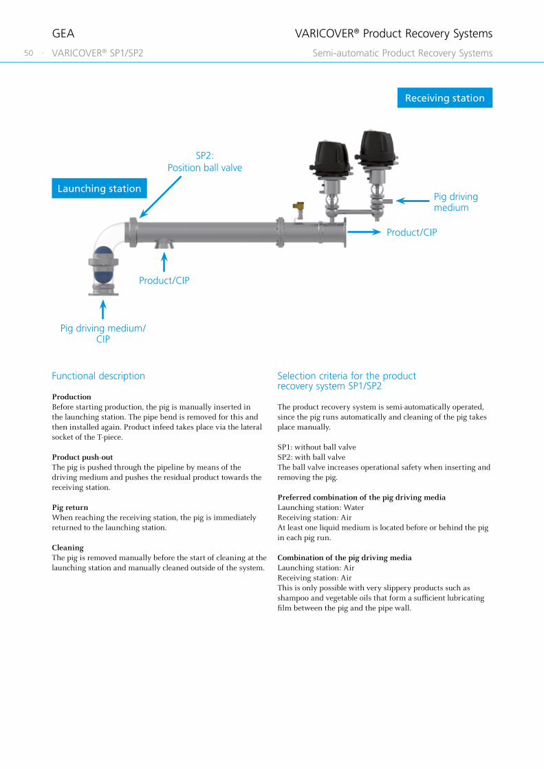
Functional description
ProductionBefore starting production, the pig is manually inserted in the launching station. The pipe bend is removed for this and then installed again. Product infeed takes place via the lateral socket of the T-piece.
Product push-outThe pig is pushed through the pipeline by means of the driving medium and pushes the residual product towards the receiving station.
Pig returnWhen reaching the receiving station, the pig is immediately returned to the launching station.
CleaningThe pig is removed manually before the start of cleaning at the launching station and manually cleaned outside of the system.
Selection criteria for the product recovery system SP1/SP2
The product recovery system is semi-automatically operated, since the pig runs automatically and cleaning of the pig takes place manually.
SP1: without ball valveSP2: with ball valveThe ball valve increases operational safety when inserting and removing the pig.
Preferred combination of the pig driving mediaLaunching station: WaterReceiving station: AirAt least one liquid medium is located before or behind the pig in each pig run.
Combination of the pig driving mediaLaunching station: AirReceiving station: AirThis is only possible with very slippery products such as shampoo and vegetable oils that form a sufficient lubricating film between the pig and the pipe wall.
Pig driving medium
Product/CIP
Pig driving medium/ CIP
Product/CIP
SP2: Position ball valve
Launching station
Receiving station
VARICOVER® Product Recovery Systems
VARICOVER® SP1/SP2 Semi-automatic Product Recovery Systems

GEA
· 51
11Functional description
ProductionBefore starting production, the pig is manually inserted in the launching station. The pipe bend is removed for this and then installed again. Product infeed takes place via the lateral socket of the T-piece.
Product push-outThe pig is pushed through the pipeline by means of the driving medium and pushes the residual product towards the receiving station. It is removed for subsequent cleaning there and not pushed back to the launching station.
CleaningThe pig is manually cleaned outside of the system.
Selection criteria for the product recovery system MP1/MP2
The product recovery system is manually operated, since both the pig runs and the cleaning of the pig take place manually.
MP1: without ball valvesMP2: with ball valvesThe ball valves increase operational safety when inserting and removing the pig.
Preferred pig driving medium at system MP1Launching station: AirWhen using water, there is the danger of water escaping when opening the pipe bend at the receiving station.
Preferred pig driving medium at system MP2Launching station: WaterUsing water permits better adjustment of the pig speed than with the compressible medium of air. There is no risk of water escaping since the ball valve before the receiving station is closed when opening the pipe bend.
Alternatively, the MP1 and MP2 systems can also be operated semi-automatically. For this, the valves are equipped with pneumatic actuators. The pig run takes place automatically and the pig is cleaned manually. As for the manual application, the pig is taken out at the receiving station.
Product/CIP
Pig driving medium/ CIP
Product/ CIP
MP2: Position ball valvesLaunching station Receiving station
VARICOVER® Product Recovery Systems
VARICOVER® MP1/MP2 Manual Product Recovery Systems

GEA
52 ·
Article number
228-000358
Material Article number
FKM 228-000259
Silicone 228-000260
Pig detector
The pig detector serves to find an unmoving pig along the pipeline or in a pig station. For this, the detector is manually routed to the pipeline from the outside. Once it has entered the area of the pig’s magnetic field, an indicator light comes on. The design of the pig detector is comparable to that of a pen. The detector is also approved for use in potentially explosive atmospheres (ATEX and FM).
Pig test material
Using pig test materials helps to determine the chemical resistance of the pig material against products and/or cleaning media in the planning stages.
This procedure is particularly recommended when the resistance of the pig material is unknown. The test bodies have a diameter of approx. 40 mm and a thickness of approx. 4 mm. During resistance tests, deviations from the surface properties, dimensions and weights can be found. Available materials: Silicone and FKM.
VARICOVER® Product Recovery Systems
Options

GEA
· 53
11
Pipe bracket for magnetic sensors*
Nominal width Article number
DN 25 228-168.02
DN 40 228-168.04
DN 50 228-168.06
DN 65 228-168.08
DN 80 228-168.10
DN 100 228-168.12
OD 1" 228-168.01
OD 1 ½" 228-168.03
OD 2" 228-168.05
OD 2 ½" 228-168.07
OD 3" 228-168.09
OD 4" 228-168.11
Magnetic sensor with pipe bracket
Pigs are often detected along pipelines in the running state to initiate measures to reduce the pig speed. For this, magnetic sensors are attached to pipe brackets. They can be fitted anywhere at the pipeline.
* The magnetic sensors can be taken from the catalog GEA Valve Automation.
VARICOVER® Product Recovery Systems
Options
GEA
54 ·
Customer
Company name/customer number
Project
Contact
Phone
Basic data (these parameters refer to the pipeline)
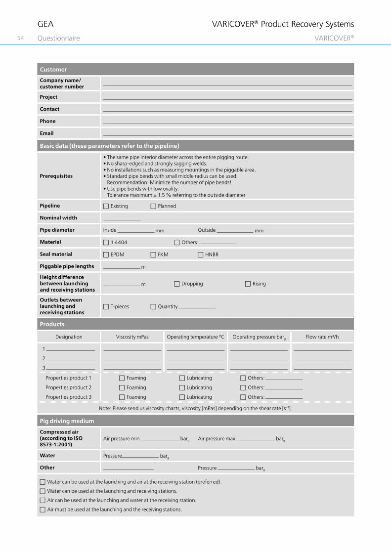
Prerequisites
• The same pipe interior diameter across the entire pigging route.• No sharp-edged and strongly sagging welds.• No installations such as measuring mountings in the piggable area.• Standard pipe bends with small middle radius can be used.
Recommendation: Minimize the number of pipe bends!• Use pipe bends with low ovality.
Tolerance maximum ± 1.5 % referring to the outside diameter.
Pipeline Existing Planned
Nominal width
Pipe diameter Inside mm Outside mm
Material 1.4404 Others:
Seal material EPDM FKM HNBR
Piggable pipe lengths m
Height difference between launching and receiving stations
m Dropping Rising
Outlets between launching and receiving stations
T-pieces Quantity
Products
Designation Viscosity mPas Operating temperature °C Operating pressure barg Flow rate m³/h
1
2
3
Properties product 1 Foaming Lubricating Others:
Properties product 2 Foaming Lubricating Others:
Properties product 3 Foaming Lubricating Others:
Note: Please send us viscosity charts, viscosity [mPas] depending on the shear rate [s–1].
Pig driving medium
Compressed air (according to ISO 8573-1:2001)
Air pressure min. barg Air pressure max. barg
Water Pressure barg
Other Pressure barg
Water can be used at the launching and air at the receiving station (preferred).
Water can be used at the launching and receiving stations.
Air can be used at the launching and water at the receiving station.
Air must be used at the launching and the receiving stations.
VARICOVER® Product Recovery Systems
Questionnaire VARICOVER®

GEA
· 55
11
Comments
Cleaning
Cleaning media Concentration % Temperature °C
1.
2.
3.
Design
Explosion protected design No Yes
Control top
With control top AS-interface-bus 24 V DC, 3-wire With solenoid valve Without solenoid valve
Others:
Without control top With holding plate “INA” for proximity switches With proximity switches Without proximity switches
Note: Please send us a sketch of the planned installation position or a flow chart of the plant section into which the VARICOVER® product recovery system is to be integrated.
Air supply pressure(according to ISO 8573-1:2001)
Air pressure min. barg Air pressure max. barg
Use of ball valves possible from a hygienic point of view?
Yes No
3-A certified Yes No
Process
Pipeline is cleaned after each product push-out.
Pipeline must be emptied after each cleaning.
If so, the system is self draining. If so, the pig must push out the water.
The pipeline is sterilized with steam after cleaning. Temperature: °C
How often is the product pushed out?
× × × per day per week per month
VARICOVER® Product Recovery Systems
Questionnaire VARICOVER®


22
Surface QualitiesInner and Outer Surface of the Housings ................................................................................................................................................................. 58
Connection FittingsOverview ............................................................................................................................................................................................................................... 59VARIVENT® Flange Connection .................................................................................................................................................................................... 60Clamp Connection (Tri-Clamp) ..................................................................................................................................................................................... 61
Additional OptionsTest Report and Inspection Certificate....................................................................................................................................................................... 62ID Plates, TAG Numbers .................................................................................................................................................................................................. 633-A Symbol .......................................................................................................................................................................................................................... 64
GeneralLubricant ............................................................................................................................................................................................................................... 65
GEA Options
· 57Available Options Pages

GEA
58 ·
Position Description of the order code for options
* Surface quality of the housing
2** Inside Ra ≤0.8 μm, outside matte blasted
3 Inside Ra ≤ 0.8 μm, outside ground
Incorporation of the option in the order code and example
* According to valve type
Typical application and description
Deviating from the quality of the standard surface quality (** DN / OD corresponding to Ra ≤ 0.8 μm), different surface qualities are available up to a medium roughness for surfaces in contact with the product of Ra ≤ 0.4 μm. The outer surface of the housings is matte blasted as standard. Optionally, it can also be supplied ground. Housings that should comply with the 3-A standard are produced as standard with an inner surface of Ra ≤ 0.8 μm with ground welds and a blasted outer surface. If a configuration with a ground outer surface is required, it is necessary to select not only option /3-A but also the corresponding surface quality 3.
Options
Surface Qualities Inner and Outer Surface of the Housings
Position 1 2 3 4 5 6 7 8 9 10 11 to 16
Code PIG/PCS - G DN 80 - 1 33 - 2 2 2 - N /52 + 0 0 0 0 0 M

GEA
· 59
22
Position 1 2 3 4 5 6 7 8 9 10 11 to 16
Code PIG/PCS - G - DN 80 - 1 2 - 2 2 2 - JJ /52 + 0 0 0 0 0 M
Position Description of the order code for options
Connection fittingsJ Component with connection fittings (required connection fitting according to list above, please state separately)
Incorporation of the option in the order code and example
Typical application and description
The valve housings can be specified with a welded-on connection fitting. To find which connection fittings are available, please refer to the list on the following pages.
If the vertical ports within a valve do have different configurations, please inform us of the designation for the particular housing port including the required connection fitting (as in the example below). The seal which may be included corresponds to the sealing material of the valve.
Connection fittings
TK VARIVENT® flange connection, groove flange on housing
TN VARIVENT® groove flange incl. O-ring and connecting parts
TF VARIVENT® flange
CO Clamp connection / TRI-Clamp, DIN 32676 (DN) / ISO 2852 (OD)
Options
Connection Fittings Overview

GEA
60 ·
Position Description of the order code for options
Connection fittingsJ Component with connection fittings (please state option TK, TN or TF separately with reference to the connection)
Incorporation of the option in the order code and example
Typical application and description
An O-ring is used for sealing the VARIVENT® flange connection, and is given a defined compression by a metal stop. The O-ring is also protected by the special geometry of the recess from being pulled out at high flow rates.
Available nominal widths
Metric DN 25 – 100
Inch OD OD 1" – 4"
Technical data
Material 1.4404
Surface in contact with the product
Ra ≤ 0.8 μm
Certificates 3.1/AD2000W2
Seal materials EPDM (FDA), FKM (FDA), HNBR (FDA)
The VARIVENT® flange connection (TK) can be ordered either as a complete connection including bolts and nuts (TK) or a groove flange (TN)/flange (TF) as a connection fitting on a vertical port. If a complete connection is ordered as the connection fitting, the groove flange is welded onto the housing. The groove flange (TN) contains not only the O-ring but also the required connecting elements.
Dimensions O-ring
Nominal width
D1 [mm]
D2 [mm]
D3 [mm]
D4 [mm]
d [mm]
L [mm]
L1 [mm]
[mm] PS
DN 25 70 30.0 26.0 53 4 × Ø 9 50 25 25.0 × 5.0 16
DN 40 82 42.0 38.0 65 4 × Ø 9 50 25 36.0 × 5.0 16
DN 50 94 54.0 50.0 77 4 × Ø 9 50 25 47.0 × 5.0 16
DN 65 113 70.0 66.0 95 8 × Ø 9 50 25 62.0 × 5.0 16
DN 80 128 85.0 81.0 110 8 × Ø 9 50 25 75.0 × 5.0 10
DN 100 159 104.0 100.0 137 8 × Ø 11 50 25 95.0 × 5.0 10
OD 1" 66 25.5 22.0 49 4 × Ø 9 50 25 25 × 5.0 16
OD 1 ½" 79 38.5 35.0 62 4 × Ø 9 50 25 36 × 5.0 16
OD 2" 91 51.0 47.5 74 4 × Ø 9 50 25 47 × 5.0 16
OD 2 ½" 106 63.5 60.0 88 8 × Ø 9 50 25 62 × 5.0 16
OD 3" 119 76.5 73.0 101 8 × Ø 9 50 25 75 × 5.0 10
OD 4" 156 102.0 97.5 134 8 × Ø 11 50 25 95 × 5.0 10
Complete connection including bolts and nuts (TK)
TK = VARIVENT® flange connection
TN = VARIVENT® groove flange
Groove flange (TN), including connecting elements and seal ring
Flange (TF)
TF = VARIVENT® flange
Options
Connection Fittings VARIVENT® Flange Connection
Position 1 2 3 4 5 6 7 8 9 10 11 to 16
Code PIG/PCS - G - DN 80 - 1 2 - 2 2 2 - JJ /52 + 0 0 0 0 0 M

GEA
· 61
22
Position 1 2 3 4 5 6 7 8 9 10 11 to 16
Code PIG/PCS - G - DN 80 - 1 2 - 2 2 2 - JJ /52 + 0 0 0 0 0 M
Position Description of the order code for options
Connection fittingsJ Component with connection fittings (required connection fitting, please state separately)
Incorporation of the option in the order code and example
Available nominal widths
Metric DN 25 – 100
Inch OD OD 1" – 4"
CO – Clamp connection
Typical application and description
The clamp connection acc. to DIN 32676 is a widely used connection fitting, especially in North America. The connection uses a symmetrically structured clamp connection with a seal located in between it, and is secured by a clamp. The second clamp connection, the seal and the clamp are not supplied.
Clamp connection (CO)
Options
Connection Fittings Clamp Connection (Tri-Clamp)
Technical data
MaterialDN 1.4404 (AISI 316L) OD AISI 316L
StandardDN DIN 32676 OD DIN 32676*; Length 28.5 mm**
Inner diameterDN DIN 11866 row AOD DIN 11866 row C
Certificates 3.1
*similar to ASME BPE B** OD 6" referred to DIN 32676

GEA
62 ·
Position Description of the order code for options
Accessories
/ 41 Test report 2.2
/ 42 Inspection certificate 3.1 according to EN 10204
Incorporation of the option in the order code
Optionally, the housings and connection fittings can be supplied with a test report 2.2 and/or an inspection certificate 3.1 acc. to EN 10204.
European standard EN 10204 in its 2004 edition defines the various types of test certificate that can be issued to the ordering party in accordance with the agreements in the order for delivery of metallic products.
Typical application and description
NumberType of
test certificateContent of the
certificateConfirmation of the
certificate by
2.2 Test report Confirmation of compliance with the order, specifying
results of a non-specific testThe manufacturer
3.1Inspection
certificate 3.1*
Confirmation of compliance with the order, specifying
results of a specific test
The manufacturer’s acceptance officer
independent of the production department
* Inspection certificates 3.1 can be selected either for the housing or for product wetted parts, incl. connection fittings or ADW2 (please specify when ordering).
Options
Additional Options Test Report and Inspection Certificate

GEA
· 63
22
Position Description of the order code for options
Accessories
/ 50 Engraved metal plate
/ 51 Metal plate (US version)
/ 52 Adhesive ID tag
/ 55 Valve identification 10 numbers on carrier
/ 56 Valve identification 20 numbers on carrier
Incorporation of the option in the order code and example
If no alternative identification option is selected, the valves are always provided with a nameplate for clear identification (option /52). All key information required for clear allocation of the component, as well as technical data, is specified on the nameplate. The plate is glued onto the actuator. If the required identification number is specified, this is allocated to the valve by means of a separate sticker on the actuator.
Option /50 – engraved labeling plate cpl. for system identification number
In addition to the nameplate, the option /50 consists of an engraved labeling plate attached between the actuator and lantern using a key ring on the clamp connection.
Option /51 – metal labeling plate US version cpl.
The engraved labeling plate is attached between the actuator and lantern using a key ring on the clamp connection. Additional information can be recorded as well as the TAG number, customer designation and the valve type. In addition, the valve is identified with a nameplate.
Option /55 – valve identification with TAG number (yellow)
Option /55 consists of a carrier for up to 10 characters made of plastic which is attached to the actuator with cable carriers. For clear identification, the valve is additionally provided with a nameplate.
Option /56 – valve identification with TAG number (yellow)
Option /56 consists of two carriers for up to 10 characters each made of plastic which are attached to the actuator with cable carriers. For clear identification, the valve is additionally provided with a nameplate.
Typical application and description
Key data contained
Valve type
Serial number
Materials in contact with the product
Metallic material / seal material
Air supply pressure Min./Max. [bar/psi]
Product pressure Housing 1/2/3 [bar/psi]
Options
Additional Options ID Plates, TAG Numbers
Position 1 2 3 4 5 6 7 8 9 10 11 to 16
Code PIG/PCS - G - DN 80 - 1 2 - 2 2 2 - N /50/50 + 0 0 0 0 0 M

GEA
64 ·
Position Description of the order code for options
Accessories
/ 3A Adhesive ID tag, configuration of the valve according to 3-A standard
Incorporation of the option in the order code and example
3-A Sanitary Standards, Inc. is an independent, non-profit corporation dedicated to advancing hygienic equipment design for the food, beverage, and pharmaceutical industries. In particular, it represents the interests of three stakeholder groups in the US dairy industry with a common commitment to promoting food safety and the public health – regulatory sanitarians, equipment fabricators and processors. To achieve this purpose, it has produced guidelines which define various design requirements on components. Compliance with these design specifications is examined by an independent expert and confirmed by issuing a certificate.
If the 3-A option is selected, compliance with the requirements of the standard is confirmed by means of a sticker on the component. Consequently, if this option is selected, it is necessary to comply with the standard in terms of identification as well.
Furthermore, when this option is selected, the welds of the port connections are ground smooth. The standard does not specify that this is mandatory, but it is in line with customers’ preferences in this market.
IMPORTANT: The standard surface when this option is selected is “inside surface Ra ≤ 0.8 µm, outside matte”. Many customers in this market ask for the alternative surface quality “inside surface Ra ≤ 0.8 µm, outside ground”. If this is required, it must be selected separately in the order code as a non-standard surface.
Typical application and description
Options
3-A Symbol Additional Options
Position 1 2 3 4 5 6 7 8 9 10 11 to 16
Code PIG/PCS - G - OD 3" - 1 2 - 2 2 2 - N/S/S /52 /3A/3A + 0 0 0 0 0 M

GEA
· 65
22
Lubricant Article number
Rivolta F.L.G. MD-2 (1,000 g) 413-071
Rivolta F.L.G. MD-2 (100 g) 413-136
Options
General Lubricant
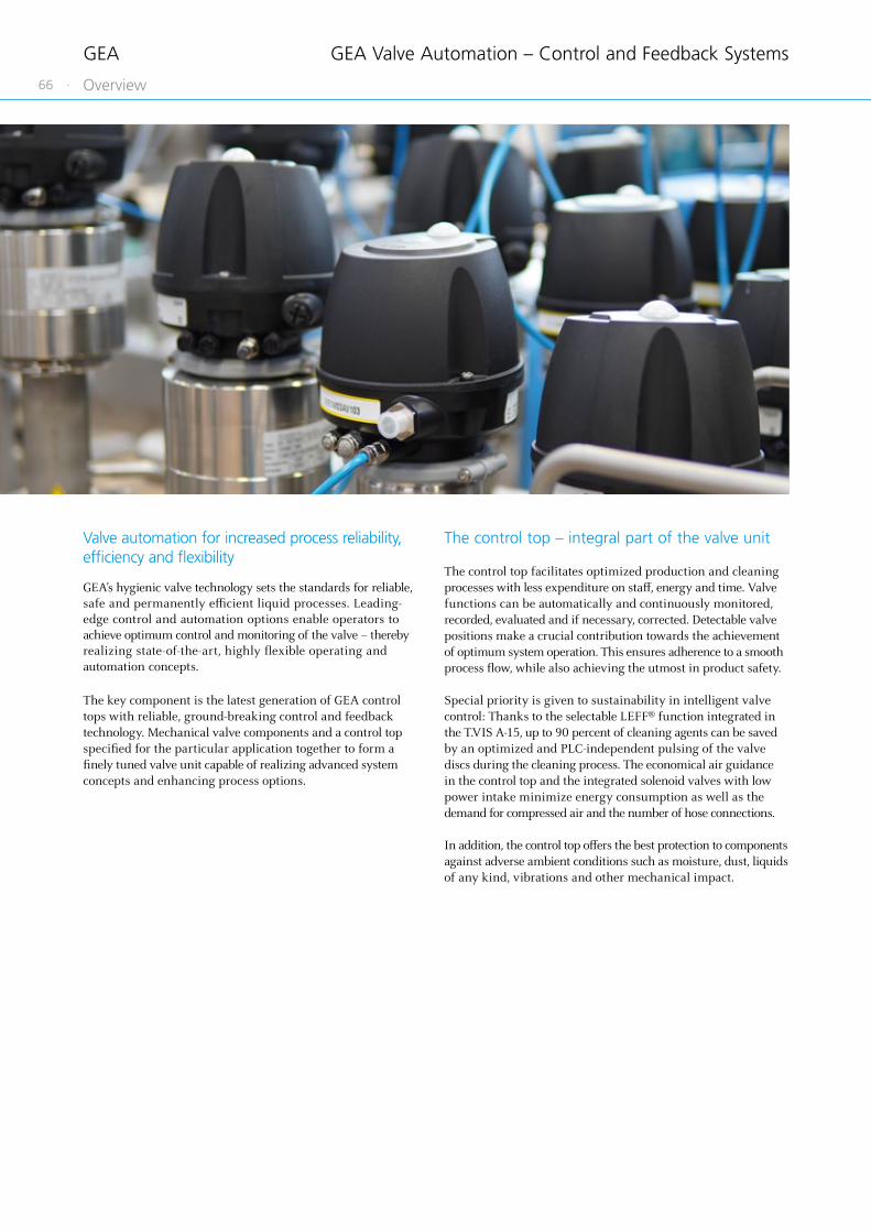
GEA
66 ·
GEA Valve Automation – Control and Feedback Systems
Overview
Valve automation for increased process reliability, efficiency and flexibility
GEA’s hygienic valve technology sets the standards for reliable, safe and permanently efficient liquid processes. Leading-edge control and automation options enable operators to achieve optimum control and monitoring of the valve – thereby realizing state-of-the-art, highly flexible operating and automation concepts. The key component is the latest generation of GEA control tops with reliable, ground-breaking control and feedback technology. Mechanical valve components and a control top specified for the particular application together to form a finely tuned valve unit capable of realizing advanced system concepts and enhancing process options.
The control top – integral part of the valve unit The control top facilitates optimized production and cleaning processes with less expenditure on staff, energy and time. Valve functions can be automatically and continuously monitored, recorded, evaluated and if necessary, corrected. Detectable valve positions make a crucial contribution towards the achievement of optimum system operation. This ensures adherence to a smooth process flow, while also achieving the utmost in product safety.
Special priority is given to sustainability in intelligent valve control: Thanks to the selectable LEFF® function integrated in the T.VIS A-15, up to 90 percent of cleaning agents can be saved by an optimized and PLC-independent pulsing of the valve discs during the cleaning process. The economical air guidance in the control top and the integrated solenoid valves with low power intake minimize energy consumption as well as the demand for compressed air and the number of hose connections.
In addition, the control top offers the best protection to components against adverse ambient conditions such as moisture, dust, liquids of any kind, vibrations and other mechanical impact.
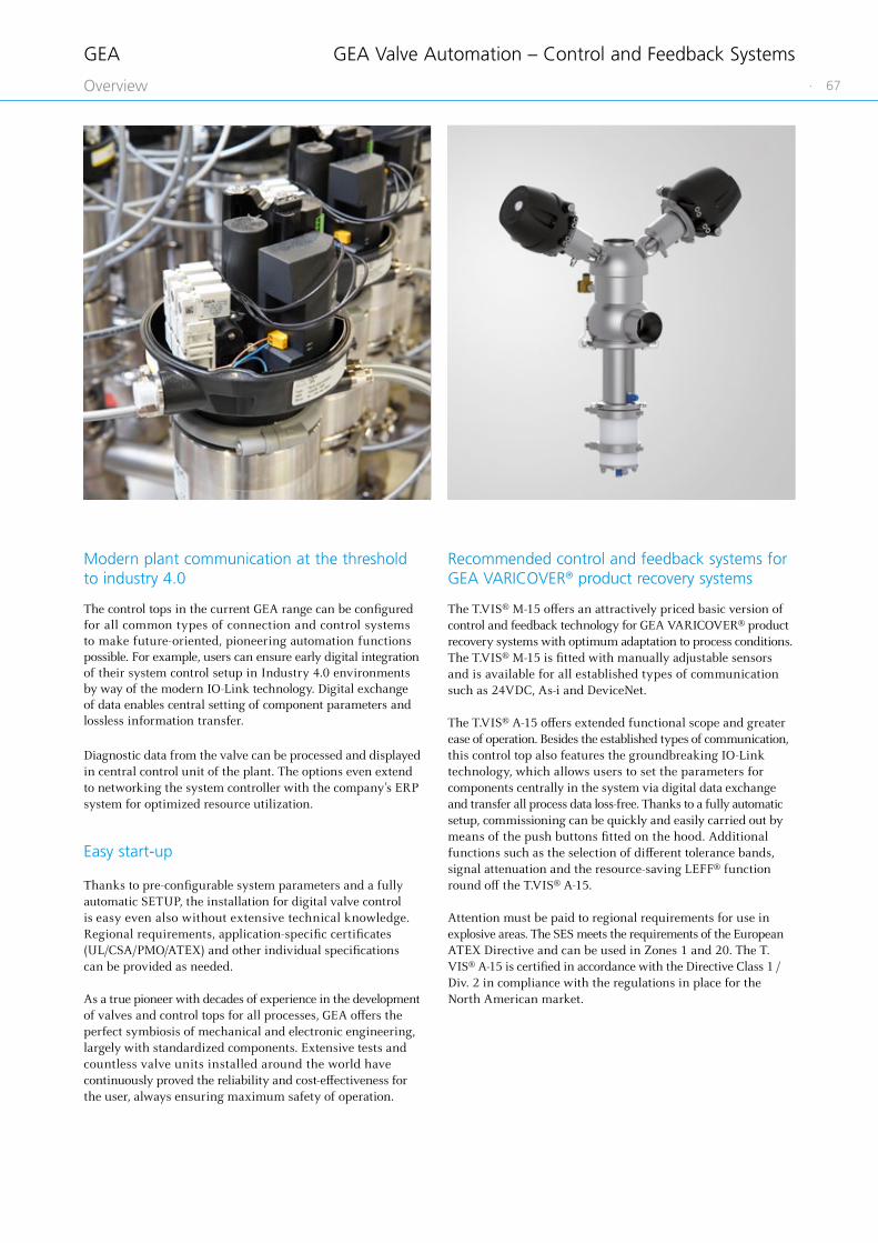
GEA
· 67Overview
GEA Valve Automation – Control and Feedback Systems
Recommended control and feedback systems for GEA VARICOVER® product recovery systems
The T.VIS® M-15 offers an attractively priced basic version of control and feedback technology for GEA VARICOVER® product recovery systems with optimum adaptation to process conditions. The T.VIS® M-15 is fitted with manually adjustable sensors and is available for all established types of communication such as 24VDC, As-i and DeviceNet.
The T.VIS® A-15 offers extended functional scope and greater ease of operation. Besides the established types of communication, this control top also features the groundbreaking IO-Link technology, which allows users to set the parameters for components centrally in the system via digital data exchange and transfer all process data loss-free. Thanks to a fully automatic setup, commissioning can be quickly and easily carried out by means of the push buttons fitted on the hood. Additional functions such as the selection of different tolerance bands, signal attenuation and the resource-saving LEFF® function round off the T.VIS® A-15.
Attention must be paid to regional requirements for use in explosive areas. The SES meets the requirements of the European ATEX Directive and can be used in Zones 1 and 20. The T.VIS® A-15 is certified in accordance with the Directive Class 1 / Div. 2 in compliance with the regulations in place for the North American market.
Modern plant communication at the threshold to industry 4.0
The control tops in the current GEA range can be configured for all common types of connection and control systems to make future-oriented, pioneering automation functions possible. For example, users can ensure early digital integration of their system control setup in Industry 4.0 environments by way of the modern IO-Link technology. Digital exchange of data enables central setting of component parameters and lossless information transfer.
Diagnostic data from the valve can be processed and displayed in central control unit of the plant. The options even extend to networking the system controller with the company’s ERP system for optimized resource utilization.
Easy start-up
Thanks to pre-configurable system parameters and a fully automatic SETUP, the installation for digital valve control is easy even also without extensive technical knowledge. Regional requirements, application-specific certificates (UL/CSA/PMO/ATEX) and other individual specifications can be provided as needed.
As a true pioneer with decades of experience in the development of valves and control tops for all processes, GEA offers the perfect symbiosis of mechanical and electronic engineering, largely with standardized components. Extensive tests and countless valve units installed around the world have continuously proved the reliability and cost-effectiveness for the user, always ensuring maximum safety of operation.

GEA
68 · Overview
Technical data
Nominal switching distance 90 mm
Protection class IP67
Operating voltage 10 – 65 V DC
Material GD-Zn, chrome-plated
Permitted ambient temperature −25 to 70 °C
Technical data
Nominal switching distance 2 mm
Protection class IP67
Operating voltage 10 – 30 V DC
MaterialBrass, chrome-plated / PA12
Permitted ambient temperature −25 to +70 °C
Marking EX II 2 G EEx ia IIC T6
Technical data
Nominal switching distance 10 mm
Protection class IP68
Operating voltage 1.4301 / LCP
Material GD-Zn, chrome-plated
Permitted ambient temperature −30 to +85 °C
Technical data
Nominal switching distance 90 mm
Protection class IP67
Operating voltage 8.2 VDC
MaterialCuZn, chrome-plated / PA12-GF30
Permitted ambient temperature −25 to 70 °C
Magnetic sensor M12 × 1 for pig recognition –
normally open functionArticle number
3-wire PNP (terminal chamber) 505-081
Proximity switch M12 × 1 for ATEX application
Article number
NAMUR (terminal chamber) 505-085
Proximity switch M12 × 1 Article number
3-wire PNP, normally close (plug connector 508-953) 505-103
Magnetic sensor M12 × 1 for pig recognition –
ATEX category II 2 G, Ex zone 1Article number
NAMUR (plug connector 508-953) 505-078
Magnetic-inductive proximity sensors monitor the position of the permanent magnets in the pig from outside of the pig station housing or the pipeline.
Electrical connection by M12 × 1 connector
Electrical connection by wiring in the terminal chamber
Magnetic sensors
GEA Valve Automation – Control and Feedback Systems
Proximity switches External proximity switch M12 × 1 for position feedback at the actuator of the pig cleaning station and the pig stopper.
Electrical connection by M12 × 1 connector
Electrical connection by wiring in the terminal chamber


70 ·
AppendixGEA
Our service package for dependable valve technology
With a tailored service concept, you can extend the service life of your hygienic valve technology. Professional services and original spare parts from GEA help to ensure maximum system availability and security, smooth operation and precise process execution.
Our service specialists are here to help you in every phase of system utilization – from the initial process concept and throughout the entire performance period to advising on your best strategies for the future.
GEA Service for Hygienic Valve Technology

· 71
AppendixGEA
Beginning of life services
We draw on our decades of experience to support you in confi guring your system and providing extensive employee training. Our consultations and training sessions take place in our Competence Centre in Büchen or, upon request, at your premises.
Lifetime services
We optimize your spare parts logistics by using our modular component system and our extensive service network. Preventive maintenance programmes based on comprehensive data, routine troubleshooting and effi cient repair logistics keep downtimes to a minimum.
Extended life services
When upgrades are available to enhance your system, you benefi t from our continuing advances in hygienic valve technology. We off er extensive advice and consultation.
Consulting and enhanced operations
Working in partnership with you, we support your enduring success and develop service strategies and Service Level Agreements for a profi table future operation.
GEA Service for Hygienic Valve Technology
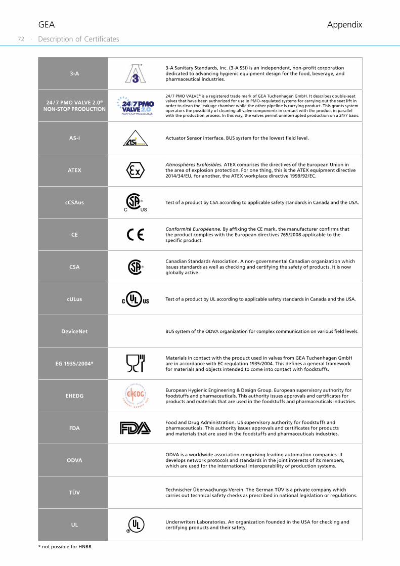
72 ·
AppendixGEA
3-A3-A Sanitary Standards, Inc. (3-A SSI) is an independent, non-profi t corporation dedicated to advancing hygienic equipment design for the food, beverage, and pharmaceutical industries.
24 / 7 PMO VALVE 2.0®
NON-STOP PRODUCTION
24 / 7 PMO VALVE® is a registered trade mark of GEA Tuchenhagen GmbH. It describes double-seat valves that have been authorized for use in PMO-regulated systems for carrying out the seat lift in order to clean the leakage chamber while the other pipeline is carrying product. This grants system operators the possibility of cleaning all valve components in contact with the product in parallel with the production process. In this way, the valves permit uninterrupted production on a 24/7 basis.
AS-i Actuator Sensor interface. BUS system for the lowest fi eld level.
ATEXAtmosphères Explosibles. ATEX comprises the directives of the European Union inthe area of explosion protection. For one thing, this is the ATEX equipment directive 2014/34/EU, for another, the ATEX workplace directive 1999/92/EC.
cCSAus Test of a product by CSA according to applicable safety standards in Canada and the USA.
CEConformité Européenne. By affi xing the CE mark, the manufacturer confi rms that the product complies with the European directives 765/2008 applicable to the specifi c product.
CSACanadian Standards Association. A non-governmental Canadian organization which issues standards as well as checking and certifying the safety of products. It is now globally active.
cULus Test of a product by UL according to applicable safety standards in Canada and the USA.
DeviceNet BUS system of the ODVA organization for complex communication on various fi eld levels.
EG 1935/2004*Materials in contact with the product used in valves from GEA Tuchenhagen GmbH are in accordance with EC regulation 1935/2004. This defi nes a general framework for materials and objects intended to come into contact with foodstuffs.
EHEDGEuropean Hygienic Engineering & Design Group. European supervisory authority for foodstuffs and pharmaceuticals. This authority issues approvals and certifi cates for products and materials that are used in the foodstuffs and pharmaceuticals industries.
FDAFood and Drug Administration. US supervisory authority for foodstuffs and pharmaceuticals. This authority issues approvals and certifi cates for products and materials that are used in the foodstuffs and pharmaceuticals industries.
ODVAODVA is a worldwide association comprising leading automation companies. It develops network protocols and standards in the joint interests of its members, which are used for the international interoperability of production systems.
TÜV Technischer Überwachungs-Verein. The German TÜV is a private company which carries out technical safety checks as prescribed in national legislation or regulations.
UL Underwriters Laboratories. An organization founded in the USA for checking and certifying products and their safety.
* not possible for HNBR
Description of Certificates

· 73
AppendixGEA
Abbreviations and Terms
Abbreviation Explanation
°C Degrees Celsius, unit of measurement for temperature
°F Degrees Fahrenheit, unit of measurement for temperature
3-A Standard of 3-A Sanitary Standards, Incorporated (3-A SSI)
3D Three-dimensional
AAmpere, unit of measurement of current intensity or Output, term used in automation
AC Alternating Current
ADI free All elastomer compounds are free of animal-derived ingredients
AISI American Iron and Steel Institute,association of the American steel industry
ANSI American National Standards Institute,American body for standardizing industrial processes
approx. approximately
AS-i Actuator Sensor interface,standard for fi eldbus communication
ASME American Society of Mechanical Engineers,professional association of mechanical engineers in the USA
ASME-BPE Standard of the ASME's – bioprocessing equipment association
ATEX Atmosphères Explosibles,synonymous with the directives of the European Union for potentially explosive areas
bar Unit of measurement for pressure. All pressure values [bar/psi] refer to positive pressure [barg / psig], unless specifi cally stated otherwise.
barg Unit of measurement for pressure relative to atmospheric pressure
CAN Controller Area Network; asynchronous serial bus system
CE Conformité Européenne,administrative symbol for the free movement of industrial products
CIP Cleaning In Place,designates a process for cleaning technical process systems.
CRN The Canadian Registration Number is issued by a Canadian Jurisdiction and covers pressurized components. The authorization is needed to operate these components in Canada.
CSA Canadian Standards Association,a non-governmental Canadian Standardization organization
Cv The Cv value corresponds to the water fl ow rate through a valve (in US gal / min) at a pressure differential of 1 PSI and a water temperature of 5 °C to 30 °C. kv = 14,28 Cv (USA).
Cvs The Cv values of a valve at nominal stroke (100 % opening) is designated the Cvs value.
dB Decibel, one tenth of a bel, named after Alexander Graham Bell and used for identifying levels and dimensions
DC Direct Current
DIN Deutsches Institut für Normung e. V. Standardization organization in the Federal Republic of Germany, DIN = synonym for standards issued by the organization
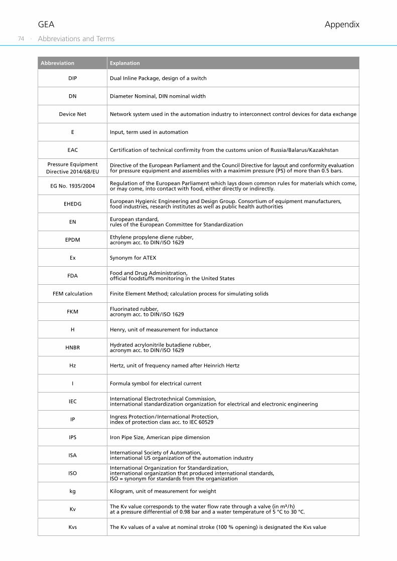
74 ·
AppendixGEA
Abbreviation Explanation
DIP Dual Inline Package, design of a switch
DN Diameter Nominal, DIN nominal width
Device Net Network system used in the automation industry to interconnect control devices for data exchange
E Input, term used in automation
EAC Certifi cation of technical confi rmity from the customs union of Russia/Balarus/Kazakhstan
Pressure Equipment Directive 2014/68/EU
Directive of the European Parliament and the Council Directive for layout and conformity evaluation for pressure equipment and assemblies with a maximim pressure (PS) of more than 0.5 bars.
EG No. 1935/2004 Regulation of the European Parliament which lays down common rules for materials which come, or may come, into contact with food, either directly or indirectly.
EHEDG European Hygienic Engineering and Design Group. Consortium of equipment manufacturers, food industries, research institutes as well as public health authorities
EN European standard,rules of the European Committee for Standardization
EPDM Ethylene propylene diene rubber,acronym acc. to DIN / ISO 1629
Ex Synonym for ATEX
FDA Food and Drug Administration,offi cial foodstuffs monitoring in the United States
FEM calculation Finite Element Method; calculation process for simulating solids
FKM Fluorinated rubber,acronym acc. to DIN / ISO 1629
H Henry, unit of measurement for inductance
HNBR Hydrated acrylonitrile butadiene rubber,acronym acc. to DIN / ISO 1629
Hz Hertz, unit of frequency named after Heinrich Hertz
I Formula symbol for electrical current
IEC International Electrotechnical Commission,international standardization organization for electrical and electronic engineering
IP Ingress Protection / International Protection,index of protection class acc. to IEC 60529
IPS Iron Pipe Size, American pipe dimension
ISA International Society of Automation,international US organization of the automation industry
ISOInternational Organization for Standardization,international organization that produced international standards,ISO = synonym for standards from the organization
kg Kilogram, unit of measurement for weight
Kv The Kv value corresponds to the water fl ow rate through a valve (in m³ / h) at a pressure differential of 0.98 bar and a water temperature of 5 °C to 30 °C.
Kvs The Kv values of a valve at nominal stroke (100 % opening) is designated the Kvs value
Abbreviations and Terms

· 75
AppendixGEA
Abbreviation Explanation
L Conductive
LED Light-Emitting Diode
LEFF® Function of the T.VIS® valve informations system for cyclical pulsing during the lifting process; Low-Emission Flip Flop
mm Millimeter, unit of measurement for length
MMetric, system of units based on the meteror Mega, one million times a unit
m3/h Cubic meters per hour, unit of measurement for volumetric fl ow
max. Maximum
NAMUR Standardization working association for measuring and control technology in the chemical industry, synonym for the interface type of the organization, especially for potentially explosive atmospheres
NC Normally Closed; valve or solenoid valve control which is closed in idle status
NO Normally Open; valve or solenoid valve control which is open in idle status
NOT-element Logic element, NOT gate
NPN Signal transmission against reference potential, current-consuming
NPT National Pipe Thread,US thread standard for self-sealing pipe fi ttings
OD Outside Diameter, pipe dimension
ODVA Open DeviceNet Vendor Association,global association for network standards
PA 12/L Polyamide
Pg Armoured thread
PLC Programmable Logic Controller, device for controlling a machine or system on a digital basis
PMO Pasteurized Milk Ordinance
PN Nominal pressure for pipeline systems according to EN 1333,rated pressure in bar at room temperature (20 °C)
PNP Signal transmission against reference potential, current-supplying
PPO Polyphenylene oxide, thermoplastic material
PS Maximum permitted operating pressure at which the components can operate safely at maximum allowable temperature (TS)
psi Unit of measurement for pressure, pound-force per square inch, 1 psi = 6894.75 Pa. All pressure values [bar/psi] refer to positive pressure [barg / psig], unless specifi cally stated otherwise.
psig Unit of measurement for pressure relative to atmospheric pressure
PV Solenoid valve
Abbreviations and Terms
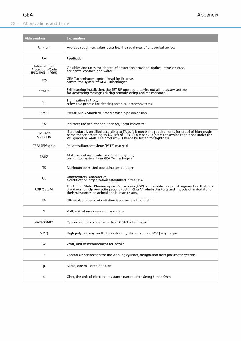
76 ·
AppendixGEA
Abbreviation Explanation
Ra in μm Average roughness value, describes the roughness of a technical surface
RM Feedback
International Protection-Code IP67, IP66, IP69K
Classifi es and rates the degree of protection provided against intrusion dust, accidental contact, and water
SES GEA Tuchenhagen control head for Ex areas,control top system of GEA Tuchenhagen
SET-UP Self-learning installation, the SET-UP procedure carries out all necessary settings for generating messages during commissioning and maintenance.
SIP Sterilization in Place,refers to a process for cleaning technical process systems
SMS Svensk Mjölk Standard, Scandinavian pipe dimension
SW Indicates the size of a tool spanner, “Schlüsselweite”
TA-LuftVDI 2440
If a product is certifi ed according to TA Luft it meets the requirements for proof of high grade performance according to TA Luft of 1.0x 10⁻⁴ mbar x l / (s x m) at service conditions under the VDI guideline 2440. The product will hence be tested for tightness.
TEFASEP® gold Polytetrafl uoroethylene (PFTE) material
T.VIS® GEA Tuchenhagen valve information system,control top system from GEA Tuchenhagen
TS Maximum permitted operating temperature
UL Underwriters Laboratories,a certifi cation organization established in the USA
USP Class VIThe United States Pharmacopeial Convention (USP) is a scientifi c nonprofi t organization that sets standards to help protecting public health. Class VI administer tests and impacts of material and their substances on animal and human tissues.
UV Ultraviolet, ultraviolet radiation is a wavelength of light
V Volt, unit of measurement for voltage
VARICOMP® Pipe expansion compensator from GEA Tuchenhagen
VMQ High-polymer vinyl methyl polysiloxane, silicone rubber, MVQ = synonym
W Watt, unit of measurement for power
Y Control air connection for the working cylinder, designation from pneumatic systems
μ Micro, one millionth of a unit
Ω Ohm, the unit of electrical resistance named after Georg Simon Ohm
Abbreviations and Terms

· 77
AppendixGEA
Typical application and description
You can receive two-dimensional and/or three-dimensional drawing fi les of our components for making your piping plan-ning. For this purpose, please send us your specifi c request, stating the particular order code and the required drawing format. The required fi les will then be individually prepared for you.
Available drawing formats:
Format Name
2D formats
drw Native Pro / E
igs (2D) IGS fi le
dxf AutoCAD drawing exchange
pdf (2D) Adobe Acrobat document
tif TIFF (plot)
3D formats
asm Native Pro / E
igs (3D) IGS fi le
pdf (3D) Adobe Acrobat document
stp STP fi le
bmp (3D) Bitmap image
jpg (3D) JPEG image
tif (3D) TIFF image
sat Standard ACIS
CAD Files

78 ·
AppendixGEA
Please note
All our sales and/or services are exclusively subject to our valid terms and conditions of sale and/or service applicable in the respective country of business, which can be found on our internet platform: www.gea.com.
If not available or if you otherwise wish to receive such terms and conditions directly from us, please contact us and we of course will send you the applicable version of our terms and conditions for the envisaged business.
General Sales Terms and Condition of Delivery


GEA
VA
RIC
OV
ER ®
Pro
duct
Rec
over
y Sy
stem
s
09/
20
© G
EA T
uche
nhag
en G
mbH
. All
right
s re
serv
ed. T
rade
mar
ks w
ith t
he ®
sym
bol a
re r
egis
tere
d in
cer
tain
cou
ntrie
s.
Sub
ject
to
mod
ifica
tions
. Prin
ted
in G
erm
any.
We live our values.Excellence • Passion • Integrity • Responsibility • GEA-versity
GEA Tuchenhagen GmbH
Am Industriepark 2–10
21514 Büchen, Germany
Tel +49 4155 49-0
Fax +49 4155 2035
gea.com/germany
“Engineering for a better world” is the driving and energizing principle connecting GEA’s workforce. As one of the largest systems
suppliers, GEA makes an important contribution to a sustainable future with its solutions and services, particularly in the food,
beverage and pharmaceutical sectors. Across the globe, GEA’s plants, processes and components contribute significantly to the
reduction of CO2 emissions, plastic use as well as food waste in production.
GEA is listed on the German MDAX and the STOXX® Europe 600 Index and also included in the DAX 50 ESG and MSCI Global
Sustainability indexes.