ASHRAE Building-Type GreenTip #1: Performing Arts Spaces - ibse.hk
Upload
khangminh22Category
view
1download
0
Energy recovery systems
Ir. Dr. Sam C. M. HuiFaculty of Science and Technology
E-mail: [email protected]
Dec 2016
SPD5132 Indoor Environment and HVAC Systemshttp://ibse.hk/SPD5132/

Contents
• Basic concepts
• Air-to-air energy recovery
• Run-around coil
• Heat pipe
• Plate heat exchanger
• Energy transfer wheel
• Applied heat pumps

Basic concepts
• Energy recovery in HVAC systems
• Can improve energy efficiency and system effectiveness
• Common methods of energy recovery:
• Air-to-air energy recovery (using ventilators)
• Applied heat pumps and heat recovery systems
• Can be applied to residential, commercial and industrial HVAC and process systems
• The effectiveness depends on seasons, climate, control and operation conditions

Basic concepts
• Air-to-air energy recovery
• Recovering heat or/and moisture between two airstreams
• Important for maintaining acceptable indoor air quality (IAQ) while reducing energy costs
• Energy can be recovered either in its sensible (temperature only) or latent (moisture) form, or combination of both
• Sensible only: Heat Recovery Ventilator (HRV)
• Energy/enthalpy: Energy Recovery Ventilator (ERV)

Schematic of a heat exchanger (HX) assisted cooling coil
(Source: http://www.energyplus.net/sites/default/files/docs/site_v8.3.0/EngineeringReference/13b-EncyclopaedicRefs/index.html#heat-exchanger-assisted-air-cooling-coil-systems)

(Source: http://www.energyplus.net/sites/default/files/docs/site_v8.3.0/EngineeringReference/13b-EncyclopaedicRefs/index.html#heat-exchanger-assisted-air-cooling-coil-systems)
Psychrometric process for heat exchanger assisted cooling coil (sensible heat exchange only) - HRV
Psychrometric process for heat exchanger assisted cooling coil (sensible + latent heat exchange) - ERV

Basic concepts
• Air-to-air energy recovery (cont’d)
• Air conditioners use much energy to dehumidify moist airstreams (excessive moisture can result in mold, allergies, and bacterial growth)
• ERV can enhance dehumidification and introduce more outdoor ventilation air to achieve acceptable indoor air quality (IAQ)
• Recovery efficiency = ratio of output to its input
• For HRV or ERV, effectiveness is defined as:
� = ������ �������� �� �������� �� ������������� �������� �������� ������� ����������

(Source: 2016 ASHRAE Handbook—HVAC Systems and Equipment, Chapter 26 – Air-to-Air Energy Recovery Equipment)
Thermodynamics of heat recovery ventilators (HRV)

Schematic and psychrometric analysis of air-to-air heat exchanger

Basic concepts
• Examples of energy recovery systems:
• Run-around coil
• Heat pipe
• Plate heat exchanger
• Energy transfer wheel
• Air-source heat pump
• Closed water-loop heat pump

Air-to-air energy recovery
• Run-around coil (sensible heat)
• Finned-tube copper coils placed in supply and exhaust airstreams
• A pump circulates water, glycol or other thermal fluid solution
• The system utilizes the energy from the exhaust air stream to pre-condition the outdoor air
• Can increase overall HVAC system effectiveness from 50% to 70%

Run-around coil (sensible heat)
In summer, the exhaust air from the air-conditioned space cools the circulating fluid in the coil. The cooled fluid is then pre-cool the outdoor air. In winter, the process is reversed; heat is extracted from the exhaust air and then transferred to the make-up air.
Merits: • This system does not require that the two air streams be adjacent to each other, several air streams can be used.• It has relatively few moving parts - a small pump and control valve. • There is no cross-contamination between air streams.

Run-around coil (sensible heat)

Air-to-air energy recovery
• Run-around coil (cont’d)
• Advantages:
• Suitable for existing ductwork systems as it does not require adjacent fresh and exhaust ducts
• Relatively low capital cost compared to other systems
• Coils are standard items of proven equipment
• No possibility of cross-contamination of air streams
• The number of rows and fin spacing can be selected to suit the required heat transfer rate, permissible air pressure drop and exhaust air contaminants

Air-to-air energy recovery
• Run-around coil (cont’d)
• Disadvantages:
• Sensible heat transfer only (except when condensation occurs on the coil in warmer airstream)
• Relatively low heat transfer efficiency, typically 45% for a high quality unit
• Circulating pump and additional fan energy consumptions (or running costs) must be offset against heat recovery savings

Air-to-air energy recovery
• Heat pipe (sensible heat)
• A sealed self-contained, liquid evaporating and condensing system
• Hot air passes through the evaporator section and the cold air passes through the condenser side in a counter-flow arrangement
• Made of a material with high thermal conductivity e.g. copper or aluminum at both hot and cold ends
• Working fluid (or coolant) is normally Class I refrigerant (CFC)

Heat pipe (sensible heat)
Copper tube
Wick
Heat is transferred from the hot incoming gas to the evaporator section of the heat pipe. The local vapour pressure of the evaporator section increases and evaporated fluid moves along the pipe to the condenser section. As the condenser section’s temperature is low due to the cold air passing around it, the migrated vapour condenses and the heat is released to the cold air. The liquid then returns to the evaporator section by a combination of capillary action and gravity.

Heat pipe’s free pre-cool and pre-heat principle

Figure 2. Heat pipe exchanger effectiveness
(Source: 2016 ASHRAE Handbook—HVAC Systems and Equipment, Chapter 26 – Air-to-Air Energy Recovery Equipment)

(Source: 2016 ASHRAE Handbook—HVAC Systems and Equipment, Chapter 26 – Air-to-Air Energy Recovery Equipment)
Example. Sensible Heat Energy Recovery in a Heat PipeOutdoor air at 10°C enters a six-row heat pipe with a flow rate of 5 kg/s and a face velocity of 2.5 m/s. Exhaust air enters the heat pipe with the same velocity and flow rate but at 24°C. The pressure drop across the heat pipe is 150 Pa. The supply air density is 1.35 kg/m3. The efficiency of the electric motor and the connected fan are 90 and 75%, respectively. Assuming the performance characteristics of the heat pipe are as shown in Figure 2, determine the sensible effectiveness, exit temperature of supply air to the space, energy recovered, and power supplied to the fan motor.
Solution:From Figure 2, at face velocity of 2.5 m/s and with six rows, the effectiveness is about 58%. Because the mass flow rate of the airstreams is the same and assuming their specific heat of 1 kJ/(kg K) is the same, then the exit temperature of the supply air to the space can be obtainedfrom Equation (3a):
t2 = 10 – 0.58 [5 kg/s x 1 kJ/(kg K)]/[5 kg/s x 1 kJ/(kg K)] (10 – 24) = 18.12°C
The sensible energy recovered can be obtained from Equation (3c) asqs = (5 kg/s)[1 kJ/(kg K)](18.12 – 10) = 40.6 kW
The supply air fan power can be obtained from Equation (11) asPs = (150 Pa) /[(0.9)(0.75)] = 823 W or 0.823 kW
Because there are two airstreams, neglecting the difference in the air densities of the airstreams, the total pumping power of the heat pipe is twice the above value (i.e., 1.65 kW).

Air-to-air energy recovery
• Major merits of heat pipe:
• Passive operation: No energy input is required
• Long life: No moving parts and no wear out
• Isolated air streams: By dividing plates, assuring an excellent seal to prevent cross contamination
• Minimum maintenance: Only maintenance recommended is periodic cleaning
• Summer and winter: The same heat pipe can be used for both summer cooling and winter heat recovery without any changeover mechanism

Air-to-air energy recovery
• Heat pipe (cont’d)
• Advantages:
• Robust construction. No moving parts
• Relatively high-pressure difference between airstreams is possible, limited by baffle separating plate
• Little or no possibility of cross-contamination of air streams (airtight construction is required)
• Relatively high heat transfer rate
• May be designed for easy removal and cleaning
• The number of heat pipe rows can be selected to suit the required heat transfer rate

Air-to-air energy recovery
• Heat pipe (cont’d)
• Disadvantages:
• Relatively high capital cost
• Sensible heat transfer only (except when condensation occurs on heat pipe surfaces in warmer air stream)
• By-pass duct needed in summer to avoid overheating fresh air (in systems without air cooling). Control by tilt mechanism may be too expensive to justify

Air-to-air energy recovery
• Plate heat exchanger (mainly sensible heat)
• Two airstreams are separated by metal plates, which are usually augmented with fins
• Warm exhaust air heats a fixed plate, which, in turn, heats the incoming cool outdoor air on the other side of the plate
• The effectiveness is a function of plate gaps and lengths, and air flow rate
• A minimum effectiveness is 50%
(See also: Module 49: Saving energy through simple HVAC heat recovery http://www.cibsejournal.com/cpd/modules/2013-02/)

Plate heat exchanger (sensible heat)
Two airstreams are separated by the plates to ensure no cross contamination.

Different design of plate heat exchangers

Psychrometry of cross-flow plate heat exchanger
(Source: Module 49: Saving energy through simple HVAC heat recovery http://www.cibsejournal.com/cpd/modules/2013-02/)

Plate heat exchanger with condensation in the discharging room air
(Source: Module 49: Saving energy through simple HVAC heat recovery http://www.cibsejournal.com/cpd/modules/2013-02/)

Air-to-air energy recovery
• Plate heat exchanger (cont’d)
• Advantages:
• No moving parts
• Little or no possibility of cross-contamination of air streams (airtight construction is required)
• Materials and spacings can selected to suit applications
• Easily cleaned when withdrawn from the duct
• Some media types permit latent heat transfer by using a permeable membrane

Air-to-air energy recovery
• Plate heat exchanger (cont’d)
• Disadvantages:
• Static pressure between fresh air and exhaust air is limited, depending on construction
• A bypass may be needed to avoid over-heating fresh air in summer and to reduce power when recovery is not needed
• Care in filtration is required to avoid fouling of surfaces

Air-to-air energy recovery
• Energy transfer wheel
• A rotating wheel which allows sensible and/or latent heat transfer between the incoming outdoor air and exhaust air in an HVAC system
• The air duct connections are arranged so that each of the airstreams flow axially through approximately one half of the wheel in a counter-flow pattern
• The range of heat recovery effectiveness is 70% to 80%
• Cross leakage through the energy recovery wheels ranges from 2% to 5% between the supply and exhaust air streams

Energy transfer wheel (sensible and/or latent)

Energy transfer wheel (sensible and/or latent)
Sensible Wheel - This wheel is not coated with a desiccant and therefore transfers only sensible heat. The wheel can be constructed of almost any material (paper, metal or plastic) and transfers energy between two air streams as the mass of the material gains or loses heat to the opposite air stream. The wheel rotates at a speed of 25 to 50 revolutions per minute.
Energy Transfer Wheel
Enthalpy Wheel - It is similar to the sensible wheel except that a desiccant material such as silica gel is coated to the wheel’s surface. As the wheel rotates, it can transfer latent heat (moisture) as well as sensible heat simultaneously.

Energy transfer wheel (sensible and/or latent)Pre- cooling and dehumidification of outdoor air (OA) in summer
Hot& Humid OA
Cool & DehumidifiedSA To Room
Cool & DryRA From Room
Warm & Humid EA
Chilled Water From
Chiller
Air Filter
Air FilterOA
Damper
Energy Transfer
Wheel
RA: Return Air EA: Exhaust AirSA: Supply Air OA: Outdoor Air

Energy transfer wheel (sensible and/or latent)Pre- heating and humidification of outdoor air (OA) in winter
Cold & Dry OA
Warm & Humidified
SA To Room
Warm & Humidified
RA From RoomCooled & Dry EA
Hot Water From Boiler
Air Filter
Air FilterOA Damper
Energy Transfer Wheel
RA: Return Air EA: Exhaust AirSA: Supply Air OA: Outdoor Air

Desiccant cooling and heat recovery wheel
The wheel rotates slowly, typically at about 20 rpm.
Gas is used as a fuel for cooling system (absorption chiller).Desiccant wheel is used for dehumidification.– Absorbs humidity from outside air in the first air stream.– Desiccant wheel is dried out by a heater.Cooling coil is used to reduce temperature.

Control of energy recovery wheel
It is monitored by a rotation detector which determines the angular velocity of the core. This sensor, along with air temperature sensors installed on either side of the wheel in both air streams, feed back to a solid-state controller which instructs a variable frequency drive (VFD) connected to the wheel motor. This VFD commands the motor to speeds between ¼ and 20 rpm to most efficiently transfer total energy between the air streams.

Air-to-air energy recovery
• Energy transfer wheel (cont’d)
• Advantages:
• Some wheels can transfer both sensible and latent heat
• Relatively high heat-transfer efficiency (~70%), compared to other air-to-air heat recovery devices
• Low energy consumption of the electric motor rotating the wheel
• Matrix material and density can suit a wide range of applications
• Can be used for either heating or cooling applications

Air-to-air energy recovery
• Energy transfer wheel (cont’d)
• Disadvantages:
• Regular air filter maintenance and replacement is essential as the wheel is difficult to clean
• Static pressure in the fresh air stream must be higher than that in the exhaust air stream to limit cross-contamination and for successful purge operation
• Large ratio of surface area to volume of matrix material make it susceptible to corrosion
• Internal leakage can be an issue but should be limited to less than 5% in high quality units

Applied heat pumps
• A heat pump extracts heat from a source and transfers it to a sink at a higher temperature
• Heat pump sources and sinks
• Air (outdoor ambient, exhaust)
• Water (well, surface, tap, condensing, closed loops, waste)
• Ground (ground-coupled, direct expansion)
• Solar energy (direct or heated water)
• Industrial process (process heat or exhaust)

Basic principles of heat pump
(Source: Garrett, R. H., 2008. Hot and Cold Water Supply)

Applied heat pumps
• Common types of heat pumps
• Air-to-air heat pump
• Water-to-air heat pump
• Ground water, surface water, internal-source, solar-assisted, wastewater-source
• Water-to-water heat pump
• Ground-coupled heat pump
• Air-to-water heat pump
• Also called heat pump water heater

Heat pump types
(Source: 2016 ASHRAE Handbook—HVAC Systems and Equipment, Chapter 9 – Applied Heat Pump and Heat Recovery Systems)
Air-to-air heat pump
Water-to-air heat pump

Heat pump types
(Source: 2016 ASHRAE Handbook—HVAC Systems and Equipment, Chapter 9 – Applied Heat Pump and Heat Recovery Systems)
Water-to-water heat
pump
Ground-coupled
heat pump

Applied heat pumps
• Heat recovery heat pump (HRHP) systems
• Such as industrial heat pump systems
• Translate low grade (low temperature) rejected heat to usable heat in a process
• Two major types:
• Closed-cycle systems• Use a suitable working fluid, usually a refrigerant in a sealed
system; can use either absorption or vapour compression
• Open-cycle (and semi-open-cycle) systems• Use process fluid to raise the temperature of available heat
energy by vapour compression (to produce steam)

Air-to-air or dehumidification heat pumps (closed-cycle)
(Source: 2016 ASHRAE Handbook—HVAC Systems and Equipment, Chapter 9 – Applied Heat Pump and Heat Recovery Systems)
Most frequently used in industrial operations to dry or cure products. For example, dehumidification kilns are used to dry lumber to improve its value (lumber can be dried at a lower temperature, which reduces warping, cracking, checking, and discoloration). Can also be used to dry agricultural products; poultry, fish, and meat; textiles; and other products.

Wastewater thermal extraction technology for energy recovery
(Source: http://www.achrnews.com/articles/133785-lets-get-hvac-out-of-the-sewer )

Single-effect heat pump evaporator (open-cycle)(For separating small volumes of water and solid, e.g. in food and dairy industries)
(Source: 2016 ASHRAE Handbook—HVAC Systems and Equipment, Chapter 9 – Applied Heat Pump and Heat Recovery Systems)
The overhead vapours of the evaporator are compressed, and thus heated, and piped to the system heater (i.e. calandria). The heat is transferred to the dilute solution, which is then piped to the evaporator body. Flashing occurs upon entry to the evaporator body, sending concentrate to the bottom and vapours to the top.
Applied heat pumps
• Heat recovery heat pump systems (cont’d)
• Can be assembled by combining a number of systems to enable heat recovery functionality, e.g.
• Variable refrigerant flow (VRF) systems that enable recovery of energy between cooling and heating
• Reverse cycle water-to-air heat pumps on a common water loop that allows recovery of energy between units rejecting heat and those requiring heat
• Heat-reclaim chillers that simultaneously provide heating and cooling
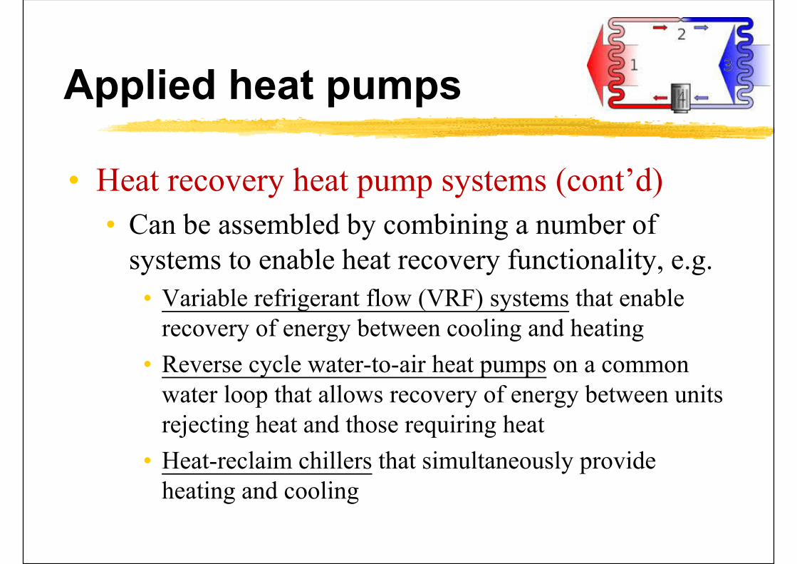
Waste heat recovery – e.g. double bundle heat recovery chiller
Strategy: use of heat recovery
Make use of waste heat from condenser to produce warm/hot water or for heating the space.
- Waste heat = “dumped” heat that can still be reused - Waste heat recovery saves fuel

Schematic diagram of waste heat recovery - heat pump + chiller
Using the waste heat for heating water or space air

Applied heat pumps
• Systems with multiple energy recovery exchangers, e.g. desiccant wheel + heat wheel
• The first exchanger reduces the cooling capacity by recovery exhaust energy
• The second exchanger improves latent cooling and reduces sensible cooling delivered by the system
• The heat dissipated in the condenser of a heat pump can be used to regenerate the desiccant wheel

Heat pump augmented by heat and desiccant wheels(multiple energy recovery exchangers in series mode)
(Source: 2016 ASHRAE Handbook—HVAC Systems and Equipment, Chapter 26 – Air-to-Air Energy Recovery Equipment)

Further Reading
• Module 49: Saving energy through simple HVAC heat recovery • http://www.cibsejournal.com/cpd/modules/2013-02/
• Application & Design of Energy Recovery Wheels • http://www.airxchange.com/resource-center-application-
design.htm
• Heat recovery systems information • http://www.renewableenergyhub.us/heat-recovery-
systems-information/
• Heat Pump and Heat Recovery Technologies • http://www.environment.gov.au/system/files/energy/files/h
vac-factsheet-heat-pump-tech.pdf
Copyright © 2022 FDOKUMEN