Telecommunication Services - ibse.hk
96
Telecommunication Services IBTM6010H Utility Services http://ibse.hk/IBTM6010H/ Mar 2021 Ir Dr. Sam C. M. Hui E-mail: [email protected] http://ibse.hk/cmhui/
-
Upload
khangminh22 -
Category
Documents
-
view
10 -
download
0
Transcript of Telecommunication Services - ibse.hk
Telecommunication Services
IBTM6010H Utility Serviceshttp://ibse.hk/IBTM6010H/
Mar 2021
Ir Dr. Sam C. M. HuiE-mail: [email protected]
http://ibse.hk/cmhui/

Contents
• Basic Concepts
• Design Issues
• Cabling Management
• Networking
• Transmission Methods
• In-Building Wireless Systems
Basic Concepts
• Telecommunication 電訊
• Communication at a distance (“Tele”)
• Transmission, emission, or reception of signs, signals, writing, images, sounds, or information of any nature by wire, radio, optical, or other electromagnetic systems
• Telecommunication system 電訊系統
• Uses electricity, light (visible & infrared), or radio waves to transmit signals that carry voice & data transmissions (may be analog or digital)
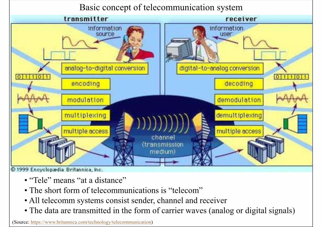
Basic concept of telecommunication system
• “Tele” means “at a distance”• The short form of telecommunications is “telecom”• All telecomm systems consist sender, channel and receiver• The data are transmitted in the form of carrier waves (analog or digital signals)
(Source: https://www.britannica.com/technology/telecommunication)
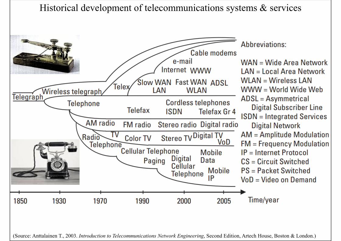
Historical development of telecommunications systems & services
(Source: Anttalainen T., 2003. Introduction to Telecommunications Network Engineering, Second Edition, Artech House, Boston & London.)

Basic Concepts
• Telecommunication network 電訊網絡
• A collection of communication equipment & devices that are interconnected so they can communicate in order to share data, hardware, and software or perform an electronic function
• The network includes a series of connecting points called nodes (e.g. a terminal like a telephone receiver or computer) that are interconnected with cables (wiring)
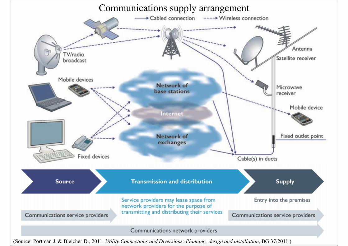
Communications supply arrangement
(Source: Portman J. & Bleicher D., 2011. Utility Connections and Diversions: Planning, design and installation, BG 37/2011.)
Basic Concepts
• Telecommunications & information technology (IT)
• Influence people & many aspects of our life
• Affect building design & requirements
• Require the setting up of information systems
• Information systems
• 1. User (voice, text, image & data networks)
• 2. Building (bldg. mgt., energy, fire, security)
• 3. Miscellaneous (public address, CCTV, etc.)
(Source: CIBSE, 1992. Information Technology and Buildings)
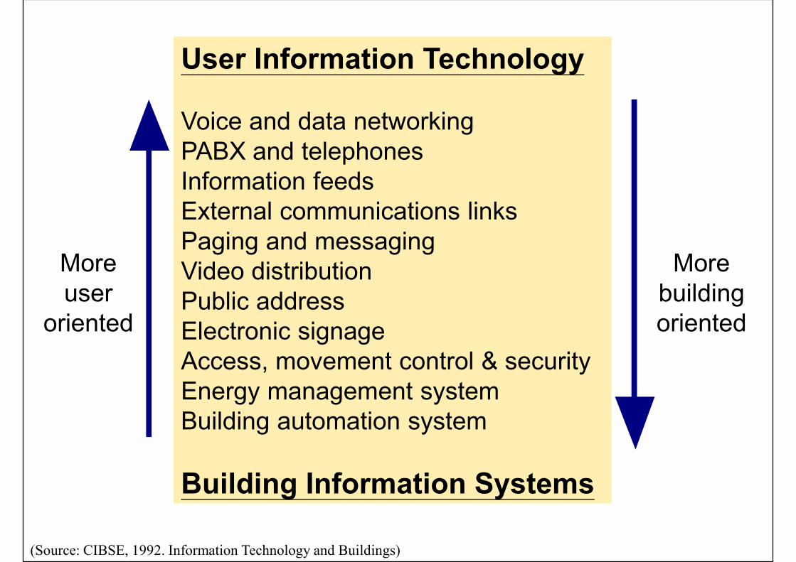
More user
oriented
More building oriented
User Information Technology
Voice and data networkingPABX and telephonesInformation feedsExternal communications linksPaging and messagingVideo distributionPublic addressElectronic signageAccess, movement control & securityEnergy management systemBuilding automation system
Building Information Systems

(Source: CIBSE, 1992. Information Technology and Buildings)
Examples of IT & telecommunication systems in a building
Basic Concepts
• Information Technology (IT) in buildings
• Systems of structured cable & wireless information technologies relating to buildings & building occupants
• Building systems -- HVAC, lighting, daylighting control, energy monitoring, security access, and fire/smoke detection and alarm
• Telecommunications -- voice, data, graphics, and audio/video
• Properly designed pathways & spaces are needed to accommodate the IT systems
Basic Concepts
• The density & demand of IT equipment in buildings increase many times
• A robust and secure infrastructure is needed to support the growing & evolving demands of business & organisations (e.g. server rooms)
• Key factors for buildings to accommodate IT
• Space requirements (for equipment & distribution)
• Power requirements (electricity supply)
• Environmental requirements (e.g. temperature)
Basic Concepts
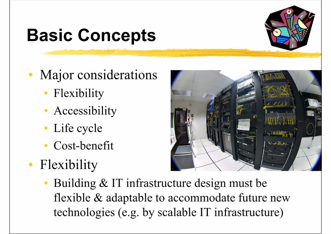
• Major considerations
• Flexibility
• Accessibility
• Life cycle
• Cost-benefit
• Flexibility
• Building & IT infrastructure design must be flexible & adaptable to accommodate future new technologies (e.g. by scalable IT infrastructure)
Basic Concepts
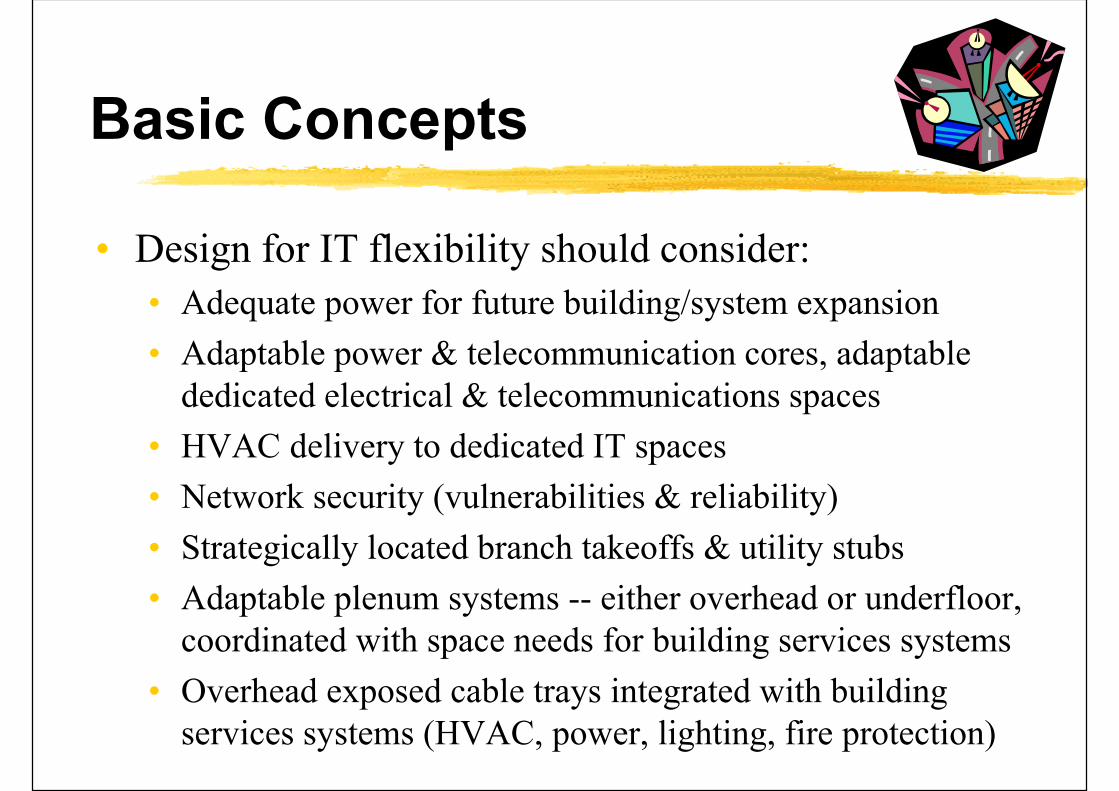
• Design for IT flexibility should consider:
• Adequate power for future building/system expansion
• Adaptable power & telecommunication cores, adaptable dedicated electrical & telecommunications spaces
• HVAC delivery to dedicated IT spaces
• Network security (vulnerabilities & reliability)
• Strategically located branch takeoffs & utility stubs
• Adaptable plenum systems -- either overhead or underfloor, coordinated with space needs for building services systems
• Overhead exposed cable trays integrated with building services systems (HVAC, power, lighting, fire protection)

Basic Concepts
• IT systems take up space, e.g.• In basements where cables enter, on desks, in
risers, above ceilings, under carpets, in special equipment areas, on roofs and in car parks
• Life cycle considerations• The frames of buildings have lives of many
decades during which the IT systems contained will be updated & replaced several times
• With proper planning, it is not necessary to provide new cabling every time systems are changed or upgraded (cost savings)
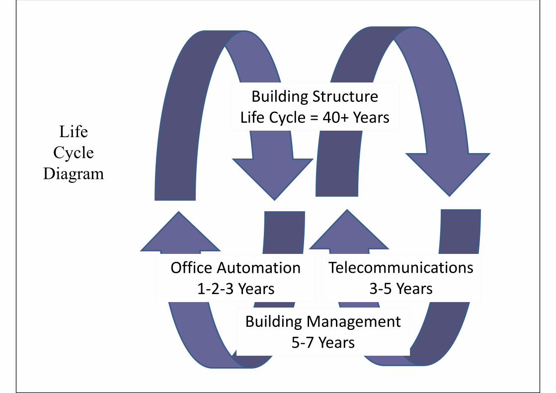
LifeCycle
Diagram
Building StructureLife Cycle = 40+ Years
Office Automation1-2-3 Years
Telecommunications 3-5 Years
Building Management5-7 Years

Basic Concepts
• Planning for IT (a dynamic process)
• Consider carefully its own “information needs”
• Present & anticipated use of information
• Standard of service: speed of transfer, availability, error rates & user-friendliness
• Corporate view of the rate of IT introduction
• Geographical distribution of IT
• Likely growth of, and ‘churn’ within, the organisation
• Existing & proposed use of building stock
• Assessment of the suitability of building stock for IT

Basic Concepts
• Example: Planning and designing your IT Infrastructure
• Part I: Networking
• https://synyx.de/blog/planning-and-designing-your-it-infrastructure-part-i-networking/
• Networking hardware and your needs
• LAN, WAN or CAN infrastructure
• Network applications and bandwidth
• Number of users and networked devices
• Office layout, hardware & software components
• Budget for the installation and maintenance
Basic Concepts
• Example: Planning and designing your IT Infrastructure (cont’d)
• Part II: Evaluating your requirements and designing your data center
• https://synyx.de/blog/planning-and-designing-your-it-infrastructure-part-ii-evaluating-your-requirements-and-designing-your-data-center/
• Evaluate what you want and what you really need
• Don’t overbuild; Don't plan for now, plan for the future!
• Cost of Ownership (vs. webhosting, cloud solutions)
• Select a proper data center site
Basic Concepts
• Following planning, the subsequent phases are important for implementing the IT:
• 1. Design & procurement of systems and cabling
• 2. Installation, testing & commissioning
• 3. Operation, management, maintenance & modification
• 4. Removal & recovery of redundant systems
• Critical for buildings with high IT demands
• Such as data centres, high-tech offices

Basic Concepts
• Emerging issues
• Integrated building design practice
• Use the same cable network for different systems
• Interoperability across all systems
• Among user IT and building operating systems
• Building Information Modeling (BIM)
• A master, intelligent data model to design & manage
• Wireless communication technologies
• Smart & intelligent buildings
(* See also: Information Technologies Engineering (WBDG) http://www.wbdg.org/design/dd_infotecheng.php)
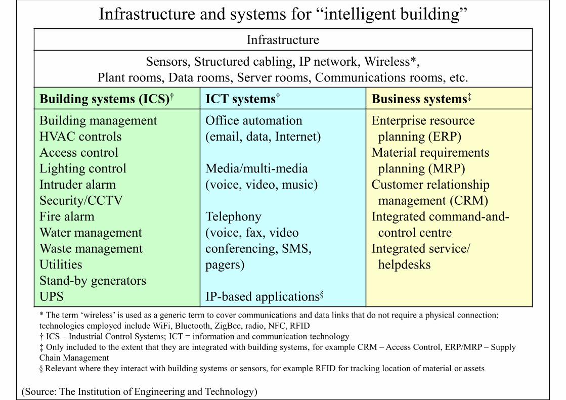
(Source: The Institution of Engineering and Technology)
Infrastructure
Sensors, Structured cabling, IP network, Wireless*,Plant rooms, Data rooms, Server rooms, Communications rooms, etc.
Building systems (ICS)† ICT systems† Business systems‡
Building managementHVAC controlsAccess controlLighting controlIntruder alarmSecurity/CCTVFire alarmWater managementWaste managementUtilitiesStand-by generatorsUPS
Office automation(email, data, Internet)
Media/multi-media(voice, video, music)
Telephony(voice, fax, videoconferencing, SMS,pagers)
IP-based applications§
Enterprise resourceplanning (ERP)
Material requirementsplanning (MRP)
Customer relationshipmanagement (CRM)
Integrated command-and-control centre
Integrated service/helpdesks
Infrastructure and systems for “intelligent building”
* The term ‘wireless’ is used as a generic term to cover communications and data links that do not require a physical connection; technologies employed include WiFi, Bluetooth, ZigBee, radio, NFC, RFID† ICS – Industrial Control Systems; ICT = information and communication technology‡ Only included to the extent that they are integrated with building systems, for example CRM – Access Control, ERP/MRP – SupplyChain Management§ Relevant where they interact with building systems or sensors, for example RFID for tracking location of material or assets
Basic Concepts
• Internet Protocol (IP) Telephony
• Use of IP-based networks to build, provide and access voice, data or other forms of telephonic communications
• Replace the telecommunications' infrastructure of circuit switched public data networks (CSPDN) and public switched telephone networks (PSTN) with packet switched IP communication networks
• Voice over IP (VoIP) is a popular implementation which only supports voice communication over IP
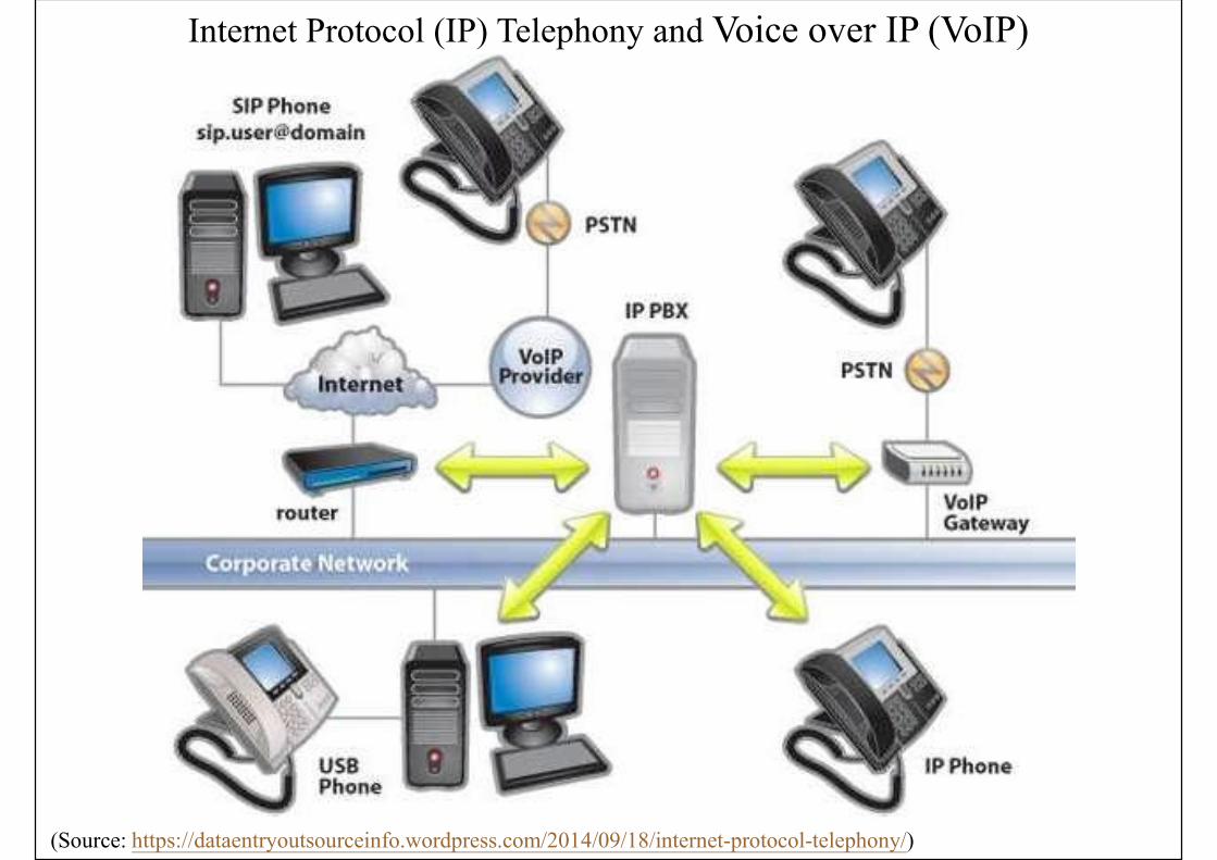
Internet Protocol (IP) Telephony and Voice over IP (VoIP)
(Source: https://dataentryoutsourceinfo.wordpress.com/2014/09/18/internet-protocol-telephony/)
Design Issues
• Design requirements
• Plant & equipment rooms, spaces & pathways
• Electrical power, bonding & earthing/grounding
• Environmental requirements (e.g. cooling)
• Fire safety issues
• Typical telecommunication room facilities
• Room lighting, air conditioning, fire protection
• Temperature senor, raised floor, AC power supply, station earthing, working tables & chairs
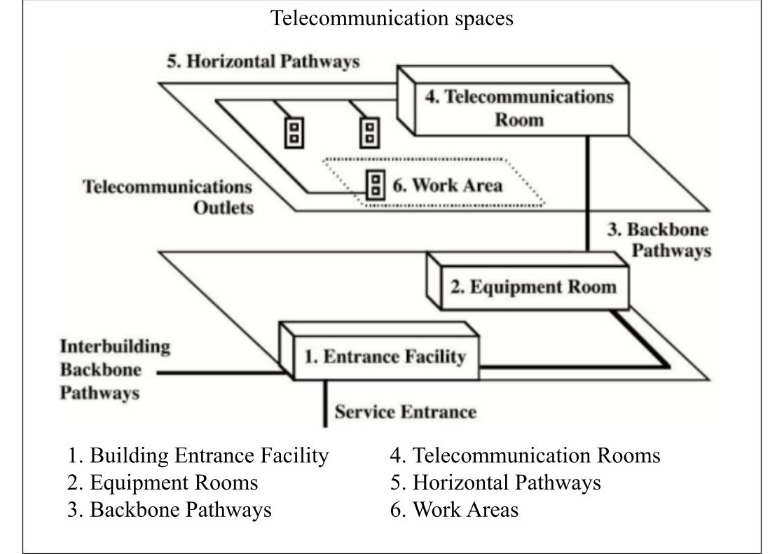
Telecommunication spaces
1. Building Entrance Facility2. Equipment Rooms3. Backbone Pathways
4. Telecommunication Rooms5. Horizontal Pathways6. Work Areas

Telecommunications spaces and pathways
(Source: https://www.tpsgc-pwgsc.gc.ca/biens-property/sngp-npms/bi-rp/tech/telecommunications/espaces-spaces-eng.html)
TR = telecommunications roomEnt. Rm/CER = Entrance Room/Common Equipment Room
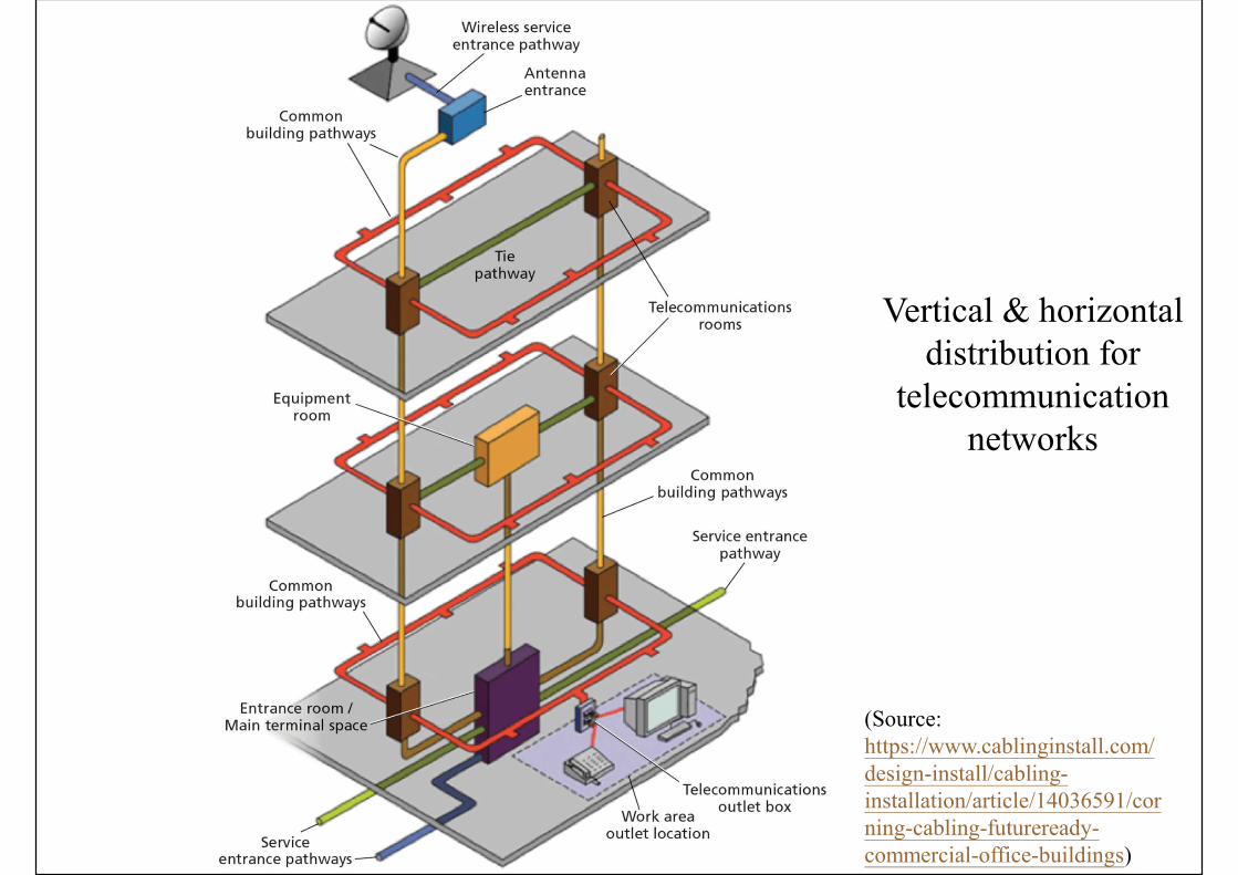
Vertical & horizontal distribution for
telecommunication networks
(Source: https://www.cablinginstall.com/design-install/cabling-installation/article/14036591/corning-cabling-futureready-commercial-office-buildings)
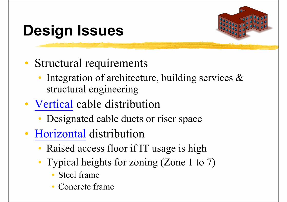
Design Issues
• Structural requirements• Integration of architecture, building services &
structural engineering
• Vertical cable distribution• Designated cable ducts or riser space
• Horizontal distribution• Raised access floor if IT usage is high
• Typical heights for zoning (Zone 1 to 7)• Steel frame
• Concrete frame
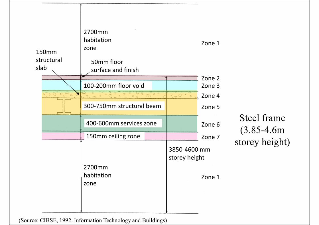
Steel frame(3.85-4.6m
storey height)
(Source: CIBSE, 1992. Information Technology and Buildings)
400-600mm services zone
300-750mm structural beam
100-200mm floor void
150mm ceiling zone
2700mm habitation zone
2700mm habitation zone
150mm structural slab
50mm floor surface and finish
3850-4600 mm storey height
Zone 1
Zone 2Zone 3
Zone 4
Zone 5
Zone 6
Zone 7
Zone 1

Re-inforcedconcrete
frame(3.7-4.2m
storey height)
(Source: CIBSE, 1992. Information Technology and Buildings)
3700-4200 mm storey height
Zone 1
Zone 2
Zone 3
Zone 4 & 5
Zone 6
Zone 7
Zone 1
400-600mm services zone
100-200mm floor void
150mm ceiling zone
2700mm habitation zone
2700mm habitation zone
50mm floor surface and finish
300-500mm structural slab
Design Issues
• Floor loading
• Usually IT equipment will not exceed the floor loads, except where equipment densities are high
• Where point loads are high, load spreading must be used, such as for power equipment
• High volume of papers (very heavy!)
• Loads of raised floors
• Access areas
• Weight of power or radio equipment on roofs
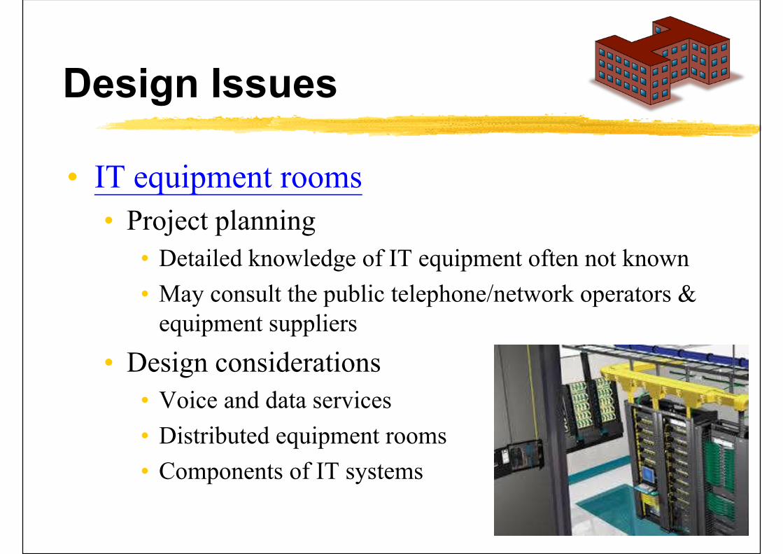
Design Issues
• IT equipment rooms
• Project planning
• Detailed knowledge of IT equipment often not known
• May consult the public telephone/network operators & equipment suppliers
• Design considerations
• Voice and data services
• Distributed equipment rooms
• Components of IT systems
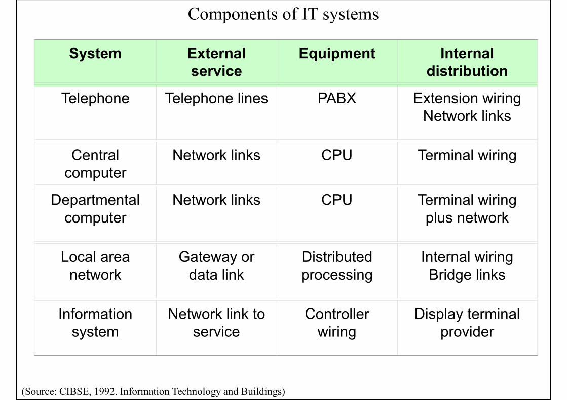
System External service
Equipment Internal distribution
Telephone Telephone lines PABX Extension wiringNetwork links
Central computer
Network links CPU Terminal wiring
Departmental computer
Network links CPU Terminal wiring plus network
Local area network
Gateway or data link
Distributed processing
Internal wiringBridge links
Information system
Network link to service
Controller wiring
Display terminal provider
Components of IT systems
(Source: CIBSE, 1992. Information Technology and Buildings)
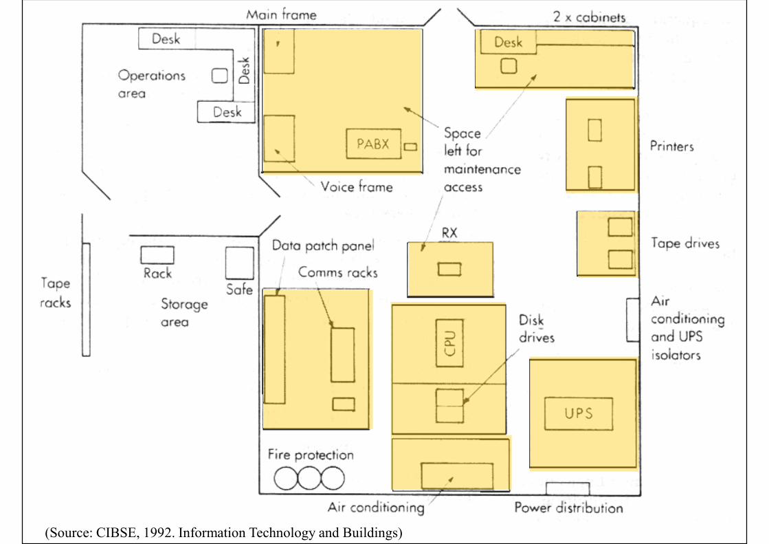
Design Issues
• General equipment rooms: design considerations• Minimum room height, floor void, ceiling void
• Sufficient floor loadings
• Access for installing, operating and maintenance of equipment
• Environment suitable for operating the equipment
• Room finishes easily cleaned
• Floor areas allowed for all equipment, staff, services, storage, etc
(Source: CIBSE, 1992. Information Technology and Buildings)
Design Issues
• General equipment rooms: design considerations (cont’d)
• Future expansion allowance
• Access for equipment deliveries
• Preferred methods of locating services
• Within raised floor void: power cabling, data cabling, HVAC pipework, air distribution supply, fire detection/protection services
• Within suspended ceiling: lighting, air distribution return, fire detection/protection services

Design Issues
• Major sub-systems:
• Lead-in or entrance facilities, including cable entry and cable entry chamber
• Telecommunications and broadcasting equipment (TBE) room [Equipment room]
• Secondary TBE room [Telecomm room]
• Vertical riser (backbone)
• Horizontal distribution facilities

Design Issues
• Major sub-systems: (cont’d)
• Telecommunications closets
• Accommodation for subscription TV receiving system
• TV/FM outlets
• Telephone sockets
• Cables
• Rooftops (antennas)
Design Issues
• Space planning
• IT fit-out: equipment is known
• “Speculative” building: equipment not known
• Electrical closets & communication closets
• Minimum areas for equipment• Consult telecom operators or follow standards
• Hong Kong telecommunication services:
• Communication Authority (CA) 通訊事務管理局https://www.coms-auth.hk/
• Codes of Practice/Guidelines https://www.coms-auth.hk/en/policies_regulations/cop_guidelines/telecomm/
Design Issues
• Entry points and equipment rooms• Entry points for cables & services
• Multiple routing to reduce risk of disruption
• Radio systems (e.g. antenna mounting)
• Frame rooms (may also houses the PABX)
• Maintenance access• Areas for maintenance and safety
• Consult telephone operators & suppliers
• Access• Clearly separate groups, compartments or rooms
• Used by operating staff and maintenance staff
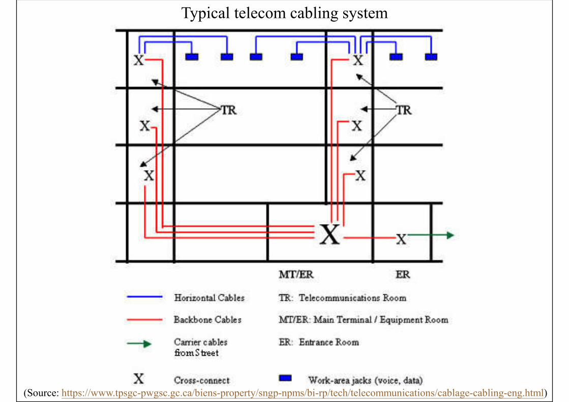
Typical telecom cabling system
(Source: https://www.tpsgc-pwgsc.gc.ca/biens-property/sngp-npms/bi-rp/tech/telecommunications/cablage-cabling-eng.html)
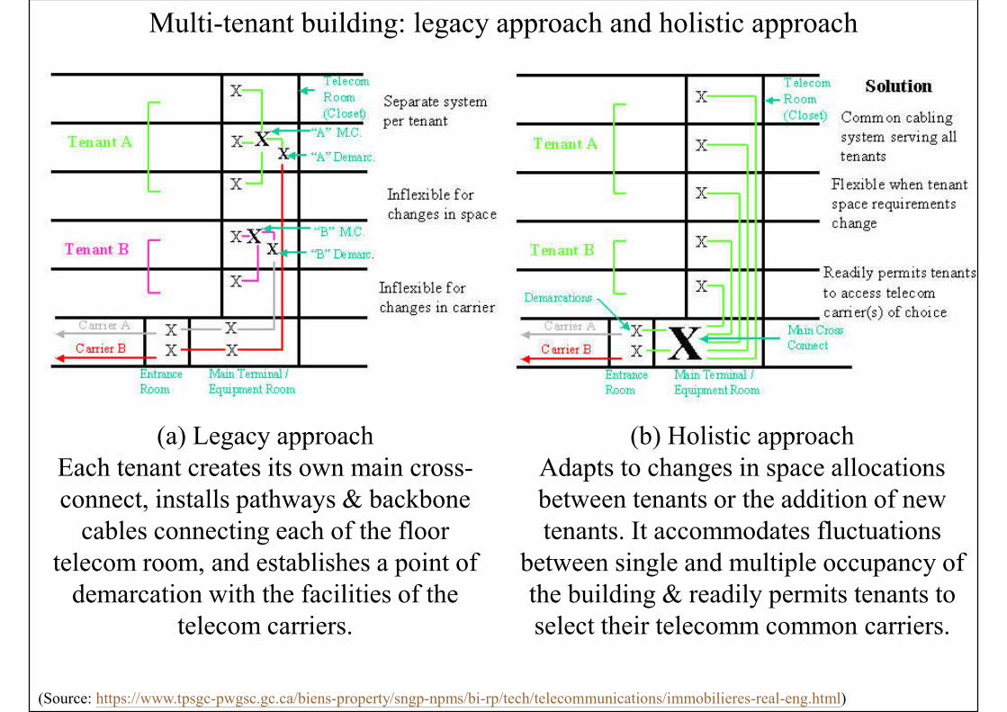
Multi-tenant building: legacy approach and holistic approach
(Source: https://www.tpsgc-pwgsc.gc.ca/biens-property/sngp-npms/bi-rp/tech/telecommunications/immobilieres-real-eng.html)
(a) Legacy approachEach tenant creates its own main cross-connect, installs pathways & backbone
cables connecting each of the floor telecom room, and establishes a point of
demarcation with the facilities of the telecom carriers.
(b) Holistic approachAdapts to changes in space allocations between tenants or the addition of new tenants. It accommodates fluctuations
between single and multiple occupancy of the building & readily permits tenants to select their telecomm common carriers.

Example of a basic data centre topology
(Source: ANSI/TIA-942-2005 Telecommunications Infrastructure Standard for Data Centers)
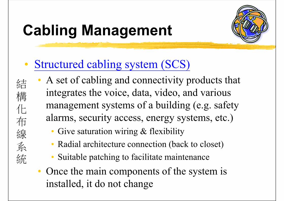
Cabling Management
• Structured cabling system (SCS)
• A set of cabling and connectivity products that integrates the voice, data, video, and various management systems of a building (e.g. safety alarms, security access, energy systems, etc.)
• Give saturation wiring & flexibility
• Radial architecture connection (back to closet)
• Suitable patching to facilitate maintenance
• Once the main components of the system is installed, it do not change
結構化布線系統

Cabling Management
• Industry standards to address the cabling and cable-delivery methods (pathways & spaces)
• Such as EIA/TIA 568, ISO/IEC 11801
• Based on a structured subsystem architecture
• 4 key components of structured cabling
• Telecommunication outlets
• Horizontal cabling
• Patch panels and floor distributors (data hub)
• Backbone cable
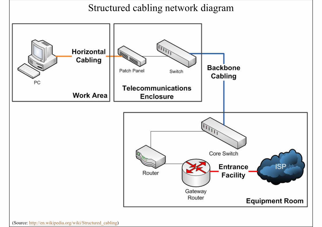
Structured cabling network diagram
(Source: http://en.wikipedia.org/wiki/Structured_cabling)
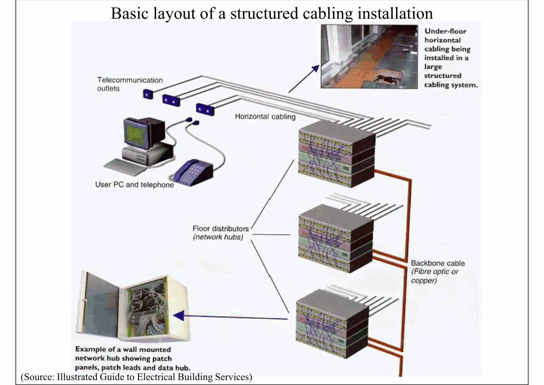
Basic layout of a structured cabling installation
(Source: Illustrated Guide to Electrical Building Services)
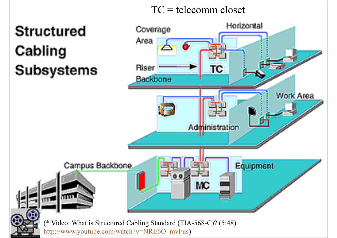
TC = telecomm closet
(* Video: What is Structured Cabling Standard (TIA-568-C)? (5:48) http://www.youtube.com/watch?v=NRE6O_mvFus)
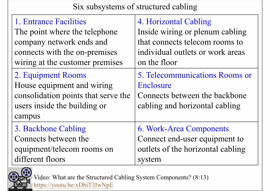
Six subsystems of structured cabling
1. Entrance FacilitiesThe point where the telephone company network ends and connects with the on-premises wiring at the customer premises
4. Horizontal CablingInside wiring or plenum cabling that connects telecom rooms to individual outlets or work areas on the floor
2. Equipment RoomsHouse equipment and wiring consolidation points that serve the users inside the building or campus
5. Telecommunications Rooms or Enclosure Connects between the backbone cabling and horizontal cabling
3. Backbone CablingConnects between the equipment/telecom rooms on different floors
6. Work-Area ComponentsConnect end-user equipment to outlets of the horizontal cabling system
Video: What are the Structured Cabling System Components? (8:13) https://youtu.be/xDbiT3IwNpE
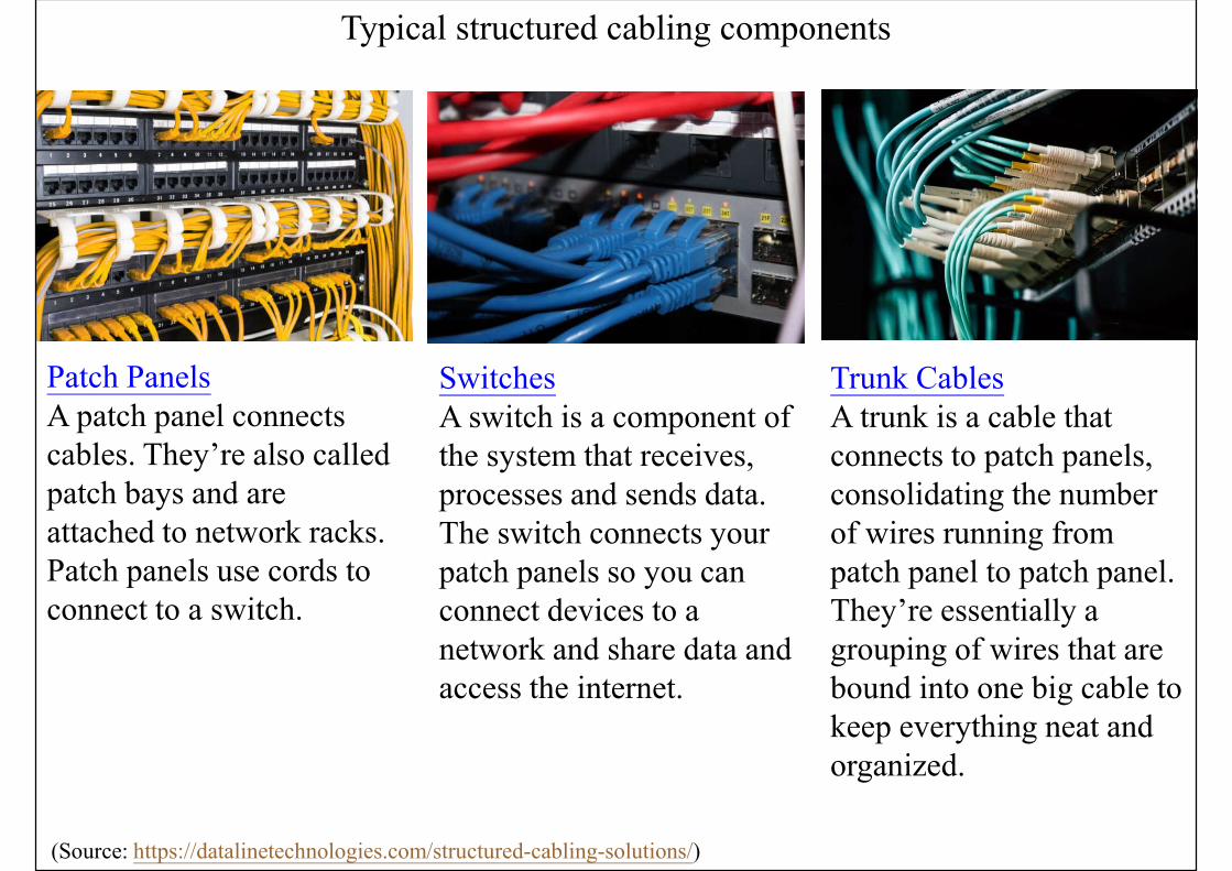
Typical structured cabling components
(Source: https://datalinetechnologies.com/structured-cabling-solutions/)
Patch PanelsA patch panel connects cables. They’re also called patch bays and are attached to network racks. Patch panels use cords to connect to a switch.
SwitchesA switch is a component of the system that receives, processes and sends data. The switch connects your patch panels so you can connect devices to a network and share data and access the internet.
Trunk CablesA trunk is a cable that connects to patch panels, consolidating the number of wires running from patch panel to patch panel. They’re essentially a grouping of wires that are bound into one big cable to keep everything neat and organized.

Typical telecommunication equipment room
(Source: http://www.fiber-optical-networking.com/key-components-form-structured-cabling-system.html)
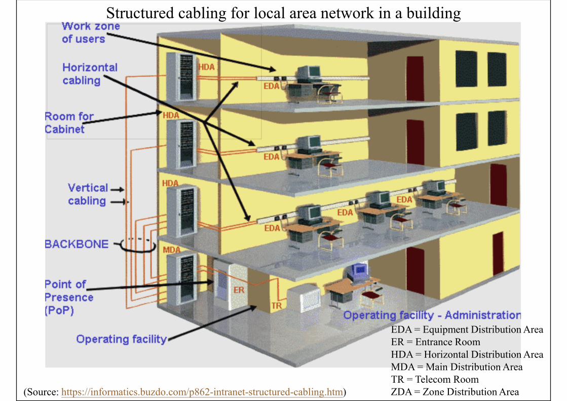
Structured cabling for local area network in a building
(Source: https://informatics.buzdo.com/p862-intranet-structured-cabling.htm)
EDA = Equipment Distribution AreaER = Entrance RoomHDA = Horizontal Distribution AreaMDA = Main Distribution AreaTR = Telecom RoomZDA = Zone Distribution Area
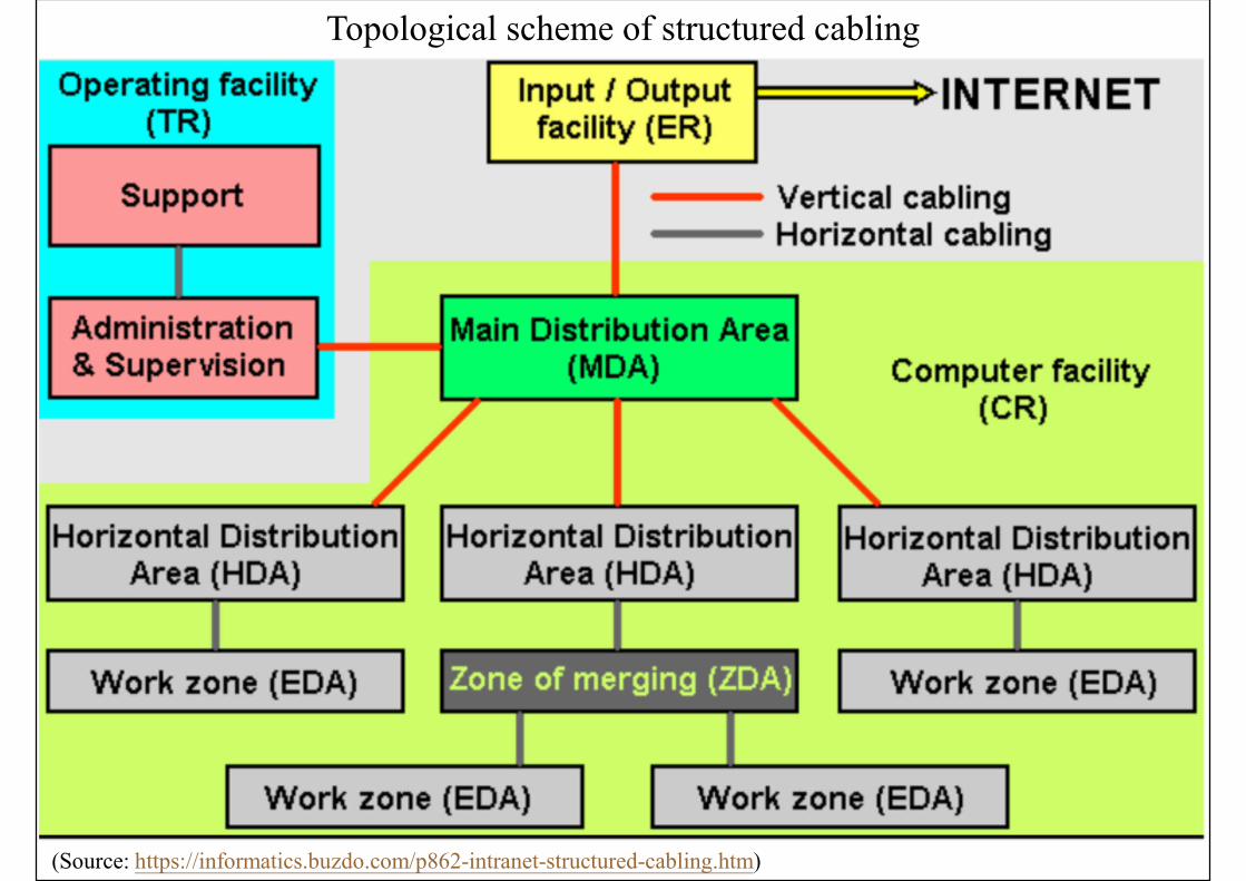
Topological scheme of structured cabling
(Source: https://informatics.buzdo.com/p862-intranet-structured-cabling.htm)
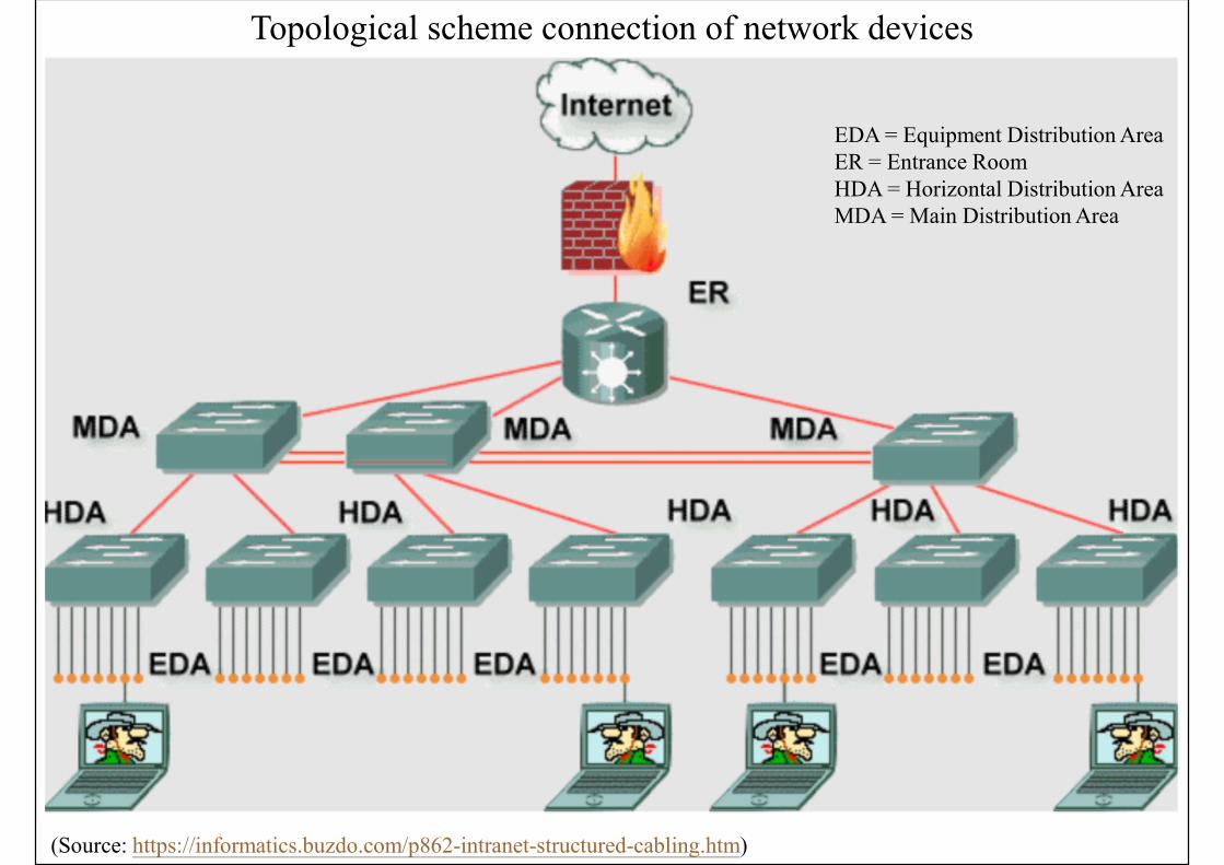
Topological scheme connection of network devices
(Source: https://informatics.buzdo.com/p862-intranet-structured-cabling.htm)
EDA = Equipment Distribution AreaER = Entrance RoomHDA = Horizontal Distribution AreaMDA = Main Distribution Area
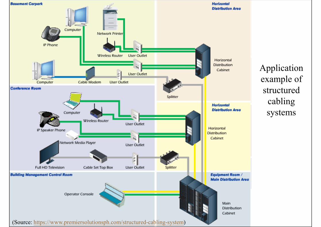
(Source: https://www.premiersolutionsph.com/structured-cabling-system)
Application example of structured
cabling systems
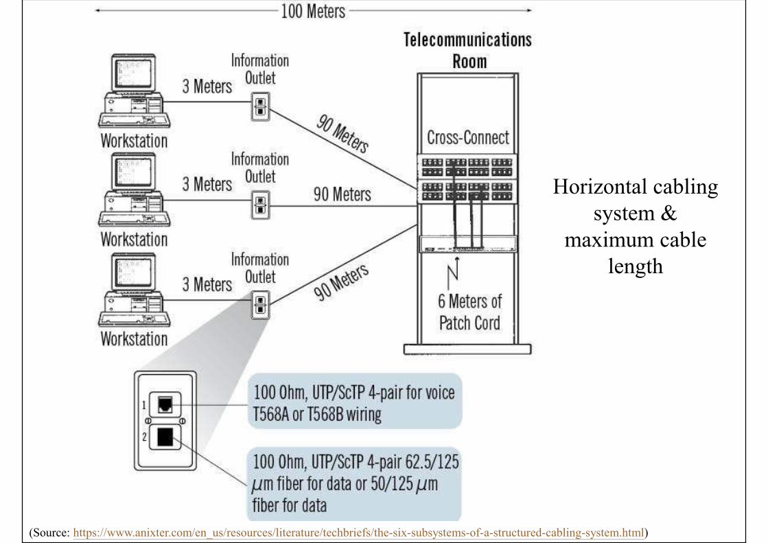
Horizontal cabling system &
maximum cable length
(Source: https://www.anixter.com/en_us/resources/literature/techbriefs/the-six-subsystems-of-a-structured-cabling-system.html)
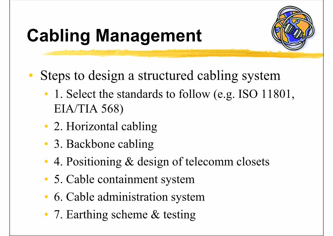
Cabling Management
• Steps to design a structured cabling system
• 1. Select the standards to follow (e.g. ISO 11801, EIA/TIA 568)
• 2. Horizontal cabling
• 3. Backbone cabling
• 4. Positioning & design of telecomm closets
• 5. Cable containment system
• 6. Cable administration system
• 7. Earthing scheme & testing
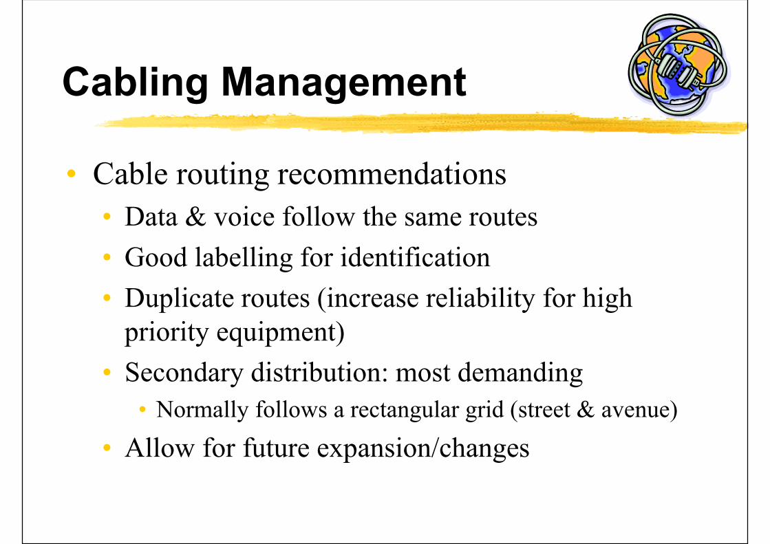
Cabling Management
• Cable routing recommendations
• Data & voice follow the same routes
• Good labelling for identification
• Duplicate routes (increase reliability for high priority equipment)
• Secondary distribution: most demanding
• Normally follows a rectangular grid (street & avenue)
• Allow for future expansion/changes
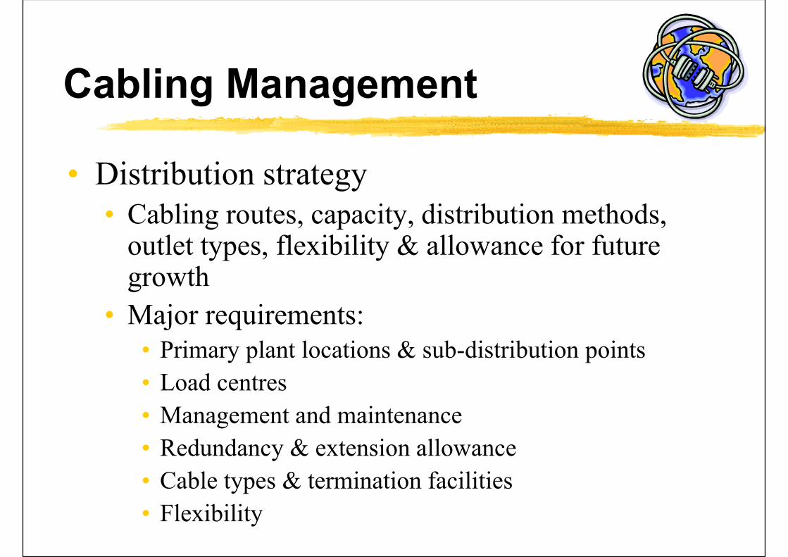
Cabling Management
• Distribution strategy• Cabling routes, capacity, distribution methods,
outlet types, flexibility & allowance for future growth
• Major requirements:• Primary plant locations & sub-distribution points
• Load centres
• Management and maintenance
• Redundancy & extension allowance
• Cable types & termination facilities
• Flexibility
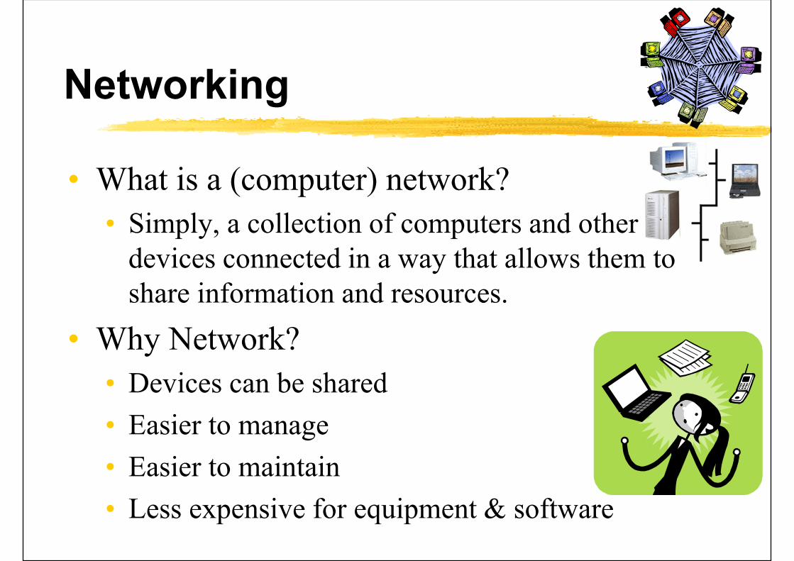
Networking
• What is a (computer) network?
• Simply, a collection of computers and other devices connected in a way that allows them to share information and resources.
• Why Network?
• Devices can be shared
• Easier to manage
• Easier to maintain
• Less expensive for equipment & software

Office/Enterprise computer network
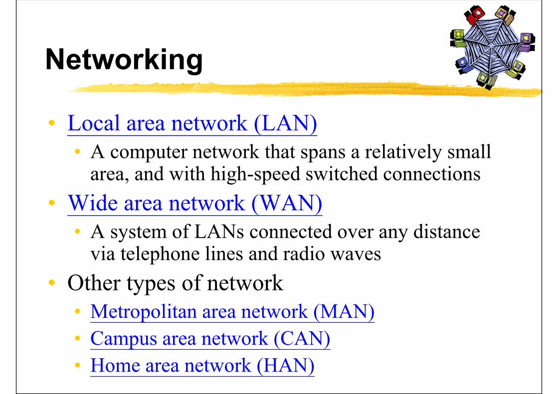
Networking
• Local area network (LAN)• A computer network that spans a relatively small
area, and with high-speed switched connections
• Wide area network (WAN)• A system of LANs connected over any distance
via telephone lines and radio waves
• Other types of network• Metropolitan area network (MAN)
• Campus area network (CAN)
• Home area network (HAN)
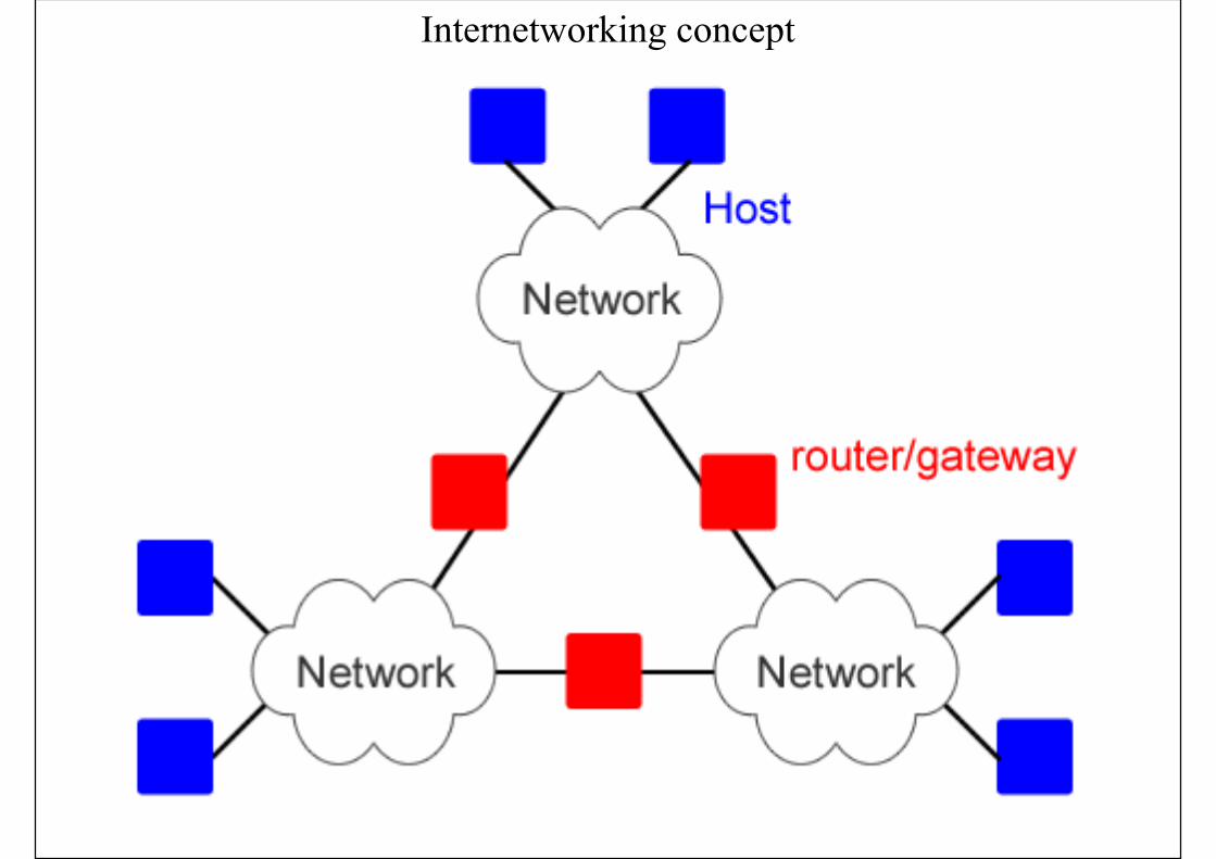
Internetworking concept
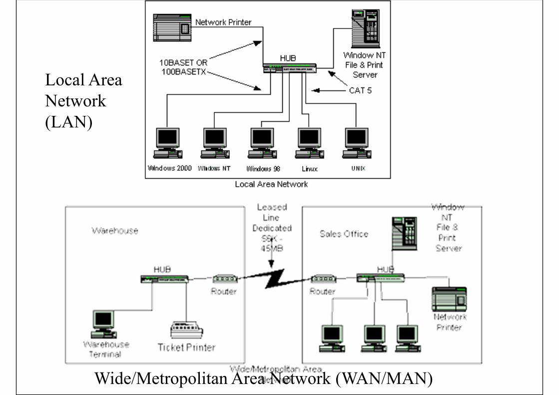
Local AreaNetwork(LAN)
Wide/Metropolitan Area Network (WAN/MAN)
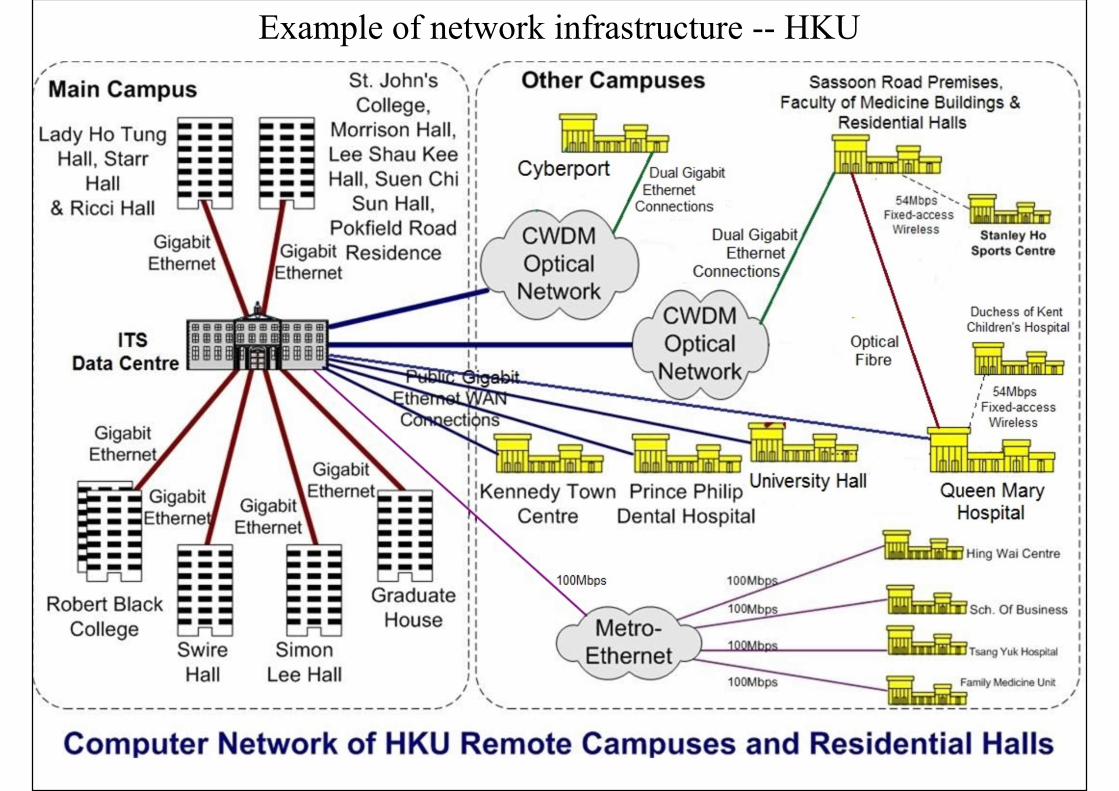
Example of network infrastructure -- HKU
(Source: https://itsc.ust.hk/services/it-infrastructure/network-infrastructure/schematic)
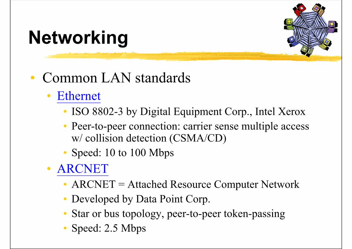
Networking
• Common LAN standards• Ethernet
• ISO 8802-3 by Digital Equipment Corp., Intel Xerox
• Peer-to-peer connection: carrier sense multiple access w/ collision detection (CSMA/CD)
• Speed: 10 to 100 Mbps
• ARCNET• ARCNET = Attached Resource Computer Network
• Developed by Data Point Corp.
• Star or bus topology, peer-to-peer token-passing
• Speed: 2.5 Mbps

Example of Ethernet system

“100 Base T” means:- 100 Mbps- Baseband signal- Twisted pair
RJ-45 = Registered Jack-45 (8-wire)(RJ-11: for telephone, 4- or 6-wire)
Ethernet port and connector
Networking
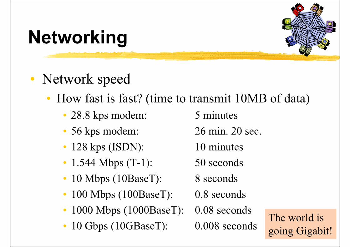
• Network speed
• How fast is fast? (time to transmit 10MB of data)
• 28.8 kps modem: 5 minutes
• 56 kps modem: 26 min. 20 sec.
• 128 kps (ISDN): 10 minutes
• 1.544 Mbps (T-1): 50 seconds
• 10 Mbps (10BaseT): 8 seconds
• 100 Mbps (100BaseT): 0.8 seconds
• 1000 Mbps (1000BaseT): 0.08 seconds
• 10 Gbps (10GBaseT): 0.008 secondsThe world is going Gigabit!

Networking
• Leading official standards organisation
• IEEE 802 LAN/MAN Standards Committee (www.ieee802.org) and its working groups
• 802.1: interface between OSI levels 1 & 2 with five higher level layers (OSI = Open Systems Interconnection)
• 802.2: logical data link
• 802.3: CSMA/CS (carrier sense multiple access with collision avoidance)
• 802.4: Token bus
• 802.5: Token ring
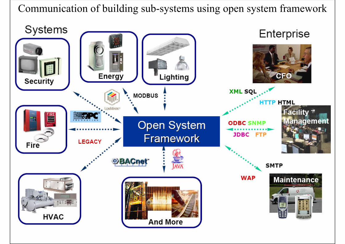
Communication of building sub-systems using open system framework
Transmission Methods
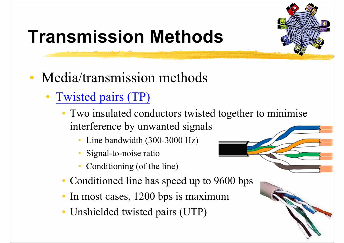
• Media/transmission methods
• Twisted pairs (TP)
• Two insulated conductors twisted together to minimise interference by unwanted signals
• Line bandwidth (300-3000 Hz)
• Signal-to-noise ratio
• Conditioning (of the line)
• Conditioned line has speed up to 9600 bps
• In most cases, 1200 bps is maximum
• Unshielded twisted pairs (UTP)

Twisted pairs (TP)

Transmission Methods
• Media/transmission methods (cont’d)• Voice grade lines
• Type 3002 in in the Bell Telephone Company’s standard BSP41004
• Coaxial cable• Centre conductor surrounded by a shield
• Electromagnetic interference
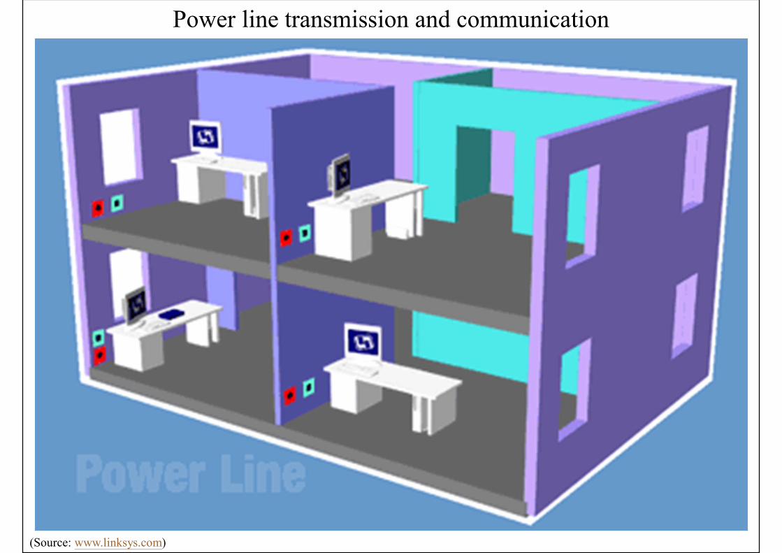
• Power lines• Using carrier current transmission that superimposes a
low RF signal (100 kHz) onto the 50/60 Hz power distribution system
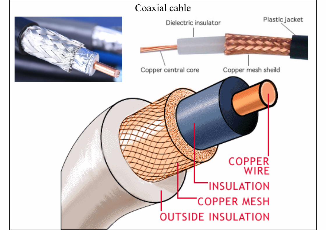
Coaxial cable
(Source: www.linksys.com)
Power line transmission and communication
Transmission Methods
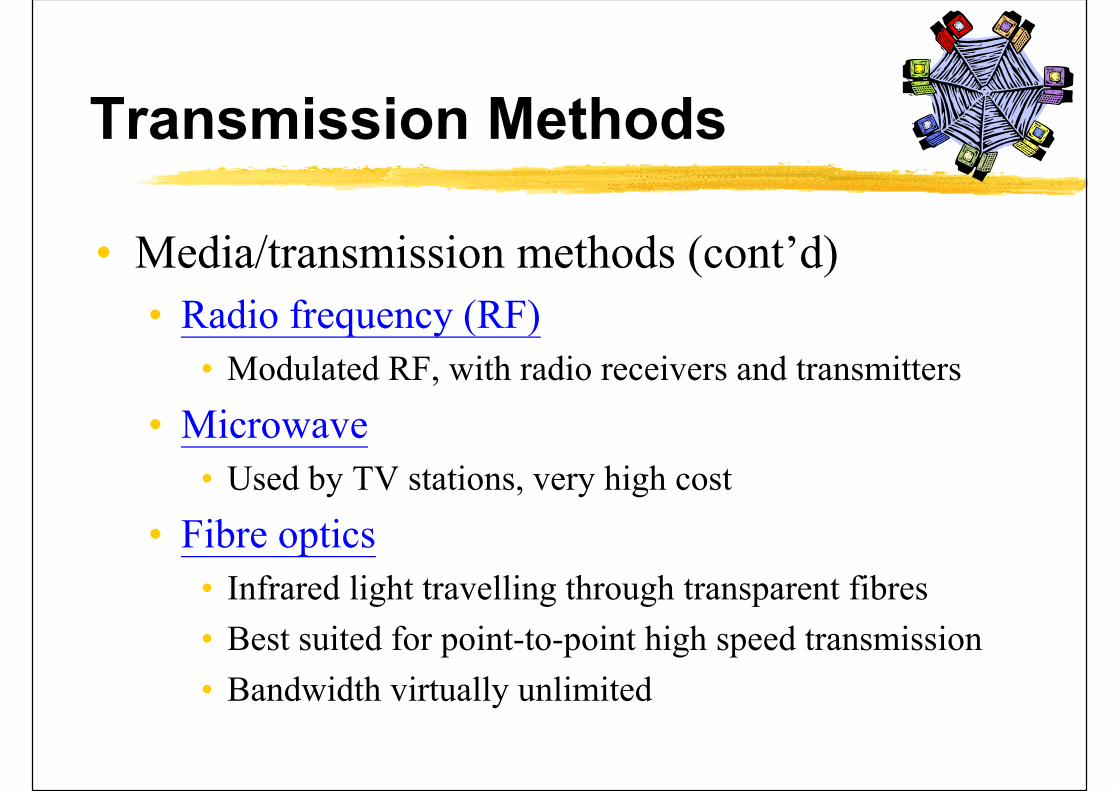
• Media/transmission methods (cont’d)
• Radio frequency (RF)
• Modulated RF, with radio receivers and transmitters
• Microwave
• Used by TV stations, very high cost
• Fibre optics
• Infrared light travelling through transparent fibres
• Best suited for point-to-point high speed transmission
• Bandwidth virtually unlimited
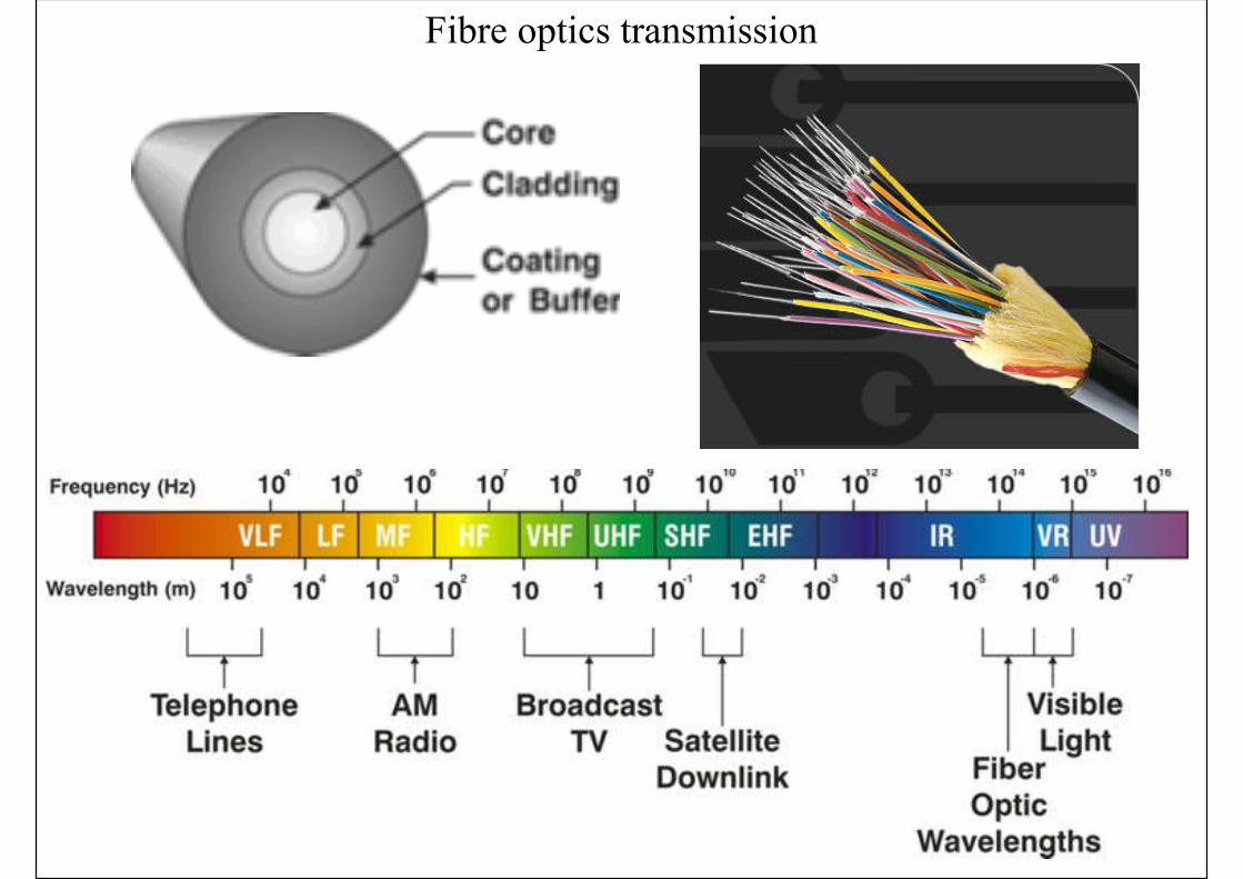
Fibre optics transmission
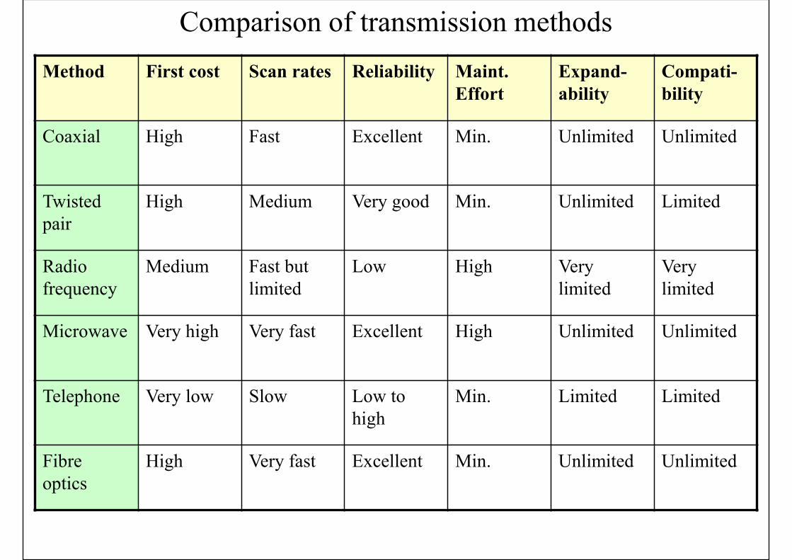
Method First cost Scan rates Reliability Maint. Effort
Expand-ability
Compati-bility
Coaxial High Fast Excellent Min. Unlimited Unlimited
Twisted pair
High Medium Very good Min. Unlimited Limited
Radio frequency
Medium Fast but limited
Low High Very limited
Very limited
Microwave Very high Very fast Excellent High Unlimited Unlimited
Telephone Very low Slow Low to high
Min. Limited Limited
Fibre optics
High Very fast Excellent Min. Unlimited Unlimited
Comparison of transmission methods
Transmission Methods
• Wireless communication• Transfer of information between two or more
points that are not connected by an electrical conductor, such as radio & infrared controller
• Modern wireless technologies• Digital devices that communicate without wires
• Such as mobile phones & wireless networking
• 4G LTE (long-term evolution), LTE-Advanced, 5G
• Wi-Fi (wireless LAN), Bluetooth

(Source: http://tutorvoice.com/index.php/2015/10/11/generations-of-wireless-communication-technology/)
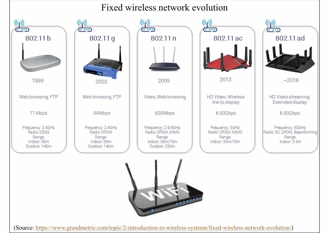
Fixed wireless network evolution
(Source: https://www.grandmetric.com/topic/2-introduction-to-wireless-systems/fixed-wireless-network-evolution/)
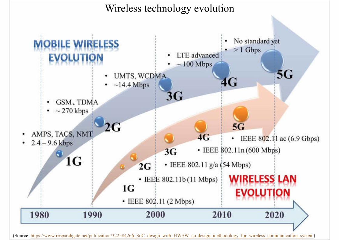
Wireless technology evolution
(Source: https://www.researchgate.net/publication/322584266_SoC_design_with_HWSW_co-design_methodology_for_wireless_communication_system)
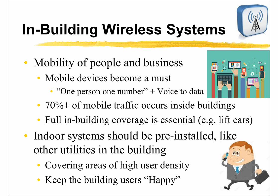
In-Building Wireless Systems
• Mobility of people and business
• Mobile devices become a must
• “One person one number” + Voice to data
• 70%+ of mobile traffic occurs inside buildings
• Full in-building coverage is essential (e.g. lift cars)
• Indoor systems should be pre-installed, like other utilities in the building
• Covering areas of high user density
• Keep the building users “Happy”
In-Building Wireless Systems
• Telecommunications infrastructure or Internet broadband as the “Fourth Utility”, after electricity, water & gas
• Reliable connectivity without restriction – all the time, at full speed, on any device, from anywhere – has become the expectation in our connected world
• Indoor access to Wi-Fi, cellular & VoIP networks
• In-building network for building automation, BMS, fire, security & other operations
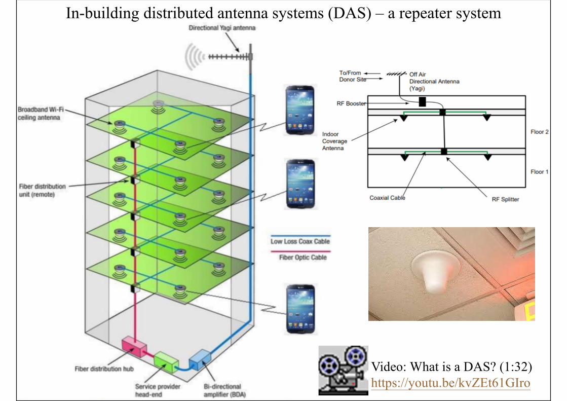
In-building distributed antenna systems (DAS) – a repeater system
Video: What is a DAS? (1:32) https://youtu.be/kvZEt61GIro
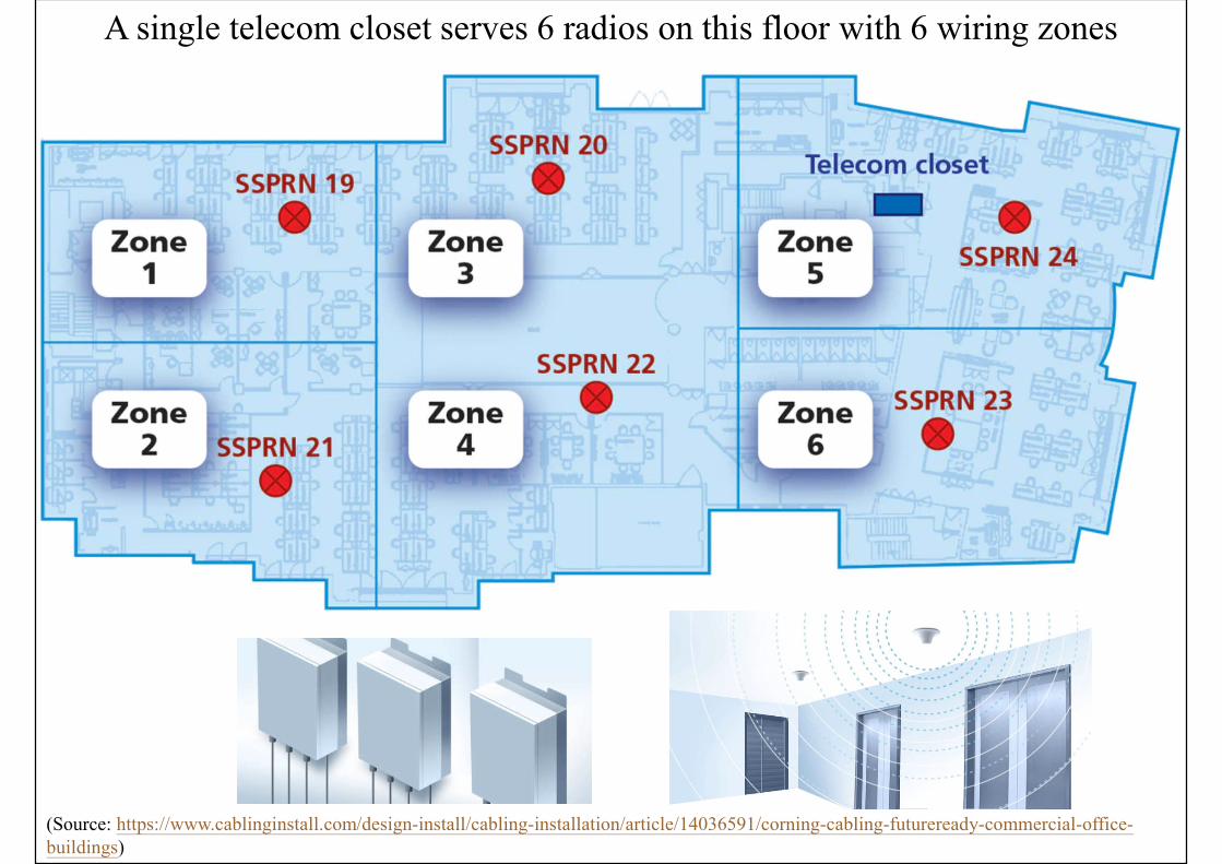
A single telecom closet serves 6 radios on this floor with 6 wiring zones
(Source: https://www.cablinginstall.com/design-install/cabling-installation/article/14036591/corning-cabling-futureready-commercial-office-buildings)
In-Building Wireless Systems
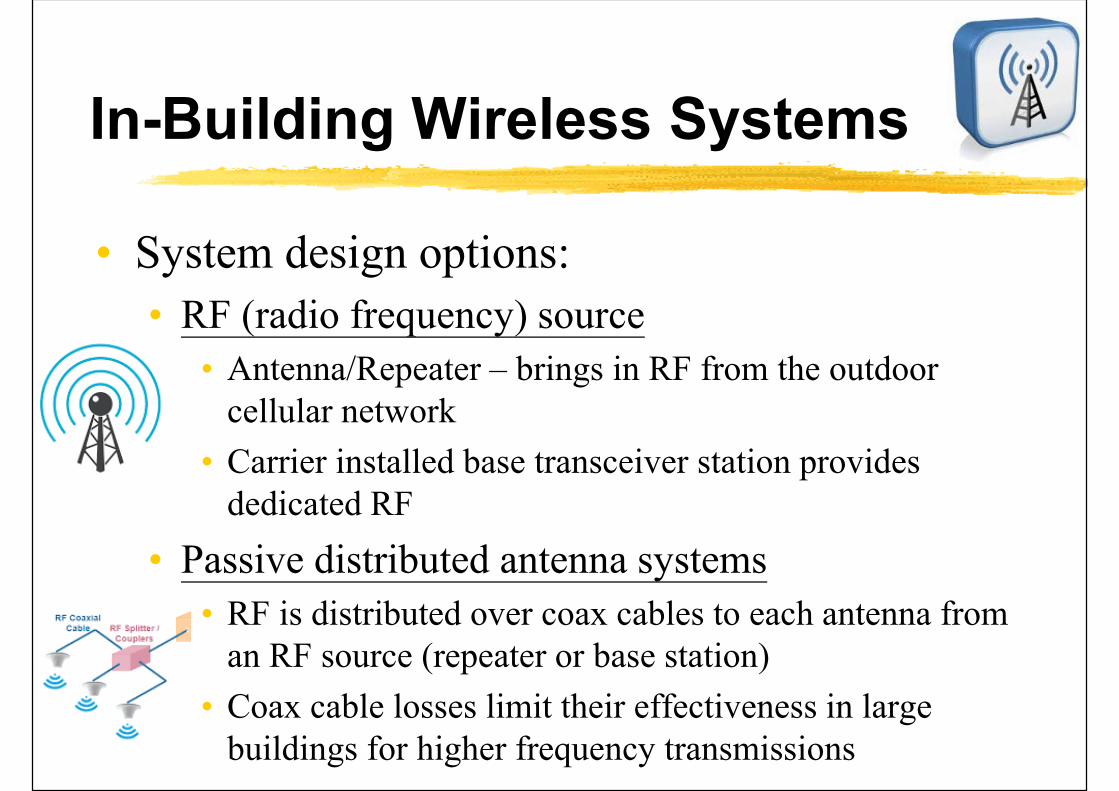
• System design options:
• RF (radio frequency) source
• Antenna/Repeater – brings in RF from the outdoor cellular network
• Carrier installed base transceiver station provides dedicated RF
• Passive distributed antenna systems
• RF is distributed over coax cables to each antenna from an RF source (repeater or base station)
• Coax cable losses limit their effectiveness in large buildings for higher frequency transmissions
In-Building Wireless Systems
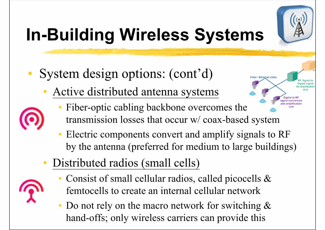
• System design options: (cont’d)
• Active distributed antenna systems
• Fiber-optic cabling backbone overcomes the transmission losses that occur w/ coax-based system
• Electric components convert and amplify signals to RF by the antenna (preferred for medium to large buildings)
• Distributed radios (small cells)
• Consist of small cellular radios, called picocells & femtocells to create an internal cellular network
• Do not rely on the macro network for switching & hand-offs; only wireless carriers can provide this

Example of passive distributed antenna system
(Source: http://www.bicsi.org/pdf/presentations/northcentral10/The%20Fundamentals%20of%20In-Building%20Wireless%20Solutions%20-%20ADC.pdf)
• Essentially a “sprinkler system” for cell phone signals
• Distribution via large coaxial cables
• Losses through the cable limit the size
• New, higher frequency bands have high loss
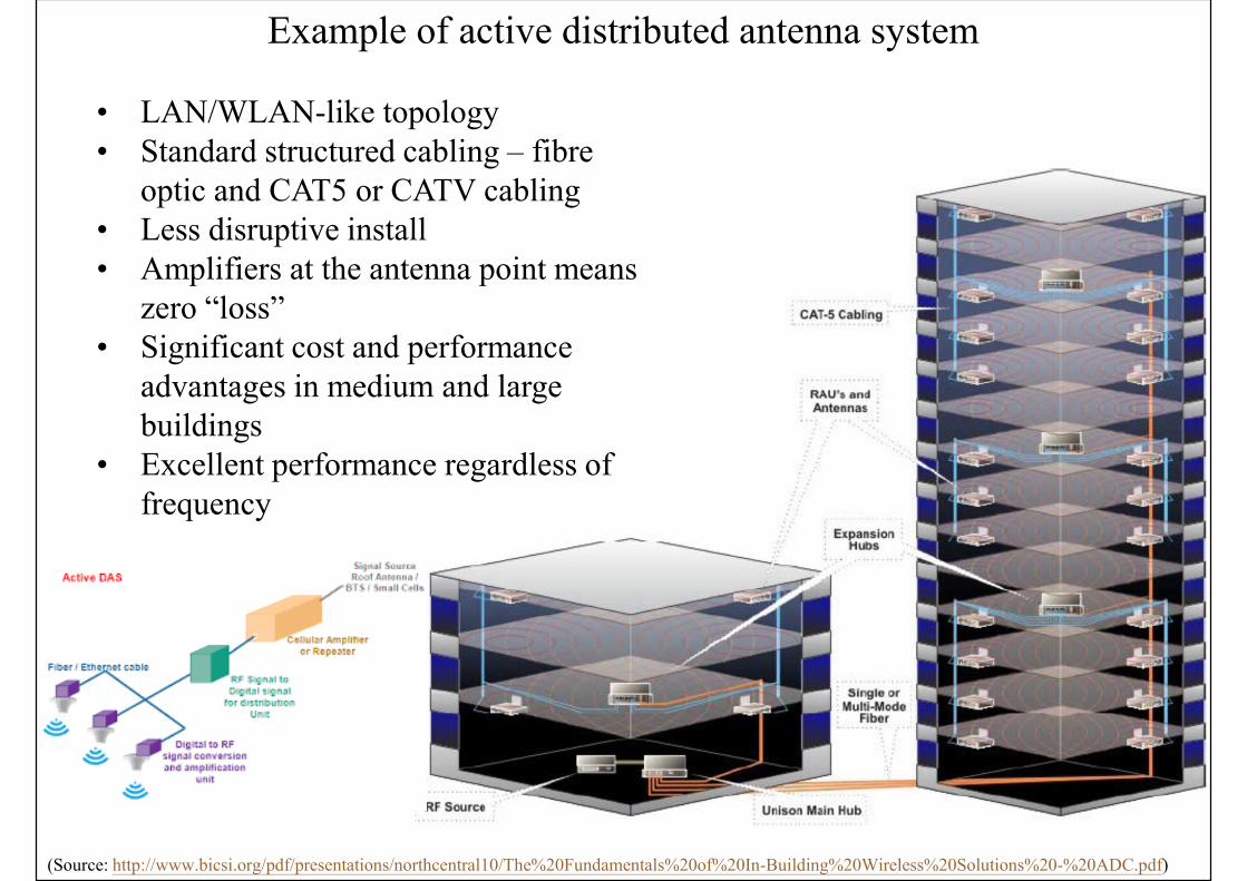
Example of active distributed antenna system
(Source: http://www.bicsi.org/pdf/presentations/northcentral10/The%20Fundamentals%20of%20In-Building%20Wireless%20Solutions%20-%20ADC.pdf)
• LAN/WLAN-like topology• Standard structured cabling – fibre
optic and CAT5 or CATV cabling• Less disruptive install• Amplifiers at the antenna point means
zero “loss”• Significant cost and performance
advantages in medium and large buildings
• Excellent performance regardless of frequency
In-Building Wireless Systems
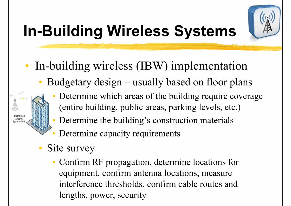
• In-building wireless (IBW) implementation
• Budgetary design – usually based on floor plans
• Determine which areas of the building require coverage (entire building, public areas, parking levels, etc.)
• Determine the building’s construction materials
• Determine capacity requirements
• Site survey
• Confirm RF propagation, determine locations for equipment, confirm antenna locations, measure interference thresholds, confirm cable routes and lengths, power, security
Further Reading
• Placing Electrical Systems and Communications Systems in Buildings [US GSA]
• https://www.gsa.gov/node/82713
• Structured cabling - Wikipedia http://en.wikipedia.org/wiki/Structured_cabling
• Structured Cabling Solutions https://datalinetechnologies.com/structured-cabling-solutions/
• In-Building Cellular Enhancement System -Wikipedia https://en.wikipedia.org/wiki/In-Building_Cellular_Enhancement_System
References
• APP-84 Access Facilities for Telecommunications and Broadcasting Services https://www.bd.gov.hk/doc/en/resources/codes-and-references/practice-notes-and-circular-letters/pnap/APP/APP084.pdf
• CA, 2012. Code of Practice for the Installation and Maintenance of In-Building Telecommunications Systems and In-building Access by Telecommunications Network Operators, Communications Authority (CA), Hong Kong. https://www.coms-auth.hk/filemanager/statement/en/upload/105/cop201202e.pdf
• CA, 2012. Code of Practice for the Provision of Access Facilities in Buildings for the Supply of Telecommunications and Broadcasting Services, Communications Authority (CA), Hong Kong. https://www.coms-auth.hk/filemanager/statement/en/upload/104/cop201201e.pdf
• CIBSE, 1992. Information Technology and Buildings, Applications Manual 7, Chartered Institution of Building Services Engineers, London.