
The electrostatic ellipsoidal mirror: A fast and efficient separator for slowly recoiling and highly...
14
Nuclear Instruments and Methods 188 ( 1981) 535 -548 535 North-Holland Publishing Company THE ELECTROSTATIC ELLIPSOIDAL MIRROR: A FAST AND EFFICIENT SEPARATOR FOR SLOWLY RECOILING AND HIGHLY CHARGED NUCLEI * G. GIORGINIS **, H. BOHN, T. FAESTERMANN, F.V. FEILITZSCH, P. KIENLE, C. KOZHUHAROV *** Physik-Department, Technische Universitd~ Mfinchen, D-8046 Garching, Germany and T. YAMAZAKI Department of Physics, University of Tokyo, Bunkyo-ku, Tokyo, Japan Received 21 April 1981 In order to perform background-free spectroscopy of short-lived nuclear states produced in light ion induced fusion reactions, an electrostatic ellipsoidal mirror has been developed which efficiently separates nuclei, recoiling out of a (thin) target into vacu- um, from their point of origin and the beam direction. Depending on their initial kinetic energy and ionic charge, the recoils are deflected by an electrostatic field acting between two ellipsoidal confocal electrodes of rotational symmetry and are focused onto a small area of typically 10 X 20 mm 2. A total transmission through the mirror of ~42% has been measured and separation times of less than 300 ns were achieved. The generation of high atomic charge states, the principles of operation of the mirror, its tech- nical realization, and performance tests are described. In first applications of the mirror, a-decay of residual nuclei excited in a-induced reactions on 209 Bi targets has been studied. 1. Introduction By bombarding a thin target with an energetic ion beam the linear momentum transfer, in general, forces the residual nuclei produced in nuclear reac- tions to recoil out of the (thin) target into vacuum. In experiments sensitive to background the study of pro- perties of excited states in recoiling nuclei can, in principle, be achieved by methods in which the recoils are separated and subsequently transported from the close vicinity of the target and the beam into a shielded counting area. Principal difficulties arise from the fact that such recoiling nuclei generally possess marked distributions in emission angle, recoil velocity, and atomic charge state, depending on reac- tion kinematics, target thickness, and production mechanism employed. Many different kinds of sepa- ration and transport processes have been developed and successfully applied in the past [ 1 ]. Particularly * Work supported by the Bundesministerium ffir Forsch- ung und Technologie, Bonn, Germany. ** Present address: Institut fiir Kernphysik, Kernfor- schungszentrum Karlsruhe, D-7500 Karlsruhe 1, Ger- many. *** Present address: GSI, D-6100 Darmstadt 11, Germany. 0029-554X/81/0000-0000/$02.50 © 1981 North-Holland interesting, short separation times of the order of 1/~s are attainable with the more recently developed recoil spectrometers [2] and velocity fdters [3]. However, since these devices only have rather small angles of acceptance (typically 1°-3 ° ) their applica- tion to the spectroscopy of short-lived nuclear states is practically restricted to thermal neutron induced fission or heavy ion induced fusion reactions, in which energetic (typically v/c >~ 3%) recoiling nuclei are produced. Many interesting spectroscopic investigations of short-lived nuclear states are feasible, employing nuclear reactions in which the nuclei of interest are produced at much lower recoil velocities (typically v/c <~ 0.5%). Such reactions are, for example, fusion reactions induced by light heavy ion beams (e.g., a, Li, Be .... ) on heavy targets (e.g., A >~ 200). With these reactions, nuclei located in several regions of large interest for nuclear spectroscopy can be popu- lated, e.g., the region of neutron rich nuclei with Z >~ 82, N> 126 where high spin yrast isomers are predicted to occur, or the region of deformed acti- nide nuclei where fission isomers can be studied. At low recoil velocity short separation times can be achieved if the excited nuclei of interest, while recoil-
-
Upload
independent -
Category
Documents
-
view
2 -
download
0
Transcript of The electrostatic ellipsoidal mirror: A fast and efficient separator for slowly recoiling and highly...
Nuclear Instruments and Methods 188 ( 1981) 535 -548 535 North-Holland Publishing Company
THE ELECTROSTATIC ELLIPSOIDAL MIRROR: A FAST AND EFFICIENT SEPARATOR FOR SLOWLY RECOILING AND HIGHLY CHARGED NUCLEI *
G. GIORGINIS **, H. BOHN, T. FAESTERMANN, F.V. FEILITZSCH, P. KIENLE, C. KOZHUHAROV *** Physik-Department, Technische Universitd~ Mfinchen, D-8046 Garching, Germany
and
T. YAMAZAKI Department of Physics, University of Tokyo, Bunkyo-ku, Tokyo, Japan
Received 21 April 1981
In order to perform background-free spectroscopy of short-lived nuclear states produced in light ion induced fusion reactions, an electrostatic ellipsoidal mirror has been developed which efficiently separates nuclei, recoiling out of a (thin) target into vacu- um, from their point of origin and the beam direction. Depending on their initial kinetic energy and ionic charge, the recoils are deflected by an electrostatic field acting between two ellipsoidal confocal electrodes of rotational symmetry and are focused onto a small area of typically 10 X 20 mm 2. A total transmission through the mirror of ~42% has been measured and separation times of less than 300 ns were achieved. The generation of high atomic charge states, the principles of operation of the mirror, its tech- nical realization, and performance tests are described. In first applications of the mirror, a-decay of residual nuclei excited in a-induced reactions on 209 Bi targets has been studied.
1. Introduction
By bombarding a thin target with an energetic ion beam the linear momentum transfer, in general, forces the residual nuclei produced in nuclear reac- tions to recoil out of the (thin) target into vacuum. In experiments sensitive to background the study of pro- perties of excited states in recoiling nuclei can, in principle, be achieved by methods in which the recoils are separated and subsequently transported from the close vicinity of the target and the beam into a shielded counting area. Principal difficulties arise from the fact that such recoiling nuclei generally possess marked distributions in emission angle, recoil velocity, and atomic charge state, depending on reac- t ion kinematics, target thickness, and product ion mechanism employed. Many different kinds of sepa- ration and transport processes have been developed and successfully applied in the past [ 1 ]. Particularly
* Work supported by the Bundesministerium ffir Forsch- ung und Technologie, Bonn, Germany.
** Present address: Institut fiir Kernphysik, Kernfor- schungszentrum Karlsruhe, D-7500 Karlsruhe 1, Ger- many.
*** Present address: GSI, D-6100 Darmstadt 11, Germany.
0029-554X/81/0000-0000/$02 .50 © 1981 North-Holland
interesting, short separation times of the order of 1/~s are attainable with the more recently developed recoil spectrometers [2] and velocity fdters [3]. However, since these devices only have rather small angles of acceptance ( typically 1 ° - 3 ° ) their applica- t ion to the spectroscopy of short-lived nuclear states is practically restricted to thermal neutron induced fission or heavy ion induced fusion reactions, in which energetic ( typical ly v/c >~ 3%) recoiling nuclei are produced.
Many interesting spectroscopic investigations of
short-lived nuclear states are feasible, employing nuclear reactions in which the nuclei of interest are produced at much lower recoil velocities ( typically v/c <~ 0.5%). Such reactions are, for example, fusion reactions induced by light heavy ion beams (e.g., a, Li, Be . . . . ) on heavy targets (e.g., A >~ 200). With these reactions, nuclei located in several regions of large interest for nuclear spectroscopy can be popu- lated, e.g., the region of neutron rich nuclei with Z >~ 82, N > 126 where high spin yrast isomers are predicted to occur, or the region of deformed acti- nide nuclei where fission isomers can be studied. At low recoil velocity short separation times can be achieved if the excited nuclei of interest, while recoil-
536 G. Giorginis et al. / Electrostatic ellipsoidal mirror
ing through vacuum, possess high atomic charge states. Due to the strongly reduced rigidity compared to the primary beam particles such recoiling heavy nuclei may easily be separated from target and beam and quickly transported to a detector, utilizing suit- able electric or magnetic field configurations. Since heavy nuclei produced in fusion-type reactions recoil with approximately the linear momentum of the beam but with much less kinetic energy, separation by means of electric fields seems to be advantageous. Isomer separation using a magnetic field has also been performed recently [4].
The present paper describes the realization of a fast and efficient separation and transport system for highly charged and slowly recoiling heavy nuclei by means of an electrostatic ellipsoidal mirror. The recoils are deflected from the target located in one of the two geometrical focal points and are focused onto a detector or a catcher foil positioned approximately at the other focal point by a static electric field, acting between two ellipsoidal and confocal elec- trodes of rotational symmetry. The production of high atomic charge states due to Auger cascades fol- lowing internal conversion processes is briefly dis- cussed in sect. 2. The principles of operation of the mirror are described in sect. 3. The technical realiza- tion of the mirror is outlined in sect. 4. Performance tests using the mirror are presented in sect. 5. First results from experiments applying the mirror are discussed in sect. 6.
2. Generation of high atomic charge states by nuclear internal conversion
Excited nuclei recoiling out of a thin target into vacuum may possess high atomic charge states even at low recoil velocities (typically v/c <~ 0.5%) if the nu- clear deexcitation process involves one or more highly converted transitions. The vacancy produced in an inner atomic shell by a nuclear internal conversion process is filled either by X-ray emission or by Auger transitions [5]. Except for the K- and L-shells the Auger process is dominant in heavy atoms. Auger transitions generate vacancy cascades because in each transition one vacancy is replaced by two. A vacancy cascade therefore converts an atom recoiling in vacu- um into a highly charged ion. Since the vacancy cas- cade takes place within a time interval (~10 -ls S [6]) short compared to the halflives (>~10 -~2 s) of many of the nuclear states involved in the deexcitation pro-
cess, in most cases the atomic shells will be readjusted and prepared for the ignition of another vacancy cas- cade when a further nuclear transition takes place. Therefore, if several consecutive nuclear internal con- versions occur along the nuclear deexcitation path, the atomic charges generated in each step may sum up to even higher charge state values.
Generation of high atomic charge states via the Auger effect induced by nuclear internal conversion was already pointed out in 1942 by Cooper [7] to be the cause of molecular dissociation. Later on occur- rences of high atomic charge states due to internal conversion following nuclear 13-[8] and a-[9] decay have been studied in detail, using radioactive sources. For example, in case of c~-decay of 241Am charge dis- tributions of about equal widths (fwhm ~ 9 units) centered at values of about 14 ÷, 21 ÷, and 26 ÷ for a number of one, two, and three cascading, highly con- verted transitions, respectively, have been measured for the recoiling 237Np nuclei [10]. From these data it is evident that the charge state value does not increase linearly with increasing number of consecu- tive nuclear internal conversions, reflecting the fact that the Auger process becomes less probable with increasing ionization.
In case of nuclear reactions induced by ion beams, charge state distributions extending up to still higher values (~45 +) have been measured for 24°Cm recoils, produced in the reaction 239pu(a, 3n) at 33 MeV [11]. In this region of deformed actinide nuclei usually the transitions between the lower lying excited states within a given band are strongly con- verted. The possibility of generating high atomic charge states due to strong internal conversion of transitions between rotational states based on a fission isomer located in the second minimum of 239pu was essential for the determination of the quadrupole moment of that isomer [ 12].
Strong internal conversion of nuclear transitions are also observed in nuclei near closed shells. Con- sidering, for instance, the region around doubly magic 2°sPb, the 8÷-6 ÷ yrast transitions, e.g., in the even Po isotopes (2°2-21°Po) or in the N = 126 isotones 2~2Rn and 214Ra are highly converted. As already ob- served for a few cases of nuclei located near closed
shells, strongly converted nuclear transitions also occur between states having much larger angular momentum. This is true more generally since it is believed that in regions near closed shells more angu- lar momentum is generated by increasingly aligning spins of valence nucleons occupying high-/" orbitals.
G. Giorginis et al. / Electrostatic ellipsoidal mirror 537
Due to this alignment mechanism the formation of high spin isomers along the yrast line is expected which may decay by very low energetic and therefore highly converted transitions to the lower lying yrast states, giving rise to a staggering of the yrast line. If the decay path of a high spin isomer located on top of the yrast line involves only very few (one or two) strongly converted transitions, the generated ioniza- tion may already be sufficient in order that the recoil- ing nucleus can be separated and subsequently detected while still being excited in one of the lower lying yrast isomers. For a given separation time the number of nuclei still excited this way at the detector depends on population mechanism, halflife, and distribution of isomeric states along the yrast line. a-decay of high spin yrast isomers can also occur in favourable cases, possibly leading to excited high spin isomers in the daughter nucleus.
It is clear that short separation times and an effi- cient collection process have to be realized for the recoiling nuclei in order to successfully perform back- ground-free spectroscopy of isomeric states at high spin and/or large deformation.
3. Principles of operation of the electrostatic ellipsoi- dal mirror
For a successful operation of the mirror the fol- lowing main requirements have to be fulfilled simul- taneously:
a) High collection efficiency for the recoiling nu- clei of interest.
b) Short flight times of the recoils along their paths between target and detector.
c) Suppression of background at the detection po- sition.
A high collection efficiency means that almost all nuclei recoiling out of the target have to be focused onto the detector. For heavy nuclei (A >~ 200)recoil- ing at low kinetic energies (E <~ 600 keV) this task is difficult to perform. The reason is that broad distri- butions in angle of emission [13-15] and atomic charge state [11] are expected and that a large spread in kinetic recoil energies occurs using target thick- nesses of ~<100 pg/cm 2 which are shown [16,17] to be at optimum for the reactions employed in order to reach a sufficient yield of recoiling nuclei. In order to focus the recoiling nuclei regardless of these distribu- tions, deflection by an electrostatic field acting between two ellipsoidal confocal electrodes of rota-
tional symmetry is applied. The confocal equipoten- tial surfaces lying between the two electrodes reflect recoils entering the field region which are emitted from one geometrical focal point and focus them close to the other focal point, independent of their angle of emission, a, and specific kinetic energy, T/q (q --- atomic charge state). The inner electrode (= cath- ode) is transparent to the recoils and the space between cathode and the axis of rotational symmetry is assumed to be field-free. This deflection process is not quite analogous to geometrical optics, because the electrostatic field represents a medium having a continuously varying index of refraction.
3.1. The deflection f ield
The general case of three-dimensional potential distributions for nonintersecting confocal conicoids is treated by Smythe [18]. In particular, a family of nonintersecting confocal ellipsoidal surfaces of rota- tional symmetry around the z-axis is described by:
Z 2 r 2
- 1 , (la) a 2 +s b 2 + s
with
a > b = c , -a2 < s < °° . ( lb)
In eq. (1) the semiaxes along the z- and r-direction are determined by (a 2 + s) In and (b 2 + s) v2, respec- tively.
The electrostatic potentials corresponding to these surfaces are given by:
A , [-(a 2 + s) 1/2 - f ] ~ , m / 7__2 - _NIT2 - - ,T 0 , (2) v=? = L(~ +s) +fJ
where f = (a 2 - b 2 ) 1/2 is equal to half the distance between the two geometrical focal points.
Differentiation of eq. (2) gives the electric field components:
Z Ez = - 2 A
M2Rs(a 2 +s ) '
r E r = - 2 A
M2Rs(b 2 +s ) '
with
Z 2 /.2
M 2 - ( a 2+s) 2 +(b 2+s) 2
R s : (a 2 +s)l/2(b 2 +s ) .
(3a)
(3b)
(3c)
(3d)
538 G. Giorginis et al. / Electrostatic ellipsoidal mirror
By specifying the parameters of the electrodes, i.e., Vc, ac, bc and VA, aA, bA which are the potential, semimajor, and semiminor axes of the cathode and anode, respectively, the constant quantities A, B are determined. Choosing s = 0 for the cathode which gives a c = a, b c = b and taking s = SA for the anode it follows:
A _ f ( V A - Vc) , (4a) C2 - C1
B = C2 Vc - C, VA , (4b) C2 - C 1
with
a - f C1 = in - - (4c) a + f '
a A - f C2 = I n - (4d) a A + f
3.2. The equations o f mot ion
For a charged particle moving in a purely electro- static field of rotational symmetry around the z-axis the equations of motion can be written in cylindrical coordinates (z, r, 9) in the following way [19]:
m~ = - e q ~ V/~z , (5a)
m~ = - e q ~ V/Or, (5b)
r2~? = r2osbo = const. , (5c)
where m and eq are mass and charge of the particle (q denoting the charge state value), V is the electric po- tential and ro, ~o are the initial values. Since V does not depend on ~0 [see eq. (2)] the motion in an equa- torial plane (i.e. plane perpendicular to z-axis) is independent from the motion in an axial plane (i.e. plane containing the z-axis). Therefore, in case of point-like emission from one of the two focal points located on the z-axis, the trajectories of the particles are confined to axial planes and are described by eqs. (Sa) and (Sb) only, resulting in:
z (6a) = - K MzRs(a 2 + s) '
r _ _ (6b) = - K m z R s ( b 2 + s) '
with
K = 2eqA/m , (6c)
_ 1 r2 s - ~{ + z 2 (a 2 + b 2)
+ if4 +2f2(r2 _ z 2 ) + ( r 2 + z 2 ) 2 1 1 / 2 } . (6d)
In case of a source of finite size from which parti- cles may be emitted with velocity directions never intersecting with the z-axis, also eq. (5c) has to be considered for a complete description of the particle trajectories.
3.3. Computat ion o f particle trajectories
Already for the simple case of particle emission from a point-like source, the equations of motion [eq. (6)] have a complicated form. Therefore, instead of trying to deduce analytical expressions by direct integration, a numerical integration procedure for the equations of motion has been performed. To do so, the set of second order differential equations [eq. (6)] was transformed into a set of first order differen- tial equations by substitution:
= u , (7a)
I: = w , (7b)
/~ =~ , ( 7 c )
/v =J: , (7d)
(o = r~ ~o/r2 . (7e)
These first order differential equations were then integrated numerically for given initial values, using existing subroutines [20]. According to the two dif- ferent cases of particle emission, i.e., emission from point-like sources and from sources of finite size, dif- ferent main programs for the calculation of the start values needed for the numerical integration have been developed subsequently. The following assumptions have been made throughout the calculations:
a) The surface of the electrodes is smooth. b) No field acts between cathode (= inner elec-
trode) and z-axis. c) The trajectories are not influenced by fringing
fields. d) The particles penetrate the cathode undis-
turbed.
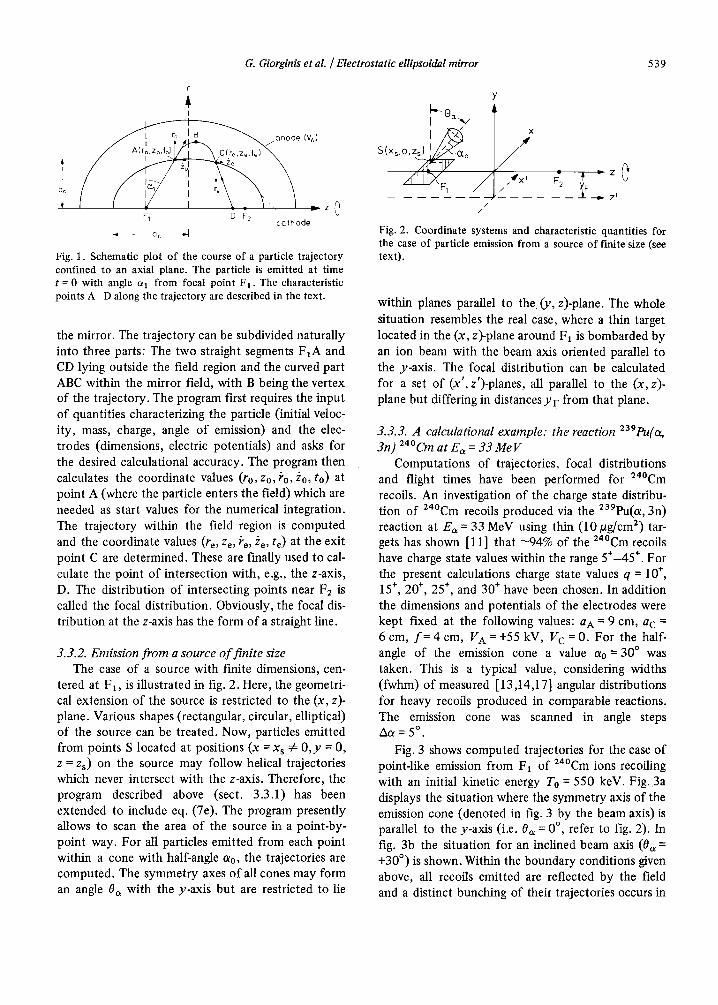
3.3.1. Emission f rom a point-like source Fig. 1 schematically shows a trajectory of a parti-
cle emitted at time t = 0 at an angle ax with respect to the r-axis from a point-like source located at the focal point FI . The figure represents a cut of an axial plane with the two confocal ellipsoidal electrodes of
G. Giorginis et aL / Electrostatic ellipsoidal mirror 5 3 9
r
I
l ,4
F~ D F? \ co'~hode
Fig. 1. Schematic plot of the course of a particle trajectory confined to an axial plane. The particle is emitted at time t = 0 with angle a 1 from focal point F l . The characteristic points A-D along the trajectory are described in the text.
the mirror. The trajectory can be subdivided naturally into three parts: The two straight segments F IA and CD lying outside the field region and the curved part ABC within the mirror field, with B being the vertex of the trajectory. The program first requires the input of quantities characterizing the particle (initial veloc- ity, mass, charge, angle o f emission) and the elec- trodes (dimensions, electric potentials) and asks for the desired calculational accuracy. The program then calculates the coordinate values (ro,zo, ~o, Zo, to) at point A (where the particle enters the field) which are needed as start values for the numerical integration. The trajectory within the field region is computed and the coordinate values (re, Ze, ke, Ze, te) at the exit point C are determined. These are finally used to cal- culate the point o f intersection with, e.g., the z-axis, D. The distribution of intersecting points near F2 is called the focal distribution. Obviously, the focal dis- tribution at the z-axis has the form of a straight line.
3.3.2. Emission from a source o f finite size The case of a source with finite dimensions, cen-
tered at F1, is illustrated in fig. 2. Here, the geometri- cal extension of the source is restricted to the (x, z)- plane. Various shapes (rectangular, circular, elliptical) of the source can be treated. Now, particles emitted from points S located at positions (x = x s ~ 0 , y = 0, z = Zs) on the source may follow helical trajectories which never intersect with the z-axis. Therefore, the program described above (sect. 3 . 3 . 1 ) h a s been extended to include eq. (7e). The program presently allows to scan the area o f the source in a point-by- point way. For all particles emitted from each point within a cone with half-angle ao, the trajectories are computed. The symmetry axes of all cones may form an angle Oa with the y-axis but are restricted to lie
Y I~ 0a x/
S(xs,O,Zs) I ~ o
/
X
/ ,-x 4,-z
/ IV Z I /
/
Fig. 2. Coordinate systems and characteristic quantities for the case of particle emission from a source of finite size (see text).
within planes parallel to the 0 ' , z)-plane. The whole situation resembles the real case, where a thin target located in the (x, z)-plane around FI is bombarded by an ion beam with the beam axis oriented parallel to the y-axis. The focal distribution can be calculated for a set of (x', z')-planes, all parallel to the (x, z)- plane but differing in distances YF from that plane.
3.3.3. A calculational example: the reaction 239pu(o~ 3n) 24°Cm at Ea = 33 M e V
Computations of trajectories, focal distributions and flight times have been performed for 24°Cm recoils. An investigation of the charge state distribu- tion of 24°Cm recoils produced via the 239pu(a, 3n) reaction at Ea = 33 MeV using thin (10/2g/cm 2) tar- gets has shown [11] that "-94% of the 24°Cm recoils have charge state values within the range 5*-45*. For the present calculations charge state values q = 10 ÷, 15 ÷, 20 ÷, 25 ÷, and 30 ÷ have been chosen. In addition the dimensions and potentials of the electrodes were kept fixed at the following values: a A = 9 cm, a c = 6 cm, f = 4 cm, V A = +55 kV, V c = 0. For the half- angle of the emission cone a value ao = 30 ° was taken. This is a typical value, considering widths (fwhm) of measured [13,14,17] angular distributions for heavy recoils produced in comparable reactions. The emission cone was scanned in angle steps Aa = 5 °.
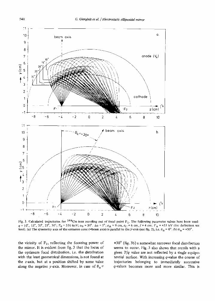
Fig. 3 shows computed trajectories for the case of point-like emission from F1 of 24°Cm ions recoiling with an initial kinetic energy To = 550 keV. Fig. 3a displays the situation where the symmetry axis of the emission cone (denoted in fig. 3 by the beam axis) is parallel to the y-axis (i.e. 0a = 0 °, refer to fig. 2). In fig. 3b the situation for an inclined beam axis (0~ = +30 ° ) is shown. Within the boundary conditions given above, all recoils emitted are reflected by the field and a distinct bunching of their trajectories occurs in
540 G. Giorgin& et al. / Electrostatic ellipsoidal mirror
10 beam axis a
°t 8
2 ///
' / 0
-1
-8 -6 - / . -2 0 2 4 6 8 10
11
10
9
8
7
6 E E5
4
2
1
0
-1
. . . . Oct. 30o / / beam axis
/ z__
/
/ /
/ \ / . \
/ "x
/ / / ]x / / '
/ / / / / ,"
. . . . l
F2
-8 -6 -4 -2 0 2 4 6 8
z(cm)
10
Fig. 3. Calculated trajectories for 24°Cm ions recoiling out of focal point F 1 . The following parameter values have been used: q = 10 ÷, 15 ÷, 20 ÷, 25 ÷, 30+; T O = 550 keV; c~ o = 30 ° , Aa = 5°; a A = 9 cm, a C = 6 cm, f = 4 cm; V A = +55 kV (for definition see
= -I- o text). (a) The symmetry axis of the emission cone (=beam axis) is parallel to the y-axis (see fig. 2), i.e. 0 a 0 °. (b) 0a = 30 .
the vicini ty o f F2, ref lect ing the focusing power o f
the mirror . It is evident f rom fig. 3 that the locus o f
the op t imum focal dis tr ibut ion, i.e. the distr ibut ion
with the least geometr ical dimensions, is no t found at
the z-axis, bu t at a posi t ion shifted by some value
along the negative y-axis. Moreover , in case o f 0 a =
+30 ° (fig. 3b) a somewhat narrower focal dis tr ibut ion
seems to occur. Fig. 3 also shows that recoils wi th a given T/q value are no t ref lected by a single equipo-
tential surface. With increasing q-value the course o f
trajectories belonging to immedia te ly successive q-values becomes more and more similar. This is
G. Giorginis et aL / Electrostatic ellipsoidal mirror 541
yF=-lcm +20-] Yv=Ocm yF=_O.5cm ".i;i,~:' +10- O' : O.
"~ O: : - e o { = O ° ~ + 1 . . .
~ - 10 ] - 10~
÷20~YF=O,cm ¥ = C ¥F ÷20] F YF=-O'5cm : i : .
@a=+30o o: j b. 8a = +30 °
_10 t -10- -20 -20: YF=-lcm
-1'0 0 +1~3-1'0 ()q'O-1'0 ()+1'0 -1'0 ; *1'0-1'0 0 +;0-10. ; +;0 x (mm)
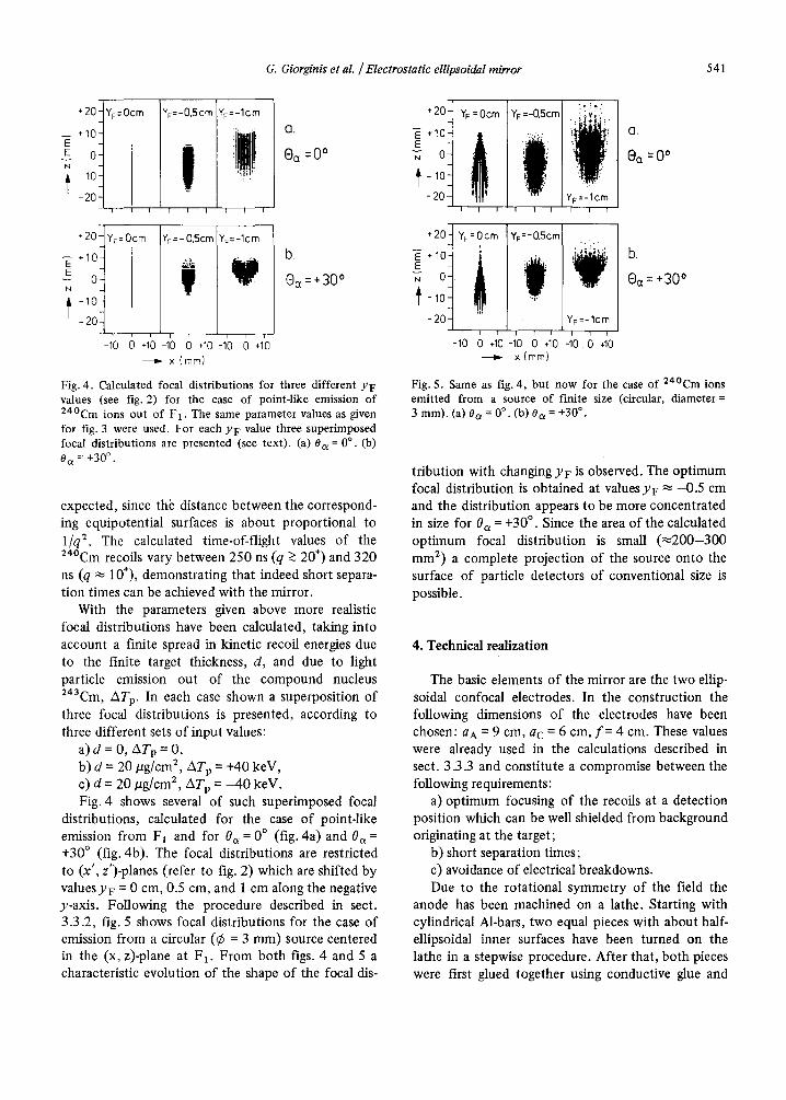
Fig. 4. Calculated focal distr ibutions for three different YF values (see fig. 2) for the case of point-like emission o f 24°Cm ions out o f F 1 . The same parameter values as given for fig. 3 were used. For each YF value three super imposed focal distr ibutions are presented (see text) . (a) 0 a = 0 °. (b)
0 a = +30 °"
expected, since th~ distance between the correspond- ing equipotential surfaces is about proportional to 1/q 2. The calculated time-of-flight values of the 24°Cm recoils vary between 250 ns (q >~ 20 ÷) and 320 ns (q ~ 10÷), demonstrating that indeed short separa- tion times can be achieved with the mirror.
With the parameters given above more realistic focal distributions have been calculated, taking into account a finite spread in kinetic recoil energies due to the finite target thickness, d, and due to light particle emission out of the compound nucleus 243Cm, AT w In each case shown a superposition of three focal distributions is presented, according to three different sets of input values:
a) d = 0, ATp = 0, b) d = 20 #g/cm 2, ATp = +40 keV, c) d = 20 #g/cm 2, ATp = 4 0 keV. Fig. 4 shows several of such superimposed focal
distributions, calculated for the case o f point-like emission from FI and for 0u = 0 ° (fig. 4 a ) a n d 0a = +30 ° (fig. 4b). The focal distributions are restricted to (x', z')-planes (refer to fig. 2) which are shifted by valuesy F = 0 cm, 0.5 cm, and 1 cm along the negative y-axis. Following the procedure described in sect. 3.3.2, fig. 5 shows focal distributions for the case of emission from a circular (¢ = 3 ram) source centered in the (x, z)-plane at F1. From both figs. 4 and 5 a characteristic evolution of the shape of the focal dis-
---~ x (ram)
Fig. 5. Same as fig. 4, bu t now for the case o f 2 4 ° C m ions emit ted from a source o f finite size (circular, diameter = 3 mm). (a) O a = 0 °. (b) O a = +30 °.
tribution with changing YF is observed. The optimum focal distribution is obtained at values Yv ~ -0 .5 cm and the distribution appears to be more concentrated in size for 0a = +30 °. Since the area of the calculated optimum focal distribution is small ( ~ 2 0 0 - 3 0 0 mm 2) a complete projection of the source onto the surface of particle detectors of conventional size is possible.
4. Technical realization
The basic elements of the mirror are the two ellip- soidal confocal electrodes. In the construction the following dimensions of the electrodes have been chosen: an = 9 cm, ac = 6 cm, f - 4 cm. These values were already used in the calculations described in sect. 3.3.3 and constitute a compromise between the following re quirements:
a) optimum focusing of the recoils at a detection position which can be well shielded from background originating at the target;
b) short separation times; c) avoidance of electrical breakdowns. Due to the rotational symmetry of the field the
anode has been machined on a lathe. Starting with cylindrical M-bars, two equal pieces with about half- ellipsoidal inner surfaces have been turned on the lathe in a stepwise procedure. After that, both pieces were first glued together using conductive glue and
542 G. Giorginis et aL / Electrostatic ellipsoidal mirror
then were screwed together in order to ensure good electrical contact. Out of this raw ellipsoid a sector has been cut covering an aperture angle of 100 ° with regard to the z-axis. The final ellipsoidal inner surface of the anode was obtained by subsequently smooth- ing the roughness of the raw surface with abrasive paper, checking always against a template.
Since the recoils have to pass through the cathode in order to enter or to leave the mirror field, the cathode has been formed out of a commercially avail- able stainless steel grid (wire diameter = 0.3 mm). The grid holes were made to be rectangular in shape (8.9 X 2 mm2), resulting in a geometrical transmission
for the grid of ~84%. To get an ellipsoidal surface confocal to the inner surface of the anode, the grid was stretched over the outer surface of an ellipsoid confocal to the inner surface of the anode, which was machined out of brass in a process similar to the one used to form the anode. In the stretched position the grid was soldered to a supporting frame made from stainless steel. The resulting aperture angle of the cathode grid was 180 ° around the z-axis.
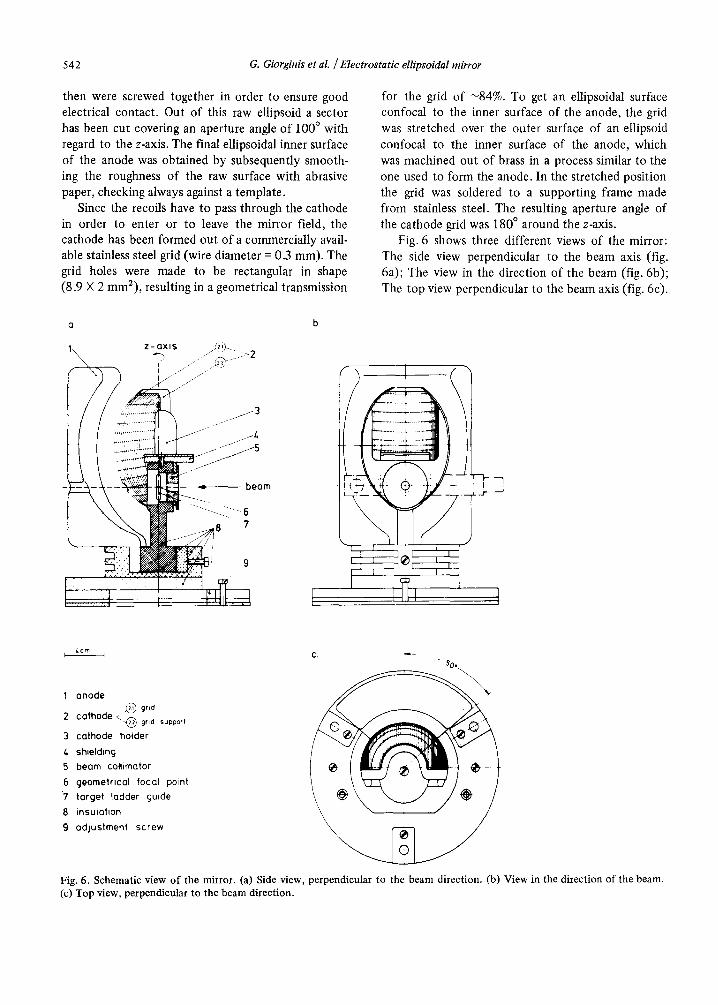
Fig. 6 shows three different views of the mirror: The side view perpendicular to the beam axis (fig. 6a); The view in the direction of the beam (fig. 6b); The top view perpendicular to the beam axis (fig. 6c).
a b.
1 z - a x i s ~,~
I1[ 4 JJ',
' i :
4cm b I C,
1 anode l ~ grid
2 c a t h o d e < . ~ grid support
,hod ,o,d r
4 shielding 5 beam collimator 6 geometrical focal point 7 target ladder guide 8 insulation \ g adjustment screw ~ ~ - ~ ~
Fig. 6. Schematic ~ew of the mirror. (a) Side view, perpendicu]ar to the beam direction. (b) View in the direction of the beam. (c) Top ~4ew, perpendicular to the beam d#ection.
G. Giorginis et al. / Electrostatic ellipsoidal mirror 543
It is evident from fig. 6a that circular holes (¢ = 10 mm) for the beam transport were cut into the elec- trodes in order to avoid background. In the vicinity of these holes the ellipsoidal field is expected to be disturbed, leading to a defocusing effect (see sect. 5.1.2). Fig. 6 also shows that quite massive shieldings can be brought into the space between the two focal points.
1 , i , r i , I , i I i , , r I T I ' I
I I I I t I I
2000 300 6oo 900 13" t:me of-fl;gn~ {nses:,
8 0 0 , Imi / [ , [ I ! ~ g "
5. Performance measurements
Experiments have been carried out in order to test the performance of the mirror, i.e. separation time, focusing power, and collection efficiency, partly pre- dicted by the calculations described in sect. 3.
5.1. Performance tests using a 22aTh source
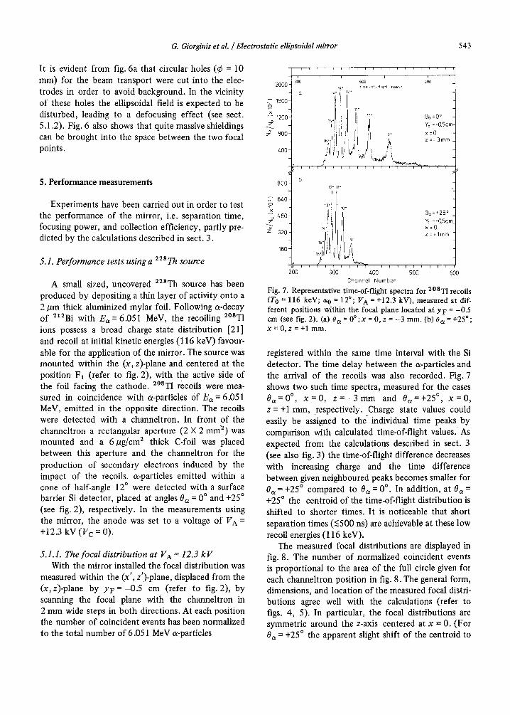
A small sized, uncovered 228Th source has been produced by depositing a thin layer of activity onto a 2/~m thick aluminized mylar foil. Following a-decay of 21~Bi with E~ = 6.051 MeV, the recoiling 2°ST1 ions possess a broad charge state distribution [21] and recoil at initial kinetic energies (116 keV) favour- able for the application of the mirror. The source was mounted within the (x, z)-plane and centered at the position F1 (refer to fig. 2), with the active side of the foil facing the cathode. 2°ST1 recoils were mea- sured in coincidence with a-particles Of Ea = 6.051 MeV, emitted in the opposite direction. The recoils were detected with a channeltron. In front of the channeltron a rectangular aperture (2 × 2 m m 2) was mounted and a 6/ag/cm 2 thick C-foil was placed between this aperture and the channeltron for the production of secondary electrons induced by the impact of the recoils, a-particles emitted within a cone of half-angle 12 ° were detected with a surface barrier Si detector, placed at angles 0a = 0 ° and +25 ° (see fig. 2), respectively. In the measurements using the mirror, the anode was set to a voltage of V A = +12.3 k V (V¢ = 0 ) .
5.1.1. The focal distribution at V A = 12.3 k V With the mirror installed the focal distribution was
measured within the (x', z')-plane, displaced from the (x, z)-plane by YF = --0.5 cm (refer to fig. 2), by scanning the focal plane with the channeltron in 2 mm wide steps in both directions. At each position the number of coincident events has been normalized to the total number of 6.051 MeV a-particles
_ 12* 11"
6~o- _ 13" i 10~
x 9~,=+25 o
z,80-_ YF =-0.5crr =o z 2o- ' =.lmm
16o
200 300 400 500 600 ChQnne[ Number
Fig. 7. Representative time-of-flight spectra for 2°8T1 recoils (To = 116 keV; so = 12°; V A = +12.3 kV), measured at dif- ferent positions within the focal plane located at YF = -0.5 cm (see fig. 2). (a) 0c~ = 0 ° ; x = 0, z = --3 mm. (b) 0 a = +25 ° ; x=0 , z = + l mm.
registered within the same time interval with the Si detector. The time delay between the a-particles and the arrival of the recoils was also recorded. Fig. 7 shows two such time spectra, measured for the cases 0 ~ = 0 °, x = 0 , z = - 3 m m and 0~=+25 ° , x = 0 , z = +1 mm, respectively. Charge state values could easily be assigned to t he individual time peaks by comparison with calculated time-of-flight values. As expected from the calculations described in sect. 3 (see also fig. 3) the time-of-flight difference decreases with increasing charge and the time difference between given neighboured peaks becomes smaller for 0~ = +25 ° compared to 0~ = 0 °. In addition, at 0a = +25 ° the centroid of the time-of-flight distribution is shifted to shorter times. It is noticeable that short separation times (<500 ns) are achievable at these low recoil energies (116 keV).
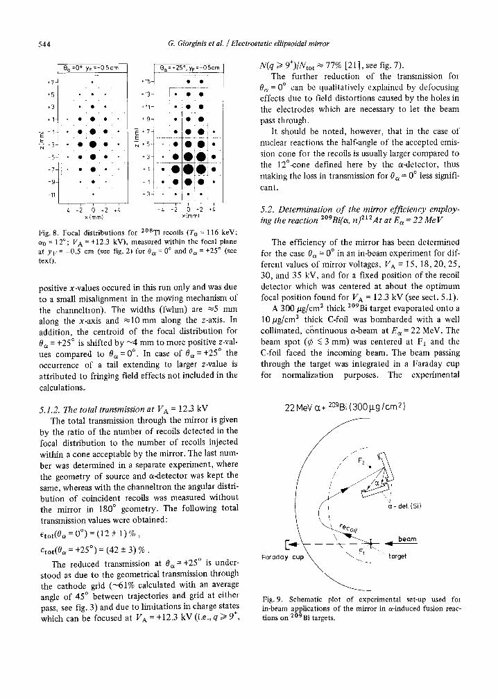
The measured focal distributions are displayed in fig. 8. The number of normalized coincident events is proportional to the area of the full circle given for each channeltron position in fig. 8. The general form, dimensions, and location o f the measured focal distri- butions agree well with the calculations (refer to figs. 4, 5). In particular, the focal distributions are symmetric around the z-axis centered at x = 0. (For 0a = +25 ° the apparent slight shift of the centroid to
544 G. Giorginis et al. /Electrostatic ellipsoidal mirror
+7-
+5
+1-
-~- I - E
- 7 -
-11-
Oct =0°; YF =-0.5cm
• • • • •
. O ~ O ' o '
• • *
.15
*13
.11-
+g-
N + ~ -
+3
+ I
- 1
- 3
0 a = .25o; yF = -05cm
] * ' 0 •
"i*!*
" j ° . *
, r _½ i T
x(mm) x(mm)
Fig. 8. Focal distributions for 2°8TI recoils (T O = 116 keV; ao = 12°; VA = +12.3 kV), measured within the focal plane at YF = -0.5 cm (see fig. 2) for 0 a = 0 ° and 0 a = +25 ° (see text).
positive x-values occured in this run only and was due to a small misalignment in the moving mechanism of
the channeltron). The widths (fwhm) are ~5 mm along the x-axis and ~10 mm along the z-axis. In addition, the centroid of the focal distribution for 0 a = +25 ° is shifted by ~4 mm to more positive z-val- ues compared to 0 a = 0 °. In case of 0a =+25 ° the occurrence of a tail extending to larger z-value is at t r ibuted to fringing field effects not included in the
calculations.
N(q >~ 9+)/Ntot ~ 77% [21], see fig. 7). The further reduction of the transmission for
0a = 0 ° can be qualitatively explained by defocusing effects due to field distortions caused by the holes in the electrodes which are necessary to let the beam pass through.
It should be noted, however, that in the case of nuclear reactions the half-angle of the accepted emis- sion cone for the recoils is usually larger compared to the 12°-cone defined here by the a-detector, thus making the loss in transmission for 0 a = 0 ° less signifi-
cant.
5.2. Determination o f the mirror efficiency employ- ing the reaction 2°9Bi(a, n) 212At at Ea = 22 Me V
The efficiency of the mirror has been determined for the case 0a = 0 ° in an in-beam experiment for dif- ferent values of mirror voltages, VA = 15, 18, 20, 25, 30, and 35 kV, and for a fixed position of the recoil detector which was centered at about the opt imum focal position found for VA = 12.3 kV (see sect. 5.1).
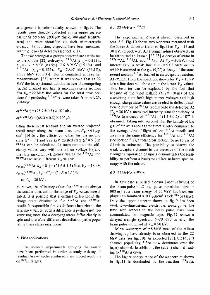
A 300 vg/cm 2 thick 2°9Bi target evaporated onto a
10/ag/cm z thick C-foil was bombarded with a well collimated, c~ntinuous a-beam at Ea = 22 MeV. The beam spot (~b <~ 3 mm) was centered at FI and the C-foil faced the incoming beam. The beam passing through the target was integrated in a Faraday cup for normalization purposes. The experimental
5.1.2. The total transmission at VA = 12.3 kV The total transmission through the mirror is given
by the ratio of the number of recoils detected in the focal distribution to the number of recoils injected within a cone acceptable by the mirror. The last num- ber was determined in a separate experiment, where the geometry of source and a-detector was kept the same, whereas with the channeltron the angular distri- bution of coincident recoils was measured without the mirror in 180 ° geometry. The following total
transmission values were obtained:
e t o t ( O a = 0 ° ) = (12 + 1) %,
etot(0a = +25 °) = (42 + 3) %.
The reduced transmission at 0a = +25 ° is under- stood as due to the geometrical transmission through the cathode grid (~61% calculated with an average angle of 45 ° between trajectories and grid at either pass, see fig. 3) and due to limitations in charge states which can be focused at V A = +12.3 kV (i.e., q /> 9 ÷,
22MeV ct+ 2°9Bi (300t-Lg/cm2)
I/ a- def. (Si)
\'---~..~e c o# [- _ ~ . ~ beQm
Faraday cup ~FFI target
Fig. 9. Schematic plot of experimental set-up used for in-beam applications of the mirror in a-induced fusion reac- tions on 2°9Bi targets.
G. Giorginis et aL/ Electrostatic ellipsoidal mirror 545
arrangement is schematically shown in fig. 9. The recoils were directly collected at the upper surface barrier Si detector (200 tam thick, 300 mm 2 sensitive area) and were identified via their characteristic a-decay. In addition, a-spectra have been measured with the lower Si detector (see sect. 6.1).
The two strongest a-groups observed are attributed to the known [22] a-decay of 212gAt [tu2 = 0.315 s, E~ = 7.679 MeV (83.5%), 7.618 MeV (15.1%)] and 2~2mAt [tl/2 = 0.122 s, Ea = 7.897 MeV (33.1%), 7.837 MeV (65.3%)]. This is consistent with earlier measurements [23] where it was shown that at 22 MeV the (a, n) channel dominates over the competing (a, 2n) channel and has its maximum cross section. For Ea = 22 MeV the values for the total cross sec- tions for producing 212g'mAt were taken from ref. 23, yielding:
G(212gAt) = (75.7 + 0.5) × 103 tab ,
o(Zl2mAt) = (68.0 + 0.5) × 103 tab.
Using these cross sections and an average projected recoil range along the beam direction, Rp ~ 65 tag/ cm 2 [14,16], the efficiency values for the ground state (U = 1-) and 222 keV excited state (pr = 9-) in 2X2At can be calculated. It turns out that the effi- ciency values vary with the mirror voltage VA and that the maximum efficiency values for 212gAt and 212mAt occur at different V A values:
emax(212gAt, 0 a = 0 °) = (21.6 + 1.5) % at V A = 18 kV,
emax(212mAt, 0c~ = 0 °) = (14.5 + 1.1) %
at V A = 30 kV.
Moreover, the efficiency values for 2x2mAt are always the smaller ones within the range of V A values investi- gated. It is possible that a distinct difference in the charge state distribution for 212gAt and 2a2rnAt recoils is responsible for the different behavior of the efficiency values. Such a difference is perhaps not too surprising since the a-decaying states differ clearly in spin and therefore different deexcitation paths popu- lating these states may occur.
6. First applications
First in-beam experiments applying the mirror have been performed in order to study a-decay of residual heavy nuclei produced in a-induced reactions on 2°9Bi targets.
6.1.22 M e V a + 2°9Bi
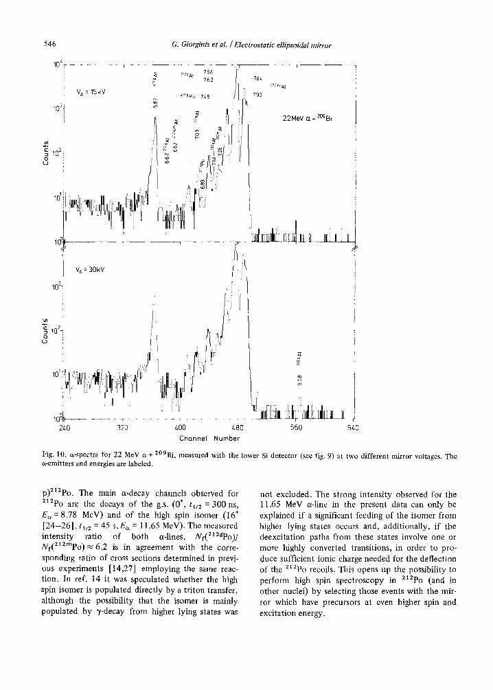
The experimental set-up is already described in sect. 5.2. Fig. 10 shows two a-spectra measured with the lower Si detector (refer to fig. 9) at V A = 15 and 30 kV, respectively. All stronger a-lines observed can be attributed to known [22,23] a-decays of states in 212g'mAt, 211gAt, and 211gPo. At VA = 30 kV, most interestingly, a weak line at Ea = 9.08 MeV occurs which is assigned to the g.s. (9]2-) a-decay of the com- pound nucleus 213At formed in an a-capture reaction. As evident from the spectrum shown for VA = 15 kV this a-line does not show up at the lower VA values. This behavior can be explained by the fact that because of the short halflife ( tu2 = 110 ns) of the a-emitting state both high mirror voltages and high enough charge state values are needed to deflect a suf- ficient number of 2~aAt recoils onto the detector. At V A = 30 kV a measured intensity ratio for a-decay of 21agAt to a-decay of 212mAt of (1.5 -+ 0.2) × 10 -3 is
obtained. Taking into account that the halflife of the g.s. of 21SAt is about three times shorter compared to the average time-of-flight of the 2~3At recoils and assuming the same efficiency for 212mAt and 21agAt (see section 5.2), a total cross section for a-capture of ~<1 mb is estimated. The possibility to observe the weak a-capture channel in the presence of the much stronger evaporation channels demonstrates the feasi- bility to perform a background-free in-beam spectro- scopy with the mirror.
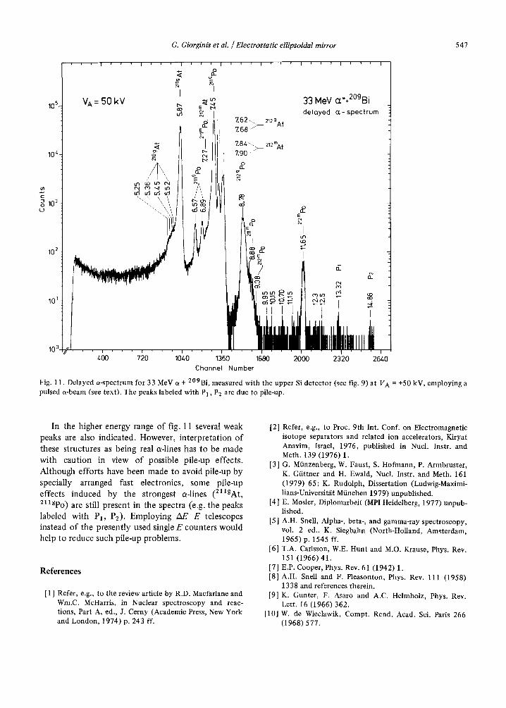
6.2. 33 M e V a + Z°9Bi
In this case a pulsed a-beam [width (fwhm) of the beam-pulse = 1.5 ns, pulse repetition time = 800 ns] at a beam energy of 33 MeV has been em- ployed to bombard a 300 tag/cm 2 thick 2°9Bi target. Only the upper detector shown in fig. 9 has been used. Two-dimensional events, i.e. a-energy vs. the time with respect to the beam pulse, have been accumulated on magnetic tape. Fig. 11 shows a delayed a-single spectrum (~70~590 ns after the beam pulse) obtained at V A = 50 kV.
Below a-energies of ~8 MeV most of the a-lines showing up have already been observed in the 22 MeV data (see fig. 10). As expected [23], the (a, 2n) channel populating 21~At now dominates over the (a, n) channel. In addition, the (a, 3n) channel lead- ing to 2~°At is open.
The higher energy range of the a-spectrum shown in fig. 11 is dominated by the reaction 2°9Bi(a,
546 G. Giorginis et al. /Electrostatic ellipsoidal mirror
103!
A
g 102! o I
4
J
IO t
lo3! !
V A = 15kV
"tn
i05 0 (-3
768 2'2gA t
762
2UgPo 7 4 5
V A = 30kV
78~ 212 m At
7 9 0
22MeV (z + 2°9Bi
h,,,4,tn r l,t
101 "j7 1
lOY~ ...... r - - " 2LO 320 400 480 560
Channel Number
640
Fig. 10. c~-spectra for 22 MeV a + 2°9Bi, measured with the lower Si detector (see fig. 9) at two different mirror voltages. The a-emitters and energies are labeled.
p)212po. The main a-decay channels observed for 2X2po are the decays of the g.s. (0 ÷, tu2 = 300 ns, E~ = 8.78 MeV) and of the high spin isomer (16 ÷ [24 -26 ] , tu~ = 45 s, Ec~ = 11.65 MeV). The measured intensity ratio of both a-lines, Nf(212gpo)/ Nf(2~2mpo) 2 6 . 2 is in agreement with the corre- sponding ratio of cross sections determined in previ- ous experiments [14,27] employing the same reac- tion. In ref. 14 it was speculated whether the high spin isomer is populated directly by a triton transfer, although the possibility that the isomer is mainly populated by 7-decay from higher lying states was
not excluded. The strong intensity observed for the 11.65 MeV a-line in the present data can only be explained if a significant feeding of the isomer from higher lying states occurs and, additionally, if the deexcitation paths from these states involve one or more highly converted transitions, in order to pro- duce sufficient ionic charge needed for the deflection of the 21~Po recoils. This opens up the possibility to perform high spin spectroscopy in 212Po (and in other nuclei) by selecting those events with the mir- ror which have precursors at even higher spin and excitation energy.
G. Giorginis et al. / Electrostatic ellipsoidal mirror 547
105,-
10 ~
t l l
~ i0 ~ c_ )
VA= 50kV
' I ' ' I
I
o
i v I i , i I ~ ' I ' i ~ 1 I , , I
I
~ 33 NoV ct"÷2°gBi E t ' ~
l de loyed o r - spec t rum
~. Ill i - - 7 " 9 0 ~ • I o
o E I
,~ o 102 ~ a . I
• t:5 d ~ c4¢q I0~ I , ~ ~ ~ ~ l . 4
I i I,IL It , "-
100 ~ ~ 400 720 1040 1360 1680 2000 2320 2640
ChQnnel Number
Fig. 11. Delayed a-spectrum for 33 MeV c~ + 2°9Bi, measured with the upper Si detector (see fig. 9) at V A = +50 kV, employing a pulsed a-beam (see text). The peaks labeled with PI, P2 are due to pile-up.
In the higher energy range of fig. 11 several weak peaks are also indicated. However, in te rpre ta t ion of these structures as being real a-lines has to be made with caut ion in view of possible pile-up effects. Al though efforts have been made to avoid pile-up by specially arranged fast electronics, some pile-up effects induced by the strongest a-lines (211gAt, 211gPo) are still present in the spectra (e.g. the peaks labeled with P1, P2). Employing A E - E telescopes instead of the present ly used single E counters would help to reduce such pile-up problems.
R e f e r e n c e s
[ 1 ] Refer, e.g., to the review article by R.D. Macfarlane and Wm.C. McHarris, in Nuclear spectroscopy and reac- tions, Part A, ed., J. Cerny (Academic Press, New York and London, 1974) p. 243 ff.
[2] Refer, e.g., to Proc. 9th Int. Conf. on Electromagnetic isotope separators and related ion accelerators, Kiryat Anavim, Israel, 1976, published in Nucl. Instr. and Meth. 139 (1976) 1.
[3] G. MiJnzenberg, W. Faust, S. Hofmann, P. Armbruster, K. Giittner and H. Ewald, Nucl. Instr. and Meth. 161 (1979) 65; K. Rudolph, Dissertation (Ludwig-Maximi- lians-Universitgt Miinchen 1979) unpublished.
[4] E. Mosler, Diplomarbeit (MPI Heidelberg, 1977) unpub- lished.
[5 ] A.H. Snell, Alpha-, beta-, and gamma-ray spectroscopy, vol. 2 ed., K. Siegbahn (North-Holland, Amsterdam, 1965) p. 1545 ff.
[6] T.A. Carlsson, W.E. Hunt and M.O. Krause, Phys. Rev. 151 (1966) 41.
[7] E.P. Cooper, Phys. Rev. 61 (1942) 1. [8] A.H. Snell and F. Pleasonton, Phys. Rev. 111 (1958)
1338 and references therein. [9] K. Gunter, F. Asaro and A.C. Helmholz, Phys. Rev.
Lett. 16 (1966) 362. [10] W. de Wieclawik, Compt. Rend. Acad. Sci. Paris 266
(1968) 577.
548 G. Giorginis et al. / Electrostatic ellipsoidal mirror
[ 11 ] V. Metag, D. Habs, H.J. Specht, G. Ulfert and C. Kozhu- harov, Hyperfine Interactions 1 (1976) 405.
[12] D. Habs, V. Metag, H.J. Specht and G. Ulfert, Phys. Rev. Lett. 38 (1977) 387.
[13] V. Metag, R. Repnow, P. von Brentano and J.D. Fox, 2rid IAEA Symp. on Physics and chemistry of fission (Vienna, Austria, 1969), IAEA-SM-122/29, p. 449 ft.
[14] E.T. Chulick and J.B. Natowitz, Nucl. Phys. A173 (1971)487.
[15] R. Skoog, Comp. Phys. Comm. 7 (1974) 392. [16] H.E. SchiCtt, Rad. Effects 6 (1970) 107. [ 17 ] E. Liukkonen, V. Metag and G. Stetten, Nucl. Instr. and
Meth. 125 (1975) 113. [18] W.R. Smythe, Static and dynamic electricity (McGraw-
Hill, New York, 1968). [19] L.S. Goddard, Proc. Phys. Soc. 56 (1944) 372. [20] E.g., subroutine HPCG, IBM Science Library.
[21 ] J. Meyer, J.M. Paulus and J.Ch. Abbe, Radiochim. Acta. 17 (1972) 76.
[22] Tables of isotopes, 7th ed., eds., C.M. Lederer and V.S. Shirley (Wiley, New York, 1978).
[23] A.R. Barnett and J.S. Lilley, Phys. Rev. C9 (1974) 2010.
[24] N. Auerbach and I. Talmi, Phys. Lett. 10 (1964) 297. [25] P.A. Baisden, R.E. Leber, M. Nurmia, J.M. Nitschke,
M. Michel and A. Ghiorso, Phys. Rev. Lett. 41 (1978) 738.
[26] P. Lemmertz, L.J. Alquist, R. Fass, H. Wollnik, D. Hir- des, H. Jungclas, R. Brandt, D. Schardt and J. Zylicz, Z. Physik A298 (1980) 311.
[27] J.P. Didelez, R.M. Lieder, H. Beuscher, D.R. Haenni, H. Machner, M. Miiller-Veggian and C. Mayer-B6ricke, Nucl. Phys. A341 (1980) 421.