Proceedings of the Ninth Canadian Soil Mechanics Conference
120
Publisher’s version / Version de l'éditeur: Vous avez des questions? Nous pouvons vous aider. Pour communiquer directement avec un auteur, consultez la première page de la revue dans laquelle son article a été publié afin de trouver ses coordonnées. Si vous n’arrivez pas à les repérer, communiquez avec nous à [email protected]. Questions? Contact the NRC Publications Archive team at [email protected]. If you wish to email the authors directly, please see the first page of the publication for their contact information. https://publications-cnrc.canada.ca/fra/droits L’accès à ce site Web et l’utilisation de son contenu sont assujettis aux conditions présentées dans le site LISEZ CES CONDITIONS ATTENTIVEMENT AVANT D’UTILISER CE SITE WEB. Technical Memorandum (National Research Council of Canada. Associate Committee on Soil and Snow Mechanics), 1955-12-15 READ THESE TERMS AND CONDITIONS CAREFULLY BEFORE USING THIS WEBSITE. https://nrc-publications.canada.ca/eng/copyright NRC Publications Archive Record / Notice des Archives des publications du CNRC : https://nrc-publications.canada.ca/eng/view/object/?id=3f5d3f14-363f-4bca-b1b1-0fd747199ee0 https://publications-cnrc.canada.ca/fra/voir/objet/?id=3f5d3f14-363f-4bca-b1b1-0fd747199ee0 NRC Publications Archive Archives des publications du CNRC For the publisher’s version, please access the DOI link below./ Pour consulter la version de l’éditeur, utilisez le lien DOI ci-dessous. https://doi.org/10.4224/40001155 Access and use of this website and the material on it are subject to the Terms and Conditions set forth at Proceedings of the Ninth Canadian Soil Mechanics Conference
-
Upload
khangminh22 -
Category
Documents
-
view
0 -
download
0
Transcript of Proceedings of the Ninth Canadian Soil Mechanics Conference
Publisher’s version / Version de l'éditeur:
Vous avez des questions? Nous pouvons vous aider. Pour communiquer directement avec un auteur, consultez la
première page de la revue dans laquelle son article a été publié afin de trouver ses coordonnées. Si vous n’arrivez pas à les repérer, communiquez avec nous à [email protected].
Questions? Contact the NRC Publications Archive team at
[email protected]. If you wish to email the authors directly, please see the first page of the publication for their contact information.
https://publications-cnrc.canada.ca/fra/droits
L’accès à ce site Web et l’utilisation de son contenu sont assujettis aux conditions présentées dans le site
LISEZ CES CONDITIONS ATTENTIVEMENT AVANT D’UTILISER CE SITE WEB.
Technical Memorandum (National Research Council of Canada. Associate Committee on Soil and Snow Mechanics), 1955-12-15
READ THESE TERMS AND CONDITIONS CAREFULLY BEFORE USING THIS WEBSITE.
https://nrc-publications.canada.ca/eng/copyright
NRC Publications Archive Record / Notice des Archives des publications du CNRC :https://nrc-publications.canada.ca/eng/view/object/?id=3f5d3f14-363f-4bca-b1b1-0fd747199ee0
https://publications-cnrc.canada.ca/fra/voir/objet/?id=3f5d3f14-363f-4bca-b1b1-0fd747199ee0
NRC Publications ArchiveArchives des publications du CNRC
For the publisher’s version, please access the DOI link below./ Pour consulter la version de l’éditeur, utilisez le lien DOI ci-dessous.
https://doi.org/10.4224/40001155
Access and use of this website and the material on it are subject to the Terms and Conditions set forth at
Proceedings of the Ninth Canadian Soil Mechanics Conference
The Associate Committee on Soil and Snow Mechanics isone of about thirty special committees which assist theNational Research Council in its work. Formed in 1945to deal with an urgent wartime problem involving soil andsnow, the Comnittee is now performing. its intended task ofco-ordinating Canadian research studies concerned with thephysical and mechanical properties of the terrain of theDominion. It does this through subcommittees on Snow andIce, Soil Mechanics, Muskeg, and Permafrost. The Committee, which consists of about fifteen Canadians appointed as individuals and not as representatives, eachfor a 3-year term, has funds available to it for makingresearch grants for work in its fields of interest. Inquiries will be welcomed and should be addressed to: TheSecretary, Associate Committee on Soil and Snow Mechanics,c/o The Division of Building Research, National ResearchCouncil, ottawa, Canada.
This publication is one of· a series being produced by the AssociateCommittee on Soil and Snow Mechanics of the National Research Council. It maytherefore be reproduced, without amendment, provided that the Division is toldin advance and that full and due acknowledgement of this publication is alwaysmade. No abridgment of this report may be published without the written authority of the Secretary of the A.C.S.S.M. Extracts may be published for purposesof review only.
NATIONAL RESEARCH COUNCIL
CANADA
ASSOCIATE COMIvIITTEE ON SOIL AND SNOW MECHANICS
PROCEEDINGS
OF THE
NINTH CANADIAN SOIL MECHANICS CONFERENCE- -
DECEMBER 15 AND 16, 1955
Technical Memorandum No.41
ottawaOctober 1956
( i )
FORWaRD
This is a record of the Ninth Canadian Soil MechanicsConference held at the University of British c ッ ャ オ ュ 「 ゥ 。 セ Vancouver,December 15th and 16th, 1955. The conference was sponsored bythe Associate Committee on Soil and Snow Mechanics of theNational Research Council. It was arranged by a local comnlitteewith the co-operation of the University of British Columbia e
Meetings on both days were conducted in the Engineering Buildingof the University of British Columbia. The emphasis of theconference was placed on the inter-relationship of pedology,geology, and engineering in dealing with the complex soils ofBritish Columbia.
On the evening of December 15th, following a receptionand dinner at the u ョ ゥ カ ・ イ ウ ゥ エ セ of British Columbia Faculty Club,the conference joined with the Vancouver Branch of the EngineeringInstitute of Canada and the British Columbia Professional Engineersto hear papers by F. L. Peckover and D. J. Bazett on soil mechanicsaspects of the st. Lawrence Seaway Development. On Saturday,December 17th, there was a field trip to the site of the ClevelandDam in the Capilano Canyon.
The Associate Committee wishes to acknowledge theassistance in the preparations of the conference made by thelocal committee under the chairmanship of Mr. Cu Fo Ripley. Theefforts of Dr. N.A.M.MacKenzie, President of the University ofBritish Columbia, Dean H.C. Gunning, Faculty of Applied Science,and Dean Bo Eagles, Faculty of Agriculture, are greatlyappreciated and contributed to the success of the conferenceoThe field trip was arranged through the co-operation of Mro T.V.Berry, Commissioner of the Greater Vancouver Water District oFinally, the stenographic assistance in the preparation of thisrecord given by Mrs. A. Peebles and Mrs. R. Taylor is appreciated o
(ii)
TABLE OF CONTENTS
Session of December 15
Section 1
Section 2
Section 3
Section 4
Section 5
Section 6
Secti0!l 7
Introductory イ ・ ュ セ ォ ウ by h セ c ッ g オ ョ ョ ゥ ョ ァ
and R.F.Legget 1
Climate and physiography of BritishColumbia by W.H.Mathews 2
Soils of British Columbia by Lo Farstad 10
Applica.tion of geology to soil problemsin the lower mainland of British Columbiaby J.E.Armstrong 11
Agricultural soils of the Fraser Valleyby E. Hughes ' 20
Foundati09 conditions and problems Vancouver, B.C. by PoM.Cook and Lo Brandon 26
Joint evening meeting with EoI.Co and BoC.Association of Professional e ョ ァ ゥ ョ ・ ・ セ ウ -Soil Mechanics aspects of the StoLawrenceSeaway by F.L.Peckover and DoJ.Bazett 31
Session of December 16
Section 8.
Section 9
Section 10
Section 11
Problems of foundation settlements inBritish Columbia by E.JoKlohn 48
The Park Bridge slide by RoCoThurber 66
Measurements of lateral movements in soilsby W.LoShannon 75
Consolidation characteristics of organicsoils by P.M.Cook 82
Section 12
Section 13
Section 14
Section 15
Section 16
Appendix A
Appendix B
(iii)
Research at Garibaldi Lake, BoCo byW.H.Mathews
Report of the National Soil SurveyCommittee, Saskatoon, Saskatchewanby Lo Farstad
Soils in relation to forestry byFoGoHaddock
Reports of research work at the Divisionof Building Research, National ResearchCouncil
General business
Trial of one-point liquid limit methodby WoJ.Eden
List of those present at the Ninth AnnualCanadian Soil Mechanics Conference
88
90
93
98
102
SESSION OF DECEMBER 1$, 1955
SECTION I
Introductory Remarks
by
Dean H.C. Gunning and R.F. Legget
Dean H. C. Gunning welcomed the delegates on behalf ofthe University of British Columbia and introduced Mr. R.Peterson who acted as Chairman for the morning session. Mr.Peterson then called on Mr. R. F. Legget, the Chairman of theAssociate Committee on Soil and Snow Mechanics.
Mr. Legget outlined the history of the past eightconferences and the work of the Associate Committee on Soiland Snow Mechanics. The Ninth Conference, Mr. Legget stated,would be devoted to the problems arising from the use of soilsin British Columbia. Mr. Legget stressed that the word soilwas being used in its broadest sense at the Conference andembraced three fields, that of pedology, geology and engineering.He hoped the members of each discipline would have much to learnfrom the others represented.
- 2 -
Section 2
Climate and Physiography of British Columbia
by
Dro WoH. Mathews
The next speaker, Mr. F.rstad, and I, have been asked tointroduce to you the soils of British Columbia and something ofthe conditions under which they have developed o My assignmentrelates to the environments and Mr. Farstad's to the soils themselveso I will feel my duty accomplished if I can but leavewith you some idea of the enormous range of soil-forming conditions that exist within this Province, and of the problemsaccompanying this diversity.
Of the five soil-forming factors listed by Jenny, threehave played a dominant role in the evolution of the soils ofthe Province - topography, climate, and parent material; hencethe title of this paper. Of these factors, topography plays adouble part inasmuch as it has, itself, exerted 。 セ 。 イ ォ ・ 、
influence on local climate.
The major topographic units of the Province consist ofnorthwesterly trending mountain ranges and intervening lowland andplateau belts o These have been defined recently by Bostock (1948),and by Brink and Farstad (1947)p from west to east as follows:
West
East
Insular mountains (of Vancouver and QueenCnarlotte Islands)
Coastal Trench (including Georgia and HecateStraits)
Coast and Cascade Mountains
Interior Plateau, Skeena and Hazelton Mountainsand Stikine Plateau
Columbia, Omineca, and Cassiar Mountains
Rocky Moununn Trench
Rocky Mountains
Great Plains
- 3 -
Throughout the Province, except in its northeasterncorner, the local relief is greato Vanderhoof in the InteriorP'Lat e au , has been reputed to be the only town in B<, Co, in whichit is not possible to see a mountain and this reputation, Isuspect y originates from the ヲ 。 セ エ that the town is nestled ina valley whose walls restrict the distant views o Extremerelief within limited areas is not uncommon9 local reliefof 5 y ooo feet is general o In the mountain belts and inseveral localities, differences in elevation of as much as10,000 feet occur within a horizontal distance of 15 miles o
Rough terrain is widespread o Mulholland (1937)9 has estimatedthat 66 per cent of the area of the Province is unsuited foreither forestry or agriculture; most of this is mountainousterrain, much of it near or above timberlineo About 70 per centof British Columbia lies more than 39000 feet 。 「 ッ カ セ sea level,and this area 1s mountainous terraino A high proportion of thesteeply-sloping ground consists of bare rock or rock thinlycovered by slide debris or by talus o
British Columbia" lying in the belt of prevailingwesterly winds 9 is swept by maritime air masses moving in fromthe Pacific Oceano These discharge much of their moisture onthe windward r-ange s , and most of the pr-ec Lp Lt a t Loe- on anyonerange falls near its western limite Thus v in the southern partof the Province the highest precipitation is found on the westernside of Vancouver Island" where at Henderson Lakey a 13-yearaverage of 263 inches per year has been recorded o Only 35 milesaway on the eastern side. of Vancouver Island" as little as 30inches a year falls at Parksville o Mean annual rainfall averagesabout 35 inches in most of the southern Coastal Trencho In theCoast Mountains precipitation is at a maximum of 100 to 150inches on its western slope£) and declines gradually to lows ofabout 8 to 15 inches at its eastern base o Farther east" theextremes of precipitation are much セウウ ーイッョッオョ」・、セ but lows offrom 8 to 18 inches per year are experienced in many of thevalleysv and highs of more than 50 inches experienced in themountains o From the scanty data for the northern interior of theProvince 9 rainfall ranges generally between 12 to 24 incheso
Marked local precipitation gradients occur of which oneof the most striking 1s in the vicinity of Vancouver o Vancouverairport receives roughly 40 inches Of rain a ケ・。イセ the Cityitself£) 57 inches; west Vancouver y 64 inches 9 Capilano Intake,126 inches f and Seymour Falls y only 12 miles northeast of theCity" and within 20 miles of the airport" 147 inches o Verticalgradients may also be notable o Britannia Beachy at sea levelreceives 76 inches a year whereas Tunnel Camp, 2,9200 feet higherand 2i miles to the east, receives 96 incheso Similarly" the
- 4 -
town of Hedley in the interior receives an average of 1105inches per year, whereas the Nickel Plate Mine, 4,000 feethigher and only 2i miles to the northeast, receives 23 08 incheso
Throughout the coastal area and in the mountains of thewestern and southern part of the Province, the greatest precipitation occurs in the months of October to Januaryo On theother hand, in the Interior p ャ 。 エ ・ 。 オ セ the southern Rocky Mountaintrench, and in the Plains area, the wettest month occurs in thesummer and is generally June. High winter precipitation in themountains leads to heavy snowfall, particularly at higher levels.In the mountains of Vancouver Island and in the Coast Mountains,the snow pack commonly attains depths of more than 10 feet byMarch (BoCo Snow Survey Bulletins) and in some years in themountains overlooking Vancouver, 20-foot snow poles become completely buried o At the higher, and cooler, levels within thesesame mountains, snow may linger throughout the summer, and overa period of years contribute to permanent snowfields and glaciers.The firn line, エ ィ セ エ critical level above which these permanentsnowfields persist, varies in altitude in the north from about3,500 feet near Juneau, Alaska to 6,500 feet on the east edge ofthe Coast Mountains and lies at about 8 9000 feet in the Rockies o
Near latitude 50 it rises easterly from 5,000 feet on VancouverIsland to 9 9 500 feet at the east edge of the Coast Mountains andlies between 8,000 and 10,000 feet in the Selkirk and RockyMountains. The easterly rise of firn line at both latitudes canbe correlated with an easterly decline in snowfall; the higherelevations in the south are determined by higher temperatures o
Temperatures are closely related to altitude, latitude,and distance from the Coast. Mean annual temperature is chieflydetermined by the first two. It decreases upward at a rateof about 3°Fo per 1000 feet. The mean annual temperaturessuch as would occur at sea level; ioeo after the effect ofaltitude is eliminated, are close to 50 oF
o across the southernpart of the Province, and close to 40 oF
o in the northwesternand 35Opo in the northeastern cornerso The daily and seasonalranges show the marked influence of nearby bodies of water andon the open coast the variations are particularly slight, Meanannual range i that is the difference between the monthly means ofthe warmest and coldest months, is less than 20 oFo on the westcoast, about 3SoFo on the east side of the Coast Mountains, 40°F.to 50Opo through much of the interior and more than SOoFe in thenortheastern part of the Provinceo The frost-free period iscorrespondingly shorter away from the coastal area o Freezingcycles, here regarded as a fall in air temperature below 28°F oand a rise above 33°F. as recorded in daily maxima and minima,occur less than 30 times per year throughout much of the coast,
- 5 -
from 50 to 80 times per year in many of the interior valleysand exceed 100 per year in some of the mountain valleys.
Permafrost, a product of low prevailing temperaturesand light snowfall is probably rare in the Province g being forthe most part restricted to high levels and sheltered locationsin the dry interior. One notable exception to this generalrule is the permafrost exposed by the recent recession of HelmGlacier (Mathews, 1955) in Garibaldi Park, 45 miles north ofVancouver, in a region of high snowfall.
A striking illustration of the extreme diversity ofclimatic conditions existing within the Province is provided byChapman (1952)9 who finds places in Europe with comparableclimates to those of stations in British Columbia, consideringtemperature, precipitation, and their seasonal distribution,these are:
Istanbul, the analogue of Victoria;Moscow, the analogue of Prince George$ andBergen (Norway), the analogue of Prince Rupert.
Thus, the climatic conditions of the Continent of Europe are heretelescoped into an area one-tenth its size.
Geology is no less varied in the Province than is climate,and the typical geologic map, regional or local, is a crazy-quiltof patterns. Rocks of all ages from Proterozoic to recent arepresent, and of all types, plutonic, volcanic 9 sedimentary, andmetamorphic. The distribution is so complex that only a fewgeneralizations are possible, namely that granitic and volcanicrocks predominate in the western and southern part of the Province 9
and sedimentary rocks prevail in the Rocky Mountains and in thenortheastern part of the Province.
The most important single geological event in so far asthe soils of the Province are concerned, has been the Pleistoceneglaciation which affected the entire area 9 save perhaps a few ofthe mountain tops. A "provincial" Cordilleran ice sheet has beenresponsible tor most of the glaciation, the Keewatin ice sheet,moving west from the r.anadian Shield, reached only to the easternedge of the Rocky Mountains. Material picked up by one or otherice sheet has been comminuted, mixed, and re-sorted by variousprocesses associated with glaciation to give rise to a variety ofunconsolidated deposits. Some of these, particularly at higherelevations, reflect the composition of the underlying or nearbybed-rock, others consist of material brought from a large areaand thus include many different rock types. The granitic rocksand the metamorphosed volcanics, being blocky, jointed, andresistant to glacial abrasion, tend to be concentrated in the
- 6 -
coarser fractions of the resulting deposits; the sedimentarysource rocks contribute largely to the finer fractionso Sourcerock and distance of transport have a marked bearing on themineral composition and particle-size distribution of glacialtill but conditions of deposition have an even more markedbearing on composition and size distribution of the otherglacial deposits. Fluvioglacial deposits contain the coarserand more resistant material carried by meltwater streams.Glaciolacustrine beds, laid down in quiet water 9 contain thefiner fractions. Glaciomarine deposits may contain all sizesbut have a structure, and fossil cDntent that distinguish themfrom till on the one hand and glaciolacustrine beds on theother. Fortunately for the mapping of the different types ofglacial deposits, they are concentrated in particular environments and associated with more or less characteristic landforms. Thus, air photographs, aided by ground control, makeit possible to ascertain the character and extent of at leastthe near surface deposits. A knowledge of glacial processesmakes it possible, with a somewhat lower degree of assurance,to extrapolate information on buried deposits from limitedsurface exposures and drill logs.
Notwithstanding very large amounts of information ontopography, climate, and geology already collected, the variationswithin the Province in these factors are so great that muchadditional information is vital to a full understanding ofconditions.
Topographic maps, on a scale of 4 miles to the inch andwith 500-foot contour intervals are now available for most of theProvince, but detailed maps, on a scale of Q Z U P セ P P P and withcontour intervals ranging from 25 to 100 feet, are available foronly about 9 per cent of the area. For many problems even thesedetailed maps are inadequate, and use must be made of aerial photographs of which, fortunately, there is almost 」 ッ ュ ー セ エ ・ coverage ofthe Province on a scale of about 2 inches to the mile.
Climatic data, though adequate to provide broad generalizations, fail singularly in all but the populated southwesterncorner .of British Columbia to provide a picture of local variations which so often have significant magnitudeo This problemstems, in part, from the fact that until recently, meteDrologicalstations have been established very largely for the benefit offarmers and mariners who operate at low altitudes. The effectson climate of altitude, slope, and exposure are still to beevaluated. The recently published Climatological Atlas of Canada(1953) which has been based on data from these low-level stations,can be particularly misleading in B.C· if the ・ ク セ ウ エ 。 ョ 」 ・ of microclimates is not fUlly appreciated. Further problems arise from
- 7 -
the practice of equating 10 inches of snowfall, regardless ofits density, to 1 inch of precipitation as rain o For thisreason, it is likely that in coastal areas where freshly fallensnow has a relatIvely high density, winter precipitation isunderestimated. Increased use of data from snow surveys, fromthe elevation of firn line, and from stream flow measurementsis desirable.
Geologic maps on a scale of 4 miles to the inch arenow available for somewhat less than 50 per cent of the Province,and detailed maps are available for not more than a few per centof the area. Few of these maps, reconnaissance or detailed, showthe distribution of the different unconsolidated deposits, whichare, as a rule, grouped together as "glacial drift and alluvium".Of late" however, some geologists are undertaking the subdivisionof glacial deposits in the course of mapping. Nevertheless, formost areas the only information currently available on theunconsolidated deposits comes from the maps and reports of theDominion-Provincial Soil Survey.
The limitations of existing data are pointed out toemphasize the difficulties of applying present information tospecific localities rather than to embarraSR the responsibleorganizations. These organizations have, indeed, performed acreditable job with limited resources and in a complex area inaccumulating and disseminating information on our environmentalconditions o Nevertheless, when a new project is undertaken,whether this be a power line or a highway through the mountains,the establishment of a new pulp mill or a townsite, the construction of a dam or the development of a new agricultural area, muchadditional research is imryerative in such items as snow depths,distribution, bearing strength and permeabilities of variousglacial deposits, landslide and snowslide hazards, and frostfree periods. Past experience elsewhere will continue to be avaluable guide o Topographic and geologic maps and air photographs will still be useful tools, but new studies in the fieldremain essential o
REFERENCES
Atlas of British Columbia Resources: Map 3 (Geology);Map 4 (Glacial geology); Map 7 (Precipitation);Map 9 (Temperature). B.C.Natural Resources Conference(In Pre ss ) •
Bostock, HoS· (1948) Physiography of the Canadian Cordillerawith Special Reference to the Area North of the FiftyFifth Parallel. Geological Survey of Canada, Memoir247.
- 8 -
Brink, V.C. and L.Farstad (1949) The Physiography of theAgricultural Areas of British Columbia. ScientificAgriculture, Vol.29, p.273-30l.
British Columbia Snow Survey Bulletins. B.C.Department of Landsand Forests.
Chapman, J.D. (1952) The Climate of British Columbia. FifthB.C.Natural Resources Conference, p. 8-54.
Climate of British Columbia, Tables of Temperature, Precipitation,and Sunshine -- Report for 1954. B.e.Department ofAgriculture.
Mathews, W.R. (1955) Permafrost and its Occurrence in theSouthern Coast Mountains of B.C. Canadian AlpineJournal, Vol. 137, p.94-98.
Mulholland, F.D. (1937) The Forest Resources of BritishColumbia. King's Printer, Victoria, B.Co
Thomas, MoKo (1953) Climatological Atlas of Canada.Meteorological Division, Department of Transport andDivision of Building Research, National ResearchCouncil. N.R.C. No. 3151.
DISCUSSION
In reply to a question, Dr. Mathews stated that mostB.G.glaciers are found in the coastal belt, the Rockies andSelkirks and in the northern interior. These areas could bereferred to as high precipitation or high altitude areas.
i セ N Crawford asked if, in view of the large number offreeze-thaw cycles in the Province, B.C. usually had a severespring break-up of roads? Mr. Crawford referred to studiesrelating climate to frost action at Calgary where severe break-up occurred with only about 15 freeze-thaw cycles. Dr. Mathewsdefined a freeze-thaw cycle as daily changes based on temperature;a change which would probably not affect roads. On this basisCalgary would have about 90 freeze-thaw cycles each winter.
Mr. Chapman asked if Dr. Mathews would care to venturean opinion as to whether the climatp. was warming up or coolingdown. Dr. Mathews replied that the long-term average temperaturessince 1910 have shown an increase, but since 1930$ if there is anytrend, there has been a slight drop in temperatures. Practicallyall mountain glaciers in B.C. have shrunk.
- 9 -
Dr. Mullineaux commented that measurements on MountRainier and the Olympic Mountains in Washington have indicatedthat glaciers are advancing in recent years. This is contraryto the trend being experienced in Europe. Dr. Mathews reportedthat B.C. glaciers under observation have shown a definiteslacking in the rate of retreat but no advances have beenobserved.
In reply to a question from Mr. Legget, Dr. Mathewsstated that he knew of no large areas of residual soils. Therecould well be small deposits particularly in the higher areas.Dean Gunning reported some instances of soil showing prePleistocene weathering which was now buried by fresher deposits.
In reply to a question from Dr. Wiloon, Dr. Mathewsstated that a large post-glacial lake existed in the Peace Rivercountry. Other lakes or groups of lakes occurred in the PrinceGeorge and Fort, St. James area and in the Okanagan and Kamloopsdistricts. There are evidences of many small lakes in localdrainage areas.
Professor Baracos asked if the residual soils showhigh pre-consolidation loads. Dr. Mathews replied that he knewof no quantitive measures because, until the present, noequipment was available by which very large pre-consolidationpressures could be determined. He added further that at thesite of the Cleveland Dam, there was an estimated 4000 to 5000foot thickness of ice.
Mr. Crawford asked if there was any information availableon the ground temperatures beneath a glacier. Dr. Mathewsknew of no observations in BoC. He thought the temperatureof the ground should be near the pressure melting point of ice.For this reason g the occurrence of permafrost at the Helm Glacierwas very puzzling. セ ィ ・ depth of this occurrence was notdetermined. It could have been due to pre-glacial climate ormight have been due to the presence of the glacier.
セ 10 -
Section 3
Soils of British Columbia
by
Lo Farstad
Manuscript of this paper was not availableat the time of publication.
DISCUSSION
In opening the discussion, Mro Farstad mentioned thevariation in clay content in the soil horizons o For sandy soils,the clay content of the B horizon is higher than the A and theCo For loam soils, the clay content is again higher in the Bhorizon than the A or C with the clay content of C horizonapproaching that of the Be In clay soils, the clay contentusually increased with depth through the A, Band C horizons o
Mro Peterson questioned the author about the use ofAtterberg limits in soil survey worko Mro Farstad did not knowhow extensively they were used but he had used them on soilsurvey work in central BoCo Dr o Rowles added that Atterberglimits were not used on a routine 「 。 ウ セ but only for specialwork Qr soils which presented peculiar problemso
Mr o Sinclair asked about the use of Atterberg limitsin SOlL survey work; ゥ ヲ セ for instance, Atterberg limits areconducted 9 will the information be included on survey maps andcan the Atterberg limits be related to workability of the soil?Mro Farstad was aware of no definite relationship betweenAtterberg limits and workabilityo Generally soils 」 ッ ュ ー セ 」 エ
easily near the plastic limit and work most easily near theplastic limite
Mr o Marantz asked if it was necessary to use sulphateresisting concrete in BoCo Mr o Ripley replied that soil withウ セ ャ ー ィ 。 エ ・ ウ was found in some of the interior valleys and in theFort StoJohn area o
Mr o Bozozuk, referring to the figures quoted for extractionof moisture by plant root systems, asked if this was also truefor trees o Mro Farstad replied that the figures quoted were forgrasseso Dro Haddock aaded that if trees had access to groundwater j they would obtain the bulk of their water from groundwater supplyo
Following セ セ ッ Farstad's paper the conference adjournedfor luncheon .at which Dr , MacKenzie, President of the Universityof British Columbia, addressed the conferenceo

- 11 -
Section 4
Application of Geology to SoilProblems in the Lower Mainland
of British Columbia
by
J c Eo Ar-mst.r-ong«
INTRODUCTION
The geological study and mapping of the Lower Mainlandof British Columbia was undertaken because such a study cangreatly aid in the future development of the area o The properrealization of the influence of geological conditions onindustrial and agricultural development is essential inintelligent planning and may result in saving considerable sumsof moneyo Application of geological information in the planningstage may indeed prevent floods, slides and other disasterso Alltoo often in the past such information has been ignored o
From 1949 up to, and including, the summer of 1955 thewriter and his co-workers have been engaged in the geologicalinvestigation of the Lower Mainland of British Columbia and theadjoining Coast Mountmns for the Geological Survey of CanadaoThe study includes both bed-rock geology and the geology of theunconsolidated sediments lying above bed-rock, that ゥ ウ セ thesoil in the engineer1s terminologyo Geological maps and reportsare in the process of compilation and will be published by theGeological Survey of Canada, Department of Mines and TechnicalSurveys y Ottawao
PHYSICAL FEATURES
The Lower Mainland is the lowland area bordering theFraser River and extending from the Gulf of Georgia 80 mileseastward o It is bounded on the north by the Coast Mountains,on the east by the Cascade Mountmns and on the south by theInternational Boundaryo The Coast Mountains rise abruptlyseveral thousand feet from deep U-shaped valleys9 which areoccupied by rivers, lakes, and arms of the sea o The CascadeMountains do not concern us in this discussion o
The dominant topographic feature of the Lower Mainlandis the Fraser River which occupies a post-glacial valley up to
* Published by permission of the Acting Deputy Minister g
Depto of Mines and Technical Surveys 0
セ 12 -
3 miles wide and 50 feet deep in a much larger lowland o Itterminates in a growing delta 19 miles long and 15 miles wideoNorth and south of the Fraser River and comprising most of theLower Mainland are wide, relatively flat-topped uplandsseparated by wide flat-bottomed valleyse Most of these uplandsconsist largely of unconsolidated materials and do not exceed500 feet in elevation, although three bed-rock uplands exceed1000 feeto The uplands range in size from 1 to 150 square miles o
GENERAL GEOLOGY
The geological history and stratigraphy of the LowerMainland of British Columbia are synopsized in Table 10
Before discussing Table 1, the writer believes a fewgeneral remarks on the terminology and types of deposits are inordera
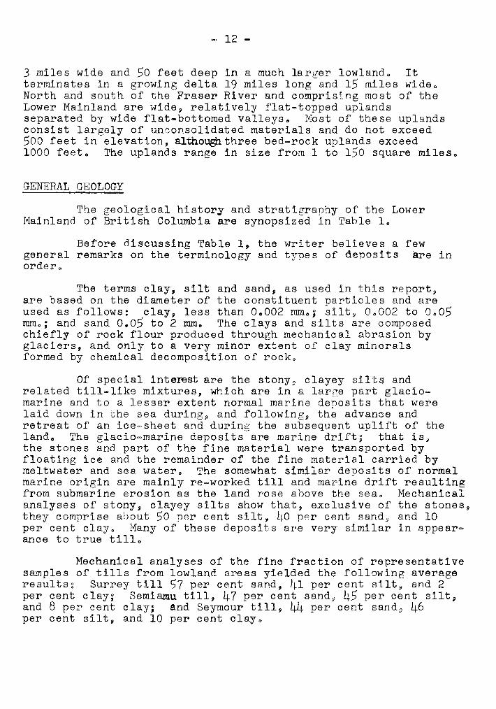
The terms clay, silt and sand, as used in this イ ・ ー ッ イ エ セ
are based on the diameter of the constituent particles and areused as follows: clay, less than 00002 rom o, silt, 00002 to 0005mrn o; and sand 0.05 to 2 rom o The clays and silts are composedchiefly of rock flour produced through mechanical abrasion byglaciers, and only to a very minor extent of clay mineralsformed by chemical decomposition of rock.
Of special interest are the stony, clayey ウ ゥ ャ エ セ andrelated till-like mixtures, which are in a large part glaciomarine and to a lesser extent normal marine deposits that werelaid down in the sea during, and following, the advance andretreat of an ゥ 」 ・ セ ウ ィ ・ ・ エ and during the subsequent uplift of thelando The glacio-marine deposits are marine drifts that is,the stones and part of the fine material were transported byfloating ice and the remainder of the fine material carried bymeltwater and sea water. The somewhat similar deposits of normalmarine origin are mainly re-worked till and marine drift resultingfrom submarine erosion as the land rose above the sea o Mechanicalanalyses of stony, clayey silts show that, exclusive of the stones,they comprise about 50 per cent silt, 40 ppr cent ウ 。 ョ 、 セ and 10per cent clayo Many of these deposits are very similar in appearance to true tillo
Mechanical analyses of the fine fraction of representativesample s of tills from lowland are as yielded the following averageイ ・ ウ オ ャ エ ウ セ Surrey till S7 per cent sand, 41 per cent silt, and 2per cent clay, Semiamu till, 47 per cent ウ 。 ョ 、 セ 45 per cent silt,and 8 per cent clay; and SeYmour till, 44 per cent ウ 。 ョ 、 セ 46per cent silt, and 10 per cent clayo
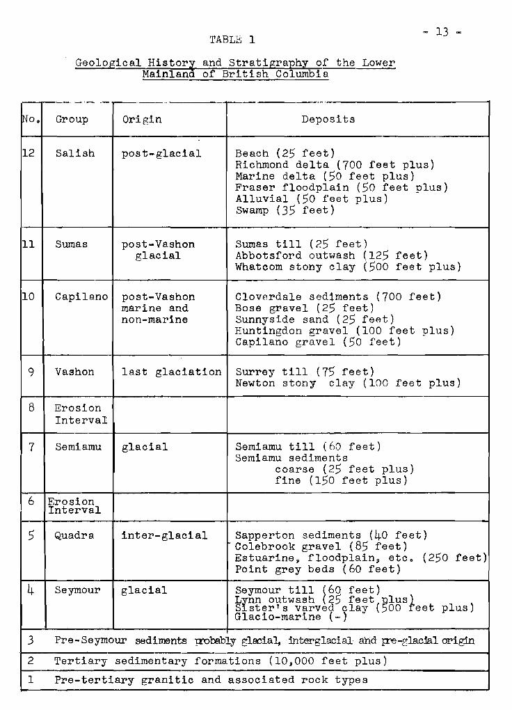
TABLE 1
Geological History and Stratigraphy of the LowerMainland of British Columbia
- 13 セ
lNo. Group Origin Deposits
12 Salish post-glacial Beach (25 feet)Richmond delta (700 feet plus)Marine delta (50 feet plus)Fraser floodplain (50 feet plus)Alluvial (50 feet plus)Swamp (35 feet)
11 Sumas post-Vashon Sumas till (25 feet)glacial Abbotsford outwash (125 feet)
Whatcom stony clay (500 feet plus)
10 Capilano post-Vashon Cloverdale sedtments (700 feet)marine and Bose gravel (25 feet)non-marine Sunnyside sand (25 feet)
Huntingdon gravel (100 feet plus)Capilano gravel (50 feet)
9 Vashon last glaciation Surrey till (7'5 feet)Newton stony clay (100 feet plus)
8 ErosionInterval.
7 Semiamu glacial Semiamu till (60 feet)Semiamu sediments
coarse (25 feet plus)fine (150 feet plus)
6 ErosionInterval
5 Quadra inter-glacial Sapperton sediments (40 feet)Colebrook gravel (85 feet)Estuarine g floodplain g etc. (250 feet)Point grey beds (60 feet)
4 Seymour glacial SeYmour till セ V P feet)LInn outwash 25 feet glus}S ster's varved clay (00 eet plus)Glacio-marine (-)
3 Pre-Seymour sediments p:'Qbebly ァャ。」ゥ。セ interglacial and Jre-glac1al origin
2 Tertiary sedimentary formations (10,000 feet plus)
1 Pre-tertiary granitic and associated rock types
- 14 -
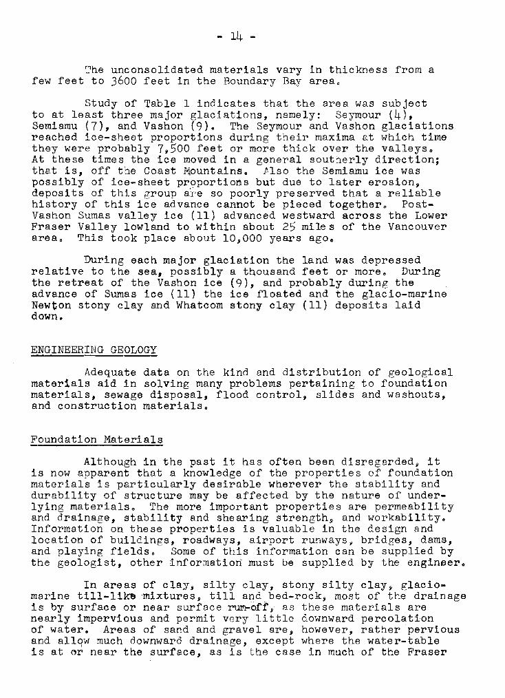
The unconsolidated materials vary in thickness from afew feet to 3600 feet in the Boundary Bay area.
Study of Table 1 indicates that the area was subjectto at least three major glaciations, namely: s ・ セ セ ッ オ イ (4),Semiamu (7), and Vashon (9). The Seymour and Vashon glaciationsreached ice-sheet proportions during their maxima at which timethey were probably 7,500 feet or more thick over the valleys.At these times the ice moved in a general southerly direction;that is, off the Coast Mountains. Also the Semiamu ice waspossibly of ice-sheet proportions but due to later erosion,deposits of this group a'l'e so poorly preserved that a reliablehistory of this ice advance cannot be pieced together. PoatVashon Sumas valley ゥ 」 セ (11) advanced westward across the LowerFraser Valley lowland to wi thin about 25 mile s of the Vancouverarea. This took place about 10,000 years ago.
During each major glaciation the land was depressedrelative to the sea, possibly a tnousand feet or more. Duringthe retreat of the Vashon ice (9), and probably during theadvance of Sumas ice (11) the ice floated and the glacio-marineNewton stony clay and Whatcom stony clay (11) deposits laiddown.
ENGINEERING GEOLOGY
Adequate data on the kind and distribution of geologicalmaterials aid in solving many problems pertaining to foundationmaterials, sewage disposal, flood control, slides and washouts,and construction materials.
Foundation Materials
Although in the past it has often been disregarded, itis now apparent that a knowledge of the properties of foundationmaterials is particularly desirable wherever the stability anddurability of structure may be affected by the nature of underlying materials. The more important properties are permeabilityand drainage, stability and shearing ウ エ イ ・ ョ ァ エ ィ セ and workability.Information on these properties is valuable in the design andlocation of buildings, roadways, airport runwaysj bridges, dams,and playing fields. Some of this information can be supplied bythe geologist, other information must be supplied by the engineer.
In areas of clay, silty clay, stony silty clay, glaciomarine till-lik'" 'mixtures, till and bed-rock, most of the drainageis by surface or near surface イ セ セ ヲ エ L as these materials arenearly impervious and permit very little downward percolationof water. Areas of sand and gravel are, however, rather perviousand allqw much downward drainage, except where the water-tableis at セ イ near the surface, as is the case in much of the Fraser
- 15 -
River delta. Although the tills contain relatively littleclay and a high percentage of sand, their cqmpact naturetends to make them nearly impervious. The compaction is dueto the angularity of the fine materials and to the weight ofglacial ice beneath which the till was deposited. Even whenexcavated, broken up, and used for fill or other purposes, thetill soon becomes impervious due to the fines washing intoand sealing the channels or cracks; if loaded it readilybecomes quite compact once more. There are many examples inthe Greater Vancouver area of drainage problems involvingtills, one of the more recent being at Empire Stadium.
Of particular interest is the fact that the Surreytill and older deposits have been pre-loaded by at least7,500 feet of ice, whereas, the post-Surrey deposits haveonly been pre-loaded by the weight of the sediments abovethem. Consequently the Surrey till and Newton stony clay,although very similar in appearance, behave very differentlyto load; the former is, except possibly for bed-rocks thebest foundation support available and the latter 9 because itundergoes considerable comnaction under load, is one of thepoorer foundations. The very different reaction of similarappearing materials to load is readily explainable when the originof the two is considered. The till was deposited under a ァイ・セエ
weight of ice whereas the till-like stony clay was droppedfrom floating ice. Fortunately for builders in the GreaterVancouver area, in most places the glacio=marine sedimentsare less than 25 feet thick and rest directly on till. Eastof the Vancouver area, however, the glacio-marine and relatedmarine deposits are up to 500 feet or more thick.
The peat bogs of the Fraser River delta, which rangefrom a few feet to more than 30 feet thick, and to a lesserextent in the uplands present probably the most obvious foundation problems of any of the deposits mapped. They undergoextreme compaction when loaded and are very difficult todrain. Hard-surfaced roads laid across these bogs tend todevelop alternating swells and depressions and deterioratevery rapidly unless the peat is excavated and where necessaryreplaced by fill before building the road.
With the exception of the tills and to a much Ie s serextent the glacio-marine sediments all the unconsolidateddeposits found in the area are easy to excavate. In the tillscohesion is so high in places that they have to be blastedbefore being excavated. Occasionally large stones in both thetills and glacio-marine sediments may have to be broken to beremoved.
セ 16 -
Sewage Disposal
Wherever sewage disposal is dependent on septic tanks aknowledge of drainage and subsoil conditions is necessaryo Mostof the uplands are covered by nearly impervious to imperviousSurrey till and Newton stony clay glacio-marine deposits at J orwithin a few feet of, the surface. For all practical purposesthese materials permit no downward drainage. Where these are notat the surface they are overlain by thin deposits of Bose graveland Sunnyside sand, deposits that permit downward drainageto the impervious materials underlying them. These sands andgravels are, however, so thin that in the rainy season» thewater-table is close to or at the surface even in these permeabledeposits o It is therefore evident that much of the overflowfrom septic tank absorption fields in the uplands must eventuallydrain down the slopes by surface or near surface run-offo
Septic tank sewage 、 ゥ ウ ー ッ セ 。 ャ systems will not oneratesatisfactorily Hhere the ground-water level is up tOg or nearlyup to the absorption tile, or in areas that are periodicdllyflooded. These conditions exist in much of the lowlandsespecially the Fraser River delta.
Flood Control
To combat flooding effectively along rivers by meansof diking and dredging the nature of the イ ゥ カ ・ イ セ 「 。 ョ ォ and bottomdeposits must be known. Most of the diking troubles along theFraser River are becau6e the dikes have had to be built onpermeable sand. Consoquently, when the River is in flood and thewater-level is higher than the land behind the dike 9 thehydrostatic head developed forceB some of the water throughthe sand beneath the dike and dike failures have resulted fromsuch seepage.
The streams that flow off the Coast Mountains occasionallyreach flood stages and bring destruction 9 and continued erosionin the mountains and continued floods into the valleys are to beexpected o Except for raised delta deposits along some of thestreams most of the slopes have impervious till or bed-rock atthe surface, which allows an extremely fast surface run-off 9
especially where the vegetative cover has been removed o Seriousflooding occurred in north and west Vancouver in November 1955following excessive rainfall. Protection by vegetative cover andtopsoils check dams, and other expedients are designed to minimizethe destructive effect of these natural forces o The ュ 。 ゥ ョ エ ・ ョ 。 ョ 」 セ
of the Greater Vancouver watershed north of Vancouver withregulations preventing removal of forest growth has certainlyhelped to prevent more serious flooding on Seymour and CapilanoCreeks o
- 17 -
Landslides and Washouts
Over the years large slides and washouts have occurred inthe Lower Mainlapd area. These slides and washouts always occuron steep slopes where the soil conditions are rendered unstableby heavy rainfall and generally excessive clearing of the land.One of the best examples of a large washout took place near theUniversity in 1935. Here the sea-cliffs reveal about 150 feetof Quadra sands and related deposits overlain by about 10 feetof Surrey till. Following an exceptionally heavy rainfal1 9 asmall stream, whose banks had been cleared of most vegetation,cut through the till into the underlying sands. Great quantitiesof these sands were eroded and carried away, and by undercutting,much of the overlying impervious till also.
In other places the disturbance of the angle of reposeof the sediments combined with geological conditions somewhatsimilar to the above have caused slides. A knowledge of thegeology cannot prevent all such slides and washouts, but itenables many to be foreseen and if necessary precautions aretaken most of these can be prevented.
AGRICULTURAL APPLICATIONS
The geological information obtained by the writer should。 ゥ セ in the study and mapping of agricultural soils, in problemsconcerning drainage and irrigation, and in outlining a source ofagricultural peat.
Agricultural Soil
Modern soil classification is based upon the nature ofthe soil profile, which reflects the influence of the variousfactors of soil development including parent material, climate,topography, organisms, time and geological environment. Thelast factor is not normally considered in discussions onagricultural soils, but some writers believe that the factorhas not been emphasized sufficiently, especially the stratigraphyand geological structure in and around a particular soil. Eachof the factors in soil development mentioned above is in itselfdependent on geological history.
The geologist is most able to help the soil scientist inhis interpretation of soils by indicating the role played byparent material and geological environment. The soil profilesin the Lower Mainland area are poorly developed and the textureand composition of the parent material is still dominant. The
- 18 -
author believes that when the agricultural soils of the area arere-mapped the broad divisions of the completed soil map will showa very marked similarity to the divisions on the surficialgeological mapse
Undoubtedly very significant soil differences are to befound in soils developed from similar parent materials but indifferent geological environments o A very important factor inthese differences is changes in the deposits underlying theparent material o For example g in the Fraser River delta the top15 feet may consist of anyone of the following: all peati allsilty clay and clay; all sand g silt above peat above silty clayand clay, peat above silty clay and clay; peat above silty clayand clay above sand, silty clay and clay above sand, and siltabove sando The claYg silty clay and silt are impermeable; thesand is permeable, and the peat has a very high absorptivevalue g that iS g it will store as much as twenty-six times itsown weight of water o Obviously the drainage pattern encounteredwill vary greatly depending on which of the combinations describedabove is found and therefore the moisture and other soil=climateconditions in the soil may show very significant differences o
Differences in materials underlying the upland soilsalso play an important role in their developmento Furthermore D
variation in surface drainage c)nditions may result in differencesin the kind of upland soil developed from a single p2rent material o
The geological history of the Vancouver area has greatly。 ヲ ヲ ・ セ エ ・ 、 the nature of many of the upland soils particularlythose developed on till g and glacio-marine stony silty clays andtill-like mixtureso Following the retreat of the Vashon icethe land rose above the sea and during. the up Lt f' t , that part ofthe uplands now below 600 feet g underwent marine erosion o As aresult much of the fine material was washed out leaving a mantle ofboulders g gravel and sando

- 19 -
DISCUSSION
In reply to ケ セ ッ Legget,geolGgica1 information on soilss t r e t l gr-aphy and s e dLmerrt a td o r, ,not been used in the geological
Dr. Armstrong stated thatT,,TE'..S gathe r-ed t.h r-o ugh methods of
As yet engineering tests havecorrelations.
Dr. Armstrong, in response to ケ セ N McLean, stated thatmany mountain valleys had artesian water conditions o Dr.liullineaux asked to what extent local engineers and governmentagencies used geological information. Dr. Armstrong said he wasencouraGed by its wide use and had had numerous requests toreport on speciel aspects of ァ ・ ッ ャ ッ セ ケ ッ
Dro Radforth asked if anyone knew of engineeringapproaches to roae building over organic terrain other than itsremoval. IT'o Thurber reported on a road built over peat nearCoqu i.tLam , 30'_1 svrveys s howe d peat extending to a depth of 30to 40 feet. An attempt was made to float the road across thebog o Unfortunqtely culverts were placed on piles g which meantthe road wculd not settle uniformly.
Professor Morrison stated that information on the densityof s oi.Ls _:culd be extreme ly valuable and sugge sted that engine ers.:\0 not; pEy sufficient attention to the density of soil formations.Mr. Ripley co®nented that in many instances in BoCo no generalization cou:d be made on the density of a soil formation. Hecited ar R ク 。 セ ョ ャ ・ of the variation in depth of penetration in asingle piJ.":' groupo In such cases one could not rely on densi tyrne82urements made frCJ:TI a sinQ"le bering or outcropo
Hr .. Hortie asked l..Jhether or not the r-eck flour referredto posse3sed any predominant mineral o Dr .. AIT!strong repliedthat analyses ィ 。 セ showed no clay minerals.
= 20 =
Section .2
Agricultural Soils of the Fraser Vallez
by
E. Hugnes
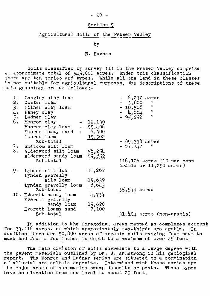
Soils classified by survey (1) in the Fraser Valley comprise2f approximate total of 545,000 acres. Under this classificationthere are ten series and types. While all the land in these classesis not suitable for agricultural purposes, the descriptions of thesemain groupings are as ヲ ッ ャ ャ ッ キ ウ Z セ
31,454 acres (non-arable)
acres
""""
acresif
6,2323,800
- 10,5084,664
= 95,292
116,106 acres (10 per centarable or 119250 acres)
56,25459,852
15,6398,643
4,734
19,6207,100
12,13055,4066,300
1$,502
11,267
Langley clay loamCuster loamKilner clay loamHaney clayLadner clayMonroe clayMonroe clay loamKonroe loamy sandronroe loam
Sub-totalWhatcom silt loamAlderwood silt loamAlderwood sandy loam
Sub-total
Lynden silt loamLynden gravelly
silt loamLynden gravelly loam
Sub=totale セ ・ イ ・ エ エ sandy loamEverett gravelly
sandy loamEverett loamy sand
Sub-total
1020
100
In addition to t he foregoing, areas ma ppe d as complexes accountfor 33,116 acres, of which approximately two=thirds are arableo Inaddition there are 50,890 acres of organic soils ranging from peat tomuck and from a few inches in depth to a maximum of over 25 feeta
The main division of soils correlate to a large degree withthe parent materials outlined by Dr. J. Armstrong in his geologicalreporto The Monroe and Ladner series are situated on a combinationof alluvial and deltaic deposits. Intermixed with these series arethe major areas of non-marine swamp deposits or peatso These typeshave an elevation from sea level to about 25 feeta
= 21 -
The l。ョァャ・ケセ Milner and Haney series are developed over normalmarine silty clays and siltso Bordering the edge of these soils area few areas of Custer series, developed over a combination of littoraland alluvial sandso These series occur generally in the 25 to 150feet above sea level area o
What is conmonly referred to as the "Upland area" includes theWha teem, Alderwood, Lynden and Everett serie so The Wha tcom serie s isdeveloped on glacial marine silty depositso The Alderwood series 9 asclassified by soil survey differs most from the geological mappingoIt appears for the most part to have been developed over a glacialtill and glacial marine till-like mixtureso The Everett and Lyndenseries is developed mainly over outwash sands and gravelso All theagricultural soils occur below the 400=foot elevationo
In this paper an attempt is made to describe the soils onlyin general ter-ms , bringing out their agricultural potentialitiesoI think there are few areas of comparable size in Canada that havea greater variety of soils than the Fraser Valley soilso They rangefrom fine to coarse texture 9 very rapidly to very poorly dralned 9
from acid to neutral and from marginal to highly productive o Eachhave their management proble ms 0
The "Upland area" can be readily broken into two 」 。 エ ・ ァ ッ イ ゥ ・ ウ セ
excessively or rapidly dr-a t.ne d , and restricted or very slowly dr-a Lne d ,The excessively drained soils include both the Everett and Lyndenserleso These soils consist of a shallow foregt litter (2 inches)covering a loose sandy loam to silt loamo The subsoil is a sand orgravelly sand, of some considerable depth v yellowish=brown horizon 8to 20 inches thick which is freely permeable and of low moisture=holding capacityo
The restricted drainage uplands include the Alderwood andv セ 。 エ 」 ッ セ series o The Alderwood has the greatest relief and includesthe rolling and hilly areaso Approximately 10 per cent of its areaof 116 9000 acres is classed as arableo Two broad textural classeshave been ュ 。 ー ー ・ 、 セ sandy loam and silt loam underlain セ セ エ ィ a compactedcemented till of sands and gravelso The Whatcom topography is amixture of gently undulating round hills and depressionso Surfacetexture is silt loam to a depth of 12 inches grading to a clay loamfrom 12 to 20 inches!! underlain by a cemented clay in which areimbedded occasional stoneso Both soils are characterized byimpervious subsoils 9 a perched and moveable water=table 9 and a pro=gression of profiles related to the varying moisture condition9o
The normal marine soils generally have moderately well=developed profileso The Cuater series differs largely from the othersin textureo It has a sandy loam profile to a depth of 2 to 3 feetresting on dense fine clay subsoilo The Langley clay 10am 9 typically
= 22 ""
a forest meadow 80i1 9 has approximately a foot of black clay loamtopsoil of well aggregated structure grading to a ァイ・ケセ「イッキョ clayoverlying a dense clay similar to that underlying the Custerse r-Le s , The Haney and Milner series differ from the Langley andCuster largely on the basis of drainage and position o They occupygently undulating and sloping positions as compared to relativelyflat and depressional site characteristics of Langley and CustaroConsequently they are better drainedo Milner soils range fromsilty clay loam to clay loam in the surface textureo The Haneyseries are generally somewhat finer I t.ex tur-e d , particularly on the sureface horizonso Both have subsoils similar to that of the Custer andLangley series o
Ladner and Monroe series are developed on relatively recentalluvial or deltaic depositso Both have flat topography and areof insufficient age for the formation of well devoloped so11horlzonso Many of the layers occurring in the profile tirB due tostratification of the material as it was laid downo ThE Ladnerseries mainly consists of approximately V セ ゥ ョ 」 ィ b la ck silty clay loamoverlying varying depths of siliceous grey silty clay loam 9 which 9
in turn n is underlain with sands o The Monroe series differs fromthe Ladtier largely by its COarser textureo The surface (0 to 6inches) textures may be similar but the subsoila grade to 8 siltyalluvium, which in turn is abruptly underlain with sand at a depthof approximately 20 incheso
Agriculturally the Fraser Valley soils have manyinteresting features 0 Generally they are acid in r-eec t i.on , lowin exchangeable bases and readily available nutrientso All pHvalues below 300 have been recorded in Valley peat30 Tn ァ・ョセイ。ャ
the pH values in mineral soil ranges from about 600 to a low of4000 This latter condition is associated wi:h poor" dr-a rnage ,The solls as a group respond readily to liming" manurial andfertilizer application and when properly mana ge d , have a highproducti v» capac i ty 0 Soil type of c ourse セ determine s in. scmeinstances the crops that Can be grown" but there is ample avidenceto show that fertility response is dictated more by crop than by soiltype 0 However" within each エ ケ ー ・ セ several phases or d13tinctionsbased on practical considerations are apparento These phase5bring out the complexi ty of the types and furnish t nror-ma s ionrelative to their na t.ur-e , suf t.ao t Lf.t y , limitations and management
. r-e quLr-emerrt s 0
The Everett and Lynden series being open and porous have avery low moisture=holding capaciJ:;yo With the exception of theLynden silt loam and without irrigation these 30ils are marginalfor a gr-Lcu'l, t ur-e 0 Even so 9 Lynden silt loam is limited to t heproduction of early rna tur-Lng crops such as atr'awberrie s or earlypotatoes and require ::lupplemental water for other crop'=lo Thesesoils require addi tiona 1 moisture to carry C1:"OPS through to maturi tyoShort and frequent appLac a tiona of irriga tion water" 13 de s i r ab.Le l'J
= 23 ...
heavy aop Li.c e tdcna being conduc i ve to exce ssive leaching of pla ntnutrients and erosiono Manager practices, which accelerate organicmatter 、 ・ ー ャ ・ エ ゥ ッ ョ セ further enhance this problemo
Alderwood series soils are also of limited agriculturalvalue 0 The porous top soils show a favourable non=capillary porosity(which is 15 to 20 per cent by volume) but the Lmper-vI oua substratumof cemented sands and gravels is, for practical purpcses y imperviousto セ 。 エ ・ イ and rootso Concentrated roots have been seen to depthsof 1 1/2 to 2 inches on this hardpan layer 0 The net e f'f'e c t,agriculturallYD is that these surface soils permit rapid percolationof moisture to the hardpan depth v from which point further movementoccurs only laterallyo Tap-rooted plants such as strawberriesand clovers will not tolerate this 」 ッ ョ 、 ャ エ ゥ ッ ョ セ especially wherethe impervious substratum is close to the surfaceo Grass speciesand shallow-rooted crops could thrive except for the fact thatour summer イ 。 ゥ ョ ヲ 。 ャ ャ セ which averages between 1 and 2 inches permonth 9 is inadequate to maintain a constant supply of soil moistureoThe キ。エ・ABセィッャ、ゥョァ capacity of the soil to hardpan depth is Ln suf'f'd «
c i.en t to carry general crops through a season when Bummer dr-ough toccurso These two ヲ。」エッイウセ summer drought and the impervious sub=s t.r-a t.um, are definite limiting factors militatir.g against thecomplete utilization for arable agricultureo They assume moreimportance in the utilization of Alderwood series when it ゥ セ
recalled that only 1 per cent of the total acreage 1s topographi=cally suitable for agricultureo
The other upland member with restricted 、 イ 。 ゥ ョ 。 ァ セ Y セ セ 。 エ 」 ッ ュ
s11 t Lcam ; is of greater agricultural value than the Alderwood o Ithas e. higher ュ o ャ ウ エ オ イ ・ セ L ィ ッ ャ 、 ゥ ョ ァ capacity in the top soil and Ls thusable to wi &h5tar_d summer dr-ought. to a much gl"'eater de gr-ee 0 It toe 11
however.' has ar... impervious subsoil (gener'slly oc cur-r ing at greaterdepth) making the necessity of adequate 、 イ 。 ゥ ョ 。 ァ セ 1mperatlv8o Ihe "'6 SN='!1 Bog r-us h .(Junella effusus) growing on a h:1.1l side of theWh.atc.om ae rre s , Th15 illustrates the need for 。 」 セ ア オ 。 G エ R ゥ drainageeven on s1.cpn.g Larid , There is also much of the Wha 1,;·GOYn occupying「 X X ゥ ョ セ ャ ゥ ォ ・ de pr-e as Lons and these depressions de nc; z-ead I Ly lendthemselves to dralnageo
The foregoing remarks may be applied in part to the Langley 9
Haney and Custer aeries", and, to a somewhat Le s ser- exrent , toMilner soils 0 In gener-aL, these soils all r-equ i re a de qua t edrainage> for maximum pr-oduc td on , Growth in poorly dr-aIne d fieldsi8 often retarded weeks in the early springo Excessive ュ P Q ウ セ オ イ ・
produces a cold poorly aerated soil with properties unfavourableto gr-ow Lng of crops common to the area 0 Then." r-at.he r ironicallY!J5ummer drought ョ ・ 」 セ ウ ウ ゥ エ 。 エ ・ ウ irrigation during late 5ummer' 1I espe0iallyin pa s tur-e s C!' msadows where the maintenance of growth is e s serrt Le.If'or: high pr-oduc ti; vi tyo If fields of these soil type 03> are adequatelydrained a::l d properly managed they compare favourably inr:.ropproduction to any other series in the Valleyo

The Monroe and Ladner classes, can, I believe, be classedas the most productive soil serieso Th9 Monroe, due to itsgenerally coarser texture, lends itself to a greater varietyof crops; climatically it is characterized by a slightly highersummer rainfall and higher summer temperatures than Ladner, thuspermitting a greater variety of crops to be grown, eog o corn andhopso .
Natural drainage in Ladner series is generally muchslower than in MonroeQ This is due largely to particle sizedistributiono Generally, the Ladner soils contains 50 to 60 percent silt, and when distributed compacts readily with the formationto a plough sole or tillage pano In its natural state weaklydeveloped structures are lacking and the A, (0 to 6 inches)containing some organic matter, has a natural non-capillaryporosity varying from 6-15 per cente The C horizon is massiveand mottled and has a non-capillary porosity of S セ V per centby volume (2) Ladner soils generally have a high moisture holdingcapacity, but due to location the extreme portion around LadnerVillage suffers from summer droughto Rainfall distributionduring the summer in this area is the lowest for any section ofthe Valleyo Since dairying is the major enterprise» late summerpastures are definitely moisture deficientQ
These remarks, of course, do not apply to the Ladnerseries of the more easterly Pitt Meadows イセァゥッョッ Continuoushigh water-table accented by poor general drainage of this area,lowers the productivity of this fertile solI typeo At present,unless more main ditches and pumps are installed in the largersection of this region 9 farm drains cannot function properly andc.rops will suffero With adequate drainage 9 however 9 these soilshave as high a productivity potential as any other part of theLa dne r- ser-ae s , .,
Associated with the Ladner and to some extent the Monroeser-Le s , are large areas of organic depo s t t s , They are generallyall sphagnum moss type and form t he basis for Canada I is large stcommercial peat harvesting operationso The peat originally isvery strongly acid and イ ・ ア オ ゥ セ considerable drainage and limingbefore they can be croppeda Once these factors are overcome theyhave proved to be our largest vegetable producing acreags g
especially in the c ャ ッ カ ・ イ 、 。 セ Mud Bay regiono A characteristicof these acid peats ia a high moisture holding capacity and theneed for heavy fertilization of phosphates and potasho Furthermore 9 once they have dried out, they take up water slowly andrequire considerable care during irrigationo
I have tried to point out in very general terms theagricultural soils of the Fraser Valley and t he problems relatedto these 80i18 0 I believe you will agree that a major portionrequires a combination of adequate area drainage, and farmdrainage, to remove excess water occurring naturally or in theform of precipitation. Summer irrigation to compensate forthe lack of rainfall during the dry period, along with goodmanagement practices are necessary for maximum productivityo
REFERENCES
(1) Soils Survey of the Lower Fraser Valley. CoCo Kelly andR.Ho Spillsbury.
(2) Thesis Data. Soils Department, Faculty of Agriculture.University of British Columbia.
DISCUSSION
In answer to Mr. Chapman, Mr. Hughes reported that mosteffective drainage was through tile drains. Some of the olderfarms used cedar box drains for drainage.
In reply to Mr. Thrussell, Mr. Hughes thought that about150,000 acres out of 545.000 acres in the lower mainland were notpotentially arable.
Mro Trow asked if there had been any difficulties withthe 、 ・ エ ・ イ ゥ セ 。 エ ゥ ッ ョ of concrete drain pipes and foundations dueto the presence of peat. Mr. Hughes answered that although noserious trouble was reported, concrete pipe was not recommended o
No foundation difficulties were known because most farm bUildingswere built on higher ground and hence not in peat areas o
Dr. Mathews inquired about the amount of settlement thatresults from the drainage of a peat bog. Mr. Hughes had no directfigures but he thought that the figure of 4 feet over a period of25 years would not be far wrong.
Mro Hortie asked if daily tidal variations causedfluctuations in the ground water table in low lying areas. Mro,Hughes reported that water levels in the ditches certainly wereaffected. Mro Armstrong reported that the ground water table insands did vary with tide conditions.

- 26 -
Section 6
Foundation Conditions and Problems - Vancouver» BoCo
by
P"Mo Cook and Lo Brandon
The first part of this paper will deal with geologicalconditions and the effect they havp upon building foundationsand other problems associated with buildingo The second partof the paper will consist of a few examples to show that soilconditions themselves do not entirely govern the problems to bemet 9 10eo that artificial conditions such as building regulationsand others p have a great effect in creating problemse So faras foundation conditions are concerned 9 probably the best methodof getting a アオセ」ォ general appreciation of the Vancouver area isto recall the paper by Dre Armstrong given earlier in this sessiono
To summarize this paper-, br-Le f'Ly , the Vancouver area canbe broken down into three zones o On the north shore we have thegranites of tbe coast range, which in places come down to tide-wa t e r-, Second we have the glacial till., overlying other materials,but rendering them densec This till covers parts of north andwest Vancouver, and extends virtually over the entire area ofVane ouve r- and underlie s the alluvials of the Fra ser Hiver andcomes up again at Point Robertso The third element in theVancouver area are the alluvials of the Fraser,·: Coqui tlam andPi tt Hi ver- S 0
Each of these areas has its own particular problemsoIr the Case of the rook this enters into such a small percentageof' the potential industrial land as to not be of much consequence"One problem in connection with this is that in regions where thiscomes down to tidewater it presents a severe problem in theconstruction of docks in that it is difficult to get enough gripfor piles to hang on to the steep slopes o The ョ・クセ 。イ・。セ thatis the area chiefly occupied by glacial til1 9 presents a fewpr-obLems , The till of course is an excellent foundation ma t e r-La L,It has a density varying between 125 to 145 on a wet basis withmoisture content ranging from 9 to 15 per cent depending on claycontento The clay in this till is very low ゥ ョ 、 ・ ・ 、 セ on the orderof 2 to 8 per cento This permits very high bearing loads o Thereare buildings in Vancouver which use loads as high as 7 tons persquare ヲ ッ ッ エ セ although normal practice is somewhat lesso
Another characteristic of the till is that it is ratherexpensive to excavateg This can be appreciated in the foregoingremarks 0 hッキ・カ・イセ it stands well in vertical cuts and thereare examples where Q U セ エ ッ ョ dual axle coal trucks have been backing

= 27 -
up within 2 or 3 feet of the edge of a vertical 20-foot bank oftill, and doing this over the last 15 years, without any damageto the bank other than minor erosion due to rainso Speaking oferosion it is often found in excavations in till and it is goodpractice to cut the banks vertically instead of sloping themsince they will stand at this angle and also suffer less fromerosiono
It might be said that the area in Vancouver and vicinityoccupied by till is more interesting for the exceptions to therule rather than the rule itselfe I am speaking now of the factthat in places there are exposures of a clay-silt materiala Theseseem to occur in some' sort of a band along the vicinity of 16thAvenue just west of Granville to as far east as Main Street ..These 」 ャ 。 ケ セ ウ ゥ ャ エ ウ give rise to some problems since in this Casethey occur on a steep banka The next exception to the rule isthe great Burnaby bog which is traversed by the Great Northern andCanadian National Railways. On this account the area is beingbuilt up as an industrial centreo This bog varies in depth from20 to & reported 80 feet in the vicinity of the Dominion Bridgeplant.. In general it is deeper towards its centreo The peat inthis bog sometimes runs as high as 1000 per cent mOlsture g
although in other cases, particularly near the boundaries of thebog, it is contaminated with silt and clay fractions of soilmixed in with the peat so that the moisture content drops as low,in some places» as 150 per cento Of course this gives rise tovariations in the consolidation characteristicse There are otherisolated small boggy regions, namely Nanaimo Road and TroutLake 0 There is another area just east of Central p 。 セ ォ and therei8 quite a notable boggy area in the vicinity of Highbury from33rd Avenue north to about 16th Avenue 0 A third feature of theVancouv&r area which sometimes g!ves rise to foundation problemsis the deep gullies which streams have cut in the tilL and insome cases breached the tillo These gullies have in the pastbeen filled in so that a casual observer might miss themoSeveral of these gullies are present in the vicinity of theGeneral h ッ ウ ー ゥ エ 。 ャ セ (12th Avenue between Cambie and Oak Street) andagain in New Westminster notably between about 8th Street and thenorth approach of the patullo Bridge o
We come now to the third zone of the Vancouver 。 イ ・ 。 セ
namelyv the alluvials of the of the Fraser g Coquitlam and Pitt RiversaThese areas are flat, are accessible by rail and in many casesare accessible by watero This is bound to lead to their increaseduse in the future as industrial land so that the soil conditionsin this area are of particular interesto' The soil profile of theFraser 、 ・ ャ エ 。 セ which is the largest area involved g consists almostinvariably of a few feet of fine soil which can be ・ セ エ ィ ・ イ siltor clayey silt, and then sand to quite a great depth, and finallyglacial tillo It is found that in some places there is a finesilt or clayey silt or even an organic clay between the sand andthe tillo In some cases this clay does not show up until 130 feet
- 28 -
or more in depth, or other Cases notably the Marpole area it showsup at fairly constant deptn of about 6S feet, and extends down rightto the エ ゥ ャ ャ ッ セ Naturally under these conditions the size of theloaded area is of considerable importanceo Isolated heavy structures·do not present much foundation problem but extensive warehouse 10ads 9
or in operations which call for the placement of several feet of fillever a large area, there are real problems in that they give rise toquite large settlements in the fine layer. Elsewhere in the alluvialarea problems centre on the character of the surface s011 9 that isthe top 6 or 8 feet of silt or clay. It is noted that in the lowerreaches of the north arm on the north side of the Fraser River andclose to the toe of the glacial till slope, soils of this type arefound, and also at the eastern tip of Lulu Island on both riverfrontso It is noticed that a narrow zone some 2 or 3 hundred feetwide bordering the river has no fine soils on the surface and thatfurther in from this the soils get progressively finer and deeperuntil finally a condition is reached where the surface soils areso clayey, and in cases so high in organic content that for manyindustrial purposes the land is quite useless without the expenseof a large outlay in pilingo In the regions where the surface soilis silt, the condition is not nearly so bad because the applicationof fill brings about the slight settlements quite quickly so thatthe only settlements to be dealt with are the slight settlementsinduced by the live load of the building.
So much for the soil and geological conditions in the area.The second part of this paper, as mentioned earlier, deals with afew specific examples of how some artificial conditions can compounda soil problem and materially affect building costs. All of theseconditions apply in the alluvial area just dealt witho The firstexample is to mention that in the industria) area along the northside of the north arm of the Fraser River, from about Fraser streetto Marpole the lack of pumping of storm waters coming into thearea requires owners to put in depths of fill up to 6 or 8 feet.This 。 イ ・ 。 セ as mentioned before, is characterized by having in agreat many places, 6 to 8 feet of fine soil with fairly highorganic content 0 It is quite apparent tha t if it were not for thelack of pumping requiring the placement of fill, the foundationproblems in the area would be materially reducedo
The second example is the penchant most owners have forde-manding concrete floors, where in many cases their operationswould be quite well met by the use of bituminous concrete floorsoIn sites where settlements are not more than 2 or 3 inches thechoice of floor is quite important. Where an owner is inordinatelyfussy and demands a floor of concrete in which there will be nocracks there is often no choice but to tell him he must pile the
- 29 -
whole thing. Whereas if some owners would only realize it, anasphalt floor would be quite satisfactory and a good deal cheaper.
The third case of an artificial condition affecting costis in the case of Lulu Island. Lulu Island, for the benefit ofvisitors to the City, is an Island in the delta of the Fraser andis entirely surrounded by dikes. Many persons coming into thisarea to build industrial plants cast a rather jaundiced eye onthe dikes and wonder if their investment is going to be safebehind them. They are told about the 1948 floods and that theriver did not breach the dikes at that time, and of course theysay to themselves, "well the river didn't do it then but it couldgo higher". It may not be generally known but the highest waterin the lower reaches of the Fraser did not occur in May of 1948with the Fraser flood, but occurred in December of the same year,due to a combination of an extremely high tide and a strongwesterly wind. The fact is that tides and winds are sometimesmore predictable than rivers and if the dikes did not breach inDecember 1948 it is not likely that they will breach in thefuture. The condition of the di1e, or to put it more correctly,the attitude of prospective owners toward the dikes thenbecomes an artificial condition greatly affecting the cost ofbuilding in this area. The reason for this statement lies inthe fact that owners in order to be certain of being aboveflood level have sometimes called for the pm cement of up to 7or 8 feet of fill. While this may be all right along the southarm of the Fraser, there are certainly areas along the north armwhere it would be absolutely impossible to do this successfullyin view of the presence of deep beds of clay at considerable depth.
The fourth example where an artificial conditionmaterially increases building costs is the requirement of manybuilding codes that buildings over a certain area must have wallsof masonryo The writer has seen many, many sites in the Vancouverarea for large warehousing operations where the logical choiceof type of structure from the point of view of foundationconditions would be steel frame with transite or other sidinghung on girts. This type of structure will permit minordifferential movements without any adverse effects. Where thecode denies this type of building to the owner, and forces himinto masonry there are often cases where he has no choice but touse an expensive pile foundation.
I should like to close this paper with the observationthat there is often more to be gained by trying to educate a prospective owner to tone down his requirements on the one hand, andthere may be something to be gained by trying to bring about aneasement of certain building regUlations on the other hand, sothat a more logical approach can be made to foundation problems.
- 30 -
It is perhaps timely that this conference is being held under theauspices of the National Research Council, and particularly sincethe Division of Building Research is primarily concernedo
DISCUSSION
Mro Spence, in reply to a question from Mro Marantz,stated that there were clays underlying the surface sands andsilts which would settle under a superimposed load caused bya hydraulic fill. This settlement might damage structures adjacentto the fill area o
Mro Peckover asked about the bearing capacity of glacialtills and what the bearing capacity of 6000 p.s.fa was based on.
Mro Spence replied that it was local practice. The glacialtills in the area were frequently modified by marine action andhence have a relatively low bearing capacity.
Mro Lea asked if the fluvial deltaic deposits in the areawere normally loaded or pre-consolidated; if the latter, was thepre-consolidation pressure uniform in the area?
Mro Ripley replied that reliable laboratory data werelacking at present. However field observations of settlementindicate that if there is any pre-consolidation pressure, it issmallo Dro Armstrong added that geological history of the alluvialdeposits of the Fraser Valley indicates ro pre-consolidation.
In the evening a session was held jointly with the VancouverBranch of the Engineering Institute of Canada and local chapter ofthe BoCo Association of Professional Engineerso
Illustrated lectures on soil mechanics aspects of the St.Lawrence Seaway Development were delivered. The lectures follow inabridged formo

- 31 -
Section 7
Soil e ョ F セ ョ ・ ・ イ ゥ ョ ァ Aspects of the sto Lawrence River Development
by
Fo Lionel Peckover
Most Canadian engineers will be quite familiar with thegeneral arrangement of the st o Lawrence Seaway and Power Projects,and some will know many of their detailso Nevertheless, to startfrom a common point it will be well to review briefly the mainphysical features of the development as a whole, along with thegeology of the upper st'u Lawrence River Valley which controlsthese features to a considerable degreeo
The st o Lawrence Seaway development is part of a broadplan to provide a navigation channel with a depth of 27 feet fromthe sea to the head of the Great Lakes o The major part of theimmediate work is to build a channel of this depth from Montrealharbour to Lake Ontarioo This involves the construction of sevenlocks and the excavation of about 120 miles· of channel betweenMontreal and Lake Ontarioo It is worth noting that five of thelocks and about 100 miles of the channel will be built byCanadian forceso The Canadian work on the Seaway is planned andadministered by The st o Lawrence Seaway AuthoritY9 a crownc or-pora t Lon , The corresponding United States! work is done bythe st o Lawrence Seaway Development Corporation for whom the UoSoCorps of Engineers acts as construction agent 0
The Seaway and power Projects are mutual:y dependento Thepower development must allow for the continuation of the presentnavigation facilitieso Improvement of the river for the jointbenefit of power and navigation affords much better navigationconditions than could be obtained economically by improving it inthe interests of navigation aloneo
The Power Project is centred near Cornwall where theinternational power house is locatedo It includes the constructionof two large dams and numerous dikes j and the dredging of channelsboth upstream and downstream from the power house for the controlof water levelso The Canadian work on the Power Project is doneby the Hydro-Electric Power Comrdssion of Ontario" and thecorresponding United States! work by the Power Authority of theState of New Yorko
Regional Geology
In the planning of such an extensive development as this,the influence of the geology of the region is most importanto Thegeology of the upper sto Lawrence River Valley has been thoroughly
- 32 -
investigated, initially nearly 100 years ago by Sir William Logan,founder of the Geological Survey of Canada, and more recently andcompletely by Dro WoA. Johnston in 1917.
The bed-rock occurring along エ ス セ river between Montrealand Lake Ontario is mainly sedimentary. Igneous rock occurs onlywhere a southward projection of the Precambrian Shield extendsinto New York state in the Thousand Islands sections. Thesedimentary rock includes shale, limestone, 、 ッ ャ ッ ュ ゥ エ ・ セ sandstone,and various combinations of theseo
From the point of view of construction operations, bedrock throughout the area is relatively free from major structuralweaknesses such as large fault zones or folding. Bedding isusually horizontal with local dips of not more than 10 degrees.In the limestone near the Montreal area, several parallel faultscross the line of the navigation channel but faulting is notthought to occur where any major Seaway or Power structure isto be locatedo
Overlying the bed-rOCk, all soil deposits are of glacialand more recent origin. During Pleistocene time, the region wasinvaded by one or more ice sheets, originating in central Quebec,which removed all the overburden and modified the surface of thebed-rock by erosion. As the cycle of glaciation progressed, thematerial removed was replaced on the bed-rock in the form of aground moraine, consisting mainly of glacial till with accompanyingキ 。 エ ・ イ セ ウ ッ イ エ ・ 、 deposits in some locations.
The depth of the glacial till ranges up to 100 feet butaverages perhaps 20 to 30 feet. The unweathered till is blue-greyin colour and a typical sample would contain about 30 per cent eachof silt 9 sand, and the coarse fraction, and 10 per cent of clay-sizematerial. It usually contains many boulders and occurs in a verydense condition with an average natural unit weight of about 145pounds per cubic foot o It is generally impermeable but may containlenses of water-bearing sand, sometimes with gravel. 'Vhenweathered it is brown in colour, less compact and more sandy. Theglacial till occurs almost continuously along the river valleyand is a valuable construction material since it is sufficientlywell-graded to be used for impervious fill in dikes and cofferdams.
During the Pleistocene epoch, the St. Lawrence and OttawaRiver valleys were depressed relative to sea level by the greatweight of the ice mass covering the area. As a result, when thelower st. Lawrence River Valley became free of ice, an arm of thesea invaded the region to a depth of several hundred feet. This
- 33 -
body of water is known as the Champlain Sea and thick deposits ofLeda clay were laid down in its deeper partso This clay is bluegrey in colour and generally massive in structureo It 1s ofmedium to stiff consistency in the undisturbed ウ エ ・ エ ・ セ but whendisturbed may turn to a semi-liquid due to its high water content.On account of these properties it causes serious constructiondifficul tie s 0
As the land began to recover and emerge from beneath thesea, shallow water deposits consisting mainly of fine sand werelaid downo Beaches with their usual deposits of sand, gravel,and boulders were formed where the clay was eroded down to theunderlying till 0 The se beache s ha ve since be en rai sed to between240 and 700 feet above present sea levelo Streams formed on thisnewly emerged land and weathering and erosion have since removeda great part of the soft and loose depositso Along the st o LawrenceRiver!, the Leda clay now occurs only in scattered areas, and itsdepth may range up to 60 or 70 feet but is generally much less thanthi S 0
The whole region is now one of low relief with an undulatingto rolling surface, occasionally relieved by ridges and drumlins oAssociated with the general uplift of the area is its seismicactivity which has included at least one disturbance of majorゥ ュ ー ッ イ エ 。 ョ 」 ・ M セ エ ィ ・ c ッ イ ョ キ 。 ャ ャ セ m 。 ウ ウ ・ ョ 。 earthquake of 19440
In summarY1 the typical ground profile of the region consistsof sedimentary 「 ・ 、 セ イ ッ 」 ォ overlain by dense glacial till, at the surfaceof which beach deposits may be presento In many places the till isoverlain by marine 」 ャ 。 ケ セ and a thin layer of sand sometimes occursat the ground surface over t ill and clay alike 0
General Features of Seaway and Power Projects
In reViewing the construction arrangement of the SeawayProjects it is convenient to start at the Montreal endo Here thechannel is located along the south shore of the river p opposite thedensely populated Montreal area. Two locks are provided to overcome the T Y セ ヲ ッ ッ エ difference in water level between Montreal harbourand Lake sto Louis, one at Victoria Bridge and one at the villageof C$te Steo Catherine 0
From Montreal harbour to t he second lock all construe tionis carried on in the bed of the rivero This requires numerouscofferdams which consist generally of rock fill with an impervious
- 34 -
seal of glacial till or clay dumped on the outer side. The usualconstruction procedure is to import rock and earth for the firstcofferdam in any particular ares. Once this is dewatered, sufficientmaterials are then svailabl. from the channel excavation within itto build the next cofferdam, and the procedure is repeated asrequired.
From the harbour to the first lock the river is shallowwith light overburden and the channel is being excavated in rock.A low head dike is built on the river side of the channel,consisting mainly of broken rock from the excavation faced with afilter and an impervious zone of well-graded soil from the shore nearbyo
Along the broad section of the river between the locks,known as Laprairie Basin, the channel is constructed in the riverbed by the excavation of varying proportions of earth and rockoA dike designed for a head of 20 feet is being built on the riverside of the channel, consisting of an impervious core of compactedglacial till supported between two rock fills e The slopes of theimpervious zone are arranged to be varied by the contractor to suitthe quantity of earth available while keeping the overall dimensionsof the dike constant, so using to the maximum the materialsavailable from the channel excavation.
Beneath all this section of the river, bed-rock consistsof black shale of Ordovician age. Twelve million cubic yards of thisrock must be excavated and the broken rock used extensively as fillmateriala Although relatively hard and non-plastic, this shaledisintegrates rapidly on freezing, drying, or simply on exposure tothe air o Since it is wished to use the broken shale as perviousfill in dikes in the area, both a field survey and laboratory testswere made to find its maximum degree of disintegrationo It wasfound that 9 in spite of its rapid rate of breakdown, not more thana small proportion of fines was produced and the particles did notregain their original plasticity. It was therefore judged that fillsof this material would remain pervious, and it is being widely usedon this basiso Investigation of other properties of the shale arecontinuingo
From c セ エ ・ ste. Catherine Lock upstream, past the LachineRapids to Lake st. Louis the ship channel runs inland. Excavationin this section is in limestone bed-rock with a shallow cover ofglacial tillo
In Lake st. Louis, Lake st. Francis, and river channels onthe Seaway route, dredging is necessary to obtain a RWセヲッッエ
controlling deptho Of the overburden materials which have been
- 35 -
mentioned, the marine deposits--clays and sands--are economicallyexcavated by suction dredge. The glacial deposits must be removedby dipper dredge at a much higher cost due to their density and thenumerous boulders which may range up to 15 feet in sizeo
At the upper end of Lake St. Louis the ship channelproceeds through two locks into the Beauharnois power canal whichcarries it past the coteau, Cedars, Split Rock, and Cascades Rapidswith a total drop of 83 feet. This canal is excavated across aャ・カセャ plain of marine clay underlain by glacial till and sandstonebed-rock. It conducts the water of Lake st. Francis to theBeauharnois power house which is built on a rocky escarpment onthe shore of Lake st , Louis. The twonavigation lock sites areto be excavated in the sandstone adjacent to the power houseo
The most important single responsibility of the SoilEngineering staff of the Seaway Authority lies in this area: toensure the safety of the existing dike, and design new dikes toretain the water in the power canal during and after constructionof the locks 0 •
Upstream from here, the channel traverses the 30-milelength of Lake St o Francis, where scattered dredging is necessary,and enters the International Rapids Section of the river wherepower and navigation interests are closely linkedo The powerhouse will be located upstream from Cornwall across the northbranch of the river. A dike, several miles in total length, isneeded at both ends of the power house to retain the power pool.The south branch of the river will be blocked by the Long SaultDam a few miles upstream. Further オ ー セ the Iroquois Control Damwill control and regulate the water level of Lake Ontarioo Veryheavy excavation, both wet and dry, is necessary in this sectionof the river to control water levels and currents and to obtain thecontrolling depth of 27 feet.
Navigation from Lake st. Francis enters United States l
waters south of Cornwall Island, and passes through two lockswith an intervening overland channel to re-enter the river aboveLong Sault Damo A temporary diversion of the present Q T セ ヲ ッ ッ エ canalnear Cornwall is necessary to permit completion of the power housedike 0 In the reservoir formed by the power house and Long SaultDam, little excavation is necessary for the Seaway channel, buta lock is required at Iroquois to permit the passage of shipsaround the control 、 。 ュ セ This lock is being built on the Canadianside and involves a deep excavation in glacial till overlyingdolomite bed-rocko The three locks in the International RapidsSection overcome a total drop in head of 92 feeto
From Iroquois upstream to Lake Ontario through the Thousandi ウ ャ 。 ョ 、 ウ セ only scattered dredging is required for navigation purposesand this is beiIlS done by construction forces of the country whoseterritory is involved.
- 36 -
In passing from Montreal harbour to Lake Ontario, ships areraised a total vertical distance of 225 feet. At present this isdone in 19 lift locks. The Seaway will use seven much larger locksand provide greatly improved navigation ccnditions.
Role of Soil Engineering in Seaway Work
From this description of the general type of civilengineering work involved in the Seaway construction, it is notdifficult to see how the principles of soil mechanics may beapplied in many and varied ways. In all stages -- exploration,design, preparation of contract documents, and actual construction-- the application of these principles is making a significantcontribution to the economy and safety of the work.
From the establishment of the st. Lawrence Seaway Officein Montreal in 1952, ground exploration to supplement that donein previous years on various Seaway schemes was continued, and aConsulting Soil Engineer (Professor J.E. Hurtubise of Ecole Polytechnique in Montreal) and a Consulting Geologist (Mr. E.B" Owenof the Geological Survey of canada) were engagedG The Authority'sown Soil Engineering staff has grown since that time to includenine D of which five are engineers, and will increase further as theconstruction program accelerates.. All the v.ork of the SoilEngineering Section is done with the advice of the Consulting SoilEngineer 0
Exploration Phase
The importance of proper ground exploration in the planningand design of the work cannot be over-emphasizedo The cost ofalternate schemes can only be compared with a knowledge of the typeand volume of earth and rock to be ・ク」。カ。エ・、セ and of the usefulnesscf these materials .in the accompanying dikes and f1llso The locationof the expensive lock structures is based largely on an accurateknowledge of the depth of bed-rock. Above all, there is the almostunprecedented situation in such an extensive construction project,that over 75 per cent of the actual work area is initially underwatero Consequently, the only first-hand information on the typeand quantity of materials present, for the use of both the engineerand the contractor, is that available from the test boringso It isnot surprising then that subsurface exploration is an essential andcontinuing part of the work.
The exploration program falls naturally into three separatestages: the first, to obtain a general picture of the extent andproperties of materials present; the second, to obtain more detailedinformation on particular problems; and third" for "trouble-shooting"

- 37 -
purposes during construction. In consultation with the designsection responsible for the work to follow, the Soil EngineeringSection sets the location and sampling program for each boring,assisted by air photos, and geological and soil maps where available.A drilling inspector is provided to take care of soil samples androck cores and to keep the boring record. The samples and cores areexamined by the Consulting Soil Engineer and Geologist, respectively,and a soil testing program laid out. Finally, reports from thedrill inspector, the consultants, and the Boil testing laboratoryare assembled for each boring and kept on file, initially for usein design and later for the information of prospective tenderers.
Test boring is done by the Authority with its own drillswhich are nedium-weight diamond drill rigs with hydraulic feed.Subsurface information, particularly at shallow depths, is alsoobtained by other means. When feasible, test pits are made to getfirst-hand information, using a backhoe for speed and economy. Inless accessible areas a portable gasoline-driven auger is useful.This machine is operated by two men and will make a 4-inch hole toa depth of about 25 feet rapidly, when only small stones are present,and bring disturbed samples to the surface for identification.Probing rods are used occasionally and, in conjunction with theauger, supplement test boring data on the depth of clay or loosesand overlying glacial till.
Split spoon samplers are used in glacial till, and thinwalled tube samplers in 」 ャ 。 セ and silt. The standard penetrationtest is usually applied. Occasionally, undisturbed samples havebeen taken in glacial till by drilling with a core barrel, shOWingthe extremely compact condition in which this soil may occur.
The drilling program is not without its difficult problems,the most important of which are associated with detecting anddefining water-bearing layers in both soil and rock. These layersare particularly troublesome in work involving cofferdams and dikes.In addition to careful and continuous sampling where such layers are3uspected 9 rough field permeability tests are made by measuring therate of rise or fall of water in the drill casing under controlledconditions. In addition, numerous piezometers are installed in dikesand slopes to obtain a check on 。 ウ ウ ャ ャ ゥ セ ・ 、 ground water levels.
Design Phase
In the design phase of the work the Section plays a dualroleo Where any structure, or zone, or slope composed of earthis involved, the design is actually done by the Section. On theother hand where the final design is the responsibility of anothersection, for example as with a retaining wall or a bridge pier, theSection supplies any necessary soil or rock data. These may consist
- 38 -
simply of test boring information, or may be calculated values suchas those necessary in bearing capacity and earth pressure problemso
Work of the first type, involving complete designs, hasincluded dikes and other pervious and impervious fills with theiraccompanying filter; drainage, and rip-rap zones, the junctions ofthese with concrete structures, and cutoffs for underlying waterbearing layers of soil. Also included have been the design of cutslopes and roadway bases. Work of the second type, involving thecalculation of design values, has been associated mainly withconcrete and steel structures such as navigation lock walls,retaining walls, and water control works.
In dealing with this quantity and variety of design problems,a semi=empirical type of approach frequent'ly provides the bestsolution since construction procedures are often more important thandesign methods. In a project involving such large quantities ofexcavation and fill, the ever-present requirement is to make thefullest possible use of excavated material to build the necessarycofferdams, dikes, and other fill structures, and provide economicaldisposal for the remainder. In these circumstances, sound designcalls for judgment and experience in balancing a few fundamentalsof soil mechanics with a knowledge of economical constructionprocedures o
It is ゥ ョ カ 。 イ セ 。 「 ャ ケ necessary to make a few detailed analysesto check a design developed on this basis. This approach wasfollowed in choosing slopes for the excavation for the navigationlock at Iroquoiso This cut ranges up to 90 feet in depth and ismade across a low hill composed entirely of glacial till, very denseand stoneyo The empirical part of the investigation consisted ofa survey of the high natural slopes in the general areao Some 22slopes were photographed and their slope angle and characteristicsnoted, along with the soil and vegetation typeo It was found thatthe slopes seemed to be permanently stable at an angle of 2 to 1 orless! At steeper slopes up to 1 1/2 to 1, a small amount ofsurface sloughing might occur.
A theoretical investigation of the problem was made, usingthe results of triaxial shear tests on samples of the till recompactedto its natural density. The slope analyses were based on a modification of the ウ ャ ゥ ー セ 」 ゥ イ 」 ャ ・ method, proposed by May and used by theUoSo Bureau of Reclamation, which gives an overall graphical solutionfor the forces involved in any particular slip circle. Theseanalyses showed that, neglecting seepage forces, a safe angle for theslope was 1 1/2 to I, whereas consideration of seepage forces reducedthis angle to 2 to I. In view of the good correlation betweenresults obtained by the two methods of attack, these slopes wereadopted for the temporary and permanent cuts, respectively.

- 39 -
A major design problem which was dealt with on a theoreticalbasis was the value of earth pressure against navigation lock walls.These are designed as gravity-type structures resting on bed-rock.They average about 1,300 feet in length and are subjected to earthpressure over heights of up to 65 feet. Collectively, therefore,they represent a very large investment.
Available literature on earth pressure tests and on theparticular problem was searched. For the deflection which it wascalculated the walls would undergo on backfilling, the bestinformation indicated that the forces acting would be in the rangebetween active and at-rest earth pressure; that is, somewhat greaterthan active pressure. At the same time, other information showedthat standard practice for the design of lock キ 。 ャ セ on this continentuses the less severe assumption of active earth pressure. With thisprecedent, and the expense whicb any increase in the assumed coefficient of earth pressure would involve, active pressure was usedin design. It is hoped to obtain measurements during construction tocheck this assumption.
Construction phase
During the last few months the construction phase of theproject has started. In this the Soil Engineering Section isgenerally responsible for advising and assisting in the inspectionof that work with which it was involved in the design phase.Naturally, for this purpose it works closely with the Field Engineering staff of the Authority.
To date, construction operations have included considerableexcavation and the placement of materials in cofferdams and dikes,involving many problems typical of those which will be met throughoutthe work. The biggest single task for the Section is control of theplacement of compacted fill, and this will require a Soil Engineerand a field soil testing laboratory on each major rolled fill contract.Two laboratories are operating now, equipped to do standard Proctor,field density, water content and grain size tests.
The soil used for compacted fill is invariably the glacialtill, and its high proportion of stones has created problems inmaking both the standard Proctor and the field density tests. In theProctor test the standard procedure with soil passing a No.4 sieveis used. However, following a practice suggested by the Road ResearchLaboratory in Britain and used to some extent on this continent,tests are also run with soil passing a 3/4 inch sieve. The Britishexperience is that no appreciable difference in density is obtainedin the test up to a stone content of about 50 per cent, and thecorrection to the optimum unit weight due to stones is therefore

- 40 -
small as compared with usual practice. It is hoped during thiswinter to compare the results of these two methods.
In performing field density tests on compacted till, threetypes of apparatus have been used in an attempt to overcomedifficulties due to the stones. The sand cone apparatus gave fairlyconsistent results, but it was difficult and 'time-consuming to dig ahole to the' pr-oper- dimensions in the stoney ground. The washingtonDensometer, a large-scale adaptation of the water balloon apparatus,gave the same difficulty as the sand cone apparatus and did notproduce as consistent results. Finally, a procedure was used whichwas originated by Mr. F.W. Patterson of HoG. Acres and Co. and furtherdeveloped by the Ontario Hydro and the Authority. A chunk ofcompacted till weighing 4 to 5 pounds is dug, weighed, and ャ ッ セ ・ イ ・ 、into a bath of oil to find its volume by displacement, and hence itsdensityo The apparatus and procedure which has been developed willrapidly find the field density of a sample to an accuracy of about± 100 pounds per c ubf.c ·"foot.,
The glacial till in its saturated condition occurs at awater content of about 9 per cent, which is close to the optimumand reflects the remarkable grading of the soil. The addition orsubtraction of even a small amount of water alters considerably theproportion of water in the soil mass and results in an appreciableloss in strength of the fill. As a consequence, most of the fillplacement difficulties to date have resulted from wet weather andattempts to place rolled filIon wet foundation areas. Withincofferdams in particular, the operation of heavy equipment and sometimes the presence of underlying pervious layers have made thepreparation of a dry, firm foundation area most difficult. Inextreme cases it has been necessary to drive steel sheet piling tointercept the flow of water from underlying layers and, where theimpervious fill is placed on bed-rock, to clean with air and waterhoses to remove disintegrated rock and ensure an impervious bondo
Conclusion
Many problems in addition to these will arise as constructionproceeds during the next three years. On the Canadian portion of thes ・ 。 キ 。 ケ セ N ウ ッ ュ ・ 19 million cubic yards of rock will be dug. In addition,36 million cubic yards of earth will be moved, of which more than 3million yards will be placed as compacted fill.
During that time the Soil Engineering SectionAuthority will deal with a great variety of problemsoexception of the field of building foundations, thesewill cover the complete range of that branch of Civilwhich is calJ.ed Soil Mechanics.
of theWith the
problemsEngineering

- 41 -
The Application of Soil Mechanics to the St.LawrencePower Project with Reference to the
Cornwall Dike
by
D. J. Bazett
The Ontario Hydro is interested primarily in only aportion of the River. The chief components of the power schemewill be a control dam at the Village of Iroquois reguiating LakeOntario water levels and replacing the natural control lost byflooding from the works approximately 30 miles downstream atthe powerhouse site near Cornwall. These works near Cornwallwill consist primarily of tpe Barnhart Island Powerhouse crossing the International Boundary at what is now a minor channelof the st. Lawrence River, the Long Sault control dam containingthe spillway sections across the main channel and the earthembaqkments joining these two concrete structures and extendingupriver on both the Canadian and U.S. sides of the River. Somethree and a half miles of dikes are required on the Canadianside, and 7 or 8 miles on the U.S. side.
As soils engineers, we have been concerned with a largerange セ ヲ problema. Among these were the problems of earthpressures on retaining walls, seepage, bearing capacity, thestability of temporary cuts and fills.
However, I intend to concentrate on the earth dikes, andthe soils investigations connected with them, since their problemsare nearly exclusively within the field of soil mechanics. Muchof the investigation is common to all our soils investigationsand the work in connection with the dikes should serve toillustrate the function of soil mechanics and some of its uses and,perhaps, some of its limitations.
The work on the dikes falls naturally into four phaseswhich are as follows: first the determination of the distributionof the.natural subsoils and their properties in general, then anattempt tb determine their properties in detail with plannedlaboratory and field investigations, next, an effort to suit theproposed structure to the natural materials in design, and last,the control of the construction materials to ensure that thedesign conditions are met.
As the first step in investigation extensive mapping ofthe area of our dikes was done to outline the clay areas. Thiswas accomplished by surface mapping aided by a large number ofhand-augered bore holes, probings, test pits and deeper sampledbore holes.
- 42 -
The chief concern was to outline the areas of marineclay and those areas in which glacial till could be found closeto the ground surface.
There was a constant effort to move the dike line awayfrom the marine clay onto areas of glacial till and, where itwas impossible to aV01d the clay, to find the shallowest andshortest crossing.
The marine clay is a soft uniform deposit of normallyconsolidated grey slightly silty clay. Its strength isgenerally in the order of 500 p.s.f. although it may rise tonearly double this figure and in some cases may be considerablyless. It shows no distinctive increase of strength with depthand some desiccation stiffening near the surface. It is verysensitive to remQulding with sensitivity in the order of 15.This means, in physical terms, that an undisturbed specimen ofclay held in the hand and appearing reas9nably firm will, onworking between the fingers, have its strength rapidly reducedto 5 or 10 per cent of its original strength and will have aconsistency very like that of toothpastel
In addition to its sensitivity these clays anpear tobe fissured with ウ ッ セ ・ of the fissures silt-filled and also insome locations show marked horizontal bedding or varYing withsome quite distinct and continuous silt seams.
The glacial till on the other hand is a dense, or verydense, heterogeneous mixture of clay, silts, sand, gravel,cobbles and boulder! - the whole range of soil particle sizes.It is generally very well graded (its grading curve beingapproximately a straight diagonal line on a grading chart).Glacial till usually is found at about 140 to 150 p.c.f. or aboutthe density of concrete. It can be cored in many cases with adiamond drill and occasionally quite long cores are obtained,say 2 to 3 feet long, which are quite difficult to break.
The glacial till makes an almost ideal foundation material.A large number of bore holes were put down and considerable workwas done to confirm this.
It is easy to see that with a sensitive material such asthe clay, the standard sampling techniques could lead to considerable disturbance when it is realized that first the sample tubemust be driven into the clay; it must then be removed from theground relieving the original stress from the clay; it must thenbe transported to the laboratory, extruded from the sample tube,trimmed and then manhandled into a testing machine.

- 43 -
As might be expected, very erratic results were obtainedin the preliminary sampling using standard methods with an averageshearing strength considerably less than it was felt to be justified by the appearance of the clay.
. A variety of modified procedures were then tried: largerdiameter samples Here used, as was a fixed piston sampler (theNorwegians have reported good success with this equipment insampling their clays), and two エ ケ ー セ ウ of in-situ tests were tried a static cone penetrometer and the vane test. Various means ofhandling the samples were attempted from the most careful handlingto the rough handling of ordinary freight service, and fromimmediate testing to testing of samples which had been stored formany days.
The vane test apparatus 。 ー セ 。 イ ウ an extremely promisingtool for this type of work. It is quick and cheap, avoids thehandling of the samples, and has the advantage of eliminatingmuch of the disturbance and avoids the stress relief caused bynormal sampling techniques.
Although the advanced sampling and testing programindicated generally higher average shearing values to the claya great scatter in the results were found. The vane test wasgiving more consistent results but always at higher values thanthe conventional testing indicated.
At the same time the Americans had been having very muchthe same difficulties. Therefore, in an effort to correlatesampling and testing methods, both ours and theirs, and obtainan absolute value for the shearing strength of the clay, theBuffalo District Corps of Engineers decided to put down a testtrench to failure in a clay deposit in an area tested by boththe U.S. and Canadian authorities, using a variety of testingtechniques. By analysing the failure it was hoped to determinethe shearing properties of the clay.
All of the groups sampling obtained roughly the sameresults still indicating the scatter which had worried us initially,irrespective of the sampling technique involved. The trench wascarried to failure but rather thwarted efforts by failing twice,the analysis of the two failures again indicating the previouslyfound range of shear values. Only the vane test throughout hadindicated anything like uniformity and that was at values higherthan either the clay samples or the test trench analysis indicated.
Although this at first appeared depressing, as theconsiderable data accumulated were analysed, some of the manydiscrepancies started to make sense. It is characteristic of
- 44 -
these clays that they have a sharp stress-strain relation, thatis, that they fail at a low strain or about 3 per cent whenundisturbed, but at much greater strains, between 10 per centand up, when disturbed. On this basis, some of the moreobviously disturbed test results were discarded and, thus, someof the low shear values. The New York State Department of PublicWorks Laboratory, who did an admirable job of testing for theN.Y.S.Power Authority, had noted that in nearly every case oflow shear strength イ ・ ュ セ ゥ ョ ゥ ョ ァ they could, on careful examination,find flaws or fissures in the sample which had contributed to thefailure. They had followed this line of reasoning pretty carefully and had documented much of it with photographs of splitsamples. It was concluded that the stress relief caused byremoving the sample from the ground allowed fissures, where theyintersected a sample, to open and weaken. The N.Y.S.Departmentof Public Works Laboratory had demonstrated that in some but notall cases they had been able to counteract this by replacing theoriginal pressure in a triaxial cell and allowing the sample tostand for a day or two under the pressure but not allowingconsolidation. It was generally conceded that the same stressrelief had been allowed in the test trench and that perhaps thehigher vane test results where stress relief was not a factorwere not unreasonable. The building of a dike on the clay would,of course, not relieve the stresses in the ground and the highershear values might seem reasonable.
It was considered that, in the interests of safety, thesehigher shear strengths would not be considered and the averageshear strengths from the more reliable samples would be used astested (that is, the samples not subjected to re-stress). Thisargument in shear values was over a scatter of values generallybetween 200 to 1000 p.s.f. Where the low average of tests wasabout 300 p.s.f. the average of tests considered reliable about500 p s s s f", and the higher average values and the vane testindicating 800 p.s.f. The design value chosen was thought to beconservatively taken as 500 p.s.f.
The testing program for the construction material consisted of reasonably detailed tests on glacial till. TtJe carriedout an extensive series of tests with pore pressure measurementstaking a range of densities, 95 per cent Proctor, Proctor, andmodified Proctor, and carrying out our shearing tests at optimumMe, Ii per cent (by moisture content) above and below. Thisgave us a range of values of shear strength about our expectedplacement conditions.

- 45 -
Our design analysis was proceeding concurrently with thetesting and this resolved itself into the two chief problems the design for a marine clay foundation and the design for aglacial till foundation.
Our primary problem with the marine clay was whether wewould build on it or remove it to found the entire dike onglacial till. セ ッ establish this we designed dikes to satisfyall the chief variables involved: the ウ エ セ ・ ョ ァ エ ィ and depth ofthe clay deposits and the height of dike.
It soon became apparent that dikes would be requiredwith slopes of 10:1 to 20:1. The shapes and proportions of thesewere varied by designing a variety of bermed sections in attemptsto economize, and at one time considered the possibility ofusing sand drains to increase the rate of consolidation of theclay in order to use the associated increase in shear strength.
On the other hand, the excavation of the clay introducedits own problems. We knew, and had confirmed, at the testtrench, that vertical or steep slopes woulQ only stand to aheight of something less than 20 feet and that, for deepexcavations, very flat excavation slopes would be required.This, in itself, would be expensive, the clay would be difficultto work with, or on, and it would be difficult to dispose oflarge quantities of clay spoil.
On the basis of assumed unit prices and comparing thedike on clay with our designs for the dike on till, it was foundthat it would be cheaper to excavate and build on the glacial tillprovided the clay was not deeper than OCout 10 to 15 feet •. Atgreater depths of excavation it became increasingly economicalto build on the clay.
As our investigations of the clay areas became moredetailed we finally found that we could locate the dtke line insuch a way that the clay would not be in excess of 15 feet forany appreciable length of the dike line and our dike designresolved itself into the single problem of the dike founded onglacial till.
However, conditions were different on the u.s. side ofthe River. They had unavoidable clay areas of up to 70 or 80feet of clay, and in addition, they had quantities of cheapborr'ow material available which would ッ エ ィ ・ セ キ ゥ ウ ・ have to bedisposed of from the seaway excavations. These two factors haveled to their choice of building on the clay and they are usingbermed dikes with slopes as flat as 18:1.
- 46 -
With respect to our dike on glacial till, t here wasnot much difficulty. We had ideal foundation apd constructionmaterials and virtually any practicable slope at which thematerial could conveniently be placed and maintained. would provestable.
Now, of our nearly S セ miles of dike only a veVY fewhundred lineal feet reach the maximum height of about 85 feet.The greater percentage of the dike is セ ウ ウ than 40 feet high.The top width of the dike being fixed, minor changes of thedike slopes would only affect the quantities appreciably forthe high dike sections but only a small proportion of the dikeis involved in the high dike section. Thus, it appeared thatthe total dike quantities were not sensitive to changes inslope within reasonable limits •.
The final dike was chosen and the upstream slope andrip-rap requirements were chosen largely on the basis of theexperience of others with similar structures. The top widthwas chosen to suit road requirements.
A horizontal drainage layer was provided to pull downthe top seepage line and prevent seepage from appearing on thedownstream slope of the dike. However, cases have been reportedof cracking in this type of homogeneous dike section and althoughthe glacial エ セ ャ ャ msterial would be self-healing, a smallpervious zone was included to control any unexpected leakageof this nature.
The chosen section at its maximum height was checkedanalytically by the conventional slip circle method for" threecases; the construction case, the sudden drawdown case, andthe steady seepage case. セ カ ・ obtained our results in terms ofthe shear properties required for any given factor of safety andcompared these required values with those we felt confident wecould obtain from compacted till and found high factors ofsafety for all the cases analysed.
Construction of the dike started last summer. We hadestimated that 8 passes of a sheepsfoot roller would result inthe 、 ・ ョ ウ ゥ セ ケ we desired, that is, 100 per cent of standard Proctor.The specifications were written on the basis that c ompac t Lonwould be 8 passes of an approved sheepsfoot roller with provisionfor revision of payments for fewer or more passes if they wererequired.
It now Rope ars that the compaction required is sufficientwith the specified 8 passes. Periodic density checks on thematerial are taken as it is placed and in addition, ウ 。 セ ー ャ ・ ウ ofthe material are taken from time to time for strength tests.
- 47 -
In addition, there are inspectors at the borrow pits continuouslyinspecting the セ 。 エ ・ イ ゥ 。 ャ as it is taken and ッ エ ィ セ on the dikeapproving the placement.
The dikes are under construction now and, although nota great deal of material has been placed, it appears to be goingin quite well. One of the borrow pits has turned out to be moregravelly than anticipated, but this is, if anything, an advantageas that material has been placed in the downstream portion of thedike and it should impro ve the seepage c ontir-oL,
The Americans are proceeding with their dikes and abouttwo weeks ago had one of the smaller dikes on marine clay up tograde. It appeared quite satisfactory and, since the constructioncase is the worst with the clay, consolidation of this stratumleading to an increase of the factor of' safety with time, therewould anpear to be no grounds for concern in this respect.
- 48 -
Session of December 16, 1955
Section 8
Problems of Foundation セ ・ エ エ ャ ・ ュ ・ ョ エ ウ in British Columbia
by
E.J. Klohn
INTRODUCTION
In British Columbia, the major foundation problem isrelated to settlement as a result of the widespread existenceof compressible soils throughout the Province. Settlement, dueto consolidation of the underlying soil, occurs whenever a loadis applied to the soilo Commonly such loads are composed oftwo major components; the first being the weight of the structureand its contents, the second being the weight of fill ー セ 」 ・ 、 indevelopment of the site. In many instances the weight of fillplaced in development of the site is more critical than theweight of the structure. Unfortunately, unless a proper foundationil'lV"estigation is earried out, the possible effect of the appliedfill load is often overlooked by the designers in consideringconstruction on a proposed site.
Two examples in the Greater Vancouver area whichillustrate the severity of settlement problems which may ariseas a result of neglecting to carry out a foundation investigationprior to construction follow. In each instance the structure キ 。 セ
relatively small and light and as a result no thought was givenby the designers to the possibility of settlement of the foundationunder the applied building and fill loads o
EXAMPLE A
Structure - Single storey, 30 feet wide by 50 feet long, cementblock construction. Building frame supported on spread footings,with slab セ ョ grade.
Settlement Problem - Building began settling as soon as constructed.Two ye.ars after construction the differential settlement over thelength of the building as measured along the foundation wall was0.6, feet. The settlement had caused severe cracking and the building frame was on the verge of being damaged beyond repair.
- 49 -
Cause of Settlement - A subsoil investigation revealed that thebuilding had been constructed with a major portion of the structureoverlying a deep guTl.y , which had previously been filled. Theextreme west end of the building was founded on dense glacialtill whereas the extreme east end of the structure was under-lain by 18 feet of waste fill consisting of metal shavings, scrapmetal, wood, glass, etc. The cause of settlement was consolidationof the waste fill material under the applied bUilding load.
EXAMPLE B
structure - Single storey, 130 feet wide by 140 feet long, brickconstruction. Building frame supported on end bearing piles andfloor slab on grade. From 2 to 4 feet of fill was placed indevelopment of the site.
Settlement Problem - Uneven settlements of the floor slab werenoted shortly after construction was completed. Two years afterconstructed differential settlements up to 4 inches in magnitudehad developed over the floor slab. No settlement of t he buildingframe which is supported on 20-foot end bearing ー ゥ セ s has occurred.
Cause of Settlement - A review of all available data in the areaindIcated that the building was located on a site formerly occupiedby a sawmill and a power substation, with a subsoil profileconsisting of:
o - 2.5 feet2.5 - 5.0 feet5.0 - 6.0 feet6.0 :J.i6.0 feet
16.0 -
SandPeaty SoilWood slabs, etc.Silt, softRelatively uncompressible material
Settlements were caused by consolidation of both the peatand silt layers under the applied floor and fill loads. It wasinteresting to note that under those portions of the existingbuilding where in former times floor slabs from previous structureshad been located the present settlements were smaller even underthe heaViest floor loads. This was no doubt due to the pre-loadingeffect the original floor slabs had had on the underlying soilo
Evidence of similar settlements of floor slabs were notedfor several structures in the immediate vicinity of the abovebuilding. Unfortunately these had not been noticed by the designersprior to construction of the building.
- 50 -
coセpressible SOILS
For the sake of this discussion the most commoncompressible soils encountered in B.C. have been classifiedinto three major groups with the classification being based onthe physical characteristics of the material rather than methodof deposition. The three broad major groups are:
- Peats and peaty soils- Organic silts- Sensitive clays
Peats and peaty so11s - occur commonly throughout the coastal areasof the Province where they are found not only at ground surface butalso buried beneath sand and silt depositso In general, extensivedeposits of these soils occur along river deltas and flood plainswith very large deposits also common in the northern section of theProvince, notably along the northwest highway system. These soilsare highly compressible and the settlements which occur under anyapplied load are very large and erratic.
0fSanic Silts - these materials occur most frequently at the deltaso our coastal rivers and also some of our lakes. The materialswhich for purposes of this discussion have been classified asorganic silt vary in composition from clayey silts with scatteredorganic matter throughout to mixtures of silty sands and sandysilts containing scattered organic matter and perhaps the occasionalthin organic layer. The physical properties of the material varywidely with the range of variation indicated below.
Grain sizeNatural water contentLiquid limitUnconfined compressive
strengthCompressive index
DIO °.1 to less than .002 mm ,RPセ to 60%20% to 50% non-plastic
3 posoio to 12 posoi.Cc 0010 to 0.50
Sensitive Clays - these materials which are marine in origin arenormally consolidated except where desiccated and are generallyfound near or below existing sea level. In many instances theyare buried beneath thick deposits of alluvial material althoughin several areas they have been encountered with little or nodeposition over their upper surface. The highest elevation notedby the writer to date at which these deposits have been encounteredis 350 feet above sea level. In appearance the sensitive clays arenormally a very dark blue-grey with black organic spots throughoutand often the occasional sea shell. On slicing and drying nostratification is discernible. The general physical propertiesof the sensitive clays are listed.
- 51 -
Liquid limitNatural water contentCompressive indexUnconfined compressive strengthSensitivity indexLiquidity index
30% to 100%SUセ to Q R P セ0.3 to 2065 poSoi. to 10 p.s.i.6 to 120.6 to 207
SETTLEMENTS OF STRUCTURES FOUNDED ON COMPRESSIBLE SOILS
Several case histories of settlements which have beenobserved for structures founded on each of the above three typesof compressible soil are described:
Ao Peats and Peaty Soils
These materials are highly compressible and the settlementswhich occur when they are loa,ded are very erratic and impossibleto predict. Normally when such soils are encountered on a site,they are either removed and replaced with suitable backfill or thestructure is carried on piles to a more suitable material atgreater depth. If the latter course is followed careful consideration must be given to the effects on the structure of settlementsin the peaty soil as caused by necessary site grading operations.
Two examples illustrating the damaging effects settlementsmay ィ。カ・セ due to the consolidation of peaty ウ ッ ゥ セ on a structure,are discussed belowo
EXAMPLE C
structure セ Single ウ エ ッ イ セ ケ L steel frame with metal siding. Approximatedimensions 250 feet by 300 feet. Building frame supported on endbearing piles and floor slab on gradeo Development of the siteinvolved placement of from 2 to 5 feet of fill over the area.
Settlement Problem セ Since construction approximately two years agolarge settlements have occurred both within the bUilding under thegrade supported slab, and in the yard area outside the buildingoThe settlements in the yard area which vary with both the subsoilprofile and the thickness of fill placed during site gradingoperations range from one to two inches to eighteen inches. Settlements beneath the grade supported floor slab in those areas wherethe live floor loads are very small range from one to two inches tosix to eight inches. In those areas where floor loads are very high(lyOOO lbo per sq. ftu) due to storage of material the floor slabhas settled more than 12 incheso It is anticipated that the settlements will continue for some time reaching an ultimate value of 2to 3 feeto

- 52 -
Cause of Settlement - The site is underlain at varying depths bydeposits of peat. The thickness of the peat deposits vary rathererratically and range from a few feet to ILL or 20 feet. The depthat which the peat is encountered also varies from ground surface to10 feet below ground surface and'in some instances is overlain bysilty sands and gravelso
EXAMPLE D
Structure - Single storey concrete block. Approximate dimensions100 feet by 120 feet. Building frame supported on piles and floorslab on gradeo The floor' slab is supported on fill ranging inthickness from approximately 1 foot at the front of the building to3 feet at the rear o
Settlement' Problem - Since 」 ッ ョ ウ エ イ オ 」 エ ゥ ッ ョ セ approximately two yearsago, serious settlements have occurred at this site. From a soilmechanics point of view the settlements are very interesting asthey illustrate quite clearly the effects of the applied fillload on:
(1) the grade supported floor slab;(2) the pile supported building frame;(3) an adjacent existing building.
At the present time a differential settlement of from 6 to 9 inchesexists across the floor slab. The effect of the pile supported rowof interior columns on the floor slab settlements can be seen inFig. I. Freeing of the floor slab from the column footings wouldhave considerably reduced the differential settlements of the slabalthough it would have had no effect on total settlemento
The severe cracking of the building occurred as a result ofdifferential settlement of the pile supported buiMing frame. Inthis instance the piles were not driven to an adequate penetrationresistance to support both the applied building loads plus theadded loads transferred to the piles due to negative skin friction.The result was overloading the piles with subsequent downward movemento
An adjacent building, founded on shallow spread footings,has settled due to consolidation of the underlying soil which wascaused by the 3 feet of fill placed beneath the floor ウ ャ 。 セ N
Cause of Settlement - The site is underlain by up to 12 feet ofpeat. Below the peat a soft silt extends for an additional 8 feetor moreo The major portion of the settlement was caused byconsolidation of the underlying peat under the applied fill loads.
- 53 -
Bo Organic Silts
Whenever it is pDoposed to support a structure on organicsilts and sands, solution of the settlement problem becomes amatter of adaptation to site rather than prevention of settlement,as the latter course is normally impossible. Settlement analyseson organic silts and sands cannot be carried out with the sameaccuracy as similar analyses on clay due to the wide variationin both the horizontal and vertical directions of the 」 ッ ュ ー イ ・ ウ ウ セ
ibility of the material plus the fact that it is very difficultto obtain undisturbed samples of organic silts and sands. However, on the basis of past experience with similar materials,if detailed test data from relatively undisturbed soil samplesare available for correlation, a reasonable estimate can be madeof the magnitude of t he settlement s which will occur under theapplied loads.
EXAMPLE E
Structure - Single storey, steel frame with metal siding. Buildingframe supported on spread footing and floor slab on grade. Sitedevelopment required raising site elevation 6 feet by filling.The area to be filled was approximately 900 feet long by 300 feetwide.
Settlement Analysis - The site was underlain by 350 feet of siltand sand with occasional thin clay layers throughout. The probablerange of settlements to be anticipated within this material wascomputed on the following basis:
(1) Consolidation test results on samples of the clay andsilt lenses were examined and an average value of compressiveindex for the compressible silt and clay material was chosen.This was done by comparing the natura+ water content of theindividual consolidation tests with complete water contentprofiles from the drilled test holes;
(2) Estimates were made of the total thickness of compressiblerna teria 1;
(3) Conventional stress distribution and settlement analyseswere carried out for these conditions;
(4) As a check on the values obtained using the above procedure comparisons were made with actual settlements observed atother sites under similar conditions and the computed settlementvalues were further weighted in light of this data. On the basisof the above analysis settlements ranging between 1.0 and 1.5 feetwere predicted.
- 54 -
Foundation Treatment - In order to speed up the rate of consolidation and also reduce to a minimum the differential settlementswhich would normally be expected due to variations in compressibilityat shallow 、 ・ ー エ ィ セ it was decided to pre-load the entire buildingsite with an additional 4G5 feet of fill over and above the 6feet required to meet site grading requirements. Settlementgauges were installed at several locations on the site to determinethe rate and magnitude of the settlements which occurred. As soonas the settlement gauge readings indicated that the consolidationprocess had reached the secondary stage the pre-load fill wasremovedo In every instance the settlement gauge readings indicatedthat the rate of settlement decreased to practically zero onremoval of the pre-load fillo It is interesting to note that theactual settlements as indicated by the settlement gauge readingsranged from 100 to 1.3 feet. The estimated settlement range was100 to 105 feet o
As might be anticipated, a large proportion of theindustrial development in BoCo is located along the coast attidewatero In many instances foundation conditions at suchlocations are poor with the subsoil profile consisting mainly oforganic silts and sands. セ セ ・ イ ・ it is required to keep settlementsto an absolute minimum, end bearing piles are used. In thoseinstances where larger settlements can be tolerated and in somecases where the depth of compressible deposits is too great topenetrate with end bearing piles, friction piles are used. Almostinvariably development of these sites requires the placement ofseveral feet of fill to raise the yard level to the required gradewith buildings being supported on pileso The settlements inducedin the foundation soil by such fill loads present a serious problemwith respect to negative skin friction loads on end bearing pilesand general settlement of friction pilese The following examplesillustrating settlements which have been observed for structuresfounded on organic silts are of particular interest in that pileswere used for support of the structureso
EXAMPLE F
Structure - Single storey, wood frame, floor slab supported ongrade and building frame on end bearing piles. The owners hadconsidered that the anticipated settlement of the floor slab wastolerable and the floor slab was therefore grade supported a
Development of the site entailed the placement of approximately8 feet of fill over the entire area. Prior to paving the warehouseヲ ャ ッ ッ イ セ several inches of fill was required within the building tobring the slab to grade.

- 55 -
Settlement Problem - Since construction approximately 10 years ago,settlement of hoth the grade-supported floor slab and pilesupported building frame have been noted.
Floor Slabo- Settlements of the floor slab ranging up to 2 feet haveoccurred since the floor was paved shortly after construction.Settlements in the yard area surrounding the bUilding areestimated to be a maximum of 12 inches. Figure 3 (b) presentsa longitudinal section through the warehouse showing the largedifferential settlement between the north and south ends of thebuilding which is due largely to an increase in both the thiok-ness and compressibility of the underlying organic silt. Figure4 presents a typical observed settlement-time curve for the floorslabo It is interesting to note the effect of loading the warehouse floor (approx. floor load = 800 lb. per sq. fto) on therate of settlement. This behaviour is typical for the softnormally consolidated organic silts.
Building Frame - Reference is made to Fig. 3 (c) which presentsa section along the foundation wall of the building showing thesettlements which the piles have undergone. It is interestingto note that the only appreciable settlement occurred at thatend of the building where the subsoil was most compressible andthe piles longest. Movement of the piles is attributed tonegative skin friction forces caused by consolidation of theorganic ウ セ ャ エ under the applied fill and floor loads.
EXAMPLE G
Structure - Two storey wood frame building. Approximatedimensions 40 feet by 90 feet. Building frame on 35-foot frictionpiles o floor slab on grade. Development of the site involved placement of from 2 to 3 feet of fill beneath the floor slab. Entirearea had been filled 6 years previously to a depth of approximately8 feet.
Settlement Problem - In the four years since construction, settlementof both the grade-supported floor slab and pile-supported buildingframe have been noted.
Floor Slab - Settlements estimated to be in the order of 4 to 6inches have occurred under the floor slab. Settlements which ィ 。 カ セ
occurred in the yard area surrounding the building are estimatedto be 2 to 3 inches.
Building Frame - Reference is made to Fig. 5 (b) which presents asection along the foundation wall of the building showing thesettlements which the piles have undergone. Maximum settlements

- 56 -
have occurred where the fill was thickest and the subsoil conditionspooresto The effect of friction piles in reducing settlements isshown by differential settlements between pile supported and nonpile supported portions of the structure. Figure 5 (b) presentsa typical settlement-time curve for one of the friction pile groups.It is interesting to note the shape of the settlement-time curvewhich indicates that the pile stopped moving for a period ofseveral months and then resumed ュ ッ セ ・ ュ ・ ョ エ again.
EXAMPLE H
structure - Steel oil tank, 36 feet high by 45 feet in diameter.The tank is supported on timber friction piles 35 feet long.Development of the site required the placement of approximately4 feet of fill over the general tank area. Figure 6 (a) presentsa section through the tank showing the elevations as constructedand the present elevations of both the tank and the surroundingarea o
Settlement Problem - The subsoil profile at the site of the oiltank consists of approximately 4 feet of very organic silt andpeaty soil, underlain by 100 feet of organic silt. Relativelyimcompressible material underlies the organic silt. Settlementsof the pile supported oil tank slab ranged from 1.5 feet to 1.7feet. Settlement of the fill surrounding the tank ranged from2.0 to 205 feet.
The most interesting features of the above example are:
(a) The small differential settlement across the oil tankslab despite a total settlement of 1.7 ヲ エ セ
(b) The difference in settlement between the oil tank slaband surrounding ground with the timber piles greatly· reducing thesettlement of the oil tank;
(c) The settlement-time relationship illustrated by Fig. 6 (bl.As compared to the primary branch of the curve the secondarybranch is very flat.
Co Sensitive Clays
The sentitive clay soils encountered in this Provincepresent a very serious foundatiori problem and in many instancestheir presence beneath a site renders the site unsuitable fordevelopment as the application of more than a few hundred poundsper square foot net load may result in several feet of settlement.

- 57 -
EXAMPLE I
Structure - Industrial development, building frames and floor slabssupported on 70- to 90 - foot end bearing pile s ,
Settlement Problem - Since construction several years ago, settlements of the pile supported structure have reached 2.0 feet. Thissettlement has been due entirely to the consolidation of a 20-foot thick layer of sensitive clay located 20 feet below the surfaceof the gravel stratum on which the end bearing piles are founded.In the drilling records the clay has been described as stiff andhard by the 、 イ ゥ ャ ャ ・ イ ウ セ
EXAMPLE J
Structure - Light, single storey concrete block building. Floorslab on grade and bUilding frame on spread footings.
Settlement Problem - A foundation investigation indicated the siteto be underlain to·depth of 30 feet or greater with sensitive clay.The upper 6 to 8 feet of the clay was desiccated and very stiff.Fortunately, the site was located on top of a small hill and sitegrading could be adjusted such that a weight of cut equal to theweight of the proposed building could be removed. It was recommendedthat the building frame be supported on spread footings using verylow footing pressures in the desiccated layer. At this time thestructure has not been completed although no settlement of thestructure is anticipated.
Do Micaceous Sand (Example K)
A rather unique settlement problem which was encounteredin the interior of B.C. involved the support of several structureson a fine micaceous sand. Visual examination of Shelby tubesamples indicated the material to be very loose and micaceous andas a result several consolidation tests were run on undisturbedsampleso The tests indicated the material to be highly compressibleand as a result$ it was necessary to found the more sensitivestructures on piles, with less sensitive structures such as tanksbeing founded on concrete slabs. A brief description of thephysical properties of the fine ml oace ous sand and the settlementsobserved follows:
Properties of Sand - Natural water contentDIO sizeUnit weight
Specific gravityCompressive index
6% to 10%0.015 to 0.07 rnm.セケ - 75 lb. per cu. ft.Wet - 83 lb. per cu. ft.2.700 ..40
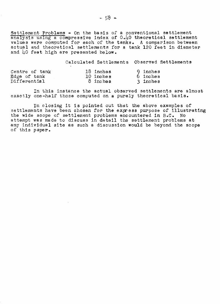
- 58 -
Settlement Problems - On the basis of a conventional settlementanalysis using a compressive index of 0.40 theoretical settlementvalues were computed for each of the tanks. A comparison betweenactual and theoretical settlements for a tank 120 feet in diameterand 40 feet high are presented below.
Calculated Settlements Observed Settlements
Centre of tankEdge of tankDifferent ia 1
18 inches10 inc he s
8 inches
9 inches6 inches3 inches
In this instance the actual observed settlements are almostexactly one-half those computed on a purely theoretical basis.
In closing it is pointed out that the above examples ofsettlements have been chosen for the express purpose of illustratingthe wide scope of settlement problems encountered in B.C. Noattempt was made to discuss in detail the settlement problems atany individual site as such a discussion would be beyond the scopeof this paper.
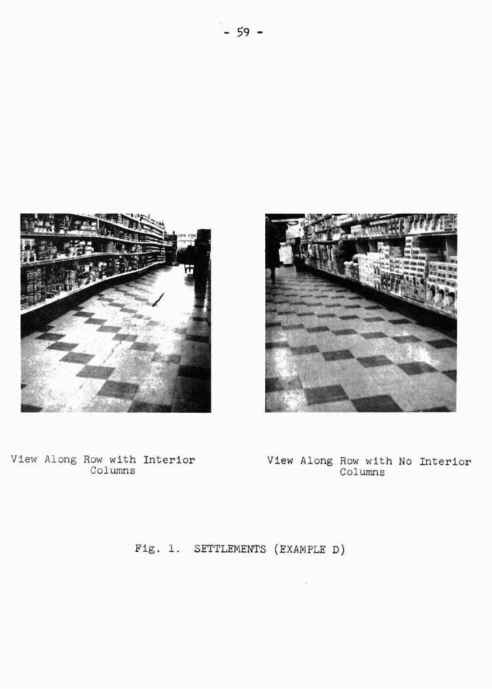
View Along Row with InteriorColwnn s
- 59 -
View Along Row wit h No InteriorCol wnns
Fig. 1. SETTLEMENTS (EXAMPLE D)

PAGE 60
o
FI LL PLACED HYDRAULICALLY TO SURCHARGE E LEV·
DEC JAN FEB MAR APR MAY JUN JUL AUG SEP
TIME - MONTHS
-4r-
セi
I ji\^セ 1_",. セセM t-6--A- セMMV 4 セ 6·2 Mョクイッ⦅ッセッ⦅ッN 1--0-0-0-t-o-o-1-0-0- -0
I / /1 x I If 0" __xj---:x-x-t--X-x-x- セ x M ャ c M I-X-X---: -x
-0/' I [NNNNセN •
セ \-0 セO !
tf;/y I i
IV1X
I
I
セ
JI
l1\-8
il LREMOVALi xl OF
1/ I PRELOAD FILL
-6J x I
nj
-4Ii ,
I
I,2
0
x
0 I
o
I- 0ZLtJセLtJ..JI- 0ILtJen
-I-LtJLtJu,-
FIGURE 2
SETTLEMENT - TIME CURVES SITE PRELOADED
TECH MEMO 41
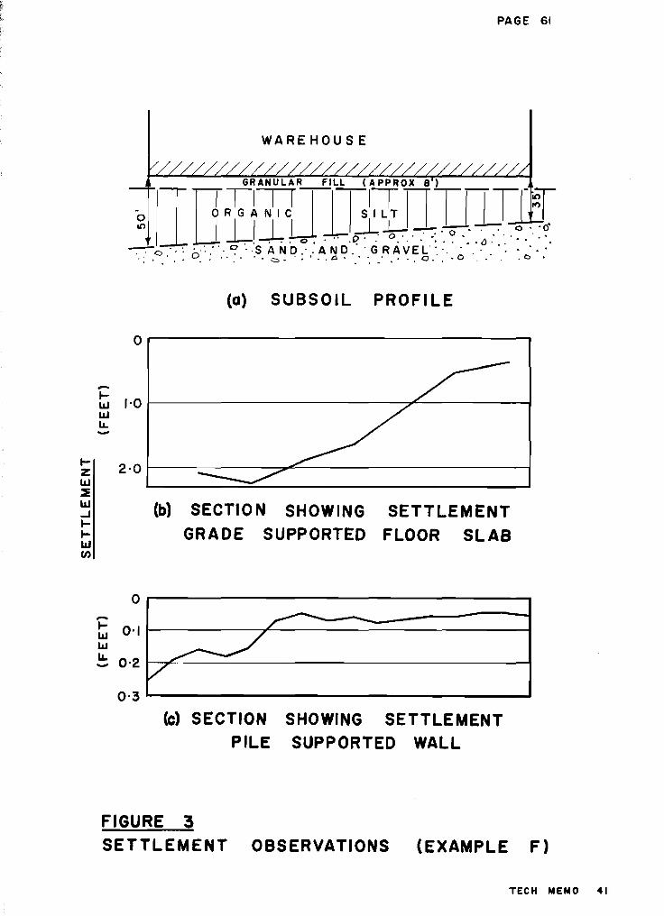
PAGE 61
WAREHOUSE
/GRANULAR FILL (APPROX 8)
i i jt G i ャ M M B ョ M M t M セ
セ I セlゥャlャャ[lセNセwᄋ「セNZセセ-:-:- '.: ᄋ L ᄋ ᄋ Z ᄋ ᄋ セ B ᄋ s a n d N ᄋ B a n d N ·GRAVEL·.·. "."" .' .'
.: .0." . . 0. . "... '. c::>. . ••• "a • .' ". .' .' . " 0" . • 0 .' . . o •
(a) SUBSOIL PROFI LE
2 -0 Q M M M M M M M M M M M Z セ Z N N N N M M M M M M M M M M M ⦅ ⦅ ⦅ Q
0,..-------------------,
(b) SECTiON SHOWING SETTLEMENT
GRADE SUPPORTED FLOOR SLAB
-セ '-0 iMMMMMMMMMMMMセNL・NNMMMMM⦅エiLlI.L.-
...ZiLlセiLl-J......iLl(f)
o
-セ 0'1iLlw
セ 0-2
0·3
r--- -
»:>V
(c) SECTION SHOWING SETTLEMENT
PILE SUPPORTED WALL
FIGURE 3
SETTLEMENT OBSERVATIONS (EXAMPLE F)
TECH MEMO 41
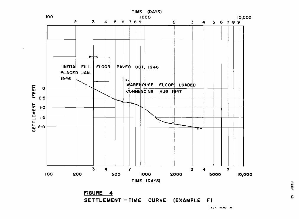
100
2 3
TIME (DAYS)
10004 56789 2 3
10,0004 5 6 7 8 9
ot:1&J1&J
セ 0'5
セ
z 1-01&J::E1&J 1-5...Jセ
セ 2'0(J)
I
INITIAL FILL FLOl,l PA IIEI OC T. 1946I
PLACE P JAN.
II
1946 t--- I........ I
........
'"AF EI 10USE FLOOR LOADE D......
I<, COMME NICING AUG 14セTW<,
--- --f----セ
1-0-1-00.....--,Mセ ._---_.
"'0セI"---
I
セ
I
3 4 7 3 4 7100 200 500 1000 2000 5000 10,000
TIME (DAYS)セ(i)
fTI
FIGURE 4セ
SETTLEMENT - TIME CURVE (EXAMPLE F)
TECH MEMO セi

PAGE 63
セ BUILDING 1セ I I I II IIIIII IIIIII i i i セ
-,., FLOOR SLAB FILL ON
セ Z[[ZGNセ セNセ GNセ «: セoMZZZᄋ Lセセ -.-:-:: o· .,: '.:-,.. ••.... " ,0 '. : .. SANO· 'ANO' :GRAVEL···· .... :.. -CZl
⦅セ ッッ\NHセ セKGヲZsifjjitヲ セ_--- セ G M G M M g B B セ B G o
0·..·.·... ,.·:·.0 : .. L セ Z .: : SA NO." AN.p· GRAVEL:·-. ·.·.0·,' ;:.,.• I NセG '. 0 .. ' " 4$ : •••. 0 . セ , . ,.... 0 '- - .... - .' '- •. <Jr, セ " • '. :) .'
(a) SUBSO I L PROFI LE
__ 0-2 1----------::::::;;;;00-=--------------1
....ILlILlu,
0.3 1--------7"''-------------------------1
セ ッ M -
.>/
°
o 0_°-0-<>-<,.d""
r;/
IZILl::EILl..J....IILlen
0'3
i= 0·2ILlILlLL....
0-1
o
(b) SECTION SHOWI NG SETTLEMENT
PILE SUPPORTED WALL
10 20 30
TIME (MONTHS)
te) TYPICAL SETTLEMENT - TIME CURVE
PILE SUPPORTED COLUMN
40
TECH MEMO 41
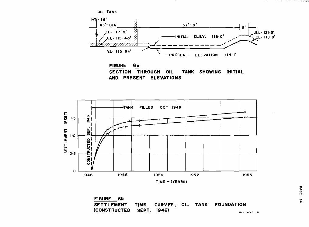
i=1IJ1IJ r- 5u,....IZ1IJ 1'021IJ..Jl-I-1IJ
en 0.5
o
OIL TANK
HTI- 36'45'-OlA .: 57'-6"
セ EL' 117. 0' 5' I-- ,
セO L. 115.46' セ i n i t i a l ELEV. 116'0' ....._kEL.121.5,I / ",'" ,EL' 118·9
セ セ O W O O G セ セ セ ", ..----..../----------- --'"EL· 115· 68'---
PRESENT ELEVATION 1/4 '1'
FIGURE 60
SECTION THROUGH OIL TANK SHOWING INITIAL
AND PRESENT ELEVATIONS
I i
I TAN< FILL 0 OC 1946 I
COlセM
i ャZャセセi "
I
I .......セ ! I
0:1 セ,...1'1.-' i
セi _ ... MNMMセセMMMMMM セM⦅N⦅セMMM セMMMM --
01
IfI
セi1
セia:: -- -_.
セ カzl81
I
1946 1948 1950 1952 1955
TIME - lYEARS)
"0J>G)
f1l
FIGURE 6b (lI
SETTLEMENT TIME OIL TANK FOUNDATIONセ
CURVES,(CONSTRUCTED SEPT. 1946)
TECH MEMO 41
- 65 -
DISCUSSION
In reply to a question from Dean Hardy, Mr. Klohn statedthat no attempt has been made to compare the measured time-settlementcurves with those obtained theoretically. Mr. Klohn added that thesecondary settlements appeared to be minor.
Mr. Klohn, in reply to Dr. Mathews, said no evidence ofstratification in the marine clays had been observed even when thesamples were dried. Mr. Lea commented that for a time the Ledaclays in Eastern Canada were considered non-stratified. Howeverrecent results show that they are.
Mr. Martin inquired if there was any knowledge of buildingon sawdust. He reported that at many old sawmill sites, there weredeep deposits of sawdust and they raised problems. Mr. Klohn statedthat it would be better to stay off the sawdust if possible. Ifit were necessary to construct on sawdust, then pre-loading thesite may be effective.
Referring to the ・ ク 。 ュ ー セ of the settlement of the tank onsand; Professor Morrison asked how the differences arise betweenthe anticipated settlements and the actual settlement. Mr Klohnreplied that the major difference in the two values is probablydue to the effects of confinement of the sand in place, on itscompressibility characteristics as determined from a consolidationtest on an undisturbed sample. A second factor affecting thecomputed settlement values would be of course the effects ofsample disturbance on the laboratory specimens.
In reply to Professor Torchinsky, Mr. Klohn reported thatthe set tlement of the tank on sand occurred rapidly and did notaffect the operation of thA tank.
- 66 -
Section 9
The Park Bridge S,lide
by
R. C. Thurber
The Park Bridge slide, discovered moving on August 11th,1954, easily shifted and broke up a large bridge abutment, eventhough it was supported by dozens of steel H piles driven intobed-rock below. The fact that this moving mass was hangingsteeply above the Kicking Horse River, the TranscontinentalRailway, and the Trans Canada Highway, and Park Bridge, indicatedto all that the danger should be eliminated even though the costwould be high.
LOCATION AND GEOLOGY OF THE AREA
The slide is located on the Trans Canada Highway andeasterly approach to the Park Bridge over the Kicking Horse
- River, eight miles east of Golden, B.C·
The area at Park Bridge has been classified as undividedthin bedded shales and limestone of the Ordovician Period andPaleozoic era. Rock of the Paleozoic eras, which usually borderPre-Cambrian shield areas, are less metamorphosed. Hore recently,the Kicking Horse River cut a valley in the rock which wassubsequently dammed to form a lake. Alluvial clay, sand andsilts were deposited in the valley, which was subsequently drained.The river cut down to rock, clearing most of the clay depositsaway. However, talus from the steep mountain sides above,covered some of the clay pockets, preserving them from erosion bythe river.
These alluvial strata of silt and clay are being exposedby the present road and bridge construction. This is true of thePark Bridge slide, although the bulk of the slide consists of aboulder clay material of glacial origin.
PRELIMINARY INSPECTION
As part of the building of the Trans Canada Highway it wasnecessary to cross the Kicking Horse River with a bridge, and aftermuch investigation the only available site was found at Mile 26.7Mountain subdivision on the C.P.R.
A contract was let and work proceeded. The easterly pierwas completed, and easterly abutment partially constructed beforewinter forced a shutdown in the fall of 1953. The abutment consisted of a standard section supported on steel H piles driven tobed-rock. In June 1954, the site was inspected and everything
- 67 -
found in order. When work was resumed at the site about Augustloth, 1954, the contractor found the abutment had cracked andshifted.
The following features were noted:
(1) A large mass was moving and had moved the abutment nineteeninches and cracked it in several places.
(2) A crack and push-ups could be traced completely aroundthe moving mass, which defined the limits very definitely.
(3) The slide was divided naturally into two sections:
a) The westerly section, consisting of about 387,000cubic yards, embraced the area with the toe justabove the pier and the railway, and includingthe abutment;
b) The easterly section, consisting of about 376,000cubic yards, embraced the remainder, with the toealong the upper ditch line of the new highway.
(4) On August 18th, 1954, gauges which had been set up showedthe ュ 。 ウ セ was moving as much as 5/8 of an inch per day, but was notdisturbing the railway or bridge pier.
(5) A small amount of seepage was noticed near the pier atthe toe of the west section. Also seepage was noticed above a blueclay stratum exposed by the road cut.
(6) Grey and blue clay seams were also exposed in theabutment excavation.
(7) The bulk of the slide appeared to be a boulder clay ofglacial origin with considerable slide talus.
(8) A valley above the slide area appeared to drain towarda ravine in the opposite direction. The valley ground is almostflat and swampy in nature. It would appear that except underheavy saturation, this would not contribute to moisture in the slide.
(9) The spoil bank of 17,000 cubic yards, on the lower sideof road, prevented the easterly part of the slide from extendingdown to the railway.
(10) The movement was felt to be a slide with a definite slipsurface, as compared to a "flown. Due to the movement being slowand of a ltcreep" nature, it was thought that there would not be asudden disastrous movement before next spring.
- 68 -
(11) Old slide escarpments were found on the slide area, and frominspection of the growth, appeared to be twenty to thirty years old.
CAUSES OF SLIDE
(1) It was learned locally, that the previous fall was verywet and an extremely heavy snowfall was experienced during thewinter. A late spring caused a high run-off and heavy saturationof the ground.
(2) The grey and blue clay strata encountered were very sensitive to moisture and contributed to the slide action.
(3) The easterly road approach to the bridge necessitated acut of over 100 feet and was made at セ to 1 slope. There is nodoubt that this cut removed the toe of the slope and contri butedto the slide.
(4) The construction of the bridge abutment left a largeexcavation which was reported to have been full of water from latefall to time of movement. This would contribute to saturation ofthe toe area, and general weakening of the lower section.
Generally it was found, after drilling, that the triggeringaction which started the mass movement, was the extremely high porepressure and lifting action of water entering at the top and notfinding a free avenue of escape. A head of 100 feet was detected,which would give an uplift of approximately 6,200 pounds per squarefoot at the slip surface. .
PROCEDURES FOR STABILIZATION
(1) Relocation of Road and Bridge - Due to the nature of thevalley, it would be extremely expensive to relocate at this point.An alternative bridge would cost over $1,000,000.00 alone. Dueto the danger to the railway, the slide would have to be stabilize4.The relocation method, was therefore discarded.
(2) Removal of the Landslide - This was a practical approach, andpartial removal was decided upon.
(3) Drainage - Very little seepage was noticed and therefore suchwork would have to be based on the results of drilling. Thiscould be considered later when drilling results were available.
- 69 -
(4) Load the Toe Area - This method has great merit and wasconsidered seriously. A study showed that the only way to londエ セ tOE would be to raise the road and bridge level. It waslearned that the structural steel for the bridge had already beenfabricated, and such a change would be very expensive, and shouldonly be considered as a last resort.
(5) Unload the Slide - This solution appeared to be the mostpractical, and entirely feasible, except from the point of viewof disposal.
Other ウ ッ セ オ エ ゥ ッ ョ ウ such as grouting! chemical treatment, etc.,did not appear applicable to this slide.
STABILIZATION PROCEDURE
iセセ・、ゥ。エ・ action was felt to be necessary and the unloadingmethod was started on September 13th, 1954. It was noted thatlittle to no movement was detected after September. Haul roadswere constructed to the upper centre of the westerly part calledthe Lower Haul Road; and to the top of the slide area, called theUpper Haul Road.
Almost 110,000 cubic yards of material were イ ・ セ ッ カ ・ 、 beforewinter forced 8 shutdown. Disposal was made one mile to the eastup a seven per cent grade. This increased excavation costs tonearly $1.00 per yard. This was unavoidable due to the railwaybelow.
The Upper and Lower Haul Roads were sloped toward the bankand compacted as surface drainage channels.
DRILLING
Drilling was arranged for immediately, and four holescompleted to bed-rock across the central portion of the slide.The material was reported 。 セ a well-graded cemented clay silt andsand with round smooth pebbles to boulders dispersed throughout.Soft clay strata were reported wi thin six feet of the slip surfacewhich had been calculated earlier. A hole located about centreof the westerly part, detected no water until it was within a fewfeet of bed-rock. Then a pressure developed and water flowed outthe top of the casing for several days.
An attempt was made to obtain good undisturbed samples,suitable for strength tests during drilling, but this was foundto be impossible due to the presence of pebbles.
- 70 -
SUBSURFACE DRAINAGE
On completion of the drilling and the detection of highpore pressure, the subject of sUbsurface drainage was considered.It was kept in mind that any stabilization work would have to beof a permanent nature, and results both positive and assessable.
With these considerations in mind a tunnel was decidedupon. Soft clay strata with high pore pressure were detected bydrilling, therefore ordinary tunnelling operations could beextremely hazardous. A 62-inch diameter, 10-gauge galvanized tunnelliner was used. An electric hydraulic poling plate arrangementwas devised to support the tunnel ahead of operations. Thissystem worked well and no trouble was experienced.
The tunnel was carried in from C.P.R. track level for200 feet then a branch to the west for 45 feet and another brancheast for 94 feet. This would drain the most critical westerlysection.
Seepage was noticed after the tunnel reached 100 feet andincreased at 149 feet. From 149 feet to 200 feet, water flowedfreely at times, and measured at 12,000 gallons per day near theᄏ セ N
The west lateral ran into boulders and pervious materialat 45 feet and so was stopped. The east lateral followed over thebed-rock for 94 feet then was stopped by a vertical face of bedrock. A hole was drilled several feet into this rock, and a goodflow of water has emitted from it since.
Operations were halted at this time and further work willbe considered when piezometer readings indicate the effectivenessof the tunnel.
The cost of tunnelling is shown in Appendix I.
Well points were jacked up 15 to 25 feet on each side ofthe "y" to intercept seepage from a possible perched water tableabove the tunnel. They produced little or no water so thisoperation was temporarily discontinued.
SLIDE ANALYSIS
Stabilization work can easily be planned to be of benefit,but an estimate of the degree of stability produced is necessary.An analysis can be based on the shear resistance of the soil basedon laboratory tests, if such are possible. o エ ィ ・ イ キ ゥ セ ・ it isnecessary to estimate an average value for "C".

- 71 -
With the above in mind, six cross-sections were analysed.It was clear that the material was not homogeneous and that bedrock influenced the slip circle. However, the arcs were arrivedat by a series of trials, and bracketing.
Prior to drilling, it was found that the removal of about300,000 cubic yards of material from the top of the slide wouldbe necessary to produce a safety factor or 1.5 with no considerationbeing given to the effects of the pore water pressure.
セ ウ shown earlier 110,000 cubic yards were removed beforewinter. On gaining the pore pressure information, it was decidedthat a subsurface drainage system would be as beneficial asremoving more material from the top, and further analyses werecarried out on this basis.
The Swedish arc circle method of analysis, proposed byPetterson, was felt to be adequate for the purpose here, and wasused for the analysis work.
Just before sliding, and with the high pore pressure, theresisting ヲ ッ イ 」 セ ウ were taken to equal the motivating forces. Onthis basis average ¢ was estimated at 20°" and average ',Ie" at1200 p.s.f. Lowering of the water table by the tunnel, ゥ ョ 」 イ セ 。 ウ ・ 、
the S.F. to 1.15; and lowering the water table and unloading,both gave an S.F. = 1.36. Based on the above computed forces, theshearing strength averaged 1.5 tons per square foot.
SOIL TESTS AND RESULTS
As noted ー セ ・ カ ゥ ッ オ ウ ャ ケ L it was impossible to obtain undisturbedsamples of the soil from the drill holes. Also it was felt that theslide itself was a large shear test and that the values obtainedfrom such would be accurate enough for purposes of analysis.
However, undisturbed samples were obtained from the siltyclay strata and unconfined compression tests gave the followingresults:
SAT1PLE I WATER STRESS STRAIN
I 26 % 22 p.s.i. 17%2 30.5?t 10 p.s.i. 15%3 24.5% 27 p.s.i. 12%4 27.9% 17 p.s.f. 17%
AVERAGE 27.2% 19 p.s.i. 15.2%
This correlates with the results computed from the slideanalysis reasonably well as the above shows 2736 p.s.f. as against3000 p.s.f. computed.

- 72 -
Piezometer readings and flow from the drainage tunnel havebeen checked ー ・ イ ゥ ッ 、 ゥ セ ャ ケ N
It was interesting to note that when drilling Holes 7, 8,and 9, (above the abutment) during July and August, 1955, forplacing further piezometers, the water frorn T.H.9 caused thewater to rise in the old test hole (below, at the abutment) fora short period, about October 1st, 1955. The water level soondropped again after drllling stopped•.
DISCUSSION
Considerable yardage has been removed from the westerlyand most important part of the slide. It appears, however, thatmore consideration should be given the easterly part where forexample at Sta 375 + 00 the S.F. is only 1.03. Further to theexcavating, it was noticed in the spring of 1955, that the haulroads being used for drainage carried the water only part waydown. Fissures and sink holes formed, and the water was lostbefore it reached the culverts.
The drainage tunnel without doubt, is lowering the waterlevels very well in the critical zone. It may be worthwhile,however, to continue the tunnel in the easterly direction whereconsiderable pore pressure is still recorded. This is outsidethe most critical zone however. The use of well points jackedout from the tunnel was disappointing. However, further effortsin this manner to tap the water bearing strata would be worthwhile.
The fact that an analysis shows the S.F. = 1.36 for the mostcritical west section indicates that a thorough recheck should bemade and pos$ibly further drainage work and possibly more excavationshould be considered. It must be kept in mind that no further movement can be tolerated in the bridge abutment.
r e c o セ セ n d a t i o n s
The following points should be considered further, toensure adequate permanent stabilization of the Park Bridge slide:
(1) Now that piezometric readings are available indicationsare that the drainage system should be extended somewhat.
(2) A complete recheck of the analysis オ セ ョ ァ mQre refineセ ・ ョ エ ウ should be carried out and if the S.F. is under 1.5 thenpossibly further excavation on the west section should be considered.
(3) Further sloping and excavation would appear to beproper on the easterly portion even though it possibly does notendanger the bridge and railway.
- 73 -
(4) Some type of surface treatment and sealing of theウ オ イ ヲ セ 」 ・ drainage ditches ウ セ ッ オ ャ 、 be carried out to prevent thesurface water entering the slide area.
(5) No changes, such as excavation of the spoil bank,etc., should be made without consulting the Materials Engineer.
In conclusion, and to the best of our knowledge, the ParkBridge slide is stable, and construction of the bridge can becontinued, but careful watch must be kept on the area and theadditional items noted above should be considered for possiblefurther acti on.
,REFERENCES
(1) Krynine, D.P. Soil mechanics
(2) Highway Research Board Bulletin 1949. Analysis of landslides.
(3) Harvard Soil Mechanics Series No. 46. Stability analysis ofslopes with dimensionless parameters.
(4) Terzaghi and Peck. Soil mechanics in engineering practice.
(5) Taylor, D. Fundamentals of soil mechanics.
(6) Nasmith, Hugh. The Yoho Bridge slide. August 12th, 1955.
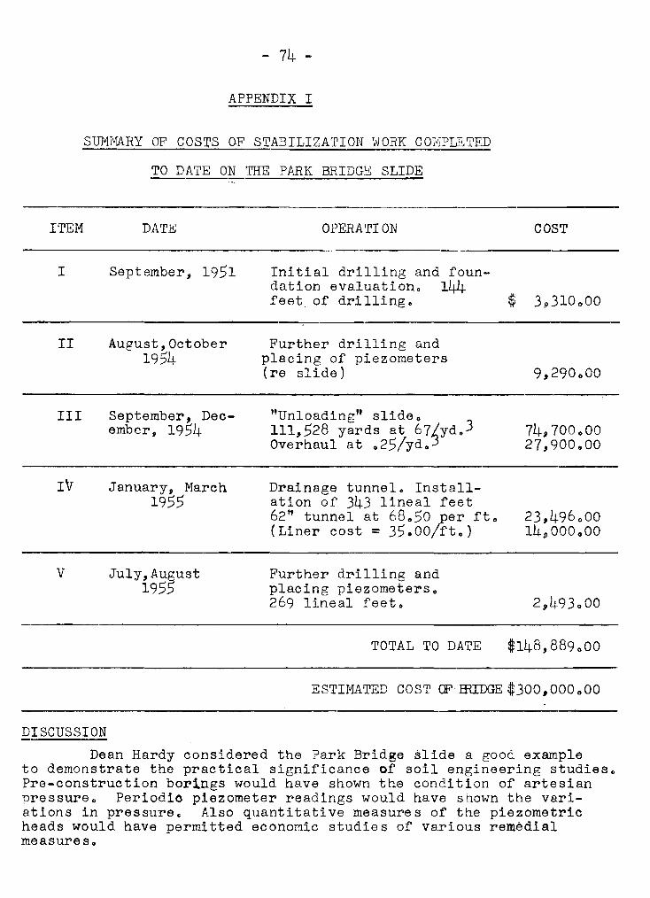
- 74 -
APPENDIX I
SUMMARY OF COSTS OF STABILIZATION vJORK COIvIPLETED
TO DATE ON THE PARK BRIDGE SLIDE
ITEM DATE OPERATION COST
I September, 1951 Initial drilling and foundation evaluation. 144feet. of drilling. $ 3.310 000
II
III
IV
v
August, October1954
September, December, 1954
January, March1955
July,August1955
Further drilling andplacing of piezometers(re slide)
"Unloading" slide.111,528 yards at 67/yd. 3
Overhaul at .25/yd.3
Drainage tunnel. Installation of 343 lineal feet62" tunnel at 68 .. 50 per ft.(Liner cost = 35.00/ft.)
Further drilling andplacing piezometers.269 lineal feet.
TOTAL TO DATE
9,290000
74,700.0027,900 .. 00
23,496 00014.0000000
$148,889000
ESTIMATED COST CF mIDGE $300,000000
DISCUSSION
Dean Hardy considered the Park Bridge slide a good exampleto demonstrate the practical significance of soil engineering studies.Pre-construction borings would have shown the condition of artesianpressure. Periodio piezometer readings would have shown the variations in pressure. Also quantitative measures of the piezometricheads would have permitted economic studies of various remedialmeasures.

- 75 -
Section 10
Measurements of Lateral Movements in Soils
by
wゥャャゥ。ュセlッ Shannon
In 1951 S.D. Wilson became interested in the developmentof an instrument which 」 ッ オ セ be used under water, and which wouldmeasure directly the slope or inclination of steel sheet pilingat various depths. From 1951 to 1954 Mr. Wilson built severalsuch instruments and used them to practical advantage. In 1954I became associated with 1w. Wilson, and we have further developedand applied the instruments not only to bulkhead problems» butalso to horizontal movements of soil and rock masses e It maybe significant to our Canadian friends that we now have nearlyas many installations for such measurements in Canada as we havein our own countrYG
This instrument, which is referred to as a "SlopeLnd Lc a bor-!", was initially developed to analyse the stability ofsa¥eral existing bulkheads which were known to be criticallystressed. The advantage of designing an instrument to measureinclination instead of deflection, is that the bending moment(and therefore the stresses) can be computed directly by graphicalprocedures from the slope diagram. The deflections likewise canbe easily computed. Therefore the two quantities in which we aremost interested are each only one step removed from the originalmeasurement and are relatively insensitive to small errors in themeasurements themselves.
The slope indicator is based upon the well-known セ ヲ オ ・ 。 エ ウ エ ッ ョ ・
Bridge circuit. It consists of a heavy pendulum inside a watertight box suspended by three insulated and shielded electriccables. The tip of the pendulum contacts a resistance coil andforms one half of a conventional Wheatstone Bridge circuit withthe other half in a control box above water. As the watertightbox is tilted the inclination of the pendulum relative -to the,box is altered, and the central arm of the precision potentiometer inside the control box is adjusted until no cur-r-ent flowsthrough the neutral wire. The true inclination of the sheet pileat any elevation is obtained by a calibration curve whichconverts instrument ,reading (with the bridge circuit in balance)to inclination.
The watertight plastic box which encloses the pendulumis mounted on two sets of wheels, each of which encloses fourAlnico bar magnets. These magnetized wheel assemblies maintaina firm contact between the rim of the wheels and the sheet piling,
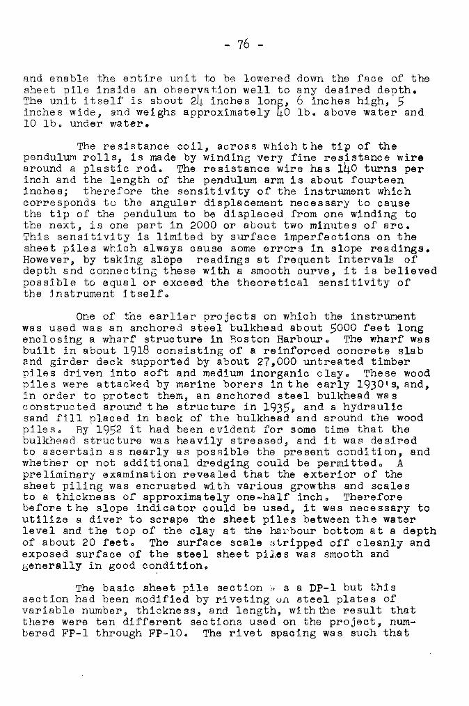
- 76 -
and enable the entire unit to be lowered down the face of thesheet pile inside an observation well to any desired depth.The unit itself is about 24 inches ャ ッ ョ セ L 6 inches high, 5inches wide, and weighs approximately 40 lb. above water and10 lbo under water.
The resistance coil, across which the tip of thependulum rolls, is made by winding very fine resistance wirearound a plastic rod. The resistance wire has 140 turns perinch and the length of the pendulum arm is about fourteeninches; therefore the sensitivity of the instrument whichcorresponds to the angular displacement necessary to causethe tip of the pendulum to be displaced from one winding tothe next, is one part in 2000 or about two minutes of arc.This sensitivity is limited by surface imperfections on thesheet piles which always cause some errors in slope readings.However, by taking ウ ャ セ ー ・ readings at frequent intervam ofdepth and connecting these with a smooth curve, it is believedpossible to equal or exceed the theoretical sensi tivity ofthe instrument itself.
One of the earlier projects on which the instrumentwas used was an anchored steel bulkhead about 5000 feet longenclosing a wharf structure in Boston Harbour. The wharf wasbuilt in about 1918 consisting of a reinforced concrete slaband girder deck supported by about 27,000 untreated timberpiles driven into soft and medium inorganic clay. These woodpiles were attacked by marine borers inthe early 1930 t s, and,in order to protect them, an anchored steel bulkhead wasconstructed around t he structure in 1935, and a hydraulicsand fill placed in back of the bulkhead and around the woodpiles. By 1952 it had been evident for some time that thebulkhead structure was heavily stressed, and it was desiredto ascertain as nearly as possible the present condition, andwhether or not additional dredging could be permittedo Apreliminary examination revealed that the exterior of thesheet piling was encrusted with various growths and scalesto a thickness of approximately one-half inch. Thereforebefore t he slope indi ca tor could be used, it was nece ssary toutilize a diver to scrape the sheet piles between the waterlevel and the top of the clay at the har-bour- bottom at a depthof about 20 feet. The surface scale Htripped off cleanly andexposed surface of the steel sheet piles was smooth andgenerally in good condition.
The basic sheet pile section." e a DP-I but thissection had been modified by riveting un steel plates ofvariable number, thickness, and length, withthe result thatthere were ten different sections used on the project, numbered FP-I through FP-IO. The rivet spacing was such that
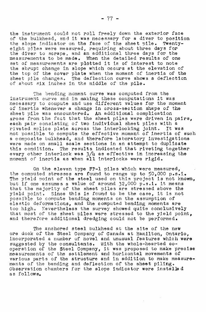
- 77 -
the instrument could not roll freely down the exterior faceof the bUlkhead, and it was necessary for a diver to positionthe slope indicator on the face of the sheet pile. Twentyeight piles were measured, requiring about three days forthe diver to scrape, and an additional three days for themeasurements to be made. セ セ ・ ョ the detailed results of oneset of measurements are plotted it is of interest to notethe abrupt change in slope which occurs at the elevation ofthe top of the cover plate when the moment of inertia of thesheet pile changes. The deflection curve shows a deflectionof about six inches in the middle of the pile.
The bending moment curve was computed from theinstrument curve and in making these computations it wasnecessary to compute and use different values for the momentof inertia whenever a change in cross-section shape of thesheet pile was encountered. An additional complicationarose from the fact that the sheet piles were driven in ー 。 ゥ イ ウ セ
each pair consistinG of two individual sheet piles with ariveted splice plate across the interlocking jointo It wasnot possible to compute the effective moment of inertia of sucha composite bulkhead, and therefore laboratory investigationswere made on small scale sections in an attempt to duplicatethis condition. The results indicated that riveting togetherevery other interlock was 3/4 as effective in increasing themoment of inertia as when all interlocks were rigid.
On the eleven type FP-l piles which were measured,the computed stresses are found to range up to 50,000 p.s.i.The yield point of the steel used on this project is not known,but if one assumes a value of around 32,000 posoi. it meansthat the majority of the sheet piles are stressed above theyield pointo Since this is found to be the case, it is notpossible to compute bending moments on the assumption ofelastic deformations, and the computed bending moments aretoo higho Nevertheless the survey showed quite conclusivelythat most of the sheet piles were stressed to the yield ー ッ ゥ ョ エ セ
and therefore additional dredging could not be performed.
The anchored steel bulkhead at the site of the neware dock of the Steel Company of Canada at h 。 ュ ゥ ャ エ ッ ョ セ Ontario,incorporated a number of novel and unusual features which weresuggested by the consultants. with the whole-hearted cooperation of the Steel Company, it was proposed to make precisemeasurements of the settlement and horizontal movements ofvarious parts of the structure and in addition to make measurements of the bending and deflection of the sheet piling.Observation chambers for the slope indicator were ゥ ョ ウ エ 。 ャ セ 、
as follows.
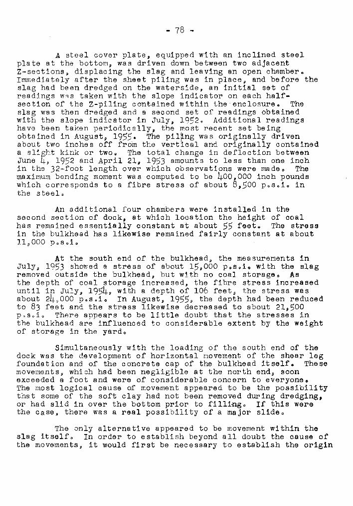
- 78 -
A steel cover plate, equipped with an inclined steelplate at the bottom, was driven down between two adjacentZ-sections, displacing the slag and leaving an open chamber.Immediately after the sheet piling was in place, and before theslag had been dredged on the waterside, an initial set ofreadings WqS taken with the slope indicator on each halfsection of the Z-piling contained within the enclosure. Theslag was then dredged and a second set of readings obtainedwith the slope indicator in July, 1952. Additional readingshave been taken periodically, the most recent set beingobtained in August, 1955. The ー ゥ ャ セ ョ ァ was originally drivenabout two inches off from the vertical and originally containeda ウャゥセィエ kink or two. The total change in deflection betweenJune 4, 1952 and April 21, 1953 amounts to less than one inchin the S R セ ヲ ッ ッ エ length over which observations were madeo Themaximum bending moment was computed to be 400,000 inch poundswhich corresponds to a fibre stress of about 8,500 posoio inthe steelo
An additional four chambers were installed in thesecond section of dock, at which location the height of coalhas remained essentially constant at about 55 feet. The stressin the bulkhead has likewise remained fairly constant at about11.9000 posoio
At the south end of the bulkhead j the measurements inJUly, 1953 showed a stress of about 15,000 posoio with the slagremoved outside the bulkhead, but with no coal storageo Asthe depth of coal storage increased, the fibre stress increaseduntil in July, 1954, with a depth of 106 feet, the stress wasabout 249000 posoio In August, 1955, the depth had been reducedto 83 feet and the stress likewise decreased to about 21,500posoio There appears to be little doubt that the stresses inthe bulkhead are influenced to considerable extent by the weightof storage in the yard o
Simultaneously with the loading of the south end of thedock was the development of horizontal movement of the shear legfoundation and of the concrete cap of the bulkhead itself. Thesemovements, which had been negligible at the north end» soonexceeded a foot and were of considerable concern to everyoneoThe most logical cause of movement appeared to be the possibilitythat some of the soft clay had not been removed during dredging,or had slid in over the bottom prior to fillingo If this werethe case, there was a real possibility of a major slideo
The only alternative appeared to be movement within theslag itselfo In order to establish beyond all doubt the cause ofthe movements, it would first be necessary to establish the origin
- 79 -
of the movements o It was decided therefore to proceed as follows:
At two locations near the south end of the dock, H-pileswith 1/4-inch steel plates welded across the flanges and closedat the bottom with a chisel point, were driven through the slagand seated キ ・ セ ャ into the hard clay. Then the slope indicatorwas lowered down each of the two 7-inch x 14-inch box openings,and slope readings taken at five-foot increments of depth.This was accomplished in the fall of 1953. Several months later,surveys from a reference line along the dock face showed thatthe top of Pile No. B, had moved out a total of 6.25 inches. Asurvey with the slope indicator was made on this date and startingat the top with this measured deflection, the deflection of thepile is as indicated. This plot shows conclusively that therehas been no movement of the underlying clay, and no movement atthe boundary between the clay and the slag. Instead the bulkof the movements have originated between depths 50 feet and 75ヲ ・ ・ エ セ corresponding to depths just below the tips of the sheetpiling in the bulkheads
Because of the high angle of internal friction of theウ ャ 。 ァ セ it was inconceivable that a failure slide was developingin the slage Therefore, the movements were only strainsassociated with the development of stresses in the slag whichhad been dumped under water in a very loose state. In such amaterial, large strains must develop before resisting stressescan build up. Likewise, large strains must develop in order toreduce the earth pressure from the "at rest" pressure to "active"pressure 0 This explains why the stresses in the sheet pilingwere higher than anticipated, and why they were influenced byloads in the ore yardo
Once the cause of the movements was understood, immediatesteps were taken to compact the underwater slag on the outsideof the bulkhead o This was done by driving a steel mandrel intothe slag at close spacingo This resulted in a settlement ofabout five feet on the outside. Horizontal movements subsequentto compacting the slag have been very small.
The H-pile movements were undoubtedly influenced by therigidity of the H-pile as compared to the rigidity of the slag.Nevertheless the success of the method led to the development ofan instrument much smaller and lighter which could be lowereddown the inside of a 3-inch plastic casing. The plastic casingis installed in a 5-inch uncased bore hole, filled with thixotropic drilling mud" The alignment tool lines Q N ャ p セ ゥ thSllflour ',,., ,longitudinal grooves which have been broached on the interior ofthe casing, and which control the azimuth of the slope indicatoras it is lowered. An installation has been made at the site of
- 80 -
a full-scale floodwall test being undertaken by the Ohio RiverDivision Laboratories of the Corps of Engineerso
These floodwall tests are still in progress and it isanticipated that the measurements taken will greatly assist usin understanding the horizontal movements which lead up to thedevelopment of a failure conditiono
In Canada p in addition to the installation at the oredock at Hanlilton, we have an installation in Vancouver in theleft abutment of Cleveland Dam. The purpose of this installationis to detect any horizontal movements of the abutment whichmight be detrimental to the integrity of the mass o Measurementsare being made every few months during reservoir fillingo Thusfar the small observed movements, in our opinion, are adjustments of the plastic casing within the hole, and elastic movements of the mass due to reservoir fillingQ
Also the p セ f ッ r ッ a ッ is now in the process of putting inseveral such installations for the purpose of measuring downhill creep of the steep abutments at sites for proposed dams.
At many of our installations the purpose of-the investigation is to assure beyond doubt that there are no lateralmovementso Such negative results are, of course, the mostdifficult to achieve, but often the most vital to the engineerand his cliento
We believe that the potentialities of such measurementsare of great interest o Already we have several successfulapplications in connection with sheet pile bulkheads and are nowapplying the method to the measurement of downhill creep andlateral spreadingo We can see much promise in the applicationto the analysis of landslide problems for with measurement ofhorizontal movements the delineation in depth of the landslidemass and its rate of movement are now possible.
- 81 セ
DISCUSSION
Krc Peterson outlined the P.F.R.A. work with the slopeindicatore PoFoR.A. had installed pipes on two projects$ oneon the clay shales of the south Saskatchewan project to measurecreep of the shales and the other to measure movements at thetoe of an earth dam. The foundation of the dam consisted of20 feet of sand and about 40 to 50 feet of clay which wasunderlain by sand, The dam will rise about 65 feet above thefoundation levele Movements of the foundation will occur duringthe construction of the dam and the slope indicator will beused to measure these movements. Thus far the dam is about 50feet high and all movements have occurred in a downwarddirection.
Mr. Trow asked if any attempt has been made tocorrelate measurements taken with the slope indicator with straingauge measurements on the sheet piling. セ キ N Shannon repliedthat a bulkhead under observation in Seattle had strain gaugesplaced on the tie rodso He did not know of any other installation where an attempt had been made to correlate measurements.
Mr o Peckover wondered if it would be feasible tomeasure both horizontal and vertical movements with the slopeindicatorc Mrc Shannon reported that thus far only horizontalmovements have been attempted. One difficulty was that theplastic pipe casing settled in the drilling mude Mr. Petersoncommented that such measurements would be highly desirable.PoFcR,Ac have considered such a matter but have not arrived atany solutiono
A luncheon followed at which Dr. Victor Dolmage$Consulting Geologist$ Vancouver$ addressed the Conferenceon what he considered to be the role of the geologist incivil engineering works.
- 82 -
Section 11
CONSOLIDATION CHARACTERISTICS OF ORGANIC SOILS
by
Paul M. Cook
This paper. presents a compilation of test data showingthat a relation exists between the coefficient of compressibilityand moisture content over a wide range of soils, from pure peatto organic clay silts. Other parts show the relationshipbetween moisture contents and the following soil properties:specific gravity, void ratio, and submerged weight.
These simple イ ・ ャ 。 エ ゥ ッ ョ セ セ セ ー ウ are $uffiQient to permitcalculation of settlement without the trouble of lengthyconsolidation tests.
GENERAL DESCRIPTION OF AREA FROM WHICH THE TESTS WERE TAKEN
Other papers given durinf the meeting mentioned severalpeat bOfs in the Vancouver area. Some of these bogs are verylarge. Toward their centres the peat is quite uncontaminated byaddition of silt and clay. However, in the smaller bogs and nearthe margins of the larfer ones, it is usual to find that thepeat is contaminated with soil to varying degrees. Moisturecontents range from 120 per cent to 800 per cent or more. Itis largely in these marginal regions that industry encountersproblems which require soil testing.
In trying to establish consolidation properties forthese sodLs it is at once apparent that a few tests may be misleading in that they may not cover the range of soils in theウ セ 」 エ ゥ ッ ョ which is present. In thinking about this problem, itis apparent that the lower moisture contents apply to soils ofa higher sail content and lesser peat content, and vice versa.Variation in moisture is extreme because not only does highersoil content mean less organic material to hold water, but inexpressing moisture as a percentage by dry weight, the value isfurther reduced by virtue of there being a greater dry weight.
This thought seems to point to a relation betweenmoisture content and specific gravity and possibly even compressibility. Accordingly, it was decided to compile all availabledata and see what relationship, if any, appeared. The resultswere quite e n'lLghtenLng as will be seen from the following figures .•
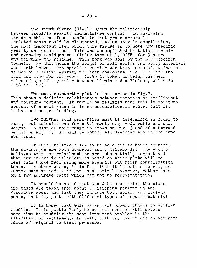
- 83 -
The first figure (Fig.l) shows the relationshipbetween specific gravity and moisture content. In analysingthe data エ セ ゥ ウ was found useful in that gross errors inisolated tests could be eliminated, saving work in compilation.The most important item about this figure is to note how specificgravity was calculated. This was accomplished by taking the airand oven-dry resid46s and firing them at 1,40o?F. for 3 hoursand weighing the residue. This work was done by the B.C.ResearchCouncil. By this means the weight of soil solids and woody materialswere both knownu The specific gravity was then computed, using thevalues of specific gravity for each component, i.e. 2.70 for thesoil and 1.SO for the v-JOOc'J. (1.50 is taken as being the meanvalue of' sne c l I'Lc grf'vity between lic:nin and cellulose, which isQ N L Q セ V to 1.52).
The most noteworthy plot in the series is Fig.2.This shows a definite relationship between compression coefficientand moisture content. It should be realized that this is moisturecontent of a soil which is in an unconsolidated state, that is,it has had no pre-loading.
Two further soil properties must be determined in order tocarry out calculations for settlement, e.g. void ratio and unitweight. A plot of void ratio is shown on Fig. 3 and of submergedweight on fゥァNセN As will be noted, all diagrams are on the sameabscissae.
If these relations are to be accepted as being correct,the advants=es are both apparent and considerable. The authorbelieves that the relationships are substantially correct andthat any errors in calculations based on these plots will beless than those from using more accurate but ヲ ・ キ セ イ consolidationtests. In other words, it is felt that it is better to rely onapproximate methods with good statistical coverage, rather thanon a few accurate tests キ ィ セ 」 ィ may not be representative.
It should be noted that the data upon which the plotsare Qased are taken from about 5 different regions in theVancouver area, and that they include both upland and lowlandpeats, that is, peats with different types of organic material.
It is hoped that セ ィ ゥ ウ paper will prompt others to similarstudies. It is particularly hoped that someone will devotesome time to studying the most important problem in theestimating of settlements in peat, that is, how to get an accuratevalue of original vertical pressure.
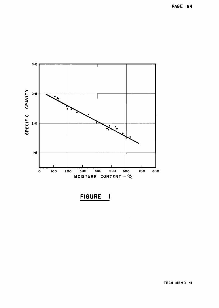
3·0
>-セ 2-5
>c(
a:C)
0
u,- 2·00UJQ.
en
セセ
t
100..
セ e. ••
<,
I I I I
PAGE 84
o 100 200 300 400 500 600 700 800
MOISTURE CONTENT - %
FIGURE
TECH MEMO 41
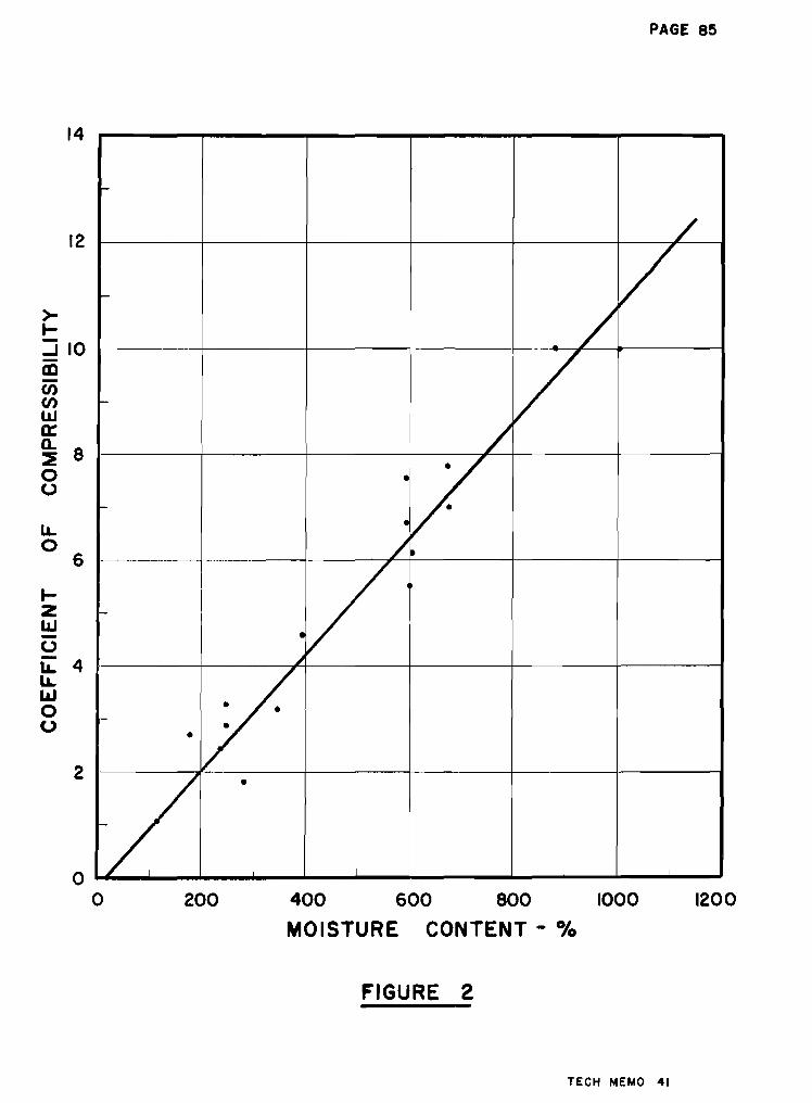
PAGE 85
1200400 600 800 1000
MOISTURE CONTENT - 0/0
200
r-
/
f- //
- //
•
/r-
•/ I
- I
•セ
• •r-
••
•
r-
I I I Ioo
12
14
>-I-:J 10rnC/)C/)
wa::a..
8セ0(,.)
u,0
6
I-ZL&J-o- 4u,u,UJ0o
2
FIGURE 2
TECH MEMO 41
PAGE 86
1000600 800
CONTENT-%
200 400
MOISTURE
I I I I I
c- 0/ -
I
I-- -
... v -
- -
-jO
I-- -
;.-
- .- -
/- -
I I I .J I
2
4
8
oo
12
10
14
oIcta:::
Q 6g
FIGURE 3
TECH MEMO 41
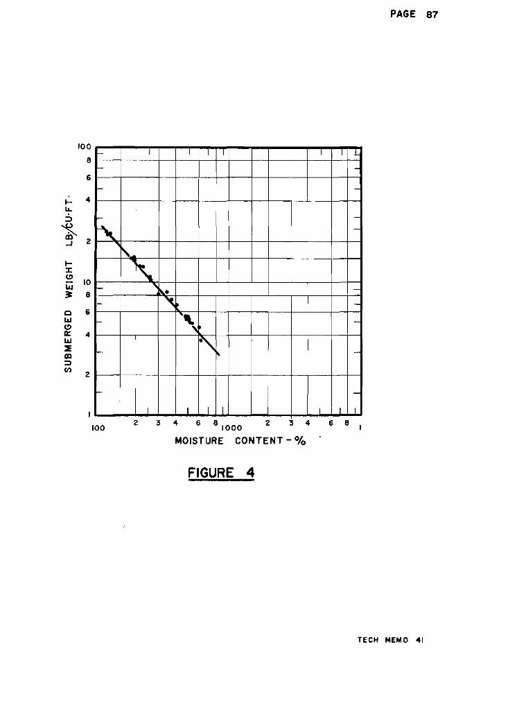
f- I I I I I I L
f- -
I- -
- -, -,
BセM
セf- セ A i | N N -
I- セ ー -
I- '\. -セ
f- ゥ セ セ -
I- -
I I I I I I I
100
8
6
.... 4u,
;:)
セ m2...J
....:t:C>
10LLI
セ 8
0 iLLIC>0:: 4LLI
セm;:)
en2
I
1002 3 4 6 8 1000 2 3 4
MOISTURE CONTENT - 0/0
FIGURE 4
PAGE 87
6 8 I
TECH MEMO 41
- 88 -
Section 12
Research at Garibaldi Lake, B.C.
by
v, H. )·'1a thews
In 1952 and 1954 I found it possible to undertakebrief field studies of sedimentation in a glacial lake, and duringthe following winters to examine samples and work up the data.'I'he results of the study are to be published 「 セ the GeologicalSociety of America which sponsored the field work. The lake inquestion, Garibaldi La.ke, lies in the Coast Mountains 45 milesnorth of Vancouver, is 4 miles long, 1 mile wide, and up to 850feet deep. It receives meltwater from 4 square miles of glaciers,ulus run-off from"12 square miles of ice-free ground. It was atfirst considered to be a tYPical small scale glacial lake, thoughone of rather great depth. Subsequent field work raises somedoubts on this assumption.
A part of the field work was devoted to the collectionof core samples of bottom sediment, a part to the determinationof the character, density, and sediment content of the lakewaters and of the glacial streams feeding the lake so as toget a better unde r-s t an dl ng of the dynamic s of sedimentation.Though the latter is of some significance, the character of thebottom sediments is of perhaps more ゥ ョ エ ・ セ ・ ウ エ N
Three types of sediment were obtained in core samples,each with a characteristic topographic association:
(1) fine-grained poorly stratified silty clay* on themore or less ウ エ ・ ・ ー ャ ケ セ ウ ャ ッ ー ゥ ョ ァ walls of the lake basin;
(2) slump breccia, consisting of more or less distortedfragments of silt and clay, from the base of the slopes;
(3) clay, silt and fine sand in well-graded beds underlying the nearly flat floor of the deep lake basin.
None of the sediment showed regular, annual varves, heretofore」 ッ セ ウ ゥ 、 ・ イ ・ 、 characteristic of glacial lakes. Probably slow sedimen-
セ セ The term clay is used for material finer than 0.002 rom.regardless of plasticity or mineral content.

- 89 -
tation together with incipient slumping may have obliteratedthin rhythmic sedimentary layers in the clays of the basin walls,and coarser detritus carried to the deeper part of the lake bynon-periodic subaqueous landslides and resulting turbidity currentshas masked. any varves developed there. More rapid sedimentationon the flat lake bottom than on the slopes is indicated. Thougnmuch clay ウ ゥ セ ・ 、 material is present, no clay minerals have beendetected, only rock-forming minerals such as quartz, feldspar,and minor micas. Porosity in the clays is high, up to 75.5 percent (114 per cent natural water content), and base exchangecapacity reaches 19 milliequivalents per gram. The clays aresensitive.
- 90 -
Section 13
Report of the National Soil Survey Committee
Saskatoon, Saskatchewan*
by
L. Farstad
Soil surveys were first started in a few provinces inCanada by grants-in-aid to universities by the provincialgovernment concerned. Later the DOminion Government gave supportto any province wishing to carryon soil surveys. This policyresulted in expansion of such work in all provinces. Atpresent soil surveys are jointly supported by both provincialand dominion governments and by agricultural colleges.
Correlation of the work of these pr-ov Lnc LaL so ilsurveys has been accepted as a Federal responsibility and inthis connection the establishment of the National Soil SurveyCommi ttee about twel;ve years ago has been of material as si. stancein promoting uniformity in nomenclature and in descriptive termsacross the country.
The meetings this year, the first since 1948, wereheld in Saskatoon on October 31 to November 5. All the committeemembers as well as a number of visitors attended the conference.The United States Department of Agriculture was represented byDr. ReWeSimmonson j Director of Soil Survey Operations and SoilClassification, Soil Conservation Service.
'The program of the Saskatoon conference was devotedlargely to the consideration and revision of subcommitteereports dealing with certain aspects of soil survey work orwith matters arising out of such work e
A few of the major accomplishments of the Saskatoonconference are briefly discussed below.
SOIL CLASSIFICATION
The system adqpted will consist of six categories andwill group our hundreds and even thousands of soil t'Ypes intoprogressively broader classes until at Category six, all our
* Information given is Q 。 セ ァ ・ ャ ケ that supplied by Dr. A. Leahey,Chairman of N.S.S.C.
- 91 -
soils are grouped into seven classes. The classes aredefined in terms of similarities or differences of the・ ョ エ ゥ セ ・ solumo Category five corresponds closely to ourconcept of Great Soil Groups. Category four corresponds tothe intergrade. Category three is a grouping of series whichhave a number of characteristics in common. This can be avery important and significant grouping in that the soilsincluded in a single class will be reasonably homogeneous withrespect to the properties affecting ai r, water and r-oot s , Category two corresponds to the soil series, while Category onecorresponds to the soil type.
The outline of classification in no way interferes withor detracts from the established concept of soil ウ ・ イ ゥ ・ ウ セ catenas,and soil zones. These concepts have been very useful and willprobably be retained and further developed.
PHYSICAL AND CHEHICAL ANALYSES
Acting on the recommendations of the subcommitteeson chemical and physical analyses, the survey organizations ineach province agreed to:
(a) Carry out the same determinations on soil profilesamples in order that the results would be more comparablebetween provinces than has been the case in the past.
(1) Method - The pipette method for mechanlcalanalyses was recommended as the standard with エ ィ セ removal ofcarbonates, sesquioxides being optional. The use of sodium Hexametaphosphate was suggested as the dispersing agent to be used;this product is widely used and commercimly available under thetrade name "Calgon".
(2) Expression of Results, - The percentages s ai d ,silt and clay to be expressed as a percentage of the total soil,organic matter, soluble salts, carbonates, iron ・ エ 」 ッ セ reportedseparatelyo A new class, heavy clay, was established for soilscontaining 60 per cent or ュ ッ セ ・ clay. Gravel ranging from 3 mm.to 3 inches reported separately as a percentage of the whole soilo
The results should be reported as percentage summationcurves whenever possible.
In chemical analyses the mineral constituents are to beexpressed as elements except in the case of soluble saltso
- 92 -
(b) Carry out collaborative studies on certain methodswhich at present appear to be unsatisfactory.
Further study will be made on the hydrometer methodof mechanical analyses and on certain methods used in chemicalanalyses.
(c) To conduct collaborative studies on determinationsnot in general use which have merit in characterizing the soils,minerals and mineralogy of the coarse fractions, viz., claymineralogy, etc.
Other tests recommended which have significance incharacterizing soils include bulk density, field capacity,permanent wilting point, Atterberg constants, etc.
SOIL MAP OF' CANADA
The National Committee is sponsori$g a soil map ofCanada which will appear in the New Canadian Atlas on a scaleof Q Z セ P million. However, on this scale only a very generalizedmap can be made. The Conference decided that a larger map wouldbe necessary to show the desired amount of information at aNational level. Hence it was agreed that the survey organizationsshould start compiling the soils information which could be shownon a map with a scale of 1:4 million. It is hoped that such amap will be ready for publication in two or three years.
- 93
Section l!t
Soils in Relation to Forestry
by
Philip G. Haddock
Today in North America foresters are only justbeginning to show serious interest in soils. This concernis greatest where economic factors have resulted in thestrongest emphasis being placed on forest restoration orthe growing of the second or third forest crop. Even thoughin much of Canada we have yet to complete the first cycle ofharvesting the crop provided unaided by nature, as professionalforesters we feel responsible for doing a better job in theinitial harvest from now on than has been generally true inmuch of the not so distant past.
My remarks are not really a report of researchefforts in forest soils in this イ ・ セ ゥ ッ ョ L but rather a prospectusof some of our more urgent problems needing solution. It is .cTear from Dr. Mathews f and Mr. Farstad1s papers エ ィ セ エ ᄋ a verylarge part of British Columbia is primarily useful only for thegrowing of wood crops. We do not know enough about our vastforest resources yet to give a very accurate estimate of thetotal area of productive forest soils in the Province, but itis certainly many times that of the total potentially arableland.
As foresters, we naturally believe that we mustpractice sustained yield, or at least aim at it, and such agoal seems to have been accepted by the publico If we are tolearn what the sustained yield potential actually ゥ ウ セ we havea great deal to learn about our forest soilso
Forest ァ イ ッ キ エ ィ セ or ケ ゥ ・ ャ 、 セ depends upon a great complexof biotic, climatic» and edaphic or soil factorso The diversityof forest types and the range in forest land productivity in theProvince are very great, as might be expected from the physiographic and climatic diversity so vividly brought out by someof yesterday1s speakers. Of these. factor complexes, the soilfactors are surely as tangible as the biotic factors andcertainly are more subject to t he direct or indirect influenceof the forest manager than are the climatic factorso Hence webelieve, with some logic, that if the forest resource as a
セ 94 -
whole is the main arch in the bridge supporting a permanentlyprosperous provincial economy (we are told that half ourdollars are "wooden" ones), then our forest soil resourcesform the keystone in that archo
Recognition of this in the Pacific Northwestgenerally was reflected in the organization in 1949 of theForest Soils Committee of the Douglas Fir Region o Thisc ッ セ ュ ゥ エ エ ・ ・ is a co-operative group consisting of foresters,soil scientists» engineers, and others from federal, state,provincial, and industrial organizationso Although most ofthe members are resident in Oregon and Washington, the groupincludes several active workers in British Columbia 0 Thecommittee has held numerous conferences, sponsored elementaryshort courses in forest soils, and conducted forest soilウ ケ ュ ー ッ ウ ゥ 。 セ and is actively promoting forest soils researchprograms 0 A project currently underway is the preparation of aforest soils manual aimed to help the practising foresterto gain a better understanding of the ウ ッ ゥ セ that produce hissaw- and ー オ ャ ー セ ャ ッ ァ ウ ッ Several Canadians have contributed tothis efforto
Now we should look at some of our major problemso
The nature of the forest crop, the character of theland that forests occupy, and the relatively low per-acrevalues involved, arevent the forester from exerting as muchdirect control over soil productivity as the agriculturistcan economically justifyo Although he usually cannot affordto put much effort into improving the productivity of forestャ 。 ョ 、 セ the forester finds it quite ゥ ュ ー ッ セ エ 。 ョ エ to be able todetermine where the most productive soils are located andequally important to make sure that his operations do notreduce their productivityo It is all too easy to induce sitedeterioration through careless logging, and very time consumingand costly to rehabilitate the soil o This we know fromexperience elsewhere, but we lack adequate data for ourlocal species as to what soil properties are most importanthere to ヲ ッ イ セ ウ エ growth and what our forest practices may bedoing to the soil's 」 。 ー 。 」 ゥ エ セ to produce another crop of treeso
The first group of major problems, then, relates to theevaluation of forest soils in terms of their wood=producingcapacityo The second group relates to the probable effects oflogging practices on forest regeneration and the third grouprevolves around the effects of forest practices on the watercycle and related influences of the foresto
Some progress is being made on the first group, andfour or five papers have been published in the United states
"c'- '-;/:; -
',8alinG with corr-elations between forest soil characteristics;';(le1 site quality f01° Douglas firj> all of them since 19470
P8 st dies 8].1 ゥ ョ H G セ ゥ X X エ ・ a セエイッョァ correlation:etV'IGen <:'",';C: qua Ll t : arid total de p t.h of soil available forc:::ot de ve Lopme n t; , soil texture in the upper horizons, andlrginace conditionso The effects of these factors are
--'odified considerably by rainfall and topography, and sometimes by other factors.
Some related studies indicate that soil organicma t t.er- content an d humus types, c he ml c a L 5nfluences of parentmaterial. weathering processes, f1.re history, or standcomposition may also exert 80me important influencesot セ ヲ ッ イ エ オ ョ 。 エ ・ ャ ケ very little work has been accomplished in thesef Le Ld s , Ground ve ge t a t Lcn and "p Lan t Lnd Lc a t.or-s " have alsobeen investigated extensively by some workers who have foundcorrelations of these with soil type and forest site quality.
The second group of problems - that relating tologging and other forest practices covers a tremendous rangeeDuring the process of initial timber harvest and conversionto managed stands, we need to be sure that soils are maintained at a hi8h level of productivity. We need to recognizepractices that lead to soil damage and how to measure them,an d mus t then proceed promptly to educate the practisingforester, the logger, and the general public in order toュ ゥ ョ ゥ ュ ゥ セ ・ or eliminate such practices. It is one thing torecognize damage, but quite another to express it in termsof dollars and cents to be put up against logging costsoLoggers are now moving into steeper country, where soilsare thinner and more unstable and subject to erosion.. Somerre t.ho da of harvesting old-growth timber, especially on sometypes of soils) mc1 Y eau se excessive soil disturbance becauseof poorly planned or constructed access イ ッ 。 、 ウ セ the use ofunsuitable cutting practices and logging ・ ア オ ゥ ー ュ ・ ョ エ セ orexcessive use of fire in slash disposal. Soil erosion, soilcomnaction, changes in levels of ground water, and loss ofsoil nutrients are 811 ways in whl ch site quality may belowered to varying degrees. Logging practices are receivingclose attention and although improvements are being made, wes t l L'I lack proper means for measuring the significance ofmany of these changes. The use of fire for slash disposal asa means of hazard reduction is receiving closer scrutiny asfire prevention and control measures are improvedo On theother hand i there are instances where some modification in thecondition of the surface soil layers is necessary or desirable in order to create more favourable conditions forgermination and establishment of desired species when naturalor artificial reproduction by seed is the aimo Whether

= 96 =
mechanical means of scarification or controlled burning canbest accomplish these ends is also in need of further investigationo
The third major area of growing concern in mountainousWestern Canada and United States is that coming under thegeneral heading of watershed management. This field dependsupon a knowledge of forest influences in which are includedall aspects of the effect of £orests upon the water cyc1eoThese include, among others, the influence of forest cover uponinterception, microclimate, transpiration losses, surface soil・ カ 。 ー ッ イ 。 エ ゥ ッ ョ セ pail porosity and infiltration capacity, surfacerun-off, soil moistlwe, snow storage and melting rate, erosioncontrol and streamflow. The influence of the forest on all ofthese factors, of course, differs greatly from place to placeand the relative tmpor bance of these factors likewise variesgreatly with the kind of forest cover. Much of our mountainforest lands, particularly in the more arid regions, may bemore valuable for their influence on soil stabilization andregulation of streamflow than for their wood-producing capacity.Keasurements of these influences are needed if the managementof such lands is to be effectively planned. Research in theRocky l\;ountains ha s shown that timber utilization and goodwatershed management may go hand in hand providing that properprecautions are taken. Harvest of the timber crop may increasethe usable streamflow by decreasing interception and transpirationlosses and increasing the accumulation of snow. h ッ キ ・ カ ・ イ セ ifsoil erosion is to be kept under control, great care is essentialin the operation, especially on some soil types on steep terrainand where rainfall intensities are high. We have alreadylearned from some past mistakes how essential it is to secureco-operation between forest engineers and forest managersif we are to avoid costly errors due to poor logging roadlocation and construction. Building of truck roads to bestadvantage requires much more care and knowledge of regionalァ ・ ッ Q P ァ ケ セ soils and hydrology than has been evident in the past.
Even the use of the modern tractor for skidding logsmay cause serious damage to the soil under certain conditionsoIn his study of residual soils on highly productive Douglasfir sites in the State of Washington, Steinbrenner has shownthat main tractor skid-roads covered 26 per cent of the arealoggede On these portions of the cutover, the tractor reducedsoil permabi1ity by 93 per cent and Lnc r e a sed bulk darn 81 ty()ofthe surface soil by IS per cent. These changes remain to beevaluated in terms of soil productivity lossese The effects ofcompaction may also contribute to increased surface run-offand soil erosion. In some areas, skid-roads are covered withbrush or slash, ditched for drainage, or seeded to grass after

- 97 -
completion of loggingo Problems such as these are of muchconcern to western forestersv
I have not mentioned the studies of soil moisturetrends in relation to radial growth on several Douglas firsites being carried out by DrQ Griffith of our FacultY$ northose being undertaken by a private firm on Vancouver Islandto do with the influence of chemical fertilizers on growthon poor soils, nor problems of forest nursery soil managementbeing studied by the BeCo Forest Serviceo The improvementof forest nursery stock, investigations of the mineralnutrient requirements of forest trees and a host of othersimilar subjects are all in need of more studyo
In conclusion, it is my opinion that ten times thepresent effort in the field of forest soils research wouldscarcely be enough in view of its importance to the basicindustry of British Colunmia o
- 98 -
Section 15
Reports of Research Work at the Divisionof Bui1cUijrr h ・ ウ ・ セ 」 ィ N l N j ヲ 。 エ ゥ ッ ョ 。 セ Research Council
(a) Review of Work of Soil Mechanics Section - C.BoCrawford
Much of the work of the Soil Mechanics Section of theDivision of Building Research durinf: the past year has beendevoted to the study of soil moisture and its effect on thenhysical characteristics of the soil. A neutron moisturemeter was constructed and tested in the laboratory. Theinvestigation of the performance of electrical-type moisturemeters was continued. Laboratory studies of swelling andshrinkage 」 ィ 。 イ X セ エ ・ イ ゥ ウ エ ゥ 」 ウ of marine 」 ャ セ ケ were carried out.
Interest in ground temperatures snd frost action has beenmaintained. Temperature ュ ・ 。 ウ オ イ ・ セ ・ ョ エ ウ and the collection offrost penetration data across Canada is being continued. Aspecial apparatus for studying the frost action phenomena wasconstructed and put into operationo Equipment for measuringunsaturated permeability constants and surface area has beendeveloped in connection with frost action study. ,Further development of the study of muskeg has taken place. Much literatureon the subject has been reviewed and a successful meeting onresearch was held. p イ ・ ャ ゥ ュ ゥ ョ ア セ ケ field work has been carried oute
Long term ウ エ セ 、 ゥ ・ ウ of building settlements are continuingoAn extensive detailed sturly of movements in shallow foundationsdue to seasonal changes in subsoil water conteQt is being carriedout. Many interesting measurements Here made during the s urnme rof Q Y U U セ when extreme weather conditions were encountered. Vanetesting equipment was designed and built and correlation studiesbetween the vane and laboratory tests were made. An extensivestudy of the effect of sampler size on soil test results wasmade.
Interest in two large construction projects, at steepHock Iron 11ines and the Labrador iron development, was continued c,
Co-operative work with ァ ・ ッ ャ ッ セ ゥ ウ エ ウ L soil ウ 」 ゥ ・ ョ エ ゥ ウ エ ウ セ
forestry engineers and climatologists has continued to illustratethe value of co-oneration in these fields.
(b) An Evaluation of the Effect of Sampler Size on SampleDisturbance for s ・ ョ ウ ゥ エ ゥ カ セ Leda Clay - W.J.Eden
Because of the extreme sensitivity of the Leda clay in theOttawa area, there has been considerable apprehension about effectof sampler size on sample di s t ur-b anc e , .IvIost of the sampling wor-k

- 99 -
is done with 2" ¢ Shelby tubes. To obtain larger samples meansthe driller must carry extra equipment and the cost of samplingincreases 。 ー ー イ ・ 」 ゥ 。 「 ャ ケ セ
An opportunity to look into this problem was presentedwhen a drainage pit for a service tunnel was excavated at theMontreal Road Laboratories of N.R.C. This pit was sunk 18 feetin Leda clay. From the bottom of the pit, three 5tt ¢ samples,three 3" ¢ samples, three 2i" ¢ samples and three 2" ¢ sampleswer-e taken from the s ame elevation. The samples were all thinwalled and their kerf ratio and inside clearance were close tothat recommended by Hvorslev.
rrhe 2 tt ¢, RセB ¢ and 51t ¢ were conventional Shelby tubesamplers equipped wIth. a ball check valve. The 3" ¢ samplerwas a stationary piston type. The 2" ¢, 2i" ¢ and 31t ¢ werepushed in by hand with one rapid stroke. It was necessary touse two or three taps of a 140 lb. hammer to advance the 5t
• ¢samplers.
The samples were taken inNovember, 1954 to February, 1955.stored in the sample tubes sealedtemperature humid room.
July 1954 and tested fromIn the interval, they were
with Petrowax in a controlled
To test, each sample was jacked out in the same directionas it had entered the tube. As エセ・ samples were extracted, theywere cut into test cylinders according to a pre-arranged testingschequle for triaxial and consolidation tests.
Triaxial Tests
Seventy triaxial tests were conducted to de t er-mt ne :1) if sampler size had any effect on strength; and 2) if sidepressure was necessary in this clay.
Results
All tests - 70 tests
Overall Average
"ttIt
It
1.080.961.181.121.38
エ ッ ョ ウ O ヲ セ Rton/fttons/ft2
tons/ft2
tons/ft2
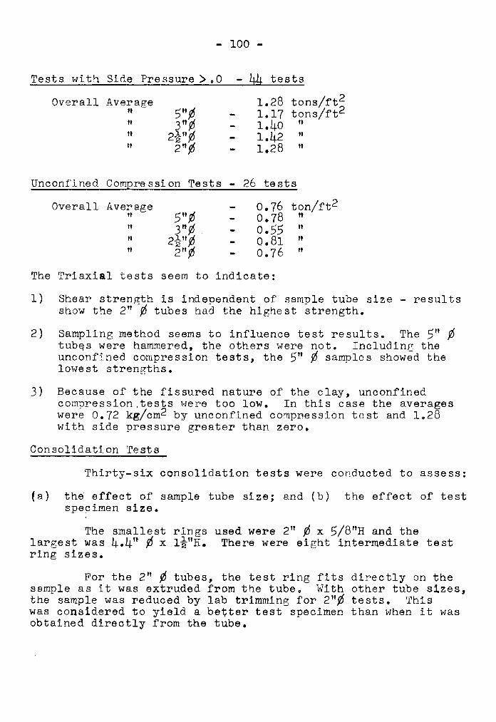
- 100 -
Tests with Side Pre ssure >•a - 44 tests
Overall Average 1.28 tons/ft2,.
5"¢, 1.17 tons/ft2
" 3 ft ¢. 1.40 ft
It 2i"¢' 1.42 "n 2 t1¢' 1.28 It
Unconfined Compre ssi on Tests - 26 te sts
Overall Average 0.76 ton/ft2
" 5",0 0.78,.
f' 3",0 0.55 It
" RセBᄁN 0.81 11
tI 2 ft ¢' 0.76 "
The Triaxial tests seem to indicate:
1) Shear strength is independent of sample tube size - resultsshow the 2" ¢ tubes had the highest strength.
2) Sampling method seems to influence test results. The 5" ¢エオ「セウ were hammered, the others were not. Including theunconfined compression tests, the 5" ¢ samples showed thelowest strengths.
3) Because of the fissured nature of the clay, unconfinedcompression ,tests were too low. In this case the averageswere 0.72 kg/cm2 by unconfined compnession test and 1.28with side pressure greater than zero.
Consolidation Tests
Thirty-six consolidation tests were conducted to assess:
(a) the effect of sample tube size; and (b) the effect of testspecimen size.
The smallest rings used were 2" ¢ x 5/8"H and thelargest was 4.4" ¢ x ャセBhN There were eight intermediate testring sizes.
For the 2" ¢ tubes, the test ring fits directly on thesample as it was extruded from the tube. With other tube sizes,the sample was reduced by lab trimming for 2",0 tests. Thiswas considered to yield a better test specimen than when it wasobtained directly from the tube.
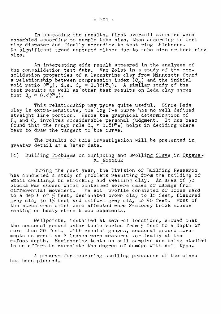
- 101 -
In assessing the results, first over-all avera3es wereassembled according to sample tube size, then according to testring diameter and finally according to エ セ ウ エ ring エ ィ ゥ 」 ォ セ ・ ウ ウ N
No significant trend appeared either due to tube size or test ringsize.
An interesting aide result appeared in the analyses ofthe 」 ッ ョ ウ セ ャ ゥ 、 。 エ ゥ ッ ョ test data. Van Zelst in a study of エ セ ・ Gonウ ッ ャ ゥ 、 。 エ ゥ ッ セ properties of a lacustrine clay from Minnesota founda relationship between compression index (C e ) and the initialvoid ratio (eo), i.e. Cc = 0.38(e o ) . A similar study of thetest results as well as other test イ ・ ウ オ ャ エ セ on Leda clay showsthat Cc = 0.8(e o ) "
This relationship may prove quite useful. Since Ledaclay is extra-sensitive, the log P-e curve has no well definedstraight line portion. Hence the graphical determination ofPn and Cc involves considerable personal judgment. It has beenfound that the rough rule Cc = 0.8(e o ) helps in deciding wherebest to draw the tangent to the curve ..
The results of this investigation will be presented ingreater detail at a later date.
(c) Building Problems on Shrinking and .swelling Clays in OttawaM. Bozozuk
During the past year, the Division of BUilding Researchhas condu<;:ted a study of problems resulting from the building ofsmall dwellings on shrinking and swelling clay. An area of 30blocks was chosen which contalned severe cases of damage fromdifferential movement. The soil profile consisted of loose sandto a depth of 5 feet, desiccated brown clay to 10 feet, fissuredgrey clay to 15 feet and uniform grey clay to 90 feet. Most ofthe structures which were affected were 2-storey brick housesresting on heavy stone block basements.
Wellpoints, installed at several locations, showed thatthe seasonal セ イ ッ オ ョ 、 water table varied from 5 feet to a depth of,-more than 20 feet. With special gauges, seasonal ground move-ments as great as 2 inches were measured vertically at the6-foot depth. Engineering tests on soil ウ セ セ ー ャ ・ ウ are being studiedin an effort to correlate the degree of damage with soil type ..
A program for measuring swelling pressures of the clayshas been planned.
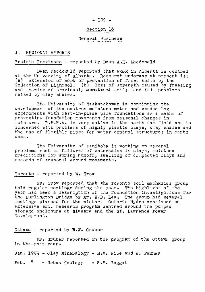
- 102
Section 16
General Busine s !'l
1. REGIONAL REPORTS
Prairie Provinces - reported by Dean A.E. Macdonald
Dean Macdomld reported that work in Alberta is centredat the University of Alberta. Research underway at present is:(a) extension of work of prevention of frost heave by theinjection of Lignosol; (b) loss of strength caused by freezingand thawing of previously セ 。 セ ・ 、 soil; and (c) problemsraised by clay shales.
The University of Saskatchewan is continuing thedevelopment of the neutron moisture meter and conductingexperiments with cast-in-place pile foundations as a means ofpreventing foundation movements from seasonal changes inmoisture. P.F.R.A. is very active in the earth dam field and isconcerned with problems of highly plastic clays, clay shales andthe use of flexible pipes for water control structures in earthdams.
The University of Manitoba is working on severalproblems such as failures of watermains in clays, moisturepredictions for spring runoff, ウ キ セ ャ ャ ゥ ョ ァ of compacted clays andrecords of seasonal ground rrovements.
Toronto - reported by W. Trow
Mr. Trow reported that the Toronto soil mechanics groupheld regular meetings during the year. The highlight of theyear had been a description of the foundation investigations forthe Burlington Bridge by Mr. N.D. Lea. The group had severalmeetings planned for the winter. Ontario Hydro continued anextensive soil research program centred around the pumpedstorage enclosure at Niagara and the st. Lawrence powerDeve lopmen t ,
ottawa - reported by W.W. Gruber
Mr. Gruber reported on the program of the o エ エ 。 セ groupin the past year.
Jan. 1955 - Clay Mineralogy - H.M. Rice and E. Penner
Feb. " - Urban Geology - R.F. Legge t
- 103 -
Mar. 1955 - Permafrost Investigations at Aklavik - J.A. Pihlainen
Apr.
May
June
Nov.
If
"
"
- Application of Electro-osmosis - Dr. G.G. Meyerhof
- Discussion of Foundation Section of National BuildingCode - S.G. Frost, W.R. Schriever and R.F. Legget
- BUilding Problems on Shrinking Clays - M. Bozozuk
- Quebec North Shore and Labrador Railway-C.B.Crawford and W.J. Eden
Montreal - reported by C. Brodeur
Mr. Brodeur reported that theabout seven meetings during the year.had been marred by the untimely deathQuintal. Three meetings were planned
Montreal group had heldThe group's activities
of the Chairman, Mr. R.for the immediate future.
Maritimes - reported by H.W. MacFarlane
Professor MacFarlane reported that no organized studygroups existed in the Maritimes. However two schools, theUniversi ty of New Brunswick and Nova Scotia Technical College,gave engineering instruction in soil mechanics. Dr. G.G.Meyerhof is now at Nova Scotia Technical College and will bestarting soil mechanics research.
Outside the universities the construction of the TransCanada Highway had raised some problems especially in CapeBreton Island. There were several instances of sink holes ingypsum deposits. In some localities there was a scarcity ofhigh quality aggregates.
2. Soil Mechanics Subcommittee
The Chairman reported that the Soil Mechanics Subcommittee had been organized along more formal lines. Mr. R.Peterson is Chairman and membership included the six regionalrepresentatives (BoC., Prairies, Toronto, Ottawa, Montreal andthe Maritimes), the Secretary of the Canadian Section of theI.SoS.M.F.E., Dr. A Leahey, Chairman of the National SoilSurvey Committee and Dr. V.K. Prest of the Pleistocene Sectionof the Geological Survey of Canada. The Subcommittee wouldhenceforth be responsible for arranging the program of theAnnual Soil Mechanics Conferences.
- 104 -
Sセ Muskeg Subcommittee
Dr. N.W. Radforth, Subcommittee Chairman, reported onthe wo rk of the Muskeg Subcommi ttee • A '\Ve stern Muskeg Re searchMeeting was held in Edmonton, February, 1955. Over 50 were inattendance for the one-day session. An eastern meeting wasplanned for .ue be c City on February 22nd. Referring to his ownwork, Dr'" Radforth stated that he had found 16 categories oforganic material based on structure.
4. Land81ide Subcommittee
Mro N.D. Lea, Subcommittee Chairman, stated that thethird meeting of the Subcommittee would be held that evening.A ーッウゥエゥカセ program for a research program on landslides in thesensitive ffi8rine clays of the st. Lawrence Valley would besuggested.
5. Canadian Section of the r.S.S.M.F.E.
Mr. Crawford, Secretary of the Canadian section,referred to'a circular letter sent to the Canadian membersasking for reports of their activities for 1955. He outlinedthe plans for the Fourth International Conference to be heldin Britain in August, 1957. Suromaries of the Canadian papersmust be presented by March 1st, 1956, and papers were to becompleted by August, 1956.
60 Other Business
(a) Soil Classification
ス セ イ ッ Peterson told of the VIOrk of a special committeeestablished two years ago to look into the question of soilclassification. The first part of the committee's work hadbeen completed with the publication of ttA Guide to the FieldDescription of Soils for Engineering Purposes". This wasdistributed by the Associate Committee on Soil and SnowMechanics of the National Research Council as TechnicalMemorandum Noo 37.
(b) One-Point Liquid Limit Procedure
Mro Eden reported that the Soil Mechanics Sectionof the Division of Building Research had looked into the onepoint method. This study was distributed to those in attendance at the Conference (see Appendix A).
- 105 -
(c) Tenth Qanadian s セ ャ f/echanic s Conference
Mr. Peterson stated that t he Tenth Conference would beheld in Ottawa in December, 1956. Since it will be セ ィ ・ tenthconference, a special effort would be made for the program. DroTerzaghi had been ihvited to attend.
The Chairman then patd tribute to the VancouverCommittee which organized·the Conference. Dean Hardy moved avote of thanks to Dean Gunning and Dean Eagles and their staffof the University of British Columbia for their part in thearrangements.
Mr. C.F. Ripley, Chairman of the Vancouver OrganizingCommittee, then adjourned the Conference at 4.30 p.m.
Appendix A
Trial of One-point Liquid Limit Method
by
W.J. Eden
rr1he r e has been considerable attention devoted to thesimplification of the liquid limit procedure in recent years.This was started by the U.S. Corps of Engineers (1) and extendedby the U.s. Bureau of Public Roads under Olmstead (2) 0 Thesimplified or one-point method consists of determining the numberof blows at one water content for a soil, and by a process ofextrapolation determining the liquid limit. Thus the one-pointmethod will significantly reduce the cost of liquid limit determinationso
Olmstead (2) has suggested that many checks on the one-pointmethod be made by other laboratories. If such analysis leads toreasonable accuracy, then steps can be taken to adopt the one-pointmethod as a standard test by such bodies as the American SOCo forTesting Materials and American Association of state Highway Officials.
At the Eighth Canadian Soil Mechanic's Conference (3) セ theresults of analyses of three Canadian soils were presentedo Since thenthe analyses have been extended to include 390 liquid limit determinations. Most of the determinations were on soils from the Ottawa andSteep Rock Lake areas, but some test results on soils from all partsof Canada were included. The analyses were conducted by assemblingthe 390 determinations made by use of three or more points. Fromthese test results, .. one determination at "Nft blows was chosen and theliquid limit was calculated using the coefficient tabled latero Thisvalue of liquid limit was tabulated against the value determined bythe conventional method. N was taken anywhere between 15 and 35blows; in most cases it was taken between 15 and 20 or 30 and 35blows.
The maxumum difference between the values of liquid limit was606 per cento This sample contained an appreciable amount of organicmaterial and should not have been included; 95 per cent of the 390tests had discrepancies less than 2 per cent and 67 per cent less than1 per cent. Thus practically all the tests, except those on organicsoils, fall in the 2 per cent limit set by Olmstead, in spite of thefact that values of N were deliberately chosen between 15 and 20 or30 and 35 wherever possible. If the number of blows was between 20and 30 in all cases, a much closer comparison would have resulted.
The results of this study have led us to adopt the ッ ョ ・ セ ー ッ ゥ ョ エ
method as a standard test in our laboratory, subject to the following
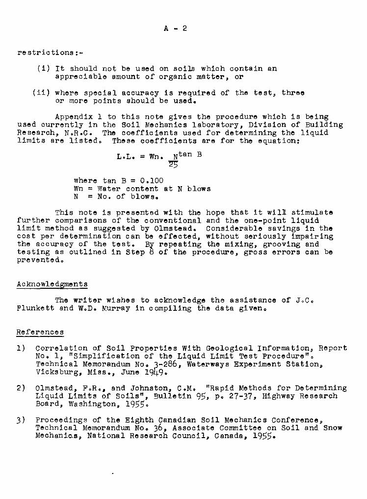
A - 2
re stric tions :-
(i) It should not be used on soils which contain anappreciable amount of organic matter, or
(ii) where special accuracy is required of the test, threeor more points should be used.
Appendix 1 to this note gives the procedure which is beingused currently in the Soil Mechanics laboratory, Division of BuildingResearch, NoR.C. The coefficients used for determining the liquidlimits are listed. These coefficients are for the equation:
L.L. = Wn. Nt an B"25
where tan B = 0.100Wn = Water content at N blowsN = No. of blows.
This note is presented with the hope that it will stimulatefurther comparisons of the conventional and the one-point liquidlimit method as suggested by Olmstead. Considerable savings in thecost per determination can be effected, without seriously impairingthe accuracy of the test. By repeating the mixing, grooving andtesting as outlined in Step 8 of the procedure, gross errors can bepreventedo
Acknowledgments
The writer wishes to acknowledge the assistance of JoCoPlunkett and W.D. Murray in compiling the data giveno
References
1)
2)
Correlation of Soil Properties With Geological Information, ReportNo.1, "Simplification of the Liquid Limit Test Procedure".Technical Memorandum Noo 3-286, waterways Experiment Station,Vicksburg, Miss., June 1949.
Olmstead, FoR., and Johnston, C.M. "Rapid Methods for DeterminingLiquid Limits of Soils", Bulletin 95, po 27-37, Highway ResearchBoard, Washington, 19550
Proceedings of the Eighth Canadian Soil Mechanics Conference,Technical Memorandum No. 36, Associate Committee on Soil and SnowMechan Ic.e , National Research Council, Canada, 1955.
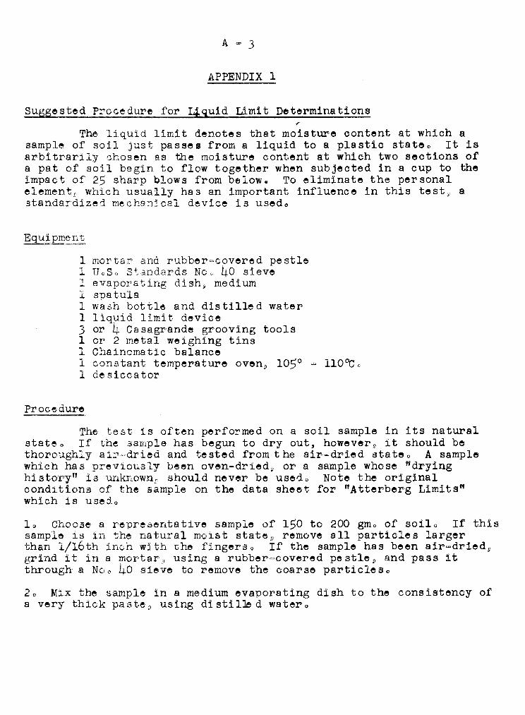
A = 3
APPENDIX 1
Suggested Prooedure for i4quid Limit Determinations!'
The liquid limit denotes that moisture content at which asample of soil just passes from a liquid to a plastic stateo It isar-b I trarily ch oaen as the moisture content at which two sections ofa pat of soil begin to flow together when subjected in a cup to theimpact of 25 sharp blows from belowQ To eliminate the personalelement v which usually has an important influence in this test» astandardized mechanical 、 セ カ ャ 」 ・ is usedo
1 ュッイエ。セ and rubber=covered pestle1 UoSo Standards Noo 40 sieve1 evaporating 、 ゥ ウ ィ セ medium1 spatula1 wash bottle and distilled water1 liquid limit device3 or 4 Casagrande grooving tools1 or 2 metal weighing tins1 Chainomatic balance1 constant temperature oven, 1050
= 11000 0
1 desiccator
Procedure
The test 1s often performed on a soil sample in its naturalstateo If the sample has begun to dry out, however» it should bethoroughly a iZ'=dried and tested from t he air-dried state 0 A samplewhich has pr-ev t ous Iy been overr-dr-Le d , or a sample whose "dryinghi s cor-y" is unknown; should never be used 0 Note the originalconditions of the sample on the data sheet for "Atterberg Limits"which is usedo
10 Choose a representative sample of 150 to 200 gm , of so i.L, If thissample is in the natural moist stateD remove all particles largerthan 1/16th inch with セ ィ ・ fingerso If the sample has been air=dried»grind it in a ュッイエ。イセ using a rubber-covered pestle g and pass itthrough a Noo 40 sieve to remove the coarse particleso
20 Mix the sample in a medium evaporating dish to the consistency ofa very thick paste p using 、 ゥ ウ エ ゥ ャ セ 、 watero

A - 4
30 Cover the dish and allow t he soil to soak, preferably over-nLgh t ,Record the time of soaking on the data sheet.
40 Using the handle of the grooving tool as a gauge, check theliquid limit device to ensure that the height of fall of the cup isexactly 1 」ュッセ and adjust if necessary. This should be the verticaldi stance from the centre of the worn spot on the c up to the solidbase, when the crank is just about to drop the cup. Set the devicein a predetermined spot on a エ。「セ of sturdy construction, where itwill remain throughout the test. (See page 152 - Soil Testing forEngineers by Lambe for illustration of adjustment of deviceo)
50 Place some of the soil sample in the cup of the liquid limitdevice to a depth of 3/8 inch, being careful not to entrap any airbubbles, and smooth the surface with a spatula so it is horizontalwhen the cup is at rest in the device.
60 Take the oup in the palm of one hand. Holding the groovingtool perpendicular to the surface of the oup, and starting at theback 9 cut a groove in one continuous motion along the diameterthrough the centre line of the oam followero In silty and sandysoils it may sometimes be necessary to cut the groove with aspatula or special tool, using the grooving tool to check dimensionso
70 Place the cup gently in the liquid limit deviceo Turn the handleat approximately 2 turns per second until the bottom of the groove isclosed for a distance of 1/2 inch, and record the number of blowsoTo ensure that the handle is rotated smoothly, the operator shouldstand facing the handle of the device. The number of blows must liebetween 15 and 34 before proceeding with the testo More blows than34 require the addition of distilled water and remixing while less than15 blows requires air drying.
80 Repeat the operation of mixing in the cup, grooving and testinguntil three successive determinations show logical agreement with adifference of not more than one or two blowso Record the number ofblows for.these last three determinations.
90 Immediately transfer a minimum of 10 gmso of the soil from thevicinity of the closed groove to a weighing tin and cover the tino
100 Weigh the tin containing the ウ 。 ュ ー セ tothe nearest 0001 gmo andrecord o
110 Dry the open tin in the oven overnight.
120 After drying, replace cover and place in the desiccator to cooland then weigh to 0001 gmG
130 Compute the water content based on the dry weight of the solloThe liquid limit is then computed by multiplying the water contentat N blows by the coefficient corresponding to N blows o
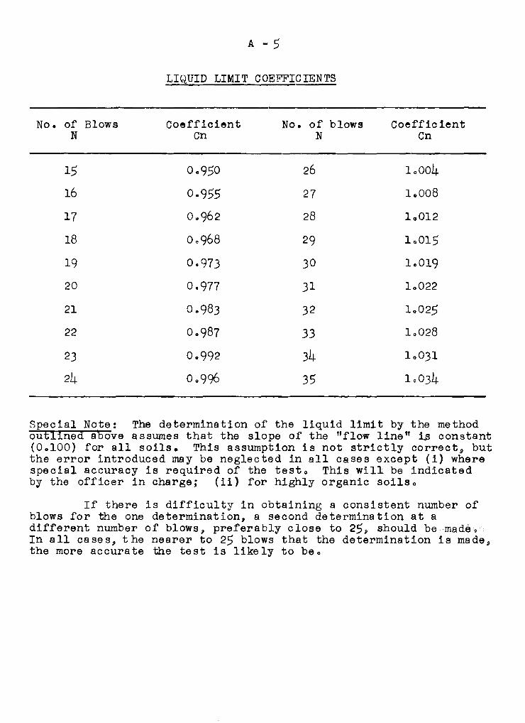
A - 5
LIQUID LIMIT COEFFICIENTS
NOe of Blows Coefficient No. of blows CoefficientN Cn N Cn
15 0.950 26 10004
16 0.955 27 1.. 008
17 0 .. 962 28 10012
18 00968 29 10015
19 0.973 30 10019
20 0.977 31 10022
21 0.983 32 10025
22 Oe987 33 10028
23 0 .. 992 34 10031
24 00996 35 10034
Special Note: The determination of the liquid limit by the methodoutlined above assumes that the slope of the "flow line" 113 constant(0 .. 100) for all soilso This assumption is not strictly correct» butthe error introduced may be neglected in all cases except (i) wherespecial accuracy is required of the testo This willi be indicatedby the officer in charge; (ii) for highly organic soilso
If there is difficulty in obtaining a consistent number ofblows for the one determination, a second determination at adifferent number of blows, preferably close to 25, should be made,In all cases, the nearer to 25 blows that the determination is made athe more accurate the test is likely to be ,

APPENDIX B
LIST OF' THOSE PRESENT AT rrHE NINTH
ANNUAL CANADIAN SOIL MECHANIC S CONFERENCE
Aho, A.E.Aho, S. 1. A.Anderson, J.D.Armstrong, J.E.
Baracos, A.Bazett, D. J.Bell, G.L.Bell, H.R.Bilodeau, P.M.Black, J.M.Blue h, J. IV セ
Brawner, C.Brodeur, セ N c N
Chapman, L.J.Cook, PoM.Cosok, C). E.Coulthard, T.L.Crerar, A.D.Cunliffe, S.J.Currie, R.H.
Dargie, EodeJong, S.. H.Dishaw, H.EoDolmage, V.Dowling, P.J.Dutz, HoG.
Eagles, B"Eldridge, G.So
Farstad, LoFinlay, A.H.Fletcher, A. G.Fletcher, R.F.Fowler, E·Lo
Gill, G.JoGoodman, K. S.Gordon, A.E.Green, A.J.Gruber, W"W.Gunning, HoC.
Haddock, PoGo
Hall, EoHalstead, E.C.Hardy, R. M.Herlihy, v, J.Heslop, W.C.Horcoff, J.Hortie, H.J.Hughes, E. C.\Hughes, RoD.
Kidd, D.F·Klinck, R.W.Klohn, E. J.Kluczynski, p.J.Knight, H.A.W.Knight, R. Go
Laird, \'J. G•.Langston, LoLea, N.D.Leach, ToLeonoff, C.E.Lipson, S.L.Lord, T.M"Lyall, J.Ro
McCallum, B.McCallum, FoMacdonald, AoE.MacDonald, DoH.Macdonald, R.C.I'1cFarlane, H.WoMcGregor, C"A.MacKenzie, N.A.M.McLean, A. A.MacLean, D.A.McRostie, G.C.Manley, D.V.Marantz, O.March, G.C.Mathews, WoH.May, E.R.Morrison, I.F.Mouat, F. I
Muir, JoFoMullineaux, D.R.Mussallem, P.

Nasmith, H.
Okulihk, V.J.
Parkinson, G.W.Parkinson, w セ
Patterson, F.W.Peckover, F.L.Peebles, a セ
Perkins, C.L.Peters, N.Peterson) R.Pretious, E.S.
Radforth, N. \1.Raudsepp, V.Reid, N.L.Ripley, C.F.Rowles, CoA.Ruus, E.Ryan, W.'iJ •
Scarisbrick, R.Schmidt, R.L.Shannon, W.L.Sinclair, S.H.
B-2
Smith, AoB oSpence, RoA.starr, GoB.
Tai t , T. M.ThoDlson, H.J.Thomson, J.G.Thrussell, E.F.Thurber, R·C,Torchinsky, B.B.Trow, W.Tubbesing, K.
Weston, s.Williams, M. Y.Wilson, J.T.Winyarp, JoM.
Yurkiw, P.
Bozozuk, M.Crawford, C.B.Eden, W.J.
. Legge t , R•F•

NATIONAL RESEARCH COUNCILASSOCIATE COMMITTEE" ON SOIL AND SNOW MECHANICS
L1ST OF TECHNICAL MEMORANDA
1 Proposed field soiJ testing device. August 1954*
2 Report classified "restricted"; September 1945
j Report classified "c onr Lden t La L". November 1956
4
5
6
8
Soil survey of the Vehicle Proving Establishment, Ottawa, Oct. 1945*
Method of measuring the significant characteristics of asnow-cover. G.J. Klein. Nov. 1946*
Report classified 'c cnr Ldent La l " . November 1945
Report classified "restricted" . March 1947
Report classified "confidential" . June 1947
9 Proceedings of the 1947 Civilian Soil Mechanics Conference. Aug. 1947*
10 Proceedings of the Conference on Snow and Ice, 1947. Oct. 1947*
11 Proceedings of the 1948 Civilian Soil I,jechanics Conference. Oct. 1949*
12 Index to Proceedings of Rotterdam Soil Mechanics Conference. s ッ セ ャ
Mechanics b セ ャ セ ・ エ ゥ ョ No.1. May 1949*
13 Canadian papers: Rotterdam Soil Mechanics Conference. June 1949*
14 Canadian papers presented at the Oslo meetings of the InternationalUnion of Geodesy セ セ 、 Geophysics. December 1949
15 Canadian survey of phys12al 」 ィ 。 イ 。 」 エ ・ イ ゥ ウ セ ゥ 」 ウ セ Z s セ X w M c P カ ・ イ セ N
G.J. Klein. ;pril 1950
16 Progress report en organic terrain studies. N.W. r。ェZ」セエセN Apri: Q セ U P
17 Froceedings of the 1949 Civilian Soil Mechanics Conference. Aug. 1950
18 Method of ュ ・ 。 ウ セ イ ゥ ョ ァ セ ィ ・ significant characteristics of a snow-cover.G.J. Klein, D.C. Pearce, L.W. Gold. November 1950
19 Proceedings of the 195C Soil Mechanics Ccnf'e renc e , April 1951
20 Snow studies in Germany. Major M.G. Bekker, Directorate of VehicleDevelopment, Department of National Defence. May 1951
21 The Canadian snow survey, 1947-1950. D.C. Pearce, L.W. Gold. Aug. 1951
22 Annual report of the Canadian Section of the International Society ofSoil Mechanics and Foundation Engineering (June 1950 - June 1951).Soil IvIechanics Bulletin No.2.
23 Proceedings of the Fifth Canadian So11 Mechanics Conference,Jan. 10 and II", 1952. May 1952
* Out of print (Continued on back of cover)
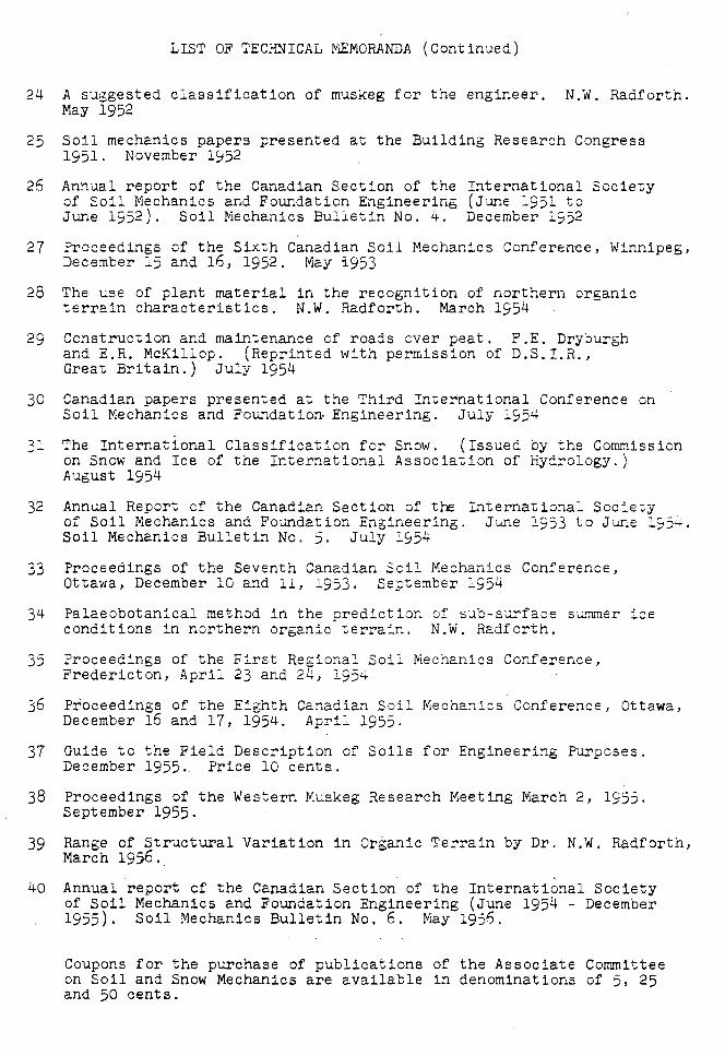
LIST OF TECHNICAL セゥャゥmoranda (Continued)
24 A suggested classification of muskeg for the engineer. N.W. Radforth.May 1952
25 Soil mechanics papers presented at the BUilding Research Congress1951. November 1952
26 Annual report of the Canadian Section of the International Societyof Soil Mechanics and Foundation Engineering (June 1951 toJune 1952). Soil Mechanics Bulletin No.4. December 1952
27 Proceedings of the Sixth Canadian Soil Mechanics Conference, Winnipeg,December 15 and 16, 1952. May i953
28 The use of plant material in the recognition of northern organicterrain characteristics. N.W. Radforth. March 1954
29 Construction and maintenance of roads over peat. F.E. Dryburghand E.R. McKillop. (Reprinted with permission of D.S.I.R.,Great Britain.) July 1954
30 Canadian papers presented at the Third International Conference onSoil Mechanics and Foundation Engineering. July 1954
31 The International Classification for Snow. (Issued by the Commissionon Snow and Ice of the International Association of Hydrology.)August 1954
32 Annual Report of the Canadian Section of the l セ エ ・ イ ョ 。 エ ゥ ッ ョ 。 ャ Societyof Soil Mechanics and Foundation Engineering. June 1953 to J'une 1954.Soil Mechanics Bulletin No.5. July 1954
33 Proceedings of the Seventh Canadian Soil Mechanics Conference,Ottawa, December 10 and 11, 1953. September 1954
34 Palaeobotanical method in the prediction of sub-surface ウ セ セ ・ イ iceconditions in northern organic terrain. N.W. Radforth.
35
36
37
38
39
40
Proceedings of the First Regional Soil l\'iechanics Conference,Fredericton, April 23 and 24, 1954
Proceedings of the Eighth Canadian Soil Mechanics Conference, Ottawa,December 16 and 17, 1954. April 1955.
Guide to the Field Description of Soils for Engineering セ オ イ ー ッ ウ ・ ウ N
December 1955.. Price 10 cents.
Proceedings of the Western Muskeg Research Meeting March 2, 1955.September 1955.
Range of Structural Variation in Organic Terrain by Dr. N.W. Radforth,March 1956.
Annual report of the Canadian Section of the International Societyof Soil Mechanics and Foundation Engineering (June 1954 - December1955). Soil Mechanics Bulletin No.6. May 1956.
Coupons for the purchase of publications of the Associate Committeeon Soil and Snow Mechanics are available in denominations of 5, 25and 50 cents.