Procedure for Classification of Coarse Aggregates Based on ...
Upload
independentCategory
view
0download
0
Professor A. Volinsky EML3500 Mechanics of Solids 1
Ch 10. Strain Transformation
Six independent stress components, which act on the faces of an element, and
six corresponding strain components. (Three normal and three shear stresses
and strains). For simplification simpler strain states are assumed in engineering.
Plane strain has two normal and one shear components, acting on an element
with a specific orientation. Plane Strain ≠ Plane Stress due to Poisson’s effect.
Plane Strain ≠ Plane Stress.

Professor A. Volinsky EML3500 Mechanics of Solids 2
Sign ConventionPositive normal strains cause elongation along x and y axis.
Positive shear strains make AOB angle less than 90°.
Counterclockwise rotations are positive. Since stress is
proportional to strain in the elastic regime (Hooke’s law), the strains have the same sign convention as stresses.

Professor A. Volinsky EML3500 Mechanics of Solids 3
Translation of Plane Strain• Plane strain - deformations of the material
take place in parallel planes and are the
same in each of those planes.
• Example: Consider a long bar subjected
to uniformly distributed transverse loads.
State of plane stress exists in any
transverse section not located too close to
the ends of the bar.
• Plane strain occurs in a plate subjected
along its edges to a uniformly distributed
load and restrained from expanding or
contracting laterally by smooth, rigid and
fixed supports
( )0
:strain of components
x === zyzxzxyy γγεγεε

Professor A. Volinsky EML3500 Mechanics of Solids 4
Normal and Shear Strains
dx=dx’ cos θ
dy=dx’ sin θ δx’=εxdx cos θ + εydy sin θ + γxy sin θ cos θ

Professor A. Volinsky EML3500 Mechanics of Solids 5
Normal and Shear Strains
δy’= - εxdx sin θ + εydy sin θ - γxy dy sin θ
γ x’y’ = -2(εx - εy)sin θ cos θ + γ xy(cos2 θ - sin2 θ)
Professor A. Volinsky EML3500 Mechanics of Solids 6
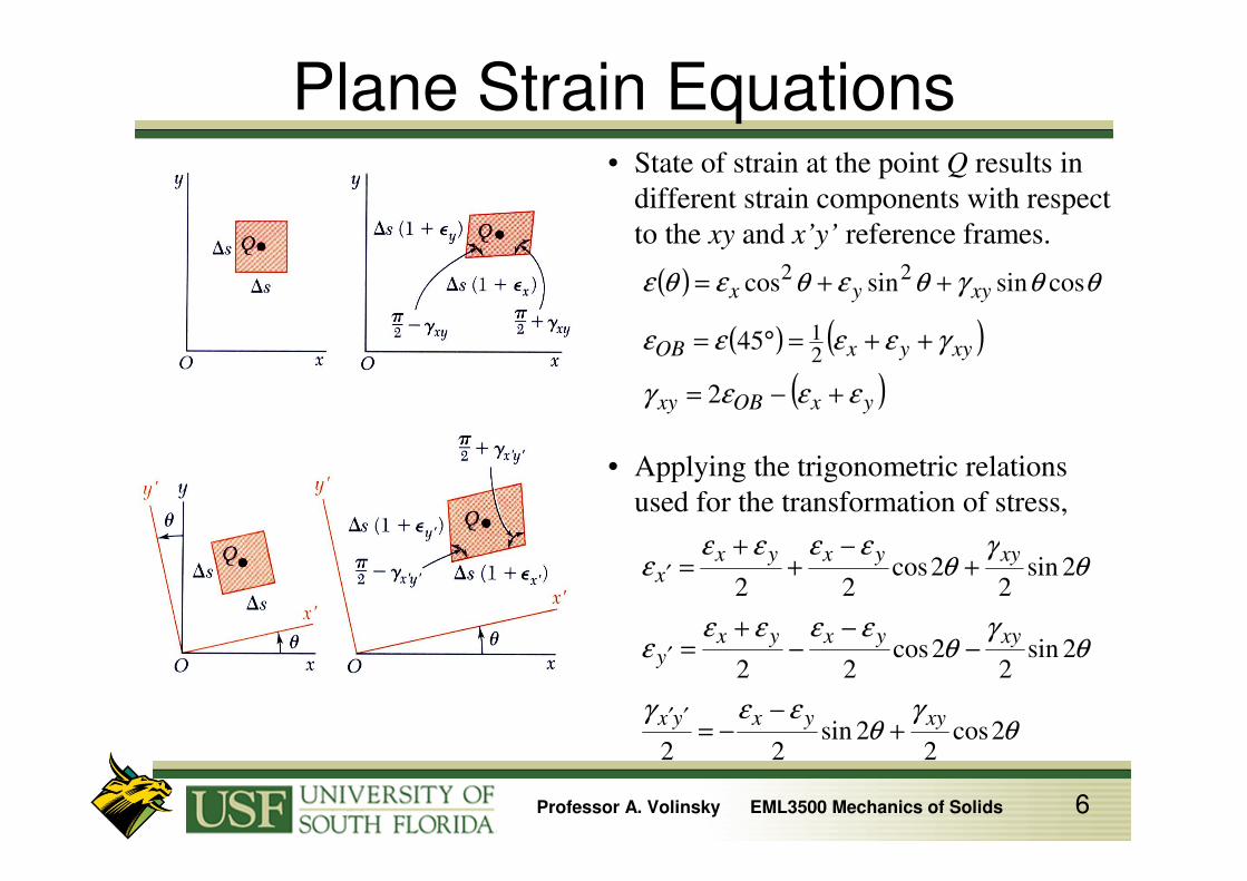
Plane Strain Equations• State of strain at the point Q results in
different strain components with respect
to the xy and x’y’ reference frames.
( )
( ) ( )
( )yxOBxy
xyyxOB
xyyx
εεεγ
γεεεε
θθγθεθεθε
+−=
++=°=
++=
2
45
cossinsincos
21
22
θγ
θεεγ
θγ
θεεεε
ε
θγ
θεεεε
ε
2cos2
2sin22
2sin2
2cos22
2sin2
2cos22
xyyxyx
xyyxyxy
xyyxyxx
+−
−=
−−
−+
=
+−
++
=
′′
′
′
• Applying the trigonometric relations
used for the transformation of stress,

Professor A. Volinsky EML3500 Mechanics of Solids 7
Principal Strains

Professor A. Volinsky EML3500 Mechanics of Solids 8
Example 10.1

Professor A. Volinsky EML3500 Mechanics of Solids 9
Continued

Professor A. Volinsky EML3500 Mechanics of Solids 10
Continued

Professor A. Volinsky EML3500 Mechanics of Solids 11
Important Points
Whole for the Stress, Half for the Strain!

Professor A. Volinsky EML3500 Mechanics of Solids 12
Mohr’s Circle. Plane Stress• The equations for the transformation of
plane strain are of the same form as the
equations for the transformation of plane
stress - Mohr’s circle techniques apply.
• Abscissa for the center C and radius R ,
22
222
+
−=
+=
xyyxyxave R
γεεεεε
• Principal axes of strain and principal strains,
RR aveave
yx
xyp
−=+=
−=
εεεε
εε
γθ
minmax
2tan
( ) 22max 2 xyyxR γεεγ +−==
• Maximum in-plane shearing strain,

Professor A. Volinsky EML3500 Mechanics of Solids 13
Procedure for Analysis

Professor A. Volinsky EML3500 Mechanics of Solids 14
Continued

Professor A. Volinsky EML3500 Mechanics of Solids 15
Example 10.4

Professor A. Volinsky EML3500 Mechanics of Solids 16
Continued

Professor A. Volinsky EML3500 Mechanics of Solids 17
3D Strain• Previously demonstrated that three principal
axes exist such that the perpendicular
element faces are free of shearing stresses.
• By Hooke’s Law, it follows that the
shearing strains are zero as well and that
the principal planes of stress are also the
principal planes of strain.
• Rotation about the principal axes may be
represented by Mohr’s circles.

Professor A. Volinsky EML3500 Mechanics of Solids 18
Mohr’s Circle Strain• For the case of plane strain where the x and y
axes are in the plane of strain,
- the z axis is also a principal axis
- the corresponding principal normal strain
is represented by the point Z = 0 or the
origin.
• If the points A and B lie on opposite sides
of the origin, the maximum shearing strain
is the maximum in-plane shearing strain, D
and E.
• If the points A and B lie on the same side of
the origin, the maximum shearing strain is
out of the plane of strain and is represented
by the points D’ and E’.

Professor A. Volinsky EML3500 Mechanics of Solids 19
3D Strain• Consider the case of plane stress,
0=== zbyax σσσσσ
• Corresponding normal strains,
( ) ( )babac
bab
baa
E
EE
EE
εεν
νσσ
νε
σσνε
σνσε
+−
−=+−=
+−=
−=
1
• If B is located between A and C on the
Mohr-circle diagram, the maximum
shearing strain is equal to the diameter CA.
• Strain perpendicular to the plane of stress
is not zero.

Professor A. Volinsky EML3500 Mechanics of Solids 20
Important Points

Professor A. Volinsky EML3500 Mechanics of Solids 21
Example 10.7

Professor A. Volinsky EML3500 Mechanics of Solids 22
Continued

Professor A. Volinsky EML3500 Mechanics of Solids 23
Strain Measurements: Rosettes
• Strain gages indicate normal strain through
changes in resistance.
( )yxOBxy εεεγ +−= 2
• With a 45o rosette, εx and εy are measured
directly. γxy is obtained indirectly with,
3332
32
3
2222
22
2
1112
12
1
cossinsincos
cossinsincos
cossinsincos
θθγθεθεε
θθγθεθεε
θθγθεθεε
xyyx
xyyx
xyyx
++=
++=
++=
• Normal and shearing strains may be
obtained from normal strains in any three
directions,

Professor A. Volinsky EML3500 Mechanics of Solids 24
Generalized Hooke’s Law
σx causes εx’ = σx/E σy causes εx
’’ = -νσy/Eσz causes εx
’’’ = -νσz/E
Professor A. Volinsky EML3500 Mechanics of Solids 25
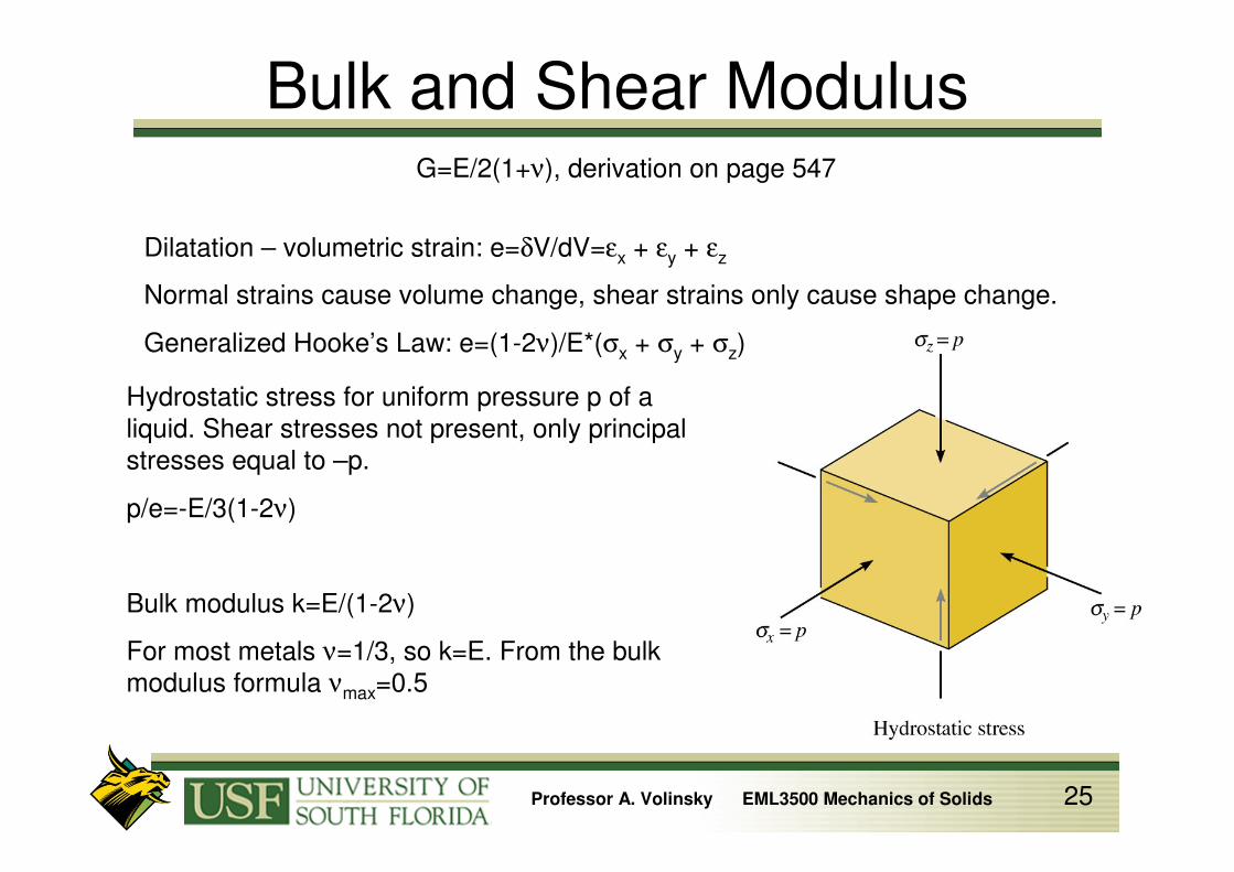
Bulk and Shear ModulusG=E/2(1+ν), derivation on page 547
Dilatation – volumetric strain: e=δV/dV=εx + εy + εz
Normal strains cause volume change, shear strains only cause shape change.
Generalized Hooke’s Law: e=(1-2ν)/E*(σx + σy + σz)
Hydrostatic stress for uniform pressure p of a
liquid. Shear stresses not present, only principal
stresses equal to –p.
p/e=-E/3(1-2ν)
Bulk modulus k=E/(1-2ν)
For most metals ν=1/3, so k=E. From the bulk
modulus formula νmax=0.5

Professor A. Volinsky EML3500 Mechanics of Solids 26
Important Points

Professor A. Volinsky EML3500 Mechanics of Solids 27
Ch10 Review
Theories of failure:
review on your own.
Ch11, review on your
own.
Copyright © 2022 FDOKUMEN