California State University Procedure Manual for Capital ...
47
Exhibit D: California State University Procedure Manual for Capital Projects 01/10/03 and 12/2/11 Introduction CSU Campuses Bakersfield Channel Islands Chico Dominguez Hills East Bay Fresno Fullerton Humboldt Long Beach Los Angeles Maritime Academy Monterey Bay Northridge Pomona Sacramento San Bernardino San Diego San Francisco San José San Luis Obispo San Marcos Sonoma Stanislaus
-
Upload
khangminh22 -
Category
Documents
-
view
1 -
download
0
Transcript of California State University Procedure Manual for Capital ...
Exhibit D:
California State University Procedure Manual for Capital Projects
01/10/03 and 12/2/11 Introduction
CSU Campuses Bakersfield Channel Islands Chico Dominguez Hills East Bay
Fresno Fullerton Humboldt Long Beach Los Angeles Maritime Academy
Monterey Bay Northridge Pomona Sacramento San Bernardino San Diego
San Francisco San José San Luis Obispo San Marcos Sonoma Stanislaus

California State University Procedure Manual for Capital Projects
Introduction Page 2 12/2/11
INTRODUCTION
A. INTRODUCTION
This document and the Submittal Requirements and Procedure Manual for CSU Capital Projects (edition 01/10/03) shall be considered as one exhibit.
The following information does not supersede information in the 01/10/03 edition but clarifies requirements that warranted further explanation or have been instituted in the intervening years. Cross references (ex: 1.1 Project Submittals) to section headings in the existing manual have been utilized for ease of reference.
1. GENERAL PROVISIONS
1.1 PROJECT SUBMITTALS (Revised)
a. Schematic presentation to CPDC (75% Schematic Design): At 75% Schematic Design, a presentation shall be made to the AVC for Capital Planning, Design and Construction (CPDC) for acceptance to proceed to the Board of Trustees for their approval.
g. 95% Construction Documents (Plan Check) At 95% Construction Documents, the project will be submitted for all necessary regulatory agency reviews and approvals. This set shall be sufficiently complete to be considered as 100% complete minus plan review comments and their resolution incorporation into the final set of 100% Construction Documents ready for bid/GMAX.
1.3.1 Code Requirements .1 The California Building Code (New)
Part 11, California Green Building Standards Code (CalGreen)
1.3.2 University Design Standards .4 CSU Computer-Aided Design Standards (Revised) As each campus is the repository for archiving and maintaining documents during development and post construction of a project, the architect/engineer shall contact the Project Administrator to discuss the appropriate format for all project deliverables including those utilizing CAD, BIM (Building Information Modeling) and other electronic documentation. There are currently no systemwide CSU Computer-Aided Design Standards.
1.4 REGULATORY APPROVALS .7 Mechanical Systems Review (MSR) (New) The Mechanical Systems Review is a peer review of the project during all phases (SD, PD, CD) and is performed by a member of the CSU Mechanical Review Board (MRB) selected by the Project Administrator. A letter of design concurrence from the MRB reviewer is required at the Schematic Design Submittal to CPDC (75% Schematic Design). At the completion of construction documents and prior to bid, a letter from the MRB reviewer signifying that all MSR issues have been resolved to
California State University Procedure Manual for Capital Projects
Introduction Page 3 12/2/11
the peer reviewer satisfaction is required. Phase milestone reviews are required as well. Early interaction with the peer reviewer is highly recommended. Further information may be found at http://www.calstate.edu/cpdc/ae/review/mechanical_systems.shtml
1.5 CSU ACCESS COMPLIANCE DESIGN GUIDELINE (New) The CSU Access Compliance Design Guideline intentionally exceeds California Building Code accessibility minimums. By implementing a buffer capacity requirement, this Guideline seeks to allow CSU a measure of discretion to accept minor variances in as-constructed conditions while ensuring code requirements are achieved. Having this discretion will reduce costly delays. To the extent the additional buffer is realized, increased physical accessibility will also be provided. This Guideline is a policy document. It is intended to supplement, not supersede, code requirements. Where code imposes a more restrictive standard the code standard shall apply.
Systemwide CSU Guidelines are available online at: http://www.calstate.edu/CPDC/ae/gsf/guidelines.shtml
1.6 BASIS OF DESIGN REPORTS (Revised)
The Basis of Design Report shall be prepared for Trustees’ understanding of the implications of major design decisions. The report shall be prepared at a minimum to address site design, building design (general design and envelope design), and sustainability measures in addition to mechanical and electrical including lighting systems. The Basis of Design Report shall be submitted at
75% Schematic Design (Submittal to CPDC) 100% Schematic Design 100% Preliminary Design 95% Construction Documents (Plan Review Submittal Set)
1.10 BUILDING COMMISSIONING (Revised) Building Commissioning is required on all new construction projects 10,000 SF or greater per CalGreen (2010 California Green Building Code). Projects meeting this new threshold, as well as all other projects requiring commissioning per the CSU, shall follow the CSU Commissioning Guidelines which may be found at http://www.calstate.edu/CPDC/ae/review/commissioning.shtml The architect/engineer responsibilities shall be performed by the architect/engineer at no additional cost to the Trustees. The commissioning agent is contracted separately by the Trustees.
2.1 SCHEMATIC DESIGN
2.1.2 (SD) CPDC Review Submittal Requirements (Revised)
At 75% Schematic Design all major capital projects shall be presented to the Assistant Vice Chancellor at CPDC for review prior to submittal for Trustees’ approval. The following information is in addition to information currently included in the Submittal Requirements and Procedure Manual.

California State University Procedure Manual for Capital Projects
Introduction Page 4 12/2/11
Review and design intent concurrence letters from Mechanical Systems Reviewer and Seismic Peer Reviewer are required as part of the 75% Schematic Design submittal.
Following schematic design acceptance by CPDC, the following shall be submitted to the Chief of Architecture and Engineering at CPDC no less than three weeks prior to the Board of Trustees meeting date:
1. A colored rendering perspective view: a. Mounted on a 30” x 42” board (gator board) with title information
containing University name/logo, project name, Board of Trustees date and architectural firm name/logo.
b. Electronic copy of the above. c. Color photograph of the project site taken from same vantage point
as rendering (electronically). d. Colored site plan (electronically).
Submittal information and appropriate deadline dates shall be coordinated with the Project Administrator.
4.1.6 Final Submittal of 100% Construction Documents .5 (New) All required regulatory plan approvers shall indicate concurrence on one set of construction documents by stamping/signing the documents (plans and specs). At a minimum these include State Fire Marshal, Seismic Peer Review, private plan review agency, and Division of State Architect (DSA). This set will form the basis for the issuance of bid documents.
MATERIALS BOARDS (Revised)
At appropriate project milestones, the architect/engineer shall present in a method acceptable to the Project Administrator, the projects exterior and interior finish materials. The method of presentation shall be consistent with the level of project development. At the time when materials are finalized and fixed, information of actual materials shall be submitted in final format acceptable to Project Administrator.
SPECIFICATIONS (Revised)
The Architect/Engineer shall develop specifications at all phase milestones consistent with the appropriate level of project development.
GEOTECHNICAL INFORMATION (New)
The project’s geotechnical report may be bound into the project manual/contract documents as ‘For Information Only.’ Information and accepted project recommendations shall be directly incorporated into the project’s construction documents. No direct reference to the Geotechnical Report shall be contained in the construction documents. Sample of a disclaimer for the project manual can be obtained from the Project Administrator.
Prior to issuance for bid, the architect/engineer shall obtain concurrence from project geotechnical engineer that the bid documents appropriately address issues contained in the geotechnical report.
California State University Procedure Manual for Capital Projects
Introduction Page 5 12/2/11
CONSTRUCTION MANAGER at RISK (CM@R) (New)
Construction Manager at Risk is one of the CSU’s project delivery methods. The CM@R method incorporates the Construction Manager as part of the team effort in addition to the University and architect/engineer team. The process is collaborative in nature and requires all members of the team to participate in the development of the project according to the objectives of CM@Risk for the CSU.
PROJECT MEETINGS (New)
At a minimum, project meetings are as specified in the architect/engineer agreement. Further requirements shall be as specified in Exhibit C: Project Design Schedule. The architect/engineer shall attend as basic services the project meetings necessary to meet the required scope and project type. Further meeting requirements maybe defined in the project schedule by the Project Administrator.
Rev.: 01/10/03
01/10/03f
The California
State University
Office of the Chancellor
Submittal Requirements and Procedure Manual
for CSU Capital Projects
Submittal Requirements and Procedure Manual for CSU Capital Projects
Rev.: 01/10/03 1
INDEX
PROCEDURE MANUAL INTENT _______________________________________ 3 1. GENERAL PROVISIONS ___________________________________________ 4 1.1 PROJECT SUBMITTALS ________________________________________ 4 1.2 COST ESTIMATE SUBMITTALS ________________________________ 4 1.3 APPLICABLE CODES, RULES & REGULATIONS _________________ 5
1.3.1 Code Requirements _________________________________________ 5 1.3.2 University Design Standards __________________________________ 6
1.4 REGULATORY APPROVALS ____________________________________ 6 1.5 EXAMINATION OF SITE _______________________________________ 7 1.6 BASIS OF DESIGN REPORTS____________________________________ 7 1.7 CODE ANALYSIS REPORTS AND PLANS_________________________ 8 1.8 INTERDISCIPLINARY COORDINATION REVIEW ________________ 8 1.9 PUBLIC CONTRACT CODE REQUIREMENTS FOR CSU PROJECTS 8
1.9.1 Brand or Trade Name _______________________________________ 8 1.9.2 Proprietary Specifications ____________________________________ 9 1.9.3 Alternatives _______________________________________________ 9
1.10 BUILDING COMMISSIONING ___________________________________ 9 1.11 RESPONSE TO CSU COMMENTS/DIRECTIONS _________________ 10 2.1 SCHEMATIC DESIGN PHASE (SD) ______________________________ 11
2.1.1 (SD) General Requirements __________________________________ 11 2.1.2 (SD) Trustees’ Review Submittal Requirements __________________ 11 2.1.3 (SD) Schedule, Program and Budget ___________________________ 14 2.1.4 (SD) Architectural Requirements______________________________ 14 2.1.5 (SD) Structural Requirements ________________________________ 16 2.1.6 (SD) Plumbing Requirements ________________________________ 16 2.1.7 (SD) HVAC Requirements __________________________________ 16 2.1.8 (SD) Electrical & Telecom Requirements _______________________ 16 2.1.9 (SD) Outline Specifications __________________________________ 17 2.1.10 (SD) Estimated Project Construction Cost ______________________ 17 2.1.11 (SD) Area Tabulation ______________________________________ 17 2.1.12 (SD) Basis of Design Reports ________________________________ 18 2.1.13 (SD) Response to CSU Comments: ____________________________ 18
3.1 PRELIMINARY DESIGN (DESIGN DEVELOPMENT) PHASE (PD) __ 19 3.1.1 (PD) Project Schedule ______________________________________ 19 3.1.2 (PD) Architectural Requirements______________________________ 19 3.1.3 (PD) Structural Requirements ________________________________ 21 3.1.4 (PD) Plumbing Requirements ________________________________ 21 3.1.5 (PD) HVAC Requirements __________________________________ 22 3.1.6 (PD) Electrical & Telecom Requirements _______________________ 22
Submittal Requirements and Procedure Manual for CSU Capital Projects
Rev.: 01/10/03 2
3.1.7 (PD) Outline Specifications __________________________________ 23 3.1.8 (PD) Estimated Project Construction Costs ______________________ 24 3.1.9 (PD) Area Tabulation ______________________________________ 24 3.1.10 (PD) Interdisciplinary Coordination Review _____________________ 24 3.1.11 (PD) Soils and Materials Testing______________________________ 24 3.1.12 (PD) Basis of Design Reports ________________________________ 25 3.1.13 (PD) Response to CSU Comments ____________________________ 25
4.1 CONSTRUCTION DOCUMENTS PHASE (CD) ____________________ 26 4.1.1. (CD) General _____________________________________________ 26 4.1.2 (CD) Program and Budget ___________________________________ 26 4.1.3 (CD) 50% Progress Submittal Requirements ____________________ 26 4.1.4 (CD) 95% Progress Submittal Requirements ____________________ 29 4.1.5 (CD) Agency Plan Review Submittals __________________________ 33 4.1.6 Final Submittal of 100% Construction Documents ________________ 34
5.1 BIDDING PHASE ______________________________________________ 35 5.1.1 General _________________________________________________ 35 5.1.2 Addenda During Bidding ____________________________________ 35 5.1.3 Pre-qualification Process ____________________________________ 35 5.1.4 Pre-Bid Conference and Site Visit _____________________________ 35 5.1.5 Bidders Calls _____________________________________________ 36
6.1 CONSTRUCTION PHASE ______________________________________ 37 6.1.1 General _________________________________________________ 37 6.1.2 Construction Meetings ______________________________________ 37 6.1.3 Interpretations ____________________________________________ 38 6.1.4 Inspection________________________________________________ 38 6.1.5 Materials Testing __________________________________________ 38 6.1.6 Color and Material Boards and Schedules _______________________ 39 6.1.7 Pre-Final Inspection of Project (Punch Lists) ____________________ 39 6.1.8 Final Inspection and Acceptance ______________________________ 39 6.1.9 Record Documents (As Builts) _______________________________ 39
7. ADDITIONAL MATERIALS _______________________________________ 41 CSU Seismic Safety Standards _______________________________________ 41 Energy & Utility Systems Requirements ________________________________ 41 Life Cycle Cost Analysis Spreadsheet __________________________________ 41 CSU Telecommunications Infrastructure Planning Guidelines ________________ 41 Commissioning __________________________________________________ 41 CSU Computer Aided Design Standards ________________________________ 41 CSU Invoice Forms _______________________________________________ 41
8. ADDITIONAL WEB RESOURCES __________________________________ 41
Submittal Requirements and Procedure Manual for CSU Capital Projects
Rev.: 01/10/03 3
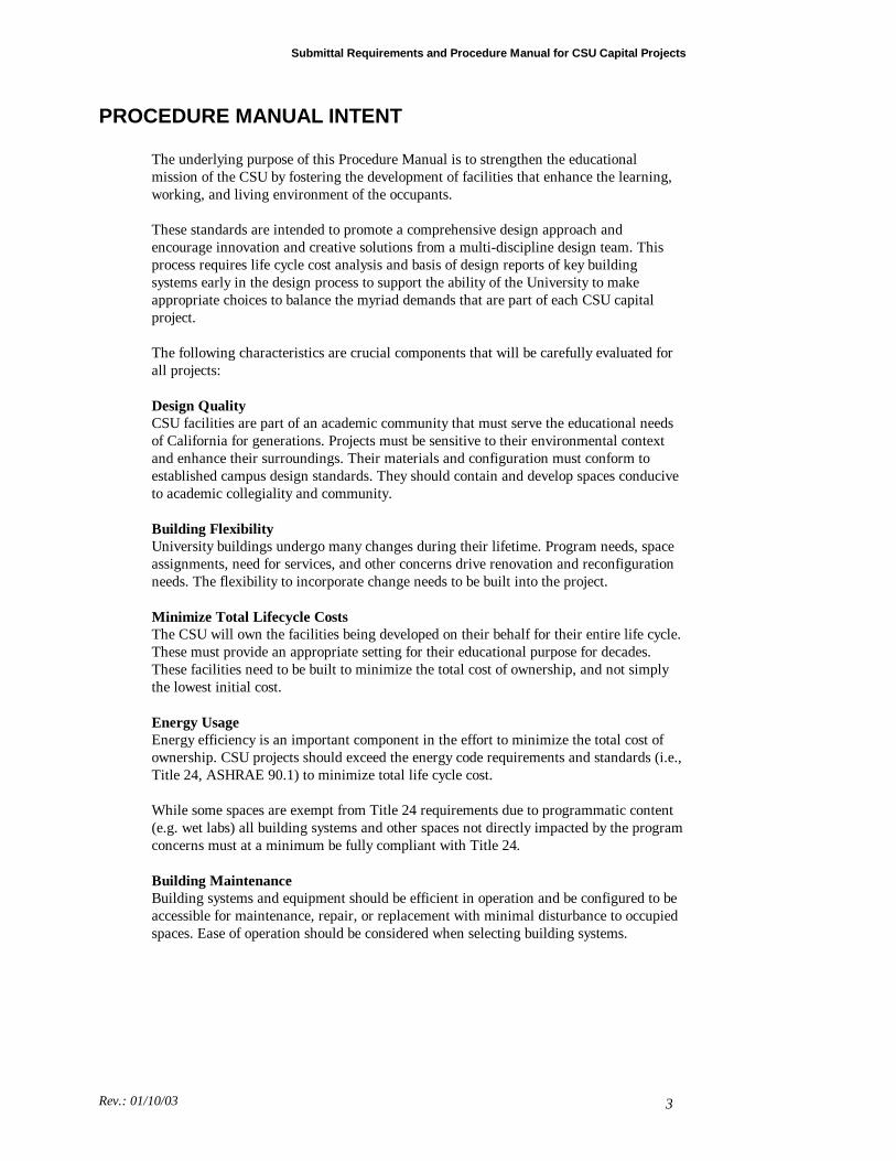
PROCEDURE MANUAL INTENT The underlying purpose of this Procedure Manual is to strengthen the educational mission of the CSU by fostering the development of facilities that enhance the learning, working, and living environment of the occupants. These standards are intended to promote a comprehensive design approach and encourage innovation and creative solutions from a multi-discipline design team. This process requires life cycle cost analysis and basis of design reports of key building systems early in the design process to support the ability of the University to make appropriate choices to balance the myriad demands that are part of each CSU capital project. The following characteristics are crucial components that will be carefully evaluated for all projects: Design Quality CSU facilities are part of an academic community that must serve the educational needs of California for generations. Projects must be sensitive to their environmental context and enhance their surroundings. Their materials and configuration must conform to established campus design standards. They should contain and develop spaces conducive to academic collegiality and community. Building Flexibility University buildings undergo many changes during their lifetime. Program needs, space assignments, need for services, and other concerns drive renovation and reconfiguration needs. The flexibility to incorporate change needs to be built into the project. Minimize Total Lifecycle Costs The CSU will own the facilities being developed on their behalf for their entire life cycle. These must provide an appropriate setting for their educational purpose for decades. These facilities need to be built to minimize the total cost of ownership, and not simply the lowest initial cost. Energy Usage Energy efficiency is an important component in the effort to minimize the total cost of ownership. CSU projects should exceed the energy code requirements and standards (i.e., Title 24, ASHRAE 90.1) to minimize total life cycle cost. While some spaces are exempt from Title 24 requirements due to programmatic content (e.g. wet labs) all building systems and other spaces not directly impacted by the program concerns must at a minimum be fully compliant with Title 24. Building Maintenance Building systems and equipment should be efficient in operation and be configured to be accessible for maintenance, repair, or replacement with minimal disturbance to occupied spaces. Ease of operation should be considered when selecting building systems.
Submittal Requirements and Procedure Manual for CSU Capital Projects
Rev.: 01/10/03 4
1. GENERAL PROVISIONS This Procedure Manual defines deliverables and describes the responsibilities of the architect/engineer under the terms of the Trustees’ Project Architect/Engineer Agreement. Submittal requirements as shown are minimum requirements. The architect/engineer remains fully responsible for providing a complete and professional design and construction documents sufficient for any qualified contractor to construct the facility.
1.1 PROJECT SUBMITTALS The architect/engineer shall assemble all materials required for each submittal and present in the form of drawings, reports and exhibit boards as appropriate. A binder of narrative responses shall accompany each submittal. The narrative response shall address each item listed in this guideline point by point. Project submittals are required at the following design milestone points:
.a Schematic presentation to CPDC
.b 100% Schematic Design (update of initial submittal)
.c 50% Preliminary Design (progress submittal)
.d 100% Preliminary Design
.e 50% Construction Documents (progress set)
.f 95% Construction Documents (plan check)
.g 100% Final Construction Documents (reflective of bid set)
See individual submittal requirements per phase.
1.2 COST ESTIMATE SUBMITTALS Throughout the project, and in accordance with the Project Architect/Engineer Agreement, the architect/engineer is expected to keep the project cost within the construction budget and is required to periodically submit a current Estimated Project Construction Cost to verify and document this. Project construction cost estimates shall be developed/updated and submitted as a part of each of the following submittals:
.a Schematic Presentation (to CPDC)
.b 100% Schematic Design (updated)
.c 100% Preliminary Design
.d 50% Construction Documents
.e 95% Construction Documents (updated)
.f 100% Final Construction Document submittal (updated)
Each cost estimate shall:
.a Reflect the best professional estimate of actual costs anticipated.
.b Establish internal estimating allowances, consistent with good professional practice, appropriate to the phase of development. Larger allowances are assumed held at early phases gradually diminishing to
Submittal Requirements and Procedure Manual for CSU Capital Projects
Rev.: 01/10/03 5
zero at completion of final cost estimate. Do not include a discrete line-item allowance for ‘contingency’.
.c Adjust reported cost values to contract ENR CCCI value. Do NOT present costs to the estimated start of construction, mid-point of construction or to present day values. Questions regarding the calculation of ENR CCCI values should be reviewed with the project administrator.
See individual submittal requirements per phase.
1.3 APPLICABLE CODES, RULES & REGULATIONS
1.3.1 Code Requirements It is architect/engineer's responsibility to design the project in compliance with federal and state laws, codes, rules, regulations, ordinances, and standards, including, but not limited to the following: .1 The California Building Code -- Title 24 as adopted by the
California Building Standards Commission. Part 1, Building Standards Administrative Code Part 2, California Building Code Part 3, California Electrical Code Part 4, California Mechanical Code Part 5, California Plumbing Code Part 6, California Energy Code Part 7, California Elevator Safety Construction Code Part 8, California Historical Building Code Part 9, California Fire Code Part 12, California Reference Standards Code
.2 The California Administrative Code, Title 19 (Industrial Relations, Public Safety)
.3 The California Occupational Safety and Health Act
.4 The California Environmental Quality Act, latest edition
.5 Requirements of the Regional Water Quality Board
.6 Public Contract Code, Sections 10700 et seq. (California State Contract Law)
.7 State/local health departments (regarding food services, pools, etc.)
.8 Air Quality Management District regulations
.9 Americans with Disabilities Act (ADA), Title II, ADAAG
.10 California Coastal Commission Regulations
.11 Local Public Agency standards.
The university is not subject to local jurisdictions' planning/building codes, nor is it required to obtain building permits from local jurisdictions for construction on real estate owned or controlled by the University. However, the design and construction of utility connections and fire-protection systems may require liaison with local jurisdictions. This liaison shall be coordinated through the university project administrator. Con-struction or encroachment upon city or county owned property is subject to local codes and permit requirements.
Submittal Requirements and Procedure Manual for CSU Capital Projects
Rev.: 01/10/03 6
.12 ASHRAE indoor air quality standard 62-1989.
1.3.2 University Design Standards The architect/engineer shall design the project in compliance with all university design standards, including but not necessarily limited to:
.1 CSU Seismic Safety Standards
.2 Energy & Utility Systems Requirements
.3 CSU Telecommunications Infrastructure Planning Guidelines
.4 CSU Computer Aided Design Standards
(See Section 7, Additional Materials)
1.4 REGULATORY APPROVALS The architect/engineer shall be responsible for obtaining review and approval by applicable regulatory agencies. Specific plan review and approvals are required by statute and Trustee policy. Submittals must be coordinated with the university project administrator. The project administrator will furnish a project specific listing of agency contact information to the architect/engineer. The architect/engineer’s sole responsibility for code compliance is not diminished in any manner by the comments or lack of comments from any plan review agency. Early consultation with all plan check groups is strongly encouraged. Review by the Seismic Peer Reviewer during schematic design is mandatory.
.1 Handicapped Access Compliance (ADA): For all new, alteration or
remodeling projects, the CSU must be in compliance with access requirements. The State of California Department of General Services, Division of the State Architect (DSA), must certify compliance.
.2 State Fire Marshal (SFM): If the project involves new construction or
alterations to state-owned or leased facilities, the plans must be submitted directly by the architect to the SFM for approval. (Health and Safety Code, Section 13143; Title 19, California Code of Regulations, Section 3.28(b).) The project designer should be aware of local fire access needs as expressed by the local fire department.
.3 Code Plan Check: For each project, the architect/engineer, shall submit
plans and specifications to a university-approved independent plan check service for review. The appropriate regulatory authority, e.g. State Fire Marshal or Division of the State Architect Access Compliance Unit, shall take precedence over private plan check review comments.
.4 Seismic safety structural peer review: Seismic peer review is required by the
Trustee’s policy on Seismic Safety. The peer review is performed by the member of the CSU Seismic Review Board assigned to the campus.
Resolution of seismic peer review comments is a requirement for each
design phase. Evidence of seismic peer review and concurrence is required as a part of the schematic review to CPDC. Accordingly, early interaction by the architect/engineer with the peer reviewer is required.
Submittal Requirements and Procedure Manual for CSU Capital Projects
Rev.: 01/10/03 7
In the event of disputes over interpretation of the Trustee’s seismic safety
policy, the full CSU Seismic Review Board shall issue a final determination under the authority of the university building official.
.5 State/local health departments: Required when the project involves food
services, pools, or other components regulated by the health department. .6 Federal and state environmental regulatory agencies Contracts and payments for these plan check reviews shall be the responsibility of the project administrator.
1.5 EXAMINATION OF SITE At the beginning of the schematic design phase the architect/engineer shall:
.1 Visit the project site to become familiar with existing site conditions, including the site location and size, utility capacities, and connection options of external utilities. Contact the university project administrator for information on underground utilities and site constraints.
.2 For alteration projects visit all relevant areas of the existing buildings to be altered.
.3 All site examinations as described above shall be documented by means of a report (see schematic phase submittal requirements). The report must identify the existing conditions found and list recommendations or plans of action.
1.6 BASIS OF DESIGN REPORTS It is imperative that the university understands the implications of design decisions being made during the design process. Especially in the early stages of design, it is important that the architect/engineer provide insights into the implications of a given choice, e.g. materials, building skin, mechanical systems, etc. To achieve this the architect/engineer shall develop basis of design reports for key building systems. These reports are first due during the initial stages of schematic design and provide the basis for the university’s acceptance of design submittals. A Basis of Design Report shall be prepared for each of the following systems:
.a Building envelope
.b HVAC
.c Lighting
Each report shall provide a narrative discussion covering the following points. Some systems may require additional information.
.1 Applicable codes & standards
.2 Performance characteristics
.3 Life cycle cost analysis spreadsheet (available online), must include, but may not be limited to:
.a Initial cost of system
.b Energy costs
Submittal Requirements and Procedure Manual for CSU Capital Projects
Rev.: 01/10/03 8
Note: The life cycle cost analysis will require a performance based Title 24 calculation as a part of its completion
.c Maintenance and custodial costs
.d Life expectancy (may require life expectancy of subsystems)
.e Replacement costs (if applicable)
.f Total cost of ownership over 50 (fifty) years
Basis of Design Reports are required at the following design milestones:
.a 50% Schematic Design (internal review with campus)
.b 100% Schematic Design (update of initial submittal)
.c 100% Preliminary Design
.d 95% Construction Documents (plan check) (See individual submittal requirements per phase)
1.7 CODE ANALYSIS REPORTS AND PLANS Provide a narrative discussion and summary of building code issues, impacts and restrictions particular to this project. The outline shall include a written report and diagrammatic plan drawings delineating design criteria (e.g. exit paths, travel distances, required exits, rated walls, rated corridors, building occupancy, construction type, and fire zones). The analysis shall be updated for each design phase.
1.8 INTERDISCIPLINARY COORDINATION REVIEW Evidence of interdisciplinary coordination is required as a part of preliminary design and construction document submittals. Coordination reviews shall include the following:
1. A narrative discussion of methodology used to segregate structural, mechanical electrical and plumbing systems. Describe any zoning or hierarchies used.
2. Provide composite drawing files to show mechanical duct routing relative to structural constraints, ceiling heights and wall locations.
1.9 PUBLIC CONTRACT CODE REQUIREMENTS FOR CSU PROJECTS
1.9.1 Brand or Trade Name Where the specifications call for a designated material, product, item, or service by specific brand or trade name, at least two (2) brands or trade names of comparable quality or utility must be listed followed by the words "or equal." In cases where a unique or novel product application is required to be used in the public interest or where only one brand or trade name is known, only one brand or trade name may be listed followed by the words "or equal." This “or equal” provision may, on rare occasions, be eliminated when a product or system must match an existing product of system. Acceptable examples include:
Submittal Requirements and Procedure Manual for CSU Capital Projects
Rev.: 01/10/03 9
1. Expanding an existing energy management system on campus
2. Specification of a specific lockset manufacturer to match an existing campus standard.
3. Use of specific irrigation valves heads etc. to match an existing campus standard.
The specification must provide a period prior to the contract award for the contractor to submit data to substantiate a request for a substitution of an “equal" item (Public Contract Code, Section 3400) (See also SUAM Section 9721.01). The Architect/Engineer shall review all submittals for "equal" substitutions submitted during the bid process. An addendum to bidders shall be issued listing all "equals" approved to the bid opening.
1.9.2 Proprietary Specifications Technical specifications prepared for bidding public works projects must provide for fair and equal competition among potential bidders. Specifications supplied by vendors or manufacturers should be reviewed carefully to ensure that they do not limit the bidding to a particular company, brand, or trade name. The architect/engineer is expected to be knowledgeable in the field and to be aware of the existence of equal brands or products. To avoid conflict of interest, any person or firm preparing specifications for a project shall not be eligible to bid on the project or to work on the project as a subcontractor (See also SUAM Section 9721.02).
1.9.3 Alternatives The architect/engineer for each project shall prepare bid alternates. Alternatives shall not exceed ten percent of the estimated cost of the base project. A series of deductive alternates totaling approximately 6 to 8% of the total project construction budget should be developed as a precaution against unanticipated high bids should be created as an integral part of the design documents. Each alternative must be described in the specifications and distinguished in the plans separately and in numerical order. The bid proposal must clearly state the bidding requirements and the basis upon which an award will be made (See also SUAM Section 9721.07). While a combination of additive and deductive alternates may be used alternates must be taken in the order listed on the proposal form. The architect/engineer shall coordinate with the project administrator to structure alternates for the project.
1.10 BUILDING COMMISSIONING Building commissioning may be undertaken at the discretion of the university. When building commissioning is undertaken the architect/engineer’s responsibilities as shown in the appendix shall be performed by the architect/engineer at no additional cost to the trustees.
Submittal Requirements and Procedure Manual for CSU Capital Projects
Rev.: 01/10/03 10
1.11 RESPONSE TO CSU COMMENTS/DIRECTIONS The university will provide written comments to the architect/engineer for each submittal. The architect/engineer shall provide a written response to each item and return to the university prior to the next submittal. When the response indicates work has been incorporated into the documents, the response must indicate the appropriate drawing location and specification section incorporating the work.
Submittal Requirements and Procedure Manual for CSU Capital Projects
Rev.: 01/10/03 11
2.1 SCHEMATIC DESIGN PHASE (SD) The following items constitute the minimum schematic design phase submittal requirements for a project. For presentations to the university simplicity and clarity shall be the governing factors in the development of drawings and written documents. The architect/engineer shall assemble all materials required for schematic submittal and present in the form of drawings and or exhibits as appropriate along with a binder of narrative responses. The narrative response shall address each item listed in this guideline point by point.
2.1.1 (SD) General Requirements .1 Review the program specifications upon receipt of the
authorization to begin work
.2 Attend the planning conferences to receive instruction from the campus and its designated representatives
.3 Secure project planning information including information on underground utilities and site constraints
.4 Request any additional data needed from the campus
.5 Submit a listing of proposed consultants planned for the project to the project administrator
.6 Coordinate the project with other campus projects
.7 Consult with the campus, the consulting architect, and the campus landscape architect regarding the project when directed by the University Administrator
.8 Design the facility in accordance with all applicable codes and standards
.9 Obtain concurrence of the schematic design documents from the State Fire Marshal, where applicable
.10 Obtain concurrence of the structural design approach from the CSU Seismic Review Board peer reviewer prior to the 75% Schematic submittal
.11 Obtain campus approval of schematic work in progress prior to presentation to CPDC
.12 Modify or redesign the project, as necessary, to secure approval from the campus, validation from CPDC and approval by the Board of Trustees as per the architectural agreement.
.13 Request and obtain approval from the project administrator before initiating any work to modify the project documents, which may require performance of extra services.
2.1.2 (SD) Trustees’ Review Submittal Requirements CPDC Review & Validation All major capital projects require review and validation by CPDC and approval by the Trustees. The architect/engineer shall make a progress schematic phase
Submittal Requirements and Procedure Manual for CSU Capital Projects
Rev.: 01/10/03 12
presentation to CPDC early enough in the development of the phase (approximately 75%) so that design comments from this review meeting can be effectively incorporated into the final 100% schematic submittal for Trustee approval. The architect/engineer shall develop and present the following materials: .1 Schematic Presentation to CPDC:
.1 The latest approved Physical Master Plan, (available from campus).
.2 A colored ‘presentation’ site plan, showing the shape and location of adjacent improvements, landscaping, shadows, and paving patterns.
.3 A plan of each floor
.4 All elevations
.5 Sections necessary to show basic structural and vertical space organization
.6 A colored rendering perspective view. Rendering shall be cast to provide a single overall view of the project typically from eye level. Coordinate vantage point with campus. Samples of the rendering style shall be submitted to the campus for approval prior to beginning rendering.
.7 A color photograph of the project site taken from a vantage point approximating that of the rendering.
.8 An estimate of the total construction costs presented in CSU 2-7 format (See 2.1.10)
.9 Basis of Design reports for building envelope, HVAC and lighting (See 2.1.12)
The architect/engineer shall adjust and complete the schematic design incorporating comments received. The response to review comments received from the CPDC review meeting shall be noted in the final schematic submittal narrative.
.2 Presentation Materials for Board of Trustees Meeting: Provide in .JPG format on CD-ROM electronic image files of items 1 through 7 above updated to incorporate comments received.
(.JPG format shall be sized with an image area exclusive of titles and borders of 1024 x 768 resolution or greater).
3. Trustees Meeting Mounted Presentation Board: Provide a display board of the project rendering. The rendering
shall be mounted on a rigid, non-warping base. Board of Trustees Review Meeting If requested by the campus, the architect/engineer shall attend and be available for comment at this meeting.

Submittal Requirements and Procedure Manual for CSU Capital Projects
Rev.: 01/10/03 13
Submittal Requirements and Procedure Manual for CSU Capital Projects
Rev.: 01/10/03 14
2.1.3 (SD) Schedule, Program and Budget 1. Project Schedule:
The architect/engineer shall develop a simple project schedule identifying the following:
.1 Project phase submittals (from A/E contract Exhibit C)
.2 Review times assumptions (from A/E contract Exhibit C)
.3 Submittal dates for CPDC review and submittal of BOT items
.4 BOT meeting date
.5 Plan submittal (from A/E contract Exhibit C)
.6 Back check submittal (from A/E contract Exhibit C)
.7 Pre-bid operations
.8 Bidding
.9 Notice to proceed
.10 Construction duration
.11 Campus Group II outfitting
.12 Classes begin/building program operations begin
This schedule shall be reviewed with the university at all project meetings and updated by the architect/engineer at each submittal.
2. Program and Budget: The architect/engineer shall prepare a written evaluation of any imbalance between the construction budget and the project program requirements. The architect/engineer shall be prepared to present program or design adjustment alternatives for campus consideration when adjustments are needed to bring the project scope, project schedule, and construction budget into alignment.
2.1.4 (SD) Architectural Requirements .1 Site Civil and Landscape Drawings:
(Scale: Minimum 1 inch = 40 feet). .1 Depict the overall dimensions of the proposed new building(s). .2 Depict and identify (name) existing structures within a radius
of 300 feet of the project site. Indicate the distances from proposed new building(s) to (1) adjacent existing buildings, (2) property lines (setbacks), and (3) roadways.
.3 Depict major new exterior elements and, for alterations and additions, existing exterior elements that will remain in place. Show streets, service drives, easements, loading docks, parking areas, paved areas, walks, stairs, ramps, pools, retaining walls, fences, fire hydrants, and equipment.
.4 Depict the proposed finished elevations of building entrances and major exterior elements.
.5 Depict existing and proposed contours at one-foot intervals. Indicate method of general site drainage. Provide a written narrative on design grading and retention systems proposed. Discuss possible alternate systems..
.6 Provide sections through the site as needed to explain changes
Submittal Requirements and Procedure Manual for CSU Capital Projects
Rev.: 01/10/03 15
in levels within the proposed building as related to the site. .7 Depict the placement of ramps and other provisions for
disabled access to the site and building. .8 Depict landscape design. .9 Depict site demolition. .10 Show locations of existing utilities. .11 Provide a site utilities plan indicating both existing Facility
utilities and proposed new utilities work. 12. Document finding and design impacts from initial site
investigations.
.2 Floor Plans: (Scale: Minimum 1/8 inch = 1 foot). .1 Indicate the locations, room names, sizes (in assignable square
feet), and space numbers for all programmed spaces and required gross area spaces including entrances, lobbies, corridors, stairs, elevators, toilet rooms, janitors' closets, and mechanical/electrical equipment rooms.
.2 Indicate the overall dimensions of major elements of the building.
.3 Indicate such building elements as walls, columns, doors, windows, openings, and major built-in equipment.
.4 Indicate compliance with applicable disabled access codes.
.5 Provide a demolition plan whenever a project requires the demolition of a building or portions thereof. Indicate existing work to be removed, and existing work to remain in place.
.3 Elevations and Sections:
(Scale: Minimum 1/16 inch = 1 foot). .1 Show all elevations of the building. Depict floor-to-floor
dimensions and the overall building height. .2 Include sections as needed to explain the structure and any
unusual design features. Depict existing and proposed grades.
.4 Code Analysis Report & Plans: Provide a narrative discussion and summary of building code issues, impacts and restrictions particular to this project. The outline shall include a written report and diagrammatic plan drawings delineating design criteria (e.g. exit paths, travel distances, required exits, rated walls, rated corridors, building occupancy, construction type, and fire zones). The analysis shall be updated for each design phase.
.5 Interdisciplinary Coordination Review: Provide a narrative discussion of methodology used to segregate structural, mechanical electrical and plumbing systems. Describe any zoning or hierarchies used.
.6 Building Materials and Massing: .1 Provide a display board with mounted samples of the actual
exterior materials proposed by architect/engineer. .2 Provide study models as needed to analyze various alternative
building site locations and building massing schemes. .3 Provide a narrative description setting forth the design concept
and important features of the Project.
.7 Basis of Design Report (Building Envelope): Provide an analysis of at least two alternate building envelope
Submittal Requirements and Procedure Manual for CSU Capital Projects
Rev.: 01/10/03 16
solutions as a part of the initial 75% progress schematic design review. (See Section 1.6) Note that the analysis required for this phase will require a performance based Title 24 calculation.
2.1.5 (SD) Structural Requirements
.1 Provide a detailed written description of the recommended structural system and the basis for recommending this system over other approaches.
.2 Provide a conceptual structural framing plan of a typical floor. Indicate via a dimensioned grid reference system, columns, load-bearing walls, shear walls, footings, and related items.
.3 Provide evidence of review and concurrence by the CSU Seismic Safety Peer Reviewer.
2.1.6 (SD) Plumbing Requirements
.1 Provide a written analysis of the calculated load demands of proposed new plumbing systems, the design demands of the project, and the capacity of the existing plumbing systems, if any. Show domestic water, sanitary and storm sewer, and fire protection sub-systems.
.2 Provide an analysis of male and female fixture count and location with a comparison to plumbing code minimum requirements.
.3 Indicate the proposed points of connection to utility systems.
2.1.7 (SD) HVAC Requirements
.1 Provide a written analysis of the calculated loads of proposed new HVAC systems.
.2 Provide a conceptual single-line mechanical diagram showing major ducts and equipment. Identify the sizes and locations of major equipment items including cooling towers, chillers, pumps, fans, air-handling units, compressors, and related items.
.3 Determine the capacity of existing systems if any, based on an examination of the facility's record drawings, an inspection of the existing system, and test reports.
.4 Provide a description of the proposed fume hood ducting and exhaust system. .5 Show air intakes and exhausts and demonstrate how air entrainment is avoided.
2.1.8 (SD) Electrical & Telecom Requirements
.1 Provide a site plan showing the proposed method of service for the electrical power, telecommunications, and fire alarm systems.
.2 Provide a single-line diagram showing the following:
Submittal Requirements and Procedure Manual for CSU Capital Projects
Rev.: 01/10/03 17
.1 Method of service (campus or local utility)
.2 Major transformers and transformer substations
.3 Major switchboards, motor control centers, and panel and distribution boards
.4 Major components of the emergency power system
.5 Major components of telecommunications system
a. Building Distribution Facility (BDF)
b. Intermediate Distribution Facility (IDF)
c. Proposed point of connection to campus backbone
d. Narrative on proposed system design, media type conduit routing and access
2.1.9 (SD) Outline Specifications Develop an outline specification for the project. These specifications shall include the following:
1. A general description of the project's site, architectural design, building, and type of construction.
2. Identify the structural system, including materials and systems, a strategy for dealing with special conditions, subsurface conditions, and substructure.
3. Describe the mechanical and electrical systems conceptually.
4. Identify all special systems including special laboratory control systems, energy management systems, and special exhaust systems.
5. Identify finishes at a gross level, indicating the type and quality level. Define casework systems conceptually.
6. Include a separate paragraph in the electrical specifications describing proposed new systems for the power, lighting, communication, fire alarm, and security systems. Describe the proposed power system voltages including the main points of connection to existing systems.
2.1.10 (SD) Estimated Project Construction Cost .1 Provide an estimate of the total construction cost of the project.
Estimates for building projects shall be arranged in CSI Uniformat format (a building systems organization format) detailed to Level 2. This cost information shall also be summarized in a 2-7 format.
.2 Provide a written narrative explaining in detail any deviation from the initial project budget.
.3 Bring any unusual cost item to the attention of university's project administrator.
2.1.11 (SD) Area Tabulation
.1 Using Form CPDC 3-1, provide a summary comparing the area allocation in the Program Specifications presented in the capital
Submittal Requirements and Procedure Manual for CSU Capital Projects
Rev.: 01/10/03 18
outlay request, with the area allocations in the schematic design documents. The summary must include the total assignable area, the total gross area, and the resulting percentage efficiency of the design (SUAM SECTION V, 9050 et seq. contains this form and a guide to its proper completion).
.2 Develop a space-by-space comparison of the schematic design documents' ASF with the project program's ASF. These tabulations shall be made by floor and program component and include totals for the building, or renovated area as a whole.
.3 Provide a thorough written explanation of any major deviations from the area allocations in the program specifications presented in the capital outlay request.
2.1.12 (SD) Basis of Design Reports A schematic phase Basis of Design Report shall be prepared for each of the following systems:
.a Building Envelope
.b HVAC
.c Lighting
(See Section 1.6)
2.1.13 (SD) Response to CSU Comments: Provide a written response to all university comments. (See Section 1.11.)
Submittal Requirements and Procedure Manual for CSU Capital Projects
Rev.: 01/10/03 19
3.1 PRELIMINARY DESIGN (DESIGN DEVELOPMENT) PHASE (PD) The architect/engineer shall make a submittal at 50% and 100% of phase. At 50% provide two (2) sets of progress prints and an updated 50% preliminary design cost estimate to substantiate preliminary design work in progress. The basis of design report updates shall be submitted as a part of the 100% submittal. The following items describe the Preliminary Phase submittal requirements for a 100% submittal.
3.1.1 (PD) Project Schedule The architect/engineer shall update the project schedule and review assumptions with the project administrator.
3.1.2 (PD) Architectural Requirements .1 Site, Civil, and Landscape Drawings:
(Scale: Minimum 1 inch = 40 feet):
.1 Depict the overall dimensions of proposed new building(s). Indicate all references to a benchmark and a baseline. Indicate the distances from each proposed new building to (1) existing buildings, (2) property lines (setbacks), and (3) roadways.
.2 Depict existing structures within a radius of at least 300 feet of the project. Identify all structures and streets by name.
.3 Depict new exterior elements and all existing exterior elements that will remain in place after an alteration or addition. Show streets, service drives, easements, loading docks, parking areas, paved areas, walks, stairs, ramps, retaining walls, fences, fire hydrants, and equipment.
.4 Depict the elevations of building entrances and major exterior elements.
.5 Provide a site plan indicating existing and proposed contours at one-foot (1’) intervals. Indicate the method of general site drainage. Provide a written narrative on design grading and retention systems proposed. Discuss possible alternative solutions.
.6 Provide sections through the site as needed to explain changes in levels within the proposed building as related to the site.
.7 Depict the placement of ramps and other provisions for disabled access to the site and building. Identify the parking area and drop-off location nearest the building. Show the path of travel and indicate travel distances to all building entrances.
.8 Provide a site utilities plan that depicts existing utilities, including underground lines, located within the project site and proposed new utility services. Indicate the points of connection between new work and the existing utility systems.
.9 Provide a site demolition plan indicating existing structures and utilities that are to be removed either by the construction Contractor or by others.
.10 Provide landscape design drawings.
Submittal Requirements and Procedure Manual for CSU Capital Projects
Rev.: 01/10/03 20
.2 Floor Plans:
(Scale: Minimum 1/8 inch = 1 foot). :
.1 Indicate the locations, room names, sizes (in assignable square feet), and space numbers for all programmed spaces and required gross areas including entrances, lobbies, corridors (with widths), stairs, elevators, toilet rooms, janitors' closets, and mechanical/electrical equipment rooms. Floor plans for additions or alterations to existing buildings shall show the existing floor plan and indicate the existing space usage and any proposed changes.
.2 Indicate the locations of all doors (showing door swings) and windows.
.3 Indicate the overall dimensions of the major elements of each building.
.4 Indicate the locations and fire ratings of fire separations, exit enclosures, fire doors, and similar elements.
.5 Indicate the provisions for making facilities accessible to and usable by the disabled. Indicate accessible toilets and drinking fountains.
.6 Indicate the location of plumbing fixtures such as lavatories, floor drains, water closets, urinals, service sinks, drinking fountains, eyewash fountains, deluge showers, and fire-hose cabinets.
.7 Indicate principal built-in features such as fixed auditorium seats, kitchen equipment, display cases, counters, shelves, lockers, laboratory benches, casework, glass washers, sterilizers, fume hoods, and similar items.
.8 Provide a Fitment Plan depicting the locations of movable furniture including "interior landscape" partitions and equipment. Differentiate between movable furniture and equipment and built-in furniture and equipment. Clearly identify items not in contract (NIC).
.9 Provide a demolition plan whenever a project requires the demolition of any building or portions thereof.
.10 Provide a roof plan showing associated equipment, slopes, ridges, drains, and other items.
.3 Elevations and Sections:
(Scale: Minimum 1/8 inch = 1 foot).
.1 Depict in building elevations, all building elements including penthouses, entrances, windows, doors, stairs, platforms, louvers, vents, exhaust stacks, retaining walls, and similar items. Indicate proposed finished grades.
.2 Indicate the overall building and floor-to-floor heights.
.3 Include longitudinal and transverse sections for each major area, indicating floor elevations, existing and proposed exterior grades, ceiling heights, pipe tunnels, unexcavated areas, basement areas, rooflines, and parapets. Where appropriate, show connections to adjoining buildings.
Submittal Requirements and Procedure Manual for CSU Capital Projects
Rev.: 01/10/03 21
.4 Cross-reference sections and elevations to floor plans.
.5 Indicate in the sections, provisions for HVAC distribution and hood venting.
.4 Interior Details:
(Scale: Minimum 1/4 inch = 1 foot). Provide detail plans, sections, and elevations for the following types of space:
.1 Classrooms and lecture halls
.2 Kitchens and related service areas
.3 Laboratories and laboratory support areas
.4 Toilet and locker rooms
.5 Other areas of special design
.5 Schedules:
.1 Provide a door schedule indicating each door's type, size, material, hardware group and pertinent comments.
.2 Provide a preliminary interior finish schedule indicating the material, texture, and color of each finish material proposed for use in the project.
.6 Materials Boards:
The architect/engineer shall provide samples of all finish materials listed in the materials/color schedule. These samples shall be accurate with respect to the actual finishes, textures, and colors being proposed. Materials samples shall be mounted and displayed on presentation boards for review and approval by university. Proprietary materials proposed must allow for equal products to be substituted (See Section 1.9).
.7 Code Analysis Report & Plans: Provide an update of the Code Analysis Report & Plans previously developed. The update shall document and illustrate the code implications of design development changes, and requirements arising from outside agency reviews (e.g. DSA, Fire Marshal interpretation).
3.1.3 (PD) Structural Requirements The architect/engineer shall provide a structural plan for each level of the structure at the same scale as that used for the architectural plans. Indicate via a dimensioned grid reference system, columns, load-bearing walls, shear walls, footings, and related items.
3.1.4 (PD) Plumbing Requirements .1 Site Utilities Plan:
(Scale: Minimum 1 inch = 40 feet).
.1 Indicate the routing of proposed new external utilities from each new building to each point of connection to the campus utility system. Indicate all utility lines that are to be
Submittal Requirements and Procedure Manual for CSU Capital Projects
Rev.: 01/10/03 22
abandoned, removed, or rerouted.
.2 Show all existing utilities within the project site based on both the information provided by University and on architect/engineer's field investigation.
3. Indicate proposed points of connection to existing campus utility systems. Refer to the site plan requirements outlined in subparagraph 3.1.2.1.
.2 Floor Plans:
(Scale: Minimum 1/8 inch = 1 foot).
.1 Indicate all piping on the floor-level plan in which it will be installed.
.2 Indicate the locations of main waste lines and stacks and vents as well as all service mains, including those for water, air, gas, and vacuum.
.3 Indicate all pieces of equipment—including pumps, tanks, generators, pressure-reducing valves, and so on—showing their locations and required piping connections.
3.1.5 (PD) HVAC Requirements .1 Floor Plans:
(Scale: Minimum 1/8 inch = 1 foot).
.1 Indicate the location of each piece of equipment including air-handling units, chillers, cooling towers, pumps, converters, expansion tanks, boilers, fans, fan coil units, and other equipment.
.2 Indicate all mains for each duct system.
.3 Indicate the typical supply and return air zones for each type of occupancy. Occupancy types include offices, laboratories, computer rooms, conference rooms, and special application rooms. A typical air zone shall include the terminal unit with associated branch ducts and air outlets and inlets.
.4 Indicate the typical exhaust air duct for each type of application. Application types include: hoods, toilet rooms, janitors' closets, transformers, mechanical/electrical equipment rooms, and other rooms as required for a satisfactory indoor environment. A typical duct shall include an air inlet and a source destination for exhaust air.
.2 Enlarged Mechanical Plans:
(Scale: Minimum 1/4 inch = 1 foot). The architect/engineer shall provide a layout of all equipment rooms to ensure that the proposed equipment will fit in the allotted space.
3.1.6 (PD) Electrical & Telecom Requirements The power, signal, and telecommunications layouts shall be shown on one set of drawings, and the lighting layouts shall be shown on a different set of drawings. Use standard symbol conventions.
Submittal Requirements and Procedure Manual for CSU Capital Projects
Rev.: 01/10/03 23
.1 Floor Plans: (Scale: Minimum 1/8 inch = 1 foot).
.1 Provide a single-line electrical distribution diagram showing primary service to substations and secondary service to distribution switchboards, motor control centers, and panel boards for power and lighting. This diagram shall include and show the permanent as well as temporary points of connection to external utilities such as high-voltage, telephone, and all signal systems.
.2 Indicate each load center unit substation, motor control center, distribution switchboard, telecommunications equipment room, and closet. Indicate the types and locations of lighting fixtures in typical offices, laboratories, corridors, examination rooms, and similar spaces, and use a schedule for detail.
.3 Indicate major components of telecommunications system
.a Building Distribution Facility (BDF)
.b Intermediate Distribution Facility (IDF)
.c Point of connection to campus backbone. Indicate conduit number and size. Indicate size and locations of vaults
.d Coordinate information with site utilities plan
.e Narrative on proposed system design, media type conduit routing and access
.2 Enlarged Equipment Room Plans:
(Scale: Minimum 1/4 inch = 1 foot). Provide a layout of all equipment rooms to ensure that the proposed equipment will fit in the allotted space.
3.1.7 (PD) Outline Specifications The preliminary design phase outline specifications shall provide a more detailed description of all building components and systems as compared with the schematic design documents submittal. Prior to developing the specifications for this phase, the architect/engineer shall schedule a meeting with university's Design and Construction, and Contract Administration units to review specifications guidelines. At this meeting, the university will provide guidelines for preparing specifications. Attendees at this meeting shall include architect/engineer, architect/engineer's Consultants, and architect/engineer's specifications writer. The preliminary design outline specifications shall include the following:
.1 An index showing divisions and sections intended to be used. The format shall be that recommended by the Construction Specifications Institute (CSI), narrow scope type.
.2 A general description of the construction, including the structural system; wall, ceiling, roofing, and waterproofing systems; exterior and interior finishes; and doors, windows, and case work. These descriptions shall include applicable code references.
.3 A general description of the plumbing and HVAC systems
Submittal Requirements and Procedure Manual for CSU Capital Projects
Rev.: 01/10/03 24
including controls, ducts, filtration, and piping. These descriptions shall include applicable code references.
.4 A general description of electrical services including the voltage and the number of feeders. The specifications shall provide a specific description of items to be served by emergency power and shall describe design considerations for special areas. This description shall include applicable code references.
.5 A general description of fire safety mechanical and electrical systems and devices required by the State Fire Marshal for the intended occupancy of the building.
.6 A description of special systems including laboratory control systems, energy management systems, and special exhaust systems.
3.1.8 (PD) Estimated Project Construction Costs .1 Provide an updated estimate of the total construction cost of the
project. Estimates for building projects shall be arranged in CSI Uniformat format (a building systems organization format) detailed to Level 3. This cost information shall also be summarized in a 2-7 format.
.2 Provide a written narrative explaining in detail any deviation from the approved estimated construction cost.
.3 Bring any unusual cost item to the attention of university's project administrator.
3.1.9 (PD) Area Tabulation
.1 Updating the form 3-1 used in Schematic Design, provide a summary comparing the area allocation in the Program Specifications presented in the capital outlay request, with the area allocations in the preliminary design documents. The summary must include the total assignable area, the total gross area, and the resulting percentage efficiency of the design.
.2 Develop a space-by-space comparison of the schematic design documents' ASF with the project program's ASF. These tabulations shall be made by floor and program component and include totals for the building, or renovated area as a whole.
.3 Provide a thorough written explanation of major deviations from the area allocations in the program specifications presented in the capital outlay request.
3.1.10 (PD) Interdisciplinary Coordination Review Provide an update to the Interdisciplinary Coordination Check (IDC) for the preliminary design phase documents.
3.1.11 (PD) Soils and Materials Testing The architect/engineer shall make initial recommendations for construction phase testing and special inspections such as soils and materials testing, welding inspections, and dewatering requirements.

Submittal Requirements and Procedure Manual for CSU Capital Projects
Rev.: 01/10/03 25
3.1.12 (PD) Basis of Design Reports Submit updated Basis of Design Reports for all systems as a part of the 100% preliminary design submittal. The updates should clearly indicate any changes proposed to the systems, and any revisions to performance characteristics that have been discovered through the design process.
3.1.13 (PD) Response to CSU Comments Provide a written response to all comments.
Submittal Requirements and Procedure Manual for CSU Capital Projects
Rev.: 01/10/03 26
4.1 CONSTRUCTION DOCUMENTS PHASE (CD)
4.1.1. (CD) General The following items constitute the minimum construction document phase submittal requirements. The construction documents phase submittal shall include all elements previously shown on the preliminary design documents but with greater detail and specificity. 50%, 95% and corrected 100% back-check construction documents phase submittals are required.
4.1.2 (CD) Program and Budget As a part of each submittal the architect/engineer shall evaluate the program requirements and request direction/clarification from the project administrator as necessary. The architect/engineer shall inform university's project administrator of any imbalance between the approved construction budget and the project program requirements. The architect/engineer shall be prepared to present program or design adjustment alternatives for university consideration when adjustments are needed to bring the project scope, project schedule and construction budget into alignment.
4.1.3 (CD) 50% Progress Submittal Requirements The 50% construction document submittal shall include two (2) sets of the following:
.1 A progress set of all working drawings from all disciplines
.2 A an updated cost estimate reflecting current work to date
Full specifications need not be submitted as a part of the 50% CD submittal, since normally these documents are prepared late in the development of the working drawings. Submittal documents shall include: .1 Civil Drawings:
.1 Existing civil survey
.2 Site plan
.3 Grading and drainage plan
.4 Site profile sections
.5 Details
.6 Site utilities plan
.7 Site demolition plan
.2 Architectural Drawings: .1 Title sheet
Indicate index, general notes, legends, and a small-scale site and project location map. Plan notes shall not include General Condition items. Notes must coordinate with and conform internally within the document set.
.2 Site plan
.3 Floor plans indicating fixed (built-in) equipment
.4 Roof plan
Submittal Requirements and Procedure Manual for CSU Capital Projects
Rev.: 01/10/03 27
.5 Reflected ceiling plans showing all penetrations
.6 Demolition plan (when appropriate)
.7 Elevations and sections
.8 Details
.9 Schedules Door and window schedules Interior finish schedule Other schedules as appropriate
.10 Updated materials board
.3 Structural Drawings: .1 Plans
Indicate the location, type of member, size, and material of each structural element for foundations, floors, roofs, and any intermediate levels
.2 Schedules (beam, column, slab, etc.)
.3 Details of connections, special assemblies, expansion joints, etc.
.4 Details of the structural framing systems required to support nonstructural elements and fixed equipment
.4 Plumbing Drawings:
.1 Locations, sizes, and elevations of the site sewer, building sewer, drains, street water main, and water service into the building
.2 Locations and sizes of the waste, and waste vent stacks with connections to drains, fixtures, and equipment
.3 Locations and sizes of hot, cold, and circulation water mains, branches, and risers from the service entrance and tanks
.4 Riser diagrams for each system showing plumbing stacks with vents, water risers, and fixture connections for multistory buildings; materials, gauges, and sizes for all elements
.5 Fire-extinguishing equipment such as sprinklers and wet/dry standpipes
.6 Plumbing fixtures and equipment that requires water and drainage connections including pumps and storage tanks
.7 Locations and sizes of natural gas vacuums and medical gas systems
.8 Equipment piping connections including those for pumps, tanks, and generators
.9 Sections that show structural, HVAC, and piping systems through congested areas
.5 HVAC Drawings:
.1 Schedule and legend starting on sheet M-1 or its equivalent and continuing on the following sheets
.2 Sequence of operations diagram
.3 Detailed floor plans and sections as needed to clearly indicate the work required for all mechanical equipment rooms
.4 Air and piping systems, including all branches, on each floor plan
.5 Air balance schedule indicating the CFM (cubic feet per minute) of outside air, supply air, return air, and exhaust air for each air system; elevations of built-up fan units to ensure
Submittal Requirements and Procedure Manual for CSU Capital Projects
Rev.: 01/10/03 28
required air flows and access to the component parts of the units
.6 Flow diagram for each of the following types of water systems:
Chilled water Condenser water Hot water Others as needed to clearly define the scope of work
.7 Air riser diagram for each type of system
.8 Mechanical drawings that show the complete HVAC systems including the following items:
Heating and steam mains, including branches, with pipe sizes
Air-conditioning systems including refrigerators, water and refrigerant piping, and duct work
Exhaust and supply ventilating systems showing duct sizes for steam or water connections and piping
.6 Electrical and Telecommunications Drawings:
.1 Electrical service to the building
.2 Transformers and their connections, whether in the building or on the Project site
.3 Main switchboard, power panels, light panels, and associated equipment
.4 Feeder and conduit sizes
.5 Light fixtures, receptacles, switches, and power outlets
.6 Telecommunications system design including point and nature of connection to existing service, BDF’s, IDF’s, conduit routing, outlets, cabling/wiring, terminal cabinets, and backboards, show coordination with supporting mechanical services and with site utilities plans.
.7 Complete fire alarm system including its connection to the Facility's system
.8 Emergency electrical power system including generator transfer switches, fuel tanks, and all auxiliaries
.9 Electrical service entrance and its service switches, the service feeds to the public service feeders, and the characteristics of the light and power currents
.7 Landscape Drawings:
.1 Finished grading plan
.2 Irrigation plan
.3 Irrigation details
.4 Planting plan
.5 Planting details
.6 Hardscape (paving) plan
.7 Hardscape details (walls, walks, planters, and so on)
.8 Specifications: The Architect/Engineer shall develop a draft Division I project special conditions for review. The special conditions include provisions tailored to meet local campus needs, e.g., issuing keys, traffic and parking control, etc. These complement, but do not supersede the Contract General Conditions. They should always be customized to the campus and project specific (See SUAM Section
Submittal Requirements and Procedure Manual for CSU Capital Projects
Rev.: 01/10/03 29
9722.02).
.8 Cost Estimate The architect/engineer shall provide an updated estimate as part of the 50% completed Construction Documents Phase submittal. The architect/engineer shall use the same estimation method and building component format as used in the preliminary design Phase.
..9Code Analysis Report & Plans Provide an update of the code analysis report & plans. The update shall document and illustrate the code implications of all design development and changes, and any requirements arising from outside agency reviews (e.g., DSA, Fire Marshal, Etc.). Provide a narrative discussion on corrections made arising from reviews.
.10 Interdisciplinary Coordination Review Provide an updated interdisciplinary coordination check (See Section 1.8)
.11 Responses on the Owners Comment Provide a written response to all comments.
4.1.4 (CD) 95% Progress Submittal Requirements All documents in the 50% submittal shall be further developed by architect/engineer in sufficient detail as to be deemed 100% complete and buildable. This submittal shall also provide full book specifications for the project. The 95% designation is solely to acknowledge that the plans have not been plan checked. The standard of completion shall be 100% complete. Prior to submitting the 95% construction documents, the architect/engineer and their consultants shall have thoroughly checked, coordinated, and revised all documents to bring them to 100% completed level. General Condition items shall not be included on drawings or schedules. Notes must coordinate with, and conform to the written contract documents. Products and materials specified on the drawings must be identical to the products and materials required in the written contract documents specifications. In addition to the documents enumerated for the 50% completed submittal, the architect/engineer shall submit the following items for the 95% construction document submittal: .1 Architectural Drawings:
Detail the anchorage of all fixed equipment in accordance with the California Building Standards Code, Title 24, CCR, all applicable parts.
.2 Structural Drawings: Structural drawings shall be accompanied by computations, stress diagrams, and other pertinent data and shall be complete to the extent that the calculations for individual structural members can be readily interpreted. The computations shall be prefaced by a statement outlining the basis for the structural design and indicating the manner in which the proposed building will resist vertical loads and horizontal forces. The computations shall be
Submittal Requirements and Procedure Manual for CSU Capital Projects
Rev.: 01/10/03 30
sufficiently complete as to establish that the structure will resist the loads and forces prescribed by the California Code of Regulations, Title 24, all applicable parts. Assumed safe bearing pressures on soils and the ultimate strengths of concrete shall be provided in computations and noted on the drawings. Where unusual conditions occur, any additional data that are pertinent to the work shall be submitted.
.3 Plumbing Drawings: All plumbing drawings shall indicate the complete plumbing system in detail and shall include methods for fastening equipment to the structure to resist seismic forces.
.4 HVAC Drawings: All HVAC drawings shall indicate the complete heating, ventilating, and air-conditioning systems in detail and shall include methods for fastening equipment to the structure to resist seismic forces.
.5 Electrical/Telecommunication Drawings:
Electrical drawings shall indicate all components of the electrical and telecom system in place and connected to the sources of services. A sufficient level of detail shall be provided to illustrate connections, routings, and other items in complex areas. All wiring shall be final-sized. Detailed methods for fastening equipment to the structure to resist seismic forces shall be indicated. Indicate the following: .1 Feeder and conduit sizes
.2 Schedule of feeder breakers or switches
.3 Locations of light fixtures, receptacles, switches, power outlets
.4 All circuits.5 Complete telecommunications system design to accommodate terminal resources to be provided separately by campus. Show point and nature of connection to existing service. Show BDF’s, IDF’s, terminal racks/cabinets and/or backboards. Show conduit routing, cabling/wiring and outlets.
.6 Materials Board:
A final updated materials board shall be submitted.
.7 Basis of Design Reports: Submit updated Basis of Design Reports for all systems. The update should clearly indicate any changes proposed to the systems, and any revisions to performance characteristics that have been discovered through the design process.
.8 Contract Documents: The university will prepare and supply the front end bidding documents. . The final contract documents shall be bound and shall include the documents listed below. (The entity responsible for providing each item is indicated below within parentheses; "CSU" means the University's Contract
Submittal Requirements and Procedure Manual for CSU Capital Projects
Rev.: 01/10/03 31
Administration unit, "A/E" means Architect/Engineer). .1 Cover Page (CSU) .2 Certification Page (prepared by CSU, signed and stamped by
A/E) .3 Table of Contents (CSU) .4 Project Description (furnished by A/E, approved by CSU) .5 Advertisement for Bids (CSU) .6 Project Directory (CSU) .7 Instructions to Bidders (CSU) .8 Supplementary Instructions to Bidders (CSU) .9 Information Available to Bidders (CSU) .10 Bid Form (CSU) .11 Bonds (CSU) .12 Agreement (CSU) .13 General Conditions (CSU) .14 Supplemental Conditions (CSU) .15 Exhibits (CSU) .16 Index to Specifications (furnished by A/E, prepared by CSU) .17 Specifications, Division 1, General Requirements (CSU) .18 Specifications, Divisions 2 through 16 (A/E) .19 List of Drawings (with dates; A/E) .20 Appendices (A/E)
.9 Specifications: Prepare full book specifications in CSI format. Division 1 of these specifications shall be structured as follows:
CONTRACT GENERAL CONDITIONS (See SUAM Section 9722) The Contract General Conditions include all the required provisions of the contract relating to bidding, award, performance of the work, changes, claims and damages, payment, and completion. They must be incorporated into every public works contract. Two versions of Contract General Conditions are available: Contract General Conditions for Minor Capital Outlay Projects and Contract General Conditions for Major Capital Outlay Projects. Contract General Conditions prevail over all sections of the specifications except for specific modifications that may be stated in the Supplementary General Conditions or the Addenda. The Architect/Engineer shall not change the Contract General Conditions without review and approval by the CSU Office of General Counsel. SUPPLEMENTARY GENERAL CONDITIONS (See SUAM Section 9722.01) The Supplementary General Conditions (SGC) are a means of updating the Contract General Conditions between printings, and a means of customizing and modifying the Contract General Conditions, when appropriate, for a specific project. SPECIAL CONDITIONS (See SUAM Section 9722.02) The Special Conditions shall be refined based on earlier 50%
Submittal Requirements and Procedure Manual for CSU Capital Projects
Rev.: 01/10/03 32
comments. The architect/engineer shall coordinate revisions with the project administrator.
The architect/engineer shall provide as a part of the full specifications individual appendix listings of the following:
1. Named manufacturers
2. Required submittals
3. Required warranties exceeding 12 months
4. Required spare parts
5. Required tests and inspections
6. Tests and inspections to be paid for by contractor
Each appendix shall be keyed to its respective CSI section.
.10 Estimated Project Construction Cost: .1 Provide updated estimates of the total construction cost of the
project at 95% and 100%. Estimates for building projects shall be arranged in CSI Uniformat format detailed to Level 4. This cost information shall also be summarized in a 2-7 format.
2. The 95% and final 100% Estimated Project Construction Cost shall include materials quantities and unit prices. The estimates shall include itemized cost breakdowns of all work activities on the project; these breakdowns will be used to establish the format used by the contractor in applying for progress payments.
.3 The final 100% completed Estimated Project Construction Cost shall be revised and updated from the95% cost estimate to reflect any changes in the design of the Project as well as all revisions made to the Construction Documents after the 95% submittal.
4. The architect/engineer shall compare the 95% and final 100% Estimated Project Construction Cost with the construction budget. Any significant differences between the revised estimates and the construction budget shall be brought to the immediate attention of the project administrator.
.5 Provide a written narrative explaining in detail any deviation from the approved estimated construction cost.
.11 Calculation of Areas:
An area summary comparing the area allocations in the approved program and approved schematic and preliminary plans. The summary should include the total assignable area, the total gross area, and the resulting building efficiency. Definitions and a guide to the computation area of the gross and assignable areas for buildings are given in SUAM (SECTION V, 9050 et seq.).. The architect/engineer shall include, with the 95% completed submittal, calculations of gross square footage (GSF), assignable square footage (ASF) and shall make a direct comparison of these areas with the original project program areas.
.12 Soils and Materials Testing: The architect/engineer shall include, with the 95% completed submittal, a list of requirements for special testing and inspections,
Submittal Requirements and Procedure Manual for CSU Capital Projects
Rev.: 01/10/03 33
such as soils and materials testing, welding inspections, and dewatering requirements, to be conducted during the construction phase, as specified in Divisions 1 through 16 of the contract documents.
.13 Interdisciplinary Coordination Review: Provide interdisciplinary coordination check (IDC) drawings (hard copy and electronic files) as described in the Section 1.8.
.14 Responses to CSU Comments; Provide a written response to all comments(See 1.11).
4.1.5 (CD) Agency Plan Review Submittals The architect/engineer shall be responsible for obtaining review and approval by regulatory agencies. Submittals must be coordinated with the university project administrator. The project administrator shall provide a listing of contact information to the architect/engineer. The university will initiate all contracts for plan reviews and make payment for all plan check services. Obtain approval of the construction documents from the required plan check reviewers.
.1 State Fire Marshal Review: Obtain approval of the construction documents directly from the State Fire Marshal. Submit one complete set of working drawings and specifications for plan check. Upon approval by the SFM, provide an original wet signed set, for stamping by as required by the SFM for certification of compliance.
.2 Seismic Review: Obtain concurrence letter from the CSU Seismic Review Board Structural Peer Reviewer
.3 Building Code Review: Submit two sets of working drawings, specifications, structural calculations, energy calculations and soils report to the university’s independent plan-checking organization.
.4 (DSA) Access Compliance Review: Submit one set of working drawings and specifications the Division of the State Architect, Access Compliance Unit or their designated agent
.5 Local Health Department Reviews: Projects with swimming pools and/or food service facilities will require submittal to local city/county health department. Coordinate requirements with project administrator.
6. Non-Typical Reviews: Coordinate any special submittals to Costal Commission, Army Corp of Engineers, Bay Area Conservancy Group, etc. with the project administrator. Provide documents as required.
Submittal Requirements and Procedure Manual for CSU Capital Projects
Rev.: 01/10/03 34
4.1.6 Final Submittal of 100% Construction Documents
.1 Certify, by a signed statement on the drawings and by provision of required calculations, that the construction documents comply with the energy conservation standards set forth in Title 24.
.2 Stamp all drawings and specifications as required by law for registered architects and engineers.
.3 Submit three (3) sets of completed, stamped and signed construction documents to the project administrator.
.4 Provide on CD-ROM the same items in their electronic equivalents. Verify current software versions accepted with the university project administrator prior to transmitting electronic files.
Submittal Requirements and Procedure Manual for CSU Capital Projects
Rev.: 01/10/03 35
5.1 BIDDING PHASE
5.1.1 General The Architect/Engineer will be instructed in writing by the university construction administrator to prepare the bidding documents. During the bidding phase the responsibilities of the architect/engineer shall include:
• Reproducing the plans and specifications (a reimbursed expense in
the architect/engineer’s agreement) and ensuring delivery to the campus.
• Answering questions from bidders relative to the project in an appropriate manner.
• Issuing addenda, after approval by the construction administrator. • Attending the formal bid opening. • Providing a written evaluation of the bid results. • Submitting a complete list of tests required per the specifications.
5.1.2 Addenda During Bidding The architect/engineer is the only person who may answer technical questions from bidders or other interested parties during the bidding period. If, as a result of these questions and the architect/engineer's review of the plans, clarification or additional information is thought desirable, the architect/engineer must contact the construction administrator for authorization to prepare and issue an addendum to the plans and specifications. The architect/engineer is responsible for timely furnishing copies of the addenda to the designated distribution location for mailing to all bidders and for attachment to any remaining plans and specifications.
5.1.3 Pre-qualification Process Contractor pre-qualification is required on all projects with an estimated construction cost of $400,000 or above. General pre-qualification of contractors is provided systemwide by the office of Capital Planning, Design and Construction. The architect/engineer shall work with university to identify an appropriate project specific bidder pre-qualification process if requested by the university.
5.1.4 Pre-Bid Conference and Site Visit The architect/engineer and architect/engineer's consultants shall attend and participate in all scheduled pre-bid conferences and pre-bid site visits with potential bidders conducted by university's representative to help identify questions that bidders may raise during the bidding phase. Questions from prospective bidders shall be written down by university's representative during these conferences and job site visits. No questions shall be answered at these events that require interpretation, clarification or modifications of the contract documents. Interpretation, clarification, and modification of the contract documents shall be issued only in the form of an Addendum to the Contract Documents. architect/engineer shall furnish the design related
Submittal Requirements and Procedure Manual for CSU Capital Projects
Rev.: 01/10/03 36
information required for the interpretation, clarification or modification to university's representative for preparation of Addendum. Addenda will be issued only by university. Addenda which require interpretation, clarification or modification of the contract documents must be issued not less than three days (72 hours) prior to the bid opening or else a bid extension will be required [Section 4104.5 Public Contract Code].
5.1.5 Bidders Calls In the Notice to Contractors, the architect/engineer shall designate an individual as the recipient of all bidding inquiries regarding the contract documents. During the bidding phase, this individual shall receive all calls from bidders and maintain a log of all calls. The log shall indicate date, time, caller’s name/firm, question and response.
Submittal Requirements and Procedure Manual for CSU Capital Projects
Rev.: 01/10/03 37
6.1 CONSTRUCTION PHASE
6.1.1 General The duties and responsibilities of the architect/engineer during the construction phase include:
.1 Observe construction throughout the construction of the project.
.2 Periodically examine the contractor's work to ascertain its conformance with contract documents.
.3 Certify all contractor's payments.
.4 Determine the need for change orders and issue all change proposals, cost request bulletins, and contract change orders.
.5 Prepare and approve all change proposals, cost request bulletins, and contract change orders complete with approved back-up.
.6 Issue clarifications and interpretations of construction documents.
.7 Conduct project site meetings.
.8 Review the testing program, including specifying tests that are required in accordance with the construction documents and checking test compliance.
.9 Provide consultant services.
.10 Assist the Trustees in litigation or disputes arising from the project construction, including claim rebuttals and attendance at hearings.
.11 Conduct the pre-final and final inspections with the project manager/construction inspector, the construction administrator, and campus officials.
.12 Review contractor as-built drawings, and prepare final as-built record drawings.
6.1.2 Construction Meetings .1 Pre-Construction Meeting (Kick-off): The architect/engineer shall attend a kick-off meeting scheduled
and conducted by university's representative. The agenda for the meeting shall be as determined by university and university's representative. Construction scheduling and the establishment of working relationships shall be included.
.2 Construction Meetings Construction meetings shall be held at the project site and chaired by the architect/engineer. Attending shall be architect/engineer, architect/engineer's consultants as necessary, contractor's field supervisors, sub-contractors as needed and as specified in the contract documents, university professional staff and others as determined to be required by university's representative and university.
.3 As-Built Documents The architect/engineer shall review contractor's as-built documents prior to or immediately following each construction meeting to verify that contractor's work is in compliance with the contract documents. The architect/engineer shall advise university's representative in writing the result of such review. The
Submittal Requirements and Procedure Manual for CSU Capital Projects
Rev.: 01/10/03 38
architect/engineer shall initial any changes to the as-built documents made by contractor.
6.1.3 Interpretations Decisions, interpretations and dispute resolution regarding the contract documents will be issued by the project administrator. The project administrator will rely upon the architect/engineer's recommendations and independent judgment in making these decisions. Information regarding, or changes to, the contract documents shall be issued on the following forms furnished or approved by university:
• Bulletins
• Cost Request Bulletin
• Field Instructions
• Change Proposals
• Change Orders
Construction phase clarifications and revisions to the drawings shall be maintained and updated in the original CAD files. Bulletin revisions shall be made on the appropriate CAD drawing or specification files, then electronically copied out for issuance in 8-1/2" x 11" format. Revisions shall be indicated and logged on each document.
6.1.4 Inspection Construction phase inspection will be provided and paid for by university (Trustees). The architect/engineer shall:
.1 Provide design-related technical direction to, and design-related interpretation of, the contract documents for the project’s inspector of record. The architect/engineer shall advise the inspector of record of all decisions rendered
.2 Review inspection reports submitted by the inspector of record and any reports furnished by others retained or employed by university to review the work
.3 Recommend to the project administrator the issuance of any directives that, based on architect/engineers' evaluation of the report data, are deemed necessary to obtain compliance with the requirements of the contract documents.
6.1.5 Materials Testing .1 Upon architect/engineer's recommendations, and as required by the
specifications, university will contract with soils and materials testing laboratories.
.2 The architect/engineer shall identify and provide a summary list in the specifications of the tests that the contractor is required to make and pay for.
.3 University's representative shall coordinate the activities of
Submittal Requirements and Procedure Manual for CSU Capital Projects
Rev.: 01/10/03 39
contractor and university's testing consultants.
6.1.6 Color and Material Boards and Schedules The architect/engineer shall revise and update the materials/color schedule and materials boards, as necessary to reflect the actual manufacturers' products that have been submitted by contractor and approved for use on the project.
6.1.7 Pre-Final Inspection of Project (Punch Lists)
.1 The architect/engineer shall inspect the construction with the university and the contractor when notified by the contractor that the construction is substantially complete, and again when notified by the contractor that the construction is fully complete.
.2 The architect/engineer shall compile a punch list indicating any lack of compliance with contract document requirements. Copies of the punch lists shall be issued to the contractor as directives in completing the project. When it is judged that all the items on the punch list have been corrected or completed, the final inspection shall be scheduled by the architect/engineer.
.3 All operation and maintenance manuals for the project shall be delivered by the contractor, reviewed by the inspector of record and found to be complete and in good form, before the final inspection is scheduled.
6.1.8 Final Inspection and Acceptance
.1 The architect/engineer shall review the contractor's as-built documents, guarantees, and operating data to assess compliance with the contract document requirements and notify university's representative [project administrator] in writing of its findings.
.2 The architect/engineer shall assist university's representative to assemble written guarantees, operating and maintenance instruction books, diagrams, and charts required of contractor. University's representative is responsible for verifying that all required submittals have been received.
.3 The architect/engineer shall assist university's representative to conduct the final acceptance inspection of the construction with university and contractor and shall advise university's representative of the acceptability of the work performed by contractor.
.4 An inspection acceptance form must be executed by university's representative and received by university within seven (7) calendar days from the inspection acceptance date. All parties required to sign the Inspection Acceptance form must be present for the final inspection.
6.1.9 Record Documents (As Builts) During construction, the architect/engineer shall have reviewed all
revisions and changes and shall have recommended approval of the
Submittal Requirements and Procedure Manual for CSU Capital Projects
Rev.: 01/10/03 40
set of drawings and specifications maintained by contractor during the course of construction.
2. The architect/engineer's preparation of the final record documents
shall indicate all revisions and changes that have been made during construction so as to provide the university with a correct and complete record of the project as actually constructed.
3. The architect/engineer shall furnish an initial review copy of the
as-builts for review by the university (inspector of record). 4. Upon the draft edition being deemed complete and accurate by the
university, the architect/engineer shall provide to the university one (1) final reproducible as-built record document on 0.004" (4 mil) thick, photo wash off Mylar drafting film with matte finish on both sides.
5. An identical copy of the record documents shall also be submitted
in electronic format on CD-ROM. The format and internal arrangement of the CAD files shall be in compliance with the CSU CAD Standards.
___
Submittal Requirements and Procedure Manual for CSU Capital Projects
Rev.: 01/10/03 41
7. ADDITIONAL MATERIALS The documents below provide further design guidelines and requirements for university
projects. All requirements therein are hereby included as part of this document. All documents listed on this page are available online (http://www.calstate.edu/CPDC/AE) and from the university project administrator.
CSU Seismic Safety Standards
Energy & Utility Systems Requirements
Life Cycle Cost Analysis Spreadsheet
CSU Telecommunications Infrastructure Planning Guidelines
Commissioning
CSU Computer Aided Design Standards
CSU Invoice Forms
8. ADDITIONAL WEB RESOURCES SUAM Documents
http://www.calstate.edu/CPDC/SUAM.shtml General Conditions
http://www.calstate.edu/CPDC/CM/CGC.shtml ____