A. A.1 A.1.1 Penyiapan Bahan A.1.1. 1 Pengayak (Screening ...
Upload
khangminh22Category
view
3download
0
Příloha A - Technická specifikace předmětu veřejné zakázkyNázev veřejné zakázky: Měřicí systém pro modální analýzuMinimální technické požadavky na předmět veřejné zakázky
Celkem bodů za splnění technických podmínek:
85 85
Hodnota požadavkuPožadavek na splnění/ počet bodů
za splnění požadavkuSplněno (Ano/Ne/počet bodů)
Systém obecně: • příprava, měření, zpracováni a reportování modální analýzy v jediném prostředí (v jednom projektu) (v jednom software)
Technické minimum, bez jeho splnění nabídka není
akceptovatelná
ANO - HW a SW od jediného dodavatele Brüel & Kjaer Dánsko, SW BK Connect
• Počet měřených signálůmin. 10 s min. dvěma nezávislými programovatelnými generátory
Technické minimum, bez jeho splnění nabídka není
akceptovatelná
ANO - 10 měřicích vstupů a 2 generátory - moduly 3050-A-060 a 3160-A-042
HW moduly : • Dynamický rozsah ne nižší než 160dB s technologií, při
které není třeba nastavovat dynamický rozssah během měření
Technické minimum, bez jeho splnění nabídka není
akceptovatelná
ANO - 10 měřicích vstupů a 2 generátory - moduly 3050-A-060 a 3160-A-042
• Kmitočtový rozsah 0 Hz – min. 50 kHz 1ANO - moduly 3050-A-060 a 3160-A-042, 0-51.2 kHz
• Technologie – rozšíření kmitočtového rozsahu – ekvalizace v reálném čase
ANO 1 ANO - REq-X
• Napájení 10-32 V DC a 100 - 240V AC 1 ANO - zdroj ZG-0426, 90-264 V AC• Amplitudová přesnost ne horší než ±0.01 dB 2 ANO• Amplitudová linearita ne horší než ±0.02 dB 2 ANO• Přeslech mezi kanály v pásmu 0 – 51.2 kHz ne větší než ±0.05 dB 2 ANO• Technologie TEDS IEEE 1451.4 ANO 1 ANO• Synchronizace s protokolem IEEE 1588 ANO 1 ANO• Vysoká mechanická odolnost Kovové šasi skříně 2 ANO - magneziový odlitek
• DC výstup 0 až10± V ANO 1 ANO - možno nastavit limit až 31 V
• Signály: libovolný tvar signálu, sinus, rozmítaný sinus, pevný + měnící se sinus, náhodný, periodický, skokový, pseudonáhodný
ANO 1 ANO - modul 3160-A-042
• Podpora technologie PoE (IEEE 802.3af) – napájení modulů i měřicí signály vedeny jediným kabelem
AnoTechnické minimum, bez jeho
splnění nabídka není akceptovatelná
ANO - switch UL-0265
Požadavek

Modální kladívko pro malé a střední konstrukce, citlivost 1,1 mV/N : • rozsah mezi 3500 až 4800N 1 ANO - kladívko 8206--003
• napájení kompatibilní s dodaným systémem 1 ANO - CCLD
Tříosé akcelerometry vibrací
• akcelerometr tříosý citlivost 100 mV/g (±20mV/g),
rozsah ±50g, frekvence min. do 3kHz (±10°/%)
1 ANO - typ 4524-B
• montáž akcelerometrů snadná 1ANO - sady klipů UA-1407, UA-1475, UA-1478, UA-1480, YJ-0216
Jednoosé akcelerometr vibrací
• akcelerometr jednoosýcitlivostí 100 mV/g (±20mV/g), ±70g, frekvence 0,3- min. 6kHz (±10°/%)
1 ANO - 4507-B-004
• montáž akcelerometrů snadná 1ANO - sady klipů UA-1407, UA-1475, UA-1478, UA-1480, YJ-0216
Montážní příslušenství pro provedení experimentu
• Vibrační budič musí být snadno k použitíprůchozí díra pro rychlé připojení
k referenčnímu bodu struktury1 ANO - soupravy 3624 a 3625
Snímače síly• odpovídajícího rozsahu a citlivosti ANO 1 ANO - soupravy 3624 a 3625
Souprava modálního budiče 100 N
• výkonový zesilovač s pracovním rozsahem min. DC - 5000Hz 1 ANO - souprava 3624 • maximální hodnoty výchylky alespoň 25mm 1 ANO - souprava 3624 • rychlost sinus [špička/náhodný šum (RMS)] 1.5/1.5m/s 2 ANO - souprava 3624 • zrychlení sinus [špička/náhodný šum (RMS)] 432/304 m/s2 2 ANO - souprava 3624
Souprava modálního budiče 200 N
• výkonový zesilovač s pracovním rozsahem min. DC - 5000Hz 1 ANO - souprava 3625 • maximální hodnoty výchylky alespoň 25mm 1 ANO - souprava 3625 • rychlost sinus [špička/náhodný šum (RMS)] 1.5/1.5m/s 2 ANO - souprava 3625 • zrychlení sinus [špička/náhodný šum (RMS)] 863/608m/s2 2 ANO - souprava 3625
Příslušenství pro modální analýzu – HW

Komerční SW pro modální analýzu
• SW
pro přípravu experimentu, měření FFT funkcí FRF, zpracování výsledků modální analýzy, porovnání korelací experimentu a výsledku MKP (FEM)
a vytvoření zprávy o měření
Technické minimum, bez jeho splnění nabídka není
akceptovatelná
ANO - SW BK Connect - moduly 8411-A-NS, 8401-V-N, 8421--N, 8400-D-N speciálně pro modální analýzu
• Příprava zkoušky možná bez nutnosti použít HW analyzátoru a snímačů – virtuální HW setup
ANO 3 ANO - 8401-V
• Podpora technologie Transducer Smart Setup - snímače s QR-kódem
ANO 1 ANO - snímače 4507-xxx i 4524-xxx
• Monitor signálů v reálném case ANO 2 ANO -základní vlastnost 8411
• On-line LED informace o správnosti připojení, ANO 1ANO -základní vlastnost HW modulů LAN-XI a 8411
• Okamžitá barevná indikace stavu HW – červená (problém)/zelená (vše ok) / modrá (generátor v chodu)
ANO 1ANO -základní vlastnost HW modulů LAN-XI a 8411
• Monitor celkové hladiny signálů, FFT, spektrogram a časový signál v reálném čase
ANO 1 ANO
• Kontrola kvality elektrických cest systému, verifikace vnitřního šumu systému
ANO 1 ANO
• Automatická kontrola správnosti upevněni snímače ANO 1 ANO - SW modul 8401-A• Neomezeny počet modulů LAN-XI +1000 kanálů ANO 2 ANO - SW modul 8401-A• Integrovaná graficky vedená databáze snímačů ANO 1 ANO - SW modul 8410• Integrovaná databáze projektů (úloh) ANO 1 ANO - SW modul 8400• Integrovaný grafický nástroj pro nastavení a kontrolu HW včetně automatické detekce případné špatné kabeláže
ANO 1 ANO - SW modul 8401
• Záznam časových signálů současně s měřením ANO 1 ANO - SW modul 8401• Manuální i grafické nastaveni signálů buzení ANo 1 ANO - SW modul 8401• Manuální i grafické nastaveni signálů odezvy ANO 1 ANO - SW modul 8401• Automatické zvukové vedeni zkoušky ANO 1 ANO - SW modul 8401• Zvukové výstraha při chybě měření ANO 1 ANO - SW modul 8411
• Spouštění – volný běh, spouště libovolnou úrovní, s libovolnou hysteresí, sklonem, dělitelem, zpožděním, pozastavením
ANO 1 ANO - SW modul 8411
• Okamžitá animace přenosových funkcí ANO 1 ANO - SW modul 8410
• Buzení kladívkem ANOTechnické minimum, bez jeho
splnění nabídka není akceptovatelná
ANO - kladívko 8206--003, SW modul 8411
• Buzení shakerem – 2 nekoherentní ANOTechnické minimum, bez jeho
splnění nabídka není akceptovatelná
ANO - modul 3160-A-042, SW modul 8411

• Buzení rozmítaným sinem ANO 3 ANO - SW modul 8412• Buzení po dílčích sinusových stupních ANO 1 ANO - SW modul 8412• Řízení zkoušky s uzavřenou smyčkou ANO 1 ANO - SW modul 8412• Podpora akcelerometrů, snímačů rychlosti a výchylky ANO 2 ANO
• Spektrální analyzátor – FFT, kmitočtový rozsah ne horší než: 1 Hz
– 50 kHz, 1 ANO - 0 - 51,2 kHz
• Autospektra a cross-spektra ANO 1 ANO - SW modul 8411• koherence, funkce FRF a MIMO ANO 1 ANO - SW modul 8411• Animace AVI a GIF, objekt samostatné / 2 objekty / překrývání, výstup do Word a PowerPoint®
ANO 2 ANO - SW modul 8410
• Import geometrie UFF 15, 18, 82, 2411, 2412, *.csv, *. Nastran (MSC, NX, NEi), Ansys a Abaqus
ANO 1 ANO - SW modul 8410
• FEM Export UFF 15, 18, 2412 nebo 82, a Microsoft® Excel® (*.csv)
ANO 1 ANO - SW modul 8410
• Kartézský, cylindrické a sférické koordináty ANO 1 ANO - SW modul 8410• Automatické, poloautomatické nebo ruční číslování měřicích bodů
ANO 1 ANO - SW modul 8410
• Modální identifikátory ANO 1 ANO - SW modul 8420• Výsledky experimentu automaticky generovány volitelně do Microsoft® Word, Excel® nebo PowerPoint®
ANO 2 ANO - SW modul 8420
• Normální MIF (NMIF) a Power MIF (PMIF) ANO 1 ANO - SW modul 8420
• stanovení křivky SDOF- systém s jedním stupněm volnosti – identifikace metodou nejmenších čtverců (Globální i lokální),
ANO 1 ANO - SW modul 8420
• stanovení křivky MDOF - systém s více stupni volnosti, Polyreferenční identifikace v kmitočtové nebo časové doméně s libovolným počtem referencí
ANO 1 ANO - SW modul 8420
• Diagram stability ANO 1 ANO - SW modul 8420• Automatizovaný vyhledávání módů ANO 1 ANO - SW modul 8420• Kontrola validity – kritéria AutoMAC a CrossMAC ANO 1 ANO - SW modul 8420• MIMO - systém s více vstupy a více výstupy ANO 1 ANO - SW modul 8420-A
• Identifikace komplexních módů (CMIF, MMIF, RFP-Z, AFPoly) ANO 1 ANO - SW modul 8420-A
Samostatná výuková nekomerční licence
Pro práci alespoň 25 posluchačů na učebně ANOTechnické minimum, bez jeho
splnění nabídka není akceptovatelná
ANO - nekomerční SW balík 8400-U-F pro univerzity
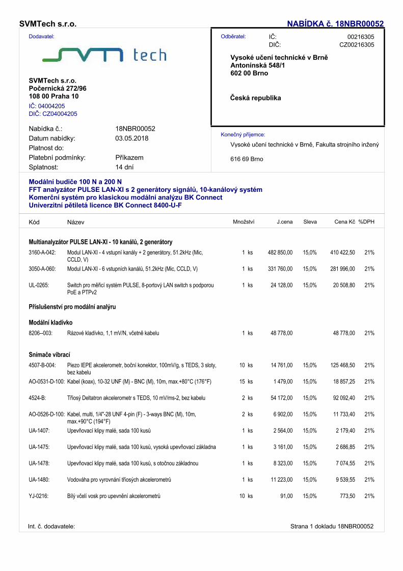
Dodavatel:
SVMTech s.r.o.
Vysoké učení technické v BrněAntonínská 548/1602 00 Brno
NABÍDKA č. 18NBR00052
Nabídka č.: 18NBR00052Datum nabídky: 03.05.2018
616 69 Brno
Vysoké učení technické v Brně, Fakulta strojního inženýrstvíKonečný příjemce:
DIČ: CZ00216305Odběratel: 00216305IČ:
Platnost do:
DIČ: CZ04004205IČ: 04004205
SVMTech s.r.o.Počernická 272/96108 00 Praha 10 Česká republika
14 dníPlatební podmínky:Splatnost:
Příkazem
Modální budiče 100 N a 200 NFFT analyzátor PULSE LAN-XI s 2 generátory signálů, 10-kanálový systémKomerční systém pro klasickou modální analýzu BK ConnectUniverzitní pětiletá licence BK Connect 8400-U-F
Kód J.cena Sleva Cena Kč %DPHMnožstvíNázev
Multianalyzátor PULSE LAN-XI - 10 kanálů, 2 generátory3160-A-042: ks 15,0% 21%410 422,50482 850,001Modul LAN-XI - 4 vstupní kanály + 2 generátory, 51.2kHz (Mic,
CCLD, V)3050-A-060: ks 15,0% 21%281 996,00331 760,001Modul LAN-XI - 6 vstupních kanálů, 51.2kHz (Mic, CCLD, V)
UL-0265: ks 15,0% 21%20 508,8024 128,001Switch pro měřicí systém PULSE, 8-portový LAN switch s podporou PoE a PTPv2
Příslušenství pro modální analýru
Modální kladívko8206--003: ks 21%48 778,0048 778,001Rázové kladívko, 1,1 mV/N, včetně kabelu
Snímače vibrací4507-B-004: ks 15,0% 21%125 468,5014 761,0010Piezo IEPE akcelerometr, boční konektor, 100mV/g, s TEDS, 3 sloty,
bez kabeluAO-0531-D-100: ks 15,0% 21%18 857,251 479,0015Kabel (koax), 10-32 UNF (M) - BNC (M), 10m, max.+80°C (176°F)
4524-B: ks 15,0% 21%92 092,4054 172,002Tříosý Deltatron akcelerometr s TEDS, 10 mV/ms-2, bez kabelu
AO-0526-D-100: ks 15,0% 21%11 733,406 902,002Kabel, multi, 1/4"-28 UNF 4-pin (F) - 3-ways BNC (M), 10m, max.+90°C (194°F)
UA-1407: ks 15,0% 21%2 179,402 564,001Upevňovací klipy malé, sada 100 kusů
UA-1475: ks 15,0% 21%2 686,853 161,001Upevňovací klipy malé, sada 100 kusů, vysoká upevňovací základna
UA-1478: ks 15,0% 21%7 074,558 323,001Upevňovací klipy malé, sada 100 kusů, s otočnou základnou
UA-1480: ks 15,0% 21%9 539,5511 223,001Vodováha pro vyrovnání tříosých akcelerometrů
YJ-0216: ks 15,0% 21%773,5091,0010Bílý včelí vosk pro upevnění akcelerometrů
Strana 1 dokladu 18NBR00052Int. č. dodavatele:
Kód J.cena Sleva Cena Kč %DPHMnožstvíNázev
Soupravy modálních budičů3624: ks 15,0% 21%307 632,00361 920,001Souprava modálního budiče (100N)
3625: ks 15,0% 21%429 896,00505 760,001Souprava modálního budiče (200N)
8230--001: ks 15,0% 21%55 758,3032 799,002IEPE snímač síly, rozsah 220 N, bez kabelu
SW BK Connect měření modální analýzy v reálném čase8411-A-NS: ks 25,0% 21%574 200,00765 600,001Software BK Connect Structural Measurements and Analysis Pack
(adv.), Node-locked licence8401-V-N: ks 21%0,000,001Software BK Connect Virtual Hardware Setup, Node-locked licence
8412--N: ks 25,0% 21%91 828,50122 438,001Software BK Connect Advanced Sine Measurements, Node-locked licence
8421--N: ks 25,0% 21%120 038,25160 051,001Software BK Connect Correlation Analysis, Node-locked licence
8400-D-N: ks 25,0% 21%50 394,7567 193,001Software BK Connect Nastran Interface, Node-locked licence
M1-8411-A-NS: ks 25,0% 21%172 260,00114 840,002Roční servis a podpora pro BK Connect Structural Measurements and Analysis Pack (advanced)
M1-8401-V-N: ks 21%0,000,002Roční servis a podpora pro BK Connect Virtual Hardware Setup
M1-8412--N: ks 25,0% 21%27 535,5018 357,002Roční servis a podpora pro BK Connect Advanced Sine Measurements
M1-8421--N: ks 25,0% 21%36 018,0024 012,002Roční servis a podpora pro BK Connect Correlation Analysis
M1-8400-D-N: ks 25,0% 21%15 138,0010 092,002Roční servis a podpora pro BK Connect Nastran Interface
Nekomerční kompletní pětiletá licence pro PULSE REFLEX8400-U-F: ks 21%34 800,0034 800,001BK Connect Educational License, Floating License (25 seats). For
Educational Purposes OnlyM1U-8400-U-F: ks 21%26 100,0026 100,001Podpora a upgrade (5 let), BK Connect Educational License, Floating
License (25 seats).
ST-PSKOZ-INDA: ks 21%24 190,0024 190,001Školení u zákazníka individuální, včetně nákladů na dopravu a
ubytováníJednodenní školení na VUT Brno
ST-SHIP-010: ks 21%2 100,002 100,001Balné, doprava (do 10 kg)
630 000,02 KčDPH CelkemZaokrouhlení 0,98 Kč
Celkem (bez DPH) 3 000 000,00 KčCelkem k úhradě (vč. DPH) 3 630 001,00 Kč
Vystavil: Záruční doba:Termín dodání: 2 měsíce
Volitelné položky nejsou započítány v celkové ceně.
12 měsícůVyužijte služeb našeho AKREDITOVANÉHO KALIBRAČNÍHO CENTRA.
Pro zboží s klasifikací zboží dvojího užití (dual use) je nezbytné uvádět koncového zákazníka.
Strana 2 dokladu 18NBR00052Int. č. dodavatele:
Dobrý den, dovolujeme si vám předložit cenovou nabídku k výběrovému řízení
MĚŘICÍ SYSTÉM PRO MODÁLNÍ ANALÝZU
Veřejná zakázka je zadávána v zadávacím řízení podle zákona č. 134/2016 Sb. o zadávání veřejných zakázek
ID zakázky na profilu: 1601
Obsah nabídky
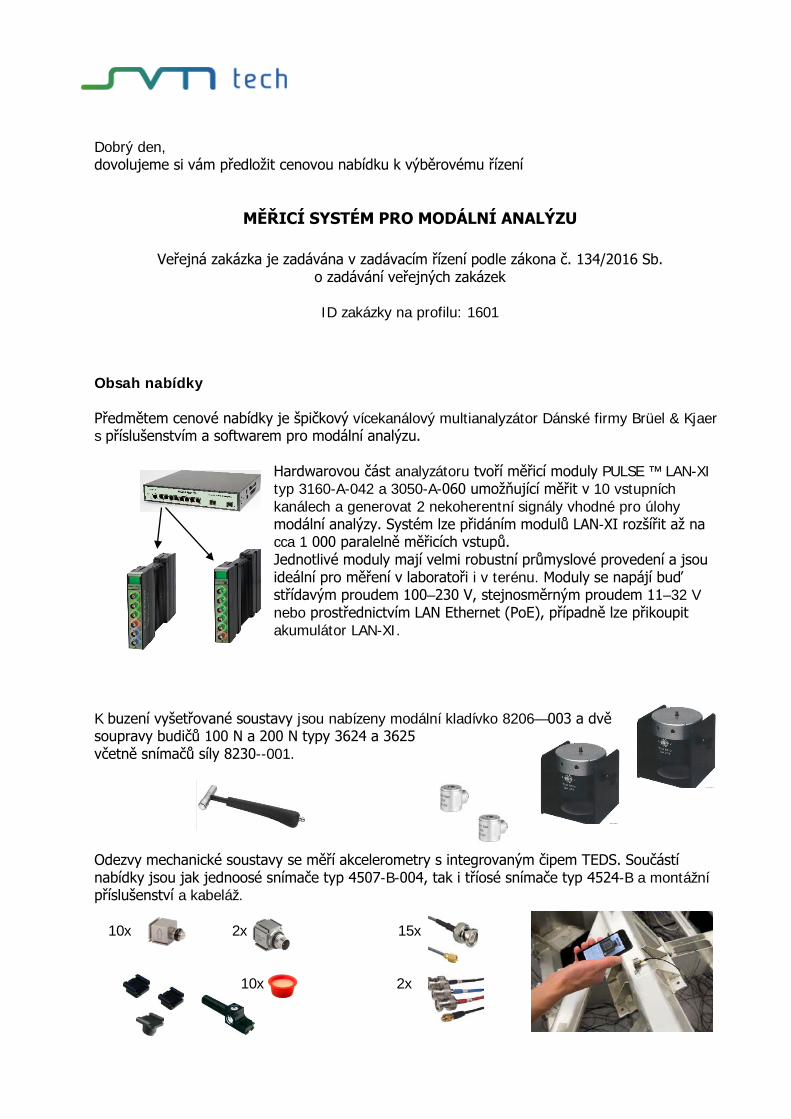
Předmětem cenové nabídky je špičkový vícekanálový multianalyzátor Dánské firmy Brüel & Kjaer s příslušenstvím a softwarem pro modální analýzu.
Hardwarovou část analyzátoru tvoří měřicí moduly PULSE ™ LAN-XI typ 3160-A-042 a 3050-A-060 umožňující měřit v 10 vstupních kanálech a generovat 2 nekoherentní signály vhodné pro úlohy modální analýzy. Systém lze přidáním modulů LAN-XI rozšířit až na cca 1 000 paralelně měřicích vstupů. Jednotlivé moduly mají velmi robustní průmyslové provedení a jsou ideální pro měření v laboratoři i v terénu. Moduly se napájí buď střídavým proudem 100–230 V, stejnosměrným proudem 11–32 V nebo prostřednictvím LAN Ethernet (PoE), případně lze přikoupit akumulátor LAN-XI.
K buzení vyšetřované soustavy jsou nabízeny modální kladívko 8206—003 a dvě soupravy budičů 100 N a 200 N typy 3624 a 3625 včetně snímačů síly 8230--001.
Odezvy mechanické soustavy se měří akcelerometry s integrovaným čipem TEDS. Součástí nabídky jsou jak jednoosé snímače typ 4507-B-004, tak i tříosé snímače typ 4524-B a montážní příslušenství a kabeláž.
10x 2x 15x
10x 2x

Softwarovou část nabídky představuje nový balíček BK Connect™ Structural Measurements and Analysis Pack, který zajišťuje přípravu měření, vlastní měření a modální analýzu včetně vytváření zpráv. Dílčí SW produkty, ze kterých se systém skládá, jsou:
Data Viewer Type 8400 Hardware Setup Type 8401 Hardware Setup (advanced) Type 8401‐A Geometry Type 8410 Structural Measurements –Hammer and Shaker Type 8411
Modal Analysis Type 8420 Modal Analysis (advanced) Type 8420‐A Advanced Sine Measurements 8412 Correlation Analysis 8421 Nastran Interface 8400-D
Jednotlivé položky předkládaného řešení jsou uvedeny v příloze 1 Formulář nabídky včetně přílohy A – Technická specifikace předmětu veřejné zakázky , v oddílu 5. Cenová nabídka 18NBR00052 a velmi detailně popsány výrobcem v části 6. Katalogové listy - (anglicky).

Součástí nabídky je rovněž pětiletá nekomerční univerzitní licence BK Connect Educational Floating License (25 seats) For Educational Purposes Only pro výuku, která zahrnuje kompletní produkty BK Connect:
Typ SW produkt
-8400--F- BK Connect Data Viewer, Floating License
-8400-A-F- BK Connect Data Viewer (advanced), Floating License
-8400-B-F- BK Connect B&K File Importers, Floating License
-8400-C-F- BK Connect External File Importers, Floating License
-8401--F- BK Connect Hardware Setup, Floating License
-8401-A-F- BK Connect Hardware Setup (advanced), Floating License
-8401-V-F- BK Connect Virtual Hardware Setup, Floating License
-8402--F- BK Connect Time Data Recorder, Floating License
-8402-A-F- BK Connect Time Data Recorder (advanced), Floating License
-8404--F- BK Connect Data Processing Specialist, Floating License
-8404-A-F- BK Connect Data Processing Specialist (advanced), Floating License
-8405-B-F- BK Connect Advanced Frequency Analysis Option, Floating License
-8405-C-F- BK Connect CPB Option, Floating License
-8405-D-F- BK Connect Calculations Option, Floating License
-8405-E-F- BK Connect Order Analysis Option, Floating License
-8405-F-F- BK Connect Order Tracking Option, Floating License
-8405-G-F- BK Connect Sound Quality Metrics Option, Floating License
-8410--F- BK Connect Geometry, Floating License
-8411--F- BK Connect Structural Measurements - Hammer and Shaker, Floating License
-8412--F- BK Connect Advanced Sine Measurements, Floating License
-8420--F- BK Connect Modal Analysis, Floating License
-8420-A-F- BK Connect Modal Analysis (advanced), Floating License
-8421--F- BK Connect Correlation Analysis, Floating License
-8429--F- BK Connect Shock Response Analysis, Floating License
-8430--F- BK Connect Array Analysis, Floating License
-8440--F- BK Connect Angle Domain Analysis, Floating License

1. Formulář nabídky včetně přílohy A - specifikace předmětu veřejné zakázky
2. Výpis ze seznamu kvalifikovaných dodavatelů a výpis z obchodního rejstříku
3. Obsah nabídky
4. Návrh kupní smlouvy
5. Cenová nabídka 18NBR00052
6. Katalogové listy - (anglicky)

PRODUCT DATA
Generator, Input/Output Module LAN-XI 51.2 kHz Type 3160A combination of inputs and generator outputs make a completestand-alone analyzer test system. Type 3056 is ideal forapplications where system excitation is required – such as audioand electroacoustic test applications.
Type 3160 comes in two basic variants, offering the choice between2 inputs/2 outputs and 4 inputs/2 outputs. All input and outputchannels have a frequency range of DC to 51.2 kHz.
Type 3160 works equally well as a single-module test system, or asone part of a large LAN-XI measurement system. The combinationof inputs and output channels makes it one of the most versatiledata acquisition modules available, while interchangeable front-panels give the flexibility to use a wide range of transducers.
Uses and Features
Uses• General sound and vibration measurements • Generator output channels for system excitation for sound and
vibration measurements • Ideal for audio and electroacoustic measurements • Measurement front-end module for PULSE™ measurement
and analysis software • Front-end for PC-based Data Recorder Type 7708 • Single-module measurements • Multi-module measurements/distributed system • Stand-alone recording (no PC) using LAN-XI Notar™ software
Features• 2 or 4 input channels • 2 generator output channels • DC to 51.2 kHz input range • 131 ksamples/s sampling rate• Power for 200 V microphones • Dyn-X technology • REq-X technology • Supports TEDS transducers • Interchangeable front panels

Input Channels
2
Independent ChannelsThe input channels on a module can be set up independently. You can set up the high-pass filters and inputgain separately and attach different types of transducer to different channels.
IEEE 1451.4 TransducersAll input modules support TEDS transducers. This allows automatic front-end and analyzer setup based onTEDS information stored in the transducer, for example, sensitivity, serial number, manufacturer andcalibration date. The individual frequency response of a transducer can be corrected for using PULSE’sTransducer Response Equalisation, REq-X, to achieve higher accuracy over extended frequency ranges.
OverloadConstant Current Line Drive (CCLD) conditioning monitors the supply voltage used by CCLD-compatibletransducers. Available CCLD transducers include:• Accelerometers• Charge amplifiers• Microphone preamplifiers• Tacho probes
If conditioning errors, such as a broken cable, are detected, an error is indicated as an overload on thespecific channel connector (using a ring-LED around the connector) and in the PC software.
Overload indications for input channels include (see Specifications for details): • Signal overload with adjustable detection level • CCLD overload: detection of cable break, short-circuit or CCLD transducer working point fault • Microphone preamplifier overload: detection of microphone preamplifier current consumption too high or
too low• Common mode voltage overload – relevant when input coupling is floating
Ground-loop Noise SuppressionThe module’s floating/grounded, differential input design and the fact that all external connections (LAN,power supply) are galvanically isolated in the module provide optimal ground-loop noise suppression.
Output Channels
Features• Two output channels: full generator functionality from 0 to 51.2 kHz• Output voltage up to 10 Vpeak and output current up to 40 mApeak in two output ranges only• Waveforms determined by software (see below)• High amplitude and frequency linearity• Extremely low noise floor• Selectable floating or grounded outputs• Capable of heavy complex loading without instability• Low out-of-band spurious noise• Overload detection on both channels individually (voltage and current) indicated by alternating red/blue
LEDs on front panel• Generator channel indicated by blue LED on front panel (active or not)• Automatic shutdown (muting) of both channels simultaneously at power failure• Full output phase control among LAN-XI modules*
The two output channels on Type 3160 can be used as high-quality signal generators with a frequency rangefrom 0 to 51.2 kHz and can supply the signals necessary for performing system analysis.
Type 3160 is designed around a powerful digital signal processor and a low-noise, 24-bit, D/A converter.Type 3160 has exceptional flexibility, stability and accuracy. Output levels are adjustable in hardware (tworanges) with maximum outputs of 316 mVpeak and 10 Vpeak. High-quality levels from 1 μV to 316 mV or 10 V
* Signal generators are not synchronized between LAN-XI and IDAe generator modules. This does not affect continuous signals (random, white- or pink-noise) but is not suitable for burst random signals and sine signals requiring phase control between generators.
are obtained. The output signal is provided by a BNC connector and can be referred to ground or floating. Itis possible to add a DC offset, but any unwanted DC offset is automatically removed.
When Type 3160 is powered by PoE, only the generator channels and two input channels can be used. If DCor mains power is available, the generator channels and all four input channels can be used.
WaveformsThe waveform types supported by PULSE are:
RangesThe fact that there are only two hardware ranges allows amplitude sweeping over a larger range without thepresence of disturbing transients from range-shifting attenuators. To avoid these transients, the range ofinterest can be locked.
Due to the large dynamic range, it is possible to generate very accurate low-level signals.
LinearityFrequency linearity is better than ±0.1 dB over the entire frequency range, and amplitude linearity is betterthan 0.1 dB over at least 100 dB amplitude range referred to full scale.
OverloadOutput voltages above 11 Vpeak or output currents above 40 mApeak are indicated as overloads by thecircular LEDs on the output channels.
SecurityAutomatic shutdown of both outputs is initiated in cases of heavy overload (shorted output) that could affectmodule functionality by drawing more current than available. The signal ramps up again when the overloadis removed.
• Single fixed sine (continuous or burst)• Single swept sine • Dual fixed sine • Dual swept sine • Fixed sine plus swept sine
• Stepped sine (with Steady State Response Analyzer)• Random (continuous or burst)• Pseudo-random • Periodic random • User-defined, arbitrary waveforms can be downloaded
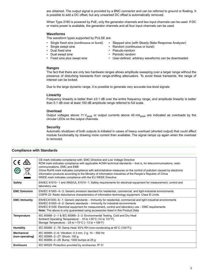
Compliance with Standards
CE-mark indicates compliance with: EMC Directive and Low Voltage DirectiveRCM mark indicates compliance with applicable ACMA technical standards – that is, for telecommunications, radio communications, EMC and EMEChina RoHS mark indicates compliance with administrative measures on the control of pollution caused by electronic information products according to the Ministry of Information Industries of the People’s Republic of ChinaWEEE mark indicates compliance with the EU WEEE Directive
Safety EN/IEC 61010–1 and ANSI/UL 61010–1: Safety requirements for electrical equipment for measurement, control and laboratory use
EMC Emission EN/IEC 61000–6–3: Generic emission standard for residential, commercial, and light-industrial environmentsCISPR 22: Radio disturbance characteristics of information technology equipment. Class B Limits
EMC Immunity EN/IEC61000–6–1: Generic standards – Immunity for residential, commercial and light industrial environmentsEN/IEC 61000–6–2: Generic standards – Immunity for industrial environmentsEN/IEC 61326: Electrical equipment for measurement, control and laboratory use – EMC requirementsNote: The above is only guaranteed using accessories listed in this Product Data
Temperature IEC 60068−2−1 & IEC 60068−2−2: Environmental Testing. Cold and Dry HeatAmbient Operating Temperature: −10 to +55°C (14 to 131°F)Storage Temperature: −25 to +70°C (−13 to +158°F)
Humidity IEC 60068−2−78: Damp Heat: 93% RH (non-condensing at 40°C (104°F))
Mechanical(non-operating)
IEC 60068–2–6: Vibration: 0.3 mm, 2 g, 10 – 500 HzIEC 60068–2–27: Shock: 100 g IEC 60068–2–29: Bump: 1000 bumps at 25 g
Enclosure IEC 60529: Protection provided by enclosures: IP 31
3

EFFECT OF RADIATED AND CONDUCTED RF, MAGNETIC FIELD AND VIBRATIONRadiated RF: 80−2700 MHz, 80% AM 1 kHz, 10 V/mConducted RF: 0.15−80 MHz, 80% AM 1 kHz, 10 VMagnetic Field: 30 A/m, 50 Hz
4
Vibration: 5−500 Hz, 12.7 mm, 15 m/s2
Input measured with shorted input. All values are RMS. Conducted RF immunity on all channels is only guaranteed using an external connection from measuring ground to chassis terminal
Specifications – LAN Interface
Input Radiated RF Conducted RF Magnetic Field Vibration
Direct/CCLD <250 μV <300 μV <4 μV <80 μVPreamplifier <250 μV <50 μV <8 μV <80 μV
CONNECTORRJ 45 (10baseT/100baseTX) connector complying with IEEE−802.3 100baseXTypes 3660-C and -D permit the use of a ruggedized RJ45 data connector (Neutrik NE8MC-1) to screw the cable to the frameTypes 3660-C and -D communicate at 1000 Mbits/s: shielded cables of type “CAT 5e” or better should be usedIndividual modules communicate at 100 Mbits/s All LAN connectors support MDIX, which means that cables may be “crossed” or notFor stand-alone modules, PoE is also supported (IEEE 802.3af). PoE requires screened shielded twisted pair (S/STP or S/FTP) CAT6 LAN cables
PROTOCOLThe following standard protocols are used:• TCP• DHCP (incl. Auto-IP)• DNS (on top of UDP)• IEEE 1588–2002 (on top of UDP)• IP• Ethernet
ACQUISITION PERFORMANCEEach LAN-XI module generates data at almost 14 Mbit/s when measuring four channels at 51.2 kHz bandwidth. The modules are
capable of handling their own maximum traffic while the built-in switch in the frame’s backplane has more than sufficient capacity. This means that bottlenecks can only occur outside these, for example in:• External switches• PCFor convenience, it is possible to daisy-chain LAN-XI frames. However, it is not recommended to daisy-chain more than two frames. For larger configurations, a star configuration with a central switch is recommended. This must have a switch capacity well beyond N × 20 Mbit/s, where N is the total number of modules
PTP PERFORMANCEPTP Synchronisation (with 1 Gigabit LAN Switch): Typical sample synchronisation better that 200 ns (approx. ±0.07° @ 1 kHz, ±2° @ 25.6 kHz)Tested with:• Cisco® SG300-10MP, 10-port 10/100/1000 Managed Gigabit Switch
with Maximum PoE (8 ports)• Netgear® 5-port Gigabit Switch GS105Better performance can be expected with a dedicated PTP switch:• UL-0265: 10-port Gigabit Managed Switch with PTPv2 and PoE (8
ports).This is a dedicated PTP switch, preconfigured for optimal use with LAN-XI
Specifications – Generator, Input/Output Module LAN-XI 51.2 kHz Type 3160
POWER REQUIREMENTSDC Input: 10−32 V DCConnector: LEMO coax., FFA.00.113, ground on shieldPower Consumption:DC Input: <15 WSupply via PoE: According to IEEE 802.3af, Max. cable length 50 mTemperature Protection:Temperature sensor limits module's internal temperature to 80ºC (176ºF). If temperature exceeds limit, system will automatically enable fan in LAN-XI frame or shut down module outside frame
DIMENSIONS AND WEIGHTHeight: 132.6 mm (5.22″)Width: 27.5 mm (1.08″)Depth: 250 mm (9.84″)Weight: 750 g (1.65 lb)
5
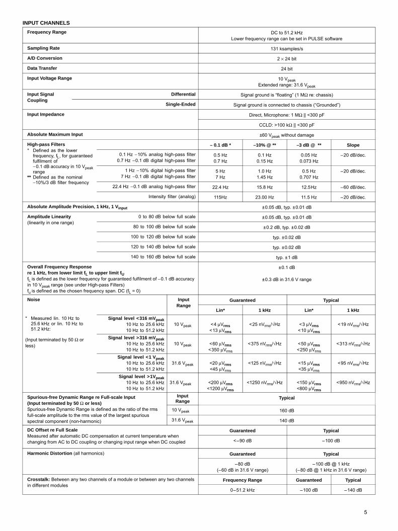
INPUT CHANNELS
Frequency Range DC to 51.2 kHzLower frequency range can be set in PULSE software
Sampling Rate 131 ksamples/s
A/D Conversion 2 × 24 bit
Data Transfer 24 bit
Input Voltage Range 10 VpeakExtended range: 31.6 Vpeak
Input Signal Coupling
Differential Signal ground is “floating” (1 MΩ re: chassis)
Single-Ended Signal ground is connected to chassis (“Grounded”)
Input Impedance Direct, Microphone: 1 MΩ || <300 pF
CCLD: >100 kΩ || <300 pF
Absolute Maximum Input ±60 Vpeak without damage
High-pass Filters* Defined as the lower
frequency, fL, for guaranteed fulfilment of −0.1 dB accuracy in 10 Vpeak range
** Defined as the nominal−10%/3 dB filter frequency
– 0.1 dB * –10% @ ** –3 dB @ ** Slope
0.1 Hz −10% analog high-pass filter0.7 Hz −0.1 dB digital high-pass filter
0.5 Hz0.7 Hz
0.1 Hz0.15 Hz
0.05 Hz0.073 Hz
–20 dB/dec.
1 Hz −10% digital high-pass filter7 Hz −0.1 dB digital high-pass filter
5 Hz7 Hz
1.0 Hz1.45 Hz
0.5 Hz0.707 Hz
–20 dB/dec.
22.4 Hz −0.1 dB analog high-pass filter 22.4 Hz 15.8 Hz 12.5Hz –60 dB/dec.
Intensity filter (analog) 115Hz 23.00 Hz 11.5 Hz –20 dB/dec.
Absolute Amplitude Precision, 1 kHz, 1 Vinput ±0.05 dB, typ. ±0.01 dB
Amplitude Linearity(linearity in one range)
0 to 80 dB below full scale ±0.05 dB, typ. ±0.01 dB
80 to 100 dB below full scale ±0.2 dB, typ. ±0.02 dB
100 to 120 dB below full scale typ. ±0.02 dB
120 to 140 dB below full scale typ. ±0.02 dB
140 to 160 dB below full scale typ. ±1 dB
Overall Frequency Responsere 1 kHz, from lower limit fL to upper limit fUfL is defined as the lower frequency for guaranteed fulfilment of −0.1 dB accuracy in 10 Vpeak range (see under High-pass Filters)fu is defined as the chosen frequency span. DC (fL = 0)
±0.1 dB
±0.3 dB in 31.6 V range
Noise Input Range
Guaranteed Typical
Lin* 1 kHz Lin* 1 kHz
* Measured lin. 10 Hz to 25.6 kHz or lin. 10 Hz to 51.2 kHz:
(Input terminated by 50 Ω or less)
Signal level <316 mVpeak10 Hz to 25.6 kHz10 Hz to 51.2 kHz
10 Vpeak <4 μVrms<13 μVrms
<25 nVrms/√Hz <3 μVrms <10 μVrms
<19 nVrms/√Hz
Signal level >316 mVpeak10 Hz to 25.6 kHz10 Hz to 51.2 kHz
10 Vpeak <60 μVrms <350 μVrms
<375 nVrms/√Hz <50 μVrms<250 μVrms
<313 nVrms/√Hz
Signal level <1 Vpeak10 Hz to 25.6 kHz10 Hz to 51.2 kHz
31.6 Vpeak <20 μVrms <45 μVrms
<125 nVrms/√Hz <15 μVrms<35 μVrms
<95 nVrms/√Hz
Signal level >1Vpeak10 Hz to 25.6 kHz10 Hz to 51.2 kHz
31.6 Vpeak <200 μVrms<1200 μVrms
<1250 nVrms/√Hz <150 μVrms<800 μVrms
<950 nVrms/√Hz
Spurious-free Dynamic Range re Full-scale Input(Input terminated by 50 Ω or less)Spurious-free Dynamic Range is defined as the ratio of the rms full-scale amplitude to the rms value of the largest spurious spectral component (non-harmonic)
Input Range
Typical
10 Vpeak 160 dB
31.6 Vpeak 140 dB
DC Offset re Full ScaleMeasured after automatic DC compensation at current temperature when changing from AC to DC coupling or changing input range when DC coupled
Guaranteed Typical
<–90 dB –100 dB
Harmonic Distortion (all harmonics) Guaranteed Typical
–80 dB(–60 dB in 31.6 V range)
–100 dB @ 1 kHz(–80 dB @ 1 kHz in 31.6 V range)
Crosstalk: Between any two channels of a module or between any two channels in different modules
Frequency Range Guaranteed Typical
0–51.2 kHz –100 dB –140 dB

6
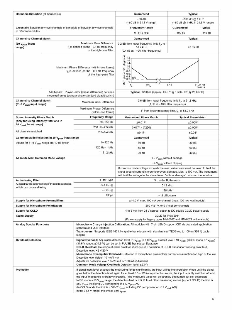
Channel-to-Channel Match Guaranteed Typical
(10 Vpeak input range)
Maximum Gain DifferencefL is defined as the −0.1 dB frequency
of the high-pass filter
0.2 dB from lower frequency limit, fL, to 51.2 kHz
(0.4 dB at −10% filter frequency)
±0.05 dB
Maximum Phase Difference (within one frame)fL is defined as the −0.1 dB frequency
of the high-pass filter
Additional PTP sync. error (phase difference) betweenmodules/frames (using a single standard gigabit switch)
Typical: <200 ns (approx. ±0.07° @ 1 kHz, ±2° @ 25.6 kHz)
Channel-to-Channel Match (31.6 Vpeak input range)
Maximum Gain Difference 0.6 dB from lower frequency limit, fL, to 51.2 kHz(1 dB at −10% filter frequency)
Maximum Phase Difference(within one frame)
4° from lower frequency limit, fL, to 51.2 kHz
Sound Intensity Phase Match(only for using intensity filter and in 10 Vpeak input range)
All channels matched
Frequency Range Guaranteed Phase Match Typical Phase Match
50–250 Hz ±0.017° ±0.005°
250 Hz–2.5 kHz 0.017° × (f/250) ±0.005°
2.5–6.4 kHz ±0.17° ±0.08°
Common Mode Rejection in 10 Vpeak input range Guaranteed Typical
Values for 31.6 Vpeak range are 10 dB lower. 0–120 Hz 70 dB 80 dB
120 Hz–1 kHz 55 dB 60 dB
1–51.2 kHz 30 dB 40 dB
Absolute Max. Common Mode Voltage ±5 Vpeak without damage
±4 Vpeak without clipping)
If common mode voltage exceeds the max. value, care must be taken to limit the signal ground current in order to prevent damage. Max. is 100 mA. The instrument will limit the voltage to the stated max. “without damage” common mode value
Anti-aliasing FilterAt least 90 dB attenuation of those frequencies which can cause aliasing
Filter Type 3rd order Butterworth
–0.1 dB @ 51.2 kHz
–3 dB @ 128 kHz
Slope –18 dB/octave
Supply for Microphone Preamplifiers ±14.0 V, max. 100 mA per channel (max. 100 mA total/module)
Supply for Microphone Polarization 200 V ±1 V, or 0 V (set per channel)
Supply for CCLD 4 to 5 mA from 24 V source, option to DC-couple CCLD power supply
Tacho Supply CCLD for Type 2981(Power supply for legacy types MM-0012 and MM-0024 not available)
Analog Special Functions Microphone Charge Injection Calibration: All modules with 7-pin LEMO support CIC via dedicated application software and OLE interfaceTransducers: Supports IEEE 1451.4-capable transducers with standardised TEDS (up to 100 m cable length)
Overload Detection Signal Overload: Adjustable detection level ±1 Vpeak to ±10 Vpeak. Default level ±10 Vpeak (CCLD mode ±7 Vpeak) (31.6 V range: ±31.6 V) can be set in PULSE Transducer DatabaseCCLD Overload: Detection of cable break or short-circuit + detection of CCLD transducer working point fault. Detection level: +2 V/20 VMicrophone Preamplifier Overload: Detection of microphone preamplifier current consumption too high or too low. Detection level default 10 mA/1 mAAdjustable detection level 1 to 20 mA or 100 mA if disabledCommon Mode Voltage Overload: Detection level: ±3.0 V
Protection If signal input level exceeds the measuring range significantly, the input will go into protection mode until the signal goes below the detection level again for at least 0.5 s. While in protection mode, the input is partly switched off and the input impedance is greatly increased. (The measured value will be strongly attenuated but still detectable)In DC mode –10 Vpeak range, the detection limit is ±12 V. In all other measuring modes (except CCLD) the limit is ±50 Vpeak including DC component or ±12 Vpeak AC(In CCLD mode the limit is +50/–2 Vpeak including DC component or ±12 Vpeak AC)In the 31.6 V range, the limit is ±50 Vpeak
INPUT CHANNELS (CONTINUED)
080229
1.81.61.41.21.0
Max
. pha
se d
iff. (
degr
ees)
0.80.60.40.2
0fL 10fL 6.4k 51.2k Hz
DC

OUTPUT CHANNELS
Output Connector 2 × BNC
Output Coupling DC
Signal Ground Coupling Floating or grounded to chassis
D/A Conversion 24 bit
DC Offset (DC Value set to 0 V) ≤1 mV auto-adjusted by loopback (<–80 dB re full scale)
Output Voltage Range (DC) 0 to ±10 V ±0.5% of requested value
Output Voltage Range (AC) 1 μVRMS – 10 Vpeak in two ranges
Output Impedance 50 Ω
Output Load Max. 40 mApeak
Frequency Range 0 – 51.2 kHz
Frequency Response re 1 kHz ±0.1 dB, 1 mHz to 51.2 kHz
Frequency Accuracy 0.00025%
Frequency Resolution 1 mHz (defined in PULSE software)
Phase Resolution 100 mdegrees (defined in PULSE software)
Phase Deviation Between Channels <20 mdegrees for frequencies below 1 kHz*
Waveform Software determined arbitrary waveforms up to 2 MsamplesWaveforms available in PULSE: Single fixed sine (continuous or burst), single swept sine, dual fixed sine, dual swept sine, fixed sine plus swept sine, stepped sine (with SSR Analyzer), random (continuous or burst), pseudo-random, periodic randomUser-defined, arbitrary waveforms can be downloaded
Amplitude Linearity @ 1 kHz Guaranteed Typical
±0.1 dB 0 – 100 dB below 7 Vrms 0 – 110 dB below 7 Vrms
Noise μVrms (nV/√Hz) in 50 kHz bandwidth
Range Guaranteed Typical
316 mVpeak 1 μVrms (4.4 nV/√Hz) 0.5 μVrms (2.2 nV/√Hz)
10 Vpeak 10 μVrms (44nV/√Hz) 5 μVrms (22 nV/√Hz)
Harmonic Distortion Products 0 – 51.2 kHz <–80 dB re full range output
Spurious In Band (non-harmonic) 0 – 51.2 kHz <– 100 dB re full range output or 1 μV, whichever is greater
Spurious Out of Band (non-harmonic) Up to 1 MHz <– 80 dB re full range output
Absolute Amplitude Precision Guaranteed
@ 23°C, 1 kHz, 1 Vrms ±0.05 dB
CrosstalkBetween output channels and between any output channel and any input channel terminated by less than 50 Ω (unloaded generator output)
Guaranteed Typical
0 – 51.2 kHz –120 dB –130 dB
Common Mode Rejection Guaranteed
1 Hz – 1 kHz 60 dB
Maximum Common Mode Voltage 5 Vpeak, DC – 80 MHz
If common mode voltage exceeds the max. value, care must be taken to limit the signal ground current in order to prevent damage. Max. is 100 mA. The instrument will limit the voltage to the stated max. “without damage” common mode value
Reconstruction Filter Sixth order Butterworth (–3 dB frequency = 120 kHz typically)
Attenuation of Mirror Frequencies >80 dB
Overload DetectionReported to PULSE and indicated by light rings on output connectors for output voltage above 11 Vpeak and output current above 40 mApeak
* Signal generators are not synchronized between LAN-XI and IDAe generator modules. This does not affect continuous signals (random, white- or pink-noise) but is not suitable for burst random signals and sine signals requiring phase control between generators
7

HT
L
Ordering Information
Type 3160-A-042 Generator, 4/2-ch. Input/Output Module LAN-XI JJ-0081 BNC Adaptor, female to female
51.2 kHz (Mic, CCLD, V)includes the following accessories:• UA-2100-060: LAN-XI Detachable front panel with 6 BNC inputconnectors• ZG-0426: Mains Adaptor (100 – 240 V)• AO-1450: Shielded CAT 6 LAN Cable with RJ 45 (2 m)
Type 3160-A-022 Generator, 2/2-ch. Input/Output Module LAN-XI 51.2 kHz (Mic, CCLD, V)includes the following accessories:• UA-2100-022: LAN-XI Detachable front panel with 4 BNC input/output
connectors• ZG-0426: Mains Adaptor (100 – 240 V)• AO-1450: Shielded CAT 6 LAN Cable with RJ 45 (2 m)
OPTIONAL ACCESSORIESAO-0090 7-pin LEMO to BNC male (1.2 m) for floating groundAO-0091 7-pin LEMO to BNC female (1.2 m) for floating groundAO-0526 4-pin Microtech to 3 × BNC CableAO-0546 DC Power Cable, Car Utility Socket to 1 moduleAO-0548 DC Power Cable, Source to 4 modulesAO-1450 Shielded CAT 6 LAN Cable with RJ45 (2 m)
EADQUARTERS: Brüel & Kjær Sound & Vibration Measurement A/S · DK-2850 Nærum · Denmaelephone: +45 7741 2000 · Fax: +45 4580 1405 · www.bksv.com · [email protected]
ocal representatives and service organisations worldwide
JJ-0152 BNC T-connectorJP-0145 BNC to 10−32 UNF Plug AdaptorUA-1713 10 × 2 mm Hex Wrench (QX-1315) for front panel exchangeUL-0265 10-port Gigabit Managed Switch with PTP and
PoE (8 ports)WB-1497 20 dB Attenuator
SOFTWAREPlease refer to the System Data for PULSE Software (BU 0229)
Service Products3160-CAI Type 3160 Initial Accredited Calibration3160-CAF Type 3160 Accredited Calibration3160-CTF Type 3160 Traceable Calibration3160-TCF Type 3160 LAN-XI Conformance Test with Certificate
A wide range of Brüel & Kjær Accelerometers, Microphones, Preamplifiers and Sound Intensity Probes is available for use with a LAN-XI system. The system supports IEEE 1451.4-capable transducers with standardised TEDS
ËBP-2331---ÄÎ
BP23
31–
1320
13-0
9
TRADEMARKSICP is a registered trademark of PCB Group Inc. · Netgear is a registered trademark of NetGear, Inc. · Cisco is a registered trademark of Cisco Systems, Inc. and/or its affiliates in the United States and certain other countries
Brüel & Kjær reserves the right to change specifications and accessories without notice. © Brüel & Kjær. All rights reserved.
rk
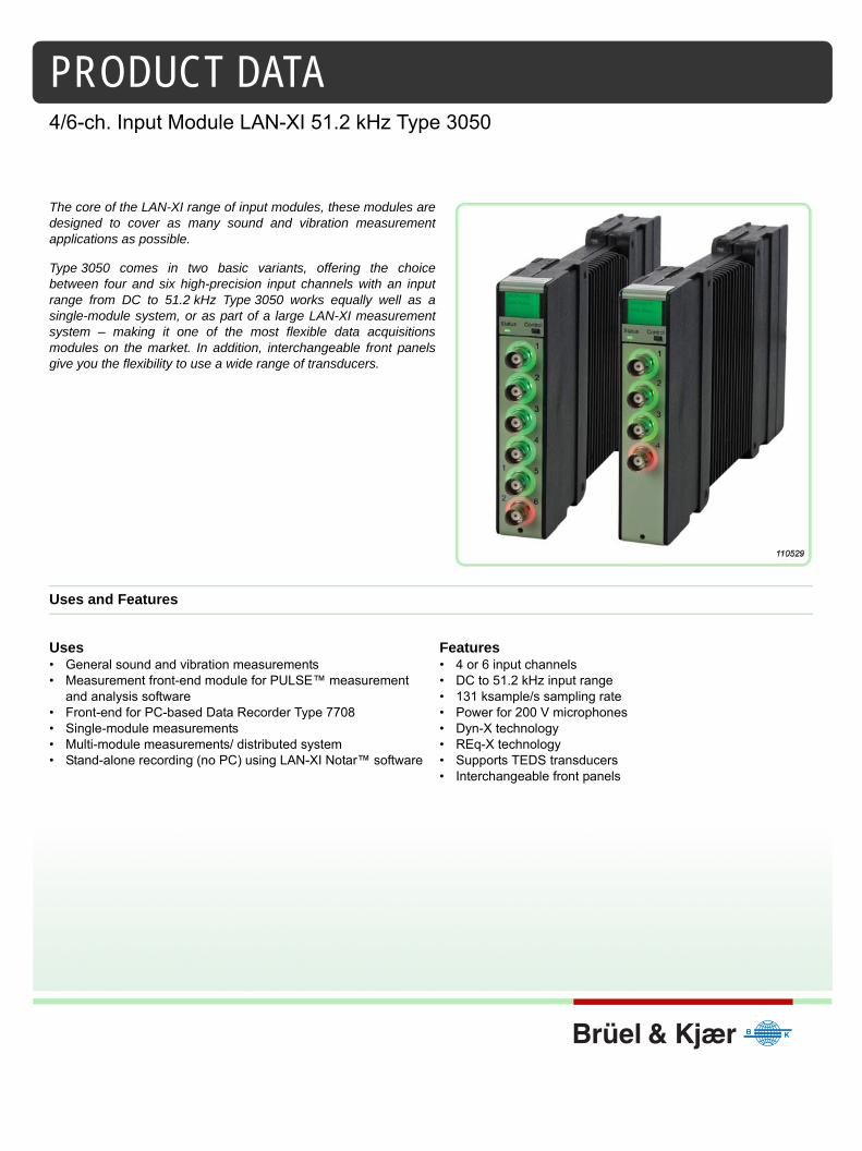
PRODUCT DATA
4/6-ch. Input Module LAN-XI 51.2 kHz Type 3050The core of the LAN-XI range of input modules, these modules aredesigned to cover as many sound and vibration measurementapplications as possible.
Type 3050 comes in two basic variants, offering the choicebetween four and six high-precision input channels with an inputrange from DC to 51.2 kHz Type 3050 works equally well as asingle-module system, or as part of a large LAN-XI measurementsystem – making it one of the most flexible data acquisitionsmodules on the market. In addition, interchangeable front panelsgive you the flexibility to use a wide range of transducers.
Uses and Features
Uses• General sound and vibration measurements • Measurement front-end module for PULSE™ measurement
and analysis software • Front-end for PC-based Data Recorder Type 7708 • Single-module measurements • Multi-module measurements/ distributed system • Stand-alone recording (no PC) using LAN-XI Notar™ software
Features• 4 or 6 input channels • DC to 51.2 kHz input range • 131 ksample/s sampling rate• Power for 200 V microphones • Dyn-X technology • REq-X technology • Supports TEDS transducers • Interchangeable front panels

2
One Cable OperationYou can use standard LAN cables for synchronous sampling between modules and system power, thanks toPower over Ethernet (PoE). This minimises the number of cables required and results in lower cost, lessdowntime, easier maintenance, and greater flexibility of installation.
Power over EthernetPoE is implemented according to IEEE 802.3af. PoE is wired Ethernet LAN technology that, with a suitablePoE LAN switch, allows the power needed for each module to be carried by screened shielded twisted pair(S/STP or S/FTP) CAT6 LAN cables rather than by separate power cables. This minimises the number ofcables required and results in lower cost, less downtime, easier maintenance and greater installationflexibility. PoE switches, such as 10-port Gigabit Managed Switch with PTP and PoE (8 ports) UL-0265, andPoE Injectors, such as ZyXEL® PoE-12 Power over Ethernet (a single-port PoE injector), can be used.
Built for Field and Lab UseThe modules and the detachable front plates are cast in magnesium for maximum stability, light weight, andtough field use.
Interchangeable Front PanelsThe modules allow front panels to be interchanged freely, with a variety of connectors for differenttransducers and applications. This results in fewer patch panels, less cable “spaghetti”, fewer cable adaptorsand faster system setup.
Independent ChannelsThe input channels on a module can be set up independently. You can set up the high-pass filters and inputgain separately and attach different types of transducer to different channels.
IEEE 1451.4 TransducersAll input modules support TEDS transducers. This allows automatic front-end and analyzer setup based onTEDS information stored in the transducer, for example, sensitivity, serial number, manufacturer andcalibration date. The individual frequency response of a transducer can be corrected for using PULSE’sTransducer Response Equalisation, REq-X, to achieve higher accuracy over extended frequency ranges.
OverloadConstant Current Line Drive (CCLD) conditioning monitors the supply voltage used by CCLD-compatibletransducers. Available CCLD transducers include:• Accelerometers• Charge amplifiers• Microphone preamplifiers• Tacho probes
If conditioning errors, such as a broken cable, are detected, an error is indicated as an overload on thespecific channel connector (using a ring-LED around the connector) and in the PC software.
Overload indications for input channels include (see Specifications for details): • Signal overload with adjustable detection level • CCLD overload: detection of cable break, short-circuit or CCLD transducer working point fault • Microphone preamplifier overload: detection of microphone preamplifier current consumption too high or
too low• Common mode voltage overload – relevant when input coupling is floating
Ground-loop Noise SuppressionThe module’s floating/grounded, differential input design and the fact that all external connections (LAN,power supply) are galvanically isolated in the module provide optimal ground-loop noise suppression.

Compliance with Standards
EFFECT OF RADIATED AND CONDUCTED RF, MAGNETIC FIELD AND VIBRATIONRadiated RF: 80−2700 MHz, 80% AM 1 kHz, 10 V/m Input measured with shorted input. All values are RMS. Conducted RF
CE-mark indicates compliance with: EMC Directive and Low Voltage DirectiveRCM mark indicates compliance with applicable ACMA technical standards – that is, for telecommunications, radio communications, EMC and EMEChina RoHS mark indicates compliance with administrative measures on the control of pollution caused by electronic information products according to the Ministry of Information Industries of the People’s Republic of ChinaWEEE mark indicates compliance with the EU WEEE Directive
Safety EN/IEC 61010–1 and ANSI/UL 61010–1: Safety requirements for electrical equipment for measurement, control and laboratory use
EMC Emission EN/IEC 61000–6–3: Generic emission standard for residential, commercial, and light-industrial environmentsCISPR 22: Radio disturbance characteristics of information technology equipment. Class B Limits
EMC Immunity EN/IEC61000–6–1: Generic standards – Immunity for residential, commercial and light industrial environmentsEN/IEC 61000–6–2: Generic standards – Immunity for industrial environmentsEN/IEC 61326: Electrical equipment for measurement, control and laboratory use – EMC requirementsNote: The above is only guaranteed using accessories listed in this Product Data
Temperature IEC 60068−2−1 & IEC 60068−2−2: Environmental Testing. Cold and Dry HeatAmbient Operating Temperature: −10 to +55°C (14 to 131°F)Storage Temperature: −25 to +70°C (−13 to +158°F)
Humidity IEC 60068−2−78: Damp Heat: 93% RH (non-condensing at 40°C (104°F))
Mechanical(non-operating)
IEC 60068–2–6: Vibration: 0.3 mm, 2 g, 10 – 500 HzIEC 60068–2–27: Shock: 100 g IEC 60068–2–29: Bump: 1000 bumps at 25 g
Enclosure IEC 60529: Protection provided by enclosures: IP 31
Conducted RF: 0.15−80 MHz, 80% AM 1 kHz, 10 VMagnetic Field: 30 A/m, 50 HzVibration: 5−500 Hz, 12.7 mm, 15 m/s2
immunity on all channels is only guaranteed using an external connection from measuring ground to chassis terminal
Specifications – LAN Interface
Input Radiated RF Conducted RF Magnetic Field Vibration
Direct/CCLD <250 μV <300 μV <4 μV <80 μVPreamplifier <250 μV <50 μV <8 μV <80 μV
CONNECTORRJ 45 (10baseT/100baseTX) connector complying with IEEE-802.3 100baseXTypes 3660-C and -D permit the use of a ruggedized RJ45 data connector (Neutrik NE8MC-1) to screw the cable to the frameTypes 3660-C and -D communicate at 1000 Mbits/s – shielded cables of type “CAT 5e” or better should be usedIndividual modules communicate at 100 Mbits/s All LAN connectors support MDIX, which means that cables may be “crossed” or notFor stand-alone modules, PoE is also supported (IEEE 802.3af). PoE requires screened shielded twisted pair (S/STP or S/FTP) CAT6 LAN cables
PROTOCOLThe following standard protocols are used:• TCP• DHCP (incl. Auto-IP)• DNS (on top of UDP)• IEEE 1588–2002 (on top of UDP)• IP• Ethernet
ACQUISITION PERFORMANCEEach LAN-XI module generates data at almost 20 Mbit/s when measuring six channels at 51.2 kHz bandwidth. The modules are capable
of handling their own maximum traffic while the built-in switch in the frame’s backplane has more than sufficient capacity. This means that bottlenecks can only occur outside these, for example in:• External switches• PCFor convenience, it is possible to daisy-chain LAN-XI frames. However, it is not recommended to daisy-chain more than two frames. For larger configurations, a star configuration with a central switch is recommended. This must have a switch capacity well beyond N × 20 Mbit/s, where N is the total number of modules
PTP PERFORMANCEPTP Synchronisation (with 1 Gigabit LAN Switch): Typical sample synchronisation better that 200 ns (approx. ±0.07° @ 1 kHz, ±2° @ 25.6 kHz)Tested with:• Cisco® SG300-10MP, 10-port 10/100/1000 Managed Gigabit Switch
with Maximum PoE (8 ports)• Netgear® 5-port Gigabit Switch GS105Better performance can be expected with a dedicated PTP switch:• UL-0265: 10-port Gigabit Managed Switch with PTPv2 and PoE (8
ports).This is a dedicated PTP switch, preconfigured for optimal use with LAN-XI
3
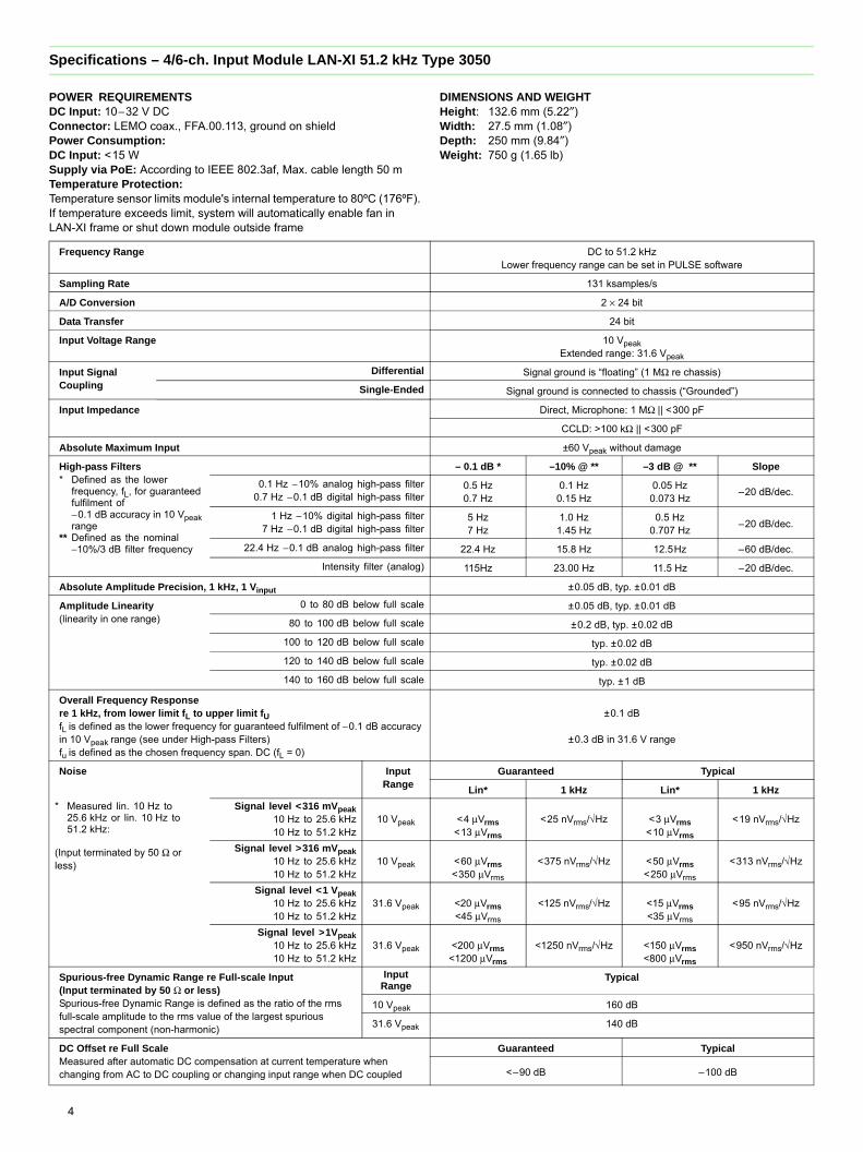
Specifications – 4/6-ch. Input Module LAN-XI 51.2 kHz Type 3050
POWER REQUIREMENTSDC Input: 10−32 V DCConnector: LEMO coax., FFA.00.113, ground on shieldPower Consumption:DC Input: <15 WSupply via PoE: According to IEEE 802.3af, Max. cable length 50 mTemperature Protection:Temperature sensor limits module's internal temperature to 80ºC (176ºF). If temperature exceeds limit, system will automatically enable fan in LAN-XI frame or shut down module outside frame
DIMENSIONS AND WEIGHTHeight: 132.6 mm (5.22″)Width: 27.5 mm (1.08″)Depth: 250 mm (9.84″)Weight: 750 g (1.65 lb)
4
Frequency Range DC to 51.2 kHzLower frequency range can be set in PULSE software
Sampling Rate 131 ksamples/s
A/D Conversion 2 × 24 bit
Data Transfer 24 bit
Input Voltage Range 10 VpeakExtended range: 31.6 Vpeak
Input Signal Coupling
Differential Signal ground is “floating” (1 MΩ re chassis)
Single-Ended Signal ground is connected to chassis (“Grounded”)
Input Impedance Direct, Microphone: 1 MΩ || <300 pF
CCLD: >100 kΩ || <300 pF
Absolute Maximum Input ±60 Vpeak without damage
High-pass Filters* Defined as the lower
frequency, fL, for guaranteed fulfilment of −0.1 dB accuracy in 10 Vpeak range
** Defined as the nominal−10%/3 dB filter frequency
– 0.1 dB * –10% @ ** –3 dB @ ** Slope
0.1 Hz −10% analog high-pass filter0.7 Hz −0.1 dB digital high-pass filter
0.5 Hz0.7 Hz
0.1 Hz0.15 Hz
0.05 Hz0.073 Hz –20 dB/dec.
1 Hz −10% digital high-pass filter7 Hz −0.1 dB digital high-pass filter
5 Hz7 Hz
1.0 Hz1.45 Hz
0.5 Hz0.707 Hz –20 dB/dec.
22.4 Hz −0.1 dB analog high-pass filter 22.4 Hz 15.8 Hz 12.5Hz –60 dB/dec.
Intensity filter (analog) 115Hz 23.00 Hz 11.5 Hz –20 dB/dec.
Absolute Amplitude Precision, 1 kHz, 1 Vinput ±0.05 dB, typ. ±0.01 dB
Amplitude Linearity(linearity in one range)
0 to 80 dB below full scale ±0.05 dB, typ. ±0.01 dB
80 to 100 dB below full scale ±0.2 dB, typ. ±0.02 dB
100 to 120 dB below full scale typ. ±0.02 dB
120 to 140 dB below full scale typ. ±0.02 dB
140 to 160 dB below full scale typ. ±1 dB
Overall Frequency Responsere 1 kHz, from lower limit fL to upper limit fUfL is defined as the lower frequency for guaranteed fulfilment of −0.1 dB accuracy in 10 Vpeak range (see under High-pass Filters)fu is defined as the chosen frequency span. DC (fL = 0)
±0.1 dB
±0.3 dB in 31.6 V range
Noise Input Range
Guaranteed Typical
Lin* 1 kHz Lin* 1 kHz
* Measured lin. 10 Hz to 25.6 kHz or lin. 10 Hz to 51.2 kHz:
(Input terminated by 50 Ω or less)
Signal level <316 mVpeak10 Hz to 25.6 kHz10 Hz to 51.2 kHz
10 Vpeak <4 μVrms<13 μVrms
<25 nVrms/√Hz <3 μVrms <10 μVrms
<19 nVrms/√Hz
Signal level >316 mVpeak10 Hz to 25.6 kHz10 Hz to 51.2 kHz
10 Vpeak <60 μVrms <350 μVrms
<375 nVrms/√Hz <50 μVrms<250 μVrms
<313 nVrms/√Hz
Signal level <1 Vpeak10 Hz to 25.6 kHz10 Hz to 51.2 kHz
31.6 Vpeak <20 μVrms <45 μVrms
<125 nVrms/√Hz <15 μVrms<35 μVrms
<95 nVrms/√Hz
Signal level >1Vpeak10 Hz to 25.6 kHz10 Hz to 51.2 kHz
31.6 Vpeak <200 μVrms<1200 μVrms
<1250 nVrms/√Hz <150 μVrms<800 μVrms
<950 nVrms/√Hz
Spurious-free Dynamic Range re Full-scale Input(Input terminated by 50 Ω or less)Spurious-free Dynamic Range is defined as the ratio of the rms full-scale amplitude to the rms value of the largest spurious spectral component (non-harmonic)
Input Range
Typical
10 Vpeak 160 dB
31.6 Vpeak 140 dB
DC Offset re Full ScaleMeasured after automatic DC compensation at current temperature when changing from AC to DC coupling or changing input range when DC coupled
Guaranteed Typical
<–90 dB –100 dB
Harmonic Distortion (all harmonics) Guaranteed Typical
–80 dB(–60 dB in 31.6 V range)
–100 dB @ 1 kHz(–80 dB @ 1 kHz in 31.6 V range)
Crosstalk: Between any two channels of a module or between any two channels in different modules
Frequency Range Guaranteed Typical
0–51.2 kHz –100 dB –140 dB
Channel-to-Channel Match Guaranteed Typical
(10 Vpeak input range)
Maximum Gain DifferencefL is defined as the −0.1 dB frequency
of the high-pass filter
0.2 dB from lower frequency limit, fL, to 51.2 kHz
(0.4 dB at −10% filter frequency) ±0.05 dB
Maximum Phase Difference (within one frame)fL is defined as the −0.1 dB frequency
of the high-pass filter
Additional PTP sync. error (phase difference) betweenmodules/frames (using a single standard gigabit switch)
Typical: <200 ns (approx. ±0.07° @ 1 kHz, ±2° @ 25.6 kHz)
Channel-to-Channel Match (31.6 Vpeak input range)
Maximum Gain Difference 0.6 dB from lower frequency limit, fL, to 51.2 kHz(1 dB at −10% filter frequency)
Maximum Phase Difference(within one frame) 4° from lower frequency limit, fL, to 51.2 kHz
Sound Intensity Phase Match(only for using intensity filter and in 10 Vpeak input range)
All channels matched
Frequency Range Guaranteed Phase Match Typical Phase Match
50–250 Hz ±0.017° ±0.005°
250 Hz–2.5 kHz 0.017° × (f/250) ±0.005°
2.5–6.4 kHz ±0.17° ±0.08°
Common Mode Rejection in 10 Vpeak input range Guaranteed Typical
Values for 31.6 Vpeak range are 10 dB lower. 0–120 Hz 70 dB 80 dB
120 Hz–1 kHz 55 dB 60 dB
1–51.2 kHz 30 dB 40 dB
Absolute Max. Common Mode Voltage ±5 Vpeak without damage
±4 Vpeak without clipping
If common mode voltage exceeds the max. value, care must be taken to limit the signal ground current in order to prevent damage. Max. is 100 mA. The instrument will limit the voltage to the stated max. “without damage” common mode value
Anti-aliasing FilterAt least 90 dB attenuation of those frequencies which can cause aliasing
Filter Type 3rd order Butterworth
–0.1 dB @ 51.2 kHz
–3 dB @ 128 kHz
Slope –18 dB/octave
Supply for Microphone Preamplifiers ±14.0 V, max. 100 mA per channel (max. 100 mA total/module)
Supply for Microphone Polarization 200 V ±1 V, or 0 V (set per channel)
Supply for CCLD 4 to 5 mA from 24 V source, option to DC-couple CCLD power supply
Tacho Supply CCLD for Type 2981(Power supply for legacy types MM-0012 and MM-0024 not available)
Analog Special Functions Microphone Charge Injection Calibration: All modules with 7-pin LEMO support CIC via dedicated application software and OLE interfaceTransducers: Supports IEEE 1451.4-capable transducers with standardised TEDS (up to 100 m (328 ft) cable length)
Overload Detection Signal Overload: Adjustable detection level ±1 Vpeak to ±10 Vpeak. Default level ±10 Vpeak (CCLD mode ±7 Vpeak) (31.6 V range: ±31.6 V) can be set in PULSE Transducer DatabaseCCLD Overload: Detection of cable break or short-circuit + detection of CCLD transducer working point fault. Detection level: +2 V/20 VMicrophone Preamplifier Overload: Detection of microphone preamplifier current consumption too high or too low. Detection level default 10 mA/1 mAAdjustable detection level 1 to 20 mA or 100 mA if disabledCommon Mode Voltage Overload: Detection level: ±3.0 V
Protection If signal input level exceeds the measuring range significantly, the input will go into protection mode until the signal goes below the detection level again for at least 0.5 s. While in protection mode, the input is partly switched off and the input impedance is greatly increased. (The measured value will be strongly attenuated but still detectable)In DC mode –10 Vpeak range, the detection limit is ±12 V. In all other measuring modes (except CCLD) the limit is ±50 Vpeak including DC component or ±12 Vpeak AC(In CCLD mode the limit is +50/–2 Vpeak including DC component or ±12 Vpeak AC)In the 31.6 V range, the limit is ±50 Vpeak
080229
1.81.61.41.21.0
Max
. pha
se d
iff. (
degr
ees)
0.80.60.40.2
0fL 10fL 6.4k 51.2k Hz
DC
5

Ordering Information
Type 3050-A-060 6-ch. Input Module LAN-XI 51.2 kHz (Mic, CCLD, V) JJ-0152 BNC T-connector
includes the following accessories:• UA-2100-060: LAN-XI Detachable front panel with 6 BNC inputconnectors• ZG-0426: Mains Adaptor (100 – 240 V)• AO-1450: Shielded CAT 6 LAN Cable with RJ 45 (2 m)
Type 3050-A-040 4-ch. Input Module LAN-XI 51.2 kHz (Mic, CCLD, V)includes the following accessories:• UA-2100-040: LAN-XI Detachable front panel with 4 BNC input
connectors• ZG-0426: Mains Adaptor (100 – 240 V)• AO-1450: Shielded CAT 6 LAN Cable with RJ 45 (2 m)
OPTIONAL ACCESSORIESAO-0090 7-pin LEMO to BNC male (1.2 m) for floating groundAO-0091 7-pin LEMO to BNC female (1.2 m) for floating groundAO-0526 4-pin Microtech to 3 × BNC CableAO-0546 DC Power Cable, Car Utility Socket to 1 moduleAO-0548 DC Power Cable, Source to 4 modulesJJ-0081 BNC Adaptor, female to female
6
JP-0145 BNC to 10−32 UNF Plug AdaptorUA-1713 10 × 2 mm Hex Wrench (QX-1315) for front panel exchangeUL-0265 10-port Gigabit Managed Switch with PTP and
PoE (8 ports)WB-1497 20 dB Attenuator
SOFTWAREPlease refer to the System Data for PULSE Software (BU 0229)
Service Products3050-CAI Type 3050 Initial Accredited Calibration3050-CAF Type 3050 Accredited Calibration3050-CTF Type 3050 Traceable Calibration3050-TCF Type 3050 LAN-XI Conformance Test with Certificate
A wide range of Brüel & Kjær Accelerometers, Microphones, Preamplifiers and Sound Intensity Probes is available for use with a LAN-XI system. The system supports IEEE 1451.4-capable transducers with standardised TEDS

P R O D U C T D ATA
PULSE Measurement System Switch UL-02658-port LAN-switch with PoE and PTPv2 Support
Uses• Data transfer and synchronization of LAN-XI modules• Powering of up to eight PoE devices, each using a single
twisted-pair Ethernet cable• Distributed PULSE™ measurement setups
Features• Configured specifically for optimum PULSE measurement
performance: preconfigured for plug and play set up• Power over Ethernet (PoE; 802.3af) enables the switch to
power stand-alone LAN-XI modules• Precision Time Protocol (PTPv2; IEEE 1588–2009)
synchronizes LAN-XI modules and frames with each other at sample-level accuracy
• Web-managed switch: configurable via browser• No bandwidth limitations
IntroductionUL-0265 is a 10/100/1000 Mbps network switch that can powerup to eight PoE devices, for example seven LAN-XI modules andone PC. The switch is preconfigured for plug and play setup – itsenses whether the LAN-XI modules need PoE and supplies thepower if they do.
UL-0265 is configured specifically for optimum PULSEmeasurement performance (PULSE LabShop, PULSE Time DataRecorder and PULSE Reflex Measuring).
PoweringUL-0265 is powered from a 100 – 240 V AC, 50 – 60 Hz mainspower supply.
Fig. 1 With UL-0265, LAN-XI frames and modules can be combined in a distributed system*
* If more than two Type 3660-D-100 or four Type 3660-C-100 frames are used, please add an extra Gigabit connection to the PC and configure the two connections as one aggregated connection. This is an advanced feature that requires a Network Interface Card on the PC with more than one Ethernet port, and setup of this and the switch.
PC
UL-0265 PULSEMeasurementSystem Switch
Stand-alone LAN-XI Modules
LAN-XI Frames 3660-C-100/3660-D-100
150110

Brüel & Kjær Sound & Vibration Measurement A/SDK-2850 Nærum · Denmark · Telephone: +45 77 41 20 00 · Fax: +45 45 80 14 05www.bksv.com · [email protected] representatives and service organizations worldwideAlthough reasonable care has been taken to ensure the information in this document is accurate, nothingherein can be construed to imply representation or warranty as to its accuracy, currency or completeness,nor is it intended to form the basis of any contract. Content is subject to change without notice – contactBrüel & Kjær for the latest version of this document.
Brüel & Kjær and all other trademarks, service marks, trade names, logos and product names are the property of Brüel & Kjær or a third-party company. ËBP-2529---UÎ
BP25
29–
1220
16-0
5©
Brü
el&
Kjæ
r. Al
l rig
hts r
eser
ved.
Specifications – PULSE Measurement System Switch UL-0265
POWER REQUIREMENTSMains: 100–240 V AC, 50–60 HzPower Consumption:(Full data load, no transducers mounted)• PoE on 7 LAN-XI modules: 100 W• No PoE: 20 W
ACOUSTIC NOISE EMISSION
DIMENSIONSHeight: 48 mm (1.9″)Depth: 230 mm (9.1″)Width: 280 mm (11.0″)Weight: 2.3 kg (5.1 lb)
ENVIRONMENTALEnclosure: IP 20Temperature Range: • Operating: 0 to 50 °C (32 to 122 °F)• Storage: –20 to +70 °C (–4 to +158 °F)Operating Humidity: 10% to 90% RH, non-condensing
COMPLIANCE WITH STANDARDS
Ordering Information
UL-0265 PULSE Measurement System Switch, 8-port LAN-switch with PoE and PTPv2 Support
Includes the following accessories:• Country-specific power cable• Monitor cable• Documentation CD• Quick Start BR 8039
OPTIONAL ACCESSORIESAO-1450-x-yyy* Cable, Cat. 6 S/FTP, RJ45 (M)
to RJ45 (M), +70 °C (158 °F)
UL-0265dB, A-weighted
No PoE in use (fan off) 19.6
Full PoE on seven connections (fan on) 37.1
The CE marking is the manufacturer's declaration that the product meets the requirements of the applicable EU directivesRCM mark indicates compliance with applicable ACMA technical standards – that is, for telecommunications, radio communications, EMC and EMEChina RoHS mark indicates compliance with administrative measures on the control of pollution caused by electronic information products according to the Ministry of Information Industries of the People’s Republic of ChinaWEEE mark indicates compliance with the EU WEEE Directive
FCC mark indicates compliance with 47 CFR FCC rules and regulations Part 15 subpart B, Class A Digital Device
* x = D (decimetres) or M (metres)yyy = length in decimetres or metresPlease specify cable length when ordering
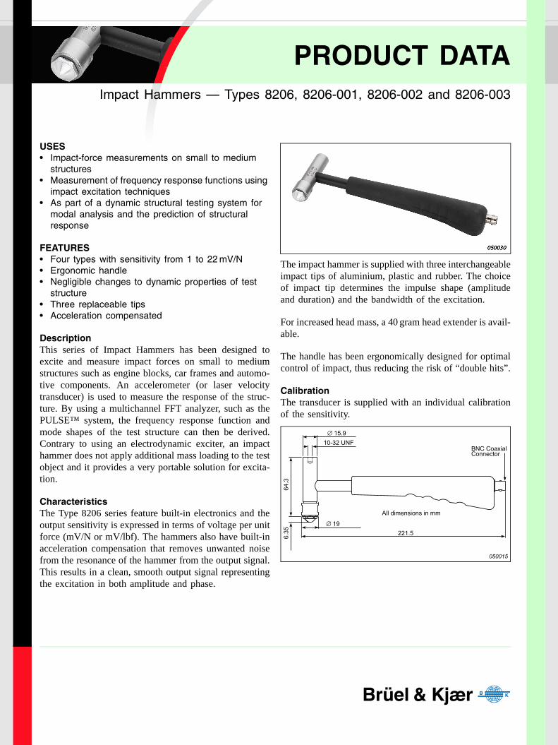
PRODUCT DATAImpact Hammers — Types 8206, 8206-001, 8206-002 and 8206-003
USES• Impact-force measurements on small to medium
structures• Measurement of frequency response functions using
impact excitation techniques• As part of a dynamic structural testing system for
modal analysis and the prediction of structural response
FEATURES• Four types with sensitivity from 1 to 22 mV/N• Ergonomic handle• Negligible changes to dynamic properties of test
structure• Three replaceable tips• Acceleration compensated
DescriptionThis series of Impact Hammers has been designed toexcite and measure impact forces on small to mediumstructures such as engine blocks, car frames and automo-tive components. An accelerometer (or laser velocitytransducer) is used to measure the response of the struc-ture. By using a multichannel FFT analyzer, such as thePULSE™ system, the frequency response function andmode shapes of the test structure can then be derived.Contrary to using an electrodynamic exciter, an impacthammer does not apply additional mass loading to the testobject and it provides a very portable solution for excita-tion.
CharacteristicsThe Type 8206 series feature built-in electronics and theoutput sensitivity is expressed in terms of voltage per unitforce (mV/N or mV/lbf). The hammers also have built-inacceleration compensation that removes unwanted noisefrom the resonance of the hammer from the output signal.This results in a clean, smooth output signal representingthe excitation in both amplitude and phase.
The impact hammer is supplied with three interchangeableimpact tips of aluminium, plastic and rubber. The choiceof impact tip determines the impulse shape (amplitudeand duration) and the bandwidth of the excitation.
For increased head mass, a 40 gram head extender is avail-able.
The handle has been ergonomically designed for optimalcontrol of impact, thus reducing the risk of “double hits”.
CalibrationThe transducer is supplied with an individual calibrationof the sensitivity.
050015
All dimensions in mm
∅ 19
∅ 15.910-32 UNF
64.3
6.35 221.5
BNC CoaxialConnector
bp207812.fm Page 1 Monday, May 30, 2005 10:11 AM
HEADQUARTERS: DK-2850 Nærum · Denmark · Telephone: +45 4580 0500 · Fax: +45 4580 1405www.bksv.com · [email protected]
Australia (+61) 2 9889-8888 · Austria (+43) 1 865 74 00 · Brazil (+55)11 5188-8166 · Canada (+1) 514 695-8225China (+86) 10 680 29906 · Czech Republic (+420) 2 6702 1100 · Finland (+358) 9-521 300 · France (+33) 1 69 90 71 00Germany (+49) 421 17 87 0 · Hong Kong (+852) 2548 7486 · Hungary (+36) 1 215 83 05 · Ireland (+353) 1 807 4083Italy (+39) 0257 68061 · Japan (+81) 3 5715 1612 · Korea (+82) 2 3473 0605 · Netherlands (+31)318 55 9290Norway (+47) 66 77 11 55 · Poland (+48) 22 816 75 56 · Portugal (+351) 21 47 11 4 53 · Singapore (+65) 377 4512Slovak Republic (+421) 25 443 0701 · Spain (+34) 91 659 0820 · Sweden (+46) 8 449 8600Switzerland (+41) 44 880 7035 · Taiwan (+886) 2 2502 7255 · United Kingdom (+44) 14 38 739 000USA (+1) 800 332 2040 · Local representatives and service organisations worldwide
BP
2078
–12
05/0
5R
osen
dahl
s B
ogtr
ykke
ri
Specifications – Impact Hammers Types 8206, 8206-001, 8206-002 and 8206-003
All values are typical at 25°C (77°F) unless measurement uncertainty is specified
COMPLIANCE WITH STANDARDSCompliance with EMC Directive and Low Voltage Directive of the EU
Compliance with the EMC requirements of Australia and New Zealand
Ordering Information
Type 8206, 8206-001, 8206-002 and8206-003 include:• Impact tip of aluminium• Impact tip of plastic (Delrin)• Impact tip of rubber (Polyurethane)• Carrying box• Calibration chart• Head extender (40 grams)• PVC Insulated Cable, 70°C, 10–32 UNF to
BNC Connector, 5 m (16.4 ft)
• Plug Adaptor, BNC to 10–32 UNF
OPTIONAL ACCESSORIES*• AO 0531: 70°C, Insulated single screen
flexible cable, 10–32 UNF to BNC, 5 m (16.4 ft)
• JP 0145: Plug adaptor, BNC/10–32 UNF• AO 0406: Low-noise, double-screened
cable, 10–32 UNF to BNC, 200°C, 5 m (16.4 ft)
• DB 3996: Head extender (40 grams) forImpact Hammer Type 8206
• UA 2059: Set of three impact tips for Type 8206 series impact hammers
• ZZ0245: In-line TEDS Adaptor, 10–32UNF to 10–32UNF
Units 8206 8206-001 8206-002 8206-003
Dynamic Characteristics
Voltage Sensitivity (typical) mV/N (mV/lbf) 22.7 (100) 11.4 (50) 2.27 (10) 1.14 (5)
Full Scale Force Range Compression N (lbf) 220 (50) 445 (100) 2200 (500) 4448 (1000)
Linear Error at Full Scale % full scale <±1
Electrical Characteristics
Full Scale Output Voltage V +5
DC Output Bias Voltage V 10 ±1
Output Impedance Ω <100
Power Supply mA 2 to 20
Voltage Range V DC +18 to +30
Environmental Characteristics
Temperature Range °C (°F) –73 to +60 (–100 to +140)
Max. Force Compression N (lbf) 4448 (1000) 8896 (2000)
Physical Characteristics
Dimensions See outline drawing
Overall Length mm (in.) 221.5 (8.72)
Effective Seismic Mass gram (oz.) 100 (3.53)
Sensor Housing Material Stainless steel (17–4 PH)
Handle Material Fibreglass
Connector BNC
*Additional accessories and cables are available (see www.bksv.com)
Brüel & Kjær reserves the right to change specifications and accessories without notice
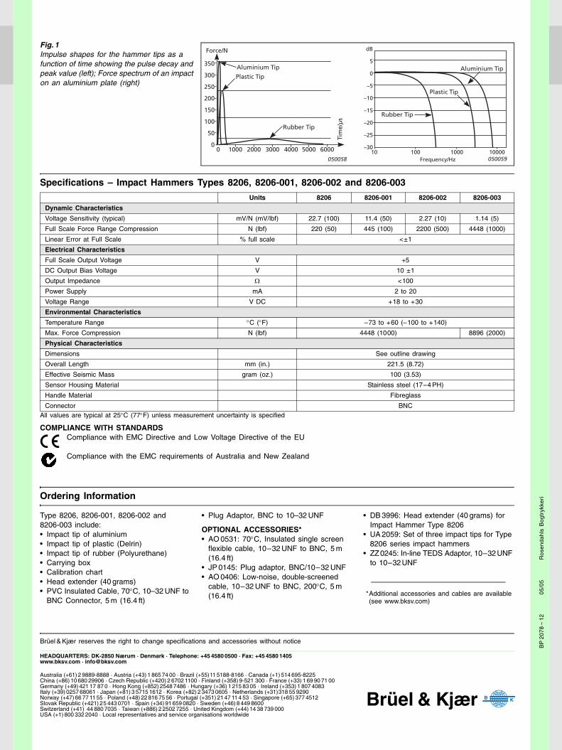
Fig. 1 Impulse shapes for the hammer tips as a function of time showing the pulse decay and peak value (left); Force spectrum of an impact on an aluminium plate (right)
350
300
250
200
150
100
50
00 1000 2000 3000 4000 5000 6000
Force/N
Aluminium Tip
Plastic Tip
Rubber Tip
050058
Tim
e/µ
s
050059
dB
5
0
–5
–10
–15
–20
–25
–3010 100 1000 10000
Frequency/Hz
Aluminium Tip
Rubber Tip
Plastic Tip
bp207812.fm Page 2 Monday, May 30, 2005 10:11 AM
PRODUCT DATAPRODUCT DATA
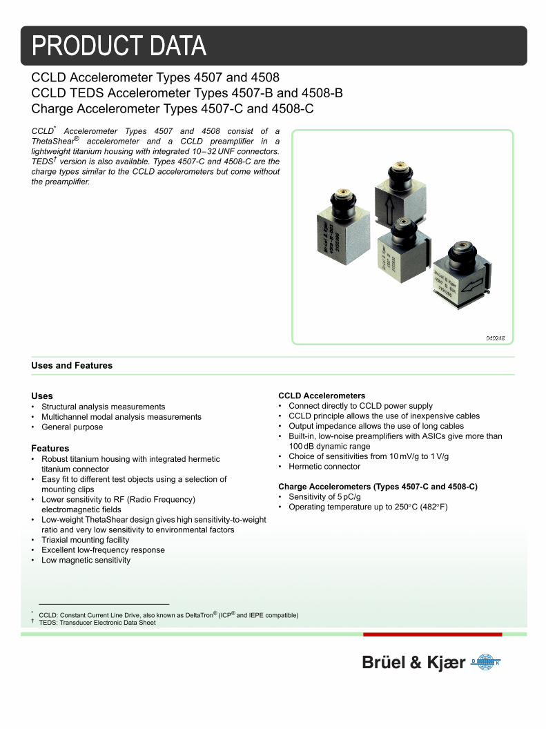
CCLD Accelerometer Types 4507 and 4508CCLD TEDS Accelerometer Types 4507-B and 4508-BCharge Accelerometer Types 4507-C and 4508-CCCLD* Accelerometer Types 4507 and 4508 consist of aThetaShear® accelerometer and a CCLD preamplifier in alightweight titanium housing with integrated 10–32 UNF connectors.TEDS† version is also available. Types 4507-C and 4508-C are thecharge types similar to the CCLD accelerometers but come withoutthe preamplifier.
Uses and Features
Uses• Structural analysis measurements• Multichannel modal analysis measurements• General purpose
Features• Robust titanium housing with integrated hermetic
titanium connector• Easy fit to different test objects using a selection of
mounting clips• Lower sensitivity to RF (Radio Frequency)
electromagnetic fields• Low-weight ThetaShear design gives high sensitivity-to-weight
ratio and very low sensitivity to environmental factors• Triaxial mounting facility• Excellent low-frequency response• Low magnetic sensitivity
CCLD Accelerometers• Connect directly to CCLD power supply • CCLD principle allows the use of inexpensive cables• Output impedance allows the use of long cables • Built-in, low-noise preamplifiers with ASICs give more than
100 dB dynamic range • Choice of sensitivities from 10 mV/g to 1 V/g• Hermetic connector
Charge Accelerometers (Types 4507-C and 4508-C)• Sensitivity of 5 pC/g• Operating temperature up to 250C (482F)
* CCLD: Constant Current Line Drive, also known as DeltaTron® (ICP® and IEPE compatible)† TEDS: Transducer Electronic Data Sheet

Description
Accelerometer Types 4507 and 4508 are specifically designed to withstand rough environments. Acombination of high sensitivity, low mass and small physical dimensions makes them ideal for modalmeasurements such as automotive body and power-train ones as well as for modal analysis on aircraft,trains and satellites. The main difference between the Types 4507 and 4508 is the position of the coaxialconnector, which is on the top surface perpendicular to the main axis for Type 4508 (top-mounted connector)and on the side surface parallel to the main axis for Type 4507 (side-mounted connector).
Design
Fig. 1 Exploded view of Miniature CCLD Accelerometer Type 4508 (top mounted connector) showing the ThetaShear design and built-in CCLD preamplifier
The 1032 UNF connector (1) is an integrated part of the top piece (2),which also contains the preamplifier (3) (not Type 4507-C or 4508-C).The slotted cylindrical stanchion holds a central seismic mass (4)flanked by two piezoelectric plates (5). This assembly is clampedrigidly by a ring (6). The parts are firmly held together without the use ofany bonding agent other than friction, a principle which has provedextremely reliable in Brüel & Kjær DeltaShear accelerometers. Thisassembly is hermetically welded to the titanium housing (7).
Mounting
Special effort has been put into making the mounting process as flexible as possible. The accelerometerhousing has slots that allow the use of mounting clips so that the accelerometers can be easily fitted to anumber of different test objects, or removed, for calibration. UA-1407, UA-1475 and UA-1478 are sets whicheach contain 100 plastic mounting clips. UA-1564 is a set of 5 high-temperature mounting clips.
12
3
5
4
7
6
960454e
Fig. 2 High-temperature Mounting Clip UA-1564
Specifications: Temperature range: –55 to +175C (–67 to +347F)Acceptable if discolouring: up to +250C (+482F)
Weight: 5.7 grams (0.20 oz)Maximum acceleration:(with 5 gram accelerometer): 50 g peak(Perpendicular to mounting surface): 250 g peak
Material: Base – Anodized aluminium; Spring – Stainless steelMounting: 10–32 UNF
120592
2
Common Specifications for all Plastic Mounting ClipsTemperature range: –54C to +50C (–65 to +122F)For brief use (<1 hour): up to +80C (up to +176F)
Maximum acceleration: 10 g peakPerpendicular to mounting surface: 70g peak
Material: Glass reinforced polycarbonate
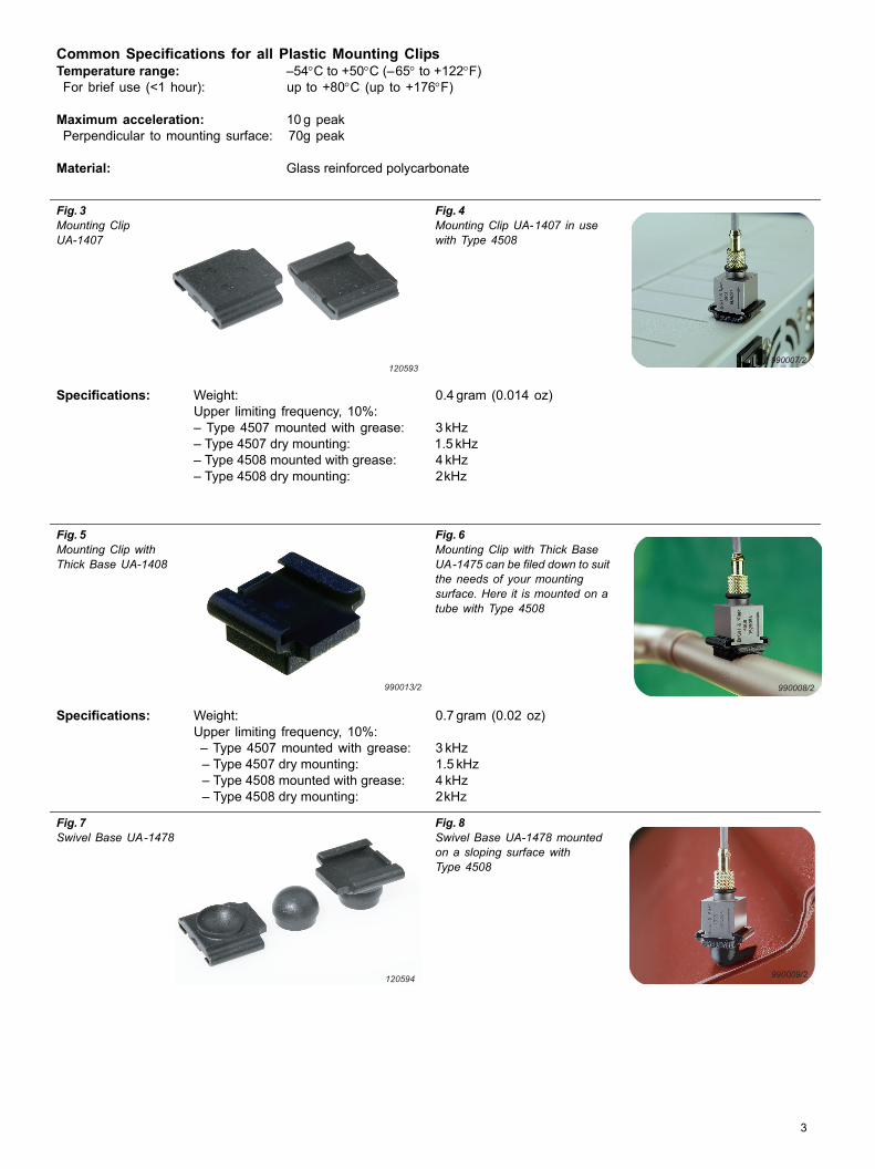
Fig. 3 Mounting ClipUA-1407
Fig. 4 Mounting Clip UA-1407 in use with Type 4508
Specifications: Weight: 0.4 gram (0.014 oz)Upper limiting frequency, 10%:– Type 4507 mounted with grease: 3 kHz – Type 4507 dry mounting: 1.5 kHz – Type 4508 mounted with grease: 4 kHz – Type 4508 dry mounting: 2kHz
Fig. 5 Mounting Clip with Thick Base UA-1408
Fig. 6 Mounting Clip with Thick Base UA-1475 can be filed down to suit the needs of your mounting surface. Here it is mounted on a tube with Type 4508
Specifications: Weight: 0.7 gram (0.02 oz)Upper limiting frequency, 10%:– Type 4507 mounted with grease: 3 kHz – Type 4507 dry mounting: 1.5 kHz – Type 4508 mounted with grease: 4 kHz – Type 4508 dry mounting: 2kHz
Fig. 7 Swivel Base UA-1478
Fig. 8 Swivel Base UA-1478 mounted on a sloping surface with Type 4508
120593990007/2
990013/2 990008/2
120594 990009/2
3
Environmental Sensitivity
Some of the most troublesome environmental factors encountered when using piezoelectric accelerometersare temperature transients. By careful choice of materials, mechanical design and the shear concept,however, the influence of these factors has been reduced to a minimum. Special effort has also been madeto minimise interference from RF (Radio Frequency) electromagnetic fields.
High humidity is another environmental factor that can influence the accuracy of piezoelectric transducers.Careful design and manufacturing have reduced this effect to a minimum for the Type 4507 and 4508families. Furthermore, all CCLD members of the families (see Specifications) are equipped with hermeticallysealed (glass) connectors, that make them completely independent of humidity and aggressive gases.
Calibration
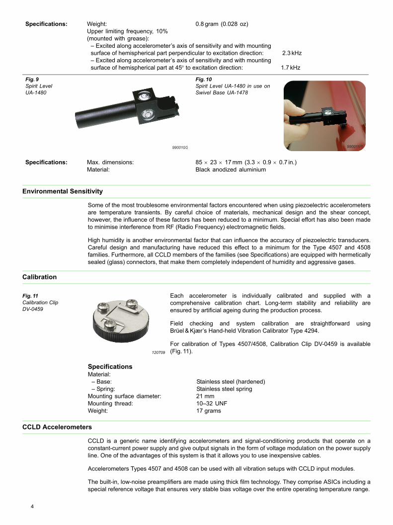
Fig. 11 Calibration Clip DV-0459
Each accelerometer is individually calibrated and supplied with acomprehensive calibration chart. Long-term stability and reliability areensured by artificial ageing during the production process.
Field checking and system calibration are straightforward usingBrüel & Kjær’s Hand-held Vibration Calibrator Type 4294.
For calibration of Types 4507/4508, Calibration Clip DV-0459 is available(Fig. 11).
SpecificationsMaterial:
– Base: Stainless steel (hardened)– Spring: Stainless steel spring
Mounting surface diameter: 21 mmMounting thread: 10–32 UNFWeight: 17 grams
CCLD Accelerometers
CCLD is a generic name identifying accelerometers and signal-conditioning products that operate on aconstant-current power supply and give output signals in the form of voltage modulation on the power supplyline. One of the advantages of this system is that it allows you to use inexpensive cables.
Accelerometers Types 4507 and 4508 can be used with all vibration setups with CCLD input modules.
The built-in, low-noise preamplifiers are made using thick film technology. They comprise ASICs including aspecial reference voltage that ensures very stable bias voltage over the entire operating temperature range.
Specifications: Weight: 0.8 gram (0.028 oz)Upper limiting frequency, 10% (mounted with grease):
– Excited along accelerometer’s axis of sensitivity and with mountingsurface of hemispherical part perpendicular to excitation direction: 2.3 kHz – Excited along accelerometer’s axis of sensitivity and with mountingsurface of hemispherical part at 45to excitation direction: 1.7 kHz
Fig. 9 Spirit Level UA-1480
Fig. 10 Spirit Level UA-1480 in use on Swivel Base UA-1478
Specifications: Max. dimensions: 85 23 17 mm (3.3 0.9 0.7 in.)Material: Black anodized aluminium
990010/2 990011/1
120709
4

The low-output impedance allows long cables connection of between the accelerometer and measurementequipment.
Charge Accelerometers
Accelerometer Types 4507-C and 4508-C can be used in high-temperature applications up to 250C(482F), and the use of an external conditioning amplifier allows variable amplification foroptimum signal-to-noise ratio. Brüel & Kjær has a wide range of equipment to support piezoelectric chargeaccelerometers, and Types 4507 and 4508 can be connected to the following:
• LAN-XI Front Panel UA-2105-060 – usable with Type 2647• Charge to CCLD Converter Type 2647 (with TEDS) – which enables the accelerometers to be used with
CCLD power supplies• NEXUS™ Charge Conditioning Amplifier Type 2692 – suitable for conditioning the signal• Measuring Amplifier Type 2525 – suitable for conditioning the signal• Charge Amplifier Type 2635 – suitable for conditioning the signal
Cables and Connectors
In order to distinguish the individual accelerometers in a multichannel measurement setup, coloured cablemarkers (UA-1243) are available to fit cables which are 1.6 mm and 2 mm in diameter.
Types 4507 and 4508 require cables with 10 32 UNF connectors. For general, non-critical use, standardcables AO-0463 and AO-0531 are recommended (not for Type 4507-C or 4508-C) since they are veryflexible and economic.
For Types 4507-C and 4508-C, low-noise or super low-noise cables AO-0038, AO-0122, AO-0406 or AO-1382 are recommended (see Ordering Information for details).
Maximum Cable Length (CCLD only)The maximum output voltage of a CCLD accelerometer when driving long cables depends on the supplycurrent at which it is operating and on the capacitive load due to the connecting cable.
The maximum cable length in metres (for distortion 1%) is given by:
where:Is = supply current (mA)f = frequency (kHz)Vo = output voltage (Vpeak)Cm = cable capacitance (pF/m)
Characteristics
Frequency ResponseThe following frequency response information is included on each accelerometer’s accompanying calibrationchart. However, certain accelerometers have this information built in electronically (TEDS) as well.
The upper frequency limits given in the specifications are the frequencies where the deviation from thereference sensitivity is less than 10%. It is approximately 30% of the mounted resonance frequency. Thismakes the assumption that the accelerometer is correctly mounted on the test structure a poor mountingcan have a marked effect on the mounted resonance frequency.
The lower frequency limits and phase response are determined by the built-in preamplifiers. The lowerfrequency limits are given in the specifications for deviations from reference sensitivity of less than 10%.
Increased measurement accuracy can be achieved by dividing the actual measurement by the individualfrequency response.
Frequency response curves generated from the individual TEDS values are given on the calibration chart forthe major part of the frequency range. At low frequencies, the curves given are typical.
The calibration chart also includes the individual TEDS values that, together with a general formula, best fitthe measured frequency response. The expression can be used for frequency response compensation inthe specified frequency range.
L 140 000Is 1–
f Vo Cm-------------------------------------=
5

The relative frequency response, including amplitude and phase, is given by:
where:Sign = Polarity b = Temperature CoefficientT = Temperature Tref = Reference Temperaturef = Frequency fhp = High-pass Cut-off Frequencyflp = Low-pass Cut-off Frequency fres = Resonance Frequencyfref = Reference Frequency Q = Quality Factora = Amplitude Slope/Decade
Combining this equation with the amplitude sensitivity Sref, fref and Tref gives you:
Implementation of this formula in either real-time data acquisition systems or in post-processing will supportan automatic update of amplitude and/or phase.
Triaxial Measurements
Types 4507-B-004, -B-005, -B-006 and 4507-C are equipped with three sets of mounting slots. These makeit possible to perform triaxial measurements by successively mounting the accelerometer in three directionsperpendicular to each other. This is easily done when the accelerometer is mounted in one of the mountingclips. However, it requires that the measurements take place on a non-variant system.
Applications
The features of Types 4507 and 4508 make them ideal for modal analysis on ground vehicles, aircraft andsatellites. These applications often involve large, composite structures that require multiple measurementpoints. Types 4507 and 4508 excel in such situations, providing ease of handling, reliability and fastcalibration. With a rugged construction, Types 4507 and 4508 can also be used in a wide range ofmeasurement environments. They also have low sensitivity to temperature transients, which isadvantageous when it comes to making measurements at low frequencies.
Compliance with Standards
Srel f T( , ) Sign 1 b T Tref– + j
ffhp-------
1 j ffhp-------+
------------------------ 1
1 j fflp-----+
---------------------- 1
1 j ffres--------
2j fQfres-------------+ +
------------------------------------------------------- j
ffref-------
a
ln10-----------
=
S f T( , ) Sref
Srel f T( , )Srel fref Tref( , )-----------------------------------=
,
CE-mark indicates compliance with: EMC Directive and Low Voltage Directive.C-Tick mark indicates compliance with the EMC requirements of Australia and New Zealand
Safety EN 61010–1 and IEC 61010–1: Safety requirements for electrical equipment for measurement, control and laboratory use.UL 3111–1: Standard for Safety – Electrical measuring and test equipment
EMC Emission EN/IEC 61000–6–3: Generic emission standard for residential, commercial and light industrial environments.EN/IEC 61000–6–4: Generic emission standard for industrial environments.CISPR 22: Radio disturbance characteristics of information technology equipment. Class B Limits.FCC Rules, Part 15: Complies with the limits for a Class B digital device.
EMC Immunity EN 500821: Generic immunity standard. Part 1: Residential, commercial and light industry.EN 50082 2: Generic immunity standard. Part 2: Industrial environment. Note 1: The above is guaranteed using Cable AO-1382 only.Note 2: Sensitivity to RF (in accordance with EN500822) 4507, 4507-B, 4507-B-003, 4507-B-004, 4508, 4508-B and 4508-B-003: <60 V4507-001, 4507-B-001, 4508-001 and 4508-B-001: <10V4507-002, 4507-B-002, 4507-B-005, 4507-B-006, 4508-002, 4508-B-002 and 4508-B-004: <100V
Temperature IEC 6821 & IEC 6822: Environmental Testing. Cold and Dry Heat.Operating Temperature:4507, 4507-001, 4507-B, 4507-B-001, 4507-B-003, 4507-B-004, 4508, 4508-001, 4508-B, 4508-B-001 and 4508-B-003: 54 to +121C (65 to +250F)4507-002, 4507-B-002, 4507-B-005, 4507-B-006, 4508-002, 4508-B-002 and 4508-B-004:54 to +100C (65 to +212F)4507-C and 4508-C: 74 to +250C (101 to +482F)
6
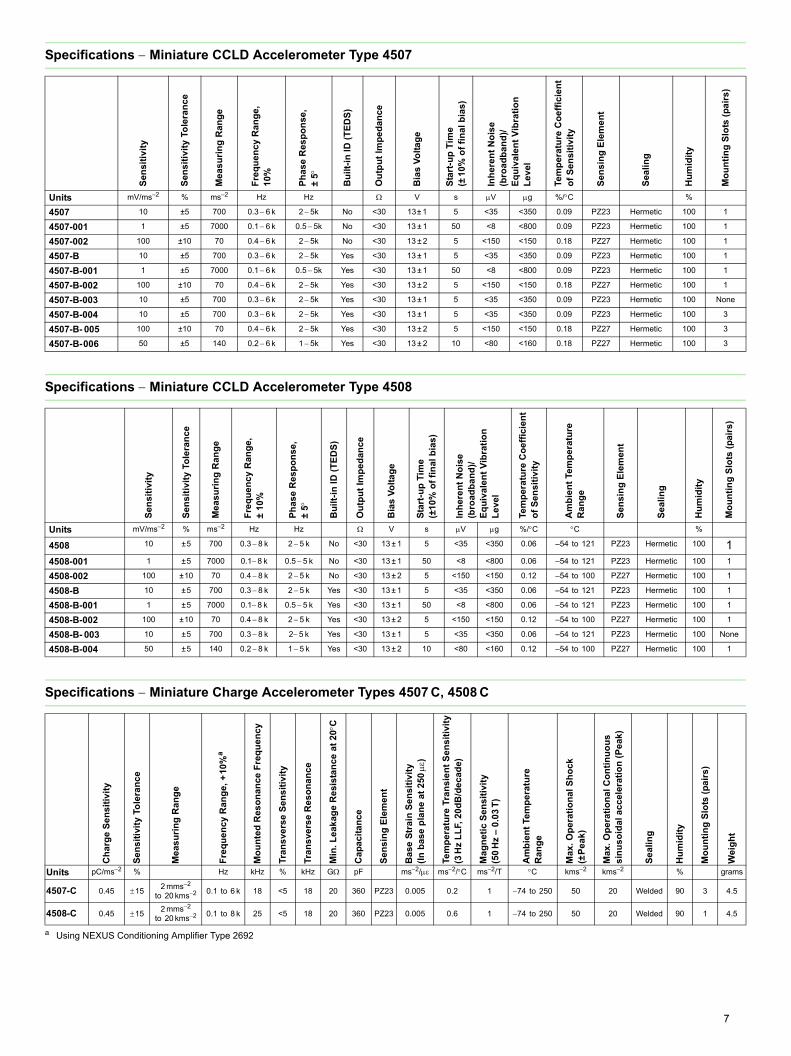
7
Specifications Miniature CCLD Accelerometer Type 4507
Specifications Miniature CCLD Accelerometer Type 4508
Specifications Miniature Charge Accelerometer Types 4507 C, 4508 C
Sen
sit
ivit
y
Sen
sit
ivit
y T
ole
ran
ce
Mea
su
rin
g R
ang
e
Fre
qu
en
cy
Ra
ng
e,
10%
Ph
ase
Res
po
nse
,±
5
Bu
ilt-
in I
D (
TE
DS
)
Ou
tpu
t Im
ped
ance
Bia
s V
olt
ag
e
Sta
rt-u
p T
ime
(±1
0% o
f fi
na
l b
ias
)
Inh
eren
t N
ois
e(b
road
ban
d)/
Eq
uiv
ale
nt
Vib
rati
on
Le
vel
Tem
pe
ratu
re C
oe
ffic
ien
to
f S
en
sit
ivit
y
Sen
sin
g E
lem
en
t
Sea
lin
g
Hu
mid
ity
Mo
un
tin
g S
lots
(p
air
s)
Units mV/ms–2 % ms–2 Hz Hz V s V g %/C %
4507 10 ±5 700 0.3 6 k 25k No <30 13± 1 5 <35 <350 0.09 PZ23 Hermetic 100 1
4507-001 1 ±5 7000 0.1 6 k 0.55k No <30 13 ± 1 50 <8 <800 0.09 PZ23 Hermetic 100 1
4507-002 100 ±10 70 0.4 6 k 25k No <30 13 ± 2 5 <150 <150 0.18 PZ27 Hermetic 100 1
4507-B 10 ±5 700 0.3 6 k 25k Yes <30 13 ± 1 5 <35 <350 0.09 PZ23 Hermetic 100 1
4507-B-001 1 ±5 7000 0.1 6 k 0.55k Yes <30 13 ± 1 50 <8 <800 0.09 PZ23 Hermetic 100 1
4507-B-002 100 ±10 70 0.4 6 k 25k Yes <30 13 ± 2 5 <150 <150 0.18 PZ27 Hermetic 100 1
4507-B-003 10 ±5 700 0.3 6 k 25k Yes <30 13 ± 1 5 <35 <350 0.09 PZ23 Hermetic 100 None
4507-B-004 10 ±5 700 0.3 6 k 25k Yes <30 13 ± 1 5 <35 <350 0.09 PZ23 Hermetic 100 3
4507-B- 005 100 ±10 70 0.4 6 k 25k Yes <30 13 ± 2 5 <150 <150 0.18 PZ27 Hermetic 100 3
4507-B-006 50 ±5 140 0.2 6 k 15k Yes <30 13 ± 2 10 <80 <160 0.18 PZ27 Hermetic 100 3
Se
ns
itiv
ity
Se
ns
itiv
ity
Tole
ran
ce
Mea
su
rin
g R
ang
e
Fre
qu
en
cy
Ra
ng
e,
± 1
0%
Ph
ase
Re
sp
on
se
,±
5
Bu
ilt-
in I
D (
TE
DS
)
Ou
tpu
t Im
ped
ance
Bia
s V
olt
ag
e
Sta
rt-u
p T
ime
(±10
% o
f fi
nal
bia
s)
Inh
eren
t N
ois
e(b
road
ban
d)/
Eq
uiv
ale
nt
Vib
rati
on
Le
vel
Tem
per
atu
re C
oe
ffic
ien
to
f S
ensi
tiv
ity
Am
bie
nt
Tem
pe
ratu
reR
ang
e
Sen
sin
g E
lem
ent
Se
ali
ng
Hu
mid
ity
Mo
un
tin
g S
lots
(p
airs
)
Units mV/ms2 % ms2 Hz Hz V s V g %/C C %
4508 10 ±5 700 0.3 8 k 2 5 k No <30 13 ± 1 5 <35 <350 0.06 –54 to 121 PZ23 Hermetic 100 14508-001 1 ±5 7000 0.18 k 0.5 5 k No <30 13 ± 1 50 <8 <800 0.06 –54 to 121 PZ23 Hermetic 100 1
4508-002 100 ±10 70 0.4 8 k 2 5 k No <30 13 ± 2 5 <150 <150 0.12 –54 to 100 PZ27 Hermetic 100 1
4508-B 10 ±5 700 0.3 8 k 2 5 k Yes <30 13 ± 1 5 <35 <350 0.06 –54 to 121 PZ23 Hermetic 100 1
4508-B-001 1 ±5 7000 0.18 k 0.5 5 k Yes <30 13 ± 1 50 <8 <800 0.06 –54 to 121 PZ23 Hermetic 100 1
4508-B-002 100 ±10 70 0.4 8 k 2 5 k Yes <30 13 ± 2 5 <150 <150 0.12 –54 to 100 PZ27 Hermetic 100 1
4508-B- 003 10 ±5 700 0.3 8 k 2 5 k Yes <30 13 ± 1 5 <35 <350 0.06 –54 to 121 PZ23 Hermetic 100 None
4508-B-004 50 ±5 140 0.2 8 k 1 5 k Yes <30 13 ± 2 10 <80 <160 0.12 –54 to 100 PZ27 Hermetic 100 1
Ch
arg
e S
en
sit
ivit
y
Se
ns
itiv
ity
Tole
ran
ce
Mea
su
rin
g R
ang
e
Fre
qu
en
cy
Ra
ng
e,
+10
%a
a Using NEXUS Conditioning Amplifier Type 2692
Mo
un
ted
Res
on
an
ce
Fre
qu
en
cy
Tra
ns
vers
e S
en
sit
ivit
y
Tra
ns
vers
e R
es
on
an
ce
Min
. Le
ak
age
Re
sist
an
ce
at
20
C
Ca
pac
ita
nc
e
Sen
sin
g E
lem
ent
Ba
se S
tra
in S
en
siti
vit
y(I
n b
ase
pla
ne
at
250
)
Tem
pe
ratu
re T
ran
sie
nt
Se
ns
itiv
ity
(3H
z L
LF,
20d
B/d
ec
ade)
Ma
gn
eti
c S
ensi
tiv
ity
(50
Hz
– 0
.03
T)
Am
bie
nt
Tem
pe
ratu
reR
ang
e
Max
. O
per
atio
nal
Sh
ock
(±P
eak
)
Max
. O
per
atio
nal
Co
nti
nu
ou
ss
inu
so
ida
l ac
cel
era
tio
n (
Pe
ak)
Se
ali
ng
Hu
mid
ity
Mo
un
tin
g S
lots
(p
air
s)
Wei
gh
t
Units pC/ms2 % Hz kHz % kHz G pF ms2/ ms2/C ms2/T C kms2 kms2 % grams
4507-C 0.45 152 mms2
to 20 kms2 0.1 to 6 k 18 <5 18 20 360 PZ23 0.005 0.2 1 74 to 250 50 20 Welded 90 3 4.5
4508-C 0.45 152 mms2
to 20 kms2 0.1 to 8 k 25 <5 18 20 360 PZ23 0.005 0.6 1 74 to 250 50 20 Welded 90 1 4.5

HEADQUARTERS: Brüel & Kjær Sound & Vibration Measurement A/S · DK-2850 Nærum · DenmarkTelephone: +45 7741 2000 · Fax: +45 4580 1405 · www.bksv.com · [email protected]
Local representatives and service organisations worldwide
ËBP-1841---4Î
BP
1841
–15
201
2-12
Common Specifications – Types 4507 and 4508 (CCLD only)
DYNAMICMounted Resonance Frequency:
4507: 18 kHz4508: 25 kHz
Transverse Sensitivity: <5% of sensitivity
ELECTRICALConstant Current Supply: 2 to 20 mASupply Voltage (unloaded):+24 to +30 V DC (for full specification range)Min. +18 V DC (reduced measuring range)Polarity: Positive (for an acceleration in the direction of the engraved arrows)
ENVIRONMENTALMax. Non-destructive Shock (±Peak): 50 kms2; 5000 g Temp. Transient Sensitivity (3 Hz lower limiting frequency):
4507: 0.2 ms2/C4508: 0.3 ms2/C
Base Strain Sensitivity (mounted on adhesive tape 0.09 mm thick): 0.005 ms2/
Magnetic Sensitivity: 3 ms2/TTemperature Range:
4507, 4507-001, 4507-B, 4507-B-001, 4507-B-003, 4507-B-004, 4508, 4508-001, 4508-B, 4508-B-001 and 4508-B- 003:54 to +121C (65 to +250F)4507-002, 4507-B-002, 4507-B-005, 4507-B-006, 4508-002, 4508-B-002 and 4508-B-004:54 to +100C (65 to +212F)
PHYSICALCase Material: TitaniumSensing Element: Piezoelectric Design Configuration: ThetaShearConnector: 10 32 UNF coaxialDimensions (HWL): 10 10 10 mm (0.4), excl. connectorWeight: 4.8 gram (0.17 oz.)
Note: All values are typical at 25C (77F), unless measurement uncertainty is specified. All uncertainty values are specified at 2 (i.e., expanded uncertainty using a coverage factor of 2)
Ordering Information
Types 4507/4508: Miniature CCLD AccelerometersTypes 4507-B/4508-B :Miniature CCLD TEDS AccelerometersTypes 4507-C/4508-C: Miniature Charge AccelerometersInclude the following accessories:• Carrying Box• Individual Calibration Chart• One Mounting Clip (not 4507-B-003 or 4508-B-003)
OPTIONAL ACCESSORIESAO-0531 Cable AC 0208 with 10–32 UNF to BNC connectors,
5 m (16.4 ft) –5 to 70°C (23 to 158°F)AO-0463 Cable AC 0208 with 10–32 UNF connectors,
1.2 m (4 ft) –5 to 70°C (23 to 158°F)AO-0038 Super low-noise Teflon cable, AC 0005 with 10–32 UNF
connectors, 1.2 m (4 ft), 250°C (482°F)AO-0122 Reinforced super low-noise cable, AC 0200 with
10–32 UNF connectors, 3 m (10 ft), 250°C (482°F) AO-0406 Double-screened low-noise cable AC 0104 with
10–32 UNF connectors, 5 m (16 ft), 250°C (482°F). Includes adaptor JP 0145
AO-1419 Low-noise cable AC 0066 with 10–32 UNF connectors, 1.2 m (4 ft), 250°C (482°F)
AO-1382 Low-noise, double-screened Teflon cable AC 0104 with 10–32 UNF connectors, 1.2 m (4 ft), 200°C (392°F)
Cables AO-0038, AO-0122, AO-0406 and AO-1382 are recommended for use with Miniature Charge Accelerometers Types 4507-C and 4508-C
Different lengths of the cables are available
UA-1243 330 pieces of 1/2/3 markers for Cable AC-0104UA-1244 As above, for Cable AC-0005 and AC-0208YJ-0216 Mounting WaxQS-0007 Cyanoacrylate AdhesiveWB-1372 DeltaTronPower SupplyUA-1407 Set of 100 Mounting Clips DV-0459 Calibration ClipUA-1418 Set of 25 dummy accelerometers for mass loadingUA-1478 Set of 100 swivel basesUA-1475 Set of 100 mounting clips with thick baseUA-1564 Set of 5 high-temperature mounting clipsJP-0192 Solder connector adaptor
CALIBRATION SERVICES4507-CFF Re-calibration (sensitivity)4508-CFF Re-calibration (sensitivity)
TRADEMARKSICP is a registered trademark of PCB Group, Inc.
Brüel & Kjær reserves the right to change specifications and accessories without notice. © Brüel & Kjær. All rights reserved.

PRODUCT DATA
Piezoelectric AccelerometerMiniature Triaxial DeltaTron® Accelerometers Types 4524, 4524-B and 4524-B-001
Type 4524 series consists of lightweight triaxialpiezoelectric OrthoShear® accelerometers, eachwith three independent outputs for simultaneousmeasurements in three mutually perpendiculardirections. Type 4524 series utilise a 4-pin connector.
The clip mounting facility combined with the ability tomount the transducer on five of its six surfaces makesmounting on structures very flexible and quick and thusideal for structural and modal analysis measurements.
The light compact construction is an improved designcovered by the OrthoShear patent.
USES AND FEATURES
USES Structural analysis measurements Multichannel modal analysis measurements Modal measurements for automotive body and
power-train applications Hand and arm measurements (4524-B-001)
FEATURES High sensitivity-to-weight ratio Light weight (<5 gram) Excellent low-frequency response Electrically insulated Hermetically sealed Easy mounting on five of six surfaces B-versions utilise TEDS
Characteristics
Fig. 1 Exploded view of Type 4524
The piezoelectric accelerometer features a built-inpreamplifier. The sensitivity is expressed in terms ofvoltage per unit acceleration (mV/g).
The OrthoShear design used in Type 4524 (Fig. 1) isbuilt around a common seismic mass. This uni-massdesign results in a very compact triaxialaccelerometer where all the axes have the same pointof reference and ensures accurate and consistentmeasurements, even when the accelerometer isexposed to complex vibration patterns. The seismicmass is surrounded by a piezoelectric ring, which issurrounded by three individually suspended, curvedarms. Because of the suspension pins, differentsections are exposed to shear forces for different
directions of acceleration. By appropriate summation of the signals, the outputs for the X-, Y-and Z-axes are obtained.
040114
Preamplifier + Connector
Arms
PZ Ring
Central Seismic Mass
Housing
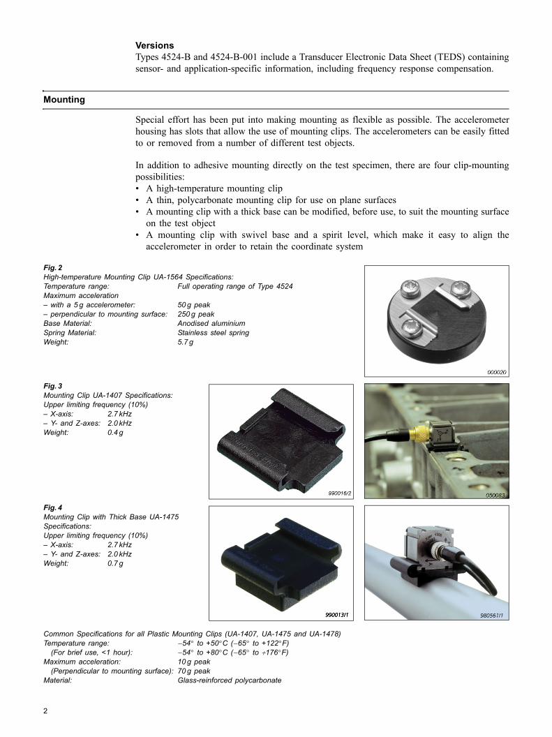
VersionsTypes 4524-B and 4524-B-001 include a Transducer Electronic Data Sheet (TEDS) containingsensor- and application-specific information, including frequency response compensation.
Mounting
Special effort has been put into making mounting as flexible as possible. The accelerometerhousing has slots that allow the use of mounting clips. The accelerometers can be easily fittedto or removed from a number of different test objects.
In addition to adhesive mounting directly on the test specimen, there are four clip-mountingpossibilities: A high-temperature mounting clip A thin, polycarbonate mounting clip for use on plane surfaces A mounting clip with a thick base can be modified, before use, to suit the mounting surface
on the test object A mounting clip with swivel base and a spirit level, which make it easy to align the
accelerometer in order to retain the coordinate system
Fig. 2 High-temperature Mounting Clip UA-1564 Specifications:Temperature range: Full operating range of Type 4524Maximum acceleration with a 5 g accelerometer: 50 g peak perpendicular to mounting surface: 250 g peakBase Material: Anodised aluminiumSpring Material: Stainless steel springWeight: 5.7 g
Fig. 3 Mounting Clip UA-1407 Specifications:Upper limiting frequency (10%) X-axis: 2.7 kHz Y- and Z-axes: 2.0 kHzWeight: 0.4 g
Fig. 4 Mounting Clip with Thick Base UA-1475Specifications:Upper limiting frequency (10%) X-axis: 2.7 kHz Y- and Z-axes: 2.0 kHzWeight: 0.7 g
Common Specifications for all Plastic Mounting Clips (UA-1407, UA-1475 and UA-1478)Temperature range: −54° to +50°C (−65° to +122°F)
(For brief use, <1 hour): −54° to +80°C (−65° to +176°F)Maximum acceleration: 10 g peak
(Perpendicular to mounting surface): 70 g peakMaterial: Glass-reinforced polycarbonate
2
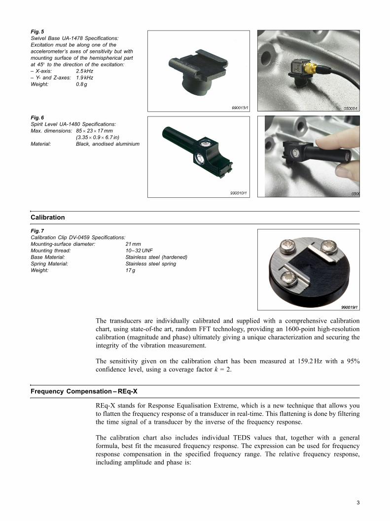
Fig. 5 Swivel Base UA-1478 Specifications:Excitation must be along one of theaccelerometers axes of sensitivity but withmounting surface of the hemispherical partat 45° to the direction of the excitation: X-axis: 2.5 kHz Y- and Z-axes: 1.9 kHzWeight: 0.8 g
Fig. 6 Spirit Level UA-1480 Specifications:Max. dimensions: 85 × 23 ×17 mm
(3.35 × 0.9 × 6.7 in)Material: Black, anodised aluminium
Calibration
Fig. 7 Calibration Clip DV-0459 Specifications:Mounting-surface diameter: 21 mmMounting thread: 1032 UNFBase Material: Stainless steel (hardened)Spring Material: Stainless steel springWeight: 17 g
The transducers are individually calibrated and supplied with a comprehensive calibrationchart, using state-of-the art, random FFT technology, providing an 1600-point high-resolutioncalibration (magnitude and phase) ultimately giving a unique characterization and securing theintegrity of the vibration measurement.
The sensitivity given on the calibration chart has been measured at 159.2 Hz with a 95%confidence level, using a coverage factor k = 2.
Frequency Compensation REq-X
REq-X stands for Response Equalisation Extreme, which is a new technique that allows youto flatten the frequency response of a transducer in real-time. This flattening is done by filteringthe time signal of a transducer by the inverse of the frequency response.
The calibration chart also includes individual TEDS values that, together with a generalformula, best fit the measured frequency response. The expression can be used for frequencyresponse compensation in the specified frequency range. The relative frequency response,including amplitude and phase is:
3
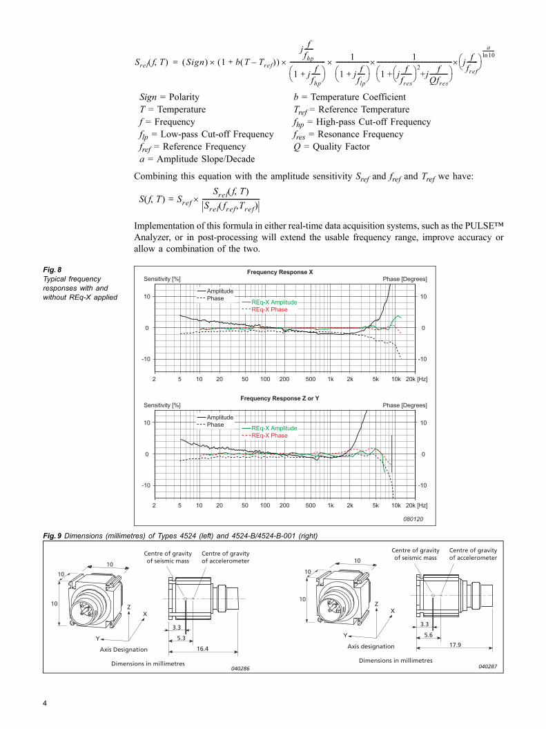
Combining this equation with the amplitude sensitivity Sref and fref and Tref we have:
Implementation of this formula in either real-time data acquisition systems, such as the PULSEAnalyzer, or in post-processing will extend the usable frequency range, improve accuracy orallow a combination of the two.
Fig. 8 Typical frequency responses with and without REq-X applied
Fig. 9 Dimensions (millimetres) of Types 4524 (left) and 4524-B/4524-B-001 (right)
Sign = Polarity b = Temperature CoefficientT = Temperature Tref = Reference Temperaturef = Frequency fhp = High-pass Cut-off Frequencyflp = Low-pass Cut-off Frequency fres = Resonance Frequencyfref = Reference Frequency Q = Quality Factora = Amplitude Slope/Decade
Srel f T,( ) Sign( ) (1 b T Tref–( )+ )j ffhp------
1 j+f
fhp------⎝ ⎠
⎛ ⎞-----------------------×× 1
1 j fflp-----+⎝ ⎠
⎛ ⎞----------------------× × 1
1 + j ffres-------⎝ ⎠
⎛ ⎞ +j fQfres------------
2
⎝ ⎠⎛ ⎞-------------------------------------------------× j f
fref-------⎝ ⎠
⎛ ⎞a10ln
-----------
=
S f T,( ) Sref=Srel f T,( )
Srel fref,Tref( )------------------------------------×
Sensitivity [%]Frequency Response X
Phase [Degrees]
10
-10
2 5 10 20 50 100 200 500 1k 2k 5k 10k 20k [Hz]
AmplitudePhase
REq-X AmplitudeREq-X Phase
REq-X AmplitudeREq-X Phase
0
080120
10
-10
0
Sensitivity [%]Frequency Response Z or Y
Phase [Degrees]
10
-10
2 5 10 20 500 1k 2k 5k 10k 20k [Hz]
AmplitudePhase
0
10
-10
0
50 100 200
10
10
10 Z X
Y
Centre of gravityof accelerometer
Centre of gravityof seismic mass
5.3
3.3
Axis Designation
Dimensions in millimetres
16.4
040286
10
10
10Z
X
Y
Centre of gravityof accelerometer
Centre of gravityof seismic mass
5.6
3.3
Axis designation
Dimensions in millimetres
17.9
040287
4
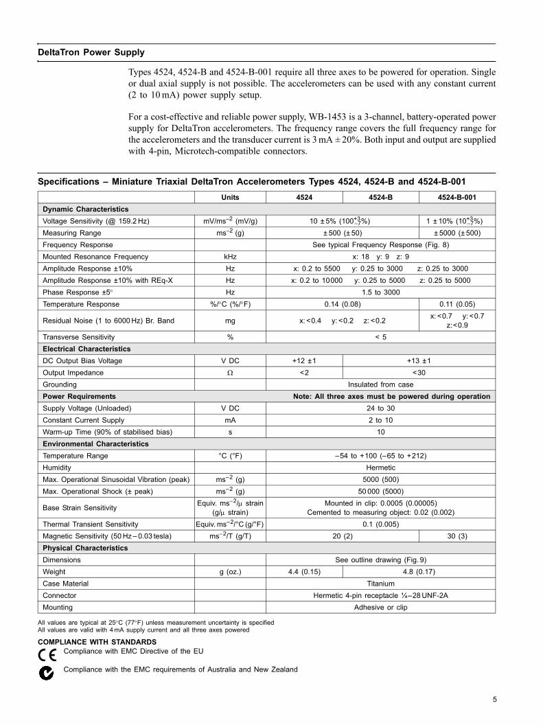
5
DeltaTron Power Supply
Types 4524, 4524-B and 4524-B-001 require all three axes to be powered for operation. Singleor dual axial supply is not possible. The accelerometers can be used with any constant current(2 to 10 mA) power supply setup.
For a cost-effective and reliable power supply, WB-1453 is a 3-channel, battery-operated powersupply for DeltaTron accelerometers. The frequency range covers the full frequency range forthe accelerometers and the transducer current is 3 mA ± 20%. Both input and output are suppliedwith 4-pin, Microtech-compatible connectors.
Specifications Miniature Triaxial DeltaTron Accelerometers Types 4524, 4524-B and 4524-B-001
All values are typical at 25°C (77°F) unless measurement uncertainty is specifiedAll values are valid with 4 mA supply current and all three axes powered
COMPLIANCE WITH STANDARDSCompliance with EMC Directive of the EU
Compliance with the EMC requirements of Australia and New Zealand
Units 4524 4524-B 4524-B-001Dynamic CharacteristicsVoltage Sensitivity (@ 159.2 Hz) mV/ms2 (mV/g) 10 ± 5% (100+3
7%) 1 ± 10% (10+37%)
Measuring Range ms2 (g) ± 500 (± 50) ± 5000 (± 500)Frequency Response See typical Frequency Response (Fig. 8)Mounted Resonance Frequency kHz x: 18 y: 9 z: 9Amplitude Response ±10% Hz x: 0.2 to 5500 y: 0.25 to 3000 z: 0.25 to 3000Amplitude Response ±10% with REq-X Hz x: 0.2 to 10000 y: 0.25 to 5000 z: 0.25 to 5000Phase Response ±5° Hz 1.5 to 3000Temperature Response %/°C (%/°F) 0.14 (0.08) 0.11 (0.05)
Residual Noise (1 to 6000 Hz) Br. Band mg x: <0.4 y: <0.2 z: <0.2 x: <0.7 y: <0.7 z:<0.9
Transverse Sensitivity % < 5Electrical CharacteristicsDC Output Bias Voltage V DC +12 ±1 +13 ±1Output Impedance Ω <2 <30Grounding Insulated from casePower Requirements Note: All three axes must be powered during operationSupply Voltage (Unloaded) V DC 24 to 30Constant Current Supply mA 2 to 10Warm-up Time (90% of stabilised bias) s 10Environmental CharacteristicsTemperature Range °C (°F) 54 to +100 (65 to +212)Humidity HermeticMax. Operational Sinusoidal Vibration (peak) ms2 (g) 5000 (500)Max. Operational Shock (± peak) ms2 (g) 50 000 (5000)
Base Strain Sensitivity Equiv. ms2/μ strain(g/μ strain)
Mounted in clip: 0.0005 (0.00005) Cemented to measuring object: 0.02 (0.002)
Thermal Transient Sensitivity Equiv. ms2/°C (g/°F) 0.1 (0.005)Magnetic Sensitivity (50 Hz 0.03 tesla) ms2/T (g/T) 20 (2) 30 (3)Physical CharacteristicsDimensions See outline drawing (Fig. 9)Weight g (oz.) 4.4 (0.15) 4.8 (0.17)Case Material TitaniumConnector Hermetic 4-pin receptacle ¼28 UNF-2AMounting Adhesive or clip

ËBP-2216---+Î
BP
2076
13
2008
-05
Ros
enda
hls
Bog
trykk
eri
Ordering Information
ACCESSORIES INCLUDED Carrying Box Calibration Chart One Mounting Clip
OPTIONAL ACCESSORIESAO-0526-D-050 Cable with 4-pin to 3 × BNC connectors, 5 m (16 ft),
85°C (185°F)AO-0527-D-050 Cable with 4-pin to 3 × 1032 UNF connectors,
5 m (16 ft), 85°C (185°F)AO-0528-D-050 Cable with 4-pin to 4-pin connectors, 5 m (16 ft),
85°C (185°F)AO-0534-D-050 Cable with 4-pin to 3 × BNC connectors,
5 m (16 ft), 120°C (248°F)AO-0536-D-100 Cable with 37-pin D-range sub-connector to
2 × 4-pin, 10 m (33 ft), 85°C (185°F)DV-0459 Calibration ClipUA-1407 Set of 100 Mounting ClipsUA-1418 Set of 25 Dummy Accelerometers for mass
loadingUA-1475 Set of 100 Mounting Clips with thick baseUA-1478 Set of 100 Swivel Base Clips
UA-1480 Spirit Level Set (including 100 Swivel Base Clips)UA-1564 Set of 5 High-temperature Mounting ClipsUA-3015 Hand Adaptor (clip) T-shapedUA-3016 Handle Adaptor (clip) L-shapedUA-3017 Mounting Adaptor with strips (clip)WB-1453 DeltaTron Power SupplyYJ-0216 Mounting Wax
ServiceACCREDITED CALIBRATION 4524-CAI Accredited Initial Calibration4524-B-CAI Accredited Initial Calibration4524-CAF Accredited Calibration4524-B-CAF Accredited Calibration
TRACEABLE CALIBRATION 4524-CTI Traceable Initial Calibration4524-B-CTI Traceable Initial Calibration4524-CTF Traceable Calibration4524-B-CTF Traceable Calibration
Brüel & Kjær reserves the right to change specifications and accessories without notice
HEADQUARTERS: DK-2850 Nærum · Denmark · Telephone: +45 4580 0500Fax: +45 4580 1405 · www.bksv.com · [email protected]
Australia (+61) 2 9889-8888 · Austria (+43) 1 865 74 00 · Brazil (+55)11 5188-8161Canada (+1) 514 695-8225 · China (+86) 10 680 29906 · Czech Republic (+420) 2 6702 1100Finland (+358) 9-755 950 · France (+33) 1 69 90 71 00 · Germany (+49) 421 17 87 0Hong Kong (+852) 2548 7486 · Hungary (+36) 1 215 83 05 · Ireland (+353) 1 807 4083Italy (+39) 0257 68061 · Japan (+81) 3 5715 1612 · Republic of Korea (+82) 2 3473 0605Netherlands (+31)318 55 9290 · Norway (+47) 66 77 11 55 · Poland (+48) 22 816 75 56Portugal (+351) 21 4169 040 · Singapore (+65) 6377 4512 · Slovak Republic (+421) 25 443 0701Spain (+34) 91 659 0820 · Sweden (+46) 33 225 622 · Switzerland (+41) 44 8807 035Taiwan (+886) 2 2502 7255 · United Kingdom (+44) 14 38 739 000 · USA (+1) 800 332 2040
Local representatives and service organisations worldwide
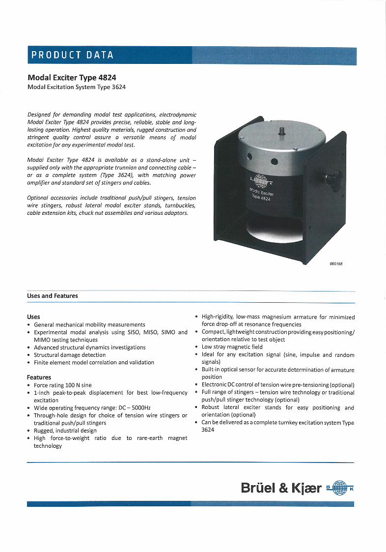
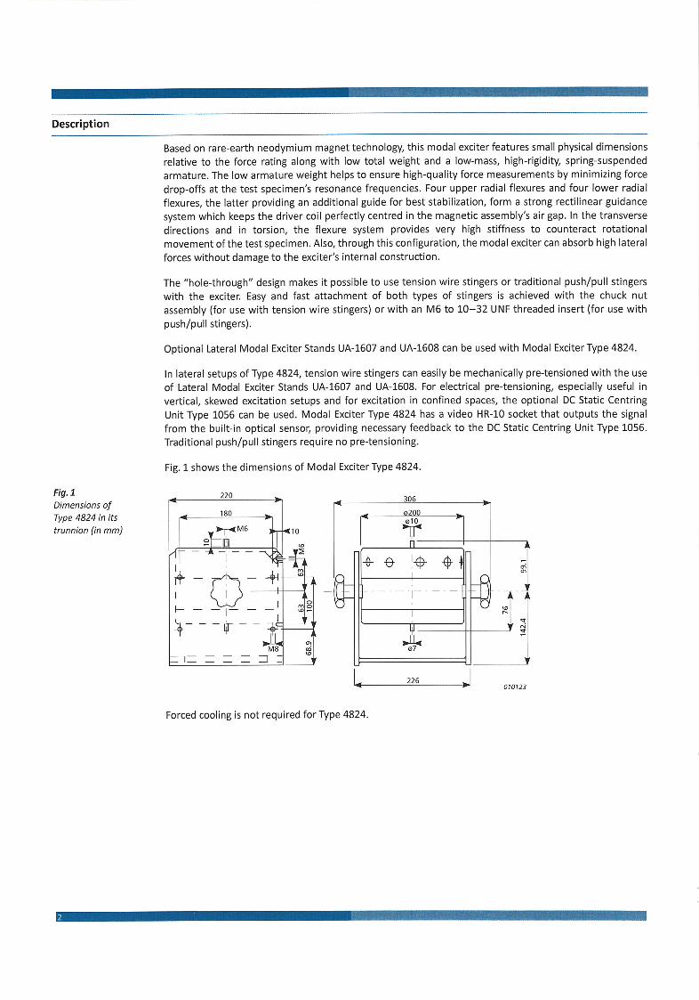

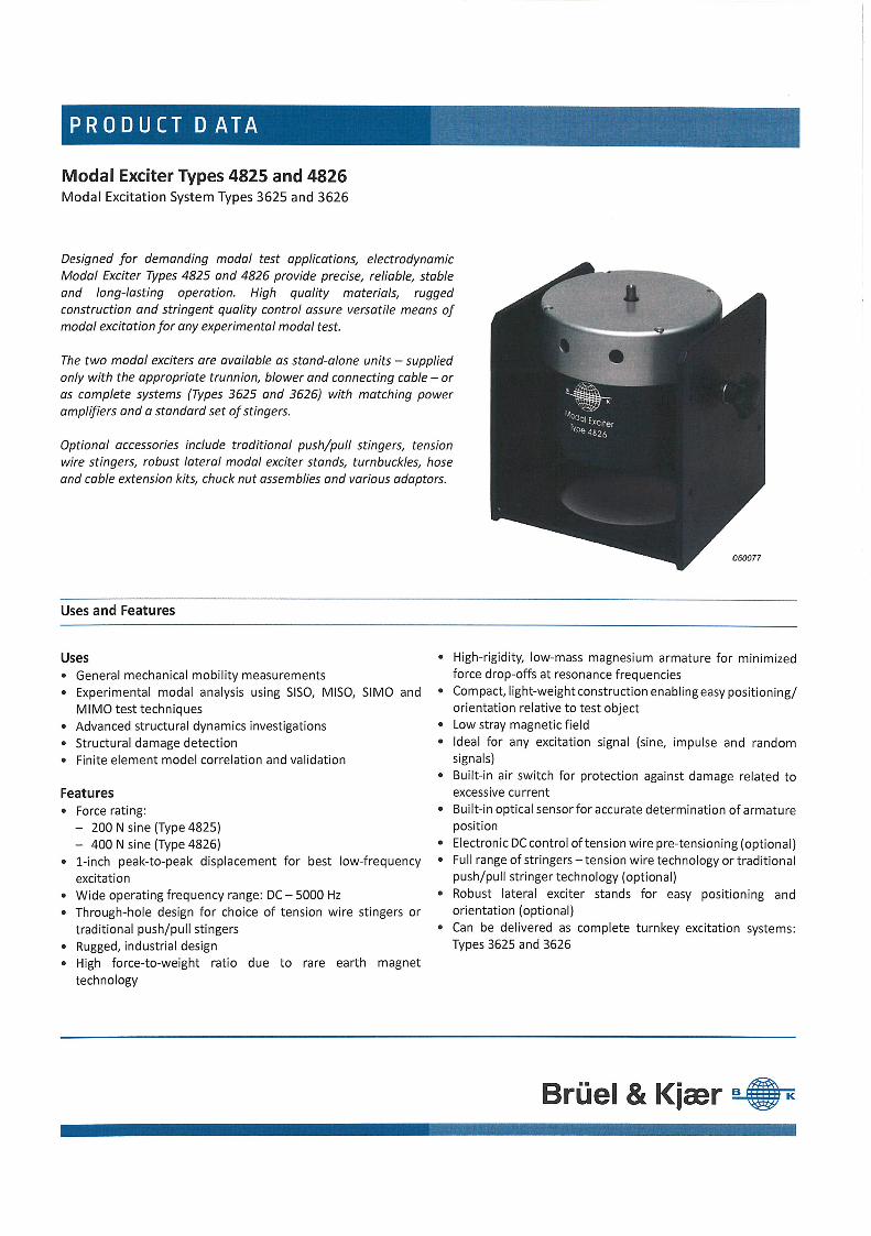

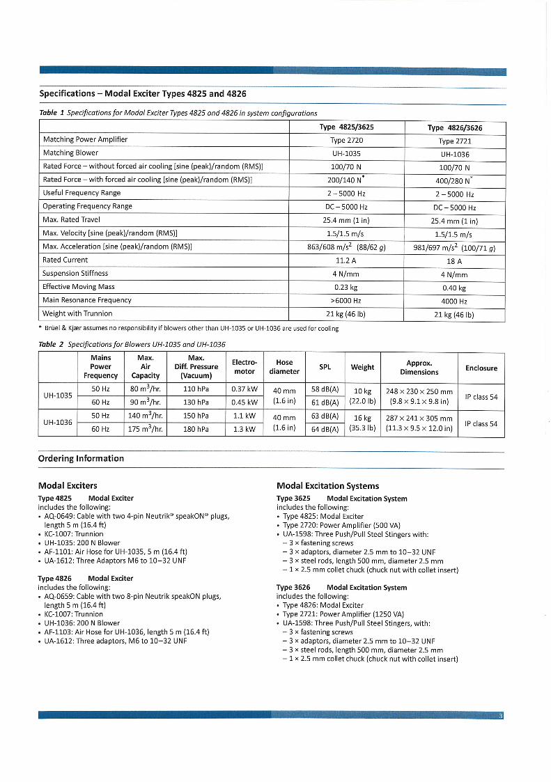


PRODUCT DATA
Force TransducerDeltaTron® Force Transducers Types 8230, 8230-001, 8230-002 and 8230-003
USES Measurements of tensile and compressive forces For modal or process applications
FEATURES Easily mounted Includes impact cap Low-impedance output Rigid construction with high stiffness
DescriptionTypes 8230, 8230-001, 8230-002 and 8230-003 are forcetransducers with integral electronics designed for dynam-ic, short-duration static and impact force measurements.The transducers are typically used for measuring appliedforces in modal applications, for example, inserted direct-ly between an exciter and the test structure or for general-purpose force measurements within process applications.
The transducers are mounted using the ¼″28 UNFtapped holes on the top and bottom of the body. Thetransducers feature a 1032 UNF side connector.
CharacteristicsThe transducers work on the piezoelectric effect of quartz,which when stressed, in this case compressed, gives anelectrical charge proportional to the compressing force.This charge is converted to a low-impedance voltage out-put and the sensitivity is therefore expressed in terms ofvoltage per unit force (mV/N). The housing material isstainless steel giving a very stiff and rigid construction.
CalibrationThe transducers are supplied with an individual calibrationof the sensitivity.
VersionsType 8230 has a sensitivity of 110 mV/N (500 mV/lbf).Type 8230-001 has a sensitivity of 22 mV/N (100 mV/lbf).Type 8230-002 has a sensitivity of 2.2 mV/N (10 mV/lbf).Type 8230-003 has a sensitivity of 0.2 mV/N (1 mV/lbf).
040352
17.48
∅ 19.05
∅ 9
.52
15.9
3
6.81
1/4" 28 UNF
4.4
10-3
2 U
NF
29.46
All dimensions in mm
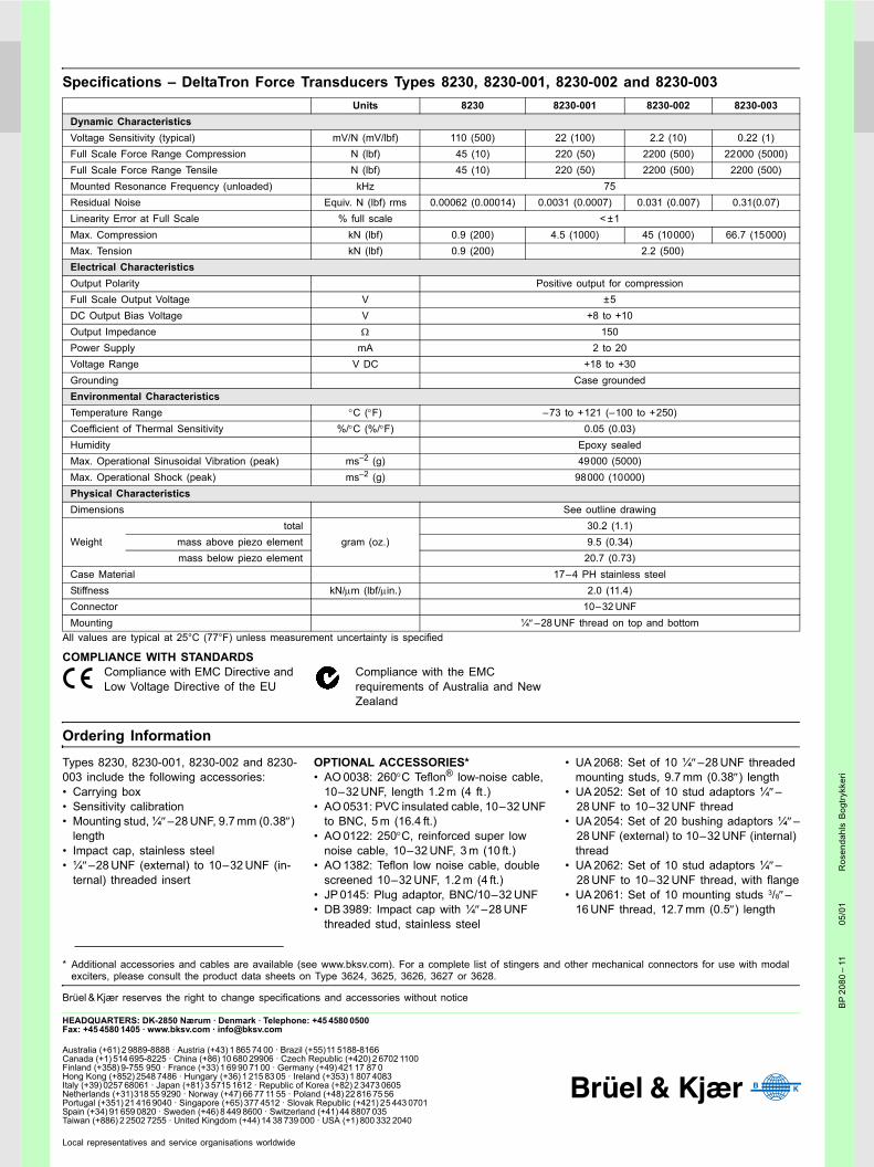
HEADQUARTERS: DK-2850 Nærum · Denmark · Telephone: +45 4580 0500Fax: +45 4580 1405 · www.bksv.com · [email protected]
Australia (+61) 2 9889-8888 · Austria (+43) 1 865 74 00 · Brazil (+55)11 5188-8166Canada (+1) 514 695-8225 · China (+86) 10 680 29906 · Czech Republic (+420) 2 6702 1100Finland (+358) 9-755 950 · France (+33) 1 69 90 71 00 · Germany (+49) 421 17 87 0Hong Kong (+852) 2548 7486 · Hungary (+36) 1 215 83 05 · Ireland (+353) 1 807 4083Italy (+39) 0257 68061 · Japan (+81) 3 5715 1612 · Republic of Korea (+82) 2 3473 0605Netherlands (+31)318 55 9290 · Norway (+47) 66 77 11 55 · Poland (+48) 22 816 75 56Portugal (+351) 21 416 9040 · Singapore (+65) 377 4512 · Slovak Republic (+421) 25 443 0701Spain (+34) 91 659 0820 · Sweden (+46) 8 449 8600 · Switzerland (+41) 44 8807 035Taiwan (+886) 2 2502 7255 · United Kingdom (+44) 14 38 739 000 · USA (+1) 800 332 2040
Local representatives and service organisations worldwide
BP
2080
11
05/0
1R
osen
dahl
s B
ogtry
kker
i
Specifications DeltaTron Force Transducers Types 8230, 8230-001, 8230-002 and 8230-003
All values are typical at 25°C (77°F) unless measurement uncertainty is specified
COMPLIANCE WITH STANDARDSCompliance with EMC Directive and Low Voltage Directive of the EU
Compliance with the EMC requirements of Australia and New Zealand
Ordering Information
Types 8230, 8230-001, 8230-002 and 8230-003 include the following accessories: Carrying box Sensitivity calibration Mounting stud, ¼″28 UNF, 9.7 mm (0.38″)
length Impact cap, stainless steel ¼″28 UNF (external) to 1032 UNF (in-
ternal) threaded insert
OPTIONAL ACCESSORIES* AO 0038: 260°C Teflon® low-noise cable,
1032 UNF, length 1.2 m (4 ft.) AO 0531: PVC insulated cable, 1032 UNF
to BNC, 5 m (16.4 ft.) AO 0122: 250°C, reinforced super low
noise cable, 1032 UNF, 3 m (10 ft.) AO 1382: Teflon low noise cable, double
screened 1032 UNF, 1.2 m (4 ft.) JP 0145: Plug adaptor, BNC/1032 UNF DB 3989: Impact cap with ¼″28 UNF
threaded stud, stainless steel
UA 2068: Set of 10 ¼″28 UNF threaded mounting studs, 9.7 mm (0.38″) length
UA 2052: Set of 10 stud adaptors ¼″28 UNF to 1032 UNF thread
UA 2054: Set of 20 bushing adaptors ¼″28 UNF (external) to 1032 UNF (internal) thread
UA 2062: Set of 10 stud adaptors ¼″28 UNF to 1032 UNF thread, with flange
UA 2061: Set of 10 mounting studs 3/8″16 UNF thread, 12.7 mm (0.5″) length
Units 8230 8230-001 8230-002 8230-003Dynamic CharacteristicsVoltage Sensitivity (typical) mV/N (mV/lbf) 110 (500) 22 (100) 2.2 (10) 0.22 (1)Full Scale Force Range Compression N (lbf) 45 (10) 220 (50) 2200 (500) 22000 (5000)Full Scale Force Range Tensile N (lbf) 45 (10) 220 (50) 2200 (500) 2200 (500)Mounted Resonance Frequency (unloaded) kHz 75Residual Noise Equiv. N (lbf) rms 0.00062 (0.00014) 0.0031 (0.0007) 0.031 (0.007) 0.31(0.07)Linearity Error at Full Scale % full scale < ±1Max. Compression kN (lbf) 0.9 (200) 4.5 (1000) 45 (10000) 66.7 (15000)Max. Tension kN (lbf) 0.9 (200) 2.2 (500)Electrical CharacteristicsOutput Polarity Positive output for compressionFull Scale Output Voltage V ±5DC Output Bias Voltage V +8 to +10Output Impedance Ω 150Power Supply mA 2 to 20Voltage Range V DC +18 to +30Grounding Case groundedEnvironmental CharacteristicsTemperature Range °C (°F) 73 to +121 (100 to +250)Coefficient of Thermal Sensitivity %/°C (%/°F) 0.05 (0.03)Humidity Epoxy sealedMax. Operational Sinusoidal Vibration (peak) ms2 (g) 49000 (5000)Max. Operational Shock (peak) ms2 (g) 98000 (10000)Physical CharacteristicsDimensions See outline drawing
Weighttotal
gram (oz.)30.2 (1.1)
mass above piezo element 9.5 (0.34)mass below piezo element 20.7 (0.73)
Case Material 174 PH stainless steelStiffness kN/µm (lbf/µin.) 2.0 (11.4)Connector 1032 UNFMounting ¼″28 UNF thread on top and bottom
* Additional accessories and cables are available (see www.bksv.com). For a complete list of stingers and other mechanical connectors for use with modal exciters, please consult the product data sheets on Type 3624, 3625, 3626, 3627 or 3628.
Brüel & Kjær reserves the right to change specifications and accessories without notice

P R O D U C T D ATA
BK Connect Structural Measurement ApplicationsStructural Measurements – Hammer and Shaker Type 8411, Advanced Sine Measurements Type 8412 and Geometry Type 8410
BK Connect™ real‐time measurements are designed to takeadvantage of Brüel & Kjær’s unique coverage of the completemeasurement chain, from transducers and front‐end hardwareto data acquisition, analysis and reporting. The emphasis is onscalability, from small (single‐module) systems to large (multi‐module) systems, and high productivity in the traditionallymost time‐consuming aspects of data measurement:• Setting up transducers, channel tables, excitation and analysisparameters
• Post‐processing, displaying and reporting results
All measurements are directly accessible by the BK Connectpost‐processing applications: BK Connect Data Processing forgeneral purpose post‐processing, BK Connect Modal Analysisfor modal parameter estimation and BK Connect CorrelationAnalysis for test‐FEA model correlation.
Uses and Features
Uses• Modal data acquisition and validation• Impact hammer FRF measurements• Single‐ or multi‐shaker FRF measurements• Mechanical impedance or mobility measurements• Linearity checks and analysis• Time data recording during measurements• Integrated solution from structural measurements to FEM
correlation with BK Connect Modal Analysis Types 8420 and8420‐A and BK Connect Correlation Analysis Type 8421
Features• Live Monitor showing levels and spectra for all active channels
once the system is activated• Geometry‐guided modal data acquisition using BK Connect
Modal Analysis or BK Connect Data Processing• Interactive graphical representation of the front‐end hardware
using the Hardware Matrix, with coloured light rings to indicatechannel status, for example, overloads, just as on the actualLAN‐XI hardware
• Easy management and overview of large channel counts • Automatic detection of TEDS‐enabled transducers as well as
auto‐import of TEDS data • Integrated transducer manager and database
• Quick assignment of non‐TEDS transducers by simple drag anddrop (singly or in groups) from database to specific channels
• Transducer verification/calibration with automatic detectionof calibration signals and optional automatic application ofgain adjustment
• Powerful test geometry creation tools• Decimation of FE models to test geometries• Intuitive hammer and shaker setup and measurement tasks • Wide range of excitation signals including random
(continuous, burst, periodic and pseudo), periodic chirp, fixedsine and stepped sine
• Voice feedback during hammer setup and measurement• Result Matrix tool (as in BK Connect post‐processing) for easy
display, comparison and reporting of results• Support of SI and imperial units and acceleration in ‘g’ • Support of accelerometers, displacement and velocity
transducers for response measurements

Transducer and Hardware Setup
Prerequisite SoftwareTo measure in BK Connect, you must have a BK Connect Hardware Setup Type 8401 licence installed inorder to connect to and set up your LAN‐XI data acquisition hardware.
With the Hardware Setup licence, you get the following tools and setup tasks:• Hardware Browser• Monitor• Transducer Manager• Transducer Verification• Accelerometer Mounting Check (with Type 8401‐A)
Data Acquisition SetupThe Hardware Browser displays your data acquisition hardware, graphically using the Hardware Matrixand as a list using the Hardware (HW) Setup Table.
The Hardware Matrix is an interactive graphical representation of the physical hardware that functions bothas a channel selector, for choosing channels of interest, and as a status indicator for the measurement system.It can provide useful information for troubleshooting error states such as overloads and cable breaks. The LEDrings on the physical LAN‐XI front end are reproduced in the Hardware Matrix to provide insight into thephysical state of the system. Transient overloads are latched to enable the root cause to be investigated.
The Transducer Manager comes with an established database of Brüel & Kjær transducer types. You caneasily create new transducer types and new devices of specific types, and add them to the database,making it simple to register your equipment for later use. Triaxial accelerometers are explicitly recognizedas a transducer type so that sensitivity data for the three axes is kept together in one device. Images ofeach transducer type make identification and selection much easier. A calibration history is stored witheach transducer making it easy for you to check when the next calibration is due.
When TEDS transducers are present, they are automatically detected. The HW Setup Table automaticallyupdates the hardware list with the TEDS information and the Hardware Matrix indicates, per channel,each transducer with a type‐specific symbol. Non‐TEDS transducers are not auto‐detected, but can easilybe assigned to individual channels by dragging and dropping them from the Transducer Manager to theHardware Matrix. This can be done one‐by‐one or collectively for a group of channels. If desired, you caninstrument a system of 1000 channels or more in one go using transducers of nominal sensitivity.
Simplifying Large System SetupWe know that setting up large systems can be cumbersome, so we have enabled both single or multiplechannel selection in the Hardware Matrix for setup, management and editing. You can even select one ormore front‐end modules. Channels can be displayed in an abstract, non‐physical view, sorted according tochannel state, transducer type, or error state. This enables, for example, grouping of overloaded channelsfor easy troubleshooting.
You can store HW Setup tables and reload them later to restore a known setup. The default file format isXML, but import and copy/paste from Microsoft® Excel® is also supported as well as Universal Datasetnumber 1808 (Channel Table), enabling offline setup outside BK Connect if desired.
Smart Setup of Transducers via AppBK Connect interfaces to Brüel & Kjær's Transducer Smart Setup app, making transducer setup as simple,safe and automated as possible. Using the camera on your iOS 8.0 device (or later), you can scan anyBrüel & Kjær transducer with a laser‐engraved data matrix code for quick and easy reading of transducerdata and orientation. If needed, the data matrix code can also give you instant access to specifications,documentation and calibration data. With the transducer information, you can start building a transducersetup project that can be seamlessly exported to the HW Setup table using a cloud service, an emailaccount or iTunes® (via wired transfer).
2
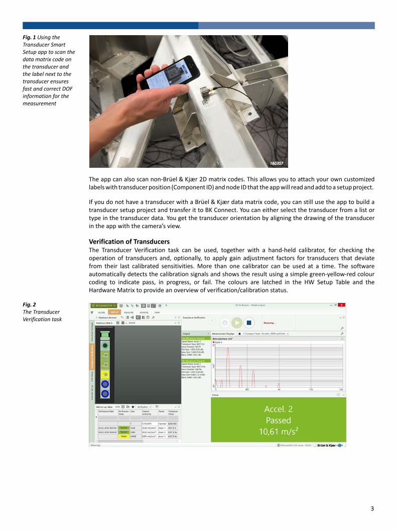
Fig. 1 Using the Transducer Smart Setup app to scan the data matrix code on the transducer and the label next to the transducer ensures fast and correct DOF information for the measurement
The app can also scan non‐Brüel & Kjær 2D matrix codes. This allows you to attach your own customizedlabels with transducer position (Component ID) and node ID that the app will read and add to a setup project.
If you do not have a transducer with a Brüel & Kjær data matrix code, you can still use the app to build atransducer setup project and transfer it to BK Connect. You can either select the transducer from a list ortype in the transducer data. You get the transducer orientation by aligning the drawing of the transducerin the app with the camera’s view.
Verification of TransducersThe Transducer Verification task can be used, together with a hand‐held calibrator, for checking theoperation of transducers and, optionally, to apply gain adjustment factors for transducers that deviatefrom their last calibrated sensitivities. More than one calibrator can be used at a time. The softwareautomatically detects the calibration signals and shows the result using a simple green‐yellow‐red colourcoding to indicate pass, in progress, or fail. The colours are latched in the HW Setup Table and theHardware Matrix to provide an overview of verification/calibration status.
Fig. 2 The Transducer Verification task
3
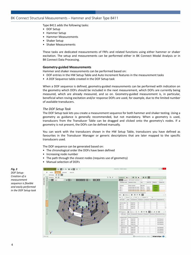
BK Connect Structural Measurements – Hammer and Shaker Type 8411
Type 8411 adds the following tasks:• DOF Setup• Hammer Setup• Hammer Measurements• Shaker Setup• Shaker Measurements
These tasks are dedicated measurements of FRFs and related functions using either hammer or shakerexcitation. The setup and measurements can be performed either in BK Connect Modal Analysis or inBK Connect Data Processing.
Geometry‐guided MeasurementsHammer and shaker measurements can be performed based on:• DOF entries in the HW Setup Table and Auto Increment features in the measurement tasks• A DOF Sequence table created in the DOF Setup task
When a DOF sequence is defined, geometry‐guided measurements can be performed with indication onthe geometry which DOFs should be included in the next measurement, which DOFs are currently beingmeasured, which are already measured, and so on. Geometry‐guided measurement is, in particular,beneficial when roving excitation and/or response DOFs are used, for example, due to the limited numberof available transducers.
The DOF Setup TaskThe DOF Setup task lets you create a measurement sequence for both hammer and shaker testing. Using ageometry as guidance is generally recommended, but not mandatory. When a geometry is used,transducers from the Transducer Table can be dragged and clicked onto the geometry’s nodes. If ageometry is not present, the DOFs can be defined manually.
You can work with the transducers shown in the HW Setup Table, transducers you have defined asfavourites in the Transducer Manager or generic descriptions that are later mapped to the specifictransducers used.
The DOF sequence can be generated based on:• The chronological order the DOFs have been defined• Increasing node number• The path through the closest nodes (requires use of geometry)• Manual selection of DOFs
Fig. 3 DOF Setup:Creation of a measurement sequence is flexible and easily performed in the DOF Setup task
4
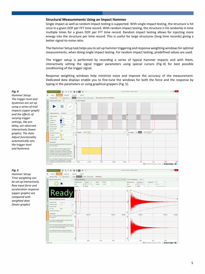
Structural Measurements Using an Impact HammerSingle impact as well as random impact testing is supported. With single impact testing, the structure is hitonce in a given DOF per FFT time record. With random impact testing, the structure is hit randomly in timemultiple times for a given DOF per FFT time record. Random impact testing allows for injecting moreenergy into the structure per time record. This is useful for large structures (long time records) giving abetter signal‐to‐noise ratio.
The Hammer Setup task helps you to set up hammer triggering and response weighting windows for optimalmeasurements, when doing single impact testing. For random impact testing, predefined values are used.
The trigger setup is performed by recording a series of typical hammer impacts and with them,interactively setting the signal trigger parameters using special cursors (Fig. 4) for best possibleconditioning of the trigger signal.
Response weighting windows help minimize noise and improve the accuracy of the measurement.Dedicated data displays enable you to fine‐tune the windows for both the force and the response bytyping in the parameters or using graphical grippers (Fig. 5).
Fig. 4 Hammer Setup: The trigger level and hysteresis are set up using a series of trial impacts (upper graph) and the effects of varying trigger settings, like pre‐delay, are observed interactively (lower graphs). The Auto Adjust functionality automatically sets the trigger level and hysteresis
Fig. 5 Hammer Setup: Time weighting can be set up interactively. Raw input force and acceleration response (upper graphs) are compared with weighted data (lower graphs)
5
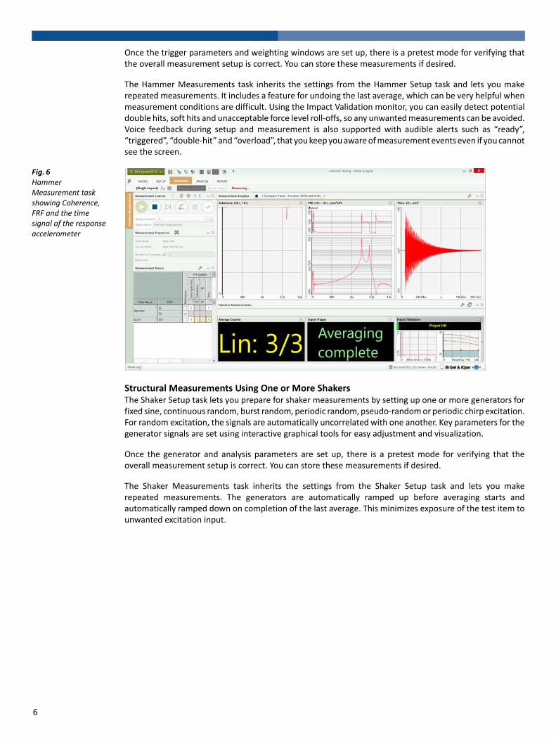
Once the trigger parameters and weighting windows are set up, there is a pretest mode for verifying thatthe overall measurement setup is correct. You can store these measurements if desired.
The Hammer Measurements task inherits the settings from the Hammer Setup task and lets you makerepeated measurements. It includes a feature for undoing the last average, which can be very helpful whenmeasurement conditions are difficult. Using the Impact Validation monitor, you can easily detect potentialdouble hits, soft hits and unacceptable force level roll‐offs, so any unwanted measurements can be avoided.Voice feedback during setup and measurement is also supported with audible alerts such as “ready”,“triggered”, “double‐hit” and “overload”, that you keep you aware of measurement events even if you cannotsee the screen.
Fig. 6 Hammer Measurement task showing Coherence, FRF and the time signal of the response accelerometer
Structural Measurements Using One or More ShakersThe Shaker Setup task lets you prepare for shaker measurements by setting up one or more generators forfixed sine, continuous random, burst random, periodic random, pseudo‐random or periodic chirp excitation.For random excitation, the signals are automatically uncorrelated with one another. Key parameters for thegenerator signals are set using interactive graphical tools for easy adjustment and visualization.
Once the generator and analysis parameters are set up, there is a pretest mode for verifying that theoverall measurement setup is correct. You can store these measurements if desired.
The Shaker Measurements task inherits the settings from the Shaker Setup task and lets you makerepeated measurements. The generators are automatically ramped up before averaging starts andautomatically ramped down on completion of the last average. This minimizes exposure of the test item tounwanted excitation input.
6

BK Connect Advanced Sine Measurements Type 8412
Type 8412 adds the following tasks:• DOF Setup• Stepped Sine Setup• Stepped Sine Measurements
These tasks are dedicated measurements of FRFs and related functions using stepped sine excitation.Geometry‐guided measurements can be performed as seen with Hammer and Shaker Type 8411measurements. The setup and measurements can be performed either in BK Connect Modal Analysis or inBK Connect Data Processing.
Stepped Sine MeasurementsStepped sine measurement is a technique where sine excitation and corresponding measurements aremade at predefined fixed frequencies (step frequencies). After the measurement at each step frequency,the frequency is swept to the next step frequency. The step type, the step frequency interval and the stepdirection(s) are user‐defined.
Advantages of stepped sine testing includes:• High signal‐to‐noise ratio• Low crest factor of the excitation signal• Possibility to control excitation and response amplitude• Concentration of energy allowing smaller shakers to be used compared to broadband testing
Applications of stepped sine measurements include:• Leakage‐free FRF measurements as input to very accurate modal analysis• Resonance surveys• Forced response ODS analysis• Control and study of non‐linearities
Performing Stepped Sine MeasurementsWith Type 8412, stepped sine measurements can be performed with single‐shaker excitation (SIMO) andmulti‐shaker excitation (MIMO). For multi‐shaker excitation, the calculation of the MIMO FRFs requires morestepped sine sweeps, where the phases between the excitation forces are changed for each sweep.
Type 8412 can be set up to perform a classical full MIMO sweep series with N shakers consisting of 2(N‐1)independent sweeps, where the excitation phases are either in‐phase or out‐of‐phase. In addition, a moretime efficient optimal MIMO sweep series of only N sweeps can be performed using a more efficientphase distribution scheme.
Type 8412 supports software closed‐loop control. Each generator, with corresponding shaker, can be setup to attempt control of the amplitude and/or the phase of a selected control signal. The control signalcan be a force signal or a response signal. A target RMS and/or phase with corresponding tolerance isspecified. The phase to be controlled is the relative phase between the control signal and a selectedreference force signal. This allows for measurements where an excitation force or a response signal iscontrolled and attempted to be kept constant at a target RMS and/or phase at all frequencies during thestepped sine sweep (or sweeps in cases of multiple shakers).
In order to protect the test item and avoid high response levels during the measurements, alarm and abortlevels for each signal can be specified in the HW Setup table. The levels are taken directly from your LAN‐XIfront‐end hardware to avoid any software delays.
If alarm levels are exceeded, a warning is given in the Level Meter and, if an abort level is exceeded, themeasurement will stop and the generators will shut down.
7
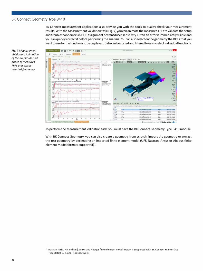
BK Connect Geometry Type 8410
BK Connect measurement applications also provide you with the tools to quality‐check your measurementresults. With the Measurement Validation task (Fig. 7) you can animate the measured FRFs to validate the setupand troubleshoot errors in DOF assignment or transducer sensitivity. Often an error is immediately visible andyou can quickly correct it before performing the analysis. You can also select on the geometry the DOFs that youwant to use for the functions to be displayed. Data can be sorted and filtered to easily select individual functions.
Fig. 7 Measurement Validation: Animation of the amplitude and phase of measured FRFs at a cursor‐selected frequency
To perform the Measurement Validation task, you must have the BK Connect Geometry Type 8410 module.
With BK Connect Geometry, you can also create a geometry from scratch, import the geometry or extractthe test geometry by decimating an imported finite element model (UFF, Nastran, Ansys or Abaqus finiteelement model formats supported)*.
* Nastran (MSC, NX and NEi), Ansys and Abaqus finite element model import is supported with BK Connect FE Interface Types 8400‐D, ‐E and ‐F, respectively.
8
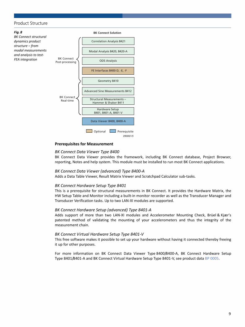
Product Structure
Fig. 8 BK Connect structural dynamics product structure – from modal measurements and analysis to test‐FEA integration
Prerequisites for Measurement
BK Connect Data Viewer Type 8400BK Connect Data Viewer provides the framework, including BK Connect database, Project Browser,reporting, Notes and help system. This module must be installed to run most BK Connect applications.
BK Connect Data Viewer (advanced) Type 8400‐AAdds a Data Table Viewer, Result Matrix Viewer and Scratchpad Calculator sub‐tasks.
BK Connect Hardware Setup Type 8401This is a prerequisite for structural measurements in BK Connect. It provides the Hardware Matrix, theHW Setup Table and Monitor including a built‐in monitor recorder as well as the Transducer Manager andTransducer Verification tasks. Up to two LAN‐XI modules are supported.
BK Connect Hardware Setup (advanced) Type 8401‐AAdds support of more than two LAN‐XI modules and Accelerometer Mounting Check, Brüel & Kjær'spatented method of validating the mounting of your accelerometers and thus the integrity of themeasurement chain.
BK Connect Virtual Hardware Setup Type 8401‐VThis free software makes it possible to set up your hardware without having it connected thereby freeingit up for other purposes.
For more information on BK Connect Data Viewer Type 8400/8400‐A, BK Connect Hardware SetupType 8401/8401‐A and BK Connect Virtual Hardware Setup Type 8401‐V, see product data BP 0005.
Optional Prerequisite
BK Connect Solution
Geometry 8410
Modal Analysis 8420, 8420-A
Structural Measurements – Hammer & Shaker 8411
Advanced Sine Measurements 8412
BK ConnectPost-processing
090061/5
Correlation Analysis 8421
FE Interfaces 8400-D, -E, -F
ODS Analysis
BK ConnectReal-time
Hardware Setup 8401, 8401-A, 8401-V
Data Viewer 8400, 8400-A
9

Post‐processing in BK ConnectAll measurements are directly accessible by the BK Connect post‐processing applications.
The BK Connect post‐processing platform brings together a range of generic post‐processing tools forimmediate and offline analysis and processing of measurement data. Data viewing, storage and reportingare built into the workflow with immediate traceability via an SQL database. Special tools and featuresallow for quick data overviews and automatic report creation based on user‐definable templates – the aimis to make the task of data processing and reporting as simple and straightforward as possible, givingtesters and engineers more time to focus on result interpretation
BK Connect Data Processing Types 8403 and 8404BK Connect Data Processing is a general purpose sound and vibration signal analysis and reportingapplication, enabling engineers to perform a range of signal analysis types with high productivity. Thetools are built into a framework that provides for fully automated operation, including batch processingand the ability to create project templates to standardize and simplify repetitive processes.
For more information on BK Connect Data Processing, see product data BP 0005.
BK Connect Modal Analysis Type 8420An application designed for single‐reference modal analysis with a basic, yet comprehensive, set of modeindicator functions (MIFs), curve‐fitters and analysis validation tools. For use with single shaker FRF dataand single‐reference hammer testing data.
BK Connect Modal Analysis (advanced) Type 8420‐AModal Analysis (advanced) adds polyreference modal analysis capabilities and advanced MIFs, curve‐fitters and analysis validation tools to the Modal Analysis application. For use with shaker MIMO(multiple‐input multiple‐output) FRF data, polyreference hammer testing data or for advanced analysisand validation of both single and polyreference data.
Type 8411 and Type 8412 tasks can be executed inside BK Connect Modal Analysis. There is no switchingbetween applications when going from setup, measurement and on to analysis – simply progress to thenext task.
For more information on BK Connect Modal Analysis, see product data BP 1523.
BK Connect ODS AnalysisWith Type 8400 and Type 8410 licences installed, a BK Connect ODS Analysis application is available forfrequency‐based spectral ODS post‐processing analysis or for viewing modal analysis results.
BK Connect Test‐FEA IntegrationFE Interfaces Type 8400‐D/E/F enable you to import FE models from Nastran, Ansys and Abaqus.BK Connect Correlation Analysis Type 8421 adds the ability to correlate two modal models: FEM vs test,test vs test or FEM vs FEM.
For more information on BK Connect Correlation Analysis, see product data BP 2577.
10

Specifications – BK Connect Structural Measurement Applications
SYSTEM REQUIREMENTS• BK Connect 2018.0 or later• The following BK Connect applications:– Data Viewer Type 8400– Hardware Setup Type 8401– Geometry Type 8410 is required for geometry‐guided measurements
• Microsoft® Windows® 10 Pro or Enterprise (x64) with either Current Branch (CB) or Current Branch for Business (CBB) servicing model; or Windows® 7 Pro, Enterprise or Ultimate (SP1) (x64) operating systems
• Microsoft® Office 2016 (x32 or x64) or Office 2013 (x32 or x64) • Microsoft® SQL Server® 2014 Express (SP2) (included in installation), SQL Server® 2014 (SP2), SQL Server® 2012 R2, SQL Server® 2008 or 2008 R2 Express Edition SP1
RECOMMENDED PC SYSTEM• Recommended PC System• Intel® Core™ i7, 3 GHz processor or better• 32 GB RAM• 480 GB Solid State Drive (SSD) with 20 GB free space, or better• 1 Gbit Ethernet network*• Microsoft® Windows® 10 Pro or Enterprise (x64) with CB • Microsoft® Office 2016 (x32)• Microsoft® SQL Server® 2014 (SP2)• Screen resolution of 1920 × 1080 pixels (full HD)
For more information on setup specifications, please see product data BP 0005.
Specifications – BK Connect Structural Measurements – Hammer and Shaker Type 8411
Setup and measurement of FRFs (and related functions) using either hammer or shaker excitation
Hammer SetupFor single impact and random impact test setups
TRIGGER Record a set of experimental hammer impacts and display as time history. Using graphical tools, adjust the trigger parameters directly on the data display, or by direct parameter entry, until the desired trigger behaviour is achieved. An Auto Adjust functionality set the Trigger Level and Hysteresis automatically. The aim is to condition the trigger parameters for maximum success in the actual measurement
WEIGHTINGThe hammer signal and a response signal are displayed in graphs with graphical tools for adjusting the type and amount of time weighting to be applied to each. The aim is to use as much of the measured signals as possible whilst minimizing noise
PRETESTExperiment with different FFT settings (bandwidth, number of spectral lines) and perform trial measurements for display and (optional) storage to the database
RESULT MODEPretest measurement results can be viewed and overlaid with previous measurements before storing to the database
Hammer MeasurementsThe Hammer Measurements user interface is streamlined for typical hammer test scenarios in which the hammer excitation location is roved from point to point or performed at a fixed location. All measurement parameters are inherited from the Hammer Setup. Key features include:• Last hit undo• Double‐hit detection• Frequency content warning (soft hit)• Auto‐increment of the reference DOF after a measurement
MEASUREMENT MODEIncludes a measurement control panel that is detachable and resizable Control Buttons: • Initialize analysis system• Measurement start/stop• Undo last hit• Delete last measurement
RESULT MODEMeasurement results can be viewed and overlaid with previous measurements
VOICE FEEDBACKAudible status/error warnings during hammer testing setup and measurement
Shaker SetupSet up the generator(s) and FFT properties before measurement
GENERATOR CONTROLGraphical tools can be used for setting up excitation type, frequency parameters, output level, level ramp up/down times, and whether burst excitation is to be usedGenerator Signal Types: • Sine (fixed frequency)• Continuous and Burst Random• Periodic and Pseudo‐random• Periodic chirp
ANALYSIS SETTINGFFT properties are adjusted to match generator settings, but can be independently adjusted if desired. Interface tools are highly interactive, enabling engineers to quickly assess when the settings are appropriate for the structure under test
PRETESTExperiment with different FFT settings (bandwidth, number of spectral lines) and perform trial measurements for display and (optional) storage to the database
RESULT MODEPretest measurement results can be viewed and overlaid with previous measurements before storing to the database
Shaker MeasurementsClassical Modal Analysis (with single/multiple references): Autospectra, Cross‐spectra, FRF, Impulse response, Coherence and Correlation functions
MEASUREMENT MODEIncludes a measurement control panel that is detachable and resizable Control Buttons: • Initialize analysis system• Generator start/stop• Measurement start/stopThe averaging setup can be adjusted from within this mode
* A dedicated data acquisition network (LAN or WAN) is recommended. A network that only handles data from the front end improves the stability of the data
11

RESULT MODEMeasurement the results can be viewed and overlaid with previous measurements
Specifications – BK Connect Advanced Sine Measurements Type 8412
Setup and measurement of FRFs (and related functions) using single‐ or multiple‐shaker stepped sine excitation
Stepped Sine SetupSet up the closed‐loop control, the generator(s) and the analysis parameters before measurement
CLOSED‐LOOP CONTROLSoftware‐basedType: None, Amplitude, Phase, BothParameters: Amplitude Tolerance, Phase Tolerance, Control Strength (Strong, Balanced, Gentle), Max. Control (Time, Periods), Control Fail Action (Stop, Continue)Analysis Parameters: Settling Type (Time, Periods), Settling Time
Phase Control Matrix for manually or automatic specification of phase control and showing the phase relations between the excitation signals.Force and Control Signal Monitor with amplitude and phase readout including tolerance bands
SWEEP MODES• Optimal Sweep Series: Phases uniformly distributed• Full MIMO Sweep Series: Phases either 0 or 180 degrees• Manual: User‐defined phases• Specific Sweep Series: User‐defined subset of sweeps
GENERATOR PARAMETERSStep Type (Linear, Log (Octaves), Log (Decades)), Step Size, Lower Frequency, Upper Frequency, Step Direction (Up, Down, Alternating), Start Frequency (Lower, Upper), Transition Mode (Fixed Time, Automatic)
GENERATOR CONTROLGraphical tools for setting up master control and individual generators with respect to ramp up/down, amplitude and phase
Stepped Sine Measurements
MEASUREMENT MODEIncludes a measurement control panel that is detachable and resizableControl Buttons: • Initialize analysis system• Generator start/stop• Measurement start/stop• Dwell/sweep mode• Step sine frequency – adjustable when dwelling• Frequency step upwards/downwards while dwelling
ALARM AND ABORT LEVELS• Alarm and abort levels for each signal can be specified in the HW Setup Table
• If alarm level is exceeded, a warning is given in the Level Meter• If abort level is exceeded, the measurement will be stopped and the generators will be shut down
• Detection of alarm and abort levels are detected in the LAN‐XI input
Specifications – BK Connect Geometry Type 8410
Geometry‐guided MeasurementsSupported for both hammer and shaker measurements
DOF SETUPFor defining the DOFs to be measured and a DOF sequence• Using transducers from the HW Setup Table, favourites transducers defined in the Transducer Manager or generic transducers
• DOFs are defined by dragging transducers to the geometry nodes or by manual definition
• Creation of DOF sequence based on:– Chronological order the DOFs have been defined– Increasing node number– Path through the closest nodes (requires use of geometry)– Manual selection of DOFs
Geometry Creation, Import and Decimation
GEOMETRY CREATION AND EDITING• Basic geometries using nodes, trace lines, triangle and quad elements
• Geometries based on built‐in CAD models:– Curves: Circle, Circular Arc, Ellipse, Elliptical Arc, Hyperbolic, Parabolic, Line, Polyline, Interpolation Spline and Control Points Spline
– Surfaces: Circular, Circular Arc, Ellipse, Elliptical Arc, Hyperbolic, Parabolic, Triangular, Rectangular, Polygon, Interpolation Spline and Control Points Spline
– Solids: Cylinder, Hemisphere, Sphere, Box, Cone and Conical Frustum• CAD models with selectable colour and transparency• Move (translate, rotate) and copy (linear, radial) operators for CAD models and meshes using interactive handles or manual entry
• Definition of locations with three directions on a CAD model (Sites)
• Definition of locations with three directions on a CAD model (Sites)• Meshing of built‐in CAD models• Extrusion of CAD models: Curves can be extruded to surfaces. Plane surfaces can be extruded to solids. Preselection of colour is available
• Hierarchical geometry tree view with subfolders for Coordinate Systems, Nodes, Elements, Trace Lines and Equations
• Tables for Coordinate Systems, Nodes, Elements, Trace Lines and Equations with sorting, filtering, multiple selection and editing
• Support of Cartesian, Cylindrical and Spherical coordinate systems. Local and Global coordinate systems
• Automated point numbering. Partial or complete semi‐automated point renumbering
Visual link between selections in Geometry 3D View and Geometry Tree
GEOMETRY IMPORT FORMATS• UFF data set types 15, 18, 82, 2411 or 2412 and Microsoft® Excel® (*.csv)
• UFF FE models • Nastran (MSC, NX, NEi), Ansys and Abaqus FE models (requires BK Connect FE Interface Type 8400‐D/E/F, respectively)
GEOMETRY EXPORT FORMATS UFF data set types 15, 18, 2412 or 82 and Microsoft® Excel® (*.csv)
DECIMATIONImported FE models can be decimated to test models by manually selecting nodes on the FE model or by entering the nodes directly in a table
DYNAMIC POINT NUMBERING Show more point numbers (IDs) when zooming in on parts of the geometry (user‐definable) – also during animation
12

GEOMETRY VIEWS• Single, Side‐by‐Side, Top‐Bottom and various Quad views• Definition of front, back, left, right, top and bottom view axis• Isometric view• Perspective, orthographic and stretched projections of geometry• Hidden lines and transparency• Pan, zoom and rotate options for viewing geometries• Symbols for shaker, impact hammer, force transducer, accelerometer, velocity transducer and displacement transducer positions shown on geometry with customized colours and sizes
CUTTING PLANESCut through a geometry in three user‐definable 2D planes to view the interior or exclude viewing parts of the geometry – also during animation
ANIMATION• Deformed and undeformed animation with Max. Deformation
• Single, overlaid and difference animation• Wireframe, contour (solid/solid edge) points and arrow animation• Animation of non‐measured DOFs using interpolation equations• Geometry legends showing information about the shapes being animated such as shape number, frequency and complexity
• GIF and AVI video file generation with selectable codec and geometry legends
Measurement Validation
GEOMETRY DRIVEN FUNCTION DISPLAYS Show FRFs based on selected excitation and response DOFs on the geometry
FUNCTION‐BASED ANIMATIONAnimate geometry using, for example, FRFs or phase‐assigned spectra (PAS) for ODS analysis. Saving of shapes in Shape Table
Ordering Information
Table 1 Ordering information for BK Connect Structural Dynamics suite software
Table 2 Overview of BK Connect Modal Analysis and Structural Measurement packs)
Item No.*
* “X” indicates the licence model, either N: Node‐locked or F: Floating
Description
Type 8400‐X BK Connect Data Viewer
Type 8400‐A‐X BK Connect Data Viewer (advanced)
Type 8400‐D‐X BK Connect Nastran Interface
Type 8400‐E‐X BK Connect Ansys Interface
Type 8400‐F‐X BK Connect Abaqus Interface
Type 8401‐X BK Connect Hardware Setup
Type 8401‐A‐X BK Connect Hardware Setup (advanced)
Type 8410‐X BK Connect Geometry
Type 8411‐X BK Connect Structural Measurements – Hammer and Shaker
Type 8412‐X BK Connect Advanced Sine Measurements
Type 8420‐X BK Connect Modal Analysis
Type 8420‐A‐X BK Connect Modal Analysis (advanced)
Type 8421‐X BK Connect Correlation Analysis
Packs
Type 8411‐XS BK Connect Structural Measurements and Analysis Pack
Type 8411‐A‐XS BK Connect Structural Measurements and Analysis Pack (advanced)
Type 8420‐XS BK Connect Modal Analysis Pack
Type 8420‐A‐XS BK Connect Modal Analysis Pack (advanced)
Packs
8411‐S 8411‐AS 8420‐S 8420‐AS
Structural
Measurements
and Analysis
Structural
Measurements and Analysis
(advanced)
Modal Analysis
Modal
Analysis
(advanced)
ComprisesBK Connect:
Data ViewerType 8400
Hardware Setup Type 8401
Hardware Setup (advanced) Type 8401‐A
GeometryType 8410
Structural Measurements – Hammer and
Shaker Type 8411
Modal Analysis Type 8420
Modal Analysis (advanced)Type 8420‐A
13
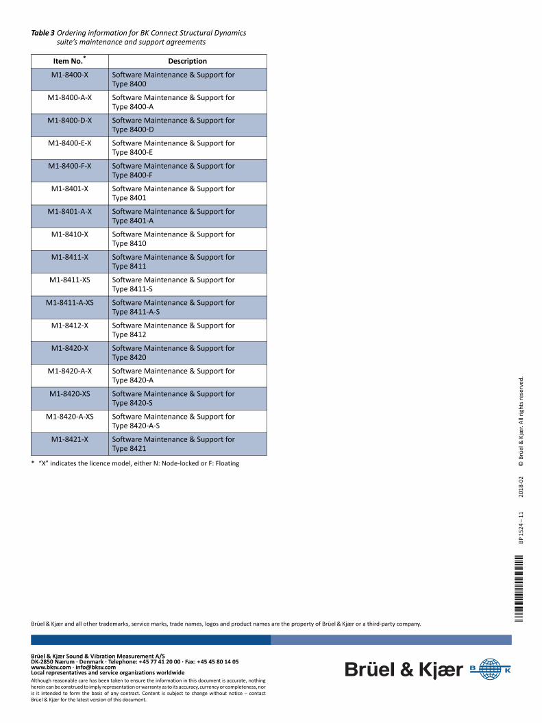
BP-1524---.Î
BP15
24–11
2018
‐02
© Brüel&Kjær. All rights reserved.
Table 3 Ordering information for BK Connect Structural Dynamics suite’s maintenance and support agreements
Item No.*
* “X” indicates the licence model, either N: Node‐locked or F: Floating
Description
M1‐8400‐X Software Maintenance & Support for Type 8400
M1‐8400‐A‐X Software Maintenance & Support for Type 8400‐A
M1‐8400‐D‐X Software Maintenance & Support for Type 8400‐D
M1‐8400‐E‐X Software Maintenance & Support for Type 8400‐E
M1‐8400‐F‐X Software Maintenance & Support for Type 8400‐F
M1‐8401‐X Software Maintenance & Support for Type 8401
M1‐8401‐A‐X Software Maintenance & Support for Type 8401‐A
M1‐8410‐X Software Maintenance & Support for Type 8410
M1‐8411‐X Software Maintenance & Support for Type 8411
M1‐8411‐XS Software Maintenance & Support for Type 8411‐S
M1‐8411‐A‐XS Software Maintenance & Support for Type 8411‐A‐S
M1‐8412‐X Software Maintenance & Support for Type 8412
M1‐8420‐X Software Maintenance & Support for Type 8420
M1‐8420‐A‐X Software Maintenance & Support for Type 8420‐A
M1‐8420‐XS Software Maintenance & Support for Type 8420‐S
M1‐8420‐A‐XS Software Maintenance & Support for Type 8420‐A‐S
M1‐8421‐X Software Maintenance & Support for Type 8421
Brüel & Kjær Sound & Vibration Measurement A/SDK‐2850 Nærum ∙ Denmark ∙ Telephone: +45 77 41 20 00 ∙ Fax: +45 45 80 14 05www.bksv.com ∙ [email protected] representatives and service organizations worldwideAlthough reasonable care has been taken to ensure the information in this document is accurate, nothingherein can be construed to imply representation or warranty as to its accuracy, currency or completeness, noris it intended to form the basis of any contract. Content is subject to change without notice – contactBrüel & Kjær for the latest version of this document.
Brüel & Kjær and all other trademarks, service marks, trade names, logos and product names are the property of Brüel & Kjær or a third‐party company.
Ë
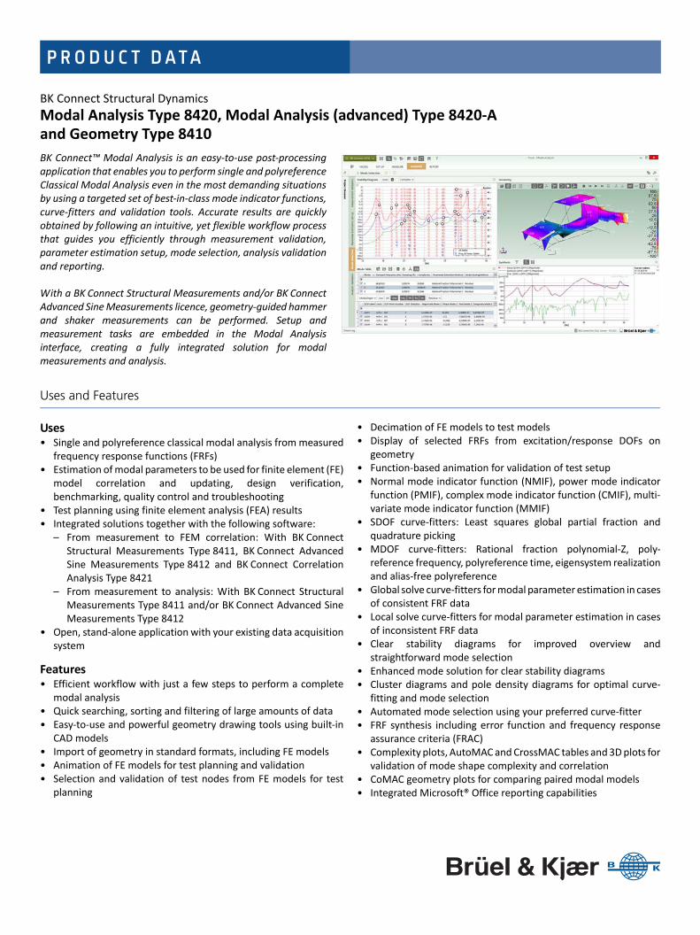
P R O D U C T D ATA
BK Connect Structural DynamicsModal Analysis Type 8420, Modal Analysis (advanced) Type 8420‐A and Geometry Type 8410
BK Connect™ Modal Analysis is an easy‐to‐use post‐processingapplication that enables you to perform single and polyreferenceClassical Modal Analysis even in the most demanding situationsby using a targeted set of best‐in‐class mode indicator functions,curve‐fitters and validation tools. Accurate results are quicklyobtained by following an intuitive, yet flexible workflow processthat guides you efficiently through measurement validation,parameter estimation setup, mode selection, analysis validationand reporting.
With a BK Connect Structural Measurements and/or BK ConnectAdvanced Sine Measurements licence, geometry‐guided hammerand shaker measurements can be performed. Setup andmeasurement tasks are embedded in the Modal Analysisinterface, creating a fully integrated solution for modalmeasurements and analysis.
Uses and Features
Uses• Single and polyreference classical modal analysis from measured
frequency response functions (FRFs)• Estimation of modal parameters to be used for finite element (FE)
model correlation and updating, design verification,benchmarking, quality control and troubleshooting
• Test planning using finite element analysis (FEA) results • Integrated solutions together with the following software:
– From measurement to FEM correlation: With BK ConnectStructural Measurements Type 8411, BK Connect AdvancedSine Measurements Type 8412 and BK Connect CorrelationAnalysis Type 8421
– From measurement to analysis: With BK Connect StructuralMeasurements Type 8411 and/or BK Connect Advanced SineMeasurements Type 8412
• Open, stand‐alone application with your existing data acquisitionsystem
Features• Efficient workflow with just a few steps to perform a complete
modal analysis• Quick searching, sorting and filtering of large amounts of data• Easy‐to‐use and powerful geometry drawing tools using built‐in
CAD models• Import of geometry in standard formats, including FE models• Animation of FE models for test planning and validation• Selection and validation of test nodes from FE models for test
planning
• Decimation of FE models to test models• Display of selected FRFs from excitation/response DOFs on
geometry• Function‐based animation for validation of test setup• Normal mode indicator function (NMIF), power mode indicator
function (PMIF), complex mode indicator function (CMIF), multi‐variate mode indicator function (MMIF)
• SDOF curve‐fitters: Least squares global partial fraction andquadrature picking
• MDOF curve‐fitters: Rational fraction polynomial‐Z, poly‐reference frequency, polyreference time, eigensystem realizationand alias‐free polyreference
• Global solve curve‐fitters for modal parameter estimation in casesof consistent FRF data
• Local solve curve‐fitters for modal parameter estimation in casesof inconsistent FRF data
• Clear stability diagrams for improved overview andstraightforward mode selection
• Enhanced mode solution for clear stability diagrams• Cluster diagrams and pole density diagrams for optimal curve‐
fitting and mode selection• Automated mode selection using your preferred curve‐fitter• FRF synthesis including error function and frequency response
assurance criteria (FRAC)• Complexity plots, AutoMAC and CrossMAC tables and 3D plots for
validation of mode shape complexity and correlation• CoMAC geometry plots for comparing paired modal models• Integrated Microsoft® Office reporting capabilities

Introduction
BK Connect is the latest addition to Brüel & Kjær’s platform of software products. It provides real‐timemeasurements, analysis and test‐FEA integration in a modern, intuitive GUI environment and is theculmination of extensive customer surveys to resolve their most important issues when analysing soundand vibration data.
BK Connect provides:• Enhanced usability for high productivity with an intuitive user interface that puts the tools you need at your
fingertips. The graphical user interface is built around a workflow model that leads you easily through anytest setup, measurement and analysis process
• Open data policy that supports a wide range of native and third party formats for improved import andexport of data
• Consistent user interface throughout all applications encouraging faster learning of new applications
BK Connect Structural Dynamics allows you to observe, analyse and document the dynamic behaviour ofstructures using a single software platform covering setup, measurements, analysis and test‐FEAintegration. With BK Connect Structural Measurements, you can set up and perform single or poly‐reference hammer and shaker measurements, whereas BK Connect Modal Analysis provides accurate andreliable results even in the most demanding situations using a targeted set of best‐in‐class mode indicatorfunctions, curve‐fitters and analysis validation tools.
BK Connect Correlation Analysis adds the capability of correlating two modal models, for example, finiteelement model versus test model using tools such as Geometry Alignment, CrossMAC and Cross‐orthogonality calculations.
The open data policy behind the BK Connect Structural Dynamics suite also allows the post‐processingapplications to be used as stand‐alone applications together with your existing measurement and analysis system.
Measurement and Integration
BK Connect Structural Measurements – Hammer and Shaker Type 8411Type 8411 contains tasks for setup and measurement to perform hammer and shaker testing. And withthe addition of BK Connect Advanced Sine Measurements Type 8412, tasks for setup and measurementare available for stepped sine testing. The tasks are fully embedded into BK Connect Modal Analysis –creating a single application for modal setup, measurement and analysis. Measurement setup, executionand validation can be performed manually, table‐based or geometry‐guided.
2
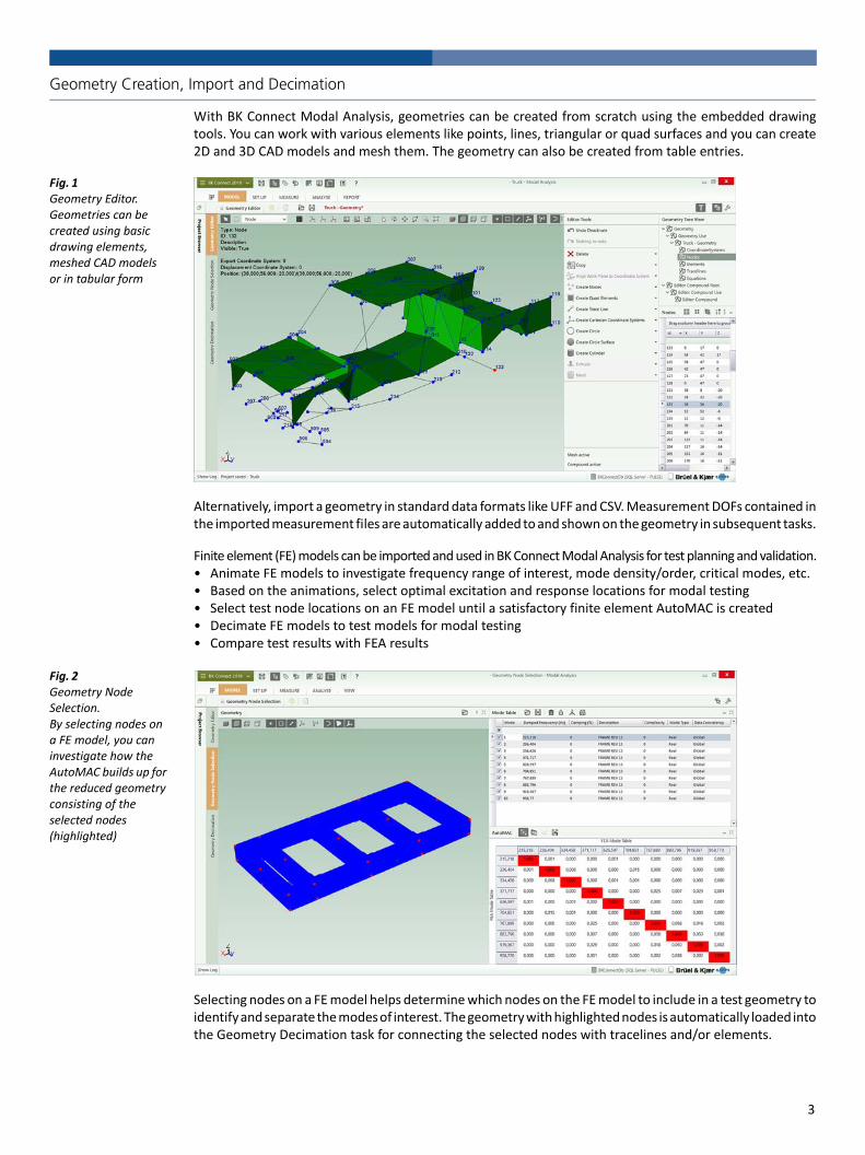
Geometry Creation, Import and Decimation
With BK Connect Modal Analysis, geometries can be created from scratch using the embedded drawingtools. You can work with various elements like points, lines, triangular or quad surfaces and you can create2D and 3D CAD models and mesh them. The geometry can also be created from table entries.
Fig. 1 Geometry Editor.Geometries can be created using basic drawing elements, meshed CAD models or in tabular form
Alternatively, import a geometry in standard data formats like UFF and CSV. Measurement DOFs contained inthe imported measurement files are automatically added to and shown on the geometry in subsequent tasks.
Finite element (FE) models can be imported and used in BK Connect Modal Analysis for test planning and validation.• Animate FE models to investigate frequency range of interest, mode density/order, critical modes, etc.• Based on the animations, select optimal excitation and response locations for modal testing• Select test node locations on an FE model until a satisfactory finite element AutoMAC is created• Decimate FE models to test models for modal testing• Compare test results with FEA results
Fig. 2 Geometry Node Selection.By selecting nodes on a FE model, you can investigate how the AutoMAC builds up for the reduced geometry consisting of the selected nodes (highlighted)
Selecting nodes on a FE model helps determine which nodes on the FE model to include in a test geometry toidentify and separate the modes of interest. The geometry with highlighted nodes is automatically loaded intothe Geometry Decimation task for connecting the selected nodes with tracelines and/or elements.
3

Analysis and Reporting
By logically grouping features and display of results, BK Connect Modal Analysis allows you to do acomplete modal analysis in just four main steps: • Measurement Validation• Parameter Estimation Setup• Mode Selection• Analysis Validation
In addition, a User‐defined Displays task is available, and extensive live reporting can be done inMicrosoft® Word, Excel® or PowerPoint® at any time in the analysis using integrated reporting functions.
Measurement ValidationThe Measurement Validation task is used to check the quality of the measurement data prior toperforming the modal parameter extraction. Functions like ordinary and multiple coherence, reciprocityand driving point FRFs, or all FRFs from selected references can easily be shown by simply dragging thefunctions from the Project Browser.
The Geometry‐driven Function Display provides a graphical tool that allows you to select on the geometrythe DOFs that are to be used for the displayed function types. Data can also be sorted and filtered in atable to easily select individual functions to be displayed.
Fig. 3 Measurement Validation.In the Geometry‐driven Function Display, functions are selected by clicking on the desired excitation and response DOFs on the geometry. In this example, the FRFs are those related to the shaker at the front. You can easily scroll up and down to view all selected FRFs related to this shaker
For validation of test setups, such as identifying cable breaks and faulty and incorrectly mountedtransducers, animations can be done based on FRFs. For structures with lightly damped and well‐separated modes, the FRF shapes will resemble mode shapes.
Operating deflection shapes (ODS) from phase‐assigned spectra can also be shown and saved, forexample, to compare with mode shapes.
Parameter Estimation SetupThe Parameter Estimation Setup task is where you prepare and execute the curve‐fitting. FRF data toinclude in the analysis are easily filtered, sorted and then selected using the Data Matrix Selector table. Inthe same screen layout, the geometry with DOF information is shown together with a graph area forinvestigating potential modes using different mode indicator functions. Various SDOF and MDOF curve‐fitters can be selected and the frequency range of interest can be set, including the time range, whenusing time domain curve‐fitters. Both global and local solve curve‐fitters are available.
Previews of the stability diagram for the different curve‐fitters aid in the selection of the preferred curve‐fitterfor the task. To assist in this, powerful tools like cluster diagrams and pole density plots are also available.
4
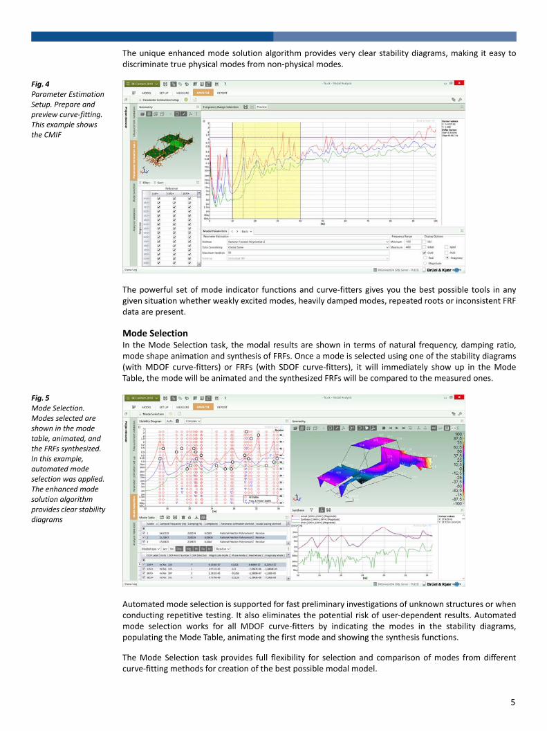
The unique enhanced mode solution algorithm provides very clear stability diagrams, making it easy todiscriminate true physical modes from non‐physical modes.
Fig. 4 Parameter Estimation Setup. Prepare and preview curve‐fitting. This example shows the CMIF
The powerful set of mode indicator functions and curve‐fitters gives you the best possible tools in anygiven situation whether weakly excited modes, heavily damped modes, repeated roots or inconsistent FRFdata are present.
Mode SelectionIn the Mode Selection task, the modal results are shown in terms of natural frequency, damping ratio,mode shape animation and synthesis of FRFs. Once a mode is selected using one of the stability diagrams(with MDOF curve‐fitters) or FRFs (with SDOF curve‐fitters), it will immediately show up in the ModeTable, the mode will be animated and the synthesized FRFs will be compared to the measured ones.
Fig. 5 Mode Selection.Modes selected are shown in the mode table, animated, and the FRFs synthesized. In this example, automated mode selection was applied. The enhanced mode solution algorithm provides clear stability diagrams
Automated mode selection is supported for fast preliminary investigations of unknown structures or whenconducting repetitive testing. It also eliminates the potential risk of user‐dependent results. Automatedmode selection works for all MDOF curve‐fitters by indicating the modes in the stability diagrams,populating the Mode Table, animating the first mode and showing the synthesis functions.
The Mode Selection task provides full flexibility for selection and comparison of modes from differentcurve‐fitting methods for creation of the best possible modal model.
5

Analysis ValidationThe Analysis Validation task supplies you with a number of tools for further investigation of the obtainedmodal results for maximum confidence in your obtained modal model. This includes FRF Synthesis, ModeShape Animation, AutoMAC and CrossMAC tables and 3D plots, CoMAC geometry plots and Complexityplots. Modes can be normalized to non‐complex values (normal modes) for comparison with real‐valuedFE modes.
Fig. 6 Analysis Validation. Side‐by‐side animation of first torsional and bending modes
Fig. 7 Analysis Validation. CrossMAC comparing the mode shapes found using the Rational Fraction Polynomial‐Z and Polyreference Time curve‐fitters. The mode pair selected is automatically animated
The Analysis Validation task can also be used to animate FE models for test planning or validation.
6

Fig. 8 Quad View colour contour animation of two mode shapes from a MSC Nastran FE model with more than 1 million nodes
ReportingThe Report task enables reports to be prepared in parallel with the analysis process, linking importantresults as they are produced. Store geometries, displays, tables and text in the Project Browser as reportelements and generate the report when you are ready. Reports can be based on standard embedded orcustomized templates you define, or on‐the‐spot. High‐quality, active or static reports are easily createddirectly in Microsoft® Word, Excel® or PowerPoint®.
User‐defined DisplaysThe User‐defined Displays task enables you to create customized layouts consisting of graphs, geometries(with or without animation), shape tables, MAC tables/plots and complexity plots. Data can be linkedbetween displays in the layout so that source data in one display is reflected in a result display. Forexample, when linking a mode table to a geometry, changes to the mode table will be automaticallyupdated in the geometry. This allows for fast and flexible data viewing and ad hoc analysis.
Product Structure
Fig. 9 BK Connect structural dynamics product structure – from modal measurements to analysis and test‐FEA integration
Optional Prerequisite
BK Connect Solution
Geometry 8410
Modal Analysis 8420, 8420-A
Structural Measurements – Hammer & Shaker 8411
Advanced Sine Measurements 8412
BK ConnectPost-processing
090061/5
Correlation Analysis 8421
FE Interfaces 8400-D, -E, -F
ODS Analysis
BK ConnectReal-time
Hardware Setup 8401, 8401-A, 8401-V
Data Viewer 8400, 8400-A
7

Core Applications
BK Connect Data Viewer Type 8400BK Connect Data Viewer provides the framework, including BK Connect database, Project Browser,reporting, Notes and help system. This module must be installed to run most BK Connect applications.
BK Connect Hardware Setup Type 8401This is a prerequisite for structural measurements in BK Connect. It provides the Hardware Matrix, theHW Setup Table and Monitor including a built‐in monitor recorder as well as the Transducer Manager andTransducer Verification tasks. Up to two LAN‐XI modules are supported.
BK Connect Hardware Setup (advanced) Type 8401‐AAdds support of more than two LAN‐XI modules and Accelerometer Mounting Check, Brüel & Kjær'spatented method of validating the mounting of your accelerometers and thus the integrity of themeasurement chain.
BK Connect Virtual Hardware Setup Type 8401‐VThis free software makes it possible to set up your hardware without having it connected thereby freeingit up for other purposes.
For more information on BK Connect Data Viewer Type 8400, BK Connect Hardware Setup Type 8401/8401‐A and BK Connect Virtual Hardware Setup Type 8401‐V, see product data BP 0005.
Measurement and Modelling Applications
BK Connect Structural Measurements – Hammer and Shaker Type 8411Adds dedicated setup and measurements tasks for hammer and shaker testing, including measurementsfor MIMO analysis. Geometry‐guided measurement setup, execution and validation is supported.
BK Connect Advanced Sine Measurements Type 8412Type 8412 adds dedicated setup and measurement tasks for single and multi‐shaker stepped sine testing.Geometry‐guided measurement setup, execution and validation is supported.
Geometry Type 8410Geometry allows the importation and creation of geometries and is used across the various BK ConnectStructural Dynamics solutions. FE models can be imported using UFF, and decimated to test models.
A variety of animation types are supported including wire frame, surface contour, point and arrowanimation as well as overlaid, difference, top‐bottom and side‐by‐side animation in single, dual or quadview format. The animations can be recorded as AVIs and included in Word and PowerPoint® reports.
For further information on BK Connect Structural Measurements – Hammer and Shaker Type 8411, BK ConnectAdvanced Sine Measurements Type 8412 and BK Connect Geometry Type 8410, see product data BP 1524.
Modal and ODS Analysis Applications
BK Connect Modal Analysis Type 8420An application designed for single‐reference modal analysis with a basic, yet comprehensive, set of modeindicator functions (MIFs), curve‐fitters and analysis validation tools. For use with single shaker FRF dataand single‐reference hammer testing data.
Modal Analysis includes:• Mode indicator functions: Normal MIF (NMIF) and Power MIF (PMIF)• Curve‐fitting:
– SDOF: Least Squares Global Partial Fraction, Quadrature Picking– MDOF: Polyreference Time, Polyreference Frequency – limited to one reference– Global solve curve‐fitting– Local solve curve‐fitting (Polyreference Time)– Stability diagram with Enhanced Mode Solution (Polyreference Time)– Advanced stabilization diagrams: Cluster diagram and Pole Density plot– Automated mode selection
• Analysis validation: AutoMAC, CrossMAC, Complexity plot and CoMAC geometry plot
8

Specifications – BK Connect Modal Analysis
SYSTEM REQUIREMENTS• BK Connect 2018.0 or later• The following BK Connect™ applications:– BK Connect Data Viewer Type 8400 – BK Connect FE Interface Types 8400‐D, ‐E and ‐F: To import Nastran, Ansys and Abaqus FE models and results
– BK Connect Geometry Type 8410: For all geometry functionality– BK Connect Modal Analysis Type 8420: To run Type 8420‐A– BK Connect Structural Measurements Type 8411: For hammer and shaker measurements
– BK Connect Advanced Sine Measurements Type 8412: For stepped sine measurements
• Microsoft® Windows® 10 Pro or Enterprise (x64) with either Current Branch (CB) or Current Branch for Business (CBB) servicing model; or Windows® 7 Pro, Enterprise or Ultimate (SP1) (x64) operating systems
• Microsoft® Office 2016 (x32 or x64) or Office 2013 (x32 or x64) • Microsoft® SQL Server® 2014 Express (SP2) (included in installation), SQL Server® 2014 (SP2), SQL Server® 2012 R2, SQL Server® 2008 or 2008 R2 Express Edition SP1
RECOMMENDED PC FOR USE WITH FE MODELS• Intel® Core™ i7, 3 GHz processor or better• 32 GB RAM• 480 GB Solid State Drive (SSD) with 20 GB free space, or better• 1 Gbit Ethernet network* • Microsoft® Windows® 10 Pro or Enterprise (x64), CB • Microsoft® Office 2016 (x32)• Microsoft® SQL Server® 2014 (SP2)• Screen resolution of 1920 × 1080 pixels (full HD)This will support FEM import, visualization and animation of models up to 1 M nodes
Data Input• Requires FRF data as input for the curve‐fitting process• Acquired using BK Connect Structural Measurements • Measurement data and geometry seamlessly transferred from PULSE LabShop Modal Test Consultant (modal analysis) or from PULSE LabShop ODS Test Consultant (ODS analysis)
* A dedicated data acquisition network (LAN or WAN) is recommended; a network that only handles data from the front end improves the stability of the data
BK Connect Modal Analysis (advanced) Type 8420‐AModal Analysis (advanced) adds polyreference modal analysis capabilities and advanced MIFs, curve‐fitters and analysis validation tools to the Modal Analysis application. For use with shaker MIMO(multiple‐input multiple‐output) FRF data, polyreference hammer testing data or for advanced analysisand validation of both single and polyreference data.
Modal Analysis (advanced) adds:• Geometry Node Selection task• Mode indicator functions: Complex MIF (CMIF) and Multi‐variate MIF (MMIF)• Curve‐fitting:
– MDOF Curve‐fitters: Polyreference Time and Polyreference Frequency (no reference limitations), RationalFraction Polynomial‐Z (RFP‐Z), Eigensystem Realization and Alias‐Free Polyreference (AFPoly™)
– Local solve curve‐fitting (RFP‐Z)– Stability diagram with Enhanced Mode Solution (RFP‐Z)
• Analysis validation: Complexity plot and CoMAC geometry plot
BK Connect ODS AnalysisWith licences for Types 8400 and 8410 installed, a BK Connect ODS Analysis application is available forfrequency‐based spectral ODS post‐processing analysis or for viewing modal analysis results.
Test‐FEA Integration Applications
BK Connect FE Interfaces Types 8400‐D, ‐E, ‐FFE Interfaces enables you to import FE models from Nastran, Ansys and Abaqus.
BK Connect Correlation Analysis Type 8421Correlation Analysis adds the ability to correlate two modal models: FEM vs Test, Test vs Test or FEM vs FEM.For more information, see product data BP 2577.
Complete Measurement Chain
With Brüel & Kjær’s complete and fully integrated measurement chain, including accelerometers, impacthammers, force transducers, modal exciter systems, data acquisition front ends and measurement andpost‐processing software, you can select the optimal solution for your structural dynamics needs. Theopenness and flexibility of BK Connect Structural Dynamics applications support your needs today and inthe future. You are never limited to a vendor‐specific system configuration and can easily assemble thesystem of your choice.
9

• Standard measurement data formats: UFF type 58 (Binary & ASCII), UFF type 1858 (damping correction)
• Test for I‐deas data: Function (.afu) and shape (.ash) files
Geometry Creation, Import, Node Selection and DecimationRequires BK Connect Geometry Type 8410
GEOMETRY CREATION AND EDITING• Basic geometries using nodes, tracelines, triangle and quad elements• Geometries based on built‐in CAD models:– Curves: Circle, Circular Arc, Ellipse, Elliptical Arc, Hyperbolic, Parabolic, Line, Polyline, Interpolation Spline and Control Points Spline
– Surfaces: Circular, Circular Arc, Ellipse, Elliptical Arc, Hyperbolic, Parabolic, Triangular, Rectangular, Polygon, Interpolation Spline and Control Points Spline
– Solids: Cylinder, Hemisphere, Sphere, Box, Cone and Conical Frustum• CAD models with selectable colour and transparency• Move (translate, rotate) and copy (linear, radial) operators for CAD models and meshes using interactive handles or manual entry
• Definition of locations with three directions on a CAD model (Sites)• Definition of locations with three directions on a CAD model (Sites)• Meshing of CAD models• Extrusion of CAD models: Curves can be extruded to surfaces. Plane surfaces can be extruded to solids. Preselection of colour is available
• Hierarchical geometry tree view with subfolders for Coordinate Systems, Nodes, Elements, Tracelines and Equations
• Tables for Coordinate Systems, Nodes, Elements, Tracelines and Equations with sorting, filtering, multiple selection and editing
• Support of Cartesian, Cylindrical and Spherical coordinate systems. Local and Global coordinate systems
• Automated point numbering. Partial or complete semi‐automated point renumbering
• Visual link between selections in Geometry 3D View and Geometry Tree
GEOMETRY IMPORT FORMATSUFF data set types 15, 18, 82, 2411 or 2412, Microsoft® Excel® (*.csv), UFF, Nastran (MSC, NX, NEi), Ansys and Abaqus FE models (requires Type 8400‐D/E/F)
GEOMETRY EXPORT FORMATS UFF data set types 15, 18, 2412 or 82, and Microsoft® Excel® (*.csv)
GEOMETRY NODE SELECTION (Modal Analysis (advanced) only)Select test node locations on a FE model until a satisfactory FE AutoMAC is created.A‐set nodes from an imported Reduced Mass Matrix or Reduced Stiffness Matrix from MSC Nastran (.op2) are automatically selected for validation and potential modification.Nodes selected are automatically high‐lighted in the Geometry Decimation task for connection with tracelines and/or elements
DECIMATIONImported FE models can be decimated to test models by manually selecting nodes on the FE model or by entering the nodes directly in a table. Selected nodes can be connected with trace lines and/or elements
DYNAMIC POINT NUMBERING Show more point numbers (IDs) when zooming in on parts of the geometry (user‐definable) – also during animation
GEOMETRY VIEWS• Single, Side‐by‐Side, Top‐Bottom and various Quad views• Definition of front, back, left, right, top and bottom view axis• Isometric view• Perspective, orthographic and stretched projections of geometry• Hidden lines and transparency• Pan, zoom and rotate options for viewing geometries
• Symbols for shaker, impact hammer, force transducer and accelerometer positions shown on geometry with customized colours and sizes
CUTTING PLANESCut through a geometry in three user‐definable 2D planes to view the interior or exclude viewing parts of the geometry – also during animation
ANIMATION• Deformed and undeformed animation with Max. Deformation• Single, overlaid and difference animation• Wireframe, contour (solid/solid edge), points and arrow animation• Animation of non‐measured DOFs using interpolation equations• GIF and AVI file generation with selectable codec
Measurement ValidationRequires BK Connect Geometry Type 8410
Geometry‐driven Function Displays: Show FRFs based on selected excitation and response DOFs on the geometry Function Animation: Animate geometry using, for example, FRFs or PAS (ODS). Saving of shapes in Shape Table
Parameter Estimation Setup
FUNCTION SELECTOR Selection of FRF data to be included in curve‐fitting
MODE INDICATOR FUNCTIONS Modal Analysis: Normal Mode Indicator Function (NMIF) and Power Mode Indicator Function (PMIF)Modal Analysis (advanced): Complex Mode Indicator Function (CMIF) and Multi‐variate Mode Indicator Function (MMIF)
CURVE‐FITTERS Modal Analysis: • SDOF: Least Squares Global Partial Fraction, Quadrature Picking• MDOF: Polyreference Frequency and Polyreference Time (with single reference)
Modal Analysis (advanced): MDOF: Polyreference Frequency and Polyreference Time (with multiple references), Rational Fraction Polynomial‐Z (RFP‐Z), Eigensystem Realization, Alias‐Free Polyreference (AFPoly)Enhanced Mode Solution: Optimal clarity of the stability diagrams with Polyreference Time and RFP‐ZSolve Method: • Global: All curve‐fitters• Local: Polyreference Time and RFP‐Z
Mode SelectionMode Selection: Manual or AutomaticShape Types: Real or Complex
DIAGRAMSStability Diagram: For indication and selection of modes. Plotted in an Iteration versus Frequency diagram• Mode stability indication: Computational, New, Frequency Stable, Damping Stable, Vector Stable, All Stable
• Selectable mode symbols, colours and tolerance propertiesCluster Diagram Modal Analysis (advanced) only: For indication and selection of modes. Plotted in a Damping versus Frequency Diagram• Mode stability indication: Computational, New, Frequency Stable, Damping Stable, Vector Stable, All Stable
• Selectable mode symbols, colours and tolerance propertiesPole Density Diagram Modal Analysis (advanced) only: For indication and selection of modes. Plotted in a colour‐coded Damping versus Frequency diagram
10
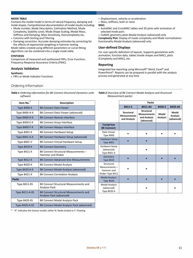
MODE TABLE Contains the modal model in terms of natural frequency, damping and mode shapes. Comprehensive documentation of modal results including:• Mode number, Mode Description, Estimation Method, Mode Complexity, Stability Level, Mode Shape Scaling, Modal Mass, Stiffness and Damping, Mass Sensitivity, Overcomplexity etc.
• Columns with Sorting and Filtering• Damping correction: Accurate damping estimates by correcting for the effects of exponential weighting in hammer testing
Mode tables created using different parameters or curve‐fitting algorithms can be combined into a single mode table
SYNTHESIS Comparison of measured and synthesized FRFs; Error Function; Frequency Response Assurance Criteria (FRAC)
Analysis ValidationSynthesis: • FRFs or Mode Indicator Functions
• Displacement, velocity or acceleration• Mass, stiffness, both or noneMAC: • AutoMAC and CrossMAC tables and 3D plots with animation of selected mode pairs
• CoMAC geometry plots Modal Analysis (advanced) onlyComplexity Plot: Display of mode complexity and Mode normalization functionality Modal Analysis (advanced) only
User‐defined DisplaysFor user‐specific definition of layouts. Supports geometries with animation, function data, tables (mode shapes and MAC), plots (Complexity and MAC), etc.
ReportingIntegrated live reporting using Microsoft® Word, Excel® and PowerPoint®. Reports can be prepared in parallel with the analysis process and generated at any time
Ordering Information
Table 1 Ordering information for BK Connect Structural Dynamics suite software
Table 2 Overview of BK Connect Modal Analysis and Structural Measurement packs)
Item No.*
* “X” indicates the licence model, either N: Node‐locked or F: Floating
Description
Type 8400‐X BK Connect Data Viewer
Type 8400‐A‐X BK Connect Data Viewer (advanced)
Type 8400‐D‐X BK Connect Nastran Interface
Type 8400‐E‐X BK Connect Ansys Interface
Type 8400‐F‐X BK Connect Abaqus Interface
Type 8401‐X BK Connect Hardware Setup
Type 8401‐A‐X BK Connect Hardware Setup (advanced)
Type 8401‐V BK Connect Virtual Hardware Setup
Type 8410‐X BK Connect Geometry
Type 8411‐X BK Connect Structural Measurements – Hammer and Shaker
Type 8412‐X BK Connect Advanced Sine Measurements
Type 8420‐X BK Connect Modal Analysis
Type 8420‐A‐X BK Connect Modal Analysis (advanced)
Type 8421‐X BK Connect Correlation Analysis
Packs
Type 8411‐XS BK Connect Structural Measurements and Analysis Pack
Type 8411‐A‐XS BK Connect Structural Measurements and Analysis Pack (advanced)
Type 8420‐XS BK Connect Modal Analysis Pack
Type 8420‐A‐XS BK Connect Modal Analysis Pack (advanced)
Packs
8411‐S 8411‐AS 8420‐S 8420‐AS
Structural
Measurements and Analysis
Structural Measurements
and Analysis
(advanced)
Modal
Analysis
Modal
Analysis (advanced)
ComprisesBK Connect:
Data ViewerType 8400
Hardware Setup Type 8401
Hardware Setup (advanced) Type 8401‐A
GeometryType 8410
Structural Measurements – Hammer and
Shaker Type 8411
Modal Analysis Type 8420
Modal Analysis (advanced)Type 8420‐A
11Stránka 98 z 111

BP-1523---’Î
BP15
23–1
120
18‐02
© Brüel&Kjær. All rights reserved.
Table 3 Ordering information for BK Connect Structural Dynamics suite’s maintenance and support agreements
Item No.*
* “X” indicates the licence model, either N: Node‐locked or F: Floating
Description
M1‐8400‐X Software Maintenance & Support for Type 8400
M1‐8400‐A‐X Software Maintenance & Support for Type 8400‐A
M1‐8400‐D‐X Software Maintenance & Support for Type 8400‐D
M1‐8400‐E‐X Software Maintenance & Support for Type 8400‐E
M1‐8400‐F‐X Software Maintenance & Support for Type 8400‐F
M1‐8401‐X Software Maintenance & Support for Type 8401
M1‐8401‐A‐X Software Maintenance & Support for Type 8401‐A
M1‐8410‐X Software Maintenance & Support for Type 8410
M1‐8411‐X Software Maintenance & Support for Type 8411
M1‐8411‐XS Software Maintenance & Support for Type 8411‐S
M1‐8411‐A‐XS Software Maintenance & Support for Type 8411‐A‐S
M1‐8412‐X Software Maintenance & Support for Type 8412
M1‐8420‐X Software Maintenance & Support for Type 8420
M1‐8420‐A‐X Software Maintenance & Support for Type 8420‐A
M1‐8420‐XS Software Maintenance & Support for Type 8420‐S
M1‐8420‐A‐XS Software Maintenance & Support for Type 8420‐A‐S
M1‐8421‐X Software Maintenance & Support for Type 8421
Brüel & Kjær Sound & Vibration Measurement A/SDK‐2850 Nærum ∙ Denmark ∙ Telephone: +45 77 41 20 00 ∙ Fax: +45 45 80 14 05www.bksv.com ∙ [email protected] representatives and service organizations worldwideAlthough reasonable care has been taken to ensure the information in this document is accurate, nothingherein can be construed to imply representation or warranty as to its accuracy, currency or completeness, noris it intended to form the basis of any contract. Content is subject to change without notice – contactBrüel & Kjær for the latest version of this document.
Brüel & Kjær and all other trademarks, service marks, trade names, logos and product names are the property of Brüel & Kjær or a third‐party company.
Ë
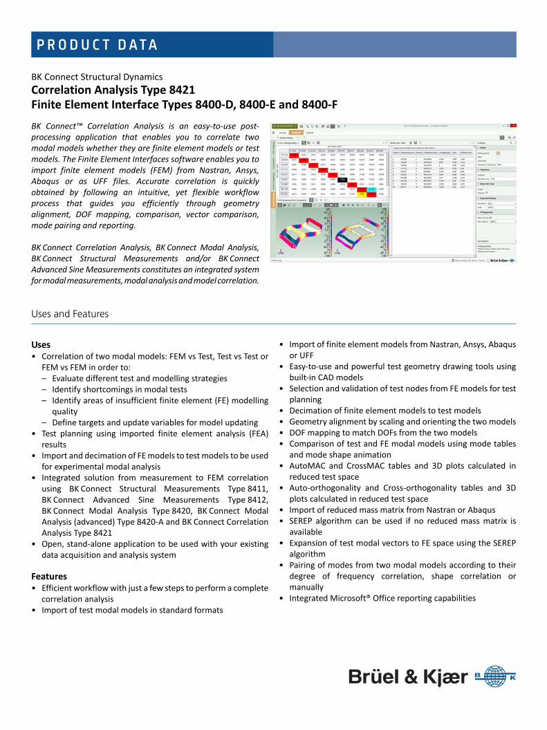
P R O D U C T D ATA
BK Connect Structural DynamicsCorrelation Analysis Type 8421Finite Element Interface Types 8400‐D, 8400‐E and 8400‐F
BK Connect™ Correlation Analysis is an easy‐to‐use post‐processing application that enables you to correlate twomodal models whether they are finite element models or testmodels. The Finite Element Interfaces software enables you toimport finite element models (FEM) from Nastran, Ansys,Abaqus or as UFF files. Accurate correlation is quicklyobtained by following an intuitive, yet flexible workflowprocess that guides you efficiently through geometryalignment, DOF mapping, comparison, vector comparison,mode pairing and reporting.
BK Connect Correlation Analysis, BK Connect Modal Analysis,BK Connect Structural Measurements and/or BK ConnectAdvanced Sine Measurements constitutes an integrated systemfor modal measurements, modal analysis and model correlation.
Uses and Features
Uses • Correlation of two modal models: FEM vs Test, Test vs Test or
FEM vs FEM in order to:– Evaluate different test and modelling strategies– Identify shortcomings in modal tests– Identify areas of insufficient finite element (FE) modelling
quality– Define targets and update variables for model updating
• Test planning using imported finite element analysis (FEA)results
• Import and decimation of FE models to test models to be usedfor experimental modal analysis
• Integrated solution from measurement to FEM correlationusing BK Connect Structural Measurements Type 8411,BK Connect Advanced Sine Measurements Type 8412,BK Connect Modal Analysis Type 8420, BK Connect ModalAnalysis (advanced) Type 8420‐A and BK Connect CorrelationAnalysis Type 8421
• Open, stand‐alone application to be used with your existingdata acquisition and analysis system
Features • Efficient workflow with just a few steps to perform a complete
correlation analysis• Import of test modal models in standard formats
• Import of finite element models from Nastran, Ansys, Abaqusor UFF
• Easy‐to‐use and powerful test geometry drawing tools usingbuilt‐in CAD models
• Selection and validation of test nodes from FE models for testplanning
• Decimation of finite element models to test models• Geometry alignment by scaling and orienting the two models• DOF mapping to match DOFs from the two models• Comparison of test and FE modal models using mode tables
and mode shape animation• AutoMAC and CrossMAC tables and 3D plots calculated in
reduced test space • Auto‐orthogonality and Cross‐orthogonality tables and 3D
plots calculated in reduced test space• Import of reduced mass matrix from Nastran or Abaqus• SEREP algorithm can be used if no reduced mass matrix is
available• Expansion of test modal vectors to FE space using the SEREP
algorithm• Pairing of modes from two modal models according to their
degree of frequency correlation, shape correlation ormanually
• Integrated Microsoft® Office reporting capabilities

Introduction
BK Connect is the latest addition to the Brüel & Kjær platform of software products. It provides real‐timemeasurements, analysis and test‐FEA integration in a modern, intuitive GUI environment and is theculmination of extensive customer surveys to resolve their most important issues when analysing soundand vibration data.
BK Connect provides:• Enhanced usability for high productivity with an intuitive user interface that puts the tools you need at your
fingertips. The graphical user interface is built around a workflow model that leads you easily through anytest setup, measurement and analysis process
• Open data policy that supports a wide range of native and third party formats for improved import andexport of data
• Consistent user interface throughout all applications encouraging faster learning of new applications
The BK Connect Structural Dynamics suite allows you to observe, analyse and document the dynamicbehaviour of structures using a single software platform covering setup, measurements, analysis and test‐FEA integration. With BK Connect Structural Measurements, you can set up and perform single orpolyreference hammer and shaker measurements, and with BK Connect Advanced Sine Measurements youcan set up and perform SIMO or MIMO stepped sine measurements with closed‐loop control, whereas BKConnect Modal Analysis provides accurate and reliable results even in the most demanding situations using atargeted set of best‐in‐class mode indicator functions, curve‐fitters and analysis validation tools.
BK Connect Correlation Analysis adds the capability of correlating two modal models, for example, finiteelement model versus test model using tools such as Geometry Alignment, CrossMAC and Cross‐orthogonality calculations.
The open data policy behind the BK Connect Structural Dynamics suite also allows the post‐processingapplications to be used as stand‐alone applications together with your existing measurement and analysis system.
Geometry
BK Connect Correlation Analysis contains powerful tools for working with geometries. It allows you tocreate test geometries, import test and finite element geometries, decimate finite element geometries totest geometries and align test and finite element geometries.
Geometry Creation and ImportTest geometries can be created from scratch using the embedded drawing tools. You can work with variouselements like points, lines, triangular and quad surfaces and you can create various 2D and 3D CAD modelsand mesh them. The geometry can also be created from table entries. Alternatively, test geometries canbe imported in standard data formats like UFF and CSV.
Finite element (FE) models can be imported as UFF files or from Nastran, Ansys and Abaqus. Import of FEmodels can include, apart from geometry data and modal data, also reduced mass matrices (Nastran orAbaqus). This allows for animation of the FE modes as well as correlation of Finite element analysis (FEA)results with test results.
Geometry DecimationImported FE geometries can be decimated to test geometries for use in, for example, BK Connect StructuralMeasurements or BK Connect Advanced Sine Measurements. The decimation can be done graphically byclicking on the nodes of the FE geometry to keep. Lines and optional surface elements like triangles or quadsconnecting the points, are automatically drawn on‐the‐fly.
You can also select nodes on a FE model and investigate how the AutoMAC builds up for the reducedgeometry consisting of the selected nodes. This helps determine which nodes on the FE model to includein a test geometry to identify and separate modes of interest.
2
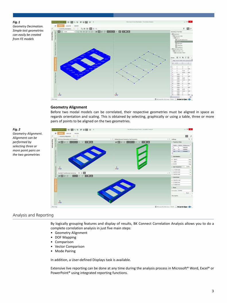
Fig. 1 Geometry Decimation.Simple test geometries can easily be created from FE models
Geometry AlignmentBefore two modal models can be correlated, their respective geometries must be aligned in space asregards orientation and scaling. This is obtained by selecting, graphically or using a table, three or morepairs of points to be aligned on the two geometries.
Fig. 2 Geometry Alignment.Alignment can be performed by selecting three or more point pairs on the two geometries
Analysis and Reporting
By logically grouping features and display of results, BK Connect Correlation Analysis allows you to do acomplete correlation analysis in just five main steps: • Geometry Alignment• DOF Mapping• Comparison• Vector Comparison• Mode Pairing
In addition, a User‐defined Displays task is available.
Extensive live reporting can be done at any time during the analysis process in Microsoft® Word, Excel® orPowerPoint® using integrated reporting functions.
3
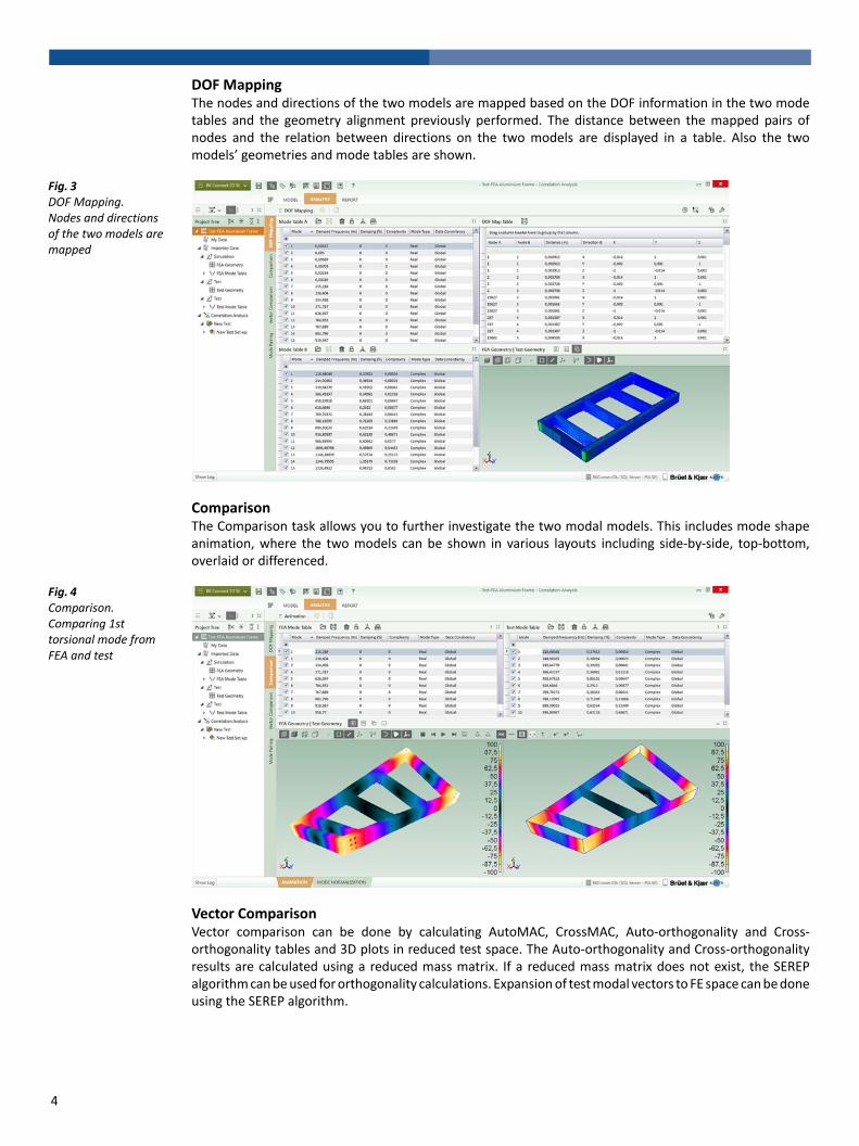
DOF MappingThe nodes and directions of the two models are mapped based on the DOF information in the two modetables and the geometry alignment previously performed. The distance between the mapped pairs ofnodes and the relation between directions on the two models are displayed in a table. Also the twomodels’ geometries and mode tables are shown.
Fig. 3 DOF Mapping.Nodes and directions of the two models are mapped
ComparisonThe Comparison task allows you to further investigate the two modal models. This includes mode shapeanimation, where the two models can be shown in various layouts including side‐by‐side, top‐bottom,overlaid or differenced.
Fig. 4 Comparison. Comparing 1st torsional mode from FEA and test
Vector ComparisonVector comparison can be done by calculating AutoMAC, CrossMAC, Auto‐orthogonality and Cross‐orthogonality tables and 3D plots in reduced test space. The Auto‐orthogonality and Cross‐orthogonalityresults are calculated using a reduced mass matrix. If a reduced mass matrix does not exist, the SEREPalgorithm can be used for orthogonality calculations. Expansion of test modal vectors to FE space can be doneusing the SEREP algorithm.
4
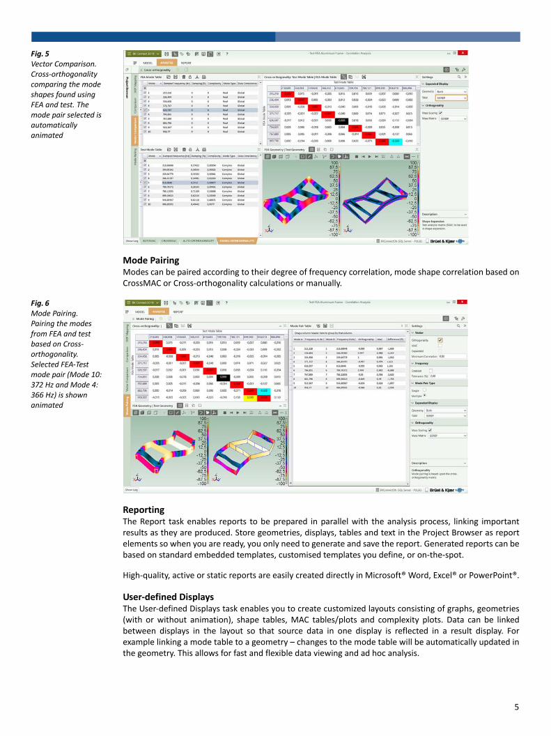
Fig. 5 Vector Comparison. Cross‐orthogonality comparing the mode shapes found using FEA and test. The mode pair selected is automatically animated
Mode PairingModes can be paired according to their degree of frequency correlation, mode shape correlation based onCrossMAC or Cross‐orthogonality calculations or manually.
Fig. 6 Mode Pairing. Pairing the modes from FEA and test based on Cross‐orthogonality. Selected FEA‐Test mode pair (Mode 10: 372 Hz and Mode 4: 366 Hz) is shown animated
ReportingThe Report task enables reports to be prepared in parallel with the analysis process, linking importantresults as they are produced. Store geometries, displays, tables and text in the Project Browser as reportelements so when you are ready, you only need to generate and save the report. Generated reports can bebased on standard embedded templates, customised templates you define, or on‐the‐spot.
High‐quality, active or static reports are easily created directly in Microsoft® Word, Excel® or PowerPoint®.
User‐defined DisplaysThe User‐defined Displays task enables you to create customized layouts consisting of graphs, geometries(with or without animation), shape tables, MAC tables/plots and complexity plots. Data can be linkedbetween displays in the layout so that source data in one display is reflected in a result display. Forexample linking a mode table to a geometry – changes to the mode table will be automatically updated inthe geometry. This allows for fast and flexible data viewing and ad hoc analysis.
5
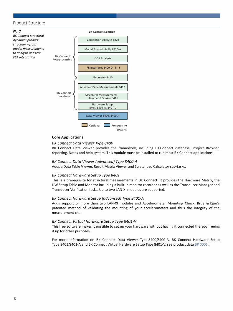
Product Structure
Fig. 7 BK Connect structural dynamics product structure – from modal measurements to analysis and test‐FEA integration
Core Applications
BK Connect Data Viewer Type 8400BK Connect Data Viewer provides the framework, including BK Connect database, Project Browser,reporting, Notes and help system. This module must be installed to run most BK Connect applications.
BK Connect Data Viewer (advanced) Type 8400‐AAdds a Data Table Viewer, Result Matrix Viewer and Scratchpad Calculator sub‐tasks.
BK Connect Hardware Setup Type 8401This is a prerequisite for structural measurements in BK Connect. It provides the Hardware Matrix, theHW Setup Table and Monitor including a built‐in monitor recorder as well as the Transducer Manager andTransducer Verification tasks. Up to two LAN‐XI modules are supported.
BK Connect Hardware Setup (advanced) Type 8401‐AAdds support of more than two LAN‐XI modules and Accelerometer Mounting Check, Brüel & Kjær'spatented method of validating the mounting of your accelerometers and thus the integrity of themeasurement chain.
BK Connect Virtual Hardware Setup Type 8401‐VThis free software makes it possible to set up your hardware without having it connected thereby freeingit up for other purposes.
For more information on BK Connect Data Viewer Type 8400/8400‐A, BK Connect Hardware SetupType 8401/8401‐A and BK Connect Virtual Hardware Setup Type 8401‐V, see product data BP 0005.
Optional Prerequisite
BK Connect Solution
Geometry 8410
Modal Analysis 8420, 8420-A
Structural Measurements – Hammer & Shaker 8411
Advanced Sine Measurements 8412
BK ConnectPost-processing
090061/5
Correlation Analysis 8421
FE Interfaces 8400-D, -E, -F
ODS Analysis
BK ConnectReal-time
Hardware Setup 8401, 8401-A, 8401-V
Data Viewer 8400, 8400-A
6

Measurement and Modelling Applications
BK Connect Structural Measurements – Hammer and Shaker Type 8411Adds dedicated setup and measurements tasks for hammer and shaker testing, including measurementsfor MIMO analysis. Geometry‐guided measurement setup, execution and validation is supported.
BK Connect Advanced Sine Measurements Type 8412Type 8412 adds dedicated setup and measurement tasks for single and multi‐shaker stepped sine testing.Geometry‐guided measurement setup, execution and validation is supported.
BK Connect Geometry Type 8410Geometry allows the importation and creation of geometries and is used across the various BK ConnectStructural Dynamics solutions. FE models can be imported using UFF and decimated to test models.
A variety of animation types are supported including wire frame, surface contour, point and arrow animationas well as overlaid, difference, top‐bottom, and side‐by‐side animation in single, dual or quad view format.The animations can be recorded as GIF files or AVIs and included in Word and PowerPoint® reports.
For further information on BK Connect Structural Measurements – Hammer and Shaker Type 8411,BK Connect Advanced Sine Measurements Type 8412 and BK Connect Geometry Type 8410, see productdata BP 1524.
Modal and ODS Analysis Applications
BK Connect Modal Analysis Type 8420An application designed for single‐reference modal analysis with a basic, yet comprehensive, set of modeindicator functions (MIFs), curve‐fitters and analysis validation tools. For use with single shaker FRF dataand single‐reference hammer testing data.
BK Connect Modal Analysis (advanced) Type 8420‐AModal Analysis (advanced) adds polyreference modal analysis capabilities and advanced MIFs, curve‐fitters and analysis validation tools to the Modal Analysis application. For use with shaker MIMO(multiple‐input multiple‐output) FRF data, polyreference hammer testing data or for advanced analysisand validation of both single and polyreference data.
For more information on BK Connect Modal Analysis Type 8420 and BK Connect Modal Analysis(advanced) Type 8420‐A, see product data BP 1523.
BK Connect ODS AnalysisWith Type 8400 and Type 8410 licences installed, a BK Connect ODS Analysis application is available forfrequency‐based spectral ODS post‐processing analysis or for viewing modal analysis results.
Test‐FEA Integration Applications
BK Connect FE Interfaces Types 8400‐D, ‐E, ‐FFE Interfaces enable you to import FE models from Nastran, Ansys and Abaqus, respectively.
BK Connect Correlation Analysis Type 8421Correlation Analysis adds the ability to correlate two modal models: FEM vs Test, Test vs Test or FEM vs FEM.
Complete Measurement Chain
With Brüel & Kjær’s complete and fully integrated measurement chain, including accelerometers, impacthammers, force transducers, modal exciter systems, data acquisition front ends and measurement andpost‐processing software, you can select the optimal solution for your structural dynamics needs. Theopenness and flexibility of the BK Connect Structural Dynamics applications support your needs today andin the future. You are never limited to a vendor‐specific system configuration and can easily assemble thesystem of your choice.
7

Specifications – BK Connect Correlation Analysis Type 8421
Correlation of two modal models with Cartesian coordinate systems
SYSTEM REQUIREMENTS• BK Connect 2018.0 or later• The following BK Connect™ applications:– Data Viewer Type 8400– FE Interfaces Types 8400‐D, ‐E, ‐F to import Nastran, Ansys and Abaqus models and results
– Geometry Type 8410 for all geometry functionality• Microsoft® Windows® 10 Pro or Enterprise (x64) with either Current Branch (CB) or Current Branch for Business (CBB) servicing model; or Windows® 7 Pro, Enterprise or Ultimate (SP1) (x64) operating systems
• Microsoft® Office 2016 (x32 or x64) or Office 2013 (x32 or x64) • Microsoft® SQL Server® 2014 Express (SP2) (included in installation), SQL Server® 2014 (SP2), SQL Server® 2012 R2, SQL Server® 2008 or 2008 R2 Express Edition SP1
RECOMMENDED PC FOR USE WITH FE MODELS• Intel® Core™ i7, 3 GHz processor or better• 32 GB RAM• 480 GB Solid State Drive (SSD) with 20 GB free space, or better• 1 Gbit Ethernet network* • Microsoft® Windows® 10 Pro or Enterprise (x64), CB • Microsoft® Office 2016 (x32)• Microsoft® SQL Server® 2014 (SP2)• Screen resolution of 1920 × 1080 pixels (full HD)This will support test‐FEA correlation analysis of FE models up to 1 M nodes
Geometry
GEOMETRY CREATION AND EDITING• Basic geometries using nodes, trace lines, triangle and quad elements• Geometries based on built‐in CAD models:– Curves: Circle, Circular Arc, Ellipse, Elliptical Arc, Hyperbolic, Parabolic, Line, Polyline, Interpolation Spline and Control Points Spline
– Surfaces: Circular, Circular Arc, Ellipse, Elliptical Arc, Hyperbolic, Parabolic, Triangular, Rectangular, Polygon, Interpolation Spline and Control Points Spline
– Solids: Cylinder, Hemisphere, Sphere, Box, Cone and Conical Frustum
• CAD models with selectable colour and transparency• Move (translate, rotate) and copy (linear, radial) operators for CAD models and meshes using interactive handles or manual entry
• Definition of locations with three directions on a CAD model (Sites)• Meshing of CAD models• Extrusion of CAD models: Curves can be extruded to surfaces. Plane surfaces can be extruded to solids. Preselection of colour is possible
• Hierarchical geometry tree view with subfolders for Coordinate Systems, Nodes, Elements, Trace Lines and Equations
• Tables for Coordinate Systems, Nodes, Elements, Trace Lines and Equations with sorting, filtering, multiple selection and editing
• Support of Cartesian, Cylindrical and Spherical coordinate systems. Local and Global coordinate systems
• Automated point numbering. Partial or complete semi‐automated point renumbering
• Visual link between sections made in the geometry display and Geometry Tree
GEOMETRY IMPORT FORMATSUFF data set types 15, 18, 82, 2411, 2412, 2416 or 2431; Microsoft® Excel® (*.csv); UFF FE models; Nastran (MSC, NX, NEi), Ansys and Abaqus FE models (requires Type 8400‐D/E/F)
GEOMETRY EXPORT FORMATS UFF data set types 15, 18, 82 or 2412 and Microsoft® Excel® (*.csv)
NODE SELECTIONSelect test node locations on a FE model until a satisfactory FE AutoMAC is created.A‐set nodes from an imported Reduced Mass Matrix or Reduced Stiffness Matrix from MSC Nastran (.op2) are automatically selected for validation and potential modification.Nodes selected are automatically highlighted in the Geometry Decimation task for connection with trace lines and/or elements
DECIMATIONImported FE models can be decimated to test models by manually selecting nodes on the FE model or by entering the nodes directly in a table.Selected nodes can be connected with trace lines and/or elements
ALIGNMENTTwo modal models can be aligned as regards orientation and scaling using three or more node pairs. Graphical and tabular methods available
DYNAMIC POINT NUMBERING Show more point numbers (IDs) when zooming in on parts of the geometry (user‐definable). Also supported during animation
GEOMETRY VIEWS• Single, Side‐by‐Side, Top‐Bottom and various Quad views• Definition of front, back, left, right, top and bottom view axis• Isometric view• Perspective, orthographic and stretched projections of geometry• Hidden lines and transparency• Pan, zoom and rotate options for viewing geometries• Symbols for shaker, impact hammer, force transducer and accelerometer positions shown on geometry with customized colours and sizes
CUTTING PLANESCut through a geometry in three user‐defined 2D planes to view the interior or exclude viewing parts of the geometry. Also supported during animation
ANIMATION• Deformed and undeformed animation with Max. Deformation• Single, overlaid and difference animation• Wireframe, contour (solid, solid edge), point and arrow animation• Animation of non‐measured DOFs using interpolation equations• AVI file generation with selectable codec
DOF Mapping• Map DOFs from two aligned geometry models, their mode shape tables and DOF node and DOF direction tolerances
• Mapped DOFs shown with resulting node distance and direction relationship
• Nodes on Geometry B (typically a test geometry) can be re‐numbered to the same node IDs as the nodes on Geometry A (typically a FE model)
ComparisonGeneral comparison of two modal models. Mode tables contain the modal models in terms of natural frequency, damping and mode shapes. Comprehensive documentation of modal results including:• Mode number, Mode Description, Estimation Method, Mode Complexity, Mode Type, Mode Shape Scaling, etc.
• Columns with Sorting and FilteringSelected mode pairs are automatically animated
* A dedicated data acquisition network (LAN or WAN) is recommended; a network that only handles data from the front end improves the stability of the data
8
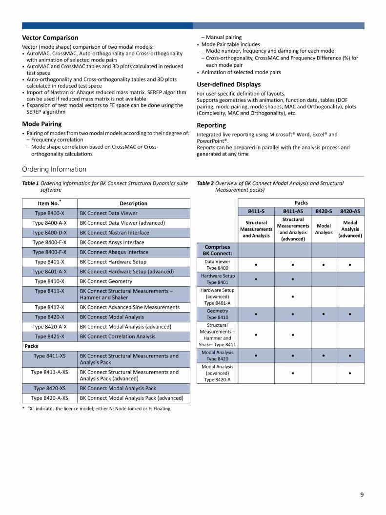
Vector ComparisonVector (mode shape) comparison of two modal models:• AutoMAC, CrossMAC, Auto‐orthogonality and Cross‐orthogonality with animation of selected mode pairs
• AutoMAC and CrossMAC tables and 3D plots calculated in reduced test space
• Auto‐orthogonality and Cross‐orthogonality tables and 3D plots calculated in reduced test space
• Import of Nastran or Abaqus reduced mass matrix. SEREP algorithm can be used if reduced mass matrix is not available
• Expansion of test modal vectors to FE space can be done using the SEREP algorithm
Mode Pairing• Pairing of modes from two modal models according to their degree of:– Frequency correlation– Mode shape correlation based on CrossMAC or Cross‐orthogonality calculations
– Manual pairing• Mode Pair table includes– Mode number, frequency and damping for each mode– Cross‐orthogonality, CrossMAC and Frequency Difference (%) for each mode pair
• Animation of selected mode pairs
User‐defined DisplaysFor user‐specific definition of layouts.Supports geometries with animation, function data, tables (DOF pairing, mode pairing, mode shapes, MAC and Orthogonality), plots (Complexity, MAC and Orthogonality), etc.
ReportingIntegrated live reporting using Microsoft® Word, Excel® and PowerPoint®.Reports can be prepared in parallel with the analysis process and generated at any time
Ordering Information
Table 1 Ordering information for BK Connect Structural Dynamics suite software
Table 2 Overview of BK Connect Modal Analysis and Structural Measurement packs)
Item No.*
* “X” indicates the licence model, either N: Node‐locked or F: Floating
Description
Type 8400‐X BK Connect Data Viewer
Type 8400‐A‐X BK Connect Data Viewer (advanced)
Type 8400‐D‐X BK Connect Nastran Interface
Type 8400‐E‐X BK Connect Ansys Interface
Type 8400‐F‐X BK Connect Abaqus Interface
Type 8401‐X BK Connect Hardware Setup
Type 8401‐A‐X BK Connect Hardware Setup (advanced)
Type 8410‐X BK Connect Geometry
Type 8411‐X BK Connect Structural Measurements – Hammer and Shaker
Type 8412‐X BK Connect Advanced Sine Measurements
Type 8420‐X BK Connect Modal Analysis
Type 8420‐A‐X BK Connect Modal Analysis (advanced)
Type 8421‐X BK Connect Correlation Analysis
Packs
Type 8411‐XS BK Connect Structural Measurements and Analysis Pack
Type 8411‐A‐XS BK Connect Structural Measurements and Analysis Pack (advanced)
Type 8420‐XS BK Connect Modal Analysis Pack
Type 8420‐A‐XS BK Connect Modal Analysis Pack (advanced)
Packs
8411‐S 8411‐AS 8420‐S 8420‐AS
Structural
Measurements and Analysis
Structural Measurements
and Analysis
(advanced)
Modal
Analysis
Modal
Analysis (advanced)
ComprisesBK Connect:
Data ViewerType 8400
Hardware Setup Type 8401
Hardware Setup (advanced) Type 8401‐A
GeometryType 8410
Structural Measurements – Hammer and
Shaker Type 8411
Modal Analysis Type 8420
Modal Analysis (advanced)Type 8420‐A
9

Table 3 Ordering information for BK Connect Structural Dynamics suite’s maintenance and support agreements
Item No.*
* “X” indicates the licence model, either N: Node‐locked or F: Floating
Description
M1‐8400‐X Software Maintenance & Support for Type 8400
M1‐8400‐A‐X Software Maintenance & Support for Type 8400‐A
M1‐8400‐D‐X Software Maintenance & Support for Type 8400‐D
M1‐8400‐E‐X Software Maintenance & Support for Type 8400‐E
M1‐8400‐F‐X Software Maintenance & Support for Type 8400‐F
M1‐8401‐X Software Maintenance & Support for Type 8401
M1‐8401‐A‐X Software Maintenance & Support for Type 8401‐A
M1‐8410‐X Software Maintenance & Support for Type 8410
M1‐8411‐X Software Maintenance & Support for Type 8411
M1‐8411‐XS Software Maintenance & Support for Type 8411‐S
M1‐8411‐A‐XS Software Maintenance & Support for Type 8411‐A‐S
M1‐8412‐X Software Maintenance & Support for Type 8412
M1‐8420‐X Software Maintenance & Support for Type 8420
M1‐8420‐A‐X Software Maintenance & Support for Type 8420‐A
M1‐8420‐XS Software Maintenance & Support for Type 8420‐S
M1‐8420‐A‐XS Software Maintenance & Support for Type 8420‐A‐S
M1‐8421‐X Software Maintenance & Support for Type 8421
10
Copyright © 2022 FDOKUMEN