25. A RR', a. Primary Examiner—Ralph A. Lewis
14
USOO6726478B1 (12) United States Patent (10) Patent No.: US 6,726,478 B1 Isiderio et al. (45) Date of Patent: Apr. 27, 2004 (54) SYSTEMS AND METHODS FOR BITE- 4,798.534 A 1/1989 Breads SETTING TEETH MODELS 4,836,778 A 6/1989 Baumrind et al. 4,837,732 A 6/1989 Brandestini et al. (75) Inventors: Jun Samones Isiderio, Sunnyvale, CA 4,850,865 A 7/1989 Napolitano (US); Juan D. Gonzales, San Jose, CA 4,856.991 A 8/1989 Breads et al. (US) (List continued on next page.) (73) Assignee: Align Technology, Inc., Santa Clara, FOREIGN PATENT DOCUMENTS CA (US) FR 2369828 6/1978 (*) Notice: Subject to any disclaimer, the term of this W W 3. E. patent is extended or adjusted under 35 WO WO 98/58596 7/1998 U.S.C. 154(b) by 148 days. OTHER PUBLICATIONS (21) Appl. No.: 09/702,360 Doyle, “Digital Dentistry” Computer Graphics World (Oct. 1-1. 2000) pp. 50–52, 54. (22) Filed: Oct. 30, 2000 Redmond et al., “Clinical Implications of Digital Orthodon (51) Int. Cl." ................................................ A61C 11/00 tics”. Am. J. Orthodont. Dentofacial Orthopedics (2000) (52) U.S. Cl. .......................................... 433/69, 433/213 117(2).240–242. (58) Field of Search ................................ 433/3, 69,73, Andrews, "The Six Keys to Optimal Occlusion" Straight 433/72, 213 Wire, Chapter 3 pp13-24. Biostar Opeation & Training Manual. Great Lakes Orth (56) References Cited odontics, Ltd. 199 Fire Tower Drive, Tonawanda, New York. 14150-5890. 20 pages total. U.S. PATENT DOCUMENTS Chiappone, “Constructing the gnathologic Setup and posi 3,407,500 A 10/1968 Kesling tioner” J. Clin. Orthod. (1980) 14:121–133. 3600sos A 8/1971 Reeve Cottingham, “Gnathologic clear plastic positioner Am. J. 3,660.900 A 5/1972 Andrews Orthod. (1969) 55:23–31. 3.683,502 A 8/1972 Walshein Cureton, “Correcting malaligned mandibular incisors with 3,860,803 A 1/1975 Levine removable retainers” J. Clin. Orthod. (1996) 30:390–395. 3,922,786 A 12/1975 Lavin 3.950,851 A 4/1976 Bergersen (List continued on next page.) 25. A RR', a. Primary Examiner—Ralph A. Lewis 4,324,547 A 4/1982 Arcan et al. (74) Attorney, Agent, or Firm Townsend and Townsend 4,500,294 A 2/1985 Lewis and Crew LLP, Bao Tran, ESq. 4,504,225. A 3/1985 Yoshii 4,505,673 A 3/1985 Yoshii (57) ABSTRACT 5. A 3. E. Ring A System arranges a computer model of teeth by displaying 4.609349 A 3. 1986 news an outline of the first jaw on the Screen; overlaying the teeth 4664626 A 5/1987 Kesling on the Second jaw with the outline on the Screen; and 4676747 A 6/1987 Kesling aligning the outline with the teeth on the Second jaw. 4,755,139 A 7/1988 Abbatte et al. 4,793,803 A 12/1988 Martz 10 Claims, 7 Drawing Sheets
-
Upload
khangminh22 -
Category
Documents
-
view
0 -
download
0
Transcript of 25. A RR', a. Primary Examiner—Ralph A. Lewis
USOO6726478B1
(12) United States Patent (10) Patent No.: US 6,726,478 B1 Isiderio et al. (45) Date of Patent: Apr. 27, 2004
(54) SYSTEMS AND METHODS FOR BITE- 4,798.534 A 1/1989 Breads SETTING TEETH MODELS 4,836,778 A 6/1989 Baumrind et al.
4,837,732 A 6/1989 Brandestini et al. (75) Inventors: Jun Samones Isiderio, Sunnyvale, CA 4,850,865 A 7/1989 Napolitano
(US); Juan D. Gonzales, San Jose, CA 4,856.991 A 8/1989 Breads et al. (US) (List continued on next page.)
(73) Assignee: Align Technology, Inc., Santa Clara, FOREIGN PATENT DOCUMENTS CA (US) FR 2369828 6/1978
(*) Notice: Subject to any disclaimer, the term of this W W 3. E. patent is extended or adjusted under 35 WO WO 98/58596 7/1998 U.S.C. 154(b) by 148 days.
OTHER PUBLICATIONS
(21) Appl. No.: 09/702,360 Doyle, “Digital Dentistry” Computer Graphics World (Oct. 1-1. 2000) pp. 50–52, 54.
(22) Filed: Oct. 30, 2000 Redmond et al., “Clinical Implications of Digital Orthodon (51) Int. Cl." ................................................ A61C 11/00 tics”. Am. J. Orthodont. Dentofacial Orthopedics (2000) (52) U.S. Cl. .......................................... 433/69, 433/213 117(2).240–242. (58) Field of Search ................................ 433/3, 69,73, Andrews, "The Six Keys to Optimal Occlusion" Straight
433/72, 213 Wire, Chapter 3 pp13-24. Biostar Opeation & Training Manual. Great Lakes Orth
(56) References Cited odontics, Ltd. 199 Fire Tower Drive, Tonawanda, New York. 14150-5890. 20 pages total.
U.S. PATENT DOCUMENTS Chiappone, “Constructing the gnathologic Setup and posi 3,407,500 A 10/1968 Kesling tioner” J. Clin. Orthod. (1980) 14:121–133. 3600sos A 8/1971 Reeve Cottingham, “Gnathologic clear plastic positioner Am. J. 3,660.900 A 5/1972 Andrews Orthod. (1969) 55:23–31. 3.683,502 A 8/1972 Walshein Cureton, “Correcting malaligned mandibular incisors with 3,860,803 A 1/1975 Levine removable retainers” J. Clin. Orthod. (1996) 30:390–395. 3,922,786 A 12/1975 Lavin 3.950,851 A 4/1976 Bergersen (List continued on next page.)
25. A RR', a. Primary Examiner—Ralph A. Lewis 4,324,547 A 4/1982 Arcan et al. (74) Attorney, Agent, or Firm Townsend and Townsend 4,500,294 A 2/1985 Lewis and Crew LLP, Bao Tran, ESq. 4,504,225. A 3/1985 Yoshii 4,505,673 A 3/1985 Yoshii (57) ABSTRACT
5. A 3. E. Ring A System arranges a computer model of teeth by displaying 4.609349 A 3. 1986 news an outline of the first jaw on the Screen; overlaying the teeth 4664626 A 5/1987 Kesling on the Second jaw with the outline on the Screen; and 4676747 A 6/1987 Kesling aligning the outline with the teeth on the Second jaw. 4,755,139 A 7/1988 Abbatte et al. 4,793,803 A 12/1988 Martz 10 Claims, 7 Drawing Sheets
US 6,726,478 B1 Page 2
U.S. PATENT DOCUMENTS
4,877,398 A 10/1989 Kesling 4,880,380 A 11/1989 Martz 4,936,862 A 6/1990 Walker et al. 4.941,826 A 7/1990 Loran et al. 4,983,334. A 1/1991 Adell 5,011,405 A 4/1991 Lemchen 5,017,133. A 5/1991 Miura 5,035,613 A 7/1991 Breads et al. 5,055,039 A 10/1991 Abatte et al. 5,059,118 A 10/1991 Breads et al. 5,100,316 A 3/1992 Wildman 5,125,832 A 6/1992 Kesling 5,139,419 A 8/1992 Andreiko et al. 5,145,364 A 9/1992 Martz et al. 5,186,623 A 2/1993 Breads et al. 5,273.429 A 12/1993 Rekow et al. 5,338,198 A 8/1994 Wu et al. 5,340,309 A 8/1994 Robertson 5,342,202 A 8/1994 Deshayes 5,367.478 A 11/1994 Hattori 5,368,478 A 11/1994 Andreiko et al. 5,382,164 A 1/1995 Stern 5,395.238 A 3/1995 Andreiko et al. 5.431,562 A 7/1995 Andreiko et al. 5,447.432 A 9/1995 Andreiko et al. 5,452.219 A 9/1995 Dehoff et al. 5,454,717 A 10/1995 Andreiko et al. 5,456,600 A 10/1995 Andreiko et al. 5,474,448 A 12/1995 Andreiko et al. 5,528,735 A 6/1996 Strasnicket al. 5,533,895 A 7/1996 Andreiko et al. 5,542,842 A 8/1996 Andreiko et al. 5,549,476 A 8/1996 Stern 5,587,912 A 12/1996 Anderson et al. 5,605.459 A 2/1997 Kuroda et al. 5,607,305 A 3/1997 Andersson et al. 5,645,420 A 7/1997 Bergersen 5,645,421 A 7/1997 Slootsky 5,683.243 A 11/1997 Andreiko et al. 5,692,894 A 12/1997 Schwartz et al. 5,725,376 A 3/1998 Poirier 5,725,378 A 3/1998 Wang 5,800,174 A 9/1998 Andersson 5,866,058 A 2/1999 Batchelder et al. 5,879,158 A 3/1999 Doyle et al. 5,880,961. A 3/1999 Crump 5,957,686 A 9/1999 Anthony 5,964,587. A 10/1999 Sato 5,971,754. A 10/1999 Sondhi et al. 5,975,893 A 11/1999 Chisti et al. 6,015,289 A 1/2000 Andreiko et al. .............. 433/3 6,044,309 A 3/2000 Honda 6,049,743 A 4/2000 Baba 6,068,482 A 5/2000 Snow ......................... 433/223 6,123,544. A 9/2000 Cleary 6,152,731. A 11/2000 Jordan et al. ................. 433/69 6,183.248 B1 6,190,165 B1 6,217,334 B1
OTHER PUBLICATIONS
2/2001 Chishti et al. 2/2001 Andreiko et al. 4/2001 Hultgren
Dent-X posted at http://www.dent-X.com/DentSim.htm Sep. 24, 1998, 6 pages ttoal. Elsasser, “Some observations on the history and uses of the Kesling positioner” Am. J. Orthod. (1950) 36:368-374. Kamada et al., “Case reports on tooth positioners using ITV vinyl silicone rubber' J. Nihon University School of Den tistry (1984) 26(1):11-29.
Kamada et al., “Construction of tooth positioners with LTV vinyl silicone rubber and some case reports' J. Nihon University School of Dentistry (1982) 24(1):1-27. Kesling, "Coordinating the predetermined pattern and tooth positioner with conventional treatment” Am. J. Orthod. Oral. Surg. (1946) 32:285-293. Kesling, “The philosophy of the tooth positioning appli ance” Am. J. Orthod. Oral. Surg. (1945) 31(6):297-304. Kleemann et al., “The speed positioner” J. Clin. Orthod. (1996) 30:673–680. Kunii et al., “Articulation Simulation for an Intelligent Dental Care System” Displays (1994) 15:181-188. Kuroda et al., “Three-dimensional dental cast analyzing System using laser Scanning Am. J. Orthod. Dentofac. Orthop. (1996) 110:365–369. Nahoum et al., “The vacuum formed dental contour appli ance” The New York State Dental Journal (1964) 30(9):385–390. Nippon Dental Review “New Orthodontic device-dynamic positioner (D.P)-I. Approach to the proposal of D.P. and transparent silicone rubber” (1980) 452:61-74. Nippon Dental Review “New Orthodontic device-dynamic positioner (D.P)-II. Practical application and construction of D.P.” (1980)454:107-130. Nippon Dental Review “New Orthodontic device-dynamic positioner (D.P)-III. Case reports of reversed occlusion” 1980) 457:146-164. Nippon Dental Review “New Orthodontic device-dynamic positioner (D.P)-Case reports of reversed occlusion” (1980) 458:112-129.
Nishiyama et al., “A new construction of tooth repositioner by LTV vinyl silicone rubber" J. Nihon University School of Dentistry (1977) 19(2):93-102. Cardinal Industrial Finishes, Powder Coatings information posted at http://www.cardinalpaint.com on Aug. 25, 2000, 2 pages total. Profit et al., “Contemporary Orthodontics' Second Edition, Chapter 15, pp. 470-533. Raintree EssixTM & ARS Materials, Inc., Raintree EssixTM Technical Magazine Table of Contents and EssixTM Appli cations, http://www.essix.com/magazine/default.html (Aug. 13, 1997) 7 pages total. Richmond et al., “The development of the PAR Index (Peer Assessment Rating): reliability and validity” European Journal of Orthodontics (1992) 14:125-139. Schroeder et al., The Visual Toolkit, Prentice Hall PTR, New Jersey (1998) Chapters 6, 8, and 9 (pp. 153–210, 309-354, and 355-428, respectively). Shilliday, “Minimizing finishing problems with the mini-positioner” Am. J. Orthod. (1971) 59:596–599. Warunek et al., "Clinical use of Silicone elastomer appli ances” JCO (1989) XXIII(10):694-700. Warunek et al., “Physical and mechanical properties of elastomers in orthodontic positioners' Am. J. Orthod. Dentofac. Orthop. (1989) 95:388-400. Wells, "Application of the positioner appliance in Orthodon tic treatment” Am. J. Orthodont. (1970) 58:351–366.
* cited by examiner
U.S. Patent Apr. 27, 2004 Sheet 1 of 7 US 6,726,478 B1
FIG.2B
US 6,726,478 B1 Sheet 2 of 7 Apr. 27, 2004 U.S. Patent

U.S. Patent Apr. 27, 2004 Sheet 3 of 7
Digitize initial tooth arrangement to produce
initial digital data set (IDDS)
Manipulate DDS to produce final digital data set (FDDS)
corresponding to a desired final tooth
arrangement
enerate nultiple intermediate digital dat
sets (INTDDS's) corresponding to Successive tooth arrangements from
initial to final
Produce incremental position adjustment applicances based on NTDOS's and FDDS
FG. 3
US 6,726,478 B1
200

U.S. Patent Apr. 27, 2004 Sheet 4 of 7 US 6,726,478 B1
v w
11 a a a w Y v s W w Y
A V v Y v M w
P a p P W a W V
W. N. W f A. d v N W
r Y A. A. f V w V
f 310
t
wr us an of a m A. W
- a s W. s W (A w w V w a V w Y a w W V - so a Y
FIG. 4A 340 330 341 343
342
346 347
348
349
s
US 6,726,478 B1 Sheet 5 of 7 Apr. 27, 2004 U.S. Patent
FG. 5B
U.S. Patent Apr. 27, 2004 Sheet 6 of 7 US 6,726,478 B1
450 Generate and display outline of upper jaw
452
Display lower jaw on screen
454 Overlay outline of upper jaw on image of lower
jaw
456 Determine and display contact points on screen
Allow user to adjust relative position of jaws on SCee
Done with adjustment
F.G. 6
U.S. Patent Apr. 27, 2004 Sheet 7 of 7 US 6,726,478 B1
Storage Subsystem 506 500
Memory Subsystem
510 514
File Storage Subsystem
Bus Subsystem
504
502 516 518
Moderns and User interface Processor(s) Network interface Inputput
520 522
Fabrication NetWork Machine interface
524
Casts Dental Appliances
FIG. 7
US 6,726,478 B1 1
SYSTEMS AND METHODS FOR BTE SETTING TEETH MODELS
BACKGROUND
The present invention is related generally to the field of orthodontics, and more particularly to Systems and methods for bite-setting teeth models. One objective in orthodontics is to move a patient's teeth
to positions where the teeth function optimally and aestheti cally. Conventionally, appliances Such as braces are applied to the teeth of the patient by an Orthodontist. Each appliance exerts continual force on the teeth and gradually urges the teeth toward their ideal positions. Over a period of time, the orthodontist adjusts the appliances to move the teeth toward their final destination.
Generally, the Orthodontist Specifies in a prescription the final tooth arrangement. The prescription is based on the orthodontist's knowledge and experience in Selecting the intended final position of each tooth. The orthodontist or an assistant applies the prescription in moving the teeth Over a number of office visits.
The process of attaching the braces to teeth is tedious and painful to the patient. Additionally, each Visit reduces the “chair-time' available to the orthodontist that could be used for another patient. Hence, the process of treating teeth using braces can be expensive. New methods, Such as those described in U.S. Pat. No.
5,975,893, allow the treatment to be planned in advance and all individual appliances to be fabricated at the outset of treatment. The appliances may thus be provided to the patient as a single package or System. Unlike braces, the patient need not visit the treating professional every time an adjustment in the treatment is made. While the patients will usually want to visit their treating professionals periodically to assure that treatment is going according to the original plan, eliminating the need to visit the treating professional each time an adjustment is to be made allows the treatment to be carried out in many more, but Smaller, Successive Steps while Still reducing the time spent by the treating profes sional with the individual patient. Moreover, the ability to use polymeric shell appliances that are more comfortable, leSS Visible, and removable by the patient, greatly improves patient compliance, comfort, and Satisfaction.
In the above System, and in other computer-aided teeth treatment System, as a first Step, a digital data Set represent ing an initial tooth arrangement is obtained, referred to hereinafter as the IDDS. The IDDS may be obtained in a variety of ways. For example, the patient's teeth may be Scanned or imaged using well known technology, Such as X-rays, three-dimensional X-rays, computer-aided tomo graphic images or data Sets, magnetic resonance images, etc. Methods for digitizing Such conventional images to produce data Sets useful in the present invention are well known and described in the patent and medical literature. Usually, however, the present invention will rely on first obtaining a plaster cast of the patient's teeth by well known techniques, such as those described in Graber, Orthodontics. Principle and Practice, Second Edition, Saunders, Philadelphia, 1969, pp. 401-415. After the tooth casting is obtained, it can be digitally Scanned using a conventional laser Scanner or other range acquisition System to produce the IDDS. The data Set produced by the range acquisition System may, of course, be converted to other formats to be compatible with the soft ware which is used for manipulating images within the data Set, as described in more detail below. General techniques
15
25
35
40
45
50
55
60
65
2 for producing plaster casts of teeth and generating digital models using laser Scanning techniques are described, for example, in U.S. Pat. No. 5,605,459. After scanning, com puter models of teeth on an upper jaw and a lower jaw are generated. However, these models are not aligned relative to each other. Thus, a bite Setting operation is manually per formed using human operators.
SUMMARY OF THE INVENTION
The present invention includes a System, apparatus and computer-implemented method for arranging a computer model of teeth. According to one implementation, the method includes displaying an outline of the first jaw on the Screen; overlaying the teeth on the Second jaw with the outline on the Screen; and aligning the outline with the teeth on the Second jaw.
Implementations of the System may include one or more of the following. The System can display contact points between teeth on the first and Second jaws. A grid can be displayed on the Screen. The System can automatically align the first and Second jaws based on one or more tooth features. An outline of a tooth can be displayed with the outline of the first jaw.
Advantages of the invention include one or more of the following. When digital data relating to teeth on the upper and lower jaws is provided, a bite-aligned computer model can be generated. The models of jaws are visible for align ment purposes as an operator moves them either left or right or tilts them up or down. The System provides an easy way to determine the relative position of the upper jaw to the lower jaw. By providing a visual picture of one jaw relative to another jaw, the system eliminates guesswork as to the bite setting for the models of the teeth on the jaws. The operation can be performed using little or no human labor.
BRIEF DESCRIPTION OF THE DRAWINGS
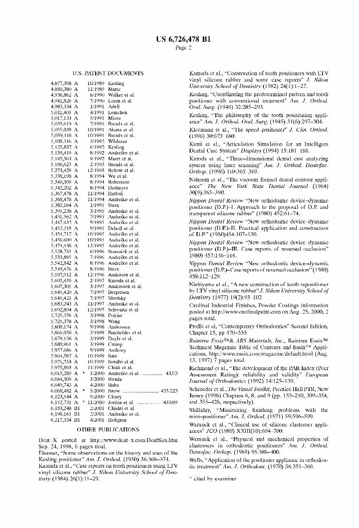
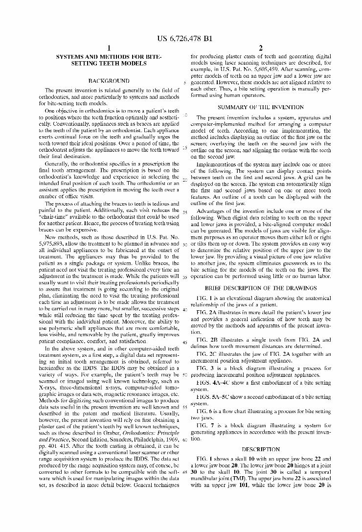
FIG. 1 is an elevational diagram showing the anatomical relationship of the jaws of a patient.
FIG. 2A illustrates in more detail the patient's lower jaw and provides a general indication of how teeth may be moved by the methods and apparatus of the present inven tion.
FIG. 2B illustrates a single tooth from FIG. 2A and defines how tooth movement distances are determined.
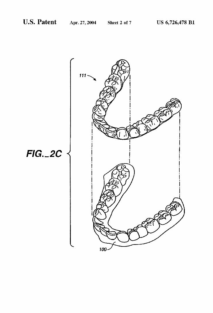
FIG. 2C illustrates the jaw of FIG. 2A together with an incremental position adjustment appliance.
FIG. 3 is a block diagram illustrating a proceSS for producing incremental position adjustment appliances.
FIGS. 4A-4C show a first embodiment of a bite setting System.
FIGS. 5A-5C show a second embodiment of a bite setting System.
FIG. 6 is a flow chart illustrating a process for bite setting two jaws.
FIG. 7 is a block diagram illustrating a system for generating appliances in accordance with the present inven tion.
DESCRIPTION
FIG. 1 shows a skull 10 with an upper jaw bone 22 and a lower jaw bone 20. The lower jaw bone 20 hinges at a joint 30 to the skull 10. The joint 30 is called a temporal mandibular joint (TMJ). The upper jawbone 22 is associated with an upper jaw 101, while the lower jaw bone 20 is
US 6,726,478 B1 3
associated with a lower jaw 100. A computer model of the jaws 100 and 101 is generated, and a computer simulation models interactions among the teeth on the jaws 100 and 101. The computer simulation allows the system to focus on motions involving contacts between teeth mounted on the jaws. The computer Simulation allows the System to render realistic jaw movements that are physically correct when the jaws 100 and 101 contact each other. The model of the jaw places the individual teeth in a treated position. Further, the model can be used to Simulate jaw movements including protrusive motions, lateral motions, and "tooth guided” motions where the path of the lower jaw 100 is guided by teeth contacts rather than by anatomical limits of the jaws 100 and 101. Motions are applied to one jaw, but may also be applied to both jaws. Based on the occlusion determination, the final position of the teeth can be ascer tained.
Referring now to FIG. 2A, the lower jaw 100 includes a plurality of teeth 102, for example. At least some of these teeth may be moved from an initial tooth arrangement to a final tooth arrangement. As a frame of reference describing how a tooth may be moved, an arbitrary centerline (CL) may be drawn through the tooth 102. With reference to this centerline (CL), each tooth may be moved in orthogonal directions represented by axes 104,106, and 108 (where 104 is the centerline). The centerline may be rotated about the axis 108 (root angulation) and the axis 104 (torque) as indicated by arrows 110 and 112, respectively. Additionally, the tooth may be rotated about the centerline, as represented by an arrow 112. Thus, all possible free-form motions of the tooth can be performed.
FIG. 2B shows how the magnitude of any tooth move ment may be defined in terms of a maximum linear trans lation of any point P on a tooth 102. Each point P1 will undergo a cumulative translation as that tooth is moved in any of the orthogonal or rotational directions defined in FIG. 2A. That is, while the point will usually follow a nonlinear path, there is a linear distance between any point in the tooth when determined at any two times during the treatment. Thus, an arbitrary point P1 may in fact undergo a true Side-to-side translation as indicated by arrow d1, while a Second arbitration point P2 may travel along an arcuate path, resulting in a final translation d2. Many aspects of the present invention are defined in terms of the maximum permissible movement of a point P1 induced on any par ticular tooth. Such maximum tooth movement, in turn, is defined as the maximum linear translation of that point P1 on the tooth that undergoes the maximum movement for that tooth in any treatment Step.
FIG. 2C shows one adjustment appliance 111 which is worn by the patient in order to achieve an incremental repositioning of individual teeth in the jaw as described generally above. The appliance is a polymeric shell having a teeth-receiving cavity. This is described in U.S. application Ser. No. 09/169,036, filed Oct. 8, 1998, which claims priority from U.S. application Ser. No. 08/947,080, filed Oct. 8, 1997, which in turn claims priority from provisional application No. 06/050,352, filed Jun. 20, 1997 (collectively the “prior applications”), the full disclosures of which are incorporated by reference. AS Set forth in the prior applications, each polymeric Shell
may be configured So that its tooth-receiving cavity has a geometry corresponding to an intermediate or final tooth arrangement intended for the appliance. The patient's teeth are repositioned from their initial tooth arrangement to a final tooth arrangement by placing a Series of incremental position adjustment appliances over the patient's teeth. The
15
25
35
40
45
50
55
60
65
4 adjustment appliances are generated at the beginning of the treatment, and the patient wears each appliance until the preSSure of each appliance on the teeth can no longer be felt. At that point, the patient replaces the current adjustment appliance with the next adjustment appliance in the Series until no more appliances remain. Conveniently, the appli ances are generally not affixed to the teeth and the patient may place and replace the appliances at any time during the procedure. The final appliance or Several appliances in the Series may have a geometry or geometries Selected to overcorrect the tooth arrangement, i.e., have a geometry which would (if fully achieved) move individual teeth beyond the tooth arrangement which has been Selected as the “final.” Such over-correction may be desirable in order to offset potential relapse after the repositioning method has been terminated, i.e., to permit movement of individual teeth back toward their pre-corrected positions. Over-correction may also be beneficial to Speed the rate of correction, i.e., by having an appliance with a geometry that is positioned beyond a desired intermediate or final position, the indi vidual teeth will be shifted toward the position at a greater rate. In Such cases, the use of an appliance can be terminated before the teeth reach the positions defined by the appliance.
The polymeric shell 111 can fit over all teeth present in the upper or lower jaw.
Often, only certain one(s) of the teeth will be repositioned while others of the teeth will provide a base or an anchor region for holding the appliance 111 in place as the appliance 111 applies a resilient repositioning force against the tooth or teeth to be repositioned. In complex cases, however, mul tiple teeth may be repositioned at Some point during the treatment. In Such cases, the moved teeth can also Serve as a base or anchor region for holding the repositioning appli
CC.
The polymeric appliance 111 of FIG. 2C may be formed from a thin sheet of a Suitable elastomeric polymer, Such as Tru-Tain 0.03 in, thermal forming dental material, available from Tru-Tain Plastics, Rochester, Minnesota. Usually, no wires or other means will be provided for holding the appliance in place over the teeth. In Some cases, however, it will be desirable or necessary to provide individual anchors on teeth with corresponding receptacles or apertures in the appliance 100 So that the appliance can apply an upward force on the tooth that would not be possible in the absence of Such an anchor.
FIG.3 shows a process 200 for producing the incremental position adjustment appliances for Subsequent use by a patient to reposition the patient's teeth. As a first Step, an initial digital data Set representing an initial tooth arrange ment is obtained (step 202). The initial data set may be obtained in a variety of ways. For example, the patient's teeth may be Scanned or imaged using X-rays, three dimen Sional X-rays, computer-aided tomographic images or data Sets, or magnetic resonance images, among others. The teeth data may be generated by a destructive Scanner, as described in the incorporated-by-reference U.S. application Ser. No. 09/169,034, filed Oct. 8, 1998. The initial data set is then manipulated using a computer having a Suitable graphical user interface (GUI) and Software appropriate for viewing and modifying the images. More specific aspects of this process will be described in detail below. Individual tooth and other components may be segmented or isolated in the model to permit their individual repositioning or removal from the digital model.
After Segmenting or isolating the components, the teeth are moved based on rules and algorithms programmed into
US 6,726,478 B1 S
the computer. In this step, each Stage of tooth movement is determined by an attraction model between Selected points on adjacent teeth. This step is iterated until an acceptable result is achieved (step 204). In one embodiment, the system Stops the movement when the relative positions of the teeth Satisfy a predetermined target.
In step 206, positions for the upper and lower teeth in a masticatory System of a patient are determined by generating a computer representation of the masticatory System. An occlusion of the upper and lower teeth is computed from the computer representation; and a functional occlusion is com puted based on interactions in the computer representation of the masticatory System. The occlusion may be determined by generating a set of ideal models of the teeth. Each ideal model in the set of ideal models is an abstract model of idealized teeth placement, which is customized to the patient's teeth, as discussed below. After applying the ideal model to the computer representation, the position of the teeth can be optimized to fit the ideal model. The ideal model may be specified by one or more arch forms, or may be Specified using various features associated with the teeth.
Once the teeth arrangements are determined, a Series of appliances that move the teeth in a specified Sequence are generated (step 208). For example, the teeth models may be rotated until their roots are in the proper Vertical position. Next, the teeth models may be rotated around their vertical axis into the proper orientation. The teeth models are then observed from the side, and translated vertically into their proper Vertical position. Finally, the two arches are placed together, and the teeth models moved slightly to ensure that the upper and lower arches properly mesh together. The meshing of the upper and lower arches together can be Visualized using a collision detection process to highlight the contacting points of the teeth. AS part of the generation of the initial digital data Set
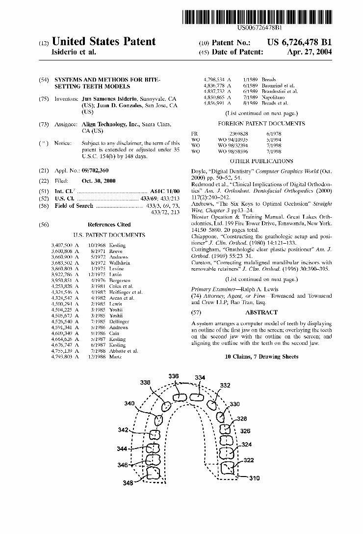
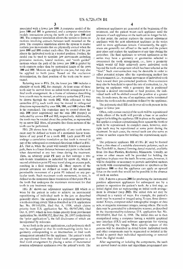
representing an initial tooth arrangement of Step 202, a bite-setting guide 310 is used to make a bite-setting of upper and lower jaws. AS shown in FIG. 4A, the bite-setting guide 310 is a computer generated image that provides a perimeter outline of one jaw, for example the upper jaw. In one embodiment, the system generates the outline 310 by fitting an arch-shaped curve to the teeth in the upper jaw. The outline, exemplified by the dashed line, is displayed on screen. An operator can then move the outline 310 and position the outline 310 on top of the remaining jaw, in this case the lower jaw.
FIG. 4B illustrates the combination of the outline 310 representing in this case a model of the upper jaw and a model of teeth on the lower jaw. As shown therein, the outline 310 is Superimposed with teeth 322, 324, 326, 328, 330,332,334,336,338,340, 342,344,346 and 348. Using the outline 310, the operator can See and make adjustments to the position of the upper jaw relative to the lower jaw
FIG. 4C illustrates another embodiment showing the combination of FIG. 4B with contact points 323,327, 331, 335, 341, 343, 347 and 349. Further, in this embodiment, a grid 350 is Superimposed to Support the operator in precisely positioning the jaw models to arrive at a proper bite-setting. In the embodiment, the contact points constitute light con tacts with a predetermined pressure on the bite associated with the upper and lower jaws.
FIG. 4C thus shows the outline of the teeth of the upper jaw that is overlaid on the top of the lower jaw. When viewed on the grid 350, the operator can See precisely how the upper teeth is related to the lower teeth So that the operator can make incremental movements or adjustments to achieve the
15
25
35
40
45
50
55
60
65
6 correct teeth registration. The process eliminates guesswork as to where the upper teeth need to be moved because the operator has a clear view of the relationship between the jaws.
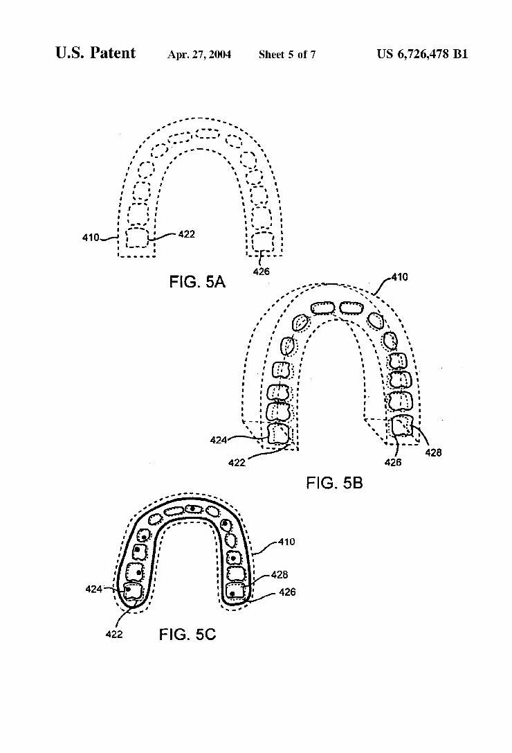
FIGS. 5A-5C shows a second embodiment of the system. As shown in FIG. 5A, a bite-setting guide 410 is a computer generated image that provides a perimeter outline of one jaw Such as the upper jaw in conjunction with outlines of the teeth of the jaw. In one embodiment, the System generates the outline 410 by fitting an arch-shaped curve to the teeth in the upper jaw. The outline 410 is then placed over the teeth of the jaw, and an outline of the teeth is added to the outline 410. The outline 410 is displayed on screen and the operator can then move the outline 410 and position the outline 410 on top of the remaining jaw, in this case the lower jaw.
FIGS. 5B-5C illustrate the combination of the outline 410 representing in this case a model of the upper jaw and a model of teeth on the lower jaw. As shown therein, the outline 410 is Superimposed with teeth 422-428. Using the outline 410, the operator can See and make adjustments to the position of the upper jaw relative to the lower jaw. Also, FIG. 5C shows a plurality of contact points showing light contacts between the upper and lower jaws.
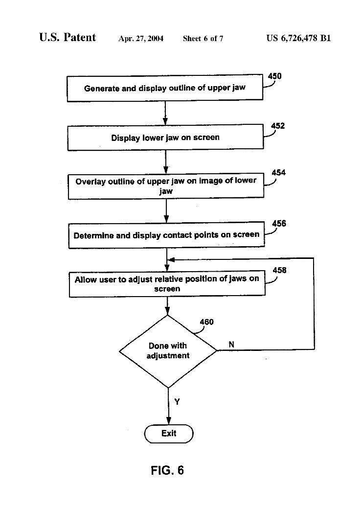
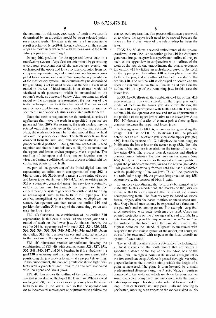
Referring now to FIG. 6, a process for generating the image of FIG. 4C or FIG. 5C is shown. First, the process determines an outline of one jaw, Such as the upper jaw (Step 450). Next, the process of FIG. 4 displays the remainingjaw in this case the lower jaw on the screen (step 452). Next, the outline of the aperture is overlaid on the image of the lower jaw (step 454). The process then determines and displays contact points between the two jaws on the Screen (Step 456). Next, the process allows the operator to manipulate or adjust the positions of the two jaws on the screen (step 458). This process is iteratively formed until the user is satisfied with the positioning of the two jaws. Thus, if the operator is not satisfied in step 460, the process loops back to step 458. Alternatively, the process of FIG. 6 exits.
In another embodiment, the teeth may be aligned auto matically. In this embodiment, the models of the jaws are moved So that they are aligned to the features of one or more corresponding teeth. The features may be based on cusps, foSSae, ridges, distance-based metrics, or shape-based met rics. Shape-based metrics may be expressed as a function of the patients arches, among others. For example, cusp fea tures associated with each tooth may be used. Cusps are pointed projections on the chewing Surface of a tooth. In a detection Stage, a possible cusp is viewed as an “island” on the Surface of the tooth, with the candidate cusp at the highest point on the island. “Highest” is measured with respect to the coordinate System of the model, but could just as easily be measured with respect to the local coordinate System of each tooth. The Set of all possible cusps is determined by looking for
all local maxima on the tooth model that are within a specified distance of the top of the bounding box of the model. First, the highest point on the model is designated as the first candidate cusp. A plane is passed through this point, perpendicular to the direction along which the height of a point is measured. The plane is then lowered by a Small predetermined distance along the Z axis. Next, all vertices connected to the tooth and which are above the plane and on Some connected component are associated with the candi date cusp as cusps. This Step is also referred to as a flood fill Step. From each candidate cusp point, outward flooding is performed, marking each vertex on the model Visited in this

US 6,726,478 B1 7
matter as part of the corresponding candidate cusp. After the flood fill Step is complete, every vertex on the model is examined. Any vertex that is above the plane and has not been visited by one of the flood fills is added to the list of candidate cusps. These StepS are repeated until the plane is traveled a specified distance. After the detection Stage, the cusp detection proceSS may include a rejection Stage where local geometries around each of the cusp candidates are analyzed to determine if they possess non-cusp-like features. Cusp candidates that exhibit non-cusp-like features are removed from the list of cusp candidates. Various criteria may be used to identify non-cusp-like features. According to one test, the local curvature of the Surface around the cusp candidate is used to determine whether the candidate poS SeSSes non-cusp-like features. Alternatively, a measure of Smoothness is computed based on the average normal in an area around the candidate cusp. If the average normal deviates from the normal at the cusp by more than a Specified amount, the candidate cusp is rejected.
Additionally, a simplified Set of movement physics (kinematics) may be applied to the bite-set dental models. The process can perform a Simulation using a simplified Set of interacting forces on the jaws in relation to one another. The Simplified physical Simulation allows the System to focus on motions involving much contact between the jaws. The physical Simulation allows the System to render realistic physically correct jaw movements when the jaws come into contact with each other. A range of simulated motion may be Supplied using a library of motions. One typical motion supplied by the library is a protrusive motion where the lower jaw 101 is moved forward and backward to bring the front teeth on both jaws into contact with each other. Another motion is a lateral motion found in food chewing. The lateral motion involves moving the jaws side to Side. Other motions that may be supplied in the library include motions that are “tooth guided” where the path of the lower jaw is guided by the teeth in contact with each other. Next, the process adjusts the final position based on contacts observed during the simulation of motions. The result of the Simulation is analyzed, the position of each tooth can be adjusted if contacts associated with that tooth are deemed excessive. Finally, based on the contact data generated, the proceSS determines whether additional motion Simulations need to be done. The motion simulation may be rerun until the contacts associated with each tooth are acceptable to the treating Orthodontist. The tooth model manipulation proceSS can be done Subjectively, i.e., the user may simply reposition teeth in an aesthetically and/or therapeutically desired man ner based on observations of the final position or based on the Simulation of contacts. Alternatively, rules and algo rithms may be used to assist the user in repositioning the teeth based on the contacts.
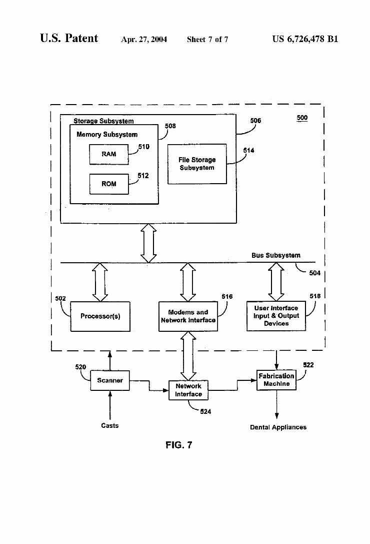
FIG. 7 is a simplified block diagram of a data processing system 500. Data processing system 500 typically includes at least one processor 502 that communicates with a number of peripheral devices over bus subsystem 504. These periph eral devices typically include a storage subsystem 506 (memory subsystem 508 and file storage subsystem 514), a Set of user interface input and output devices 518, and an interface to outside networks 516, including the public Switched telephone network. This interface is shown sche matically as “Modems and Network Interface' block 516, and is coupled to corresponding interface devices in other data processing Systems over communication network inter face 524. Data processing system 500 may include a termi nal or a low-end personal computer or a high-end personal computer, WorkStation or mainframe. The user interface
15
25
35
40
45
50
55
60
65
8 input devices typically include a keyboard and may further include a pointing device and a Scanner. The pointing device may be an indirect pointing device Such as a mouse, trackball, touchpad, or graphics tablet, or a direct pointing device Such as a touchscreen incorporated into the display. Other types of user interface input devices, Such as voice recognition Systems, may be used. User interface output devices may include a printer and a display Subsystem, which includes a display controller and a display device coupled to the controller. The display device may be a cathode ray tube (CRT), a flat-panel device Such as a liquid crystal display (LCD), or a projection device. The display Subsystem may also provide nonvisual display Such as audio output. Storage Subsystem 506 maintains the basic program ming and data constructs that provide the functionality of the present invention. The Software modules discussed above are typically stored in storage subsystem 506. Storage sub system 506 typically comprises memory Subsystem 508 and file storage subsystem 514. Memory subsystem 508 typi cally includes a number of memories including a main random access memory (RAM) 510 for storage of instruc tions and data during program execution and a read only memory (ROM) 512 in which fixed instructions are stored. In the case of Macintosh-compatible personal computers the ROM would include portions of the operating system; in the case of IBM-compatible personal computers, this would include the BIOS (basic input/output system). File storage subsystem 514 provides persistent (nonvolatile) storage for program and data files, and typically includes at least one hard disk drive and at least one floppy disk drive (with associated removable media). There may also be other devices such as a CD-ROM drive and optical drives (all with their associated removable media). Additionally, the system may include drives of the type with removable media cartridges. The removable media cartridges may, for example be hard disk cartridges, Such as those marketed by Syguest and others, and flexible disk cartridges, Such as those marketed by Iomega. One or more of the drives may be located at a remote location, Such as in a Server on a local area network or at a site on the Internet's World Wide Web. In this context, the term “buS Subsystem” is used generically So as to include any mechanism for letting the various components and Subsystems communicate with each other as intended. With the exception of the input devices and the display, the other components need not be at the same physical location. Thus, for example, portions of the file Storage System could be connected over various local-area or wide-area network media, including telephone lines. Similarly, the input devices and display need not be at the Same location as the processor, although it is anticipated that the present invention will most often be implemented in the context of PCS and workstations. Bus Subsystem 504 is shown Schematically as a Single bus, but a typical System has a number of buses Such as a local bus and one or more expansion buses (e.g., ADB, SCSI, ISA, EISA, MCA, NuBus, or PCI), as well as serial and parallel ports. Network connections are usually established through a device Such as a network adapter on one of these expansion buses or a modem on a Serial port. The client computer may be a desktop System or a portable System. Scanruer 520 is respon Sible for Scanning casts of the patient's teeth obtained either from the patient or from an Orthodontist and providing the Scanned digital data Set information to data processing system 500 for further processing. In a distributed environment, Scanner 520 may be located at a remote location and communicate Scanned digital data Set informa tion to data processing system 500 over network interface

US 6,726,478 B1 9
524. Fabrication machine 522 fabricates dental appliances based on intermediate and final data Set information received from data processing system 500. In a distributed environment, fabrication machine 522 may be located at a remote location and receive data Set information from data processing system 500 over network interface 524.
Various alternatives, modifications, and equivalents may be used in lieu of the above components. Although the final position of the teeth may be determined using computer aided techniques, a user may move the teeth into their final positions by independently manipulating one or more teeth while Satisfying the constraints of the prescription. Additionally, the techniques described here may be imple mented in hardware or Software, or a combination of the two. The techniques may be implemented in computer programs executing on programmable computers that each includes a processor, a Storage medium readable by the processor (including volatile and nonvolatile memory and/or Storage elements), and Suitable input and output devices. Program code is applied to data entered using an input device to perform the functions described and to generate output information. The output information is applied to one or more output devices. Each program can be implemented in a high level procedural or object-oriented programming language to operate in conjunction with a computer System. However, the programs can be implemented in assembly or machine language, if desired. In any case, the language may be a compiled or interpreted language. Each Such computer program can be stored on a storage medium or device (e.g., CD-ROM, hard disk or magnetic diskette) that is readable by a general or Special purpose programmable computer for configuring and operating the computer when the Storage medium or device is read by the computer to perform the procedures described. The System also may be implemented as a computer-readable Storage medium, configured with a computer program, where the Storage medium So configured causes a computer to operate in a specific and predefined manner. Further, while the invention has been shown and described with reference to an embodiment thereof, those
15
25
35
10 skilled in the art will understand that the above and other changes in form and detail may be made without departing from the Spirit and Scope of the following claims. What is claimed is: 1. A method for aligning computer models of teeth on a
first jaw and a Second jaw, comprising: displaying a top view of the first jaw on the Screen; overlaying teeth a top view of the Second jaw and the top
view of the first jaw; and aligning the top views of the jaws. 2. The method of claim 1, further comprising displaying
contact points between teeth on the first and Second jaws. 3. The method of claim 1, further comprising displaying
a grid on the Screen. 4. The method of claim 1, further comprising aligning the
first and Second jaws based on one or more tooth features. 5. The method of claim 1, further comprising displaying
an outline of a tooth on the outline of the first jaw. 6. A System to align computer models of teeth on a first
jaw and a Second jaw, comprising: means for displaying a top view of the first jaw on the
Screen,
means for overlaying a top view of the Second jaw and the top view of the first jaw; and
means for aligning the top views of the jaws. 7. The system of claim 6, further comprising means for
displaying contact points between teeth on the first and Second jaws.
8. The system of claim 6, further comprising means for displaying a grid on the Screen.
9. The system of claim 6, further comprising means for aligning the first and Second jaws based on one or more tooth features.
10. The system of claim 6, further comprising means for displaying an outline of a tooth on the outline of the first jaw.
k k k k k