
PRESERVATION AND MANAGEMENT OF LOCATION ...
257
PRESERVATION AND MANAGEMENT OF LOCATION PRIVACY IN THE INTERNET OF THINGS Mahmoud Elkhodr A thesis submitted in fulfilment of the degree of Doctor of Philosophy School of Computing, Engineering and Mathematics Western Sydney University March 2016
-
Upload
khangminh22 -
Category
Documents
-
view
0 -
download
0
Transcript of PRESERVATION AND MANAGEMENT OF LOCATION ...

PRESERVATION AND MANAGEMENT
OF LOCATION PRIVACY IN THE
INTERNET OF THINGS
Mahmoud Elkhodr
A thesis submitted in fulfilment
of the degree of
Doctor of Philosophy
School of Computing, Engineering and Mathematics
Western Sydney University
March 2016

I
5 ABSTRACT
The Internet of Things (IoT) connects everyday objects including a vast array of sensors,
actuators, and smart devices, referred to as “things” to the Internet, in an intelligent and
pervasive fashion. This connectivity gives rise to the possibility of using the tracking
capabilities of things to impinge on the location privacy of users. Most of the existing
management and location privacy protection solutions do not consider the low-cost and
low-power requirements of things; or, they do not account for the heterogeneity,
scalability, or autonomy of communications supported in the IoT. Moreover, many
traditional location privacy preserving techniques anonymize location information so that
adversaries cannot infer or relate location information to specific users. However, these
techniques do not consider the case where a user wishes to control the granularity of the
disclosed information based on the context of their use (e.g., based on the time or the
current location of the user).
To fill this gap, a middleware referred to as the Internet of Things Management Platform
(IoT-MP) is proposed in this thesis. The IoT-MP provides users with fine-grained control
over the granularity and disclosure settings of their location information in the IoT. It is
based on a distributed architecture that utilises an agent, a manager, and a manager of
managers paradigm. The IoT-MP adopts an extensible design where things are
represented as attributes in a management database located at the manager. In this way,
IoT applications can access things transparently over the Internet, irrespective of the
underlying used communication technologies. The IoT-MP’s manager comprises several
modules. The Privacy Module (PM), which consists of a Context Analysis Component,
Privacy Manager Component, and Semantic Obfuscation Component, enables the user to
alter the location of things and to control the granularity of the produced location based
on a context-aware and policy enforcement mechanism. The obfuscation process is
supported by a novel ontological classification of locations based on a geographical
knowledge, which takes into account both the user’s informed consent and preferences.
Furthermore, the proposed Semantic Obfuscation approach improves the performance of

II
two major classical location protection methods by making it harder on an adversary to
infer the actual location of a device from a received obscured location..
To confirm the effectiveness of the proposed management platform in preserving location
privacy in the IoT, a diverse range of experimental and simulation studies are carried out.
The experimental studies aimed to demonstrate the capability of the proposed platform in
preserving the location privacy of users in an IoT setup which uses physical low-power
sensor devices. The setup involved the utilisation of several Bluetooth Low Energy (BLE)
sensor devices, the implementations of two mobile applications and a web application.
The results collected from the experimental works validate the IoT-MP approach in
providing the user with a method that can be used to control to whom, when, and in which
context the location information of their sensors is revealed. They further show that the
proposed Obfuscation approach has outperformed the performance of the classic
Dispersion method. For instance, using “Obfuscation level 3”, it is found that the S-
Obfuscation has produced better-obscured location by 60% than that of the Dispersion
technique and by 50% than that of the Rand technique.
The simulation studies, conducted using the Opnet and NS2 simulation tools, combined
several wireless network scenarios which utilise the low-power wireless ZigBee and
IEEE 802.11ah protocols as a practical example of a heterogeneous communication
network in the IoT. In these scenarios, as per the IoT-MP approach, privacy policies were
defined for a group of sensors which took turns in requesting the location of each other.
By observing and analysing the traffic stored in the log file of the simulation, specifically,
the location information exchanged between the sensors, the privacy-preserving
capabilities of the proposed platform in a large-scale heterogeneous network were
demonstrated and verified. Additionally, it was found that the application end-to-end
delay experienced by the ZigBee network is low. Furthermore, the average consumed
energy to send a packet across the network by a ZigBee and 802.11ah node was also
within acceptable levels. These performance results clearly show that the approaches of
the IoT-MP in preserving the location privacy of things in the IoT has no noticeable
impact on the power consumptions and network performance of both ZigBee and IEEE
802.11ah end devices.

III
6 TABLE OF CONTENTS
ABSTRACT ----------------------------------------------------------------------------------------------------------- I
TABLE OF CONTENTS ---------------------------------------------------------------------------------------------- I
STATEMENT OF AUTHENTICATION --------------------------------------------------------------------------- VII
ACKNOWLEDGEMENTS ---------------------------------------------------------------------------------------- VIII
LIST OF FIGURES --------------------------------------------------------------------------------------------------- IX
LIST OF TABLES -------------------------------------------------------------------------------------------------- XIV
LIST OF ACRONYMS ---------------------------------------------------------------------------------------------- XV
PUBLICATIONS FROM THIS THESIS --------------------------------------------------------------------------- XVI
CHAPTER 1- INTRODUCTION ------------------------------------------------------------------------------------- 1
1.1 Research Questions -------------------------------------------------------------------------------------------------------- 5
1.2 Thesis Objectives ----------------------------------------------------------------------------------------------------------- 6
1.3 Thesis Contributions ------------------------------------------------------------------------------------------------------- 7
1.4 Thesis Layout ---------------------------------------------------------------------------------------------------------------- 9
CHAPTER 2- BACKGROUND AND CHALLENGES ------------------------------------------------------------- 12
2.1 The Internet of Things: Research Challenges --------------------------------------------------------------------- 12
2.1.1 The IoT Interoperability and Integration Challenges ---------------------------------------------------- 15
2.1.2 WSNs Topologies in the IoT ------------------------------------------------------------------------------------ 16
2.1.3 The IoT Management Challenges ----------------------------------------------------------------------------- 19
2.1.4 The IoT Security Challenges ------------------------------------------------------------------------------------ 27
2.2 IoT Privacy: Threats and Challenges -------------------------------------------------------------------------------- 32
2.3 Measures in Preserving Location Privacy -------------------------------------------------------------------------- 41
2.3.1 Privacy Middleware ---------------------------------------------------------------------------------------------- 44
2.3.2 The Classical Obfuscation Technique 1: Random --------------------------------------------------------- 46

IV
2.3.3 The Classical Obfuscation Technique 2: Dispersion ------------------------------------------------------ 47
2.3.4 The Weaknesses in the Classical Obfuscation Techniques --------------------------------------------- 48
2.4 Summary -------------------------------------------------------------------------------------------------------------------- 48
CHAPTER 3- WIRELESS ENABLING TECHNOLOGIES FOR THE IOT ---------------------------------------- 51
3.1 Wireless Low-Power Technologies for the IoT ------------------------------------------------------------------- 52
3.1.1 Bluetooth Low Energy: A Low-power, Low-cost Solution for the IoT ------------------------------- 54
3.1.2 ZigBee IP: an IPv6-based Wireless Mesh Networking Solution for the IoT ------------------------ 56
3.1.3 Analysis of IEEE 802.11 WLANs for IoT Communications ---------------------------------------------- 59
3.2 A state of the art on the Adoption of Wireless Technologies in the IoT --------------------------------- 63
3.2.1 WLANs: Capacity vs. IoT Requirements --------------------------------------------------------------------- 64
3.2.2 Network Size Capabilities for IoT Networks---------------------------------------------------------------- 66
3.2.3 Transmission Power Evaluation ------------------------------------------------------------------------------- 68
3.2.4 The IoT Ecosystem: Influential Factors and Requirements -------------------------------------------- 69
3.3 Summary -------------------------------------------------------------------------------------------------------------------- 73
CHAPTER 4- THE INTERNET OF THINGS MANAGEMENT PLATFORM ------------------------------------ 74
4.1 The Semantic Obfuscation Approach (S-Obfuscation) --------------------------------------------------------- 74
4.1.1 The S-Obfuscation Levels --------------------------------------------------------------------------------------- 78
4.1.2 A Scenario based on the S-Obfuscation --------------------------------------------------------------------- 81
4.2 Architecture of the IoT-MP -------------------------------------------------------------------------------------------- 83
4.3 The IoT-MP Components ----------------------------------------------------------------------------------------------- 86
4.3.1 The Agent and Managed Things Components ------------------------------------------------------------ 86
4.3.2 The Managerial Components ---------------------------------------------------------------------------------- 89
4.4 The Manager Modules -------------------------------------------------------------------------------------------------- 94
4.4.1 The Communication Module (CM) --------------------------------------------------------------------------- 94
4.4.2 The Things Management Module (TMM) ------------------------------------------------------------------ 99
V
4.4.3 The Things Registration Module (TRM) --------------------------------------------------------------------100
4.4.4 The Security Module (SM) -------------------------------------------------------------------------------------102
4.4.5 The Database Module (DM) -----------------------------------------------------------------------------------105
4.4.6 The API Module ---------------------------------------------------------------------------------------------------106
4.5 Managing Location Privacy through the Privacy Module (PM) --------------------------------------------112
4.5.1 The Context Analysis Component (CAC) -------------------------------------------------------------------113
4.5.2 The Privacy Manager Component (PMC) ------------------------------------------------------------------115
4.5.3 The Semantic Obfuscation Component (SOC) ------------------------------------------------------------118
4.6 Summary -------------------------------------------------------------------------------------------------------------------122
CHAPTER 5- THE EXPERIMENTAL STUDIES ----------------------------------------------------------------- 124
5.1 Overview of the Experiments ----------------------------------------------------------------------------------------125
5.2 The Four Stages of the Experiment ---------------------------------------------------------------------------------126
5.2.1 Stage 1- The Sensor Scenario Setup -------------------------------------------------------------------------131
5.2.2 Stage 2- The Web Application and Database Setup ----------------------------------------------------133
5.2.3 Stage 3- Developing a Mobile Policy-based Application and LBS Web Application ------------153
5.2.4 Stage 4- The Design and Implementations of an IoT Application -----------------------------------171
5.3 Summary -------------------------------------------------------------------------------------------------------------------177
CHAPTER 6- THE SIMULATION STUDIES -------------------------------------------------------------------- 179
6.1 Overview of the Simulations -----------------------------------------------------------------------------------------179
6.2 Network Scenarios based on IEEE 802.15.4 ----------------------------------------------------------------------180
6.2.1 Network Design and Simulations using NS2 --------------------------------------------------------------184
6.2.2 Simulation Results and Performance Analysis -----------------------------------------------------------194
6.2.3 Network Scenarios based on IEEE 802.11 -----------------------------------------------------------------195
6.3 The Heterogeneous Network ----------------------------------------------------------------------------------------199
6.3.1 Network Design and Simulation using Opnet ------------------------------------------------------------199
VI
6.3.2 Scalable ZigBee Simulation ------------------------------------------------------------------------------------203
6.3.3 Network Scenarios based on IEEE 802.11ah --------------------------------------------------------------210
6.3.4 The Integration of 802.11ah and ZigBee Scenarios in one Heterogeneous Network ----------211
6.4 Summary -------------------------------------------------------------------------------------------------------------------214
CHAPTER 7- CONCLUSION ------------------------------------------------------------------------------------ 216
REFERENCES ---------------------------------------------------------------------------------------------------- 221
APPENDIX ------------------------------------------------------------------------------------------------------- 237

VII
7 STATEMENT OF AUTHENTICATION
I declare that to the best of my knowledge the work described in this thesis is, except
where otherwise stated, entirely my own work and has not been submitted for a degree
at this or any other university.
X
VIII
8 ACKNOWLEDGEMENTS
I would like to thank my supervisor Dr. Seyed Shahrestani for his guidance,
encouragement, and support throughout my entire thesis and for supporting my
scholarship application. He always motivated me whenever I needed any assistance
throughout my research. Thanks are further due to my co-supervisor Dr. Hon Cheung for
his continuous help in completing this thesis.
This thesis has been written on a full time basis using a highly competitive scholarship,
the International Postgraduate Research Scholarships (IPRS) and an award, the
Australian Postgraduate Award (APA) granted by Western Sydney University.
I would like to express my cordial gratitude to the University for making my studies
possible. I would also like to acknowledge my fellow Ph.D. candidates, Nabil Giweli and
Farnaz Farid for their encouraging words and friendship. A special thank goes to
Catherine Aylmer, who always motivated me and helped me transcend past stressful
obstacles.
IX
9 LIST OF FIGURES
FIGURE 2.1- NETWORK-BASED INTEGRATION ....................................................................................................... 17
FIGURE 2.2- INDEPENDENT INTEGRATION ............................................................................................................. 18
FIGURE 2.3- HYBRID INTEGRATION ..................................................................................................................... 18
FIGURE 2.4- SOME IOT SECURITY ISSUES .............................................................................................................. 29
FIGURE 2.5- OBFUSCATION TECHNIQUE .............................................................................................................. 47
FIGURE 3.1- BLUETOOTH CONNECTION AND ADVERTISING EVENTS. ........................................................................... 55
FIGURE 3.2- ZIGBEE IP NETWORK TOPOLOGY EXAMPLE .......................................................................................... 58
FIGURE 3.3- A COMPARATIVE STUDY OF POWER CONSUMPTION, DISTANCE COVERAGE IN METERS, AND DATA RATE. .......... 65
FIGURE 3.4- IEEE 802.11 TECHNOLOGIES RANGE COMPARISON IN METERS .............................................................. 66
FIGURE 3.5- COMPARATIVE STUDY OF TCP/IP STACK WITH ZIGBEE, 6LOWPAN, AND IEEE 802.11AH ............................ 70
FIGURE 4.1- THE LOCATION ONTOLOGY .............................................................................................................. 76
FIGURE 4.2-TREE ONTOLOGY ............................................................................................................................ 77
FIGURE 4.3- THE OBFUSCATION LEVELS ............................................................................................................... 78
FIGURE 4.4- CARTESIAN REPRESENTATION OF THE THREE SETS.................................................................................. 79
FIGURE 4.5- LEVEL ONE OF OBFUSCATION ........................................................................................................... 82
FIGURE 4.6- OBFUSCATION LEVEL 2 AND 3 .......................................................................................................... 83
FIGURE 4.7- A HIGH-LEVEL VIEW OF THE IOT-MP ................................................................................................. 84
FIGURE 4.8- IOT-MP TWO-TIERS ARCHITECTURE ................................................................................................. 85
FIGURE 4.9- DISTRIBUTED ARCHITECTURE ............................................................................................................ 86
FIGURE 4.10- THE ATTRIBUTE OF THINGS ............................................................................................................ 87
FIGURE 4.11- MANAGED THINGS ....................................................................................................................... 89
FIGURE 4.12- THE MANAGER POSITION IN THE IOT-MP ......................................................................................... 90
FIGURE 4.13- MTS ENTRIES .............................................................................................................................. 91
X
FIGURE 4.14- DATABASE SCHEMA ...................................................................................................................... 92
FIGURE 4.15- THE MANAGER'S MODULES ........................................................................................................... 94
FIGURE 4.16- UPDATE MESSAGE FORMAT ........................................................................................................... 96
FIGURE 4.17- GETUPDATE MESSAGE FORMAT ..................................................................................................... 97
FIGURE 4.18- ACTUATE AND ACK MESSAGE FORMAT ............................................................................................. 98
FIGURE 4.19- GETUPDATE SEQUENCE DIAGRAM .................................................................................................. 98
FIGURE 4.20- UPDATE MESSAGE DIAGRAM ......................................................................................................... 99
FIGURE 4.21- GETSTATUS MESSAGE ................................................................................................................. 100
FIGURE 4.22- METHOD I AND II SEQUENCE DIAGRAMS ......................................................................................... 102
FIGURE 4.23- SM ACTIVITY DIAGRAM .............................................................................................................. 104
FIGURE 4.24- DATABASE MODULE ARCHITECTURE .............................................................................................. 106
FIGURE 4.25- THE RESTFUL BASED MANAGEMENT API ........................................................................................ 107
FIGURE 4.26- CONSOLIDATED ACTIVITY DIAGRAM............................................................................................... 110
FIGURE 4.27- PRIVACY MODULE ...................................................................................................................... 113
FIGURE 4.28- CONTEXT ANALYSIS LAYERS .......................................................................................................... 114
FIGURE 4.29- POLICY P1 EXAMPLE ................................................................................................................... 116
FIGURE 4.30- AN EXAMPLE OF THREE POLICIES ASSOCIATED WITH ONE MT .............................................................. 117
FIGURE 4.31- PM FLOWCHART PROCESS ........................................................................................................... 120
FIGURE 5.1- EXPERIMENT ARCHITECTURE .......................................................................................................... 128
FIGURE 5.2- THE BLE SENSOR BOARD ............................................................................................................... 131
FIGURE 5.3- SMART HOME SETUP .................................................................................................................... 132
FIGURE 5.4- TEXAS INSTRUMENT APPLICATION.................................................................................................... 133
FIGURE 5.5- IOT SMART HOME DEMO ............................................................................................................... 134
FIGURE 5.6- THE IMPROVED MODEL ................................................................................................................ 135
FIGURE 5.7- MANAGEMENT API ...................................................................................................................... 136

XI
FIGURE 5.8- TEST CASE 1 RESULTS .................................................................................................................... 141
FIGURE 5.9- TEST CASE 1 AND 2 RESULTS........................................................................................................... 142
FIGURE 5.10- EXPECTED VS. COMPUTED LOCATIONS ........................................................................................... 142
FIGURE 5.11- ACTIVITY DIAGRAM: STORING SENSORS’ DATA INTO THE DATABASE ...................................................... 144
FIGURE 5.12- STATE MACHINE DIAGRAM AS PER THE IOT-MP .............................................................................. 144
FIGURE 5.13- APPLICABILITY TO OTHER LOW-POWER WIRELESS NETWORK .............................................................. 145
FIGURE 5.14- WEB APPLICATION REQUESTING THE SENSOR LOCATION ..................................................................... 154
FIGURE 5.15- UI FOR DEFINING POLICIES ........................................................................................................... 156
FIGURE 5.16- LBS REQUEST SEQUENCE DIAGRAM ............................................................................................... 157
FIGURE 5.17- TEST CASE1 .............................................................................................................................. 160
FIGURE 5.18- TEST CASE 2 ............................................................................................................................. 160
FIGURE 5.19- TEST CASE 3 .............................................................................................................................. 162
FIGURE 5.20- RESULTS OF TEST CASE USING OBFUSCATION LEVEL 2(1ST ROUND) ...................................................... 163
FIGURE 5.21- RESULTS OF TEST CASE USING OBFUSCATION LEVEL 2(2ND ROUND) ..................................................... 163
FIGURE 5.22- EVALUATION PROCESS ................................................................................................................. 164
FIGURE 5.23- PERFORMANCE EXAMPLE ............................................................................................................. 166
FIGURE 5.24- RESULTS OF THE EVALUATION TEST CASE 1 ...................................................................................... 167
FIGURE 5.25- RESULTS OF THE EVALUATION TEST CASE 2 ...................................................................................... 168
FIGURE 5.26- PREDICTION RATE RESULTS .......................................................................................................... 171
FIGURE 5.27- STAGE 4 OF THE EXPERIMENT ....................................................................................................... 172
FIGURE 6.1- ZIGBEE STACK ............................................................................................................................. 182
FIGURE 6.2- NETWORK TOPOLOGY OF THE ZIGBEE SIMULATION ............................................................................ 184
FIGURE 6.3- ZIGBEE NODES DEFINITIONS FROM NS2 TCL FILE ................................................................................ 184
FIGURE 6.4- BEACON USING DIRECT TRANSMISSION DEFINITION ............................................................................. 185
FIGURE 6.5- FLOODTIMER .............................................................................................................................. 186
XII
FIGURE 6.6- SENSOR NODE 4 IS SENDING STATUS UPDATE TO MANAGER VIA AGENT NODE 2 (TRAFFIC IN RED LINE) ....... 188
FIGURE 6.7- A REAL-TIME STATUS REQUEST OF NODE 3 INITIATED BY NODE 6 SEQUENCE DIAGRAM .............................. 189
FIGURE 6.8- NODES ARE EXCHANGING MESSAGES ................................................................................................ 191
FIGURE 6.9- SENSOR NODE 3 IS SENDING STATUS TO MANAGER VIA AGENT NODE 1 (TRAFFIC IN BLUE LINE) .................. 192
FIGURE 6.10- TRAFFIC FROM SENSORS TO AGENTS .............................................................................................. 193
FIGURE 6.11- LOG FILE OUTPUT ....................................................................................................................... 193
FIGURE 6.12- MAC LAYER THROUGHPUT .......................................................................................................... 194
FIGURE 6.13- APPLICATION END TO END DELAY ................................................................................................. 195
FIGURE 6.14- MEDIA ACCESS DELAY ................................................................................................................ 195
FIGURE 6.15- FROM THE LOG FILE: ONLY REQUESTER2 RECEIVED LOCATION INFORMATION ......................................... 197
FIGURE 6.16- COMPARISON OF POWER CONSUMED ............................................................................................ 197
FIGURE 6.17- END TO END DELAY COMPARISON ................................................................................................. 198
FIGURE 6.18- THROUGHPUT COMPARISON ........................................................................................................ 198
FIGURE 6.19- ZIGBEE USING OPNET ................................................................................................................. 200
FIGURE 6.20- PARENT ADDRESS CONFIGURATION ................................................................................................ 201
FIGURE 6.21- CREATING A NEW PACKET ............................................................................................................ 201
FIGURE 6.22- PACKET FORMAT ........................................................................................................................ 202
FIGURE 6.23- PACKET CREATION CODE .............................................................................................................. 203
FIGURE 6.24- INCREASING THE SIZE OF THE ZIGBEE SIMULATION WITHIN ONE CLUSTER ............................................... 204
FIGURE 6.25- THREE CLUSTERS OF ZIGBEE NETWORK .......................................................................................... 205
FIGURE 6.26- PERFORMANCE RESULTS .............................................................................................................. 206
FIGURE 6.27- BATTERY CONSUMED ENERGY IN JOULE .......................................................................................... 207
FIGURE 6.28- LARGE SCALE SIMULATION ........................................................................................................... 208
FIGURE 6.29- LARGER SCALE SIMULATION OF HUNDREDS OF ZIGBEE NODES (FIGURE ADJUSTED TO FIT SCREEN) ............... 209
FIGURE 6.30- ENERGY CONSUMPTION: 802.11AH .............................................................................................. 211

XIII
FIGURE 6.31- LARGER SCALED WITH THOUSANDS OF DEVICES ................................................................................ 212
FIGURE 6.32- DELAYS COMPARISON ................................................................................................................. 213
FIGURE 6.33- LOG FILE................................................................................................................................... 214
XIV
10 LIST OF TABLES
TABLE 2.1 EMERGENT IOT APPLICATIONS AND THEIR IMPACT ON SOCIETIES ................................................................ 13
TABLE 2.2- MANAGEMENT ISSUES ...................................................................................................................... 22
TABLE 3.1- NETWORK SIZE COMPARISON OF ZIGBEE, BLE, AND WI-FI ...................................................................... 67
TABLE 3.2- A COMPARATIVE STUDY OF LOW POWER WIRELESS TECHNOLOGIES ........................................................... 69
TABLE 3.3- COMPARATIVE STUDY OF ZIGBEE, BLE, AND 802.11AH BASED ON VARIOUS CRITERIA .................................. 71
TABLE 4.1- S-OBFUSCATION ALGORITHM ............................................................................................................ 79
TABLE 4.2- BEHAVIOURAL AND MANAGEMENT ATTRIBUTES EXAMPLE ....................................................................... 87
TABLE 5.1- SENSORS' SPECIFICATIONS [196]. ..................................................................................................... 131
TABLE 5.2- AN EXAMPLE OF THE TEST CASES ....................................................................................................... 140
TABLE 5.3- CONTEXT ANALYSIS PSEUDO CODE .................................................................................................... 146
TABLE 5.4- PRIVACY MANAGER-SELECTED PSEUDOCODE ...................................................................................... 149
TABLE 5.5- S-OBFUSCATION CODIFICATION EXTRACT............................................................................................ 152
TABLE 5.6 TEST CASES ................................................................................................................................... 158
TABLE 5.7- THE RAND TECHNIQUE SELECTED CODES ............................................................................................. 165
TABLE 5.8- RESULTS OF 10 OTHERS TEST TRIALS CONDUCTED USING A RADIUS OF 10 KM ........................................... 169
TABLE 5.9- RESULTS OF 10 OTHERS TEST TRIALS CONDUCTED USING A RADIUS OF 50 KM ........................................... 170
TABLE 5.10- CHECKFLAG() CODE ..................................................................................................................... 174
TABLE 5.11- TEST CASE DESIGN....................................................................................................................... 176
TABLE 6.1 ZIGBEE CONFIGURATIONS ................................................................................................................ 181
TABLE 6.2- 802.11 PARAMETERS .................................................................................................................... 196
TABLE 6.3- 802.11AH SIMULATION PARAMETERS .............................................................................................. 210

XV
11 LIST OF ACRONYMS
.11ah IEEE 802.11ah
6LoWPAN IPv6 Low power Wireless Personal Area Networks
AODV Ad-Hoc On-Demand Distance Vector
BLE Bluetooth Low Energy
DSSS Direct Sequence Spread Spectrum
EHR Electronic Healthcare Record
EIS Enterprise Information System
EPC Electronic Product Code
FDMA Frequency Division Multiple Access
FHSS Frequency Hopping Spread Spectrum
HTTP Hypertext Transfer Protocol
ID Identification
IEEE Institute of Electrical and Electronics Engineers
IETF Internet Engineering Task Force
IKE Internet Key Exchange
IoE Internet of Everything
IP Internet Protocol
IPv4 Internet Protocol Version 4
IPv6 Internet Protocol Version 6
JSON JavaScript Object Notation
M2M machine-to-machine
MANET Mobile Ad-Hoc Network
MoM Manager of Mangers
MTs Managed Things
NS2 Network Simulator version 2
PAN Personal Area Network IID Interface Identifiers
PKI Public Key Infrastructure
REST Representational State Transfer
RFID Radio Frequency Identification
Rx Receive
SNMP Simple Network Management Protocol
SOA Service Oriented Architecture
S-Obfuscation Semantic Obfuscation
SSL Secure Socket Layer
TCP Transmission Control Protocol
TDMA Time Division Multiple Access
TLS Transport Layer Security.
Tx Transmission power
URI Uniform Resource Identifiers
USN Ubiquitous Sensor Networks
WAN Wide Area Network
Wi-Fi Wireless Fidelity

XVI
12 PUBLICATIONS FROM THIS THESIS
[1] M. Elkhodr, S. Shahrestani, and H. Cheung, "A Review of Mobile Location Privacy in the Internet
of Things," in IEEE Tenth International Conference on ICT and Knowledge Engineering, Bangkok,
Thailand, 2012, pp. 266-272.
[2] M. Elkhodr, S. Shahrestani, and H. Cheung, "A Contextual-adaptive Location Disclosure Agent for
General Devices in the Internet of Things," in Local Computer Network (LCN), Sydney- Australia,
2013, pp. 848 - 855.
[3] M. Elkhodr, S. Shahrestani, and H. Cheung, "The Internet of Things: Vision & Challenges," in IEEE
Tencon Spring 2013, Sydney, Australia, 2013, pp. 218 - 222.
[4] M. Elkhodr, S. Shahrestani, and H. Cheung, "A Semantic Obfuscation Technique for the Internet of
Things," in IEEE International Conference on Communications (ICC), Sydney, Australia, 2014, pp.
448 - 453.
[5] M. Elkhodr, S. Shahrestani, and H. Cheung, "A Smart Home Application Based on the Internet of
Things Management Platform," in 2015 IEEE International Conference on Data Science and Data
Intensive Systems, Sydney, Australia, 2015, pp. 491-496.
[6] M. Elkhodr, S. Shahrestani, and H. Cheung, "Managing the Internet of Things," in 2015 IEEE
International Conference on Data Science and Data Intensive Systems, Sydney, Australia, 2015, pp.
579-585.
[7] M. Elkhodr, S. Shahrestani, and H. Cheung, " Internet of Things Research Challenges " in Security
Solutions for Hyperconnectivity and the Internet of Things, Chapter 2, M. Dawson, M. Omar, and
M. Eltayeb, Eds., ed Hershey, PA, USA: IGI Global, 2016.
[8] M. Elkhodr, S. Shahrestani, and H. Cheung, "Wireless Enabling Technologies for the Internet of
Things," in Innovative Research and Applications in Next-Generation High Performance
Computing, Chapter 16, Q. Hassan, Ed., ed Hershey, PA, USA: IGI Global 2016.
[9] M. Elkhodr, S. Shahrestani, and H. Cheung, "Internet of Things Applications: Current and Future
Developments," in Innovative Research and Applications in Next-Generation High Performance
Computing, Chapter 17, Q. Hassan, Ed., ed Hershey, PA, USA: IGI Global, 2016.
[10] M. Elkhodr, S. Shahrestani, and H. Cheung, "A Management Platform for the Internet of Things,"
in Internet of Things Applications and Implementations, Chapter 6, Q. Hassan, A. u. R. Khan, and
S. Madani, Eds., ed Florida, USA: CRC Press, 2016 (Accepted, In Press).
[11] M. Elkhodr, S. Shahrestani, and H. Cheung, "The Internet of Things: New Interoperability,
Management and Security Challenges," The International Journal of Network Security & its
Applications (IJNSA), vol. 8, No2, pp. 85-102, 2016.
[12] M. Elkhodr, S. Shahrestani, and H. Cheung, "A Middleware for the Internet of Things," The
International Journal of Computer Networks & Communications, vol. 8, No.2, pp. 159-176, 2016.
1
13 CHAPTER 1- INTRODUCTION
The Internet of Things (IoT) is the future of the Internet. It provides societies,
communities, governments, and individuals with the opportunity to obtain services over
the Internet wherever they are and whenever they want. The IoT enhances
communications on the Internet among not only people but also things. It introduces a
new concept of communication which extends the existent interactions between humans
and computer applications to things. Things are objects of the physical world referred to
as physical things, or of the information world referred to as virtual things [1]. Things are
capable of being identified and integrated into the communication networks. Physical
things such as industrial robots, consumer products, and electrical equipment, are capable
of being sensed, actuated, and connected to the Internet. More specifically, a physical
thing can be described as a physical object equipped with a device that provides the
capability of connecting to the Internet. The International Telecommunication Union
(ITU) defines a device in the IoT as a piece of equipment with the mandatory capabilities
of communications and the optional advanced capabilities of sensing and actuating [1].
On the other hand, virtual things are not necessarily physical or tangible objects. They
can exist without any association with a physical object. Examples of virtual things are
multimedia contents [2] and web services, which are capable of being stored, processed,
shared, and accessed over the Internet. A virtual thing may be used as a representation of
a physical thing as well such as the use of objects or classes in object-oriented
programming approaches [3].
Communications in the IoT can occur between not only the users and things, but also
exclusively between things. These include communications between physical things,
(also known as Machine-to-Machine communications), between virtual things, as well as
among physical and virtual things. This heterogeneity of communications extends
computation and connectivity on the Internet to anything, anyplace, and anytime. As a
result, the IoT is expected to be used in numerous application domains, including but not
limited to, manufacturing [4], smart cities [5], agriculture and breeding [6], environmental
Chapter 1- Introduction
2
management [7], and smart homes [8]. Significantly, the IoT enables the sharing of
information between different domains [9]. For instance, in the healthcare sector, the IoT
supports the sharing of medical information among various healthcare professionals, and
therefore it enhances the delivery of health services [10]. From a networking perspective,
the IoT can be described as a heterogeneous network that connects many wired and
wireless networks, including low-power wireless networks and personal area networks,
with an increasingly complex structure. This heterogeneous network encompasses
devices which connect to the Internet using various types of wireless, mobile and LAN
technologies such as Wi-Fi, ZigBee, Bluetooth, and 3G or 4G technologies among other
evolving communication technologies.
Therefore, the IoT has the potential to provide an intelligent platform for the
collaborations of distributed things via local-area wireless and wired networks, and/or via
a wide-area of heterogeneous and interconnected networks such as the Internet [11]. The
availability of information coming from non-traditional computer devices in the IoT will
change society and transform businesses. In 2010, the IoT market value was estimated to
be worth more than 100 billion dollars by 2020 [12]. In 2013, Cisco forecasted that the
economic value created by the IoT will exceed 14.4 trillion dollars in 2020 [13]. Cisco
increased its forecast in 2014 to 19 trillion dollars [14]. Furthermore, IC Insights predicts
that the number of new connections to the IoT will grow from 1.7 billion devices in 2015
to more than 3.1 billion devices in 2019 [15]. On the other hand, Cisco estimates that the
number of connected devices to the Internet will exceed 50 billion in 2020 [16]. BI
Intelligence also predicts that the number of things connected to the Internet will grow by
35% between the years of 2014 and 2019 [17]. Consequently, these forecasts and
predictions highlight the significance and economic value of the IoT, and the role it plays
in elevating communications on the Internet.
Beyond the massive technological opportunities and benefits of the IoT, important
challenges such as interoperability, security, and privacy arise [18]. Currently, many
research studies are involved in developing solutions to solve the various problems facing
the IoT. However, the complexity of addressing the IoT challenges lays in the fact that
these challenges are correlated together. That is, there is a need to achieve full

Chapter 1- Introduction
3
interoperability between the various types of things that communicate, seamlessly, over
heterogeneous communication networks. This interoperability needs to be achieved while
guaranteeing the best possible Quality of Service (QoS) and highest degree of security,
trust, confidentiality, and privacy. Additionally, the IoT presents unique challenges for
energy-efficient operations [19]. Many things in the IoT need to run for years on batteries
[20]. Therefore, until contemporary power sources or energy harvesting solutions are
developed, energy consumption remains a challenging issue in the IoT.
In the IoT, things, such as sensor devices, will be integrated into streets, homes, work and
recreation places, buildings, shopping centres, cars, and other public environments. They
will also be carried by people and communicate with each other locally, or with IoT
applications remotely over the Internet. Therefore, things will have the capabilities of
automatically sensing, communicating, and processing the information collected from
their environments and their users [21], with a high degree of spatial and temporal
precision. This information may comprise the exchange of users’ personal and contextual
information, including their location information. It is likely that new privacy issues will
arise with such a deep penetration of technology in our life [22]. Therefore, the diversity
of things and heterogeneous nature of the IoT have an impact on the privacy of the users
[23]. Public concerns with regard to privacy issues are a major obstacle to the wide
adoption of the IoT [24]. Chief among these issues is location privacy. Recent
technological advances in wireless communications, location-enabled hardware, and
location-identification techniques provide things with the capabilities of acquiring and
revealing the location of their users. This gives rise to the possibility of using the tracking
capabilities of things for the violation of the privacy of users [25]. Not only is preserving
the location privacy of users vital, but also preserving the location privacy of the actual
things is of paramount importance [24].
Typically, most location-based services do not require the personal identification of a user
[26]. However, even without providing any personal identification, associating the
location information collected by things with other inferred personal or contextual
information, such as the time and nature of the activity performed, can lead to revealing
a user’s personal information. Combining the contextual information of things with other

Chapter 1- Introduction
4
quasi-identification information will infer other types of sensitive information such as,
the contexts of things, their activities, and possibly the identity of the user. In the IoT,
privacy is concerned not only with hiding the personal information of a user but also with
the ability to control how this information is disclosed [27]. There are two major
challenges associated with privacy in the IoT. The first relates to the protection of
personal information, e.g., location information [28]. The second relates to the issue of
profiling the users’ information and tracking their movements by a third party without
obtaining their consent [29].
Most of the existing privacy protection solutions are designed to work with traditional
devices such as computers and mobile phones. They do not consider the low-cost and
low-power requirements of things. Other solutions designed for Wireless Sensor
Networks (WSNs), such as those in [30], were optimised to accommodate the low-power
characteristics of sensor devices. However, they do not account for the heterogeneity,
scalability, and autonomy of communications supported in the IoT. Many traditional
location privacy preserving methods, such as the K-anonymity technique [31], anonymize
location information so that adversaries cannot infer or relate location information to
specific individuals. However, these anonymization methods do not consider the case
where a user wishes to control the granularity of the disclosed information based on the
context. Contextual data plays a significant role in the IoT as they are used to provide
tailored services, increase the quality of information, and discover nearby services.
Although current research in the field has introduced some IoT middleware solutions,
such as that in [32], these solutions only focused on particular aspects of the IoT; or did
not cater for the unique characteristics of the IoT such as the heterogeneous nature of the
communications encountered in the IoT. They do not also provide the users with methods
allowing them to control the disclosure settings of their location information collected by
things in the IoT. Other solutions such as the platform developed by Axeda [33] provides
a Cloud-based system for managing things connected to the cloud. It provides security
services for securing the communications between things and the cloud system as well.
The Kaa platform [34] also offers a middleware solution to connect things to the cloud.
However, Kaa requires the integration of a specific microchip in the hardware of the IoT

Chapter 1- Introduction
5
device. Besides, none of these middleware provide location privacy protection
capabilities in the IoT.
To fill this gap, this research proposes the Internet of Things Management Platform (IoT-
MP). The IoT-MP is a middleware providing a user with the capabilities needed to
manage the location information collected by things in the IoT. The IoT-MP encompasses
novel approaches allowing the management and preservation of location privacy of things
and hence their users in heterogeneous communications in the IoT.
1.1 Research Questions
As discussed in Section 1.1, the IoT is characterised by its heterogeneous nature regarding
its size, diversity of communications, and the variety of devices envisioned in the IoT.
Therefore, things in the IoT, which generally have limited resources, may communicate
seamlessly with other things or IoT applications in complex and dynamic environments.
Specifically, things play specific roles in supplying information about an environment to
other things or IoT applications. Also, things may process and receive information or
actuation instructions from other things or IoT applications as well. Thus, the flow of
information and actuation events, in the IoT, includes the exchange of the users’ personal
and contextual information including their location information. For instance, many IoT
applications require the geographic knowledge about resources or things and utilise the
location information in providing IoT services in fields as diverse as transportation,
disaster management, utility management, smart cities, and e-health, among others.
Therefore, given the rich, heterogeneous, and dynamic nature of communications
encountered in the IoT, this research aims to answer the followings research questions:
How to manage the location privacy of things to prevent them from disclosing the location
information they collect and carry about their users to unauthorised entities? Specifically,
how to protect the location privacy of constrained things and that of their users in
situations where decisions about disclosing location information need to be made by
things dynamically without or with minimal human intervention?

Chapter 1- Introduction
6
To answer these research questions, the research investigated the following sub-
questions:
What are the existing techniques in use for protecting location privacy on the Internet?
Can they be used, modified or improved to manage and protect location information
in the IoT?
Can an approach be used to control the disclosure and granularity of location
information produced by things, given that things may be lightweight, mobile across
many heterogeneous domains and networks, and involved in seamless IoT interaction
scenarios; and how to accommodate the user’s informed consent in this approach?
Can existing network management solutions be used to manage the location privacy
of things in the IoT? How can they be adapted, adjusted or improved to fit the
requirements of the IoT?
1.2 Thesis Objectives
One of the main objectives of this thesis is to provide the users with a solution that enables
them to manage the location privacy of their constrained things remotely over the Internet
with no or minimal disruption to the IoT services. To achieve this objective, a middleware
is proposed referred to as the Internet of Things Management Platform (IoT-MP). The
IoT-MP incorporates a novel location privacy protection method referred to as the
Semantic Obfuscation approach (S-Obfuscation). It relies on geographical knowledge
when producing obscured locations.
The approaches provided by the proposed platform give the user the granule control over
the disclosure settings of the location information produced or collected by things. They
further allow the user to define location privacy disclosure policies that can be assigned
to specific contexts, enabling them to control to whom, when, and to which extent and
precision their location information is disclosed in the IoT.

Chapter 1- Introduction
7
1.3 Thesis Contributions
In this thesis, a novel middleware referred to as the IoT-MP is developed. The IoT-MP
enhances the management and preservation of location information generated by things,
including constrained things, in the IoT. It is well suited to operate in large-scale and
heterogeneous communications networks such as those encountered in the IoT. The
middleware is a major improvement to tradtional management and privacy protection
techniques which were designed to work with conventional devices such as computers
and mobile phones. Thus, they cannot be used efficiently to manage and preserve the
location privacy of things, specifically constrained things, in the IoT. The proposed
platform provides the user with the management and privacy-preserving capabilities over
the location information produced by things in rich and dynamic contexts such as in
applications where things are involved in seamless communications in the IoT; and in
situations where things are moving across several heterogeneous networks, including
LAN, Wireless, and Low-power networks.
On one hand, the middleware provides the user with a method to manage the location
information of things in heterogeneous networks. On the other hand, the IoT-MP
preserves the location privacy of things by incorporating a novel location privacy
protection method referred to as the Semantic Obfuscation approach (S-Obfuscation).
The S-Obfuscation provides the users with fine-grained control over the disclosure
settings of their location information in the IoT. It provisions five levels of location
Obfuscation offering the users the capability of controlling the granularity of the disclosed
information in specific contexts. Significantly, the S-Obfuscation improves the
performance of two major traditional location protection methods by incorporating
geographic knowledge in the generation of the altered locations. This makes it harder on
an adversary to infer the actual location of things from a received obscured location.
The IoT-MP employs a mechanism that allows a user to create user-defined policies that
specify the level of location Obfuscation things should use when revealing their locations
to other entities over the Internet. These policies allow the preservation of location
information in situations where the privacy-disclosure decisions need to be made without

Chapter 1- Introduction
8
the real-time intervention of the user. Unless, a user has specifically configured a policy
which requests his or her permission in real-time. Thus, the IoT-MP caters for the need
to preserve the location privacy of users in seamless communications in the IoT with
minimal or no disruption to the IoT services. The results collected from the experiments
and simulations, conducted in this research, confirm the effectiveness of the IoT-MP in
managing and preserving the location privacy of things, including constrained things, in
large scale and heterogeneous networks. The performance results also show that the
preservation and management solutions provided by the IoT-MP have no noticeable
impact on the power consumptions and network performance of both ZigBee and IEEE
802.11ah end devices.
Additionally, this research makes the followings contributions:
The establishment and quantification of a context. The proposed platform
incorporated a context analysis process which allows users to attach location privacy
disclosing policies and an Obfuscation level to a specific context. Thus, a method has
been suggested to quantify contexts.
The development of a privacy manager that enables users to define privacy disclosure
policies.
The development of an experiment that included several implementations and
development processes that implemented the proposed IoT-MP. This experiment
demonstrated the capability of the IoT-MP in enhancing the location privacy
protection of things in the IoT. The experiment validated the possibility of managing
efficiently using the proposed platform the location privacy of low-power sensor
devices remotely over the Internet using physical sensor devices in real-time setups.
The simulations of several wireless network scenarios which utilise the low-power
wireless ZigBee and IEEE 802.11ah protocols as a practical example of a
heterogeneous communication network in the IoT. The simulation work also confirm
the capability of the IoT-MP in preserving the location privacy of things in large scale
heterogeneous wireless low-power networks with no noticeable impact on the
network performance.

Chapter 1- Introduction
9
1.4 Thesis Layout
The remainder of this thesis is organised as follows:
Chapter 2 provides the backgrounds and motivations of this thesis. It presents the state
of the art of the issues challenging the IoT regarding interoperability, management,
security and, privacy. The chapter discusses interoperability and its different types in the
IoT. It explores the different ways and topologies available for integrating WSNs into the
IoT. This is essential to understand and identify the contexts in which location
information is used in the IoT. The chapter then moves into identifying the fundamental
management challenges and requirements needed for the management of the IoT. Next,
the chapter discusses the methods and technologies that can be used to obtain location
information in the IoT. It investigates various localization techniques, including that
which uses Bluetooth proximity technology, and examine their capabilities and risks in
the light of the IoT. This is followed by a study which introduces a new vector of location
privacy attacks envisioned in the IoT. The rest of this chapter selects and analyses two
traditional Obfuscation techniques. It then outlines the weaknesses identified in these two
techniques.
Chapter 3 introduces the wireless enabling technologies in the IoT. It first provides an
overview of the contemporary wireless technologies, specifically low-power wireless
protocols. This is followed by an analysis of their technical characteristics, including their
topology, energy requirements, and their suitability for implementation in the IoT. It then
reports on some of the evolving low-power wireless technologies and the issues arising
from their use in providing connectivity in the last 100 m of the IoT. Specifically, the
chapter provides analytical comparisons among ZigBee, 6Lowpan, IEEE 802.11ah, and
other variants of Wi-Fi technology (802.11a/b/g/n/ac), as well as with LTE. It investigates
the capabilities of these technologies in view of the challenges discussed in Chapter 2.
Chapter 4 introduces the Internet of Things Management Platform (IoT-MP) and the
Semantic Obfuscation approach (S-Obfuscation). It first describes the major components
of the S-Obfuscation. It then introduces the architecture of the proposed platform. The
Chapter 1- Introduction
10
chapter outlines the IoT-MP approach in providing the user with the management
capability of their location information. It then presents the three major components of
the IoT-MP where the notion of Managed Things, agents, managers, and MoM
components are discussed. Specifically, the role of the manager in providing the
middleware functionalities is highlighted. The chapter then moves into modelling and
presenting the manager’s modules. The followings modules are introduced:
1) The Communication Module, which supports the communications between things and
the manager;
2) The Things Management Module, which provides management capabilities similar to
those provided by SNMP but for things;
3) The Security Module, which leverages the security requirements needed for securing
the communications between “things and the manager” and between “IoT
applications and the manager”;
4) The Database Module, which provides storage services;
5) The API Module, which provides an integrated and enhanced access interface for IoT
applications.
The chapter then moves to outlining the Privacy Module, which is used by the user to
define location privacy disclosure policies. The chapter also details the process of
incorporating the S-Obfuscation into the Privacy Module of the manager. The chapter
then highlights the capability of the proposed platform in preserving the location privacy
of things and that of their users in the IoT.
Chapter 5 presents the experimental studies conducted in this thesis. They demonstrate
and validate the capabilities of the IoT-MP previously proposed in Chapter 4. The chapter
first outlines the four stages of the experiment. In the first stage, a setup is created where
physical sensors are utilised to communicate sensory information to a mobile device in a
piconet. In stage 2 of the experiment, the major modules of the proposed IoT-MP are
implemented. It then moves to creating a network scenario where the data collected by
the sensors are transmitted over the Internet via a mobile application to a web application
implemented in this stage. Stage 3 and 4 report on the implementations carried out to

Chapter 1- Introduction
11
design an IoT application, which combined various software and hardware setups. This
IoT application is used to request the location information of the sensors as part of a
service it provides. This allowed the research to verify the effectiveness of the proposed
approach in protecting the location privacy of the sensors. The results of several test cases
conducted to demonstrate and validate the capability of the IoT-MP in preserving the
location privacy of things in the IoT are also reported.
Chapter 6 reports on the simulation works conducted in this thesis. Firstly, it outlines the
major aspects of the setups involved in the design of the simulations. It then moves to
describe the results of mainly three simulation scenarios. The first scenario involves the
design of a ZigBee-based network. The second involves the design of an IEEE 802.11ah-
based network. The last scenario combines the previous ZigBee and IEEE 802.11ah
simulations into one heterogeneous network. In each of these scenarios, the effectiveness
of the proposed IoT-MP in preserving the location privacy of things is evaluated and
verified. Also, in each of the simulations described above, the performance of the IoT-
MP with regard to the end-to-end delays and energy consumptions are measured and
analysed.
Chapter 7 provides the conclusions and future work of this thesis. The chapter mainly
discusses the way the research is developed throughout the end and highlights its
contributions. It also reports on the limitations of this work. Finally, the potential future
directions for this research are illustrated.

12
2 CHAPTER 2- BACKGROUND AND
CHALLENGES
This chapter presents the background of this work. It starts first by presenting the general
issues challenging the IoT. The chapter then moves to study the localization techniques
and identify the contexts in which location information is used in the IoT; including the
derived and associated privacy issues. It then concludes by analysing the major traditional
location privacy protection techniques and discusses their applicability in the IoT.
Section 2.1 discusses the general issues challenging the IoT with regard to
interoperability, integration, management, and security. Studying the overall challenges
confronting the IoT is essential to identify the factors impacting the preservation and
management of location information in the IoT. Section 2.1.1 discusses interoperability
and its different types in the IoT, specifically, the challenges derived from integrating
Wireless Sensor Networks (WSNs) into the IoT. This section also explores the different
ways and topologies available for integrating WSNs into the IoT. The chapter then moves
into analysing some of the fundamental management challenges and requirements needed
for the management of the IoT in Section 2.1.3. Next, the various security requirements
relating to things and IoT applications are outlined and discussed in Section 2.1.4.
Section 2.2 discusses the traditional methods and technologies that can be used to obtain
location information in the IoT. It investigates various localization techniques including
that which uses Bluetooth proximity technology and their capabilities and risks in the
light of the IoT. This is followed by a study which introduces a new vector of location
privacy attacks envisioned in the IoT. In Section 2.3, two classic Obfuscation techniques
are presented and analysed. The section then outlines the weaknesses identified in these
techniques.

Chapter 2- Background and Challenges
12
2.1 The Internet of Things: Research Challenges
The Internet of Things (IoT) goes beyond the typical computer-based-Internet model to a
distributed heterogeneous model of connected things. The state of the art application in
the IoT provides IoT services based on utilising and combining data received from various
things. It is a complex system that has the capabilities of sensing information about the
environment and collecting physiological measurements. It has also the capabilities to
collect machine operational data, identify users, animals, other things, events in an
environment, and the capabilities of processing and communicating these data with other
things. Moreover, it has the capabilities of converting the data into automated instructions
that feedback through the communication networks to other things with actuating
capabilities. These things will, in turn, actuate other things, eliminating many human
interference roles. Clearly, with such a diverse, complex, and heterogeneous model of the
IoT numerous challenges arise.
To realise the unique and innovative characteristics of the IoT, management of things
should be well thought-out as one of the fundamental enablers of this technology. There
is a need to manage the unprecedented number of things connected to the Internet that
generates a large amount of traffic, particularly things with low resources. With billions
of things equipped with sensors and actuators entering the digital word using a vast array
of technologies, incorporated into devices like lights, electric appliances, home
automation systems and a vast number of other integrated machinery devices, transport
vehicles, and equipment; the overall management of things become a necessity and
cumbersome task. Towards this aim, this section reviews some of the significant issues
challenging the realisation of the IoT with regard to interoperability, management, and
security. Also, many of these challenges bring to light many significant requirements that
need to be considered. These requirements relate to the nature and capabilities of things.
Generally, things are characterised as low-cost and lightweight devices that communicate
using low-power wireless technologies such as ZigBee or IEEE 802.11ah. Therefore, the
resources of things such as memory, processing power, and battery consumption are very
Chapter 2- Background and Challenges
13
limited. This is, in fact, a challenge to the application of many traditional networking,
management, security, and privacy techniques.
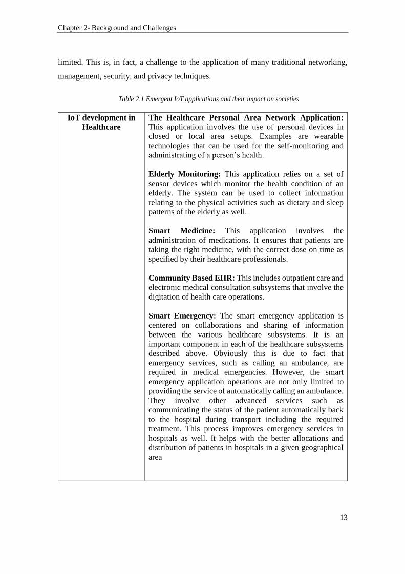
Table 2.1 Emergent IoT applications and their impact on societies
IoT development in
Healthcare
The Healthcare Personal Area Network Application: This application involves the use of personal devices in
closed or local area setups. Examples are wearable
technologies that can be used for the self-monitoring and
administrating of a person’s health.
Elderly Monitoring: This application relies on a set of
sensor devices which monitor the health condition of an
elderly. The system can be used to collect information
relating to the physical activities such as dietary and sleep
patterns of the elderly as well.
Smart Medicine: This application involves the
administration of medications. It ensures that patients are
taking the right medicine, with the correct dose on time as
specified by their healthcare professionals.
Community Based EHR: This includes outpatient care and
electronic medical consultation subsystems that involve the
digitation of health care operations.
Smart Emergency: The smart emergency application is
centered on collaborations and sharing of information
between the various healthcare subsystems. It is an
important component in each of the healthcare subsystems
described above. Obviously this is due to fact that
emergency services, such as calling an ambulance, are
required in medical emergencies. However, the smart
emergency application operations are not only limited to
providing the service of automatically calling an ambulance.
They involve other advanced services such as
communicating the status of the patient automatically back
to the hospital during transport including the required
treatment. This process improves emergency services in
hospitals as well. It helps with the better allocations and
distribution of patients in hospitals in a given geographical
area
Chapter 2- Background and Challenges
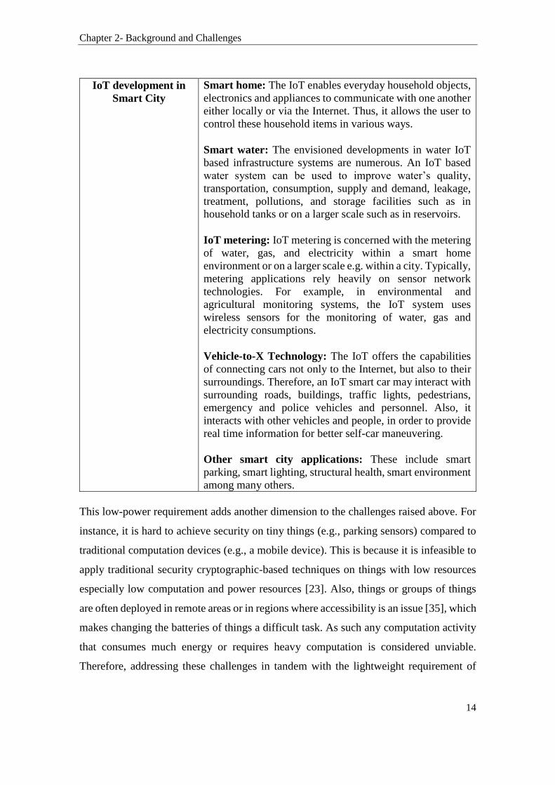
14
IoT development in
Smart City
Smart home: The IoT enables everyday household objects,
electronics and appliances to communicate with one another
either locally or via the Internet. Thus, it allows the user to
control these household items in various ways.
Smart water: The envisioned developments in water IoT
based infrastructure systems are numerous. An IoT based
water system can be used to improve water’s quality,
transportation, consumption, supply and demand, leakage,
treatment, pollutions, and storage facilities such as in
household tanks or on a larger scale such as in reservoirs.
IoT metering: IoT metering is concerned with the metering
of water, gas, and electricity within a smart home
environment or on a larger scale e.g. within a city. Typically,
metering applications rely heavily on sensor network
technologies. For example, in environmental and
agricultural monitoring systems, the IoT system uses
wireless sensors for the monitoring of water, gas and
electricity consumptions.
Vehicle-to-X Technology: The IoT offers the capabilities
of connecting cars not only to the Internet, but also to their
surroundings. Therefore, an IoT smart car may interact with
surrounding roads, buildings, traffic lights, pedestrians,
emergency and police vehicles and personnel. Also, it
interacts with other vehicles and people, in order to provide
real time information for better self-car maneuvering.
Other smart city applications: These include smart
parking, smart lighting, structural health, smart environment
among many others.
This low-power requirement adds another dimension to the challenges raised above. For
instance, it is hard to achieve security on tiny things (e.g., parking sensors) compared to
traditional computation devices (e.g., a mobile device). This is because it is infeasible to
apply traditional security cryptographic-based techniques on things with low resources
especially low computation and power resources [23]. Also, things or groups of things
are often deployed in remote areas or in regions where accessibility is an issue [35], which
makes changing the batteries of things a difficult task. As such any computation activity
that consumes much energy or requires heavy computation is considered unviable.
Therefore, addressing these challenges in tandem with the lightweight requirement of
Chapter 2- Background and Challenges
15
things is essential for the successful deployment and advance of the IoT. The remainder
of this section discusses interoperability and its different type in the IoT, WSNs
integration issues, management, and the security concerns challenging the IoT. Privacy
challenges are discussed in a dedicated section, i.e. Section 2.2.
2.1.1 The IoT Interoperability and Integration Challenges
Interoperability in information technology is as old as the Internet is, if not older.
Solutions considering the issues associated with information systems’ interoperability can
be traced back to 1988 [36], and perhaps even earlier. Wikipedia defines Interoperability
as “the ability to make systems and organisations work together” [37]. The IEEE defines
interoperability as “the ability of two or more systems or components to exchange
information and to use the information that has been exchanged” [38]. Other definitions
of interoperability are further tailored according to the particular application’s
requirements or needs. As a result, different categories of interoperability have been
emerging. Technical interoperability [39], Semantic interoperability [40],
Syntactic interoperability [41], and Cross-domain interoperability [42] are examples of
these categories.
All these types of interoperabilities are needed to support seamless and heterogeneous
communications in the IoT. Achieving interoperability is vital for interconnecting
multiple things across different communication networks. It defeats the purpose to have
billions of sensors, actuators, tiny, and smart devices connected to the Internet if these
devices cannot communicate with each other in a way or another. In fact, for the IoT to
flourish, things connecting to the communication networks, which can be heterogeneous,
need to be able to communicate with other things or applications.
In traditional computer environments, computer devices are treated equally when
connected to the Internet. Their functionalities vary depending on how the users use them.
However, in the IoT, each device would be subject to different conditions such as power
energy consumption restrictions, communication bandwidth requirements, and
computation and security capabilities. Additionally, things may be made by various

Chapter 2- Background and Challenges
16
manufacturers that do not necessarily comply with a common standard. Things may also
operate using a variety of communication technologies. These technologies do not
necessarily connect things to the Internet in the same way a typical computer device
usually do. For instance, we will see in Chapter 3, that 6LoWPAN offers interoperability
with other 802.15.4 devices as well as with any IP-based devices using a simple bridging
device. However, an advanced application layer gateway is required to bridge between
ZigBee and non-ZigBee networks [43].
Moreover, the highly competitive nature of the IoT makes interoperability between things
even a more difficult task to achieve. Besides, wireless communication technologies are
evolving and changing rapidly. This adds to the complexity of creating interoperable
communications in the IoT as well. This raises many integration issues in the IoT. Service
descriptions, common practices, standards, and discovery mechanisms are among the
many other challenges that also need to be considered before enabling interoperable
interactions between things [44].
2.1.2 WSNs Topologies in the IoT
Integrating WSNs in the IoT, where sensor nodes dynamically join the Internet,
collaborate or communicate with other similar sensors or other types of things, opens the
door to novel challenges. In this section, we will explore the ways in which WSNs could
join the Internet as part of the IoT. This will help the research to identify the contexts of
communications in which location information is used.
Network-based Integration
In the Network-based Integration topology, the sensors join the Internet through their
network gateway as shown in Figure 2.1. In the case of a multi-hop mesh wireless
topology, the sensors rely on a base node, also known as a sink, which even possesses
gateway’s capabilities or have a connection to a gateway. The sensors, in this case, are
not directly accessible on the Internet. Communications between a sensor of a particular

Chapter 2- Background and Challenges
17
WSN and that of another WSN or/and with other things on the IoT are not going to be
direct but via the WSN’s base node.
Figure 2.1- Network-Based integration
Independent Integration
In the Independent Integration topology, the sensors can connect directly to the Internet
independently from their base point. As a result, the interaction between an independent
sensor and other things in the IoT can be established without the need to pass by the
intermediate node (i.e. the sink node in the WSN). The topology of such a network is
given in Figure 2.2. However, giving an IP address to every sensor, for the purpose of
connecting to the Internet, may not be the right approach. This is because wireless sensors
are generally characterised by their low-cost and low-power features with packets
exchanged across the network periodically and in small sizes [45]. Therefore, it is quite
challenging to provide every IoT device with an IP address to connect to the Internet.
This is due to the communication and processing overheads associated with the use of the
TCP protocol that challenges the capabilities of small and low-cost sensors [46].
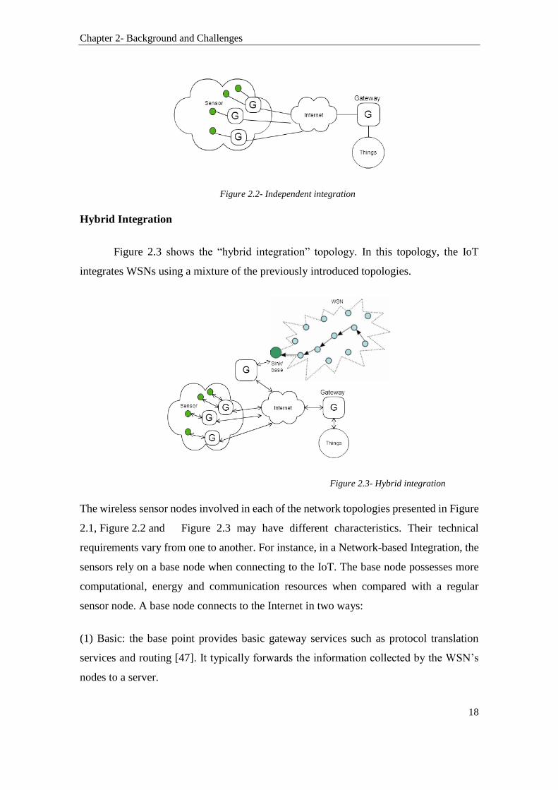
Chapter 2- Background and Challenges
18
Figure 2.2- Independent integration
Hybrid Integration
Figure 2.3 shows the “hybrid integration” topology. In this topology, the IoT
integrates WSNs using a mixture of the previously introduced topologies.
Figure 2.3- Hybrid integration
The wireless sensor nodes involved in each of the network topologies presented in Figure
2.1, Figure 2.2 and Figure 2.3 may have different characteristics. Their technical
requirements vary from one to another. For instance, in a Network-based Integration, the
sensors rely on a base node when connecting to the IoT. The base node possesses more
computational, energy and communication resources when compared with a regular
sensor node. A base node connects to the Internet in two ways:
(1) Basic: the base point provides basic gateway services such as protocol translation
services and routing [47]. It typically forwards the information collected by the WSN’s
nodes to a server.
Chapter 2- Background and Challenges
19
(2) Advanced: In addition to its gateway functionality, the base point has the capabilities
of computing, and performing some data analysis. This can help reducing redundancy in
the network.
Consequently, at least, the base node in a WSN requires an IP address to connect to the
Internet. In the case of a Network-based Integration, there is a need to identify uniquely
all the sensors on the Internet. Traditionally, the Internet is designed around an address-
centric scheme (IP address) as almost all transactions (e.g., HTTP and email) require
information about where the data are hosted [48]. Henceforth, a solution based on globally
uniquely identifying things should be explored. Dynamic address allocation schemes
similar to DHCP and translation schemes similar to DNS need to be exploited as well.
2.1.3 The IoT Management Challenges
The IoT will certainly include some devices that produce contents that need to be
retrieved only by authorised users or things. Searching, finding and accessing things on
the IoT require effective addressing policies. Therefore, the identity of Things is an
important topic in the IoT that requires further research. Currently, Domain Name service
(DNS) is the Internet naming service that translates IP addresses into human-readable
names. In the IoT, things will be connected using various technologies and protocols.
Some of these protocols are non-HTTP, and some might not even be based on the IP
protocol [49]. Therefore, not all devices in the IoT would necessarily have an IP-address.
As a result, there is a need to identify uniquely things on the IoT.
Additionally, the characteristics of the traffic exchanged by things, in the IoT, could be
periodic and subtle. Further contributions are needed to determine if the TCP protocol is
adequate to use in the IoT or if a new concept of a transport layer is required. This is
because TCP is a connection-oriented protocol, in which sessions always starts with a
connection setup procedure known as the three-way handshakes. Given that some of the
communications within the IoT will involve the exchange of an only small amount of data
generated from constrained devices, the TCP protocol cannot be used efficiently for
transmission control. For example, consider a case where an IoT sensor is to exchange a

Chapter 2- Background and Challenges
20
small amount of data in a single session with another device or application. In this case,
the use of the TCP congestion control mechanism is considered to be ineffective. This is
because the whole TCP session will be concluded with the transmission of the first
segment and the consequent reception of the corresponding acknowledgment [50].
Interoperability between TCP and future non-TCP enabled devices need to be taken into
consideration as well.
On the other hand, the research into device naming or identity management is an active
area as well. For instance the work in [46] points out that a device naming scheme should
contain key elements of device meta-data such as the device’s type and domain
information. For addressing purposes, the format should allow accessibility and
addressability to the physical world in a granule and efficient way. Profile services are
also needed to aid the application query and system configurations such as the device
status and presence [46].
Other works on identity management in the IoT are based on the Service Oriented
Architecture (SOA) such as OpenID [51]. OpenID describes the process of authenticating
users in decentralised systems. These authentication features are necessary for preserving
privacy in the IoT. Preserving privacy has to take into account not only the privacy of
services or data but also the discovery through user devices. The work in [52] discusses
the need to distinguish between connected things and their identities. It proposes the use
of tokens. A token is used by a device in an API call when engaging in communications.
A user controls the process of issuing tokens. This approach allows the user to impose
access control policies as to when that token can be used and how his or her information
is shared [52].
2.1.3.1 Network and Device Management Challenges in the IoT
Traditionally, network management solutions are needed to manage network equipment,
devices, and services. However, in the IoT, there is a need to manage not only the
traditional networked devices and their services but also an entirely new range of things.
The enormous number of things and their diversity create many management
Chapter 2- Background and Challenges
21
requirements. Thus, traditional management functionalities such as remote control,
monitoring, and maintenance are considered of paramount significance for the operation
of things in the IoT. However, these management solutions need to evolve to cater for the
unique characteristics of the IoT. This is because the IoT is of a diverse nature supporting
heterogeneous communications and seamless machine-to-machine interactions. This is in
addition to the distinctive management capabilities required for managing things in the
IoT. For example, self-configuration and network reconfiguration are essential
management requirements in the IoT.
Moreover, traditional network management solutions usually aim at providing
management information with a minimal response time. However, in some IoT scenarios
that may involve lightweight devices, the management solutions should provide
comprehensive management information with minimal energy use [53]. Nevertheless, the
characteristics of data generated in the IoT are distinct from other data in use today [54].
For instance in [55], IoT data have been described as having five distinct characteristics:
Heterogeneity, Inaccuracy of sensed data, Scalability, and Semantics. We add minimally
or constrained as another important feature governing data in the IoT as, generally, things
in the IoT have limited computation, communication, and power resources at their
disposal [56, 57].
Therefore, management solutions are needed to allow managers to perform many
maintenance tasks remotely over the Internet and possibly across many heterogeneous
interconnected networks. These management capabilities should aim at reducing errors
and accelerating response time. The ability to turn things on and off, disconnecting things
from specific networks, and monitoring the statuses of things are amongst the important
tasks that these solutions should support. Additionally, having a management system
deployed in an IoT network helps in eliminating travel’s and staff training’s costs. Also,
it helps in accelerating the response to failure events. For example, a management system
that supports the remote monitoring, via the Internet, of sensors or other smart devices
deployed in remote locations or a busy city is highly beneficial and essential in emergency
applications [58]. Such a system allows managers to control remotely, diagnose errors,
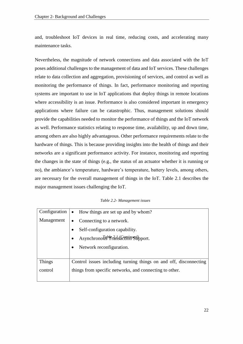
Chapter 2- Background and Challenges
22
and, troubleshoot IoT devices in real time, reducing costs, and accelerating many
maintenance tasks.
Nevertheless, the magnitude of network connections and data associated with the IoT
poses additional challenges to the management of data and IoT services. These challenges
relate to data collection and aggregation, provisioning of services, and control as well as
monitoring the performance of things. In fact, performance monitoring and reporting
systems are important to use in IoT applications that deploy things in remote locations
where accessibility is an issue. Performance is also considered important in emergency
applications where failure can be catastrophic. Thus, management solutions should
provide the capabilities needed to monitor the performance of things and the IoT network
as well. Performance statistics relating to response time, availability, up and down time,
among others are also highly advantageous. Other performance requirements relate to the
hardware of things. This is because providing insights into the health of things and their
networks are a significant performance activity. For instance, monitoring and reporting
the changes in the state of things (e.g., the status of an actuator whether it is running or
no), the ambiance’s temperature, hardware’s temperature, battery levels, among others,
are necessary for the overall management of things in the IoT. Table 2.1 describes the
major management issues challenging the IoT.
Table 2.2- Management issues
Configuration
Management
How things are set up and by whom?
Connecting to a network.
Self-configuration capability.
Asynchronous Transaction Support.
Network reconfiguration.
Things
control
Control issues including turning things on and off, disconnecting
things from specific networks, and connecting to other.
Table 2.1 (Continued)
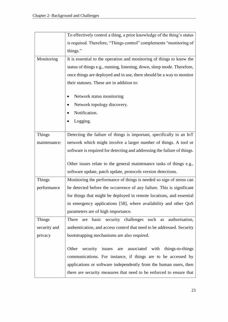
Chapter 2- Background and Challenges
23
To effectively control a thing, a prior knowledge of the thing’s status
is required. Therefore, “Things control” complements “monitoring of
things.”
Monitoring It is essential to the operation and monitoring of things to know the
status of things e.g., running, listening, down, sleep mode. Therefore,
once things are deployed and in use, there should be a way to monitor
their statuses. These are in addition to:
Network status monitoring
Network topology discovery.
Notification.
Logging.
Things
maintenance:
Detecting the failure of things is important, specifically in an IoT
network which might involve a larger number of things. A tool or
software is required for detecting and addressing the failure of things.
Other issues relate to the general maintenance tasks of things e.g.,
software update, patch update, protocols version detections.
Things
performance
Monitoring the performance of things is needed so sign of stress can
be detected before the occurrence of any failure. This is significant
for things that might be deployed in remote locations, and essential
in emergency applications [58], where availability and other QoS
parameters are of high importance.
Things
security and
privacy
There are basic security challenges such as authorisation,
authentication, and access control that need to be addressed. Security
bootstrapping mechanisms are also required.
Other security issues are associated with things-to-things
communications. For instance, if things are to be accessed by
applications or software independently from the human users, then
there are security measures that need to be enforced to ensure that

Chapter 2- Background and Challenges
24
things are not leaking information and disclosing private information
to unauthorised things or used miscellaneously.
Things have their users and owners. Thus, privacy is vital as well
[59].
Energy
Management
Management of energy resources.
Statistics on energy levels e.g., estimated lifespan.
2.1.3.2 Traditional Management Protocols
The purpose of a network management protocol is to transport management information
from a device (e.g., a computer or a networked node) referred to as a managed device or
object to an application referred to as the manager. Network management protocols are
also used to transport control information from the manager to the managed devices.
Traditionally, in a client-server scheme, a management protocol is used to transport
messages between the manager and the network components. A network component can
be a typical network device such as a server, router or a specific network interface on a
router. Generally, network management protocols define a static protocol message format
and a small set of predefined messages for gathering and posting managed information to
and from the managed devices [60]. Emerging standards, which are based on the
distributed object-oriented approach, define more complex network management
architecture. In this approach, the management protocol is tightly coupled with the
management application; thereby facilitating code-on-demand (COD) object
transmission, plug-and-play component management, and also defining a rich set of
communication primitives between managers and managed devices [61].
The two most widely used management protocols are the Simple Network Management
Protocol (SNMP) and the Common Management Information Protocol (CMIP). Although
these two protocols have a similar architecture, they vary slightly in operations. Both
SNMP and CMIP define a single management device that assumes complete control over
all management functions. The manager is an application that interacts with network

Chapter 2- Background and Challenges
25
agents embedded in each managed device using the network management protocol. In the
context of SNMP and CMIP, agents are simple computational entities that provide
mechanisms for accessing managed information stored on the managed devices [25].
SNMP’s agents store device-specific information in managed information bases (MIB).
On the other hand, the CMIP protocol defines a managed information tree (MIT) to store
and access configuration information.
The Simple Network Management Protocol (SNMP)
Although SNMP was designed specifically for managing IP-based data networks, it has
become the de facto standard for telecommunications network management. The
popularity of SNMP is mainly due to its simplicity that allows manufacturers to enhance
their products with network management functionality with a minimal effort. This
protocol also provides simple and hierarchical management architecture with multi-
vendor support.
SNMP aims to unify and minimise the complexity of management functions between
various networked and hardware devices. The use of SNMP reduces the cost of
management. Significantly, the SNMP’s architecture enables the efficient integration of
devices across a network. It facilitates seamless integration and management of existing
and newly added hardware devices on a network. Additionally, SNMP implementations
define a set of management functions that can be easily adopted by network managers
and developers of network management systems. Another characteristic of SNMP is
extensibility. SNMP’s design allows the addition of newly developed extensions with less
complexity. The SNMP protocol is a platform independent as well. It supports an array
of various network technologies.
The Common Management Information Protocol (CMIP)
Almost in parallel with the development of SNMP, the International Standards
Organization (ISO) defined the specifications for the Common Management Information
Protocol (CMIP). Unlike SNMP, CMIP is designed to provide network management
operations for a wide variety of network architectures [27]. In the open systems

Chapter 2- Background and Challenges
26
interconnection (OSI) architecture, the fundamental function of network management
solutions is to assist with the exchange of management information between the manager
and managed devices. This functionality is referred to as the Common Management
Information Service Element (CMISE) and is composed of two parts. The first specifies
the services provided by the network management, and it is termed as the Common
Management Information Service (CMIS). The second part is referred to as the Common
Management Information Protocol (CMIP) [26]. It specifies the mechanisms and message
format by which the management information is exchanged between the manager and
managed devices. The CMIP framework is broken down into three interacting
components. These components consist of the Layer Management Entity (LME), the
System Management Application Entity (SMAE), and the common management
information protocol (CMIP), which facilitates the communication of managed
information among the management layer and management devices.
The CMIP implements a much richer set of management functions when compared to
SNMP. It organises the managed entities and manager using a hierarchical approach. This
allows managed information to be accessed within the scope of the manager. This
hierarchical approach significantly increases the protocol’s scalability. However, because
the services offered by the CMIS entities are considerably more sophisticated than the
management functions of SNMP, CMIP protocol is considered harder to implement [27].
For this reason, CMIP has not gained as much popularity as SNMP. Even though SNMP
has gained major popularity in network management systems, the IETF designed this
protocol to manage TCP/IP-based local area networks. Therefore, the challenges posed
by emerging communication standards require a more sophisticated network management
approach.
Facing new technologies in the era of the IoT, network management approaches must
implement scalable, flexible, robust, adaptive, and automated management architectures.
This is because the IoT encompasses several heterogeneous networks consisting of a
range of lightweight and more capable devices. This heterogeneity of devices and
networks raises some novel management challenges. To address this challenge, studies
such as the one reported in [62], examined the possibility of adopting existing network

Chapter 2- Background and Challenges
27
management protocols for the management of constrained networks and devices in the
IoT. It is found, through simulation studies, that SNMP makes efficient use of resources
on constrained devices [62]. Future contributions are required to investigate the
applicability and performance of traditional network management protocols such as the
SNMP in physical IoT setups.
2.1.4 The IoT Security Challenges
The growth in the number of connected devices to the communication networks in the
IoT translates into increased security risks and poses new challenges to security. A device
which connects to the Internet, whether it is a constraint or smart device, inherits the
security risks of today’s computer devices. Almost all security challenges are transferred
to the IoT. Hence, some fundamental security requirements in the IoT such as
authorisation, authentication, confidentiality, trust, and data security need to be
considered; which are shown in Figure 2.4.
Therefore, things should be securely connected to their designated network(s), firmly
controlled and accessed by authorised entities. Data generated by things need to be
collected, analysed, stored, dispatched, and always presented in a secure manner.
Nevertheless, there are security risks associated with things-to-things communications as
well. This is in addition to the risks relating to things-to-person communications. For
instance, if things are to be accessed by things independently from the human users, then
there are security measures that need to be enforced. These security measures are
necessary to ensure that things are accessed only by authorised entities in a secure manner.
Also, they need to ensure that things are not leaking information or disclosing private
information to unauthorised things and users, or used miscellaneously. Figure 2.4 shows
the inherited security issues that challenge the IoT, which are detailed as follows:
End-to-End Security
It is the process of protecting the communications and data exchanged between both ends
of the communication without being read, eavesdropped, intercepted, modified, or

Chapter 2- Background and Challenges
28
tampered. In the IoT, end-to-end security remains an open challenge for many IoT devices
and applications. The nature of the IoT with its heterogeneous architecture and devices
involve the sharing of information and collaboration between things across many
networks. This poses serious challenges to the end-to-end security.
When devices have different characteristics and operate using a variety of communication
technologies (802.11 vs. 802.15.4), establishing secure sessions and secure
communications, become a very complex task to achieve. Additionally, not all devices in
the IoT are equal. Currently, computers, smartphones, and other computerised devices
connect to the Internet via HTTP, SMTP and the like for most of their activities. As such
TLS and IPsec protocols are usually used to negotiate dynamically the session keys, and
to provide the required security functions. However, some of the devices in the IoT do
not possess the ability to run TLS and IPsec protocols due to their limited computation
and power capabilities. Additionally, some embedded devices in the IoT have limited
connectivity as such they may not necessarily use HTTP or even IP for the
communications (e.g., a sensor in a WSN).

Chapter 2- Background and Challenges
29
Figure 2.4- Some IoT security issues

Chapter 2- Background and Challenges
30
Data Security
Data security involves the protection of data during communications and storages. In [63],
data security is defined as the process of protecting data from destructive forces or from
unauthorised access. Data security also referred to as information security is vital to the
IoT security. Data security in the IoT is also associated with safety. Usually, the impact
of data security breaches on the human life remained within the scope of hacking the
personal information of an individual or getting unauthorised access to sensitive
information such as financial data. However, data security breaches in the IoT could pose
a serious threat to humans’ safety. For instance, the accidental intrusion or malicious
access that could interfere or interrupt the operations of a driverless car or a heart
pacemaker will threaten the user’s life. Security breaches in an IoT forest fire detection
system could lead to catastrophic results as well.
Access control
The earliest access control system in use is physical access control. It is the physical
access given to individuals based on physical guards. These access control measures are
imposed and protected by humans or using devices such as parking machines, locks or
keys. Typically, access control means restricting access to resources or physical access to
a room or building. However, access control widely covers more than the physical access
to a particular system. In some cases, access control is enforced using electronic access
system cards, biometric devices, and other electronic methods. An example is the use of
biometrical identification systems, such as a fingerprint identification system, to control
access to resources. It sets the user privilege based on their biometric identity i.e. their
fingerprint. The system controls access to services and networks by issuing access codes
to the users. The process of enforcing access control on a resource is typically associated
with an authentication and authorisation process. An authentication approval, for
example, is based on some security techniques such as digital signatures, passwords,
digital certificates, and smart cards.
Chapter 2- Background and Challenges
31
Role-Based Access Control (RBAC) is a widely adopted access control approach that
restricts access to systems or resources to authorised users. RBAC is based on the concept
of assigning permissions to roles. However, in the IoT, things, including mobile things
(things on the move), and users might require to access data anytime and anywhere from
various types of devices. Therefore, the IoT poses new challenges for access control. In
fact, the low power requirements of things, limited bandwidth, heterogeneity of
communications, and the large scale of devices in the IoT create a unique set of access
control requirements. Thus, traditional access control systems in their current status, such
as RBAC, might not work efficiently in the IoT. Typically, the advantage of using RBAC
in a system is the ability of easily adding access rights to a user, as long as it uses existing
roles. In the IoT, as the number of connected devices and networks grow, the number of
users and devices requesting access to data and services grow as well. Therefore, an IoT
system that comprises thousands of devices would perhaps end up with thousands of roles
and permissions that need to be maintained. Therefore, the challenge of managing access
control to thousands of devices in the IoT will be simply transformed into a complex task
that requires the management of a vast number of roles. This is known as “role explosion”
and it is a major drawback of RBAC systems. This is because adding new roles to a
system require a system-wide update. Generally, RBAC systems are implemented in a
centralised architecture whereas an access control server assigns roles to users and grants
them access to resources. Thus, updates at the system level are even harder to implement
in the IoT given its distributed architecture.
Attribute-based access control (ABAC) is an access control model that abstracts identity,
role, and resources information of the traditional access control into entity attributes [64].
An ABAC system grants access to services based on the attributes possessed by the
requester [65]. Therefore, unlike RBAC, the ABAC model uses attributes to describe the
requesters and the requested services. The associated attributes of each entity can be
defined according to the system needs [66]. Thus, relying on attributes provides a much
more fine-grained access control approach. As such access control strategies can be
designed to use not only the requester’ attributes but also other contextual data e.g., the
location of the requester. Therefore, rather than granting or denying access to a resource

Chapter 2- Background and Challenges
32
based on the role of a user, an ABAC system combines the user’s attributes along with
other contextual information which provides a way of dynamically generating context-
aware decisions for requests [67]. This makes ABAC suitable for adoption in systems that
require fine-grained access control such as the IoT. Additionally, the ABAC model suits
the access control requirements of the IoT including the dynamic expansion in the number
of connected users and things to the IoT.
2.2 IoT Privacy: Threats and Challenges
The convergence of location-based services (LBS) and wireless communication
technologies in the Internet of Things (IoT) will enable a revolution in our everyday
activities. Location based services are becoming more mainstream. Location-based
service technologies play an important role in the IoT. Recent studies on the IoT show
the importance of LBS in this domain. Examples are the integration of RFID technology
into mobile devices in [68] and LBS into a mobile logistic information system [69], to
name a few. While there are apparent benefits in using LBS systems in the IoT [70], they
challenge the privacy of users [71]. IoT systems have the potential to enable systematic
mass surveillance that could impinge on the personal privacy of users especially their
location privacy. Location privacy concerns are not new. What is new is the increased
scope of the problem in the IoT.
The automation in gathering and analysing the users’ information in the IoT gives location
privacy an added dimension. Currently, LBSs have seen a widespread adoption in mobile
applications. Applications such as those which run on the iPhone or Android devices
provide mobile users with the capabilities to access data anytime and anywhere. They
improve the users’ productivity in a variety of contexts ranging from personal
customization e.g., calendar, work, Mobile banking, health to social networking [72].
Searching for a restaurant nearby, or exploring the area for shopping deals or discounts
are some examples of LBSs in use today on almost every smartphone. In early 2000’s, a
study found that most teenagers use SMS to connect with their friends and arrange
meetings [73]. Recently, SMS communications have evolved significantly with the
penetration of mobile applications in our life. Nowadays, messaging and VOIP
Chapter 2- Background and Challenges
33
applications are widely available on iPhone, Android devices, and Windows Mobile.
They have taken over traditional SMS. Most of these applications also offer location
sharing with friends. Smith refers to them as social location disclosure applications [74].
The cross mobile platform application “Whatsapp” or “Viber”, for example, enables
mobile users to exchange, using an Internet connection, text messages, images, audio and
video messages, and location information with one another at no cost. Other location
based services have emerged and applications such as child location tracking services are
becoming popular [75]. Location-aware browsing and geolocation marketing are other
examples of LBS [76].
Location information can be obtained using a variety of location positioning techniques,
such as GPS systems, cellular tower triangulation, or using the device's media access
control (MAC) address e.g., on a Wi-Fi network [77]. In most LBS applications, users
are unable to manage their locations disclosure settings effectively as they lack the control
over the sharing of their locations. Obviously, the user can decide not to disclose his or
her location information, but this limits the disclosure settings to two options “disclose”
or “do not disclose.” However, the user may wish to stay anonymous and may not want
to be identified by the LBS providers, especially when the information requested are
sensitive. Researchers have long been aware of the potential privacy risks associated with
the use of LBSs [78]. These risks have received considerable attention from the users and,
in some cases, from service providers and government organisations as well. While better
services can be provided if personalisation is allowed, not all LBSs require the personal
identification of the user. However, the risk lays in the fact that positioning information
in the form of a particular location can lead to the personal identification of the user and
his or her behavior.
The study in [79] showed that a driver’s home location can be inferred from the GPS data
collected from his or her vehicle even if the location information were anonymized. It
further shows that the reconstruction of an individual’s route could provide a detailed
movement profile that allows sensitive data inferences. For example, recurring visits to a
medical clinic could indicate illness. Visits to activist organisations could hint at political
opinions. In [79], it has been found that using clustering techniques, sensitive locations
Chapter 2- Background and Challenges
34
of users can be exposed even when the GPS traces, collected by the location-based
services, are anonymized. In [80], it was found that there are ethical issues associated
with the use of GPS with the public users. Adequate safeguards need to be in place to
avoid the abuse of information gathered through GPS technology. This was derived from
an experiment where the authors used a combination of GPS data and diary logs of a
volunteer over a period of two weeks. The study aimed at understanding the social
implications of tracking and monitoring subjects. In [81], it has been shown that the future
movements of a user can be predicted. The study used GPS data from a single volunteer
collected over a four month period and used it to derive the location context of the user.
They developed an algorithm which extracted locations of importance from the GPS data
and used it to design a model that predicts the user's future movements. In a similar study
[82], a protocol was developed for the purpose of identifying and inferring the home’s
location and identities of 172 participants. A reverse geocoder system was able to infer
the homes’ locations of roughly 5% of the participants correctly.
In the smartphone ecosystem, many mobile applications collect the location information
of the users without their consent. For example, TaintDroid project [83], has identified
that some Android’s applications are releasing users’ private information to online
advertisers. TaintDroid is developed as a mobile application. It provides real-time
monitoring services that monitor the traffics exchanged by other applications installed on
the same device. It detects when the user’s private information is released by an
application to a third party. In a study of the 30 most popular applications, TaintDroid
revealed that 15 applications were sending users' geographic location to remote
advertisement servers. Another study found that 7.5% of the total applications on the
Android market have the capability of accessing the user’s stored contacts; while 28% of
them had access to the user’s location [84]. The study in [85] analysed the 101 most
popular smartphone applications running on various mobile operating systems, including
Windows Phone, iPhone, and Android. It was reported that out of the 101 applications,
56 were transmitting the unique phone ID to other companies without the user’s
permission. Forty-seven applications were caught transmitting location information to

Chapter 2- Background and Challenges
35
third parties. The other five applications were found to be leaking other specific
information like gender and age.
Some applications running on the Window Mobile platform had the capability to access
the user’s picture library, video library, webcam’s video feed, microphone’s audio feed,
location, and other parameters related to the Internet connection [86]. Some of these
applications also had the ability to add, change or delete files from both the picture and
video libraries. In 2011, another study detailed the vulnerability of the RIM BlackBerry
device [87]. The author developed a spyware targeted for Blackberry devices. The
spyware was able to access and transfer sensitive data to a remote server without being
noticed by the user. The study in [88], showed that a driver’s home location can be
inferred from the GPS data collected from his vehicle even if the location information
was anonymized. The study conducted in [59] also reported on various privacy incidents
associated with the use of mobile applications on the Android, Blackberry, iPhone, and
Windows Phone platforms. It is concluded that the proliferation of mobile devices, GPS
systems and other evolving technologies into our lives has introduced a new set of privacy
threats.
Henceforth, given the impact smartphones have on the users’ privacy, it is anticipated
that the amount of personal data that would be occasionally collected in an IoT
environment will be extremely larger than what we have ever experienced before. The
IoT highly distributed nature of technologies, such as embedded devices in public areas,
creates weak links that malicious entities can exploit and can as well open the door for a
mass surveillance, tracing, tracking, and profiling of the users’ movements and activities
[89]. Moreover, the collection of sensitive data, the tracking of people’s movement, data
mining, and services provisioning can become automated and unpredictable in the IoT.
With the pervasive growth of IoT-connected devices and applications, privacy threats are
more likely to increase rapidly.
Consequently, privacy is one of the major implications the Internet of Things develops
[90]. Privacy no longer means anonymity in the IoT. Profiling and data mining within
any IoT scenario can form a potential harm to individuals due to the automatic process of

Chapter 2- Background and Challenges
36
data collection, storage and the way personal data can be easily shared and analysed [91].
Also, the foundations, laws, and regulations for digital privacy were established some
years ago when the Internet was centralised. These regulations deal, usually, with the
collection of personal information, access rights, and ensure their correct handling [92].
This is no longer considered enough in the IoT. By definition, privacy means giving the
users the option to control how their collected personal information is used, specifically
for secondary usage and third party accesses. As an example, in the online environment,
privacy choices are made by the user in real-time by controlling the amount of personal
information the user discloses on the Internet (e.g., when filling a form). The concept
remained the same in the evolution of social networking websites, where users in
Facebook, for example, indicate to whom and to which extent their information can be
revealed. These are known as the principles of notice and choice [93].
Conversely, the vision of the IoT allows automated machine-to-machine interactions
independently from the user. One of the promising features of the IoT is the ability of
devices to observe, sense their environments, and track the user’s activities continuously.
This poses new risks to the user’s privacy. Thus, attackers may configure devices to join
a given IoT system or network for the purpose of miscellaneously collecting information
about the system environment and the user. The ability of things to participate in
communications and exchange information, independently from the user, with each other
in the IoT raises many privacy concerns. Smart devices such as smart home appliances,
smart cars, and others that log data about their environment, e.g., their locations,
constitute a source of risks and vulnerabilities with regard to the privacy of their owners.
If these devices are connected, as envisioned in the IoT, and these logs are shared among
IoT applications, then there is an increased risk of personal information leakage which
threatens the users’ privacy.
2.2.1.1 The First Hand Attack
In a first-hand attack, the attacker obtains the information directly from the user. An
objectionable disclosure of information can happen accidently, such as the presence of
security holes in a system, which leads to a leakage of the information or by tricking the

Chapter 2- Background and Challenges
37
user. For example, cookiejacking is a form of a first-hand communication attack wherein
the attacker can gain access to the session cookies of an Internet Explorer user. Thus, it
can be used to gain access to the user’s username and password stored in the cookie [94].
Additionally, news on security flaws found on computers’, and recently mobiles’
operating systems are all on the web. Back in 2003, serious flaws in the authentication
and data transfer mechanisms on some Bluetooth enabled devices leading to the
disclosure of personal information were reported [95]. Nowadays with the explosion of
smartphones technologies, applications installed on the Android, iOS, Windows mobile
devices, and others are known to have the capabilities of accessing the personal
information of the users including their location information. This could form a
vulnerability that may allow an attacker to obtain a live location feed. Bluetooth, NFC,
and ZigBee devices are also prone to various security and privacy threats. These are a few
examples of the triggers that might lead to a first-hand attack on location privacy.
Additionally, numerous electronic devices which provide constant precise location
information to location based servers are seen as overly permissive. If this location
information is produced by automated devices, then these devices form a source of
potential risk to the users’ privacy. In a world surrounded by intelligence in the IoT, the
threat of disclosing personal information unconsciously via a first-hand communication
is significant. At the bare minimum, these concerns must be considered in the IoT.
2.2.1.2 The Gossip Attack
The English definition of the word “Gossip” is an unconstrained conversations or reports
about other people personal or private affairs [96]. In digital terms, a gossip attack is
relaying personal information from one entity to another unauthorised entity. The main
difference between a gossip and first-hand communication is that the user is no longer the
direct source of information. Disclosure of the user’s personal information can be done
without being noticed by the user. This behavior has been already observed in online
activities and recently on some portable devices such as tablets’ or mobiles’ applications
that sell the users’ location information or their shopping behaviors to advertisement
companies. It seems naive not to expect this type of information, which is available via
things and fine-tuned by their technological advanced features and automation, not to be

Chapter 2- Background and Challenges
38
similarly misused. The widespread use of devices and the deployment of IoT networks,
such as sensor networks, will lead to an enormous amount of data being captured by
commercial and state enterprises. This poses concerns relating to the issue of associating
data, including location information, with another set of data. These concerns are related
to the collection and appropriate use of this information and the consequence of their
leakage on the users’ privacy. It is almost ascertained that the more the technology
develops, the capacity to gather, organise, and data-mine on the personal information will
also develop. Therefore, the disclosure of information is always at risk of leakage whether
accidently (via a first-hand communication) or intentionally for someone else’s benefit
such as in the gossip communication. Currently in the online environment, cautions can
be exercised such as controlling the entity acquiring the personal information, and
controlling whether the collected information should be transmitted over a secure channel
(HTTP vs. HTTPs). In things-to-things communications in the IoT, the user loses this
supervisory control role over his or her information.
2.2.1.3 The Inference Attack
Some studies reported the use of recorded personal information to demonstrate a privacy
attack, often referred to as an “inference attack.” The idea is to build a map reflecting on
the activities, mobility behavior, and other patterns of the user’s life using the data
gathered. An example of an inference attack is the study conducted in [97]. The authors
were able to determine the names of the persons stored in their database by observing and
noting the location where people spent most of their time in the office building, and by
noting who spent more time at their desk. Apart from inferring people’s location, some
researcher reported the inference of other information based on the observed context. For
example in [98], the authors used real-time GPS traces to infer a traveling person mode
of transportation (i.e. by car, train, bus, and walking) they were also able to predict the
victim’s route, based on their movements and historical behaviors. Therefore, the
seamless interconnectivity of things envisioned in the IoT will open the door to various
inference attacks. When interconnected networks of things in the IoT are capable of
tracking the users automatically on an ongoing basis, they generate an enormous amount
Chapter 2- Background and Challenges
39
of potentially sensitive information leading to possible inference attacks similar to the
ones described above.
2.2.1.4 The Automated Invasion Attack
In the IoT, some of the risks associated with automated communications are the
compilation of users’ profile. After gathering large amounts of information via a first-
hand communication, gossip and inference attacks, an automated system can combine
these data and perform some data mining or analysis, which lead to a new vector of
inference attacks. These combinations of attacks give birth to what we refer to as the
“Automated Invasion Attack”. An automated invasion attack can be constructed using
any of the following gathered information:
Current data collected from typical computer usage including the data generated
from mobiles’ and tablets’ application: This set of collected data is a possible
source of information in which the attacker can gather to infer some patterns relating
to the user's activities. For instance, the IP address reflects on the location of the user.
The time, date, and other parameters can also be collected. Mobile applications can
log their location, usage history, and their interactions with a location based server.
Current data collected from the Internet or via social networking websites. The
website “Please Rob Me” is an example of how to predict a person presence at home
from publicly available information by looking at the places where the users check-
in [99]. With the public availability and accessibility of some of the users’ information
found on various social networking websites, it is possible to infer various data
relating to an individual.
Data collected on the mobility behavior of an individual: The movement patterns
of a person constitute a form of fingerprinting. This enables an attacker to infer a
user’s points of interest. The location of the user’s kids, school, and the time the victim
usually picks up their kids and their Friday weekly social activity locations are all
examples of a user’s point of interest. Other mobility behavior could hint on other
sensitive information. A frequent visit to a political party location or religious group
could expose their social, political or religious activities.
Chapter 2- Background and Challenges
40
Data collected from things in the IoT environment: Whether the user is interacting
with a particular device directly or indirectly using another device which they own or
operate, there is a threat to the user’s privacy. The information generated from these
interactions constitute a possible source of information that reflects the behaviors,
location, date, timing, shopping habits, and other personal information of the user.
Linking the records of things: Data collected by Things are a possible source of
information that the attacker can collect to infer the victim personal information.
Additionally, in the IoT, if a device’s set of data that contains logs about its use,
location, history, and others private information, is linked to the same type of data
generated by another device, it could lead to a linking attack. In a geolocation context,
a linking attack work by associating the movements of an individual physical
belonging device, for instance, his car (stored in log A) with the tracking of their
mobile phone locations (stored in another log B). Consequently, an automated
invasion attack is an incremental process of inference attacks in which the attacker
gradually gathers more knowledge on the victim life or activities throughout the
combination and linking of the information collected from the various source of
attacks listed above.
In summary, location privacy is one of the major concerns in the IoT. The seamless
interconnectivity of things, envisioned in the IoT, highlights the complexity of realising
location privacy in this environment. It is clearly evident that it is almost impossible to
achieve a complete privacy as long as seamless communications are taking place. When
IoT systems, which can operate in an autonomous fashion in the IoT, track the users
automatically on an ongoing basis, they generate an enormous amount of potentially
sensitive information. This occurs especially when the location information is coupled
with identity information. The main location privacy concern with regards to the IoT is
that many new automated attack vectors become possible [100]. If effective public
records of people’s locations are created through systems automation then discrimination
against race, religious group and prices, to name but a few, are most likely to occur.
Things that log data about their usages, locations, histories, and others sensitive
information present an interesting challenge to privacy protection. The amount of
Chapter 2- Background and Challenges
41
personal data that would be occasionally collected in an IoT environment will be
extremely larger than what we have experienced before. In facts, the collection, mining,
and provisioning of data in the IoT are at a larger scale from those we experiment with
traditional computer devices. The exchange of location information particularly in the
IoT can become arbitrary as more devices and applications obtain access to the user’s
personal information.
Thus, recent technological advances in wireless communications, location-enabled
hardware, and location identification techniques extend the location sensing capabilities
to several things in the IoT. This gives rise to the possibility of using the tracking
capabilities of things for the violation of the privacy of users. Not only preserving the
location privacy of users is vital, but also preserving the location privacy of things is of
paramount importance. In principle, most location-based services do not require the
personal identification of a user. However, even without providing any personal
identification, positioning information in the form of a specific location of a thing along
with the possibility of associating the location information gathered from another thing
or group of things will eventually lead to revealing the movement of a thing or the user;
along with other inferred personal or contextual information such as the type and nature
of the activity performed. Combining all of this information with other quasi-
identification information will infer other types of sensitive information such as, the
thing’s context, its activities, and possibly the identity of the owners of things.
Consequently, the complexities involved in protecting location information in the IoT
demand a new approach to the management and preservation of location information in
the IoT. In the search for a solution, the next section (i.e. Section 2.3) investigates the
current techniques used to protect location information on the Internet and investigates
their applicability to the IoT.
2.3 Measures in Preserving Location Privacy
Current research on location privacy is mainly centered on two main computational
protection techniques: anonymity and Obfuscation [101]. Thus, this work reviews two
Chapter 2- Background and Challenges
42
relevant techniques: the Random and Dispersion techniques, which are discussed in
Section 2.3.2. To perform Obfuscation, three key concepts have been widely used,
described as follows:
Adding random noise to location information: The aim is to make it harder on the
adversary to infer the actual location of the user;
Rounding by narrowing the coarse location e.g., by using landmarks to approximate
a location;
Redefinition of possible areas of the location. Example: the use of “invisible
cloaking”, in which no locations are provided for identified selected areas [102].
Based on these three concepts, most of the computational techniques used for privacy
protection alter the location information in a way of reducing the information granularity.
This includes the randomization technique, regulatory-based technique, anonymity, and
Obfuscation.
The Randomization Technique
Randomization is a core principle in statistical theory. It is the process of making a data
stream random. As an example, the study in [103] uses a decision-tree classifier to
randomize data. This results in a new data stream that looks different from the original
data stream. A reconstructed distributions procedure is proposed to estimate the
distribution of the original information accurately. However, the issue with the use of
randomization-based methods is that randomization does not offer the flexibility needed
in the protection of location information.
Regulatory-based Techniques
This method relies on the government rules and regulations in protecting the personal
information of users. The work in [104] reports on the status of privacy legislations and
fair information practices in some countries. The problem with relying on regulations for
protecting the privacy of the users is that regulations vary from a country to another. They
also usually lag behind newly developed technologies.
Chapter 2- Background and Challenges
43
Privacy Policies
This is a trust-based agreement policy arranged between the user and service provider.
However, similar to the regulatory method, privacy policies cannot offer a complete
solution since they are vulnerable to malicious disclosure of private information [105].
Privacy policies solutions are often used as part of middleware solutions which improve
their efficiencies.
Anonymity
This method uses pseudonyms, normally to hide the identity of a user by anonymizing
the user’s personal information, e.g., the work in [106]. K-anonymity is another well-
established anonymity-based privacy solution [107]. However, the use of anonymity as a
privacy protection solution challenges the performance of many personalised services as
it eliminates authentication and personalisation options [108].
Obfuscation
The term Obfuscation is introduced in [109]. It is described as the practice of deliberately
degrading the quality of location information in some way to protect the privacy of an
individual to whom that location information refers. Location Obfuscation is a technique
used to protect a user’s location by generalising the location information, or using
substitution or alteration. The Obfuscation concept can also be linked to the principle of
need-to-know. Obfuscation offers a good approach for preserving the location privacy of
users. However, obfuscating the location information is ineffective when owners of
location information do not wish to obfuscate their location information at all time or in
all situations. The challenge is then in providing a solution that would vary the degree of
location privacy by using different levels of Obfuscation. Determining the level of
Obfuscation is based on the context of the communication and the privacy policies defined
by the user.
Chapter 2- Background and Challenges
44
2.3.1 Privacy Middleware
Developing new middleware solutions for the IoT is an active area of research [110].
Initially, these solutions were designed to support privacy protections in pervasive
computing. They are also designed to guide the development and implementation of
pervasive systems [111]. In regards to privacy, the physical outreach of IoT makes
preserving the users’ privacy a difficult task [111]. Typically, privacy is of three types:
content, identity, and location [112]. Content privacy is concerned with keeping data or
content private. The second type relates to hiding the identity of the user; while, location
privacy is concerned with hiding the location of the user. Based on these types of privacy,
a benchmark for pervasive computing systems ,which considered two characteristics for
privacy models was proposed in [111]. The first characteristic is the user control over his
or her private information, which is the model ability to provide content, identity, and
location privacy. The second related to the unobtrusiveness of the privacy mechanisms.
Pervasive systems in the IoT attempt to provide a seamless user-centric environment,
where users no longer need to spend much of their attention to computing machinery.
Therefore, unobtrusiveness can be measured by the percentage of time a user consumes
on interacting with privacy settings [113].
There is also a challenge of balancing privacy with usability [114]. Traditional models
requiring explicit users’ input have to be replaced with models that can sense information
securely and automatically from the context and environment, and exchange it seamlessly
with communicating devices and users. An XML-based User-centered Privacy Model
(UPM) for pervasive computing systems that provide content, identity, location, and time
privacy with low unobtrusiveness was proposed in [115]. The model consists of three
layers: User context layer, Service layer, and Owner layer. It functions as follows: a user
sends data to a portal without revealing the user’s identity (portals are wireless nodes
managing the users’ context). Then the portal hides the user’s location and forwards the
data to an intermediate entity referred to as a lighthouse. A lighthouse is a trusted entity
that holds the user’s identity information; but it does not have access to user’s location,
content, and time of the interaction. By doing so, the user portal only knows the user’s
location and the lighthouse only knows the user’s identity. The lighthouse is responsible

Chapter 2- Background and Challenges
45
for communicating with the service provider. The service provider receives the needed
contents from the owners. The authors claim that their UPM model provides the user with
control over the content of the information disclosed and the disclosure settings of their
identity, location, and time. In [116], the UPM model was evaluated based on the
benchmark proposed in [111] as follows: to assess the unobtrusiveness of the privacy
policies, the percentage of time the user spends dealing with the privacy subsystem to
make a decision was measured. An experiment was designed to show how to measure the
model unobtrusiveness. Three tasks with different privacy levels were implemented. The
aim is to demonstrate that the privacy files support mandatory and discretionary rules,
reflect context sensitivity, handle uncertain situations, and resolve conflicts [116].
In [117], a middleware architecture for privacy protection on the Internet is proposed.
The middleware mediates between service providers and users and constitutes a
distributed unit of trust that enforces the legal requirements. Before the development of
the middleware, the authors classified the data into three types: active data (which are in
direct control by the user), semi-active data (users have partial control over them such as
RFIDs generated data) and passive data (these data are disclosed without any user’s
action). Next, the authors proposed a policy framework which incorporated a large set of
rules. This framework is used to formalise how users express their privacy preferences.
To model the rules, a relevant XML-based language was defined called the Discreet
Privacy Language (DPL). To limit the control from the service provider over the user’s
personal data, a discreet Box was proposed. The Box incorporates the personal data
repository that cashes personal data and a policy framework that is responsible for the
decisions of personal data disclosure. It serves as the entry point for a service and its
operation is similar to a proxy server. While the authors claim that the proposed
architecture has numerous benefits, no evaluation has been performed.
Other solutions, such as the mix zone technique [118], were designed to protect the
privacy of users in location-aware pervasive computing applications. The mix zone is a
middleware, which enables an application to receive and reply to anonymous requests. It
passes users’ input and output between the application and the user. The mix zone is
analogous to a mix node in a communication network [119]. A mix network is a store and
Chapter 2- Background and Challenges
46
forward network that offers anonymous communication facilities. The proposed
technique was applied to location data collected from the Active Bat system installed at
At&T Labs Cambridge [120]. The results demonstrated that privacy is low even with a
relatively large mix zone. However, this technique could lead to a better privacy if applied
over a larger and more populated area. While the mix zone technique provides a way of
hiding the location of the users, it does hide their identities. The choices are also restricted
to two: anonymized or real location.
Therefore, solutions based on the mix networks, mix nodes model, pseudonyms, and
those presented in [97, 121], provide location privacy without addressing the need to
provide the user with granule control over the disclosure settings of their information.
Other alternative solutions, such as the LocServ model, support location privacy policies
that can be checked automatically on behalf of the user [122]. However, LocServe suffers
from major flexibility and arrangement limitations and cannot be reliably used in IoT.
2.3.2 The Classical Obfuscation Technique 1: Random
The Random Technique, referred to as Rand in [123], is the simplest Obfuscation
technique. This technique alters the original location L by a location L’. Figure 2.5 (a)
shows an example that uses this technique. L’ is an obfuscated location generated from
the original location. The algorithm works as follows:
1) For a location L, generate a circular area A with a center L and radius r. Increasing
the radius r will result in enlarging the area around L.
2) Generate a random point within the circular area A e.g., L’ from Figure 2.5 (a).
3) Substitute L by L’, note that a larger r implies a larger expected noise in the
generated location point L’.
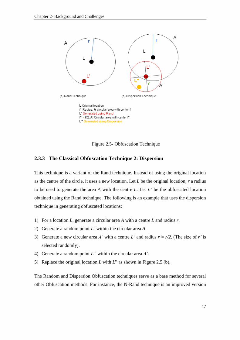
Chapter 2- Background and Challenges
47
Figure 2.5- Obfuscation Technique
2.3.3 The Classical Obfuscation Technique 2: Dispersion
This technique is a variant of the Rand technique. Instead of using the original location
as the centre of the circle, it uses a new location. Let L be the original location, r a radius
to be used to generate the area A with the centre L. Let L’ be the obfuscated location
obtained using the Rand technique. The following is an example that uses the dispersion
technique in generating obfuscated locations:
1) For a location L, generate a circular area A with a centre L and radius r.
2) Generate a random point L’ within the circular area A.
3) Generate a new circular area A’ with a centre L’ and radius r’= r/2. (The size of r’ is
selected randomly).
4) Generate a random point L” within the circular area A’.
5) Replace the original location L with L” as shown in Figure 2.5 (b).
The Random and Dispersion Obfuscation techniques serve as a base method for several
other Obfuscation methods. For instance, the N-Rand technique is an improved version

Chapter 2- Background and Challenges
48
of the random technique reported above. The N-Rand introduces a new parameter that
allows the selection of location points that are more distant from the original location L.
The dispersion technique has also been extended in such a way that L is also generated as
the most distant point to the original location. In [123], these methods were compared and
evaluated, and it was found that the N-Dispersion technique produced a larger minimum
distance to the original location and the greatest average distance to the original path.
2.3.4 The Weaknesses in the Classical Obfuscation Techniques
As we have seen in section 2.3.2 and 2.3.3, the traditional location Obfuscation
techniques, such as the Random and Dispersion techniques, employ geometric methods
to generate obfuscated locations. These methods are referred to as the geometric based
techniques in [124]. These techniques do not account for geographical knowledge. Thus,
they do not take into consideration the actual geographical environment at a generated
obfuscated location. In real life, a location may be in a public place, a private location
such as inside a building which is closed during that time of the day, somewhere in the
middle of the desert, or the ocean. Geometric-based Obfuscation techniques ignore the
semantics behind a geographic location. Consequently, the authors in [125] claim that an
adversary with sufficient geographical knowledge may be able to infer location sensitive
information from obfuscated locations generated by geometric-based technique. Our
work aligns with this claim. We will show, through experimentations conducted in
Chapter 5, that when a geometric-based Obfuscation technique is applied to a physical
environment, certain obfuscated locations are more likely to be identified as fake locations
by an adversary. Section 5.2.3.4 describes the experimental works conducted which
implement both the Rand and Dispersion techniques. It also reports on the performance
results collected for the experiments.
2.4 Summary
This chapter provided discussions and reviews of the major challenges facing the
widespread adoption of the IoT including issues relating to interoperability, management,
security, and privacy. It highlighted the need for a multifaceted approach to the privacy

Chapter 2- Background and Challenges
49
preservation and management of location information in the IoT. A new set of privacy
attacks were discussed and introduced in this chapter. For instance, the Automated
Invasion Attack is described as an incremental process of an inference attack in which the
attacker gradually gathers more knowledge on the user’s life or activities through the
combination and linking of the information collected from various things associated with
the user in the IoT. Furthermore, the chapter analysed several traditional privacy
protection methods and investigated their applicability in the IoT. It also reviewed two
major classical Obfuscation techniques and identified their weaknesses and investigated
their suitability for adoption in the IoT. This chapter also highlighted the major role WSNs
play in the integration of things and a group of things in the IoT. Specifically, the role
wireless low-power technologies play in supporting connectivity of small, low-cost, and
low-power things in the IoT.
The investigations conducted in this chapter lead to the following conclusions:
Several location positioning techniques can be used by things in the IoT to collect the
location of a user.
The disclosure of location information in the IoT can be used to violate the location
privacy of things and that of their users.
The low-cost and lightweight characteristics of things in the IoT challenge the
adoptions and implementations of much traditional management and location
preserving techniques in the IoT.
The unique characteristics of the IoT make the preservation of the location privacy of
things in the IoT a complex task. This demands a new approach to location privacy
protection in the IoT. Such an approach should account for the heterogeneity of IoT
communications, lightweight characteristics of things, dynamic and rich interactions
between things, and the need to accommodate contextual adaptive privacy policies in
the IoT.
The next chapter (i.e. Chapter 3) studies the various enabling wireless technologies in
IoT. It conducts several studies on various wireless technologies such as ZigBee,
6lowpan, Bluetooth Low Energy, LTE, and Wi-Fi protocols including the latest IEEE

Chapter 2- Background and Challenges
50
802.11ah technology. These studies assess the capabilities and behaviors of these wireless
technologies and identify their shortcomings, suitability of adoption, and their impact on
the preservation and management of location information in the IoT.

51
3 CHAPTER 3- WIRELESS ENABLING
TECHNOLOGIES FOR THE IOT
As previously discussed in Chapter 2, an interesting aspect of the integration of WSNs in
the IoT is the incorporation of multiple long-range and short-range wireless technologies
into the designs of IoT applications. For instance, eHealth applications such as body area
networks may develop into an autonomous world of small wireless and networked mobile
devices attached to their users [126]. They mostly connect to the Internet using a mobile
phone as a gateway or via a wireless access point. Wireless technologies in the IoT need
to handle a large degree of ad-hoc growth in device connectivity, structure, organisation,
and significant change in contextual use, including mobility as well [127]. Many devices
will constantly be connected to the energy grid such as smart appliances in the smart home
application example [128]. On the other hand, many other IoT devices suffer from limited
energy resources as they are powered by small batteries or rely on energy harvesting
techniques throughout their lifetime [129]. The need to accommodate the requirements
for minimum energy computation, slim and lightweight solutions for the management
and preservation of location privacy in the IoT is essential. Therefore, it is vital to
understand the networking context and requirements in which location information is
exchanged in the IoT. This is because, as identified in Chapter 2, traditional Internet
location management and privacy protection techniques cannot be used efficiently in the
IoT.
This chapter provides a state of the art on wireless enabling technologies in the IoT.
Section 3.1 discusses the wireless protocols available to connect things to the IoT within
the last few 100 meters. Section 3.2 reviews the major candidates to providing wireless
connectivity in the IoT including the IEEE 802.15.4, Bluetooth Low Energy, and IEEE
802.11 technologies. Section 3.2 provides several analyses and comparative studies
between various low-power wireless technologies, particularly ZigBee, 6Lowpan, and
IEEE 802.11ah, and the other variants of IEEE 802.11 technology (i.e. IEEE
Chapter 3- Wireless Enabling Technologies for the IOT
52
802.11a/b/g/n/ac), and LTE. These studies examine many parameters of these wireless
technologies such as their data rates and ranges, network sizes, transmission powers,
security, and significantly their ecosystem and suitability of adoption in the IoT. These
are needed to identify the requirements and capabilities of the technologies in which
lightweight things use to connect to the Internet. This is in addition to examining the
networking contexts and characteristics, in which things exchange location information
with IoT applications and with each other.
3.1 Wireless Low-Power Technologies for the IoT
The IoT covers a broad range of applications and devices. The 802.11 protocol with its
802.11a/b/g/n/ac variants, popularly known as Wi-Fi, is among the first obvious
technology candidates for the IoT. Examples of Wi-Fi applications in the IoT are
presented in [130]. Today, almost every house, workplace, cafe, and university has a Wi-
Fi network. Wi-Fi has become the de-facto term when referring to connecting to the
Internet via a wireless access point. The widespread adoption of Wi-Fi makes it a first
technology choice for many IoT applications. However, in some IoT applications, the
choice of technology is limited to the device’s hardware capabilities, low-power
consumption requirements, and the overall cost. Many IoT devices require the use of a
low-cost and low-power wireless technology when connecting to the Internet [131].
Traditionally, energy consumption has always been a limiting factor in many wireless
sensor network applications. This limiting factor will continue as a major challenge facing
the development of many applications in the IoT. In fact, for the growth of the IoT, low-
power consumption is an essential requirement that needs to be met.
In addition to low-power consumption, other associated requirements need to be
considered as well. For instance, the cost of technology, security, simplicity (easy to use
and manage), wireless data rates and ranges, among others, such as those reported in
[132], are essential requirements that require attention. Many evolving wireless
technologies such as ZigBee and Bluetooth are competing to provide the IoT with a low-
power wireless connectivity solution. Other wireless technologies such as the IEEE
802.11ah and 6Lowpan protocols are emerging as well [133]. They offer similar low-

Chapter 3- Wireless Enabling Technologies for the IOT
53
power wireless connectivity solutions for the IoT. Consequently, there could be many
choices of low-power wireless protocols for many IoT applications. Consider, for
example, a car-parking system application based on the IoT such as the one presented in
[134]. The IoT-based car parking system combines many components together. It
combines a variety of devices, multiple networking protocols, several sources of data, and
various wireless and generations of technologies. Many of the devices involved in the
communications are lightweight devices such as sensors that operate on batteries. They
would require a low-power wireless technology to function effectively.
Essentially, low-power wireless technologies contribute to improving not only the way
an IoT device connects to the Internet but the efficiency of the overall IoT application as
well. A network consisting of low-cost and lightweight IoT devices can be used to
monitor relevant operation and contextual parameters. These devices are also capable of
making appropriate decisions (based on the occurrence of specific events) while
simultaneously communicating with some other IoT devices. In general, a heterogeneous
setup allows an IoT system to perform many automated tasks by combining the various
data gathered from these IoT devices. In the smart home IoT application example, IoT
devices such as wireless sensors can report the ambiance temperatures in various
locations in a house to an IoT central device, referred to as the controller, which in turns
can make a decision on varying the output of the air-conditioning system. Adding more
IoT devices to the IoT system will increase the intelligence of the system as well. For
instance, if some other sensors are providing information on whether the house is
occupied or not (whether the people occupying the house are out or no), then the
controller will be able to make a better decision on when the heating system should be
turned on or off. In this smart home example, the IoT devices are in the form of simple
sensor devices which have a small bandwidth and low-power requirement. Hence, the
need for low-power wireless technologies in this and many other similar applications in
the IoT is essential.
Chapter 3- Wireless Enabling Technologies for the IOT
54
3.1.1 Bluetooth Low Energy: A Low-power, Low-cost Solution for the IoT
Bluetooth Low Energy (BLE), also known as Bluetooth Smart and Bluetooth version 4 is
an enhancement to the classic Bluetooth protocol [135]. Bluetooth is a packet-based
protocol. It implements master-slave communication architecture. A master is a Bluetooth
enabled device which has the capability of communicating with a maximum of seven
other Bluetooth-enabled devices, referred to as slaves, at a time. In Bluetooth terms, a
master is a device that initiates a connection. By agreements, Bluetooth devices can
switch roles from a master to slave and vice versa as well [135]. BLE allows devices to
communicate with each other when they come within a permitted range, normally up to
100 meters depending on the power classification of the device (more power, longer
range). The BLE protocol is designed to have an over the air data rate of 1 Mbps and
throughput of around 0.27 Mbps [136]. However, in practical implementations, the data
rate and throughput are much lower [137]. The low-power consumption feature of BLE
is achieved by putting a BLE device to sleep for a longer period. The device will only
wake up for a shorter amount of time when it is sending or receiving data. However, the
fact that BLE is only sending a small amount of data at a time with efficient energy
consumption makes it a favorable technology choice for several light IoT applications.
On the contrary, BLE can be judged as impractical to use in many other IoT applications
which may require the utilisation of a more capable technology regarding range and
bandwidth such as the IoT application reported in [138].
The throughput, range, data rate, and power consumption parameters of BLE are affected
by some other parameters such as the connection parameters. Two important aspects of
BLE are the physical channels and events. The physical channel specifies the frequency
at which data is sent. An event is the time unit in which data are sent between BLE
devices. There are two types of events: advertising events and connection events.
Advertising events are used to send advertising packets; while connection events are used
to send the actual data. Figure 3.1 shows an example of two connection events and one
advertising event. In these events, the slave and master devices are exchanging some
packets. The packets of each of the events are sent on a different frequency given that
BLE uses frequency hopping technique. Other important aspects that relate to BLE are
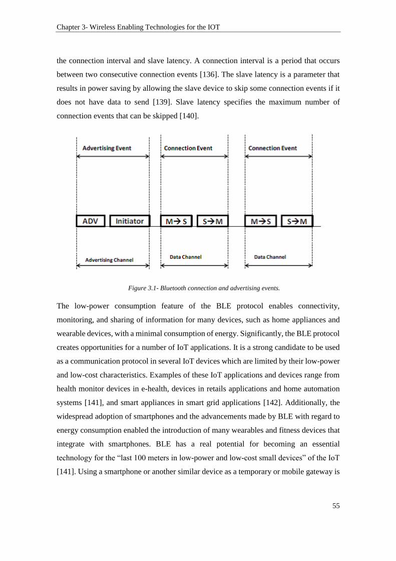
Chapter 3- Wireless Enabling Technologies for the IOT
55
the connection interval and slave latency. A connection interval is a period that occurs
between two consecutive connection events [136]. The slave latency is a parameter that
results in power saving by allowing the slave device to skip some connection events if it
does not have data to send [139]. Slave latency specifies the maximum number of
connection events that can be skipped [140].
Figure 3.1- Bluetooth connection and advertising events.
The low-power consumption feature of the BLE protocol enables connectivity,
monitoring, and sharing of information for many devices, such as home appliances and
wearable devices, with a minimal consumption of energy. Significantly, the BLE protocol
creates opportunities for a number of IoT applications. It is a strong candidate to be used
as a communication protocol in several IoT devices which are limited by their low-power
and low-cost characteristics. Examples of these IoT applications and devices range from
health monitor devices in e-health, devices in retails applications and home automation
systems [141], and smart appliances in smart grid applications [142]. Additionally, the
widespread adoption of smartphones and the advancements made by BLE with regard to
energy consumption enabled the introduction of many wearables and fitness devices that
integrate with smartphones. BLE has a real potential for becoming an essential
technology for the “last 100 meters in low-power and low-cost small devices” of the IoT
[141]. Using a smartphone or another similar device as a temporary or mobile gateway is

Chapter 3- Wireless Enabling Technologies for the IOT
56
increasingly getting popular in numerous IoT applications. Thus, BLE plays a significant
role in providing the communication medium needed between this gateway and the IoT
devices. There are also other applications where the same IoT device (e.g., a sensor) is
used for both mobile and fixed-location applications such as in the IoT hospital system
proposed in [143].
3.1.2 ZigBee IP: an IPv6-based Wireless Mesh Networking Solution for the
IoT
ZigBee supports interoperable communications among a broad range of smart and
innovative business products that enhance everyday life [144]. The IEEE 802.15.4 is a
protocol designed for low-rate wireless personal area networks (LR-WPANs). It defines
the physical and media access control layers [145]. The IEEE 802.15.4 is the basis
standard for ZigBee [146], WirelessHART [147], and 6LoWPAN [148]. The IEEE
802.15.4 operates in the unlicensed 2.4 GHz band which overlaps with other wireless
technologies (e.g., Wi-Fi and Bluetooth) sharing the same band. ZigBee is an extension
to the 802.15.4 standard. ZigBee is built on top of the 802.15.4's radio layer. It specifies
the application, network, and security layers as described in [149]. Often, the terms
802.15.4 and ZigBee are used interchangeably. However, this may not be correct as
ZigBee devices are not necessarily compatible with some implementations of the
802.15.4 standard. ZigBee’s data rate is considered low when compared with Bluetooth
and Wi-Fi. For instance, ZigBee has a data rate that ranges from 20 to 250 kbps [150].
On the other hand, Bluetooth has a maximum speed of 3 Mbps, and a practical data
transfer rate of 2.1 Mbps [151], whereas Wi-Fi has significantly higher data rates when
compared to that of Bluetooth. The battery lifetime of Bluetooth classic device is a few
days while that of Wi-Fi is a few hours. In some BLE devices, the battery can last for
over a year. However, the battery in a ZigBee device may last for five years before having
to be recharged or replaced [152]. Although ZigBee does not have the capability of a high
data rate and it is not adequate for real-time applications, it is, per se, serves best in
applications where both Wi-Fi and Bluetooth are less suitable.
Chapter 3- Wireless Enabling Technologies for the IOT
57
ZigBee IP is an improvement to the standard ZigBee. ZigBee IP has a layered architecture
that makes it suitable to work with other 802.15.4 implementations. The design of ZigBee
IP accommodates an IPv6 protocol stack. This stack is developed specifically to operate
on low-power and low-cost devices. Moreover, ZigBee IP incorporates technologies,
such as 6LoWPAN [153], that optimise routing and meshing in wireless sensor networks.
It supports the requirements of ZigBee Smart Energy as well [154]. This combination of
technologies offers a solution that enables the extension of IEEE 802.15.4 based networks
to IP-based networks. With regard to the network size, ZigBee IP network is considered
to be highly scalable. ZigBee-IP protocol does not enforce any limitations on the network
size. Theoretically, the size of the network is limited by the hardware specifications of
ZigBee devices such as the available memory and the amount of data that need to be
exchanged across a network. A typical IEEE 802.15.4 network supports a large number
of ZigBee devices. Several ZigBee-IP networks can coexist in the same physical area.
They can be designed to interconnect at the coordinator level, which allows a network to
further increase the number of connected devices. The main advantage of ZigBee-IP
compared to other 802.15.4 technologies is its architecture. ZigBee-IP provides a scalable
architecture that supports an end-to-end networking based on IPv6. Therefore, many
applications in the IoT benefit from this architecture [155].
3.1.2.1 ZigBee Network Topology based on the IoT
A typical ZigBee network consists of a ZigBee coordinator, ZigBee routers, and ZigBee
end devices [156]. Each ZigBee device on the network has a specific functionality that is
defined by its operational role. The ZigBee coordinator is responsible for controlling the
ZigBee network by coordinating the messages between the ZigBee routers and ZigBee
end devices [156]. The ZigBee router acts as a message relay that performs like a bridge
for ZigBee networks. The ZigBee end devices are standalone devices that participate in
the ZigBee network. Figure 3.2 shows an example of a ZigBee network topology, in
which the information flow is illustrated. The coordinator may stand for a smart-home
control system [157]. The routers can be appliances such as an air conditioner or a
thermostat; while the end devices can be security sensors or light switches [156].

Chapter 3- Wireless Enabling Technologies for the IOT
58
ZigBee supports star and mesh topologies [158]. The star topology is used when the
devices are close to each other and where the use of one coordinator is sufficient. A star
topology can also be a part of a larger mesh network with several routers that connect
several end devices. A mesh network is a network topology that allows the nodes to
communicate via an alternative path in case there is any failure in one of the intermediate
devices in an existing path e.g., link redundancy [156]. ZigBee has two operational
modes, i.e., beacon mode and non-beacon mode. In the beacon node, the nodes are aware
of when to communicate with one another and the coordinator periodically sends beacons
to all devices on the network. The ZigBee nodes, including the coordinator, may sleep
between beacons.
Figure 3.2- ZigBee IP network topology example
The beacons sent by the coordinator check whether there is a message received or not. If
there are no messages received, the nodes can go back to sleep mode. On the other hand,
the non-beacon mode is characterised by less coordination between the coordinator and
Chapter 3- Wireless Enabling Technologies for the IOT
59
the other ZigBee nodes. Since the end-device nodes only communicate when they need
to, the coordinator’s receiver is always active which enables it to receive messages from
other nodes in real-time. Consequently, in the non-beacon mode, the coordinator
consumes more energy since it has to be always listening. In contrast, other ZigBee
devices on the network save their power since they do not need to stay awake when they
are not engaging in any communication. Therefore, they remain in sleep mode for a longer
period. To better understand the differences between the beacon and non-beacon modes,
consider the following simple IoT application scenario where the ZigBee network is
configured in a non-beacon mode: A wireless switch is used to turn on/off an appliance
e.g., a lamp. The switch is battery operated while the ZigBee node i.e. the lamp is
connected to the power supply. Therefore, the lamp (the ZigBee coordinator) is always
active; while the switch (the ZigBee end device) remains asleep until someone uses the
wireless switch to turn on or off the lamp. In this scenario, the switch wakes up and sends
a command to the lamp which is always active and listening. The switch then remains
active until it receives an acknowledgment from the lamp and then returns to sleep.
3.1.3 Analysis of IEEE 802.11 WLANs for IoT Communications
Wireless Local Area Networks (WLANs) is the dominant technology for indoor
broadband wireless access. WLAN products have become commodity items used in
professional and consumer products alike. Recently, the propagation of WLANs as
extensions of wired networks has been increasing dramatically, and thereby, giving
devices equipped with wireless interfaces a higher degree of mobility. The two most
common WLAN standards are the IEEE 802.11 standard (commonly branded as Wi-Fi)
and the European HIPER (High-Performance Radio) LAN [159]. The IEEE 802.11
defines two types of configurations, the Infrastructure Basic Service Set (iBSS) and
Independent BSS (IBSS). In iBSS, an access point (AP) is the central entity of each
coverage area with coordination functionality. Additionally, the AP acts as a bi-
directional bridge between the wireless network and the wired infrastructure (i.e.,
typically Ethernet). Stations (STA) are mostly mobile devices equipped with IEEE 802.11
wireless network interfaces. Communication between the AP and the associated stations
occurs over the shared wireless medium that carries the data. A station must associate
Chapter 3- Wireless Enabling Technologies for the IOT
60
with an AP for it to transmit and receive data to and from the wired infrastructure, and to
communicate with other stations on the same WLAN. A Basic Service Set (BSS) is the
term used to refer an AP and its associated stations. In large WLANs, multiple BSSs can
be joined using a distribution system (DS), thus providing sufficient coverage for a greater
number of stations. This setup of having two or more BSSs is referred to as an Extended
Service Set (ESS). The DS is the wired backbone connecting APs and allowing the
associated stations to access services available on the wired infrastructure. Therefore, Wi-
Fi devices can form a star topology with its AP acting as an Internet gateway. The output
power of Wi-Fi is higher than other local area network wireless technologies. Full
coverage of Internet connectivity is necessary for Wi-Fi networks, so dead spots which
may occur are overcome by the use of more than one antenna in the AP.
Wi-Fi operates in the 2.4 and 5 GHz bands. Its operations in the 5 GHz band allow the
use of more channels and provide higher data rates. However, the range of 5 GHz radio
indoors (e.g., inside buildings) is shorter than 2.4 GHz. The IEEE 802.11b and IEEE
802.11g operate in the 2.4 GHz ISM band. The IEEE 802.11n improves the previous
versions of the standard by introducing the multiple input and multiple output methods
(MIMO) [160]. It supports a data rate ranging from 54 Mbit/s to 600 Mbit/s [161]. The
IEEE 802.11ac is an improved version of the IEEE 802.11n, and it provides high-
throughput wireless local area networks (WLANs) in the 5 GHz band with more spatial
streams and higher modulation with MIMO yielding data rates up to 433.33 Mbps [162].
The IEEE 802.11ac provides a single link throughput of at least 500 Mbps and up to 1
gigabit per second. The IEEE 802.11ac has a wider RF bandwidth of up to 160 MHz and
a higher density modulation up to 256 QAM [163].
At the other end of the spectrum, the IEEE 802.11ah standard operates in the unlicensed
900MHz frequency band. A wireless signal operating in the 900MHz band can penetrate
walls, but it would deliver a limited bandwidth ranging from 100Kbps to 40Mbps [164].
One common IoT application of this technology would be sensors and actuators in homes
or commercial buildings. Thus, IEEE 802.11ah could be positioned as a competitor to
Bluetooth and ZigBee protocols in the IoT space.
Chapter 3- Wireless Enabling Technologies for the IOT
61
3.1.3.1 The IEEE 802.11ah
Wi-Fi, with its 802.11 a/b/g/n/ac variants, may not be deemed suitable to use in some IoT
applications where low-power consumption is a vital requirement. Wi-Fi was originally
designed to offer high throughput to a limited number of devices located indoor at a short
distance from each other. Therefore, to meet the IoT low-power requirements, the IEEE
802 LAN/MAN Standards Committee (LMSC) formed the IEEE 802.11ah Task Group
(TGah) [165]. The task group objective is to extend the applicability area of 802.11
networks. It aims to design an energy efficient protocol allowing thousands of indoor and
outdoor devices to work in the same area [166]. The IEEE 802.11ah seeks to support a
range of throughput options ranging from 150 Kbps up to 40 Mbps over an 8 MHz band
[164]. With regard to the wireless range, the proposed IEEE 802.11ah protocol supports
a wider coverage range when compared to that of the IEEE 802.11n/ac protocol. The
IEEE 802.11ah supports applications with coverage of up to 1 km in outdoor areas and
up to 8191 devices associated with one access point [167]. The IEEE 802.11ah operates
in the unlicensed sub-1GHz bands, excluding the TV white-space bands. Sub 1 band
provides an extended wireless range when compared to the other bands used by
conventional 802.11 Wi-Fi standards which operate in the 2.4 GHz and 5 GHz bands
[168]. The IEEE 802.11ah relies on the one-hop network topology and employs power
saving mechanisms [164]. Given that the IEEE 802.11ah protocol falls under the overall
Wi-Fi umbrella, it is expected that it will be compatible with the existing Wi-Fi
infrastructure [169]. The IEEE 802.11ah allows access to more than 8 thousand devices
in the range of 1 km within an area with high concentration of small devices such as
sensors, and mini controllers. Therefore, the IEEE 802.11ah technology can satisfy the
IoT requirements while maintaining an acceptable user experience in parallel with the
IEEE 802.11 technologies. One of the interesting functional requirements of the IEEE
802.11ah is to enable coexistence with the IEEE 802.15.4 standard [170].
The IEEE 802.11ah standard includes new PHY and MAC layers grouping devices into
traffic induction maps to accommodate small units and machine to machine (M2M)
communications [171]. The physical layer allows devices along with the AP to operate
over various sub-1GHz ISM bands depending on the regulation of the country [171]. The
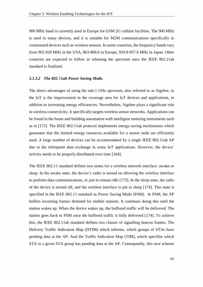
Chapter 3- Wireless Enabling Technologies for the IOT
62
900 MHz band is currently used in Europe for GSM 2G cellular facilities. The 900 MHz
is used in many devices, and it is suitable for M2M communications specifically in
constrained devices such as wireless sensors. In some countries, the frequency bands vary
from 902-928 MHz in the USA, 863-868.6 in Europe, 950.8-957.6 MHz in Japan. Other
countries are expected to follow in releasing the spectrum once the IEEE 802.11ah
standard is finalised.
3.1.3.2 The 802.11ah Power Saving Mode.
The direct advantages of using the sub-1 GHz spectrum, also referred to as Sigsbee, in
the IoT is the improvement in the coverage area for IoT devices and applications, in
addition to increasing energy efficiencies. Nevertheless, Sigsbee plays a significant role
in wireless connectivity. It specifically targets wireless sensor networks. Applications can
be found in the home and building automation with intelligent metering instruments such
as in [172]. The IEEE 802.11ah protocol implements energy-saving mechanisms which
guarantee that the limited energy resources available for a sensor node are efficiently
used. A large number of devices can be accommodated by a single IEEE 802.11ah AP
due to the infrequent data exchange in some IoT applications. However, the device’
activity needs to be properly distributed over time [164].
The IEEE 802.11 standard defines two states for a wireless network interface: awake or
sleep. In the awake state, the device’s radio is turned on allowing the wireless interface
to perform data communications, or just to remain idle [173]. In the sleep state, the radio
of the device is turned off, and the wireless interface is put to sleep [174]. This state is
specified in the IEEE 802.11 standard as Power Saving Mode (PSM). In PSM, the AP
buffers incoming frames destined for mobile stations. It continues doing this until the
station wakes up. When the device wakes up, the buffered traffic will be delivered. The
station goes back to PSM once the buffered traffic is fully delivered [174]. To achieve
this, the IEEE 802.11ah standard defines two classes of signalling beacon frames. The
Delivery Traffic Indication Map (DTIM) which informs, which groups of STAs have
pending data at the AP. And the Traffic Indication Map (TIM), which specifies which
STA in a given STA group has pending data at the AP. Consequently, this new scheme

Chapter 3- Wireless Enabling Technologies for the IOT
63
of PSM, TIM, and Page improves the overall power efficiency of IEEE 802.11ah devices.
For further readings on the new proposed PSM scheme the reader is referred to [175].
On the other hand, the IEEE 802.11af also called Super Wi-Fi or White-Fi, operates in
the unused TV spectrum [176]. 802.11af coverage can extend up to several kilometres as
it operates in the frequency bands between 54MHz and 790MHz. It offers a reasonable
throughput, estimated at 24Mb/s. It has similar applications as 802.11ah, providing
bandwidth for sensors and other devices of the IoT [177].
3.2 A state of the art on the Adoption of Wireless Technologies in the
IoT
There is a growing momentum to embrace and design technologies that adhere explicitly
to the IoT requirements. This includes the modification of existing technologies e.g., from
Bluetooth classic to Bluetooth smart, and from ZigBee classic to ZigBee-IP or the design
of new technologies such as the IEEE 802.11ah. These technologies aim at addressing
key IoT wireless and devices’ requirements such as low-power consumption, lower
computation capabilities, reduced implementation and operational costs, and a wider
coverage range. The previous section provided a brief review of the IEEE 802.15.4
technologies, Bluetooth Low Energy, and the IEEE 802.11ah technology. The IEEE
802.15.4 family of technologies, such as the 6Lowpan and ZigBee technologies, are
currently used in various wireless sensor network applications. These applications are
characterised by requirements similar to those encountered in the IoT. For instance, BLE
is widely adopted in wearables and consumer products. On the other hand, the IEEE
802.11ah is a new protocol under development. It is designed to operate in the sub-one-
gigahertz (900MHz) band. It has an extended range when compared to traditional Wi-Fi,
and it is regarded as a competitor for both ZigBee, 6Lowpan, and the other already-
established protocols in this sub-one band.
However, all the technologies above have their weaknesses and obviously their strengths.
For example, the gain in range with the use of the IEEE 802.11ah is lost in bandwidth.
Whereas, with the use of ZigBee the gain in bandwidth is lost in range. The areas of the

Chapter 3- Wireless Enabling Technologies for the IOT
64
IoT involve diverse sets of devices that use various communication technologies to share
and exchange information. Within the IoT, some applications can be in the form of simple
peer-to-peer applications. Other IoT applications can also be based on personal area
network setups, involving the use of few devices and users. Other complex applications
may involve the utilisation of a variety of heterogeneous devices which communicate
using a wide array of technologies, in different setups and topologies. Therefore, a
technology that can be deemed suitable for a particular IoT application might not
necessarily be suited to many others. In fact, the ability to connect and coexist various
devices operating using several communication technologies is the vision behind the IoT.
Having an ecosystem of coexisted technologies and devices is what enables the IoT vision
of extending communications to anything and anywhere.
3.2.1 WLANs: Capacity vs. IoT Requirements
The IEEE 802.11ac and LTE Advanced have the highest data rate among the wireless
technologies in use today. The IEEE 802.11ac specification provides a theoretical
maximum data transfer speed of more than 3Gbps. It can provide a transfer speed up to
1.3Gbps as well, and supports up to 8 streams [178]. On the other hand, LTE Advanced
has a 1 Gbps fixed speed and a rate of 100 Mbps to mobile users [179]. Figure 3.3
compares between various wireless technologies regarding distance coverage in meters,
rates, ranges, and power consumptions. In the low-power wireless technology space,
Bluetooth Low Energy has the highest data rate of 2.1 Mbps. ZigBee and 6Lowpan
technologies, supported by the IEEE 802.15.4 standard, have a data rate of 250 Kbps in
the 2.4 GHz frequency band. However, ZigBee’s data rate falls to 20 Kbps in the 868
MHz band and to 40 Kbps in the 915 MHz band in some countries [180]. In contrast, the
IEEE 802.11.ah has the lowest data rate targeted at 150Kbps with an average of 100 Kbps.
As of the theoretical wireless range, as illustrated in Figure 3.3, cellular technologies, e.g.,
LTE, cover a larger area when compared with other Wi-Fi technologies with IEEE 802.11
variants coming second at an approximate maximum range of a 100 m.

Chapter 3- Wireless Enabling Technologies for the IOT
65
Figure 3.3- A Comparative study of power consumption, distance coverage in meters, and data rate.
As of the range of low-power wireless technologies, the IEEE 802.11ah rules the chart
against 802.15.4 and BLE technologies. The 802.11ah coverage range also outperforms
that of the other variants of the 802.11 protocol, with a range coverage of approximately
1 km, as shown in Figure 3.3 and Figure 3.4. On the other hand, it should be noted that
the 802.15.4 supports mesh networking. In mesh networking, a message is routed through
several nodes on a network until it reaches its destination. Therefore, a ZigBee network’s
range can be easily extended with the use of repeaters in a mesh formation. Data in a
ZigBee network “hops” around a mesh of nodes until a route to the host (usually the
Internet) is found.
Therefore, repeaters and/or a high density of nodes can be used to extend the coverage of
a ZigBee network. Interestingly, the IEEE 802.11ah is under development with meshing
in mind as well. Therefore, the choice of technology regarding data rate and range come
back to the requirements of the IoT applications in hand.

Chapter 3- Wireless Enabling Technologies for the IOT
66
Figure 3.4- IEEE 802.11 technologies Range Comparison in Meters
Accordingly, if an IoT application requires the use of a larger number of nodes and
meshing is an option, ZigBee appears to be a suitable candidate given its data rate
advantage over its 802.11ah counterpart. On the other hand, IoT applications that require
the deployment of fewer nodes with minimal traffic, 802.11ah is a strong contender to
ZigBee. This is because 802.11ah has a larger coverage area without relying on any
meshing technique. Also, it is intended to be backward compatible with the variants of
802.11 Wi-Fi technologies. However, as we will see in the next subsections that the data
rate and range parameters do not provide enough and sufficient measures when
comparing IoT wireless technologies as other criteria need to be considered as well.
3.2.2 Network Size Capabilities for IoT Networks
The BLE protocol supports a maximum of eight nodes per network which include one
master device and seven devices as slaves. ZigBee can have up to 65,000 nodes per
network in a star topology [150]. These technologies can be extended to more
sophisticated networks as well. For instance, ZigBee can be extended to a cluster tree or
mesh network; while BLE can be extended to a scatternet network. An interconnected
piconet consisting of more than eight Bluetooth devices is referred to as a scatternet. It is
35 35 38 70
500
120 140 140
250
1000
0
200
400
600
800
1000
1200
802.11a 802.11b 802.11g 802.11n/ac 802.11ah
802.11 Range Comparison in meters
Approximate indoor range Approximate outdoor range

Chapter 3- Wireless Enabling Technologies for the IOT
67
the process of connecting two piconets together. A scatternet can be created when a device
belonging to one piconet is elected to be a member of the second piconet as well [181].
On the other hand, the baseline IEEE 802.11 standard does not limit the number of devices
in the network. However, the limitation can be attributed to the length of some of the
fields defined in the management frames of the standard [182]. The Association Identifier
(AID) which is a unique value assigned to a station by the AP during an association
handshake, is 14 bits long. However, the values other than 1-2007, which are 0 and 2008-
16383, are reserved. In particular, AID of value 0 is reserved for group addressing traffic
[166]. Therefore, the AID design limits the number of stations that can be associated with
an AP to 2007 [166]. Additionally, the Traffic Indication Map (TIM) bitmap enforces the
same limit on the number of associated stations as well. The TIM is used for power
management mechanisms. It defines the number of buffered frames received from an AP.
For these reasons, TGah is extending the range of AID values for 802.11ah’s devices
from 1-2007 to 0-8191. Also, the IEEE 802.11ah draft standard is increasing the maximal
length of the TIM bitmap for 802.11ah’s devices from 2008 bits to 8192 bits [166].
Therefore, it is quite obvious that ZigBee and IEEE 802.11ah protocols outperform the
classic 802.11a/ac protocol when it comes to the network size requirements. Of course,
cellular technologies have an enormous network size. However, cellular connectivity
cannot be possible without involving a mobile provider that usually charges a fee per
connection. Therefore, while cellular technology can accommodate a larger number of
devices, the costs involved are dramatically higher than those associated with other
technologies such as ZigBee. Table 3.1 provides a brief comparison between ZigBee,
BLE, and Wi-Fi with regard to their network sizes.
Table 3.1- Network Size comparison of ZigBee, BLE, and Wi-Fi
Technology Network Size
ZigBee Approximately up to 65,000 nodes
Bluetooth Eight nodes per network/piconet
Wi-Fi (802.11a/ac) 2007 associated with an AP
Wi-Fi 802.11ah Approximately 8000 nodes
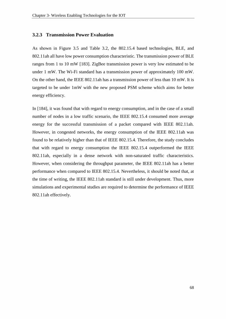
Chapter 3- Wireless Enabling Technologies for the IOT
68
3.2.3 Transmission Power Evaluation
As shown in Figure 3.5 and Table 3.2, the 802.15.4 based technologies, BLE, and
802.11ah all have low power consumption characteristic. The transmission power of BLE
ranges from 1 to 10 mW [183]. ZigBee transmission power is very low estimated to be
under 1 mW. The Wi-Fi standard has a transmission power of approximately 100 mW.
On the other hand, the IEEE 802.11ah has a transmission power of less than 10 mW. It is
targeted to be under 1mW with the new proposed PSM scheme which aims for better
energy efficiency.
In [184], it was found that with regard to energy consumption, and in the case of a small
number of nodes in a low traffic scenario, the IEEE 802.15.4 consumed more average
energy for the successful transmission of a packet compared with IEEE 802.11ah.
However, in congested networks, the energy consumption of the IEEE 802.11ah was
found to be relatively higher than that of IEEE 802.15.4. Therefore, the study concludes
that with regard to energy consumption the IEEE 802.15.4 outperformed the IEEE
802.11ah, especially in a dense network with non-saturated traffic characteristics.
However, when considering the throughput parameter, the IEEE 802.11ah has a better
performance when compared to IEEE 802.15.4. Nevertheless, it should be noted that, at
the time of writing, the IEEE 802.11ah standard is still under development. Thus, more
simulations and experimental studies are required to determine the performance of IEEE
802.11ah effectively.
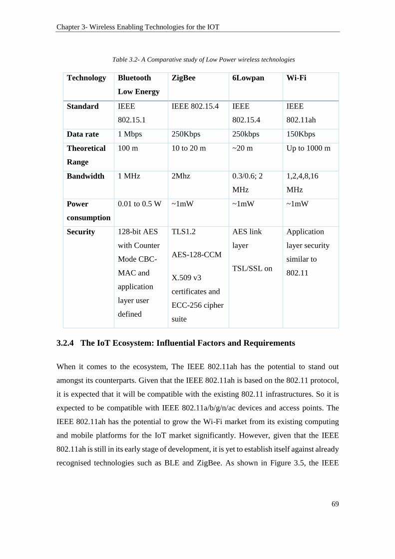
Chapter 3- Wireless Enabling Technologies for the IOT
69
Table 3.2- A Comparative study of Low Power wireless technologies
Technology Bluetooth
Low Energy
ZigBee 6Lowpan Wi-Fi
Standard IEEE
802.15.1
IEEE 802.15.4 IEEE
802.15.4
IEEE
802.11ah
Data rate 1 Mbps 250Kbps 250kbps 150Kbps
Theoretical
Range
100 m 10 to 20 m ~20 m Up to 1000 m
Bandwidth 1 MHz 2Mhz 0.3/0.6; 2
MHz
1,2,4,8,16
MHz
Power
consumption
0.01 to 0.5 W ~1mW ~1mW ~1mW
Security 128-bit AES
with Counter
Mode CBC-
MAC and
application
layer user
defined
TLS1.2
AES-128-CCM
X.509 v3
certificates and
ECC-256 cipher
suite
AES link
layer
TSL/SSL on
Application
layer security
similar to
802.11
3.2.4 The IoT Ecosystem: Influential Factors and Requirements
When it comes to the ecosystem, The IEEE 802.11ah has the potential to stand out
amongst its counterparts. Given that the IEEE 802.11ah is based on the 802.11 protocol,
it is expected that it will be compatible with the existing 802.11 infrastructures. So it is
expected to be compatible with IEEE 802.11a/b/g/n/ac devices and access points. The
IEEE 802.11ah has the potential to grow the Wi-Fi market from its existing computing
and mobile platforms for the IoT market significantly. However, given that the IEEE
802.11ah is still in its early stage of development, it is yet to establish itself against already
recognised technologies such as BLE and ZigBee. As shown in Figure 3.5, the IEEE
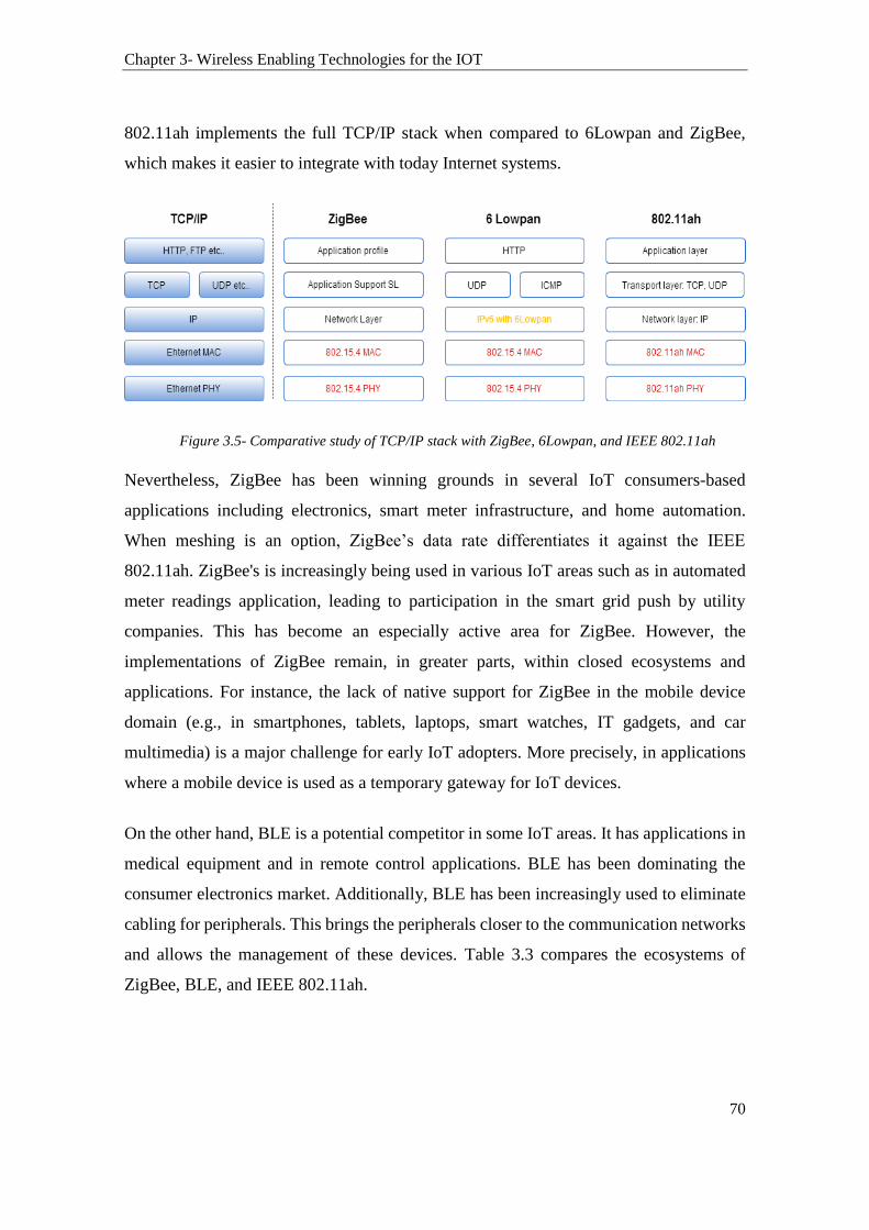
Chapter 3- Wireless Enabling Technologies for the IOT
70
802.11ah implements the full TCP/IP stack when compared to 6Lowpan and ZigBee,
which makes it easier to integrate with today Internet systems.
Figure 3.5- Comparative study of TCP/IP stack with ZigBee, 6Lowpan, and IEEE 802.11ah
Nevertheless, ZigBee has been winning grounds in several IoT consumers-based
applications including electronics, smart meter infrastructure, and home automation.
When meshing is an option, ZigBee’s data rate differentiates it against the IEEE
802.11ah. ZigBee's is increasingly being used in various IoT areas such as in automated
meter readings application, leading to participation in the smart grid push by utility
companies. This has become an especially active area for ZigBee. However, the
implementations of ZigBee remain, in greater parts, within closed ecosystems and
applications. For instance, the lack of native support for ZigBee in the mobile device
domain (e.g., in smartphones, tablets, laptops, smart watches, IT gadgets, and car
multimedia) is a major challenge for early IoT adopters. More precisely, in applications
where a mobile device is used as a temporary gateway for IoT devices.
On the other hand, BLE is a potential competitor in some IoT areas. It has applications in
medical equipment and in remote control applications. BLE has been dominating the
consumer electronics market. Additionally, BLE has been increasingly used to eliminate
cabling for peripherals. This brings the peripherals closer to the communication networks
and allows the management of these devices. Table 3.3 compares the ecosystems of
ZigBee, BLE, and IEEE 802.11ah.

Chapter 3- Wireless Enabling Technologies for the IOT
71
Table 3.3- Comparative study of ZigBee, BLE, and 802.11ah based on various criteria
Security Location
Detection
Low
Cost
Ease of
use
Ecosystem Low Power
Range Remote
control
Antenna
size
Networking
size
Frequency
band
802.15.4 ()
BLE
802.11ah ()
Comment
Wi-Fi
target:
as per
ZigBee
Wi-Fi
target:
as per
802.11
- BLE and 802.11ah
have larger
ecosystems. BLE is
established in
phones, wearables
802.11ah
compatible with
802.11
- ZigBee has a
closed ecosystem
established in some
use cases e.g., smart
energy
802.11ah
target: as per
ZigBee
Criteria:
‘home’.
ZigBee
Mesh will
improve
range.
-BLE:
Room range
-Wi-Fi:
Home
range,
extendable
by mesh
lower
frequencies
require
larger
antennas
Criteria:
>1000
Nodes per
network.
ZigBee has
an edge of
networking
size of 65,000
device
802.15.4 and
BLE operate
at 2.4 GHz;
while
802.11ah is
fragmented
by region

Chapter 3- Wireless Enabling Technologies for the IOT
72
The criteria considered in the rating of technologies provided in Table 3.3 and the
conclusions that can be drawn include the followings:
The wireless technologies surveyed above have built-in link layer authentication and
encryption, which most likely need to be completed with an end-to-end security at the
application layer.
Bluetooth Low Energy has the potential for less power consumption compared to that
of IEEE 802.15.4 (less overhead).
The IEEE 802.15.4 lacks the native support in the important ecosystem of mobile
devices.
The ecosystem with phones, tablets, laptops, and phone accessories is driving down
the cost of BLE.
The IEEE 802.15.4 has a data rate advantage over the 802.11ah. With regard to
coverage, similarly to 802.11ah, many IEEE 802.15.4 based technologies such as
ZigBee support meshing with the use of repeaters to extend the coverage of a network.
The IEEE 802.11ah can be employed in a variety of existing devices, which will
significantly improve the low-power consumption for these devices.
6LoWPAN implementations allow a device to communicate with another device over
the Internet without having to go through, for example, a ZigBee-to-IP translation
layer/device. At the time of writing, it is not clear as yet if the IEEE 802.11ah is
backward compatible with existing IEEE 802.11n/ac infrastructure and if any
infrastructure update or upgrade is needed. However, the fact that IEEE 802.11 is
widely accepted as the dominant indoor wireless technology including IEEE 802.11
based indoor access points (APs) and stations [185], makes Wi-Fi’s infrastructure
compatibility with IEEE 802.11ah a core aspect of its adoption.
6LoWPAN offers interoperability with other wireless IEEE 802.15.4 devices as well
as with devices on any other IP network with the use of a simple bridging device.
However, a more complex bridging device is needed to connect ZigBee with other
types of networks.
For IoT scenarios that require the use of thousands of devices, ZigBee has a
networking size of 65,000 devices. Similarly, the IEEE 802.11ah can also cater for

Chapter 3- Wireless Enabling Technologies for the IOT
73
approximately eight-thousand devices as well. Data rate and the required coverage
area play their roles in marking the differences between these two technologies as
well.
The IEEE 802.11ah benefits from the optimal propagation characteristic of sub-1GHz
license-exempt frequency bands compared to 2.4 and 5 GHz bands. However, the
IEEE 802.11ah frequency band fragmentation across different countries may be an
issue for some IoT applications.
3.3 Summary
This chapter reviewed some of the enabling wireless technologies in the IoT particularly,
ZigBee, 6lowpan, BLE, and Wi-Fi including the low-power IEEE 802.11ah protocol. It
examined these technologies and evaluated their capabilities and behaviours with regard
to various metrics including the data range and rate, network size, RF channels and
bandwidth, antenna design considerations, power consumption, security, and the IoT
ecosystem. The chapter highlighted the unique characteristics of these wireless low-
power technologies and the issues about their incorporation in the IoT. The low-power
and low-cost characteristics of these technologies and their integration in the IoT demand
either new location management and privacy-preserving methods or approaching the
prevailing management and location privacy protection systems differently. There is a
need to manage the location privacy of an unprecedented number of things connected to
the Internet generating a large amount of traffic across heterogeneous networks,
particularly those with low-power capabilities such as those examined in this chapter.
The next chapter builds on the studies conducted in this and the previous chapters (i.e.
Chapter 2 and 3). Chapter 4 proposes a management platform that provides users with the
capability of managing the location information of their devices and preserving their
location privacy in low-power wireless network setups similar to those investigated in
this chapter. Additionally, the proposed platform incorporates an enhanced novel location
privacy Obfuscation technique which addresses the shortcomings of classic Obfuscation
techniques identified in Chapter 2.
74
4 CHAPTER 4- THE INTERNET OF
THINGS MANAGEMENT PLATFORM
This chapter introduces the Internet of Things Management Platform (IoT-MP). The IoT-
MP aims to provide users with the capabilities to manage their IoT devices, specifically
their location privacy in the IoT. Also, the IoT-MP provides a communication platform
enabling IoT applications to support things-to-things communications over the Internet.
The IoT-MP offers the users with management capabilities, supervision, and control over
things. The platform supports management over services running on managed things,
such as sensing, actuating, monitoring, and managing the location information of things,
in a local area network or remotely over the Internet. The design of the proposed IoT-MP
takes into account the fact that things, in general, have limited power, computation, and
communication resources available to them. Significantly, the IoT-MP preserves the
location privacy of users and things during communications by supporting a privacy
module. In this privacy module, a novel location privacy-preserving technique referred to
as the Semantic Obfuscation approach (S-Obfuscation) is implemented which is
presented in Section 4.1. The IoT-MP’s architecture is presented in Section 4.2. Section
4.3 introduces the various IoT-MP components. The IoT-MP’s manager modules are
introduced in Section 4.4. Section 4.5 discusses the privacy module responsible for the
management of location privacy of things.
4.1 The Semantic Obfuscation Approach (S-Obfuscation)
The Semantic Obfuscation approach (S-Obfuscation) proposed in this work uses
geographical knowledge to guarantee that a generated obfuscated location is sensible in
the context of the location’s environment. That is, the method avoids generating an
obfuscated location that could be easily identified as fake by an adversary. For example,
if an obfuscated location is in the middle of a lake or sea, then it is easy for the adversary
to determine that either the subject is on a boat or the location received is not real. Further
knowledge of the geographic location may help the adversary in identifying the received

Chapter 4- The Internet of Things Management Platform
75
location as not original or obfuscated (such as whether boats are allowed on that location
or no). This is important in the IoT as the physical location of a device is considered
sensitive. Thus, there exist situations in the IoT where only specific entities or
applications should access the location of an IoT device with greater precision. For
instance, a public sensor collecting temperature information in a park or a given street
should not reveal its exact location, for example, to everyone. For many IoT applications,
it will be just sufficient to know the area where the sensor is located. Thus, by using
different levels of proximity to the original location (referred to as Obfuscation levels in
this work), we can control the granularity of the disclosed location.
To incorporate local geographical knowledge in the generation of obfuscated locations
for a device, a novel method that uses an ontological classification of geographic locations
is proposed. Our ontology is based on the one proposed in [186]. In our new approach to
Obfuscation, an original location L, consisting of longitude and latitude coordinates is
converted into ontology as shown in Figure 4.1. Ontologies are used as structural
frameworks for organising information and concepts within a domain, and the
relationship between those concepts. We use ontology as a form of knowledge
representation about the geographic knowledge of a location. The ontology, presented in
Figure 4.1, is part of a larger ontology that follows a top-down representation of several
classes and subclasses arranged in a hierarchy as shown in Figure 4.2. Note that in Figure
4.1, only a single path of the ontology is presented from Figure 4.2. The ontology classes
are constructed based on the naming of the geographic subdivisions used for address
purposes in Australia. Therefore, in this work, the scope of the ontology is limited to
Australia.
The parent ontological class in the hierarchy has n child classes. Each of these child
classes is a parent of another set of subclasses, which in turn are more general than their
child classes. This top-down hierarchal distribution represents the relative proximity of
the obfuscated location to the original true location. The parent class has the widest
proximity in the hierarchy while objects of the lower classes represent a smaller
proximity. Thus, proximity decreases the further we go down in the hierarchy and
increases the further we go up. Ontological classes on the same level of the hierarchy are

Chapter 4- The Internet of Things Management Platform
76
considered to be of the same granularity. These classes are structured in a tree starting
from the tree root country (1), where 1 is the node identifier, as shown in Figure 4.1 and
Figure 4.2. Each class in the tree has a name, an identifier, and a node address. For
example, the class “Street (4a)” has the name “Street” and the identifier “4a”. The node
address is constructed from the set of identifiers, separated by a dot (.). This node address
is used to define the path to the class from the tree root. All classes start with the number
1. For example, the node address for the class with the name ”Street” and identifier “4a”
is constructed by following the path starting from “country(1)” through “state(2a)” and
“suburb(3a)” down to “street(4a)”. Thus the node address of class “street (4a)” is
1.2a.3a.4a. Thus, this scheme allows the identifications of each of the classes. It also
provides a framework for the implementations, given that the scheme is adapting the
concept of classes and inheritance from the Object Oriented approach.
Figure 4.1- The Location Ontology

Chapter 4- The Internet of Things Management Platform
77
Figure 4.2-Tree Ontology
The S-Obfuscation works as follows: For each object belonging to a class of Level 2, an
object from a Level 1 class is selected and defined as a base point (an object is an instance
of a class). The base point is chosen based on the geographic knowledge. For example,
from Level 2, the class “Street (4a)” has subclasses with the following node addresses:
1.2a.3a.4a.5a; 1.2a.3a.4a.5b; and 1.2a.3a.4a.5c. The object with the node address
1.2a.3a.4a.5b is defined as the base point for all objects of the class “Street (4a)”.
Similarly, the object with the node address 1.2a.3a.4b.5h is defined as the base point for
all objects of the class “Street(4b)” and so on. Therefore, any object with a node address
of 1.2a.3a.4a.X (where X represents the identifier of the object of a Level 1 class) will be
obfuscated to 1.2a.3a.4a.5b. Similarly, for the class “Street(4b)”, any object with a node
address of 1.2a.3a.4b.X will be obfuscated to the defined base point 1.2a.3a.4b.5h, and so
on.
Consequently, the followings base points are defined for all classes of Level 2:
1.2a.3a.4a.5b, 1.2a.3a.4b.5h, 1.2a.3a.4c.5k, 1.2a.3a.4d.5m, 1.2a.3a.4e.5o, and
1.2a.3a.4f.5t. Defining multiple base points will increase the number of available
obfuscated locations that can be used. Also, randomising the appointment of objects as
base points will help in addressing historical profiling of locations.

Chapter 4- The Internet of Things Management Platform
78
4.1.1 The S-Obfuscation Levels
As discussed in the previous section, there are five levels of Obfuscations: L0, L1, L2,
L3, and L4, which are illustrated in Figure 4.3.
Figure 4.3- The Obfuscation levels
Level 0 (L0) discloses the true location of the object and Level 4 (L4) generates a dummy
location. The remaining three obfuscated location levels (L1, L2, L3) are will be
described subsequently. The position of any location on earth, on a 2D scale, can be
determined using the conjugate graticule, which is where the latitude and longitude
intercept. Determining the precise latitude and longitude coordinates of a location is
available using many technologies such as a global positioning satellite receiver, which
can communicate with satellites over the Earth to triangulate to a certain position.
Therefore, an object’s location in geographic space can be represented as a point on a
map and denoted by L, where L is a 2-tuple (latitude, longitude). Define L to be a member
of a set LS such that L∈ LS. LS is a collection of locations (refer to Table 4.1). For every
element L∈ LS, define a base point LS (Xsi , Ysj) to represent each L∈ LS. Let the set LS
be a subset of another set ℘(LS). In turn, let ℘(LS) be a subset of a master set ℘(℘(LS)).
Each of these three sets has a base point that can represent L in its correspondent subset.
Therefore, by selecting a set, a different base point location can be used and hence
different levels of Obfuscation are provided using different base points. Figure 4.4 depicts
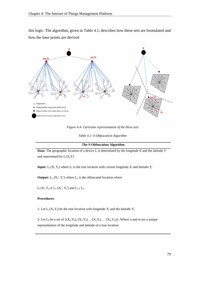
Chapter 4- The Internet of Things Management Platform
79
this logic. The algorithm, given in Table 4.1, describes how these sets are formulated and
how the base points are derived
Figure 4.4- Cartesian representation of the three sets
Table 4.1- S-Obfuscation Algorithm
The S-Obfuscation Algorithm
Data: The geographic location of a device L is determined by the longitude X and the latitude Y
and represented by L{X,Y}
Input: Li (Xi, Yj) where Li is the true location with current longitude Xi and latitude Yj
Output: Lo (Xi′, Yj′) where Lo is the obfuscated location where
Li (Xi, Yj) ∈ Lo (Xi′, Yj′) and Li ⊆ Lo.
Procedures:
1- Let Li (Xi,Yj) be the true location with longitude Xi and the latitude Yj
2- Let LS be a set of {(Xa,Yb), (Xc,Yd) …(Xi,Yj) … (Xn,Ym)}; Where n and m are a unique
representation of the longitude and latitude of a true location.

Chapter 4- The Internet of Things Management Platform
80
That’s for a given set of locations denoted by LS1, ∀ (Xn,Ym) [(Xn,Ym) \∈ LS1]
where \∈ means “strictly an element of”
// A certain location can strictly be an element of the lower subset.
Define the base point 1 LS (Xsi ,Ysj) to represent any (Xn,Ym) included in a particular LS set in a
way that:
If (Xn, Xm) ∈ LS then ∀ (Xn,Ym) there exist
(Xsi ,Ysj) ∈ LS such that [(Xsi ,Ysj) → (Xn,Ym)] where “represent any” is donated by →
3- A collection of sets of LS is denoted by ℘(LS)= {LS1, LS2 … LSp} where p is an integer
representing the number of subsets in ℘(LS) such as ℘(LS)={ Z | Z ⊆ LS }
Let ϔ= ℘(LS)
Define the base point 2 ϔ (XTi ,YTj) to represent any (Xn,Ym) included in any subset of ϔ in a
way that:
If (Xn, Xm) ∈ LS and LS ∈ ϔ then ∀ (Xn,Ym) there exist
(XTi ,YTj) ∈ ϔ such that [(XTi ,YTj) → (Xn,Ym)]
4- Define ℘(ϔ) to be the master set of ϔ where ℘(ϔ)= ϔ1⋃ ϔ2⋃ ϔf ; where f is an integer
representing the number of ϔ subsets available.
Let δ = ℘(ϔ).
Define the base point 3 δ(XCi ,YCj) to represent any (Xn,Ym) included in any subset of δ in a way
that:
If (Xn, Xm) ∈ LS and LS ∈ ϔ and ϔ ∈ δ then ∀ (Xn,Ym) there exist
(XCi ,YCj) ∈ δ such that [(XCi ,YCj) → (Xn,Ym)]
5- Therefore if Li (Xi, Yj) ∈ LS and LS ∈ ϔ and ϔ ∈ δ
There exist: ∀(Xi, Yj) [(Xsi ,Ysj) ∈ LS, (XTi ,YTj) ∈ ϔ, (XCi ,YCj) ∈ δ → (Xi, Yj)]
Table 4.1 - S-Obfuscation Algorithm (Continued)

Chapter 4- The Internet of Things Management Platform
81
4.1.2 A Scenario based on the S-Obfuscation
Consider the following typical example where a device requests a location based service:
Let L0 (lon, Lat) be a true original location and L the new obfuscated location. Convert
L to ontology with a node address of 1.2a.3a.4a.5a. Suppose Bob is at a location that he
considers sensitive. This location has a GPS location of L (151.2069364,-33.870887)
which corresponds to the physical address 22 George Street, Sydney, NSW, Australia.
The preference is as follows:
Preference 1: Bob, the owner of the sensor, is happy to share the location of the sensor
with other IoT applications. While Bob does not mind revealing that the sensor is located
at George Street, he prefers not to disclose its exact location.
To do that, Bob uses Level 1 of the S-Obfuscation technique. Therefore using Level 1,
for L with the correspondent node address 1.2a.3a.4a.5a, the obfuscated location L’ with
the correspondent node address of 1.2a.3a.4a.5b will be used (refer to Figure 4.2). Figure
4.5 shows the flowchart representing the actual implementation of this example. It shows
that instead of sending the sensor’s true location of 22 George Street, Sydney, NSW,
Australia, an obfuscated location of 35 George Street, Sydney, NSW, Australia, is used
instead. Thus, the base point in this class is 35 George Street, Sydney, NSW, Australia.
By obfuscating his true location L with a location L’ located on George Street, the sensor
can participate in the IoT application and the services it provides without revealing the
exact true location of the sensor. In addition, since L’ is already carefully selected based
on geographic knowledge, Bob is confident that adversaries will not be able to detect if
Bob is sending a fake location. In another scenario, Bob preferences are changed to as
follows:
Preference 2: Bob does not wish to reveal the sensor’s exact location, but he does not
mind letting an adversary know that the sensor is located at somewhere in Sydney.
To create this policy, Bob uses Level 2 of the S-Obfuscation techniques. Instead of
sending the true location L of the sensor, with the node address 1.2a.3a.4a.5a, Bob is now

Chapter 4- The Internet of Things Management Platform
82
able to choose to send an obfuscated location, with a wider proximity to the true location
used before. The obfuscated location generated in level 2 is selected based on geographic
knowledge as well. Figure 4.6 shows several options for obfuscated locations that Bob
can use. Level 3 of S-Obfuscation will allow Bob to choose an obfuscated location with
a wider proximity to the sensor’s true location than those produced in Levels 2 and 1.
This process is illustrated in Figure 4.6. On the other hand, Level 4 of S-Obfuscation will
allow Bob to select an obfuscated location with a wider proximity to those generated in
Levels 3, 2 and 1.
Figure 4.5- Level one of Obfuscation

Chapter 4- The Internet of Things Management Platform
83
Figure 4.6- Obfuscation Level 2 and 3
The rest of the chapter introduces the Internet of Things Management Platform, which
utilises the Semantic Obfuscation approach for the preservation of location privacy in the
IoT.
4.2 Architecture of the IoT-MP
The IoT-MP supports the communications among things regardless of their capabilities
and the technology they use. The IoT-MP architecture enables heterogeneous
communications to occur between the various types of things and IoT applications. Figure
4.7 shows a high-level view of the IoT-MP. It shows four types of things. A general device
(things) represents a generic form of physical devices that possess a communication
capability as a minimum requirement. The second type of things has actuation
capabilities. These are devices which receive remote commands over the Internet. They
have the capabilities of modifying the physical environment. Things with sensors collect
information from the physical environment and transmit this information over the
Internet. The last type of things is a hybrid device which possesses both sensing and
actuation capabilities. The IoT-MP acts as a communication bridge between these things.
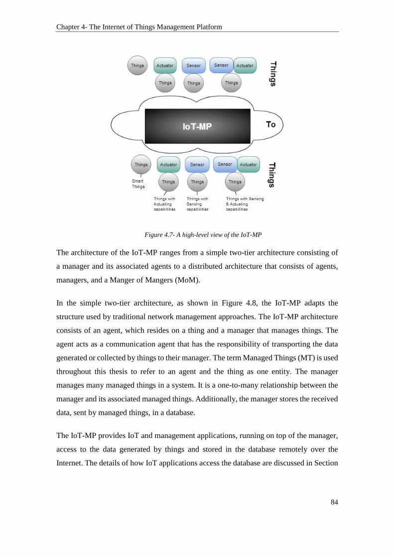
Chapter 4- The Internet of Things Management Platform
84
Figure 4.7- A high-level view of the IoT-MP
The architecture of the IoT-MP ranges from a simple two-tier architecture consisting of
a manager and its associated agents to a distributed architecture that consists of agents,
managers, and a Manger of Mangers (MoM).
In the simple two-tier architecture, as shown in Figure 4.8, the IoT-MP adapts the
structure used by traditional network management approaches. The IoT-MP architecture
consists of an agent, which resides on a thing and a manager that manages things. The
agent acts as a communication agent that has the responsibility of transporting the data
generated or collected by things to their manager. The term Managed Things (MT) is used
throughout this thesis to refer to an agent and the thing as one entity. The manager
manages many managed things in a system. It is a one-to-many relationship between the
manager and its associated managed things. Additionally, the manager stores the received
data, sent by managed things, in a database.
The IoT-MP provides IoT and management applications, running on top of the manager,
access to the data generated by things and stored in the database remotely over the
Internet. The details of how IoT applications access the database are discussed in Section

Chapter 4- The Internet of Things Management Platform
85
4.4.6. The IoT-MP also provides IoT applications with a mechanism to send instructions
to managed things e.g., sending actuation instruction to managed things.
Figure 4.8- IoT-MP Two-Tiers Architecture
In the distributed architecture, a Manager of Mangers (MoM) is introduced. This
architecture is provided in Figure 4.9. The MoM is a web application that contains an API
referred to as the management API. It allows the MoM to communicate with many
managers. The MoM also has a database that stores the addresses of managed things. The
MoM database is hierarchical (tree-structured), and each entry relevant to a managed
thing is addressed through the Manager unique ID. Thus, the MoM database does not
store any information collected from managed things. It only stores their addressing
information i.e. through which manager, managed things can be accessed. An IoT
application running on top of the MoM can provide services based on combining data
collected from various managed things. Therefore, IoT applications and services are built
on top of the M2M by supporting communications among things via their respective
managers.
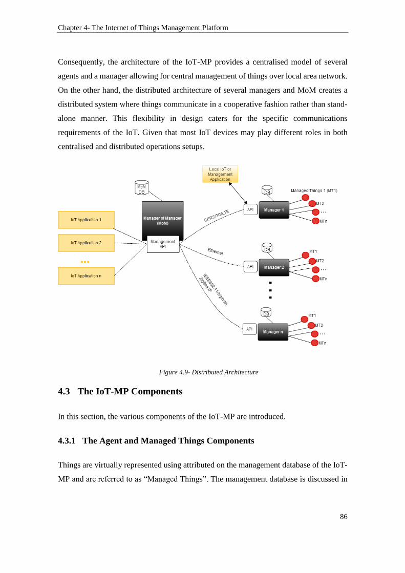
Chapter 4- The Internet of Things Management Platform
86
Consequently, the architecture of the IoT-MP provides a centralised model of several
agents and a manager allowing for central management of things over local area network.
On the other hand, the distributed architecture of several managers and MoM creates a
distributed system where things communicate in a cooperative fashion rather than stand-
alone manner. This flexibility in design caters for the specific communications
requirements of the IoT. Given that most IoT devices may play different roles in both
centralised and distributed operations setups.
Figure 4.9- Distributed Architecture
4.3 The IoT-MP Components
In this section, the various components of the IoT-MP are introduced.
4.3.1 The Agent and Managed Things Components
Things are virtually represented using attributed on the management database of the IoT-
MP and are referred to as “Managed Things”. The management database is discussed in

Chapter 4- The Internet of Things Management Platform
87
a subsequent section. The representation of things using attributes is shown in Figure
4.10.
Figure 4.10- The Attribute of Things
More specifically, things are represented using two types of attributes. The first type of
attributes is referred to as the management attributes. They are used for the virtual
representation of things. The second type of attributes is referred to as the behavioural
attributes. These attributes are used to hold the data things sense or collect. They are also
used to hold information relating to actuation events. The definition of these attributes
provides a way to store information about things and the information they collect on the
management database. Table 4.2 provides an example of management and behavioural
attributes that represent a wireless sensor device.
Table 4.2- Behavioural and Management Attributes example
Management Attributes Behavioral attributes
ID
Name
Serial Number
Firmware version
IP, MAC address, network name or others
Battery life
Location (if fixed)
Temperature
Motion
Sound
Pressure
Water & fire detection
Location (if mobile)
Therefore, we define a Managed Thing (MT) as the entity that represents the device and
its agent. Managed Things are accessed via the management database by the manager and

Chapter 4- The Internet of Things Management Platform
88
other IoT applications. Managed Things are abstract representation of things that
comprises not only the device e.g. a wireless sensor but also the communication module,
driver, and software (i.e. the agent) that handles the communications between the device
and the manager. In particular, an MT has a name and a unique identifier. The
management and behavioural attributes can be optionally defined and implemented for
things. From Table 4.2, the management attributes are descriptors of a wireless sensor
device. For example, the ID is used to identify uniquely a thing. The name, serial number,
firmware version, and the rest of these management attributes are also used as descriptors
for things. These attributes are optional, and the decision whether to use them or no is left
to the specification of things. For instance, not all things necessary have a firmware
version. Thus, a wireless sensor device may elect to use only the ID and location, as an
example, from the list of the management attributes. While, a smart enabled Wi-Fi device
may utilise more management attributes. Similarly, the behavioural attributes are used as
records in the management database. These are also optional as they are inheritably
associated with the characteristics of things. For instance, a temperature sensor that has
the responsibility for collecting motion and temperature data from a given environment
will choose the “Temperature” and “Motion” from the behavioural attributes lists. Other
things with a different functionality or scope such as a fire detection sensor will choose
the “Fire Detection” from the behavioural attributes. Operators of things may also create
new attributes in the management database to represent them.
Figure 4.11 models MTs. It further shows that an agent has two main modules. The
communication module is responsible for the communications with the manager. The
agent services module is responsible for the execution of services such as generating alerts
or processing an actuation instruction. Thus, the agent handles the communications
between the manager and thing by forwarding the collected data to the manager and by
processing the requests sent by the manager. Further details on how MTs associate with
a manager is provided in Section 4.4.3. In summary, the agent has the followings
responsibilities:
Establish communication with the manager.
Sending data updates from MTs to the manager.
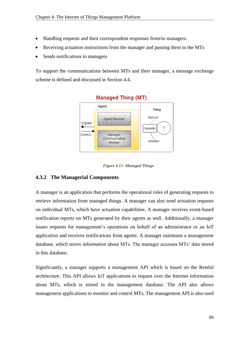
Chapter 4- The Internet of Things Management Platform
89
Handling requests and their correspondent responses from/to managers.
Receiving actuation instructions from the manager and passing them to the MTs
Sends notifications to managers
To support the communications between MTs and their manager, a message exchange
scheme is defined and discussed in Section 4.4.
Figure 4.11- Managed Things
4.3.2 The Managerial Components
A manager is an application that performs the operational roles of generating requests to
retrieve information from managed things. A manager can also send actuation requests
on individual MTs, which have actuation capabilities. A manager receives event-based
notification reports on MTs generated by their agents as well. Additionally, a manager
issues requests for management’s operations on behalf of an administrator or an IoT
application and receives notifications from agents. A manager maintains a management
database, which stores information about MTs. The manager accesses MTs’ data stored
in this database.
Significantly, a manager supports a management API which is based on the Restful
architecture. This API allows IoT applications to request over the Internet information
about MTs, which is stored in the management database. The API also allows
management applications to monitor and control MTs. The management API is also used
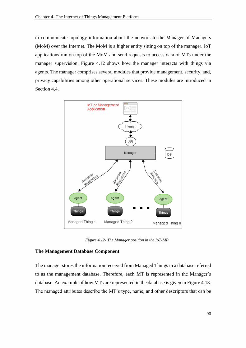
Chapter 4- The Internet of Things Management Platform
90
to communicate topology information about the network to the Manager of Managers
(MoM) over the Internet. The MoM is a higher entity sitting on top of the manager. IoT
applications run on top of the MoM and send requests to access data of MTs under the
manager supervision. Figure 4.12 shows how the manager interacts with things via
agents. The manager comprises several modules that provide management, security, and,
privacy capabilities among other operational services. These modules are introduced in
Section 4.4.
Figure 4.12- The Manager position in the IoT-MP
The Management Database Component
The manager stores the information received from Managed Things in a database referred
to as the management database. Therefore, each MT is represented in the Manager’s
database. An example of how MTs are represented in the database is given in Figure 4.13.
The managed attributes describe the MT’s type, name, and other descriptors that can be

Chapter 4- The Internet of Things Management Platform
91
defined by the administrator. The Behavioural attributes are used to store the data
received by the manager from an MT. MTs’ information is indexed in the database using
the unique ID of the MT. Figure 4.13 shows examples of Managed and Behavioural
attributes. For instance, the MTID is used to uniquely identify an MT. The Type, Name,
Admin, and AgentID are other examples of managed attributes. The Loc, Sensor Reading
A, and B are examples of behavioural attributes entries in the database. The security layer
is a pointer to another process that is concerned with security and location privacy
protection. This is further discussed in section 4.4.4. The main parts of the database
scheme are provided in Figure 4.14. The complete database schema is provided in the
appendix.
Figure 4.13- MTs Entries
From Figure 4.14- Database Schema, table Managed Thing:
MTID is an identifier used to uniquely identify things in the IoT-MP. It is assumed
that each IoT device (things) is assigned a unique identifier.
AgentID is an identifier used to identify agents. This AgentID is assigned by the
manager. The MTID and AgentID are used to identify an MT. In the case where the
agent is residing on the MT, the MTID is used in place of the AgentID.

Chapter 4- The Internet of Things Management Platform
92
The security pointer points to another process that enforces access control disclosures
policies on the data of MTs.
The descriptions of the rest of the entries in the database are provided in Figure 4.14
and are self-explanatory.
Figure 4.14- Database Schema
The Manager of Managers (MoM)
The Manager of Managers (MoM) provides mapping and routing services over the IoT-
MP. The functionality of a MoM is similar to a router that performs "traffic directing"
functions on the Internet. The MoM forwards data packets between managers’ networks
and IoT applications over the Internet. An IoT application accesses the MoM remotely
over the Internet. It can request information about an MT (belonging to a particular
manager’s network) or supply information that can be used by other MTs or IoT
applications.

Chapter 4- The Internet of Things Management Platform
93
As previously mentioned in Section 4.2, the MoM sits on top of the tree structure of the
IoT-MP and communicates with many managers. Communications between a manager
and the MoM are via their APIs and over HTTPS. The MoM maintains a hierarchical
database, which stores the addresses of managed things and their managers. The MoM
does not store in its database any operational data on MTs. Thus, similarly to a routing
table, the MoM database is used to store information about the topology of the network
such as which manager is overseeing which group of MTs. This information is used by
the MoM to determine where a request, sent by an IoT application, should be directed
within the IoT-MP network.
The MoM database consists of a table which has three fields:
The ManagerID: i.e. the destination of the manager network
The IP address of the manager
The list of MTID belonging to its manager network
The scenario is as follows: the MoM receives a request to access a certain MT data from
an IoT application over the Internet (HTTP request). The request must specify at least the
MTID of the requested MT and the “AppID” of the application, along with some other
credentials used for authentication (this will be described in more details in section 4.4.6).
The MoM then lookups the MoM database and retrieves the correspondent ManagerID
and its IP address. The MoM forwards the request to the correspondent manager and waits
for a response. Lastly, the manager responds to the MoM with either an error message or
with the data being requested. This scenario will become clearer once the manager and
its components are introduced in the next section (Section 4.4).
In the rest of this chapter, the work assumes that IoT applications communicate with a
manager transparently. That is the communication medium is already established between
the IoT application and the manager. Thus, instead of passing through the MoM each time
a request is issued by an IoT application, we will simply refer to the request as being
issued by an IoT application to a manager.
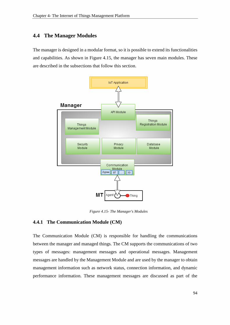
Chapter 4- The Internet of Things Management Platform
94
4.4 The Manager Modules
The manager is designed in a modular format, so it is possible to extend its functionalities
and capabilities. As shown in Figure 4.15, the manager has seven main modules. These
are described in the subsections that follow this section.
Figure 4.15- The Manager's Modules
4.4.1 The Communication Module (CM)
The Communication Module (CM) is responsible for handling the communications
between the manager and managed things. The CM supports the communications of two
types of messages: management messages and operational messages. Management
messages are handled by the Management Module and are used by the manager to obtain
management information such as network status, connection information, and dynamic
performance information. These management messages are discussed as part of the

Chapter 4- The Internet of Things Management Platform
95
Management Module in Section 4.4.2. Operational messages are mainly used to get status
information and updates from managed things. These messages are based on two
messages “Get” and “Update”. As their names suggest, the ‘Get’ messages are used by
the manager to get information from an MT. The “Update” message is utilised by an MT
to send an update to a manager. These messages are defined as follows:
Update (MTID, [AgentID], Array5): The Update message is used by an MT to send
periodic messages to the manager. The agent can also use this message to send event-
based alerts to the manager. It has three arguments: the MTID, which stands for the
Managed things Unique Identifier ID. The MTID is used by the manager to identify
MTs. The second argument, [AgentID], is optional and is used to identify the agent.
The last argument, Array[], contains the content of the message, in which the MT is
sending to the manager, stored in an array format. The format of the message Update
is provided in Figure 5.10.
GetUpdate (MTID, [AgentID]): This message is used by the manager to request an
update from the MT. For instance, GetUpdate(temperature collected by MT) is an
implementation example of the message GetUpdate()
Response (MessageID, AgentID, Array[], ErrorIndex): This is a response message
to the manager’s message GetUpdate(). The MessageID argument in the Response
message is used by the manager for matching requests to responses. The ErroIndex
is a number which points to an error. The Array[] contains the content of the
message supplied in the reply.
Actuate (): This message is optional. It is sent by the manager to an MT triggering
an actuation event on the MT.
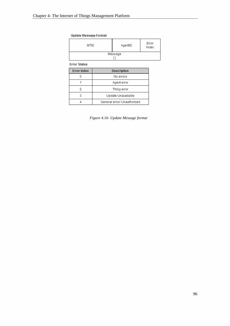
Chapter 4- The Internet of Things Management Platform
96
Figure 4.16- Update Message format

Chapter 4- The Internet of Things Management Platform
97
Figure 4.17- GetUpdate Message Format
The GetUpdate message is sent by a manager to an MT. It is used to request data update.
For example, GetUpdate(Location) is used to get an update on the location of an MT. The
format of this message is provided in Figure 4.17. It shows the entries for both GetUpdate
and Ack messages. Figure 4.17 contains as well a description of each of the entries of
these messages. The message Actuate() is an optional message. It is only supported by
MTs that have actuation capabilities. The message Actuate() has a response message
defined as Ack(). The messages formats of Actuate() and Ack() are given in Figure 4.18.
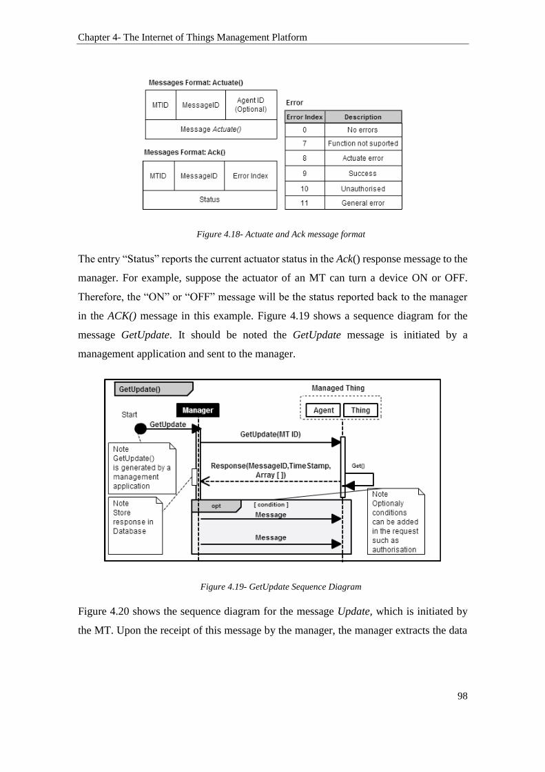
Chapter 4- The Internet of Things Management Platform
98
Figure 4.18- Actuate and Ack message format
The entry “Status” reports the current actuator status in the Ack() response message to the
manager. For example, suppose the actuator of an MT can turn a device ON or OFF.
Therefore, the “ON” or “OFF” message will be the status reported back to the manager
in the ACK() message in this example. Figure 4.19 shows a sequence diagram for the
message GetUpdate. It should be noted the GetUpdate message is initiated by a
management application and sent to the manager.
Figure 4.19- GetUpdate Sequence Diagram
Figure 4.20 shows the sequence diagram for the message Update, which is initiated by
the MT. Upon the receipt of this message by the manager, the manager extracts the data

Chapter 4- The Internet of Things Management Platform
99
contained in the Update message and updates the relevant records in the management
database for the MT using its MTID.
Figure 4.20- Update Message Diagram
4.4.2 The Things Management Module (TMM)
The Things Management Module (TMM) defines the messages used by the manager to
manage MTs. These management messages are adapted from SNMP. Mainly, the TMM
adapts three SNMP messages: the SET, GET, and Alert SNMP messages. They are used
to inspect and communicate information about MTs to the manager. The TMM messages
are described as follows:
GetMTStatus(MessageID, MTID, [AgentID]): This message is used by the manager
to request information on the status of an MT. The message takes the Managed Thing
ID (MTID) as an argument. The AgentID can be optionally specified as well. This
message returns an Update message (previously introduced in Section 4.4.1)
containing the information requested. For instance, a scenario of a GetStatus message
is provided in Figure 4.21.

Chapter 4- The Internet of Things Management Platform
100
GetDeviceMode ([SensorMode], [ActuatorMode], [AgentID]): The SensorMode and
ActuatorMode are optional arguments. Their implementations depend on whether an
MT possess sensing and actuation capabilities.
SetLoc (MTID, Location): This message is used to set the location of an MT. Mainly,
it is used for MTs with fixed location e.g., an item on a shelf in a warehouse.
Other management messages based on the SNMP GET message can also be implemented
to retrieve specific information from MTs.
Figure 4.21- GetStatus message
4.4.3 The Things Registration Module (TRM)
The Thing Registration Module (TRM) is responsible for registering things on the IoT-
MP. It involves the process of things bootstrapping, connecting and joining the network,
and creating an entry for the thing in the database. A thing joins the IoT-MP network and
becomes an MT by connecting to a manager using an agent. Thus, it is assumed for the
communication to be established with a manager, a thing must rely on an agent that is
capable of communicating with the manager. As previously mentioned in Section 4.3.1,
the agent is a software that can be installed on the thing, or it could reside on another
device in the thing local area network. For example, a Bluetooth slave device (thing) may

Chapter 4- The Internet of Things Management Platform
101
communicate with a Bluetooth Master device that implements the agent capability. In this
example, the Bluetooth Master device is considered to be the agent. The combination of
the master and slave device is referred to as the MT. It is assumed that communications
between the Bluetooth Master and Slave devices are already provisioned. Assuming a
thing already has an agent capable of communicating with the manager, a thing connects
to the manager and becomes an MT using one of the followings three methods:
I. by joining the network directly;
II. by requesting to join the network through associations;
III. by reconnecting to the network.
In the direct joining method I, the thing is pre-programed with the network address of the
manager. This allows the thing to send a DIRECT-JOIN request, via an agent, to the
manager. In method II, the process of connecting an MT to the manager through an
association is similar to that of a Wi-Fi device that associates with an access point.
Method III is used when an MT loses its connection with the manager and tries to re-
connect. This can happen when an MT moves out of range of the local-area network or
when the manager becomes unavailable. In such a case, the MT will try to reconnect and
join the network using Method I or II. The difference between method I and II, on one
hand, and that of III, on the other hand, is that in method III there is no need to create a
new record in the database for the MT. Instead, the manager updates the existing records.
The sequence diagrams for the method I and II are provided in Figure 4.22. In the
sequence diagram of method II, the security negotiation messages are discussed in
Section 4.4.4.

Chapter 4- The Internet of Things Management Platform
102
Figure 4.22- Method I and II sequence diagrams
4.4.4 The Security Module (SM)
The Security Module (SM) provides (1) security services between managed things and a
manager and (2) security between IoT applications and the manager using a security
profile. In (1), the SM enforces that an agent must first be registered with the manager
and approved by an administrator. The manager keeps a database of authorised agents
using their AgentIDs. Therefore, the SM ensures that only authorised remote agents are
allowed to connect to the manager. To achieve this, the SM enforces this two directives:
a) The SM prevents unknown remote agents from connecting to the manager.

Chapter 4- The Internet of Things Management Platform
103
b) Remote agents need to be manually approved by an administrator before they can
communicate with the manager.
This work assumes that the identity of an agent (AgentID) is unique and protected against
classic identity threats such as identity forging, poison attack, and the likes. To relax the
condition implied in b,), which requires the manual approval of agents by a human and
to automate the process, classical access control and identity management solutions can
be employed to preserve the identity of agents. For instance, a digital certificate solution
can be combined with an Attribute-based access control (ABAC) system to secure the
process of establishing a security association between an agent and a manager. However,
identity management is not the focus of this thesis. Therefore, this work assumes that an
agent is securely connected to a manager at all time. This includes encrypting the
communication channel between these two entities.
In (2), IoT applications can connect to the manager by sending requests over HTTP to the
management API. The processes relating to this HTTP request along with the
management API are discussed in Section 4.4.6.1. The role of the SM in here is to provide
optional security services that protect HTTP sessions using SSL. The SM also contains a
security profile enabling owners or admins of MTs to define security disclosure policies.
These policies are used to define the authorised entities permitted to access the MTs’ data
stored in the management database. Thus, the security profile allows the owner of an MT
to define to whom the information collected from MTs is disclosed. This is achieved by
providing them with a UI enabling them to maintain a list of authorised entities.
Furthermore, the security profile is used to create policies that govern whether
information collected from MTs should only be disclosed to IoT application over secured
channels or no. An activity diagram showcasing the role of the SM and its security profile
is provided in Figure 4.23.

Chapter 4- The Internet of Things Management Platform
104
Figure 4.23- SM Activity Diagram
From Figure 4.23, the manager receives a Get Request message from an IoT application
requesting some information on an MT. The details of how these messages are processed
are provided in Section 4.4.6. Upon the receipt of the message “1.GetRequest”, the
manager proceeds first into checking whether the requesting entity (the IoT application
in this case) is authorised to access the requested MT data. The manager does that by
sending to the SM the message “2.1CheckPolicy”, which returns a flag that can be either
“True” which means the request is approved or otherwise “False”. The message
“2.1CheckPolicy” has the following sub-messages:
It starts with the message “2.2 CheckRequirments” that retrieves from the database
the security policies stored by the user, which govern the disclosure of the information
of the MT under request. Note that in Figure 4.23 the owner or admin of an MT has
access to the list of approved entities. This enables him or her to add an approved
entity to the list and to indicate whether their MT’s data should only be disclosed over
secured connections.
The “Is communication secure” decision point checks whether the policy indicates
that the MT’s data under request should only be disclosed to authorised entities. If the
request does not meet this condition, then the decision point takes the “No” path and

Chapter 4- The Internet of Things Management Platform
105
sends a “False” return message back to the manager. If this criterion is met, then the
“Yes” path moves to another decision point.
The “is the requester approved” decision points checks whether the requester (the IoT
application is this case) is on the list of the approved entities. If “Yes” then the flag is
set to “True”. In this case, the manager receives a return message “True” that indicates
that the SM approves this request. Otherwise, if the result is “No” then the request
will not be approved, and the original Get Request message will be replied to with an
error message. Note that the manager does not disclose the MT’s information in the
case of “Yes” yet, as the manager has to obtain an approved message from the Privacy
Module as well. This is discussed in Section 4.5.2.
4.4.5 The Database Module (DM)
The database module (DM) contains two types of databases: Data Resource (DR)
database and Operational Database (OD).
The DR is used by the manager to store management information of things, their agents,
the security profile of the Security Module, and other information relating to the Privacy
Module. The DR also stores information relating to architectures, policies, practices and
procedures that govern many operations of the IoT-MP. This database is not accessible
by IoT applications. It is only accessible by the administrators and/or owners of things.
Also, the management API, which is used by IoT applications to exchange messages with
the manager, does not have access to the DR database. On the other hand, the OD database
is used to store the information sent by MTs to the manager. This database is accessible
by the management API whereas IoT applications can request access to the MTs’ data
stored in this database over the Internet. The separation of two databases ensures the
security of the database module by splitting between the operational data and that of the
Data Resource Management.
The database Module (DM) also has an archive database (AD). The DM uses this AD to
archive the DR and OD records of MTs, which are no longer connected to a manager.
This helps in reducing the amounts of data stored in a database. Figure 4.24 shows the

Chapter 4- The Internet of Things Management Platform
106
DM architecture. It illustrates how the management API only has access to the OD. This
work assumes that traditional security database management and access control solutions
are already employed to secure and maintains the databases included in this module.
Figure 4.24- Database Module Architecture
4.4.6 The API Module
The API module contains an application programming interface (API), referred to as the
Management API. The API provides an integrated and enhanced access interface for IoT
applications. It enables IoT applications to participate in communication in the IoT-MP.
That is the API allows IoT applications to retrieves MT’s data stored in the database
remotely over the Internet. It also allows IoT applications to send actuation instructions
over the Internet to relevant MTs. The API design is based on the Representational State
Transfer (REST). REST implements a set of messages known as HTTP verbs (GET,
POST, PUT, and DELETE) as shown in Figure 4.25. It is platforms and languages
independent. Thus, it supports multiple platforms (HTML, UNIX, Android, Windows,
and iOS.) and does not require the use of a specific programming language (e.g., Java).
Hence, theoretically, the API module can support a variety of IoT applications regardless
of the platform or programming language they run or use. However, these applications
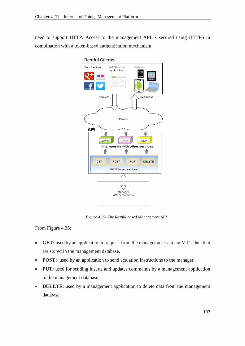
Chapter 4- The Internet of Things Management Platform
107
need to support HTTP. Access to the management API is secured using HTTPS in
combination with a token-based authentication mechanism.
Figure 4.25- The Restful based Management API
From Figure 4.25:
GET: used by an application to request from the manager access to an MT’s data that
are stored in the management database.
POST: used by an application to send actuation instructions to the manager.
PUT: used for sending inserts and updates commands by a management application
to the management database.
DELETE: used by a management application to delete data from the management
database.

Chapter 4- The Internet of Things Management Platform
108
PUT and DELETE commands are reserved for management applications only.
Consequently, an IoT application can only use two commands: GET, which is used to
retrieve information about MTs, and POST that is used to contribute with information or
to send actuation events.Designing APIs for the Internet of Things is an active area of
research. The design of APIs has recently matured a lot in a way it can be used to combine
authorisation with authentication. For instance, JSON web tokens can be used with OAuth
2.0 to provide identity delegation services as well. The API designed in this work is
intentionally kept simple. This is to avoid drifting into API research and design, which is
a research area by itself. The aim is the provision of a valid method to authenticate an IoT
application to the IoT-MP. Thus, providing IoT applications with a method to connect to
the IoT-MP. Other researchers or future works may look into designing an optimised API
for the IoT-MP.
4.4.6.1 Authorizing IoT Application
The IoT-MP requires that IoT applications must be authenticated first by the manager.
That is, for an IoT application to send an actuation instruction, contribute with some data,
or request access to an MT’s information over HTTP, the IoT application must be first
authenticated by the management API. This authentication is done by communicating
certain credentials to the management API. The authentication process is as follows:
The administrator or owner of the IoT application must first register the IoT
application on the IoT platform using a unique identifier referred to as the “AppID”.
This “AppID” can be chosen by the person registering the IoT application. However,
the API must verify that the AppID is unique. That is, the IoT-MP will verify that no
other IoT applications, registered on the IoT-MP, are using the same AppID.
Alternatively, an IoT application can utilise a unique AppID automatically generated
by the API registration interface.
Upon successful registration, the IoT application will be issued with a unique “Secret
Token”.
Chapter 4- The Internet of Things Management Platform
109
For an IoT application to be granted permission to access MT’s data, the IoT application
must authenticate itself by sending a valid access token in the HTTP request header to the
manager along with its AppID. The access token is, in fact, the Secret Token, which was
assigned to the application upon registration. The supplied credentials will then be used
in the authentication flows between an IoT application and a manager. The authentication
flow starts with the manager validating the Secret Token initially passed in the request.
After the Secret Token is validated, the manager uses the Secret Token to establish a
security context for the IoT application. That is, if the IoT application is successfully
authenticated, then the request moves to another stage of authorisation conducted by the
Security Module (SM). The SM has to responsibility for checking whether an IoT
application is on the list of approved entities by the owner of the MT under request. This
process is done using the function CheckPolicy() from the security profile as previously
described in Section 4.4.4. Unauthenticated requests issued by the IoT application will be
replied with an HTTP 401 Unauthorised response message and will not reach the
authorisation stage.
The design of the API is based on the JSON web API. The main parts of the API design
are summarised to as follows: The format of the JSON based web token is three strings
separated by a dot (.). Example: stringA.stringB.stringC. StringA is the header. StringB
is the payload and stringC is the signature. The header specifies the type of the request
and the hashing algorithm in use, which is SHA256. The payload carries the “AppID”
and “Secret Token”. The last part, stringC, is the signature, which is a hash that combines
the header, the payload, and a secret. The secret is the signature held by the manager. It
allows the manager to verify existing tokens and sign new ones.
To this end, the work has introduced the IoT-MP and all the main components of the
manager, except the Privacy Module (PM). A state diagram that consolidates the
communications containing the modules involved in processing a request to access an
MT data, sent from an IoT-application to the IoT-MP, is shown in Figure 4.26. It is
essential to understand the roles and responsibilities of each of the modules introduced so
far and illustrated in Figure 4.26 before proceeding into presenting the architecture of the
PM.
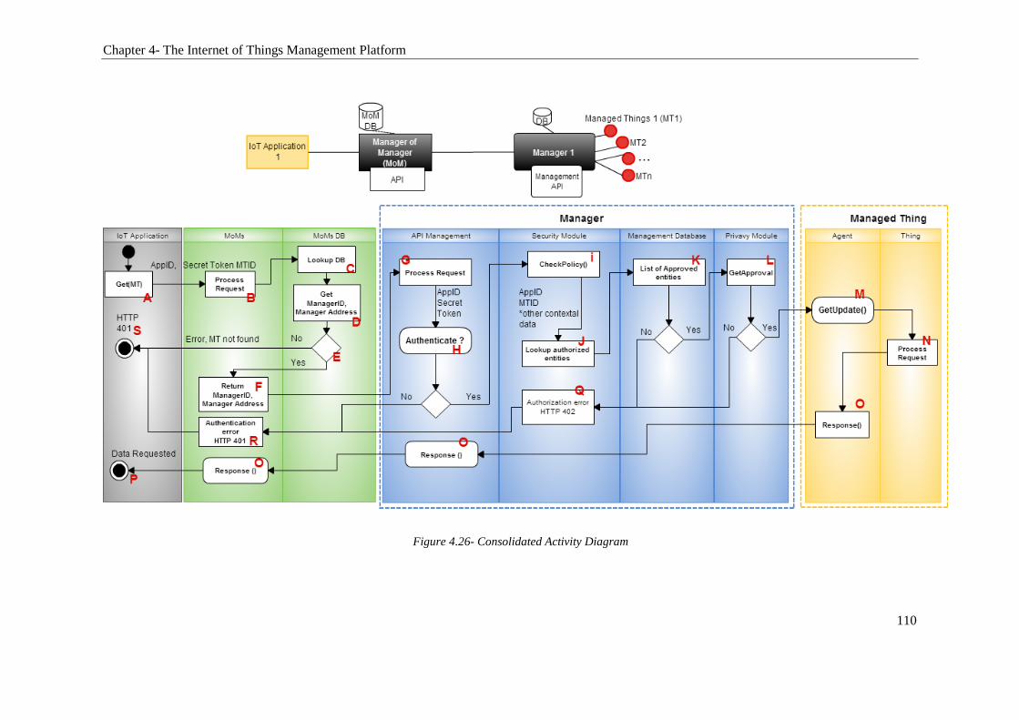
Chapter 4- The Internet of Things Management Platform
110
Figure 4.26- Consolidated Activity Diagram

Chapter 4- The Internet of Things Management Platform
111
From Figure 4.26, an IoT application sends a request to access MT’s data to the IoT-MP,
specifically to the MoM API. This request is sent using HTTPS over the Internet. To
begin, the IoT application needs to be authenticated first. This is done by sending to the
MoM the “AppID” and “Secret Token” of the IoT application (A and B in Figure 4.26).
To process the request, the MoM needs to find first the correspondent manager. Using the
MTID supplied in the request, the MoM lookups its database to find the address of the
manager responsible for the MT (C and D Figure 4.26). If the MoM failed to find in its
database a manager associated with the MTID, the decision point, shown in E in Figure
4.26, sends an HTTP 401 error message back to the IoT application and the process
terminates here. If a match for a manager is found then, the request is forwarded to the
manager using the manager address (F and G Figure 4.26).
The manager proceeds into the authentication process by validating the AppID and the
Secret Token. If the request is unauthenticated, the process is halted, and a 401 error is
sent back to the IoT application (H, R, and S Figure 4.26). If the request is authenticated,
then the manager moves into obtaining approval from the Security Module (SM). The
SM lookups the management database. It verifies whether the requested entity (the IoT
application) is on the list of approved entities to access the MT’s data (H, I, J and K in
Figure 4.26). If the IoT application is unauthorised to access the MT data, the request is
halted, and a 401 error message is sent back to the IoT application (Q, R, and S in Figure
4.26). If the request is authorised, then the manager moves into obtaining approval from
the Privacy Module (PM). The details of this approval will be discussed further in Section
4.5 once the PM is introduced. For now, let’s consider if the PM did not approve the
request, a 401 error is replied to the IoT application (L, Q, R, and S). If the PM approves
the request, then a “GetUpdate” message is sent from the manager to the MT to request a
fresh update on the data collected by the MT (L, M, N and O). The response message
containing the data initially requested by the IoT application is sent back from the
manager to the MoM and then to the IoT application (N, O, and P from Figure 4.26).

Chapter 4- The Internet of Things Management Platform
112
4.5 Managing Location Privacy through the Privacy Module (PM)
The Privacy Module (PM) provides the owner or administrator of an MT, referred from
now on as the user, with an added layer of privacy protection. As shown in Figure 4.26,
obtaining approval from the PM is the last criterion that need to be met before providing
an IoT application with access to an MT data. The PM enables the user to define privacy
disclosure policies. These policies are used by the manager to determine whether “to
disclose” or “not disclose” the location of an MT when an IoT application request access
to it. The decision to reveal the location is not simply based on a “Yes” or “No” basis but
involves several processes in which an obfuscated location is computed and used in the
reply to the request. The PM has three main components: the Context Analysis, Privacy
Manager, and Semantic Obfuscation components.
When an IoT application requests the location of an MT, the request is first authenticated,
authorised and then forwarded to the PM to be processed. The PM then processes the
request and replies with a response message, which even contains a location output or an
error message. The architecture of the PM module is provided in Figure 4.27. It shows
that the context analysis component has four layers, which are described in Section 4.5.1.
The Privacy Manager component stores two types of policies: User’s defined policies and
default policies. These are discussed in Section 4.5.2. Figure 4.27 also shows that the S-
Obfuscation component produces four levels of obfuscated location, which are introduced
in Section 4.5.3.

Chapter 4- The Internet of Things Management Platform
113
Figure 4.27- Privacy Module
4.5.1 The Context Analysis Component (CAC)
In the IoT, the user is no longer the implicit source of information; and therefore, privacy
choices cannot explicitly rely on the users’ decisions in real-time. Hence, the challenge is
in providing privacy solutions that autonomously adapt to variations in contexts. To
achieve this, this work provides a method to formulate contexts. The formulation of
contexts is based on the concept that a user makes privacy choices based on some
contextual parameters. For example, the user may choose to hide its location at a
particular time of the day, from specific entities, and at a precise location. The user may
also elect to reveal their location to other specific entities at a given time and location.
Thus, the user’s decision depends on the context of use of their information. This work

Chapter 4- The Internet of Things Management Platform
114
defines a context using the contextual parameters of four layers: the Network, Location,
Period, and Requester layers as shown in Figure 4.28.
Figure 4.28- Context Analysis Layers
Thus, for a given scenario n, a context denoted by C is defined using the following
statement:
Cn = F(N) + F(L) + F(P) + F(R)
F(N) represents the contextual parameters related to the network settings e.g., a
mobile network name or Wi-Fi network name.
F(L) represents the current location of the device.
F(P) includes the time and date of the interaction.
F(R) contains parameters that identify a requester. For instance, the “AppID” or
the IP address are the parameters used to identify an IoT application requesting
access to the location of an MT.
With this formulation of context, we can quantitatively identify a context of interaction
in the IoT. This opens the door to numerous opportunities such as providing services
based on specific contexts, restricting services to a particular context, and building
automation services based on predefined settings. The four layers of the CAC provide the
user with a method to attach a user’s defined policies to a specific context using the
Privacy Manager Component (PMC) discussed in Section 4.5.2. The policies can then be
Chapter 4- The Internet of Things Management Platform
115
appended to a variety or combination of contextual parameters such as the user’s and the
device’s attributes.
4.5.2 The Privacy Manager Component (PMC)
The Privacy Manager component (PMC) provides the user i.e. the owner or admin of an
MT with a method to define privacy disclosure policies that govern the location privacy
of their things. Specifically, the PMC has two main modules: the User Policy Module,
which is used to create user’s defined policies. A user’s policy is defined by the user by
specifying the level of Obfuscation used in a particular context for a specific MT. The
second module, the Default Policies Module, is used to create default policies that rule
the disclosure of an MT location in the absence of a user’s defined policy.
The PMC allows the user to define location privacy disclosure policies for each of their
MTs. Thus, it provides the user with the granule control over the location privacy of their
MTs including to whom, when and in which context the location of their MT is revealed.
To do that the user creates policies that attach an Obfuscation level to a context using the
contextual parameters defined in CAC. An example of a user’s defined policy is provided
in
Figure 4.29. It shows how a user uses the privacy manager to select an Obfuscation level
(from Figure 4.29, step 1- Select Obfuscation level) and then attach it to a C1 (Figure
4.29, steps: 2.1, 2.2, 2.3 and 2.4) before associating it to an MT (Figure 4.29, step 3-
associate with an MT). This policy example is formulated as follows:
P1= Attach (Obfuscation level 1) to C1 (F (N1) + F (L1) + F (P1) + F (R1)) for MT1

Chapter 4- The Internet of Things Management Platform
116
Figure 4.29- Policy P1 example
Consequently, the PMC allows the user to attach several users’ defined policies for each
of their MTs. The ability to attach more than one policy to a specific MT where each of
these policies is coupled to a context provides granule control over the disclosure settings
of an MT and allows for greater flexibility. Figure 4.30 shows three examples of policies
attached to one MT along with a default policy. For instance, P1 enforces that Obfuscation
level 1 should be used when the MT is on Vodafone network, located in X Location and
the time of the request must fall on a weekday between 09:00 and 17:00 i.e. any day
between Monday and Friday at any time between 09:00 AM and 17:00 PM. Note that P1
is also enforcing this policy to a specific IoT application using its AppID i.e. AppID=123.
P2 and P3 enforce a different level of Obfuscation for different contexts. However, the
DefaultPolicy enforces Obfuscation level 4 for all other contexts.

Chapter 4- The Internet of Things Management Platform
117
Figure 4.30- An example of three policies associated with one MT
Figure 4.30 shows two examples of policies attached to two different IoT applications
(AppID=123 and AppID=456). However, it is also possible to associate more than one
policy to one specific IoT application. For instance, an additional Policy denoted by P4
can be defined to attach an Obfuscation level 0 to AppID=123 when F(L) is at ZLocation
instead of XLocation or when the time of the request is set to be in a different time frame
from the one defined in F(P) in P1.
On the other hand, the default privacy module allows the user to define a default policy
for an MT. Below are some examples of default policies:
Example 1: DefaultPolicy 1= Use Obfuscation level 2 for MT1 in C1
Example 2: DefaultPolicy 2= Do not disclose location for MT1
Chapter 4- The Internet of Things Management Platform
118
Example 3: DefaultPolicy 3= Request User’s permission for MT1
In the example provided in Figure 4.30, the Obfuscation level 4 for MT1 is used as the
default policy. Thus, in the absence of a user’s defined policy or in the case where a user’s
defined policy was not met for a particular request, then the DefaultPolicy will be called.
Therefore, the location of the MT will be obfuscated using Obfuscation level 4. Similarly
in Example 2, the default policy is set to “Do not disclose” the location of MT1. The
DefaultPolicy 3, defined in Example 3, is set to request the user’s permission before
disclosing the location of MT1. Hence, there are two possible options for policy: (1)
define a policy and attach it to a context, and (2) define a policy that prompts the user and
requests his or her permission. Additionally, in the absence of policy, the default policy
is used.
Consequently, the formulation of contexts as part of CAC allows for the integration of
Attribute-Based Access Control (ABAC) policy-based system in the PMC and the
possibility of adding other systems to be integrated with modules as well. For instance,
the work in [187] expanded on our work, which was published in [188], by proposing a
rule-based agent that integrate our proposed CAC with behaviour modeling and
community-based reputation system in the algorithm of the agent.
4.5.3 The Semantic Obfuscation Component (SOC)
As previously discussed in Section 4.1, the Semantic Obfuscation approach (S-
Obfuscation) proposed in this work is an improvement over classic Obfuscation
techniques. Consider, for example, a public sensor collecting temperature information in
a park or a street. The sensor should not reveal its exact physical location to everyone.
For many IoT applications, it will be just sufficient to pinpoint the location of the sensor
to a specific area only. Other applications, such as fire detection applications, may require
access to the exact location of the sensor. Hence, the S-Obfuscation provides the user
with this granule control over the location disclosure of their things. It does that by
providing 4 levels of Obfuscation each representing a different degree of granularity or
location precision, which was previously introduced in Section 4.1.1.

Chapter 4- The Internet of Things Management Platform
119
The S-Obfuscation Component (SOC) incorporates the S-Obfuscation approach in the
Privacy Module (PM) of the manager. Figure 4.27 shows that the PM has the following
components: The Context Analysis Component (CAC), the Privacy Manager Component
(PMC), and The Semantic Obfuscation Component (SOC). The SOC is used by the user
to attach an Obfuscation level to a context when creating a policy as seen in
Figure 4.29. The Obfuscation levels range from L0 (true location) to L4 (an obfuscated
location with a wider proximity). Therefore, the SOC allows the user to indicate the level
of Obfuscation used when defining a policy.
The Location Output, shown in red in Figure 4.27, is the last process in the PM. It is
responsible for generating a response to the input request received by the PM. Figure 4.31
shows a flowchart that details how the Privacy Module approves a request to access the
location of an MT and the processes the PM goes through before generating a response
message. It should be noted that the response message is the same one previously
illustrated in step L of Figure 4.26.

Chapter 4- The Internet of Things Management Platform
120
Figure 4.31- PM flowchart process
The PM flowchart process is as follows:
1. A “get LocationOutput” request is placed to the PrivacyManager. In this request, two
arguments are passed: the MTID, which is the ID of the MT in which its location is
required and the “AppID” of the requesting IoT application
2. The PrivacyManager in “2- CheckPolicy()” check if there is a user’s defined policy
for the MT in which its location is under request.
3. In “3- GetPolicy” the PM lookups if there is a defined policy for this particular IoT
application using “AppID”. From here, there are decision points that will dictate how
the process continues:
a. Firstly, if there is no policy found (step 4) the decision point takes the yes path
to “5- CheckDefaultPolicy”. The PM then proceeds in using the Obfuscation

Chapter 4- The Internet of Things Management Platform
121
level as defined in the Default policy and generates an obfuscated location for
the MT under request and uses it as a location output (11- End
LocationOutput).
b. If in Step 4 a policy is found then the PM examines whether this policy is set
to request permission from the user. If yes, the decision point in Step 5
“Prompt” requests from the user the level of Obfuscation that should be used
for the location output. If no (the policy is not set to seek permission from the
user), then the PM proceeds, in step 6, to check the user defined policy.
4. In step 7 “Get MTContext”, the PM requests from the manager the current context of
MT. This context is compared to the context defined in the policy.
5. The comparison between the contexts is made in Step 8 “Compare Contexts”. The
process is as follows:
a) Firstly, the PM checks if the user has indicated in this policy that all the
contextual parameters need to be satisfied (F(N), F(L), F(P) and F(R)). These
are the steps in 9, 9.1, 9.2, 9.3 and 9.4. If one of the criterion did not match the
one defined in the policy, the process will be halted, and No path will be taken
by the decision point to 5- “CheckDefaultPolicy”. The obfuscated location
defined in the default policy will then be used.
b) If each of the contextual parameters defined in the policy matches those of the
current context, the process then proceeds into getting the location
Obfuscation level required from the S-Obfuscation Component in Step 10
“GetObLevel”. If one of the parameters does not match the one supplied in
the request, it will use the default location.
c) Step 9 “CheckCriteria” is used by the PM in case the user has indicated in the
defined policy that only specific criteria from the context analysis layers need
to be met.
To this end, this section has introduced the modules of the manager along with the
components contained in each of these modules.
Chapter 4- The Internet of Things Management Platform
122
4.6 Summary
A middleware referred to as the Internet of Thing Management Platform (IoT-MP) is
developed in this chapter. The IoT-MP provides users with a method to manage the
location information generated by things and their privacy across various heterogeneous
networks such as those discussed in the previous chapter (Chapter 3). The proposed
platform is specifically designed to work with things, which have limited communication,
processing, and power capabilities. The IoT-MP uses a distributed architecture consisting
of agents, managers, and a Manager of Managers. This architecture is based on an
extensible design where things are virtually represented using attributes in the
management database. These attributes are accessible via the IoT-MP and are used by
IoT applications to control and access things remotely over the Internet. In this way, IoT
applications can access things transparently, irrespective of the underlying used
communication technologies. This eliminates many of the interoperability issues
challenging the IoT and facilitates thing-to-thing communications.
The various modules of the IoT-MP’s manager, presented in this chapter, guarantee that
the location information of things are only disclosed to authenticated and authorised
entities while preserving the location privacy of things and that of their owners.
Specifically, the Privacy Module (PM) ensures that an IoT application has sufficient
access rights to remotely access the location information of things. The PM consists of
three components: The Context Analysis Component, The Privacy Manager Component,
and the Semantic Obfuscation Component. These components are used by the user to
create privacy disclosure policies that govern accesses to the location information of
things based on some identified contextual parameters. This enables the user to define
context-aware adaptive policies. These policies utilise different levels of location
Obfuscations providing protection for the location information of things. The novel S-
Obfuscation approach, incorporated in the IoT-MP platform, enhances the performance
of two classic Obfuscation techniques. They rely on a geographic knowledge when
producing obscured location.
Chapter 4- The Internet of Things Management Platform
123
In the next two chapters (i.e. chapter 5 and 6), a range of experimental and simulation
studies are conducted. They aim to validate and demonstrate the efficiency of the
proposed IoT-MP in managing the location information and preserving the location
privacy of things in the IoT. Chapter 5 demonstrates and confirms the capabilities of the
IoT-MP and its new approach to privacy management and protection in an experiment
that utilises physical low-power and low-cost sensor devices. On the other hand, Chapter
6 supplements the experimental studies, conducted in Chapter 5, by demonstrating the
capability of managing the location information of things and protecting their location
privacy in large-scale heterogeneous low-power wireless networks similar in scope,
complexity, and size to that envisioned in the IoT.

124
5 CHAPTER 5- THE EXPERIMENTAL
STUDIES
This chapter describes the four stages of the experimental studies. It reports on the
implementations of the Internet of Things Management Platform (IoT-MP) previously
introduced in Chapter 4. The purpose of these implementations is to demonstrate that the
IoT-MP enhances the management and preservation of location privacy of things and that
of their users in a physical IoT setup. The experimental studies also aim to demonstrate
and validate the feasibility of incorporating a location protection technique i.e. the
proposed Semantic Obfuscation approach, introduced in Chapter 4, into an IoT
application that utilises low-power and low-cost sensor devices.
Section 5.1 provides an overview of the experiments and outlines their objectives. Section
5.2 discusses the architecture and design of the four stages of the experiments. Section
5.2.1 describes the developments and implementations carried out in stage 1 of the
experiments that involved the setup of a Wireless Personal Area Network using BLE 4.0
sensor devices. Section 5.2.2 reports on stage 2 of the experiments, which included the
implementation of an LBS web application. This section also describes the
implementations of the various modules of the IoT-MP previously introduced in Chapter
4. Section 5.2.3 discusses the stage 3, which involved the developments of a mobile
application and a web application. The mobile application provides users with a user
interface allowing them to create location privacy-disclosure policies as an
implementation of the IoT-MP’s Privacy Manager Component. The web application is
used to issue a request to access the location information of the BLE sensor devices over
the Internet. In addition to implementing the proposed S-Obfuscation approach, this
section also implements the two classical Obfuscation techniques previously described in
Section 2.3 of Chapter 2. Thus, in stage 3, the work evaluates the S-Obfuscation and
reports on its performance against the two selected classic Obfuscation techniques.

Chapter 5- The Experimental Studies
125
Section 5.2.4 reports on the implementations carried out in stage 4 of the experiments. In
this section, an IoT application is developed as a practical example of an application that
supports interactions between various devices operating using two different
communication protocols. The works conducted in stage 4 expand on the three previous
stages of the experiments by adding a Wi-Fi enabled bulb to the experimental works. The
4 stages of the experiments allowed the development of an IoT application in which the
status of a Wi-Fi device was automatically manipulated based on the location of a specific
BLE sensor device. By implementing the approaches proposed by the IoT-MP and that
of its S-Obfuscation, we were able to evaluate and demonstrate the capability of our new
approach to management and preservation of location privacy of things in a physical setup
that uses low-power and low-cost devices.
5.1 Overview of the Experiments
The main aim of the experiments is to demonstrate the capability of the IoT-MP in
providing the owners or administrators of things, referred to as users, with the
management of their location information and that of their things. Also, to demonstrate
the capability of the IoT-MP in preserving the location privacy of constrained things in
the IoT. The experiment mainly has two key purposes:
1. To technically evaluate the IoT-MP, proposed in Chapter 4, under realistic conditions
using physical low-power constrained sensors, which are powered by batteries;
2. To assess the performance of the Privacy Module, introduced in Section 4.5, in
physical environments that involve dynamic changes in context, interactions and,
importantly, mobility. As discussed in before, the IoT-MP encompasses an approach
where decisions to disclose location information are based on policies that vary based
on the context of their use (e.g., the current location of the Managed Thing, users’
preference among the rest of the contextual parameters discussed in Section 4.5.1).
Thus, it is important for the research to generate and model a variety of contextual
and dynamic interaction scenarios so the proposed IoT-MP can be effectively
evaluated.

Chapter 5- The Experimental Studies
126
The experiments involved the followings setups:
Designing a testbed based on the concept of WSNs: The testbed brings a WSN
setup to the Internet.
The use of Low-power sensor devices: this involves the utilisation of low-power
and low-cost IoT sensor devices. Specifically, BLE sensors are used.
The design and implementation of an IoT application: this involves the design of
scenarios that use location information of the BLE sensors as part of the service and
information being exchanged. These scenarios model the envisioned interactions
between sensor devices and an IoT application.
Generating different contextual scenarios: varying the parameters of the
experiments to produce different contextual data including location inputs. This is
necessary to test the validity of the proposed approach in various contexts.
Implementing the IoT-MP: this involves the implementation of the IoT-MP entities
i.e. the agent, manager, and the management database and the rest of the modules
previously introduced in Section 4.3.
Implementing the Privacy Module: Implementing the privacy module, described in
Section 4.5, including the implementation of the S-Obfuscation, context analysis, and
privacy manager components for the purpose of protecting the location privacy of
BLE sensors during communications.
Implementing the classical Obfuscation technique: these implementations are used
to compare and evaluate the S-Obfuscation performance against the classic
Obfuscation techniques.
5.2 The Four Stages of the Experiment
A high-level view of the experiment architecture is provided in Figure 5.1. The scenarios
conceived in this experiment are summarised as follows:
A group of Bluetooth Low Energy (BLE) sensors sends sensory information to an
Android mobile application over BLE 4.0. This mobile device acts as an IoT gateway and
a backhaul to the Internet. This is in line with many other recent experiments and setups
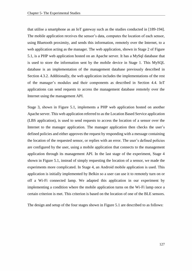
Chapter 5- The Experimental Studies
127
that utilise a smartphone as an IoT gateway such as the studies conducted in [189-194].
The mobile application receives the sensor’s data, computes the location of each sensor,
using Bluetooth proximity, and sends this information, remotely over the Internet, to a
web application acting as the manager. The web application, shown in Stage 2 of Figure
5.1, is a PHP web application hosted on an Apache server. It has a MySql database that
is used to store the information sent by the mobile device in Stage 1. This MySQL
database is an implementation of the management database previously described in
Section 4.3.2. Additionally, the web application includes the implementations of the rest
of the manager’s modules and their components as described in Section 4.4. IoT
applications can send requests to access the management database remotely over the
Internet using the management API.
Stage 3, shown in Figure 5.1, implements a PHP web application hosted on another
Apache server. This web application referred to as the Location Based Service application
(LBS application), is used to send requests to access the location of a sensor over the
Internet to the manager application. The manager application then checks the user’s
defined policies and either approves the request by responding with a message containing
the location of the requested sensor, or replies with an error. The user’s defined policies
are configured by the user, using a mobile application that connects to the management
application through its management API. In the last stage of the experiment, Stage 4
shown in Figure 5.1, instead of simply requesting the location of a sensor, we made the
experiments more complicated. In Stage 4, an Android mobile application is used. This
application is initially implemented by Belkin so a user can use it to remotely turn on or
off a Wi-Fi connected lamp. We adapted this application in our experiment by
implementing a condition where the mobile application turns on the Wi-Fi lamp once a
certain criterion is met. This criterion is based on the location of one of the BLE sensors.
The design and setup of the four stages shown in Figure 5.1 are described to as follows:

Chapter 5- The Experimental Studies
128
Figure 5.1- Experiment Architecture
Stage 1- The sensors setup: Some Bluetooth Low Energy Sensor devices in a piconet
setup (piconets were discussed previously in section 3.1.1) are configured to collect some
sensory information e.g., temperature. The basic topology is a star network where five
sensors communicate with a single gateway that provides the backhaul to the Internet.
This gateway is referred to as the IoT gateway as shown in Figure 5.1. The IoT gateway
is an Android mobile device which has a mobile application implemented specifically to
support the communications with the BLE sensors. The mobile application is developed
to collect the location information of the connected sensors using Bluetooth proximity
technology. Also, the application implements a Restful API, referred to as the
“connection API”. This API allows the mobile application to transmit the collected
sensory data over the Internet to a remote web application hosted on an Apache local
server. As with any typical API design, the connection API has two parts: the client side
API, which is implemented in the mobile application, and the Server side API, which is
implemented in the web application.
Chapter 5- The Experimental Studies
129
Stage 2- The manager web application Setup: As discussed in Stage 1, the sensory data
collected from the BLE sensors, along with the location information of each sensor are
transmitted over the Internet to a web application hosted on an Apache server on our
domain. This web application hosts the server-side implementations of the connection
API. The connection API is responsible for establishing communication with the Android
device. It acts as a web service. It handles the incoming and outgoing communications
between the web application and the mobile application. Additionally, the web
application has an attached MySQL database. This database is used to store the
information sent by the Android application. Mainly, the database stores the followings
data: sensory data and the GPS location of the Mobile device and proximity of each of
the BLE sensors to the mobile device in meters.
Significantly, the web application represents the manager that was discussed in Section
4.3.2. The web application hosts the implementations of the manager’s modules including
that of the Privacy Module, described in Section 4.5, and its major components such as
the S-Obfuscation component that was introduced in Section 4.5.3. Additionally, the web
application includes the implementation of the management API (described in Section
4.4.6). The management API is used to receive requests for sensors’ data and respond to
these requests by IoT applications over the Internet using HTTP. That is, to access the
sensors’ data over the Internet, HTTP requests must be placed on the web application
using its management API. The Web application then responds to the requests for
information about the sensors. Decisions about disclosing sensory and location
information are computed using the various modules of the manager as previously
discussed in Section 4.5.
The management API should not be confused with the connection API. The connection
API is an implementation specific. It is specifically implemented for establishing
communications between the mobile device and the web application over the Internet,
and it is not part of the IoT-MP components. On the other hand, the management API is
used to provide a method to access the management database over the Internet. The
management API is one of the manager’s modules as discussed in Section 4.4.6.
Chapter 5- The Experimental Studies
130
Stage 3- The Location Based Service (LBS) application setup: In this stage, a Location
Based Service (LBS) web application is developed. This LBS application is designed to
model the operations of an IoT application that provides services based on the location of
a BLE sensor. This application is used to request the location of a BLE sensor using the
unique sensor ID (UID) over the Internet by sending an HTTP request to the management
application. The purpose behind the design of this LBS application is to simulate the
behaviour of a Location Based Service provider that provides localised services based on
the location information supplied in the request.
Stage 4- The IoT application setup: To make the experiment more interesting, the
developments carried out at this stage have the purpose of simulating the behaviour of an
IoT application. For example, an IoT smart home application requests the location of an
IoT device (device A) and performs some operations on another IoT device (device B)
based on the location of device A as part of the service it provides. Therefore, in this
stage, an IoT application is developed to turn on a Wi-Fi connected lamp based on the
location of one of the BLE sensors. To achieve this, we modified an Android mobile
application developed by Belkin. Usually, the Belkin application is used by a user to
control a Wi-Fi connected lamp over the Internet. This experiment adapted this mobile
application by automating the process of turning the lamp on once a certain condition is
met, which is when the BLE sensor location is within 100m of any GPS coordinates that
correspond to Sydney.
As an example, the scenario is set up as follows: if the sensor with the ID 1 is at 100 m
from X location, then a Smart light connected via Wi-Fi to the mobile application will be
turned on. Manipulating a device or service based on the condition of another
device/service is also known as If This Then That (IFTTT). IFTTT is a web service that
allows users to create chains of simple conditional statements triggered based on changes
to other web services [195]. Thus, the work implemented in this Stage uses the IFTTT
concept. In fact, our work is an improvement over IFTTT by providing the user with more
control over the disclosure decisions of their personal information including their location
privacy and by connecting low-power devices into the service.

Chapter 5- The Experimental Studies
131
5.2.1 Stage 1- The Sensor Scenario Setup
The experiment uses Bluetooth Low Energy sensors developed by Texas Instrument
[196]. The sensors have the following sensing capabilities: temperature, proximity,
pressure, accelerometer, gyroscope, and magnetometer. The sensors use Bluetooth Smart,
also known as Bluetooth 4.0, in a star topology. The technical specifications of these
sensors are provided in Table 4.2 and Figure 5.2. According to the manufacturer, the
onboard battery attached to these sensors last up to two years in operation [196].
Table 5.1- Sensors' specifications [196].
Frequency 2.4 GHz
Range ~60 m
Flash size (KB) 256
RAM size (KB) 8
Operating Temperature Range (C) -40 to 125
Addressing Unique 48-bit IEEE Address
Data Rate (Max) (kbps) 1000
Sensors on board Temperature, proximity, accelerometer,
gyroscope and magnetometer.
Figure 5.2- The BLE sensor board
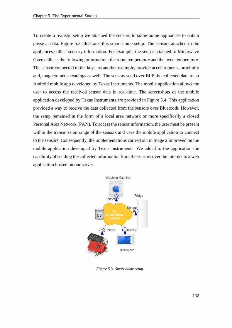
Chapter 5- The Experimental Studies
132
To create a realistic setup we attached the sensors to some home appliances to obtain
physical data. Figure 5.3 illustrates this smart home setup. The sensors attached to the
appliances collect sensory information. For example, the sensor attached to Microwave
Oven collects the following information: the room temperature and the oven temperature.
The sensor connected to the keys, as another example, provide accelerometer, proximity
and, magnetometer readings as well. The sensors send over BLE the collected data to an
Android mobile app developed by Texas Instruments. The mobile application allows the
user to access the received sensor data in real-time. The screenshots of the mobile
application developed by Texas Instruments are provided in Figure 5.4. This application
provided a way to receive the data collected from the sensors over Bluetooth. However,
the setup remained in the form of a local area network or more specifically a closed
Personal Area Network (PAN). To access the sensor information, the user must be present
within the transmission range of the sensors and uses the mobile application to connect
to the sensors. Consequently, the implementations carried out in Stage 2 improved on the
mobile application developed by Texas Instruments. We added to the application the
capability of sending the collected information from the sensors over the Internet to a web
application hosted on our server.
Figure 5.3- Smart home setup

Chapter 5- The Experimental Studies
133
Figure 5.4- Texas instrument application
5.2.2 Stage 2- The Web Application and Database Setup
Additional implementations took place to connect the Bluetooth network to the Internet.
To achieve this, an API and a web application attached to a database were implemented.
The API is a software incorporated in both the mobile and web application. The API,
referred to as the connection API as stated earlier, has the responsibility for sending the
collected data from the sensors to the web application, periodically, over the Internet. The
Web application stores the received data into the database. The database is an online
MySQL database that can be accessed via the Internet. To provide this functionality, an
open web service based on Restful API architecture [197] referred to as the management
API is also implemented. The management API allows other devices and applications to
access the database and hence the sensory data over the Internet. The purpose behind

Chapter 5- The Experimental Studies
134
these implementations is to create a more complex IoT setup. Consequently, the
components of the IoT-MP were implemented as part of this IoT experiment.
Figure 5.5 shows how the experiment used the IoT-MP’s agent-manager architecture to
make the information available on the Internet. The agents are software applications that
could even run on mobiles, tablets or computers (mobile phone is used in this experiment).
This software has Bluetooth functionalities implemented allowing it to establish
communications with Things (the sensors in this experiment). On the other hand, the
manager is implemented as part of a server application that resides on a web server.
Communications between the mobile device and the web application are secure and
encrypted using the SSL3.0 protocol. The Bluetooth communications between the sensors
and the mobile device are encrypted using 128 bit AES supported by BLE 4.0. Figure 5.6
shows the additions made to the application provided by Texas Instruments.
Figure 5.5- IoT Smart home demo
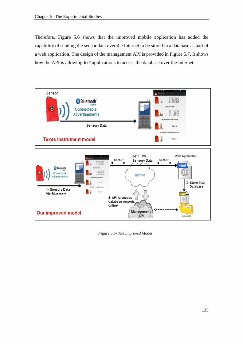
Chapter 5- The Experimental Studies
135
Therefore, Figure 5.6 shows that the improved mobile application has added the
capability of sending the sensor data over the Internet to be stored in a database as part of
a web application. The design of the management API is provided in Figure 5.7. It shows
how the API is allowing IoT applications to access the database over the Internet.
Figure 5.6- The Improved Model

Chapter 5- The Experimental Studies
136
Figure 5.7- Management API
5.2.2.1 The Connection and Management APIs:
As stated earlier, the connection API is used to establish a communication channel
between the mobile and web applications by supporting the exchange of HTTP messages.
It allows the mobile application to send the received sensory data over the Internet to the
Web application. It also allows the web application to send requests to the web
application. On the other hand, the management API allows applications running to
access the sensory data stored in the database, remotely over the Internet. While both
APIs use the Restful architecture, they differ in implementations and complexity. The
connection API is simple. It is implemented in a closed architecture, and it is commonly

Chapter 5- The Experimental Studies
137
used to relay information from mobile applications developed on the Android platform to
web applications over the Internet. Therefore, the connection API is not accessible to the
public or any other applications. It has the sole purpose of sending the data over HTTPS
from the mobile device to the Web application. However, the management API is more
complex as accessing the database is not straightforward and requires permission from
the PM.
The Connection API uses a well-defined Restful structure that utilises the URL scheme.
Normally, the API’s URL structure depends on the type of the operation requested and
on how these requests are processed. These operations need to be defined in the API to
be able to receive and parse requests. For that purpose, the JavaScript Object Notation
(JSON) is used [198]. JSON is a lightweight data interchange format. JSON is built into
two structures: A collection of name/value pairs and an ordered list or an array of values.
Therefore, JSON presents a method for handling arrays. It also defines a structure on how
to read and parse the value from an array. The connection API re-uses the messages and
the methods defined in the HTTP protocol. These are the GET, POST, PUT, and DELETE
methods. These methods will cover all the requests needed for transferring the data from
the mobile application to the web application. The communication is as follows:
The mobile application receives sensors’ readings (e.g., temperature) and put them in
an array. The array includes a unique ID, which represents each of the Bluetooth
sensors. This part of the implementations is already provided in the original
application implemented by Texas Instruments.
Next, our work added to the array the followings parameters:
1. The location proximity of the sensor to the mobile device using Bluetooth
proximity technology.
2. The location of the mobile device. This has been obtained using A-GPS, which
combines technologies that extract the location of a device using GPS and cellular
network localisation techniques.
3. The mobile device IMEI number (The International Mobile Station Equipment
Identity). This is a unique ID that uniquely identifies the mobile device. This helps

Chapter 5- The Experimental Studies
138
in uniquely identifying the IoT gateway. It also serves as the AgentID in the IoT-
MP architecture.
4. A timestamp is finally added to the array. The array is then sent over HTTPS to
the web application.
5. The web application receives the request (the array containing the data) and
responds to the mobile application. The response can even be an OK (HTTP status
code 200), which means the data are successfully inserted into the database or
‘Bad Request’, which means the data were not inserted into the database.
Therefore, the web application relies on the HTTP status codes [199] when
generating a reply to the mobile application. A “401” response code sent from the
server side application to the client side application indicates that authorisation
has been refused. The connection with the web application is established using
the HTTPS Post method:
private final static String url ="https://elkhodr.com/ci/index.php/welcome/insert_reading";
…
htttpsPost = new HttpsPost(url);
The following code extract shows the data being stored in the array using JSON.
jsonReq.put("reading", value);
jsonReq.put("imei", getImei(context));
jsonReq.put("deviceid", deviceid ); jsonReq.put("ble.getloc", loca );
jsonReq.put("lat", locLat);
jsonReq.put("lon", locLan);
Calendar rightNow = Calendar.getInstance();
jsonReq.put("timestamp", ( rightNow.getTimeInMillis() / 1000) );
postParams.clear();
postParams.add(new BasicNameValuePair("jsonstr", jsonReq.toString()));
From the above code:
The “reading” is an array that holds the sensory readings.
The “imei” is the mobile device unique ID. This represents the agentID.
The “deviceid” is the unique ID of the Bluetooth sensor.
Chapter 5- The Experimental Studies
139
The “loc” is the location of the sensor. It is calculated using the method
BLE.GetLoc(), which returns three possible values: 10 (which means the sensor
is within 10 meters proximity), 50 (within 50m proximity), and 100 (for any
distance over 50m of proximity).
The “lat” and “lon” are the GPS coordinates of the mobile device.
The “timestamp”, as the name suggests, adds a timestamp to the received
readings.
The function used to obtain location is adapted from the Android iBeacon Code developed
by David Young [200]. Our work improves this function by pinpointing the proximity of
a sensor to a range within 10m, 50m, or 100m from the GPS location of the mobile device.
The mobile device in this experiment calculates the proximity of the BLE sensor by
estimating the distance to the sensor (more specifically the transmitted beacon). It does
that by comparing the signal level with the level of that of the reference signal. For
instance, consider that a BLE advertisement packed was received by the mobile device
and had a signal level of -70dBm. Assume the calibration value of this packet is -62 dBm.
Then the method concludes that the sensor is more than one meter away since the signal
of -70dBm is weaker than the reference signal. Therefore, each time a location estimate
is calculated a formula is called that compares the signal level with that of the reference
signal level. As noted by many other researchers, it is feasible to estimate if the sensor is
within a meter or two rather than 20 meters away. However, it is difficult to compute
whether the sensor is 5m or 15 meters away. For these reasons, our method provides three
values estimate for locations: within 10m, 50m, and 100m. The purpose behind this
generalisation is to obtain a valid location input that can be further used in the experiment.
Also, since indoor positioning technology is outside the scope of this work, the focus was
on getting a real location input rather than studying or improving the accuracy of BLE
proximity technology. We are confident that, in the future, Bluetooth and other low-
power wireless technologies will mature to provide the capability of accurately locating
a device. Readers interested in reading more on the performance of BLE proximity
location are referred to [201].

Chapter 5- The Experimental Studies
140
5.2.2.2 Evaluating the Performance of BLE Proximity Positioning
For this work, we kept the deployment of the sensors simple. The sensors were deployed
in an open air flat hall 100m *40m. The experiment used 5 BLE sensors positioned at
approximately 1m high. The mobile device used was Nexus 5 running Android 5.1. The
hall had no moving objects that might interfere with the sensors’ signal. The mobile
application was configured to scan for beacons every 2 seconds for 5 minutes. We initially
conducted 20 tests and few others when we implemented the S-Obfuscation approach. In
the first 20 test cases, we measured the performance of the application in locating the
sensor devices. In each of these tests, the sensors were placed at a predefined distance
from the mobile device. We used a combination of schemes and we noted the results.
Table 5.2 shows an example of the test cases.
Table 5.2- An example of the test cases
Sensor 1 Sensor 2 Sensor 3 Sensor 4 Sensor 5
Test 1 1m 15m 3.5m 30m 48m
Test 2 5m 5m 5m 5m 5m
Test 3 0.5m 12.2m 22m 30m 55m
Figure 5.8 and Figure 5.9 show the results of the test cases reported in Table 5.2. While
Figure 5.10 compares the results of the expected sensors’ locations against the location
computed by the application for the 20 test cases.

Chapter 5- The Experimental Studies
141
Figure 5.8- Test case 1 results
Sensor 1 Sensor 2 Sensor 3 Sensor 4 Sensor 5
Actual Location 1 15 3.5 30 48
Expected location 10 10 10 50 50
Computed location 10 50 10 50 100
1
15
3.5
30
48
10 10 10
50 50
10
50
10
50
100
Test Case 1
Actual Location Expected location Computed location

Chapter 5- The Experimental Studies
142
Figure 5.9- Test case 1 and 2 results
The actual location is the true location of the sensor. The expected location is the location
calculated as expected by the formula with null errors. The computed location is the actual
location resulted from the experiment. Figure 5.10 shows the results of 20 test cases.
Figure 5.10- Expected vs. Computed Locations
Sensor 1 Sensor 2 Sensor 3 Sensor 4 Sensor 5 Sensor 1 Sensor 2 Sensor 3 Sensor 4 Sensor 5
Computed 10 50 10 10 10 10 50 50 50 100
Expected 10 10 10 10 10 10 10 50 50 50
Actual Location 5 5 5 5 5 0.5 12.2 22 30 55
5 5 5 5 5 0.5 12.2 22 3055
10 10 10 10 10 1010
5050
50
10
50
10 10 10 10
50
5050
100
Test Case 1 and 2
0
20
40
60
80
100
120
1 2 3 4 5 6 7 8 9 10 11 12 13 14 15 16 17 18 19 20
Expected vs. Computed locations for 20 test cases
Expected Computed
Chapter 5- The Experimental Studies
143
It shows that our approach to generalising the location of a sensor has improved the
proximity calculation of the sensors location. However, we are still far from accurately
positioning the location of the sensor. Our results correlate with those reported in the
literature and demonstrate that BLE is best fit to proximity localization rather than
accurate positioning. They show that it is more accurate to determine if a sensor is located
within few meters of the mobile device or no. However, when it comes to measuring how
far the Beacon from the mobile device is, the formula used to calculate the proximity
proved to be unreliable. In some cases, the formula was able to correctly position the
Beacon within 50 meters. In other cases, the formula failed to do so. For example in text
case 1, sensor 5 was located at 48m from the mobile device. The formula should have
calculated the location of the sensor to be within 50m. However, the computed location
was 100m. Also, we observed that some factors affected the performance of the signal
and that of the formula performance including the position in which the sensor’s antenna
is directed, the height of the sensor, how many people are in the room, and whether Wi-
Fi devices are active in the same room. This is an interesting area that can be further
explored by the research committee.
To this end, we have completed the part where the data collected by the sensors along
with the location information of the sensors and that of the mobile device are transmitted
over the Internet to the web application. Therefore, at this stage, the sensory information
is successfully stored in the database. The activity diagram for this interaction is provided
in Figure 5.11. Figure 5.12 shows the interaction between the sensors, mobile device, and
the web application as per the IoT-MP architecture.
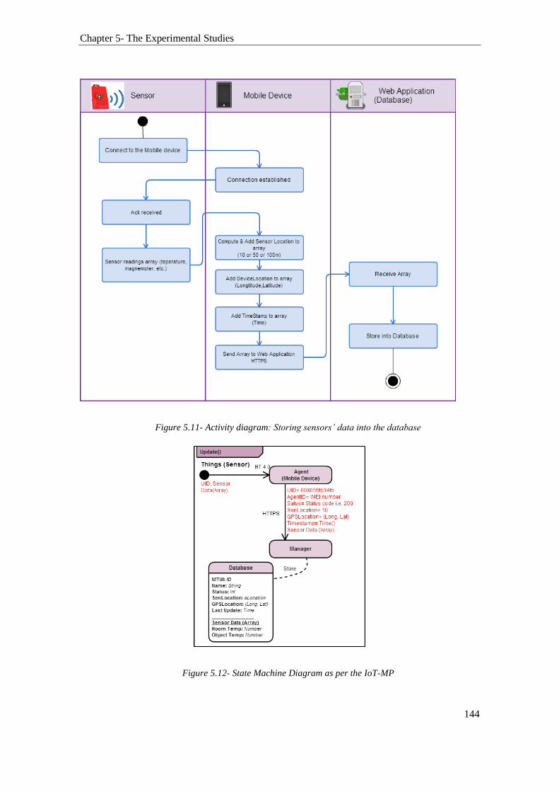
Chapter 5- The Experimental Studies
144
Figure 5.11- Activity diagram: Storing sensors’ data into the database
Figure 5.12- State Machine Diagram as per the IoT-MP

Chapter 5- The Experimental Studies
145
5.2.2.3 Scope of the Experiment Designed in this Stage
This experiment uses Bluetooth Low Energy as the communication medium between the
sensors network and the IoT gateway (the mobile application). However, the concept of
using one of the nodes as the gateway to the Internet is also used in other low-power
wireless technologies such as ZigBee IP, 6Lowpan, and 802.11ah; which were reviewed
in Chapter 3. Figure 5.13 shows that the use of the technology does not affect the
architecture of the model. This is because most wireless low-power technologies follow
the same architecture of using a node as a backhaul to the Internet when connecting
devices to the Internet, with few implementation differences. For instance, in the case of
a ZigBee Smart network, the gateway will have the capability of communicating with the
sensors using ZigBee protocol. On the other hand, the gateway connects to the Internet in
the same fashion an 802.11 based access point connects to the Internet. Typically, the
gateway provides embedded bridging services such as translation, repackaging, and
reformatting of packets. In fact, commercialised ZigBee gateway which provides this
functionality have started to gain popularity such as the Xbee hub [202].
Figure 5.13- Applicability to other Low-Power Wireless network
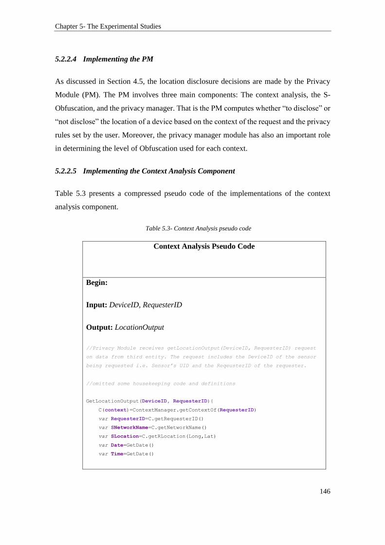
Chapter 5- The Experimental Studies
146
5.2.2.4 Implementing the PM
As discussed in Section 4.5, the location disclosure decisions are made by the Privacy
Module (PM). The PM involves three main components: The context analysis, the S-
Obfuscation, and the privacy manager. That is the PM computes whether “to disclose” or
“not disclose” the location of a device based on the context of the request and the privacy
rules set by the user. Moreover, the privacy manager module has also an important role
in determining the level of Obfuscation used for each context.
5.2.2.5 Implementing the Context Analysis Component
Table 5.3 presents a compressed pseudo code of the implementations of the context
analysis component.
Table 5.3- Context Analysis pseudo code
Context Analysis Pseudo Code
Begin:
Input: DeviceID, RequesterID
Output: LocationOutput
//Privacy Module receives getLocationOutput(DeviceID, RequesterID) request
on data from third entity. The request includes the DeviceID of the sensor
being requested i.e. Sensor’s UID and the ReqeusterID of the requester.
//omitted some housekeeping code and definitions
GetLocationOutput(DeviceID, RequesterID){
C(context)=ContextManager.getContextOf(RequesterID)
var RequesterID=C.getRequesterID()
var SNetworkName=C.getNetworkName()
var SLocation=C.getRLocation(Long,Lat)
var Date=GetDate()
var Time=GetDate()
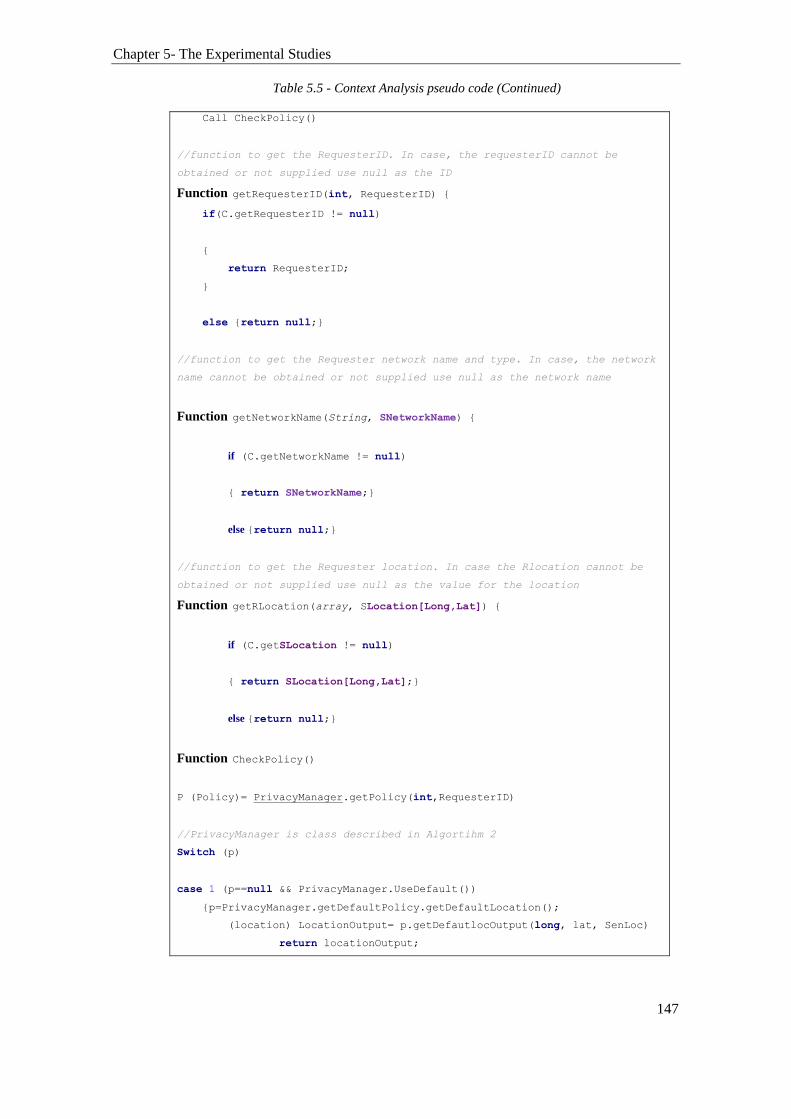
Chapter 5- The Experimental Studies
147
Call CheckPolicy()
//function to get the RequesterID. In case, the requesterID cannot be
obtained or not supplied use null as the ID
Function getRequesterID(int, RequesterID) {
if(C.getRequesterID != null)
{
return RequesterID;
}
else {return null;}
//function to get the Requester network name and type. In case, the network
name cannot be obtained or not supplied use null as the network name
Function getNetworkName(String, SNetworkName) {
if (C.getNetworkName != null)
{ return SNetworkName;}
else {return null;}
//function to get the Requester location. In case the Rlocation cannot be
obtained or not supplied use null as the value for the location
Function getRLocation(array, SLocation[Long,Lat]) {
if (C.getSLocation != null)
{ return SLocation[Long,Lat];}
else {return null;}
Function CheckPolicy()
P (Policy)= PrivacyManager.getPolicy(int,RequesterID)
//PrivacyManager is class described in Algortihm 2
Switch (p)
case 1 (p==null && PrivacyManager.UseDefault())
{p=PrivacyManager.getDefaultPolicy.getDefaultLocation();
(location) LocationOutput= p.getDefautlocOutput(long, lat, SenLoc)
return locationOutput;
Table 5.5 - Context Analysis pseudo code (Continued)
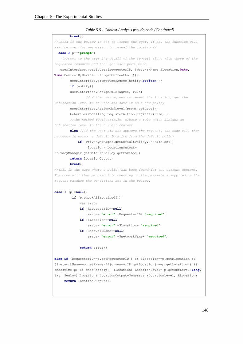
Chapter 5- The Experimental Studies
148
break;}
//Check if the policy is set to Prompt the user. If so, the function will
ask the user for permission to reveal the location//
case 2(p=="prompt")
{//post to the user the detail of the request along with those of the
requested resource and then get user permission
userInterface.postToUser(requesterID, SNetowrkName,SLocation,Date,
Time,DeviceID,Device.UUID.getCurrentLoc());
userInterface.promptUserAgree(notify(boolean));
if (notify){
userInterface.AssignRule(agree, rule)
//if the user agrees to reveal the location, get the
Obfuscation level to be used and save it as a new policy
userInterface.AssignObfLevel(promt(obfLevel))
behaviourModelling.registerAction(Register(rule))}
//the method register(rule) create a rule which assigns an
Obfuscation level to the current context
else //if the user did not approve the request, the code will then
proceeds in using a default location from the default policy
if (PrivacyManager.getDefaultPolicy.useFakeLoc())
(location) LocationOutput=
PrivacyManager.getDefaultPolicy.getFakeLoc()
return locationOutput;
break;}
//This is the case where a policy has been found for the current context.
The code will then proceed into checking if the parameters supplied in the
request matches the conditions set in the policy.
case 3 (p!=null){
if (p.checkAllrequired()){
var error
if (RequesterID==null)
error= "error" +RequesterID+ "required";
if (SLocation==null)
error= "error" +SLocation+ "required";
if (RNetworkName==null)
error= "error" +SnetworkName+ "required";
return error;}
else if (RequesterID==p.getRequesterID() && SLocation==p.getRlocation &&
$SnetworkName==p.getRName)&&(c.sensorID.getLocation()==p.getLocation() &&
checktime(p) && checkdate(p)) (location) LocationLevel= p.getObfLevel(long,
lat, SenLoc)(location) LocationOutput=Generate (LocationLevel, RLocation)
return locationOutput;}}
Table 5.5 - Context Analysis pseudo code (Continued)
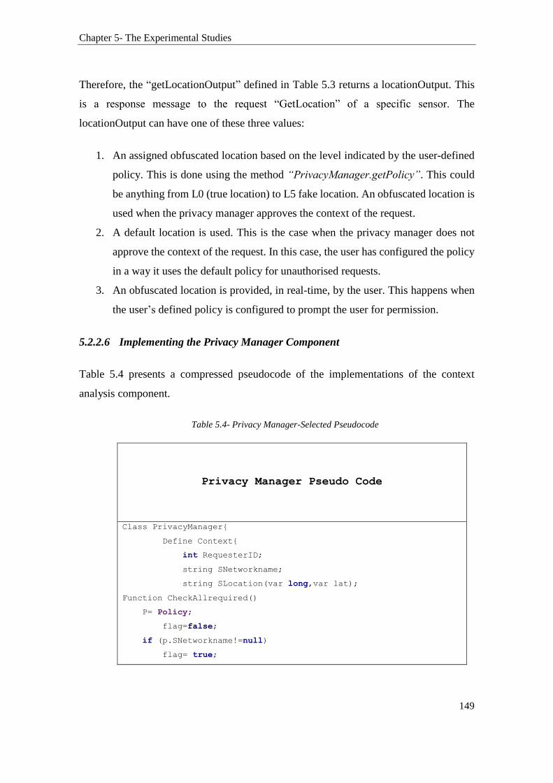
Chapter 5- The Experimental Studies
149
Therefore, the “getLocationOutput” defined in Table 5.3 returns a locationOutput. This
is a response message to the request “GetLocation” of a specific sensor. The
locationOutput can have one of these three values:
1. An assigned obfuscated location based on the level indicated by the user-defined
policy. This is done using the method “PrivacyManager.getPolicy”. This could
be anything from L0 (true location) to L5 fake location. An obfuscated location is
used when the privacy manager approves the context of the request.
2. A default location is used. This is the case when the privacy manager does not
approve the context of the request. In this case, the user has configured the policy
in a way it uses the default policy for unauthorised requests.
3. An obfuscated location is provided, in real-time, by the user. This happens when
the user’s defined policy is configured to prompt the user for permission.
5.2.2.6 Implementing the Privacy Manager Component
Table 5.4 presents a compressed pseudocode of the implementations of the context
analysis component.
Table 5.4- Privacy Manager-Selected Pseudocode
Privacy Manager Pseudo Code
Class PrivacyManager{
Define Context{
int RequesterID;
string SNetworkname;
string SLocation(var long,var lat);
Function CheckAllrequired()
P= Policy;
flag=false;
if (p.SNetworkname!=null)
flag= true;

Chapter 5- The Experimental Studies
150
if (p.SLocation!=null)
flag= true;
//do the rest for all condition
return flag;
Define ContextManager (c context){
function getRequesterID(){
return c.RequesterID();}
function getRNetworkname(){
return c.SNetworkname();}
function getSLocation(){
return c.SLocatione();}
Function getContextof(RequesterID)
return (getRequesterID(), getSNetworkname(),
getSLocation())
}
Define Policy{
Policy (C,deviceID,UserPolicy){
C=GetContextof(RequesterID);
deviceID= GetContextof(deviceID);
UserPolicy=Set {
SNetworkname=User.NetworkInput
SLocation= User.LocationInput
TimeRestriction= User.TimeInput
Date.Restriction= User.DateInput}
Call registerAction(RegisterRule())
}}
Define DefaultPolicy {
Function UseDefault(){
GetDefaultPolicy.FilterBy(DeviceID)
GetDefaultPolicy.getDefaultLocation(){
return SObf.default(DeviceID)}}
//user interactions omitted
This is an implementation of the context analysis component introduced in Section 4.4.1.
Table 5.4 should be read in conjunction with Figure 4.31.
Table 5.6 - Privacy Manager-Selected Pseudocode (Continued)
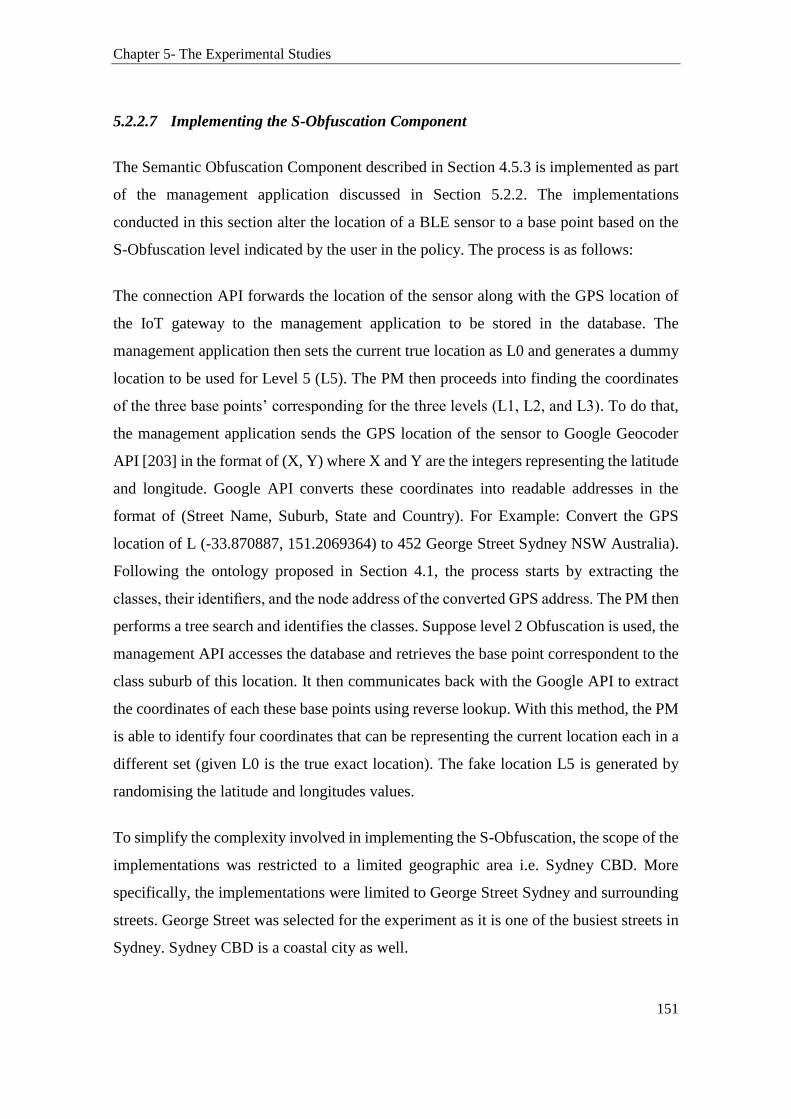
Chapter 5- The Experimental Studies
151
5.2.2.7 Implementing the S-Obfuscation Component
The Semantic Obfuscation Component described in Section 4.5.3 is implemented as part
of the management application discussed in Section 5.2.2. The implementations
conducted in this section alter the location of a BLE sensor to a base point based on the
S-Obfuscation level indicated by the user in the policy. The process is as follows:
The connection API forwards the location of the sensor along with the GPS location of
the IoT gateway to the management application to be stored in the database. The
management application then sets the current true location as L0 and generates a dummy
location to be used for Level 5 (L5). The PM then proceeds into finding the coordinates
of the three base points’ corresponding for the three levels (L1, L2, and L3). To do that,
the management application sends the GPS location of the sensor to Google Geocoder
API [203] in the format of (X, Y) where X and Y are the integers representing the latitude
and longitude. Google API converts these coordinates into readable addresses in the
format of (Street Name, Suburb, State and Country). For Example: Convert the GPS
location of L (-33.870887, 151.2069364) to 452 George Street Sydney NSW Australia).
Following the ontology proposed in Section 4.1, the process starts by extracting the
classes, their identifiers, and the node address of the converted GPS address. The PM then
performs a tree search and identifies the classes. Suppose level 2 Obfuscation is used, the
management API accesses the database and retrieves the base point correspondent to the
class suburb of this location. It then communicates back with the Google API to extract
the coordinates of each these base points using reverse lookup. With this method, the PM
is able to identify four coordinates that can be representing the current location each in a
different set (given L0 is the true exact location). The fake location L5 is generated by
randomising the latitude and longitudes values.
To simplify the complexity involved in implementing the S-Obfuscation, the scope of the
implementations was restricted to a limited geographic area i.e. Sydney CBD. More
specifically, the implementations were limited to George Street Sydney and surrounding
streets. George Street was selected for the experiment as it is one of the busiest streets in
Sydney. Sydney CBD is a coastal city as well.

Chapter 5- The Experimental Studies
152
Consider the following exemplary address: 452 George Street Sydney NSW Australia,
which corresponds to Australia (1), NSW (2a), Sydney (3a), George Street (4a), 452.
Therefore, the node address is 1.2a.3a.4a.452. Based on the Obfuscation level indicated
by the user, a base point will be selected from the ontology. Suppose the user has selected
Obfuscation Level 2 then the node address will be shortened to 1.2a.3a. Then, a search
for base points is conducted on all subclasses that start with a node address of 1.2a.3a.
The search will return all base points defined below the subclasses with the identifier “3a”.
Next, a base point is randomly selected, e.g., 1.2a.3a.4a.5b or 1.2a.3a.4b.5h. To reduce
the implementation complexity, we manually populated the database with an address for
each Obfuscation level. This allows the management database to simply lookup the
correspondent table for the base point address assigned to each level.
Finally, the selected base point is then converted, using Google Map API, to a GPS
coordinates and used as an obfuscated location for the original location. It should be noted
that Google Geocoder API is only used as a service for converting the coordinates into a
possible readable address. The Google Geocoder API is not made aware of the true
location of the device nor its identity. The relevant code is provided in Table 5.5. The
code is adapted from Google Maps Geocoding API [203].
Table 5.5- S-Obfuscation codification extract
S-Obfuscation codification
<?php
/*
* For a true GPS location of a sensor, return the longitude and latitude using The Google Geocoding
API V3
**/
function Get_Loc($address) {
$Loc = urlencode($Loc);
$url = "http://maps.googleapis.com/maps/api/geocode/json?address=$address&sensor=false";
// Make the HTTP request

Chapter 5- The Experimental Studies
153
$data = @file_get_contents($url);
// Parse the json response
$jsondata = json_decode($data,true);
// If the json data is invalid, return empty array
if (!check_status($jsondata)) return array();
$LatLng = array(
'lat' => $jsondata["results"][0]["geometry"]["location"]["lat"],
'lng' => $jsondata["results"][0]["geometry"]["location"]["lng"],
);
return $LatLng;
}
/*
* Check if the json data from Google Geo is valid
*/
function check_status($jsondata) {
if ($jsondata["status"] == "OK") return true;
return false;
}
5.2.3 Stage 3- Developing a Mobile Policy-based Application and LBS Web
Application
As mentioned in Section 5.1, the LBS application models the operation of an IoT LBS
application whereas a service is provided based on the location of a sensor. So the LBS
web application is used to request the location of a sensor. This enables the research to
observe the received location and determine whether the PM was successful in preserving
the location privacy. However, for this to work, a user-defined policy or a default policy
must be first configured and defined in the management application. Therefore, before
Table 5.7 - S-Obfuscation codification extract (Continued)

Chapter 5- The Experimental Studies
154
developing the LBS web application, we needed to implement another mobile
application. This mobile application referred to as the Policy-based app is used by the
user to create and assign policies to a particular BLE sensor (Figure 5.14 step 5). The
steps 1, 2, 3 and 4 were already done in Stage 1, 2 and 3 of this experiment.
Figure 5.14- Web application requesting the sensor location
5.2.3.1 The Development of a Policy-based Mobile Application
The mobile application, implemented in step 5 of Figure 5.14, provides the user with a
UI that allows him or her to define a policy and to assign it to a specific context using the
followings criteria:
Network restrictions: This feature enables the user to define a policy restriction on a
particular network e.g., mobile network or Wi-Fi.
Time restrictions: It is where a limitation on time can also be enforced e.g., between
9:00 AM and 17:00 PM.

Chapter 5- The Experimental Studies
155
Date restrictions: It is where a limitation on the weekdays can be enforced as well,
e.g., Monday to Friday.
Location restrictions: This is a policy which enforces a specific Obfuscation level.
Objects restrictions: This allow the enforcement of the policies mentioned above to
specific entities.
Default settings: Allows the enforcement of a set of configurations (restrictions) as a
default profile. This default profile is used in the absence of specific policies that
govern specific sensors.
For example, using this mobile application the user can create the following policy:
Policy 1: If my sensorID 1 is currently connected to the Internet via Home Wi-Fi (the
sensor relies information to the management application through a mobile application),
and it is Sunday between 8:00 AM and 6:00 PM then only reveal the suburb as the location
of the sensor (which correspond to Obfuscation level 2). The default policy is configured
to as “Do not disclose the object’s location.
Therefore, if an entity requests the location of sensor ID 1 and its context matched the
one defined in the policy, then it will receive a location narrowed to a suburb granularity.
Else, if the context does not match the one defined in the policy, then a fake location is
used instead. The screenshot of the mobile application used to create the user defined
policy is given in Figure 5.15. It shows how the user of a sensor device can attach
restrictions to a location output by setting restrictions on the network, time, days, location
and, a device identity.
This mobile application offers users with a UI enabling them to assign an Obfuscation
level to a context based on some contextual parameters. However, the actual
computations are done in the background on the server side (the management
application).
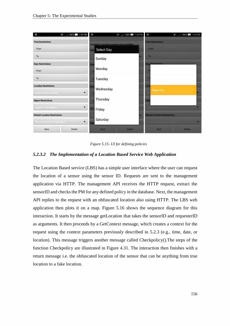
Chapter 5- The Experimental Studies
156
Figure 5.15- UI for defining policies
5.2.3.2 The Implementation of a Location Based Service Web Application
The Location Based service (LBS) has a simple user interface where the user can request
the location of a sensor using the sensor ID. Requests are sent to the management
application via HTTP. The management API receives the HTTP request, extract the
sensorID and checks the PM for any defined policy in the database. Next, the management
API replies to the request with an obfuscated location also using HTTP. The LBS web
application then plots it on a map. Figure 5.16 shows the sequence diagram for this
interaction. It starts by the message getLocation that takes the sensorID and requesterID
as arguments. It then proceeds by a GetContext message, which creates a context for the
request using the context parameters previously described in 5.2.3 (e.g., time, date, or
location). This message triggers another message called Checkpolicy().The steps of the
function Checkpolicy are illustrated in Figure 4.31. The interaction then finishes with a
return message i.e. the obfuscated location of the sensor that can be anything from true
location to a fake location.
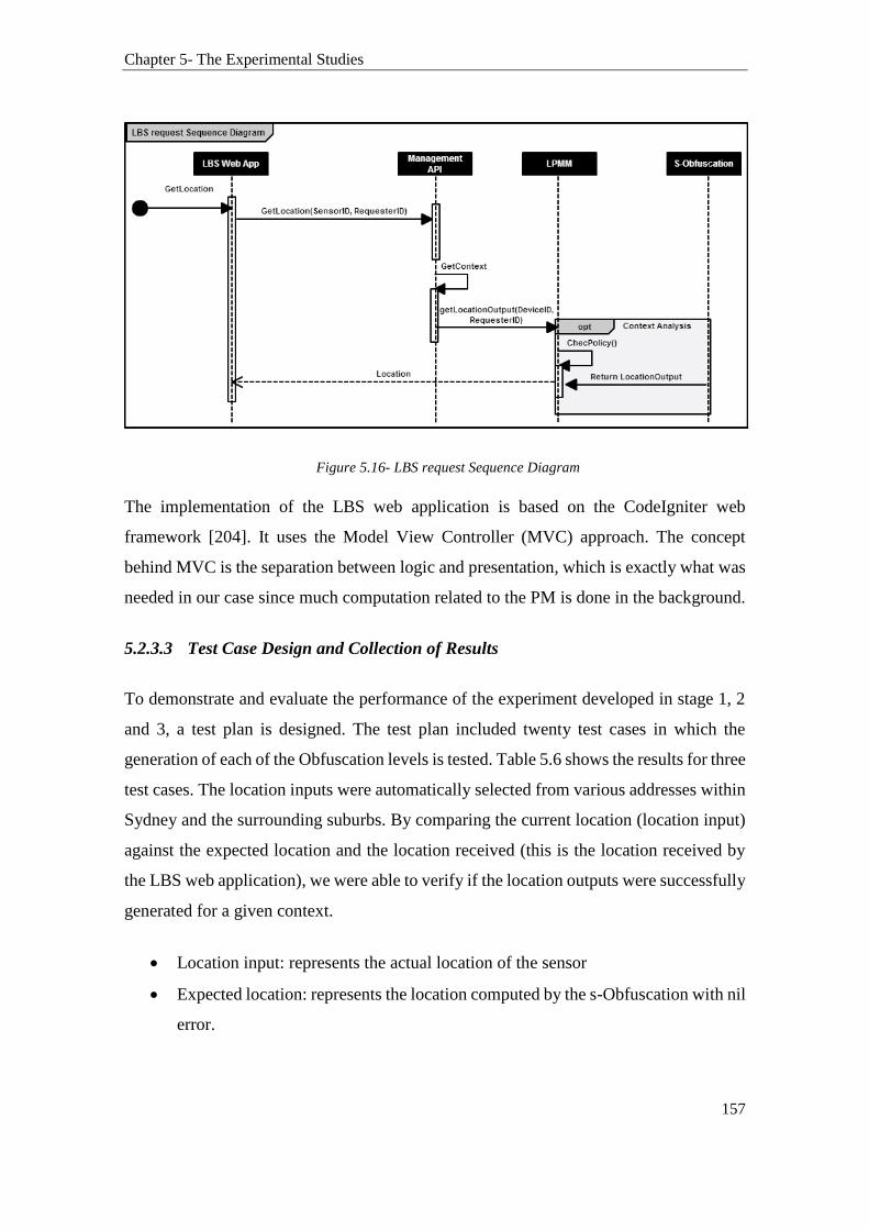
Chapter 5- The Experimental Studies
157
Figure 5.16- LBS request Sequence Diagram
The implementation of the LBS web application is based on the CodeIgniter web
framework [204]. It uses the Model View Controller (MVC) approach. The concept
behind MVC is the separation between logic and presentation, which is exactly what was
needed in our case since much computation related to the PM is done in the background.
5.2.3.3 Test Case Design and Collection of Results
To demonstrate and evaluate the performance of the experiment developed in stage 1, 2
and 3, a test plan is designed. The test plan included twenty test cases in which the
generation of each of the Obfuscation levels is tested. Table 5.6 shows the results for three
test cases. The location inputs were automatically selected from various addresses within
Sydney and the surrounding suburbs. By comparing the current location (location input)
against the expected location and the location received (this is the location received by
the LBS web application), we were able to verify if the location outputs were successfully
generated for a given context.
Location input: represents the actual location of the sensor
Expected location: represents the location computed by the s-Obfuscation with nil
error.
Chapter 5- The Experimental Studies
158
Location output: represents the received location as observed in the test.
Table 5.6 Test cases
Location input Obfuscation
level
Expected output
(Refer to Fig 19)
Actual output
10 m of GPS
(-33.870887,
151.2069364)
Readable GPS: 452-
456 George St,
Sydney NSW 2000,
Australia
Level 1
10 m of GPS
(-33.873961, 151.20569)
Readable GPS: within few addresses of
35 George St, Sydney NSW 2000,
Australia
GPS
(-33.873939, 151.205645)
Readable address:
37 George St, Sydney NSW
2000, Australia
50 m of GPS
(-33.870887,
151.2069364)
Readable GPS: 452-
456 George St,
Sydney NSW 2000,
Australia
Level 2
Two additional base points were defined
in the database:
50m of GPS
(-33.8593221, 151.20360619999997)
within few addresses
40 Kent St, Sydney
And
50m of GPS
(33.8657357,
151.20360619999997)
within few addresses
25 York St, Sydney
GPS (-33.8684743,
151.20601750000003)
Readable address:
26 York St, Sydney NSW
2000, Australia
Level 3

Chapter 5- The Experimental Studies
159
100 m of GPS
(-33.870887,
151.2069364)
Readable GPS: 452-
456 George St,
Sydney NSW 2000,
Australia
In addition to those defined in level 1 and
2:
100m of GPS
(-33.837634, 151.20496926)
Within few addresses of
26 Oak St, North Sydney NSW 2060,
Australia
And
100m of GPS
(-33.842064, 151.206189)
Within few addresses of 19 Miller St,
Lavender Bay NSW 2060, Australia 100
m of GPS
(-33.841122, 151.20751)
Within few addresses of 11 Blue St,
North Sydney NSW 2060, Australia
GPS (-33.840858, 151.206849)
48 Blue St, North Sydney NSW
2060, Australia
Figure 5.17 visualises the expected location and actual location. It shows that the original
location of “452-456 George St, Sydney NSW 2000, Australia” has been successfully
obfuscated to “37 George St, Sydney NSW 2000, Australia” (Just 2 addresses from the
base point “25 George St, Sydney NSW 2000, Australia”).
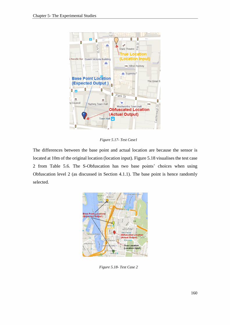
Chapter 5- The Experimental Studies
160
Figure 5.17- Test Case1
The differences between the base point and actual location are because the sensor is
located at 10m of the original location (location input). Figure 5.18 visualises the test case
2 from Table 5.6. The S-Obfuscation has two base points’ choices when using
Obfuscation level 2 (as discussed in Section 4.1.1). The base point is hence randomly
selected.
Figure 5.18- Test Case 2

Chapter 5- The Experimental Studies
161
Therefore, in this test case 2, as shown in Figure 5.18, using Obfuscation level 2 the
original location of “452-456 George St, Sydney NSW 2000, Australia” has been
successfully obfuscated to the “26 York St, Sydney NSW 2000, Australia”. The rest of
test cases that used level 2 Obfuscation produced results near Kent St and York St as well.
This is because the S-Obfuscation selects a base point from the available ones randomly.
Figure 5.19 visualises the test case 3 from Table 5.6. In this case, a wider proximity to
original location is used (Obfuscation level 3). This provides the S-Obfuscation with a
higher number of base point choices.
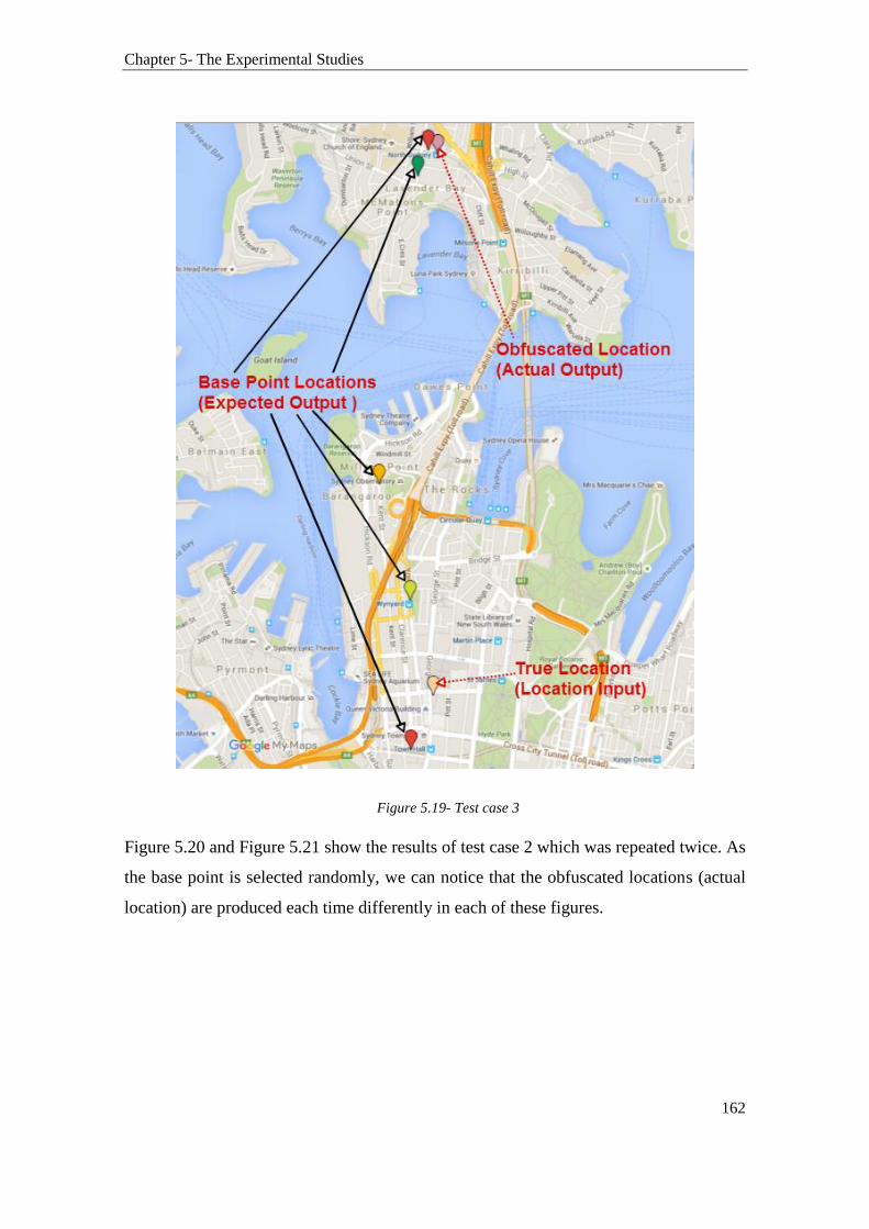
Chapter 5- The Experimental Studies
162
Figure 5.19- Test case 3
Figure 5.20 and Figure 5.21 show the results of test case 2 which was repeated twice. As
the base point is selected randomly, we can notice that the obfuscated locations (actual
location) are produced each time differently in each of these figures.

Chapter 5- The Experimental Studies
163
Figure 5.20- Results of test case using Obfuscation level 2(1st round)
Figure 5.21- Results of test case using Obfuscation level 2(2nd round)
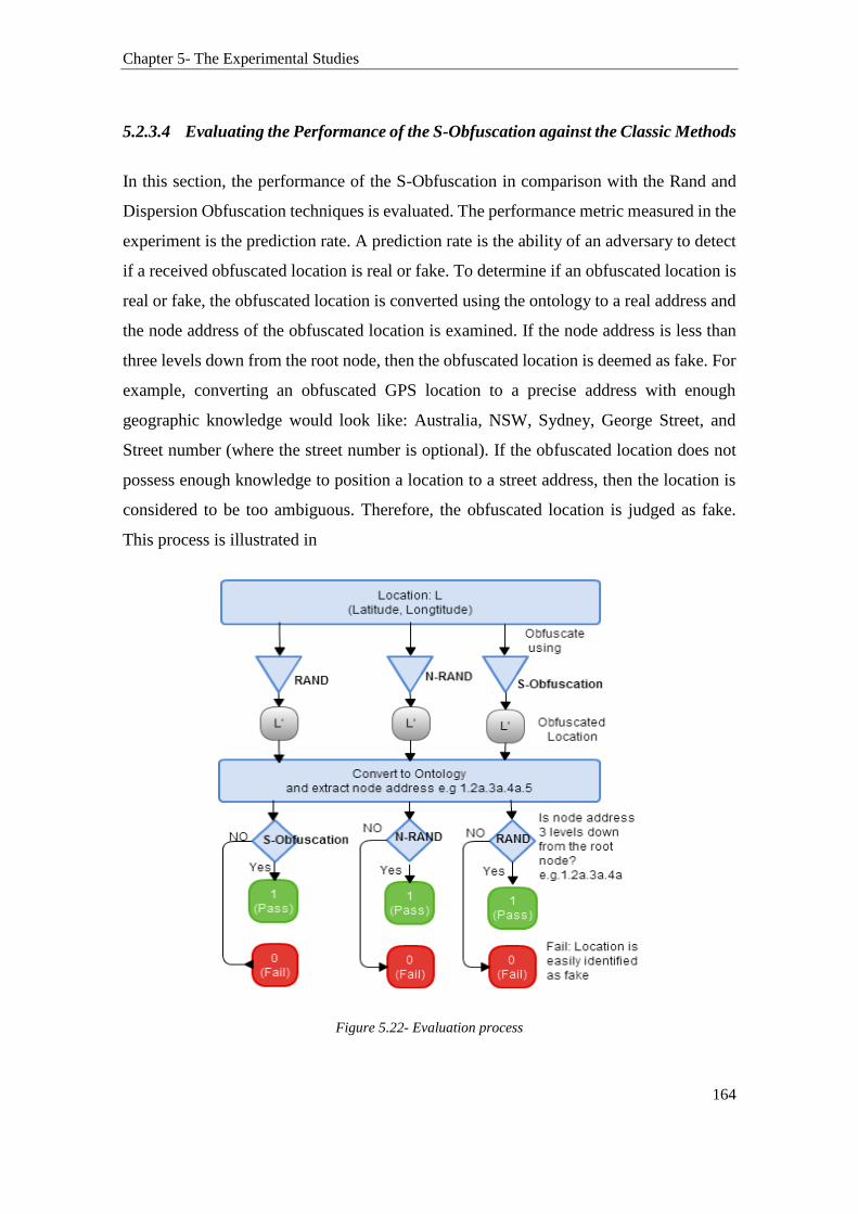
Chapter 5- The Experimental Studies
164
5.2.3.4 Evaluating the Performance of the S-Obfuscation against the Classic Methods
In this section, the performance of the S-Obfuscation in comparison with the Rand and
Dispersion Obfuscation techniques is evaluated. The performance metric measured in the
experiment is the prediction rate. A prediction rate is the ability of an adversary to detect
if a received obfuscated location is real or fake. To determine if an obfuscated location is
real or fake, the obfuscated location is converted using the ontology to a real address and
the node address of the obfuscated location is examined. If the node address is less than
three levels down from the root node, then the obfuscated location is deemed as fake. For
example, converting an obfuscated GPS location to a precise address with enough
geographic knowledge would look like: Australia, NSW, Sydney, George Street, and
Street number (where the street number is optional). If the obfuscated location does not
possess enough knowledge to position a location to a street address, then the location is
considered to be too ambiguous. Therefore, the obfuscated location is judged as fake.
This process is illustrated in
Figure 5.22- Evaluation process

Chapter 5- The Experimental Studies
165
5.2.3.5 Implementing the Rand and Dispersion Techniques
The Rand and Dispersion techniques described in Section 2.3 were implemented as part
of a web application. This application is used to test and evaluate the obfuscated location
generated by these techniques. It allows the user to randomly generate obfuscated location
for specific GPS coordinates. The implementations of the Rand and Dispersion
Obfuscation Techniques are publically available online using an open source license.
They can be accessed via this link http://elkhodr.com/obf.html . These implementations
provide the user with a method to vary the radius of the area where obfuscated locations
are generated. Table 5.7 shows the main parts of the code used to implement the Rand
technique. The Dispersion technique is based on this code as well.
Table 5.7- The Rand technique selected codes
//Generate Random Numbers between -1 and 1
var u= ((Math.random()*-1)+1)*1; var v= ((Math.random()*-1)+1)*1;
r= Number(r) /111300;
var w = Number(r) * Math.sqrt(u);
var t = 2 * Math.PI * v;
var x = w * Math.cos(t);
var xx = x / Math.cos(y0)
var y = w * Math.sin(t);
//Generate the new location using the above
var xnew=Number(x0)+Number(xx);
var ynew=Number(y0)+ Number(y);
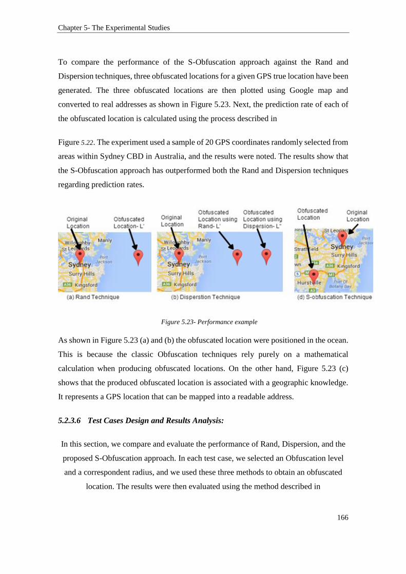
Chapter 5- The Experimental Studies
166
To compare the performance of the S-Obfuscation approach against the Rand and
Dispersion techniques, three obfuscated locations for a given GPS true location have been
generated. The three obfuscated locations are then plotted using Google map and
converted to real addresses as shown in Figure 5.23. Next, the prediction rate of each of
the obfuscated location is calculated using the process described in
Figure 5.22. The experiment used a sample of 20 GPS coordinates randomly selected from
areas within Sydney CBD in Australia, and the results were noted. The results show that
the S-Obfuscation approach has outperformed both the Rand and Dispersion techniques
regarding prediction rates.
Figure 5.23- Performance example
As shown in Figure 5.23 (a) and (b) the obfuscated location were positioned in the ocean.
This is because the classic Obfuscation techniques rely purely on a mathematical
calculation when producing obfuscated locations. On the other hand, Figure 5.23 (c)
shows that the produced obfuscated location is associated with a geographic knowledge.
It represents a GPS location that can be mapped into a readable address.
5.2.3.6 Test Cases Design and Results Analysis:
In this section, we compare and evaluate the performance of Rand, Dispersion, and the
proposed S-Obfuscation approach. In each test case, we selected an Obfuscation level
and a correspondent radius, and we used these three methods to obtain an obfuscated
location. The results were then evaluated using the method described in

Chapter 5- The Experimental Studies
167
Figure 5.22.
Test case 1: Using Obfuscation level 1
Parameters of the test:
Input Address: GPS (-33.870887, 151.2069364)
Readable Address: 452-456 George St, Sydney NSW 2000, Australia
Radius used for Rand and Dispersion methods: 2000 meters
S-Obfuscation level: level 1.
Visual results
Figure 5.24- Results of the evaluation test case 1
As shown in Figure 5.24, with a smaller radius of 2KM the Rand and Dispersion
techniques both produced obfuscated GPS locations that can be converted to readable
addresses.
Evaluation
Given that all three methods, in this test case, produced obfuscated locations that can be
mapped to readable addresses, then using the evaluation flowchart shown in
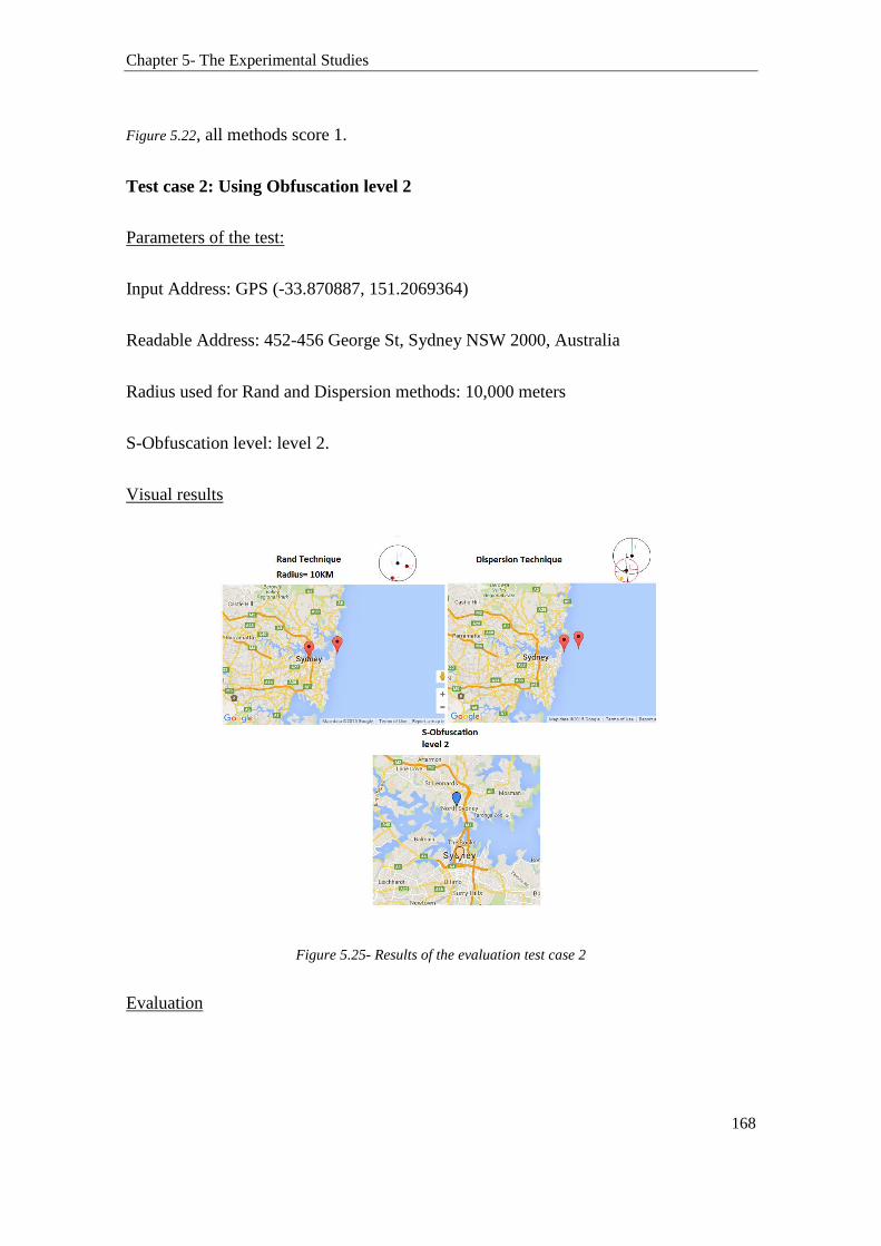
Chapter 5- The Experimental Studies
168
Figure 5.22, all methods score 1.
Test case 2: Using Obfuscation level 2
Parameters of the test:
Input Address: GPS (-33.870887, 151.2069364)
Readable Address: 452-456 George St, Sydney NSW 2000, Australia
Radius used for Rand and Dispersion methods: 10,000 meters
S-Obfuscation level: level 2.
Visual results
Figure 5.25- Results of the evaluation test case 2
Evaluation
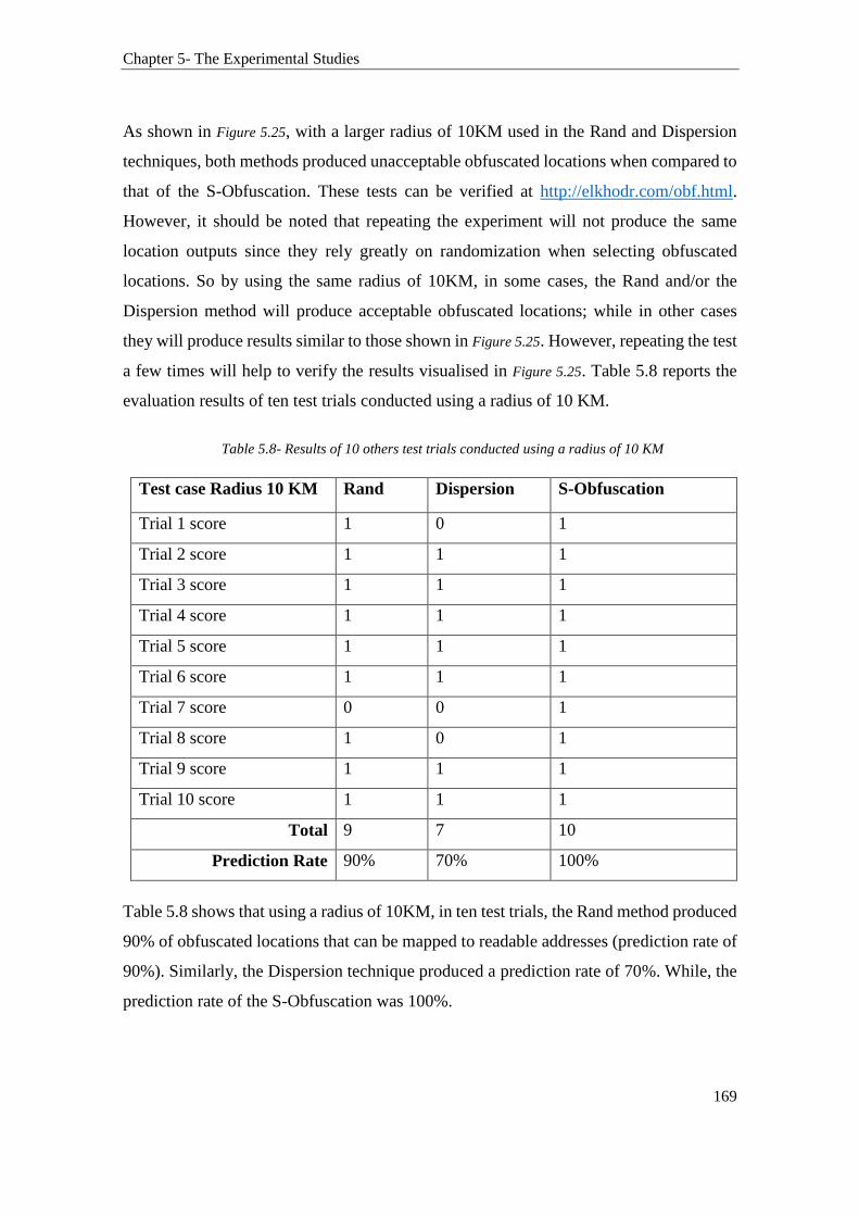
Chapter 5- The Experimental Studies
169
As shown in Figure 5.25, with a larger radius of 10KM used in the Rand and Dispersion
techniques, both methods produced unacceptable obfuscated locations when compared to
that of the S-Obfuscation. These tests can be verified at http://elkhodr.com/obf.html.
However, it should be noted that repeating the experiment will not produce the same
location outputs since they rely greatly on randomization when selecting obfuscated
locations. So by using the same radius of 10KM, in some cases, the Rand and/or the
Dispersion method will produce acceptable obfuscated locations; while in other cases
they will produce results similar to those shown in Figure 5.25. However, repeating the test
a few times will help to verify the results visualised in Figure 5.25. Table 5.8 reports the
evaluation results of ten test trials conducted using a radius of 10 KM.
Table 5.8- Results of 10 others test trials conducted using a radius of 10 KM
Test case Radius 10 KM Rand Dispersion S-Obfuscation
Trial 1 score 1 0 1
Trial 2 score 1 1 1
Trial 3 score 1 1 1
Trial 4 score 1 1 1
Trial 5 score 1 1 1
Trial 6 score 1 1 1
Trial 7 score 0 0 1
Trial 8 score 1 0 1
Trial 9 score 1 1 1
Trial 10 score 1 1 1
Total 9 7 10
Prediction Rate 90% 70% 100%
Table 5.8 shows that using a radius of 10KM, in ten test trials, the Rand method produced
90% of obfuscated locations that can be mapped to readable addresses (prediction rate of
90%). Similarly, the Dispersion technique produced a prediction rate of 70%. While, the
prediction rate of the S-Obfuscation was 100%.

Chapter 5- The Experimental Studies
170
Test case 3: Using Obfuscation level 3
In this test case, we used a radius of 50 KM for the Rand and Dispersion technique and
Obfuscation level 3 in the S-Obfuscation. Table 5.9 shows the evaluation results of
another ten trials conducted in test case 3.
Table 5.9- Results of 10 others test trials conducted using a radius of 50 KM
Test case Radius 50 KM Rand Dispersion S-Obfuscation
Trial 1 score 1 1 1
Trial 2 score 0 0 1
Trial 3 score 0 0 1
Trial 4 score 0 0 1
Trial 5 score 0 0 1
Trial 6 score 1 0 1
Trial 7 score 1 1 1
Trial 8 score 1 1 1
Trial 9 score 0 0 1
Trial 10 score 1 1 1
Total 5 4 10
Prediction Rate 50% 40% 100%
Table 5.9 shows that the S-Obfuscation approach has again outperformed both the Rand
and Dispersion methods with regard to the prediction rate. The Dispersion method was
the lowest performer with a prediction rate of only 40% (only 40% of the produced
locations were successfully mapped to readable addresses). The Rand come second at
50%; while the S-Obfuscation scored 100%. These results were expected given the S-
Obfuscation selects a predefined well-chosen base point when generating obfuscated
locations.
To this end, the Random and Dispersion techniques, implemented in this work, employ
geometric methods to generate obfuscated locations. In real life, a location may be in a
public place, a private location such as inside a building, which is closed during that time
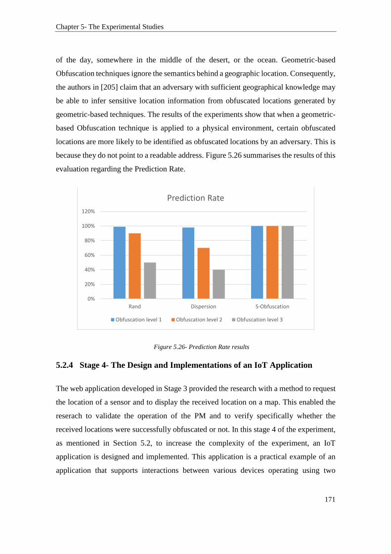
Chapter 5- The Experimental Studies
171
of the day, somewhere in the middle of the desert, or the ocean. Geometric-based
Obfuscation techniques ignore the semantics behind a geographic location. Consequently,
the authors in [205] claim that an adversary with sufficient geographical knowledge may
be able to infer sensitive location information from obfuscated locations generated by
geometric-based techniques. The results of the experiments show that when a geometric-
based Obfuscation technique is applied to a physical environment, certain obfuscated
locations are more likely to be identified as obfuscated locations by an adversary. This is
because they do not point to a readable address. Figure 5.26 summarises the results of this
evaluation regarding the Prediction Rate.
Figure 5.26- Prediction Rate results
5.2.4 Stage 4- The Design and Implementations of an IoT Application
The web application developed in Stage 3 provided the research with a method to request
the location of a sensor and to display the received location on a map. This enabled the
reserach to validate the operation of the PM and to verify specifically whether the
received locations were successfully obfuscated or not. In this stage 4 of the experiment,
as mentioned in Section 5.2, to increase the complexity of the experiment, an IoT
application is designed and implemented. This application is a practical example of an
application that supports interactions between various devices operating using two
0%
20%
40%
60%
80%
100%
120%
Rand Dispersion S-Obfuscation
Prediction Rate
Obfuscation level 1 Obfuscation level 2 Obfuscation level 3

Chapter 5- The Experimental Studies
172
different communication protocols. This IoT application is designed to support
automation and things-to-things communications seamlessly while, importantly,
preserving the location privacy of a BLE sensor. Particularly, in preserving the location
privacy of a BLE sensor in scenarios where the location of the sensor is used to make an
automated decision on whether to change the status of a smart lamp, which is accessible
via Wi-Fi. Figure 5.27 depicts the architecture of the developments added in stage 4 to
the experiment.
Figure 5.27- Stage 4 of the experiment
From Figure 5.27:
The sensors 1 and 2 are the BLE sensors developed by Texas Instruments. In stage 1 and
2 of this experiment, the data collected using these sensors along with their locations were
transmitted and stored in the management database in the web application (the manager).
The lamp showing in Figure 5.27 is a smart light developed by Belkin (commercially
known as WeMo) and has Wi-Fi capabilities. Belkin has developed a mobile application
that allows users to control, via Wi-Fi, their WeMo bulb. This ability is provided using
an API developed by Belkin, which supports both Android and iOS devices. Therefore,
the experiment reused and adapted Belkin’s mobile application in order to integrate the
WeMo into the IoT-MP. This has saved us much time and efforts given that building
automation is not the aim of this thesis. Instead, the goal is to create a simple and practical
example of an automated scenario where the location information of a BLE sensor is used

Chapter 5- The Experimental Studies
173
to make a decision to whether the WeMo bulb should be turned on or no. To achieve this,
we modified the Belkin Android application by adding a function that can be used to
receive and extract the HTTP requests sent by the management API over the Internet.
These HTTP requests are sent by a specially designed PHP function hosted by the
management web application server.
The scenarios illustrated in Figure 5.27 are further described as follows:
Sensor 1 and 2 are collecting temperature information and sending this information to the
manager via an intermediate mobile device. The manager stores the information received
in the database along with the location information of each of the sensor (using the method
described in stage 1 and 2). An IoT application is implemented and hosted by the
management application (the manager). This IoT application sends a request over the
Internet using HTTP to the WeMo bulb. These requests are used to change the status of
the WeMo bulb (on/off) based on a predefined Flag (the Flag will be explained
subsequently). However, this app does not know the status of the WeMo Bulb. It only
supports one-way communication, which is sending a message to the WeMo Bulb. Thus,
the Bulb does not initiate communication with the web application or acknowledge any
received messages. Instead, the IoT application is only capable of sending a request using
the method SetDeviceSate supported by Belkin SDK implementations to WeMo. We did
not go into the details of how this request is processed through Belkin API as this is not
the focus of our work. We only needed to achieve the capability of changing the status of
the bulb (on or off) when a Flag is changed (True or False). Readers interested in further
readings on the Belkin API are referred to [206].
The Flag is a Boolean variable set by the CheckFlag() function that consists of a set of
conditions, which the user can define. The parameters of the function CheckFlag() was
hardcoded and manipulated manually when testing the app. A compressed pseudocode of
the CheckFlag() function is provided in Table 5.10.

Chapter 5- The Experimental Studies
174
Table 5.10- CheckFlag() Code
CheckFlag() Function Pseudo Code
Function CheckFalg() {
Flag= False;
Location=CheckPM(sensor 3)
if location= X // X is for a given GPS address
and Sensor1.temp< Y //given temperature
Then Flag=True;
If (Flag)
Device1.Change_Status }
Firstly, the function CheckFalg() initialises the Flag variable. The function CheckPM
checks if the requester (in this example, the IoT app) has permission to access the location
of sensor 3 within the requested context. This function calls the message
getLocationOutput(DeviceID, RequesterID) and passes the argument sensor 3 as the
Device ID. The function getLocationOutput returns an obfuscated location of the device
under request as previously described in Table 5.3. This location can range from a precise
location (level 0) or a location that was obfuscated using one of other four levels of the
S-Obfuscation approach. Therefore, the function CheckPM (sensor 3) has a return
message consisting of the location of sensor 3 as outputted by the PM. Importantly, it
should be noted that sensor 3's location was disclosed based on the user's defined policy.
Therefore, the actual location of the device is disclosed only if the defined user's policy
permit to do so. To this end, the location of sensor 3 is received. The code then moves
into comparing the received location against a condition that can be used to trigger the
change in the Bulb status. Additionally, the code compares two other conditions including
that of sensor 1. If these conditions are met, then the Flag is set to true. If not, the Flag
remains set to false. Next, the code completes by checking the status of Flag. If it is true,

Chapter 5- The Experimental Studies
175
then the function Change_status is triggered which turns on the WeMo bulb. We repeated
the experiment several time by manually altering the parameters including the GPS
location used for the comparison. We also manipulated the policies defined by the PM on
sensor 3. This allowed us to observe the change in the status of the bulb in different
contexts.
In the first test case of this stage of the experiment, we configured the PM to skip the
context analysis and to use the default policy. In the default policy, the policy governing
the location of sensor 3, was set to reveal the true location (L0) of sensor 3. This is to
reduce the complexity involved in the testing and to see whether the WeMo light is
successfully turned on when simple configurations are used. However, the experiment
did not work. After some diagnosis, we realised that it is inefficient to obtain a GPS
reading that can be compared with a hard coded GPS location. To overcome this
challenge, instead of comparing the two GPS coordinates, the CheckPM() code was
updated to calculate the distance between the two GPS coordinates instead of comparing
if they are equal. Thus, if the difference between the two compared GPS locations was
found to be less than 100m, then it is assumed that the two GPS locations are matching.
The code is adapted from the Haversine Formula [207]. We made some additions to the
Haversine Formula to compare the calculated difference in distance between the two GPS
coordinates against the number 100 (representing 100m). Fortunately, the Haversine
formula has solved the issue and test 1 run successfully. The IoT application was
successful in turning on the WeMo light based on the location and parameters of a BLE
sensor, autonomously while preserving the location privacy of the BLE sensor.
5.2.4.1 The IoT Application: Test Case Design and Results Analysis
This section reports on the design the test cases. Each of these test cases used a different
set of configurations. The dependent variables being manipulated are:
The location and temperature of the BLE sensors;
The user-defined policy settings ;
The level of Obfuscation assigned to the policy.

Chapter 5- The Experimental Studies
176
Table 5.11 shows an exemplary of a test case designed to verify the operation of the IoT
application.
Table 5.11- Test Case Design
Step Test Steps Test Data Expected Result Actual
Result
Status
(Pass/Fail)
1
Set policy for
sensor 3 to be null P=null
WeMo light
should turn on
WeMo light is
on Pass
2 Verify Sensor 3 25 George St,
Test Case ID: WeMo_1
Test Title: Verify WeMo is turned on with simple PM configurations
Description: Verify WeMo is turned on when sensor 3 is at 25 George St, Sydney NSW and
temperature of Sensor 1 is below 25 C. Policy defined by the user is to bypass PM context
analysis process and always to disclose the true location of sensor 3.
Pre-conditions:
1. Sensor 1, 3 and device 1 are running
2. User has configured a valid policy that reveals the true location of sensor 3
3. Sensor 1 temperature is set to be below 40C
4. The light of device 1 is turned off
5. Hard code the comparable variables in CheckFlag function to match those
configured in the pre-condition 1 and 2
Dependencies:
1. Sensor 1 and 3, Device 1
2. PM settings
3. CheckFlag variables
Post-conditions:
1. WeMo light is turned on

Chapter 5- The Experimental Studies
177
location Sydney NSW
3
Create Default
Policy
LocationOutput
=L0
4
Verify Sensor 1
temperature is
below 40C
Check stored
value in the
database
5
hardcode
comparative
variable 1
X= GPS address
6
hardcode
comparative
variable 2
Y= 40
7
Verify WeMo bulb
is powered on and
connected via Wi-
Fi to the Mobile
App
Manually set
WeMo status to
off
8
Run the IoT app
Verify IoT app
can access the
database
5.3 Summary
In this chapter, the Internet of Things Management Platform has been evaluated through
experiments about its capabilities in preserving the location privacy of things in a physical
setup. The experiments incorporated several stages of experimentations that involved the
implementation of an IoT application and several mobile and web applications. Through
the use of physical GPS location coordinates collected in real-time, the experimental
studies demonstrated the capability of the IoT-MP in preserving the location privacy of
BLE 4.0 sensors. They also demonstrated that it is possible for users to manage the
location privacy of their devices by configuring location disclosure policies that can be
attached to specific contexts. Furthermore, the experiments confirmed that it is possible
to preserve the location privacy of a sensor in scenarios where the sensor is participating
in a seamless and autonomous communications as part of an IoT application.
Table 5.15 - Test Case Design (Continued)

Chapter 5- The Experimental Studies
178
Additionally, in this chapter, two classic Obfuscation techniques (i.e. the Rand and
Dispersion techniques) were implemented and their performances were compared to that
of the proposed S-Obfuscation approach. Unlike the classic Obfuscation techniques that
employ geometric methods to generate obfuscated locations, the S-Obfuscation relies on
a geographic knowledge to produce obfuscated locations that are harder to be detected as
fake or obfuscated. The results show that the performance of the S-Obfuscation approach
has outperformed that of the two classic techniques under comparison. For instance, using
“Obfuscation level 3”, it is found that the S-Obfuscation has produced better-obscured
location by 60% than that of the Dispersion technique and by 50 % than that of the Rand
technique.
While the experimental studies allow for the practical evaluation of the IoT-MP on
physical hardware devices in contextual and physical setups, they suffer from few
limitations. These limitations mainly relate to the scalability of the experiments. The
experiments validated and provided feedbacks on the performance of the IoT-MP and that
of the S-Obfuscation approach when using BLE sensor devices, but on a limited scale.
Thus, the experiments cannot be used to assess the performance of the IoT-MP in large-
scale heterogeneous networks. To address these shortcomings, several simulations studies
are conducted in Chapter 6. These simulations aim to complement the experiments by
assessing the performance of the proposed IoT-MP in setups which combine various low-
power wireless networks together using a large number of low-power sensor devices.
179
6 CHAPTER 6- THE SIMULATION
STUDIES
This chapter reports on the simulation studies that supplement the experiments previously
reported in Chapter 5. They demonstrate the capability of the IoT-MP in preserving the
location privacy of things in large and heterogeneous environments similar in scale and
complexity to those envisioned in the IoT. Section 6.1 provides an overview of the
simulation studies. It outlines the three major parts of the simulations, which are the
ZigBee, Wi-Fi, and the heterogeneous network scenarios. Section 6.2 discusses the
simulation of IEEE 802.15.4 network scenarios. These scenarios included the
implementation of the IoT-MP in a ZigBee WSN. Section 6.2.3 reports on the simulations
of IEEE 802.11 networks. Section 6.3 discusses the development of a large-scale
heterogeneous network. Section 6.3.4 reports on the simulations conducted to integrate
the IEEE 802.11ah, ZigBee, and the other IEEE 802.11 scenarios, previously simulated
in Section 6.2 and 6.3, in one large heterogeneous network consisting of thousands of
nodes. In each of these scenarios, the approaches of the IoT-MP in managing and
preserving the location privacy of things are simulated, and their performances are noted.
Additionally, the network performance of each of these simulations about the end-to-end
delays and power consumption at the end host devices are also reported.
6.1 Overview of the Simulations
The simulations aim to evaluate the effectiveness and scalability of the IoT-MP in
protecting the location privacy of things. That is, they aim to validate the capability of the
IoT-MP in a dynamic environment that encompasses heterogeneous communications
among large numbers of devices engaged in seamless interactions. The simulation
scenarios are divided into three major parts as follows:
802.15.4 based-network scenarios
802.11 based-network scenarios

Chapter 6- The Simulation Studies
180
Heterogeneous network scenarios based on different technologies
Each of the above scenarios has several sub-scenarios or stages of simulations. The
simulation’s setup of the technology used in each of these scenarios and the details of
some other parameters such as the number of nodes and the application setups are
discussed in the next sections. Some performance related parameters relevant to the work,
such as the delays and energy consumptions, are also reported.
6.2 Network Scenarios based on IEEE 802.15.4
The aim of this IEEE 802.15.4 simulation also referred to as ZigBee simulation
throughout the rest of this Chapter, is to validate and test the applicability of the proposed
IoT-MP in a low-power and low-rate wireless network. The simulated scenario consists
of several devices that communicate over ZigBee. It is based on the scenarios provided
in the ZigBee IP technical specification report [208]. Thus, the network setup of this
scenario consists of several ZigBee devices acting as smart appliances, smart plugs or
simply temperature sensors in an IoT Smart Home example. These devices communicate
sensory data to a ZigBee router device, which in turn routes the data to a ZigBee
coordinator device. The router device, as described in the ZigBee IP specification
example, can be any device that has an additional function of routing the data to the
network. On the other hand, the ZigBee coordinator can be a programmable
communicating thermostat with advanced support for an in-home display system [208].
We simulated the scenario provided by ZigBee Alliance in their ZigBee IP
documentations by porting the model into the IoT-MP [208].
As discussed in Section 3.1.2.1, ZigBee is based on the IEEE 802.15.4 standard for Low-
Rate Wireless Personal Area Network (LR-WPAN). It is well-suited for IoT devices that
transmit smaller packets over a network. Typically, ZigBee’s transmission range is within
few meters at a maximum data rate of 250Kbps. The network simulator NS2 version 2.35
was used to design, develop, and implement the simulation scenarios carried out in this
research. The simulator supports a class hierarchy in C++ (compiled hierarchy), and a
similar class hierarchy within the OTcl interpreter (interpreted hierarchy). The two
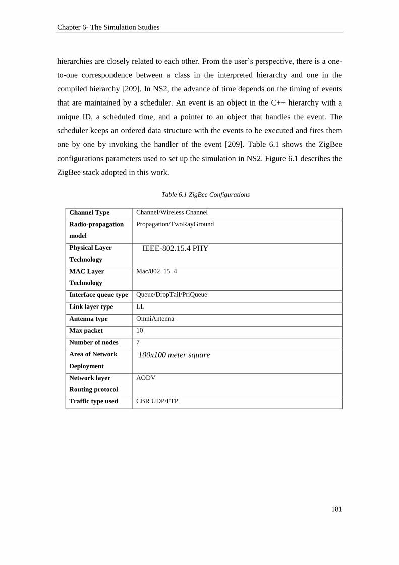
Chapter 6- The Simulation Studies
181
hierarchies are closely related to each other. From the user’s perspective, there is a one-
to-one correspondence between a class in the interpreted hierarchy and one in the
compiled hierarchy [209]. In NS2, the advance of time depends on the timing of events
that are maintained by a scheduler. An event is an object in the C++ hierarchy with a
unique ID, a scheduled time, and a pointer to an object that handles the event. The
scheduler keeps an ordered data structure with the events to be executed and fires them
one by one by invoking the handler of the event [209]. Table 6.1 shows the ZigBee
configurations parameters used to set up the simulation in NS2. Figure 6.1 describes the
ZigBee stack adopted in this work.
Table 6.1 ZigBee Configurations
Channel Type Channel/Wireless Channel
Radio-propagation
model
Propagation/TwoRayGround
Physical Layer
Technology
IEEE-802.15.4 PHY
MAC Layer
Technology
Mac/802_15_4
Interface queue type Queue/DropTail/PriQueue
Link layer type LL
Antenna type OmniAntenna
Max packet 10
Number of nodes 7
Area of Network
Deployment
100x100 meter square
Network layer
Routing protocol
AODV
Traffic type used CBR UDP/FTP

Chapter 6- The Simulation Studies
182
Figure 6.1- ZigBee Stack
The topology of the simulated network is given in Figure 6.2. The simulation includes the
following nodes that communicate over the IEEE 802.15.4 standard:
ZigBee Coordinator (Manager):
A ZigBee coordinator has the responsibility for controlling and monitoring the other
sensor nodes. A ZigBee coordinator can be configured in two different types: an ordinary
coordinator that operates within the scope of a cluster, and a PAN coordinator that acts
as a coordinator for the entire PAN network. In this simulation, node ID 0 is configured
as a PAN coordinator. It is referred to as the manager (represented by the green circle in
Figure 6.2). This manager will have additional functionalities than those provided by a
general ZigBee PAN coordinator as we have implemented the PM and attached a database
to it.
Full Function Device (Agent)
A ZigBee Full Function Device (FFD), representing an agent, supports all the 49
primitives defined by the IEEE 802.15.4 standard [210]. An agent acts as a routing device
or intermediate node to relay and forward the sensor’s data to the ZigBee coordinator.
Simply, it can be described as a communication agent. Node 1 and 2 are configured as
Chapter 6- The Simulation Studies
183
ZigBee full functioning devices. They are referred to as an agent and represented in the
blue circle in Figure 6.2.
Reduced Function Devices (Things/ Sensor)
A reduced function device (RFD) is a ZigBee device with reduced and limited
functionalities. That is, an RFD only functions as an end device. RFD’s capabilities are
limited to collecting and transmitting sensory information. In this work, RFD devices
represent IoT devices (things) in the IoT. Things have the capability of communicating
only with an agent. Their functionality is extremely low. Their interactions are limited to
sending sensory information to their respective agents at a regular time interval. Figure
6.3 shows that Node 3 and 4 are configured as sensors in the grey circle. An RFD is
intended for very simple applications and can only communicate to FFDs (denoted as
agents in this experiment). On the other hand, FFD can operate as a coordinator or as an
RFD. It can communicate also with RFDs or other FFDs.
Requesters (acting as management or IoT application)
Requesters are nodes that play the role of an IoT application. A requester has the
responsibility of requesting information about a sensor from the manager, including the
sensor’s location information. A request can be made locally within the same PAN
network or via the Internet depending on the application design. The requesters are
implemented in this simulation for the purpose of simulating requests to location
information and, therefore, to verify the capability of the PM in preserving the location
privacy of things and their users. We will see later how the requesters are used to
demonstrate the location privacy feature of the IoT-MP.

Chapter 6- The Simulation Studies
184
Figure 6.2- Network Topology of the ZigBee Simulation
Figure 6.3- ZigBee nodes definitions from NS2 Tcl file
6.2.1 Network Design and Simulations using NS2
The Network Simulation tool NS2 implements a generic ZigBee stack (module). It
provides basic configuration files that can be used as a base template to create ZigBee
simulations. Therefore, this work adapted this generic ZigBee module for the
implementation of the IoT-MP architecture. Mainly, the following modules have been
modified:

Chapter 6- The Simulation Studies
185
In the AODV module the following packages: Aodv.cc, aodv.h,
aodv_packet.h, aodv_rtable.cc and aodv_rtable.h
packet.h from the Ns2.35 common module
Briefly, these implementations are mainly concerned with the creation of packets at the
sensors, transmission of packets from the sensors to agents, and from agents to managers.
They also support the receipt of packets on the manager side. This involves extracting the
data from a packet and storing them in the manager’s database. The packet’s structure of
the communication is defined by the IEEE 802.15.4 coordinator. The network operates in
beacon mode as shown in Figure 6.4. In this mode, the coordinator (manager) sends out
periodic beacons throughout the network. This is to enable all nodes to sleep between
beacons and to wake up when the beacon timer expires. This is obviously to reduce the
energy consumption of RFDs.
Figure 6.4- Beacon using direct transmission definition
In the file “packet.h”, a new data type packet is defined. This packet is used by the sensor
to create a beacon. There is no predefined method in which two nodes in a ZigBee
network can communicate. However, the suitable methods of transmission can be
achieved using mutual synchronization techniques, or direct transmission using un-slotted
CSMA-CA. The simulations used the direct transmission method as it is less complex to
implement.
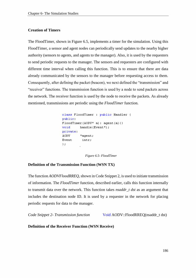
Chapter 6- The Simulation Studies
186
Creation of Timers
The FloodTimer, shown in Figure 6.5, implements a timer for the simulation. Using this
FloodTimer, a sensor and agent nodes can periodically send updates to the nearby higher
authority (sensors to agents, and agents to the manager). Also, it is used by the requesters
to send periodic requests to the manager. The sensors and requesters are configured with
different time interval when calling this function. This is to ensure that there are data
already communicated by the sensors to the manager before requesting access to them.
Consequently, after defining the packet (beacon), we next defined the “transmission” and
“receiver” functions. The transmission function is used by a node to send packets across
the network. The receiver function is used by the node to receive the packets. As already
mentioned, transmissions are periodic using the FloodTimer function.
Figure 6.5- FloodTimer
Definition of the Transmission Function (WSN TX)
The function AODVFloodRREQ, shown in Code Snippet 2, is used to initiate transmission
of information. The FloodTimer function, described earlier, calls this function internally
to transmit data over the network. This function takes nsaddr_t dst as an argument that
includes the destination node ID. It is used by a requester in the network for placing
periodic requests for data to the manager.
Code Snippet 2- Transmission function Void AODV::FloodRREQ(nsaddr_t dst)
Definition of the Receiver Function (WSN Receive)
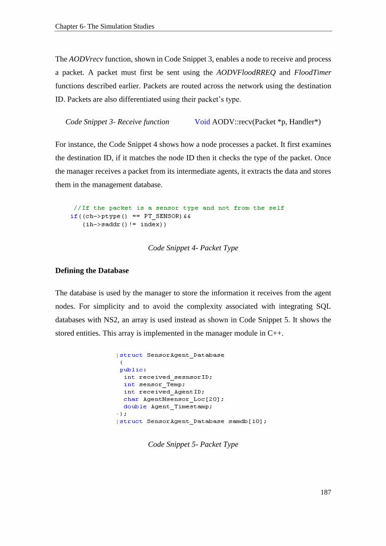
Chapter 6- The Simulation Studies
187
The AODVrecv function, shown in Code Snippet 3, enables a node to receive and process
a packet. A packet must first be sent using the AODVFloodRREQ and FloodTimer
functions described earlier. Packets are routed across the network using the destination
ID. Packets are also differentiated using their packet’s type.
Code Snippet 3- Receive function Void AODV::recv(Packet *p, Handler*)
For instance, the Code Snippet 4 shows how a node processes a packet. It first examines
the destination ID, if it matches the node ID then it checks the type of the packet. Once
the manager receives a packet from its intermediate agents, it extracts the data and stores
them in the management database.
Code Snippet 4- Packet Type
Defining the Database
The database is used by the manager to store the information it receives from the agent
nodes. For simplicity and to avoid the complexity associated with integrating SQL
databases with NS2, an array is used instead as shown in Code Snippet 5. It shows the
stored entities. This array is implemented in the manager module in C++.
Code Snippet 5- Packet Type
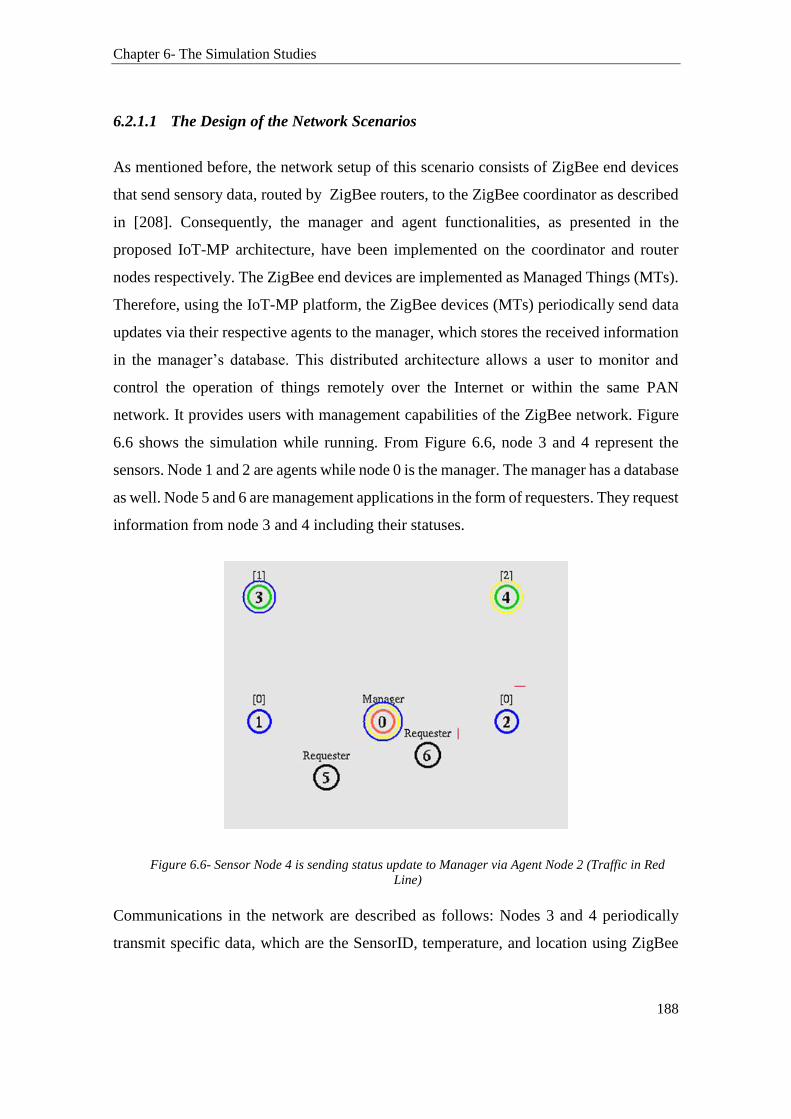
Chapter 6- The Simulation Studies
188
6.2.1.1 The Design of the Network Scenarios
As mentioned before, the network setup of this scenario consists of ZigBee end devices
that send sensory data, routed by ZigBee routers, to the ZigBee coordinator as described
in [208]. Consequently, the manager and agent functionalities, as presented in the
proposed IoT-MP architecture, have been implemented on the coordinator and router
nodes respectively. The ZigBee end devices are implemented as Managed Things (MTs).
Therefore, using the IoT-MP platform, the ZigBee devices (MTs) periodically send data
updates via their respective agents to the manager, which stores the received information
in the manager’s database. This distributed architecture allows a user to monitor and
control the operation of things remotely over the Internet or within the same PAN
network. It provides users with management capabilities of the ZigBee network. Figure
6.6 shows the simulation while running. From Figure 6.6, node 3 and 4 represent the
sensors. Node 1 and 2 are agents while node 0 is the manager. The manager has a database
as well. Node 5 and 6 are management applications in the form of requesters. They request
information from node 3 and 4 including their statuses.
Figure 6.6- Sensor Node 4 is sending status update to Manager via Agent Node 2 (Traffic in Red
Line)
Communications in the network are described as follows: Nodes 3 and 4 periodically
transmit specific data, which are the SensorID, temperature, and location using ZigBee
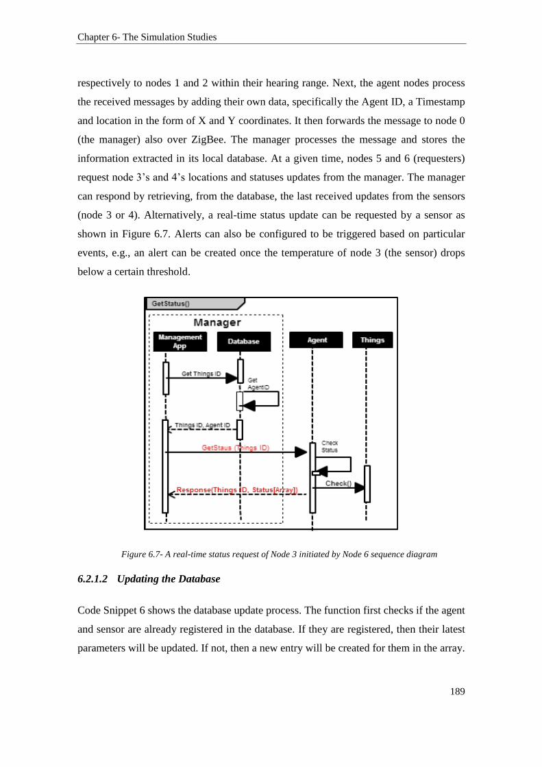
Chapter 6- The Simulation Studies
189
respectively to nodes 1 and 2 within their hearing range. Next, the agent nodes process
the received messages by adding their own data, specifically the Agent ID, a Timestamp
and location in the form of X and Y coordinates. It then forwards the message to node 0
(the manager) also over ZigBee. The manager processes the message and stores the
information extracted in its local database. At a given time, nodes 5 and 6 (requesters)
request node 3’s and 4’s locations and statuses updates from the manager. The manager
can respond by retrieving, from the database, the last received updates from the sensors
(node 3 or 4). Alternatively, a real-time status update can be requested by a sensor as
shown in Figure 6.7. Alerts can also be configured to be triggered based on particular
events, e.g., an alert can be created once the temperature of node 3 (the sensor) drops
below a certain threshold.
Figure 6.7- A real-time status request of Node 3 initiated by Node 6 sequence diagram
6.2.1.2 Updating the Database
Code Snippet 6 shows the database update process. The function first checks if the agent
and sensor are already registered in the database. If they are registered, then their latest
parameters will be updated. If not, then a new entry will be created for them in the array.
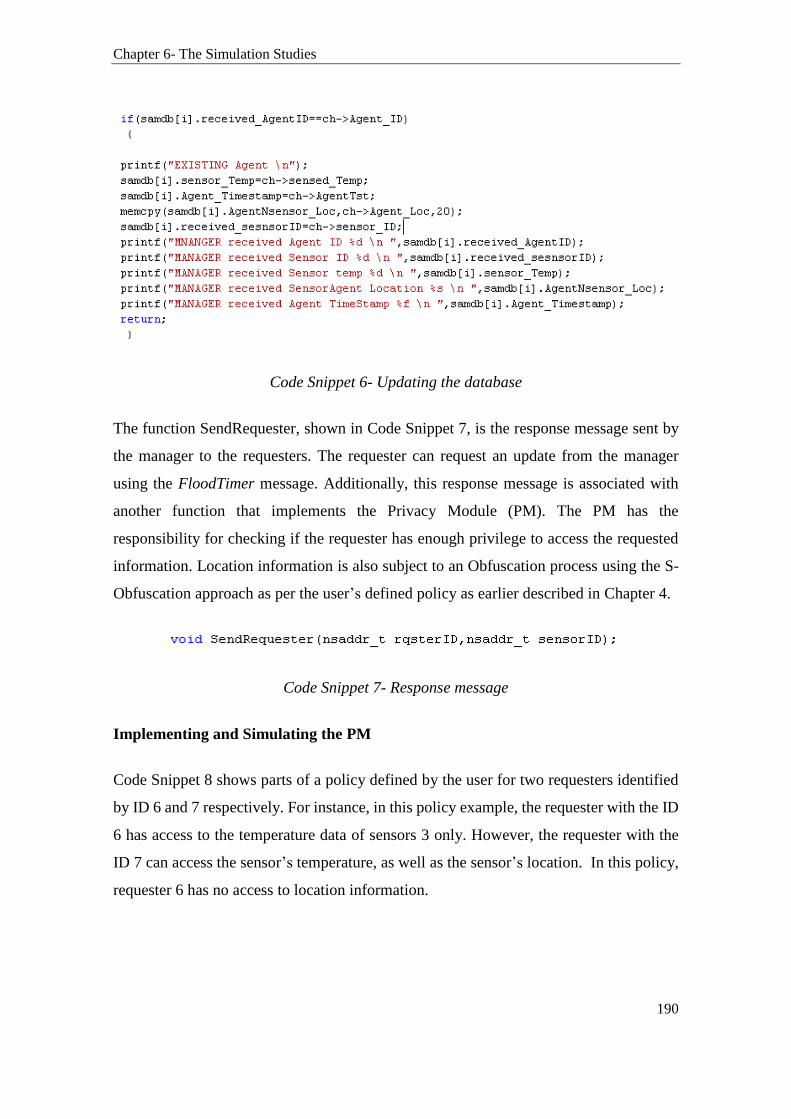
Chapter 6- The Simulation Studies
190
Code Snippet 6- Updating the database
The function SendRequester, shown in Code Snippet 7, is the response message sent by
the manager to the requesters. The requester can request an update from the manager
using the FloodTimer message. Additionally, this response message is associated with
another function that implements the Privacy Module (PM). The PM has the
responsibility for checking if the requester has enough privilege to access the requested
information. Location information is also subject to an Obfuscation process using the S-
Obfuscation approach as per the user’s defined policy as earlier described in Chapter 4.
Code Snippet 7- Response message
Implementing and Simulating the PM
Code Snippet 8 shows parts of a policy defined by the user for two requesters identified
by ID 6 and 7 respectively. For instance, in this policy example, the requester with the ID
6 has access to the temperature data of sensors 3 only. However, the requester with the
ID 7 can access the sensor’s temperature, as well as the sensor’s location. In this policy,
requester 6 has no access to location information.

Chapter 6- The Simulation Studies
191
Code Snippet 8- PM implementation code extract
6.2.1.3 Running the Simulation
Figure 6.8- Nodes are exchanging messages
From Figure 6.8, this setup represents the initial network scenario where all three types
of nodes are initiated and respectively configured to join the network. The manager joins
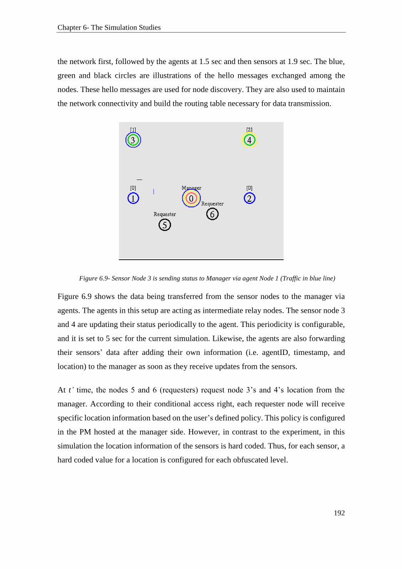
Chapter 6- The Simulation Studies
192
the network first, followed by the agents at 1.5 sec and then sensors at 1.9 sec. The blue,
green and black circles are illustrations of the hello messages exchanged among the
nodes. These hello messages are used for node discovery. They are also used to maintain
the network connectivity and build the routing table necessary for data transmission.
Figure 6.9- Sensor Node 3 is sending status to Manager via agent Node 1 (Traffic in blue line)
Figure 6.9 shows the data being transferred from the sensor nodes to the manager via
agents. The agents in this setup are acting as intermediate relay nodes. The sensor node 3
and 4 are updating their status periodically to the agent. This periodicity is configurable,
and it is set to 5 sec for the current simulation. Likewise, the agents are also forwarding
their sensors’ data after adding their own information (i.e. agentID, timestamp, and
location) to the manager as soon as they receive updates from the sensors.
At t’ time, the nodes 5 and 6 (requesters) request node 3’s and 4’s location from the
manager. According to their conditional access right, each requester node will receive
specific location information based on the user’s defined policy. This policy is configured
in the PM hosted at the manager side. However, in contrast to the experiment, in this
simulation the location information of the sensors is hard coded. Thus, for each sensor, a
hard coded value for a location is configured for each obfuscated level.

Chapter 6- The Simulation Studies
193
6.2.1.4 Analysing the Simulation Traffics by Examining the Log file
We examined the log file generated by the simulation to view the traffics exchanged
among the nodes. The log file can be used as well to observe the response message
generated by the sensors. This allows the verification of the location output received by
checking if the location was disclosed in the response message generated by the sensors.
Figure 6.10- Traffic from sensors to agents
Figure 6.11- Log file output
The results validated the approaches of the IoT-MP in preserving the location privacy of
the sensors in a large scale heterogeneous network. Figure 6.11(a) and (b) show that the
manager has successfully received data from sensors 3 and 4 that were routed via their
respective agents (Agent ID 1 and 2). Figure 6.11(c) shows that requesters 1 and 2 (ID 6
and 7 respectively) are requesting, from manager1, access to the sensor 3 and 4 data.
Figure 6.11(d) and (e) show that only requester 2 is receiving location information update
on sensor 3. This is because the policy is configured to deny requester ID6 the right to
access the sensors location. Several other tests were also conducted. Each time a different

Chapter 6- The Simulation Studies
194
policy was configured with different access right. In each test case, the traffics stored in
the log file were examined. The results confirmed the successful deployment and
operations of the IoT-MP including that of its privacy module.
6.2.2 Simulation Results and Performance Analysis
This section reports on the performance results collected from the 802.15.4 simulation.
Figure 6.12 shows the overall network throughput experienced by the MAC layer of all
the nodes is around 80Kbps, which is considered to be acceptable in typical ZigBee
simulations. The overall ZigBee application end-to-end delay is measured at 7ms in this
simulation as shown in Figure 6.13. Figure 6.14 reports the Media Access Delay. It
indicates the total of queuing and contention delays of the data frames transmitted by all
the 802.15.4 MAC. For each frame, this delay is calculated as the duration of the time
when the frame is inserted into the transmission queue, which is the arrival time for higher
layer data packets and creation time for all other frames types, until the time when the
frame is sent to the physical layer for the first time. The results also confirm that the
experienced MAC delays are insignificant.
Figure 6.12- MAC layer throughput

Chapter 6- The Simulation Studies
195
Figure 6.13- Application End to End Delay
Figure 6.14- Media Access Delay
6.2.3 Network Scenarios based on IEEE 802.11
The previous simulated ZigBee scenarios consisting of a manager, agents, and sensors
were also simulated using IEEE 802.11 technology. The performance is measured with

Chapter 6- The Simulation Studies
196
regard to the throughput, total traffic received, and network delays as well. Table 6.2
shows the simulation parameters.
Table 6.2- 802.11 parameters
The transmission path between the simulated nodes (sensors, agents, and manager) can
vary from simple line of sight to dense area with obstacles. A deployment area which
includes obstacles presents more challenges to the network such as signal fading and
reflection. Therefore, to avoid the multipath effect that can be caused by ground
reflections of the radio wave, the two Ray ground model was used in this simulation. This
802.11b Parameters Respective value
Radio propagation model Two Ray Ground
Transmission Power 1.3962527e-2
Frequency of Operation 2.4 Ghz
Preamble Length 144 bits
SIFS 10 us
Physical Layer Technology IEEE-802.11 Wireless Phy
PLCP Header Length 48 bits
Slot Time 20 us
Receiver Sensitivity Threshold 1.309573e-10
MAC Layer Technology IEEE-802.11 MAC
Network Layer Routing Protocol AODV
Number of Nodes 7
Area of Network Deployment 500x500 meter square
Antenna Type Omni Directional
Data Rate 1 -11 Mbps
Interface Queue type Drop Tail /Priority Queue
Traffic Type used Cbr / poisson /ftp

Chapter 6- The Simulation Studies
197
is because the work does not aim to optimise transmissions within the network. It simply
seeks to simulate a network where location information is exchanged and requested. This
is to test the location privacy preserving capability of our proposed approach. Therefore,
we repeated the same scenario conducted in the ZigBee simulation in this 802.11
simulation. The log file shows that it is also possible to manage the location privacy of
802.11 nodes in an 802.11 network. Figure 6.15 shows that only requester 2 has received
location information of sensor 3.
Figure 6.15- From the log file: Only Requester2 received location information
Evaluating the Simulations Results of ZigBee and 802.11
Figure 6.16 provides energy consumption statistics for both ZigBee and 802.11 network
devices. Due to ZigBee low-energy characteristics, ZigBee devices are drawing only up
to 100 mW of power. This shows the efficiency of the IoT-MP with regard to power
consumption. On the other hand, WLAN device is consuming much higher power of
about 700-800 mW.
Figure 6.16- Comparison of Power consumed
0
200
400
600
800
1000
0 500 1000 1500
Po
we
r C
on
sum
pti
on
(mW
)
Simulation Time(min)
Zigbee Power
Wlan Power

Chapter 6- The Simulation Studies
198
Figure 6.17 compares the delays achieved post-simulation between the two protocols
under comparison. The 802.11 network experienced delays of less than 1ms compared to
that of 7ms in the ZigBee network.
Figure 6.17- End to End delay comparison
The overall network throughput achieved for both protocols is shown in Figure 6.18. It
shows that there are not many variations in throughput. This is because the overall amount
of data transmitted over the network is small. This also validates that the IoT-MP did not
add much of overhead to the sensor network. Both simulations provided a throughput of
80 Kbps initially, but later WLAN throughput slightly came down to 70 Kbps.
Figure 6.18- Throughput Comparison
These results show that the IoT-MP message scheme added little to no overheads to the
sensor network. They also validate the power efficiency of the proposed approach.

Chapter 6- The Simulation Studies
199
6.3 The Heterogeneous Network
The heterogeneous network simulation involves 802.15.4, 802.11n, and 802.11ah
technologies. The simulation is designed in the context of a WSN. This simulation
encompasses scenarios which expand on the size, scale, and complexity of the two ZigBee
and 802.11 scenarios previously reported. The core architecture of these scenarios is
based on the IoT-MP. The aim of these extended network scenarios is to test the capability
of the IoT-MP in preserving location privacy in different network setups that utilise a
large number of devices. In other words, it aims to verify the scalability and flexibility of
the proposed IoT-MP. The development of the heterogeneous network scenario is the
results of several other sub-scenarios that were designed and simulated. The work
gradually expanded the size of the ZigBee scenario, reported in section 6.2.1.1, from few
nodes to few thousands of nodes. It also progressively increased the complexity of the
overall simulation. Thus, to arrive at the final heterogeneous network simulation, several
scenarios were designed as follows:
1. Increased the size of the ZigBee simulation from few nodes to few hundred.
2. Increased the size and complexity of the ZigBee simulation by creating two clusters
of ZigBee networks and connecting them together.
3. Further increased the scale of the ZigBee scenarios.
4. Implemented sensors’ mobility between different ZigBee clusters.
5. Introduced 802.11ah scenarios to the simulation.
6.3.1 Network Design and Simulation using Opnet
The design of the heterogeneous network was conducted using the Opnet simulation tool.
This is because, with the increase in the complexity of the simulation, Opnet supports an
intuitive GUI, which facilitated the deployment of a large number of devices. Also, NS2
did not offers efficient and bugs free implementation for 802.15.4 application and
network layers (only PHY and MAC layers). For the design of the 802.11 based scenarios,
we used the model provided by Opnet as it was well established. For the ZigBee network
design, we used the open source “Open-ZigBee toolset”. On one hand, this is because the
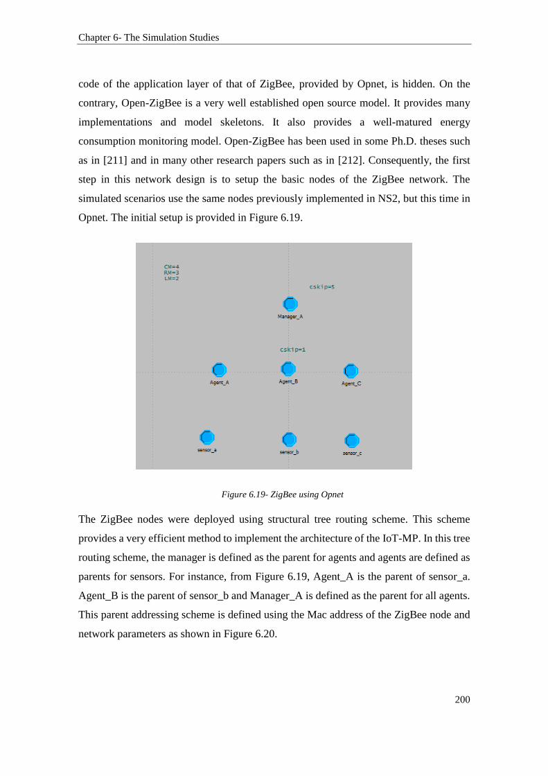
Chapter 6- The Simulation Studies
200
code of the application layer of that of ZigBee, provided by Opnet, is hidden. On the
contrary, Open-ZigBee is a very well established open source model. It provides many
implementations and model skeletons. It also provides a well-matured energy
consumption monitoring model. Open-ZigBee has been used in some Ph.D. theses such
as in [211] and in many other research papers such as in [212]. Consequently, the first
step in this network design is to setup the basic nodes of the ZigBee network. The
simulated scenarios use the same nodes previously implemented in NS2, but this time in
Opnet. The initial setup is provided in Figure 6.19.
Figure 6.19- ZigBee using Opnet
The ZigBee nodes were deployed using structural tree routing scheme. This scheme
provides a very efficient method to implement the architecture of the IoT-MP. In this tree
routing scheme, the manager is defined as the parent for agents and agents are defined as
parents for sensors. For instance, from Figure 6.19, Agent_A is the parent of sensor_a.
Agent_B is the parent of sensor_b and Manager_A is defined as the parent for all agents.
This parent addressing scheme is defined using the Mac address of the ZigBee node and
network parameters as shown in Figure 6.20.

Chapter 6- The Simulation Studies
201
Figure 6.20- Parent address configuration
Next, to implement the IoT-MP message scheme, further implementations of the
application layer were needed. This is to add the required functionalities such as adding
a Unique ID to the sensor nodes and adding agentIDs to the agent nodes communication.
The traffic configured for this simulation is the best effort traffic. Hence, we needed to
modify the packet and traffic to insert the data into the communication exchanged
between the nodes. The code relevant to the creation of the new packet is provided in
Figure 6.21. Also, Figure 6.22 shows the new packet format.
Figure 6.21- Creating a new packet
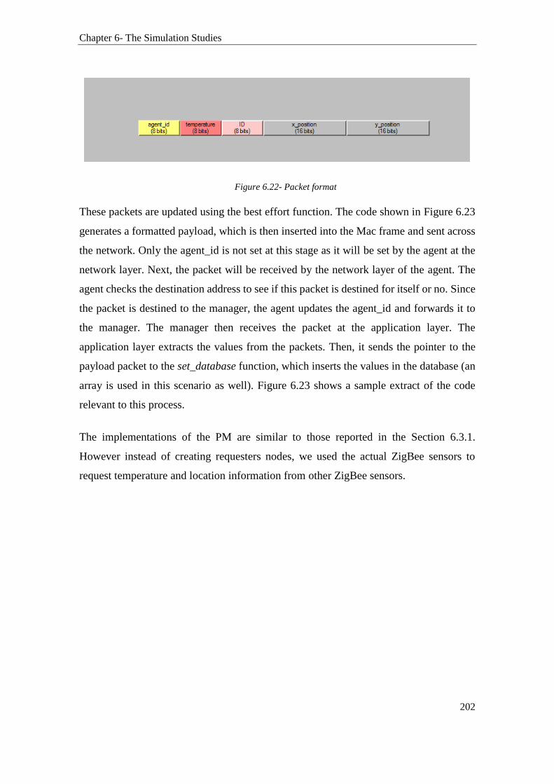
Chapter 6- The Simulation Studies
202
Figure 6.22- Packet format
These packets are updated using the best effort function. The code shown in Figure 6.23
generates a formatted payload, which is then inserted into the Mac frame and sent across
the network. Only the agent_id is not set at this stage as it will be set by the agent at the
network layer. Next, the packet will be received by the network layer of the agent. The
agent checks the destination address to see if this packet is destined for itself or no. Since
the packet is destined to the manager, the agent updates the agent_id and forwards it to
the manager. The manager then receives the packet at the application layer. The
application layer extracts the values from the packets. Then, it sends the pointer to the
payload packet to the set_database function, which inserts the values in the database (an
array is used in this scenario as well). Figure 6.23 shows a sample extract of the code
relevant to this process.
The implementations of the PM are similar to those reported in the Section 6.3.1.
However instead of creating requesters nodes, we used the actual ZigBee sensors to
request temperature and location information from other ZigBee sensors.
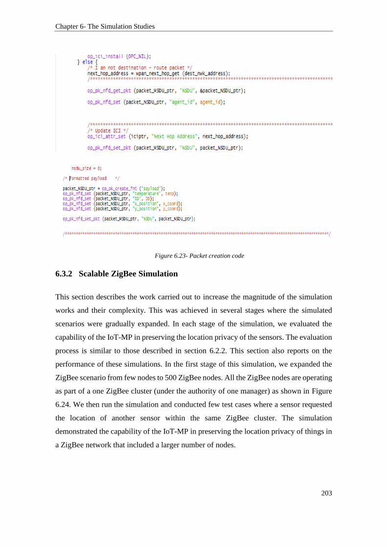
Chapter 6- The Simulation Studies
203
Figure 6.23- Packet creation code
6.3.2 Scalable ZigBee Simulation
This section describes the work carried out to increase the magnitude of the simulation
works and their complexity. This was achieved in several stages where the simulated
scenarios were gradually expanded. In each stage of the simulation, we evaluated the
capability of the IoT-MP in preserving the location privacy of the sensors. The evaluation
process is similar to those described in section 6.2.2. This section also reports on the
performance of these simulations. In the first stage of this simulation, we expanded the
ZigBee scenario from few nodes to 500 ZigBee nodes. All the ZigBee nodes are operating
as part of a one ZigBee cluster (under the authority of one manager) as shown in Figure
6.24. We then run the simulation and conducted few test cases where a sensor requested
the location of another sensor within the same ZigBee cluster. The simulation
demonstrated the capability of the IoT-MP in preserving the location privacy of things in
a ZigBee network that included a larger number of nodes.

Chapter 6- The Simulation Studies
204
Figure 6.24- Increasing the size of the ZigBee simulation within one cluster
In the next stage of this simulation, the scenario depicted in Figure 6.24 were further
expanded to encompass three clusters of ZigBee networks. The new modified scenario is
shown in
Figure 6.25. In this new scenario, each cluster has its ZigBee coordinator (manager). The
managers of each of these clusters were connected through the manager of managers
(MoM) (previously described in Section 4.3.2). The MoM is a ZigBee coordinator node
configured as a parent node for the managers of each of these clusters. Therefore, by the
IoT-MP architecture described in Section 4.2, the manager of each group manages the
nodes in their cluster and acts as an agent to the MoM. Consequently, the MoM has also
its database. It keeps tracks of the nodes structure and hierarchy within the tree structure.
The MoM oversees the whole network and can communicate with the ZigBee sensors
through their managers. This architecture of managers to MoM allows other ZigBee
clusters to join and participate in the network using a designated manager. Significantly,
this demonstrates the capability of the IoT-MP in connecting ZigBee networks together
and in providing users with a method to manage the location privacy of their ZigBee
devices. In this simulation, the communications between the managers and MoM are
implemented in a fashion where the managers send periodic updates to the MoM. The
connections are made at the application layer via a designated function.

Chapter 6- The Simulation Studies
205
Figure 6.25- Three Clusters of ZigBee network
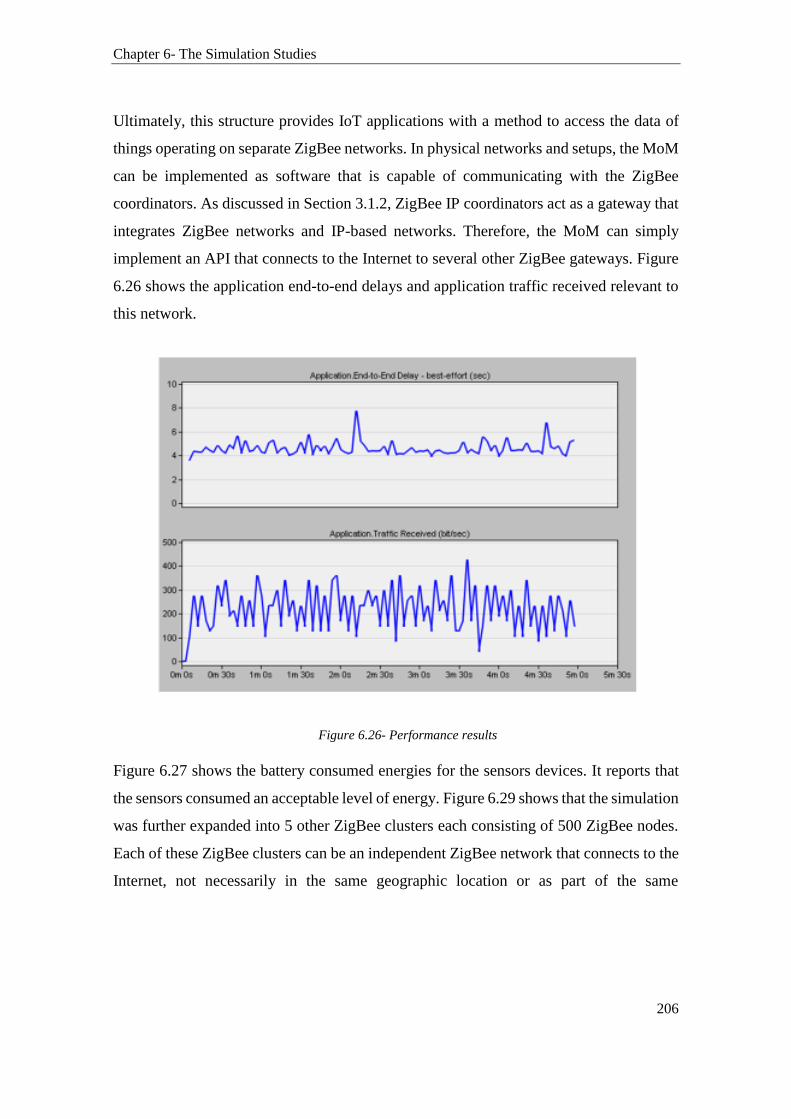
Chapter 6- The Simulation Studies
206
Ultimately, this structure provides IoT applications with a method to access the data of
things operating on separate ZigBee networks. In physical networks and setups, the MoM
can be implemented as software that is capable of communicating with the ZigBee
coordinators. As discussed in Section 3.1.2, ZigBee IP coordinators act as a gateway that
integrates ZigBee networks and IP-based networks. Therefore, the MoM can simply
implement an API that connects to the Internet to several other ZigBee gateways. Figure
6.26 shows the application end-to-end delays and application traffic received relevant to
this network.
Figure 6.26- Performance results
Figure 6.27 shows the battery consumed energies for the sensors devices. It reports that
the sensors consumed an acceptable level of energy. Figure 6.29 shows that the simulation
was further expanded into 5 other ZigBee clusters each consisting of 500 ZigBee nodes.
Each of these ZigBee clusters can be an independent ZigBee network that connects to the
Internet, not necessarily in the same geographic location or as part of the same
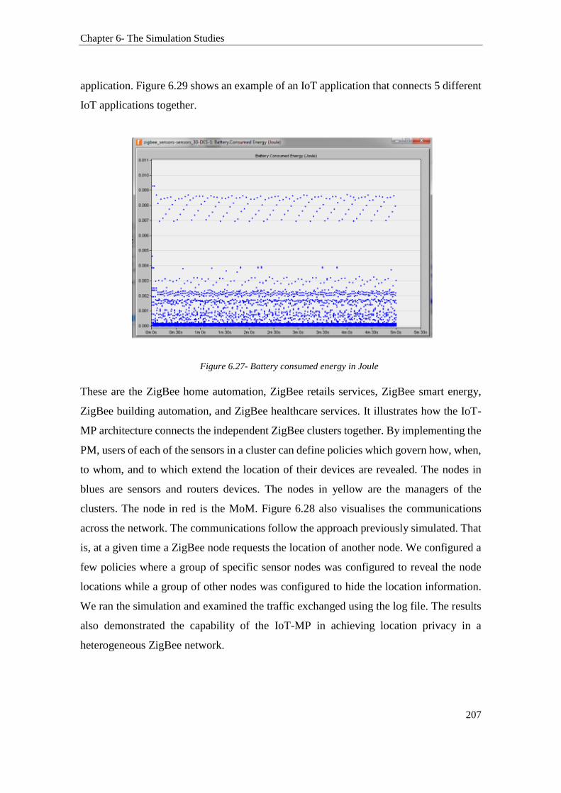
Chapter 6- The Simulation Studies
207
application. Figure 6.29 shows an example of an IoT application that connects 5 different
IoT applications together.
Figure 6.27- Battery consumed energy in Joule
These are the ZigBee home automation, ZigBee retails services, ZigBee smart energy,
ZigBee building automation, and ZigBee healthcare services. It illustrates how the IoT-
MP architecture connects the independent ZigBee clusters together. By implementing the
PM, users of each of the sensors in a cluster can define policies which govern how, when,
to whom, and to which extend the location of their devices are revealed. The nodes in
blues are sensors and routers devices. The nodes in yellow are the managers of the
clusters. The node in red is the MoM. Figure 6.28 also visualises the communications
across the network. The communications follow the approach previously simulated. That
is, at a given time a ZigBee node requests the location of another node. We configured a
few policies where a group of specific sensor nodes was configured to reveal the node
locations while a group of other nodes was configured to hide the location information.
We ran the simulation and examined the traffic exchanged using the log file. The results
also demonstrated the capability of the IoT-MP in achieving location privacy in a
heterogeneous ZigBee network.

Chapter 6- The Simulation Studies
208
Figure 6.28- Large Scale Simulation
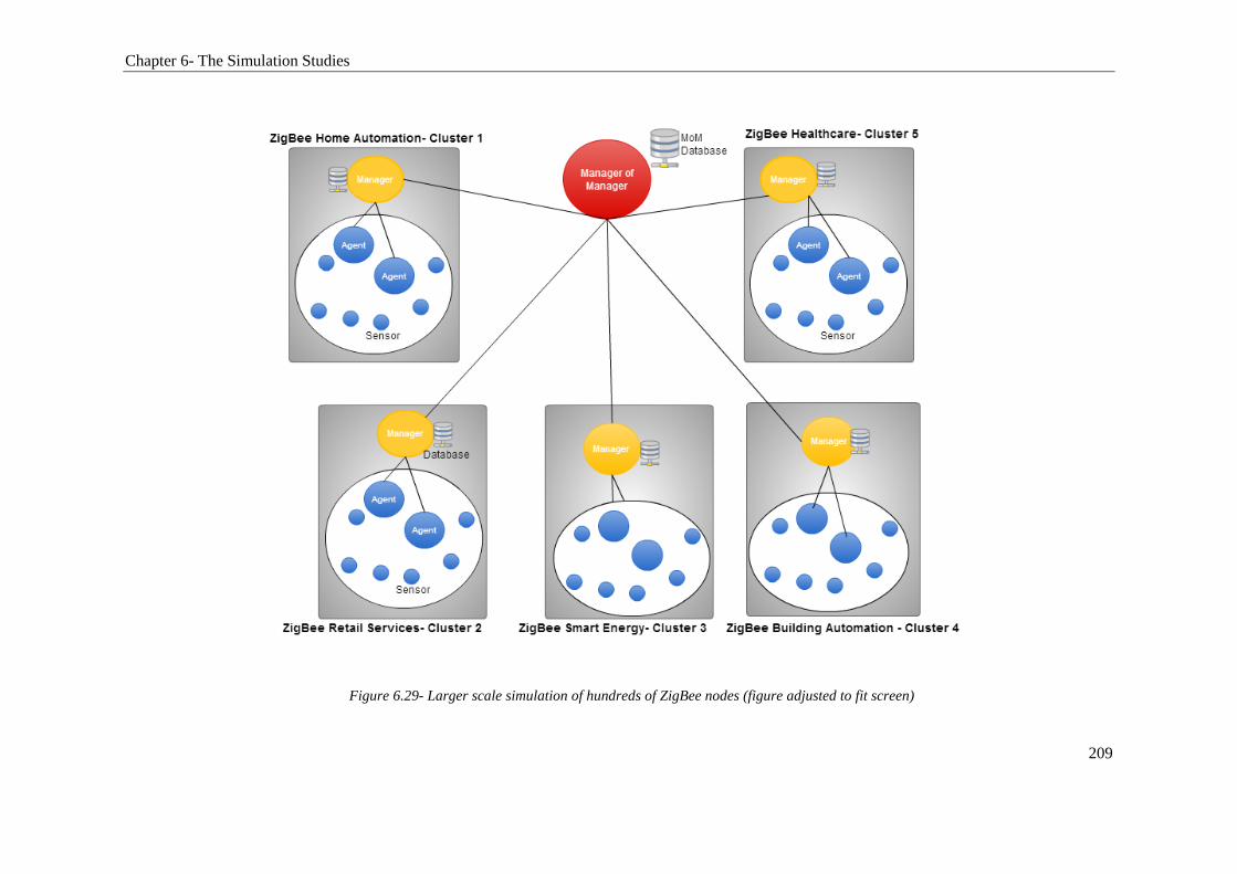
Chapter 6- The Simulation Studies
209
Figure 6.29- Larger scale simulation of hundreds of ZigBee nodes (figure adjusted to fit screen)

Chapter 6- The Simulation Studies
210
6.3.3 Network Scenarios based on IEEE 802.11ah
The IEEE 802.11ah is the new low-power approach to Wi-Fi. In contrast to classic Wi-
Fi (802.11/a…ac), 802.11ah uses a sub-l GHz frequency band. The 802.11ah is IEEE
attempt to cater for IoT devices, specifically low-cost and low-power devices. Therefore,
it is empirical for this research to verify the capabilities of the proposed IoT-MP in a .11ah
setup. Hence, this stage of the research simulated the IoT-MP in an IEEE.11ah network.
We repeated the exact scenario previously designed using ZigBee but this time with .11ah
used as the communication technology. As IEE802.11ah is still in development stage,
there are no established models that can be used to simulate this new technology. To
overcome this challenge, and since 802.11ah is based on the general 802.11 protocol, we
modified the base model of 802.11 in Opnet to model the behaviours of 802.11ah. The
common settings for this simulation are provided in Table 6.3. These are based on the
802.11ah simulation works reported in [213]. Mainly, in this simulation, the work has
reduced the data rate and receiver’s power of the base 802.11 protocol along with
changing few other parameters. The simulation calculated the average consumed energy
to transmit a packet by a node, which contained the sensorID and the temperature, to
another node. It is shown in Figure 6.30. It is noted that the energy consumed by the
sensor to send a packet are slightly lower than those reported in [213]. This is attributed
to the small size of the packet used in our simulation. Readers interested in a performance
comparison between 802.11ah and ZigBee are referred to [213].
Table 6.3- 802.11ah Simulation Parameters
Data rate 250 kbps
Physical Header 5 Bytes
MAC Header 10 Bytes
Receiver sensitivity -92 dBm
Frequency 900 MHz
Traffic Uplink
Deployment size 200m*200m
Number of nodes (including AP) 20

Chapter 6- The Simulation Studies
211
Importantly, this stage of simulation demonstrated the successful deployment of the IoT-
MP in an 802.11ah network. The results relating to location privacy were identical to
those collected from the ZigBee simulations. This also confirms the capability of the IoT-
MP in preserving location privacy in low-power wireless networks, specifically in ZigBee
and 802.11ah.
Figure 6.30- Energy consumption: 802.11ah
6.3.4 The Integration of 802.11ah and ZigBee Scenarios in one
Heterogeneous Network
Figure 6.31 shows the previous simulation scenarios, reported in Section 6.2.3, were
further expanded to incorporate an 802.11ah network to form a heterogeneous network.
It is noted that with the increase in the number of devices, the overall end-to-end delay of
the ZigBee network has increased as well.
0
1
2
3
0 5 10 15 20 25
Average time consumption to send a packet mJ/packet

Chapter 6- The Simulation Studies
212
Figure 6.31- Larger scaled with thousands of devices
802.11a
h

Chapter 6- The Simulation Studies
213
Also, we observed that the queuing delay at the agents has increased with the rise in the
number of connected sensors as shown in Figure 6.32. This is caused by the dramatic
increase in the number of nodes in the network as well.
Figure 6.32- Delays Comparison
In each of the simulations described above, a group of nodes (from both ZigBee and
802.11ah networks) were configured to request the location of other nodes at t’’ of the
simulation. Each time we repeated the test with different policy configurations which
involved the use of a different set of ZigBee and .11ah nodes. The results were verified
by examining the log file that shows the traffics exchanged among the nodes. Figure 6.33
is an extract of the log file. It shows that Manger_A is sharing sensor_a X and Y
coordinates (location) with sensor a_1_3.

Chapter 6- The Simulation Studies
214
Figure 6.33- Log file
6.4 Summary
In this chapter, the proposed Internet of Things Management Platform has been evaluated
using various simulations studies. Through different simulation scenarios and results
analysis, the capability of the proposed platform in preserving the location privacy of
things in the IoT was assessed. The research started by simulating the IoT-MP in a ZigBee
WSN network that comprised few sensor nodes. Then the work increased the size of the
ZigBee simulations from few nodes to few hundred. Additional simulations were also
carried out to increase not only the size of the ZigBee network but also its complexity, by
creating two clusters of ZigBee networks and connecting them together. This also
included the simulations of sensors’ mobility between the different ZigBee clusters.
Lastly, the research introduced the IEEE 802.11ah scenarios to the simulations creating
large scale heterogeneous network scenarios. In each of these scenarios, a group of sensor
nodes were configured to request the location of other sensor nodes. By observing the
traffics exchanged among the nodes in the network, the work verified and demonstrated
the capabilities of the IoT-MP in preserving the location privacy of the sensors in a
heterogeneous network.
Chapter 6- The Simulation Studies
215
Additionally, the results collected from the simulations studies confirm that using the
approaches proposed by the IoT-MP, it is possible to provide the users with a method that
allow them to manage the location privacy of their devices. Specifically, in large scale
low-power wireless networks with no noticeable impact on the power use and response
time of the network. For instance, the scenarios implemented in this chapter show that it
is possible to preserve location privacy in networks that utilise the ZigBee wireless
technology. It was found that the application end-to-end delay experienced by the ZigBee
network is below 7.5ms. This is achieved without affecting the performance of the
network with regard to power consumptions. Likewise, the results were verified in a
network scenario that uses the 802.11ah protocol as well. For example, it is found that the
average consumed energy to send a packet across the network by a ZigBee and 802.11ah
node was fewer than 3mJ. Lastly, the capabilities of the IoT-MP in supporting a large
scale of devices in a heterogeneous network were also confirmed. The results
demonstrated that using the IoT-MP, the protection of the location privacy of things can
be achieved in heterogeneous networks with negligible impact on the network
performance.

216
7 CHAPTER 7- CONCLUSION
The Internet of Things (IoT) foresees the interconnection of billions of things by
extending the interactions between humans and applications to a new dimension of
communications via things. Rather than always interacting with the human users, things
will be interacting with each other autonomously by performing actions on behalf of the
users. This will result in the IoT being pervasive in many different areas. Thus, the
potentially massive number of things, their diversity, and the seamless and heterogeneous
nature of communications encountered in the IoT challenge the privacy of the users. Data
collected by a single IoT device may not infringe on the privacy of the users. However,
many envisioned IoT applications will require the automated sharing of the users’
information collected by things including their location information. The aggregation of
this information, gathered from a large number of things and exchanged over various
heterogeneous networks, can impinge on the privacy of the users, specifically their
location privacy. For this reason, the development of solutions to support location privacy
preservation is a key factor for the widespread proliferation of the IoT. Various privacy
protection methods have been proposed in the literature to deal with the location privacy
issue. However, most of these methods did not consider the low-cost and low-power
requirements of things, or the heterogeneity, scalability, and autonomy of
communications supported in the IoT. To address these shortcomings, this thesis
proposed a middleware solution that enables the management and preservation of
location privacy of things in the IoT.
The thesis started first by examining the research issues challenging the IoT, specifically
the location privacy issue. It examined the methods and various localisation techniques
that can be used to obtain location information by things in the IoT. The research then
reviewed the capabilities of these methods and analysed the risks they pose from their
usages in the IoT. It was found that the flow of information and actuation events in the
IoT may comprise the exchange of personal and contextual information supplied by
things, including location information. It was further identified that the disclosure of

Chapter 7- Conclusion
217
location information in the IoT gives rise to the possibility of using the tracking
capabilities of things to impinge on the location privacy of users. The findings of these
analyses also highlighted the necessity of embedding privacy preservation methods in the
design of IoT applications. The research then moved to examine the traditional location
privacy protection methods and their suitability for implementation in the IoT. The
characteristics, technical parameters, and the challenges about the use of various low-
power wireless technologies in the IoT were also studied. The results of these
examinations and analyses have clearly pointed to the need for a lightweight solution that
supports the preservation of the users’ location information in heterogeneous networks
in the IoT. It was further found that the deployment of solutions to warrant location
privacy protection in the IoT can be quite different in each specific context.
Consequently, the research has attributed the complexity of protecting the location
privacy of users in the IoT to two main factors. The first is derived from the heterogeneity
of the communications encountered in the IoT. The second relates to the unique
characteristics of things such as their low-power and low-cost requirements. In fact, these
factors highlight the infeasibility to preserve the location information of things and that
of their users using traditional privacy protection methods such as anonymization.
To accomplish one of the main objectives of this research in finding a solution to enhance
the preservation and management of location privacy in the IoT, a middleware referred
to as the Internet of Things Management Platform (IoT-MP) was proposed in Chapter 4.
The middleware encompassed context-adaptive approaches that enable the user to
manage the location information disclosed by things based on a context-aware and policy
enforcement mechanism. This mechanism takes into account both the user’s informed
consent and preferences. The IoT-MP has a distributed architecture consisting of agents,
managers, and a Manager of Managers. The various modules of the IoT-MP’s manager
guarantee that the location information of things are only disclosed to authenticated and
authorised entities while preserving the location privacy of things and that of their
owners. Specifically, the Privacy Module (PM) provides fine-grained features for
adapting the users' defined policies and location information granularity to specific
contexts dynamically. It is shown through experimental and simulation studies that the
IoT-MP has managed to preserve the location privacy of users in the IoT. The privacy
Chapter 7- Conclusion
218
preserving capabilities of the IoT-MP were also supported by a novel Obfuscation
technique, referred to as the Semantic Obfuscation approach (S-Obfuscation). The
research has also shown that the S-Obfuscation has enhanced the performance of two
classic Obfuscation techniques by relying on a geographic knowledge when producing
obscured location.
Therefore, the validities and effectiveness of the proposed platform have been illustrated
through different experimental and simulation studies. The experimental studies, reported
in Chapter 5, comprised scenarios that involved the utilisation of some Bluetooth Low
Energy (BLE) sensor devices, and the implementation of two mobile applications and a
web application. The reported results, collected from the experiments, confirmed the
effectiveness of the proposed platform in preserving the location privacy of low-power
sensor devices in physical environments, which use physical location information
including GPS coordinates. In the experiments, the S-Obfuscation was shown to have
better performance than that of the classic Dispersion method. The improvement in the
performance was over 50% in cases where a wider proximity to the original true location
was used.
On the other hand, the results collected from the simulations, discussed in Chapter 6, also
have shown that using the proposed platform, it is possible to achieve location privacy in
a heterogeneous and low-power network similar in scope and size to that usually
employed in the IoT. Several network scenarios based on ZigBee and the IEEE 80211ah
protocols, which used more than three thousand things, were simulated in Opnet. To
simulate communications among IoT devices over the Internet, a group of sensors took
turns in requesting the location of other sensors in the network. The traffics correspondent
to the information exchanged between the sensors in the simulations were analysed. The
results have demonstrated the IoT-MP capabilities in preserving the location privacy of
the sensors in a large scale heterogeneous network. Additionally, the performance results
collected from the simulations have clearly shown that the use of the IoT-MP had no
noticeable impact on the power consumptions and end-to-end delays of both ZigBee and
IEEE 802.11ah end devices.

Chapter 7- Conclusion
219
Consequently, this thesis has answered the research questions by demonstrating that it is
possible to provide the users with a method that enable them to control the granularity of
the location information disclosed by constrained things in heterogeneous networks. The
research has further demonstrated that it is possible to improve location privacy
protection in the IoT by incorporating a location Obfuscation approach in a platform that
uses an architecture adapted from traditional network management approaches. The IoT-
MP has made some significant improvements to the preservation of location privacy of
things, and that of their users in seamless and heterogeneous communications in the IoT
as set out by the objectives of this research as well.
It should be noted that this thesis has made some assumptions. In the simulations, it was
assumed that an IoT device is already associated with an agent in the IoT-MP. It was also
assumed that only authorised IoT applications are connected to the manager in the IoT-
MP. Additionally, the research also suffers from a few limitations. The IoT-MP relied on
an API module to securely connect things and IoT applications to the IoT-MP network.
However, the security services provided by the API module have not been validated.
Additional simulations or experimental studies are needed to test and validate the
effectiveness of the IoT-MP in securing the communications between IoT applications
and the IoT-MP’s manager over the Internet. Although, a behaviour modelling and
reputation system have been suggested by other researchers [187] to improve the
authorisation mechanism of the IoT-MP, other aspects of security such as authentication
remain unresolved and are left for future works.
Furthermore, to reduce the complexity of the simulations, the data sent from the sensors
to the manager in the simulations were only stored in an external file in the form of an
array. Thus, this thesis did not consider the problems and associated delays that could
arise from storing thousands of sensors’ data over a longer period in the manager’s
database. The long-term impact of the IoT-MP’s management and operational messages
on the power consumption of things has not been evaluated as well. Therefore, future
works should investigate whether it is needed to optimise the communications between
the entities of the IoT-MP. It is essential that communications between things are efficient
especially in terms of energy consumptions and latency. Therefore, it is important for
Chapter 7- Conclusion
220
future works to look into ways to reducing the overheads on the communications and
improving the overall energy efficiencies as well. Future works should also consider
extending the location privacy preserving capability of the IoT-MP to protect the privacy
of other sensitive information of the user as well. The research conducted in [214] has
already done that but on a small scale. The challenge, however, remains in validating the
effectiveness of the extended IoT-MP privacy preservation capabilities in heterogeneous,
large-scale, and dynamic networks environments.
The future of communications in the Internet of Things envisions the pervasive
interconnection of things across several heterogeneous networks. Therefore, the
challenge of provisioning interoperability between IoT networks and devices remains
unanswered. Consequently, some of the new research questions arising from this thesis
are as follows: How to create an ecosystem of coexisted devices that could connect to the
Internet using various wired and wireless protocols? And how to achieve interoperable
communications between these devices, in addition to maintaining scalable, private,
secure and trustworthy operations in the IoT. With regards to privacy, this thesis provided
a context-aware privacy solution that enhances the preservation and management of
location privacy of users in the IoT. However, the challenge remains in designing privacy
protection solutions for the IoT that balance between the users’ privacy requirements and
the need for the IoT to know and learn more about the users’ daily activities and lifestyle.

221
8 REFERENCES
[1] International Telecommunication Union (ITU), "ITU Internet Reports 2005: The Internet
of Things," Geneva 2005.
[2] M. D. Francesco, N. Li, M. Raj, and S. K. Das, "A storage Infrastructure for
Heterogeneous and Multimedia Data in the Internet of Things," in IEEE International
Conference on Green Computing and Communications (GreenCom), Besançon, France,
2012, pp. 26-33.
[3] J. Rumbaugh, M. Blaha, W. Premerlani, F. Eddy, and W. E. Lorensen, Object-oriented
modeling and design vol. 199: Prentice-hall Englewood Cliffs, 1991.
[4] F. Tao, Y. Zuo, L. Da Xu, and L. Zhang, "IoT-based intelligent perception and access of
manufacturing resource toward cloud manufacturing," IEEE Transactions on Industrial
Informatics, vol. 10, pp. 1547-1557, 2014.
[5] A. Zanella, N. Bui, A. P. Castellani, L. Vangelista, and M. Zorzi, "Internet of Things for
Smart Cities," IEEE Internet of Things Journal, vol. 1, pp. 22-32, 2014.
[6] Y. Shifeng, F. Chungui, H. Yuanyuan, and Z. Shiping, "Application of IoT in
Agriculture," Journal of Agricultural Mechanization Research, vol. 7, pp. 190-193, 2011.
[7] S. Fang, L. Da Xu, Y. Zhu, J. Ahati, H. Pei, J. Yan, et al., "An Integrated System for
Regional Environmental Monitoring and Management Based on Internet of Things,"
IEEE Transactions on Industrial Informatics, vol. 10, pp. 1596-1605, 2014.
[8] C. Wilson, T. Hargreaves, and R. Hauxwell-Baldwin, "Smart homes and their users: a
systematic analysis and key challenges," Personal and Ubiquitous Computing, vol. 19,
pp. 463-476, 2015.
[9] M. Zorzi, A. Gluhak, S. Lange, and A. Bassi, "From today's INTRAnet of things to a
future INTERnet of things: a wireless- and mobility-related view," IEEE Wireless
Communications, vol. 17, pp. 44-51, 2010.
[10] P. Parwekar, "From Internet of Things towards cloud of things," in 2nd International
Conference on Computer and Communication Technology (ICCCT), Allahabad, India,
2011, pp. 329-333.
[11] L. Mainetti, L. Patrono, and A. Vilei, "Evolution of wireless sensor networks towards the
internet of things: A survey," presented at the 19th International Conference on Software,
Telecommunications and Computer Networks (SoftCOM), Split, Croatia, 2011.
[12] M. Clendenin. (2010). China's 'Internet Of Things' Overblown, Says Exec. Available:
http://www.informationweek.com/news/storage/virtualization/225700966?subSection=
News
222
[13] J. Bradley, J. Barbier, and D. Handler, "Embracing the Internet of Everything To Capture
Your Share of $14.4 Trillion " White Paper, Cisco Systems Inc, p. 17, 2013.
[14] J. Bradley, C. Reberger, A. Dixit, and V. Gupta, "Internet of everything: A 4.6 trillion
public-sector opportunity," White Paper, Cisco Systems Inc, p. 17, 2014.
[15] R. Lineback. (2015, 11/12/2015). Internet of Things Market to Nearly Double by 2019
Available: http://www.icinsights.com/data/articles/documents/846.pdf
[16] D. Evans, "The Internet of Everything. How More Relevant and Valuable Connections.
Will Change the World.," Cisco IBSG, pp. 1-9, 2012.
[17] BI Intelligence. (2015, 11/12/2015). The Internet of Everything: 2015. Available:
http://www.businessinsider.com/internet-of-everything-2015-bi-2014-12?IR=T#-1
[18] J. Gubbi, R. Buyya, S. Marusic, and M. Palaniswami, "Internet of Things (IoT): A vision,
architectural elements, and future directions," Future Generation Computer Systems, vol.
29, pp. 1645-1660, 2013.
[19] S. Rani, R. Talwar, J. Malhotra, S. H. Ahmed, M. Sarkar, and H. Song, "A Novel Scheme
for an Energy Efficient Internet of Things Based on Wireless Sensor Networks," Sensors,
vol. 15, pp. 28603-28626, 2015.
[20] L. Roselli, C. Mariotti, P. Mezzanotte, F. Alimenti, G. Orecchini, M. Virili, et al.,
"Review of the present technologies concurrently contributing to the implementation of
the Internet of Things (IoT) paradigm: RFID, Green Electronics, WPT and Energy
Harvesting," in IEEE Topical Conference on Wireless Sensors and Sensor Networks
(WiSNet), San Diego, USA, 2015, pp. 1-3.
[21] S. Sicari, A. Rizzardi, L. A. Grieco, and A. Coen-Porisini, "Security, privacy and trust in
Internet of Things: The road ahead," Computer networks, vol. 76, pp. 146-164, 2015.
[22] C. M. Medaglia and A. Serbanati, "An Overview of Privacy and Security Issues in the
Internet of Things," in The Internet of Things: 20th Tyrrhenian Workshop on Digital
Communications, D. Giusto, A. Iera, G. Morabito, and L. Atzori, Eds., ed New York,
NY: Springer New York, 2010, pp. 389-395.
[23] R. H. Weber, "Internet of Things–New security and privacy challenges," Computer Law
& Security Review, vol. 26, pp. 23-30, 2010.
[24] C. M. Medaglia and A. Serbanati, "An overview of privacy and security issues in the
internet of things," in The Internet of Things, ed: Springer, 2010, pp. 389-395.
[25] A. Ukil, S. Bandyopadhyay, and A. Pal, "Iot-privacy: To be private or not to be private,"
in 2014 IEEE Conference on Computer Communications Workshops (INFOCOM
WKSHPS), Toronto, Canada, 2014, pp. 123-124.
[26] C. Bettini, X. S. Wang, and S. Jajodia, "Protecting privacy against location-based
personal identification," in Secure Data Management, ed: Springer, 2005, pp. 185-199.
223
[27] S. Gürses, B. Berendt, and T. Santen, "Multilateral Security Requirements Analysis for
Preserving Privacy in Ubiquitous Environments," in Workshop on Ubiquitous Knowledge
Discovery for users, 2006, pp. 51-64.
[28] R. Roman, J. Zhou, and J. Lopez, "On the features and challenges of security and privacy
in distributed internet of things," Computer Networks, vol. 57, pp. 2266-2279, 2013.
[29] F. J. Riggins and S. F. Wamba, "Research Directions on the Adoption, Usage, and Impact
of the Internet of Things through the Use of Big Data Analytics," in 2015 48th Hawaii
International Conference on System Sciences (HICSS), Hawaii, USA, 2015, pp. 1531-
1540.
[30] P. Qian and M. Wu, "A Privacy Preserving Method in WSN," Telecommunications
Science, vol. 29, pp. 23-30, 2013.
[31] R. Trujillo-Rasua and J. Domingo-Ferrer, "On the privacy offered by (k, δ)-anonymity,"
Information Systems, vol. 38, pp. 491-494, 2013.
[32] A. Azzara, S. Bocchino, P. Pagano, G. Pellerano, and M. Petracca, "Middleware solutions
in WSN: The IoT oriented approach in the ICSI project," in SoftCOM, 2013, pp. 1-6.
[33] Axeda. (2014, 10/03/2016). AXEDA MACHINE CLOUD SERVICE. Available:
http://www.axeda.com/node/886
[34] kaa Project. (2016, 10/03/2016). Kaa Overview - Kaa open-source IoT platform.
Available: www.kaaproject.org/overview
[35] M. J. Murillo, J. A. Paco, and D. Wright, "Long-distance telecommunication in remote
poor areas: from partnerships and implementation to sustainability," IEEE Technology
and Society Magazine, vol. 34, pp. 19-30, 2015.
[36] H. y. D. o. C. Science, F. Eliassen, and J. Veijalainen, A functional approach to
information system interoperability, 1988.
[37] Wikipedia. Interoperability. Available: https://en.wikipedia.org/wiki/Interoperability
[38] "IEEE Standard Computer Dictionary: A Compilation of IEEE Standard Computer
Glossaries," IEEE Std 610, pp. 1-217, 1991.
[39] H. van der Veer and A. Wiles, "Achieving technical interoperability," European
Telecommunications Standards Institute, 2008.
[40] (2011). Semantic interoperability of health information Available:
http://www.en13606.org/the-ceniso-en13606-standard/semantic-interoperability
[41] A. E. Andargoli, P. Bernus, and H. Kandjani, "Analysis of Interoperability in the
Queensland Disaster Management System," in ICEIS (3), 2013, pp. 310-317.

224
[42] (2015). Cross-Domain Interoperability. Available: https://www.ncoic.org/cross-domain-
interoperability
[43] J. Sarto. ZigBee VS 6LoWPAN for Sensor Networks. Available:
https://www.lsr.com/white-papers/zigbee-vs-6lowpan-for-sensor-networks
[44] (10/07/2010). Available: http://www.hybus.net/lan_english/index.htm
[45] S. Kumar, M. Bhardwaj, and A. Q. Bhat, "Study of Wireless Sensor Networks its Routing
Challenges and Available Sensor Nodes," in International Journal of Engineering
Research and Technology, 2013.
[46] C. H. Liu, B. Yang, and T. Liu, "Efficient naming, addressing and profile services in
Internet-of-Things sensory environments," Ad Hoc Networks, vol. 18, pp. 85-101, 7//
2014.
[47] Q. Zhu, R. Wang, Q. Chen, Y. Liu, and W. Qin, "Iot gateway: Bridgingwireless sensor
networks into internet of things," in 2010 IEEE/IFIP 8th International Conference on
Embedded and Ubiquitous Computing (EUC), 2010, pp. 347-352.
[48] R. R. Kujur and A. Dwivedi, "Exploration of Existing Frameworks for Connecting
Wireless Sensor Networks (WSNs) with Current Internet," International Journal of
Computer Applications, vol. 86, 2014.
[49] C. Perera, A. Zaslavsky, C. H. Liu, M. Compton, P. Christen, and D. Georgakopoulos,
"Sensor search techniques for sensing as a service architecture for the internet of things,"
IEEE Sensors Journal, vol. 14, pp. 406-420, 2014.
[50] L. Atzori, A. Iera, and G. Morabito, "The internet of things: A survey," Computer
Networks, vol. 54, pp. 2787-2805, 2010.
[51] M. Cordeiro Domenech, E. Comunello, and M. Silva Wangham, "Identity Management
in E-Health: A Case Study of. Web of Things application using OpenID Connect," in
IEEE 16th International Conference on e-Health Networking, Applications and Services
(Healthcom), Natal, Brazi, 2014, pp. 219-224.
[52] P. Madsen, "OpenID Connect and its role in Native SSO," ed: Youtube, 2013.
[53] M. Welsh and G. Mainland, "Programming Sensor Networks Using Abstract Regions,"
in NSDI, 2004, pp. 3-3.
[54] Y.-K. Chen, "Challenges and Opportunities of Internet of Things," in 17th Asia and South
Pacific Design Automation Conference (ASP-DAC), 2012, pp. 383-388.
[55] C. C. Aggarwal, N. Ashish, and A. Sheth, "The Internet of Things: A Survey from the
Data-centric Perspective," in Managing and Mining Sensor Data, ed: Springer, 2013, pp.
383-428.
225
[56] N. A. Ali and M. Abu-Elkheir, "Data Management for The Internet of Things: Green
Directions," in Globecom Workshops (GC Wkshps), Anaheim, USA, 2012, pp. 386-390.
[57] M. Chui, M. Löffler, and R. Roberts, "The Internet of Things," McKinsey Quarterly, vol.
2, pp. 1-9, 2010.
[58] L. Yang, S. Yang, and L. Plotnick, "How the internet of things technology enhances
emergency response operations," Technological Forecasting and Social Change, vol. 80,
pp. 1854-1867, 2013.
[59] M. Elkhodr, S. Shahrestani, and H. Cheung, "A Review of Mobile Location Privacy in
the Internet of Things," in 2012 Tenth International Conference on ICT and Knowledge
Engineering, Bangkok, Thailand, 2012, pp. 266-272.
[60] W. Stallings, "SNMP and SNMPv2: the infrastructure for network management,"
Communications Magazine, IEEE, vol. 36, pp. 37-43, 1998.
[61] J.-P. Martin-Flatin, Web-based management of IP networks and systems: John Wiley &
Sons, Inc., 2002.
[62] A. Sehgal, V. Perelman, S. Kuryla, and J. Schonwalder, "Management of resource
constrained devices in the internet of things," Communications Magazine, IEEE, vol. 50,
pp. 144-149, 2012.
[63] G. Summers, "Data and databases," Koehne, H Developing Databases with Access:
Nelson Australia Pty Limited, pp. 4-5, 2004.
[64] N. Ye, Y. Zhu, R.-C. Wang, R. Malekian, and L. Qiao-min, "An Efficient Authentication
and Access Control Scheme for Perception Layer of Internet of Things," Applied
Mathematics & Information Sciences, vol. 8, pp. 1617-1624, 2014 2014.
[65] L. Wang, D. Wijesekera, and S. Jajodia, "A logic-based framework for attribute based
access control," presented at the ACM Workshop on Formal Methods in Security
Engineering, NY, USA, 2004.
[66] Q. Han and J. Li, "An authorization management approach in the internet of things,"
Journal of Information & Computational Science, vol. 9, pp. 1705-1713, 2012.
[67] D. R. Kuhn, E. J. Coyne, and T. R. Weil, "Adding attributes to role-based access control,"
Computer, pp. 79-81, 2010.
[68] Y. Dong and W. Qingxian, "The study on the application of RFID- based mobile payment
to the Internet of Things," in Multimedia Technology (ICMT), 2011 International
Conference on, 2011, pp. 908-911.
[69] Y. Wei, "Design and realization of mobile information collection module in logistic
Internet Of Things Unified Information System," in Business Management and
Electronic Information (BMEI), 2011 International Conference on, 2011, pp. 36-39.

226
[70] F. Xia, L. T. Yang, L. Wang, and A. Vinel, "Internet of things," International Journal of
Communication Systems, vol. 25, p. 1101, 2012.
[71] D. Kozlov, J. Veijalainen, and Y. Ali, "Security and privacy threats in IoT architectures,"
in Proceedings of the 7th International Conference on Body Area Networks, 2012, pp.
256-262.
[72] K. Zickuhr, "Three-quarters of smartphone owners use location-based services," Pew
Internet & American Life Project, 2012.
[73] R. Ling, "The Sociolinguistics of SMS: An Analysis of SMS Use by a Random Sample
of Norwegians
Mobile Communications." vol. 31, ed: Springer London, 2005, pp. 335-349.
[74] I. Smith, S. Consolvo, A. Lamarca, J. Hightower, J. Scott, T. Sohn, et al., "Social
Disclosure of Place: From Location Technology to Communication Practices Pervasive
Computing," in Pervasive Computing. vol. 3468, H. Gellersen, R. Want, and A. Schmidt,
Eds., ed: Springer Berlin / Heidelberg, 2005, pp. 151-164.
[75] A. Leonhardi and K. Rothermel, "Architecture of a large-scale location service," in
Distributed Computing Systems, 2002. Proceedings. 22nd International Conference on,
2002, pp. 465-466.
[76] A. Haghighat, C. V. Lopes, T. Givargis, and A. Mandal, "Location-aware web system,"
in Workshop on Building Software for Pervasive Computing at the Object-Oriented
Programming, Systems, Languages and Applications, 2004.
[77] Y. Gu, A. Lo, and I. Niemegeers, "A survey of indoor positioning systems for wireless
personal networks," IEEE Communications Surveys & Tutorials, vol. 11, pp. 13-32,
2009.
[78] M. Gruteser and X. Liu, "Protecting privacy in continuous location-tracking
applications," IEEE Security & Privacy, pp. 28-34, 2004.
[79] B. Hoh, M. Gruteser, H. Xiong, and A. Alrabady, "Enhancing Security and Privacy in
Traffic-Monitoring Systems," Pervasive Computing, IEEE, vol. 5, pp. 38-46, 2006.
[80] K. Michael, A. McNamee, and M. Michael, "The Emerging Ethics of Humancentric GPS
Tracking and Monitoring," presented at the Proceedings of the International Conference
on Mobile Business, 2006.
[81] D. Ashbrook and T. Starner, "Using GPS to learn significant locations and predict
movement across multiple users," Personal and Ubiquitous Computing, vol. 7, pp. 275-
286, 2003/10/01 2003.
[82] J. Krumm, "Inference attacks on location tracks," presented at the Proceedings of the 5th
international conference on Pervasive computing, Toronto, Canada, 2007.

227
[83] W. Enck, P. Gilbert, B.-G. Chun, L. P. Cox, J. Jung, P. McDaniel, et al., "TaintDroid: an
information-flow tracking system for realtime privacy monitoring on smartphones,"
presented at the Proceedings of the 9th USENIX conference on Operating systems design
and implementation, Vancouver, BC, Canada, 2010.
[84] (2011). App Genome Project. Available: https://www.mylookout.com/appgenome
[85] S. THURM and Y. I. KANE. (2010, Your Apps Are Watching You. Available:
http://online.wsj.com/article/SB10001424052748704368004576027751867039730.html
[86] P. Gupta, "Metro Interface Improves Windows 8 While Increasing Some Risks," ed:
McAfee, 2012.
[87] H. Fredrik, "System Integrity for Smartphones: A security evaluation of iOS and
BlackBerry OS," Master, Department of Electrical Engineering, Information Coding,
Linkoping University, 2011.
[88] B. Hoh, M. Gruteser, H. Xiong, and A. Alrabady, "Enhancing security and privacy in
traffic-monitoring systems," IEEE Pervasive Computing, vol. 5, pp. 38-46, 2006.
[89] M. Elkhodr, S. Shahrestani, and H. Cheung, "Preserving the Privacy of Patient Records
in Health Monitoring Systems," in Theory and Practice of Cryptography Solutions for
Secure Information Systems, ed: IGI Global, 2013, pp. 499-529.
[90] I. Gudymenko, K. Borcea-Pfitzmann, and K. Tietze, "Privacy implications of the internet
of things," in Constructing Ambient Intelligence, ed: Springer, 2011, pp. 280-286.
[91] F. Chen, P. Deng, J. Wan, D. Zhang, A. V. Vasilakos, and X. Rong, "Data Mining for the
Internet of Things: Literature Review and Challenges," International Journal of
Distributed Sensor Networks, vol. 2015, p. 12, 2015.
[92] F. H. Cate, Privacy in the information age: Jessica Kingsley Publishers, 1997.
[93] L. F. Cranor, "Necessary but not sufficient: Standardized mechanisms for privacy notice
and choice," J. on Telecomm. & High Tech. L., vol. 10, p. 273, 2012.
[94] J. Cashion and M. Bassiouni, "Protocol for mitigating the risk of hijacking social
networking sites," in Collaborative Computing: Networking, Applications and
Worksharing (CollaborateCom), 2011 7th International Conference on, 2011, pp. 324-
331.
[95] A. Laurie and B. Laurie, "The Bunker í Serious flaws in Bluetooth security lead to
disclosure of personal data," ed: The Bunker, homepage, 2004.
[96] "Gosip," in Wikipedia, ed.
[97] A. R. Beresford and F. Stajano, "Location Privacy in Pervasive Computing," IEEE
Pervasive Computing, vol. 2, pp. 46-55, 2003.

228
[98] D. Patterson, L. Liao, D. Fox, and H. Kautz, "Inferring high-level behavior from low-
level sensors," in UbiComp 2003: Ubiquitous Computing, 2003, pp. 73-89.
[99] P. R. Me, "Raising awareness about over-sharing," ed, 2010.
[100] A. Görlach, A. Heinemann, and W. Terpstra, "Survey on Location Privacy in Pervasive
Computing
Privacy, Security and Trust within the Context of Pervasive Computing." vol. 780, P. Robinson,
H. Vogt, and W. Wagealla, Eds., ed: Springer US, 2005, pp. 23-34.
[101] J. Krumm, "A survey of computational location privacy," Personal and Ubiquitous
Computing, vol. 13, pp. 391-399, 2009.
[102] B. Schilit, J. Hong, and M. Gruteser, "Wireless location privacy protection," Computer,
vol. 36, pp. 135-137, 2003.
[103] R. Agrawal and R. Srikant, "Privacy-preserving Data Mining," SIGMOD Rec., vol. 29,
pp. 439-450, 2000.
[104] N. Huijboom and T. Van den Broek, "Open data: an international comparison of
strategies," European journal of ePractice, vol. 12, pp. 1-13, 2011.
[105] M. Gruteser and D. Grunwald, "A methodological assessment of location privacy risks
in wireless hotspot networks," in Security in pervasive computing, ed: Springer, 2004, pp.
10-24.
[106] M. Mano and Y. Ishikawa, "Anonymizing user location and profile information for
privacy-aware mobile services," presented at the Proceedings of the 2nd ACM
SIGSPATIAL International Workshop on Location Based Social Networks, San Jose,
California, 2010.
[107] L. Sweeney, "k-anonymity: A model for protecting privacy," International Journal of
Uncertainty, Fuzziness and Knowledge-Based Systems, vol. 10, pp. 557-570, 2002.
[108] L. Liu, "Privacy and location anonymization in location-based services," SIGSPATIAL
Special, vol. 1, pp. 15-22, 2009.
[109] M. Duckham and L. Kulik, "A formal model of obfuscation and negotiation for location
privacy," Pervasive Computing, pp. 243-251, 2005.
[110] M. Satyanarayanan, "Pervasive computing: vision and challenges," Personal
Communications, IEEE, vol. 8, pp. 10-17, 2001.
[111] A. Ranganathan, J. Al-Muhtadi, J. Biehl, B. Ziebart, R. H. Campbell, and B. Bailey,
"Towards a pervasive computing benchmark," in Pervasive Computing and
Communications Workshops, 2005. PerCom 2005 Workshops. Third IEEE International
Conference on, 2005, pp. 194-198.
229
[112] D. A. Cooper and K. P. Birman, "Preserving privacy in a network of mobile computers,"
in Security and Privacy, 1995. Proceedings., 1995 IEEE Symposium on, 1995, pp. 26-38.
[113] M. Conti, S. K. Das, C. Bisdikian, M. Kumar, L. M. Ni, A. Passarella, et al., "Looking
ahead in Pervasive Computing: Challenges, Opportunities in the era of Cyber Physical
Convergence," Pervasive and Mobile Computing, vol. 8, pp. 2-21, 2012.
[114] P. Bhaskar and S. I. Ahamed, "Privacy in Pervasive Computing and Open Issues," in
Availability, Reliability and Security, 2007. ARES 2007. The Second International
Conference on, 2007, pp. 147-154.
[115] A. Dehghantanha, R. Mahmod, and N. I. Udzir, "A XML based, User-centered Privacy
Model in Pervasive Computing Systems," International Journal of Computer Science and
Network Security, vol. 9, pp. 167-173, 2009.
[116] A. Dehghantanha, N. Udzir, and R. Mahmod, "Evaluating User-Centered Privacy Model
(UPM) in Pervasive Computing Systems
Computational Intelligence in Security for Information Systems." vol. 6694, Á. Herrero and E.
Corchado, Eds., ed: Springer Berlin / Heidelberg, 2011, pp. 272-284.
[117] G. V. Lioudakis, E. A. Koutsoloukas, N. L. Dellas, N. Tselikas, S. Kapellaki, G. N.
Prezerakos, et al., "A middleware architecture for privacy protection," Computer
Networks, vol. 51, pp. 4679-4696, 2007.
[118] A. R. Beresford and F. Stajano, "Mix Zones: User Privacy in Location-aware Services,"
in The Second IEEE Annual Conference on Pervasive Computing and Communications
Workshops, 2004., Orlando, FL, USA, 2004, pp. 127-131.
[119] G. Danezis, "Mix-networks with restricted routes," in Privacy Enhancing Technologies,
2003, pp. 1-17.
[120] J. Hightower and G. Borriello, "Location systems for ubiquitous computing," Computer,
pp. 57-66, 2001.
[121] A. R. Beresford and F. Stajano, "Mix zones: user privacy in location-aware services," in
Pervasive Computing and Communications Workshops, 2004. Proceedings of the Second
IEEE Annual Conference on, 2004, pp. 127-131.
[122] G. Myles, A. Friday, and N. Davies, "Preserving privacy in environments with location-
based applications," Pervasive Computing, IEEE, vol. 2, pp. 56-64, 2003.
[123] P. Wightman, W. Coronell, D. Jabba, M. Jimeno, and M. Labrador, "Evaluation of
Location Obfuscation techniques for privacy in location based information systems,"
presented at the IEEE Latin-American Conference on Communications (LATINCOM),
2011.
230
[124] M. L. Damiani, E. Bertino, and C. Silvestri, "Protecting Location Privacy through
Semantics-aware Obfuscation Techniques," in Trust Management II, ed: Springer, 2008,
pp. 231-245.
[125] M. L. Damiani, E. Bertino, and C. Silvestri, "Protecting location privacy against spatial
inferences: the PROBE approach," in The 2nd SIGSPATIAL ACM GIS 2009 International
Workshop on Security and Privacy in GIS and LBS, Seattle, WA, USA, 2009, pp. 32-41.
[126] P. Castillejo, J.-F. Martinez, J. Rodriguez-Molina, and A. Cuerva, "Integration of
wearable devices in a wireless sensor network for an E-health application," IEEE
Wireless Communications, vol. 20, pp. 38-49, 2013.
[127] F. Li and P. Xiong, "Practical secure communication for integrating wireless sensor
networks into the internet of things," IEEE Sensors Journal, vol. 13, pp. 3677-3684, 2013.
[128] Y. Jie, J. Y. Pei, L. Jun, G. Yun, and X. Wei, "Smart Home System Based on IOT
Technologies," in Conference on Computational and Information Sciences (ICCIS), 2013
Fifth International 2013, pp. 1789-1791.
[129] M. Vecchio, R. Giaffreda, and F. Marcelloni, "Adaptive Lossless Entropy Compressors
for Tiny IoT Devices," IEEE Transactions on Wireless Communications, vol. 13, pp.
1088-1100, 2014.
[130] L. Li, H. Xiaoguang, C. Ke, and H. Ketai, "The applications of WiFi-based wireless
sensor network in internet of things and smart grid," in 2011 6th IEEE Conference on
Industrial Electronics and Applications (ICIEA), 2011, pp. 789-793.
[131] R. Want, B. N. Schilit, and S. Jenson, "Enabling the internet of things," Computer, pp.
28-35, 2015.
[132] D. Christin, A. Reinhardt, P. S. Mogre, and R. Steinmetz, "Wireless Sensor Networks and
the Internet of Things: Selected Challenges," presented at the The 8th GI/ITG KuVS
Fachgespräch Drahtlose Sensornetze, 2009.
[133] Z. Sheng, S. Yang, Y. Yu, A. Vasilakos, J. Mccann, and K. Leung, "A survey on the ietf
protocol suite for the internet of things: Standards, challenges, and opportunities," IEEE
Wireless Communications, vol. 20, pp. 91-98, 2013.
[134] S. Lee, D. Yoon, and A. Ghosh, "Intelligent parking lot application using wireless sensor
networks," in International Symposium on Collaborative Technologies and Systems,
2008, pp. 48-57.
[135] Bluetooth SIG. (2001, 01/05/2014). Bluetooth specification version 1.1. Available:
http://www.bluetooth.com
[136] Bluetooth SIG. (2012, 11/04/2015). Bluetooth Core Version 4.0. Available:
https://www.bluetooth.org/Technical/Specifications/adopted.htm

231
[137] C. Gomez, J. Oller, and J. Paradells, "Overview and evaluation of bluetooth low energy:
An emerging low-power wireless technology," Sensors, vol. 12, pp. 11734-11753, 2012.
[138] D. Carlson, M. Mogerle, M. Pagel, S. Verma, and D. S. Rosenblum, "Ambient flow: A
visual approach for remixing the Internet of Things," in 2015 5th International
Conference on the Internet of Things (IoT), 2015, pp. 114-121.
[139] H. Ahmed, "Study on the trade off between throughput and power consumption in the
design of Bluetooth Low Energy applications," The University of Tennessee At
Chattanooga, 2013.
[140] Texas Instruments. (2013, 02/06/2014). Texas Instruments CC2540/41 Bluetooth® Low
Energy Software Developer’s Guide v1. 4.0. Available:
http://www.ti.com/lit/ug/swru271f/swru271f.pdf
[141] (2015, 11/12/2014). Bluetooth Smart Technology: Powering the Internet of Things.
Available: http://www.bluetooth.com/Pages/Bluetooth-Smart.aspx
[142] J. Decuir, "Bluetooth Smart Support for 6LoBTLE: Applications and connection
questions," IEEE Consumer Electronics Magazine, vol. 4, pp. 67-70, 2015.
[143] J. Yang, Z. Wang, and X. Zhang, "An ibeacon-based indoor positioning systems for
hospitals," International Journal of Smart Home, vol. 9, pp. 161-168, 2015.
[144] A. Elahi and A. Gschwender, ZigBee wireless sensor and control network: Pearson
Education, 2009.
[145] G. Hackmann, "802.15 Personal Area Networks," Department of Computer Science and
Engineering, Washington University, 2006.
[146] ZigBee Alliance. (2006, 12/08/2013). Zigbee specification. Available:
http://www.zigbee.org/zigbee-for-developers/network-specifications/
[147] D. Chen, M. Nixon, and A. Mok, WirelessHART: Springer, 2010.
[148] N. KUSHALNAGAR, G. MONTENEGRO, and C. SCHUMACHER, "IETF RFC 4919,
6LoWPAN: overview, assumptions, problem statement, and goals," ed: 2007.
[149] ZigBee Alliance. (2014, 12/07/2015). ZigBee architecture and specifications overview.
Available: http://www.zigbee.org/zigbee-for-developers/network-
specifications/zigbeeip/
[150] N. Baker, "ZigBee and Bluetooth: Strengths and weaknesses for industrial applications,"
Computing and Control Engineering, vol. 16, pp. 20-25, 2005.
[151] M. Ayad, R. Voyles, and J. Bae, "Locally selectable protocol for sparse, highly-volatile,
robotic wireless video sensor networks," International Journal of Sensor Networks, vol.
20, pp. 70-83, 2016.

232
[152] M. Siekkinen, M. Hiienkari, J. K. Nurminen, and J. Nieminen, "How low energy is
bluetooth low energy? comparative measurements with zigbee/802.15. 4," in 2012 IEEE
Wireless Communications and Networking Conference Workshops (WCNCW), 2012, pp.
232-237.
[153] J. Hui and D. Culler. 6LoWPAN: Incorporating IEEE 802.15.4 into the IP architecture.
Available: http://www.ipso-alliance.org/wp-content/media/6lowpan.pdf
[154] M. B. Baria, A. P. Gharge, and N. D. Sheth, "A Review of Zigbee Smart Energy," in
International Journal of Engineering Development and Research, 2014.
[155] A. J. Jara, L. Ladid, and A. F. Gómez-Skarmeta, "The Internet of Everything through
IPv6: An Analysis of Challenges, Solutions and Opportunities," JoWUA, vol. 4, pp. 97-
118, 2013.
[156] B. Yang, "Study on security of wireless sensor network based on ZigBee standard,"
presented at the International Conference on Computational Intelligence and Security,
Beijing, China 2009.
[157] R. Jain. (2014, 12/03/2015). Wireless Protocols for Internet of Things: Part II–ZigBee.
Available: www.cse.wustl.edu/~jain/cse574-14/j_13zgb.htm
[158] S. Farahani, ZigBee wireless networks and transceivers: Newnes, 2011.
[159] W. Lemstra, V. Hayes, and J. Groenewegen, The innovation journey of Wi-Fi: The road
to global success: Cambridge University Press, 2010.
[160] F. Rusek, D. Persson, B. K. Lau, E. G. Larsson, T. L. Marzetta, O. Edfors, et al., "Scaling
up MIMO: Opportunities and challenges with very large arrays," IEEE Signal Processing
Magazine, vol. 30, pp. 40-60, 2013.
[161] E. Perahia and R. Stacey, Next Generation Wireless LANs: 802.11 n and 802.11 ac:
Cambridge university press, 2013.
[162] I. F. Akyildiz, W. Su, Y. Sankarasubramaniam, and E. Cayirci, "Wireless Sensor
Networks: A Survey," Computer Networks, vol. 38, pp. 393-422, 2002.
[163] L. Verma, M. Fakharzadeh, and S. Choi, "WiFi on Steroids: 802.11 ac and 802.11 ad,"
IEEE Wireless Communications, vol. 20, pp. 30-35, 2013.
[164] T. Adame, A. Bel, B. Bellalta, J. Barcelo, and M. Oliver, "IEEE 802.11 AH: the WiFi
approach for M2M communications," IEEE Wireless Communications, vol. 21, pp. 144-
152, 2014.
[165] IEEE. (2015, 30/05/2014). IEEE P802.11 Sub 1GHz Study Group. Available:
http://www.ieee802.org/11/Reports/tgah_update.htm
233
[166] E. Khorov, A. Lyakhov, A. Krotov, and A. Guschin, "A survey on IEEE 802.11 ah: An
enabling networking technology for smart cities," Computer Communications, pp. 53-69,
2014.
[167] T. Adame, A. Bel, B. Bellalta, J. Barcelo, J. Gonzalez, and M. Oliver, "Capacity analysis
of IEEE 802.11 ah WLANs for M2M communications," in Multiple Access
Communcations, ed: Springer, 2013, pp. 139-155.
[168] Qualcomm. (2014, 12/10/2014). Improving whole home coverage and power efficiency.
Available: https://www.qualcomm.com/invention/research/projects/wi-fi-
evolution/80211ah
[169] O. Raeesi, J. Pirskanen, A. Hazmi, T. Levanen, and M. Valkama, "Performance
evaluation of IEEE 802.11 ah and its restricted access window mechanism," in 2014 IEEE
International Conference on Communications Workshops (ICC), 2014, pp. 460-466.
[170] S. Aust, R. V. Prasad, and I. G. Niemegeers, "Outdoor long-range WLANs: a lesson for
IEEE 802.11 ah," IEEE Communications Surveys & Tutorials, vol. 17, pp. 1761-1775,
2015.
[171] P. Valerio. (2014) Can Sub-1GHz WiFi Solve The IoT Connectivity Issues? The New
Global Enterprise. Available: http://www.frontwave.eu/2014_12_01_archive.html
[172] P. Carreira, S. Resendes, and A. C. Santos, "Towards Automatic Conflict Detection in
Home and Building Automation Systems " Pervasive and Mobile Computing, vol. 12, pp.
37-57, 2014.
[173] M. M. Asha, "Analysis of PS Protocols Using Markov and Cluster Modelin 802.11
WLANS," Analysis, vol. 2, pp. 298-305, 2012.
[174] Y. He, R. Yuan, X. Ma, and J. Li, "The IEEE 802.11 power saving mechanism: An
experimental study," presented at the IEEE Wireless Communications and Networking
Conference, Las Vegas, USA, 2008.
[175] T. Adame, A. Bel, B. Bellalta, J. Barcelo, J. Gonzalez, and M. Oliver, Capacity analysis
of IEEE 802.11 ah WLANs for M2M communications: Springer, 2013.
[176] A. B. Flores, R. E. Guerra, E. W. Knightly, P. Ecclesine, and S. Pandey, "IEEE 802.11
af: a standard for TV white space spectrum sharing," IEEE Communications Magazine,
vol. 51, pp. 92-100, 2013.
[177] S. K. Mohapatra, R. R. Choudhury, and P. Das, "The Future Directions in Evolving WI-
FI: Technologies, Applications, and Services," International Journal of Next-Generation
Networks, vol. 6, pp. 13-22, 2014.
[178] F. Siddiqui, S. Zeadally, and K. Salah, "Gigabit Wireless Networking with IEEE 802.11
ac: Technical Overview and Challenges," Journal of Networks, vol. 10, pp. 164-171,
2015.

234
[179] F. Stroud. (2015, 15/01/2015). 802.11ac. Available:
http://www.webopedia.com/TERM/8/802_11ac.html
[180] P. Anitha and C. Chandrasekar, "Energy Aware Routing Protocol For Zigbee Networks,"
Journal of Computer Applications (JCA), vol. 4, pp. 92-94, 2011.
[181] P. McDermott-Wells, "What is bluetooth?," IEEE Potentials, vol. 23, pp. 33-35, 2004.
[182] IEEE 802.11 Working Group, "IEEE Standard for Information Technology–
Telecommunications and information exchange between systems–Local and
metropolitan area networks–Specific requirements–Part 11: Wireless LAN Medium
Access Control (MAC) and Physical Layer (PHY) specifications Amendment 6: Wireless
Access in Vehicular Environments," IEEE Std, vol. 802, p. 11, 2010.
[183] A. Dementyev, S. Hodges, S. Taylor, and J. Smith, "Power Consumption Analysis of
Bluetooth Low Energy, ZigBee and ANT Sensor Nodes in a Cyclic Sleep Scenario "
Microsoft Research, pp. 1-5, 2013.
[184] B. B. Olyaei, J. Pirskanen, O. Raeesi, A. Hazmi, and M. Valkama, "Performance
comparison between slotted IEEE 802.15. 4 and IEEE 802.1 lah in IoT based
applications," in IEEE 9th International Conference on Wireless and Mobile Computing,
Networking and Communications (WiMob), Lyon, France, 2013, pp. 332-337.
[185] S. Aust, R. V. Prasad, and I. G. Niemegeers, "IEEE 802.11 ah: Advantages in standards
and further challenges for sub 1 GHz Wi-Fi," in IEEE International Conference on
Communications (ICC), Ottawa, Canada, 2012, pp. 6885-6889.
[186] R. Wishart, K. Henricksen, and J. Indulska, "Context Obfuscation for Privacy via
Ontological Descriptions," in Location- and Context-Awareness. vol. 3479, T. Strang and
C. Linnhoff-Popien, Eds., ed: Springer Berlin Heidelberg, 2005, pp. 276-288.
[187] B. Copigneaux, "Semi-autonomous, Context-Aware Agent Using Behaviour Modelling
and Reputation Systems to Authorize Data Operation in the Internet of Things," in 2014
IEEE World Forum on Internet of Things (WF-IoT), 2014, pp. 411-416.
[188] M. Elkhodr, S. Shahrestani, and H. Cheung, "A Contextual-adaptive Location Disclosure
Agent for General Devices in the Internet of Things," in Local Computer Network (LCN),
Sydney- Australia, 2013, pp. 848 - 855.
[189] G. Li, "WSN Data Acquistion System for Mobile Service Based on IoT Gateway," 2015.
[190] S. K. Datta and C. Bonnet, "Connect and Control Things: Integrating Lightweight IoT
Framework into a Mobile Application," in 9th International Conference on Next
Generation Mobile Applications, Services and Technologies, 2015.
[191] J. M. Hsu and C. Y. Chen, "A Sensor Information Gateway Based on Thing Interaction
in IoT-IMS Communication Platform," in Intelligent Information Hiding and Multimedia
Signal Processing (IIH-MSP), 2014 Tenth International Conference on, 2014, pp. 835-
838.

235
[192] F. K. Santoso and N. C. Vun, "Securing IoT for smart home system," in Consumer
Electronics (ISCE), 2015 IEEE International Symposium on, 2015, pp. 1-2.
[193] L. Mohan, M. Jinesh, K. Bipin, P. Harikrishnan, and S. Sathyadevan, "Implementation of
Scatternet in an Intelligent IoT Gateway," in Proceedings of the 49th Annual Convention
of the Computer Society of India CSI, 2015, pp. 275-287.
[194] C. Meizhen, W. Jizhang, L. Pingping, Z. Jinsheng, and X. Defeng, "Development of
intelligent gateway for heterogeneous networks environment monitoring in greenhouse
based on Android system," Transactions of the Chinese Society of Agricultural
Engineering, vol. 31, 2015.
[195] S. Ovadia, "Automate the Internet With “If This Then That”(IFTTT)," Behavioral &
Social Sciences Librarian, vol. 33, pp. 208-211, 2014.
[196] T. Instruments, "Texas Instruments CC2540/41 Bluetooth® Low Energy Software
Developer’s Guide v1. 4.0," SWRU271F Version, vol. 1, 2013.
[197] C. Pautasso, "RESTful web services: principles, patterns, emerging technologies," in Web
Services Foundations, ed: Springer, 2014, pp. 31-51.
[198] L. Bassett, Introduction to JavaScript Object Notation: A To-the-Point Guide to JSON: "
O'Reilly Media, Inc.", 2015.
[199] R. Fielding and J. Reschke, "Hypertext Transfer Protocol (HTTP/1.1): Message Syntax
and Routing," 2014.
[200] GitHub. (2015, 11/08/2015). Android Beacon Library. Available:
http://altbeacon.github.io/android-beacon-library/
[201] M. Ji, J. Kim, J. Jeon, and Y. Cho, "Analysis of positioning accuracy corresponding to
the number of BLE beacons in indoor positioning system," in 2015 17th International
Conference on Advanced Communication Technology (ICACT), 2015, pp. 92-95.
[202] DIGI. (2014, 01/02/2015). XBee: Connect devices to the cloud. Available:
http://www.digi.com/lp/xbee
[203] Google. (28/11/2014). Google Maps Geocoding API - Google Developers. Available:
https://developers.google.com/maps/documentation/geocoding/intro
[204] Codeigniter. (02/02/2014). CodeIgniter Web Framework. Available:
https://www.codeigniter.com/
[205] C. A. Ardagna, M. Cremonini, E. Damiani, S. D. C. di Vimercati, and P. Samarati,
"Location Privacy Protection Through Obfuscation-Based Techniques," in Data and
Applications Security XXI, ed: Springer, 2007, pp. 47-60.
[206] Belkin. (2016). The WeMo-PHP-Toolkit Open Source Project on Open Hub. Available:
https://www.openhub.net/p/wemo-php-toolkit

236
[207] Calculate distance, bearing and more between Latitude/Longitude points. Available:
http://www.movable-type.co.uk/scripts/latlong.html
[208] ZigBee Alliance. (2014). ZigBee IP and 920 IP. Available:
http://www.zigbee.org/zigbee-for-developers/network-specifications/zigbeeip/
[209] E. Altman and T. Jiménez, NS Simulator for Beginners: Morgan & Claypool Publishers,
2012.
[210] J. Zheng and M. J. Lee, "Will IEEE 802.15. 4 make ubiquitous networking a reality?: a
discussion on a potential low power, low bit rate standard," IEEE Communications
Magazine, vol. 42, pp. 140-146, 2004.
[211] R. Aguilar, "Dynamic Structural Identification using. Wireless Sensor Networks,"
University of Minho, Portugal. PhD Thesis, 2010.
[212] P. Jurcik, A. Koubâa, R. Severino, M. Alves, and E. Tovar, "Dimensioning and worst-
case analysis of cluster-tree sensor networks," ACM Transactions on Sensor Networks
(TOSN), vol. 7, p. 14, 2010.
[213] B. B. Olyaei, J. Pirskanen, O. Raeesi, A. Hazmi, and M. Valkama, "Performance
comparison between slotted IEEE 802.15. 4 and IEEE 802.1 lah in IoT based
applications," in 2013 IEEE 9th International Conference on Wireless and Mobile
Computing, Networking and Communications (WiMob), 2013, pp. 332-337.
[214] R. Neisse, G. Baldini, G. Steri, Y. Miyake, S. Kiyomoto, and A. R. Biswas, "An agent-
based framework for Informed Consent in the Internet of Things," in IEEE 2nd World
Forum on Internet of Things (WF-IoT), 2015, pp. 789-794.

237
9 APPENDIX
The codes, software packages, and tools relevant to the experiments and simulations are
available to download from http://elkhodr.com/phdappendix.html
The Experiments
The Android Mobile Application that connects to the BLE sensors
Download Zip Folder
The PHP web Application
Available at URL: http://elkhodr.com/ci/welcome/display_data
This webpage displays in real-time the data read and transmitted by the BLE sensors. To
repeat the experiment you have to first download the BLESensorTag Mobile application and
connect it to the BLE sensors. The BLE sensors can be purchased
from http://www.ti.com/tool/cc2650stk
The Codeigniter framework used for the IoT web application.
Download Zip Folder
For this application to function, an active Google play services account is needed. The
Codeigniter framework should be installed on the server/domain first as well. More details
can be found at https://www.codeigniter.com/docs
The Android Application used to configure users’ defined policies
Download Zip Folder from URL: Download APK, Download Source Code
For the App to run make sure you are logged in to Google Play and Google play services are
running. Also, location should be enabled on the mobile device. This app was tested on Nexus
5 handset running Android 5.0
238
The Modified Belkin Wemo Android Mobile Application
Download Zip Folder
For this application to run, all previous applications should be set and running. Specifically,
the BLE sensors should be running and transmitting their location to the PHP web application.
The Belkin Wemo Android app changes the status of the Wemo light based on the location
of the sensors. Some values were hardcoded and may require alteration to work again
(depends on the location of the sensors).
The Rand and Dispersion Obfuscation Technique codes
Available at URL: http://elkhodr.com/obf.html
The Simulations
NS2 ZigBee Simulation
Download Zip Folder: WLAN and ZigBee
Opnet large scale ZigBee simulation.
Download Zip Folder
Note this requires the Open ZigBee framework to be installed and configured first in Opent.
Details at www.open-zb.net

239