Predictions of Vacuum Pump Degradation By Condition ...
13
IOSR Journal of Engineering (IOSR JEN) www.iosrjen.org ISSN (e): 2250-3021, ISSN (p): 2278-8719 PP 01-13 8 th National Conference on “Recent Developments in Mechanical Engineering” [RDME-2019] 1 | Page Department of Mechanical Engineering, M.E.S. College of Engineering, Pune, Maharashtra, India. Predictions of Vacuum Pump Degradation By Condition Monitoring and Improving Performance H. G. Patil 1 , V.G.Arajpure 2 , R.P.Kale 3 1 (Department of Turbine and auxiliaries maintenance, Vidharabha Industrial Power Limited ,Butibori, Nagpur, India) 2 (Department of Mchanical Engineering, Godavari College of engineering, Jalgaon,India) 3 (Department of mechanical maintenance, Vidharabha Industrial Power Limited, Butibori, Nagpur, India) Abstract: Condition Monitoring is an area that has seen substantial growth in the last few decades. The purpose for implementing condition monitoring in thermal power plant is to decrease maintenance costs and increase safety of the equipment. Condition Monitoring identifies the issue of vacuum pump degradation in thermal power plant. The ability to identify the number of factors depend on the effect of vacuum pump degradation and predicts the Remaining-Useful-Life (RUL) of a vacuum pump and reduces the instances of unexpected pump failures, which can incur significant costs. Some typical causes of low vacuum levels, including: open valve in the vacuum line or header; plugged screens at the vacuum pump inlet; low seal water flow, number of leakages in system includes valve gland, manholes, pump gland, LP turbine gland seal ring, LPT rapture disk, cooling water flow, temperature and pressure at the vacuum system are discussed this paper.Condition Monitoring is applied to the rotor blades of pump degradation using pump operating parameters as inputs and techniques prediction method is employed to estimate the Remaining-Useful-Life (RUL) of the pump. This paper investigates the causes of cavitation. Potential solutions for installations with cavitation issues are discussed but some of these can be very expensive and disruptive. Condition monitoring carried out so that cavitation and the downstream impact on maintenance and repair costs can be avoided. This paper will increase awareness of the cavitation issue and offer some solutions for vacuum pump. Keyword: Cavitation, condition monitoring, performance, degradation, vacuum, leakages. I. Introduction Vacuum systems have been used in the power thermal power plant for over 100 years.[1] The typical configuration of the sub-critical 300MW unit vacuum system is often equipped with one low pressure turbine cylinders, one condenser and two 100% capacity water-ring vacuum pumps. Today, vacuum equipment, such as water ring vacuum pumps systems, is used in all types of power plants.[2] The running method of the water ring vacuum pumps is one pump runs with one standby mode.[3] The water-ring vacuum pump is usually designed to meet the demands of start-up and shut-off conditions, which will bring about a large margin of the vacuum pump output, and unnecessary power consumption. Now a days more renewable power is available in India, power plants that previously ran at full load now turn down their generation capability to provide only enough power to "fill in the cracks" on the power grid. At reduced load, the turbine main condenser will operate at a lower pressure than it did at full load. Since turbine condensers operate at the saturation temperature, the lower operating pressure means the vapor pressure of the water ring will be closer to the saturation temperature at the operating pressure. As the ambient temperature increases, the risk of the vacuum pumps rotor damages will also increase, which will lower the reliability of the unit. This is a recipe for vacuum systems in 'unhealthy' condition. But also results in significant reduce heat rate of plant, which can be a major expense. Furthermore, a vacuum pump failure results in unplanned maintenance of a pump which is significantly more expensive than planned maintenance in terms of resources, planning and manpower.The condition monitoring is considered in based diagnostic scheme to detect mechanical inefficiency and several issues of vacuum pump in a system. In this paper, the condition monitoring is used to reform, diagnosis, recommendations and improve the vacuum system. II. Performance problem formulation The performance of a power plant is expressed by some common performance factors as: heat rate, thermal efficiency, economic efficiency and operational efficiency. These performance indices are affected by several plant components, whereby failure of a component will result in the performance indices deviating from the desired results. The performance problems encountered at the low vacuum: poor performance of condenser or vacuum pump in thermal power plant were,
-
Upload
khangminh22 -
Category
Documents
-
view
5 -
download
0
Transcript of Predictions of Vacuum Pump Degradation By Condition ...

IOSR Journal of Engineering (IOSR JEN) www.iosrjen.org
ISSN (e): 2250-3021, ISSN (p): 2278-8719
PP 01-13
8th
National Conference on “Recent Developments in Mechanical Engineering” [RDME-2019] 1 | Page
Department of Mechanical Engineering, M.E.S. College of Engineering, Pune, Maharashtra, India.
Predictions of Vacuum Pump Degradation By Condition
Monitoring and Improving Performance
H. G. Patil1, V.G.Arajpure
2, R.P.Kale
3
1(Department of Turbine and auxiliaries maintenance, Vidharabha Industrial Power Limited ,Butibori, Nagpur,
India) 2(Department of Mchanical Engineering, Godavari College of engineering, Jalgaon,India)
3(Department of mechanical maintenance, Vidharabha Industrial Power Limited, Butibori, Nagpur, India)
Abstract: Condition Monitoring is an area that has seen substantial growth in the last few decades. The
purpose for implementing condition monitoring in thermal power plant is to decrease maintenance costs and
increase safety of the equipment. Condition Monitoring identifies the issue of vacuum pump degradation in
thermal power plant. The ability to identify the number of factors depend on the effect of vacuum pump
degradation and predicts the Remaining-Useful-Life (RUL) of a vacuum pump and reduces the instances of
unexpected pump failures, which can incur significant costs. Some typical causes of low vacuum levels,
including: open valve in the vacuum line or header; plugged screens at the vacuum pump inlet; low seal water
flow, number of leakages in system includes valve gland, manholes, pump gland, LP turbine gland seal ring,
LPT rapture disk, cooling water flow, temperature and pressure at the vacuum system are discussed this
paper.Condition Monitoring is applied to the rotor blades of pump degradation using pump operating
parameters as inputs and techniques prediction method is employed to estimate the Remaining-Useful-Life
(RUL) of the pump. This paper investigates the causes of cavitation. Potential solutions for installations with
cavitation issues are discussed but some of these can be very expensive and disruptive. Condition monitoring
carried out so that cavitation and the downstream impact on maintenance and repair costs can be avoided. This
paper will increase awareness of the cavitation issue and offer some solutions for vacuum pump.
Keyword: Cavitation, condition monitoring, performance, degradation, vacuum, leakages.
I. Introduction Vacuum systems have been used in the power thermal power plant for over 100 years.[1] The typical
configuration of the sub-critical 300MW unit vacuum system is often equipped with one low pressure turbine
cylinders, one condenser and two 100% capacity water-ring vacuum pumps. Today, vacuum equipment, such as
water ring vacuum pumps systems, is used in all types of power plants.[2] The running method of the water ring
vacuum pumps is one pump runs with one standby mode.[3] The water-ring vacuum pump is usually designed
to meet the demands of start-up and shut-off conditions, which will bring about a large margin of the vacuum
pump output, and unnecessary power consumption. Now a days more renewable power is available in India,
power plants that previously ran at full load now turn down their generation capability to provide only enough
power to "fill in the cracks" on the power grid. At reduced load, the turbine main condenser will operate at a
lower pressure than it did at full load. Since turbine condensers operate at the saturation temperature, the lower
operating pressure means the vapor pressure of the water ring will be closer to the saturation temperature at the
operating pressure. As the ambient temperature increases, the risk of the vacuum pumps rotor damages will also
increase, which will lower the reliability of the unit. This is a recipe for vacuum systems in 'unhealthy'
condition. But also results in significant reduce heat rate of plant, which can be a major expense. Furthermore, a
vacuum pump failure results in unplanned maintenance of a pump which is significantly more expensive than
planned maintenance in terms of resources, planning and manpower.The condition monitoring is considered in
based diagnostic scheme to detect mechanical inefficiency and several issues of vacuum pump in a system. In
this paper, the condition monitoring is used to reform, diagnosis, recommendations and improve the vacuum
system.
II. Performance problem formulation The performance of a power plant is expressed by some common performance factors as: heat rate,
thermal efficiency, economic efficiency and operational efficiency. These performance indices are affected by
several plant components, whereby failure of a component will result in the performance indices deviating from
the desired results. The performance problems encountered at the low vacuum: poor performance of condenser
or vacuum pump in thermal power plant were,

Predictions of Vacuum Pump Degradation By Condition Monitoring and Improving Performance
8th
National Conference on “Recent Developments in Mechanical Engineering” [RDME-2019] 2 | Page
Department of Mechanical Engineering, M.E.S. College of Engineering, Pune, Maharashtra, India.
Fig.1 Vacuum pump cross section view
2.1 Due to leakage in gland packing.
2.2 Rotor blades with high erosion, cavitation, external corrosion etc.
2.3 Poor water chemistry has affected the condition of heat exchangers performance.
2.4 Low flow of sealing water of recirculation pump and cooling water system resulting maintaining in higher
temperature of sealing water.
2.5 Low vacuum in condenser due to dirty / plugged tubes, air ingress and tube leakages.
2.6 High vibrations in vacuum pumps resulting in cavitation.During its lifetime, a vacuum pump is exposed to
large quantities of often non condensable gases. In some cases, the higher temperature gases used may reduce
the expected lifetime of the pump. This non condensable gas is highly corrosive, higher temperature in hotwell
and in large quantities, can lead to an increased rate of degradation of pump components, resulting in the
gradual loss of vacuum performance. Eventually, this loss of performance results in the sealing water exceeding
temperature limits and the possibility of irreparable damage to rotor blades. This paper focuses on a means to
identify of vacuum pump degradation from analysis of pump operating parameters and having identified the
vacuum pump performance, provide a means to estimate the Remaining-Useful-Life (RUL) of the pump As
analyzed above, it can be seen that the vacuum pumps of the condenser is affected by the ambient temperature,
determined by the steam saturation temperature and pressure corresponding to the sealed cooling water flow and
temperature. It is known that the ambient temperature is higher in summer than in winter, which will bring about
cavitation phenomenon, resulting in decreasing the unit economy, increasing pump vibrations, and decreasing
the reliability.
III. Condition Monitoring Condition monitoring is an area that has seen substantial growth in the last few decades. As a simple
definition, condition monitoring is an approach which can be used to gain information on the “health” of
components or systems. Condition monitoring includes not only fault detection and fault diagnosis, but also
fault analysis. The purpose for implementing condition monitoring in thermal power plant is to decrease
maintenance costs, enhanced safety of equipment, reliability and the knowledge gained through continuous
assessment of critical plant components. Therefore, condition monitoring can be used not only for planning
maintenance, but also for allowing the selection of the most efficient equipment to minimize operating costs.
The final goal of a successful condition monitoring scheme is to detect the presence of faults before a
catastrophic event or unscheduled shutdown occurs. Condition monitoring provides information about the likely
future performance, which is most suitable when the failure mode is gradual and progressive. The condition
monitoring techniques as applied to vacuum pump is a significant technical challenge. In the degradation of a
vacuum pump rotor to excessive loss of vacuum performance is addressed. To develop a means to identify, track
and predict the rate of pump degradation. Component failures at power plants are extremely costly. Preventing
one such failure per year would provide a return on the investment, through preventing or minimizing potential
down-time. Additional benefits of condition monitoring system can be acquired through. The ability to identify
and predict the loss of vacuum performance will allow for pump maintenance at convenient times, resulting in
less downtime and loss of heat rate. Checking of pump performance by slowly shut off the inlet side of
pneumatic and gate valve of the vacuum pump. Some vacuum pumps are able to sustain complete shut off
condition but then a system may leak or vacuum pump is not producing enough capacity to sustain your system
at a sufficient vacuum level. Check system for leaks and adopt methods to inspect and/or test the capacity of
vacuum pump. If the pump is not able to achieve high vacuum check the following points and rectify:-

Predictions of Vacuum Pump Degradation By Condition Monitoring and Improving Performance
8th
National Conference on “Recent Developments in Mechanical Engineering” [RDME-2019] 3 | Page
Department of Mechanical Engineering, M.E.S. College of Engineering, Pune, Maharashtra, India.
3.1 Low seal water flow rate
The seal water pressure gauge and seal water flow meter provide the data of flow of Seal water into the
vacuum pump. However, the flow rate of seal water required at vacuum pump inlet is 15 – 17 cubic meter per
hour. High seal water flow reduces efficiency by taking up space that would otherwise be used by air and
increases horse power. Less seal water flow can cause a large temperature to rise in the pump. The higher
temperature rises if accompanied by vacuum and hot seal water supply can reduce the pump performance and
may result in internal damage of the pump. Therefore, it is important to determine the water flow to the pump as
it is the essential parameter as far as the performance of the pump is considered.
Fig. 2 Sealing water spray nozzle and replacement of gland sealing line valve.
The seal water flow can be varied by increasing or decreasing size of orifice installed in the seal water line.
During inspection, Orifice Size in Spray Nozzle line was found 14 mm and Orifice Size in seal water line was
found 16 mm. Install the flow meter so that the exact seal water parameters can be monitored.
3.2 Calibration of pressure gauges and temperature gauges
The correct readings by all the gauges help in recording the exact performance parameters of the
vacuum pump system. Hence, calibrate all the gauges installed in the vacuum pump system. Check the details of
instruments missing/damaged or not functioning correctly and to replace/rectify the same.
Fig. 3 Pressure gauges
3.3 Air ingress during shut- off head.
While taking the shut-Off trial of the vacuum pump air- ingress was observed while taking the reading
through rotameter. Higher air- ingress results in deteriorated vacuum pump performance and in turn affects the
vacuum pump holding capacity. The various reasons for air- ingress are as below: Air-ingress through Stuffing
Box due to long operation of the vacuum pump. This results in damage of the gland packing and may cause
scoring on the shaft if prevails for longer duration. Air–ingress through body drive end (DE) and non drive end
(NDE) ends because of the damage in the O-rings / body gaskets. Air ingress may also be possible through the
flanges because of the damage of the gaskets with due course of time. Importance of checking rotameter
leakages during holding operation of vacuum pump with System: The capacity of the pump is 20 SCFM; i.e. the
pump is designed to handle 20 SCFM of air at design point; beyond this, the pump performance will get
affected.

Predictions of Vacuum Pump Degradation By Condition Monitoring and Improving Performance
8th
National Conference on “Recent Developments in Mechanical Engineering” [RDME-2019] 4 | Page
Department of Mechanical Engineering, M.E.S. College of Engineering, Pune, Maharashtra, India.
Fig. 4 Air ingress in rotameter during shut off head
The vacuum pump efficiency can be improved by improving shut-off vacuum i.e. by avoiding the air
ingress in the vacuum pump package, maintaining Seal water temperature and setting correct clearances
between the vacuum pump internals. There are many factors which influence the vacuum being maintained by
the pump and with the diagnostics during overhauling, Best practices are recommended which might also save
costs related to power consumption, DM water consumption.
Table no 1-Suction pressure measured during inspection UNIT VACUUM
PUMP
DESIGN OF
SUCTION
PRESSURE
DESIGN COOLING
WATER
TEMPERATURE
SEALING
WATER FLOW
IN m3/hr
SUCTION PRESSURE
MEASURED DURING
INSPECTION
1 1A
690 mmHg
33 0 c
15
650 mmHg
1B 660 mmHg
2 2A 725 mmHg
2B 655 mmHg
Fig.5 Suction pressure measured during shutoff head
3.4 Heat exchangers performance
Heat exchanger serves the purpose of maintaining the seal water temperature which is crucial for
efficient and effective working of vacuum pump. Chocking in heat exchangers would lead to slower flow of
cooling water thus the heat exchange rate would be affected, which would eventually lead to the higher seal
water temperature. Generally, the standard seal water temperature to vacuum pump inlet should below 36 oC.
High temperature of seal water can cause distortion of water, decrease the compression of the process inlet and
increase the operating temperature. Hot seal water temperature 43°C to 49°C and higher - also causes reduced
vacuum pump capacity. This in turn can cause cavitations and damage the pump rotor permanently.
Table 2 comparison of vacuum pump sealing water temperature measured with shell and tube type cooler &
plate type heat exchanger. Vacuum pump sealing water temperature
Vacuum
pump
ACW inlet
temperature
in
°C
shell and tube type
cooler
Plate type heat
exchanger
Before
cooler
°C
After
cooler
°C
Before
cooler
°C
After
cooler
°C
2A 33.64 53 47.6 53 47.1
30.91 49 44 53 47.1
2B 30.97 48 43.2 41.3 31.3
29.3 46 41.6 43 31

Predictions of Vacuum Pump Degradation By Condition Monitoring and Improving Performance
8th
National Conference on “Recent Developments in Mechanical Engineering” [RDME-2019] 5 | Page
Department of Mechanical Engineering, M.E.S. College of Engineering, Pune, Maharashtra, India.
Fig. 6 Replacements of existing shell and tube cooler by plate type heat exchanger
3.5 Gland packing leakages
The leakage from gland packing is for sealing and maintaining the healthiness of the gland packing by
maintaining proper moisture to it. If the healthiness of the gland packing is maintained, it ensures no air ingress
and also increases the life of the rotor shaft. In case of no water leakage from the gland, the packing will heat up
and get and will also lead to rubbing marks on the shaft. If operated for longer in this condition, it can damage
the rotor shaft and also affect the performance of pump due to air ingress.
Fig.7 Wear Gland packing replaced by one gland packing
In case of more flow, there will be loss of seal water and the gland packing will also get damaged,
resulting in damage to the rotor shaft; eventually damaging the pump. So inspection must be carried out from
time to time to inspect and correct the flow of seal water from the gland packing i.e. 60-80 drops per minute.
3.6 Overflow and pump vent line
The main purpose of the non return valve (NRV) in the overflow line is to prevent back flow of water or air
inside the separator. Hence, install the same in the over-flow line in order to maintain the level in the separator.
Fig.8 Non return valve (NRV) installation required Overflow line
3.7 Separator tank level
The level in the separator tank of the vacuum pump is higher than the recommended. The recommended level
for normal level should be 15 cm and low-level switch be at 9 cm. Also inspect make-up solenoid valve and by-
pass manual valve for all vacuum pump system for any passing to check it and valve replaced. High water level
in separator tank can cause:
3.7.1 High Motor Power Consumption due to overload due to flooded pump
3.7.2 Affects the Vacuum level due to back pressure inside the separator tank.
3.7.3 Loss of demineralized water.
Predictions of Vacuum Pump Degradation By Condition Monitoring and Improving Performance
8th
National Conference on “Recent Developments in Mechanical Engineering” [RDME-2019] 6 | Page
Department of Mechanical Engineering, M.E.S. College of Engineering, Pune, Maharashtra, India.
3.7.4 High vibration level-excessive loading - motor is overloaded by excessive load from rubbing pump
components due to flooded pump.
Fig. 9 Normal water levels in separator tank
It is observed that vacuum pump in separator tank continuously overflow during pump running condition. 3.5
m3/day demineralized water overflow in tank due to pump take non condensable gas with saturated steam from
condenser. It reduces the performance of pump.
3.8 Abnormal sound or high vibration during operation
Bearing failure – abnormal sound is coming from the motor and pump during operation probably indicates a
bearing failure. Rotate the system or motor by hand and listen carefully to determine if abnormal sound is
coming from bearings. Replace bearings and/or motor as necessary.
3.8.1 Pump Cavitations – If the noise is coming from the pump during operation and the vacuum level is
relatively lower. The pump will vibrate and sound as if it has marbles inside. Check the pump performance
curve and make sure the pump is not running above the maximum or minimum rated vacuum level. You may
also bleed air into the system to reduce the vacuum level. If the noise is eliminated at lower vacuum levels it is
most likely due to cavitation. Run the pump at a vacuum level that does not create cavitation, try reducing the
seal water temperature maintain 33 oC.
3.8.2 Drive System vibration/noise – vibration are created due to drive system is improperly aligned (direct
drive). Adjust alignment as necessary to eliminate the problem.
Rotating components improperly balanced or damaged – the rotating components of the pump (rotor, shaft, gear
coupling etc.) or the system are not properly balanced or damaged.
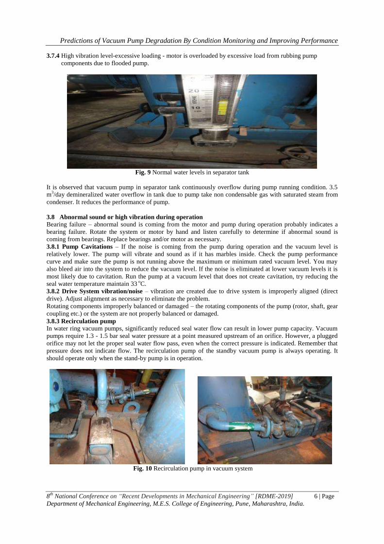
3.8.3 Recirculation pump
In water ring vacuum pumps, significantly reduced seal water flow can result in lower pump capacity. Vacuum
pumps require 1.3 - 1.5 bar seal water pressure at a point measured upstream of an orifice. However, a plugged
orifice may not let the proper seal water flow pass, even when the correct pressure is indicated. Remember that
pressure does not indicate flow. The recirculation pump of the standby vacuum pump is always operating. It
should operate only when the stand-by pump is in operation.
Fig. 10 Recirculation pump in vacuum system

Predictions of Vacuum Pump Degradation By Condition Monitoring and Improving Performance
8th
National Conference on “Recent Developments in Mechanical Engineering” [RDME-2019] 7 | Page
Department of Mechanical Engineering, M.E.S. College of Engineering, Pune, Maharashtra, India.
IV. Diagonosis And Recommendations According to the baroscopic inspection, operational parameters recorded, and other operational checks carried
out at site, the diagnostics along with recommendations are mentioned as below:
4.1 Boroscope inspection
From the inspection point of view, the first stage rotor’s inner blades and buckets show heavy damage
due to cavitations. The baroscopic inspection clearly indicates severe damage to the rotor and thus the pump
requires replacement of the same in order to avoid any sudden breakdown. Also, the overhauling of the pump
required and during overhauling as any reused / repaired part may result in faulty operations. Regular and
Planned overhauling will help with cost management and improve efficiency of vacuum pump. Timely and
correct overhauling practice can help reducing downtime and reduce consumption of vacuum pump. Overhaul
pump to avoid any sudden breakdown and rotor needs replacement.
4.2 Cavitation failure analysis
Cavitation in a water ring vacuum pump is caused when the operating pressure of the water ring
reaches the vapor pressure of that water. This causes some of the water to become vapor, forming bubbles that
travel around with the water ring. As these bubbles travel inside the pump they collapse, or implode, and can
break off pieces of the pump rotor blades. These pieces travel with the water ring and cause further damage
through erosion. Cavitation is a function of both temperature and pressure.The lower the operating temperature
of the water ring, the lower the potential for cavitations. However, if the operating pressure of the pump is close
to the vapor pressure of the ring water at the operating temperature, cavitations can still occur.
Fig.11 Boroscope inspections of second stage and first stage of Vacuum pump rotor.
In cavitations prone operations, like condenser vacuum pump duty, it is a good idea to periodically record the
temperature of the seal water supply and discharge. Increase in temperature can indicate the need for a checkup,
and trending them over time will allow to schedule preventative maintenance before reliability is affected.
Fig. 12 Damages in Inner blades of vacuum pump rotor due to cavitations.
Predictions of Vacuum Pump Degradation By Condition Monitoring and Improving Performance
8th
National Conference on “Recent Developments in Mechanical Engineering” [RDME-2019] 8 | Page
Department of Mechanical Engineering, M.E.S. College of Engineering, Pune, Maharashtra, India.
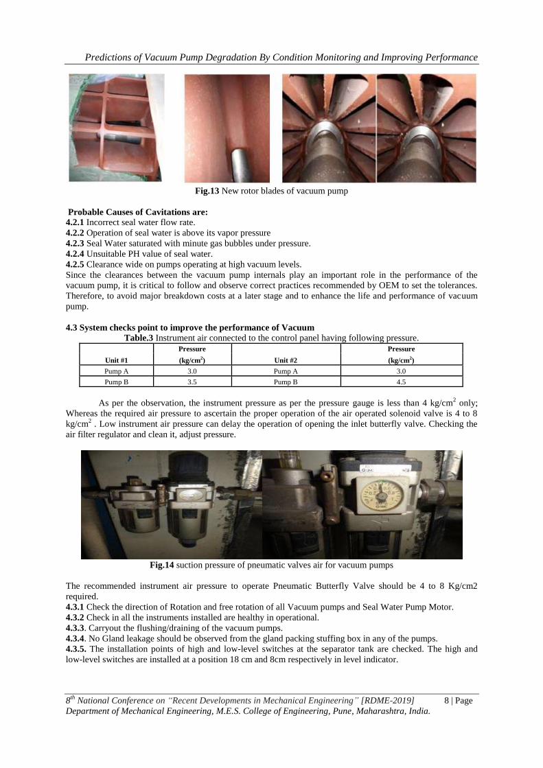
Fig.13 New rotor blades of vacuum pump
Probable Causes of Cavitations are:
4.2.1 Incorrect seal water flow rate.
4.2.2 Operation of seal water is above its vapor pressure
4.2.3 Seal Water saturated with minute gas bubbles under pressure.
4.2.4 Unsuitable PH value of seal water.
4.2.5 Clearance wide on pumps operating at high vacuum levels.
Since the clearances between the vacuum pump internals play an important role in the performance of the
vacuum pump, it is critical to follow and observe correct practices recommended by OEM to set the tolerances.
Therefore, to avoid major breakdown costs at a later stage and to enhance the life and performance of vacuum
pump.
4.3 System checks point to improve the performance of Vacuum
Table.3 Instrument air connected to the control panel having following pressure.
Unit #1
Pressure
Unit #2
Pressure
(kg/cm2) (kg/cm2)
Pump A 3.0 Pump A 3.0
Pump B 3.5 Pump B 4.5
As per the observation, the instrument pressure as per the pressure gauge is less than 4 kg/cm2 only;
Whereas the required air pressure to ascertain the proper operation of the air operated solenoid valve is 4 to 8
kg/cm2 . Low instrument air pressure can delay the operation of opening the inlet butterfly valve. Checking the
air filter regulator and clean it, adjust pressure.
Fig.14 suction pressure of pneumatic valves air for vacuum pumps
The recommended instrument air pressure to operate Pneumatic Butterfly Valve should be 4 to 8 Kg/cm2
required.
4.3.1 Check the direction of Rotation and free rotation of all Vacuum pumps and Seal Water Pump Motor.
4.3.2 Check in all the instruments installed are healthy in operational.
4.3.3. Carryout the flushing/draining of the vacuum pumps.
4.3.4. No Gland leakage should be observed from the gland packing stuffing box in any of the pumps.
4.3.5. The installation points of high and low-level switches at the separator tank are checked. The high and
low-level switches are installed at a position 18 cm and 8cm respectively in level indicator.
Predictions of Vacuum Pump Degradation By Condition Monitoring and Improving Performance
8th
National Conference on “Recent Developments in Mechanical Engineering” [RDME-2019] 9 | Page
Department of Mechanical Engineering, M.E.S. College of Engineering, Pune, Maharashtra, India.
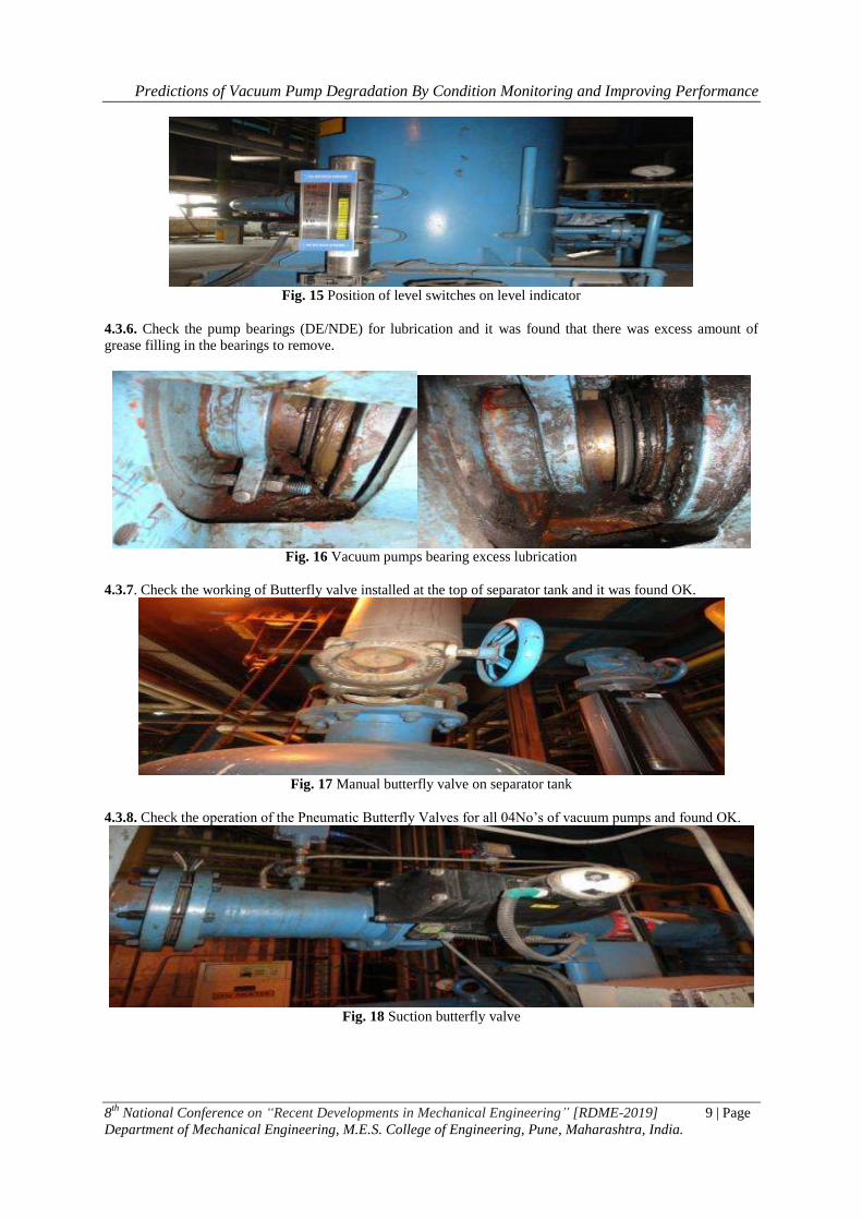
Fig. 15 Position of level switches on level indicator
4.3.6. Check the pump bearings (DE/NDE) for lubrication and it was found that there was excess amount of
grease filling in the bearings to remove.
Fig. 16 Vacuum pumps bearing excess lubrication
4.3.7. Check the working of Butterfly valve installed at the top of separator tank and it was found OK.
Fig. 17 Manual butterfly valve on separator tank
4.3.8. Check the operation of the Pneumatic Butterfly Valves for all 04No’s of vacuum pumps and found OK.
Fig. 18 Suction butterfly valve

Predictions of Vacuum Pump Degradation By Condition Monitoring and Improving Performance
8th
National Conference on “Recent Developments in Mechanical Engineering” [RDME-2019] 10 | Page
Department of Mechanical Engineering, M.E.S. College of Engineering, Pune, Maharashtra, India.
4.3.9. Check and clean seal water line strainers of all pumps.
Fig.19 Recirculation pump of suction strainer.
4.3.10. Seal water flow meter is not installed in any vacuum pump system.
4.3.11 Check inter stage non return valve (NRV) and it is found OK.
Fig. 20 Inter stage NRV condition
4.3.12. Check suction line non return valve (NRV) and the installation position is found Ok. However in two
non return valve (NRV) O-ring found missing and same is replaced with the new one.
Fig. 21 Suction NRV without “o” ring and suction NRV with “o” ring.
4.3.13. Overflow non return valve (NRV) is not installed in any pump and this non return valve (NRV) is used
for preventing back flow of air ingress in system.
Fig. 22 Recommendations for NRV installation overflow loop NRV missing
Predictions of Vacuum Pump Degradation By Condition Monitoring and Improving Performance
8th
National Conference on “Recent Developments in Mechanical Engineering” [RDME-2019] 11 | Page
Department of Mechanical Engineering, M.E.S. College of Engineering, Pune, Maharashtra, India.
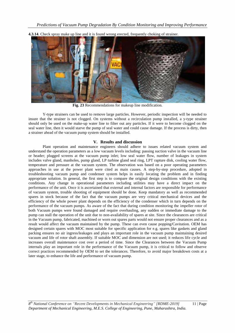
4.3.14. Check spray make up line and it is found wrong erected, frequently choking of strainer.
Fig. 23 Recommendations for makeup line modification.
Y-type strainers can be used to remove large particles. However, periodic inspection will be needed to
insure that the strainer is not clogged. On systems without a recirculation pump installed, a y-type strainer
should only be used on the make-up water line to filter out any particles. If it were to become clogged on the
seal water line, then it would starve the pump of seal water and could cause damage. If the process is dirty, then
a strainer ahead of the vacuum pump system should be installed.
V. Results and discussion Plant operation and maintenance engineers should adhere to issues related vacuum system and
understand the operation parameters as a low vacuum levels including: passing suction valve in the vacuum line
or header; plugged screens at the vacuum pump inlet; low seal water flow, number of leakages in system
includes valve gland, manholes, pump gland, LP turbine gland seal ring, LPT rapture disk, cooling water flow,
temperature and pressure at the vacuum system. The observation was based on a poor operating parameters
approaches in use at the power plant were cited as main causes. A step-by-step procedure, adopted in
troubleshooting vacuum pump and condenser system helps in easily locating the problem and in finding
appropriate solution. In general, the first step is to compare the original design conditions with the existing
conditions. Any change in operational parameters including utilities may have a direct impact on the
performance of the unit. Once it is ascertained that external and internal factors are responsible for performance
of vacuum system, trouble shooting of equipment should be done. Keep mandatory as well as recommended
spares in stock because of the fact that the vacuum pumps are very critical mechanical devices and the
efficiency of the whole power plant depends on the efficiency of the condenser which in turn depends on the
performance of the vacuum pumps. As aware of the fact that during condition monitoring the impeller rotor of
both Vacuum pumps were found damaged and require overhauling, any sudden or immediate damage to the
pump can stall the operation of the unit due to non-availability of spares at site. Since the clearances are critical
in the Vacuum pump, fabricated, machined or worn out spares parts would not ensure proper clearances and as a
result would affect the vacuum maintained by the pump. These can even cause popping/Cavitation. OEM has
designed certain spares with MOC most suitable for specific application for e.g. spares like gaskets and gland
packing ensures no air ingress/leakages and plays an important role in the vacuum pump maintaining desired
vacuum and life of rotor shaft assembly. If suitable MOC and dimension are not used; it reduces life cycle and
increases overall maintenance cost over a period of time. Since the Clearances between the Vacuum Pump
internals play an important role in the performance of the Vacuum pump, it is critical to follow and observe
correct practices recommended by OEM to set the tolerances. Therefore, to avoid major breakdown costs at a
later stage, to enhance the life and performance of vacuum pump.
Predictions of Vacuum Pump Degradation By Condition Monitoring and Improving Performance
8th
National Conference on “Recent Developments in Mechanical Engineering” [RDME-2019] 12 | Page
Department of Mechanical Engineering, M.E.S. College of Engineering, Pune, Maharashtra, India.
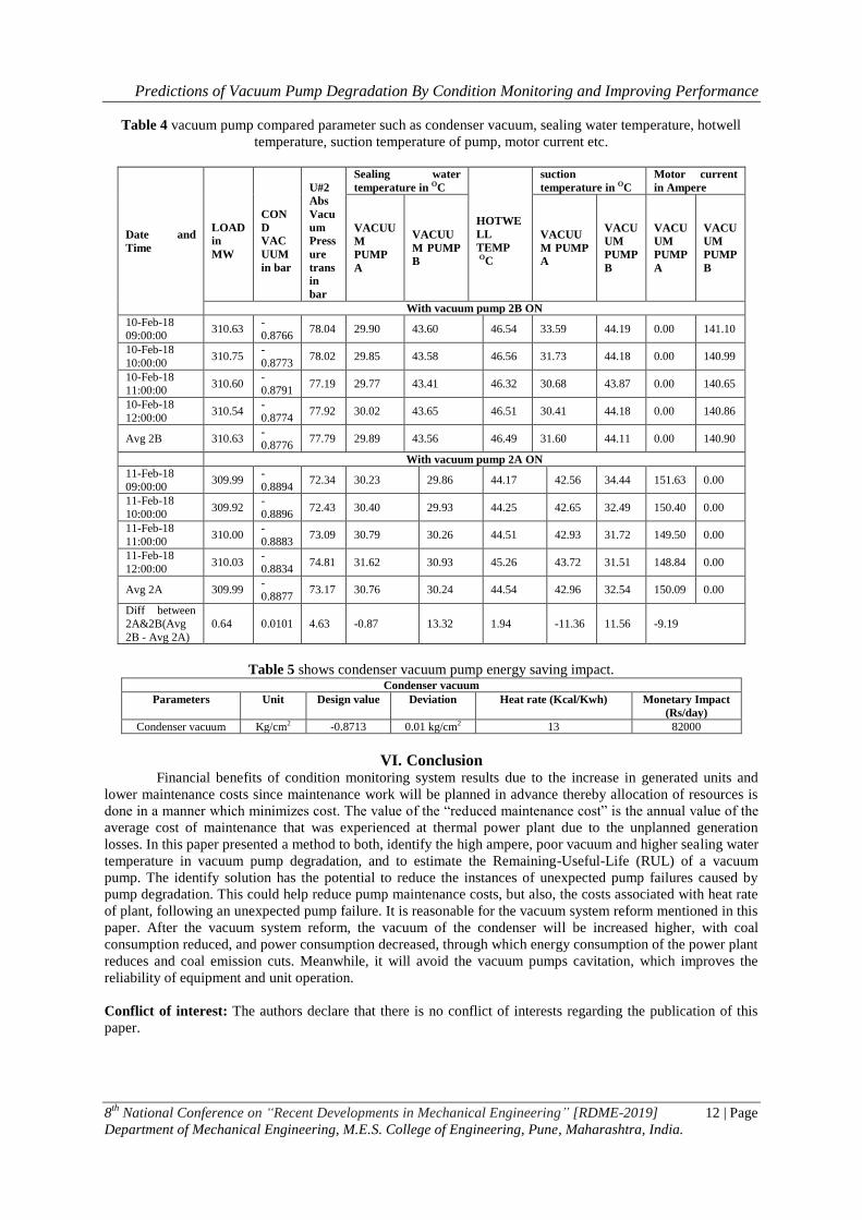
Table 4 vacuum pump compared parameter such as condenser vacuum, sealing water temperature, hotwell
temperature, suction temperature of pump, motor current etc.
Date and
Time
LOAD
in
MW
CON
D
VAC
UUM
in bar
U#2
Abs
Vacu
um
Press
ure
trans
in
bar
Sealing water
temperature in OC
HOTWE
LL
TEMP
OC
suction
temperature in OC
Motor current
in Ampere
VACUU
M
PUMP
A
VACUU
M PUMP
B
VACUU
M PUMP
A
VACU
UM
PUMP
B
VACU
UM
PUMP
A
VACU
UM
PUMP
B
With vacuum pump 2B ON
10-Feb-18 09:00:00
310.63 -0.8766
78.04 29.90 43.60 46.54 33.59 44.19 0.00 141.10
10-Feb-18
10:00:00 310.75
-
0.8773 78.02 29.85 43.58 46.56 31.73 44.18 0.00 140.99
10-Feb-18 11:00:00
310.60 -0.8791
77.19 29.77 43.41 46.32 30.68 43.87 0.00 140.65
10-Feb-18
12:00:00 310.54
-
0.8774 77.92 30.02 43.65 46.51 30.41 44.18 0.00 140.86
Avg 2B 310.63 -0.8776
77.79 29.89 43.56 46.49 31.60 44.11 0.00 140.90
With vacuum pump 2A ON
11-Feb-18
09:00:00 309.99
-
0.8894 72.34 30.23 29.86 44.17 42.56 34.44 151.63 0.00
11-Feb-18
10:00:00 309.92
-
0.8896 72.43 30.40 29.93 44.25 42.65 32.49 150.40 0.00
11-Feb-18
11:00:00 310.00
-
0.8883 73.09 30.79 30.26 44.51 42.93 31.72 149.50 0.00
11-Feb-18
12:00:00 310.03
-
0.8834 74.81 31.62 30.93 45.26 43.72 31.51 148.84 0.00
Avg 2A 309.99 -
0.8877 73.17 30.76 30.24 44.54 42.96 32.54 150.09 0.00
Diff between
2A&2B(Avg
2B - Avg 2A)
0.64 0.0101 4.63 -0.87 13.32 1.94 -11.36 11.56 -9.19
Table 5 shows condenser vacuum pump energy saving impact. Condenser vacuum
Parameters Unit Design value Deviation Heat rate (Kcal/Kwh) Monetary Impact
(Rs/day)
Condenser vacuum Kg/cm2 -0.8713 0.01 kg/cm2 13 82000
VI. Conclusion Financial benefits of condition monitoring system results due to the increase in generated units and
lower maintenance costs since maintenance work will be planned in advance thereby allocation of resources is
done in a manner which minimizes cost. The value of the “reduced maintenance cost” is the annual value of the
average cost of maintenance that was experienced at thermal power plant due to the unplanned generation
losses. In this paper presented a method to both, identify the high ampere, poor vacuum and higher sealing water
temperature in vacuum pump degradation, and to estimate the Remaining-Useful-Life (RUL) of a vacuum
pump. The identify solution has the potential to reduce the instances of unexpected pump failures caused by
pump degradation. This could help reduce pump maintenance costs, but also, the costs associated with heat rate
of plant, following an unexpected pump failure. It is reasonable for the vacuum system reform mentioned in this
paper. After the vacuum system reform, the vacuum of the condenser will be increased higher, with coal
consumption reduced, and power consumption decreased, through which energy consumption of the power plant
reduces and coal emission cuts. Meanwhile, it will avoid the vacuum pumps cavitation, which improves the
reliability of equipment and unit operation.
Conflict of interest: The authors declare that there is no conflict of interests regarding the publication of this
paper.
Predictions of Vacuum Pump Degradation By Condition Monitoring and Improving Performance
8th
National Conference on “Recent Developments in Mechanical Engineering” [RDME-2019] 13 | Page
Department of Mechanical Engineering, M.E.S. College of Engineering, Pune, Maharashtra, India.
References [1]. W. Burgmann and K. Gohler,¨ “Modern vacuum pumps for the vacuum degassing of steel in small and large vacuum-degassing
units,” Metallurgist, vol. 57, no. 5-6,2013, pp. 516–525.
[2]. H. M. Yu, “Analysis on selection of water ring vacuum pumps in the chemical industry,” Applied Mechanics and Materials, vol.
327, 2013, pp. 1435–1439. [3]. Y. M. Vertepov, V. N. Matsenko, and V. M. Antonov, “Advances in water-ring vacuum pumps and compressors,” Chemical and
Petroleum Engineering, vol. 33, no. 5,1997,pp. 522-523.
[4]. NASH Vacuum pump TC-11 manual [5]. Condition monitoring report of Gardner Denver NASH TC-11 vacuum pump installed at unit-1 and 2, millennium enterprise date
07-10 march 2017.
[6]. N. D. Karlsen-Davies and G. A. Aggidis, “Regenerative liquid ring pumps review and advances on design and performance,” Applied Energy, vol. 164,2016, pp. 815–825.
[7]. U. Segebrecht, Liquid Ring Vacuum Pumps and Liquid Ring Compressors: Technical Details and Fields of Application, Verlag
Moderne Industrie, Landsberg am Lech, Germany, 1994. [8]. R. Prager, “Operational Conditions and Application Field of Liquid-Ring Machines,” in Proceedings of the Third Conference on
Fluid Mechanics and Fluid Machinery, 1969.
[9]. H. Bannwarth, Liquid Ring Vacuum Pumps, Compressors and Systems: Conventional and Hermetic Design, John Wiley and Sons, Compressors and Systems: Conventional and Hermetic Design, 2006.
[10]. S. Huang, R. Zhi-Yong, Q. J. Deng, W. U. Tai-Zhong, and Z. H. Tan, “Numerical analysis of gas-liquid two-phase flow in liquid-
ring vacuum pump,” Vacuum, vol. 46, no. 2,2009, pp. 49–52. [11]. M. Radle and B. Shome, “Cavitation prediction in liquid ring pump for aircraft fuel systems by CFD approach,” in Proceedings of
the SAE 2013 Aerotech Congress, 2013.
[12]. G. Q. Qiu, S. Huang, L. L. Zhu, Y. Chen, and J. He, “Performance monitoring analysis of liquid ring vacuum pumps,” Applied Mechanics and Materials, vol. 853,2017, pp. 463–467.