Increasing the Quality of Father-Child Interactions within the Juvenile Justice System
Upload
independentCategory
view
2download
0
Engineering Failure Analysis 27 (2013) 150–164
Contents lists available at SciVerse ScienceDirect
Engineering Failure Analysis
journal homepage: www.elsevier .com/locate /engfai lanal
Predicting failure within TBC system: Finite element simulation ofstress within TBC system as affected by sintering of APS TBC, geometryof substrate and creep of TGO
Si Kyaw, Arthur Jones ⇑, Tom HydeFaculty of Engineering, The University of Nottingham, University Park, Nottingham NG7 2RD, UK
a r t i c l e i n f o
Article history:Received 21 February 2012Received in revised form 28 May 2012Accepted 6 July 2012Available online 9 September 2012
Keywords:Stress analysisAgingTurbine bladeCoating failureFinite element analysis
1350-6307/$ - see front matter � 2012 Elsevier Ltdhttp://dx.doi.org/10.1016/j.engfailanal.2012.07.005
⇑ Corresponding author.E-mail address: [email protected] (
a b s t r a c t
Demand for economically efficient and environmental friendly gas turbine engines leads tothe usage of a thermal barrier coating (TBC) system, which is usually sprayed on the top ofa superalloy substrate. The system includes a ceramic TBC, a bond coat (BC) and a ther-mally grown oxide (TGO) layer. Thermo-mechanical mismatch stresses created withinthe coating at the end of a thermal cycle lead to spallation of the ceramic coating and arapid increase in the temperature of the substrate. The thickness of the oxide layer andthe amount of aluminium depleted during high temperature operation also affect the life-time of the TBC. As a first step to the prediction of the failure mechanisms and the lifetimesof TBCs, a preliminary study of how the stress distribution within the TBC system isaffected by different factors is required. This paper investigates the effects of the sinteringof the ceramic layer, of the geometry of the substrate and of the creep of the TGO, on thestresses built up in the TBC system. Three different TBC system geometries were modelledusing plane strain FE models with three different sets of TGO creep properties. An Arrhe-nius equation was fitted to the temperature dependent modulus of the sintered TBC usingresults published in the open literature. The equation was later implemented within the FEmodel. It is concluded that the TBC on the top of flatter regions of substrate produces smal-ler tensile residual stresses compared to sharp corners of the substrate. It was also foundthat the initiation and propagation of cracks within a TBC, during steady state operationdepends on the choice of the creep parameters of the TGO. At the cooling stage, increasein the modulus of the TBC, due to sintering, has been shown to produce stresses withinthe TBC near the TGO interface that are as large as twice the value that is predicted usinga model without sintering.
� 2012 Elsevier Ltd. All rights reserved.
1. Introduction
There are economic and environmental drivers to increase the efficiency of power generation of an industrial gas turbineengine by increasing the inlet temperature of the turbine. Although Ni based superalloys commonly used for turbine com-ponents have good mechanical properties, e.g. creep and fatigue strengths, their temperature capability is limited by theirmelting points. They are also prone to oxidation and corrosion. Thus, a TBC system, which consists of a yttria stabilisedzirconia (YSZ) thermal barrier coating (TBC) layer with a bond coat (BC) layer between the substrate and the TBC, is appliedto reduce failures by those factors while operating at high temperature. The low thermal conductivity of the TBC makes it
. All rights reserved.
A. Jones).
S. Kyaw et al. / Engineering Failure Analysis 27 (2013) 150–164 151
possible to use higher operation temperatures. A thermally grown oxide (TGO) layer, which forms during oxidation of BC atelevated temperature, slows down the migration of oxygen towards the BC, giving better oxidation resistance. The bond coatis generally made up of MCrAlY powder, where M stands for Ni, Co or Cr. The constituents within MCrAlY can be variedaccording to the requirements of a system such as mechanical strength, oxidation and corrosion resistance [1]. The TBC sys-tem modelled in this paper contains IN738LC superalloy substrate, CO211 (Co–32Ni–21Cr–8Al–0.5Y in wt%) BC and air plas-ma sprayed (APS) yttria stabilised zirconia (YSZ) TBC.
It is necessary to be able to predict the failure mechanisms and lifetime of the TBC system accurately in order to avoid lossof TBC and rapid increase in substrate temperature which accelerates the failure of the coated components. The main factoraffecting failure is the tensile stress state generated within the system, especially at the TGO interfaces. Growth of the TGOlayer causes tensile stresses in an out of plane manner. Furthermore, thermo-mechanical stresses are also generated eitherfrom quenching strain and/or mismatch strain due to differences in coefficients of thermal expansion (CTEs) of TBC layers.These stresses can lead to the initiation and propagation of cracks within the TBC and to the eventual spallation of the TBC orthe delamination failure at the TGO interfaces.
The stress state is affected by the mechanical and physical properties of the coating layers, which are dependent uponboth temperature and operation time. For example, the proportions of the constituent phases within the BC, the degreeof sintering of the TBC and the thickness of the TGO layer all vary with time at elevated temperature. Although there havebeen efforts by researchers [2–4] in recent years to predict the stress state within the TBC systems, evolution of materialproperties of the layers of the TBC system was never fully implemented. Hermosilla et al. [5] built the FE model based onthe model proposed by Busso [6] to describe evolutions of BC phases but omitted the sintering effect of TBCs. Both the evo-lution of the phases within the BC and the consequent effects on the properties of MCrAlYs and the increase in the modulusof the TBC due to sintering are included here.
Moreover, it is important to test the effect of the geometry of the substrate on stress development, since TBC layers areapplied onto various components of industrial gas turbine engines; for example, vanes and blades. Nevertheless, the effect ofgeometry of the substrate was ignored when stress analysis of TBC systems was undertaken in the past. Here, a parametricstudy of the effect of the substrate geometry has been undertaken based on the test specimen that has been developed fortesting of TBC spallation, within the present SuperGen consortium (details given in Acknowledgements).
2. Material properties
2.1. Temperature dependent material properties
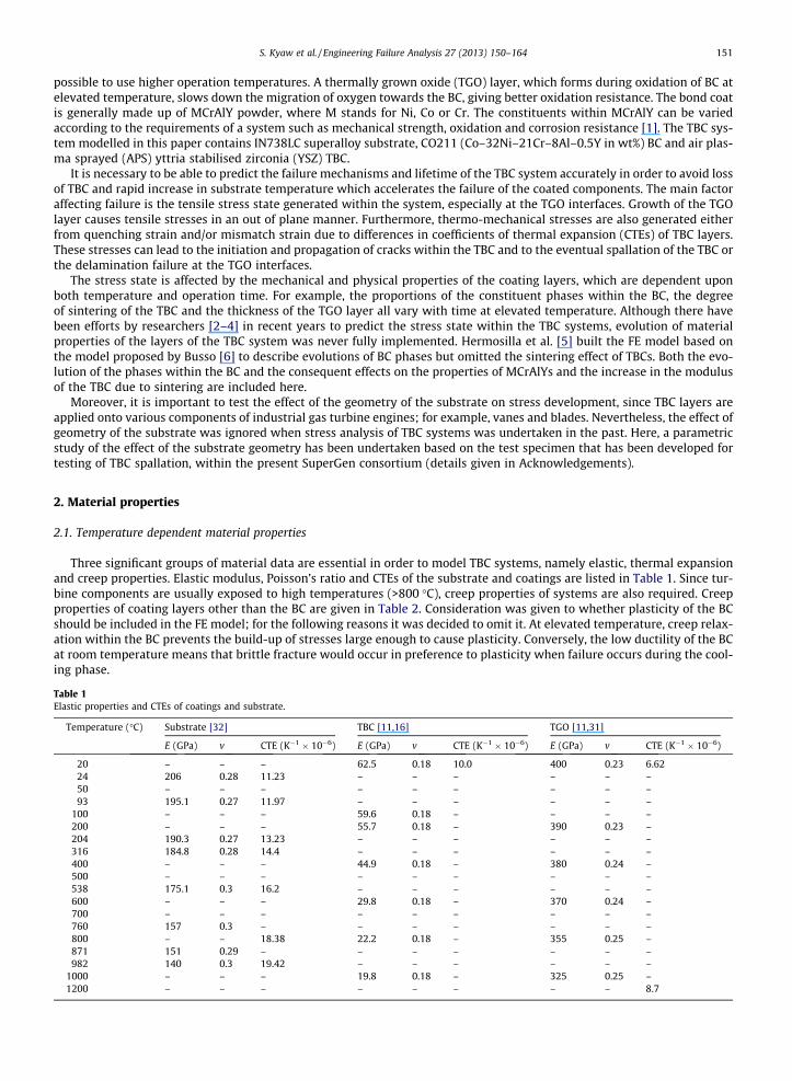
Three significant groups of material data are essential in order to model TBC systems, namely elastic, thermal expansionand creep properties. Elastic modulus, Poisson’s ratio and CTEs of the substrate and coatings are listed in Table 1. Since tur-bine components are usually exposed to high temperatures (>800 �C), creep properties of systems are also required. Creepproperties of coating layers other than the BC are given in Table 2. Consideration was given to whether plasticity of the BCshould be included in the FE model; for the following reasons it was decided to omit it. At elevated temperature, creep relax-ation within the BC prevents the build-up of stresses large enough to cause plasticity. Conversely, the low ductility of the BCat room temperature means that brittle fracture would occur in preference to plasticity when failure occurs during the cool-ing phase.
Table 1Elastic properties and CTEs of coatings and substrate.
Temperature (�C) Substrate [32] TBC [11,16] TGO [11,31]
E (GPa) v CTE (K�1 � 10�6) E (GPa) v CTE (K�1 � 10�6) E (GPa) v CTE (K�1 � 10�6)
20 – – – 62.5 0.18 10.0 400 0.23 6.6224 206 0.28 11.23 – – – – – –50 – – – – – – – – –93 195.1 0.27 11.97 – – – – – –
100 – – – 59.6 0.18 – – – –200 – – – 55.7 0.18 – 390 0.23 –204 190.3 0.27 13.23 – – – – – –316 184.8 0.28 14.4 – – – – – –400 – – – 44.9 0.18 – 380 0.24 –500 – – – – – – – – –538 175.1 0.3 16.2 – – – – – –600 – – – 29.8 0.18 – 370 0.24 –700 – – – – – – – – –760 157 0.3 – – – – – – –800 – – 18.38 22.2 0.18 – 355 0.25 –871 151 0.29 – – – – – – –982 140 0.3 19.42 – – – – – –
1000 – – – 19.8 0.18 – 325 0.25 –1200 – – – – – – – – 8.7

Table 2Power law constants of coatings, superalloy substrate and intermetallicsa.
A0 (MPa�ns�1) Q(J/mol) n Temperature (�C)
IN-738LC [32] 6.68 � 1048 1.72 � 106 9.96 8506.6 1050
AL2O3 (Set 1) [31] 415.12 3.23 � 105 1.08 1200AL2O3 (Set 2) [30] 6800 4.24 � 105 2.3 1200AL2O3 (Set 3) [29] 1.53 � 1010 6.3 � 105 2.5 1200YSZ [33] 2.60 � 10�2 � t�0.67 1.05 � 105 0.56 1323c (Ni) [34] 2.79 � 105 3.81 � 105 5.42 850
4.90 1050c0 (Ni3Al) [35] 8.19 � 10�14 2.68 � 104 3.14 850
4.3 1050b (NiAl) [36] 2.18 � 10�1 3.15 � 105 5.42 850–1050c (Ni) [34] 2.79 � 105 3.81 � 105 5.42 850
4.90 1050c0 (Ni3Al) [35] 8.19 � 10�14 2.68 � 104 3.14 850
4.3 1050
a Power law creep strain rate = A0 expð�Q=RTÞ � rn .
152 S. Kyaw et al. / Engineering Failure Analysis 27 (2013) 150–164
2.2. Constitutive material model for the BC
Due to the heterogeneous nature of the MCrAlY BC, its properties depend not only on the temperature but also on thevolumetric compositions of phases within the BC. It is therefore challenging to obtain material properties of the BC exper-imentally; especially creep data. Firstly, it is difficult to design an experiment which can measure the properties of a thin BClayer (100–200 lm). Wereszczak et al. [7] and Hebsur and Miner [8] measured creep properties on bulk hot pressed MCrAlYpowder specimens; the specimen, thus, may have different porosity and might exhibit different creep properties comparedwith thin coatings. Secondly, the microstructure of a MCrAlY coating is not fixed but is constantly evolving with temperature.Therefore, experimental properties measured on one particular composition of BC cannot be applied to other MCrAlYs withdifferent nominal compositions. This was the motivation for Hermosilla et al. [9] to formulate a creep constitutive modelwhich can be implemented in ABAQUS and gives creep properties of a BC based on its composition and service temperature.The power law creep model was used for intermetallics phases within the BC to take account of the temperature dependencyof the MCrAlY creep. Power law creep properties of the BC phases are listed in Table 2. The effect of composition was con-sidered by assuming that creep strain rate of the aggregate MCrAlY is the sum of creep strain rates of phases volumetrically.
Based on Eshelby’s approach, Hermosilla et al. [5] also predicted the elastic properties (Young’s modulus and Poisson’sratio) and CTE of the BC which are dependent on the evolving composition and the operation temperature. The constitutivematerial model then allows evolution of the material properties of MCrAlY, which will then be used within the FE model,without the need for extensive experimental data gathering. However, the reliability of the model was still a cause for con-cern. Temperature dependent properties of the intermetallics are crucial for obtaining accurate material data for MCrAlY. Byusing elastic properties and CTEs of intermetallics listed in Table 3, properties calculated by the constitutive model are val-idated against the experimental values from the open literature. It is planned to validate the creep model of MCrAlY withdata generated by small punch test creep tests (SPCTs) on the MCrAlY using the method by Hyde et al. [10]. Nevertheless,the creep properties from the constitutive model [9] were used without validation for the FE models presented within thispaper.
2.2.1. Validation of the constitutive material model for the BCTo test the accuracy of the method used for calculating the properties of aggregate BC from those of intermetallics, the
elastic modulus and the CTEs calculated from the constitutive model were compared to relevant experimental results fromthe open literature. The elastic moduli of CO211 for temperatures between 500 �C and 1000 �C were compared against theexperimental data from Pointer and Morrell [11]. Numerically calculated elastic moduli using the model from Hermosilla
Table 3Elastic properties and CTEs of intermetallics.
Temperature(�C)
c (Ni) [34] c0 (Ni3Al) [37] b (NiAl) [36] r (Cr) [34]
E(GPa)
v CTE(K�1 � 10�6)
E(GPa)
v CTE(K�1 � 10�6)
E(GPa)
v CTE(K�1 � 10�6)
E(GPa)
v CTE(K�1 � 10�6)
10 – – – 184.54 0.32 – – – – – – –27 206.72 0.31 13.4 – – 12.3 188.0 0.313 11.9 304.92 0.21 4.9
850 – – – 142.26 0.34 – – – – – – –1000 132.14 0.31 – – – – 150.0 0.313 – 236.34 0.21 –1027 – – 18.9 – – 15.6 – – 16 – – 14
S. Kyaw et al. / Engineering Failure Analysis 27 (2013) 150–164 153
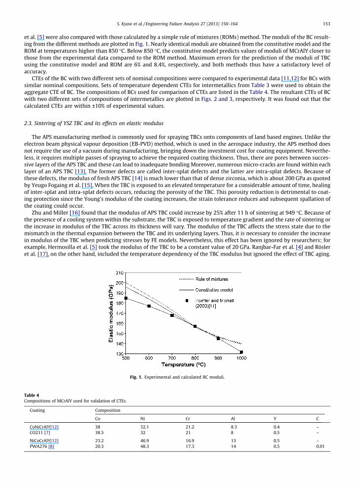
et al. [5] were also compared with those calculated by a simple rule of mixtures (ROMs) method. The moduli of the BC result-ing from the different methods are plotted in Fig. 1. Nearly identical moduli are obtained from the constitutive model and theROM at temperatures higher than 850 �C. Below 850 �C, the constitutive model predicts values of moduli of MCrAlY closer tothose from the experimental data compared to the ROM method. Maximum errors for the prediction of the moduli of TBCusing the constitutive model and ROM are 6% and 8.4%, respectively, and both methods thus have a satisfactory level ofaccuracy.
CTEs of the BC with two different sets of nominal compositions were compared to experimental data [11,12] for BCs withsimilar nominal compositions. Sets of temperature dependent CTEs for intermetallics from Table 3 were used to obtain theaggregate CTE of BC. The compositions of BCs used for comparison of CTEs are listed in the Table 4. The resultant CTEs of BCwith two different sets of compositions of intermetallics are plotted in Figs. 2 and 3, respectively. It was found out that thecalculated CTEs are within ±10% of experimental values.
2.3. Sintering of YSZ TBC and its effects on elastic modulus
The APS manufacturing method is commonly used for spraying TBCs onto components of land based engines. Unlike theelectron beam physical vapour deposition (EB-PVD) method, which is used in the aerospace industry, the APS method doesnot require the use of a vacuum during manufacturing, bringing down the investment cost for coating equipment. Neverthe-less, it requires multiple passes of spraying to achieve the required coating thickness. Thus, there are pores between succes-sive layers of the APS TBC and these can lead to inadequate bonding Moreover, numerous micro-cracks are found within eachlayer of an APS TBC [13]. The former defects are called inter-splat defects and the latter are intra-splat defects. Because ofthese defects, the modulus of fresh APS TBC [14] is much lower than that of dense zirconia, which is about 200 GPa as quotedby Yeugo Fogaing et al. [15]. When the TBC is exposed to an elevated temperature for a considerable amount of time, healingof inter-splat and intra-splat defects occurs, reducing the porosity of the TBC. This porosity reduction is detrimental to coat-ing protection since the Young’s modulus of the coating increases, the strain tolerance reduces and subsequent spallation ofthe coating could occur.
Zhu and Miller [16] found that the modulus of APS TBC could increase by 25% after 11 h of sintering at 949 �C. Because ofthe presence of a cooling system within the substrate, the TBC is exposed to temperature gradient and the rate of sintering orthe increase in modulus of the TBC across its thickness will vary. The modulus of the TBC affects the stress state due to themismatch in the thermal expansion between the TBC and its underlying layers. Thus, it is necessary to consider the increasein modulus of the TBC when predicting stresses by FE models. Nevertheless, this effect has been ignored by researchers; forexample, Hermosilla et al. [5] took the modulus of the TBC to be a constant value of 20 GPa. Ranjbar-Far et al. [4] and Rösleret al. [17], on the other hand, included the temperature dependency of the TBC modulus but ignored the effect of TBC aging.
Fig. 1. Experimental and calculated BC moduli.
Table 4Compositions of MCrAlY used for validation of CTEs.
Coating Composition
Co Ni Cr Al Y C
CoNiCrAlY[12] 38 32.1 21.2 8.3 0.4 –CO211 [7] 38.5 32 21 8 0.5 –
NiCoCrAlY[12] 23.2 46.9 16.9 13 0.5 –PWA276 [8] 20.3 48.3 17.3 14 0.5 0.01

Fig. 2. Comparisons of CTEs calculated using the constitutive models and experimental results for CO211.
Fig. 3. Comparisons of CTEs calculated using the constitutive models and experimental results for PWA276.
154 S. Kyaw et al. / Engineering Failure Analysis 27 (2013) 150–164
As a result, the predicted stress state can be significantly underestimated by the FE model. Busso et al. [18] have formulatedan equation to calculate temperature dependent modulus of the sintered TBC. However, the formula was derived by fittingtemperature dependent modulus data of a TBC which has been heat treated for a period of only 100 h. An equation for pre-dicting rate of increase in the modulus of a TBC due to sintering, with dependencies on temperature and time of sintering, isformulated in Section 2.3.1 using empirical measurements of TBC moduli by Zhu and Miller [16]. Since the measurements ofthe moduli of the TBC were measured at the end of different durations of heating, the resultant equation captures continuouschanges in moduli of the TBC more realistically than earlier approaches. The resultant relationship will be used in future FEmodels of TBCs for the prediction of stress.
2.3.1. Arrhenius fit for rate of change in modulus of YSZ TBC due to sinteringAn Arrhenius rate equation is often used to determine the dependence of the rate of reaction on the temperature at which
the reaction takes place [19]; it has the form shown in Eqs. (1) and (2), the latter being an alternative in a logarithmic form.
k ¼ Z � exp � QR� T
� �ð1Þ
lnðkÞ ¼ lnðZÞ þ �QR
� �1T
� �ð2Þ
Q and R are the activation energy of the reaction and the universal gas constant respectively. Z is a constant prefactor in theArrhenius equation. k is the rate constant, or rate of reaction, at different temperatures. Q and Z from Eq. (1) can be obtainedby fitting a straight line to a plot of ln(k) Vs 1
T
� �. Various kinetic assumptions can be made to describe the rate of reaction; for
example, it can be constant throughout the reaction period as is the case of a zeroth order reaction. Alternatively, the rate of
S. Kyaw et al. / Engineering Failure Analysis 27 (2013) 150–164 155
reaction can be assumed to depend upon the concentrations of one or two reactants. The former situation is known as firstorder reaction and the latter is second order reaction. k can be found from various straight line fits as indicated in Table 5.
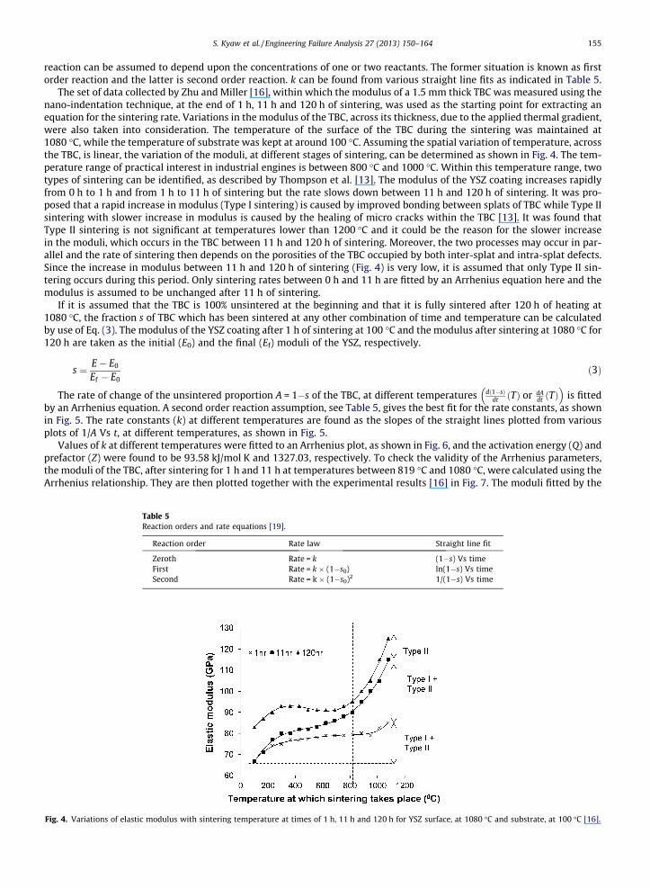
The set of data collected by Zhu and Miller [16], within which the modulus of a 1.5 mm thick TBC was measured using thenano-indentation technique, at the end of 1 h, 11 h and 120 h of sintering, was used as the starting point for extracting anequation for the sintering rate. Variations in the modulus of the TBC, across its thickness, due to the applied thermal gradient,were also taken into consideration. The temperature of the surface of the TBC during the sintering was maintained at1080 �C, while the temperature of substrate was kept at around 100 �C. Assuming the spatial variation of temperature, acrossthe TBC, is linear, the variation of the moduli, at different stages of sintering, can be determined as shown in Fig. 4. The tem-perature range of practical interest in industrial engines is between 800 �C and 1000 �C. Within this temperature range, twotypes of sintering can be identified, as described by Thompson et al. [13]. The modulus of the YSZ coating increases rapidlyfrom 0 h to 1 h and from 1 h to 11 h of sintering but the rate slows down between 11 h and 120 h of sintering. It was pro-posed that a rapid increase in modulus (Type I sintering) is caused by improved bonding between splats of TBC while Type IIsintering with slower increase in modulus is caused by the healing of micro cracks within the TBC [13]. It was found thatType II sintering is not significant at temperatures lower than 1200 �C and it could be the reason for the slower increasein the moduli, which occurs in the TBC between 11 h and 120 h of sintering. Moreover, the two processes may occur in par-allel and the rate of sintering then depends on the porosities of the TBC occupied by both inter-splat and intra-splat defects.Since the increase in modulus between 11 h and 120 h of sintering (Fig. 4) is very low, it is assumed that only Type II sin-tering occurs during this period. Only sintering rates between 0 h and 11 h are fitted by an Arrhenius equation here and themodulus is assumed to be unchanged after 11 h of sintering.
If it is assumed that the TBC is 100% unsintered at the beginning and that it is fully sintered after 120 h of heating at1080 �C, the fraction s of TBC which has been sintered at any other combination of time and temperature can be calculatedby use of Eq. (3). The modulus of the YSZ coating after 1 h of sintering at 100 �C and the modulus after sintering at 1080 �C for120 h are taken as the initial (E0) and the final (Ef) moduli of the YSZ, respectively.
Fig. 4.
s ¼ E� E0
Ef � E0ð3Þ
The rate of change of the unsintered proportion A = 1�s of the TBC, at different temperatures dð1�sÞdt ðTÞ or dA
dt ðTÞ� �
is fittedby an Arrhenius equation. A second order reaction assumption, see Table 5, gives the best fit for the rate constants, as shownin Fig. 5. The rate constants (k) at different temperatures are found as the slopes of the straight lines plotted from variousplots of 1/A Vs t, at different temperatures, as shown in Fig. 5.
Values of k at different temperatures were fitted to an Arrhenius plot, as shown in Fig. 6, and the activation energy (Q) andprefactor (Z) were found to be 93.58 kJ/mol K and 1327.03, respectively. To check the validity of the Arrhenius parameters,the moduli of the TBC, after sintering for 1 h and 11 h at temperatures between 819 �C and 1080 �C, were calculated using theArrhenius relationship. They are then plotted together with the experimental results [16] in Fig. 7. The moduli fitted by the
Table 5Reaction orders and rate equations [19].
Reaction order Rate law Straight line fit
Zeroth Rate = k (1�s) Vs timeFirst Rate = k � (1�s0) ln(1�s) Vs timeSecond Rate = k � (1�s0)2 1/(1�s) Vs time
Variations of elastic modulus with sintering temperature at times of 1 h, 11 h and 120 h for YSZ surface, at 1080 �C and substrate, at 100 �C [16].

Fig. 5. Second order straight line fit for reaction rate.
Fig. 6. Arrhenius fit for reaction rates of sintering.
Fig. 7. Experimental moduli [16] compared with Arrhenius fitted moduli.
156 S. Kyaw et al. / Engineering Failure Analysis 27 (2013) 150–164
Arrhenius parameters are within ±10 GPa of empirical values, as shown in Fig. 7. These results confirm the validity of theArrhenius fitting process for TBC modulus. With the Arrhenius parameters calculated in this section, the elastic modulusof a TBC can be evaluated at any combination of sintering time and temperature. It should, however, be noted that it is

S. Kyaw et al. / Engineering Failure Analysis 27 (2013) 150–164 157
necessary to consider in situ changes in modulus of the YSZ coating since Zhu and Miller [16] measured the TBC modulus atroom temperature after sintering had taken place at various temperatures. The modulus of the TBC could be reduced at high-er temperatures and it is possible to scale the moduli of a TBC, using the graph of in situ temperature dependent TBC moduligiven by Qi et al. [20], though the process has not been validated. Finally, the modulus of the YSZ coating can be expressed asa function of temperature, sintering time and sintered temperature by the following equation:
EðT; Top; tÞ ¼E0ðTÞ
E01� 1
1þR t
0 Z exp � QRTop
� �� �dt
h i0@
1A� ðEf � E0Þ
8<:
9=;þ E0
24
35 ð4Þ
where E0(T) is the modulus of a fresh TBC at temperature T (GPa), T is the temperature of YSZ TBC (�C), t is the sintering time(h), Top is the operation temperature of a gas turbine and R is the Universal gas constant (J K�1 mol�1)
3. Finite element model
A FE model for the TBC system was based on the geometry of the curved specimen shown in Fig. 8, which was developedwithin the SuperGen consortium for carrying out isothermal spallation testing of the TBC system. To simplify the boundaryconditions used for the model, it has been assumed that three different points from the curved specimen, labelled A, C and Din Fig. 8, are part of cylinders with different outer and inner radii, as tabulated in Table 6. The models will be called model A,model C and model D, for consistency with the notations used within the consortium. Generalised plane strain elementswere used because there is no axial restraint on the specimen as a whole. The spray thicknesses of the BC and the TBCare 100 lm and 200 lm, respectively, and the initial TGO is assumed to be 1 lm. The geometry and boundary conditionsfor the model are shown in Fig. 9i and the model meshes are illustrated in Fig. 9ii and iii. Zero circumferential movementis applied at the plane where t = 0 and t = h. The interface of the TGO is assumed to have a sinusoidal shape with a peakamplitude of 6 lm and a wavelength of 48 lm. It is assumed that the TGO interface undulates in the circumferential direc-tion. For the model representing point A, an inner radius of 0.1 mm was used to approximate a solid cylinder while avoidingthe need to mesh into a sharp wedge angle. The models were chosen to approximate the true outer (and where appropriate)inner radii of the specimen. However, it has been demonstrated via sensitivity studies that the thickness of the cylinder wallassumed in the model, and indeed whether or not a given cylinder is hollow, has negligible effect (typically around 0.3%) onthe stresses. This is because its wall thickness, and hence its stiffness, are much greater than those of the TBC.
3.1. Implementation of the constitutive FE model
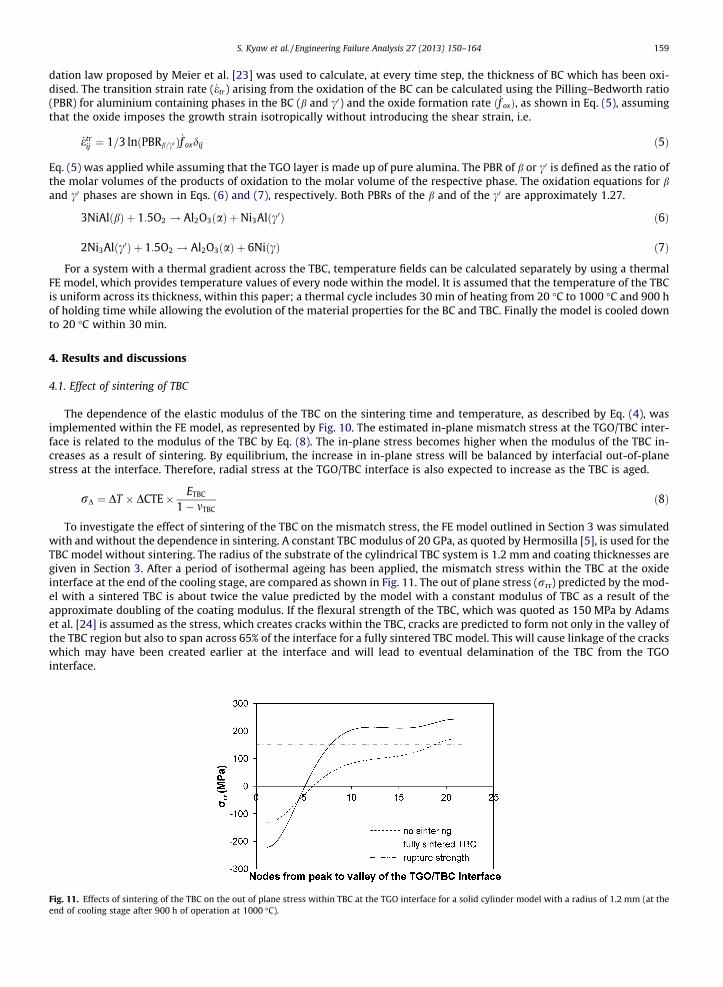
The flowchart for the ABAQUS routine, which takes into account material and microstructural evolutions of the BC and thesintering of the TBC, is shown in Fig. 10. The material properties of the intermetallics, at various operation temperatures,shown in Tables 2 and 3, are implemented via a user defined PROPS module. The relevant properties are accessed by a userdefined subroutine (UMAT) [21] during the processing stage to calculate the instantaneous aggregate properties of BC and to
Fig. 8. Geometry of the curved specimen.
Table 6Radii of curvatures at different positions of the curved specimen.
Positions Radii of curvature (mm) Inner radius (mm)
D 6.2 3.2C 35 27A 1.2 0.0
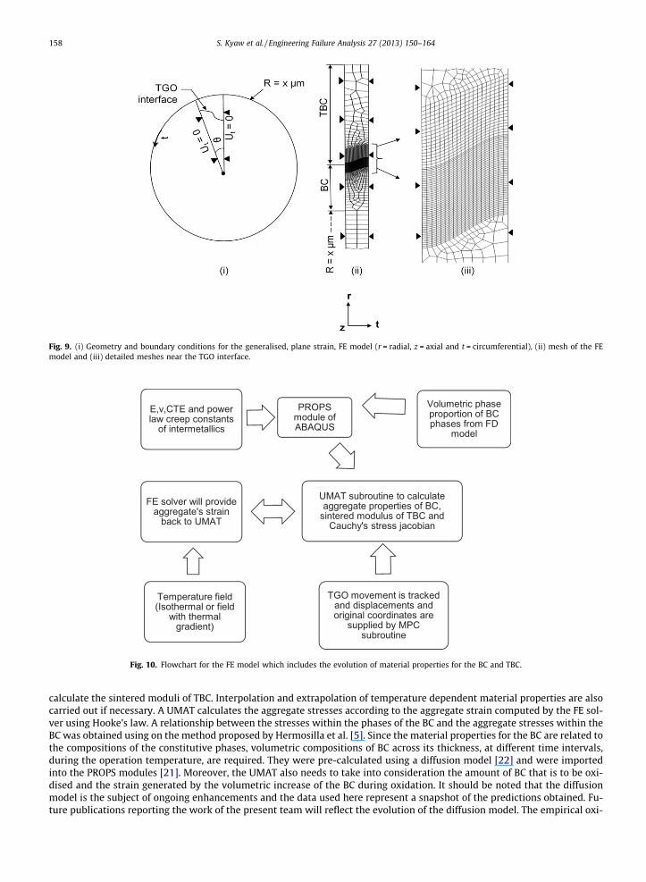
Fig. 9. (i) Geometry and boundary conditions for the generalised, plane strain, FE model (r = radial, z = axial and t = circumferential), (ii) mesh of the FEmodel and (iii) detailed meshes near the TGO interface.
Fig. 10. Flowchart for the FE model which includes the evolution of material properties for the BC and TBC.
158 S. Kyaw et al. / Engineering Failure Analysis 27 (2013) 150–164
calculate the sintered moduli of TBC. Interpolation and extrapolation of temperature dependent material properties are alsocarried out if necessary. A UMAT calculates the aggregate stresses according to the aggregate strain computed by the FE sol-ver using Hooke’s law. A relationship between the stresses within the phases of the BC and the aggregate stresses within theBC was obtained using on the method proposed by Hermosilla et al. [5]. Since the material properties for the BC are related tothe compositions of the constitutive phases, volumetric compositions of BC across its thickness, at different time intervals,during the operation temperature, are required. They were pre-calculated using a diffusion model [22] and were importedinto the PROPS modules [21]. Moreover, the UMAT also needs to take into consideration the amount of BC that is to be oxi-dised and the strain generated by the volumetric increase of the BC during oxidation. It should be noted that the diffusionmodel is the subject of ongoing enhancements and the data used here represent a snapshot of the predictions obtained. Fu-ture publications reporting the work of the present team will reflect the evolution of the diffusion model. The empirical oxi-
S. Kyaw et al. / Engineering Failure Analysis 27 (2013) 150–164 159
dation law proposed by Meier et al. [23] was used to calculate, at every time step, the thickness of BC which has been oxi-dised. The transition strain rate ( _etr) arising from the oxidation of the BC can be calculated using the Pilling–Bedworth ratio(PBR) for aluminium containing phases in the BC (b and c0) and the oxide formation rate ð _f oxÞ, as shown in Eq. (5), assumingthat the oxide imposes the growth strain isotropically without introducing the shear strain, i.e.
Fig. 11.end of
_etrij ¼ 1=3 lnðPBRb=c0 Þ _f oxdij ð5Þ
Eq. (5) was applied while assuming that the TGO layer is made up of pure alumina. The PBR of b or c0 is defined as the ratio ofthe molar volumes of the products of oxidation to the molar volume of the respective phase. The oxidation equations for band c0 phases are shown in Eqs. (6) and (7), respectively. Both PBRs of the b and of the c0 are approximately 1.27.
3NiAlðbÞ þ 1:5O2 ! Al2O3ðaÞ þ Ni3Alðc0Þ ð6Þ
2Ni3Alðc0Þ þ 1:5O2 ! Al2O3ðaÞ þ 6NiðcÞ ð7Þ
For a system with a thermal gradient across the TBC, temperature fields can be calculated separately by using a thermalFE model, which provides temperature values of every node within the model. It is assumed that the temperature of the TBCis uniform across its thickness, within this paper; a thermal cycle includes 30 min of heating from 20 �C to 1000 �C and 900 hof holding time while allowing the evolution of the material properties for the BC and TBC. Finally the model is cooled downto 20 �C within 30 min.
4. Results and discussions
4.1. Effect of sintering of TBC
The dependence of the elastic modulus of the TBC on the sintering time and temperature, as described by Eq. (4), wasimplemented within the FE model, as represented by Fig. 10. The estimated in-plane mismatch stress at the TGO/TBC inter-face is related to the modulus of the TBC by Eq. (8). The in-plane stress becomes higher when the modulus of the TBC in-creases as a result of sintering. By equilibrium, the increase in in-plane stress will be balanced by interfacial out-of-planestress at the interface. Therefore, radial stress at the TGO/TBC interface is also expected to increase as the TBC is aged.
rD ¼ DT � DCTE� ETBC
1� mTBCð8Þ
To investigate the effect of sintering of the TBC on the mismatch stress, the FE model outlined in Section 3 was simulatedwith and without the dependence in sintering. A constant TBC modulus of 20 GPa, as quoted by Hermosilla [5], is used for theTBC model without sintering. The radius of the substrate of the cylindrical TBC system is 1.2 mm and coating thicknesses aregiven in Section 3. After a period of isothermal ageing has been applied, the mismatch stress within the TBC at the oxideinterface at the end of the cooling stage, are compared as shown in Fig. 11. The out of plane stress (rrr) predicted by the mod-el with a sintered TBC is about twice the value predicted by the model with a constant modulus of TBC as a result of theapproximate doubling of the coating modulus. If the flexural strength of the TBC, which was quoted as 150 MPa by Adamset al. [24] is assumed as the stress, which creates cracks within the TBC, cracks are predicted to form not only in the valley ofthe TBC region but also to span across 65% of the interface for a fully sintered TBC model. This will cause linkage of the crackswhich may have been created earlier at the interface and will lead to eventual delamination of the TBC from the TGOinterface.
Effects of sintering of the TBC on the out of plane stress within TBC at the TGO interface for a solid cylinder model with a radius of 1.2 mm (at thecooling stage after 900 h of operation at 1000 �C).

160 S. Kyaw et al. / Engineering Failure Analysis 27 (2013) 150–164
4.2. Effect of the geometry of the substrate on the stress state within the TBC system
Models representing positions A, C and D of the curved specimen described in Section 3 were subjected to a simulatedthermal cycle consisting of 900 h of operation at 1000 �C followed by cooling to 25 �C. Maps of radial stress (rrr) at theend of steady state and after cooling for model D are shown in Fig. 12i and ii respectively. TBC radial stresses in the vicinityof the TGO interface are plotted against positions within the profile for the three different models (A, C and D); these areshown in Fig. 13i for stresses at the end of steady state and in Fig. 13ii after cooling. It is seen from Fig. 12i that, by theend of the steady state period, stresses have begun to build up due to the growth of oxide, while creep in all the coating lay-ers (TBC, TGO and BC) tends to relax away stresses caused by differential thermal expansion arising during heat-up. As can beseen from Figs. 12i and 13i, the radial stresses within the TBC for model D at the end of steady state range from moderately
Fig. 12. Out of plane stress, rrr, for the hollow cylinder model with a outer radius of 6.2 mm and an inner radius of 3 mm (i) at the end of the steady stateafter 900 h of heating at 1000 �C and (ii) at the end of the cooling stage.
Fig. 13i. Out of plane stress within the TBC at the TGO interface, for different positions on the curved specimen at 1000 �C after 900 h of heating at the sametemperature.
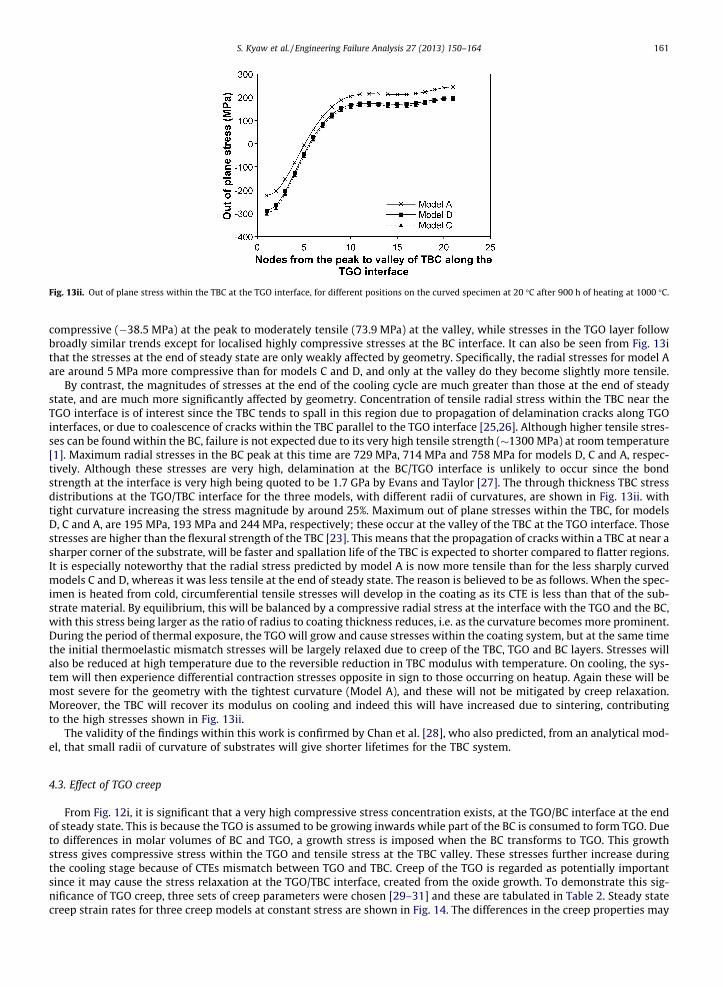
Fig. 13ii. Out of plane stress within the TBC at the TGO interface, for different positions on the curved specimen at 20 �C after 900 h of heating at 1000 �C.
S. Kyaw et al. / Engineering Failure Analysis 27 (2013) 150–164 161
compressive (�38.5 MPa) at the peak to moderately tensile (73.9 MPa) at the valley, while stresses in the TGO layer followbroadly similar trends except for localised highly compressive stresses at the BC interface. It can also be seen from Fig. 13ithat the stresses at the end of steady state are only weakly affected by geometry. Specifically, the radial stresses for model Aare around 5 MPa more compressive than for models C and D, and only at the valley do they become slightly more tensile.
By contrast, the magnitudes of stresses at the end of the cooling cycle are much greater than those at the end of steadystate, and are much more significantly affected by geometry. Concentration of tensile radial stress within the TBC near theTGO interface is of interest since the TBC tends to spall in this region due to propagation of delamination cracks along TGOinterfaces, or due to coalescence of cracks within the TBC parallel to the TGO interface [25,26]. Although higher tensile stres-ses can be found within the BC, failure is not expected due to its very high tensile strength (�1300 MPa) at room temperature[1]. Maximum radial stresses in the BC peak at this time are 729 MPa, 714 MPa and 758 MPa for models D, C and A, respec-tively. Although these stresses are very high, delamination at the BC/TGO interface is unlikely to occur since the bondstrength at the interface is very high being quoted to be 1.7 GPa by Evans and Taylor [27]. The through thickness TBC stressdistributions at the TGO/TBC interface for the three models, with different radii of curvatures, are shown in Fig. 13ii. withtight curvature increasing the stress magnitude by around 25%. Maximum out of plane stresses within the TBC, for modelsD, C and A, are 195 MPa, 193 MPa and 244 MPa, respectively; these occur at the valley of the TBC at the TGO interface. Thosestresses are higher than the flexural strength of the TBC [23]. This means that the propagation of cracks within a TBC at near asharper corner of the substrate, will be faster and spallation life of the TBC is expected to shorter compared to flatter regions.It is especially noteworthy that the radial stress predicted by model A is now more tensile than for the less sharply curvedmodels C and D, whereas it was less tensile at the end of steady state. The reason is believed to be as follows. When the spec-imen is heated from cold, circumferential tensile stresses will develop in the coating as its CTE is less than that of the sub-strate material. By equilibrium, this will be balanced by a compressive radial stress at the interface with the TGO and the BC,with this stress being larger as the ratio of radius to coating thickness reduces, i.e. as the curvature becomes more prominent.During the period of thermal exposure, the TGO will grow and cause stresses within the coating system, but at the same timethe initial thermoelastic mismatch stresses will be largely relaxed due to creep of the TBC, TGO and BC layers. Stresses willalso be reduced at high temperature due to the reversible reduction in TBC modulus with temperature. On cooling, the sys-tem will then experience differential contraction stresses opposite in sign to those occurring on heatup. Again these will bemost severe for the geometry with the tightest curvature (Model A), and these will not be mitigated by creep relaxation.Moreover, the TBC will recover its modulus on cooling and indeed this will have increased due to sintering, contributingto the high stresses shown in Fig. 13ii.
The validity of the findings within this work is confirmed by Chan et al. [28], who also predicted, from an analytical mod-el, that small radii of curvature of substrates will give shorter lifetimes for the TBC system.
4.3. Effect of TGO creep
From Fig. 12i, it is significant that a very high compressive stress concentration exists, at the TGO/BC interface at the endof steady state. This is because the TGO is assumed to be growing inwards while part of the BC is consumed to form TGO. Dueto differences in molar volumes of BC and TGO, a growth stress is imposed when the BC transforms to TGO. This growthstress gives compressive stress within the TGO and tensile stress at the TBC valley. These stresses further increase duringthe cooling stage because of CTEs mismatch between TGO and TBC. Creep of the TGO is regarded as potentially importantsince it may cause the stress relaxation at the TGO/TBC interface, created from the oxide growth. To demonstrate this sig-nificance of TGO creep, three sets of creep parameters were chosen [29–31] and these are tabulated in Table 2. Steady statecreep strain rates for three creep models at constant stress are shown in Fig. 14. The differences in the creep properties may
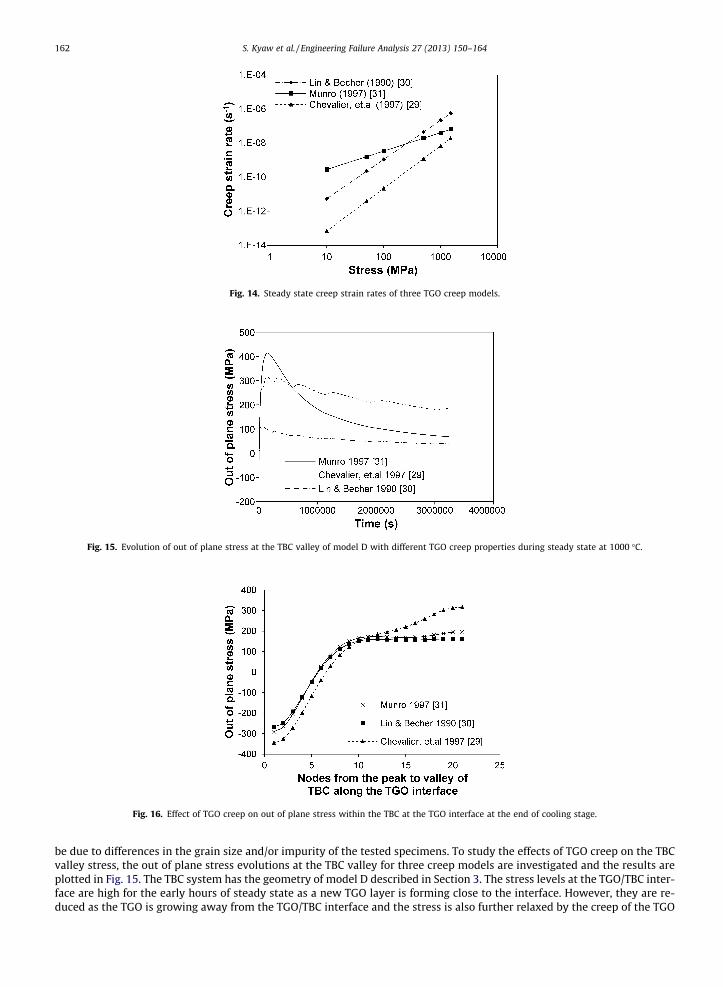
Fig. 14. Steady state creep strain rates of three TGO creep models.
Fig. 15. Evolution of out of plane stress at the TBC valley of model D with different TGO creep properties during steady state at 1000 �C.
Fig. 16. Effect of TGO creep on out of plane stress within the TBC at the TGO interface at the end of cooling stage.
162 S. Kyaw et al. / Engineering Failure Analysis 27 (2013) 150–164
be due to differences in the grain size and/or impurity of the tested specimens. To study the effects of TGO creep on the TBCvalley stress, the out of plane stress evolutions at the TBC valley for three creep models are investigated and the results areplotted in Fig. 15. The TBC system has the geometry of model D described in Section 3. The stress levels at the TGO/TBC inter-face are high for the early hours of steady state as a new TGO layer is forming close to the interface. However, they are re-duced as the TGO is growing away from the TGO/TBC interface and the stress is also further relaxed by the creep of the TGO
S. Kyaw et al. / Engineering Failure Analysis 27 (2013) 150–164 163
and TBC. There is initially a sharp increase in the stress level at the TBC valley for the Munro model [31] since it has smallerpower law creep stress exponent and has low stress relaxation rate at high stress levels. After 100 h into steady state, stressarising from the growth of TGO at the TGO/TBC level is reduced and the Munro model [31] relaxes the stress faster than oth-ers. The Chevalier model [29] shows the slowest stress relaxation rate for the TGO and the stress level at the TBC valley ishigher than its rupture strength [24] throughout the steady state. Because the Chevalier [29] model predicts a higher stresslevel at the TBC valley, at the end of steady state, it also predicts around 50% higher stress than the other creep models, at theend of the cooling stage. The radial stress levels within the TBC at the TGO/TBC interface, after cooling down, are shown inFig. 16 for the three different creep models.
5. Conclusions and future work
This publication has reported on a number of developments on the modelling of thermal barrier coated components. Spe-cifically, temperature-dependency has been incorporated into the models for CTEs of the substrate and the BC, TGO and TBClayers. Furthermore, a new framework has been proposed for modelling the elastic properties of TBC as they evolve due tosintering. The modulus is represented as a function of thermal history and instantaneous temperature, based on an assumedArrhenius temperature dependency of the rate of sintering-related bond formation. These improvements to the underlyingmaterial models have been applied within a parametric study of failure related stresses as a function of the radius of curva-ture of the substrate forming the coated component.
Sintering of the TBC layer has been demonstrated to have a strong effect with the stresses being increased by a factor ofup to two as a result of the increased modulus, notwithstanding the effects of TBC creep which tend to relax these stresses. Itis noteworthy that the stresses predicted within the TBC are very sensitive to the parameters chosen for the TGO creep mod-el; depending on the creep properties assumed for the TGO, stress levels within the TBC may or may not be sufficiently highto exceed the TBC’s rupture strength [24].
The effect of geometry of the substrate on the TBC stress is subtle compared to that of sintering of the TBC: curvature, suchas that found on the leading edge of coated aerofoil sections, has been found to increase the through-thickness stresses in theTBC layer adjacent to the TGO interface by around 25% compared with regions where curvature is less significant. The depen-dency on geometry is less significant still for the radial stresses at the BC/TGO interface, with stresses changing only by a fewpercent and remaining well below the interface strength.
The present form of the sintering model represents a useful and powerful tool for modelling TBC property evolution; how-ever, it currently neglects pure type II sintering and the assumption of a second order Arrhenius relationship is based uponevidence of rather limited experimental data. Additional measurements of modulus for sintered TBCs covering the sinteringperiod 1–11 h would improve confidence in the choice of order of the Arrhenius rate model. There is also scope for incorpo-rating additional terms in the model to represent type II sintering though this would require still more data (covering tests inwhich type II sintering is predominant) in order that the parameters for these terms could be determined.
Future work will involve validation of the model against experimental spallation tests, in order to confirm that demon-strate that early spallation occurs in TBC at sharper corners of the substrate compared to less sharp regions. This work will bereported in a future paper. Quantitative validation of the predicted stress values with values measured from the actual heattreated specimen are also needed.
Acknowledgements
We would like to acknowledge the support of The Energy Programme, which is a Research Councils UK cross council ini-tiative led by EPSRC and contributed to by ESRC, NERC, BBSRC and STFC, and specifically the Supergen initiative (Grants GR/S86334/01 and EP/F029748) and the following companies; Alstom Power Ltd., Doosan Babcock, E.ON, National Physical Lab-oratory, Praxair Surface Technologies Ltd., QinetiQ, Rolls-Royce plc, RWE npower, Siemens Industrial Turbomachinery Ltd.and Tata Steel, for their valuable contributions to the project. We would also like to acknowledge Mudith Karunaratneand Rachel Thomson for contributing the results of their work on the diffusion model of the bond coat, and Graham McCart-ney for drawing our attention to a number of the references.
Appendix A. Supplementary material
Supplementary data associated with this article can be found, in the online version, at http://dx.doi.org/10.1016/j.engfailanal.2012.07.005.
References
[1] Bose S. High temperature coatings. Elsevier Butterworth-Heinemann; 2007.[2] Bialas M. Finite element analysis of stress distribution in thermal barrier coatings. Surf Coat Technol 2008;202:6002–10.[3] Martena M, Botto D, Fino P, Sabbadini S, Gola MM, Badini C. Modelling of TBC system failure: stress distribution as a function of TGO thickness and
thermal expansion mismatch. Eng Failure Anal 2006;13:409–26.[4] Ranjbar-Far M, Absi J, Mariaux G, Dubois F. Simulation of the effect of material properties and interface roughness on the stress distribution in thermal
barrier coatings using finite element method. Mater Des 2010;31:772–81.

164 S. Kyaw et al. / Engineering Failure Analysis 27 (2013) 150–164
[5] Hermosilla U, Karunaratne MSA, Jones IA, Hyde TH, Thomson RC. Modelling the high temperature behaviour of TBCs using sequentially coupledmicrostructural–mechanical FE analyses. Mater Sci Eng: A 2009;513–514:302–10.
[6] Busso EP. Oxidation-induced stresses in ceramic–metal interfaces. J Phys IV France 1999;09. Pr9-287–Pr9-96.[7] Wereszczak AA, Hemrick JG, Kirkland TP, Haynes JA, Fitzgerald TJ, Junkin JE. Stress relaxation of MCrAlY bond coat alloys as a function of temperature
and strain. In: International gas turbine & aeroengine congress & exhibition proceedings; 1998. p. 1–7.[8] Hebsur MG, Miner RV. High temperature tensile and creep behaviour of low pressure plasma-sprayed Ni–Co–Cr–Al–Y coating alloy. Mater Sci Eng
1986;83:239–45.[9] Hermosilla U, Karunaratne M, Jones IA, Hyde T, Thomson RC. MCrAlY creep behaviour modelling by means of finite-element unit cells and self-
consistent constitutive equations. IMechE 2009;223:41–51.[10] Hyde TH, Stoyanov M, Sun W, Hyde CJ. On the interpretation of results from small punch creep tests. J Strain Anal Eng Des 2010;45:141–64.[11] Pointer CFH, Morrell P. Private communication.[12] Itoh Y, Saitoh M, Miyazaki M. Microstructure and residual stress of low-pressure plasma-sprayed mcraly coatings. Nippon Kikai Gakkai Ronbunshu A
Hen/Trans Jpn Soc Mech Eng. Part A 1995;61:87–92.[13] Thompson JA, Ji W, Klocker T, Clyne TW. Sintering of the top coat in thermal spray TBC systems under service conditions. In: Ninth international
symposium on superalloys; 2000. p. 685–92.[14] Thompson JA, Clyne TW. The stiffness of plasma sprayed zirconia top coats in TBCs. In: Thermal spray united thermal spray conference; 1999. p. 835–
40.[15] Fogaing E, Lorgouilloux Y, Huger M, Gault C. Young’s modulus of zirconia at high temperature. J Mater Sci 2006;41:7663–6.[16] Zhu D, Miller R. Thermal conductivity and elastic modulus evolution of thermal barrier coatings under high heat flux conditions. J Therm Spray Technol
2000;9:175–80.[17] Rösler J, Bäker M, Aufzug K. A parametric study of the stress state of thermal barrier coatings: Part I: Creep relaxation. Acta Materialia
2004;52:4809–17.[18] Busso EP, Lin J, Sakurai S, Nakayama M. A mechanistic study of oxidation-induced degradation in a plasma-sprayed thermal barrier coating system.
Part I: Model formulation. Acta Materialia 2001;49:1515–28.[19] Kotz JC, Treichel P, Townsend JR, Chemistry and chemical reactivity, vol. 2, Stamford; 2009.[20] Qi HY, Zhou LZ, Ma HQ, Yang XG, Xu L. In-situ measurement of elastic modulus for ceramic top-coat at high temperature. J Central South Univ Technol
2008;15:372–6.[21] ABAQUS. 6.9 User’s manual.[22] Karunaratne MSA, Ogden SL, Kenny SD, Thomson RC. A multicomponent diffusion model for prediction of microstructural evolution in coated Ni based
superalloy systems. Mater Sci Technol 2009;25:287–99.[23] Meier SM, Nissley DM, Sheffler KD. Thermal barrier coating life prediction model development. Phase II final report, technical report NASA contractor
report 18911/NAS3-23944, National aeronautics and space administration, NASA Lewis Research Center; 1991.[24] Adams JW, Ruh R, Mazdiyasni KS. Young’s modulus, flexural strength, and fracture of yttria-stabilized zirconia versus temperature. J Am Ceram Soc
1997;80:903–8.[25] Cheruvu NS, Chan KS, Gandy DW. Effect of time and temperature on thermal barrier coating failure mode under oxidizing environment. J Eng Gas
Turbines Power 2009;131:022101–22107.[26] Schlichting KW, Padture NP, Jordan EH, Gell M. Failure modes in plasma-sprayed thermal barrier coatings. Mater Sci Eng A 2003;342:120–30.[27] Evans HE, Taylor MP. Delamination process in thermal barrier coating systems. J Corrosion Sci Eng 2003;6.[28] Chan K, Cheruvu S, Viswanathan R. Development of a thermal barrier coating life model. In: Proceedings of ASME turbo expo, Atlanta paper number
GT2003-38171; 2003.[29] Chevalier J, Olagnon C, Fantozzi G, Gros H. Creep behaviour of alumina, zirconia and zirconia-toughened alumina. J Eur Ceramic Soc 1997;17:859–64.[30] Lin HT, Becher PF. Creep behavior of a SiC-Whisker-reinforced alumina. J Am Ceramic Soc 1990;73:1378–81.[31] Munro RG. Evaluated material properties for a sintered alpha-alumina. J Am Ceramic Soc 1997;80:1919–28.[32] The International Nickel Company Inc. Alloy IN-738 technical data.[33] Zhu D, Miller RA. Determination of creep behavior of thermal barrier coatings under laser imposed temperature and stress gradients; 1997.[34] Frost HJ, Ashby MF. Deformation-mechanism maps. The plasticity and creep of metals and ceramics. Pergamon Press; 1982.[35] Wolfenstine J, Kim HK, Earthman JC. Elevated-temperature deformation mechanisms in Ni3Al. Mater Sci Eng A 1995;192–193:811–6.[36] Stoloff NS, Sikka VK. Physical metallurgy and processing of intermetallic compounds. Chapman & Hall; 1996.[37] Dickson RW, Wachtman Jr JB, Copley SM. Elastic constants of single-crystal Ni3Al from 10� to 850�C. J Appl Phys 1969;40:2276–9.
Copyright © 2022 FDOKUMEN