Precision Surveying the Principles and Geometrics Practice.pdf
714
-
Upload
khangminh22 -
Category
Documents
-
view
1 -
download
0
Transcript of Precision Surveying the Principles and Geometrics Practice.pdf


TableofContentsCoverTitlePageCopyrightAboutTheAuthorForewordPrefaceAcknowledgmentsChapter1:PrecisionSurveyPropertiesandTechniques
1.1Introduction1.2BasicClassificationofPrecisionSurveys1.3PrecisionGeodeticSurveyTechniques1.4ReviewofSomeSafetyIssues
Chapter2:Observables,MeasuringInstruments,andTheoryofObservationErrors2.1Observables,MeasurementsandMeasuringInstruments2.2AngleandDirectionMeasuringInstruments2.3ElevationDifferenceMeasuringInstrument2.4DistanceMeasuringInstrument2.5AccuracyLimitationsofModernSurveyInstruments2.6ErrorPropertiesofMeasurements2.7PrecisionandAccuracyIndicators2.8SystematicErrorandRandomErrorPropagationLaws2.9StatisticalTestofHypotheses:TheToolsforDataAnalysis2.10NeedforEquipmentCalibrationandTesting
Chapter3:StandardsandSpecificationsForPrecisionSurveys3.1Introduction3.2StandardsandtheConceptofConfidenceRegions3.3StandardsforTraditionalVerticalControlSurveys3.4StandardsforHorizontalControlSurveys3.5UnifiedStandardsforPositionalAccuracy3.6MapandGeospatialDataAccuracyStandards3.7QualityandStandards

Chapter4:AccuracyAnalysisandEvaluationofAngleMeasurementSystem4.1SourcesofErrorsinAngleMeasurements4.2SystematicErrorsEliminatedbyMeasurementProcess4.3SystematicErrorsEliminatedbyAdjustmentProcess4.4SummaryofSystematicErrorElimination4.5RandomErrorEstimation4.6TestingProcedureforPrecisionTheodolites
Chapter5:AccuracyAnalysisandEvaluationofDistanceMeasurementSystem5.1Introduction5.2GeneralPropertiesofWaves5.3ApplicationofEMWavestoEDM5.4EDMInstrumentalErrors5.5EDMExternalErrors5.6RandomErrorPropagationofEDMDistanceMeasurement5.7CalibrationandTestingProceduresforEDMInstruments
Chapter6:AccuracyAnalysisandEvaluationofElevationandCoordinatedifferenceMeasurementSystems
6.1Introduction6.2PointingError6.3Reading/RodPlumbingError6.4LevelingError6.5Collimation,RodScale,andRODIndexErrors6.6EffectsofVerticalAtmosphericRefractionandEarthCurvature6.7RandomErrorPropagationforElevationDifferenceMeasurements6.8TestingProceduresforLevelingEquipment6.9CalibrationofCoordinateDifferenceMeasurementSystem(GNSSEQUIPMENT)
Chapter7:SurveyDesignandAnalysis7.1Introduction7.2NetworkDesign7.3SolutionApproachestoDesignProblems7.4NetworkAdjustmentandAnalysis7.5AngularMeasurementDesignExample7.6DistanceMeasurementDesignExample7.7TraverseMeasurementDesignExamples

7.8ElevationDifferenceMeasurementDesignExampleChapter8:Three-DimensionalCoordinatingSystems
8.1Introduction8.2CoordinateSystemforThree-DimensionalCoordinatingSystems8.3Three-DimensionalCoordinationwithGlobalNavigationSatelliteSystem8.4Three-DimensionalCoordinationwithElectronicTheodolites8.5Three-DimensionalCoordinationwithLaserSystems
Chapter9:DeformationMonitoringandAnalysis:GeodeticTechniques9.1Introduction9.2GeodeticDeformationMonitoringSchemesandTheDesignApproach9.3MonumentationandTargeting9.4HorizontalDeformationMonitoringandAnalysis9.5VerticalDeformationMonitoringandAnalysis
Chapter10:DeformationMonitoringandAnalysis:High-DefinitionSurveyandRemoteSensingTechniques
10.1Introduction10.2LaserSystems10.3InterferometricSyntheticApertureRadarTechnologies10.4ComparisonofLaser(LDAR)andRadar(ISAR)Technologies
Chapter11:DeformationMonitoringandAnalysis:GeotechnicalandStructuralTechniques11.1Introduction11.2OverviewofGeotechnicalandStructuralInstrumentation11.3DesignofGeotechnicalandStructuralMonitoringSchemes11.4AnalysisofGeotechnicalMeasurements11.5IntegratedDeformationMonitoringSystem
Chapter12:MiningSurveying12.1Introduction12.2MiningTerminology12.3HorizontalMineOrientationSurveys12.4TransferringLevelsorHeightsUnderground12.5VolumeDeterminationinMines
Chapter13:TunnelingSurveys13.1Introduction13.2BasicElementsandMethodsofTunnelingSurveys

13.3MainSourcesofErrorinTunnelingSurveys13.4HorizontalDesignandSimulationofTunnelingSurveys13.5VerticalDesignandSimulationofTunnelingSurveys13.6NumericalExample:HorizontalBreakthroughAnalysis13.7ExamplesofTunnelingSurveys13.8AnalysisofUndergroundTraverseSurveys
Chapter14:PrecisionAlignmentSurveys14.1Introduction14.2DirectLaserAlignmentTechnique14.3ConventionalSurveyingTechniquesofAlignment14.4Optical-ToolingTechniques14.5MetrologybyLaserInterferometerSystems14.6AlignmentbyPolarMeasurementSystems14.7MainSourcesofErrorinAlignmentSurveys
AppendixI:ExtractsFromBaarda'SNomogramAppendixII:CommonlyUsedStatisticalTablesAppendixIII:TauDistributionTableforSignificanceLevelαAppendixIV:ImportantUnitsReferencesIndexEndUserLicenseAgreement
ListofIllustrationsChapter2:Observables,MeasuringInstruments,andTheoryofObservationErrors
Figure2.1Anglemeasurementschemeinfaceleft(FL)andfaceright(FR)positionsofthetelescope.
Figure2.2Atypicalerrorellipse.
Figure2.3Relativeerrorellipsebetweenpoints1and2.
Chapter3:StandardsandSpecificationsForPrecisionSurveys
Figure3.1Samplelevelingnetwork.
Figure3.2Indirectdistancemeasurement.
Figure3.3Localaccuracybetweencontrolpoints.
Figure3.4Networkaccuracybetweenacontrolpointandadatum.

Chapter4:AccuracyAnalysisandEvaluationofAngleMeasurementSystem
Figure4.1Relationshipamongtheaxesofatheodolite.
Figure4.2Anillustrationofahorizontalcollimationerroranditseffectonanglemeasurement.
Figure4.3Anillustrationofaverticalcollimationerrorofatheodolite.
Figure4.4Anillustrationoftiltingaxiserrorofatheodolite.
Figure4.5Extendingastraightlinebydouble-centeringmethod.
Figure4.6Typicalplatebubblevial.
Figure4.7Refractedandexpectedwavepropagationpaths.
Figure4.8Representationofahorizontalangle(θ)betweensurveypoints.
Figure4.9Errorindirectionmeasurementduetotargetmiscentering.
Figure4.10Effectofinstrumentmiscenteringonanglemeasurement.
Figure4.11Exampleofaloopedtraversesurvey.
Figure4.12TestfieldforhorizontalanglemeasurementsshowingthepositionPoftheodoliteandthearrangementoftargets1–4(withsubscripttrepresentingsetnumberandsubscriptsrepresentingseriesnumber).
Figure4.13Testfieldforzenithanglemeasurements(withsubscriptsrepresentingseriesnumber)showingthepositionPofthetheodoliteandtheinvarrodtargets1–3.
Chapter5:AccuracyAnalysisandEvaluationofDistanceMeasurementSystem
Figure5.1Familiarcircularwaterwaves.
Figure5.2Generalpropertiesofelectromagnetic(EM)waves.
Figure5.3Electromagnetic(EM)wavepropagationinspace(Eisthedirectionofelectricfield;Bisthedirectionofmagneticfield).
Figure5.4Aportionoftheelectromagneticspectrum.
Figure5.5EDMphasemeasurementtechnique.
Figure5.6ResolvingambiguitiesinEDMmeasurements.
Figure5.7BaselinemeasurementswithtwodifferentEDMinstruments.
Figure5.8BaselinesandmeasuringarrangementforEDMcalibration.
Figure5.9ApproximateapproachofEDMsystemconstantdetermination.
Figure5.10DeterminationofEDMsystemconstant.
Chapter6:AccuracyAnalysisandEvaluationofElevationandCoordinatedifferenceMeasurementSystems

Figure6.1Relationshipbetweennonverticalityoflevelrodandrodreadings.
Figure6.2Relationshipbetweeninstrumentlevelingerrorandrodreadings.
Figure6.3Atypicalsetupoflevelonatestline.
Chapter7:SurveyDesignandAnalysis
Figure7.1Asimplesurveyingproblem.
Figure7.2Atypicaldirectionmeasurementtoatarget.
Figure7.3Asketchofatraversearoundarectangularcityblock.
Chapter8:Three-DimensionalCoordinatingSystems
Figure8.1Representationoflocalgeodetic(LG)coordinatesystem.
Figure8.2Three-dimensionalintersectionproblem.
Figure8.3Relationshipbetweenaplaneandalevelsurface.
Figure8.4Exampleofthree-dimensionaltraversesurvey.
Figure8.5Coordinatesystemofaterrestriallaserscanner.
Chapter9:DeformationMonitoringandAnalysis:GeodeticTechniques
Figure9.1Typicalreferencecontrolpillar(showingextensometeranchor)forgeodeticmonitoring:(a)GPSunitsetup,(b)topofsurveypillar,and(c)wholelengthofsurveypillar.
Figure9.2Typicaldammonitoringinstrumentpillardesign.
Figure9.3(a)Twomonitoringpillars(Monitor1andMonitor2)forstabilitytestofanotherpillar(controlpillar).(b)Amonitoringpillarwithasurveymarker(e.g.,Monitor1).
Figure9.4Atypicaldamcrestmonumentinstallation.
Figure9.5Typicallevelingmarkersusedinsubsidencemonitoringsurveys.
Figure9.6GeodeticgradeGPSunitsetuptomonitorsubsidence-inducedhorizontaldisplacementsinaminingarea:GPSunitsetupona(a)tripodoveramonitoringpointand(b)high-precisionpillar.
Figure9.7SimpletotalstationsubnetworktraversecontrolledbyGPScontrolpointsC1,C2,andC3inthree-baselinesurveys.
Figure9.8Mainfeaturesofatypicalhydroelectricgeneratingstation.Source:BackgroundimageisreproducedbypermissionofNBPower.
Figure9.9Simulateddeformationmonitoringscheme.
Figure9.10ExternalminimallyconstraineddisplacementswithpointAandazimuthA-Bheldfixed(errorellipsesat95%confidencelevel).

Figure9.11DisplacementfieldafterIWST(errorellipsesat95%confidencelevel).
Figure9.12Typicaltrilaterationnetworkfordeformationmonitoringofanhydroelectricdam(nottoscale).Source:BackgroundimageisreproducedbypermissionofNBPower.
Figure9.13(a)GPSunitinstalledeccentricallyfromageodeticpillarontheIntakestructureofageneratingstation.(b)GPSunitinstalledonthecrestofthegravitydam/diversionsluicewaystructureofageneratingstation.
Figure9.14Three-baselineGPSsurveymethod.
Figure9.15Tiltedandinclinedsurfaces.
Figure9.16Subsidencebowl.
Figure9.17Integratedlevelingsurveysfortiltandverticalexpansiondetermination.
Chapter10:DeformationMonitoringandAnalysis:High-DefinitionSurveyandRemoteSensingTechniques
Figure10.1Propagationoflaserbeam.
Figure10.2Radarsystemoperatingfromasatellite.
Figure10.3BasicgeometryofSARinterferometryfortopographicheightdetermination.
Figure10.4BasicgeometryofSARinterferometryfordisplacementdetermination.
Figure10.5Possibleinterferogramshowingthreefringesofmodeleduplift.
Figure10.6TypicalInSARcompleximageofascene.
Figure10.7TypicalInSARinterferogramofascene.
Figure10.8Typicalartificialcornerreflector.
Chapter11:DeformationMonitoringandAnalysis:GeotechnicalandStructuralTechniques
Figure11.1Twomechanicaldevicesforreadingrodextensometers.
Figure11.2Sketchofasingle-pointrodextensometer.
Figure11.3(a)Referenceheadforasix-pointrodextensometerinstallationwithdepthmicrometerinoneofthereferencepoints.(b)Asix-pointrodextensometerassemblywithdepthmicrometerinoneofthereferencepointsforillustration.(c)Asketchofsix-pointrodextensometerinstallation.
Figure11.4(a)BoreholerodextensometerequippedwithLVDTsensorsforautomaticmonitoringofrodextensometers.(b)CentralizedLVDTreadoutsystemforautomaticmeasurementsofLVDTinstallationsatdifferentlocations.
Figure11.5(a)Arrangementofsuspendedpendulumandinvarrodextensometer.(b)Micrometermeasurementofrelativeverticaldisplacementbetweentheextensometer

anchorpointandthebracketgroutedtothewallintheIntakestructure.
Figure11.6Invarrodextensometerinstallationwiththemeasuringheads(withmicrometermeasurementsusuallytakenbetweenthetwoheads).
Figure11.7MeasuringthechangeinthejointonanIntakestructureofahydroelectricgeneratingstationusinginvarrodmicrometergauge.
Figure11.8(a)Tapeextensometermeasurementbetweentwowallanchorpoints.(b)Tapeextensometermeasurementbetweentheupstreamanddownstreamcolumns(anchorpointonendsideofonecolumnisshown)inaPowerhouse.
Figure11.9Four-pingaugefordisplacementmeasurement.(a)Four-pinmonitoringpoints.(b)Four-pinverticalmovementmeasurement.(c)Four-pinjointmeasurementacrosspointsP4andP3.
Figure11.10(a)Jointmetermountedoverajointwithverticalreadingtakenwithamicrometergauge.(b)Jointmetermountedoverajointwiththehorizontalreadingtakenwithamicrometergauge.
Figure11.11Aweightedplumblinesystemtomeasuretheinclinationofacolumn.
Figure11.12(a)TypicalmeasurementlocationofstairwellplumblineinaPowerhouse.(b)TypicalmeasurementlocationofhoistwellplumblineinaPowerhouse.
Figure11.13(a)Aschematicdiagramofaweightedplumblineinstallation.(b)HorizontaldisplacementofpointPwithrespecttopointQ.
Figure11.14Readingthex-andy-displacementofaweightedplumbline.
Figure11.15AninvertedplumblineinstallationinaPowerhouseofadam.
Figure11.16Aplumblinetankcontainingafloatandliquid.
Figure11.17(a)Aschematicdiagramofinvertedplumblineinstallation.(b)DisplacementofpointQwithrespecttopointP.
Figure11.18InvertedplumblineinstallationsinoneofthegalleriesoftheIntakestructureofageneratingstation(withbracketsboltedtoconcretewall).
Figure11.19RoctestRxTxtelependulumdeviceinterfacedwithacomputerforreadingrelativepositionofaninvertedpendulumwire.
Figure11.20Ashuttleprobebeingloweredintoaboreholeguidingtube.
Figure11.22Typicalshuttleprobesinboreholecasings.
Figure11.23TypicalMEMSTiltMetersbyRSTInstrumentsLtd.
Figure11.24OperationalprincipleoffiberBragggrating(FBG).
Figure11.25AnatomyofanSAA,showingtheplacementofX-mark,label,andeyeletontheSAAtubing.

Figure11.26SAAplacedonareelforstorage.
Figure11.27SimulationoftunneldeformationswithanSAA,andthecorrespondingreal-timedisplayofthedeformations(inwhiteoutline)onalaptopcomputer.
Figure11.28SchematicrepresentationofatypicalSAAstringinstallation.
Figure11.29Determinationofazimuthanddipatthecollarofaborehole.
Figure11.30(a)InvarrodmicrometersandthetypicalverticalandhorizontalcalibrationbenchesinstalledinaPowerhouseofahydroelectricgeneratingstation.(b)Horizontalcalibrationbenchfortapeextensometercalibration.
Figure11.31Sampledisplayof1989–2013displacementsfromsix-pointboreholeextensometerinstalledinasingleborehole.
Figure11.32Sampledisplayof1985–2013tapeextensometermeasurementsbetweentwopairsofcolumnsinaPowerhouse.
Figure11.33Sampledisplayof1984–2014JointmetermeasurementsforthreeunitsofaPowerhouse.
Figure11.34SampledisplayofinvertedpendulumX-movementsprofilesfrom2011to2013basedonshuttleprobemeasurementswithJuly2011measurementsasbaseline.
Figure11.35SampledisplayofinvertedpendulumY-movementsprofilesfrom2011to2013basedonshuttleprobemeasurementswithJuly2011measurementsasbaseline.
Chapter12:MiningSurveying
Figure12.1Acrosssectionofamineillustratingsomeminingterms.
Figure12.2Differentminingorientationtechniques.
Figure12.3Transferringsurfacealignmentunderground(cross-sectionalview).
Figure12.4Weisbachtriangle(planview).
Figure12.5PlanviewofWeisbachtriangle(surfacepart).
Figure12.6PlanviewofWeisbachtriangle(undergroundpart).
Figure12.7Quadrilateralmethod(planview).
Figure12.8Exampleonquadrilateralmethod(planview).
Figure12.9GP-1gyrounitmountedonSet3Xtotalstation.
Figure12.10GyrostationeyepieceshowingthegyromarkintheVshape.
Figure12.11Timemethodofgyroazimuthdetermination.
Figure12.12SetupprocedureoftheGP3XGyrostation.
Figure12.13Sampledisplayforthefollow-upandTimemethodsofgyromeasurements.

Figure12.14SamplegyrodatabyTimemethod.
Figure12.15EDMapproachfortransferringheightsunderground(cross-sectionalview).
Figure12.16Transferringheightsundergroundusingmeasuringtape(cross-sectionalview).
Figure12.17Singlecross-sectionprofileofanundergroundexcavation.
Figure12.18Differentcrosssectionsofminingexcavationsforvolumedetermination.
Chapter13:TunnelingSurveys
Figure13.1Typicalsetupofalaserdeviceforalignmentofaboringmachine.
Figure13.2Refractionoftraverselinesinatunnelwhenanglesaremeasured(assumingtemperatureishigheraroundthetunnelwall).
Figure13.3Refractionoftraverselinesinatunnelwhengyroazimuthsaremeasured(assumingtemperatureishigheraroundthetunnelwall).
Figure13.4Tunnelingwithtwoopposingheadings.
Figure13.5Horizontalcontrolnetworkforatunnelconstruction.
Figure13.6Representationofcombinedbreakthrougherror.
Figure13.7Relativeconfidence-errorellipseforpointP.
Figure13.8Simulatedsimpletunnelingprojectwithtwoopposingheadings.
Figure13.9Layoutofasurfacenetwork.
Figure13.10Layoutofanundergroundnetwork.
Figure13.11Opentraverse.
Figure13.12Designofanundergroundtunnel.
Figure13.13Gyroorientationprocedureinatunnel.
Chapter14:PrecisionAlignmentSurveys
Figure14.1AlignmentofpointsBandC.
Figure14.2Single-stationsmallanglemethodofalignmentofpointsBandC.
Figure14.3Closedtraversemethod.
Figure14.4SeparatepointincludedanglemethodofalignmentofpointsBandC.
Figure14.5Concentriccirclewalltargetdesigns.
Figure14.6Special(a)Instrumentstandand(b)Precisionlateraladjustermountedontheinstrumentstand.
Figure14.7Paragonalignmenttelescopewiththeaccessoriestomountit.

Figure14.8Sphericalcupbeingsupportedonalarge-diameterscrewthreadinthebaseofthemountandthealignmenttelescopeshowingtheauto-reflectiontargetintheobjectivelens.
Figure14.9K&EParagonalignmenttelescopesetinanalignmentbracket.
Figure14.10Sideandfrontviewsofmountedalignmenttelescope.
Figure14.11SideandfrontviewsoftheJigtransitshowinganautocollimationunitwithalightunitmountedontheviewingend.
Figure14.12TypicalK+EParagonJigtransit.(a)Jigtransitwithautocollimationandautoreflectionsidemirror.(b)Jigtransitwithsee-throughsidetelescope.
Figure14.13Opticalmicrometerattachment(graduatedto0.05mm)forKernGK23tiltinglevel.
Figure14.14K+EWytefaceopticalalignmentscalesininchesandcentimeters.
Figure14.15Kerninvarstaff(1m,5mmdivision,2×).
Figure14.16KernGK23tiltinglevelwithoutandwithopticalmicrometer.
Figure14.17Levelingwithoptical-toolingscale.
Figure14.18Idealtargetdesign.
Figure14.19SphericaltargetandKernconcentrictarget(forsightsofover4–40m)setinKerntrivets.
Figure14.20TwoJigtransitssetforcollimation(settingthefocusesofbothinstrumentsoninfinity).
Figure14.21Autocollimationorauto-reflectionlevelingmirror.
Figure14.22Alignmenttelescopesetforautocollimation/auto-reflection.
Figure14.23Settingout90°anglebyautocollimationorauto-reflectionusingsidemirror.
Figure14.24Arrayofpillarstobealigned.
Figure14.25AlignmentOption1.
Figure14.26AlignmentOption2.
Figure14.27SchematicdiagramofMichelsoninterferometricprocedures.
Figure14.28Schematicillustrationofanglemeasurementwithinterferometer.
Figure14.29Illustrationofangledeterminationwithinterferometer.
Figure14.30Astandard1.5"diameterSMRreferencesittingonadriftnest.
Figure14.31Errorofalignmentduetoatmosphericrefraction.

ListofTablesChapter2:Observables,MeasuringInstruments,andTheoryofObservationErrors
Table2.1GeomaticsMeasurementTechniquesandtheTypicalSurveyObservables
Table2.2FieldNotesforAngleMeasurementbyRepetitionMethod.
Table2.3FieldNotesforAngleMeasurementbyDirectionalMethod.
Table2.4ExamplesofPrecisionLevelingInstruments
Table2.5MainPropertiesoftheTwoMainTypesofEDM
Table2.6ExamplesofDistanceMeasuringInstruments
Table2.7FormulatedHypotheses
Table2.8DecisionsonaSinglePopulationMean
Table2.9DecisionsontheDifferenceBetweenTwoPopulationMeans
Table2.10DecisionsonaPopulationVariance
Chapter3:StandardsandSpecificationsForPrecisionSurveys
Table3.1AccuracySpecificationsforVerticalControlinCanadaandtheUnitedStates
Table3.2SampleFieldNotesforThree-WireLevelingMethod(ForwardRun)
Table3.3AccuracyStandardsforVerticalControlintheUnitedStates(AccuracyofHeightDifference)
Table3.4AccuracyStandardsforHorizontalControlSurveysinCanada
Table3.5HorizontalAccuracyStandardsintheUnitedStates
Table3.6MinimumClosureAccuracyStandardsforTraverseSurveys
Table3.7SpecificationsforGPSFieldSurveyProcedures
Table3.8AccuracyClassificationStandards(Horizontal,EllipsoidHeight,andOrthometricHeight).
Table3.9MainFeaturesofNMAS,ASPRSAccuracyStandard,andNSSDA–PartI
Table3.10TheMainFeaturesofNMAS,ASPRSAccuracyStandard,andNSSDA–PartII
Table3.11SomeoftheElementsofQA/QC(PartI)
Table3.12SomeoftheElementsofQA/QC(PartII)
Table3.13SomeoftheElementsofQA/QC(PartIII)
Chapter4:AccuracyAnalysisandEvaluationofAngleMeasurementSystem
Table4.1CircleReadingstoTargetsAandB.

Table4.2SummaryofSystematicErrorElimination
Table4.3FieldMeasurements.
Chapter5:AccuracyAnalysisandEvaluationofDistanceMeasurementSystem
Table5.1SimpleApproachforResolvingEDMAmbiguities–Example5.1
Table5.2SimpleApproachforResolvingEDMAmbiguities–Example5.2
Chapter7:SurveyDesignandAnalysis
Table7.1ProblemofNetworkDesign
Table7.2GuidelinesforGNSSNetworkDesign,GeometryandConnections
Table7.3ApproximateCoordinates,HeightsofInstrumentandPillarPlateElevations
Table7.4SummaryofTraverseDesign.
Chapter8:Three-DimensionalCoordinatingSystems
Table8.1PropertiesoftheThreeCommon3DCoordinateSystems
Chapter9:DeformationMonitoringandAnalysis:GeodeticTechniques
Table9.1SummaryoftheTraditionalGeodeticTechnologiesUsedinDeformationMonitoring
Table9.2GeodeticObservablesandTheirSpecificationsforDamMonitoring
Table9.3ApproximateCoordinatesofPoints
Table9.4SimulatedFieldMeasurementsforBothEpoch1andEpoch2
Table9.5HorizontalDisplacementsBasedonExternalMinimalConstraints
Table9.6HorizontalDisplacementsBasedonIWST
Chapter10:DeformationMonitoringandAnalysis:High-DefinitionSurveyandRemoteSensingTechniques
Table10.1Short-RangeLaserScanners
Table10.3Long-RangeLaserScanners
Table10.4DifferentRadarFrequencyBands
Table10.5ApproximateParametersofSomeRepresentativeInSARPlatforms
Table10.6SummaryoftheDifferencesBetweenGB-InSARandSpace-BorneInSAR
Table10.7SummaryofDifferencesBetweenSyntheticApertureRadarandReal-BeamApertureRadar
Table10.8IBIS-LMainFeatures
Table10.9ComparisonofLiDARSystemswithInSARSystems

Chapter11:DeformationMonitoringandAnalysis:GeotechnicalandStructuralTechniques
Table11.1SomeoftheGeotechnicalStructuralInstrumentationandTheirApplicationswithAchievableAccuraciesat95%ConfidenceLevel
Chapter12:MiningSurveying
Table12.1FieldNotesforOrientationTransferthroughaSingleShaft.
Table12.2GivenCoordinates.
Table12.3FieldMeasurements.
Table12.4TraverseComputation.
Table12.5GyrotheodoliteFieldSheetI(TurningPointorFollow-UpMethod).
Table12.6GyrotheodoliteFieldSheetII(AzimuthDetermination).
Chapter13:TunnelingSurveys
Table13.1EstimatedCoordinatesofNetworkPoints
Table13.2ProposedAngleandBearingMeasurements
Table13.3ProposedDistanceMeasurements
AppendixI:ExtractsFromBaarda'SNomogram
TableI.1FortheValuesλ0=λ(α0,β0=0.20,1)=λ(α,β0=0.20,df)
TableI.2FortheValuesof100α0=0.1,β0=0.20,λ0=17.0
TableI.3FortheValuesof100α0=0.9,β0=0.20,λ0=12.0
TableI.4FortheValuesof100α0=1.0,β0=0.20,λ0=11.7
AppendixII:CommonlyUsedStatisticalTables
TableII.1StandardNormalDistribution
TableII.2TableforStudentt-Distribution
TableII.3DistributionTableforChi-Square
TableII.4TableforF-Distribution

PRECISIONSURVEYING
ThePrinciplesandGeomaticsPractice
JOHNOLUSEGUNOGUNDARE,PH.D.InstructorofGeomaticsEngineeringDepartmentofGeomaticsEngineeringTechnologySchoolofConstructionandtheEnvironmentBritishColumbiaInstituteofTechnology(BCIT)'Burnaby

Copyright©2016byJohnWiley&Sons,Inc.Allrightsreserved
PublishedbyJohnWiley&Sons,Inc.,Hoboken,NewJerseyPublishedsimultaneouslyinCanada
Nopartofthispublicationmaybereproduced,storedinaretrievalsystem,ortransmittedinanyformorbyanymeans,electronic,mechanical,photocopying,recording,scanning,orotherwise,exceptaspermittedunderSection107or108ofthe1976UnitedStatesCopyrightAct,withouteitherthepriorwrittenpermissionofthePublisher,orauthorizationthroughpaymentoftheappropriateper-copyfeetotheCopyrightClearanceCenter,Inc.,222RosewoodDrive,Danvers,MA01923,(978)750-8400,fax(978)750-4470,oronthewebatwww.copyright.com.RequeststothePublisherforpermissionshouldbeaddressedtothePermissionsDepartment,JohnWiley&Sons,Inc.,111RiverStreet,Hoboken,NJ07030,(201)748-6011,fax(201)748-6008,oronlineathttp://www.wiley.com/go/permissions.LimitofLiability/DisclaimerofWarranty:Whilethepublisherandauthorhaveusedtheirbesteffortsinpreparingthisbook,theymakenorepresentationsorwarrantieswithrespecttotheaccuracyorcompletenessofthecontentsofthisbookandspecificallydisclaimanyimpliedwarrantiesofmerchantabilityorfitnessforaparticularpurpose.Nowarrantymaybecreatedorextendedbysalesrepresentativesorwrittensalesmaterials.Theadviceandstrategiescontainedhereinmaynotbesuitableforyoursituation.Youshouldconsultwithaprofessionalwhereappropriate.Neitherthepublishernorauthorshallbeliableforanylossofprofitoranyothercommercialdamages,includingbutnotlimitedtospecial,incidental,consequential,orotherdamages.
Forgeneralinformationonourotherproductsandservicesorfortechnicalsupport,pleasecontactourCustomerCareDepartmentwithintheUnitedStatesat(800)762-2974,outsidetheUnitedStatesat(317)572-3993orfax(317)572-4002.Wileyalsopublishesitsbooksinavarietyofelectronicformats.Somecontentthatappearsinprintmaynotbeavailableinelectronicformats.FormoreinformationaboutWileyproducts,visitourwebsiteatwww.wiley.com.
LibraryofCongressCataloging-in-PublicationData:Ogundare,JohnOlusegun.
Precisionsurveying:theprinciplesandgeomaticspractice/JohnOlusegunOgundare,Ph.D.,InstructorofGeomaticsEngineering,DepartmentofGeomaticsEngineeringTechnology,SchoolofConstructionandtheEnvironment,BritishColumbiaInstituteofTechnology(BCIT)-Burmaby.pagescm
Includesbibliographicalreferencesandindex.ISBN978-1-119-10251-9(hardback)
1.Surveying.I.Title.TA545.O3642015
526.9–dc232015021577

AboutTheAuthorJohnOlusegunOgundarereceivedhisB.Sc.andM.Sc.degreesinsurveyingengineeringfromtheUniversityofLagos,Nigeria,andM.Sc.E.andaPh.D.inhighprecisionanddeformationanalysisfromtheUniversityofNewBrunswick(UNB)inCanada.Hehasbeeninthefieldofgeomaticsforover30years,asasurveyorinvarioussurveyengineeringestablishmentsinAfricaandCanadaandalsoasasurveyinginstructororteachingassistantinuniversitiesandpolytechnicinstitutionsinAfricaandCanada.
Forover8years,hehasbeenservingasaspecialexaminerfortheCanadianBoardofExaminersforProfessionalSurveyors(CBEPS)withtheresponsibilitythatincludessettingandmarkingexamsonthesubject“MapProjectionsandCartography”andthenonthesubject“CoordinateSystemsandMapProjections.”Asasubject-matterexpertinthosesubjects,hehasalsohadtheopportunitytoserveasaconsultanttotheCanadianCouncilofLandSurveyors(CCLS)in2007and2009inreviewingandmakingrecommendationstoaJointSyllabusDevelopmentTaskForceonthesubjectdescription,prerequisites,texts,andreferencesandindevelopinglearningoutcomesandstudyguidesforthetwosubjects.Thematerialthathehasdevelopedonthesesubjectsiscurrentlybeingusedinaccreditinguniversityprogramsandingrantingequivalenciestotechnicalschoolsforrelatedcoursesandalsoinassistingtheprofessionalassociationsinevaluatingthecredentialsofcandidatesforprofessionalmembershipinsurveying.HeisalsoarepresentativeontheCBEPSBoardofDirectorsandtheCBEPSExemptionsandAccreditationCommittee.TheCBEPSBoardestablishes,assesses,andcertifiestheacademicqualificationsofindividualswhoapplytobecomelandsurveyorsorgeomaticsprofessionalsorboth,inCanada,whiletheCBEPSExemptionsandAccreditationCommitteeisresponsibleforevaluatingcoursesofferedbypost-secondaryinstitutionsintermsoftheirequivalencetoindividualCBEPSSyllabusitems.
Dr.JohnOlusegunOgundarehasbeenworkingasaninstructorofgeomaticstechnology(inthediplomaanddegreeprograms)forabout20yearsattheBritishColumbiaInstituteofTechnology(BCIT),Canada,whereheteachessubjectssuchasAdvancedTopicsinPrecisionsurveys,GeodeticPositioning,LeastSquaresAdjustments,MathematicalCartography.HealsomentorstheBachelorofTechnologystudentsintheirtechnicalprojectsandreports.SomeofhisBCIT-fundedworksincludedprovidingmanualsforCBEPS-accreditedcourses,whichhedevelopedandteachestofull-timeanddistance-learningstudents.SomeofthosefundedcoursesaretheAdvancedTopicsinPrecisionSurveys,GeodeticPositioning,SpecialTopicsinLeastSquaresAdjustment,andMathematicalCartography.Apartfrombeinganinstructor,Dr.JohnOlusegunOgundarehasalsoservedforover10yearsasamemberofthequalitycommitteeoftheBCITSchoolofConstructionandtheEnvironmentandforover5yearsasamemberoftheSchoolResearchcommittee.Hiscurrentmainprofessionalinterestandexpertiseincludemonitoringandanalysisofdeformationsinengineeringandgeoscienceprojects;precisionengineeringsurveys;geodeticcontrolsurveys,analysisandoptimization;spatialdataanalysisandadjustments;coordinatesystemsandmapprojections;rockmechanics

instrumentation,groundsubsidenceinminingareasandGPSapplications.

Foreword“PrecisionSurveyingcomesasaveryneededtextbookinNorthAmerica.Itfillsthegapbetweenexistingtextbooksdealingwithbasicprinciplesofsurveyingandtextbooksdealingwiththetheoryofgeodeticscience.Theoryofadvancedsurveyingtechniques,theirproperuseinengineeringandgeoscienceprojectsandthoroughaccuracyanalysishavebeenmissinginthecontemporarytechnicalliteratureingeomatics.Dr.JohnOlusegunOgundare,theauthorofthebook,wasoneofmybestgraduatestudentsatUniversityofNewBrunswickabout20yearsago.Hewasahardworking,youngscientist,eagertolearn,andverythoroughinhiswork.Thisisreflectedinthistextbook,whichbringsenormousamountofinformationonmodernsurveyingtechniquesofhighprecision,theirproperuse,andverydetailedanalysisandevaluationofsurveyingprojects.Settingoutandhigh-precisionalignmentofengineeringstructures,advancedtechniquesinminingandtunnelingsurveys,andstructuralandgrounddeformationmonitoringandanalysisarecoveredinthisbookwithseveralcasestudiesandpracticalexamples.Readersatalllevelsoftheirknowledgeingeomaticswillcertainlybenefitfromthistextbook.Mycongratulationsgototheauthor.
AdamChrzanowski,Ph.D.,Drh.c.,P.Eng.
DirectorofCanadianCentreforGeodeticEngineering
UniversityofNewBrunswick

PrefacePrecisionsurveyingisnotaspecificareaofdisciplinesuchasgeodesy,hydrography,remotesensing,andphotogrammetry.Itisageomaticsengineeringpracticethatappliesanyappropriatefieldofgeomaticstoprojectsinordertoachieveadesiredaccuracyorprecision;itdealswithimportantaspectsofreal-worldproblems,suchasdesigningandmonitoringhuman-madeinfrastructuresformillimeter-levelmovements,alignmentoflargemachinesinindustrialenvironment,andsoon.Someoftheconceptsandtechniquesinvolvedhavebeendevelopedoverseveraldecades,andsomehavejustbeenaccomplishedrecently.Althoughthebasicconceptsandtechniqueshavenotchangedsignificantlyandarenotlikelytochangeinthenextseveralyears,theyarestillnotpopularandaremainlyunderstoodbyresearchersoracademicexperts.Thisispartiallyduetothecomplextheoreticalbackgroundinvolved,whichareusuallydifficultforstudentsandpracticingsurveyors/geomaticsengineerstograsp.
Myprimarymotivationtowritethisbookcamefrommyover15yearsofexperienceinteachingrelatedcoursestotheBachelorofGeomaticsengineeringtechnologystudentsattheBritishColumbiaInstituteofTechnology(BCIT)Canada,andmy8yearsofbeingaspecialexaminerfortheCanadianBoardofExaminersforProfessionalSurveyors(CBEPS)onCoordinateSystems,MapProjections,andCartographysubjects.Myinvolvementin2007and2009asaconsultanttotheCanadianCouncilofLandSurveyors(CCLS)/CBEPStodeveloplearningoutcomes,studyguides,andreferencematerialsforoneofthesubjectstheyuseasentrancerequirementstowardbecomingaCanadianprofessionalsurveyoralsogavemeaninvaluableinsightintoadefiniteneedforacomprehensivetextbookonprecisionsurveying.OneofthemostdifficulttasksIhavehadisfindingappropriatebooksonPrecision(Advanced)Surveyingtorecommendtostudents;tothebestofmyknowledge,nocomprehensiveanddedicatedbooksareavailableforthissubject.Ialsowrotethisbookasaframeworkforlearningunderlyingprinciplesandproceduresofprecisionsurveyingwithexamplesthataresimpleenoughforthegeomaticsstudentsandthepracticingsurveyors/engineerstounderstandandtohelpthemdeveloptheirinterestinprecisionsurveyingandtheinterdisciplinaryaspects.
Ihadtwomaingoalsinwritingthistext:tosatisfytheneedforacomprehensivetextbookonprecisionsurveyingthatwoulddealwiththetotalityofprecisionsurveyingprinciplesandpractice,includingtherecentdevelopmentsingeodeticsurveyingandtheinterdisciplinarycollaborationswithotherfields;andtodemystifyvariousaspectsofprecisionsurveyingsothatpracticingsurveyors/geomaticsengineerscanapplythemtoreal-worldproblems.Myinitialefforttowardrealizingacomprehensiveprecisionbookwasindevelopingamanualtitled“PrecisionSurveying:ThePrinciplesandPractice,”fundedbyBCIT,whichIhavebeenusingindeliveringmyprecisionsurveyingcoursestostudentsatBCIT.Thismanualhasevolvedoveranumberofyearswithmanyupdatesbasedonsuggestionsandcorrectionsfromstudents,academiccolleagues,andthosefromtheindustry.Recently,duringmy1yearprofessionaldevelopmentleavetotheCanadianCentreforGeodeticEngineering(CCGE)at

theUniversityofNewBrunswick(UNB)inCanada,Iupdatedthemanualtoincludemoreundergraduateandgraduatecourses,suchasSurveyDesignandAnalysis(orGeomaticsNetworkDesignandAnalysis),PrecisionSurveying,EngineeringSurveying,MiningandTunnelingSurveying,andIndustrialMetrology.
Incomparisonwithothergeomaticsbooks,thisbookisconsidereduniquebecauseofitsin-depthtreatmentofmanyspecializedtopicsandmoderntrendsingeomaticsthathaveonlybeendiscussed,uptillnow,inarticles,journals,andconferencepapers.Althoughthebookplacesmoreemphasisonconceptsandprinciplestopreventitscontentsfromagingtooquickly,sometheoreticaldiscussionsandcomplexderivationsofformulaeareavoidedwhentheyarenotrelevanttotheunderstandingoftheconceptsbeingpresented.Moreover,thisbookdoesnotincludedescriptionsofmeasuringtechniquesandsomebasicinstrumentation,whichcanbefoundinelementarysurveyingbooks.
Thisbookconsistsof14chaptersand4appendixes.Chapter1explainsthemainpropertiesofprecisionsurveyswithregardtobasicsurveyproceduresanddifferenttraditionalmeasurementtechniques;itdistinguishesthepropertiesofthemainclassesofprecisionsurveys,examinesgeneraltermsintheprecisiongeodeticsurveytechniques,andpresentssomesafetyissuesandtheirmanagementinrelationtoprecisionsurveyprojects.
Chapter2discussessurveyobservables,measuringinstruments,andthetheoryofobservationerrors,includingtheapplicationoftheconceptsofconfidenceregions,theimportanceofequipmenttestingandcalibrationandthestatisticalanalysistoolsforsurveymeasurementsandparameters.InChapter3,anin-depthdiscussionisgivenonvariousstandardsandspecificationsavailableforgeomaticsprojects,includingtheirrepresentations,interpretations,relationshipswithqualityassurance/qualitycontrolmeasures,andtheiruseingeomaticsprojects.
Accuracyanalysesandevaluationsofsurveymeasurementsandtheirmeasurementsystems,includingerrorsourcesandtheirtreatmentarepresentedindetailinChapters4–6.Chapter4dealswithanglemeasurementandthemeasurementsystems;Chapter5describeselectronicdistancemeasurementsandthemeasurementsystems;andChapter6analyseselevationdifferenceandcoordinatedifferencemeasurementsandtherelevantequipment,suchasgeodeticlevelingandGlobalNavigationSatelliteSystem(GNSS)equipment.
Chapter7discussessurveydesignandanalysis,includingthemainpurpose,thestepsinvolved,theelementsandproblemsofnetworkdesign,andtheissuesrelatedtodeformationmonitoringschemes.Thedescriptionofcommonlyusedthree-dimensionalcoordinatereferencesystems,theirneeds,andthecommonmodelsforthree-dimensionalcoordinatingsystemsarepresentedinChapter8.Alsopresentedinthischapteraredetailedexplanationontheconcepts,features,andaccuracylimitationsofsomecoordinatingsystems,suchaselectronictheodolitecoordinatingsystem,GNSS,airbornelaser,andterrestriallaserscanningsystems.
Comprehensivediscussionsondeformationmonitoringtechniquesandanalysiswithregardtooperatingprinciplesofrelevantinstruments,designelementsofdeformationmonitoring

schemes,datagathering,dataprocessing,anddataanalyses,includingcomparisonsofdifferenttechniquesandtheirmainadvantagesandlimitationsaregiveninChapters9–11.Chapter9discussesthetraditionalgeodetictechniques;Chapter10coversmodernhigh-definitionsurveying(HDS)andremotesensingtechniqueswhileChapter11carefullyevaluatesgeotechnicalandstructuraltechniques.SomeofthediscussionsinChapter10includetheessentialpropertiesandfeaturesofHDStechniques,suchaslaserscanning,ground-basedinterferometricsyntheticapertureradar(GBInSAR)andLightDetectionAndRanging(LiDAR)systems;andthesatellite-basedInSAR.Chapter11identifiesthedifferencesbetweengeotechnicalandgeodeticdeformationmonitoringschemes,analysesgeotechnicaldeformationmeasurements,andexplainstheaccuracyspecificationsforvariousgeotechnicalinstrumentationswithregardtodeformationmonitoringandhowthegeotechnicalmonitoringtechniquescomplementgeodeticmonitoringtechniques.Thischapterispresentedfromthegeomaticspointofviewsoastoinformandacquaintthegeomaticsspecialistswiththerelevanceofgeotechnicalmonitoringtechniquestotheirpractice.
Chapters12and13describethemainelementsofminingandtunnelingsurveys.Chapter12startswiththedefinitionsofsomeminingterminology,discussestheproblemsandvarioustechniquesoforientationtransferinminingandtunnelingsurveys,andevaluatesthesourcesofsystematicandrandomerrorsinalignmentandundergroundsurveys,includinghowtheerrorsareminimized.InChapter13,thebasicelementsandmethodsoftunnelingsurveysaredescribed.Thisincludesadiscussiononapproximateeffectsoflateralatmosphericrefractiononalignmentsurveys,horizontalandverticaldesignandsimulationoftunnelingsurveys,erroranalysisofundergroundtraversesurveys,andthedeterminationofgridazimuthfromgyroazimuthmeasurementforundergroundtraversesurveys.
Chapter14givesacomprehensivedescriptionofthemaintechniquesofprecisionalignment,suchasdirectlaseralignment,conventionalsurveyingtechniques,opticaltooling,laserinterferometrictechniques,andpolarmeasurementtechniques;thechapteralsoexplainsthemainsourcesoferrorandtheadvantagesandlimitationsofthedifferenttechniques.Thebookendswithfourappendices:AppendicesI–IIIcontainingsampletablesforuseinstatisticalanalysesofdata,andAppendixIVpresentssomecommonlyusedunits.
Sincethisbookisbasedonthemanualthathasalreadybeenusedforseveralcoursestaughtbytheauthorattheundergraduatelevel,itcanbeconsideredtohavebeentestedthroughteachingonthebachelordegreelevel.Certainfeaturesofthebookaredesignedtoaidinthelearningandteachingactivities:thechapterobjectives,whichprovideanoverviewofthematerialcontainedinthatchapter;andanumberofexampleproblemswithsuggestedsolutions,whicharetoassistreadersinunderstandingtheprinciplesdiscussed.Theuseofthisbook,however,isrecommendedforthirdandfourthyeartechnologicalanduniversityundergraduatecoursesaswellasforgraduatecourses.Someaspectsofthebook,however,canbeadaptedforuseinsecondyearcoursesifthetopicsofthecoursesarewellorganizedwiththemethodofleastsquaresadjustmentcoursetakenconcurrently.Ingeneral,agoodunderstandingofelementarysurveying,geodesy,andthemethodofleastsquaresadjustmentarerecommendedprerequisitestounderstandingsomeoftheconceptsdiscussedinthisbook.

Apartfrombeingappropriateforuseastextbookincollegeanduniversityclasses,thisbookisalsoavaluabletoolforreadersfromavarietyofsurveyingbackgrounds,includingpracticingsurveyors/engineerswhoareinterestedinprecisionsurveys,geomaticsresearchers,softwaredevelopersforgeomatics,andsoon.
JohnOlusegunOgundare
Burnaby,B.C.,Canada
9July2015

AcknowledgmentsTheauthorwouldliketoacknowledgeandthankallofthosebodiesandindividualswhohavecontributedinanywaytotheformationandupdatingofthisbook.TheauthorisparticularlyindebtedtoBritishColumbiaInstituteofTechnology(BCIT),Canada,forprovidingthefundingforthedevelopmentofthemanualonwhichthisbookisbased;withoutthisfunding,thisbookwouldnothavebeenpossible.
SpecialthanksareduetoDr.AdamChrzanowski(ProfessorEmeritus,UniversityofNewBrunswickinFredericton),theauthor'sgraduatestudymentorandteacher,whoprovidedtheauthorwithavastmaterialresourceonvariousaspectsofthestudiesresultinginthisbook,andforhisconstructiveandvaluablecriticism.Dr.Chrzanowskiisparticularlyacknowledgedforhishelpinfacilitatingtheauthor'sprofessionaldevelopmentleavetotheCanadianCentreforGeodeticEngineering(CCGE)attheUniversityofNewBrunswickinCanada,wheretheauthorwroteasubstantialpartofthisbook.Inaddition,athankyoutoDr.AnnaChrzanowskiandMaciejBazanowskioftheCCGEfortheirinvaluablesupport,friendship,andencouragement.Theauthoralsogratefullyacknowledgesthehelpreceivedfromthemanypapers,books,seminars,lecturenotes,andreports,whichwerewrittenbymanyotherspecialistsintheareaofprecisionsurveys.
TheauthorwishestorecognizetheassistanceofMr.JohnFletcheroftheNewBrunswickPower(NBPower)Generation,MactaquacGeneratingStation,N.B.,Canada,whodevotedseveralhoursofhistimetotakingtheauthorroundtheMactaquacdammonitoringsystemsandforprovidingsourcematerialongeotechnicalinstrumentationsatthedam.TheauthorisgratefultohimandtotheotherNBPowerstaffforwillinglyrespondingtohisvariousrequestsforinformationandfortirelesslyansweringtheauthor'sendlessquestions.
Otherindividuals/corporationswhocontributedtothisbookinonewayoranotherareDr.JamesSecordoftheUniversityofNewBrunswick,whoprovidedtheauthorwithvaluablecomments,suggestions,andreferencematerials;Mr.BrianRoulstonandotherstaffmembersofthePotashCorporation,Sussexmine,N.B.,whohelpedtheauthorinunderstandingtheworkingsoftheundergroundmine;Dr.TomasBeranandotherstaffmembersofMeasurandInc.,Fredericton,N.B.,Canada,whohelpedinclarifyingtheworkingsofaparticularMEMSsystemandforreviewingtherelatedsectionofthisbook;thestaffofRSTInstrumentsLtd,Coquitlam,B.C.,Canada,forprovidingtheauthorwithusefulinformationontheirgeotechnicalinstrumentations;theCanadianBoardofExaminersforProfessionalSurveyors(CBEPS)forgivingtheauthorthepermissiontoreproducesomeoftheirpastExamquestionsonAdvancedSurveyingsubjectinthisbook;andAlistairBoakesofBCITLearningandTeachingCentre,whohelpedinthedesignofthecoverpageforthisbook.Theauthorisgratefultoallofthemandalsotothereviewers,whopointedoutproblemsandidentifiedsomeareasofimprovementtothisbook.
Finally,theauthorisgratefultohiswife,Eunice,andhischildren,JoyandIsaac,fortheir

patience,understanding,andencouragement.

Chapter1PrecisionSurveyPropertiesandTechniques
ObjectivesAfterstudyingthischapter,youshouldbeableto
1.Explainthemainpropertiesofprecisionsurveyprocedurewithrespecttobasicsurveyprocedure
2.Discussthepropertiesofthemainclassesofprecisionsurveys
3.Explaindifferenttraditionalmeasurementtechniquesusedinprecisionsurveys
4.Discusstheusesofdifferentcoordinatesystemsforprecisionsurveys
5.Discussthegeodeticchallengesofsomeprecisionsurveyprojects
6.Evaluatesomesafetyissuesrelatingtoprecisionsurveyprojects
1.1INTRODUCTIONPrecisionsurveyingisnotaspecificareaofdisciplinelikegeodesy,photogrammetryandremotesensing.Itisaboutapplyingappropriatefield(s)ofsurveyingtoprojectsinordertoachieveadesiredaccuracy(orprecision).Ordinarymeasurementstoafewmillimetresaresufficientlypreciseinsomeprojectssuchasconstructionofbuildingsandbridges;butgreaterprecisionmayberequiredforalignmentofprefabricatedsteelstructureormembers,andfordeformationmonitoring.Forexample,analignmentofmagnetsofacceleratorfacilitiesmayberequiredtoatoleranceofupto0.1mmorbetter;inmonitoringanddeformationsurveys,strictrequirementsonobservationsanddatahandlingmethodsareimposedinordertoachievedesiredaccuracy;andinlongtunnelsurveys,thecriticalfactorisusuallytominimizelateralbreakthrougherrorwhichrequiresspecialmethodsofnetworkdesignthataredifferentfromthoseappliedtoordinarygeodeticnetworks.Precisionsurveysaredonebyeducatedspecialistswhoareabletodeterminetheappropriateinstrumentation,evaluatesourcesoferrorandprescribesuitableerror-mitigatingprocedures,foragivenproject.
Themostsignificantpropertiesdistinguishingprecisionsurveysfromordinarysurveyscanbesummarizedasfollows:
1.Precisionsurveysrequiretheuseofpreciseandexpensiveinstrumentations.
2.Precisionsurveysrequirestricterobservationsanddatahandlingmethods,whichrequiredirectlyproportionateincreaseintimeandeffortofthesurveyorandalsoincreaseincostofthesurveys.
3.Precisionsurveysinvolvecollectingalargernumberofobservations.Inordertoobtain

accuraciesinthemillimetrerange,ahighdegreeofredundancyisrequiredinthesurveynetworkwhich,inpractice,translatesintoalargenumberofobservations.Redundantobservationsareneededinordertobeabletoassesstheaccuracyandreliabilityoftheresults.
4.Precisionsurveysrequiremorerigorousmathematicaltreatmentforerrorevaluation.Errorsindatahandling,fromobservationstagetofinalprocessingcanoftencontributesignificanterrorsinfinalresults.Reducingthemagnitudesoftheseerrorsindatahandlingaswellasinprocessingthedatacansignificantlyimprovetheaccuracyofthesurvey.
Itisthedutyofthesurveyortomaintainadegreeofprecisionashighascanbejustifiedbythepurposeofthesurvey,butnothigher.Forthesurveyortoachieveanappropriatedegreeofprecisionforasurvey,thesurveyormusthavepossessedathoroughunderstandingofthefollowing:
a.Theintendeduseofthesurveymeasurements.
b.Sourcesoferrorsandtypesoferrorsinsurveymeasurements.
c.Designofappropriatesurveyschemetoaidinchoosingappropriatesurveyinstruments.
d.Fieldsurveyprocedures(includingtheamount,type,andsurveydataacquisitiontechniques)forkeepingthemagnitudeoferrorswithinallowablelimits.Theproceduresshouldalsoincludeperforminginstrumentsetuporcalibrationorboth.
e.Methodsofadjustmentandanalysisoftheacquiredmeasurementswhichwillincludeprovidinganindicationofthequalityandreliabilityoftheresults.
1.2BASICCLASSIFICATIONOFPRECISIONSURVEYSItshouldbementionedthattheclassificationbeingattemptedinthissectionissubjectiveandmaynotbegenerallyaccepted;itismadetofacilitatetheunderstandingofvariousaspectsofprecisionsurveys.Forthepurposeofthisbook,thehighprecisionsurveywillbeclassifiedtoincludethefollowing:
1.Geodeticcontrolnetworksurveys
2.Monitoringanddeformationsurveys
3.Geodeticengineeringsurveys
4.Industrialmetrology
5.Surveysforresearchandeducation
1.2.1GeodeticControlNetworkSurveysGeodeticcontrolnetworksurveyisasurveyprocesswhichtakesintoaccountthetrueshapeandsizeoftheearth;itemploystheprinciplesofgeodesyandisgenerallyconductedoverlargeareaswithpreciseinstrumentsandprecisesurveyingmethods.Thesurveyisconducted

inordertoestablishhorizontalandverticalpositionsofpointsaswellasthree-dimensionalpositionsofpoints.Ageodeticcontrolnetworkisaseriesofwidely-spaced,permanentandinterconnectedmonumentswhosepositions(orcoordinates)andelevationsareaccuratelyknown.Theagenciesofgovernments,suchastheGeodeticSurveyDivision(GSD)ofCanada,areprimarilyresponsibleforconductinggeodeticsurveys.Relativelyfewengineersandsurveyorsareinvolvedingeodeticcontrolsurveysbuttheresultingdataareusuallyofgreatimportancesincetheyprovideprecisepointsofreferencetowhichamultitudeofsurveysoflowerprecisionmaybetied.
Geodeticcontrolsurveyistypicallycarriedoutinordertoprovide:
1.Basicframework(e.g.,theCanadianreferenceframeworkandtheCanadianSpatialReferenceSystems(CSRS),theAmericanNationalSpatialReferenceSystem(NSRS),theEuropeanSpatialReferenceSystem(ESRS))fordetailedsiteplantopographicmapping,boundarydemarcation(international,andinter-stateorinter-provincial),mappingnaturalresources,andsoon.Generally,itprovidescontrolforlargegeopoliticalareaswherethereisaneedtoaccuratelyconnectwithadjacentpoliticalareas,andalsoforthepurposeofcontrollinginter-statetransportationcorridors,suchashighways,pipelines,railroads,andsoon.
2.Primaryreferenceforsubsequentengineeringandconstructionprojects(e.g.,buildingofbridges,dams,tunnels,highways,pipelines,etc.).
3.Referenceforpositioningmarineconstructionvessels(continuouspositioningofdredgesandsurveyboats).
4.Referenceforeffectivelyandefficientlymonitoringandevaluatingdeformationsoflargeextent,whichmayincludetectonicplate,landslide,dams,andsoon.
1.2.2MonitoringandDeformationSurveysMonitoringanddeformationsurveysareessentiallyforthepurposeofmodelingandanalysingnaturalphenomena(earthquakes,landslides,crustalmovement)andman-madestructures(bridges,buildings,tunnels,dams,andmines).Theaccuracyrequirementsofthesurveyscandiffersignificantlyfromthoseofcontrolorlegalsurveys.Inmonitoringanddeformationsurveys,stricterrequirementsonobservationanddatahandlingmethodsareusuallyimposedindeterminingtherelativepositionsofthemonitoredorobservedstations.
Geodeticcontrolsurveysaredifferentfromgeodeticdeformationsurveys.Ingeodeticcontrolsurveys,thedeterminationofabsolutepositions(coordinates)ofpointsisofinterestwhileinthegeodeticdeformationsurveys,oneisinterestedonlyinthedeterminationofchangesofpositions(displacements).Somespecificmonitoringanddeformationsurveysprojectsareasfollows:
DeformationmeasurementsofFlamingGorgeconcretedamontheGreenRiverinUtah(Roehm,L.H.,1968).
MonitoringEarthfilleddamsinSouthernCalifornia(Duffyetal.,2001).

MonitoringexposedpitwallsattheHighlandValleyCoppermineinBritishColumbia,Canada(Wilkinsetal.,2003).
Otherprojectsrequiringdeformationmonitoringsurveysareasfollows:
Measurementofdeformationonbuildingsexposedtosomeparticularmechanicalorthermalstrain.Accuracyrequirementsmaybeintheorderofmillimetresforobjectdimensionsofmorethan100m(e.g.coolingtowers,chimneys,dams,sluices,cranes,historicalbuildings,etc.).
Deformationofconcretetanksusedforgalvanizingandelectroplatingmayneedtobemeasuredunderworkingconditions.Thetanksareconstructedfromspecialconcreteandinoperation,areslowlyfilledwithliquidofseveraltons.Thetankwallsaresubjecttocriticaldeformationswhichmayneedtobeobservedatregularintervals.
Deformationanalysisofrotarycementkiln.Arotarykilnisacylindricalvesselmadeofsteelplateandlinedwithfirebrick.Thevesselslowlyrotatesaboutitsaxisbetween0.5and5revolutionsperminuteandcontinuestorun24hoursadayandonlystopafewdaysonceortwiceayearforessentialmaintenance.Thekilnmustbemonitoredforsafetyreason.Bymeasuringthesurfaceofthevessel,criticalareasofthekilncanbedetectedanddeformationmonitored.
Tunnelprofilemeasurementrequiresmeasuringtunnelinteriorsforshapeanddeformationanalysis.
1.2.3GeodeticEngineeringSurveysGeodetic(orprecision)engineeringsurveysapplyrigorousgeodeticmethodstocontrolandsupportconstructionandbuildingprojectswhichincludeconstructionandmaintenanceoftunnels,bridges,hydroelectricpowerstations,railways,andsoon.Unlikeingeodeticpositioning,geodeticengineeringsurveysarebasedonlocalcoordinatesystemsandrelativepositioningofobjectsareofmoreimportancethanabsolutepositioning.Manyoftoday'sengineeringsurveysrequirerelativepositionalaccuraciesintheorderof1:100,000orbetter.Mostfirstordernationalgeodeticnetworks,however,maynotbesuitableforcontrollingengineeringprojectswherehighprecisionisrequiredbecauseofpossibledistortionsinthenationalgeodeticnetworks.Whatisusuallyappropriateistoadoptappropriategeodeticmodelandlocalcoordinatesystem.
EngineeringSurveysdealswithspecialsurveytechniquesandprecisionmeasurementtechniquesdevelopedforthreepurposes:
1.Positioningtheconstructionelementsoflargeengineeringworkssuchasdams,tunnels,pipelines,deepmineshafts,high-riseofficebuildings,andbridges;
2.Deformationmonitoringoftheseworksandtheirsurrounding(groundsubsidenceandslopestability)andtheiranalysis;
3.Positioningandalignmentofmachineryandscientificapparatus.

“Miningsurveyingisanimportantbranchofengineeringsurveyingdealingwithrockstabilitycontrolandprotectionofundergroundandsurfacestructuresthatmaybeinfluencedbygroundsubsidence”(Chrzanowski,1999).Actualminingsurveyingconsistsofunderminingandcontrollingcavingoftheore;itisalsonecessarythatthepositionoftheworkingsatonelevelbeknownpreciselyatthenextlevelabove.Minesurveyingaredoneincrampedareas,withirregularroutes,noreferenceobjectssuchassunorstartoprovideazimuth.
Landsurveyingisahighlyspecializedbranchofgeodeticengineeringsurveyingthatfocusesonestablishingboundarylinesofrealpropertyownerships,whichincludeestablishingnewboundariesasmayberequiredinre-establishingtheoriginalboundariesorinlandpartitioning;italsodealswiththedeterminationofareasoflandtracts.Withregardtoconstructionprojects,thelandsurveyingproblemusuallyariseswhencostlylandacquisitionisinvolved,suchasinpipelinesurveys.
Forconvenienceandsimplicity,engineeringandlandsurveysareusuallymadeasifthesurveysaredoneonaplaneearthsurface.Inthiscase,planelocalcoordinatesystem(requiringmapprojectionprocess)iscommonlyused.Sincealocalcoordinatesystemisanisolatedsystemwithrespecttoothertypesofcoordinatesystemsuchasgeodeticcoordinate(latitude,longitude,ellipsoidheight)systems,itisimpossibletodirectlycorrelateoneengineeringsurveywithotherswhenlargeareasareinvolved.Moreover,localcoordinatesystemscannotbeextendedtoomuchfromtheiroriginssincetheextensionmayintroducesomeunacceptabledistortionstothesurveys.
Someofthegeodeticengineeringchallengesthatmaybeencounteredingeodeticengineeringsurveysincludethefollowing:
1.Withregardtopipelineprojects,fortransportationofoilandnaturalgas,overalongdistance,forexample,TransMountainPipeline(TMPL)projectfromtheoilfieldsinAlbertatoBritishColumbia(Hamilton,1951;Chrzanowski,1999),thefollowinggeodeticengineeringchallengesareencountered:
Choosingthebestpossiblerouteforthepipelinewithconsiderationfortheenvironmentalimpactoftheprojectaswellasthepossiblepresenceandimpactofsubsidenceandgeologicalfaultlinesonthefunctioningofthepipelines.Thiswillrequireconsultingothergeoscientistsandusingappropriatetools,suchastopographicmaps,GeographicInformationsystem(GIS),GoogleEarthtoolsandLIDARsystem,toidentifythebestroute.
Acquiringtheright-of-way,whichmayinvolverelocatingandsettlingtheownersoftheacquiredlandedproperties;thiswillrequirecarryingoutlegalsurveysfortheroute.Today,traditionalsurveyswiththeodoliteandchainsaregivingwaytotheuseofmoderntechnology,suchastotalstationequipmentandGlobalPositioningSystem(GPS).
Providingthedesiredgradesofpipelines,sincepipelinesaresensitivetogradeswhichareveryimportantinthecalculationofpumpingfacilitiesandattainingappropriatepressuresinthepipelines.Today,inestablishinggradesforpipelines,theuseof

traditionaldifferentiallevelingprocedureisstillcommon.
Ensuringthatallnecessarysafetyregulationsatallgovernmentlevelsarecompliedwithandthattheenvironmentalimpactofthepipelineprojectisminimized.
2.Withregardtoconstructionoflargedams,suchashydroelectricdams,thefollowinggeodeticaspectsareusuallyinvolved:
Preliminaryreconnaissancesurveysusinglarge-scale(1:50,000orlarger)topographicmapsinordertoidentifyandtentativelyselecttheextentofthedam,thereservoirandtail-waterareas.
Establishingpermanentprecisionsurveycontrolstationsaroundthedamsite.
Mappingthetopographybeneaththedamwithhighprecisionforthepurposeofdesigningthedamandestimatingthequantitiesofmaterialsinvolved.
Mappingthecorridorsforthelayoutofpowerlines;andcarryingoutothersurveysneededforthedrawingofgenerallayoutplansandthesettingoutofconcreteforms.
Carryingoutprecisemonitoringsurveystodetectandmeasureanydeformationduringthedamconstructionandduringtheloadingandunloadingofthedam.
Carryingoutsurveysforthepositioningofthegeneratingequipment,andtherelatedpenstocksandoutflowconduits.
FurtherinformationongeodeticsurveysforlargedamconstructionprojectcanbefoundinWilliams(1958),MoreauandBoyer(1972),andChrzanowski(1999).Examplesoftransportationtunnelingsurveysisthesurveyforthe14.5kmlongrailwaytunnelattheRogersPassinBritishColumbia,Canada(Lachapelleetal.,19841985,and1988)andthesurveyof50.5kmChannelTunneltransportationsystemconnectingBritainandFranceinEurope;andanexampleoftunnelingsurveysforscientificresearchisthetunnelingsurveysfortheSuperconductingSuperCollider(SSC)projectinTexasinvolving4.2mdiameter,87-km-longtunnel(Chrzanowskietal.,1993;Chrzanowski,1999;Robinsonetal.,1995;andDekrom,1995).
1.2.4IndustrialMetrologyMetrology,ingeneral,isthescienceofperformingaccuratemeasurement.Industrialmetrologyistheuseofprecisionmeasuringtechniquesforpositioningandaligningindustrialmachineryandscientificapparatus.Itdealswithaligningcomponentsoflargeantennas(parabolic,flat,etc.),checkingaircraftdimensionalqualityofthevarioussubassemblieswhichformthestructureoftheaircraft(aerospacealignment),makinggeometricalchecksonfinishedcomponentsinshipandcarbuildings,alignmentandpositioningofmagnetsofcolliders,alignmentofacceleratorfacilities,settingupandaligningmachinesintheindustries,in-situcalibrationofindustrialrobots,andsoon.Thesetypesofprojectusuallyrequirethattighttolerancesbesatisfiedandtheworkisdoneintheenvironmentwheretherearealotofvibrationsandunpleasantconditions.Thecommonlyemployedtechniques(whicharedifferentfromthoseusedinconventionalgeodeticsurveys)arebasedmainlyonspecialmechanicaland

opticaltoolssuchasjigtransits,opticalsquares,aligningtelescopes,opticalmicrometers,laserinterferometry.
Nowadays,geodeticmeasuringtechniquesareincreasinglyusedintheindustry(becauseoftheadventofelectronictheodoliteswhichareeasilyinterfacedwithcomputers),wherethree-dimensionalmicro-triangulationsurveyscanbecarriedoutinreal-timepositioningofindustrialcomponentswithaccuraciessatisfyingtherequirementsofindustry.Forexample,intheChalkRiverNuclearLaboratoryoftheAtomicEnergyofCanadain1987,theUniversityofNewBrunswick(UNB)Canadateamused3Dcoordinatingsystemtoalignover40magnetsinacrampedlaboratoryspaceoveradistanceofabout40mwithaccuraciesbetterthan0.1mminthetransverseandverticaldirectionsandbetterthan0.2mminthelongitudinaldirection(Chrzanowski,1999).
Industrialmetrologyorindustrialsurveyinghasanotherspecializedcomponentknownasopticaltooling(oropticalalignment).Itisamethodofmakingextremelyaccuratemeasurementsformanufacturingprocesseswheresmalltolerancesarerequired.Measurementsareusuallymadebyapersoninterpretingascaleoropticalmicrometerbylookingthroughanalignmenttelescope,orthelinesandplanesarecreatedbyalaserwithdigitalmeasurements.
1.2.5SurveysforResearchandEducationSurveysforresearchandeducationdealwithscientificexperimentationofideals.Theyprovidetheoreticalandpracticaltestingproceduresfordifferentmeasurementsystems.Someoftheexamplesofsuchresearchprojectsareasfollows:
PhotogrammetricandterrestrialdeformationsurveysforTurtleMountain(FraserandGruendig,1985;Chapman,1985).
Integratedanalysisofgroundsubsidenceinacoalminingarea:acasestudy(ChrzanowskiandSzostak-Chrzanowski,1986).
ImplementationoftheUNBgeneralizedmethodfortheintegratedanalysisofdeformationsattheMactaquacgeneratingstationinCanada(Ogundare,1990).
UseofGPSinintegrateddeformationsurveys(Chrzanowski,etal,1990).
1.3PRECISIONGEODETICSURVEYTECHNIQUESGenerally,specificationsforprecisiongeodeticsurveytechniquesincludetheleastangularcountofinstrumentstobeused,numberofobservations,rejectioncriteriaofobservations,spacingofmajorstations,andtheexpectedangularandpositionaltolerances.Toobtainprecisemeasurements,thesurveyormustuseprecisionequipmentandprecisiontechniques.Manyofthetechniquesusedinprecisesurveysareadaptedfromtheconventionalgeodeticpositioningmethodsandinstrumentation,butwithsomedifferencesinthefieldsurveyproceduresandwiththestretchingofinstrumentperformancetothelimitofaccuracy.Conventional(non-GlobalNavigationSatelliteSystem,non-GNSS)horizontalandverticalsurveytechniquesusingtraditionalgroundsurveyinstruments(theodolites,electromagnetic

distancemeasurement(EDM),totalstations,levels)andtheGPSsurveytechniquesareused.
1.3.1PositioningusingGlobalNavigationSatelliteSystemGlobalNavigationSatelliteSystem(GNSS)currentlyreferstotheUnitedStates'GPS,theRussianFederation'sGLobalOrbitingNAvigationSatelliteSystsem(GLONASS),theEuropeanUnion'sGalileosystemandChina'sCompasssystem.GPS,however,iscurrentlythepredominantsatellitesurveyingsysteminuse;GLONASSisoperational,butthefullconstellationofthesatellitesisyettobelaunched;GalileoandCompassarestillunderdevelopment.AllthesesatellitepositioningsystemsareknowncollectivelyasGNSS.TheGNSSpositioningtechniquesarenowgenerallyusedformosthorizontalcontrolsurveysperformedformappingframeworks.ThecurrenttrendistouseGNSSinprecisionsurveys,butconventionalterrestrialtechniquesarestillrequiredinlocalandisolatedmonitoringschemes,especiallyforeconomyandrelativeaccuracy.Thesurfacecontrolforlargetunnels,suchasthe87kmlongmainCollidertunnelfortheSSCinTexaswasestablishedbymeansofGPSsurveysusingdualfrequencyequipment(Chrzanowski,etal.,1993).ControlstationsestablishedusingGPStechniqueswillinherentlyhavethepotentialforhigherordersofaccuracyincontrolsurveys.
SelectionoftherightGNSSreceiverforaparticularprojectiscriticaltothesuccessoftheproject.Receiverselectionmustbebasedonanumberofcriteria,whichincludetheapplicationsforwhichthereceiveristobeused,accuracyrequirementsandsignalprocessingrequirements.GNSSreceiversrangefromhigh-end,high-cost,high-accuracygeodeticqualitythroughmoderatecost,meter-levelaccuracymappinggrade,tolow-end,low-cost,low-accuracyresourcegradeorrecreationalmodels.Geodeticqualitytypeisusedmainlyinhighprecisionsurveys.
TherearetwogeneraltypesofGNSSreceivers:codephaseandcarrierphase.Geodeticqualityreceiversprocessbothcodeandcarrierphases.Thereceiversandtheirauxiliaryequipmentcancostseveralthousandsofdollars.AcodephasereceiverrequiresaccesstothesatellitenavigationmessageoftheP-orC/A-codesignaltofunction,whilecarrierphasereceiverutilizestheactualGNSSsignaltocalculateposition.Therearetwogeneraltypesofcarrierphasereceivers:singlefrequencyanddualfrequency.Thesingle-frequencyreceiverstracktheL1frequencysignalandarenotveryaccurateinresolvinglongbaselineswhereionosphericeffectsareveryhigh.DualfrequencyreceiverstrackboththeL1andL2frequencysignalsandwilleffectivelyresolvebaselineslongerthan20kmwhereionosphericeffectshavealargerimpactoncalculations.Allgeodeticqualityreceiversaremulti-channel,inwhichaseparatechannelistrackingeachsatelliteinview.SomeofthequalitiestolookforinGNSSgeodeticreceiversareasfollows:
1.Inthecaseofdualfrequencyreceivers,thereceiversmustprovideatleastthefollowingtime-tagged(basedontimeofreceiptofsignalreferencedtothereceiverclock)observables:
FullL1C/Acode,andL1P-code

ContinuousfullwavelengthL1carrierphase
L2P-codeandcontinuousfullwavelengthL2carrierphase
2.Inthecaseofsinglefrequencyreceivers,thereceiversmustprovideatleastthefollowingtime-tagged(basedontimeofreceiptofsignalreferencedtothereceiverclock)observables:
FullL1C/Acode
ContinuousfullwavelengthL1carrierphase
3.WhentheGNSSreferencereceiverisusedwitharemoteone,thereferenceshallbecapableof10mm+2ppmaccuracyorbetteronbaselinesof1–100kminlengthwhenusedinthestaticdifferentialmode.Thereceiversshallhaveanaccuracyof5mmorbetteronbaselineslessthan1km
4.ThereceivershallhaveL1andL2fullwavelengthcarrierphasemeasurementaccuraciesof0.75cm(RMS)orbetter,exclusiveofthereceiverclockoffset.
5.ThereceivershallhaveanL1C/Acodephasemeasurementaccuracyof30cm(RMS)orbetter,exclusiveofreceiverclocktimeandfrequencyoffsets.
6.Theprocessingsoftwaremustallowbaselinecomputationswiththeoptionsofusingthebroadcastandpreciseephemerides.
TypicalequipmentselectionforprecisionGNSSsurveyswillincludethefollowing:
1.Aminimumoftworeceivers(fourreceiversforeconomyandefficiency).
2.Ideally,anantennatypewiththesmallestsensitivitytomultipathandthesmallestphasecentervariationshouldbeselected.Sametypeofantennaforallreceiversontheprojectisrecommendedtominimizephasecentrebiases.
3.Dualfrequencyreceiversarerecommendedwheretheionosphereisunpredictableandirregularandalsoforsecondorderaccuracyorbetterandwherethebaselinelengthsconsistentlyexceed15km.
1.3.2ConventionalHorizontalPositioningTechniquesTypicalconventionalhorizontalpositioningtechniquesincludetriangulation,trilateration,combinedtriangulationandtrilateration,traversing,intersection,andresection.Atriangulationsurveynetworkconsistsofaseriesofinterconnectedtrianglesinwhichanoccasionallineismeasuredandtheremainingsidesarecalculatedfromanglesmeasuredattheverticesofthetriangles.Thismethodofsurveywasoriginallyfavoredforextendingthefirst-ordercontrolsincethemeasurementofangles(andonlyafewsides)couldbetakenmorequicklyandpreciselythanthemeasurementofallthedistancesasintrilateration.Itisnowpossibletomeasurepreciselythelengthofatrianglesideinaboutthesamelengthoftimeaswasrequiredforanglemeasurement.Atriangulationnetusuallyofferthemosteconomicalandaccurate(first-orderaccuracy)meansofdevelopingahorizontalcontrolsystemwhen

extremelyroughterrainisinvolved.
Trilaterationsurveynetworkconsistsofinterconnectedtrianglesinwhichalllengthsandonlyenoughanglesordirectionsforazimuthdeterminationaremeasured.ThetrilaterationtechniqueshavebecomecompetitivewiththetriangulationtechniquesforestablishinghorizontalcontrolsincetheadventofprecisionEDM.Usually,thetrianglesofatriangulationoratrilaterationnetworkshouldcontainanglesthataremorethan15–25°.TheEDMequipmentusedshouldyieldtherequiredstandarddeviationsindistancesandthedistancesmustbecorrectedforallsystematicinstrumentalerrorsandfortheeffectsofatmosphericconditions.Trilaterationtechniquesmaybeusedforextendingfirst-orderhorizontalcontrolthroughanentirecontinent.
Combinedtriangulationandtrilaterationnetworkconsistsofinterconnectedtrianglesinwhichalltheanglesandallthedistancesaremeasured.Thecombinedtriangulationandtrilaterationsurveytechniquesproducethestrongestnetworkofhorizontalcontrolthatcanbeestablishedbyconventionalterrestrialmethods.Modernterrestrialcontrolsurveypracticefavorsthesurveytechniquessincetheyensuremanyredundantmeasurements.Thecombinedtriangulationandtrilaterationtechniquesmaybeusedtoprovidefirst-orderorprimaryhorizontalcontrolforthenationalcontrolnetworkandthenetworkcanbeusedforearthcrustalmovementstudies,engineeringprojectsofhighprecision,andsoon.Thecombinedtechniqueshavealsobeenusedinprovidingsurfacegeodeticnetworkfortunnelconstruction,networkforpreconstructionworkfordams.
Atraverseconsistsofaseriesofstraightlinesconnectingsuccessiveestablishedpointsalongtherouteofasurvey.Distancesalongthelinesaremeasuredusingtapeorelectromagneticdistancemeasurement(EDM)equipmentandtheangleateachtraversepointismeasuredusingatheodoliteoratotalstation.Traversingisaconvenient,fastmethodforestablishinghorizontalcontrolindenselybuiltupareasandinheavilyforestedregionswherelengthsofsightsaretooshorttoallowtriangulationortrilateration.TheadventofreliableandpreciseEDMinstrumentshasmadetraversemethodveryimportantinstrengtheningatriangulationnetandinprovidingcontrolpoints.Insurveyingworkfortunnelsinmountainousareas,acombinationoftriangulationandtraversingismostsuitable.TheundergroundsurveyisbasedonanopentraversemeasuredwithprecisiontheodoliteandEDMequipmentwithprecisionsurveyinggyroscopeprovidingorientation.AtypicalfullyautomaticprecisionsurveyinggyroscopeisGYROMAT2000withprecisionofonemeasurementofastronomicazimuthbeing±3-in.Thisisagyroscopictraversingforthepurposeofguidingtheboringmachineduringtunnelconstruction.Precisiontraversingcanalsobecarriedoutindammonitoringsurveys.Inthiscase,traversesaremeasuredincorridorswhichhavepillarswithforcedcentringtribrachs.Traversing,however,havelimitedusesinprecisionsurveyssinceitisincapableofprovidingsufficientredundancyrequiredinmostprojects.
Intersectionmethodprovidesthecoordinatesofunknownpointsbasedonthemeasurementsmadefromatleasttwootherpoints.Thistechniqueiscommonlyusedin3Dcoordinatingsystems,terrestriallaserscanningsystems,automaticmonitoringsystems,andsoon.
Resectionmethodisusedindeterminingthepositionandheightofaninstrumentsetupstation

bymakingmeasurementstoatleasttwopointswhosecoordinateshadbeenpreviouslydetermined.Inthismethod,theaccuracyofresectedpointincreaseswithstrongangularrelationship(approaching90°attheresectedpoint)oftheresectedpointandtheobservedpoints,thenumberofpointsobservedto(creatingredundantmeasurements)andtheaccuracyoftheobservedpoints.Resectionhasanimportantadvantageofallowingtheinstrumenttobelocatedinanyfavorablelocationofchoicebytheinstrumentpersonsothatoneisnotforcedtosetuponaknownpointthatisinanunsatisfactorylocation.Thisprocedureallowstheeffectsofinstrumentcenteringerrorsonangularmeasurementstobeminimizedsinceoneisnotrequiredtocenteronaparticularstation.
1.3.3GeodeticVerticalPositioningTechniquesThegeodeticverticalpositioningsurveysconsistofestablishingtheelevationsofpointswithreferencetothegeoid.Thesurveysareusedtoestablishabasicnetworkofverticalcontrolpoints.Fromthese,theelevationsofotherpositionsinsurveysaredeterminedbylower-accuracymethods.Differentiallevelingisapreciselevelingtechniqueforprovidingverticalcontrolwithhighprecision(withinthelimitsoffirst-orspecial-orderaccuracy).Indammonitoring,preciselevelingisperformedalongthecrestaswellasincorridorsinthedam.Precisionspiritlevelswithmicrometerordigitallevels,andinvarrodsareusedinordertoobtainastandarddeviationoflessthan1mm/kmorbetterinleveling.
1.4REVIEWOFSOMESAFETYISSUESAsafetyprogramshouldbedesignedaspartofeverysurveyproject.Inthisprogram,thesurveycrewsaretrainedorinstructedtoconformtosomedesignedsafetyrulesthatwillenablethemtoperformtheirdutiesinasafemanner.Dedicatedpersonnelshouldbeassignedasoleresponsibilityofmanagingandpromotingthesafetyofworkcrews,whichincludesthefollowing:
Takingappropriateactioninmattersrelatingtosafetyofthecrews
Creatingsafetyawarenessinthecrews
Organizingregularsafetymeetingsasmaybeneeded,usuallybeforestartinganyhazardousproject.
Thesubjectsthatareusuallyconsideredaspartofsafetyprogramsmayincludetrainingofsurveycrewsonthefollowing:
1.Howtorecognizeandavoidorrespondtopotentialhazards,suchaspoisonousplants,poisonoussnakes,insectbitesandstings,andsoon.
2.Howtodetectandtakeprecautionswithregardtothreateningweatherconditions,suchastornado,lightening,extremetemperatures,andsoon.
3.Howtoproperlyuseandoperateequipmentandtools,suchasmotorvehicle;transportationoftoolsandequipment,suchascuttingtools;properuseofprotective

equipmentandclothingsuitableforaworkarea,whichmayincludeuseofsafetyboots,eyeprotectionandgloves;andinthecaseofworkinginboats,touseCoastGuard-approvedlifejackets;andsoon.
4.Firstaidproceduresandhowtoequipthemselveswithproperfirst-aidkitswithappropriatemedicationandmanuals.
5.Awarenessofsafetyprecautions,existinglawsandpolicieswithregardtoicecrossing,workingneartraffic,andworkingundergroundandunderoverheadutilitylines.Forexample,whenworkingneartraffic,personnelaretobeconstantlyalert,wearingreflectivecoloredvestsandhatsatalltimes;whensurveyingaroundtheFederalhighways,thelawsconcerningsecuritymustbestrictlyobeyed;whenworkingonrailwayrights-of-way,permissionshouldbesecuredfromtherailwaymanagement;andsoon.Typically,whenworkingneartraffic(within15mfromtheedgeofthehighway),thereshouldbeanappropriatesignboards(aboutworkahead)250mbeforethesurveyactivityareaof1kmwith100mbufferaheaddisplayinganothersignboardoftheongoingsurveyactivity.Theremustbeadisplayofsignboardalsoat100mbeforetheactivityarea,showingthat“Surveywork”isgoingonahead.Theremustalsobeafirst-aidkitinastandbyvehicleincaseofemergency.

Chapter2Observables,MeasuringInstruments,andTheoryofObservationErrors
ObjectivesAfterstudyingthischapter,youshouldbeableto
1.Identifybasicsurveytechniquesandtheirtypicalobservables
2.Explainbasicmodernsurveyinstrumentsandtheirlimitations
3.Discusstheerrorpropertiesofmeasurementsandhowtheyarepropagated
4.Discusstheneedsforaccuracyanalysisandthestepsforestimatingaccuracyoftypicalsurveyobservables
5.Discusstheapplicationoftheconceptsofconfidenceregionsinuncertaintydeterminationofmeasurements
6.Explainstatisticaltoolsforanalysisofmeasurementsandparameters
7.Discusstheimportanceofcalibratingandtestingsurveyequipment
2.1OBSERVABLES,MEASUREMENTSANDMEASURINGINSTRUMENTSAnobservableisaphysicalorgeometricalquantitytowhichanumericalvaluecanbeassigned(throughmeasurementprocess)withadegreeofcertainty.SomeofthetypicalgeomaticsmeasurementtechniquesandthecorrespondingobservablesaregiveninTable2.1.

Table2.1GeomaticsMeasurementTechniquesandtheTypicalSurveyObservables
SurveyTechniques TypicalObservablesDifferentialleveling Elevation(leveledheight)differencesbetweensectionsTrigonometricleveling
Zenith(orvertical)angles,slope(orhorizontal)distances,heightsofinstruments,heightsoftargetsorstaffreadings,andhorizontaldirections(orangles)
Traverse Horizontaldirections(orangles),horizontal(orslope)distances,zenith(orvertical)angles,andbearings
Triangulation Horizontaldirections(orangles),zenith(orvertical)angles,baselinedistances,andbearings
Trilateration Horizontal(orslope)distances,zenithangles,andbearingsGyrostation/gyrotheodolitemeasurements
Astronomicazimuths(orbearings)
GPSsurveys Baselinevectors(coordinatedifferencesofbaselines)andellipsoidalheights
Gravimetricleveling RelativegravityvaluesConventionalphotogrammetry
Photocoordinatesofpoints(x,y);coordinatesoffiducialcenter(x0,y0)ofphoto;focallengthofcamera(f);orientationofphotoinspace(ifmeasuredusinggyroorinertianavigationsystem),suchasΩ0,Φ0,K0;andtranslations(X0,Y0,Z0)ifmeasuredusingGPS
Close-rangephotogrammetryandremotesensing
Distancesinlaseraltimeters;phaseshiftsandintensityvaluesofreturnedradarenergyininterferometricsyntheticapertureradar(InSAR);andthex,y,zcoordinates(ortheverticalangles,horizontalangles,andslopedistances)inlightdetectionandranging(LiDAR)scanningsystems
Ameasurementoranobservationisanumericalvaluethatisassignedtoanobservable.Thetermmeasurementorobservationisalsoused,inpractice,torefertotheactualprocessofassigninganumericalvaluetoanobservable.Forexample,theprocessofdeterminingthatanobservable(thedistancebetweentwopoints)hasavalueof100misameasurement,andthevaluesodetermined(e.g.,100m)isalsoreferredtoasmeasurement.Sincetheexactvaluesofobservablescannotbedetermined,butestimated,ithasbecomeafundamentalprincipleofmeasurementinsurveyingthatnomeasurementisexactandthetruevalueofanobservablecanneverbeknown.This,however,doesnotmeanthattheexactortruevaluesoftheobservablesdonotexist,butthattheycannotbedeterminedexactly.Surveyingisconcernedwithestimatingthevaluesofobservablesthroughmeasurementprocess.

2.1
2.2ANGLEANDDIRECTIONMEASURINGINSTRUMENTSAngleanddirectionmeasuringinstrumentsareessentiallytheodoliteswithdifferentformsofmodifications.Itshouldbepointedoutthatdirectionobservablesmeasuredbytheodolite(ortotalstation)equipmentarearbitrary;theyaredirectionswithrespecttothereferencezeroscalepointoftheinstrument.Thesedirectionsshouldnotbeconfusedwithazimuths(orbearings),whicharedirectionswithrespecttothedirectionofthenorth(servingasreferencezeropointinspace,notoftheinstrument).Itshouldalsobepointedoutherethattheterm“angleanddirection”discussedinthissectioncanalsobeconsideredforvertical(orzenith)angles.Differenttypesofangleanddirectionmeasuringinstrumentscanbesummarizedasfollows:
Opticaltheodolites
Electronicdigitaltheodolites
Gyrotheodolite/gyrostationequipment
Globalnavigationsatellitesystem(GNSS)surveyingequipment.
2.2.1OpticalTheodolitesOpticaltheodolitesarenonelectronictheodolites.TypicalexamplesofsuchtheodolitesaretheKernDKM3precisiontheodoliteswithhorizontalandverticalangularaccuracyof0.5″andtelescopemagnificationof45×andKernDKM2precisiontheodoliteswithhorizontalandverticalangularaccuracyof1″andtelescopemagnificationof32×.Theopticaltheodolitesareoftwotypes:repeatingtheodolitesanddirectionaltheodolites.
Therepeatingtheodolitesaredesignedtoallowhorizontalanglestoberepeatedanynumberoftimesandaddeddirectlyontheinstrumentcircle.Theyhavelowerlockandtangentscrew,whichallowsanglestobesetandrepeated.Excessiveeffort,however,isrequiredtoobtainresultsofsufficientaccuracy.Theirmainadvantageisthatbetteraccuracyisobtainedthroughaveragingoferrorsandmistakesbycomparingvaluesofsingleandmultiplereadings.Usingrepetitionmethod(withmthetotalnumberofturningsofthesameangleinbothfaceleft(FL)andfaceright(FR)positions),theaverageanglemeasurementcanbeexpressedasfollows:
whereR0isthefirstdirectionreading(zeroingthecircle),Rfisthedirectionreadingafterfinal(mth)repetition,andqisthenumberoftimesacomplete360°isturnedonthegraduationscaleoftheinstrument.Inrepetitionmethod,thecumulativeangleisdividedbythenumberofrepetitions(m)withtheresultingaverageanglehavingaprecisionthatexceedsthenominalleastcountoftheinstrumentused.Repetitioncanbeuptobetween6and12repetitions;beyond12repetitions,theprecisionisnotappreciablyincreasedbecauseofothererror

sourcessuchasgraduationerrors.Figure2.1andthefieldnotesinTable2.2showanexampleoftheobservationsmadeofanangleAOB(whentheinstrumentissetupatpointO)byrepetitiontwiceinFLpositionofthetelescopeandtwiceinFRpositionofthetelescope.
Figure2.1Anglemeasurementschemeinfaceleft(FL)andfaceright(FR)positionsofthetelescope.
Table2.2FieldNotesforAngleMeasurementbyRepetitionMethod.
StationSighted Repetition Face CircleReadingA 0 FL 0°10′10″B 1 FL 146°54′20″B 4 FR 227°07′10″
Theaverageangleisdeterminedasfollows:
TheapproximateangleAOB=146°54′20″−0°10′10″(or146°44′10″).
Forfourrepetitions,theapproximatetotalanglesturned=4(146°44′10″)or(586°56′40″).
Addthisvaluetotheinitialdirectionreading(0°10′10″),giving587°06′50″,whichwouldhavebeenthefinaldirectionreadingifthescalegraduationsarelimitless(morethan360°).Thisindicatesthatthecircleindexmarkhadgonepastthezero(or360°)graduationmarkoftheinstrumentonce(q=1inEquation(2.1))and360°mustbeaddedtothefinalcirclereadingtocalculatethefinalangle;theaverageangle( )canthenbegivenasfollows:
Directionaltheodolitesaretraditionallynonelectronicandnonrepeatinginstrumentthathavenolowermotion;theyarecapableofreadingdirectionsratherthanangles.AnexampleofdirectionaltheodolitesisWildT2.Anglesareobtainedbysubtractingthefirstdirectionreadingfromtheseconddirectionreading.Forexample,usingthedirectionalmethodwithanangleobservedinnsets(i.e.,onefaceleftandonefacerightmeasurementsperset),theaverageanglemeasurement( )canbeexpressedasfollows:

2.2
wherethesubscriptsFSandBSrepresentforesightandbacksight,respectively; istheforesightpointinginfaceleft(orfaceI)positionoftelescope, isthebacksightpointinginfaceright(faceII)position,andthesubscripts“1”to“n”denotethesetnumberofthemeasurements(witheachsetconsistingoftwoseparateanglemeasurements).Forexample,thefieldnotesinTable2.3aretheobservationsmadeofanangleAOBintwosets(whentheinstrumentissetupatpointO)bydirectionalmethod.AnglesarecomputedbysubtractingdirectionreadingstoAfromthecorrespondingdirectionreadingstoB.Foreachset,twoanglesaredetermined,andthemeanangleisgivenincolumn6.Thefinalaverageangleistheaverageofthemeanangles(fromsets1and2)givenincolumn6.
Table2.3FieldNotesforAngleMeasurementbyDirectionalMethod.
Set(1)
StationSighted(2)
ReadingFaceI(3)
ReadingFaceII(4)
MeanDirection(5)
MeanAngle(6)
1 A 0°00′00″ 0°00′00″ 0°00′00″B 37°30′27″ 37°30′21″ 37°30′24″Angle 37°30′27″ 37°30′21″ 37°30′24″ 37°30′24″
2 A 0°00′00″ 0°00′00″ 0°00′00″B 37°30′26″ 37°30′26″ 37°30′26″Angle 37°30′26″ 37°30′26″ 37°30′26″ 37°30′26″
Finalaverage 37°30′25″
2.2.2ElectronicDigitalTheodolitesForseveralyears,thetechnologicalprogressinanglemeasurementshasbeenmainlyintheautomationofthereadoutsystemsofthehorizontalandverticalcirclesofthetheodolites.Thishasresultedintheinventionofelectronicdigitaltheodolites.Intermsofaccuracy,electronictheodoliteshavenotbroughtanydrasticimprovementsincomparisonwithprecisionopticaltheodolites.Electronicdigitaltheodoliteswillautomaticallyreadandrecordhorizontalandverticalangles.Thus,theyeliminatepersonalreadingerrorsduetomanualreadingofscalesongraduatedcirclesandprovideenhancedaccuracyandfacilityindatacollection.
Electronictheodoliteinstrumentsofhighestaccuracyareusuallydesignedforfirst-ordersurveys.Standarddeviationsofsuchinstrumentscanbereducedto0.1″forasinglereadingandtheinstrumentsareusuallyequippedwithbiaxiallevelingcompensator.Forexample,electronictheodolitessuchasKernE2andWildT3000areequippedwithmicroprocessor-controlledbiaxialsensors(biaxiallevelingcompensator)orelectronictiltmeters,whichcansenseinclination(misleveling)ofthetheodolitetoanaccuracyofabout0.5″andautomaticallycorrecthorizontalandverticaldirectionreadoutsfortheeffectsofthemisleveling.Someofthecharacteristicsoftheelectronicdigitaltheodolitesareasfollows:

Circlescanbeinstantaneouslyzeroedorinitializedtoanyvalue.
Anglescanbemeasuredwithincreasingvalueseitherleftorright.
Anglesmeasuredbyrepetitioncanbeaddedtoprovideacumulativevaluethatislargerthan360°.
Mistakesinreadinganglesaregreatlyreduced.
Theyareeasytooperateandthespeedofoperationishigh.
2.2.3Gyrotheodolite/GyroStationEquipmentAzimuths(orbearings)arenotmeasureddirectlywiththeodolitesortotalstation;theyarederivedbymeasuringanglestocelestialbodies,suchasstarsandtheSun.Thederivedazimuths(orbearings)areknownasastronomicazimuths.Currently,azimuthdeterminationthroughdirectmeasurementstocelestialobjectsisbecomingoutdated.Themoderntechnologies,suchasgyrotheodolites(orgyrostation)andGPSmethodsarecapableofdirectdeterminationofastronomicazimuthswithoutmakingmeasurementstothecelestialbodies.Forexample,theautomaticgyrostationsuchasSokkiaGP3XandthemanualgyrotheodolitesuchasGAK1arecapableofastronomicazimuthdeterminationtoanaccuracyof20″.OthertypicalprecisiongyrotheodolitesareGiB-23(MOM,Hungary),MW77(WBK,Germany),GYROMAT2000,andGYROMAT3000withcompatibleaccuraciesofabout3″;andMOMGiB-11gyrotheodolitewithanaccuracyof±5″.
2.2.4GlobalNavigationSatelliteSystem(GNSS)SurveyEquipmentGNSSsurveymethodsaregraduallybeingusedfordetermininggeodeticazimuthssincethemethodscanbemorecost–effective,faster,accurate,andreliablethanconventional(terrestrial)surveymethods.GNSSmethodsdonotrequireintervisibilitybetweenadjacentstationsunlikeconventionalmethods;however,theyproducegeodeticazimuthsthataredifferentfromastronomicazimuths.
ThedifferencebetweengeodeticazimuthsderivedfromGNSSsurveysandthosederivedfromastronomicobservationstocelestialbodies(starsandSun)canbelessthanafewtensofsecondsofarc.TheGNSSmethodusesGNSSsatellitestodeterminethecoordinatesofantennaslocatedontheearthsurface,whicharethenusedtoderivetheneededazimuths.Forexample,twoGNSSantennaslocatedonthestationswherethegeodeticazimuthisneededareobservedsimultaneouslyandthegeodeticazimuthisderivedfromtheGNSS-determinedgeodeticlatitudeandlongitudeofthetwostationsbyusing,forexample,theGaussmid-latitudemethod.Thealternativeapproachforderivingthegeodeticazimuthisbyobtainingthegridcoordinatesofthetwostationsonthebasisofareferencehorizontaldatum;thegridazimuthobtainedisthencorrectedforarc-to-chordandthemeridianconvergencetoobtainthegeodeticazimuth.

2.3ELEVATIONDIFFERENCEMEASURINGINSTRUMENTTheprecisemeasurementofheightdifferenceshasbeentraditionallydonebygeometricordifferentialleveling.Differentiallevelingwithverticalpositiontoveryhighaccuracyof
overshortdistances(10–100m)usingprecisionlevelsisusuallyrequired.Aprecisionlevelwithmicrometerandcapableofreadingelevationsto0.001mandatleast30×magnificationiscommonlyusedinprecisionleveling.Threemajorclassesofprecisionlevelscommonlyusedareautomaticlevels,tiltinglevels,anddigitallevels.Notethatrefractioninfluencescandeterioratetheaccuracyofleveling,thuscausingsystematicdeviationsinmeasurements.Adangerousaccumulationofrefractionerrorupto15mmforeach100mdifferenceinelevationmaytakeplacealongmoderatelyinclinedlongroutesifforwardandbackwardhorizontallinesareofunequalheightsabovetheterrain.
Digitallevelsarecurrentlyreplacingopticallevelsandarebeingusedforprecisionworks.Digitallevelsmakeiteasytolevelwithouthavingtoreadlevelingrodthroughthetelescopeandalsoallowelectronicdatarecording.Sourcesoferrorsinlevelingwithdigitallevelsaresimilartothosefromlevelingwithautomaticlevels.Someofthecommonlyusedprecisionspiritlevels(withmicrometer)anddigitallevelsaregiveninTable2.4.
Table2.4ExamplesofPrecisionLevelingInstruments
Make Description Accuracy(Per1kmDoubleRun)WildN3PrecisionLevel
M=42×;bubblesensitivity/div:10″;accuracyoflevelinglineofsight:0.25″
±0.2mm
LeicaNA2/NAK2
AutomaticopticallevelsMagnification:32×
0.7mm(0.3mmwithparallel-platemicrometer);compensatorsettingaccuracyof0.3″
LeicaDNA03
DigitallevelMagnification:24×
1.0mm(0.3mmwithinvar)
SokkiaPL1 TiltinglevelMagnification:42×
0.2mm(0.1mmwithmicrometer)
SokkiaSDL30
DigitallevelMagnification:32×
1mm(0.6mmwithinvar)
SokkiaB20 AutomaticlevelMagnification:32×
1.0mm(0.8mmwithmicrometer)
TopconDL-101C
DigitallevelMagnification:32×
0.4mmwithinvar;compensatorsettingaccuracyof0.3″
Insurveying,preciseheightsaredeterminedfrommeasuredelevationdifferencesobtainedthroughgeodeticleveling.Differentialortrigonometriclevelingtechniquescanbeusedto

obtaintheelevationdifferenceswiththedifferentiallevelingtechniquestillconsideredthebetter.Theelevationdifferencessodetermined,however,mustfirstbeconvertedintoheightdifferencesbeforetheyareusedinheightsystem,knowingthatheightdifferencesareusuallydifferentfrommeasuredelevationdifferences.Heightdifferencesareuniquequantities(sincetheyrepresentdifferencesinuniqueheightvaluesofgivenpoints),whileelevationdifferences(fromleveling)dependonthelevelingroutetaken.Themeasuredelevationdifferences,evenstartingfromthesamebenchmark,willgenerallyresultindifferentheightsfortheendbenchmarkofalevelcircuit,dependingonthelevelingroute.Thenumberofpossibleheightsystemsislimitless;someofthemaregeopotentialnumbers,dynamicheights,normalheights,andorthometricheights.
Heightsystemsbasedsolelyonmeasuredelevationdifferencesfromdifferentialleveling(withnogravitycorrectionsapplied)andorthometricheightsystemsbasedonelevationdifferencesandgravitymeasurementshavegeometricsignificancebecausetheirheightmeasurementscanbelikenedtomeasurementsmadewithagraduatedscaleruleinagivenlinearunitsuchasmeters.Inthiscase,pointswiththesameheightvalueareofthesamegeometriclengthaboveareferencesurface.This,however,isnotthecasewithgeopotentialnumbersanddynamicheightsystems,whichhavenogeometricsignificance.Ingeopotentialnumbers,geopotentialunitsareusedinsteadoflinearunitofmeters,andindynamicheightsystems,thescaleofmeasurementisincompatiblewiththewell-knownlinearscalessuchasmetersandfeet.
Theorthometricheightsystemisthemostcommonlyusedoftheheightsystemsinprecisionsurveys.Itindirectlyconvertsmeasuredelevationdifferencesobtainedfromgeodeticlevelingintouniquelydefinedheightdifferences(thetruegeometriclengthsbetweenthegeoidandthegivengroundsurfacepointsmeasuredalongplumblines)byapplyinggravity-dependentcorrectionknownasorthometriccorrection.Thecalculatedorthometriccorrectionsareappliedtoknownheightsofstartingpointsinordertodetermineorthometricheightsoftheunknownendpointsconnectedbygeodeticleveling.Usually,fororthometriccorrectiondetermination,gravityobservationsarerequiredatevery1–2kminthemountainousareasandatevery5–10kminflatterrains.Orthometriccorrection,however,willnotbenecessaryforshortlevelrunsinrelativelyflatterrains.
Theconceptoforthometriccorrectionsisbasedontheconceptoflevelsurfacesorequipotentialsurfaces.Theequipotentialsurfacesareknowntocorrespondwiththelinesofsightthroughthetelescopeofaleveledsurveyor'sinstrumentsothatthesurfacesareperpendiculartothedirectionofgravityateverysetuppointoftheinstrument.Thegravityfield,however,increaseswithlatitudeduetoearth'scentrifugalforceanddecreaseswithaltitudeabovetheearth'ssurface.Thisgravityfieldvariationcauseslevelsurfacestoconvergetowardthepole,insteadofbeingparalleltoeachother.Theorthometriccorrectionistoaccountfortheconvergenceoflevelsurfacesforlonglevelrunsinnorth–southdirectionsorrunsathighelevations.Indeterminingtheorthometricheightsofbenchmarks,themeasuredelevationdifferencesarefirstconvertedintogeopotentialdifferencesbyusingthemeasuredsurfacegravityvalues.Forexample,thegeopotentialdifferencesforageodeticlevelingbetweenpointsAandBcanbeexpressedmathematicallyas

2.3
2.4
2.5
where istheaveragemeasuredgravityvaluesbetweenturningpointsk=iandk=i+1onthesurfaceand istheelevationdifferencebetweentheturningpointsk=iandk=i+1.Ifthegravitymeasurements(gk)alongthelevelingrouteareavailable,thegeopotentialdifferencecanbeevaluatedbyusingEquation(2.3).Thegeopotentialdifferencecanthenbeconverteddirectlyintoanyheightdifferenceofinterest.Forexample,thegeopotentialdifferencescanbedividedbytheaveragevalueofgravity(G)foragivenareainordertoproducethedynamicheightdifferences,whichareinunitsoflength.Usingthedynamicheightofafixedpointandthedynamicheightdifferencebetweenthepointandanotherpoint,thedynamicheightoftheotherpointcanbedetermined.ForageodeticlevelingbetweenafixedpointAandanunknownpointB,theorthometriccorrection(OCAB)tobeappliedtotheobserved(measured)elevationdifferencebetweenthetwopointscanbegiven(HeiskanenandMoritz,1967)asfollows:
whereDCABisthedynamiccorrectionexpressedas
hAandhBaretheheightsofpointsAandB(whichonlyneedtobeknownapproximately),respectively;Gisthemeanvalueofgravityfortheregionofinterest; isthemeangravityvaluealongtheplumblinethroughpointAtothegeoidand isthemeangravityvaluealongtheplumblinethroughpointBtothegeoid.ThemainprobleminusingEquations(2.4)and(2.5)isthat and mustbepredictedbyusingsomemodelssincetheycannotbemeasureddirectly.ThecommonlyusedpredictionmodelsarediscussedbyHeiskanenandMoritz(1967).ThechoiceofmodeldetermineswhetherHelmertorthometricheightsornormalorthometricheightsaredetermined.
Thetwocommonlyusedheightsystems(differentiallevelingandorthometric)areattractivetosurveyorsbecauseoftheirgeometricsignificancesincepointshavingthesamenumericalheightvaluewillhavethesamegeometriclengthfromareferencedatum(orlevelsurface).Forexample,apointwithanorthometricheightvalueof4.000mwillhavethelengthfromthegeoidtothepointas4.000mifmeasuredwithascalerulealongtheplumblinepassingthroughthepoint.Thetwoheightsystems,however,havenophysicalsignificancesincepointsonagivenlevelsurface,apartfromthereferencedatum,willlikelyhavedifferentheightvaluesduetononparallelismoflevelsurfaces.
Geopotentialnumbersanddynamicheightsystemshavephysicalsignificancebutnogeometricsignificance.Inthesesystems,pointsonthesamelevelsurfacewillhavethesameheightvalue,meaningthatthesurfaceofalakewillberepresentedasaflatsurfaceinthesystems.

Thisexplainstheconceptthataheightsystemcannotsatisfyboththegeometricandthelevelsurfacepropertiessimultaneouslysincethetwopropertiestogetherareactuallyincompatiblewiththenonparallelismofequipotentialsurfacesoftheearth'sgravityfield.
Theorthometric,geopotentialnumber,anddynamicheightsystemsaresingle-valuedsystemscomparedtothedifferentiallevelingheightsystem.Thismeansthatindifferentiallevelingsystems,therewillbemisclosurewhentheheightofthesamepointisdeterminedfollowingdifferentroutesduetononparallelismofequipotentialsurfacesresultingfromtheearth'sgravityvariations;thisisbasedontheassumptionthatnoobservational,environmental,instrumental,andpersonalerrorsareintroducedintolevelingmeasurements.Theothersystemswillprovidesingleheightvalueforthesamepointirrespectiveoftheroutetaken,unlikeinthedifferentiallevelingsystem,whoselevelingresultsareroutedependent.
2.4DISTANCEMEASURINGINSTRUMENTDifferenttypesofdistancemeasuringinstrumentscanbesummarizedaselectromagneticdistancemeasurement(EDM)equipmentandtotalstationinstruments.ThetwomaincommonlyusedtypesofEDMareelectromagnetic(microwave)EDMandelectromagnetic(lightwaveorelectro-optical)EDM.ThemainpropertiesofthesetwotypesofEDMaresummarizedinTable2.5withthedetailsofthepropertiesdiscussedinChapter5.
Table2.5MainPropertiesoftheTwoMainTypesofEDM
Property Electro-OpticalType MicrowaveTypeAccuracyofinstrument
Short-rangetypes(0.1mto5km):5mm+5ppmto5mm+0.1ppmLong-rangetypes(upto70km):5mm+0.1ppmto0.1mm+0.1ppm
Fordistancesupto150kmanddependingonatmosphericrefractiveindex:22mm+5ppmto1mm+1ppm
Operationprinciple
a.SetupEDMatoneendofthelinebeingmeasuredandareflectorattheotherendoftheline
b.EDMsendsamodulatedbeamoflighttothereflector
c.ReflectoractslikeamirrorandreturnsthelightpulsebacktoEDM
d.EDMregistersreadingsthatareconvertedintolineardistancebetweentheEDMandthereflector
e.Requiresoneoperator
a.Masterunittransmitsaseriesofmodulatedradiowavestoremoteantennaintheremoteinstrument
b.Remoteinstrumentinterpretsthesesignalsandsendsthembacktotheantennaofthemasterunit
c.Masterunitmeasuresthetimerequiredfortheradiowavestomaketheroundtrip
d.Distanceiscomputedbasedonthevelocityoftheradiowaves
e.Requiresoneoperatorateachendofline

ThetotalstationinstrumentsareelectronicdigitaltheodolitesintegratedwithEDMinstrumentsandelectronicdatacollectorstoreplacemanualfielddatarecording;theyarecapableofprovidingelectronicanglereadingsaswellasdistancemeasurementsandarecurrentlyreplacingtheodolites,EDM,andlevels.ThetypeofEDMincorporatedtothemoderntotalstationinstrumentsiscommonlyofelectro-opticaltype,usinginfraredandlaserlightascarriersignal.ExamplesofprecisionEDMsandtotalstationequipmentareshowninTable2.6.
Table2.6ExamplesofDistanceMeasuringInstruments
Make Description Angular/DirectionAccuracy
DistanceAccuracy
KernDM502 PrecisionEDMs N/A Range:2kmforDM502and5kmforDM5033mm±2.0ppm
KernME3000 PrecisionEDM N/A Range:2.5km0.2mm±1.0ppm
KernME5000 PrecisionEDM N/A Range:8km0.2mm±0.2ppm
ComRadGeomensor204DME
PrecisionEDM N/A Range:10km0.1mm±0.1ppm
LeicaTC2003/TCA2003andTC2002
Without/withATRtotalstationMagnification:30×
0.5″Resolution:0.1″
Range:2.5/3.5km1mm±1.0ppm(withoneprismandaverageweather)
LeicaTDM/TDA5005
IndustrialtotalstationMagnification:30×
0.5″Resolution:0.1″
Range:2–600m1mm±2.0ppm
2.5ACCURACYLIMITATIONSOFMODERNSURVEYINSTRUMENTSThemaininstrumentsusedbysurveyorsoftodayarethedigitallevels,thetotalstations,andtheGNSSreceivers.DetailsofthetechnologicalprogressonthegeodeticsurveyingequipmentcanbefoundinRüeger(2003).Inthepast,accuracyofmeasurementsissolelydependentontheskillsoftheobserversandtheprecisionoftheequipmentused.Today,limitationstotheaccuracyofmeasurementsaremainlyduetoatmosphericandtargetconditions,equipmentdesignandprecision,andtheinstrumentoperatorfactor.Theselimitationsarediscussedinthefollowingsections.
2.5.1AtmosphericandTargetConditions

Atmosphericconditionslimittheaccuracyofmodernsurveyequipmentasfollows:
i.Atmosphericrefractioncausesthetotalstationhorizontalandverticalanglemeasurementstoberefractedawayfromtheiridealpathsinspace.ThetotalstationandEDMdistancemeasurementsarealsorefractedawayfromtheiridealpaths,andthedistancemeasurementsareshortenedorincreasedinlengthdependingontheatmospherictemperature,pressure,andhumidity.Whentheatmosphericconditionschange,thevelocityofthemeasuringsignalintheatmosphereandtheresultingdistancemeasurementsareconsequentlychanged.
ii.Atmosphericrefractiongenerallydeterioratestheaccuracyoflevelingoperations,causingsystematicdeviationsinelevationdifferencemeasurements.Forexample,thetotalstationdistancemeasurementdependsonthesignalstrengthofradiationintheatmosphere.
iii.Atmospherictemperaturechangesusuallyhavehighereffectsonmodernelectronicinstruments,reducingtheiraccuracy.Becauseofthis,mostoftheelectronicequipment(e.g.,electroniclevels)needtoacclimatizebeforeuseinthefield.
iv.EDMinstrumentmayfailintunnelingsurveysormaynotworksmoothlyduetousuallypoorconditionsintunnels.
v.Intervisibilitybetweentargetsandinstrument(e.g.,GPSandreceiver)arerequiredforgoodresultstobepossible.
vi.ReflectorlessEDMorreflectorlesstotalstationequipmentdependsonthetypeofsurfacethatismeasuredtoandtheorientationofthesurfaceofthemeasuringbeaminordertoproducegoodresults;theyarecurrentlynotsuitableforhigh-accuracymeasurements.
OneoftheattemptsatminimizingtheeffectsofatmosphericrefractionsonEDMmeasurementsincludesdevelopingtwo-colorpreciseEDMinstrument,whichproducesaprecisionof0.5–1.0mm(or±0.1ppm)forrangesbetween1and12km(USGS,2010).Thisinstrumentusestwocolors(redandblue)tomeasurethetraveltimeoflightthroughtheatmosphere,unlikethecommerciallyavailableonesthatuseonecolor(redorinfraredlaser)asacarrier.Thedifferencebetweenthetraveltimesofredandbluewavelengthsintheatmosphereisadirectfunctionoftemperatureandpressureoftheatmospherebetweentheinstrumentandthereflector.Thisdifferenceisusedtodeterminetheaveragerefractiveindexbetweentheinstrumentandthereflector,whichisthenusedtocalculatetheprecisedistance.ThissystemismoreprecisethanGPSatrangeslessthan10kmbutitsrangeislimited,anditrequiresintervisibilitybetweenstationsunlikeinGPS.Moreover,thetwo-colorEDMwasonlyavailablecommerciallyforafewyearsintheearly1980s;onlyafewofthemweremadeandtheycostashighas$250K.Thetwo-colorEDMwasuseduntil2005inParkfieldontheSanAndreasFaultinCalifornia(USGS,2010).
2.5.2EquipmentDesignandPrecisionElectronictheodoliteshavenotbroughtanydrasticimprovementinaccuracycomparedwithprecisionopticaltheodolites(oldtypes);theprecisionofelectronicequipmentandtheir

accessoriesissimilartothatoftheoldtypesexceptthatreadingerrorsarereducedandmistakesintransferringdataarereducedbytheuseofelectronicdatarecorders.Thereare,however,somepeculiaritieswithsomeofthemodernsurveyequipment,suchasthefollowing:
i.Laserscannersprovidemeasurementprecisions,whicharedependentontheprecisionofdirection,zenithangle,anddistancemeasurements;theyarecurrentlynotsuitableforprecisionworks.Useoflaserscanners,however,providessomeadvantagessincetheyareabletoprovidex,y,zcoordinatesofalargenumberofpoints.FurtherdetailsonthisaregiveninChapters8and10.
ii.GPSprovidesunacceptablerelativeprecisionsfortypicallyshortbaselines(<500m)involvedinstructuraldeformationmonitoring;therelativeprecisionofmeasurementsusingGPSsurveytechniquesisintheorderof2–5mm,whichisunacceptable.
iii.Vibrationsandinternalworkingsofelectroniccomponentswillfurtherreducetheaccuracyofmeasurements.
iv.Poorcalibrationofelectronicequipmentwillfurthercompromisetheaccuracyofmeasurements;electronicequipmentusuallyrequiremorefrequentcalibrationthantheoldertypes.
2.5.3InstrumentOperatorFactorMostofthemodernsurveyinstrumentsoperatelikeblackboxes;theyarebasedonhardwareandsoftwarecomponentsthatarecontrolledbythemanufacturersoftheinstrumentswithonlylittleinputfromtheoperatorsoftheinstruments.Comparedwithtraditionalsurveyequipment,theskillrequirementsforanoperatorofmodernequipmentaredifferent,suchasthefollowing:
1.Mostmoderninstrumentshavedigitalreadoutanddatarecordingunits,sothattheskillofbeingabletoreadplatecirclescalesandrecordmeasurementsinaparticularformatisnolongerimportantnowadays.
2.Skillofbeingabletoperfectlylevelatheodoliteisnomorerequiredsinceonecanapproximatelylevelanelectronicinstrumentandletthedual-axiscompensatorsintegratedwiththeinstrumentcompletetheremainingfinelevelingoperations.
3.Withautomatictargetrecognition(ATR)systemofmodernequipment,themodernequipmentrequireslessskillinaccuratelybisectingsurveytargets;andwiththemotorizedsystemsintegratedwithsomemoderninstruments,theinstrumentsarecapableofautomaticallychangingtheirtelescopepositionswhilemakingrepetitivemeasurements.
4.Motorizedtotalstationinstrumentswithtelemetriclinkscanrecognizeandtrackmovingreflectors.Theoperatorsofsuchinstruments,throughremotecontrollers,areabletosendinstructionstotheinstrumentstorecorddataastheymovefromonepointtoanotherwithreflectors.Thistypeofinstrument,whichallowsone-personsurveys,increasesgreaterefficiencyandcostsavingsofsurveyworks.
5.Roboticsurveyingsystemhasmadeitpossibletoautomaterepetitivesurveyworks;theinstrumentoperatorpointstothereflectorandthenleavesitunmannedandtheunmanned

instrumentwillautomaticallylocateandfollowthereflector.Thesystemcanbeprogrammedforsequentialself-pointingtoasetofprismtargetsatpredeterminedtimeintervals.Inthiscase,thesystemisfirsttrainedbymanuallypointingittoasetoftargetsinthedesiredsequenceandtheinformationisthenusedlaterbythesystemtofindthetargetsagainduringroutinemeasurements.Thisrequiresthatthesystembewellcalibratedinordertoensurethattheresultsobtainedareaccurate.
2.6ERRORPROPERTIESOFMEASUREMENTSAmajorconcernineverysurveyisclosenessofmeasurementstotheirtruevalues(i.e.,theiraccuracy).Theaccuracyofasurveyislimitedbecauseofimperfectionsofthemeasurementsystem(surveyor,instrument,andenvironment).Thedifferencebetweenameasurementanditstruevaluecanbeduetothreetypesoferror:blunders(orgrosserrors),randomerrors,andsystematicerrors.Nomeasurementisexact;ameasurementisitsbestestimateplusthemeasurementuncertainty.Themeasurementuncertaintyprovidesameasureofqualityofthemeasurementbyaccountingforbothsystematicandrandomerrors.Thisisameasureofhowwellonebelievesoneknowsthetruevalueoftheobservable.Uncertaintyofmeasurementisthedoubtthatonehasaboutthevalidityoftheoutcomeofameasurement.Ameasureofuncertainty,however,isnotintendedtoaccountformistakesandblunders.
2.6.1Blunders(orGrossError)Blunder(orgrosserror)isamistakecausedbycarelessnessofthesurveyororbyfailureofthemeasuringequipment.Thecarelessnessofthesurveyormayincluderecordingwrongnumbersinthefieldnotes,misreadingthenumbersonthemeasuringinstrument,addingnumbersincorrectly,andsoon.Blunderscanbeeliminatedbyacarefulcheckingorconsistentlyfollowingaself-checkingprocedureduringmeasurement.Allsurveymeasurementsaresuspectsofmistakesuntilthemeasurementshavebeenverified.Asarule,everymeasurementshouldbeimmediatelycheckedorrepeated.Immediaterepetitionofeverymeasurementwillenablethesurveyortoeliminatemostmistakesandalsotoimprovetheaccuracyofthemeasurement.
2.6.2RandomandSystematicErrorsComparedwithblunders,randomandsystematicerrorsareusuallyverysmallinmagnitude.Theerrorscannotbecompletelyeliminatedbutcanbeminimizedbyfollowingcarefulsurveyproceduresandbyapplyingappropriatecorrectionstomeasurements.Therearethreemainsourcesoftheseerrors:people(personalerrorsduetoimperfectsightandtouch),instruments(manufacturingdefects,agingofinstruments),andnature(temperature,wind,moisture,magneticvariations,etc.).
Arandom(alsoknownasaccidentalorcompensating)errorisatypeoferrorwhosemagnitudeanddirectionarejustbyaccidentandarebeyondthecontrolofthesurveyor.Forinstance,whenapersonreadsatape,theyareusuallynotabletoreaditperfectly;onetime

theymayreadavaluethatistoolargeandthenexttimetheymayreadavaluethatistoosmall.Sincetheseerrorsarejustaslikelytohaveonesignastheother,theytendtoacertaindegreecanceleachotherorcompensateforeachother.Becauseoftheimperfectionsinmeasurementsystems(people,instruments,andnature),randomerrorsareunavoidable.Theycannotbemathematicallymodeled,butareknowntofollowstatisticallawsofprobability,andtheycanbecontrolled,minimized,investigated,andestimated,butnevereliminated.
Asystematic(orcumulative)erroristhetypeoferrorthat,forconstantconditions,remainsthesameastosignandmagnitude.Forinstance,ifasteeltapeis0.10mtooshort,eachtimethetapeisused,thesameerrorismade.Ifthefulltapelengthisused10times,theerroraccumulatesandtotals10timestheerrorforonemeasurement.Systematicerrorsobeymathematicalorphysicallawsandarepredictable,correctable,oravoidable.Thesystematicerrorsmustberemovedbyfollowingsomespecificobservationproceduresorusingsomemathematicalmodelstocalculateappropriatecorrectionstomeasurements.
2.7PRECISIONANDACCURACYINDICATORSTheoverallgoalofasurveyoristomakemeasurementsthatarebothpreciseandaccurate.Itisgenerallyknownthatphysicalmeasurementsacquiredintheprocessofsurveyingarecorrectonlywithincertainlimitsbecauseofrandomandsystematicerrors.Precisionandaccuracyofmeasurementsarerelateddirectlytorandomandsystematicerrors.Thetermsprecisionandaccuracyarecommonlyusedinsurveyingtomeanthesamething,buttheyarenotexactlythesame.
Precision(orapparentaccuracy)isthedegreeofclosenessofonemeasurementtoanotherortherepeatabilityofthereadings.Itincreaseswhenrandomerrorsdecreaseanddecreaseswhentherandomerrorsincrease;precisionisthenconsideredameasureoftheamountofrandomerrorspresentinthemeasurement.Precisionisrelatedtorandomerrorsduetothecenteringofequipmentused,levelingoftheequipment,pointingoftelescope,atmosphericrefractions,designoftargets,numberofrepetitionsofmeasurements,skillofobserver,surveytechniques,leastcountofinstruments,andsoon.Everythingaffectingrandomerrors,infact,willaffectprecision,sincereducingrandomerrorsimprovesprecision.Precisionhastodowiththemethodofmeasurementaswellastheexpressedvalueofmeasurement.
Accuracyreferstothedegreeofclosenessofameasurementtoitstruevalue;itisameasureoftheamountofsystematicandrandomerrorspresentinthemeasurement.Theoretically,truevalueofanobservableexists,butitcannotbedeterminedexactlyfromvaluesbasedonmeasurementsbecauseoferrorsandvariationsinthestandardsandsystemsusedtomeasureit.Astandardvalueorasetofstandardvaluesmustbeavailableforcomparison,forexample,comparingameterwithinternationalmeter;comparingsumsofanglesinplanetriangleswith180°;orcomparingavaluewithavaluedeterminedbyrefinedmethodsdeemedsufficientlynearthetruevaluetobeheldasconstant(likeadjustedelevationofapermanentbenchmark).Ifstablestandardsandsystemsofcontrolaremoreaccuratethanwhatthesurveyorcanmeasure,accuracywillbereducedonlytotheeffectsoferrorsandblundersinmeasurements.Accuracy

2.7
2.6
ofmeasurementisdeterminedbycalibrationofinstruments,avoidingorremovingblunders(ormistakes)andbydetectingandremovingsystematicerrorscausedbytheenvironmentorinstrumentadjustments.Anyprocedurethatcannotdetectsystematicerrorwillnotfullycheckaccuracy.
Themainstepsforestimatingaccuracyoftypicalsurveyobservables,suchasspatialdistances,horizontaldirectionsandangles,heightdifferencesandzenith(orvertical)angles,areasfollows:
1.Understandtheproceduretobetakeninthedataacquisition.
2.Identifyallthepossiblerandomandsystematicerrorsources.
3.Removethemajorpartsoftheeffectsofthesystematicerrorsfromtherawdatabyapplyingappropriatecorrectionstothem.Theresidualsystematiceffectscausedbyuncertaintyinthedeterminationofthesystematicerrorsarethenconsideredrandomerrors.
4.Computethetotaleffectofalltherandomerrorsandresidualsystematicerrorsontheobservablebyusingthelawofrandomerrorpropagation.Ifoneassumesthattheeffectsofallthedifferenttypesoferrorsontheobservablearestatisticallyindependent,thevarianceoftheobservablewouldbeequaltothesumofthesquaresofeachindividualeffect.
Fromtheforegoing,itcanbeseenthatthesurveyorcanattainaccuracyandprecisionbyexercisingcareandpatience,byusinggoodinstrumentsandprocedures,andbyapplyingappropriatecorrections.Ifsystematicerrorshavebeeneffectivelyaccountedforinsurveymeasurements,onecansafelytakeprecisionasbeingthesameasaccuracy.
2.8SYSTEMATICERRORANDRANDOMERRORPROPAGATIONLAWS2.8.1SystematicErrorPropagationLawsConsideraquantityzasafunctionoftwoquantities(xandy)asexpressedbythefollowingequation:
wherezisasubjectwhosesystematicerroristobedetermined,giventhesystematicerrorsofxandyasdxanddy,respectively.Thedifferentialchange(dz)ofzintermsofthedifferentialchanges(dx,dy)ofxandycanbederivedasfollows:
Equation(2.7)canbeconsideredtheruleforthepropagationofsystematicerrors,wheredxanddyareconsideredcomponentsystematicerrorsanddzisthepropagatedsystematicerror.Equation(2.7)canbeexpressedinmatrixform:

2.8
2.9
2.12
2.13
2.10
2.11
whereJistheJacobianmatrixwhichcanbegivenas
ThesystematicerrorpropagationEquation(2.7)forzexpressedasafunctionoftwovariablesxandycanbeextendedforacaseofwheremorethantwovariablesareinvolved,byappropriatelyincreasingthetermsinEquation(2.7).
2.8.2RandomErrorPropagationLawsStandarddeviationsusuallyservesasameasureofprecisionofmeasurementsortheirfunctionsaffectedbyrandomerrors;itiscalculatedasthesquarerootofitsvariance,s2.Thetermcovariancewithsymbolsxyisusedasanumericalmeasureofthecorrelationbetweentwoquantitiesxandyorbetweentwofunctionsofthequantities.Twomeasurementsmaybecorrelatedifthesameinstrumentisusedandtherearecommonsourcesoferrorsthatcouldinfluencebothmeasuringproceduresinasimilarway.Standarddeviationofaquantity(sayx)isusuallysosmallthatitsvariance maybeapproximatedbyitssquareddifferentialchange(dx),suchas
Similarly,thecovariance( or )oftwoquantitiesxandymaybeapproximatedbyproductsoftheirdifferentialchanges(dxanddy)as:
Consideraquantityzasafunctionoftwoquantities(xandy)asexpressedbyEquation(2.6).Letznowbeasubjectwhosevariance istobedetermined,giventhevarianceofxas ,varianceofyas andthecovarianceofxandyas (or ).Accordingtothelawsofvariance–covariancepropagation,thevariance canbeexpressedasfollows:
whereitisassumedthat .Equation(2.12)isconsideredasexpressingthevariance–covariance(randomerror)propagationlaws.Thisequationcanalsobeexpressedinmatrixformasfollows:
whereJisthesameJacobiangiveninEquation(2.8)sincewearedealingwiththesameEquation(2.6);and isthevariance–covariancematrixofxandyvariables,givenas

2.14
2.15
2.16
withthecovariancebetweenxandybeingthesameinthecaseofsymmetricmatrix,thatis,.
2.8.3ConfidenceRegionsforOne-DimensionalParametersTheone-dimensionalparametersdiscussedherearethepopulationmeans(μ)ofsurveydata.Apopulationmeanherecanalsobeconsideredastheadjustedone-dimensionalparameters,suchasadjustedelevationsofbenchmarks,andtheadjustedvaluesofsurveyobservables,suchasdistances,angles,directions.Increatingaconfidenceregionforthepopulationmean,thesamplestandarddeviation(s)willbeconsideredasasufficientlygoodapproximationtothepopulationstandarddeviation(σ),providedthesampleislargeenough.Theoftenquotedcriterionfortherequiredsizeofthesample,bytheauthoritiesinstatisticalinferences,isthatasizelargerthan30constitutesalargesample.Thepopulationmean(μ)canbeestimatedintwoways:aspointestimateandasintervalestimate.
Thepointestimateofpopulationmeanprovidesaspecificvalue( )knownassamplemeanasasingleestimateofthepopulationmean(μ)andstipulatestheprecisionofthisestimateatacertainprobability.Theuncertainty(orprecision)oftheestimationof atagivenprobability1−α(whereαisthestatisticalsignificancelevel)dependsonthesamplesize(n).Ifthesamplesizeisgreaterthan30orthepopulationvariance( )isgiven,thez-scorecanbeusedtodeterminetheprecisionofestimate(orwhatissometimesknownasuncertainty,errorbarormarginoferror)atprobability1−α(fortwo-tailedcase)asfollows:
whereSEisthestandarderrororthestandarddeviationoftheerror( )determinedfromitserrorpropagation,whichisequivalenttothestandarddeviationofthemean( )orthestandarddeviationoftheadjustedquantity( )iftheleastsquaresadjustmentprocedureisused;inthecasewherethemean( )isasimpleaverageofnmeasurements,thestandarderror, forngreaterthan30withaknownpopulationstandarddeviation(σ),or
ifthestandarddeviationofthepopulationisunknownbutthesamplestandarddeviation(s)isdetermined; isthecriticalvalueofzatprobability1−α.
Thet-statisticisusedinsteadofz-scoreforacasewherethesamplesizeislessthanorequalto30andthepopulationstandarddeviationisunknown.Inthiscase,theprecisionofestimateatprobability1−αcanbeexpressedas
whereSEisdeterminedbasedonwhetherσorsisknownasdiscussedabove, isthecriticalvalueoft(intwo-tailedcase)atprobabilityof1−α,anddfisthenumberofdegreesoffreedom.TheprecisionofestimateinEquations(2.15)and(2.16)abovecanbegivenas
.FromEquation(2.15),theprobabilityof beinglessthan is1−

2.17
2.18
2.19
2.20
α;similarly,inEquation(2.16),theprobabilityof beinglessthan is1−α.Forexample,fromEquation(2.15),theuncertaintyofanestimate(havingastandarderrorof0.005m)at99%probabilitywillgive (TableII.1inAppendixII),sothattheuncertaintywillbecome2.58(0.005m)or0.0129m.
Theintervalestimateplacesthepopulationmean(μ)withinanintervalandstipulatesadegreeofconfidenceasameasureofprecisionofthisintervalestimate.Theintervalestimateimmediatelyrevealstheuncertaintyassociatedwiththeestimationofthepopulationmean(μ).Confidenceintervalisusedtodescribetheamountofuncertaintyassociatedwithasampleestimateofapopulationparameter.Confidenceintervalsarerandomregionsthatcontainastatisticwithsomeconfidencelevel(1−α)or(1−α)×100%associatedwithitsothatthetruevalueoftheparametercanbeclaimedtofallwithintheseintervals.Forexample,ifα=0.05,the95%confidenceintervalistherangeofvaluesinwhichoneis95%confidentthatthetruevalueofthemeanordifferencebetweenthemeanswillfall.Rememberthatthepopulationparameters(μ,σ)arequantitieswithconstantvaluesandtheycannotbetreatedasvariablesorstatistics,sincetheirvaluescannotchange.Toexpressaconfidenceinterval,oneneedsthreepiecesofinformation:
Confidencelevel(1−α)
Samplestatistic( )
Precisionofestimate(ormarginoferror)ofthestatisticgiveninEquations(2.15)and(2.16).
Therangeofconfidenceintervalcanthenbedefinedasfollows:
Theprecisionofestimate(ormarginoferror)isconsiderederrorinconfidenceinterval.Theconfidenceintervalswillbeconstructeddifferentlydependingonwhetherthesamplesize(n)isgreaterthan30andifσisknown.Inthecasewheren>30,thefollowingintervalsareobtained:
or
whereSEisthepropagatedstandarddeviationofthemean( )and valueisobtainedfromthestandardnormaldistributioncurve.Inthecasewherethenumberofobservationsorsamplesizen≤30,thestudent'st-distributionvaluewillbeusedasfollows:
or

2.21
2.22
where valueisobtainedfromthet-distributiontablewiththedegreesoffreedom(orredundancy)df.Thet-distributionissimilartonormaldistribution,exceptthatthedegreesoffreedomarenowinvolved.
2.8.4ConfidenceRegionsforTwo-DimensionalParametersThetwo-dimensionalparametersreferredtointhissectionarethepositionsofpointsintwodimensions,suchas(x,y)coordinatesofpoints.Confidenceregionswillbeconstructedforadjusted(x,y)coordinatesofpointsortheadjustedcoordinatedifferences(Δx,Δy)ofpairsofpoints.Confidenceregionistheareawithinwhichonehasacertaindegreeofconfidencethatthetruevalueofthequantitybeingdeterminedwilllie.Theimmediatelocalmeasureofaccuracyfortheadjustedcoordinatesofapointisthecovariancematrixoftheadjustedcoordinatesforthatpoint.Thecovariancematrixoftheadjustedcoordinates ofapoint(usingthe2×2-blockcovariancematrixcorrespondingtothepoint)canbegivenasfollows:
wherethestandarddeviations(orprecisions)oftheadjustedcoordinates and are and,respectively;and and arethecovariancesbetween and .Iftheapriorivariance
factorofunitweight( )isunknownbutsetequalto1,anewvalue( )calledaposteriorivariancefactorofunitweightmustbecalculatedandusedtoscalethecofactoroftheadjustedcoordinatesinordertoobtainamorerealisticcovariancematrixoftheadjustedcoordinates.Usually,aconfidenceregionindicatingtheaccuracyofhorizontalcontrolsurveycoordinatesisboundedbyanellipse.Standarderrorellipsesaregeneralizationsofstandarddeviations.Confidenceerrorellipsesarethe2Dequivalentoftheconfidenceintervals(for1Dcases).Threequantities(parameters)arerequiredtodefineanerrorellipse:thesemi-majoraxisa,semi-minoraxisb,andthebearingofthesemi-majoraxisβ.AtypicalerrorellipseisshowninFigure2.2.

2.23
2.24
2.25
Figure2.2Atypicalerrorellipse.
Thestandardellipseboundsaconfidenceregionoffrom30%to39%,dependingonthenumberofdegreesoffreedom(redundantobservations)intheadjustment.Therearetwotypesoferrorellipsesdependingonwheretheerrorellipsesaresituated:Absoluteerrorellipsesareusuallysituatedatthestationpoint,thusreferringtothatgivenpoint;relativeerrorellipsesaresituatedinbetweentwostationpointsthatareconnectedbyobservationsandtheellipsesrefertothepositiondifferenceofthetwopoints.Anerrorellipsecanbeconstructedforagivenpointbyusingthecovariancematrix( )oftheadjustedcoordinatesofthepoint.Ifthecofactormatrixofthepointisestimated(andapriorivariancefactorofunitweightisunknownorthestandarddeviationsofobservationsnotperfectlyknown),itmustbemultipliedbytheestimatedvariancefactorofunitweight( )computedintheleastsquaresadjustment.TheparametersofanabsoluteerrorellipsecanbecomputedfromthecovariancematrixinEquation(2.22)dependingonwhether isknownornot.Thestepsforthecomputationsareasfollows.
Computetheeigenvalues (maximumvalue)and (minimumvalue)fromthecovariancematrix oftheadjustedcoordinatesofthepoint(fromEquation(2.22))asfollows:
where
Inthecasewhere isknown,theparametersoftheconfidenceerrorellipse(at1−αconfidencelevel)canbegivenusing distributionwiththedegreesof

2.26
2.27
2.28
2.29
2.30
2.31
freedomdf=2andthe2representingtwocoordinates(x,y)associatedwiththepointasfollows:
where , ,and arethesemi-majoraxis,semi-minoraxis,andthebearingofthesemi-majoraxisofthe confidenceerrorellipse,respectively.Forexample, and9.21forα=0.05and0.01respectively.
Inthecasewhere isunknownand isusedinscalingthecofactoroftheadjustedcoordinates,theparametersoftheconfidenceerrorellipse(at1−αconfidencelevel)canbegivenasfollows:
The distributionisusedwiththedegreesoffreedomdf1=2,df2=n−u,where2representsthetwocoordinates(x,y)associatedwiththepoint,nisthenumberofobservations,anduisthenumberofunknownparameters(coordinates)determinedintheoriginaladjustment.
where , ,and arethesemi-majoraxis,semi-minoraxis,andthebearingofthesemi-majoraxisofthe confidenceerrorellipse,respectively.
Relativeerrorellipsesareconstructedforcoordinatedifferences(Δx,Δy)betweenpairsofstationsandareusuallydrawnatthemidpointofthetwostationsinvolved.Inthiscase,thevariance–covariancematrixofthecoordinatedifferencesbetweenthetwopointswillbeusedtoconstructtherelativeerrorellipses.Forexample,therelativeerrorellipsebetweentwostations1and2inFigure2.3canbeconstructedasfollows:

2.32
2.36
2.37
2.33
2.34
2.35
Figure2.3Relativeerrorellipsebetweenpoints1and2.
Letthevariance–covariancematrix(fromtheleastsquaresadjustment)forthetwostations1and2begivenasfollows:
Forasymmetricmatrix,upperdiagonalelementsarethesameasthecorrespondinglowerdiagonalelements,forexample, ,andsoon.Thecoordinatedifferencesbetweenthetwopoints1(x1,y1)and2(x2,y2)canbegivenasfollows:
Byvariance–covariancepropagationlawonEquations(2.33)and(2.34),therelativecovariancematrix( )forthetwopointscanbegivenasfollows:
whereBistheJacobianofEquations(2.33)and(2.34)withrespecttothecoordinatesofpoints1(x1,y1)and2(x2,y2):
UsingEquations(2.32)and(2.36)inEquation(2.35)gives
where

2.38
2.39
2.41
2.42
2.43
2.44
2.26
2.27
2.28
2.29
2.30
2.31
2.40Tocomputetheparametersoftherelativeerrorellipsebetweenpoints1and2,usetherelativecovariancematrix( )inEquation(2.37)asfollows:
where and arethemaximumandminimumeigenvaluesoftherelativecovariancematrix(herealsonotethat isalwaysgreaterthan );θisthebearingofthemajorsemi-axis
oftherelativeerrorellipse.Theconfidencerelativeerrorellipsescanbeobtainedsimilarlyasinthecaseoftheabsoluteerrorellipses,bysubstitutingtheeigenvaluesintheappropriateequationsintoEquations(2.26)–(2.31):

2.9STATISTICALTESTOFHYPOTHESES:THETOOLSFORDATAANALYSISThetypeofhypothesistestingdiscussedinthissectionisbasedonthenullhypothesis(H0)probabilitydistributioninwhichitisassumedthatH0istrue(withanerrorofjudgmentofα,knownassignificancelevel).Thishypothesistestingdoesnotincludeadistributionbasedonthealternativehypothesis(HA)beingtrue(sothattheprobability1−β,thepoweroftest,isnotconsidered).
2.9.1ObservationsofOneObservable:TestontheMeanThestatisticaltestofthemeanoftheobservationsofoneobservableisacaseinwhichonehastodecideifapopulationmean(μ)isequaltoaknownstandardvalue( ).Inthistest,itisrequiredtofindifthesamplemean( )isconsistentwiththepopulationmeanthatisassignedastandardvalue( ).ThehypothesesinTable2.7canbeformulatedforone-tailedandtwo-tailedtests:
Table2.7FormulatedHypotheses
NullHypothesis AlternativeHypothesisOne-tailedtestTwo-tailedtest
Ataselectedsignificancelevelαandagivensamplesizen,thedecisionsinTable2.8arepossible.
Table2.8DecisionsonaSinglePopulationMean
DecisionOne-tailedtest AcceptH0ifthefollowingaresatisfied:
For : (or )orFor (or )or
Two-tailedtest AcceptH0ifthefollowingaresatisfied:FororForor
InTable2.8,SEisthepropagatedstandarddeviationofthemean and.Thecriticalvalues or forone-tailedtestsand or fortwo-tailed
testsareextractedfromtheappropriatestatisticaldistributioncurves.RememberthatifH0isaccepted,itisbeingacceptedagainstthealternativehypothesisHA.Inthecaseoftwo-tailed

2.47
2.48
2.45
2.46
tests,if issignificantlylessthanμ,wemustacceptHA.
2.9.2ObservationsofTwoObservables:TestontheDifferenceofTheirMeansThestatisticaltestofthedifferenceofthemeansofobservationsfromtwoobservablesisacaseinwhichoneistryingtodecideiftwopopulationmeans( and )fortwoobservablesareequal.Forexample,iftwosurveycrewsindependentlydeterminedtheelevationofabenchmark(as and )basedontheirlevelingrunfromdifferentstartingpointsandalongdifferentroutes,onemaywanttodecideif and arestatisticallyequalortheyarefromthesamepopulation,thatis, and areequal.Thehypothesescanbeformulatedasfollows:
Forthistest,thet-statisticisusedifthesamplesizesn1or andz-scoreusedwhenthesamplesizesn1,n2>30.ThedecisionsinTable2.9canbemadeaccordingtotheabovehypotheses.
Table2.9DecisionsontheDifferenceBetweenTwoPopulationMeans
DecisionOne-tailedtest AcceptH0ifthefollowingaresatisfied:
Forn1or (or )orForn1, (or )or
Two-tailedtest AcceptH0ifthefollowingaresatisfied:Forn1ororForn1,or
InTable2.9,thestandarderror(SE)ispropagatedfromthedifference usingthecorrespondingvariancesandcovariancesofthetwomeans andfollowingthevariance–covariancepropagationlaws(refertoSection2.8.2);thet-statisticandthez-scorearedeterminedfromthefollowingequations:

2.51
2.52
2.49
2.50
Consideringthetwo-tailedtestfurther,itcanbeshownfromEquations(2.47)and(2.48)thattheexpectedcriticalvalueofthedifferencebetweenthetwosamplemeansat(1−α)confidencelevelwillbe
or
wherethestandarderror(SE)ispropagatedfromthedifference usingthecorrespondingvariancesandcovariancesofthetwomeans followingthevariance–covariancepropagationlaws(refertoSection2.8.2).
Thereisacommonrelationshipbetweenthe criticalvaluesfromthenormaldistributioncurveandtheChi-square( )criticalvaluesforone-dimensionalcases(upper-tailareas)fromtheChi-squaredistributioncurve,whichcanbeexpressedasfollows:
wheredfisthenumberofdegreesoffreedom,df=1forone-dimensionalcasesandαisthelevelofsignificance(forupper-tailareas).IfEquation(2.51)issubstitutedintoEquation(2.50),thefollowingexpressioncanbeusedtotestifthedifferencebetweentwoparameters
issignificantlydifferentfromzerovalue:

2.55
2.53
2.54
Example2.1
ThelinebetweentwosurveymarkersPandQwasmeasuredrepeatedlybysurveycrewAandtheadjusteddistanceobtainedwas1500.030m;surveycrewBobtainedtheadjusteddistanceforthesamelineas1500.042.Ifthestandarderroroftheadjusteddistancebyeachcrewis4mm(consideredwellknown),determineiftheexpectedcriticalvalueofthedifferenceinthetwodistanceshasexceededat80%confidencelevel.Basedonyourresult,arethetwodistancessignificantlydifferentat80%confidencelevel?
Solution
Differenceinmeasurements,
Bytheerrorpropagationofthedifference, (or5.66mm)
Significancelevel:α=0.20
UsingEquation(2.50),if issatisfied,thenthedistancesarenotsignificantlydifferentat80%confidencelevel.
Sincethestandarddeviationsareconsideredwellknown,z-scorewillbeused:
FromEquation(2.50),is ?oris ?Sincethisconditionisnotsatisfied,thetwodistancesaresignificantlydifferentat80%confidencelevel.
2.9.3ObservationsofOneObservable:TestontheVarianceThestatisticaltestonthevarianceoftheobservationsofoneobservableisacaseinwhichoneistodecideifthesamplestandarddeviation(s)compareswiththepublishedprecision(orpopulationstandarddeviation)σ.Thehypothesescanbeformulatedasfollows:
Theteststatisticforthistypeoftestisthe statistic(orChi-squarestatistic)givenas

2.56
If , , ,and (withdfasthedegreesoffreedom)arethecriticalvaluesfromtheChi-squaredistributioncurve(upperareatype),thedecisionsgiveninTable2.10canbemadewithregardtotheabovehypotheses.
Table2.10DecisionsonaPopulationVariance
DecisionOne-tailedtest AcceptH0ifthefollowingaresatisfied:
(or )
or
Two-tailedtest AcceptH0ifthefollowingissatisfied:
Consideringtheone-tailedtest(inTable2.10)further;itcanbeshownfromEquation(2.55)thattheexpectedcriticalvalueofthesamplestandarddeviationat(1−α)confidencelevelwillbe
where isthecriticalstandarddeviation.Usually,thesamplestandarddeviationmustbelessthanorequaltothiscriticalstandarddeviationinordertoacceptthatthesamplestandarddeviation(s)compareswiththepublishedvalue(σ)accordingtotheone-tailedhypothesistestformulatedearlier.Inthistypeofproblem,theone-tailedtestseemstobemorereasonablethanthetwo-tailedtestsincehavingasmallerstandarddeviation(s)thanthepublishedone(σ)isusuallynotcritical.

2.57
2.58
Example2.2
Thestandarddeviationofmeasuringa1000.000-m-longbaselinewiththeLeicaTPS1203equipmentis1.8mm(accordingtothemanufacturer'sspecification).Aftercalibratingtheequipmentonthebaseline,thecalculatedstandarddeviationis2.5mmbasedon15measurementsofthebaseline.Determine,statisticallyat95%confidencelevel,iftheequipmentisperformingaccordingtothemanufacturer'sspecification.
Solution
Since2.5mmisnotlessthanorequalto2.3mm,weare95%certainthattheequipmentisnotperformingaccordingtothemanufacturer'sspecification.
2.9.4ObservationsofTwoObservables:ComparisonofTheirStandardDeviationsComparisonofstandarddeviationsofobservationsoftwoobservablesdealswithtestingiftwoexperimentalstandarddeviations,s1ands2,forthetwoobservablesasdeterminedfromtheirdifferentsamplesofmeasurementsbelongtothesamepopulation(σ)attheconfidencelevel1−α.Thetwosampleswillbeconsidereddifferentif(1)thesamplesarecollectedusingthesameinstrumentbutdifferentobservers,(2)thesamplesarecollectedusingdifferentinstrumentswiththesameobserver,or(3)thesamplesarecollectedatdifferenttimesusingthesameinstrumentwiththesameobserver.Thestatisticaltestscanbeexpressedasfollows:
ThecorrespondingH0: isnotrejectedifthefollowingconditionissatisfied:

wherethesmallerofthetwovariancesisusedasthenumeratorinEquation(2.58);df1anddf2arethedegreesoffreedomfordeterminings1ands2,respectively;and
and aretheFisherdistributionvaluesthatcanbeextractedfromtheF-distributioncurveforαbeingtheupper-tailareaoftheF-distributioncurve.NotethatitisassumedinEquation(2.58)thats1issmallerthans2,otherwise,theyshouldbeswitchedaroundandalsotheircorrespondingdegreesoffreedom.Generally,
,takingnoteoftheflippingaroundofthedegreesoffreedomin
thedenominatoraswellasthechangeinthesignificancelevel.
2.10NEEDFOREQUIPMENTCALIBRATIONANDTESTINGCalibrationistheprocessofestablishingtheaccuracyperformanceofaninstrumentwithinsomestatedandlimitedcriteria.Itistheactofcheckingoradjustingbycomparisonwithastandardorreference,theaccuracyofameasuringinstrument.Itinvolvescomparingtheoutputofaninstrumentbeingtestedwithaknownstandardinordertodeterminesomeconversionfactororaconstant(bothsystematicandrandomeffects)thatcanbeappliedtotheinstrumentoutputtomaketheoutputmoreaccurate.Themanufacturer'sclaimedaccuraciesofinstruments,however,usuallyrepresentingeneraltheaveragesituationsandmaybesignificantlydifferentfromtheactualsituationsunderwhichobservationsarebeingmade,hencetheneedtoindependentlyestimateaccuraciesofmeasurements.Thecalibrationprocedurestobeadoptedmustconformtoanacceptablestandardandbewithinstatisticallystatedrulesinorderfortheresultstobevalid.Astandardorareferenceinthiscasecanbetakenasaninstrumentoramethodthatwillmeasuremoreaccuratelyandpreciselythedesiredquantitythanthemeasuringinstrumentitself.Foranexample,alaserinterferometercanmeasuremoreaccuratedistances(relativedisplacements)thananEDMdoes,soitisconsideredastandardorareferenceinstrumentforcalibratingtheEDM.
Testingisasimplerprocessusedtofindoutiftheinstrumentisperformingaccordingtothemanufacturer'sspecification.Thisprocesswillnotrequirecomparisonwithasetofstandards;itsimplydeterminestherandomcomponentoftheaccuracymeasure(i.e.,theprecisionthatcanbeexpectedundersimilarconditionsoftesting).Testingproceduresusuallyexcludetheinfluencesofexternalfactorssuchasatmosphere,targetingdevices,orobservers.Ifthespecificationclaimedbythemanufacturerisnotsatisfied,thenitmaybepossibletocalibratetheinstrumentsothatitdoes.Usually,instrumentsarecalibratedlessoftenthantheyarefieldtested;calibrationisdonebythemanufacturerorbytheaccreditedcalibrationlaboratory,whiletestingisdonebytheinstrumentusers.
Calibrationandtestingofprecisioninstrumentsareimportantininvestigatingiftheprecisioninuseofthemeasuringequipmentisappropriatefortheintendedsurveyproject.Aprioriknowledgeofaccuraciesofproposedobservationsintheprojectisneededatthedesignstageinordertounderstandhowtheprojectandthefinalresultsaretobeaffectedbyboththe

instrumentsandtheenvironment.Notethatprecisionisusedasameasureofaccuracyandstandarddeviationistheexpectedprecisionofonemeasurementbasedontheuseofthegivenprocedure.Toarriveatareliablestandarddeviationforameasurement,atestmustbedone,usingseveralrepetitions(about15or20)ofameasurement,simulatingthefieldconditionstobeusedlater.
Beforecalibratingandtestingthemeasuringequipment,theequipmentmustbeinknownandacceptablestatesofpermanentadjustmentasspecifiedbythemanufacturer,andtheequipmentmustbeusedwithrecommendedsupportingequipment.Itshouldalsobenotedthatresultsoftestsareinfluencedbymeteorologicalconditions,especiallybythegradientoftemperature.Anovercastskyandlowwindspeedwillguaranteethemostfavorableweatherconditions.Notesshouldalsobetakenoftheactualweatherconditionsatthetimeofmeasurementandthetypeofsurfaceabovewhichthemeasurementsaremade.Laboratorytestswillbemostpreferredsincesuchtestsarealmostunaffectedbyatmosphericinfluencesbutaretoocostlyandarenotpracticableformostusers.Laboratorytestsalsoyieldprecisionsthataremuchhigherthanthosethatcanbeobtainedunderfieldconditions.
InChapters4–6,thefieldproceduresfordeterminingandevaluatingtheaccuracy(precision)ofsurveyequipmentwhenusedinsurveyingmeasurementswillbespecified.Rigorousproceduresfortestingdistancemeasuringequipment(EDMortotalstationinstruments),directionandanglemeasuringequipment(precisiontheodolites),elevationdifferencemeasuringequipment(precisionlevels),andtheGPSsurveyequipmentareconsideredinthosechapters.Theproceduresadoptedinthesechaptersaretocreateawarenessoftheexistenceoftheinternationallyacceptedstandards,suchastheInternationalOrganizationforStandardization(ISO)standardsandtheGermanDeutschesInstitutfürNormung(DIN)standards.
TheISOandDINstandardsspecifyfieldprocedurestobefollowedeachtimetheachievableprecision(oraccuracy)foragivensurveyinginstrumentusedtogetherwithitssupportingequipment(tripod,staffs,etc.)hastobedetermined.Theseprocedures,whicharenottodiscredittheequipmentmanufacturers'quotedprecisionsfortheirequipment,aretohelpthesurveyorinvestigateiftheprecisiongivenbythemeasuringequipmentisappropriatefortheintendedproject.Moreover,theproceduresaretoprovideameansofassociatingprecision(accuracy)todifferentsurveyequipmentandintheprocesshelpinclassifyingequipment,suchas5″-and3″-instruments.Withthis,thesurveyorisabletoknowthoseinstrumentsthatareinthesamecategoryandthosethatarenot.
Anumberofrecommendationsconcerningtheneedsforcalibrationandtestingofsurveyequipmenthavebeenmade(Becker,2002)topartners(surveyors,surveyinstitutions,etc.)thatareresponsibleformaintenanceandqualityspecificationsofsurveyinstruments.Therecommendationstothesurveyorsincludethefollowing(Becker,2002):
Alwaysrequireacalibrationdocumentfromthemanufactureratthedeliveryofequipment.
Befamiliarwiththeequipmentandreadthetechnicaldocumentsinordertounderstandthepossibilitiesandlimitationsoftheequipment.

Followthemanufacturerinstructionsforproperhandlingoftheequipment.
Checktheinstrumentperformanceregularlyforitsrepeatabilityandsuitability.
Monitorcontinuouslytheinstrumenthealthinalogbookfromthetimeofitsdelivery.
Checkbeforeeachprojectthefunctionalityandsuitabilityoftheequipment.
Useappropriateequipmentforeachspecificworktype.
Reportallchanges,weaknesses,errors,andsoontothemanufacturer,ownerandotherusers,oftheequipment.
ItcanbegenerallyunderstoodfromtheabovelistthatitisimportantthatsurveyorsbefamiliarwiththeISOstandardsandtheirproceduresinordertodeterminetheprecisionoftheirmeasuringsystemandtomonitorthehealthoftheirequipment.Someoftherecommendations(Becker,2002)tothesurveyortraininginstitutionsareasfollows:
Testallnewandcurrentequipment.
Reportaboutthepossibilities,limitations,andweaknessesofequipmenttoallpartners.
Reportalsoabouthowtooperateandhowtominimizetheerrorbudgetwhenusingdifferentequipment(i.e.,thebestusepractice).
Ensurethatthestudentsaretrainedtocarryoutroutinechecksandcalibrationsinaccordancewithexistingstandardsandregulations.
Makethestudentsawareabouttheerrorsourcesandtheirminimization.
Spreadtheimportanceofguidelines,standards,andsoon.
Collaboratewithusers,manufacturers,andISOtoupgradeguidelinesandstandards.
Therecommendationsgofurthertoencouragestudentstobemoreinvolvedinthestandardizationworkinordertobetterunderstandtheneedsforstandards,maintenance,andcalibrationofinstruments.Theoverallinterestinerrortesting,however,seemstoberelativelylowamongsurveyingprofessionals.Asurveyorneedstohaveverygoodunderstandingofhowerrorsareinvestigatedthroughcalibrationandtesting.Assumptions,ormanufacturers'statementsastoprecision,canbeconsiderablyfarfromreality,andthegeometryandatmosphericconditionsofthesurveyaffecttheerrorsmuchmorethanmanyrealize.Dependingonhowtheinstrumentisused,themeasurementaccuracymaybehigherorlowerthanthespecifiedvalue.TheISOorDINaccuracy(orprecision)valuesindicatedforinstrumentsshould,therefore,beusedwithcaution.

Chapter3StandardsandSpecificationsForPrecisionSurveys
ObjectivesAfterstudyingthischapter,youshouldbeableto
1.Explainvariousstandardsavailableforgeomaticsprojects
2.Discussaccuracystandardsandspecificationsforprecisionsurveys
3.Explainhowtheconceptsofconfidenceregionsareappliedinaccuracystandardsandsurveyspecifications
4.Interpretthecommonstandardsusedinconventionalhorizontalcontrolsurveys
5.Interpretthecommonstandardsusedinconventionalverticalcontrolsurveys
6.Applyvariousstandardstogeomaticsprojects
7.Determinenetworkandlocalaccuracyvaluesandusethemtoclassifygeomaticsprojects
8.DiscussandapplythevariousspecificationsforprecisionlevelingandGPSsurveys
9.Discussthedifferencesbetweenqualityassurance(QA)andqualitycontrol(QC)asappliedingeomatics
10.DevelopQA/QCchecklistsforsomegeomaticsprojects
3.1INTRODUCTIONStandardsarelimits,requirements,orrulesapprovedasminimumacceptablebenchmarksoralistoftechnicalspecificationsdescribingtheimportantcharacteristics(thequality)ofaserviceoradeliverable.Ifaserviceoradeliverablesatisfiesthegivenstandards,theserviceorthedeliverablewillbesaidtohavequalityaccordingtothestandards.Inthiscase,thequalityofanyworkisdefinedbysomestandardsthatareideallydependentonthegenerallyacceptedcharacteristicsofthework.AccordingtotheAmericanCongressonSurveyingandMapping(ACSM),fourtypesofstandardscanbeidentifiedas(ACSM,2002)precisionstandards,accuracystandards,contentstandards,andperformancestandards.Theyarediscussedinthefollowingsections.
3.1.1PrecisionStandardsInordertounderstandwhatprecisionstandardsare,theconceptofprecisionmustbeunderstoodfirst.Precisionisthelevelofclosenessofagreementofasetofmeasurement

resultsofthesameobservableamongthemselves.Itcanalsobereferredtoastherepeatabilityorreproducibilityofthemeasurementresultsoftheobservable.Repeatabilityofresultsofmeasurementsisdefinedasprecisionofmeasurementresultsinwhichrepeatedmeasurementsofthesameobservablearemadeoververyshorttimeintervalsunderthesameconditionssuchassamemeasurementprocedure,observer,measuringinstrument,location,andenvironment.
Reproducibilityofresultsofmeasurementsisthesameasrepeatabilityofresultsofmeasurementsexceptthatmeasurementsofthesameobservablearerepeatedoverlongtimeintervalsatdifferentconditions,suchasdifferentmeasurementprinciple,method,observer,location,orenvironment.Withregardtothemeaningsofprecisionandstandards,precisionstandardscanbedefinedasapprovedlimitswithwhichprecisionsofmeasurementresultscanbecomparedforconformance.Qualityofinstrumentoperationorthedegreeofperfectionininstrumentandthemethodusedinmakingmeasurementsaredeterminedbyusingtheprecisionstandards.TheallowablediscrepancybetweenindependentforwardandbackwardlevelingrunsbetweenbenchmarksfortheverticalcontrolsurveysinCanadaandintheUnitedStates(discussedinSection3.3)canbetakenasanexampleofprecisionstandards.
3.1.2AccuracyStandardsUnderstandingwhataccuracystandardsarestartswiththeunderstandingofwhataccuracyis.Accuracyofmeasurementreferstoclosenessofmeanofmeasurementresultstothetruevalueandthedegreeofagreementwithinindividualmeasurementresults.Thisisameasureofcombinedeffectofsystematicandrandomerrorsinameasurement.Ameasurementthatisaffectedonlybyrandomerrorsisconsideredaccuratetowithintheprecisionofthemeasurement.Ifsystematicerrorsarepresentinthemeasurement,theaccuracyofthemeasurementcannotbebasedontheprecisionalone,butonthecombinedeffectsofsystematicerrorsandtheprecision.Indeterminingtheaccuracyofmeasurements,however,thefocusisusuallyonidentifyingandeliminatingsystematicerrorssinceprecisionisrandominnatureandcannotbeeliminatedbutcanonlybeminimized.
Withregardtothemeaningsofaccuracyandstandards,accuracystandardscanbedefinedasacceptedvalues(consideredtobeclosetotheirtruevalues)withwhichmeasurementresultscanbecomparedforconformanceorthemaximumacceptableuncertaintiesinaresult.Theyareameasureofqualityofendresults.Accuracystandarddescribesthestandardforclassifyingresults;inthiscase,accuracycanbeseenasclosenessofanestimatedormeasuredvaluetoanaccuracystandard.Accuracyofasurvey,forexample,cannotbedeterminedsolelyfrommeasurements;astandardvalueorsetofstandardvaluesmustbeavailableasareferenceforcomparisonsomewhereduringtheaccuracydetermination.Areferenceforcomparison,forexample,couldbe180°forthesumofanglesinatriangle,theinternationallyacceptedstandardunitvaluesfortheconventionalunitofmeasurements,avaluedeterminedbyrefinedmethodsanddeemedsufficientlyneartheidealortruevaluetobeheldconstantasreferenceforothersimilardetermination,andsoon.
Themaincomponentofaccuracystandardisthepositionalaccuracy,whichdealswithhowcloselythecoordinatedescriptionsoffeaturescomparewiththeiractuallocation.Typical

standardsbasedonpositionalaccuracyarestandardsforgeodeticcontrolnetworksfordeterminingthequalityofgeodeticallysurveyedpoints(discussedinSections3.3.2and3.4.3)andthosedesignedtoallowusersofmapsandgeospatialdatatodetermineiftheirmapsordataaresuitableforuse,suchasNationalMapAccuracyStandards(NMAS),theAmericanSocietyforPhotogrammetryandRemoteSensing(ASPRS)standardandtheNationalStandardforSpatialDataAccuracy(NSSDA)(discussedinSection3.6).OtherexampleofaccuracystandardsistheaccuracystandardsforverticalcontrolintheUnitedStatesinwhichtheorderofaccuracyisdeterminedbyusingthestandarddeviationsfromleastsquaresprocessesofelevationdifferencesbetweendirectlyconnectedpoints(discussedinSection3.3).Generally,thestandardsforgeodeticcontrolnetworksaretoprovidecommonmethodologyfordeterminingandreportingthepositionalaccuracyforallgeodeticcontrolpointsrepresentedbypermanentmonuments(FGDC,1998a).Withthestandards,theaccuracyofcoordinatevaluesofsomepointsdeterminedfromGPSsurveys,forexample,canbecomparedwiththeaccuracyofcoordinatevaluesofcorrespondingpointsbasedonconventionalterrestrialsurveymethods.
3.1.3ContentStandardsContentstandardsspecifytheamountoffeaturestobemeasuredandrepresentedonadeliverableanddescribeissueswithattributeaccuracy,extenttowhichgeometricproblemsanddraftinginconsistenciesaretakencareof,sourcesofdataanddataprocessingsteps,andcompletenessofdatarepresentation.
3.1.4PerformanceStandardsPerformancestandardsspecifystepstofollowinasurveyoperation,whichmaygobeyondpurelytechnicaloperationsofthesurvey.Theydefinethelevelsofperformancetobemadeavailabletoclientsandcoverissues,whichincludeaccuracystandardsandprecisionstandards.
3.1.5GeneralComparisonofStandardsPrecisionandaccuracystandardsdealwithqualityintechnicalways,whicharemoremeaningfultopractitioners.Contentandperformancestandardsdealwithstepstobetakeninordertocompleteaprojectbyestablishingthescopeofworkforboththepractitionerandtheclient.Thesestandardsareconceptualinnatureandareofmoreinteresttoclientswhoseethemasbeinglesscomplexthanthetechnicalstandards.Ingeneral,allthestandardspresentthespecificrequirementsandbasiccharacteristicsofanacceptablequalitysystem.Inordertohelpmeettherequirementsofthestandards,someacceptedtechnicalspecificationsandguidelinesareusuallydesignedtoprovidesurveyoptions,methods,procedures,tolerancelimits,equipment,technologies,andsoontobeusedinordertobeabletoachievethegivenstandards.
3.1.6StandardsandSpecifications

Specificationsorsurveyspecificationsdescribethefieldoperationsandproceduresrequiredinordertoattainaparticularaccuracystandard.Theyprescribeprecisionandallowabletolerancesfordatacollection,appropriatenetworkgeometry,fieldprocedures,instrumentation,calibrationprocedures,officeprocedures,monumentation,anddescriptionofsurveypoints.Specificationsarenotsubstitutesforinstrumentmanualsthatgiverecommendedfieldoperationsandproceduresforachievingthespecifiedaccuracyoftheinstrument.Beforeaninstrumentischosenforanysurvey,onemustbesurethattheinstrumentwillmeettheprecisionrequirementsofthespecifications.Accuracyspecificationswillbeconsideredameansofquantifyinganddocumentingaccuracy.Someoftheadvantagesofspecificationscanbesummarizedasfollows:
Theyhelpthesurveyorinunderstandingthetechniquestobeusedforaparticularproject.
Theyprovideanoutlineofthepracticesandstandardsofhowworkistobecarriedoutandhowitistobepresented.
Theyhelpthesurveyorinmanagingtheclientexpectations;thesurveyoristhenabletofocusonwhataclientactuallyneeds.
Theyhelpthesurveyortobeaccountablewithregardtothesurveyprocess.
Thereareinternationalstandards,whichcanbeconsideredasspecificationsorguidelinesforfieldprocedures,suchasInternationalOrganizationforStandardization(ISO)standards(e.g.,ISO17123standards)andtheGermanDeutschesInstitutfürNormung(DIN)standards(e.g.,DIN18723).TheISO17123standardsspecifyfieldprocedurestobeadoptedwhendeterminingandevaluatingtheprecisionofgeodeticinstrumentsandtheirancillaryequipmentwhenusedinsurveyingmeasurements.Thistypeofstandardprovidesstandarddeviationthatisrepeatableforparticularequipmentforthespecifiedmeasuringprocedure.Theproceduresconstitutethefirststepintheprocessofevaluatingtheaccuracyofasurveyinginstrument.TheISOstandards,forexample,makeitpossibletocomparetheachievableprecisionofdifferentinstrumentsortheprecisionofoneinstrumentatdifferenttimes.
3.2STANDARDSANDTHECONCEPTOFCONFIDENCEREGIONSTheuseofstandardsrequiresafundamentalunderstandingofstatisticsandadjustments,whilespecificationsarebasedonconsiderablepracticalexperience.Theprecisionandaccuracystandardsarebasedontheconceptsofstandarddeviationandconfidenceregionestimation.Confidenceregionisaregionwhereonehasaspecifiedlevelofconfidence(e.g.,95%confidence)thatatruevalueofquantitybeingestimatedwilllie.Forexample,a95%confidenceregionaboutanadjustedpointisaregionwithinwhichtheprobabilityis0.95thatthetruecoordinateposition(verticalorhorizontal)ofthepointliesrelativetotheselectedpoint(orgroupofpoints)usedasdatuminthesurveynetwork.TheconceptofconfidenceregionsisusedforcontrolsurveyspecificationsinCanada.
Generally,forclassifyingsurveyprojects,95%confidenceregion(or )isusedfor

specifications.Forexample,inalooptraversesurvey,95%confidenceregionmaybecomputedfortheunclosedtraversetochecktheactualmisclosureagainstwhatisexpectedforthatlevelofconfidence.Ifthe95%confidenceregiondoesnotenclosethestartingposition,thenthereisaprobabilitythateitherblunderorbiasorbothmayexistinthemeasurements.Ifsuchablunderorbiasisindicatedtoexistandaninvestigationcannotdiscloseandcorrecttheerror,therewillbeaneedtodothesurveyalloveragain.
Theapplicationoftheconceptofconfidenceregionsinsurveyingcanbesummarizedasfollows:
1.VerticalcontrolsurveysspecificationsinCanadarequirethatuncertaintyofthediscrepancybetweenindependentforwardandbackwardlevelingrunsbetweensurveybenchmarksat95%confidencelevelbeusedtoassessthelevelingruns.Theformulaforestimatingthisuncertaintyvalue( )isgiveninEquation(2.15),whereSEisthepropagatedstandarderrorofthediscrepancyandz-valueat95%probability(two-tailed)isobtainedfromthestandardnormaldistributioncurve.Equation(2.16)canalsobeuseddependingonthesituationssurroundingthefieldmeasurements.
2.HorizontalcontrolsurveysspecificationsinCanadarequirethat95%confidenceregionbeusedasthebasiccriterionforassessingtheaccuracyofhorizontalcontrol.Inthiscase,therelatedobservationsarestatisticallyassumedtobenormallydistributedandtheconfidenceregionindicatingtheaccuracyofhorizontalcontrolsurveycoordinatesisboundedbya95%relativeconfidenceerrorellipsediscussedinEquations(2.41)–(2.44).
3.Thefollowingshouldbeconsideredwithregardtoconstructinganytypeofconfidenceregionsforhorizontalcontrolsurveys:
a.Inthecaseofminimalconstraintadjustment(whereonlyonestationisfixed),ifgoodestimatesofstandarddeviationsofobservationsareavailable,theapriorivariancefactorofunitweight( )shouldbeusedindeterminingthevariance–covariancematrixoftheadjustedcoordinatesandtheChi-squarestatisticsshouldbeusedinEquations(2.26)and(2.27)inordertodeterminetheconfidenceellipses.
b.Inthecaseofoverconstrainedadjustment(wheremorethanonestationisfixed),ifgoodestimatesofstandarddeviationsofobservationsareavailable,theaposteriori(orcomputed)variancefactorofunitweight( )shouldbeusedindeterminingthevariance–covariancematrixoftheadjustedcoordinatesandtheChi-squarestatisticsshouldbeusedinEquations(2.26)and(2.27)inordertodeterminetheconfidenceellipses.
c.Inthecaseofminimalconstraintoroverconstrainedadjustment,ifgoodestimatesofstandarddeviationsofobservationsarenotavailable,theaposteriori(orcomputed)variancefactorofunitweight( )shouldbeusedindeterminingthevariance–covariancematrixoftheadjustedcoordinatesandtheF-statisticsshouldbeusedinEquations(2.29)and(2.30)inordertodeterminetheconfidenceellipses.

3.2
3.3
3.3STANDARDSFORTRADITIONALVERTICALCONTROLSURVEYS3.3.1AccuracyMeasureofVerticalControlSurveysTheinherentprecisionofdifferential(orspirit)levelinghasmadeitthemostcommonlyusedgeodeticmeasurementsysteminverticalcontrolsurveys.Themeasurementsystemcanreliablybedesignedtoenhancetheprecisionofheightdeterminationofsurveypoints,consideringthesourcesofsystematicandrandomerrorsandminimizingoreliminatingtheireffects.Themajorityofthefieldspecificationsandinstrumentalrequirementsindifferentiallevelingaretoeliminateorminimizepossiblesystematicerrors;andthestatisticallyindependentrandomerrorsassociatedwiththelevelingproceduresaregenerallycontrolledthroughredundantmeasurementsandrandomizationprocedures.Theconceptsofaccuracymeasureofverticalcontrolsurveyscanbesummarizedasfollows:
1.TheaccuracyoflevelingalineoflengthL(km)isinfluencedbyrandomandsystematicerrorsofmeasurements.Generally,theinfluenceofsystematicerrorsismuchsmallerthanthatofrandomerrorsiflevelinglinesdonotexceedafewkilometersandiflevelingspecificationsarefollowedinfieldmeasurements.Theeffectofsystematicerrors(σ)inL(km)oflevelingaccumulatesasfollows(Bomford,1980):
3.1
where isthesystematicerroraccumulatinginproportiontolengthL(km).Theeffectofrandomerrors(σ)inL(km)oflevelingaccumulatesasfollows(Bomford,1980):
where istherandomerroraccumulatingover1kmofleveling(thestandarddeviationofelevationdifferenceover1km).Theaccumulationofthetotalerrorsmayalsobeproportionaltothenumber(n)ofsetupsortimespentonthework.AccordingtoBomford(1980),thesequantitiesarebothroughlyproportionaltolengthL.Itistherecognitionofthepotentiallylargeerrorcontributionfromsystematiceffectsthathasdictatedmanyoftheproceduralrequirementsspecifiedforgeodeticleveling,aslistedinSection3.3.2.ThetotalsystematicandrandomerrorsinlevelingalineofL(km)isgiven(Bomford,1980)as
2.AccordingtoBomford(1980),theeffectofrandomerrors(Equation(3.2))predominatesforashortdistance(about1–5km)ofleveling,whiletheeffectofsystematicerrors(Equation(3.1))predominatesoveralongdistance(greaterthan5km)ofleveling.Overashortdistanceofleveling,Equation(3.2)canbeconsideredthestandarddeviationofthedifferenceinelevationbetweenthebenchmarksinasingle-runsection(assumingthesystematicerroreffectsareminimized).Themainsourcesofrandomerrorsareduetocenteringthespiritlevel,readingthelevelingrods,andvariationsinrefractions.

3.4
3.5
3.6
3.IfthelevelingisrunroundaloopoflengthL(km),Equation(3.2)canbeconsideredasrepresentingthestandarddeviationoftheloopclosure.FromEquations(3.2)and(2.15),theloopclosure,whichistheprecisionofestimateat95%confidencelevelforone-waylevelinginaloopoflengthL(km),canbegivenasfollows:
wherethestandarderror(SE)ofthediscrepancyisexpressedbyEquation(3.2)andthestandardnormaldistributionvalueat95%confidencelevel( )is1.96.
4.IfonelevelsbetweentwobenchmarksseparatedbyL(km)(onceforward(F)andoncebackward(B)),thestandarddeviationofthediscrepancy(Δ=F−B)betweenforward(F)andbackward(B)levelingrunscanbedetermined.AssumingtheerrorinforwardandbackwardlevelingiseachexpressedbyEquation(3.2)andusingvariance–covariancepropagationlawsonthediscrepancy,thepropagatedstandarddeviationforthediscrepancyoverthelineoflengthL(km)canbegivenasfollows:
FromEquations(3.5)and(2.50),themaximumdiscrepancyorthesectionclosure( )betweentwolevelingrunsoverthelineoflengthL(km)canbegivenas
wherethestandarderror(SE)ofthediscrepancyisexpressedbyEquation(3.5)and.
5.TheaccuracyspecificationsforverticalcontrolinCanadaandintheUnitedStatesaregiven(NRC,1978;Blachutetal.,1979)inTable3.1,whereL(km)istheapproximatedistancebetweenbenchmarkpositionsmeasuredalongthelevelingroute.(Note:Lisone-waydistanceinasectionorthedistanceroundtheloopinthecaseofaloop.)Thetableprovidesthemaximumdiscrepanciesoflevelingfordifferentorders.Ineachorder,thechoiceofvaluefor andthespacingL(km)willvaryinordertomaintainfairlyconsistentexpectedmaximumdiscrepancyinallorders.Inthiscase,ifthevaluefor isreduced,thenthespacingbetweenthebenchmarksinthatordermustbeincreased.Onthisbasis,higherorderbenchmarkshavegreaterseparationthanlowerorderones;inthesameway,thehigherorderlevelingrequireshigherprecisionthanitslowerordercounterpart.

Table3.1AccuracySpecificationsforVerticalControlinCanadaandtheUnitedStates
OrderofAccuracy(Canada)
OrderofAccuracy(USA)
AllowableDiscrepancybetweenIndependentForwardandBackwardLevelingRunsbetweenBenchmarks
Specialorder First-order,ClassI
Firstorder First-order,ClassII
Secondorder Second-order,ClassII
Thirdorder
Fourthorder
6.Theprecisionoftheverticaldistancesbetweenpointsdependsonthespacingbetweenthepoints.AccordingtoBlachutetal.(1979),thecommonseparationsbetweenbenchmarksareasfollows:
First-ordercontrolpointsarespaced2–4km(withanaverageof3km).
Second-ordercontrolpointsarespaced0.5–1km(withanaverageof0.75km).
Third-ordercontrolpointsarespaced0.1–0.3km(withanaverageof0.2km).Forexample,thethird-orderbenchmarksarespacedat200-mintervalsinthecorecityandat500-mintervalsinsuburbanareas.
Forexample,given(Table3.1)thespecificationforfirst-orderverticalcontrolas,whereL=3km,themaximumdiscrepancyexpectedwillbe6.9mm;andfor
second-orderverticalcontrol,thespecificationis ,whereL=0.75km,themaximumdiscrepancyexpectedwillbe6.9mm.Itcanbeseenthattheprecisionsoflevelingrunsinthefirst-orderandsecond-ordersurveysaredifferentandtheseparationsbetweenthecorrespondingbenchmarksarecorrespondinglyvariedinordertomaintainconsistentmaximumdiscrepancyinleveling.
7.Withregardtostep6, betweentwofirst-orderbenchmarkshavinganaverageseparationofL=3km;ifweusethesevaluesinEquation(3.6)andsolvefor ,wewillhave .Similarly, betweentwosecond-orderbenchmarkshavinganaverageseparationofL=0.75km;ifweusethesevaluesinEquation(3.6)andsolvefor ,wewillhave .Theseresultsareconsistentwiththegeneralconclusion(Blachutetal.,1979)thattheaccuraciesofhigherordernetworksareusuallyatleasttwiceashighasthatoflowerordernetworks.Fromthis,itcanbeseenthatbylevelingovera1kmsection,thestandarddeviationofsecond-orderlevelingwillbetwotimesashighasthatoffirst-orderleveling.Similarly,itis

likelythatthethirdorderwillbeaboutfourtimesashighasthefirstorder,andsoon.
8.Generally,itcanbestatedthattherearemoreaccumulatederrorsinlowerorderbenchmarkelevationsthaninhigherorderbenchmarkelevations;thismeansthatthelowerorderbenchmarkelevationsarelessaccuratethanthehigherorderbenchmarkelevations,inabsoluteterm.Theprecisionoftheverticaldistancesbetweenthethird-orderbenchmarkswillbeduetothreesources:thelevelingerrorsofthethird-ordernetworkitself,errorsduetothesecond-ordernetwork,anderrorsduetothefirst-ordernetwork.
3.3.2SpecificationsandGuidelinesforVerticalControlSurveysSpecificationsforlevelingarebasedonthedifferentordersofverticalcontrol,whicharedefinedintermsoftheallowablediscrepancybetweenindependentforwardandbackwardlevelingrunsbetweenbenchmarks(refertoTable3.1).Special-orderlevelingsurveysarethemostprecisetypeandareusuallyconductedformonitoringearthmovement.Fourth-ordersurveysarethelowestordertype,whichareconductedtosupportconstructionworks.Ifrecommendedproceduresandequipmentareusedineachsurveytype,itisexpectedthattheabove-specifiedallowablediscrepancieswillnotexceedinapproximately95%ofthesectionsoverthecourseofalevelline.Thosesectionsexceedingtheallowablediscrepancymustbereleveled.Ifloopmisclosuresaretobeused,theallowablediscrepancyisnottobeexceededbytakingL(km)asthelengthalongthelevelroutearoundtheloop.Inthiscase,long,narrowloopsshouldbeavoidedinordertomaintainthespecifiedaccuracy.
Notethatthediscrepancybetweentheforwardandbackwardlevelingrunswillnotdetectsystematicerrorsthatremainthesameintheforwardandbackwardlevelingruns;theclassificationsinTable3.1cannotbereferredtoasaccuracystandards,butaspartoffieldspecifications.Theyarespecificationssinceachievingthesevaluesalonedoesnotactuallyguaranteetheaccuracyofthejobexceptalloftheotherfieldspecificationsstatedinthefollowinglistaresatisfied.Forexample,itispossibletoachievethenumericalvaluespecifiedforaspecial-orderjobbyusinganinappropriatefieldprocedure(e.g.,usingwoodenstaff,engineerlevels,andobservingreadingsbelow0.5montherod);however,itisobviousthatthevaluesoobtainedisnotaconfirmationthatthejobhasbeenpreciselydone.Thereisobviouslynoattemptinthistypeofproceduretoremovepossiblesystematicerrorsandtominimizerandomerrors,makingthejobunacceptableforthespecialordereventhoughthevaluefortheorderisachieved.
Someofthetypicalspecificationsforthedifferentiallevelingfieldprocedures,whichmustbefollowedtogetherwiththespecificationsinTable3.1,arediscussedasfollows.Theemphasisisbeingplacedonthespecial-orderandthefirst-ordergeodeticlevelingrunssincetheyrequirethehighestpossiblelevelofcare.Toachievethestandardsofaccuracysetoutforthespecial-orderandthefirst-orderlevelingrunsinTable3.1,thefollowingproceduresarerecommended(NRC,1978):
1.Leveleachsectiononceforwardandoncebackwardindependentlyusingdifferentinstrumentmen,andifpossible,differentinstrumentsunderdifferentweatherconditionsandatdifferenttimesoftheday.Thisisreferredtoasdouble-runlevelingprocedure.

3.7
3.8
Redundancyisintroducedthroughdoublerunningandthroughtheuseofdouble-scalerods,makingmeasurementsmorepreciseandblunderfree.Sincetheprocedureforwardisaboutthesameasthatofbackward,therandomerrorisreasonablyassumedtoaccumulateaboutthesamewayinforwardandbackward.Iftheforwardandbackwardrunsaredoneonalternatedays,therearepossibilitiesthatrandomeffectsofrefraction,movementoftripodduringsetups,andgradualmovementofturningpins/platesbetweensetupsmightbeminimized.
2.Afterasectionisdoublerun,checkthattheelevationdifferencesfromthetworunsagreewithintheallowablediscrepanciesspecifiedinTable3.1.Thisprocessofcheckingfortheagreementisusuallyreferredtoas“closingthesection”.Eachlevelingsectionwillbecompleteiftheagreementisachieved.Otherwise,thesectionmustbereleveled.Itshouldbementionedthatthemisclosuresbetweentheforwardandbackwardrunsindouble-runlevelingprovidesameasureofsystematicerrors,butdoesnotprovideanydirectinsightintothesourceoftheerrors.Significantmisclosuresmaybeduetoblundersortheoccurrenceofcrustaldeformationduringthecompletionofarun,sothatmisclosuresalonecannotbetakenastheoverallindicatorofsystematicerrorsinleveling.
3.Thefollowingrejectionstepsshouldbecarriedoutiftheallowablediscrepancyisnotsatisfiedinstep2.NotethatthisrejectiontestisnotasubstitutefortheoveralltesttocheckthecompliancewiththeallowablediscrepancyspecifiedinTable3.1.ThistestisonlyanintermediatetestfordecidingwhichoftheforwardandthebackwardlevelingrunstobeusedforthefinalcompliancetestwithregardtoTable3.1:
i.Afterthreeormorerunsofasection,checkagreementagain.
ii.Computethemean( )ofalltheruns(disregardingsigns)includingthosethathavebeenrejectedpreviously.
iii.Computethedifferencesbetweenthemeanandeachrunning,( ).
iv.Performthefollowinglevelingrejectiontest:
v.Removetheonethatfailstherejectiontestandcomputenewmean,excludingthefailedoneandperformingthetestagain.
vi.Afterallhavebeentested,ifthereareatleasttwoforwardrunsandtwobackwardrunspassingtherejectiontest(eventhoughthereisnocheckbetweentheforwardrunningandbackwardrunning),thereleveledsectionissaidtobecomplete.
vii.Ifonlytwoforwardrunsandnobackwardrunpassed,rerunthelevelingforthesection;includethenewsectionrunwithallofthepreviousruns(includingthosepreviouslyrejected)andstartthetestfromstep(ii).

viii.Somerunsrejectedpreviouslymaynowpassafterthenumberofrunshasincreased;thisisacceptablesincethemeanofsamplehasalsoimproved.
4.Themeanelevationdifferenceforforward( )andbackward( )runsbetweentwobenchmarksaregivenasfollows(whileretainingtheirnegativeorpositivesigns):
3.9
5.Allsectionsmusthaveanevennumberofsetups.Thisistocancelouttheeffectofthezero-pointoffsetsoftwolevelingstaffsused.
6.Differencebetweenbacksight(BS)andforesight(FS)distancesateachsetupandtheirtotalforeachsectionmustnotexceed5mforspecialorderor10mforfirstorder.Thisistominimizetheeffectsofcollimationerroroflevelinginstrument,collimationchangeduetorefocusingoftelescope,andtherefractioneffects.
7.Alternatereadingsofbacksightandforesightatsuccessivesetupsmustbeadopted,forexample,backsight–foresight,foresight–backsight,backsight–foresight,andsoon.Thiswillminimizetheeffectsduetothesinkingofinstrument/tripodsbetweenmeasurements.
8.Maximumlengthofsightis50mforspecialorderor60mforfirstorder,withweatherconditionsandterrainpermitting.Thishasbeenfoundtohaveimprovedprecisionofleveling.
9.Lineofsightmustnotbelessthan0.5mabovetheground.Thisistominimizetheeffectofrefraction,whichmightbehigherwhenthelineofsightisclosertotheground.
10.Rodreadingmustconsistofmeanofcenter-wirereadingoneachscaleafterapplyingconstant;ifthree-wiremethodisusedinthecaseoffirst-orderleveling,meanofthereadingsforthethreewiresmustbeused.Themeanofredundantmeasurementsismoreprecisethanthatofindividualmeasurements.
11.Benchmarkstabilitymustbecheckedbycarryingouttwo-waylevelingbetweenthestartingandanadjacentbenchmarkandcomparingthenewdifferenceofelevationwiththeoriginaldifference.Thetwobenchmarksmustbefarenoughapartsothatanydisturbinginfluenceisnotthesameonbothbenchmarks.Ifthecheckiswithintheallowablediscrepancyfortheorderofleveling,bothbenchmarksareassumedtobestable.Otherwise,otherbenchmarksmustbeusedforthecheckuntilanagreementisobtainedwithrespecttotheallowablediscrepancy.Thiswillhelpcheckblundersduetotheoccurrenceofcrustaldeformationsthatmaybemisconstruedasrandommisclosure.
Inordertoachievethestandardsofaccuracysetforpreciseleveling,thefollowingequipmentisrecommendedbyNaturalResourcesCanada(1978)forspecial-orderandfirst-orderlevelingworks:
1.Self-levelinginstrumentequippedwithparallel-platemicrometer,telescopemagnificationofatleast40×forspecialorder(and32×forfirstorder),andahigh-speedcompensatorwithsensitivityequaltoorbetterthana10″/2-mm-levelvial;orspirit-levelinstrumentequippedwithparallel-platemicrometer,telescope

magnificationofatleast40×forspecialorder(and32×forfirstorder),anda10″/2mmorbetterlevelvial.Thecompensatoristotakecareofunder-orovercompensation,collimationerrorduetocollimationfluctuationswithtemperatureorcollimationchangeduetorefocusingoftelescope.
2.Invar,double-scalerodswithlinegraduationsofwidth1–1.6mm(invarrodsofcheckerboarddesignwithsmallestgraduationsnotlessthan1cmandwithcheckgraduationsonthereversesideisalsoacceptableforfirst-orderjobs).
3.Rodsupportsforspecialorder(notrequiredforfirstorder).
4.Circularlevelspermanentlyattachedtotherods.
5.Footplatesorsteelpinsforturningpoints.
6.Sunshadeandinstrumentcover.
7.Calibrationofrodstocheckrodscaleerror;andinabnormaltemperature,thermalexpansioncorrectionstolevelingrodsmustbemade.
Parallelglassplatemicrometerisusuallyfittedinfrontoftheobjectiveofapreciseorgeodeticlevel.Theplateistoenabletheintervalbetweenthecrosshairandtheneareststaffdivisiontobereaddirectlyto0.1mm.Theplateistiltedtillafullreadingofthestaffcoincideswiththecrosshair;thiswillresultinacertaindisplacement,whichgivesthefractionalreadingthatcanbeobtaineddirectlyfromthemicrometerdrum.Itisrequiredthatwhenemployingtheparallel-platemethodoflevelingforspecial-orderorfirst-orderleveling,double-scaleline-graduatedrodsbeused.Thespacingofthesmallestgraduationsmustbeequivalenttothedisplacementoftheparallel-platemicrometer.Usingthethree-wiremethodforfirst-orsecond-orderlevelingrequiresthatrodswithcheckerboarddesignbeused.
3.3.3TypicalFieldProcedureforPreciseDifferentialLevelingThree-wirelevelingisadifferentiallevelingmethodappliedingeodeticorprecisionwork.Inordinary(nongeodetic)levelingprocedure,thelevelingstaffisreadagainstonlythemiddlehorizontalcrosshair,whereasinthree-wirelevelingprocedure,levelingstaffisreadagainstallthethreehorizontalcrosshairs[upper(u),middle(m),andlower(l)crosshairs]andrecordedasshowninthesamplefieldnotesinTable3.2.Inthetable,forexample,u,m,andlcrosshairreadingsarerecordedforthebacksightincolumn2andu,m,andlcrosshairreadingsfortheforesightincolumn5.Thecrosshairreadingsareconsideredthestadiareadings.Thesestadiareadingscanbeusedtodeterminetheapproximatedistance(knownasthestadiadistance)betweentheinstrumentandthestaffsightedtoifthestadiafactoroftheinstrumentisknown(usuallythestadiafactoris100).
Forexample,referringtoTable3.2,thestadiareadingsaremadeinstadiaunit(inthiscase,millimeters);thestadiaintervals(u−m)and(m−l)aregivenincolumns3and6;assumingthestadiafactoris100,halfofthestadiadistancebetweentheinstrumentandtherodisthecorrespondingstadiainterval(incolumns3and6)multipliedby100;thesumoftwohalves

foragivensetupgivestheapproximatedistancebetweentheinstrumentandthestaffsightedto.Halfthestadiadistancesarerecordedincolumns4and7forthebacksightandforesightstaffs,respectively(assumingthestadiafactoris100).Forexample,inTable3.2,halfstadiaintervalfortheBSreadingonBMAis(u−m)=(0819−0733)or86mm;halfstadiadistancetoBMAis100(86mm)or8.6m.Similarly,theotherhalfstadiadistancetoBMAis8.5m;thetotalstadiadistancebetweentheinstrumentandthebacksightstaffatBMAis17.1m(shownincolumn4).
Thesurveyormustguideagainstblundersinfieldnotes.Beforethestadiareadingsonagivenstaffcanbeaccepted,thereadingsmustbecheckedusinganumberofproceduressuchas
1.Theintervalvalues(u−m)and(m−l)mustagreewithinoneortwoofthesmallestunitsbeingrecorded(e.g.,±2mm)orrepeatobservations.
2.Theaverage(u+m+l)/3mustbeclosetomreadingwithinthelastdigit(±1mm).
3.Ifsteps1and2arenotsatisfied,youmustdothemeasurementagain.
Assuming,forsomereasons,theblunderswerenotdetectedandremovedimmediatelyinthefield,youcanstilldosomeminoralterationsonthefieldmeasurements;inthiscase,steps1and2willstillbeperformedforeachsetofreadingsinasetuptobefollowedbythefollowingadditionalsteps:
4.Ifsteps1and2arenotsatisfied,adjustjustoneofthedigitsinonlyoneofthestadiareadings(u,m,orl).Forexample,ifyouareadjustingu,donotadjustmandl;ifyouareadjustingm,thenuandlshouldbeleftastheyare,andsoon.InTable3.2,theoriginalBSreadings(0819,0753,0648)toBMAdonotsatisfystep1(stadiaintervals66and105areobtained);if0753ischangedto0735(notethat3and5aretransposedhereasapossiblemistake),step1willstillnotbesatisfied(stadiaintervals84and87areobtained)eventhoughthesumofthestadiadistanceswillbeclosetothatofFSreadings(8.3+8.2);changing0753to0733(assumingthat5in0753isatypo)willsatisfystep1asshowninTable3.2.
5.Continuewithstep4untilsteps1and2aresatisfied(makingsurealsothattheBSandFSstadiadistancesarethemostidentical,assumingthesurveyormadeagoodattemptatbalancingtheBSandFSdistancesinthefield).InTable3.2,thenewstadiadistancetoBMAis17.1(stillidenticaltothatfromtheFSreadingsandalsoidenticaltotheothertrialsinstep4).
6.Iftherearetoomanyblundersinthefieldnotes,itwouldbesaferforthesurveyortogobacktothefieldandredothemeasurements.Theaboveprocedureshouldonlybeusedinfixingthedataiftheblundersareobviousandfew.Thefixeddatacanthenbeusedinadditiontotheothermistake-freedatainthefielddatareductionprocess.

3.10
Table3.2SampleFieldNotesforThree-WireLevelingMethod(ForwardRun)
Station(1)
Backsight(BS+)(2)
StadiaInterval(StadiaUnit)(3)
StadiaDistance(m)(4)
Foresight(FS−)(5)
StadiaInterval(StadiaUnit)(6)
StadiaDistance(m)(7)
BMA(u) 0819 1034(m) 0753
073386 8.6 0951 83 8.3
(l) 0648 85 8.5 0869 82 8.22200/3 171 17.1 2854/3 165 16.5
Mean +0733.3 0951.3TP1(u) 1052 1140(m) 0982 70 7.0 1069 71 7.1(l) 0913 69 6.9 0997 72 7.2
2947/3 139 13.9 3206/3 143 14.3Mean +0982.3 1068.7TP2(u) 2009 1365(m) 1941 68 6.8 1293 72 7.2(l) 1873 68 6.8 1222 71 7.1
5823/3 136 13.6 3880/3 143 14.3Mean +1941.0 1293.3BMBSUM 3656.6 446 44.6 3313.3 451 45.1
Ifduringcalibrationofthelevelingequipment,itisfoundthatthereisacollimationerror,theelevationdifferenceinalevelingsectionmustbecorrectedfortheeffectofthiscollimationerror.ThiswillbenecessaryiftheBSdistancesarenotthesameasthecorrespondingFSdistances.Theamountofcorrectiontobeaddedtotheobservedelevationdifferenceinalevelingsectioncanbegivenas
whereCisthecollimationfactor(orC-factor)inmm/mormm/stadiaunit(besuretoconfirmtheunitsoftheC-factorforyourequipment),nisthenumberofinstrumentsetupsintheleveled

3.11
section,and and aretheBSandFSdistances,respectively,atagivensetupnumberi.Thecorrectedelevationdifferenceoveraleveledsectioncanbegivenas
whereΔh(observed)istheobservedelevationdifference.
3.3.3.1ElectronicLevelingDuetotheadvancementoftechnology,precisiondifferentiallevelingisnowpossibleelectronicallyusingdigitallevelinstrumentwithbar-coderods.Inthistypeofinstrument,theelectroniceyedoesthereadinginsteadofopticalreading.AtypicalexampleofadigitallevelisLeicaDNA03,whichiscapableofelectronicmeasurementwithastandarddeviationperkilometerdouble-run(ISO17123-2)of0.3mm(whenusedwithbar-codeinvarrods).LeicaDNA03isconsideredsuitableforfirst-orderandhigh-precisionjobs.Theinstrumenthasadistancerangeof1.8–110mforelectronicmeasurements.Inelectronicleveling,ithasbeensuggestedinFGCS(2004)thataminimumofthreereadingswithastandarddeviationlessthanorequalto1.0mmbetakentoobtainacompleteobservationtoabar-coderod.
3.3.4AccuracyofHeightDifferencesHeightdifferencesshouldbedistinguishedfromelevationdifferences:heightdifferencesarederivedfromtheleastsquaresadjustedheightsofthelevelingnetworkpoints,whileelevationdifferencesarethosederivedfromdirectdifferentiallevelingmeasurements.TheUSAaccuracystandardsforverticalcontrolaregiven(FGCC,1993)inTable3.3.Inthistable,L(km)istheapproximatedistancebetweenbenchmarkpositionstracedalongexistinglevelroutes(Lisone-waydistanceinasectionorthedistanceroundtheloopinthecaseofaloop),andthestandarddeviationisfortheelevationdifferencebetweensurveycontrolpointsobtainedbyerrorpropagationinacorrectlyweightedleastsquaresadjustmentprocedure.Theleastsquaresadjustmentprocedureallowedforthemodelingofsometypicalsystematicerrorsandcheckingforblundersandgrosserrorsinthelevelingmeasurements.Rememberthattheleastsquaresadjustmentisonlydoneafterthejobhassatisfiedsomelevelingfieldspecifications(whichincludesatisfyingsomesectionandloopmisclosurespecificationssimilartotheCanadianversioninTable3.1).ThevaluesgiveninTable3.3areaccuracystandardssincethecompliancetestofthemeasuredlevelingnetworkwillfailifsystematicerrorsinthemeasurementsarenotthoroughlyaccountedfor;theprocessofstatisticalblunderdetectioninleastsquaresadjustmentofthelevelingnetworkistohelpidentifyandeliminatetheblundersthatwerenotdetectedbyfollowingthespecifiedlevelingproceduresconsistentwiththeorderoftheleveling.
Theelevationdifferenceaccuracypertainstoallpairsofpoints;thestandarddeviationswerenotchosenbasedonanyspecialtheoreticalconcepts,butbytheexperienceoftheNationalGeodeticSurveyagencies.Forexample,ifthedistancebetweentwolevelingpointsis5km,first-order,ClassIaccuracyoftheverticalrelationshipbetweenthetwopointswillbe
or1.1mm.

TheclassificationstandardsofthehorizontalandverticalcontrolnetworksintheUnitedStatesarebasedonaccuracy(ortheabilityofthatsurveytoduplicatealreadyestablishedcontrolvalues),nottheobservationclosureswithinasurvey.Thestandardstakeintoaccountalltheknownsystematiceffectsthatmayinfluencethesurveymeasurements.
3.3.5VerticalControlSurveysExamples
Example3.1
Figure3.1Samplelevelingnetwork.
ConsiderFigure3.1,wherelineADwasnotleveled.TheaccuracyoftheverticalrelationshipbetweenpointsAandDcanbederivedbasedonthelevelingrouteA-B-C-D(10km)as or1.6mm.
Table3.3AccuracyStandardsforVerticalControlintheUnitedStates(AccuracyofHeightDifference).
OrderofAccuracy
RelativeAccuracybetweenDirectlyConnectedPointsorBenchmarks(StandardDeviationofElevationDifference)
Firstorder,ClassIFirstorder,ClassIISecondorder,ClassISecondorder,ClassIIThirdorder

Example3.2
ConsideradifferentiallevelingwiththeLeicaNA2automaticlevelwiththetelescopemagnificationof32×andacompensatorsettingaccuracyofσv=0.3″andthestandarddeviationofmeanelevationdifferenceof0.7mm/km(doublerun).Determinethestandarddeviationofelevationdifferencesover1km(forsingle)andthesectionclosureandtheloopclosureoverL=3km.
Solution
Givenfordoublelevelingrun,thestandarddeviationofmeanelevationdifferenceas0.7mm/km,thefollowingcanbedetermined.
Forsinglerun:Thelevelingaccuracy(doublerun)ispropagatedforthemeanelevationdifferencefromEquation(3.9)asfollows:
Errorpropagationonthisequationgives:
Assuming andsimplifying ,where isthestandarddeviationofsingleleveling(forelevationdifferenceinoneway)over1km;
; (or1.0mm/km).
Hence,fromEquation(3.6),standarddeviationofelevationdifferencesover1km(forsinglerun), .
Sectionclosure(Equation(3.6)):
Loopclosure(Equation(3.4)):

Example3.3
Theerrorof5mmindifferenceinelevationbetweenthethird-orderbenchmarks(withanaverageseparationof200m)isusuallyacceptedasthemaximumallowableerrorat95%confidencelevel(refertoBlachutetal.,1979).Assumingthestandarddeviationofhigherorderlevelingistwiceashighasthelowerorderleveling,determinethestandarddeviationoflevelinga1-kmsectionbasedonfirst-orderprocedure.
Solution
Basedontheconceptofconfidenceintervals(Section2.8.3),theprecisionofestimateat95%confidencecanbegivenfromEquation(2.18)or(2.15)as
Sincetheaverageseparationbetweenthethird-orderbenchmarksis200m(or0.2km),theerrorinonesection(2.55mm)willbepropagatedoverfiveindependentsectionsmakingup1kmtoobtainthepropagatederrorover1kmas .Thestandarddeviationofthird-orderlevelingisduetothreesources:
Standarddeviation( )ofthethird-orderleveling
Standarddeviation( )ofthesecond-orderleveling
Standarddeviation( )ofthefirst-orderleveling.
Totalstandarddeviation
Sincethestandarddeviationofthehigherorderlevelingistwiceashighasthelowerorderleveling,thefollowingrelationshipscanbeestablished:
Substitutingintototalstandarddeviationgives .
Substitute .
Thestandarddeviationoflevelinga1-kmsectionbasedonfirst-orderprocedureis1.24mm/km.

Example3.4
ReferringtoTable3.2,determinetheelevationdifferencebetweenBMAandBMBandapplythecorrectionsduetocollimationerrorsontheelevationdifference,assumingtheC-factoris+0.5mm/stadiaunitandthestadiafactoris100.Expressthedifferenceinelevationinmeters.
Solution(forwardrun)
(Rememberthatthestadiadistancedividedbythestadiafactorgivesthestadiainterval.)

3.9
Example3.5
ContinuingfromExample3.4,ifthebackwardlevelingrungivesthecorrectedelevationdifferenceas−0.3420m,determinethemeanelevationdifferencebetweenBMAandBMBandcheckifthelevelingsatisfiesthefirst-orderspecification.ReferringtoEquation(3.9):
where and ,givingthemeanelevationdifferenceas0.3425m.Themisclosureis0.001m(or0.3430−0.3420m)andtheallowablediscrepancyoverthedistanceof89.7mis1.2mmor ;itcanbeseenthatthefirst-orderspecificationissatisfiedsincethemisclosureof1mmislessthantheallowablediscrepancyof1.2mm.
Example3.6
CanadianSpecialOrderLevelingproceduresrequirethat“…differencebetweenbacksightandforesightdistancesateachsetupandtheirtotalforeachsectionnottoexceed5m…”withmaximumlengthsofsightof50m.Normally,invardouble-scalerodsandalevel[M·40×,sensitivity·10”/div]withparallel-platemicrometerareused.Howwellwouldthelengthsofsighthavetobedetermined(i.e.,σs)?Howwouldtheybemeasured?Interpret“nottoexceed”asbeingat99%.
(ReproducedbywithpermissionofCBEPS.)

SuggestedSolution
Maximumdiscrepancybetweenbacksightandforesight(Δs)isbasedontheconceptofconfidenceregionsinEquation(2.52),wherethemaximumdiscrepancybetweenbacksightandforesightdistances(Δs=5m)canbegivenasbeingequivalenttothe99%confidenceinterval,whichisgivenas
where isthestandarddeviationforthediscrepancyΔs.ApplyingtheerrorpropagationlawonthediscrepancyexpressedasΔs=sb−sf(withequalcontributionfrombacksightandforesightdistances,sbandsf,respectively):
Substitutingthisinto abovegives
Thisvaluewasobtainedbyerrorpropagationbackwardfromdiscrepancy.Thestandarddeviationofsightmeasurementshouldthereforebelessthan1.4m.Howtheywouldbemeasuredcanbegivenasfollows:
Carefulpacingwillgiveanaccuracyof±1/100orabout±0.4mifconsistentoveruniformterrain.
Stadiamethodwillgiveanaccuracyof±1/300orbetter.
Tapingwillgiveanaccuracyof±1/1000orbetter.
Thesecanbeappliedtothelengthofsighttoseewhetherthemethodisappropriate,keepinginmindtheconditions,especiallythenatureoftheterrain.
3.4STANDARDSFORHORIZONTALCONTROLSURVEYS3.4.1AccuracyStandardsforTraditionalHorizontalControlSurveysThevariousmeasurementsforhorizontalgeodeticcontroldemanddifferentlevelsofpositional

3.13
3.12
accuracy.InCanada,horizontalcontrolsurveysareclassifiedasfirst,second,third,orfourthorderaccordingtostandardofaccuracy(NRC,1978).Asurveystationofanetworkisclassifiedaccordingtowhetherthesemi-majoraxis(a)ofthe95%confidenceregion,withrespecttootherstationsofthenetwork,islessthanorequalto
wheredisthedistance(inkilometers)toanystationandCisafactorassignedaccordingtotheorderofsurvey.ExampleofaccuracystandardsforhorizontalcontrolsurveysforCanadaisgiven(NRC,1978)inTable3.4.Forexample,fromthetable,iftwostationsare1kmapart,thesemi-majoraxisofthe95%confidenceregionofonestationrelativetotheothermustbelessthanorequaltoa=2.4cminordertoclassifythestationsasfirstorder.Careshouldbetakentoensurethatneighboringsurveystations,particularlythosenotdirectlyconnectedbymeasurements,meetthiscriterion.
Thetestingofanetworkcomputationcanbedonebycomputingthesemi-majoraxisvalues(a95)oftherelativeerrorellipsesbetweenpairsofpointsbasedonEquation(2.26)andtherelativeeigenvalues(λ1)computedbyusingEquation(2.41).Thecomputeda95valuesarethencomparedwiththe“a”values(Equation(3.12))basedontheaccuracystandardsgiveninTable3.4;ifthecomputeda95valuesarelessthanthegivenstandards,thentheassociatednetworkcomputationsaresaidtosatisfythegivenaccuracystandards.
ExampleofaccuracystandardsforhorizontalcontrolsurveysintheUnitedStatesisgiven(FGCC,1993)inTable3.5.Thestandardsareexpressedasdistanceaccuracyratio1:r,whichiscomputedfromaminimallyconstrained,correctlyweighted,leastsquaresadjustmentby
Table3.4AccuracyStandardsforHorizontalControlSurveysinCanada
Order ForDistanced=1.0kmC a(cm) RatioFirst 2 2.4 1/41,700Second 5 6.0 1/16,700Third 12 14.4 1/6,900Fourth 30 36.0 1/2,800

Table3.5HorizontalAccuracyStandardsintheUnitedStates
OrderofAccuracy MaximumClosure(1:r)Firstorder 1:100,000Secondorder,ClassI 1:50,000Secondorder,ClassII 1:20,000Thirdorder,ClassI 1:10,000Thirdorder,ClassII 1:5,000
whereSisthepropagatedstandarddeviationofthedistancebetweensurveypointsobtainedfromtheleastsquaresadjustmentanddisthedistancebetweenthesurveypoints.Usingdistanceaccuracytorepresenttheaccuracyofhorizontalcoordinatesislikesayingthatthecoordinatesofthatcontrolpointbearadistancerelationofthespecifiedaccuracytothecoordinatesofallotherpointsinthehorizontalcontrolnetwork.Forexample,ifadistanceof10,000mismeasuredbetweentwopoints,thefirst-orderhorizontalaccuracyofthedistance(fromTable3.5)is10,000m/100,000(or0.1m).
ConsiderthedistancemeasurementinFigure3.2,wherethereisnodirectconnectionbetweennetworkpointsBandC:
Thefirst-orderaccuracyofdistanceABis15,000m/100,000or0.15m.
Thefirst-orderaccuracyofdistanceACis10,000m/100,000or0.10m.
Thefirst-orderaccuracyofdistanceBCcanbederivedasfollows:
Figure3.2Indirectdistancemeasurement.
Generally,first-order(orPrimary)controlisusedtoestablishgeodeticpointsandtodeterminethesize,shape,andmovementsoftheearth;secondorder,ClassI(orSecondary)orsecond-ordercontrolisusedfornetworkdensificationinurbanareasandforpreciseengineeringprojects;andlowerordercontrolsareusedfornetworkdensificationinnonurbanareasandforsurveyingandmappingprojects.
3.4.2AccuracyStandardsandSpecificationsforTraverseSurveysEngineeringandconstructiontraversesurveysarenormallyspecifiedandclassifiedbasedon

thehorizontal(linear)pointclosureratiostandard.Theminimumclosureaccuracystandards(traversemisclosureorprecision)forNnumberoftraverseanglestationsaresummarizedinTable3.6(FGDC,2002).Theclosurestandardforlow-precisionengineeringconstructionistypicallyoffourthorder.
Table3.6MinimumClosureAccuracyStandardsforTraverseSurveys
Closure FirstOrder SecondOrder ThirdOrder FourthOrderStandard ClassI ClassII ClassI ClassII
Distanceratio 1:100,000 1:50,000 1:20,000 1:10,000 1:5,000 1:2,500Angleclosure
Twotypesoftraversediscussedinthissectionareclosedandopentraverses.Closedtraversescanbedividedintoloopandconnectingtraversesasdiscussedasfollows:
1.Looptraverse.Inthistraversetype,positionmisclosureusuallyrevealsmeasurementblundersandinternallooperrors,butwillnotdisclosesystematicerrorsorexternalinaccuraciesinthecontrolpointcoordinates.Theclosureofthetraversecanbegivenas(n−2)×180°fornnumberofinternalanglesand(n+2)×180°fornnumberofexternalangles.
2.Connectingtraverse.Thistraversetypeusuallystartsonastationofknownpositionandterminatesonadifferentstationofknownposition.Thetraverseiscapableofdetectingandeliminatingsystematicerrorsandpositioninaccuraciesaswellasblundersandaccidentalerrorsofmeasurements.
Opentraversesareveryseldomusedintopographicsurveys.Theystartonknownstationsandterminateonstationsofunknownpositions,andtheyusuallyprovidenocheckstodetermineblunders,accidentalerrors,orsystematicerrorsthatmayoccurinmeasurements.
Inatraversesurvey,theratiooftheresultanterrorofclosureforthetraversetothetotallengthofthetraverseprovidesanindicationoftheaccuracyofthesurveyonalocalscaleandisoftenreferredtoastheratioofmisclosure(ROM)ortherelativeaccuracyratio.Forexample,iftheresultantclosureofatraverseis0.20mforatraversehavingatotallengthof2000m,theROMforthistraverseis0.20m/2000or1partin10,000(or1:10,000).Thisprovidestherelativeaccuracyofthetraversebutnottheabsoluteaccuracyinpositionforeachstationinthetraverse.Thetechniquesoferrorpropagationareemployedtodeterminethecovariancematrixforeachpointinthetraverseinordertoestimatetheaccuraciespossibleatspecifictraversestations.Toachieveadesiredrelativeaccuracyforagiventraverse,specificationsareprovidedtogovernthetraversefieldoperationsandthetypesofequipmentallowed.
Foraconnecting(nonloop)traverse,theresultantclosureiscausedbyrandomerrorsinobservationsaswellasuncorrectedsystematicerrorsindistanceanddirectionmeasurements.Whenblundersoruncorrectedsystematicerrorsindistanceordirectionsarepresent,theclosureandconsequentrelativeaccuracyratiowillbeverylarge.Foralooptraverse,theresultantclosuredependsonrandomerrorsinobservationsanduncorrectedsystematicerrors

inanglesordirections.Anysystematicerrorsindistance-measuringequipmentwillcanceloutandwillnotberevealedbythemathematicalclosureofthetraverse.Moreover,itispossiblefortheentirepolygontoberotatedaboutthestartingpoint(duetoaconstantsystematicerrorinadirectionoranglemeasurement)withoutanynoticeableeffectonthetraversecomputations.Thiseffect,however,willonlyberevealedifthereisasecondtietoalineofknownbearingorazimuth.Generally,itcanbesaidthatinlooptraversecomputation,errorofclosurecannotdetectsystematicerrorsindistances,whichthenmeansthaterrorofclosuredoesnotchecktheaccuracyoftheworkbuttheprecision.Infact,theerrorofclosureinthiscasewillbethesamewhethersystematicerrorsindistancesarecorrectedornot.
Inatraversesurvey,thehorizontalcontrolstandardisanumbercorrespondingtotheradiusofarelativeerrorcircle(orsemi-majoraxisoftheconfidenceellipse)withaprobabilityof0.95.Theaccuracyofatraversesurveycanbecategorizedintotwodependingonwhetheroneisevaluatingnetworksorlocalsurveys.Fornetworkaccuracy,theerrorcircle(orthesemi-majoraxisoftheconfidenceellipse)isdeterminedbyerrorpropagationinaleastsquaresadjustmentbetweenthetraversepointsandthegeodeticdatum(suchastheCanadianActiveControlSystem(CACS)).Forlocalaccuracy,theerrorcircle(orthesemi-majoraxisoftheconfidenceellipse)isdeterminedbyerrorpropagationinaleastsquaresadjustmentbetweenknowncontrolpointsconnectedbythelocalsurvey.
Rememberthattakingonesurveystationoftheprojectastheoriginofthecoordinatesystemandonelinetoanothersurveystationtoprovideorientationformsalocalgridcoordinatesystem.Thislocalsystemshouldalwaysbeconnectedbyadditionalsurveystopointsofthenationalorregionalgeodeticcontrolnetwork,whichareusuallyofhigherorder,eventhoughthenationalorregionalnetworkmaysometimesbelessaccuratethanthelocalnetworkfromthepointofviewofrelativepositioning.Someofthereasonsfordoingsoaregivenasfollows:
1.Tocalculatesomegeodeticcorrectionstolocalobservations,forexample,convergenceofmeridiansingyroazimuthmeasurements.
2.Tocalculatetransformationparametersbetweenlocalandnationalsystems.
3.Tointegratelocalsurveysintotheregionalmappingandgeographicinformationsystemforfutureapplications.
Intownshipsurveying,relocationworkcanbeachievedinmanyways,includingusinglarge-scalemapssupplementedbyoriginalfieldsurveysketchesandusingcoordinatesofallpoints.Insomecases,coordinatesofpointsareusedastheonlyevidenceforthepositioningandrelocationoflanddetails,includingpropertyboundaries.This,however,requireshigherdensityandaccuracyrequirementsofhorizontalcontrolforthearea.Thegeodetichorizontalcontrolpointsareusuallyspacedinsuchawaythatsurveyorsareabletotiedetailedsurveyswithoneortwoinstrumentsetups;theordersofcontrolaredependentonthespacingbetweenthecontrolpointswithfirstorderhavingthelongestandthelowestorderhavingtheshortest.TheconceptofordersofhorizontalcontrolisdiscussedbyBlachutetal.(1979)asbeingbasedontheneedforsurveyorstobeabletolocatecornersofpropertiesinurbanareasto

within25mm(takenasapositionalerrorat95%confidencelevel).The25mmisaccepted(Blachutetal.,1979)asthemaximumpositionalerrorinarelocationsurvey.Inthiscase,theaccuracyofasurveyingnetworkisfullydefinediferrorsofrelativepositionsbetweenanytwopointsinthenetworkareknownatacertainconfidencelevel(usually95%confidencelevel)asrequiredinaccuracystandards(refertoTable3.4).Inrelocatingapointbyusingindependentcoordinatesurveys,themaximumpositionalerror(at95%confidencelevel)consistsofthreepartialerrors(Blachutetal.,1979):
1.Errorsofrelativepositioningofthecontrolnetworkpoints(givenasthecovariancematrixofthepoints)iftheoriginalandrelocationsurveysaretiedtodifferentpointsofthenetwork.Ifthesamepointsofthenetworkareusedinboththeoriginalandtherelocationsurveys,theerrorsinthisstepwillbezero.
2.Errorsoftheoriginalconnectingsurvey.
3.Errorsoftheconnectingsurveysintherelocationprocedure(basedontheorderofsurvey).
Ifeachfactoroftheaforementionedlisthasthesameinfluence,theaccuracyofthecontrolsurveyswouldbeintheorderof (or14mm)intermsofthesemi-majoraxisvalueoftherelativeerrorellipseatthe95%confidencelevel.AccordingtoBlachutetal.(1979),if200misacceptedasanaveragespacingbetweencontrolpointsinurbanareas,therequiredrelativeaccuracybecomes (or1:14,000)forthelowestordercontrol.Thehigherordercontrolpointsaremoreaccuratesothatwhenheldfixedfortheadjustmentoflowerordersurveys,thelowerordercontrolwillnotbesignificantlydistortedasaresult.Theorder-basedclassificationswithlistedaccuraciesofcontrolnetworksarerecommendedforusewithpurelynumericalsystemoftheintegratedsurveysystem,basedoncoordinatesofboundariesastheprimaryevidenceinpropertysurveys.Ifthethird-orderjob(refertoTable3.4withC=12)issatisfiedintheconnectingsurveysintherelocationprocedureandassuming150mistheaveragespacingbetweenthesurveypoints,theaccuracy(at95%confidencelevel)ofthesurveycanbecalculatedbyusingEquation(3.12)as4.2cm.Ifeachoftheaforementionedfactorswillhaveapproximatelythesameinfluence,thetotalmaximumpositionalerror(at95%confidencelevel)intherelocationsurveycanbedeterminedthrougherrorpropagationas
or7.3cm.Therelativepositioningerrorintermsofthesemi-majoraxisofthestandarderrorellipsecanthenbedeterminedfromEquation(3.16),giving or3cm.Thelimitingaccuracyforrelocatingapointbyusingindependentcoordinatesurveysisthen3cm.
Assumingtherelocationsurveysweretiedtothesecond-ordercontrolnetworkwithanaveragespacingof3km,theexpectedrelativepositionalerrorbetweenapairofcontrolpointswillbecalculatedfromEquation(3.12)as16cm.Thiserrorwillpropagatetoanypointinthetraverseseveniftheconnectingtraversesareerrorless.
3.4.3AccuracyStandardsandSpecificationsforGNSSSurveysAccuracystandardsforGlobalNavigationSatelliteSystem(GNSS)surveysarenotbasedon

3.14
3.15
thetechnicaltrainingorabilityofthesurveyorbutarebasedonthecapabilitiesofGNSSmeasurementsystems.TheoriginalGPSgeodeticcontrolnetworksclassificationsarebasedondistance-dependentaccuracystandards,suchas
whereaisthemaximumallowableerror(geometricrelativepositionaccuracystandard)incentimetersbetweenapairofcontrolpointsat95%confidencelevel,eisthebaseerror(at95%confidencelevel)from0.3cm(highestorder)to5cm(lowestorder),andkisminimumgeometricrelativepositionaccuracystandard(at95%confidencelevel)from0.01ppm(highestorder)to100ppm(lowestorder),andListhedistanceinkilometersbetweenanytwostations.Equation(3.14)appliestobothone-dimensionaltraditionalterrestrialtechniquesandthree-dimensionalGPSrelativepositioningtechniques.Thesurveypointinagivennetworkisclassifiedbasedonwhetherthepropagatederrorofthestationat95%confidencelevelislessthanorequaltothemaximumallowableerror(a)chosenfortheproject;thestandarddeviationthatisindependentlydeterminedfromthesurveyismultipliedbyafactorof1.96(inone-dimensionalcase)or2.79(inthree-dimensionalcase)inordertoconvertitintoerrorat95%confidencelevel.Thebaseerror(e)isusuallyassociatedwiththesourcesoferrors,suchasantennasetup(plumbing,centering,andmeasurementofheightofantennaphasecenterabovethestationmark);antennaphasecenterstability;andsignalmultipath.Thepartspermillion(ppm)valuesofconstantkinEquation(3.14)canbegivenas
SpecificationsforGPSfieldprocedureswillbecommonforallprecisionsurveys,nodifferencesinthefieldproceduresforhigherandlowerordersurveys.Notethatifoneormoreofthestationsinaprojectnetworkarecontinuouslyreoccupiedduringeachsession,thesestationsaregenerallycalled“master”or“fiducial”stations.Inthisobservingscheme,theobservationsforthe“master”stationsarecommontomostoralltheotherobservingsessionsfortheproject.SomeofthespecificationsforGPSfieldsurveyprocedureswereextractedfromFGCC(1989)andgivenasshowninTable3.7.

Table3.7SpecificationsforGPSFieldSurveyProcedures
Procedures Items1.Twofrequency(daylight)observationsrequired Yes2.Recommendednumberofreceiversobservingsimultaneously,notlessthan 5to43.Periodofobservingsession(observingspan)(with4ormoresimultaneoussatelliteobservationsnotlessthan25%oftheobservingperiod):
Processingcarrierphasedatausingsingle,double,nondifferencing,orothercomparablepreciserelativepositioningtechniques
Continuousobservations(datacollectedthathavenobreaksinvolvingallsatellitesorthosewithoccasionalbreaksforindividualsatellitescausedbyobstructions)
Notlessthan240to120minNotlessthan180to60min
4.Datasamplingrate,maximumtimeintervalbetweenobservations 15–30s5.Maximumangleabovehorizonforobstructionssuchasbuildings,trees,fences,humanbeings,vehicles
10–20°
6.Antennasetupwithindependentheavyweightplumbbobcheck(ifopticalplummetusedincentering)isrequired
Numberofantennaphasecenterheightmeasurementspersession,notlessthan(measuredinmetersandfeetatthebeginning(B),midpoint(M),andend(E)ofeachstationoccupation)
B-M-EtoB-E
7.Meteorologicalobservations(atbeginning(B),midpoint(M),andend(E))
Perobservingsession,notlessthan
Samplingrate(measurementinterval),notlessthan:
B-M-EtoB-E30–60min
3.5UNIFIEDSTANDARDSFORPOSITIONALACCURACYAsdiscussedinSection3.3.2,theusualaccuracystandardsfortraditionaltriangulationnetworksortraversesurveysusedtobebasedonproportionaldistance-dependentstandards;andtheaccuracyofGPSsurveysarebasedonadifferentstandardusingpositionalcovariancematrices.Inordertoallowcomparisonofcoordinatevaluesfromdifferentsurveytechniques,theNationalGeodeticSurveyoftheUnitedStates(FGCS,1998)andGeodeticSurveyofCanada(1996)cameupwithaunifiedmethodologyforreportingtheaccuracyofhorizontalandverticalcoordinatevalues.Theunifiedaccuracystandardsarebasedontwotypesofaccuracythatcanbeestimatedforgeodeticcoordinatesoflatitude,longitude(horizontalcoordinates),andellipsoidalheight:networkaccuracyandlocalaccuracy.
3.5.1NetworkAccuracyNetworkaccuracyistheabsoluteaccuracy(orstationerrorellipse)ofthecoordinatesofa

3.16
3.17
pointatthe95%confidencelevel,withrespecttothegeodeticdatum.Itisanindicationofhowaccuratelyapointispositionedrelativetothegeodeticdatum,suchastheCanadianSpatialReferenceSystem(CSRS),theNationalSpatialReferenceSystem(NSRS)fortheUSAortheEuropeanTerrestrialReferenceSystem89(ETRS89).Thenetworkaccuracyprovidesthepositionaltoleranceassociatedwithasetofcomputedcoordinatesofapoint.Forexample,thenetworkaccuracyofanewlypositionedpointinCSRSwilldependonthenetworkaccuracyattheknownpointandtherelativeaccuracywithinthenewwork.SincepointsintheCACSandtheCanadianBaseNetwork(CBN)maybeconsideredtoapproachanerror-freerealizationoftheCSRS,theaccuracywithrespecttothesemonumentedpointsinthenationalCSRSnetworkmaybeinterpretedasanexpressionofnetworkaccuracy.Networkaccuracy,therefore,canbeconsideredameasureofhowwellthegivencoordinatesapproachanidea,error-freedatum.TheaccuraciesofthehorizontalcoordinatesandellipsoidalheightsofpointsintheCSRSarecomputedfromtheelementsofacovariancematrixoftheadjustedparameters.ThecovariancematrixisfromtheleastsquaresadjustmentwheretheknownCSRScontrolcoordinatevalueshavebeenweightedusingtheirone-sigmanetworkaccuracies.Thesemi-axes(majoraxis,a95;andtheminoraxis,b95)ofthe95%confidenceellipserepresentingthenetworkaccuracyatagivenpointaregenerallycomputedasfollows:
whereaandbarethesemi-majorandsemi-minoraxesofthestandardabsoluteerrorellipseforthegiventwo-dimensionalnetworkpoint.
3.5.2LocalAccuracyLocalaccuracyofacontrolpointisanumber(e.g.,mean,median,etc.)thatrepresentstheuncertainty,atthe95%confidencelevel,inthecoordinatesofacontrolpointwithrespecttothecoordinatesofotherdirectlyconnected,existingprimarycontrolpoints.Thecoordinatesoftheprimarycontrolpointsareweightedbyusingtheirone-sigmanetworkaccuraciesintheleastsquaresadjustmentofthenetworkmeasurements.Localaccuracyisanindicationofhowaccuratelyapointispositionedwithrespecttootheradjacentpointsinthenetwork.Itprovidespracticalinformationforusersconductinglocalsurveysbetweencontrolmonumentsofknownpositions.Forhorizontalcoordinateaccuracyofapoint,thelocalaccuracyofthepointistheaverageofthemajorsemi-axesofthe95%relativeconfidenceellipsesbetweenthepointandotheradjacentpoints.Forellipsoidalheightaccuracy,thelocalaccuracyistheaverageofthe95%relativeconfidenceintervalsbetweenthepointandotheradjacentpoints.Notethathighorlowindividuallocalaccuraciesarenotconsideredincomputingtheaveragelocalaccuracyofacontrolpoint.
Localaccuracydependsonthepositioningmethodusedtoestablishapoint.Ifverypreciseinstrumentsandtechniquesareused,localaccuraciesrelatedtothepointwillbeverygood.Localaccuracyisbestadaptedtocheckrelationsbetweennearbycontrolpoints.Forexample,asurveyorcheckingclosurebetweentwoCSRSpointsismostlyinterestedinalocalaccuracy

measure.Thelocalaccuracyisespeciallyimportantforsurveysthataredesignedtomeethigh-accuracyrequirementssuchassurveysforestablishmentofaprecisionprimarynetwork,deformationmeasurementinvestigations(crustalmotion,subsidencemonitoring,motionofstructures,etc.),andotherspecialprecisionsurveys.
3.5.3AccuracyClassificationThenetworkandlocalaccuraciesmaybeclassifiedbycomparingthe95%confidenceellipseforhorizontalcoordinateaccuracyandthe95%confidenceintervalforellipsoidalheightaccuracy,againstasetofstandards.Toclassifycontrolpointsinasurvey,thesurveymustbeproperlyconnectedtoexistingdatumpointswithestablishednetworkaccuracyvalues,andthecontrolpointsmustbeverifiedasbeingconsistentwithallotherpointsinthenetwork,notmerelythosewithinthatparticularsurvey.Theprocedureleadingtoclassificationinvolvesfoursteps(FGCS,1998):
1.Surveymeasurementsystems(measurements,fieldrecords,sketches,andotherdocumentations)areensuredtobeinaccordancewithspecifications.Ifspecificationsarenotfollowed,theexpectedaccuracymaybemodifiedatthisstage.
2.Minimallyconstrained,leastsquaresadjustmentofsurveymeasurementsisperformedtoensurecorrectweightingofobservationsandcorrectremovalofpossibleblunders.
3.Localandnetworkmeasurescomputedbyrandomerrorpropagationareusedindeterminingtheprovisionalaccuracy.Theseaccuracymeasuresaretobecomputedbyweightingdatumvaluesinaccordancewiththenetworkaccuraciesoftheexistingnetworkcontrol.
4.Thesurveyaccuracyischeckedbycomparingminimallyconstrainedadjustmentresultswithestablishedcontrol.Thiscomparisontakesintoaccountthenetworkaccuracyoftheexistingcontrol,aswellassystematiceffectssuchascrustalmotionordatumdistortion.Ifthecomparisonfailsata95%confidencelevel,thenboththesurveyandthenetworkmeasurementsmustbescrutinizedtodeterminethesourceoftheproblem.
Theclassificationstandardforgeodeticnetworksisbasedonaccuracy.TheaccuraciesarecategorizedseparatelyaccordingtoTable3.8forgeodeticelements,suchashorizontal,ellipsoidheight,andorthometricheight(GeodeticSurveyofCanada,1996).ThestandardsapplytobothconventionalandGPSgeodeticnetworksurveys.InthecaseofGPSsurveys,thesurveysmustbeperformedbyrelativepositioningtechniquesinwhichtwoormorereceiversaresimultaneouslycollectingcarrierphasemeasurements.Itshouldalsobementionedthatlongobservationtimesarenecessarytoestablishgeodeticcontrol.Techniquessuchasrapidstatic,faststatic,kinematic,andreal-timekinematicarenotacceptabletoestablishcontrolthatmeetsthegeodetic-levelstandards,suchasmillimeteraccuracies.
TheNationalGeodeticSurveyoftheUnitedStatesofAmericausessimilaraccuracystandards(FGCS,1998)asCanada.Theirstandardsincludethefollowingclasses:1mm(or0.001m),2mm(or0.002m),and5mm(or0.005m).Theclassificationstandardsarerecommendedforuseduringthesurveydesignandevaluationphasesofapositioningproject.Theclassification

processprovidesanopportunitytoassessthereliabilityoftheresultsofapositioningprojectandtoassignaccuracyclassesaccordingly.Theglobalandregionalgeodynamicsmeasurements,deformationmeasurements,andsomeprecisionengineeringsurveyswillrequirethat1-mmto5-mmlocalaccuracystandardsaremet.Whenprovidinggeodeticpointcoordinates,astatementshouldbeprovidedthatthedatameetaparticularaccuracystandardforboththelocalaccuracyandthenetworkaccuracy.Forexample,itcanbestatedthatthesegeodeticcontroldatameetthe2-cmlocalaccuracystandardforthehorizontalcoordinatevaluesandthe5-cmlocalaccuracystandardfortheverticalcoordinatevalues(heights)atthe95%confidencelevel.Asimilarstatementshouldalsobeprovidedwhilereportingthenetworkaccuracy.
Example3.7
ConsiderthenetworkinFigure3.3inwhichtwocontrolpointsHandMarerelatedtoadatum(CSRS)pointCSRS-1.IfthenetworkaccuracyofstationHisNH=3unitandthatofstationMisNM=4unit,determinethelocalaccuracybetweenHandMrepresentedasLH-M.
Table3.8AccuracyClassificationStandards(Horizontal,EllipsoidHeight,andOrthometricHeight).
AccuracyClassification
UpperClassBoundary(LessThanorEqualto)95%Confidence
1cm 0.010m(or0.005–0.010m)2cm 0.020m(or0.010–0.020m)5cm 0.050m(or0.020–0.050m)1dm 0.100m(or0.050–0.100m)2dm 0.200m(0.100–0.200m)5dm 0.500m(0.200–0.500m)1m 1.000m(0.500–1.000m)2m 2.000m(1.000–2.000m)5m 5.000m(2.000–5.000m)10m 10.000m(5.000–10.000m)

Figure3.3Localaccuracybetweencontrolpoints.
SincepointsHandMarenotconnected(asshowninFigure3.3),onlythelocalaccuracybetweenthemcanbedeterminedasfollows:
or
Example3.8
ConsiderthenetworkinFigure3.4inwhichcontrolpointHiswellconnectedtotheCSRSpointCSRS-1withanetworkaccuracyofNH=3unitandthelocalaccuracyfrompointHtoMasLH-M=5units.CalculatethenetworkaccuracyforstationM.
PointsCSRS-1andMarenotconnected.Thenetworkaccuracycanbegivenas
Figure3.4Networkaccuracybetweenacontrolpointandadatum.

Example3.9
AnewsurveypointistiedtooneofthenationalgeodeticcontrolmonumentsusingGPSRTKsurveyprocedure.Thenewpointis5kmawayfromthecontrolmonumentwhosepublishednetworkaccuracyis0.030m;thespecificationfortheRTKsurveyissuchthatthestandarddeviationofabaselineis1cm±2ppm.Determinethelocalaccuracy,thenetworkaccuracy,andtheaccuracyclassificationforthenewsurveypoint.
Solution
FromEquation(3.17),thelocalaccuracy=14.1mm×2.45=34.6mm(or3.5cm)
FromTable3.8,itcanbeseenthatthesurveysatisfieshorizontalnetworkaccuracyof5cmandalocalaccuracyof5cm.
3.6MAPANDGEOSPATIALDATAACCURACYSTANDARDSThemapandgeospatialdataaccuracystandardsaredesignedtoallowusersofmapsandgeospatialdatathatcomplywiththestandardstodetermineifthosemapsareaccurateenoughforthemtouse.Thesestandardsapplytoallfeaturesonmapsandspatialdatabutdonotapplytoabstractfeaturessuchascadastralboundaries,surveynetworks,orgeodeticnetworkpoints.Threemapandgeospatialdataaccuracystandardsarecommon:
TheNationalMapAccuracyStandards(NMAS)bytheU.S.BureauofBudget(1947)
TheAmericanSocietyforPhotogrammetryandRemoteSensing(ASPRS)standardbytheASPRSspecificationsandstandardscommittee(1990)
TheNationalStandardforSpatialDataAccuracy(NSSDA)bytheFGDC(1998b)
Ineachofthestandards,theaccuracyofdatasetischeckedbycomparingcoordinatevaluesoflocationsinthetestdatasetwithcoordinatevaluesoflocationsthatcanbeassumedtobethesameintheindependentsourceofhigheraccuracy,suchasgeodeticterrestrialsurveys,GPSsurveys,andmapsoflargerscaleandbetteraccuracy.Itisrecommended(ASPRSspecificationsandstandardscommittee,1990;FGDC,1998b)thatatleast20well-definedandwell-distributedpointsbyindependentsourceofhigheraccuracybeusedascheckpointsfor

comparingthecoordinatevalues.Ifgroundsurveycontrolpointsaretobeusedasindependentsourceofhigheraccuracy,accordingtotheNMAS,thosepointsmustbeestablishedtoanaccuracyofthreetimestheallowableerrorofplottedpoints.Thetypicalfeatureswhoselocationsarecheckedarebuildings,roads,contours,andspotelevations.
Thethreemapandgeospatialdataaccuracystandardsaredifferentintheirstatisticalmeansandmethodologyforpresentingaccuracies.Theusuallyreportedaccuracyvaluebasedonthestandardsassumesthatsystematicerrorshavebeeneliminatedasbestaspossiblesothattheaccuracyvaluereflectsalluncertainties,includingthoseintroducedbygeodeticcontrolcoordinates,mapcompilation,dataconversion,anddatamanipulation(FGDC,1998b).TheNSSDA,however,providesthebestlanguageforreportingaccuracy,whichmakesiteasierforuserstoevaluatethequalityoftheirdataset.Thisstandard,however,isnotreallyatruemapstandardinthesamesenseasintheNMASandASPRSstandards,butitisconsideredageneralguidelinethatprovidesawell-definedstatisticalestimationandtestingmethodologyforevaluatingandreportingpositionalaccuracyofpointsonmapsandindigitalgeospatialdata.TheothermainelementsofthethreeaccuracystandardsaregiveninTables3.9and3.10.

Table3.9MainFeaturesofNMAS,ASPRSAccuracyStandard,andNSSDA–PartI
NMAS ASPRSAccuracyStandards NSSDAScope Suitableforlarge-
andsmall-scalephotogrammetricmapping;focusedonpaperorhardcopymapswithaccuracyvaluesbasedonthepublishedmapscales
Suitableforlarge-scaletopographicandengineering-grademaps(mapsof1:20,000scaleorlarger)
Suitableforalltypesofmapsandgeospatialdata(digitalorprintedform)derivedfromaerialphotographs,satelliteimagery,groundsurveys,ormapsandcanbeusedformapscalessmallerthan1:20,000
Methodology(howaccuraciesareestimated)
Accuracyisbasedontheresidualbetweenpositionofafeatureonahardcopymapanditscorrespondingspatialpositionontheearth
Itusesthestatisticalrootmeansquareerror(RMSE)toestimatepositionalaccuracyforx,y,zcoordinatevalues,individually;atleast20well-definedandwell-distributedpointsbyanindependentsourceofhigheraccuracyareusedincomputingRMSE
ItusesRMSEtoestimatepositionalaccuracyforx,y,zcoordinatevalues,individually;atleast20well-definedandwell-distributedpointsbyanindependentsourceofhigheraccuracyareusedincomputingRMSE
Confidencelevelofaccuracy
Basedon90%confidencelevelforbothhorizontalandvertical
BasedonRMSE(oronestandarddeviation),whichcanbescaledto95%confidencelevel
Positionalaccuracyisreportedingrounddistancesat95%confidencelevel
Sampleaccuracyreporting
ThismapcomplieswithNMASof1947forhorizontalaccuracy(orforverticalaccuracyorforboth)
ThismapwascompiledtomeettheASPRSstandardforClass(I,II,III)mapaccuracy
Tested___(meters,feet)horizontalaccuracyat95%confidencelevel,___(meters,feet)verticalaccuracyat95%confidencelevel

Table3.10TheMainFeaturesofNMAS,ASPRSAccuracyStandard,andNSSDA–PartII
NMAS ASPRSAccuracyStandards
NSSDA
Pass/failcriterionforaccuracyofhorizontallocations
ThresholdaccuracyvaluesaredefinedatmapunitsResidualsbetweenmeasuredcheckpointsandmappedfeaturesnottobemorethan0.8mmor1/30″formapscaleslargerthan1:20,000;andnotmorethan0.5mmor1/50″formapscalesof1:20,000orsmaller
ThresholdaccuracyvaluesaredefinedatgroundunitsMaximumallowableRMSEoraccuracylimitingRMSE(inmeters)rangefrom0.0125to5.00formapscales1:50to1:20,000,respectively,forLarge-scalemaps,ClassIClassIIhasRMSEvaluestwiceasthoseallowedforClassImaps;ClassIIIhasthreetimesRMSEvaluesallowedforClassI
Doesnotdependonmapscalesanddoesnotdefinethresholdaccuracyvalues.Itprovidesstatisticalmeasurebutdoesnotspecifyapass/failRMSEDataandmapproducersareexpectedtodeterminewhataccuracyexistsorisachievablefortheirdataandreportitaccordingtoNSSDA
Pass/failcriterionforaccuracyofverticallocationsofwell-definedpoints
Thefollowingareapplicableonallpublicationscalesforwell-definedpoints:Forcontourmaps:withinone-halfofcontourinterval(CI)(andwithinonefullCIat100%confidencelevel)Forspotelevations:withinone-fourthofCI(andwithinone-halfofCIat100%confidencelevel)
Contourmaps:maximumallowableerrors(limitingRMSE)relativetocontourinterval(CI):ClassIisCI/3;ClassIIis(2×CI)/3;ClassIIIisCISpotelevation:maximumallowableerrors(orlimitingRMSE):ClassIisCI/6;ClassIIisCI/3;andClassIIIisCI/2
Sameasinhorizontalaccuracy;itdoesnotdeterminepass/failcriterion,whichislefttotheusers.ItgivesonlystatisticalmeasurebutdoesnotspecifyRMSE
3.6.1PositionalAccuracyDeterminationBasedonNSSDAOnthebasisofNSSDA,positionalaccuracyisusuallydeterminedintwoseparatecomponents:horizontalaccuracyandverticalaccuracy.Thehorizontalaccuracyisdeterminedbycomparingtheplanimetric(x,y)coordinatesofwell-definedpointsinthedatasetwiththe(x,y)coordinatesofthesamepointsfromanindependentsourceofhigheraccuracy(at95%confidencelevel)andcanbeexpressedas(FGDC,1998b)

3.20
3.21
3.22
3.23
3.24
3.26
3.18
3.19
3.25
wherethevalue2.4477isobtainedfromtheChi-squarestatisticaldistribution( )forthedegreesoffreedomdf=2andthelowertailareaα=0.05;AccuracyxandAccuracyyaretheaccuraciesofxandycoordinates,respectively;Accuracyhisthehorizontalpositionalaccuracy;
xmap,i,ymap,iarethecoordinatesoftheithcheckpointinthemap;xground,i,yground,iarethecoordinatesoftheithcheckpointintheindependentsourceofhigheraccuracy;nisthenumberofcheckpointstested;andiisanintegerrangingfrom1ton;
or
Theverticalpositionalaccuracyisdeterminedbycomparingtheelevationsinthedatasetwithelevationsofthesamepointsasdeterminedfromanindependentsourceofhigheraccuracy(at95%confidencelevel);thiscanbeconsideredthemarginoferror,expressedas
where1.96isthenormaldistributionvalueat95%confidencelevel.

3.28
3.29
3.27
3.30
zmap,iistheverticalcoordinateoftheithcheckpointinthedataset,zground,iistheverticalcoordinateoftheithcheckpointintheindependentsourceofhigheraccuracy,nisthenumberofcheckpointstested,andiisanintegerrangingfrom1ton.
3.6.2RelationshipbetweenStandards
3.6.2.1NSSDAandNMASHorizontalAccuracyStandardsNMASstandardsarecommonlyinterpretedasthelimitingsizeoferrorofwhich90%ofthegroundpositionswillnotexceed.Thecircularmapaccuracystandard(CMAS)correspondstothe90%confidencelevelcircularmaperrordefinedintheNMAS(FGDC,1998b)asfollows:
or
where2.1460isthesameas forαbeingthelowertailareaofChi-squaredistributionanddf=2asthenumberofdegreesoffreedom.UsingEquations(3.18)and(3.27),theCMAScanbeconvertedintoaccuracy(Accuracyx)reportedaccordingtoNSSDA,as
TheNMAShorizontalaccuracyreportedaccordingtotheNSSDAcanbeexpressedformapscaleslargerthan1:20,000withtheCMASgivenas feetor0.00278×Sfeet,whereSisthemapscaledenominator.TheCMAScanthenbeusedinEquation(3.29)toobtainAccuracyxaccordingtoNSSDA;formapscalesof1:20,000orsmaller,theCMAScanbegivenas feetor0.00167×SfeetwithSasthemapscaledenominator.
3.6.2.2NSSDAandNMASVerticalAccuracyStandardsNMASspecifiesthemaximumallowableverticaltolerancetobeone-halfthecontourinterval,atallcontourintervals.Therefore,theVerticalMapAccuracyStandard(VMAS)basedonNMAS(at90%confidencelevel)isestimatedbythefollowingformula(FGDC,1998b):
where1.6449isthesameas (lowerareaofChi-squaredistribution).TheVMAScanbeconvertedintoAccuracyz,theaccuracyreportedaccordingtotheNSSDAasfollows:

3.31
3.32
3.33
TheNMASverticalaccuracyreportedaccordingtotheNSSDAcanbeexpressedforwell-definedpointsforcontourmapswithVMASgivenasCI/2or0.5×CI.TheVMAScanthenbeusedinEquation(3.31)toobtainAccuracyzaccordingtoNSSDA,as0.5958×CI,whereCIisthecontourinterval.
3.6.2.3NSSDAandASPRSStandardsNSSDAstandardisdirectlyderivedfromtheASPRSstandardbutwiththeASPRScoordinate-basedstandardconvertedintoa95%radial(circular)errorstatisticandtheverticalfromone-sigma(68%)to95%standard(linearerror),givingthefollowing:
3.7QUALITYANDSTANDARDSQualityisthedegreetowhichsurveyproducts(servicesordeliverablesorboth)aresatisfactorytotheclients.Thesurveyproductwillbeconsideredtohaveanacceptablelevelofqualityifitsatisfiessomeprecisionstandardsorsomeaccuracystandardsorboth.Inthiscase,thestandardsensurequalityandareconsideredcomponentsofquality.Qualityassurance(QA)isasetofactivitiesputinplaceforensuringadesiredlevelofqualityintheprocessesinvolvedinprovidingsurveyproducts,whilequalitycontrol(QC)isasetofactivitiesforverifyingadesiredlevelofqualityinthesurveyproducts.SomeoftheelementsofQA/QCaregiveninTables3.11–3.13.

Table3.11SomeoftheElementsofQA/QC(PartI)
QualityAssurance(QA) QualityControl(QC)Mainconcerns
Administrativeandproceduralactivitiestohelppreventorminimizeerrorsinobservablesandsurveyproducts:
Assuringtheclientsoftheabilityoftheindustrytodeliveroncontractualpromises
Identifyingerrorsinfinishedproductsandrecommendinghowtocorrecttheerrors:
Anerror-detectionsystemforuncoveringerrorssothatdecisioncanbemadeastowhethertoacceptorrejecttheproduct
Goalatdesignstageofproject
Definingthestandardsandspecificationstobefollowedinordertoachievethesetrequirements(sothaterrorswillbeeliminatedorminimized)
Notappliedatthedesignstage
Goalattheprocessandfinishedproductstages
Verifyingcomplianceofprocesseswithsetstandards,specifications,andrequirements:
Whentestingprocedureisappliedtotheprocessratherthanthefinishedproduct,itisconsideredQAprocedure;thisprocedureisdoneinordertocontroltheprocess
Itensurestherightprocessesarebeingfollowedintherightway.SomeoftheprocessparametersthatcanbecontrolledwillbecheckedforrejectionsoastoachievetheoverallQCobjectiveofprovidingerror-freeproductorservice
Validatingcomplianceoffinishedproductwithsetstandardstoidentifyerrorsintheproductorassignproperqualitytotheproduct
Overallgoal
Ensure:
Knowninconsistenciesanduncertaintiesindataareminimized
Errorsandomissionsindataareidentifiedandtakencareof
Dataarecorrectandcomplete
Reporteddataandconclusionsarejustifiable
Ensure:
Productsobtainedareaccordingtoexpectation
Sourcesofqualityproblemsareidentified
Resultsobtainedagreewiththeexpectedvalues

Table3.12SomeoftheElementsofQA/QC(PartII)
QualityAssurance(QA) QualityControl(QC)
Howgoalsareachieved
Itensuresqualitythroughgoodprojectmanagement,goodtraining,useofpropertools,carefulplanning,gooddocumentation,continuedtestingofprocedures,immediateprovisionofcorrectiveactions,andsoon
Itassuresthatasoundprocessisbeingfollowed
Itphysicallyverifiesortestsfinalproductsforcompliancewithstandardsandtakescorrectivestepsbyreclassifyingthequalityoftheproduct
Itensuresthattheproductsobtainedarewhatareexpected
Ittestsforqualitybycontrollingitbutdoesnotassurequality
Whocanprovideit
Everyoneontheteam,managers,clients,orthird-partyreviewers,suchastheInternationalOrganizationforStandardization(ISO)9000(NRC,1996)
Specificteamsofexpertswhoperformtestsonthefinalproductorperformreclassificationoftheproducts
Applicationofstatistics
Whenstatisticaltestingproceduresareappliedtoprocesses(observablesandintermediateparameters),theyarestillconsideredpartofQA,butknownasstatisticalprocesscontrol(SPC)Examplesofstatisticalprocesscontrolare
Checkingtheacceptabilityofeachmeasurementinrepeatedsetsofmeasurements
Comparingoutcomeofstationadjustmentwithwhatisexpected
Blunderdetectioninleastsquaresadjustment
Whenstatisticaltestingproceduresareappliedtofinishedproducts(processoutputs),theybecomepartofQC,knownasstatisticalqualitycontrol(SQC).Examplesofstatisticalqualitycontrolsare
Post-leastsquaresanalysisofpositionalaccuracy
Statisticaltestingofcalibrationparameters
Precisionstandardtestingincontrolsurveys
Accuracystandardtestingincontrolsurveys
Inthecaseofprojectmanagement,qualitycontrolrequiresthattheprojectmanagerandtheprojectteaminspectthecompletedworktoensureitsconformancewiththeprojectscope
Table3.13SomeoftheElementsofQA/QC(PartIII)

QualityAssurance(QA) QualityControl(QC)Verifiablefeatures
Managementdemonstratingthat:
1.Theyarecommittedtoqualitythroughmissionstatementandqualitypolicy
2.Theyhavemanagementskillswithregardtobudgets,milestoneevents,clientservice
3.Theyhaveneededresources,includingqualifiedpersonnel,fieldandofficeequipment,advancedtechnologies,trainingpolicyforstaff,andsoon
4.Theyhavegoodprojectworkplans,includingflowchartofactivities,frameworkformajorprojects,establishedproceduresforprojectimplementation,reportingmethodology,safetypolicies,familiaritywithexistinglegislationandcodes,andsoon
Professionalsdemonstratingthat:
1.Systemcalibrationparametersareproperlyapplied
2.Datacollectionmeetsprojectaccuracyrequirementsandadequatelycoverstheprojectarea
Teamofexpertsmustdemonstratethatfinishedproductsconformtostandards,suchas:
1.Surveyormappingcriteria,includingreviewandcheckingformats
2.Standards,suchasNMAS,ASPRS,andNSSDAstandards
3.Officetechnicalproductionprocedures,suchasdraftingandCADstandards,whichincludefinalmapformat,mappinglimits,featurelocationandattributerequirements,scale,contourinterval,sheetlayout,andsoon
4.Accuracyreporting:whenprovidinggeodeticpointcoordinatesdata,astatementshouldbeprovidedthatthedatameetaparticularaccuracystandardforboththelocalaccuracyandnetworkaccuracy.Forexample,“Thesegeodeticdatameetthe2-cmlocalaccuracystandardforthehorizontalcoordinatevaluesandthe5-cmlocalaccuracystandardfortheverticalcoordinatevalues(heights)atthe95%confidencelevel”
5.Checkingtraverseclosureandcompliancewithstandards
Instrumentcalibrationstatisticaltesting(ifthegoalistodeterminethequalityoftheinstrument)

3.Resultsmatchthechecksderivedbyanalternativetechnology
4.Resultsmeetdatum,mapprojection,featuresymbology,projectformatcriteria,andsoon
5.Adequatemeasurementsandresultsareacquiredtoverifytheinternalaccuracyoftheappliedtechnologyandprocess
AsampleQAchecklistforatypicalcontrolsurveycanbegivenasfollows:
Listallthetestingstandardstobeusedineachphaseofsurvey.
Trainprojectpersonnelinallaspectsofthesurveyproject.
Plotallexistinggeodeticstationsandproposedlocationsconsideredfortheprojectasanoverlayonatopographicmapforuseinreconnaissanceandsurveyplanning.
Makeavailableallneededwell-calibratedequipmentanddatarecorderfortheproject.
AdheretothemilestonesasindicatedontheprojectScheduleandTaskOrderStatementofWork.
MakedailyQAreviewsandconductdailyprogressmeetings.
Conductinternalteammeetingsonaminimalweeklybasistomonitorprogress.
Ensuresurveyworkisdoneunderthesupervisionofalocallicensedlandsurveyortrainedandqualifiedingeodesyandintheuseoftheequipmentandsoftware.
Downloaddailyallfieldmeasurementsfromthedatacollectortoafieldcomputer.
Backupalldownloadeddatadailyontoasecureserversite.
Archivetherawdataanduseacopyofthatdataforprocessingandadjustment.
Typicalchecklistofprocesscontrol(sometimesconsideredastheQCaspectofQA)foratypicalcontrolsurveycanbegivenasfollows:
Checktripodsforgoodworkingorderandcalibratebubblelevelspriortomovementtothefield.
Checktripodsforplumbatstart,during,andendofeachobservingsession.
Enteranyunusualoccurrencesintheremarkssectionoftheobservationlog.
Verifystationdescriptionsandprovideastationmarkrubbingateverystationoccupation.

Checkfieldformsforaccuracyandcompleteness.
Checkandinitialallmanualcomputations.
Checkmanualdatacomputerentries.
Checkallreportsanddeliverabledataforaccuracyandcompleteness.
Checkfieldmeasurementsrecordedontheobservationformsagainstdataretrievedfromthedatacollector.
Performaseriesofadjustments(bothhorizontalandverticalandbothfreeandconstrained)ofallprojectdatatoensurethatallprojectdataarefreeofblunders.
TheQCaspectonatypicalsurveyproductcanbestatedasfollows:
Performpostanalysisoftheleastsquaresadjustedresultstoensurethatallprojectdatameetprojectaccuracystandards.
Presentfinaldataandfinalreportdetailsaccordingtotheofficestandardsormapaccuracystandards.

Chapter4AccuracyAnalysisandEvaluationofAngleMeasurementSystem
ObjectivesAfterstudyingthischapter,youshouldbeableto
1.Discussthesourcesoferrorsinanglemeasurementsandhowtheirinfluencecanbeminimizedoreliminated
2.Adjustsurveyinstrumentsandmeasurementsfortheeffectsofsystematicerrors
3.Analyzetheaccuracyofhorizontaldirection(angle)measurements,includingsourcesoferrorsandtheappropriateerrorbudgets
4.Formulateerrorpropagationforhorizontaldirection(includingazimuthandbearing)andanglemeasurements
5.Evaluatetheprecisionofgeodetictheodoliteinstrumentunderfieldconditions
4.1SOURCESOFERRORSINANGLEMEASUREMENTSThemaininstrumentsformeasuringdirectionsandanglesaretheodolitesandtotalstations;themainerrorsourcesinanglemeasurementsareassociatedwiththem.Twotypesoferrorsinmeasuringhorizontaldirectionandangleobservablescanbegivenasfollows:
Internalorinstrumentalerrors,whichconsistoftheodoliteaxial(construction)errors,pointing,reading,andinstrumentleveling(duetocompensatorordefectivelevelbubble)errors.
Externalerrors,whichconsistoferrorsinmanuallylevelingandcenteringtheinstrumentandtargetsonsurveymarkers,andtheerrorsduetolateralandverticalatmosphericrefraction.
Theotherimportantsourceoferroristheoperatorofthesurveyinstrument.Duetopersonaldifferences,instrumentoperatorstendtointroducesomeerrorsintomeasurementsduringthemeasuringprocess.Thetheodoliteaxialerrorsandatmosphericrefractionarethemainsourcesofsystematicerror.Therandomerrorsareunavoidableandcanbeduetoalloftheaforementionedsourcesoferror.
4.2SYSTEMATICERRORSELIMINATEDBYMEASUREMENTPROCESS

Inordertounderstandthedifferenttypesofsystematicerrorsthatcanbeeliminatedbymeasurementprocedure,typicallyknownasdoublecentering(makingmeasurementsattheface-leftandface-rightpositionsofthetheodolitetelescope),therelationshipsamongthethreeaxesofatheodoliteinstrumentmustbewellunderstood.TheaxesofatypicaltheodoliteareillustratedinFigure4.1.
Figure4.1Relationshipamongtheaxesofatheodolite.
InFigure4.1,VVrepresentstheverticalaxisofthetheodolite,HHisthetilting(horizontal)axis,XXistheopticalorline-of-sight(collimation)axis,andLListheplatelevelaxis(thestraightlinetangenttothelongitudinalcurveoftheplateleveltubeatitscenter,whichissupposedtobeperpendiculartotheverticalaxiswhentheinstrumentisleveled).TheexpectedrelationshipsamongtheaxesaftertheinstrumenthasbeenconstructedaresuchthatVVmustbeperpendiculartoLL,otherwisetherewillbestandingaxiserror;HHmustbeperpendiculartoVV,otherwisetherewillbetiltingaxiserror;XXmustbeperpendiculartoHH,otherwisetherewillbehorizontalcollimationerror.Alltheseerrorsarecollectivelyreferredtoasaxialerrors.
Otherpossibleinstrumentalerrorsarevertical-index(verticalcollimation)error,instrumentcirclegraduationerror,andcompensatorindexerror(ifatheodoliteisequippedwithacompensator).Whenthetheodoliteisequippedwiththecompensator,thecompensatorwillautomaticallycompensateforthelevelingerrorthatmayoccuraftertheoperatorhasapproximatelyleveledtheinstrument.Thezeroindexofthecompensator,however,maybeoutofalignmentwiththedirectionofgravity,producingwhatisknownascompensatorindexerror.Theeffectsofhorizontalcollimationerror,verticalcollimationerror,tiltingaxiserror,compensatorindexerror,andcirclegraduationerroraresystematicandmustbeeliminatedfromtheodolitemeasurements.
4.2.1HorizontalCollimation(Line-of-Sight)ErrorHorizontalcollimationerrorisadefectduetothelineofsightnotbeingconstructedperpendiculartothetiltingaxisofthetheodolite.Thisdefect(c)isillustratedforatheodoliteinFigure4.2.Inthefigure,thedefectivetheodolitewillhaveitscirclereadingalignedwith

4.1
lineRRwhilethelineofsightthroughthetelescopeisinclinedatananglecalonglineXX.Thismeansapositivevalueofanglecmustbeaddedtothecirclereadinginordertomakethereadingcorrespondwiththedirectioninwhichthetelescopeiscurrentlypointing(i.e.,alonglineXX).Inthiscase,theconstructiondefectorcollimationerror(c)isnegativewhenthelineofsightthroughthetelescopeistotherightoftheperpendicularlineRR(withthetelescopeinthefaceleftposition).Ifthetelescopeisrotatedintheverticalplane(aboutthehorizontalaxisHH),thetelescopewillnotmovealonglineRR(asexpected)butalongthecurveX-XR,asshowninFigure4.2.
Figure4.2Anillustrationofahorizontalcollimationerroranditseffectonanglemeasurement.
Ifatheodolitewithaconstructiondefect(orcollimationerror)ofcisusedtomeasureanangle,theanglewillbeinerror(ϵc),whichcanbeexpressedas
wherezisthezenithanglereading.Sinceϵcisanerrorcontributiontoaparticularhorizontalcirclereading,itshouldbesubtractedfromthereadinginordertoobtainthecorrected

4.2
4.3
horizontalreading.ItcanbeseenfromEquation(4.1)thattheinfluenceofhorizontalcollimationerroronhorizontalcircle-readingdependsonthezenithangle(z),andthisinfluencevariesfromthehorizon(z=90°)tothezenith(z=0°).
Horizontalcollimationerror(c)canbedeterminedinthefieldbyobservingtoawell-markedtarget(thatisclosetothehorizon)infaceleftandfacerightpositionsofthetelescope.Theexpressionforthehorizontalcollimationerrorataparticularzenithangle(z=90°)canthenbegivenas
whereHzIandHzIIarethehorizontaldirectionreadingsinthefaceleftandfacerightpositionsofthetelescopetothetargetlocatedinthehorizon.Theinstrumentcanbeadjustedtoremovethiscollimationdefectbylooseningthecapstanscrewsandmovingthecrosshairringleftorrighttoeliminatetheerror,thatis,makelinesRRandXXcoincide.Thissystematicerror,however,willcanceloutifallhorizontalanglesaremeasuredatthesamezenithanglepositionorifalltheanglesaremeasuredinthefaceleftandfacerightpositionsofthetelescopeandtheiraveragestakenasmeasuredangles.
4.2.2VerticalCollimation(Index)ErrorVerticalcollimation(orverticalindex)error(v)isadefectduetothezeropointoftheverticalscalereadingnotbeingalignedperfectlywith(orparallelto)thestandingaxisoftheinstrument,asshowninFigure4.3.Thiserrorcanbedeterminedinthefieldasfollows:
Withthetelescopeinthefaceleftposition,measurethezenithangle(zI)toawell-definedpoint.
Withthetelescopeinthefacerightposition,measurethezenithangle(zII)tothesamepoint.
Theverticalindex(orcollimation)error(v)canbegivenas

4.4
Figure4.3Anillustrationofaverticalcollimationerrorofatheodolite.
Theverticalcollimationerrorisasystematicerrorthatwillcanceloutifthezenithangleismeasuredinfaceleftandfacerightpositionsofthetelescopewiththeaverage(z)takenasthemeasuredzenithangle;thisaveragecanbegivenas

Example4.1
Anopticallineofsightmakesanangle89°59′00″(measuredclockwise)withthehorizontal(tilting)axisoftheinstrument.Inturningahorizontalangle,ifthelineofsightonthebacksightishorizontalandontheforesight,itisinclinedwithazenithangle60°00′00″,determinetheerrorintheobservedhorizontalangleduetolackofadjustment.
Solution
Horizontalcollimationerror,c=89°59′00″−90°(givingtheinstrumentdefectc=−60″,andthelineofsightistotherightoftheperpendiculartothehorizontalaxis).
ApplyEquation(4.1)withc=−60″tothebacksight(BS)readingasfollows.Sincethelineofsighttothebacksightishorizontal,zenithanglewillbez=90°;fortheforesight, .
Thecorrectedhorizontalangleisequaltothedifferencebetweenthecorrectedforesightreadingandthecorrectedbacksightreading:
Theerrorintheobservedangleis–9.3″(followingtheconventionthaterrorhasoppositesigntocorrection).
4.2.3Tilting(orHorizontal)AxisErrorTilting(orhorizontal)axiserror(t)isadefectduetothetiltingaxis(orthehorizontalaxisoftheodolite)notbeingconstructedperpendiculartothestandingaxis(verticalaxis)oftheinstrument,asillustratedinFigure4.4.Inthefigure,thehorizontalaxisHHistiltedtotherightbyangletwithrespecttothehorizontalplaneoftheinstrumentorinclinedbyangle(90°+t)withtheverticalaxisthroughthezenith.
Todetermineifaninstrumenthasatiltingaxiserror,thefollowingstepscanbetaken:
Withthetelescopeinthefaceleftposition,sightahighpointAwiththetelescope,thendropthelineofsighttothegroundlevelandmarkthepointonthegroundaspointA′.

4.5
4.6
4.7
ReversethetelescopeandsightthesamehighpointAagain,anddropthelineofsighttothegroundlevelandmarkthispointaspointA″.
IfpointsA′andA″arenotthesamepoint,thereistiltingaxiserror.
CorrectingatheodolitefortiltingaxiserrorrequiresmovingtheadjustableendofthehorizontalaxisupordowninordertoeliminatethetiltangletshowninFigure4.4.Theerrorcancanceloutbymeasuringallanglesatthesameverticalangleposition,ifpossible,orbymeasuringinthefaceleftandfacerightpositionsofthetelescopeandtakingtheaveragesasthemeasurements.Theerrorcontribution( )ofthetiltingaxiserror(t)onhorizontalanglereadingscanbedeterminedmathematicallyas
wheretisthetiltingaxiserroroftheinstrumentortheanglebywhichthetiltingaxisdeviatesfromthehorizontalplanewhentheverticalaxisisalignedwiththedirectionofgravity.FromEquation(4.5),itcanbeseenthattheinfluenceoftiltingaxiserroronthehorizontalcirclereadingisdependentonthezenithangle(z),andthisinfluencevariesfromzeroonthehorizonandincreasestowardthezenith.Theerror canbeappliedtothehorizontalcirclereadingsasinthecaseofhorizontalcollimationerror .Thetiltingaxiserror(t),ifthetelescopeisinthefaceleftposition,ispositivewhenthetelescopeistiltedtotherightofthetelescope(theangleofinclinationofthetiltingaxiswiththeverticalaxiswillbegreaterthan90°inthisdirection).Thetiltingaxiserrortofaninstrumentcanbedeterminedthroughacalibrationprocedureinthefield.Atthistime,thecombinedeffectofcollimationandtiltingaxiserrorsataparticularzenithangle(z)canbedeterminedbasedontheprocedureadoptedfordeterminingthehorizontalcollimationerror.Byfollowingtheprocedurefordeterminingthehorizontalcollimationerror,ifthehorizontalanglesarenotobservedinthehorizontalplane,theresultobtainedwillbeduetocombinedtiltingaxisandcollimationerrors,whichcanbeexpressedasfollows:
or
wherecisthecollimationerroroftheinstrument,tisthetiltingaxiserroroftheinstrument,zisthezenithangle,HzIisthehorizontaldirectionreadinginfaceI,HzIIisthehorizontaldirectionreadinginfaceII,andthefirstandsecondtermsontheleftofEquation(4.7)arethetiltingaxiserrorandcollimationerrorcomponents,respectively.ItcanbeseenfromEquation(4.7)thatwhenthetargetobservedtoisonthehorizon(z=90°),Equation(4.7)givesthevalueforthehorizontalcollimationerror.ItcanalsobeseenfromEquation(4.7)thatthetiltingaxiserror(t)canonlybedeterminedafterremovingtheinfluenceofthecollimationerror(c).

Inthiscase,inordertodeterminethetiltingaxiserror(t),thefollowingstepsaretobetaken:
1.Selectatargetinthehorizontalplaneoftheinstrument,thendeterminethehorizontalcollimationerror(c)byusingEquation(4.2).
2.Selectanothertargetatanelevatedposition,thendeterminethecombinedtiltingaxisandcollimationerrorsasgiveninEquation(4.6).
3.Usingthealreadydeterminedcollimationerror(c)instep(1)andthezenithangleandthecombinedtiltingaxisandcollimationerrorsinstep(2),solveforthetiltingaxiserror(t)inEquation(4.7).
Example4.2
ThecirclereadingstotargetsAandBinTable4.1wererecordedwithatheodolite.
(a)Calculatetheverticalcollimation(index)errorforthistheodoliteandtheadjustedverticalcirclereadingstotargetsAandB.
Table4.1CircleReadingstoTargetsAandB.
A BHorizontalcirclereadinginfaceI 12°23′30″ 74°33′50″HorizontalcirclereadinginfaceII 192°23′50″ 254°34′10″VerticalcirclereadinginfaceI 60°00′20″ 90°00′20″VerticalcirclereadinginfaceII 300°00′20″ –
Solution
ForTargetA:UseEquation(4.3)todeterminetheverticalcollimationerror(v)asfollows:
Alternatively,theadjustedzenithangletotargetAisgivenfromEquation(4.4)asfollows:

Figure4.4Anillustrationoftiltingaxiserrorofatheodolite.
ForTargetB:Thesameverticalcollimationerrorapplies,givingtheadjustedverticalcirclereadingtotargetBas90°00′20″−(20″)=90°00′00″.
(a)Calculatethehorizontalcollimationerrorandthetiltingaxiserrorforthistheodolite.

Solution
TheadjustedzenithangletotargetBis90°00′00″sothatwhensubstitutedintoEquation(4.7)gives
SubstitutingthehorizontalcirclereadingstotargetBintheequationgives
SubstitutingthehorizontalcirclereadingstotargetAandc=−10″intoEquation(4.7)gives
or
4.2.4CompensatorIndexErrorandCircleGraduationErrorThecompensatorindexerrorisduetothezeropointofthecompensatornotbeinginalignmentwithplumbline.Theerrorcomesiniftheinstrumenthasacompensatorforcorrectingtheverticalaxis(standingaxis)error.Thecompensatorwillcalculatetheinfluenceoftheverticalaxiserror(i)onthehorizontalreading(iH)andontheverticalreadingoralongthetelescopeaxis(iV)andapplythemaccordingly.Theresidualerrorsafterthesecorrectionshavebeenappliedarethecompensator-indexerrors.Withadual-axiscompensator,theindexerrorofthecompensatorisdividedintotwocomponents:alongsideerrorwiththetelescopeandcrosswiseerrortothetelescope.Thealongsideerrorcomponentissimilartotheverticalindexerror(affectingtheverticalangleonly);thecrosswiseerrorissimilartothehorizontalindexerror(affectingthehorizontalangleonly).
Compensatorsusuallyhavespecifiedsettingaccuraciesof0.3″–6″withworkingrangesof2′–6′.Thismeansthatcompensatorsarecapableofcorrectingcirclereadingsforstandingaxiseffectwithaprecisionof0.3″–6″ifthestandingaxisofthetheodoliteiswithin2′–6′ofbeingvertical.
Notethatthecirclegraduationerrorisnegligiblewithtoday'stotalstationequipment.

Becauseofthis,itwillnotbediscussedanyfurther.
4.2.5EliminatingSystematicErrorsbyDouble-Centering:ExampleDouble-centeringordouble-sightingprocedureconsistsofmakingameasurementwithatheodoliteoncewiththetelescopeinthefaceleftpositionandoncewiththetelescopeinthefacerightposition;thetwomeasurementswillhaveequalandoppositeaxialerrors.Atypicalexampleofusingdouble-centeringmethodtoeliminatesomeaxialerrorsisintheextensionofastraightline.Forexample,consideracaseinwhichastraightlineABistobeextendedtoCasshowninFigure4.5.Thedouble-centeringstepsforextendinglineABtoCcanbedescribedasfollows:
1.SetuptheinstrumentatstationB,sighttostationAinfaceI(faceleft)positionoftheinstrument,thenplungetheinstrumenttelescopetofaceII(faceright)position,andsighttothedirectionofC;marktheimageofthereticuleasC1.
2.WhilestillinfaceII,rotatethetelescopetosighttostationAandplungethetelescopeagaintofaceItosightinthedirectionofC;marktheimageofthereticuleasC2.
3.ThemiddleofthetwomarksC1andC2isthelocationofstationC,formingpartoftheextendedline.NotethatangleC1-B-C2isequaltofourtimesthecollimationerror(4ϵc)expressedbyEquation(4.1).
BylocatingstationCintheaforementionedsteps,theinfluenceofinstrumentaxialerrorsiseliminated.Sincenoanglesaresetout(i.e.,circlereadingsarenottaken)intheprocess,theproblemofpossiblecirclegraduationerrors,whicharenegligiblewithtoday'stotalstations,willnotarise.Ifthelineofsight,however,isnothorizontal,thestandingaxiserrorwillaffectthelocationofpointCsinceitcannotberemovedbydouble-centeringprocedure.Foracaseinvolvinginclinedsights,theappropriateprocedureforaligningpointCwithAandBcanbegivenasfollows:
1.WiththetelescopeinfaceIposition,sighttostationA,thenturnoff180°,andsightinthedirectionofCandmarkthepointasC1.Thecompensatoroftheinstrumentmustbeonduringthisprocess.
2.NowsighttostationAinfaceIIposition,thenturnthetelescopeby180°towardstationCandmarkthepointasC2.
3.Theaverageofthereadingsinbothfacesresultsinthecorrectstraightlineextensionevenforsteepsightings(bothdirectionstoC1andC2shouldpracticallycoincideiftheinstrumenthasbeenproperlycalibrated).
Note:Inorderforthecompensatorinaninstrumenttocorrectthecirclereadings,theinstrumentmustberotatedphysically;thecorrectionsareonlyappliedastheangularreadingsarebeingchanged.

Example4.3
Thelineofsightofatheodoliteisoutofadjustmentbyacollimationerrorof12″.Inprolongingalinebyplungingthetelescopebetweenbacksightandforesight,butnotdouble-centering,whatangularerrorisintroducedandwhatoff-linelinearerrorresultsonaforesightof500m(assumingflatterrain)?
Solution
Collimationerrorofinstrument(orinstrumentdefect)is12″:
ReferringtoFigure4.5,theangleC1-B-C2representsα=4ϵc(theaccumulatedcollimationerrorofdirectionmeasurementsindouble-centeringprocedure).
Bythedouble-centeringmethod,theangleα/4representsthecollimationerroronasingle-directionmeasurement;byassumingflatterraincondition,z=90°inEquation(4.1)sothatc=ϵcandα=12″×4(or48″).TheangularerrorintroducedinaligningA-B-C1isα/2(or24″):
Linearerror(ordistanceC-C1)=Angularerror(inradians)×lengthB-C1
Figure4.5Extendingastraightlinebydouble-centeringmethod.

Example4.4
ReferringtoFigure4.5,ifthedistancefromtheinstrumentsetuppointBtopointsC1andC2is600meachandthedistancebetweenC1andC2is10cm,calculatethepossiblecollimationerror(toonedecimalarcsecond)oftheinstrument,assumingtheinstrumenttiltingaxiserroriszeroandthemeasuredverticalanglestopointsA,C1,andC2are+15°.
Solution
UsingthelinearerrorapproachinExample4.3:
Collimationerroreffectonasingle-directionmeasurementisα/4or8.6″.ThecollimationerrorofinstrumentcanbedeterminedfromEquation(4.1)usingtheerrorinasingle-directionmeasurement(sincetiltingaxiserrorisnegligible)sothat:
Thecollimationerrorofinstrumentis8.3″.
4.3SYSTEMATICERRORSELIMINATEDBYADJUSTMENTPROCESSTypicalsystematicerrorsthatcanonlyberemovedbyadjustingtheinstrumentorbymathematicallycorrectingtheanglemeasurementsareduetothefollowingerrorsources:plummeterror,standingaxiserror,platebubbleerror,atmosphericrefraction,deflectionofthevertical(bycomparingthegeoidwiththereferenceellipsoid).
4.3.1PlummetErrorPlummeterrororcenteringerrorisaninstrumentdefectduetotheopticalaxisoftheplummetnotbeingalignedinthedirectionoftheverticalaxisoftheinstrument;thismaybeduetothewearingoutoftribrachorplummetisoutofadjustment.Withthisdefect,accuratehorizontalanglescannotbedetermined.Theeffectofthiserrorissimilartothatofstandingaxiserror(discussedinwhatfollows).

Testinganinstrumentforplummeterrordependsonwhethertheplummetismountedontheupperpartoftheinstrumentalidadeandcanberotatedabouttheverticalaxisortheplummetislocatedonthetribrach.Inthecasewheretheplummetislocatedontheinstrumentalidade,theplummeterrorcanbecheckedasfollows:
Secureapieceofpaperonthegroundbelowtheinstrument(afterithasbeenleveledonitstripod)andmarkwheretheplummetintersectsit.
Rotatethetheodolite180°andmarksecondpointwheretheplummetintersectsthepaper;ifthesecondpointcoincideswiththefirstpoint,theplummetisinadjustment.
Inthecasewheretheplummetislocatedonthetribrach,checktheplummeterrorasfollows:
Carefullylaythetheodoliteonitssideonatable.
Lookthroughtheopticalplummettoapieceofpaperonawallabout1.5–2maway.
Markthepointonthepaper,wherethelineofsightthroughtheplummethitsthepaper.
Rotatethetribrach180°,andmarkagainthepointwherethelineofsightthroughtheplummethitsthepaper.
Iftheopticalplummetisoutofadjustment,itslineofsightwillformacircleonthepaperwhenthetribrachisrotatedround.
Measurethediameterandtheradiusofthecircleformed.
Calculatetheanglesubtendedattheinstrumentbytheradiusofthecircle.
Inthecaseoflaserplummets,setthetheodoliteonitstripod,leveltheinstrument,andswitchonthelaserplummet;markthecenterofthelaserspotontheground,slowlyrotatetheinstrumentthrough360°whileobservingthepositionsofthelaserspot;ifthecenterofthelaserspotmakesacircularmovementofmorethan1–2mminsteadofremainingstationary,theplummetneedsadjustment.
Tocorrecttheinstrumentfortheplummeterror,useanadjustmenttooltoraiseorlowerthethreecornersofthe“bulls-eye”bubble,untilthereisnocirclescribedoutonthepapersightedtothroughtheopticalplummet.Theeffectofthiserroronangularmeasurementcanbecancelledoutbymeasuringananglewithonepositionofthetribrach,turningthetribrach180°onthetripod,measuringtheangleagain,andtakingtheaverageofthetworeadingsastheactualreading.
4.3.2StandingAxisErrorThestandingaxiserror(i)isasetuperror,notaninstrumenterror.Thiserrorisduetotheobservernotperfectlycenteringthebubblesothatthestandingaxisoftheinstrumentisnotalignedwiththeplumbline(gravity)direction.Inthiscase,theverticalaxis(standingaxis)isinclined.Iftheinstrumentisturnedarounditsstandingaxis(assumingtheplumblinedoesnotcorrespondwiththestandingaxis),theinstrumentisactuallynotturnedaroundtheverticalaxisortheplumblinedirectionasitshouldbe.Thiscreatesanerror(similartotiltingaxiserror)

4.9
4.8
4.10
4.11
whosevalueiszeroonthehorizonandvaryingwithzenithangle.Apartfromchangingwithzenithangle,standingaxiserroralsochangeswithchangeinhorizontaldirection.Bychangingthehorizontaldirections,thehorizontalmeasurementsareaffectedbytheeffectsofthemisleveling.
Thestandingaxiserroraffectsthetheodolitebylongitudinal(iV)andtraverse(iT)tiltsexpressedasfollows:
whereiVisthetiltalongthedirectionofthetelescope,iTisthetiltinthedirectionperpendiculartothetelescope,iisthestandingaxiserror(ortheamountofdisplacementontheplatelevelbubbleinthevialortheanglebetweenthestandingaxisandthedirectionofgravity),zisthezenithanglemeasurement,andαistheangleturnedbetweentheplanecontainingtheinclinedaxisandthedirectionofthetelescope.Theodoliteswithdual-axiscompensatorscomputeanddisplayiVandiTandalsointernallycorrectthehorizontalandzenithanglemeasurementswiththesevaluesasfollows:
where isthetransversetiltdefinedbyEquation(4.9),Hz′isthecorrectedhorizontaldirection,Hzisthemeasuredhorizontaldirection,z′isthecorrectedzenithangle,zisthemeasuredzenithangle,and isthelongitudinaltiltdefinedbyEquation(4.8).
Ifatelescopeisinfaceleftpositionandthestandingaxisisinclinedtotheleft,thestandingaxiserrorwillbetakenaspositive.ItcanbeseenfromEquation(4.11)thatbychangingthezenithanglefromthehorizon,thezenithanglemeasurementsareaffectedmainlybythelongitudinaltilt( )componentofthemisleveling(usingthecompensator).Theeffectsofstandingaxiserroronhorizontaldirectionandzenithanglemeasurementsareautomaticallycorrectedforifcompensatorisactivatedinthetotalstationequipmentused.Thedual-axiscompensatorwillcorrectstandingaxistiltinthedirectionofthetelescopeandmeasurehowmuchthetiltingaxisisoutoflevelandcorrecthorizontalcirclereadingsautomaticallyforthiserror.Theotherwaytocorrectthiserroristoleveltheinstrumentusingproperprocedureasfollows:
Alignthelevelvialalongtwoofthelevelingscrews,turnthetelescope180°,andobservetheamountofmovementofthebubble.
Inthisposition,ifthebubbleisoffthecenter,bringithalfwaybackandturnthetelescopeagain180°;repeatthisstepuntilthebubbleremainscenteredwhenturned180°.
Nowalignthebubblevialinthedirectionofthethirdfootscrewandcenterthebubble.

4.12
Turnthetelescope180°andobservethemovementofthebubble;ifoffthecenter,bringitbackhalfway;repeatthisstepuntilthebubbleremainscenteredwhenturned180°.
Atthislocation,thetelescopecanbepointedinanydirectionandthebubblewillstillremaincentered.
Figure4.6Typicalplatebubblevial.
Ifthebubblevialoftheinstrumentisnotsensitiveenoughtoprovidethedesiredaccuracy,anadditionallevel,suchasstridinglevel,ofhighersensitivitymustbeusedonthehorizontalaxisofthetelescope.Iftheamountofinclinationandthedirectionofinclinationoftheverticalaxisareknown,mathematicalformulas(Equations(4.10)and(4.11))canbeappliedtocorrecteachreadingtoitspropervalue.Analternativewayofdeterminingthecorrectedhorizontaldirectionmeasurementistocountthenumberofgraduations(NR)thelevelingbubbleisoffthecentertotherightandthenumberofgraduationsoffthecentertotheleft(NL).Thecorrectedhorizontaldirectioncanthenbegivenas
whereHzisthemeasuredhorizontaldirection,Hz′isthecorrectedhorizontaldirection,andv″isthesensitivityofthebubble.ConsideringFigure4.6forexample,ifthebubbletotheleftNL=2,thattotheright,NR=4,thesensitivityofthebubbleis20″/div,andthezenithangleofthelineofsightis75°,theerrortobesubtractedfromthemeasuredhorizontaldirectionwillbe5.4″.ThepositionofthebubbleinthisexampleisillustratedinFigure4.6.
(Rememberthatstandingaxiserrorisatemporaryerrorthatchangesinmagnitudeeachtimethattheinstrumentisleveled.)
4.3.3PlateBubbleErrorPlatebubbleerrorisaninstrumenterrorduetotheplatebubbleaxisnotbeingperpendiculartotheverticalaxisoftheinstrumentortheverticalaxisoftheinstrumentisnotbeingalignedwiththeplumbline(gravity)directionaftercenteringthebubble.Whenthebubbleiscentered,itrunsoutwhenrotated180°inazimuth.Normally,iftheplatebubbleisinadjustment,itsaxis(axisLLinFigure4.1)willbeatrightanglestotheverticalaxis(lineVVinFigure4.1);otherwise,theinstrumentwillbesettomeasurehorizontalangleswithaninclinedverticalaxis,thatis,angleswillbemeasuredonaninclinedplane.Inthiscase,iftheinstrumentisturnedarounditsstandingaxis(assumingtheplumblinedoesnotcorrespondwiththestandingaxis),theinstrumentisactuallynotturnedaroundtheverticalaxisortheplumblinedirection

asitshouldbe.Theeffectofthiserrorissimilartothatofstandingaxiserrorandwillnotcanceloutbyfindingaveragesofmeasurementstakeninfaceleftandfacerightpositionsofthetelescope.Aninstrumentcanbetestedinthefieldforplatebubbleerrorbycenteringtheplatebubbleoftheinstrumentintwopositions(atrightangles);rotatetheinstrumentthrough180°,ifthebubblemovesoffcentreinthisthirdposition,theplatelevelisoutofadjustment.
Thecorrectionofthetheodoliteforplatebubbleerrorwillrequireraisingorloweringoneendofthelevelvialuntilthebubbleendsupinthecenterwhentestingtheinstrument.Iftheamountofinclinationandthedirectionofinclinationoftheverticalaxisareknown,mathematicalformulas(Equations(4.10)and(4.11)orEquation(4.12))canbeappliedtocorrecteachreadingtoitspropervalue.Mosttotalstationstodayhavethe“automaticcompensation”softwarebuiltintotheprocessor,whichautomaticallyappliescalculatedcorrectionstoeachreading.Dual-axiscompensatorswillcorrectboththeverticalandhorizontalanglesfortheplatebubbleerroriftheinclinationangleiswithintheworkingrangeofthecompensators;single-axiscompensators,however,willonlycorrecttheverticalangles.

Example4.5
Alinewasprolongedbyreversingthetelescopefromthebacksight(BS)positiontoforesight(FS)positionwiththezenithanglesforbothbacksightandforesightbeing60°andtheverticalaxisbeinginclined30″inthedirectionperpendiculartothedirectiontoBS.Whatisthemeasuredanglebetweenthebacksightandtheforesight(assumingnocollimationerrorandnotiltingaxiserror)?
Solution
Thisisastanding-axisproblem(Equation(4.9));takethebearing(clockwise)ofBSdirectionasα=270°;thebearingofFSdirectionwillbeα=90°;i=30″;z=60°.
SubstitutethevaluesintoEquation(4.9)andapplythecorrectiontoeachdirectionasfollows:
Theangleatthestationatwhichtheinstrumentwassetwouldbeinerrorof34.6″;anglesetoutwillbe179°59′25.4″insteadofbeingthetruevalueof180°.Iftheprolongedlinefromtheset-upstationtotheforwardstationis100m,theestablishedlinewoulddepartfromthetruedirectionby
4.3.4AtmosphericRefractionWheneveroneissightingthroughaninstrumenttelescopetoatarget,oneisobservingthenaturalwaveorradiation(e.g.,whitelight)emittedbythetarget.Varyingdensitiesoftheatmosphericairalongthepathofanywavepropagationwillcausethespeedanddirectionofthewavetochange.Thechange,ineitherspeedordirection,isreferredtoasrefractivity.Thismeansthattheopticalpathofradiationintheatmosphereiscurvedduetoatmosphericrefraction.ThecurvatureoftheopticalpathmaydifferfromagivenpointAtoanotherpointBalongthelineofsightABasshowninFigure4.7.
Whenlightraypassesfromcolderairtowarmerair,theraywillbendinaconcavetowardthe

4.13
directionofthegradient.Thisistosaythatgenerally,lightrayswillmovetowardwarmerair,wherethepropagationspeedisgreater.ForthehorizontaldirectionmeasurementfrompointAtoBinFigure4.7,anangularerror isintroduced.EventhoughpointB′issightedto,pointBisactuallylocated;thelinearerrorinsightingtothewrongpointise.
Figure4.7Refractedandexpectedwavepropagationpaths.
Atmosphericrefractionisdangeroustoanyopticalmeasurements.Therefractioneffectsaremostpronouncedinlevelingandzenithanglemeasurements,especiallywhenthelineofsightisnear(about2morless)thegroundsurfacewiththetemperatureofthelayersofairabovethesurfacebeingsignificantlydifferent.Thehorizontaleffectsofrefractionmayalsobedangerousifthelineofsightoftheobservedhorizontaldirectionrunsparallelandveryclose(likesay1m)toprolongedobjectsofadifferenttemperature,suchaswallsofstructuresorsoilexposedtotheSun'sradiation,wallsoftunnels,galleriesoflongdams,turbines,transformers,andsoon.Generally,ifthetemperaturegradient acrossthelineofsight(Figure4.7)isconstantatallpointsoftheline,thenthelinewillberefractedalongacircularcurveproducingalinearerror(e)ofpointingtoasurveytarget.Thiserrorcanbegiven(USArmyCorpsofEngineers,2002)as
where
S=distancebetweenthestations;
P=barometricpressure(mbar);
T=atmospherictemperatureinKelvin(273.15+t°C)
t=atmospherictemperaturein°C;

4.14
4.15
4.16
=temperaturegradientinthedirectionperpendiculartothedirectionofwavepropagation.
Usually,thetemperaturegradientdiffersfromonepointtoanother,producinganirregularshapeoftherefractedlineofsight.ThetemperaturegradientasshowninFigure4.7mustbedetermined,eitherhorizontallyforlateralrefraction(forhorizontaldirectionmeasurement)orverticallyforverticalrefraction(forverticalanglemeasurement),inadirectionperpendiculartotheopticalpathorlineofsight.Thissuggeststhathorizontalorverticalgradientsoftemperatureandbarometricpressureshouldbemeasuredatanumberofpointsalongthelineofsightofthesurvey.NotethatthiseffectofrefractioncalculatedusingEquation(4.13)isusuallynotapplieddirectlytomeasurements,butismainlyusedtoquantifytheexpectedeffectofrefractionsothatthesurveyorcanavoidanyunacceptableatmosphericconditionforthemeasurements.Thisisusuallythecasesincethedistributionofhorizontaltemperaturegradientsisdifficulttomeasureprecisely.
Equation(4.13)givespositionalerrorintheunitsofdistanceS;thedirectionalerrorinarcsecondscanbederivedfromEquation(4.13).Ifthedirectionalerrorisdδ(radians)andthedistanceisS,thene=S×(dδ)sothatfromEquation(4.13)
or
or
Equation(4.16)assumesthatauniformtemperaturegradientpersistsoverthewholelengthSofthelineofsight.Forexample,ifagradientof0.2°C/mpersistsoveradistanceof250matP=1000mbarandt=25°C,fromEquation(4.13),thepositionalerror(e)willbecalculatedas5.5mm.UsingEquation(4.16),thedirectionalerrorwillbe4.5arcsec.
Figure4.8Representationofahorizontalangle(θ)betweensurveypoints.
Effectsofatmosphericrefractionaresystematic,andtheymustbeappliedascorrections(knownasmeteorologicalcorrections)totherawdatabeforeuseinnetworkadjustment.Over

4.17
4.18
4.19
alineofsightoflengthS,theeffectsofatmosphericrefractiononhorizontaldirectionmeasurementdcanbegivenbyEquation(4.16)orexpressedintermsofthehorizontalcoefficientofrefraction(kh)as(Torge,2001):
RefertoSection5.3.3forfurtherdiscussiononatmosphericrefractions.Forameasuredhorizontalangle(θ),whichisthedifferencebetweentwomeasureddirectionsdlianddlj(Figure4.8),theeffectsoftheatmosphericrefractioncanbegivenfromEquation(4.17)as
where and arethelateralcoefficientsofrefractionofthelinesofsightljandli,respectively; and arethedistancesalongthelinesofsightljandli,respectively.ThesystematiceffectsofatmosphericrefractiononazenithangleZcanbededucedfromEquation(4.17)as
wherekvistheverticalcoefficientofrefraction,Sisthesightlength,andRisthemeanradiusoftheearth.

Example4.6
Duringacitysurvey,itwasnecessarytorunatraverselineat 0.4mawayfromthesouthfaceofseveralbuildingsoveradistanceof 270m.Thetemperatureatthebuildingfacewasabout40°Cand,at 1maway,was30°C.Thislineisoneofthefourtraverselinessupposedlyclosingaroundtheblock.Explainwhatmightaffecttheangularmisclosureandsuggestbyhowmuchandwhetherthemisclosurewouldappeartobelargerorsmallerthanitwouldbewithouttheinfluence(s).Whatwouldyoudoaboutitorthem?
(ReproducedbypermissionofCBEPS.)
Solution
Theparticulardangerstomeasurements:
a.Atmosphericrefraction–gradientofairtemperature inthedirectionperpendiculartothelineofsightbeingthemainparameter
b.Humanerrorsofpointingtelescope
c.Centeringerrors(morepronouncedforshortdistances).
RefractionErrorfromEquation(4.16):
SubstitutingP=1000mbar,S=270m,andT=309.15°C,gives:dδ=226″(or3′46″).
Thisgivespositionalerrorofthetargetas
Whattodo:Avoidtherefractioncondition–performmeasurementswhenradiationisstable.
Performshort-distancemeasurementsorperformreciprocalanglemeasurements.

Example4.7
Theeffectsoflateralrefractioncanbequantifiedmoretorecognizewhenconditionsshouldbeavoidedratherthantoapplyasacorrection.Alongthesouthfaceofablockofbuildings,temperaturereadingsweretakenatthewallsurfaceandat1maway.Theaveragevalueswere35and30°C,respectively.Atraversearoundtheblockhadtoberunwiththelinesoffsetby0.5mfromthebuildingfaces.Theblockis300m2.Byhowmuchistheeffectofrefractionalongthisonesidelikelytocontaminatethemisclosureoftheblock,assumingstandardpressure?
(ReproducedbypermissionofCBEPS.)
Solution
Givent=32.5°C,T=(273.15+t°C)orT=305.65°C,P=1013.25mbar,S=300m
dδ=130.15″(or2′10″)smallerateachedge;givingatotalmisclosureof260″(or4′20″)(130″smallerateachoftheSEandSWcorners).
4.4SUMMARYOFSYSTEMATICERRORELIMINATIONItshouldbementionedthatdirectionmeasurementsbydouble-centering(faceleftandfacerightpositionsofprecisionelectronictheodolites)proceduremustalwaysbeobeyedinordertoeliminatesystematicerrorscausedbymechanicalmisalignmentofthetheodolite'saxialsystem.Thisshouldbedoneevenifthemanufacturerclaimsthattheerrorsareautomaticallytakencareof.Thoseerrorsthatcannotbeeliminatedbydouble-centeringproceduremustalsobeaccountedforasdiscussedearlier.ItshouldbenotedthatEquations(4.8)and(4.9)arebothapplicabletostandingaxis,plummet,andplatebubbleerrors.Asummaryofthesourcesofsystematicerrorsthatareeliminatedbydouble-centeringprocedureandthosethatarenotisgiveninTable4.2.

4.20
Table4.2SummaryofSystematicErrorElimination
ErrorType AffectedAngles EliminatedbyTwo-FaceHorizontal Vertical Measurement
Horizontalcollimationerror(c) Yes YesTiltingaxiserror Yes YesVerticalindex(verticalcollimation)error Yes YesCompensatorindexerror(landt) Yes Yes YesStandingaxiserror Yes Yes NoPlummeterror Yes Yes NoPlatebubbleerror Yes Yes NoAtmosphericrefraction Yes Yes No
4.5RANDOMERRORESTIMATIONSourcesofrandomerrorsarepointing,reading,leveling,andcenteringofmeasuringinstrumentaswellascenteringofthetargetandtheeffectsofresidualatmosphericrefraction.
4.5.1PointingErrorPointingerror( )istheerrorinaligningoraimingthecrosshairoftheinstrument'stelescopewiththetargetandisduetoanumberoffactorssuchasthefollowing:
Opticalqualitiesoftelescope,suchastelescopemagnificationandfocusingerrorofinstrument
Limitedhumanvisionwhenusingtheinstrument,includingthevisibilityandbrightnessconditions
Variationsoftheatmosphericconditions(heatwavesorthermalturbulence,fog,etc.)
Targetconditionsanddesign,suchassize,shape,distancetothetarget,background,andilluminationofthetargetpoint
Widthofcrosshairs.
AccordingtoChrzanowski(1977),“…withaproperlydesignedtargetandinaveragevisibilityandthermalturbulenceconditionsthestandarddeviationofonepointingovershortdistancesisequalto”thefollowing:
whereCisaconstant,whichcanvaryfromC=30″toC=60″,andMisthetelescopemagnificationoftheinstrument.Unlessotherwisespecified,theaveragevalue(C=45″)is

4.21
4.22
4.23
4.24
4.25
commonlyusedincomputations.Forexample,anobjectivelenswith30×magnificationwouldhaveapointingerror( )ofapproximately1.5″ifC=45″.Theactualpointingerrorislikelytobelargerthantheestimatedvalueifthevisibilityispoororthethermalturbulenceislarge.Thestandarddeviationduetopointingerror( )ofasingledirectionmeasuredin“n”sets(i.e.,onefaceleftandonefacerightmeasurementsperset)canbedeterminedasfollows:
Ifthepointingerrorofone-directionmeasurementisthesameasthepointingerroroftheother,thepointingerrorfornsetsofangle(θ)measurementwillcontain2npointingsinthebacksightdirectionandanother2npointingsintheforesightdirectionsothatthepointingerrorinanangle(θ)canbepropagatedasfollows:
or
whereσpisthepointingerrorofadirectionmeasuredonlyonce.Asanexample,ifσpis1.8″,andanangleismeasuredfourtimes(ortwosets)usingthedirectionalmethod,theexpectederrorintheanglemeasurementduetothepointingerrorcanbegivenas
Pointingerrorforagiveninstrumentcanbedeterminedempiricallyasfollows(cf.Nickerson,1978):
a.Setandleveltheinstrumentandthetargetaccordingtostandardtechniques.
b.Pointthetheodolitecrosshairsonthetargetandrecordthedirectionreading.
c.Movethecrosshairsoffthetarget,thenpointandmakeanotherdirectionreadingonthetarget.
d.Repeatthepointingprocedureatleast20timestogatherasufficientnumberofdirectionmeasurementsforcalculatingameanerrorvaluefromthedata.
e.Computethestandarddeviationoftheresultingdata(inarcsec).Thisgivesthecombinedpointingandreadingerror with asthereadingerror.
f.Calculatethepointingerrorfortheinstrumentasfollows:

4.27
4.28
4.29
4.26
Thereadingerror( )isdeterminedindependentlyfromeitherthestandarddeviationofaseriesof20directionreadings(readatseparatetimes)ofthesamepointingofthetheodolitewiththeinstrument'smotionlockedorextractedfromtheinstrumentspecifications.Inthecaseoftotalstationequipment,thepowershouldbeswitchedonandoff(orclickingthemeasurekey)eachtimetotakeeachreading.
Thepointingerrorcanbeminimizedbyobservingsurveytargetsunderhighmagnification.Someinstruments,suchasLeicaT3000Electronicprecisiontheodolite,areequippedwithinterchangeableeyepiecesthatprovideupto59×M(whereMisthetelescopemagnification).Intheabsenceofgreaterlensmagnification,thetechniqueofaveragingrepeatedsetsofanglemeasurementscanbeusedtoreducetheinstrumentpointingerror.
4.5.2ReadingErrorThereadingerror( )isduetoaninabilityoftheobservertorepeatthesamereading.Thereadingerrorforonesightingcanbegiven(Chrzanowski,1977)as
whered″istheleastcount(s)ofthetheodolite;fortheodoliteswithcoincidencemicrometerswithleastcountofd=1″ord=0.5″, ;andfortheodoliteswithamicroscopeandaleastcountof10″to1′, .Readingerrorinanangle(θ)canbepropagateddependingonthemeasuringmethodwithatheodolite,suchasrepetitionanddirectionalmethods.
4.5.2.1RepetitionMethodUsingrepetitionmethod(withmtotalnumberofturningsofthesameangleinbothfaceleftandfacerightpositions),theaverageanglemeasurementcanbeexpressedas
whereqisthenumberoftimesthezeroindexmarkoftheinstrumentispassedonthehorizontalcirclereadingscale,R0isthefirstdirectionreading(zeroingthecircle),andRfisthedirectionreadingafterthefinal(mth)pointing.Ifthereadingerrorofthefirstdirectionreadingisthesameasthereadingerrorofthefinaldirectionreading,thereadingerrorfortheangle(θ)canbederivedfromEquation(4.27)as
or
whereσristhereadingerrorofadirectionmeasuredonlyonce,m=2nwithnasthenumber

4.30
4.31
4.32
4.33
4.34
4.35
ofsetsofreadings(onesetconsistingofmeasurementsmadeinfaceleftandfacerightpositions).Asanexample,ifσr=1.5″,andanangleismeasuredfourtimesusingtherepetitionmethod,theexpectederrorintheangleduetothereadingerrorcanbegivenas
4.5.2.2DirectionalMethodIndirectionalmethodofanglemeasurement,ifnisthenumberofsetsofmeasurements,2nreadingsaremadeinthebacksightdirectionandanother2nreadingsintheforesightdirection,similartothecaseofpointingerror.Thepropagatederrorduetoreadingwillbesimilartothatduetopointingerrorandcanbegivenasfollows.Ifthereadingerrorofone-directionreadingisthesameasthereadingerroroftheother,thereadingerrorfortheangle(θ)canbegivenas
wherethereadingerrorforeachdirectionfornsetisgivenas
andσristheerrorofonesinglereadinginonedirection.Asanexample,ifσr=1.5″,andanangleismeasuredfourtimes(ortwosets)usingthedirectionalmethod,theexpectederrorintheangleduetothereadingerrorcanbegivenas
4.5.3InstrumentLevelingErrorInstrumentlevelingerrordependsonthesensitivityofthetubularspiritlevelusedinlevelingtheinstrument.AccordingtoChrzanowski(1977),ifaninstrumentiswellprotectedfromanypossibleheatsources,“acarefulobserverandawell-adjustedspiritlevelmaygivethestandarddeviationoflevelling,”whichcanbegivenas
where istheestimatedstandarddeviationoflevelingtheinstrumentandv″isthelevelbubblesensitivityperdivision.Forasplitbubblelevelinginstrument,whichiscenteredbyacoincidencereadingsystem,theaccuracyforlevelingtheinstrumentcanbegiven(Kuang,1996)as

4.38
4.39
4.36
4.37
Thetubularbubblesoninstrumentsprovidehigheraccuracythanbull'seyebubbles(havingtheusual8′sensitivity).Instrumentsofhighaccuracyoccasionallyhavestridinglevelplaceddirectlyontothehorizontalaxisoftheinstrumentstoleveltheaxisortodetermineitstiltduringmeasurementsinvolvinginclinedsights(especiallyfordirectionswithslopeangleslargerthan5°).Thestandarddeviation( )ofanymeasuredhorizontaldirectionduetotheeffectofthelevelingerrorcanbegivenas
wherezisthemeasuredzenithangletothetargetand canbeconsideredastheinclinationofthestandingaxisofthetheodolitewiththedirectionofgravity.Inthecaseofzenith(vertical)anglemeasurement,Equation(4.36)isnotused,butthelevelingerrorforzenith(vertical)anglemeasurementcanbegivensimply
Typicalelectronictheodolitewithbiaxiallevelingcompensatorcansensetheinclination(misleveling)ofthetheodolitetoanaccuracyofabout0.5″andautomaticallycorrectverticalandhorizontaldirectionreadouts.Inopticaltheodolites,inclinationiscontrolledonlybyaspiritlevelsothatlevelingerrorofseveralsecondsofarcinhorizontaldirectionmeasurementscanbeproducedwhenmeasuringalongsteeplyinclinedlinesofsight.Levelingerrorsaffecttheaccuracyofhorizontalanglemeasurementsmainlywhenobservingoversteepverticalangles.Forprecisionsurveys,electronictheodoliteswithbiaxiallevelingcompensatorsshouldbeused.Thissituationiscommoninmonitoringembankmentdamswheretargetssetonthecrestofthedamareobservedfromthetopofthestructureorviceversa.Theinstrumentmislevelingerroronanangle(θ)canbegivenfromEquation(4.36)as
where
=fractionaldivisionofthebubble×sensitivityofthebubble.
=zenithangletothebackstation.
=zenithangletotheforwardstation.
Thelevelingerrorisconsideredrandomifthelevelingbubbleiscarefullymonitoredandattemptsaremadetokeepitcenteredwhileturningangles.Fornrepetitionofanangleordirection(levelingtheinstrumenteachtime),thecorrespondinglevelingerrorwillbereducedbyafactorof ,sothatEquation(4.36)willbecome
andEquation(4.38)willbecome

4.40
4.41
Example4.8
Whaterrorinmislevelingcanbeexpectedfromasunshotifthefollowingaregiven?
Bubblesensitivity=30″/div
Leveledtowithin0.5fractionofadivisionoftheplatebubble
Backsightzenithangle=91°30′45″
Foresightzenithangle=55°15′30″
Solution
σv=fractionaldivisionofthebubble×sensitivityofthebubbleσv=0.5×30″(or15″)
Theerrorinmislevelingexpectedfromthesunshotis10.4″.
4.5.4InstrumentandTargetCenteringErrorsCenteringisaprocessofsettinganinstrumentoratargetoverasurveymarkersothattheverticalaxisoftheinstrumentorofthetargetpassesthroughthemarker.Centeringerrorisduetoaninabilityoftheobservertoperfectlymaketheverticalaxisofawell-leveledandwell-adjustedinstrumentorofawell-leveledandwell-adjustedtargetpassthroughthecenterofthesurveymarker.Themagnitudeofthecenteringerrordependsonthemethodandequipmentused.Forexample,usingawell-adjustedopticalplummet,awell-adjustedlaserplummetorplumbingrod,withwell-definedstationmarker,willgivecenteringerror:
Thestringplumbbobsinwindlessweatherconditionwillgiveacenteringerrorof1mmperheightofinstrumentinmeters;itwillbequiteworseinwindyweather.Givenawell-definedstationmarker,theforcedcentering(orself-centering)method,whichrequiresleavingthe

4.43
4.44
4.42
tribrachsattachedtothetripodsandexchangingonlytheinstrumentandthetargets,willgivecenteringerror:
Iftheforced-centeringisdoneonadedicatedsurveypillar(asinthecalibrationbaselines),thecenteringerrorcanbetakenas0.1mm.
Centeringerrorcanbedividedintotwoparts:errorduetotargetmiscenteringanderrorduetoinstrumentmiscentering.TheeffectoftargetmiscenteringerrorisshowninFigure4.9,wheretheerroneouspositionoftargetBislikelytobeB′orB″duetothetargetcenteringerrorof±σc1.
InFigure4.9,insteadofobservingdirectionAB,theobserveddirectionislikelyAB′orAB″withacenteringerrorof±σc1(meters).IfthelengthofABisS1(meters)andthereisnoinstrumentcenteringerror,thetargetmiscenteringerroronthedirectionmeasurementcanbegivenas
Figure4.9Errorindirectionmeasurementduetotargetmiscentering.
ConsideringtwotargetsthatareofdistancesS1andS2metersawayfromtheinstrumentstationA,theerroroftargetmiscenteringonangle(θ)atpointAcanbededucedfromEquation(4.43)as
whereσc1andσc2arethemiscenteringerrorsoffirstandsecondtargets,respectively.Itshouldalsobeunderstoodthatthemiscenteringerrorissystematicforanindividualsetupanditoccursoneverypointing.Targetmiscenteringerrorcannotbereducedinsizebymultiplepointings,buttheerrorwillappearrandomovermultiplesetupsonapoint.Inthiscase,theeffectofcenteringwillberandomizedandreducedbythesquarerootofthenumberofindependentrecenteringdoneinthemultiplesetupswhilemeasuringtheobservable.Forexample,ifaninstrumentisrecenteredfourtimesoverapointwhilemeasuringanangle,the

4.45
4.46
centeringerrorintheanglewillbereducedby2.
Example4.9
Ifhand-heldtargetsarecenteredoverastationtowithin0.005m,whatistheerrorinangleduetotargetmiscentering?AssumeS1=75.00mandS2=50.00m.
Solution
UsingEquation(4.44):
Theeffectofinstrumentmiscenteringerroronadirectionmeasurementissimilartothatduetotargetmiscentering.SimilartoEquation(4.43),theinstrumentmiscenteringerror[ ]onadirectionmeasurementcanbegivenas
whereσc3istheamountoferror(miscenteringerrorofinstrument)bywhichtheverticalaxisoftheinstrumentisoutofalignmentwiththesurveymarkonwhichtheinstrumentissetupandS1isthedistancefromtheinstrumentsetuppointtothetargetbeingobservedto.
Theeffectofinstrumentmiscenteringerroronangle(θ)isillustratedinFigure4.10,wherethereisanerrorineverydirectionduetoinstrumentmiscenteringerror±σc3.Inthefigure,themeasuredangleiseitherθ′orθ″insteadofθduetoinstrumentmiscenteringerrorof±σc3.Theerrorinangleduetoinstrumentmiscenteringcanbegivenas
whereS1andS2arethedistancestothefirstandsecondtargets,respectively.
Theerrorofinstrumentmiscenteringissystematicforaparticularsetup,butappearsrandomwithmultiplesetupsandmultiplestations.

Figure4.10Effectofinstrumentmiscenteringonanglemeasurement.

4.47
4.48
Example4.10
Whatistheerrorina50°angleduetoinstrumentmiscentering,ifthesetupiswithin0.002mandS1=50.00mandS2=75.00m?
Answer
Generally,ifthecenteringerrorofinstrumentis ,andthecenteringerrorsofthetargetsare and ,theinfluenceoftheerrorsonameasuredhorizontalangle(θ)isderivedbycombiningEquations(4.44)and(4.46)asfollows:
whereS1andS2aretheslopedistancesfromtheinstrumentstationtothetwotargetsinvolved.Thecombinedinfluenceofthetargetandinstrumentcenteringerrors( ,
)onahorizontaldirectionmeasurementcanbeobtainedbycombiningEquations(4.43)and(4.45)asfollows:
Notes:Thecenteringerror(forinstrumentortarget)isaconstantforasetup;themeandirectionormeananglehasthesamecenteringerrorasasingledirectionorsingleangle,sothatthiserrorisnotreducedbytakingseveralrepetitions.Also,theeffectsofcenteringerrorsonzenith(orvertical)anglemeasurementsarenegligibleandcanbetakenaszero.
4.5.5RandomAtmosphericRefractionErrorByapplyingtheerrorpropagationlawsonEquations(4.17)and(4.18),thestandarddeviations(orrandomerrors)ofmeasurementsduetoatmosphericrefractioncorrections(inaccuracyofdeterminingthetemperaturegradient)canbegivenasfollows.Fordirectiond,therandom

4.49
4.50
4.51
error(σd)duetoinaccuracyofdeterminingthehorizontaltemperaturegradientis
where isthestandarderrorofdeterminingthecoefficientoflateralrefraction,whichisrelatedtothestandarderrorofthelateraltemperaturegradient( ).Forzenithanglez,therandomerror(σref)duetoinaccuracyofdeterminingtheverticaltemperaturegradientis
where isthestandarderrorofdeterminingthecoefficientofverticalrefraction,whichisrelatedtothestandarderroroftheverticaltemperaturegradient( ).Itshouldbementionedthattemperaturegradientsaredifficulttomeasure;usually,regionswheresignificantairtemperaturevariationsmayoccurshouldbeavoided.Inordertominimizetheeffectsoftheatmosphere,observationsshouldbemadeundermorefavorableconditions,suchasintheearlymorninghours,onovercastdays,andduringcoolerseasons.
4.5.6RandomErrorPropagationforAngleMeasurementsItshouldbementionedthattherandomerrorcomponentsoftheatmosphericrefractionsareomittedinthefollowingerrorpropagationformulassincethevaluesoftheseerrorcomponentsareusuallyignoredinrealityastheyaregenerallyunknown.Tominimizetherandomerrorsduetorefractions,however,measurementsmustberepeatedatsignificantlydifferentatmosphericconditions.Intheerrorpropagationformulasforanglemeasurements,itisassumedthattheerrorsinthebacksightdirectionmeasurementsarethesameasthoseoftheforesightdirectionmeasurements.
4.5.6.1HorizontalDirectionMeasurementsVarianceofahorizontaldirectionmeasurementdcanbegivenasfollows(withrefractioneffectignored):
where , , , ,and areasdefined,respectively,forEquations(4.20),(4.26),(4.36),(4.45),and(4.43),respectively; and aretheinstrumentandtargetmiscenteringerrorsrespectively,forthedirectionmeasurementd.Traditionally,horizontaldirectionsaremeasuredinmultiplesetswithtwopointingsandtworeadings(infaceIandfaceIIpositions)ofthesamehorizontal(Hz)directionwithineachset.ThismeasurementprocedureismainlytominimizetheinstrumentaleffectsonmeasurementsasdiscussedinSections4.2,4.3,4.4.Ifnsetsofthesamedirectionaremeasured,themeandirection canbecalculatedasfollows(usingdirectionaltheodolitemethod):

4.52
4.53
4.54
4.55
4.56
where and arethehorizontaldirectionmeasurementsinfaceIandfaceIIpositionsoftheinstrumentforeachseti,respectively.Ifnorelevelingandnorecenteringoftheinstrumentandtargetsaredonebetweensets,thevarianceofthemeandirectionmeasurementiscalculatedbasedontheerrorpropagationlawsasfollows:
withthenotationsasdefinedforEquation(4.51).
4.5.6.2HorizontalAngleMeasurementsHorizontalanglesarederivedasdifferencesofpairsofdirections.Onthisbasis,thevarianceofahorizontalangle(θ)derivedfromtwohorizontaldirections(Figure4.8)canbegivenasfollows:
where and aretheinstrumentandtargetcenteringerrorsoftheangleθ,respectively,definedinEquations(4.46)and(4.44);andallothernotationsareasdefinedinEquation(4.51).Ifthemeanangle isderivedfromthemeansofhorizontaldirectionsmeasuredinnsets(referringtothedirectionalmethodofanglemeasurementsofEquations(4.22)and(4.31)),thevarianceofthemeananglecanbegivenasfollows:
Equation(4.55)isbasedontheassumptionthattherearenorelevelingandnorecenteringofinstrumentandtargetsbetweennsets.Iftheinstrumentandtargetsarereleveledandrecenteredbetweenthensets,thelevelingandthecenteringvariancecomponentswillbereducedbynasfollows:
4.5.6.3Zenith(orVertical)AngleMeasurementsZenithanglecanbeconsideredasthedifferenceintheverticalaxisdirectionoftheinstrumentandthelineofsightthroughtheinstrumenttelescopetothetarget.Themeasuredquantityisthedirectionoftheopticalaxis.Thetypesoferrorsinmeasuringzenith(orvertical)angleobservablearesimilartothoseinmeasuringhorizontaldirectionobservable.Thoseerrorsincludeerrorsduetopointing(σp),reading(σr),leveling(σv),andverticalatmosphericrefraction(σref).Theeffectsofcenteringerrorsonzenith(orvertical)anglemeasurementsare

4.57
4.58
negligible.Thevarianceofanyzenithanglezcanbegivenasfollows:
where , ,and areexpressedinEquations(4.20),(4.26),and(4.34)or(4.35),respectively,with accountingforthelevelingerroroftheverticalcircleindex.Ifazenithangleismeasurednsets,thevarianceforthemeanzenithangle isgivenasfollows:
wheretheverticalcircleindexisassumedtobereleveledforeachobservation.
Example4.11
Asurveyinstrumenthavingthesmallestdisplayresolutionof1″(foranglemeasurement)and1mm(fordistancemeasurement)isspecifiedbythemanufacturerashavingtheaccuraciesof5″(accordingtoISO17123-3)forangleand2mm±2ppm(accordingtoISO17123-4)fordistancemeasurements.Interpretthemanufacturer'sspecificationsintermsofwhatstandarddeviationtoassociatewithananglemeasurement.
Solution
Itshouldbementionedthatamanufacturer'sspecificationsforaccuracyofanglemeasurement(basedonISO17123-3standardorDIN18723standard)arebasedontwo-facemeasurementsofadirection.Thesespecificationscanbeinterpretedtomeanthatwhenonehorizontaldirectionismeasuredintwoface(directandreverse)positionsofthetelescope,thestandarddeviationforthemeanofthatdirectionis5″;foronefacemeasurementofadirection,thestandarddeviationofthemeasurement(usingerrorpropagationlaws)willbe (or7.1″).Theactualstandarddeviationoftheaverageangleatapoint(withintwolines),iffourfacepositions(twofacepositionsineachline)weretaken,willbe (or7.1″)andnot5″.

4.59
4.60
Example4.12
AhorizontalanglewasmeasuredsixtimesbyanobserverwithatotalstationhavinganISO17123-3valueof±5″.Whatistheestimatederrorintheangle,assumingthemeasurementsweremadeinonefaceposition?
Solution
AccordingtotheISO17123-3standards,thestandarddeviationforsingledirectionmeasuredwithbothfacesofinstrumentis .Thestandarddeviationforsingle-directionmeasurementinonefaceposition( )canbegivenas
FromEquation(4.59),thepropagatederrorforananglemeasurementwillbeor .Fornmeasurementsofanangle(inoneface),thestandarddeviationoftheanglewillbereducedby ,whichcanbegivenas
SubstitutingthegiveninformationintoEquation(4.60)givestheestimatederrorintheangleas
Example4.13
Adirectionwasobservedinonesetusinga“single-second”theodolite,forexample,aWildT2.Determinetherealisticstandarddeviationofthedirectionmeasurementifthelineofsightis500mwiththeinclinationsof±30°.ForWildT2instrument,themagnification(M)is30×,bubblesensitivityoftheplatelevelis20″/2mmrun,andmicrometerreadingis1″/div.
(ReproducedbypermissionofCBEPS.)
Solution
T2specifications:Magnification(M)=30×

Bubblesensitivityoftheplatelevel=20″/2mmrunDirectionreading=1″.
Centeringerror(1set):
HIforcenteringerrorwithopticalplummet
Forheightofinstrument,HI=1.5m; .
Assumingthesameinstrumentandtargetmiscenteringerrors,Equation(4.48)canbeusedasfollows:
Levelingerror(1set):
FromEquation(4.31), levelingerrorwithv=sensitivity/division
FromEquation(4.36):
Pointingerror(1set):
FromEquation(4.20),thepointingerrorinone-directionmeasurementis;inoneset(consistingoftwomeasurements),theerrorwillbe
reducedby ,givingthefollowing:
Readingerror(1set):
FromEquation(4.26),thereadingerrorinone-directionmeasurementis;inoneset(consistingoftwomeasurements),theerrorwillbereduced
by fromEquation(4.32),givingthefollowing(ford=1″):

Totalerrorindirectionmeasurement(1set):
4.5.7ErrorAnalysisofAzimuthDeterminationErrorsindeterminingtheazimuthofaline(basedonsolarorstellarobservations)canbedividedintotwoparts:
a.Errorsinmeasuringthehorizontalanglefromthereferencelinetothecelestialobject(Sunorstar)
b.Errorsindeterminingtheazimuthofthecelestialobject.
Errorsinmeasuringthehorizontalanglearesimilartothoseinanyotherfieldanglemeasurements,exceptforthepointingerrorstotheSun.Levelingerrorisverycriticalinsolarobservations;thehighertheverticalangletothesunorthereferenceobject,themoretheerrorinanglemeasurement.Thepointingerrorisalsoimportant;thewidthofatheodolitecrosshairinrelationtothesunmayrangefrom2to3arcsecandtrailingSun'sedgecanbepointedwithinthiswidth,therebyintroducingmoreerrorthanpointingtothebacksightreferencemark.Errorsindeterminingthesun'sazimuthisafunctionoferrorsinobtainingUT1timeandtheerrorsinscalinglatitudeandlongitudefromlarge-scalemap.Themagnitudethattheseerrorswillcontributetothetotalerrorisinturndependentontheobserver'slatitude,declinationofthesun,andthetimefromlocalnoon.TheinterpolationoftheGreenwichhourangle(GHA)andthedeclinationofthesundatahavetobedonetothetimeofsolarobservation;timeisthereforethemostcriticalelementinanhouranglesolarobservation.
LatitudeiscriticalinboththehourangleandaltitudesolarobservationsbecausewearesolvingalargePZSastronomictrianglewheretheco-latitudeisoneofthesides.Longitudeisalsocriticalinthehouranglesolarcomputation.Errorsinscalinglatitudeandlongitudewillbeconstantforalldatasetsofanobservation;eachcomputedazimuthofthesunwillcontainaconstanterror;errorsintimeaffecttheazimuthinasimilarmanner.Increasingthenumberofdatasetswillnotappreciablyreducethesun'sazimutherror.Butanincreaseindatasetswillimprovethehorizontalangleaccuracyonlyontheazimuth.
Fordirectionaccuracyrequirementsofabout10″orless,astarobservationwillberequired.ForthemiddlelatitudesoftheNorthernhemisphere,Polarisisthepreferredstartoobservefor

azimuth.Polarisismuchlesscriticalfortimeaslongastheobserverisataconvenientobservinglatitude(between25°and55°).PolarisrequiresonlyinterpolationofGHAandthedeclinationforeachdaysincethedatachangeonlyveryslowlyineachdayforstars,unlikeforthesun.Atnear-poleandnear-equatorlatitudes,astarotherthanPolarisshouldbeselected(Polariscannotbeseeninthesouthernlatitudes);nearthepole,timebecomesverycriticalindeterminingtheazimuth.Polaris,however,maynotbevisibleneartheequatorandhorizontalrefractionmaybeaproblem.Houranglemethodisthemostgeneralandconvenientmethodofazimuthdetermination.
LevelingerroriscriticalinPolarisobservationsinceitisalwaysatasignificantverticalangle;thisisbyfarthemostsignificantcontributortoerrorinthePolarisazimuth.Inordertominimizelevelingerror,theinstrumentmustbecarefullyleveled.Ingeneral,theaccuracyofanazimuthdetermination(basedonPolarisobservations)willdependonthefollowing:
Instrumentandpersonalerrors(suchaspointing,reading,leveling,centering).ThesewillaffectthemeasurementofhorizontalanglefromthelinetothePolaris.
TimeofpointingonthePolaris(whichalsowillaffectthelocalhourangle).
Scalingoftheobserver'slatitude.Itispossibletoscalethelatitudefromagoodlarge-scalemaptoanaccuracyofabout10″(or300m).
Scalingoftheobserver'slongitude;thiscanalsobescaledtoanaccuracyof10″(or270matLatitude30°or150matLatitude60°).
InNorthAmerica,disregardingtheeffectoferrorsinhorizontalanglefrommarktothestar,accuracyof0.5″ispossible.Sinceerrorsinscalinglatitudeandlongitudewillbeconstantforalldatasetsofastellarobservation,eachcomputedazimuthofthestarwillcontainaconstanterror.Errorsintimeaffecttheazimuthinasimilarmanner.Asaresultofthis,increasingthenumberofdatasetswillonlyimprovethehorizontalangleaccuracy(andtheoverallazimuthaccuracyofthereferenceline),butwillnotappreciablyreducethestar'sazimutherror.Othercorrectionsthatmaycontributeabout0″–0.5″areasfollows(intheorderofimportance):standingaxiserror,diurnalaberration,eccentricstation,curvature,refraction,Polarvariation,andskewnormal.
NotethatlinearinterpolationofGHAanddeclinationishighlyaccurateforstarsthanforSun(insolarobservations).Solarobservationsforazimuthdeterminationarenotaccurateenoughforprecisionprojects.Alsorememberthatgyrotheodolitesprovideastronomicazimuthswithoutanyneedofobservationtoanycelestialobject(starorsun);forexample,SokkiaGP1–2AGyroStationcombinedwithaSET3110electronictotalstation,makingthesystemfullyautomatic,willgiveastronomicazimuthto20″accuracy.
4.5.8CheckofAngularClosureofaTraverse
Example4.14

4.61
AssumethateachoftheanglesshowninFigure4.11andgiveninTable4.3wasobservedinthreesets(asetbeingonefaceleftandonefacerightmeasurement)andtheestimatedstandarddeviationofmeasuringanangleateachstationwas5″.Doesthistraversemeetacceptableangularclosureata95%levelofconfidence?
Solution
Formulaformisclosure:
Actualangularmisclosure,
Figure4.11Exampleofaloopedtraversesurvey.
Table4.3FieldMeasurements.
Angle ObservedValue1 60°40′50″2 91°59′45″3 107°09′55″4 100°09′10″
Twoapproacheswillbeusedtocheckifthisclosureisacceptableat95%level.
ApproachNo.1:
Ifweassumethattheallowablediscrepancybetweeneachmeasurementandthemeanmeasurementmustbesatisfiedateachstation,wecandeterminethe95%probableerrorateachstationandthenpropagatetheerrorsassumofsquares,summingto95%errorvalues.Eachstationhas5redundantmeasurements(threesetstimestwomeasurementspersetminusoneunknownangle)sinceonemeasurementisactuallyneeded.
Theallowablediscrepancybetweenthemeanmeasurementandagiven

4.63
4.64
4.62
measurementatastationcanbeexpressedfromEquation(2.49)inChapter2,as
where
isthestandarddeviationofeachanglemeasurement,n=6isthenumberofmeasurementsusedindeterminingthemean,df=5(forthreesetsofanglemeasurementsorsixanglemeasurements)ateachstation,thesignificancelevelα/2=0.025and .SubstitutingtheappropriatevaluesintoEquation(4.62)givestheallowablediscrepancybetweenananglemeasurementandthemeanofallthemeasurementsateachstationas .Fortheproblem,
andalltheanglesinthenetworkwillhavethesamestandarddeviation.Thepropagatedallowablediscrepancyforthewholenetworkcanbegivenasfollows:
or
Since20″islessthan27.8″,thenthemisclosureisnotsignificantlydifferentfromzero.Wecanthenconcludethatthetraverseanglesarewellwithintherangeofallowableerror.Wecannotrejectthenullhypothesisthattheerrorintheanglesisnotstatisticallyequaltozero.Notethatthetargetandinstrumentcenteringerrorsaffectangleobservationsonlyiftheinstrumentandtargetsareresetaftereachobservation.Sincethisisneverdone,onlypointingandreadingerrorsareconsideredmainlyfortheanglemeasurements.
ApproachNo.2:
Considermeanangleateachstationassingleobservation;thisassumesthatsystematicerrorsarenotpresentateachstation(sincetheaverageoffaceleftandfacerightmeasurementswilleliminatethesystematicerrorsduetotheinstrument).Inthiscase,foreachstation,therewillbethreemeanvalues;sinceonlyonemeanvalueisneeded,thenumberofdegreesoffreedomistwo(df=2).
Forthisproblem,themodifiedversionsofEquations(4.62)and(4.63)canbeused,where (or )isthestandarddeviationofthemeanofeachsetofanglemeasurement,n=3isthenumberofsetsofmeasurementsusedindeterminingtheoverallmean,df=2(forthreesetsofanglemeasurements)ateachstation,thesignificancelevelα/2=0.025and .Substituting

4.65
theappropriatevaluesintoEquation(4.62)givestheallowablediscrepancybetweenasetandthemeanofthreesetsateachstationas .Fortheproblem, andalltheanglesinthenetworkwillhavethesamestandarddeviation.Thepropagatedallowablediscrepancyforthewholenetworkcanbegivenasfollows:
or
Since20″islessthan35.1″,thenthemisclosureisnotsignificantlydifferentfromzero.ThesameconclusionisarrivedatasinApproachNo.1.
4.6TESTINGPROCEDUREFORPRECISIONTHEODOLITESThissectiondealswithtestingprocedureforprecisiontheodolitesasmeasurementsystemforangles.Usually,theodolitesarecalibratedbyspeciallaboratoryinstrumentation(usingasetofcollimatorsandpreciseinvarscales),determiningthefollowingtypesoferrors:horizontalcollimationerror,vertical(index)collimationerror,tiltingaxiserror,errorsofhorizontalandverticalanglemeasurements,settingaccuracyofcompensatorsandcenteringdevice,andcirclegraduationerrors.Thetestingprocedureforaprecisiontheodoliteisfordeterminingthebestachievablemeasureofprecision(repeatability)ofaparticularprecisiontheodoliteanditssupportingequipmentunderfieldconditions.Themeasureofprecisionoftheodolitesisexpressedintermsoftheexperimentalstandarddeviationofahorizontaldirectionobservedonceinbothfacepositionsofthetelescopeorofazenith(orvertical)angleobservedonceinbothfacepositionsofthetelescope.Thetestingproceduresforhorizontaldirectionandzenithanglemeasurementswillbegivenseparatelyasfollows.
4.6.1PrecisionofTheodoliteBasedonHorizontalDirectionMeasurementsItwasunderstoodfromthepreviousdiscussionsthattherearethreemainsourcesoferrorthatcancontributetothetotalrandomerrorinthehorizontaldirectionmeasurements:instrumental,personal,andatmosphericconditions.Theseerrorsourceswerefurtherbrokendowntoincludeerrorsduetoreading,pointing,instrumentleveling,instrumentcentering,targetcentering,measuringmethod(repetitionvs.directionalmethod),numberofrepetitions,sightingconditions(sun,haze,heatwaves,groundstability,etc.).Somesurveyorsmayincorrectlythinkthattheonlysourceoferrorindirectionmeasurementisthereadingprecision(orleastcount)oftheinstrument;andmostoften,thesurveyorsusethereadingprecisiontodenotethe

precisionofthedirectionmeasurements.Itshouldbenoted,however,thatprecisionofatheodolite,forexample,cannotbeinferredfromtheleastcountofthetheodolite.Infact,withtheadventofelectronicinstruments,relianceontheleastcountforprecisionishighlyinadvisable.
Someofthesourcesoferrorlistedintheprecedingparagraphcanbeisolatedandtestedforinhorizontaldirectionmeasurements,butthescopeofthissectionistoinvestigatehowtoestimatetheoverallprecisionofthehorizontaldirectionmeasuringequipment;theproceduresillustratedarenotnecessarilythestandardones.Thereadersarereferredtotheinternationallyacceptedstandards(ISO17123-3,2001)fordetailsoftheacceptableprocedures.Themeasurementconfigurationfortheillustrationofhowtodeterminetheprecisionofhorizontaldirectionmeasurementofthemeasuringequipment(e.g.,atheodolite)isshowninFigure4.12.Thetestfieldconsistsoffourwell-markedandwell-definedtargets,labeled1–4.Thetargetsaresituatedatalmostregularintervalsaroundthesamehorizontalplaneastheinstrument'stelescopeatpointP.Theinstrumentshouldbesetupbetween100and250mawayfromthosetargetsinordertominimizetheeffectsofinstrumentmiscenteringonthedirectionmeasurements.
Themeasuringschemegiveninthissectionisjustforthepurposeofillustratinghowtodeterminetheprecisionofthehorizontaldirectionmeasurements.ItconsistsofcenteringandlevelingthetheodoliteinstrumentatpointPandmakingaseriesofmeasurementstotargets1–4andclosingthehorizonbackattarget1.AssumethatSseriesofmeasurementsweremadewitheachseriesconsistingofTsetsofreadingstoeachdirectionP-1,P-2,P-3,P-4,P-1,andeachsetofreadingsconsistingoftwomeasurements(oneinfaceleftpositionandthesecondinfacerightposition).Inordertorandomizethecenteringandlevelingerrors,theinstrumentmustberecenteredandreleveledonpointPatthebeginningofmeasurementofeachseries.Targetsaretobeobservedinclockwisesequencewiththegraduatedhorizontalcircletobechangedby60°aftereachsetinthecasewherephysicalrotationofthegraduatedcircleispossible;fordigitaltheodolites,thetheodoliteitselfmaybeturnedonthetribrachbyapproximately120°.Rememberthatacomputedstandarddeviationforadirectionmeasurementwillonlybevalidwhenseveralrepetitionsofmeasurementsareusedinitscomputation.

Figure4.12TestfieldforhorizontalanglemeasurementsshowingthepositionPoftheodoliteandthearrangementoftargets1–4(withsubscripttrepresentingsetnumberandsubscriptsrepresentingseriesnumber).
4.6.1.1PrecisionDeterminationofHorizontalDirectionMeasurementLettheindextrepresentthemeasurementsetnumberandtheindexkthetargetnumber.Letone-directionmeasurementinfaceleftposition(L)begivenby andforthedirectioninfacerightposition(R)be .Thestepsfordeterminingthestandarddeviationofhorizontaldirectionmeasurementwillbeillustratedusingtwosetsofmeasurementsinonlyoneseries(withnoclosingofhorizonforsimplicity)asfollows:
1.Calculatethemeanhorizontaldirection( )toeachdirectionkineachsettasfollows:
[Recenterandrelevelatthebeginningofaseries.]
Sett=1:graduatedcircleisturnedonlyby60°or120°

4.66
4.67
4.68
4.69
Sett=2:graduatedcircleisturnedonlyby60°or120°
2.Usetheeightmeanhorizontaldirectionscalculatedinstep1toformulatetheleastsquaresparametricequationsasfollows:
Forsett=1:
Forsett=2:
wherethevectorofunknownparametersisgivenas ,and aretheunknownorientationofthezeroindexreadingoftelescopewithrespect

4.70
4.72
4.71
4.73
tothefirstdirectiontotarget1(therearetwosincethegraduatedhorizontalcircleischangedby60°atthebeginningofeachofthetwosets); , ,and aretheunknownincludedanglesbetweenpairsoflines(theseanglesaretoremainthesameinaseriessincetheinstrumentisnotreleveledandnotrecentered).Iftheaboveprocedureisrepeatedexactlyinanotherseries(afterrelevelingandrecenteringofinstrument),therewillbeexactlyanother5unknownparameters(givingatotalof10unknownparametersintwoseries).
3.Fromtheparametricequationsinstep2,calculatetheadjustedvaluesoftheunknownparametersbyleastsquaresmethodasfollows:
where
δisthevectorofcorrectionstobeappliedtotheapproximatevaluesoftheparameters,whichcanbegivenas
AistheJacobianmatrixofthe8parametricequationswithrespecttothe5unknownparametersandwisthemisclosurevector.
4.Calculatethesamplestandarddeviation( )ofthemeanhorizontaldirectionmeasurementstakenatthefaceleftandfacerightpositionsofthetelescopeasfollows:
wheredf=n−uisthenumberofdegreesoffreedomandristheresidualvectorgivenasfollows:
5.Thesamplestandarddeviation( )computedinEquation(4.72)shouldbestatisticallytestedusingtheChi-squaretestingprocedureinChapter2,Equation(2.56),tocheckifthecomputedsamplestandarddeviation( )iscompatiblewiththestandarddeviation(σ)providedbythemanufactureroftheequipment.Thistestingprocedureisillustratedinthe

followingExample4.14.
Example4.15
Ifthestandarddeviationofahorizontaldirectionmeasurementwithatheodoliteisprovidedbythemanufacturerasσ=2″,checkiftheexperimentalstandarddeviation(
)ofthemeanofthemeasurementsmadeinbothfaceleftandfacerightpositionsofthetelescopeissmallerthanorequaltothemanufacturer'svalueat95%confidencelevel.Assumethatthenumberofdegreesoffreedomforthedeterminationof is32.
Solution
Thisexampledealswithhypothesistestingtodetermineifthecalculatedexperimentalstandarddeviation, ,issmallerthanorequaltothemanufacturer's(orsomeother)predeterminedvalueσattheconfidencelevel1−α.ThisisatypicaltestofhypothesisforapopulationvariancediscussedinSection2.9.Thetwohypothesesinvolvedcanbegivenas
Givenσ=2″and ,α=0.05anddf=32.
TheteststatistictobeusedisgiveninEquation(2.56)inSection2.9.3as
Sincetheaboveconditionisfulfilled,thenullhypothesisstatingthattheempiricallydeterminedstandarddeviation, ,issmallerthanorequaltothemanufacturer'svalue,σ=2″,isnotrejectedattheconfidencelevelof95%.
4.6.2PrecisionofTheodoliteBasedonZenithAngleMeasurementsThepurposeofthissectionisnottogivethestandardtestingproceduresbuttopresentthemethodofcalculatingtheprecisionofazenithangle,whichcanbeusedinconjunctionwithanystandardprocedures.ThosewhoareinterestedintestingtheirequipmentaccordingtotheinternationallyacceptedstandardsshouldrefertotheISOstandards(ISO17123-3,2001)fortheappropriatetestingprocedures.Inthissection,thezenithanglemeasurementsfor

determiningtheprecisionofzenithangleofatheodolitewillbebasedonthemeasurementconfigurationshowninFigure4.13.Theconfigurationconsistsofthreewell-markedlines(servingastargets)onapreciseinvarlevelingrod(oronahigh-risebuilding),labeled1–3.Thetheodoliteshouldbesetupinadistanceapproximately5mfromthepreciseinvarrod(orthehigh-risebuilding)coveringtherangeofzenithangleofapproximately60°asshowninFigure4.13.
AssumingaftersettinguptheinstrumentatpointPandallowingtheinstrumenttoacclimatizetotheambienttemperature,thefollowingmeasurementsaremade:SseriesofmeasurementsconsistingofTsetsofzenithanglereadingstotargets1–3witheachsetconsistingoftwomeasurements(oneinfaceleftpositionandthesecondinfacerightposition).Thestandarddeviationofonezenithanglemeasurementcanbedeterminedasfollows.
Figure4.13Testfieldforzenithanglemeasurements(withsubscriptsrepresentingseriesnumber)showingthepositionPofthetheodoliteandtheinvarrodtargets1–3.
4.6.2.1PrecisionDeterminationofZenithAngleMeasurementLetindextrepresentthemeasurementsetnumberandindexkthetargetnumber.Letonezenithanglemeasurementinfaceleftposition(L)begivenby andforthezenithangleinfacerightposition(R)be .Thestepsfordeterminingthestandarddeviationofzenithanglemeasurementwillbeillustratedusingtwosetsofmeasurementsinonlyoneseriesasfollows:
1.Calculatethemeanzenithangle( )toeachtargetkineachsettasfollows:
Sett=1:

4.74
4.75
4.76
4.77
Sett=2:
Notethatthecalculatedmeanzenithanglesarefreefromverticalindexerror.
2.Usethesixmeanzenithanglescalculatedinstep1toformulatetheleastsquaresparametricequationsasfollows:
Forsett=1:
Forsett=2:
wherethevectorofunknownparametersisgivenas ,andz11,z21,z31aretherespectivezenithangles(freeofindexerror).Iftheaboveprocedureisexactlyrepeatedinanotherseries(afterrelevelingtheinstrument),therewillbeanother3unknownparameters(givingatotalof6unknownparametersintwoseries).
3.Fromtheparametricequationsinstep2,calculatetheadjustedvaluesoftheunknownparametersbyleastsquaresmethodasfollows:

4.78
4.80
4.79
4.81
where
AistheJacobianmatrixofthesixparametricequationswithrespecttotheunknownthreeparameters,andwisthemisclosurevector.
4.Calculatethesamplestandarddeviation( )ofthemeanzenithanglemeasurementstakenatthefaceleftandfacerightpositionsofthetelescope,asfollows:
wheredf=n−uisthenumberofdegreesoffreedomandristheresidualvectorgivenasfollows:
5.Thesamplestandarddeviation( )computedinEquation(4.80)shouldbestatisticallytestedbyusingtheChi-squaretestingprocedureinSection2.9.3,Equation(2.56),tocheckifthecomputedsamplestandarddeviation( )iscompatiblewiththestandarddeviation(σ)providedbythemanufactureroftheequipment.ThetestingprocedureissimilartotheoneillustratedinExample4.14.

Example4.16
Ontheshelfinthecompany'ssurveystores,youhavefoundatotalstationthathasnotbeenusedforatleast20years.Themanufacturer'sclaim,followingDIN18723[orISO17123,now],isanangular“accuracy,”horizontallyorvertically,of±2″.Sincethereisnorecordofanytestingorcalibrationofthisparticularinstrument,explainthestepsthatyouwouldrecommendfollowingtodeterminewhetherthistotalstationiscapableofbehavingasthemanufacturerclaimed.(ReproducedbypermissionofCBEPS.)
SuggestedSolution
Thetestingproceduresconsistoftwoparts:procedurefordeterminingtheprecisionofhorizontaldirectionmeasurementsandthatfordeterminingtheprecisionofzenithanglemeasurements.RefertoSection4.6.1forprecisiondeterminationofhorizontaldirectionmeasurementsandnotethefollowingdifferenceswithregardtoISO17123-3(2001)standards:
5targetsareusedforfulltestprocedure;
4seriesofdirectionmeasurementswith3setsperseriesaretobemadetothe5targets.
Graduatedcircleistobechangedby60°aftereachsetorlowerpartoftheodoliterotatedby120°onthetribrachaftereachset.
Parametricleastsquaresapproachisnotappliedinadjustingthemeasurements.
Withregardtoprecisiondeterminationofzenithangles,refertoSection4.6.2andtakenoteofthefollowingdifferenceswithregardtoISO17123-3(2001)standards:
Distancesbetweeninstrumentandtargetsaretobeabout50m;
4seriesofzenithanglemeasurementswith3setsperseriesaremadeto4targets;
Norelevelingandrecenteringofinstrumentisrequiredbetweensetsorbetweenseries;
Parametricleastsquaresapproachisnotappliedinadjustingthemeasurements.

Chapter5AccuracyAnalysisandEvaluationofDistanceMeasurementSystem
ObjectivesAfterstudyingthischapter,youshouldbeableto
1.Describethegeneralpropertiesofelectromagnetic(EM)waves,includingthespectrum
2.DiscusstheapplicationofEMwavestoEDMincludingthebasicprinciplesofEDMmeasurement
3.PerformcomputationsrelatedtoEMwavepropagation
4.ApplyvelocitycorrectionstoEDMmeasurements
5.Analyzetheaccuracyofdistancemeasurements,includingsourcesoferrorsandtheappropriateerrorbudgets
6.Formulateerrorpropagationfordistancemeasurement
7.EvaluategeodeticEDMunderfieldconditions(instrumentalandscaleerrors)
5.1INTRODUCTIONTheaccuracyanalysisandevaluationofdistancemeasurementsystemarediscussedinthischapter.Themoderndistancemeasurementsystemistheelectromagneticdistancemeasurement(EDM)instrument,whichisnowanintegralcomponentofthemoderntotalstationinstruments.TheEDMinstrumentsusethepropertiesofelectromagneticwavestomeasurespatialdistances.InordertoanalyzeandevaluatetheaccuracyofEDMdistancemeasurements,itisnecessarytofirstunderstandhowEDMdistancemeasurementsareobtained,whichincludesunderstandingthegeneralpropertiesofwaves.
5.2GENERALPROPERTIESOFWAVESAwaveisamovingdisturbanceinamediumthattransportsenergyfromonepointtoanotherwithouttransportingthematerialofthemedium.Thefollowingsummarizessomeofthepropertiesofwaves:
Awavetransportsenergyandmomentumfromasourcethroughvibrations(withorwithoutthehelpofamedium).
Awavehasnomass.

Wavescontinuetotravelafterthesourceisturnedoff.
Wavescanpassthroughoneanother;afterpassingthrough,theycontinueontheirseparateways.
Whentwowavesoverlap,thetotalwaveisjustthesumofthetwowaves.
Speedofawaveissolelydeterminedbythecharacteristicsofthemedium,notbythefrequency.Forexample,thespeedofaparticularwaveinairisdifferentfromitsspeedinwater;thefrequencyofthewavewillremainthesameinbothmedia.
Whenawavepassesintoanotherdifferentmedium,itsspeedchanges,butitsfrequencywillnot,thatis,changeinmediumdoesnotchangethefrequencyofwave.
Therearetwotypesofwaves:TransverseandLongitudinal:
Transversewaves–Thedirectioninwhichtheparticlesoftheconductingmediumoscillate(orvibrate)isperpendiculartothedirectioninwhichthewavetravels,forexample,electromagnetic(EM)waves.
Longitudinalwaves–Thedirectioninwhichtheparticlesoftheconductingmediumoscillate(orvibrate)isparalleltothedirectioninwhichthewavetravels,forexample,soundwaves.
Figure5.1illustratesthecharacteristicsofwavesbasedonthefamiliarwaterwavesasanexample.Inthefigure,awaterdropintoalakeproduceslongitudinalwaves(travelingdisturbanceswiththewatermoleculesnottravelingwiththewaves)thatpropagateonthesurfaceofthewater.Thelinejoiningallthecrestsofawaveisthewavefront.
Figure5.1Familiarcircularwaterwaves.
Fordistancemeasurements,electromagnetic(EM)wavesareused.Thegeneralpropertiesof

5.1
EMwavescanbeseenfordifferentwavesshowninFigure5.2.
Figure5.2Generalpropertiesofelectromagnetic(EM)waves.
InFigure5.2,λisthewavelengthandAistheamplitude.Crestsarethehighestpointsofawavewhiletroughsarethelowestpointsofawave.Velocityofwaves(c)inavacuumisexpressedas
wherefisthefrequencyofthewave(numberofcompletewavesproducedpersecondmeasuredinhertzorHz),λisthewavelength(thedistancebetweenanytwoidenticalpointsonsuccessivewavesmeasuredinmeterorm).ThreeveryimportantparametersdescribinganEMwaveareasfollows:
Frequency,whichdescribeshowrapidlythewaveoscillatesorthecolororenergylevelofthewave;itisthenumberoftimestheparticleofthemediumatagivenspotmovesupandbacktoequilibriumlevelin1s.
Amplitude,whichisthemaximumdisplacementfromequilibriumthatanypointinthemediummakesasthewavetravelsby.Thisindicateshowmuchpotentialenergythewavetransports.Inanotherwords,itindicateshowbrightorintensethewaveoritssourceis.Amplitudeonlydependsonhowmuchenergyisinputanddoesnotdependonthefrequency(f),velocityofwave(v),andwavelength(λ).
Velocityofwave,whichisconstantandequivalenttothatoflightinavacuum,thatis,299,792,458m/s±1.2m/s.

TheEMwavesconsistofbothelectricandmagneticfields,whichtravelthroughspacetogetherundercertaincircumstances.Theelectricandmagneticcomponentsofthewavearealwaysperpendiculartoeachotherandalsotothedirectioninwhichthewaveistraveling.AsillustratedinFigure5.3,anoscillatingelectricchargegenerateselectricfield(E)andmagneticfield(B)perpendiculartoeachotherwiththeEMwavesbeinggeneratedinthedirectionperpendiculartothetwofields.Theseelectricandmagneticfieldsoscillatewiththesamefrequencyasthesourcechargesthatcreatedthem.TheEMwavesgenerated,however,becomeindependentofthesourcechargesastheymovefarawayfromthesource;atthisstage,theynowgenerateandregeneratethemselvesasaresultoftheirownchangingelectricandmagneticfields.
Figure5.3Electromagnetic(EM)wavepropagationinspace(Eisthedirectionofelectricfield;Bisthedirectionofmagneticfield).
ThesunisabletoradiateawiderangeofwavelengthsofEMenergy.AchartshowingthedifferentclassesofelectromagneticradiationaccordingtotheirwavelengthswitheachclassassociatedwithadescriptivenameisknownasEMspectrum.AportionoftheEMspectrumshowingsomeoftheclassesofEMradiationthatareusableinsurveyingisgiveninFigure5.4.
Figure5.4Aportionoftheelectromagneticspectrum.

5.2.1ModulationofEMWavesInordertofurtherexplainthepropertiesofelectromagnetic(EM)waves,thefollowingtermswillbedescribed:modulation,carrierwave,modulatingsignal,andmodulatedsignal.Modulationisaprocessinwhichanelectromagneticsignal(themodulatingsignal)isencodedintooneormoreofthecharacteristicsofanothersignal(thecarrierwave)toproduceathirdsignal(themodulatedsignal),whosepropertiesarematchedtothoseofthemediuminwhichthesignalisbeingtransmitted.Themainpurposeofmodulationthereforeistoovercomeanyinherentincompatibilitiesbetweentheelectromagneticpropertiesofthemodulatingsignalandthoseofthemediuminwhichsignalistransmitted.Acarrierwaveisanelectromagneticwavethatiscapableofcarryingsomedatajustasalongnarrowsteelbandiscapableofcarryingsomescalegraduationsfordistancemeasurement.Thedatacarriedbythecarrierwaveisknownasthemodulatingsignal(justlikethegraduationsonasteelband).Carrierwavesareusuallyofhigherfrequenciesthanthemodulatingsignal.Themodulatingsignalcontainsthedata(unitsoflength),whichthecarrierwavewillcarryforuseindistancedetermination,justasthesteelbandwillcarryscalegraduationsforuseindistancemeasurement.Whenacarrierwaveismodulated,thecarrierwaveisencodedwithdata,andthedatacanberecoveredlaterfromthemodulatedwavebyaprocesscalleddemodulation.
Modulationalsomeansvaryingsomeparameterofthecarrierwaveusingmodulatingsignal.Theparametersofthecarrierthatcanbevariedareitsamplitude,frequency,orphase.Basedonthis,thetypeofmodulationcanbeamplitudemodulation,frequencymodulation,orphasemodulation.Theinstrumentsusinginfraredandvisible-spectrumascarrierwillemployamplitude(orintensity)modulation,thoseusingmicrowaveascarrierwillusedirectfrequencymodulation,andthoseusinglongradiowavesascarriersusenomodulationatall.ThesignalusedforEDMismodulatedbyimposingonthebasiccarrierwaveaseriesofmodulationfrequencies,whichareusedformeasurement.Thevelocityoftheresultantwaveformisthegroupvelocity.Thecorrespondingrefractiveindexisknownasgrouprefractiveindex.
InmodernEDMinstruments,timeisnomoredirectlymeasured,butthenumberofone-halfofthemodulationwavelength(λ/2)alsoknownaspatternwavelengthorunitlengthofinstrument.Themodulationfrequencycanbecalibratedwithanaccuracyofabout0.1ppmandcanbestabilizedduringtheuseoftheEDMinstrument(atconstanttemperature),butmaydriftperyear,makingitnecessarytocalibratetheinstrumentanddeterminetheamountofdrift.
5.3APPLICATIONOFEMWAVESTOEDMTwomaintypesofEDMareincommonuse:
1.Electromagnetic(microwave)EDM,whichusesthemicrowaveandradiopartsofthespectrum(withwavelengthsthataregreaterthan103µmandfrequenciesthatareintherangeof3–30GHz)ascarrier.Sincemicrowavehasalongerwavelength,ithasbetterpenetrationthroughhazeandfogandisgoodforlongdistancemeasurements;distancesupto150kmcanbemeasuredwiththistypeofEDM.AnexampleofthistypeofEDMis

5.2
5.3
5.4
Tellurometerwithpossibleaccuracyof±15mmto5mm/km.
2.Electro-optical(lightwave)EDM,whichusesthevisiblepartofthespectrum(lightwith0.4–0.7µmwavelengthsorinfrared(IR)with0.7–0.9µmwavelengths)ascarrier.Sincelightwaveshaveshorterwavelengths,theyproducebetteraccuracyifvisibilityisgood.Themodernshort-rangetypesofthisEDMuseIRandarecapableofmeasuringdistancesbetween0.1mupto5kmdependingonthenumberofprismsused;andthelong-rangetypesusecoherentlasersandarecapableofmeasuringdistancesupto70kmwithmanyprisms.Anexampleoflong-rangetypeisGeodimeter(usingamplitudemodulation)withpossibleaccuracyof±10mmto±2mm/km;thenearIRtypeoftheEDMisDistomatwithpossibleaccuracyof±10mm.
ThebasicprinciplesofmeasurementusedinthetwomaintypesofEDMsaretime(pulseortime-of-flight)andphase(orcontinuouswave)measurementprinciples.
5.3.1EDMPulseMeasurementPrincipleEDMpulsemeasurementisbasedontheprinciplewheretheEDMinstrumenttransmitsashortandintensivesignalandthetime(ΔT)takenbythesignaltotraveltoandfromthetargetisrecordedandusedtodeterminetheone-waydistance(d)betweentheinstrumentandthetarget.Forexample,themeasureddistance,d,canbeexpressedas
wherevisthespeedoftheelectromagneticwave;ΔTisthetimefromthestartpulsetothereturnpulse(measuredinEDM).ThespeedofEMenergy(v)canbeexpressedintermsofthewell-knownspeed(c)oftheelectromagneticwaveinthevacuum:
wherenistheindexofrefractionoftheatmosphere(varyingbetween1.0001and1.0005),whichismainlyafunctionoftemperatureandpressure.UsingEquations(5.2)and(5.3),theEDMdistancebypulsemeasurementbecomes
Pulsetechniqueiswidelyusedingeodesyandinotherapplications.Someoftheelectro-opticalapplicationsofpulsetechniqueincludeLunarLaserRanging(LLR)andSatelliteLaserRangingandTracking(SLRT).SomeofthemicrowaveandradiowavesapplicationsofpulsetechniqueincludeRadioDetectionAndRanging(RADAR)andSatelliteRadarAltimeter.
5.3.2EDMPhaseDifferenceMeasurementPrinciplePhase(orcontinuouswave)measurementtechniqueofdistancedeterminationconsidersthephaseofawaveasthelevelofenergyfrom0to2π(usuallyexpressedinradians)atapointof

5.5
thewave.Itcanbeusedtodescribethepositionofapoint(atagiventime)inonewaverelativetoanotherwave.TheEDMphasemeasurementprinciplecanbeexplainedwiththecontinuouswavediagramgiveninFigure5.5.WiththeaidofFigure5.5,thetotal2-waydistancetraveledbyameasuringwavecanbegeneralizedasfollows:
Figure5.5EDMphasemeasurementtechnique.
where
Mistheunknownintegernumberofmodulationwavelengths(λ)overthe2-waymeasuringpathortheintegerambiguity;
λisthewavelengthoftheEDMsignal;
Δϕisthephasedelayinradian(measuredintheEDM);
isthephasedelayasafractionofacycle(measuredintheEDM).
Usingaphaseresolver,atypicalphaseresolutionis3×10-4ofthemodulationwavelength(λ).Foraunitlength(λ/2)of10m,theaccuracyofdistancemeasurementwillbeabout3×10−4×10m(or0.003m).Thisistosaythataphasedelayinthiscasewillonlybemeasuredtofourdecimalplacesandtheequivalentdistancetothreedecimalplaces.Forexample,itispossiblefortheresolvertomeasureaphasedelayof0.0123ofacycle(not0.01226ofacycle),givinganequivalentdistance(iftheunitlengthis10m)as0.123m.Phasemeasurementsareusuallyrepeatedseveraltimesduringdistancedetermination,andthephaseerrorisdecreasedby

5.6
5.7
5.8
averagingthemeasurements.Theone-waydistance(d)betweenthetransmitterandthereceivercanbededucedbydividingEquation(5.5)by2:
LettheunitlengthofEDMbe and ,Equation(5.6)becomes
TheunknownsinEquation(5.7)arethed(whichisconstantforalength)andM(whichvariesdependingontheunitlengthofinstrumentused);unitlength(U)isusuallyprovidedforeachinstrumentbythemanufacturer.ThevalueofMisconsideredastheintegerambiguity(unknownintegernumberofmodulationwavelengths)thatmustbesolvedforandthevalueofMisdeterminedintheEDMastheEDMsuccessivelysendsout(andreceivesback)signalsatdifferentfrequencies.SomeEDMscansenduptofoursignalsofdifferentfrequencies.FoursignalsofdifferentfrequencieswillresultinfourunitlengthsUi(i=1,2,3,4)withsomeunitlengthsrangingfrom10mto10km.
ThegeneralequationfordistancemeasurementinEDMbasedonseveralunitlengthscanbeformulatedfromEquation(5.7)as
where ,andλiisthewavelengthofmeasuringsignalmodulatedonthecarrierwave.Thephasedelay (inradians)ismeasuredintheEDMbycomparingincomingphasewithanonboard(receiver)reference.Examples5.1and5.2explainhowtheEDMinstrumentsindirectlyfixtheintegerambiguities(Mi)whenmeasuringdistances.
Example5.1
AtotalstationsentthreedifferentfrequenciesfrompointBtoaremoteprismatpointA.ThereturnedsignalsfromtheprismbacktothetotalstationatpointBareshowninFigure5.6withthefollowingphasedelays(infractionsofaunitlength):
DeterminetheambiguitiesMiforthetotalstationmeasurements.

5.9
5.10
5.11
5.12
5.13
Figure5.6ResolvingambiguitiesinEDMmeasurements.
Solution
Equation(5.8)canberewrittenas
or
where (infractionsofacycle).ConsideringFigure5.6andEquation(5.10),thefollowingthreeequationsforthethreedifferentfrequencies(orwavelengths)withcorrespondingphasesp1,p2,andp3canbeformulated:

5.14
5.15
5.16
StartingfromEquation(5.11)andknowingfromFigure5.6(andalsounderstandingthataninstrumentcannotmeasureadistancethatislongerthanitslongestunitlength,U3),thenumberofintegerwavelengthforthiswaveisM3=0,forp3=0.1025andU3=1000m.Wecanthenobtain
(Thisgivestheapproximatedistanceas102.500m.)
Usetheapproximatedistance(102.500m)toobtaintheapproximateintegerwavelength,M2fromEquation(5.12)as
UseM2=1,p2=0.0214,andU2=100mbackintoEquation(5.12)inordertoobtainamoreprecisedistance:
Themoreprecisedistanceisnow102.140m;usethisvalueinEquation(5.13)toobtaintheapproximateintegerwavelength(M1)forthiswave:
UseM1=10,p1=0.2135,andU1=10mbackintoEquation(5.13)inordertoobtainthemostprecisedistance:
Themostpreciseandfinaldistance(recordedbytheinstrument)is102.135m.ThesimplewaytoquicklyproducethemeasureddistancefromthedataprovidedinrelationtoFigure5.6issummarizedinTable5.1.Inthetable,itemsincolumn(4)areobtainedbymultiplyingcorrespondingitemsincolumns(2)and(3)andaligningthedigitsasshown.Sincep1hasfinerunitlength(column3),thewholecorrespondingdigitsgivenincolumn(4)willbeconsideredgood;astheunitlengthincreases,thedecimalpartsasshownincolumn(4)becomelessreliable.Thefinalmeasureddistancewillbe102.135(wherethe102partiscomposedfrom2,02,and102fromp1,p2,andp3,respectively;the0.135partiscomposedfrom0.135fromp1only).Theunderlinedfiguresincolumn(4)aretransferredmechanicallytothedistancereadoutoftheinstrument,giving102.135asthefinaldistancemeasurement.

5.17
Example5.2
AnEDMcapableofamaximumrangeof1kmhastwounitlengths,U1=10mandU2=1000m.UsingtheEDMtomeasureadistanceAB,thephasedelaymeasurements(infractionsofaunitlength)are0.8253and0.4384,respectively.WhatisthevalueofthedistanceAB?
Solution
FollowingthesimilarapproachusedinExample5.1,Table5.2isobtainedasfollows.Themeasureddistancewillbe438.253(the438partiscomposedfrom8and438fromp1andp2,respectively;the0.253partiscomposedfrom0.253fromp1only).Theunderlinedfiguresincolumn(4)aretransferredmechanicallytothedistancereadoutoftheinstrument,giving438.253asthefinaldistancemeasurement.
5.3.3EffectsofAtmosphereonEDMMeasurementsThebasicoperationofanEDMisthattheelectromagneticwavetravelsoutwardfromthesourcewithuniformvelocity(v)inalldirections.Threeimportantparametersofthewaveareitsamplitude(orintensity),frequency(f),andphaseangle(Φ).Theintensityofthesignalwillnaturallyreduceslowlyalongthepathlengthasenergyisdissipatedwhenthesignalistravelingthroughanabsorbingmedium,suchastheearth'satmosphere.Theearth'satmospherewillalsovarythespeedofthepropagatedelectromagneticenergyandtheshapeofitspathbybending(orrefracting)it.Usually,thefrequency(f)ofthesignalisaconstantfactorwithinsomelimitsandwillnotchangeunlessthereisarelativemovementbetweenthesourceandthetarget.Wavelength(λ)ofthesignalisgenerallyavariable,foritsvaluedependsonthevelocity(v),whichitselfdependsontherefractiveindex(n)ofthemedium.
Thegenerallyacceptedvalueforthespeedoflight(c)inavacuumis299,792,458m/s±1.2m/s.Thisspeed,however,isaffectedbytemperature,pressure,andhumidityintheearth'satmosphere.Forexample,atsealevelandunderstandardconditions,thevelocityoflight(v)intheearth'satmosphereisabout299,702,532m/s.Theratiobetweenthevelocityoflightinavacuum(c)andtheactualvelocity(v)isknownastherefractiveindexn,andiscomputedasfollows:

5.18
5.19
5.20
Table5.1SimpleApproachforResolvingEDMAmbiguities–Example5.1
Position(1) PhaseDelay, (2) UnitLength(Ui)(3) (4)
1 0.2135 10m 2.1352 0.0214 100m 02.143 0.1025 1000m 102.5
Measureddistance 102.135
Table5.2SimpleApproachforResolvingEDMAmbiguities–Example5.2
Position(1) PhaseDelay, (2) UnitLength(Ui)(3) (4)
1 0.8253 10m 8.2532 0.4384 1000m 438.4
Measureddistance 438.253
Theatmosphericrefractionintroduceserrorsinthewavelengthsofwaves,whichalsoresultinsystematicscaleerrorinthemeasureddistance.Systematicscaleerrorisintroducedintothemeasureddistancebecausetheactualrefractiveindex(na)atthetimeofmeasurementisdifferentfromthereferencerefractiveindex(nREF)setbythemanufacturerfortheinstrument.Theactualwavelength(λa)ofawaveinspacecanbegivenas
where isthespeedoflightinavacuum, isthewavelengthoflightinavacuum,andfisthemodulationfrequency.Similarly,thereferencewavelength(λREF)basedonthereferencerefractiveindex(nREF)setbythemanufacturerforagivenEDMinstrumentcanbeexpressedasfollows:
TherefractiveindexnREFisusuallycalculatedfromEquation(5.19)orexpressedinasimpleformulabytheEDMinstrumentmanufacturer.Therecommendedactualrefractiveindexnaforelectro-opticalinstrumentsisdeterminedusingthefollowingequation(IUGG,1960):
wherepisthemeasuredatmosphericpressure(mbar)(validbetween533and1067mbar);tistheatmospherictemperature(°C)(validbetween−40and+50°C);eisthemeasuredpartialwatervaporpressure(mbar);andngisthegrouprefractiveindex(forallfrequenciesmakingupthewave),whichcanbegivenas

5.21
5.22
withλasthecarrierwavelength(micrometerorµmunit);forexample,ifthegivencarrierwavelengthis0.45µm,λ=0.45shouldbeusedinEquation(5.21),not0.45E−6.Thegrouprefractiveindexngisthesameastherefractiveindexdeterminedatthestandardairtemperature(0°C),standardpressure(1013.25mbar),anddryair(humidityofzero)with0.03%carbondioxide.Thisrefractiveindexisthemostimportantpropertyofwavepropagationsinceallthegroupofwaves(exceptthecarrier)travelwiththegroupvelocitywiththecarrierwavestravelingatphasevelocity.Veryoften,thepartialwatervaporpressure(e)isdisregardedinformulaeprovidedbymanufacturers;anapproximateformulaforcalculatingtheactualrefractiveindexforelectro-opticalinstrumentissimplifiedfromEquation(5.20)as
whereng=grouprefractiveindexofwhitelightexpressedinEquation(5.21)
na=actualrefractiveindexofatmosphere;
t=ambienttemperature(°C);
p=ambientpressure(mmHg;1mbar=0.7500616mmHg).
NotethateisdisregardedinEquation(5.22)andtheunitsusedforpressureisinmillimeterMercury(mmHg)whilemillibar(mbar)isusedforpressureinEquation(5.21);takenoteofthesedifferenceswhenusingeitheroftheequationsinacalculation.
If,forexample,anerrorinwavelengthis5nm(or5×10−9m),theerror(ppm)inthegrouprefractiveindexng(assumingλ=0.910µmor910nm)canbedeterminedfromEquation(5.21)asfollows.Equation(5.21)canberewrittenas
andfindingthepartialderivativesoftheequationwithrespecttothewavelength(λ),gives
Thewavelengthvaluesmustbesubstitutedintotheequationinµm;λ=0.910µm;dλ=0.005µmasfollows:

5.23
5.24
5.25
5.26
5.27
5.28
Theerrorinthegrouprefractiveindexngiscalculatedas0.067ppm.
ItisusuallymoreconvenienttorepresentninpartspermillionsuchasN=(n−1)×106knownasrefractivenumber(orrefractivity).Forexample,intheearth'satmosphereatsealevel,nisoftheorderof1.0003000.Inthiscase,theNvalueforearth'satmosphereatsealevelwillbe300.0.TheformulaforcalculatingtherefractivityNdirectlyforvisiblelightandmodulatedinfraredlight(electro-optical)canbederivedfromEquation(5.20)(Laurila,1976)as
whereNg=(ng−1)×106isthegrouprefractivenumber(orrefractivity),TisthetemperatureinKelvin(T=273.15+t),tisthetemperaturein°C,pisthetotalpressure(mbar),andeisthepartialpressureofwatervaporin(mbar).
Usually,asurveyorwouldwanttoknowhowaccuratelytoobservetheparametersT,p,andeinordertomaintainacertainrequiredaccuracylevelinN.ThiscanbeaddressedbydifferentiatingEquation(5.23)withrespecttoT,p,andeasfollows:
UsingthepartialdifferentialsinEquations(5.24)–(5.26)andassuminganaveragesealevelatmosphericconditionsoft=15.0°C,p=1015mbar,ande=10.0mbarwithNg=294.0andN=278.8,thecorrespondingsystematicchangesinNduetosystematicchangeintemperatureof1°C,and1mbarsystematicchangesinpandecanbedetermined.SubstitutingtheabovevaluesintoEquations(5.24)–(5.26)givesthefollowing:

5.29
5.30
5.31
Since ,itcanbededucedthat (orthevalueofdNinppm).FromEquations(5.27)–(5.29),itcanbeseenthat
achange(orerror)of1°CinTproducesachangeof−0.97inNoradnof−0.97ppm;
achange(orerror)in1mbarinpproducesachangeof0.28inNoradnof0.28ppm;
achange(orerror)of1mbarineproducesachangeof−0.039inNoradnof−0.039ppm.
Ifanassumptionisfurthermadethatathermometerwithaprecisionof±1°C(or2°F)isusedformeasuringthetemperatureandabarometerwithaprecisionof±3mbarisusedformeasuringtheatmosphericpressure,andtaking ,thestandarddeviationofmeasuringthepartialpressureecanbedetermined.Accordingtotheconceptofthegeneralvariance–covariancepropagation,thevarianceofNcanbedeterminedasfollows:
BysubstitutingEquations(5.27)–(5.29)intoEquation(5.30),thefollowingareobtained:
ThisexampleshowsthattokeepσNwithin±2ppminclosetosealevelatmosphericcondition,theallowableerrorsinT,p,andeare , , .Thisistosaythatanyvariationsintheactualvaluesofairtemperatureandpressurecomparedwiththenormalvalueswillaffecttherefractiveindex(nREF)setintheEDMinstrumentandalsothecorrespondingmeasureddistance.Itisrecommendedthathumidityshouldbeconsideredformorepreciseandoverlongdistanceswhenusingelectro-opticalinstruments.
Theactualrefractiveindexnaformicrowaveinstrumentsisdeterminedusingthefollowingequation(IUGG,1960):
wherepisthemeasuredatmosphericpressure(mbar);tistheatmospherictemperature(°C);andeisthemeasuredpartialwatervaporpressure(mbar).Theequationisvalidforcarrierwavelengthsbetween0.03and1.00m.Followingsimilarapproachasinthecaseofelectro-optical,inmicrowaveinstruments,thefollowingdeductionscanbemade:
Errorintof1°Cislikelytoaffectnanddistanceby1.4ppm.
Errorinpof1.0mbarislikelytoaffectnanddistanceby0.3ppm.

5.32
5.33
5.34
Errorinhumidity(ore)of1.0mbarislikelytoaffectnanddistanceby4.6ppm.
Asitcanbeseenintheabovediscussion,thecriticalparameterinmicrowavemeasurementishumidity.Sinceecannotbepreciselydetermined,theerrorduetohumiditylimitstheaccuracyofmicrowaveinstrumentscomparedtoelectro-opticalones.Ingeneral,thefollowingstatementscanbemade:
Anaccuracybetterthan3ppmintherefractiveindexofmicrowavecannoteasilybeachieved,evenifthehumidity(e)ismeasuredverypreciselyatbothinstrumentstations.Thismeansthatthemicrowavemeasurementislessaccuratethantheelectro-opticalmeasurement.
Duringnormalfieldmeasurement,theeffectofatmosphericconditionsiscorrectedforbyenteringasettingintotheinstrument,determinedfromambienttemperatureandpressuremeasurement;thisisforapplyingthefirstvelocitycorrection.
SomeEDMsreduceallmeasurementsautomaticallyforthefirstvelocitycorrectionassumingtherefractiveindexattheinstrumentisrepresentativeofthewholewavepath.
5.3.3.1VelocityCorrectionstoEDMMeasurements
TherearetwotypesofvelocitycorrectionstobemadetotheEDMdistancevalue,d′,actuallydisplayedonadistancemeter:Firstvelocityandsecondvelocitycorrections.Theeffectsofthesecorrectionsareexpressedinthefollowingderivations.Rememberthattheactualrefractiveindex(na)duringthemeasurementwillbedifferentfromtheone(nREF)inputintheinstrumentbythemanufacturer.Thetwodifferentrefractiveindexvaluesindirectlymeanthatthewavelengthusedbythemanufacturerindeterminingdistanceisdifferentfromthewavelengthactuallyusedindeterminingdistanceinthefieldbytheinstrument.FromEquations(5.18)and(5.19),thechange(orerror)inthewavelength( )canbegivenas
or
SubstitutingEquation(5.19)intoEquation(5.33)gives
where canbeconsideredasthecorrectiontobeappliedto inordertoobtaintheactualvalueofthewavelength .Equation(5.34)representstheamountofcorrectiontobeappliedtoeachwavelengthmakingupadistance(d′)measuredwiththeEDM.Thetotalcorrection(δ′)tobemadetomeasureddistance(d′)asaresultoftheerrorinthewavelength(

5.35
5.36
5.37
5.38
5.39
5.40
5.41
5.42
)canbeexpressedby
or
where ,andδ′isknownasthefirstvelocitycorrection(intheunitofthedistance,e.g.,meters).Thedistancecorrectedforfirstvelocitycanbegivenas
Equation(5.37)canbesimplifiedto
orsincenaisapproximatelyequalto1,thesimplifiedequationcanbegivenas
Analternativeapproachistouserefractivitytocomputethefirstvelocitycorrectiontobeappliedtothemeasureddistanceasfollows(assumingnaisapproximatelyequalto1.0):
where
NotethatEquation(5.40)isexactlythesameasEquation(5.35)whennaisassumedtobeequalto1.0.Thequantity inEquation(5.40),whichcanbeseenasacorrection(ppm)tobeappliedtothemeasureddistance,canbereplacedbyadifferentialchange
.ThiscorrectiongivenbyEquation(5.35)or(5.36)orEquation(5.40)isalsoknownasthefirstvelocitycorrection.
Aftercorrectingthemeasureddistanceforfirstvelocitycorrection(δ′),thecorrecteddistancewillfollowthecurvatureoftheearth(withradiusR),whichisdifferentfromtheactualwavepath,duetosecondvelocityeffect(δ″).Thesecondvelocitycorrectionaccountsforthenonuniformityofthecurvatureofthepropagatedwavepathduetotheheterogeneousrefractiveindexalongthewavepath.Thiscorrectionisnegligibleforelectro-opticalinstruments,butcan

5.43
5.44
5.45
5.46
besignificantformicrowaveinstruments.
Ifthesphericallylayeredatmosphereisassumed,themeanrefractiveindexatbothterminals(BandE)ofthewavepathwouldbevalidalongthecircularcurvewithitsradiusofcurvature(R)beingthemeanradiusofcurvatureoftheearthalongthepath.Themeanrefractiveindex(na)basedontherefractiveindicesnBandnEattheterminalscanbegivenas
Thisassumption,however,isnotvalidsincetheactualwavepathwillhavearadiusofcurvatureρthatisdifferentfromtheearthcurvaturewiththeradiusofcurvature(R)oftheearthbeingsmallerthanthatofthewavepath.ThismeansthattheraypathfallsintothelowerandwarmeratmospherewithagreaterrefractiveindexnthanthemeanvaluenadeterminedinEquation(5.43).Thisrequiresthatadditionalcorrectionbeappliedtothefirstvelocitycorrecteddistance.Thecorrectionisreferredtoasthesecondvelocitycorrection,whichisgiven(Rüeger,1980)as
withkbeingthecoefficientoflateralrefraction(orcurvatureoftheopticalpathrelativetotheearthcurvature); isthesmallsystematicscalecorrectioninthedistanceintroducedbythesecondvelocitycorrection;d′isthemeasureddistance,displayedoninstrument;andRisthemeanradiusofcurvatureoftheearthalongthelinemeasured.Equation(5.44)issimilartoarc-to-chordcorrectioninwhichthecorrectionisaddedtothe“arcdistance”inordertoobtainthe“chorddistance.”Thecoefficientofrefraction(k)isusuallyexpressedas
Theusuallyadoptedmeanvaluesofk(undernormalconditions)forEDMlinesthatarehighabovethegroundisk=0.13forlightwavesandk=0.25formicrowaves.Thesevalues,however,shouldbeusedwithgreatcautionaskcanhavevaluesaslowas−1.0orlessandashighas+1formeasurementsmadeclosetoglaciersurfacesornearhotground(Chrzanowski,1977).Moreover,thevaluesofkmayvaryconsiderablyduringthenight,atsunrise,oratsunset.Itisrecommendedthatinaprojectrequiringveryhighprecision,simultaneousreciprocalzenithanglemeasurementsbemadeforthesolepurposeofdeterminingk.Thesecondvelocitycorrectioncanbeignoredformostofengineeringapplications.Thewavepathdistance(correctedforfirstandsecondvelocitycorrections)canbegivenas
5.3.3.2GeometricCorrection:WavePathtoChordCorrectionThisisanothercorrectionthatcanbeignoredinmostengineeringapplications.Thecorrection

5.47
reducesthemeasureddistancealongacurvedwavepathtothechorddistancebetweentwoterminalsofthewavepath.Thecorrectionisgiven(Rüeger,1980)by
whered1isthemeasureddistance(withthefirstandsecondvelocitycorrectionsalreadyappliedasshowninEquation(5.46)).Generally,toimprovetheaccuracyofdistancemeasurementsbyEDM,measurementsshouldbemadeindaylightandatnighttimewiththemeteorologicalconditionsatintermediatepointsmeasuredforcalculatingappropriatecorrections.
Example5.3
Theformulagiveninamanufacturer'sinstructionmanualforcomputingtheatmosphericrefractiveindexforanelectro-opticaldistancemeasurementis
t=ambientatmospherictemperatureinK(whereK=t°C+273);
P=ambientatmosphericpressure(mbar).
Theambientatmospherictemperaturewast=12°C.Ifthefieldbarometerisinerrorby+24mbar,determinethechangeinrefractiveindexduetothiserrorandthecorrespondingcorrectiontobemadetoadistancemeasurementof2999.100m.

Solution
Given:
Basedontheconceptofpartialderivatives,thepartialderivativeofnawithrespecttopressure,p,canbegivenasfollows:
Thiswillgive
With ,thechangeinrefractiveindexcanbegivenas
Thecorrection(negativeoferror)tothemeasureddistanceusingthefirstvelocitycorrectionEquation(5.36)andassumingthatnaisapproximatelyequalto1.0:
Example5.4
ForvisibleandNIRradiationandneglectingtheeffectsofwatervaporpressure,refractiveindex,n,canbedeterminedby
ThefirstvelocitycorrectionisinthesensethatS=S1+k′S1withk′=[n0−n]/n.The

uncorrecteddistanceS1measuredbytheinstrumentis1600m,thereferencerefractiveindexsetintheinstrumentbythemanufacturerisn0=1.000294497andtheaveragetemperatureandpressureduringthemeasurementsare30°Cand950mbar.
(a)Whatisthefirstvelocitycorrectiontothedistance?
Solution
Firstvelocitycorrectiontothedistance
Thefirstvelocitycorrectiontothedistance(k′S1)is
(a)Whatisthetruedistance(distancecorrectedforfirstvelocity)?
Solution
Thedistancecorrectedforthefirstvelocitycorrection:

Example5.5
Anelectro-opticalEDMinstrumentwasusedtomeasurethedistancebetweentwostationsAandC.ThereferencemanualfortheEDMgivesthefollowingequationforuseincorrectingdistancereadingsforatmosphericeffects:
wherePispressureinmmHg;tistemperaturein°C;Nisrefractivity,expressedas(n−1)×106;nisrefractiveindex.GiventhatthedistanceACis5021.845mmeasuredwiththeEDMwhenthetemperatureis28°C,thepressureis750mmHg,andthecalibrationrefractivityis300,whatisthecorrecteddistancefromAtoC?
Solution
CorrecteddistancefromAtoC:UseEquation(5.41)todeterminerefractiveindexofcalibration(nREF):
Usethereferencemanualformulatodeterminerefractivityofmeasurement(Na):
UseEquation(5.40)todeterminethecorrectiontothedistancemeasurement:
Correcteddistanceforfirstvelocityis5021.845+0.155(or5022.000m).
5.4EDMINSTRUMENTALERRORSEDMinstrumentalorinternalerrorsconsistofzeroerror(orsystemconstant),cyclicerror,phasemeasurementerror,phasedrifts,long-termvariationsinEDMmodulationfrequency,verticaltiltaxiserror(affectingthecenteringofinstrument).Theinternalerrorsofmicrowaveandelectro-opticalinstrumentsarebasicallysame.TheinternalsourcesofEDMerrorsthataresystematicinnaturearetheverticaltiltaxiserror,systemconstantorzeroerror,cyclicerror,phasedrift,andlong-termvariationsinmodulationfrequency.Themostimportantofthe

5.48
errorsarethezero,cyclic,andphasemeasurementerrors.
Thezeroerror(orsystemconstant)isduetotheinaccurateknowledgeofthedifferencebetweenelectronicandmechanicalcentersofEDMandthedifferencebetweentheopticalandmechanicalcentersofthereflector.Light-waveinstrumentsusuallyhavesmallzeroerrorswhiletheerrorscanbesignificantinmicrowaveinstruments.Zeroerrorofaninstrumentisaconstantvaluethatisusuallyprovidedbythemanufacturerordeterminedthroughthecalibrationoftheinstrumentonknownbaselines.Ameasureddistancemustbecorrectedforazeroerrorbeforeuse.Forexample,adistancemeasuredwithaninstrumenthavingzeroerror(z0)shouldbecorrectedbyapplyingthecorrection(−z0).
Cyclicerrorofanelectro-opticalinstrumentiscausedprimarilybyelectriccross-talkwithintheinstrument.Theerror,whichisafunctionofinternalphasemeasurementofanEDM,repeatsitselfforeveryunitlengthcontainedwithinameasureddistance.Moderninstrumentsaredesignedsuchthatthistypeoferrorisminimumornegligible.
Thephasemeasurementerrorwilldependontheaccuracyofphaseresolverused.ThevariationinEDMmodulationfrequencydependsonthestabilityoffrequencygeneration.Forexample,iftheactualfrequency(f2)issignificantlydifferentfromthenominalfrequency(f1)forwhichtheinstrumentisdesigned,themeasureddistance(S1)canbecorrectedforscaleerrors,givingthefrequencycorrection( )tobeaddedtothemeasureddistanceas
Theaccuraciesofphasemeasurementsandofthemodulationfrequenciesareusuallyveryhigh.Measureddistancesmustbecorrectedforsystematicerrorsbeforetheyareusedinanyanalysisorcomputations.Afterremovingsomeofthesystematicerrors,thosethatarenotremovedwillberandominnatureandwillbecomerandomerrors.Theserandomerrorsareusuallyduetotheinabilitytodeterminethesystematiceffectsexactly.ThefollowinginternalsourcesofEDMerrorsarerandom:
LevelingerrorsofEDMinstrument,assumingcompensators,whichareintegratedwiththeEDMareusedforlevelingtheinstrument.
Errorsinthemanufacturer'sdeterminationofthevelocityoflight,modulationfrequency,andrefractiveindex;thecombinedeffectisusuallyexpressedintheformofinstrument'saccuracyspecifications,suchas±(2mm+3ppm).
Errorinreadingverticalanglesoftheodoliteforslopereduction,assumingthedigitalreadoutunitoftheinstrumentisused.
TherandomerrorsthatwillhavethelargesteffectonthelevelofuncertaintyofEDMmeasurementsaretherandomerrorsexpressedintheformoftheinstrument'saccuracyspecifications.

5.49
5.50
5.5EDMEXTERNALERRORSTheexternalsourcesofEDMerrorsareatmosphericconditions,refractionandearthcurvature(forlongdistances),centeringandlevelingofEDMinstrumentandprismonsurveymarkers,readingatmosphericconditions,readingverticalanglesoftheodoliteforslopereduction,andEDM/theodolite/prismheightrelation.Thoseerrorsourcesthataresystematicinnatureare
effectsofatmosphericconditions,whichchangethespeedofsignalpropagationintheatmosphere;
EDM/theodolite/prismheightrelation,whichresultsinopticalpointingerror;
effectsofrefractionandearthcurvature(forlongdistances).
Thefollowingerrorsourcesarerandom:
CenteringandlevelingerrorsofEDMinstrumentandtheprism
Errorinmanuallyreadingverticalanglesoftheodoliteforslopereduction
Errorinreadingatmosphericconditions.
TherandomerrorsthatwillhavethelargesteffectonthelevelofuncertaintyofEDMmeasurementsarethecenteringerrorsoftheEDMandprism.Theuncertaintiesfrommisreadingofatmosphericconditionswouldnormallybenegligible.
5.6RANDOMERRORPROPAGATIONOFEDMDISTANCEMEASUREMENTAllcommonEDMinstrumentsusedinsurveyingarebasedonphasedifference(Δϕ)methodasdiscussedinSection5.3.2.TheequationfordistancebasedonthephasedifferencemeasurementmethodisgivenfromEquation(5.6)asfollows:
or
where
distheEDMmeasured(uncorrected)distance;
Δϕisthemeasuredphasedifferencebetweenthetransmittedandthereflectedwavesinradians;
λREFisthemanufacturer'sspecifiedmodulationwavelengthbasedonthemanufacturer'ssetEDMmodulationfrequency(f);

5.51
5.52
5.53
Mistheintegernumberofwavelengthintwicethedistance,whichisresolvedbyintroducingmorethanonewavelengthfortheEDMmeasurement;
Uistheunitlengthgivenas ;
Lisafractionofunitlength(U)measuredintheEDM,whichcanbeexpressedas.
AlltheEDMinstrumentsusedinsurveyingusemodulatedsignalsfordistancemeasurements.Thewavelength(λREF)ofthemodulatedsignaliscalledareferencewavelength,anditisusedincreatingaunitforthemeasurement(alsoreferredtoasunitlength).Differentinstrumentsusedifferentpatternsofwavelengthsthatrangefromafewdecimeterstoafewhundredmeters.
TheusualorderofcorrectingEDMmeasurementsisasfollows:
Applysystemconstantcorrection.
Applyscaledifferencecorrection.
Applyfirstandsecondvelocitycorrections.
Applygeometriccorrections.
TheaforementionedcorrectionswillnowbeappliedtothedistancemeasurementgiveninEquation(5.50)asfollows.IfnREFistherefractiveindexspecifiedbythemanufacturerfortheEDMandnaistherefractiveindexoftheatmosphereduringthemeasurement,theEDMmeasureddistancecanbecorrectedforthedifferenceinrefractiveindicesbyapplyingthefirstvelocitycorrectioninEquation(5.35)tothemeasureddistance;thedistancecorrectedforthefirstvelocityeffectisgivenfromEquation(5.38)as
wheresisthecorrecteddistance.ThefollowingcanbeshownfromEquation(5.50):
Substituting and (fromEquation(5.19))intoEquation(5.52)gives
wherecisthevelocityofpropagationofelectromagneticradiationinavacuum,fistheEDMmodulationfrequency,andtheothersymbolsareasdefinedpreviously.Addingthezerocorrectionorsystemconstant(Z0)andtheothercorrections,includingthesecondvelocitycorrectionandthegeometriccorrectiontoreducethedistancetoadatumsurface(Δs),thefinalcorrecteddistance(s0)canbegivenfromEquation(5.53)asfollows:

5.54
5.55
5.56
5.57
5.58
5.59
Iftheactualfrequencyvariesfromthemanufacturer'ssetfrequency(duetoinstabilityofthemodulationfrequency),thefrequencycorrectionmustbeaddedtoEquation(5.54).ApplyingtherulesoferrorpropagationonEquation(5.54)gives
Assumingthat inEquation(5.54)andevaluatingEquation(5.55)give
where
isthestandarddeviationofthefractionaldistancemeasurement,whichismainlyafunctionofthephasedifferencedetermination;
isthestandarddeviationofthevelocityofthesignalpropagationinthevacuum;
isthestandarddeviationofthemodulationfrequency;
isthestandarddeviationofmeasuringtherefractiveindex;
isthestandarddeviationofthezerocorrectiondetermination;and
σΔsisthestandarddeviationsoftheothercorrectionstothedistance.
Substitutinganapproximation intoEquation(5.56)givesthefollowing:
Equation(5.57)canberelatedtoprecisionsusuallyspecifiedbymanufacturersfortheirEDMinstruments.Inthiscase,anEDMprecisionspecifiedforadistanceScanbeexpressedintermsofaconstanterror(a)andadistance-dependenterror(b)asfollows:
or
RelatingEquation(5.57)toEquations(5.58)and(5.59)gives

5.60
5.61
5.62
and
Usually ,whichisprimarilyduetotheerrorindeterminingthecoefficientofrefraction,theerrorinmakinggeometricreductionofthedistancetothereferencedatum,andtheerrorincenteringtheEDMinstrumentandthetargets,isdeterminedseparatelyandaddedlaterto .Amoremeaningfulwayofexpressingtheprecisionofadistancemeasurementisintheformofwhatisknownasrelativeprecisionoraccuracyratio(at95%confidencelevel).Forexample,if andS=1000m,theaccuracyratioofthedistancemeasurement(at95%confidencelevel)canbeexpressedgenerallyas
ItcanbeseenfromEquations(5.60)and(5.61)that“a”accountsfortheeffectsofzeroerror(additiveconstantoftheinstrumentandofthereflector),cyclicerror,andphasemeasurementerror;and“b”accountsmainlyfortheeffectsoftheuncertaintiesindeterminingthevelocityoflightinthevacuum,uncertaintiesindeterminingtherefractiveindex,andtheerrorsincalibratingthemodulationfrequency.ThevelocityoflightinthevacuumcanbepreciselydeterminedandthemodulationfrequencycanbecalibratedwithveryhighaccuracyandcanalsobestabilizedduringtheuseoftheEDMinstrument.However,themodulationfrequencycandrift,creatingupto10ppmerrorindistancemeasurement,duetoagingofthecontrolcrystalsorwhentheEDMisnotallowedtoacclimatizebeforeuse.ThefrequenciesofEDMshouldthereforebecheckedasfrequentlyaspossible.Asignificantcontributiontoscaleerrorsmayalsobeduetorefractiveindex(n)determinationiftheappropriatereductionformulasarenotusedorifthedevicesformeasuringtheweatherconditionsatthetimeofuseoftheEDMequipmentarenotpreciseenough.Themainlimitingfactorsintheaccuracyofdistancemeasurementwillthereforebeduetothoserelatingtotheconstanterror(a),theuncertaintiesinfrequencymodulation,andthemeasurementofweatherconditions.Arepetitionofmeasurementindifferentatmosphericconditions(resultingindifferentdeterminationofvaluesforrefractiveindexn),suchasmakingonesetofmeasurementsinthedaylightandanotheratnight,mayimprovetheaccuracyofdistancemeasurement,assumingtheeffectsofconstanterrorandthemodulationfrequencyareminimum.
Microwaveinstrumentsmayyieldmuchlargerdeviationscomparedwithelectro-opticalinstrumentsfromthevaluesoftheparameters“a”and“b”listedbythemanufacturers.Thisisbecausethemicrowaveinstrumentsaremorevulnerabletogroundreflectionsandaremoreaffectedbytheuncertaintiesinthedeterminationoftherelativehumidityofair.Forshortrange(severalkilometers)measurements,electro-opticalEDMinstrumentswithvisibleornearinfraredcontinuousradiationareusedwidelyinengineeringsurveys.Invery-high-precisionEDMinstrumentssuchasKernME5000,“a”is2mmto0.2ppmbasedonahighmodulation

frequencyandhighresolutionofthephasemeasurementsintheinstrument.Overdistanceslongerthanafewhundredmeters,theprevailingerrorinallEDMinstrumentsisduetothedifficultyindeterminingtherefractiveindex.
5.6.1NumericalExamples
Example5.6
AssumingtheaccuracyofthevelocityofpropagationofanEDMis0.1km/s;theaccuracyofdeterminationofindexofrefractioninthelaboratoryis ;theaccuracyofdeterminingthemodulationfrequencyoftheEDMis .DeterminethecombinedeffectoftheerrorsonrangemeasurementsbythisEDMifthespeedoflightistakenas299,792.5km/s.
Solution
Theratiooferrorstodistancecanbegivenasfollows:
Thecombinedeffectoferrorsonrangemeasurement(fromEquation(5.61)):

Example5.7
AnEDMhasacombinederrorduetothevelocityoflight,atmosphericconditionandthemodulationfrequencyasb=3ppm.AssumethattheEDMcanmeasurethephasedifferencewithastandarddeviationof2.0mm,andthezerocorrectioncanbedeterminedwithastandarddeviationof1.5mm.
a.Calculatethefactor“a”fortheEDMandthestandarddeviationofthemeasureddistanceof500m.
b.IfthecenteringerroroftheEDMinstrumentandtheprismis0.8mmeach,calculatetheaccuracyofthedistancemeasurement.
Solution
a.Factor“a”fortheEDMandthestandarddeviationofthemeasureddistance
Standarddeviationofdistanceof500m:
b.Accuracyofthedistancemeasurement:
CenteringerrorofEDM=0.8mm
Centeringerrorofprism=0.8mm
Combinedstandarddeviation,
Example5.8
Twodistances and weremeasured(asshowninFigure5.7)usingtwodifferentEDMinstruments.ThedistanceS1wasmeasuredwithaninstrumentwithaspecifiedstandarddeviationof andS2wasmeasuredwithaninstrumentwithaspecifiedstandarddeviationof .Thetwodistancesweremeasuredindependently(oneatdaylightandtheotheratnight)sothatthecorrelationbetweenthetwomeasurementscanbeignored.
Answerthefollowing:

5.64
5.65
5.66
5.67
5.68
5.63
(a)Whatistheaccuracy(amountofrandomerror)oftheshortdistance ,whichiscalculatedasadifference ?
Figure5.7BaselinemeasurementswithtwodifferentEDMinstruments.
Solution
RefertoSection2.8.2forthereviewofvariance–covariancepropagationlaws.Thetwomeasurements( and )arenotcorrelatedsincetheyweremeasuredindependentlyandtheinstrumentsweredifferent.Equationforcalculatingthedistancecanbegivenas
Throughvariance–covariancepropagation(Section2.8.2):
or
UsingthelistedstandarddeviationforthecorrespondingEDMinstrument:
SubstitutingEquations(5.66)and(5.67)intoEquation(5.65)givesthefollowing:
(a)IfthetwoEDMshavesystematicerrorsof1.5mmand2.0mm,respectively,whatisthesystematicerrorontheshortdistanceQR?

5.69
5.70
5.71
Solution
TotalsystematicerrorontheshortdistanceQR: ; .
FindingthepartialderivativesofEquation(5.63)andreferringtosystematicerrorpropagationlaws(Section2.8.1):
(a)Calculatethetotal(combinedsystematicandrandomerrors)onthemeasureddistanceQR.
Solution
Totalerror:
(a)ThedistanceQRwaslatermeasuredwiththeEDMwithaspecifiedstandarddeviationof ;themeasureddistancewas499.990m.Isthisdistancesignificantlydifferent(at99%confidencelevel)fromthederivedvaluein(a)(assumingtherewasnocorrelationbetweenthemeasurementandtheothermeasurements)?

5.72
5.73
5.74
5.75
5.76
Solution
Significanceofthemeasuredandderivedvaluesofat99%confidencelevel:
Thedifferencebetweenthederivedandthemeasureddistanceisd=0.010m.
Thestandarddeviationcalculatedforthederiveddistanceis .
Thestandarddeviationforthemeasureddistancecanbecalculatedfrom,giving:
Errorpropagationonthedifferencebetweenthetwodistancesgives
SubstitutingthecalculatedvaluesaboveintoEquation(5.73)gives .ThesignificanceofthedifferencecanbetestedusingEquation(2.52)asfollows:
Sincetheexpressionissatisfied,itcanbeconcludedthatthederiveddistanceandthemeasureddistancesarenotsignificantlydifferentat99%confidencelevel.
Example5.9
Therecommendedactualrefractiveindexnaforelectro-opticalinstrumentsisdeterminedusingthefollowingequation(IUGG,1960):
wherepisthemeasuredatmosphericpressure(mbar);tistheatmospherictemperature(°C);eisthemeasuredpartialwatervaporpressure(mbar);andngisthegrouprefractiveindex(forallfrequenciesmakingupthewave).Assumingthevaluesofthevariablesintheequationaret=15°C,p=1007mbar,e=13mbarandng=1.0003045,answerthe

5.77
5.78
5.80
5.81
5.79
following:
(a)Whataretheindividualeffectofsystematicerrorsdt=1°C,dp=1mbar,andde=1mbaronthederivedquantityna(usingtheirpartialdifferentials)?
Solution
IndividualeffectofsystematicerrorsonthederivedquantitynaEquation(5.76)canberewrittenas
Findthepartialderivativesoftheequationwithrespecttothevariablesp,t,andeasfollows.Forerrorintemperaturemeasurement,findingthepartialderivativewithrespecttotemperaturetgives
Usingtheprinciplesofpartialdifferentials,thefollowingcanbegiven:
Substitutingallthevaluest=15°C,p=1007mbar,e=13mbarandng=1.0003045intoEquations(5.77)and(5.78)gives
Fordt=1°C: or .
Forerrorinpressuremeasurement,findingthepartialderivativewithrespecttopressurepgives:
Substitutingallthevaluest=15°C,p=1007mbar,e=13mbar,andng=1.0003045gives ;fordp=1mbar, or .
Forerrorinrelativehumiditymeasurement,findthepartialderivativewithrespectto

5.82
5.83
relativehumiditye:
Substitutingallthevaluest=15°C,p=1007mbar,e=13mbar,andng=1.0003045gives ;forde=1mbar, or .
(a)Whatisthecombinedeffectofthesystematicerrorsonthederivedquantityna?

5.84
5.85
5.86
5.87
Solution
Forthecombinedeffectonthederivedrefractiveindex,findthepartialderivativesoftheequationwithrespecttothevariables(referringtoSection2.8.1),givingthefollowing:
SubstitutingthepartialdifferentialsinEquations(5.77),(5.80),and(5.82)givesthefollowing:
Substitutingthevaluesofthevariablesintothepartialderivativegives
or
Forerrordt=1°C,dp=1mbar,andde=1mbar,thefollowingresultisobtained:
Thecombinedeffecton ;thisvalueisthesameassumminguptheindividualeffectcalculatedinSolution(a)above.
(a)Whatisthecombinedeffectoftherandomerrorsdt=1°C,dp=1mbar,andde=1mbaronthederivedquantityna(usingthevariance–covariancepropagationlaws,assumingnocorrelationamongstthevariables)?

5.88
5.89
Solution
Userandomerrorpropagationlaws(Section2.8.2);andassumenocorrelationamongthevariables(sothatthecovariancesamongthevariablescanbesettozero).Accordingtotheconceptofthegeneralvariance–covariancepropagationlaw(Section2.8.2),thevarianceofnacanbedeterminedasfollows:
ThepartialdifferentialsinEquation(5.88)arethesameasthoseinquestions(a)and(b)above:
Substituting , ,and andEquationsin(5.89)intoEquation(5.88)gives

5.91
5.90
Example5.10
Thestandarddeviationofmeasuringabaselinewas10mm.Thebaselinewasmeasuredattwodifferentepochs,usingtheidenticalinstruments,as1200.000mand1200.025m.Arethebaselinemeasurementssignificantlydifferentat90%confidencelevel?
Solution
Thisisatypicalexampleofacaseinwhichthemeasurementsarefromthesamepopulationandwewanttotestifthetwosamplemeansarethesame.ReferringtoSection2.9.2(Equations(2.45)and(2.46)),thehypothesescanbestatedasfollows:
Sincethestandarddeviationsofmeasurementsarewellknown,Equation(2.50)or(2.52)canbeused,butEquation(2.52)willbeusedasanexampleasfollows:
wherethemisclosure ;(or1.645)or ;andthestandarddeviationofeachdistance,(0.010m).Thestandarderror(SE)ofthemisclosurecanbepropagatedbasedonthedifferencebetweenthetwomeasuredbaselinesas (or14.1mm).Substitutethecorrespondingvaluesintotheaboveequationandcheckiftheconditionoftheequationissatisfiedasfollows:
Since25mmisnotlessthannorequalto23.26mm,wecansayat95%confidencethatthetwobaselinemeasurementsaresignificantlydifferent.
5.7CALIBRATIONANDTESTINGPROCEDURESFOREDMINSTRUMENTSCalibrationandtestingproceduresforgeodeticEDMinstrumentsaretoprovidethebestachievablemeasureofprecision(repeatability)ofaparticularelectro-opticaldistancemeters(EDMinstruments)andtheirsupportingequipmentunderfieldconditions.Theyareperformedinordertodeterminetheinstrument(additiveconstantandcyclicerror)andscaleerrors.Theadditiveconstantandscaleerroroftheinstrumenttendtochangeduetousage,transportation,

andagingoffrequencyoscillatorintheinstrument.Theadditiveconstantconsistsoftwoparts:
ErrorduetouncertaintyoftheelectronicoriginofmeasurementwiththeEDM
ErrorduetouncertaintyofthereflectedpositionoftheEDMsignalwithintheprism.
Notethattheadditiveconstant(oradditivecorrection)isofequalmagnitudebutofoppositesigntothezeroerror.TheEDMinstrumentsshouldbecalibratedwheneveroneormoreofthefollowingneedsorrequirementsaretobesatisfied:
1.NeedtoverifythattheEDMequipmentisworkingwithintheEDMmanufacturer'sstatedspecificationforscaleerrorandconstanterror.
2.Arequirementbeforeasurveycontrolprojectfortheestablishmentand/ormaintenanceofsurveycontrolmarkers.
3.AstatutoryrequirementoftheSurveysAct,whichrequiresverificationofallelectroniclinearmeasuringdevicesbycomparisonwithcalibrationbaselinesestablishedbytheappropriategovernmentagencyforthatpurpose.EDMequipmentmustbecalibratedoveracertifiedbaselineatintervalsnotexceeding12monthsormorefrequentlyifconditionswarrantit.
4.NeedtocheckthequalityoftheEDMinsituationswhereithasbeendamagedduringregularsurveyingoperationsorwhentheEDMisoldandmaynolongerbeoperatingwithinthemanufacturer'sspecifications.
ThestandardcalibrationapproachforgeodeticEDMinstrumentsistousedistancemeasurementsinallcombinationsonbaselinesofbetween6and8stations.ThemaximumbaselinedistanceshouldcorrespondtothemaximumrangeoftheEDMtooneprismunderfairconditions.Acalibrationbaselineconsistsofasetofforced-centeringconcretefilledsteelpillarswithaninterpillarspacingofapproximately100mtoover2km.IntheprovinceofBritishColumbiainCanada,forexample,therearecurrentlysixEDMbasenets,locatedinVernon,PrinceGeorge,Surrey,Victoria,VancouverWest,andCranbrook.TheSurreybasenetislocatedonthegroundsoftheSurreyNurseryandseedorchardsandconsistsof6-pierlinearbaselinewiththe7thpieronlyvisiblewithPiers1–3.TheGeodeticSurveyDivision(GSD)isresponsiblefordeterminingthebaselinelengths.AllbaselinesaremeasuredbyGSDatregularintervals(epochsofobservations)toverifytheinterpillardistancesandpillarstability.Ingeneral,theremeasurementschedulehasbeenbetween1and3yearsdependingonthebaseline.Thecurrentpolicyforreobservationofthebaselinelengthsisonceevery5years.BaselinelengthsforallofthebaselinesarepublishedontheDirectorofSurveyswebsites.
5.7.1ObservationandData-ProcessingMethodologyItistheresponsibilityofthesurveyortoensurethatallequipmentusedinameasurementwillachievearesultintermsoftheaccuracyrequired.ThefollowinggeneralinformationshouldbeconsideredwhileconductinganEDMcalibrationsurvey:
a.UsersmustfullyunderstandtheoperatingmanualoftheEDMbeingused.

b.Allequipmentshouldbecheckedandconfirmedtobeingoodadjustmentandingoodworkingorderasspecifiedbythemanufacturer;appropriatestepsshouldalsobetakentoensuretheirproperusewithappropriatetripods,forced-centeringequipment,andrecommendedreflectors.
c.Allappropriateinstrumentself-checksasstatedinthemanufacturer'soperatingmanualshouldbedone.
d.Calibrationsurveysshouldonlybeconductedwithintheallowablerangeofweatherconditionsasdefinedbythemanufacturer.
e.Eachpillar-to-pillarslopedistanceshouldbemeasuredatleasttwicewiththeaverageusedastheobservedvalue.
f.Meteorologicalconditionssuchasvariationsinairtemperatureandbarometricpressureshouldbemeasuredatboththeinstrumentstationandthetarget(prism)stationforalldistances.Thetemperatureandpressurevaluesaretoberecordedasthecorrectvalue(s)inthefieldregardingknownstandards.Measurementsshouldalsoincludewindspeed,cloudcover,andvisibility.Sinceinaccuratemeteorologicalobservationscancontributetoasmuchas1–2ppmerrorinthescaledeterminationofanEDM,itisimportanttoverifytheaccuracyofthemeteorologicalequipmentbycomparingitagainstaknownstandard.
g.Ifleastsquaresadjustmentwillbeperformedonthedistancemeasurementsinanetwork,theadditiveconstantwillbemostimportanttobedeterminedandbeknown,butthescalefactorwillbefixedbythenetworkdatum.Inthiscase,thecalibrationofEDM(forscaleerror)maybeconsiderednotneeded.
h.Whenalineararrayofmarkers(abovewhatisrequiredinuniquedetermination)isusedinthedeterminationoftheadditiveconstantofanEDM,thereareanumberofadvantagesassociatedwiththisprocess:
Thereareredundantmeasurementssothatleastsquaresmethodofadjustmentcanbeapplied.
Thelineararrayofmarkersprovidesaperfectgeometry.
Redundantmeasurementswillincreasethereliabilityandprecisionoftheestimatedadditiveconstant.
Ifdesired,usersofEDMequipmentmaysubmittheirEDMcalibrationsurveydatatotheSurveyandTechnicalServicesSectioninordertodeterminethescaleandconstanterrorfortheirEDM.Thisserviceisofferedfreeofcharge,anditusuallytakesonebusinessdaytocompleteprovidedallthepertinentinformationfortheEDMandthesurveyhasbeenprovided.Pertinentinformationwillincludethefollowing:
1.EDMmake,model,andserialnumber
2.Numberandtypeofprismsemployedinthecalibrationsurvey
3.Themake,model,andserialnumberofbarometerused

4.Themake,model,andserialnumberofthermometerused
5.CarrierwavelengthoftheEDM
6.ModulationwavelengthoftheEDM
7.ModulationfrequencyoftheEDM
8.Calibrationsurveydatasubmittedinappropriateforms.
Items5–7arerequiredinordertobeabletoderivethemeteorologicalcoefficientvaluesneededwithintheevaluationsoftware.Thecarrierwavelength,modulationwavelength,andthemodulationfrequencycanbeobtainedbycontactingtheEDMequipmentsupplierorthemanufacturerdirectly.
5.7.1.1TemperatureSensorTypesSomeofthecommonlyusedtemperaturesensortypesareasfollows:
PrecisionHygro-Thermometerwithsimultaneousdisplayofhumidity/temperatureandhumidity/wetbulbwithanaccuracyof2%relativehumidity
Precisionpsychrometerwithanaccuracyof2%relativehumidity
Precisionpsychrometerforsimultaneousdisplayofrelativehumidity(%),temperatureanddewpointorwetbulbwith±0.1°Cresolutionoftemperatureand±1%forrelativehumidity
Thermistorswithanaccuracyof±0.1°Cor±0.2°C
Precisionthermometer,whichcanmeasurewithanaccuracyof±0.01°Cor±0.02°C.
5.7.1.2AtmosphericPressureandRelativeHumiditySensorTypesSomeofthecommonatmosphericpressureandrelativehumiditysensortypesareasfollows:
Precisionbarometer(ordigitalbarometer)withanaccuracyof±1.0mbar
Handheldmultibarometerswithanaccuracyof±5.0mbarforpressureand±1.0°Cfortemperature
Microbarometerswithanaccuracyofµbar
Digiquartzpressuresensorwithanaccuracyof0.01%.
AtypicalrelativehumiditysensorisHygristorsensor,whichmeasureshumiditytoanaccuracyof0.25%relativehumidity.

Figure5.8BaselinesandmeasuringarrangementforEDMcalibration.
5.7.2EDMBaselineDesignsEDMbaselinesmustbewelldesignedinordertoallowallthesystematicerrorsintheEDMtobedetectedwhenused.Thebaselinefacilitiesareprovidedbythegovernmentoritsagencies.TherearethreebasicEDMbaselinedesigntypes(Hazelton,2009):
1.Aaraudesign,whichisnamedafteratowninSwitzerlandwhereKerninstrumentsaremade.Inthisbaselinedesign,allbaselines(whicharestraight)aremeasuredasintegralmultiplesofsomenumbers,suchas60m;thebaselinesmayconsistof4or9points,dependingontherangeoftheEDM.Thedesignalsorequiresthataseparatecyclicerrorbedonewithinthebaselines.
2.Hobartdesign,whichisnamedafterthecityinAustraliawheretheauthorsofthedesignwerefacultymembersoftheUniversityofTasmania(SprentandZwart,1978).ThisdesignrequirestheEDMinstrumentbeingcalibratedtobesetupatjusttwopoints(atthezeropillarandatapillarthatishalftheunitlengthoftheEDMfromthezeropillar),wheredistancesaremeasuredtoalltheotherpointsontheline.Thishasanadvantageofmakinguseoffewermeasurements,butwithadisadvantagethatthedesignisrestrictedtoafewinstrumentswithcertainunitlengths.
3.Heerbruggdesign,whichisnamedafterthecityinSwitzerlandwhereWild(nowLeica)islocated.Thebaselinedesignallowscombinedzeroandreflectoroffsetsand

5.92
5.93
5.94
5.95
5.96
5.98
5.97
cyclicerrortobedeterminedforacasewherethebaselinedistancesareknownorunknown;andinaddition,thedesignallowsthescaleerrortobedeterminedifthebaselinedistancesareknown.AccordingtoISOstandard17123-4,anarrayof7collinearpoints(with21one-waydistancesbeingobservable)isneededwithspacingfollowingoneunitlength( )oftheelectro-opticaldistancemeasuringinstrument(EODMI)andtheoveralllengthofthearray,whichisusuallyatleastaslongasanyintendeduseoftheEODMI.Onthebasisofthisdesignandconsideringthenumberofmeasurementsandthenumberofunknownparameters,theleastsquaresestimationispossible.WithregardtoHeerbrugg'design,thefollowingsettingoutmustbedoneinpreparationformeasurementswiththeEODMI(Rüeger,1996):
Designsixdistances(m12,m23,m34,m45,m56,m67)ofthetestlineasshowninFigure5.8withthewholelength(frompoints1to7)beingm17usingthefollowingformulae:
where
distheEODMIrangetobetested;
U=unitlength( )andλisthemodulationwavelengthoftheEODMI;
,whichmeansthatμistheintegervaluederivedfrom ;
Setoutcollineararrayof7pointsusingaseriesoftribrachsontripodsforforced-centeringinterchange.
Basedontheabove,theinformationusuallyknownpriortotheEDMmeasurementsinthiscaseisasfollows:
Unitlengthoftheinstrumentmustbeknowninordertosetuppointswithappropriatespacing(e.g.,theunitlengthofLeicaTPS700seriesis1.5m;itcanmeasure3000minaverageweatherconditionsusingstandardprism;anditsstandarddeviationaccordingtoISO17123-4EDMcalibrationandtestingis2mm+2ppmforIRFine).

5.99
Pointsusedshallbeknowntobestableduringthetestmeasurements
UsingtheLeicaTPS700seriesasanexample,U=1.5m,λ=3mandd=3000m(rangeoftheEDMtobetested):
Thedesigneddistancesarem12=201.125m;m23=597.292m;m34=993.458m;m45=795.375m;m56=399.208m;m67=3.042m;sumofallthesubsectionsgivesm17=2989.5m.
5.7.3EDMCalibrationWhenLengthofBaselineIsKnownThecalibrationofEDMshouldbedoneonthegovernment-providedcalibrationbaselines.AsamplecalibrationbaselineisshowninFigure5.8.Itconsistsofsevenstations(labeled1–7)establishedinahorizontalarea.Thesestations,whichshouldremainstablethroughoutthecalibrationmeasurements,areusuallyequippedwithforced-centeringdevices.
ThecalibrationmeasurementschemeinrelationtothesamplebaselineinFigure5.8isasfollows:
Force-centertheEDMinstrumentonthepillarswithforced-centeringdevicesinordertominimizecenteringerrors.
Usesufficientnumberofprismsinordertoensurethatallthedistancesaremeasuredwithagoodreturnsignal.
Measureallpossiblecombinationsofdistancesbetweenthebaselinepillarsinthesamedaywhenvisibilityisgood.
Measuretheairtemperatureandpressureandapplyappropriateatmosphericcorrectionstothemeasureddistances.
Thedistancemeasurements(themeansoffourmeasurementspersection)madecanbeprocessedasfollows:
1.Correcttheslopedistancesforatmosphericconditions(calibrationvaluesofbarometerandthermometermustbeapplied)byapplyingthefirstvelocitycorrections;usetheEDMmanufacturer'sprovidedformulaforcorrectingthedistancesformetrologicalcondition.Thiscanbeobtainedfromtheinstrumentmanual.
2.Ifthepublisheddistances(p)forthebaselinesaremark-to-markdistances,thecorrectedslopedistances(SD)willhavetobereducedtomark-to-markdistances(m).Forexample,themark-to-markcalculateddistancefrompillar1topillar2(Figure5.8)canbegivenby

5.100
5.102
5.103
5.104
5.101
where isthemark-to-markdistancefrompillar1topillar2,SDistheslopedistancefrompillar1topillar2(correctedformeteorologicalconditions),H1istheorthometricheightoftheinstrumentstation(pillar1),HIistheheightofinstrumentatpillar1,H2istheorthometricheightofthetargetstation(pillar2),andHTisthetargetheightatpillar2.
3.Usethepublisheddistances(p)andthecalculatedmark-to-markdistances(m)inthefollowinglinearregressionformulaandperformtheleastsquaresadjustmenttodeterminethecalibrationparameters(thesystemconstantandthescalefactor):
wherepisavectorofpublisheddistances,misavectorofmeasuredmark-to-markdistances(correctedformeteorologicalconditions),Cisthesystem(instrument/reflector)constant(whichisexpectedtobeclosetozerovaluesetintheinstrument),andSisthescalefactor(whichisexpectedtobeclosetoanidealvalueof1)with1−Sasthescaleerror.
4.Sincethestandarddeviationsofthepublisheddistancesareusuallyprovided,andthestandarddeviationsofthecalculateddistancescanbepropagatedfromthemanufacturer'saccuracyspecificationorfromtherepeateddistancemeasurements,theleastsquaresadjustmentofgeneralmodelapproachwillbeappropriate.Inthiscase,theregressionformulacanberearrangedasfollows:
InrelationtoFigure5.8,theleastsquaresadjustmentofthegeneralmodel canbedonewiththevectorofparameters(x)andthevectorofobservations( ),respectively,asfollows:
Theweightmatrix(W)isadiagonalmatrixwithitselementscorrespondingtotheweightsofthemeasuredandpublisheddistancesinvector .Forexample,theweight(wij)ofadistancemeasurement(mij)betweenpointsiandjcanbederivedfromthemanufacturer'sspecifiedaccuracyfortheEDMinstrumentandtheerrorsofcenteringtheinstrumentandtargetsas
where“a”istheEDMconstanterror(m),“b”isthedistance-dependenterror(ppm),andand arethecenteringerrors(m)oftheinstrumentandtarget,respectively.The
weightofapublisheddistancewillbeequaltotheinverseofthevarianceofthedistance.

5.105
5.107
5.110
5.106
5.108
5.109
5.Determinetheadjustedvaluesoftheunknownparametersbytheleastsquaresmethod:
whereAisthefirstdesignmatrixofthe21generalmodelequationsformedinEquation(5.101)withrespecttotwounknownparametersCandS;BistheseconddesignmatrixofEquation(5.101)withrespectto42observationsgiveninEquation(5.103);wisavectorofmisclosuresobtainedwhenapproximateparameters and andtheobservationsandpublishedvaluesaresubstitutedintoEquation(5.101);and
6.Calculatethestandardfactorofunitweight, ,fortheEDMinstrument:
wherev=n−uisthenumberofdegreesoffreedom(inthiscase,v=19),n=21isthenumberofgeneralmodelequations,u=2isthenumberofunknownparameters,andkisthevectorofcorrelatesgivenas
with
7.Thestandarddeviationofthesystemconstant( )andthescalefactorstandarddeviation( )canbeextractedfromthecovariancematrixoftheadjustedparametersgivenas
where
8.Performstatisticaltestsontheadjustedparameters(C,1−S).UsetheStudent'ststatisticaltestinSection2.9.2(Equation(2.49))tocheckifCand(1−S)arestatisticallydifferentfromzero.Inthiscase, and areusedinEquations(2.49)–(2.52)inSection2.9.2.Ifthetestsfail,thenthesystemconstantandthescalefactorerroraresignificantlydifferentfromzero.ThisisanindicationthattheremaybeproblemswiththemodulationfrequencyoftheEDM,reflector,orpointingoftelescope,andfurthertests

mustbecarriedoutontheinstrumenttoconfirmifactuallytheinstrumentisnotworkingproperly.Thereisaneedtorecalibratetheinstrumentonanotherbaseline.Ifthesameresultsareobtained,thenitmaybeconcludedthattheinstrumentisnotworkingproperlyandtheservicerepresentativesshouldbeconsultedforpossiblerepairoftheinstrument.
9.PerformChi-squaresstatisticaltest(testofhypothesisforapopulationvarianceinSection2.9.3,usingEquation(2.56))onthestandarddeviations( )and( )tocheckiftheyaresignificantlygreaterthanthosespecifiedfortheinstrumentbythemanufacturer.Forexample,ifthemanufacturerspecifies2mm±3ppmfortheinstrument,2mmmustbecomparedwiththecomputed ,and3×10−6with .Ifthetwotestsfail,thenthemanufacturer'sconstanterrorandscaleerrorclaimsaretoooptimistic,meaningthattheprecisionquotedbythemanufacturerisdifferentfromwhatitisinreality.
Itshouldbementionedthatusingdedicatedfacilities(suchasthegovernmentcalibrationbaselines)forinstrumentcalibrationhasalotofadvantagesifthefacilitiesarereadilyaccessibleatthetimeofneed.Someoftheadvantagesareasfollows:
Dedicatedpillarsarestableduringmeasurements;nodangerofmovementwheninterchangingreflectorandheavyinstruments.
Fastinstrumentandreflectorsetupresultingfromforced-centeringandpreleveledcenteringplates.
Constantheightofinstrumentandreflectorsresultinginstandardizedcomputations.
Highprecisionforadditiveconstant(evenifknowndistancesarenotavailableorareoutofdate).
Distancesarespreadoverthewholerangeoftheinstrument.
Example5.11
LeicaDistomatDI1600EDMequipmentwascalibratedoverSurreyEDMseven-pointbaselineinBC.TheconstantcorrectionfortheEDMisassumedtobeequaltozeroandthemanufacturer'sstatedaccuracyis3mm±2ppm.Usingthepublishedmark-to-markbaselinedistances(p)andthecalculatedmark-to-markdistancescorrectedformeteorologicalconditions(m)intheleastsquaresadjustmentbasedonthelinearregressioninEquation(5.100),thefollowingleastsquaresadjustedquantitieswereobtainedwith13degreesoffreedom:
Performthefollowingtasks:
(a)Chi-squaresteston at95%andstateifthemanufacturer'sclaimedscaleerrorisacceptable.

SolutionManufacturer'sspecification:
Computed:
FromEquation(2.56):
Thisgives ?
Sincetheconditionissatisfied,themanufacturer'sscaleerrorclaimmaybepessimisticbutacceptableat95%confidencelevel.
(b)Chi-squaresteston at95%andstateifthemanufacturer'sclaimedconstanterrorisacceptable.
SolutionManufacturer'sspecification:
Computed:
FromEquation(2.56)
Thisgives ?
Sincetheconditionissatisfied,themanufacturer'sconstanterrorclaimmaybepessimisticbutacceptableat95%confidencelevel.
(c)Usethet-statistictotestifthesystemconstantandthescalecorrectionaresignificantlydifferentfrom0at95%confidencelevel.
SolutionForthescalefactorS:
1−S=−3.01ppmand
UsingEquation(2.16):
At95%confidencelevel: ?or ?

Sincetheconditionisnotsatisfied,thescalecorrectionisconsideredtobesignificantlydifferentfrom0at95%confidencelevel.
FortheconstantcorrectionC:
C=0.70mmand
UsingEquation(2.16):
At95%confidencelevel: ?or ?
Sincetheconditionissatisfied,theconstantcorrectionisnotsignificantlydifferentfromtheexpectedvalueof0at95%confidencelevel.
GeneralConclusion:Thecalibrationoftheinstrumentshouldbedoneagainatanothertimeandprobablyonadifferentbaselinesincethescalefactortestfailed;allthetestsmustpassinordertoconsiderthecalibrationassuccessful.
5.7.4EDMCalibrationWhenLengthofBaselineIsUnknownThecalibrationofEDMcanalsobedoneintwosteps:determiningthesystemconstant(C)onabaselinewithunknownlengthanddeterminingthescalefactor(S)bycalibratingthemodulationfrequency(EDMstandardization).Theprocedurefordeterminingthesystemconstantwillbediscussedinthissection,whilethescalefactordetermination(EDMstandardization)procedurewillbegiveninthenextsection.IncalibratingtheEDMequipmentwhenaknownbaselineisnotavailable,acollineararrayofpointsrepresentedbyaseriesoftribrachsontripodsmaybeused.Thistypeofcalibration,however,cannotprovidethescaleerrorsoftheEDM,butcanonlydeterminethesystemconstantoftheEDM.Thesystemconstantdeterminationinthissectionisdividedintothreeapproaches:thestandardapproach,themodifiedstandardapproach,andtheapproximateapproach.
5.7.4.1SystemConstantDetermination:StandardApproachThestandardapproachofEDMsystemconstantdeterminationisbasedontheISOstandardsapproach,whichprovidestheprocedurefortestingtheEDMequipment(asopposedtocalibratingtheEDMequipment).Inthetestingprocedure,astraightlineapproximately600mlongwithsevenpoints(designedbasedonunitlengthoftheinstrument)asshowninFigure5.8istobemeasuredinallpossiblecombinations;fortheseven-pointbaseline,21distanceobservationsaremeasured.Forced-centeringinterchangeshouldbeusedtoeliminatecenteringerrorsandsufficientnumberofprismsmustbeusedtoensurethatalldistancesaremeasuredwithgoodreturnsignals.Therawmeasurements(eachdistancemeasuredthreetimesandaveraged)arecorrectedforsystematiceffects(atmosphericcorrectionandslopereduction).Atmosphericcorrectionsaretoremoveanyscalebiasinthedistanceobservationduetochangeinvelocityofpropagationintheatmosphere.Slopereductionmayrequirethatthezenithanglesbeequallymeasured;theremayalsobeachallengeinaligningalltheseven

5.111
5.112
5.113
5.114
5.115
5.116
pointsinthestraightlineaswellasforcedcenteringonthepoints.Thecorrectedmeasurementsarethenevaluatedbyparametricleastsquaresmethodwithequalunitweightsforallmeasurementstosolveforsevenunknownparameters,whicharethesixdistances(m12,m23,m34,m45,m56,m67)andthesystemconstant(C).Forthe21distanceobservations,theparametricleastsquaresequationscanbegivenasfollows:
where istheadjusteddistanceobservationfrompointitopointj; istheunknowndistancefrompointitopointjtobedetermined;andCisthesystemconstantalsotobedetermined(dependingonwhetherthemanufacturer-suppliedconstantiszeroornot).Aftertheleastsquaresadjustmentoftheobservations,theexperimentalstandarddeviation(s)ofasinglemeasureddistanceisdeterminedas

5.117
5.118
wherevisnumberofdegreesoffreedom(21-7or14);risthevectorofobservationresidualsdeterminedaftertheleastsquaresadjustment.ThemostimportantparametercalculatedisthesystemconstantCanditsstandarddeviation.Theconstant(C)mustbetestedifitissignificantlydifferentfromzerousingt-orz-test,andthecalculatedstandarddeviationmustbetestedifitiscompatiblewiththequotedvaluebytheinstrumentmanufacturer(Section2.9).Asitcanbeseenabovethatscalefactorisnotdeterminedbytheaboveprocedure,buttheexperimental(orrepresentative)standarddeviationofasingledistancemeasurementbytheEDMunderthesameconditionoftestingisdetermined.BeforetestingtheEDMequipmentinthisapproach,theEDMmusthavebeencheckedtobeinanacceptablestateofpermanentadjustmentwithappropriatetripods,forced-centeringequipmentandreflectorsused,andsoon.ThestabilityofthescaleoftheEDM(ifsuspected)istestedbyanotherprocedure(EDMstandardizationprocedurediscussedlater).Iftheabovesetupisusedtodeterminethesystemconstant(C)oftheEDMequipment,thefollowingdisadvantagesmaybeexperiencedwiththeapproach:
Itisverytime-consuming,especiallyforcenteringtripodsandmeasuringzenithangleseverytimeacalibrationiscarriedout.
Itisimpossibletoachievethesamelevelofaccuracyincenteringasinthecasewherededicatedpillarsareused.
Thereisahighdegreeofuncertaintyaboutthestabilityoftripodsduetotheeffectsofthesun,interchangeofreflectorsandEDMinstrument,andsoon.
ItcannotprovidethescalefactorerrorfortheEDMinstrument.
5.7.4.2SystemConstantDetermination:ModifiedStandardApproachThemodifiedstandardapproachofEDMsystemconstantdeterminationinvolveschangingonlytheparametricequationsinthestandardapproachasfollows.ThecollineararrayinFigure5.8isstillused,butitisnowassumedthatthepointsarealignedinthex-axisdirectionwithcoordinateofpoint1fixedas ;thecoordinatesoftheremainingpointsandthesystemconstant(C)arethenconsideredastheunknownparameters.Inthiscase,theunknownparametersare andtheparametricleastsquaresequationsareasfollows:

5.119
5.120
5.121
5.122
5.123where isthedistanceobservationfrompointitopointj.Fortheleastsquaresadjustmentoftheobservations,thestandarddeviationofeachmeasurementcanbetakenastheprecisionofthemeasurement( )orestimatedfromtherepeatedmeasurementsofthesamedistance.Itshouldbementionedthateachmeasurement hasthefollowinguncertainties:
SystematicerrorduetozeroconstantCnotbeingaccountedfor
Randomerror duetoprecisionofinstrumentandmeasurements.
Attheendoftheleastsquaresadjustment,theestimateddistance(whichwillbeequivalenttothecoordinatesofthestations,suchas ),willhavethefollowinguncertainties:
Randomerror duetoprecisionofinstrumentandmeasurements.
Randomerrorduetouncertaintyinremovingthesystematicerrorfromthemeasurementthroughadjustment.
Indicatedrandomerrorwillbehigherthanthatofthedirectmeasurement,butestimateismorecertainsincethesystematicerrorisaccountedfor.
Generally,theleastsquaresadjusteddistanceswillbemorepreciseandmoreaccuratethantheoriginalmeasurementssincethesystemconstantistakencareofalreadyintheadjustedquantities,andtheestimatedsystemconstantwillbemoreprecisethanwhenuniquelydeterminedfrommeasurements.

5.125
5.126
5.124
5.7.4.3SystemConstantDetermination:ApproximateApproachTheapproximateapproachofEDMsystemconstantdeterminationinvolvesmeasuringalineofunknownlengthinseveralsectionsandcalculatingthesystemconstantbyusingasimpleformula.Forexample,letthedistanceMinFigure5.9bedividedintoarbitraryfoursubsectionswithmeasureddistancesasm1,m2,m3,andm4(notnecessarilyofthesamelength);therecanbeasmanysectionsasneededforbetteraccuracy,withtheminimumforuniquedeterminationbeingtwosections.MeasurethetotallengthMofthelinewiththeEDMequipmenttobecalibratedandthenmeasurethefoursectionsseparately.Forelectro-opticalEDMequipment,thesamereflectorshouldbeusedthroughoutthemeasurementprocessandalldistancemeasurementsmustbecorrectedformeteorologicalconditionsandslope.
Figure5.9ApproximateapproachofEDMsystemconstantdetermination.
InFigure5.9,letthesystemconstantcorrectionbeCandthecorrectedmeasuredtotaldistancebeM+Candthecorrectedmeasuredsubsectionsbem1+C,m2+C,m3+Candm4+C.Thetotalmeasureddistance(M+C)canbeexpressedas
FromEquation(5.124),thesystemconstantcorrectioncanbedeterminedas
Equation(5.125)canbegeneralizedfornsectionsofaline,givingthecomputedsystemconstantas
RandomerrorpropagationlawscanbeappliedtoEquation(5.125)orgenerallytoEquation(5.126)inordertodeterminetheerror( )ofcomputingthesystemconstant.
5.7.5EDMStandardizationEDMstandardizationreferstoaprocessofcomparingtheoutputoftheEDMtoastandardoflengthtraceabletotheNationalStandard.ItisrelatedtotheEDMscaledetermination;thescalecanbewrongduetosomereasons,whichincludethefollowing:
Thecalculatedrefractiveindex(n2)isincorrectorhasbeenincorrectlyapplied.
Thereferencefrequency(fREF)oftheoscillatorfromwhichthereferencewavelength

5.127
(λREF)isderivedhaschanged.
WhenEDMcalibrationisdoneonaknownbaseline,thecalibrationguidelinesareusuallygiventoassistusersinverifyingthattheirEDMequipmentisworkingwithintheEDMmanufacturer'sstatedspecificationforscaleerrorandconstanterror.TheSurveyorsBoardofeachoftheprovincesinCanadasetsrequirementsforcalibrationandstandardizationofsurveyequipment.TheSurveyorGeneralisresponsibleforissuingpracticalimplementationadviceandforprovidingcertifiedcalibrationfacilities.
TwodifferentwaysofstandardizinganEDMinstrumentareasfollows:
a.MeasuringthefrequenciesoftheEDM,whichismoreprecise,buthassomemajorproblem.ThemajorproblemisthatthecalibratedfrequencycounterssufficientlyaccurateforEDMstandardizationarenormallynotreadilyavailabletosurveyors.
b.Determiningascalefactorfromabaselineofknownlength(abaselinethathasbeenpreviouslyknownbyinvartaping,interferometricmethod,oraprecisionEDMinstrument).Themainproblemwiththisapproachisthattheresultsmaybeaffectedbytheinstrumental(orconstant)errorsorerrorsinreductionofmeasurements.
5.7.5.1EDMStandardization:FrequencyMethodIftheactualfrequency(fa)issignificantlydifferentfromthereferencefrequency(fREF)forwhichtheinstrumentisdesigned,themeasureddistance(Smeas)canbecorrectedforscaleerrors,givingthecorrecteddistance(Scorr)as
Notethatthescaleerrorisnotverycritical;itmaybeassumedtobefairlyconstantduringtheperiodofobservationinaproject.However,inordertoavoidlarge-scaleerrorsinEDM,periodicstandardizationofEDMshouldbedone.IfthecalibrationofEDMisperformedoveracertifiedbaselinetoaprescribedlevelofprecision,theEDMisalsoconsideredtobestandardized.NotealsothattheadjustmentprocesswillautomaticallyadjusttheactualmeanscaleoftheEDMtothegridscaledefinedbythetwocontrolpointsandtheircoordinates.Additiveconstantandcyclicerrorsarenoteliminated,however,byadjustmentandmaycausesystematicerrorsinthecoordinatesoftraversepointsifnotaccountedfor.
5.7.6UseofCalibrationParametersAfteranEDMinstrumentcalibration,thederivedcalibrationparameters(instrumentsystemconstant,scalefactor),iffoundtobestatisticallysignificant,mustbeappliedtosubsequentmeasurementsmadewiththeinstrument.Forexample,ifthecalibrationofanEDMisdoneonacalibrationbaselinewiththesystemconstant(C)andthescalefactor(S)determinedforitandtheEDMisusedtomeasureadistancem,thecorrecteddistancemeasurement(d)willbegivenasd=C+Sm.Inthecasewhereonlythesystemconstant(C)isdetermined,the

correcteddistancewillbed=C+m(assumingthescalefactorisgood).Correctionsshouldonlybeappliedforstatisticallysignificantsystematicerrorsinordertoprovideimprovementinaccuracy.
Example5.12
Thesystemconstant,z0,ofanEDMistobedeterminedwithoutusingthecalibrationbaseline,asshowninFigure5.10.Answerthefollowing:
(a)Explainhowz0canbeuniquelydetermined.
Figure5.10DeterminationofEDMsystemconstant.

5.128
5.129
5.130
5.131
5.132
5.133
Solution
Layoutthreestations(A,B,C)separatedbydistancesm1andm2asshowninFigure5.10;settheEDMconstanttozeroandmeasurethedistances , ,andM.
Thedistances,correctedforsystemconstant(z0),canbegivenasfollows:
Thecorrecteddistancescanbeusedtoformulatethefollowing:
SubstitutingEquations(5.128)–(5.130)intoEquation(5.131)givesthefollowing:
SystemconstantisuniquelydeterminedfromEquation(5.132)asfollows:
Alternatively,Equation(5.133)canbededucedfromEquation(5.126)bysubstitutingn=2(thenumberofsectionsmeasuredinFigure5.10)intotheequation.
(b)Whatistheuncertainty(standarddeviation)oftheuniquelydeterminedsystemconstant(z0)ifeachdistanceinvolvedismeasuredwithuncertaintyof ?
Solution
ApplyerrorpropagationlawtoEquation(5.133):
Foruncertaintyof±0.003meach:
(c)Explainhowyoucanimprovetheuncertaintyofz0.

5.134
5.135
Solution
Acollineararrayofmorethanthreepointswouldimprovetheuncertaintyinthevalueofz0.Forexample,forn=5sections,thefollowingequationcanbeformulatedfromEquation(5.126):
ByapplyingrandomerrorpropagationlawsonEquation(5.134)andassumingtheerrorsareequal( )forallthesectionmeasurements,thevarianceofthesystemconstantcanbegivenas
For ,theerrorincomputingthesystemconstantwillbe .Comparingthiserrorwiththevalue( )computedinQuestion(b)fortheuniquedeterminationofz0,itcanbeseenthatthesizeofthestandarddeviationinthecaseinvolvingfivesections(0.0018m)issmaller.Thus,itcanbeconcludedthatincreasingthenumberofsectionswillimprovetheuncertaintyofdeterminingz0.

5.136
Example5.13
InthecalibrationofanEDMinstrument,thezero-pointcorrection( )tothebaselinemeasurementsis1.3mmanditsstandarddeviation( )is0.7mm.Evaluateif isequaltozeroat95%confidencelevel,assumingthenumberofdegreesoffreedomfortheadjustmentofthebaselinemeasurementsis14.
Solution
ThehypothesestobetestedaregivenfromTable2.7asfollows:
Given andSE=
Numberofdegreesoffreedom,
Significantlevel,α=0.05
FromTable2.8,theH0isnotrejectedifthefollowingconditionissatisfied:
Sincetheaboveconditionissatisfied,thenullhypothesisstatingthatthezero-pointcorrectioniszeroisnotrejectedattheconfidencelevelof95%.Similarevaluationcanbeperformedontheverticalindexerroroftheodolite'szenithanglemeasurements.

5.137
Example5.14
Ontheshelfinthecompany'ssurveystores,youhavefoundatotalstationthathasnotbeenusedforatleast20years.Themanufacturer'sclaim,followingDIN18723(orISO17123,now),isadistance“accuracy”of±2mm±2ppm.Sincethereisnorecordofanytestingorcalibrationofthisparticularinstrument,explainthestepsthatyouwouldrecommendfollowingtodeterminewhetherthistotalstationiscapableofbehavingasthemanufacturerclaimed.
(ReproducedbypermissionofCBEPS.)
SuggestedSolution
TheISO17123-4(EDMtestingprocedures)accordingtoISO17123-4(2001)determinesonlytherepresentativestandarddeviationofdistancemeasurementandtheadditiveconstant.RefertoSection5.7.4.1forthesetupandmeasurementprocedures,Section5.7.2fortheHeerbrugg'sdesignofthebaselineusedinthetestingprocedure,andExample5.11fortypicalstatisticaltestingprocedure.
Example5.15
Rüeger(1996)offerssolutions,usingcombinationsofsummations,fortheadditiveconstantandscalefactorfromcalibrationbaselineobservationsandfortheadditiveconstantfromlineararrays.Foracalibrationbaseline,thesolutionuseslinearregressionintheform
(ReproducedbypermissionofCBEPS).
(a)Explainwhich,oftheknownpillardistancesandoftheobserveddistances,istheindependentvariableandthedependentvariableintheregressionandwhy.

SuggestedSolution
yrepresentstheobserveddistancesinallcombinations;theycanbeusedtodeterminetheconstant(a)withoutusingabaselinewithknowndistances;thisvariableisdependentonxtodeterminethescale.
xrepresentstheknownpillardistancescorrespondingtotheobserveddistances(y),determinedthroughamorepreciseprocedure(suchasusinghigherprecisioninstrumentandcontrolledprocedure);thisisneededtodeterminethescalefactoroftheEDM;thisvariableisindependent.
(a)Usingtheestimatedvaluesof“a”and“b”,explainhowtheadditiveconstant,z0,andthescalefactor,k,arecalculated.

5.138
5.139
SuggestedSolution
Rearrangetheregressionasfollows:
Foracalibrationbaseline,thelinearregressionsolutionisgivenintheform
Forexample,iftheleastsquaresadjustedquantitiesaregivenas and,theadditiveconstantandthescalecorrection(ppm)canbe
determinedasfollows:
TheamountofcorrectiontobeappliedtoanymeasurementDcanbeexpressedas
IfthecorrectionisappliedtothemeasurementD,thecorrecteddistancewillbegivenas
or
(a)Explainwhetherthesearerigorousleastsquaresestimationsandwhy.

5.140
5.141
5.142
5.143
5.144
SuggestedSolution
Thequantitiesaandbaredeterminedthroughleastsquaresprocess;thederivedadditiveandscalefactorarealsorigorouslydeterminedfromredundantmeasurements.
(a)Thestandarddeviations, and ,canbeestimatedfromtheregression.Explainhowthisisdoneandwhy.
SuggestedSolution
Fromtheleastsquaresadjustmentprocedure,thecofactormatrixoftheadjustedparametersaandb(whicharecorrelated)willbeprovidedasQ:
Thecovariancematrix(C)oftheadditiveconstant(z0)andthescalefactor(k)isobtainedthroughvariance–covariancepropagation:
whereJistheJacobianofEquations(5.140)and(5.141)withrespecttoaandb,givenas
andtheaposteriorivariancefactorofunitweight(assumingunitweightsforallthemeasurementsandtakingthetruedistancesaserrorless)canbegivenas
Ifthecorrelationsbetweenparametersaandbareignored,thentheirstandarddeviationscanbegiven,respectively,asfollows:

5.145
5.146
5.147
5.148
5.149
5.150
and
FromEquation(5.142),thevariance–covariancematrixcanbegivenas
sothat
Thestandarddeviationsaredeterminedinordertostatisticallytestifz0andthescalecorrection1−karesignificantlydifferentfromzeroat95%confidencelevel,andalsotocheckifthestandarddeviationforz0iscompatiblewiththemanufacturerspecification(a)fortheadditiveconstantandalsoifthatofscalefactor(k)iscompatiblewiththevaluesuppliedbythemanufacturer(bppm).
(a)Foralineararray,thesolutioninvolvescalculationoftheadjusteddistancesandmisclosures.Thishasbeensimplifiedforlineararrayswithaparticularnumberofpoints.Forexample,withsevenpoints,theadditiveconstantis
Explainwhythisisarigorousleastsquaresestimationofz0andwhatassumptionsarethebasisforthat.

SuggestedSolution
FromtheparametricEquations(5.111)–(5.116),formthedesignmatrix,A,ofsize21by7.Thissizedisbasedon21observationsofallcombinationsofbaselinesin7-pointbaselinewith6distancesbetweenbaselinepointsandtheadditiveconstantCformingtheunknownparameters.Fromtheleastsquaressolution,(where isavectorof21observations,solvefortheadditiveconstantandrearrangetoobtainEquation(5.150)).Onthebasisofsatisfyingtheleastsquarescriterion,theequationgivestheleastsquaresadjustedsolutionfortheadditiveconstantz0.Thebasicassumptionsinarrivingattheabovesolutionarelistedasfollows:
1.Allthe7pointsarecolinearsothatsumsofmeasurementsofsectionsofthebaselinesgivethecorrespondinglengthofthewholesectionmeasured.
2.Allmeasurementshaveequalweights(unitweights).
3.Noinitialvaluesareassumedfortheunknown6baselinedistancesbetweenthemarkersandtheunknownadditiveconstant.
4.21distanceobservationsinallcombinationsaremeasuredtosolveforthe7unknowns,giving14redundancies(degreesoffreedom).
5.Shortperiodicerrorswillnotaffecttheadditiveconstant.
(a)Fromthe28distancesonan8-pointlineararray,theadditiveconstant,z0,wasestimatedtobe−0.91mmwiththestandarddeviationofanobservationofunitweightbeingestimatedtobe±1.14mm.Explainwhetherthevaluez0issignificantat95%.

5.151
SuggestedSolution
AccordingtoRüeger(1996):
whereNisthenumberofbaselinestations,and
Thegivenquantitiesarez0=−0.91mmands0=±1.14mm;substitutingthesevaluesintoEquation(5.151)gives
Forthedegreesoffreedom,df=28−8=20(for28possiblemeasurementsandthe7unknowndistancesbetweenbaselinepointsplusoneadditiveconstantformingtheunknownparameters),theadditiveconstantcanbetestedforsignificancebyusingEquation(2.16)andtwo-tailedtestinTable2.8:
with ,thefollowingconditionisobtained:
Sincetheconditionisnotsatisfied,theadditiveconstantis(just)statisticallysignificantat95%confidence.

Chapter6AccuracyAnalysisandEvaluationofElevationandCoordinatedifferenceMeasurementSystems
ObjectivesAfterstudyingthischapter,youshouldbeableto
1.Analyzeaccuracyofelevationdifferenceandcoordinatedifferencemeasurements,includingsourcesoferrorsanderrorpropagation
2.Evaluatetheprecisionofgeodeticlevelingequipmentunderfieldconditions
3.EvaluatetheGPSequipment/softwareperformance
6.1INTRODUCTIONPreciseelevationdifferencesbetweenaccessibleterrainpointsarepreciselydeterminedusinggeodeticlevelingprocedure.Theinternalerrorswiththeprocedureareduetothetypeoflevelinstrumentandlevelrodsused.Themajorinternalerrorsassociatedwithalevelinstrumentaregivenasfollows:
Pointingerror
Readingerror
Instrumentlevelingerror
Levelcollimationerror,whichisasystematicdeviationofthelineofsightfromthehorizontalplanethatisperpendiculartothedirectionofgravitythroughtheinstrument.
Themajorinternalerrorsassociatedwithalevelrodaregivenasfollows:
Rodscaleerror,whichisduetothegraduationsontherodnotbeinguniformandnotbeingconsistentwiththeNationalstandardsofunits.
Rodindexerror,whichisduetoapossibleconstantoffsetofthezeromarkontherodfromthebaseoftheplate;evennumberofsetupsareusuallyrequiredingeodeticlevelinginordertoeliminateitseffect.
Themajorexternalerrorsourcesingeodeticlevelingaregivenasfollows:
Verticalatmosphericrefraction,whichisduetoverticaltemperaturegradient
Sinkingofinstrumentandturningpoints,whichisduetotheweightoftheinstrumentorlevelrodonthepoints.
Reboundofinstrumentandturningpoints,whichiscausedbytheresponseofthespongy

6.1
materialofthelocationsoftheinstrumentandturningpoints.
Earthcurvature,whichisaconsequenceoftheearthnotbeingflat.
Rodtemperature,whichtendstochangethelengthofthelevelingrodduringthemeasurementprocessasaresultofchangingatmospherictemperature.Thisrequiresthatthetemperatureoftherodbetakenatregularintervalsandtheappropriatecorrectionappliedtotherodreadings.
Astronomiccorrection,whichisduetotheeffectsofMoonandSuntidesontheequipotentialsurfacesoftheearth,maycontributeupto0.1mm/km,accumulatingalongthenorth–southdirection.Theseeffectsmustbecorrectedforinaregionalorcontinentallevelingproject.
Orthometriccorrection,whichisduetotheeffectofnonparallelismofequipotentialsurfaces(especiallyalongthenorth–southdirection).
Systematicerrorscommonlyaccountedforingeodeticlevelingaretheeffectsduetoverticalcollimation,rodscale,verticalatmosphericrefraction,rodtemperature,astronomicandorthometriccorrections.
6.2POINTINGERRORPointingerroringeodeticlevelingisduetoprevailingatmosphericconditionsandmagnificationoftheinstrumenttelescope.Iftheatmosphericconditionisgood(withclearvisibility),theeffectofpointingerroronalevelingobservationcanbegivenas
whereCisaconstantvaluerangingfromC=30″toC=60″,Sisthelengthofthelineofsight,andMisthemagnificationofthetelescopeofthelevelinstrument.
6.3READING/RODPLUMBINGERRORReadingandrodplumbingerrorswillbeconsideredtobethesame;iftherodisnotplumb,ahigherreadingthanthetruereadingwillbereadontherod.Usually,readingerroringeodeticlevelingisduetotheeffectsofnonverticalityofthelevelrodandtheimperfectioninreadingtherod.Geodeticlevelrodsareusuallyequippedwithlevelvial;thelimitedsensitivityofthelevelbubble,however,preventstherodfrombeingperfectlyvertical.TheeffectofthenonverticalityofalevelrodonalevelmeasurementisdemonstratedinFigure6.1.Inthefigure, isthesensitivityofthelevelbubbleontherodinarc-secondsand isthelengthO-R1oftherod.(Thesensitivityofthelevelbubbleofmostofthegeodeticlevelrodsis10′.)TheactualreadingontherodisR1(affectedbynonverticalityoftherod)whileR2isdesired.Theeffectofnonverticalityofthelevelrodincreasestherodreadingbyanamountthatcanbegivenas

6.2
6.3
Ingeodeticleveling,someoftheerrorsinreadingtherodareaveragedoutbyreadingandaveragingthethreestadiahairsreadontherod.
Figure6.2Relationshipbetweeninstrumentlevelingerrorandrodreadings.
6.4LEVELINGERRORLevelingerror( )ofalevelinstrumentisduetothesensitivityofthelevelbubbleontheinstrument.AnymislevelingoftheinstrumentwillcausethelineofsighttodeviatefromthehorizonasillustratedinFigure6.2.
Figure6.1Relationshipbetweennonverticalityoflevelrodandrodreadings.
Theeffectoftheinstrumentlevelingerroronalevelmeasurementcanbeestimatedby
where istheerrorinlevelingtheinstrumentandSisthehorizontaldistancebetweenthelevelinstrumentandthelevelrod.

6.4
6.5
6.5COLLIMATION,RODSCALE,ANDRODINDEXERRORSLevelcollimationerrorresultsfromasystematicdeviationofthelineofsightfromthehorizontalplane.Inprecisionleveling,acompensatingdeviceisusedtoorientthelineofsightinahorizontalplaneafterapproximatelylevelingthelevelinstrument.Dependingonthetypeoflevelingjob,thecollimationerrorfactor(orC-factor)ofaprecisionlevelinstrumentisnottoexceed0.05mm/mforasinglelineofsight.Iftheinstrumentusesareversiblecompensator,C-factorofthemeanoftwolinesofsightshouldnotexceed0.02mm/m.Inordertofurthercontroltheeffectsofcollimationerrorsonleveling,itisusuallyspecifiedthattheimbalancebetweenbacksightandforesightdistancesateachinstrumentsetupandtheirtotalforeachsectionbeingleveledmustnotexceedaspecifiedtolerance;forexample,forspecial-ordergeodeticleveling,itmustnotexceed5mpersetuporaccumulatealgebraicallytomorethan5minasection(NRC,1978).
Theeffectofcollimationerroronalevelmeasurementisthesameasthatoftheinstrumentlevelingerror,exceptthatcollimationerrorissystematicanditseffectcanberemovedbybalancingthelengthsofthebacksights(BS)andforesights(FS)orbyinstrumentcalibration.Bycalibratingtheinstrument,theC-factorforthelevelisdeterminedandthefollowingcorrectioncanbeaddedtotheelevationdifferenceinaleveledsection:
whereCistheC-factorinmm/mandnisthenumberofinstrumentsetupsintheleveledsection, and arethebacksight(BS)andforesight(FS)distancesatagivensetupnumberi.Thecollimationerrorpersetupcanbegivenas
whereΔsisthedifferenceinthelengthofthebacksightandforesightin(m)givenas().IfC=0.05mm/m(themaximumcollimationerrorforsinglelineofsightforfirst
order)andΔs=5m,theerroroverasetupis0.25mm.Thiscorrectionisappliedforeverysetupinasectionwheninstrumentsotherthanthosehavingareversiblecompensatorareused.Whendouble-compensatorinstrumentsareused,theCisnotexpectedtoreachmorethan0.02mm/mor0.08mm/sectionlengthwhenthemaximumdiscrepancyofΔsdoesnotexceed5m.Thecollimationcheckofinstrumentmustbeperformeddailytokeepinstrumentwithin0.02mm/m;ifthisamountisexceeded,theinstrumentmustbereadjusted.
Theeffectsofrodscaleandrodindexerrorsarealsosystematic.Therodscaleerrorcanberemovedorreducedtoanegligibleamountbycalibratingtherodjustbeforealevelingcampaign.Byusinganevennumberofsetupsorusingthesamerodforboththebacksightandforesightreadingsineachsetup,theeffectofrodindexerrorcanbecompletelyremoved.

6.7
6.8
6.6
6.6EFFECTSOFVERTICALATMOSPHERICREFRACTIONANDEARTHCURVATURETheeffectofverticalrefractioninreadingarodatabacksightdistanceSBcanbegivenasδZB(SB)andfortheforesightdistanceSFasδZF(SF).Theerror( )inthedifferencebetweenthebacksightandforesightrodreadingsasaresultofverticalatmosphericrefractioncanbegivenas
or
where and arethecoefficientsofverticalrefractionfortheforesightandbacksightreadings,respectively;δZFandδZBaretheatmosphericrefractioneffectsintheverticaldirections(inradians)totheforesightandbacksight,respectively;andRisthemeanradiusoftheearth.Thiseffectissystematicandcanbeappliedtothemeasurement;theresidualerrorduetotheinaccuracyindeterminingthecoefficientofverticalrefractioncouldbenegligibleifshortdistancesareinvolvedinthelevelingandiftheforesightandbacksightdistancesarebalancedduringthesurvey.
Theeffectofearthcurvatureonalevelingmeasurementcanbegivenasfollows:
Thiseffectisremovedfromlevelingbybalancingtheforesightandbacksightdistances.Theeffectsofthesinkingandreboundoftheinstrumentandtheturningpointscanbeminimizedbysettinguptheinstrumentandthelevelrodsonstablelocationsandalsobyalternatingthebacksightandforesightreadingsateveryothersetup.
6.7RANDOMERRORPROPAGATIONFORELEVATIONDIFFERENCEMEASUREMENTSThestandarddeviationofleveledelevationdifferencewillvarydependingonthelevelingprocedureadopted.Oneofthegeodeticlevelingproceduresisknownasdoublesimultaneousobservationwithinvardouble-scale(highandlowscales)rodsandageodeticlevel.Theusualreadingprocedureofdouble-scalerodcanbesummarized(cf.FGCC,1984)asfollows:
Firstsetup:
Takebacksight–readlow-scalestadia
Takeforesight–readlow-scalestadia

6.9
6.10
6.11
Off-level/relevelorreversecompensator
Takeforesight–readhigh-scalestadia
Takebacksight–readhigh-scalestadia.
Secondsetup:
Takeforesight–readlow-scalestadia
Takebacksight–readlow-scalestadia
Off-level/relevelorreversecompensator
Takebacksight–readhigh-scalestadia
Takeforesight–readhigh-scalestadia.
Ascanbeseenintheaforementionedsteps,fourreadingsaretakenateachsetup,andthereisrelevelingbetweeneverypairofmeasurements.Theelevationdifferenceateachsetupcanbedeterminedfromthefollowing:
where and arethebacksightandforesightreadingsonthelowscale; andarethebacksightandforesightreadingsonthehighscale.FromEquation(6.9),assumingthepointingerrorforeachsightingisthesameandthereadingerrorforeachsightingisthesame,thevarianceof inEquation(6.9)canbedeterminedbythelawoferrorpropagationasfollows(rememberthatlevelingisdonetwiceineachsetup):
where , ,and arethepointing,reading,andlevelingerrorsasexpressedinEquations(6.1)–(6.3),respectively.RememberthatinEquation(6.10)theeffectofrefractionisignoredsincenecessaryprecautionsaretakeninminimizingitseffectongeodeticleveling;theeffectsofresidualsystematicerrorsarealsonotconsidered.ThevarianceofaleveledsectionwithmnumberofsetupscanbededucedfromEquation(6.10)as
Toachievehigheraccuracyingeodeticlevelingsurveys,fieldcrews,instruments,andsectionstobeleveledmustbechosenrandomly;thetemperatureistobemeasuredbyusingtemperatureprobesatchosendifferentheightsabovetheterrain(e.g.,at0.3,0.7,1.2,1.8,and3.0m)forcalculatingtheverticaltemperaturegradientsalongthelevelingline.Sincethetemperatureprobesarecapableofstoringtemperaturereadingsforawhole-dayprobes,thestoreddatacanbedownloadedandthememorycleareddaily.

Example6.1
ConsideradifferentiallevelingwiththeLeicaNA2automaticlevelwiththetelescopemagnificationof32×andacompensatorsettingaccuracyofσv=0.3″.Determinethestandarddeviationofelevationdifferencesover1km(forsingleanddoublelevelingruns)andthesectionclosureandtheloopclosureoverL=3km.
Solution
FromEquation(6.1),thepointingerroroverasightdistance,S=50m,canbedeterminedasfollows:
FromEquation(6.2),thereadingerrorcanbecalculatedasfollows:
Takingtherodlength( )as3000mmandsensitivityoftherodlevelbubbleas600″,thereadingerrorcanbegivenasfollows:
FromEquation(6.3),thelevelingerror(over50msightdistance)canbecalculatedasfollows:
WithS=50,000mmandσv=0.3″,thelevelingerrorisdeterminedasfollows:
ThetotalstandarddeviationoftheelevationdifferenceinonesetupbasedontheprocedureexpressedinEquation(6.9)canbegivenas

6.12
6.13
or
wherethetotalstandarddeviationoftheelevationdifference( )isoverthedistanceof100m.Thetotalstandarddeviationofelevationdifferencesover1000misgivenusingEquation(6.11):
Forsinglerun: :Fordoublelevelingrunwiththeaverageofforwardandbackwardrunsconsidered,thestandarddeviationis (or1.0mm/km).
Sectionclosure:Forsectionclosure,whichisthediscrepancy(at95%confidencelevel)betweenthemeasuredforwardandbackwardelevationdifferences,thefollowingcanbeobtainedfromEquation(3.6):
Loopclosure:Loopclosureisthediscrepancy(at95%confidencelevel)fromzeroofthesumofelevationdifferencesoveratotallevelinglooplengthL,whichcanbeexpressedfromEquation(3.6)asfollows:

6.14
6.15
6.16
Example6.2
Ageodeticlevelingsurveyistobecarriedoutsuchthatitsatisfiestherequirementthatthedifferencebetweenbacksightandforesightdistancesateachsetupandtheirtotalforeachsectionisnottoexceed5mwithamaximumlengthofsightof50m.Whatisthestandarddeviationexpectedforeachlengthofsightif“nottoexceed”isconsideredtheexpectederrorat99%.
Solution
UsingEquation(2.52):
whereΔs=sb−sf; isthestandarddeviationofΔs;sfandsbaretheforesightandbacksightdistances,respectively; istheupperareaChi-squaredistributionvalueatthesignificancelevelofα=0.01;anddf=1isthenumberofdegreesoffreedom,whichis1(forone-dimensionalcases).Inthisproblem,themaximumdiscrepancybetweenthebacksightandforesightdistances(Δs=5m)canbegivenasbeingequivalenttothe99%confidenceintervalasfollows:
ApplyingtheerrorpropagationlawsonthediscrepancyΔs=sb−sf(withequalcontributionfromthebacksightandforesightdistances,sbandsf,respectively)gives
FromEquations(6.15)and(6.16):
Thestandarddeviationofsightdistancemeasurementshouldbelessthan1.4m.
6.8TESTINGPROCEDURESFORLEVELINGEQUIPMENT

Theoptical-mechanicallevelsarecalibratedbyusingasetofcollimators,preciseinvarrods,andsightingdistancesof30m;themeanerrorofdifferenceinheightisdeterminedaswellassettingaccuracyofcompensator,collimationerrors,andsoon.Thetestingprocedureforlevelingequipmentisdeterminingthebestachievablemeasureofprecisionofaparticularprecisionlevelanditssupportingequipmentunderfieldconditions.Themeasureofprecisionofthelevelingequipmentisusuallyexpressedintermsoftheexperimentalstandarddeviationofa1-kmdouble-runleveling.Attheendofthetestingprocedure,statisticaltestsshouldbeappliedtodeterminewhetherthecalculatedstandarddeviation( )obtainedcompareswiththemanufacturer'sclaimedstandarddeviation(σ)andwhetherthedifference(dz0)ofthezero-pointsofthelevelingstaffsusedisequaltozero.Thetestingprocedure,however,doesnotcheckcollimationerroroftheinstrument.
Thetestingproceduretobediscussedinthissectionistoillustratehowtheprecisionoflevelingequipmentcanbeevaluated.TheISOstandards(ISO17123-2,2001)aretheinternationallyrecommendedstandardsfortestingproceduresandshouldbeconsultedinpractice.Thetestingprocedureinthissection(Figure6.3)consistsofsettinguptwolevelingpointsPandQatapproximately100mapart(basedonspecial-orderspecificationforprecisionleveling;theISOstandardsproceduresuse60minstead);thelevelingstaffsaretobesetuponpositionsthatwillremainstableduringthemeasurements.Thegroundmustbecompactanduniform(orfairlyhorizontal)inordertokeeptheinfluenceofrefractionasminimalaspossible.Sincerefractioneffectscanbemoretroublesomeontheroadscoveredwithasphaltorconcrete,suchroadsareconsideredunsuitableastestlines.
FromFigure6.3,thelevelinginstrumentistobesetupapproximatelyatanequalsightdistanceofaboutS=50mfromthelevelingpointsPandQ.Thisistoreducetheinfluenceofrefractionandthedisplacementofthecollimationaxis.Thelevelinginstrumentmustbeshadedwithumbrellafromanydirectsunlightontheinstrumentduringdataacquisition.Thecollimationerroroftheinstrumentshouldalsobecheckedbeforetakingthemeasurements.Itisimportantthatthelevelinginstrumentbeallowedtoacclimatizetotheambienttemperatureforabout2min/°Ctemperaturedifferencebeforetakingthemeasurements.Thedataacquisitionprocedurecanbeillustratedasfollows.Foranexample,let10pairsofrodreadingsbemadeusingthesetupinFigure6.3.Eachpairofreadingsshallcompriseofonebackwardreading,RP,j,tothelevelingstaffatpointPandoneforwardreading,RQ,j,tothelevelingstaffatpointQwithj=1,…,10.Aftereachpairofreadings,theinstrumentmustbeliftedandplacedataslightlydifferentlocationandleveledinordertorandomizethemeasurementerrors.ItshouldbementionedthattheISOstandardstestingprocedurerecommends20pairsofreadings(withthedistancebetweentherodsbeing60m)foreachofthetwosetsofmeasurements(ISO17123-2,2001).RefertoExample6.5forfurtheranalysisofISOstandardstestingprocedureforlevelingequipment.Theprocedurestatedinthefollowingsection,however,isfoundbytheauthortobeconsistentwiththeISOstandardsprocedureforlevelingequipment.

6.17
6.18
6.19
Figure6.3Atypicalsetupoflevelonatestline.
6.8.1PrecisionDeterminationofLevelingEquipmentThestepsfordeterminingtheprecision(experimentalstandarddeviation)oflevelingequipmentareasfollows:
1.Determinetheheightdifferences(dhj)betweenthebackwardreadings, ,andtheforwardreadings, ,ofthe10pairsofreadings:
2.IftheelevationofpointPisassumedtobehP=0.0m(known)andtheelevationofpointQ(hQ)isunknown,theleastsquaresparametricequationscanbeformulatedasfollows:
wherehQanddz0aretheunknownparameters,anddz0isthedifferenceinthezero-pointoffsetsofthetwolevelingstaffsused.Assumethatanotherseriesofmeasurementsconsistingof10pairsofrodreadingsareaddedtotheoriginalmeasurements.IfforthenewseriesofmeasurementthetwolevelingstaffsatthepointsPandQareinterchangedforrandomizingtheerrors,thefollowingparametricequationscanbeaddedtoEquation(6.18):
whereEquation(6.18)isforthefirst10pairsofelevationdifferencemeasurementsandEquation(6.19)isforthesecond10pairsofelevationdifferencemeasurements.FromEquations(6.18)and(6.19)therewillben=20parametricequationsformulatedwiththeu=2unknownvaluesoftheparameters(hQanddz0)tobesolvedfor.
3.Thecalculatedvaluesfortheunknownparametersaregivenfromtheleastsquares

6.20
6.22
6.23
6.24
6.25
6.27
6.21
6.26
6.28
solutionas
where , aretheapproximateelevationofpointQandtheapproximatevalueofthedifferenceinthezero-pointoffsetsofthetwolevelingstaffsused(therevaluescanbesettozeroes);thecorrectionstobeappliedtotheapproximatevaluescanbegivenfromleastsquaresadjustmentas
AistheJacobianmatrixofEquations(6.18)and(6.19)withrespecttotheu=2unknownparameters(hQanddz0)andwisthemisclosurevectorgivenasfollows:
with
and and aretheapproximatevaluesoftheparameters.
4.Calculatetheexperimentalstandarddeviation( )oftheheightdifferenceforadistanceof100m:
wheredf=n−uisthenumberofdegreesoffreedom(inthiscase,df=18)andristheresidualvectorgivenasfollows:
5.Calculatetheexperimentalstandarddeviationfor1-kmdouble-runleveling(usualformofexpressingprecisionoflevelequipment):
or

6.29
6.Theexperimentalstandarddeviation( )ofthezero-pointoffsetsofthetwolevelingstaffscanbeextractedfromthecovariancematrixoftheadjustedparameters,givenas
7.Inordertointerprettheresults,appropriatestatisticaltestsmustbeperformed.Thetestswilldetermineiftheexperimentalstandarddeviation( )ofaheightdifferencemeasuredonthetestlineisstatisticallythesameasthatclaimedbythemanufacturerandwillalsodetermineifthedifference(dz0)inthezero-pointoffsetsofthetwolevelingstaffswithitsexperimentalstandarddeviation( )isstatisticallyequaltozero.Thecalculatedzero-pointoffsetofanytwolevelingstaffscanbetestedifitisstatisticallydifferentfromzerobyusingtheconceptoftestofhypothesisaboutdifferenceoftwopopulationmeansgiveninSection2.9.2,inthiscase isusedinEquations(2.49)–(2.52)inthesection;orusingthetwo-tailedtestsinTables2.7and2.8.
Example6.3
Inordertoinvestigatethattheprecisioninuseoflevelingequipmentisappropriatetotheintendedmeasuringtask,twoexperimentswerecarriedoutwithtwosamplesofmeasurementsbythesameinstrumentbutdifferentobservers.Theresultsoftheexperimentsareasfollows:
Experiment1:Computedstandarddeviationofinstrument(s1)=2.0mm,numberofdegreesoffreedom(df1)=38.
Experiment2:Computedstandarddeviationofinstrument(s2)=2.5mm,numberofdegreesoffreedom(df2)=38.
Dothetwoexperimentalstandarddeviations,s1ands2,asdeterminedfromthetwodifferentsamplesofmeasurementsbelongtothesamepopulationat95%confidencelevel?

6.30
6.31
Solution
ThisexampledealswithcomparingtwosamplestandarddeviationsdiscussedinSection2.9.4.Inthiscase,twoexperimentalstandarddeviations,s1ands2,determinedfromtwodifferentsamplesofmeasurementsbelongingtothesamepopulation(σ)aretobecomparedattheconfidencelevel,1−α.Thestatisticaltestscanbeexpressedasfollows:
Givens1=2.0mm,s2=2.5mm,υ1=38andυ2=38.
Theconfidenceintervalexpressiontobeused(atα=0.05)isgiveninSection2.9.4,Equation(2.58),asfollows:
Sincetheconditionisfulfilled,thenullhypothesisstatingthattheexperimentalstandarddeviationss1=2.0mmands2=2.5mmbelongtothesamepopulationisnotrejectedattheconfidencelevelof95%.

6.32
Example6.4
Inthecalibrationofsomegeodeticlevelingequipment,twolevelingstaffswereused.Aftertheleastsquaresadjustmentofthemeasurements,thedifferenceinthezero-pointoffsetsofthetwolevelingstaffsanditsexperimentalstandarddeviationwerecalculatedas−0.3mmand0.2mm,respectively.Evaluateifthedifferenceinthezero-pointoffsetsofthetwolevelingstaffsisequaltozeroat95%confidencelevel,assumingthenumberofdegreesoffreedomfortheadjustmentis38.
Solution
Thehypothesestobetested(fromTable2.7inChapter2):
Differenceinthezero-pointoffsetsoftwolevelingstaffs,
Standarddeviationofthedifference, .
Numberofdegreesoffreedom,df=38;significantlevel,α=0.05.
TheH0isnotrejectedifthefollowingcondition(Table2.8inChapter2)issatisfied:
Sincetheaforementionedconditionissatisfied,thenullhypothesisstatingthatthezero-pointoffsetofthelevelingstaffsiszeroisnotrejectedattheconfidencelevelof95%.
Example6.5
Alevelinginstrumentthathasnotbeenusedforover20yearsistobeusedforasurveyproject.Themanufacturerclaims,followingDIN18723(orISO17123,now),thattheequipmenthasastandarddeviationof±0.2mmover1-kmdouble-runleveling.Sincethereisnorecordofanytestingorcalibrationofthisparticularinstrument,explain(withreasons)allofthenecessarysettingout,someimportantqualityassurance(QA)/qualitycontrol(QC)measures,andthefieldprocedure(includingthenumberandtypesof

measurementsmadeinthefield)thatyouwouldrecommendfollowinginordertodeterminewhethertheleveliscapableofbehavingasthemanufacturerclaimed.Explainfourquantitiesthatwillbedeterminedfromthemeasurementsandfullydiscussthestatisticalteststhatwillbeperformedonsomeofthequantitiesinordertodeterminewhethertheleveliscapableofbehavingasthemanufacturerclaimed.
SuggestedAnswer
PerformtheequipmenttestsatisfyingtheISO17123-2accordingtothefollowingprocedures(ISO17123-2,2001):
Settingout:
i.Settingup2levelingpointsPandQatapproximately60mapartonfairlyhorizontaltestarea.
ii.SettheinstrumentapproximatelyequidistantbetweenpointsPandQ.
QA/QCmeasures:
i.Checkthecollimationerrorofthelevelinginstrumenttocheckthatitiswithinacceptablelimits.
ii.Avoiddirectsunlightontheinstrumentbyshadingtheinstrumenttoavoiddifferentialheatingofinstrumentthatmayaffectinternalworkingoftheinstrument.
iii.Allowtheinstrumenttoacclimatizetoambienttemperatureforabout2min/°Ctemperaturedifferencetoavoidinitialblundersinmeasurements.
iv.Avoidroadscoveredwithasphaltorconcreteastestsitetoreducerefractioneffects.
v.Choosestablepoints(PandQ)foryourlevelingstaffstoavoidsinkingofrodbetweenmeasurements.
vi.SettheinstrumentapproximatelyequidistantbetweenpointsPandQ(toreduceeffectsofrefractionandcollimationerror).
Fieldmeasurementsandprocedure:
i.Takeandrecordthetemperaturereadingofthebarometerbeforeandafterthetest.
ii.Takeandrecord20pairsofrodreadings(apairconsistsofonebackreadingtoPandoneforwardreadingtoQ);beforeeachpairofreadings,liftuptheinstrument,placeitataslightlydifferentlocation,andrelevelit.
iii.SwitchthetwolevelingstaffsatpointsPandQ(torandomizedifferenceinzero-pointserrorsofstaffs)andrepeatstep(ii).

iv.Attheendofthedatacollection,youshouldhaveatotalof40pairsofrodreadings(or80readingsinall).
Quantitiescalculated:
Experimentalstandarddeviationoveryourlevelingdistanceof60m
Adjustedvalueofdifferenceinthezero-pointoffsetsofthetwolevelingstaffsused
Thepropagatedstandardfortheadjustedvalueofthedifferenceinthezero-pointoffsets
Propagatedstandarddeviationover60mtomm/kmdoublerun.
Statisticaltests:
Performt-test(two-tailedtestinTable2.8inChapter2)tocheckifyouradjustedvalueofthedifferenceinthezero-pointoffsetsisstatisticallydifferentfromzeroat95%confidencelevel.
PerformtheChi-squaretestusingEquation(2.56)inChapter2tocheckiftheexperimentalstandarddeviationfor1-kmdouble-runisthesameasthatspecifiedbythemanufacturerat95%confidencelevel.
6.9CALIBRATIONOFCOORDINATEDIFFERENCEMEASUREMENTSYSTEM(GNSSEQUIPMENT)SincethebasicobservablesofGlobalNavigationSatelliteSystems(GNSS)surveysarebaselinevectors(coordinatedifferences),theGNSSequipmentisconsideredinthischapterasacoordinatedifferencemeasurementsystem.BasicinstrumentationforGNSSnetworksurveyincludesmultiplesetsofgeodeticreceivers,antennas,fixed-heighttripods,andmeteorologicalinstruments.Theequipmentmustbemaintainedaccordingtomanufacturerspecificationsandcalibratedonaregularbasis.Equipmentcalibrationsshouldbeperformedatthestartandendofaproject,beforeandafteranymaintenance,andatsufficientintervalstomaintaindataintegrity.Anydatanotsupportedbysuccessfulcalibrationsaresuspects.Topreventtheinvalidationofgooddata,frequentcalibrationsarerecommended.
FieldcalibrationisnecessarytocontrolsystematicerrorsthatmaybecriticaltoGNSSsatellitesurveys.ThiswillverifytheadequacyoftheGNSSsurveyequipment,observationprocedures,processingsoftware,andstepsimplementedinthedataanalysis,therebydeterminingwhethersignificantbiasesexist.ExamplesofsystematicerrorsinrelativepositiondeterminationinthestaticmodeofGNSSsurveysincludethefollowing:
a.Errorsinsatellitepositions
b.Atmosphericrefraction(ionosphericandtropospheric)modelerrors

c.Receivertimingbias
d.Fieldproceduralerrors
e.Antennasetup(plumbing,centering,measurementofheightofantennaphasecenterabovethestationmark)
f.Antennaphasecenterstability
g.Signalmultipath.
ThefollowingsystematicerrorsarepossibleinGNSSderivedorthometricheights:
BiasinGNSSellipsoidalheightdifferences
Biasinorthometricheightsfortheverticalcontrol
Biasingeoidundulationdifferences.
Developmentofmodels,methods,andtechniquestobringtheseerrorsourcesundercontrolwillenhancesurveycapabilityintermsofaccuracy,logistics,andeconomy.
Calibrationtestsareperformedforanumberofreasons,suchastestingthetotalsystemwiththepurposeofdeterminingtheoverallcharacteristicsofGNSSperformance(e.g.,GNSSmeasurementvalidation)andtestinginordertoisolateasmanyoftheexternalerrors/biasesaspossible(e.g.,GNSSzero-baselineandGNSSantennaphasecentervariationstests).Sometestsareconductedonce,eitherinthelaboratory(bythemanufactureroranindependentorganization)orinthefield;othersareconductedonacontinuousbasis.
6.9.1GNSSMeasurementValidationFieldcalibrationorGNSSmeasurementvalidationconsistsoftestingtheGNSSequipmentperformance(measurementtechniques)andtheassociatedbaselineprocessingsoftwareonanapprovedGNSSthree-dimensionaltestnetwork.TheentiresystemofGNSSequipmentandprocessingproceduresareprovedwithavalidationsurveyasafinalchecktoensureallcomponentsinteractproperly.
TheapprovedGNSS3Dtestnetworksorvalidationnetworks,whichusuallyincludeexistingelectromagneticdistancemeasurement(EDM)baselines,arecoordinatedthreedimensionallyinthelocalcoordinatesystem.Byholdingthecoordinatevaluesofatleastoneofthesenetworkpointsfixed,thecoordinatesforalltheotherknownpointsarederivedindependentlyusingtheGNSSobservations.Thedifferencesbetweenthederivedcoordinatesandthoseprovidedforthenetworkpointsareusedtodeterminewhetherornotthevalidationisacceptable.ThevalidationnetworksmaybeusedtocheckthefullrangeofGNSSequipmentfromhand-heldC/Acodereceiverstogeodeticqualitydual-frequencyreceivers.Generally,theycanbeusedinevaluatingthefollowing:
ResultsobtainedfromaspecificcombinationofGNSSequipment,software,andobservationprocedures
TheproposedGNSSequipment,proceduresfordatacollection,softwareandprocedures

usedforthedataprocessingandadjustment,anddeterminingwithconfidencewhethertheycanmeetcontractaccuracyrequirements.
GNSSmeasurementvalidationisusuallyrepeatedifanysignificantmodificationsorupgradesaremadetotheGNSSreceiverorthepostprocessingsoftware.However,inordertoavoidadditionalfieldworkforeverysoftwareupgrade,itisrecommendedthattheoriginalvalidationrawdatabereprocessedwiththenewsoftwareversionsothatanychangesintheresultsareonlyevaluated.
TheestablishmentofGNSSvalidationnetworks(alsoknownasbasenets)acrossCanadaisduetotheneedforaphysicalstandardforevaluatingGNSSpositioningaccuracyandprecision,GNSSequipmentandsoftware,andpositioningmethodologies.Currently,therearetwoGNSSvalidationnetworksintheProvinceofBritishColumbia(BC)inCanada:theGreaterVancouverbasenetandtheOkanaganbasenet.ThemaintenanceresponsibilityofthebasenetsissharedbytheGeodeticSurveyDivision(GSD),NaturalResourcesCanada(NRCan),andtheprovincialsurveyagencies.Insharingthemaintenanceresponsibility,forexample,theGeographicDataBC(theprovincialsurveyagency)located,designed,andinstalledtheOkanaganandGreaterVancouvernetworks,whiletheGSDandNRCanestablishedthevalidationcoordinatesforthenetworksthroughpreciseGNSSmeasurements.
6.9.1.1BasicConfigurationofGNSSValidationNetworksTheconfigurationofaGNSSvalidationnetworkiscomposedofbetween5and10forcedcenteringpillarsorpiers.Usually,someofthepillarsarealsopartsofanEDMcalibrationbaseline,whichformsthecoreofthenetwork.ThenetworkdesignprovidesGNSSbaselinesofvaryinglengths,usuallyrangingbetween1and100km;theforced-centeringdevicesonthepillarsaretohelpinminimizingcenteringerrorsofGNSSantennas;andthepillarsarelocatedwheretheyareeasilyaccessiblewithclearvisibilityabove10°fromthehorizon.Forstabilityandlongevityofthepillars,thepillarsarebuilttothesamespecificationsastheEDMcalibrationbaselinepillars.
OneoftheexamplesofGNSSvalidationnetworksinBritishColumbia,Canada,istheGreaterVancouverGNSSvalidationnetwork,whichiscomprisedofsevenconcreteforcedcenteringpillars(GSDandNRCan,1997).Thenetwork,whichiscenteredinSurrey,spanstheentirelowerFraserValleyfromMissiontoWestVancouverwithoneofthenetworkpillars(Pier3)relatingtotheWestVancouverEDMbaselineandanothertwo(Pier1andPier6)belongingtotheCityofSurreyEDMbaseline.Thebaselinelengthsrangefrom800mto74km;andallthepillarsinthenetworkarepositionedthreedimensionallyusingGNSSwiththeorthometricheightsofthepillarsestablishedthroughfirst-orderleveling.MoredetailsontheGreaterVancouvervalidationnetworkcanbefoundinGSDandNRCan(1997).
6.9.2GNSSZero-BaselineTestGNSSreceiversmustbecalibratedtoensurethattheycontainthelatestmanufacturer'sfirmwareupgrades.Azero-baselinetestcanmeasurereceiverinternalnoiseiftheperformanceisasuspect.Someofthebasicitemsevaluatedinthetestincludethefollowing:

Receiverhardwarevariations(whichcanbeupto10m),whichareprimarilyduetotemperatureeffects
Receivercharacteristics,suchasitscorrectoperation,itsmeasuringprecision,anditsdataprocessingsoftware.
Azerobaselinetestconsistsofhookinguptwo(ormore)receiverstothesameantenna(usingantennasplitter)andobservingthedifferencesbetweenthemeasurementsmadebythetworeceivers,whichwouldideallybezero.Thetworeceiversconnectedtothesameantennamayberunningfromacommonclockorfromseparateclocks.Whentworeceiverssharethesameantenna,biasessuchasthosedependingonthesatellite(clockandephemeris)andtheatmosphericpath(troposphereandionosphere),aswellaserrorsduetomultipath,willcanceloutduringdataprocessing.Thequalityoftheresultingzero-baselineisafunctionoftherandomobservationerror(ornoise)andthepropagationofanyreceiverbiasesthatdonotcancelindatadifferencing.Theimpactofresidualbiaseffectsonthebaselinesolutionsisafunctionofbaselinelength,suchassatelliteephemerisbias,handlingofobservationtime-tagsandatmosphericdelay,andcannotbeevaluatedbyzero-baselinetest.
Someoftheimportantadvantagesofzero-baselinetestareasfollows:
Itiscomparativelysimpletoadministersincenospecializedsoftwareorgroundtruthdataisrequired,andthelocationoftheantennaisimmaterial.
GNSSsurveyingreceivermanufacturersusethistestproceduretoperformfinalproducttestingofallreceiverunitsbeforetheyleavethefactory.
Nosignificanttime-dependencytothequalityofthezerobaselineresultsshouldbeevident,apartfromaverysmalleffectthatisduetothedailyvariationinreceiver-satellitegeometry.
Oneimportantdisadvantageofzero-baselinetestisthatitcannotbeappliedtointegratedantenna/receiversystemssuchassomeofLeica,TrimbleandAshtechGNSSinstruments.
6.9.3GNSSAntennasPhaseCenterVariationsDifferentialGNSSsolutionsareusedroutinelytoprovidegeodeticpositionswithprecisionsthatareoftenasgoodasafewmillimeters.AGNSSgeodeticsolutionforabaselineprovidesthevectorbetweenthephasecentersoftheantennasateitherendofthebaseline.ThephasecenterofaGNSSantenna,however,isneitheraphysicalpointthatcanbeaccessedwithatapemeasurementbyausernorastablepoint.ForanygivenGNSSantenna,thephasecenterisafunctionofthechangingdirectionofthesignalfromasatellite.Ideally,mostofthesephasecentervariationsdependonthesatelliteelevation.Azimuthaleffectsareonlyintroducedbythelocalenvironmentaroundeachindividualantennasite.Ifthephasecentervariationisignored,themeasuredbaselinewillbebetweentheaveragesofalltheindividualphasecentersforeachofthemeasurementsincludedinthesolution.Whentheantennasatoppositeendsofrelativelyshortbaselinesareidentical,thesevariationsshouldcanceloutandnoeffectshouldbeseen.Differentantennatypes,however,exhibitdifferentphasevariationssothatbaselines

withdifferentantennatypeswillshowincreasingsensitivitytothingssuchaselevationcut-offangleandthedistributionofobservationswithinasolution.GNSSantennas,therefore,mustbecalibratedinordertodeterminetheantennasphasecentervariations.SincethephasecentervariationsaffecttheantennaoffsetsthatareneededtoconnectGNSSmeasurementstophysicalmonuments,ignoringthemcanleadtoserious(upto10cm)verticalerrors.
AnantennacalibrationisanessentialpartofmakingthemostpreciseGNSSsurveyingpossible.Sinceallantennashaveanaveragephasecenteroffsetandaphasecentervariationwithrespecttoanantennareferencepoint,anantennacalibrationbyitselfcannotbeconsideredasastatementabouttherelativemeritsofanyparticularmodelsofantennas.Themostsignificantcontributionofantennacalibrations,however,isensuringinteroperabilitywithinthegrowingcommunityofGNSSantennatypes.
6.9.4SupplementaryGNSSEquipmentCalibrationThetripodstobeusedinGNSSsurveymustbecalibrated;theymustbeexaminedforstabilityandensuredthathinges,clamps,andfeetaresecureandingoodrepair.Fixed-heighttripodsmustbetestedforstability,plumbalignment,andheightverificationatthestartandendofeachproject.Thetribrachstobeusedfortheantennasmustbecalibratedtoensurethattheopticalplummetalignmentiscorrect.Themeteorologicalequipment,whichincludeswet-bulbanddry-bulbthermometerstomeasuretemperaturesandabarometeroraltimetertomeasureatmosphericpressure,shouldalsobecalibratedatthebeginningandendofaproject.
6.9.5GeneralConcernsonGNSSEquipmentCalibrationThefollowingconcernsmayarisefromsomeorallofthetestingproceduresforGNSSsurveyingsystems:
a.TestmaynotbeconclusiveifitiscarriedoutonlyoncesinceGNSSerrors/biasesareafunctionoftime.
b.Testmaynotbeconclusiveifitiscarriedoutinonlyonelocation.SomeoftheGNSSerrors/biasesareafunctionofgeographiclocation.
c.Thereisusuallyageneralquestionwhetherallthebaselinelengthsbesampledorwhetherallthepossiblesatellitegeometriesbesampled,andsoon.PropagationofmostGNSSerrors/biasesintothebaselinesolutionisacomplexcombinationoffactors,suchastime,location,baselinelength,andsatellitegeometry.
d.Thereisusuallyconfusionabouttheoperationalprocedurestobeadoptedfordatacollectionanddataprocessing.ThequalityofGNSSbaselinesisafunctionoflengthofobservationsession,typeofcarrierphasesolution,andtheprocessingtechniques.Thequalityisalsoinfluencedbydataeditingandpreprocessingproceduresthatareused.Somemayadoptautomaticdataprocessingproceduresandsomemaynot.
e.TheotherconcernmaybeonhowoftenoneshouldconductthetestingofproceduresforGNSSsurveyingsystems.

Chapter7SurveyDesignandAnalysis
ObjectivesAttheendofthischapter,youshouldbeableto
1.Discusstheelementsandproblemsofnetworkdesign
2.Carryoutsimpletwo-dimensionalnetworkdesignbysimulation
3.Performsimpletwo-dimensionalnetworkanalysis
4.Designdeformationmonitoringscheme
5.Discussthepurposeofsimulatingsurveymeasurements
6.Carryoutsimplesimulationofsurveymeasurementstocheckiftolerancelimitsofmeasurementscanbemet
7.1INTRODUCTIONThesurveydesignconsideredinthischapterisessentiallynetworkdesignandtheaccompanyingsimulations.Networkdesignistoestimatetheconfidenceoffuturesurveybeforeitisactuallycarriedout.Itallowsonetoexperimentwithdifferentsurveyingvariablessoastomeetorexceedthedesiredsurveyaccuracyrequirements.Afteraninitialdesign,itmaybediscoveredthatthedesiredaccuracyrequirementsarenotmet;inthiscase,theremaybeaneedtoiterativelychangethesurveyingvariablesuntiltheaccuracyrequirementsaresatisfied.Thisisusuallydonethroughaprocessofcomputersimulation.Simulationofsurveymeasurementsisanimitationprocess(beforethemeasurementsaremade)toseehowthosemeasurementswouldbemadeunderdifferentconditionsandalsotoanalyzecomponentmeasurementsofnewdesign.Itincludesplanningandlayingoutofaprojectandproperselectionofequipment,measurementmethods,andprocedures.Itprovidesabasisforevaluatingtheaccuraciesofthesurveymeasurementsandformeetingtolerancesthatmayhavebeenimposedonthesemeasurements.Currently,thereisagreatdemandformoreaccuratesurveymeasurements,whichrequiresthatthesurveyorchoosesanappropriatesurveyinstrumentoutofseveralmodelsofsurveyinginstrumentsandanappropriatesurveytechniqueoutofpossiblesurveytechniques.Foranillustration,considerFigure7.1,inwhichthecoordinates(XC,YC)ofpointCaretobedetermined,giventhatthecoordinatesofpointsA(XA,YA)andB(XB,YB)areknown.

Figure7.1Asimplesurveyingproblem.
Thesurveyorcansolvetheaboveproblemusinganumberofmeasuringtechniques,suchasthefollowing:
Triangulation–measuringthreeanglesαA,αB,andαCTrilateration–measuringtwodistances and
Triangulateration–measuringthethreeanglesαA,αB,andαCandthetwodistances and.
Inaddition,thesurveyorwillhavetodecideonwhichtypeofinstrumenttouseoutofanumberofmodelsofsurveyinginstrumentstochoosefrom.Thesurveyor'schoiceofsurveytechniquesandinstrumentsmustbebasedonathoroughsimulationoftheprojectsothattheselectedtechniquesandinstrumentswouldsatisfytheaccuracyrequirementsoftheclientinaneconomicalway.Thesimulationisusedinordertopredict(ordesign)whattypeofinstrumentationandwhatprocedureofmeasurementsshouldbeusedinordertosatisfythespecificationsoftheclient.Itshouldalsobementionedthatwhenatolerancetobeachievedisprovidedbytheclient,itiscustomaryforthesurveyortoreservehalfoftheerrorbudgetforsystematicerrors(suchasrefractioneffectsthatcannotbecompletelyeliminated)andtoreservetheotherhalfforrandomerrors,whichwillbeusedindeterminingthetypeofmeasurementandinstrumentstousefortheproject.
Afterthedesignandsimulationprocesseshavebeencompleted,ablueprintforthefieldcrewisusuallycreated,suchaswherethenetworkstationswouldbelocated,typesofobservablestomeasureateachstation,levelofaccuracyneededfortheobservations.
7.2NETWORKDESIGNThelevelofaccuracyofgeodeticpositioninghasincreasedinthepastfewyears,requiringthatthegeodeticsurveyorsshouldshifttheirfocusawayfromjustbeingabletomakequickandaccurateobservations;theyshouldalsobeabletoperformsurveydesign,dataprocessing,

7.1
andanalysisinordertoproducereliableresults.Althoughthecommercialcomputersoftwarepackagesfornetworkdesignandadjustmenthavemadetheworkofdesignandanalysiseasy,agoodunderstandingoftheterminology,concepts,andproceduresinvolvedarestillneededinproperlyinterpretingtheresultsandsuccessfullydesigningand/oranalyzingasurvey.
Networkdesign,accordingtoKuang(1996),willhelpinidentifyingandeliminatingblundersinnetworkmeasurements;itwillalsoensurethattheeffectsoftheblundersthatarenotdetectedandeliminatedareminimalonthenetworksolution.Someoftheotherbenefitsofnetworkdesigncanbesummarizedasfollows:
Ithelpsinreducingtheamountoftimeandeffortrequiredincarryingoutafieldproject,whichwillalsoresultinthereductionofthecostoftheproject.
Itprovidesameasureofconfidencethattheprojectcanorcannotbecompletedasspecifiedbytheclient.
Itwillaffordthesurveyortheopportunitytoexperimentwithdifferentdesignvariablessuchas
i.networkgeometry(numberandphysicallocationofsurveypoints);
ii.networkaccuracy(orprecisionofmeasurements);
iii.reliability(ensuringenoughredundantobservationsinordertobeabletoassesstheaccuracyofnetwork);and
iv.costofsurvey(ifnumberofmeasurementtobemadeisreducedandiftheobservationprocedureismadesimple).
Anetworkmustbedesignedtosatisfythepresetprecision,reliability,andcostcriteria.Inordertoachievethenetworkqualitysetbyaclient,thenetworkdesignessentiallyinvolvesthefollowing:
Decidingonthebestconfiguration(orgeometry)ofageodeticnetworkordecidingonthelocationofstationpoints
Choosingthemeasuringtechniquesandthetypesofgeodeticobservablestobemeasured
Makingdecisionsonwhichinstrumentstouseamonghundredsofavailablemodelsofvariousgeodeticinstruments
Computingtheoptimaldistributionofrequiredobservationalprecisionsamongheterogeneousobservables.
7.2.1GeodeticNetworkDesignMuchcanbedonetodesignanetworktoensurethatitwillachieveitsdesiredaimbeforeanymeasurementsaremade.Fromtheleastsquaresadjustmentofnetworksurveymeasurements,theadjustedcoordinatesofthenetworkpoints( )canbeexpressedas

7.2
7.3
wherex0isthevectorofapproximatecoordinatesofthenetworkpoints(takenfromalarge-scalemaporanaerialphotograph);and isthevectorofunknowncorrectionstotheapproximatecoordinatesofthenetworkpoints.Theleastsquaressolutionfor canbegivenas
whereAisthefirstdesignmatrixalsoknownastheconfigurationmatrix,Pistheweightmatrix(inverseofthecovariancematrixoftheobservations),andwisthevectoroftheobservationscomputedbyusingapproximatecoordinatesminustheoriginalobservations.Fromthevariance–covariancepropagationlaws,itcanbeshownfromEquation(7.1)thatthecovariancematrix( )oftheestimatedparameters(unknowncoordinatesofthenetworkpoints)isasfollows:
ThebasisonwhichadesigncanbecarriedoutisseenfromthecovariancematrixoftheestimatedparametersinEquation(7.3).Itcanbeseenfromtheequationthatthecovarianceoftheestimatedparameters( )canbedeterminedbeforemakingtheactualfieldmeasurementsiftheapproximatecoordinatesofthenetworkstationsareknown.Thissituationrepresentsthemostusualdesignproblem,whichistodecidewheretopositionobservationstationsandwhichmeasurementstomakeinordertosatisfythedefined(precision)criteria.Theproblemofnetworkdesignhasbeendividedintothefollowing(Grafarend,1974;Grafarendetal.,1979):zero-orderdesign(ZOD),first-orderdesign(FOD),second-orderdesign(SOD),third-orderdesign(THOD),andcombined-orderdesign(COMD).ThecharacteristicsofthedifferentclassesofdesignproblemsaregiveninTable7.1.

Table7.1ProblemofNetworkDesign
ProblemOrder Unknown(ToBeDetermined) Known(orProvidedAPriori)
Zero-orderdesign(ZOD)–alsoknownasdatumproblem
Referencecoordinatesystemisunknownsothattheoptimalvaluesofunknownparameters(x)andtheircovariancematrix( )areunknown
Matrixindicatingtheconfigurationorgeometryofnetwork(A)andweightmatrixofobservations(P)
First-orderdesign(FOD)–alsoknownasconfigurationproblem
Optimallocations(orconfiguration)ofnetworkstations(A)andobservationtechniqueorplan(hownetworkpointsaretobeconnected)
Weightmatrixofobservations(P)andcovariancematrixofparameters( )areknown
Second-orderdesign(SOD)–alsoknownasweightproblem
Whattypeofobservationstomakeandtheirprecisionsorweightmatrix(P)
Networkgeometry(Amatrix)andcovariancematrixofparameters( )
Third-orderdesign(THOD)–alsoknownasimprovementproblem
Improvementofexistingnetworkconfiguration(A)andweightorprecisionofobservationstobemade(P).CombiningmodifiedFODandmodifiedSOD
Covariancematrix( )ofparametersareknown
Combineddesign(COMD)
SolvescombinedFODandSODsimultaneously(AandParenotknown)
Covariancematrix( )ofparametersareknown
Thedesignproblemisnotonlylimitedtosolvingtheproblemofmeetingprecisioncriteria,butitalsoincludesprovidingtheminimum-costsolution.Whenadesignsatisfiesboththeprecisionandtheminimum-costcriteria,itisoftenreferredtoastheoptimumdesign.Thecostelementcanbeverydifficulttoquantifysothatdesignsareusuallyassessedsubjectivelybyconsideringthepreviousexperienceofthesurveyor.
7.2.2DesignofGNSSSurveyOneofthesignificantadvantagesoftheGlobalNavigationSatelliteSystem(GNSS)surveytechniqueoverconventionaltechniquesisthatsurveystationsmaybeplacedwheretheyarerequired,irrespectiveofwhetherintervisibilitybetweenstationsispreserved,providedtherearenoobstructionsbetweenthestationsandthesatellitestobetracked.ItshouldberememberedthattheGNSStechnologyiscontinuallyevolvingandthefollowingarecontinuallychanging:
RequirementsforclassificationofgeodeticcontrolsurveysbyGNSStechniques
DefinitionsforGNSSaccuracystandards

ExperienceinperformingGNSSsurveys
GNSSsurveyingequipmentimprovement
GNSSfieldprocedures
Refinementstoprocessingsoftware.
ThedesignofGNSSsurveysisacomponentoftheGNSSspecifications.Thespecificationsareforcontrolsurveysperformedbyrelativepositioningtechniqueswheretwoormorereceiversarecollectingcarrierphasemeasurementdatasimultaneously;andtheyincludenetworkdesignandgeometry,instrumentation,calibrationprocedures,fieldprocedures,andofficereduction(processing)procedures.SomeoftheguidelinesforGNSSnetworkdesign,geometry,andconnectionsaregivenforthehighestordersofsurveysbyFGCC(1989)asshowninTable7.2.
Table7.2GuidelinesforGNSSNetworkDesign,GeometryandConnections
GeometricAccuracyStandards1.Minimumnumberofstationsofthehorizontalnetworkcontrolofareferencesystemtobeconnectedto
4to3
2.Minimumnumberofstationsoftheverticalnetworkcontrolofareferencesystemtobeconnectedto
5
3.Forcontinuouslytrackingstations(masterorfiducials):minimumnumberofstationstobeconnectedto
4to2
4.Stationspacing(km)betweenoldnetworkcontrolandcenterofprojectshouldnotbemorethan(and50%notlessthan ):(wheredisthemaximumdistance(km)betweenthecenteroftheprojectareaandanystationoftheproject)
100dto7d
5.Stationspacing(km)betweenoldnetworkcontrollocatedoutsideoftheproject'souterboundaryandedgeoftheboundary,notmorethan
3000to100
6.Locationofnetworkcontrol(relativetocenterofproject):numberof“quadrants,”notlessthan
4to3
7.Directconnectionsshouldbeperformed,ifpractical,betweenanyadjacentstations(neworold,GNSSornon-GNSS)locatednearorwithintheprojectarea,whenspacingislessthan(km)
30to5
7.2.3DesignofDeformationMonitoringSchemeDeformationmonitoringschemesofobjectsaredesignedtohelpinaccuratelydeterminingtheexpecteddeformationmodelanddeformationparameters(whichmustbeknownapriori)oftheobject.Inpractice(Chen,1983;Secord,1985),theinitialdesignisusuallybasedonsingle-pointdisplacementmodelswithxandydisplacementssettozeroforeachreference

networkpointandeachobjectnetworkpointisgivenconstantxandydisplacementswhosevariancesandcovariancesarelatersolvedfor.Withsomemodificationsbasedonthedifferentpurposeofthegeodeticnetwork(whichistoprovideabsolutepositionsofnetworkpoints)comparedtothatofthemonitoringnetwork(whichistodeterminedisplacementsofnetworkpointsbetweenepochs),thedesignofdeformationmonitoringnetworkscanbeclassifiedbasedonthedesignordersforgeodeticnetworksgiveninsection7.2.1,asfollows(Kuang,1996):
1.TheZero-orderdesign(ZOD)problemisaboutconfirmingthestability(inpositionandorientation)ofreferencenetworkpointsbetweenmonitoringepochs;thereferencenetworkthatremainsstableoverseveralepochsisconsideredoptimal.
2.TheFirst-orderdesign(FOD)problemisaboutlocatingmonitoringpointswheremaximumdeformationsareexpectedandensuringthatthereferencenetworkpointsarelocatedinstableregions.Thelocationsofpointswithexpectedmaximumdeformationscanbedeterminedbymodelingthedeformationsusingfiniteelementmethod.
3.TheSecond-orderdesign(SOD)problemistodeterminethetypesofobservablesandtheiraccuraciesthatwillprovideaccuratedeformationparameters.TheThird-orderdesign(THOD)isaboutimprovingtheaccuraciesofthedeformationparameters.
Theimportantrequirementstobesatisfiedinthesolutionforthedesignparametersofthemonitoringschemeareaccuracy,reliability,separability(ordiscriminability),andcost-effectiveness.
7.2.3.1AccuracyRequirementThesourcesoferrorscausinguncertaintyinengineeringsurveymeasurementsarenumerousanddiverse.Themainconcernsincludefactorssuchasphysicalinstabilityofobservationstations;atmosphericrefractionsalongthelineofobservation,thermaleffectsonthemechanical,electronic,andopticalcomponentsoftheinstrumentused;instrumentmalfunctionandhumanabilitytofail.Sinceonmanyoccasions,particularlyprecisionobservationsarerequired,specialattentionmustalsobepaidtomatterssuchascentering,targeting,andlevelingofinstruments.
Generally,themainproblemofdeformationmonitoringschemeisnottodefineanoptimumdatum(orreferencesystem)fortheinitialepochofmeasurementsbuttoconfirmthestabilityofthedatum.Forexample,ifasetofreferencepoints(servingasreferencedatum)usedtoconstrainthenetworkadjustmentareerroneouslyassumedstablewhiletheyarenot,abiaseddisplacementpatternthatcanbemisinterpretedasmonitoringresultscouldbeobtained.Unstablereferencepointsmustbeidentifiedpriortodataacquisitionstagebasedontheknowledgeofboundariesofdeformationzoneorduringdataprocessingbyusingappropriatealgorithm.
Thereareseveralwaysofattemptingtoreducetheerrorsduetotheeffectsofsystematicerrorsonsurveyingmeasurements.Itmaybepossibletocalibratetheinstrumentconcerned,quantifytheerror,andapplycorrectionstosubsequentmeasurements.Theeffectsofrandomerrorson

7.4
measurements,whicharerepresentedbytheprecision(orinternalaccuracy)ofthemeasurements,cannotbecompletelyeliminated.
Asageneralrule,theaccuracyofmonitoringgrounddisplacementsat95%confidencelevelshouldbeatleastthreetimessmallerthantheexpected(orpredicted)averagedisplacementsovertheobservationtimespan.Thefrequencyofobservationswillthendependontheexpectedratesandmagnitudesofthepracticallydetectabledeformations.Inthiscase,thestandarddeviationofmonitoringdisplacementscanbetakenasthepredicteddisplacementreducedbyafactorof3×2.48forhorizontaldisplacementsandreducedbyafactorof3×1.96forverticaldisplacements.Thisrequiresthatthepredictedmaximumgrounddisplacementoverthetotalperiodofthedeformationactivitiesbeavailableinordertobeabletodeterminetheaccuracyofmonitoringsurveys.Forexample,fromthepredictedmaximumdeformationoveraperiodinwhichgaswillbewithdrawnfromanundergroundreservoir,onecandeterminetheannualrateofsubsidenceandtheaccuracyofmonitoringsurveys.Sincethepredictedvalues,however,maybedifferentfromtheactualvalues,theaccuracyrequirementforthesurveyswillhavetoberevisitedtimetotimedependingonthedepthandgeometryofthemineandalsoontheminingmethodbeingadopted.
Theabilityofamonitoringscheme(configurationofstationsandobjectpointsandobservables)torevealrelativemovementisrelatedtotherelativepositioningerror(relative95%confidenceerrorellipse)betweenanypairofstations(ChrzanowskiandSecord,1985).Inthiscase,relativemovementmustbegreaterthan (wherea95isthesemi-majoraxisvalueoftherelative95%confidenceerrorellipse)inthecaseoftwo-dimensionalnetworksinordertobeabletodetectthemovement.
Relativeconfidenceregionsprovidetheaccuracyofcoordinatedifferencesamongmonitoringnetworkstationsandareameasureoftheinternalaccuracyofthenetwork.Therelativeerrorellipsesbetweentheobjectpointsandselectedreferencestationsbecomeindicatorsoftheabilityofthescheme,configuration,andobservablestomonitorthebehaviorofthestructurerepresentedbytheobjectpointswithrespecttothereferencecreatedbythenetworkstations.Forexample,assuminganetworkistobedesignedsuchthatitiscapableofdetectingtheminimumhorizontaldisplacementofdmin=±3.0mmandassumingnocorrelationbetweenapairofmeasurementepochs,itcanbeexpressedthat
whereaIandaIIarethesemi-majoraxisvaluesofthestandardconfidenceellipseforepochsIandII,respectively.Assumingthesamevalue(astd)forthesemi-majoraxisvaluesforthetwoepochs,then .Thus,forthedetectionof±3.0mmhorizontaldisplacementatthe95%confidencelevel,thetoleranceforthesemi-majoraxisofthestandardconfidenceellipsesbecomes

7.5
7.6
forthepositionalaccuracyinasinglecampaign,where istheChi-distributionvalueat95%confidencelevelforthedegreesoffreedomofdf=2(fortwo-dimensionalcases).Similarly,forthedetectionof±3.0mmverticaldisplacementatthe95%confidencelevel,thetoleranceforthestandardconfidencelevelbecomes
forthepositionalaccuracyinasinglecampaign,where isthestandardnormaldistributionvalueat95%confidencelevel(forone-dimensionalcases).Theamountofdisplacementtobedetected(e.g.,±3.0mm)canbepredictedbasedontheannualrateofdisplacementdeterminedinitiallyfromthegeotechnicalmeasurements.
7.2.3.2ReliabilityRequirementReliabilityofamonitoringnetworkisameasureoftheabilityofameasuringschemetodetectandeliminateblundersfromobservations.Itisafunctionofboththenetworkgeometryandtheprecisionofobservations.Anobservationthatisreliableisunlikelytocontainanundetectedblunder,and,conversely,ablunderisunlikelytobedetectedinanunreliableobservation.Thereliabilityofthemonitoringnetworkwillgenerallyimproveifthedesigniscapableofproducingredundantobservationsandifthesourcesoferrorsarewellunderstoodandwelltakencareof.Anunreliableandpoorlydesignedmonitoringsystemwillleadtofalseconclusionsandmisinterpretationofdeformationofthemonitoredobject.Thedesignofmonitoringnetworkshouldalsomakesurethatatleastamonitoringpointislocatedatthepointofexpectedmaximummovement;otherwise,thedeformationanalysisbasedonthisdesignmaybecomeinconclusive.
7.2.3.3SeparabilityorDiscriminabilityRequirementInaspecificcaseofadeformationmonitoringnetwork,thedesignmaynotonlyberequiredtomeetprecision(e.g.,variancesofpointpositionsorderivedquantities)andreliabilitycriteria,butalsotobesensitivetothedeformationpatternthatisexpectedtotakeplace.Ifsuchapatternofadeformationcanbeformulatedinamathematicalmodel,thennetworkdesignscanbequantitativelyassessedastotheircapabilitytoidentifythetruedeformation.Suchabilityissometimesreferredtoasseparability(ordiscriminability)ofthenetwork.Whenconsideringdesignfordeformationanalysis,itisimportanttoconsidertheseparabilityoftheresultingnetworktotheparticulardeformationexpected.Thisisbecausethepurposeofsuchanetworkisusuallynotonlytodetectpossiblemovementsbutalsototryandestablishthegeneralmechanismofthemotiontakingplace.
Separabilityistoindicateifthenetworkissensitiveenoughtodetectanddiscriminatepossiblecausativefactorsandthemechanismspostulatedasresponsibleforthedeformationof

theobject.Thisconceptwasextendedintowhatisknownasdiscriminabilityofthemonitoringnetwork(Ogundare,1995).Discriminabilityincorporatesallpossiblecausativefactorsandthepostulateddeformationmechanismsinitsformulationwhileseparabilityconsidersonlyonepossiblecausativefactorandapostulatedmechanismatatime.
7.2.3.4Cost-EffectivenessRequirementThenetworkdesignmustsatisfytherequiredaccuracy,reliability,andthree-dimensionalmonitoringcriteriainthemosteconomicalway.Thechoiceofmonitoringtechnologyormonitoringsystem,however,mustbechosenaccordingtotheaccuracyrequirement,reliabilityofthenetworkdesign,andcostrequirements.
7.3SOLUTIONAPPROACHESTODESIGNPROBLEMSOncethedesignproblemhasbeenformulated,therearetwobasicapproachestoitssolution:
Computersimulationortrialanderrormethods
Analyticalmethods,whichattempttomathematicallyformulatethedesignproblemintermsofequationsorinequalitiesandthenexplicitlysolvefortheoptimalsolution.
Thetrialanderrormethodusespersonaljudgmentateverystepofthedesign.Itrequiresrepeatedpostulationofsolutionuntilasatisfactory(unlikelytobeoptimal)networkisfound.Withthedevelopmentofmoderncomputers,thetrialanderrormethodisnowreferredtoasthecomputersimulationmethod.
7.3.1SimulationStepsforNetworkDesignInsimulation,theproblemofpropagationoferrorsisreversedinordertodeterminetheaccuracyofmeasurementsthatwillsatisfyaspecifiedtolerancelimitfortheunknownquantitiestobedetermined.Asimulationmaytellusthattherequirementsfortheaccuraciesofmeasurementsarewithinorbeyondourcapabilities.Iftherequirementsarebeyondourcapabilities,theclientmustbetoldthatthetolerancelimitsspecifiedarebeyondwhatcanbesatisfied.Thecommonstepsforcarryingoutanetworkdesignbycomputersimulationmethodareasfollows(cf.Cross,1985):
1.Specifyprecisionandreliabilitydesiredforthenewnetwork.
2.Chooseameasurementscheme,suchasstationlocations,typesofobservations,andweights(fromprecisions)ofobservations.
3.Selectpreliminarylocationsofcontrolstationsonanexistingmaporonanexistingphotographsbasedonthespecificneedsofthesurveyprojectcontrolrequiredbytheclient.
4.Performapreliminaryfieldreconnaissance,andbasedontheavailableinstrumentation,determinethepossibleinterconnectionofstationsbygeodeticobservables.

5.Theproposedstationlocationsandgeodeticobservablesinsteps1–4constituteaninitialdesignofthenetwork.Accordingtothisinitialdesign,hypotheticalprecisionsorweightsofobservablesarethenusedtosimulatethequalityofthenetwork.Thisisdonebycomputingthecovariancematricesofthedesiredleastsquaresestimatesandderivingthevaluesofthequantitiesspecifiedasprecisionandreliabilitycriteria(suchasstandarddeviation,standarderrorellipse,andrelativeerrorellipseorredundancynumber).
6.Ifthevaluesderivedinstep5arecloseenoughtothosespecifiedinstep1,gotostep7;otherwise,altertheobservationschemeinstep2(byremovingobservationsordecreasingweightsiftheselectednetworkistoogood,orbyaddingmoreobservationsorincreasingweightsifitisnotgoodenough)andreturntostep5.
7.Computethecostofthenetworkandconsiderthepossibilityofreturningtosteps2and3andrestartingtheprocesswithacompletelydifferenttypeofnetwork(e.g.,usingtraverseinsteadofusingtriangulation,etc.).Stopwhenitisbelievedthattheoptimum(minimumcost)networkhasbeenachieved.
8.Performafieldreconnaissancetoexaminethephysicalpossibilitiesofthesimulatednetwork.Controlstationsaretemporarilymarkedontheground.Ifconventionalterrestrialgeodeticobservablesareproposed,intervisibilityofcontrolstationsmustbeensured.IftheGNSStechniqueistobeused,thestationsiteshouldbewideopenwithnoobstructionstoblocktheGNSSsatellitesignalbetweenthestationsandthesatellites(within10–15°abovethehorizon).
9.Ifstep8issuccessfullydone,thenetworkwillbemonumentedandsurveyed.
Thismethodhasbeenusedfordecades,andanumberofcommercialsoftwarepackages,suchasMicrosearchGeoLabandStar*NetPro,areavailableforthenetworksimulations.Themainadvantageofthismethodoveranalyticalmethodsisthatthereisnoneedofevaluatinganycomplexmathematicalformulation,unlikeintheanalyticalmethods.Themaindisadvantageofthemethodisthatanoptimum(minimum-cost)solutionmayneverbeachieved.
Someofthepropertiesofawell-designedcontrolnetworkshouldincludethefollowing:
a.Stationsmustbeasevenlyspacedaspossible;ratioofthelongestlengthtotheshortestshouldneverbegreaterthan5.
b.Adjacentpairsofstationsshouldbeconnectedbydirectmeasurements.
c.Thereshouldbereasonablenumberofredundantmeasurementsinthenetwork.
d.Goodaprioriestimatesoftheaccuraciesofvariousinstrumentsusedwithvarioustechniquesmustbeavailableinordertodesignanetworkthatwillachieverequiredaccuracies.Accuracyofahorizontalcontrolcanbeassessedproperlyfromtheresultsofarigorousleastsquaresadjustmentofthemeasurements.
Typicalexamplesofsimulationproblemsaregivenasfollows.Consideracasewhereyouaretodesignasurveyscheme(i.e.,decidingonthebestchoiceofequipmentandprocedures)for

horizontalpositioningbytheprocessoftrialanderrororsimulationassumingthefollowing:
Twotypesofobservables(anglesanddistances)aretobemeasured.
Standarddeviationofeachangleis ,andofeachdistanceis .
Potentialgeometryisexpressedasapproximatecoordinates,x0.
Ninety-fivepercentrelativepositioningtolerance(relativeellipsesat95%confidence)istobeachievedinthesurvey,thatis,thesemi-majoraxisoftherelativeerrorellipsesshouldbea95.
Thestepsforcarryingoutthenetworkdesignbythecomputersimulationmethodcanbegivenasfollows:
1.Specifyprecisionandreliabilitydesiredofthenewnetwork:
Semi-majoraxisoftherelativeerrorellipsesexpectedisa95.
2.Chooseameasurementscheme,suchasstationlocations,typesofobservations,andweights(fromprecisions)ofobservations.
Standarddeviationsofobservationsareprovided( ).
UsethemtoformthecofactormatrixQ(matrixofvariancesofobservations,assumingobservationsareuncorrelated).
Formtheweightmatrix(P)fromQ,assuming ,giving .
3.Selectpreliminarylocationsofcontrolstationsonanexistingmaporonanexistingphotographsbasedonthespecificneedsofthesurveyprojectcontrolrequiredbytheclient.
Useapproximatecoordinates(x0)ofnetworkpointstocreatethefirstdesignmatrix(A)basedontheobservationequationsofdistancesandanglesasfunctionsofunknowncoordinatesofnetworkpoints.
4.Computefromtheavailabledatainsteps2–3,theachievablesemi-majoraxisoftherelativeerrorellipses asfollows:
i.Createthecovariancematrix( )oftheadjustedcoordinatesofthenetworkpointsfromEquation(7.3).
ii.Determinetherelativestandarddeviationsandcovariancesofpairsofpoints(x1,y1)and(x2,y2)involvedinthenetworkfromthe .RefertoEquations(2.32)–(2.40)foratypicalcovariancematrix andfortherelativevariancesandcovariancesofapairofpoints.
iii.ObtainthestandardrelativeerrorellipsesfromEquations(2.41)–(2.44)as, andθ,whereasisthesemi-majoraxisofthestandardrelativeerrorellipse,bsisthesemi-minoraxisofthestandardrelativeerrorellipse,θistheorientationof

7.7
7.8
7.9
7.10
thesemi-majoraxisofthestandardrelativeerrorellipsewithλ1andλ2asthemaximumandtheminimumeigenvaluesoftherelativecovariancematrix.
iv.Obtainthe95%relativeerrorellipsesfromEquations(2.26)–(2.28),whichcanalsobeexpressedasfollows:
where isthecomputedsemi-majoraxisofthe95%relativeerrorellipse, isthesemi-minoraxisofthe95%relativeerrorellipse,βistheorientationofthesemi-majoraxisofthe95%relativeerrorellipse,andk95isobtainedfromtheChi-squarestatisticaltable.NotethatEquations(7.7)–(7.10)giveidenticalresultsasthosegiveninEquations(2.26)–(2.28);theaboveequationsarejusttoshowthevariationsinformulascommonlyused.
v.Thesemi-majoraxisoftherelativeerrorellipsescomputedis inEquation(7.7).
5.Comparetheobtained instep4withthelimitontherelativeellipses(a95)fromstep1;if islessthanthetolerancea95,thentheprecisionofpotentialobservablesandpotentialgeometryareconsideredacceptable.If instep4,however,isgreaterthanthetolerancea95,modifytheprecisionandthegeometryofobservablesoroneofthemandrepeatthesimulationuntil islessthanthetolerance(a95).
Referringtotheaboveillustration,onecanensurethattheintendedstandarddeviations andarerealizedduringtheobservationsbytakingthefollowingsteps:
1.Confirmthattheinstrumentsarewellcalibratedandtheirstandarddeviationsquotedarecorrect.
2.Avoidsourcesofsystematicerrorssuchas
refractions(avoidtemperaturevariationsormakemeasurementatdifferentatmosphericconditionsandaveragetheresults);
considerlevelingandtiltingaxiserror(usedual-axiscompensatorsandensurethatinstrumentisingoodadjustment);
designallowablediscrepancyfortestingtheacceptabilityofthesetofmeasurementsandimplementthisduringthedataacquisitionstage.

3.Usefaceleftandfacerightpositionsofinstrumentfordirectionmeasurements.
4.Targetsmustbewelldesignedandappropriatefortheproject.
5.Targetsmustbewellilluminatedandvisiblefromtheinstrumentstations.
6.Useappropriatecenteringdevices;well-adjustedoptical/laserplummetoruseforcedcenteringprocedure.
7.Minimizepointingerrorbyusingexperiencedinstrumentpersons.
8.Useinstrumentswithslightlybetterprecisionthanthosedesigned.
Simulationof3DTraverse:Modernprecisiontotalstationscanbeusedinthree-dimensionaltraversingtoresultinEasting(E),Northing(N),andorthometricheight(H)simultaneously,providedthatpointswithknownE,N,andHareavailable.The3Ddesignisaccompaniedusingappropriatecomputersoftwaresimulation.Thedesign(especiallythenetworkconfiguration)maybemodifiedbasedontheoutcomeofthereconnaissancesurvey.Thefollowingstepsmaybetaken:
1.Inthesimulationprocess,theapproximatecoordinates(N,E,H)ofnetworkpointsaretobeusedtodeterminethestandarddeviationsofthehorizontalandzenithanglestobemeasured.
2.Forsimulationpurpose,thetypicalheightofinstrument(HI),heightofreflectorortarget(HRorHT)canbeassumedtobe1.600m;andheightsabovepillarplatesusedasreferencecanbeassumedtobe0.300m.
3.Insimulationandlaterintheleastsquaresadjustmentofmeasurements,twomeasurementsbetweentwostationstakenatbothendswillnotnecessarilybeofthesameobservablesincetheHIs,HRs,and,possibly,themeteorologicalconditionsatthetimeofmeasurementsmaybedifferent.Ifthisisthecase,theaveragemeasurementscorrectedformeteorologicalconditionsandreducedtomarktomarkcanbeusedorthetwomeasurementsinvolvedcanbetreatedasseparateobservables.
4.Usetheinputfromthedesigninthesimulationsoftwareandgeneratestation(orrelative)errorellipsesandconfidenceintervalsat95%.Takenoteofthefollowingwithregardtorelativeerrorellipses:
Theyareunaffectedbythechoiceoforiginofanetworkintheminimallyconstrainedadjustment.
Theyaretheprecisionsofrelativepositionsoftwopoints;theyrepresenttherelativeprecisionofeachstationpair.
Theycanbesmallerthantheabsolute(station)errorellipseoneachend,thatis,thecoordinatesforeachstationcouldbecompletelywrong(e.g.,basedonincorrectlyusedfixedcoordinates),buttherelativeerrorsbetweenstationsgivethebestestimateoftheprecisionofthesurveyregardlessofthecoordinates.Forexample,intermsofGPSmeasurements,thestationcoordinatesdeterminedusingGPSmaybeoffbymeters,but

thevector(thedifferencebetweenthesecoordinates)canbeaccuratetocentimeterlevelorbetter.Theerrorinthisvectoristhebestindicatorastothequalityofthemeasurement.
5.Imposeminimalconstraintsonthetraversebyfixing(E,N,H)oneofthecontrolpointsavailableandanazimuthtoanothercontrolpoint(assumingdistanceshavebeenmeasured).
6.Oftenthequalityofatraversedependsonitsnotexceedingamaximumallowablelinearmisclosureortheratioofmisclosure.Itshouldbementionedthattheratioofmisclosureonlyimpliesgeneralqualityofrelativeprecisionofaclosedtraverse;itdoesnotevaluatescale,rotationalerrors,blunders,andpositionalerrorsofthetraverse.Theproductofasimulationsuggestingthattheexpectedqualitywouldmeetthatratioofmisclosurecriterionisthe95%confidencerelativeerrorellipsebetweenapairofpointsortherelativedistanceaccuracyestimatesbetweenthepointsinthenetwork.Therelativedistanceaccuracyestimateisdeterminedbyerrorpropagationusingthepositionalstandarderrorsateachendofthegivenline.Ifonlyapproximateadjustmentsarebeingperformed,therelativedistanceaccuraciesmaybetakenasafunctionofpositionmisclosure.
7.Thegeneratedrelativeerrorellipsesaretosuggesthowwellthe3Dconnectionbetweeneverypairofpointsshouldbedeterminedbytheschemethathasbeendesigned.
7.4NETWORKADJUSTMENTANDANALYSISAccordingtoKuang(1996),networkanalysisinsurveyingisaboutprocessingandanalyzingsurveydataandreportingtheoutcomewithitsqualitytotheclient.Thestepsinvolvedinnetworkanalysisaregivenasfollows(cf.Kuang,1996):
1.Accuracyanalysisofobservations
2.Observationdatapreprocessing
3.Preadjustmentdatascreening
4.Leastsquaresnetworkadjustment
5.Postadjustmentdatascreening
6.Qualityanalysisoftheresults
7.Reportingnetworkresultsandtheirqualitytotheuser.
Ingeneralterms,items1–3canbeconsideredaspreanalysisofmeasurements;anditems5and6aspostanalysisofmeasurementsandresults.
Basicprobleminsurveyingistodeterminecoordinatesofanetworkofpointsusingvarioustypesofmeasurementsthatestablishaknowngeometricalrelationshipbetweenthem.Pointswithunknownspatialcoordinatesareconnectedtothenetworkbythemeasurements.Networkadjustmentpermitsalloftheavailablesurveymeasurementstobeprocessedtogethertodetermineaweightedmeanvalueforthecoordinates.Coordinateaccuracyisdeterminedby

7.11
7.13
7.12
theapplicationoferrorpropagationtotheobservationequations.Apredetermineduncertainty(standarddeviation)isassignedtoeachmeasurement,whichthenpropagatestothecoordinatesduringtheadjustment.Theprobableerrorinthecoordinates(orpositioningaccuracy)isreportedbytheabsoluteconfidenceellipseforeachpointorbytherelativeconfidenceellipsebetweentwopoints.Itisessentialtodeterminethepositioningaccuracy;withoutanadequateknowledgeofthepositioningaccuracy,thesurvey(andthenetworkadjustment)shouldbeconsideredincomplete.
7.5ANGULARMEASUREMENTDESIGNEXAMPLEInmonitoringadykesystemalongacertaincoast,direction,distance,andheightdifferencemeasurementsweremadetoanetworkofstationsonthedykesystem.DirectionswereobservedusingaKernDKM3optical-mechanicaltheodolite(withadaptertofitontoaWildtribrach)andWildtraversingtargets,bothontoWildtrivets;thedistancesweremeasuredusingaTellurometerMA-100infrareddistancemeter;andtheheightdifferencesweremeasuredusingaWildN3tiltinglevelandinvarstaves.Theapproximatecoordinates,heightsofinstrument(DKM3,tiltingaxisabovepillarplate),andpillarplateelevationsaregiveninTable7.3forthreeofthestationsinvolvedinthenetwork.TJ-8Brequiredtripodsetup(usingWildtribrachwithopticalplummet)sincethepillartopwastooclosetothegroundtobeuseddirectly.
Table7.3ApproximateCoordinates,HeightsofInstrumentandPillarPlateElevations
Station x/E(m) y/N(m) H(mabovemsl) HI(m)TJ-8 2037.384 1197.560 1.464 0.300TJ-8A 2050.536 1138.241 1.249 0.300TJ-8B 2051.170 1075.133 0.646 1.080
IfthedirectionsatstationTJ-8Aaretobeobservedtoeachofthetwootherstations,whatwouldyouexpecttobethestandarddeviationofeachofthedirections,measuredinonesetusingDKM3?
SolutionSomeofthespecificationsofKernDKM3areasfollows:M=45×;micrometer=0.5″;platevialsensitivity=10″/2mm.Figure7.2andEquations(7.11)–(7.13)canbeusedincomputingthecorrespondinghorizontaldistance(HD),changeinelevation(∆H),andslopedistance(s):

7.14
7.15
whereHIistheheightofinstrument,HTistheheightoftarget,andsistheslopedistance.
Figure7.2Atypicaldirectionmeasurementtoatarget.
UsingEquations(7.11)–(7.13),thefollowingarecalculated:
Computethetotalrandomerrorinasingledirectionduetocentering,pointing,reading,levelingasfollows:
StationsTJ-8andTJ-8A:Useforced-centeringdevice, ;
StationsTJ-8B:Useopticalplummet, .
DirectionTJ-8AtoTJ-8B:
FordirectionTJ-8AtoTJ-8B,thechosencenteringerrorforeachstationareasfollows:
UsingEquation(4.48),thecenteringforadirectionmeasurementcanbegivenas
FromEquation(4.21)andusingC=45″,thepointingerrorfordirectionmeasurementforn=1setcanbecalculatedas

7.16
7.17
7.18
7.19
FromEquation(4.32),thereadingerrorfordirectionmeasurementforn=1setcanbegivenas
FromEquations(4.34)and(4.36),thelevelingerrorfordirectionmeasurementinonesetcanbegivenas
where andthelevelbubblesensitivityperdivisionis10"/div.Thisgivesthelevelingerrorofdirectionas .Thetotalerrorduetocentering,pointing,reading,andlevelingiscalculatedtobe2.12″.
DirectionTJ-8AtoTJ-8:FordirectionTJ-8AtoTJ-8,thechosencenteringerrorforeachstationis±0.0001m;Distance=60.760m.
UsingEquation(4.48),thecenteringforadirectionmeasurementcanbegivenas
UsingthesameapproachasinthecaseofdirectionTJ-8AtoTJ-8B,thecalculatedpointingerroris0.707″;thereadingerroris0.884″;thelevelingerroris0.0071″;andthetotalerroris1.23″.
7.6DISTANCEMEASUREMENTDESIGNEXAMPLEForvisibleandnearinfraredradiationandneglectingtheeffectsofwatervaporpressure,therefractivecorrection,ΔN,canbedeterminedby
Themeteorologicalcorrectionisinthesensethat ,with .
Temperatureandpressurearetobemeasuredateachendofan1800mdistance,therefractivitycorrectionateachendwillbecalculated,andtheaveragevalueofΔNiwillbeusedtodeterminethemeteorologicalcorrection,Cmet.TheinstrumentbeingusedhasadesignnD=1.0002818(sothatND=281.8)andtheaveragetemperatureandpressureduringthemeasurementsareexpectedtobe+35°Cand1000mb.Whatwouldbethelargestvaluesofσtandσpthat,togetherwithequalcontributiontoσΔN,wouldresultinameteorologicalcorrectionthatwouldcontributeuncertaintyofnomorethan2ppmtothecorrecteddistance?(ReproducedbypermissionofCBEPS.)

7.20
7.21
7.22
7.23
7.24
7.26
7.25
7.27
SolutionFromEquation(5.40),thefirstvelocitycorrection(ormeteorologicalcorrection)canbegivenas (where isinppm).Uncertaintyinmeteorologicalcorrection(m)byerrorpropagationofCmetcanbegivenas .Theerrorpropagationoftheaveragevalueofrefractivecorrection( with and astherefractivecorrectionsatthetwoendsofthemeasuredline)canbegivenas
Assumingequalcontributionoferrorwith ,then
Applyingthelawsofvariance–covariancepropagationonEquation(7.19)withpressure(p)andtemperature(t)asvariablesgivesthefollowing:
Inordertosolvefortheunknownquantities and inEquation(7.22),itwillbeassumedthateachterminEquation(7.22)contributesequallyto ,resultinginthefollowingrelationships:
Usingthegivenuncertaintyinmeteorologicalcorrection( )inEquation(7.21)andsubstitutingthevalue(ppm)for inEquation(7.23)givethefollowing:
SimilarlyfortheotherterminEquation(7.23):
Thevaluesσt=2.39°Candσp=7.76mbararethelargesterrorsexpected.

7.28
7.29
7.30
7.31
7.7TRAVERSEMEASUREMENTDESIGNEXAMPLES
Example7.1
Aclosed-looptraverseof5pointsistoberuninafairlyflatandhomogeneousterrain.Assumethatthetraverselegswillbeapproximatelyequalto300mandthespecifiedallowablemaximummisclosureofthefiveanglesistobe15″.Designthemeasurementschemeandthetypeoftheodolitetobeusedforthistraverse.
Solution
Let3σ=15″;thepermissiblestandarddeviationofclosureofthetraversewillbe5″.Assumingthesameprecision(σθ)ofangularmeasurementsateachstation(withfivestations),fromerrorpropagationrule:
Thepermissiblestandarddeviationoftheanglemeasurementsateachstationwillbe
Thepermissiblestandarddeviationoftheanglemeasurementsateachstationwillbeduetoreadingerror(σθr),pointingerror(σθp),andcenteringerror(σθc)(assumingtheinstrumentsareingoodadjustmentandthetargetswillbewelldesigned).Thelevelingerrorwillbeignoredsincetheterrainisfairlyflat.Thepermissiblestandarddeviationforeachangularmeasurementbecomes
Letusassume(forthesakeofpreanalysis)thattheerrorcomponentswillhaveequalcontribution,sothat .Inthiscase,eacherrorwillbeequalto
(or ):
FromChrzanowski(1977)andSection4.5.2.2,thereadingerrorforananglemeasured(basedondirectionalmethod)innsetsfortheodoliteswithopticalmicrometersandwiththesmallestdivisionof1″or0.5″isgivenas

7.32
7.33
7.34
7.35
7.36
7.37
wheredisthenominalvalueofthesmallestdivisionoftheinstrument(inarcseconds).
Inthecurrentproblem,theleastcountoftheinstrumenttobeusedcanbeestimatedasfollows:
or
FromEquation(7.34),itcanbededucedthatforn=1set, or0.5″,meaningthat0.5″theodoliteshouldbeused;forn=4sets, or1″,meaningthat1″theodoliteshouldbeused.
Consideringacaseofanaverageatmosphericcondition(averagevisibilityandthermalturbulenceovershorttraverselegs)andtheuseofwell-designedtargets,itisunderstoodfromChrzanowski(1977)andthatprovidedinSection4.5.1thatthepointingerrorforangularmeasurementcanbeexpressedby
GiveninEquation(7.31)that ,themagnificationofinstrumenttelescopecanbecomputedasfollows:
or
FromEquation(7.37),itcanbededucedthatforn=1set, or35,meaningthatatheodolitewithamagnificationof35×shouldbeused;forn=4sets,
or18,meaningthatatheodolitewithamagnificationof18×shouldbeused.
Theinfluenceofcenteringerrors(σc)onananglemeasurementisgivenby

7.38
7.39
7.40
7.41
Chrzanowski(1977)andcanbededucedfromEquation(4.46)fromSection4.5.4byassumingtheanglemeasurementθ=180°;centeringerrorsoftargetandinstrumentarethesame;andthedistances(D)arethesame.FromtheappropriatesubstitutionintoEquation(4.46),theinstrumentcenteringerroronanglemeasurementisdeducedas
andsimilarly,thetargetcenteringerroronanglemeasurementcanbededucedfromEquation(4.44)as
GiveninEquation(7.31)that andassumingthecenteringerrorsoftargetandinstrumentarethesame,theerrorduetoeachcomponentwillbeor .Thetypeofinstrumentcenteringdevicetobeusedcanbedeterminedfromtheestimatedcenteringerror(σc)asfollows:
sothatbyrearrangingEquation(7.40):
SubstitutingD=300,000mmintoEquation(7.41)givesσc=0.7mmor0.4mm/miftheheightofinstrumentistakenas1.6m.Thecenteringdevice(suchasforcedcenteringwithtripod)thatwillgiveacenteringerrorof0.7mmattheheightoftheinstrument(about1.6m)abovethegroundwillbesuitable.Similarly,solvingEquation(7.39)givestargetcenteringerrorσc=0.9mmorbetterthan0.6mm/mfortheheightoftargetof1.6m;aplumblinewillbesuitableasacenteringdeviceifitisnotwindy.ThesummaryofthedesignisgiveninTable7.4.
Table7.4SummaryofTraverseDesign.
Option Magnification Least Numberof TypeofSuitable(M) Count(d) Sets(n) Theodolite
1. 35 0.5″ 1 KernDKM3(M=45,d=0.5″)2. 18 1″ 4 WildT2(M=28,d=1″)
Ineachoption,opticalplummet,laserplummet,orplumbingrods(0.5mm/m)canbeusedasacenteringdeviceforthetargetandaforced-centeringdevicewithtripodfor

7.43
7.42
theinstrument.Iftherewillberecenteringoftheinstrumentbetweensets,thentheopticalplummet,laserplummet,orplumbingrodscanbeusedasthecenteringdevicefortheinstrument.
Example7.2
Themaximumallowableangularmisclosure( )inatraverseof10anglesis50″at99%confidencelevel,whatistheexpectedstandarddeviationofmeasuringeachoftheanglesofthetraverse,assumingequalerrorforeachangle?
Solution
Equation(2.15)or(2.16)canbeused,butEquation(2.15)willbeusedasanexampleasfollows:
wherethemisclosure or50″,α=0.01, and isthestandarddeviation(whichshouldbeconsideredastheSE)ofthemisclosure;notealsofromEquation(2.51)that .Determinetheunknown fromtheequationasfollows:
Byerrorpropagation,thestandarddeviationofthemisclosurecanbeexpressedintermsofthestandarddeviationofindividualmeasuredangleasfollows:
Forthisproblem, ;thepropagatederrorofmisclosurecanbegivenas sothat
Eachofthetraverseanglesshouldbemeasuredwithaprecisionofnotmorethan6.1″.

Example7.3
Atraverseistobemeasuredaroundarectangularcityblock,whichis100mby210masshowninFigure7.3.Forsubsequentuse,therehastobeanintermediatepointalongeach210msidesothattherewouldbesixangles(one, 90°,ateachcornerandone, 180°,inthemiddleofeachlongside)withapproximatehorizontal“lengthsofsight”of 100or105m.Thetwo100msidesarerelativelyflatwhiletheothertwohaveslopesof+18%andof−18%.Theequipment(theodoliteortargets)wouldbesetupontripodswithHIorHTof1.755m.Sincethesurveymayextendoveronesession,forcedcenteringcannotbeassumed,butthiswouldbeinappropriateanywaysinceonlygroundmarkpoints(monumentedintheconcreteofthesidewalkbyeitherbrassplatesorfinelycutcrosses)willbeoccupied.Atleasttwosetswouldbeobserved.Usingtheodoliteswithlowerprecisionmayrequiremoresetstomakethemeanvaluescompliantwiththemisclosurelimitorcompatiblewiththeresultfromtwosetsusingthehighestprecisioninstrument.Offeronechoiceofequipmentandtheassociatedproceduresforobservingtheanglesassociatedwiththegivensituation,withconsiderationfortheeffectsofcentering,leveling,pointing,andreading.Determinethemaximummisclosureintheloopofsixangles.
Figure7.3Asketchofatraversearoundarectangularcityblock.
Solution
Informationsupplied:HIorHT=1.755m;atleasttwosetsobserved;andforcedcenteringisnotassumedsincethesurveymayextendbeyondonesession.
Horizontaldistanceof210msideisgiven,ataslopeof+18%and−18%.The

7.44
7.45
calculatedslopedistancesABis213.375m;AP1,P1B,CP2,andP2Dareallequalto106.687m.AssumethechoiceofLeicaTC2003withastandarddeviationofanglemeasurementof0.5"(ISO17123-3)andelectronicdual-axiscompensatorwithasettingaccuracyof0.3".
CenteringerrorofinstrumentandtargetsonhorizontalanglescanbedeterminedfromEquation(4.47):
Assumingallbacksight(bs),foresight(fs),andsetup(st)pointsareallcenteredandleveledusingthesamemethods( ).Ifopticalplummetwillbeused,then
CenteringerroratstationsA,B,C,andD:SubstitutingSbs=106.687m,Sfs=100.000m,θ=90°,andσc=0.0008775minEquation(7.44)givesthecenteringerroras .Forrecenteringbetweentwosets,thecenteringerrorwillbe2.48".
CenteringerroratstationsP1andP2:SubstitutingSbs=106.687m,Sfs=106.687m,θ=180°,andσc=0.0008775minEquation(7.44)givesthecenteringerroras
.Forrecenteringbetweentwosets,thecenteringerrorwillbe2.94".
LevelingerroronanglemeasurementisdeterminedfromEquation(4.38)assumingelectronicdual-axiscompensatorwithasettingaccuracy(σv)of±0.3"(forLeicaTC2003)willbeused:
LevelingerrorsatA,B,C,D:For18%slope,thebacksightzenithangleateachstationwillbe79.796°andtheforesightzenithanglewillbe90°;substitutingthesevaluesintoEquation(7.45)gives .Forrelevelingbetweentwosets,thelevelingerrorwillbe0.04".
LevelingerrorsatP1andP2:For18%slope,thebacksightandforesightzenithanglesateachstationwillbe79.796°;substitutingthesevaluesintoEquation(7.45)gives .Forrelevelingbetweentwosets,thelevelingerrorwillbe0.06".
PointingandreadingerrorsateachstationusingthechosenLeicaTC2003is0.5"foranglemeasurementintwosets:
Totalerror(fortwosets)ateachofstationsA,B,C,D: .

7.46
7.47
7.48
Totalerror(fortwosets)ateachofstationsP1,P2: .
Thetotalerrorforthesixstationsis ;theexpectedmaximumerror(at99%confidencelevel)forthelooptraversewillbedeterminedfromEquation(2.15)as
or16.9".
Example7.4
Aspartofaspecialtraverseof“n”anglesaroundacityblock,atotalstationistobesetupalongonesideoftheblock,atonestationwithsightdistancesof50and200mwiththeanglebeingverycloseto180°.The50msightisnearlyhorizontal,butthe200msightisataslopeof15%.Thesearetheextremevaluesforthissituation.Accountingfortheeffectsofcentering,leveling,pointing,andreading,recommendaninstrumentthatwouldbecapableofmeetingtherequirementthattheblockangularmisclosureisnottoexceed
.“Nottoexceed”istoberegardedasbeingat99%.Thevaluestakeninthecalculationofthemisclosurewouldbeaveragesfromatleasttwosets(asetbeingtheaverageoffaceleftandfacerightsightings)
(reproducedbypermissionofCBEPS).
Solution
Standarddeviationofmisclosureof“n”angles: .
UsingEquation(2.52),themaximummisclosure(at99%)canbegivenas
Equatethemaximummisclosuretotheangularmisclosureandsolvefor :
Errorpropagationforeachangleθduetocentering,leveling,pointing,andreadingerrors:
Assumingequalcontribution(σ)ofalltheerrors: sothateacherrorwillcontribute (or1.94″),and .
FromEquation(4.22),thepointingerror(twosets):

7.49
7.50
7.51
7.52
7.53
7.54
7.55
7.56
SolveforMinEquation(7.49):
FromEquation(4.31),thereadingerror(twosets):
Solvefordiv(given ):
Centeringerror(duetotargetandinstrument):Sincethequestionisspecificaboutthedistances,wecannotmakeanyotherassumptionsaboutthembutuseEquation(4.47)andassumethattheworstangleθwillbe180°andthecenteringerror(σc)fortargetandinstrumentareequal.Thecenteringerrorσcisthensolvedforasfollows:
or
Forrecenteringbetweentwosets,thecenteringerrorononesetofanglewillbeor2.74".Theerrorincenteringtheinstrumentandthetargetcanbe
calculatedfromEquation(7.54)as
withσ=4.1E−4m(or0.41mmor0.00041m)astheexpectedcenteringerroroftheinstrumentandthetarget,whichrequiresforcedcenteringdeviceof±0.0001m.
FromEquation(4.40),thelevelingerror(relevelingbetweentwosets)canbegivenas

7.57
7.58
7.59
Sincetheslopeangle(tangentoftheverticalangle(90°−Zf))is15%,cotan(Zf)=0.15,sothatthefollowingisobtained:
FromEquation(7.57), or18.3"sothatthesensitivityofplatebubbledivisequalto92"/2mm.Onthebasisofthisdesign,therecommendedinstrumentwillhavethefollowingfeatures:M=22×;leastcount=1″;forcedcenteringwithtargetandinstrumentinterchangeontripods(withequivalentcenteringerrorof0.0001×heightofinstrument);andbubblesensitivitybetterthan92"/2mm.
7.8ELEVATIONDIFFERENCEMEASUREMENTDESIGNEXAMPLEDetermine,bythepropagationofvariance,whetheraWildN3couldbeused,withdouble-scaleinvarstaves,forCanadianspecial-orderleveling.Ifnot,suggesttheorderforwhichitwouldbesuitableandwhy.
SolutionSomeofthespecificationsforWildN3levelareasfollows:standarddeviationfor1kmdoublerunlevelingis0.2mm;settingaccuracy(splitbubble)is0.25″;parallel-platemicrometer(witharangeof10mm,intervalofgraduationof0.1mmwithestimationto0.01mmpossible);magnificationoftelescope,M=42×;andtubularlevelsensitivityper2mmis10″.
Thesourcesoferrorarepointing,reading,andlevelingoftheinstrument;themagnitudeofeacherrorisestimatedasfollows:
PointingerrorcanbecalculatedfromEquation(6.1)as
ForthegivensightdistanceS=50mandmagnificationM=42,thecalculatedpointingis.Thereading/plumbingerrorisestimatedusingEquation(6.2):
Forthegivenlengthofrod andsensitivityoflevelingrodvr=600″,thecalculatedreadingerroris .Theinstrumentlevelingerroriscalculatedfrom

7.60
7.61
7.62
Equation(6.3):
Giventheerrorinlevelingtheinstrumentas andthesightdistanceasS=50m,thelevelingerroriscalculatedas .Thetotalinanelevationdifferencemeasurementinasetupiscalculatedas
ThevaluecalculatedinEquation(7.61)isfortheaverageoftwolevelingrunsinonesetupasthedouble-scaleinvarrodreadingssuggest.ItcanbeconcludedfromtheabovecalculationsthatWildN3levelwithdouble-scaleinvarrodswillyieldastandarddeviationofelevationdifferenceof0.267mmpersetupwith50msightlengths.Thefollowingrelationshipcanbeestablishedforspecial-orderlevelingusingEquation(3.6)andthespecificationinTable3.1:
where isthestandarddeviationofelevationdifferenceover1km,Listhetotallengthoflevelingsection,and istheallowablediscrepancybetweenindependentforwardandbackwardlevelingrunsbetweenbenchmarks(at95%confidence)forspecial-orderleveling.Thevalueof fromEquation(7.62)is .Theexpectedstandarddeviationofelevationdifference( )ateveryinstrumentsetup(withatotalbacksightandforesightdistanceof100mpersetupor10setupsin1kmlevelingsection)canbecalculatedas or0.342mm.Thisisconsideredasthevalueforlevelingdonetwiceinasetup;levelingwithdouble-scaleinvarstavesinvolveslevelingtwicepersetupwiththeaverageofthetwoelevationdifferencesdeterminedandusedastheelevationdifferenceforthatsetup.Onthisbasis,0.342mmisconsideredasthestandarddeviationoftheaverageoftwoelevationdifferencesatasetup.Sincethestandarddeviation(±0.267mmpersetup)achievablewithN3withdouble-scalerodsislessthan±0.342mmpersetuprequiredbyspecialorder,thenWildN3canbeusedfortheCanadianspecial-orderleveling.

Chapter8Three-DimensionalCoordinatingSystems
ObjectivesAttheendofthischapter,youshouldbeableto
1.Describethecommonlyusedthree-dimensionalcoordinatereferencesystems
2.Discusstheneedsandthecommonmodelsforthree-dimensionalcoordinatingsystems
3.Explaintheconceptsandprincipleofelectroniccoordinatingsystems
4.Describethefeaturesofthree-dimensionalcoordinationwithGlobalNavigationSatelliteSystem(GNSS)
5.Discussthefeaturesandapplicationsofthree-dimensionalcoordinationwithelectronictheodolites
6.Analyzetheaccuracylimitationsofthree-dimensionalcoordinationwithelectronictheodolite,includingthree-dimensionaltraversesurveys
7.Describethefeaturesandaccuracylimitationsofairbornelaserscanningsystemascoordinatingsystem
8.Describethefeaturesandaccuracylimitationsofterrestriallaserscanningsystemascoordinatingsystem
8.1INTRODUCTIONAthree-dimensionalcoordinatingsystemisconsideredinthisbookasasystemofhardwareandsoftwarethatallowsthree-dimensional(x,y,z)coordinatesofanytargetedornontargetedpointtobedeterminedthroughdirectmeasurementsorthroughinternaltransformationofthemeasuredquantities.Certaintypesofthree-dimensionalcoordinatingsystemsarebecomingincreasinglyimportantforindustrialmetrology(suchasmeasurementofantennasandmeasurementsonaircraftforitsdimensionalcontrol)anddeformationmonitoringapplications,sincetheyprovideaportable,noncontact,andreal-timemethodofacquiringthree-dimensionalcoordinatesaboutobjectssmallerthanameterinsizetoobjectsofseveralmetersinsize.
Threetypesofcoordinatingsystemsarediscussedinthischapter:CoordinatingwithGlobalNavigationSatelliteSystem(GNSS),theelectroniccoordinatingsystem,andtheterrestriallaserscanningsystem.Eachmethodofferscomplementaryadvantagestosurveyorsandengineers;however,sincethesolutionforreal-timethree-dimensionalcoordinatesofremotepointsiscentraltomostcoordinatingsystemapplications,moreemphasiswillbeplacedontheelectroniccoordinatingsystemandtheterrestriallaserscanningsystem.

Anintegralpartofanycoordinatingsystemisareferencecoordinatesystem,whichmustbewellunderstoodinordertoproperlyusesurveymeasurementsforcalculatingpositions(coordinatesofpoints)andforsolvingdifficultproblemsingeomatics.Coordinatescanbesimplydefinedasseparationsfromagivenorigin,incertaindirectionsororderedvalues(x,y,z)inagivencoordinatesystem.Acoordinatesystemisamethodologyoranidealizedabstractionfordefiningthecoordinates(orlocation)ofafeatureinspace.Inorderforacoordinatesystemtobeusableinlocatingapointinspace,itmusthaveanoriginaswellasproperlydefinedreferencedirectionsforitsaxes.Thecoordinatesystem,therefore,specifieshowcoordinatesareassignedtopoints(orlocations)ontheearthanditsenvironment.Whentheoriginandorientationofaxesofthecoordinatesystemarespecifiedwithregardtotheearth,thecoordinatesystemisknownasadatumoracoordinatereferencesystem.Adatum,however,maybeassociatedwithareferenceellipsoid(onwhichmeasurementscanbereducedforfurthercomputations)inadditiontoacoordinatesystemorthegeoid(inthecaseofheightsystem).Therearethreetypesofcoordinatereferencesystems:one-dimensionalcoordinatereferencesystems,two-dimensionalcoordinatereferencesystems,andthree-dimensionalcoordinatereferencesystems.
Theone-dimensionalcoordinatesystemisbasicallyaboutheightdeterminationforpointsontheearthsurfaceorneartheearthsurface.Thedeterminedheights,however,areonlyusefulasone-dimensionalcoordinatesiftheyarereferencedtoawell-definedoriginordatum(e.g.,thegeoid)andiftheyhavewell-definedunitofmeasurementinageometricalsense.Insurveying,preciseheightsaredeterminedfrommeasuredelevationdifferences.
8.1.1Two-DimensionalCoordinateReferenceSystemsTwo-dimensionalcoordinatereferencesystemscanbedividedintotwotypes:coordinatereferencesystemsonreferenceellipsoidandcoordinatesystemsontheplane.Thecoordinatereferencesystemsonreferenceellipsoidtendtolocatepositionsinangularunits(aslatitudeandlongitude)onthesurfaceofthethree-dimensionalmodeloftheearth(theellipsoid).Thelatitudeandlongitudevaluesareknownasgeodeticcoordinates,andtheyareconsideredastwo-dimensionalcoordinatesontheellipsoid.AnexampleofsuchasystemistheNorthAmericanDatumof1983(NAD83).
Thecoordinatereferencesystemsontheplanetendtolocatepositionsinlinearunits(EastingandNorthing)onthetwo-dimensionalmodeloftheearth,whentheportionoftheearthbeingmappedisconsideredtobesosmallthatitcanberepresentedbyaplaneasinthecaseofplanesurveyingorinthecasewherethethree-dimensionalmodeloftheearthistransformedintotwodimensionsthroughaprocessofmapprojections.Amapprojectionsystemconsistsofconventionsthatprescribehowgeodeticcoordinates(latitudeandlongitude)aretransformedtoandfromgridcoordinatesbymeansofmapprojections.Commonlyusedmapprojectioncoordinatesystems(alsoknownasgridcoordinatesystems)areUniversalTransverseMercator(UTM)andthestereographicdoubleprojectionforprojectareasofcircularshape,suchassupercolliderringinTexas,USA.Theyarebothconformalmapprojectionsthatpreservelocalshapesbypreservinglocalanglesateachpointoftheareasbeingprojected.Theshapeandanglepreservationpropertiesofconformalprojectionsareveryattractiveto

geomaticsprofessionals.
Onthebasisofthedefinitionofacoordinatereferencesystem,itcanbesaidthatatopographicmapwillhavetwotypesofcoordinatesystemsdefinedforitasfollows:
Two-dimensionalcoordinatesystem:originisatthecenterofthemapprojection;x-axisdirectionintheEast–Westdirection;andthey-axisdirectionintheNorth–Southdirection.Forexample,theUTMprojectionwillhaveitsoriginonthesurfaceofthereferenceellipsoidattheintersectionoftheequatorandthecentralmeridian;x-directionisintheEast–Westdirectionandy-axisisintheNorth–Southdirection.
One-dimensionalcoordinatesystem:(forrepresentingelevationsororthometricheightsonthemap):originisonthesurfaceofthegeoid(ormeansealevel)andz-axisinthedirectionofgravity,perpendiculartothegeoid.
Someoftheimportantadvantagesofusingtwo-dimensionalcoordinatesystemasacomputationmodelareasfollows:
a.Itallowspositionalaccuracyof10ppmorbettertobeachievedbyseparatinghorizontalcontrolsurveyprojectsfromverticalcontrolsurveyprojects.Forexample,horizontaltraversesurveysareseparatedfromthelevelingsurveyssothattheeffectsofatmosphericconditionsarereducedintheprocess.
b.Orthometric(meansealevel)height(H)producedthroughlevelingispracticallymeaningfulinengineering;pointshavingthesameorthometricheightsareatthesamegeometricheightabovethegeoid(meansealevel).
c.The(Northing,Easting,Orthometricheight)coordinatesareeasytomanipulateinsurveycomputations,forexample,usingplanegeometryandplanetrigonometryincomputations.Analysesofsomeengineeringprojectsarebetterdoneinmapprojectioncoordinatesystemsince(Northing,Easting,Orthometricheight)coordinatesareeasytomanipulate,andtheyareeasilyusedtoproducemorepracticalresults.
Oneimportantdisadvantageofusingthetwo-dimensionalcoordinatesystemasacomputationmodelisthatmeasurementsmustfirstberigorouslyreducedtothereferenceellipsoidandthentothemapprojectionplanebeforeusingthemtocalculatethetwo-dimensional(Northing,Easting)coordinates.Manyreductionsmustalsobeappliedtoleveledheightsinordertoobtaintheorthometricheights.
8.1.2Three-DimensionalCoordinateReferenceSystemsThree-dimensionalcoordinatereferencesystemscanbeofthreedifferenttypes,suchasConventionalTerrestrialReferenceSystem(CTRS)(nowknownasInternationalTerrestrialReferenceSystem(ITRS)),localgeodetic(LG)system,andlocalastronomic(LA)system.Thesesystemstendtolocatepositionsinthreelineardimensions(X,Y,Z)withrespecttotheirorigins.ThepropertiesofthesystemsaredescribedinTable8.1.

Table8.1PropertiesoftheThreeCommon3DCoordinateSystems
ITRSSystem LGSystem LASystemOrigin Centerofmassofthe
earthAchosenpointonthereferenceellipsoidortheinstrumentsetupstationprojectedtothereferenceellipsoid
Apointontheearthsurfacewhereanobservationismade(instrumentsetuppoint)
Primary(orz-)axis
Alinefromtheoriginpointinginthedirectionoftheconventionalterrestrialpole(CTP)
Anorthogonallinepassingthroughtheoriginonthereferenceellipsoid
Alinethatisorthogonalattheorigintothegeoid(directionofgravityorzenithatthesetuppoint–directionofplumblinewhenthesurveyinstrumentislevel).ThisisusuallyreferredtoasUpdirection
Secondary(orx-)axis
AlinefromtheorigincorrespondingtotheintersectionofthemeanequatorplaneandthemeanmeridianplaneofGreenwich
Alinetangentattheoriginandalignedalongthegeodeticmeridian,pointingtowardthegeodeticNorth
Alinetangentattheoriginandalignedalongtheastronomicalmeridian,pointingtowardthetrueNorth.ThisisreferredtoasNorthingdirection
Tertiary(ory-)axis
Alinefromtheoriginthatisorthogonaltothez–xplaneinaright-handedsystem
Alinefromtheoriginthatisorthogonaltothez–xplaneinaleft-handedsystem
Alinefromtheoriginthatisorthogonaltotheup-Northplaneinaleft-handedsystem.ThisisreferredtoasEastingdirection
TheITRSisareferencesystemthatcanbeaccessedforpracticaluseasacoordinatesystemthroughitsrealizationcalledInternationalTerrestrialReferenceFrame(ITRF).TheITRFisadynamicdatum,whichisregularlyupdatedbytheInternationalEarthRotationandReferenceSystemService(IERS)toaccountforthedynamicsoftheearth.Itisaglobalnetworkofcontrolstations(withknowncoordinatesandvelocitycomponents)thatbindsanearth-centered,earth-fixedthree-dimensionalcoordinatesystemtotheearth.OneoftheimportantpropertiesofITRSisthatitistheclosestapproximationofthegeocentricnaturalcoordinatesystem,whosecoordinateaxesaredefinedbythedirectionsofgravityandthespinaxisoftheearth.Thenaturalcoordinatesystem,whosenaturalcoordinatesaretheastronomiclatitudeandlongitudeandgravitypotential,canbedeterminedbymeasurements:thelatitudeandlongitudevaluesaredeterminedbyastronomicpositioning(suchasobservationofstarpositions)andaparticulargravitypotentialisderivedfromlevelingandgravitymeasurementswithreferencetoaselectedlevelsurface.
AscanbeseeninTable8.1,theLAsystemisacoordinatesysteminwhichobservationscan
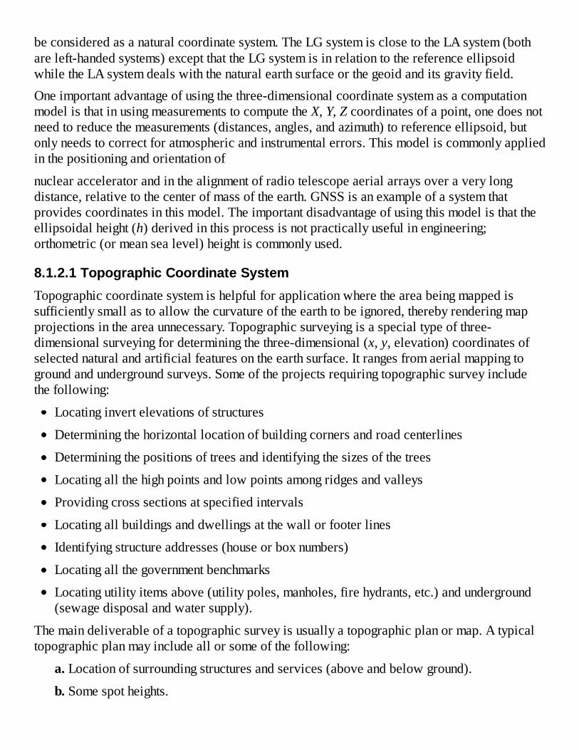
beconsideredasanaturalcoordinatesystem.TheLGsystemisclosetotheLAsystem(bothareleft-handedsystems)exceptthattheLGsystemisinrelationtothereferenceellipsoidwhiletheLAsystemdealswiththenaturalearthsurfaceorthegeoidanditsgravityfield.Oneimportantadvantageofusingthethree-dimensionalcoordinatesystemasacomputationmodelisthatinusingmeasurementstocomputetheX,Y,Zcoordinatesofapoint,onedoesnotneedtoreducethemeasurements(distances,angles,andazimuth)toreferenceellipsoid,butonlyneedstocorrectforatmosphericandinstrumentalerrors.Thismodeliscommonlyappliedinthepositioningandorientationof
nuclearacceleratorandinthealignmentofradiotelescopeaerialarraysoveraverylongdistance,relativetothecenterofmassoftheearth.GNSSisanexampleofasystemthatprovidescoordinatesinthismodel.Theimportantdisadvantageofusingthismodelisthattheellipsoidalheight(h)derivedinthisprocessisnotpracticallyusefulinengineering;orthometric(ormeansealevel)heightiscommonlyused.
8.1.2.1TopographicCoordinateSystemTopographiccoordinatesystemishelpfulforapplicationwheretheareabeingmappedissufficientlysmallastoallowthecurvatureoftheearthtobeignored,therebyrenderingmapprojectionsintheareaunnecessary.Topographicsurveyingisaspecialtypeofthree-dimensionalsurveyingfordeterminingthethree-dimensional(x,y,elevation)coordinatesofselectednaturalandartificialfeaturesontheearthsurface.Itrangesfromaerialmappingtogroundandundergroundsurveys.Someoftheprojectsrequiringtopographicsurveyincludethefollowing:
Locatinginvertelevationsofstructures
Determiningthehorizontallocationofbuildingcornersandroadcenterlines
Determiningthepositionsoftreesandidentifyingthesizesofthetrees
Locatingallthehighpointsandlowpointsamongridgesandvalleys
Providingcrosssectionsatspecifiedintervals
Locatingallbuildingsanddwellingsatthewallorfooterlines
Identifyingstructureaddresses(houseorboxnumbers)
Locatingallthegovernmentbenchmarks
Locatingutilityitemsabove(utilitypoles,manholes,firehydrants,etc.)andunderground(sewagedisposalandwatersupply).
Themaindeliverableofatopographicsurveyisusuallyatopographicplanormap.Atypicaltopographicplanmayincludeallorsomeofthefollowing:
a.Locationofsurroundingstructuresandservices(aboveandbelowground).
b.Somespotheights.

c.Contourswithappropriateintervals(constantelevationdifferencebetweentwoadjacentcontourlines)withsteepslopeshavingmorecontourintervaltomakemapmorelegible;flatareaswilldecreasethecontourintervaltoalimitthatwillnotinterferewithplanimetricdetailslocatedonthetopographicmap.Inessence,contourintervalsmustbeselectedtoallowgoodinterpretationofthecharacteroftheterrain.
d.Planscale,whichiswellchosensothattheplancanserveasbasemapoverwhichsubsequentprojectdrawingscanbedrawnatthesamescale.Thedetailedtopographicplanwillthenserveasabaseuponwhichtoprepareutilitymaps.
Errorsinmapplottingandscalingshouldbecheckedtoensurethatappropriatemapaccuracystandardsarecompliedwith.
8.2COORDINATESYSTEMFORTHREE-DIMENSIONALCOORDINATINGSYSTEMSTheITRSiscommonlyusedinspaceorextraterrestrialtechniquesinthree-dimensionalpositioningandorientationofnuclearacceleratorandinthealignmentofradiotelescopeaerialarraysoververylongdistances,relativetothecenterofmassoftheearth.TheLGsystemiscommonlyusedinengineeringprojects,suchaslocaldeformationmonitoringandalignmentofmachinecomponentsinindustrialmetrology,wheretheearth'scurvaturecanbeignored.TheLGcoordinatesystemisillustratedinFigure8.1,whereφ,λarethegeodeticcoordinatesoftheoriginPandthecoordinateaxesarerepresentedbyxLG,yLG,andzLG.
Basedontheright-handconventionofthecoordinatesysteminNorthAmerica,itisnecessarytohavearight-handedlocalgeodetic(rLG)coordinatesystem.ThedifferencebetweentheLGsystemandtherLGwilljustbethat(x,y,z)inLGisswitchedto(y,x,z)inrLGsystem;ascanbeseen,thexandyvaluesareswitchedaroundsoastosatisfytheirright-handedrepresentationinadiagram.IfthetermsNorthing,Easting,andUPareusedtorepresentthecoordinatevalues,themeaningsofthetermsarenotchanged.Forexample,ifthecoordinatesofpointPinLGaregivenas(1000,2000,10),thecoordinatesofthepointinrLGwillbe(2000,1000,10).SincerLGsystemisonlydifferentfromLGsystemintheorderinwhichcoordinatevaluesarepresented,theLGandrLGsystemswillbeusedtomeanthesamething.NotethatthegeodeticNorthisnotanobservablethatcanbemeasuredsinceitisnotaphysicalquantitylikeastronomicNorth.
8.3THREE-DIMENSIONALCOORDINATIONWITHGLOBALNAVIGATIONSATELLITESYSTEMGNSS,forexample,theGlobalPositioningSystem(GPS),usesmessagesreceivedfromspace-basedsatellitesandthepositionsofthesatellitestocomputepositionsofearth-basedantennasbyusingsomenavigationequations.Thepositionsoftheantennasaregivenaslatitude,longitude,andellipsoidalheightcoordinatesorasthree-dimensionalCartesian(X,Y,

Z)coordinates,whicharebasedonWorldgeodeticsystemof1984(WGS84)geodeticdatum(coordinatereferenceframe).ThecurrentversionofWGS84asofYear2002isWGS84(G1150),whichiscloselyrelatedtotheITRF2000(epoch2001.0)(DepartmentofRuralDevelopmentandLandReform,2013).Inthiscase,thethree-dimensional(X,Y,Z)coordinatesproducedbyGPSiscloselyrelatedtotheITRSparametersgiveninTable8.1,knowingthatITRSisthemostpreciseearth-centered,earth-fixeddatumcurrentlyavailable.FurtherinformationanddetailsontheuseofGNSSasacoordinatingsystemcanbefoundinanymodernGeodesybook.
Accuratethree-dimensionaldataarealsopossiblefromextraterrestrialpositioningtechniques,suchasverylongbaselineinterferometry(VLBI)andsatellitelaserranging(SLR).Theyproduceathree-dimensionalglobalcoordinatesystembasedonITRF,whiletheterrestrialpositioningisdoneintheLAsystem.
8.4THREE-DIMENSIONALCOORDINATIONWITHELECTRONICTHEODOLITES8.4.1CoordinatingTechniquesTheelectroniccoordinatingsystemusuallyconsistsoftwoormorehigh-magnification,short-focusmodelelectronictheodoliteslinkedtoamicrocomputerforreal-timecalculationsofthree-dimensionalcoordinatesoftargetpoints.Thesystemiscommonlyusedforthehighestprecisionpositioningoftargetsanddeformationmonitoringsurveysoversmallareas.SokkiaNET2100andLeica(Wild)tunnelmeasurementsystem(TMS)areexamplesofsuchsystems.
Theprincipleofcoordinatedeterminationusedintheelectroniccoordinatingsystemisbasedonthesurveyingtechniqueknownasthree-dimensionalintersection.Thisprincipleinvolvesthesimultaneousmeasurement,usingtwotheodolites(T1andT2),ofhorizontalanglesθ1andθ2fromeitherendofapreciselymeasuredbaseline(b)andthezenithanglesz1andz2asshowninFigure8.2.Beforethemeasurementsaremade,theopticallinesofsightthroughthetelescopesofthetwotheodolitesarefirstmadetocoincidewitheachother,andthetelescopesarethenturnedtomeasurethegiventargets.Standardsurveyingcomputationaltechniquescanthenbeappliedtoderivethethree-dimensionalcoordinatesofanyunknowntargetpointP.
Analternativeapproachtocoordinatedeterminationwiththeelectroniccoordinatingsystemmaybeadoptedifthesimultaneoususeoftwotheodolitesprovidingreal-timecoordinatesisnotrequired.Insuchacase,dataacquisitionmaybeaccomplishedbyusingasingletheodoliteandtherewillbenoneedtoalignthetheodoliteinrelationtoanotherinstrumentbeforeobtainingmeasurements.Moreimportantly,theacquireddatacanberigorouslyprocessedusingleast-squarestechniquestofullyexploitanyredundantdata.Theobservationequationsmaybeformulatedfortheproblemandthensolvedbythemethodofleastsquaresadjustmentinordertodeterminethethree-dimensionalcoordinatesoftheunknownpoints.
FromFigure8.2,ifthebaselinelengthb,thezenithangles(z1andz2),andthehorizontalangles

(θ1andθ2)areknown,thecoordinatesofpointPcanbedeterminedbyusingtrigonometricfunctions.Thebaselinelengthb,however,mustbeaccuratelyknowninordertoaccuratelydeterminethecoordinatesofpointP.Twowaysofdeterminingthebaselinelengtharebydirectlymeasuringthebaselineorbyintroducingintothemeasuringschemeadifferentscalingmechanism.Sinceshortbaselinesarecommonlyinvolvedintheapplicationsofthecoordinatingsystem,directmeasurementofthebaselinesmaybeimprecise.Themostcommontechniqueistointroduceintothemeasuringschemeascalingmechanism,whichinvolvessettingupshortinvarscalingbarsofknownlengthsatsuitablelocationsaspartofthemicronetworktobemeasured.Theinvarscalingbarisusedbecauseofitslowcoefficientoflinearexpansion,whichensuresthatnosystematicchangeinitslengthoccurswhileitisbeingused;itsusegenerallyreducesthemeasuringtime,andifwellcalibrated,itwillallowthebaselinetobedeterminedtoahighlevelofaccuracywithrelativeease.Thecalibrationoftheinvarbarisessentialifsystematicerrorsaretobeavoided.
Thetypeofnetworkusuallyestablishedforelectronictheodolitecoordinationisknownasmetrologicalmicronetwork.Ametrologicalmicronetworkistypicallyatriangulationnetworkwiththeobservablesbeingthehorizontaldirectionsandzenithangles;distancesarenotmeasuredbuttheinvarscalebarswithknownlengths(markedwithtargetsonthebar)aretoprovidescalesforthenetworks.Insomecases,walltargetsareusedascontrolpointswithdirectionsandzenithanglesmeasured(inbothfaces)tothewalltargets,thetargetsontheinvarscalebarsandthetargetedpointsonthealreadypositionedcomponentsintheworkarea.Asinglesimultaneousleastsquaresadjustmentisthenperformedtoallthemeasurementstoobtaintheadjustedcoordinatesofallthetargetsinthedesigncoordinatesystem.
8.4.2FieldDataReductionsThetypicalfielddataacquiredintheelectroniccoordinatingsystemareazimuth,horizontaldirections,orhorizontalangles,zenithangles,andslopedistances.Beforethesefielddataareusedincalculatingthethree-dimensional(x,y,z)coordinatesofpoints,theymustfirstbecorrectedforinstrumentalerrors,meteorologicaleffects,andgravityeffects(suchasdeflectionofthevertical).Inindustrialmetrology,spatialdistancesaremuchshort.Asaconsequenceofthis,theeffectsofrefractionondistancemeasurementsarereduced,whiletheprecisionofmeasuringsuchdistancesarereduced.Inordertoimprovetheaccuracyofthree-dimensionalpositioning,horizontalanglesandzenithangles,whichcanbemeasuredmoreaccurately,aremeasuredinsteadofdistances.

8.1
8.2
Figure8.2Three-dimensionalintersectionproblem.
Figure8.1Representationoflocalgeodetic(LG)coordinatesystem.
Sincetheverticalaxesofsurveyor'sinstrumentsarealignedinthedirectionoflocalplumblines(directionsofgravity),surveyobservationsmustbecorrectedfordeflectionoftheverticaltoreducethemtoareferenceellipsoid,alongthenormaltotheellipsoid.Thedeflectionofthevertical,whichmayvaryfromseveralsecondsinflatareastoupto60″inthemountains,causesangulartraverseloopmisclosuresasinthecaseofinstrumentlevelingerrors.Thecomponents( , )ofthedeflectionoftheverticalatagivenpointcanbegivenasfollows:

8.4
8.3
8.5
8.6
8.7
or
where
isthedeflectionoftheverticalintheNorth–Southdirection;
isthedeflectionoftheverticalintheEast–Westdirection;
istheastronomiclatitude; isthegeodeticlatitude;
isthegeodeticlongitude; istheastronomiclongitude;
Aistheastronomicazimuthofalinefromthegivenpointtoanotherpoint;and
isthegeodeticazimuthofthelinefromthegivenpointtoanotherpoint.
Theslopedistancemeasurementsarenotaffectedbygravityeffectsandarenottobecorrectedforgravityeffects.Themeasuredzenithangle( )frompoint“i”to“j”iscorrectedforgravity(ordeflectionofthevertical)effectsasfollows:
where
or isthedeflectionoftheverticalinthedirectionofthegeodeticazimuth ;
aretheNorth–SouthandEast–Westcomponentsofthedeflectionoftheverticalattheinstrumentstation“i,”respectively;and isthegeodeticazimuthofline“i”to“j.”
Theastronomicazimuth(ordirection)measurement( )iscorrectedforgravityeffectsasfollows:
where
or isthecorrectiontobeappliedtotheobservedastronomicalazimuthAijtorelateittothesameellipsoidalnormalasthegeodeticazimuth (theoffsetduetothedeflectionofthevertical);
istheLaplacecorrectionortheazimuthcorrectiontolineupthexLGandthexLAaxes(withxasthedirectionoftheNorthasshowninFigure8.1);
isthemeasuredastronomicazimuth(orthetotalstationdirectionmeasurement)fromitoj;

8.8
aretheNorth–SouthandEast–Westcomponentsofthedeflectionoftheverticalattheinstrumentstationi,respectively;and
φiisthegeodeticlatitudeofpointi.
Ifahorizontalangleθ′ismeasuredatstation2,backsightingtostation1andforesightingtostation3,thecorrectedangleθ(reducedtothereferenceellipsoid)canbeformulatedfromEquation(8.6)asfollows:
where
isthemeasuredhorizontalangle;
and arethegeodeticazimuthsinthedirections2-3and2-1,respectively;Z23andZ21arethemeasuredzenithangles;
and arethecomponentsofthedeflectionoftheverticalmeasuredatsetuppoint2.
Inhorizontalanglemeasurements,theinfluenceofdeflectionoftheverticalisidenticaltotheinfluenceofmislevelingthetheodolite.Correctionstohorizontalanglemeasurementsforalmostallpracticalsituationsareinsignificantlysmall,exceptifthelinesofsightshavelargezenithangles.Iftheterrainisrelativelyflat,wherezenithanglesZ23andZ21arelikelytobe90°(inhorizontalsightings),Equation(8.8)willbereducedto ,meaningthattheeffectofthedeflectionoftheverticalwillbezerointherelativelyflatterrains.
8.4.3Three-DimensionalCoordinateDeterminationAscanbeseeninTable8.1,theoriginoftheLAsystemistheinstrumentsetupstation,meaningthateveryinstrumentsetupstationinamicronetworkmusthaveitsownseparateLAsystem.Ifthisisthecase,andunderstandingthatthedirectionsofgravityfromonesetupstationtoanotherareusuallynotparallel(duetoearthcurvature),theLAcoordinatesystemaxesestablishedforonesetupstationwillnotbeparalleltothecorrespondingLAcoordinatesystemaxesatanothersetuppoint.Also,theazimuthofalineinonesystemwillbedifferentinanothersystemforthesamelineduetotheconvergenceofmeridian.Sincedistancemeasurementsareusuallyavoided(becauseofprecisionproblem)inindustrialmetrology,targetsinageodeticmicronetworkmustbesightedandintersectedfromatleasttwostationsintriangulationtechniquesusuallyadopted.Inthiscase,everymicronetworkstationthatisintroducedduetosettingupoftheodolitewillhaveitsownLAcoordinatesystemwithitsoriginatthestation,whichwillbedifferentfromeachother,andtheorientationofeachcoordinatesystemwillbedefinedbytheastronomiclatitude(φ)andlongitude(λ)andatangenttothelocalgravityvectorateachstation.
ThetraditionalapproachinmicronetworkestablishmentistosimplyfixoneoftheseveralLAcoordinatesystemsasareferenceandrelatetheresttoitbysolvingfortranslationcomponents(stationcoordinates)withrespecttothisfixedcoordinatesystem,foreachoftheothersystems.

8.10
8.11
8.9
Solvingforthetranslationcomponents,however,willnotmakeallthecorrespondingaxesofallthedifferentLAcoordinatesystemsparallel,althoughsomeoftheeffectswillbeabsorbedintheestimatedtranslationcomponents.Thenonparallelismpropertyisduetobothgravimetricandgeometriccauses.ThegravimetriccauseistheeffectofdeflectionoftheverticalcomponentsintheNorth–Southdirection(ξ)andintheEast–Westdirection(η)andthedifferencebetweenthedirectionofastronomicandgeodeticNorth,whichcanbegivenfromEquation(8.3)as
whereAistheastronomicazimuthofaline,αisthegeodeticazimuthofthesameline,andΔAisthechangethatonlyexistsbecauseoftheinitialconditionenforcedwhendeterminingthebiaxialellipsoid'spositionwithrespecttotheITRSsystem.If arethesameinthearea,theywillaffectthetransformationfromLAtoLGidenticallyforallstationsinthenetwork,exceptthatthedifferentdirectionsofastronomicandgeodeticNorthwillnotbeaffectedidentically.Thetransformationofcoordinates(xj,yj,zj)ofpoint“j”inLAsystemtoLGcoordinatesystemwiththeoriginattheinstrument'ssetupstation“i”canbegivenmathematicallyas(VanicekandKrakiwsky,1986)
whereξiandηiarethedeflectionoftheverticalcomponents(radians)intheNorth–SouthandEast–Westdirectionsatpoint“i,”respectively.Ifthecoordinatesofthesetupstationat“i”are(0,0,0),thecoordinatesofpoint“j”intheLAisystemcanbegivenasfollows:
wheresij,Aij,and representthemeasuredslopedistance,astronomicazimuth,andzenithangle,respectively,fromsetupstation“i”totargetpoint“j”;and(xj,yj,zj)aretheLAicoordinatesoftargetpoint“j.”AscanbeseeninEquation(8.11),theslopedistance(sij)andzenithangle( )measurementsprovidethenecessarylinkbetweenthe(x,y)horizontalcoordinatesandthezcoordinate.Theverticalinformationobtainedfromthespatialdistance,however,isonlyusefulwhenthelinesofsightaresteeplyinclined.Alternatively,thecoordinatesintheLGicoordinatesystem,inEquation(8.10),canbeobtaineddirectlybysubstitutingintoEquation(8.11),thecorrectedzenithangleZijfromEquation(8.4)andthegeodeticazimuth fromEquation(8.6).
AftertheeffectsofgravityhavebeentakencareofasshowninEquation(8.10),theLAcoordinatesystemaxesateachtheodolitestationwillbecometransformedtotheir

8.12
8.13
correspondingLGcoordinatesystemaxesatthattheodolitestation;butthecorrespondingaxesoftheLGcoordinatesystemsforallthedifferenttheodolitestationsarenotlikelytobeparalleltoeachother.
InordertoalignalltheaxesofallthedifferentLGcoordinatesystemsinthemicronetwork,thegeometriceffectsmustbetakencareof.Inthiscase,theeffectsofcurvatureareeffectivelytakencareofbyperformingcorrespondingrotationsofeachcoordinatesystemtolinethemupwiththefixedLGkreferencecoordinatesystem(withthesetupstationatpoint“k”).Forexample,thetransformationof(xj,yj,zj)coordinatesofpoint“j”fromLGisystem(forsetupstation“i”)intothefixedLGksystemofanothersetupstation“k”canbegivenmathematicallyasfollows(Wilkins,1989):
whereΔλandΔφaresmallchanges(radians)inlongitudeandlatitudeoftheoriginsoftheLGiandLGksystems;(x0,y0,z0)arethecoordinatesoftheoriginofLGisystemintheLGkcoordinatesystem;andωisasmallangle(radians)givenas
withdasthedistancefromtheoriginofthefixedLGksystemtothezaxisoftheLGisysteminthehorizontalplaneofthefixedLGksystem;Ristheradiusoftheearth;histheellipsoidal(orspherical)heightofthefixedLGksystemorigin.
Ingeodeticmicronetworks,thetransformationEquation(8.12)isusuallyappliedimplicitlyintheadjustmentequations.Inthiscase,theearthisassumedflatandthedatumisdefinedbyfixinganLGksystemandthetranslationcoordinates(x0,y0,z0)ofotheroriginswithrespecttoit,andtakingthesmallchanges(Δλ,Δφ,ω)asnegligible.Theassumptionofaflatearth,whileacceptableforhorizontalpositionalapplications,maynotbeacceptableforfindingelevations,asthegeoidorthereferenceellipsoidmaydeviatefromthetangentplanebyaboutseveralmillimetersat1kmfromthepointofcontact.
Sinceengineeringprojectsareusuallylimitedtosmallareas,thereferencesurfacemaybeconsideredasaplanetoallowtheuseofsimpleplanetrigonometryforcoordinatecomputation.Thereisusuallyalimitonthelengthofsightthatwillallowplanetrigonometrytobeused,beyondwhichthecurvatureoftheearthwouldhavetobeconsidered,especiallywithregardtotheheightsystem.ThisisillustratedbyFigure8.3.Forsimplicity,considertheearthasasphereofradiusRcenteredatpointO;points“k”and“i”arethesetupstationswiththezcomponentoftheLGcoordinatesystemspassingthroughthesetupstationsasshowninFigure8.3;curvek-iisalevelsurfacewithstationskandibeingatthesameelevation.Areasaroundstation“k”(thefixedorigin)canbeconsideredasaplane,butasonemovestowardpoint“i,”

8.16
8.14
8.15
theplanek-i′(oflengthd)deviatesbylengthi-i′(orΔh)fromthelevelsurfacek-i.Thelengthi-i′(orΔh)canbederivedusingPythagorastheoremontheright-angletrianglek-O-i′asfollows:
Figure8.3Relationshipbetweenaplaneandalevelsurface.
FromFigure8.3,thefollowingrelationshipcanbeestablished:
whichreducestothefollowing:
Wecanset inEquation(8.15)sinceaddingitto willnotsignificantlychanged2(knowingthattheradiusoftheearth,R,isverylarge).Withthis,Equation(8.15)canbereducedtothefollowing:
where istheerrorinheightifthecurvatureoftheearthisneglectedoveradistancedfromatangentplane.Inmostmetrologyapplications,however,ΔhinEquation(8.16)canbeneglectedsincetheprojectareainvolvedisusuallysmallandrelativelysmooth.Forinstance,themicronetworksinindustrialmetrologyapplicationswouldrarelyexceedadistanceof100msothatΔhislikelytobelessthan0.8mm.
FromEquation(8.10),itcanbeseenthatifthereisnodeflectionofthevertical(i.e.,thedirectionofnormaltothereferenceellipsoidandthedirectionofgravitylineup),thecoordinatesofthesamepointinbothLAandLGsystemswillbethesame,sincethetwocoordinatesystemswillbethesame.Ifthereisnocurvatureoftheearth,Equation(8.12)willbesimplifiedtoasimpleproblemoftranslatingcoordinatesfromonesystemtoanotherbyfixedamounts(i.e.,x0,y0,z0coordinates),withoutanyneedfortherotationoftheaxes.Inthiscase,allthecorrespondingcoordinateaxesofallthesetupstationsinthenetworkwillbeparalleltoeachother.

Inpractice,theonlytimethatthecorrespondingaxesofalltheLGsystemsconstitutingamicronetworkcanbecomeparalleliswhentheprojectionsofallthesetupstationsareonthesameplanesurface,assumingthereferenceellipsoidisaplane.Thesecanbeassumedtobethecaseinpracticesincethesizeofamicronetworkinindustrialmetrologyapplicationsrarelyexceedsadistanceof100minonedirection.Withtheareaofapplicationofthissize,aplanesurfacecanbeassumedwithrespecttothereferenceellipsoid.
Generally,themajorityofengineeringsurveysarecarriedoutinareasoflimitedextent,inwhichcasethereferencesurfacemaybetakenasatangentplanetothegeoidandtheprinciplesofplanesurveyingapplied.Theplanesurveyingprinciplesignorethecurvatureoftheearthandtakeallpointsonthephysicalsurfaceasorthogonallyprojectedontoaflatplane.Forareaslessthan10km2,theassumptionofaflatearthisacceptablewhenoneconsidersthatinatriangleofapproximately200km2,thedifferencebetweenthesumofthesphericalanglesandtheplaneangleswouldbe1arcsec,orwhenoneconsidersthatthedifferenceinlengthofanarcofapproximately20kmontheearthsurfaceanditsequivalentchordlengthisjust8mm.
8.4.4FactorsInfluencingtheAccuracyofElectronicCoordinatingSystemsThemetrologicalmicronetworksestablishedforelectroniccoordinatingsystemsareessentiallythree-dimensionalnetworksrequiringveryhighprecisionandsomecriticalconsiderationswhendesigningandmeasuringthemicronetworks.ApartfromthepossibleeffectsofthesourcesofsystematicerrorsdiscussedinSections8.4.2and8.4.3,theoverallaccuracyofthecoordinatesdeterminedbythecoordinatingsystemwillalsodependonotherfactors.Someofthesefactorsaretheequipmentandtargetdesignusedformeasurements,thegeometryofthemeasurementscheme,andtheinfluenceoftheenvironment(duetovibration,wind,temperaturefluctuations,refractionandvaryinglightingconditions,etc.),discussedasfollows(Wilkins,1989).
8.4.4.1EffectofEquipmentandTargetDesignTheuseofprecisionelectronictheodolitesthatareabletoresolvetoafractionofasecondisessentialifhigh-accuracymeasurementsaretobeobtained.Theeffectsofanyinstrumentalerrorsmustbeeliminatedandthepointingofthetelescopetowell-designedtargetsonthestructuremustbeprecise.Thedesignofthetargetsshouldenableprecisecenteringofthetelescopecrosshairsoverawideangularrange(60–120°).Otherconsiderationisabouthowthescaleisdeterminedforthenetworkadjustment.
Inmetrologynetworksoffewtensofmetersdistances,shortdistancescannotbemeasuredaccuratelyenough(0.05mm)tosatisfythescalerequirements.Therealsolutiontothisistousecalibratedinvarscalebars,whicharewellpositionedintheworkareatoprovidetheneededscaleforthenetwork.Thetwotargetsthatdefinethescalebarlengthcanbetiedtothenetworkthroughtriangulation(observedinthesamewayasthewalltargets),withtheknowndistancebetweenthemaddedasspatialdistanceobservableinanadjustmentprocedure.Thethree-dimensionalcoordinates(x,y,z)ofthescalebars'targetlocationsareestimatedinthe

adjustmentprocessalso;andthroughcalibrationprocedureusinginterferometriccomparator,theabsolutelengthsofthebarscanbedeterminedtoanaccuracyof0.01mm.
Theothercriticalconsiderationwithregardtoequipmentisthecenteringerrorofthecoordinatingsystem.Inordertoreducethecontributionofthecenteringerroringeodeticmeasurementsto±0.1mm,forcedcenteringprocedureiscommonlyused.Forcedcenteringprocedureforachievingthislevelofaccuracy,however,willrequirethatpermanentandstablepillarsbeconstructedatnetworkstations.Becauseofrestrictedspaceandthespecialrequirementthatinstrumentlocationsbeclosetothestructuresbeingsetoutormonitored,itisimpossibletoestablishpermanentpillarsontheprojectsites.Generally,ifonedoesnotneedtocenteronanyspecificsurveymarkerorifonedoesnotneedtosetonthemarkerinthenextsessionofmeasurement,thelocationoftheinstrumentduringmeasurementwillnotmatter,andtheinstrumentcanbelocatedinanyconvenientlocation.Inthiscase,thelocationoftheinstrumentwheneveritissetupcanbedeterminedthroughresectionbyobservingtodistantcontrolpoints(i.e.,byfree-stationingmethod).Thewalltargets(establishedfromprevioussurveys)areusedascontrolpoints,andobservationsbetweeninstrumentlocationsarenotnecessaryifthereareenoughwalltargetstocreateenoughredundancy.Thismakesreferencewalltargetcoordinationaprimaryconcerninindustrialmetrology,withtheinstrumentlocationsservingonlyasalinkbetweenthedifferentwalltargets.Theinstrumentcanbelocatedanywhereintheprojectarea;thecoordinatesoftheinstrumentlocationsaredeterminedbyresection,thentheresectedcoordinatesoftheinstrumentlocationsareusedtoobtaintheintersectedcoordinatesoftargets(i.e.,theobjectpoints)locatedonthestructurestobealignedormonitored.Theintersectedcoordinatesoftheobjectpointscanbeusedtodeterminecorrections,offsets,orcalibrationvaluesforthestructuresbeingalignedormonitored.Somepolynomialfunctionscanalsobefittedtothecoordinatesoftheobjectpointsinordertodeterminediscrepanciesofthesurfaceofthestructures.Sincethecoordinatesoftheobjectpointsarecomputedusingthecoordinatesoftheinstrumentlocations,anyerrorinthesecomputedinstrumentcoordinates(x,y,z)willbereproducedintheobjectpointcoordinates(X,Y,Z).
8.4.4.2EffectofGeometryofMeasurementSchemeThegeometricalrelationshipbetweenthetheodolitesandthepointsontheobjecttobemeasuredshouldbeinsuchawaythatthelengthofthebaselineisrestrictedtobetween5and10m.Theintersectionanglerangesuggestedforhigh-accuracyprojectsisbetween78°and142°.Thepositionandorientationofthescalingbararealsoveryimportant.Thebarshouldbelocatedsothattheangleofintersectionatthetargetpointsonthebariscloseto90°;thebarshouldalsobeorientedinsuchawayastoenableaclearviewofthetargetsonthebar.
8.4.4.3EffectoftheEnvironmentThebulkofthestationsinmetrologynetworksarewalltargetsinadditiontoothertargetsthatmaybeattachedtothestructuresbeingsetuporalignedusingthecoordinatingsystem.Horizontalandverticalrefractionsmustbeconsidered.Theonlyrealsolutiontotherefractionistotrytokeeptheeffectstoaminimumthroughthedesignofthenetwork.Mostrefraction

effectscanbeeliminatedbykeepingthesightdistancesveryshort(<20m)andbykeepingthelinesofsightawayfromalargebulkyapparatus(e.g.,largemachinery,hangingfixtures,juttingwalls),whichmaybeasourceofheatorprocessesthatreleaselargeirregularquantitiesofheatenergyintoair.Othersolutionistokeepthetemperaturedistributionconstantwithintheworkarea(i.e.,keepingdoorsandwindowsclosed,switchingoffmachinery).
8.4.5AnalysisofThree-DimensionalTraverseSurveysThree-dimensionaltraversesurveysaredifferentfromtheusualtwo-dimensionaltypeinwhich(x,y)coordinatesaredetermined.Apartfromdeterminingthe(x,y)coordinatesofpointsinthree-dimensionaltraversesurveys,theelevationsofthosepointsarealsodetermined.ThetotalstationequipmentortheEDMandtheodolitecombinationiscommonlyusedinthemodernthree-dimensionaltraverse,whichisacombinationoftrigonometriclevelingandtwo-dimensionaltraversemethods.
Inadditiontopredictingthequalityofpositioninginsimulationorpreanalysis,itisnecessarytosuggestqualityassurance(QA)/qualitycontrol(QC)measuresbeforeembarkingonthree-dimensionaltraversesurveys.Thisentailsdeterminingdiscrepancies(betweensetsofangles,directions,zenithangles,anddistances)usedinfieldassessmentandspecifyingwhatfield“reductions”shouldbedonebeforeendingastationoccupation(e.g.,mark-to-markforcomparisonofsets).Usually,thestepsinvolvedinthree-dimensionaltraversesurveysare:
1.Reconnaissance:Identifyingsubjectpoints;confirminglocationsofpossiblecontrolpoints(frommapandsketches,etc.);makingfinalchoiceofintermediateortemporarypoints;andprovidingstationsketches.
2.Designandsimulation:Designingmeasurementprocesses(equipment,techniques,specificationsforQA/QC);predictingtheprecisionandaccuracyoftheexpectedresultsusingappropriatenetworkadjustmentsoftware,formingthebasisforQA/QC.
3.Equipmenttesting:Testingtheopticalplummetsandadditiveconstantsoftotalstationequipment(avalueforadditiveconstantshouldbedeterminedforeachcombinationoftotalstationandreflector);testingcollimationerrorsoflevels;rodconstants;differentoffsets(fortworodsused).
4.Fieldobservation:Datagathering;QA/QCevidencedinfieldnotes.Thefieldnotesaretheonlyrecordofwhatactivitieshavetakenplaceinthefieldandareveryimportanttothosewhowouldbeinterestedinthosefieldactivities.Becauseofthis,thefieldnotesmustbeorganizedandformatted(demonstratingduecareinQA/QCduringtheobservations)sothatthosewhomaynothavebeeninthefieldcanunderstandthefieldnotes.
5.Dataprocessing:Postanalysisandverification;“reduction”orpreprocessingofdata;estimationofcoordinatesandelevationsusingappropriatesoftware;statisticalassessmentofresults;comparisonofresultswithothermethods.
6.Reportingandpresentingthedeliverables.
8.4.5.1ObservablesinThree-DimensionalTraverseSurveys

Theobservablescommonlymeasuredateachsetupoftotalstationequipmentforthree-dimensionaltraversesurveysareasfollows:
Heightsofinstrumentsandreflectors/targetsabovetraversestations
Horizontalanglesbetweenbacksightandforesightstations(ifonlytworaysatastationarebeingmeasured)orhorizontaldirections(ifthreeormoreraysatastationarebeingmeasured)
Zenithanglestotargets
Slopedistancestotargetpoints,includingthefollowing:
Measurementofmeteorologicaldatatoallowcorrectingtheslopedistancesforsystematicerrorscausedbytheatmosphericconditions
Reductionofcorrectedslopedistancestohorizontalusingaveragezenithanglesorusingelevationdifferencesifavailable.
Inathree-dimensionaltraverse,eachsuccessivestationisoccupiedsothatobservationsfrom“B”to“A”aredoneaswellasthosefrom“A”to“B”(Figure8.4).Observationsofdirectionsandzenithanglesarealwaysdoneinatleasttwosets,withfieldchecksthroughlimitsonthediscrepanciesbetweenindividualsetsorbetweenasetandthemean.Theaveragescalculatedfromtheacceptablesetsarethenusedinsubsequentcalculations.Inordertorandomizecertainerrors,afreshsetupshouldbedonebeforeeachset.Further,evenwithkeepingthesametripodandtribrachsetupsat“A”andat“B,”theheightsofinstrumentandofreflector/targetarenotnecessarilythesame,especiallywithWildorLeicastylethreefoot-screwtribrachs;andthemeteorologicalconditionsmaybedifferentatthedifferentoccupationsof“A”and“B.”
Theslopedistance,zenithangle,andelevationdifferencesmeasuredinanoccupationfromstationAtoB(forward)willbesimilartocorrespondingvaluesfromBtoA(backward)ifthesevaluesarereducedtomarktomark.Otherwise,becauseofdifferentheightsofinstrumentandtargetsanddifferentmeteorologicalconditions,theircorrespondingvalueswillbedifferentandwouldhavetobetreatedastwoseparateobservables.Theforwardandbackwardmark-to-markvaluescanbeusedtochecktheaccuracyofmeasurementsandtheaverageofthevalueswillhaveitserrorreducedbyasquarerootoftwo.Ifthedistanceisappreciablylongerthan200m,theeffectofverticalrefractiononzenithanglewillbecomesignificantandwillhavetobeconsidered.
Forexample,fromFigure8.4,whileoccupyingstationAsightingtoB,zAistheaveragezenithanglefromzAi,eachfromonesetofwhichtherearensAsets;thestandarddeviationofzAcanbegivenas .Thelimitonthediscrepancybetweenanytwosetswillbe
.Atthesametime,SAiistheslopedistance,whichistheaveragefromseveralfaceleftandfacerightobservationsassociatedwitheachset.TheaverageoftheSAiisSAwithastandarddeviationof .Itshouldbenoted,however,thatthisvaluewillnotbemadesmallerintheaveraging,exceptiftheatmosphericconditionsareconsiderablydifferentatthetimeofdataacquisitionforeachset.

8.17
8.18
Figure8.4Exampleofthree-dimensionaltraversesurvey.
Foreachset,theheightofinstrumentisHIAiandtheheightofreflector/targetisHRBi.Inordertocomparesetsduringanoccupation,itisnecessarytoaccountforthevariationintheHIsandHRsby“reducing”thezAiandSAito“mark-to-mark”values,thatis,to and inFigure8.4withtheassumptionthattheslopedistanceandheightdifference,betweenthegroundmarksAandB,remainthesameforeachset.Themark-to-markdistanceandthemark-to-markzenithanglecanbederivedfromFigure8.4,asfollows:
and
IntheoccupationofBsightingtoA,thecircumstancesaresimilarwith fromnsBsetsandwith andwithHIBiandHRAibasedontheassumptionthattheslopedistanceandheightdifferencebetweenAandBremainsthesameasintheoccupationofstationA.Themark-to-markvaluescanbeusedinappropriatemapprojectionformulasinordertoderivetheEastingandNorthingcoordinatesforthehorizontalcomponentofthetraverse.
8.4.5.2DataProcessingandAnalysisWithregardtonetworkleastsquaresadjustmentofthree-dimensionaltraversesurveys,the

8.19
8.20
overconstrainedadjustmentisusuallymisleading,showingmoreerrorofobservationssincecontrolpointsconsiderederrorlessareactuallynoterrorless,sothatpositionsareoverprecise.Insimulation,whentwocontrolpointsarefixed,moreerrorsshowupinmeasurements;andoutlierdetectionismoredifficult.Thefollowingarethereforepossibleinoverconstrainedadjustment:
Moreerrorsshowupintheresiduals,makingthemeasurementappearslessprecise.
Computedcoordinatesaremoreprecise.
Inadjustment,therewillbemorefalseoutliersandhighvariancefactor.
Inminimalconstrainedadjustment,thefollowingarepossible:
Errorsinmeasurementsareunbiased.
Coordinatesarelessaccurate(moreerrorsincomputationsofcoordinatesduetoerrorsinfixedpoint);becausethereareuncontrollederrorsinmeasurements,therewillbemoreerrorsinpositions,makingthepositionslessprecise.
Inadjustment,measurementoutlierswillbeappropriate.
Intraversesurveys,horizontalangles,zenithangles,directions,andhorizontaldistancesmayneedtobemeasuredinordertodeterminecoordinatesoftraversepoints.Sinceerrorsareinvolvedineachcomponentmeasurement,thereisusuallyaneedtoanalyzetheaccuracyofthetraversesurveys.Inthedesignofexpectedstandarddeviationofmeasuringanglesinatraverse,theexpectedmaximum(atspecificconfidencelevel)misclosureofthetraversemaybegiven.Equations(2.49),(2.50),and(2.52)canalsobeinterpretedtomeanthemaximumallowableerrors.Inthiscase, willbeconsideredthemaximumallowableerroratthegivenconfidencelevel(1−α).Equation(2.50)or(2.52)canalsobeusedtocheckmisclosuresoftraversesinwhichanglesanddistancesaremeasured.Letthecoordinatesofthelastpointkofthetraversebegivenas(xk,yk);andletthecoordinatesofthislastpointkcalculatedwiththeunadjustedmeasuredanglesanddistancesinthetraversebe( )withtheirpropagatedstandarddeviationsas( ),respectively;usingEquation(2.50),thefollowingareobtained:
IfEquations(8.19)and(8.20)arebothsatisfied,thenthelinearmisclosuresofthetraversearenotsignificantat(1−α)100%confidencelevel.Theabovetestscanbeappliedtotraversesthatcloseonthesamepoint(looptraverse)oratbothendstodifferentpointsofahigherordercontrolnetwork,forexample,asinconnectingtraverses.Ifthetraverseclosesatbothendstodifferentpointsofahigherordercontrolnetwork,theexpectedlinearmisclosurewillbelargerthanthatofalooptraversebecauseoftheadditionaleffectofrelativeerrorsofcoordinatesoftheterminalpointsofthehigherordercontrol.

8.21
8.22
8.23
8.24
8.25
8.26
8.4.5.3EffectofCorrelationonTraverseClosureSometimesitmayberequiredtocheckthesignificanceofagroupofparametersthatarelikelytobecorrelated;forexample,itmayberequiredtocheckiftwosetsofcoordinates(xand )arestatisticallythesame(wheretheelementsofthevector arecorrelatedorrelatedtoeachother).Inthiscase,itcouldbethatoneistestingforcompatibilityofestimatedparameters( )withexistingindependentestimates(x).Thiscanbestatedinanotherway:testingwhetherindependentlydeterminedvaluesxliewithinagivenconfidenceregionaboutadjustedvalues,whichcanbeexpressedmathematicallyas
where isafullypopulatedcovariancematrixoftheadjustedcoordinatesofthenetworkpoint(s)considered.Foragivensignificancelevelα,xand maybeassumedcompatible(usingmodifiedversionofEquation(2.52))ify< (forupper-tailareasinthecasewherethevariancefactorisknownanduisthenumberofparametersbeingtested);forthecasewherethevariancefactorisunknown,theestimatedaposteriorivariancefactormaybeused.Inthiscase,xand maybeassumedcompatibleify< (forupper-tailareas,wheredf2isthenumberofdegreesoffreedomfordeterminingtheuunknownparameters).
Forexample,giventhecovariancematrixoftheadjustedcoordinatesofapointas
andlettingthevectorofcoordinatedifferencesbegivenas
Equation(8.21)canberewrittenasfollows:
or
or
UsingEquation(8.24),or(8.25)or(8.26),foragivensignificancelevelα,xand maybe

assumedcompatibleat95%confidencelevelifyislessthan (forupper-tailareasinthecasewherethevariancefactorisknownandu=2,thenumberofcoordinatedifferencestested).Theseequationscanbeappliedtoeachofthenetworkpointstocheckthecompatibilityofthetwoindependentdeterminationsofthecoordinatesofeachpoint.Equation(8.24)or(8.25)or(8.26)canalsobeusedtocheckifthemisclosureofatraverseisacceptableataparticularconfidencelevelbyconsideringΔEandΔNasthemisclosureofthetraverseinNorthingandEastingwith asthecovariancematrixoftheadjustedcoordinatesoftheunclosedtraversepoint.Ifyislessthan ,themisclosureisacceptableatthe95%confidencelevel.
8.5THREE-DIMENSIONALCOORDINATIONWITHLASERSYSTEMSTwotypesoflasersystemscanbeidentifiedasthree-dimensionalcoordinatingsystems:airbornelaserscanningsystemandterrestriallaserscanningsystem.Thecharacteristicsofthesesystemsascoordinatingsystemsarediscussedinthissection.FurtherdetailsonsomeaspectsofterrestriallaserscanningsystemarediscussedinChapter10.
8.5.1CoordinationwithAirborneLaserScanningSystemTheoperationalprincipleofairbornelaserscanningsystemisbasedonthatoflaserprofiler,whichisasystemthatusesphasecomparisonandpulseechomethodsofmeasuringdistancefromtheairborneplatformtotheground.Thelaserprofiler,however,canonlyacquireelevationdataoverasinglelinecrossingtheterrainduringanindividualflight.Airbornelaserscanningsystemisanupgradeoflaserprofilerwithascanningmechanism(rotatingmirrororprism)addedsothatitcanmeasureandmapthetopographicfeaturesofanareaindetailinsteadofsimplydeterminingelevationvaluesalongalineintheterrain.Theairbornelaserscanningsystemsoperateoverrangesofseveralhundredmeterstoseveralkilometersfromhelicoptersorfixed-wingairplanes.Thesystemuseslasermountedbeneathanairplaneorhelicoptertoscanthegroundbyemittingtensofthousandsofpulsespersecondastheairplaneorhelicopterfollowsapredeterminedpath,producingtheLiDARthree-dimensionalpointcloud.Inordertogetmeasurementsforthehorizontalcoordinates(x,y)andelevation(z)oftheobjectsscanned,theaircraftpositionisdeterminedwithGNSSmeasurementsandthedistancemeasurementsfromtheaircrafttotheground.
Theairbornelaserscanningsystems,alsoknownasLiDARsystems,consistofanairborneandgroundsegment.Theairbornesegmentconsistsofairborneplatform,laserunit,andpositionandorientationsystem(POS).Thelaserunitistoproviderange(distance)informationfromthelaserbeamfiringpointtothegroundpoint.ThePOScomponentconsistsofGNSSsystemtoprovidepositionalinformationandaninertialmeasurementunit(IMU)forattitudedeterminationwiththegroundsegmentconsistingofGPSreferencestations,processinghardwareandsoftwareforsynchronizationandregistration,whichisdoneoff-line.Duringalaserscanningprocess,thetimeittakeseachlaserpulsetotraveltothetargetandreturntothe

aircraftisrecordedalongwiththeanglefromnadiratwhicheachpulseisemittedtoproducetheline-of-sightslantrangesreferencedtothelaserunitcoordinatesystem.ThePOSwillthenstore,fortheentiresession,theairborneGPSdata(includingcarrierphaseinformation)recordedatarateof1HzandtheIMUattitudedataoftheaircraftatarateof50Hzfortheentiresession.Eachcalculatedslantdistanceiscorrectedforatmosphericconditions,andforroll,pitch,andyawoftheaircraftusingtheIMUdata.GPSdataisprocessedseparatelyandimportedintotheLiDARsolution,andeachcorrectedslantdistanceistransformedtoagroundsurfaceelevation.
ThelaserunitandthePOSwillsamplethedataindependently;atthesametime,on-groundGPSstationsgatherGPSdataandGPScarrierphasedataatknownearth-fixedpositionsforlateroff-linecomputingofdifferentialGlobalPositioningSystem(DGPS)positionsoftheairborneplatform.UsingDGPSandinertialdata,thepositionofthelaserscannercanbecomputedwithcentimetertodecimeteraccuracy,anditsorientationcanbedeterminedtobetterthanabout40″.ThepositionandorientationdataarestoredasafunctionoftheGPStime.AsthelaserscannerdataarealsostoredwithtimestampsgeneratedfromthereceivedGPSsignal,thescannerandPOSdatasetscanbesynchronized.Aftersynchronization,thelaservectorforeachsampledgroundpointcanbedirectlytransformedintoanearth-fixedcoordinatesystem,producinggeocodedlaserdata.ThemodernLiDARsystemscanalsocaptureintensityimagesoverthemappedarea.Currently,registeredlaserscannerdatawithaccuracybetterthan10cminthree-dimensionalspacearepossibleandtheaccuracyisprimarilydeterminedbytheaccuracyofPOS.
8.5.1.1AccuracyAnalysisofAirborneLaserScanningSystemAirbornelaserscanningsystemsorairborneLiDARsystemsareacceptedfortheacquisitionofdenseandaccuratesurfacemodelsoverextendedareas.Derivedfootprintsfromthissystemarenotbasedonredundantmeasurements,makingtheLiDARdataand,consequently,thefinalproducts,lessreliable.Moreover,thequalityofsurfacesderivedfromLiDARdatadependsontheaccuracyoftheinvolvedsubsystems(laser,GNSS,andIMU)andthecalibrationparametersrelatingthesecomponents.ThecalibrationprocessofLiDARsystems,however,isstillnottransparentandremainsrestrictedtothesystem'smanufacturer,sothatthesystemsareusuallyviewedasblackboxes(BrinkmanandO'Neil,n.d.).Ingeneral,theLiDARsystemmanufacturersusuallyprovidearangeofexpectedaccuracyofthederivedpointcloud.Atypicalhorizontalaccuracyisusually1/2000thoftheflyingheightandtheverticalaccuracyisbetween15and35cmdependingontheflyingheight(BrinkmanandO'Neil,n.d.).Inthiscase,lowerflyingheightswillprovideasmallerlaserspotsizeorfootprint,allowingformoreaccuratedata.OperatingaltitudesofLiDARprojectsaregenerally400–1200morupto3000m.Theotherrulesofthumbrelatingtoaccuracyarethattheslowertheaircraft,thedenserthespotspacing;thedenserthespotspacing,themorereliablethedigitalterrainmodel(DTM);andthelaserspotsatnadiraremoreaccuratethanthespotsattheoutsideedgeoftheswathorfieldofview.
Generally,whendiscussingtheaccuracyofairborneLiDARdata,thefollowingshouldbeconsidered(BrinkmanandO'Neill,n.d.):

1.TotalerrorforaLiDARsystemisthecontributingerrorbudgetsfromeachsubsystemofLiDAR,suchaslaserranger,GPS,IMU,andsoon.FinalaccuracyofLiDARdataare,therefore,significantlyaffectedbyvariationinqualityofthesesubsystems.Thelaserrangererrorsmaybeduetothedistortionoftheradiationpathbythevaryingatmosphericconditions(introducingerrorofthelaserpulse),pointingerrorofthelaser,errorinrecordingthescannerangleatthemomentofeachlaserpulse;theGPSsourcesoferrorincludesatellitegeometry,orbitalbiases,multipath,antennaphasecentervariations,integerresolutionandatmosphericerrors,andtheeffectsoftheoperationaldistancefromthegroundGPSstations;andtheIMUsourcesoferrorincludetypicalsmallangularmisalignmentsbetweenthelaserreferenceframeandtheIMUreferenceframe,suchaserrorsofpitch,rollandheading.
2.SincerigoroustheoreticalerroranalysisofLiDARsystemisdifficultorimpossibletodo,thereisapossibilityofwronglyinterpretingwhatismeantbytheaccuracyoftheLiDARdata.
3.ThecurrentmethodofaccuracyanalysisofLiDARdatatendstofocusonverticalaccuracy(z),anddetailsonhowplanimetricaccuracy(x,y)isverifiedareusuallynotclear.
4.AccuraciesofLiDARdataandproductswillvaryunderdifferentconditionsacrossaproject,suchasintheareasofsteepslopefromthemaximumangleofthescantotheminimum.
5.Geoidheightmodelerrorswillimpactfinalaccuracy.AnyverticalGPSerror,suchasgeoidheightmodeling,willdirectlyinfluencetheaccuracyofanyLiDARproduct.
6.Skillofpersonnelinprojectplanningandexecutionwillhaveimpactondataaccuracyandquality.
8.5.2CoordinationwithTerrestrialLaserScanningSystemTerrestriallaserscannersareneitherautomatedtotalstationsnordigitalcameras,buttheyarecurrentlybeingacceptedassurveyingtoolsinsurveyingprofession.Theiracceptancemaybeduetothecurrentdevelopmentinthedesignofmodernterrestriallaserscannersinwhichsomeofthemnowcomplywiththestandardsrequiredofthegeodeticsurveyingtotalstationinstruments.Forexample,someofthescannersarenowequippedwithtypicalgeodeticdevicessuchasleveling,centering,andorientingdevices.However,thescannersdonotplacecrosshairsonspecificgroundfeaturesinordertomeasurethem;instead,theyallowautomatedmeasurementandlocationoftensorhundredsorthousandsofnonspecificpointsintheareasurroundingthepositionswheretheinstrumentsaresetupallwithinaveryshorttimeframe.Whenareflectivetargetisused,aterrestrialscanneronlyreturnsaclusterofresponsesfromthetargetwithaneedtoreducetheresponsestoapositionestimateforthecenterofthetarget.
Comparedwiththesurveyor'stotalstationequipment,theterrestriallaserscanningtechniquesrequireonlyarelativelyshorttimefordataacquisition,whichmaybeveryimportantifthereisaneedtoreducetheinterruptiontimeintheworkplacetoaminimumduringthesurvey.In

addition,scanningsystemwillprovideapermanenthistoricalrecordoftherawdatawhensaveddigitallyincomputerdisks.Withthis,remeasurementprocesscantakeplacebyusingtherecordatalaterstageifrequired.
Threerawobservablesthataremeasuredbyterrestriallaserscannersareslantrange(basedonpulseorphase-shiftmethodasdiscussedinChapters5and10)andthetwoassociatedanglestakenbytheangularencodersinthehorizontalandverticalplanes(horizontalandverticalangles)passingthroughthecenteroftheinstrument.Somescanners,however,arecapableofrecordingtheintensityofthereflectedlaserbeamateachobjectpointasthefourthobservable.Theserawobservablesaresimultaneouslymeasuredinahighlyautomatedmannerusingapredeterminedscanpatternoftenatameasuringrateof1kHzormore.Therangemeasurementsareusuallymadeinuniformangularincrementsinbothhorizontalandverticalplaneswiththeiraccuracydependingonthemethodofmeasurement,suchaspulseorphasemethod.
Themeasuredrangesandvertical(orzenith)andhorizontalanglesbythescannersareusedtocalculatepositionsofeachreturnedlasersignalinthescanner'sinternallydefinedcoordinatesystem.Thiscoordinatesystem(Figure8.5)isdefined(Lichtietal.,2002;Balisetal.,2004)asfollows:
Origin:Theelectro-opticalcenterofthescannerorthepointofintersectionofthehorizontalandverticalrotationaxesofscannerorthezerodistancemeasurementpointofthescanner.
z-axis:Fromtheoriginalongtheinstrumentvertical(rotation)axis
x-axis:Fromtheoriginalongtheinstrumentopticalaxisbasedonsomearbitraryhorizontalangleorabuilt-inmagneticcompassdirection
y-axis:Orthogonaltox–zplaneinaright-handedsystem.

8.27
Figure8.5Coordinatesystemofaterrestriallaserscanner.
Therelationshipbetweentherange(s),horizontaldirection(θ)andverticalangle(v)andthecoordinatesofanobjectpointP(xp,yp,zp)intheinstrument'sinternallydefinedcoordinatesystemcanbegivenas
Thex,y,zoutputcoordinatesofseveralpointsconstitutingwhatisknownaspointcloud(orscan)areallreferencedtotheinstrument'sinternallydefinedcoordinatesystem.TheseCartesiancoordinates(x,y,z)inthescannercoordinatesystemarethequantitiesusuallyprovidedasoutputfrommostofthescannersoftwarepackages,andthesecoordinatesareusuallytreatedasobservablesinsteadofthemeasuredquantitiessuchasdistances(s),verticalangles(v),andhorizontaldirections(θ).MoredetailsontheoperationprincipleofterrestriallaserscannerscanbefoundinChapter10andinLichtietal.(2002)andLichtiandGordon(2004).
8.5.2.1GeoreferencingProblemSincecoordinatesinapointcloud(scan)areallreferencedtotheinstrument'sinternallydefinedcoordinatesystem,thereisaneedtogeoreferencethecoordinatestothegroundcoordinatesystem(X,Y,Z).Thegeoreferencingprobleminvolvestransformingthepointclouds(orscandata)fromthescanner'sinternallydefinedcoordinatesystemtothegroundcoordinatesystem.Twomethodsofgeoreferencingthescandataaredirectmethodandindirectdirect(GordonandLichti,2004).Thetechniquesusedindirectgeoreferencing

8.28
methodarewellknowntosurveyors,whoarenowabletointegratethemwiththeirtraditionalsurveypractice.ThedirectmethodisdiscussedfurtherinthissectionwhiletheindirectmethodisdiscussedlaterinChapter10.
Indirectgeoreferencingmethod,ascannerissetupoveraknownpointcenteredandleveled;itsheightoverthepointismeasured;anditstelescopeisorientedtowardanothertarget(backsight)likeatotalstation.Inthiscase,themethodrequiresthatthescannerbeequippedwithlevelingbubble,dual-axiscompensatorforpreciseleveling,opticalplummet,amarktowhichtheinstrumentheightismeasured,andatelescopeforbacksightingtotargets.Thepositionandorientationinformationaswellastheinstrumentheightmaybeenteredintothesoftwarebeforescanningorusedlaterduringthedataprocessing(Gordon,2005).Thismethodissimilartoreflectorlesstotalstationsurveymethodwithsimilarlimitations,suchastheuncertaintyintheangularlocationofarangemeasurementduetofinitediameterofpropagatedlaserbeamandtheuncertaintyduetothemodelforcentroid-derivedtargetpointing.Unlikewithatotalstation,however,itisnotpossibletoopticallyorientthetelescopesofsometerrestriallaserscannerstowardknowntargetpoints.Withsuchscanners,thecentersofstructuredtargetsareusuallyestimatedusinghigh-resolutionscanningandcentroid-estimationalgorithm(GordonandLichti,2004).Inthiscase,thepointingerrorisgovernedbytheuniformangularsamplinginterval(Δ),whichisassumedequalinboththehorizontalandverticalanglemeasurements.
Atypicalrelationshipbetweenavectorofdirectlygeoreferencedgroundcoordinatesofapoint(P)andavectorofthecorrespondingscannerspacecoordinatesofthesamepointcanbegivenasfollows:
where
isavectorofgeoreferencedobjectspacecoordinatesofpointP;
isavectorofobjectspacecoordinatesofsetupstationO;
isavectorofscannerspacecoordinatesofpointP;and
kisthederivedazimuthfromthesetupstationtothebacksightstation.
8.5.2.2AccuracyAnalysisofTerrestrialLaserScanningSystemInordertodeterminethepropagatedvariance–covariancematrixofavectorofdirectly

8.29
georeferencedcoordinatesofanypointP,variance–covariancepropagationlawscanbeappliedtoEquation(8.28)withrespecttothemeasuredquantities,suchasranges,horizontaldirections,verticalangles,derivedazimuth,instrumentsetupcoordinates,andtheircorrespondingvariance–covariancematrices.Thepossiblesourcesoferrorsforeachofthemeasuredquantitiesarediscussedasfollows.
Indeterminingtheerrorbudgetforpointsinascannedpointcloud,thecontributionsofrandomerrorsduetointernalsources(noiseintheobservationsandbeamwidthuncertainty)andexternalsources(instrumentsetuperrorsanderrorsduetosurveypointsusedforgeoreferencing)areconsidered.Theseerrorsourcesassociatedwithdirectgeoreferencingmethodareconsideredheresincedirectgeoreferencingisamorefamiliarapproachtosurveyors.Detaileddescriptionsoferrorbudgetingfordirectgeoreferencing,whichcanbefoundinLichtiandGordon(2004),aresummarizedasfollows:
1.Randomerrorsincoordinatesoftheelectro-opticalcenterofthescannerareduetothevariance–covarianceofthecoordinatesofthescannersetuppointwiththevarianceinthez-componentincreasedbythevarianceofmeasuringtheinstrumentheightwithatape.
2.Randomerrorsincoordinatesofthecenterofthebacksighttargetareduetothevariance–covarianceofthecoordinatesofthetargetsetuppointwiththevarianceinthez-componentincreasedbythevarianceofmeasuringthetargetheightwithatape.
3.Randomerrorintheazimuthfromthescannersetuppointtothebacksighttargetisobtainedbytheerrorpropagationoftheazimuthbasedonthecoordinatesofthescannersetuppointandthebacksightsetuppoint.
4.Errorsinhorizontaldirectionmeasurementfromthescannersetuppointtothebacksighttargetarepropagatedfromthefollowing:
LevelingerrorsofthescannerandtargetaccordingtoSection4.5.3.
CenteringerrorsofthescannerandtargetaccordingtoSection4.5.4.
PointingerrortothebacksighttargetwithatelescopeaccordingtoSection4.5.1;ifthecentroidofthebacksighttargetisdeterminedbyscanningthetargetatdensesamplinginterval(Δ),thepointingerrorcanbereplacedinthiscasebytheerrorindeterminingthecentroid(assumedtobeequalinthehorizontalandverticaldirections)givenas(LichtiandGordon,2004):
5.Errorsinverticalanglemeasurementfromthescannersetuppointtothebacksighttargetarepropagatedfromthefollowing:
LevelingerrorsofthescannerandtargetaccordingtoSection4.5.3withtheerrorintheverticalanglemeasurementbeingequaltotheerrorinlevelingthebubblegivenasinSection4.5.3(afractionofthebubblesensitivity)orthecompensatorsetting
accuracy;Equation(8.29)canbeusedinstead,ifthecenterofthebacksighttargetis

8.30
determinedbythescanningtechnique.Forexample,LeicaScanStationP20hasadual-axiscompensatorsettingaccuracy( )of±1.5″.
6.Errorsinscannermeasurementofthethreeobservables(range,horizontaldirection,andverticalangle),whichareusuallyprovidedbythescannermanufacturer,areduetothefollowing:
ErrorsinrangemeasurementsaresimilartoerrorsindistancemeasurementswithEDMaccordingtoSection5.6;thescannermanufacturermayprovidethespecificationsfortheerrorpropagation.Forexample,inLeicaScanStationP20,thespecifiedstandarddeviationfortherangemeasurementupto100mis±1.5mm.
Errorsinhorizontaldirectionmeasurementsareduetothemanufacturer-specifiedvarianceforthehorizontalanglemeasurementplustheeffectofbeamwidthuncertainty.Thestandarddeviationofbeamwidthuncertaintyisgiven(LichtiandGordon,2004)as
whereδisthediameter(angularunits)oflaserbeamofcircularcrosssection.Thelaserbeamwidthisknowntostronglyinfluencebothpointcloudresolutionandpositionaluncertaintysinceitdeterminesboththeuncertaintyintheangularlocationofthepointtowhichtherangemeasurementismadeandthespotsizeatdifferentrangesfromtheinstrument.Forexample,forLeicaScanStationP20,thebeamdivergence(δ)isquotedas0.2mrad(or42″),givingtheuncertainty( )of±11″;andthestandarddeviationofhorizontalanglemeasurementis±8″.Thecombinederrorinhorizontaldirectionmeasurementwillbe±13.6″.
Errorsinverticalanglemeasurementsareduetothemanufacturer-specifiedvariancefortheverticalanglemeasurementplustheeffectofbeamwidthuncertaintygiveninEquation(8.30).Forexample,thespecifiederrorinverticalanglemeasurementforLeicaScanStationP20is±8″.

Chapter9DeformationMonitoringandAnalysis:GeodeticTechniques
ObjectivesAttheendofthischapter,youshouldbeableto
1.Discusstheroleofgeodeticdeformationmonitoringandanalysis
2.Discussthecharacteristicsofgeodeticdeformationmonitoringtechniquesincontrastwithothersimilartechniques
3.Discusstheimportantdifferencesbetweenabsoluteandrelativegeodeticnetworksandtheimportanceofdatumdefinition
4.Discussthedifferencesbetweendeformationmonitoringandcontrolsurveys
5.Usethedesignelementsofdeformationmonitoringschemestocarryoutdeformationmonitoringsurveys
6.Describethevariousmonumentationandtargetingrequirementsfordeformationmonitoringnetworks
7.Performgeodeticdeformationmonitoringsurveysforhydroelectricdamstructuresandforsubsidenceareas
8.Reducedeformationmonitoringdataforinputintoleastsquaresnetworkadjustmentsoftwarepackageforfurtherprocessing
9.Explaintheimportanceofsingle-pointmovementinabsolutegeodeticdeformationmonitoringnetworks
10.Explaintheconceptoftheiterativeweightedsimilaritytransformation(IWST)anduseittosolvetheproblemofdatuminstability
11.Discussthedifferencesbetweentheobservation-differenceandcoordinate-differenceapproachesindeformationanalysis
12.Performstatisticalandgraphicaltrendanalysesofdeformations
13.Discussthenewdevelopmentsintheautomationofgeodeticdeformationmonitoringofslopewallsinopen-pitmining
14.Discussthegeodetictechniquesfordeformationmonitoringoftunnelsduringtheirconstruction
15.Discusstheuseofgeodeticlevelingprocedureindeducingtilt,strain,andcurvature

resultingfromgroundsubsidence
9.1INTRODUCTIONDeformationreferstochangesinshape,dimension,andpositionofadeformableobject.Deformationsofobjectsareessentiallythreedimensional,butitiscommontomeasurethehorizontalandverticaldeformationsseparatelyforbetteraccuracy.Inthisbook,verticaldeformationofgroundsurfacewillbereferredtoasgroundsubsidence.
Themostcommonparametersofadeformableobjectcommonlymonitoredaredeformation,strain,load,stress,groundwaterpressure,andsoon;amongthem,surveyorsaremainlyinterestedinthedeformationparameter.Thegoalofgeodeticdeformationmonitoringistodeterminechangesinpositions(ordisplacements)ofpointsconstitutingtheobjectbeingmonitored.Thetechniques,althoughbecominglessattractive,arestillimportantsincetheyproduceabsolutedataandallowlocalizedmeasuringdevices,suchasgeotechnicalinstrumentation,tobeconnectedtogetherinacomplementaryway.Deformationmonitoringinvolvesperiodicandprobablyautomaticmeasurementofreferenceandobjectpointsinoraroundtheactiveareainordertodeterminethedeformationofthoseobjects;inmostcases,deformationisacontinuousprocessaffectingthewholeobject.Deformationanalysisisaboutdetecting,localizing,andmodelingmonitoringnetworkpointmovementsbasedondeformationmeasurements.Overthelastseveralyears,theroleofdeformationmonitoringandanalysishassignificantlyincreasedtoincludethefollowing(ChrzanowskiandBazanowski,2011;Chen,2011):
1.Providesafetyassuranceagainstpossiblefailureofthemonitoredobject.Thisrequiresdeterminingthedeformationsoftheobjectandcomparingthedeformationswithgiventolerances.Sinceengineeringcompaniesarenowheldliableforthehealthofstructurestheycreateandmaintain,itisimportantthattheyhaveaccurateandtimelyinformationontheactualstatusofthestructureforevaluatingthesafetyofthestructuresoastoinitiatenecessaryamendmentstotheirinitialdesigns.
2.Gainingbetterunderstandingofthemechanismofrockdeformationthroughscientificexperimentationandresearch.Thisrequirescorrelatingobserveddeformationswiththeircausativefactorsinordertoprovidefurtherknowledgeforthefuturedesignofsaferstructuresandinthecaseofminingareas,toprovidebetterplanningandsaferoperationinmines.
3.Verifybehaviorsofrockmassesagainsttheirpredictedpatternsinordertorefinethepredictionmodelsorvalidatedesignassumptionsmadewithregardtothemonitoredobject.Someparameterssuchaspropertiesofsoilorrockofacutslopeareoftenassumedatthedesignstagebasedonsomelimitedfieldinvestigations.Resultsofmonitoringduringorafterconstructionofthestructurescanhelpinvalidatingsuchassumptionssoastobeabletodoremedialworkifneededortoconstitutethebasisforfuturedesign.
4.Derivinginformationinordertoresolvedisputeonhowtheeffectsofminingimpactonsurfaceinfrastructureandtohelpprotecttheinfrastructure.

5.Derivinginformationforthepurposeofidentifyingandseparatingvariouscausesofdeformation.
Deformationmonitoringisoneofthemostimportantactivitiesinengineeringsurveying.Thenumberofobjectsrequiringmonitoring,suchasdams,tunnels,high-risebuildings,bridges,industrialcomplexes,slopes,glaciers,andareasoflandslide,subsidence,andrecentcrustalmotion,inhighlypopulatedareasisincreasingeveryday.Theseobjectsaresubjecttodeformationasaresultofmanyfactorssuchastidaleffect,changinggroundwaterlevel,miningactivities,tectonicphenomena,landslide.Thestructuresofadammayundergodeformationduetoanumberoffactors,includingalkalineaggregatereactionexpansionofconcrete,instabilityofsurroundingbedrock,changeablewaterloadonthedamstructures,seasonalthermal-induceddeformations,andpossibleseismicevents.Adamfailureisalsopossibleifanembankmentdamisoverflownbeyonditsspillway,requiringahighsafetymeasureforthespillwaytoensurethatitiscapableofcontainingamaximumfloodstage.Verticaldeformationofgroundsurfaceorgroundsubsidencemaybeduetoanumberoffactors,suchasminingactivities;withdrawalofoil,gas,sulfurorotherminerals,andexcessivegroundwaterwithdrawal;effectsoftectonicmovements;long-termtrendofpermafrostcompactionorfrostheave;changeinthesedimentationloading;earthquakesandothermovements;andtheinstabilityofreferencepoints.Thesemovementsmaybedifficulttodetectovershorttimeperiods,butastheyaccumulateoverlongtimeperiods,theireffectsmaybecomesignificantenoughtocauseseriousconcerns.Indenselypopulatedareas,groundsubsidenceduetominingactivitiesandthewithdrawalofoil,gas,andsaltorotherminerals,andexcessivegroundwaterwithdrawalareusuallyamajorconcern.Insomeareas,seasonaldeformationoftheactivelayerandlong-termsettlementofpermafrostwillbethemainprobleminseparatinggroundsubsidenceduetogaswithdrawalfromthetotalsurfacedeformationresultingfromacombinationofmanyfactors(ChrzanowskiandSzostak-Chrzanowski,2010).
9.1.1CharacteristicsofGeodeticMonitoringTechniquesIncomparisonwithothermonitoringtechniques,suchashigh-definitionsurveyingandremotesensingandgeotechnicalinstrumentationtechniques,thegeodeticdeformationmonitoringtechniqueshavethefollowingcharacteristics:
1.Theyarebasedonagroundsurfacenetworkofpointsinterconnectedbyangleand/ordistancemeasurements;theymeasureonlythegroundsurfacedeformations.
2.Theyareusuallyconductedsoastoprovidesufficientredundantmeasurementsforstatisticalevaluationofthequalityofthemeasurementsandfordetectionoferrorsinthemeasurements.Thismakesthetechniquesmorereliablethanthegeotechnical/structuraltechniques.Indatacollectionprocedure,acampaigninvolvesseverallocationsasthestationsinanetworkandrequiresacampaign“adjustment”toobtainleastsquaresestimatesandstatisticalassessmentoftheobservations.
3.Theyprovideoverallpictureofdeformationtrendofthewholeobjectbeingmonitoredandofthesurroundings,withrespecttosomestablereferencepoints.

4.Theyrequireskillfulobserversanddataanalystsandarelabor-intensiveandarenotdonefrequently,exceptwhentheyareoperatedinafullyautomatedmode.
5.Instrumentsinvolved(i.e.,robotictotalstation(RTS)equipmentandGPS)canbeautomatedtoprovidecontinuousinformationofbehaviorofthemonitoredstructures,butcanbemoreexpensivetoinstallandoperatecomparedwithgeotechnical/structuralinstruments.
6.Theyrequireintervisibilitybetweenobservingstationsandareaffectedbytheenvironmentsuchasatmosphericrefractions,effectofthermalexpansiononthemeasuringequipmentandonthemonitoredstructure,possibleinfluenceofthechangeablewaterlevelofthereservoirofadam,troposphericdelay,andinstabilityofgeodeticreferencenetworkstations.
Geodeticdeformationmonitoringstartswiththeestablishmentofmonitoringnetworks.Thegeodeticmonitoringnetworkscanbeputintotwoclasses(Chrzanowskietal.,1986):absolutegeodeticnetworksandrelativegeodeticnetworks.Anabsolutegeodeticnetworkhassomeofitsnetworkpointsthatarenotlikelytomoveovertimeandsomethataresubjecttomovementorarewithinthedeformableobject.Thosenetworkpointsthatarenotsubjecttomovementareusuallyoutsidetheareaofinfluenceofdeformationandthosepointsconstitutethereferencenetworkorreferencedatumforleastsquaresadjustmentanddeformationanalysis.Thepointsthataresubjecttomovementareusuallythepointsthatarebeingmonitoredandareknownasobjectpoints.Absolutedeformationisdescribedwithrespecttothereferencedatumthatisassumedtobestable.Sincethestabilityisnotsoeasytodetermineapriori,itshouldbeensuredthattherearesufficientnumberandsuitabledistributionofreferencepointsthattheirrelativestabilitycanbeassessedaspartofthemonitoringprocess.Therelativenetwork,however,hasallitsnetworkpointslocatedwithintheareaofinfluenceofdeformation,andallthenetworkpointsaresubjecttomovementwithnostablepointstobeusedasreferencedatum.Therelativemonitoringnetworkwillallowthedetectionofstraincomponentsderivedfromrelativedisplacements,differentialrotation,andrelativerigidbodymovements,whiletheabsolutenetworkcandetectabsolutemovementsofobjectpointsrelativetothestablereferencepoints,inadditiontowhatcanbedetectedinrelativemonitoringnetworks.AlistofsomeoftheadvancedgeodetictechnologiesusedindeformationmonitoringisgiveninTable9.1(Chrzanowski,2009;ChrzanowskiandChrzanowski,2012;Leica,2006).
Table9.1SummaryoftheTraditionalGeodeticTechnologiesUsedinDeformationMonitoring
Technology Accuracy Advantages Limitations
1.Robotictotalstations(RTS)
Anglemeasurementscanbebetterthan1″
Precisionofsinglepointingatdistances400–1500minharshconditions:3″
Provides3Dpositionsinalmostrealtime
Usedasautomaticdeformationmonitoringsystem
Canonlymeasurediscretepoints
Affectedbyatmosphericrefraction

horizontal,and4″vertical
Distancemeasurementscanbebetterthan1mm±1ppm
(canoperatecontinuouslyintimedomainandcancommunicatedatatoremotestation)
LimitedbytheATRresolutionandrangewhenusedinautomaticmodefordirectionmeasurements
2.Preciselevelingwithprecisionlevelorautomaticlevelswithparallel-platemicrometer(WildN3precisionlevel)
Forspecial-order:±3mm whereL(inkm)isone-waydistancebetweenbenchmarks;levelingaccuracyof±0.2mm/1kmdoublerun
Capableofhighprecision
Reliable
Affectedbyatmosphericrefraction
Slow(maximumof5km/day)andlabor-intensivewithsurveycrewof3
Providesonly1Dinformation
3.GNSSpositioning(GPS,GLONASS,Galileo,Compass,etc.)withorwithoutpseudolites
Canprovidemillimeteraccuracyinrelativepositioning(2mmhorizontaland4mmvertical)
CanmonitorslowdeformationincampaignmodeandfastordynamicdeformationinRTKmode
Provides3Dpositionsinalmostrealtime
Lineofsightbetweengroundpointsnotrequired
Limitedbysatellitevisibility
Majorsourceoferrorismultipath
Moretroposphericdelaywithelevationdifferencegreaterthan100mbetweenantennalocations
Uneconomical

iflargenumberofpointsaremonitored
Requiresupto12hpersessionforverticalcomponent
InTable9.1,pseudolites(orpseudo-satellites)areground-basedemittersofGPSsignals,whichcanbeusedtocomplementGPSmeasurementswherethereislimitedvisibilityofsatellites.WithregardtoGNSSpositioningtechnique,itshouldbenotedthatthelongerthelengthofsessions,thebetterthesolution;12hofobservationswillgivereasonableaccuraciesinthehorizontalandtheverticalwiththeerrorinverticalcomponentbeingabouttwicethatofthehorizontalcomponent(ChrzanowskiandChrzanowski,2012).Itcanalsobeunderstoodfromthetablethatallofthegeodetictechnologiesareaffectedbyatmosphericrefractionand/ortroposphericdelayandnotallaresuitableforfullyautomatedandcontinuousmonitoring.
9.1.2DeformationMonitoringandControlSurveysGeodeticdeformationmonitoringmustbedistinguishedfromgeodeticcontrolsurveys.Ingeodeticcontrolsurveys,theabsolutepositions(coordinates)ofpointsareofinterestandcommonsystematicerrorsduetotheeffectsofconstantrefraction,calibrationerror,scaleerror,andconfigurationdefectsarephysicallyremovedorrandomizedwhiletheyareexpectedtocanceloutindeformationsurveysiftheyarethesameinallepochsofobservations.Therequirementforabsolutescaleofthegeodeticcontrolnetworkisnotnecessaryinnetworksestablishedforthemonitoringofdeformations;whatismoreimportantistheabilitytodetectandcontrolachangeinscalebetweenmeasurementepochs.Configurationdefectssuchaseccentricitiesofinstrumentswithrespecttotargets,triangularmisclosuresarepermittedindeformationsurveys,butnotingeodeticpositioningsurveys.Generally,geodeticdeformationmonitoringencourageslargecorrelationbetweenrepeatedobservationsofthesameobservable,whilegeodeticpositioningsurveydoesnot,butinsteadattemptstorandomizetheeffectsofallsourcesoferrors.Inordertoobtainastrongcorrelationandthusthehighestpossibleaccuracyinthedisplacementcalculation,observationsshouldbemadeinthesameenvironmentandobservationconditions,andthesameobservables,observer,andinstrumentsshouldbeusedinallepochsofobservations.
9.1.3GeodeticMonitoringMeasurementsandErrorSourcesMonitoringtasksanddeformationanalysispresentsomeofthemostimportantchallengesinthesurveyingindustrytodaybecausetheyrequirehigheraccuracyofmeasurements,maximumreliabilityofmeasuringinstruments,abilitytoautomatemeasuringsystem,andhighflexibility

ofcomputationandanalysistools.Geodeticmeasurementsareusuallyconsideredascontaminatedwiththefollowingeffects(ChrzanowskiandSecord,1987):
Observationrandomerrors
Systematicerrorsduetoinconsistenciesintheinstrumentconstruction(axial)errorsandtheatmosphericconditionssuchasatmosphericrefractionortroposphericdelayinthecasewhereGPStechnologyisused
Seasonal(thermal)cyclicexpansionsofthemeasuredobjects
Othersystematicerrorsarisingfromlackofpropercalibrationofinstruments(especially,distancemeasuringequipment).
Theobservationrandomerrorsarecausedduetoreading,pointing,centering,andlevelingoftheinstrument.Thereadingerrorisnonexistentinelectronicinstrumentsexceptforresidualgraduationerrorswiththesuggestedreadingerror,forexample,forKernandLeicainstrumentsbeing0.5″basedonlaboratorytests.Pointingofinstrumentisverycriticalindistancemeasurementssincechangesinthereturnsignalstrengthmayintroduceabiasinphasemeasurementsfordistancedetermination.RefertoChapters2,4–6forfulldiscussiononthesourcesofsystematicandrandomerrorsandtheirtreatment.Itshouldbementionedthattheindexerrorinelectronictheodolitesequippedwithtwo-axisliquidcompensatorsisdirectlyaffectedbytemperaturevariations,necessitatingthatobservationsbemadeindifferenttelescopepositionsintheshortestpossibletimeinterval.Moreover,inordertoincreasetheusefulnessofgeodeticsurveysforthedetectionofsystematicdeformations,calculateddisplacementsmustbecorrectedforthermalexpansionofthestructures(aftercorrectingfortheatmosphericeffectsonthemeasurements)andforapossibleinfluenceofthechangeablewaterlevel,inthecasewheredamstructuresaremonitored.Inthiscase,thecycliceffectduetothoseeffectsmustbeseparatedfromthesystematicdeformations,whichareofmaininterest.
9.2GEODETICDEFORMATIONMONITORINGSCHEMESANDTHEDESIGNAPPROACHDeformationmonitoringschemeisanelaborateandsystematicplanofactiontobefollowedinmonitoringdeformationofanobject.Theschemesystematicallyidentifiesandarrangesalloftheinterrelatedelementsneededinsuccessfullydetectingdeformations.Theseelementsincludemakingchoicesaboutthetypeandlocationsofobservables;timingofmeasurementcampaign,determiningthestabilityofreferencepoints;selectingmonitoringtechniques,suitableinstrumentationandtypeofmonumentationandtargeting(forgeodeticmonitoring);identifyingthedataprocessingandanalysistechniques;anddeterminingtheactualdeformations.Sincedeformationsthataretobedetectedareusuallywithinthemarginofmeasurementerrors,itisrequiredthattheschemebecarefullydesigned.
Someofthemaincriteriaforthedesignofdeformationmonitoringschemesareaccuracy,reliability,temporalandspatialcontinuity,stabilityofreferencepoints,cost-effectiveness,andchoiceofmonitoringtechnology.Thecriteriaofaccuracy,reliability,cost-effectiveness,and

choiceofmonitoringtechnologywerediscussedinChapter7.Temporalandspatialcontinuitybothdependonthetypeofrockmaterialsintheareabeinginvestigated.Temporalcontinuityhastodowiththefrequencyofmonitoringanobjectandthespatialcontinuityisaboutwhethersufficientnumberandlocationofdiscretemonitoringpointsareachieved.Forexample,theprocessofgroundsubsidenceinviscousrock(suchassaltandpotash)isslowsothattemporalcontinuityofthemonitoringsurveysabovethesaltandpotashextractionwillnotbecritical.
Spatialcontinuitydesigncriterionisarequirementforappropriatedistributionofreferenceandobjectpoints.Thiscriterionrequiresthatthenetworkofdiscretepointsbeasdenseaspossibleandthesensorsorthemonitoringpointsbelocatedwheremaximumorcriticaldeformationsareexpected.TheselectionofsitepointsarealsobasedonfieldreconnaissancewiththecriteriaofaccessibilitytothesitesandgoodvisibilitytoGPSsatellites(ifGPSmonitoringsurveyisbeingconsidered).Areferencedatumerroneouslyassumedstablewillgiveabiaseddisplacementpatternthatcanbemisinterpretedasmonitoringresults.Unstablereferencepointsmustbeidentifiedpriortodataacquisitionstagebasedontheknowledgeofboundariesofdeformationzoneorduringdataprocessingusingappropriatealgorithm.
Inthetotaleffortofdeformationmonitoring,thequalityoftheanalysisofthebehavioroftheobjectbeingmonitoreddependsonthelocation,frequency,type,andreliabilityofthedatagathered.Sincetheobjectofinterestisbeingmonitoredatdiscreteobjectpoints,acampaignofobservationsmustbedonewithinashorttimetoensurethatallofthepointsarebeingobservedwhileinthesamestate;thepointsmustbeknowntoremainunchangedinpositionduringthecampaign.Inboththehorizontalandverticalobservationschemes,thedurationofthecampaignmustnotexceedtheintervalwithinwhichtheobservationswouldallremainamongthesamepoints;thetypicaldurationshouldnotbemorethan1week,dependingontherateofmovementtakingplace.Theamountofmovementtobedetectedmustbepredictedandthedesiredaccuracyofmeasurementsmustbebetterwiththemeasuringinstrumentstobechosentosatisfytheaccuracyrequirements.Itshouldbementionedthatwithregardtodammonitoring,therearenouniversallyacceptedstandardsandspecificationsforthechoiceofmonitoringschemes;monitoringschemesareusuallydesignedbasedonindividualguidelinesorthoseprovidedbytheInternationalCommissionofLargeDams(ICOLD)(Avella,1993).AccordingtoChrzanowskietal.(1992),theaccuracyofmonitoringbothhorizontalandverticaldisplacementsinconcretedamsshouldbearound1–2mm;andforembankmentdams,theaccuracyshouldbeapproximately10mmforhorizontaldisplacements,5–10mmforsettlementsduringconstruction,and5mmforhorizontaland3–5mmforverticaldisplacements,duringnormaloperationofthedams.SamplegeodeticspecificationsfordammonitoringbytheNewZealandElectricCorporation(ECNZ)aregiven(Avella,1993)inTable9.2.

Table9.2GeodeticObservablesandTheirSpecificationsforDamMonitoring
Observables RecommendedAccuracyHorizontalobservation
Standarddeviationofmeandirection/anglemeasurementshouldbe≤±1.5″
Verticalangles Standarddeviationofmeanangleshouldbe≤±2.0″Heightbyverticalangle
Accuracyoffinalheightshouldbe≤±5.0mm
Distances Alldistancesaretobeaccuratetowithin±3.0mm
Preciseleveling Maximumdifferencebetweenpairsofreadingbetweentwoconsecutivemarksshouldbe≤±0.7mm
Maximumdifferencebetweenforwardandbackwardrunsbetweenbenchmarksshouldbe
Forconcretestructures,maximumdifferencebetweentwoconsecutivemarksshouldbe≤±0.3mm
Preciselevelingiscarriedoutto
Opticalplumbing
Accuracyoffinalresultsshouldbe≤±3mm
Crackorjointmovement
Forcracksorjointswithmarkers<500mmapart,ameasurementaccuracyof≤±0.2mmisrequired
Offsets Accuracyofobservationsshouldbe≤±2.0mm
Aftertheinitialdesignofthemonitoringschemes,theymustberevisitedandenhancedtimetotimewithregardtothefollowing:
Configuration(orgeometry)ofreferencenetworkstationsandtheobjectpoints
Typesofobservable,dependingontheangularandlinearrelationshipsamongthereferencenetworkstationsandobjectpoints
Timingofcampaigns,includingdurationandappropriatesequencingofobservations
Accuracyofmeasurements,whichdependsonthesituationofthereferencenetworkstationsaboutthestructureandthechoiceofobservablesandtheirmeasurementaccuracies
Economy,whichdependsonthechoiceofobservablesandtheproceduresandinstrumentationnecessarytoensurethemeasurementaccuracies.
Theoriginaldesignofthemonitoringschemesmaybealteredifnetworkstationsorpointsaredamagedandlostbetweenobservationepochs,newstationsorpointsaretobeinstalledtostrengthenthenetwork,newinstrumentswithbetteraccuracyareavailable,orthereisaneed

forobservationschemestobereducedtocutcostswithoutcompromisingtheintegrityofmonitoring.Asthemonitoringschemesandnetworkpointsincreasewithtime,itmaybecomenecessarytoperformoptimizationanalysisoftheexistingnetworkinordertoimproveoverallaccuracyinthedetectionofdisplacementsofobjectpoints.Thismayrequireaddingthemeasurementofdifferenttypesofobservables(e.g.,measuringdirectionobservablewithhighprecisioniftheexistingnetworkisatrilaterationnetwork)anddeletingpossibleredundantmeasurementsfromtheexistingscheme.Itmayalsobecomenecessarytomodifythefrequencyofmeasuringthenetworksorabandonsomeaspectsofthemonitoringschemes,dependingonthesituationsofthemonitoredobjects.Surveys,however,mustberepeatedatintervalsnecessarytodetectshortperiodicorlong-termvariationsintherateofdeformation.Atypicalgeodeticdeformationmonitoringschemeforahydroelectricdamwillconsistofthefollowingelements:
1.Horizontalangleorhorizontaldirectionmeasurements.
2.Distancemeasurements(shortdistancesof1–2kminlengthareusuallyinvolved),whicharereducedtomarktomarkandallmeteorologicalandcalibrationreductionsapplied.Thereduceddistancesarethenprojectedontoahorizontalplaneusingstationelevationsobtainedinthearealevelingbeforetheyareadjustedbythemethodofleastsquares.
3.Zenithanglemeasurements(usuallyaround90–95°);itshouldbenotedthataccuracyofreducingslopedistancesusingzenithanglesisinferiortousingelevations.
4.Orthometricheightdifferencemeasurements(usuallyfromdifferentialleveling).
5.Forced-centeringmonuments(withonlyfewtripodsetups)arecommonlyused.
6.Networkpointsareinsuchawaythatthereferencepointsareinstableregionsandareclosetothedam,bothupstreamanddownstream,outsidetheinfluencezoneofthestructure;thepointsmustbeintervisibleandaccessibleallyearround.Theminimumreferencepointsshouldbefour.Thereferencepointsareusedtointersecttheobjectpoints.
7.Areferencepointshouldbeadeeplyanchoredrounddouble-walledconcretepillarwithaforced-centeringdeviceandmustbewellprotectedfromthesunandvandals.Thestabilityofthepoints(observationpillars)mustbecheckedbyresectionfromclose(relocationpoints)anddistanttargets;eachreferencepointshouldhaveclearsightstoatleastfourrelocationmarksthatareatacloserangeforcheckingthereferencepointmovements.
8.Theobjectpointsarespreadonthecrest,insidethegalleries,andonthebaseoftheupstreamanddownstreampartsofthedamstructure,andtheyareusuallytargetswithconcentriccircles,typicallyinstalledingridpattern(inrows(horizontally)andcolumns(vertically)).Theobjectpointscanbepillars(withforced-centeringsystem),brackets(withforced-centeringsystem),andbolts(withforced-centeringsystem).Electromagneticdistancemeasurement(EDM)reflectorsmustbeabletobefittedintotheobjectpoints.Objectpointslocatedinsidethegalleries(ofconcretedams)canbeconnectedtotheexteriorgeodeticnetworktoprovideabsolutedeformationinformation,exceptifthepoints

havebeenreferencedtosomestablepointsinthefoundationorintheabutments.
9.Settlementofthedamiseithermonitoredbylevelingrunsacrossthecrestandalongthebaseofthedam,orlessoften,byzenithanglesfromthereferencepoints(pillars)totheobjectpoints(targetsonthedam).
10.Opticalalignmentonthecrestisnotconsideredsuitableforhighestprecisionbecauseofhugerefractionproblemsusuallyexperiencedwhenmeasuringalongthecrest.Refractionproblemsonthecrestareduetothelinesofsightbeingclosetothegroundorstructuresandtheeffectsoftheblendingoftheupstreamordownstreamwindsoverthecrestandthestrongtemperaturegradientsassociatedwithit.
11.TheX,Yplanecoordinatesdeterminedfromtheadjustmentarebasedonalocalreferencecoordinatesystemwiththeaxesusuallydefinedasfollows:
Theoriginisassignedassumedcoordinates,suchas1000mN,1000mE.
X-axisisparalleltothelongitudinalcenterlineofthedamunitswiththeX-axisincreasingeasterlyortotheright-lookingupstream.
PositiveY-axisisdirectedupstreamthroughthedamunits.
TheZ-axisisalongthedirectionofgravitywiththeoriginasthemeansealevel;theelevationsabovemeansealevelaretakenastheZ-coordinateswithoutconcernforanygeodeticcomplicationsofcurvatureornonorthogonality.
12.Insteadofthelocalreferencecoordinatesystemdefinedabove,themapprojectioncoordinatesystemwithatranslatedorigincanalsobeusedtocreatealocalcoordinatesystem.
Withregardtodistancemeasurements,two-waydistancesamongthenetworkpointsshouldbemeasuredwithabout15measurementseachway.Thestandarddeviationsassociatedwiththesemeasurementsarecomputedandthosemeasurementsthataredifferentfromtheirmeanvaluebytwicethestandarddeviationareeliminated;theremainingmeasurementsarecorrectedfortheeffectsoftheatmosphereandheightdifferencesinordertoobtainmark-to-markreductions.Althoughthecomputedstandarddeviationsareusedtoeliminateinconsistentmeasurements,theyarenotusedintheleastsquaresadjustment;themanufacturer-specifiedstandarddeviationfortheequipmentisusedforeachdistanceobservation.Eachangleorroundofdirectionsmustbedoneinseveralsets,usuallyatleastthreesets.Thecirclereadingsandconsequentmicrometerreadingsaretobesampledatvariouspositionsofthehorizontalcirclewiththeinstrumentreleveledbeforeeachset.Astandarddeviationisassociatedwitheachmeanofthesetsandusedinleastsquaresadjustmentoftheoverallnetwork.Directionmeasurementstoeveryvisiblereferencestationandobjectpointanddistancestoeveryotherreferencestationshouldbeobserved.Inordertoobtainheightdifferencesfromdifferentialgeometricleveling,precisionlevelsandinvarrodsareusedamongthepointsofinterest.Theinverseofthenumberofsetupscanbeusedinrelativeweightingofthemeasuredheightdifferences.
Inordertoaccountforseasonalvariationsinthebehaviorofamonitoredobject,thegeodetic

surveysshouldbeperformedmoreoftenthroughouttheyear.Forexample,overallgeodeticnetwork(includingprecisionlevelingofreferencenetwork)ofanhydroelectricgeneratingstationshouldbemeasuredonceperyear;subnetworkforthePowerhouse/IntakestructuresofthestationshouldbemeasuredfourtimesayearwiththelevelingofvariouslevelsofthePowerhousedoneasoftenasactivitypermits;andthemaindam/slopeindicatorstationsshouldbemeasuredtwiceayear.Thecampaignshouldberepeatedusingthesameobservationschemeandproceduresandatthesametimeseachyear,especiallyinconcurrencewiththeactivityofthereservoir.Thisshouldcontinueforatleast2yearssoastoprovidesufficientnumberofrepeatedcampaignsforevaluatingtheconsistencyofthegeotechnicalmeasurements(ifavailable)andoftheircompatibilitywiththegeodeticsurveys.Afterdataanalysisfromthe2yearsofcampaignsandapossibleadvancementininstrumentationanddataprocessing,theoverallmonitoringschemecanbeassessedandrevisedforfurtherenhancement.
Thecurrenttrendindamdeformationmonitoring,however,istointegratevariousgeotechnical/structuralandgeodeticsurveystechniquesintointegratedmonitoringscheme(ChrzanowskiandSecord,1987).Theinitialnetworkconfigurationforthedammonitoringdescribedabovemayneedsomemodificationswithtime;networkstationsandpointsmayhavetobelocatedsothattheycanbeinterconnectedamongthemselves;somestations(suchastheslopeindicatorstations)maynotrequiresettingupinstrumentsonthem;andinvertedpendulumsmaybeincludedasstationsofthenetworkratherthanconcretepillars.Ifinvertedpendulumsareincluded,thependulumsmayneedtobeanchoredto30mwithinthebedrock,atgeometricallysuitablelocationswithinthenetwork(ChrzanowskiandSecord,1985).Iftheinvertedpendulumissituatedwithinthestructurebeingmonitored,thenthependulumcanalsobeusedtodeterminethehorizontalmovementofthestructureapartfromservingasastablereferencepoint.
9.3MONUMENTATIONANDTARGETINGIndeformationstudies,typesofmonumentsandtargetstobeusedwilldependonthelevelofaccuracyofthemonitoringsurveyandthelocationofthemonitoredobject.Twodifferentmonumentdesignphilosophiescommonlyfollowedareasfollows:
Pointsformingthereferencenetworkmustbedesignedtominimizetheeffectsoflocalmovements;thepointsmustbedurableandstable.
Objectpointsmustbedesignedtobeabletorevealwhatlocalmovementsareactuallytakingplace.
Thesephilosophiesrequirethatonebefamiliarwiththecharacteristicsofthesiteortheobjectbeingmonitored,includingconstructionconstraintssuchaslocation,rockandsoiltypes,andotherinformationthatmayhelptodeterminethedurabilityandstabilityofthereferencenetworkpoints.Inthiscase,theexpertiseofsoilandgeotechnicalspecialistsisrequiredpriortoconstructingmonitoringsurveymonuments.
Consistentrepeatabilityofcenteringisveryimportantinmonumentationandtargetingofamonitoredstructure.Thelocationoftheobjectpointsonthemonitoredstructuremustbein

suchawayastoallowabetteraccuracyforcenteringandeasierconnectiontothegeotechnicalobservables,ifavailable.Thereferencenetworkandobjectpointscanbedesignedtoallowinstrumentsetup,targetsetup,orboth.Theseinstrumentandtargetsetuppointsareusuallypillarsmadeofconcretematerialsthatareinstalledintoexposedbedrocktoacertaindepth(usuallybetween1and2mdependingonthenatureofthesite)belowthesurfaceoftheground.Afterinstallation,dryshrinkageofthepillars(affectingonlytheheightsofthepillars)willtakeplaceforalongperiodoftimewiththerateofshrinkagedecreasingwithtime.AccordingtoP.R.Zwart(unpublished),adryshrinkageintheorderoflessthan1.0mmispossibleifhigh-qualityaggregatessuchasquartz,limestone,orgraniteareusedwiththewater–cementratiokeptto0.5orless.Pillarinstallationisexpectedtobecompletedinapproximately60–90daysbeforethefirstmeasurementcampaignisdoneinordertoallowforcuringandtheinitialdryshrinkageoftheconcrete(Rohde,1991).
Theinstrumentandtargetcenteringdevicesonmonitoringsurveymonumentsareusuallyofforced-centeringtypessothatsetuperrorscanbeeliminated.AtypicalexampleofsuchdevicesisWildtribrachcenteringsystemwiththequotedaccuracyoftheballandsocketarrangementbeing±0.1mmorless(Deumlich,1980).Theselectionofanappropriatecenteringmechanism,however,willdependonsurveyaccuracyspecifications,availableinstrumentation,andthetypeofsurveycontrolbeingestablished.AtypicalreferencecontrolpillarforgeodeticmonitoringofadamisshowninFigure9.1,wheretheextensometeranchoronthepillarisforstabilitytestofthepillar.Theschematicdesignofatypicaldammonitoringinstrumentpillarinstalledinabedrock,whichisbasedontheUSArmyCorpsofEngineers(2012),Rohde(1991),andthepersonalinvestigationoftheauthor,isshowninFigure9.2.Inthefigure,thewhitepolyurethanefoampads,usually50mmthick,arecuttofitandwrappedaroundthepillartoreducetheeffectsofthermalexpansionandcontractionduringasurveycampaignaccordingtoJ.H.Chrzanowski(personalcommunication).Itisbelievedthatthecenteringaccuracyofbetterthan±0.3mmcanbemaintainedwiththisapproach.

Figure9.1Typicalreferencecontrolpillar(showingextensometeranchor)forgeodeticmonitoring:(a)GPSunitsetup,(b)topofsurveypillar,and(c)wholelengthofsurveypillar.

Figure9.2Typicaldammonitoringinstrumentpillardesign.
Itshouldbementionedthatathermalexpansionofpillarmaterialduetodifferentialheatingofthepillarcancauselateralshiftofthetopofthepillardependingonthecoefficientofexpansionofconcreteandthetemperaturedifferencebetweenthetwosidesofthepillar.Generally,themovementsofsomeofthereferencepillarswillnotbeconsidereddangerousaslongas,atleast,twopillarsinthereferencenetworkareidentifiedasstableduringtheprocessofdeterminingthedisplacementsoftheobjectpointsonthemonitoredstructures.Oneofthemeansofclarifyinglocalmovements(i.e.,movementsofpillarswithrespecttobedrockormovementsofpillarscausedbybedrock)isillustratedinFigure9.3(a).Inthefigure,theextensometeranchorpointonareferencecontrolpillarandthesurveymarkersontheothertwomonitoringpillars(Monitor1andMonitor2)aremeasuredwithanextensometer;atypicalmonitoringpillarwithasurveymarkerisshowninFigure9.3(b).Theextensometermeasurementofthenetworkisusedtoperformthecontrolpillarstabilitytest.

Figure9.3(a)Twomonitoringpillars(Monitor1andMonitor2)forstabilitytestofanotherpillar(controlpillar).(b)Amonitoringpillarwithasurveymarker(e.g.,Monitor1).
WithregardtoFigure9.3(a),thefollowingstepsareusuallytaken(J.H.Chrzanowski,personalcommunication)inperformingthecontrolpillarstabilitytest:
Establishaminimumoftwomonitoringconcretemonuments(Monitor1andMonitor2inFigure9.3(a))withinafewmeters(e.g.,10maway)fromthereferencecontrolpillarandtesttheirrelativestabilitybymeasuringtheshortdistancesandanglesfromthereferencepillartothetwomonitoringmonuments.NotethatthemonitoringconcretemonumentsshowninFigure9.3(a),inpractice,aretobeflushwiththeground.
MeasurethedistancesamongthereferencepillarandthetwomonumentseitherwithKerninvarwiredistometer(withanaccuracyof±0.05mm)orwithtapeextensometer.
Measuretheverticalandhorizontalanglesfromthereferencepillartothetwomonitoringmonumentsusingprecisiontheodolite.
Performthemeasurementprocedureeverymonthfor1yearanddeterminethepossiblerelativemovementsbyperformingleastsquaresadjustmentofthemeasurementsforthedeterminationofpositionsofthereferencepillarandthemonitoringmonuments.Iterativeweightedsimilaritytransformation(IWST)describedinSection9.4.3.5canbeperformedtodeterminetherelativedisplacementsofthepillars.

Oncetheunstablepillarsareidentified,theyarenotincludedinthefinaldeterminationofdisplacementsoftheobjectpoints.
Inthecasewhereareferencemonumentistobeinstalledinthesoil(ratherthanintherock),theUSArmyCorpsofEngineers(2012)suggestthat1.2mby1.2mconcretefootingwith0.6mthicknessbeconstructedbelowthefrostlinesothata10-cm-diameterconcretemonument(similartothatinFigure9.2)isattachedtoitwithfive13-mm-diameterrebars.Itissuggestedthatatleast50cmofthelengthofeachrebarbeembeddedbothinthefootingandthemonument.
9.3.1DamSlopeandCrestMonumentsandTargetsThedesignofdamslopeandcrestmonumentsisdifficultduetothesteepnessandcompositionofthedownstreamrockfillshell.Theshelliscomposedofplacedrockranginginsizefromlargecobbletosmallboulderswithsizablevoids.Surveyrequirementistomonitorthesurfaceandnear-surfacemovements(1.5–1.8mdepth)ofthedownstreamslope.Theobservedmovementmustrelatetotheactualmotionofthedownstreamslope,andthemonumentsmustbedesignedtobeabletoaccommodateallstandardtargetsandprismholders.Accuraterepeatabilityofcenteringinallthree(X,Y,Z)coordinatesmustalsobeensuredfortargets.Sincetargetsarelikelytoberotatedtobeviewedfromseveraldifferentpillarlocations,eccentricityabouttheverticalaxismustbeminimizedbyusingaspeciallydesignedcircularspiritlevelingdevice.
Theconceptbehinddesigningadamslopemonumentistobondtherebarandpipewiththesidesofthecoreholeandsurroundingrockwithconcrete,thusprovidinggoodstabilityandamorerepresentativeindicationoflocalsurfaceandnear-surfacemovements.Thecrestmonumentdesignisessentiallythesameastheslopemonument.However,becausethecrestofthedamalsoservesaspartoftheaccessroadtothedam,itisnecessarytosetthemonumentsflushwiththesurfaceoftheroad.AtypicaldamcrestmonumentisshowninFigure9.4.Inthismonument,abrassdiskembeddedinconcretewithcenteringmarkmaybeusedasreferencepointbyoccupyingthesitewithaheavy-dutytripod,therebyusingthetripodassurveymarker.Withawell-adjustedopticalplummet,surveyinstrumentsetonthetripodcanbecenteredwithanerrorsmallerthan1mm.

Figure9.4Atypicaldamcrestmonumentinstallation.
Suitabletargetplatesaretobeusedforslopeandcrestmonuments.Wildconcentriccircleinserttargetcanbeusedfortheballandsocketcenteringdeviceinstalledintheinstrumentpillars.Thesetargetsaredesignedforline-of-sightdistancesuptoabout300m;thisdesignassemblyappearstofavorthehorizontalpointingaccuracyovertheverticalbyafactorof2(Rohde,1991).Speciallydesignedtargetsarerequiredforinstrumentpillars,thetypesthatareomnidirectional(360°target)soastobeabletoaccommodateallline-of-sightdistancesrangingfrom70to400m.
9.3.2MonumentsforSubsidenceMonitoringinMiningAreaSomeofthemonumentsusedinminingsubsidencemonitoring(Figure9.5)aredrilledtobetween1.5and3.4mdepthdependingonthenatureofthesoil(ChrzanowskiandBazanowski,2011).Typicalmonumentsaremadeofdrilled-in4″pipeswithsurveymarkersweldedtotheinnersurfacesofthepipes(Figure9.5(d)).Thedesigndepthoftheinstallationisusuallybelowthefreezinglevel,whichisabout1.4m.

Figure9.5Typicallevelingmarkersusedinsubsidencemonitoringsurveys.
9.4HORIZONTALDEFORMATIONMONITORINGANDANALYSIS9.4.1MonitoringTechniquesThetraditionalgeodetictechniquesformonitoringhorizontaldeformationofanobjectarebasedontheuseofterrestrialpositioningwithtotalstations,theodolites,andEDM,andtheuseofspace-borneGPSsurveytechniquesaugmentedwithGLobalOrbitingNAvigationSatelliteSystem(GLONASS).AtypicalGPSsurveyofaminingareamayrequiresimultaneoususeofuptosixormoregeodeticgradereceivers/antennasinstaticrelativepositioningmodewiththedataratesetat10s.Figure9.6showsthetypicalGPSantennasetupsonmonitoringpointsinaminingarea.Areferencemonument,preferablyahigh-precisionGPScontrolnetworkpoint(Figure9.6),willbeconsideredfixedforthenetworkadjustment,andthehorizontalcoordinatesarecommonlyprovidedintheappropriatemapprojectiongridcoordinatesystem,suchasUniversalTransverseMercator(UTM).

Figure9.6GeodeticgradeGPSunitsetuptomonitorsubsidence-inducedhorizontaldisplacementsinaminingarea:GPSunitsetupona(a)tripodoveramonitoringpointand(b)high-precisionpillar.
InGPSsurvey,themeasurementprocedureisarepetitiveoneinwhichthetripod/tribrachandGPSantennaarecenteredonamonitoringpointandtheslantantennaheightfromthesurveypointtothemarkededgeoftheantennaismeasured;inthecaseofthereferencepillar,theantennaheightismeasuredfromthetopofthepillartothemarkededgeoftheantenna.IfthevisibilitytoGPSsatellitesispoorintheareawheretheGPSsurveyisbeingconducted,atotalstationtraversesurveysubnetconnectingtothemainprojectnetworkcanbecreated;andifthehigh-precisionpillarbeingusedisstable,itcanbeconsideredasafixedreferencepointforGPSthree-baselinesurveys.AnexampleoftotalstationsubnetworktraversecontrolledbyGPScontrolpointsC1,C2,andC3inthree-baselinesurveyswithdottedlinesasmeasuredGPSbaselinesisshowninFigure9.7.

Figure9.7SimpletotalstationsubnetworktraversecontrolledbyGPScontrolpointsC1,C2,andC3inthree-baselinesurveys.
AtypicalprocedurefortotalstationtraverseandtheGPSthree-baselinesurveysofasubnetworkillustratedinFigure9.7isasfollows(A.ChrzanowskiandM.Bazanowski,personalcommunication):
SetuptwolocalGPSpointsTPD3andTPD4insuitablelocationsanddeterminethepositionsofthepointsinrelationtothreeGPSreferencepointsC1,C2,andC3containinggeodeticgradeGPSantennas,whicharecontinuouslyrunningintheoverallprojectnetwork.ThecoordinatesofpointsTPD3andTPD4willbeusedtocontrolthetraversesubnetwork(providingazimuthandtranslationforthesubnetwork).
MeasuretheincludedanglesatthelocalGPSpointsTPD3andTPD4andthedistanceTPD3-TPD4andperformanopentraversetoconnectthepointstootherpoints(e.g.,D8andD9)usingRTSwithautomatictargetrecognition(ATR)capability.
InFigure9.7,itisassumedthatpointsTPD3andTPD4aretemporarypointslocatedwherethereisvisibilitytotheskytoallowforGPSpositioningofthepoints;andpointsD8andD9aretraversepointslocatedinsomevegetatedareaswithnovisibilitytotheskyforGPSmeasurements.
Forced-centeringprocedurewithtribrachsleftontripodseachtimeistobefollowedduringthetraverse.

InordertodeterminethepositionsofD8andD9inFigure9.7,forexample,thefollowingstepscanbetaken:
1.SetuptheRTSonTPD3(withreflectorssetuponpointsTPD4,D8,andD9)andmaketwoseriesofdirectionanddistancemeasurements.Eachseries,consistingofGroupAandGroupBmeasurements,mustbecompletedinordertorandomizemeasurementerrors.Themeasurementstepsaregivenasfollows:
SeriesI,GroupAmeasurementsteps:
i.WhilethetotalstationissetuponTPD3,traintheATRdevicetoautomaticallylocatepointsTPD4,D8,D9inthatorderinthefirsthalfofset1andcompletethesetmeasurements;attheendofset1measurements,inputtemperature,pressure,andhumidity(tobeassociatedwiththesetmeasurementsattheprocessingstage)intotheautomaticdatarecorder;theobservablesthatareautomaticallymeasuredandrecordedbytheRTSdatarecorderarethehorizontaldirection(HZ),zenithangle(Z),andslopedistance(SD).
ii.Addtwomoresetsofmeasurementstothedatafile(whileinputtingtothedatarecorder,thetemperature,pressure,andhumidityattheendofeachset)tocompletethreesetsofmeasurementstoeachofthethreepoints;thiscompletesseriesI,GroupAmeasurements.
iii.ComputethestandarddeviationsofmeasurementsfortheGroup.
iv.StartseriesI,GroupBmeasurementstepsasfollows.
SeriesI,GroupBmeasurementsteps:
i.Repeatsteps(i)–(iii)foranotherthreesetsofmeasurements,givingatotalofsixsetsofmeasurementstocompleteseriesI,GroupBmeasurements.
ii.ComparethestandarddeviationsofmeasurementsinGroupAandGroupBinthisseriesforconsistency;ifthecomputedcorrespondingstandarddeviationsofmeasurementsforthetwogroupsinthisseriesarenotconsistent,anothergroupofmeasurementsmustbemadeuntilconsistencyisachieved.
iii.StartseriesIIasfollows.
SeriesII
WhiletheinstrumentisstillsetuponTPD3,repeatseriesIbutnowchangetheorderofATRpointingandmeasurementstoTPD4,D9,andD8.Attheendofthisseries,thetotalnumberofsetsofmeasurementsshouldbe12(combining6setsofmeasurementsfromseriesIwith6setsfromseriesII).
2.SwitchtheRTSfromTPD3andthereflectorfromTPD4(withoutmovingthetribrachsfromtheirtripodsforforced-centeringprocedure)andrepeatstep1above.
3.Aftercompletingthetotalstationmeasurementsinsteps1and2,settheGPSantennasonTPD3andTPD4andleavetheantennastomakecontinuousmeasurementsforatleast6hrelativetothethreeGPSreferencepoints(C1,C2,andC3)intheoverallprojectnetwork.PostprocessthemeasurementsanddeterminethepositionsofTPD3andTPD4.

9.1
4.UsethecomputedcoordinatesofTPD3andTPD4instep3withtheircovariancematricesandthetotalstationmeasurementsinsteps1and2andtheirestimatedstandarddeviations,inacombinedleastsquaresadjustmenttodeterminetheadjustedcoordinatesofD8andD9intheoverallprojectnetwork.
9.4.2ObservablesandDataPreprocessingThetypicalgeodeticobservablesindeformationmonitoringareslopedistances,horizontalangles,directions,zenith(orvertical)angles,andheightdifferences.Afterthemeasurementoftheobservables,themeasurementsmustbepreprocessedbeforetheyareusedinnetworkadjustmentbythemethodofleastsquares.Inmonitoringdamstructuresforhorizontaldisplacements,distanceobservablesareusuallymeasuredindirectandreversedirectionsintrilaterationnetworksusingpreciseEDM,suchasDM502(withmanufacturerspecifiedaccuracyof0.005m±5ppm),KernMekometerME3000(withmanufacturer-specifiedaccuracyof0.0003m±3ppm),TellurometerMA200(withmanufacturer-specifiedaccuracyof±0.3mm±2ppm),orComRadGeomensor204DME(withmanufacturer-specifiedaccuracyof0.0001m±0.1ppm).WiththehighprecisionofEDM,theycanalsobeusedaselectronicextensometerstocomplementthegeotechnicalextensometerscommonlyusedinmonitoringdeformationsofdamstructures.InusingEDMfordeformationmonitoringofdamstructures,thefollowingproceduresarerecommended(ChrzanowskiandSecord,1985):
Calibratingtheequipmentonthecalibrationbaselineestablishednearthestructures.
Measuringtwo-waydistanceobservableswith5measurementsforeachofthethreeelectronicpointingstakeneachway,givingatotalof15measurementseachway.
Computingthemeanandthestandarddeviationofthe15distancemeasurementsandprescreeningthemeasurementusing±2σ(withσasthestandarddeviationofmeasurement)asthetolerancelimitbetweenanytwomeasurements.
Usingheightdifferencesbasedonthevaluesdeducedfromdifferentiallevelingfordistancereduction.
Correctingreduceddistancesforatmosphericconditionsatthetimeofmeasurementsandfortheeffectofdifferencesinelevationbetweenstationpairsinvolvedandproducingcorrectedmark-to-markdistances.Themark-to-markdistanceisausefuldistancethatisindependentofinstrumentandreflectorheightsandisusuallytheoutputofGPSprocessing;acorrectedEDMdistancecanbereducedtomarktomarkusingthefollowing:
wheredmisthemark-to-markdistance,disacurvedEDMdistancebetweentheinstrumentsetuppointandthereflector(aftervelocitycorrections),HIistheheightofinstrument,HRistheheightofreflector,andZmisthemark-to-markzenithangle.Sincedmisonbothsides

9.2
ofEquation(9.1)andisalsoneededincomputingZmlater,therewillbeaneedforrigoroussolutionfordmandZmbyperformingseveraliterations.Inthecasewhereelevationsareavailableinsteadofzenithdistances,asimplecorrectiontobeappliedtomeasureddistance(d)inordertoobtainthemark-to-markdistancecanbegivenasfollows(assumingtheEDMiscollinearwiththetheodoliteandthereflectorandtargetarethesame):
whereH2istheelevationofthehigh-pointmarker;H1istheelevationofthelow-pointmarker;h2istheheightofthereflector/instrumentatthehighpoint;h1istheheightofthereflector/instrumentatthelowpoint;andRistheradiusofthesphericalearth.
Performingfurtherreductionofcorrectedmark-to-mark-distancestoareferenceellipsoidandtoamappingplaneifcomputationsaretobedoneonamappingplane.
Assigningtoeachreduceddistanceavariancebasedonthemanufacturer-specifiedstandarddeviationoftheequipmentusedinthemeasurementprocess.
Inmeasuringangleanddirectionobservablesfordeformationpurpose,thecommonlyrecommendedinstrumentsaretheopticaltheodolitessuchasDKM2-A(forangles),DKM3(foranglesanddirections);ortheelectronictheodolites,suchasKernE2electronictheodolite(capableofdirectionmeasurementtoanaccuracyof0.7″).Ifangleordirectionobservablesaremeasured,theneachangleorroundofdirectionsmustbemeasuredinatleastthreesets,withrelevelingbetweensets,andsamplingthecirclereadingsandconsequentmicrometerreadingsatvariouspositionsofthehorizontalcircle(ChrzanowskiandSecord,1985).
Whenobservinghorizontaldirectionsinmultiplesets,ifoneormoresetsshowasystematictrendinthecomputeddiscrepanciesbetweenthereduceddirectionsandtheaveragedvalues,thentheeffectofhorizontalrefractionmaybeconsideredasasuspect.Theonlysolutiontominimizingtheeffectofrefractionisbyselectinglinesofsightawayfromheatsourcesandtorandomizetheeffectbyperformingobservationsatdifferenttimesundervaryingatmosphericconditions.
Itisreported(VanicekandKrakiwsky,1986)thattheeffectofrefractionintheverticaldirectionisatleastoneorderofmagnitudelargerthaninthehorizontaldirection.Verticaltemperatureandthusdensitygradientsaresubstantiallygreaterthanhorizontalgradients;therefore,thecurvatureoftheraypathismuchgreaterintheverticalthaninthehorizontaldirection.Incorrectingfortheeffectofverticalrefractiononzenithanglemeasurements,theobservedzenithangleissmallerthantheactualvalueandthecomputedheightdifferenceistoolargesincethetelescopedirectionissightedtoapointhigherthanthepointactuallybeingobserved.Theairiswarmerthanthegroundandthecoefficientofrefractionkispositive(forpositivegradient);thecoefficientofrefraction(k)canbeincludedintheparametricmodelasunknownateachstation.Thevariationofcoefficientofrefraction(k),however,fromstationtostationiscomplex,dependingonthefollowing:

9.3
9.4
9.5
9.6
Theazimuthandlengthoftheobservedline
Thetimeofdaywhentheobservationisacquired
Topographyorterrainprofileofthelineofsight
Variationofvegetationalongthelineofsight
Theheightofthelineofsightabovetheground
Atmosphericconditionsatthetimeofobservation.
Onthebasisofthislist,itiscommonlysuggestedthatangularobservationsbemadequicklyoverashortperiodoftimetoavoidrapidlychangingrefractionfield,whichmayresultininconsistentdata.
Intrigonometriclevelingorthree-dimensionaltriangulationnetworks,itmaybenecessarytoreducezenithanglestotheirmark-to-markequivalentduetodifferencesintheheightsofinstrumentsandtargets.Thisisnecessarysincethetheodoliteheightcouldnotberesettothesameheightwitheachepoch,sothatthiseffectisnotcancelledoutbycomparingtwoepochsofmeasurements.Theassociatedcorrectionisalsoknownastheeye-to-objectcorrection(Clark,1973).Themark-to-markreduction(Czm)forzenithanglecanbeapproximatedas
or
or
whereΔhisthedifferencebetweentheheightofinstrument(HI)andheightoftarget(HT)givenas(HT−HI);Zistheobservedzenithangle;disthemeasuredslopedistancecorrectedformeteorologicaleffects;Disthereducedhorizontaldistance;anddmisthemark-to-markdistancethatcanbedeterminediterativelywithEquation(9.1).Equation(9.5)isapproximate,butvalidiftheheightdifferenceoftargetandinstrumentislessthan0.5m.Thereducedzenithangle(Z′)canbeexpressedas
Generally,beforezenithangleobservationsareusedinleastsquaresadjustmentmethod,itisnecessarythattheybereducedfirsttotheirmark-to-markequivalent.Forthepurposeofnetworkadjustment,averticaldatumisestablishedbyfixingZcoordinateofastation,whichservesastheorigin.Inthiscase,theverticaldatumisahorizontalplanetangenttothe

9.7
9.8
equipotentialsurfacewithalocalverticalpassingthroughtheorigin.Atotherstations,thelocalverticalsarenotparalleltotheverticalattheoriginpointandthezenithanglemeasurementsatthosestationswillbesmallerthanwhatwouldbeexpectedifalltheverticalswereparallel.Inordertoaccountforthenonparallelismofthelocalverticalsattheobservingstations,appropriatecorrectionsmustbeappliedtothezenithanglemeasurements.Thecorrection( )tobeaddedtothecorrespondingzenithanglemeasurementscanbecalculated(Rohde,1991)as
whereΔxandΔyarethecoordinatedifferencesbetweentheobservationnetworkstationandthefixedstationconsideredastheorigin,andαistheazimuthofthelineconnectingtheobservationstationtotheorigin.Sincetheellipsoidofrevolutionisnotbeingusedasamathematicalapproximationoftheearth,deflectionsoftheverticalarenotrequired.IftheverticaldatumisnotbeingimposedbyarbitrarilyfixingtheZcoordinateattheorigin,theresultingheightswillbeorthometricheightsbasedonthegeoidasthedatum.
Ifzenith(vertical)anglesaremeasuredfordeterminingheightdifferences,thezenith(vertical)anglesmustfirstbecorrectedfortheeffectsofearthcurvature,instrumentandtargeteccentricities(ormark-to-markcorrection),andtheeffectsofrefractionbeforetheyareusedincomputingtheheightdifferences.Earthcurvaturecorrectionisappliedsinceintheabsenceofrefraction,thelineofsightfollowsahorizontallineandnottheexpectedcurvedlineofthelevelsurface.TheheightdifferencebetweenforwardandbackwardpointsseparatedbydistancediscorrectedforearthcurvaturebyaddingthefollowingearthcurvaturecorrectionCctoittocanceltheeffect:
whereRisthemeanradiusoftheearth;anddandRdonotneedtobepreciselyknown.Itisimportantthatdatacollectorbeusedduringgeodeticobservations,asthedatacollectorisusedtoautomaticallyperformseveralqualitychecksthataidinavoidingblundersandobtainingreliabledata.ATR,ifavailableinthesurveyinstrument,shouldalsobeusedtofreetheoperatorfromthetime-consumingandrepetitivetaskofaccuratelypointingtheinstrumenttothesurveytarget.ATRisbetterthanbisectingusingcrosshairswiththehumaneye,sothattheangularmeasuringaccuracyoftheinstrumentisnotcompromised.
9.4.3Monitoring-DataProcessingTechniquesIndeterminingthedeformationofanobject,thegeodeticmonitoringdata(distances,angles,directions,etc.)ofanobjectarecollectedatdiscretepointsoftheobjectovercertainepochsoftime.Thesedata,however,mustbetransformedtohorizontaldisplacementsofthosepointsbetweenepochsoftime,whicharemoreusefulasameasureofdeformationoftheobject.Twowaysofdoingthistransformationarebytwo-epoch(orcoordinatedifferencing)approachandobservationdifferencingapproach.Ineachapproach,theconceptsofleastsquaresparametric

9.9
9.10
9.11
modeladjustmentareemployed.Thetwo-epochapproachconsistsofleastsquaresadjustmentofsingle-epochmeasurementsperformedintwoseparateepochs(oneadjustmentforeachepoch)withtheirresultscomparedlatertodeterminepossibledeformationbetweenthetwoepochs.
9.4.3.1LeastSquaresAdjustmentofSingle-EpochMeasurementsAdjustmentofsingle-epochmonitoringdataisperformedwiththepurposeofdeterminingthecoordinatesofpointsrepresentingthemonitoredobjectatagiventimeepoch.Themonitoringdata(observations)forthatepochcanbeexpressedintheformofleastsquaresparametricmodelasfollows:
where isavectorofadjustedmonitoringdata(observations)and isavectorofadjustedcoordinatesofnetworkpoints.Sincecoordinatesofnetworkpointsareofinterest,ageodeticdatum(orCartesianreferenceframe)mustalsobedefinedinordertosolveforthecoordinates.Thisisdonebyspecifyingthevaluesforthedatumelements,suchasorigin,orientation,andscaleoftheCartesianreferenceframeforthenetwork.Fromthedefinedreferenceframe(computationalbase),theapproximatecoordinates( )ofalltheothernetworkpointsarecomputedusingsuitablyselectedmeasurementsfromthefirstorreferenceepoch.Thissamesetofapproximatecoordinatesisthenusedfortheleastsquaresestimationofcoordinatesforeachofthesubsequentepochsofmeasurements.TheseapproximatecoordinatesdefinethecoordinatesystemandserveastheTaylorpointforthelinearizationofEquation(9.9)asfollows:
or
whereVisavectorofobservationresiduals; isavectorofmonitoringdata(observations)forthegivenepoch; isavectorofapproximatevaluesofmonitoringdataforthegivenepoch,calculatedfromtheapproximatecoordinates( )ofthenetworkpoints;Aisthefirstdesignmatrixortheconfigurationmatrix; isavectorofcorrectionstobeappliedtotheapproximatenetworkcoordinates;and isavectorofmisclosures.TheconfigurationmatrixAdependsonthegeodeticobservations(suchasdistances,angles,directions),whichdefinetheinternalnetworkgeometryandthecoordinatesandelevationsofthenetworkpoints,whichconstitutetheexternalnetworkgeometry.Equations(9.9)–(9.11)areformulatedforpairsofepochstobeevaluated.ThelinearizedEquation(9.11)foreachepochisadjustedseparatelybythemethodofleastsquaresandanalyzedinpairsinthetwo-epochapproach.TheleastsquaresadjustmentsolutionofthelinearizedEquation(9.11)givesthevectorofunknowncorrections( )totheapproximatevaluesoftheunknowncoordinates()foreachepochas

9.14
9.15
9.12
9.13
wherePisaweightmatrixformedbyinversingthevariancesoftheobservations(usuallyadiagonalmatrixiftheobservationsareassumeduncorrelated).Theuseofweightmatrixisanindicationthatthequalityofmonitoringdataisimportantandmustbeknowninordertoavoidmisinterpretingpossiblesystematicerrorsoroutliersintheobservationsasdeformationissue(Chen,1983).Theadjustedcoordinates( )foreachepochcanbegivenas
andthecovariancematrixoftheadjustedcoordinatescanbegivenforeachepochas
where isthecofactormatrixoftheadjustedcoordinates; isthevariancefactorofobservationofunitweight,whichcanbecalculatedforeachepochfrom
Visthevectorofresiduals(correctionstoobservations);nisthenumberofequations,includingparametricandconstraintequations;anduisthenumberofunknownparameters,includingthenumberofunknowncoordinatesofthenetworkpointstobedeterminedandthenumberofnuisanceparameters,suchasorientationparametersandscalefactorchanges.MoredetailsabouttheleastsquaresadjustmentprocedureandstatisticalanalysisstepsusedinthisbookcanbefoundinOgundare(2012).
Itisassumedintheforegoingadjustmentprocedurethatthedatumdefecthasbeeneffectivelytakencareof.Indeformationnetworks,however,theleastsquaresestimateofunknownparameterscannotbeobtainedfromthesolutiongiveninEquation(9.12)withoutadatumbeingdefinedsincethenormalequationcoefficientmatrix willbesingularorrankdeficient.Thedatum(orrank)willbedeficientbecausethecoordinatedatumisnotcompletelydefinedbytheobservations.Theclassicalsolutiontoovercomingtherankdeficienciesistoadequatelydefinethenetworkdatumthroughtheadditionofabsoluteorweightconstraintsontheunknowncoordinatesofthenetworkpoints.Whenthecoordinatesofanetworkpointarefixed(assumederrorless),thepointissaidtobeabsolutelyconstrained;whenthecoordinatesofthepointareassignedsomeprecisions,thepointissaidtohaveweightconstraint.Overcomingrankdeficiencies,however,dependsonthenumberofdatumelementstobedefinedinanadjustment;thedatumelementsarethoseparametersthatconstitutewhatisknownasthedatumoftheadjustmentmodel.Generally,adatumwillbedefined,forexample,fortwo-dimensionalgeodeticnetworks,iffourdatumelementsareknown,suchastwocoordinates,onescale,andoneorientation(orazimuthofaline).Forthree-dimensionalgeodeticnetworks,sevendatumelementsmustbedetermined,suchasthreecoordinates,threerotations,andonescale.Thenumberofdatumelementstobedefinedinanadjustmentalsodependsonthetypeofmeasurementsavailablesincecertaintypesofmeasurementwillimplicitlydefinedatumelements.Forexample,adistancemeasurementincludedinanetwork

willprovidescaletothatnetwork;gyrotheodoliteazimuthwillprovideorientation;andapoint-positioningGPSmeasurementwillprovidepositionintermsofneededcoordinates.Ifmoredatumelementsareaddedthanarenecessarytoremovetherankdeficiency,thenthenetworkissaidtobeoverconstrained.
Networkadjustmentthatincorporatesaminimalamountofinformationnecessarytodefineadatumsothatauniquecoordinatesolutionisobtainediscalledminimalconstraint(minimaldatumconstraints)orfreenetworkadjustment(Leick,1982).Suchanetworkisconsideredfreeinthesensethatitsgeometricalsizeandshapeisdeterminedwhileremainingessentiallyindependentofthereferencecoordinatesystem(ordatum).Sinceaminimalconstraintnetworkadjustmentmusthavethecoordinatesofoneofthenetworkpointsfixed,thereisusuallyaproblemofhowtochoosethepointtofix.Thisisparticularlyimportantindeformationanalysissincearbitrarilyfixingapointwillleadtoarbitraryestimatesofthesolutionandtheassociatedprecisions.Ifthecoordinatesofthenetworkpointsarefixedindefiningthedatum,thenthenetworkissaidtobeexternallyconstrained.Constraintequations(ordatumelements)canalsobeaddedtoremovetherankdeficiencybythesocalledfree-networkadjustment,usuallyassociatedwithminimalconstraintswherethecenterofgravityofthenetworkisfixed;thisisreferredtoasinnerconstraintadjustment.Inthisstudy,freenetworkadjustmentwillbeusedtomeanthesamethingasinnerconstraintadjustment.
9.4.3.2FreeNetworkAdjustmentModelFreenetwork(innerconstraint)adjustmentmodelprovidesameansofsolvingrank-deficientsystemsthroughtheimpositionofparticularsetofminimalconstraintsthatdonotlimitthefreedomofthenetworktotranslate,rotate,orchangesize.Thismethodofadjustmenthasbeenwidelyusedandisreputedtoremovetheproblemofdatumdefinition.Withoutthetooloffreenetworkadjustment,movementsofthedatumpointscouldnotbedetectedormightleadtoerroneousconclusions.Thisadjustmentmethodimposesthefollowingconstraintsontheadjustment:
Therewillbenochangeinthecoordinatesofthecentroidaftertheadjustment(thetranslationsinthexandycoordinateaxesarezero,forexample,translationsδXG=0andδYG=0).Thismeansthatthecenterofgravity(G)ofthenetwork(thecentroid)isfixed.
Theaveragebearingfromthecentroidtoeachotherpointremainsunchanged,thatis,nodifferentialchangeinrotationofthenetwork.
Averagedistancefromthecentroidtoeachotherpointremainsunchanged,thatis,nodifferentialchangeinscaleofthenetwork.
Generally,theinnerconstraintsstatethattheinitialcoordinatevaluesassignedtoeachofthenetworkpointsatthestartoftheiterativeleastsquaresolutiondefinethedatumandassuch,thesolutionisaffectedbyanychangeinthoseinitialcoordinates.
Infreenetworkadjustment,twotypesofmodelsarecreated:themodelthatrelatesobservationstocoordinates(parametricmodel)andthemodelthatconstrainstheparameterstoallowthesolutionoftheparametricmodel(constraintmodel).Theconstraintmodelequations

9.17
9.18
9.19
aremostofthetimebasedonthedatumdefinition.Forfreetwo-dimensionalnetworkadjustment(innerconstraintcase),themaximumnumberofdatumdefectspossiblewillbefour;thiswillresultincreatingfourconstraintequationstodefinethedatum.Theconstraintmodelwillconsistsofthefollowingfourgeneralconstraintequations:
1.Equationsthatwilldefinetheorigin(ortranslationsfromthisorigin)ofthecoordinatesystem.Theusuallychosenequationsforinnerconstraintadjustmentimposethepositional(ortranslational)constraintsonthecentroid(withcoordinatesXG,YG)ofthenetworkbyspecifyingthatchangesinthosecoordinatesofthecentroidremainzeroaftertheadjustment,thatis, and .Thecentroidofthenetworkcanbedeterminedas
9.16
where( )[fori=1,2,…,m]aretheapproximatecoordinatesofthenetworkpoints.Inordertosatisfytheconstraintconditionthat and ,thepartialderivativesofequationsinEquation(9.16)aredonewithrespecttothecoordinatesofthenetworkpointstobeusedfordefiningthedatum(thiscouldbeasubsetofthenetworkpointsorthewholenetworkpoints)andthederivativessetequaltozero.Thefollowingtwoconstraintequations(9.17)and(9.18)arethenobtained:
2.Equationthatwilldefinetheorientations(orrotations)ofthecoordinatesystem.Theequationimposesrotationalconstraintbyspecifyingthattheaveragebearingfromthecentroidtoeachofthenetworkdatumpointmustnotchangeaftertheadjustment.Thiswillrequirethatthesumofallthechangesinbearingsfromallthedatumnetworkpointstothecentroidmustbeequaltozero.Thisisdonebycalculatingbearingsfromthecentroidtothedatumnetworkpoints(usingthetangentfunctionandthecoordinatesofthecentroidandthecorrespondingpoints),findingtheirpartialderivatives,andsettingthesumofthosederivativestozero.Thefollowingconstraintequationisthenobtained.
3.Equationthatwilldefinethescale(orprovidetheideaofdistance)ofthecoordinatesystem.
Theequationimposesscalarconstraintbyspecifyingthattheaveragedistancefromthecentroidtoeachofthenetworkdatumpointmustnotchangeaftertheadjustment.This

9.20
9.21
9.22
9.23
9.24
9.25
requiresthesumofchangesindistancesfromthecentroidtothedatumnetworkpointsmustbeequaltozero.Inthiscase,thedistanceequationsfromthedatumnetworkpointstothecentroidareformed,andthesumofpartialderivativesofthosedistancesissetequaltozero.Thefollowingconstraintequationisthenobtained.
Equations(9.17)–(9.20)aretheconstraintsmathematicallyexpressingthatthenetworkisinvariantinitsshapewithrespecttosmalldifferentialtranslation,rotation,andscalechange.Thismeansthattheadjustmentpreservestheshapeofthenetworkdefinedbytheobservations.Equations(9.17)–(9.20)canbeexpandedandpresentedinmatrixformasfollowsforhorizontalnetworkwheretherearenofixedpoint,noazimuth,andnoscale(withthenumberofdatumdeficienciesequaltofour):
where
ThecoordinatesusedintheGTmatrixinEquation(9.22)canbereducedtothecentroidasshowninEquation(9.24)toreduceroundingerror.However,itcanbeshownthattheoriginalnetworkcoordinates(unreducedtothecentroid)canalsobeuseddirectly.Thesolutionsobtainedinbothcaseswillbeidentical.
Infree-networkadjustment,thefollowingpropertiesarealsosatisfied:
and

9.29
9.30
9.31
9.32
9.26
9.27
9.28
where isthevectorofcorrectionstotheapproximatevaluesoftheunknownparameters(asgiveninEquation(9.23)),and iscofactormatrixoftheadjustedparameters.Equation(9.26)issatisfiedbythefreenetworkadjustmentsincetheadjustmentminimizesthetraceorasubtraceofthecofactormatrixoftheadjustedparametersinordertoarriveata“best”precision.Theresultingestimatedparametervector fromtheadjustmentbasedontheaboveconstraintsisreferredtoasthebestlinearunbiasedestimates(BLUE)fortheunknownparameterx.
Thesolutionvectorforthefreenetworkadjustmentmodelcanbeexpressedas
whereAisthefirstdesignmatrixfromtheparametricmodelequationsrelatingobservationsandunknownparameters,Pistheweightmatrixofobservations,wisthemisclosurevector,and isthepseudo-inverse,whichcanbegiven(Ogundare,2012)as
with ,andGisgiveninEquation(9.22).ThesolutionvectorinEquation(9.27)canbemodifiedifnuisanceparameters( )areinvolved;inthiscase,wewanttoeliminatetheeffectofthenuisanceparametersbeforetheinversionisdone.Thesolutionvectorcanbemodifiedasfollows:
where isavectorofcoordinatecorrections, isavectorofnuisanceparameters,A1andA2arethefirstdesignmatriceswithrespecttotheunknowncoordinates(x)andthenuisanceparameters(z),respectively.Thepseudo-inverse(Equation(9.28))ismodifiedasfollows(Ogundare,2012):
where
Themodifiedsolutionvectorofcorrectionstotheapproximatecoordinates( )isgivenas
wherewisthemisclosurevector.Thenuisanceparameterscanbecalculatedasfollows:

9.33
9.35
9.36
9.34
Theresidualvectoroftheobservationscanbegivenas
Thecovariancematrixofthesolutionvectorcanbegivenas
where istheaposteriorivariancefactorofunitweightexpressedas
wherenisthenumberofobservations,disthenumberofdatumdeficiencies(numberofparameterstofixinordertodefinethedatum),anduisthenumberofunknownparametersinthenetworkadjustment.Theaposteriorivariancefactorprovidesaglobalmeasureoftheprecisionoftheobservations.
9.4.3.3StatisticalAnalysisofSingle-EpochMeasurementsSincethemagnitudeofdeformationtobedetectedissometimesintheorderofobservationaccuracy,thestatisticalanalysisofeachepochofmeasurementsiscritical.Thestatisticalanalysisplaysseveralimportantrolesintheprocessingandanalysisofdeformationsurveydata,suchasthefollowing:
Assessmentofobservationqualitytodecidewhethertoincludetheobservationornotintheadjustment.Thisisdonethroughtheleastsquaresadjustmentblunderdetectionalgorithm.
Assignmentofrelativeweightsindeformationanalysis;ensuringthatvariancefactorscomputedforpairsofepochsarecompatiblesothatthecomparisonofepochsisnotbiased.Ifappropriaterelativeweightsarenotassignedtothemeasurements,theywillaffecttheestimateddeformationparameters.
Beforedeterminingtheadjustedcoordinatesofnetworkpoints,thecovariancematrixoftheadjustedcoordinates,andtheaposteriorivariancefactorofunitweightforthemonitoredpoints,theappropriatestatisticaltestsmustbeperformedtodetectandeliminatepossibleoutliersfromthemeasurements.Detectionofoutliersineachofthesingle-epochadjustmentsisveryimportantsinceanyundetectederrorswilllikelybeassessedasdeformationslaterintheanalysis.Generally,inordertodetectoutlier(gross)error(duetosystematiccomponents)ingeodeticmeasurements,thenumberofobservationsmustbeapproximatelytwicethenumberofunknowncoordinates.
Theoutlierdetectionisbasedontheoutcomesofglobalandlocaltestsandmustbebasedonminimumconstraintleastsquaresadjustment.Inglobal(orChi-square)test,thecomputed(aposteriori)variancefactorofunitweight, ,istestedstatisticallyagainstthegiven(apriori)

9.37
9.38
9.39
variancefactor, asfollows:
wheresubscriptirepresentsanepochi,αisthechosensignificancelevelforthetest(usually,α=0.05,usinglowertailareasofChi-squaretable),dfi=ni−uiisthenumberofdegreesoffreedomfortheadjustmentatepochi, isthecomputedvariancefactorbeingtestedatepochi, isthelarger(upper)valueoftheChi-squarevalueextractedfromthestatisticaltable,niisthenumberofobservations(orleastsquaresequations),uiisthenumberofunknownparameters(includingnuisanceparameters),and , arethevaluesfromtheChi-squaretablewhereαistheupperareavalue.
ThelocaltestcanbebasedonthetaumethodbyPope(1976)oronthedatasnoopingtechniquebyBaarda(1968).InthePope'smethod,theapriorivariancefactor, ,isassumedunknownsothattheratiooftheresidualofobservationtoitsstandarderror(standardizedresidual)isdistributedasTau, ,whichisexpressedasfollows:
where isthecovariancematrix(withthediagonalelementsas )oftheresidualvectorV, isthecovariancematrixoftheobservation,Aisthefirstdesignmatrix,isthecovariancematrixoftheobservations,and isthecovariancematrixofthe
adjustedcoordinates.Thestatistics (fori=1,…,n)isthencomparedinaone-dimensionaltestwithavalue, ,computedfromtheTautableforthegivennumberofobservations(n),degreesoffreedom(df)andthelevelofsignificance,α0.Thevalueofα0isrelatedtotheαusedintheglobaltest(Equation(9.37))asfollows(Pope,1976):
If ,theassociatedobservationiinEquation(9.38)isconsideredapotentialoutlier.Thisisaformofin-contexttestingofeachobservationfortheoutlier.Usingαdirectlyinthetestwillresultinout-of-contexttesting.Anobservationthatdoesnotpassthetestisthensubjectedtofurtherinvestigationandpossiblerejection.TheBaarda'sapproach,whichassumesthattheapriorivariancefactorisknown,willnotbediscussedanyfurther.
9.4.3.4DeformationEstimationfromTwo-EpochMeasurementsThreeimportantprerequisitesforthecomparisonofleastsquaresadjustmentresultsoftwoepochsdeformationmonitoringaregivenasfollows:
Observationmodelsforthetwoepochsofmeasurementsmustbebasedonthesamegeodeticdatum(fixedpoints,networkscale,andorientationofnetworkmustremain

9.40
stable).
Appropriatestandarddeviationsofobservationsareavailableforweightingtheobservations.
Thesameapproximatecoordinatesforthecommonstationshavebeenusedforlinearizationpurpose.
Iftheabove-listedconditionsaresatisfied,theapproachhassomeadvantages,whichincludethefollowing:
Noneedofmeasuringthesameobservableineachepoch.
Itprovidesameansofassessingtheconsistencyoftheobservationstogetherinanetworkwiththeobservationscheckingeachotherforblunderdetection.
Someofthedisadvantagesofthisapproachincludethefollowing:
Usualproblemofdatumdefinitionandthestabilityofreferencedatumbetweenepochs.
Theapproachmaynotbeabletohandleanycontaminationofobservationsduetosystematicerrorsrelatingtochoiceofinstrumentsandobservers.Inthiscase,iftherearesystematicerrorsineachepochmeasurement,theseerrorswillimpactthecorrespondingvariancefactorofunitweight,therebyaffectingtheaccuracyofcomputeddisplacements.
Themainobjectivesoftwo-epochdeformationanalysisareasfollows:
Toconfirmthestabilityofreferencepointsandtodetectsingle-pointmovements.Single-pointmovementsareconsideredasdiscontinuitieswithrespecttotimeandlocality,thusnotconformingtocontinuousdeformationmodels.
Toprovideaplotofdeformationvectorsforassistingindevelopingasuitabledeformationmodel.Thisgeometricalaidisparticularlyusefulforthedetectionoftrends,whichmaynotbedetectablebystatisticaltests.
Toinformaboutthemostrecentdeformations,whichmaybeimportantforquickdecisions,whichcannotwaituntiltheentirematerialisanalyzed.
Thedisplacementsbetweentwoepochsofmeasurementscanbedeterminedfromtwoseparatesingle-epochoutlier-freeleastsquaresadjustmentsofcoordinatesusingexternalconstraint(fixingthestablereferencepointsasdatum)orinnerconstraint(fixingthecenterofgravityofthenetwork).Theresultsofthetwosingle-epochadjustmentsareasfollows:
where aretheestimatedcoordinatesofthenetworkpoints;P1,P2aretheweightmatrices; aretheabsolutecofactormatrices; arethevariancefactorsofunitweight;andthesubscripts1and2representingepoch1andepoch2,respectively.Absolutecofactormatricesprovideameasureoftheabsoluteaccuracyofthestationcoordinatedeterminationwithrespecttotheoriginofthenetworkandinthecaseoffreenetworks,with

9.41
9.42
9.43
9.44
respecttotheselectedminimalconstraintsfortheadjustment.Alternatively,thetwoepochsofmeasurementscanbecombinedandadjustedwitheachobjectpointinthenetworkrepresentedastwodifferentpointsintheadjustment.Thistypeofadjustmentisonlynecessaryinthecasewherecorrelationsbetweenepochsexist.Manypracticalreasonsaswellasexperiencesupportthepresumptionofcorrelationsbetweenepochs.However,noprovenmethodisknowntoprovidereasonableestimationofcorrelations.Ifactualcombinedadjustmentisnotcarriedout,somecalculationsarerequiredtomaketheepochscomparable.Incombinedadjustmentssuchasthis,onevariancefactor commontobothepochsiscalculated.Theestimateofthisvariancefactorcanalsobecomputedfromthetwosingle-epochadjustmentsprovidedthatthesameapriorifactor hasbeenusedor,moreprecisely,theestimateshavethesameexpectation andverifiedwithF-testasfollows.Theestimateshavethesameexpectationifthefollowingistrue(forαbeingtheareaintheuppertailofF-distribution):
NotethattheFvaluesrefertotheupper-tailareasoftheF-distribution,meaningthatvalueshouldbesmallerthan .IfEquation(9.41)issatisfied,thecombined(orpooled)variancefactor iscalculatedfrom
where and arethedegreesoffreedomforleastsquaresadjustmentofthemeasurementsfromthefirstandsecondepochs,respectively;and isthepooleddegreesoffreedom.
Thesimplestmethodofshowingdeformationsofadeformableobjectfromrepeatedgeodeticsurveysisinformofdisplacementsoftheobservedpointswithrespecttoselectedreferencepoints(ordatum).Fromtheresultsofthetwosingle-epochadjustments,itispossibletocalculatethedisplacements andtheassociatedcofactormatrix from
where and areobtainedfromtwoseparatesingle-epochadjustmentsofthenetworkusingminimumconstraints(assuming areuncorrelated).ThegeneralprocessresultinginEquations(9.43)and(9.44)isknownascoordinatedifferencingortwo-epochapproach.ThedirectsubtractionandadditiongiveninEquations(9.43)and(9.44)aresimplistic;thesecannotbedonedirectlyasgiven,foranumberofreasons,whichinclude(A.Chrzanowski,unpublished)thefollowing:

9.46
9.47
9.45
Thereferencepointsusedinprovidingminimumconstraintsforleastsquaresadjustmentforthetwoepochsmaynotbestablefromoneepochtotheother.Thismeansthatthetwoquantitiesbeingcompareddonothavethesamereference.
Thevaluesofthequantities , ,and dependonthechoiceoftheminimaldatumconstraints;differentminimumconstraintswillproducedifferentvaluesofthequantities.Thequantitiesareincomparableexcepttheyarebasedonthesamedatumconstraints.Thedatumconstraintsmaybedifferentintwoepochsifsomereferencepointsusedinepoch1weredamagedsothatdifferentpointshavetobeusedinthefollowingepoch.
Theremaybedifferenttypesofdatumdefectsinthetwoepochsconsidered,forexample,trilaterationnetworkmaybemeasuredinoneepochwhiletriangulationnetworkisconsideredintheotherepoch.
Innerconstraintsolutionsinbothepochsmighthavebeendefinedbydifferentsetsofpoints,forexample,ifnewpointsareaddedinthefollowingepoch.
Duetotheabove-listedreasons,thevectorofdisplacementswillnotprovidetherealpictureofdisplacementsandmaylikelycontainfalsedisplacementscausedbydifferentdatumparameters.Theaboveconditionsrequirethatthetwoepochsconcernedbeevaluatedforthedetectionofunstablereferencestationsfirst.Theassumptioncanbemadethat hasbeencreatedwiththereferencestationsremainingstablebetweenepochs,thatis,thatthereferencestationshavenotmovedbetweenthetwoepochsofmeasurements.However,toensurethattheassumptionisvalid,itisnecessarytotransform andtheircofactormatrices intoformsthatareindependentofthechoiceofdatumorintoacommondatum.ThisisdonebytheIWST(Chen,1983;Secord,1985;Chrzanowskietal.,1986;A.Chrzanowski,unpublished)discussedinthefollowingsection.
9.4.3.5IterativeWeightedSimilarityTransformationThecorrectionstoapproximatevaluesofunknownparameters( )andthecofactormatrixofadjustedparameters( )foreachepochofmeasurementswillvarydependingonthechoiceofdatumconstraints.However,theso-calledsimilarity(Helmert's)transformationorS-transformationcanbeusedtotransformsvalues ofacertainsetofconstraintsiintoanothervalues ofadifferentsetofconstraintsj.Thistransformationprocesspreservesthenetworkgeometrybytranslating,rotating,andscalingthegivennetworkdifferentiallyintotheotherdatumusingawell-chosentransformationmatrixSasfollows:
whereGmatrixisdefinedinEquation(9.22);Iistheusualidentitymatrix(amatrixwithallof

9.49
9.50
themaindiagonalelementsequaltooneandalloftheoff-diagonalelementsequaltozero)withthematrixsizeequaltothesizeofthematrixproductbeingsubtractedfromitinEquation(9.47);Pjisaspecialtypeofidentitymatrixwhosediagonalelementsareequaltounityforthecorrespondingcoordinateparametersdefiningthedatumwithallotherelementsbeingzero.Whenallpointsofacontrolnetworkconstitutethedatum,likeinthefree-networks(innerconstraint)adjustment,matrixPispurelyanidentitymatrix.TheideaofIWSTistofindsucha“weight”matrixPforappropriatedefinitionofthedatumsothat andthefirstnormofthevectorofdisplacementwillbeminimized,thatis, .Thisoptimizationproblemisgenerallynonlinear,requiringthatiterationsbeperformed,hence,theIWST.Thisprocedurehelpsinfindingthe“best”datuminsuchasensethatsuchadatumwillhavetheminimaldistortinginfluenceonthevectorofdisplacements.ThestepsfortheIWSTcanbedescribedasfollows(Chen,1983;Secord,1985;Chrzanowskietal.,1986;A.Chrzanowski,unpublished):
1.Performtheminimalconstraintleastsquaresadjustmentofthereferencenetworkwiththeobjectpointsfirsttreatedasnuisanceparameterswiththeaccompanyingqualityassessmentofthenetwork.
2.Determinethevectorofdisplacements anditscofactor fromEquations(9.43)and(9.44),respectively.
3.Confirmthecompatibilityoftheaposteriorivariancefactorsofunitweight oftheleastsquaresadjustmentsoftheepoch1andepoch2measurementsusingthestatisticalF-distributiontestinEquation(9.41).Ifthetestfails,thentheweightmatricesusedineachepochadjustmentmustbereevaluatedandtheadjustmentsrepeateduntilthetestpasses.ThendeterminethepooledvariancefactoranditsdegreesoffreedomfromEquation(9.42).
4.Inthefirstiteration,theweightmatrix,Pistakenasidentitymatrix(P=I)andusedinthefollowingtransformation:
9.48
5.Performsubsequentiterationsuntilconvergencecriterionisachievedusingthefollowing:
whereGisthetransformationmatrix(scale,rotation,translations)giveninEquation(9.22);
istheithcomponentofthevectorofdisplacements computedafterthekthiteration;andcisasmallconstantvaluechosentoavoidhavingzerodenominators.Theconvergence

9.51
9.52
9.53
9.54
9.55
9.56
criterioncanbegiventhatthemaximumdifferencebetweentwocorrespondingvaluesofdisplacementsofthetwoconsecutiveiterationsislessthanapredeterminedsmalltolerancevalue :
6.Iftheprocessconvergedinstep(5),computethetransformedcofactormatrixofthefinalvectorofdisplacements asfollows(usingPdeterminedinstep(5)):
7.Fromnowonthesuperscriptandsubscriptonthetransformedvectorofdisplacementscanbedroppedforthesakeofsimplicityfor anditscofactormatrixas .
9.4.4ObservationDifferencingAdjustmentApproachThemodelfortheobservationdifferencingapproachisobtainedbysubtractingtheparametricmodelequationsforepoch1fromthoseforepoch2.Forexample,theobservationequationsforthetwoepochsofobservations,forsubsequentleastsquaresadjustment,canbeexpressedinlinearizedform(afterEquation(9.10))asfollows:
where isavectorofobservations;Viisavectorofobservationresiduals; isavectorofapproximateobservationscalculatedfromapproximatecoordinates(x0)ofnetworkpoints;Aiisthefirstdesignmatrixortheconfigurationmatrix; isavectorofcorrectionstobeappliedtotheapproximatenetworkcoordinates;andi=1,2forepochs1and2.ThemodelfortheobservationdifferencingapproachisobtainedbysubtractingEquation(9.53)fromEquation(9.54),givingthefollowing:
whereV=(V2−V1)isthevectorofresidualsoftheobservationdifferences.Assumethatthefollowingconditionsaresatisfiedforthetwoepochsofmonitoring:thesameapproximatecoordinates(datumfortheadjustmentremainsthesamebetweenepochs);thesameobservables(measuredbythesameobserversusingthesameinstrumentation);andthesamenetworkgeometry.Onthebasisoftheaboveassumptions, , ,and ,sothatEquation(9.55)canbesimplifiedtogivethefollowing:
wheredisthevectorofdisplacementsofnetworkpoints.Equation(9.56)canbesolvedfor“d”bythemethodofleastsquares,providedappropriateconstraints(ordatum)existforthe

adjustment.TheconceptofconstrainingthenetworkforleastsquaresadjustmentwasdiscussedinSection9.4.3.1.Theadvantagesofusingobservation-differencingapproachincludethefollowing:
ConsideringtheconditionssatisfiedbeforeusingEquation(9.56),commonsystematicerrors(e.g.,duetoinstrumentation,observer,andatmosphere)wouldberemoved,exceptthoseduetoseasonalvariationsoftheatmosphericconditions.
Ifreferencepointsusedasconstraintsareunstable,strainanalysis(whichisindependentofdatum)couldstillbedoneforadeformableobject.
Thisapproachcaneasilyaccommodategeotechnicaldata,suchasextensometerandtiltmetermeasurements,inanintegratedleastsquaresadjustmentmethod.Forexample,thechangeindimensionofahomogeneousstructurederivedfromthemeasurementsofmultipointextensometersanchoredtothestructureattwopointscanbeconsideredasthechangeindistancesmeasuredintwoepochs.Thisobservationdifferencecanthenbetransformedintoanobservationequation,whichisafunctionofdisplacementssimilartoEquation(9.56).
Geometricaldefectsarepermitted,forexample,thedefectscausedbyeccentrictargetsattheobservingstationsorbypointsestablishedbyonlyobservingasingledistance.Thisresultsingeometricalmisclosuresbutstillallowsforthecalculationofdisplacements.
Therearealsosomedisadvantagesofusingobservationdifferencingapproach,whichincludethefollowing:
Needtomeasurethesameobservables,usethesameinstrumentationandthesameobserversinalltheepochs,whichmaybepracticallyimpossible.
Outlierdetectionprocedureforindividualepochofmeasurementscannotbedone,makingtheapproachmoresusceptibletoblunders.
9.4.5GeometricalAnalysisofDeformationMeasurementsDeformationofanobjectisnowwidelyacceptedingeodeticengineeringsurveyingasaconsequenceofadynamicprocessordynamicsystem(WelschandHeunecke,2001),whichiscomposedofthefollowingthreeintegratedelements:
Factorscausingthedeformation(causativeforces,internalandexternalloads)asinput
Physicalpropertiesofthemonitoredobject(materialproperties,materialresponsebehavior,extensioncoefficients,geometry,etc.)
Responseoftheobjectinformofdeformation,asoutput.Beingoneoftheelementsofadynamicprocessordynamicsystem,deformationcanbeconsideredasanaspectofadynamicsystem(ordynamicprocess).
Thedynamicprocesses(orsystems)arecompletelydescribedandexplainedbydynamicmodels,whicharetohelpinstudyingtheeffectsofthedifferentelementslistedaboveandtomakepredictions.Themodelsareconsideredthemostgeneralandcompletewithoneofthe

simplificationsbeingthedeformationmodelofanobjectinspaceandtime.Thedynamicmodelsconsidermonitoredobjectpointsascontinuouslymovingwithtimeasaresultofvariableactingforces(loads).Themodeliscalleddeterministic(Chrzanowskietal.,1990a,1990b)ifthefactorcausingthedeformationoftheobjectandthephysicalpropertiesoftheobjectareknownandthedeformationsoftheobjectareonlytobepredicted(e.g.,byfiniteelementmethod).Ifthefactorscausingthedeformationandthephysicalpropertiesoftheobjectareknownwithdeformationmeasurementsavailablefromgeodeticmonitoring,thedynamicmodelwillbereferredtoasintegratedmodel(WelschandHeunecke,2001).Thecomplexityofdynamicmodelingmakesinterdisciplinarycooperationanecessity.Thetypicaldynamicmodelsappliedtodeformationanalysisareempiricalmodelsorexperimentalmodels,whichrequirethatpermanentandautomaticobservationproceduresbeavailablefordeformationmonitoring.
Thedynamicmodelscanbebrokenintothreesimplertypesofmodels:kinematic,static,andgeometrical.Thekinematicmodelsconsiderthemonitoredobjectpointsasmovingcontinuouslywithmovementsasfunctionsoftimeonly,andnoactingforcesorloadsareinvolved.Onthisbasis,akinematicmodelwilldescribeandexplaindeformation(informofvelocityandaccelerationoftheobjectpoints)usingtimefunctionswithnoregardforthefactorscausingthedeformation.Inthecaseofstaticmodels,timeisnotinvolvedandthemonitoredobjectsarenotincontinuousmotion(i.e.,notmovingatleastduringthetimeofmonitoring),butareatequilibriumundertheactingforces(loads).Thedeformationsofanobject,inthiscase,arefunctionsofonlytheactingforces(loads)andnotoftime.Thoseelementsthatneedtobeknowninstaticmodelingarethephysicalandgeometricalstructuresoftheobject,thematerialproperties,andothercharacteristicquantitiesoftheobject.Thegeometricmodelsofdeformationprocessesinspaceandtime,however,modelanobject(whichisacontinuum)asasetofdiscretepointsinspace;thesediscreteobjectpoints,whicharesupposedtobeincontinuousmotion,aremodeledasmovingonlywithincertaintimeintervals.Themodelsdonotexplicitlyconsidertimefactors;theydonotconsidertheactingforces(loads)thatareresponsiblefordeformation;andthemonitoredobjectpointsarenotconsideredasmovingcontinuously,butaretakenasbeingatequilibriumundertheactingforces(loads).Ingeneralterm,geometricmodelsareaboutmodelingmonitoringnetworkpointmovementsorchangesinthegeometryofthemonitoredobjectinspaceandtime.Thesemodelsarethenusedinwhatiscalledgeometricaldeformationanalysis.
Geometricaldeformationanalysisisaboutdetecting,localizing,andmodelingmonitoringnetworkpointmovementsbasedondeformationmonitoring.Inthecaseofdeformationmonitoringbasedonabsolutenetworks,theusualproblem(ormaintask)ofgeometricaldeformationanalysisistoconfirmthestabilityofthereferencepointsandtoidentifythepossiblesingle-pointmovementthatmaybeduetolocalphenomenaorwrongmonumentationofsurveymarkers.Iftheunstablereferencepointsarenotidentified,theobjectpointsandtheotherreferencepoints(thatarestable)willshowmovementsevenwhen,inreality,theyaretrulystable.Thesubsequentanalysisandinterpretationwillthenbedistortedandbiased.Oncethestablereferencepointshavebeendetermined,thedeformationoftheobjectcaneasilybedetermined.Inrelativenetworks,geometricaldeformationanalysisisnotthateasy;inaddition

topossiblesingle-pointmovement,allthenetworkpointsalsomayundergorelativemovementsduetostrainsinthematerialsofadeformableobject.Moreover,ifthereisadiscontinuity(asinthecaseoftectonicfaults)intheobject,relativerigidtranslationsandrotationsofablockoftheobjectwithrespecttootherblocksmayoccur.Themainprobleminthistypeofnetwork,therefore,ishowtoidentify,onthebasisofrepeatedgeodeticobservations,thedeformationscausedbystrains,relativerigidbodytranslations,andsingle-pointmovements.Inanalyzingarelativenetwork,however,thefirststepisusuallytoestablishwhetheranygroupofpointsinthenetworkhasretaineditsshapebetweenthetwoepochsofmeasurementsbyusingtheIWSTwithanappropriatestatisticaltesting.Ifsuchagroupofpointscanbeidentified,thenthepointsmaybeusedasadatum,thusprovidinganabsolutenetworkfortheanalysisoftheotherpoints.Ifnogroupofstablepointscanbeidentified,thentheresultingrelativenetworkcanbeassessedintermsofdatuminvariantcriteria,usingIWST.
Theoveralltaskofdeformationanalysisistoobtainadisplacementfunction(deformationmodel),whichcharacterizesthedeformationinspaceandtime.Thebestdeformationmodelproducestheoverallgeometricaldeformationtrend.Oncethedisplacementfunctionisdetermined,allthebasicdeformationparameterssuchasstraincomponents,rotations,andrigidbodymovementscanbecalculatedatanydesiredpointofthemonitoredobject.
9.4.5.1StatisticalTrendAnalysisofDeformationsAfterperforminganappropriateleastsquaresadjustmentandatransformationusingIWST,thegeometricalanalysisofdeformationmonitoringnetworksusuallyconsistsofdetectingdeformationusingtwo-epochanalysis,whichwillincludedeterminingstableandunstablereferencepointsbylocalizationofdeformationthroughsingle-pointstatisticaltestortrendanalysis.Thestepsforstatisticaltrendanalysisofdeformationscanbegivenasfollows(Chen,1983):
1.Performleastsquaresestimationofthecoordinatesofthepointsandtheirvariancesandcovariancesfromeachcampaignseparately,usingminimalconstraints(holdingareferencestationandthedirectionfromonestationtoanotherfixedanderrorless).
2.Determinethedatum-dependentdisplacementsfromtheestimatedcoordinates.
3.PerformIWSTofthedisplacementstoobtaindatum-independentrelativedisplacementsandidentifythestablereferencepoints.
4.AftertheIWST,determinethestatisticalsignificanceofthedisplacementsbytestingthesubvectorofdisplacementsateachpoint againstthecorrespondingcofactorsubmatrix
atcertainconfidenceregionasfollows:
9.57
whereα0isthechosensignificancelevel(areaintheuppertailofF-distribution),udisthedimensionoftheconfidenceregion,whichcouldbeud=1(forone-dimensionalcases),ud

9.58
9.59
=2(fortwo-dimensionalcases),andud=3(forthree-dimensionalcases); isthepooledvariancefactor;anddfpisthenumberofdegreesoffreedomforthepooledvariancefactor.ApointthatdoesnotpasstheaboveF-test(ifFc>F)isflaggedasunstableandcanbegroupedwiththeunstableobjectpointsinfurtheranalysis.Thepointsthatarefoundtobestableareusedtodefinethedatumusedindeterminingthefinalquantities andtheircofactormatrices .ThesefinalquantitiesarethenusedinEquations(9.43)and(9.44).AccordingtoCaspary(1987),thesignificancelevel(α0)tobeusedinEquation(9.57)canbegivenasfollows:
wheremisthenumberofpoints(notcoordinates)beingconsideredinthenetwork.Iftheapriorivariancefactor isknown,thestatisticgiveninEquation(9.57)canbetestedagainsttheChi-squarevalue forα0beingtheareaintheuppertailofChi-squaredistribution.Inthiscase,thedisplacement willbeconsideredsignificantifthecomputedFisgreaterthan .
5.Modelthestablepointsasafixedreferenceblockanddeterminethedisplacementsoftheobjectpoints.
Thewholeprocessstatedinstep4constituteswhatisreferredtoasstatisticalanalysisofdeformationtrendorthelocalizationofdeformation;intheprocess,thedifferencesincoordinatesatdifferentepochsarecompared.Generally,trendanalysisistheintermediatelinkbetweendeformationmeasurementsandthedeformationmodelingreferredtoinstep5.MoredetailsondeformationmodelingcanbefoundinChen(1983)andOgundare(1990).
9.4.5.2GraphicalTrendAnalysisofDeformationsGraphicaltrendanalysisofdeformationconsistsofplottingnetworkpointsdisplacementvectorsalongwiththeircorrespondingerrorellipsesasagraphicalrepresentationofthesignificanceofanymovementofthenetworkpoints.Thisplotshowsthespatialtrendovertimeintervalbetweenthegiventwoepochs.Ifadisplacementvectorextendsoutsidetheerrorellipse,themovementcanbeseenasbeingsignificantatthespecifiedlevelofsignificanceandtheassociatedpointwillbeconsideredtobeunstable.Anyunstablereferencepointsaresegregatedfromtherestofthereferencepointsandconsideredasobjectpointsduringdeformationmodeling.Thepointdisplacementerrorellipsecanbecomputedbyusingtheappropriatedisplacementcofactorsubmatrixof (i.e.,submatrix foragivennetworkpointi)whichcanbegivenas
Usingtheelementsofthesubmatrix, ,theparametersofthepointdisplacementerrorellipse

9.60
9.61
9.62
9.63
9.64
9.65
9.66
9.67
9.68
canbegivenasfollows,inthecasewheretheapriorivariancefactorofunitweight( )isknownfortheleastsquaresadjustmentofthedeformationmeasurementswiththepooledaposterioristandardfactorofunitas computedfromEquation(9.42)(withαorα0beingtheareaintheuppertailofthedistribution):
where
λ1andλ2arethemaximumandminimumeigenvaluesofthecofactormatrix ,respectively;istheChi-squaredistributionvalueatα0significancelevel(usingthein-contextvalue)
anddf=2degreesoffreedom(for2Dorx–yproblem);andθistheorientationofthesemi-majoraxisofthepointdisplacementellipse.Inthecasewheretheapriorivariancefactorofunitweight( )isunknownfortheleastsquaresadjustmentofthedeformationmeasurements,thefollowingareused:
where isthepooledaposterioristandardfactorofunitweightcomputedfromEquation(9.42), istheFisherdistributionvalueat ,α0isthesignificancelevel(in-contextvalue),misthenumberoffreepoints(ifoneofthecoordinatesofthepointisfixed,thepointcanstillbeconsideredasfree)whosecoordinatesweredetermined,anddf1=2(for2Dorx–yproblem)anddf2=dfpisthepooleddegreesoffreedom(thesumofdegrees

offreedomfromthetwoepochsofmeasurements).
9.4.6Examples:DeformationMonitoringandAnalysisofHydroelectricDamsThereareseveralthousandsofregistereddamsoperatingallovertheworld.Thepurposesofthosedamsrangefromhydroelectrictodomesticsupply.Atypicalhydroelectricgeneratingstationconsistingofanembankmentdam(rock-filledstructurewithwatertightclaycore),concretediversionsluiceway,concretemainspillway,andIntake/PowerhousestructuresisshowninFigure9.8.Theembankmentdamshowninthefigureis42.367mhighand518.16mlongandcanbeconsideredasalargedamaccordingtotheInternationalCommissionofLargeDams(ICOLD,1977).WaterflowsthroughtheWaterChannelintotheIntakestructurebytheopeningbelowtheheadgateandfallsdownachutecalledthePenstocktospintheturbinesthatdrivetheelectricgeneratorsinthePowerhouse;thewaterthencomesoutdownstreamfromthetailrace.TheMainSpillwayandtheDiversionSluicewaystructuresofthegeneratingstationaretoprovidecontrolledreleaseoffloodsfromthedamintothedownstreamareasothatthewaterdoesnotoverflowanddamagethedam.
Figure9.8Mainfeaturesofatypicalhydroelectricgeneratingstation.Source:BackgroundimageisreproducedbypermissionofNBPower.

Damsmustbecarefullyandpreciselymonitoredasrequiredbylawsincetheyareconsideredtobeinherentlydangeroustolivesandpropertiesiftheyfail,andalsotokeeptheuseofthestructuresofthedamslongerthanareusuallyexpected.Thegeneralnormisthatdamsshouldbemeasuredduringthefirstfillingandemptyingtotestifthemeasureddeformationsagreewiththeexpecteddeformations.Someofthefactorsthatmaycausedamstructurestodeformincludethefollowing:
Alkalineaggregatereactionexpansionofconcrete
Instabilityofsurroundingbedrock
Changeablewaterloadonthedamstructures,withthereservoirbehindthedamplacingnewweightonthefloorandsidesofthevalleyofthereservoirwiththewaterpushingagainsttheupstreamfaceofthedam
Seasonalthermal-induceddeformations
Possibleseismicevents.
Inordertobeabletodiscriminateamongthesepossiblecausesofdeformations,along-termpattern,usuallybasedonaminimumof2yearsofdata,mustbeanalyzed(ChrzanowskiandSecord,1987).Itshouldalsobementionedthatadamfailureisalsopossibleifanembankmentdamisoverflownbeyonditsspillway.Inthiscase,itwillberequiredthatahighsafetymeasureforthespillwaybeprovidedtoensurethatitwillbecapableofcontainingamaximumfloodstage.
9.4.6.1SimulatedDamDeformationMonitoringandAnalysisAsimulatedmonitoringnetworkpresentedinFigure9.9istoillustratethestepsofthetwo-epochapproachofdeformationanalysis.Themonitoringnetworkisinalocal(X,Y)coordinatesystemwithallthemeasurementsanddeformationssimulated.Figure9.9showsthemonitoringschemewiththenetworkpointP(assumedtobelocatedonthecrestofthedam)servingasanobjectpointthatisunstable.PointsA,B,andCconstitutethereferencenetwork,whichisassumedstableduringthetwoepochsofmeasurement.TheapproximatecoordinatesofthenetworkpointsaregiveninTable9.3andthesimulatedhorizontalangleandhorizontaldistancemeasurementsfortwoepochsaregiveninTable9.4.ItisassumedthatTCR705totalstationinstrumentwiththedistanceaccuracyspecificationof2mm+2ppmandtheaccuracyspecificationfordirectionmeasurement(accordingtoISO17123-3)as5″wasusedforthemeasurements.Itisfurtherassumedthateachangleismeasuredintwosetswiththepropagatedstandarddeviationfortheaverageofthetwosetsas5″;andthecenteringerrorsoftheinstrumentandtargetsare0.2mmeach(withforced-centeringpillarsused).

Figure9.9Simulateddeformationmonitoringscheme.
Table9.3ApproximateCoordinatesofPoints
Point Y(m) X(m)1 800.000 600.0002 700.000 900.0003 100.000 600.000P 400.000 200.000

Table9.4SimulatedFieldMeasurementsforBothEpoch1andEpoch2
At From To Epoch1Observation Epoch2Observation CommentsA C P 45°00′10″ 45°00′15″ Angleα1A B C 71°33′50″ 71°33′50″ Angleα2B P A 41°37′55″ 41°37′50″ Angleα3B C P 40°14′10″ 40°14′30″ Angleα4C A B 26°33′55″ 26°34′00″ Angleα5C P A 53°07′50″ 53°07′45″ Angleα6A B 316.228m 316.230m Distances1B P 761.577m 761.575m Distances2B C 670.820m 670.815m Distances3C A 700.000m 699.990m Distances4C P 500.000m 500.025m Distances5A P 565.675m 565.670m Distances6
Therequiredtaskstobecarriedoutcanbegivenasfollows:
Performstatisticalanalysisofthedeformationtrendat95%confidencelevelaccordingtoSection9.4.5.1withpointAandazimuthA-B(108°26′05″)heldfixed(withnoerrors)asminimumconstraints.
Representthedeformationtrendgraphicallybasedon95%confidencelevelaccordingtoSection9.4.5.2.
Inthisproblem,thefollowingtwoconstraintsareimposedonthegivendeformationmonitoringnetworkbeforedeterminingdisplacements(whicharetobeanalyzedstatisticallyandgraphically):
1.Externalminimalconstraints
2.Iterativeweightedtransformationconstraints.
ResultsofExternalMinimalConstraintAdjustmentFromtheminimalconstraintleastsquaresadjustmentofeachepochofmeasurementsinwhichpointAandazimuthA–Bareheldfixedwithnoerrors,andbasedonthetwo-epochapproach,thehorizontaldisplacementsgiveninTable9.5andthefollowingresultsweredetermined.
Variancefactorofunitweightforepoch1adjustmentis ,df1=7.
Variancefactorofunitweightforepoch2adjustmentis ,df2=7.

AccordingtoFishertestforcompatibilityofvariancefactors(Equation(9.41))forthetwoepochs,thetwovariancefactorsarecompatiblesincethefollowingistrue:0.200<1.245<4.995.
FromEquation(9.57),assumingtheapriorivariancefactorisknown,
andthepooledaposterioristandardfactorofunitweight,
FromEquation(9.57),thefollowingwereobtained:Fc=0.000forpointB;Fc=3.510forpointC;andFc=11.442forpointP.
Table9.5HorizontalDisplacementsBasedonExternalMinimalConstraints
Displacement(Epoch2–Epoch1) 95%ConfidenceErrorEllipsesPoint dx(mm) dy(mm) a(mm) b(mm) OrientationA 0 0 – – –B 0 0 6.9 0.1 161°34′
C +5 +7 19.9 6.1 167°48′
P −12 +24 19.4 6.4 126°18′
AccordingtoEquation(9.57),ifFcvalueisgreaterthanthecriticalFvalue,thenetworkpointconcernedissuspectedtobeunstable.Basedonthisstatisticaltestprocedure,wecanconsiderthereferencepointsBandCtobestablesincetheircomputedFcvaluesarelessthanthecriticalvalue(F=3.739);andtheobjectpointPseemstohavesignificantlymovedat95%confidencelevelsinceitsFcvalueisgreaterthantheFvalue.
Assumingtheapriorivariancefactorofunitweightisknown,Equations(9.60)to(9.65)areusedincomputingpointdisplacement95%confidenceerrorellipseswhoseparametersareshowninTable9.5.TheplotofthedisplacementfieldbasedontheexternalminimalconstraintsolutionsisgiveninFigure9.10;thegraphicalanalysisisaccordingtoSection9.4.5.2.Fromthefigure,itcanbeseenthattheplotteddisplacementforpointPextendsoutsidethepointdisplacementellipse,indicatingthatthepointhassignificantlymovedat95%confidencelevel;forpointC,itcanbeseenthatthereisasmalldisplacement,whichisnotclearlysignificantat95%confidencelevel.Itcanalsobeseenthattheanalysisoftheplotisinagreementwiththeresultofthestatisticalanalysisdone.

Figure9.10ExternalminimallyconstraineddisplacementswithpointAandazimuthA-Bheldfixed(errorellipsesat95%confidencelevel).
IterativeWeightedTransformationResultsTheresultsoftheexternalminimallyconstraineddisplacementsaresubjecttoIWSTaccordingtoSection9.4.3.5.Theresultsofthetransformationandtheparametersofthepointdisplacement95%confidenceerrorellipsesaregiveninTable9.6.Incomputingthedisplacement95%confidenceerrorellipses,theapriorivariancefactorofunitweightisassumedknownsothatEquations(9.60)to(9.65)areused.

Table9.6HorizontalDisplacementsBasedonIWST
Displacement(Epoch2–Epoch1) 95%ConfidenceErrorEllipsesPoint dx(mm) dy(mm) a(mm) b(mm) OrientationA −2.0 +0.1 8.4 0.7 86°30′
B +0.2 −2.2 10.7 1.2 05°00′
C 0.0 0.0 0.1 0.0 164°24′
P −19.5 +21.7 11.7 10.3 59°48′
TheplotofthehorizontaldisplacementsafterIWSThasbeenperformedisgiveninFigure9.11;thisisdoneaccordingtoSection9.4.5.2.Fromthefigure,itcanbeseenthattheplotteddisplacementforpointPextendsoutsidethedisplacementerrorellipse,indicatingthatthepointhassignificantlymovedat95%confidencelevel.ItcanalsobeseenthatallthereferencepointsA,B,andCareclearlyshowntobestablewithnopossibilityofmisinterpretinganymovementasdeformation,unlikeinthecaseofexternalminimallyconstraineddisplacementsshowninFigure9.10,inwhichthereisuncertaintyintheinterpretationofthemovementofpointC.

Figure9.11DisplacementfieldafterIWST(errorellipsesat95%confidencelevel).
9.4.6.2DamDeformationMonitoringandAnalysisinPracticeThetraditionalgeodeticmonitoringschemesforthepurposeofmonitoringstructures(Powerhouse,Intake,maindam,andsluiceways)ofageneratingstation,inpractice,arebasedonbothpreciseverticalandhorizontalcontrolnetworks.Thehorizontalreferencenetworkpoints(usuallynotlessthanfivepoints)areestablishedatstableareasaroundthestructureswhilethehorizontalobjectnetworkpointsareestablishedmainlyonthePowerhouserooftop,tailracedeck,Intake,crestofmaindam,slopeindicatorareas,diversionsluiceway/spillwaydecks,riverbank,abutment,andavailableaccessroads.Figure9.12showsatypicalabsolutegeodeticnetworkfordeformationmonitoringofahydrodam,whichisatrilaterationnetworkconsistingofareferencenetworkofPillarsREF100–REF800withtheobjectpointslocatedonthestructuresofthegeneratingstation,withinthereferencenetwork.

Figure9.12Typicaltrilaterationnetworkfordeformationmonitoringofanhydroelectricdam(nottoscale).Source:BackgroundimageisreproducedbypermissionofNBPower.
Inanabsolutehorizontalgeodeticmonitoringnetwork,someoftheobjectandreferencepointsmaybeadaptedforGPSsurveysascanbeseeninFigure9.13,whereGPSantennasareinstalledonbrackets.InFigure9.13(a),aGPSantennaisinstalledeccentricallyonabracket,awayfromageodeticpillar,fordeformationmonitoring.ThistypeofGPSsetupisusuallydesignedforautomaticdatacollectionanddatatransfertoremotestation.Inordertoachievesubcentimeteraccuracyinhorizontalpositioningat95%confidencelevel,thedurationoftheobservationsessionshastobeupto6h(ChrzanowskiandSzostak-Chrzanowski,2010;ChrzanowskiandBazanowski,2011).

Figure9.13(a)GPSunitinstalledeccentricallyfromageodeticpillarontheIntakestructureofageneratingstation.(b)GPSunitinstalledonthecrestofthegravitydam/diversionsluicewaystructureofageneratingstation.
Thepreciseverticalcontrolnetworkmeasurementsarebasedonprecisedifferentiallevelingprocedureconnectingthefollowingimportantregionsofthegeneratingstation:
Pointsonthegeneratorfloor,tailrace,andturbinefloorofthePowerhouse
PointsonthegalleriesoftheIntakestructure
Pointsonthediversionsluiceways/spillways
Possiblesuspendedandinvertedplumblinepointsandboreholeextensometercollarpoints,inthePowerhouse,Intakestructure,anddiversionsluiceways/spillways.
DeformationTrendAnalysisTwo-epochdeformationanalysiscanbeperformedonthetrilaterationnetworkinordertodeterminethedeformationtrendofthestructure.ThisnetworkisbasedonalocalcoordinatesystemwithreferencenetworkpointsasREF200toREF800.Thedisplacementfieldbasedonexternalminimallyconstrained(pointREF800andazimuthREF800toREF600heldfixed)adjustmentofdeformationmeasurementstakenintwoepochscanbeprocessedaccordingtoEquation(9.12);theparametersofthe95%confidenceerrorellipsescanbecomputedusingEquations(9.66)to(9.68),assumingtheapriorivariancefactorofunitweightisunknown.A

figuresimilartoFigure9.10,showingthedisplacementsofpoints,willthenbeplotted.Thepointdisplacementsthatareoutsidetheirdisplacementerrorellipsesareconsideredtohavesignificantlymovedat95%confidencelevel.ByapplyingtheIWSTtothedisplacementsandtheircorrespondingcofactormatrices,thenewdisplacementfield,similartothatshowninFigure9.11,canbeplotted.Pointsthatarenowoutsidetheirdisplacementellipseswillbeconfirmedtohavesignificantlymoved;pointsthathavebeenwronglyidentifiedbasedontheresultsofexternalconstraintadjustmentswillalsoberevealed.
9.4.7DeformationMonitoringofSlopeWallsDevelopmentsintotalstationdesignandconstructionhaveledtothedevelopmentoffullyautomatedmonitoringsystems.Thecurrentdirectioninmonitoringanddeformationsurveysofslopewallsinopen-pitminesincludesthefollowing:
CreatingfullyautomatedmonitoringschemebasedonRTSs,activeGPS,andanassortmentofgeotechnicalinstrumentation
Integratinganumberofmonitoringtechniques,includingGPS,totalstations,reflectorlessEDM,anddifferentialleveling.
Theautomatedreal-timedeformationmonitoringsystemiscurrentlybeingappliedindeformationmonitoringofslopewallsformedinopen-pitmining;theslopewallscanbeafewhundredmetersdeepand1or2kmlongandwide.Sincetheinclinationanglesofaslopewallaredirectlyrelatedtoprofit-to-costratioofaminingoperation,withsteeperanglesrequiringlesswasteremoval,whichalsoresultsinlesscostofoperation,ithasbecomeadvantageoustodesignverysteepmineslopestoreducecostofmining.Theconsequenceofthisistheveryhighfrequencyofslopefailuresthatoftenbringsaboutsignificantsafetyandfinancialproblems.Asaresultofthis,monitoringofslopewallshasbecomeanintegralpartofaminingoperation,butwithgeotechnicalinstrumentsbeingcommonlyusedsincetheyareeasilyautomated.
Theconventionalsurveyingproceduretomonitorthestabilityofslopewallsinvolvesmeasuringspatialdisplacementsofselectedobjectpoints(locatedontheslope)fromreferencepointsthatarefixedinposition.Thespatialdisplacements,whichareconsideredasthecoordinatedifferencesofthesamenetworkofreferenceandobjectpointsfromrepeatedindependentsurveys,canbedeterminedfromtheterrestrialandsatellite-basedmeasurementsasdiscussedinSection9.4.TheadvantagesanddisadvantagesofanautomaticmonitoringsystemaregivenbySecord(1995).Someoftheadvantages(cf.Secord,1995)includethefollowing:
Reductioninmanpowerisachievedwithregardtodataacquisitionandanalysis.
Datacanbecollectedmorefrequentlythaninthecaseofmanualdatacollection.
Fewererrorsareincurredindatarecordingandtransmissionoverlongdistances.
Someofthedisadvantagesofautomaticmonitoringsystemincludethefollowing(cf.Secord,1995):

Thereisaproblemofhavingtomanagealargevolumeofdatageneratedbythesystemovertime.
Thereareusuallyhighinitialcostofsettingupthesystemandahighcostofmaintainingthesystemovertime.
Thereisusuallyhightemptationtousethecollecteddatadirectlyinanalysiswithoutconsideringthepossibleerrorsthatmayhavebeenduetolackofhumaninterventionovertime.
Thereisaneedforspecializedpersonneltoperformregularfieldchecksandcarryoutsystemmaintenance.
Thesuccessofanyminingandmonitoringapproachdependsonhowreliable,accurate,andtimelytheinformationprovidedbythemonitoringsystemis.Foranexample,inHighlandValleyCoppermineinBritishColumbia,miningoccursbyopen-pitmethods.Stabilityofthebenches,whichformthemassivewallsencompassingthepit,ismonitoredusingautomatedmonitoringsystems.TheRTStheodolites(suchasTCA1800S)aretheprimarymeasurementsensorsintheautomatedmonitoringsystemwithapproximately500slopemonitoringtargetprismslocatedstrategicallythroughoutthepit;targetprismsareplacedat100mincrementsawayfromaspecificRTS.Thepitwallareasarecontinuouslymonitored24haday.Monitoringprismsaremountedtothepitwalls,anddistances,horizontaldirections,andzenithanglesaremeasuredtotheminordertouniquelydetermine3Dpositionsoftheprisms.TheRTSscanbeprogrammedforsequentialself-pointingtoasetoftargetprismsatpredeterminedtimeintervalsandthemeasurementscanbetransmittedtoremotestationsviaatelemetrylink.Theapproachusedinminimizingtheeffectsofbothrefractionandrandompointingerrorsbasedontheuseofrobotictotalstationmeasurementsisgivenasfollows(Bond,2004):
MaintainshortdistancesfromtheRTSstothetargetprisms.
Takeobservationsinseveralsetsandspreadtheobservationsoverlongperiodstorandomizetheeffectsofrefraction.Inmonitoringsystem,meteorologicalsensorsareinterfacedwithacomputertocreateafullyautomatedstand-alonemonitoringsystemthatcorrectsmeasurementsformeteorologicalinfluencessuchasrefraction.
Keeplinesofsightawayfromstrongsourcesofheatradiation.
ThereareconcernsthatifRTSsareunstable,thedisplacementsdeterminedforthewallpointswillbebiased.IftheRTSsaresuspectedtobeunstable,theRTScanbeusedtogetherwiththeGPSantennasineitherofthefollowingarrangements:
1.CollocatetheGPSantennawiththemainRTSshelteredintheunstableminingregion,thendothefollowing:
ChoosetwootherGPSantennascollocatedwith360°prismsandlocateoneofsuchcombinationsonastablepointSprobablyoutsidetheminingregionandtheotherwithintheunstableregionatpointU.
ThestablepointSmustbewithin200–1000mforbestresultswithATRintheRTS.

UsetheGPSantenna(withprism)atstablepointStoprovideorientationforthemainRTSintheshelter;theGPScollocatedwiththeRTSwillupdatethepositionoftheRTS;andthemainRTSwillusetheorientationandtheupdatedpositiontomake“correct”measurementtothetargetsontheunstableobjectpoints.
2.CollocatetheGPSantennaswith360°prismsandpositionthemonatleastthreestablepoints(formingreferencepoints),probablyoutsidetheminingregion(butwithin200–1000mofthemainRTSforbestATRresults),thendothefollowing:
TheshelteredmainRTS(inanunstableregion)willmeasuretothreeormorereferencepointswithmounted360°prismsinfreestationcomputationtodetermineitspositionandorientationbeforemakingmeasurementstothetargetsontheunstableobjectpoints.
TheGPSantennascollocatedwiththeprisms(thereferencepoints)aretobepositionedsoastoformastronggeometryinordertoensurethatfreestationcalculateswithhighaccuracy.
Ineitheroftheabovearrangements,thecorrectionstotheRTSsarederivedinfullyautomatedmode.ThetypicalmeasurementsmadebytheRTSstothetargetprismsarethedirection,zenithangle,anddistancemeasurements.ThemainchallengesinusingGPSforopen-pitmonitoringweregiven(Bond,2007,2004)asfollows:
1.Thesteepwallsofanopenpitlimittheeffectivenessofsatellitepositioningtechnologiesbymaskingsomesatellitesignalsandtherebydilutingthegeometricstrengthofsolutions.
2.Largeheightdifferencesbetweenmasterandroverstationscanleadtosignificantheightbiasesinbaselinesolutions.ResidualtroposphericdelaybiasesduetoalargeheightdifferencebetweenmasterandroverstationscancontaminatetheverticalcomponentofGPSbaselinesolutions.HeightdifferencebetweentheRTS/GPSatthebottomofthemineandthereferenceGPSstationmaybeintheorderofseveralhundredmeters(e.g.,700m)andslopedistancecanbeupto2.5km.
3.ThereisaneedtodevelopafullyautomatedGPSprocessorforcontinuousupdatesinrealtimeandtobeabletoprovidecommunicationlinkstotransferdatabetweenGPSreceiverandacentralprocessingcomputer.
4.Theproblemofmultipath,resultingininaccurateGPSmeasurements;sourcesofinterferenceforwirelessnetworkingandradiorepeaterswillbeofconcerninautomatedmonitoringsystems.
5.SupplyingpowertoGPSunitswhenalargenumberoftargetsmustbemonitored.Thiscanbedifficultininaccessibletargetareas.Noisyandfluctuatingpowersupplymayalsobeofconcern.
6.Hostileandvariableweatherconditionsmayrequirethattheinstrumentsbeshelteredinthecaseofautomatedmonitoringsystems.
ThepurposeofRTS/GPShybridsystemistoobtaincorrectionstotheRTSposition

components(northings,eastings,andheights)withastandarddeviationoflessthanorequaltoabout2.5mminafullyautomatedmodeofoperation.Thefollowingaresomeofthetotalstationequipment-relatedconcernswhenusedinopen-pitmines:
1.Refractionandpointingerrorslimittheaccuracyofdirectionanddistancemeasurementsmadebytotalstationinstrumentsandlaserscannerswherethepitdiameterexceeds1kmasisusuallythecaseinlarge-scaleprojects.Degradationinprecisionofgeodetictechnologieswillbesolargethattheminimumdetectabledisplacementcanexceedthemine'srequirementsfordisplacementdetection.
2.Complexbehaviorofthepitasitrespondstochangesinitsenvironment(e.g.,excavation,increaseinwatersaturation,tectonicmovement).Thereisaneedtodelineatezoneofdeformationinordertoidentifystableregionsasreferencepoints.Suitablelocationsfortargetpointsshouldalsobedeterminedandtheexpecteddisplacementratesmustbepredicted.Thiscreatesaproblemofconnectingtostablereferencepoints;eachreferencecontrolpointmustbestable.Theinstrumentlocationsmayalsobecomeunstable;thismustbemonitoredintheautomatedmonitoringsystem.
Thegeneralconclusionisthatinmostcases,itismorepracticalandeconomicaltouseGPStomonitorthestabilityofothersensors(e.g.,totalstations,laserscanners)thatcanprovidespatialresolutionatalowercostinlocalizedareas.GPSunits,however,areexpensive;theyshouldnotbeleftinareasthatarelikelytofail,causingtheunitstobedamagedorlost.
9.4.8DeformationMonitoringofTunnelsDeformationsofusualinterestintunnelingaremovementofthetunnelwalls(inwardmovement,settlement,heave,andoftenthree-dimensionaldisplacement),deformationinthegroundaroundthetunnelandaheadofthetunnelexcavationface,anddeformation(suchassettlement,tilt,lateraldisplacement,andusuallythreedimensionaldisplacement)at,ornear,groundsurface(onstructuresandutilities).Deformationmonitoringoftunnelsistoensurethatstructuresatthegroundsurfacearenotharmedbythetunnelingoperations.Theprocessistoprovideearlywarningagainstthecollapseofthetunnels.Thepossiblecausesoftunneldeformationsincludethefollowing:
Combinationofadversegroundandgroundwaterregimes
Largeoverburdenpressures,suchastheexistenceofsensitiveand/orutilitieswithinthezoneofinfluenceofthetunnel,especiallyinthecaseofshallowurbantunnels
Intensetectonicactivities.
Grounddeformationmonitoringhasdifferentobjectivesinmountainandurbantunnels.Inmountaintunnels,themainobjectiveofdeformationmeasurementsduringconstructionisusuallytoensurethatthereexistsenoughmarginofsafetyagainstroofcollapse,bottomheave,failureoftheexcavationface,yieldingofthesupportsystem,andsoon.Inshallowurbantunnels,themainobjectiveofgrounddeformationmonitoringistolimitgrounddisplacementstovaluesthataresufficientlylowsoastopreventsignificantdamagestostructuresand

utilitiesonthesurface.
Deformationmonitoringintunnelingprojectsiscarriedoutwithinstrumentsthatareinstalledoroperatedeitherfromthegroundsurfaceorfromwithinthetunnel.Typically,themajorityofgrounddeformationtakesplaceaheadandclosetothetunnelface.Thisrequiresthatthemonitoringsystembeinstalledasearlyaspossible.However,thereisusuallyalimittohowclosethemonitoringsystemcouldbetothetunnelfacetoavoidinterferingwiththeconstructionofthetemporarysupportsystemforthetunnel(suchassprayedconcrete,steelsets).Thegeodeticandgeotechnicalmonitoringapproachescanbeusedtocomplementeachother.Thegeodeticmeasurementswillprovideabsolutecoordinatesofthetargetlocationsintime,whilethegeotechnicalmeasurementswillusuallyproviderelativedisplacementsofthetargetlocationsinonedirectiononly,withrespecttoaninitialconditionofthetarget.Thegeotechnicalmeasurementscanalsoprovideabsolutecoordinatesoftargetlocationsiftheinitialcoordinatesofthetargetsarealreadyobtainedusinggeodeticmethods.Typicalgeotechnicalmeasurementsinthetunnelarebasedontheuseofextensometers,whichallowmeasurementsonlyalongaspecificline;theequipmentiseasytouseandmaintain,butconstructionprocessisusuallyobstructedduringthereadingoftheequipment.
Thegeodeticapproachinmeasuringthetunnelwallusuallyinvolvesusingtotalstationswithopticalreflectortargets(upto5–7reflectorspersection),whichareinstalledatsectionsalongthetunnel(e.g.,15–20m).Thewallsaremeasuredthreedimensionallywithrespecttostablereferencepositions,whicharelocatedoutsidethetunnel.Measurementofthetargetsinsidethetunnelisobtainedbyplacingthetotalstationonpredefinedbrackets(typicallyboltedonthetunnelwall).Asthebracketsusedforpositioningtheinstrumentoftenmove,followinglong-termdisplacementofthetunnelwall,correctionstothepositionsofbracketsarenecessary;positionsofbracketsmaybeunstableduetocreepdeformationofthetunnelwalls.
9.5VERTICALDEFORMATIONMONITORINGANDANALYSISPrecisegeodeticlevelingproceduressuchasspecial-orderandfirst-orderdifferentiallevelingprocedurescanbeemployedindeformationmonitoringofanobjectinordertodeterminethefollowing:
Tiltsbasedonheightdifferencesmeasuredoverextendedbasesofvirtuallylimitlesslengthsbetweenpairsofbenchmarkslocatedinoronthemonitoredobject
Verticalexpansion(settlement,uplift,orsubsidence)
Absoluteheightchangeswithrespecttostablepoints.
Withregardtogroundsurfacesubsidencemonitoringofactiveareas,suchasminingareas,itiscommontoemployspecial-orderorfirst-orderdifferentiallevelingprocedure.Levelingwithparallelglassplatemicrometerwithinvargraduatedrodsorfirst-orderdigitallevelswithbar-codeinvarrodscanbeusedforthispurpose.Sincelevelreferenceingeodeticlevelingiscreatedbyanopticallineofsightthroughatelescope,verticalatmosphericrefractionwill

becomethemajorsourceofsystematicerrors.Verticalrefractionerrors,however,mayaccumulateuptoafewmillimetersalongmoderatelyinclinedlongroutesifthereareunequalheightsoftheforwardandbackwardhorizontallinesabovetheterrain.Othersourceoferrorsingeodeticlevelingapproachistheusualincreaseinrandomerrorsduetorodscaleerrorandsettlementofinstrumentandrodswhenalargenumberofsetupsareinvolved.Trigonometriclevelingmethodmayalsobeusedforeconomicreasonssincethemethodismoreeconomicalthantheconventionaldifferentiallevelingprocedure,especiallywhenusedinregionswithrapidlychangingelevations.Ifthetrigonometricmethodisused,measurementsmustbemadereciprocallyinordertominimizetheeffectsofrefraction,whichisusuallythemainsourceoferrorswiththemethod.
Space-borneGPSsurveytechniquescanalsobeemployedinverticaldeformationmonitoring.However,inordertooptimallycompromisebetweengeodeticlevelingandGPSdeterminationofverticalcomponentsofdisplacements,theuseofathree-baselinemethodhasbeenfound(ChrzanowskiandSzostak-Chrzanowski,2010;ChrzanowskiandBazanowski,2011)tohaveproducedreasonableresults.ThemethodeconomizesGPSsurveyssinceonecancarryoutthefieldoperationunassisted.ThismethodisillustratedinFigure9.14andinthefollowingsteps.InFigure9.14,letnetworkpointsC1,C2,andC3representthecontrolpointswithcontinuouslyoperatingGPSreceivers,whilepointPisthepointwhosepositionistobedetermined.
Figure9.14Three-baselineGPSsurveymethod.
ThestepsforpositioningpointPusingthree-baselineapproachcanbegivenasfollows:
SetupthreeGPSantennasonthethreecontrolpointsC1,C2,andC3tooperatecontinuouslyduringthewholesurveycampaign(ofseveraldays).
SetupanotherGPSantennaonthemonitoringpointPanddetermineitspositionbymeasuringthethreeGPSbaselines(B1,B2,andB3)betweenthethreecontrolpointsandthemonitoringpoint.Discrepanciesbetweenthethreebaselineresultsserveasaverificationoftheactualpositioningaccuracy.Additionalmonitoringpointscanbeaddedandtheirpositionsdeterminedindependentlybasedonthesamethreecontrolpoints.
Inordertoachievesubcentimeteraccuracyinverticalpositioningat95%confidencelevel,thedurationoftheobservationsessionshastobeupto12h(ChrzanowskiandSzostak-Chrzanowski,2010;ChrzanowskiandBazanowski,2011).

9.69
9.5.1Tilt,Strain,andCurvatureDeterminationfromGeodeticLevelingTiltisdefinedasthedeviationofasurfacerelativetoahorizontalreferencesurface,asshowninFigure9.15(a).Thetermstiltandinclinationareoftenusedinterchangeablytomeanthesamething.Inclination,however,isthedeviationofamonitoredsurfacefromareferenceverticalplane(i.e.,theplanecontainingthedirectionofgravity)asshowninFigure9.15(b).InFigure9.15(a),ifthetiltangleisαforasurfacelengthofs1,thetiltdisplacementcanbeexpressedas (whereαisinradians);similarly,forinclinedangleβwithsurfacelengthofs2,thecorrespondinginclinationdisplacementcanbegivenas (whereβisinradians).
Figure9.15Tiltedandinclinedsurfaces.
Tiltsofamonitoredsurfacecanbedeterminedusinggeodeticlevelingapproach.Ifthisapproachisused,tiltoveranextendedbaseofvirtuallylimitlesslengthcanbedetermined.Thisisanadvantageoverthegeotechnicalapproach(e.g.,usingtiltmeters),whichisonlyabletodeterminetiltsoveraveryshortbaselength.Forexample,atypicalgeodetic-orderdigitalleveliscapableofachieving0.3mmstandarddeviationover1kmdoublelevelingrunwithinvarrod;thiserrortranslatestolessthan0.1″inangulartilt.ThegeodeticlevelingapproachfordeterminingtiltsofstructuralcomponentscanbeillustratedusingFigure9.15(a).Inthefigure,lettheelevationsofpointsP1andP2determinedinepocht1beh1andh2,respectively.Themeasuredordeterminedheightdifferencebetweenthetwopointsatepocht1canbegivenas .Similarly,themeasuredheightdifferenceinepocht2canbegivenas .Thetiltangle(α)inradiansbetweenthetwopointsfromepocht1tot2canbecalculatedas
wheres1isthehorizontalseparationbetweenP1andP2,and .IfpointP1remainsstablebetweenthetwoepochs,thenδΔhwillbeequalto inFigure9.15(a).AccordingtoChrzanowskiandSecord(2000),theheightdifferenceandthedistancebetween

9.70
9.71
9.72
thetwopointsneednotbemeasureddirectlybetweenthetwopoints.Thelevelingcanbedonealonganyconvenientrouteandthedistancecanbeobtainedinavarietyofways,forexample,inversingfromthecoordinatesofthetwopoints.
Apartfrombeingabletoderiveverticaldisplacementsandtiltsofterrainsfromgroundsubsidencemonitoringdata,otherdeformationparametersassociatedwithgroundsubsidencecanalsobedetermined,suchasextensionsbetweengroundpoints(orchangesinhorizontalstrain)andcurvatureofsubsidencebowl.Deformationtolerancesforassessingtheimpactofgroundsubsidenceoninfrastructureareusuallyspecifiedbasedonsomeofthedeformationparametersorcriteria,suchastilt(orverticaldisplacements),horizontalstrain(orhorizontaldisplacements),andcurvatureofthesubsidencetrough.Thetypicalspecificationswithregardtodeformationcriteriaarethattheacceptabletiltandhorizontalstrainshouldnotexceeddeformationtoleranceof2.5and1.5mm/m,respectively;andtheradiusofgroundcurvatureshouldbelargerthan20km(ChrzanowskiandSzostak-Chrzanowski,2010).Ifthesespecificationsareexceededwithregardtosurfacestructure,thenitcouldbeconcludedthatthesubsidencehassignificantlyimpactedthestructure.Figure9.16canbeusedtoillustratehowtilt,strain,andcurvatureofasubsidencebowlcanbedetermined.Inthefigure,lettheverticaldisplacements(determinedfromtwoepochsofsurvey)attwopointsP1andP2inthebowlbe
and ,respectively,andSisthelengthseparatingthetwopoints.Thetiltofonepointrelativetotheothercanbegivenas(ChrzanowskiandSzostak-Chrzanowski,2010)
Figure9.16Subsidencebowl.
Similarly,ifthehorizontaldisplacements(resultingfromtheverticaldisplacements)inthedirectionofx-axisatthetwopointsare and ,thehomogeneousstraincomponentinthex-axisdirectionbetweenthetwopointscanbegivenas
Thecurvature(K)ofthesubsidencebowl(animpactofminingonsurfacestructures)canbegivenas(ChrzanowskiandSzostak-Chrzanowski,2010):
whereT1isthetiltbetweenP1andP2,T2isthetiltbetweenP2andP3,andListhedistance

betweenthemidpointsofP1-P2andP2-P3(representingthelocationsofT1andT2)asillustratedinFigure9.16.
Ifgeodeticlevelingsurveysareconductedinsidethegalleriesofdamstructuresandthesurveysareconnectedtoadeeplyanchoredrodofaboreholeextensometer,theresultinglevelingmeasurementscanbeusedtodeterminetheabsoluteheightchangesaswellastiltsofcomponentsofthedamstructures.ThisisillustratedinFigure9.17.
Figure9.17Integratedlevelingsurveysfortiltandverticalexpansiondetermination.
InFigure9.17,forexample,theverticalcontrolstationBMatFloor1andthepreciselevelinstrumentsatFloor1andFloor2canbeusedtoestablishtheelevationsofPiandtheboreholeextensometercollarlocationPjbymakingmeasurementtoasuspendedlonginvarscaleline.Aftertheinitialestablishmentoftheelevationsofthepoints,theinvarscalelinecanbereplacedwithasuspendedplumblinewithtwoscalesattached,asshowninFigure9.17.Thisistoinexpensivelyallowsubsequentmonitoringoftheestablishedpoints(PiandPj)for

9.73
9.74
9.75
9.76
9.77
relativeverticalmovements.Iftheboreholeisstable,changesinheightbetweenpointsPiandPjintwoepochscanbedeterminedasfollows.Foreachcampaignk,lettheadjustedelevationsofpointsPiandPjbe and ,respectively;theadjustedheightdifference( )isderivedfromtheadjustedelevationsby
Achangeinheightdifference betweencampaignkandtheinitialcampaignk=1canbecreatedforthekthcampaignas
Thesubsequentcampaignswillgivechangesintheheightdifferencewithrespecttothevalueattheinitialcampaignk=1.Takingykas andxkasagivenpointintimeofthecampaign,ykcanbeplottedagainstxk(fork=1,2,…,n).Byfittingasinusoidtothedataseries,therateofchangeofheightdifference(mm/year)istransformedintotiltrate(mm/m/year)bydividingtheratebythehorizontalseparationbetweenthetwopointsPiandPj(usingtheircoordinates).Theverticaldisplacementrate(mm/year)istransformedintoanextensionorstrainrate(mm/m/year)bydividingtheratebytheverticalseparationbetweenthetwopointsPiandPj(usingtheirelevations).IfPjismovingupwardwithrespecttoPi,thentheheightdifferencebetweenthemisincreasing,consequentlyboththedisplacementrateandthetiltrateandstrainratewillbepositive.Thelevelingresults,however,areusuallylistedintheformofverticaldisplacementrateswithrespecttothereferencehorizontalsurfaceoftheboreholeextensometer(thedeepestanchoredinvarrod)acceptedasstable.
AlthoughinFigure9.17theactualverticaldistancebetweenapairofscalezeroesalongaplumblinemaybeunknown,therelativechangebetweenthemcanbeconsideredasconstant.Thescalezeroeswouldnotlikelyremainatthesameelevationbecauseofpossiblemovementofthesuspensionpointoftheplumbline,butthereadingswithrespecttothescalezeroescanbeusedtodeterminethechangesintheheightdifferenceastimechanges.FromFigure9.17,iftheelevationsofpointsPiandPjare and ,respectively,thechangeinheightcanbegivenas
FromFigure9.17,itcanbeexpressedthat
SubstitutingEquation(9.76)intoEquation(9.75)gives
IfEquation(9.77)isconsideredatthekthcampaign,heightdifference willbeobtained,

9.78
9.79
andthechangeintheheightdifferenceatthekthcampaign(comparedtothefirstcampaign)canbegivenas
or
where isconsideredasconstant.AdataseriesisthencreatedsimilarlyasinthecaseofEquation(9.74).

Chapter10DeformationMonitoringandAnalysis:High-DefinitionSurveyandRemoteSensingTechniques
ObjectivesAttheendofthischapter,youshouldbeableto
1.Describetheoperationprinciplesoflaserscanningsystems
2.Classifyterrestriallaserscannersaccordingtodatagatheringtechniques,angularcoverage,andrangecoverage
3.Discusstheproperties,advantages,andlimitationsofvariousclassesofterrestriallaserscanners
4.Explainthesourcesoferrorinterrestriallaserscanners
5.Discusstheapplicationofterrestriallaserscannersindeformationmonitoring,includingthelimitations
6.Discusstheconceptsofsyntheticapertureradarandtheapplicationininterferometry
7.Discussthebasicprinciplesofsatellite-basedinterferometricsyntheticapertureradar(InSAR),includingthedataprocessingtechniques
8.ExplaintheapproachforcreatingInSARinterferogram
9.InterpretInSARinterferogramwithregardtodeformationmonitoring
10.ExplainthedifferenttechniquesforimprovingInSARresultswithregardtothechoiceofscatterers
11.Discusstheapplications,advantages,andlimitationsofInSARandground-basedInSAR(GB-InSAR)
12.CompareLiDARandInSARsystems
10.1INTRODUCTIONHigh-definitionsurvey(HDS)andremotesensingtechniquesfordeformationmonitoringandanalysisdiscussedinthischapterarebasedonsomeaspectsoflaserscanningandradarsystemsthatarecapableofaccuratelydetectingdeformationsintheorderofcentimeterstomillimeterlevels.TheHDSaspectreferstomappingmethodsthatproduceadensesetofthree-dimensionaldatapointsonlargeobjects.Itisbasedontheconceptsofclose-rangephotogrammetrictechnologies,whichincludeterrestriallaserscanner(TLS)andground-based

interferometricsyntheticapertureradar(GB-InSAR)systems.Theremotesensingaspectisbasedonsatellite-basedinterferometricsyntheticapertureradar(InSAR)technologies.
10.2LASERSYSTEMS10.2.1PropertiesofLaserLASERisanacronymforlightamplificationbystimulatedemissionofradiation.Thisisanothertypeoflightsource,justasacandleisalightsourcewhenitisburning.Lasermakesuseofprocessesthatincreaseoramplifylightsignalsafterthosesignalshavebeengeneratedbyothermeans.Lasersourceconsistsofanamplifyingmedium(wherestimulatedemissionoccurs)andasetofmirrorstofeedthelightbackintotheamplifierforcontinuedgrowthofthedevelopingbeam.
Comparinglaserwithaburningcandle,theburningcandleradiateslightinalldirections.Thismeansthatitilluminatesvariousobjectsequallyiftheyareequidistantfromthecandle.Alasertakeslightthatwouldnormallybeemittedinalldirections,suchasfromacandle,andconcentratesthatlightintoasingledirection,forexample,intoasinglebeamofthediameterofprobablyafewmillimeters.Ifyouwerestandingadistanceof1mfromthecandle,thenthelightintensitywouldbeseveralthousandtimesasbrightasthelightthatyounormallyseeradiatingfromthecandle.Note,however,thatacandleisnotthekindofmediumthatproducesamplificationandthustherearenocandlelasers.Lasersspanthewavelengthrangingfromthefarinfraredpartofthespectrum(λ=1000µm)tothesoft-X-rayregion(λ=3nm),suchasfarinfrared,middleinfrared,nearinfrared,visible(blue,green,red),ultraviolet,softX-rays.Lasersareconsideredtobemorehazardousthanordinarylightbecauseoftheirmonochromatic,directional,coherency,andintensityproperties(i.e.,itcansqueezeamassiveamountofenergyintoitsnarrowbeam).Thehighoutputpowerofsomelasersisusefulincuttingthroughsteelandevenceramics,whereasnarrowandstraightbeampropertiesareusefulinsurveying.
10.2.1.1MonochromaticPropertyofLaserLaserlightissaidtobemonochromatic(orspectrallypure)becauseitconsistsofonewavelengthoronecolorhue.Generally,itcanbesaidthatithasaspectralwidth(ornarrowfrequencydistribution)muchlessthanthatofotherlightsources,thatis,ithasaverynarrowbandwidth.Dispersionoflightintheatmosphereislessforamonochromaticsource.Incontrast,ordinarywhitelightisacombinationofmanydifferentwavelengthsorcolorhues.
10.2.1.2DirectionalPropertyofLaserLaserisdirectional(orhaslowangulardivergence)sinceitisemittedasarelativelynarrowbeaminaspecificdirectionunlikeordinarylight,whichisalwaysemittedinmanydirectionsawayfromthesource.Thebeamdivergence(θ,usuallyinmilliradiansormicroradians)isillustratedinFigure10.1andbyEquation(10.1):

10.1
10.2
whereD1isthediameteroftheobjectivelensoftelescopeforfocusingthelaserbeamandD2isthediameterofthelaserbeamatdistanceSmawayfromtheobjectivelens.Forexample,ifthelaserhasa1-mm-diameteroutput(i.e.,thediameteroftheobjectivelens)anda120µraddivergence(orangularaccuracyof±60µrador ),atS=100m,thebeamwillhaveadiameterof13mm.
Figure10.1Propagationoflaserbeam.
Lasers,particularlyHeNegaslasers,propagateasGaussianbeamsandhaveaverywell-definedsymmetryacrosstheirpropagatedwavefronts.Thecenterofthelaserbeamcanbedetectedaccurately.Usually,thediameterofthelaserspotatatargetisdescribedasthediameter,D2,oftheAirydiskonly,whichcanbecalculatedfrom(ChrzanowskiandAhmed,1971;ChrzanowskiandEgberongbe,1971):
where
S=distanceofthetargetfromthelasersource;
D1=diameteroftheobjectivelensoftelescopeforfocusingthebeam;
λ=wavelengthofthelaser(0.63µmforHe–Nelaser;0.55µmforgreenlightusedinsomescanners).
Practicalexperiments(ChrzanowskiandAhmed,1971;ChrzanowskiandEgberongbe,1971)showthatinreasonableatmosphericconditions,thelaserspotdiametersareabout25%largerthanthecalculatedvaluesfromEquation(10.2).Instrongthermalturbulenceofair,thediametermaybeasmuchas80%larger.
10.2.1.3CoherencyPropertyofLaserLaseriscoherentbecauseitconsistsofwaveshavingahighdegreeofsimilarityofphase,direction,andamplitude.Thewavelengthsofthelaserlightareinphaseinspaceandtime.

Thereisnomixtureofmanyfrequenciesindifferentdirections,and,spatially,allpartsofalaserwavefrontinaplaneperpendiculartothedirectionofpropagationareinphase.Thismeansthatlasersarestable(movewithalmostthesamefrequency)withlessinterferenceamongthemselvesinspace.Forexample,a10Wlaserwillburnoneatseveralmetersawaywhileonehastotoucha100Wlightbulbbeforeonegetsburnt.
10.2.1.4OutputIntensityPropertyofLaserLaserhashighoutputintensity(amplitudeorbrightness).Thismeansthatlasershavemoreenergyorarestrongerthananyothervisiblelight.OutputpowerisexpressedinwattsandtheoutputenergyisquotedinJoules.Outputenergyistheoutputpowermultipliedbythepulseduration.
10.2.1.5DegradationofLaserPropertiesWhentransmittedthroughtheatmosphere,acertaindegradationoflaserpropertiesoccurs.Someofthefactorscausingthedegradationsareasfollows:
1.Amountofwatervapororparticlespresentintheair.Rangewillbedecreasedinafoggyordustyenvironment.Attenuationisgenerallylowerforinfrareddiodeandsolid-statelasersthanforHeNelasers.
2.Influenceoftheatmosphericrefraction.Theatmosphericrefractionaffectslaserradiationthesamewayitaffectsanyotherlightorinfraredsource.
3.Influenceofairturbulenceinthelaserpath.Airturbulencecanaffectquiteseriouslythebeamemittedbyfixedandrotatinglaserinstruments;itaffectscoherenceofbeamsandcausesthelaserspottobebrokenintoseparatepartsthatappeartospark.Airturbulenceisbasicallycausedbyrandomtemperaturefluctuations,whichrangefromafewtenthstoseveraldegreeCelsiusintheatmospherictemperatureclosetotheground.Thefluctuationsresultindensitychangesofair,andtheseinturnresultinfluctuationsintherefractiveindex.Atdistancesgreaterthan150m,itisoftenquitedifficulttoestablishthecenteroflaserbeam.
Notealsothatintensityoflaserdependsonthedistancetothetarget,angleofincidencewiththetarget,andthesurfaceproperties(e.g.,color,roughness)ofthetarget.Theintensityoflaserbeamactuallyreduceswithdistancesothatphaseshiftcannotbereliablydetectedatsomedistances.
10.2.1.6ApplicationofLaserOneofthecommonapplicationsoflasertodayisinproducingreflectorlesstotalstationequipmentandthree-dimensionallaser-scanninginstruments,whichareusefulforvariousgeodeticandengineeringapplications.Reflectorlesstotalstationinstrumentsarenowwidelyusedingeomaticsandwillnotbediscussedanyfurtherinthischapter.Withregardtolaser-scanninginstruments,twotypescanbeidentifiedasairbornelaserscannersandTLSs.SinceonlyTLSshavedemonstratedsufficientaccuracytojustifytheiruseindeformationmonitoring

andanalysis,TLSswillonlybediscussedfurtherinthischapter;thecuriousreaderscanrefertoSection8.5.1forabriefdiscussionprovidedonsomeaspectsofairbornelaserscanners.
10.2.2TerrestrialLaserScannersTLSsbelongtothefamilyofactivesensors,suchasthewell-knownradar.Thescannersareconsideredactivebecausetheyilluminatetheirtargetsthemselves.Theircarrierwaveislaser(whichmaycontainmodulatedsignals),andtheycannotsurveyspecificpoints,butinstead,providenearlycontinuousscanningofthetargetobjectaroundthescanners.
TLSsareknownbyvariousnames,suchasground-basedlaserscanners,staticTLSs,orterrestrialLightDetectionAndRanging(LiDAR)systems.Theyareclose-rangesurveyingsystems,whicharetypicallyoperatedfromfixedlocationsontheground.
10.2.2.1MeasuringTechniquesofTerrestrialLaserScannersTheTLSsystemisacombinedhardwareandsoftwarepackage.Thehardwarecomponentconsistsofatripod-mountedlaserdistancemeasuringsystem,thehorizontalangleandvertical(zenith)anglemeasuringdevice,andamechanicalscannerformeasuringlightreflectanceorintensityreflectedfromthetargets.Thehardwareiscoupledwithpolygonalmirrorstofacilitatebeamdeflectioninthehorizontalandverticaldirections,whiletheangleencodersrecordtheorientationofthemirror.Inmostofthescanners,however,three-dimensional(x,y,z)coordinatesareprovidedasoutputinsteadofthemeasuredquantities(distances,horizontalandverticalangles).Forthemeasurementofdistances,differenttypesofscannersadoptdifferentdistancemeasuringtechniques,suchastime-of-flight(pulse),phase-shift,andlasertriangulationtechniques.Thedescriptionofeachofthesetechniquesisgivenasfollows.
Time-of-FlightorPulseTechniqueIntimeofflight(orpulse)technique,ascannermeasuresthetimeelapsedbetweenemissionanddetectionoflaserpulsetoproducethedistancebetweenthescannerandthetarget.Thistypeofinstrumentfiresrapidlaserpulsesofabout10×10−9slongatasurfaceandthenrecordstheamountoftimeittakeseachofthelaserpulsestotravelthedistancetothesurfaceandback.Thetimemeasurementisthenconvertedintoadistancemeasurement.Currentlasersystemsoperateatpulseratesfromafewhundredpulsespersecondto10,000pulsespersecond.Ahigherpulserateallowsforawidercoverageswathoracloserspacingofelevationpointsandincreasesthelaserpowerrequirements.Eachpulsecoversafiniteareadeterminedbytheinstantaneousfieldofview(IFOV)ofthescanner.Asinglepulsemayhavemultiplereturns,asinthecasewhenitispartiallyreflectedfromtreecanopies,undergrowth,ortheground.Somescannersystemsrecordthesemultiplereflectionstoaidinremovingvegetationreflectionsfromtheterrainmodel.Thetime-of-flightmethod,however,islimitedbytheprecisionofthetimingdevice(clock)inthesystem.MoredetailsonthistechniquecanbefoundinSection5.3.1.
Phase-ShiftTechnique

Inphase-shifttechnique,ascannercomparesthephaseshiftinthelaserlightreflectedfromthescannedobjecttostandardphase,whichisalsocapturedforcomparison.Thephase-shiftscanneremploysanamplitude-modulatedcontinuouswaveformlasersothatwhenthelaserbeaminteractswiththetarget,thephaseisreset,andthereturnedphase-shiftedsignalisprocessedtoderivethedistance.Thephaseshiftcanberesolvedfrom1/4000andupto1/8000ofthewavelength.Morethanonefrequencyisusedtoresolvedistanceambiguity;thelowestfrequencydefinesthemaximumdistanceandhigherfrequenciesaretoimprovethecoarsedistanceprovidedbythelowestfrequencywithinthedesiredprecision.Somescannersusetwofrequenciesforambiguityresolution.MoredetailsonthistechniquecanbefoundinSection5.3.2.
LaserTriangulationTechniqueInlasertriangulationtechnique,thescannerdeterminesthedistancebetweeninstrumentandthetargetbyusingthetriangleformedbythelasersource,thetarget,andtheinstrument'srecordingunit(BoehlerandMarbs,2002).Inthisprocess,thebaseformedbythedistancebetweenthelasersourceandtherecordingunitandthetwoanglessubtendedwiththisbasebythepropagatedlaserbeamsareusedincalculatingthedistance.Thistechniqueisusedintheindustrialfieldwiththemeasuringdistanceupto5m.
10.2.2.2GeoreferencingPrinciplesofScannerDataThedistancemeasurements,theverticalangle,andhorizontaldirectionmeasurementsareusedindeterminingthe(x,y,z)coordinatesbasedonthescanner'sinternallydefinedcoordinatesystemasdiscussedinChapter8.Thesetof(x,y,z)coordinatesforseveralpointsconstitutewhatisknownaspointcloudorscan.Thistermreferstoalargecollectionofdenselyspacedandregularlymeasuredpoints,appearingasarenderingoftheprojectscene.Thepointsareoftencoloredaccordingtotheintensityofthelaserreturnsignal,andastheresultantimageonthecomputerscreenappearsasmanyunconnectedbutcloselyspaceddots,itisoftenreferredtoasapointcloud.
ThepointcloudmustbetransformedfromthescannercoordinatesystemtothegroundcoordinatesystemthroughgeoreferencingprocessasdiscussedinChapter8.Thetwomethodsofgeoreferencingthescandataaredirectmethodandindirectmethod(GordonandLichti,2004).ThedirectmethodwasalreadydiscussedinChapter8andwillnotberepeatedinthischapter;instead,theindirectgeoreferencingmethodwillonlybediscussed.
Theindirectgeoreferencingmethodinvolvestheuseofscannersthatusuallydonothavehardwarefacilitiesforpositioningororientingthescannersasrequiredinthedirectmethodscanners.Itcanbedividedintotwoapproaches:two-stepapproachandone-stepapproach(Reshetyuk,2009).Thetwo-stepapproachofgeoreferencingrequiresperformingregistrationofpairsofpointclouds(scans)toformaregisteredpointcloudofthewholeobjectasafirststepandthenfollowingthatwithgeoreferencingoftheregisteredpointcloudofthewholeobjectasasecondstep.Itshouldbementionedthatinscanninglargeobjects,itiscommonthatmanyscansaremadefromdifferentsetupstationsinordertocompletelycapturetheobjects.Theusualproblemwiththisisthatthereisaneedto“stitch”thedifferentscanstogetherto

formonelargescan,basedononecommonscannersetupcoordinate(x,y,z)system.Theprocessofdoingthisisknownasregistration.
Thepointcloudsareregisteredbasedonclearlyidentifiablepointsthataresampleinbothpointclouds.Oneofthepointcloudsistransformedinsuchawaythatthedistancebetweenthetiepointsisminimized,usually,throughleastsquaresadjustmentofHelmerttransformation.Thesevenunknownparameters(threetranslations,threerotations,andonescalechange)oftheregistrationaresolvedbyusingatleastthreetie(orcontroltarget)pointsintheregionofoverlap.ThehighpointdensityoftheTLSacquisitionofthetargetisusedtodeterminethecoordinatesofatargetpoint.Thetargetsshouldbelocatedinsuchawaythattheyformagoodgeometry,andwhentheyarerotatedortilted,theircentersremaininthesamelocations;theycouldbeplanarorsphericalinshape.Usingtheprovidedregistrationsoftware,thecentersofthetargetsaredetermined.
Thesetieorcontrolpointsareneededforeachpairofscansinordertodeterminethesevenunknownparametersneededtotransformonescanintoanotherandthentieallthescansintoonecoordinatesystemofachosenreferencescan.Aftertheregistrationofallthepointclouds,theregisteredpointcloudofthewholeobjectistransformedintoachosenexternal(ground)coordinatesystemthroughtheprocessofgeoreferencingtocompletethetwo-stepapproach.Helmerttransformationmayalsobeusedinthissteptodothetransformations(Lichtietal.,2002).Intheone-stepapproachofindirectgeoreferencing,pointcloudsaretransformedintoexternalgroundcoordinatesystemusingjustthecontrolpoints;atleastthreecontrolpointsarerequiredineachscanforthispurpose.Thisapproachgeoreferenceseachscanindependentlyanddoesnotrequireanyoverlapbetweenscans.
Boththeindirectanddirectapproachesofgeoreferencinghavetheirownadvantagesandlimitations.Theindirectgeoreferencinghavetheadvantagesofbeingmoreaccuratethanthedirectgeoreferencingapproach;centering,leveling,andmeasuringheightsofinstrumentsandtargetsarenotrequiredintheapproach;anditismoreflexibleaboutinstrumentlocation.Someofthedisadvantagesoftheapproacharethatitrequiresoverlapareasanditisnotalwayspossibletoachievetheneededgoodgeometryintheoverlapareas(Reshetyuk,2009).Inthecaseofdirectgeoreferencing,overlapareasbetweenpairsofscansarenotneeded;andsincetheapproachiswellknowntosurveyors,itiswidelyacceptabletosurveyors,whoareabletointegratetheapproachwiththetraditionalsurveypractice.
10.2.2.3ClassificationofTerrestrialLaserScannersThe3Dlaserscannerscanbeclassifiedintothreecategoriesaccordingtothetechniquesadoptedinmeasuringranges(distances)tothetargets(SchulzandIngensand,2004;Goor,2011;CatalinaandAndreea-Florina,2013),suchaslasertriangulationbasedscanners,pulse-basedortime-of-flightscanners,andphase-basedscanners.Themaximumrangesfortime-of-flightsystemsareusuallylongerthanphase-shiftsystems,butphase-shiftsystemsusuallyhaveahighermeasurementrateandhigheraccuracy.Ingeneral,phase-shiftsystemsarewellsuitedforhighprecisionanddetailedmeasurementofnearbyscenes,suchasindustrialobjects,heritagesitesandcrimescenes,whilepulsesystemsarewellsuitedfor3D

reconstructionofscenesfartherawayfromthescanner,forexample,creating3Dmodelsofplants,entirecities,andsoon.
TheTLSscanalsobeclassifiedintothreegroupsaccordingtotheangularcoverageofthescannersasfollows(PetrieandToth,2009):
i.Panoramic-typescannersgiveafull360°angularcoveragewithinthehorizontalplanepassingthroughtheinstrument'scenterandtypicallyhaveaminimum180°coverageintheverticalplaneatrightanglestothehorizontalplane.
ii.Hybrid-typescannershave50–60°verticalangularcoverageandunrestrictedhorizontalscanningmovement.
iii.Camera-typescannershavemuchmorelimitedangularrange.
TheotherclassificationsofTLSscanbegivenbasedontherangesofthescannersasfollows(PetrieandToth,2009):
a.Short-rangescannerswithmaximumrangeof50–150m.
b.Medium-rangescannerswithmaximumrangeof150–350m.
c.Long-rangescannerswithmaximumrangegreaterthan350m.
Theexamplesofshort-range,medium-range,andlong-rangescannersaregiveninTables10.1–10.3,respectively,accordingtospecificationsquotedfromLemmens(2009),PetrieandToth(2009),POB(2006),Leica(2013a,2013b),andZ+FImager(2013).

Table10.1Short-RangeLaserScanners
Manufacturer Trimble Callidus FAROScannerProductionGmbH
LeicaGeosystems
System TrimbleFX CPW8000 Photon120 LeicaScanStationP20
Rangemeasurementprinciple
Phaseshift Pulse/phase Phase Pulse
Minimum/maximumrange
46m 80m 0.6m/120m(at90%targetreflectivity)
0.4m/120m(at18%albedo)
Standarddeviationofrange
2.4mmat15m(90%targetreflectivity)
2mmat30m
Rangeerrorat25m:2mm
±1.5mmat100%targetreflectivityupto100m
Verticalangularfieldofview
270°Std:±30″
300° 320° 270°Std:±8″
Horizontalangularfieldofview
360°Std:±30″
360° 360° 360°Std:±8″
Measurementrate 190kHzaverage 50kHz 976kHz 1MHzApplications Civil,as-built
surveys,archaeology
Plant,civil,archaeology
Industryproducts,residential;notfortopography
Roadways,buildings,human-madeobjects
Tiltcompensator No No No Yes

Table10.2Medium-RangeLaserScanners
Manufacturer LeicaGeosystems Z+FGmbH Trimble MaptekSystem LeicaScanStation
C10Imager5010C TrimbleVX I-Site4400CR
Rangemeasurementprinciple
Phase-shiftmeasurement
Phaseshift Timeofflight Pulsedlaser
Minimum/maximumrange
300m(with90%targetreflectivity)
0.3/187m 1/250m 2/350m
Standarddeviationofrange
±4mmover1–50m
1.6mmat100m(with80%targetreflectivity)
3mmat<150m 20mm
Standarddeviationsofverticalandhorizontalangles
±12″ ±25″ 1″ N/A
Verticalangularfieldofview
270° 320° 270° 80°
Horizontalangularfieldofview
360° 360° 360° 360°
Measurementrate 50kHz 1MHz Upto0.015kHz 4.4kHzApplications As-built,
topographic,incidentscene,monitoringsurveys
Propertysurvey,industry,forensics,archaeology
Conventionalsurveyandscanning;landsurvey,civil
Underground,tunnelsurvey,infrastructuralmapping,topography
Tiltcompensator Yes(accuracy:1.5″)
Yes(accuracy:25″)
No Yes

Table10.3Long-RangeLaserScanners
Manufacturer OptechIncorporated
RIEGLLaserMeasurementSystemsGmbH
LeicaGeosystems Maptek
System ILRIS-HD RIEGLLMS-Z620
LeicaHDS8810 I-Site8810
Rangemeasurementprinciple
Pulsed,timeofflight
Timeofflight Pulsedlaser Pulsed
Minimum/maximumrange
3/1800m(80%reflectivity)
2/2000m(80%targetreflectivity)
Max.2000m(500moncoalwith10%reflectivity)
2.5m/2000m(upto1400mwith80%targetreflectivity)
Standarddeviationofrange
7mm(4mmaveraged)
10mm 8mmat200m,20mmat1000m(underlaboratoryconditions)
±8mm
Verticalangularfieldofview
40°(with360°option)Std.ofangle:±17″
80° 80°Std.ofangle:±36″
80°
Horizontalangularfieldofview
360° 360° 360° 360°
Measurementrate(kHz)
10 11 8.8 40
Applications Geological,civil,forensics,mining
Topographyandmining,monitoring,civil,archaeology
Mineandtopographicsurveying
Miningandtopographicsurveys;monitoring
Tiltcompensator No Yes Yes Yes
10.2.2.4ProceduresforTerrestrialLaserScanningProjectThefieldprocedureforlaserscanningprojectwillrequirethefollowing:
1.PlacinghighlyvisibletargetsaroundtheprojectsiteandcoordinatingthembyusingtheconventionaltraversingmethodsorbytheGPSsurveymethod.
2.Settingupthescannersystemandscanningtheobjecttobemeasured;ifdirectgeoreferencingmethodisused,thebacksighttargetwillbeusedtoorientthescanner.
3.Processingthescandata,whichwillincludethefollowing:

Usingtheprecisecoordinatesofthetargetpointstoperformpointcloudregistrationandgeoreferencing;
Determiningthecoordinatesofthebacksighttargetcenterbasedonthepointcloudandusingthemtoimprovetheregistrationprecision;
Performingdataresamplingtoensurethatthepointclouddataareevenlydistributed;
Editingandtilingupthescandataforfurtheranalysis,suchasdeformationanalysis,digitalelevationmodel(DEM)generation,andsoon.
4.Producingthedeliverables(finalproducts),whichmayincludethecontoursofthemeasuredareaordeformationmapofthearea.
Thehighlyvisibletargetsmustbeplacedaroundtheprojectsiteinsuchawaythattheycanbeincludedinmultiplescansforuseinstitchingtheoverlappingscanstogetherlater.Suggestedtargetsshouldincludetheobjectsthatarevisibleonallscansforaligningdifferentscans.Suchtargetscouldbedifferentgeometricobjects,GPSantenna,andStyrofoamspheres.
Carefulselectionofscanstationisveryimportantintopographicsurveying.Ateachlocation,theoperatormustidentifytheareasthatwillbeobscuredanddecidewhetherthereisapreviousorfuturestationthatwill“see”thatarea.Thedifferencefromatheodolitesurveyisthelackofprismrodtoextendaboveobstructions.Whiledatagatheringissimplified,someexpertiseforthisprocessisstillrequired,especiallywhenselectingscanstationsandcoveragerange.
Scandataprocessingisprimarilyaimedatreducingthedatasettoamanageablesize;asatopographicmappingtool,thescannerexceedsmostuserspointdensityneeds.Thelargedatasetscreatedbylaserscannersdemandspecialtreatmentinprocessing,suchasthefollowing:
1.Powerfulcomputerwithlargeharddriveisrequiredforthemanipulationofthelargedatasets.
2.Viewingthecombinedimagesonscreeninthescanners'ownsoftwareoffersarichcollectionofoptions–rotatingtheimage,applyingcolors,andsoon.ForthosewhomaywanttoimportscanneddataintoCADsoftware,thespecialproblemisthatmanysoftwarepackagesareunabletoprocessthemultimillionpointdatasetscreated.Onewayofovercomingthisistoapplythinningfiltertothedatabeforeexport.Thisrequiresspecifyingaminimumseparationbetweenpoints,resultingindeletionofextrapoints.Atitshighestdensitysetting,thescannercangeneratepointsataspacingof0.12moveradistanceof100m.Inthisinstance,thinningto0.25mwilleliminateapproximately50%ofthedataatthisrange.Evenat0.25mseparations,topographicdataisfarmoredenselypackedthananysurveyorwouldthinkofprovidingbytraditionalmeans.
3.Datafromtheprojectmaybeofalowqualityiflonggrasscoversmostofthesiteatthetimeofsurvey.Thelaserdetectsthetopsurface,andsomapsthegrasscover.Inthisregard,aprismandtheodolitesurveywouldbesuperior.
10.2.2.5SourcesofErrorinTerrestrialLaserScanners

Eachpointcloudmeasuredwithalaserscannerwilllikelycontainanumberofpointsthatareaffectedbyerrors.Thesourcesofthoseerrorscanbegivenasfollows(NguyenandLiu,n.d.{;LichtiandGordon,2004;Soudarissananeetal.,2008;Cosarcaetal.,2009):
1.Instrumentalerrors,whicharedifficulttodetermineandappliedtoangleanddistancemeasurements.Theyreducetheprecisionofangleanddistancemeasurements.Someoftheinstrumentalerrorsareasfollows:
a.Laserbeamdivergenceerror,whichwillaffecttheanglemeasurementsandalsothepointcloudresolutionandpositionaluncertainty.Apparentlocationoftheobservationisalongthecenterlineoftheemittedbeam;theuncertaintyofthecenterlinecouldbeasmuchasaone-quarterofthebeamdiameter.
b.Zeroerror,whichwillaffectthedistanceaccuracy(basedonEDMapproach).Thiserrorwilloccurasaresultofimpreciselyknownphasecenteroflaserunit.Thezeroerroralsovariesdependingonthereflectivityofthescannedsurface;auniversalcorrectionforzeroerrorcannotbedetermined(agenerallyacceptablecalibrationandcertificationoflaserscannerisnotpossible).
c.Positioningerrorsofrotatingangle-measuringdevices,whichwillimpacttheangularaccuracy.Angularerrorswillgenerateerrorsincoordinatesofpointswhenusedforcomputingthem.
d.Axialerrors(double-centeringisnotpossibleinthiscase)duetothepossibilityofthescanneraxesnotbeingperfectlyaligned.Anyaxialerrorwillresultinangularerrors.Thetypicalaxialerrorsareasfollows:
Verticalaxis(rotationaxis)erroroccursiftherotationaxisofthescanner(aboutwhichtheinstrumenthorizontallyrotatesthelaserbeam)doesnotcorrespondwiththeverticalaxisofinstrument,causingeccentricities.
Collimationaxiserroroccursduetoscancenternotbeingthesameastheverticalaxis,whichmaycausethecenterofscanningmirrorandthecenteroflaserspotnotbeingthesame.
Horizontalaxis(rotatingaxisofdeflectingmirrors)erroroccursiftheaxisofthedeflectingmirrorsdoesnotcorrespondwiththehorizontalaxisofscanner.
Wobbleofrotationaxesofthescannerduringscanningoperationwillfurthercompoundtheeffectsoftheaxialerrors.
2.Errorsrelatedtotheformandnatureofscannedobject,suchasboundarieseffect,willcausethereturnedsignaltobeaweightedaverageofboththereflectionfromtheedgeandthemainsurfaceofthescannedobject.Boundarieseffectdependsonthereflectiveabilityofthesurfacesinvolvedwiththewhitesurfacesprovidingthestrongestreflectionsandlessnoise.Thiseffectwillleadtosystematicerrorsindistancemeasurementswithmultipatheffectcontributingadditionalconstanterrorstothedistancemeasurements.
3.Environmentalerrorsduetothewaystheatmosphericparametersmodifythe

characteristicsofthelaserbeamasittravelsthroughtheatmosphere.Someoftheatmosphericparametersareasfollows(Cosarcaetal.,2009):
Temperatureofinstrument,surroundingatmosphereandscannedsurface.Someerrorsareintroducedtomeasurementsiftheinstrumentisoperatedinanunfavorableweathercondition,orifitisnotallowedtoacclimatizebeforeuse;signalreceivedfromascannedsurfacemayvarydependingonthetemperatureofthesurface.
Temperaturegradient,pressure,andhumidityaffectmeasurementsastheydoinEDMmeasurements;theeffectsareusuallysmallonsmalldistancemeasurements.
Refractionandturbulenceofbeam.Turbulencecausesbeamtolandatdifferentspotsonthescannedsurfacewhilestillmaintainingthelaserspotsize.
Effectofatmosphericattenuationisnotasmuchasintotalstationsinceshortdistancesareinvolved.
Interferencefromexternalradiationsuchassunlightandlamp.Scanningatnightisrecommendedtominimizethiseffect.
Effectsofparticlesintheatmosphere.Laserbeamspenetratemuchworsethroughdensefogthanthroughheavyrain(fogisamoresevereproblemforlaserrangingthanrain).
4.Methodological(orscanninggeometry)errors,whicharerelatedtothemethodusedtoacquireandregistermultiplepointclouds,affectpointclouds.Inscanningasurface,theincidenceanglehasthemostinfluenceonthedataqualitybyaffectingthesignal-to-noiseratio;thereceivedsignallevelofthemeasurements(whichinfluencestheprecisionofdistancemeasurements)decreaseswithincreasingincidenceangles.Idealsetupforscanningasurfaceofanobject(soastoincreasetheaccuracyofdistancemeasurements)istopositionthelaserscannerinawaythatthelaserbeamisnearperpendiculartothesurface.Thefollowingarerelatedtothescanninggeometry:griddensity(orresolution),whichcannotbehigherthanthelaserpointaccuracy;anddistortionsofmeasurementsduetomotionsorvibrationsduringscanning,whichcancauseerrorsinanglemeasurements.
5.Errorsduetosensorgeoreferencingatdifferentepochsusuallyworsenthequalityofresultswhenusedindeformationmeasurements.However,TLSscanbeusedtoevaluateseasonaldeformationsofstructureswithinpointsfeaturingafewcentimeterdisplacementsbutnotforthecontinuousmonitoringasinGB-InSAR.
6.Inlaserscanners,scanningareaswithelevatedobjectswillresultin“shadows,”ormissingdata,behindtheobjects.Theterrainintheshadowmustbeinterpolatedfromadjacentpoints.Tominimizeshadowing,thetotalscanangleiskeptnarrow;however,thiswillreducetheareacovered,increasingthenumberofscansrequired.
10.2.2.6AdvantagesandLimitationsofTerrestrialLaserScannersSomeoftheadvantagesofusingTLSsincludethefollowing:

1.Accessibilityproblemissolved.Laserscannerhasanabilitytogatherdatainanoncontactmanner.Thispropertycanbeimportantwhenanareaisculturallysensitiveorhazardous.Itcanbeusedformeasuringdistanceswhereaccessibilityisaproblem,formonitoringsubsidence,orshifting,ofwreckagepiles(especiallywhenthepileisinaccessible).
2.Largedensityofdatapointscollectedforanarea.Comparedwithconventionalmethods,laserscanningtechnologyhelpsinremovingtheneedtomakedecisionsregardingspecificdetailpointstomeasure.Withthescanner,oneisconcernedwithcoverageofregionsratherthanchoosingbreaklines,significantfeatureedgesorpoints.Thescannerhasanabilitytocollectverydense,precisethree-dimensionaldataoveralargearea.ThetraditionalmethodsbasedontheuseoftotalstationequipmentandGPSrecordalimitedamountofmeasurementpointscomparedtolaser-basedtechnologies.Inmanycaseswithtraditionalmethods,finalproductsordeliverableslackkeyinformation,vitalpoints,andcoordinatesrequiredtoaccuratelycompletethetaskathand.Indeformationmonitoring,thescannersareabletomeasureenoughobjectpointstorepresenttheobjectbeingmonitored.
3.Speedofdatacaptureisincreased.Duetotherapidnatureofdatacapture,thescannersofferacost-effectiveoptionforlargersitesbyallowingtimeinthefieldtobereducedsignificantly,astheareacoveredinasinglescancanbeintheorderofseveralsquaremeters.Onlythetimetoplacemeasurementtargetsandtakeimagesisusuallyrequired;itallowsnearlyreal-timedatacollectionandcoordinatesgeneration.Apartfromprovidingminimumimpactonindustrialprocessesinanindustrialarea,thespeeditprovidescantranslateintoincreasedsafetyofthepersonnelinahazardousenvironment.
4.Canbeusedanytime.Lasermappingoffersanadvantageoverconventionalaerialphotographybecauselaserisnotaffectedbylightandshadow,anditcanoperatebothduringthedayandatnight.
5.Easytosetupanduse,makingthetechniquelesslaborintensive.Scannerdoesnotneedtobesetonlevelground,aslongasonehasthreedefinedpointsinthescene,onecangetcoordinatesfromeverypoint,andthesoftwarecancoordinatethedata.
6.Permanentrecordisprovided.Laserscannersprovideadetailedrecordoftheobjectatthetimeofinspection,allowinglaterviewingormeasurementofotheraspectsoftheobject.
7.RBGdatacollectedwithintegratedcamerainascannercanbeusedtogetherwith3Dscanningdataindeformationmonitoringsurveytoconfirmmovementidentifiedinananalysisanysingle-pointmovement,forexample,apieceofripraptopplinginaslopestabilitysurvey.
SomeofthepossiblelimitationsoftheTLSsystemscanbesummarizedasfollows:
i.WithTLSs,itispossibletorecordthesameobjectseveraltimesfromdifferentinstrumentsetuppoints;however,itisimpossibletorecordtheverysamepointsintheserepeatedsurveys,makingitnearlyimpossibletocomparedatacollectedwithlaserscanners.

ii.Sincelaserscannersdonotsupportdirectdeterminationofcoordinatesofdiscretepoints,singlepointsofscanscannotbeanalyzedandcompared.Themostappropriateobjectforlaserscanningintermsofderivingcoordinatesofadiscretepointisasphere,whosecenteranddiameteraredefined.Aminimumnumberoffourpointswillberequiredtodeterminethecenterandthediameterofasphere;ifredundantscanningdataarecollected,theleastsquaresadjustmentmethodmaybeappliedforthedeterminationofthecenterandthediameterofthesphere.
iii.Eachlaserscannerflightscancoversarelativelynarrowswath,necessitatingmergingdatafrommultiplescanstomaplargeareas.Resolutionistheabilitytodetectsmallobjectsinthepointcloudduetotheeffectsofthesmallestpossibleincrementoftheanglebetweentwosuccessivepointsandthesizeofthelaserspotitselfontheobject.Anobjectrepresentationinthepointcloudissuchthatthepointisrecordedattheangularpositionofthecenteroftherayeveniftheobjectishitonlywiththeedgeoftheray.Wrongpointsareinevitablesincethelaser“spot”cannotbefocusedtoapointsize.
iv.Thereareissueswiththeeffectofpoorgeometryofscanningandhowscannerpositionswillbemarkedforthefutureuse.Inreality,withoutanyidentifiablephysicalpointsbetweentwosurveycampaigns,onewillbeabletodetermineonlyachangeinshapeoftheobservedsurface,whichwillgiveusdeviationsbetweentheobservedsurfaceswithrespecttothereferencemesh.Itmeansonlydisplacementsinthedirectionperpendiculartothesurfacewillbedetected.Thiswillbeachievedbycomparingpointcloudareawiththebaselinemesh.Forthispurpose,sphericaltargetscanbeusedatcontrolpoints(stablepoints)andtiepointsforregistrationofpointclouds;incorrelatingtwoepochs,thecontrolpointswillbematchedtogether;onlychangesinthetiepointswillbeinvestigatedin3D;changesinotherunmarkedpointscanbeviewedifRBGimagesareusedandtheintensityvaluesfromthescannercanbeconvertedintoRBGimages.Ifallpointsinthepointcloudsarematched,itwillstillbeimpossibletodeterminethe3Ddisplacements;determinationoftheperpendicularchangeintheshapeofthetwopointcloudswillonlybepossible.
v.IssuewithcalibrationofTLSs.Calibrationistoprovidevaluesfortheadditiveconstant,verticalindexerror,horizontalcollimationerror;tiltingaxiserror.Itisnotpossibletosupplyacalibrationorcertificationforlaserscannerssincetheparametersandproceduresinfluencingtheresultofameasurementaretoomany.
vi.Issuewithhowtoscreenscanningdataforblunderssinceredundantmeasurementsareimpossibleexceptatcontrolpoints(asinmodelingasphere).Blundersandnoiseofthepointcloudsthatarenotcompletelyeliminatedpriortoregistrationwilldirectlyinfluenceregistrationalgorithm.Thereisalsoaneedtounderstandhowredundantmeasurementstothesamepointcanbemade.
vii.IssuewithhowtodesignoptimalTLSlocationsandtiepoints.
viii.Issueswithhowtocompareareaswithinatileincludethefollowing:
Howtocreatematchingtiles,identifyingpossiblemovementofpointsbetweenepochs;

itseemsthatitiscurrentlyfeasibletocheckonlytheheightcomponents.
Howtodeterminetheaccuracyofcreatingmeshsurfaceinthefirstepochoflaserscanningwiththeaimofbeingabletocompareitwithanothercorrespondingmeshinthesecondepoch.
HowtoquantifypointaccuracyrelatingtocenteringofTLSs,measurements(edgeeffect,effectsofvaryingreflectivesurfacesondistances,anddivergence)andgeometry.
ix.ProcessingtheTLSdataischallengingandtime-consuming,requiringtraineddataprocessors(Goor,2011).Laserscanningsystemproduceslargevolumesofdata,whichrequiresseveralprocessingstepstoproducethefinalproducts,suchasDEMandthedataacquisition/datapostprocessingtimeratioisusuallysetat1:10.AfteracquiringtheTLSdata,severalprocessingstepsarerequiredbeforedeformationanalysiscanbedone.
x.Thecostofthree-dimensionalterrestrialscannersystemsmaybeveryhigh,rangingfromlessthan$30,000–$400,000withtheusualoperationalrangesbeingbetweenafewcentimeterstoover3km.
xi.Shadowingcanbeaprobleminareaswithlargeterrainrelieforinurbanareaswithtallbuildings.
10.2.2.7ApplicationofTerrestrialLaserScannersinDeformationMonitoringTheTLSdeformationmonitoringtechniqueseemstohaveanadvantageovertheothertraditionalsurveytechniquessinceityieldsobservationsinthreedimensionsunlikethosetechniquesanditprovidesalargeredundancyinobservationsthatpotentiallyallowonetodetectdeformationswellbelowthenominalindividualpointquality(Vezočniketal.,2009).Untilrecently,theuseofTLSinmonitoringmeasurementswasprecludedbecauseofitsperceivedpoorprecision,butthenewgenerationofscannersaswellastheemergingtechnologiesinthisfieldishelpingtochangethisperception.Itis,however,stillconsideredthatTLSbeusedasacomplementarymethod,providingusefuladditionalinformation,butnottocompletelyreplacethetraditionalpoint-wisetechniques.Twomainproblems,however,existifdensepointcloudsfromlaserscannermeasurementsareusedfordeformationanalysis(HesseandKutterer,2006):
Handlingofhugedatavolume
Lackoffullyautomateddeformationanalysismethods.
Handlingandespeciallyreductionofhighvolumeofscandatawithoutlosingrelevantinformationisachallengingtask.Fordetectingdeformationsofanentireobject,itisrecommended(Vezočniketal.,2009)thatthesurfaceoftheobjectbeproperlymodeledbyexploitingthehighdataredundancysinceindividualsampledpointswillonlyprovidelowerprecisionresults.
ThetypicalworkflowanddataprocessingstepsinvolvedinthemonitoringanddeformationanalysisbasedonTLSsystemareasfollows(Vezočniketal.,2009;Goor,2011):

Designofmeasurementscheme
Collectionofpointclouds
Registrationofpointclouds
Segmentationoftheregisteredpointcloud
Deformationinformationextraction.
DesignofMeasurementSchemeAtthedesignstageofdeformationmonitoringwithterrestrialscanners,locationandnumberofmonitoringpointsshouldbearrangedtoensurethatthescanningdistanceislessthantheeffectivemeasurementrangeofthescannerandtoreducethenumberofstationssoastoimprovethefielddataacquisitionspeed,aswellastoreducedataregistrationerrorbetweendifferentstations.Thetypicalobservablesoflaserscannersarethree-dimensionalcoordinateinformation,intensityinformation,colorinformation,andechowaveform.Sincescannersusetargetscoordinatedbyothermeans,suchastotalstationsurveyorusingGNSSmethod,effortsmustbemadetoprovidesufficientcontrolpointsforuseinscannerresectionaswellasingeoreferencingthepointclouds.Fordeformationanalysispurpose,someofthetargetlocationsmustbestablebetweenepochs;thosepointswillbeusedtodefinethedatumforthepointcloudsintwoepochs.
Stabilityofthedatumisveryimportant.Itisneededinordertoseparatethedisplacementsfromthenoiseproducedbyerrorswithinthegeoreferencingprocessandtopreventunstabledatumfrombiasingthecomputeddeformationparameters(translation,rotations,andotherstructuraldistortions)whenthe3DsurfacemodelsfromTLSdataarecompared.Thegeodeticdatumwillberealizedbythegeodeticpointslocatedongeologicallystableground.Thesepointsaretoserveasgroundreferencesystem,andsomearetoserveasgroundcontrolpointsforgeoreferencingandasindependentcheckpoints,whencomparingscanscapturedatdifferenttimes.Thepointscanbealuminumdiskswithacentralreflectingcircularshapetobefixedtothestructurebeingmonitoredortosomestablerocksinthenearbylaserscannerstations;sometarget-tapecanbefixedtemporarilyonsomeareasofthestructureduringeachcampaignforusewiththescanners.
TheTLS,precisetotalstation,andGNSSpositioningtechniquescanbeusedinacomplementarywayinthemeasurementsetuptosolvetheproblemofdatumcorrectly.TheuseoftotalstationandGNSpositioningtechniquesaretodesignandcontrolthestabilityofthedatumfortheevaluationofpointclouddisplacementsacquiredwithTLS.Ifastablesetofgroundcontrolpointshasbeenestablished,theTLStechniquecanbeusedwithoutcontinuitysincethepointswillallowtherepositioningofthescannerintothesamedatumeachtimeitisused.Itshouldbenotedthatlaserscannersaremainlyusefulforperiodicmonitoringunlikegeotechnicalsensors,whichcanbeusedforcontinuousmonitoring.
CoordinatesofpointsinascanareuniquelydeterminedinTLS.Itisimportanttohavesomeredundancyinordertocheckforblundersandtoimproveprecisionofscanning.Itisclaimed(Gordonetal.,2003)thataveragingrepeatscancloudswillgivebetterprecisionthansingle-

pointprecision.Inthiscase,multiplescansacquiredsequentiallyandaveragedhavebeenfoundtocreateacloudthatmaybetwotothreetimesmoreprecisethananindividualcloud,accordingtotherootofthenumberofrepeatscans(Gordonetal.,2003).Themeasurementschememustconsiderthepossibilityofmakingmultiplescans.
Ingeneral,thedesignshouldestablishanetworkofreferencepointswithgeodeticnetworkdesignedneartheobjectbeingmonitored.Inordertocontrolthequalityandstabilityofthereferenceframe,GNSSobservationsshouldbeusedtoprovideabsolutepositionsinawell-definedgeocentricsystem.Forhigh-precisionprojects,GNSSobservationsmustbeplannedandprocessedaccordingtorecommendationsforhigh-precisioncoordinateestimation.ThepurposeofGNSSobservationsisfortherealizationofastablereferenceframeforfurtherterrestrialobservationsinallmeasurementcampaigns.Anotherpossibilityofcontrollingthereferenceframeistouseprecisetotalstationmeasurements,requiringthatthereareenoughreliableorientationpointsinthelineofsight(LoS).
ThereferenceframeislinkedwiththeTLSmeasurements(i.e.,acquiredpointclouds)onthebasisofthereferencepointsformingthegeodeticnetwork.Thenetworkincludesthereferencepoints,scannertargetpositions,andcontrolpoints;thecontrolpointscanbeusedforcomparisonwiththeTLSresultsormaybeusedtodeterminetherepresentativepointsoftheobject.Thetotalstationmeasurementsincludeseveralsetsofhorizontalandverticalanglesandslopedistancestobeusedinestimatinghigh-precisionthree-dimensionalcoordinatesofnetworkpoints;heightdifferencesaredeterminedtrigonometrically.Allnecessarycorrectionsareappliedtothemeasurementsbeforeuseincoordinateestimation.Ifidentical(at95%confidencelevel)coordinatesofpillarsareobtainedfromGNSSbetweenepochs,thenthepillarsareconsideredstableandcanbeusedasstabledatum.Forexample,ifthedownstreamofadamistobemonitoredwithTLS,asetofsignalizedtargetsshouldbedistributedonthewholefrontofthestructure,sothattheir3Dpositionscouldbemeasuredbymultipleintersectionsusingatotalstationtoserveascontrolsandtiepoints.
CollectionofPointCloudsTLSshouldbeperformedwheregoodcoverageofobjectispossible.Measurementapproachmustallowacompleteandeffectivecontrolovertheindividualsegmentsinvolvedaswellastheerrorpropagationprocess.Itisimportanttohavesufficientobjectcoverage,thatis,pointclouddensity,whichdependsonangularresolutionandscanninggeometry(i.e.,incidenceangleanddistancetotheobject)ofthescanner,andthechosenlocationsofthescanner.Thequalityofrelativeorientationofscansiscloselyrelatedtotheproperconfigurationofscannertargetsinthegeodeticnetwork.Thetargetsmustbemeasuredinthescans,withsomeofthemservingasindependentcheckpointsandsomeasgroundcontrolpoints.Toexcludethepossibleerrorsduetovariationsinthenetworkconfiguration,thescannertargetscouldbeplacedinthesamelocationsinbothepochs.Thescannertargetscanbeplacedonsurveypillarsaswellasontripods.Thescanningcouldbeperformedfromdifferent(three)viewingangleswithstationsregularlyarrangedsothatadjacentpointcloudsaretohavesomeoverlap.Theremustbedensepointsamplingoftheobjectbeingmonitored.

Ineachmeasurementcampaign,GNSSequipmentcouldbeinstalledontothereferencepillarsshortlyaftertotalstationandTLSmeasurementshavebeenperformedandtheGNSSobservationscouldcontinuenonstopforadditionalfewdaysafter.Forced-centeringproceduremustbeadoptedtominimizecenteringerroronmeasurements.Eachmeasurementtechnologymustbeprocessedseparately;thecoordinatesofthereferencecontrolpointsdeterminedbyGNSSaretobeusedintotalstationadjustmentprocedure,whichwillprovidescannertargetpositionsfortheregistrationofthepointcloudsaswellasobservationpoints.InGNSSnetworkadjustment,oneofthereferencepointsisconsideredstable.
GeoreferencingofPointCloudsIngeoreferencingprocess,alltheacquiredpointcloudsaretransformedtoonecommongroundcoordinatesystem.Theaccuracyandstabilityofgeoreferencingareveryimportantinmakingcomparisonsbetweendifferentmultitemporalscansinordertodetectdeformations.Georeferencingofscansintwoepochsmayrequiremanygroundcontrolpointspositionedcorrectlyonthemonitoredobjectsothatthescansaregeoreferencedintoastablereferenceframe.Theaccuracyofgeoreferencingdependsonthegeometricdistributionofgroundcontrolpointsaswellasontheaccuracyoftheirmeasurementingroundreferencesystem.
Georeferencingisaffectedbyerrorsandtheseerrorspropagateintothegeoreferencedpointcloudsandinfluencetheabilitytodetectdeformations.Thereis,therefore,aneedtoperformgeoreferencingveryaccuratelytotheorderofafewmillimeterssoastobeabletocheckwhichpartofthedetecteddisplacementisreallyduetoastructure'smovement.
SegmentationofRegisteredPointCloudsSegmentationofregisteredpointcloudsisaprocessofgroupingpointsofthepointcloudsonthebasisoftheirhomogeneityproperty.Thisprocessreducestheobjectmodeltosingle,representativepointsbydividingthegivensurfaceintosegments,whichcanbeplanes,spheres,cylinders,ormorecomplexsurfaces.Thedeterminationofidenticalrepresentativepointsinallmeasurementcampaignsisveryimportantintreatingtheirdisplacementscorrectly.Ifasurfaceischangedsignificantlybetweenacquisitions,thesegmentationresultswillbedifferent;thesegmentationisconsideredthesame,ifsurfaceshavethesameorientation,position,andsize,whentakenfromthesamesetuppoint.Iftheobject'sshapehasdeformed,therepresentativepointsmustbedeterminedonthesurfaceitself.Therepresentativepointscouldbeobtainedonthebasisofmodelingtheshapeoftheobjectusingappropriatesurfaces,includingdiscontinuities.Themodel,however,shouldresembletheactualshapetoarequireddegree.
AccordingtoRemondino(2004),polygonsareusuallytheidealwaytoaccuratelyrepresenttheresultsofmeasurementsandareabletoprovideanoptimalsurfacedescription.ForanalyzingthedeformationmeasurementsofastructureacquiredusingTLS,thepointclouddatamustbeinterpolatedandreconstructedasathree-dimensionalsurfacemodel.Forexample,surfacemodelingofadamthathasacomplexgeometrywithpossibledefects,damages,anddeteriorationswillbecomplex.

DeformationInformationExtractionThecomputationofdeformationbasedontheacquiredpointcloudsisnotaneasytask.Thetraditionalapproachofobtainingdisplacementscannotbeusedinlaserscanningapproachsinceitisimpossibletoscanthesamepointindifferentmeasurementsessions,becauseoftheimperfectrepositioningoftheinstrumentandtheuncertaintyassociatedwithlaserbeamwidth(LichtiandGordon,2004).Theindividuallaserpulsesofrepeatedscanswouldnothitexactlythesamelocations.Thisrequiresthatdeformationsbeanalyzedbasedondifferentapproaches.
Deformationofanobjectbetweentwoepochsbasedonscanningdatacollectedinthetwoepochscanbeanalyzedbasedonthefollowingmethods(Goor,2011):
Pointcloudtopointcloudmethod
Pointcloudtosurfacemodelmethod
Surfacemodeltosurfacemodelmethod.
PointcloudtopointcloudmethodInthepointcloudtopointcloudmethod,thehighpointdensityprovidedbyTLSisnotfullyutilized;anditisdifficultorimpossibletofullydodirectpoint-to-pointcomparisonsinceoneisnotsurethattheexactsamepointissampledattwodifferentepochs.Asacompromise,themethodusuallyusesthelocalneighborhoodofpointstoestimatepointsforcomparison.Indoingthis,thescansarefirsttransformedtothesamesetuppoint,andthedistanceiscalculatedbysubtractingtherangeimageofthatpixelfromtheotherrangeimage.Therangedifferenceisthenusedtoquantifythedeformation(Little,2006).Theotherapproachistoselectcorrespondingsphericaltargetsfrompointcloudsintwoepochsandcontrasttheirdeformationsbasedontheirfittedcenters.Thisapproach,however,islaborintensive,theanalysisresultsarerestricted,andtheresultsareaffectedbynoise.
PointcloudtosurfacemodelmethodInthepointcloudtosurfacemodelmethod,surfacereconstructiontechniquesconverttheirregulardiscretepointofthereferencepointcloudintothree-dimensionalsurfacemodel,andthesurfacedeformationisdetectedbycalculatingthedistancebetweenapointinthesecondpointcloudandthesurfacemodel.Deformationisthencalculatedforeverypointinthesecondpointcloud.Thesurfacereconstructiontechniquesaretofindasurfacemodelthatrepresentsthesurfacewiththesampledpointsassumedlyingonthesurface.Sincethenumberofsampledpointsisusuallylimited,itismostlikelythatthesurfacemodelgeneratedwillnotexactlyrepresenttheoriginalsurface.Inthiscase,thesecondpointcloudcanbebrokenintosegmentsofneighborhoodsothatforeverypointinapointcloud,thedistancetoalocalsurfacerepresentationofthelocalneighborhoodinotherpointcloudiscomputed.
Thepointcloudtosurfacemodelmethod,whichrequiresalargeamountofcomputermemory,isverytime-consumingandisonlysuitableforsimpleobjects.ThemethodwasproposedbyVanGosligaetal.(2006)inadeformationanalysisofatunnel,whereacylinderwasusedtomodelthetunnel.Anothertypicalmodelthatcanbecreatedfromapointcloudisadigital

terrainmodel(DTM).Inthiscase,aftergeneratingtheDTMwiththefirstepochmeasurements,thefollowingphasesofthepointclouddataaresegmentedintosmallgrids,andbycontrastingtheelevationofcorrespondinggridpointwiththeDTMofthefirstepoch,changesaredetermined.
SurfacemodeltosurfacemodelmethodThesurfacemodeltosurfacemodelmethodrequiresasurfacerepresentation,accordingtoLindenberghandPfeifer(2005),forthepointcloudsinthetwoepochsofdeformationanalysis.Thedifferencebetweenthesurfacesisdetectedafterresolvingthecelldivisionandpointclouddensityissues.Thedeformationisnotcalculatedfortheoriginalpointsinthepointclouds,butforpointsatafixedinterval(celldivision).Asegmentofthesurfacemaybedividedintogridcells,andforeachcell,aplanecanbefittedtoallthepointscontainedinthatcell.Theplaneparametersandtheircovarianceareusedforthedeformationanalysis,resultinginasurfacemodeltosurfacemodelmethod.Advantageofaplanarsurfacemodel,inthiscase,isthesimplicityofthemodel,sothata3Dplaneisdefinedbyonlyfourparametersoftheplane.
Asanexample,ifasurveypillaristobemonitoredforinclinationandhorizontalmovement,afterregistrationofthepointcloudsinthetwoepochs,thedatanotbelongingtothepillarsurfacecanbemanuallyremovedfromthepointclouds;andtheremainingpointsforthepillarcanbeusedtomodeltheshapeofthepillarinthetwoepochs.Cylindricalmodelcanbeusedforthepillarintheleastsquaresadjustmentprocesstodeterminethecylinderparametersandtoprovidethebest-fitsurfaceforthepillar.Inthiscase,thepatternsofthepillarinthetwoepochswillbeconsistentinbothepochs,affectingthecylinderparametersinthesameway.TheTLSdatacanthenbeusedtoanalyzethetrendsinthepillarinclinationinordertogetabetterunderstandingofhowtheterrainmovementaffectsthepillar.Fromthecomputedinclination,itispossibletoderiveifthedisplacementsoftheobservationpointsonthetopofthepillarreflecttheactualmovementofthegroundonwhichthepillarissituated.
10.2.2.8PropagatedErrorforComputedDeformationsTheestimateddeformationofasurfaceisthesumofregistrationerrors,deformations,measurementerrors,planefittingerrors,andunmodelederrors.Onthisbasis,thepropagatederroronthecalculateddeformationwillbeduetoerrorcontributionsfromregistrationerrors,measurementerrors,planefittingerrors,andunmodelederrors,suchaserrorsintroducedbythelaserscanningsystem.Forexample,theerroroffittingaplanetoasurfaceisdirectlyrelatedtothesumoftheresidualsinfittingtheplanetothatsurface.
OnthebasisofcurrentdevelopmentinTLS,itispossiblewithTLStodeterminedeformationstothesameorderofmagnitudeastheonesmeasuredwithtotalstationsandprobablygeotechnicalinstrumentations.However,therearestillprocessingproblemswithTLStechniqueasaresultofcomputermemoryandlimitationsofsoftwareinsegmentingpointclouds,modelingthesurfaces,andsoon.Deformationanalysisusuallyrequiresthenearestneighborhoodanalysisaswell,whichisacomputationallyheavytaskwhensegmentscontainmanypoints.Moreover,deformationanalysisisonlysensitivetodeformationsperpendicular

tothelocalsurface.Fordeformationsinorderdirections,correspondingpointsinbothpointcloudshavetobeidentified.
Gooddistributionofsetuppointsisessentialforusablepointcloud.Itguaranteesagoodpointdensityfortheareasofinterest,goodscanninggeometry(rangeandincidenceangle),andaminimumofocclusions.Thescanninggeometryforthetargetsmustbeinsuchawaythatthereareenoughtargetswelldistributedintheoverlapareasofthescansandthatthosetargetswillhavehighpointdensityonthem;theseareneededinordertoreducetheregistrationerrorforthetargets.Morediscussionsonpropagatedvariance–covariancematrixofdirectlygeoreferencedcoordinatesofpointsinregisteredpointcloudsareprovidedinChapter8.
10.3INTERFEROMETRICSYNTHETICAPERTURERADARTECHNOLOGIESInSAR,whichisbasedontheconceptsofsyntheticaperture,willbediscussedundertwomaintechnologies,suchassatellite-basedInSARandGB-InSAR.Beforethedetailsofthesetwotechnologiesaregivenlaterinthischapter,thefoundationforunderstandingthemarefirstlaidbyreviewingtheconceptsofsyntheticapertureradar(SAR)andthebasicprincipleofinterferometry.
10.3.1ConceptsofSyntheticApertureRadarTheconceptsofSARarebasedontheconceptsofradar,whichisanacronymforradiodetectionandranging.Beinganactiveilluminationsystem,radartransmitsandreceivesmicrowaveradiation,whichisapartoftheelectromagneticspectrum(consistingofbothelectricandmagneticfieldswhoseintensitiesfollowasinusoidalpattern)inthefrequencyrangeof108–1011Hzwithcorrespondingwavelengthsoforder1–1000mm.ThedifferentradarfrequencybandsaregiveninTable10.4.
Table10.4DifferentRadarFrequencyBands
FrequencyBand Frequency(GHz) Wavelength(cm)Ka 40to26.5 0.8–1.1K 26.5to18 1.1–1.7Ku 18to12.5 1.7–2.4X 12.5to8 2.4–3.8C 8to4 3.8–7.5S 4to2 7.5–15L 2to1 15–30P 1to0.3 30–100
Asanactiveilluminationsystem,radariscapableofilluminatingthegroundfeature(withthe

illuminatedareaknownasantennafootprint)therebyfunctioningbothdayandnight;andsinceitsradiationismicrowave,itiscapableofpenetratingcloudsandprecipitation.Theradarilluminationdirectionisside-lookingwithrespecttothedirectionofmotionoftheaircraftorspacecraftcarryingtheradar.ThemainelementsofatypicalradarsystemareillustratedinFigure10.2.Inthefigure,twocoordinatesmostoftenusedtodescribearadarimageofthegroundareshownasxandy,wherex-coordinateisthedirectionofplatformmotionknownastheazimuthdirectionoralong-trackcoordinateandy-coordinateisthedirectionofradarilluminationknownasradarrangeoracross-trackcoordinate.Thedirectionalongthe“lineofsight”(LoS)fromtheradartothetargetisknownasslant-rangedirection,andtherangeresolutionisbasedonthearrivaltimeoftheradarsignal(echo)andthetimingprecisionoftheradar.
Figure10.2Radarsystemoperatingfromasatellite.
Therangeresolutionisalsodependentonthetransmittedradarpulsewidthwithanarrowpulseproducingafinerangeresolution.Theazimuthdimensionisperpendiculartotherangedimensionanditsresolutionisdependentonthepositionoftheplatformcarryingthetransmittingantennaandthebeamwidthoftheradar.Astheantennabeamfansout,theazimuthresolutiondeteriorates.Differentrowsofpoints(pixels)ofradarimageareassociatedwithdifferentazimuthlocations,whiledifferentcolumnsofpixelsoftheimageindicatedifferentslantrangelocations.Foraradarsystemtoimageseparatelytwogroundfeaturesthatareclosetogetherintherangedirection,itisnecessaryforallpartsofreflectedsignalsofthetwofeaturestobereceivedseparatelyatdifferenttimesbytheradarantenna.Ifthetimeintervalbetweenthereceptionsofthetwosignalsistooshort,theimagesofthetwofeatureswill

becomeblurredtogether.Groundfeaturesintherangedirectionisresolvedbypreciselytimingthereturnsofradarenergy,whilethefeaturesintheazimuthareresolvedbytrackingchangescausedbytheDopplereffects.
Airborneorsatellite-basedradarsystemcollectsdatawithitssinglephysicalantennaelementatdifferentpositionsatdifferenttimeswhilemovingintheazimuthdirection;thesedataarestoredasfunctionsoflocations(whileignoringthetimevariable)andprocessedlaterasiftheyhavebeencollectedbyonephysicallylongrealantennaelement.Thedistancemovedalong-trackbytheantennafortheprocesseddataisknownassyntheticapertureandtheradarequivalenttothistraveleddistanceisanextremelylargeelectronicallysimulatedantennaaperturecalledSAR.Inthiscase,thedataprocessingtechniqueisconsideredtohaveeffectivelylengthenedtheantennaalong-trackdirectionandthetermSARiscoinedfromthissignalprocessingtechnique.Onthisbasis,theterm“aperture”referstotheforwardmotionoftheantennaovermanyradarpulses,whicharecombinedtocreatetheimageofagroundscatterer.Thesynthesizedantennaismuchlargerthanitsrealaperture,whichhelpsinimprovingtheresolutionoftheradarintheazimuthdirection.Inanidealcase,theachievableazimuthresolutionofaSARisapproximatelyequaltoone-halfthelengthoftheactualantennaiftheeffectofplatformaltitudeneglected(ESA,2007).Foratypicalciviliansatellite,SAR'srangeresolutionisabout20manditsazimuthresolutionisabout5m(Pritchard,2006).
SARsensorsareabletotransmitmorethanathousandpulsespersecond,illuminatemillionsofpixelsintheradarbeamateachpulsetime,andrequirethousandsofprocessoroperationsperpixelinordertoresolveanimage.EachpixelinanSARimagegivesacomplexnumberthatcarriesamplitudecorrespondingtotheintensityofthereturnedradarenergyandphaseinformationrepresentingafractionofacompletewavelength.Theamplitudeandphasemeasurementsarethepropertiesofthemicrowaveradiationbackscatteredtowardtheradarbyallthescatterers(rocks,vegetation,buildings,etc.)withinthecorrespondingpixel.Amplitudemostlydependsontheroughnessthanonthechemicalcompositionofthescatterersontheterrain;forexample,exposedrocksandurbanareasusuallyshowstrongamplitudes,whereassmoothflatsurfacessuchasquietwaterbasinsshowlowamplitudes.Theamplitudeimagesshowrecognizablefeaturesoftheground(similartoopticalimages)whilethephaseimageslooklikerandomnoise.ApixelinaSARimagewillchangeitsphaseduetoanumberoffactors,suchastheantenna-scattererrelativeposition,possibletemporalchangesofthetarget(reflectivityofscatterer),andtheatmosphericvariations(Ferretietal.,2001).Atypicalradarimagedisplaysonlyamplitude(orbrightness)data,butaSARsystemisabletoretainbothamplitudeandphaseinformationintheradarechoduringdataacquisitionandsubsequentprocessing.Theamplitudemeasurementswillhave“noisy”aspectsinceindividualreflectionscontributingtoonepixelcanaddtogetherandmaketheoverallreflectionstrongerortheycancanceloneanotherout.Thisnoise-likecharacteristicinthereflectionofcoherentradiationiscalledspeckle.ThegeneralcharacteristicsofSARimagescanbegivenasfollows:
1.Smoothsurfaces,suchascalmsurfacesofwaterbodies,willappearblackinSARimagessincetheincidentradarreflectsawayfromthespacecraft.
2.Surfacevariationsofthesizeclosetotheradar'swavelengthcancausestrong

backscattering.
3.Aroughsurfacewillbackscattermorebrightlywhenitiswet.
4.Duetothereflectivityandangularstructuresofbuildings,bridges,andotherhuman-madeobjects,thesetargetstendtobehaveascornerreflectorsandwillshowupasbrightspotsinaSARimage.
10.3.2BasicPrinciplesofInterferometricSyntheticApertureRadarInSARisaSARimagingsystem,whichhasinterferometricconfiguration.Interferometry,withregardtoSAR,isagroupoftechniquesinwhichphaseshiftsofreflectedmicrowavesignalsarecombinedandthepatternsformedthroughthecombinationprocessareinvestigatedinordertoextractusefulinformationassociatedwiththesignals.TwoSARinterferometrymethodscanbeidentifiedasfollows(Keydel,2005):
1.Single-passinterferometrymethodinwhichtwoantennas(oneamasterandtheotheraslave)areplacedonthesameplatformandaresimultaneouslyacquiringimagesofthesamescenefromtwodifferentangles.TherelativephasedifferencesfromthetwoimagesareusedtoconstructDEM.
2.Repeat-passinterferometrymethodinwhichapairofimagesfromthesamesensoristakenatdifferenttimes.Inthismethod,thescenesareacquiredatdifferenttimeswithlikelydifferentviewinggeometry.Thetwopasses,however,musthaverathersimilargeometryinordertoallowtheextractionoftherelativephasedifferences,requiringthatthesatellitebeonanexactrepeatorbit.ThetermInSARismostcommonlyassociatedwithrepeat-passinterferometry.
FromthetwomethodsofSARinterferometry,itcanbededucedthatnotallSARplatformsarecapableofproducingimagessuitableforinterferometricuse.SomerepresentativeInSARplatformsaregiveninTable10.5.TheseInSARsystemsworkinmicrowaveC-band,L-band,orX-band.
Table10.5ApproximateParametersofSomeRepresentativeInSARPlatforms
Sensor NominalAltitude(km)
Wavelength(cm)
Repeat(days)
CanadianRADARSAT-1 798 5.66 24CanadianRADARSAT-2 798 5.55 24EuropeanUnionEnviSat/ASAR 790 5.63 35ItalianCOSMO/SkyMed 619 3.125 16GermanAerospaceCenter/EADSAstriumTerraSAR-X/TanDEM-X
514 3.125 11

10.3
Figure10.3BasicgeometryofSARinterferometryfortopographicheightdetermination.
ThebasicmeasurementmadebyanInSARsystemisthesingle-lookcomplex(SLC)imageconsistingofboththeamplitudeandphaseofthereturnsignalfromtheinvestigatedsurface.Themeasuredphasevalues,however,canonlytakevaluesbetween0and2πsincetheintegernumberof2πinherentinphasemeasurements(i.e.,thenumberofwholewavelengths)tothesatelliteisusuallyunknownandonlyphaseshift(somefractionsofwavelengths)canbepreciselymeasured.ThebasicimagingprincipleofinterferometryisexplainedinFigure10.3.Inthetwofigures,itcanbeseenthat(y,z)locationofeverysurfacepointisreducedtorangeRandtheradarlookangleθintheSARimage.ConsideringFigure10.3,tworadarantennasS1andS2aresimultaneouslyviewingthesamescenewiththeinterferometricbaselineasb,theattitudeangleasα(measuredbetweenthebaselineandthehorizon),andtheantennaS1locatedatheighthabovethedatum.Thefigurecanalsorepresentasingleantennaviewingthesamesceneontwoseparatepasses.Inthecasewherethetwoantennasareviewingthesamescenesimultaneously,oneantenna(consideredasthemaster)willbothtransmitandreceiveradarsignal,whilethesecondonewillonlyreceivesignalwithnocapabilitytotransmitsignal.FromFigure10.3,theelevation(z)ofpointPabovethedatumcanbegivenas

10.5
10.6
10.7
10.8
10.10
10.4
10.9
10.11
Fromcosinelaw,
FromEquation(10.2),itcanbededucedthat
AccordingtoMadsenandZebker(1994)andKeydel(2005),theinterferometricphase(φ)fromthecorrespondingpixelsintwoSARimageswiththeirmeasuredphasesφ1andφ2andcorrespondingrangesR1andR2,canbegivenas
wherem=1whentheantennassharethesametransmitter,andm=2ifeachantennaactastransmitterandreceiver.WithregardtoFigure10.3,iftheantennasS1andS2sharethesametransmitter,therangedifferencedR=R2−R1canbegivenfromEquation(10.6)as
SubstitutingEquations(10.5)and(10.7)intoEquation(10.3)gives
FromEquation(10.4),ifitisassumedthat (forverysmallbaseline),thentheapproximaterangedifferencecanbegivenas
FromEquations(10.7)and(10.9),theinterferometricphasecanbegivenas
FromFigure10.3,assumeθ0representstheradarlookangletoapointP0onadatum(flatearthsurface),thefollowingcanbeexpressedfromthefigure:
or

10.13
10.14
10.15
10.12TheinterferometricphaseinEquation(10.10)canberewrittenas
wherethefirstterminEquation(10.13)representstheflatearth(ortopography-free)phasedifference.Iftheflatearthphasedifferenceisremovedfromthemeasuredinterferometricphase,whatisleftisknownasflattenedinterferogram,whichisexpressedas
Theflattenedinterferogramrelatestotheheightvariationofthescenerelativetotheflatearth.InconventionalInSARterrainmapping,thisisusedtotransforminterferometricphasetochangeinrelativeheightfromonepixeltothenext.Aheightmapisformedbychoosingareferencepointintheimage,assigningaheightvaluetothepoint,andthenusingthechangeinrelativeheightsderivedfromEquation(10.14)todeterminetheheightsofotherpointsbasedonthevalueofthereferencepoint.Equation(10.8)isacasewhentheSARinterferometryisusedfordeterminingtheelevationsofterrainpointsasinDEM.Forrepeat-passapproach,wheresingle-antennaSARsystem(actingbothastransmitterandreceiver)revisitsthesamepositionandimagesthesamesceneaftersometime(assumingnosignificantchangeinthescenebetweenacquisitionofthetwoimages),dRinEquations(10.5),(10.7),and(10.9)willbereplacedby .
Consideringarepeat-passapproachinwhichgrounddeformation(duetoanearthquakeorvolcanoswelling)hasdisplacedmanyoftheresolutionelementsinthesecondpassasshowninFigure10.4;ifanobjectisimagedfromthesamelocationattwodifferenttimes(thesameorbitintwopasses)andphasesofthebackscatteredsignalsdiffer,itcanbeinferredthattheobjecthasmovedaboutΔh,whichcanbegivenfromFigure10.4,as
whereR1andR2aretherangesattwolocationsS1andS2,respectively;dRistherangechange;Δhisthemovementinthedirectionofthesatellite(changeingroundheight);andθisthelookangle.

10.16
10.17
Figure10.4BasicgeometryofSARinterferometryfordisplacementdetermination.
FromEquation(10.6)andtakingm=1,theinterferometricphasecanbegivenas
where and .SubstitutingdRfromEquation(10.15)into(10.16)andrearranging,thesmallheightchangeΔh,whichoccursbetweenthetimesofacquiringtheimages(PmovingtoP′),canbeexpressedasfollows:
InFigure10.4,therangedifferencedR=R2−R1producesthegroundupliftΔh.Radar,however,measuresonlychanges(dR)intheLoSdirection;inordertoestimatedeformationinanyotherdirection(verticallyorinthreedimensions),theascending,descending,andadjacentsatelliteorbits,togetherwithcertainassumptionsdependingonthecase,mustbeused.Inpractice,todeterminethedisplacementdueonlytotheupliftintheverticaldirection,theflatphasecontributionmustfirstbesubtractedfromtheinterferometricphasedifferencebyaprocessknownasflatteningtheearth;theeffectoftopographyisthensubtracted.Generally,theinterferometricphasedifferencemaybemorecomplexandmayconsistofuptoseven

10.19
10.18
10.20
10.21
layersofcontributions(whichareusuallynotperfectlyknown)suchasflatearth(ororbitaleffect),topographiccontribution,effectsofatmosphericinhomogeneity,grounddisplacement,orbitaluncertainties,randomnoise,anddecorrelation(Stevensetal.,2001).Inordertogetridofanyunwantedlayersofinformationwithineachpixel,themostbasicstepofSARinterferometryconsistsofsubtractingcorrespondingphase-shiftvaluesfromtheoriginalinterferometricphaseoftwosuccessiveradarimagesofthesamearea.ItshouldbementionedthattheorbitalparametersofthespacecraftandthespacecraftorientationduringSARimageacquisitionisconsideredwellknowniftheantennabaselinelengthbandtheorientationangleαareknown.
10.3.3InSARDataProcessingOverviewReferringtoFigures10.3and10.4again,itcanbeseenthattwosingle-lookcomplex(SLC)imagesarerequiredinSARinterferometryinordertodeterminethenatureoftheinvestigatedsurface.Foragivencompleximage1(themaster),thesignalfromapixel(u1)oftheimagecanberepresentedasacomplexfunction(BamlerandHartl,1998;Stillaetal.,n.d.{):
wherea1andφ1aretheamplitudeandphaseofthesignalfromthepixelinimage1,respectively.ForanytwocorrespondingpixelsofanytwoSLCimagesofthesamescene,theinterferogramrepresentation(u)canbegivenastheproductofthemastersignal withthecomplexconjugatedslavesignal of ,whichcanbegivenas
or
where and aretheamplitudeoftheinterferometricsignalandtheinterferometricphase,respectively,forthepixeloftheinterferogram.Theoverallinterferogramisdeterminedbypixel-by-pixelcomplexmultiplicationofthemastersignalwiththecomplexconjugatedsignal;theamplitudeoftheinterferogramistheproductoftheamplitudesofthetwoinitialSLCimages;anditsphaseisequaltothephasedifferenceoftheimages.ItshouldbementionedthattheinterferometricphaseinEquations(10.7),(10.16),and(10.20)isthepredictedunwrappedphase,whichcannotbemeasureddirectly;whatismeasuredinpracticeisthewrappedphase( )fromwhichtheunwrappedphase(φ)isdetermined.Thewrappedphasecanbeexpressedas
wherenistheunknownintegernumber,whichhastobedeterminedindependentlythroughtheprocessknownasunwrapping.Duetothecyclicnatureofinterferometricphase-shiftvalues,interferometricphase-shiftvaluesarerecordedasrepeatingfringeswithvaluesranging

betweenzeroandafull2πcycle.ButaccordingtoLu(2007),thephasevalueofasinglepixelinaninterferogramcannotbepracticallyusedindeterminingtherangedifferencedR,butthephasedifference(δφ)betweentwoadjacentpixelsoftheinterferogramiswhatisusedinestimatingtherangedifferencetoasubwavelengthprecision.
ConsideringtheSARinterferometryfordisplacementdeterminationasillustratedinFigure10.4andEquation(10.17),ifforexampletwoRADARSAT-2imagesrecordedbeforeandafterthegrounduplift(withλ=5.55cm,nominalaveragelookangleas30°,andthecalculatedphasedifferenceφ=2π)areanalyzed,thecorrespondingupliftvalue(Δh)willbecalculatedfromEquation(10.17)as3.2cm.Ifthetotalgroundupliftis10cm(or100mm)asillustratedinFigure10.4,thetwoRADARSAT-2images,whencombined,willgenerateaninterferogramwithacolorfulpatternofthreefringesasshowninFigure10.5.Inthefigure,eachofthethreefringes(fromredtoblue)representsachangeinthedirectionofgravity(z-axis)ofabout3.2cm(32mm)forafullphasecycle2π.IfthedisplacementalongtheLoSisbeingconsidered,thelookangleinEquation(10.11)willbesettozerosothateachfringeofinterferometricphasewillcorrespondtoachangeinthesatellite-to-grounddistanceofhalftheradarwavelength(forRADARSAT-2,itwillbe2.8cm).
Figure10.5Possibleinterferogramshowingthreefringesofmodeleduplift.
Theinterferometricphase,however,containscomponentsduetotopography(orbaseline)andthegrounddisplacements,assumingsomeofthepointscatterersonthegroundslightlychangetheirrelativepositioninthetimeintervalbetweenthetwoSARobservations,forexample,intheeventofsubsidence,landslide,earthquake,andsoon.IfaDEMoftheregionisavailable,

thetopographiccontributioncanbesubtractedfromtheinterferometricphase,thusgeneratingtheso-calleddifferentialinterferogram,inwhichtheremaininggrounddisplacementscanbemeasured.TheDEMcanbegeneratedbyusingtheinterferogramsformedfromtwoSARimagesofthescenebeforethemovement.Inthiscase,threeradarimagesastwopairsofinterferogramsarecombinedtoseparatetopographiccomponentsothatthedisplacementfieldcanbeobtainedtomillimeterlevel(Zebkeretal.,1994;Pratietal.,1992).
Differentialinterferometrysyntheticapertureradar(orD-InSAR)isthecommontermfortheproductionofinterferogramsfromwhichthetopographiccontributionhasbeenremoved.Interferometricphases,however,areonlyresolvablerelativetootherpointsintheinterferogram.Inthiscase,absolutedeformationcanbeinferredbyassumingoneareaintheinterferogram(e.g.,apointfarawayfromexpecteddeformationsources)experiencednodeformation,orbyusingagroundcontrolbasedonconventionalsurveyingtechniques(e.g.,GPSortotalstationpositioning)toestablishtheabsolutemovementofapoint.
SomeofthecorrectionsusuallyappliedtoD-InSARinterferogramintheprocessofproducingsurfacedeformation(displacementfield)canbesummarizedasfollows:
1.Baselinecorrections.Thesecorrectionsaretoaccountfortheslightlydifferentlocationsofthesatelliteantennaduringthetwoconsecutivecoverageofthegivenregion.Forinterferometrytowork,thesatellitesmustbeascloseaspossibletothesamespatialpositionwhentheimagesareacquired.Thismeansthatimagesfromtwosatelliteplatformswithdifferentorbitscannotbecomparedandthatsatellitedatafromthesameorbitaltrackareidealandmostdesired.Inpractice,theperpendiculardistancebetweenthetwoorbits(knownasbaseline)isoftenknowntowithinafewcentimeters.Thisslightdifferencecausesaregulardifferenceinphasethatchangessmoothlyacrosstheinterferogramandcanbemodeledandremoved.Theslightdifferenceinsatellitepositionalsoaltersthedistortioncausedbytopography,meaninganextraphasedifferenceisintroducedbyastereoscopiceffect.Thelongerthebaseline,thesmallerthetopographicheightneededtoproduceafringeofphasechange,knownasthealtitudeofambiguity.Thealtitudeofambiguityistheamountoftopographicerrorrequiredtogenerateoneinterferometricfringeinatopography-freeinterferogram(MassonnetandFeigl,1998).ThiseffectcanbeexploitedtocalculatethetopographicheightandusedtoproduceaDEM.
2.Correctionsfortopography.Iftheheightofthetopographyisalreadyknown,thetopographicphasecontributioncanbecalculatedandremoved.
3.Correctionsforspatialandtemporalvariationsintheatmosphericcondition,forexample,duetoairtemperature,atmosphericpressure,andwatervaporcontentvariation,betweenobservations.Thesevariationscausedelayinphasepropagationthroughthetroposphere,sothattheatmospherecontributestheatmosphericphasecontributiontotheinterferogram.Theeffectsofsuchcontributionimpactonbothaltitude(especiallyinthecaseofsmallbaselines)andterraindeformationmeasurements.
4.Correctionsforotherphasenoisesources.Theotherphasenoisesarerelatedtothepresenceandtypesofmanyscatterersperpixelandtheirchangesintime.Fourmain

contributionstothephasenoisecanbegivenasfollows(ESA,2007):
Phasenoiseduetotemporalchangeofscatterers.Waterbasinsordenselyvegetatedareasasscatterersmaychangeafterafewmillisecondswhereasexposedrocksorurbanareasremainstableoverseveralyears.
Phasenoiseduetodifferentlookangle.Thereisacriticalbaselineoverwhichtheinterferometricphaseispurenoise.Thecriticalbaselinedependsonthedimensionofthegroundrangeresolutioncell,whichisafunctionofterrainslope,radarfrequency,andsensor-targetdistance.
Phasenoiseduetovolumescattering.Thecriticalbaselinereducesinthecaseofvolumescatteringwhenelementaryscatterersarenotdisposedonaplanebutoccupyavolume(e.g.,thebranchesofatree).Thespecklechangewillthenalsodependonthedepthofthevolumeoccupiedbytheelementaryscatterers.
Natureofinteractionwiththeground,suchaschangesintherefractiveindexofthemedium,transitionataninterface,uniformchangesoftheelectricalconductivitywithinthesurfacecoveredbytheradarpixels.Thereflectedsignalbackfrom1pixelisthesummedcontributiontothephasefrommanysmallertargetsinthatgroundarea,eachwithdifferentdielectricpropertiesanddistancesfromthesatellite.
GiventwoSLCimagesofthesamearea(labeledas“master”and“slave”)thatarefocusedandwithpreservedphase,theinterferogramprocessingstepsaregivenasfollows(Keydel,2005;Dixon,1995)andillustratedinFigures10.6and10.7:
1.Filterthecompleximagestooptimizecoherenceandinterferometryphasepurityandtominimizebaseline-induceddecorrelation,andsoon.
2.Coregistertwoimagesto1/8thto1/20thpixelaccuracy(Ouchi,2013)usingacorrelationproceduretofindtheoffsetanddifferenceingeometrybetweentheirtwoamplitudeimages.Inthiscase,theslaveSARimageisresampledtomatchthegeometryofthemasterimagesothateachpixelnowrepresentsthesamegroundareainbothimages.Thisstepistoensurethateachgroundtargetcontributestothesame(range,azimuth)pixelinboththemasterandtheslaveimages,therebyincreasinginterferometriccoherence.
3.Computeraw(orcomplex)interferogram(Figure10.7)bycross-multiplyingpixelbypixelthecomplexmasterimagebythecoregisteredcomplexconjugateoftheslaveimage(Equation(10.20)).Theamplitudeofthecomplexinterferogrambecomestheamplitudeofthemasterimagetimesthatoftheslaveimageandisusedtoproducecoherenceimage,anditsphase,calledtheinterferometricphase.Thisinterferometricphaseisthephasedifferencebetweentwoimages,whichisusedforcontourgeneration(calledinterferometricfringesortheinterferogram).Ifthecoherenceislow,thecontrastoftheinterferometricfringesbecomeslow,ornofringesareproducedatall.
4.Performflat-earthororbitalphaseremovaltoproduceflattenedinterferogram.TheflatphasedependsonthebaselineseparationofthesuccessiveSARimages,whichtranslatestochangeinground-rangedistance,assumingtheearthsurfaceisflat;thecorresponding

interferometricfringesarecalledtheorbitalfringes.
5.Performtopographicphaseremovalbysimulatingthecontributionofthetopographytotheinterferometricphaseandremovingthetopographiceffectfromtheinterferogram.IfanaccurateDEM,sampledattheSARresolution,fortheareaimagedisavailable,itcanbeusedtoestimateandcompensatefortopography.Thisprocessproduceswhatisknownasdifferentialinterferogramsuitableformonitoringanddetectinggrounddisplacements.Inordertocomputethetopographicphase,theflatphasemusthavebeenremovedfromtheinterferogram(fromstep4).
6.Performcoherenceimageestimationbydeterminingthecorrelationbetweenthemasterandthecoregisteredslaveimages.Thecross-correlationoperationisdoneoverasmalllocalareasurroundingeachpixelintheinterferogram.
7.Reducethephasenoisefromtheinterferogramsoastofacilitatephaseunwrapping.Thisinvolvesfilteringtheresidualinterferogrambyusinganaveragingwindowwithasizeofseveralresolutionelementsinbothrangeandazimuthdirections.Thecoherenceimagecanbeevaluatedtocheckifthereislossofcoherenceduetotemporaldecorrelationsinthecompleximagesused;iftherearedecorrelations,itwouldbecomedifficulttoproduceaproperanalysisofdeformationofthesurfaceofinterest.Sometimes,wrappedphasesmaynotbeavailableeverywhereintheimagessincetheremaybepixelswithoutsignificantradarreturn.Thiswillrequirethatbilinearinterpolationofphasesbeperformedtofillinthegaps.
8.Performphaseunwrappingoftheconsecutivefringespresentintheinterferogrambyaddingthecorrectintegermultipleof2πtotheinterferometricfringes.Thisprocessistodeterminetheabsolutephaserelationshipbetweenallpixelsinaninterferogram.Inaninterferogram,the2πphasediscontinuitiesareusuallyclearlyvisibleasblack/whitetransitions,whichcanbeeliminatedbyaddingorsubtractinganintegermultipleof2πtoeachpixeloftheoriginalinterferometricphaseimage.Oneofthemostdifficultproblemsininterferometry,however,ishowtoextractabsolutephasesfromtheavailableambiguous(wrapped)values.
9.Geocodetheimagetoproducetheinterferograminadesiredgeographicprojection.Usually,thescalebarontheinterferogram-baseddeformationmaprepresentsonefringe,thatis,onecycleofphasevariationfrom0to2πrad.

Figure10.6TypicalInSARcompleximageofascene.Source:AmplitudeimageisduetotheCourtesyofNASA/JPL-Caltech.
Figure10.7TypicalInSARinterferogramofascene.Source:CourtesyofNASA/JPL-Caltech.
InFigure10.6,itcanbeseenthatthephaseofpixelsseemstoberandomlydistributed,whichcanbeattributedtothelargenumberofscatterersusuallycontainedintheSARresolutioncell.Thephase,however,canonlybeexploited(forminganinterferogram)iftwoimagesofthesamescene,inwhichthescatterersremainunchangedintheresolutioncell,arecombined.Figure10.7showstheinterferogramofthesamesceneshowninFigure10.6,displayinginterferometricphaseshiftateachpixel(color-coded)asafunctionofposition,representedascolorfringes.ThefringepatterninthefigurecanbeinterpretedasacontourmapoftheLoScomponentofdisplacement(asopposedtodisplacementcomponentalongthedirectionof

gravity(z)giveninFigure10.4)ofthegroundsurfacepointinrelationtothespacecraftovercertainperiod,withcontourintervalofhalfthewavelengthoftheimagingradar.Inthefigure,the“contourinterval”representedbythecompletecolorsequenceisequivalentto360°or2πphase.Inprinciple,thereisaneedtocorrectforsurfacetopographybeforesurfacedisplacementcanbedetermined.Theeffectofsurfacetopographycanbeignoredifthesurfacebeingconsideredisnearlyflat(Goldsteinetal.,1993).Animportantconditionforsuccessfullycreatinganinterferogramisthatthescatteringpropertiesofthegroundsurfacemustberelativelyconstantbetweenobservationssoastomaintainhighcoherenceoftheradarreturns.Radarreturnsarecoherentwhentheyareinphase,thatis,theyvibrateinunison.Inaninterferogram,coherenceisameasureofcorrelations,whichrangefrom0(wherethereisnousefulinformationintheinterferogram)to1.0(wherethereisnonoiseintheinterferogramandthephaseinformationisreliable).Highcoherenceresultsinattractiveandless-noisyinterferograms,whilelowcoherenceresultsinunattractiveandnoisyinterferograms;theareasofnofringesusuallycorrespondtoareasoflittlecoherence.Thedegreeofcoherencecanbeusedasaqualitymeasuresinceitsignificantlyinfluencestheaccuracyofphasedifferencesandthequantitiesderivedfromthem.Someofthefactorsthatmayaffecttheinterferometriccoherence(thedegreeofcorrelation)includethefollowing(Ouchi,2013):
Localslopeofthesurface,withsteepslopesproducinglowcoherence;aflatsurfacetiltedtowardtheimagingradarwillproducedecreasedcoherence,whilethesurfacetiltedawayfromtheradarincreasesthecoherence.
Temporaldecorrelationduetotheinteractionofincidentmicrowavewiththescatteringobjects.Thisincludesthedecorrelationbythetemporalchangesofscatteringobjectsaswellasmultiplescatteringassociatedwithdifferentincidenceangles.Forexample,surfaceofabodyofwaterwillchangebetweenpassesandproducenear-zerocoherence;surfaceofsolidgroundthatdoesnotchangebetweenpasseswillproducehighcoherence;andvegetationandforestswillhavemoderatetolowcoherence.Propertiesofthesurfacebeingmapped,suchasduetoconstruction,erosion,andgroundmovement,willalsoresultinlowcoherence.
Timelagbetweenpasses,withlonglagsleadingtolowcoherence.
Baselineseparation,withlongbaselinesresultinginlowcoherenceandtheshorteronegivinghighercoherence,butattheexpenseofinterferometricresolution.Thismeansthatsmallbaselineorzerobaselinewillresultinreducedbaselinedecorrelation.
Additivesystemnoisewillleadtolossofcoherenceifthesignal-to-noiseratio(SNR)issmall.
Coregistrationandresamplingtechniques,withpoorcoregistrationorresamplingresultinginlowcoherence.
10.3.4PersistentorPermanentScattererInSARTechnique

Persistentorpermanentscatterer(PS)pointsaresparselydistributedphase-stablepointtargetsthatprovideconsistentandstableradarreflectionsbacktothesatellite.ThePSpointsarepreexistingreflectorssuchasbuildings,radiomasts,orprominentfeatures.APSpoint,usuallyofthesizeofapixelorasubpixel,isexpectedtoremaincoherentovertheentireobservationintervalandtobepresentineveryimageinastackofInSARimagesfortheobservationinterval;pixelsshowingastablesequenceofamplitudewillbeconsideredaspermanentscatterers,providedthesametargetsappearinthesamepixelsforallthecampaigns.ThetechniquesofstudyingsuchimagesandinterferogramsforpixelsthatdisplaystableamplitudeandcoherentphasethroughouteveryimageofthedatasetareusuallyreferredtoaspersistentorpermanentscattererInSAR(orPS-InSAR)techniques.ThepixelswithPSpointsaretobeusedtoovercometheshortcomingsduetotemporalandgeometricaldecorrelation(Noferinietal.,2005)ortoevaluatetheatmosphericdisturbancewiththeaimofremovingit.Commonly,thePS-InSARtechniquesaremostusefulinurbanareaswheretherearealotofpermanentstructures.Amillimeter-levelaccuracyhasbeenquoted(Noferinietal.,2005)fordisplacementdeterminationusingarraysofPSpoints.
10.3.5ArtificialScattererorCornerReflectorInSARTechniqueIfpermanentscatterersarenotavailableforanInSARtechnique,artificialonesknownascornerreflectors(CR-InSAR)canbeused.Anartificialcornerreflector,showninFigure10.8,isasimplestructure,whichisstablewithrespecttoamplitudeandphase.AccordingtoHanssen(2011),thesetypesofscatterershavesomedisadvantages,whicharemainlyduetotheirbigandheavysizes;difficultiesindeployingandmaintainingthem;theirsusceptibilitytodisturbancebyweather,animals,vandalism,ortheftduringlong-termmeasurements;theirlikelihoodofbeingaffectedbysnow,rain,anddebris;theirlikelihoodofundergoinglocalmovementifnotproperlyanchoredtotheground;andtheirlikelihoodofpoorlyreflectingbacktothesatelliteiftheyarenotproperlyorientedtowardthesatellite.TheCR-InSARtechniques,however,arecapableofmonitoringthemovementofspecificstructuresandlocationswithmillimeter-levelLoSaccuracypossible(Chrzanowski,2009).

Figure10.8Typicalartificialcornerreflector.Source:CourtesyofNASA/JPL-Caltech.
10.3.6LimitationsofInSARTechniquesSomeofthelimitationsofInSARareessentiallyduetothefollowing(ZebkerandVillasenor,1992;Dixon,1995;Zebkeretal.,1997;Chenetal.,2000;Ferretietal.,2001):
1.InSARonlydetectsdeformationintheLoSdirectionoftheradarbeam.Thisimpliesthatonlyonecomponentofdeformation(movementtowardorawayfromsatellite)canbemeasuredinanindividualinterferogram,whichistheanticipatedlimitationofinterferometrictechnology.
2.NotallSARimagesaresuitableforinterferometricuse.ThesuitabilityofSARimagesdependsontheviewangle,geometricaldecorrelationandbaselinedecorrelation,timeofdataacquisition,coherence,andatmosphericinhomogeneity.Geometricaldecorrelationandthebaselinedecorrelationduetodifferencesinantenna'sviewingpositionsbetweentwoobservations(alsoknownasspatialdecorrelation)willlimitthenumberofimagepairssuitableforinterferometricapplications.Accuracyofcentimeterlevelrequiredinbaselineestimationisnotpossiblewiththecurrentorbitparameters.Withregardtocoherence,temporaldecorrelation,whichisduetolackoftemporalcoherence,isamajorproblemsincetheelectromagneticprofilesorthepositions(orboth)ofthescatterersusuallychangewithtimewithintheresolutioncell.ForsuccessfulcomparisonoftwoSARimages,Dixon(1995)specifiedthatthestandarddeviationofpositionofthesurfacescattererswithinapixelmustremainconstantwithinafraction,ofaround10–20%,ofthe

radarwavelength.Theatmosphericinhomogeneity(suchaschangeinhumidityorvariationsofatmosphericwatervapor),whichcreatesatmosphericphasedelaysoneachSARimage,canseriouslycompromiseaccuratedeformationmonitoringwithInSARtechniques.
3.NotallSAR-image-producingsatellitesaresuitable.Onlyafewoperatingsatellites(Table10.4)arecurrentlyabletoprovidestabledataforinterferometricuse.OtherimportantconsiderationsinchoosingsuitableSARplatformsaretherevisittimesoftheplatformandtheavailabilityofsuitableDEMfortwo-passInSARmethod.
4.Amixofseveraldifferentlayersofgeometricalinformationinagivensignalmaybedifficulttoseparate.MeasurementaccuracyinInSARmethodsisdrivenbytheterrainstabilityandtheabilitytoseparatethevariouscomponentsintheSARsignal.Themainlimiterofthebasicaccuracyofthemeasurementischangeinthegeometricandphysicalpropertiesofthegroundduringthetimeintervalsbetweentheobservations,forexample,ifthemoisturecontentofthesoilchanges,orthereisalocalmotion.Thereisalsoadifficultyofseeingthroughvegetationtothegroundbeneathandaproblemofdistinguishingdeformationsignalsfromorbitaluncertainties.
5.Coregistrationproblem.IntheprocessofmatchingtwopixelsofthesamepointtargetfromtwodifferentSARimages,theremaybeseriouserrorsorcoherencelossifthematchingisnotdonetosubpixellevel(FornaroandFraceschetti,1995).Inthiscase,themismatchedpixelswillrepresentslightlydifferentscatteringtargetsanddifferentinterferencepatterns,producingincoherentpixelphase(thephasebecomesessentiallyrandomandnoisyfrompixeltopixelratherthanvaryingsmoothly).Anythingthatwillchangethecontributionstothephasewithineachpixel(suchaschangestothegroundtargetsineachpixelduetovegetationgrowth,landslides,agricultureorsnowcover,variationinatmosphericcondition)willessentiallydestroycoherence.Theoretically,accuracyofcoregisteringtwoimagestoasubpixelleveltoensurethatthesamegroundtargetsarecontributingtothatpixelcanbereached,butitmaybeimpossibleinpractice.
6.Phaseunwrappingalgorithmusedmaybeunreliable.Unreliablephaseunwrappingalgorithmmayintroduceconsiderableerrorstotheprocesseddata.
7.InSARcanonlybeusedperiodically(notcontinuouslyintimedomain)anddifficultforremotecontrol.
8.AchievableaccuracyindeformationmonitoringwithInSARtechniquesisstillatthemediumlevel.Forexample,eachorbitalpathofSARplatformsusuallydeviatesslightlyfromthepreviousonetoformaspatialbaselinebetweentheimagingcenters;thiswillintroducesomeerrorsintodeformationdetermination.
9.Largemovementexceedingcertaininterval(Dixon,1995)maybedifficulttodetect.Thismaybethecasewhenthereareglacierflowsorlargedeformationbyearthquakes,volcaniceruptions,landslides,andsoon,wherephasemaychangemorethanonecyclewithintheslantrangeresolutioncell,makingthedeterminationofsurfacemovementmorechallenging.

10.Withregardtodeformationanalysis,aposterioriassessmentofunstablereferencepointscanonlybedonewithInSARtechniquesbasedoninformationderivedfromtheSARdataitself.Inthecaseofgeodetictechniques,aprioriassessmentofunstablepointsispossible,whichcanbebasedonphysicalinspectionofthereferencepointsfortheirstabilityorusingotherpracticaltechniques.
10.3.7ApplicationsofInSARTechniquesInSARisanemergingtechnologythatiscapableofmeasuringavarietyofobservables.SomeoftheimportantapplicationsandadvantagesofInSARincludethefollowing:
1.ConventionalInSARtechniqueisnowbeingappliedinDEMgeneration.InterferometricphasecomparisonofSARimagesgatheredatdifferenttimesandwithdifferentbaselinesiscapableofprovidingDEMswithmeteraccuracy(Pratietal.,1992).
2.Differentialinterferometry(D-InSAR)techniqueisalsoappliedingrounddisplacementsmonitoring.Theearth'ssurfacedisplacementsfromglaciers,earthquakes,andvolcanoestosubcentimeterlevelsaremeasuredbycomparingphaseinformationfromradarimagestakenatdifferenttimes.TheD-InSARtechniquegivesscientistsalarge-areaimageofthedeformationfield,notjustdeformationataseriesofpointsonamap.Ithasbeenshown(ESA,2007)thatradarinterferometrycanbeusedforproblemsrelatedtolegalissuesandformonitoringdamagestotheenvironment.Subsidencecausedbynaturalgasstorage,oilextraction,irrigationwaterpumping,ormininghasalsobeenmonitoredbasedonD-InSARtechnique;andthedisplacementofadamhasbeenmonitoredusingD-InSARmethodsoveralongperiodwithanaccuracyintheorderofafractionofmillimeterclaimed(Tarchietal.,1999).Thetechniquehasbeenreported(Pratietal.,1992)tobecapableofprovidingterraindeformationswithmillimeteraccuracy.However,landslides(alwayslocatedonslopes)havebeenfounddifficulttomonitorwiththetechniqueconsideringtheangleofincidenceoftheimagingradar.
3.DataobtainedfromInSARtechniqueshavealsobeenused(Pritchard,2006)inmanymajordiscoveries,suchasgroundmoisturechanges,groundwatermovementsbeneathmajorcities,magmamovement,oceancurrents,andsoon.
4.InSARtechniquescanbeusedwithoutendangeringhumanbeingsorexpensiveinstrumentsandcanbeusedquicklytosurveyextremelyremoteandotherwiseunmonitoredareasintheorderofthousandsofsquarekilometersandachieveaspatialresolutionofafewmeters.Thetechniquesareusedwithoutsubjectingfieldcrewstohazardousconditionsontheground.
5.Unlikeothertechniquessuchasgeotechnicalinstrumentationandmanygeodetictechniquesthatrelyonmeasurementsatafewpointsatveryhighcosts,InSARtechniquesproduceaspatiallycompletemapofgrounddeformationwithcentimeter-levelaccuracyatlowcosts.Itcanprovidedeformationinformationcontinuouslyinspacedomainanditcanshowspatialpatternsofdeformationinremarkabledetail.Sincetheareausuallycoveredbythetworadarimagesistypicallyasquareof50or100kmonaside,thismethodallows

scientiststolookatdeformationoverlargeareas,includingmonitoringlongbridges.WithInSARtechniques,itispossibletodetectdeformationsatlocationswheredeformationsisnotanticipated,unlikeinthecaseofgeodetictechniqueswhere(becauseofcosts)deformationmeasurementsareonlymadeatlocationssuspectedofpossibledeformations.
10.3.8Ground-BasedInSAR(GB-InSAR)TechniquesGB-InSARisaremotesensingradartechniquethatusesamicrowavetransmitterandreceiverthattravelbackandforthonamechanicalrail(usually2–3mlong)tomapgroundmovement.TheinterferometricconceptusedintheGB-InSARtechniquesisessentiallythesameasthatofspace-borneInSARtechniques.Inasimilarway,theGB-InSARantennaemitsmicrowavesignalandmeasuresthecompleximageconsistingofamplitudesandphasesofthegroundpixelsfromthereturnedsignals.Thedifferenceoftwophaseimagesoftheobjectobservedattwodifferenttimesisusedtodeterminethedisplacementsinthelineofsight(LoS)directions(fromthesensorheadtothesurfacetobemonitored)foreachresolutioncelloftheinterferogramformed.Inthiscase,onlyone-dimensionalvariationsinLoSrangeareevaluated;thevariations,however,canbedecomposedalongotherlinesifthelocalgeometryisknown.Usually,negativedisplacementvaluesindicatemovementtowardthesensor(shorteningalongtheLoS),andpositivedisplacementvaluesindicatemovementawayfromthesensor(lengtheningalongtheLoS).Sinceonlyrelativephasedifferencesareformedinthisprocess,withthenumberoffullphasecyclesunknown,phaseunwrappingisalsodonetothephasedifferencesinordertodeterminethephaseambiguities.TheunwrappedphasedifferenceoftheinterferogramisusedtodeterminetheLoSrangechangeswith2π(oronecycle)phasedifferencecorrespondingtohalftheradarwavelength.GB-InSARtechniqueallowstwo-dimensionalcolorradarimageoftheinvestigatedareatobeachievedwithahigh-rangeresolutionalongtheinstrumentLoSandcross-rangeresolutionalongthescandirection.Italsoallowsthedisplacementtimeseriesofeachpixeltobeplotted.SomeofthedifferencesbetweenGB-InSARandspace-borneInSARaresummarizedinTable10.6.

Table10.6SummaryoftheDifferencesBetweenGB-InSARandSpace-BorneInSAR
Space-BorneInSAR GB-InSAR1.Rateofimageacquisition
Severaldaysorweeks Fewminutes(asoftenas5or10min)
2.Workingrange/altitude
Severalhundredkilometersaway(about800kminaltitude)
Fewkilometersaway(upto4km)inline-of-sightdistanceoftheareabeingmapped
3.Howsyntheticapertureofradarisobtained
Obtainedbytheantennamovingroundanorbit
Obtainedbyanantennatravelingbackandforthonamechanicalrailofabout2–3mlong
4.Groundhorizontalspatialresolutionsize
Dependsonsatellite,radarinstrument,andlookangleofradar;rangesfrom3to30m(TerraSAR-Xhasavariableresolution,typically3mby3m)
Fewdecimeterstoseveralmetersdependingontheequipmentandthemonitoringdistance(atypicalcommercialequipmenthasaresolutionofabout0.5by4mat1km)
TherearecurrentlytwogenerictypesofGB-InSARsystemsthatarecommerciallyavailable:
1.SARtypewhereasmallradarantennaslidesalongarailcollectingdata,whichisprocessedtoformmultiplefan-shapedbeams.Thistypeofsystemscansonlyintheazimuthdirectionwithafanbeamthatsimultaneouslycoversallelevationangles.WithafinegrainDTM,rangemeasurementscanbemappedintoelevations.TheexamplesofthistypeofsystemareIBIS-LandIBIS-FSfromtheItaliancompanyIngegneriadeisistemi(IDS).
2.Real-beamapertureradartype,whichusesaconventionaldishantennatomechanicallyscanapencilbeaminrasterfashionovertheregionofinterest.Thistypeofsystemallowsthree-dimensionalrepresentationoftherockfacewiththedisplacementcharacteristicssuperimposedincolor.TheexamplesofthistypeofsystemareSlopeStabilityRadar(SSR)developedbyGroundProbePtyinAustraliaandMovementandSurveyingRadar(MSR300)byReutechMininginSouthAfrica.
TheSARtypedoesnotformanarrowtransmitterbeamlikethereal-beamapertureradar;ittransmitsandreceiveswithawidepatternastheantennatraversesahorizontalrailplacedside-ontothescene.Aftercompletingthetransition,allthebeamsaresynthesizedbyprocessingthedataset.Thistechniqueformsasetoffanbeams,whichhaveanarrowpatterninazimuthandabroadpatterninelevation.Animportantadvantageofthistechniqueisthatthehorizontalrailcanspanamuchwiderhorizontalaperturethanispracticallypossiblewithadishantenna.Oneofthedisadvantagesofthistechniqueisthattheverticalfanbeamgivesnoinformationabouttheelevationangleofanyreturnedsignalsandtheradarhastorelyonrangeresolutiontohelpseparatereturnsfromdifferentelevations.Thefactthatverticalresolutionis

variableanddependentontheslopewillaffecttheaccuracyofmeasureddisplacement,makingthesystemlessprecisecomparedwiththereal-beamapertureradarsystem.ThesummaryofthedifferencesbetweenthetwotypesofGB-InSARsystemsisgiveninTable10.7.Generally,itisthetechnologybehindtheimageformationprocess,whichdifferentiatesthesetworadarsystemsandtheirsuitabilityforparticularapplications.Bothofthem,however,arenotsuitableformonitoringsteepslopesrelativetoLoS.
Table10.7SummaryofDifferencesBetweenSyntheticApertureRadarandReal-BeamApertureRadar
Constraints SyntheticApertureRadar(IDSIBIS) Real-BeamApertureRadar(GroundProbeSSRandReutechMSR)
1.Mappingdisplacement
Lessrobustandnotaccuratein3D Morerobustandmoreaccuratein3D
2.Coverageofslope
Typically70%ofthescannedareaiscoveredwithmeasurementerrorsandlessreliability
100%ofscannedareaiscovered
3.Maximumsectorscanned
Upto±30°inazimuthdirectiononly Typically±120°infront,leftsideandrightsidedirectionswithpotentialfor360°coverage
4.Monitoringshallowslopesatlongrange
Suitableforallranges Suitablebutnotforextremelylongranges(manykilometers)
TheaccuracyofGB-InSARsystemsisaffectedbyanumberoffactors,whichincludethefollowing:
a.Propagationanomaliessuchasshimmerseenonahotday
b.Movementofvegetationcover
c.Interferingreturnsfromreflectorsatotherangles.
Thefirsttwofactorsaffectbothtypesofradarinasimilarway,butinterferingreflectionswillimpactthemdifferently.Generally,thetheoreticalaccuracyofGB-InSARequipmentisintheorderoftenthsofmillimeterstoafewmillimetersdependingonthemonitoringdistanceandtheatmosphericconditions(Mazzanti,2012).
Thebestapplicationsoftheground-basedSARinterferometryincludecontinuousdisplacementmonitoringofunstableslopesanddams,bridges,localizedsubsidence,rockscarps,volcanoes,landslides,infrastructures,andsoon.InthecasewherenoncontinuousmeasurementsarecarriedoutatdifferenttimesafterdismountingandrepositioningtheGB-InSARsystem,itisnecessarytoperformimagecoregistration.Ifthesystemisdismountedandrepositionedateachobservationcampaign,theGB-InSARwillnotbeabletounambiguouslydetectdisplacementscorrespondingtomorethanoneπ(orhalfofacycle)intermsofphase

(Crosettoetal.,2011).Inthiscase,propertiesofGB-InSARwillbeverysimilartothoseofthespace-bornetype,requiringtheuseofartificialstable(coherent)reflectortargetssuchaspassivecornerreflectors(PCRs)ortheuseofnaturaltargets.WiththeuseofPCRs,GB-InSARsystemcanbemechanicallyrepositionedwithcentimeteraccuracywithoutcompromisingtheprecisionobtainedfromthecoregistrationinthefinaldisplacementmapsbymeasuringdisplacementsatthePCRs.TheintegrationofTLSandGB-InSARdataisexpectedtoopenupfurtherinterestingapplicationsinthefuture,whereTLSisabletodetectlowerfrequencydeformationswithahigherpointdensityandGB-InSARisabletomonitorhigherfrequencydeformationsatalowerspatialresolution.
10.3.8.1ExamplesofSARSystems:IBIS-LandIBIS-FSTheSARsystems,suchasIBIS-LandIBIS-FSsystemsconsistofthefollowingunits:
Radarunit,aportableunitforgenerating,transmitting,andreceivingmicrowaveelectromagneticsignals,whichareprocessedinordertodeterminethedisplacementoftheinvestigatedobject.
Linearscannerconsistingofa2.5-m-longaluminumtrackwithsupportsystem,alongwhichtheradarunit(thesensor)ismovedunderthecontrolofastep-by-stepmotor.
ControlPC,runningthesystemmanagementsoftwareforconfiguringtheacquisitionparameters,managingandstoringmeasurementsandfordisplayingfirstresultsjustaftergrounddataacquisition.
Powersupplyunitforprovidingpowertothesystemthroughapackoftwo12Vbatteriesorthroughtheconnectiontoanexternalenergysupplier.
ConsideringIBIS-Lsystemasanexample;itcanbeboltedonconcreteblockforstabilitywheninuse;andwhenitisbeingusedtomonitorlandslide,thesystem,whichisabletocontinuouslysurveythelandslidewithouthumanintervention,isusuallylocatedonthecrestofthelandslideheadscarpwithdownslopeviewofnearlytheentirelandslide.ThemainfeaturesofIBIS-LsystemaregiveninTable10.8.Theotherimportantfeaturesofthesystemincludetheabilitytoprocessradardatawithautomaticatmosphericcorrectionsinrealtime;abilitytoprovidefullygeoreferencedoutputsintheformofdisplacementandvelocitymaps;abilitytogeneratealarmsbasedonvelocitydataanduser-definedlevelsandalsoallowmultiplealarmcriteriaforuser-definedspatialzones;andabilitytoprovideallitssoftwareoutputsintheformatsthatcanbeexportedtocommonGIS,CAD,ormineplanningsoftware(Crosettoetal.,2011).Themajortechnicaladvancesofthesystemareitsinterferometricprocessingtechniquesbasedonadvancedalgorithmsthatusestatisticalanalysestoselectagridofhigh-qualitypixels(persistentscatterers,PS)forremovingatmosphericartifactsfromtheinterferometricsignal.SinceIBIS-Lhastwo-dimensionalmeasuringfeature,itissuitableformeasuringsurfacedisplacementsuchasinslopecollapses,erosionofvolcanicedifices,landslides,andlarge-scalestructuressuchasdams.The4kmoperatingrangeofthesystem,whichallowsforcompletecoverageofarangeoflandslidesizesandremoteinstallationinstablelocations,makesthesystemidealformostlandslideapplications.Conventionalapproachesusedinotherradarsystemsandopticalsystemssuchasrobotictotalstationsgenerallydonotworkwell

overlongrangesorwithhighlyvariableatmosphericconditions.
Table10.8IBIS-LMainFeatures
Feature ValueOperatingfrequency/wavelength 17GHz(Kuband)/17.6mmBestspatialresolution(range×azimuth)at1kmrange 0.5×4.4mDisplacementsensitivity(accuracy) Upto0.1mmMinimumdatacollectionrate 5minMaximumoperationdistance 4000m
ThemainadvantagesofIBIS-Loverthespace-borneSARcanbesummarizedasfollows(Rödelsperger,2011):
ThepositionofthelinearscannercanbedeterminedandbemonitoredaccuratelysothatIBIS-Linterferogramsarefreeoforbiterrors.
TheIBIS-Lsystemuseszerobaselines,sothatitdoesnotrequiretheuseofDEMtoretrievedisplacements.
Thesamplingrateof5–10minofIBIS-Lishighcomparedtothespace-borneSARsystemsthathaverevisittimeofseveraldays.Thishighsamplingratesimplifiesphaseunwrappingconsiderably.
Itisbetterinmonitoringsteepslopesthanthespace-borneSARsystemsdo.
SomeofthedisadvantagesofIBIS-Loverthespace-borneSARcanbesummarizedasfollows(Rödelsperger,2011):
IBIS-Lsystemislimitedtomonitoringdisplacementsatlocalscale,whilespace-borneSARsystemscanmonitorlargeareaatanyplaceontheearth.
IBIS-Lisnotasgoodinmonitoringsubsidenceasspace-borneSARsystems.
10.3.8.2ExamplesofReal-BeamApertureRadarSystems:SSRandMSR300TheSSRdevelopedbyGroundProbePtyinAustraliain2001forremotelytrackingmovementofslopesinopen-pitmines,isanexampleofreal-beamapertureradarsystem.TheSSRsystemusesrealapertureradar(RAR)toscantheinvestigatedobjectwithamechanicallyrotatingdishantennaupto270°inhorizontaldirectionandupto100°verticallyoverarangeof2800m.Itisalsocapableofgivingalarmwarningsifthemovementoftheslopebeingmonitoredisacceleratingtowardfailure.Thesystemprovidestwooperatingranges(GroundProbe,n.d.1{):SSR–T(0.9mdish)withanoperationalrangeof30–1400mandSSR–XT(1.8mdish)withanoperationalrangeof30–3500m.AccordingtoGroundProbe(n.d.2){,SSRtechnologyisnowgenerallyacceptedasatoolforhigh-riskslopemanagementwithitsdeploymentandapplicationinmanyminesinAustralia,Indonesia,Africa,Chille,Canada,andtheUnitedStates.Itshouldalsobementionedthatthelargestpracticalsizeddish

antennalimitstheeffectiveoperatingrangeofRARstoseveralkilometers,beyondwhichfailurescannolongerberesolved.Thebeamconeangleissetbythesizeoftheantennaaperturemeasuredinwavelengths,andfora1-m-diameterdishat3cmwavelength(10GHz)thisis2°.Soarequirementfora10–15mresolvingpowerlimitsthemaximumrangeofradarwiththeseparameterstoabout300–450m.Themaximumrangewillincreaseproportionatelyasthesizeofthedishortheoperatingfrequencyoftheradarisincreased.
Theothertypeofreal-beamapertureradarsystemisMSR300byReutechMininginSouthAfrica.Thissystem,whichissimilarindesigntotheSSRsystem,isanall-weathersystemcapableofoperatinginharshminingenvironmentsandalsocapableofreal-timedetectionofsubmillimeterslopemovements(ReutechMining,2014;Little,2006).Themanufacturer-claimedoperatingrangeis2500m.
10.3.8.3Example:FastGround-BasedSyntheticApertureRadar(FastGBSAR)MetaSensing,aremotesensingcompanyintheNetherlands,offersvery-high-resolutionairborneandground-basedsensorsforreal-timedeformationmonitoringofstructures,slopes,dikes,andbridges.Theground-basedsystem,knownasfastground-basedsyntheticapertureradar(FastGBSAR)system,isafullyportableproductconsistingofacompactradarsensor,anenvironmentallyresistant2-m-longrail,andtheprocessingandpowerunits.Itisanactivesystem,capableofproducingitsownilluminationoverthemonitoredscenedayandnight.TheFastGBSARinstrumentcanbeusedintwodifferentoperationalmodes:
1.SARmodewhentheFastGBSARismountedon2-m-longlineardrive(aground-basedrail).Thismodeisusedwhenlargeunstableareasneedtobemonitored,asinthecaseoflandslides,open-pitmines,dikes,anddams.
2.RARmodeinwhichtheinstrumentisplacedonatripodoranyotherfixedinstallationandcantakemeasurementsatarateof4000profilespersecond(4kHz).
TheFastGBSARproducesdisplacementmaps,whicharegivenintheLoSdirectionjoiningtheFastGBSARsensorandtheobservedpoint.Negativedisplacementsindicatethemovementofpixelstowardtheradar,whilepositivedisplacementsindicatethatthepixelsaregettingfurtherawaywithapossibilityofthemonitoredregioncollapsing.Theotherspecificationsforthissystemaregiven(Rodelspergeretal.,2013;MetaSensing,2013)asfollows:
Itisafrequency-modulatedcontinuouswaveradar.
ItoperatesinKufrequencyband(17.2GHz).
Spatialresolutionpixel:0.75m×4.5mrad(or4.5mat1kmdistance).
Accuracy:±0.1mm(forSAR)and±0.01mm(forRAR)upto4kmdistancefromthesceneevenongrass-coveredslopes(withthislevelofaccuracynotyetachievablewithotherground-basedSARsystems).
Operatingtemperature:−20to60°C.
Dataacquisitionduration:only4s.

10.3.8.4AdvantagesandDisadvantagesofGB-InSARTechniquesTheadvantagesofGB-InSARsystemovertheconventionalmonitoringtechniques,suchasGPSandtotalstationequipmentandTLSs,canbesummarizedasfollows(Rödelsperger,2011;Hanssen,2011;Chen,2011):
1.Ithasanabilitytomonitordisplacementsfromaremotepositionofupto4kmawaywithouttheneedtoinstalltargetsorsensorsonthemonitoredgroundorstructure.Inthiscase,anaccesstomonitoredobject,whichisrequiredintotalstationsurvey,isnotneededwithregardtoGB-InSAR,sothathazardousareasorinaccessiblepartsofastructure(largetowers,damsorlandslideareas)upto4kmawaycanbemonitoredremotely.
2.Itiscapableofhigh-precisiondetectionofrelativedisplacementtosubmillimeterlevelwithalltargetssimultaneouslymonitored.
3.Itsoperationsareautomaticandthesystemiscapableofreal-timemonitoringoflargeareasofseveralsquarekilometers.
4.Asanactivesystem,itisabletocarryoutmeasurementunderanylightingandweatherconditions,includingrainfalls,cloudsandfog.
5.Ithasahighdata-samplingrate(intheorderoffewminutes).
6.Customsoftwareenablestheusertopinpointmovementswiththehelpofahigh-resolutionvisualimage,andtosetalarmthresholdtowarnofanyunstableconditions.
ThemaindisadvantagesandlimitationsofGB-InSARwithrespecttotheconventionalmonitoringtechniques,suchasGPS,totalstationandlaserscannersystemsareasfollows(Rödelsperger,2011;Hanssen,2011;Chen,2011):
1.Itrequirescomplexmanagement,processing,andinterpretationofdata.Thequalitiesofallmajorprocessingsteps(e.g.,imageprocessing,imageregistration,interferogramfiltering,phaseunwrapping)aretime-consuming.
2.Thesizeoftheequipment,whichmaybeupto3mlongormoremakesitdifficulttodeployandmaintain.
3.Limitedconeofview(intheorderofsometenthsofdegreesinboththehorizontalandverticalplanes).
4.Measurementofdisplacementsisalongtheinstrumentone-dimensionalLoS,sothatdeformationsthatarebasicallythreedimensionalareprojectedontoonedimension.Someassumptionsareusuallyrequiredinordertoresolveone-dimensionaldisplacementsintothree-dimensionalortwo-dimensionaldisplacements.
5.Theeffectofsignalphaseambiguity;themeasureddisplacementsareusuallyambiguoussincephaseshifts,andnotabsolutephases,aremeasured.Moreover,displacementhigherthancertainamountbetweentwoimagesmaynotbeeasilydetected.
6.Ingeodesy,threeimportantqualityaspectsareusuallyconsideredasprecision,accuracy,andreliabilityestimates.TheresultsofmostD-InSARapplicationsarederived

usingasingleinterferometricpair;thereisnoredundancyinvolvedsothatonecansaythatthedeformationestimatesarenotreliable.Moreover,theerrorsassociatedwiththeD-InSARobservationshavedifferentorigins,suchasunwrapping-relatederrors,residualtopographiccomponentduetoDEMerrors,andtheeffectsoftheatmosphere.
7.Reflectivityofthemonitoredsurfacewillimpactthemonitoringresults,forexample,intheareasofhigh-groundvegetation,theradarwavesmaynotpenetratethevegetationsothatonlythevegetationsurfaceisobserved,leadingtolossofcoherence.
8.Difficultyinlocalizingpointdisplacementfromvolumedisplacementsprovidedbythesystem.Theexactlocationsofthemeasuringpointsareunknown(whereartificialscatterersarenotused)inInSARtechniquessincenetworkisusuallyrandomlyformedbasedontheaccidentalpresenceofcoherentscatterers.Thisisunlikeinthecaseofgeodetictechniquesinwhichnetworkpointsarecarefullychosenatthedesignstage.
10.4COMPARISONOFLASER(LDAR)ANDRADAR(ISAR)TECHNOLOGIESLiDARsystemsandInSARsystemsarecomparedinTable10.9(Stillaetal.,n.d.{).
Table10.9ComparisonofLiDARSystemswithInSARSystems
Property InSARSystems LiDARSystemsSignal Returnedmicrowavesignal ReflectedinfraredlaserpulseMeasuringtechnique
Phasedifference Timeofflight
Wavelength Centimeterlevel MicrometerlevelIllumination Side-looking Nadirorside-lookingRangemeasurement
Weatherindependent Attenuation(byrainorfog)inatmospherelimitstherange
Elevationaccuracy
Variable(moresensitivetonoise) Decimeters(higherthanInSAR)
Pixelresolution
Decimeterstometers Decimeterstometers
Similarity Activesystem,illuminatingthescene
Reflectancedependsmainlyonsurfaceproperties
Activesystem,illuminatingthescene
Reflectancedependsmainlyonsurfaceproperties
Coverage Largeareacoverageinashorttimeandfromalongdistance
Lesscoverageoverashortdistance

Chapter11DeformationMonitoringandAnalysis:GeotechnicalandStructuralTechniques
ObjectivesAttheendofthischapter,youshouldbeableto
1.Describetheobservablesandtheoperationprinciplesofvariousgeotechnicalinstrumentationsfordeformationmonitoring
2.Discusstheadvantagesanddisadvantages(orlimitations)ofvariousgeotechnicalinstrumentationsfordeformationmonitoring
3.Discussthevariousapplicationsofgeotechnicalmonitoringtechniques,usingextensometers,four-pingauges,jointmeters,plumblines,inclinometers,tiltmeters,fiber-opticsensors(FOS),andmicro-electro-mechanicalsystem(MEMS)sensors
4.Designgeotechnicaldeformationmonitoringschemes
5.Identifythedifferencesbetweengeotechnicalandgeodeticdeformationmonitoringschemes
6.Performbasicanalysisofgeotechnical(extensometer,plumbline,jointmeter,tiltmeter)deformationmeasurements
7.Appreciatetheaccuracyspecificationsforvariousgeotechnicalinstrumentationswithregardtodeformationmonitoring
8.Explainhowgeotechnicalmonitoringtechniquescomplementgeodeticmonitoringtechniques
11.1INTRODUCTIONThreetypesofmeasuringtechniquesareusedinmonitoringadam:traditionalgeodetictechniques(discussedinChapter9);high-definitionsurveyingandremotesensingtechniques(discussedinChapter10);andgeotechnicalandstructuraltechniques,whicharethesubjectofthischapter.Theknowledgeofsurveyorsindataacquisition(inrelationtotraditionalgeodeticandremotesensingandphotogrammetrictechniques)andtheintimateknowledgeofthebehaviorofstructures,soils,androckbyotherspecialists,suchasgeotechnical,structural,androckmechanicsengineers,arecurrentlybeingadvocatedtocomplementeachotherinsuccessfullyanalyzingandinterpretingdeformationmonitoringdata.AccordingtoAvella(1993),itisusuallyconcludedwithregardtodamdeformationmonitoringandanalysisthatsurveyingengineersarenotpromotingoreducatingthemselvesadequatelyinthefieldof

deformationmonitoringwithregardtoothertechniquesoutsidetheirdiscipline.Withregardtothisconclusion,ithasbecomeimportantforsurveyingengineerstobecomeenlightenedontheavailablemethodologiesofthedesignandimplementationofdeformationmonitoringandanalysisofdeformableobjects,includingthemonitoringofhydroelectricdams.Thegeotechnicalandstructuraltechniquesofdeformationmonitoringdiscussedinthischaptermainlyfocusonmonitoringandanalysisofhydroelectricdams.
Geotechnicalandstructuraltechniquesfordeformationmonitoringhavethefollowingcharacteristics:
1.Theyprovidemorelocalizedinformation(usuallyinonedimension)atdiscretelocationswithnophysicalcorrelationwithotherinstrumentlocations.Thetypicalinformationtheyprovideincludesdeformation,load,stressandgroundwaterpressure,aboutdeformablestructure.Withthis,thetechniquesalonecannotprovideoverallbehaviorofthestructurebeingmonitored.Whenanobservationisisolated,itisimportanttoensureitsacceptableprecisionandconsistency.RecenttechnologiesofnanometrologyandMEMSsensorsallowminiaturizationofsensors,whichcanbeusedtomonitormovementinanyparticulardirectionwithapossibilityofthree-dimensionalresults.
2.Theyrequirefrequentcalibrationoftheinstrumentsusedfortheeffectsofenvironmentaltemperature,driftofthereadoutunit,andconversionconstantofthereadoutunit.Calibrationofequipmentisusuallyverycriticaltothelong-termreliabilityoftheequipment,especiallyforequipmentthatwillbelefton-siteforautomaticdatacollection(e.g.,theinsituequipment);suchequipmentusuallyhastheequipmenttestingaspartofthemeasuringprocedure.Becauseoftheisolationandlocalizationofgeotechnicalinstruments,testingandcalibrationoftheinstrumentsareveryimportant.Geotechnicalinstruments,however,areusuallypoorlycalibratedandtheirreadoutunitsaresusceptibletodrift.
3.Theydonotprovideredundantmeasurementssothattheirmeasurementsareconsideredlessreliable;theyonlyproviderepeatedmeasurementsofthesameobservable,whichmaybesubjecttodeformation.Asaresultofthis,locallydisturbedinformationisobtainedwithoutanycheckunlesscomparedwithsomeotherindependentmeasurements.Inthedatacollectionprocedure,acampaignconsistsofasinglemeasurementandcouldbeobservedrelativelyfrequently;anygeotechnicaldataseriescanbedepictedasasimpleseriesplotofthedata.
4.Thosethatcanoutputelectricalsignalsareeasilyadaptedforautomaticandcontinuousmonitoringintimedomainthanconventionalgeodeticsurveytechniques.Thetechniquesalsoallowautomaticandremotecontrolofoperationanddatatransmissionwiththeinstrumentationandarecapableofprovidingmonitoringinformationmorefrequentlythanthegeodeticsurveytechniques.
5.Theycanproviderelativedisplacementswithinlimitedranges;therelativedisplacementscouldalsobeconsideredasabsolutedisplacementsifthemeasurementsaremaderelativetoastablereferencesuchasthebedrockbelowthedeformationzone.
6.Theyareexpensivetoinstallsincetheyareverysensitivetolocalinstabilityoftheir

installationcomponents,suchastheanchorpointinsolidbedrock.Mostgeotechnicalinstrumentsneedcareful,complicated,andexpensiveinstallationsbyexperiencedpersonnel;ifinstrumentmalfunctions,itmaybedifficulttogetitrepairedorreplaced.
7.Onceinstalled,geotechnicalinstrumentsrequireonlyinfrequentchecksontheirperformancesothatskillfulobserversareusuallynotrequired.
8.Thetechniquescanmeasurepointsthattheoperatorhasnoaccess,suchastheinternalpartofthestructure,forexample,boreholesandfoundationsofstructures.
9.Someofthegeotechnicalinstruments,suchasboreholeextensometers,areaffectedbylocaldisturbances,suchasthermalinfluenceandinstabilityofanchorpointsandvibrations;theserequirethatadequatecarebetakeninordernottointerpretthelocaldisturbancesasdeformations.
10.Theyareabletoprovidehighlyprecisereadingsthataretakentowithinafewonehundredthofamillimeter(0.01mm);thisprecisionishighercomparedtothatofgeodetictechniques.Becauseoftheconditionsunderwhichmeasurementsaremadeingeotechnicalinstrumentation,theobservationalaccuracyofinstruments,whichisoftenexpressedasatoleranceorresolution,doesnotalwayscorrespondtotheclaimsbythemanufacturer.
11.Shortbasesofgeotechnicalinstruments,suchastiltmeters,makethemsensitivetolocaltilt,whichmaynotberepresentativeofthetiltofthestructurebeingmonitored.Theyare,therefore,notrecommendedoveralargearea,althoughtheycanbeusedassupplementarytoolinmonitoringminingeffectsonlargeinfrastructure,suchasbuilding,shafts,boreholes,pipelines.
Inthetotaleffortofdeformationmonitoring,thequalityoftheanalysisofthebehavioroftheobjectbeingmonitoreddependsonthelocation,frequency,type,andreliabilityofthedatagathered.Thecurrenttrendindamdeformationmonitoringistointegratevariousgeotechnical/structuralandgeodeticsurveytechniquesintointegratedmonitoringscheme(ChrzanowskiandSecord,1987).
11.2OVERVIEWOFGEOTECHNICALANDSTRUCTURALINSTRUMENTATIONDuringtheconstructionoflargedams,geotechnicalinstrumentationisinstalledtomonitorloads,stresses,anddeformationstoconfirmdesignassumptionsandtodetermineiftherewouldbeneedforchangesorremedialmeasures(Hunt,2005).Afterthecompletionofdamconstruction,stressesanddeformationsaremonitoredtoprovideearlywarningagainstpossiblefailureofthedamstructures.Theinstrumentationistomonitormovementsofrockandsoilslopes,groundwaterconditions,crustalactivity,deflectionsofstructuralcomponents,andsoon.Theselectionofgeotechnical/structuralinstrumentationtypeforaparticularphenomenondependsontheconditionofthedamthathastobemonitored,thatis,surfacemovements,subsurfacedeformation,andinsitupressureandstresses.Differenttypesofgeotechnicalinstrumentsareneededforvariedlocationsofthestructuresbeingmonitored.

Someofthegeotechnical/structuralinstrumentationandtheirapplicationswithachievableaccuraciesat95%aregiven(Hunt,2005;Chrzanowski,2009)inTable11.1.
Table11.1SomeoftheGeotechnicalStructuralInstrumentationandTheirApplicationswithAchievableAccuraciesat95%ConfidenceLevel
Method/Instrument Applications AchievableAccuracyat95%Level
Extensometersorstrainmeters(rods,wires,tapes)
Installedsinglyorinseries(MPBX)inboreholes(inanyorientation)oranchoredatfoundationsofdamstructures,tomonitordeflectionsorsettlementofstructuresorandtodetectsubsurfaceshearzones
±0.05mm/10m
Plumblines(suspendedandinvertedtypes)
Monitorstructures(dam,column/beams)forsurfacehorizontalmovementsortilts
±0.05mm/10m
Vibratingstrainmeters
Measurelinearstrainsdownslopeoracrossfaultsorjoints
10−5
Shuttleprobes(biaxialoruniaxialinclinometer)
Measuresubsurfacedeformationsuchaslateraldeflectionsorshearzones;locatefailuresurfaceinaslopeandmonitorslopemovements
±0.5mm√Lm(Lismeasurementintervalorlongitudinaldistancebetweeninclinometerwheels)
Tiltmeters Measurerotationalcomponentofdeflectionofstructures,forexample,dams
±0.2”
Fiber-opticstrainmeters
Measurelinearstrains Conduitupto10kmispossible
MEMS-inclinometerstring
Measuresthree-dimensionaldisplacementsandstraincomponents
Accuracydegradeswithsquarerootoflength(overhundredsofmetersrange)
Themaincoresofgeotechnicalinstrumentsaretransducers,whichareoftwotypes:mechanicaltransducersandelectricalresistancetransducers.Themechanicaltransducersareoftwotypes:dialindicatorandmicrometertypes.Therangesofdialindicatorsareabout50mmupto300mm,andtheirreadingresolutionsaregenerallywithin±0.0025mmto±0.025mm.Themicrometersoftransducersmeasuredisplacementsbymeasuringrotationsoffinelythreadedplungerswhentheytravelinoroutoftheirhousing.Theymeasurefractionalrevolutionswithvernier.Depthmicrometers(whichareconsideredmorerobustthandial

indicators)haveaccuraciesthatarelimitedtoabout±0.025mm,andtheirrangescanbeextendedto5m(forlonglengthinsidemicrometers).Inthecaseofelectricalresistancetransducers,measurementsaremadeusingthebasicpropertyofelectricalconductorthattheresistanceofconductorisdirectlyproportionaltothelengthofconductor.
11.2.1ExtensometersExtensometersaredesignedtomeasureextension(displacement)thattakesplacewithtimebetweenpairsofpointsofastructure.Theymeasurerelativemovementsbetweenpointsandtheycanbeusedtomeasuremovementsacrossacrackorinsideoronthesurfaceofastructure.
TwomechanicaldevicesmostfrequentlyusedformeasuringmovementsingeotechnicalinstrumentationaredialindicatorsanddepthmicrometersshowninFigure11.1.Therangesofdialindicatorsareabout50mmupto300mmwiththereadingresolutionsgenerallywithin±0.0025mmto±0.025mm.Amicrometer,whichisconsideredtobemorerobustthanadialindicator,measuresdisplacements
Figure11.1Twomechanicaldevicesforreadingrodextensometers.Source:UsedwithpermissionfromGeokonInc.
bymeasuringtherotationofafinelythreadedplungerwhenittravelsinoroutofitshousing.Fractionalrevolutionsaremeasuredwithavernier.Therangeofamicrometercanbeextendedto150mmwithaccuracieslimitedtoabout±0.025mm.

Apartfromprovidinghigh-resolutionmeasurements,electricalsensorswillallowunattendedmonitoringbythedatalogger.Theelectronicreadingsarebasedonlinear-displacementtransducers,suchaslinearpotentiometerorlinearvariabledifferentialtransformer(LVDT)alsoknownaslinearvariabledisplacementtransducer(LVDT),whichcanbeconnectedtotheextensometerrodsandthereadoutboxordatalogger.ThisLVDTisatypeofelectricaltransformerusedformeasuringlineardisplacementwithhighprecisionandrepeatability.Itiscapableofoperatinginharshenvironmentandunderhighvibrationandshocklevels.Itisalsoabletoretainitsmeasurementsevenafterthepowerisswitchedoffsothatonrestartingit,itwillstillshowthesamemeasurementwithoutlosinganyinformation.ThemovementrangeswithLVDTsensorsaregenerallyabout3cmtoseveralcentimetersandtheirsensitivityisabout10μstrains.LVDTsensorsareconsideredtobemuchlesssensitivetomoistureandlessaffectedbytemperaturethanarelinearpotentiometers.
TheLVDTsystemalsoprovidesameansofconnectingallthecomponentsofinstrumentationsystemintoonecentralnetworkapplication,sothatonecanusetheEthernet-to-serialcontrollersandhavecompletecontroloftheinstrumentationsystemfromalocalcomputer.Forexample,theLVDTsystemcanbeusedtomeasurexandydisplacementcomponentsofplumb-lineinstallationsandthemeasurementstransmittedremotelytothereadoutbox;anditisalsoabletoprovideonereadoutboxthatcandisplaymeasurementsfromplumbline,extensometer,andtemperaturesensorsinstalledatdifferentremotepointsofthestructurebeingmonitored.TheaccuracyofmeasurementsofboreholeextensometerswithLVDTisabout±0.1mm(J.Fletcher,personalcommunication).Mostoftheextensometerscurrentlyinusetodayhaveadigitalreadoutandcanstoredatadigitallyandarecapableofbeinglinkedtoanalarmsystem.Limitationtoitsuse,however,maybeimposedbythenarrowrangeofthemeasuringequipment,whichistypicallybetween25and100mmwithatotalrangeofabout25cmpossibleifboththedepthmicrometerandtheelectricsensorswillbereset(whichmayintroducesomeadditionalerror)toobtainthatrange.
Oneoftheadvantagesofusingextensometersisthatitcanbeautomated(allowingcontinuousautomatedmonitoringofextension)withacapabilityofbeinginterfacedwithtemperaturesensorstocorrectforwireexpansionorcontraction.Theautomatedsystemmayalsotransmitalarmstotheremotestationifcertainconditionsoccur,suchasbrokenwire,movementexceedingaparticularspecifiedamount.Theremotestationcollectsandprocessesthedataandgeneratesscreendisplaysandreportsofrockmovements.Thistypeofmonitoringsystemdoesnotrequireperiodicsitevisitsbytechnicianstoundertakemeasurements,unliketheprobe-typemonitoringsystems;anditiseasytouse.
Varioustypesofextensometersareavailable,suchasrod,tape,wire,video,laserextensometers.Twocommontypesofextensometersarefixedboreholerodextensometersandportablewirelineextensometer.Boreholerodextensometersarethemostreliablewhencomparedwiththewireextensometermeasurements;invarrodmaybeusedinrodextensometerstoreducetheeffectsofthermalexpansionwithachievableaccuraciesof±0.1mmorbetterforupto100mrange.
11.2.1.1RodExtensometers

Thefixedboreholerodextensometerisusedformeasuringextensionparalleltotheboreholeaxisbetweenafixednumberofanchorpointsandareferencepointonthesamemeasurementaxis.Thebasiccomponentsofafixedboreholeextensometerareananchor,alinkage,andareferencehead.Thereferenceheadisinstalledattheboreholecollar;thelinkagesystem,whichmaybecomposedoffiberglass,alloy,invar,orofstainlesssteel,spansthedistancebetweenthereferenceheadandtheanchor.Therodisinstalledwithoneendanchoredinnaturalgroundintheborehole.Thepositionoftheouterendoftherodcanbemonitoredrelativetoafixedcollarontheboreholeface.Bycomparingthecurrentreadingtothepreviousreading,theoperatorcancalculatethechangebetweentheanchorpointandthefixedcollarpoint.Readingsontherodextensometerscanbetakenmanuallyusingdepthmicrometerorusingelectricalresistancetransducers(sensors),whichstorethereadingsinanelectronicdataloggertobetransferredtoacomputerlater.
Twotypesofrodextensometerscanbeidentifiedassingle-pointrodextensometerandmultipointextensometer.Asingle-pointrodextensometerconsistsofananchor,arod,andareferenceheadasshowninFigure11.2.AmultipointextensometerconsistsofmanyrodsofvariouslengthsanchoredatdifferentpointswiththerodsmonitoredatonereferenceheadasshowninFigure11.3.Thereferenceheadisinstalledattheboreholecollar.Therodspansthedistancefromtheanchortothereferencehead.Readings,whichcanbetakenmechanicallyorelectronically,areobtainedatthereferenceheadbymeasuringthedistancebetweenthetipoftherodandareferencehead.Achangeinthedistancesbetweentwoepochsofmeasurementsindicatesthatmovementhasoccurred.
Figure11.3(b)illustrateshowreadingscanbetakenmechanically(usingdepthmicrometer)atareferenceheadofamultipointextensometerassembly.Forelectronicreadingsofextensometers,LVDTsystemiscommonlyused;atypicalsystemconsistingofboreholeextensometers,LVDT,andareadoutboxisshowninFigure11.4.
Multipointmeasurementsofverticaldeformationusingmultipointextensometercanrevealthedistributionofmovementalongtheaxisoftheboreholeinadditiontoprovidingtotalmovementasitisusuallydonewithasingle-pointextensometer.ReferringtoFigure11.3,forexample,ifR10andR11aretheinitialandcurrentreadingsatthereferenceheadforRod1,whichisanchoredatdepthd1,andR20andR22aretheinitialandcurrentreadingsatthesamereferenceheadforanotherRod2anchoredatdepthd2(withd2atagreaterdepththand1),thechangeinlengthbetweenanchors1and2willbe(R22−R20)–(R11−R10)overadistanceofd2−d1.Itisusuallyassumedthatthedeepestanchorisinastablegroundsothattherodassociatedwithitwillrecordnomovement.
Dependingontheorientationoftheextensometerrodintheborehole,someboreholeextensometermeasurementswillprovidemainlytheinformationontheverticalorhorizontalexpansionofthemonitoredstructure,soilorrock.InFigures11.2–11.4,therodextensometersareplacedverticallytomonitorverticaldeformations,whichmayberequiredinordertoverifythefollowing:
Ifsoilconsolidationsduetostructuresbeingmonitoredareconsistentwiththesoil

predictions.
Ifengineeredfoundationsofmonitoredstructuresareperformingaccordingtoexpectations.
Iftheimpactofmonitoredsettlementsoninfrastructuresisattheacceptablelevel.
IfarodextensometerandaweightedplumblinecanbearrangedasshowninFigure11.5,itispossibletousethemtoestablisharelationshipbetweentheverticalmovementofasectionofastructure(measuredwiththerodextensometer)andthehorizontalmovementofthatsection(measuredwiththeweightedplumbline).Inthisarrangement,theverticaldisplacementofareferencesurface(groutedtothestructure)relativetotherodextensometeranchorpointismeasuredwithamicrometerasillustratedinFigure11.5(b);theplumblineisthenmeasuredasusualtodeterminethehorizontalmovementofthestructurerelativetotheplumblineanchorpoint,whichisrelatedtotheextensometeranchorpoint.
AnonverticalinstallationofrodextensometersisshowninFigure11.6,inwhichtwoinvarrodextensometersareinstalledhorizontallyfromtwoanchorpointsonthewallsofagalleryofahydroelectricgeneratingstationandconnectedtotwomeasuringheads;therelativemovementsofthemeasuringheadsofthetwoextensometersarethenmeasuredwithmicrometergauge.ThemeasuringheadscanalsobeequippedwithLVDTsensorsforautomaticreadingofpossiblemovements.IftherodsareconnectingthedownstreamandupstreamwallsofaPowerhouse,thenthedownstream/upstreammovementofthewallswillbemonitored.Itshouldalsobementionedthattheoperationalprincipleofinvarrodextensometersisthesameasthatofboreholeextensometersexceptthatinvarrods,whicharemountedonthesurfaceinthiscase,areusedinsteadinordertoreducetheeffectsofthermalexpansionoftherodsondeformationmeasurements.Thedeformationmeasurements,however,maybeerroneousiftheanchorpointsareloosenedandiffreemovementofrodsaredisallowedduetobendingoftubing.
AnonverticalapplicationofrodextensometerisshowninFigure11.7,wherethehorizontalchangesindistance(acrossajointinastructure)betweentwomeasuringheadsaremeasuredusinglonginvarrodmicrometergauge.
11.2.1.2TapeExtensometersAtapeextensometer,consistingofameasuringinvartape,tape-tensioningdevicecoupledtoaslidingscale,andadialgauge,isusedformeasuringdistancesbetweenpairsofpoints.Themeasuringtapehasequallyspacedpunchedholesofabout25cmapartwithalocationpinatthetipoftheinstrument.Thislocationpinisinsertedintoaholeonthetapeandsecuredinplacewitharetainingclipandthetapetensionadjustedtoadesiredlevelbeforetheextensometerisread.Inreadingtheextensometer,thepositionofthepinalongthetapeisreadfirstandthenthedialgauge,whichispreciseto±0.01mm,isreadafter.Manytapeextensometerandinvarrodextensometermeasurementsareoftenmadeatthegeneratorandturbinefloors;andmanyhorizontalinvarrodextensometersareofteninstalledalongtheupstreamanddownstreamwallsofthePowerhousestructureandalsoalongthewallsoftheIntakestructure.AtypicaltapeextensometermeasurementprocedureintheIntakeandPowerhousestructuresofageneratingstationareshowninFigure11.8(a)and(b).

Theuseoftapeextensometerindeformationmeasurements,however,hasprovedtobemosttroublesomewiththefollowingpossibleproblems(ChrzanowskiandSecord,1987):
Tapemaybeimproperlycalibratedoveritsentirelength,beforeandaftereachsurveycampaign.
Tapemaybebrokenandrepairedresultinginlengthchange,ortapeholesmaybecomedeformedovertimeduetofrequentinsertionofsteelpinintheinvartapeholesandtensioningofthetape.
Tensioningdeviceforthetapemayhaveweakenedovertimeormayhavechangedduetorepairorexchangesothatachievingrequiredtensionforwireextensometersmaybecomedifficult.Also,asthetensioningspringsoftheinstrumentages,theinstrumentsmayindicatefalseexpansionresultsunlesstheyarecarefullycalibratedonasuitablebaselinebeforeandaftereachmeasuringcampaign.
Inconsistentalignmentofthetensioningmarksduringreadings,whichmayaffectthesagofthetapeandtheaccuracyofmeasurements.
Theeffectsofinaccuratetemperaturereductionandwindonthetapemeasurements.
Tapeorwireextensometerswillhangintheshapeofacatenaryifnotfullysupported,requiringsagcorrection.
Ingeneral,tapeorwiremeasurementresultsmaylackcontinuity,resultingingapsorslips,whichhavetobeincludedasnuisanceunknownparametersinfittingcyclicfunctiontothemeasurements.Withoutthetapeextensometermeasurements,however,deformationanalysisofaPowerhousestructurecouldbecomeincomplete.SomeoftheexamplesofwireortapeextensometersincludeKerndistometerandCERNdistinvar,whichareaccurateto0.05mmorbetter,over1–100mbaseifproperlycalibrated(Chrzanowski,1986).
11.2.2Four-PinGaugesFour-pingaugeisamonitoringdevicefordeterminingthree-dimensionaldisplacementsofonesideofacrackoropeningwithrespecttoanoppositeside.Inthistechnique,whichisillustratedinFigure11.9(a),threepins(P1,P2,P3)inatriangularpatternonasteelplateisanchoredonasurfaceononesideofajointorcrack;thefourthpin(P4)isinstalledonanotherplatethatisanchoredtotheothersideofthejointorcrack.TheverticaldisplacementbetweenthebaseplatethatisputflushwiththethreepinsononesideandthetopofthesinglepinontheothersideismeasuredusingdepthmicrometerwithabaseplateasshowninFigure11.9(b).ThehorizontalcomponentsofdisplacementaredeterminedusingamicrometercaliperbymeasuringdistancesP2-P3,P2-P4,andP3-P4withthedistanceP2-P3beingaconstant;themeasurementofdistanceP4-P3isshowninFigure11.9(c).Theaccuracyofdisplacementsdeterminedthroughthisprocessisquoted(J.Fletcher,personalcommunication)as±0.1to0.2mm.

11.2.3JointMetersAjointmeterisadeviceformeasuringdisplacementsacrossacrackorjoint.Inthistechnique,twosteelbracketsareplacedoneachsideofacrackorjointwiththeshapeofthebracketdesignedtomeasuredisplacementinone,two,orthreedirections(X,Y,Z)asshowninFigure11.10.TheX,Y,andZcoordinatesaremeasuredwiththeX,YaxesbasedonthelocalcoordinatesystemandZbasedonmeansealevelelevation.Micrometergaugeorlinearvariabledisplacementtransducer(LVDT)canbeusedtomeasurethesedisplacementcomponentstoanaccuracyofbetterthan±0.1mm.
11.2.4PlumbLinesAplumbline(orpendulum)isawirewithaweightorplumbbobhangingonit,whichisusedtoprovideaverticalreferenceline.Itcanbeusedtomeasuretiltsofstructuresandrelativehorizontalmovementsofreferencepointswithrespecttoaverticalreferenceline(orwire).Therearetwotypesofplumblines:suspended(orweighted)andinverted(orreversed).Twotypesofwirecommonlyusedintheplumblinesystemsarethecheaper1.05-mm-diameterstainlesssteelspringwireandtheveryexpensive1.68-mm-diameterinvarwire.Theinvarwiretypeisusedwheredimensionalstabilityisimportantasinthecaseofheighttransfer.Thelengthofaplumblineisusuallylimitedto60minordertominimizevibrationoftheplumbwireduetoaircurrentandwindfromthesurroundings.Tomonitor,forexample,thedeflectionofacompleteprofileofahighconcretedamwhoseheightismuchgreaterthan60m,severalplumblinesmayhavetobeinstalledinverticalalignmentoneabovetheotherstartingwithaninvertedplumblineanchoredintheboreholelocatedinthedamfoundation.Theanchorsforinvertedplumblinesareusuallyseveralmetersdeep(upto50morevenmore)belowthedamfoundationinordertoobtainabsolutedisplacementsofthesurfacepoints.
Aplumblinesystemconsistsoftwotypesofreadoutdevices:manualandautomatic.Inthemanualdevicetypes,readingsaretakenwithasteelmeasuringtapetoanaccuracyof±0.5mmortoanaccuracyof±0.03mmusingtravelingverniermicroscopes(Dunnicliff,1988).Inthecaseofautomaticreadouttypes,positionsofplumbwiresarecontinuouslysensed,withremotereadingsandrecordingspossible.Thesepositionmeasurementsaremadewithnophysicalcontactwiththependulumwire.Mostautomaticreadouttypesarebasedoninductionwithfrequencyoutputoropticalprinciples.Thosebasedoninductionprinciplesaredesignedwithatargetinsertedalongtheplumb-linewirethatpassesthroughtheinductivetable.Thereadouttypebasedonopticalprinciplesusuallyhavealightsourceincorporatedononesideofthewiresuchthattheshadowofthewireisprojectedontoalinearphotodiodearrayattachedtothetableframeontheoppositeside.Accuraciesof0.01mmto0.05mmarequoted(ASCE,2000)forthereadouttypesbasedontheopticalprinciples;theinductionreadouttypesarelikelytohaveaccuracybetterthan0.1mm.

Figure11.2Sketchofasingle-pointrodextensometer.

Figure11.3(a)Referenceheadforasix-pointrodextensometerinstallationwithdepthmicrometerinoneofthereferencepoints.(b)Asix-pointrodextensometerassemblywithdepthmicrometerinoneofthereferencepointsforillustration.(c)Asketchofsix-pointrodextensometerinstallation.

Figure11.4(a)BoreholerodextensometerequippedwithLVDTsensorsforautomaticmonitoringofrodextensometers.(b)CentralizedLVDTreadoutsystemforautomaticmeasurementsofLVDTinstallationsatdifferentlocations.

Figure11.5(a)Arrangementofsuspendedpendulumandinvarrodextensometer.(b)MicrometermeasurementofrelativeverticaldisplacementbetweentheextensometeranchorpointandthebracketgroutedtothewallintheIntakestructure.

Figure11.6Invarrodextensometerinstallationwiththemeasuringheads(withmicrometermeasurementsusuallytakenbetweenthetwoheads).
Figure11.7MeasuringthechangeinthejointonanIntakestructureofahydroelectricgeneratingstationusinginvarrodmicrometergauge.

Figure11.8(a)Tapeextensometermeasurementbetweentwowallanchorpoints.(b)Tapeextensometermeasurementbetweentheupstreamanddownstreamcolumns(anchorpointonendsideofonecolumnisshown)inaPowerhouse.

Figure11.9Four-pingaugefordisplacementmeasurement.(a)Four-pinmonitoringpoints.(b)Four-pinverticalmovementmeasurement.(c)Four-pinjointmeasurementacrosspointsP4andP3.

11.1
11.2
Figure11.10(a)Jointmetermountedoverajointwithverticalreadingtakenwithamicrometergauge.(b)Jointmetermountedoverajointwiththehorizontalreadingtakenwithamicrometergauge.
Thecommonsourcesoferrorinusingplumblinestomonitordeformationaretheinfluenceofaircurrentsandthespiralshapeofwires.Theamountofhorizontaldisplacementcausedbyaircurrentcanbegiven(ChrzanowskiandRobinson,1981)as
whereH(m)isthedistancebetweentheanchorpointoftheplumblineandthecenteroftheundergroundexcavationexposedtotheaircurrent;h(m)isthelengthofthewire,approximatelyequaltotheheightoftheundergroundopeningexposedtotheaircurrent;d(m)isthediameterofthewire;v(m/s)istheaircurrentvelocityatthecrosssectionh;Q(kg)istheweightoftheplumbbob.Spiralshapewillaffectallwiresthatarenotspeciallystraightened.Thehorizontaldistance(s)betweentheactualpositionofthespiralwireandtheexpectedplumbline(directionofgravity)isgiven(ChrzanowskiandRobinson,1981)as
whereEisYoung'smodulusofelasticity(about2×1011Paforsteel);R(cm)istheradiusoftheunloadedspiralwire;d(cm)isthediameterofthewire;Q(kg)istheweightoftheplumbbob.
Theuseofplumblinesinmonitoringdeformationshassomeadvantages:theyaresimpletouseandtheyareabletooperateoverseveralyearswithlittleornomaintenance.Becauseoftheseadvantages,theyareusuallypermanentlyinstalledinPowerhouses,Intakestructures,and

Diversionsluicewaystructuresofhydroelectricgeneratingstations.Thesuspended(orweighted)andinvertedplumblinemethodsofmonitoringdeformationsarediscussedinthefollowingsections.
11.2.4.1Suspended(orWeighted)PlumbLinesAsuspendedpendulumorplumbline(showninFigure11.11)consistsofananchorpoint,afree-hangingwire,andaweightofabout10–20kgimmersedinatankfilledwithliquid.Immersingtheplumblineweightinliquidistohelpreducevibrationsandswingingoftheplumbline,whichmaybeduetothemotionofturbinesinthePowerhousestructureorduetosomeothersources.Thesuspendedplumblineisusedformeasuringtherelativehorizontaldisplacementofsuspensionpointoftheplumbline(orthependulumwire)withrespecttoreferencemarks(referenceframe)anchoredtoastructureatvariouslevels.Figure11.11isanexampleofasuspendedplumblinesysteminstalledtomonitortheinclinationofthetop(anchorpointP)ofacolumnofaPowerhousestructureofahydroelectricgeneratingstation,withrespecttothebottom(thereadingtablepositionQ).Itiscommontohavemanycolumns(inbothupstreamanddownstreamsides)andothercomponentsofaPowerhousestructureofageneratingstationequippedwithweightedplumblines.
Figure11.11Aweightedplumblinesystemtomeasuretheinclinationofacolumn.

Someoftheweightedplumblineinstallations(thestairwellandthehoistwellplumblines)inaPowerhouseofageneratingstationareshowninFigure11.12;theplumblinesaretomonitorinclinationsofcertainwallsofthePowerhouse.
Figure11.12(a)TypicalmeasurementlocationofstairwellplumblineinaPowerhouse.(b)TypicalmeasurementlocationofhoistwellplumblineinaPowerhouse.
TheoperationofasuspendedoraweightedplumblineissimilartothatofaninvertedplumblineexceptthattheprocessisreversedasshownintheschematicdiagramofaweightedplumblineinstallationinFigure11.13,inwhichtheanchorpointisatpointPandthemeasuringtableisboltedtothestructureatlevelQ.ThereadingsatlevelQwillreflecttherelativehorizontalmovementbetweentheanchorpointPandthemeasuringtableQ.ThemovementismeasuredbythemeasuringunitatQasx-andy-displacementsinathree-dimensionalx,y,zcoordinatesystemwithitsoriginatQ;thez-axiscorrespondswiththedirectionoftheplumbwire,whilethex-andy-axesareonaplanewhichisorthogonaltoz-axisatQ.Similartothecaseofinvertedplumbline,thetiltofthestructureiscalculatedasthedifferencebetweenthe“top”andthe“bottom”measurementsandpresentedasanonnegativevalue.

Toillustratehowaweightedplumblineoperates,considertheschematicviewoftheweightedplumblineinstallation,showninFigure11.13(a),andlet(b)bethestateoftheplumblinesystematthesecondepochofmeasurement.InFigure11.13(b),theanchorpointPandtheplumbwirePQmovedtopointP′andlineP′-P″,respectively;andthereferencepointQmovedtoQ′.ThedisplacementreadingatthereadingtableQwillbedrQ,whichistherelativemovementbetweenpointsPandQ(orlengthQ′P″).ThedisplacementwillalwaysbemeasuredfromtheinstantaneouspositionofQ(whichisQ′sinceitmoveswiththemeasuringunit)totheinstantaneouspositionofplumbwireP′.Thisdisplacementcanbemeasuredeitherelectronically(usingsensors)ormechanically(usingmicrometers).
Theaccuracyofmeasuringdisplacementinplumblinesystemsdependsonthereadingsystemandthelocationoftheinstrument.Inanareawhereairflowisaproblem,itispossibletoachieveanaccuracyof±0.2mmto±0.4mmandwhereatablesystemisusedinamoderateairflowcondition;theaccuracyof±0.1mmispossible.Atypicaldeviceforelectronicallymeasuringdisplacementsbetweenreferencemarksandawire(blackhollowcylindricalobject)isshowninFigure11.14,inwhichthex-displacementmeasurementiscurrentlybeingdisplayedinthedigitalreadoutunit;they-displacementismeasuredseparatelybydisconnectingthedigitalreadoutunitfromthex-displacementunitandhookingittothey-displacementunit.
Therelativehorizontalmovementbetweentwolevels(PandQ)asshowninFigure11.13canbeconvertedintotiltbydividingthehorizontalmovementbythedistancebetweenthetwolevels.SincethedisplacementdrQisinrelationtotheverticaldistance(dh)betweenpointsPandQ,thetilt(inradians)canbegivenas .ThedisplacementdrQcanalsoberesolvedintotwo(x,y)perpendiculardirectionsandreadasxandycomponentssothatthetiltineachdirectioncanbedetermined.Itistypicaltohavex-directioninthedownstreamdirectionandthey-directionperpendiculartoit.

Figure11.13(a)Aschematicdiagramofaweightedplumblineinstallation.(b)HorizontaldisplacementofpointPwithrespecttopointQ.

Figure11.14Readingthex-andy-displacementofaweightedplumbline.
Theprimarydisadvantagesofusingweightedplumblinesareasfollows:theyrequiretrainedpersonneltooperatethemeasuringunitsandtoacquiredisplacementreadings;themetalcomponentsofthesystemsarepronetocorrosion,whichmayimpacttheaccuracyofmeasurements;andtheycannotbeusedattheconstructionstageofthestructurebeingmonitored(thestructurebeingmonitoredmustbecompletedbeforetheplumblinescanbeinstalledandused).
11.2.4.2InvertedPlumblinesInvertedplumbline(pendulum)isusedtomeasuretherelativehorizontaldisplacementbetweenareferencedatum(thewireortheanchorpoint)andthereadingtableonthemetalframeboltedtothestructure(thefloor)whosemovementisbeingmonitored,asillustratedinFigure11.15.Theplumblineconsistsofastainlesssteelspringwireanchoredinthestructurefoundationwithafloattankfixedatitsupperend.Thefloat(showninFigure11.16),whichisfreetomoveinthetank,istoprovidetensiononthewireandkeepitvertical;thispendulumwirewillretaintheverticalpositionaslongasthemovementofthefloatisunrestricted.

Figure11.15AninvertedplumblineinstallationinaPowerhouseofadam.
Figure11.16Aplumblinetankcontainingafloatandliquid.
InthetypicalinstallationofaninvertedplumblineshowninFigure11.15,thependulumwireisguidedthroughaverticalpipeof15cmormoreindiameterfromthegalleryofthedamtothedesireddepthuptothestableanchorpointwiththewirefreetoswingwithinthepipe.Arightamountoftensionismaintainedintheplumblinewirewiththeliquidinthetankactingas

dampingmediumtopreventanyto-and-frooscillationoftheplumbline.Atiltorrelativehorizontalmovementbetweentheanchorpointandthemetalframeboltedtothestructurewillbringaboutashiftinthefloat.Thisshiftismeasuredonthemeasuringunitonthereadingtablebyreadingthescalesontheunitintwo(xandy)orthogonaldirections.Thetiltofthemetalframeiscalculatedasthedifferencebetweenthe“anchorpoint”andthe“readingtable”measurements,presentedasanonnegativevalue.Iftheanchorpointisstable,theinvertedpendulumwillprovideinformationontheabsolutehorizontaldisplacementsaswellasverticaldisplacementsofthereadingtableatthegivenlevelwithrespecttothestablepoint.Byconnectingtheinvertedplumblinereadoutswiththereadoutsofsuspendedplumblinesatotherlocationsinthestructure,theabsolutehorizontalmovementsofthereadingtablesatthoseotherlocationscanalsobedetermined.TheschematicdiagramofatypicalinstallationofaninvertedplumblineisshowninFigure11.17(a),inwhichthedisplacementofthetableatlevelQrelativetotheanchorpointPistobedetermined.InFigure11.17(b),thedisplacementreadingofpointQwithrespecttostablepointPcanbegivenasdrQ=rQ2–rQ1(whererQ1andrQ2arethemeasurementsatepochs1and2,respectively).Thisdisplacement,beingovertheverticaldistance(dh)betweenpointPandQ,willtranslatetoatilt, (inradians).Thedisplacementcanalsoberesolvedintotwo(x,y)perpendiculardirectionsandreadasxandycomponentssothatthetiltineachdirectioncanbedetermined.Itistypicaltohavex-directioninthedownstreamdirectionandthey-directionperpendiculartoit.

Figure11.17(a)Aschematicdiagramofinvertedplumblineinstallation.(b)DisplacementofpointQwithrespecttopointP.
TwoinvertedplumblineinstallationsinoneofthegalleriesofanIntakestructureofageneratingstationareshowninFigure11.18.Theinstallationsareformeasuringthetiltofthewallatthislevelofthegalleryrelativetothelowerlevelofthestructure.AnexampleofadeviceformonitoringrelativehorizontaldisplacementsbetweenasuspendedorinvertedpendulumwireandastructureistheRoctestRxTxtelependulum.Thisdevice,whichhastwocommunicationportsfordatatransmissiontocomputerorremotestationviaamodem,iscapableofopticallymeasuringtherelativepositionofapendulumwireintheX,Y,andZaxeswithaprecisionof±0.05mm(Roctest,2007).Theaccuracyofthedevice,however,isusuallyconsideredtobe±0.25mmto±0.30mm.ThesetupoftheRxTxtelependulumdeviceinanIntakestructureofageneratingstationtomeasurethepositionofaninvertedpendulumwireisshowninFigure11.19.

Figure11.18InvertedplumblineinstallationsinoneofthegalleriesoftheIntakestructureofageneratingstation(withbracketsboltedtoconcretewall).
Figure11.19RoctestRxTxtelependulumdeviceinterfacedwithacomputerforreadingrelativepositionofaninvertedpendulumwire.

Themainadvantageofinvertedplumblineapproachoverweightedplumblineapproachisthatitispossibletodeterminetheabsolutehorizontaldisplacementofstructureswithrespecttostablebedrockorfoundationwiththeuseofinvertedplumbline,whichisimpossiblewithweightedplumbline.Themaindisadvantageoverweightedplumblineapproachisthattheinstallationofinvertedplumblinesrequiresdrillingverticalholesofbetween6and50mdeep(dependingontheanchorpoints)withthediameteroftheholesvaryingfrom70to170mmtoallowaverticalpendulumcylinderofabout50mmindiametertobefreewithintheholes;itisusuallydifficulttodrillstraightverticalductsorboreholesintobedrocksoffoundationssoastoallowplumbwirestoswingfreelyinthedrilledboreholes.Theotherpointtonoteaboutinvertedplumblines(andalsothesuspendedplumblines)isthatitwillfailtorecognizedisplacementwhentheentireobjectbeingmonitoredincludingtheanchorpointtranslatesasanentity;inthiscase,therewillbenochangeintiltandnodisplacementwillbedetected.
11.2.5InclinometersInclinometersareusedtomonitordifferentialsubsurfacedeformationsbymeansofaprobethatmeasureschangesininclinationalongthelengthofaborehole.Inclinometersarethemaingeotechnicalinstrumentsformonitoringhorizontalsubsurfacemovementsofsoilandrocksandforprofilemeasurements.Theyconsistofservo-acceleratorsassensorsandrequiretheuseofinclinometercasing.Thecasingofatraditionalinclinometerisaspecial-purpose,groovedpipethatprovidesaccessfortheinclinometerprobesothattheprobecanobtainsubsurfacemeasurements.Itcanbeinstalledinaboreholethatpassesthroughsuspectedzonesofmovementorembeddedinfill,castintoconcrete,orattachedtostructuresbeingmonitored.Thecasing,whichisdesignedtodeformwithmovementoftheadjacentgroundorstructure,isusuallymadeofABSplasticmaterialsothatitcanretainitsshapeandflexibilityoverawiderangeoftemperature.Theusefullifeofthecasing,however,endswhencontinuedmovementofthegroundshearsthecasingsothatthepassageoftheinclinometerprobeishindered.Thegroovesinsidethecasingareforcontrollingtheorientationoftheprobeandtoprovideasurfacefromwhichrepeatablemeasurementscanbeobtained;andtheyshouldbeplacedinsuchawaythatonesetofoppositegroovesarealignedwiththedirectionofexpectedmovement.Thequalityofthegroovesinsidethecasingdirectlyinfluencesthemeasurementaccuracyoftheinclinometer,andtheinclinometersensorsworkbestincasingthatisinstalledwithin3°ofvertical.
Thetraditionaltypesofinclinometersmaybeclassifiedaccordingtothenumberofservo-acceleratoritconsists,suchasuniaxialinclinometersconsistingofoneservo-accelerator,formeasuringinclinationinonedirection;andbiaxialinclinometersconsistingoftwoservo-accelerometers,formeasuringinclinationintwoperpendicularplanes.Twomaintypesofinclinometersareportable,traversingprobesystem(ortheshuttleprobe)anddedicated,insitusensorsystem.Thetraversingprobesystem(orshuttleprobe)consistsofsensors(usuallyofservo-accelerometertypes),aportablewheeledprobe,graduatedcontrolcable,andaportablereadoutasshowninFigures11.20–11.22.Theshuttleprobehelpstocentralizetheplumblinewireateachmeasuringpointintheboreholebeingmonitoredwiththeelectronicsensorsusedforreadingthepositionsofthewire.

ExamplesofinclinometerprobesareGeokonModel6100DdigitalinclinometerprobeandDigitiltinclinometerprobesystems,suchasthetypeshowninFigure11.22.GeokonModel6100Ddigitalinclinometerprobeisquoted(Geokon,2013)tohavearesolutionof±0.025mm/500mmcasing;andDigitiltinclinometerprobesystemsarequoted(DGSI,2013)tohavearesolutionof±0.02mm/500mmcasingandasystemaccuracyofabout±6mm/25mofcasing.Someoftheadvantagesofthetraversinginclinometerprobesystemaregivenasfollows:
Abilitytoprovideadetailedsurveyoftheentirelengthoftheinclinometercasing,whichwillallowmultipleshearzonestobeidentified.
Possibilityofreusingthesameprobetomonitorotherinstallations.
Someofthelimitationsofthetraversingprobesystemareasfollows:
Inconvenienceofhavingtocarrybulkyandheavyprobecableandreadoutunitfromoneinstallationtoanother.
Needfordirectaccesstoboreholeinstallationsfordataacquisitionsinceitisimpossibletoreadthesystemremotely.
Inabilitytoallowautomaticdataacquisitionasinthecaseofinsitusystem.
Costofboreholeforinclinometercasingandongoingcostofsendingoutatechniciantoreadtheinstallations.
Theinsituinclinometersystemconsistsofoneormorededicatedsensorsconnectedtoadatalogger.Itisinstalledinastructurewhencontinuousmonitoringofthestructureisrequired.Inclinometersthatareplacedpermanentlyatimportantlocationstologdatacontinuouslyareoperatingsimilartotiltmetersandcanbereferredtoastiltmeters.Thesensorsinthesystemarepositionedtospanthezoneswheredeformationislikelytooccur(atraversingprobesystemmaybeusedinitiallytodetectsuchzones).Thistypeofinclinometeriscapableofgoodangularresolutionbutisveryexpensiveandinflexible.Becauseofhighcost,itisimpracticabletoinstallmultipleofsuchsensorsonasingleline.Someofthemainlimitationsofinsituinclinometersystemincludethefollowing:
Needtoconstantlyprotectlonghorizontalrunsofcablefrompossibleelectricalinterference.
Costofboreholeforinclinometercasingwithaminimalongoingcostofsendingoutatechniciantoreadtheinstallations.
AccordingtoDingandQin(n.d.),boreholeofupto200mindepthcanbemeasuredusinginclinometersorshuttleprobes.Theshuttleprobemeasurementsaremadeinagivennearverticalboreholebyloweringtheprobe(placedatacertainorientation)throughthecasingtothebaseoftheboreholeandthenpullingitupwhiletheinclinationinformationoftheprobeintwoorthogonalplanesisregisteredatcertainintervals(about0.5minterval,whichisthetypicallengthbetweenthetwowheelsoftheprobe).Theorientationoftheprobeisthenchangedbyrotatingtheprobe180°andasecondsurveyisdonedowntheborehole.The

resultingaveragedataateachprobepointprovidesadetailedprofileofthecasing.Ifgroundmovementoccurs,subsequentsurveyswillrevealchangesoftheprofile.Thesechangescanbeplottedtodeterminethemagnitude,depth,direction,andrateofgroundmovement.Thesoftwarecomponentoftheinclinometersystemisusedfordatareductionandgraphingofdata,showingthelocationofsensors,readings,alarmstatus,andtrendplots.
11.2.6TiltmetersTiltmetersareformeasuringangulartiltatspecificlocationsonastructureoroverrelativelysmallbaselength.Theyconsistofgravity-sensingtransducerwithinahousingcase,abeam,andbubblelevel(similartoatheodolite'slevel)withlevelingadjustmentdeviceattheendofthebeam.Thebeamwillbeinahorizontalplanewhenthebubbleisleveled.Beforetiltmeterreadingsofamonitoredstructurearetaken,tiltmetermustbeproperlyorientedonthepartofthestructurethatisrepresentativeofthewholestructureanditmustbeplacedinanexactlyreproduciblepositiononareferenceplate(securelyboltedtothemonitoredsurface).Bycomparingcurrenttiltmeterreadingswiththepreviousreadings,changesintiltofthestructuremonitoredaredetermined.
Therearetwomaintypesoftiltmeters:portableandinsitutypes.Theportabletiltmetertypesaremountedonbracketsandattachedsecurelyonthestructurestheymonitor,inordertomeasurethetiltsofthestructures.Inordertoproperlymeasurethetilts,thetiltmetermustbeattached(usingalignmentbars)tothebracketinaparticularpositionthatcanberepeatedinthenextepochofmeasurements.Usually,aportabletiltmeteriscarriedfromonebrackettoanothertoobtainreadings.Inthecaseofinsitutiltmetertypes,theyaremoreexpensiveandtheiruseislimitedtoonlythemostcriticalapplicationswhiletheportabletypescanbeusedanywhere.Oneofthedisadvantagesoftheportabletiltmeteristhatitisslowandrequiresanon-siteoperatorunlikeinthecaseofinsitutype.Dependingonthetype,tiltmetersarecapableofprovidingdigitaloranalogoutputs.
Tiltmetersarealsoavailableinuniaxialandbiaxialtypes.Uniaxialtiltmetersarecapableofmeasuringtiltsinonedirection,whilebiaxialtypesarecapableofmeasuringtiltsintwoperpendiculardirections.AnexampleofuniaxialtiltmeterisModel801TuffTiltbyAppliedGeomechanicsInc.(2005)withaquotedrepeatabilityof0.72″to1′12″andresolutionsof0.36″to36″,dependingontheversion.ExamplesofbiaxialtypesareLeicaNivel210precisionbiaxialinclinationsensor(aformoftiltmeter)capableofsimultaneousmeasurementofinclinationdisplacementanddirectionofinclinationofGPSreferencestationinstallation,andIn-placeMEMSTiltMetersbyRSTInstrumentsLtd(2010).ThequotedresolutionofLeicaNivel210sensoris0.001mradwithachievableaccuracyof0.47mm/100mrange(or0.0047mrad)andinstrumentrangeof±1.51mrad(Leica,n.d.).TheIn-placeMEMStiltmeter(showninFigure11.23),whichcanbeuniaxialorbiaxial,hasavariablerangeofupto±15°,aresolutionof0.01–0.025mm/mandarepeatabilityof0.06–0.03mm/m(RSTInstrumentsLtd,2010).Typicalprecisionofsometiltmetersisbetween±0.013mmfor200-mm-longbeamand±0.13mmfor900-mm-longbeam(Dunnicliff,1988).
Someoftheapplicationsoftiltmetersincludeslopestabilitystudiesanddamdeformation

monitoring.Thedeformationprofilesofadamstructure,forexample,maybedeterminedbyplacingaseriesoftiltmetersatdifferentlevelsofthestructure.Someofthefactorsaffectingtheaccuracyoftilt-sensingdeviceswhentheyareappliedinclude(Chrzanowski,1986;ChrzanowskiandSecord,2000)thefollowing:
Temperaturechanges,whichcanchangethedimensionsofthemechanicalcomponentsortheviscosityoftheliquidinthecaseofliquidtiltmeters.
Driftsinthetiltindicatorandfluctuationsofthereadout,whichcouldbeduetomanyreasons,includingagingofthetilt-sensingdevice;thoroughtestingandcalibrationoftheinstrumentwillbeneededtoestablishtheeffects.
Thoroughtestingandcalibrationoftiltmetersorinclinometersatthestartandendofmeasurementsaresuggested(ChrzanowskiandSecord,2000)forminimizingtheeffectsoftheaforementionedsourcesoferrors.
Someoftheimportantadvantagesofusingtiltmetersincludethefollowing:
Theiruseisnotlaborintensive,andnointervisibilitybetweensurveystationsarerequiredasingeodeticsurveys.
Theycanbeleftinplaceattheobservingstationwithatelemetrymonitoringsystemallowingforcommunicationtotheremoteprocessingstation.
Theyarecapableofhigheraccuracythanaregeodeticsurveys.
11.2.7Fiber-OpticSensorsFiber-opticsensors(FOS)oropticalfibersensorsarefiber-baseddevicesforsensingtemperature,mechanicalstrain,displacements,andsoon.Opticalfibersarelong,thin,andflexiblethreads(muchlessthanamillimeterindiameter)madeofglassorplasticthatallowelectro-opticalwavestobepropagatedthroughthem;theyareopticalwaveguides,whichareusuallypackagedinlargercables,muchlikecopperconductorsarepackagedinelectricalcables.Opticalfibersareusuallymadeofglassmaterialandcanbefairlyflexibleandcanbeseveralhundredsofkilometerslong.Tolaunchlightintoglassfiber,collimatedlaserbeamisfocusedintothefibercore.Thelightthenpropagatesalongthecore(withtheintensitydistributionofthelightpossiblyextendingbeyondthecore)andcomesoutofthefiberattheotherendasdivergentbeam.Thepropagationoflightthroughthefibergenerateslowpropagationlossessothattheopticalintensitycanbemaintainedoverthewholelengthofthefiberthatmaybeseveralkilometerslong.
TheapplicationofFOSisduetotheiradvantagesovermoreconventionalelectricallybasedsensors.Someoftheadvantagesare(Paschotta,n.d.)asfollows:FOSaresafetouseinhazardousenvironments;theyhaveexcellentresistancetochemicalsandcanbeusedinhighlycorrosiveenvironment;theyarefreefromproblemsassociatedwithlightningstrike,electromagneticinterference;theymaybeusedinhigh-temperatureareaswhereelectronicsystemswouldnotsurvive;thereareusuallynoelectronicsorpowerrequiredatremote-sensingpoint;opticalfibersaresmall,light,andrelativelycheap;andtheyareabletosense,

communicate,andmultiplexsignalswithinsingleopticalnetwork.
11.2.7.1BasicPrincipleThebasicprincipleoffiber-opticsensingisfeedinglight(usuallyfromlaserwithclosetosinglefrequency)intoanopticalfiber.Thelightfedintothefiberismodulatedthroughitsinteractionwithwhatisbeingsensed(suchaspressure,strain,temperature,Bragggratings),andthemodulatedlightistransmittedbacktoadetectorarrangement,whichwilldetectanddemodulatethelightandmeasuretheperceivedchanges.Itisthenbelievedthattherewillbeone-to-onecorrelationbetweenthephenomenonbeingsensedandthedemodulatedsignal.
FOScanbedividedintotwolargecategoriesaccordingtothetypesofmodulationimplementedforthesensors:Intensity-modulatedFOSandphase-modulatedFOS.Verypopulartypeofintensity-modulatedFOSisbasedonfiberBragggratings(FBGs)andthephase-modulatedtypesarethosebasedoninterferometricprinciples.FOScanalsobeclassifiedintofourtypesaccordingtotheiroperationtechniquesasfollows(InaudiandGlisic,2007a):
Pointsensorswithsinglesensingpointslocatedattheendofthefiberline.ThistypeusestheFabry–Pérotinterferometrictechnique,whichisbasedonmonitoringthegapchangeinspacing(ofabout10mm)betweentwofibersattachedtoacapillarytubenearitstwoextremities.Themonitoredgapchangeisthentranslatedtoaveragestrainvariation.
PartiallydistributedsensorswithmultiplesensingpointsalongasinglefiberlinearebasedonFBGstechniques.
Long-basesensors,producingsinglemeasurementintegratedoveralongmeasurementbase.TheyarebasedonMichelsoninterferometrictechnique.
Fullydistributedsensors,capableofmultiplesensingalongasinglefiberline.TheyarebasedonBrillouinscatteringandRamanscatteringtechniques.
11.2.7.2PartiallyDistributedFiber-OpticSensorsPartiallydistributedFOSarealsoreferredtoasFBGsensorssincetheyarebasedonFBGtechnology.Theyarethemostimportanttypeofmultiplexedsensors,allowingmeasurementstobemadeatmultiplesensingpointsalongasinglefiberline(InaudiandGlisic,2007a).AFBGisapatternofdisturbancesintheindexofrefractionfabricatedorwritteninthecoreofashortsegment(alengthoffewmillimetersorcentimeters)ofspecialtypeofopticalfiber;themajorityofcommercialgratingsarefabricatedusingintenseultraviolet(UV)source,suchasUVlaser.ByexposingthecoreofthefibertoUVlaser,therefractiveindexofthecoreischangedintheprocess.Thepattern(grating)fabricatedconsistsofmultiplefringeswithspecificspacingbetweenthemandvaryingrefractiveindex,anditservesaspartialreflector,reflectingcertainwavelengthsoflight(blockingthemoff)andtransmittingallothers.Inthiscase,eachfringeactsasapartiallyreflectivemirrorreflectingatleastasmallamountoflight.
Allreflectedlightwavesfromgratingfringescombinecoherentlytoonelargereflection(withamaximumamplitude)ataparticularwavelengthwhenthespacingbetweengratingfringesis

11.3
approximatelyhalf(oraquarterof)theinputlight'swavelength,makingtheelementsactasahigh-qualityreflector.ThispropertyisreferredtoasBraggcondition,andthewavelengthatwhichthisreflectionoccursiscalledtheBraggwavelength.IfthelightsignaltravelsatwavelengthsotherthantheBraggwavelength,thelightwillessentiallypropagatethroughthegratingwithnegligibleattenuationorsignalvariation.OnlythosewavelengthsthatsatisfytheBraggconditionareaffectedandstronglybackreflected.Therangeofwavelengthsthatarereflectedbythegratingelementsisalsocalledthephotonicstopbandandanylightwithinthisrangeofwavelengthswillnotbetransmittedthroughthegrating.TheabilitytoaccuratelypresetandmaintainthegratingwavelengthisafundamentalfeatureandanadvantageofFBGs.
ThebasicprinciplebehindtheoperationofaFBGisFresnelreflection,wherelighttravelingbetweenmediaofdifferentrefractiveindicesmaybothreflectandrefractattheinterface.ConsiderFigure11.24,inwhichanopticalfiberconsistsofthreerefractiveindices:n1fortheouterpartofthefiber,n2forthecore,andn3istheeffectiverefractiveindexofthegratinginthefibercore.Inthefigure,n0istherefractiveindexforthesurroundingair;Λisthegratingspacing,whichcanbeoftheorderofhundredsofnanometers(1×10⁻⁹m),ormuchlongerforlongfibergratings;andλBisthereflectedBraggwavelength.ThereflectedBraggwavelengthcanbegivenbythestandardBraggequationforlightatnormalincidenceas(Paschotta,n.d.;Lee,2003):

Figure11.20Ashuttleprobebeingloweredintoaboreholeguidingtube.

Figure11.21Invertedpendulummeasuringheadandlaptopcomputerfordatacapturewhileashuttleisloweredintoacasing.

Figure11.22Typicalshuttleprobesinboreholecasings.

Figure11.23TypicalMEMSTiltMetersbyRSTInstrumentsLtd.
Figure11.24OperationalprincipleoffiberBragggrating(FBG).
ItcanbeseeninEquation(11.3)thatBraggwavelengthischangedwithachangeinthegratingspacing(period)ortheeffectiverefractiveindex.Thechangeinspacingrelatestostrainwhilethechangeineffectiverefractiveindexrelatestotemperaturevariation.Sincethegratingreflectsaspectralpeakbasedonthegratingspacing,anychangeinthelengthofthefiberduetotensionorcompressionwillchangethegratingspacingandthereflectedBraggwavelengthatwhichoneobtainsmaximumreflectanceoflight.Inthiscase,bymeasuringthewavelengthofthemaximumreflectance(reflectedBraggwavelength),itispossibletoquantitativelydeterminestrain,makingFBGstrainsensor.Whenusedasastrainsensor,however,itmustbecompensatedforthetemperatureinfluencesincetheparametersn3,Λ,andthereflectedBraggwavelengtharedependentontemperatureandstrainofthefiber.ThisdependencyiswellknownandallowsthedeterminationoftemperatureorstrainfromthereflectedFBGwavelength.Inthiscase,everyphysicalparameterthatcanbeconvertedintostraincanbemeasuredbyFBG.
ThemaininterestinusingBragggratingsisduetotheirmultiplexingpotential.Multiplexingisamethodofsendingmultiplesignalsorstreamsofinformationonacarrieratthesametimeintheformofasingle,complexsignalandthenrecoveringtheseparatesignalsatthereceivingend.Insomeopticalfibernetworks,multiplesignalsarecarriedtogetherasseparatewavelengthsoflightinamultiplexedsignal.FBGsensorscanbemultiplexedinonefiberusingwavelengthdivisionmultiplexing(WDM)ortimedivisionmultiplexing(Chen,2011).

Manygratingscanbewritteninthesamefiberatdifferentlocationsandtunedsothateachsensorreflectsaspecificwavelength.Thisallowsthemeasurementofstrainatdifferentplacesalongafiberusingasinglecablewithgratingssharingthespectrumofthesourceusedtoilluminatethem.Typically,4–16gratingscanbemeasuredonasinglefiberline(InaudiandGlisic,2007a).SinceFBGshaveshortbaselengths,theycanalsobeusedasconventionalstraingages,whichcanbeinstalledbygluingthemonmetalsandothersmoothsurfaces.NetworksofFBGswrittenintoasinglefiberlengthhavebeenextensivelyusedinmultiple-pointmodeasarraysofstrainandtemperaturesensorsforloadandconditionmonitoring.ButthecostoffabricatingFBGsensorscanbehigh,beingintheorderofathousandUSdollarsapiece(Chen,2011),andtheymaybeunreliableespeciallyinenvironmentswheretemperatureishigh.
11.2.7.3Long-BaseFiber-OpticSensorsLong-baseFOSuseFBGsasmerereflectorsinMichelsoninterferometricapplication.Aslong-basesensors,theyintegratemeasurementsoveralongmeasurementbasethatcanbeuptoseveralmeterslong.Theyarephase-modulatedFOStypesorfiber-opticinterferometers,whicharecommonlyusedwhenextremesensitivityisrequired.InthistypeofFOS,achangeinlengthorrefractiveindexorbothofthefiber,undertemperatureinfluence,orfiberstrainwillcauseaphasechangeinthefiber.Thephasechangecanbelargeevenifthechangeinfiberlengthissmall(intheorderofawavelength)orifthechangeinrefractiveindexatlongsectionsofthefiberisverysmall.Sinceopticalphasechangescannotbedirectlydetected,theprinciplesofinterferometryareusedinordertodeterminethem.
Theoperationoflong-basesensorsystemisbasedontheprincipleofMichelsoninterferometryinwhichtheamplitudeofalightwaveissplitintotwocomponents,whichpropagatealongdifferentpathsandlaterrecombinedtocreateinterferencethatcanbeobservedwithadetector(Measures,2001).Thesystemmeasuresthedifferenceoftraveltimeswithinfibersorthephasedifference.Inthiscase,thedisplacementorstraininformationisderivedfromthecoherencepropertiesofthelightandnotfromitsintensity.Basedontheinterferometricprinciple,thelong-basesensorsystemusestwofiber-opticbeamsplitters.Thefirstsplittersplitstheopticalwaveintotwoanddirectsthemintotwoseparatefibers.Oneofthefibersknownasthemeasurementfiberispretensionedandmechanicallycoupledtothestructureattwoanchorpointssoastobeabletomeasureboththeelongationandshorteningofthestructure.Theotherfiber,thereferencefiber,isfreeinatube(isolatedfromthesurrounding)andnodisplacementofthestructureshouldstrainit.Sincethemeasurementfiberwillalsochangeitslengthanditsrefractiveindexduetotemperaturechanges,thereferencefiberistohelpcompensateforthiseffectsincebothfiberswillbeaffectedbythesameamount,beinginthesametube.Thereferencefiberisalsofixedtotheanchorpointsbutduetoitsextralengthitwillnotexperiencestrainifthestructurechanges.Ifthemeasurementfiberisundisturbed,thenbothfiberswillhaveexactlythesamelengthandtheopticalwavesinthesecondsplitterwillbeinphaseandcoherentlyaddtogiveamaximumintensityoutput.Ifthemeasurementfiber,however,experiencessomekindofstrain,theopticallengthofthemeasurementfiberincreasesandtheopticalpathdifferencechangesandtheintensityoutput

decreasesduetodestructiveinterference.Thesystemreadoutunitmeasurestheopticalpathdifferencechangesbycompensatingitwithamatchinglengthdifferenceinitsinternalinterferometer.Eachmeasurementgivesanewcompensatedpositionreflectingtheelongationorshorteningofthestructurerelativelytothepreviousmeasurementpoints.
Fiber-opticmonitoringsystembasedonlong-base(long-gauge)FBGsensorscandetectsubmicrometerleveldeformationsinbothtriggered-dynamicandcontinuousmeasurements.Theycanbeinstalledasfullyembeddedboreholesensorsorassurfaceextensometers.Thesinglereadoutunitofthesensorscanbeusedwithhighprecisionandhighstabilitytomonitorseveralfiberpairsinmultiplestructures.Inthiscase,thereadoutunitcanbedisconnectedandusedagaintomonitorotherfibersensorsandotherstructures;andinsomecases,itispossibletoconnectanumberofsensorstothesamereadoutunit.
Anexampleoflong-basesensortypeistheSOFO(aFrenchacronymforSurveillanced'OuvragesparFibresOptiquesorStructuralMonitoringusingOpticalFibers)systembySMARTEC,IMAC-EPFLinSwitzerland.Itisawhite-lightMichelsoninterferometricfiber-opticsensoractingasapreciseextensometerovergaugelengthsfromafewcentimetersuptoafewtensofmeterswithlong-termstability(overyearsofmeasurements)andaprecisionmechanicalreadoutinmicrons.Thesystemhasbeenusedinbridges,tunnels,dams,piles,anchors,historicalmonuments,nuclearpowerplants,andsoon(Inaudietal.,1994,1999;InaudiandVurpillot,1999).Theinterferometricsensorisusedinmultipointandcontinuousmodes.SomeoftheimportantcomponentsandpropertiesoftheSOFOsystemareasfollows(Inaudietal.,1999):
Stand-aloneFOS,whicharemostsuitableforharshenvironmentwithlotsofmud,dust,andsoon
Gaugelengthof20cm–10mforstandardsensorsupto50mwithspecial-typelongsensors
Cablenetworkwithacablelengthofupto10km
Reliablereadingunitwitharesolutionof2µm(2/1000mm),whichisindependentlyfromthegaugelength(forstaticmeasurements)
Measurementspeedoflessthan10s/measurement
Dataacquisitionandanalysissoftware
Long-termstabilitywithdriftnotobservableoveratleast4years.
11.2.7.4FullyDistributedFiber-OpticSensorsFullydistributedFOSprovidetheabilitytomeasurefromasinglereadoutunitstrainsandtemperaturesatseveralmeasuringpointsoverseveraltensofkilometerslongsinglefiberline.Thetypicalspacingbetweenmeasuringpointsis1m,whichisalsoreferredtoasspatialresolutionofthesensor;anditispossibletohaveafiberwithalengthofupto30km,whichistermedtherangeofthesensor(InaudiandGlisic,2007a).Thistypeofsensorisconsideredcapableofbeingusedfordeformationmonitoringlandslides,dams,dikes,levees,pipelines,

tunnels,andsoon.
ThefullydistributedFOSusetheopticalfibersthemselvesassensingmedia.Theyusetheinteractionbetweentheintenselightpropagatingthroughthemediaandtheglassmaterialofwhichthefibersaremade.MostofthesensorsarethenbasedontheprinciplesofRayleighscattering,RamanscatteringorBrillouinscattering,andtheprinciplethatifanintenselightatagivenwavelengthispropagatedthroughafiber,averysmallamountofthelightwillbescatteredbackfromeverylocationalongthefiberitself(InaudiandGlisic,2007b).Theback-scatteredlightaresaidtocontaininformationaboutthestrainandtemperaturethatwerepresentatthelocationwherethescatteringoccurred.TheoriginalpropagatedlightiscalledtheRayleighcomponent,whilethetwocomponentscontainedintheback-scatteredlightareknownasRamanandBrillouincomponents.ThescatteredcomponentsareknowntohavewavelengthsthatarehigherandlowerthantheoriginalRayleighcomponent(InaudiandGlisic,2007b).ThesensorsbasedonBrillouinscatteringareconsideredbetterinstrainmeasurementsthanthosebasedonRamanscattering(InaudiandGlisic,2007b).TheBrillouinscatteringtechniqueisusedinlongsensingdistanceintheorderoftensofkilometers,butusuallyaccompaniedbylowspatialresolutionwithitsmeasurementsensitivityfarworsethanthatbasedonFBGsensorarray.
ThegeneraloperationprincipleofthefullydistributedFOSissimilartothatusedinradartechniques;thelightpulsesaresenttointerrogatethefibersoastobeabletodiscriminatedifferentpointsalongthesensingfiberusingthedifferenttime-of-flightofthescatteredlight.Bycombiningtheradartechniqueandthespectralanalysisofthereturnedlight,thecompleteprofileofstrainortemperaturealongthefiberisobtained.Distributedfibersensors,however,arestilllimitedtotemperatureandstrainmeasurements;withthesensors,itisdifficulttoachievehighspatialresolutioninmeasurements,producingpoorresultswhenusedaspointsensors.Thefollowingspecificationsarequoted(InaudiandGlisic,2007b)fortypicaldistributedsensorsystems:
SystemsbasedonRamanscatteringareabletoachieveatemperatureaccuracyof±0.1°Candaspatialresolutionof1moverameasurementrangeofupto8km.
SystemsbasedonBrillouinscatteringareabletoachieveatemperatureaccuracyof±0.1°C,astrainaccuracyof±20μstrains,andaspatialresolutionof1moverameasurementrangeof30km.
11.2.8Micro-Electro-MechanicalSystem(MEMS)SensorsMicro-Electro-MechanicalSystems(MEMS)isatermusedinNorthAmericatomeanamanufacturingtechnologyforcreatingtinyintegrateddevicesorsystemsthatcombinemechanicalandelectricalcomponents(LoughboroughUniversity,2002).ThetechnologyisknownasMicrosystemsTechnology(n)inEuropeorMicromachinesinJapan.
TheMEMSdevicesorsystems,whichareusuallyfabricatedusingintegratedcircuit(IC)batchprocessingtechniques,canrangeinsizesfromafewmicrometerstomillimeterswiththeircomponentsusuallyofmuchsmallersizes.AtypicalMEMSdevicewillconsistofmechanical

microstructures,acentralunitthatprocessesdata(themicroprocessororthemicroelectronics)andseveralcomponentsthatareabletointeractwiththesurroundingssuchastransducers,allintegratedontothesamechip.Adevice,however,isonlyconsideredMEMSdevicebasedonhowitismade;itselectronicsmustbefabricatedusingICtechnologyandthemicromechanicalcomponentsmustbefabricatedbysophisticatedmanipulationsoftheappropriatewafer,usingmicromachiningprocesses.Inthiscase,MEMStechnologiesaredesignedtotakefulladvantageoftheelectricalandmechanicalpropertiesofthewafer.
AccordingtoBryzek(2005),MEMSdoesnotrefertoaspecificproduct,buttothetechnologythatincludesmanyprocessesneededforthree-dimensionalshapingofwafersorstacksofwafers.WhilemostoftheMEMSapplicationsusesiliconwafers,manyothermaterialshavebeenused,includingglassandquartzwafers.Technically,someofthefactorsmakingMEMSattractiveasmanufacturingtechnologyarelisted(Bryzek,2005;LoughboroughUniversity,2002)asfollows:
InterdisciplinarynatureofMEMStechnologyanditsmicromachiningtechniques,whichincludesdesigning,engineering,manufacturing,integratedcircuitfabricationtechnology,materialscience,andsoon.
Provisionofbasisformanufacturingproductsthatcannotbemadebyothermeans.
PotentialforintegratingdeviceswithICcircuitrytocreateintegratedsystemsonachip.
Useofsiliconwithexcellentmechanicalproperties,whicharecomparableorsuperiortosteel.
Low-costandhigh-volumeproductionofdevicesmadepossiblethroughbatchwaferprocessingtechnology.
Potentialforproducingdeviceswithreducedphysicalsizes.
Availabilityofcutting-edgeICprocessingequipmentandhigh-volumeICpackagingtechnologies.
Availabilityofneededknowledge,skills,andexpertiseinMEMStechnology.
ThecurrentMEMSdevicesincludeaccelerometersforairbagsensors,inkjetprinterheads,computerdiskdriveread/writeheads,projectiondisplaychips,bloodpressuresensors,opticalswitches,micro-valves,biosensors,andmanyotherproductsthatareallmanufacturedandshippedinhighcommercialvolumes(PFP,2002).ManymanufacturersarenowofferingMEMS-basedinclinometerprobes,suchasthedigitalhorizontalMEMSinclinometersystembyRSTInstrumentsLtd(RSTInstrumentsLtd,n.d.).DigitalMEMSinclinometerprobeisconsideredtobemoreaccuratewithaquotedaccuracyof±2mm/25mandwithahigherthermalstabilityandruggeddurabilitycomparedwiththeoldertechnologiesbasedonservo-accelerators(RSTInstrumentsLtd,n.d.).AnotherMEMS-baseddeviceisknownasShapeAccelArray(SAA)byMeasurandInc.(Measurand,2013).AsatypicalexampleofMEMSsensor,moredetailsonSAAareprovidedinthefollowingsections.
11.2.8.1ExampleofMEMSSensor:ShapeAccelArray(SAA)Sensor

SAAisareal-timemonitoringsystemthatcanbeinstalledinaboreholeorembeddedinastructuretobemonitored(Danischetal.,2008).ThemajorelementsoftheSAAmonitoringsystemare500-or305-mm-longsegmentsandjoints,communicationcable,PEXtubing,eyelet,X-marks,on-reelmarkings,andalabel,asillustratedinFigure11.25.ThecableisusedtoprovidepowertotheinstrumentandtoallowforcommunicationsbetweenSAAandadataloggerorcomputer;PEXtubingistoprotectthecommunicationcablefromdamage,toprovideasecurewayofretrievingtheSAA,andalsotosetazimuthoftheSAA;andthesoftware-calibratedXaxisforeachsensorisalignedwiththeX-marks.TheX-marksaretoprovideasenseofdirectionofdeformation,oralternatively,theusercanchoosetoincludemagnetometersintheSAAconstructionforthatpurpose.

Figure11.25AnatomyofanSAA,showingtheplacementofX-mark,label,andeyeletontheSAAtubing.
Source:ReproducedbypermissionofMeasurandInc.
AtypicalpackageofSAAforshipmenttocustomersisshowninFigure11.26.Thepackage,whichincludesawoodenreelonwhichthedeviceiswound,isdesignedtoeaseinstallationandstorageofSAA.TheweightsofSAAreelsvaryfrom43kgfor32m(anarrayof104segments)SAAto113kgforthe100m(anarrayof328segments)SAA.AnimportantrecommendationbythemanufactureristhatSAAshouldalwaysremainonitsreel,afteruse,forstoragewiththejointsbentthesamewayasatthefactoryandshouldonlybeoffthereelwhenitisbeingusedtomeasuretheshape.TherecommendationistohelppreservethemechanicalintegrityofthejointsofSAA.

Figure11.26SAAplacedonareelforstorage.Source:ReproducedbypermissionofMeasurandInc.
SAAshavebeenusedinmanydifferentapplications,whichincludeinsitumonitoringofunstableslopes,monitoringofcivilengineeringstructures,monitoringofminesandexcavations,andmeasuringdrill-holeshape(Measurand,2013).
SomeoftheimportantpropertiesofSAAareasfollows(Danischetal.,2008;Barendse,2012;Measurand,2013):
1.SAAiscomposedofanarrayofrigidhollowsegmentsconnectedendtoendbynontwistingflexiblejointswitheachrigidsegment(definingthespatialresolution)being0.305or0.500mlong,measuredfromonejointcentertoanotherjointcenter,asshowninFigure11.25.
2.EachsegmentofSAAcontainstriaxialMEMSaccelerometerswiththeiraxessettoformorthogonalX-,Y-,andZ-axesofalocalcoordinatesysteminwhichtheX,Y,Zcomponentsofthejointcentersaredefinedandknown.TheX-,Y-,andZ-axesarealignedinthesoftwareaccordingtocalibrationfilescreatedatthemanufactureofthesystem.TheaccelerometersarefordeterminingthetiltofindividualsegmentsofSAAwithrespecttogravity:theXandYaccelerometersareforcalculatingthetiltofasegmentinanear-verticalorientation;andtheZ-accelerometerisneededforbetteraccuracyforacasewhen

thesegmentliesinanear-horizontalorientation.
3.Everyeighthsegmentcontainsamicroprocessor,analog-to-digitalconverter(forcollectingdatafromthegroupsofaccelerometers),anddigitaltemperaturesensorwitharesolutionof0.0625°Cforaccelerometertemperature-dependencecorrection.
4.TheSAAmeasurementscanberecordedusingdataloggersorusingcomputersrunningspecializedMeasurandsoftware.Ifconnectedtoanuplinkdevice,SAAmeasurementscanbecollectedinrealtimeanduploadedwirelesslytotheInternet,withacapabilitytosendalarmwarningviacellphoneifacertainthresholdmovementisexceeded.TherawmeasurementscollectedbySAA;thetiltcalibrationparameters;andthefactorycharacterizationdataforeachindividualsensorforoffset,gain,andtemperaturedependence,areusedonthededicatedcomputerinbuildinga3Dor2Dpolylinethatrepresentstheshapeofthearray.
5.InbuildingthepolylinethatrepresentstheshapeofSAAinaborehole,thetiltvectorofeachSAAsegmentcalculatedrelativetogravityandtheazimuthofeachresultingtiltvectorknownrelativetothefirstsegmentbecauseofthetwistconstraintareused.Usingthecalculatedangles,theknownsegmentlengths,andbycalculatingandsummingthedisplacementsofsegmentsfromthebottomup,theshapeoftheentirearray(SAA)isdetermined.Thisshapewillresemblethedeformedshapeoftheboreholeaxis,appearingintheformofapolyline.Figure11.27illustrateshowtunneldeformationsareprocessedanddisplayedbySAA.Inthisfigure,SAAisusedtosimulatedeformationsoftunnelwithreal-timecomputerdisplayofthedeformations(inwhiteoutline)inthree-dimensional(X,Y,Z)coordinatesystem.
6.ThemanufacturerofSAAconsiderstheinstallationofSAAasoneofthemostimportantaspectsofusingthemonitoringsystem.TypicalSAAinstallationshavetheSAAplacedinside27±1mminside-diameterpolyvinylchloride(PVC)electricalnongroovedverticalconduitheldinsoilorstructurewithgrout.WhentheSAAisbeinginstalledintheverticalconduit,theSAAjointswillbeinextension(withsmallerdiameterofabout23mm)andthejointswillbesmallerthantheinsidediameteroftheconduit.WhentheSAAisrestingonthebottomcapoftheconduit,itwillbeincompressionwithitsdiameterincreasingsufficientlysothatitisincontactwiththeinnerwallofthePVC.AschematicrepresentationofatypicalSAAstringinstallationisshowninFigure11.28.
7.TheSAAsystemisguidelessinthesensethatitdoesnotutilizeanyspecialgroovedcasingorwheelassembliesasinthetraditionalinclinometercasingwithamanualservo-accelerometer–basedinclinometerprobe.
8.Thetechnique(knownas“AveragingInArray”)inwhichSAAaveragesmultiplesamplesofreadingstogetherintoasinglereadingisclaimedbythemanufacturertoimprovetheaccuracyofSAAmeasurementstotheorderofsquarerootofthenumberofsamplesaveragedtogethertoproducethesinglereading(Measurand,2013).

Figure11.27SimulationoftunneldeformationswithanSAA,andthecorrespondingreal-timedisplayofthedeformations(inwhiteoutline)onalaptopcomputer.
Source:ReproducedbypermissionofMeasurandInc.

Figure11.28SchematicrepresentationofatypicalSAAstringinstallation.Source:AdaptedfromMeasurandInc.;http://measurandgeotechnical.com/Installation_Guide_2011.pdf.

SomeoftheimportantadvantagesofSAAaregiven(Danischetal.,2007,2008;Barendse,2012)asfollows:
ItisalongMEMS-inclinometerstring(about32m)thatdoesnotutilizegroovedcasingorguidewheels.Thesystemcanbeadaptedtofitintosmallerdiameterdrillholesorcasedholesnotoriginallyintendedforinclinometers.
Itisabletomeasureinsituthree-dimensionalgrounddeformationandtwo-dimensionallateralsoilaccelerationat0.5–1mintervals.SincethesensorspacingusedinSAAisshort(0.305and0.5m),itisabletoachievedetaileddeformationprofilingtodetectmultiplezonesofgrounddeformation.
ByvirtueoftheSAA'sshortersegmentlengthandsmallerdiameterofcasing(about25mm),thesystemisabletomeasurealargerbendingdeformationintheboreholeanditiseasiertoextractthearrayfromsignificantlydeformedcasingsandreuseitonotherapplications.Thisisanadvantageovertheconventionalgroovedcasinginclinometerprobes,whichhavealimitationwheremultipleshearzonesexist.Inthiscase,anupperdeformationzonecouldcausetheguidecasingtobendexcessivelyandobstructtheprobefrombeingloweredtomeasuredeepershearzones.
MEMStechnologyleadstolowcostpersensor.Forexample,MEMSaccelerometers,whichareusedinSAAsystem,areminiaturizedinsuchawaythattherearemanyofthemtoawafer,leadingtolowcostpersensor.AccordingtoDanischetal.(2007,2008),anMEMSpackagemeasuring1.5mmby4mmby4mmwillincludetwoorthreeorthogonalaccelerometersalongwithcircuitry,toproduceanalogordigitaloutputscorrespondingtosomeacceleration.TheSAAsystemisthereforesaidtotakeadvantageofsmallsizesofMEMSaccelerometers(withthelargestdimensionbeinglessthan0.5mm)andthepropertiesofsingle-crystalsilicononwhichmanyoftheaccelerometersaremanufactured,whicharesuperiortothoseofsteel.
SAAhasthepotentialofprovidingmoreaccurateresultscomparedwithconventionalinclinometers.SinceMEMSsensorsusedinSAAdonotdriftandareusuallyheldinperfectregistrywiththestructurebeingmonitored,themainerrorsourceremaininginSAAisnoise.Thetechniqueofaveragingmanysamplesintoasinglereadingeffectivelyreducesthisnoise.Withregardtorandomnoise,themanufacturerclaimsthattheerrorwillgrowalongthelengthofSAAaccordingtothesquarerootofthenumberofsegmentscontainedinthatlengthorthelengthofSAA.Basedonthisunderstanding,Measurand(2013)predictedtheaccuracyofdeformationvalueovera32-m-longSAAas±1.5mmwiththisvalueincreasingto2.1mmover64mlength.Inpracticeandbasedonsomestudies(Rollinsetal.,2009;Birchetal.,2011),theaccuracyofSAAfordeformationmeasurements,incomparisonwithresultsfromconventionalinclinometers,hasbeenshowntobeintherangeof1.5–2mm.
TheguidelessdesignpropertyofSAAhasbeenstudiedandfound(Barendse,2012)tocreatesomedisadvantagesasfollows:
AfterinstallingtheSAAdevice,sand(insteadofgrout)issometimesusedtobackfillthe

casingsoastoputthedeviceinintimatecontactwiththesoil;thisapproach,however,isnotrecommendedsincethiswillbeasourceofvariabilityinlateralsupportoftheSAA.Inthiscase,anincompletebackfillingorbackfillsettlementmaycausespuriouscasingmovements.Measurandnowrecommendsgroutinsteadofsandtoalleviatethisproblem(Measurand,2014,personalcommunication).
ThepossibilityoftheaxialrotationalalignmentofindividualSAAsensorsdeviatingfromtheirfactory-calibratedconditionmayconstituteasourceoferrorsincethecorrectorientationofthesensorsystemisveryimportantforcorrectresults.MaintainingtherotationalalignmentofthemanysegmentsofSAAsystemiscrucialinthesamerespectthatavoidingoridentifyingaspiraledinclinometercasingis.AfterSAAisassembled,eachsegmentiscalibratedatthefactorytoa“zeroazimuth,”whichisthenmarkednearthetopoftheinstrument.Anytwistsbetweensegmentswouldleadtoincorrectdirectionalreadingsandincorrectsummationofthedisplacements(aswithanuncorrectedspiraledinclinometercasing).Fieldchecksoncalibrationstatusareusuallyrecommendedonaretrievedinstrumentpriortoeachsubsequentinstallationtoverifythesensoralignmentandtoensurethatallthecomponentsarefunctioningasoriginallyintended.TheSAAmanufacturernowaffirmsthatsoftwarepackagesareavailableforperformingfieldcalibrationofrotationalalignmentofSAA,andtriaxialmagnetometerscannowbeinstalledwithSAAtofacilitateidentificationoftwistsinsitu.
11.3DESIGNOFGEOTECHNICALANDSTRUCTURALMONITORINGSCHEMESInGeomatics,thedesignofmonitoringschemesisusuallydonebasedonthecriteriasuchasprecision,reliability,andoverallcostofmeasurements.Thesecriteria,however,areusuallyconsidereddifferentlyinthedesignofgeotechnicalmonitoringschemes.Forexample,ingeotechnicalinstrumentationprocedures,reliabilityisconsideredasaconsequenceofhuman,instrument,andenvironmentfactors.Thehumanfactorisbasedonthequalityofperformanceofpersonnelduringtheinstrumentinstallation;theprecautionstakenduringdatacollection,processing,andinterpretation;andthemaintenanceandcalibrationprocedureadoptedinascertainingthecorrectnessoftheinstrument.Theinstrumentfactorisdependentonthedurability,simplicity,andself-checkingabilityoftheinstrumentintheinstalledenvironment.Inthiscase,theinstrumentationwillbeconsidereddurableifthecables,tubes,orpipesconnectingthesensortoitsreadoutunitareabletosurviveimposedpressurechanges,deformation,water,sunlight,corrosion,andsoon.Withregardtosimplicityofaninstrument,Dunnicliff(1988)claimsthatopticalsensorsaresimplerthanmechanicalsensorsandmechanicalsensorsaresimplerthanelectricalones;onthisbasis,theauthorclaimsthatmechanicalsensorsaregenerallymorereliablethanelectricalsensors.
Geotechnicalinstrumentsareusuallyinstalledtosolveaspecificproblem.Theinstrumentsmaybeinstalledattheconstructionstageofthestructuretoinitiallymonitorthestructureforpurposesthatmayincludethefollowing:

Evaluatingandapplyingappropriatemodificationstotheuncertaintiesinthedesignofthestructureastheconstructionisbeingcarriedout.
Checkingthesafetyofadjacentinfrastructureswithregardtotheongoingconstruction.
Demonstratingtothepublic(forgainingtheirtrust)thattheimpacttheconstructionwillhaveontheirinfrastructuresarebeingcloselywatchedandthattheirinterestsarebeingprotected.
Providingdatathatmaybeusedaslegalprotectionfortheengineerincaseofanylitigation.
Themonitoringprocessduringtheoperationofthestructurewillservesimilarpurposesasinthecaseofmonitoringprocessattheconstructionstageofthestructure,exceptthatsafetyoflifeandtheinfrastructuresareparamountduringtheoperationofthestructure.Someofthestepsinvolvedinthedesignofgeotechnicaldeformationmonitoringschemesincludethefollowing(Dunnicliff,1988):
1.Predictionofwhatwillconstitutetheprimarymechanismsthatarelikelytodeterminethebehaviorofthemonitoredobjects,suchasstressdeformation,possibleshearstrength.
2.Preliminaryevaluationoftheconstructionsiteconditionswithregardtostabilityofthesiteintimeandspace;anyphysicalevidenceofdeformationsuchascracks;possiblelocationsofinstruments;possiblelengthsofconnectingtubesandcablesforinstrumentinstallations;magnitudeanddistributionofloads,andsoon.
3.Definingwhatpurposetheinstrumentationwillservetoprovideinitialdatafordesignpurposeontemporarybasis,toprovidedataduringtheconstructionstageontemporarybasis,ortoprovidedataontheperformanceoftheobjectafterconstructiononshort-termorlong-termbasis.Thisisdonetodeterminethelifeexpectancyoftheinstrumentstobeusedsothatappropriateprotectivemeasuresmaybedesignedfortheinstruments.
4.Identificationoftypesofparameterstobemonitored,suchasone-dimensionaldeformations,two-dimensionaldeformations,three-dimensionaldeformations,tilt,strain,stress,porewaterpressure,surfacemovements,subsurfacemovements.
5.Predictionofthemagnitudesofchangesexpected.Thisistobeusedinpredictingtherange,sensitivity,accuracy,andalarm-warningtoleranceforthemonitoredobject.
6.Selectionofinstrumentationtypedependingonthefollowing:
a.Availabilityofresourcesandtheskillsrequiredbythepersonnelinordertobeabletousetheinstruments.
b.Availabilityofadequatesupportfacilitiesformaintainingandcalibratingtheinstrumentsafterinstallation.
c.Dataacquisitiontechniqueswhetherautomaticormanualdataacquisitionwillbeappropriate.Therewillbeaneedforautomaticdataacquisitioninsituationswherereadingsarerequiredveryfrequently,real-timemonitoringandautomaticalarmsare

needed,ifeasyaccessibilitytosensorlocationsarelimitedorimpossible,ifinstalledsensorsaretoomanyfortimelymanualreadingsorifqualifiedtechniciansformanualreadingofsensorsarenotavailable.
d.Costofinstrument,whichmustbecomparabletoothercostsassociatedwiththeinstallationoftheinstrument.Forexample,thequalityofboreholeextensometerinstrumentmustbehighenoughsothatitscostiscomparabletothecostofdrillingandbackfillingaborehole,whichcanbeupto10–20timesgreaterthanthecostoftheboreholeextensometerthatgoesintotheborehole.
e.Instrumentperformanceonthebasisofreliability,simplicity,durability,goodpastperformancerecord,sensitivity,range(thelowestandhighestreadingspossiblewiththeinstrument),resolution(thesmallestchangethatcanbedisplayedonareadoutdevice),andprecisionorrepeatabilityofinstrument,whichisusuallyveryimportantwhenmonitoringchanges.Ingeneral,inassigningvaluestotheparametersbeingmonitored,theinstrumentusedshouldnotundulychangethevaluesoftheparameters.
7.SelectionofinstrumentlocationsbasedontheidentifiedzonesofprimaryconcernwithanIn-placesystemthatwillallowcross-checkingofreadingsatthoselocations.
8.Establishmentofamethodologytoensurethatinstrumentreadingsarecheckedforerrorsandarebackedupregularly.
9.Designingaplanforinstrumentinstallationandprocurementofnecessarymaterialsandtools.
10.Designingaplanforregularcalibrationandmaintenanceofinstallations,includingreadoutunitsandembeddedcomponents.
11.Designingaplanfordatacollectionintheformofdatacollectionschedule,provisionofappropriatefielddatasheets,andhowoftenthedatawillbecollected.
12.Designingaplanfordataprocessingwithaconsiderationforautomaticdataprocessing,typesofdataformat,andthestafftrainingrequirement.
13.Designingaplanfordatapresentation,interpretation,andreporting.Theseshouldincludethenatureofconclusionstobemadeandthereportingrequirements,contents,andfrequency.
14.Designingaplanforimplementationofreports.
Therearenounifiedmonitoringstandardsandspecificationsintheworldforconductingdeformationmonitoringworksapartfromthosedesignedbyindividualcountries,someorganizations,andsomedamownersandoperators(Avella,1993).Sincethedesignofamonitoringsystemisentirelydependentontheexpectedbehaviorofthedam,itispracticallyimpossibletoprepareunifiedstandardsandspecificationsthatwillbeapplicabletoalldams.ThesamplespecificationsforgeotechnicalmonitoringofconcretedamswererecommendedbytheSwissNationalCommitteeonLargeDams(SNCOLD)(Biedermannetal.,1988;Avella,1993).Intherecommendations,forexample,variationsinlengthsanddeflections

alongboreholesshouldbemeasuredwithrodorwireextensometerstoanaccuracyof±0.5mmandmovementofcracksshouldbemeasuredwithmicrometertoanaccuracyof±0.05mm.
Inordertoachievetheobjectiveofbeingabletodetectanysignofabnormalityinthebehaviorofastructurereasonablyearlyistodesignthemonitoringprogramsuchthatthenumber(frequency)ofmeasurementsissufficientandnotoverlyabundantastobecomeuneconomical.Thefrequenciesofmeasurementsgenerallyvary,dependingonthetypeofparametertobemonitored.Inthecasewhereafullyautomaticdataacquisitionsystemisused,thefrequencyofmeasurementsdoesnotimposeanyproblemssincethefrequenciescanbepreprogrammedforanydesiredtimeinterval.Thereisnogenerallyacceptedrangeoffrequenciesofmonitoringdams(Avella,1993).SummariesofsomecommonlyimplementedrangesoffrequenciesofmonitoringconcreteandembankmentdamsaregivenbyAvella(1993).Fromthesummaries,rangesoffrequenciesofmonitoringconcretedamsdependonthetypeofinstrumentbeingusedandthestagesofthedambeingmonitored,whichcanbeconstruction,initialfilling,andthenormaloperationstagesofthedam.Therangeoffrequenciesofmonitoringcouldvaryfromonceperdaytoonceperyear.
11.4ANALYSISOFGEOTECHNICALMEASUREMENTSThegeotechnicalmeasurementsareusuallyconsideredascontaminatedwiththefollowingeffects(ChrzanowskiandSecord,1987):
Observationerrors.
Seasonal(thermal)cyclicexpansionsofthemeasuredobjects.
Changeablethermalexpansionofthemechanicalcomponentsofthegeotechnical;instrumentation(particularly,tapeandboreholeextensometers).
Uncertaintiesassociatedwithinstallinginstrumentsandobservingdeformationparalleltotheboreholeaxis;theuseofboreholeextensometersmaybelimitedbytheorientation,depth,andsize,ofdeformationsintheborehole.
Frictionbetweenrodsandtheprotectivepipesinthecaseofnonverticalinstallationsofrodextensometers;boreholerodextensometersusuallyhaveprotectiveplasticpipetopreventitfrombondingwiththegroutbackfill;mostin-wallextensometersextendtoabout30–40m,andboreholesaretypicallyof60–100mmindiameters.
Othersystematicerrorsarisingfromlackofpropercalibrationoftheinstruments.
Theactualdeformationtrendanditsaccuracyarethenanalyzedandevaluatedtoremovetheaforementionedeffects.Geotechnicalmeasurementsmayhavecombinedeffectofthecyclicexpansionsofthestructuresandthermalexpansionoftheinstrumentsreachingorexceeding2mminamplitude.Thefollowingweregenerallyconcluded(ChrzanowskiandSecord,1987;Chrzanowskietal.,1989)withregardtoresultsandinterpretationsofgeotechnicalmeasurements:
Thereareshort-termirregularitiesofdeformations.Anyextrapolationofthesmoothed

resultsofthelong-termanalysisfordetailedpredictionpurposesisnotreliable.
Anyinterpretationoftheshort-termdeformationtrendsseemstobemeaninglessunlessrigorousthermalexpansioncorrectionscouldbeappliedtoboththeinstrumentationandstructuralmaterial.Thiswillbebasedondirecttemperaturemeasurementsateachsurveylocation,includinganchorpointsofboreholeextensometers(highaccuracyoftemperaturemeasurementsisnotusuallyneeded,approximately±0.5°Caccuracyissufficient).Thesecorrectionscanonlybederivedempiricallyfromlong-termobservationsateachlocationseparately.
Cyclicityofthetemperatureinfluencehasaperiodofabout1year,requiringthatatleast2yearsofobservationsbecollectedinordertoderivereliabletemperaturecorrections.
Thephaseofcyclicchangesdependsondelaysintheheattransferinsidethestructuralmaterial,whichisnotthesameateachlocation.
Amplitudeofseasonalchangesusuallyvariesfromonelocationofthestructuretoanotherandmayvaryfromyeartoyeardependingontheannualaveragetemperatureoftheenvironment,suchasairandwater.
Attainingappropriateaccuracyforthemonitoringinvolves(Chrzanowskietal.,1989)thefollowing:
Extensivecalibrationprocedures;thedesignoftapeextensometerthatdoesnotallowforadirectcalibrationofthetensioninginstrumentagainstaknowntensioningforceisimproperforthehighaccuracymeasurements.Tapecalibrationisexpectedtobedoneeachdayduringthesurveycampaigns.
Documentationforallmeasuringsensors,especiallytomaintaincontinuityincaseofinstrumentfailure,repair,exchange,orreplacement.
Oneofthecommonlyusedinstrumentationdatamanagementsoftwarepackagesforlong-termperformancemonitoringofdamsisknownasDamSmartbyURSSystemsEngineeringCompanyintheUnitedStates.DamSmarthandlesavarietyoftasksfromdatacollectionandreductiontodatastorage/archiving,dataanalysis,reporting,andplotting.FielddataareusuallycollectedelectronicallyandstoredinExcelspreadsheetsinthefieldcomputerandlater,intheoffice,uploadedtoadesktopPCthathasDamSmartsoftwareinstalled(J.Fletcher,personalcommunication).Someoftheimportantcapabilitiesofthesoftwareincludethefollowing(URS,2012):
Automatinginstrumentationdatacollection,reduction,plotting,andreportingformultipleprojects.
Storingrawandhistoricaldatawiththecorrespondinginstrumentationandallassociatedformulas.
Allowingalsomanualdataentryintothesystem.
Allowingin-houseroutinetobeintegratedforinstantaneousviewingofselectedinstrumentswithsinusoidalregressionplot.

11.4
11.5
11.6
Allowingin-houseroutinetobeintegratedfordiscontinuousregressionlineswhentheslopeshowsasuddenchangeduetoacutorsomeotheractivity.
AllowingGISintegrationandpublishingofdatatotheweb.
Allowinganalyticalplotsandreportstobeprepared;andthecommunicationofresultsofanalysestobefacilitated.
Generally,graphsofmeasurementsasshowninthefollowingsectionscanbeusedbyprojectengineerstodesignappropriateremedialmeasures;andbyextrapolatingthegraphs,theycanpredictthefuturebehaviorofthemonitoredobjects.
11.4.1AnalysisofExtensometerMeasurementsAccordingtoChrzanowski(1986),ifanextensometerisinstalledinastructurehavingahomogeneousstrainfield,themeasuredchange ofthedistance intwoepochsgivesdirectlythestraincomponentinthedirectionofthemeasurement.Thestraincomponent(ϵ)forthehomogeneousmaterialbetweenthetwoanchorpointscanbegivenas
where isthechangeinlengthsoftwoextensometerrodsanchoredattwodifferentpointsand isthedistancebetweenthetwoanchorpoints.Forthehomogeneousstructure,letthemultipointextensometerreadingsatthetwoanchorpoints(takenatthecollarofthestructure)atepoch1ber11andr12;forepoch2,letthereadingsber21andr22(whereforagivenrijreading,irepresentsepochs1and2,andjrepresentstheextensometeranchorpoints1and2).Therelativemovementoftheanchorpointscanbegivenas .Thisrelativemovementcanbeconsideredasdistancechangeds12betweentheanchorpoints1and2,whichcanberepresentedasafunctionofthethree-dimensionalcoordinatechanges(
)and( )oftheanchorpoints,assumingthecoordinatesoftheanchorpoints1and2are( )and( ),respectively.Letthedistance( )betweenthetwoanchorpointsbegivenas
ThepartialderivativeofEquation(11.5)canbegivenasfollows:
Equation(11.6)simplifiestothefollowingequationrelatingchangeindistance( )tothecoordinatechanges( )and( )asfollows:

11.7
11.8
11.9
Similarly,iftheazimuthoftheline1-2isgivenas ,theverticalanglefrom1to2is ,andthehorizontaldistanceis ,thefollowingcanbeformulated:
SubstitutingEquation(11.8)intoEquation(11.7)givesextensometerobservationequationasfollows:
Equation(11.9)astheextensometerobservationequationcaneasilybeintegratedwiththegeodeticobservationequationsinleastsquaresadjustmentforthesolutionofthedisplacementvectororvectorofcoordinatechanges( ).
Figure11.29Determinationofazimuthanddipatthecollarofaborehole.
Thecoordinatesoftheanchorpoints1( )and2( )canbedeterminedbyfirstofallcoordinatingthecollaroftheextensometerboreholeanddeterminingtheazimuthanddipoftheborehole.ThestepsfordeterminingthedipandtheazimuthoftheholeareillustratedinFigure11.29,whereCTisastraightpipeplacedintheborehole,Cisinthecollaroftheborehole,andTisthetailofthepipe.
InordertodeterminethedipandtheazimuthatthecollaroftheboreholeinFigure11.29,thefollowingstepscanbetaken:
1.EstablishcontrolpointA(xA,yA,zA)wherepointsCandTandthebacksightcontrolpointBcanbeclearlyseen.Thethree-dimensionalcoordinatesofthecontrolpointsmusthavebeendeterminedfromtheprevioussurvey.

11.10
11.11
11.13
11.15
11.16
11.17
11.12
11.14
2.SetthetotalstationinstrumentoverpointAandmakethefollowingmeasurements:
Heightofinstrument(HI)
ZenithanglesZTandZCtopointsTandC,respectively
HorizontalanglesθTandθCfromcontrolpointBtopointsTandC,respectively
SlopedistancesdTanddCtopointsTandC,respectively.
3.Calculatetheelevations(zTandzC)ofpointsTandC,andtheelevationdifferenceΔhbetweenthemasfollows:
4.ComputethehorizontaldistancessTandsCtopointsCandT,respectively:
5.ComputethehorizontalcoordinatesforpointsT(xT,yT)andC(xC,yC)asfollows:
where and aretheazimuthsfrompointAtopointsTandC,respectively.Notethattheseazimuthsaredeterminedusingthemeasuredangles(θTandθC)andthecalculatedbackbearingfromcontrolpointAtocontrolpointB.
6.Computetheazimuth andthehorizontallength ofthelineTCasfollows:
(withquadrantanalysisapplied)
7.Computethedipangle(Dip)orgrade(inpercent)asfollows:

11.18
11.19
11.20
11.21
11.22
8.Usethecomputedazimuthoftheborehole(Equation(11.16)),thecomputeddip(Equation(11.18)),andthedistancesfromthecollartoanchorpoints1and2todeterminethecoordinatesofthepoints.Forexample,giventhelengthoftheextensometerfromthecollartoanchorpoint1as ,thecoordinatesofanchorpoint1canbecomputedasfollows:
whereHDC−1isthehorizontaldistancefromthecollarpointCtotheextensometeranchor1,expressedas
Theaboveapproachcanalsobeusedinthecaseofanopen-pitminewheremanyboreholesaredrilledwiththeaimoflocatingmineralsunderground.Usually,thedrillholesmaynotbestraightdownwithsomeofthemdeviatinginazimuthordip/climbininclination.Thismeansthatthedrillholes,whicharelikelytobeevenlyspacedacrossthesurface,mayhavedifferentarrangementunderground.Inthiscase,theholesmustbesurveyed(andtheirthree-dimensionalcoordinatesdeterminedasearlier)inordertodeterminewheretheholesareunderground.Thisistoconfirmthespacingofeachdrillholeundergroundinordertoimproveandeconomizeblastingandtheassociatedoperations.Thecoordinatesofboreholelocationsundergroundandonthesurfacearealsousedtoprovidethethree-dimensionalviewofthepathoftheborehole.
11.4.1.1CalibrationAspectsofRodandTapeExtensometersInordertosuccessfullyuseinvarrodmicrometergaugefordisplacementmeasurements,micrometermustbecalibratedregularlyonadedicatedcalibrationbeamintheenvironmentwherethemeasurementswilltakeplace.LVDTsalsoneedtobecalibratedonthecalibrationbenchesbeforetheyareinstalled.Typicalinvarrodandtapeextensometercalibrationbeams(orbenches)inaPowerhouseofahydroelectricgeneratingstationareshowninFigure11.30.Thebeamsconsistofasystemofinvarrodswithknownvaluesandanchorpoints,forcalibratingrodandtapeextensometersovertheirworkingranges.
TapeextensometermeasurementsarecalibratedusingreferenceinvarroddistancesondedicatedcalibrationtableshowninFigure11.30(b).Thecalibrationtableistoallowtheinvartapetobecomparedtocommonandstablereference,therebyeliminatingproblemsduetotensioningandcreepingofthetapeextensometer.Atypicalcalibrationtable(usuallymadeofinvar)consistsoffive0.25″diameterinvarrods(5,10,15,20,and25mlong)placedonaflatleveledsteelbeamasshowninFigure11.30(b).Therodsareanchoredtothebeamatone

endandareinsertedintoastainlesssteelreadinghead.Theunrestrictedbeammayexpandorcontractaccordingtotemperaturechangeswithoutaffectingthelengthoftheinvarrods;theinvarrodsandthetablereactequallytoanambienttemperaturesincebotharemadeofthesameinvarmaterial.Ifthetapeextensometerisallowedtoacclimatizewiththecalibrationtablebeforereadingsaretaken,therewillbenoneedtoincludetemperatureeffectsinthemeasurements.Thecalibrationisdonebycomparingthedistancebetweentheanchorandreadingheadobtainedfrommicrometermeasurementstothesamedistancemeasuredbythetapeextensometer.Itisassumedthatchangesinlengthofthetapearelinearover5-mintervals;thus,obtainedcorrectionsareappliedproportionallyoverthesame5-mintervals.Everyotherfactorthatmayaffectthecalibrationissupposedtobetakencareofwiththemicrometermeasurementthatistakeneverytimethecalibrationisdone.
Figure11.30(a)InvarrodmicrometersandthetypicalverticalandhorizontalcalibrationbenchesinstalledinaPowerhouseofahydroelectricgeneratingstation.(b)Horizontalcalibrationbenchfortapeextensometercalibration.

11.23
11.24
11.25
Thecalibrationprocedureoftapeextensometerscanbeillustratedasfollows.Giventheinvarrodmicrometerreadingsasm0(initialmicrometerreading),mt(finalmicrometerreading)andthecorrespondingextensometerreadingsase0(initialextensometerreading)andet(finalextensometerreading),thecorrection toextensometerreadingcanbedeterminedasfollows(Chrzanowskietal.,1989):
or
Inordertocalibratetapeextensometer,thetapeextensometeranchorsaremonitoredusingaseriesofinvarrodsatintervalsof5,10,15,20and25m.Thecalibrationprocessrequiresthat1µmreadingbetakenoneachcalibrationlineandseveralextensometerreadingsbetakenoneachline.Iftherearecalibrationirregularities,itismorelikelythattheyareduetochangeabletensionoftheextensometerinstrument.Thecalibrationbarmeasurementsarethenusedtoderivecorrectionstobeappliedtothemeasurements.Fordistancemeasurementsotherthanthemultiplesof5mtakenduringthecalibrationoftheextensometer,thecorrectionstobeappliedarecommonlyinterpolated.
11.4.1.2BoreholeRodExtensometerMeasurementsAtypicalboreholerodextensometermeasurement(y)isanalyzedusingthefollowingcyclicfunctionalmodel(ChrzanowskiandSecord,1987):
where and arecomponentsoftheamplitude,wisthephaseangle, istherateofthelengthchangesoftheextensometerrod,and isaconstantatthestartofepoch.Thevalueofanditsstandarddeviationarethemostimportantparametersinthistypeofdeformation
analysis.Theusualproblemoffittingthemodeltothemeasurementsmaybeduetoerrorsinmeasurementsandalsononuniformexpansionoftheextensometerrods.Thereisaneedtoincorporateacorrectiontermfortheeffectoftemperaturechangesonthealuminumrodsoftheboreholeextensometers;thiscorrectiontermisrepresentedbythefirsttwotermsinEquation(11.25).
Thesamplemeasurementsofverticalmovementsatsix-pointinvarrodboreholeextensometers(orientedverticallyalongthedirectionofgravity)inoneboreholeareplottedovertheintervalsfrom1989to2013(inclusive)asshowninFigure11.31.Thefiguredisplaysthesampledatafromsixextensometersinoneboreholewiththefluctuationsattributedtochangescausedbytemperaturevariations.Theslopesoftheplotsrepresenttherateofexpansionoftheobjectbeingmonitored.Thelengthsofthesixextensometerrodsfromtheirrespectiveanchorpointstothesamecollarpoint(readinghead)are6.0,14.0,20.5,27.4,29.5,and42.0m.Thetypicalmonitoringintervalwiththeextensometeris4weeks.

11.26
Figure11.31Sampledisplayof1989–2013displacementsfromsix-pointboreholeextensometerinstalledinasingleborehole.
11.4.1.3TapeExtensometerMeasurementsTapeextensometermeasurements(y)areanalyzedbyfittingacyclicfunctiontothemeasurements.Atypicalfunctionthatcanbeusedisgivenasfollows(ChrzanowskiandSecord,1987):
where and arecomponentsoftheamplitude;wisthephaseangle; istherateofthelengthchangesoftheextensometertape; isaconstantatthestartofepoch;andaretheunknownslips,whichcouldbeduetoperiodicbreakageofthetapeorotherfactorsthatmayinfluencethelengthchangeofthetape.Justasinthecaseofboreholerodextensometers,thevalueof anditsstandarddeviationarethemostimportantparametersinthistypeofdeformationanalysis.Mostofthefactorsthatmayaffecttheaccuracyofthetapeextensometermeasurements,however,canbetakencareofbypropercalibrationoftheinstrument.
Thetypicalexampleofmeasuredhorizontalmovements(intheY-axisdirectionofthelocalcoordinatesystemorthedownstreamdirectionofaPowerhouse)usingtapeextensometerbetweentwopairsofanchorpoints(boltedtocolumnsinaPowerhouse)locatedalongtheX-axisdirectionofthelocalcoordinatesystemisplottedovertheintervalsfrom1985to2013(inclusive)asshowninFigure11.32;thedistancebetweenthefirstpairofcolumnsis24.660m(correctedforcalibration)andthedistancebetweenthesecondpairofcolumnsis23.050m(correctedforcalibration)withthetypicalmonitoringintervalof4weeks.

Figure11.32Sampledisplayof1985–2013tapeextensometermeasurementsbetweentwopairsofcolumnsinaPowerhouse.
ThedisplayinFigure11.32issimilartothatinFigure11.31andcanbeinterpretedsimilarly.Inthefigure,itcanbeseenthattheplotsseemtobedeceleratingtoward2013(astheslopeseemstobedeviatingfrombeingconstant).
11.4.2AnalysisofJointMeterMeasurementsThemeasuredhorizontalmovementsinaPowerhouseofahydroelectricgeneratingstation(intheY-axisdirectionofthelocalcoordinatesystem)atthreepointsalongajointextendingintheX-axisdirectionofthelocalcoordinatesystemareplottedovertheintervalsfrom1984to2014(inclusive)asshowninFigure11.33;thetypicalmonitoringintervalis3weeks.

Figure11.33Sampledisplayof1984–2014JointmetermeasurementsforthreeunitsofaPowerhouse.
AscanbeseeninFigure11.33,thedisplayofJointmetermeasurementsissimilartothoseofextensometermeasurementsinFigures11.31and11.32.TheinterpretationandanalysisofJointmetermeasurements,therefore,canbedoneinthesamewayasinthecaseofextensometermeasurements.InFigure11.33,however,theslopeoftheplotschangedaround1999,showingsomeformofaccelerationatthattime.
11.4.3AnalysisofPlumblineMeasurementsThemeasuredhorizontalmovements(intheX-andY-axesdirectionsofthelocalcoordinatesystem)atvariousmeasuringpositionsofplumblineswithrespecttocertainanchorpoint(atelevation−22.83ft.)areplottedovertheintervalsfromJuly2011toJuly2013(inclusive)asshowninFigures11.34and11.35;thetypicalmonitoringintervalusingshuttleprobeis6weeks.TheinvertedpendulumdataiscollectedusingalaptopcomputerwiththesoftwarethatmonitorstheXandYmovementsoftheplumbwireaftertheshuttleismovedtoeachsuccessivemeasuringposition.Thesoftwareusuallyallowsmeasurementstoberecordedatthemeasuringpositionaftertheplumblinewirehascometorestorhascompletelystoppedswingingtoensurethatreadingsarenottakenprematurely.Thesoftwarealsoallowsdatatobecollectedonlywhenthereadingsarewithin±0.1mmfor10successivereadings.Withaninvertedpendulumviewerthataccompaniesthesoftware,anysetofinvertedpendulumreadingscanbeusedasabaselinewiththeothersetsofreadingsreducedrelativetothebaseline.

Figure11.34SampledisplayofinvertedpendulumX-movementsprofilesfrom2011to2013basedonshuttleprobemeasurementswithJuly2011measurementsasbaseline.

Figure11.35SampledisplayofinvertedpendulumY-movementsprofilesfrom2011to2013basedonshuttleprobemeasurementswithJuly2011measurementsasbaseline.
InFigure11.34,usingtheplotofJuly2011measurementsasreference,thestructureshowssomemovementtowardright(alongthepositiveX-axis)between2011and2013aroundFebruaryandMarchwiththegreatermovement(+9.0mm)inMarch.Thestructurethenshowssomemovementtowardleft(alongthenegativeX-axis)between2011and2013aroundJulyandAugustwiththegreatermovement(−2.0mm)inJuly;themovementsinJulyandAugust,however,areveryclose.
Similarly,inFigure11.35,usingtheplotofJuly2011measurementsasreference,thestructureshowssomemovementupstream(alongthepositiveY-axis)between2011and2013aroundFebruaryandMarchwiththegreatermovement(+0.5mm)inFebruarywiththemovementsinMarchclosetozeroandmostofthetimedownstream.Thestructureshowsmovements

11.27
11.28
downstream(alongthenegativeY-axis)inJulyandAugustwiththegreatermovement(−3.0mm)occurringinJuly.
11.4.4AnalysisofTiltmeterMeasurementsAccordingtoChrzanowskietal.(1980),groundsubsidencealongaterrainprofileofaminingareacanbemonitoredusingaseriesoftiltmetersarrangedalongtheprofile.Insuchanarrangement,if,forexample,points1,2,3,and4wereoriginallyonthesamelevelgroundsurface1-P,thesubsidence( )(i.e.,thevariationfromthelevelgroundsurface)atpoint4withrespecttopoint1canbegiven(Chrzanowski,1986)as:
whereα1,α2,α3,andα4arethechangesintiltobservedbythetiltmetersatpoints1,2,3,and4,respectively;andS1,S2,andS3arethecorrespondingdistancesbetweenpairsoftiltmeterpositions.Theaccuracyofthismethod,however,willdependonthedensityoftiltmeasurementsalongtheprofileandthecontinuityoftheprofile(aconstantchangeinslopeoftheterrainbetweenmeasurementpointsisassumed).
Tiltobservations(similartoextensometerobservationsdiscussedinSection11.4.1)canalsobeintegratedwithgeodeticobservationequationsinleastsquaresadjustmentofthedisplacementvector.Inthiscase,atiltobservationmaybeconsideredasaspecialcaseofaverticalangleobservationwhenpoints1and2arecloseenough.Ifthetiltmeasurement (inradians)frompoint1topoint2betweentwoepochsofsurveyisverysmall(asusuallyexpected),itcanbeexpressedas
where and aretheverticaldisplacementsatthetwopoints1and2,respectively;andisthedistanceseparatingthetwopoints.
11.4.5NumericalExamples
Example11.1
Adeformablestructureisexpectedtoexpanduniformlyandlinearlyby0.001mat95%confidencelevel(in1year)alongitslengthof20m.Answerthefollowing:
(a)Whatisthestraincomponentperyear(at95%confidencelevel)forthisstructure?

Solution(a)
FromEquation(11.4),thestraincomponentat95%confidencelevelperyearcanbegivenas
(a)Thetraditionalassumptioninthedesignofdeformationsurveysisthatthesurveyshouldbeabletodetectone-thirdoftheexpecteddeformation,meaningthatthemaximumerror(errorat95%confidencelevel)ofdetectingthedeformationshouldbeone-thirdofthedeformationat95%confidencelevel.Basedonthisassumption,whatisthestandarddeviationofdetectingtherelativemovementbetweenanytwopointsonthisstructure?

11.29
11.30
11.31
Solution(b)
Basedontheassumption,theprecisionofthesurveycanbecalculatedasfollows:
Thestrainshouldbedetectedto peryear(or1.67E−5/year)at95%confidencelevel;
FromthestatisticaltestingprocedureinChapter2,fromEquation(2.15),itcanbeseenthat (wherez0.975=1.96isthenormalstatisticaldistributionvalueat95%confidenceleveland isthestandarddeviationofstraindeterminationperyear).Basedonthis,thestandarddeviationforthestraindeterminationperyearwillbe
Considertherelativemovementasthechangeinlengths ofthetwoextensometerrodsanchoredattwodifferentpointswiththestandarddeviationof .FromerrorpropagationofEquation(11.4),thefollowingisobtained:
Forchangeinlength, ;substitutethisand intotheaboveEquation(11.29)toobtainthefollowing:
Since comparedwith1,Equation(11.30)canbereducedto
Substituting and strainsintoEquation(11.31)givesthestandarddeviationofrelativemovementof1.70E−4mperyear.
(a)Ifthesurveywillbeperformedtwiceayear(withthesameprecisioneachtime),whataretheexpectedstandarddeviationsofdetectingrelativemovementandthestraincomponentbetweenanytwopointsonthisstructure?

Solution(c)
Assumingtheprecisionsofdetectingrelativemovementforthetwomonitoringsessionsintheyearare and (beingthesame),followingthevariance–covariancepropagation:
;fromSolution(b),
.
Similarlyforthestraincomponent: strainperyear,sothat
straineveryhalfayear.
(a)ExpressanswersinQuestion(c)intermsoftiltanglesat95%confidencelevel,givingyouranswersinarcseconds.
Solution(d)
Thestandarddeviationforthestrainperhalfayearcanbeconsideredastiltiftheerrorisconsideredintheverticaldirection,perpendiculartothesurfaceofthestructure.Inthiscase,thetiltvalue(atstandardlevel)canbedeterminedbyusingthestandarddeviation pereveryhalfayearandthegivenlength
ofthestructure:
Tiltat95%confidencelevelisobtainedbymultiplyingthisby1.96,giving2.43″.
Similarly,thetiltvaluecanbeobtainedusingtheerrorcalculatedforthestraindetection,sothatthetiltvalueisgivenas .Thetiltvalueat95%confidencelevelisobtainedbymultiplyingthisby1.96,giving2.43″.Thevaluescalculatedinbothcasesshouldbethesameascanbeseenabove.
(a)AssumingtheavailableinstrumentationforthetiltmeasurementinQuestion(d)hasamaximumerrorof2″(at95%confidencelevel)andtakingintoconsiderationtheamountoftiltthatcanbedetectedin1year,willitbejustifiedtorepeatthetiltmeasurementthreetimesayear(e.g.,atregular4-monthintervals)?

Solution(e)
FollowingthestepsinQuestion(c),theexpectedprecisionofdetectingrelativemovementforthreemonitoringsessionsintheyearcanbegivenas (beingthesameforthethreesessions),followingthevariance–covariancepropagation:
;fromSolution(b),
.
Thetiltvalueforevery4monthswillbegivenas
Multiplythisvalueby1.96toobtainthevalueat95%confidencelevelas1.98″.Sincetheprecision(2″)ofinstrumentationisnotasgoodaswhatistobedetected(1.98″),itwillnotbejustifiedtomeasurethetiltvaluethreetimesayear.
11.5INTEGRATEDDEFORMATIONMONITORINGSYSTEMIntegrateddeformationmonitoringsystemisahighlyflexiblemonitoringsystemthatcombinesgeodetic,geotechnical,andmeteorologicalsensorstomatchtheneedsofamonitoringchallenge.Someofthebasicproblems(orlimitingfactors)ofdeformationmonitoringthatthesystemislikelytoaddressincludethefollowing(cf.Chrzanowski,1993):
a.Inadequateinstrumentation.Sparseinstrumentation(orthemonitoringsystemnotmeasuringkeyfeatures)willnotprovideexpectedquantitativeinformationtoidentifyornarrowdownthemechanismsthattriggeredthedeformation.
b.Poorlydesignedmonitoringschemessuchasthemonitoringschemesnotincludingstationsatthepointswheremaximumdeformationshavebeenpredictedand/orthemeasurementsnotbeingaccurateenoughduetoinstrumentprecision.Inabsolutemonitoringoverdecades,somepointsinthepoorlydesignednetworkmaylackintervisibilityorsomemarkersmaybedestroyed,sothatthegeometryofthenetworkbecomesveryweak.Newconstructionsmightblocktheintervisibilityofsomemarkersovertimeorsomemarkerstamperedwithovertime.Inthiscase,thenetworkhasbecomemoreunreliableformonitoringtocontinuesuccessfully.Itisexpectedthattheoriginaldeformationmonitoringnetworkwillbestrongenoughtoprovidelargeredundantmeasurementsattheinitialstagesothatoverdecadesthenetworkwillstillremainfairlystrong.

c.Effectofatmospherictemperature,refraction,andsoon.Inabsolutemonitoringcaseoverseveraldecades,theeffectofsecularchangesinatmospherictemperaturemaycreatepermanentdeformation,whichisapartfromtheusualprocessofdeformationofthestructure.Thisisusuallyaconcernthatcanbeapproachedbymodelingtheeffectsofatmosphericchangeintemperature.Thiswillinvolveobservingthetrendofthedeformationoverthedecades,producingatimeseries,whichisthenmodeledappropriately;theresultoftimeseriesanalysisisusedtoreducethemeasurementsfortheeffectofsecularchanges.Theterms(consideredasduetosecularchanges)intimeseriesfunctionthataretimedependentareimportantandmustbecorrectedforinthedeformationmeasurementsandnotinterpretedasdeformation.
d.Environmentalinfluencessuchasthermaleffectsonthemechanical,electronic,andopticalcomponentsoftheinstruments.Atemperaturechangewillproducedimensionalchangesofthemechanicalandothercomponentsoftiltmeters,causingdriftsoftiltindicationsandfluctuationsofthereadout.
e.Lackoforimpropercalibrationoftheinstruments(orlackofadequateknowledgeofcalibratinggeotechnicalinstrumentsandlackofsufficientcalibrationfacilities)–agingoftheinstrumentsmayresultinadriftoftheinstrumentreadout.Thepermanentlyinstalledinstrumentsareveryoftenleftinsituforseveralyearswithoutcheckingthequalityoftheirperformance.Inlong-termmeasurements,instrumentprecisionmaybeaffectedbyagingoftheelectronicandmechanicalcomponents,resultinginadriftoftheinstrumentreadout.Itisalsopossiblethatdifferentinstrumentsneedtobeusedduetonewtechnologyortheneedtoupgradetheinstrumentduetochangingaccuracy(orprecision)oftheinstrumentasaresultofaging.Itwillbeimportantthatinstrumentsbecalibratedregularlyandthecalibratedprecisionvaluesusedinthesubsequentleastsquaresadjustmentanddeformationanalysis.
f.Localinstabilityoftheobservationstations(duetoimpropermonumentationofsurveystationsandimproperinstallationoftheinsituinstrumentation).Asarule,thereferencenetworkshouldconsistofatleastsixpointssothattheycanbeusedinidentifyingpossibleinstabilityinthenetwork.AccordingtoChrzanowski(1993),theidentificationoftheunstablepointsmaybedifficultorevenimpossibleifthereferencenetworkconsistsoflessthansixpoints.Whenconsideringabsolutedeformationmonitoringoverseveraldecades,stabilityofreferencepointsbecomesaproblem.Thisproblemmaybeapproachedbyconsideringthefollowing:
Ensuretherearesufficientrelocationpoints(atthedesignstage)formonitoringthereferencepoints.
Usefreenetworkconstraintsadjustmentwithoutfixinganyofthenetworkpoints;performweightedsimilaritytransformationtobringcoordinatesinbothepochstothesamedatum.Thiswillprovidegoodresultsifthereareenoughredundantpointsandmeasurementsforidentifyingunstablepoints.
Thereferencemarksmustbewellprotectedfrompersistentheatfromthesun.

Fromtheadvantagesandlimitationsofgeodeticandstructural/geotechnicalinstrumentations,itseemsthatintegratingthetwotechniqueswillenhancetheabilitytodeterminethestatusofamonitoredobject.Theintegrationofthemeasurementsfrombothtechniquesattheprocessinglevelusuallycomplementseachotherinachievingbetteraccuracyofdeformationmonitoring(Chrzanowski,1993).Someoftheexamplesofhowtheintegrationmaycomplementeachotherareasfollows:
1.Forthedetectionofanexpectedtiltinastructure,levelingsurveysmaybesupplementedbytiltmeterandplumblinemeasurements.Geodeticleveling,withanachievableaccuracyofbetterthan±0.1mmoverdistancesof20m(orequivalentof±1″)mayprovidebetteraccuracyforthetiltdeterminationthanlocalmeasurementswithelectronictiltmeters.
2.Inthecaseofanexpectedexpansionbetweentwopointsofastructure,extensometermeasurementsmaybesupplementedbygeodeticsurveysusingelectromagneticdistancemeasurement(EDM)devicetodeterminetherelativedisplacementofthetwopoints.AmongthemostprecisewireextensometersareKerndistometerandCERNdistinvar;ifproperlycalibratedandused,cangiveaccuraciesof0.05mmorbetterinmeasurementsofchangeindistanceoverlengthsintherangeof1–30m.Digitaltapeextensometersmayproviderelativemovementovershortdistancestoprecisionsashighas0.1mmwithlessaccumulatedrandomerrors,unlikegeodeticapproach.Precisionelectro-opticalgeodeticinstrumentssuchasKernME5000withaccuraciesof±0.3mmovershortdistancesmayserveasextensometersinrelativedeformationsurveys.However,geodeticsurveyswithopticalandelectro-opticalinstrumentsarealwayscontaminatedbyatmosphericrefraction,whichlimitstheirpositioningaccuracytoabout±2ppm(atonesigmalevel)ofthedistance.Withtheaveragedistancebetweentheobjectandreferencepointsofabout500m,theabsolutedisplacementsoftheobjectpointscannotbedeterminedwithanaccuracybetterthanabout±3mmatthe95%probabilitylevel.
3.Inthecaseofwheninformationonabsolutedisplacementsofastructureisneeded,geodeticpositioningsurveysmaybesupplementedbymeasurementswithaninvertedplumblineorboreholerodextensometer,anchoreddeepinthebedrock.Invertedplumblinesandboreholeextensometers,ifanchoreddeeplyenoughinbedrockoutsidethedeformationzone,mayservebetterthangeodeticsurveysfordeterminingtheabsolutedisplacementsofobjects.Forpowerdams,thedepthoftheanchorsmustbe30morevenmorebelowthefoundations.Thebasicconcernwithusinganinvertedplumblineisensuringverticalityoftheboreholessothatthewirehasfreedomofmotion,andtheinfluenceofaircurrentsandthespiralshapeofwires.
4.Geotechnicalinstrumentationismorelikelytobeusedtomonitortherelativemovement,especiallywhereitispracticallyimpossibletousegeodeticapproach.Forexample,inordertodeterminetherelativemovementofpointsinsideagalleryofadam(e.g.,ifthelocalstabilityoffoundationofadamneedstobemonitored),intervisibilitywillbeimpossibleforgeodeticapproachtobeused;extensometermayhavetobeusedinthefoundationofthestructures,forexample,dams,Powerhouses,walls,andsoon,whichareinaccessibleforgeodeticmeasurements.

5.Therewillbesufficientredundantmeasurementsbyusingdifferentmeasuringtechniques;geometryoftheschemewillalsobeself-checking.Geodeticobservablesareusuallyinterrelatedtoformanetwork,whilegeotechnicalobservablesarelocatedinisolationfromotherobservables,andtheonlycheckonanobservableisusuallyanassessmentoftheimmediaterepetitionofanobservation.
6.Geodeticsurveysmaybeinadequateanduneconomicalwhenahighfrequencyofrepeatedobservationsisneeded.Themovementsmaybedesiredmorefrequentlysothatitwillbetooexpensivetocarryoutrepeatedmeasurementsatshortintervalsusinggeodeticapproach.Geotechnicalmethodscaneasilybeadaptedforcontinuousmonitoringofrelativemovementsandcaneasilybeusedtotransmitdataremotelybyradiotooffthesiteoffices.Itisalsopossibletousegeodeticapproachtotransmitdataremotely,butitismoreexpensiveinvolvingmoreexpensiveequipment.

Chapter12MiningSurveying
ObjectivesAttheendofthischapter,youshouldbeableto
1.Describesurveystandardsandproceduresforminesurveys
2.Definesomeminingterminology
3.Discussvarioustechniques(includinginstrumentation)fortransferringpositionandorientationunderground
4.Describetheadvantages,disadvantages,andlimitationsofvariousminingorientationtechniques
5.Solveproblemsrelatedtoorientationtransferinmining(includingtunneling)surveys
6.Discussthesourcesoferrorsinvariousminingorientationtechniquesandexplainthemethodsofminimizingtheireffects
7.Discusstheoperationsofgyrotheodolite/gyrostationinorientationtransfer,includingvariousgyroorientationmethods,sourcesoferrors,andhowtheireffectsareminimizedandvariousreductionsapplicabletogyromeasurements
8.Determinevolumesofmaterialsmovedinminingactivities
12.1INTRODUCTIONThemainfocusofthischapterisonundergroundminingsurveysratherthansurfaceminingsurveysthatarebasicallythesameasthewell-knownconventionalsurveys.Usually,minebaselines,whicharepermanentlymarkedsurveylinesonthesurface,areestablishedusingconventionalsurveymethodsorGPSsurveytechniques.Anestablishedbaselineisthenextendedundergroundthroughsubsidiarycontrolsurveystodefinethedirectionandpositionoftheworkingsofamine.
Amineisapitoranexcavationmadeintheearthfromwhichmineraloresareextracted.Anoreisamineraldepositthathasenoughworthtobeminedataprofit.Generally,amineralisanonrenewableresourcesuchaspetroleum,naturalgas,water,andmininghastodowithextractingtheminerals.Miningtechniquescanbedividedintotwocommonexcavationtypes:surfaceminingandundergroundmining.Surfaceminingisdonebyremoving(stripping)surfacevegetation,dirt,andifnecessary,layersofbedrockinordertoreachburiedoredeposits.Techniquesofsurfaceminingincludeopen-pitmining,whichconsistsofrecoveryofmaterialsfromanopenpitintheground,andstripmining,aformofopen-pitmining,which

consistsofstrippingsurfacelayersofftorevealore/seams(flat-lyingorebodies)underneath.Undergroundminingconsistsofdiggingtunnelsorshaftsintotheearthtoreachburiedoredeposits.Notethatproductionofliquidsandgases,asinthepetroleumindustry,isnotgenerallyconsideredmining,andminingclaimisaportionofminingland,usually40acresinsize.
AccordingtotheInternationalSocietyforMineSurveying(ISM,n.d.),“Minesurveyingisabranchofminingscienceandtechnologywhichincludesallmeasurements,calculationsandmappingwhichservethepurposeofascertaininganddocumentinginformationatallstagesfromprospectingtoexploitationandutilizingmineraldepositsbothbysurfaceandundergroundworking.”TheISM(n.d.)givesthefollowingasthelistofthemainactivitiesexpectedofaminesurveyor:
Theinterpretationofthegeologyofmineraldepositsinrelationtotheeconomicexploitationthereof.
Theinvestigationandnegotiationofmineralminingrights.
Makingandrecordingandcalculationsofminesurveyingmeasurements.
Miningcartography.
Investigationandpredictionofeffectsofmineworkingonthesurfaceandundergroundstrata.
Mineplanninginthecontextoflocalenvironmentandsubsequentrehabilitation.
Fromthislist,itcanbededucedthatminingsurveyingincludessurfacesurveyingassociatedwithundergroundandopen-pitminingandundergroundsurveyingforminingpurpose.ThisclassifiesminingsurveyingasanintegralpartofSurveyingEngineeringdisciplineinvolvingallmeasuringactivitiesconnectedwithminingoperationsonorbelowthesurface,representation(producingminesurveyingplansforopen-pitandundergroundworkings)andmanagementofdataassociatedwithaminingoperation.Minesurveying,however,isdifferentfromthetunnelingsurveyinginthattheworkingsofaminearefarmoreirregularsincetheexcavationsmustfollowundergrounddepositsofore,coal,orminerals.
Typically,aminesurveyormusthavegeodeticandtopographicskillsinordertobeabletocarryoutprospectingsurveys;cadastralskillsindealingwithmineralrightsandminingleaseboundaries;engineeringsurveyskillsforday-to-dayoperationsofamine;andcartographicskillsforpreparingsurfaceandundergroundplans.MiningsurveyorsdealwithmanyactivitiesaboveandbelowgroundsurfaceusingadvancedtechniquessuchasGPSsurveying,classicalsurveying,aerialphotogrammetry,terrestrialscanning,gyrotheodolitetraversing.MiningsurveyorsareofteninchargeofproducingandupdatingthedatabaseoftheGISforthemine;usually,mappingandvolumedeterminationisadailyjobofminingsurveyors.Allsurveysareplottedonamasterminemap,whichisupdateddaily.Themapshowsundergroundworkingsandthebuildingsandotherfacilitiesonthesurface,aswellasboundaryandleaselines.Featuresthatmustbeavoidedsuchaswellsareshownonthemaps.Emergencyescaperoutesareclearlymarked,bothundergroundandonthemaps.Intheeventofamineemergency,

managementandrescuepersonnelcanusethemaptosavevaluabletimeandperhapslives.
Someofthespecificandpeculiarcircumstancesinundergroundminingsurveysareasfollows:
1.Surveynetworksfollownarrowcorridorsandinclineddrifts,requiringsteepverticalsightswithspecialequipment.
2.Controlpointsarebuiltupfromshorttraverses(sincelightingissometimesverypoor),withanunfavorableinfluenceontheerrorpropagation.
3.Three-dimensionalcoordinatesmayberequired;thecoordinatesystem(ortheorientationoftheundergroundsurveyingnetworks)mustbecorrelatedtothatonthesurface.Underground,theGPS,andastronomicmethodscannotbeusedmakingcontroltransferandorientationdifficulttasks.
4.Needstodetectrockmovement;extensiverockmassdeformationorsurfacemovementscanresultinunnecessaryexpenseordangersofafarmoreseriousnature,suchashumaninjuries,cave-ins,andpropertydamages.Detectionoftheexistence,magnitude,anddirectionofthesemovementsisanotherimportanttaskoftheminingsurveyor.
5.Roughworkingconditions.Theremaybehightemperature,fallingwater,poorvisibility,andheavytraffic.Surveyorsundergroundaremostofthetimerequiredtocarryalotofheavyitemssuchassurveyequipment(totalstation,tripod,plumbbobs,measuringtapes,etc.);andotheritemssuchashammers,stakes,methanedetectortoavoidsettingoffexplosion.
6.Surveycontrolpointsofundergroundminesaregenerallylocatedintheroof(backs)ofmineworkings.Thisisdonebyfirstdrillingasmallholeintheroof,intowhicharoundwoodenplugisdriven.Locatingpointsinthefloorisnotviable.Themaindisadvantagesarethatitisdifficulttoinstallandaccessroofpoints(whichmaybeuptoheightsofover5m)anditischallengingtothesurveyteamtocentertheinstrument(usingopticalorzenithplummetorplumbbob)underthosesurveypoints.Thistypeofcenteringmaycontributecenteringerrorofupto±2mmormore.Surveypointsarebetterlocatedinthewallinstallation;thismakesaccessmucheasier,safer,andfasterandinstrumentcenteringunderapointwillnotberequired.Thismethod,however,requiresspeciallydesignedtargetprismsthatretaincentralpositionthroughallrotations(TaylorHobsonspheresmaybeused).
12.1.1SurveyStandardsandProceduresforMineSurveysAllminingsurveysandplansshouldbebasedonminebaselines,whicharecommonlyestablishedonthesurfacethroughcontrolsurveys.Thebaselinesareusuallyabout25mlongwiththeirendpointspermanentlymarked(usuallyinconcrete)(DepartmentofMinesandPetroleum,2011).Surfaceandundergroundcontrolsurveysaresubsequentlycarriedoutfromthesebaselinestoestablishthepositionofmineworkings.AccordingtoDavisetal.(1981),horizontalcontrolnetworksurveysintheminesarebasedonthefollowingthreeorders,usuallydoneinreversedorder:

Third-orderopentraversewithallowableaccuracyof1:1000
Second-orderopentraversewithallowableaccuracyof1:5000
First-orderclosed-looptraversewithallowableaccuracyof1:10,000to1:20,000.
Itistypicallyrequiredthatthepositionofmineworkingsbeestablishedwithsecond-orderaccuracyorbetterwithrespecttominedatum(DepartmentofMinesandPetroleum,2011).Lowerorderaccuracymaybeacceptable,however,inthecaseofinaccessiblemineworkingsorwherereflectorlesstotalstationequipmentorlaser-rangingequipmentisbeingusedforcavitymeasurements.Correlationbetweensurfaceandundergroundsurveysshouldbecarriedoutwithanaccuracythatisbetterthanthirdorder.
Thetypicalobservablesforminetraversesurveysarethedirection(orangle)anddistancemeasurements.Inordertoachievethedesiredleveloftraverseaccuracy,thedirectionoranglemeasurements(horizontalandvertical)shouldbedonewithamaximumstandarderrorof±5″;forced-centeringinstrumentsarenotrequiredforsecond-orderandthird-orderworks,butneededforfirst-orderwork.Iftheinstrumentcannotbesetonatripodonthefloor,itcanbehungfromsomespecialsupportingbars.Centeringaninstrumentbeneathasurveymarkerthatisonthebackisdoneusingasharpstringplumbbobspointingonthespeciallymarkedpointontopoftheinstrumenttelescope.Theinstrumenttelescopeusuallycomeswithanattachable(tothetopoftheinstrumenttelescope)opticalzenithplummetsorinterchangeable(sametribrach)withtheinstrument.Lightedtargetsaretobeusedforfirst-ordersurveyswhileminerslightshoneonaplumbbobstringwithlightcoloredmaterialbehindthestringistoserveasatargetforotherlowerordersurveys.
Distancemeasurementshouldbedonewithamaximumstandarderrorof±3mm+5ppm.Dependingontheorderofjob,measurementscanbemadewithsteeltape,totalstationthatmeetsundergroundrequirements(fireanddampproofingaseousmines)andstadiameasurements.Totalstationandtapingareusedforfirst-orderandsecond-orderworksandstadiameasurementsfordetailsurveys.Surveyorscannowusetotalstationequipmenttoperformresectiontotwoknownsurveypointsasanalternativetophysicallysettinguponthepoints;inthiscase,noinstrumentandtargetheightsneedbemeasured.Theresectionprocesswillinvolvemeasuringonehorizontalangle,twoverticalangles,andtwoslopedistancestotwoknownsurveypointsthathavebeenpreviouslyestablishedinthemine.Theresectionmethodcombinedwiththeuseofwallstationsisalsosuperiorintransferringheightsundergroundsincenotargetorinstrumentheightsaremeasured,thuseliminatingmostoftheerrorsinheighttransfer.Heighttransfertypicallyshouldbedonewithamaximumstandarderroroflevelingperkilometerofdoublerunof±4mm.Whereverticalmeasurementisrequiredforheighttransferunderground,themaximumpermissibleerrorshouldnotexceed0.05m(DepartmentofMinesandPetroleum,2011).Nowadays,terrestrialscanninglasersystemsarebecomingcommonfordetail(three-dimensionalpositioning)andsomedriftvolumedeterminations.
12.1.1.1TypicalSurveyMarkersintheMinesFloorsurveypointsinminesarerarebecauseoftraffic,mud,andwater;theymaybeusedin

mineswithconcretefloors.Mostofthesurveypointsarelocatedontheminewalls.Thewalltargets,creatingreferencepointsfromwhichatheodolitecanbesetupon,overorundercanbeindifferentforms,suchasforced-centeredbracketsinstalledinabout30-mm-diameterholedrilledinthewall;permanentstructuresboltedtothewall,similartosurveypillarsonthesurfaceTheycanprotrudefromthewallbyasmuchas30cmandcaneasilybedamaged.Intheundergroundenvironment,however,itisnotpracticaloreconomicaltopermanentlymountelectromagneticdistancemeasurement(EDM)prismstothewalls.Usually,asmallholeisdrilledintothewallofastopewithapieceofaluminumtubeinsideit;thealuminumtubewouldstayinthewallpermanently.Theprismandstemwouldbeinsertedduringthesurveyandremovedlater.Thewallstationstemmadeofstainlesssteelisdesignedtofitintothealuminumsleeveatoneendandtolockintothebaseoftheprismattheotherend.Theprismshouldbesuchawaythatifonerotatesthetargetleftorright,thebackoftheprismactuallywillnotmoveoffthelineofsight.Wallstationsleevesinstalledinundergroundminescouldbeapieceofaluminumtubeinstalledintothewallorsimplyaholedrilledintotherock.
12.2MININGTERMINOLOGYSomeoftheminingtermsthatwillbeusedinthischapterareillustratedinFigure12.1anddiscussedasfollows.Thetermaditwillbeusedtomeanahorizontalorslightlyinclinedpassagefromthesurfacetoamine;itissimilartoatunnelexceptthatthetunnelmustbeopentotheatmosphereatbothendswhiletheaditendsinthemine.Inundergroundtransportationsystem,tunnelsareusuallydriventoconnectinclinedorverticalshaftswhoserelativelocationsareestablishedbysurfacesurveys.

Figure12.1Acrosssectionofamineillustratingsomeminingterms.
Unlikeatunnel,whichisusuallyhorizontalornear-horizontal,ashaftisverticalornear-vertical;itisaprimaryverticalorinclinedholethatstartsfromthesurfaceandgoesintotheundergroundmine.Thewoodorconcreteliningatthesurfacearoundthemouthoftheshaftisknownasshaftcollar;andtheprocessofexcavatingtheearthvertically(ornear-vertically)fromthesurfacetotheundergroundisknownasshaftsinking.Thestructureerectedovertheshaftforsupportingthemachine,whichraisesandlowersthecageorotherconveyanceinashaft,isknownasheadframe.
Theotherimportantminingtermsaresump,whichisanundergroundexcavationusedasacollectingpointfordrainagewater;crosscut,aholedrivenfromashaft,cuttingacrossthesubstancetobemined;anddrift,whichisahorizontalundergroundholedrivenalongtherockformationofthesubstancebeingmined.Forfurtherinformation,theminingglossaryofterms,suchasKMIGlossary(2009),canbeconsulted.
12.3HORIZONTALMINEORIENTATIONSURVEYSThesubjectofminesurveyingalsoincludessurfacesurveyingforminingclaimsandsurveyingforpatent;orientationsurveysmayalsobeneededfortunnelingbetweentwominesorbetweentwoshaftsorforsinkingofshafts.Orientationsurveysarealsoimportantintheprocessofprotectingsurfaceandundergroundobjectsandstructuresfromtheadverseeffectsofundergroundmining.Theusualpurposeofmineorientationsurveysistogivecoordinates(X,Y,Z)ofatleastonepointoftheundergroundnetworkwithreferencetothesurfacecoordinatesystemandtoestablishtheazimuthofonelineoftheundergroundnetwork.Inmining,thisis

usuallyreferredtoascorrelationofsurfaceandundergroundsurveys.Thechosenorientationsurveytechniquedependsonthemethodofgainingentranceintothemine,forexample,byanadit,aninclinedshaft,oraverticalshaft.TheclassificationofmainsurveytechniquesisshowninFigure12.2.Theindividualtechniquesarediscussedinthefollowingsections.Alsonotethattheorientationmethodsdiscussedinthissectionarealsoapplicabletotunnelingsurveys,wherethetunnelingstartsfromshafts,suchasinthecaseofundergroundnuclearacceleratorring.
Figure12.2Differentminingorientationtechniques.
12.3.1DirectTraversingTechniqueDirecttraversingmethodisdonewhennonverticalshaftsleadtoundergroundworkings;inthis

case,opentraverseprocedureiscarriedoutthroughanaditoranear-horizontalshaft.Three-dimensionaltraverseanglesanddistancesmeasuredareusedtodeterminethecoordinatesoftheundergroundcontrolpoints,giventhebearingofatleastoneofthetraverselegs;elevationofeachsurveystationmaybedeterminedbytrigonometricmethod.Disadvantagesofthismethodincludethefollowing:
a.Steepsightsmightbeinvolved–anglefromhorizonmaybeupto80°;theeffectsofcenteringandlevelingerrorsonanglemeasurementsbecomeseriousproblems;forcedcenteringwithincreasednumberofangularobservationsateachstationarerequiredtoreduceangularerrorpersetup.
b.Inclinedsightmayrequireincreasednumberofsetups.
12.3.2MechanicalTechniqueThemechanicalcorrelationtechniqueisalsoknownasshaftplumbingmethod.Thebasicconceptofthismethodisthatwireshangingfreelyinashaftwilloccupythesamepositionundergroundthattheyoccupyatthesurfaceandthebearingofthelineconnectingthewireswillremainconstantthroughtheshaft.Shaftplumbingisthereforeaprocessoftransferringoneormorepoints(orbearing)atthesurfaceofashafttoplumblinepointsatthebottomoftheshafttoensurethattheshaftissunkinthedirectionofgravityortotransferbearingunderground.Inshaftplumbingapproach,pianowireshanginginaverticalshaftareused.Itisrecommendedthatweights(usuallymadeoflead)notgreaterthan50%ofthebreakingstrengthofthewireusedbeappliedtothewirewhenitishanginginashaft.Thefollowingaretrueconcerningweightstobehangedonthewires:
Sufficientweightisneededtokeepthewirefromcoilingandtohelpreduceswinging.Magneticattraction(duetosurroundingrockcontaininglargeamountofmagneticminerals)willinfluencesteelbobsandsteelwires.Itmaybenecessarytousebronzewirestopreventattractiveforcesthatcoulddisplacethewiresslightlyandwarptheplane.Weightsmustbecarefullymadesothatexcessiveswingingofthewireisminimal.Indeepshafts(inexcessof900m),gravitationalattractionbetweenbobsandnearbymassesorvoidsmaybecomeverysignificant,causingmoredisplacementofthewire.
Asshaftsdeepen,heavierweightsmustbeappliedtocorrespondinglythickerwires.Onedisadvantageofusingthickerwiresisthatthethickerthewirethemoredifficultitistomakeaccuratepointingstoit.
Plumbbobisusuallyimmersedinadrumcontainingwater,viscousoils,orothersuitableliquidsinordertosteadytheplumbbob;wateristhemostcommonlyusedsinceitischeapertoget.
Anglesanddistancestoplumbwirescannotbemeasuredveryreliablyandaccuratelyinundergroundbecauseofmovementsoftheplumbwires.
Generally,equipmentforshaftplumbingincludesreels,wire-centeringdevices,plumbob,pianowire,andimmersionliquids.Reelsareforpreserving,lowering,andwindingupthe

wire.Usually,shaftsinkingisthemostexpensivepartofaminedevelopment,requiringthatsitesoftheshaftbecarefullyselected.Diametersofshaftsrangeusuallyfrom4to8mdependingontheplannedtransportationcapacity.
Themostdangerousfactorcausingerrorsinthemechanicalcorrelationmethodisthedeflectionofwiresbyaircurrentoftheventilationsystem;anymechanicalventilationsystemshouldbecloseddownwhilethewiresaresuspended.Toreducefurtheroscillationofthewiresduetotheventilation,plumbbobs(weights)areusuallyimmersedinadrumcontainingwater,lightoil,orotherliquid;waterisnaturallyusedsinceitisreadilyavailableatthebottomoftheshaft.Inspiteofthis,itmaystilltakeseveralhoursfortheswingingweighttocometoacompletestop.
Apartfromminingorientation,otherapplicationsofshaftplumbingincludesinkinganewshaftandalsoinacontrolsurveytodeterminethedeformationsofashaftanditsequipmentowingtorockmassmovement(butplumbingwiresmaydisturbworkscheduleinthiscase).
AscanbeseeninFigure12.2,thetwosubtechniquesinvolvedinmechanicalplumbingare
orientationtransferusingtwoormorewiresinasingleverticalshaft;
orientationtransferusingonewireineachoftwoverticalshafts.
Someoftheadvantageswithmechanicalplumbingmethodincludethefollowing:
a.Itgivesmuchhigheraccuracyofmineorientation.Theaccuracyachievabledependsonthemethod(Weisbachorquadrilateral)andthegeometryofthemeasurementnetwork(refertoSection12.3.2.1).
b.Mechanicalmethodissimplecomparedwithothermethods.
c.Automaticdatatransferispossiblewhenthemethodisusedinshaftdeformationmonitoring;itcaneasilybeadaptedtocontinuousmonitoringofdeformationsusinginductivesensorsofstructuraldeformationsoverdistancesuptoafewhundredmeters(withachievableaccuraciesof0.1mm).
12.3.2.1OrientationTransferwithTwoWiresinaSingleVerticalShaftInthismethodofshaftplumbing,thetransferoforientation(i.e.,azimuthandposition)underground(e.g.,toatunneloranadit)isdonedownasingleshaftusingapairofplumblines,P1andP2.Establishingtheseplumblines(withatypicaldistanceofabout2–4mbetweenthem)intheshaft,however,requiresutmostcareandexperience.Alsonotethatasmalldeflectionoftheundergroundpositionofoneoftheplumblinesinthedirectionperpendiculartotheverticalplaneofthetwopointsonthesurfacewillcausealargerotationoftheundergroundcontrolnetwork.Forexample,adeflectionofoneoftheplumblinesundergroundbyonly1mmmayresultintherotationangleofmorethan1minofarc.
Threemethodsofperformingorientationtransferwithtwowiresinasingleverticalshaftareasfollows:
Coplaningmethod

Weisbachtriangulationmethod
Weissquadrilateralmethod.
CoplaningMethodCoplaningmethodisamineorientationtechniqueinwhichtheverticalcrosshairofatheodolite'stelescopeisplacedexactlyintheverticalplaneformedbytwowiressuspendedinaverticalshaft(Frush,1973).Inthemethod,twopointsrepresentingthecenterlineofthetunnelissetoutonthegroundsurfaceandplumbedontothebottomoftheverticalshaftandthenextendedintothetunnel.Theorientationprocedureissuchthatatheodolite,setuponthesurfacewithin3–4mofthenearerofthetwowires,isbroughtintolinewiththetwowires.Thisisdonebyfirstobservingthefarwireandthenmovingthetheodoliteonline.Anglesmaybemeasuredtoanumberofcontrolpointsonthesurfaceinordertoestablishtheazimuthbetweenthetwowires.Similarly,thetheodoliteisalignedwiththetwowiresateachlevelinthemineusuallyatthesametimeasitisdoneonthesurface.However,thedeepertheshaft,themoredifficultitbecomestoalignthetheodolitewiththetwowiressincethewiresareconstantlyswingingduetoaircurrent.Themainadvantageofthemethodisitssimplicitywithlittlechanceofblunders.
WeisbachTriangulationMethodWeisbachtriangulationmethodisanattemptatminimizingtheproblemsassociatedwithexactlyaligningthetheodolitewithtwowiresasrequiredincoplaningmethod.Thetechniqueisdifferentfromthecoplaningmethodsinceitonlyrequiresthatthetheodolitebesetupclosetotheplaneofthewireandnotexactlyontheplaneofthewire(Frush,1973).Inthismethod,twopianowiresP1andP2areleddownasingleverticalshaftasshowninFigure12.3.Inthefigure,atheodoliteislocatedonthesurfaceatpointBandanotheroneundergroundatpointC.ThelocationsofthetwowiresareP1andP2onthesurfaceand and underground.ThedirectionP1-P2isdeterminedonthesurfaceandthentransferredto underground,whichisusedtoorientundergroundsurveys.Ifverticalcollimatorisused,twopointsonthetopoftheshaftwillbetransferredonthefloorthroughverticallinesofsight.Thesepointsareutilizedinaprecisedouble-centeringoperationtoprolongthetunnelalignment.Specificmethodsoftransferringalignmentundergroundarediscussedasfollows.

Figure12.3Transferringsurfacealignmentunderground(cross-sectionalview).
TheWeisbachmethodisillustratedfurtherinFigure12.4(inplanview),wherepointsAandBaresurfacestations,pointsCandDareundergroundstations,andP1andP2aretheverticalshafts(orplumblines).IntheWeisbachtriangleinthefigure,forsurfacesurveys,theknownsurfacedataarethefollowing:
CoordinatesofthesurfacestationsAandB
Measuredsurfaceangles and
MeasuredsurfacedistancesB-P1,B-P2,andP1-P2.

Figure12.4Weisbachtriangle(planview).
Forundergroundsurveys,theknownundergrounddataareasfollows:
Measuredangles and
MeasuredundergrounddistancesC-P1,C-P2,andC-D.
TheunknownundergroundparameterstobedeterminedarethecoordinatesofpointsCandDandtheazimuthofthelineC-D.Therequiredcomputationstepsindeterminingtheunknownundergroundparametersareasfollows:
1.Solveforangles( and )inthesurfacetriangleB-P1-P2usingSinelaw.
2.Solveforangles( and )intheundergroundtriangleC-P1-P2usingSinelaw.
3.Solveforazimuthsofsurfaceandundergroundlines(B-P1,B-P2,P2-P1,P1-P2,P2-C,P1-C,C-D.
4.TraverseA-B-P1-C-DorA-B-P2-C-D.

Advantages,Disadvantages,LimitationsSomeoftheimportantelementsoftheWeisbachmethodareasfollows:
1.Theodolite(orWeisbach)stationsBandCareascloseaspossibletothenearwirealmostinlinewithbothwires.Thismaybeseenasanadvantage,sincetheshaftareaisusuallyverysmallandcramped.
2.Anglesβ1andβ2areequalto180°andα1andα2aremeasuredwithhighdegreeofprecisions(theangleattheWeisbachstationmustbemeasuredrepeatedly).Formaximumaccuracy,theanglessubtendedbythewiresshouldbemeasuredinnotlessthanthreesets.Meanpositionofthewireisdeterminedbyplacingascalebehindeachwire,perpendiculartoeachlineofsight.Theobservernotesaseriesofextremepositionsforeachwire,onbothsidesofthemean.Theaverageiscalculated,andthisaveragescalereadingusedforsubsequentpointingsofthetelescopefortheangularobservations.Theneedtomeasuretheanglespreciselyisadisadvantageofthismethod,sincemoreworkandcarearerequiredindoingthis.
3.Distancebetweenthewiresshouldbeaslongaspossible.Thereisusuallyalimittohowlongthisdistancecanbe,consideringtheusualdiameteroftheshaftofabout4–8m.
4.Errorsindistanceaslargeas10mmmaybeneglectediftheanglesα1andα2arelessthan30′(Davisetal.,1981).Thismaybeconsideredanadvantageofusingthismethod,sincedistancesdonotneedtobemeasuredveryprecisely.Usually,thedistancesbetweenthewiresandtothetheodolitestationsshouldbeaccurateto0.3–3mm.
5.Themethodisnotappliedwhentheanglessubtendedbythetwowires(anglesα1andα2)mustbegreaterthan10°,becausetheinfluenceoftheerrorsofthemeasureddistancesbecomescritical.Typically,theanglesubtendedbythetwowiresshouldbelessthan1°.Thismaybeconsideredadisadvantageandalimitationsincethechoiceofanglesα1andα2isrestrictedwhenusingthemethod.
SourcesofErrorinWeisbachTriangleThestandarderrorofthetransferredbearing( )forlineCDundergroundismadeupfromthefollowingeffects:
i.Uncertaintyinconnectingthesurfacebasetothewirebase, ,whichismainlyduetotheerrorsinmeasuringangles and onthesurface.
ii.Uncertaintyinconnectingthewirebasetotheundergroundbase, ,whichismainlyduetotheerrorsinmeasuringangles and underground.
iii.Uncertaintyintheverticalityofthewireplane, ,whichisduemainlytorandomdeflectionsofthetwoplumblines.Theexpectedrandomerroreffectonazimuth(Az)determinationusingshaftplumbingmethodhasbeengiven(Davisetal.,1981)as
12.1

12.2
12.3
12.5
12.6
12.4
wheree1ande2aresmallrandomdeflectionsforthefirstandsecondplumblines(withrespecttotheplanedefinedatthesurface)andaisthedistanceseparationbetweenthetwoplumblines.AssumingthatthedeflectionsofthetwowiresP1andP2,atrightanglestothelineP1P2,are1mmeachandthatthewiresare2mapart,then .
ThecombinederrorontheazimuthoflineCDundergroundcanbegivenas
or
If inEquation(12.2)or(12.3)isrequiredtobelessthan120″andassuming and,thefollowingcanbecalculatedfor or :
ReferringtoFigure12.4,theangles and arenotdirectlymeasuredbutareusuallycalculatedusingtheSinelaws.TheusualSinelawforcalculatinganyofthesetwoangles( ,i=1,2)canbegivenbyageneralformula
whereaisthedistancebetweenthetwoplumblines,biisthelengthofthelinefacingthecorrespondingangle ,and isthecorrespondinganglefacingthelineconnectingthetwoplumblines.FollowingtherulesoferrorpropagationonEquation(12.5),thevarianceofanycalculatedangle canbegivenas
where , ,and arethevariancesofdistanceb,distanceai,andangle (inradian),respectively.Ofcourse,theangle musthavebeendetermineddirectlyfromEquation(12.5)beforetheerrorpropagationformulainEquation(12.6)canbeused,sinceEquation(12.6)isderiveddirectlyfromEquation(12.5).
Example12.1
Table12.1showsthefieldnotestakenintheprocessoforientationtransferdownasingleshaftbymeansofWeisbachtriangle(referringtoFigure12.4).LetP1andP2representtheplumblines,BandCtherespectivesurfaceandundergroundtheodolitestations,andAandDthesurfaceandundergroundreferencepoints,respectively.

12.7
12.8
Table12.1FieldNotesforOrientationTransferthroughaSingleShaft.
At From To Distance(m) AngleB P2 A B–P2=8.83 107°43′35″
P1 A B–P1=4.34 107°43′31″
P1P2 4.48 –
C P1 D C–P1=9.40 156°04′18″
P2 D C–P2=4.91 156°04′27″
(a)DeterminethebearingoflineCDassumingthebearingoflineBAis300°00′00″.
Solution
FromFigure12.5,representingthesurfacepartoftheWeisbachtriangle,useSineruleasfollows:
or

Figure12.5PlanviewofWeisbachtriangle(surfacepart).
ConsideringtriangleBP2P1inFigure12.5:
TheundergroundcalculationsaredonesimilarlyusingFigure12.6asfollows:

Figure12.6PlanviewofWeisbachtriangle(undergroundpart).
FromFigure12.6:
ThebearingCDis168°20′49″.
(a)UsingFigure12.5forthesurfacetriangle,determinetheangleatpointP1(angleB-P1-P2)usingtheSinelaw(Equation(12.5))anditspropagatedstandarddeviation(Equation(12.6)).Takethestandarddeviationsofthemeasureddistancesas2mmandthestandarddeviationsforthemeasuredanglesas1″.

12.9
12.10
Solution
RememberthatyouhavetouseSinelaw(Equation(12.5))directlybeforeyoucanusetheerrorpropagationformula(Equation(12.6))
Forthesurfacepart(Figure12.5):a=4.48m(or4480mm);b1=8.83m(or8830mm)andα1=4″.
FromEquation(12.5):
Sincearcsineofanumbercannotgivevaluesgreaterthan90°,thevaluefortheanglewillbeβ1=180°−0°00′7.9″orβ1=179°59′52.1″.
UsingerrorpropagationlawsfromEquation(12.6):
wherea=4.48m(or4480mm);b1=8.83m(or8830mm);α1=4″;
Approximateapproachcanbeusedtodeterminethestandarddeviationoftheangleβ1asfollows.Assumeβ1=180°inEquation(12.6),sothat ; ;Equation(12.6)becomesreducedto
Substitutingthecorrespondingvaluesa=4.48m,b1=8.83m,andintoEquation(12.10)gives or ,
whichisthesameasthevalueobtainedinEquation(12.9).

WeissQuadrilateralMethodInmodernpractice,boththecoplaningmethodandWeisbachmethodhavebeenreplacedbyquadrilateralmethod.IncomparisonwiththeWeisbachmethod,thesurfaceconnectionstoP1andP2(inFigure12.3)arethesameforthequadrilateralmethodbuttheundergroundconnectionsaredifferent.Inthequadrilateralmethod,pointsP1,P2,C,andDareplumbpointssetoutbyplumblines(forP1andP2)andthetotalstationopticalplummetorlaserplummet(atCandD).LinesP1andP2canalsobefixedpreciselybylaserplummetonboththegroundsurfaceandtheshaftbottom.Theplumbpointsarethentiedwithgroundcontrolpointsbytotalstation,withdistancesbeingmeasuredbetweenthem.Insidethetunnel,coordinatesoftheestablishedcontrolpointsaredeterminedbymeasuringbothangularanddistancemeasurementstothefourplumbpointsandcomputedbytheleastsquaresmethod.ThismethodisfurtherillustratedinFigure12.7(inplanview),wherepointsAandBaresurfacestations,pointsCandDareundergroundstations,andP1andP2areplumblinesinaverticalshaft.
Figure12.7Quadrilateralmethod(planview).
Measuredsurfaceanglesanddistances:
Angles: , .
Distances:B-P1,B-P2,P1-P2.
Knownsurfacedata:CoordinatesofsurfacestationsAandB.
Measuredundergroundanglesanddistances:
Angles:a1,a2,a3,a4.

12.11
12.12
12.15
12.13
12.14
Distances:onlyC-Dneeded,butcanalsomeasureC-P1,C-P2,D-P2,D-P1.
Unknownundergroundquantities:
CoordinatesofCandD.
AzimuthofthelineC-D.
ThemainprobleminFigure12.7isdetermininganglesuandv,whichcanbedoneintwoways:solvingfortheanglesdirectlyorusinglocalcoordinatingapproachtosolvefortheangles.Thedirectsolutionoftheanglesuandvcanbegivenas
or
where
anda0anda5aredeterminedbysolvingthetrianglesP2-C-DandP1-C-D,respectively.
Inthelocalcoordinatingapproach,therequiredcomputationstepsforthedeterminationofanglesuandvareasfollows:
1.Useangles and tocomputebearingstoP1andP2andtheircoordinates.
2.SolvefordistanceandazimuthofthelineP1-P2(byinvertingtheircoordinates).
3.Uselocalcoordinatesystem(withCasoriginandlineCDasx-axiswithassumedbearinglike90°)andcoordinateP1andP2byintersection;usethecomputedlocalcoordinatesofpointsC,D,P1,andP2todeterminetheanglesuandv.
Afterdeterminingtheanglesuandv,theazimuthP1toCorazimuthP2toDcanbedetermined;thetraverseP1-C-DorP2-C-DisthenruninordertodeterminethecoordinatesofCandDandtheazimuthCD.
Advantages,Disadvantages,LimitationsSomeoftheimportantelementsofthequadrilateralorWeissmethodareasfollows:

Erroranalysisindicatesthatthebestshapeforthequadrilateralissquare;theerroroforientationwillincreaseiftheratioofthelengthCDtothewirebaseisincreased.Achievingsquareshapemaybecomealimitation/disadvantagesinceasquareconfigurationmaybeimpossibletoachievewithlimitedspaceavailableintheshaftarea.Thisapproachisusuallyrecommendedwhenα1andα2aregreaterthan10°.Thispropertymayalsobeconsideredanadvantageinthatthemethodcanbeappliedwhentheanglesα1andα2aregreaterthan10°,whenWeisbachmethodcannotbeused.
CalculationofdistanceCDisnotcriticalindeterminingorientationangleatP1andP2;andtheerrorsofdistanceshavenoinfluenceontheaccuracyofthetransferredazimuth;theydonotneedtobemeasuredprecisely.Thisisanadvantageofusingthismethodsincetheerrorsofdistanceswillnotaffectthetransferredazimuth.
Centeringofinstrumentsandtargetsareveryimportant.SincedistanceCDisjustafewmeters,theaccuracyofcenteringthetheodoliteandthetargetiscritical.ForcedcenteringisrecommendedorelsetwotheodolitesshouldbeusedsimultaneouslyatstationsCandD,eachpointingatthecrosshairsoftheother(telescopesfocusedtoinfinity).Thisisadisadvantageofthismethodsincecenteringerrorsmaybiastheorientationresult,ifcenteringofinstrumentsandtargetsarenotproperlydonewhentheorientationdataarebeingcollected.
Redundantmeasurementsarepossible.Thiswillallowsimultaneousleastsquaresadjustmentofmeasurementsandstatisticalanalysisofresults.Thispropertycanbeseenasanadvantageaswellasadisadvantage.Itisanadvantagesinceredundantmeasurementsproducebetterreliabilityofresult;itisadisadvantagesinceitinvolvesmoremeasurements,makingthemethodmorelaboriousthantheWeisbachmethod.
Example12.2
EmployingtheWeissquadrilateralapproach,usingFigure12.8andthecoordinatesforthetwosurfacepointsS1andS2providedinTable12.2,andthedistanceandangledeterminationsgiveninTable12.3,computethenorth(N)andeast(E)coordinatesoftheundergroundpoints5and6andtheazimuthoftheline5-6.(Note:S1andS2aresurfacecontrolpoints,WAandWBarethetwowiresintheshaft,and3–6areundergroundcontrolpoints.)

Figure12.8Exampleonquadrilateralmethod(planview).
Table12.2GivenCoordinates.
Point Northing(m) Easting(m)S1 252,990.500 54,021.135
S2 253,000.000 54,010.000

Table12.3FieldMeasurements.
Setup(From-At-To) AngleS1-S2-WA 215°30′40″
S1-S2-WB 269°01′49″
WB-3-WA 60°50′24″
4-3-WB 56°30′40″
WB-4-WA 56°59′40″
WA–4–3 30°00′20″
5-3-4 58°45′10″3-4-5 57°25′55″4-5-3 63°48′55″4-5-6 190°30′05″Setup(At-To) Distance(m)S2-WA 3.725
S2-WB 4.885
WB-3 4.598
3-4 2.7284-5 2.5995-6 3.495
1.SolveforthecoordinatesofWAandWB
2.SolvefordistanceandazimuthofthelineWAWB:

3.UsingEquations(12.11)–(12.15)asfollows:
FromFigure12.8andTable12.3:
FromEquation(12.15),x=0.6883636.
FromEquation(12.14),y=86°31′00″.
FromEquation(12.11),v=53°06′41″.
FromEquation(12.13),u=33°24′19″.
Table12.4TraverseComputation.
From Distance(m) Bearing Northing(m) Easting(m) To253,003.614 54,009.098 WA
WA 4.012 87°47′09″ 253,003.769 54,013.107 WBWB 4.598 301°11′28″ 253,006.150 54,009.174 3
3 2.728 64°40′48″ 253,007.317 54,011.640 44 2.599 302°06′43″ 253,008.699 54,009.438 55 3.495 312°36′48″ 253,011.065 54,006.866 6
4.CalculateAzimuthsWB-3,3-4,4-5,and5-6:
5.PerformthetraversecomputationalongWB-3-4-5-6asshowninTable12.4.

12.3.2.2OrientationTransferwithTwoorMoreVerticalShaftsThisisamethodofshaftplumbingthroughtwoormoreverticalshaftswithoneplumblineineachshaft.Forexample,foracaseoftwoshafts,onewireP1willbeinoneshaftandwireP2willbeintheothershaft.Thismethodoforientation,whichisalsocalledfittedtraversemethod,determinescoordinatesofeachwireonthesurfacebymultipleintersectionsfromasmanysurfacecontrolstationsaspossible.Fromthecoordinatesofthesurfacewirepoints,thebearingofthesurfacewirebaseisobtained.Afittedtraverseisthenrun(usingassumedbearing)fromonewiretotheotherthroughanundergroundconnectingtunnel.Sincetheanglesattheundergroundwirepointscannotbemeasureddirectly,thetraverseisrunasanopenonebasedonassumedbearingofthefirsttraverseleg.Attheendoftheundergroundtraverse,thecomputedbearingbetweentheundergroundwirepointsiscomparedwiththebearingbetweenthecorrespondingsurfacewirepoints;theundergroundtraverseisthenswungbytheamountofthedifferencebetweenthetwobearings.Anypossiblelinearerrorbetweenthesurfaceandundergroundtraversescanbecorrectedbymultiplyingeachundergroundtraverselengthbyascalefactorthatisequaltotheratioofthedistancebetweenthewiresonthesurfaceandthecorrespondingundergrounddistance.Thetraverseisthenrecalculatedbasedonthecorrectedbearingsanddistancesinordertoobtainnewcoordinatesforthewires.
OrientationerrorduetothenonverticalityofthewiresismuchsmallerinthismethodthaninthemethoddiscussedinSection12.3.2.1,sincethedistancebetweenshaftscanbeseveralhundredmetersapart.Thismethod,therefore,givesahigheraccuracyofmineorientationthanshaftplumbingthroughoneverticalshaft;itmayalsogivebetteraccuracythangyroorientation.Errorinorientingtheundergroundtraverseusingfittedtraversemethodconsistsofthefollowing:
Errorinazimuthoflinebetweentwoplumblines(fromsurface)
Errorinazimuthoflinebetweentwoplumblines(fromundergrounddistanceandanglemeasurements)
Errorduetodeflectionsofplumblines.
Someofthetypicalproblemswiththismethodofmineorientationincludethefollowing:
a.Noteveryminehasaccesstothesurfacethroughtwoormoreverticalshaftsfrommininglevelsthatrequireorientation.Thismethodisusefulonlywhenthelevelisaccessedbytwoverticalshaftsorraisesstraightenoughtoallowonewiretobehungineachwithoutcontactwiththesidesoftheshafts.
b.Itistime-consumingandrequirestheutmostcaretofulfillthehigh-accuracyrequirements(30–120″inazimuth).
c.Aircurrentsneedtobeminimized.
12.3.3OrientationTransferUsingOpticalMethodTheorientationtransferinthisapproachwillhavetheopticallinesofsight(basedon

theodolite,lasers,andzenithplummets)replacingtheplumblines(inthecaseoforientationwithtwoplumblines);sometimes,strongventilationmaymakeitdifficulttosetupunderastationusingaplumbbob,requiringthatopticalapproachbeused.Thismayrequiresettingupatheodoliteontheedgeoftheshaftordirectlyovertheshaftwithcorrespondingdifficultiesinvolved.Theopticalinstrumentcanalsobesetatthebottomoftheshafttoprojectlineofsightverticallyuptospeciallyarrangedtargetsatthesurfaceandappropriateobservationsmadedirectlytothetargets.Iftheopticallinesofsightarearrangedinaformofwell-configuredWeisbachtriangles,theorientationprocesswillfollowtheWeisbachapproach.
Insomecases,theopticalplummetmaybesetupundergroundandthetarget(usuallyinTaylorHobsonsphere)maybebracket-mountedatthetopoftheshaft;optical(orlaser)plummetsareusedinconjunctionwithtotalstationsandgyrostationtoaccomplishsurveycontroltransfertoundergroundminingworkings.Thetotalstationsetuponthesurfaceisusedtolocatethecenterofprecisesphericaltarget(targetinTaylorHobsonsphere)whosepositionistransferredthroughtheverticalshafttoundergroundpoint(atthenadiroftheplummet)usingzenithplummetsetdirectlybelowthesphericaltarget.Thedistanceandazimuthtothelocatedundergroundpointaredeterminedusingtotalstationandgyrostationlocatedundergroundawayfromthelocatedpoint.Someofthedisadvantagesofopticalsightinginashaftareasfollows:
Limitationofvisibilityduetofog,causingincreasedpointingandfocusingerrors–accuracyofpointingimproveswithcollimatedlasers.
Limitationduetothedepthoftheshaft(high-magnificationtelescopeisneeded;magnificationofsomeopticalplummetis31.5×);thereisusuallyaproblemofcorrectlydetectingthecenterofthelaserbeamindeepshaftsorwheretherearevariationsinairdensity.
Ensuringtheverticalityoflaserbeam;automaticcompensatormaybeusedforthispurpose.
Effectofrefractionintheshaft.
Someoftheadvantagesofopticalsightinginashaftareasfollows:
1.Useoflasersallowsautomatedalignmentprocedureforcontinuousdataacquisition.
2.Useofopticalplummetisdiversesinceitprovidesverypreciselineofsightwhenthedepthinvolvedisshort.Apartfromminingsurveying,opticalorlaserplummetsareusedinthefollowing:
Determinationofverticalityoftallbuildingandtowerconstruction
Tunneling(shaftsinking);undergroundhighwaysandrailways;water,sewer,anddrainagesystems,andscientificpurposessuchastheconstructionofsuper-conductingsupercolliderrings
Deformationstudies–damsandtallstructures(buildings,towers,andchimneys)
Theopticalmethodoforientationtransferisdividedintothreesubmethods(Figure12.4),such

12.16
12.17
as
Usingalignmenttelescope
Usinglaserplummet
Usingzenith(ornadir)plummet.
Alignmenttelescopecannotbeusedifvisibilityispoorintheshaftsincethemethodrequiresaclearlineofsight.Inthismethod,pointingandfocusingoftelescopeislimitedbyvisibilityintheshaft.
12.3.3.1UsingLaserPlummetInthismethod,thelaserbeamwithitssmallangleofdivergenceandhighintensityprovidesagoodvisiblereferenceplumbline.Inprinciple,ifalaserbeamprojectedstraightdownashaftisreflectedback(fromalevelsurfaceunderground)tothepointoforigin,itisclearthatsuchabeamistrulyvertical.Fordeepershafts,collimatedlaserbeamcanbeusedastheplumbline.Itispossible(Dazhi,1988)touselaserguidingequipmentforshaftplumbingupto1200m.Thedeviationsofalaserbeamwillbecausedmainlybythefollowingfactors(Dazhi,1988):
Nonverticalityoftheverticalaxisofthelaserequipment,whichdependsprimarilyonthesensitivityoftheleveloftheinstrument.
Nonalignmentofthelaserbeamaxiswiththedirectionofgravity,whichcanbecontrolledtoafewarcseconds.
Divergenceorwaveringofthelaserbeaminairduetorefractionasaresultofchangingtemperaturegradientandhumidityandtheeffectsofmovingaircurrents.Thismakesitdifficulttodefinesufficientlynarrowbeamoflighttoproduceapoint.Thisdivergence,however,issmallcomparedtothatoftheotherlightsources.
Thetotalplumbingerror(ep)fromusinglaseropticalplummetcanbeexpressedas
whereelisthelevelingerror(inarcsec)resultinginnonverticalityoftheverticalaxisofthelaserequipment(equivalenttohowmuchthelevelbubbleisoff);etistheamountbywhichthestandingaxisoflaserbeamisoffthedirectionofgravity(inarcsec),andedisthedivergentangleofthelaserbeam(inarcsec).IftheshaftisHmdeep,theplumbingerror( )inmeterscanbegivenas
wheretheconstant206,265isforconvertingtheangle fromarcsecondsintoradians.
Laserequipmentmaybeveryusefulincontrollingshaft-sinkingproceduresandintransferringcoordinates(shaftplumbing)whenusingthegyroorthetwo-shaftmethodofmineorientation.

Rememberthattheplumblinesdefinedopticallywillbeaffectedbyrefractionsincetheymaybeclosetothewallsoftheshaft.
12.3.3.2UsingZenithPlummetSpeciallydesignedoptical(zenithornadir)plummetcanbeusedinprovidingaverticaldirectioninashaft.Theuseinshaftplumbingislimited,however,toashortrange(about100–200m)onlybecauseofthepoorvisibilityintheshaftatmosphere;moreover,opticalmeasurementfromthebottomuptheshaftoftencausesproblemsbecauseofwaterdroppingdown.AtypicalopticalplummetisWILD/LeicaZLautomaticZenithplummetwithaspecifiedaccuracyof1:200,000(GeodeticSupply&Repair,2009).Themainstepsinusingzenithplummetinorientationtransferaregivenasfollows:
Surfacecontrolpointisestablishedabout3mfromtheshaft.
Setupatheodoliteoverthecontrolpoint,withthetheodolitesleeve,tangentdevice,extensionrods,andtarget.
Atthebottomoftheshaft,anailorboltisplacedinthedeckingcoveringthesumpandthezenithplummetsetoverthispoint.
Theobserverlinesuptheplummetsothattheinitialplaneisapproximatelynormaltothelineoftheextensionrodsonthesurfaceandthehorizontalangleobserved.
Theobservertheninstructviatheshafttelephonetotheinstrumentmanonthesurfacetomovethetargetawayfromortowardthetransituntilthetargetiscenteredovertheplummetcrosshair–thisisdonebyslidingtheextensionrodinoroutthroughthetheodolitesleeveandoverthetangentdevice.Twopersonsareusuallyrequiredinthismethod.
Coordinatesoftargetarecalculatedandtakenascoordinatesoftheplummetandalsothestationoverwhichplummetisset.Theplummethas90°mechanicalstopsinsteadofthehorizontalcircleallowingthemeasurementsinthefourpositionstobecarriedouteasierandmuchfaster.
Fromtheundergroundbaseline,thebearingofwhichhasalreadybeendeterminedbyagyrotheodolite,theshaftstationisobservedandthedistancemeasured.
12.3.3.3UsingTheodoliteandPlummetTheodoliteandzenithplummetcanbeusedintransferringorientationundergroundinthecaseofshallowshafts(about20–80mdeep).Theprocedurefortransferringhorizontalcontrolundergroundinthiscasecanbesummarizedasfollows:
1.Atthetopoftheshaft,setupTaylorHobsonspheresonsurveybracketsincludedintheshaftcollar;thecentersoftheTaylorHobsonsphereswillthenbedefinedinthreedimensions.SomeoftheimportantpropertiesofTaylorHobsonspheresare
Theycanaccommodateconcentricringtargetsorretro-reflectorssothatdirection,

zenithangle,anddistancemeasurementscanbemadedirectlytothecentersofthespheres.
Theycanbesetinanyarbitraryorientationwithoutintroducinganeccentricity,forexample,theycanbesetuptomeasurethedistanceverticallyfromthebottomoftheshaftsandcanalsoberotatedinanyotherdirectionsforsurfacemeasurements.
2.Locatetwoormoretemporarytripodpointswithin40moftheshaftcollarasfollows:
ThetripodsmustbearrangedformingstronggeometrywiththetwoTaylorHobsonsphereslocatedatthecollaroftheshaft.
Thetripodpointsmustbevisiblefromseveralcontrolpointsalreadypositionedaspartofdensificationnetworkonthesurface.
3.Measurethedirections,zenithangles,anddistancesaccordingtothedesignednumberofsets(withdistancesmeasuredfrombothendsofeachline),toconnecttheTaylorHobsonspheres,thetemporarytripods,andthecontrolpoints;thesemeasurementsaremadeinthreedimensionsusingforced-centeringsystem.
4.Setuptwotripodsatthebottomoftheshaftwithpairsoftranslationstagesthatwillallowplumbingtobeperformedwithgoodaccuracyasfollows:
Mountprecisionzenithplummet(suchasWild/LeicaZLplummet)onthetranslationstagesforcenteringunderthesphericaltargetsonthesurface.
5.Aftercompletingtheplumbingoperationunderground,oneoftheplummetsisremovedandreplacedbyatotalstation;controlisthenextendedfromtheplumbpointstothepermanenttunnelbracketsusingtemporaryforced-centeredtripodpoints.
12.3.4OrientationTransferbyGyroAzimuthInthemethodoforientationtransferbygyroazimuths,coordinatesmuststillbetransferredfromthesurfacebyshaftplumbingifmoreefficientmethodsarenotavailableorusinglaseropticalplummet.Inthiscase,shaftplumbingisusedonlyforthetransferofcoordinatesofonepointandgyrotheodolitesareusedfortransferringazimuthindependentlyofshaftplumbing.Theorientationtransferwithgyroequipmentisnaturallymoreaccuratethanusingplumblinessincepositiondeterminationandazimuthtransferareindependentlydone.
12.3.4.1Gyrotheodolite/GyroStationEquipmentGyrosarenorth-seekingdevicesthataremountedontheodolites.Agyroattachmentconsistsofminiaturegyromotorsuspendedonathintapewiththedrivingcurrentreachingthemotorviathinleads.Whenspinningathighspeed,thegyroisinfluencedbythehorizontalcomponentoftheearth'srotation,makingittooscillateabouttheplumblinesymmetricallytothemeridianplane.Thedeterminationoftruenorthentailsfindingtheaxisofsymmetryofasinusoidaloscillationofthegyro;thisisafunctionoftimeandtheanglebetweenthespinaxisandthemeridianplane.Todeterminethemeridianplane(thenorthdirection),thetimeortheangleorbothcanbemeasured.TypicalgyrotheodolitesusedareWild/LeicaGAK1(manualtype)with

anaccuracyofabout±20″,whichisachievablein20–30min;SOKKIAGP3XGyrostationwithanaccuracyof±20″,whichisachievablein20–30min;andtheprecisiongyrotheodoliteGyromat3000(fullyautomatictype)withanaccuracyofabout±3″,whichisachievablein10–15min.Asanexample,GP3XGyrostationbySOKKIAisillustratedinFigure12.9anddiscussedinthefollowingsubsections.
Figure12.9GP-1gyrounitmountedonSet3Xtotalstation.
TheGP3XGyrostation(showninFigure12.9)isusedtolocatetruenorthandtodeterminetheazimuthwithoutanyotheraid.ThegyrostationconsistsoftheGP-1gyroscopeunitmountedontheSet3Xtotalstation.Thetotalstationistoimplementthegyrocalculationprogram.ThegyrostationGP3X,forexample,ismadeupoftwomaincomponents:theGP-1gyroscopeunitandthetotalstationSet3X.Someofthetechnicaldetailsofeachofthesecomponentsaresummarizedasfollows.
SomeofthespecificationsoftheSokkiaGP-1gyroscopeunitaregiven(SOKKIA,2004)asfollows:
Thegyroscopeunitallowsthetruenorthtobedeterminedwith20″accuracyin20–30min.TheGP-1gyroscopeunit,inprinciple,hasarotatingrotorthatmaintainsthedirectionofits

originalrotatingaxisinspacewiththeearth'srotationmakingtheaxisappeartobechangingindirectionfrom0°to360°in24h.Duetotheearth'sgravityforceactingtopushdowntheforwardtailendoftherotatingaxis,thegyroscopeaxisalsorotates(orundergoprecession)aboutitslocalhorizonaboutthenorth–southdirection(themeridian).Theprecessionofthegyroscopeaxisisusedtolocatethemeridianplaneatthegivenlocation.
Thereisalwayssomehummingsoundnoticeablewhilethegyrorotorisspinningat1200rpm(theusualspeedoftherotor).
Whenthegyroaxisisrotating,itprojectsthegyromark,whichismeasuredagainstagraduatedscale.Whentheprojectedmarkisexactlyinthecenterofthescale,thespinaxisofthegyroandthelineofsightthroughthetelescopeofthetheodoliteareparallel.
SomeofthespecificationsoftheSokkiaSet3Xtotalstationpartofthegyrostationaregiven(SOKKIATOPCON,2009)asfollows:
Angularmeasurementaccuracy(ISO17123-3)is3″.
Automaticdual-axiscompensatorhasaworkingrangeof±4′;andthesensitivityofthetubularlevelis30′/2mm;andthetelescopemagnificationis30×.
DistancemeasurementaccuracywithPrisminfinemodeis(2+2ppm×D)mm(whereDisthedistancemeasurement).
Refractionandearth-curvaturecorrectioncanbeappliedautomaticallyusingcoefficientofrefractionof0.14/0.20;orothervaluescanbeselectedandused.
Themaindifferencesbetweenthepossiblemethodsofdeterminingthemeridianplaneusingdifferentgyroequipmentdependonthefollowing:
Keepingthetheodolitetelescopepermanentlyparalleltothegyro'sspinaxis(byfollowing-upwiththetheodolitealidade),forexample,reversalpointmethods(alsoknownasturningpointorfollow-upmethods).
Keepingthealidadefixedinadirectionclosetonorth,forexample,thetimeoramplitudeandtransitmethods.
TheprocedureforazimuthdeterminationusingGP3Xgyrostationcanbesummarizedasfollows:
1.Preorientthetelescopeofthegyrostation(orgyrotheodolite)approximatelytowardnorthusingthemethodsdiscussedinSection12.3.4.2.
2.AccordingtoSokkia(2004),orientthetelescopeprecisely(to±20")inthedirectionofnorthusingfollow-up(withmultipleturningpoints)methodifthetelescopeispreorientedtowardnorthto±2°ortransitmethodifthepreorientationtowardnorthisknownto±2′,asdiscussedinSection12.3.4.3.
3.Transferthetruenorthazimuthtothetotalstationhorizontalangle-displayingdeviceusingtheappropriategyrostationbuilt-infacility.
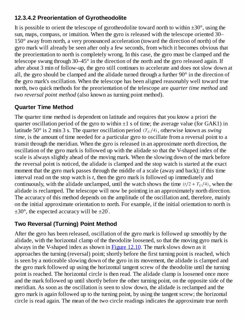
12.3.4.2PreorientationofGyrotheodoliteItispossibletoorientthetelescopeofgyrotheodolitetowardnorthtowithin±30°,usingthesun,maps,compass,orintuition.Whenthegyroisreleasedwiththetelescopeoriented30–150°awayfromnorth,averypronouncedacceleration(towardthedirectionofnorth)ofthegyromarkwillalreadybeseenafteronlyafewseconds,fromwhichitbecomesobviousthatthepreorientationtonorthiscompletelywrong.Inthiscase,thegyromustbeclampedandthetelescopeswungthrough30–45°inthedirectionofthenorthandthegyroreleasedagain.Ifafterabout3minoffollow-up,thegyrostillcontinuestoaccelerateanddoesnotslowdownatall,thegyroshouldbeclampedandthealidadeturnedthroughafurther90°inthedirectionofthegyromark'soscillation.Whenthetelescopehasbeenalignedreasonablywelltowardtruenorth,twoquickmethodsforthepreorientationofthetelescopearequartertimemethodandtworeversalpointmethod(alsoknownasturningpointmethod).
QuarterTimeMethodThequartertimemethodisdependentonlatitudeandrequiresthatyouknowapriorithequarteroscillationperiodofthegyrotowithin±1softime;theaveragevalue(forGAK1)inlatitude50°is2min3s.Thequarteroscillationperiod ,otherwiseknownasswingtime,istheamountoftimeneededforaparticulargyrotooscillatefromareversalpointtoatransitthroughthemeridian.Whenthegyroisreleasedinanapproximatenorthdirection,theoscillationofthegyromarkisfollowedupwiththealidadesothattheV-shapedindexofthescaleisalwaysslightlyaheadofthemovingmark.Whentheslowingdownofthemarkbeforethereversalpointisnoticed,thealidadeisclampedandthestopwatchisstartedattheexactmomentthatthegyromarkpassesthroughthemiddleofascale(awayandback);ifthistimeintervalreadonthestopwatchist,thenthegyromarkisfollowedupimmediatelyandcontinuously,withthealidadeunclamped,untilthewatchshowsthetime ,whenthealidadeisreclamped.Thetelescopewillnowbepointinginanapproximatelynorthdirection.Theaccuracyofthismethoddependsontheamplitudeoftheoscillationand,therefore,mainlyontheinitialapproximateorientationtonorth.Forexample,iftheinitialorientationtonorthis±30°,theexpectedaccuracywillbe±20′.
TwoReversal(Turning)PointMethodAfterthegyrohasbeenreleased,oscillationofthegyromarkisfollowedupsmoothlybythealidade,withthehorizontalclampofthetheodoliteloosened,sothatthemovinggyromarkisalwaysintheV-shapedindexasshowninFigure12.10.Themarkslowsdownasitapproachestheturning(reversal)point;shortlybeforethefirstturningpointisreached,whichisseenbyanoticeableslowingdownofthegyroinitsmovement,thealidadeisclampedandthegyromarkfollowedupusingthehorizontaltangentscrewofthetheodoliteuntiltheturningpointisreached.Thehorizontalcircleisthenread.Thealidadeclampisloosenedoncemoreandthemarkfollowedupuntilshortlybeforetheotherturningpoint,ontheoppositesideofthemeridian.Assoonastheoscillationisseentoslowdown,thealidadeisreclampedandthegyromarkisagainfolloweduptotheturningpoint,byusingthetangentscrew;thehorizontalcircleisreadagain.Themeanofthetwocirclereadingsindicatestheapproximatetruenorth

12.18
direction.Thegyroisthenclamped,andthetelescopeissetinthedirectionofthemeanofthetwocirclereadings.
Figure12.10GyrostationeyepieceshowingthegyromarkintheVshape.
Fortwoturning(orreversal)pointmeasurements(a1,anda2),thecorrectednorthdirectionN=(N'+E)canbegivenas
whereEisthealignmentconstantforthegyroscope.Theaccuracyachievedinlocatingthenorththiswayis±2′to3′.Ifmorethantwoturningpointsaremeasured,theSchulerMeandiscussedinSection12.3.4.3canbeusedtodeterminetheaveragenorthdirectionN.
12.3.4.3PreciseMethodsofGyroOrientationAfterthetelescopehasbeenapproximatelyorientedinnorthdirectionusinganyofthequickmethods,thepreciseorientationwillberequiredinminesurveyorientation.Twoprecisemethodsofobservationsarediscussed:multiplereversalpointmethod(multipleturningpointorfollow-upmethod)andmultipletransit(ortime)method.

MultipleReversalPointMethod(MultipleTurningPointMethodorFollow-UpMethod)Inordertousethismethodforaprecisenorthdetermination,thetheodolitemustalreadybeorientedtowithin±0.5°to2°,dependingontherangeofthetangentscrewofthetheodoliteortotalstationinstrument(about3°forT2andabout10°forT16/T1A).Thismusthavebeendoneusinganyofthequickmethods.Inthismethod,afterthegyrohasbeenreleased,theoscillationofthegyromarkisfollowedupbythealidade,usingthetangentscrewwiththemovinggyromarkkeptassharplyaspossibleintheV-shapedindexinthemiddleofthescale.Atthereversalpoint,wherethegyromarkseemstobeatcompletestandstillforafewseconds,thehorizontalcircleisreadandthegyromarkisfollowedupagainimmediatelyintheoppositedirection;thehorizontalcircleisreadateachturningpoint,andfromthesevaluesthemeanoscillationpositioniscalculatedasSchulerMean.Jerkymovementsofthegyromarkmustbeavoidedbymovingthetangentscrewslowlyandsmoothly.TheaccuracyofthismethodislimitedbytheabilitytomaintainthecoincidencebetweenthegyromarkandtheV-shapedscaleindex,whichispossiblewithstandarderrorof±6″to10″.Thegeneralstandarderrorexpectedforthismethodis±15″to30″.Thefollowingexampleshowshowthebookingandcalculationformultiplereversalpointmethodaredone.Thefourturningpointvaluesarey0toy3;themeannorthvaluesarehighlightedincolumns2and4;andtheSchulerMean(N′)isgivenonthelastrowincolumn5.
Example12.3
Table12.5isthefieldsheetIconsistingoffourturningpointmeasurementsfromGAK1gyroequipment.TheSchulerMeanistobecalculatedforthemeasurements,assumingthegyroequipmentisbeingusedtodeterminetheazimuthoflineB1-RO(withthegyroequipmentsetuponstationB1).

Table12.5GyrotheodoliteFieldSheetI(TurningPointorFollow-UpMethod).
Gyro:GAK1
Observer Date
Column1 Column2 Column3 Column4 Column5TurningPoint(y)Left
TurningPoint(y)Right
SchulerMean(LineAverages)
y0 32° 02′ 31″
Mean(y0+y2)
32° 04′ 16.5″ y1 39° 42′ 32″ 35° 53′ 24.2″
y2 32° 06′ 02″ Mean(y1+y3)
39° 40′ 56.5″ 35° 53′ 29.2″
y3 39° 39′ 21″
SchulerMean=Meanofcolumn5
N′ 35° 53′ 26.7″

12.19
12.20
12.21
12.22
12.23
Solution
ThesolutiontothisproblemispresentedinTable12.5.Inthetable,theSchulerMeanisthecirclereadingoftheapproximatenorthpositionbasedonthetheodolite'slineofsight,whichcanbegivenasN′.Ifthealignmentconstant(orthecalibrationcorrection)betweenthezeroofthegyro(theV-shape)andthelineofsightthroughthetotalstationtelescopeisE,thecorrectedcirclereadingofthenorthpointthroughthegyroaxis(N)willbeN′+E.Ifthemeananglemeasurementbetweenthezeroscaleofthetheodoliteandthereferenceobject(RO)isH,thecorrectedGyroazimuth(AG(RO))totheROcanbegivenas
or
where(H−N′)istheuncorrectedgyroazimuthofthelineofsighttoRO.IfthegridazimuthisdesiredfromthesetuppointtoRO,theconvergenceofmeridianatthesetuppointmustbedeterminedwithrespecttothecentralmeridianofthemapprojection.Iftheconvergenceofmeridianatthesetuppointiscalculatedasγ,thedesiredgridazimuth,Br(RO),fromastationtoareferenceobject(RO)canbecalculatedas
or
Notethatγwillhavenegativenumericalvaluewhenthesetuppointisinthewesternsideofthecentralmeridianandwillhavepositivenumericalvaluewhenitisontheeasternside(dependingonthetypeofmapprojectionused).
Thecalibrationcorrection(E)canbedeterminedonabaselinewhoseastronomicazimuth(Abase)isalreadyknown.Ifthegyrouncorrectedazimuthofthebaselineis(H−N′)accordingtoEquation(12.20),thecorrectionEcanbedeterminedas

Example12.4
ContinuingfromTable12.5,calculatethegyroazimuth(AG)andthegridazimuth(Br)oflineB1-RO.TheotherrelevantfielddataareprovidedinthegyrotheodolitefieldsheetIIinTable12.6.AssumeE=−0°02′52″andγ=1°23′48″forthecalculations.
Table12.6GyrotheodoliteFieldSheetII(AzimuthDetermination).
Name:A001Station:B1RO:RO(FL) 245° 28′ 25″RO(FR) 65° 28′ 23″MeanRO(H) 245° 28′ 24″Gyronorthreading(N′) 35° 53′ 27″Calibrationcorrectionoralignmentconstant(E) 0° 02′ 52″Gyroazimuth:AG(RO)=H−(N′+E) 209° 37′ 49″
Meridianconvergence(γ) 1° 23′ 48″Gridazimuth:Br(RO)=AG(RO)−γ 208° 14′ 01″
Solution
ThesolutiontothisproblemispresentedinTable12.6.
AlsonotethatthemethodillustratedinExamples12.5and12.6arebasedonwhatisalsoreferredtoas“follow-up”methodintheGP3Xgyrostationbrochure(SOKKIA,2004).
Transit(orTime)MethodTransitmethod,whichisalsoreferredtoasTimemethodintheGP3Xgyrostationbrochure,isbasedonthetimeoftransitoftheapproximatenorthN′(alongwhichthegyro'szerograduationiscurrentlyaligned)asillustratedinFigure12.11.InFigure12.11,TL(orTR)isthelengthoftimetakenbythegyromarktotransittheV-shapedindextotheL(orR)directionandback,DL(orDR)istheoscillationamplitudevalueofthegyromarktotheturningpointintheL(orR)directionandθistheoffsetofthetruenorth(N)fromthedirectionwherethetelescopeiscurrentlypointing(N′).

12.24
Figure12.11Timemethodofgyroazimuthdetermination.
Inordertousethetransitmethodforaprecisenorthdetermination,thetotalstationequipmentmustalreadybeorientedtowithin±20′ofthetruenorthusinganyofthequickmethodsdescribedinSection12.3.4.2.Thetotalstationequipmentanditshorizontalcirclearethenkeptclampedthroughoutthemeasurementsession,whilethetimeepochisrecordedeachtimethegyromarktransitsthroughthemiddleoftheV-shapedindexofthegyrounit.Theauxiliaryscale,whichcanbeseenthroughthegyroeyepiece,isusedtoestimatethevaluesoftheoscillationamplitudeofthegyromarktotheLandRdirectionsinthegyrounit.Thecorrection(θ)tobeappliedtoN′inordertoobtainthecorrectednorthN=N′+θisgiveninEquation(12.24):
wherek(givenforsomeGP-1as3.452)istheinstrumentalconstantorinstrument'sproportionalityfactor(alsoknownastorqueratioconstant)forconvertingmeasuredtimesintoangularequivalentvalues;E(givenforsomeGP-1as−10″)isthealignmentconstantfortransferringdirectionfromthezerograduationofgyrotoopticalaxisofthetotalstationequipment;
isthesimpleaverageofallthetimedifferences( )betweensuccessivezerograduationtransitsasshowninFigure12.11.
TheconstantkinEquation(12.24)isdependentonthelatitudeandshouldbedeterminedforthegyroinstrumentwheneverthesuspensiontapeofthegyrohasbeenreplacedorwheneverthemeasuringlocationissignificantlydifferentinlatitudefromtheoriginallocationoftheinstrumentcalibration.ThedeterminationofkandEisdoneautomaticallyandsimultaneously

12.25
inGP-1gyrostationusingthegyrostationprogram.Forthesakeofexplainingtheunderlyingconceptsinvolvedindeterminingk,theproceduresfordeterminingkempiricallyforGP-1gyrostationarediscussedasfollows:
1.Makemultiplegyromeasurementsusingthefollow-upmethodanddeterminethenorthdirectionreading(N1)basedontheSchulerMean.TheGP-1willautomaticallydetermineanddisplayN1astheazimuth(AZ)ofthecurrenttelescopedirection.ClampthegyroandrotatethetelescopeuntilAZreadingbecomeszero,whichisthedirectionofthenorth.
2.Rotatethetelescopeoftheinstrumenthorizontallyby10′totherightofthedeterminednorthinstep1;unclampthegyroandperformgyromeasurementsusingTimemethod.Calculatetheaverage(D1)oftheDRandDLamplitudevaluesandtheaveragetimedifference( )betweenthesuccessivezerograduationtransitsofthegyromark,andrecordtheazimuthofthecurrentdirectionofthetelescopeas .
3.Rotateagainthetelescopeoftheinstrumenthorizontallyby10′totheleftofthedeterminednorthinstep1(i.e.,by20′totheleftofthecurrentdirectionofthetelescope);unclampthegyroandperformanothergyromeasurementsusingTimemethod.Calculateagaintheaverage(D2)oftheDRandDLamplitudevaluesandtheaveragetimedifference( )betweenthesuccessivezerograduationtransitsofgyromark,andrecordtheazimuthofthecurrentdirectionofthetelescopeas .
4.Fromthetwosetsofmeasurementsmadewithsymmetricorientations( and )aboutthemiddleoscillationpositionofthedeterminednorth,calculatekasfollows:
12.3.4.4AzimuthDeterminationwiththeGyroStationGP3XEquipmentThestepsforsettingupthegyrostationGP3XareillustratedinFigure12.12andexplainedasfollows(referalsotoSOKKIA,2004):
1.SetuptheSet3Xtotalstationonthetripodandlevel:Ontheleftofthedisplaypanel(showninFigure12.9),presstheOnbutton,andthentheSettingsbutton(ifrequired,pressESCuntilprogramisexited);usethestyluspentoselectTilttabandlevelthetotalstationelectronically.
2.ConnectthegyroinvertertothegyroandtotheaccompanyingDC12VbatteryandsetthegyroontheSet3XtotalstationasshowninFigure12.12(a);ontheleftofthedisplaypanel,pressProgrambuttonandthentaponthedisplaywiththestyluspentoselectGyroStation;orienttheGyroapproximately(usingMagneticCompass)tothenorthafterconfirmingthattheinstrument/totalstationisleveled;taponOSETfunctiontosetthehorizontalanglereading(HAR)oftotalstationtozeroifneeded;theinstrumentwillnowbereadyforazimuthmeasurementbydisplayingAZtextbox;pressagaintheSettingsbuttonontheleftdisplaypanelandtapTilttabtoconfirmthattheinstrumentisstill

leveled.
3.Preliminarychecksonthegyro:Removetheprotectivecover(orclamplock)fromthegyroclampringasshowninFigure12.12(c)anddothefollowing:
i.WhiletheGP-1gyropowerisstilloff,turnthegyroclampringslowlytoHALF-CLAMP(HC)asshowninFigure12.12(d);waitforabout10s,checkingthatthefloatingindexmark(orgyromark)isnotmoving;thenslowlycontinuetoturntheclamptoFREE(Forfullyunclamped)position.
ii.Atthistime,theoscillationofthefloatinggyromarkshouldbesymmetricalaboutthezerograduationmarkwithin1.0scaledivision(rememberthattheGP-1gyropowerisstilloffatthistime);ifthisisnotthecase,therewillbeaneedforthegyroadjustment.
iii.TurntheclampscrewbackintheCdirectionuntilthegyroisintheFULLCLAMP(FC)positiononceagain.
4.TurntheGP-1gyropowerswitchontheinvertertoOn(andwaitforabout1minuntilthemotorstartlampontheinverterislitGREEN)withtheaccompanyingloudhummingsoundandthendothefollowing:
i.TurnthegyroclampingscrewslowlytoHALF-CLAMP(HC)asshowninFigure12.12(d);waitforabout10s,checkingthattheindexmarkisnotmoving,slowlycontinuetoturntheclamptoFREE(Forfullyunclamped)position.Notethatwhenfullyclamped,thegyromakesahummingnoiseandthegyromarkisstationary,butwhenitisfullyunclamped,thehummingnoisestopsandthegyromarkoscillatesfreely.
ii.Asawarning,thegyromustbefullyclampedbeforeitisgivenanyjerkyrotationorwhenevertheslowmotionscrewoftheinstrumentisnotbeingused.Thisistoavoidbreakingthewirethatsupportsthegyro.
5.ThegyromeasurementprocedureisillustratedinFigure12.13.Inthecaseoffollow-upmethod,pressFOLorF1keyonthegyrostationscreenanddothefollowing(asshowninFigure12.13(a)and(b)):
i.Usetheslowmotionscrewofthetotalstationequipmentorgentlyturnthetelescope(iftheslowmotionisoutofthread)tofollowthegyromark,keepingitonthezerograduation(orwithintheVshape)ofthegyro(asshowninFigure12.10).ContinuetokeepthefloatingmarkintheVshapeuntilareversalpointisreachedandthegyromarkismomentarilystationaryandabouttomoveintheoppositedirection;atthisreversalpoint,press[REV.P]orF3key(showninFigure12.13(a)).
ii.Press[REV.P]keyagainwheneverareversalpointisreached,andcontinuethisprocedureuntilsufficientnumberofreversalpointsaretaken;tworeversalpointsaresufficientforapproximatelocationofthenorthdirection.
iii.Morereversalpointreadingscanbetakenforbetterdeterminationofthenorthdirection;whentherequirednumberofreversalpointsreadingshavebeentaken,press[OK]button(showninFigure12.13(b))forthegyrotousethosereadingstodetermine

theprecisedirectionofthenorthandtheazimuthangle(AZ)ofthecurrentlineofsightofyourtelescope;theAZvalueandtheHARofthecurrentdirectionofthetelescopearedisplayedinthegyrostationpanel.Pressingthe[OK]buttonatthistimewillendthefollow-upmeasurements;computetheazimuthofthecurrentdirectionofthetelescopewithrespecttothecomputedtruenorthpositionandexitthegyroprogramintotheazimuthdisplaymode.
iv.Withthegyrostationinazimuthdisplaymode,clampthegyroallthewaytoFULLYCLAMPED(FC)position–noneedofhalf-clampingtheclampingscrewthistime.
v.UsetheslowmotionscreworturnthetelescopeiftheslowmotionscrewisoutofthreaduntilzeroreadingisdisplayedforAZ.Atthispoint,thetelescopeispointinginthegyrodeterminednorthdirection.ThetelescopeoftheinstrumentcanbeclampedinthisdirectionforuseintheTimemethodprocedures.
vi.
UnclampthegyroagainandturntheclampingringuntilHCandFpositionsarereachedasdiscussedinstep4anddoamorepreciseTimemethodtorefinethedirectionofthenorthdeterminedinstepv.
6.TostarttheTime(orTransit)method,press[TIME]functionontheGyroStationscreen;atthistime,theturningofthetelescopefromthedirectionitiscurrentlypointingisnotallowed.TapontheEPOCHorF3key(showninFigure12.13(c))onthedisplaypanelanddothefollowing:
i.Atthistime,thedisplayunitshouldbedisplayingtheinputboxesforDRandDLasshowninFigure12.13(d),requiringthatthenumberofgraduationsmovedbythegyromarktothereversalpointsintheRandLdirectionsbeinputintotheDRandDLtextboxes,respectively.InputtheamplitudevaluesobservedforDRandDLintothecorrespondingboxesandpress[OK]buttontoacceptthem;pressthe[EPOCH]keywhenthegyromarkjusttransitsthezerograduation(ortheVshape)tostartthegyromeasurements,andthenclickthecorrespondingarrowkeyonthekeyboardtomatchthedirectioninwhichthegyromarkisheadingatthattimewhenrequiredbythegyro.
ii.Whenthe[EPOCH]keyispressedagainatthesubsequenttransitsofthezerograduation,thetimetakenbythegyromarktotraveltothereversalpointsandbacktothezerograduationpointwillbedisplayedonthedisplaypanel.
iii.AftertwoconsecutivetransitsoftheVshapebythegyromark,thetimeforhalf-cycleofthetransitisdisplayed(inseconds);afteracompletecycle(twohalf-cycles)ismade,theazimuthofthetelescopelineofsight(AZvalue)isdisplayed;averagesareprovidedaftertwoormoreazimuthvalueshavebeendetermined;anyunwantedazimuthvaluefromtheaveragescanbeexcludedbydeletingthevaluebyfirsthighlightingitandthenpressing[CE]keytoremoveit.
iv.Afterobtainingsufficienttransitreadings,click[OK]keytodeterminefinalazimuth(theaveragedvalue)anddisplayitinAZbox.NotethattheAZvaluedisplayedmaybe

unrelatedtothevaluedisplayedinHAR.TheHARcanbedisplayedasaclockwise/counterclockwisevaluedependingonthesettingsinthetotalstation;buttheAZisalwaysdisplayedasclockwisevaluefromthenorthdirection.Pressingthe[OK]keyatanytimewillendthetimemeasurements;computetheazimuthofthecurrentdirectionoftelescopewithrespecttothetruenorthpositionandexitthegyroprogramintotheazimuthdisplaymode.
v.AfterAZisdisplayed;press[N]keyonthetotalstationtotransferthemeasuredazimuthangle(theanglewithrespecttothecalculatedtruenorth)totheHARbox.TheazimuthangleofthetelescopedirectionwillnowbedisplayedintheHARbox.
vi.Indeterminingtheazimuthofalinetothereferenceobject(RO),thegyroisfirstclampedfully;thenthetotalstationisrotatedontothelineforwhichtheazimuthisdesiredandtheazimuthofthatlineisrecordedonFLandFRpositionsofthetelescope,andtheaveragevalueistakenastheazimuthoftheline.
vii.Toshutdownthegyroafterclamping,switchoffthepowerontheinverter;waitforapproximately10minforthemotortocometoacompletestandstill;checkthatnosoundiscomingfromthemotor,andthenputtheclamplockbackontheclampingscrew.


Figure12.12SetupprocedureoftheGP3XGyrostation.
Figure12.13Sampledisplayforthefollow-upandTimemethodsofgyromeasurements.

12.27
12.26
Example12.5
Giventhefollowingsampledata(Figure12.14)takenwithGP3Xgyrostationwiththeapproximatedirectionofthenorth(N′)asreadonthetotalstationbeing0°0′0″,determinetheazimuthcorrectionθ(usingtheTimemethodapproach)andthecorrecteddirectionofthenorth(N).Takek=3.452andE=−10″forthegyrostation.
Figure12.14SamplegyrodatabyTimemethod.
UsingEquation(12.24):
EachΔtabovecanbeusedinEquation(12.26)inordertoobtainindividualazimuthcorrectionsandthenaveragingtoobtainanaveragevalue;orfindingtheaverage( )ofalltheΔt'sas
Givenk=3.452andE=−10″fortheGP-1andsubstitutingthevaluesintoEquation(12.26)givesθ=53″.Thismeansthatthecurrentlineofsightthroughthetelescopeisatanangle0°00′53″clockwise(negativesigniscounterclockwise)withrespecttothedirectionofthenorth,thatis,azimuth(AZ)ofthecurrentdirectionofthetelescopeis0°00′53″.

12.29
12.3.4.5UseofGyroEquipmentinUndergroundMinesTheusualstepsinorientationtransferwithgyrotheodolitesinundergroundminesareasfollows:
1.First,gyrotheodoliteequipmentiscalibratedonthesurfaceonabaselinewhoseazimuthisalreadyknown,beforetakingtheequipmentundergroundtotheplacewheretheazimuthistobedetermined;thecorrectionorcalibrationfactor(E)tobeappliedtosubsequentazimuthdeterminationsundergroundwiththeequipmentisdeterminedusingEquation(12.23).Itisimportantthatthecalibrationbedonewithin60–90meastorwestofthepointwhereitistobeusedifcalculationsfortheconvergenceofthemeridiansaretobeavoided.Inthiscase,iftheundergroundworkingsarewithin60–90mofthegyrocalibrationsite,onecanstillusethesameconvergenceofmeridiandeterminedforthecalibrationsiteintheundergroundworkings.
2.Attheundergroundsetuppoint(usuallyapermanentpoint),thegyrotheodoliteiscenteredoverthepointandcarefullyleveled.Thesurveyororientsthegyrotheodolitetothenorthdirectionandthenmeasuresthedirectandreversedanglestothereferencepoint(whichmaybeseveralhundredmetersaway).Thesurveyormaylikelyrepeattheoperationattheotherend(referencepoint)backtotheinitialsetuppointasacheckandmayprobablyusetheaverageofforwardandbackazimuths,therebyminimizingpossiblerefractioneffectsonthecomputedaverageazimuth.
3.Coordinatescanbebroughtdownintotheminetothenewlevelusingsinglewire,whosepositionisdeterminedfromthesurface.
Gyrotheodolitesprovidegyroazimuthsthatarebasicallyastronomicalazimuth(insteadofgridorplaneazimuths).Someofthecorrectionsthatareusuallyappliedtogyroazimuthscanbegivenasfollows:
1.Convergenceofmeridians(γ),whichdependonthetypeofmapprojectionusedinobtainingthegridcoordinates.Asoneproceedsalongastraightlinesetoutbyatheodoliteonthesurfaceoftheearth,theazimuthofthelinewillnotremainconstant.Gyrosettlesalongameridian(truenorth),whichwillonlycoincidewiththemapgridalongthemiddlemeridianofthemapgrid.Thefarthereastorwestonegetsfromthemiddlemeridian,thelargerthedeviationbetweenthedirectionofnorthofthemapgridandthemeridianoflongitudethatthegyroshows.Theconvergenceofmeridiancanbecomputedapproximatelyforapositionwithmeanlatitude(φ)andlongitude(λ)byusingthefollowingformulas:
12.28
or
whereλ0isthelongitudeofthecentralmeridian(theoriginofthemapgridrectangular

12.30
12.31
12.32
coordinatesystem),ΔEisthedifferenceineastingcoordinate(distancebetweenthemeridians)oftheobservingstation,andRistheradiusoftheearthintheprojectsite(e.g.,6370km).Amorepreciseformulaforcomputingtheconvergenceofmeridianscanbegivenas
whereeisthefirsteccentricityandaisthesemi-majoraxisofthereferenceellipsoid.Toobtainthegridazimuth,γshouldbesubtractedfromthegyroazimuthsvaluewhentheundergroundstationislocatedeastofthesurfacestation.ThegridazimuthcanbedeterminedfromEquation(12.21)or(12.22).
2.Errorduetothemislevelingofinstrument,whichcanbeexpressedmathematicallyas
where istheinclinationoftheinstrumentinthedirectionperpendiculartothelineofsightandZisthezenithanglereading.Thiserrorisrandominnature;theeffectcanbeminimizedbyrelevelingtheinstrumentbetweensetsandfindingtheaverageofthesets,orusingamoresensitivelevelingbubble(likestridinglevel)todeterminethemislevelingcorrectionstobeappliedtothemeasurements.
3.Effectofdeflectionofthevertical,whichwillaffectdirectionandanglemeasurementsinasimilarwayasmislevelingoftheinstrument.Thecorrection(duetothiseffect)tobeappliedtothegyroazimuthcanbeexpressedas
where isthecomponentofdeflectionoftheverticalinthenorth–southdirectionatthesetuppoint; isthecomponentofdeflectionoftheverticalintheeast–westdirectionatthesetuppoint; islatitudeofthesetuppoint, isthegeodeticazimuthtothereferenceobject,andZisthezenithanglereading.Thiscorrectionwillbesignificantonlyinacasewherethedeflectionoftheverticalislargeandthelineofsightisinclined.Inthetunnelwherelinesofsightareapproximatelyhorizontal,cotZ=0,sothat withonlythecomponentofthedeflectionoftheverticalintheeast–westdirection( )accountingforthecorrection.Theapplicationofthecorrectionduetothedeflectionoftheverticalallowsanastronomicazimuthtobeconvertedintogeodeticazimuth.Thiseffecthasbothsystematicandrandomcomponents.
4.Effectsofrefraction,whichwillbereducedifreciprocalobservationsaremadewiththegyrotheodolitesonthesametraverselines.TheseeffectshavebothsystematicandrandomcomponentsasdiscussedinSections4.3.4and4.5.5.
5.Effectoflocalcalibrationvalue(E)ofthegyrotheodolite.Thisisanalignmenterrorbetweenthegyrozero(theindicatedheadingofthegyro)andthehorizontalopticalaxisofthetheodolite.Itisadvisabletosetupthegyrotheodoliteonaknownbaselineonthe

surfacetoestablishthedifferenceEbetweenthegyroazimuthandtheactualazimuthofthebaselineonthesurface.ThegyromustagainbesetuponthesurfacebaselineandaseconddeterminationofEmadeafterthecompletionoftheundergroundsurveys.AnychangeinEwouldhavetobeappliedtothemeasuredazimuthsproportionatelywithrespecttothetimeofobservation.ThevalueofEcanbedeterminedfromEquation(12.23).
12.4TRANSFERRINGLEVELSORHEIGHTSUNDERGROUNDTransferofverticalcontrolpointsandalignmentsfromgroundsurfacedowntoundergroundtunnelsdependsontheconfigurationoftheaccess.Fortransferthroughinclinedshafts,differentiallevelingwillbemoreappropriate;forverticalshafts,verticalEDMandprecisetapearecommonlyused.Rememberthathorizontalandverticalcontrolpointsareusuallysetinthebackofanundergroundmineandboththeverticalandthehorizontalcontrolpointsaregenerallyestablishedatthesametime.Thecontrolpointsareestablishedinthereverseorder(loworderfirstfollowedbyhigherorder)fromwhatisdoneforsurfacesurveys.Low-ordertraversesusuallyhaveshortlegs(lessthan50m)andhigherorderonesusuallyhavelongerlegs(upto1000m).Severalmethodsareusedintransferringlevelsunderground,suchasusingEDMinstrumentadaptedforverticalviewingintheshaftandusingverylongtapeswithmarkeddivisions(calibratedandcorrectedfortensionandtemperature).Inbothmethods,theconnectingsurveybetweenthebenchmarksandtheEDM/reflectorcenters,orrulerswith1mmdivisionsattachedtothetape,aremadebymeansofspiritortrigonometricleveling.
12.4.1HeightTransferwithEDMUsingEDMtotransferheightsrequirescarefuldeterminationofthecentersoftheinstrumentandofthereflector;thereisalsoaneedforvisibilityconditionintheshaftinordertousenonlaserEDMinstrumentforheighttransfer.OneimportantadvantageofEDMmethodisthatitcanprovidemoreaccurateresultanditcanalsoprovideautomaticandinstantreadoutunlikeinthecaseoftapemethod.DirectmeasurementwithEDMusinginfraredorlasermodels,however,ispreferabletothatbasedonnonlaserEDMprovidedtheinfraredorthelasersignalwillreachthetargetandbereflectedback.
InthemethodofheighttransferwithEDM,eitherofthefollowingapproachesmaybeadopted:
Theinstrumentandreflectorarekeptintheuprightpositionswiththemirrorsorright-angledprismsusedonthesurfaceandundergroundtoredirecttheEDMsignalasshowninFigure12.15.Inthismethod,distancesfromtheEDMinstrumentandreflectortorespectivemirrorsaremeasured,andheightsofinstrumentandreflectoraredeterminedinordertocompletetheheighttransferunderground.ReferringtoFigure12.15,theelevationofsurfacebenchmark(BM)isHs;backsightreadingtothesurfaceBMisBS;foresightreadingtotheundergroundBMisFS;themeasuredrounddistancemeasurementbytheEDMisdm;andthemeasureddistancestotheright-angledprismsared1andd2;the

elevationoftheundergroundBM(Hu)canbegivenas12.33
Alternatively,theinstrumentandthecorrespondingreflectorcanbeclampedinaverticalpositionintheshaft,atthesurfaceandunderground.Thentheelevationsaretransferredtoandfromtheinstrumentcenterandthereflector,usingtrigonometricorspiritlevelingmethod.Inthiscase,theEDMissupportedatthetopfacedownandthereflectorintegratedwiththelevelinstrumentislocateddirectlybelowthesurfaceplumblineunderground.Fromthis,theelevationoftheundergroundbenchmark(BM),whichisonthebackofthetunnel,canbedetermined.Forexample,aTaylorHobsonspherecontainingthereflectorcanbesupportedinaspecialbracketmountatpointP1andthespeciallydesignedEDMlocatedatpointP2(Figure12.15).Inthiscase,theelevationofthehorizontalaxisoftheEDMinstrumentistransferredtotheundergroundBM.
Figure12.15EDMapproachfortransferringheightsunderground(cross-sectionalview).
12.4.2HeightTransferwithMeasuringTape

ElevationscanbetransferredfromthesurfacelevelundergroundusingsteeltapeinaverticalshaftasshowninFigure12.16.Inthismethod(Figure12.16),thelevelinstrumentissetatpointAonthesurfaceandbydifferentiallevelingprocedure,thelevelofP1ofthetapeisdeterminedusingtheknownbenchmarkBM1.Fromthelengthofthetape(P1–P2)andtheforesightreadingonBM2,theelevationofBM2isestablished.Thismethod,however,requiresthatsimultaneousreadingsbetakenonthetapebyonecrewwithspiritlevelatthesurfaceandtheotherwithspiritlevelunderground.Notealsothatthetapeiskeptverticalbymeansoftheheavyweightattheendofthetape;thisverticalitymaybeaffectediftheweightisnotheavyenough.Someofthedisadvantagesofusinglongtapefordirectmeasurementincludethefollowing:
Highcostofatapethathaslittlefurtheruseaftertheinitialsurvey.Indirectmeasurementsintheshaftusingpianowiremaybehelpfulsincethepianowireusedfortransferringcoordinatesanddirectionmaynowbeusedtotransferelevations.
Needtomakecomplexcorrectionfortapeelongation.SomeoftherequiredcorrectionsarediscussedinSection12.4.4.
Figure12.16Transferringheightsundergroundusingmeasuringtape(cross-sectionalview).
Oneoftheadvantagesofusingsteeltapemethodisthatthesteel-tapemeasurementsmaybefasterandaccurateforshortdistances.
12.4.3HeightTransferinShallowShafts

Heighttransferapproachdiscussedinthissectionisacontinuationofhorizontalcontroltransferthroughashallowshaft(Section12.3.4);usually,horizontalandverticalcontroltransfersaredoneaboutthesametime.Inthiscase,elevationsaretransferredfromthesurfacelevelthroughtheshallowshafts(about20–80mdeep)usingopticalorzenithplummets.Heightsinthiscasearetransferredbasedonthefollowingtechniques:
1.Atthetopoftheshaft,setupaTaylorHobsonsphereonasurveybracketincludedintheshaftcollar;thecenteroftheTaylorHobsonspherewillthenbedefinedinthreedimensions.
2.Setupatripodatthebottomoftheshaftwithtranslationstagethatwillallowplumbingtobeperformedwithgoodaccuracyasfollows:
Mountprecisionzenithplummet(suchasWild/LeicaZLplummet)ontheKerntripodwithcenteringrodandtranslationstageforcenteringunderthesphericaltargetonthesurface.
3.Aftercompletingtheplumbingoperationunderground,replacetheTaylorHobsonsphereonthesurfacewithpreciseprisminserts(reflectors)toserveasretro-reflectors.TheTaylorHobsonspherecanbefittedwithreflectiveprismswithnoeccentricityintroduced,nomatterwhatdirectiontheprismisfacing.
4.Intheunderground,thezenithplummetisremovedandreplacedbyacoaxialprecisiontotalstationwiththetelescopepointedverticallytotheprismlocatedintheTaylorHobsonsphereonthesurface.
5.Observeverticaldistancesinatleastthreesetswithindependentre-pointingsbetweenthesetsbyusingthetotalstationinstrumentunderground;correcttheverticaldistancesforprismcalibrationandatmosphericeffects.
6.Onthesurface,useasuitablelevelinstrumentsetupbetweenthebracket-mountedTaylorHobsonsphere(verticallyabovethetotalstationunderground)andalevelingrodlocatedonabenchmarktopreciselytransferverticalcontroltothecenteroftheTaylorHobsonsphere.
7.Usinganotherlevelinstrumentsetupundergroundandalevelingrod,transfertheelevationfromthehorizontalaxisofthetotalstationtoseveralwallmarkersservingasbenchmarks.
12.4.4TypicalCorrectionsAppliedtoMeasurementsinHeightTransferGenerally,theaccuracyofleveltransferundergroundwilldependonthefollowing:
Accuracyoftransferringlevelfromthesurfacebenchmarkstothecentersofthebracket-mountedtarget(orasuspendedtape)atthetopoftheshaft.
Accuracyofmeasuringverticaldistancebetweenthebottomandtopoftheshaft.
Accuracyoftransferringelevationfromthehorizontalaxisoftheinstrumentset

12.35
12.36
12.34
underground(orfromthesuspendedtapeattheundergroundlevel)tothenearbyundergroundbenchmarks.
Withregardtotapemeasurementsinheighttransfer,anumberofcorrectionsmustbeapplied,suchasthefollowing:
a.Correctionforthestandardizationoftape(Δhd).Standardizationofatapeisaprocessofdeterminingthestandardtemperatureandtensioncorrespondingtotheexactlengthofthetape.Ifthetapeisusedatanyothertemperatureandtensionapartfromthestandardvalues,themeasurementsmadewiththetapemustbecorrectedforstandardizationerror.Thiscorrection,whichistomakethetapelengthequivalenttothestandardlength,isappliedinamannersimilartowhenusingthetapeinhorizontalmeasurements.
b.Correctionduetotemperaturevariation(Δht).Thiscorrectionisappliedtoeliminatetheeffectoftemperaturevariationsintheshaft.AccordingtoChrzanowskiandRobinson(1981),thetemperaturevariationsintheminingshaftsareusuallynonlinearunlikeinthecaseofwhenatapeisusedhorizontallyfordistancemeasurementsonthesurface;theysuggestedthattemperatureTibemeasuredatdifferentlevels(i)ofabout3050mintheshaftaspartofheighttransferprocedurethroughtheshaft.TheweightedmeantemperatureTisthenusedtodeterminethecorrectionasfollows:
whereTisestimated(ChrzanowskiandRobinson,1981)as
whereTiisthetemperaturemeasuredatanygivenlevelwiththelengthofthetapeatthatlevelbeinghi;h1istheheightofthefirstlevel;hnistheheightofthelastlevel;T0isthetemperatureatwhichthetapewasstandardized,αisthethermalcoefficientofexpansion(e.g.,11.6×10−6per1°Cforsteel),andhisthetotallengthoftapemeasurement.ItcanbeunderstoodthatEquation(12.34)issimilartotheonethatisgenerallyusedinelementarysurveyingincorrectingfortemperaturechangesinhorizontaltapemeasurement.ThemajordifferenceisthatTisnonlinearinaverticalshaftanditsvaluemustbecalculatedfromEquation(12.35)whenthetapeisusedverticallyintheshaft;inthecaseofhorizontaltapemeasurement,Tisconsideredconstantalongthewholelengthofthetape.
c.Correctionduetothetapestretchingunderitsweight(Δhw).Thestretchcorrectioniscalculatedfrom(ChrzanowskiandRobinson,1981)as
wherehistheheightmeasuredfromthetopoftheshafttothepointwheremeasurementismadeunderground,Listhetotallengthoftape(ormeasuredlength),wistheweightoftape

12.37
perunitlength,aisthecross-sectionalareaofthetape(cm2orin.2),andEisthemodulusofelasticityforthetapematerial(inkg/m/s2).
d.Tensioncorrection(Δhp).Thisisnecessaryifthepullonthetapeisdifferentfromthatusedwhenstandardizingthetape.Thetapewilleitherbeshortenedorlengthenedbytheamount,whichcanbegivenas
wherePisthepull(kg)onthetape,P0isthepull(kg)onthetapewhenstandardizingit,andothersymbolsareasdefinedin(c).
e.Othercorrections,suchastapenotbeingstraight(duetoaircurrentandspiralshapeoftape).Thecombinedeffectofaircurrentandspiralshapeoftapemaybecomparedtotheeffectofsagonhorizontaldistancemeasurementwiththetape.
Amongthecorrectionsneededtobeappliedtotapemeasurementsinheighttransfer,thetemperaturecorrectionsandstretchoftapeunderitsownweightwillbedifferentfromwhenthetapeisusedtomeasurehorizontaldistances.Intheshaftwhereheighttransferisbeingmade,temperatureusuallyvariesnonlinearlyalongtheshaft,requiringthatmorecomplextemperaturecorrectiontotapemeasurementsbemadeinheighttransfer;andsincethetapeisintheverticalposition,thestretchofthetapeunderitsownweightneedstobeapplied,whichisnotdoneinthecaseofhorizontaldistancemeasurementwithtapes(sagcorrectionandtheeffectoftapenotbeinghorizontalareappliedinstead).

Example12.6
Theelevationofthebackofadrift(ortunnel)hasbeendeterminedviaaconnectingshaftusingasteeltapeandlevelsasshowninFigure12.16.Thefollowingdataisknownfromthecontrolinformationandmeasurements:
ElevationofthesurfacebenchmarkBM1:426.97m
RodreadingatBM1:1.55m
Heightofinstrument(underground)relativetothebenchmarkBM2inthebackofthedrift:−0.92m
TapeddistancebetweenthesurfacepointP1andtheundergroundP2:45.72m.
Whatistheelevationofthenewcontrolpointinthedrift?
Solution
UsingtheideabehindtheformulationofEquation(12.33),theelevationofthenewcontrolpointinthedriftcanbegivenasfollows:
Example12.7
Amineorientationsurveyistobedoneusingtwomechanicalplumblinesinoneverticalshaft.ThedepthoftheorientedlevelH=300m.Thedistancebetweenthetwoplumblinesis4m.Steelwiresoftensilestrength200kg/mm2areavailableforplumbing.Theheightoftheshaftopeningtotheorientedlevelh=5mandtheaverageairvelocityinthecrosssectionoftheopeningv=1m/s.Therearenootheropeningstointermediatelevelsbetweenthesurfaceandtheorientedlevel.Answerthefollowing:
(a)Whatdiameter(d)oftheplumbwiresandwhatweight(p)oftheplumbbobswouldyouusefortheorientationpurpose?

12.38
Solution
Asarule,weightofthebobisusuallyequaltoH/3inkilograms(whereHisthedepthofplumbinginmeters);usingawirewithatensilestrengthof200kg/mm2toadepthofH=300m,theexpectedweightofbobwillbep=300/3or100kg.
Forsafetyreasons,theloadshouldnotexceedhalfofthemaximum(breaking)loadofthewire.Sincetheexpectedloadis100kg,themaximumloadexpectedistwicetheexpectedloador200kg.
Thecross-sectionalareaofthewirecanbegivenas
Forthewirewithtensilestrengthof200kg/mm2,thecross-sectionalareais
Theradiusofthewirecanbedeterminedfromtheareaofacircleequation:
Thediameter,d=1.128mm.
(a)Whaterrorofthetransferredazimuthwouldyouexpectasaresultoftheaircurrentandspiralshapeofthewires(taketheradiusofthespiralshapeR=15cmandusevaluesofdandpasobtainedfrompart(a)).
Solution
Errorduetoairinfluenceonplumblinecanbegiven(ChrzanowskiandRobinson,1981)as
wherev=1m/sisthevelocityofair.
SubstitutingvaluesintoEquation(12.38)gives

12.41
12.42
12.39
12.40
Onlyhalfoftheairinfluenceistakenaspartoftheestimatedstandarddeviationbecausebothplumblinesaremostprobablydeflectedinasimilardirection;thiscanbeexpressedasfollows:
Theerrorduetospiralshapeofplumblinecanbegivenforthetwoextremepositionsofeachwire(ChrzanowskiandRobinson,1981)as
where
Usingπ=3.14,d=1.128mm,E=2.1×10⁴kg/mm2,R=150mm,p=100kginEquation(12.41)gives ;fromEquation(12.40),
.
Errorofthemeanpositionsdeterminedonthescalescanbekeptsmallerthan0.2mmiftheplaneoftheoscillationsoftheplumbbobsisparallelwithin±10°tothescale,theamplitudeissmallerthan10cm,andifatleast10readings(withanestimationto0.2mm)oftheleftandrightreversalpositionsaretakenonthescaleforthecalculationofthemeanpositionoftheplumbline.Basedontheaboveassumption,escale=0.2mm.Thetotalstandarddeviationoftheazimuthtransferbasedonthedistancebetweenthetwowiresbeingb=4.000mcanbegiven(ChrzanowskiandRobinson,1981)forthetwoplumblinesas
SubstitutingtheappropriatevaluesintoEquation(12.42)givesthetotalstandarddeviationoftheazimuthtransferas28.4″.
12.5VOLUMEDETERMINATIONINMINESApartfromtheminesurveyingactivitiesdiscussedintheearliersections,anotherimportantactivityusuallyperformedbytheminesurveyorisvolumedetermination.Forexample,duringatunnelconstruction,as-builtsurveysarerequiredtochecktolerancesoftunnelstructures.Surveysarealsocarriedoutincompletedtunnelstocheckifsufficientclearancesareavailablefortheinstallationofpipelines,lighting,ventilation,andsoon.Thesurveysaretoprovidearecordofexistingstructuresandtheas-constructedconditionofthetunnel.As-builtsurveysofatunnelshouldbeimplementedintwostepsasfollows:

12.43
i.Surveythefinishedtunnelbeforeandafterthebreakthrough.
ii.Checkiftheexistingtunnelshavebeenbuilttowithinallowabletolerances,andifthedesigntolerancesareexceeded,toseeifitispossibletorealignthetunnelwithoutremedialworktotheexistingstructures.Inthiscase,crosssectionsatregularintervalsalongthewholelengthofthetunnelaresurveyed.
Accurateandcost-effectivesurveyingmethodappliedbysurveyorsincheckingprofilesisusingreflectorlesstotalstationsbywhichcoordinatedpointsonthetunnelsurfaceareautomaticallyrecorded,processed,andanalyzedoncomputersinthefield.Allofthefielddataarestoredelectronicallyintheformofthree-dimensionalcoordinatesinthetotalstations,andtheaccuracybetween5and10mmisexpected.Basedonthecross-sectiondatabase,volumeofexcavationandmaterialsarecomputed.
Whetherundergroundorontheearthsurface,mininginvolvesmovingvolumesofmaterialfromoneplacetoanother.Mappingthechangesmadebytheminingactivityanddeterminingthevolumesmovedisadailyjobofminingsurveyors.Nowadays,forundergroundandopen-pitoperations,laserscanningsystems,reflectorlesstotalstationequipment,GPSsurveys,andterrestrialphotogrammetryareusedfordailyminevolumedeterminations.Oneapproachforvolumedeterminationforundergroundoperationscanbedescribedasfollows:
1.Observecross-sectionprofilesatmeasuredintervals(withdistancebetweeneachcrosssectionbeingd12,d23,etc.).
2.Determinethecross-sectionalareasusingcoordinatemethodbasedonlocalx–ycoordinatesystemestablishedforeachcrosssection.Atypicalcrosssectionwiththelocalx–ycoordinatesystemisshowninFigure12.17.Thearea(A)ofthiscrosssectioncanbegivenusingcoordinateapproachas
3.ComputevolumesbetweencrosssectionsasshowninFigure12.18usingaverageend-areamethod:

12.44
12.45
12.46
12.47
Figure12.18Differentcrosssectionsofminingexcavationsforvolumedetermination.
Theindividualcross-section/end-areavolumesaregivenasfollows:
whereV12,V23,V34aretheindividualcross-section/end-areavolumes.
4.Computethetotalvolume(VT)bythesumofthecross-section/end-areavolumes:

Figure12.17Singlecross-sectionprofileofanundergroundexcavation.
Volumedeterminationsforopenpitarenowbeingdoneusingterrestriallaserscanningsystem.Withthissystem,high-accuracyanddetailedsurveyscanbeperformedquicklyfromasafedistancefromthemineandvolumetricsurveysaredoneimmediatelyafterblastingandaftereveryshift.Sincethistypeofsystemisusuallyunmanned,thesystemcanbeusedbothdayandnight,allowingcontinuousslopestabilitymonitoringoftheminingareas.

Chapter13TunnelingSurveys
ObjectivesAttheendofthischapter,youshouldbeableto
1.Describethebasicelementsandmethodsoftunnelingsurveys
2.Calculatetheapproximateeffectsoflateralatmosphericrefractiononalignmentsurveys
3.Performbothhorizontalandverticaldesignandpreanalysisoftunnelingsurveys
4.Carryouttheanalysisofbreakthroughaccuracyoftunnelingprojects
5.Performerroranalysisofundergroundtraversesurveys
6.Determinegridazimuthfromgyroazimuthmeasurementforundergroundtraversesurveys
13.1INTRODUCTIONTunnelingsurveyisanundergroundsurveydoneforconstructingatunnel.Othermajorapplicationsofundergroundsurveytechniquesareinrelationtoundergroundutilitiessuchasnuclearacceleratorsandinminingoperations.Theundergroundsurveysarenecessaryintunnelingoperationsforestablishingtransportationandcommunicationroutes,waterconduitsandpipelines;inminingoperations,theyarenecessaryinexcavatingores.
Undergroundsurveyisdifferentfromsurveyingonthesurface.Itisessentiallysimilartothree-dimensionalsurveysonthesurfaceinthatthepurposeisusuallytoobtainthehorizontalaswellastheverticalcoordinatesofpointsunderground.Someofthepeculiaritiesofundergroundsurveysincomparisontosurfacesurveysareasfollows:
1.Workenvironmentundergroundisrestricted,hot,dusty,dirty,andcramped.
2.Artificialilluminationisusuallyneededsincethepassagewaysaredarkandpoorlylit.
3.Workareasarewet,withconsiderablewaterdrippingfromtheroofsofpassageways.
4.Instrumentstationsandbenchmarksforlevelingareoftensetintotherooftominimizedisturbancefromundergroundoperations.
5.Instrumentstationsaresetwithmuchdifficulty,especiallywhenplugsmustbedrivenintodrillholesinrocks.
6.Linesofsightaresometimesveryshortandsightstakeninshaftsandslopingpassagewaysmaybesharplyinclined.

7.Plumbingdowntheshaftusuallyconstitutesaspecialproblem,whichispeculiartoundergroundsurveying.
Theessentialproblemintheundergroundsurveyingisthatoforienting(oraligning)theundergroundsurveystothesurfacesurveys.Theprocessoforientationistogivecoordinates(easting,northing,andelevation)ofatleastonepointandazimuthofonelineoftheundergroundnetworkinthesurfacecoordinatesystem.Intheundergroundtransportsystem,thetunnelsaredriventoconnectinclinedorverticalshafts(pointsofthesurfaceentrytothetransportsystem)whoserelativelocationsareestablishedbythesurfacesurvey.Iftheentrytotheundergroundtunnelsystemisviaaninclinedshaft,thenthesurfacesurveymaysimplybeextendedandcontinueddownthatshaftandintothetunnelbythemethodoftraversing.Theextracareneededwillbetomeasurehorizontalanglescarefullyduetosteeplyinclinedsightsandtocorrectfortemperatureeffectsduetopossiblethermalgradientsinthetunnel.Ifentryisviaaverticalshaft,thenoptical,mechanical,orgyroscopicmethodsoforientationarecommonlyused.MechanicalmethodsoftransferringbearingsundergroundusehangingwireswiththeWeisbachtrianglemethodbeingthemostpopular;typicalmechanicalmethodsarediscussedinSection12.3.2.Notethattypicallyastandarderrorof1′intransferringthebearingdowntheshaftwouldlikelyresultinapositionalerrorattheendof1kmoftunnelofuptoafewdecimetersandwouldincreaseasthetraverseprogresses.
13.2BASICELEMENTSANDMETHODSOFTUNNELINGSURVEYSSomeofthetunneltypesrequiringprecisetunnelingsurveysarerailroads,subways,highways,hydroprojects,miningprojects,andwatersupplyprojectsforlargecities.Thethreemaintypesoftunnelinconstructionindustryarehighwaytunnels,railwaytunnels,andutilitytunnels(e.g.,watersupplyanddrainagetunnels).Theusualworkofasurveyorinsuchtunnelingprojectsconsistsofthefollowing:
1.Performingallsurveyworkbeforethestartofconstruction,suchaspreliminarysurveysandpreliminaryhorizontalandverticalcontrolsurveysonthesurfacetoobtaingeneralsitedataforrouteselectionandforstructuredesign.Someofthestepsthatwouldberequiredintheprocessincludethefollowing:
Usingexistingsurveyrecordsandmonuments
Placingadditionaltemporarymonumentsandbenchmarks
Performingphotogrammetricmapping,recordingofseismicactivity,andgeophysicalprofiling
Preparingalarge-scaletopographicmapofthesurveyedcorridortolocatethehorizontalandverticalprojectionofthetunnelcenterline.
2.Conductingprimaryhorizontalandverticalcontrolsurveysofhighorderofaccuracyforfinaldesignandconstruction,aftercompletingtherouteselection.Thiswillrequire

designingthesurveycontrolforthealignmentofthetunnelaxiswiththehighestpossibleaccuracysothatoppositeheadingsmeetatthebreakthroughpointswithoutanyneedforanadjustmentoftheexcavations.Generally,anaccuracyof10–20mm/kmofthedriventunnelisrequiredformeetingtheoppositeheadings;
establishingpermanentmonumentsandbenchmarks,consistingofbrassdiscssecuredinconcrete,attunnelportalsandoverthetunnelalignmenttoserveasprimarycontrolduringthefinaldesignstageandduringconstruction;
settingreferencemarksforeachmonumentsothatthemonumentscanbereadilyverifiedandreestablishedifdisturbedordestroyedduringconstruction.
3.Connectingtheprimarycontrolnetworktothenationalgeodeticcontrolnetworkoftheareasothatsurveyclosureswillprovideanindependentcheckonthenewsurvey,andanytwoormoreconnectionswillprovideadequateorientationforthehorizontalcontrolsurveys.Duringthesurveys,horizontalcontrolpointsareextendedtotheundergroundtunnelsbyzigzagorbracedtraversesthroughtheaccessportals(entrancestothetunnel),shafts(inclinedorvertical),andstairwellsintotheundergroundtunnels.Zigzagtraversesarecarriedoutinordertoavoidsightlinesgrazingthetunnelwallssoastominimizelateralrefractionerrors.Thetransferofhorizontalcontrolpointsthroughverticalventilationshaftscanbeachievedbyco-planningmethod,Weisbachmethod,orquadrilateralmethod(discussedinSection12.3.2)dependingontheavailableinstrumentation.
4.Performingprincipalcontrolsurveyinthetunnelwiththestationpointsoftenestablishedontheroofofthetunnelintheformofwallbrackets.Thesurveyoristoperformthisaftereveryfewhundredmetersofprogressinatunnelingwork.Theuseofwallbrackets,however,makesitdifficulttocenterthetargetsandtheinstrumentstoaccuracybetterthan±1mm.AccordingtoFowler(2006),spigotsshouldbemountedtotunnelwallsorroofs,astargets,inordertoachievebetterpositionalaccuracy.Atypicalspigotconsists(Fowler,2006)ofbrassscrewinsertedwithrubberedgingplacedinthetunnelwallorroofwithspeciallymadebrassplugsscrewedintotheinsertuntilflushed,keepingthespigotinthesamepositioneverytime.ThestandardLeicaGPRseriesprismcanbeattachedtothebrasssothatwhentheprismisturnedandrotatedinanydirection,thecenteroftheprismwillstillstayinthesameplace.Whensuchprismshavebeenpreviouslycoordinatedfromprimarycontrolsurveyfromthesurfacenetwork,theirpositionscanbeusedinresectingtotalstationsetuppointsinfreestationingprocedure.
5.Setting,attheconstructionstageofthetunnel,thesurfaceandsubsurfacesettlementmonitoringpointsoverthecenterlineofthetunnelandonadjacentbuildings.Ifsettlementoverthetunnelwereaconcern,additionalbenchmarkswouldhavetobeplaced(awayfromthecenterline)alongthetunnelalignment.
6.Performingconstructionsurveyworksthatincludethefollowing:
Transferringtunnelcenterlinelocation,tunnelstationing,andtunnelgradefromtheprimarycontrolmonumentsandbenchmarkslocatedonthesurfacetothetunnel,and

carryingthisforwardasthetunnelisconstructed.
Establishingaconstructioncontrolsystemthatwillassuretunneldrivingorplacementoftubeunderwaterwithintheallowabletolerance.
Installingobservationwellstomonitorground-waterlevelsadjacenttotunnelsandundergroundstructures.
Checkingtheprofilesofthecrosssectionsoftheexcavations.
Carefullymonitoringsurfacemovementsovertunnels,tunnelcrosssections;andverticalandlateralsoilmovementorstressesadjacenttotunnelsorundergroundstructures.Thisistosafeguardandmaintainthetunnels.
Tunnelingsurveysaregenerallydonetoachievethefollowing:
Establishandcontrolthedirectionoftunnelconstruction,whicharetokeeptunnelboringonlineandgrade.
Establishsurveycontrolinordertotiemultiplesectionsoftunnelstogetherwithintheallowableconstructiontoleranceforbothlineandgrade.
Providecontrolformultipleheadingsthataredrivenatthesametimebydifferentconstructioncontractors.
Intunnelingprojects,itiscommon,aftersinkingashaft,toplacereferencepillarsatthebottomoftheshaftandthenconnectthepillarstothesurfacegeodeticnetwork.Inachievingtheconnectiontothesurface,atleastthreegeometricreferencepointsarefixedonbracketsboltedtothecollaroftheshaftandintegratedintothegeodeticnetwork.Thesereferencepointsareusedtodetermineatleastthreereferencepillarsatthebottomoftheshaft.Dependingonthesizeoftheshaftanditsdepth,differentmethodsasdiscussedinChapter12canbeusedtotransferorientationunderground.Asthetunneldrillingadvances,areferencepillarisplacedonthetunnelwallevery50m,thusformingtheundergroundsurveycontrolnetworkinconjunctionwiththepillarsatthebottomoftheshaft.
Withregardtothetunnelconstructioncontrol,wherethetunnelisexcavatedbydrillandblastmethods,thecenterlinemustbeextendedtothetunnelfacebeforedrillingforthenextroundisbegun.Thiscenterlinelocationismarkedonthetunnelface,andthedrillpatterniscenteredonthatmark.Wherethetunnelingmachineisused,thelocationandattitudeofthemachinearedeterminedatcertainintervalswhenthemachineistemporarilystopped;ifthemachineisfoundtobeoff-line,adjustmentsofthesteeringmechanismaremadetoguideitbacktoitsdesiredlocation.Themostpracticalmethodoftunnelingmachinecontrolisbylaserbeamanddoubletargetwiththesetting-upprocedureasfollows:
Mounttwotargets(thefronttargetandthereartarget)onthetunnelingmachine,centeredonalineparalleltoitslongitudinalaxisand1.2–3.0mapart.Thereartargetistransparentandtheleadingtargetisopaque.Thetargetsaretobeintersectedbythelaserbeam,whichproducesabrightredspotonthetargets.Theoreticalpointsofintersectionbetweenlaserbeamlineandtargetsarecalculatedinadvanceforeachmachinelocation.

Setupalasertubeatadistancebehindthetunnelingmachinetoemitalaserbeamfromapredeterminedpointoforiginalongapredeterminedlinetothetargetsmountedonthetunnelingmachine(atypicalsetupoflasertubeisshowninFigure13.1).Onthehorizontalplane,thelaserlineisachordlineoratangenttothetunnelcenterline;intheverticalplane,thelaserlineapproximatestheslopeofthetunnelcenterline.
Movethelasertubetothenextpointafterthetunnelisdriventotheendofonelaserbeamline.
Figure13.1Typicalsetupofalaserdeviceforalignmentofaboringmachine.
Aftersettingupthecontrollaserline,thetunnelingmachineisguidedbythetunnelingcrew,whilemaintainingcoincidenceoftheactuallaserlineintersectionpointswiththepredeterminedintersectionpointsonthetargetssetonthemachine.Theoffsetstolaserlinefromthetunnelcenterlinecanbecalculatedfromtheplanandelevationplotofthepredeterminedlaserlineandtheknowncenterlineoftunnel.
Whenthetunnelconstructioniscompleted,permanentcenterlinemonumentsareplacedinthecompletedtunnelatsomeintervals(typicallyabout300m)andatalltangent-to-spiralandspiral-to-circularcurvepoints(ASCEManuals,1985).Fromthesemonuments,measurementsaretakenlaterallytocriticalclearancepointstoensurethattheclearanceenvelopeisinaccordancewithdesignrequirements.

13.3MAINSOURCESOFERRORINTUNNELINGSURVEYSTwospecificsourcesofgrosserrorsintunnelsurveyingaretheinfluencesofrefractionandrockdeformation.Refractionisduetotemperaturedifferencebetweenthetunnelwallsandthecenterofthetunnel.Thereisusuallyalargetemperaturedifferenceatthetunneladits,betweentheoutsidetemperatureandthetemperatureinsidethetunnel.Therefractioneffectsareusuallyonbothdistanceanddirectionmeasurements.Rockdeformationusuallyaffectsthepositionsofreferencenetworkpoints;afterexcavatingrocks,thereferencenetworkpointsareusuallyestablishedalmostimmediatelyonthetunnelsurfaces.However,ittakesawhilefortheremainingrocktostabilize,causingthereferencenetworkpointstomovewiththedeformationoftheremainingrock.Thisdeformationwilldestroythenetworktherebycreatingtheneedtoperformcompletenetworksurveyupdates.
Thetasksofasurveyorinatunnelingprojectincludeestablishingprecisesurfacecontrolnetworkandpreciseundergroundcontrolnetworkforthealignmentofthetunnelaxis.Ifthetunnelconcernedisshort,theentrancepointsarecommonlyconnectedonthesurfacebyatraverse;ifitisverylong,theentrancepointsareconnectedbytrigonometricnetwork(oracombinationoftraversesandtriangulation).Theaccuracyoftheundergroundcontrolsurveys(usuallyopen-endedtraverses)withrefractioneffectbeingthemostdangeroussourceoferrorismuchmorecriticalthantheaccuracyofthesurfacecontrolnetwork.Theundergroundtraverseisusuallyestablishedalongandclosetooneofthewallsofthetunnelsincethecenterportionofthetunnelisoccupiedbyconstructionandtransportationsystems.Theheattransferfromthesurroundingrocksofthetunnelmayproducetemperaturegradientnearthewallinthedirectionperpendiculartothelinesofsightofthecontroltraverse.Thiswillresultinthelinesofsightbeingbentconcaveawayfromthewarmerwallsurface(refertoSection4.3.4).
TheeffectofrefractiononatunneltraverseisillustratedinFigure13.2,wherepointsA,B,andCaretheoriginalproposedtraversepointsandpointsa,b,andcaretherefractedtraversepoints.WhenatheodoliteissetuponpointAandthetelescopeisalignedonlineA-B,thepointactuallysightedandestablishedispointbduetorefraction.ThedeflectionangleisγandthepointsupposedlysightedisdeflectedbyanamountofBb.Ifthetheodoliteisnowsetatpointb(establishedfromtheprevioussetup)andthetelescopeissightedatpointA,thetelescopeactuallywillbealignedinthedirectionb-A′duetorefraction;whenthetelescopeisplunged(assumingnocollimationerrorintheinstrument),thetelescopewillbealignedonbc′,butthepointactuallysightedandestablishedispointc;theeffectofrefractiononthemeasuredangleatpointbistheangleb′bc(or2γ).Theanglemeasuredinthetraverse(byplungingthetelescope)is180°,buttheactuallymeasuredangleatthistraversepointis180°+2γ.Asitcanbeseeninthefigure,theoveralltraverselineswillfollowacircularcurveabc.ThelasttraversepointCwillbedeflectedbyCcfromtheoriginaltraverseline,withthedeflectionangleatpointAasγ0.

13.1
13.2
Figure13.2Refractionoftraverselinesinatunnelwhenanglesaremeasured(assumingtemperatureishigheraroundthetunnelwall).
Thisdeflectionangleγ0inFigure13.2canbededucedfromChrzanowski(1979)as
whereS0isthetotallengthofthetraverse,Pisthebarometricpressure(mbar),Tistheatmospherictemperature(K),and isthelateraltemperaturegradient(°C/m).Equation(13.1)shouldbeusedintheabovetraversetype,insteadofcomputingtheindividualeffectofrefractionateachtraversepoint.Theamountofdeflection( )ofthelasttraversepoint(c)inmeterscanbegivenas
ConsideracasewherethegyroazimuthsaremeasuredateachtraversestationasillustratedinFigure13.3.Inthiscase,therefractioneffectoneveryazimuthmeasurementateachstationwillbe+γ.Forexample,ifthetheodoliteissetupatpointAandthetelescopeisalignedonA-B,pointbwillbeestablished;ifthetheodoliteissetupatpointbanditstelescopeisalignedonb-c′,pointcwillbeestablished.Thetotaleffectofrefractiononthelasttraversepointwillbeequaltothesumoftherefractioninfluenceateachstation.Inordertodeterminetheamountofdeflectionatthelasttraversepoint,Equation(13.1)willbeusedtodeterminethedeflectionangle(γ)ateachtraversepointbasedonthelengthoftheindividualtraverseleg(s).The

computedγandthemeasureddistancesarethenusedinEquation(13.2)tocomputethedeflection(inmeters)atthattraversepoint.Thesumoftheindividualdeflectionateachtraversepointuptothelastpointgivestheoveralldeflectionofthelasttraversepoint.
Figure13.3Refractionoftraverselinesinatunnelwhengyroazimuthsaremeasured(assumingtemperatureishigheraroundthetunnelwall).
Usually,therefractioneffectscalculatedfromEquations(13.1)and(13.2)arenotappliedtomeasurements;theyarejusttoserveasanestimationofexpectederrorssincethedistributionofthehorizontaltemperaturegradientsisunpredictableanddifficulttomeasure.Temperaturegradientsmayreachvaluesof0.3°C/mandevenhigherinurbanareasifthelinesofsightpassclosetothewallsofbuildingsexposedtothesun.Intunnelingprojects,thetemperatureisusuallyhigheratthecenterlineofthetunnelandthehorizontalgradientswillbepositivefromthewalltothecenterline.Thehorizontalrefractionwillbecurvedtowardthewarmerairwherethevelocityofthewavefrontwillbegreaterandtheairdensitywillbesmaller(assumingthesameatmospherepressureatthatlevel).Thedensityofairisproportionaltotheairpressureandinverselyproportionaltoitstemperature.Basedonthis,onecansaythattheairbecomeslessdense,thehigherthetemperature.Thelessdensetheair,theeasierandfasteritisfortherayoflighttopassthrough.
Therefractioneffectsintunnelingsurveyscanbeminimizedinanumberofways,dependingonthesituationsinthetunnel,suchasfollows(Fowler,2006):
Surveyinginthecenterofthetunnelandnotalongthewallsofthetunnel,andalsoawayfromanyoperatingmachinery,sincethetemperatureatthecenterofthetunneltendstobemoststable.Intunnels,heatisknowntomovetowardthetunnelcenterwiththelineofsightconcavetothetunnelwalls.Theinfluenceofthehorizontalrefractionismuchlesswhenthetraverseisruninthecenterofthetunnelthanwhenrunonthebracketsnearthewallsofthetunnel.

Runningtheconstructiontraverseononesideofthetunnelandthehigherorderoneontheotherside.Bothtraversesshouldbedeflectedinoppositedirectionsifthetemperaturegradientsnearthewallsinthedirectionperpendiculartothelinesofsightaresymmetricallydistributed.Themeanvaluesfrombothtraversesforsettingoutthecenterlineofthetunnelshouldminimizetheinfluenceofrefractions.Inthisapproach,thefinalcorrectiontotheaxisofthetunneliscalculatedasweightedmeanfromtheresultsofthehigherandlowerordertraverses,therebyminimizingtheeffectsofrefraction.Usually,thepositionofthelastpointoftheconstructiontraversewillbeadjustedforrefractioneffects.
Useofgyroinstrumentwillalsocheckanopentraverse.Itisrecommendedthatgyrochecksbemadeatleastateveryfourthorfifthstation,atleastinthehighestordercontroltraverse,butpreferablyateachstation.Usually,baselinesaremeasuredwithgyrotheodolitesfrombothendsandtheaveragemeasurementsusedastheazimuthoftheline;thisistominimizetheeffectsofrefractionandalsotopreventthepropagationoferrorsduetopossibleinstabilityofwallsurveybracketsandthemovementoflinersegmentsinthelinedportionsofthetunnelormine.
Runningzigzagtraversemayalsobedonetoavoidtheinfluenceofrefractionasmuchaspossible.Inlargetunnelingprojects,suchasinSuperconductingSuperCollider(SSC)projectinTexas,thetunnelnetworkcomprisedoftwozigzagtraversesthroughpairsofpointswith150mdistancebetweentwopairscreatingalatticenetwork(Robinsonetal.,1995).Typicaltunneltraversesconsistofzigzagobservations,alternatingbetweenbracketsoneithersideofthetunnel.
13.4HORIZONTALDESIGNANDSIMULATIONOFTUNNELINGSURVEYSAtunnelingsurveyisanexcellentproblemtoinvestigatewhenconsideringhigh-accuracyrequirementsinanengineeringsurvey.Dependingontheconditionsofthematerialbeingtunneledthrough,3-madvancementcantakeupto10htocomplete,makingitnecessarytodrivethetunnelfrombothends.Indrivingthetunnelfromthetwooppositeentrancessimultaneously,thereisusuallyacriticalproblemofhowtominimizethebreakthrougherrorofheadingsdrivenfromtheoppositeendsofthetunnel.Thisproblemrequiresrigoroussolutionapproachsincethelateralbreakthroughhastobedeterminedbyanopentraverseandtheverticalbreakthroughbyanopenlevelingsurvey.
Generally,indesigningtunnelsurveynetworks,onemustconsiderthattunnelsusuallyhaveelongatedandsmalldiametercomparedtosurfacenetworks.Theuseoftunnelboringmachines(TBMs)nowdemandsthattheaccuracyoftunnelnetworksbehigh.Itshouldalsoberememberedthatitisexpensivetoexcavaterock.Whentunnelsareconstructedfromtwodirections,itisnecessarytoestimatethebreakthroughaccuracybeforetheconstructionbegins;thisistosimulatehowrandomerrorswillaccumulateuntilthepointofbreakthrough.
Erroranalysisoftunnelingsurveysconsistsofcalculatingthebreakthrougherrorsinlateral,

longitudinal,andverticaldirectionsofthetunnelaxis.Foranillustration,thetunnelinFigure13.4willbeused.Inthefigure,astraighttunnelisdrivensimultaneouslyfromtwooppositeentrancesAandB.TheaxesoftheheadingsA-PandB-ParesupposedtomeetatthebreakthroughpointP.However,duetounavoidableerrorsofgeodeticmeasurementsinthesurfacecontrolnetworkanderrorsoftheundergroundcontrolnetworksurveys,thephysicallocationP′ofpointPsetoutbythesurveyA-PdiffersfromthelocationP″setoutbythesurveyB-P.Hence,thebreakthroughpointPisactuallytwopoints(P′andP″)andshouldbetreatedasdifferentpointsintheaccuracyanalysis(Chrzanowski,1979).
Figure13.4Tunnelingwithtwoopposingheadings.
Atypicalsurfacecontrolnetwork,whichisusuallyacombinationoftraversesandtriangulationforalongtunnelofabout10km,isshowninFigure13.5.Inthefigure,thesurfacecontrolpointsarelabeledA,B,and1–9.TheundergroundcontrolpointsaretobefittedbetweentheentrancepointsAandBtothebreakthroughpointPinthetunnel.Usually,theundergroundnetworkisanopen(orfitted)traverseinzigzagform.RelativecoordinatesoftheentrancepointsAandBaredeterminedbyconnectingthemonthesurfacebyasurfacesurveycontrolnetworkinalocalcoordinatesystem.
Intheundergroundtraversesurveyforthealignmentofthetunnelaxis,gyrotheodolite(orgyrostation)iscommonlyusedforprovidingastronomicazimuth.Thecommonpracticeinperformingthebreakthrougherroranalysisistoseparatethesurfacecontrolsurveyfromtheundergroundtunnelsurvey.Withthispractice,theerrorsinestablishingentrancepointsAandB,whichareduetothesurfacesurvey,arefirstdetermined,thentheerrorsduetotheundergroundtunnelsurvey.ThecombinederrorfromthesurfaceandtheundergroundsurveysisthentakenasthetotalbreakthrougherroratthebreakthroughpointP.ThiscombinederrorisgivenaslengthP′–P″asshowninFigure13.6,whereeandlarethelateralandlongitudinalcomponentsofthetotalbreakthrougherror,respectively.Thelateralcomponentoftotalbreakthrougherror,however,ismuchmoreimportantthanthelongitudinalcomponentsothatthemainconcerninthebreakthrougherroranalysisismoreondeterminingthelateralbreakthrougherrorcomponent.

AbreakthrougherrorcomponentcanbecomputedasarelativepositionalerrorforpointsP′andP″at95%probabilitylevel(refertoFigure13.7).Therelativepositionalerrorisdescribedbytherelativeconfidence-errorcurveorellipserepresentedbythevaluesofthesemi-majoraxis(a),thesemi-minoraxis(b),andtheazimuth(φ)ofthesemi-majoraxisoftherelativeerrorellipse,asshowninFigure13.7.
Figure13.5Horizontalcontrolnetworkforatunnelconstruction.
Figure13.6Representationofcombinedbreakthrougherror.

13.3
13.6
13.4
13.5
Figure13.7Relativeconfidence-errorellipseforpointP.
InFigure13.7,αistheazimuthofthetunnelaxisatpointP;ϵistheanglebetweenthedirectionperpendiculartothetunnelaxis(directionofthelateralbreakthrougherrorcomponent)andtheaxisofthesemi-majoraxisoftheconfidencerelativeerrorellipse;andeisthelateralbreakthrougherrorthatismostdesired.Thecovariancematrix( )fromtheleastsquaresadjustmentforthetwobreakthroughpoints(P′andP″)canbegivenas
wherethediagonalelementsofthematrixarethevariancesofthecoordinatesintheorder;andtheoff-diagonalelementsarethecovariancesbetweenthecorresponding
coordinatepairs.Therelativecovariancematrixforthetwobreakthroughpoints andcanbederivedfromthecoordinatedifferences(Δx,Δy)betweenthebreakthrough
pointsasfollows:
Byvariance–covariancepropagationlawonEquations(13.4)and(13.5),therelativecovariancematrix( )forthetwobreakthroughpointsP′andP″canbegivenfromEquation(2.37)as
andtheparameters(ast,bst,φ)oftherelativestandarderrorellipsecanbecalculatedonthe

13.7
13.8
13.9
13.12
13.13
13.14
13.10
13.11
basisoftheelementsofthecovariancematrix( ),asfollows:
where and arethemaximumandminimumeigenvaluesoftherelativecovariancematrix,whicharedefinedinEquations(2.41)–(2.44).
Usually,thebreakthrougherrorsaregivenintermsofthe95%confidencerelativeerrorellipse(a,b,φ),whichcanbeexpressedintermsofthestandardrelativeerrorellipseasfollows(assumingtheapriorivariancefactorofunitweightiswellknownortheobservationprecisionsarewellestimatedfromtheleastsquaresadjustment):
Generally,thelateralcomponent(e95%)ofthebreakthrougherrorat95%confidencelevelcanbegivenintermsoftheparameters(a,b,φ)ofthe95%confidencerelativeerrorellipse,asfollows:
where .Inpractice,thebreakthrougherrorsfromthesurfaceandundergroundnetworksaredeterminedseparatelysincebothnetworksaredistinctlydifferent.Thehorizontalbreakthrougherror(eh)willbeduetothefollowingtwoseparateinfluences:
i.Influenceesduetothesurfacenetworksurveys
ii.Influenceeuduetotheundergroundnetworksurveys.
Thehorizontalbreakthrougherror(eh(95%))iscalculatedasthesumofthetwoinfluences(thesurfaceinfluencees(95%)andtheundergroundinfluenceeu(95%))asfollows:
Toobtainthevaluefores(95),performminimalconstraint(holdingonepointfixedandkeepingoneazimuthalsofixed)simultaneousleastsquaresadjustmentofthesurfaceandthe

undergroundsurveymeasurements.Intheadjustment,theundergroundmeasurementsareconsiderederrorless(e.g.,referringtoFigure13.5,thetwoerrorlessdistancesareA-PandB-P,andthetwoerrorlessanglesare3-A-Pand6-B-P)andtheestimatederrorsofmeasurementsforthesurfacenetwork(formingaclosed-looptraverse)mustbeused.Thecomputedparameters(a,b,φ)ofthe95%confidencerelativeerrorellipseforthebreakthroughpointPareusedinEquation(13.13)toobtainthees(95%)(at95%confidencelevel).
Similarly,toobtainthevalueforeu(95%),performminimalconstraint(holdingonepointfixedandkeepingoneazimuthalsofixed)simultaneousleastsquaresadjustmentofthesurfaceandtheundergroundsurveymeasurements.Intheadjustment,theestimatederrorsoftheundergroundmeasurementsmustbeusedandthesurfacepointsmustbefixedandconsiderederrorless.Thecomputedparameters(a,b,φ)ofthe95%confidencerelativeerrorellipseforthebreakthroughpointParethenusedinEquation(13.13)toobtaintheeu(95%)(valueat95%confidencelevel).ThetotalhorizontalbreakthrougherrorisobtainedbyusingEquation(13.14).
Insummary,apreanalysisofatunnelingsurvey(e.g.,a10-kmtunnel)willincludethefollowing:
1.Mixingtriangulationandtrilaterationmethodsforthesurfacesurvey.
2.UsingopentraversesfortheundergroundsurveywiththebreakthroughpointPat6kmfromonetunnelentrancepoint(and4kmfromtheotherentrancepoint).
3.Makingthetraverselegsfortheundergroundsurveyofequallength,forexample,1km(or500m)foreachleg.
4.Usingtheaccuracyspecificationsoftheinstruments(EDMandtheodolite)toestimateerrorsinthemeasurements(forweightingthemeasurements).Forexample,thegyroazimuth(whichisequivalenttotheastronomicazimuth)maybedeterminedundergroundwithastandarddeviationrangingfrom3″to20″ifatypicalprecisiongyrotheodolite(orgyrostation)isused.Itisgenerallybelievedthatgyroobservationswillimprovetheaccuracyofpositioningtunnelnetworks.
5.Usingaprovenleastsquaresadjustmentsoftware(e.g.,GeoLab)todothepreanalysis(i.e.,determiningtheinfluenceofthesurfacenetworkandthatoftheundergroundtraverse)onthebreakthroughaccuracyofthesurvey.
6.Calculatingthetotallateralbreakthrougherrorcomponentinordertoevaluateiftheacceptablelimitisexceededornot.
13.5VERTICALDESIGNANDSIMULATIONOFTUNNELINGSURVEYSThedesignofverticalcontrolfortunnelingprojectsisusuallydividedintotwoparts:thedesignofsurfaceverticalcontrolnetwork(usuallyrunalongroadsandrailways)andthe

13.15
13.16
13.17
designofunderground(orconstruction)verticalcontrolnetworkconductedintunnels.Itistraditionalthatverticalcontrolnetworksandhorizontalcontrolnetworksareestablishedindependently.
13.5.1DesignofSurfaceVerticalControlNetworkSurfaceprimaryverticalcontrolnetworksareestablishedtoprovideastablecontroloveralongperiod.Thefollowingareafewnotesonatypicaldesignofasurfaceverticalcontrolnetwork(DeKrom,1995):
Benchmarksaregroutedintobedrocktoensurestabilityovertheconstructionperiod.
Deepbenchmarksareinstalledonlyatjunctionpoints(whicharelocatedoutsidetheconstructionarea)oflevelloopsandaretoserveascontrolfordensificationandelevationtransferstothetunnel.
Temporarybenchmarksorlowerordercontrolmonumentsareusedbetweenthedeepbenchmarkstoensuresectionlengthsofunder3kmtohelpincontrollingtheaccumulationofsystematiceffectsinleveling.
Atleasttwotemporarybenchmarksarelocatedonthecollarofanyofthepossibleshaftconstructedortobeconstructed.
Simpleconcretemonumentsareusedasbenchmarksforserviceareaswiththedensificationnetworkincludingatleastthreebenchmarkslocatedneareachservicearea.
Densificationateachserviceareashouldbecarriedoutafewdaysbeforetheelevationtransferisdoneinordertoensurethestabilityofthemonuments.
Levelingprocedureshouldfollowspecial-ordergeodeticcontrolspecifications(NRC,1978)orlowerorder,dependingonthedesiredaccuracyofwork;forspecial-ordergeodeticcontrol,thepermissibledifference(at95%confidencelevel)betweentworunsofalevelsectionwillbegivenfromNRC(1978)as
wherekisone-waydistance(km)inasection.FromEquation(13.15),thestandarddeviationfordifferencebetweentworunsofalevelsectioncanbegivenas
Assumingnocorrelationbetweendirectandreverseruns,thestandarddeviationofasingle-runsectioncanbedeterminedby
Usually,theelevationdifferencesmustbeconvertedintoorthometricheightsbyapplyingthe

orthometriccorrectionstotheleveledheightvaluesdetermineddirectlyfromthegeodeticlevelingprocedure.
13.5.2DesignofUndergroundVerticalControlNetworkTherearethreeordersoflevelingtraversesinthetunnel:thirdorder,secondaryorder,andprimaryorderasdiscussedinSection12.1.1.Thethird-ordertraverseisrunfirstfollowedbysecondaryandthenprimary;thecorrectiontotheaxisofthetunneliscalculatedasweightedmeanoftheresultsofhigherandlowerordertraversesinordertominimizerefractioneffects.Theprimarycontrolmonumentstaketheformofwallbrackets(itiscommontoincludesomepartsofsecondarycontrolnetworkinprimarynetworks)withtotalstationsusuallysettooccupythebracketlocationsduringthesurvey.Primarycontrolnetworksusuallytakeplaceatregularintervals,forexample,everyfewmonths,asthetunneladvances;primaryordersurveyisusuallyrestartedfromthetunnelentrance(theportal)eachtime.Thissurveycouldtakeuptofourtofivesetsofmeasurementspersetupwithminimallyconstrainedleastsquaresadjustmentofthemeasurementsperformedattheendofthesurvey.
Thepreanalysisofaverticalcontrolnetworkisusuallybasedsolelyonthedesignoftheprimarynetwork.Thepreanalysisistoensurethatthedesignrequirementsareachievablebytakingintoaccountboththereliabilityandaccuracyofthesurfaceverticalcontrolnetwork,densificationsurveys,elevationtransferprocedures,andtunnelcontrol.Atypicaldesigntolerancecouldbestated,forexample,thatthemaximumdepartureoftheexcavatedtunnelfromitstheoreticalpositiononaplanemustnotexceedanenvelopeof200mm.Thistolerancemustbeinterpretedcorrectly;itisusualtoassumethatthetoleranceisgivenfor99%levelofconfidence(forastringentcase,requiringhigherprecision)or95%levelofconfidenceforacaserequiringlessprecision.Withthistypeoftolerance,itistypicaltoreservehalfofthiserrorlimitforboringandliningthetunnelandtheotherhalfasthesurveyingerrorbudget.Forthesurveyingcomponentoftheerrorbudget,itisimportanttocorrectlyinterpretwhattherequirementsare.Typicalrequirementsbasedontheprojectdesignmaybeasfollows(refertoDeKrom,1995):
Themaximumverticaladjustmentrangeofsomemachinerywithrespecttothetunnelfloorshouldbewithinsomespecifiedtolerance,suchas±15mm.Thistolerancecanbeinterpretedtomeanthattheerrorinthedifferenceinelevationbetweenanytwopointsanywherealongthetunnelbe±15mmat99%levelofconfidence.Ifonewantstobemorestringent,onecanassumethathalfofthisor±7.5mmat99%levelofconfidenceisthedesirederrorforthedifferenceinelevationbetweenanytwopointsanywherealongthetunnel.
Therelativeverticalpositionalerrorsbetweenanytwopointsalongthetunnelshouldbelessthanacertaintolerance.Forexample,iftheverticalpositionaltoleranceexpectedis80mm,therelativepositionaltolerancebetweenanytwopointsshouldbe80timessquarerootoftwo(or113mm).
13.5.3VerticalBreakthroughAnalysis

13.18
13.20
13.21
13.22
13.23
13.24
13.19
Precisespiritlevelingisstillconsideredthebestinextendingverticalcontrolundergroundintunnelingprojects.VerticaldesignandpreanalysisaresimilartohorizontaldesignandpreanalysisdiscussedinSection13.4,exceptthatthehorizontalaspectistwodimensional(dealingwitherrorellipses),whiletheverticalaspectisonedimensional(dealingwitherrorbars).Inthecaseofverticalpreanalysis,thecovariancematrix( )fromtheleastsquaresadjustmentfortwobreakthroughpoints(P′andP″)canbegivenas
wherethediagonalelementsofthematrixarethevariancesoftheelevationsofpointsP′andP′,respectively;andtheoff-diagonalelementsarethecovariancesbetweentheelevationsofthetwobreakthroughpoints;forsymmetricmatrix, .TherelativecovariancematrixforthetwobreakthroughpointsP′andP″canbederivedfromtheelevationdifference(Δz)betweenthebreakthroughpointsasfollows:
Byperformingvariance–covariancepropagationlawonEquation(13.19),therelativecovariancematrix( )forthetwopointscanbegivenas
whereJistheJacobianofEquation(13.19)withrespecttotheelevationsofpointsP′( )andP″( ),givenas
UsingEquations(13.18)and(13.21)inEquation(13.20)givestherelativecovariancematrix()fromtheelevationdifference(Δz)ofthetwobreakthroughpointsP′andP″:
where
Therelativeerrorbarat95%canbecalculatedfromEquation(13.23)as1.96sΔz.Thetotalverticalbreakthrougherror(ev(95%))intunnelingsurveyscanbeexpressedas
wherees(95%)andeu(95%)aretheerrorcomponentsofthesurfaceandtheundergroundsurveysat95%confidencelevel,respectively.The95%confidencerelativeerrorbar fromthe

13.25
13.26
surfacesurveyanalysisforthebreakthroughpointsP′andP″canbegivenfromEquation(13.23)as
Similarly,the95%confidencerelativeerrorbar fromtheundergroundsurveyanalysisforthebreakthroughpointsP′andP″canbegivenfromEquation(13.23)as
Itshouldbementionedthatduetosomeunpredictedcircumstancesorconditions,itispossiblethatadesignmayfailtoachievethedesiredbreakthroughaccuracy.Foranexample,intheconstructionof8-km-longRogersPassTunneloftheCanadianPacificRailway(CPR),lateralandverticalbreakthrougherrors(at95%confidencelevel)of35and1cm,respectively,wereachievedcomparedwiththedesignedlateralandverticalbreakthrougherrors(at95%confidencelevel)of15and5cm,respectively(Lachapelleetal.,1985).Asitcanbeseenforthe8-kmtunnel,thespecifiedlateralbreakthrougherrorwasexceededwhilethatoftheverticalbreakthroughwasachieved.
13.6NUMERICALEXAMPLE:HORIZONTALBREAKTHROUGHANALYSISAstraighttunnelistobedrivensimultaneouslyfromtwooppositeentrances1and4asshowninFigure13.8.Thesurfacenetworkconsistsofpoints1–4.
Figure13.8Simulatedsimpletunnelingprojectwithtwoopposingheadings.
Theapproximatevaluesofcoordinates(takenfromalarge-scalemapoftheprojectarea)forthesurfacenetworkpointsandtheproposedundergroundpointsaregiveninTable13.1.TheproposedmeasurementstobemadearegiveninTables13.2and13.3.

Table13.1EstimatedCoordinatesofNetworkPoints
Point X(m) Y(m) Comments1 800 100 Surfacepoint2 900 400 Surfacepoint3 100 400 Surfacepoint4 200 100 SurfacepointP 500 100 ExpectedbreakthroughpointA 600 100 ProposedundergroundpointB 700 100 ProposedundergroundpointC 300 100 ProposedundergroundpointD 400 100 Proposedundergroundpoint
Table13.2ProposedAngleandBearingMeasurements
Point(From)
Point(At)
Point(To)
Comments
3 1 2 Surfaceangle1 2 4 Surfaceangle4 2 3 Surfaceangle2 3 1 Surfaceangle1 3 4 Surfaceangle3 4 2 SurfaceangleB 1 3 UndergroundangleP2 A B Undergroundangle
A B 1 Undergroundangle2 4 C Undergroundangle4 C D UndergroundangleC D P1 Undergroundangle
2 3 Fixedsurfacebearingfornetworkconstraint4 C UndergroundgyroazimuthtobemeasuredwithGYROMAT
gyrotheodolite1 B UndergroundgyroazimuthtobemeasuredwithGYROMAT
gyrotheodolite

Table13.3ProposedDistanceMeasurements
Point(From) Point(To) Comments2 1 Surfacedistance2 4 Surfacedistance2 3 Surfacedistance3 1 Surfacedistance3 4 Surfacedistance4 C ProposedundergrounddistanceC D ProposedundergrounddistanceD P1 Proposedundergrounddistance
A P2 Proposedundergrounddistance
A B ProposedundergrounddistanceB 1 Proposedundergrounddistance
InTable13.2,surfaceangleswillbemeasuredwithatotalstationwithastandarddeviationof±5″;theundergroundangleswillbemeasuredwithastandarddeviationof±6″;thebearingofline2-3willbefixedandconsiderederrorless(0.01″maybeused);andtheazimuthmeasurementswillbemadeusingGYROMAT(σ=3″)gyrotheodolitefortraverselegs4-Cand1-Bintheundergroundtraverse(witheachtraverselegintheundergroundtraversetakenas100mlong).
InTable13.3,thedistancemeasurements(onthesurfaceandunderground)willbemadewithatotalstationwithdistanceprecisionof2mm+2ppm.
Requiredtask:Useanyappropriatesoftwaretoperformapreanalysistocheckifthelateralbreakthrougherror(at95%confidencelevel)willbeacceptableifthemaximumbreakthrougherrorforthetunnelingisnottoexceed20mm.
13.6.1SurfaceNetworkAnalysisTheproposedsurfacenetworkisgiveninFigure13.9:
AllofthesurfaceangularmeasurementsgiveninTable13.2willbemadewithastandarddeviationof±5″.
OnlytheanglesP2-1-2(angleatpoint1)and3-4-P1(angleatpoint4)willbeconsideredfromtheundergroundintheanalysisandtheywillbetakentobeerrorless.
AllofthesurfacedistancemeasurementsgiveninTable13.3willbemadewithaprecisionof2mm+2ppm.
TheundergrounddistancesgiveninTable13.3willbesimplifiedintotwolongdistances

4-P1and1-P2intheanalysisandwillbeconsiderederrorless.
Figure13.9Layoutofasurfacenetwork.
Fortheminimumconstraintpreanalysis,thefollowingaretobekeptfixed:
Coordinatesofpoint2
Azimuth2-3(assumederrorless).
13.6.1.1ResultsoftheSurfaceSurveyAnalysisUsingEquations(13.10)–(13.12),theparametersofthe95%confidencerelativeerrorellipsebetweenthebreakthroughpointsP1andP2areasfollows:
Thelateralbreakthrougherrorat95%confidencelevelduetothesurfacesurveyisobtainedfromEquation(13.13)asfollows(assumingtheazimuth(α)ofthetunnelaxisis90°):
Thelateralbreakthrougherrorat95%confidenceduetothesurfacesurvey(es(95%))is4.6mm.
13.6.2UndergroundNetworkAnalysisTheproposedundergroundnetworkisgiveninFigure13.10:
AllofthesurfaceangularmeasurementsgiveninTable13.2willbeconsiderederrorless.
Alloftheundergroundangularmeasurementswillbeusedintheanalysiswithastandarddeviationof±6″.
Thegyroazimuthoflines4-Cand1-Bwillbemeasuredwithagyrotheodolitewithastandarddeviationof3″.
AllofthesurfacedistancemeasurementsgiveninTable13.3willbefixedandconsiderederrorless.

AlloftheproposedundergrounddistancesinTable13.3willbemeasuredwithaprecisionof2mm+2ppm.
Fortheminimumconstraintpreanalysis,thefollowingaretobekeptfixed:
Coordinatesofpoint2
Azimuth2-3(assumederrorless).
13.6.2.1ResultsoftheUndergroundSurveyAnalysisUsingEquations(13.10)–(13.12),theparametersofthe95%confidencerelativeerrorellipsebetweenthebreakthroughpointsP1andP2areasfollows:
Figure13.10Layoutofanundergroundnetwork.
Thelateralbreakthrougherrorat95%confidencelevelduetotheundergroundsurveyisobtainedfromEquation(13.13)asfollows(assumingtheazimuth(α)ofthetunnelaxisis90°):
Thelateralbreakthrougherrorat95%confidenceduetotheundergroundsurvey(eu(95%))is26.2mm.Thecombinedhorizontalbreakthrougherrorat95%confidencelevelisobtainedfromEquation(13.14)aseh(95%)=26.6mm.Thisresultwillnotbeacceptablesince26.6mmisgreaterthanthetolerancelimitof20mmexpectedforthetunnelingsurvey.Sincemostoftheerrorinbreakthroughisduetotheundergroundsurvey,moreeffortshouldbemadetoreducetheerrorcontributionduetotheundergroundsurvey,suchasreducingthenumberofpointswhereanglesareobservedandreplacingtheanglemeasurementsatthosepointswithazimuthmeasurementswithgyrotheodoliteandalsoconsideringusinginstrumentswithbetterprecision.
13.7EXAMPLESOFTUNNELINGSURVEYS

13.7.1TransportationTunnelingSurveys:RogersPassTunnelinCanadaAnexampleoftransportationtunnelingsurveyisthesurveyforthelongrailwaytunnelattheRogersPassinBritishColumbia,Canada,discussedindetailbyLachapelleetal.(1984,1985,1988).
TheRogersPassTunnelwastohaveadiameterof8.5mwitha350-m-deepverticalventilationshafttobelocatedabouthalfwayalongthetunnel.Thepurposeofthistunnelwastodecreasethegradientofthewestboundrailwaytrackfrom2.6%tolessthan1%.Thetunnelwastobedrivenfromoppositedirectionssoastomeetatapredesignedbreakthroughpoint.Thedesignedlateralbreakthrougherrorwassupposedtobelessthan15cmat95%confidencelevel,but35cmwasachieved;thedesignedverticalbreakthrougherrorwas5cmat95%confidencelevel,but1cmwasachieved.Forthesurfacesurvey,thedesignedrelativeaccuracybetweenthetwoportalsofthetunnelat95%confidencelevelwas7cm,but4.4cmwasachieved.
Someofthesurveychallengesoftheprojectincludeddeterminingtheeffectsofthelargechangesinthedeflectionoftheverticalintheareaandtheatmosphericrefractioninthetunneltraverses.Thesurveynetworkstobemeasuredfortheprojectweredividedintotwoparts:surfacenetworkandundergroundnetwork.Eachofthenetworksconsistedofhorizontalandverticalnetworks,whichweremeasuredindependently.
Forthesurfacenetwork,thefollowingobservablesweremeasuredduringthehorizontalcontrolnetworksurveys:
HorizontalandverticaldirectionsmeasuredusingWildT3theodoliteovertwonightswith16setsmeasuredeachnight.
EDMdistancemeasurementofsomeofthenetworklinesmadewithtwodifferentHP3808instrumentswitheachdistancemeasuredfourtimesoverseveralhours.
Astronomicobservationsforlatitude,longitude,andazimuthatsomestationsforthepurposeofdeterminingindependentazimuthsforsomelinesandforpredictingtheeffectsofthedeflectionoftheverticalondirectionandzenithanglemeasurements.Theobservationsbecamenecessarybecauseoftheexpectedlargedifferencesinthedeflectionsoftheverticalduetolargedifferencesinelevations(upto1600m)ofobservingstations.WildT4theodolitewasusedintheastronomicobservations.
Fortheverticalcontrolnetworksurveys,special-orderspiritlevelingrunwascarriedoutalongtheTrans-CanadaHighwaybetweentheentrancestothetunnelusingaZeissNI-1precisionlevel.Theelevationdifferenceobservationsweretransformedintogeopotentialnumberdifferencesbyusingthegravityvaluesmeasuredalongthelevelingroute.TheadjustedgeopotentialnumberswerethentransformedintoHelmertorthometricheights.Someoftheimportantaspectsoftheundergroundcontrolnetworksurveysareasfollows:
Theexcavationofthetunnelwasdonefrombothendsusingtheconventionaldrill-and-blasttechniqueatthewestsectionandthetunnelboringmachine(TBM)intheeastsection.

Ontheeastside,thehorizontalandverticaltraverses(whichweredoneindependently)couldonlyberunalongoneofthewallsofthetunnelbecausecables,pipes,andotherobstaclesarepreventingthezigzagrulefrombeingfollowed.
MOMGiB-11gyrotheodolite(withthemanufacturerspecifiedaccuracyof±5″)wasusedtocontroltheorientationofthetunnel.
Thelast3kmofeachtunnelsectionfromthebreakthroughpointcouldonlybeguidedbyangleanddistancemeasurementsafterthebreakdownofthegyrotheodolite.
13.7.2TransportationTunnelingSurveys:TheChannelTunnelinEuropeTheChannelTunnel,whichwascompletedonJune28,1991,isatransportationsystemtunnelconnectingBritainandFrance.ItconsistsofthreesubtunnelsrunningparallelundertheEnglishChannelattheStraitofDoverbetweenterminalsintheUnitedKingdomandFrance.Thetotallengthofthetunnelis50.5kmwith38kmofitunderthesea.Thetunnelisgenerally100mbelowthesealevelwithitslowestpointbeing75mdeep.Someofthechallengesintheconstructionofthetunnelaregivenasfollows:
DeterminingthegeologicalmakeupandprofileoftheEnglishChannelseafloor.ThisinvolveddrillingofboreholesonlandandhydrographicsurveyingatseawiththeaccompanyingproblemofstrongtidalcurrentsintheEnglishChannel.Thehydrographicsurveyswerealsotohelpdeterminethetunnelrouteandtolocatetheexistingboreholes,submarinepipelines,andcables.
Surveyingthetunnel.Thisincludedestablishinghorizontaltriangulationstationsandverticalcontrolintheprojectareaaswellasbringingsurveycontrolundertheseafromthesurfacebyatraverserunbetweenwall-bracketstationsonthewallofthetunnel.Linesofsightduringmeasurementinthetunnelweretypically0.3mfromthewalland1.0mabovethelevelofthetunnelcenterline(Johnston,1991).Allprimaryandmaincontroltraverseswereconductedtofirst-orderstandardswhileallsurveysfortheTBMguidancewereofsecondorder.
Controllingtheeffectoflateralrefractioninthetunnelsurveys,whichmaybeduetopossiblelargetemperaturegradientsacrossthetunnel.AccordingtoJohnston(1991),"thetraverseanglesinthetunnelwerefoundonaveragetovarybetweenoccasionsofobservingby4.2timestheirindividualstandarderrors…duetolateralrefraction."Theeffectofrefractionissuchthattheanglesmeasuredtothetraversestationsthatwerelocatedononesideofthetunnelwallbecametoolarge.Inminimizingthisrefractioneffect,eachtotalstationpositionwasalternatedtotheoppositetunnelwallfromitsprecedingposition.Thisresultedinmeasuringaseriesofzigzagtraverselinesbetweenleft-andright-handwallbracketsdownthetunnelsoastocanceltheerrorsduetorefraction,assumingthelateralrefractioneffectwassymmetricalaboutthetunnelcenterline.Inthiscase,doubletraversesweremadetostationsthatwerelocatedoppositeoneanotherandzigzagtraverseswererunwiththesamenumberofleft-to-rightandright-

to-leftlegssothatallthefirst-orderrefractioneffectscancancelthemselvesout.Itis,however,widelyrecommended(Chrzanowski,1981a)thatzigzagtraversemethodwithmanycomplementarygyrotheodoliteobservationsbeusedforbestresultsintunnelingprojects.
GuidingtheTBMfrombothsidesofthetunnelinordertoachieveareasonablebreakthroughaccuracyatthecenterofthetunnel.SinceitistypicaloftheTBMtoinstallaliningofconcreteringsthatisabout0.3mthickassoonastherockisexposed,inensuringexactrepositioningoftotalstationsforthetunnelsurveysandforguidingtheTBM,bracketswereboltedtothetunnelliningateachinstrumentlocation.
Choosingthemostsuitablemapprojectionforthesite.UTMprojectionwasfoundunsuitableforthesiteduetotheperceiveddifferencebetweentheellipsoidalEarthandtheUTMgrid,whichresultedindiscrepanciesbetweenthegroundandgriddistances.AspecialprojectionknownasChannelTunnelGrid(CTG),whichwaslaterrenamedRéseauduTunnelsouslaManche1987grid(RTM87),wasdevelopedandadoptedforthesite.TheprojectionisaCylindricalOrthomorphicTransverseMercatorwiththeCentralMeridianandLatitudeoforiginpassingthroughthecenteroftheprojectareainordertoreducedistortion.Thisgridbecamethebasisforallhorizontalcomputationsrequiredonthetunnelproject,providinggoodaccuraciesofmapdistancesanddirections.
Providingthemostsuitableverticaldatumforthesite.SurveyorscouldnotusethesealeveloneithersideoftheChanneltorelatetheheightsofonetunnelentrancetoanotherbecauseofthedifferencesinmeansealevelsoneithersideofthetunnel,whicharedue,inpart,totheeffectsofwinds,tides,andthespinningearth.HeightsinBritainwerereferencedtotheOrdnanceDatumNewlynwhileheightsinFrancewerebasedonsealevelestablishedbytheInstitutGeographiqueNational,andthetwodatumsaredifferentbyabout30m.Toavoidnegativeelevationswherethetunnelwasdeepbeneaththesea,thereferencedatumforthetunnelwasloweredby200mbelowNewlynandrenamedNivellementTransmanchedatum1988(NTM88);allthetunnelprojectelevationswerebasedonthisdatum.
13.7.3TunnelingSurveysforScientificResearch:SSCProjectinTexas,USAAnexampleoftunnelingsurveysforscientificresearchisthetunnelingsurveysfortheSSCprojectinTexasinvolvinga4.2mdiameter,87-km-longtunnel(Chrzanowskietal.,1993;Chrzanowski,1999;Robinsonetal.,1995;Dekrom,1995).Includedinthedesignweretheadditionaltunnelsmakingupanother27kmoftunneling.Themaincollidertunnelandtheotheradditionaltunnelsweretobeconnectedtothesurfacebyanumberofverticalshaftsofvarioussizesbased,onaverage,every4.3kmalongthemaincolliderring.Over12,000magnetsweretobeinstalledinthemaincollideralone.Tohavetheacceleratorworkingefficiently,themagnetsinthemaincolliderwouldhavetobealignedinaperfectgeometricplane(whichwasnotahorizontalsurface)tobetterthan1ppmofdistance(1mm/km)inorderthattwocounter-rotatingbeamswouldcollideatthedesignedlocations.Aftercompletingthetunnelexcavation

ofeach4.3kmsectionofthetunnel,afinalinvertwouldbepouredandtheinstallationandalignmentofmagnetswouldbeginwithoutwaitingfortheentiretunnelingworktobecompletedandcheckedforclosureofthegeodeticcontrolsurveys.Theideaofnotallowingforthecheckingoftheclosureofsurveysbeforeinstallingandaligningthemagnetscreatedachallengeforthesurveyorswithregardtoconductingveryprecisesurveys.
Thesurveytolerancesfortheexcavationsofthemaincollidertunnelandtheotheradditionaltunnelswerenottoexceed±108mmerrorintherelativepositioningofanytwopointslocatedanywhereinthetunnel;54mmwasassignedtorandomnessandtheother54mmassignedtosystematicerrors.Duetothestrictalignmentguidelines,thespecifiedrelativepositioningtolerancewastakenasthemaximumpermissibleerroratthe99%confidencelevel,ratherthantheusual95%confidencelevel.Fortheverticalcontrolsurveys,thetoleranceforrelativepositioningwas±12mmtoaccommodatethestrictrequirementsforplacingthefinalconcreteinvertsonwhichthemagnetsweretobeinstalled.Otherchallengesincludedpredictingtheinfluenceofsystematicerrorsarisingfromatmosphericrefraction,uncertaintiesinthedeflectionofthevertical,andcalibrationerrorsofthesurveyinstruments.
Thegeodeticnetworksurveysconsistedofthesurfacecontrolnetworksurvey,shafttransfersurvey,andundergroundcontrolnetworksurvey.Ineachsurvey,thehorizontalandverticalnetworksweremeasuredindependently.Thesurfacehorizontalcontrolnetworkwasestablishedusinghigh-precisionGPSprocedure,whiletheverticalcontrolnetworkwasbasedongeodeticlevelingofspecialorder.Speciallydesignedmonumentationwasusedforsomecontrolnetworkpoints;somehadinvertedplumblinesanchoreddeeplyinthebedrockattachedtothemtomonitortheirstability.ThetransferofbothhorizontalandverticalcontrolstothetunnelwasbyverticalshaftsusingsphericalTaylorHobsontargets,Leicaprecisionopticalplummets,totalstationsTC2002,andprecisionlevel.Theundergroundhorizontalcontrolwasrunwithdoublezigzagtraversing(toreducerefractionerrors)withoccasionaluseofGYROMAT2000precisiongyrotheodolitestomeasureazimuthsbetweensomeoftheundergroundcontrolpoints.TheTC2002totalstationinstrumentsplacedonspeciallydesignedwallbracketsspacedat150mintervalwereusedtomeasurethedistancesofthetraversenetworks.Inordertoprovideverticalcontrolinthetunnel,spiritlevelingrunwasdonewiththemaximumsightdistancestothewalltargetsbeingabout50m.
13.8ANALYSISOFUNDERGROUNDTRAVERSESURVEYSTheundergroundcoordinatesystemmustrelatetothesurfacecoordinatesystemsothatpositionsofdetailsundergroundcanbecorrelatedwiththoseonthesurface.Mostoftheundergroundcontrolsurveysarebasedonopentraverses.Atthedesignstage,itisnecessarytoanalyzewhatthepositionalaccuracyofthelastpointofthetraversewouldbewiththedesignedmeasurementschemes,whichistobeimplemented.Thiswillbedoneusingtheconceptsofvariance–covariancepropagationofopentraverse.ConsidertheopentraverseinFigure13.11,wherecoordinates(X1,Y1)ofpoint1andbearingAto1(βA1)areknown,and

13.29
13.30
13.33
13.34
13.27
13.28
13.31
13.32
angles(θ1,θ2)anddistances aremeasured.
Figure13.11Opentraverse.
Thecoordinatesofpoint3canbegivenasfollows:
Thevariance–covariancepropagationlawscanbeappliedtoEquations(13.27)and(13.28)inordertodeterminethestandarddeviationsofX3andY3.ThepropagatedvariancesofX3andY3(takingn=3)canbesummarizedasfollows:
where and arethevariancesoftheanglesandthedistances,respectively.IfinFigure13.11,themeasuredanglesarereplacedbythegyroazimuthsα1andα2atstations1and2,respectively,thecoordinatesofpoint3willbegivenasfollows:
ThepropagatedvariancesofX3andY3(takingn=3)canbesummarizedasfollows:

13.35
where and arethevariancesoftheazimuthsandthedistances,respectively.Ifthedistancesareconsiderederrorless,thevariancesofdistances( )willbezeroandallthecorrespondingtermsinEquations(13.29),(13.30),(13.33),and(13.34)willbecomezero.Rememberthatthenumberingoftraversepointsdependsonwhetherthecoordinatesofpoint1(Figure13.11)arefixedanderrorlessandtheazimuthiserrorless.Forexample,ifthecoordinatesofpoint1areunknownandaretobedeterminedfromthedistanceA-1andtheazimuth andiftheazimuthandthedistancehavesomerandomerrorsassociatedwiththem,thenpointAwillbenumberedasI=1inEquations(13.29),(13.30),(13.33),and(13.34)withtheazimuthmeasuredatpointAconsideredasthemeasuredanglewithitsstandarddeviation(
)andthedistanceA-Banditsstandarddeviation( )usedappropriatelyintheequations.Forexample,fromEquation(13.29),thefollowingwillbeobtainedforthetraversewithpointAfixed,azimuth measuredwithastandarddeviation andthedistanceA–1( )measuredwithastandarddeviation :
13.8.1AnalysisofUndergroundTraverseSurveys:NumericalExamplePointsA,B,C,D,andEareinorderalongapracticallystraighttunnelasshowninFigure13.12.PointsAandBhaveknowncoordinatesandcanbeconsiderederrorless.PointEistobecoordinatedoffpointsAandBthroughatraversehavingpointsCandDasintermediatestations.Eachpointisapproximately200mfromitsimmediateneighbor.TheincludedangleatB,C,orDis 180°,andthelineofthefivepointscanbeconsideredparalleltothexcoordinateaxis.(ReproducedbypermissionofCBEPS)
Figure13.12Designofanundergroundtunnel.
a(a)Ifeachoftheincludedangleshasastandarddeviationof±5″,whatisthelateralrandomerror(i.e.,σy)associatedwiththepositionofpointE?
SolutionRefertoFigure13.12fortheillustrationoftheproblem.
Byerrorpropagation:

or
ThisissimilartoEquation(13.30)withthelasttermsettozero:
Sincedistancemeasurementsarealongthex-axis
b(b)Ifazimuths,ratherthanincludedangles,wereobserved[±5″]atpointsB,C,andD,whatwouldbetherandomlateralerrorinthepositionofpointE?
Solution
or
ThisissimilartoEquation(13.34)withthelasttermsettozero:

Sincedistancemeasurementsarealongthex-axis
13.8.2GyroOrientationofUndergroundSurveys:NumericalExampleGiventhatthegridazimuthoflineABisequalto26°16′30″,agyrotheodolitewascalibratedonlineABgivingthegyroazimuthofthelineas27°14′00″.ThesamegyrotheodolitewasusedatstationCinordertodeterminethegridazimuthoflineCD.ThegyroazimuthofCDwas72°20′00″.WhatisthegridazimuthoflineCDifthegridX-coordinatesfromthecentralmeridianforpointsAandCareXA=101,250m,XC=102,416m,respectively;andthelatitudesofthepointsareφA=43°20′30″andφC=43°21′00″?(Assumetheradiusoftheearthis6378.3km.)
Solutionsteps:ConsiderFigure13.13,inwhichGNrepresentsthedirectionofGridNorthandTNrepresentsthedirectionofTrueNorth(AstronomicNorth),andassumethefollowing:
γistheconvergenceofmeridianatthegivenpoint.
AABisthegyro(astronomical)azimuthofthesurfacelineAB.
ACDisthegyroazimuthoftheundergroundlineCD.
BrABisthegridazimuthoflineAB.
BrCDisthegridazimuthoflineCD.

13.40
13.36
13.37
13.38
13.39
Figure13.13Gyroorientationprocedureinatunnel.
ItcanbeshownfromFigure13.13that
or
where .FromFigure13.13,thefollowingcanalsobederived:
or
oringeneral,
SincethesurfaceandundergroundlinesareintheE-Wdirection(alongapproximatelythesamelatitude43°N),thefollowingapproximateformula(Equation(12.33))canbeused:
AssumeX0=0mistheoriginofthecoordinatesystem;forpointA,

13.41
13.42
ForpointC,
OnbaselineAB:Gyrocalibrationconstant,E(fromsurface)canbecalculatedfromEquation(12.23)asfollows:
Underground:
or
ThesameresultisobtainedbyusingEquation(13.39)asfollows:

Chapter14PrecisionAlignmentSurveys
ObjectivesAttheendofthischapter,youshouldbeableto
1.Describethemaintechniquesofprecisionalignment
2.Performalignmentsurveysbasedonaparticulartechnique
3.Explaintheadvantagesandlimitationsofdifferentalignmenttechniques
4.Designandimplementobservationschemesforalignmentsurveysbasedonthree-dimensionalelectroniccoordinatingsystem
5.Describedifferentoptical-toolinginstrumentations
6.Performverticalandhorizontalalignmentusingoptical-toolingtechniques
7.Discusstheprincipleandapplicationsoflaserinterferometerforalignmentinsmall-scalemetrology
8.Describethealignmentinlarge-scalemetrologyusingpolarmeasurementsystemssuchaslasertrackersandindustrialrobotictotalstations
9.Evaluatesourcesoferrorandtheirpropagationinalignmentsurveys
14.1INTRODUCTIONPrecisionalignmentsurveysusuallyrequirethatthreeormorepointsbecollinearorcoplanar.Alignmentsurveyscoveralargeareaofengineeringapplicationsfromthetoolingindustrytodeformationmeasurementsoflongengineeringstructures(e.g.,deformationmonitoringofnuclearaccelerometersofseveralkilometerslong).Eachapplication,however,mayrequiredifferentspecializedequipment.Themethodsusedinpracticemaybeclassifiedaccordingtothetechniqueforestablishingthereferenceline,suchasthefollowingtechniques:
1.Mechanicalalignmenttechniqueinwhichasteelornylonthread(appropriatelytensioned)isusedtoestablishthereferenceline.Thismethodisattractivebecauseofitssimplicityanditsadaptabilitytocontinuousdatacollection,whichcanbeusedinstructuraldeformationmonitoring.Accuraciesofupto0.1mmhavebeenquoted(Chrzanowski,1993)forthistechnique.Themajordisadvantageofthismethodliesinitsuseasaverticalreferenceframe.Thetwoheightdifferencesthatenabletheverticalcurvetobecomputedmustbemeasured,andCartesiancoordinatesmustbecalculated,withthehighestpossibleaccuracy.Theadvantagesofthismethodcanbesummarizedasfollows:

Offsetscanbemeasuredwithmicrometerprecision,andthewiresareunaffectedbyradiationorrefraction.
Alargenumberofsensorscanbeusedsimultaneouslyonthesamereferenceline.
Planimetricpositionisverywelldefinedsinceonlythepositionsofthetwoendpointsneedtobeknown.
Verticalpositionisverywelldefinedprovidedthetwoheightdifferencesaremeasuredwithsufficientaccuracy.
2.Diffractionalignmenttechniqueinwhichaprojectedpatternofdiffractionslitsisusedasareferenceline.Thismethodusesdiffractionzoneplates(withlaserpointsourceandequidistantorFresnelzoneplatesandcenteringdetector).Inthismethod,thezoneplatesactasfocusinglensesandthemethodislessaffectedbytheatmospherethanthedirectopticalmethod.Notethatinthismethodthelaserisjustasourceofmonochromaticlightbehindthepinholeandnotareferenceline.Thelasersource,thecenterofdiffractionslits,andthecenterofthephoto-electricsensortargetformthethreebasicpointsofthealignmentline.
3.Directlaseralignmenttechniqueinwhichcoherentlaserbeamdirectlyprovidesthereferenceline.Thistechniqueusescollimatedlaserbeamandopticalorphotoelectricmovablecenteringdetectors.Whenused,thetechniqueisusuallyveryfast;anditalsorequiresnocommunicationbetweentheobserver(laserman)andthetargetman.Moreover,thetechniquemightbeusedduringaverystrongthermalturbulenceconditionwhenitwouldhavebeenpracticallyimpossibletousetheconventionalsurveyingtechniquesofalignment.
4.Conventionalsurveyingtechniquesinwhichtwocoordinatedpointsdefineareferenceline.Thetechniquesmayusedirectopticallineofsightasinthecasesofdirectlaseralignmentandalignmentbasedonthree-dimensionalcoordinatingsystem,electromagneticdistancemeasurement(EDM)equipment,electronictheodolites,andlevels.
5.Opticaltoolingtechniquesinwhichopticallineofsightprovidesthereferencelinedirectly.
6.Metrologybylaserinterferometertechniquesinwhichangularandstraightnessmeasurementsaremadeusinglaserinterferometers.
7.Alignmentbypolarmeasurementtechniquesinwhichsystemssuchaslasertrackersandindustrialrobotictotalstationsareusedinrelationtolarge-scalemetrology(LSM).Thesetechniquesusesphericallymountedreflector(SMR)astargetsandmeasurepreciselytothosetargetsthesphericalcoordinates,suchasthelineardistances,azimuths(orhorizontalangles),andverticalangles.Thesemeasurementsarethenconvertedinrealtimetothree-dimensionalCartesian(X,Y,Z)coordinatesofthecenterlocationsofthetargets.
8.Hydrostaticalignmenttechniquesusedfordefiningtheverticalreferenceframeforpositioningofcomponentsoftheacceleratoralongastraightline.Thisalignmenttechnique

usestheequipotentialsurface(orlevelwatersurface)intheearthgravityfieldasareference.Thetechniqueworksbyusingasystemoftwovesselsconnectedtoeachotherbypipesofadiameterof60mmpartiallyfilledwithwaterandallowingwaterandairtocirculatefreelywithinthesystem.Toeliminatetheeffectsofdifferentialvariationsofatmosphericpressure,thewholepipeworksystemisonlyopentofreeairatonepoint.Thevesselsareequippedwithtemperaturesensors.Thevessels,pipes,andcasingofthesensorsaremadeofstainlesssteel.Theunitconsistingofthevesselandthesensorformsacylinder,withadiameterof100mmandaheightof120mm.Theusualmeasuringrangeofthesystemis5mm.Themajordisadvantageofusingthismethodforverticalreferencingisthatwaterlevelsfollowequipotentialsurfacesoftheearth'sgravitationalfield.Itisdifficulttodeterminethegeometryofsuchsurfacesinrelationtoareferenceframesoastoallowastraightlinetobeestablished.Oneusuallyneedsagoodgeoidmodeltoformthebasisforthedeterminationofthecorrectionstobemadeinordertoreturntoastraightline.Themethod,however,hassomeadvantages:
Verticalpositionisverywelldefinedprovidedthetwoheightdifferencesaremeasuredwithsufficientaccuracy.
Itcanprovideheightmeasurementstomicrometerprecisionanditisunaffectedbyradiation.
Thelongandcontinuousreferencesystemthatitprovidesallowsheightdifferencestobedeterminedveryaccuratelybyreferencetoawaterlevelovermuchgreaterrangesthanopticalleveling.
Items3–7,whichareaffectedbytheatmosphericrefraction,pointing,andfocusingerrors,arebecomingmorepopularingeomaticspractice.Theywillbeexploredfurtherinthefollowingsectionswithregardtotheprinciplesinvolved,applications,andthesourcesoferrorandprocedurestomitigatethem.
14.2DIRECTLASERALIGNMENTTECHNIQUEThepropertyofthelaseremittingaparticularlycollimated,directionalbeamgivesinstrumentsusedforalignmentanadvantage,asanextensionoftheplumblineonagenericdirection,whichisnotnecessarilyvertical.Inanalignment,itisusuallyofinteresttoprojectabeamatadistanceofinterestandbeabletokeepthesizeofthebeamassmallestaspossiblealongthegivenpath.Thisispossiblewithlaser,sothatitisusedforpositioningobjectsalongadesireddirection,asindicatedbythepropagationdirectionofthelaserbeam.Actualrangeoflaserislimitedprimarilybyweatherconditions,whichaffectatmosphericattenuationandturbulence.Inthepresenceofhazeandfog,theopticalpowerisattenuatedandtheusefulrangedrops.
ThedirectalignmentwithlasermethodusesthecentroidofenergyofacollimatedHe–Nelaserbeamasareferencelineforthealignmentmeasurements.Theprocedureissuchthatalaserwithacollimatingtelescopeisplacedbehindtheendpointofthealignmentlineandthelaserbeamisusedtodefinethereferenceline.Auniversalbaseplatewithslowmotionhorizontalandverticaladjustmentscrewsmustbeusedformountingondifferenttypesof

lasersandcollimatingtelescopes.Thecommonlyusedtelescopeshaveamagnificationof80×anda90mm-diameterobjectivelens.Themagnificationsizeofthetelescopeistoensurethatanydirectionaldrift(ChrzanowskiandJanssen,1972)ofthelaseroutputwouldnotbesignificantonthestabilityofthelaserbeamandalsotopermitthefocusingofthelaserbeamtoaspotwithinthelimiteddimensionsofself-aligningcenteringdetectorsorzeroingtargetsusedatalongdistanceofatestline.Thistechniqueallowsforautomatedalignmentprocedurewithcontinuousdatacollection.
14.3CONVENTIONALSURVEYINGTECHNIQUESOFALIGNMENTTheconventionalsurveyingtechniquesofalignmentdiscussedinthissectionconsistofalignmentproceduresrequiringanestablishmentofnetworkofcoordinatedpoints.Theproceduresincludetraversingwithforcedcentering,suchasaclosed(loop)traverse,fittedtraverse,andseparate-point-included-angletraverse(usingprecisiontheodoliteandfixedtargets);andthree-dimensionalcoordinatingsystem;trilaterationnetworkmeasurement.
Itshouldalsobementionedherethatforcomputationalpurpose,asuitablecomputationalsurfacemustbechosenforanyengineeringproject.Inengineeringprojects,aglobalreferenceellipsoidsuchastheinternationalellipsoidoftheGeodeticReferenceSystemof1980(GRS80)isusedintheNorthAmericanDatumof1983(NAD83),theEuropeanTerrestrialReferenceSystemof1989(ETRS89),andintheWorldGeodeticSystemof1984(WGS84)usedinGlobalPositioningSystem(GPS).Allthecontrolsurveymeasurementsmustbereducedtothereferenceellipsoidbycorrectingthedistancesforgeoidundulationandanglesanddirections(orazimuths)fortheeffectsofthedeflectionofthevertical.Localthree-dimensionalcoordinates(X,Y,Z)withtheoriginatthecenterofthereferenceellipsoidmaybecomputedwhenalargesurfaceisinvolved.Sometimes,itmayberequiredtoreducethefieldmeasurementstosomemappingplanebasedonsomecriteria;foracircularsuperconductingsupercollider(SSC)project,thedoublestereographic(conformal)mapprojectionwasconsidered(Chrzanowskietal.,1993).IfGPSellipsoidalheightsaremeasured,theymustbereducedtomoremeaningfulorthometricheightsbyapplyingthegeoidundulations.
Atypicalalignmentproblem.ConsiderthealignmentofpointsBandCwiththelineA-DinFigure14.1inevaluatingthedifferentconventionalsurveyingtechniquesofalignment.Inthefigure,alocal(x,y)coordinatesystemisused,takingpointAastheoriginofthesystemandthelineA-Dasthex-axis.Theestimatedy-coordinatesofBandCwillbeconsideredasthealignmentresult.
ConsideraconventionalalignmentprocedurewiththemovabletargetslocatedatBandC,afixedtargetlocatedatAorDandthealignmenttheodolite(DKM3opticaltheodolite)locatedonpillarAorD.Traversetargetscanbeusedasthemovabletargetsifadaptedonaslowmotionslidingdevicehavingvernier-typereadoutof0.05mmresolution,andaradiocommunicationmayberequiredbetweentheobserverandthetargetman.Thismethodofalignment,whichisalsoreferredtoassingle-station-small-anglemethod,isillustratedin

Figure14.2.Thesmallangles(α1andα2)measuredatpointAareusedindeterminingthealignmentcorrectionsYB(mm)andYC(mm).Eachanglemeasurementmayconsistofupto12pointingsonthefixedtargetand12readoutsonthealignedmovabletargetinordertocalculatethealignmentresultsYB(mm)andYC(mm);thedistancesaremeasuredwithMekometerME3000orME5000.
Figure14.2Single-stationsmallanglemethodofalignmentofpointsBandC.
14.3.1TraversingMethodofAlignmentThreefieldproceduresmaybeconsideredundertraversingmethod:closedtraverse,fitted(oropen)traverse,andseparate-point-included-anglemethods.Closedtraverseandseparate-point-included-anglemethodswillgivecomparablypreciseresults;fittedmethodmaybelessprecise.
14.3.1.1ClosedTraverseInclosedtraverseprocedure,anglesaremeasuredonpillarsA,B,C,andD,usingprecisiontheodolite(suchasDKM3opticaltheodolite)andsuitabletargetsontheself-centeringbaseplates(refertoFigure14.3).Sixsetsoftheanglemeasurementsareusuallymadeoneachpillarformingaclosedtraverse(withdirectionsA-DandD-Aincluded),andthedistancesaremeasuredpreciselyusingpreciseEDM(suchasMekometerME5000).Thesixsetsofanglemeasurementsareusedinestimatingthevariancesoftheanglemeasurements,andthespecifiedprecisionoftheEDMisusedtoestimatethevariancesofthedistancemeasurements.ThemeasurementsandtheestimatedvariancesarethenusedintheparametricleastsquaresadjustmentmethodinordertocalculatetheY-coordinatesofBandCasthealignmentresult.
14.3.1.2Fitted(orOpen)TraverseTheopentraverseprocedurewillusethesametraversedatafromtheclosedtraverseshowninFigure14.3exceptthattheanglesαAandαDatthepillarsAandD,respectively,arenotmeasuredinthecaseofopentraversemethod.Asusual,YB(mm)andYC(mm)arethealignmentresultstobedetermined.

Figure14.3Closedtraversemethod.
14.3.1.3Separate-Point-Included-AngleTraverseIntheseparate-point-included-angletraverseprocedure,independenttraversesforpointsBandCaremeasuredasshowninFigure14.4.ThisisdonebyindependentlymeasuringtheanglesatBandC.Usually,sixsetsofanglemeasurementsaremadeateachpointusingprecisiontheodolite,andthedistancemeasurementsarepreciselymadeusingprecisionEDM.ThemeasurementsandtheirestimatedvariancesarethenusedinthemethodofleastsquaresadjustmentincalculatingthealignmentresultsYB(mm)andYC(mm).
Figure14.4SeparatepointincludedanglemethodofalignmentofpointsBandC.
14.3.2AlignmentwithThree-DimensionalElectronicCoordinatingSystemTheprobleminFigure14.1canbeconsideredasaproblemofaligningmachinecomponentsBandConlineADinanindustrialenvironment.Thiscanbeconsideredasacaseofindustrialmetrology,definedbyWilkins(1989)as“…adisciplineofengineeringsurveysthatrequirestheutmostinachievableaccuracies.”Theconceptsofindustrialmetrologyareappliedinanumberofprojects,whichincludepositioningacceleratorcomponents,determiningtheshapeofassembledsurfaces,calibratingaroboticarm,alignmentsurveyscarriedoutinareasof

limitedextent,andprecisepositioningofsomeengineeringstructuresinacertainarrangementinanareaoflimitedextent.
Figure14.1AlignmentofpointsBandC.
Oneprocedureoftenusedinsurveyingforthedeterminationofcoordinatesisintersectionmethod.Ifitisintendedthatsuchmeasurementswillberepeatedinthesamearea,itisnecessarytoestablishareferencegeodeticmicro-networkoffixedpoints.Thefixedpointscanbeinstalledeitherastheodolitestations,aspillars,asbracketsonwallsorasmarksfixedonthewallsatsuitableheights.InaligningcomponentsBandCinFigure14.1,athree-dimensionalreferencegeodeticmicro-network,usuallyassociatedwithindustrialmetrology,isfirstestablished.Thereferencemicro-networkcanbeconsideredasanarrayofwalltargetssetuptoaidintheproperalignmentorsetupofthemachinecomponents.Thesetargetsformingthegeodeticmicro-networkcanbeinstalledatregularincrementsonthewallsparallelingthecomponentsbeingaligned.Theestablishmentofthisreferencegeodeticmicro-networkistoprovidethefollowing:
a.Meansofestimatingthreepossibletranslationsofthemisalignmentofthecomponentsinthedesiredalignmentdirection
b.Rigorousmeansofestimatingtheerrorsofthetargetlocations
c.Flexibilityinselectingthelocationofthecoordinatingsystems(suchaselectronictheodolites)dependingontheshape,size,andpositionofthecomponenttobemeasured
d.Anetworkofreferencepointsforfuturemonitoringofthestatusofthealignedcomponents
e.Anetworkofreferenceforthedesigncoordinatesofthecomponentsintheworkarea.

Figure14.5Concentriccirclewalltargetdesigns.
Typicalsurveyitemsforestablishingthegeodeticmicro-networkwillincludethefollowing:
i.Adhesivetypeofconcentriccirclepatternedtargets,asshowninFigure14.5.Thebesttargetsaresaid(Keuffel&EsserCo.,1957)tobemadeofwhitespacebetweentwoblacklinesorareas.Aseriesofnarrowwhitespacesofdifferentwidthsseparatedbyblackspacescanbechosensuchthattheseriesofpairedblacklines(orareas)onthetargetarespacedsothatatwhateverdistanceitisobserved,atleastonewhitespacewillbeofsuchawidththatsubtendsanangleofbetween8and21arcsec.Theconcentriccircletargetpatterns(Figure14.5)withwhiteandblackspacesareabletoallowobliquelinesofsighttobeusedtoobservethetargetsandtofacilitatesimultaneoushorizontalandverticalpointingstothetargets(Wilkins,1989).
ii.Somesupportforthewalltargets,suchasbrassplaqueshavingsurfaceareassuitabletoadheretheadhesivetargetandanametarget.Theplaques,whichcanbe5mmormoreinthickness,aretobeinstalledontheconcretewallsatthetargetlocations.
iii.Well-calibrated(toaccuracyofabout±0.01mm)invarscalebartoprovidescaleforthenetwork.Thesuitablescalebarsareusually2–3mlongduetoconstraintsofcalibrationprocessandtheneedtobeabletotransportthemwithouttamperingwiththecalibration.
iv.Coordinatingsystemtomeasurethehorizontaldirectionsandthezenithanglestoaccuraciesofatleast±1″,dependingonthepositioningaccuracydesired.Thecoordinatingsystemappliesthree-dimensionalcoordinategeometryinpositioningitsstationsandthetargetlocationsonthecomponentsbeingaligned.TotalstationequipmentorelectronictheodolitecanbeusedasacoordinatingsystemasdiscussedinChapter8.
14.3.2.1MeasurementofReferenceMicro-NetworkThemethodoftriangulationwithoutsightingbetweeninstrumentstationscanbeusedtocoordinatethetargetsinthemicro-network.Thedirectionandzenithanglesaremeasuredto

thetargetsandscalebartargetsbyusingtheelectronictheodoliteasacoordinatingsystem.Eachtargetmustbesightedfromatleasttwotheodolitesetupstations.Thecalibratedscalebarswiththeirtwoendstargetedaretobesituatedindifferentlocationsthroughoutthemicro-network.Theelectronictheodolitecanbeusedtoperformsomeobservationsatonesetupstationandthenmovedtothenextstationtoobservethenextsetoftargets,andsoon.Alloftheobservationsgatheredarethencombinedtoperformasinglesimultaneousleastsquaresadjustmenttoobtainthethree-dimensionalcoordinateestimatesofthetargetlocations.Thespatialcoordinatesofsubsequentlysurveyedcomponentsbasedonthesetargetswillthenrefertothelocalcoordinatesystemdefinedbythesetupstationsofthetheodolite.
Inordertobeabletoperformtheleastsquaresadjustmentofthemicro-network,areferencedatummustbedefinedforthenetwork.Thefollowingstepscanbefollowedindefiningthedatumforthemicro-network:
Origin–Apointinthecenterofoneofthecomponentsalreadypositionedintheworkplaceistargetedanditsdesignthree-dimensionalposition(x,y,z)heldasfixedinanysubsequentadjustment.
Orientation–Thedirectionofthealignmenttakenasthex-axisofthelocalcoordinatesystemisfixed;directionofgravityistakenasz-axisandthey-axiswillbeperpendiculartothex–zplaneinaright-handedsystem.Thesedirectionswillbeheldfixedtoprovidethreeorientationsforthenetwork.
Scale–Sincedistancesarenotmeasured,theinvarscalebarswellpositionedintheworkareaaretoprovidetheneededscaleforthenetwork.
14.3.2.2MeasurementofObjectMicro-NetworkThetargetsonthecomponentstobealignedcanbeconsideredasconstitutingtheobjectnetwork.Afterestablishingthereferencegeodeticmicro-network,settingoutofthemachinecomponentsinanindustrialmetrologycancommence.Thesetting-outofmachinecomponentscanbeputintothreepartsasfollows(cf.Wilkins,1989):
1.Targetingofcomponents
2.Coarsealignmentorprealignmentsurveying
3.Finealignmentandsmoothingsurveying.
TargetingofComponentsTargetingofcomponentsinvolvesplacingappropriatetargetsonthecomponentsanddefiningthe“true”axisofthecomponentstobepositionedandalignedaccordingtodesign.Rememberthatthetrueaxisofthecomponentsmaybemagneticorelectricalaxis,whichmaybephysicallydifficulttodetermine.
CoarseAlignmentThecoarsealignmentorprealignmentsurveyingisusuallypartoftheoriginalconstruction

workwhenthecomponentsareapproximatelyputintheirnominallocations.Usually,thecomponentsaresupportedonstandsthatareboltedtothefloorandconfirmedtobestable.Thesupportstandsaresetwithintheworkingrangeofthefineadjustmentmechanismsforthecomponentsandthecomponentsmusthavefreedomtotranslateandrotateonthestands.Theproceduresimplyinvolvesanalignmenttelescopeforhorizontalorientation,tiltinglevelforverticalorientation,andasteeltapeforthedistancealongthebeamline(Wilkins,1989).Oncealigned,thestandsareboltedtothefloorandtheiralignmentrechecked;andifthealignmentisfoundsatisfactory,thestandsaregroutedinplaceforstability.
FineAlignmentFinealignmentisaniterativeprocessinwhichadjustmentsaremadetothecoarsealignmentuntilthelocationsofthecomponentsconvergetothenominallocationswithinsomespecifications.Duringthisprocess,thecoordinatingsystemcanbelocatedaroundthecomponentstobesetoutinawaythatwilloptimizetheintersectiongeometryandcreateverysmalldistancesfromthecomponents.
Theprocessofcoordinatingthecomponentscaninvolveobtainingtheresectedpositionsoftwoormoretheodolitessetupintheworkareabyobservingtothewalltargetsascontrolpointsandsubsequentlydeterminingtheintersectedcoordinatesofthetargetsonthecomponentsbeingaligned.Thesemayrequireperformingtwosetsofdirectionmeasurementstoatleasteightwalltargetsforeachresectioninordertorandomizetheeffectsofthewalltargeterrors.Theintersected(x,y,z)coordinatesofthetargetlocationsonthealignedcomponentsarethendeterminedfromtheresectedpositionsofatleasttwoofthecoordinatingsystems.Thecomputedcoordinatesofthetargetsonthealignedcomponentsandtheirdesigncoordinatesareusedtocomputenecessaryadjustmentstobemadetothepositionsofthecomponents;thisprocessof“intersectionoftargetsonthecomponentsandthesubsequentadjustmentsoflocationsofcomponents”isrepeateduntilthelocationsofthecomponentscorrespondtothedesignlocationswithinsomespecifications.
QualityAnalysisofAlignmentThecoordinatesofthetargetsonthecomponentsbeingalignedarebasedonresectionandintersectionmethods.Tobeabletocarryoutresectionsoftheodolitepositionsrequiresthatcontrolpointshavebeenpreviouslyestablishedtoasuitabledensityandaccuracy,whichdependsontheprojectspecifications.Iftheaccuracyofthecontrolpointsisnotsuitableenoughtotreatthecontrolpointsasfixedanderrorless,weightedleastsquaresadjustmentproceduremaybeemployed,inwhichtheinverseofcovariancematricesofthecontrolpointsareusedasweights.Fortheintersectedobjectpoints,theaccuracyoftheircoordinateswilldependonthefollowing:
Accuracyofthecalibratedscalebardistancesandthehorizontalandverticalanglemeasurementsfromwhichthemicro-networkdataarederived
MagnitudeoftheintersectionangleasdiscussedinChapter8
Targetqualityandilluminationconditions

Stabilityoftheodolitelocations.
Someoftheinstrumentsystematicerrors(refertoChapter4)canbetakencareofifthetargetsareobservedinbothdirectandreversetelescopepositionsandthemeasurementsaveraged,withwell-establishedproceduresformeasuringsetsandpointingorderwithinasetfollowed.Indexerrorandtruecollimationerrorforeachinstrumentareuniqueandshouldremainconstantforeachset,andassuchprovideaverygoodassuranceofdataquality.ThetruecollimationerrorbasedonEquations(4.1)and(4.2)andindexerrorderivedfromEquation(4.3)canbeusedasconsistencychecks(Wilkins,1989).Iftheconsistencychecksareunacceptable,thecurrentsetforthatobservableshouldberepeateduntilthediscrepancyisacceptable.Discrepancybetweenthemeanobservationoftwotelescopepositionsinthecurrentsetandthemeanvaluefromthesameobservablefromprevioussetscanbeusedaspartofqualityfilter.Thecheckisdoneagainstknowntolerance.Forexample,ifthetestingisassumedtobeat95%confidencelevel,thetolerancevaluewouldbetwicethestandarddeviationofthesamplethatthetestedquantityhasbeenpulledfrom;ifthecheckisunacceptable,themeasurementinthatsetshouldberepeated.Usually,repeatedmeasurementsofthesamepointandaveragingthecoordinatevaluesaretoimprovetheaccuracycoordinatedetermination.
14.3.2.3NotesonAlignmentofUndergroundNuclearAcceleratorsThemainprobleminacceleratoralignment,fromthesurveyingviewpoint,istheorientationtransferfromthesurfacereferencenetworktothetunnelssincetunnelingisstartedfromtheshafts.ThevariousapproachesforundergroundorientationdiscussedinChapter12arerelevanttothediscussioninthissection.Acceleratoralignmentusuallyconsistsofthefollowingsteps:
Surveyingofthesurfacenetwork.
Surveyingoftheundergroundnetworks,usuallyaringinthecaseofcircularacceleratorsorlinearinthecaseoflinearaccelerators;inthecaseoflinearaccelerator,diffractiongratingwithlasersourcemaybeusedtoprovideabsolutestraightnesswithsub-millimeteraccuracyoveralongdistance(greaterthan3km).
Prealignmentsurveying(discussedinSection14.3.2).
Finalalignmentandsmoothingsurveying(discussedinSection14.3.2)
Inacceleratoralignment,twotolerancespecificationsforpositioningareprovided:onefortheabsolutepositioningandtheotherforrelativepositioningofcomponents.Theabsolutepositioningtolerancedefinesamaximumglobalgeometricdistortionbyspecifyinghowcloselythecomponentshavetobeplacedontheirideallocation.Themoreimportantrelativetolerancedefinesthealignmentqualityofadjacentcomponents.Absolutepositioningaccuracydependsonanumberoferrorsources.Someoftheerrorsourcesareasfollows(Chrzanowskietal.,1993):
Errorinsurfacenetwork

Errorintransferringorientationthroughshafts
Errorinundergroundcontrolsurveys
Errorinidentifyingtheaxesofthecomponentstobealigned
Errorinfinallyorientingthecomponentsintheirideallocation
Systematicresidualerrorduetoinstrumentcalibration
Residualsystematicerrorduetoverticalrefraction.
Ineveryalignment,asuitablemathematicalmodelforcomputationsmustbedefined.Thisinvolveschoosingthereferenceellipsoidandthemapprojectionmethod.Inthiscase,themeasuredgyroazimuths,angles,anddistancesmustbecorrectedforthedeflectionoftheverticalandthegeoidundulationstoreducethemtothereferenceellipsoid,andthecorrectedmeasurementsmustsubsequentlybereducedtothemappingplanebyapplyingappropriatecorrections.Thecomponentsarethenlocatedinthemapcoordinatesystemforfurtheranalysis.Typicalhigh-precisionequipmentforalignmentcanincludethefollowing:
WildT3000theodolitesfordirectionmeasurements.
DistomatWildDI2002andMekometerKernME5000forprecisedistancemeasurements.
Calibratedinvarscalebarforprovidingscaleinthecasewheredistancescannotbepreciselymeasured.
OpticalplummetsuchasWildNLforshaftplumbing.
PrecisionlevelsuchasWildN3withinvarstaffsforleveltransfer.
Gyromat5000withanaccuracyof±2.5″andGyromat3000withanaccuracyof±3″,forazimuthdetermination.Theyareusefulinverifyingdirectionsbetweenwallbracketsandmonumentsusedforprimarytunnelcontrol.
Aligningtelescope,suchasTaylorHobsonmicro-alignmenttelescopeforprealignmentofcomponents.
14.4OPTICAL-TOOLINGTECHNIQUESOpticaltoolingisaspecialbranchofsurveying(ASCEManuals,1985)thatusespowerfultelescopicsightstoestablishprecisereferencelinesandplanesforaligningintegralpartsoflargeindustrialproducts.Forexample,parallelandangularmisalignmentofshaftsinmachinerymustbeheldwithinclosetolerancestoavoidexcessivewearandvibration;apermanentinstallationsuchasacoupledturbineandgeneratorinapowerplantrequiresaccuratealignment;asetofrollstandsinasteelmillorevenapapermillmayrequireprecisealignment;inairplaneindustry,precisealignmentisrequiredwhenbringingfabricatedwingandfuselagesectionstogetherforfinalassemblyandwhenensuringthateachcomponentandsubassemblyisinproperrelationtothecompleteassembly.Instrumentsformeasuringsuchmisalignmentwouldgenerallybeexpectedtohavearesolutionof0.025mmofoffsetand

0.00015radofangularmisalignment(Kissam,1962).
Becauseofthehighaccuraciesrequiredandtheshortdistancesusuallyinvolvedinopticaltooling,severalfundamentaldeparturesfromordinarysurveyingpracticecanbegiven(Kissam,1956)asfollows:
1.Thelineofsightofanytelescopicinstrumentusedmustbeextremelystraight;thedirectionofthelineofsightmustremainthesamewithinverytightlimitswhenthefocusischanged,especiallyonshortsights.
2.Sinceaccuraciesof1/200,000orbetterareinvolved,measurementsarerequiredtobemadewithamicrometer.Whenmeasurementsaremadefromalineofsight,thatis,atrightanglestothelineofsight,anopticalmicrometerattachedtothetelescopeisusedwitheitheraspecialscaleorwithveryprecisetape.
3.Horizontalandverticalplanesmustbeestablishedwithagreateraccuracythatcanbeobtainedfromconventionalsurveying.Basedonthis,onlylevelscapableofgeodeticaccuraciescanbeused,andtotalstations,whichinopticaltoolingareemployedonlytoestablishverticalplanes,mustbespeciallydesignedsothatthehorizontalaxiscanbekepthorizontaltoahighdegreeofaccuracy;commonlyusedoptical-toolingtransitshavenegligibleaxialerrors.
4.Becauseoftheneedforsetupsnearthefloororinothercrampedpositions,mostinstrumentsmustbedesignedsothatangleeyepiecesandangledevicesforobservinglevelbubblescanbeattachedinorderthattheinstrumentscanbeusedfromthetoporfromtheside.
Thebasicprinciplesofopticalalignmentincludedeterminingthefollowing:
1.Straightness,whichisdeterminedusingthetelescopiclineofsightasareference.Someoftheadvantagesofusingtheopticalreferencelinearethattheopticalreferencelinecannotsag,vibrate,bend,orkinkliketapeorwire;andmeasurementscanbemadedirectlytothecenterofthereferencelinewithoutthedangerofdisturbingthelineduringthemeasurementprocess.
2.Flatness,whichisdeterminedbasedontheprincipleofpreciselevelingwithlevelingequipmentsimilartothatusedinconventionalsurveying.Usingpreciselevelinginstrumentwithanopticalmicrometerandaspecialpaired-lineopticalalignmentscale,itispossibletomeasureoffsetsaccuratelyfromthehorizontalreferenceplaneestablishedbytheinstrumentto0.025mm.
3.Plumbnessinwhichverticalreferenceplaneisestablishedbyusingtelescopiclineofsight.Insteadofusingaplumbbobtoestablishasingleverticalreferenceline,aJigtransitcanbeusedtoestablishaverticalreferenceplane.Theparallelismbetweenthereferenceplaneandanyothersurfacecanthenbedeterminedbymeasuringoffsetsbetweenthetwoplanes.Theuseoftheopticalmicrometerandpaired-linescalesenablesthemeasurementstobemadedirectlyto0.025mm.
4.Squarenessinwhichasurfaceisestablishedperpendiculartothetelescopiclineof

sight.Squarenesscanbedeterminedusingthefollowingtwomethods:
Ifasurfacewitharelativelysmallareaistobesetatrightanglestothelineofsight,itcanbedonebymountingamirroronthatsurfacesothatthemirrorisparalleltothesurface;themirrorandthesurfacecanthenbesetatrightanglestotheopticallineofsightbyeitherautocollimationorauto-reflectionprocedure.
Ifalargesurfaceistobesetperpendiculartothelineofsightortobesetupatanyrightanglewithrelativelylonglegs,aJigtransitandareferencecollimatorcanbeused.Insomespecialcases,theopticalsquaremountedontheendofanalignmenttelescopecanbeused.
14.4.1Optical-ToolingInstruments
14.4.1.1SpecialInstrumentStandandPrecisionLateralAdjusterAtypicalinstrumentstandwithadjustablelegsisshowninFigure14.6(a),andinFigure14.6(b),aprecisionlateraladjusterismountedontheinstrumentstand.Thestandcanberaisedorloweredwithahand-wheelandclampedatthedesiredinstrumentheight;itisusuallyheavy,easilyplacedinposition,andprovidesafirmthree-pointsupport.Thelateraladjusterisasupportforslidinganinstrumentmountedonitleftorrightbyafewcentimeterswithoutthrowingtheinstrumentmuchoutoflevel.
Figure14.6Special(a)Instrumentstandand(b)Precisionlateraladjustermountedontheinstrumentstand.
14.4.1.2AlignmentTelescopeAlignmenttelescope(showninFigures14.7and14.8)consistsofatelescopicsightbuiltintoaheavy,chrome-surfacedsteeltubeorbarrelinfrontofanenlargedsectionwherethefocusinglensandtheopticalmicrometercontrolsarelocated.Therearsectionofthealignment

telescopecontainsbuilt-inopticalmicrometers,afocusingknob,andaneyepiece;themagnifyingpowerofthetelescopeisusuallyabout40–60times.Theopticalmicrometersenableittomeasureprecisehorizontalandverticaldisplacements;typically,onedivisionofthemicrometerisequalto0.025mm.Thetelescopeiserectingandcanbefocusedfromthefaceoftheobjectivelenstoinfinitywiththereadingsonthefocusingscrewprovidingapproximatedistancesbetweentheinstrumentandthefocusedtargetinfeet;crosslevelorstridinglevelisusuallyplacedonthetelescopeforlevelingit.
Figure14.7Paragonalignmenttelescopewiththeaccessoriestomountit.

Figure14.8Sphericalcupbeingsupportedonalarge-diameterscrewthreadinthebaseofthemountandthealignmenttelescopeshowingtheauto-reflectiontargetintheobjectivelens.
Theotherimportantfeatureofanalignmenttelescopeisthebuilt-inauto-reflectiontargetontheinnersurfaceoftheobjectivelensofthetelescopeasshowninFigure14.8.Thereisalsoabuilt-inautocollimationunitwithanilluminationunitbuiltintotheeyepiece.Thelightsourcefortheilluminationcanberemovedwhendesired.
Thealignmenttelescopecanbemountedverticallyorhorizontally.TheaccessoriesformountingthetelescopehorizontallyinabracketareshowninFigure14.7.ThetelescopemountscanbeintheformofsphereandcuptypeasshowninFigure14.8,orintheformofcone-typeV-block.Inthecaseofsphereandcuptype,theadjustablecupmounthasataperedbaseforprovidingamountforthealignmentbracket(asshowninFigure14.9).Thecenterofthesphericalcupisadatumpointsothatwhenthetelescopeismountedinthesphericalcuponahorizontalbase,thecuppermitsalltiltingorlevelingadjustmentstobemadewithoutalteringthepositionoftheoriginallineofsightpassingthroughthisdatumpoint.Thesphericalcupcanalsobeusedtomountatarget,forwhichpurposeatargetstopringbecomesnecessary.Lineofsightestablishedwiththealignmenttelescopeformsthebasicreferenceforallmeasurements.

Figure14.9K&EParagonalignmenttelescopesetinanalignmentbracket.
Thereareseveralwaysofmountingthealignmenttelescopehorizontally,eitherrightsideuporupsidedown.Thesphericaladapter(Figure14.8)canbeslidoverthebarrelandclampedwheredesired.Itisthenplacedinacupmountandheldinpositionbyaclamp.Thecupmountisthenboltedinpositionontheobjectbeingalignedortheinstrumentsupportandadjustedinheightbyanelevatingscrew.Attachedtothebaseofthecupmountisanalignmenttelescopebracket,whichprovidestangentscrewsforaimingthetelescope;andastridinglevelcanbeusedtolevelthelineofsight.TheassembledalignmenttelescopeisshowninFigure14.9,andthealignmenttelescopeattachedtoanoptical-toolingstandisshowninFigure14.10.Thealignmenttelescopeisusedtoprovideapermanenthorizontalreferencelineofsightforajig.Ifthealignmenttelescopeismountedinaplumbalignerbracket,itcanalsobeusedtoestablishaverticalplumbline(makingalineofsightvertical).
Figure14.10Sideandfrontviewsofmountedalignmenttelescope.

14.4.1.3JigTransitJigtransit,whichisalsoknownasoptical-toolingtransitorjigcollimator,islikeasurveyor'stransit.Itisusuallydesignedforbothattachedanddetachedoperationsforestablishingaverticalplane,inanydesiredlocation,passingthroughpointstobeestablished.Itcanalsobeusedtosetoutaplanethatispreciselyatrightanglestoanyotherlineofsight.HorizontalandverticaloffsetdistancesfromthelineofsightofanopticalJigtransitarethenpreciselymeasured.TheJigtransitcanalsobeusedlikealeveltomeasureoffsetsfromachosenverticalplane;however,itismostusefulwhenonlyheightsandoffsetsfromoneverticalplaneareneeded;3Dpositioningwiththemethodwillbeawkward.TheJigtransitsaredifferentfromsurveyor'stransitsinanumberofways;someofthedifferencesareasfollows:
Theydonothavegraduatedcircles(noangularscales)andlowermotion,asinthesurveyor'stransits.Ascrewisusedforslowmotionofthetransit.
Theyhavebuilt-inopticalmicrometer,whichcanbeusedtomeasureeitherhorizontalorverticaldisplacements;thesurveyor'stransitsdonothaveopticalmicrometers.
Theycanbefittedwithanilluminatingeyepiece(asshowninFigure14.11)sothatbyilluminatingtheircrosshairsandfocusingtheinstrumentsoninfinity,theycanbeusedascollimatorsorautocollimators,unlikethesurveyor'stransits.
ThespindlesoftheJigtransitsarehollowsothatsightscanbetakenverticallydownward,andtheirtelescopescanbefocusedfrom20cmtoinfinity.
TypicalJigtransitsareshowninFigures14.11and14.12.InFigure14.12(a),aK+EParagonJigtransitwithautocollimationandauto-reflectionsidemirrorismountedonastand,readyforuse.Thesidemirrorsurfaceissetparalleltotheplanegeneratedbythelineofsightofthetelescopeandisusedforsettingthelineofsightofthejigtelescopeperpendiculartothatofanotherinstrument.ThetypeofJigtransitshowninFigure14.11hasanilluminationunitandallowsautocollimationtobeperformed.

Figure14.11SideandfrontviewsoftheJigtransitshowinganautocollimationunitwithalightunitmountedontheviewingend.
Figure14.12TypicalK+EParagonJigtransit.(a)Jigtransitwithautocollimationandautoreflectionsidemirror.(b)Jigtransitwithsee-throughsidetelescope.
ThetelescopelevelmountedonthetelescopeoftheJigtransit(Figure14.12(a))setparalleltothetelescopehasasensitivityof30–40″/2mm.Thetelescopeisadjustedsothatthebubbleiscenteredwhenthelineofsightishorizontal.ThisistoallowtheJigtransittobeusedasalevelforshortsightsorforworkrequiringlessaccuracysothatanoptical-toolinglevelisnot

necessary.Foraveryaccuratework,thehorizontalaxisoftheJigtransitcannotbereliedontobehorizontalsothatastridinglevelmayhavetobesetalongthehorizontalaxistochecktheaxis.ThetypeofJigtransitshowninFigure14.12(a)doesnothaveanilluminationunitand,thus,cannotbeusedtoperformautocollimation.InFigure14.12(b),thetypeofJigtransitshownhasasidetelescope,whichusesthesamefocusasthemaintelescope,andthetelescopewillonlyseethroughwhenfocusedoninfinity;andthedirectionofthesidetelescopeisfixedwiththehorizontalaxisofthetransit.
14.4.1.4OpticalMicrometerandOptical-ToolingScaleOpticalmicrometerisadevicecontainingathicklenswithflatparallelsides,whichisincorporatedinthetelescopicsightsofalignmenttelescopes,Jigtransits,preciselevels(Figure14.13),andsoon.Thedeviceisformovingthelineofsightleftorrightorupanddownthroughashortdistancewhilekeepingthelineofsightparalleltoitsoriginalposition.Displacementcanbereadonthemicrometerreadingto0.025mm.TheKernopticalmicrometerdrumsaregraduatedatintervalsof0.05mm.Withcare,theoperatorshouldbeabletorepeatreadingstowithinone-fifthofadivision(i.e.,0.01mm)onatargetnotmorethan3maway.Beforeusingtheopticalmicrometer,themicrometerisfirstsetatzeroandthelineofsightaimedatthereferencetarget,andthemicrometerisusedtomovethelineofsightonthereferencetarget,whiletakingnoteofthereadingsonthemicrometer.Iftheopticalmicrometerisusedwiththeoptical-toolingscale,theobservernoteswherethelineofsightfallsonthescaleandmeasuresthedistancetothenearestmarkwiththeopticalmicrometer.

Figure14.13Opticalmicrometerattachment(graduatedto0.05mm)forKernGK23tiltinglevel.
Optical-toolingscalesaresteelorinvartapeswithveryfineblacklinesengravedonawhitebackgroundasshowninFigure14.14.Thescalesaregraduatedsothatthelineofsightcanbeplacedonanygraduationwithgreataccuracy.Thegraduationsonthescalesdependontherangeofthemicrometer.Whileusingthescale,thelineofsightismovedbytheopticalmicrometertowardthezeroofthescaleuntilitbisectsagraduation.Thereadingonthedrumofthemicrometerinhundredthsofamillimeterisaddedtothevalueofthegraduationtoobtainthecompletereading.

Figure14.14K+EWytefaceopticalalignmentscalesininchesandcentimeters.
Whendeterminingtheflatnessofasurface,preciselevelcanbeusedwiththeoptical-toolingscalesorwithdedicatedinvarstaff.AtypicalinvarstaffisshowninFigure14.15.
Figure14.15Kerninvarstaff(1m,5mmdivision,2×).
14.4.1.5PreciseLevelingInstrument

Preciselevelingisforestablishingahorizontalplaneatanydesiredheight.Tiltinglevel(Figure14.16)isasurveyinginstrumentbuilttoveryclosetolerancesthatenableittomeettheaccuracyrequirementsforopticalalignment.Theheightoftheinstrumentisnotchangedbythelevelingscrewsorthemicrometertiltingscrew;theinstrumentisequippedwithacoincidencebubblesothattemperaturechangesintheinstrumentdonotaffecttheshapeoradjustmentofthevial;thelevelbubbleisattachedtothetelescopicsightinsuchawaythatwhenthelevelbubbleiscentered,thelineofsightishorizontal;anditisequippedwithopticalmicrometertomeasurepreciseverticaldisplacements.Ifthecrosshairofthetelescopeisilluminatedandthetelescopefocusedoninfinity,thisinstrumentcanalsobeusedasacollimatororautocollimator.Manyautomaticlevels,asnowdesigned,cannotbeusedinopticaltoolingsincetheycorrectimagetiltasafunctionoftelescopefocus.Thecorrectionforthetiltistoosmallforshortsights(whichistypicalinopticaltooling),makingsomeautomaticlevelsunsuitableforuse.Thosewithproperanallacticdesignareusuallyconsideredsuitableforuseinopticaltooling.
Figure14.16KernGK23tiltinglevelwithoutandwithopticalmicrometer.
Preciselevelwithopticalmicrometercanbeusedwithopticalalignmentscaletodeterminedifferenceinelevationbetweenvariousconcernedpoints(Figure14.17).Thelevelinstrumentisusuallysetupataheightwherescalecanbeconvenientlyreadonconcernedpoints.Withopticalmicrometer,thescalereadingscanbedeterminedtothenearest0.025mm.
Figure14.17Levelingwithoptical-toolingscale.
14.4.1.6Optical-ToolingTargets

Targetdesignisveryimportantinoptical-toolingprocedures.Thefundamentalcharacteristicsoftargetdesignareasfollows(Kissam,1962):
Targetsmusthavehighcontrast.Blackandwhitecolorsareconsideredasgivingthegreatestcontrast(consideredasthebestsofar);sincewhitelightcontainsallthecolorsandcannotbefocuseddirectly,alightgreenoryellowissometimesusedtogivemonochromaticlight.
Targetsmusthavepatternsthataresymmetrictoaidintheestimationofthecenterofthetargets.
Targetsmusthaveproperareaofreference.Apoortargetisonewithamarkthatissmallerthanthecrosshairitself;ifpaired-linetargetistobeused,itshouldnotbeinsuchawaythatthespacesbetweenpairedlinesaresofarapartthattheobservercannotcomparethespacesaccurately.
Targetsmusthavenophase.Ifthereisapossibilityofplacingthecrosshairatdifferentpositionsunderdifferentilluminationsorcircumstancesasinacone,thenthetargetsareconsideredashavingphase.
Targetsmustbefreefromerrorsoforientation.Forexample,concentricandpaired-linetargetsareusuallyfreefromerrorsoforientationandaresuitableforuse;Xordouble-Vtargetsaregoodbutpaired-linetargetsareconsideredthebest.Double-Vtargetscanbesightedatanydistance,butforaccurateresultsatdifferentdistancesseveralpaired-linepatternsmustbeinlineonthetarget.Atypicalpaired-linetargetdesignisshowninFigure14.18(Kissam,1962;Blachutetal.,1979).
Figure14.18Idealtargetdesign.
ThekeydimensionofthetargetdesigninFigure14.18isthewidthofthetwowhitespacesatthetwosidesofthecrosshair,calleddimensionawithxasthewidthofcrosshairinthefieldofview,whichcanbetakenas2.5–3arcsec.Mostaccuratetargetistheonethathasavalueas5arcsec,givingapointingerrorof0.23″.Thesetypesoftargetsareperfectonlyforonedistance;however,theaccuracyfallsoffverylittleforawiderangeofsizesofthevalueofa.Thus,eachpairoflinesissufficientlyaccurateforacertainrangeofdistances.Theotheroptical-toolingtargetdesignsarethesphericaltypesandtheKernconcentrictargettypes

showninFigure14.19.Targetscanalsobemountedinsphericalcupsandheldincupmounts.TypicalsphericalcupandcupmountareshowninFigure14.8.Themainadvantageofthistypeoftargetassemblyisthatwhenatargetisinasphericalmountitscenterisatthecenterofthesphere.
Figure14.19SphericaltargetandKernconcentrictarget(forsightsofover4–40m)setinKerntrivets.
14.4.1.7OtherOptical-ToolingEquipmentOthertypesofoptical-toolingequipmentareasfollows:
Pentaprismandopticalsquare,whichareattachmentsthatcanbemountedontheobjectiveendofthetelescopetoturnthelineofsightthrougharightangle.Theyareusedtoestablishaplaneperpendiculartoareferencelineatagivenstation.
Optical-toolingbarsarestraightrigidbeamsthatareusedtoprovideatrackonwhichacarriagethatsupportsanalignmenttelescopeorJigtransitcanride.Thebarsareplacedparallelwiththemeasurementstobemadebothhorizontallyandvertically.Jigtransitsaremountedoncarriagesonoptical-toolingbars.
Laserequipment,whichisadaptedforopticaltooling,isabletoprovideanaccuracyof0.025mm.
14.4.2Collimation,Autocollimation,andAuto-Reflection
14.4.2.1CollimationandAutocollimationCollimation,inanopticalsense,isaprocessofbringingraysoflightintoaparallelbeam.Acollimatoristhereforeadevicethathasasourceoflightoranilluminatedobjectonthefocalplaneofaconverginglens,whichprojectsabeamoflightparalleltotheprincipalaxisofthelens.Acollimatorisaformoftelescopewithanilluminatedreticleattheprincipalfocus.Sinceacollimatorispermanentlyfocusedatinfinity,anytelescopicsightbecomesacollimatorwhenfocusedatinfinityandarrangedsothatlightfallsonthereticle.Inthiscase,raysfromanypointonthereticlebecomeparallelwhentheypassthroughtheobjectivelens.Whenthe

reticleonthefocalpointisilluminated,shadowofthecrosslinesisprojectedthroughthelensinparallelrays.Forexample,twoJigtransitscanbesetforcollimationasshowninFigure14.20whenthefocusesofbothinstrumentsaresetoninfinityandthecrosshairsofoneinstrumentaresuperimposedonthecrosshairsofthetransitwiththecollimatingunit.Withtheaidoftheilluminatinglightatthereticleofthetransitwiththecollimatingunit,thetwocrosshairssuperimposedoneachothercanbeclearlyseen.Atthissetup,thesee-throughtelescopeofthemainJigtransitisperpendiculartothelineofsightestablishedbythetwoJigtransitsthatarecollimated.
Figure14.20TwoJigtransitssetforcollimation(settingthefocusesofbothinstrumentsoninfinity).
Autocollimationisaprocessofsettingamirrorperpendiculartoatelescopiclineofsight.Itissuchthatwhenthemirroristurnedsothatthereflectionofthecrosshairscoincideswiththeactualcrosshairs,themirrorisperpendicular(square)tothelineofsight.Theautocollimationeyepiecehasasemitransparentmirrorandalampthatisusedtoilluminatethecrosshairsonthereticle.Whilethelightilluminatesthereticle,theobservercanseethecrosshairsonthereticleandalsoseethroughthetelescope.Withthetelescopefocusedatinfinity,theraysoflightfromthetelescopearecollimated(parallel)andcanbereflectedbackalongtheirownpathfromamirrorsetsquare(ornormal)tothelineofsight,forminganimageofthecrosshairs(withthesamesizeastheoriginalcrosshairs)ontheactualcrosshairsthemselves.Ifthemirroristilted,theimageofthecross-linesisdisplaced.Suchaninstrument,havingasuitablyilluminatedcrosshairsonthereticleandsomemeansofmeasuringanydisplacementoftheimageofthecrosshairs,alsoonthereticle,isacombinedcollimatorandtelescopeandiscalledanautocollimatingtelescopeorautocollimator.Itshouldbenotedthatwhenthetelescopeisfocusedatinfinity,themicrometersonthetelescopeareineffectiveandcannotbeusedformeasurement.Anautocollimatorisacomparatorofangularpositionsofanexternalreflector;itmaybesettomeasureangularvariationsinahorizontalplanecorrespondingtotiltsofthemirroraboutaverticalaxis.Itcanalsobeusedtocheckstraightnessofmachineslides,surfaceplates,andtables.
Theadvantageoftheautocollimatoroverthelevelinginstrumentisthatmeasurementsarenotrestrictedtothemeasurementofahorizontalsurfaceasinthecaseofleveling.Thefirstreadingofanautocollimatoristakenasthedatumanddifferencesofsubsequentreadingsfrom

thisarecalculated.Generally,alineofsightthatissetsquaretoasurfacebytheuseofautocollimationisperpendiculartothesurface,thatis,perpendiculartoalllinesonthesurface,whichintersectthelineofsight.Alineofsightthatissetsquaretoanotherbytheuseofapentagonalprismissquaretothatonelineonly,nottoasurface.Sincenograticuleortargetotherthanthecrosshairsisusedinautocollimationmethod,themethodcanonlybeusedtochecksquarenessandnottomeasuretilt.Sinceperpendicularityofrelatedsurfacesismoreaccuratelycheckedbyopticsthanbyanyothermethod,thetechniqueofautocollimationispreferredaslongastheautocollimatorcanbearrangedwithin15moftheobjectbeingchecked.Intheautocollimationmethod,anopticalmirrorisattachedtothespecimenthatreflectsthecrosshairsoftheviewingtelescope'sreticlebacktothetelescope.Thecoincidenceofthereflectedcrosshairswiththeactualcrosshairsoftheviewingtelescopeverifiestheabsolutesquareness(perpendicularity)ofthesurfacebeingchecked.Theotherapplicationsofanautocollimatororanautocollimatingtelescopeincludecheckingparallelismandsquarenessofopticalandmechanicalcomponentsininstrumentsandforsettingandaligningtelescopes.
14.4.2.2Auto-ReflectionWhenanautocollimationeyepieceisunavailable,auto-reflectioncanbeused.Theauto-reflectiontargetimprintedontheobjectivelensoftheinstrument(e.g.,theauto-reflectiontargetonthealignmenttelescopeinFigure14.8)isused.Auto-reflectionprovidesamethodofsettingsquarenessandmeasuringsmallgradientsoftilt.Inordertomaketheauto-reflectiontargetvisiblethroughthetelescope,itmustbeilluminated.Thetargetisilluminatedfromwithinthetelescopewithoutobscuringthelineofsightthroughthetelescope.Auto-reflection,however,shouldnotbeusedfordistanceslessthan1.5m.Aplainmirrorthatissurface-metalizedandreasonablyflat(Figure14.21)canbeused.Theauto-reflectionmethodisusedtocheckthesquarenessofthereflectingsurface,notthesurfaceonwhichthemirrorislocated.Itisimportantthatthesetwosurfacesbeparallel.Usually,thefrontfaceofthemirrorislocatedontheworkpiece.
Figure14.21Autocollimationorauto-reflectionlevelingmirror.
Theauto-reflectionprocedureincludesfocusingandaimingattheauto-reflectiontarget,and

thenadjustingthelevelingmirroruntilthereflectionoftheauto-reflectiontargetcoincideswiththereticlepattern(asillustratedinFigure14.22withanalignmenttelescope).Notethatwhensettingsquarenessbyauto-reflectionorautocollimationmethod,thetelescopetargetimagecannotbeseenintheeyepieceuntilthemirrorisadjustedsquaretothetelescopewithin1:120.Fordistancesover15m,theauto-reflectionprincipleofopticshasbeenfoundtogiveagreaterclarityofresultsbecausetheauto-reflectiontargets,whichfitontothefrontofthetelescope,havedistinctandheavytargetoutline,whosereflectioncanbeseenveryclearly.Auto-reflection,however,isnotasaccurateasautocollimationsinceitsaccuracydependsonthefitofthereflectorontheendofthetelescopeandalsoonthepresenceofpossibleinaccuraciesbetweenthemechanicalaxisandtheopticalaxisofthetelescope.Thereislesserrorinautocollimationmethodsincethereticlecrosshairsreflectbackuponthemselveswithnointerveningmediumasinthecaseofauto-reflectionwheretheimageofthetargetlocatedontheobjectivelensandthereflectedimagefromthemirroraretobelocatedonthereticle.
Figure14.22Alignmenttelescopesetforautocollimation/auto-reflection.
Inordertoperformauto-reflectioninFigure14.22,thetelescopeisaimedandfocusedonthemirror.Ifthemirrorisperpendiculartothetelescopelineofsight,thepatterntargetonthetelescopeobjectivewillbereflectedbackandshownonthereticle;withtheilluminationofthereticle,thepatternwillbecomeclearlyvisible.ToperformautocollimationinFigure14.22,thetelescopemustfirstbefocusedoninfinityandnotonthemirror;withtheilluminationofthereticle,theimageofthecrosshairsisformedonthereticle(withouttheillumination,theimagewillnotwillnotbevisible).Thelineofsightmustbeapproximatelyperpendiculartothemirrorinordertohaveauto-reflectionorautocollimation.
TwoJigtransitscanbeusedtosetout90°anglebyautocollimationorauto-reflectionusingsidemirrorasshowninFigure14.23.WhentheJigtransitisplacedandaimedsothatanobserver,usinganotherinstrumentonamainlineofsight,canseebyautocollimationorbyauto-reflectionthroughthemirrorthatisperpendiculartothemainlineofsight,theplanegeneratedbytheJigtransitmustbeperpendiculartotheobserver'slineofsight.

Figure14.23Settingout90°anglebyautocollimationorauto-reflectionusingsidemirror.
14.4.3BasicOptical-ToolingOperationsTherearetwocategoriesofmethodinvolvedintheoptical-toolingoperations:thedetachedmethodandtheattachedmethod.Thedetachedmethodinvolvesseparatingtheinstrumentsandtheobjectbeingalignedormeasured.Inthiscase,thereferencelinesestablishedbytheoptical-toolinginstrumentsmustbemarkedbysomemeanstomakethempermanentsothatwhentheinstrumentsareremoved,inordertousetheinstrumentsagain,itisnecessarytoplacetheminlinewiththereferencemarksthroughbuckinginprocedure.To“buckin”meanstoplaceaninstrumentsothatitslineofsightpassesthroughtwogivenpoints.Sinceitisdifficulttoreplaceinstrumentsintheiroriginalpositionswithinthenecessarytolerances,attachedmethodwasdeveloped.
Theattachedmethodinvolvesattachingtheoptical-toolinginstrumentstotheobjectbeingalignedormeasured.Twofundamentalinstrumentsinattachedmethodarealignmenttelescopeandalignmenttarget.Thealignmenttelescope,supportedinacupmount,ispermanentlymountedontheobjectbeingmeasured;oncetheassemblyhasbeenadjustedexactlyinposition,itispermanentlylockedinplace.Thealignmenttargetconsistsofacirculartransparentdiskwithablackpatternonthefrontsurface,whichisilluminatedfromtherearbyasmallelectriclamp.Thetargetcanbemountedinsideaspherecalledasphericalmount,whichisthesamesizeasthesphereinwhichthealignmenttelescopeisfitted.Thetargetismountedagainstastopinthesphere(refertoFigure14.7)sothatthesurfaceofthepatternisatthecenterofthesphere.Alignmenttelescopeanditstargetaredesignedtoestablishareferencelineofsightinsuchawaythatwhenbothdeviceshavebeenremovedandthenreplaced,thelineofsightwillbeinexactlythesamepositionasearlier.Forexample,fouralignmenttelescopescanbemountedontwosimilarjigs.Someofthebasicoptical-toolingoperationsconsistofthefollowing:
1.DefiningareferencelineoracenterlineusingJigtransitbasedon“buckinginmethod”asfollows:
Giventwotargets,setupaJigtransitapproximatelyhalfwaybetweenthem,leveltheJigtransit,andthensettheopticalmicrometeronzero.Usually,amechanicallateraladjusterismountedontheinstrumentstandandtheJigtransitmountedonthelateral

adjuster(Figure14.6)andlockedsothatitswaysareapproximatelyperpendiculartothefinaldirectionofthelineofsight.Thelateraladjustermakesitpossibletomakefineadjustmentsleftandrightwiththepreciseadjustmentshandledwiththeopticalmicrometer.
AimandfocusJigtransitononetargetandthenplungeoversothatthesecondtargetcanbeobserved;ifitisveryclose,ameasurementismadewiththeopticalmicrometerofthedistancethatthecrosshairisoffthesecondtarget.
Makeadjustmentsonthetransitusingthehorizontalslideandtakingoffapproximatelyone-halfthedistancefoundwhenfocusingonthesecondtarget.
Re-aimtheJigtransitonthefirsttargetandplungeoveragainandcheckthesecondtarget.
Repeatthisoperationuntiltheinstrumentcoincideswithbothtargets;theopticalinstrumentisnowcoincidentwiththecenterlineorreferenceline.
2.Creatingamasterlinebyusingalignmenttelescope.Oncethealignmenttelescopeandthetargetareproperlyplaced,thealignmenttelescopeisaimedatthetargetanda“masterline”isestablished.Bothdevicescanthenberemovedfromtheircupmountsandreplacedinexactlythesamepositionsasearlier.Whenthetelescopeisaimedatthetarget,themasterlinewillbeinitsoriginalposition.Theproceduresinvolvethefollowingaspects:
Usingapaired-linetargetwithappropriateshapeandproportions.
Usingoptical-toolingscalestomakelinearmeasurementsfromthemasterline.
Attachingsmalllevelstotheoptical-toolingscalessothattheymaybekeptverticalorhorizontal;thezeroendisplacedatthetargetandthelengthreadonthescalewiththeopticalmicrometeroftheinstrumentonthemasterline.
Determiningthedistancealongthemasterlinebyestablishingarightangleataknownpositionwiththepentaprismattachmentandbymeasuringfromthetargetontherightanglelinewithanoptical-toolingscale.
3.Performingpreciselevelingtodeterminethedifferenceinelevationbetweenpoints.Thisinvolvesusingpreciselevelonaninstrumentstandwiththeopticalalignmentscale.Thepreciselevelissetupataheightwherethescalecanbereadconveniently;thescaleisthenheldonvariouspointsandreadingstaken.Withtheuseofopticalmicrometer,thescalereadingscanbedeterminedtothenearest0.025mm.
14.4.4Optical-ToolingExampleConsiderareferencelinedefinebypointsAandDinwhichhorizontalandverticalpositionsofpointsBandCaretobealignedwithrespecttolineA-D(Figure14.24).Thealignmentprocedurewillbedividedintotwopartstobedoneindependently:horizontalalignmentandverticalalignment.ThehorizontalalignmentcanbedoneusingJigtransitandalignmenttelescopewithoptical-toolingscalesandtheverticalalignmentcanbedonebyusing

14.1
14.2
differentiallevelingprocedurewithpreciselevelequipmentandinvarrod.
Figure14.24Arrayofpillarstobealigned.
14.4.4.1HorizontalAlignmentConsiderthecaseinFigure14.24inwhichpillarsBandCaretobealignedhorizontallywithpillarsAandD.ThelinejoiningpointsAandDcanbetakenastheX-axiswhilethedirectionperpendiculartoitcanbetakenastheY-axis;theoffsets(y)ofpointsBandC(knownasthealignmentelements)willbedeterminedofftheX-axis,alongtheY-axisdirection.WithregardtoFigure14.24,thealignmentelement(yi)atanypoint“i”isrepresentedmathematically(Chrzanowskietal.,1976)asfollows:
whereXDisthemeasureddistancefrompointAtoD;XiisthemeasureddistancefrompointAtoanygivenpoint“i”tobealigned;and , and arethemeasuredhorizontaloffsetsfrompoints"i,"AandD,respectively,totheinstrumentlineofsightprojectingfromtheinstrumentsetupreferencepointtowardtheotherreferencepoint(e.g.,fromAtoD).Sincetheoffsetstobemeasuredareusuallyafewcentimeters,Equation(14.1)canbeapproximatedas
Usually,inthecaseofhorizontalalignment,pointsAandDcannotbeoccupieddirectly(optical-toolinginstrumentssuchasJigtransitandalignmenttelescopecannotbesetonthemascanbeseeninFigure14.24).Inthiscase,thefollowingtwooptionscanbeusedforthehorizontalalignment:
Option1:EstablishalinethatisalmostparalleltothelineA-Danddeterminetherequiredoffsetsfromtheline.
Option2:EstablishalineatanangletothelineA-Danddeterminetherequiredoffsets

fromtheline.
Option1SincethearrayofpillarsinFigure14.24cannotbedirectlyoccupied,itbecomesnecessarytoestablishlineP1-P2near-paralleltolineA-DasshowninFigure14.25.
Figure14.25AlignmentOption1.
WithregardtoFigure14.25,thehorizontalalignmentofBandCwithrespecttolineP1-P2canbeperformedasfollows:
SetJigtransitatP1closetoA,establishanear-parallellineP1-P2andmeasureoffsetsfromthelineusingoptical-toolingscales.
MeasurethehorizontaloffsetsatpointsA,B,C,andD,givingthemeasuredquantitiesasfollows: , , and (O1–AshouldbeequaltoO4–Dfortheparallellines,thatis, ),sothatEquations(14.1)and(14.2)arereducedto
Forexample,fromFigure14.25,letthemeasuredquantitiesbe , ,(measuredinthenegativedirectionfromthelineofsight)and ,XA
=0.0m,XB=10.0m,XC=18.0mandXD=23.8m.
ThealignmentelementsfromFigure14.25are ; .
DeterminethealignmentelementsfromEquation(14.1)orEquation(14.2):oryb=3.0cm;and oryc=−2.0cm.
Option2Inthisoption,alineP1-P2isrunatanangletoADasshowninFigure14.26.ThiswillbethecaseifitisimpossibletorunthelineparalleltoADsothatthelinehastoberunatsomeangletoADwiththelateraloffsetsasshowninFigure14.26.TheseoffsetsarethenrotatedmathematicallytobeorthogonaltothelineAD,creatingthedesiredoffsets.Equations(14.1)and(14.2)arestillapplicableinthiscase.

14.3
Figure14.26AlignmentOption2.
FromFigure14.26,thehorizontalalignmentofBandCwithrespecttotheinclinedlineP1-P2canbeperformedasfollows:
SetJigtransitatP1closetoA;runalineP1-P2atanangletoADandmeasureoffsetsfromthelineusingoptical-toolingscales.
MeasurethehorizontaloffsetsatpointsA,B,C,andD,givingthemeasuredquantitiesas, , and .
Forexample,fromFigure14.26,letthemeasuredquantitiesbe , ,(measuredinthenegativedirectionfromthelineofsight)and
(measuredinthenegativedirectionfromthelineofsight),XA=0.0m,XB=10.0m,XC=18.0mandXD=23.8m.
ThealignmentelementsfromFigure14.26are ; .
DeterminethealignmentelementsfromEquation(14.1),forexample:
ErrorPropagationforAlignmentElementsByperformingrandomerrorpropagationonEquation(14.2),thevarianceofthedeterminedalignmentelementcanbegivenas

14.4
where , ,and arethevariancesofthemeasuredoffsets (whichcouldbe orinthecasebeingdiscussedinFigure14.26), and ,respectively;and ,and arethevariancesofthemeasureddistancesXiandXD,respectively.
Assumethatalloffsetmeasurementsaremadewithaprecisionof±0.1mmandthedistancemeasurementsalongthealignmentaxisxaremadewithaprecisionof±3mm.Thestandarddeviations( , )ofthealignmentelements(yb,yc)determinedbyOption2procedurecanbedeterminedfromtheerrorpropagationEquation(14.3)asfollows.
Forelementyb:
Forelementyc:
TheerrorpropagationfortheelementsbasedonOption1procedurewillbeidentical.
14.4.4.2VerticalAlignmentInthecaseoftheverticalalignmentofpointsBandCwithrespecttolineA-D,thedifferentiallevelingprocedurecanbefollowed.However,theverticalalignmentoffsetswillbetheverticaldistancesfromthecorrespondingpointstothelinepassingthroughpointsAandD.IfastraightlineisfittedtopointsAandD,theverticaloffsetequationcanbegivenas
whereZiistheleveledheight(abovethereferencedatum)ofanygivenpointi;ZAandZDaretheleveledheights(abovethereferencedatum)ofpointsAandD,respectively;XDisthedistancefrompointAtopointDmeasuredalongthealignmentaxis,XandXiisthedistance

14.5
measuredfrompointAtoanygivenpointi.Thevariance–covariancepropagationequationfortheverticaloffsetscanbegivenasfollows:
Giventhefollowingmeasurements:
TheverticaloffsetsofpointsBandCbasedonEquation(14.4)andtheircorrespondingstandarddeviationsbasedonEquation(14.5)canbegivenasfollows:
14.5METROLOGYBYLASERINTERFEROMETERSYSTEMSLaserinterferometryisawell-establishedmethodofmeasuringaccuratedistancesbasedonthebasicprinciplethatmonochromatic,stable,andaccuratelydefinedwavelengthoflightcanbeusedasunitsofmeasurements.Laserinterferometersystemsaredesignedtoprovidethebestpossibleaccuracy,repeatability,andtraceabilityinmeasurement,usingexternallymountedopticalcomponents.TheconceptofinterferometryisbasedontheconceptofDopplereffects.
14.5.1DopplerEffectsandInterferometerSystemsDopplereffect,namedaftertheAustrianphysicistChristianDoppler,isanapparentchangeinfrequencyofawavewhenitssourceismovingrelativetotheobserver.Thechangeinthetransmittedandthereceivedfrequencies(eventhoughthetransmittedfrequencyisconstant)asaresultofthiseffectisknownasDopplerfrequency(fD).
TheDopplerfrequenciesareusuallyobservedinthepropagationofsoundandelectromagneticwaves.Inthecaseoflightwaves,theDopplerfrequencycanbemeasuredbycountingthebright(ordark)fringesofanopticalinterferencepattern,orcountingthecyclesoftheDopplersignal(Dopplercounts)persecondinthecaseofradiowaves.Whenasourceoflightmoveswithaspeed(v)relativetoastationaryobserver,thedistancetravelledbythesourcebetweentimest1andt2canbegivenby(Rüeger,1990)

14.6
14.7
or
whereλisthewavelengthofthelightsource, istheDopplerfrequency;andtheDopplercountsinEquation(14.7)arederivedfromtheDopplerfrequencybetweenthelightsourceandtheobserver.Equation(14.6)isusedinsurveyingandmetrologyfordistancemeasurementsofhighestprecision.LaserinterferometersemployDopplereffectsinmeasuringdistancestravelledbyareflectorwithregardtolaserbeams,toaresolutionofabout10nm.Becausefringecounts(orDopplercounts)needtobeobtainedforthedistancedetermination,themovingreflectorisrequiredtotravelalongthelaserbeam.
14.5.2InterferometryPrincipleTheconceptsofDopplerfrequencymeasurementbycountingthebright(ordark)fringesofopticalinterferencepatternsoflightwavesareusedininterferometersforhigh-precisiondistancemeasurementsovershortdistances.Theopticalinterferenceisaphenomenonthattakesplacewhentwowavesmeetwhiletravellingalongthesamemedium.
TheoperationalprincipleofaninterferometerisbasedonMichelsoninterferometricprocedures,whicharesummarizedinFigure14.27andasfollows(Rueger,1990;HexagonMetrology,2012):
1.Amonochromaticlightsource(laser)sendsalaserbeamtowardabeamsplitter,whichsplitsthebeamintotwobeamswithoneofthebeamspassingthroughtothemoveableretro-reflectorandtheotheronedeflectedtoareferenceretro-reflector.
2.Thetwobeamsarereflectedfromtworetro-reflectorsandagainrecombined(superimposed)atthebeamsplitter,producinginterferencepatterninit.Iftheretro-reflectorsareexactlyalignedandmotionless,theobserverwillseeaconstantintensityoflight.Butifthemoveableretro-reflectorismovedveryslowly,theobserverwillseethebeamrepeatedlyincreasinganddecreasinginintensityasthetwobeamsaddupandcancelout(resultingininterferencepattern)inthebeamsplitter.Thesuperimposedsignalreachesamaximumintensityforconstructiveinterferencewhenthephasedifferenceiszeroandreachesaminimumwhenthephasedifferenceis180°fordestructiveinterference.Notethatthetwowavessuperimposedinthebeamsplitterareofequalfrequencyandamplitude(coherentwaves)sincetheyaregeneratedbythesamelightsource.Inthiscase,thephasedifferenceoccursbecauseofthedifferenceinpathlengths.
3.Theinterferencepatternisrecordedbythefringedetectorandthefringe(Doppler)countsarerecordedbythedigitalfringecounter.Duringadisplacementofmoveableretro-reflector,thefringecountercountsthenumberofbrightfringesintheinterferencepatterninthebeamsplitter.Thedistancebetweenthefirstandthelastpositionsofthemoveable

retro-reflectorisderivedfromEquation(14.7),wheretheDopplercountsaretakenasthenumberofcountedbrightfringes.Thehighresolutionofinterferometersisbasedonthedirectuseofthewavelengthoflightwavesformeasurement.
4.Theupdaterateofchangeindistancemeasurementisgivenonlybythespeedatwhichthemoveableretro-reflectorcanbemoved.Thismakeslaserinterferometersperfectfordynamicmeasurements,becausenomatterhowquicklythetargetaccelerates,theexactchangeinlocationisimmediatelyknowntothesubmicronlevel.
5.Distancechangeorrelativemotionismeasuredbyelectronicallycountingwavelengthsoflight,ratherthantheabsolutedistancebetweenthelaserheadandthereflector.Inthiscase,anypointmaybedefinedasazeroreferenceforthemeasurement.Inprinciple,thismeansthataninterferometercannotdetermineabsolutepositioninthree-dimensionalspacewithouthavingaknownstartingpointfirst.
Figure14.27SchematicdiagramofMichelsoninterferometricprocedures.
Interferometerscanbecomparedwithelectromagneticdistancemeasurement(EDM).InsomeEDMinstruments,lightwavesareusedascarrier,butamodulatedsignalisusedforthedistancemeasurement.Inthecaseofinterferometer,thecarrierwaveitselfisusedforthedistancemeasurement.
Commonlaserinterferometershaveamaximumrangeofabout60mandaremainlyusedindoors.Theyareusedforpreciselengthmeasurementsandinmetrologyformeasurementofstraightness,squareness,parallelism,flatness,andangle.Theirmainapplicationsareinpositioningmachines,fixtures,orjigs;installingandaligningmachinetools;performinggeometrycheck,partalignment,metrology-assistedassembly,orfullyautomatedpositioningandintegrationtasks.
14.5.2.1AccuracyLimitationFactorsEverytimethesuperimposedsignalinabeamsplitterofaninterferometerreachesmaximumintensity(afringecount),itrepresentsachangeinthedistanceofhalfofthewavelength.Forexample,alaserinterferometerusinghelium–neonlaserlightsourcewithawavelengthof

0.6328µmwillhaveachangeofdistanceoraleastcountofmeasurementofabout0.32µm.Theoverallaccuracyofsuchaninterferometerisgivenas0.1ppmbyRueger(1990).Thisoverallaccuracy,however,isduetothelimitationimposedbytheuncertaintyofmeasuringtheambienttemperatureandpressureforthedeterminationoftheatmosphericrefractiveindex.Theotherlimitationtoaccuracyisairturbulence,whichhasalwaysbeenaseriousproblemforlaserinterferometers.
Theairturbulenceiscausedbytime-dependentvariationsintheatmosphericrefractiveindexduetodynamicvariationsinairdensity,thedirection,andspeedofpropagationoflightbeamsintheatmosphere.Theeffectisequivalenttoanintensityvariation.Inperformingalignment,straightness,orangularmeasurementsusinglaserbeams,turbulence-inducednoisecanforcelongaveragingtimesandsusceptibilitytothermaldrift,duringdistancemeasurements.Theturbulencealsocausesphasenoiseininterferometersetupsandtransittimefluctuationindistancemeasurements.Minimizingtheeffectsofturbulence,however,aredonebyaveragingmeasureddataorperformingsomeoperationsthatwillhelphomogenizetheair.Mostinterferometersarecomfortablewith50%lossofsignalduetoanysource(DukesandGordon,1970).
14.5.3InterferometerSystemsandAlignmentPrinciplesTwotypesofinterferometersystemscanbeidentifiedasfollows(Renishawplc,2001):
1.Thosethathavetheirlaserhead,interferometeroptic,andphoto-detectorallintegratedasasingleunitandthemoveablereflectorasanotherunit
2.Thosethathavetheirlaserheadandtheinterferometerasasingleintegratedunitandthereflectorandthephoto-detectortargetsasanotherintegratedunit.
Sincetype(1)systemsperformmeasurementsatthelaserhead,thereisusuallyapossibilityofthermalbuild-upatthelaserheadthatmayaffectthemeasurement,especiallyifwarm-uptimeisnotallowed.Inthecaseoftype(2)systems,measurementsaremadeattheremotephoto-detectortargetssothatthepossibleeffectofheatgenerationbythelasersourceonthephoto-detectorisavoided.However,theestablishedandprovenindustrystandardmethodofmeasuringmachinetoolortheperformanceofcoordinatemeasuringmachinesusinginterferometersystemsistosetupalaserdeviceonatripodawayfromthecomponenttobemeasured,andtheinterferometerandthereflectoropticsaremounteddirectlytothemachinetableastwoseparateunitswiththemoveablereflectoropticsonthemachinespindle.Theinterferometeristhenusedtotakethelinear,angular(pitchandyaw),orstraightnessmeasurementsbetweenthetableandthespindle.
ExamplesoflasermeasurementsystemsaretheML10andXL-80lasermeasurementsystemsbyRenishawplc(2014),whicharespecifiedascapableofusingenvironmentalcompensatorstomaintainaccuracyofmeasurementsoverawiderangeofatmosphericconditions.TheML10lasersystemhasaspecifiedlinearinterferometricmeasurementaccuracyof±0.7ppmwhiletheXL-80lasersystemhasaspecifiedaccuracyof±0.5ppm.

14.5.3.1AngularMeasurementwithInterferometerAninterferometricangularmeasurementsystemcanbeused(inanalignmentprocess)tomeasurepitch(tipping)oryaw(twisting)errorsinalinearaxisorflatnessofasurface.Thismeasurementsystemusuallyconsistsofalaserhead,angularinterferometer,andangularreflector.Thelaserheadcontainsadetectorandalasersource;theangularinterferometercomponentcontainsbeam-splitterwhiletheangularreflectorcontainstworetro-reflectorswithacenter-to-centerdistanceofL(asillustratedinFigure14.28).Whenthelaserbeamgeneratedatthelasersourcereachestheangularinterferometer,itissplitintotwoseparatebeamsbythebeamsplitter.Thetwobeamsarereflectedbackintotheinterferometerfromtheretro-reflectorsandrecombinedbeforetravellingbacktothelaserdetectorwheretheyinterferetoproduceameasurementsignal.Themeasurementsystemmeasuresrelativechange(D)inthetopandbottomlengths(asshowninFigure14.28)totheremoteangularreflectorandusesthechangetodeterminetheinclinationangle(t)asillustratedinFigure14.29.Astheangularreflectorismoved,therelativechangebetweenthepathlengthsd1andd2isdetectedbyaninterferencefringecounter(interpolator)insidethelaserdetectorandthenconvertedintoalineardistancechange(D)bymultiplyingthefringecountsbyhalfthewavelengthoflaseraccordingtoEquation(14.7).Therelativechange(D)inpathlengthsisthenconvertedintoanglet,whichcanbegivenfromFigure14.29as ,whereListheknowndistancebetweenthecentersoftheretro-reflectors.
Figure14.28Schematicillustrationofanglemeasurementwithinterferometer.

Figure14.29Illustrationofangledeterminationwithinterferometer.
Thetypicaloperationalprincipleoftheangularmeasurementsystemissuchthatthelaserheadissetuponatripod;theangularinterferometerisattachedtothemachinespindle;andtheangularreflectorisattachedtotheobjectbeingmoved,whoseyaworpitchistobedetermined.Theyaworpitcherrorisdetermineddependingontheorientationoftheangularinterferometerandtheangularreflectorwithrespecttotheobject.FromFigure14.28,astheobjectcontainingthereflectorismovedinthedirectionoftheX-axis,thelaserunitandopticswillmeasureanypitcherrorintheobject'smovement.Itshouldalsobementionedthat,dependingonwhicharrangementiseasier,theinterferometercanalsobeconsideredasthemovingopticinsteadofthereflector.
14.5.3.2StraightnessMeasurementwithInterferometerStraightnessinterferometricsystemcanbeusedtomeasurehorizontalandverticalstraightnessofanobjectaswellasthestraightnessofitsmotionwhentheobjectisbeingmoved.Thestraightnessmeasurementsystemconsistsofalaserhead,straightnessinterferometer(Wollastonprism),andastraightnessreflectorunit.Thetypeofstraightnessdetermineddependsontheorientationofthestraightnessinterferometerandthereflectorunitwithrespecttotheobjectwhosestraightnessisbeingdetermined.
Theoperationalprincipleofastraightnessmeasurementsystemissuchthatwhenabeamfromthelaserheadreachesthestraightnessinterferometer,itissplitintotwoseparatebeamsthattraveltothestraightnessreflectoralongtwopathswiththeopticalpathlengthsofd1andd2betweentheinterferometerandthereflector.Thetwobeamsarethenreflectedbacktotheinterferometerwheretheyarecombinedandsenttothelaserheadwheretheyinterferetoproduceameasurementsignaltobeinterpretedatthemeasurementunit.Atthemeasurement

unit,thestraightnesserrorisdeterminedbydetectingrelativechangesbetweentheopticalpathlengthsd1andd2.Initially,thetwolengthsd1andd2willhavesomelengthrelativetoeachother;butaftermovingthereflector,therelativelengthsofthetwobeamsintheWollastonprismwillchange.Thischangeiscalledthestraightnesserrorϵ.IfthestraightnessreflectorismovedawayfromtheinterferometeralongaperfectstraightlineintheX-axisdirection,thestraightnesserrorwillbezero;ifitismovedverticallyintheZ-axisdirectionbyadistanceofS,thestraightnessreadingwillshowSastheamountofupwardmovement;ifthereflectorispitchedthroughasmallangle,thereadingwillshowthecorrespondingvalue.
14.6ALIGNMENTBYPOLARMEASUREMENTSYSTEMSUntilrecently,thedeterminationofcoordinatesinindustrialmetrologyapplicationshasusuallyrequiredtwoinstrumentsortwosetups.Mostcommonmeasurementtechniqueistriangulationinwhichhorizontalandverticalanglesaremeasuredfromatleasttwostationstodetermineobjectcoordinates.Traditionally,totalstationinstrumentsdonotmeettheaccuracyrequirementsofmostindustrialmetrologyapplications.
Polarmeasurementsystems(PMS),suchaslasertrackers(LTs)andindustrialrobotictotalstations(RTSs),areusedextensivelyinLSM.Theyareabletodeterminethree-dimensionalcoordinatesofapointbymeasuringtwoorthogonalangles(nominallyhorizontalandvertical)andadistancetoacornercubereflector(CCR)alsoknownasSMR.
LSMcoversfieldsthatrequireveryhigh-precisionalignmentoverrelativelylargeareasandvolumes.Itissometimesreferredtoasengineeringsurveyorindustrialgeodesyorthegeodeticorphotogrammetrictechniquesforaccuratemeasurementoflargeobjectsinwhichworkshoptoolscannotbeused(Mayoud,2004).ExamplesofwhereLSMisusedareparticleacceleratoralignment,aircraft,ship,andcarmanufacture(Estleretal.,2002).Thefieldofparticleacceleratoralignmentisunique.Itrequiressubmillimetermeasurementprecisionoverdistancesrangingbetweenseveralhundredmetersuptotensofkilometers,thusoverlappingwiththefieldsofmetrologyandtraditionalsurveyingandgeodesy.Thisprecisionrequirementalsodemandsthatextremelyspecializedtechniquesandinstrumentsbeusedtoguaranteethattheaccuracyrequirementwillbemet.
Inpractice,PMSerrorsareautomaticallycorrectedbyonboardsoftwareusingparametersderivedfromaseriesofmanufacturers'recommendedtestmeasurements.Othererrorslinkedtotheservomotionoftheinstrumentaboutitsaxes(e.g.,wobbleerror)arecorrectedinrealtimewithonboardinclinometersandcompensators.Allerrorswithparametersthatcanbederivedfromself-testingandonboardsoftwarearecorrectedtothelevelofinstrumentprecision.Someresidualerrors,however,mayremainduetorandomerrors,driftintheparametervaluesduringnormalinstrumentoperationandbetweenself-testingoperations,andtheeffectsofuncorrectedsystematicerrors.
14.6.1LaserTrackers

Lasertrackerisahigh-accuracyservo-controlledtrackingtotalstationthatcombineshorizontalandverticalanglemeasurementswithinterferometricdistancemeasurements.Itconsistsofthreemajorcomponents:themeasurementhead,thecontrollerwithsystemsoftware,andtheaccessories,whichincludetheremotepowerunit.
14.6.1.1TrackerMeasurementHeadThetrackermeasurementheadconsistsoftwohigh-resolutionangleencodersformeasuringazimuth(Az)andverticalangle(VA)ofthelaserbeamandadisplacementinterferometer(IFM)oranabsolutedistancemeter(ADM)formeasuringlineardistance(r)tothecenteroftheretro-reflectortargetrelativetoaknownposition.Thepolarcoordinates(r,Az,VA)arethenconvertedinrealtimeintoCartesiancoordinatesofthetargetcenterlocationbythesystemcomputer.
Themeasurementhead,whichtypicallyhasafieldofviewof±60°verticallyand±135°horizontally,islikeaservo-driventheodolite,providingrotationabouttwoorthogonalaxeswiththeencodersattachedforanglemeasurements.Topermitrandommotionoftargetretro-reflectors,aservocontrolloopconsistingofthetrackingmirrorandservosystemwithapositionsensingdetectorisused.Theautomaticaimingonaretro-reflectorisdoneusingthebeamreturnofthelasertrackeronapositiondetectingsensor(PDS).TheIFMcomponentusesahelium–neonlaser,asinglebeamtypewith0.632µmwavelength,forthedistancemeasurements.
Thegeneraloperatingprincipleofatrackerissuchthatthegeneratedlaserbeamispassedthroughtheinterferometeropticstotheservomirroruntilithitstheretro-reflector,whichreflectsthebeambacktotheservomirrorandthroughabeamsplittertotheinterferometer.Intheinterferometer,thereflectedbeamismergedwiththeinterferometerreferencebeam.Ifthelaserbeamstrikestheretro-reflectorinitscenter,thereflectedbeamisexpectedtolandonthezeropositionofthepositionsensor.Astheretro-reflectorismoved,thereflectedbeamisalsomovedawayfromthecenterpositionoftheretro-reflector.Thepositionsensormeasuresthenewbeampositionandtranslatestheoffsetsintosteeringsignalsfortheservomotors,whichcausethelaserbeamtostriketheretro-reflectorandconsequentlythepositionsensorinthecenteragain.Afringe-countinginterferometer(IFM)isthenusedtodeterminerelativedistances(orchangesindistances)ofthetargetretro-reflectorfrompointtopointwithaccuraciesonthenanometerlevel.
AnADMisusedformeasuringabsolutedistances(i.e.,distancesbetweenpointsina3Dcoordinatesystem)withextremeprecision,butlackinginspeedofIFMfordynamicmeasurements.Itrequireslongintegrationtimesfordistancemeasurements,whileinIFM,thechangeindistanceisalwaysimmediatelydetermined.OneimportantadvantagewithADMinlasertrackers(althoughwithdecreasedaccuracyincomparisonwithusingIFM)isthatifthelaserbeamisinterrupted,theoperatorwillnothavetoreturntoaknownlocationtoresetthedistanceasitisgenerallythecasewithIFM.
14.6.1.2TrackerControllerwithSystemSoftware

Inlasertrackers,thedatamanagementandtrackercontrolareexecutedonthesamecomputer.Thecomputercontainsallofthefunctionsrequiredtooperatethetrackerandcollectanddisplaydata.Typicaltrackerdatafilewillcontainthemeasuredlocationsinpolarcoordinates,suchasazimuth(Az),elevationangle(VA),andinterferometer(absoluteandrelative)radialdistance(r),andthex,y,zCartesiancoordinatesintheusercoordinatesystem.Whenscanningsurfaces,thetrackercontrollercanacquirepolarcoordinatedatatriplets(r,Az,VA)atratesashighas1000points/s.Ifsphericaltargetsareusedfordataacquisition,themeasuredpointswillbeoffsetfromthework-piecesurfacebytheradiusofthesphericaltargets,thusrequiringthatthedataanalysissoftwarebeabletocorrectforthisoffset.
Lasertrackerswiththeirassociatedcontrolsystemsanddataanalysissoftwaresharemanyattributeswithconventionalthree-dimensionaltotalstationcoordinatingsystems.Buttherearealsosignificantdifferencesbetweenthem.Oneoftheimportantdifferencesisthattheabsoluteopticaldistancemeasurementsbytotalstationcoordinatingsystemsarelimitedtoresolutionsofafewmillimeters,whicharenotofpracticallysufficientinprecisionengineeringmetrology.Anotherdifferenceisthatthewidelyusedmethodofopticaldistancemeasurementintotalstationcoordinatingsystemsisbasedonamplitude(orintensity)modulationoflightsourcescomparedwiththeinterferometricmethodusedintrackers.
Commerciallasertrackersareoftensuppliedwithoptionalmodulation-typeADMs,whichoperateinparallelwiththeinterferometerusingacommonretro-reflectortarget;theycanalsobeusedalonewheninterferometricresolutionisnotrequired.IftheinterferometercomponentofalasertrackeriseliminatedaltogetherwhileretainingtheADMandthemotorizedangularaxes,theresultinginstrumentisanautomatictrackingtotalstation,whicharetypicallyusedinhigh-accuracysurveyingprojects.
14.6.1.3RemotePowerUnitandOtherAccessoriesTheremotepowerunitisforconditioningandsupplyingtherequiredvoltagestothelasertracker.Thepowersupplyhousingmayalsocontainabuilt-inelectronicbarometerforprovidingbarometricpressureinformationforuseincompensatingfortheeffectsofvaryingatmosphericconditionsonsignalpropagation.
Oneoftheimportantaccessoriesforlasertrackersistheretro-reflector.Theretro-reflector,whichisaglasstrihedralprismoracubecornertype,isusedtoreturnlaserbeambacktothelaserhead.Thecommonlyusedretro-reflectoristheSMR,whichconsistsofthreemirrorsthataremountedorthogonallyinsidea1.5"sphere.Itsfinishedsphericityisusuallyabout0.00005"ontheballwithacenteringaccuracyofthecubecornerapexvaryingfrom0.0001"to0.0005."Thehighsphericityofthesteelhousingandaccuratecenteringofthecubecornerapexareessentialforhigh-accuracywork.
SincetheoutsidesurfaceofSMRisasphere,thereisalwaysaknownandconstantoffsetbetweentheactualpointbeingmeasured(thecenterofthesphere)andthepartofthesurfaceincontactwiththeoutsideoftheball.Atypical1.5"diameterSMRreferencesittingonasteeldriftnestisshowninFigure14.30.Thedriftnestisaforced-centeringmountforestablishingnoncriticaltemporaryorpermanentmonumentswithadhesiveorwithtackwelding.Inorderto

providetrulyforcedcenterpositionfortheSMRinallthreecoordinateaxes,amagneticcenteringnestwithathree-pointkinematicmountkeepsthecenteroftheSMRinthesameaccurateposition.ThepositionoftheSMRinacenteringnestisindependentofthedirectioninwhichitispointingandthecenteringerrorsdonotusuallyexceed5µm.
Figure14.30Astandard1.5"diameterSMRreferencesittingonadriftnest.
14.6.1.4TrackerObservablesandMeasurementsLasertrackersareveryclosetobeingthemostuniversaltoolformetrologyandalignment.Theyareusedformeasurementofpreciseundergroundtunnelnetworksaswellassmallobjects.Thebasictrackerobservablesaretheverticalandhorizontalanglesandtheradialdistance(ortheradialdifferencefromthepreviouspoint).Verticalandhorizontalanglemeasurementsmaybecompatiblewithtotalstationmeasurements,butthedistancemeasurementsaremuchbetterwithinterferometer,probablyintheratioof5:1.
Inpreparationforameasurementsessionwithatracker,thetrackershouldfirstbesetupclosetothetargetobjectinthemostappropriateverticalorientation.Inpractice,thelaserheadorthereflectorismountedonthedevicewhosemovementistobemeasuredandtheotherunitismountedatafixedpoint.Althoughthetrackerdoesnotneedtobeleveled,itmustbeverifiedthatallpointstobemeasuredcanbereachedfromthesetuppointwithoutanyobstructiontothelaserbeam;ifnecessary,offsetbarsorscalebarsshouldbeusedintheprocess.
Fordistancemeasurement,thetrackersendsalaserbeamtoaretro-reflectivetargetheldagainsttheobjecttobemeasured,andthebeamthatisreflectedfromthetargetbacktothetrackerisusedtodeterminetheprecisedistancebetweenthetrackerandthetarget.Theoperatorthenmanuallytransportstheretro-reflectortootherpointsofinterest.Ifthereisalossoflockduetobeamobstructionorexcessivetargetacceleration,thefringe-countingdisplacementinterferometer,however,willrequirethattheradialdistanceberesetataknownlocation.

Forthree-dimensionalcoordinatemeasurements,twohigh-precisionangleencoderspreciselymeasuretheverticalandhorizontalanglestoaretro-reflectorwhileahighlyaccurateADMorinterferometerisusedtomeasuretheprecisedistancetotheretro-reflector.Thethree-dimensionallasertrackerthenfollowstheretro-reflectorasitismovedbytheuserwhilethetracker'ssoftwaredeterminestheretro-reflector'sexactpositionasX,Y,Zcoordinatevaluesinathree-dimensionalcoordinatesystem.Sincetheconstructionprincipleofthetrackerisverysimilartothatoftheodolites,thedouble-centering(faceleftandfaceright)measurementprocedurecanbeassumedtobepossiblewhenusingthetracker.
Oneofthemajorapplicationsoflasertrackerisinthree-dimensionalcoordinationofgeodeticreferencenetwork.Incomparisonwiththeuseoftraditionaltotalstationequipmentfornetworkmeasurements,lasertrackerswillresultinreducedmanpowerandincreasedaccuracyofnetworkmeasurements.Oneotherimportantadvantageofusinglasertrackerinnetworkmeasurementistheideaoffreestationinginwhichthetrackerdoesnotneedtobecenteredoveraparticularmonumentormarker,butcanbelocatedinageneralareawhereallpointsofinterestarevisible.This,however,requiresthatthesurveyorfirsttakesobservationstoseveralmonumentswhosepositionsareconsideredknowntosolveforthetrackerpositionandorientationbeforeproceedingonpositioningtheobjectofinterest;itisagoodpracticetoobservefourorfivemonumentstoprovidearedundantsolution.However,sincetherangeoflasertrackerisusuallyshort,positionsoftheobjectofinterestmayhavetobemeasuredinmultistationmode,requiringthatthetrackerbemovedtoseverallocationsinordertoaccessalloftherequiredfeaturesoftheobject.Thedifferentdatasetscollectedfortheobjectarethentiedtogetherbysubsetsofpointsthatarecommontothevarioustrackerpositions.
Whenanetworkofexternalpoints(suchaspreestablishedwallpoints)andobjectpoints(onthecomponentstobealigned)aretobemeasured,forexample,fromfourdifferentsetuppointsofthelasertracker,thelasertrackerwillfirstofallresectitspositionateachpointbasedontheexternalpointsandthenmeasuretheX,Y,Zcoordinatesofthealignedcomponents,atregularintervals,bytrackingthereflectorfixedonthecomponents.Thecoordinatesofthemeasuredpointscanbecalculatedbyusingphotogrammetricbundleadjustmentprogram.
AnexampleoflasertrackerisLeicaAbsoluteTrackerAT901(LeicaGeosystems,2014a),anactivevisiontechnologythatautomaticallylocksontoanymovingtargetwithouttheuser'sintervention.ThevisionsystembuiltintothelasertrackerallowstheAT901sensortodeterminewhereatargetiswithouttheneedforthelaserbeamtobelockedon;thesensorlocksontothetargetautomaticallyassoonasitiswithintheviewofthesensor.Thetrackeralsousesaso-calledabsoluteinterferometer,whichcombinestheabsolutemeasurementfromtheADMwiththealmostinstantaneousupdaterateofthelaserinterferometer(IFM)toproducethemostaccurate,stable,technologicallymaturedistancingunit(LeicaGeosystems,2014a).Assoonasareflectorisbroughtintothelaserbeam,or“locked-on,”theIFMstartstrackingitsrelativemovement.TheLeicaAbsoluteTrackerAT901issaidtocombinetheabilitytoinstantlyreestablishabrokenlaserbeamandimmediatelystartmeasuringamovingtarget.Itisquotedashavingatypicalvolumeof160m;measuringrateof3000points/s;lateraltrackingspeedof4m/s;radialtrackingspeedof6m/s;typicallock-onworkingrangeof1.0–80.0m;interferometerdistanceaccuracyof±0.5µm/m;dynamiclock-onaccuracyof

±10µm;andtheangleaccuracy(forfullrange)of±15µm+6µm/m(LeicaGeosystems,2014a).
14.6.2High-PrecisionIndustrialTotalStationsTheprecisionthatcanbeexpectedinagivengeodeticnetworkisusuallydependentontheaccuracyoftheinstrumentsusedandtheconfigurationofthenetworkitself.Basicalignmentofcomponentsormachinetoolscanbedonewithhigh-precisionindustrialorRTSsbyspherical(polar)measurementswithrespecttoapreviouslyestablishedreferencenetwork.Inthecasewherealignmentofcomponentsistobedonewithinatunnel,manywallbracketsareusuallymountedonthetunnelwallsaswellasonthecomponentstobealignedwitheachofthepointsoccupiedandobservedbytheindustrialtotalstation.Theindustrialtotalstationmaybepreferredtoalasertrackerinsomecasessincetheremarkabledistanceaccuracyofthelasertrackermaybeinsufficienttooffsetitscomparativelypoorangularaccuracycomparedwiththatoftheindustrialtotalstationwhoseangularaccuracymaybebetter.
Usually,theplanesonwhichcomponentsaretobeinstalledarenothorizontal,butinclined,suchas1%inclined,itisnecessarytointroduceathree-dimensionalcoordinatesystemtodefinethepositionofthecomponents.Thethree-dimensionalcoordinatesofthecomponentsarethenprojectedtoareferencespherebeforetheyareusedforgeodeticmeasurements.
Inthecaseofalignmentofacceleratorandbeamline,theusuallyrequiredtolerancesaretypicallylessthan1mmandareoftenintheorderofseveralmicrometers.Inordertoachievethetolerances,awell-calibrated,high-precisionmotorizedRTSinstrumentsequippedwithautomatictargetrecognition(ATR)mustbeusedwiththecalibrationprocedurethatpaysparticularattentiontotheangleanddistancemeasuringcomponentsoftheseinstruments.Atthelimitofdistancemeterprecision,theonlywaytoimprovepositionaluncertaintyresultsistoimprovetheanglemeasuringcapacityoftheseinstrumentsbycalibratingthehorizontalandverticalanglesoftheinstruments.Byemployingthedoublecentering(faceleftandfaceright)measurementprocedure,mostofthesystematicanglecollimationerrorscanbereducedtonegligiblelevels.TheerrorsassociatedwiththeATRsystemorlasertrackinginstrumentationaredeterminedbyobservingthelaserspotindifferentpositionsoftheinstruments'CCDorPDSimagesensor(MartinandChetwynd,2009).
Inthecaseofalignmentofmachinecomponentswithinatunnelspace,itisnecessarytoguaranteeprecisionofmachineplaneandtofittheorbitofthemachineintothelimitedspaceofthetunneltobepreciselyconstructed.Ageodeticnetworkisfirstestablishedonthesurfacefororientingthetunnelintheearthbodyduringthetunnelconstructionandforaligningthecomponentswithinthetunnel.Allthedistancesbetweenthenetworkmonumentsaremeasuredbyhigh-precisionEDMinstrument,suchasKernME5000,andtheheightdifferencesaremeasuredbyprecisionlevelingprocedure.Thetunnelboringpartisdonefromeveryverticalshaftintwofaces.
Thedeterminationofreferencecoordinatesandundergroundgeodeticnetworkorientationinthebeginningofatunnelconstructionisamostimportantstageingeodeticwork.Fourtypesofsurveypointsusuallyconstitutetheunderground(tunnel)networks:floorpoints,wallpoints,

passpoints,andpointsonthecomponentstobealigned.WalltargetsareusuallysteelbracketsthatcanbeusedforholdinginstrumentsandtheirATRreflectors.
Areferencenetworkisusuallyestablishedinthetunnel(usuallyonthetunnelwalls)fromthesurfacenetworkthroughverticalshafts;distancesofoverlappinglinesfromeachpillarandthedirectionstootherpointsaretypicallymeasured.TheheightsofthegeodeticpointsattheshaftsaretransferredtotheshaftbottomwiththehelpofsteeltapemeasurementsorothermethodsasdiscussedinChapter12.Systematicerrorsinundergroundmeasurementsmaybeduetoanumberoffactorswiththemainonesbeinghorizontalrefractionduringtheanglemeasurementsandinaccuraciesofself-centeringofthetheodolitesandtargets.
Theprocedureforverticalalignmentofmachinecomponentscanbedonebydirectlymeasuringheightdifferencesbetweenadjacentcomponentsusingprecisionlevelingandmakingappropriatecorrectionswithrespecttothebestfitcurve.IftargetsinTaylorHobsonspheresareused,thehorizontaldirectionsandzenithanglesaremeasuredbypointingtothetargetsandtheirheightdifferencesarederivedfromthezenithanglemeasurements.TheheightsofsphericaltargetsofTaylorHobsonaredeterminedbypreciseleveling;scalebarscanbeusedtoprovidethescaleifneeded.
AnexampleofindustrialtotalstationsisLeicaTDA5005havingthemanufacturer'squotedabsolutestandarddeviation(perISO17123-4)ofdistancemeasurementforprecisemodeas±1mm±2ppmwithatypical(uncorrected)distanceaccuracyat120mmeasuringvolumewithCCRof±0.2mm(LeicaGeosystems,2014b);measurementrangewithCCRis2–600m;andthestandarddeviation(perISO17123-3)forangularmeasurementis0.5″.Thedistanceuncertaintycanbeimproved,accordingtoMartinandGatta(2004),tobetween0.08mmand0.1mmwiththecalibrationoftheinstrumentandtheapplicationofappropriatecorrectionstothemeasureddistance.Allofthesefeaturesofthetotalstationqualifyitforuseinprecisionprojects,suchasindustrialmetrology,constructionprojects,alignmentofmachineandaccessories,andforassemblingandadjustingcomponentsinrelationtoeachother,andsoon.
Thebuilt-inprecisiondistancemeteranditsabilitytolocateandtrackatargetmaketheLeicaTDA5005industriallasertotalstationperformmuchlikeastandardlasertracker.Theinstrumentcanproducethree-dimensionalcoordinatesalongwiththeiraccuraciesinrealtime.Theotherfeaturesoftheinstrumentaresummarizedasfollows:
Apartfrombeingabletopreciselymeasuredistancesandhorizontalandverticalangles,itiscapableoftransformingthesemeasurementsintothree-dimensionalcoordinateswiththetotalstationlocationastheoriginofthecoordinatesystem.
Whilepointingatatarget,thezerotheodolitemenuitemcanzerothehorizontalangleattheinitialtargetandusethedirectionfromthetotalstationtothetargetastheY-axis.
Thetotalstationisconnectedtoacomputerwiththenecessarysoftwareforcoordinatedetermination.Whentakingmeasurementsanddeterminingthecoordinatesofpoints,theinstalledsoftwarecaninstantlyprovidethestandarddeviationofthecalculatedcoordinates.
TheATRfunctionalityofthetotalstationisforeliminatingpointingerrorsmadebytheuser

andtoincreasethespeedandefficiencyofmanuallytakingmeasurements.Thefunctionalityeliminatestheneedforausertopointtheinstrumentdirectlyatthetargetaslongasthetargetiswithinthefieldofviewoftheinstrument.
Thetotalstationhastwo-axiscompensatorforpreciselevelingoftheinstrumentandforcompensatingmeasurementsforsomelevelingerrors.
TheATRlock-inmodeenablestheinstrumenttolockontothetargetwhileitisinmotion.Thisallowsasingleuser,witharemotecontrol,tooperatetheinstrumentandmovethereflectorwithouttheneedtoreturntotheinstrumenttotakemeasurements.
14.6.3CoherentLaserRadarSystemThedistancemetersdiscussedsofarinSections14.5and14.6allrequiretargets,usuallycubecornerretro-reflectortypes.Incoordinatemetrology,manuallymovingsuchtargetsoverawork-piececanbelaborious,slow,andcostly.Acommerciallyavailablesystemthatovercomestheselimitationsusesarangingtechnologycalledcoherentlaserradar(CLR).ThetermLaserRadarisusedtodaytomeanthesamethingasLADAR(anacronymforLAserDetectionAndRanging)orLiDAR(anacronymforLightDetectionAndRanging)accordingtoStoneetal.(2004)andSlotwinskiandBlanckaert(2007).Allrangingsystems,whetherRADAR(RAdioDetectionAndRanging),LiDARorLADAR,operateonthesameprinciplesbytransmittingandreceivingelectromagneticenergy.TheonlydifferenceamongthemisthattheyworkindifferentfrequencybandswiththeLaserRadarbasedonmuchshorterwavelengths.
CLRtechnologyconsistsofadistancemeasuringdeviceandtwo-axisbeam-steeringsystem(turningandtiltingmirror)withencodersforhorizontalandverticalanglemeasurements.Anintegratedcolorvideocamerahelpsinselectingandidentifyingmeasurementareaswitharedvisiblelaserbeingusedforbeampositioning.Thedistancemeasuringdeviceusesfrequency-modulated(coherent)lasertomeasuredistancesinthesamewayasinterferometers,butatalowercarrierfrequency.Itmeasuresthetraveltimeoftheenvelopeofthecarrierwhileinterferometersmeasuredistancesbycountingwavelengthsofthecarriersignal.
TheinnovativeaspectofCLRtechnologyistheeliminatedneedofanykindofcooperativetargetsuchasphotogrammetrydots,lasertrackersphericallymountedreflectors(SMR)whileprovidingnoncontact,auto-locating,andprecisemeasurementsofsurfacesandpointsorscanfeatures.Thetechnologycanbeusedtoprovidethree-dimensionalmeasurementofinaccessiblesurfaceswiththemeasurementstakendirectlyfromthesurfaces.Sincetargetsarenotrequired,offsetcorrectionsarenotneededasisusuallythecasewithusinginstrumentsthatrequiretheuseoftargets.
TheoperatingprincipleofCLRissuchthatitdirectsafocusedlaserbeamtoapointonthetargetsurfacetobemeasuredandrecapturesaportionofthereflectedlight.Asthelaserlighttravelstoandfromthetarget,italsotravelsthroughareferencepathofcalibratedopticalfiberinamodulethatiswellcontrolled.Thetwopathsarecombinedtodeterminetheabsolutedistancetothetargetsurface.CLRtechnologymeasuresadistanceandtwoanglestodetermineapointonasurfaceinspace.

AccordingtoWhite(1999),CLRworksontypicalengineeringsurfacesoranysurfaceaslongasthereflectivityofthesurfaceisgreaterthan1%.SomeofthetypicalapplicationsofCLRtechnologyincludetoolbuildingandalignmentandalignmentofaircraftandautomotivecomponents.AnexampleofCLRsystemistheMetricVision100BCLRabbreviatedasMV-100BCLRwithaclaimedpointcoordinateexpandeduncertaintyof±130µminaradialrangeupto10mand6.5ppmforrangesgreaterthan10m.Itisaportable,eye-safeClassIlaserradarformeasuringcoordinatesofpoints.AccordingtoWhite(1999),“[MV-100B]canbeusedtoscancomplexgeometrythatwasimpossibletoscanbeforebecauseitwastoolarge,toohardtoreach,toocomplex,toodelicateortoolabor-intensive.”
14.7MAINSOURCESOFERRORINALIGNMENTSURVEYSThemainsourceoferrorinalignmentsurveysistheatmosphericrefraction,bothintheverticalandinthehorizontaldirections.Forexample,inalignmentsurveybetweentwofixedpointsAandBasshowninFigure14.31,thelineofsightfromAisconstrainedinthedirectionoftargetatBbyrefractioneffects.Alltypesofsurveysthatuseopticaltoolsaresubjecttouncertaintiesoftherefraction.Inhorizontalalignment,thehorizontalrefractioncomponentwillbemostrelevant.
Figure14.31Errorofalignmentduetoatmosphericrefraction.
Thehorizontalrefractioncomponentismainlyafunctionofthegradientoftemperatureacrossthelineofsight.IfthisgradientisconstantbetweenanygivenpointsAandB,thenthealignmentreferencelinewillconformtoacircularpathasshownindottedlineinFigure14.31,withthelargesterrorofalignmentatthemiddleofpointsAandB.Usually,thetemperaturegradientwillvaryfromonepointofthelinetoanothersothatanirregularshapeoftherefractedlineofsightAP′Bisproduced.Inordertobeabletocorrectthealignmentsurveysforrefraction,oneshouldmeasurethegradientsoftemperaturesimultaneouslyatanumberofpointsonthealignmentlineattheinstantsofpointingthealigningtelescopeorlaserbeam,atthealigningtargets.Thesegradientsshouldbemeasuredperpendiculartotheopticalpath.
Forexample,toobtainhorizontaltemperaturegradientatthecenterofthealignmentline,threethermistorscanbearrayedperpendicularlytothealignmentlineatthecenteroftheline:one

thermistorislocatedonthealignmentlineandtheothersatdistancesof4mperpendiculartothealignmentlineoneachsideoftheline.Theobtainedgradientofthetemperatureallowsonetocalculatethecurvature(orthemaximumerrorduetorefraction)oftheopticallineinthemiddleofthetestline.TherefractioncorrectiontothepositionofanalignedpointisequaltothedistancebetweentheopticallineandthestraightlineconnectingthealignmentpointsasshowninFigure14.31,wherepointPisbeingalignedbetweenpointsAandB.Inthefigure,distanceP′-Pistheerrorofthealignment.
Betteralignmentresultsareusuallyobtainedwhenthealignmentsurveysarerepeatedseveraltimesindifferentatmosphericconditions.AccordingtoChrzanowskietal.(1976),overallcharacteristicsoftemperaturegradientsasfunctionsoftimeandlocationarerandomwithatendencytocancelout.Thismeansthattheeffectsofrefractiononalignmentsurveystendtocanceloutwhenthesurveysarerepeatedseveraltimesindifferentatmosphericconditions.RefertoSection4.3.4formorediscussionsontheeffectsofrefractionondirectionandanglemeasurements.Apartfromtheeffectsofatmosphericrefractiononalignmentsurveys,otherrelevantsourcesoferrorandtheirmitigatingtechniquescanbefoundinChapters2,4,5,and6.

AppendixI
ExtractsFromBaarda'SNomogramSeeTablesI.1–I.4.
TableI.1FortheValuesλ0=λ(α0,β0=0.20,1)=λ(α,β0=0.20,df)
100α0 DegreesofFreedom(df) λ05 1 7.82.4 2 9.61.3 3 11.00.9 4 12.00.6 5 13.00.1 12 170.2 10 160.3 9 15.50.35 8 150.40 7 140.50 6 13.50.07 14 180.04 16 190.03 18 200.02 20 210.02 22 220.01 24 22

TableI.2FortheValuesof100α0=0.1,β0=0.20,λ0=17.0
Alpha(α) DegreesofFreedom(df) Alpha(α) DegreesofFreedom(df)0.006 3 0.056 120.009 4 0.094 180.013 5 0.107 200.018 6 0.119 220.025 7 0.132 240.030 8 0.150 260.038 9 0.158 280.043 10 0.167 30
TableI.3FortheValuesof100α0=0.9,β0=0.20,λ0=12.0
Alpha(α) DegreesofFreedom(df) Alpha(α) DegreesofFreedom(df)0.01 1 0.085 60.022 2 0.100 70.038 3 0.114 80.050 4 0.129 90.070 5 0.140 10
TableI.4FortheValuesof100α0=1.0,β0=0.20,λ0=11.7
Alpha(α) DegreesofFreedom(df) Alpha(α) DegreesofFreedom(df)0.01 1 0.090 60.025 2 0.110 70.041 3 0.121 80.058 4 0.136 90.075 5 0.150 10

AppendixII
CommonlyUsedStatisticalTablesSeeTablesII.1–II.4.
TableII.1StandardNormalDistribution
α 0.001 0.002 0.003 0.004 0.005 0.01 0.025 0.05 0.10Zα 3.09 2.88 2.75 2.65 2.58 2.33 1.96 1.64 1.28
αisuppertailarea.ThesamplenormaldistributiontableisformedbyusingtheUTPNprogramintheHewlettPackard(HP)48GXcalculator.
TableII.2TableforStudentt-Distribution
Degreesof tαFreedom(df) t0.10 t0.05 t0.025 t0.011 3.08 6.31 12.7 31.82 1.89 2.92 4.30 6.963 1.64 2.35 3.18 4.544 1.53 2.13 2.78 3.755 1.48 2.01 2.57 3.366 1.49 1.94 2.45 3.147 1.42 1.90 2.37 3.008 1.40 1.86 2.31 2.909 1.38 1.83 2.26 2.8210 1.37 1.81 2.23 2.76
αisuppertailarea.
ThesampleStudentt-distributiontableisformedbyusingtheUTPTprogramintheHewlettPackard(HP)48GXcalculator.

TableII.3DistributionTableforChi-Square
Degreesof αFreedom(df) 0.995 0.99 0.975 0.95 0.05 0.025 0.01 0.0051 0.000 0.000 0.001 0.004 3.841 5.024 6.635 7.8792 0.010 0.020 0.051 0.103 5.991 7.378 9.210 10.5973 0.071 0.115 0.216 0.352 7.815 9.348 11.345 12.8384 0.207 0.297 0.484 0.711 9.488 11.143 13.277 14.8605 0.412 0.554 0.831 1.145 11.070 12.833 15.086 16.7506 0.676 0.872 1.237 1.635 12.592 14.449 16.812 18.5487 0.989 1.239 1.690 2.167 14.067 16.013 18.475 20.2788 1.344 1.646 2.180 2.733 15.507 17.535 20.090 21.9559 1.735 2.088 2.700 3.325 16.919 19.023 21.666 23.58910 2.156 2.558 3.247 3.940 18.307 20.483 23.209 25.18811 2.603 3.053 3.816 4.575 19.675 21.920 24.725 26.75712 3.074 3.571 4.404 5.226 21.026 23.337 26.217 28.30013 3.565 4.107 5.009 5.892 22.362 24.736 27.688 29.81914 4.075 4.660 5.629 6.571 23.685 26.119 29.141 31.31915 4.600 5.229 6.262 7.261 24.996 27.488 30.578 32.80131 14.458 15.655 17.539 19.281 44.985 48.232 52.191 55.00332 15.134 16.362 18.291 20.072 46.194 49.480 53.486 56.328
αisuppertailarea.ThesampleChi-squaredistributiontableisformedbyusingtheUTPCprogramintheHewlettPackard(HP)48GXcalculator.
TableII.4TableforF-Distribution
Degreesof
α DegreesofFreedom(df-2)
Freedom(df-1)
1 2 3 4 5 6 7 8 9 10
1 0.005 16211 198.5 55.552 31.333 22.785 18.635 16.236 14.688 13.614 12.8260.01 4052 98.503 34.116 21.198 16.258 13.745 12.246 11.259 10.561 10.0440.05 161.4 18.513 10.128 7.709 6.608 5.987 5.591 5.318 5.117 4.9650.95 0.006 0.005 0.005 0.004 0.004 0.004 0.004 0.004 0.004 0.0040.99 0.000 0.000 0.000 0.000 0.000 0.000 0.000 0.000 0.000 0.0000.995 0.000 0.000 0.000 0.000 0.000 0.000 0.000 0.000 0.000 0.000

2 0.005 20000 199 49.799 26.284 18.314 14.544 12.404 11.042 10.107 9.4270.01 5000 99 30.817 18 13.274 10.925 9.547 8.649 8.022 7.5590.05 199.5 19 9.552 6.944 5.786 5.143 4.737 4.459 4.256 4.1030.95 0.054 0.053 0.052 0.052 0.052 0.052 0.052 0.052 0.052 0.0520.99 0.010 0.010 0.010 0.010 0.010 0.010 0.010 0.010 0.010 0.0100.995 0.005 0.005 0.005 0.005 0.005 0.005 0.005 0.005 0.005 0.005
3 0.005 21615 199.2 47.467 24.259 16.530 12.917 10.882 9.596 8.717 8.0810.01 5403 99.166 29.457 16.694 12.060 9.780 8.451 7.591 6.992 6.5520.05 215.7 19.164 9.277 6.591 5.409 4.757 4.347 4.066 3.863 3.7080.95 0.099 0.105 0.108 0.110 0.111 0.112 0.113 0.113 0.113 0.1140.99 0.029 0.032 0.034 0.035 0.035 0.036 0.036 0.036 0.037 0.0370.995 0.018 0.020 0.021 0.022 0.022 0.022 0.023 0.023 0.023 0.023
4 0.005 22500 199.2 46.195 23.155 15.556 12.028 10.050 8.805 7.956 7.3430.01 5625 99.249 28.710 15.977 11.392 9.148 7.847 7.006 6.422 5.9940.05 224.6 19.247 9.117 6.388 5.192 4.534 4.120 3.838 3.633 3.4780.95 0.130 0.144 0.152 0.157 0.160 0.162 0.164 0.166 0.167 0.1680.99 0.047 0.056 0.060 0.063 0.064 0.066 0.067 0.068 0.068 0.0690.995 0.032 0.038 0.041 0.043 0.045 0.046 0.046 0.047 0.047 0.048
5 0.005 23056 199.3 45.392 22.456 14.940 11.464 9.522 8.302 7.471 6.8720.01 5764 99.299 28.237 15.522 10.967 8.746 7.460 6.632 6.057 5.6360.05 230.2 19.296 9.013 6.256 5.050 4.387 3.972 3.687 3.482 3.3260.95 0.151 0.173 0.185 0.193 0.198 0.202 0.205 0.208 0.210 0.2110.99 0.062 0.075 0.083 0.088 0.091 0.094 0.096 0.097 0.098 0.0990.995 0.044 0.055 0.060 0.064 0.067 0.069 0.070 0.072 0.073 0.073
6 0.005 23437 199.3 44.838 21.974 14.513 11.073 9.155 7.952 7.134 6.5450.01 5859 99.333 27.911 15.207 10.672 8.466 7.191 6.371 5.802 5.3860.05 234.0 19.330 8.941 6.163 4.950 4.284 3.866 3.581 3.374 3.2170.95 0.167 0.194 0.210 0.221 0.228 0.233 0.238 0.241 0.244 0.2460.99 0.073 0.092 0.102 0.109 0.114 0.118 0.121 0.123 0.125 0.1270.995 0.054 0.069 0.077 0.083 0.087 0.090 0.093 0.095 0.096 0.098
7 0.005 23715 199.4 44.434 21.622 14.200 10.786 8.885 7.694 6.885 6.3020.01 5928 99.356 27.672 14.976 10.456 8.2600 6.993 6.178 5.613 5.2000.05 236.8 19.353 8.887 6.094 4.876 4.207 3.787 3.500 3.293 3.135

0.95 0.179 0.211 0.230 0.243 0.252 0.259 0.264 0.268 0.272 0.275
0.99 0.082 0.105 0.118 0.127 0.134 0.139 0.143 0.146 0.149 0.1510.995 0.062 0.081 0.092 0.100 0.105 0.109 0.113 0.115 0.117 0.119
8 0.005 23925 199.4 44.125 21.352 13.961 10.566 8.678 7.496 6.693 6.1160.01 5981 99.374 27.489 14.799 10.290 8.102 6.840 6.029 5.467 5.0570.05 238.9 19.371 8.845 6.041 4.818 4.147 3.726 3.438 3.230 3.0720.95 0.188 0.224 0.246 0.261 0.271 0.279 0.286 0.291 0.295 0.2990.99 0.089 0.116 0.132 0.143 0.151 0.157 0.162 0.166 0.169 0.1720.995 0.068 0.091 0.104 0.114 0.120 0.126 0.130 0.133 0.136 0.139
αisuppertailarea.
ThesampleF-distributiontableisformedbyusingtheUTPFprogramintheHewlettPackard(HP)48GXcalculator.

AppendixIII
TauDistributionTableforSignificanceLevelαNumberof α DegreesofFreedom(df)
Observations 1 2 3 4 5 6 7 8 9 103 0.1 1.000 1.412
0.05 1.000 1.4140.025 1.000 1.4140.02 1.000 1.4140.01 1.000 1.4140.009 1.000 1.4140.007 1.000 1.4140.002 1.000 1.4140.001 1.000 1.414
4 0.1 1.000 1.413 1.6870.05 1.000 1.414 1.7100.025 1.000 1.414 1.7210.02 1.000 1.414 1.7230.01 1.000 1.414 1.7280.009 1.000 1.414 1.7280.007 1.000 1.414 1.7290.002 1.000 1.414 1.7310.001 1.000 1.414 1.732
5 0.1 1.000 1.413 1.696 1.8650.05 1.000 1.414 1.714 1.9160.025 1.000 1.414 1.723 1.9480.02 1.000 1.414 1.725 1.9550.01 1.000 1.414 1.729 1.9720.009 1.000 1.414 1.729 1.9740.007 1.000 1.414 1.730 1.9780.002 1.000 1.414 1.731 1.990

0.001 1.000 1.414 1.732 1.9946 0.1 1.000 1.414 1.702 1.880 1.991
0.05 1.000 1.414 1.717 1.926 2.0650.025 1.000 1.414 1.725 1.954 2.1170.02 1.000 1.414 1.726 1.960 2.1290.01 1.000 1.414 1.729 1.975 2.1610.009 1.000 1.414 1.729 1.977 2.1650.007 1.000 1.414 1.730 1.980 2.1730.002 1.000 1.414 1.731 1.991 2.2030.001 1.000 1.414 1.732 1.995 2.212
7 0.1 1.000 1.414 1.706 1.892 2.009 2.0870.05 1.000 1.414 1.719 1.933 2.078 2.1790.025 1.000 1.414 1.726 1.958 2.125 2.2470.02 1.000 1.414 1.727 1.964 2.137 2.2650.01 1.000 1.414 1.730 1.977 2.167 2.3100.009 1.000 1.414 1.730 1.979 2.170 2.3160.007 1.000 1.414 1.730 1.982 2.178 2.3290.002 1.000 1.414 1.732 1.992 2.205 2.3770.001 1.000 1.414 1.732 1.995 2.214 2.395
8 0.1 1.000 1.414 1.709 1.901 2.024 2.106 2.1640.05 1.000 1.414 1.721 1.939 2.088 2.194 2.2710.025 1.000 1.414 1.727 1.962 2.133 2.258 2.3510.02 1.000 1.414 1.728 1.967 2.144 2.274 2.3730.01 1.000 1.414 1.730 1.979 2.171 2.318 2.4310.009 1.000 1.414 1.730 1.981 2.174 2.323 2.4390.007 1.000 1.414 1.731 1.984 2.182 2.335 2.4560.002 1.000 1.414 1.732 1.993 2.207 2.381 2.5210.001 1.000 1.414 1.732 1.996 2.216 2.397 2.547
9 0.1 1.000 1.414 1.712 1.909 2.036 2.122 2.184 2.2290.05 1.000 1.414 1.722 1.943 2.097 2.206 2.286 2.3460.025 1.000 1.414 1.727 1.965 2.139 2.267 2.363 2.4380.02 1.000 1.414 1.728 1.970 2.149 2.283 2.384 2.4630.01 1.000 1.414 1.730 1.981 2.175 2.324 2.440 2.531

0.009 1.000 1.414 1.730 1.982 2.178 2.329 2.447 2.5400.007 1.000 1.414 1.731 1.985 2.185 2.341 2.463 2.5610.002 1.000 1.414 1.732 1.994 2.209 2.384 2.526 2.6430.001 1.000 1.414 1.732 1.996 2.217 2.400 2.551 2.677
10 0.1 1.000 1.414 1.714 1.915 2.046 2.136 2.200 2.248 2.2850.05 1.000 1.414 1.723 1.947 2.104 2.216 2.298 2.361 2.4100.025 1.000 1.414 1.728 1.967 2.144 2.274 2.373 2.450 2.5110.02 1.000 1.414 1.729 1.972 2.154 2.290 2.393 2.474 2.5390.01 1.000 1.414 1.730 1.982 2.178 2.329 2.447 2.540 2.6160.009 1.000 1.414 1.730 1.983 2.181 2.334 2.454 2.549 2.6260.007 1.000 1.414 1.731 1.986 2.188 2.345 2.470 2.569 2.6500.002 1.000 1.414 1.732 1.994 2.210 2.387 2.530 2.649 2.7470.001 1.000 1.414 1.732 1.996 2.218 2.402 2.554 2.681 2.788
11 0.1 1.000 1.414 1.716 1.920 2.055 2.148 2.215 2.264 2.303 2.3330.05 1.000 1.414 1.724 1.951 2.110 2.225 2.310 2.374 2.425 2.4660.025 1.000 1.414 1.728 1.969 2.148 2.281 2.382 2.460 2.523 2.5740.02 1.000 1.414 1.729 1.973 2.157 2.296 2.401 2.484 2.550 2.6040.01 1.000 1.414 1.730 1.983 2.181 2.334 2.453 2.548 2.625 2.6890.009 1.000 1.414 1.731 1.984 2.184 2.338 2.460 2.557 2.635 2.7000.007 1.000 1.414 1.731 1.987 2.190 2.349 2.475 2.576 2.659 2.7270.002 1.000 1.414 1.732 1.994 2.211 2.389 2.534 2.654 2.753 2.8370.001 1.000 1.414 1.732 1.996 2.219 2.404 2.557 2.685 2.793 2.884

AppendixIV
ImportantUnitsSomeoftheimportantunitsassociatedwithelectromagneticwavepropagationareasfollows:Unitsforfrequency:
1hertz(Hz)
1kilohertz(kHz)=1×10³Hz
1megahertz(MHz)=1×10⁶Hz
1gigahertz(GHz)=1×10⁹Hz
1terahertz(THz)=1×10¹²Hz
Unitsfortime:
1second(s)
1millisecond(ms)=1×10⁻³s
1microsecond(µs)=1×10⁻⁶s
1nanosecond(ns)=1×10⁻⁹s
1picoseconds(ps)=1×10⁻¹²s
Unitsforpressureandtemperature:
1millibar(mbar)=0.750063755mmHg
1013.246mbar=760mmHg(knownasthestandardatmosphericpressure)
1mmHg=1.33322mbar
Standardtemperatureis0°C(Celsius)or273.15°K(Kelvin)

ReferencesACSM.TheSurveyor'sContractsandRiskManagementManual.AmericanCongressonSurveyingandMappingandVictorO.Schinnerer&Company,Inc.;2002.
AppliedGeomechanicsInc.2005.UniaxialTiltmeter:ModelTuffTilt801.Website:http://www.roctest-group.com/sites/default/files/datasheets/products/TUFFTILT-E5077E-W_0.pdf.Accessed2015May18
ASCEManuals1985.ASCEManualsandReportsonEngineeringPracticeNo.64.EngineeringSurveyingManual,AmericanSocietyofCivilEngineers,NewYork.
ASCE.GuidelinesforInstrumentationandMeasurementsforMonitoringDamPerformance.PreparedbyASCETaskCommitteeonInstrumentationandMonitoringDamPerformance,sponsoredbyHydropowerCommitteeoftheEnergyDivisionoftheAmericanSocietyofCivilEngineers(ASCE),USA,ISBN0-7844-0531-X;2000
ASPRSSpecificationsandStandardsCommittee.Americansocietyforphotogrammetryandremotesensing(ASPRS)accuracystandardsforlarge-scalemaps.PhotogrammEngRemSens1990;56(7):1068–1070.
AvellaA.Ananalysisofaworldwidestatusofmonitoringandanalysisofdamdeformation,MasterofEngineeringReport,Fredericton,NB:DepartmentofGeodesyandGeomaticsEngineering,UniversityofNewBrunswick;1993.
BaardaW.ATestingProcedureforUseinGeodeticNetworks.PublicationsonGeodesy,NewSeries,Vol.2,No.5.NetherlandsGeodeticCommission;1968.
BalisV,KaramistosS,KotsisI,LiapakisC,SimpasN.3D-laserscanning:integrationofpointcloudandCCDcameravideodatafortheproductionofhighresolutionandprecisionRGBtexturedmodels:ArchaeologicalmonumentssurveyingapplicationinancientIlida.In:ProceedingsofFIGWorkingWeek,Athens,Greece,2004May22–27;.http://www.fig.net/pub/athens.Accessed2015May18
BamlerR,HartlP.Syntheticapertureradarinterferometry.InverseProblems1998;14:R1–R54,IOPPublishingLtd,UK.PII:S0266-5611(98)78649-6.Website:http://www.geo.uzh.ch/microsite/rsl-documents/research/SARlab/GMTILiterature/PDF/BH98b.pdf.Accessed2014Mar.
BarendseM.SPRresearchprojectC-06-02:fieldevaluationsof“ShapeAccelArray”in-placeMEMSinclinometerstringsforsubsurfacedeformationmonitoring,Finalreport,Albany,NY:NYSDOTGeotechnicalEngineeringBureau,2012Mar.
BeckerJ-M.Recommendationconcerningsurveyinstrumentsandqualityspecifications.In:FIGXXIIInternationalCongress;Washington,DC,USA,TS5.11–Standards,QualityAssuranceandCalibration;2002Apr19–26.

BiedermannR,BonhageR,IndermaurW,MullerRW,RouillerJM,VenzinC.MeasuringInstallationsforDamMonitoring:Concepts,Reliability,Redundancy.Jahrgang:Wasser,Energie,Luft;1988.p11–20.
BirchS,PollockG,EenkoorenN,SaforoS.ComparisonofslopemonitoringtechniquesfromatestslopeattheSuncoroilsandsmine,In:GeoHazards2011,5thCanadianconferenceongeotechniqueandnaturalhazards,Kelowna,BC,8pp;2011.
BlachutTJ,ChrzanowskiA,SaastamoinenJH.UrbanSurveyingandMapping.Springer-Verlag;1979.ISBN:0-387-90344-5.
BoehlerW,MarbsA.3DScanningInstruments.Tech.rapp.,i3mainz.Germany:InstituteforSpatialInformationandSurveyingTechnology,FHMainz,UniversityofAppliedSciences;2002.
BomfordG.Geodesy.4thEd.OxfordUniversityPress;1980.
BondJ.AninvestigationontheuseofGPSfordeformationmonitoringinopenpitmines.M.Sc.E.thesis,DepartmentofGeodesyandGeomaticsEngineeringTechnicalReportNo.222,Fredericton,NewBrunswick,Canada:UniversityofNewBrunswick;2004,140pp.
BondDJ.BringingGPSintoharshenvironmentsfordeformationmonitoring.Ph.D.dissertation,DepartmentofGeodesyandGeomaticsEngineeringTechnicalReportNo.253,Fredericton,NewBrunswick,Canada:UniversityofNewBrunswick;2007268pp.
BrinkmanRF,O'NeillCn.d.Apowerfulcombination:LiDARandphotogrammetricmapping.Downloaded2002Sept,fromhttp://www.woolpert.com/news/articles/ar072500.html.Accessed2015May18.
BryzekJ.PrinciplesofMEMSChapter162.In:HandbookofMeasuringSystem.JohnWiley&Sons,Ltd.Availableat:http://eu.wiley.com/legacy/wileychi/hbmsd/pdfs/mm573.pdf,Published:Jul15;2005.DOI:10.1002/0471497398.mm573.
CasparyWF.ConceptsofNetworkandDeformationAnalysis.SchoolofSurveyingMonograph11.UniversityofNewSouthWales;1987.183pp.
CatalinaC,Andreea-Florina,J.TheuseofterrestriallaserscanninginGISapplications.RecentAdvancesinGeodesyandGeomaticsEngineering;2013.ISBN:978-960-474-335-3.Website:http://www.wseas.us/e-library/conferences/2013/Antalya/GENG/GENG-22.pdf.Accessed2014May
ChapmanMA.1985.DeformationmonitoringofTurtleMountainbyhighprecisionphotogrammetry.PapersforthePreciseEngineeringandDeformationSurveysWorkshop,DivisionofSurveyingEngineering,TheUniversityofCalgary,Apr.
ChenYQ.Analysisofdeformationsurveys–ageneralizedmethod.Ph.D.dissertation,DepartmentofGeodesyandGeomaticsEngineeringTechnicalReportNo.94,Fredericton,

NewBrunswick,Canada:UniversityofNewBrunswick;1983.262pp.
ChenYQ.2011.Developmentsindeformationmonitoringtechniques.ApaperpresentedattheJointinternationalsymposiumondeformationmonitoringby14thFIGsymposiumondeformationmeasurementandanalysis,5thIAGsymposiumongeodesyforgeotechnicalandstructuralengineeringand2ndinternationalworkshoponspatialinformationtechnologiesformonitoringthedeformationoflarge-scaleman-madelinearfeatures,HongKong,China,Nov1–6
ChenYQ,KavourasM,SecordJM.1983.Designconsiderationsindeformationmonitoring.PaperpresentedattheFIGXVIIinternationalcongress,Sofia,Bulgaria,1983Jun19–28,Paper608.2.
ChenYQ,ZhangGB,DingXL,LiZL.MonitoringearthsurfacedeformationswithInSARtechnology:principleandsomecriticalissues.JGeospatialEng2000;2(1):3–21.
ChrzanowskiA.Designanderroranalysisofsurveyingprojects.LectureNotesNo.47,Canada:DepartmentofSurveyingEngineering,UniversityofNewBrunswick;1977.
ChrzanowskiA.Erroranalysisoftunnellingsurveys.In:Proceedings,thirdCanadiansymposiumonminingsurveyingandrockdeformationmeasurements,Sudbury,Ontario;1979Oct10–12.
ChrzanowskiA.Optimizationofbreakthroughaccuracyintunnelingsurvey.CanSurv1981a;35(1):5–16.
ChrzanowskiA.Geotechnicalandothernon-geodeticmethodsindeformationmeasurements.In:Proceedings:Deformationmeasurementsworkshop,modernmethodologyinpreciseengineeringanddeformationsurveys–II.MIT;1986Oct31–Nov1.
ChrzanowskiA.Modernsurveyingtechniquesforminingandcivilengineering.Chapter33.In:HudsonJA,editor.ComprehensiveRockEngineering,v.3RockTestingandSiteCharacterization.PergamonPress;1993.p773–809.ISBN:0-08-042066-4.
ChrzanowskiA.Engineeringandminingsurveys.Chapter16.In:McGrathG,SebertLM,editors.MappingaNorthernLand,1947–1994.McGill-Queen'sUniversityPress;1999.ISBN:0-7735-1689-1.
ChrzanowskiA.Reviewofdeformationmonitoringtechniques.LecturenotespresentedinWroclaw,Poland:CanadianCentreforGeodeticEngineering;2009.
ChrzanowskiA,AhmedF.Alignmentsurveysinaturbulentatmosphereusinglaser,In:Proceedingsofthe31stannualmeetingoftheACSM,Washington;1971.
ChrzanowskiA,BazanowskiM.DesignandimplementationofgrounddeformationmonitoringschemeatPCSpicadillymineinNewBrunswick.AreportsubmittedbyMonitoringSystemsLimitedofFredericton,NBtoPCSPotash–NewBrunswickDivision;2011Dec30.

ChrzanowskiAandChrzanowskiA.EffectsofPCSundergroundminingonthesurfaceinfrastructureinPenobsquis,NewBrunswick.AreportsubmittedbyCanadianCentreforGeodeticEngineering(CCGE),Fredericton,NBtoBarrySpaldingLawyers,SaintJohn,NB;2012May28.
ChrzanowskiAandEgberongbeFO.EvaluationofHe–Nelaserforuseinalignmentsurveys,Tech.ReportNo.10,Fredicton,NB:DepartmentofSurveyingEngineering(nowDepartmentofGeodesyandGeomaticsEngineering),UNB;1971.
ChrzanowskiA,JanssenD.Useoflaserinprecisionlevelling.CanSurv1972.Dec.
ChrzanowskiA,RobinsonA.MiningSurveys.Chapter20.In:DavisRE,FooteFS,AndersonJM,MikhailEM,editors.Surveying:TheoryandPractice.6thed.McGraw-HillBookCompany;1981.
ChrzanowskiAandSzostak-ChrzanowskiA.EvaluationofoptionsformonitoringofsubsidencefromhydrocarbonextractionfromtheMackenzieGasProject(2010).Areport(ContractNo.K4E21-09-0686)submittedtoEnvironmentCanada;2010Mar31.
ChrzanowskiA,SecordJM.AnevaluationofthegeodeticsurveynetworkatMactaquac.FinalReportpreparedfortheNewBrunswickElectricPowerCommission,1985Mar.
ChrzanowskiA,SecordJM.AnintegratedanalysisofdeformationmeasurementsattheMactaquacgeneratingstation,FinalreportpreparedforTheNewBrunswickElectricPowerCommission;1987Dec.
ChrzanowskiA,SecordJM.TiltMeasurement.CRCPressLLC;2000.http://www.engnetbase.com.
ChrzanowskiA,Szostak-ChrzanowskiA.Integratedanalysisofgroundsubsidenceinacoalminingarea:Acasestudy.In:Proceedings:Deformationmeasurementsworkshop,modernmethodologyinpreciseengineeringanddeformationsurveys–II.MIT;1986Oct31–Nov1.
ChrzanowskiA,AvellaS,ChenYQ,SecordJM.Reportonexistingresources,standards,andproceduresforprecisemonitoringandanalysisofstructuraldeformation.Vols.I&II,FinalcontractreportpreparedbyDepartmentofSurveyingEngineering,UniversityofNewBrunswick,Fredericton,N.B.,Canada,fortheU.S.ArmyTopographicEngineeringCenter,FortBelvoir,Va.,U.S.A.;1992Sept.
ChrzanowskiA,ChenYQ,LealJ,PoplawskiT.UseofGPSinintegrateddeformationsurveys:modellingandimplementation.In:Proceedings,2ndinternationalsymposiumonprecisepositioningwithGPS,CISM,Ottawa;1990aSept3–7,p866–882.
ChrzanowskiA,ChenYQ,SecordJM.Geometricalanalysisofdeformationsurveys.In:Proceedings:Deformationmeasurementsworkshop,modernmethodologyinpreciseengineeringanddeformationsurveys–II.MIT;1986Oct31–Nov1,p170–202.

ChrzanowskiA,ChenYQ,Szostak-ChrzanowskiA,SecordJM.Combinationofgeometricalanalysiswithphysicalinterpretationfortheenhancementofdeformationmodelling.In:XIX.FIGcongress,Helsinki1990,Proceedings,Com.6;1990b,p326–341.
ChrzanowskiA,FaigW,KurzB,MakosinskiA.Development,installationandoperationofasubsidencemonitoringandtelemetrysystem.ContractreportsubmittedtoCANMET,Calgary;1980Nov.
ChrzanowskiA,GreeningT,GrodeckiWJ,GrodeckiJ,RobbinsJS.Designofgeodeticcontrolforlargetunnellingprojects.In:Paperpresentedatthe11thannualCanadiantunnellingconference,Toronto;1993Oct20–22.
ChrzanowskiA,JarzymowskiA,KasparM.Acomparisonofprecisionalignmentmethods.CanSurv1976;30(2).
ChrzanowskiA,SecordJM,Szostak-ChrzanowskiA.The1988integratedanalysisofdeformationmeasurementsattheMactaquacgeneratingstation:Part1ondeformationanalysisandphysicalinterpretation.FinalreportpreparedfortheNewBrunswickElectricPowerCommission;1989Feb.
ClarkD.PlaneandGeodeticSurveyingForEngineers,Vol.2,HigherSurveying.6thed.London:Constable&CompanyLtd;1973.
CosarcaC,JoceaA,SavuA.Analysisoferrorsourcesinterrestriallaserscanning.RevCAD2009,“1Decembrie1918”University,AlbaIulia,Romania.Website:http://www.uab.ro/reviste_recunoscute/revcad/revcad_2009/11.cosarca_jocea_savu.pdf.Accessed2014May.
CrosettoM,LuziG,MonserratO,CuevasM.2011.Ground-basedsyntheticapertureradardeformationmonitoring:Introduction.GeoMonitoring.http://www.ideg.es/wsc_content/pics/mediabox/original/135531445811.pdf.Accessed2015May25.
CrossPA.Numericalmethodsinnetworkdesign.In:GrafarendEW,SansoF,editors.OptimizationandDesignofGeodeticNetworks.Berlin:Springer;1985.p132–168.
DanischL,AbdounT,Lowery-SimpsonM.Shape-accelerationmeasurementdeviceandmethod.USpatent7,296,363.2007.
DanischL,ChrzanowskiA,BondJ,BazanowskiM.FusionofgeodeticandMEMSsensorsforintegratedmonitoringandanalysisofdeformations,In:13thFIGsymposiumondeformationmeasurementandanalysisand4thIAGsymposiumongeodesyforgeotechnicalandstructuralengineering,LNEC,Lisbon;2008May12–15.
DavisRE,FooteFS,AndersonJM,MikhailEM.Surveying:TheoryandPractice.6thed.McGraw-Hill;1981.

Dazhi,G.Laseralignmentofverydeepshafts.In:Proceedingsofthe5thFIGinternationalsymposiumondeformationmeasurementand5thCanadiansymposiumonminingsurveyingandrockdeformationmeasurements,Fredericton,NB;1988Jun6–9.
DeKrom,PW.DesignandanalysisoftheverticalcontrolfortheSuperconductingSuperColliderProjectinTexas.M.Sc.E.Report,DepartmentofGeodesyandGeomaticsEngineeringTechnicalReportNo.173,Canada:UniversityofNewBrunswick;1995.101pp.
DepartmentofMinesandPetroleum.MinesSurveys–CodeofPractice(2ndEd.):ResourcesSafety.WesternAustralia:DepartmentofMinesandPetroleum;2011.20p.
DepartmentofRuralDevelopmentandLandReform2013.WorldGeodeticSystem1984(WGS84)andtheinternationalterrestrialreferenceframe(ITRF).Website:http://www.ngi.gov.za/index.php/technical-information/geodesy-and-gps/world-geodetic-system-1984-wgs84-and-the-international-terrestrial-reference-frame-itrf.Accessed2015May25
DeumlichF.1980.SurveyInstruments.TranslatedfromGermanbyW.Faig,WalterdeGruyter,NewYork,1982.
DGSI2013.Digitiltclassicinclinometersystem.DurhamGeo-Enterprises,Aug.Website:http://www.slopeindicator.com/pdf/digitilt-classic-system.pdf.Accessed2015May25
DingXL,QinH.Geotechnicalinstrumentsinstructuralmonitoring.JGeospatialEngn.d;2(2):45–56,TheHongKongInstitutionofEngineeringSurveyors.Downloaded2013Oct:http://www.lsgi.polyu.edu.hk/staff/zl.li/vol_2_1/05_ding.pdf.
DixonTH.1995.SARinterferometryandsurfacechangedetection.ReportofaWorkshopheldinBoulder,Colorado,1994Feb3–4,Dixon,TimothyH.(editor).1995Jul.UniversityofMiamiRosenstielSchoolofMarineandAtmosphericScience.Available:http://southport.jpl.nasa.gov/scienceapps/dixon/index.html
DuffyM,HillC,WhitakerC,ChrzanowskiA,LutesJ,BastinG.AnautomatedandintegratedmonitoringschemeforDiamondValleyLakeinCalifornia.In:Proceedingsofthe10thFIGinternationalsymposiumondeformationmeasurements,Orange,California,2001Mar19–22,pK1–K23.
DukesJN,GordonGB.Atwo-hundred-footyardstickwithgraduationseverymicroinch.Hewlett–PackardJournal1970;21:12.
DunnicliffJ.GeotechnicalInstrumentationforMonitoringFieldPerformance.NewYork:JohnWileyandSons;1988.
ESA.ASARProductHandbook,Issue2.2,27Feb.EuropeanSpaceAgency;2007.Website:https://earth.esa.int/handbooks/asar/CNTR.htm.
EstlerWT,EdmundsonKL,PeggsGN,ParkerDH.Large-scalemetrology–anupdate.CIRP

AnnManufTechnol2002;51(2):587–609.
FerretiA,PratiC,RoccaF.PermanentscatterersinSARinterferometry.IEEETransGeosciRemSens2001;39(1):8–20.
FGCC.GeometricGeodeticAccuracyStandardsandSpecificationsforUsingGPSRelativePositioningTechniques,Version5.0.FederalGeodeticControlCommittee;1989.Aug1.
FGCC.StandardsandSpecificationsforGeodeticControlNetworks.Rockville,Maryland:FederalGeodeticControlCommittee;1993.ReprintedAug.
FGCS2004.FGCSSpecificationsandProcedurestoIncorporateElectronicDigital/Bar-CodeLevelingSystems.FGCSVERT,ver.4.1,May.http://www.ncgs.state.nc.us/flood/FGCSVERT.pdf
FGDC.Part3:NationalStandardsforSpatialDataAccuracy,GeospatialPositioningAccuracyStandards,FGDC-STD-007.3-1998.Washington,DC:FederalGeographicDataCommittee;1998b.28p.
FGDC.GeospatialPositioningAccuracyStandards.Part4:StandardsforArchitecture,Engineering,Construction(A/E/C)andFacilityManagement.FederalGeographicDataCommittee;2002.FGDC-STD-007.4-2002.
FornaroG,FranceschettiG.ImageregistrationininterferometricSARprocessing.IEEProc1995;142(6):313–320.
FowlerS.Designandpreanalysisofundergroundcontrolnetworksfortunnelconstruction.AdissertationsubmittedforthedegreeofBachelorofSurveying.Dunedin,NewZealand:UniversityofOtago;2006.
FraserCS,GruendigL.TheanalysisofphotogrammetricdeformationmeasurementsonTurtlemountain.PhotogrammEngRemSens1985;51(2).
FrushCG.Minesurveying.In:CumminsAB,GivenIA,editors.SMEMiningEngineeringHandbook.Vol.2.NewYork:SocietyofMiningEngineersoftheAmericanInstituteofMining,Metallurgical,andPetroleumEngineers,Inc.;1973.
GeodeticSupply&Repair.2009.http://www.geodetic.com.au/category1484_1.htm.Accessed2009Jun28
Geokon.2013.DigitalInclinometerSystem.ModelGK-604D.Geokon,Incorporated,revised:Dec.Website:http://www.geokon.com/content/datasheets/GK-604D_Digital_Inclinometer_System.pdf.Accessed2015May25
GoldsteinRM,EngelhardtH,KambB,FrolichRM.Satelliteradarinterferometryformonitoringicesheetmotion:applicationtoanAntarcticicestream.Science1993;262:1525–1530.

GoorBV.Changedetectionanddeformationanalysisusingterrestriallaserscanning:casestudyofthemetrotunnelatRotterdamcentralstation.M.Sc.thesis,DelftUniversityofTechnology,DelftInstituteforEarth-OrientedSpaceResearch,FacultyofAerospaceEngineering,MathematicalGeodesyandPositioning;2011Feb.
GordonSJ.Structuraldeformationmeasurementusingterrestriallaserscanners.Ph.D.thesis,Australia:CurtinUniversityofTechnology,DepartmentofSpatialSciences;2005.
GordonSJ,LichtiDD.Terrestriallaserscannerswithanarrowfieldofview:theeffecton3Dresectionsolutions.SurveyReview,April12004;37(292):448–468.
GordonS,LichtiD,StewartM,FrankeJ.Structuraldeformationmeasurementusingterrestriallaserscanners.In:Proceedings,11thFIGsymposiumondeformationmeasurements,Santorini,Greece;2003.
GrafarendEW.Optimizationofgeodeticnetworks.BolletinodiGeodesiaaScienceAffini1974;33(4):351–406.
GrafarendEW,HeisterH,KelmR,KropffH,SchaffrinB.OptimierungGeodetischerMessoperationen.Karlsruhe:HerbertWichmannVerlag;1979.
GroundProben.d1.GroundProbeSlopeStabilityRadar.GP/SSR03/10.12.Website:http://www.groundprobe.com/CMS/Uploads/file/ProductFlyer_SSR_A4_web.pdf.Accessed2014Mar
GroundProben.d2.GroundProbeCaseStudies.ABN46095991549.Website:http://www.groundprobe.com/news-and-publications/case-studies.Accessed2014Mar
GSD.AccuracyStandardsforPositioningVersion1.0.GeodeticSurveyDivision,Surveys,MappingandRemoteSensingSector.Ottawa,Ontario:Energy,MinesandResourcesCanada;1996.Sept.
GSDandNRCan.GreaterVancouverGPSValidationNetwork.Preparedby.GeodeticSurveyDivision,NaturalResourcesCanada,GeographicDataBC;MinistryofEnvironment,LandsandParks;1997.Oct.
HamiltonGC.Surveyingfortheoilindustry.CanSurv1951;10(9):36–37.
HanssenR.StatusandfutureofInSARdeformationmonitoring.In:Jointinternationalsymposiumondeformationmonitoring,HongKong;2011Nov2–4.
HazeltonNWJ.Instrumentcalibrationforthe21stcentury.In:PaperpresentedattheMSPS57thannualmeeting,StCloud,MN;2009Jan28–30.
HeiskanenWA,MoritzH.PhysicalGeodesy.SanFrancisco,California:W.H.Freeman;1967.p166–169.
HesseC,KuttererH.Automatedformrecognitionoflaserscanneddeformableobjects.In:

SansoF,GilAJ,editors.GeodeticDeformationMonitoring:FromGeophysicaltoEngineeringRoles,InternationalAssociationofGeodesySymposia,Vol.131.Springer;2006.p103–111XI,306p.
HexagonMetrology.WhitePaper:LeicaAbsoluteInterferometer.Germany;2012.
HuntRE.GeotechnicalEngineeringInvestigationHandbook.2nded.NewYork:Taylor&FrancisGroup;2005.
ICOLD.AGlossaryofWordsandPhraseRelatedtoDams.ICOLDBulletinNo.31.Paris,France:InternationalCommitteeonLargeDams(ICOLD);1977.
InaudiD.,GlisicB.Overviewoffiberopticsensingtechnologiesforgeotechnicalinstrumentationandmonitoring.GeotechnicalNews;2007aSept.Downloaded(2014May):http://www.roctest-group.com/sites/default/files/bibliography/pdf/p33.pdf
InaudiD,GlisicB.Distributedfiberopticsensors:noveltoolsforthemonitoringoflargestructures.GeotechnicalNews;2007bSept.Downloaded(2014May):http://www.roctest-group.com/sites/default/files/bibliography/pdf/p34.pdf
InaudiD,VurpillotS.Monitoringofconcretebridgeswithlong-gagefiberopticsensors.JIntellMaterSystStruct1999;10:280–292.
InaudiD,CasanovaN,VurpillotS.Bridgedeformationmonitoringwithfiberopticsensors.In:PaperpresentedinIABSEsymposium,RiodeJaneiro;1999Aug25–27.Downloadedon2013Octfromhttp://www.roctest-group.com/sites/default/files/bibliography/pdf/c32.pdf
InaudiD,ElamariA,PflugL,GisinN,BreguetJ,VurpillotS.Low-coherencedeformationsensorsforthemonitoringofcivilengineeringstructures.SensActuators1994;44:125–130.
ISM(n.d.).InternationalSocietyforMineSurveying.TheInternationalSocietyforMineSurveyingsitehostedbyTheAustralianInstituteofMineSurveyors,http://www.ism-minesurveying.org/mine-surveying.html.Accessed2015July.
ISO17123-2.OpticsandOpticalInstruments–FieldProceduresforTestingGeodeticandSurveyingInstruments–Part2:Levels.InternationalStandardOrganization;2001.
ISO17123-3.OpticsandOpticalInstruments–FieldProceduresforTestingGeodeticandSurveyingInstruments–Part3:Theodolites.InternationalStandardOrganization;2001.
ISO17123-4.OpticsandOpticalInstruments–FieldProceduresforTestingGeodeticandSurveyingInstruments–Part4:Electro-OpticalDistanceMeters(EDMInstruments).InternationalStandardOrganization;2001.
IUGG.Resolutions,12thGeneralAssembly,1960Jul26–Aug6,Helsinki,Finland.InternationalUnionofGeodesyandGeophysics.BullGeodesique1960;58:413.
JohnstonA.Lateralrefractionintunnels.SurvRev1991;31:242,(1991Oct).

Keuffel&EsserCo..OpticalToolingManual.NewYork:Keuffel&EsserCo.;1957.
KeydelW.NormalanddifferentialSARInterferometry.PaperpresentedattheRTOSETLectureseriesonRadarpolarimetryandinterferometry,heldinBrussels,Belgium,2004Oct14–15;Washington,DC,USA,2004Oct18–19;Ottawa,Canada,2004Oct21–24,andpublishedinRTO-EN-SET-081;2005Feb.
KissamP.OpticalToolingforPreciseManufactureandAlignment.NewYork:McGraw-HillBookCompany,Inc.;1962.
KissamP.SurveyingInstrumentsandMethodsforSurveysofLimitedExtent.McGraw-HillBookCo.;1956.
KMIGlossary2009.KentuckyMiningInstitute:Glossaryofminingterms.http://www.coaleducation.org/glossary.htm.Accessed:2009Jun24.
KuangSL.GeodeticNetworkAnalysisandOptimalDesign:ConceptsandApplications.Michigan:AnnArborPress,Inc.;1996.
LachapelleG,DennlerM,LethabyJ,CannonE.SpecialordergeodeticoperationsforaCanadianpacificrailwayintheCanadianrockies.CanSurv1984;38(3).
LachapelleG,DennlerM,LethabyJ,CannonE.SpecialOrderOperationsforaCanadianPacificRailwayTunnelintheCanadianRockies.PapersforthePreciseengineeringanddeformationsurveysworkshop,DivisionofSurveyingEngineering,TheUniversityofCalgary;1985Apr.
LachapelleG,DennlerM,NeufeldtD,TanakaR.PositioningoftheCPrailmountMacdonaldtunnel.CISMJACSGC1988;42(1):7–16.
LaurilaSH.ElectronicSurveyingandNavigation.NewYork:Wiley-IntersciencePublication,JohnWiley&Sons,Inc.;1976.
LeeB.Reviewofthepresentstatusofopticalfibersensors.OptFiberTechnol2003;9(2):57–79.
Leica.2006.LeicaGeosystemsNewsOverview(LeicaALS50-IILIDARSystem),May19,Website:http://www.leica-geosystems.com/en/About-us-News_360.htm?id=1250
Leica.2013a.LeicaScanStationP20:industry'sbestperformingultra-highspeedscanner.Productbrochure.LeicaGeosystemsAG,Heerbrugg,Switzerland.Website:http://hds.leica-geosystems.com/downloads123/hds/hds/ScanStation_P20/brochures-datasheet/Leica_ScanStation_P20_DAT_en.pdf.Accessed2014Mar
Leica.2013b.LeicaHDS8810:longrangescanningsolutionformineandtopographicsurveying.Productbrochure.LeicaGeosystemsAG,Heerbrugg,Switzerland.Website:http://hds.leica-geosystems.com/downloads123/zz/hds/HDS8800/brochures/HDS8800_BRO_en.pdf.

Accessed2014Mar
Leica.n.d.LeicaGeosystems.Downloaded:2013Nov,http://www.leica-geosystems.com/en/gnss-reference-networks-leica-nivel210_33364.htm
LeicaGeosystems.2014a.LeicaabsolutetrackerAT901.viahttp://metrology.leica-geosystems.com/en/Leica-Absolute-Tracker-AT901_69047.htm.Accessed2014Jul10.
LeicaGeosystems.2014b.Leicaindustrialtheodolitesandtotalstations.Website:http://www.leica-geosystems.com/media/new/product_solution/L3_TDA5005.pdf.Accessed2014Jul9
LeickA.Minimalconstraintsintwodimensionalnetworks.JSurvMappDiv,AmSocCivEng1982;108(SU2):53–68.
LemmensM.2009.Terrestriallaserscannersoverview.GIMinternationalproductoverview,Aug.Website:http://www.gim-international.com/files/productsurvey_v_pdfdocument_33.pdf.Accessed2014Mar
LichtiDD,GordonSJ.Errorpropagationindirectlygeoreferencedterrestriallaserscannerpointcloudsforculturalheritagerecording.PaperPresentedatFIGworkingweek.Athens,Greece;2004May22–27.
LichtiDD,GordonSJ,StewartMP.Ground-basedlaserscanners:operation,systemsandapplications.Geomatica2002;56(1):21–33.
LindenberghR,PfeiferN.Astatisticaldeformationanalysisoftwoepochsofterrestriallaserdataofalock.In:Proceedingsofoptical3Dmeasurementtechniques,Vol.II,Vienna,Austria;2005.p61–70
LittleM.SlopemonitoringstrategyatPPRustopenpitoperation.In:Proceedingsinternationalsymposiumonstabilityofrockslopesinopenpitminingandcivilengineering;2006.
LoughboroughUniversity.AnIntroductiontoMEMS.Loughborough:PRIMEFaradayPartnership,WolfsonSchoolofMechanicalandManufacturingEngineering,LoughboroughUniversity;Jan.2002.ISBN:1-84402-020-7,Website:http://www.primetechnologywatch.org.uk.
LuZ.InSARimagingofvolcanicdeformationovercloud-proneareas–AleutianIslands.PhotogrammEngRemoteSens2007;73(3):245–257.
MadsenNS,ZebkerHA.ManualofRemoteSensing:ImagingRadarInterferometry.JetPropulsionLaboratory,CaliforniaInstituteofTechnology;1994.Website:http://saive.com/WXMOD/JPL_Manual_of_Remote_Sensing_1994.pdf.Accessed2014Mar.
MartinDandChetwyndDG.2009.Anglecalibrationofrobotictotalstationsandlasertrackers.XIXIMEKOworldcongressfundamentalandappliedmetrology,2009Sept6−11,Lisbon,Portugal.Website:http://www.imeko2009.it.pt/Papers/FP_156.pdf.Accessed2014

Jul8.
MartinDandGattaG.2004.InstrumentationandSurveyNetworksattheESRF.EightInternationalWorkshoponAcceleratorAlignment,CERN,Geneva,Switzerland,4-7October.Website:https://www.slac.stanford.edu/econf/C04100411/papers/009.PDF.Accessed2015July
MassonnetD,FeiglK.RadarinterferometryanditsapplicationtochangesintheEarth'ssurface.RevGeophys1998;36:441–500.
MayoudM.2004.Largescalemetrologyforresearchandindustry–applicationtoparticleacceleratorsandrecentdevelopments.FIGworkingweek2004,Athens,Greece,May22–27.Website:https://www.fig.net/pub/athens/papers/ts23/TS23_5_Mayoud.pdf.Accessed2014Jul8
MazzantiP.RemotemonitoringofdeformationusingTerrestrialSARinterferometry(TInSAR,GBInSAR).Geotechnicalnews;2012Mar.http://www.geotechnicalnews.com
Measurand.ManualShapeAccelArray.MeasurandInc.;2013.Mar.Downloadedon2013Nov:http://www.measurandgeotechnical.com/docs/saamanual21mar13.pdf.
MeasuresRM.StructuralMonitoringwithFiberOpticTechnology.NewYork:AcademicPress;2001.,716p.
MetaSensingBV.2013.FastGBSAR.MetaSensingBV.Website:http://www.metasensing.com/wp/wp-content/uploads/2012/12/FastGBSAR.pdf,http://www.metasensing.com/wp/index.php/products/fastgbsar/.Accessed2014Mar
MoreauRL,BoyerB.LesmethodestopographiquesappliqueesaL'AusculationduBarrageDanielJohnson(Manicouagan5).CanSurv1972;26(1):20–37.
NguyenTT,LiuXG.n.d.Analysisoferrorsourcesinterrestriallaserscanning.Website:http://www.lmars.whu.edu.cn/3DCMA2011/papers%5CCNKI%5CAnalysis%20Of%20Error%20Sources%20In%20Terrestrial%20Laser%20Scanning.pdfAccessed2014May
Nickerson,BG.Aprioriestimationofvarianceforsurveyingobservables.TechnicalReportNo.57,DepartmentofSurveyingEngineering,UniversityofNewBrunswick,Canada;1978Nov.
NoferiniL,PieracciniM,MecattiD,LuziG,TamburiniA,BroccolatoM,AtzeniC.PermanentscatterersanalysisforatmosphericcorrectioningroundbasedSARinterferometry.IEEETransGeosciRemSens2005;43(7):1459–1471.
NRC.SpecificationsandRecommendationsforControlSurveysandSurveyMarkers.Ottawa,Ontario:NaturalResourcesCanada,CanadaCentreforRemoteSensing,GeodeticSurveyDivision;1978.
NRC.QualityinGeomatics:APracticalGuidetoISO9000.NaturalResourcesCanada;

1996.ISBN:0-662-24650-0.
OgundareJ.Dataanalysisandleastsquaresestimation:thegeomaticspractice.LecturenotespreparedforthecourseGEOM8353atBCIT.AvailableintheBCITBookstore;2012Jun.
OgundareJOR.ImplementationofUNBgeneralizedmethodfortheintegratedanalysisofdeformations:acasestudy.M.Sc.E.thesis,DepartmentofSurveyingEngineering.TheUniversityofNewBrunswick;1990Oct.
Ogundare,JOR.Discriminationofdeformationmechanismsusingcombinedgeometricalanddeterministicmodeldata.Ph.D.thesis,DepartmentofSurveyingEngineering.TheUniversityofNewBrunswick;1995Jul.
OuchiK.Recenttrendandadvanceofsyntheticapertureradarwithselectedtopics.RemSens2013;5:716–807.DOI:10.3390/rs5020716.ISSN2072-4292.www.mdpi.com/journal/remotesensing.
PaschottaR.RPPhotonicsEncyclopedia.Germany:RPPhotonicsConsultingGmbH;n.d.Website:http://www.rp-photonics.com/fiber_optic_sensors.html.
PetrieG,TothCK.TerrestrialLaserScanners.In:ShanJ,TothCK,editors.TopographicLaserRangingandScanning:PrinciplesandProcessing.NewYork:TaylorFrancisGroup,LLC;2009.
PFP.AnIntroductiontoMEMS.Loughborough:PRIMEFaradayPartnership.WolfsonSchoolofMechanicalandManufacturingEngineering,LoughboroughUniversity,Jan,http://www.primetechnologywatch.org.uk;2002.ISBN:1-84402-020-7.
POB.2006.20063DLaserscannersoftwaresurvey,Dec.Website:http://www.pobonline.com/ext/resources/POB/Protected/Files/PDF/POB0506_LaserScanningSurvey.pdfAccessed2014Mar
Pope,A.J.(1976).TheStatisticsofResidualsandDetectionofOutliers,NOAATechnicalReportNo.565NGS1,NationalGeodeticSurvey,U.S.DepartmentofCommerce,Rockville,MD.
PratiC,RoccaF,andMontiGuarnieri,A.SARinterferometryexperimentswithERS-1.In:Proceedingsof1stERS-1symposium,Cannes,France;1992Nov4–6,p211–218.
PritchardME.2006.InSAR,atoolformeasuringEarth'ssurfacedeformation.AmericanInstituteofPhysics,S-0031-9228-0607-370-4,Jul,PhysicsToday.Website:http://www.geo.cornell.edu/eas/PeoplePlaces/Faculty/matt/vol59no7p68_69.pdf.Accessed2014Mar
Remondino,F.(2004).Frompointcloudtosurface:themodellingandvisualisationproblem.IntArchPhot,R.S.andSpatialInformationSciences,Vol.34(5/W10),unpaginatedCDROM.
Renishawplc.2001.Whitepaper:Thebenefitsofremoteinterferometersinlasermeasurement

(pdf),Mar23.viahttp://resources.renishaw.com/en/details/white-paper-the-benefits-of-remote-interferometers-in-laser-measurement--27972.
Renishawplc.2014.CalibrationandMachinePerformanceMonitoring[6330.aspx]:Laserinterferometersystems[6800.aspx]:“XL-80lasermeasurementsystem”[8267.aspx],“ML-10measurementsystem”[6804.aspx],“Accessories,Optics”[6806.aspx,6807.aspx];“Interferometryexplained”[7854.aspx].viawww.renishaw.com
ReshetyukY.Self-calibrationanddirectgeoreferencinginterrestriallaserscanning.DoctoralthesisinInfrastructure,Geodesy,RoyalInstituteofTechnology,DepartmentofTransportandEconomics,DivisionofGeodesy,Stockholm;2009Jan,ISBN978-91-85539-34-5.
ReutechMining.2014.Movementandsurveyingradar(MSR300).ReutechMining,SouthAfrica.Website:http://www.reutechmining.com/en/products/movement-and-surveying-radar/msr-300.Accessed2014Mar
RobinsonG,GreeningWJT,DekromP,ChrzanowskiA,SilverEC,AllenGC,FalkM.Surfaceandundergroundgeodeticcontrolforsuperconductingsupercollider.JSurvEng1995;121(1):13–34.
Roctest.2007.Remotereadingpendulumstation:modelRxTx.RoctestLimited.Website:http://www.roctest-group.com/sites/default/files/datasheets/products/RxTx-E5091X.pdf.Accessed2013Nov
RödelspergerS.2011.Real-timeprocessingofgroundbasedsyntheticapertureradar(GB-SAR)measurements.VomFachbereich13BauingenieurwesenundGeodäsiederTechnischenUniversitätDarmstadtzurErlangungdesakademischenGradeseinesDoktor-Ingenieurs(Dr.-Ing.)genehmigteDissertation.Heft33,SchriftenreihederFachrichtungGeodäsieFachbereichBauingenieurwesenundGeodäsieTechnischeUniversitätDarmstadt.Darmstadt,Oktober2011,ISBN978-3-935631-22-8
RodelspergerS,CocciaA,TrampuzC,VicenteD,MetaA.Fastgroundbasedsyntheticapertureradar(FastGBSAR):anovelsensorforreal-timedeformationmonitoring.In:XVinternationalISMcongressinconjunctionwiththeGermanMineSurveyorAssociation,Proceedings;2013Sept16–20
RoehmLH.DeformationmeasurementsofFlamingGorgeDam.JSurvMappDiv,AmSocCivEng1968.
RohdeMW.Design,implementation,andanalysisofthree-dimensionaldeformationsurveysofaRockfillDam.DepartmentofGeodesyandGeomaticsEngineeringM.Sc.E.thesis,UniversityofNewBrunswick,Fredericton,NewBrunswick,Canada;1991.
RollinsK,GerberT,CumminsC.Monitoringdisplacementvs.depthinlateralpileloadtestswithshapeaccelerometerarrays,Internationalsocietyforsoilmechanicsandgeotechnicalengineering(ISSMGE),presentedat17thinternationalconferenceonsoilmechanicsand

geotechnicalengineering,Alexandria,Egypt;2009Oct5–9,5pp.
RSTInstrumentsLtd.MEMSTiltandInclinationSeries.11545KingstonSt.MapleRidge,BC,Canada:RSTInstrumentsLtd;2010.www.rstinstruments.com.
RSTInstrumentsLtd.DigitalHorizontalMEMSInclinometerSystem.MapleRidge,BC,Canada:RSTInstrumentsLtd;n.d.http://www.geonor.com/brochures/geotechnical-instrumentatio/instrumentation-inclinomete.html,Downloadedin2013Oct.
RüegerJM.ElectronicDistanceMeasurement:AnIntroduction.3rded.Berlin,Heidelberg,Germany:Springer-Verlag;1990.
RüegerJM.ElectronicDistanceMeasurement,AnIntroduction.4thed.Springer-Verlag;1996.ISBN:3-540-61159-2.
RüegerJM.ElectronicSurveyingInstruments,AReviewofPrinciples,Problems,andProcedures.UNSWSchoolofSurveyingandSpatialInformationSystems,Monograph18;2003.ISBN:0-7334-2083-4[AvailableviaUNSWSoSaSIS].
SchulzT,IngensandH.Terrestriallaserscanning–investigationandapplicationsforhighprecisionscanning.FIGWorkingweek,Athens,Greece;2004May22–27.
SecordJM.Implementationofageneralizedmethodfortheanalysisofdeformationsurveys.DepartmentofGeodesyandGeomaticsEngineeringTechnicalReportNo.117,UniversityofNewBrunswick,Fredericton,NewBrunswick,Canada;1985
SecordJM.Developmentoftheautomaticdatamanagementandtheanalysisofintegrateddeformationmeasurements.Ph.D.dissertation,DepartmentofGeodesyandGeomaticsEngineeringTechnicalReportNo.176,NewBrunswick,Canada:UniversityofNewBrunswick,Fredericton;1995.237pp.
SlotwinskiT,BlanckaertP.Frequencycoherentlaserradartechnology.In:ProceedingsoftheOPTIMESS2007workshop;2007May28–30,Leuven,Belgium.
SOKKIA.SurveyingInstruments:SOKKIAGP3130R/GP3130R3GyroStation.Operator'sManual.SOKKIACO.,LTD;2004.1stEd.02-0512printedinJapan.
SOKKIATOPCON.SETX:SOKKIAClassic(Specifications).SOKKIATOPCONCO.,LTD;2009.http://www.tigersupplies.com/pdf/sokkia/SETXbrochure.pdf(edited2011Jun).
SoudarissananeS,LindenberghRandGorteB.Reducingtheerrorinterrestriallaserscanningbyoptimizingthemeasurementset-up.TheInternationalArchivesofthePhotogrammetry,RemoteSensingandSpatialInformationScience.Vol.XXXVII.PartB5.Beijing2008.
SprentA,ZwartPR.EDMcalibration–ascenario.AustSurv1978;29(3):157–169.
StevensNF,WadgeG,WilliamsCA.Post-emplacementlavasubsidenceandtheaccuracyofERSInSARdigitalelevationmodelsofvolcanoes.IntJRemSens2001;22(5):819–828.

StillaU,SoergelU,ThoennessenU.n.d.PotentialandlimitsofInSARdataforbuildingreconstructioninbuilt-upareas.FGAN-FOMResearchInstituteforOptronicsandPatternRecognition,Ettlingen,Germany.Website:http://www.pf.bgu.tum.de/pub/2003/stilla_et_al_isprs03_pre.pdf.Accessed2014Mar
StoneWC,JubertsM,DagalakisN,StoneJ,GormanJ.2004.Performanceanalysisofnext-generationLADARformanufacturing,construction,andmobility.UnitedStatesDepartmentofCommerce,TechnologyAdministration,NationalInstituteofStandardsandTechnology,NISTIR7117,May.Website:http://www.stoneaerospace.com/about-us/NISTIR_7117_Final_Complete2.pdf.Accessed2014Jul12
TarchiD,RudolfH,LuziG,ChiarantiniL,CoppoP,andSieberAJ.1999.SARinterferometryforstructuralchangesdetection:ademonstrationtestonadam.GeoscienceandRemoteSensingSymposium,1999.IGARSS'99Proceedings.IEEE1999International,Vol.3.Hamburg,28June-2July.p1522–1524.
ThomsonD.MineSurveying(3378).LectureNotes(inPowerPointPresentationform),Burnaby,BCIT;2008.
TorgeW.Geodesy.3rded.Berlin,Germany:WalterdeGruyterGmbH&Co.KG;2001.
U.S.BureauoftheBudget.UnitedStatesNationalMapAccuracyStandards:USBureauoftheBudget,Washington,DC;1947
URS2012.DamSmart,URSSystemsEngineering.Website:http://www.damsmart.com/software/damsmart/.Accessed2013Nov
USArmyCorpsofEngineers.Engineeringanddesign:structuraldeformationsurveying.ManualNo.1110-2-1009.DepartmentoftheArmy,USArmyCorpsofEngineersWashington,DC;2002Jun1.
USArmyCorpsofEngineers.Engineeringanddesign:surveymarkersandmonumentation.ManualNo.1110-1-1002.DepartmentoftheArmy,USArmyCorpsofEngineersWashington,DC;2012Mar1.
USGS.2010.Parkfieldtwo-colorEDM(electronicdistancemeter)network.http://earthquake.usgs.gov/monitoring/edm/parkfield/;http://earthquake.usgs.gov/monitoring/edm/
VanGosligaR,LindenberghR,PfeiferN.Deformationanalysisofaboredtunnelbymeansofterrestriallaserscanning.In:Proceedingsofinternationalarchivesofphotogrammetry,remotesensingandspatialinformationsciences,Dresden,Germany;2006Sept25–27;Vol.XXXVI(Part5),(CD-ROM).
VanicekP,KrakiwskyEK.Geodesy:TheConcepts.Amsterdam:North-HollandPublishingCo.;1986.

VanicekP,CastleRO,BalazsEI.Geodeticlevelinganditsapplications.RevGeophysSpacePhys1980;18(2):505–524.
VezočnikR,AmbrožičT,SterleO,BilbanG,PfeiferN,StoparB.Useofterrestriallaserscanningtechnologyforlongtermhighprecisiondeformationmonitoring.Sensors2009;9,ISSN1424-8220.
WelschW,HeuneckeO.Modelsandterminologyfortheanalysisofgeodeticmonitoringobservations.OfficialReportoftheAd-HocCommitteeofFIGWorkingGroup6.1.FIGPublicationNo.25;2001Feb
WhiteDA.(1999).Coherentlaserradar:truenoncontact3-Dmeasurementhasarrived.QCIInternational.Website:http://www.qualitydigest.com/aug99/html/body_radar.html.Accessed2014Jul11
WilkinsFJ.Integrationofacoordinatingsystemwithconventionalmetrologyinthesettingoutofmagneticlensesofanuclearaccelerator.M.Sc.E.thesis.Fredericton,N.B.,Canada:DepartmentofSurveyingEngineeringTechnicalReportNo.146,UniversityofNewBrunswick;1989,163pp.
WilkinsR,ChrzanowskiA,BastinG,NewcomenW,ShwydiukL.Afullyautomatedsystemformonitoringpitwalldisplacements.Apaperpresentedatthe2003SMEannualmeeting,Cincinnati,Ohio,2003Feb24–26.
WilliamsWH.SurveysontheStLawrencePowerProject.CanSurveyor1958;14(5):185–190.
Z+FImager2013.Z+FImager5010Cbrochure,Feb.Website:http://www.zf-laser.com/fileadmin/editor/Broschueren/Z_F_IMAGER_5010C_E_FINAL_kompr.pdf.Accessed2014Mar
ZebkerHA,VillasenorJ.Decorrelationininterferometricradarechoes.IEEETransGeosciRemSens1992;30:950–959.
ZebkerHA,FarrTG,SalazarRP,DixonT.Mappingtheworld'stopographyusingradarinterferometry:theTOPSATmission.ProcIEEE1994;82:1774–1786.
ZebkerHA,RosenPA,HensleyS.Atmosphericeffectsininterferometricsyntheticapertureradarsurfacedeformationandtopographicmaps.JGeophysRes1997;102:7547–7563.
BIBLIOGRAPHYAlbaM,FregoneseL,PrandiF,ScaioniM,ValgoiP.Structuralmonitoringofalargedambyterrestriallaserscanning.In:Proceedingsofinternationalarchivesofphotogrammetry,remotesensingandspatialinformationsciences,Dresden,Germany,2006Sept25–27;Vol.XXXVI(Part5),(CD-ROM).

AndersonJM,MikhailEM.Surveying:TheoryandPractice.7thed.NewYork:McGraw-Hill;1998.ISBN:0-07-015914-9.
BelletP,NoonD.RealApertureRadarforSafety-CriticalSlopeMonitoring.Brisbane,Australia:GroundProbePtyLtd;2013.GreenPaper101,Apr.
BeutlerG,BauersimaI,BottenS,GurtnerW,RothacherM,SchildknechtT.AccuracyandBiasesintheGeodeticPositioningApplicationoftheGlobalPositioningSystem.Berne,Switzerland:AstronomicalInstitute,UniversityofBerne;1987.18pp.
BoehlerW,MarbsA.Investigatinglaserscanneraccuracy.Tech.rapp.,i3mainz,Germany:InstituteforSpatialInformationandSurveyingTechnology,FHMainz,UniversityofAppliedSciences;2003.
CBEPS2005.CanadianBoardofExaminersforProfessionalSurveyors:AtlanticProvincesBoardofExaminersforLandSurveyors.ExaminationonScheduleI/Item3(AdvancedSurveying),Oct.
CBEPS2006.CanadianBoardofExaminersforProfessionalSurveyors:AtlanticProvincesBoardofExaminersforLandSurveyors.ExaminationonScheduleI/Item3(AdvancedSurveying),Oct.
ChrzanowskiA.(withcontributionsbymembersofFIGadhoccommittee).Acomparisonofdifferentapproachesintotheanalysisofdeformationmeasurements.In:ProceedingsofFIGXVIinternationalcongress,Montreux,Aug,PaperNo.602.3;1981.
ChrzanowskiA.Designandpre-analysisofsurveyingprojects.Selectedlecturenotes(basedontheLectureNotesLN47).Fredicton,NB:DepartmentofSurveyingEngineering(nowDepartmentofGeodesyandGeomaticsEngineering),UNB;1988.
ChrzanowskiA,BazanowskiM.2012resultsofgroundsubsidencestudyintheareaofPCSpotashminingoperationinPenobsquis,NewBrunswick.AreportsubmittedbyCanadianCentreforGeodeticEngineering,Fredericton,NBtoPCSPotash–NewBrunswickDivision;2012Dec18.
ChrzanowskiA,Chen,YQ.Reportofthead-hoccommitteeontheanalysisofdeformationsurveys.Paper608.1,In:Proceedingsofthe18thFIGinternationalcongress,Toronto;1986,19pp.
DanischL,PattersonT,FletcherJ.MEMS-arraymonitoringofadam.In:PaperpresentedintheCanadianDamAssociation2011annualconference,Fredericton,NB;2011Oct15–20.
DunicliffJ.ClosingRemarksonReliabilityofGeotechnicalInstrumentation.In:ElizabethWKaplan,ReliabilityofGeotechnicalInstrumentation.TransportationResearchRecord1004.Washington,DC:TransportationResearchBoard,NationalResearchCouncil;1985.ISSN0361-1981,pp46-49.

FarinaP,LeoniL,BabboniF,CoppiF,MayerL,RicciP.IBIS-M,aninnovativeradarformonitoringslopesinopen-pitmines.In:Proceedings,slopestability2011:internationalsymposiumonrockslopestabilityinopenpitminingandcivilengineering,Vancouver,Canada,2011Sept18–21.
FARO2012.FAROPhoton120/80/20.Productbrochure.3DScanCompany,Atlanta,GA.Website:http://www.3dscanco.com/products/3d-scanners/large-volume-metrology/faro/.Accessed2014Mar
FerrettiA,FerucciF,PratiC,RoccaF.SARAnalysisofBuildingCollapsebymeansofthePermanentScattererTechniques,IEEE2000;2000
FerrettiA,Monti-GuarnieriA,PratiC,RoccaF.2007.InSARprinciples:guidelinesforSARinterferometryprocessingandinterpretation.EuropeanSpaceAgencyTM-19,TheNetherland,Feb.Website:http://www.eas.int/esapub/tm/tm19/TM-19_ptA.pdf.Accessed2014Mar
FerrettiA,PratiC,RoccaF.AnalysisofpermanentscatterersinSARinterferometry.IEEE2000.
FerrettiA,PratiC,RoccaF.NonlinearsubsidencerateestimationusingpermanentscattererindifferentialSARinterferometry.IEEETransGRSS2000;38(5):2202–2212.
FGCC.StandardsandSpecificationsforGeodeticControlNetworks.SilverSpring,Maryland:FederalGeodeticControlCommittee,NationalGeodeticSurvey,NationalOceanicandAtmosphericAdministration;1984.29p.
FGCC1995.StandardsforGeodeticControlNetworks(Draft).FederalGeodeticControlSubcommittee,LewisA.Lapone,Chairman.Version1.0,May23.
FGDC.GeospatialPositioningAccuracyStandards.Part2:StandardsforGeodeticNetworks.FederalGeodeticSubcommitteeandFederalGeographicDataCommittee;1998.FGDC-STD-007.2-1998.
FrankichK.2004.Leastsquaresingeomatics.Chapter24.BCITlecturenotesonGEOM8342.
GervaiseJ.High-PrecisionSurveyandAlignmentTechniquesinAcceleratorConstruction.Geneva,Switzerland:CERN;1974.
Gonzales-AguileraD,Gomez-LahozJ,SanchezJ.Anewapproachforstructuralmonitoringoflargedamswithathree-dimensionallaserscanner.Sensors2008;8:5866–5883.
GordonSJ,LichtiDD.Modellingofterrestriallaserscannerdataforprecisestructuraldeformationmeasurement.JSurvEng2007;133:72–80.
GrahamLC.Syntheticinterferometerradarfortopographicmapping.ProcIEEE1972;62:763–768.

GreenwaltCR,ShultzME.PrinciplesofErrorTheoryandCartographicApplications.ACICTechnicalReportNo.96.St.Louis,Missouri:AeronauticalChartandInformationCenter,Feb;1962.89pp.
GSD.GuidelinesandSpecificationsforGPSSurveys:Release2.1.GeodeticSurveyDivision,Surveys,MappingandRemoteSensingSector.Ottawa,Ontario:Energy,MinesandResourcesCanada;1992.Dec.
Hewlett–Packard.LaserMeasurementSystem5528A–User'sGuide.SantaClara,California:Hewlett–PackardCompany;1982.Website:http://cp.literature.agilent.com/litweb/pdf/05528-90022.pdf.
ISM.2009.Internationalsocietyforminesurveying(ISM).http://www.ism.rwth-aachen.de/index.php/mine-surveying.Accessed2009Jun24.
ISO17123-1.OpticsandOpticalInstruments–FieldProceduresforTestingGeodeticandSurveyingInstruments–Part1:Theory.InternationalStandardOrganization;2002.
JenkinsJ,JaspersM(web).Mappingsitesofsignificance–acasestudyinPamappingwithaLASERscanner.UniversityofOtagoSchoolofSurveying.
Keuffel&EsserCo..OpticalAlignmentManual.K+E;1969.No.711000.
KinlysideDA.AcomparisonofGPSbaselinesolutionswhenstandardversesobservedmeterologicalvaluesareusedinthetroposphericmodel.In:PresentedatNewSouthWalesStaffSurveyorsconference,Australia;1988Mar,13pp.
LardelliA.ECDS1–AnElectronicCoordinateDeterminationSystemforIndustrialApplications.Kern&Co.Ltd;1985.Mechanical,OpticalandElectronicPrecisionInstruments,Aarau,Switzerland,11pp.
LaserTrackerStuff.com.2013.(TexasMachine-ToolInternational).Re:SMR's,driftnests,targetholders,specialpurposetargets,productsofBrunsonInstrumentCompany.viahttp://www.lasertrackerstuff.com
Leica.2007.LeicaHDS6000:anewgenerationofultra-highspeedlaserscanner.Productbrochure.LeicaGeosystemsAG,Heerbrugg,Switzerland.Website:http://www.surveyequipment.com/PDFs/Leica_HDS6000_brochure.pdf.Accessed2014Mar
Leica.2011.LeicaScanStationC10:theall-in-onelaserscannerforanyapplication.Productbrochure.LeicaGeosystemsAG,Heerbrugg,Switzerland.Website:http://hds.leica-geosystems.com/downloads123/hds/hds/ScanStation%20C10/brochures-datasheet/Leica_ScanStation_C10_DS_en.pdf.Accessed2014Mar
LeicaTCA1800.2009.LeicacatalogueforT1800,TC1800andTCA1800.http://www.construlink.com/LogosCatalogos/TC1800_en.pdf.Accessed2009Jun25.
LiF,GoldsteinRM.Studiesofmultibaselinespaceborneinterferometricsyntheticaperture

radars.IEEETransGeosciRemSens1990;28:88–97.
LongstaffID.ComparingRealBeamandSyntheticApertureRadarTechniquesforSlopeStabilityRadar.Brisbane,Australia:GroundProbePtyLtd;n.d.WhitePaperC1001.
LovasT,BerényiA.Laserscanningindeformationmeasurement.GIMInt2009;23:17–21Sensors2009,99894.
MooreNL,BegellRG.Controlsurveysformajorbridges.JSurvMappDiv,AmSocCivEng1971.
NoonD,HarriesN.Slopestabilityradarformanagingrockfallrisksinopencutmines.In:Largeopenpitminingconference,Perth,WA,2007Sept10–11.
Optech.ILRIS-3D.Vaughan,ON,Canada:OptechIncorporated;2006.http://archive.cyark.org/temp/Optechilris36d.pdf.
PapoHB,PerelmuterA.Freenetanalysisinclose-rangephotogrammetry.PhotogrammEngRemSens1982;48(4):571–576.
ParkHS,LeeHM.Anewapproachforhealthmonitoringofstructures:terrestriallaserscanning.Comput-AidedCivilInfrastrEng2007;22:19–30.
POB.GPSEquipmentSurvey–GeodeticReceivers.PointofBeginningPublication;2003.
PreissWJ.Theprecisionalignmentsurveyofa5kmradiotelescopeaerialarrayfortheCavendishLaboratory,CambridgeUniversity.CommonwealthSurveyOfficersconference,PaperNo.B6;1971
ProfessionalSurveyorMagazine.Vol.22,No.9–LaserScannerFundamentals.GITCPublication;2002.
RIEGL.2010.DataSheet:LMS-Z620.RIEGLlasermeasurementsystems,Mar.Website:http://www.riegl.com/uploads/tx_pxpriegldownloads/11_DataSheet_Z620_03-05-2010.pdf.Accessed2014Mar
RodriguezE,MartinJ.TheoryanddesignofinterferometricSARs.ProcIEEE1992;139:147–159.
SahRC.TheRecentHighPrecisionSurveysatPEP.ACSM,Feb.SlopeIndicatorCompany(1994).ApplicationsGuide.2nded.Bothell,Washington:SlopeIndicatorCompany;1981.
SatelliteGeodeticObservatoryn.d.InstituteofGeodesy,CartographyandRemoteSensing,SatelliteGeodeticObservatory,Fomi,Hungary.Observations–satelliteradarreflector.Website:http://www.sgo.fomi.hu/radar_eng.php.Accessed2014Mar
SchneiderD.Terrestriallaserscanningforareabaseddeformationanalysisoftowersandwaterdams.In:Proceedingsof3rdIAG/12thFIGsymposium,Baden,Austria,2006May22–

24,p10,unpaginatedCDROM
SchwarzW.n.d.Straightnessmeasurementsforacceleratorstructures.DeutschesElektronen-SynchrotronDESY,Hamburg,Germany.Website:http://www.slac.stanford.edu/econf/C951114/papers/047.PDF.Accessed2014Jul11
Trimble.2005.TrimbleGX3Dscanner:datasheet.TrimbleNavigationLimited.Ohio,USA.Website:http://www.geotrade.hu/index.php?page=letoltes&spage=fajl&id=57.Accessed2014Mar
Trimble.2010.TrimbleFXscanner:datasheet.TrimbleNavigationLimited.Ohio,USA.Website:http://www.waypointtech.com/mc_images/category/83/2012_datasheet_fxscanner.pdf.Accessed2014Mar
TuckerC.(2002).Testingandverificationoftheaccuracyof3Dlaserscanningdata.In:CostasArmenakisandY.C.Lee,Conferencepaper,ISPRSCommissionIV,Symposiumongeospatialtheory,processingandapplications,Ottawa.Vol.XXXIVPart4;July9-12.Website:www.isprs.org/proceedings/XXXIV/Part4
WilliamsCS,BecklundOA,WilliamsDC.OpticalMethodsofEngineeringMetrology.1989.ISBN:0-412-39640-8,477pp.
WillisMJ.Planningconcretedamconstructioncontrolsurveys.JSurvMappDiv,AmSocCivEng1972.
ZebkerH,GoldsteinR.Topographicmappingfrominterferometricsyntheticapertureradarobservations.JGeophysRes1986;91:4993–5001.

IndexAposteriorivariancefactor
Absoluteconfidenceellipse
Absolutedistancemeter(ADM)
Absolutenetwork
Absolutelyconstrained
Accuracy
analysis
apparent
direction
distance
elevationdifference
ellipsoidalheight
horizontalangle,of
horizontalcoordinate
local
localmeasureof
measurement,of
network
positional
positioning
setting
specificationsforverticalcontrol
standards
tiltdetermination,forthe
Accuracyratio,relative
ACSM,seeAmericanCongressonSurveyingandMapping
Adit

Adjustment
constrained
freenetwork
innerconstraint
minimalconstraint
single-epoch
two-epoch
ADM,seeAbsolutedistancemeter
Airbornelaserscanningsystem
Alignment
accelerator
automated
axialrotational
ofaboringmachine
coarse
constant
diffraction
element
fine
horizontal
opticalplummet
option
bypolarmeasurementsystems
qualityanalysisof
results
sensor
telescope
theodolite
tunnel
vertical

Alignmenttechniques
conventional
diffraction
directlaser
hydrostatic
mechanical
Alkalineaggregatereaction
Allowablediscrepancy
Alternativehypothesis
Ambient
pressure
temperature
Ambiguity
altitudeof
resolution
signalphase
AmericanCongressonSurveyingandMapping(ACSM)
AmericanSocietyforPhotogrammetryandRemoteSensing(ASPRS)
AmericanSocietyofCivilEngineers(ASCE)
Amplitude
ofEMwave
modulation
Amplitudeandtransitmethod
Antennafootprint
Antennasphasecenter
ASCE,seeAmericanSocietyofCivilEngineers
ASPRS,seeAmericanSocietyforPhotogrammetryandRemoteSensing
Astronomic
azimuth
latitude

longitude
meridian
Atmosphericrefraction
horizontal
vertical
ATR,seeAutomatictargetrecognition
Attachedmethod
Autocollimation
Automaticlevel
LeicaNA2/NAK2
SokkiaB20
Automatictargetrecognition(ATR)
Auto-reflection
Axialerrors
Azimuth
astronomic
displaymode
geodetic
grid
gyro
solarobservationsfor
Baarda
Baselines
GNSS
GPS
mine
Bestlinearunbiasedestimates
BLUE
Blunderdetection
Bragg

condition
equation
gratings
wavelength
Breakthrougherror,total
lateralcomponentof
longitudinalcomponentof
Breakthroughpoints
Bubblesensitivity
Buckinginprocedure
C/Acode
Calibratedscalebars
Calibration
antenna
baseline
correction
ofEDM
geodeticlevelingequipment
instrument
parameters
refractivity
value
CanadianActiveControlSystem(CACS)
CanadianBaseNetwork(CBN)
CanadianSpatialReferenceSystem(CSRS)
Carrierwave
Cartesian
coordinates
referenceframe
{CC}R,seeCornercubereflector

Centralmeridian
CERNDistinvar
C-factor
ChannelTunnel
ChannelTunnelGrid(CTG)
Checkpoints
Chi-square
distribution
test
Closingthesection
Closure
loop
section
CLR,seeCoherentlaserradar
Cofactormatrix
Coherency
Coherentlaserradar(CLR)
Collimation
axis
error
factor
horizontal
Collineararrayofpoints
Combineddesign
Compass
Compensatorindexerror
alongsideerror
crosswiseerror
Compensator,reversible
Computersimulation

Confidenceellipse
absolute
forhorizontalcoordinateaccuracy
relative
representingthenetworkaccuracy
standard
Confidenceinterval
forellipsoidalheightaccuracy
Confidenceregion
estimation
forpopulationmean
Confidence-errorcurve
Constant
additive
alignment
calibration
instrumental
system
torqueratio
zero
Constraint
equations
inner
minimal
weight
Contourinterval
ConventionalTerrestrialReferenceSystem(CTRS)
Convergenceofmeridian
Coordinatedifferencing
Coordinatereferencesystems

one-dimensional
three-dimensional
two-dimensional
Coordinatesystem
geocentricnatural
one-dimensional
originofthe
reference
topographic
two-dimensional
Coordination
three-dimensional
walltarget
Coplaningmethod
Cornercubereflector(CCR)
Correction
earthcurvature
eye-to-object
firstvelocity
secondvelocity
Correlation,inmining
Criticalvalue
fromtheChi-squaredistribution
fromthenormaldistribution
Crosscut
CSRS,seeCanadianSpatialReferenceSystem
CTG,seeChannelTunnelGrid
CTRS,seeConventionalTerrestrialReferenceSystem
Curvatureofsubsidencebowl
Cyclic

error
function
CylindricalOrthomorphicTransverseMercator
Dam,embankment
DamSmartsoftware
Datum
constraints
defect
deficiencies
definition
dynamic
elements
geodetic
invariant
mine
reference
vertical
Deflectionofthevertical
Deformation
analysis
geometrical
graphicaltrendanalysisof
localizationof
modeling
statisticaltrendanalysisof
Deformationmonitoring
automatedreal-time
basicproblemsof
integrated
schemes

withterrestrialscanners
Degreesoffreedom
Design
Aarau
combined
EDMbaseline
first-order
ofgeotechnicaldeformationmonitoring
Heerbrugg
Hobart
optimum
second-order
third-order
zero-order
Designmatrix
first
second
Detachedmethod
Deterministic
Dialindicator
Digiquartzpressuresensor
Digitallevels
LeicaDNA03
SokkiaSDL30
TopconDL-101C
Digitalterrainmodel(DTM)
DIN
D-InSAR
Dip
Directional

method
theodolites
Displacementellipse
Distribution
Χ2
F-
Fisher(seeDistribution,F-)
normal(z)
t
Diversionsluiceway
Doppler
counts
effects
frequency
signal
Double-centering
Double-runleveling
Double-scalerod
Drift
DTM,seeDigitalterrainmodel
Dual-axiscompensators
Dynamic
heightdifference
heightsystems
models
process
system
Earthcurvature
EDM,seeElectromagneticdistancemeasurement
EDMsystemconstantdetermination

approximateapproachof
modifiedstandardapproachof
standardapproachof
Eigenvalues,maximumandminimum
Electromagneticdistancemeasurement(EDM)
accuracyof
calibration
Geomensor204DMEprecision
internalphasemeasurementofan
modulationfrequency
phasemeasurementprinciple
reflectorless
standardization
two-color
Electronicdigitaltheodolites
Electro-opticalinstrument
Elevationdifferences
EMspectrum
EMwaves
Equipotentialsurface
Error
analysisoftunnelingsurveys
axial
breakthrough
centering
collimation
compensator-index
cyclic
external
gross

instrument
instrumentleveling
instrumentmiscentering
laserbeamdivergence
lateralbreakthrough
leveling
marginof
maximumallowable
phasemeasurement
platebubble
plummet
pointing
random
reading
relativepositional
standard
standingaxis
systematicscale
targetmiscentering
verticalindex
zero
Errorellipse
absolute
confidence
pointdisplacement
relative
standard
Errorpropagation
foralignmentelements
foranglemeasurements

oftheaveragevalueofrefractivecorrection
ontheazimuth
onthedifferenceoftwodistances
onthediscrepancy
ofthemisclosure
onsinelawequation
ontraversesurveys
ETRS89,seeEuropeanTerrestrialReferenceSystemof
EuropeanTerrestrialReferenceSystemof1989(ETRS89)
Extensometer
borehole
fixedboreholerod
multipoint
observationequation
portablewireline
single-pointrod
tape
Externalerrors
FiberBragggratings(FBGs)
Fiberopticsensor(FOS)
applicationof
intensitymodulated
longbase
phasemodulated
Fieldreconnaissance
Finiteelementmethod
Firstvelocitycorrection
First-orderdesign(FOD)
Flatteningtheearth
FOD,seeFirst-orderdesign

Follow-upmethod
Footprint,antenna
Forced-centering
Four-pingauge
Frequencycorrection
Fringe
counter
counts
Fullydistributedsensors
Galileo
Gaussmid-latitudemethod
GB-InSAR,advantagesof
Generalmodelequations
Geodesy
Geodetic
control
coordinates
datum
deformation
engineeringsurveying
latitude
leveling
local
longitude
receivers
Geodeticnetwork
absolute
relative
Geodeticreferencesystem1980(GRS80)
Geographicinformationsystem(GIS)

Geoidundulations
Geometricalmodels
Geopotential
differences
numbers
Georeferencedobjectspacecoordinates
Georeferencing
direct
indirect
two-stepapproachof
Geotechnicalinstrumentation
GIS,seeGeographicinformationsystem
GlobalNavigationSatelliteSystem(GNSS)
antennaphasecentervariations
derivedorthometricheights
ellipsoidalheightdifferences
measurementvalidation
networkdesign
performance
receivers
specifications
three-dimensionaltestnetwork
validationnetwork
zero-baseline
GlobalNavigationSatelliteSystem(GNSS)
Globalpositioningsystem(GPS)
GLONASS
GNSS,seeGlobalNavigationSatelliteSystem
GP-1gyro
GPS,seeGlobalpositioningsystem

GPSthree-baselinesurveys
Graphicalanalysis
Gravitypotential
Greenwich,meridianplaneof
Grid
azimuth
north
Groundreferencesystem
Groundtruth
Grouprefractiveindex
GRS80,seeGeodeticreferencesystem
Gyroazimuth
corrected
measurements
uncorrected
Gyromark
Gyrostation
SokkiaGP1–2A
SokkiaGP3X
Gyrounit,SokkiaGP-1
GYROMAT
GYROMAT
GYROMAT
Gyrotheodolite
azimuth
equipment
fieldsheet
traversing
Headgate
Headframe

Heading
Headpondarea
Heights
differences
dynamic
ellipsoidal
Helmertorthometric
normal
normalorthometric
orthometric
Highdefinitionsurvey
Horizontalcontrolsurveys
Horizontalindexerror
Hybridsystem
Hydrographicsurveying
Hydrostaticalignment
Identitymatrix
IFM,seeInterferometer
Insituinstrumentation
Inclinometer
insitu
MEMS
probe
sensors
servo-accelerometer-based
traditional
In-contexttesting
In-contextvalue
Industrialmetrology
Inertialmeasurementunit(IMU)

InertialNavigationSystem
InSAR,seeInterferometricsyntheticapertureradar
Instrument'sproportionalityfactor
Intakestructure
Integerambiguity
Integratedmodel
Interferogram
differential
D-InSAR
flattened
Interferometer(IFM)
angular
angularmeasurementwith
displacement
laser
operationalprincipleofan
straightness(measurementwith)
Interferometric
coherence
phase
phaseshift
Interferometricsyntheticapertureradar(InSAR)
applicationsof
CR-
GB-
limitationsof
permanentscatterer
persistentscatterer
space-borne
Interferometry

conceptof
differential
imagingprincipleof
repeat-pass
single-pass
Internalaccuracy
Internal/instrumentalerrors
InternationalCommissionofLargeDams
InternationalOrganizationforStandardization(ISO)
17123–
17123–
17123–
Internationalsocietyofminesurveying(ISM)
InternationalTerrestrialReferenceFrame(ITRF)
InternationalTerrestrialReferenceSystem(ITRS)
Intervalestimate
Invarscalebar
Invertedplumbline
ISM,seeInternationalsocietyofminesurveying
ISO,seeInternationalOganizationforStandardization
Iterativeweightedsimilaritytransformation(IWST)
ITRF,seeInternationalTerrestrialReferenceFrame
ITRF2000
ITRS,seeInternationalTerrestrialReferenceSystem
Jacobianmatrix
Jigtransit
Jointmeter
Kerndistometer
Kinematicmodels
LAsystem,seeLocalastronomicsystem

LADAR,seeLaserdetectionandranging
Landsurveying
Laplacecorrection
Largescalemetrology(LSM)
Laser
alignment
applicationof
coherencypropertyof
degradationof
directionalpropertyof
interferometry
monochromaticpropertyof
outputintensitypropertyof
plummet
profiler
scanner
trackers
triangulationtechnique
Laserdetectionandranging(LADAR)
Laserscanners
ground-based
terrestrial
Lateraladjuster
Lateralbreakthrough
Leastsquares
adjustment
equations
method
parametricmodel
LeicaDNA03

LeicaScanStationP20
Leveling
closure
differential
double-run
electronic
first-order
rejectiontest
section
single-run
special-order
three-wire
trigonometric
LGsystem,seeLocalgeodeticSystem
LiDAR,seeLightdetectionandranging
Lightdetectionandranging(LiDAR)
Limitationstotheaccuracyofmeasurements
atmosphericcondition
designandprecisionofequipment
instrumentoperatorfactor
Lineofsight(LoS)
Linearpotentiometer
Linearregression
Linearvariabledifferential/displacementtransformer(LVDT)
{LL}R,seeLunarlaserranging
Localastronomic(LA)system
Localgeodetic(LG)system
Longbasesensors
Longitudinalwaves
Looptraverse

LSM,seeLargescalemetrology
Lunarlaserranging(LLR)
LVDT,seeLinearvariabledifferentialdisplacementtransformer
Mainspillway
Mapprojection
Mark-to-mark
distance
reductions
Matrix
identity(seeIdentitymatrix)
symmetric(seeSymmetricmatrix)
weight(seeWeightmatrix)
Mechanicalalignment
Mechanicalcorrelationtechnique
Mechanicalplumbing
MEMS,seeMicro-electro-mechanicalsensors
Metrology,industrial
Michelsoninterferometricprocedures
Microbarometers
Micro-electro-mechanicalsensors(MEMS)
accelerometers
inclinometerprobe
inclinometersystem
Micro-electro-mechanicalsystems
Micromachines
Micrometer
depth
gauge
optical
parallelglassplate

parallel-plate
Micro-network
datumforthe
geodetic
reference
Microsystemstechnology
Minesurveyor
mainactivitiesexpectedofa
skills
Mining
claim
open-pit
strip
surface
underground
Miningsurveying
definitionof
specificandpeculiarcircumstancesinunderground
Misclosure
allowableangular
ratioof
traverse
Models
dynamic
geometric
kinematic
static
Modulatingsignal
Modulation
amplitude

frequency
phase
Monitoring
automated
network
Monochromaticsource
Monument
damcrest
damslope
design
Monumentationandtargeting
Multiplereversalpoint
Multipletransit
Multiplexing
timedivision
wavelengthdivision
NAD83,seeNorthAmericanDatumof
NationalMapAccuracyStandards(NMAS)
NationalSpatialReferenceSystem(NSRS)
NationalStandardforSpatialDataAccuracy(NSSDA)
Naturalcoordinatesystem
Network
accuracy
design
free-
metrology
monitoring
reference
surface
underground

Networkgeometry
external
internal
NivellementTransmancheDatum1988(NTM88)
NMAS,seeNationalMapAccuracyStandards
NorthAmericanDatumof1983(NAD83)
NSRS,seeNationalSpatialReferenceSystem
NSSDA,seeNationalStandardforSpatialDataAccuracy
NTM88,seeNivellementTransmancheDatum
Nuisanceparameters
Objectpoint
Observation
differencingapproach
equations
Openpitmine
Optical
alignment
directionaltheodolites
fibers
micrometers
plummet
repeatingtheodolites
square
Optical-tooling
bars
scales
stand
techniques
transits
OrdnanceDatumNewlyn

Originofthecoordinatesystem
localastronomic
localgeodetic
mapgridrectangular
one-dimensional
terrestriallaserscanningsystem
two-dimensional
Orthometriccorrection
Oscillationamplitudevalue
Outlierdetection
Out-of-contexttesting
Parameters
adjusted
datum
population
Parametricleastsquaresequations
Partialderivatives
Partiallydistributedsensors
Patternwavelength
Pendulum
inverted
suspended
Phase
angle
centervariation
delay
measurementerror
measurementprinciple
unwrapped
wrapped

Phasemeasurementaccuracy
carrier
code
Phasemeasurementprinciple
Phaseshifttechnique
Photogrammetry
aerial
close-range
terrestrial
Photonicstopband
Pitch
Planimetric
Platelevelbubble
Plumbline
inverted
suspended
weighted
Plummet
laser
zenith
PMS,seePolarmeasurementsystems
Pointcloudtopointcloudmethod
Pointcloudtosurfacemodelmethod
Pointclouds
segmentationoftheregistered
Pointestimate
Pointsensors
Polarmeasurementsystems(PMS)
Polarmeasurementtechniques
Polarisobservation

Pope
Populationmean
POS,seePositionandorientationsystem
Positionandorientationsystem(POS)
Powerhouse
Precision
barometer
ofestimate
hygro-thermometer
measureof
ofmeasurements
psychrometer
thermometer
Prism
holders
pentagonal
rod
targets
trihedral
Wollaston
Prolongingaline
Pseudo-inverse
Pseudolites
Pseudo-satellites
Publisheddistances
Pulsemeasurementprinciple
Pulsedlaser
Quadrilateralmethod
Quality
assurance

control
ofendresults
ofinstrumentoperation
Quartertimemethod
Radar,seeRadiodetectionandranging
Radiodetectionandranging(Radar)
real-beamaperture
slopestability
syntheticaperture
Randomerrorpropagation
Rankdeficiency
Ratioofmisclosure(ROM)
Reconnaissancesurveys
Redundancy
Reference
ellipsoid
invarrod
networkstations
refractiveindex
wavelength
Referencesystem
CanadianSpatial
conventionalterrestrial
coordinate
EuropeanTerrestrial
InternationalTerrestrial
NationalSpatial
Refraction
coefficientof
correction

effect
horizontal
vertical
Refractiveindex
effective
group
reference
Refractivenumber
Refractivity
Relativeaccuracyratio
Relativeerrorbar
Relativenetwork
Relativepositionaltolerance
Reliability
Remotesensing
Repeatability
Repeatingtheodolites
Repetitionmethod
Reproducibility
Reversalpointmethod
Roboticsurveyingsystem
Robotictotalstation
RoctestRxTxtelependulum
Rodindexerror
Roll
ROM,seeRatioofmisclosure
Rootmeansquareerror(RMSE)
Rotatinglaserinstruments
RTM87
RTS/GPShybridsystem

SAA,seeShapeAccelArray
SAR,seeSyntheticapertureradar
Satellitelaserrangingandtracking(SLRT)
Satelliteradaraltimeter
Scanners
camera-type
hybrid-type
lasertriangulationbased
long-range
medium-range
panoramic-type
phase-based
short-range
time-of-flight
Scattering
Brillouin
Raman
Rayleigh
SchulerMean
SE
Second-orderdesign(SOD)
Self-aligningcenteringdetectors
Sensors
active
biaxial
FBG
fiber-optic
inclinometer
long-base
LVDT

MEMS
partiallydistributed
point
Separability
Shaft
collar
inclined
plumbing
shallow
sinking
ventilation
vertical
ShapeAccelArray(SAA)
construction
designpropertyof
importantpropertiesof
installations
measurements
typicalpackageof
Significancelevel
Singlelookcomplex(SLC)
images
Singlepointmovement
Single-runleveling
Single-valued(leveling)systems
SLC,seeSinglelookcomplex
Slopeindicatorstations
SLRT,seeSatellitelaserrangingandtracking
SMR,seeSphericallymountedreflector
SNCOLD,seeSwissNationalCommitteeonLargeDams

SOD,seeSecond-orderdesign
SOFOsystem
SOKKIAGP3X
Solarobservations
altitude
hourangle
SourcesofEDMerrors
external
internal
Spatialcontinuity
designcriterion
Spatialtrend
Specifications
advantagesof
survey
Sphericalcup
Sphericallymountedreflector(SMR)
Spiralshape
Spiritleveling
Stadia
distance
factor
interval
Standarddeviation
ofthemean
population
sample
Standardfactorofunitweight
Standards
accuracy

ASPRS
circularmapaccuracy
classification
content
GNSSaccuracy
mapandgeospatialdataaccuracy
Nationalmapaccuracy
performance
precision
USAaccuracy
verticalmapaccuracy
Statistical
analysis
testing
trendanalysis
Statisticaltest
ofthedifferenceofthemeans
ofthemean
onthevarianceoftheobservations
Stereographicdoubleprojection
Strain
component
rate
Subsidence
Sump
Superconductingsupercollider
Surfacemodeltosurfacemodelmethod
Surveynetwork
triangulation
trilateration

Swingtime
SwissNationalCommitteeonLargeDams(SNCOLD)
Symmetricmatrix
Syntheticaperture
Syntheticapertureradar(SAR)
conceptsof
ground-basedinterferometric
images
interferometric
satellite-basedinterferometric
sensors
Systematicerrorpropagation
Tailrace
Tapecorrections,heighttransferinthemine
effectofaircurrent
sag
spiralshape
standardization
stretchingoftapeunderitsweight
temperaturevariation
tension
Targets
auto-reflection
concentriccirclepatterned
double-V
paired-line
wall
Tau
TaylorHobsonsphere
TBM,seeTunnelboringmachines

Tellurometer
MA-100
MA200
Temperaturegradient
Temporalcontinuity
Test
Chi-square
F-
global
in-context
local
one-tailed
rejection
zero-baseline
Teststatistic
Theodolites
directional
electronicdigital
nonelectronic
optical
repeating
Thinningfilter
Third-orderdesign(THOD)
THOD,seeThird-orderdesign
Three-wireleveling
Tilt
angle
measurement
rate
Tiltingaxis

Tiltinglevel,SokkiaPL1
Tiltmeter
biaxial
importantadvantagesofusing
insitu
MEMS
portable
uniaxial
Time
method
series
Timeofflight
measurementprinciple(seePhasemeasurementprinciple)
method
Tolerance
absolutepositioning
limit
relative
Topographicmap
Totalstation
industrial
reflectorless
robotic
Townshipsurveying
TransMountainPipeline(TMPL)
Transducer
electricalresistance
linearvariabledisplacement
mechanical
Transit

jig
method
surveyor's
Traverse
braced
closed
connecting
fitted
loop
mine
misclosure
open
separate-point-includedangle
zigzag
Trendanalysis
Triangulationnetwork
Trigonometricleveling
Trilaterationnetwork
Trivet
Truenorth
Tunnel
TheChannel
RogersPass
Tunnelboringmachines(TBM)
Tunnelingmachinecontrol
Tunnelingsurveys
TheChannelTunnel
forscientificresearch
fortheSuperconductingsupercollider
Turningpointmethod

Two-shaftmethod
Unitlength
Unitweight
standardfactorof
variancefactorof
UniversalTransverseMercator(UTM)
Unwrapping
Upper-tailareas
Validationnetwork
Validationsurvey
Variancefactor
aposteriori
apriori
Variance-covariance
matrix
propagation
Velocitycorrection,second
Verticalalignment
Verticalaxis
error
ofthelaserequipment
ofthetheodolite
Verticalcollimation
Verticalcontrolsurveys
Verticalindexerror
Verticalrefraction
Verylongbaselineinterferometry(VLBI)
VLBI,seeVerylongbaselineinterferometry
Volumedetermination
V-shapedindex

Waves
electromagnetic(EM)
longitudinal
transverse
Weightmatrix
Weisbachmethod
Weissquadrilateralmethod
WGS84,seeWorldGeodeticSystemof
WorldGeodeticSystemof1984(WGS84)
Yaw
Zenithanglereading
Zeroerror
Zeroindex
Zero-baselinetest
Zeroingtargets
Zero-orderdesign(ZOD)
Zero-pointoffsets
ZOD,seeZero-orderdesign

WILEYENDUSERLICENSEAGREEMENTGotowww.wiley.com/go/eulatoaccessWiley'sebookEULA.