
Praesideo 4.3 IUI EN
510
Praesideo 4.3 公共广播和紧急广播系统 zhs 安装说明和用户指南
-
Upload
khangminh22 -
Category
Documents
-
view
2 -
download
0
Transcript of Praesideo 4.3 IUI EN

Praesideo 4.3公共广播和紧急广播系统
zhs 安装说明和用户指南
Praesideo 4.3 zhs | 2
Bosch Security Systems B.V. IUI-PRAESIDEO_4.3 | V1.0 | 2015.02安装说明和用户指南
免责声明
尽管我们已尽一切努力确保本安装说明和用户指南中所包
含的信息与数据的准确性,任何人不因本指南的内容而享
有任何权利。
博世安保有限公司在此声明,不对本指南包含的信息作出
任何保证。
在任何情况下,对于因使用本指南所包含的信息而引起的
任何使用损失、数据丢失或利润损失 (无论是基于合同、
疏忽,还是基于其他侵权行为),博世安保有限公司不就
由此而导致的任何特殊的、间接的或结果性的损害负责。
重要安全防护
在您安装或操作本产品之前,请务必认真阅读重要安全防
护说明书。重要安全防护说明书作为独立文件提供,并同
一切可与主机相连的设备一起提供。
旧电气和电子设备
不再适用的电气或电子设备必须单独回收,并
运至进行环保回收 (依据欧洲废弃电器和电子
设备指令)。若要处置旧电气或电子设备,则应
使用相关国家施行的返回和收集系统。
FCC 要求 - A 类
所有 Praesideo 设备经验证均符合 47 CFR 第 15 B 分篇 “
非有意辐射器 ” 规定。 A 类数字设备、外围设备和外部开
关电源。
注:
本设备经测试符合 FCC 规章第 15 部分 B 类数字设备的限
制要求。这些限制是为了在居住场所中针对有害干扰提供
合理保护。本设备会产生、使用及发射射频能量,如果不
按照说明安装及使用,可能会对无线电通讯造成有害的干
扰。在居住区域使用本设备可能产生有害干扰,在此情况
下用户应排除干扰并自行承担相关费用。
FCC 声明
本设备符合 FCC 规章第 15 部分的规定。操作必须符合以
下两个条件:
1. 该设备不可产生有害干扰,同时
2. 该设备必须能够承受可能受到的干扰,包括可能造成意
外运行的干扰。
改动
未经制造商许可,擅自改动本设备可能导致用户失去 FCC
授予的操作本设备的权利。
加拿大
本 A 类数字设备符合加拿大 ICES-003 的规定。
Cet appareil numérique de la classe A est conforme à la norme NMB-003 du Canada.
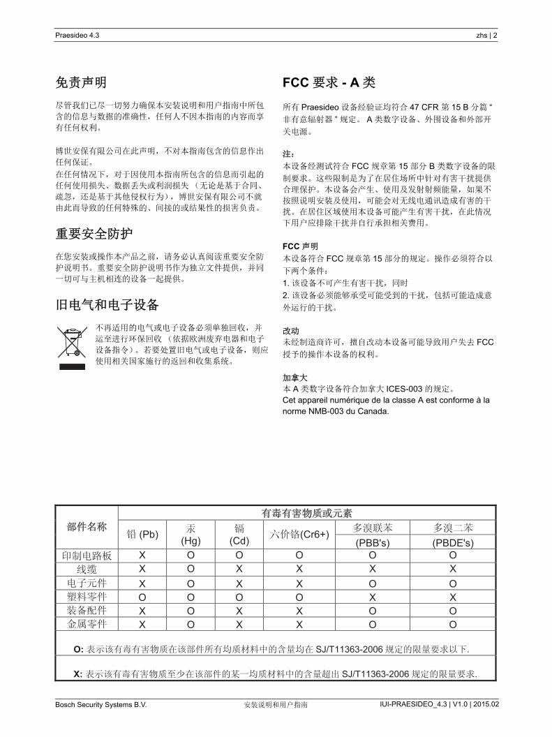
(Pb) (Hg) (Cd) (Cr6+)(PBB's) (PBDE's)
X O O O O O X O X X X X X O X X O O O O O O X X X O X X O O X O X X O O
O: SJ/T11363-2006 .
X: SJ/T11363-2006 .
Praesideo 4.3 zhs | 3
Bosch Security Systems B.V. IUI-PRAESIDEO_4.3 | V1.0 | 2015.02安装说明和用户指南
目录
免责声明 .........................................................................................2
重要安全防护 .....................................................................................2
旧电气和电子设备 .................................................................................2
FCC 要求 - A 类...................................................................................2
目录 .............................................................................................3License agreement for Praesideo software..................................................................................................... 24
紧急广播系统 ....................................................................................44EN54-16: 2008 compliancy checklist................................................................................................................ 46
EN54-16: 2008 VACIE label................................................................................................................................ 79
EN54-16: 2008 products description ................................................................................................................ 81
ISO7240-16: 2007 compliancy checklist .......................................................................................................... 83
DNV-GL 型式认可................................................................................921 手册概述 .................................................................................... 97
1.1 手册目的 ................................................................................ 97
1.2 目标受众 ................................................................................................................................................. 97
1.3 相关文件 ................................................................................................................................................. 97
1.4 警示 ........................................................................................................................................................ 97
1.5 符号 .................................................................................... 97
2 系统概述 ......................................................................................................................................................... 98
2.1 简介 ........................................................................................................................................................ 98
2.2 用户界面友好软件控制 ........................................................................................................................... 98
2.3 组网方法 ................................................................................................................................................. 98
2.4 分布式控制 ............................................................................................................................................. 98
2.5 联合功能 ................................................................................................................................................. 98
2.6 疏散符合性 ............................................................................................................................................. 99
2.7 外部接口 ................................................................................................................................................. 99
2.8 低安装费用 ............................................................................................................................................. 99
2.9 高度的系统灵活性 ................................................................................................................................... 99
3 呼叫 .............................................................................................................................................................. 100
3.1 简介 ...................................................................................................................................................... 100
3.2 呼叫属性 ............................................................................................................................................... 100
3.2.1 简介 ................................................................................................................................................. 100
3.2.2 优先级 ............................................................................................................................................. 100
3.2.3 呼叫内容 .......................................................................................................................................... 100
3.2.4 路由 ................................................................................................................................................. 100
3.2.5 定时 ................................................................................................................................................. 101
3.2.6 系统规模 .......................................................................................................................................... 101
3.3 类型 ...................................................................................................................................................... 101
3.3.1 简介 ................................................................................................................................................. 101
3.3.2 BGM 呼叫 ........................................................................................................................................ 101
3.3.3 常规呼叫 .......................................................................................................................................... 101
3.3.4 应急呼叫 .......................................................................................................................................... 101
4 术语表 .......................................................................................................................................................... 102
5 PRS-NCO3 网络控制器 ................................................................................................................................ 103
5.1 简介 ................................................................................... 103
5.2 控制器、连接器和指示器 ................................................................. 104
Praesideo 4.3 zhs | 4
Bosch Security Systems B.V. IUI-PRAESIDEO_4.3 | V1.0 | 2015.02安装说明和用户指南
5.2.1 前视图 .............................................................................. 104
5.2.2 后视图 .............................................................................. 104
5.2.3 内视图 ............................................................................. 106
5.3 连接 ................................................................................... 107
5.3.1 简介 ................................................................................ 107
5.3.2 连接主电源 .......................................................................... 107
5.3.3 连接备用电源 ................................................................................................................................... 107
5.3.4 连接网络 ............................................................................ 108
5.3.5 连接 PC ........................................................................................................................................... 108
5.3.6 连接音频输入端 ...................................................................... 108
5.3.7 连接音频输出端 ...................................................................... 109
5.3.8 连接控制输入端 ...................................................................... 109
5.3.9 连接控制输出端 ...................................................................... 110
5.3.10 设置蜂鸣器开关 ...................................................................... 110
5.3.11 使用 24 V 辅助输出 ................................................................... 110
5.3.12 连接 RS232 端口 ............................................................................................................................. 111
5.3.13 CF 卡 ............................................................................................................................................... 111
5.4 安装 ................................................................................... 111
5.5 配置菜单用法 ........................................................................... 112
5.5.1 概述 ................................................................................ 112
5.5.2 菜单导航 ............................................................................ 113
5.6 配置和操作 ............................................................................. 116
5.6.1 简介 ................................................................................ 116
5.6.2 启动 ................................................................................ 116
5.6.3 状态屏幕 ............................................................................ 116
5.6.4 紧急菜单 ............................................................................ 116
5.6.5 故障菜单 ............................................................................ 116
5.6.6 主菜单 .............................................................................. 117
5.6.7 设置监控选项 ........................................................................ 120
5.6.8 设置日期和时间 ...................................................................... 120
5.6.9 设置 TCP/IP .................................................................................................................................... 120
5.6.10 查看 MAC 地址 ................................................................................................................................ 121
5.6.11 查看版本信息 ................................................................................................................................... 121
5.7 技术数据 ............................................................................... 122
5.7.1 物理特性 ............................................................................ 122
5.7.2 气候条件 ............................................................................. 122
5.7.3 EMC 和安全 ......................................................................... 122
5.7.4 平均无故障工作时间 .................................................................. 122
5.7.5 系统总线 ............................................................................ 122
5.7.6 主电源 .............................................................................. 122
5.7.7 电源电池 ............................................................................ 122
5.7.8 音频线路输入端 ...................................................................... 123
5.7.9 音频话筒输入端(输入端 1和输入端 2专用) ............................................ 123
5.7.10 音频输出端 .......................................................................... 124
5.7.11 控制输入端 .......................................................................... 124
5.7.12 控制输出端 .......................................................................... 125
5.7.13 RS232 接口 ......................................................................... 125
5.7.14 以太网 .............................................................................. 125
Praesideo 4.3 zhs | 5
Bosch Security Systems B.V. IUI-PRAESIDEO_4.3 | V1.0 | 2015.02安装说明和用户指南
5.7.15 耳机 ................................................................................ 125
6 PRS-4AEX4 音频扩展器 ....................................................................... 126
6.1 简介 ................................................................................... 126
6.2 控制器和连接器 ......................................................................... 126
6.2.1 前视图 .............................................................................. 126
6.2.2 后视图 .............................................................................. 127
6.3 连接 ................................................................................... 128
6.3.1 简介 ................................................................................ 128
6.3.2 连接网络 ............................................................................ 128
6.3.3 连接音频输入端 ............................................................................................................................... 128
6.3.4 连接音频输出端 ...................................................................... 128
6.3.5 连接控制输入端 ...................................................................... 129
6.3.6 连接控制输出端 ............................................................................................................................... 130
6.4 安装 ................................................................................... 130
6.5 配置菜单用法 ........................................................................... 131
6.5.1 概述 ................................................................................ 131
6.5.2 菜单导航 .......................................................................................................................................... 132
6.6 配置和操作 ........................................................................................................................................... 134
6.6.1 简介 ................................................................................................................................................. 134
6.6.2 启动 ................................................................................................................................................. 134
6.6.3 状态屏幕 .......................................................................................................................................... 134
6.6.4 故障状态 .......................................................................................................................................... 134
6.6.5 主菜单 .............................................................................. 134
6.6.6 设置监控选项 ........................................................................ 135
6.6.7 查看版本信息 ........................................................................ 135
6.7 技术数据 ............................................................................... 136
6.7.1 物理特性 ............................................................................ 136
6.7.2 气候条件 ............................................................................ 136
6.7.3 EMC 和安全 ......................................................................... 136
6.7.4 平均无故障工作时间 ................................................................. 136
6.7.5 系统总线 ............................................................................ 136
6.7.6 音频线路输入端 ...................................................................... 136
6.7.7 音频话筒输入端(输入端 1和输入端 2专用) ............................................ 137
6.7.8 音频输出端 .......................................................................... 137
6.7.9 控制输入端 .......................................................................... 138
6.7.10 控制输出端 .......................................................................... 138
6.7.11 耳机 ................................................................................ 138
7 LBB4404/00CobraNet 接口 ................................................................... 139
7.1 简介 ................................................................................... 139
7.2 控制器和连接器 ......................................................................... 140
7.2.1 前视图 ............................................................................................................................................. 140
7.3 后视图 ................................................................................................................................................... 140
7.4 连接 ................................................................................... 141
7.4.1 简介 ................................................................................ 141
7.4.2 连接 Praesideo 网络 ........................................................................................................................ 141
7.4.3 连接 CobraNet 网络 ......................................................................................................................... 141
7.4.4 连接控制输入端 ...................................................................... 142
7.4.5 连接控制输出端 ............................................................................................................................... 142
Praesideo 4.3 zhs | 6
Bosch Security Systems B.V. IUI-PRAESIDEO_4.3 | V1.0 | 2015.02安装说明和用户指南
7.5 安装 ................................................................................... 143
7.6 CobraNet 配置 ...................................................................................................................................... 143
7.7 配置菜单用法 ........................................................................... 144
7.7.1 概述 ................................................................................ 144
7.7.2 菜单导航 .......................................................................................................................................... 145
7.8 配置和操作 ............................................................................. 147
7.8.1 简介 ................................................................................................................................................. 147
7.8.2 启动 ................................................................................................................................................. 147
7.8.3 状态屏幕 .......................................................................................................................................... 147
7.8.4 故障状态 .......................................................................................................................................... 147
7.8.5 主菜单 ............................................................................................................................................. 147
7.8.6 设置监控选项 ................................................................................................................................... 148
7.8.7 查看版本信息 ........................................................................ 148
7.9 技术数据 ............................................................................... 149
7.9.1 物理特性 ............................................................................ 149
7.9.2 气候条件 ............................................................................ 149
7.9.3 EMC 和安全 .................................................................................................................................... 149
7.9.4 平均无故障工作时间 ................................................................. 149
7.9.5 系统总线 ............................................................................ 149
7.9.6 控制输入端 .......................................................................... 149
7.9.7 控制输出端 .................................................................................................................................... 150
7.9.8 CobraNet ......................................................................................................................................... 150
7.9.9 耳机 ................................................................................................................................................. 150
8 PRS-4OMI4 OMNEO 接口 ........................................................................................................................... 151
8.1 简介 ................................................................................... 151
8.2 控制器和连接器 ......................................................................... 152
8.2.1 前视图 ............................................................................................................................................. 152
8.3 后视图 ................................................................................................................................................... 152
8.4 连接 ................................................................................... 153
8.4.1 简介 ................................................................................................................................................. 153
8.4.2 连接 Praesideo 网络 ........................................................................................................................ 153
8.4.3 连接 OMNEO 网络 .......................................................................................................................... 153
8.4.4 连接控制输入端 ...................................................................... 154
8.4.5 连接控制输出端 ............................................................................................................................... 154
8.5 安装 ................................................................................... 155
8.6 OMNEO 配置 ........................................................................................................................................ 155
8.7 配置菜单用法 ........................................................................... 156
8.7.1 概述 ................................................................................ 156
8.7.2 菜单导航 ............................................................................ 157
8.8 配置和操作 ............................................................................. 159
8.8.1 简介 ................................................................................ 159
8.8.2 启动 ................................................................................................................................................. 159
8.8.3 状态屏幕 .......................................................................................................................................... 159
8.8.4 故障状态 .......................................................................................................................................... 159
8.8.5 主菜单 ............................................................................................................................................. 159
8.8.6 设置监控选项 ........................................................................ 160
8.8.7 查看版本信息 ................................................................................................................................... 160
8.9 技术数据 ............................................................................... 161

Praesideo 4.3 zhs | 7
Bosch Security Systems B.V. IUI-PRAESIDEO_4.3 | V1.0 | 2015.02安装说明和用户指南
8.9.1 物理特性 ............................................................................ 161
8.9.2 气候条件 ............................................................................ 161
8.9.3 EMC 和安全 .................................................................................................................................... 161
8.9.4 平均无故障工作时间 ................................................................. 161
8.9.5 系统总线 ............................................................................ 161
8.9.6 控制输入端 .......................................................................... 161
8.9.7 控制输出端 .......................................................................... 162
8.9.8 OMNEO ........................................................................................................................................... 162
8.9.9 耳机 ................................................................................ 162
9 功率放大器 ................................................................................. 163
9.1 简介 ...................................................................................................................................................... 163
9.2 控制器、连接器和指示器 ................................................................. 164
9.2.1 前视图 .............................................................................. 164
9.2.2 后视图 ............................................................................................................................................. 164
9.3 连接 ................................................................................... 166
9.3.1 简介 ................................................................................................................................................. 166
9.3.2 连接主电源 ...................................................................................................................................... 166
9.3.3 连接网络 .......................................................................................................................................... 166
9.3.4 接地 ................................................................................................................................................. 166
9.3.5 连接到放大器通道 .................................................................... 167
9.3.6 连接音频输入端 ............................................................................................................................... 171
9.3.7 连接控制输入端 ............................................................................................................................... 171
9.3.8 连接备用电源 ........................................................................ 172
9.4 风扇控制 ............................................................................... 173
9.5 用于线路隔离器系统 ............................................................................................................................. 174
9.6 安装 ...................................................................................................................................................... 174
9.7 配置菜单用法 ........................................................................... 175
9.7.1 概述 ................................................................................ 175
9.7.2 菜单导航 ............................................................................ 176
9.8 配置和操作 ............................................................................. 177
9.8.1 简介 ................................................................................................................................................. 177
9.8.2 启动 ................................................................................................................................................. 178
9.8.3 状态屏幕 .......................................................................................................................................... 178
9.8.4 主菜单 .............................................................................. 179
9.8.5 设置监控选项 ........................................................................ 179
9.8.6 查看版本信息 ........................................................................ 179
9.9 技术数据 ............................................................................... 180
9.9.1 物理特性 ............................................................................ 180
9.9.2 气候条件 ............................................................................ 180
9.9.3 EMC 和安全 ......................................................................... 180
9.9.4 平均无故障工作时间 .................................................................. 180
9.9.5 系统总线 ............................................................................ 180
9.9.6 电源 ................................................................................ 180
9.9.7 备用电源 ............................................................................ 180
9.9.8 功耗 ................................................................................ 181
9.9.9 音频线路输入端 ...................................................................... 182
9.9.10 音频话筒输入端 ...................................................................... 182
9.9.11 扬声器输出端和备用输入端 ............................................................ 182

Praesideo 4.3 zhs | 8
Bosch Security Systems B.V. IUI-PRAESIDEO_4.3 | V1.0 | 2015.02安装说明和用户指南
9.9.12 降额 ................................................................................ 184
9.9.13 控制输入端 .......................................................................... 184
9.9.14 控制输出端 .......................................................................... 185
9.9.15 耳机 ................................................................................ 185
10 PRS-16MCI 多通道接口 ....................................................................... 186
10.1 简介 ................................................................................... 186
10.2 控制、连接和指示 ....................................................................... 187
10.2.1 前视图 .............................................................................. 187
10.2.2 后视图 ............................................................................................................................................. 187
10.3 连接器 ................................................................................. 188
10.3.1 简介 ................................................................................ 188
10.3.2 连接到基本型放大器 .................................................................. 188
10.3.3 连接网络 .......................................................................................................................................... 189
10.3.4 连接多通道接口旁路 .................................................................. 189
10.3.5 连接控制输入端 ............................................................................................................................... 189
10.3.6 连接控制输出端 ...................................................................... 191
10.3.7 接地 ................................................................................................................................................. 191
10.4 用于线路隔离器系统 ............................................................................................................................. 191
10.5 安装 ...................................................................................................................................................... 191
10.6 配置和操作 ............................................................................. 192
10.6.1 概述 ................................................................................ 192
10.6.2 失效安全 .......................................................................................................................................... 192
10.6.3 多通道接口和基本型放大器协作 ...................................................................................................... 192
10.6.4 多通道接口与线路隔离器系统协作 .................................................................................................. 192
10.6.5 前面板 LED 指示 ............................................................................................................................. 192
10.7 技术数据 ............................................................................................................................................... 193
10.7.1 物理特性 .......................................................................................................................................... 193
10.7.2 气候条件 ......................................................................................................................................... 193
10.7.3 EMC 和安全 .................................................................................................................................... 193
10.7.4 平均无故障工作时间 ....................................................................................................................... 193
10.7.5 电源 ................................................................................................................................................. 193
10.7.6 功耗 ................................................................................................................................................. 193
10.7.7 控制输入端 ...................................................................................................................................... 193
10.7.8 控制输出端 ...................................................................................................................................... 194
10.7.9 音频旁路 .......................................................................................................................................... 194
10.7.10 基本型放大器连接 ........................................................................................................................... 194
11 基本型放大器 ............................................................................... 195
11.1 简介 ................................................................................... 195
11.2 控制、连接和指示 ....................................................................... 196
11.2.1 前面 ................................................................................ 196
11.2.2 后面 ................................................................................................................................................. 196
11.3 连接器 ................................................................................. 198
11.3.1 简介 ................................................................................ 198
11.3.2 连接到主电源 ................................................................................................................................... 198
11.3.3 连接到多通道接口 ........................................................................................................................... 198
11.3.4 接地 ................................................................................................................................................. 199
11.3.5 连接到放大器通道 ........................................................................................................................... 199
11.3.6 本地音频输入端 ............................................................................................................................... 203
Praesideo 4.3 zhs | 9
Bosch Security Systems B.V. IUI-PRAESIDEO_4.3 | V1.0 | 2015.02安装说明和用户指南
11.3.7 连接备用电源 ................................................................................................................................... 204
11.4 风扇控制 ............................................................................................................................................... 204
11.5 安装 ...................................................................................................................................................... 206
11.6 操作 ...................................................................................................................................................... 206
11.7 技术数据 ............................................................................... 207
11.7.1 物理特性 ............................................................................ 207
11.7.2 气候条件 ............................................................................ 207
11.7.3 EMC 和安全 .................................................................................................................................... 207
11.7.4 平均无故障工作时间 ................................................................. 207
11.7.5 MCI 连接 ............................................................................. 207
11.7.6 电源 ................................................................................ 207
11.7.7 备用电源 ............................................................................ 207
11.7.8 功耗 ................................................................................ 208
11.7.9 音频线路输入端 ...................................................................... 209
11.7.10 扬声器输出端和备用输入端 ............................................................ 209
11.7.11 降额 ................................................................................ 210
12 单个扬声器线路检测 ......................................................................... 211
12.1 简介 ...................................................................................................................................................... 211
12.2 控制器、连接器和指示器 ................................................................. 211
12.2.1 检测主板 ............................................................................ 211
12.2.2 检测副板 ............................................................................ 211
12.3 安装 ................................................................................... 212
12.3.1 检测主板 ............................................................................ 212
12.3.2 检测副板 ............................................................................ 214
12.4 技术数据检测主控设备 ................................................................... 215
12.4.1 物理特性 ............................................................................ 215
12.4.2 气候条件 ............................................................................ 215
12.4.3 EMC 和安全 ......................................................................... 215
12.4.4 平均无故障工作时间 .................................................................. 215
12.5 技术数据检测从属设备 ................................................................... 215
12.5.1 物理特性 ............................................................................ 215
12.5.2 气候条件 ............................................................................ 215
12.5.3 EMC 和安全 .................................................................................................................................... 215
12.5.4 平均无故障工作时间 .................................................................. 215
12.5.5 扬声器线路特征 ...................................................................... 216
13 多分支扬声器线路检测 ....................................................................... 217
13.1 简介 ................................................................................... 217
13.2 控制器、连接器和指示器 ................................................................. 218
13.2.1 监控板 .............................................................................. 218
13.2.2 扬声器检测板 ................................................................................................................................... 218
13.2.3 扬声器线路检测板 ........................................................................................................................... 219
13.3 安装 ...................................................................................................................................................... 219
13.3.1 监控板 ............................................................................................................................................. 219
13.3.2 扬声器检测板 ........................................................................ 220
13.3.3 扬声器线路检测板 ........................................................................................................................... 222
13.4 寻址 ...................................................................................................................................................... 222
13.5 技术数据监控板 ......................................................................... 223
13.5.1 物理特性 ............................................................................ 223

Praesideo 4.3 zhs | 10
Bosch Security Systems B.V. IUI-PRAESIDEO_4.3 | V1.0 | 2015.02安装说明和用户指南
13.5.2 气候条件 ............................................................................ 223
13.5.3 EMC 和安全 .................................................................................................................................... 223
13.5.4 平均无故障工作时间 .................................................................. 223
13.6 技术数据扬声器检测板 ................................................................... 223
13.6.1 物理特性 ............................................................................ 223
13.6.2 气候条件 ............................................................................ 223
13.6.3 EMC 和安全 ......................................................................... 223
13.6.4 平均无故障工作时间 .................................................................. 223
13.6.5 扬声器线路特征 ...................................................................... 224
13.7 技术数据 EOL 检测板 ........................................................................................................................... 224
14 LBB4446/00 支架 ......................................................................................................................................... 225
15 LBC1256/00 EVAC 连接适配器 ................................................................................................................... 226
15.1 简介 ...................................................................................................................................................... 226
15.2 安装 ...................................................................................................................................................... 226
15.3 技术数据 ............................................................................................................................................... 226
16 LBB4430/00 呼叫站 ..................................................................................................................................... 227
16.1 简介 ...................................................................................................................................................... 227
16.2 控制器、连接器和指示器 ...................................................................................................................... 228
16.3 连接 ...................................................................................................................................................... 228
16.3.1 简介 ................................................................................................................................................. 228
16.3.2 连接网络 .......................................................................................................................................... 228
16.3.3 连接头戴式送受话器 ........................................................................................................................ 228
16.4 安装 ...................................................................................................................................................... 230
16.5 操作 ...................................................................................................................................................... 230
16.6 技术数据 ............................................................................................................................................... 231
16.6.1 物理特性 .......................................................................................................................................... 231
16.6.2 气候条件 .......................................................................................................................................... 231
16.6.3 EMC 和安全 .................................................................................................................................... 231
16.6.4 平均无故障工作时间 ....................................................................................................................... 231
16.6.5 系统总线 .......................................................................................................................................... 231
16.6.6 话筒 ................................................................................................................................................. 231
16.6.7 Loudspeaker ................................................................................................................................... 231
16.6.8 头戴式送受话器 ............................................................................................................................... 231
17 LBB4432/00 呼叫站键盘 .............................................................................................................................. 232
17.1 简介 ...................................................................................................................................................... 232
17.2 控制器、连接器和指示器 ...................................................................................................................... 232
17.2.1 俯视图 ............................................................................................................................................. 232
17.2.2 仰视图 ............................................................................................................................................. 233
17.3 配置 ...................................................................................................................................................... 233
17.4 安装 ...................................................................................................................................................... 234
17.5 操作 ...................................................................................................................................................... 235
17.6 技术数据 ............................................................................................................................................... 235
17.6.1 物理尺寸 .......................................................................................................................................... 235
17.6.2 气候条件 .......................................................................................................................................... 235
17.6.3 EMC 和安全 .................................................................................................................................... 235
17.6.4 平均无故障工作时间 ....................................................................................................................... 235
17.6.5 系统总线 .......................................................................................................................................... 235
18 PRS-CSNKP 数字键盘 ................................................................................................................................. 236
Praesideo 4.3 zhs | 11
Bosch Security Systems B.V. IUI-PRAESIDEO_4.3 | V1.0 | 2015.02安装说明和用户指南
18.1 简介 ...................................................................................................................................................... 236
18.2 17.2 兼容性 ........................................................................................................................................... 236
18.3 控制器、连接器和指示器 ...................................................................................................................... 236
18.3.1 俯视图 ............................................................................................................................................. 236
18.4 仰视图 ................................................................................................................................................... 236
18.5 安装 ...................................................................................................................................................... 237
18.6 操作 ...................................................................................................................................................... 238
18.6.1 简介 ................................................................................................................................................. 238
18.6.2 按键 ................................................................................................................................................. 238
18.6.3 显示器 ............................................................................................................................................. 238
18.7 技术数据 ............................................................................................................................................... 239
18.7.1 物理尺寸 .......................................................................................................................................... 239
18.7.2 气候条件 .......................................................................................................................................... 239
18.7.3 EMC 和安全 .................................................................................................................................... 239
18.7.4 平均无故障工作时间 ....................................................................................................................... 239
18.7.5 系统总线 .......................................................................................................................................... 239
19 PRS-CSM 呼叫站模块 .................................................................................................................................. 240
19.1 简介 ...................................................................................................................................................... 240
19.2 控制器、连接器和指示器 ...................................................................................................................... 241
19.2.1 备份电源 / 蜂鸣器 (1) ....................................................................................................................... 242
19.2.2 麦克风 /PTT 键的连接(2) ............................................................................................................ 242
19.2.3 扬声器 / 控制输入端 (3) ................................................................................................................... 243
19.2.4 耳机 / 音量控制(4) ....................................................................................................................... 243
19.2.5 控制输入 / 输出端 (5, 6) ................................................................................................................... 244
19.2.6 键盘接口 (X143) .............................................................................................................................. 246
19.3 安装 ...................................................................................................................................................... 247
19.4 技术数据 ............................................................................................................................................... 248
19.4.1 物理特性 .......................................................................................................................................... 248
19.4.2 气候条件 .......................................................................................................................................... 248
19.4.3 EMC 和安全 .................................................................................................................................... 248
19.4.4 平均无故障工作时间 ....................................................................................................................... 248
19.4.5 系统总线 .......................................................................................................................................... 248
19.4.6 备用电源 .......................................................................................................................................... 248
19.4.7 话筒 ................................................................................................................................................. 248
19.4.8 Loudspeaker ................................................................................................................................... 248
19.4.9 头戴式送受话器 ............................................................................................................................... 249
19.4.10 控件 ................................................................................................................................................ 249
19.4.11 蜂鸣器 ............................................................................................................................................ 249
20 PRS-CSKPM 呼叫站键盘模块 ..................................................................................................................... 250
20.1 简介 ...................................................................................................................................................... 250
20.2 控制器、连接器和指示器 ...................................................................................................................... 251
20.2.1 键盘输入端 (1) ................................................................................................................................. 252
20.2.2 控制输出端 (2) ................................................................................................................................. 252
20.2.3 键盘接口 (X5、 X6) ......................................................................................................................... 253
20.2.4 ID 选择器 (S9) ................................................................................................................................. 254
20.3 安装 ...................................................................................................................................................... 255
20.3.1 将 PRS-CSKPM 连接到其他模块上 ................................................................................................ 256
20.4 技术数据 ............................................................................................................................................... 257
Praesideo 4.3 zhs | 12
Bosch Security Systems B.V. IUI-PRAESIDEO_4.3 | V1.0 | 2015.02安装说明和用户指南
20.4.1 物理特性 .......................................................................................................................................... 257
20.4.2 气候条件 ......................................................................................................................................... 257
20.4.3 EMC 和安全 .................................................................................................................................... 257
20.4.4 平均无故障工作时间 ....................................................................................................................... 257
20.4.5 系统总线 .......................................................................................................................................... 257
21 PRS-CSR 远程呼叫站 .................................................................................................................................. 258
21.1 简介 ...................................................................................................................................................... 258
21.2 控制器、连接器和指示器 ...................................................................................................................... 259
21.3 连接 ...................................................................................................................................................... 259
21.3.1 简介 ................................................................................................................................................. 259
21.3.2 连接网络 .......................................................................................................................................... 259
21.3.3 连接头戴式送受话器 ........................................................................................................................ 259
21.3.4 连接电源 .......................................................................................................................................... 260
21.3.5 连接控制输入端 ............................................................................................................................... 261
21.4 安装 ...................................................................................................................................................... 262
21.5 操作 ...................................................................................................................................................... 262
21.6 技术数据 ............................................................................................................................................... 263
21.6.1 物理特性 .......................................................................................................................................... 263
21.6.2 气候条件 .......................................................................................................................................... 263
21.6.3 EMC 和安全 .................................................................................................................................... 263
21.6.4 平均无故障工作时间 ....................................................................................................................... 263
21.6.5 外部电源.......................................................................................................................................... 263
21.6.6 呼叫站接口 ...................................................................................................................................... 263
21.6.7 话筒 ................................................................................................................................................. 263
21.6.8 Loudspeaker ................................................................................................................................... 263
21.6.9 头戴式送受话器 ............................................................................................................................... 264
21.6.10 控制输入端 ...................................................................................................................................... 264
22 PRS-CSRM 远程呼叫站模块 ........................................................................................................................ 265
22.1 简介 ...................................................................................................................................................... 265
22.2 控制器、连接器和指示器 ...................................................................................................................... 266
22.2.1 备份电源 / 蜂鸣器 (1) ....................................................................................................................... 267
22.2.2 麦克风 /PTT 键的连接(2) ............................................................................................................ 267
22.2.3 扬声器 / 控制输入端 (3) ................................................................................................................... 267
22.2.4 耳机 / 音量控制(4) ....................................................................................................................... 268
22.2.5 控制输入 / 输出端 (5, 6) ................................................................................................................... 269
22.2.6 键盘接口 (X1) .................................................................................................................................. 271
22.3 安装 ...................................................................................................................................................... 272
22.4 技术数据 ............................................................................................................................................... 273
22.4.1 物理特性 .......................................................................................................................................... 273
22.4.2 气候条件 .......................................................................................................................................... 273
22.4.3 电磁兼容性 ...................................................................................................................................... 273
22.4.4 平均无故障工作时间 ....................................................................................................................... 273
22.4.5 呼叫站接口 ...................................................................................................................................... 273
22.4.6 备用电源 .......................................................................................................................................... 273
22.4.7 话筒 ................................................................................................................................................. 273
22.4.8 Loudspeaker ................................................................................................................................... 273
22.4.9 头戴式送受话器 ............................................................................................................................... 274
22.4.10 控件 ................................................................................................................................................ 274
Praesideo 4.3 zhs | 13
Bosch Security Systems B.V. IUI-PRAESIDEO_4.3 | V1.0 | 2015.02安装说明和用户指南
22.4.11 蜂鸣器 ............................................................................................................................................ 274
23 PRS-CSI 呼叫站接口 .................................................................................................................................... 275
23.1 简介 ...................................................................................................................................................... 275
23.2 控制器、连接器和指示器 ...................................................................................................................... 276
23.2.1 外部 ................................................................................................................................................. 276
23.2.2 内部 ................................................................................................................................................. 277
23.3 连接 ...................................................................................................................................................... 277
23.3.1 简介 ................................................................................................................................................. 277
23.3.2 连接网络和远程呼叫站 .................................................................................................................... 277
23.3.3 连接电源 .......................................................................................................................................... 278
23.3.4 连接控制输入端 ............................................................................................................................... 279
23.3.5 接地 ................................................................................................................................................. 279
23.4 安装 ...................................................................................................................................................... 279
23.5 操作 ...................................................................................................................................................... 280
23.6 技术数据 ............................................................................................................................................... 280
23.6.1 物理特性 .......................................................................................................................................... 280
23.6.2 气候条件 .......................................................................................................................................... 280
23.6.3 电磁兼容性 ...................................................................................................................................... 280
23.6.4 平均无故障工作时间 ....................................................................................................................... 280
23.6.5 系统总线 .......................................................................................................................................... 280
23.6.6 外部电源 .......................................................................................................................................... 280
23.6.7 呼叫站接口 ...................................................................................................................................... 280
24 PRS-CRE 呼叫堆栈 ...................................................................................................................................... 281
24.1 简介 ...................................................................................................................................................... 281
24.2 控制器和指示器 .................................................................................................................................... 282
24.3 连接 ...................................................................................................................................................... 282
24.3.1 连接网络 .......................................................................................................................................... 282
24.4 安装 ...................................................................................................................................................... 282
24.5 操作 ...................................................................................................................................................... 283
24.6 技术数据 ............................................................................................................................................... 283
24.6.1 物理特性 .......................................................................................................................................... 283
24.6.2 气候条件 .......................................................................................................................................... 283
24.6.3 EMC 和安全 .................................................................................................................................... 283
24.6.4 平均无故障工作时间 ....................................................................................................................... 283
24.6.5 系统总线 .......................................................................................................................................... 283
24.6.6 音频 ................................................................................................................................................. 283
25 LBB4436/00 按键保护盖 .............................................................................................................................. 284
26 PRS-NSP 网络分路器 .................................................................................................................................. 285
26.1 简介 ...................................................................................................................................................... 285
26.2 控制器和连接器 .................................................................................................................................... 285
26.2.1 外部 ................................................................................................................................................. 285
26.2.2 内部 ................................................................................................................................................. 287
26.3 连接 ...................................................................................................................................................... 288
26.3.1 简介 ................................................................................................................................................. 288
26.3.2 连接主支路和创建分支插接 ............................................................................................................. 288
26.3.3 连接电源 .......................................................................................................................................... 288
26.4 安装 ...................................................................................................................................................... 289
26.5 操作 ...................................................................................................................................................... 289

Praesideo 4.3 zhs | 14
Bosch Security Systems B.V. IUI-PRAESIDEO_4.3 | V1.0 | 2015.02安装说明和用户指南
26.6 技术数据 ............................................................................................................................................... 290
26.6.1 物理特性 .......................................................................................................................................... 290
26.6.2 气候条件 .......................................................................................................................................... 290
26.6.3 EMC 和安全 .................................................................................................................................... 290
26.6.4 平均无故障工作时间 ....................................................................................................................... 290
26.6.5 系统总线 .......................................................................................................................................... 290
26.6.6 外部电源 .......................................................................................................................................... 290
27 PRS-FIN、 PRS-FINNA、 PRS-FINS 光纤接口 .......................................................................................... 291
27.1 简介 ...................................................................................................................................................... 291
27.2 控制器、连接器和指示器 ...................................................................................................................... 291
27.3 连接 ...................................................................................................................................................... 293
27.3.1 简介 ................................................................................................................................................. 293
27.3.2 连接塑料光纤和玻璃光纤电缆 ......................................................................................................... 293
27.3.3 连接电源 .......................................................................................................................................... 293
27.3.4 连接控制输入端 ............................................................................................................................... 294
27.3.5 操作 ................................................................................................................................................. 295
27.4 安装 ...................................................................................................................................................... 296
27.5 技术数据 ............................................................................................................................................... 296
27.5.1 物理特性 .......................................................................................................................................... 296
27.5.2 气候条件 .......................................................................................................................................... 296
27.5.3 EMC 和安全 .................................................................................................................................... 296
27.5.4 平均无故障工作时间 ....................................................................................................................... 296
27.5.5 系统总线 .......................................................................................................................................... 297
27.5.6 外部电源 .......................................................................................................................................... 297
27.5.7 GOF 连接器 ..................................................................................................................................... 297
28 LBB4416/xx 网络电缆 ................................................................................................................................. 298
28.1 简介 ...................................................................................................................................................... 298
28.2 连接器 ................................................................................................................................................... 298
28.3 接线 ...................................................................................................................................................... 299
28.4 定制电缆 ............................................................................................................................................... 299
28.5 技术数据 ............................................................................................................................................... 299
29 LBB4417/00 网络连接器 .............................................................................................................................. 300
30 LBB4418 电缆连接器工具箱 ........................................................................................................................ 301
30.1 简介 ...................................................................................................................................................... 301
30.2 工具箱内含物 ........................................................................................................................................ 301
30.3 连接器组件 ........................................................................................................................................... 303
30.4 电缆连接器安装 .................................................................................................................................... 304
30.4.1 简介 ................................................................................................................................................. 304
30.4.2 电缆类型 .......................................................................................................................................... 304
30.4.3 准备 ................................................................................................................................................. 304
30.4.4 压接衬套 .......................................................................................................................................... 305
30.4.5 剥离铜芯 .......................................................................................................................................... 305
30.4.6 安装铜芯套筒 ................................................................................................................................... 306
30.4.7 剥离光纤 .......................................................................................................................................... 307
30.4.8 安装光纤套筒 ................................................................................................................................... 309
30.4.9 装配连接器 ...................................................................................................................................... 310
31 LBB4419/00 电缆耦合器 .............................................................................................................................. 314
32 电缆连接 ....................................................................................................................................................... 315

Praesideo 4.3 zhs | 15
Bosch Security Systems B.V. IUI-PRAESIDEO_4.3 | V1.0 | 2015.02安装说明和用户指南
32.1 简介 ...................................................................................................................................................... 315
32.2 系统总线 ............................................................................................................................................... 315
32.3 防尘盖 ................................................................................................................................................... 316
32.4 大距离 ............................................................................................................................................... 316
32.5 大电缆长度 ........................................................................................................................................ 317
32.6 弯曲度和绕线 ........................................................................................................................................ 318
32.6.1 简介 ................................................................................................................................................. 318
32.6.2 弯曲度 ............................................................................................................................................. 318
32.6.3 绕线 ................................................................................................................................................. 318
33 结构 .............................................................................................................................................................. 319
33.1 简介 ...................................................................................................................................................... 319
33.2 基本系统 ............................................................................................................................................... 319
33.3 冗余电缆连接 ........................................................................................................................................ 319
33.4 分支插接 ............................................................................................................................................... 320
33.5 备用放大器 ........................................................................................................................................... 320
33.6 CobraNet .............................................................................................................................................. 321
33.7 故障安全 ............................................................................................................................................... 322
33.7.1 简介 ................................................................................................................................................. 322
33.7.2 规则 ................................................................................................................................................. 322
33.8 IP 地址 .................................................................................................................................................. 322
34 功耗 .............................................................................................................................................................. 323
34.1 简介 ...................................................................................................................................................... 323
34.2 功耗 ...................................................................................................................................................... 323
34.3 电池容量计算 ........................................................................................................................................ 323
34.4 电源 ...................................................................................................................................................... 324
34.5 制冷能力 ............................................................................................................................................... 325
35 预防性维护 ................................................................................................................................................... 326
35.1 清洁进气口 ........................................................................................................................................... 326
35.2 更换电池 ............................................................................................................................................... 326
36 PRS-SW Praesideo 软件 DVD .................................................................................................................... 327
36.1 简介 ...................................................................................................................................................... 327
36.2 启动 DVD .............................................................................................................................................. 328
36.3 内容 ...................................................................................................................................................... 328
36.3.1 简介 ................................................................................................................................................. 328
37 必选包 .......................................................................................................................................................... 329
37.1 简介 ...................................................................................................................................................... 329
37.2 PC 上的安装 ......................................................................................................................................... 329
37.2.1 简介 ................................................................................................................................................. 329
37.2.2 Praesideo 核心软件 ......................................................................................................................... 329
37.2.3 SVG 查看器 ..................................................................................................................................... 329
37.3 建立连接 ............................................................................................................................................... 330
37.4 升级系统软件 ........................................................................................................................................ 331
37.5 升级固件 ............................................................................................................................................... 331
37.6 清理记录事件 ........................................................................................................................................ 333
38 建议包 .......................................................................................................................................................... 334
38.1 简介 ...................................................................................................................................................... 334
38.2 Adobe reader ........................................................................................................................................ 334
38.3 版本注释 ............................................................................................................................................... 334

Praesideo 4.3 zhs | 16
Bosch Security Systems B.V. IUI-PRAESIDEO_4.3 | V1.0 | 2015.02安装说明和用户指南
38.4 操作手册 ............................................................................................................................................... 334
39 可选包 .......................................................................................................................................................... 335
40 故障排除 ....................................................................................................................................................... 336
40.1 简介 ...................................................................................................................................................... 336
40.2 安全设置 ............................................................................................................................................... 336
40.3 连接 ...................................................................................................................................................... 336
41 配置软件 ....................................................................................................................................................... 337
41.1 简介 ...................................................................................................................................................... 337
41.2 启动和登录 ........................................................................................................................................... 337
41.3 概述 ...................................................................................................................................................... 338
41.4 配置部分 ............................................................................................................................................... 338
41.4.1 简介 ................................................................................................................................................. 338
41.4.2 脱机配置 .......................................................................................................................................... 338
41.4.3 提交 ................................................................................................................................................. 339
41.4.4 保存 ................................................................................................................................................. 339
41.4.5 允许字符 .......................................................................................................................................... 340
41.4.6 唯一性名称 ...................................................................................................................................... 340
41.4.7 初始值 ............................................................................................................................................. 340
41.4.8 撤消更改 .......................................................................................................................................... 340
41.4.9 启用的项目 ...................................................................................................................................... 340
41.4.10 删除项 ............................................................................................................................................. 340
41.4.11 音频输入端 ...................................................................................................................................... 340
41.4.12 下载配置 .......................................................................................................................................... 340
41.4.13 配置打印实用程序 ........................................................................................................................... 341
41.5 诊断部分 ............................................................................................................................................... 341
41.6 升级部分 ............................................................................................................................................... 341
42 用户管理 ....................................................................................................................................................... 342
42.1 简介 ...................................................................................................................................................... 342
42.2 帐户 ...................................................................................................................................................... 342
42.3 添加用户 ............................................................................................................................................... 343
42.4 删除用户 ............................................................................................................................................... 344
43 系统定义 ....................................................................................................................................................... 345
43.1 简介 ...................................................................................................................................................... 345
43.2 序列号 ................................................................................................................................................... 345
43.3 网络控制器 ........................................................................................................................................... 346
43.4 功率放大器 ........................................................................................................................................... 346
43.4.1 添加功率放大器 ............................................................................................................................... 346
43.4.2 删除功率放大器 ............................................................................................................................... 347
43.5 多通道接口 ........................................................................................................................................... 348
43.5.1 添加多通道接口 ............................................................................................................................... 348
43.5.2 删除多通道接口 ............................................................................................................................... 348
43.6 呼叫站 ................................................................................................................................................... 348
43.6.1 添加呼叫站 ...................................................................................................................................... 348
43.6.2 删除呼叫站 ...................................................................................................................................... 349
43.7 呼叫堆栈 ............................................................................................................................................... 349
43.7.1 添加呼叫堆栈 ................................................................................................................................... 349
43.7.2 删除呼叫堆栈 ................................................................................................................................... 349
43.8 音频扩展器 ........................................................................................................................................... 349

Praesideo 4.3 zhs | 17
Bosch Security Systems B.V. IUI-PRAESIDEO_4.3 | V1.0 | 2015.02安装说明和用户指南
43.8.1 添加音频扩展器 ............................................................................................................................... 349
43.8.2 删除音频扩展器 ............................................................................................................................... 349
43.9 CobraNet 接口 ...................................................................................................................................... 350
43.9.1 添加 CobraNet 接口 ......................................................................................................................... 350
43.9.2 删除 CobraNet 接口 ......................................................................................................................... 350
43.10 OMNEO 接口 ........................................................................................................................................ 350
43.10.1 添加 OMNEO 接口 .......................................................................................................................... 350
43.10.2 删除 OMNEO 接口 .......................................................................................................................... 350
43.11 光纤接口 ............................................................................................................................................... 351
43.11.1 添加光纤接口 ................................................................................................................................... 351
43.11.2 删除光纤接口 ................................................................................................................................... 351
43.12 TCP/IP 设备 .......................................................................................................................................... 351
43.12.1 添加 TCP/IP 设备 ............................................................................................................................ 351
43.12.2 删除 TCP/IP 设备 ............................................................................................................................ 352
44 设备配置 ....................................................................................................................................................... 353
44.1 简介 ...................................................................................................................................................... 353
44.2 网络控制器 ........................................................................................................................................... 353
44.2.1 步骤 ................................................................................................................................................. 353
44.2.2 概要 ................................................................................................................................................. 354
44.2.3 音频输入端 ...................................................................................................................................... 355
44.2.4 音频输出端 ...................................................................................................................................... 356
44.2.5 控制输入端 ...................................................................................................................................... 357
44.2.6 控制输出端 ...................................................................................................................................... 358
44.2.7 虚拟控制输入端 ............................................................................................................................... 359
44.3 功率放大器 ........................................................................................................................................... 359
44.3.1 步骤 ................................................................................................................................................. 359
44.3.2 概要 ................................................................................................................................................. 360
44.3.3 音频输入端 ...................................................................................................................................... 361
44.3.4 音频输出端 ...................................................................................................................................... 362
44.3.5 线路和扬声器检测 ........................................................................................................................... 363
44.3.6 控制输入端 ...................................................................................................................................... 364
44.3.7 控制输出端 ...................................................................................................................................... 364
44.4 多通道接口 ........................................................................................................................................... 365
44.4.1 步骤 ................................................................................................................................................. 365
44.4.2 音频输出端 ...................................................................................................................................... 365
44.4.3 备用输出端 ...................................................................................................................................... 365
44.4.4 控制输入端 ...................................................................................................................................... 368
44.4.5 控制输出端 ...................................................................................................................................... 368
44.5 呼叫站 ................................................................................................................................................... 369
44.5.1 步骤 ................................................................................................................................................. 369
44.5.2 概要 (LBB4430/00) .......................................................................................................................... 370
44.5.3 常规(PRS-CSM) ......................................................................................................................... 371
44.5.4 常规(PRS-CSR 和 PRS-CSRM) ................................................................................................. 372
44.5.5 音频输入端 ...................................................................................................................................... 373
44.5.6 数字键盘 .......................................................................................................................................... 374
44.5.7 控制输入端 (PRS-CSM) .................................................................................................................. 375
44.5.8 键盘 ................................................................................................................................................. 376
44.6 音频扩展器 ........................................................................................................................................... 377

Praesideo 4.3 zhs | 18
Bosch Security Systems B.V. IUI-PRAESIDEO_4.3 | V1.0 | 2015.02安装说明和用户指南
44.6.1 步骤 ................................................................................................................................................. 377
44.6.2 音频输入端 ...................................................................................................................................... 377
44.6.3 音频输出端 ...................................................................................................................................... 377
44.6.4 控制输入端 ...................................................................................................................................... 377
44.6.5 控制输出端 ...................................................................................................................................... 377
44.7 CobraNet 接口 ...................................................................................................................................... 378
44.7.1 音频输入端 ...................................................................................................................................... 378
44.7.2 音频输出端 ...................................................................................................................................... 378
44.7.3 控制输入端 ...................................................................................................................................... 379
44.7.4 控制输出端 ...................................................................................................................................... 379
44.8 OMNEO 接口 ........................................................................................................................................ 379
44.8.1 音频输入端 ...................................................................................................................................... 380
44.8.2 音频输出端 ...................................................................................................................................... 380
44.8.3 控制输入端 ...................................................................................................................................... 380
44.8.4 控制输出端 ...................................................................................................................................... 380
44.9 光纤接口 ............................................................................................................................................... 381
44.9.1 步骤 ................................................................................................................................................. 381
44.9.2 控制输入端 ...................................................................................................................................... 381
45 整个系统的设定 ............................................................................................................................................ 382
45.1 简介 ...................................................................................................................................................... 382
45.2 录制的讯息 ........................................................................................................................................... 382
45.2.1 简介 ................................................................................................................................................. 382
45.2.2 注册录制的讯息 ............................................................................................................................... 382
45.2.3 注销录制的讯息 ............................................................................................................................... 383
45.3 讯息集 ................................................................................................................................................... 383
45.3.1 简介 ................................................................................................................................................. 383
45.3.2 创建消息集 ...................................................................................................................................... 383
45.3.3 高效警报音 ...................................................................................................................................... 384
45.3.4 传输讯息集 ...................................................................................................................................... 384
45.4 系统设置 ............................................................................................................................................... 385
46 分区和放大器 ................................................................................................................................................ 387
46.1 简介 ...................................................................................................................................................... 387
46.2 分区配置 ............................................................................................................................................... 387
46.2.1 简介 ................................................................................................................................................. 387
46.2.2 简介 ................................................................................................................................................. 388
46.2.3 创建分区 .......................................................................................................................................... 388
46.2.4 音量设置 .......................................................................................................................................... 389
46.2.5 删除分区 .......................................................................................................................................... 390
46.2.6 重命名分区 ...................................................................................................................................... 390
46.3 分区分组 ............................................................................................................................................... 391
46.3.1 简介 ................................................................................................................................................. 391
46.3.2 简介 ................................................................................................................................................. 391
46.3.3 添加分区组 ...................................................................................................................................... 391
46.3.4 删除分区组 ...................................................................................................................................... 391
46.3.5 重命名分区组 ................................................................................................................................... 391
46.4 备用 ...................................................................................................................................................... 391
46.4.1 简介 ................................................................................................................................................. 391
46.4.2 简介 ................................................................................................................................................. 392

Praesideo 4.3 zhs | 19
Bosch Security Systems B.V. IUI-PRAESIDEO_4.3 | V1.0 | 2015.02安装说明和用户指南
46.4.3 步骤 ................................................................................................................................................. 392
46.5 BGM 通道 ............................................................................................................................................. 393
46.5.1 简介 ................................................................................................................................................. 393
46.5.2 概述 ................................................................................................................................................. 393
46.5.3 添加 BGM 通道 ................................................................................................................................ 394
46.5.4 删除 BGM 通道 ................................................................................................................................ 394
46.5.5 重命名 BGM 通道 ............................................................................................................................ 394
47 呼叫特性 ....................................................................................................................................................... 395
47.1 简介 ...................................................................................................................................................... 395
47.2 呼叫宏 ................................................................................................................................................... 395
47.2.1 简介 ................................................................................................................................................. 395
47.2.2 创建呼叫宏 ...................................................................................................................................... 395
47.2.3 删除呼叫宏 ...................................................................................................................................... 397
48 动作编程 ....................................................................................................................................................... 398
48.1 简介 ...................................................................................................................................................... 398
48.2 行为 ...................................................................................................................................................... 398
48.2.1 简介 ................................................................................................................................................. 398
48.2.2 瞬态行为 .......................................................................................................................................... 398
48.2.3 单激发态行为 ................................................................................................................................... 399
48.2.4 双态 ................................................................................................................................................. 399
48.3 动作 ...................................................................................................................................................... 400
48.3.1 简介 ................................................................................................................................................. 400
48.3.2 简介 ................................................................................................................................................. 401
48.3.3 按下讲话(PTT) ............................................................................................................................ 402
48.3.4 呼叫激活键 ...................................................................................................................................... 402
48.3.5 开始 ................................................................................................................................................. 403
48.3.6 停止 ................................................................................................................................................. 403
48.3.7 呼叫宏 ............................................................................................................................................. 404
48.3.8 优先级 ............................................................................................................................................. 404
48.3.9 语音 ................................................................................................................................................. 404
48.3.10 录制的讯息 ...................................................................................................................................... 404
48.3.11 分区选择 .......................................................................................................................................... 405
48.3.12 取消选择 .......................................................................................................................................... 405
48.3.13 重拨 ................................................................................................................................................. 405
48.3.14 取消上一次 ...................................................................................................................................... 406
48.3.15 取消全部 .......................................................................................................................................... 406
48.3.16 BGM 源 ........................................................................................................................................... 406
48.3.17 BGM 音量控制 ................................................................................................................................. 407
48.3.18 BGM 打开 / 关闭 .............................................................................................................................. 407
48.3.19 本地 BGM 源 .................................................................................................................................. 408
48.3.20 本地 BGM 音量控制 ......................................................................................................................... 408
48.3.21 本地 BGM 打开 / 关闭 ...................................................................................................................... 409
48.3.22 故障输入 .......................................................................................................................................... 409
48.3.23 分区线路故障 ................................................................................................................................... 410
48.3.24 确认 / 复位 ....................................................................................................................................... 410
48.3.25 指示器测试 ...................................................................................................................................... 411
48.3.26 备用电源模式 ................................................................................................................................... 411
48.3.27 同步时间 .......................................................................................................................................... 412

Praesideo 4.3 zhs | 20
Bosch Security Systems B.V. IUI-PRAESIDEO_4.3 | V1.0 | 2015.02安装说明和用户指南
48.3.28 开关触发器 ...................................................................................................................................... 412
48.3.29 开关输出 .......................................................................................................................................... 413
48.3.30 分区活动输出端 ............................................................................................................................... 413
48.3.31 音量强切输出 ................................................................................................................................... 413
48.3.32 系统故障 .......................................................................................................................................... 413
48.3.33 分区状态 .......................................................................................................................................... 413
48.3.34 分区优先级状态 ............................................................................................................................... 415
49 音频处理 ....................................................................................................................................................... 416
49.1 简介 ...................................................................................................................................................... 416
49.2 音频处理参数 ........................................................................................................................................ 416
49.2.1 均衡器 ............................................................................................................................................. 416
49.2.2 均衡器设置 ...................................................................................................................................... 416
49.2.3 音量设置 .......................................................................................................................................... 416
49.2.4 备用功率放大器 ............................................................................................................................... 416
49.3 AVC 校准 .............................................................................................................................................. 417
50 自动音量控制 ................................................................................................................................................ 418
50.1 简介 ...................................................................................................................................................... 418
50.2 感测话筒 ............................................................................................................................................... 418
50.2.1 简介 ................................................................................................................................................. 418
50.2.2 类型 ................................................................................................................................................. 418
50.2.3 Supervision ..................................................................................................................................... 418
50.2.4 安装 ................................................................................................................................................. 418
50.3 连接 ...................................................................................................................................................... 418
50.4 配置 ...................................................................................................................................................... 418
51 诊断安装 ....................................................................................................................................................... 421
51.1 简介 ...................................................................................................................................................... 421
51.2 电缆长度余量 ........................................................................................................................................ 421
51.3 节点数 ................................................................................................................................................... 421
51.4 光学网络 ............................................................................................................................................... 421
51.5 扬声器检测 ........................................................................................................................................... 422
51.6 设备信息 ............................................................................................................................................... 422
51.7 检查配置 ............................................................................................................................................... 423
52 简介 .............................................................................................................................................................. 424
52.1 简介 ...................................................................................................................................................... 424
52.2 常规事件 ............................................................................................................................................... 424
52.3 呼叫事件 ............................................................................................................................................... 424
52.4 故障事件 ............................................................................................................................................... 424
52.4.1 简介 ................................................................................................................................................. 424
52.4.2 状态 ................................................................................................................................................. 424
52.4.3 确认故障事件 ................................................................................................................................... 424
52.4.4 解决故障事件 ................................................................................................................................... 424
52.4.5 重置故障事件 ................................................................................................................................... 425
53 一般事件列表 ................................................................................................................................................ 426
54 呼叫事件列表 ................................................................................................................................................ 429
55 故障事件列表 ................................................................................................................................................ 430
56 CobraNet Discovery ................................................................................................................................... 444
56.1 简介 ...................................................................................................................................................... 444
56.2 安装 ...................................................................................................................................................... 444

Praesideo 4.3 zhs | 21
Bosch Security Systems B.V. IUI-PRAESIDEO_4.3 | V1.0 | 2015.02安装说明和用户指南
56.3 网络适配器配置 .................................................................................................................................... 445
56.3.1 IP 地址分配 .......................................................................... 445
56.3.2 分配 IP 地址 ......................................................................... 445
56.4 操作 ...................................................................................................................................................... 446
56.4.1 S (状态) ....................................................................................................................................... 446
56.4.2 MAC 地址 ........................................................................................................................................ 446
56.4.3 IP 地址 ............................................................................................................................................. 446
56.4.4 SNMP 列 ......................................................................................................................................... 446
56.5 菜单 ...................................................................................................................................................... 447
56.5.1 CobraNet ......................................................................................................................................... 447
56.5.2 编辑 ................................................................................................................................................. 447
56.5.3 视图 ................................................................................................................................................. 447
56.5.4 工具 ................................................................................................................................................. 448
56.5.5 帮助 ................................................................................................................................................. 448
56.6 固件更新对话框 ................................................................................................................................... 448
56.7 选项对话框 ........................................................................................................................................... 448
56.7.1 网络适配器 ...................................................................................................................................... 448
56.7.2 IP 地址范围 ..................................................................................................................................... 448
56.7.3 数据库位置 ...................................................................................................................................... 449
56.8 列选择器对话框 .................................................................................................................................... 449
56.8.1 可用 OID .......................................................................................................................................... 449
56.8.2 监控列表 OID .................................................................................................................................. 449
56.8.3 添加 ................................................................................................................................................. 449
56.8.4 编辑 ................................................................................................................................................. 450
56.8.5 删除 ................................................................................................................................................. 450
56.8.6 默认 ................................................................................................................................................. 450
56.9 报告功能 ............................................................................................................................................... 450
56.10 CobraNet 控制和配置 ........................................................................................................................... 451
56.10.1 简介 ................................................................................................................................................. 451
56.10.2 CobraNet 配置对话框 ...................................................................................................................... 451
56.10.3 发送器配置 ...................................................................................................................................... 452
56.10.4 接收器配置 ...................................................................................................................................... 453
56.10.5 高级配置 .......................................................................................................................................... 453
56.11 DiscoOptions ........................................................................................................................................ 454
56.11.1 一般用途 .......................................................................................................................................... 454
56.11.2 DiscoOptions 对话框字段 ................................................................................................................ 454
57 Dante 控制器的 OMNEO 配置 ..................................................................................................................... 455
57.1 简介 ...................................................................................................................................................... 455
57.2 Dante 控制器 ........................................................................................................................................ 455
57.3 安装或更新 Dante 控制器 ..................................................................................................................... 455
57.4 网络视图和路由 .................................................................................................................................... 456
57.5 更新 OMNEO 固件 ............................................................................................................................... 458
57.6 RSTP 网络 ............................................................................................................................................ 459
57.7 Dante 虚拟声卡 .................................................................................................................................... 460
58 记录服务器 ................................................................................................................................................... 461
58.1 简介 ...................................................................................................................................................... 461
58.2 要求 ...................................................................................................................................................... 461
58.3 安装 ...................................................................................................................................................... 461

Praesideo 4.3 zhs | 22
Bosch Security Systems B.V. IUI-PRAESIDEO_4.3 | V1.0 | 2015.02安装说明和用户指南
58.4 开始 ...................................................................................................................................................... 462
58.5 主窗口 ................................................................................................................................................... 463
58.5.1 打开主窗口 ...................................................................................................................................... 463
58.5.2 状态讯息 .......................................................................................................................................... 463
58.6 停止 ...................................................................................................................................................... 464
58.7 配置 ...................................................................................................................................................... 464
58.7.1 简介 ................................................................................................................................................. 464
58.7.2 连接 ................................................................................................................................................. 465
58.7.3 记录终止 .......................................................................................................................................... 466
58.7.4 数据库 ............................................................................................................................................. 467
58.7.5 安全 ................................................................................................................................................. 468
59 记录查看器 ................................................................................................................................................... 469
59.1 简介 ...................................................................................................................................................... 469
59.2 要求 ...................................................................................................................................................... 469
59.3 安装 ...................................................................................................................................................... 469
59.4 开始 ...................................................................................................................................................... 469
59.5 配置 ...................................................................................................................................................... 470
59.6 操作 ...................................................................................................................................................... 471
59.6.1 概述 ................................................................................................................................................. 471
59.6.2 菜单栏 ............................................................................................................................................. 472
59.6.3 记录状态按钮 ................................................................................................................................... 473
59.6.4 区块 ................................................................................................................................................. 473
60 PC 呼叫服务器 ............................................................................................................................................. 474
60.1 简介 ...................................................................................................................................................... 474
60.2 要求 ...................................................................................................................................................... 474
60.3 安装 ...................................................................................................................................................... 474
60.4 开始 ...................................................................................................................................................... 475
60.5 配置 ...................................................................................................................................................... 475
60.6 防火墙 ................................................................................................................................................... 475
61 PC 呼叫服务器配置客户端 ........................................................................................................................... 476
61.1 简介 ...................................................................................................................................................... 476
61.2 要求 ...................................................................................................................................................... 476
61.3 安装 ...................................................................................................................................................... 476
61.4 开始 ...................................................................................................................................................... 476
61.5 配置 ...................................................................................................................................................... 476
61.5.1 概述 ................................................................................................................................................. 476
61.5.2 菜单栏 ............................................................................................................................................. 477
61.5.3 文件 ................................................................................................................................................. 477
61.5.4 编辑 ................................................................................................................................................. 477
61.5.5 帮助 ................................................................................................................................................. 486
61.5.6 定制 ................................................................................................................................................. 486
62 PC 呼叫站客户端 .......................................................................................................................................... 489
62.1 简介 ...................................................................................................................................................... 489
62.2 要求 ...................................................................................................................................................... 489
62.3 安装 ...................................................................................................................................................... 489
62.4 许可 ...................................................................................................................................................... 489
62.5 开始 ...................................................................................................................................................... 489
62.6 用户界面 ............................................................................................................................................... 490

Praesideo 4.3 zhs | 23
Bosch Security Systems B.V. IUI-PRAESIDEO_4.3 | V1.0 | 2015.02安装说明和用户指南
62.6.1 概述 ................................................................................................................................................. 490
62.6.2 进行呼叫 .......................................................................................................................................... 490
62.6.3 更改 BGM 设置 ................................................................................................................................ 493
63 PC 电话接口客户端 ...................................................................................................................................... 495
63.1 简介 ...................................................................................................................................................... 495
63.2 要求 ...................................................................................................................................................... 495
63.3 安装 ...................................................................................................................................................... 495
63.4 许可 ...................................................................................................................................................... 495
63.5 开始 ...................................................................................................................................................... 495
63.6 操作 ...................................................................................................................................................... 496
63.7 语音应答菜单 ........................................................................................................................................ 496
63.8 Linksys SPA3102 配置 ......................................................................................................................... 499
63.8.1 设备初始化 .................................................................................................................................... 499
63.8.2 网络配置 ........................................................................................................................................ 499
63.8.3 PSTN 配置 .................................................................................................................................... 499
63.8.4 连接中断检测 ............................................................................................................................... 500
63.8.5 ISDN 电话 ..................................................................................................................................... 500
64 开放式接口 ................................................................................................................................................... 501
64.1 简介 ...................................................................................................................................................... 501
64.2 范围 ...................................................................................................................................................... 501

Praesideo 4.3 zhs | 24
Bosch Security Systems B.V. IUI-PRAESIDEO_4.3 | V1.0 | 2015.02安装说明和用户指南
License agreement for Praesideo software
License agreement for software - for United States of America, Canada, Mexico, Brazil,Argentina, Paraguay, Uruguay, Venezuela, Colombia and EcuadorBosch Security Systems B.V. (hereinafter referred to as "Bosch") licenses this computer program and all associateddocumentation (the "Software") for your non-exclusive use subject to the following terms and conditions:
1 LICENSE - Under the terms of this license:a You may use the Software only on a single computer at a time and only for the operation of Bosch products.b You may not modify, decompile, disassemble or reverse engineer the Software.c You may, not sublicense, lease or otherwise rent the Software without Bosch's prior written consent.d You may make one copy of the Software solely for backup or archival purposes. No other copying of the Software or
the accompanying documentation is permitted.e This license will terminate automatically if you fail at any time to comply with any of its terms or conditions. Upon
termination, you shall immediately destroy the Software or return it to Bosch along with any copies you have made,and to delete any installed copy from your hardware.
2 TRANSFER OF OWNERSHIP - You may transfer this license to another party only if you:a Also transfer this Agreement, the Software and all accompanying documentation and (by sale or lease) ownership of
the associated Bosch hardware, if applicableb Require the other party to abide by the terms of this license agreement, andc Destroy all copies of the Software and any updates that you do not transfer to the other party.
3 OWNERSHIP AND COPYRIGHT OF THE SOFTWARE - Although the media containing the Software is yours, theSoftware is owned and copyrighted by Bosch and/or its suppliers. Part of the software is owned by Intel. You may notremove, change or delete the copyright notice from the Software. The Software contains confidential and trade secretinformation of Bosch. You will instruct your employees and others having access to the Software in and ensure theircompliance with the terms of this agreement. You will use your best efforts to prevent any unauthorised copying of theSoftware.
4 TAXES - You must pay all taxes that may now or hereafter be imposed, levied, or assessed with respect to the possessionor use of the Software or this license. You shall file all reports required in connection with such taxes.
5 WARRANTY, LIMITATION OF LIABILITY, REMEDIES - THE SOFTWARE IS PROVIDED "AS IS" WITHOUTWARRANTY OR CONDITION OF ANY KIND INCLUDING WARRANTIES FOR MERCHANTABILITY ORFITNESS FOR A PARTICULAR PURPOSE. NEITHER BOSCH NOR ITS SUPPLIERS SHALL BE LIABLE FORANY LOSS OF PROFITS, LOSS OF USE, INTERRUPTION OF BUSINESS, LOSS OF DATA, NOR FORINDIRECT, SPECIAL, INCIDENTAL, OR CONSEQUENTIAL DAMAGES OF ANY KIND WHETHER UNDERTHIS AGREEMENT OR OTHERWISE, OR FOR ANY CLAIM BY ANY OTHER PARTY. Bosch does not warrantthe functions provided by the Software. However, Bosch warrants the media on which the Software is furnished to befree from defects in materials and workmanship under normal use for a period of 90 days from the date of originalpurchase. Bosch's entire liability to you, and your exclusive remedy, shall be the replacement of the media containing theSoftware not meeting Bosch's warranty, provided you return the same to Bosch. The replacement will be warranted forthe remainder of the term of the original warranty or 30 days, whichever is longer. You assume responsibility for theselection of the Software to achieve your intended results, and for the installation, use and results obtained from theSoftware.
6 U.S. GOVERNMENT RESTRICTED RIGHTS - The Software is provided with restricted rights. Use, duplication, ordisclosure by the U.S. Government is subject to restrictions as set forth in subparagraph (c)(1)(ii) of the Rights inTechnical Data and Computer Software clause at 52.227-7013 or its successor.
7 EXPORT LAWS, APPLICABLE LAW - If you, the licensee under this Agreement, are not a U.S. citizen or you will takedelivery of the Software outside the United States, Bosch will secure the necessary U.S. Government authorisations forexportation of the Software to your country of destination. You agree to not re-export the Software from that destinationto another foreign country without complying with all applicable U.S. Government restrictions and requirements. If you,the licensee, are a U.S. citizen or you will take delivery of the Software inside the United States, then you agree to notexport the Software from the United States without complying with all applicable U.S. Government restrictions andrequirements, including obtaining any necessary U.S. Government authorisation for the export. You will not permit theSoftware to be re-exported from an authorised foreign destination country to any other foreign country except incompliance with all U.S. laws and regulations. This Agreement will be governed by the laws of the State of New York

Praesideo 4.3 zhs | 25
Bosch Security Systems B.V. IUI-PRAESIDEO_4.3 | V1.0 | 2015.02安装说明和用户指南
and the United States of America, including U.S. copyright laws. Terms may be enforced in any court havingjurisdiction.
8 ENTIRE- CONTRACT - This Agreement including all schedules, constitutes the entire and only agreement betweenthe parties and supersedes all prior agreements, understandings and communications, whether oral or written, betweenthe parties respecting the subject matter hereof. There are no understandings, agreements, warranties or representations,express or implied, except as set forth herein. This Agreement prevails over any additional, conflicting or inconsistentterms and conditions appearing on any purchase order submitted by Licensee.
9 If any terms or conditions of this Agreement are declared illegal, null or void or for any other reason considered non-applicable, such terms or conditions will be considered eliminated or non-existing in the Agreement and will not effectthe validity and applicability of the other terms and conditions.
License agreement for software - for any other countryBosch Security Systems B.V. (hereinafter referred to as "Bosch") has developed this software program (hereinafter referredto as "the Licensed Software") contained on the media in the package and hereby licenses its use. By using the LicensedSoftware End-User agrees to be bound by the terms and conditions of this End-User license agreement (hereinafter referredto as "this Agreement") and more specifically End-User agrees to the following:
1 COPYRIGHT - The licensed Software is a proprietary product of Bosch and/or its suppliers and Bosch and/or itssuppliers own copyrights therein. Bosch and/or its suppliers retain title and ownership of the Licensed Software. Part ofthe software is owned by Intel.
2 RIGHT TO USE - End-User is hereby granted the personal non-exclusive right to use the Licensed Software only onand in conjunction with one computer at one time and without further linkups in networks and the like. Bosch reservesall rights not expressly granted to End-User herein. End-User may not sell, rent or lease the Licensed Software or otherwise transfer or assign the right to use it. End-Usermay not decompile, disassemble, reverse engineer or in any way modify program code without the prior written consentof Bosch. Unauthorised copying of the Licensed Software is expressly forbidden.
3 WARRANTY - Bosch warrants that the Licensed Software will perform in substantial compliance with all availabledocumentation supplied either with this or with previous versions of the Licensed Software. Bosch makes no furtherrepresentations or warranties expressly or implied such as by way of example but not of Limitation regardingmerchantability or fitness for any particular purpose, that Licensed Software is error-free, that the use of the LicensedSoftware or any copies thereof will not infringe any patent, copyright or trademark of third parties.
4 UPDATED - Bosch will be entitled to update and/or modify the Licensed Software.5 CHANGES TO THIS AGREEMENT - No changes to this Agreement are valid unless with Bosch's and End-User's
written approval. The terms and conditions of End-User are applicable whether or not contained in order forms orotherwise, unless specifically accepted by Bosch in writing by means of an addition to this Agreement.
6 LIMITATIONS OF LIABILITY - Bosch shall not be liable to End-User for damages, including any loss of profit, losssavings, or other End-User's incidental or consequential damages arising out of End-User's use or inability to use theLicensed Software, even if Bosch or its representatives have been advised of the possibility of such damages or for anyclaim by any other party.
7 VALIDITY AND TERMINATION - This Agreement shall be valid with effect as of the date End-User has opened thepackage containing the Licensed Software. End-User is entitled to terminate this Agreement at any time by simple written notice to Bosch subject to the provisionsset out hereinafter.Bosch is entitled to terminate this Agreement by simple written notice to End-User but only in the event End-User failsto comply with any of its obligations pursuant to this Agreement. In the event of termination, whether by End-User or byBosch, End-user shall immediately stop any use of the Licensed Software and of all copies thereof and shall return toBosch or destroy the Licensed Software and all copies thereof and End-User shall promptly (but at the latest within fivedays after termination) confirm in writing to Bosch that it has returned or destroyed Licensed Software and all copiesthereof and has terminated use. In addition, in the event of termination because of End-User's failure to comply with itsobligations, Bosch reserves the right to invoke any and all other remedies available to it in law or contract including theright to claim damages.

Praesideo 4.3 zhs | 26
Bosch Security Systems B.V. IUI-PRAESIDEO_4.3 | V1.0 | 2015.02安装说明和用户指南
Open-source componentsBosch Security Systems uses a number of open-source components in its Praesideo products. In addition to the BoschSecurity Systems software license that covers the product overall, the following licenses cover various components in itsproducts.
• "FastCGI - http://www.fastcgi.com/devkit/LICENSE.TERMS
This FastCGI application library source and object code (the "Software") and its documentation (the "Documentation")are copyrighted by Open Market, Inc ("Open Market"). The following terms apply to all files associated with theSoftware and Documentation unless explicitly disclaimed in individual files.
Open Market permits you to use, copy, modify, distribute, and license this Software and the Documentation for anypurpose, provided that existing copyright notices are retained in all copies and that this notice is included verbatim inany distributions. No written agreement, license, or royalty fee is required for any of the authorized uses. Modificationsto this Software and Documentation may be copyrighted by their authors and need not follow the licensing termsdescribed here. If modifications to this Software and Documentation have new licensing terms, the new terms must beclearly indicated on the first page of each file where they apply.
OPEN MARKET MAKES NO EXPRESS OR IMPLIED WARRANTY WITH RESPECT TO THE SOFTWARE ORTHE DOCUMENTATION, INCLUDING WITHOUT LIMITATION ANY WARRANTY OFMERCHANTABILITY OR FITNESS FOR A PARTICULAR PURPOSE. IN NO EVENT SHALL OPEN MARKETBE LIABLE TO YOU OR ANY THIRD PARTY FOR ANY DAMAGES ARISING FROM OR RELATING TO THISSOFTWARE OR THE DOCUMENTATION, INCLUDING, WITHOUT LIMITATION, ANY INDIRECT,SPECIAL OR CONSEQUENTIAL DAMAGES OR SIMILAR DAMAGES, INCLUDING LOST PROFITS ORLOST DATA, EVEN IF OPEN MARKET HAS BEEN ADVISED OF THE POSSIBILITY OF SUCH DAMAGES.THE SOFTWARE AND DOCUMENTATION ARE PROVIDED "AS IS". OPEN MARKET HAS NO LIABILITYIN CONTRACT, TORT, NEGLIGENCE OR OTHERWISE ARISING OUT OF THIS SOFTWARE OR THEDOCUMENTATION.
• ezXML - http://ezxml.sourceforge.net/license.txt
Copyright 2004, 2005 Aaron Voisine
Permission is hereby granted, free of charge, to any person obtaining a copy of this software and associateddocumentation files (the "Software"), to deal in the Software without restriction, including without limitation the rights touse, copy, modify, merge, publish, distribute, sublicense, and/or sell copies of the Software, and to permit persons towhom the Software is furnished to do so, subject to the following conditions:
The above copyright notice and this permission notice shall be included in all copies or substantial portions of theSoftware.
THE SOFTWARE IS PROVIDED "AS IS", WITHOUT WARRANTY OF ANY KIND, EXPRESS OR IMPLIED,INCLUDING BUT NOT LIMITED TO THE WARRANTIES OF MERCHANTABILITY, FITNESS FOR APARTICULAR PURPOSE AND NONINFRINGEMENT. IN NO EVENT SHALL THE AUTHORS ORCOPYRIGHT HOLDERS BE LIABLE FOR ANY CLAIM, DAMAGES OR OTHER LIABILITY, WHETHER INAN ACTION OF CONTRACT, TORT OR OTHERWISE, ARISING FROM, OUT OF OR IN CONNECTIONWITH THE SOFTWARE OR THE USE OR OTHER DEALINGS IN THE SOFTWARE.
• lighttpd - http://www.lighttpd.net/
Copyright (c) 2004, Jan Kneschke, incremental. All rights reserved.
Redistribution and use in source and binary forms, with or without modification, are permitted provided that thefollowing conditions are met:

Praesideo 4.3 zhs | 27
Bosch Security Systems B.V. IUI-PRAESIDEO_4.3 | V1.0 | 2015.02安装说明和用户指南
• Redistributions of source code must retain the above copyright notice, this list of conditions and the followingdisclaimer.• Redistributions in binary form must reproduce the above copyright notice, this list of conditions and the followingdisclaimer in the documentation and/or other materials provided with the distribution.• Neither the name of the 'incremental' nor the names of its contributors may be used to endorse or promote productsderived from this software without specific prior written permission.
THIS SOFTWARE IS PROVIDED BY THE COPYRIGHT HOLDERS AND CONTRIBUTORS "AS IS" AND ANYEXPRESS OR IMPLIED WARRANTIES, INCLUDING, BUT NOT LIMITED TO, THE IMPLIED WARRANTIESOF MERCHANTABILITY AND FITNESS FOR A PARTICULAR PURPOSE ARE DISCLAIMED. IN NO EVENTSHALL THE COPYRIGHT OWNER OR CONTRIBUTORS BE LIABLE FOR ANY DIRECT, INDIRECT,INCIDENTAL, SPECIAL, EXEMPLARY, OR CONSEQUENTIAL DAMAGES (INCLUDING, BUT NOTLIMITED TO, PROCUREMENT OF SUBSTITUTE GOODS OR SERVICES; LOSS OF USE, DATA, ORPROFITS; OR BUSINESS INTERRUPTION) HOWEVER CAUSED AND ON ANY THEORY OF LIABILITY,WHETHER IN CONTRACT, STRICT LIABILITY, OR TORT (INCLUDING NEGLIGENCE OR OTHERWISE)ARISING IN ANY WAY OUT OF THE USE OF THIS SOFTWARE, EVEN IF ADVISED OF THE POSSIBILITYOF SUCH DAMAGE.
• xnprintf for C/C++ - http://savannah.nongnu.org/projects/xnprintf
This software is distributed under the "modified BSD license". Redistribution and use in source and binary forms, withor without modification, are permitted provided that the following conditions are met:
Redistributions of source code must retain the above copyright notice, this list of conditions and the following disclaimer.Redistributions in binary form must reproduce the above copyright notice, this list of conditions and the followingdisclaimer in the documentation and/or other materials provided with the distribution. The name of the author may notbe used to endorse or promote products derived from this software without specific prior written permission.
THIS SOFTWARE IS PROVIDED BY THE AUTHOR ``AS IS'' AND ANY EXPRESS OR IMPLIEDWARRANTIES, INCLUDING, BUT NOT LIMITED TO, THE IMPLIED WARRANTIES OFMERCHANTABILITY AND FITNESS FOR A PARTICULAR PURPOSE ARE DISCLAIMED. IN NO EVENTSHALL THE AUTHOR BE LIABLE FOR ANY DIRECT, INDIRECT, INCIDENTAL, SPECIAL, EXEMPLARY,OR CONSEQUENTIAL DAMAGES (INCLUDING, BUT NOT LIMITED TO, PROCUREMENT OFSUBSTITUTE GOODS OR SERVICES; LOSS OF USE, DATA, OR PROFITS; OR BUSINESS INTERRUPTION)HOWEVER CAUSED AND ON ANY THEORY OF LIABILITY, WHETHER IN CONTRACT, STRICTLIABILITY, OR TORT (INCLUDING NEGLIGENCE OR OTHERWISE) ARISING IN ANY WAY OUT OF THEUSE OF THIS SOFTWARE, EVEN IF ADVISED OF THE POSSIBILITY OF SUCH DAMAGE.
• tropicssl - http://gitorious.org/tropicssl
Copyright (c) 2009, StackFoundry LLC < [email protected] >.Based on XySSL: Copyright (c) 2006-2008, Christophe Devine.Based on PolarSSL: Copyright (c) 2009, Paul Bakker <[email protected]>All rights reserved.
Redistribution and use in source and binary forms, with or without modification, are permitted provided that thefollowing conditions are met:• Redistributions of source code must retain the above copyright notice, this list of conditions and the followingdisclaimer.• Redistributions in binary form must reproduce the above copyright notice, this list of conditions and the followingdisclaimer in the documentation and/or other materials provided with the distribution.• Neither the names of PolarSSL or XySSL nor the names of its contributors may be used to endorse or promoteproducts derived from this software without specific prior written permission.
Praesideo 4.3 zhs | 28
Bosch Security Systems B.V. IUI-PRAESIDEO_4.3 | V1.0 | 2015.02安装说明和用户指南
THIS SOFTWARE IS PROVIDED BY THE COPYRIGHT HOLDERS AND CONTRIBUTORS "AS IS" AND ANYEXPRESS OR IMPLIED WARRANTIES, INCLUDING, BUT NOT LIMITED TO, THE IMPLIED WARRANTIESOF MERCHANTABILITY AND FITNESS FOR A PARTICULAR PURPOSE ARE DISCLAIMED. IN NO EVENTSHALL THE COPYRIGHT OWNER OR CONTRIBUTORS BE LIABLE FOR ANY DIRECT, INDIRECT,INCIDENTAL, SPECIAL, EXEMPLARY, OR CONSEQUENTIAL DAMAGES (INCLUDING, BUT NOTLIMITED TO, PROCUREMENT OF SUBSTITUTE GOODS OR SERVICES; LOSS OF USE, DATA, ORPROFITS; OR BUSINESS INTERRUPTION) HOWEVER CAUSED AND ON ANY THEORY OF LIABILITY,WHETHER IN CONTRACT, STRICT LIABILITY, OR TORT (INCLUDING NEGLIGENCE OR OTHERWISE)ARISING IN ANY WAY OUT OF THE USE OF THIS SOFTWARE, EVEN IF ADVISED OF THE POSSIBILITYOF SUCH DAMAGE.
• mDNSResponder - http://www.opensource.apple.com/tarballs/mDNSResponder and http://www.apache.org/licenses
TERMS AND CONDITIONS FOR USE, REPRODUCTION, AND DISTRIBUTION1. Definitions• “License" shall mean the terms and conditions for use, reproduction, and distribution as defined by Sections 1through 9 of this document.• "Licensor" shall mean the copyright owner or entity authorized by the copyright owner that is granting the License.• "Legal Entity" shall mean the union of the acting entity and all other entities that control, are controlled by, or areunder common control with that entity. For the purposes of this definition, "control" means (i) the power, direct orindirect, to cause the direction or management of such entity, whether by contract or otherwise, or (ii) ownership of fiftypercent (50%) or more of the outstanding shares, or (iii) beneficial ownership of such entity.• "You" (or "Your") shall mean an individual or Legal Entity exercising permissions granted by this License.• "Source" form shall mean the preferred form for making modifications, including but not limited to software sourcecode, documentation source, and configuration files.• "Object" form shall mean any form resulting from mechanical transformation or translation of a Source form,including but not limited to compiled object code, generated documentation, and conversions to other media types.• "Work" shall mean the work of authorship, whether in Source or Object form, made available under the License, asindicated by a copyright notice that is included in or attached to the work (an example is provided in the Appendixbelow).• "Derivative Works" shall mean any work, whether in Source or Object form, that is based on (or derived from) theWork and for which the editorial revisions, annotations, elaborations, or other modifications represent, as a whole, anoriginal work of authorship. For the purposes of this License, Derivative Works shall not include works that remainseparable from, or merely link (or bind by name) to the interfaces of, the Work and Derivative Works thereof.• "Contribution" shall mean any work of authorship, including the original version of the Work and any modificationsor additions to that Work or Derivative Works thereof, that is intentionally submitted to Licensor for inclusion in theWork by the copyright owner or by an individual or Legal Entity authorized to submit on behalf of the copyright owner.For the purposes of this definition, "submitted" means any form of electronic, verbal, or written communication sent tothe Licensor or its representatives, including but not limited to communication on electronic mailing lists, source codecontrol systems, and issue tracking systems that are managed by, or on behalf of, the Licensor for the purpose ofdiscussing and improving the Work, but excluding communication that is conspicuously marked or otherwise designatedin writing by the copyright owner as "Not a Contribution."• "Contributor" shall mean Licensor and any individual or Legal Entity on behalf of whom a Contribution has beenreceived by Licensor and subsequently incorporated within the Work.2. Grant of Copyright License. Subject to the terms and conditions of this License, each Contributor hereby grants toYou a perpetual, worldwide, non-exclusive, no-charge, royalty-free, irrevocable copyright license to reproduce, prepareDerivative Works of, publicly display, publicly perform, sublicense, and distribute the Work and such Derivative Worksin Source or Object form.3. Grant of Patent License. Subject to the terms and conditions of this License, each Contributor hereby grants to You aperpetual, worldwide, non-exclusive, no-charge, royalty-free, irrevocable (except as stated in this section) patent licenseto make, have made, use, offer to sell, sell, import, and otherwise transfer the Work, where such license applies only tothose patent claims licensable by such Contributor that are necessarily infringed by their Contribution(s) alone or bycombination of their Contribution(s) with the Work to which such Contribution(s) was submitted. If You institute patent

Praesideo 4.3 zhs | 29
Bosch Security Systems B.V. IUI-PRAESIDEO_4.3 | V1.0 | 2015.02安装说明和用户指南
litigation against any entity (including a cross-claim or counterclaim in a lawsuit) alleging that the Work or aContribution incorporated within the Work constitutes direct or contributory patent infringement, then any patentlicenses granted to You under this License for that Work shall terminate as of the date such litigation is filed.4. Redistribution. You may reproduce and distribute copies of the Work or Derivative Works thereof in any medium,with or without modifications, and in Source or Object form, provided that You meet the following conditions:• You must give any other recipients of the Work or Derivative Works a copy of this License; and• You must cause any modified files to carry prominent notices stating that You changed the files; and• You must retain, in the Source form of any Derivative Works that You distribute, all copyright, patent, trademark,and attribution notices from the Source form of the Work, excluding those notices that do not pertain to any part of theDerivative Works; and• If the Work includes a "NOTICE" text file as part of its distribution, then any Derivative Works that You distributemust include a readable copy of the attribution notices contained within such NOTICE file, excluding those notices thatdo not pertain to any part of the Derivative Works, in at least one of the following places: within a NOTICE text filedistributed as part of the Derivative Works; within the Source form or documentation, if provided along with theDerivative Works; or, within a display generated by the Derivative Works, if and wherever such third-party noticesnormally appear. The contents of the NOTICE file are for informational purposes only and do not modify the License.You may add Your own attribution notices within Derivative Works that You distribute, alongside or as an addendum tothe NOTICE text from the Work, provided that such additional attribution notices cannot be construed as modifying theLicense. You may add Your own copyright statement to Your modifications and may provide additional or differentlicense terms and conditions for use, reproduction, or distribution of Your modifications, or for any such DerivativeWorks as a whole, provided Your use, reproduction, and distribution of the Work otherwise complies with the conditionsstated in this License.5. Submission of Contributions. Unless You explicitly state otherwise, any Contribution intentionally submitted forinclusion in the Work by You to the Licensor shall be under the terms and conditions of this License, without anyadditional terms or conditions. Notwithstanding the above, nothing herein shall supersede or modify the terms of anyseparate license agreement you may have executed with Licensor regarding such Contributions.6. Trademarks. This License does not grant permission to use the trade names, trademarks, service marks, or productnames of the Licensor, except as required for reasonable and customary use in describing the origin of the Work andreproducing the content of the NOTICE file.7. Disclaimer of Warranty. Unless required by applicable law or agreed to in writing, Licensor provides the Work (andeach Contributor provides its Contributions) on an "AS IS" BASIS, WITHOUT WARRANTIES OR CONDITIONSOF ANY KIND, either express or implied, including, without limitation, any warranties or conditions of TITLE, NON-INFRINGEMENT, MERCHANTABILITY, or FITNESS FOR A PARTICULAR PURPOSE. You are solelyresponsible for determining the appropriateness of using or redistributing the Work and assume any risks associated withYour exercise of permissions under this License.8. Limitation of Liability. In no event and under no legal theory, whether in tort (including negligence), contract, orotherwise, unless required by applicable law (such as deliberate and grossly negligent acts) or agreed to in writing, shallany Contributor be liable to You for damages, including any direct, indirect, special, incidental, or consequentialdamages of any character arising as a result of this License or out of the use or inability to use the Work (including butnot limited to damages for loss of goodwill, work stoppage, computer failure or malfunction, or any and all othercommercial damages or losses), even if such Contributor has been advised of the possibility of such damages.9. Accepting Warranty or Additional Liability. While redistributing the Work or Derivative Works thereof, You maychoose to offer, and charge a fee for, acceptance of support, warranty, indemnity, or other liability obligations and/orrights consistent with this License. However, in accepting such obligations, You may act only on Your own behalf and onYour sole responsibility, not on behalf of any other Contributor, and only if You agree to indemnify, defend, and holdeach Contributor harmless for any liability incurred by, or claims asserted against, such Contributor by reason of youraccepting any such warranty or additional liability.END OF TERMS AND CONDITIONS
BSD 3-Clause License
Copyright (c) 2013, Bosch Security Systems B.V.All rights reserved.
Praesideo 4.3 zhs | 30
Bosch Security Systems B.V. IUI-PRAESIDEO_4.3 | V1.0 | 2015.02安装说明和用户指南
Redistribution and use in source and binary forms, with or without modification, are permitted provided that thefollowing conditions are met:• Redistributions of source code must retain the above copyright notice, this list of conditions and the followingdisclaimer.• Redistributions in binary form must reproduce the above copyright notice, this list of conditions and the followingdisclaimer in the documentation and/or other materials provided with the distribution.• Neither the name of the Bosch Security Systems B.V. nor the names of its contributors may be used to endorse orpromote products derived from this software without specific prior written permission.
THIS SOFTWARE IS PROVIDED BY THE COPYRIGHT HOLDERS AND CONTRIBUTORS "AS IS" AND ANYEXPRESS OR IMPLIED WARRANTIES, INCLUDING, BUT NOT LIMITED TO, THE IMPLIED WARRANTIESOF MERCHANTABILITY AND FITNESS FOR A PARTICULAR PURPOSE ARE DISCLAIMED. IN NO EVENTSHALL THE COPYRIGHT HOLDER OR CONTRIBUTORS BE LIABLE FOR ANY DIRECT, INDIRECT,INCIDENTAL, SPECIAL, EXEMPLARY, OR CONSEQUENTIAL DAMAGES (INCLUDING, BUT NOTLIMITED TO, PROCUREMENT OF SUBSTITUTE GOODS OR SERVICES; LOSS OF USE, DATA, ORPROFITS; OR BUSINESS INTERRUPTION) HOWEVER CAUSED AND ON ANY THEORY OF LIABILITY,WHETHER IN CONTRACT, STRICT LIABILITY, OR TORT (INCLUDING NEGLIGENCE OR OTHERWISE)ARISING IN ANY WAY OUT OF THE USE OF THIS SOFTWARE, EVEN IF ADVISED OF THE POSSIBILITYOF SUCH DAMAGE.
• PetaLinux - http://www.petalogix.com/products/petalinux and http://sourceforge.net/projects/e1000/files/e1000e%20stable
GNU GENERAL PUBLIC LICENSEVersion 2, June 1991
Copyright (C) 1989, 1991 Free Software Foundation, Inc.59 Temple Place, Suite 330, Boston, MA 02111-1307 USAEveryone is permitted to copy and distribute verbatim copies of this license document, but changing it is not allowed.
PREAMBLE• The licenses for most software are designed to take away your freedom to share and change it. By contrast, the GNUGeneral Public License is intended to guarantee your freedom to share and change free software--to make sure thesoftware is free for all its users. This General Public License applies to most of the Free Software Foundation's softwareand to any other program whose authors commit to using it. (Some other Free Software Foundation software is coveredby the GNU Library General Public License instead.) You can apply it to your programs, too.• When we speak of free software, we are referring to freedom, not price. Our General Public Licenses are designed tomake sure that you have the freedom to distribute copies of free software (and charge for this service if you wish), thatyou receive source code or can get it if you want it, that you can change the software or use pieces of it in new freeprograms; and that you know you can do these things.• To protect your rights, we need to make restrictions that forbid anyone to deny you these rights or to ask you tosurrender the rights. These restrictions translate to certain responsibilities for you if you distribute copies of the software,or if you modify it.• For example, if you distribute copies of such a program, whether gratis or for a fee, you must give the recipients allthe rights that you have. You must make sure that they, too, receive or can get the source code. And you must show themthese terms so they know their rights.• We protect your rights with two steps: (1) copyright the software, and (2) offer you this license which gives you legalpermission to copy, distribute and/or modify the software.• Also, for each author's protection and ours, we want to make certain that everyone understands that there is nowarranty for this free software. If the software is modified by someone else and passed on, we want its recipients to knowthat what they have is not the original, so that any problems introduced by others will not reflect on the original authors'reputations.

Praesideo 4.3 zhs | 31
Bosch Security Systems B.V. IUI-PRAESIDEO_4.3 | V1.0 | 2015.02安装说明和用户指南
• Finally, any free program is threatened constantly by software patents. We wish to avoid the danger thatredistributors of a free program will individually obtain patent licenses, in effect making the program proprietary. Toprevent this, we have made it clear that any patent must be licensed for everyone's free use or not licensed at all.• The precise terms and conditions for copying, distribution and modification follow.
GNU GENERAL PUBLIC LICENSETERMS AND CONDITIONS FOR COPYING, DISTRIBUTION AND MODIFICATION0. This License applies to any program or other work which contains a notice placed by the copyright holder saying itmay be distributed under the terms of this General Public License. The "Program", below, refers to any such program orwork, and a "work based on the Program" means either the Program or any derivative work under copyright law: that isto say, a work containing the Program or a portion of it, either verbatim or with modifications and/or translated intoanother language. (Hereinafter, translation is included without limitation in the term "modification".) Each licensee isaddressed as "you".Activities other than copying, distribution and modification are not covered by this License; they are outside its scope.The act of running the Program is not restricted, and the output from the Program is covered only if its contentsconstitute a work based on the Program (independent of having been made by running the Program). Whether that istrue depends on what the Program does.1. You may copy and distribute verbatim copies of the Program's source code as you receive it, in any medium,provided that you conspicuously and appropriately publish on each copy an appropriate copyright notice and disclaimerof warranty; keep intact all the notices that refer to this License and to the absence of any warranty; and give any otherrecipients of the Program a copy of this License along with the Program.You may charge a fee for the physical act of transferring a copy, and you may at your option offer warranty protection inexchange for a fee.2. You may modify your copy or copies of the Program or any portion of it, thus forming a work based on the Program,and copy and distribute such modifications or work under the terms of Section 1 above, provided that you also meet allof these conditions:a You must cause the modified files to carry prominent notices stating that you changed the files and the date of any
change.b You must cause any work that you distribute or publish, that in whole or in part contains or is derived from the
Program or any part thereof, to be licensed as a whole at no charge to all third parties under the terms of thisLicense.
c If the modified program normally reads commands interactively when run, you must cause it, when started runningfor such interactive use in the most ordinary way, to print or display an announcement including an appropriatecopyright notice and a notice that there is no warranty (or else, saying that you provide a warranty) and that usersmay redistribute the program under these conditions, and telling the user how to view a copy of this License.(Exception: if the Program itself is interactive but does not normally print such an announcement, your work basedon the Program is not required to print an announcement.)
These requirements apply to the modified work as a whole. If identifiable sections of that work are not derived from theProgram, and can be reasonably considered independent and separate works in themselves, then this License, and itsterms, do not apply to those sections when you distribute them as separate works. But when you distribute the samesections as part of a whole which is a work based on the Program, the distribution of the whole must be on the terms ofthis License, whose permissions for other licensees extend to the entire whole, and thus to each and every part regardlessof who wrote it.Thus, it is not the intent of this section to claim rights or contest your rights to work written entirely by you; rather, theintent is to exercise the right to control the distribution of derivative or collective works based on the Program.In addition, mere aggregation of another work not based on the Program with the Program (or with a work based on theProgram) on a volume of a storage or distribution medium does not bring the other work under the scope of this License.3. You may copy and distribute the Program (or a work based on it, under Section 2) in object code or executable formunder the terms of Sections 1 and 2 above provided that you also do one of the following:a Accompany it with the complete corresponding machine-readable source code, which must be distributed under the
terms of Sections 1 and 2 above on a medium customarily used for software interchange; or,b Accompany it with a written offer, valid for at least three years, to give any third party, for a charge no more than your
cost of physically performing source distribution, a complete machine-readable copy of the corresponding sourcecode, to be distributed under the terms of Sections 1 and 2 above on a medium customarily used for softwareinterchange; or,

Praesideo 4.3 zhs | 32
Bosch Security Systems B.V. IUI-PRAESIDEO_4.3 | V1.0 | 2015.02安装说明和用户指南
c Accompany it with the information you received as to the offer to distribute corresponding source code. (Thisalternative is allowed only for non-commercial distribution and only if you received the program in object code orexecutable form with such an offer, in accord with Subsection b above.)
The source code for a work means the preferred form of the work for making modifications to it. For an executablework, complete source code means all the source code for all modules it contains, plus any associated interface definitionfiles, plus the scripts used to control compilation and installation of the executable. However, as a special exception, thesource code distributed need not include anything that is normally distributed (in either source or binary form) with themajor components (compiler, kernel, and so on) of the operating system on which the executable runs, unless thatcomponent itself accompanies the executable.If distribution of executable or object code is made by offering access to copy from a designated place, then offeringequivalent access to copy the source code from the same place counts as distribution of the source code, even thoughthird parties are not compelled to copy the source along with the object code.4. You may not copy, modify, sublicense, or distribute the Program except as expressly provided under this License.Any attempt otherwise to copy, modify, sublicense or distribute the Program is void, and will automatically terminateyour rights under this License.However, parties who have received copies, or rights, from you under this License will not have their licenses terminatedso long as such parties remain in full compliance.5. You are not required to accept this License, since you have not signed it. However, nothing else grants youpermission to modify or distribute the Program or its derivative works. These actions are prohibited by law if you do notaccept this License. Therefore, by modifying or distributing the Program (or any work based on the Program), youindicate your acceptance of this License to do so, and all its terms and conditions for copying, distributing or modifyingthe Program or works based on it.6. Each time you redistribute the Program (or any work based on the Program), the recipient automatically receives alicense from the original licensor to copy, distribute or modify the Program subject to these terms and conditions. Youmay not impose any further restrictions on the recipients' exercise of the rights granted herein. You are not responsiblefor enforcing compliance by third parties to this License.7. If, as a consequence of a court judgment or allegation of patent infringement or for any other reason (not limited topatent issues), conditions are imposed on you (whether by court order, agreement or otherwise) that contradict theconditions of this License, they do not excuse you from the conditions of this License. If you cannot distribute so as tosatisfy simultaneously your obligations under this License and any other pertinent obligations, then as a consequenceyou may not distribute the Program at all. For example, if a patent license would not permit royalty-free redistribution ofthe Program by all those who receive copies directly or indirectly through you, then the only way you could satisfy bothit and this License would be to refrain entirely from distribution of the Program.If any portion of this section is held invalid or unenforceable under any particular circumstance, the balance of thesection is intended to apply and the section as a whole is intended to apply in other circumstances.It is not the purpose of this section to induce you to infringe any patents or other property right claims or to contestvalidity of any such claims; this section has the sole purpose of protecting the integrity of the free software distributionsystem, which is implemented by public license practices. Many people have made generous contributions to the widerange of software distributed through that system in reliance on consistent application of that system; it is up to theauthor/donor to decide if he or she is willing to distribute software through any other system and a licensee cannotimpose that choice. This section is intended to make thoroughly clear what is believed to be a consequence of the rest of this License.8. If the distribution and/or use of the Program is restricted in certain countries either by patents or by copyrightedinterfaces, the original copyright holder who places the Program under this License may add an explicit geographicaldistribution limitation excluding those countries, so that distribution is permitted only in or among countries not thusexcluded. In such case, this License incorporates the limitation as if written in the body of this License.9. The Free Software Foundation may publish revised and/or new versions of the General Public License from time totime. Such new versions will be similar in spirit to the present version, but may differ in detail to address new problemsor concerns.Each version is given a distinguishing version number. If the Program specifies a version number of this License whichapplies to it and "any later version", you have the option of following the terms and conditions either of that version or ofany later version published by the Free Software Foundation. If the Program does not specify a version number of thisLicense, you may choose any version ever published by the Free Software Foundation.10. If you wish to incorporate parts of the Program into other free programs whose distribution conditions are different,write to the author to ask for permission. For software which is copyrighted by the Free Software Foundation, write to the
Praesideo 4.3 zhs | 33
Bosch Security Systems B.V. IUI-PRAESIDEO_4.3 | V1.0 | 2015.02安装说明和用户指南
Free Software Foundation; we sometimes make exceptions for this. Our decision will be guided by the two goals ofpreserving the free status of all derivatives of our free software and of promoting the sharing and reuse of softwaregenerally.
NO WARRANTY11. BECAUSE THE PROGRAM IS LICENSED FREE OF CHARGE, THERE IS NO WARRANTY FOR THEPROGRAM, TO THE EXTENT PERMITTED BY APPLICABLE LAW. EXCEPT WHEN OTHERWISE STATEDIN WRITING THE COPYRIGHT HOLDERS AND/OR OTHER PARTIES PROVIDE THE PROGRAM "AS IS"WITHOUT WARRANTY OF ANY KIND, EITHER EXPRESSED OR IMPLIED, INCLUDING, BUT NOTLIMITED TO, THE IMPLIED WARRANTIES OF MERCHANTABILITY AND FITNESS FOR A PARTICULARPURPOSE. THE ENTIRE RISK AS TO THE QUALITY AND PERFORMANCE OF THE PROGRAM IS WITHYOU. SHOULD THE PROGRAM PROVE DEFECTIVE, YOU ASSUME THE COST OF ALL NECESSARYSERVICING, REPAIR OR CORRECTION.12. IN NO EVENT UNLESS REQUIRED BY APPLICABLE LAW OR AGREED TO IN WRITING WILL ANYCOPYRIGHT HOLDER, OR ANY OTHER PARTY WHO MAY MODIFY AND/OR REDISTRIBUTE THEPROGRAM AS PERMITTED ABOVE, BE LIABLE TO YOU FOR DAMAGES, INCLUDING ANY GENERAL,SPECIAL, INCIDENTAL OR CONSEQUENTIAL DAMAGES ARISING OUT OF THE USE OR INABILITY TOUSE THE PROGRAM (INCLUDING BUT NOT LIMITED TO LOSS OF DATA OR DATA BEING RENDEREDINACCURATE OR LOSSES SUSTAINED BY YOU OR THIRD PARTIES OR A FAILURE OF THE PROGRAMTO OPERATE WITH ANY OTHER PROGRAMS), EVEN IF SUCH HOLDER OR OTHER PARTY HAS BEENADVISED OF THE POSSIBILITY OF SUCH DAMAGES.
END OF TERMS AND CONDITIONS
• Precision Time Protocol daemon - http://sourceforge.net/projects/ptpd/files
Copyright (c) 2009-2012 George V. Neville-Neil, Steven Kreuzer, Martin Burnicki, Jan Breuer, Gael Mace, AlexandreVan Kempen
Copyright (c) 2005-2008 Kendall Correll, Aidan WilliamsAll Rights Reserved
Redistribution and use in source and binary forms, with or without modification, are permitted provided that thefollowing conditions are met:1. Redistributions of source code must retain the above copyright notice, this list of conditions and the following dis-claimer.2. Redistributions in binary form must reproduce the above copyright notice, this list of conditions and the followingdisclaimer in the documentation and/or other materials provided with the distribution.
THIS SOFTWARE IS PROVIDED BY THE AUTHORS ``AS IS'' AND ANY EXPRESS OR IMPLIED WARRAN-TIES, INCLUDING, BUT NOT LIMITED TO, THE IMPLIED WARRANTIES OF MERCHANTABILITY ANDFITNESS FOR A PARTICULAR PURPOSE ARE DISCLAIMED. IN NO EVENT SHALL THE AUTHORS ORCONTRIBUTORS BE LIABLE FOR ANY DIRECT, INDIRECT, INCIDENTAL, SPECIAL, EXEMPLARY, ORCONSEQUENTIAL DAMAGES (INCLUDING, BUT NOT LIMITED TO, PROCUREMENT OF SUBSTITUTEGOODS OR SERVICES; LOSS OF USE, DATA, OR PROFITS; OR BUSINESS INTERRUPTION) HOWEVERCAUSED AND ON ANY THEORY OF LIABILITY, WHETHER IN CONTRACT, STRICT LIABILITY, OR TORT(INCLUDING NEGLIGENCE OR OTHERWISE) ARISING IN ANY WAY OUT OF THE USE OF THIS SOFT-WARE, EVEN IF ADVISED OF THE POSSIBILITY OF SUCH DAMAGE.
• lldpd - https://github.com/vincentbernat/lldpd
This software is distributed under the ISC license:Permission to use, copy, modify, and/or distribute this software for any purpose with or without fee is hereby granted,provided that the above copyright notice and this permission notice appear in all copies.

Praesideo 4.3 zhs | 34
Bosch Security Systems B.V. IUI-PRAESIDEO_4.3 | V1.0 | 2015.02安装说明和用户指南
THE SOFTWARE IS PROVIDED "AS IS" AND THE AUTHOR DISCLAIMS ALL WARRANTIES WITHREGARD TO THIS SOFTWARE INCLUDING ALL IMPLIED WARRANTIES OF MERCHANTABILITY ANDFITNESS. IN NO EVENT SHALL THE AUTHOR BE LIABLE FOR ANY SPECIAL, DIRECT, INDIRECT, ORCONSEQUENTIAL DAMAGES OR ANY DAMAGES WHATSOEVER RESULTING FROM LOSS OF USE,DATA OR PROFITS, WHETHER IN AN ACTION OF CONTRACT, NEGLIGENCE OR OTHER TORTIOUSACTION, ARISING OUT OF OR IN CONNECTION WITH THE USE OR PERFORMANCE OF THISSOFTWARE.
• rstplib - http://rstplib.sourceforge.net/
GNU LESSER GENERAL PUBLIC LICENSEVersion 2.1, February 1999
Copyright (C) 1991, 1999 Free Software Foundation, Inc.59 Temple Place, Suite 330, Boston, MA 02111-1307 USAEveryone is permitted to copy and distribute verbatim copies of this license document, but changing it is not allowed.
[This is the first released version of the Lesser GPL. It also counts as the successor of the GNU Library Public License,version 2, hence the version number 2.1.]
PREAMBLE• The licenses for most software are designed to take away your freedom to share and change it. By contrast, the GNUGeneral Public Licenses are intended to guarantee your freedom to share and change free software to make sure thesoftware is free for all its users.• This license, the Lesser General Public License, applies to some specially designated software packages--typicallylibraries--of the Free Software Foundation and other authors who decide to use it. You can use it too, but we suggest youfirst think carefully about whether this license or the ordinary General Public License is the better strategy to use in anyparticular case, based on the explanations below.• When we speak of free software, we are referring to freedom of use, not price. Our General Public Licenses aredesigned to make sure that you have the freedom to distribute copies of free software (and charge for this service if youwish); that you receive source code or can get it if you want it; that you can change the software and use pieces of it innew free programs; and that you are informed that you can do these things.• To protect your rights, we need to make restrictions that forbid distributors to deny you these rights or to ask you tosurrender these rights. These restrictions translate to certain responsibilities for you if you distribute copies of the libraryor if you modify it.• For example, if you distribute copies of the library, whether gratis or for a fee, you must give the recipients all therights that we gave you. You must make sure that they, too, receive or can get the source code. If you link other codewith the library, you must provide complete object files to the recipients, so that they can re-link them with the libraryafter making changes to the library and recompiling it. And you must show them these terms so they know their rights.• We protect your rights with a two-step method: (1) we copyright the library, and (2) we offer you this license, whichgives you legal permission to copy, distribute and/or modify the library.• To protect each distributor, we want to make it very clear that there is no warranty for the free library. Also, if thelibrary is modified by someone else and passed on, the recipients should know that what they have is not the originalversion, so that the original author's reputation will not be affected by problems that might be introduced by others.• Finally, software patents pose a constant threat to the existence of any free program. We wish to make sure that acompany cannot effectively restrict the users of a free program by obtaining a restrictive license from a patent holder.Therefore, we insist that any patent license obtained for a version of the library must be consistent with the full freedomof use specified in this license.• Most GNU software, including some libraries, is covered by the ordinary GNU General Public License. This license,the GNU Lesser General Public License, applies to certain designated libraries, and is quite different from the ordinaryGeneral Public License. We use this license for certain libraries in order to permit linking those libraries into non-freeprograms.• When a program is linked with a library, whether statically or using a shared library, the combination of the two islegally speaking a combined work, a derivative of the original library. The ordinary General Public License therefore

Praesideo 4.3 zhs | 35
Bosch Security Systems B.V. IUI-PRAESIDEO_4.3 | V1.0 | 2015.02安装说明和用户指南
permits such linking only if the entire combination fits its criteria of freedom. The Lesser General Public License permitsmore lax criteria for linking other code with the library.• We call this license the "Lesser" General Public License because it does Less to protect the user's freedom than theordinary General Public License. It also provides other free software developers Less of an advantage over competingnon-free programs. These disadvantages are the reason we use the ordinary General Public License for many libraries.However, the Lesser license provides advantages in certain special circumstances.• For example, on rare occasions, there may be a special need to encourage the widest possible use of a certain library,so that it becomes a de-facto standard. To achieve this, non-free programs must be allowed to use the library. A morefrequent case is that a free library does the same job as widely used non-free libraries. In this case, there is little to gainby limiting the free library to free software only, so we use the Lesser General Public License.• In other cases, permission to use a particular library in non-free programs enables a greater number of people to usea large body of free software. For example, permission to use the GNU C Library in non-free programs enables manymore people to use the whole GNU operating system, as well as its variant, the GNU/Linux operating system.• Although the Lesser General Public License is Less protective of the users' freedom, it does ensure that the user of aprogram that is linked with the Library has the freedom and the wherewithal to run that program using a modifiedversion of the Library.• The precise terms and conditions for copying, distribution and modification follow. Pay close attention to thedifference between a "work based on the library" and a "work that uses the library". The former contains code derivedfrom the library, whereas the latter must be combined with the library in order to run.
GNU LESSER GENERAL PUBLIC LICENSETERMS AND CONDITIONS FOR COPYING, DISTRIBUTION AND MODIFICATION0. This License Agreement applies to any software library or other program which contains a notice placed by thecopyright holder or other authorized party saying it may be distributed under the terms of this Lesser General PublicLicense (also called "this License"). Each licensee is addressed as "you".A "library" means a collection of software functions and/or data prepared so as to be conveniently linked withapplication programs (which use some of those functions and data) to form executables.The "Library", below, refers to any such software library or work which has been distributed under these terms. A "workbased on the Library" means either the Library or any derivative work under copyright law: that is to say, a workcontaining the Library or a portion of it, either verbatim or with modifications and/or translated straightforwardly intoanother language. (Hereinafter, translation is included without limitation in the term "modification".)"Source code" for a work means the preferred form of the work for making modifications to it. For a library, completesource code means all the source code for all modules it contains, plus any associated interface definition files, plus thescripts used to control compilation and installation of the library.Activities other than copying, distribution and modification are not covered by this License; they are outside its scope.The act of running a program using the Library is not restricted, and output from such a program is covered only if itscontents constitute a work based on the Library (independent of the use of the Library in a tool for writing it). Whetherthat is true depends on what the Library does and what the program that uses the Library does.1. You may copy and distribute verbatim copies of the Library's complete source code as you receive it, in any medium,provided that you conspicuously and appropriately publish on each copy an appropriate copyright notice and disclaimerof warranty; keep intact all the notices that refer to this License and to the absence of any warranty; and distribute a copyof this License along with the Library.You may charge a fee for the physical act of transferring a copy, and you may at your option offer warranty protection inexchange for a fee.2. You may modify your copy or copies of the Library or any portion of it, thus forming a work based on the Library,and copy and distribute such modifications or work under the terms of Section 1 above, provided that you also meet allof these conditions:a The modified work must itself be a software library.b You must cause the files modified to carry prominent notices stating that you changed the files and the date of any
change.c You must cause the whole of the work to be licensed at no charge to all third parties under the terms of this License.d If a facility in the modified Library refers to a function or a table of data to be supplied by an application program
that uses the facility, other than as an argument passed when the facility is invoked, then you must make a good faitheffort to ensure that, in the event an application does not supply such function or table, the facility still operates, andperforms whatever part of its purpose remains meaningful.

Praesideo 4.3 zhs | 36
Bosch Security Systems B.V. IUI-PRAESIDEO_4.3 | V1.0 | 2015.02安装说明和用户指南
(For example, a function in a library to compute square roots has a purpose that is entirely well-defined independent ofthe application. Therefore, Subsection 2d requires that any application-supplied function or table used by this functionmust be optional: if the application does not supply it, the square root function must still compute square roots.)These requirements apply to the modified work as a whole. If identifiable sections of that work are not derived from theLibrary, and can be reasonably considered independent and separate works in themselves, then this License, and itsterms, do not apply to those sections when you distribute them as separate works. But when you distribute the samesections as part of a whole which is a work based on the Library, the distribution of the whole must be on the terms ofthis License, whose permissions for other licensees extend to the entire whole, and thus to each and every part regardlessof who wrote it.Thus, it is not the intent of this section to claim rights or contest your rights to work written entirely by you; rather, theintent is to exercise the right to control the distribution of derivative or collective works based on the Library.In addition, mere aggregation of another work not based on the Library with the Library (or with a work based on theLibrary) on a volume of a storage or distribution medium does not bring the other work under the scope of this License.3. You may opt to apply the terms of the ordinary GNU General Public License instead of this License to a given copyof the Library. To do this, you must alter all the notices that refer to this License, so that they refer to the ordinary GNUGeneral Public License, version 2, instead of to this License. (If a newer version than version 2 of the ordinary GNUGeneral Public License has appeared, then you can specify that version instead if you wish.) Do not make any otherchange in these notices.Once this change is made in a given copy, it is irreversible for that copy, so the ordinary GNU General Public Licenseapplies to all subsequent copies and derivative works made from that copy.This option is useful when you wish to copy part of the code of the Library into a program that is not a library.4. You may copy and distribute the Library (or a portion or derivative of it, under Section 2) in object code orexecutable form under the terms of Sections 1 and 2 above provided that you accompany it with the completecorresponding machine-readable source code, which must be distributed under the terms of Sections 1 and 2 above on amedium customarily used for software interchange.If distribution of object code is made by offering access to copy from a designated place, then offering equivalent accessto copy the source code from the same place satisfies the requirement to distribute the source code, even though thirdparties are not compelled to copy the source along with the object code.5. A program that contains no derivative of any portion of the Library, but is designed to work with the Library bybeing compiled or linked with it, is called a "work that uses the Library". Such a work, in isolation, is not a derivativework of the Library, and therefore falls outside the scope of this License.However, linking a "work that uses the Library" with the Library creates an executable that is a derivative of the Library(because it contains portions of the Library), rather than a "work that uses the library". The executable is thereforecovered by this License. Section 6 states terms for distribution of such executables.When a "work that uses the Library" uses material from a header file that is part of the Library, the object code for thework may be a derivative work of the Library even though the source code is not. Whether this is true is especiallysignificant if the work can be linked without the Library, or if the work is itself a library. The threshold for this to be trueis not precisely defined by law.If such an object file uses only numerical parameters, data structure layouts and accessors, and small macros and smallinline functions (ten lines or less in length), then the use of the object file is unrestricted, regardless of whether it is legallya derivative work. (Executables containing this object code plus portions of the Library will still fall under Section 6.)Otherwise, if the work is a derivative of the Library, you may distribute the object code for the work under the terms ofSection 6. Any executables containing that work also fall under Section 6, whether or not they are linked directly withthe Library itself.6. As an exception to the Sections above, you may also combine or link a "work that uses the Library" with the Libraryto produce a work containing portions of the Library, and distribute that work under terms of your choice, provided thatthe terms permit modification of the work for the customer's own use and reverse engineering for debugging suchmodifications.You must give prominent notice with each copy of the work that the Library is used in it and that the Library and its useare covered by this License. You must supply a copy of this License. If the work during execution displays copyrightnotices, you must include the copyright notice for the Library among them, as well as a reference directing the user tothe copy of this License. Also, you must do one of these things:a Accompany the work with the complete corresponding machine-readable source code for the Library including
whatever changes were used in the work (which must be distributed under Sections 1 and 2 above); and, if the workis an executable linked with the Library, with the complete machine-readable "work that uses the Library", as object

Praesideo 4.3 zhs | 37
Bosch Security Systems B.V. IUI-PRAESIDEO_4.3 | V1.0 | 2015.02安装说明和用户指南
code and/or source code, so that the user can modify the Library and then re-link to produce a modified executablecontaining the modified Library. (It is understood that the user who changes the contents of definitions files in theLibrary will not necessarily be able to recompile the application to use the modified definitions.)
b Use a suitable shared library mechanism for linking with the Library. A suitable mechanism is one that (1) uses atrun time a copy of the library already present on the user's computer system, rather than copying library functionsinto the executable, and (2) will operate properly with a modified version of the library, if the user installs one, aslong as the modified version is interface-compatible with the version that the work was made with.
c Accompany the work with a written offer, valid for at least three years, to give the same user the materials specifiedin Subsection 6a, above, for a charge no more than the cost of performing this distribution.
d If distribution of the work is made by offering access to copy from a designated place, offer equivalent access to copythe above specified materials from the same place.
e Verify that the user has already received a copy of these materials or that you have already sent this user a copy.For an executable, the required form of the "work that uses the Library" must include any data and utility programsneeded for reproducing the executable from it. However, as a special exception, the materials to be distributed need notinclude anything that is normally distributed (in either source or binary form) with the major components (compiler,kernel, and so on) of the operating system on which the executable runs, unless that component itself accompanies theexecutable.It may happen that this requirement contradicts the license restrictions of other proprietary libraries that do notnormally accompany the operating system. Such a contradiction means you cannot use both them and the Librarytogether in an executable that you distribute.7. You may place library facilities that are a work based on the Library side-by-side in a single library together withother library facilities not covered by this License, and distribute such a combined library, provided that the separatedistribution of the work based on the Library and of the other library facilities is otherwise permitted, and provided thatyou do these two things: a Accompany the combined library with a copy of the same work based on the Library, uncombined with any other
library facilities. This must be distributed under the terms of the Sections above.b Give prominent notice with the combined library of the fact that part of it is a work based on the Library, and
explaining where to find the accompanying uncombined form of the same work.8. You may not copy, modify, sublicense, link with, or distribute the Library except as expressly provided under thisLicense. Any attempt otherwise to copy, modify, sublicense, link with, or distribute the Library is void, and willautomatically terminate your rights under this License. However, parties who have received copies, or rights, from youunder this License will not have their licenses terminated so long as such parties remain in full compliance.9. You are not required to accept this License, since you have not signed it. However, nothing else grants youpermission to modify or distribute the Library or its derivative works. These actions are prohibited by law if you do notaccept this License. Therefore, by modifying or distributing the Library (or any work based on the Library), you indicateyour acceptance of this License to do so, and all its terms and conditions for copying, distributing or modifying theLibrary or works based on it.10. Each time you redistribute the Library (or any work based on the Library), the recipient automatically receives alicense from the original licensor to copy, distribute, link with or modify the Library subject to these terms andconditions. You may not impose any further restrictions on the recipients' exercise of the rights granted herein. You arenot responsible for enforcing compliance by third parties with this License.11. If, as a consequence of a court judgment or allegation of patent infringement or for any other reason (not limited topatent issues), conditions are imposed on you (whether by court order, agreement or otherwise) that contradict theconditions of this License, they do not excuse you from the conditions of this License. If you cannot distribute so as tosatisfy simultaneously your obligations under this License and any other pertinent obligations, then as a consequenceyou may not distribute the Library at all. For example, if a patent license would not permit royalty-free redistribution ofthe Library by all those who receive copies directly or indirectly through you, then the only way you could satisfy both itand this License would be to refrain entirely from distribution of the Library.If any portion of this section is held invalid or unenforceable under any particular circumstance, the balance of thesection is intended to apply, and the section as a whole is intended to apply in other circumstances.It is not the purpose of this section to induce you to infringe any patents or other property right claims or to contestvalidity of any such claims; this section has the sole purpose of protecting the integrity of the free software distributionsystem which is implemented by public license practices. Many people have made generous contributions to the widerange of software distributed through that system in reliance on consistent application of that system; it is up to theauthor/donor to decide if he or she is willing to distribute software through any other system and a licensee cannot
Praesideo 4.3 zhs | 38
Bosch Security Systems B.V. IUI-PRAESIDEO_4.3 | V1.0 | 2015.02安装说明和用户指南
impose that choice.This section is intended to make thoroughly clear what is believed to be a consequence of the rest of this License.12. If the distribution and/or use of the Library is restricted in certain countries either by patents or by copyrightedinterfaces, the original copyright holder who places the Library under this License may add an explicit geographicaldistribution limitation excluding those countries, so that distribution is permitted only in or among countries not thusexcluded. In such case, this License incorporates the limitation as if written in the body of this License.13. The Free Software Foundation may publish revised and/or new versions of the Lesser General Public License fromtime to time. Such new versions will be similar in spirit to the present version, but may differ in detail to address newproblems or concerns.Each version is given a distinguishing version number. If the Library specifies a version number of this License whichapplies to it and "any later version", you have the option of following the terms and conditions either of that version or ofany later version published by the Free Software Foundation. If the Library does not specify a license version number,you may choose any version ever published by the Free Software Foundation.14. If you wish to incorporate parts of the Library into other free programs whose distribution conditions areincompatible with these, write to the author to ask for permission. For software which is copyrighted by the FreeSoftware Foundation, write to the Free Software Foundation; we sometimes make exceptions for this. Our decision willbe guided by the two goals of preserving the free status of all derivatives of our free software and of promoting thesharing and reuse of software generally.
NO WARRANTY15. BECAUSE THE LIBRARY IS LICENSED FREE OF CHARGE, THERE IS NO WARRANTY FOR THELIBRARY, TO THE EXTENT PERMITTED BY APPLICABLE LAW. EXCEPT WHEN OTHERWISE STATED INWRITING THE COPYRIGHT HOLDERS AND/OR OTHER PARTIES PROVIDE THE LIBRARY "AS IS"WITHOUT WARRANTY OF ANY KIND, EITHER EXPRESSED OR IMPLIED, INCLUDING, BUT NOTLIMITED TO, THE IMPLIED WARRANTIES OF MERCHANTABILITY AND FITNESS FOR A PARTICULARPURPOSE. THE ENTIRE RISK AS TO THE QUALITY AND PERFORMANCE OF THE LIBRARY IS WITHYOU. SHOULD THE LIBRARY PROVE DEFECTIVE, YOU ASSUME THE COST OF ALL NECESSARYSERVICING, REPAIR OR CORRECTION.16. IN NO EVENT UNLESS REQUIRED BY APPLICABLE LAW OR AGREED TO IN WRITING WILL ANYCOPYRIGHT HOLDER, OR ANY OTHER PARTY WHO MAY MODIFY AND/OR REDISTRIBUTE THELIBRARY AS PERMITTED ABOVE, BE LIABLE TO YOU FOR DAMAGES, INCLUDING ANY GENERAL,SPECIAL, INCIDENTAL OR CONSEQUENTIAL DAMAGES ARISING OUT OF THE USE OR INABILITY TOUSE THE LIBRARY (INCLUDING BUT NOT LIMITED TO LOSS OF DATA OR DATA BEING RENDEREDINACCURATE OR LOSSES SUSTAINED BY YOU OR THIRD PARTIES OR A FAILURE OF THE LIBRARY TOOPERATE WITH ANY OTHER SOFTWARE), EVEN IF SUCH HOLDER OR OTHER PARTY HAS BEENADVISED OF THE POSSIBILITY OF SUCH DAMAGES.END OF TERMS AND CONDITIONS
• GoAhead - https://embedthis.com/goahead/licensing.html
LICENSE AGREEMENT
THIS LICENSE ALLOWS ONLY THE LIMITED USE OF GO AHEAD SOFTWARE, INC. PROPRIETARYCODE. PLEASE CAREFULLY READ THIS AGREEMENT AS IT PERTAINS TO THIS LICENSE, YOU CERTIFYTHAT YOU WILL USE THE SOFTWARE ONLY IN THE MANNER PERMITTED HEREIN.
1. DEFINITIONS1.1."Documentation" means any documentation GoAhead includes with the Original Code. 1.2."GoAhead" means Go Ahead Software, Inc. 1.3."Intellectual Property Rights" means all rights, whether now existing or hereinafter acquired, in and to trade secrets,patents, copyrights, trademarks, know-how, as well as moral rights and similar rights of any type under the laws of anygovernmental authority, domestic or foreign, including rights in and to all applications and registrations relating to any ofthe foregoing.1.4."License" or "Agreement" means this document.

Praesideo 4.3 zhs | 39
Bosch Security Systems B.V. IUI-PRAESIDEO_4.3 | V1.0 | 2015.02安装说明和用户指南
1.5."Modifications" means any addition to or deletion from the substance or structure of either the Original Code or anyprevious Modifications. 1.6."Original Code" means the Source Code to GoAhead's proprietary computer software entitled GoAhead WebServer. 1.7."Response Header" means the first portion of the response message output by the GoAhead WebServer, containingbut not limited to, header fields for date, content-type, server identification and cache control.1.8."Server Identification Field" means the field in the Response Header which contains the text "Server: GoAhead-Webs". 1.9."You" means an individual or a legal entity exercising rights under, and complying with all of the terms of, thislicense or a future version of this license. For legal entities, "You" includes any entity which controls, is controlled by, oris under common control with You. For purposes of this definition, "control" means (a) the power, direct or indirect, tocause the direction or management of such entity, whether by contract or otherwise, or (b) ownership of fifty percent(50%) or more of the outstanding shares or beneficial ownership of such entity. 2. SOURCE CODE LICENSE2.1.Limited Source Code GrantGoAhead hereby grants You a world-wide, royalty-free, non-exclusive license, subject to third party intellectual propertyclaims, to use, reproduce, modify, copy and distribute the Original Code. 2.2.Binary CodeGoAhead hereby grants You a world-wide, royalty-free, non-exclusive license to copy and distribute the binary codeversions of the Original Code together with Your Modifications.2.3.License Back to GoAheadYou hereby grant in both source code and binary code to GoAhead a world-wide, royalty-free, non-exclusive license tocopy, modify, display, use and sublicense any Modifications You make that are distributed or planned for distribution.Within 30 days of either such event, You agree to ship to GoAhead a file containing the Modifications (in a media to bedetermined by the parties), including any programmers' notes and other programmers' materials. Additionally, You willprovide to GoAhead a complete description of the product, the product code or model number, the date on which theproduct is initially shipped, and a contact name, phone number and e-mail address for future correspondence. GoAheadwill keep confidential all data specifically marked as such. 2.4.Restrictions on UseYou may sublicense Modifications to third parties such as subcontractors or OEM's provided that You enter into licenseagreements with such third parties that bind such third parties to all the obligations under this Agreement applicable toyou and that are otherwise substantially similar in scope and application to this Agreement. 3. TERMThis Agreement and license are effective from the time You accept the terms of this Agreement until this Agreement isterminated. You may terminate this Agreement at any time by uninstalling or destroying all copies of the Original Codeincluding any and all binary versions and removing any Modifications to the Original Code existing in any products.This Agreement will terminate immediately and without further notice if You fail to comply with any provision of thisAgreement. All restrictions on use, and all other provisions that may reasonably be interpreted to survive termination ofthis Agreement, will survive termination of this Agreement for any reason. Upon termination, You agree to uninstall ordestroy all copies of the Original Code, Modifications, and Documentation.4. TRADEMARKS AND BRAND4.1.License and UseGoAhead hereby grants to You a limited world-wide, royalty-free, non-exclusive license to use the GoAhead tradenames, trademarks, logos, service marks and product designations posted in Exhibit A (collectively, the "GoAheadMarks") in connection with the activities by You under this Agreement. Additionally, GoAhead grants You a licenseunder the terms above to such GoAhead trademarks as shall be identified at a URL (the "URL") provided by GoAhead.The use by You of GoAhead Marks shall be in accordance with GoAhead's trademark policies regarding trademarkusage as established at the web site designated by the URL, or as otherwise communicated to You by GoAhead at itssole discretion. You understand and agree that any use of GoAhead Marks in connection with this Agreement shall notcreate any right, title or interest in or to such GoAhead Marks and that all such use and goodwill associated withGoAhead Marks will inure to the benefit of GoAhead.4.2.Promotion by You of GoAhead WebServer MarkIn consideration for the licenses granted by GoAhead to You herein, You agree to notify GoAhead when Youincorporate the GoAhead WebServer in Your product and to inform GoAhead when such product begins to ship. Youagree to promote the Original Code by prominently and visibly displaying a graphic of the GoAhead WebServer markon the initial web page of Your product that is displayed each time a user connects to it. You also agree that GoAhead

Praesideo 4.3 zhs | 40
Bosch Security Systems B.V. IUI-PRAESIDEO_4.3 | V1.0 | 2015.02安装说明和用户指南
may identify your company as a user of the GoAhead WebServer in conjunction with its own marketing efforts. You mayfurther promote the Original Code by displaying the GoAhead WebServer mark in marketing and promotionalmaterials such as the home page of your web site or web pages promoting the product. 4.3.Placement of Copyright Notice by YouYou agree to include copies of the following notice (the "Notice") regarding proprietary rights in all copies of theproducts that You distribute, as follows: (i) embedded in the object code; and (ii) on the title pages of all documentation.Furthermore, You agree to use commercially reasonable efforts to cause any licensees of your products to embed theNotice in object code and on the title pages or relevant documentation. The Notice is as follows: Copyright (c) 20xxGoAhead Software, Inc. All Rights Reserved. Unless GoAhead otherwise instructs, the year 20xx is to be replaced withthe year during which the release of the Original Code containing the notice is issued by GoAhead. If this year is notsupplied with Documentation, GoAhead will supply it upon request. 4.4.No Modifications to Server Identification FieldYou agree not to remove or modify the Server identification Field contained in the Response Header as defined inSection 1.6 and 1.7. 5. WARRANTY DISCLAIMERSTHE ORIGINAL CODE, THE DOCUMENTATION AND THE MEDIA UPON WHICH THE ORIGINAL CODEIS RECORDED (IF ANY) ARE PROVIDED "AS IS" AND WITHOUT WARRANTIES OF ANY KIND, EXPRESS,STATUTORY OR IMPLIED, INCLUDING, BUT NOT LIMITED TO, THE IMPLIED WARRANTIES OFMERCHANTABILITY AND FITNESS FOR A PARTICULAR PURPOSE. The entire risk as to the quality and performance of the Original Code (including any Modifications You make) and theDocumentation is with You. Should the Original Code or the Documentation prove defective, You (and not GoAhead orits distributors, licensors or dealers) assume the entire cost of all necessary servicing or repair. GoAhead does notwarrant that the functions contained in the Original Code will meet your requirements or operate in the combinationthat You may select for use, that the operation of the Original Code will be uninterrupted or error free, or that defects inthe Original Code will be corrected. No oral or written statement by GoAhead or by a representative of GoAhead shallcreate a warranty or increase the scope of this warranty.GOAHEAD DOES NOT WARRANT THE ORIGINAL CODE AGAINST INFRINGEMENT OR THE LIKE WITHRESPECT TO ANY COPYRIGHT, PATENT, TRADE SECRET, TRADEMARK OR OTHER PROPRIETARYRIGHT OF ANY THIRD PARTY AND DOES NOT WARRANT THAT THE ORIGINAL CODE DOES NOTINCLUDE ANY VIRUS, SOFTWARE ROUTINE OR OTHER SOFTWARE DESIGNED TO PERMITUNAUTHORIZED ACCESS, TO DISABLE, ERASE OR OTHERWISE HARM SOFTWARE, HARDWARE ORDATA, OR TO PERFORM ANY OTHER SUCH ACTIONS. Any warranties that by law survive the foregoing disclaimers shall terminate ninety (90) days from the date You receivedthe Original Code. 6. LIMITATION OF LIABILITYYOUR SOLE REMEDIES AND GOAHEAD'S ENTIRE LIABILITY ARE SET FORTH ABOVE. IN NO EVENTWILL GOAHEAD OR ITS DISTRIBUTORS OR DEALERS BE LIABLE FOR DIRECT, INDIRECT, INCIDENTALOR CONSEQUENTIAL DAMAGES RESULTING FROM THE USE OF THE ORIGINAL CODE, THEINABILITY TO USE THE ORIGINAL CODE, OR ANY DEFECT IN THE ORIGINAL CODE, INCLUDING ANYLOST PROFITS, EVEN IF THEY HAVE BEEN ADVISED OF THE POSSIBILITY OF SUCH DAMAGE. You agree that GoAhead and its distributors and dealers will not be LIABLE for defense or indemnity with respect toany claim against You by any third party arising from your possession or use of the Original Code or theDocumentation. In no event will GoAhead's total liability to You for all damages, losses, and causes of action (whether in contract, tort,including negligence, or otherwise) exceed the amount You paid for this product. SOME STATES DO NOT ALLOW LIMITATIONS ON HOW LONG AN IMPLIED WARRANTY LASTS, ANDSOME STATES DO NOT ALLOW THE EXCLUSION OR LIMITATION OF INCIDENTAL ORCONSEQUENTIAL DAMAGES, SO THE ABOVE LIMITATIONS OR EXCLUSIONS MAY NOT APPLY TOYOU. THIS WARRANTY GIVES YOU SPECIFIC LEGAL RIGHTS AND YOU MAY ALSO HAVE OTHERRIGHTS WHICH VARY FROM STATE TO STATE.7. INDEMNIFICATION BY YOUYou agree to indemnify and hold GoAhead harmless against any and all claims, losses, damages and costs (includinglegal expenses and reasonable counsel fees) arising out of any claim of a third party with respect to the contents of theYour products, and any intellectual property rights or other rights or interests related thereto.

Praesideo 4.3 zhs | 41
Bosch Security Systems B.V. IUI-PRAESIDEO_4.3 | V1.0 | 2015.02安装说明和用户指南
8. HIGH RISK ACTIVITIESThe Original Code is not fault-tolerant and is not designed, manufactured or intended for use or resale as online controlequipment in hazardous environments requiring fail-safe performance, such as in the operation of nuclear facilities,aircraft navigation or communication systems, air traffic control, direct life support machines or weapons systems, inwhich the failure of the Original Code could lead directly to death, personal injury, or severe physical or environmentaldamage. GoAhead and its suppliers specifically disclaim any express or implied warranty of fitness for any high riskuses listed above. 9. GOVERNMENT RESTRICTED RIGHTSFor units of the Department of Defense, use, duplication, or disclosure by the Government is subject to restrictions as setforth in subparagraph (c)(1)(ii) of the Rights in Technical Data and Computer Software clause at DFARS 252.227-7013.Contractor/manufacturer is GoAhead Software, Inc., 10900 N.E. 8th Street, Suite 750, Bellevue, Washington 98004. If the Commercial Computer Software Restricted rights clause at FAR 52.227-19 or its successors apply, the Software andDocumentation constitute restricted computer software as defined in that clause and the Government shall not have thelicense for published software set forth in subparagraph (c)(3) of that clause. The Original Code (i) was developed at private expense, and no part of it was developed with governmental funds; (ii) isa trade secret of GoAhead (or its licensor(s)) for all purposes of the Freedom of Information Act; (iii) is "restrictedcomputer software" subject to limited utilization as provided in the contract between the vendor and the governmentalentity; and (iv) in all respects is proprietary data belonging solely to GoAhead (or its licensor(s)).10. GOVERNING LAW AND INTERPRETATIONThis Agreement shall be interpreted under and governed by the laws of the State of Washington, without regard to itsrules governing the conflict of laws. If any provision of this Agreement is held illegal or unenforceable by a court ortribunal of competent jurisdiction, the remaining provisions of this Agreement shall remain in effect and the invalidprovision deemed modified to the least degree necessary to remedy such invalidity.11. ENTIRE AGREEMENTThis Agreement is the complete agreement between GoAhead and You and supersedes all prior agreements, oral orwritten, with respect to the subject matter hereof. If You have any questions concerning this Agreement, You may write to GoAhead Software, Inc., 10900 N.E. 8th Street,Suite 750, Bellevue, Washington 98004 or send e-mail to [email protected]. BY CLICKING ON THE "Register" BUTTON ON THE REGISTRATION FORM, YOU ACCEPT AND AGREETO BE BOUND BY ALL OF THE TERMS AND CONDITIONS SET FORTH IN THIS AGREEMENT. IF YOU DONOT WISH TO ACCEPT THIS LICENSE OR YOU DO NOT QUALIFY FOR A LICENSE BASED ON THETERMS SET FORTH ABOVE, YOU MUST NOT CLICK THE "Register" BUTTON.
• Asterisk - http://www.digium.com/en/products/asterisk/licensing
Asterisk is distributed under the GNU General Public License version 2 and is also available under alternative licensesnegotiated directly with Digium, Inc. If you obtained Asterisk under the GPL, then the GPL applies to all loadableAsterisk modules used on your system as well, except as defined below. The GPL (version 2) is included in this sourcetree in the file COPYING.This package also includes various components that are not part of Asterisk itself; these components are in the 'contrib'directory and its subdirectories. Most of these components are also distributed under the GPL version 2 as well, exceptfor the following: contrib/firmware/iax/iaxy.bin.This file is Copyright (C) Digium, Inc. and is licensed for use with Digium IAXy hardware devices only. It can bedistributed freely as long as the distribution is in the original form present in this package (not reformatted or modified).
Digium, Inc. (formerly Linux Support Services) holds copyright and/or sufficient licenses to all components of theAsterisk package, and therefore can grant, at its sole discretion, the ability for companies, individuals, or organizations tocreate proprietary or Open Source (even if not GPL) modules which may be dynamically linked at runtime with theportions of Asterisk which fall under our copyright/license umbrella, or are distributed under more flexible licenses thanGPL.
If you wish to use our code in other GPL programs, don't worry -- there is no requirement that you provide the sameexception in your GPL'd products (although if you've written a module for Asterisk we would strongly encourage you to

Praesideo 4.3 zhs | 42
Bosch Security Systems B.V. IUI-PRAESIDEO_4.3 | V1.0 | 2015.02安装说明和用户指南
make the same exception that we do).
Specific permission is also granted to link Asterisk with OpenSSL, OpenH323 and/or the UW IMAP Toolkit anddistribute the resulting binary files.
In addition, Asterisk implements two management/control protocols: the Asterisk Manager Interface (AMI) and theAsterisk Gateway Interface (AGI). It is our belief that applications using these protocols to manage or control an Asteriskinstance do not have to be licensed under the GPL or a compatible license, as we believe these protocols do not create a'derivative work' as referred to in the GPL. However, should any court or other judiciary body find that these protocolsdo fall under the terms of the GPL, then we hereby grant you a license to use these protocols in combination withAsterisk in external applications licensed under any license you wish.
The 'Asterisk' name and logos are trademarks owned by Digium, Inc., and use of them is subject to our trademarklicensing policies. If you wish to use these trademarks for purposes other than simple redistribution of Asterisk sourcecode obtained from Digium, you should contact our licensing department to determine the necessary steps you musttake. For more information on this policy, please read: http://www.digium.com/en/company/profile/trademarkpolicy.php
• Intel Bootloader - http://www.intel.com/content/www/us/en/intelligent-systems/intel-boot-loader-development-kit/intel-bldk-initialization-firmware-development-solutions-toolkit.html
END-USER LICENSING TERMS
Licensee will ensure that terms at least as restrictive and protective of Intel's interests as the following minimum terms, asdescribed below, are included in all End User Licenses. These minimum terms apply to distribution of LicensedPrograms (object code) only.
An End User may: Copy the Licensed Programs and accompanying materials ("Software") onto the End User's computers for End User'sinternal use solely for development and maintenance of the End User's products supporting Intel Chipsets or IntelProcessors.
An End User may not:1. Sublicense or further distribute the Software, or permit simultaneous use of the Software by more than one user.2. Reverse engineer, decompile, or disassemble the Software.3. Use, copy, modify, sell or transfer the Software except as provided in this Exhibit B.4. Remove any copyright notices from the Software or any copies thereof.5. Export or import Software in violation of any law, regulation, order or other restriction of the United Statesgovernment and its agencies, or any foreign government.
An End User will also be made aware of and agree that:1. Title to the Software and all copies thereof remain with Licensee or its suppliers, as applicable, and the Software iscopyrighted and protected by United States and international copyright laws.2. Except as expressly provided in this Exhibit B, End User is not granted any express or implied right under Intelpatents, copyrights, trademarks or trade secret information.3. The Software is provided "AS IS" without any express or implied warranty of any kind, including warranties ofmerchantability, non-infringement of third-party intellectual property or fitness for any particular purpose.4. Liability to End User is completely disclaimed to the extent allowed by law, including without limitation all indirect,special, incidental, and consequential damages of any kind.5. The technical data and Software covered by this license is a "Commercial Item," as the term is defined by the FAR2.101 (48 C.F.R. 2.101) and is "commercial computer software" and "commercial computer software documentation" asspecified under FAR 12.212 (48 C.F.R. 12.212) or DFARS 227.7202 (48 C.F.R. 227.7202), as applicable. This commercialcomputer software and related documentation is provided to End Users for use by and on behalf of the U.S.Government, with only those rights as are granted to all other End Users pursuant to the terms and conditions of the

Praesideo 4.3 zhs | 43
Bosch Security Systems B.V. IUI-PRAESIDEO_4.3 | V1.0 | 2015.02安装说明和用户指南
End User License. Use for or on behalf of the U.S. Government is permitted only if the party acquiring or using thissoftware is properly authorized by an appropriate U.S. Government official. This use by or for the U.S. Governmentclause is in lieu of, and supersedes, any other FAR, DFARS, or other provision that addresses Government rights in thecomputer software or documentation covered by this license.6. The End User License may be terminated at any time if the End User is in breach of any of its terms and conditions.Upon termination, the End User must immediately destroy the Software or return all copies.
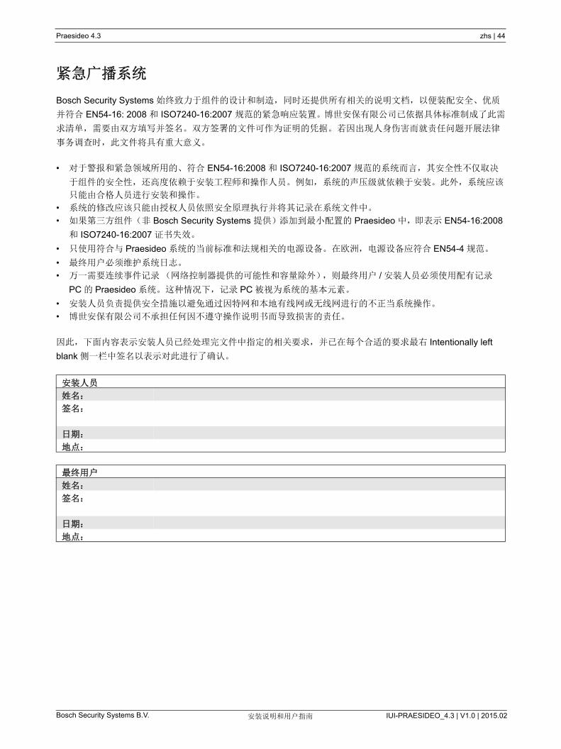
Praesideo 4.3 zhs | 44
Bosch Security Systems B.V. IUI-PRAESIDEO_4.3 | V1.0 | 2015.02安装说明和用户指南
紧急广播系统
Bosch Security Systems 始终致力于组件的设计和制造,同时还提供所有相关的说明文档,以便装配安全、优质
并符合 EN54-16: 2008 和 ISO7240-16:2007 规范的紧急响应装置。博世安保有限公司已依据具体标准制成了此需
求清单,需要由双方填写并签名。双方签署的文件可作为证明的凭据。 若因出现人身伤害而就责任问题开展法律
事务调查时,此文件将具有重大意义。
• 对于警报和紧急领域所用的、符合 EN54-16:2008 和 ISO7240-16:2007 规范的系统而言,其安全性不仅取决
于组件的安全性,还高度依赖于安装工程师和操作人员。例如,系统的声压级就依赖于安装。此外,系统应该
只能由合格人员进行安装和操作。
• 系统的修改应该只能由授权人员依照安全原理执行并将其记录在系统文件中。
• 如果第三方组件(非 Bosch Security Systems 提供)添加到 小配置的 Praesideo 中,即表示 EN54-16:2008
和 ISO7240-16:2007 证书失效。
• 只使用符合与 Praesideo 系统的当前标准和法规相关的电源设备。在欧洲,电源设备应符合 EN54-4 规范。
• 终用户必须维护系统日志。
• 万一需要连续事件记录(网络控制器提供的可能性和容量除外),则 终用户 / 安装人员必须使用配有记录
PC 的 Praesideo 系统。这种情况下,记录 PC 被视为系统的基本元素。
• 安装人员负责提供安全措施以避免通过因特网和本地有线网或无线网进行的不正当系统操作。
• 博世安保有限公司不承担任何因不遵守操作说明书而导致损害的责任。
因此,下面内容表示安装人员已经处理完文件中指定的相关要求,并已在每个合适的要求 右 Intentionally left
blank 侧一栏中签名以表示对此进行了确认。
安装人员
姓名:
签名:
日期:
地点:
终用户
姓名:
签名:
日期:
地点:
Praesideo 4.3 zhs | 45
Bosch Security Systems B.V. IUI-PRAESIDEO_4.3 | V1.0 | 2015.02安装说明和用户指南
授权 终用户列表
姓名 姓名

Praesideo 4.3 zhs | 46
Bosch Security Systems B.V. IUI-PRAESIDEO_4.3 | V1.0 | 2015.02安装说明和用户指南
EN54-16: 2008 compliancy checklist
Clause / Requirement Compliance Signature4 General requirements4.1 General Praesideo is compliant.
4.1.1 If an optional function with requirements is included in the VACIE, then all the corresponding requirements shall be met (see Annex B).
The following optional functions, with requirements, are included in Praesideo from version 3.3 upwards:
• Audible warning (7.3) • Phased evacuation (7.5)• Manual silencing of the voice alarm condition (7.6.2)• Manual reset of the voice alarm condition (7.7.2)• Output to fire alarm devices (7.8)• Voice alarm condition output (7.9)• Indication of faults related to the transmission path to the
CIE (8.3)• Indication of fault related to voice alarm zones (8.4)• Voice alarm manual control (10)• Interface to external control device(s) (11)• Emergency microphone(s) (12)• Redundant power amplifiers (13.14)
The following optional functions with requirements are not included in Praesideo:
• Delay(s) to entering the voice alarm condition (7.4)• Disabled condition (9)
4.1.2 If functions other than those specified in this European Standard are provided, they shall not jeopardize compliance with any requirements of this European Standard
Praesideo power amplifiers and basic amplifiers shall not be configured to enter the power save mode when mains power fails. Although this would save battery power, the amplifier supervision and line/loudspeaker supervision is not active in this mode, which is a necessity for systems operating in accordance with EN54-16.The Praesideo PC call station shall not be used as an emergency call station in systems operating in accordance to EN54-16. A PC does not comply with the requirements as set forward by this standard.
4.2 Combined VACIE and CIEWhen the VACIE and CIE are combined they may share common indications, manual controls and outputs (see Annex F). In this case, the following shall apply:
a single fault in the CIE shall not adversely affect the mandatory functions of the VACIE;
b indication(s) and manual control(s) of the voice alarm condition shall be clearly identifiable, with the exception of the optional audible warning.
This requirement is not applicable. In Praesideo, the Voice Alarm Control and Indicating Equipment (VACIE) is not combined with a fire alarm Control and Indicating Equipment (CIE).
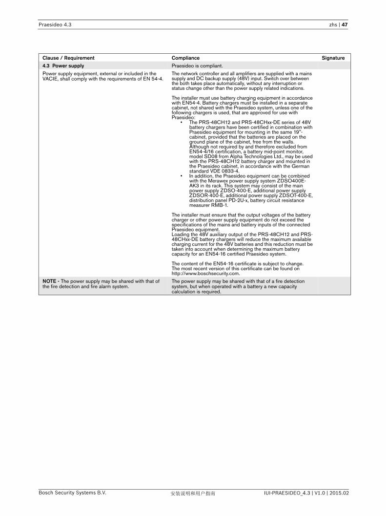
Praesideo 4.3 zhs | 47
Bosch Security Systems B.V. IUI-PRAESIDEO_4.3 | V1.0 | 2015.02安装说明和用户指南
4.3 Power supply Praesideo is compliant.
Power supply equipment, external or included in the VACIE, shall comply with the requirements of EN 54-4.
The network controller and all amplifiers are supplied with a mains supply and DC backup supply (48V) input. Switch over between the both takes place automatically, without any interruption or status change other than the power supply related indications.
The installer must use battery charging equipment in accordance with EN54-4. Battery chargers must be installed in a separate cabinet, not shared with the Praesideo system, unless one of the following chargers is used, that are approved for use with Praesideo:
• The PRS-48CH12 and PRS-48CHxx-DE series of 48V battery chargers have been certified in combination with Praesideo equipment for mounting in the same 19"-cabinet, provided that the batteries are placed on the ground plane of the cabinet, free from the walls. Although not required by and therefore excluded from EN54-4/16 certification, a battery mid-point monitor, model SD08 from Alpha Technologies Ltd., may be used with the PRS-48CH12 battery charger and mounted in the Praesideo cabinet, in accordance with the German standard VDE 0833-4.
• In addition, the Praesideo equipment can be combined with the Merawex power supply system ZDSO400E-AK3 in its rack. This system may consist of the main power supply ZDSO-400-E, additional power supply ZDSOR-400-E, additional power supply ZDSOT-400-E, distribution panel PD-2U-x, battery circuit resistance measurer RMB-1.
The installer must ensure that the output voltages of the battery charger or other power supply equipment do not exceed the specifications of the mains and battery inputs of the connected Praesideo equipment.Loading the 48V auxiliary output of the PRS-48CH12 and PRS-48CHxx-DE battery chargers will reduce the maximum available charging current for the 48V batteries and this reduction must be taken into account when determining the maximum battery capacity for an EN54-16 certified Praesideo system.
The content of the EN54-16 certificate is subject to change. The most recent version of this certificate can be found on http://www.boschsecurity.com.
NOTE - The power supply may be shared with that of the fire detection and fire alarm system.
The power supply may be shared with that of a fire detection system, but when operated with a battery a new capacity calculation is required.
Clause / Requirement Compliance Signature

Praesideo 4.3 zhs | 48
Bosch Security Systems B.V. IUI-PRAESIDEO_4.3 | V1.0 | 2015.02安装说明和用户指南
Clause / Requirement Compliance Signature5 General requirements for indications5.1 Display and functional conditions Praesideo is compliant.
5.1.1 The VACIE shall be capable of unambiguously indicating the following functional conditions, as described in Clauses 6 to 9:
• quiescent condition; • voice alarm condition; • fault warning condition; • disablement condition (option with requirements)
See Clauses 6 to 9.
5.1.2 The VACIE shall be capable of being simultaneously in any combination of the following functional conditions on different voice alarm zones:
The Praesideo system is capable of being simultaneously in the voice alarm condition and in the fault warning condition.
• voice alarm condition; The voice alarm condition is indicated per system on each call station (system status LED) and on the display of the network controller (emergency menu). This system wide indication can be combined with the indication of the fault warning condition: each call station uses a different LED (power/fault LED) for indication of the fault warning condition; therefore both conditions can be indicated simultaneously. The display of the network controller can indicate both the voice alarm condition and the fault warning condition (note that it will only show one condition automatically, the voice alarm condition has precedence; the user is able to see the fault warning condition by navigating through the menu if both conditions apply to the system simultaneously).
To indicate the voice alarm condition per zone, the installer shall use a call station keypad module with correctly connected red LEDs (see clause 13.9.1) with configuration of the ‘Zone status’.
• fault warning condition; The fault warning condition is indicated per system on each call station (power/fault LED) and on the display of the network controller (faults menu). This system wide indication can be combined with the indication of the voice alarm condition: each call station uses a different LED (system status LED) for indication of the voice alarm condition; therefore both conditions can be indicated simultaneously. The display of the network controller can indicate both the voice alarm condition and the fault warning condition (note that it will only show one condition automatically, the voice alarm condition has precedence; the user is able to see the fault warning condition by navigating through the menu if the system is in both conditions simultaneously).
The installer must configure zone names in a way that the zone name is visible in the fault logging and network controller display (see clause 8.2.7 for details). In this way faults are indicated per zone.
• disablement condition (option with requirements). The optional disablement condition is not implemented in Praesideo.
5.2 Indication display Praesideo is compliant.
All mandatory indications shall be clearly identifiable, except where otherwise specified in this European Standard.
The Praesideo system uses the following color coding for indications throughout the system:
• Green: system ok• Red: system/zone in voice alarm condition• Yellow: system in fault warning condition
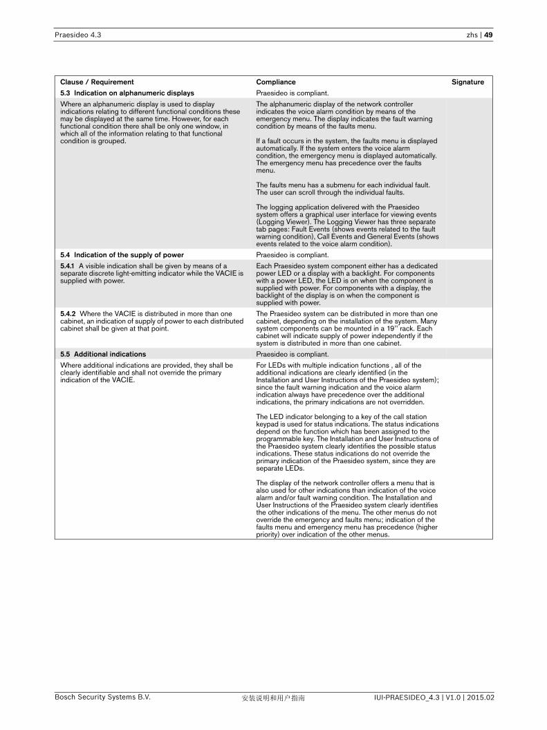
Praesideo 4.3 zhs | 49
Bosch Security Systems B.V. IUI-PRAESIDEO_4.3 | V1.0 | 2015.02安装说明和用户指南
5.3 Indication on alphanumeric displays Praesideo is compliant.
Where an alphanumeric display is used to display indications relating to different functional conditions these may be displayed at the same time. However, for each functional condition there shall be only one window, in which all of the information relating to that functional condition is grouped.
The alphanumeric display of the network controller indicates the voice alarm condition by means of the emergency menu. The display indicates the fault warning condition by means of the faults menu.
If a fault occurs in the system, the faults menu is displayed automatically. If the system enters the voice alarm condition, the emergency menu is displayed automatically. The emergency menu has precedence over the faults menu.
The faults menu has a submenu for each individual fault. The user can scroll through the individual faults.
The logging application delivered with the Praesideo system offers a graphical user interface for viewing events (Logging Viewer). The Logging Viewer has three separate tab pages: Fault Events (shows events related to the fault warning condition), Call Events and General Events (shows events related to the voice alarm condition).
5.4 Indication of the supply of power Praesideo is compliant.
5.4.1 A visible indication shall be given by means of a separate discrete light-emitting indicator while the VACIE is supplied with power.
Each Praesideo system component either has a dedicated power LED or a display with a backlight. For components with a power LED, the LED is on when the component is supplied with power. For components with a display, the backlight of the display is on when the component is supplied with power.
5.4.2 Where the VACIE is distributed in more than one cabinet, an indication of supply of power to each distributed cabinet shall be given at that point.
The Praesideo system can be distributed in more than one cabinet, depending on the installation of the system. Many system components can be mounted in a 19’’ rack. Each cabinet will indicate supply of power independently if the system is distributed in more than one cabinet.
5.5 Additional indications Praesideo is compliant.
Where additional indications are provided, they shall be clearly identifiable and shall not override the primary indication of the VACIE.
For LEDs with multiple indication functions , all of the additional indications are clearly identified (in the Installation and User Instructions of the Praesideo system); since the fault warning indication and the voice alarm indication always have precedence over the additional indications, the primary indications are not overridden.
The LED indicator belonging to a key of the call station keypad is used for status indications. The status indications depend on the function which has been assigned to the programmable key. The Installation and User Instructions of the Praesideo system clearly identifies the possible status indications. These status indications do not override the primary indication of the Praesideo system, since they are separate LEDs.
The display of the network controller offers a menu that is also used for other indications than indication of the voice alarm and/or fault warning condition. The Installation and User Instructions of the Praesideo system clearly identifies the other indications of the menu. The other menus do not override the emergency and faults menu; indication of the faults menu and emergency menu has precedence (higher priority) over indication of the other menus.
Clause / Requirement Compliance Signature

Praesideo 4.3 zhs | 50
Bosch Security Systems B.V. IUI-PRAESIDEO_4.3 | V1.0 | 2015.02安装说明和用户指南
Clause / Requirement Compliance Signature6 The quiescent conditionAny kind of system information may be displayed during the quiescent condition. However, no indications shall be given which could be confused with indications used in the
Praesideo is compliant.
• voice alarm condition, If the Praesideo system enters the voice alarm condition each call station will show a red system status LED and the emergency menu will pop up on the display of the network controller. In the quiescent condition no red indicators are used at all and the display of the network controller will never automatically switch to the emergency menu.
• fault warning condition, If the Praesideo system enters the fault warning condition each call station will show a yellow (blinking or on) power/fault LED and the faults menu will pop up on the display of the network controller. In the quiescent condition the power/fault LED of each call station will be green and the display of the network controller will never automatically switch to the faults menu.
• disablement condition (option with requirements). The disablement condition is not implemented in Praesideo.

Praesideo 4.3 zhs | 51
Bosch Security Systems B.V. IUI-PRAESIDEO_4.3 | V1.0 | 2015.02安装说明和用户指南
Clause / Requirement Compliance Signature7 The voice alarm condition7.1 Reception and processing of fire signals Praesideo is compliant.
7.1.1 The VACIE shall be capable of receiving and processing alarm signals from the CIE or from manual control on the VACIE or both, and causing the appropriate voice alarm outputs to be activated within 3 s or on expiry of any delay period (see 7.4).
Alarm signals from the CIE can be received from input contacts and the Open Interface. Manual control is possible via input contacts, the Open Interface and call station (keypad) keys.
NOTE - See Annex E for additional information relating to the interface between the VACIE and the CIE.
If input contacts are used for connection of the CIE to the Praesideo system then the input contacts can be monitored for short circuit and open line. If the Open Interface is used for connection of the CIE to the VACIE, the communication is monitored using keep-alive messaging.
7.1.2 The mandatory indications and or outputs shall not be falsified by multiple alarm signals received simultaneously from the CIE and/or manual controls.
The Praesideo system offers 32 discrete alarm priorities. Correct configuration assures that mandatory indications and or outputs behave consistently when multiple alarm signals are received simultaneously from the CIE and/or manual controls.
Higher priorities overrule lower priorities in case of resource or destination conflicts. Calls with the same priority operate on first come first serve basis, except in the case of priority 255: calls with the same priority 255 overrule each other, so the latest becomes active. This assures that high priority microphones that are left behind in an active state will never block the system.
7.1.3 Where the VACIE and CIE are in separate cabinets, failure of the transmission path between the CIE and the VACIE shall not result in any loss of control or any change of state of the VACIE.
The Praesideo system is an autonomous subsystem that can operate without connection to the CIE. The effect of the failure of the transmission path between the CIE and the Praesideo system is limited to fault reporting and losing interaction between the CIE and the Praesideo system.
7.2 Indication of the voice alarm condition Praesideo is compliant.
7.2.1 The presence of a voice alarm condition shall be indicated on the VACIE, without prior manual intervention, by:
a a visible indication by means of a separate discrete light emitting indicator (the General Voice Alarm Activated indicator);
A voice alarm condition is indicated on the Praesideo system by:
• A red indicator on all call stations (the system status LED).
• A textual indicator on the network controller display (the ‘emergency menu’ that is automatically shown when the system enters the voice alarm state).
• An output contact configured in the site specific data as voice alarm activated indicator (Emergency alarm indicator). This output contact can be used to control the General Voice Alarm Activated indicator.
• The installer must mount a red (flash) light to indicate the voice alarm condition, clearly visible from the front side of the rack, behind the glass door of the rack.
b a visible indication for each activated voice alarm zone where manual controls are provided (see 10.2);
The keys on call station keypads can be configured to have their key indicator show that an emergency is active for a specific zone or group of zones. This is achieved by configuring the action ‘Zone status’ for the key, and configuring the lowest possible alarm priority (224) for that action to ensure that for all alarm priorities (224 - 255) the indicator will be activated.
NOTE - This may be by means of separate discrete indicators or an alphanumeric display as specified in 13.8.
c an optional audible indication, as specified in 7.3. The Praesideo PRS-NCO3 has an internal buzzer for this purpose. Also, an output contact of a Praesideo system component can be configured in the site specific data as audible voice alarm activated indicator (Emergency alarm buzzer). This output contact can be connected to a buzzer. This way the voice alarm condition is indicated audibly.
7.2.2 The audible warning shall be capable of being silenced at access level 1 or 2.
The connected buzzer (see 7.2.1.c) can be silenced by acknowledging the voice alarm condition. The voice alarm condition can be acknowledged by means of an input contact, call station key, the front panel menu of the network controller or via the Open Interface.
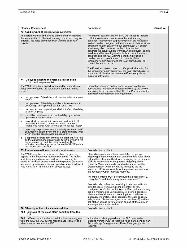
Praesideo 4.3 zhs | 52
Bosch Security Systems B.V. IUI-PRAESIDEO_4.3 | V1.0 | 2015.02安装说明和用户指南
7.3 Audible warning (option with requirements)
An audible warning of the voice alarm condition might be the same as that for the fault warning condition. If they are different, the voice alarm condition warning shall have priority.
The internal buzzer of the PRS-NCO3 is used to indicate both the voice alarm condition as the fault warning condition. Alternatively, output contacts of the Praesideo system can be configured in the site specific data as either Emergency alarm buzzer or Fault alarm buzzer. A buzzer must always be connected to the output contact to generate the actual audible warning. A single buzzer can be used as audible warning device for both the voice alarm condition and the fault warning condition, by using a parallel connection of the output contacts of the Emergency alarm buzzer and the Fault alarm buzzer to control the actual buzzer.
The Praesideo system does not offer priority handling for the Emergency alarm buzzer (i.e. the Fault alarm buzzer is not automatically silenced when the Emergency alarm buzzer is activated).
7.4 Delays to entering the voice alarm condition (option with requirements)
The VACIE may be provided with a facility to introduce a delay before entering the voice alarm condition. In this case:
Since the Praesideo system does not process the fire sensors, this functionality is better handled by the device managing the fire sensors (the CIE). The Praesideo system itself does not implement this requirement.
a the operation of the delay shall be selectable at access level 3;
b the operation of the delay shall be in increments not exceeding 1 min up to a maximum of 10 min;
c the delay to one output signal shall not affect the delay to other outputs;
d it shall be possible to override the delay by a manual operation at access level 1;
e there shall be provision to switch on and switch off delays by means of a manual operation at access level 2 (see Annex A for information on access levels);
f there may be provision to automatically switch on and/or switch off delays by means of a programmable timer which shall be configurable at access level 3;
g a separate discrete light emitting indicator and/or a field on the alphanumeric display shall be visible when a fire signal is received and the delay activated. This indication shall be suppressed when the VACIE enters the voice alarm condition.
7.5 Phased evacuation (option with requirements) Praesideo is compliant.
The VACIE may have a provision to phase the warning signals to the emergency loudspeaker zones. The facility shall be configurable at access level 3. There may be provision to switch on and switch off the phased evacuation sequence by means of a manual operation at access level 2 (see Annex A for information on access levels).
Phased evacuation can be accomplished by phased triggering of input contacts that start the same voice alarm call in different zones. The device managing the fire sensors (CIE) is responsible for the phased triggering of the contacts. Voice alarm calls can also be started via the Open Interface, where the device managing the fire sensors (CIE) is responsible for the phased invocation of the necessary Open Interface methods.
The input contacts must be configured at access level 3. Using the Open Interface requires access level 2.
Praesideo also offers the possibility to start up to 5 calls simultaneously from a single input contact or key, configured as ‘Call activation key’ or ‘Start’, where phasing can be implemented using accurately defined periods of silence in the call macros, preceding the actual tone or message. The installer shall configure the calls correctly using these chimes/messages (at access level 3) and use call station keypad keys to switch on and off the chimes/messages (at access level 2).
7.6 Silencing of the voice alarm condition Praesideo is compliant.
7.6.1 Silencing of the voice alarm condition from the CIE
7.6.1.1 Where the voice alarm condition has been triggered from the CIE, the VACIE shall respond appropriately to a silence instruction from the CIE.
Voice alarm calls triggered from the CIE can also be stopped from the CIE. To reset the voice alarm condition an Acknowledge Emergency and Reset Emergency action is required.
Clause / Requirement Compliance Signature
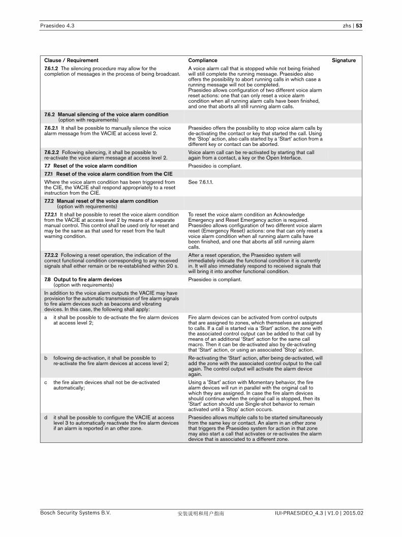
Praesideo 4.3 zhs | 53
Bosch Security Systems B.V. IUI-PRAESIDEO_4.3 | V1.0 | 2015.02安装说明和用户指南
7.6.1.2 The silencing procedure may allow for the completion of messages in the process of being broadcast.
A voice alarm call that is stopped while not being finished will still complete the running message. Praesideo also offers the possibility to abort running calls in which case a running message will not be completed.Praesideo allows configuration of two different voice alarm reset actions: one that can only reset a voice alarm condition when all running alarm calls have been finished, and one that aborts all still running alarm calls.
7.6.2 Manual silencing of the voice alarm condition (option with requirements)
7.6.2.1 It shall be possible to manually silence the voice alarm message from the VACIE at access level 2.
Praesideo offers the possibility to stop voice alarm calls by de-activating the contact or key that started the call. Using the ‘Stop’ action, also calls started by a ‘Start’ action from a different key or contact can be aborted.
7.6.2.2 Following silencing, it shall be possible to re-activate the voice alarm message at access level 2.
Voice alarm call can be re-activated by starting that call again from a contact, a key or the Open Interface.
7.7 Reset of the voice alarm condition Praesideo is compliant.
7.7.1 Reset of the voice alarm condition from the CIEWhere the voice alarm condition has been triggered from the CIE, the VACIE shall respond appropriately to a reset instruction from the CIE.
See 7.6.1.1.
7.7.2 Manual reset of the voice alarm condition (option with requirements)
7.7.2.1 It shall be possible to reset the voice alarm condition from the VACIE at access level 2 by means of a separate manual control. This control shall be used only for reset and may be the same as that used for reset from the fault warning condition.
To reset the voice alarm condition an Acknowledge Emergency and Reset Emergency action is required. Praesideo allows configuration of two different voice alarm reset (Emergency Reset) actions: one that can only reset a voice alarm condition when all running alarm calls have been finished, and one that aborts all still running alarm calls.
7.7.2.2 Following a reset operation, the indication of the correct functional condition corresponding to any received signals shall either remain or be re-established within 20 s.
After a reset operation, the Praesideo system will immediately indicate the functional condition it is currently in. It will also immediately respond to received signals that will bring it into another functional condition.
7.8 Output to fire alarm devices (option with requirements)
Praesideo is compliant.
In addition to the voice alarm outputs the VACIE may have provision for the automatic transmission of fire alarm signals to fire alarm devices such as beacons and vibrating devices. In this case, the following shall apply:
a it shall be possible to de-activate the fire alarm devices at access level 2;
Fire alarm devices can be activated from control outputs that are assigned to zones, which themselves are assigned to calls. If a call is started via a ‘Start’ action, the zone with the associated control output can be added to that call by means of an additional ‘Start’ action for the same call macro. Then it can be de-activated also by de-activating that ‘Start’ action, or using an associated 'Stop' action.
b following de-activation, it shall be possible to re-activate the fire alarm devices at access level 2;
Re-activating the ‘Start’ action, after being de-activated, will add the zone with the associated control output to the call again. The control output will activate the alarm device again.
c the fire alarm devices shall not be de-activated automatically;
Using a 'Start' action with Momentary behavior, the fire alarm devices will run in parallel with the original call to which they are assigned. In case the fire alarm devices should continue when the original call is stopped, then its 'Start' action should use Single-shot behavior to remain activated until a 'Stop' action occurs.
d it shall be possible to configure the VACIE at access level 3 to automatically reactivate the fire alarm devices if an alarm is reported in an other zone.
Praesideo allows multiple calls to be started simultaneously from the same key or contact. An alarm in an other zone that triggers the Praesideo system for action in that zone may also start a call that activates or re-activates the alarm device that is associated to a different zone.
Clause / Requirement Compliance Signature

Praesideo 4.3 zhs | 54
Bosch Security Systems B.V. IUI-PRAESIDEO_4.3 | V1.0 | 2015.02安装说明和用户指南
7.9 Voice alarm condition output (option with requirements)
Praesideo is compliant.
The VACIE may have provision for transmitting a signal that is in the voice alarm condition. In this case, it shall activate the output only in the voice alarm condition.
The Praesideo system transmits a signal that it is in the voice alarm condition via control output contacts and the Open Interface.
An output contact must be configured as voice alarm activated indicator (Emergency alarm indicator). The Praesideo system then activates the output contact when it enters the voice alarm condition and deactivates the output contact when it leaves the voice alarm condition (i.e. the voice alarm condition is reset).
The Praesideo system also indicates this condition via the Open Interface.
Clause / Requirement Compliance Signature

Praesideo 4.3 zhs | 55
Bosch Security Systems B.V. IUI-PRAESIDEO_4.3 | V1.0 | 2015.02安装说明和用户指南
Clause / Requirement Compliance Signature8 Fault warning condition8.1 Reception and processing of fault signals Praesideo is compliant.
8.1.1 The VACIE shall enter the fault warning condition when signals are received which, after any necessary processing, are interpreted as a fault.
When the Praesideo system receives a supervision fault signal (i.e. detects a fault in the system), the fault warning condition is entered until this state is explicitly reset.
8.1.2 The VACIE shall be capable of simultaneously recognizing all of the faults specified in 8.2 and, if provided, in 8.3 unless this is prevented by:
• the presence of an alarm output signal on the same voice alarm zone, and/or
All Praesideo system faults are handled (acknowledged and reset) individually. Also, the Praesideo system is capable of recognizing all of its system faults simultaneously. The Praesideo system is able to recognize faults in a voice alarm zone even when there is an alarm output signal on the zone.
• the disablement of the corresponding voice alarm zone or function.
Optional disablement of voice alarm zones or functions is not implemented in Praesideo.
8.1.3 The VACIE shall enter the fault warning condition within 100 s of the occurrence of any fault, or the reception of a fault signal or within another time as specified in this European Standard or in other parts of EN 54.
The Praesideo system recognizes and reports all faults within 100 seconds.
8.2 Indication of faults in specified functions Praesideo is compliant.
8.2.1 The presence of faults in specified functions shall be indicated on the VACIE without prior manual intervention. The fault warning condition is established when the following are present:
a a visible indication by means of a separate light emitting indicator (the general fault warning indicator);
The Praesideo system provides a visible indication when it is in the fault warning condition via the fault LED of the call stations, output contacts, key indicators of call station keys, the fixed fault output contact of the network controller and the front panel menu of the network controller.
The installer must mount a yellow (flash) light to indicate the fault warning condition, clearly visible from the front side of the rack, behind the glass door of the rack.
b a visible indication for each recognised fault as specified in 8.2.3, 8.2.4, 8.3 (if provided), 8.4 (if provided) and 8.5 and
The Praesideo system offers two ways of visual indication of individual faults: via the front panel menu of the network controller and via the Praesideo logging application.
c an audible indication, as specified in 8.6. The Praesideo PRS-NCO3 has an internal buzzer for this purpose. Also, the Praesideo system provides an audible fault indication when it is in the fault warning condition via output contacts and the fixed audible fault output contact of the network controller.
8.2.2 If the indication is on an alphanumeric display, which cannot simultaneously indicate all of the faults because of its limited capacity, at least the following shall apply:
a the presence of fault indications which have been suppressed shall be indicated;
The network controller alphanumeric display is used to indicate the fault warning condition and all individual faults.
The normal display information of the network controller is automatically overruled when there are faults present, i.e. when the system enters the fault warning state. The display of the network controller indicates the number of faults present.
b suppressed fault indications shall be capable of being displayed by means of a manual operation at access level 1 or 2 which interrogates only fault indications.
The individual faults are presented in the ‘Faults’ menu of the front panel menu of the network controller. Manual operation is needed to display and navigate through the individual faults. Each individual fault is shown in a submenu of the ‘Faults’ menu.
8.2.3 The following faults shall be indicated by means of separate light emitting indicators and/or an alphanumeric display:
Faults of the supervised items are detected and reported through the general fault warning indication. Additionally all faults are reported individually as well and can be inspected using the network controller front panel menu and the logging application.
a an indication at least common to any power supply fault resulting from:
The mains and backup power of all Praesideo system elements are supervised individually.
1 a short circuit or an interruption in a transmission path to a power supply (item L of Figure 1 of EN 54-1), where the power supply is contained in a different cabinet from that of the VACIE, and

Praesideo 4.3 zhs | 56
Bosch Security Systems B.V. IUI-PRAESIDEO_4.3 | V1.0 | 2015.02安装说明和用户指南
2 the power supply faults as specified in EN 54-4;
b an indication at least common to any earth fault of less than 50 k is capable of affecting a mandatory function, and which is not otherwise indicated as a fault of a supervised function;
All 100V lines of the Praesideo system can be supervised individually for earth faults (i.e. connections to earth with a leakage resistance of less than 50 k).
c an indication of the rupture of any fuse within the VACIE, or the operation of any protective device within the VACIE which is capable of affecting a mandatory function in the fire alarm condition;
Every rupture of a fuse or the operation of a protected device that affects a mandatory function will result in a fault since the mandatory functions are supervised. The reported fault is as close to the located defect as possible. E.g. a mains related fault is reported as a mains fault and an amplifier defect is reported as defect for that amplifier channel.
d an indication of any short circuit or interruption, at least common to all transmission paths between parts of the VACIE contained in more than one cabinet, which is capable of affecting a mandatory function and which is not otherwise indicated as a fault of a supervised function.
All network based transmission paths of the Praesideo system are supervised using a keep-alive mechanism. The CobraNet transmission path of the Praesideo system is supervised by means of clock availability.
When the Praesideo system is used in a redundant loop configuration, the loss of the redundant path is reported.
All control input contacts of the Praesideo system can be supervised for shorts and interruptions.
Analog audio connections to external parties can be supervised by pilot tone supervision.
The analog fail safe bypass input of the Praesideo multi channel interface can be supervised by pilot tone supervision.
These indications may be suppressed during the fire alarm condition.
Praesideo fault indicators are not suppressed. There are separate indicators for fault and voice alarm conditions. The only exception is that the automatic indication of the voice alarm condition has precedence over the automatic indication of the number of present faults on the display of the network controller.
8.2.4 The following faults shall be indicated at least by means of the general fault warning indicator:
a any short-circuit or interruption in a voice alarm transmission path between parts of the VACIE contained in more than one cabinet even where the fault does not affect a mandatory function;
All network based transmission paths of the Praesideo system are supervised using a keep-alive mechanism. The CobraNet transmission path of the Praesideo system is supervised by means of clock availability.
When the Praesideo system is used in a redundant loop configuration, the loss of the redundant path is reported.
All control input contacts of the Praesideo system can be supervised for shorts and interruptions.
Analog audio connections to external parties can be supervised by pilot tone supervision.
The analog fail safe bypass input of the Praesideo multi channel interface can be supervised by pilot tone supervision.
b any short-circuit or interruption in the voice alarm transmission path to the emergency microphone capsule, if provided;
The capsule of the Praesideo (emergency) call station microphone can be supervised for both short-circuit and interruption. This is configurable. Also the microphone inputs on the power amplifiers supervise the connected microphone.
c any short-circuit or interruption in the voice alarm transmission path between the VACIE and loudspeakers even where the fault does not affect the operation of loudspeakers.
The loudspeaker lines of the Praesideo system can be supervised using a master-slave communication system that uses the actual loudspeaker wiring for polling. The communication is inaudible and not affected by audio signals present.
Praesideo offers two options: single loudspeaker line supervision (master-slave) and multiple loudspeaker line supervision (master-multiple slaves) that detect short-circuits and interruption of the loudspeaker lines.
The installer shall only use the 100 V outputs of the Praesideo amplifiers.
Clause / Requirement Compliance Signature

Praesideo 4.3 zhs | 57
Bosch Security Systems B.V. IUI-PRAESIDEO_4.3 | V1.0 | 2015.02安装说明和用户指南
d any short-circuit or interruption in the transmission path between the VACIE and fire alarm devices when used (see 7.8).
The Praesideo system does not offer this functionality directly: control inputs are supervised, but control outputs are just voltage free relay contacts. The installer must create a feedback signal (corresponding to the transmission path status between the Praesideo system and the fire alarm device) to a supervised input contact of the Praesideo system.
e failure of any power amplifier. All Praesideo power amplifiers are supervised for overload, overheating, short-circuit, ground short and amplifier defect.
8.3 Indication of faults related to the transmission path to the CIE (option with requirements)
The VACIE may have provision for an indication of faults related to the transmission path to the CIE. In this case, the short-circuit or interruption of the transmission path to the CIE shall be indicated by means of a separate light emitting indicator and/or an alphanumeric display.
All input contacts of the Praesideo system can be supervised for short and interruption.
Open Interface connections are supervised through keep-alive messaging.
Faults related to the transmission path to the CIE are therefore individually reported and can be inspected using the front panel menu of the network controller or the logging application. The faults are also reported through the general fault warning indication.
8.4 Indication of faults related to voice alarm zones (option with requirements)
The VACIE may have provision for an indication of faults related to voice alarm zones. In this case the short-circuit or interruption of a voice alarm transmission path between the VACIE and the loudspeakers in that zone shall be indicated by means of a separate light emitting indicator per zone and/or an alphanumeric display.
Faults that occur in the Praesideo system are reported per defective input or output for fault allocation. When an individual fault is reported the name of the event originator (i.e. the location of the fault) is provided.
The installer must give audio outputs that are assigned to a zone, clear names, identifying the zone. This way the event originator field in the indication of the individual fault will immediately show in which zone the fault has occurred.
Praesideo provides zone fault status indicators, assigned to keypad modules. One or more zones can be configured to control such an indicator.
8.5 System fault Praesideo is compliant.
A system fault is a fault as specified in 14.4 Program monitoring (see also Annex C)or 14.6 Monitoring of memory contents in the case of software controlled VACIE. A system fault may prevent requirements of this European Standard, other than those specified below, from being fulfilled. In the event of a system fault at least the following shall apply:
14.4 Program monitoring (see also Annex C)
a a system fault shall be visibly indicated by means of the general fault warning indicator and a separate light emitting indicator on the VACIE. These indications shall not be suppressed by any other functional condition of the VACIE and shall remain until a manual reset and/or another manual operation at access level 2 or 3;
System faults are individually reported by the Praesideo system and can be inspected using the front panel menu of the network controller or the logging application.
Faults are also reported through a general fault warning indicator, connected to a control output that is configured as Fault alarm buzzer or visual Fault alarm indicator.
Both the individual fault indicator of each system fault and the general fault warning indicator are not suppressed by any other functional condition of the Praesideo system.
b a system fault shall be audibly indicated. This indication may be capable of being silenced.
A control output contact of a Praesideo system component can be configured as Fault alarm buzzer. This output contact can be connected to a buzzer. This way all faults, including system faults, are indicated audibly.
The Fault alarm buzzer can be silenced by acknowledging all faults via a key or control input that is configured as Fault acknowledge key. The control output for the visual Fault alarm indicator is only deactivated upon resolving and resetting all fault conditions.
8.6 Audible indication Praesideo is compliant.
8.6.1 The audible indication of faults required in 8.2 shall be capable of being silenced manually at access level 1 or 2 at the VACIE. The same manual operation may be used as for silencing the voice alarm condition.
The Fault alarm buzzer can be silenced by acknowledging all faults via a key or control input that is configured as Fault acknowledge key. Individual faults can also be acknowledged from the front panel menu of the network controller or via the Open Interface.
Clause / Requirement Compliance Signature

Praesideo 4.3 zhs | 58
Bosch Security Systems B.V. IUI-PRAESIDEO_4.3 | V1.0 | 2015.02安装说明和用户指南
8.6.2 The audible indication shall be silenced automatically if the VACIE is automatically reset from the fault warning condition.
Since the Praesideo system does not offer automatic reset from the fault warning condition this requirement does not need to be implemented.
8.6.3 If previously silenced, the audible indication shall resound for each newly recognized fault.
After the audible indication has been silenced (by acknowledging all faults) the Praesideo system will resound the indication upon occurrence of a new fault or reoccurrence of a previously resolved fault.
8.7 Reset of fault indications Praesideo is compliant.
8.7.1 Indications of faults as required in 8.2 shall be capable of being reset
a automatically when faults are no longer recognized, and/or
The Praesideo system does not offer automatic reset of faults
b by a manual operation at access level 2. Faults can be manually reset by acknowledging and resetting them individually or all in one action. Acknowledging and/or resetting faults individually can be done via the front panel menu of the Network Controller and via the Open Interface. Acknowledging and/or resetting all faults in one action can be done via the front panel menu of the network controller, control input contacts, call station keys or the Open Interface.
8.7.2 Following reset as specified in 8.7.1, the indication of the correct functional conditions corresponding to any received signals shall either remain or be re-established within 20 s.
A fault reset is processed by Praesideo within 20 s to update the status of all fault indicators. Praesideo will enter the fault warning condition again within 100 s of the occurrence of a new or still unresolved fault.
8.8 Transmission of the fault warning condition Praesideo is compliant.
The VACIE shall have provision for transmitting, by means of at least general fault signal, all faults specified in 8. This fault signal shall also be given if the VACIE is de-energized.
Output contact 5 of the Praesideo network controller is the fixed Fault alarm indicator output. This relay output contact indicates no fault when open (energized) and indicates a fault when closed (de-energized). If the Praesideo system is de-energized this output contact is closed, therefore the fault signal will also be given.
Clause / Requirement Compliance Signature
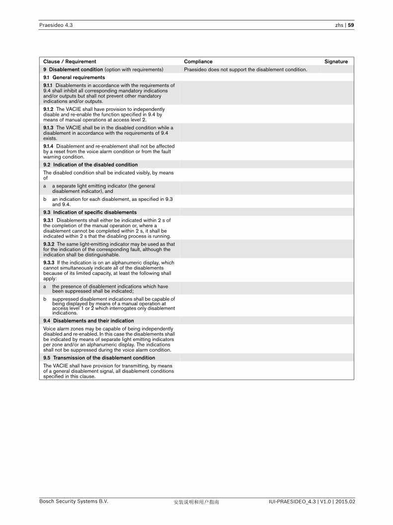
Praesideo 4.3 zhs | 59
Bosch Security Systems B.V. IUI-PRAESIDEO_4.3 | V1.0 | 2015.02安装说明和用户指南
Clause / Requirement Compliance Signature9 Disablement condition (option with requirements) Praesideo does not support the disablement condition.
9.1 General requirements9.1.1 Disablements in accordance with the requirements of 9.4 shall inhibit all corresponding mandatory indications and/or outputs but shall not prevent other mandatory indications and/or outputs.
9.1.2 The VACIE shall have provision to independently disable and re-enable the function specified in 9.4 by means of manual operations at access level 2.
9.1.3 The VACIE shall be in the disabled condition while a disablement in accordance with the requirements of 9.4 exists.
9.1.4 Disablement and re-enablement shall not be affected by a reset from the voice alarm condition or from the fault warning condition.
9.2 Indication of the disabled conditionThe disabled condition shall be indicated visibly, by means of
a a separate light emitting indicator (the general disablement indicator), and
b an indication for each disablement, as specified in 9.3 and 9.4.
9.3 Indication of specific disablements9.3.1 Disablements shall either be indicated within 2 s of the completion of the manual operation or, where a disablement cannot be completed within 2 s, it shall be indicated within 2 s that the disabling process is running.
9.3.2 The same light-emitting indicator may be used as that for the indication of the corresponding fault, although the indication shall be distinguishable.
9.3.3 If the indication is on an alphanumeric display, which cannot simultaneously indicate all of the disablements because of its limited capacity, at least the following shall apply:
a the presence of disablement indications which have been suppressed shall be indicated;
b suppressed disablement indications shall be capable of being displayed by means of a manual operation at access level 1 or 2 which interrogates only disablement indications.
9.4 Disablements and their indicationVoice alarm zones may be capable of being independently disabled and re-enabled. In this case the disablements shall be indicated by means of separate light emitting indicators per zone and/or an alphanumeric display. The indications shall not be suppressed during the voice alarm condition.
9.5 Transmission of the disablement conditionThe VACIE shall have provision for transmitting, by means of a general disablement signal, all disablement conditions specified in this clause.

Praesideo 4.3 zhs | 60
Bosch Security Systems B.V. IUI-PRAESIDEO_4.3 | V1.0 | 2015.02安装说明和用户指南
Clause / Requirement Compliance Signature10 Voice alarm manual control
(option with requirements)
10.1 General requirements Praesideo is compliant.
The VACIE may have provision for manually activating the voice alarm output condition. If a voice alarm output control facility is provided the following shall apply:
a a manual control which causes a voice alarm output condition to be given shall only be accessible at access level 2;
The Praesideo system can enter the voice alarm output condition manually via control input contacts, the Open Interface and call station (keypad) keys, by starting a call with a high enough priority.
b it shall be possible to activate each voice alarm zone individually and/or in group(s) of voice alarm zones;
A voice alarm priority call can be manually activated in one or more individual zones or zone groups. Zone selection is possible via call station keypad keys or via the Open Interface (e.g. using a PC Call Station for graphical representation of zones with mouse or touch screen selection).
Zones can also be added to and removed from a running voice evacuation call using the ‘Start’ action, even from other call stations or control inputs on other system elements. A separate ‘Stop’ action is available to stop such a call from any location.
c the manual activation of a voice alarm zone shall not prevent the mandatory indications and outputs to other voice alarm zones.
Praesideo uses the concept of audio output assignment to a dedicated zone. Because different zones use different amplifiers, the activation of an additional voice alarm zone will not affect other voice alarm zones.
Praesideo can be configured to abort lower priority calls and BGM (Background Music) if a voice alarm state is present.
The mandatory zone related indications are based on the priority of the active call in the voice alarm zones. This means that the lower priority boundary of the Zone status indicator for each zone should be set to include all priorities of possible alarm calls into that zone. Using priority level 224 as lower boundary is a safe choice, because then the Zone status indicator will cover all possible alarm priorities (224-255).
10.2 Indication of the voice alarm zones in an activated condition
Praesideo is compliant.
The indication for the voice alarm condition in the voice alarm zone(s) associated with each manual control shall be available without any manual action and shall not be suppressed. This indication shall be by means of
a a separate light emitting indicator (the General Voice Alarm Output activated indicator), and
The voice alarm condition is indicated on the Praesideo system by:
• A red indicator on all call stations (the system status LED).
• A textual indicator on the network controller display• An output contact configured as voice alarm
activated indicator (Emergency alarm indicator). This output contact can be used to control the General Voice Alarm Activated indicator.
b a separate light emitting indicator and/or alphanumeric display for each voice alarm zone and/or an indication for group(s) of voice alarm zones.
The key-indicators on call station keypad modules (or regular keypads) can be configured for ‘Zone status’, to show that a (voice) alarm is active for a specific zone or group of zones. The indication is based on the priority of the active call in that zone, see 10.1. c.
NOTE - These indicators may not necessarily indicate which emergency message is being broadcast in each voice alarm zone.
10.3 Indication of the voice alarm zones in fault condition
Praesideo is compliant.
The indication for the fault condition which would prevent the generation and transmission of the voice alarm signal to the voice alarm zone(s) associated with each manual control shall be available without any manual action and shall not be suppressed. This indication shall be by

Praesideo 4.3 zhs | 61
Bosch Security Systems B.V. IUI-PRAESIDEO_4.3 | V1.0 | 2015.02安装说明和用户指南
a a separate light emitting indicator (the general fault indicator), and
The Praesideo system provides a visual indication when it is in the fault warning condition via the fault LED of the call stations, control output contacts, key indicators of call station keys, the fixed fault output contact of the network controller and the front panel menu of the network controller.
All Praesideo call stations have a specific fault indicator, the power/fault LED, which is blinking yellow for a system fault and steady yellow when there is a fault in the call station or the Praesideo network is not operational. The power/fault LED is green when there is no fault in the system.
Control output contacts can be configured as ‘Fault alarm indicator’. A visual indicator (e.g. a lamp) can be connected to the output contact. The output contact is activated when the system enters the fault warning condition. The output contact is de-activated when the system leaves the fault warning condition, i.e. when all faults are reset.
Call station keypad keys can be configured to the action ‘Reset fault’ or ‘Ack and reset fault’. The key indicator of such a key will now light up when the system enters the fault warning condition. The key indicator is turned off when the system leaves the fault warning condition.
Output contact 5 of the network controller is the fixed Fault alarm indicator output. Other control outputs can be configured for the same function. If a visual indicator is connected to this output contact it can be used as the general fault warning indicator.
The network controller displays the number of present faults. This fault indication overrules the normal display information.
b an indication for each voice alarm zone and/or an indication for defined group(s) of zones.
The key-indicators on call station keypad modules (or regular keypads) can be configured for ‘Zone status’, to show that a (voice) alarm is active for a specific zone or group of zones. A second key indicator for this ‘Zone status’ function shows whether the zone is in fault state. The zone fault state indicator is the visual representation of the collection of all faults that may affect the voice alarm in that zone.
The zone fault state is also available on PC call stations, connected to the Open Interface. Here the zone-icons on the screen get a fault warning indication in case of a zone fault.
More in general: all faults are visible on the front panel menu of the Network Controller and via the Praesideo logging application.
By configuring sensible names for the zones and amplifier outputs contributing to these zones, fault indications become clear and easy to understand. For instance, a zone can have the name 'Floor_3' and output 4 of amplifier 'A6', contributing to that zone may have the name 'Floor_3 A6_4'. A short circuit on that amplifier output will then be shown including its name 'Floor_3 A6_4' and it will be clear that the sound on Floor_3 will be affected.
10.4 Indication of the voice alarm zones in disablement condition
The indication for the disablement condition in the voice alarm zone(s) associated with each manual control shall be available without any manual action and shall not be suppressed. This indication shall be by
Praesideo does not support the optional disablement condition.
a a separate light emitting indicator (the general disablement indicator), and
b an indication for each voice alarm zone and/or an indication for defined group(s) of zones.
Clause / Requirement Compliance Signature
Praesideo 4.3 zhs | 62
Bosch Security Systems B.V. IUI-PRAESIDEO_4.3 | V1.0 | 2015.02安装说明和用户指南
Clause / Requirement Compliance Signature11 Interface to external control device(s) (option with
the requirements)The VACIE may have provision for interfacing to external control device(s) such as standardized user interfaces required by local regulations. In this case, the following shall apply:
Praesideo is compliant.
a the interface shall allow only access level 1 and 2 functions;
Using the Open Interface requires access level 2. The Open Interface functionality is limited to call and BGM (Background Music) control as well as acknowledge/reset of fault and emergency states.
Praesideo provides control input contacts with supervision and control output contacts for external control devices, with extensive configurable functionality.
b the mandatory functions of the VACIE shall not be overridden;
The Praesideo system operates as an autonomous system. All external activations are priority based to control preference. By proper configuration system behavior is tightly controlled and the mandatory functions of the VACIE will not be overridden.
c any short-circuit , interruption or earth fault in the transmission path to the external device(s) shall
1 not prevent the mandatory function of the VACIE, and
The Praesideo system operates as an autonomous system, so its operation (functionality) is not affected by loss of connection to an Open Interface client.
2 be indicated on the VACIE, at least by means of the general fault warning indicator.
The connection to an Open Interface client is monitored by means of a keep-alive mechanism; if the connection is lost the general fault warning indicator is activated and a specific fault is reported.
NOTE - The external control devices should comply with available local or national standards.
Praesideo 4.3 zhs | 63
Bosch Security Systems B.V. IUI-PRAESIDEO_4.3 | V1.0 | 2015.02安装说明和用户指南
Clause / Requirement Compliance Signature12 Emergency microphone(s) (option with requirements)
The VACIE may have provision for emergency microphone(s). In this case the emergency microphone(s) shall have
The Praesideo system offers two types of emergency microphones with microphone supervision:
• a call station can be configured to be of class ‘emergency’ which makes the microphone of the call station an emergency microphone;
• if an audio input of the system is configured to the auxiliary microphone function, a connected microphone can act as emergency microphone.
a priority over all inputs, including pre-recorded messages,
The priority can be configured of a call stations’ ‘PTT’ key or audio input that is activated from a control input defined in a call macro. The emergency microphones must be configured to have priorities in the range 224 to 255 (highest). Higher priorities overrule lower priorities in case of resource or destination conflicts. Calls with the same priority operate on first come first serve basis, except in the case of priority 255: calls with the same priority 255 overrule each other, so the latest becomes active. This assures that high priority microphones that are left behind in an active state will never block the system.
Calls may contain pre-recorded messages. The prerecorded messages then adopt the priority of that call.
b an emergency microphone control to open the microphone channel, at access level 2,
If the microphone of a call station is used as emergency microphone, the microphone channel can be opened via:
• the ‘PTT’ key of the call station• a call station keypad key or call station module
input contact
If a microphone connected to an audio input is used as emergency microphone, the microphone channel can be opened via:
• a control input contact• a call station keypad key
The actual way of operation is defined in the system and is subject to configuration.
c where a pre-announcement attention drawing signal is provided, an indicator adjacent to the microphone shall show when the signal has finished and live speech can commence, and
A call station has a call status LED. This LED is blinking green when a pre-announcement attention signal or pre-recorded message is playing. The LED is steady green when the live speech can commence. Pre-announcement signals are also audible from the call stations’ monitor loudspeaker, to alert the experienced user about the progress.
For an emergency microphone connected to an audio input, under control of a control input contact, no such indicator exists; therefore such emergency microphones should only be configured for calls that do not have pre-announcement signals or messages.
The user interface of the Praesideo PC call station shows the call progress in a progress bar on the screen with clear indication when the speech can commence.
d when the emergency microphone control is operated, any audible indication that might interfere with the use of the microphone shall be automatically muted.
The monitor speaker of the call station is muted during the live speech phase. Other sources of interference should be minimized by proper installation, e.g. keep HVAC equipment and loudspeakers at a distance from the microphone.
The installer must use the priority mechanism of Praesideo for switching off non-relevant loudspeakers, either directly, if the loudspeakers are connected to the Praesideo system, or indirectly via control output contacts that interrupt an external system or audio path. Other audible indications, like audible fault warning or voice alarm indications, must be muted by configuring an output contact that is wired in series with the audible indications. .
If it is not possible to avoid interference from closely mounted loudspeakers receiving the call, the call stacking function of Praesideo allows for recording a call with delayed playback after the spoken announcement has finished.

Praesideo 4.3 zhs | 64
Bosch Security Systems B.V. IUI-PRAESIDEO_4.3 | V1.0 | 2015.02安装说明和用户指南
e where the VACIE has provision for the connection of more than one emergency microphone, they shall be configurable for priority at access level 3 or 4 and only one emergency microphone shall be active at any one time.
Configuration of the emergency microphones is performed via the web interface of the network controller. This web interface requires access level 3.
For emergency microphones 32 priority levels are available, in the range 224 to 255 (highest). Higher priorities overrule lower priorities in case of resource or destination conflicts. Calls with the same priority operate on first come first serve basis, except in the case of priority 255: calls with the same priority 255 overrule each other, so the latest becomes active. This assures that high priority microphones that are left behind in an active state will never block the system.
If multiple microphones are configured for the same priority the Praesideo system prevents that they are audible in the same zone at the same time. Only one microphone will be active at any one time in the same zone.
Clause / Requirement Compliance Signature
Praesideo 4.3 zhs | 65
Bosch Security Systems B.V. IUI-PRAESIDEO_4.3 | V1.0 | 2015.02安装说明和用户指南
Clause / Requirement Compliance Signature13 Design requirements13.1 General requirements and manufacturer's
declarationsPraesideo is compliant.
13.1.1 The VACIE shall comply with the design requirements of this clause, where relevant to the technology used. Some requirements can be verified by testing. Others can only be verified by inspection of the design and its accompanying documentation because of the impracticability of testing all of the possible combinations of functions and of establishing the long-term reliability of the VACIE.
See the relevant clauses regarding testing and documentation.
13.1.2 In order to assist the process of design inspection, the manufacturer shall declare the following in writing:
a that the design has been carried out in accordance with a quality management system which incorporates a set of rules for the design of all elements of the VACIE;
The Bosch Security Systems development department responsible for development/maintenance of the Praesideo system works according its own development process, Standard Development Process or SDP, that is created using the CMMI model. The SDP implements all process areas at maturity level 2 of the CMMI model, and some process areas at maturity level 3 of the CMMI model.
Rules for the design of all elements of the Praesideo system can be found in the SDP repository. In the SDP repository all process descriptions, process implementation documents, templates, guidelines, etc. of the development processes can be found.
The SDP repository is a version control system.
b that the components of the VACIE have been selected for the intended purpose and are expected to operate within their specification when the environmental conditions outside the cabinet of the VACIE comply with Class 3k5 of EN 60721-3-3:1995 + A2:1997.
The components of the Praesideo system operate within their specification within the specified environmental conditions (Class 3k5 of EN 60721-3-3:1995 + A2:1997). This is verified by means of testing and is documented in the test reports. The 19"-racks for Praesideo are part of the system and subject to certification. A rack must be selected from the list of approved racks for this purpose.
13.2 Documentation Praesideo is compliant.
13.2.1 The manufacturer shall prepare installation and user documentation which shall be submitted to the testing authority together with the VACIE. This shall comprise at least the following:
The Praesideo Installation and User Instructions (IUI) are provided as multilingual pdf-files on the DVD that contains the software for installation and configuration. The IUI can also be downloaded from Extranet.
a a general description of the equipment, including a list of
The IUI contains a general description of the Praesideo system. It includes an EN54-16 checklist, containing a list of supported optional functions.
It describes all Praesideo functions related to EN54-16 or otherwise.
1 the optional functions with requirements of this European Standard,
See this checklist, clause 4.1.1.
2 the functions relating to other parts of EN 54, and
3 the ancillary functions not required by this European Standard;
b technical specifications of the inputs and outputs of the VACIE, sufficient to permit an assessment of the mechanical, electrical, and software compatibility with other components of the system (e.g. as described in EN 54-1), including where relevant
The inputs and outputs for audio and control are described in the IUI, including the technical data, system functions, configuration instructions, compliancy to standards. This includes the information as requested in 13.2.1 b) 1)..7).
The Open Interface is described in the ‘Open Interface Programming Instructions’ (OIPI). This document is always delivered together with the Praesideo system as a pdf-file on the distribution DVD. This document gives enough information for third party programmers to create applications to control or display Praesideo functions.
1 the power requirements for recommended operation,
2 the maximum number of voice alarm zones,
3 information concerning the connection of emergency microphones,
4 the maximum and minimum electrical ratings for each input and output,

Praesideo 4.3 zhs | 66
Bosch Security Systems B.V. IUI-PRAESIDEO_4.3 | V1.0 | 2015.02安装说明和用户指南
5 information on the communication parameters employed on each transmission path,
6 recommended cable parameters for each transmission path, and
7 fuse ratings;
c specified means to limit the consequences of fault (see 13.5.2);
The IUI describes the following means to limit the consequences of fault:• Switchover to spare (standby) amplifiers• Audio/control input supervision• Backup power supply • Redundant network cabling• Loudspeaker line supervision• The ability of the emergency call station to make a ‘fail
safe’ call in case of a network controller defect • A/B group wiring of loudspeakers• The ability of the multi channel interface to bypass
routing in case of a fatal fault in the MCI
d configuring and commissioning instructions; Configuring and commissioning instructions are included in the IUI.
e operating instructions; Operating instructions are included in the IUI.
f maintenance information. Maintenance information of the Praesideo system are included in the IUI.
13.2.2 The manufacturer shall prepare design documentation that shall be submitted to the testing authority together with the VACIE. This documentation shall include drawings, parts lists, block diagrams, circuit diagrams and a functional description to such an extent that compliance with this European Standard may be checked and that a general assessment of the mechanical and electrical design is made possible.
All of the mentioned design documentation is available as TPD for inspection by testing authorities.
13.3 Mechanical design requirements Praesideo is compliant.
13.3.1 The cabinet of the VACIE shall be of robust construction consistent with the method of installation recommended in the documentation. It shall meet at least classification IP30 of EN 60529:1991+A1:2000.
The Praesideo call station product range, network splitter and fiber interfaces comply with this requirement. The installer must implement this requirement for 19”-units, by means of using a correct 19”- frame, meeting at least classification IP30 of EN 60529:1991+A1:2000. The EN 54-16 certification of Praesideo includes the 19"-rack. A rack must be used from the list of approved racks.
13.3.2 All interconnections and settings inside the cabinet shall be accessible at level 3.
The installer must ensure that the physical access to the Praesideo system is restricted to access level 3, then accessibility to all interconnections and settings inside the cabinet (e.g. interconnections between the system elements) is restricted to this access level.
13.3.3 The VACIE may be housed in more than one cabinet. If the documentation shows that the cabinets may be installed in locations distributed within the protected premises, then all of the mandatory manual controls and indicators shall be on one cabinet or on cabinets declared to be only suitable for mounting adjacent to each other.
The IUI shows that the Praesideo cabinets may be installed in locations distributed within the premises. One dedicated Praesideo call station with call station keypad(s) or call station with call station keypad module(s) can then be used for all of the mandatory controls and indicators. The installer shall take care of proper installation in order to fulfill this requirement.
13.3.4 All mandatory manual controls and light emitting indicators shall be clearly labeled to indicate their purpose. The labels shall be legible at 0.8 m distance in an ambient light intensity from 100 lux to 500 lux.
The Praesideo call station keypad has a paper slot next to each of its programmable keys. The installer must provide proper labels that fit into these paper slots and implement this requirement. Note that if the call station keypad module is used, the installer must provide custom-made call station keypads, including the labels. A regular font with with characters of 3 mm height offers sufficient readability in case of high contrast between text color and background. Lower contrast color selections will require bigger characters.
13.3.5 The terminations for transmission paths and the fuses shall be clearly labeled.
All terminations for transmission paths are clearly labeled on all of the Praesideo system elements (near the relevant connectors).
The mains fuse for each Praesideo system element that has a mains connector is labeled on the rear plate of the element.
Internal fuses have a parts code indication on the Printed Circuit Board on which they are mounted. These fuses may only be replaced by qualified service personnel having access to the service documentation.
Clause / Requirement Compliance Signature

Praesideo 4.3 zhs | 67
Bosch Security Systems B.V. IUI-PRAESIDEO_4.3 | V1.0 | 2015.02安装说明和用户指南
13.4 Electrical and other design requirements Praesideo is compliant.
13.4.1 The processing of signals shall give the highest priority to the voice alarm condition.
Calls within the Praesideo system have a configured priority. In case of conflicting requirements, system resources are assigned to the calls in order of priority. Voice alarm call must be configured with a high priority (priority 224-255). Many secondary functions of the system can be configured to stop or pause in case calls above a certain configured priority are present; this includes calls below a certain configured priority.
13.4.2 Transitions between the main and the standby power sources shall not change any indications and/or the state of any outputs, except those relating to the power supplies.
Transition between the main and standby power sources does not change any of the indications and/or state of any outputs of the Praesideo system, except for the fault warning indication (global and individual) in order to report the failure of a power source.
13.4.3 If the VACIE has provision for disconnecting or adjusting the main or the standby power source, this shall only be possible at access level 3 or 4.
The Praesideo system elements that have a mains and backup power supply offer connectors for the main and standby power source, a rear-mounted voltage selector switch and on/off switch. The installer must ensure that these items are only accessible at access level 3 or 4.
13.5 Integrity of transmission paths Praesideo is compliant.
13.5.1 A fault in any voice alarm transmission path between the VACIE and other components of the voice alarm system shall not affect the correct functioning of the VACIE or of any other voice alarm transmission path.
The Praesideo system has the following voice alarm transmission paths between itself and other parts of the voice alarm system:
• transmission path between CIE and Praesideo system via input contact or Open Interface;
• transmission path between Praesideo system and the loudspeaker(s).
If there is a fault in the transmission path between the CIE and an input contact of the Praesideo system, the configured action of the input contact will not be automatically activated or de-activated. The correct functioning of the Praesideo system or of any other voice alarm transmission path is therefore not affected. The fault will just be reported.
If there is a fault in the transmission path between the CIE and the Ethernet connection of the network controller of the Praesideo system (connection via Open Interface), methods can no longer be invoked by the CIE and no events can be notified to the CIE. However the fault will not affect the correct functioning of the Praesideo system or any other voice alarm transmission path. The fault will just be reported.
If there is a fault in the transmission path between the Praesideo system, i.e. the amplifier outputs and the loudspeaker(s), the loudspeaker(s) will not be able to produce the intended audio signal. However the fault will not affect the correct functioning of the Praesideo system or any other voice alarm transmission path. The fault will just be reported.
13.5.2 A short circuit or an interruption in the transmission path to the loudspeaker(s) shall not affect more than one voice alarm zone for longer than 100 s following the occurrence of the fault.
Each audio output of the Praesideo system can only be assigned to one voice alarm zone by means of configuration. The IUI specifies this clearly. Due to this, a short circuit or interruption in the transmission path to the loudspeaker(s) only affects the voice alarm zone it was assigned to.
Clause / Requirement Compliance Signature

Praesideo 4.3 zhs | 68
Bosch Security Systems B.V. IUI-PRAESIDEO_4.3 | V1.0 | 2015.02安装说明和用户指南
13.5.3 A single short circuit or an interruption in any voice alarm transmission path between distributed cabinets of a VACIE shall not prevent the activation of a voice alarm output condition to more than one voice alarm zone for longer than 100 s following the occurrence of the fault.
The voice alarm transmission path between distributed cabinets of the Praesideo system is achieved by means of the system bus.
A single interruption or short circuit in any data segment of this system bus does not prevent proper functioning of the system (including activation of a voice alarm output condition to more than one voice alarm one) as long as the system has redundant cabling.
The system bus also offers a power circuit. This power circuit is used to provide power to system elements that do not have its own main power supply. These elements are: audio expander, CobraNet interface, multi channel interface, call station basic with call station keypads, call station module with call station keypad modules, call station interface, remote call station with call station keypads, remote call station module with call station keypad modules. A single interruption or short circuit in the power circuit of the system bus can affect these system elements, since they will lose their power and therefore be turned off. However this can be fixed by proper installation and configuration for the following elements:
• multi-channel interface - this unit can be configured to use a connected basic amplifier as its power source (default setting) to share the main and backup power supply of the basic amplifier.
• call station module - a backup power supply can be connected in order to power the call station externally if the network power supply fails.
• call station interface - a backup power supply can be connected in order to power the call station interface externally if the network supply fails; this back-up power supply can then power both the call station interface and the connected remote call station.
• remote call station - an external power supply can be connected in order to power the call station externally if the network power supply fails.
• remote call station module - a backup power supply can be connected in order to power the call station externally if the network power supply fails.
The basic call station does not have a backup power supply and should therefore not be used as voice evacuation call station. The installer must take care of proper installation and configuration of the system.
The audio expander and CobraNet interface units will not prevent the activation of a voice alarm output condition to more than one voice alarm zone as long as they do not interrupt the system bus when the network power supply fails. This can be achieved in two ways: either by installing them on tap-off points in the network using a network splitter or by ensuring all of these units are placed together on the ring with no other type of units in between them. This way they can never break the redundant ring. The installer must deplory one of these solutions in the system installation.
13.5.4 If the VACIE is designed to be used with a power supply (item L of Figure 1 of EN 54-1) contained in a separate cabinet, then an interface shall be provided for at least two voice alarm transmission paths to the power supply, such that a short circuit or an interruption in one does not affect the other.
If a 19”-cabinet (rack) or adjacent cabinets provide enough space for the battery and/or charger, the installer can install the complete PSE (power supply equipment) as referred in EN54-4 in one cabinet. In that case this requirement is not applicable.
In case the installer installs the backup part of the PSE (battery and charger) in a separate cabinet, Praesideo provides a separate (monitored) DC-backup connection on the Praesideo units. This implies that a Praesideo installation will always have two separate voice alarm transmission paths to the power supply: one for mains and one for DC backup. Both will not influence each other.
The installer must take care that the installation complies with this requirement.
Clause / Requirement Compliance Signature

Praesideo 4.3 zhs | 69
Bosch Security Systems B.V. IUI-PRAESIDEO_4.3 | V1.0 | 2015.02安装说明和用户指南
13.6 Accessibility of indications and controls Praesideo is compliant.
Four access levels shall be provided on the VACIE, from access level 1 (most accessible) to access level 4 (least accessible). Manual controls at a given access level shall not be accessible at a lower access level.The following shall apply:
The Praesideo system offers three types of user accounts (with different access rights):
• User: user account type that offers operational control of the system; meant for operational users of the Praesideo system;
• Installer: user account type that offers operational control, configuration and diagnosis of the Praesideo system; meant for installers and/or configurators of the Praesideo system;
• Administrator: user account type that offers full control of the system including user management, i.e. the ability to add and delete user accounts.
Access level 1 is intended for operational users of the Praesideo system. It provides direct (unrestricted) operational access to the Praesideo system via:
• A call station that does not have access control (call station keys)
Access level 2 is intended for operational users of the Praesideo system. It provides operational access to the system after (some form of) identification. The Praesideo system enforces logical identification for the following access points:
• A call station with access control (via numeric keypad); a pin code must be entered before the call station can be used
• The open interface; a username and password are needed to connect to the Praesideo system via the Open Interface); the user of the Open Interface must at least have a user account of type ‘user’ (i.e. user, installer or administrator access rights)
Note that access level 2 can also be enforced for the access level 1 access points by means of physical access control, which restricts access to persons that possess the physical access device (e.g. key, access card, et cetera).This is applicable for:
• Input contacts with physical access control; the system components offering the input contacts are located in a room/cabinet that is not generally accessible
• The front panel menu (with physical access control); the system components that have a front panel menu are located in a room/cabinet that is not generally accessible
• A call station with physical access control; the call station is located in a room/cabinet that is not generally accessible
Access level 3 is intended for installers and/or configurators of the Praesideo system. It provides access for configuration and diagnosis of the Praesideo system after logical and/or physical identification. This level of access is offered through:
• The web interface offered by the web server of the network controller. A user name and password need to be provided to get access to this web interface. The user must have at least a user account of type ‘installer’ (i.e. Installer or administrator access rights). The web interface can be used for configuration and logical diagnosis of the system.
• Physical access control by means of installing the system elements in a restricted environment, such as placing the 19”-units in a 19”-rack with key lock. This type of access can be used for physical diagnosis of the system, e.g. inspect interconnections.
Access level 4 is intended for maintenance personnel of the Praesideo system. It provides software/firmware upgrade of the Praesideo system components after logical identification. This level of access is offered through:
• The file transfer application of the Praesideo system to transfer message sets to the network controller and upgrade the system software. A user name and password is needed to be able to use the File Transfer Application and get access to the network controller. The user must have at least a user account of type ‘Installer’ (i.e. installer or administrator access rights).
Clause / Requirement Compliance Signature

Praesideo 4.3 zhs | 70
Bosch Security Systems B.V. IUI-PRAESIDEO_4.3 | V1.0 | 2015.02安装说明和用户指南
a all mandatory indications shall be visible at access level 1 without prior manual intervention (e.g. the need to open a door);
All indicators of the Praesideo system can be visible at access level 1. The installer must ensure correct implementation of this requirement.
b manual controls at access level 1 shall be accessible without special procedures;
Manual controls of the Praesideo system at access level 1 are accessible without special procedures.
c indications and manual controls that are mandatory at access level 1 shall also be accessible at access level 2;
All Praesideo indications (LEDs, equipment connected to output contacts, front panel display) and manual controls (input contacts, call station keys, front panel menus) that are accessible at access level 1 are also accessible at access level 2.
d entry to access level 2 shall be restricted by a special procedure;
Entry to access level 2 is restricted by a special procedure; refer to clause13.6, access level 2 description for details.
e entry to access level 3 shall be restricted by a special procedure, differing from that for access level 2;
Entry to access level 3 is restricted by a special procedure, see clause13.6, access level 3 description for details. Correct configuration and installation (physical access control) will ensure that the special procedure differs from that of access level 2. The system administrator shall define users of type ‘user’ for access level 2 and users of type ‘installer’ for access level 3. The installer shall ensure that the physical access procedure differs from that of the physical access procedure of access level 2.
f the entry to access level 4 shall be restricted by special means which are not part of the VACIE.
Entry to access level 4 is restricted by means of having to use the File Transfer Application (FTA), see clause13.6, access level 4 description for details. This FTA is only used for access level 4 functions and is therefore not part of the daily operation/configuration of the Praesideo system.
NOTE - Further access levels are permitted provided that they are distinct from the access levels described in this standard.
13.7 Indications by means of light-emitting indicators Praesideo is compliant.
13.7.1 Mandatory indications from light emitting indicators shall be visible in an ambient light intensity up to 500 lux, at any angle up to 22.5° from a line through the indicator perpendicular to its mounting surface
• at 3 m distance for the general indications of functional condition,
• at 3 m distance for the indication of the supply of power, and
• at 0.8 m distance for other indications.
All of the light emitting indicators of the Praesideo system fulfill this requirement. When external light emitting indicators are installed, such as LEDs connected to a call station module or call station keypad module, or light emitting indicators connected to output contacts, the installer shall use indicators that fulfill this requirement.
13.7.2 If flashing indications are used, both the on period and the off period shall be greater than or equal to 0.25 s, and the frequencies of flash shall not be less than
• 1 Hz for voice alarm indications, and• 0.2 Hz for fault indications.
The voice alarm indication does not flash; it is steady on both call stations and on output contacts.
The fault indication on a call station flashes with a frequency of 2 Hz (on and off period of 0.25 s) when there is a fault in the system or is steady on when there is a fault in the call station itself. The fault indication on output contacts is always steady on.
13.7.3 If the same light emitting indicators are used for the indication of specific faults and disablements, fault indications shall be flashing and disablement indications shall be steady.
Disablement indication is not available in the Praesideo system since Praesideo does not support the optional disablement condition.
13.8 Indications on alphanumeric displays Praesideo is compliant.
13.8.1 If an alphanumeric display consists of elements or segments, the failure of one of these shall not affect the interpretation of the displayed information.
Praesideo system elements that have an alphanumeric display all have a dot matrix LCD. If a single dot of such a display fails the interpretation of the displayed information is not affected.
13.8.2 If an alphanumeric display is used to display mandatory indications, it shall be clear and unambiguous.
The display of the network controller is used to display mandatory indications. Indication of the voice alarm condition is by means of the text ‘Emergency’ and the name of the key that activated the voice alarm condition. Indication of the fault warning condition is by means of the text ‘Faults’ and an indication of the number of active faults in the system. Individual faults with details are shown in a menu structure.
Clause / Requirement Compliance Signature

Praesideo 4.3 zhs | 71
Bosch Security Systems B.V. IUI-PRAESIDEO_4.3 | V1.0 | 2015.02安装说明和用户指南
13.8.3 Mandatory indications on an alphanumeric display shall be legible for at least one hour following the display of a new indication of the voice alarm condition and at least 5 minutes for fault or disablement conditions, at 0,8 m distance, in ambient light intensities from 5 to 500 lux, at any angle from the normal to the plane of the display up to
• 22.5º when viewed from each side, and• 15º when viewed from above and below.
If the Praesideo system enters the voice alarm condition the display of the network controller will automatically show the ‘Emergency’ menu. This indication stays on as long as the system is in the voice alarm condition (i.e. until the voice alarm condition is reset).
If the Praesideo system enters the fault warning condition the display of the network controller will automatically show the ‘Faults’ menu with the current number of active faults. This indication stays on until either the rotary knob of the network controller is used to navigate through the menu, or the system enters the voice alarm condition. The ‘Faults’ menu will always be present in the Network Controller menu. Individual faults are present in this ‘Faults’ menu until they are reset or until they are overwritten by newer faults The menu can show up to 200 individual faults after which the oldest faults are deleted when new faults occur.
The display of the Network Controller complies with the legibility demands of this clause.
13.9 Indication colors Praesideo is compliant.
13.9.1 The colors of the general and specific indications from light emitting indicators shall be
a red for indications of voice alarms; The system status LED of Praesideo call stations is on (red) when the system is in the voice alarm condition. The installer must connect a red light emitting indicator to an ‘Emergency alarm indicator’ output contact of the Praesideo system. The key of a call station keypad module shall be configured to the action ‘Zone status’. The installer must connect a red LED to the appropriate control output belonging to this key.
b yellow for indications of
1 fault warnings, and2 disablements, or
The Power/Fault LED of Praesideo call stations is yellow (on or flashing) when the system is in the fault warning condition. The installer must connect a yellow light emitting indicator to the ‘Fault alarm indicator’ output contact (or another output contact configured for this function). A call station key indicator lights up yellow when the key is configured to the action ‘Reset fault’ or ‘Ack and reset’ and the system enters the fault warning condition.
Disablement indication is not available in the Praesideo system since Praesideo does not support the optional disablement condition.
c green for the indication that the VACIE is supplied with power.
All light emitting indicators of the Praesideo system that indicate power supply are green.
NOTE - Where voice alarm automatic message status indicators are provided, it may be advantageous to indicate the difference between evacuation and alert messages. In this case, red will be used for emergency messages and yellow may be used for alert messages.
13.9.2 The use of different colors is not necessary for indications on alphanumeric displays. However, if different colors are used for different indications, the colors used shall be as specified in 13.9.1.
The alphanumeric displays used in the Praesideo system do not use different colors for indications.
13.10 Audible indications Praesideo is compliant.
13.10.1 Audible indicators shall be part of the VACIE. The same device may be used for voice alarm zone activated and fault warning indications.
The installer must connect buzzers to output contacts configured as ‘Emergency alarm buzzer’ or ‘Fault alarm buzzer’. The installer may decide to connect both the voice alarm activated output contact as well as the fault warning condition activated output contact in parallel to the same buzzer.
13.10.2 The minimum sound pressure level, measured under anechoic conditions at a distance of 1 m, with any access door(s) on the VACIE closed, shall be• 60 dBA for the voice alarm condition, and• 50 dBA for the fault warning condition.
The installer must connect the buzzer, provided with Praesideo, that complies with this clause.
Clause / Requirement Compliance Signature

Praesideo 4.3 zhs | 72
Bosch Security Systems B.V. IUI-PRAESIDEO_4.3 | V1.0 | 2015.02安装说明和用户指南
13.11 Indicator testing Praesideo is compliant.
All mandatory visible and audible indicators shall be testable by a manual operation at access level 1 or 2.
Praesideo provides an ‘Indicator test’ action that can be configured for a key on a call station keypad or keypad module. When activated all indications on that call station and all its connected keypads are switched on to visually check the indicators. Bi-color indicators alternate between both colors. The call station monitor loudspeaker will sound a single tone chime with priority 223. If a numeric keypad is connected to the call station, its LCD shows an alternating test pattern to visually check all pixels.
The installer must take care that indicators that are connected to control output contacts are testable.
13.12 Audio performance Praesideo is compliant.
13.12.1 Output power
The VACIE output power shall be as declared by the manufacturer.
The output power of the amplifier elements of the Praesideo system (Power Amplifiers, Basic Amplifiers) are specified in the data sheets and in the IUI.
13.12.2 Signal-to-noise ratio
The VACIE shall have an A-weighted signal-to-noise ratio of at least 45 dB (see IEC 60268-1).
The A-weighted signal-to-noise ratio of the Praesideo amplifiers (Power Amplifiers and Basic Amplifiers) is specified in the data sheets and in the IUI. The signal-to-noise ratio is above 85 dB. The complete signal chain from microphone to loudspeaker is compliant to this clause.
13.12.3 Frequency response
The frequency response of the VACIE shall fit within the non-shaded area in Figure 1 for sound sources without microphone(s) (e.g. message store) and Figure 2 for sound sources with microphone(s).
Clause / Requirement Compliance Signature
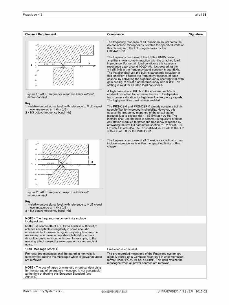
Praesideo 4.3 zhs | 73
Bosch Security Systems B.V. IUI-PRAESIDEO_4.3 | V1.0 | 2015.02安装说明和用户指南
figure 1: VACIE frequency response limits without microphone(s)
Key1 - relative output signal level, with reference to 0 dB signal
level measured at 1 kHz (dB)2 - 1/3 octave frequency band (Hz)
figure 2: VACIE frequency response limits with microphone(s)
Key1 - relative output signal level, with reference to 0 dB signal
level measured at 1 kHz (dB)2 - 1/3 octave frequency band (Hz)
The frequency response of all Praesideo sound paths that do not include microphones is within the specified limits of this clause, with the following remarks for the LBB4428/00.
The frequency response of the LBB4428/00 power amplifier shows some interaction with the attached load impedance. For certain load conditions this causes a resonance peak around 10-20 kHz, just exceeding the +1 dB limit in the frequency band between 6 and 8kHz. The installer shall use the built-in parametric equalizer of this amplifier to flatten the frequency response of each channel by activating the high frequency shelving filter, with gain setting -2 dB at a corner frequency of 6.8 kHz. This setting is valid for all rated load conditions.
A high pass filter at 68 Hz in the equalizer section is enabled by default to decrease the risk of loudspeaker transformer saturation for high level low frequency signals. The high pass filter must remain enabled.
The PRS-CSM and PRS-CSRM already contain a built-in speech-filter for improved intelligibility. However, this causes the frequency response of these call station modules just to exceed the -1 dB limit at 400 Hz. The installer shall use the built-in parametric equalizer of these call station modules to flatten the frequency response by activating the first full parametric section to +2 dB at 390 Hz with a Q of 0.8 for the PRS-CSRM, or +3 dB at 390 Hz with a Q of 0.8 for the PRS-CSM.
The frequency response of all Praesideo sound paths that include microphones is within the specified limits of this clause.
NOTE - The frequency response limits exclude loudspeakers.
NOTE - A bandwidth of 400 Hz to 4 kHz is sufficient to achieve acceptable intelligibility in some acoustic environments. However, a higher frequency limit may be necessary to achieve acceptable intelligibility in more difficult acoustic environments due, for example, to the masking effect caused by reverberation and/or ambient noise.
13.13 Message store(s) Praesideo is compliant.
Pre-recorded messages shall be stored in non-volatile memory that retains the messages when all power sources are removed.
The pre-recorded messages of the Praesideo system are digitally stored on a Compact Flash card in uncompressed format (linear PCM, 16-bit, 44.1kHz). This card retains the messages when all power sources are removed.
NOTE - The use of tapes or magnetic or optical data disks for the storage of emergency messages is not acceptable at the time of drafting this European Standard (see Annex C)
Clause / Requirement Compliance Signature
24,0 8,0 20
-10
0,4
-20
-15
01
10
-1
0,125
15
20
11,0
24,0 10
-10
0,5
-20
-15
0
5
10
-5
0,2
15
20
11,0
0,630,8 1,6
1,25

Praesideo 4.3 zhs | 74
Bosch Security Systems B.V. IUI-PRAESIDEO_4.3 | V1.0 | 2015.02安装说明和用户指南
13.14 Redundant power amplifiers (option with requirements)
Praesideo is compliant.
13.14.1 The VACIE may have provision for at least one spare power amplifier. In this case:
Each power amplifier channel of the Praesideo system has an input for connecting a spare amplifier channel. It also contains a switch-over relay to switch the loudspeaker load from the original amplifier output to the spare amplifier output. A spare amplifier channel assignment is configurable to multiple main amplifier channels.
a in the event of the failure of a power amplifier, the faulty amplifier shall be capable of being replaced automatically with a spare amplifier within 10 s of the fault being detected;
After fault detection of an amplifier all loudspeaker lines are switched automatically to the spare amplifier (if connected and configured) within 10 s.
NOTE - This can be achieved, for example, by switching or by permanently connected parallel amplifiers.
b the spare power amplifier(s) shall have at least the same functionality and output power as the replaced amplifier.
Each power amplifier channel of the Praesideo system has a spare amplifier input. The installer shall take care of proper installation and configuration of the amplifiers to match amplifier power and number of channels per amplifier. Praesideo takes care of input signal switching to the spare amplifier channel, including adaptive sound processing. This way the spare power amplifier(s) will have the same functionality and output power as the replaced amplifier.
13.14.2 Every fault of an amplifier shall be indicated by a general fault warning indicator as specified in 8.2
All Praesideo power amplifiers are supervised for overload, overheating, short-circuit, ground short and amplifier defect. If any such fault is detected it is indicated both by means of the general fault warning indicator and by means of an individual fault report.
13.14.3 Supervision of the spare amplifier(s) shall be maintained during the functional condition whilst the VACIE is powered by either the mains or standby power supplies.
The spare amplifiers can be continuously supervised, whether it is in idle or active state; this is configurable.
The supervision is active whilst the Praesideo system is powered by either the mains or standby power supplies.
Clause / Requirement Compliance Signature

Praesideo 4.3 zhs | 75
Bosch Security Systems B.V. IUI-PRAESIDEO_4.3 | V1.0 | 2015.02安装说明和用户指南
Clause / Requirement Compliance Signature14 Additional design requirements for software
controlled VACIE14.1 General requirements and manufacturer's
declarationsPraesideo is compliant.
In order to fulfill requirements of this European Standard the VACIE may contain elements which are controlled by software. In this case, the VACIE shall comply with the requirements of Clause 13 Design requirements and this clause where relevant to the technology used.
The Praesideo system is centrally controlled by the software running on the network controller.
14.2 Software documentation Praesideo is compliant.
14.2.1 The manufacturer shall prepare documentation that gives an overview of the software design, which shall be submitted to the testing authority together with the VACIE. This documentation shall be in sufficient detail for the design to be inspected for compliance with this European Standard and shall comprise at least the following:
The software design documentation is available for testing authorities. It is in sufficient detail for the design to be inspected for compliance.
a functional description, using a clear methodology appropriate to the nature of the software, e.g. graphical representations of the system design, data flows and control flows and of the main program flow, including:
An extensive set of architecture documents and software design documents are available and maintained.
1 a brief description of each module and the tasks it performs,
Architecture documents are available.
2 the way in which the modules interact, Architecture and design documents are available.
3 the way in which the modules are called, including any interrupt processing, and
Architecture and design documents are available.
4 the overall hierarchy of the program; Architecture documents are available.
b a description of which areas of memory are used for the various purposes (e.g. the program, site specific data and running data);
Memory usage is described in the system architecture document.
c a description of how the software interacts with the hardware of the VACIE.
Hardware software interaction is described in a set of Hardware-Software Interface documentation.
Where dynamic memory management is employed, a separation shall be implemented between the program, site specific data and running data and this shall be described in connection with the method of memory allocation.
The program is located in separate Flash EPROMs that are reserved for the program executable.
The message data is stored on a separate Flash card.
The site specific configuration data is stored on the Flash file system.
The running data (static variables, stacks and heap data) is stored in RAM.
After loading the program executable from Flash EPROM into RAM, the code space and the running data are separated from each other: the code space is in the bottom area of the RAM and the running data takes up the remainder. Dynamic memory is allocated from the heap using the VxWorks (first fit policy based) memory manager.
The file system that, apart from storing the site specific data, also stores the logging information and configuration web pages, is a Flash EPROM based DOS FAT file system that is managed by the VxWorks Flash file system manager.
14.2.2 The manufacturer shall prepare and maintain detailed design documentation. This need not be submitted to the testing authority but shall be available for inspection in a manner which respects the manufacturer's rights of confidentiality. This documentation shall comprise at least the following:
The software design documents contain detailed design documentation. Furthermore code comments also contain detailed design documentation.
a a description of each module of the program, as it is implemented in the source code of the program, containing:1 the name of the module, and 2 the identification of the author(s);
The Praesideo software component descriptions (module descriptions) are available from the software architecture documents. These documents contain the names of the components. The author information can be obtained from the version manager (Merant Version Manager) used for the documentation.
b the source code listing, including all global and local variables, constants and labels used, and sufficient comment for the program flow to be recognized;
All of the source code listing (including all global and local variables, constants and labels used) can be obtained from the version manager (Merant Version Manager) used for the code. All of the Praesideo code is commented.

Praesideo 4.3 zhs | 76
Bosch Security Systems B.V. IUI-PRAESIDEO_4.3 | V1.0 | 2015.02安装说明和用户指南
c details of any software tools used in the preparation of the program (e.g. high level design tools, compilers, assemblers).
The list can be composed on request and containshigh level design tools, compilers for various processors, syntax validation tools, build tools, test tools, performance validation tools, version control tools, defect tracking tools.
14.3 Software design Praesideo is compliant.
In order to ensure the reliability of the VACIE the following requirements for software design shall apply:
a the software shall have a modular structure; The modular structure of the Praesideo software is documented in the software architecture documents.
b the design of the interfaces for manually and automatically generated data shall not permit invalid data to cause an error in the program execution;
The interfaces between the modules and to external components are well defined and described in the design documents and external interface documents (Open Interface). Asserts are used to validate inputs on component boundaries.
c the software shall be designed to avoid the occurrence of a deadlock in the program flow.
Design guidelines are in place to avoid deadlocks. Multi threading within components is avoided where feasible and components have an input command queue for safe decoupling of threads.
14.4 Program monitoring (see also Annex C) Praesideo is compliant.
14.4.1 The execution of the program shall be monitored as under 14.4.2 or 14.4.3. If routines associated with the main functions of the program are no longer executed, either or both of the following shall apply:
a the VACIE shall indicate a system fault (as in 8.3); Upon activation of a watchdog, a fault is reported after restart of the failing component indicating the failing unit and processor. If a restart of the failing component is not possible, a less detailed fault will be reported. A system fault is indicated when entering the fault condition.
b the VACIE shall enter the fault warning condition and indicate faults of affected supervised functions (as in 8.2.3, 8.2.4, 8.3, 8.4 and 8.5), where only these functions are affected.
Upon activation of a watchdog, a fault is reported after restart of the failing component indicating the failing unit and processor.
14.4.2 If the program executes in one processor, the execution of the routines in 14.4.1, it shall be monitored by a monitoring device as in 14.4.4.
All processors used in the Praesideo system are either guarded by a hardware watchdog or are monitored by a processor that is guarded by a hardware watchdog.
14.4.3 If the program executes in more than one processor, the execution of the routines in 14.4.1 shall be monitored in each processor. A monitoring device as in 14.4.4 shall be associated with one or more processors, and at least one such processor shall monitor the functioning of any processor not associated with such a monitoring device.
All processors are either guarded by a hardware watchdog or are monitored by a processor that is guarded by a hardware watchdog:.The network controller is responsible for monitoring all processors in the system. Upon failure of one of the processors, either due to a watchdog failure or due to a communication failure a fault is generated. Failure of the network controller itself will cause the system fault output contact to be de-energized to indicate a system fault.
14.4.4 The monitoring device of 14.4.2 and 14.4.3 shall have a time-base independent of that of the monitored system. The functioning of the monitoring device, and the signaling of a fault warning, shall not be prevented by a failure in the execution of the program of the monitored system.
All processors are either guarded by a hardware watchdog or are monitored by a processor that is guarded by a hardware watchdog.
Additionally the correct operation of the main processor of all system elements is validated by adding execution checks on relevant locations in the code. This to assure that no important flow is excluded from execution.
The network controller multi-threaded environment is validated on correct operation by monitoring the threads: all relevant threads must report to a single thread that is responsible for resetting the watchdog. If threads do not report within a given time frame the watchdog feeding process is halted. This monitoring thread itself is supervised by a hardware watchdog.
14.4.5 In the event of a system fault as specified in 14.4.1 a) or 14.6, those parts of the VACIE affected shall enter a safe state not later than the indication of the system fault. This safe state shall not result in the false activation of mandatory outputs.
Upon restart of a unit other than the Network Controller, the unit will be reinitialized and reordered to its expected state.
Upon restart of the network controller and subsequent loss of the audio and communication network, all units will assume a safe state. The network controller orders the units to their initialization state and is responsive to new stimuli when restarted.
Information about errors and fatal errors (those resulting in a reboot) are saved in SRAM for post mortem analysis. Additionally to the display, a fault indicator can be supplied that indicates the presence of a fault.
Clause / Requirement Compliance Signature

Praesideo 4.3 zhs | 77
Bosch Security Systems B.V. IUI-PRAESIDEO_4.3 | V1.0 | 2015.02安装说明和用户指南
14.5 The storage of programs and data (see also Annex C)
Praesideo is compliant.
14.5.1 All executable code and data necessary to comply with this European Standard shall be held in memory that is capable of continuous, unmaintained, reliable operation for a period of at least 10 years.
All Praesideo programs (executable code and data) are stored in Flash EEPROM.
14.5.2 For the program, the following requirements shall apply:
a the program shall be held in non-volatile memory, which can only be written to at access level 4, and
Firmware (i.e. the program) can be replaced using the File Transfer Application. Using the File Transfer Application requires access level 4.
b it shall be possible to identify the version reference or references of the program at access level 3. The version reference or references shall be in accordance with the documentation of 14.2.1.
The version of the firmware of the units that have an LCD (access level 3) is visible on the units and on the firmware upgrade web page (that can be accessed via the web interface of the network controller). The version of the network controller software is visible on the network controller display and the web start page. Getting access to the web interface of the network controller requires access level 3.
14.5.3 For site-specific data, including emergency message(s), the following requirements shall apply:
a the alteration of site specific data shall only be possible at access level 3 or 4;
Alteration of site specific data can only be done via the web pages offered by the web interface of the network controller (configuration data) and via the File Transfer Application (message sets). Getting access to the web interface of the network controller requires access level 3. Using the File Transfer Application requires access level 4.
b the alteration of site specific data shall not affect the structure of the program;
Configuration of the Praesideo system is implemented to be data-driven and is not part of the program executable. Also transferring message sets to the Praesideo system is data-driven and is not part of the program executable. Therefore alteration of the site specific data does not affect the structure of the program.
c if stored in read-write memory, there shall be a mechanism which prevents the memory being written to during normal operation at access level 1 or 2, such that its contents are protected during a failure in program execution;
Site specific data is stored in a Flash EEPROM based file system. The file system is maintained by the VxWorks Flash file system manager using a dedicated cyclic Flash-Write program mechanism.
d It shall be possible to either read or interrogate the site specific data at access level 2 or 3, or the site specific data shall be given a version reference that shall be updated when each set of alterations is carried out.
Site specific data can be viewed and maintained from the configuration web interface. Using the web interface requires access level 3.
e If the site specific data has a version reference, it shall be possible to identify this at access level 2 or 3.
The site specific data of the Praesideo system does not have a version reference.
14.6 Monitoring of memory contents Praesideo is compliant.
The contents of the memories containing the site specific data shall be automatically checked at intervals not exceeding 1 h. The checking device shall signal a system fault if a corruption of the memory contents is detected.
The message store is checked every 100 s using checksum validation. Upon detecting corruption, a fault is reported indicating a corrupt message store.
The configuration file is checked at intervals not exceeding 1 h using checksum validation. Upon detecting corruption, a fault is reported indicating a corrupt configuration.
Clause / Requirement Compliance Signature

Praesideo 4.3 zhs | 78
Bosch Security Systems B.V. IUI-PRAESIDEO_4.3 | V1.0 | 2015.02安装说明和用户指南
Clause / Requirement Compliance Signature15 Marking Praesideo is compliant.
The VACIE shall be marked with the following information, which shall be legible at access level 1:
a the number of this European Standard; The installer must mark the Praesideo system with the number of this European standard (which is legible at access level 1) since the installer must install and configure the system properly in order to let the installation comply with this standard.
b the name or trademark of the manufacturer or supplier; The name ‘Bosch’ is visible on each element of the Praesideo system. The installer must ensure that this name is legible at access level 1 for all system elements.
c the type number or other designation of the VACIE. The type number of each unit of the Praesideo system is present on the unit itself. The installer imust ensure that this type number is legible at access level 1.
It shall be possible to identify a code or number that identifies the production period of the VACIE at access level 1 or 2 or 3.
The hardware version and production data are visible on the type number plate of each unit of the Praesideo system. The installer must ensure that this type number plate is identifiable at access level 1, 2 or 3.
Where Annex ZA.3 covers the same requirements as this clause, the requirements of this clause are met.
Clause / Requirement Compliance Signature16 Tests All tests as asked for in the clauses of section 16 have been
carried out by an accredited certification body for EN54-16 compliancy.
The Praesideo system has been found compliant to EN-54-16 and received a certification of compliancy.

Praesideo 4.3 zhs | 79
Bosch Security Systems B.V. IUI-PRAESIDEO_4.3 | V1.0 | 2015.02安装说明和用户指南
EN54-16: 2008 VACIE label
IMPORTANTThe proper functioning of an emergency sound system (VACIE) in accordance with EN54-16 is the responsibility of the manufacturer of the system. Because a Praesideo emergency sound system contains system elements that are built together and interconnected during system installation, the correct design, installation and configuration of the system are crucial for compliancy to EN54-16. Therefore Bosch Security Systems and the Notified Body that certified the Praesideo system have agreed that a strict adherence to the following rules is a necessity for compliancy of an installed Praesideo emergency sound system (VACIE) to EN54-16.
1 Bosch Security Systems shall provide training courses for VACIE installers. Such a training course will cover all necessary subjects to do successful installations of the products for which this course is intended, including the specific requirements for EN54-16, such as how to configure an EN54-16 compliant VACIE using the correct components (correct HW/SW).
2 VACIE installers who have participated in the Bosch Security Systems training and passed the examination will be certified. Certified VACIE installers need to renew their certification once every 2 years by participating in the Bosch/Dynacord follow-up training course on this subject and/or successfully pass the exam to extend their certificate.
3 Bosch Security Systems shall keep and maintain a list of all certified VACIE installers.4 VACIE installations:
• The VACIE shall be installed according to the applicable clauses mentioned in the EN54-16 standard by or under the supervision of a certified VACIE installer.
• The certified VACIE installer shall check each clause of the EN54-16 checklist, as provided in the Installation and User Instructions, upon fulfilling the requirements of that clause.
0560
Bosch Security Systems B.V.
Torenallee 49 5617 BA Eindhoven
The Netherlands
Year in which the marking has been affixed
2015 2016 2017 2018 2019 2020 2021 2022 2023 2024
Project File Number:
0560 – CPR – 10219002
EN 54-4:1997 + A1:2002 + A2:2006 EN 54-16:2008
ISO 7240-4:2003 ISO 7240-16:2007
Digital Public Address and Emergency Sound System
Praesideo 4.3
Provided options and other product information is available in the Installation and User Instructions
of Praesideo 4.3, 2015-02

Praesideo 4.3 zhs | 80
Bosch Security Systems B.V. IUI-PRAESIDEO_4.3 | V1.0 | 2015.02安装说明和用户指南
Note: Some requirements will be met by design of the equipment used, some other requirements may need a specific configuration in hardware or software.
• The certified VACIE installer shall login to the Bosch/Dynacord system registration website to register the system, and apply for a unique project file number by entering the system documentation:1. Confirmation of having checked each clause of the EN54-16 checklist for this system.2. A copy of the configuration file of each network controller used in the system.3. Entering the following data of each product in the installation: serial number, product name, hardware release number and software release number.4. Enter personal information of the certified VACIE installer and confirmation that the provided information has been entered correctly and completely.
• Bosch Security Systems will check the entered information on completeness and correctness.• If the entered information is found to be correct, Bosch Security Systems will store the project information for
future reference and email the project file number to the certified VACIE installer. • The certified VACIE installer shall fill-in the year and project file number on the VACIE label and affixes the
VACIE-label to one of the main equipment rack(s) of the VACIE, in accordance with the checklist and instructions in the Installation and User Instructions. Filling-in the year and project file number on the label shall be done legibly and indelibly.Note: indelibly means that it cannot be easily removed with water or petroleum spirits.
5 Correctness of the entered information in the system registration website is granted if all relevant clauses of the EN54-16 checklist have been checked, and all entered devices with HW/SW versions and its combinations are listed in the valid EN54-16 certificate, and that the configuration uses allowed settings according to the user manual, and that the personal information is correct and confirmation of completeness and correctness of the entered information is given by the certified VACIE installer.

Praesideo 4.3 zhs | 81
Bosch Security Systems B.V. IUI-PRAESIDEO_4.3 | V1.0 | 2015.02安装说明和用户指南
EN54-16: 2008 products description
EN 54-16 is a product standard governing 'Voice Alarm Control and Indicating Equipment' (VACIE). Telefication has declared as designated Notified Body for the European Construction Products Regulation that the products as listed in the table below are in conformity with Regulation (EU) No 305/2011 based on the applicable Technical Standards and Specifications.
Telefication has issued a Certificate of Constancy of Performance with the following certificate number:560-CPR-10219002
x = 0, 1, 2, 3y = 0, 1
Trademark Main product description Main type designation Hardware release Software releaseBosch Network Controller PRS-NCO-B 21/05, 21/08 3.5x, 3.6y
Bosch Network Controller PRS-NCO3 30/00, 30/10 4.0y, 4.1, 4.3
Bosch Audio Expander LBB4402/00 16/15 3.5x, 3.6y, 4.0y, 4.1, 4.3
Bosch Audio Expander PRS-4AEX4 17/00 3.61, 4.1, 4.3
Bosch CobraNet Interface LBB4404/00 03/10, 03/15 3.5x, 3.6y, 4.0y, 4.1, 4.3
Bosch Multichannel Interface PRS-16MCI 04/10, 04/15 3.5x, 3.6y, 4.0y, 4.1, 4.3
Bosch Network Splitter PRS-NSP 03/15 3.5x, 3.6y, 4.0y, 4.1, 4.3
Bosch Fiber Interface PRS-FIN 03/15 3.5x, 3.6y, 4.0y, 4.1, 4.3
Bosch Fiber Interface Non-Addressable PRS-FINNA 03/15 3.5x, 3.6y, 4.0y, 4.1, 4.3
Bosch Fiber Interface Single-Mode PRS-FINS 03/15 3.5x, 3.6y, 4.0y, 4.1, 4.3
Bosch Power Amplifier 8 x 60 W LBB4428/00(-EU) 04/05, 05/05 3.5x, 3.6y, 4.0y, 4.1, 4.3
Bosch Power Amplifier 1 x 500 W PRS-1P500(-EU) 06/05, 06/10 3.5x, 3.6y, 4.0y, 4.1, 4.3
Bosch Power Amplifier 2 x 250 W PRS-2P250(-EU) 06/05, 06/10 3.5x, 3.6y, 4.0y, 4.1, 4.3
Bosch Power Amplifier 4 x 125 W PRS-4P125(-EU) 06/05, 06/10 3.5x, 3.6y, 4.0y, 4.1, 4.3
Bosch Basic Amplifier 1 x 500 W PRS-1B500(-EU) 06/05 3.5x, 3.6y, 4.0y, 4.1, 4.3
Bosch Basic Amplifier 2 x 250 W PRS-2B250(-EU) 06/05 3.5x, 3.6y, 4.0y, 4.1, 4.3
Bosch Basic Amplifier 4 x 125 W PRS-4B125(-EU) 06/05 3.5x, 3.6y, 4.0y, 4.1, 4.3
Bosch Basic Amplifier 8 x 60 W PRS-8B060(-EU) 06/05 3.5x, 3.6y, 4.0y, 4.1, 4.3
Bosch Basic Call Station LBB4430/00 06/15 3.5x, 3.6y, 4.0y, 4.1, 4.3
Bosch Call Station Keypad LBB4432/00 01/18, 01/19 3.5x, 3.6y, 4.0y, 4.1, 4.3
Bosch Numeric Keypad PRS-CSNKP 01/18 3.5x, 3.6y, 4.0y, 4.1, 4.3
Bosch Call Station Interface PRS-CSI 01/15, 01/20, 01/30 3.5x, 3.6y, 4.0y, 4.1, 4.3
Bosch Remote Call Station PRS-CSR 01/15, 01/20, 01/30 3.5x, 3.6y, 4.0y, 4.1, 4.3
Bosch Call Station Module PRS-CSM 11/00 4.1, 4.3
Bosch Remote Call Station Module PRS-CSRM 11/00 4.1, 4.3
Bosch Call Station Keypad Module PRS-CSKPM 11/00 4.1, 4.3
Bosch Supervision Control Board LBB4440/00 01/05 3.5x, 3.6y, 4.0y, 4.1, 4.3
Bosch LSP Supervision Board LBB4441/00 01/05 3.5x, 3.6y, 4.0y, 4.1, 4.3
Bosch Line Supervision Set LBB4442/00 01/10 3.5x, 3.6y, 4.0y, 4.1, 4.3
Bosch EOL Supervision Board LBB4443/00 01/05 3.5x, 3.6y, 4.0y, 4.1, 4.3
Bosch Call Stacker PRS-CRF 01/10, 06/10 3.5x, 3.6y, 4.0y, 4.1, 4.3
Bosch SPEC RCS Master PSP-D00039 03/15 3.5x, 3.6y, 4.0y, 4.1, 4.3
Bosch SPEC RCS Slave PSP-D00040 03/15 3.5x, 3.6y, 4.0y, 4.1, 4.3
Bosch IP Audio Interface PRS-1AIP1 02/00 3.5x, 3.6y, 4.0y, 4.1, 4.3
Bosch 48VDC Battery Charger PRS-48CH12 n.a. 3.5x, 3.6y, 4.0y, 4.1, 4.3
PSD 48VDC Battery Charger PRS-48CHxx-DE n.a. 3.5x, 3.6y, 4.0y, 4.1, 4.3
Merawex Power Supply System ZDSO400E-AK3 n.a. 3.5x, 3.6y, 4.0y, 4.1, 4.3
Bosch Line Isolator System Master PM1-LISM6 01/00 4.1, 4.3
Bosch Loudspeaker Line Isolator PM1-LISS 01/00 4.1, 4.3
Bosch Loudspeaker DC Blocking Board PM1-LISD 01/00 4.1, 4.3

Praesideo 4.3 zhs | 82
Bosch Security Systems B.V. IUI-PRAESIDEO_4.3 | V1.0 | 2015.02安装说明和用户指南
This list of products is subject to change. The most recent version of this list can be found on www.bosch.com.
Certification of the Praesideo Digital Public Address and Emergency Sound System includes the cabinets (i.e. the enclosed 19"-racks) in which the system elements are mounted. It is allowed to use one or more cabinets, depending on the size of the Praesideo system. Within the same cabinet family, different heights are allowed up to a maximum height that depends on the brand and type of an approved cabinet. The following cabinets have been approved for use with Praesideo:• Rittal TS8 series, with lockable glass door, side panels, temperature controlled top fans and having a fixed frame
with a maximum height of 42 HU or a lockable swing frame with a maximum height of 40 HU.• Schroff 20130073PRAESIDEO, specifically designed for Praesideo.
The list of approved cabinets is subject to change. The most recent version of this list can be found on www.boschsecurity.com.
Certification of the Praesideo Digital Public Address and Emergency Sound System includes the LBB4404/00CobraNet Interface under the condition that it is directly connected to an Ethernet switch of the type Belden/ Hirschmann RSR20-0800M2M2T1UCCHPHH (an extended temperature version of the RSR20-0800M2M2T1SCCHPHH) in the same cabinet. This switch may also be used to connect, within the same cabinet, other EN54-16 compliant products, as listed in the table on the previous page.
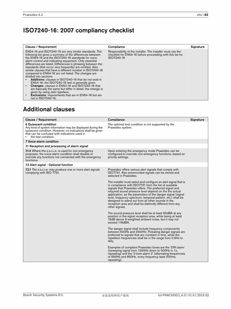
Praesideo 4.3 zhs | 83
Bosch Security Systems B.V. IUI-PRAESIDEO_4.3 | V1.0 | 2015.02安装说明和用户指南
ISO7240-16: 2007 compliancy checklist
Additional clauses
Clause / Requirement Compliance SignatureEN54-16 and ISO7240-16 are very similar standards. The following list gives a summary of the differences between the EN54-16 and the ISO7240-16 standards for voice alarm control and indicating equipment. Only essential differences are listed. Differences in phrasing between the standards (that occur very frequently) are omitted. Also similar clauses that have a different number in ISO7240-16 compared to EN54-16 are not listed. The changes are divided into sections• Additions: clauses in ISO7240-16 that do not exist in
EN54-16; the ISO7240-16 text is generally given.• Changes: clauses in EN54-16 and ISO7240-16 that
are basically the same but differ in detail, the change is given by using italic typeface.
• Exclusions: requirements that are in EN54-16 but are not in ISO7240-16.
Responsibility of the installer. The installer must use the checklist for EN54-16 before proceeding with this list for ISO7240-16
Clause / Requirement Compliance Signature6 Quiescent conditionAny kind of system information may be displayed during the quiescent condition. However, no indications shall be given that can be confused with indications used in• the test condition.
The optional test condition is not supported by the Praesideo system.
7 Voice-alarm condition7.1 Reception and processing of alarm signal7.1.4 Where the s.s.c.i.e. is used for non-emergency purposes, the voice-alarm condition shall disable or override any functions not connected with the emergency functions.
Upon entering the emergency mode Praesideo can be configured to override non-emergency functions, based on priority settings.
7.2 Alert signal - Optional function7.2.1 The s.s.c.i.e. may produce one or more alert signals complying with ISO 7731.
Praesideo offers various alert signals that comply with ISO7731. Also prerecorded signals can be stored and selected in Praesideo.
The installer must select and configure an alert signal that is in compliance with ISO7731 from the list of available signals that Praesideo offers. The preferred signal and required sound pressure level depend on the the actual application, as the parameters of the danger signal (signal level, frequency spectrum, temporal pattern, etc.) shall be designed to stand out from all other sounds in the reception area and shall be distinctly different from any other signals.
The sound pressure level shall be at least 65dBA at any position in the signal reception area, while being at least 15dB above A-weighted ambient noise, but it may not exceed 118dBA.
The danger signal shall include frequency components between 500Hz and 2500Hz. Pulsating danger signals are preferred to signals that are constant in time, while the repetition frequencies shall be in the range from 0.5Hz to 4Hz.
Examples of compliant Praesideo tones are the ‘DIN alarm’ (sweeping signal from 1200Hz down to 500Hz in 1s, repeating) and the ‘2-tone alarm 2’ (alternating frequencies of 650Hz and 850Hz, every frequency lasts 500ms, repeating).
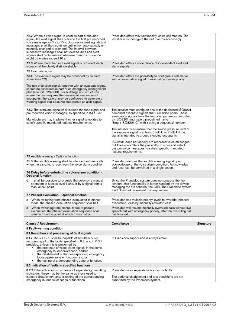
Praesideo 4.3 zhs | 84
Bosch Security Systems B.V. IUI-PRAESIDEO_4.3 | V1.0 | 2015.02安装说明和用户指南
7.2.2 Where a voice signal is used as part of the alert signal, the alert signal shall precede the first pre-recorded voice message for 3 s to 10 s. Successive alert signals and messages shall then continue until either automatically or manually changed or silenced. The interval between successive messages shall not exceed 30 s and alert signals shall be broadcast whenever periods of silence might otherwise exceed 10 s.
Praesideo offers this functionality via its call macros. The installer must configure the call macros accordingly.
7.2.3 Where more than one alert signal is provided, each signal shall be clearly distinguishable.
Praesideo offers a wide choice of independent alert and alarm signals.
7.3 Evacuate signal
7.3.1 The evacuate signal may be preceded by an alert signal (see 7.2).
The use of an alert signal, together with an evacuate signal, should be assessed as part of an emergency management plan (see ISO 7240-19). For buildings and structures where the plan requires the unassisted evacuation of occupants, the s.s.e.p. may be configured to generate a warning signal that does not incorporate an alert signal.
Praesideo offers the possibility to configure a call macro with an evacuation signal or evacuation message only.
7.3.2 The evacuate signal shall include the tone signal and pre-recorded voice messages, as specified in ISO 8201.
Manufacturers may implement other signal templates to satisfy specific mandated national requirements.
The installer must configure one of the dedicated ISO8201 compliant evacuate signals that Praesideo offers. These emergency signals have the temporal pattern as described by ISO8201 and have a predefined name ‘Emg x ISO8201 C’, with x being a sequential number.
The installer must ensure that the sound pressure level of the evacuate signal is at least 65dBA, or 75dBA if the signal is intended to arouse sleeping occupants.
ISO8201 does not specify pre-recorded voice messages, but Praesideo offers the possibility to store and select custom voice messages to satisfy specific mandated national requirements.
7.5 Audible warning - Optional function
7.5.3 The audible warning shall be silenced automatically when the s.s.c.i.e. is reset from the voice alarm condition.
Praesideo silences the audible warning signal upon acknowledge of the voice alarm condition. Acknowledge and reset can be combined in a single action.
7.6 Delay before entering the voice-alarm condition - Optional functiond It shall be possible to override the delay by a manual
operation at access level 1 and/or by a signal from a manual call point.
Since the Praesideo system does not process the fire sensors, this functionality is better handled by the device managing the fire sensors (the CIE). The Praesideo system itself does not implement this requirement.
7.7 Phased evacuation - Optional functionc When switching from phased evacuation to manual
mode, the phased evacuation sequence shall halt.Praesideo has multiple priority levels to override (phased evacuation) calls by manually activated calls.
d When switching from manual mode to phased evacuation, the phased evacuation sequence shall resume from the point at which it was halted.
Praesideo will resume manually overruled calls without live speech but with emergency priority, after the overruling call has finished.
Clause / Requirement Compliance Signature8 Fault-warning condition8.1 Reception and processing of fault signals8.1.2 The s.s.c.i.e. shall be capable of simultaneously recognizing all of the faults specified in 8.2, and in 8.3 if provided, unless this is prevented by
• the presence of voice-alarm signals in the same emergency loudspeaker zone, and/or
• the disablement of the corresponding emergency loudspeaker zone or function, and/or
• the testing of a corresponding zone or function.
In Praesideo supervision is always active.
8.2 Indication of faults in specified functions8.2.2 If the indication is by means of separate light-emitting indicators, these may be the same as those used to indicate disablement and/or testing of the corresponding emergency loudspeaker zones or functions.
Praesideo uses separate indicators for faults.
The optional disablement and test conditions are not supported by the Praesideo system.

Praesideo 4.3 zhs | 85
Bosch Security Systems B.V. IUI-PRAESIDEO_4.3 | V1.0 | 2015.02安装说明和用户指南
8.6 Fault-warning condition output signalThe s.s.c.i.e. shall have an output to transmit the fault-warning condition specified in 8.2. The output signal shall be given if the s.s.c.i.e. is de-energized.
The Praesideo network controller provides two predefined control outputs for audible and visual fault indicators with fail-safe behavior. When de-energized, the contacts of these control outputs are closed (activated).
Clause / Requirement Compliance Signature9 Disabled condition - Optional function9.3 Indication of specific disablements9.3.1 Each emergency loudspeaker zone shall be indicated by means of separate light-emitting indicators and/or an alphanumeric display. The indications shall not be suppressed during the voice-alarm condition.
The optional disablement condition is not supported by the Praesideo system.
9.3.3 The same light-emitting indicator may be used as that for the indication of the corresponding fault, although the indication shall be distinguishable. The same light-emitting indicator and the same indication may be used to indicate a disabled emergency loudspeaker zone and an emergency loudspeaker zone under test.
The optional disablement condition is not supported by the Praesideo system.
Clause / Requirement Compliance Signature10 Test condition - Optional function The optional test condition is not supported by the
Praesideo system.
Clause / Requirement Compliance Signature11 Manual mode control - Optional function11.1.2 In the manual mode, the receiving and display of signals shall not be inhibited.
Praesideo does not inhibit the receiving and display of signals in the manual mode.
11.1.3 In the manual mode, any phased evacuation sequence shall be halted. Returning the system to automatic mode shall reinstate the phased evacuation sequence as if it had not been halted.
Praesideo will resume manually overruled calls after the overruling call has finished, providing that the overruled call was without live speech and had emergency priority.

Praesideo 4.3 zhs | 86
Bosch Security Systems B.V. IUI-PRAESIDEO_4.3 | V1.0 | 2015.02安装说明和用户指南
Clause / Requirement Compliance Signature13 Emergency microphone - Optional function13.1 Generalc The emergency microphone control shall mute alert and
evacuate signals within the selected emergency loudspeaker zone.
If the configured call of the emergency microphone was given a higher priority than the calls that generate alert and evacuate signals within the same emergency loudspeaker zone, these calls will be aborted and mute.
d Use of the emergency microphone shall not reset an existing functional condition. After the microphone is no longer used, the functional condition shall be re-established.
Praesideo will resume overruled calls after the overruling call has finished, providing that the overruled call was without live speech and had emergency priority. The emergency state that was entered upon starting a call with emergency priority, will remain until explicitly manually reset.
e Unless 13.3 applies, the microphone shall broadcast voice messages to a pre-configured set of emergency loudspeaker zones.
Praesideo allows for free assignment of emergency loudspeaker zones to calls that may contain live speech or prerecorded messages. This assignment can be manually during operation or in advance during configuration.
13.2 Microphone priority - Optional function13.2.2 Where more than one microphone is configured at each priority level, only one microphone shall be active at any one time. If more than one microphone at the same priority is activated, the most recently activated microphone shall be enabled.
Praesideo allows more than one microphone to be configured for calls with the same priority, but in that case typically the most recently activated one will not be enabled until the previous one has finished, i.e. first come, first served. Only in case of the highest priority, 255, multiple calls with this priority act on overruling basis, i.e. the most recently activated microphone will be enabled.Only one microphone will be active at any one time in the same zone.
13.3 Microphone emergency loudspeaker zone control - Optional functionThe s.s.c.i.e. may be configurable to route microphone messages to groups of emergency loudspeaker zones, with each group containing at least one emergency loudspeaker zone.
Praesideo allows for configuration of zone groups, containing one or more emergency loudspeaker zones. Calls can be made to a free selection of zones and zone groups.
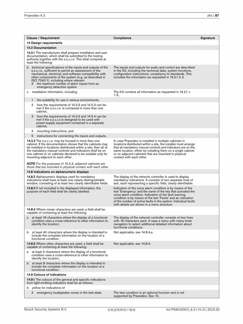
Praesideo 4.3 zhs | 87
Bosch Security Systems B.V. IUI-PRAESIDEO_4.3 | V1.0 | 2015.02安装说明和用户指南
Clause / Requirement Compliance Signature14 Design requirements 14.2 Documentation14.2.1 The manufacturer shall prepare installation and user documentation, which shall be submitted to the testing authority together with the s.s.c.i.e. This shall comprise at least the following:
b technical specifications of the inputs and outputs of the s.s.c.i.e., sufficient to permit an assessment of the mechanical, electrical, and software compatibility with other components of the system (e.g. as described in ISO 7240-1), including where relevant 3 the maximum number of alarm inputs from an
emergency detection system
The inputs and outputs for audio and control are described in the IUI, including the technical data, system functions, configuration instructions, compliancy to standards. This includes the information as requested in 14.2.1 b 3.
c installation information, including The IUI contains all information as requested in 14.2.1 c1-5.
1 the suitability for use in various environments,
2 how the requirements of 14.3.3 and 14.5.3 can be met if the s.s.c.i.e. is contained in more than one cabinet,
3 how the requirements of 14.3.3 and 14.5.4 can be met if the s.s.c.i.e is designed to be used with power-supply equipment contained in a separate cabinet,
4 mounting instructions, and
5 instructions for connecting the inputs and outputs.
14.3.3 The s.s.c.i.e. may be housed in more than one cabinet. If the documentation shows that the cabinets may be installed in locations distributed within a site, then all of the mandatory manual controls and indicators shall be on one cabinet or on cabinets declared to be suitable only for mounting adjacent to each other.
NOTE For the purposes of 14.3.3, adjacent cabinets are those that are mounted in physical contact with each other.
In case Praesideo is installed in multiple cabinets in locations distributed within a site, the installer must arrange that all mandatory manual controls and indicators are on the same location, either by installing them on a single cabinet or on adjacent cabinets that are mounted in physical contact with each other.
14.8 Indications on alphanumeric displays14.8.2 Alphanumeric displays used for mandatory indications shall have at least one clearly distinguishable window, consisting of at least two clearly identifiable fields.
The display of the network controller is used to display mandatory indications. It consists of two separate lines of text, each representing a specific field, clearly identifiable.
14.8.3 If not included in the displayed information, the purpose of each field shall be clearly labelled.
Indication of the voice alarm condition is by means of the text 'Emergency' and the name of the key that activated the voice alarm condition. Indication of the fault warning condition is by means of the text 'Faults' and an indication of the number of active faults in the system. Individual faults with details are shown in a menu structure.
14.8.4 Where roman characters are used, a field shall be capable of containing at least the following:
a at least 16 characters where the display of a functional condition uses a cross-reference to other information to identify the location;
The display of the network controller consists of two lines with 16 characters each. It uses a menu with rotary knob navigation to select additional detailed information about functional conditions.
b at least 40 characters where the display is intended to include the complete information on the location of a functional condition.
Not applicable, see 14.8.4.a.
14.8.5 Where other characters are used, a field shall be capable of containing at least the following:
Not applicable, see 14.8.4.
a at least 4 characters where the display of a functional condition uses a cross-reference to other information to identify the location;
b at least 8 characters where the display is intended to include the complete information on the location of a functional condition.
14.9 Colours of indications14.9.1 The colours of the general and specific indications from light-emitting indicators shall be as follows:
b yellow for indications of
3 emergency loudspeaker zones in the test state. The test condition is an optional function and is not supported by Praesideo. See 10.
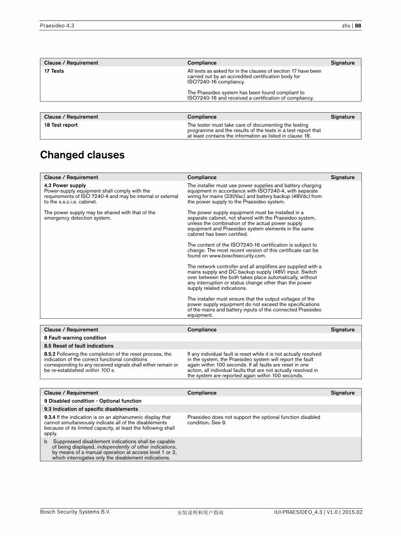
Praesideo 4.3 zhs | 88
Bosch Security Systems B.V. IUI-PRAESIDEO_4.3 | V1.0 | 2015.02安装说明和用户指南
Changed clauses
Clause / Requirement Compliance Signature17 Tests All tests as asked for in the clauses of section 17 have been
carried out by an accredited certification body for ISO7240-16 compliancy.
The Praesideo system has been found compliant to ISO7240-16 and received a certification of compliancy.
Clause / Requirement Compliance Signature18 Test report The tester must take care of documenting the testing
programme and the results of the tests in a test report that at least contains the information as listed in clause 18.
Clause / Requirement Compliance Signature4.3 Power supplyPower-supply equipment shall comply with the requirements of ISO 7240-4 and may be internal or external to the s.s.c.i.e. cabinet.
The power supply may be shared with that of the emergency detection system.
The installer must use power supplies and battery charging equipment in accordance with ISO7240-4, with separate wiring for mains (230Vac) and battery backup (48Vdc) from the power supply to the Praesideo system.
The power supply equipment must be installed in a separate cabinet, not shared with the Praesideo system, unless the combination of the actual power supply equipment and Praesideo system elements in the same cabinet has been certified.
The content of the ISO7240-16 certification is subject to change. The most recent version of this certificate can be found on www.boschsecurity.com.
The network controller and all amplifiers are supplied with a mains supply and DC backup supply (48V) input. Switch over between the both takes place automatically, without any interruption or status change other than the power supply related indications.
The installer must ensure that the output voltages of the power supply equipment do not exceed the specifications of the mains and battery inputs of the connected Praesideo equipment.
Clause / Requirement Compliance Signature8 Fault-warning condition8.5 Reset of fault indications8.5.2 Following the completion of the reset process, the indication of the correct functional conditions corresponding to any received signals shall either remain or be re-established within 100 s.
If any individual fault is reset while it is not actually resolved in the system, the Praesideo system will report the fault again within 100 seconds. If all faults are reset in one action, all individual faults that are not actually resolved in the system are reported again within 100 seconds.
Clause / Requirement Compliance Signature9 Disabled condition - Optional function9.3 Indication of specific disablements9.3.4 If the indication is on an alphanumeric display that cannot simultaneously indicate all of the disablements because of its limited capacity, at least the following shall apply.
Praesideo does not support the optional function disabled condition. See 9.
b Suppressed disablement indications shall be capable of being displayed, independently of other indications, by means of a manual operation at access level 1 or 2, which interrogates only the disablement indications.

Praesideo 4.3 zhs | 89
Bosch Security Systems B.V. IUI-PRAESIDEO_4.3 | V1.0 | 2015.02安装说明和用户指南
Clause / Requirement Compliance Signature14 Design requirements14.1 General requirements and manufacturer's declarations14.1.2 In order to assist the process of design inspection, the manufacturer shall declare in writing that
a the design has been carried out in accordance with a quality management system that incorporates a set of rules for the design of all elements of the s.s.c.i.e. [e.g. ISO 9001].
The Bosch Security Systems development department responsible for development / maintenance of the Praesideo system works according its own development process, Standard Development Process or SDP, which is created using the CMMI model. The SDP implements all process areas at maturity level 2 of the CMMI model, and some process areas at maturity level 3 of the CMMI model.Rules for the design of all elements of the Praesideo system can be found in the SDP repository. In the SDP repository all process descriptions, process implementation documents, templates, guidelines, etc. of the development processes can be found.The SDP repository is a version control system.Bosch Security Systems is ISO9001 certified.
14.8.6 Mandatory indications on an alphanumeric display shall be legible for the lesser of 1 h or the duration of the standby power source, following the display of a new indication of a functional condition, at 0,8 m distance in ambient light intensities from 5 lx to 500 lx and at any angle from the normal to the plane of the display up to
• 22,5° when viewed from each side;• 15° when viewed from above and below.
Following the lesser of 1 h or the duration of the standby power source, the indications shall be legible at 100 lx to 500 lx at the above distance and angles. It shall be possible to re-establish the legibility at 5 lx to 100 lx by means of a manual operation at access level 1.
If the Praesideo system enters the voice alarm condition the display of the network controller will automatically show the 'Emergency' menu. This indication stays on as long as the system is in the voice alarm condition (i.e. until the voice alarm condition is reset).If the Praesideo system enters the fault warning condition the display of the network controller will automatically show the 'Faults' menu with the current number of active faults. This indication stays on until either the rotary knob of the network controller is used to navigate through the menu, or the system enters the voice alarm condition. The 'Faults' menu will always be present in the Network Controller menu. Individual faults are present in this 'Faults' menu until they are reset or until they are overwritten by newer faults The menu can show up to 200 individual faults after which the oldest faults are deleted when new faults occur.The display of the Network Controller complies with the legibility demands of this clause.
14.10 Audible indication14.10.2 The minimum sound level, measured under anechoic conditions, at a distance of 1 m with any access door on the s.s.c.i.e. closed, shall be either
• 60 dBA for voice-alarm indications and 50 dBA for fault-warning indications, or
• 85 dBA for voice-alarm indications and 70 dBA for fault-warning indications.
NOTE The allowance for two sets of audible indications contemplates some s.s.c.i.e. being installed in normally occupied areas (such as a security room). The selection of an appropriate sound level can be controlled by national requirements.
The installer must connect the buzzer that is provided with Praesideo and complies with the sound levels according to the first option, or use a different buzzer with sound levels according to the second option. The selection depends on the background noise on the location where Praesideo is installed or by national requirements.
14.12.3 Frequency response of s.s.c.i.e. The frequency response requirements of ISO7240-16, clause 14.12.3 are less stringent than required by EN54-16, clause 13.12.3.The Praesideo sound paths are within the specified limits of this clause.
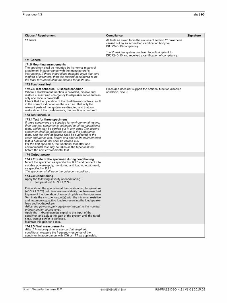
Praesideo 4.3 zhs | 90
Bosch Security Systems B.V. IUI-PRAESIDEO_4.3 | V1.0 | 2015.02安装说明和用户指南
Clause / Requirement Compliance Signature17 Tests All tests as asked for in the clauses of section 17 have been
carried out by an accredited certification body for ISO7240-16 compliancy.
The Praesideo system has been found compliant to ISO7240-16 and received a certification of compliancy.
17.1 General 17.1.5 Mounting arrangementsThe specimen shall be mounted by its normal means of attachment in accordance with the manufacturer's instructions. If these instructions describe more than one method of mounting, then the method considered to be the least favourable shall be chosen for each test.
17.2 Functional test17.2.2.4 Test schedule - Disabled conditionWhere a disablement function is provided, disable and restore at least two emergency loudspeaker zones (unless only one zone is provided). Check that the operation of the disablement controls result in the correct indication on the s.s.c.i.e., that only the relevant parts of the system are disabled and that, on restoration of the disablements, the function is restored.
Praesideo does not support the optional function disabled condition. See 9.
17.3 Test schedule17.3.4 Test for three specimensIf three specimens are supplied for environmental testing, then one test specimen is subjected to all the operational tests, which may be carried out in any order. The second specimen shall be subjected to one of the endurance tests, and the third specimen shall be subjected to the other endurance test. Before and after each environmental test, a functional test shall be carried out. For the first specimen, the functional test after one environmental test may be taken as the functional test before the next environmental test.
17.4 Output power17.4.2.2 State of the specimen during conditioningMount the specimen as specified in 17.1.5 and connect it to suitable power-supply, monitoring and loading equipment, as specified in 17.1.3.The specimen shall be in the quiescent condition.
17.4.2.3 ConditioningApply the following severity of conditioning:
• temperature: 40 °C ± 2 °C.
Precondition the specimen at the conditioning temperature (40 °C ± 2 °C) until temperature stability has been reached to prevent the formation of water droplets on the specimen.Terminate the s.s.c.i.e. output(s) with the minimum resistive and maximum capacitive load representing the loudspeaker lines and loudspeakers. Adjust the power-supply equipment output to the nominal primary power source level.Apply the 1 kHz sinusoidal signal to the input of the specimen and adjust the gain of the system until the rated r.m.s. output power is achieved.Maintain this gain for 1 min.
17.4.2.5 Final measurementsAfter 1 h recovery time at standard atmospheric conditions, measure the frequency response of the specimen in accordance with 17.6 or 17.7, as applicable.

Praesideo 4.3 zhs | 91
Bosch Security Systems B.V. IUI-PRAESIDEO_4.3 | V1.0 | 2015.02安装说明和用户指南
Excluded clauses
Clause / Requirement Compliance SignatureEN54-16, clause 12.1 Emergency microphone - option with requirements. c Where a pre-announcement attention drawing signal is
provided, an indicator adjacent to the microphone shall show when the signal has finished and live speech can commence.
This clause is not part of ISO7240-16.
Clause / Requirement Compliance SignatureEN54-16, clause 13.4.1 Electrical and other design requirementsThe processing of signals shall give the highest priority to the voice alarm condition.
This clause is not part of ISO7240-16.
EN54-16, clause 13.13 Message store(s)Pre-recorded messages shall be stored in non-volatile memory that retains the messages when all power sources are removed.
NOTE The use of tapes or magnetic or optical data disks for the storage of emergency messages is not acceptable at the time of drafting this European Standard (see Annex C)
The NOTE is not part of ISO7240-16.
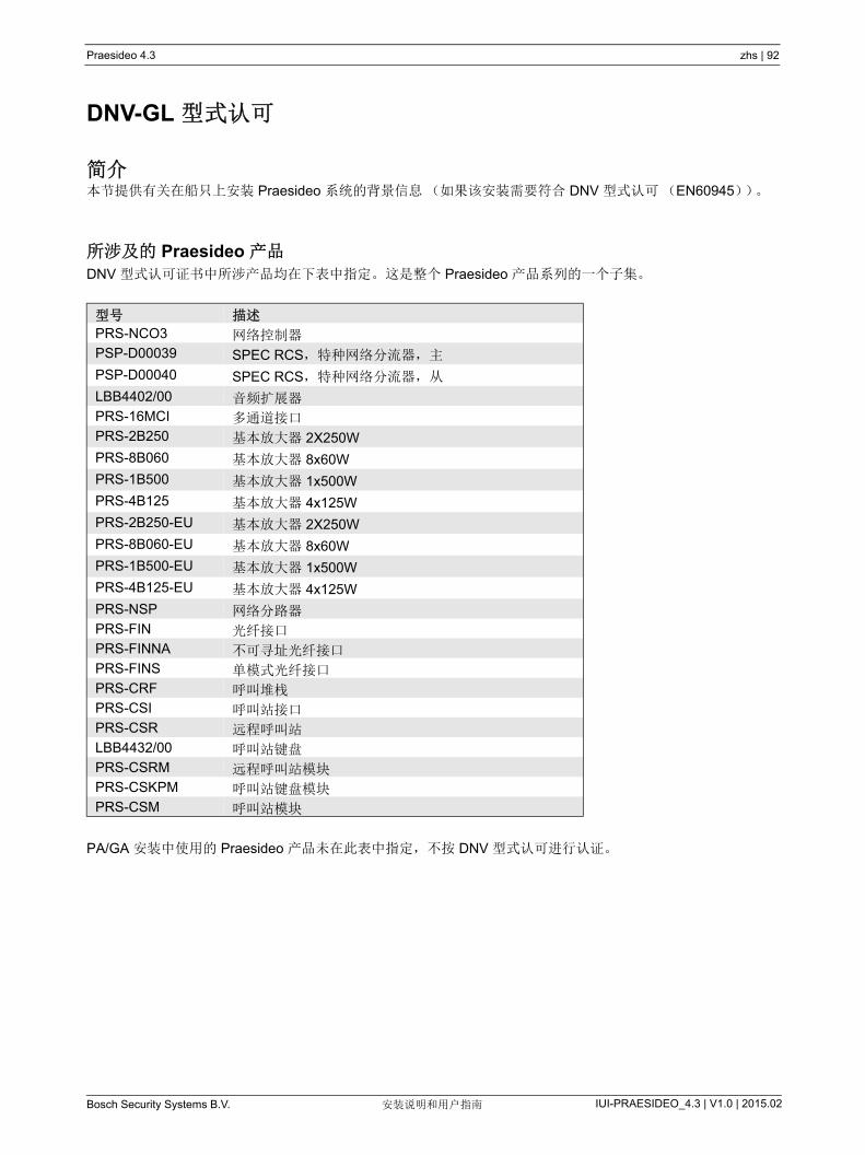
Praesideo 4.3 zhs | 92
Bosch Security Systems B.V. IUI-PRAESIDEO_4.3 | V1.0 | 2015.02安装说明和用户指南
DNV-GL 型式认可
简介本节提供有关在船只上安装 Praesideo 系统的背景信息(如果该安装需要符合 DNV 型式认可(EN60945))。
所涉及的 Praesideo 产品DNV 型式认可证书中所涉产品均在下表中指定。这是整个 Praesideo 产品系列的一个子集。
PA/GA 安装中使用的 Praesideo 产品未在此表中指定,不按 DNV 型式认可进行认证。
型号 描述
PRS-NCO3 网络控制器
PSP-D00039 SPEC RCS,特种网络分流器,主
PSP-D00040 SPEC RCS,特种网络分流器,从
LBB4402/00 音频扩展器
PRS-16MCI 多通道接口
PRS-2B250 基本放大器 2X250W
PRS-8B060 基本放大器 8x60W
PRS-1B500 基本放大器 1x500W
PRS-4B125 基本放大器 4x125W
PRS-2B250-EU 基本放大器 2X250W
PRS-8B060-EU 基本放大器 8x60W
PRS-1B500-EU 基本放大器 1x500W
PRS-4B125-EU 基本放大器 4x125W
PRS-NSP 网络分路器
PRS-FIN 光纤接口
PRS-FINNA 不可寻址光纤接口
PRS-FINS 单模式光纤接口
PRS-CRF 呼叫堆栈
PRS-CSI 呼叫站接口
PRS-CSR 远程呼叫站
LBB4432/00 呼叫站键盘
PRS-CSRM 远程呼叫站模块
PRS-CSKPM 呼叫站键盘模块
PRS-CSM 呼叫站模块

Praesideo 4.3 zhs | 93
Bosch Security Systems B.V. IUI-PRAESIDEO_4.3 | V1.0 | 2015.02安装说明和用户指南
缩写
安装指南在 DNV 型式认可中规定了有关在船只上安装 PA/GA 的要求。
本章中介绍了在安装 Praesideo 系统时需要安装者特别注意的一些具体问题。
产品安装位置的限制条件Praesideo 系统可用于货轮、客轮、高速及轻型轮船以及移动式近海装置,并遵守以下法规和规章:
• SOLAS
• 国际高速船安全规则
• 设备规则
• DNV 法定解释 [2013 年 9 月 ]
所涉 Praesideo 设备必须安装在受到保护和具备气候控制的环境中,即室内。此外,安装时,必须考虑以下与船
上磁罗盘的距离:
• 机架安装型产品:> 5 m
• PRS-CSR 与 LBB4432/00 组合:> 5 m
• PRS-CSM 与 PRS-CSKPM 组合:> 0.75 m
• PRS-CSRM 与 PRS-CSKPM 组合:> 0.85 m
系统设置下列问题必须加以考虑,以确保系统是根据 DNV 型式认可的要求进行安装和配置的:
• 对于客运船只上的 PA 使用的系统或任何船只上的集成 PA 和 GA 使用的系统,该系统的关键部件应予以重复
(A + B 系统)。各种重复在 Praesideo 内均有可能,如网络控制器、多通道接口、放大器和 A / B 扬声器电
缆。关于系统的关键部件重复的信息则在 Praesideo 的 “ 安装和用户说明 ” 手册中。
• 若用于载客船只,则 A + B 系统须安装在单独的防火区域中。
• 若用于组合型 PA/GA 系统中,则至少需要有两个独立的扬声器回路。
• 在主从网络控制器的切换过程中进行公告时,以下因素应加以考虑:
• 对于 GA 和自动化紧急 PA 公告(如,预先录制的消息),则自动化信号必须在切换后继续。
• 对于手动紧急 PA 公告(即,使用呼叫站的 PTT 键),终止公告并在切换后重新由用户发起是可以接受的
做法。
缩写 描述
dB(A) 加权分贝
DNV Det Norske Veritas
GA 一般报警
GOF 玻璃光纤
PA 公共地址
RCS 冗余网络控制器开关

Praesideo 4.3 zhs | 94
Bosch Security Systems B.V. IUI-PRAESIDEO_4.3 | V1.0 | 2015.02安装说明和用户指南
• 能够发布 GA 和紧急 PA 的呼叫站应连接到两个网络控制器上(主机和从机)。此应采用专门的网络分流器
(PSP-D00039 和 PSP-D00040),以创建冗余的网络控制器解决方案。
• 必须考虑以下电源管理指令。连接到电源和应急电源上是由 Praesideo 系统之外的 UPS 处理的。不允许在
Praesideo 系统内部使用 48V 直流输入的供电连接来进行安装。
• 输出触点须用于在 GA 和 紧急 PA 期间覆盖本地静音或本地音量控制(在扬声器上)
• 紧急 PA 应具有高于 GA 的优先级,否则就无法在 GA 已经运行时进行紧急 PA 公告。一般的 PA 应该具有低于
GA 和 PA 的优先级。
任何不用于紧急 PA 激活的呼叫站须具有低于 GA 的优先级。
• 具有激活紧急 PA 和 GA 功能的呼叫站须安装在具有访问控制的位置上。
• 具有激活紧急 PA 和 GA 功能的呼叫站须配备避免意外使用的手段。对于每个可编程的按键,详细说明标签须
滑进相应的纸槽中,以确定可编程键已配置的位置。要防止意外按键,可以安放按键保护盖 (LBB4436/00)。
• 要将 GA 紧急警报重置为默认的单键操作,必须编程联合的确认 / 重启操作,使该键能防止两个键需要分别按
下。此外,通过选择该键的 “ 重置中止活动的紧急呼叫 ”,重置操作将不由仍处于活动状态的紧急呼叫来阻止。
• 要实现所需的可听度,即将 GA 和紧急 PA 的声压水平调至 75 dB 和 120 dB 之间,音量可在放大器的输出电
平(通过 “ 音频处理 ” 页面)上 和 / 或通过区域配置进行调节。有关该主题的详细信息可在 Praesideo 的本 “
安装和用户说明 ” 手册中找到。
• 不在呼叫站麦克风附近安装扬声器可避免干扰和反馈。因为呼叫站有监听喇叭(安装在远程呼叫站内并连接
到远程呼叫站模块上),不必将扬声器安装在呼叫站附近。

Praesideo 4.3 zhs | 95
Bosch Security Systems B.V. IUI-PRAESIDEO_4.3 | V1.0 | 2015.02安装说明和用户指南
船上的 Praesideo 机架式安装
通过在船上安装 Praesideo 系统,应特别注意 Praesideo 装置的机械式安装。
Praesideo 放大器配备了延长的 19" 机架式安装支架,提供了一个坚固的结构,减少了对冲击和振动的敏感性。
电缆连接用于内部通信或信号的电缆和布线应尽量绕开船上厨房、洗衣房、 A 类机舱及其外壳和其它为火警高风险区域,
除非那些空间有此需要。
在可行情况下,所有此类电缆的布线应以排除可能由于相邻空间中的火灾引起的舱壁升温而无法使用的因素。各
防火区的所有区域应至少由两个专用回路负责,在其整个长度内与独立的放大器充分分开。
如果系统设计指定耐热玻璃光纤光缆(GOF),则建议使用以下电缆。
光纤电缆 Incore 4OF50/125-E30
• 4 纤维,多模 G50/125,松套管
• 发生火灾时功能完整性符合 DIN 4102 第 12 部分:30 分钟 (E30)
• 不含卤素,符合 IEC 60754-12
• 耐火性符合 IEC 60331、 IEC 60332.3C 和 BS 6387 类别。 C
• 适合室内使用;户外使用时具有适当的机械保护措施
• 水密性和非金属,防啮齿动物
• 良好的抗压溃性能
• 运行期间的温度范围:-25 °C 至 +70 °C
图 1: 纤维光缆 4OF50/125-E30
FR/LSOH sheath ripcord glass armouring flame retardant coating 4 multimode G50/125 fibres
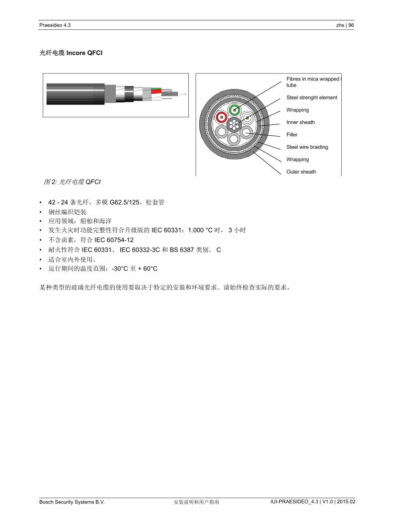
Praesideo 4.3 zhs | 96
Bosch Security Systems B.V. IUI-PRAESIDEO_4.3 | V1.0 | 2015.02安装说明和用户指南
光纤电缆 Incore QFCI
• 42 - 24 条光纤,多模 G62.5/125,松套管
• 钢丝编织铠装
• 应用领域:船舶和海洋
• 发生火灾时功能完整性符合升级版的 IEC 60331:1.000 °C 时, 3 小时
• 不含卤素,符合 IEC 60754-12
• 耐火性符合 IEC 60331、 IEC 60332-3C 和 BS 6387 类别。 C
• 适合室内外使用。
• 运行期间的温度范围:-30°C 至 + 60°C
某种类型的玻璃光纤电缆的使用要取决于特定的安装和环境要求。请始终检查实际的要求。
图 2: 光纤电缆 QFCI
Fibres in mica wrapped ltube
Steel strenght element
Wrapping
Inner sheath
Filler
Steel wire braiding
Wrapping
Outer sheath
Praesideo 4.3 zhs | 97
Bosch Security Systems B.V. IUI-PRAESIDEO_4.3 | V1.0 | 2015.02安装说明和用户指南
1 手册概述
1.1 手册目的该手册向工程师提供了安装 Praesideo 系统所必需的信
息。
Praesideo 识别以下权限级别:
• 管理员
通常是负责保证对系统适当地进行维护和修理以使
其正常运转的人员。
• 安装人员
通常是安装系统的安装工程师。
• 用户
通常是系统的终端用户。
1.2 目标受众此手册由管理员和安装人员精心制作。要能对故障做出
正确的判断,您 好接受全面的 Praesideo 培训。终端
用户的用户指南必须由管理员和安装人员提供。
本手册中带有小心、警告或者危险符号的内容为维修说
明,仅供具有相关资质的维修人员使用。为降低触电风
险,除非取得相关资质,否则不得执行操作说明范围之
外的任何维修工作。
1.3 相关文件下列相关文件可用:
• DVD 上的版本注释
• 网站上的商用手册(www.boschsecurity.com)
• 网站上的数据手册(www.boschsecurity.com)
• 网站上的建筑和工程规范
(www.boschsecurity.com)
1.4 警示该手册中采用了四种警示。警示的类型与未注意到该警
示所产生的后果密切相关。
这些警示(从 不严重的结果到 严重的结果)包括:
• 注
含有附加信息的警示。通常,未注意到此提示性警
示不会对设备造成损坏或造成人身伤害。
• 小心
如果未注意到此警示,设备可能会受到损害。
• 警告
如果未注意到此警报,设备可能会受到严重损坏,
或者会造成严重的人身伤害。
• 危险
未注意到此警报可能会导致死亡。
1.5 符号除了提示性警示,未注意到警示而引起的后果的性质可
以通过符号来指示。对于提示性警示,符号提供了比其
本身更多的信息。在此手册中,将综合采用下列符号:
注
用于表示提醒所常用的符号。
注
请参考指定的信息源。
小心、警告、危险
用于表示小心、警告和危险所常用的符号。
小心、警告、危险
危险存在电击的危险。
小心、警告、危险
危险存在静电放电的危险

Praesideo 4.3 zhs | 98
Bosch Security Systems B.V. IUI-PRAESIDEO_4.3 | V1.0 | 2015.02安装说明和用户指南
2 系统概述
2.1 简介Praesideo 是一个完整的数字公共广播系统,满足公共
广播系统或紧急广播系统专业用户规定的所有要求。该
系统为公共广播市场注入了全新的先进数字技术。完全
在数字领域中进行的音频信号和控制数据的处理和通信
使该系统成为一个高级的公共广播和紧急广播系统。
数字信号处理使音频质量得到明显改善。Praesideo 系
统可以通过 PC 进行配置,从而使得操作参数的安装和
设置变得非常简单,同时用户界面也很友好。
Praesideo 系统几乎满足了所有公共广播和话音警报系
统的要求。所有音频的处理都应在数字域内进行。设备
间的通信通过塑料光纤或玻璃光纤电缆完成,这取决于
设备间的距离。电缆连接采用菊花链原则。这使电缆连
接和安装方便快捷。系统电缆连接支持允许冗余的闭
环。如果不需要冗余,还能进行分支。
2.2 用户界面友好软件控制此系统配备有用于系统配置的用户界面友好软件。这允
许配置所有系统功能。软件是以 web 技术为基础的,所
以授权用户不受时间和场所的限制,可以完全自由地配
置。程序设计简单,结构精良,因此导航性能优越,用
户界面非常友好,容错性能极其出色。此软件还能清晰
指示退出配置过程的任何阶段之前尚未进行配置的所有
参数。
2.3 组网方法系统结构以设备的菊花链连接为基础。如果网络连接可
用,则可添加或拆除网络中任何位置上的设备,而不影
响其它设备的性能。这样,消费者无需在网络控制器设
备中添加其它任何设备就能轻松扩展该系统。通过这种
网络结构,用户可以在开始阶段使用小型系统,随后可
以通过在现有网络中添加所需的新设备来扩展该系统。
此外,还可以使用环形电缆结构为系统配置冗余电缆。
2.4 分布式控制该系统用于对不同的系统功能进行分布式控制。可以在
网络中的任何位置找到外部接口(控制输入端和输出
端)。音频输入端和输出信号的处理可以在每个设备中
进行。这样,网络控制器可以集中进行其它活动,如公
告的路由和对控制输入端采取措施等。结果是响应时间
比集中处理所有信号的系统的时间更短。
2.5 联合功能Praesideo 设备具有很多功能。此特点明显降低了系统
中所使用的不同类型设备的数量。功率放大器设备本身
提供了很多功能,如音频处理、音频延迟、放大器监
控、自动放大器切换和用于扬声器线路监控的接收器。
这样,整个系统显得更加物美价廉。Praesideo 设备的
灵活结构使消费者能在建筑物中的任何位置安装任何类
型的设备。通过配置软件,用户可以配置所有的功能参
数。在设备终端不需要编制任何程序,这明显降低了安
装和试运行时间。

Praesideo 4.3 zhs | 99
Bosch Security Systems B.V. IUI-PRAESIDEO_4.3 | V1.0 | 2015.02安装说明和用户指南
2.6 疏散符合性Praesideo 系列设备符合全球通用的各种紧急广播标
准。网络控制器能对系统中的所有设备进行监控,从呼
叫站话筒碳精盒到扬声器线路。内置存储器能存储 近
的 200 条故障信息。所有故障会报告给网络控制器。
此系统还满足应急呼叫站的应急要求。高度开放的系统
概念以及能承载大量的控制输入端和输出端设备更能满
足极其困难的应急要求。
2.7 外部接口系统接口可以是音频输入端、控制输入端或以太网。网
络控制器中配有以太网接口。音频输入端和控制输入端
可以安装到系统的任何位置,如功率放大器、音频扩展
器或网络控制器上。
系统还通过控制输入端接受触点关闭。此配置允许用户
配置输入端以启动系统中想要的操作。由于从一个系统
的任何输入端路由到另一个系统的任何输入端非常灵
活,所以 Praesideo 系列产品或大多数公共广播和紧急
广播系统的应用程序可以使用。
2.8 低安装费用Praesideo 的体系结构采用能对数据和音频信号进行分
支的菊花链原则。这样,系统配线非常实惠,采用两个
光纤芯进行数据和音频通信,采用一对铜线向设备供
电。如果距离较长,可以在当地给系统设备供电。
较之为了特定功能必须不断选购设备的系统而言,将各
种功能集成在单台设备中更加经济实惠。多项功能的集
成也节省了大量的机柜空间,并进一步降低了安装费
用。
2.9 高度的系统灵活性Praesideo 系统具有高度的灵活性,使用户能高度自由
地使用不同数量的分区、呼叫站、音频输入端和输出
端、控制输入端和输出端等。
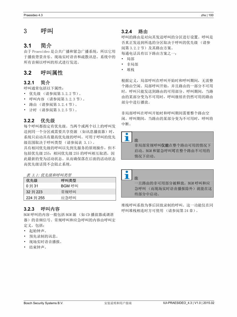
Praesideo 4.3 zhs | 100
Bosch Security Systems B.V. IUI-PRAESIDEO_4.3 | V1.0 | 2015.02安装说明和用户指南
3 呼叫
3.1 简介由于 Praesideo 是公共广播和紧急广播系统,所以它用
于播放背景音乐、现场实时语音和疏散讯息。系统中的
所有音频以呼叫的形式进行发送。
3.2 呼叫属性
3.2.1 简介呼叫通常包括以下属性:
• 优先级(请参阅第 3.2.2 节)。
• 呼叫内容(请参阅第 3.2.3 节)。
• 路由(请参阅第 3.2.4 节)。
• 计时(请参阅第 3.2.5 节)。
3.2.2 优先级每个呼叫都指定有优先级。当两个或两个以上的呼叫发
送到同一个分区或需要共享资源(如讯息播放器)时,
系统只启动具有 高优先级的呼叫。可用于呼叫的优先
级范围取决于呼叫类型(请参阅表 3.1)。
具有相同优先级的呼叫以先到先服务的原则操作,但不
包括优先级 255:相同优先级 255 的呼叫相互取消,因
此 新的变为活动状态。从而确保落在后面的活动状态
高优先级话筒不会阻止系统。
3.2.3 呼叫内容BGM 呼叫的内容一般包括 BGM 源(如 CD 播放器或调谐
器)的音频信号。常规呼叫和应急呼叫的内容由呼叫宏
定义,包括:
• 起始钟声。
• 预先录制的讯息。
• 现场实时语音播报。
• 结束钟声。
3.2.4 路由呼叫的路由是对向其发送呼叫的分区进行设置。呼叫是
否真正发送到所选的分区取决于呼叫的优先级(请参
阅第 3.2.2 节)及其路由方案。
每通电话具有以下路由方案之一:
• 局部
• 非局部
• 堆栈
根据定义,局部呼叫在呼叫开始时和呼叫期间,无需整
个路由空闲。局部呼叫开始,并且路由的一部分不可用
时,呼叫只能发送到路由的可用部分。呼叫期间,当路
由的某部分变为不可用时,呼叫继续在仍然可用的路由
部分中进行播放。
非局部呼叫在呼叫开始时和呼叫期间需要整个路由空
闲。呼叫期间,当路由的某部分变为不可用时,呼叫将
中断。
堆栈呼叫系指为事后回放录制的呼叫。这一功能仅在同
呼叫堆栈相连时方可使用(请参阅第 24 章)。
表 3.1: 优先级和呼叫类型
优先级 呼叫类型
0 到 31 BGM 呼叫
32 到 223 常规呼叫
224 到 255 应急呼叫
注
非局部常规呼叫仅能在整个路由可用的情况下
启动。BGM 和紧急呼叫可在整个路由不可用的
情况下启动。
注
一旦路由的非可用部分被释放,BGM 呼叫和应
急呼叫(而现场实时语音播报除外)就能在这
些部分中启动。

Praesideo 4.3 zhs | 101
Bosch Security Systems B.V. IUI-PRAESIDEO_4.3 | V1.0 | 2015.02安装说明和用户指南
3.2.5 定时大部分的呼叫会立即播放,但在原始呼叫结束后,呼叫
可为广播进行时间切换。这避免了话筒和附近扬声器之
间的声反馈。在广播和随意取消前,可对时间切换呼叫
的内容进行预先监控。这一功能仅在同呼叫堆栈相连时
方可使用(请参阅第 24 章)。
3.2.6 系统规模单个 Praesideo 系统的 大规模受限于系统中的 大节
点数(63)和系统总线的 大长度(取决于实际使用
的节点数)。请参阅第 32.4 和 32.5 节了解详情。
必选网络控制器占用 3个节点,为其它系统元素(如
放大器和呼叫站)保留 60 个节点。不同型号的
Praesideo 功率放大器的每个占用节点有 1 - 4 个输
出,每个输出可以用作一个独立的话音警报区。这可以
为单个系统增加 多 240 个话音警报区。如第 33.6 节
所示,通过多个子系统的联轴器,可以增加此数字。另
外,通过结合使用基本放大器和多通道接口可以增加话
音警报区的 大数,请参阅第 10 和 11 节。多通道接口
只占用 1个节点,可以驱动 14 个独立话音警报区。由
于响应时间原因,建议在系统中不要使用 20 个以上的
多通道接口。结合其它功率放大器和呼叫站,它在单个
系统中产生一些 400 个话音警报区的现实限制。
3.3 类型
3.3.1 简介如上所述,Praesideo 采用以下呼叫类型:
• BGM (背景音乐)呼叫(请参阅第 3.3.2 节)。
• 常规呼叫(请参阅第 3.3.3 节)。
• 应急呼叫(请参阅第 3.3.4 节)。
3.3.2 BGM 呼叫BGM (背景音乐)呼叫一般用于播放背景音乐。背景音
乐呼叫内容由 BGM 源(如 CD 播放器或调谐器)的音频
信号组成。默认情况下,BGM 呼叫为局部呼叫。可在任
何时候向 BGM 呼叫的路由中添加分区。如果加入的分区
已被具有相同优先级或更高优先级的另一个呼叫占用,
那么 BGM 呼叫将不会路由到该分区,直到该分区被其它
呼叫释放。
3.3.3 常规呼叫常规呼叫一般包括现场实时语音播报,也有可能包含钟
声和预先录制的讯息。常规呼叫的内容由呼叫宏定义
(请参阅第 3.2.3 节)。常规呼叫可以分为局部、非局
部以及堆栈。
3.3.4 应急呼叫应急呼叫与常规呼叫相似(请参阅第 3.2.3 节)。主
要区别是应急呼叫使系统处于应急状态,并且默认情况
下为局部呼叫。在应急状态下,Praesideo 会停止所有
的 BGM 呼叫和常规呼叫。

Praesideo 4.3 zhs | 102
Bosch Security Systems B.V. IUI-PRAESIDEO_4.3 | V1.0 | 2015.02安装说明和用户指南
4 术语表
A
B
C
D
E
G
L
M
N
P
A/D
模拟 - 数字转换器。
AEX
音频扩展器。
AVC
自动音量控制器。通过调整与测量环境噪音有关的
呼叫的音量可以改善呼叫的清晰度。
BAM
基本型放大器。
BGM
背景音乐。
CST
呼叫站。
D/A
数字 - 模拟转换器。
DCNNG
新一代数字会议系统。博世安保有限公司的数字会
议系统。
DSP
数字信号处理器。
ESD
静电放电。这可能会损害电子组件。
GOF
玻璃光纤。 Praesideo 网络中的覆盖距离大于 50m
的光纤类型。
LCD
液晶显示器。显示器类型。
LED
发光二极管。经常用作指示器电子组件。
LSP
扬声器
LSZH
低烟雾、零卤素。
MAC
媒体访问控制地址。唯一硬件地址。
MCI
多通道接口
MTBF
平均故障间隔时间。
NCO
网络控制器。
NC
常闭型。控制输出端行为。激活输出端时, NC 触点
打开。
NO
常开型。控制输出端行为。激活输出端时,NO 触点
关闭。
PAM
功率放大器。
PCB
印刷电路板。
POF
塑料光纤。 Praesideo 网络中的覆盖距离小于 50m
的光纤类型。
PTT 键盘
“ 按下讲话 ” 按键。启动发往一个或一个以上预定分
区或分区组的、具有依据呼叫宏而制定的优先级的
呼叫的按键。
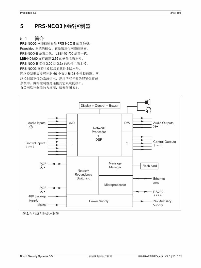
Praesideo 4.3 zhs | 103
Bosch Security Systems B.V. IUI-PRAESIDEO_4.3 | V1.0 | 2015.02安装说明和用户指南
5 PRS-NCO3 网络控制器
5.1 简介PRS-NCO3 网络控制器是 PRS-NCO-B 的改进型,
Praesideo 系统的核心。它是第三代网络控制器,
PRS-NCO-B 是第二代, LBB4401/00 是第一代。
LBB4401/00 支持 高 2.36 的软件主版本号。
PRS-NCO-B 支持 3.00 到 3.6x 的软件主版本号。
PRS-NCO3 支持 4.0 以后的软件主版本号。
网络控制器 多可控制 60 个节点和 28 个音频通道。网
络控制器不仅为系统供电,还将所有元素的配置保存在
系统中。网络控制器是连接其它系统的接口。
有关网络控制器的方框图,请参阅图 5.1。
图 5.1: 网络控制器方框图
A/D D/A
NetworkProcessor
+ DSP
Display + Control + Buzzer
Power Supply
Audio OutputsAudio Inputs
Control Inputs
POF
POF
Ethernet
Mains
Control Outputs
NetworkRedundancy
Switching
MessageManager
Microprocessor
I O
RS232
Flash card
48V Back-upSupply 24V Auxiliary
Supply

Praesideo 4.3 zhs | 104
Bosch Security Systems B.V. IUI-PRAESIDEO_4.3 | V1.0 | 2015.02安装说明和用户指南
5.2 控制器、连接器和指示器
5.2.1 前视图网络控制器的前面(请参阅图 5.2)包括以下组件:
1 扬声器 -用于音频监控的扬声器。监控耳机连接到
监控耳机输出端(4)时,扬声器静音。
2 菜单显示器 -显示网络控制器的相关信息的 2x16 字
符的 LCD 显示器(请参阅第 5.5 节)。
3 菜单按钮 -操作菜单的旋压式按钮(请参阅第 5.5
节)。
4 监控耳机输出 - A 3.5 mm (1/8 英寸 )插座,用于
连接音频监控耳机。连接耳机时,扬声器(1)静
音。
5 蜂鸣器 - 系统处于故障或紧急状态时发出通知的蜂
鸣器。
5.2.2 后视图网络控制器的背面(请参阅图 5.2)包括以下组件:
6 接地端 -将网络控制器带电接地的连接。
7 音频输入端 -用于接收模拟音频源的音频信号的四
个音频输入端。其中两个音频输入端,一个用于话
筒,一个用于线路。其它两个固定用于线路输入
端。每个音频输入端均配有 XLR 和双路 Cinch 连接
器(请参阅第 5.3.6 节)。
8 音频输出端 - 用于调用模拟音频信号的四个音频输
出端。每个音频输出端均配有 XLR 和双路 cinch 控
制器(请参阅 第 5.3.7 节)。
9 电压选择器 - 选择本地主电源电压的开关(请参阅
第 5.3.2 节)。
10 主电源打开 / 关闭开关 - 打开和关闭网络控制器的开
关(请参阅第 5.3.2 节)。
11 保险丝盒 - 配有可以保护网络控制器电源的保险丝
的保险丝盒(请参阅第 5.3.2 节)。
12 系统总线 - 将网络控制器连接到其它 Praesideo 设
备的两个系统总线连接器(请参阅第 5.3.4 节)。
13 以太网接口 - 将网络控制器连接到外部记录和配置
设备 / 系统的接口。此接口通常用于配置 PC (请参
阅第 5.3.5 节)或开放式接口客户端与 Praesideo
系统的连接。
14 控制输入端 - 用于接收必须触发 Praesideo 网络中
的操作的第三方设备的信号的控制输入端(请参阅
第 5.3.8 节)。
15 Rs232 接口 - 用于工厂 / 开发。
16 控制输出端 - 用于向第三方设备发送信号以触发
Praesideo 网络产生的动作的控制输出端(请参阅
第 5.3.9 节)。
17 电池 48V- 备用电池电源(请参阅第 5.3.3 节)。
18 主电源插槽 - 将网络控制器连接到主电源的插座
(请参阅第 5.3.2 节)。
19 蜂鸣器开关 - 这些开关用于在系统进入故障或紧急
状态时激活蜂鸣器,分别对应激活控制输出端 4 和
2。
20 24 V 辅助输出 - 给辅助设备(如:故障或紧急指示
灯)供电。输出电流 大限制为 100 mA。

Praesideo 4.3 zhs | 105
Bosch Security Systems B.V. IUI-PRAESIDEO_4.3 | V1.0 | 2015.02安装说明和用户指南
图 5.2: 网络控制器前视图及后视图
Audio In 3 Audio Out 3 Audio In 4 Audio Out 4
Audio In 1 Audio Out 1 Audio In 2 Audio Out 2
Mains
+ 0
115/230~
T2.5A 250V
Battery 48V 4 A
O I
115: 100-120V~/50-60Hz
230: 220-240V~ /50-60HzT2A H 250V
R S 2 3 2
In 1
C o n tro l In /O u t
N e t w o r k 1 2
C a u t io nR is k o f e le c tr ic s h o c k .
D o n o t o p e n
A v isR is q u e d e c h o c e le c tr iq u e .
N e p a s o u v r ir
4 8 V 4 8 VO u t 1 O u t 2 O u t 3 O u t 4 O u t 5
E th e r n e t B u z z e r
O ffO n
2 4 V O u t
+ 0
2 4 V1 0 0 m AE m e rg e n c y (O u t 2 )
F a u lt (O u t 4 )
In 2 In 3 In 4 In 5 In 6 In 7 In 8
9
321 4 5
19
8
12 7
8 7
8 7 816
14
2013 17 18
6 10 1115 7

Praesideo 4.3 zhs | 106
Bosch Security Systems B.V. IUI-PRAESIDEO_4.3 | V1.0 | 2015.02安装说明和用户指南
5.2.3 内视图网络控制器内部(请参阅图 5.3)包括以下组件:
21 接地跳线塞 -将信号接地端连接到安全接地端的跳
线塞。
22 Cf 卡 - 存储讯息的 CF 卡所用的连接器(请参阅
第 5.3.13 节)。
图 5.3: 网络控制器内视图
2221
X1
X1
123
123
SIGNAL GROUND
GROUNDED
FLOATING (DEFAULT)

Praesideo 4.3 zhs | 107
Bosch Security Systems B.V. IUI-PRAESIDEO_4.3 | V1.0 | 2015.02安装说明和用户指南
5.3 连接
5.3.1 简介本节概述了如何使用网络控制器实现一般系统连接。
• 连接主电源(请参阅第 5.3.2 节)。
• 连接网络(请参阅第 5.3.4 节)。
• 连接配置 PC (请参阅第 5.3.5 节)。
• 连接音频输入端(请参阅第 5.3.6 节)。
• 连接音频输出端(请参阅第 5.3.9 节)。
• 连接控制输入端(请参阅第 5.3.8 节)。
• 连接控制输出端(请参阅第 5.3.9 节)。
• 连接 RS232 端口(请参阅第 5.3.12 节)。
• 插入 CF 卡(请参阅第 5.3.13 节)。
5.3.2 连接主电源将网络控制器连接到主电源的过程如下:
1 使用网络控制器背面的电压选择器选择合适的本地
主电源电压(请参阅表 5.1)。
2 将主电源线连接到网络控制器。
3 将主电源线连接到经过当地批准的主电源插座。
5.3.3 连接备用电源将备用电源连接到网络控制器背面的备用电源连接器。
请参阅图 5.4。
使用随该设备一起提供的连接器。备用电源的保险丝位
于该设备内部。备用电源输入可防止反向电压。
备用电压范围是 43 至 56 V。系统总线的系统电压恒定
为 48 V。由系统总线供电的设备的电源不受备用电池
电压变化的影响。
表 5.1: 电压选择器和保险丝
选择器 主电源电压
V (AC)
保险丝
115 100 - 120 T2.5A250V
(UL 248 / IEC 60217)
230 220 - 240 T2.5A250V
(UL 248 / IEC 60217)
警告
出于安全原因,您必须使用外部断路器。按照
本地电气与建筑规范安装,例如在美国和加拿
大应遵守 NEC/CEC,在德国应遵
VDE0108-1。
为降低触电风险,除非取得相关资质,否则不
得执行操作说明范围之外的任何维修工作。参
见章节 1.2 目标受众。
注
当网络控制器已连接备用电源时,则该网络控
制器不能通过主电源打开 /关闭开关(9)来
关闭。同时必须断开电池连接。
警告
请勿将电池正极接地,以免对 Praesideo 设备
造成损害。
如果备用电源(电池)接地,必须首先连接负
极(0),然后连接正极(+)。按照相反顺序
分离:首先分离正极,然后分离负极。由此可
避免接地回路电流过大。
图 5.4: 备用电源
+ 0
Battery 48V 4 A

Praesideo 4.3 zhs | 108
Bosch Security Systems B.V. IUI-PRAESIDEO_4.3 | V1.0 | 2015.02安装说明和用户指南
5.3.4 连接网络使用系统总线连接器和 LBB4416 网络电缆将网络控制
器连接到 Praesideo 系统。两个连接器可互换。
5.3.5 连接 PC5.3.5.1 简介
网络控制器配有一个 RJ45 插座以连接 Praesideo 配置
PC。通过配置 PC,可以对 Praesideo 系统进行配置和
诊断。一般来说,有两种方式可以将配置 PC 连接到网
络控制器上:直接连接或通过网络连接。在两种情况下
可以使用正常的直通式 CAT-5 电缆,因为 PRS-NCO3
具有自动的 MDI/MDI-X 配置功能。直接连接时无需特
殊的交叉电缆。
5.3.5.2 要求
配置 PC 必须至少满足下列要求:
• 操作系统:
Microsoft® Windows 7、 8 或 8.1
• 网络连接: 100 Base-T 或 1000 Base-T
• 1 GB RAM
• 安装了 Web 浏览器,如火狐浏览器(首选)
5.3.6 连接音频输入端网络控制器配有 4 个连接模拟音频源的音频输入端。每
个音频输入端均在网络控制器背部配备了两个连接器,
一个 XLR 连接器(用于衡信号)和一个双路 cinch 连
接器(用于非衡信号)。网络控制器将与相同音频输入
端的 Cinch 连接器相连的立体声信号合成为单声道信
号。
模拟音频可以是线路源,也可以是话筒。有关每个输入
端所支持的输入类型概况,请参阅表 5.2。
有关网络控制器音频输入端插座的详细信息,请参阅
图 5.5。
小心
未咨询网络管理员之前,切勿将网络控制器和配置 PC 与任何网络相连。
小心
Praesideo 网络接口不提供广泛的安全措施来保
护系统免受恶意的网络攻击。此类措施不足以长期有效,因为 Praesideo 系统的运作不太可
能通过定期更新来修复安全漏洞。因此,不要将网络控制器永久连接到开放的以太网网络上。如果配置之后需要网络连接,如连接到 PC 调用服务器或日志记录服务器上,则使用单独的网络,其他人不能访问,或使用具有 VLAN 功能的以太网交换机设置 Praesideo 专用的 VLAN,将网络划分为多个广播域,其中的一个
域单独分配给 Praesideo。如果还要通过 CobraNet 接口或 OMNEO 接口在以太网上建
立音频连接,则这些接口还必须连接到单独的网络或 VLAN 上。因为以太网上的音频连接要
占用大量的网络带宽,而且不像物理上独立的网络,VLAN 要共享带宽,VLAN 树干可能需要
聚合链接和 / 或高质量的服务优先级排序。
注
话筒输入端不应用于连接紧急话筒。这些输入
端不提供话筒连接检测。
表 5.2: 音频输入端类型
音频输入端 话筒
(XLR 专用)
线路
1 是 是
2 是 是
3 否 是
4 否 是
注
因为网络控制器可以生成用于驻极体话筒的电
源,所以音频输入端可以处理驻极体话筒,也
可以处理动话筒。
图 5.5: 音频输入端插座
Audio In
2
3
1
5
4

Praesideo 4.3 zhs | 109
Bosch Security Systems B.V. IUI-PRAESIDEO_4.3 | V1.0 | 2015.02安装说明和用户指南
5.3.7 连接音频输出端网络控制器配有 4个音频输出端,可以将模拟音频信号
路由到其它设备(如:使用中的扬声器)。每个音频输
出端均在网络控制器背部配备了两个连接器,一个
XLR 连接器(用于衡信号)和一个双路 cinch 连接器
(用于非衡信号)。
有关网络控制器音频输出端插座的详细信息,请参阅
图 5.6。
5.3.8 连接控制输入端网络控制器配有 8个控制输入端。控制输入端可以接收
必须触发 Praesideo 系统中动作的第三方设备的信号。
控制输入端可以配置用于执行触点接通或中断(请参
阅第 44.2 节)。此控制输入端还可以检测短路和开路
连接情况(请参阅图 5.7 和图 5.8)。控制输入是否真
正受到检测,配置中已有定义。
表 5.3: 音频输入插座详细信息
引脚 插座 定义 描述
1 XLR
(母)
屏蔽 / 接
地
屏蔽 / 接地(幻象
电源 -)
2 活动 正极信号
(幻象电源 +)
3 置回 负极信号
(幻象电源 +)
4 Cinch 右 右通道输入
5 左 左通道输入
注
右 cinch 连接器和左 cinch 连接器带有相同的
单声道信号。
图 5.6: 音频输出端插座
表 5.4: 音频输出端插座详细信息
引脚 插座 定义 描述
1 XLR
Xternal
屏蔽 / 接
地
(公)
2 活动 正极信号
3 置回 负极信号
4 Cinch 右 单声道输出
5 左 单声道输出
Audio Out
1
3
2
5
4
图 5.7: 受检测的控制输入端
图 5.8: 未受检测的控制输入端
警告
切勿将直流或交流信号连接到控制输入端,否
则可能会损坏输入电路。只能使用无电压触
点。
Control In/Out
ln 1 ln 2 ln 3 ln 4 ln 5 ln 6 ln 7 ln 8
10kΩ
10kΩ
Control In/Out
ln 1 ln 2 ln 3 ln 4 ln 5 ln 6 ln 7 ln 8

Praesideo 4.3 zhs | 110
Bosch Security Systems B.V. IUI-PRAESIDEO_4.3 | V1.0 | 2015.02安装说明和用户指南
5.3.9 连接控制输出端请勿使用普通回流线)。这些控制输出端可用于向第三
方设备发送信号以触发动作。每个控制输出连接都带有
3个引脚(请参阅图 5.9)。
控制输出端的普通引脚(C)应始终连接。所连接的其
它引脚是常闭型(NC)还是常开型(NO),取决于
控制输出端处于活动状态时必须启用的动作(请参阅
表 5.5)。
在此配置中,控制输出端必须附有用途说明,指示控制
输出端激活时要启用的动作(请参阅表 44.6)。控制
输出端 4和 5 已经有固定用途(请参阅表 5.6)。
5.3.10 设置蜂鸣器开关网络控制器包含一个内部蜂鸣器,用于在系统进入故障
或紧急状态时发生音频通知。蜂鸣器可以与控制输出端
触点 2 和 4并行激活。
控制输出端 4已被预配置为故障警报蜂鸣器。打开左边
的蜂鸣器开关可在控制输出端 4切换到故障位置时激活
蜂鸣器;由于这是特殊的失效安全触点,因此为断电状
态。
控制输出端 2没有预配置,但应被配置为紧急警报蜂鸣
器 (请参阅表 44.6)了解是否符合不同的话音警报标
准。当打开右边的蜂鸣器开关时,在系统进入紧急状态
时蜂鸣器将被激活。如果需要,也可以在其它情况下激
活蜂鸣器,具体取决于控制输出端 2配置的功能。
5.3.11 使用 24 V 辅助输出网络控制器提供限制的电流 (100 mA) 24 V 电压输出。
此电压输出端可用于不同用途。当 48 V 备用电源(电
池)连接到备用电池输入端时,此 24 V 输出端也可在
主电源故障时使用。典型应用是将此输出端用作设备机
架上外部故障 /紧急灯塔的电源,使用控制输出端触点
切换灯塔线段。选择带 24 V 高效 LED 指示灯的灯塔使
总电流保持在 100 mA 以下,例如, PatLite LCE-302-
RYG 系列或类似系列,带或不带音频警报。一切正常
时显示绿色,故障状态时显示黄色,紧急状态时显示红
色。使用控制输出端开关故障警报指示器 ( 网络控制器
上的控制输出端 5)和紧急警报指示器。
注
切勿将多个控制输入端的控制输入线联合使用
(如,请勿使用公共回路线)。
图 5.9: 控制输出端
表 5.5: 控制输出端详细信息
连接 缩写 描述
常闭型 NC 激活输出端时,NC 触点
打开。
常开型 NO 激活输出端时,NO 触点
关闭。
表 5.6: 控制输出端 4和 5
控制输出端 用途
4 故障警报蜂鸣器
5 故障警报指示器
注
出于失效安全目的,这些控制输出端在默认
(无故障)状态下启动,因此 NC 为打开状态,
并在出现故障时关闭。
Out 1 Out 2 Out 3 Out 4 Out 5
图 5.10: 蜂鸣器开关
图 5.11:24 V 辅助输出端
Fault (Out 4)
OffOn
Emergency (Out 2)
Buzzer
24V
+ 0
100 mA
24VOut
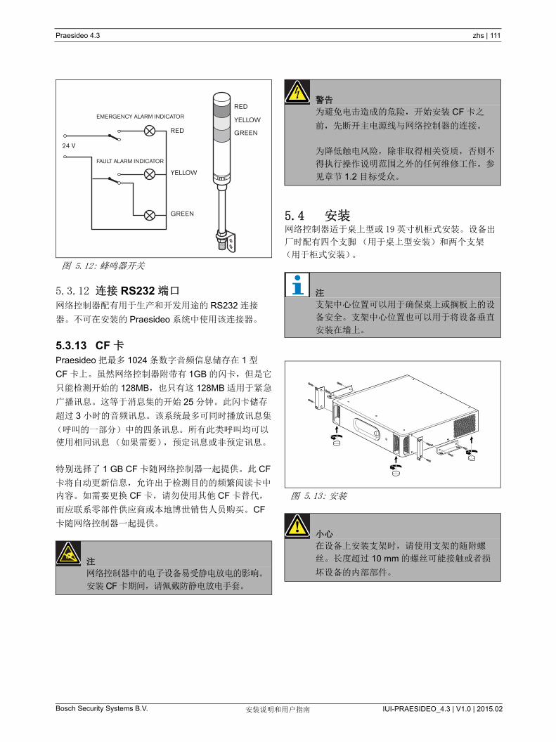
Praesideo 4.3 zhs | 111
Bosch Security Systems B.V. IUI-PRAESIDEO_4.3 | V1.0 | 2015.02安装说明和用户指南
5.3.12 连接 RS232 端口网络控制器配有用于生产和开发用途的 RS232 连接
器。不可在安装的 Praesideo 系统中使用该连接器。
5.3.13 CF 卡Praesideo 把 多 1024 条数字音频信息储存在 1 型
CF 卡上。虽然网络控制器附带有 1GB 的闪卡,但是它
只能检测开始的 128MB,也只有这 128MB 适用于紧急
广播讯息。这等于消息集的开始 25 分钟。此闪卡储存
超过 3 小时的音频讯息。该系统 多可同时播放讯息集
(呼叫的一部分)中的四条讯息。所有此类呼叫均可以
使用相同讯息(如果需要),预定讯息或非预定讯息。
特别选择了 1 GB CF 卡随网络控制器一起提供。此 CF
卡将自动更新信息,允许出于检测目的的频繁阅读卡中
内容。如需要更换 CF 卡,请勿使用其他 CF 卡替代,
而应联系零部件供应商或本地博世销售人员购买。 CF
卡随网络控制器一起提供。
5.4 安装网络控制器适于桌上型或 19 英寸机柜式安装。设备出
厂时配有四个支脚(用于桌上型安装)和两个支架
(用于柜式安装)。图 5.12: 蜂鸣器开关
注
网络控制器中的电子设备易受静电放电的影响。
安装 CF 卡期间,请佩戴防静电放电手套。
RED
YELLOW
GREEN
RED
YELLOW
GREEN
FAULT ALARM INDICATOR
EMERGENCY ALARM INDICATOR
24 V
警告
为避免电击造成的危险,开始安装 CF 卡之
前,先断开主电源线与网络控制器的连接。
为降低触电风险,除非取得相关资质,否则不
得执行操作说明范围之外的任何维修工作。参
见章节 1.2 目标受众。
注
支架中心位置可以用于确保桌上或搁板上的设
备安全。支架中心位置也可以用于将设备垂直
安装在墙上。
图 5.13: 安装
小心
在设备上安装支架时,请使用支架的随附螺
丝。长度超过 10 mm 的螺丝可能接触或者损
坏设备的内部部件。
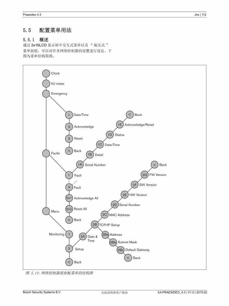
Praesideo 4.3 zhs | 112
Bosch Security Systems B.V. IUI-PRAESIDEO_4.3 | V1.0 | 2015.02安装说明和用户指南
5.5 配置菜单用法
5.5.1 概述通过 2x16LCD 显示屏中交互式菜单以及“旋压式”
菜单按钮,可以对许多网络控制器的设置进行设定。下
图为菜单结构简图。
图 5.14: 网络控制器前面板菜单的结构图
Clock
VU meter
Emergency
Faults
Fault
Fault
Menu
Address
Setup
Monitoring
TCP/IP Setup
MAC Address
Serial Number
HW Version
SW Version
FW Version
Date &Time Subnet Mask
Default Gateway
BackBack
1
2
<
<
N
N+1
N+2
2
3
<
2A
2B
2C
2D
2E
2F
2G
Back<
Acknowledge
Reset
Back
2Ba
1
2Bb
2Bc
<
1
Serial Number
Detail
Status
Date/Time
Date/Time
Acknowledge/Reset
Back
1A
1B
1C
1D
1E
<
Acknowledge All
Reset All
Back

Praesideo 4.3 zhs | 113
Bosch Security Systems B.V. IUI-PRAESIDEO_4.3 | V1.0 | 2015.02安装说明和用户指南
5.5.2 菜单导航操作菜单就是一系列的菜单旋转和按压动作:
旋转按钮完成以下操作:
• 在菜单的各项间循环。
• 转到菜单项中的可设定选项(闪烁光标在菜单屏幕
上移动)。
• 在可设定选项(值闪烁)的可用值间循环。
按下按钮完成以下操件:
• 确定选择的菜单项(出现闪烁光标)。
• 转到子菜单(子菜单项字符开始闪烁)。
• 确定对可设定选项所作的选择(光标消失选项值开
始闪烁)。
• 确定从可设定选项中选择的值(选择值停止闪烁,
光标再现)。
每个菜单以数字或数字加字符的方式进行标识(请参
阅图 5.15)。项目标识可以从第一行的开头找到,可
用于在子菜单间导航。大多数菜单项都有一个或一个以
上的可设定选项。选择可用值列表中的值可以更改一个
选项的值。
要在状态屏幕中导航:
1 旋转按钮以浏览状态屏幕(即:Clock、 VU
Meter、Emergency..., Faults ... 和 Menu ... 屏幕)
上移动。
要在主菜单中导航:
1 在状态屏幕中导航至 Menu...。
2 按下按钮转到主菜单。菜单项编号开始闪烁。
3 旋转按钮以选择另一个菜单项的编号。
4 按下按钮确定所作的选择。
要跳到子菜单:
1 导航至带有三个圆点的选(如:Setup...)。
2 按下按钮转到子菜单项,子菜单项字符开始闪烁。
3 旋转按钮以选择另一个菜单项的编号。
4 按下按钮确定所作的选择。
要在子菜单间导航:
1 旋转按钮,将光标移至子菜单选项字符。
2 按下按钮。选项字符和标题开始闪烁。
3 旋转按钮以选择另一子菜单项的字符。
4 按下按钮确定所作的选择。
要更改选项值:
1 导航至可用的菜单项。
2 旋转按钮,将光标移至要更改的选项值。
3 按下按钮激活选项。选项开始闪烁。
4 旋转按钮以选择新选项值。
5 按下按钮确定新的值。选项值停止闪烁。
6 旋转按钮,将光标移至另一个可设定的选项(可用
时),然后重复第 3 到第 5 步。
图 5.15: 菜单项屏幕元素
1 Monitoring
Input 1 -10dB
main menuitem number
option values
main itemtitle
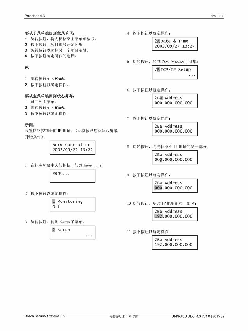
Praesideo 4.3 zhs | 114
Bosch Security Systems B.V. IUI-PRAESIDEO_4.3 | V1.0 | 2015.02安装说明和用户指南
要从子菜单跳回到主菜单项:
1 旋转按钮,将光标移至主菜单项编号。
2 按下按钮。项目编号开始闪烁。
3 旋转按钮以选择另一个项目编号。
4 按下按钮确定所作的选择。
或
1 旋转按钮至 < Back。
2 按下按钮以确定操作。
要从主菜单跳回到状态屏幕:
1 跳回到主菜单。
2 旋转按钮至 < Back。
3 按下按钮以确定操作。
示例:
设置网络控制器的 IP 地址。(此例假设您从默认屏幕
开始操作):
1 在状态屏幕中旋转按扭,转到 Menu ...:
2 按下按钮以确定操作:
3 旋转按钮,转到 Setup 子菜单:
4 按下按钮以确定操作:
5 旋转按钮,转到 TCP/IPSetup 子菜单:
6 按下按钮以确定操作:
7 按下按钮以确定操作:
8 旋转按钮,将光标移至 IP 地址的第一部分:
9 按下按钮以确定操作:
10 旋转按钮,更改 IP 地址的第一部分:
11 按下按钮以确定操作:
Netw Controller2002/09/27 13:27
Menu...
1 MonitoringOff
2 Setup ...
2A2002/09/27 13:27
Date & Time
2B TCP/IP Setup ...
2Ba Address000.000.000.000
2Ba Address000.000.000.000
2Ba Address000.000.000.000
2Ba Address000.000.000.000
2Ba Address192.000.000.000
2Ba Address192.000.000.000
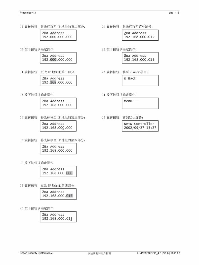
Praesideo 4.3 zhs | 115
Bosch Security Systems B.V. IUI-PRAESIDEO_4.3 | V1.0 | 2015.02安装说明和用户指南
12 旋转按钮,将光标移至 IP 地址的第二部分:
13 按下按钮以确定操作:
14 旋转按钮,更改 IP 地址的第二部分:
15 按下按钮以确定操作:
16 旋转按钮,将光标移至 IP 地址的第三部分:
17 旋转按钮,将光标移至 IP 地址的第四部分:
18 按下按钮以确定操作:
19 旋转按钮,更改 IP 地址的第四部分:
20 按下按钮以确定操作:
21 旋转按钮,将光标移至菜单编号:
22 按下按钮以确定操作:
23 旋转按钮,移至 < Back 项目:
24 按下按钮以确定操作:
25 旋转按钮,转到默认屏幕:
2Ba Address192.000.000.000
2Ba Address192.000.000.000
2Ba Address192.168.000.000
2Ba Address192.168.000.000
2Ba Address192.168.000.000
2Ba Address192.168.000.000
2Ba Address192.168.000.000
2Ba Address192.168.000.015
2Ba Address192.168.000.015
2Ba Address192.168.000.015
2Ba Address192.168.000.015
< Back
Menu...
Netw Controller2002/09/27 13:27

Praesideo 4.3 zhs | 116
Bosch Security Systems B.V. IUI-PRAESIDEO_4.3 | V1.0 | 2015.02安装说明和用户指南
5.6 配置和操作
5.6.1 简介下一节具体描述可能的配置选项。每一项说明后面均配
有相关的菜单选项,每个菜单项都带有详细的说明。可
用时,默认值由星号(*)指示。
5.6.2 启动网络控制器(重新)启动时,显示屏显示设备的名称
和时钟(状态屏幕的第一个组件)。
5.6.3 状态屏幕状态屏幕(请参阅表 5.7)提供有关网络控制器的一
般信息。
5.6.4 紧急菜单通过 Emergency ... 项可以进入紧急菜单(请参阅
图 5.14)。系统处于紧急状态时,此菜单自动激活。紧
急状态复位时,自动返回到 Clock 屏幕。 Emergency...
菜单屏幕本身显示用于激活紧急状态的按键名称或激活
紧急状态的开放式接口控制器的 IP 地址。例如:
在此例中, Emergency 指示紧急状态由 CST-EM-PTT
按钮激活, CST-EM-PTT.
紧急菜单中的菜单项提供了有关紧急状态的附加信息,
并允许确认和复位紧急状态(请参阅表 5.8)。当复位
紧急状态时,中止所有紧急呼叫。
5.6.5 故障菜单通过 Faults ... 菜单(请参阅图 5.14)可以进入故障菜
单。系统中出现故障时,此菜单自动激活。由于系统中
处于活动状态的故障数量变化不定,因此该菜单选项编
号并不固定。 新发生的故障对应 小编号。故障 大
编号为 200。
Faults ... 菜单屏幕本身显示系统中处于活动状态的故障
编号。例如:
故障菜单中已编号的菜单显示故障名称及产生故障的设
备。例如:
这种情况下,故障为 Overload,由名称为 PAM_01 的
设备产生。故障菜单中的菜单选项 显示有关所选故障
的附加信息,并允许对故障进行确认和复位(请参阅
表 5.9)。
表 5.7: 状态屏幕
菜单项 描述
Clock 显示组件名称和时间日期。
VU Meter 在网络控制器的所有音频输入端
和音频输出端上对信号强度进行
可见显示。
表 5.8: 紧急菜单
菜单项 描述
1 Date/Time 紧急状态激活的日期和时间。
2 Acknowledge 确认紧急状态。
3 Reset 复位紧急状态。
Emergency ...CST-EM-PTT
注
如果正在查看故障时,又出现新的故障,此时
正在查看故障的项目编号自动增加。例如:您
正在查看 23 Overload (过载)又有新故障出
现, 23 Overload (过载)则自动增加为 24
Overload (过载)。
注
如果您正在查看故障 200 时,又有新故障出
现,系统则自动删除故障 200,并由下一条故
障替换。例如: 故障 200 为 200 Overload
(过载),下一条故障为 199 Gnd Short (接
地短路)。发生新故障时, 200 Overload (过
载)自动变为 200 Gnd Short (接地短路)。
注
下表中, n 表示故障菜单中的第 n 条故障, N
表示故障菜单中的故障总数。
Faults ... 27 faults
23 OverloadPAM_01

Praesideo 4.3 zhs | 117
Bosch Security Systems B.V. IUI-PRAESIDEO_4.3 | V1.0 | 2015.02安装说明和用户指南
网络控制器显示的故障和故障详情与 Logging Viewer
中显示的故障密切相关(请参阅第 59 章)。在表 5.11
中列出了网络控制器显示的所有故障。根据此表和
第 55 章提供的信息,找出故障原因并给出相应的解决
方案。
5.6.6 主菜单Menu ... 项(请参阅图 5.14)提供主菜单的访问权限。
表 5.9: 故障菜单
菜单项 描述
nA Serial Nr 显示产生故障 n 的设备的序列
号。
nB Detail 显示故障 n 的详细信息。请参
阅表 5.11。
nC Date/Time 显示故障 n 出现的时间和日期。
nD Status 显示第 n 条故障讯息状态。
请参阅第 52 章。
nE Acknowledge 确认所选故障。请参阅第 52
章)。
nF Reset 重置所选择的故障。请参阅
第 52 章)。
N+1 Ack All 允许确认系统所有故障。请参
阅第 52 章)。
N+2 Reset All 重置系统中所有故障。请参阅
第 52 章)。
表 5.10: 主菜单
菜单项 描述
1Monitoring 转到 Monitoring 子菜单。请参见
第 5.6.7 节。
2 Setup 转到 Setup 子菜单。请参阅
第 5.6.8 节(及其它章节)。

Praesideo 4.3 zhs | 118
Bosch Security Systems B.V. IUI-PRAESIDEO_4.3 | V1.0 | 2015.02安装说明和用户指南
表 5.11: 故障事件表
故障 详细信息 记录信息
A/B fault (通道) 线路 A 或 B 故障
Amp missing (通道) 放大器丢失Amp Stan dBy 放大器初始化失败Audio path 呼叫站音频路径出现故障CobraNet 故障 (编号) Corbranet 网络故障:故障编码
Config file 无效不匹配错误
找不到有效配置文件: 将创建新配置文件
配置文件版本不匹配:x.xx 版本已找到, y.yy 正在查找中
配置文件出错Ctrl input (控制输入端) 控制输入线路出现故障Endof line (通道) 扬声器线路出现故障Failure (通道)
(通道)
(通道)放大器出现故障或过载
故障输入端 (文本) 故障输入端Flashcard Missing
闪卡丢失校验和
闪卡数据出错讯息名称无讯息
Gnd short (通道) 放大器接地短路Grp A fault (通道) A 组故障
Grp B fault (通道) B 组故障
HW version 不匹配 硬件版本不匹配Internal 故障 (编号) CobraNet 接口故障 / OMNEO 接口故障
Keypad n/m 不匹配 键盘不匹配
线路输入 (音频输入端) 线路输入出现故障Loop fault (通道) A 级替换
Loudspeaker (通道) 扬声器出现故障Lsp Line (通道) 放大器扬声器线路出现故障Memory EEPROM (电可擦除只
读存储器)存储器出错
Flash 存储器
Mic input (音频输入端) 话筒出现故障Missing 设备丢失Net pwr RCS 网络电源故障,远程呼叫站No mains 主电源出现故障No secpwr 备用电源出现故障OMNEO 故障编码 OMNEO 网络故障:故障编码
Overheat (通道) 放大器过热Overload (通道)
(通道)
放大器过载放大器短路
Procre set MMPCPUCNMOMNEOCPU
处理器重置:MMP (网络处理器)
处理器重置:CPU (系统处理器)
处理器重置:CNM (CobraNet 模块)
处理器重置:OMNEO (OMNEO 模块 )
处理器重置:SCB (监控板)
RCS connect 远程呼叫连接出现故障

Praesideo 4.3 zhs | 119
Bosch Security Systems B.V. IUI-PRAESIDEO_4.3 | V1.0 | 2015.02安装说明和用户指南
故障 详细信息 记录信息
Ring broken 系统网络 冗余环网断裂SCB failure 检测控制面板出现故障Secpwr RCS 备用电源出现故障,远程呼叫站Supervision (通道)
(通道)
(通道)线路检测主控不匹配
Supply 24V (通道) 冗余电源 24V
Uncfgd unit 设备未配置Unknwn unit 位置设备类型
带线 (控制输入) 外线故障
表 5.11: 故障事件表

Praesideo 4.3 zhs | 120
Bosch Security Systems B.V. IUI-PRAESIDEO_4.3 | V1.0 | 2015.02安装说明和用户指南
5.6.7 设置监控选项Monitoring 子菜单用于设置将哪个信号发送到监控扬声
器或耳机。可以发送其中一个音频输入端上的信号、可
以发送其中一个音频输出端上的信号,也可以根本不发
送任何信号。此外,该屏幕还提供电平表,用于对实际
信号强度进行可见识别。
5.6.8 设置日期和时间Date&Time 菜单项用于更改网络控制器显示的日期和
时间。
5.6.9 设置 TCP/IPTCP/IPSetup 子菜单用于设置网络控制器的 TCP/IP 参
数。
表 5.12:Monitoring 子菜单
菜单项 选项 值 1 值 2 描述
1Monitoring 源:
- Input (输入
端) n
输入端数:
1 至 4
音量:
-31 到 0 dB
音频输入端 n 的信号可用于监控扬
声器或耳机输出端。
- Output (输出
端) n
输出端数:
1 至 4
音量:
-31 到 0 dB
音频输出端 n 的信号可用于监控扬
声器或耳机输出端。
- Off* 监控扬声器或耳机输出端在正常操
作中处于关闭状态。
表 5.13: 日期和时间菜单项
菜单项 选项 值 1 值 2 描述
2ADate&Time 日期:
2000-01-01 到
2037-12-31
时间:
00:00 到
23.59
日期显示格式为
yyyy-mm-dd (年 - 月 - 日),时间显
示格式为:Hh:mm (小时:分)。
表 5.14:TCP/IPSetup 子菜单
菜单项 值 描述
2Ba Address 例如:192.168.000.015 网络控制器 IP 地址。
2Bb Subnet Mask 例如:255.255.255.000 网络控制器的子网掩码。
2Bc Def.Gateway 例如:192.168.000.050 网络控制器默认网关。

Praesideo 4.3 zhs | 121
Bosch Security Systems B.V. IUI-PRAESIDEO_4.3 | V1.0 | 2015.02安装说明和用户指南
5.6.10 查看 MAC 地址MACAddress 菜单项可用于查看网络控制器的 MAC 地
址。 MAC 地址为出厂设置的唯一地址,无法更改。在
网络中,此地址可以用于访问设备。
5.6.11 查看版本信息Serial Number、 HW Version、 SW version 和
FW version 菜单项用于获得有关网络控制器的版本信
息。
表 5.15:MACAddress 菜单项
菜单项 值(只读) 描述
2CMACAddress 如:000463-004209 显示网络控制器的 MAC 地址
表 5.16: 版本信息菜单项
菜单项 值(只读) 描述
2D Serial Number 例如:11.0.15012 显示 16 进制序列号。
2E HW Version 例如:30.00 显示硬件版本。
2F SW Version 例如:4.00.3525 显示 Praesideo 软件的版本号。
2G FW Version 例如:6.00.2818 显示固件版本号。系统所有设备的固件版本号必须相同。
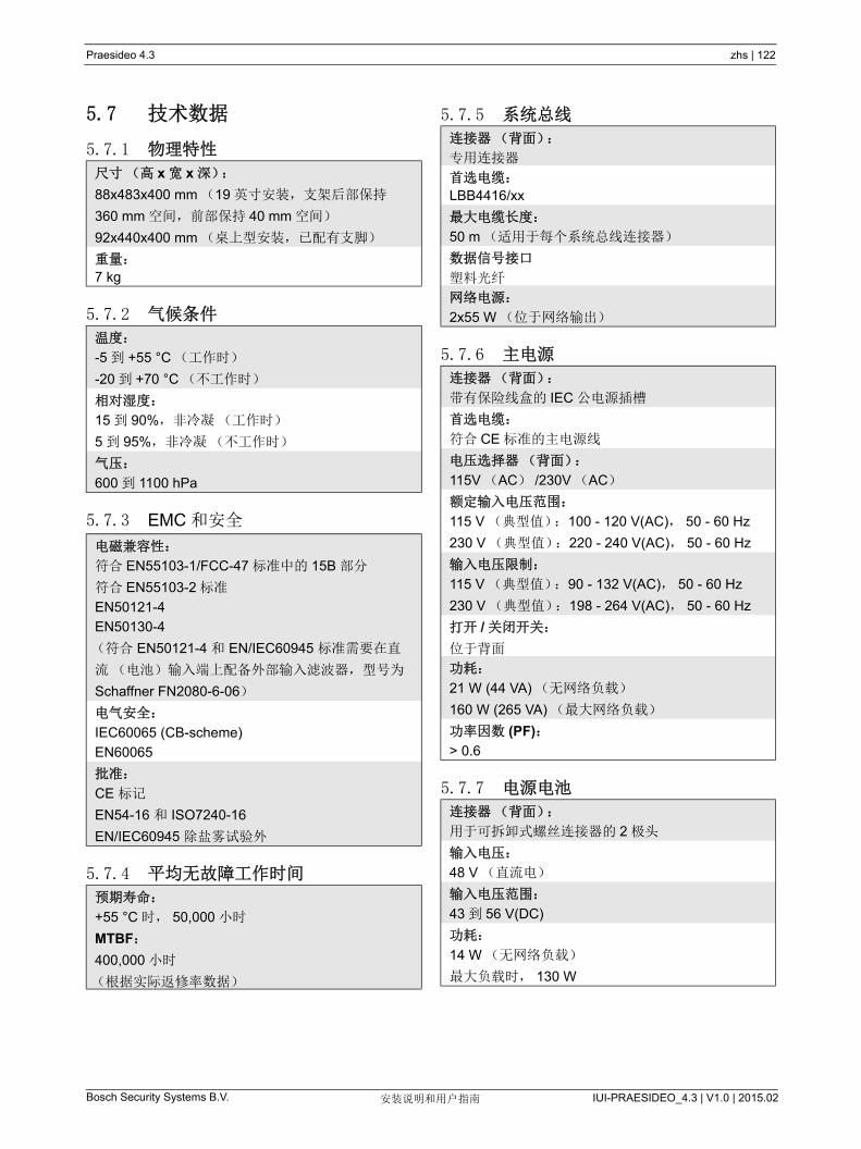
Praesideo 4.3 zhs | 122
Bosch Security Systems B.V. IUI-PRAESIDEO_4.3 | V1.0 | 2015.02安装说明和用户指南
5.7 技术数据
5.7.1 物理特性
5.7.2 气候条件
5.7.3 EMC 和安全
5.7.4 平均无故障工作时间
5.7.5 系统总线
5.7.6 主电源
5.7.7 电源电池
尺寸(高 x 宽 x 深):
88x483x400 mm (19 英寸安装,支架后部保持
360 mm 空间,前部保持 40 mm 空间)
92x440x400 mm (桌上型安装,已配有支脚)
重量:
7 kg
温度:
-5 到 +55 °C (工作时)
-20 到 +70 °C (不工作时)
相对湿度:
15 到 90%,非冷凝(工作时)
5 到 95%,非冷凝(不工作时)
气压:
600 到 1100 hPa
电磁兼容性:
符合 EN55103-1/FCC-47 标准中的 15B 部分
符合 EN55103-2 标准
EN50121-4
EN50130-4
(符合 EN50121-4 和 EN/IEC60945 标准需要在直
流(电池)输入端上配备外部输入滤波器,型号为
Schaffner FN2080-6-06)
电气安全:
IEC60065 (CB-scheme)
EN60065
批准:
CE 标记
EN54-16 和 ISO7240-16
EN/IEC60945 除盐雾试验外
预期寿命:
+55 °C 时, 50,000 小时
MTBF:
400,000 小时
(根据实际返修率数据)
连接器(背面):
专用连接器
首选电缆:
LBB4416/xx
大电缆长度:
50 m (适用于每个系统总线连接器)
数据信号接口
塑料光纤
网络电源:
2x55 W (位于网络输出)
连接器(背面):
带有保险线盒的 IEC 公电源插槽
首选电缆:
符合 CE 标准的主电源线
电压选择器(背面):
115V (AC) /230V (AC)
额定输入电压范围:
115 V (典型值):100 - 120 V(AC), 50 - 60 Hz
230 V (典型值):220 - 240 V(AC), 50 - 60 Hz
输入电压限制:
115 V (典型值):90 - 132 V(AC), 50 - 60 Hz
230 V (典型值):198 - 264 V(AC), 50 - 60 Hz
打开 / 关闭开关:
位于背面
功耗:
21 W (44 VA) (无网络负载)
160 W (265 VA) ( 大网络负载)
功率因数 (PF):
> 0.6
连接器(背面):
用于可拆卸式螺丝连接器的 2 极头
输入电压:
48 V (直流电)
输入电压范围:
43 到 56 V(DC)
功耗:
14 W (无网络负载)
大负载时, 130 W
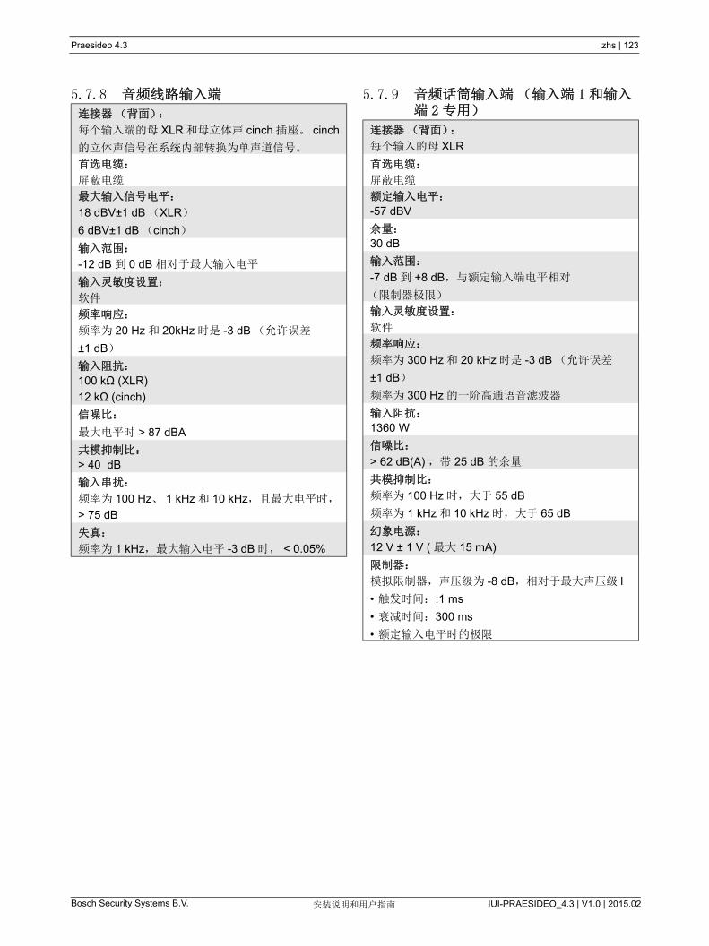
Praesideo 4.3 zhs | 123
Bosch Security Systems B.V. IUI-PRAESIDEO_4.3 | V1.0 | 2015.02安装说明和用户指南
5.7.8 音频线路输入端 5.7.9 音频话筒输入端(输入端 1和输入端 2专用)连接器(背面):
每个输入端的母 XLR 和母立体声 cinch 插座。 cinch
的立体声信号在系统内部转换为单声道信号。
首选电缆:
屏蔽电缆
大输入信号电平:
18 dBV±1 dB (XLR)
6 dBV±1 dB (cinch)
输入范围:
-12 dB 到 0 dB 相对于 大输入电平
输入灵敏度设置:
软件
频率响应:
频率为 20 Hz 和 20kHz 时是 -3 dB (允许误差
±1 dB)
输入阻抗:
100 kΩ (XLR)
12 kΩ (cinch)
信噪比:
大电平时 > 87 dBA
共模抑制比:
> 40 dB
输入串扰:
频率为 100 Hz、 1 kHz 和 10 kHz,且 大电平时,
> 75 dB
失真:
频率为 1 kHz, 大输入电平 -3 dB 时, < 0.05%
连接器(背面):
每个输入的母 XLR
首选电缆:
屏蔽电缆
额定输入电平:
-57 dBV
余量:
30 dB
输入范围:
-7 dB 到 +8 dB,与额定输入端电平相对
(限制器极限)
输入灵敏度设置:
软件
频率响应:
频率为 300 Hz 和 20 kHz 时是 -3 dB (允许误差
±1 dB)
频率为 300 Hz 的一阶高通语音滤波器
输入阻抗:
1360 W
信噪比:
> 62 dB(A) ,带 25 dB 的余量
共模抑制比:
频率为 100 Hz 时,大于 55 dB
频率为 1 kHz 和 10 kHz 时,大于 65 dB
幻象电源:
12 V ± 1 V ( 大 15 mA)
限制器:
模拟限制器,声压级为 -8 dB,相对于 大声压级 l
• 触发时间::1 ms
• 衰减时间:300 ms
• 额定输入电平时的极限
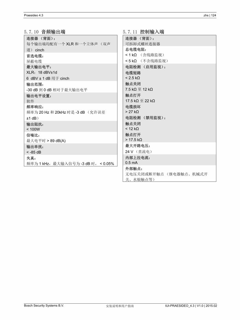
Praesideo 4.3 zhs | 124
Bosch Security Systems B.V. IUI-PRAESIDEO_4.3 | V1.0 | 2015.02安装说明和用户指南
5.7.10 音频输出端 5.7.11 控制输入端
连接器(背面):
每个输出端均配有一个 XLR 和一个立体声(双声
道) cinch
首选电缆:
屏蔽电缆
大输出电平:
XLR: 18 dBV±1d
6 dBV ± 1 dB 用于 cinch
输出范围:
-30 dB 到 0 dB 相对于 大输出电平
输出电平设置:
软件
频率响应:
频率为 20 Hz 和 20kHz 时是 -3 dB (允许误差
±1 dB)
输出阻抗:
< 100W
信噪比:
大电平时 > 89 dB(A)
输出串扰:
< -85 dB
失真:
频率为 1 kHz, 大输入信号为 -3 dB 时, < 0.05%
连接器(背面):
可拆卸式螺丝连接器
总电缆电阻:
< 1 kΩ (含线路监视)
< 5 kΩ (不含线路监视)
电阻检测(启用监视):
电缆短路
< 2.5 kΩ
触点关闭
7.5 kΩ 至 12 kΩ
触点打开
17.5 kΩ 至 22 kΩ
电缆损坏
> 27 kΩ
电阻检测(禁用监视):
触点关闭
< 12 kΩ
触点打开
> 17.5 kΩ
大开路电压:
24 V (直流电)
内部上拉电流:
0.5 mA
外部触点:
无电压关闭或断开触点(继电器触点、机械式开
关、水银触点等)
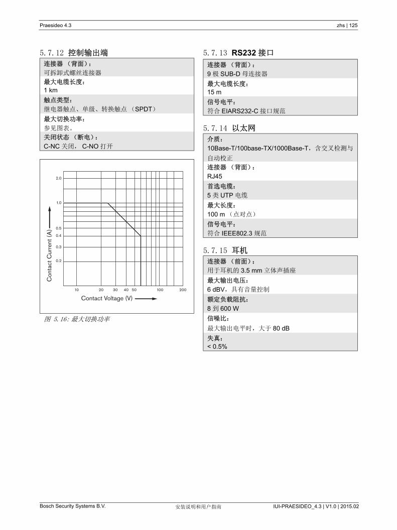
Praesideo 4.3 zhs | 125
Bosch Security Systems B.V. IUI-PRAESIDEO_4.3 | V1.0 | 2015.02安装说明和用户指南
5.7.12 控制输出端 5.7.13 RS232 接口
5.7.14 以太网
5.7.15 耳机
连接器(背面):
可拆卸式螺丝连接器
大电缆长度:
1 km
触点类型:
继电器触点、单级、转换触点(SPDT)
大切换功率:
参见图表。
关闭状态(断电):
C-NC 关闭, C-NO 打开
图 5.16: 大切换功率
Con
tact
Cur
rent
(A
)
Contact Voltage (V)10 20 30 40 50 200100
0.2
0.3
0.4
0.5
1.0
2.0
连接器(背面):
9 极 SUB-D 母连接器
大电缆长度:
15 m
信号电平:
符合 EIARS232-C 接口规范
介质:
10Base-T/100base-TX/1000Base-T,含交叉检测与
自动校正
连接器(背面):
RJ45
首选电缆:
5 类 UTP 电缆
大长度:
100 m (点对点)
信号电平:
符合 IEEE802.3 规范
连接器(前面):
用于耳机的 3.5 mm 立体声插座
大输出电压:
6 dBV,具有音量控制
额定负载阻抗:
8 到 600 W
信噪比:
大输出电平时,大于 80 dB
失真:
< 0.5%
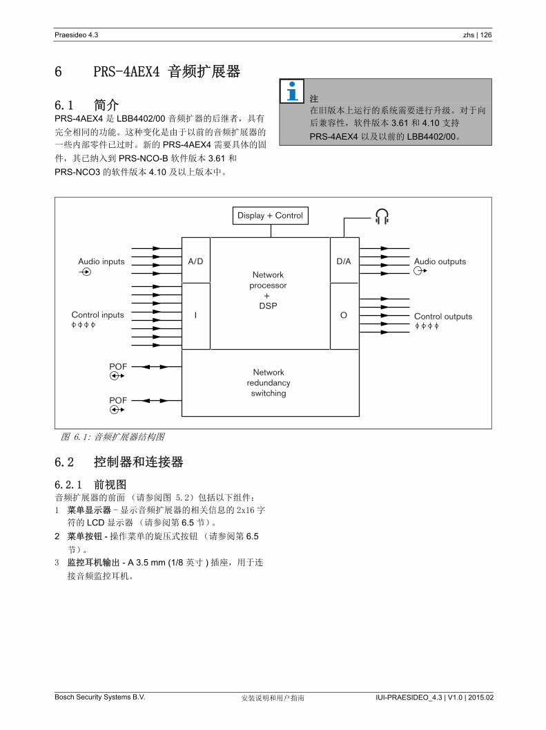
Praesideo 4.3 zhs | 126
Bosch Security Systems B.V. IUI-PRAESIDEO_4.3 | V1.0 | 2015.02安装说明和用户指南
6 PRS-4AEX4 音频扩展器
6.1 简介PRS-4AEX4 是 LBB4402/00 音频扩器的后继者,具有
完全相同的功能。这种变化是由于以前的音频扩展器的
一些内部零件已过时。新的 PRS-4AEX4 需要具体的固
件,其已纳入到 PRS-NCO-B 软件版本 3.61 和
PRS-NCO3 的软件版本 4.10 及以上版本中。
6.2 控制器和连接器
6.2.1 前视图音频扩展器的前面(请参阅图 5.2)包括以下组件:
1 菜单显示器 -显示音频扩展器的相关信息的 2x16 字
符的 LCD 显示器(请参阅第 6.5 节)。
2 菜单按钮 - 操作菜单的旋压式按钮(请参阅第 6.5
节)。
3 监控耳机输出 - A 3.5 mm (1/8 英寸 ) 插座,用于连
接音频监控耳机。
注
在旧版本上运行的系统需要进行升级。对于向
后兼容性,软件版本 3.61 和 4.10 支持
PRS-4AEX4 以及以前的 LBB4402/00。
图 6.1: 音频扩展器结构图
A/D D/A
Networkprocessor
+ DSP
Display + Control
Audio outputsAudio inputs
Control inputs
POF
POF
Control outputs
Networkredundancyswitching
I O

Praesideo 4.3 zhs | 127
Bosch Security Systems B.V. IUI-PRAESIDEO_4.3 | V1.0 | 2015.02安装说明和用户指南
6.2.2 后视图音频扩展器的后面(图 6.2)包括以下组件:
4 音频输入端 - 用于接收模拟音频源的音频信号的四
个音频输入端。其中两个音频输入端,一个用于话
筒,一个用于线路。其它两个固定用于线路输入
端。每个音频输入端均配有 XLR 和双路 Cinch 连接
器(请参阅第 6.3.3 节)。
5 音频输出端 - 用于调用模拟音频信号的四个音频输
出端。每个音频输出端均配有 XLR 和双路 cinch 控
制器(请参阅第 6.3.4 节)。
6 接地连接 - 将音频扩展器带电接地的连接。
7 系统总线 - 将音频扩展器连接到其它 Praesideo 设
备的两个系统总线连接器(请参阅第 6.3.2 节)。
8 控制输入端 - 用于接收必须触发 Praesideo 网络中
的操作的第三方设备的信号的控制输入端(请参阅
第 6.3.5 节)。
9 控制输出端 - 用于向第三方设备发送信号以触发
Praesideo 网络产生的动作的控制输出端(请参阅
第 6.3.6 节)。
图 6.2: 音频扩展器前视图及后视图
Network
Control In
Audio In 3
1 2 3 4 5 6 7 8
C NC NO C NC NO C NC NO C NC NO C NC NO
1 2
48V
Audio Out 3 Audio In 4 Audio Out 4
Audio In 1 Audio Out 1 Audio In 2 Audio Out 2
Control Out
1 2 3 4 548V
Avis
CautionRisk of electric shock.
Do not open.
Risk of electric shock.Do not open.
5
7 4
4 5 4
5 4 5
6
8 9
21 3

Praesideo 4.3 zhs | 128
Bosch Security Systems B.V. IUI-PRAESIDEO_4.3 | V1.0 | 2015.02安装说明和用户指南
6.3 连接
6.3.1 简介本节概述使用音频扩展器实现的一般系统连接。
• 连接网络(请参阅第 6.3.2 节)。
• 连接音频输入端(请参阅第 6.3.4 节)。
• 连接音频输出端(请参阅第 6.3.4 节)。
• 连接控制输入端(请参阅第 6.3.5 节)。
• 连接控制输出端(请参阅第 6.3.6 节)。
6.3.2 连接网络使用系统总线连接器和 LBB4416 网络电缆将音频扩展
器连接到 Praesideo 系统。两个连接器可互换。
该设备由网络控制器通过 Praesideo 系统总线供电。
6.3.3 连接音频输入端音频扩展器配有 4 个音频输入端,以连接模拟音频源。
每个音频输入端均在音频扩展器后面配备两个连接器,
一个 XLR 连接器(用于衡信号)和一个双路 cinch 连
接器(用于非衡信号)。音频扩展器将与相同音频输入
端的 Cinch 连接器相连的立体声信号合成为单声道信
号。
模拟音频可以是线路源,也可以是话筒。有关每个输入
端所支持的输入类型概况,请参阅表 6.1。
有关音频输入端插座的详细信息,请参阅图 6.3。
6.3.4 连接音频输出端音频扩展器配有 4个将模拟音频信号发送到其它设备
(如: 用于录制特殊音频信号的磁带录音机)的音频输
出端。每个音频输出端均在音频扩展器后面配备两个连
接器,一个 XLR 连接器(用于衡信号)和一个双路
cinch 连接器(用于非衡信号)。
注
话筒输入端不应用于连接紧急话筒。这些输入
端不提供话筒连接检测。
表 6.1: 音频输入端类型
音频输入端 话筒
(XLR 专用)
线路
1 是 是
2 是 是
3 否 是
4 否 是
注
由于音频扩展器可以产生用于驻极体话筒的幻
象电源,因此音频输入端可以处理驻极体话筒
和动话筒。
图 6.3: 音频输入端插座
表 6.2: 音频输入插座详细信息
引脚 插座 定义 描述
1 XLR
(母)
屏蔽 / 接地 屏蔽 / 接地(幻象
电源 -)
2 活动 正极
(幻象电源 +)
3 置回 负极
(幻象电源 +)
4 Cinch 右 右通道输入
5 左 左通道输入
注
右 cinch 连接器和左 cinch 连接器带有相同的
单声道信号。
Audio In
2
3
1
5
4

Praesideo 4.3 zhs | 129
Bosch Security Systems B.V. IUI-PRAESIDEO_4.3 | V1.0 | 2015.02安装说明和用户指南
有关音频输入端插座的详细信息,请参阅图 6.4。
6.3.5 连接控制输入端音频扩展器配有 8 个控制输入端。控制输入端可以接收
必须触发 Praesideo 系统中动作的第三方设备的信号。
控制输入端可以配置用于执行触点接通或中断(请参
阅第 44.6 节)。此控制输入端还可以检测短路和开路
连接情况(请参阅图 6.5 和图 6.6)。控制输入是否真
正受到检测,配置中已有定义。
图 6.4: 音频输出端插座
表 6.3: 音频输出端插座详细信息
引脚 插座 定义 描述
1 XLR
Xternal屏蔽 / 接地 (公)
2 活动 正极
3 置回 负极
4 Cinch 右 右输入通道
5 左 左输入通道
Audio Out
1
3
2
5
4
图 6.5: 受检测的控制输入端
图 6.6: 未受检测的控制输入端
警告
切勿将直流或交流信号连接到控制输入端,否
则可能会损坏输入电路。只能使用无电压触
点。
注
切勿将多个控制输入端的控制输入线联合使用
(如,请勿使用公共回路线)。
10kΩ
10kΩ
RTN Control input
RTN Control input
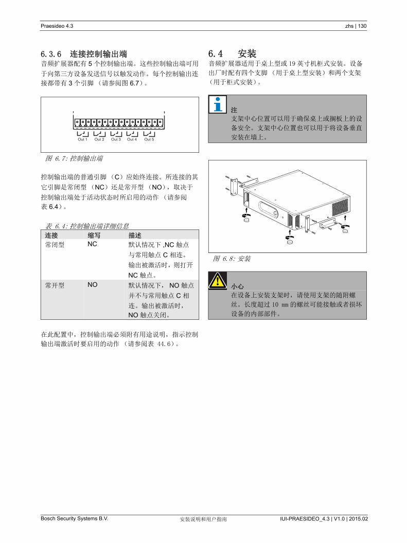
Praesideo 4.3 zhs | 130
Bosch Security Systems B.V. IUI-PRAESIDEO_4.3 | V1.0 | 2015.02安装说明和用户指南
6.3.6 连接控制输出端音频扩展器配有 5 个控制输出端。这些控制输出端可用
于向第三方设备发送信号以触发动作。每个控制输出连
接都带有 3 个引脚(请参阅图 6.7)。
控制输出端的普通引脚(C)应始终连接。所连接的其
它引脚是常闭型(NC)还是常开型(NO),取决于
控制输出端处于活动状态时所启用的动作(请参阅
表 6.4)。
在此配置中,控制输出端必须附有用途说明,指示控制
输出端激活时要启用的动作(请参阅表 44.6)。
6.4 安装音频扩展器适用于桌上型或 19 英寸机柜式安装。设备
出厂时配有四个支脚(用于桌上型安装)和两个支架
(用于柜式安装)。
图 6.7: 控制输出端
表 6.4: 控制输出端详细信息
连接 缩写 描述
常闭型 NC 默认情况下 ,NC 触点
与常用触点 C 相连。
输出被激活时,则打开
NC 触点。
常开型 NO 默认情况下, NO 触点
并不与常用触点 C 相
连。输出被激活时,
NO 触点关闭。
Out 1 Out 2 Out 3 Out 4 Out 5
注
支架中心位置可以用于确保桌上或搁板上的设
备安全。支架中心位置也可以用于将设备垂直
安装在墙上。
图 6.8: 安装
小心
在设备上安装支架时,请使用支架的随附螺
丝。长度超过 10 mm 的螺丝可能接触或者损坏
设备的内部部件。

Praesideo 4.3 zhs | 131
Bosch Security Systems B.V. IUI-PRAESIDEO_4.3 | V1.0 | 2015.02安装说明和用户指南
6.5 配置菜单用法
6.5.1 概述通过 2x16LCD 显示屏中的交互式菜单以及 “ 旋压式 ”
菜单按钮,可以对许多音频扩展器设置进行设定。下图
为菜单结构简图。
图 6.9: 音频扩展器前面板菜单的结构图
Name
VU meter
Menu
Monitoring
Setup
Serial Number
HW Version
FW Version
Back
1
2
<
2A
2B
2C
Back<
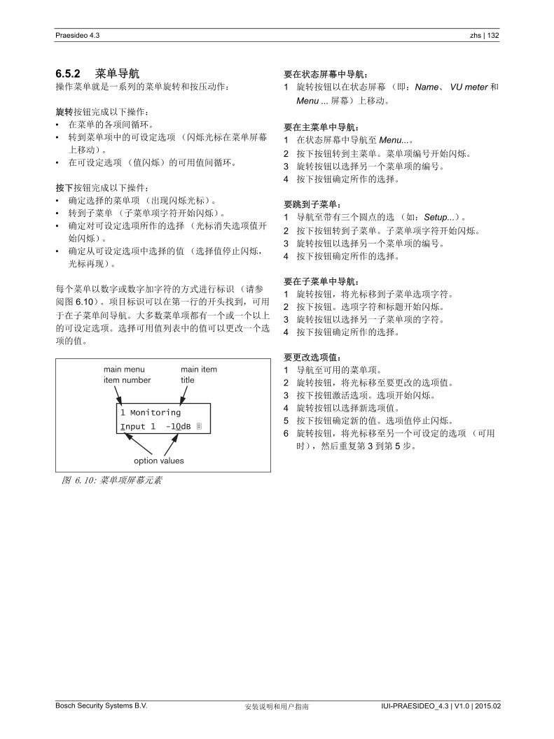
Praesideo 4.3 zhs | 132
Bosch Security Systems B.V. IUI-PRAESIDEO_4.3 | V1.0 | 2015.02安装说明和用户指南
6.5.2 菜单导航操作菜单就是一系列的菜单旋转和按压动作:
旋转按钮完成以下操作:
• 在菜单的各项间循环。
• 转到菜单项中的可设定选项(闪烁光标在菜单屏幕
上移动)。
• 在可设定选项(值闪烁)的可用值间循环。
按下按钮完成以下操件:
• 确定选择的菜单项(出现闪烁光标)。
• 转到子菜单(子菜单项字符开始闪烁)。
• 确定对可设定选项所作的选择(光标消失选项值开
始闪烁)。
• 确定从可设定选项中选择的值(选择值停止闪烁,
光标再现)。
每个菜单以数字或数字加字符的方式进行标识(请参
阅图 6.10)。项目标识可以在第一行的开头找到,可用
于在子菜单间导航。大多数菜单项都有一个或一个以上
的可设定选项。选择可用值列表中的值可以更改一个选
项的值。
要在状态屏幕中导航:
1 旋转按钮以在状态屏幕(即:Name、 VU meter 和
Menu ... 屏幕)上移动。
要在主菜单中导航:
1 在状态屏幕中导航至 Menu...。
2 按下按钮转到主菜单。菜单项编号开始闪烁。
3 旋转按钮以选择另一个菜单项的编号。
4 按下按钮确定所作的选择。
要跳到子菜单:
1 导航至带有三个圆点的选(如:Setup...)。
2 按下按钮转到子菜单。子菜单项字符开始闪烁。
3 旋转按钮以选择另一个菜单项的编号。
4 按下按钮确定所作的选择。
要在子菜单中导航:
1 旋转按钮,将光标移到子菜单选项字符。
2 按下按钮。选项字符和标题开始闪烁。
3 旋转按钮以选择另一子菜单项的字符。
4 按下按钮确定所作的选择。
要更改选项值:
1 导航至可用的菜单项。
2 旋转按钮,将光标移至要更改的选项值。
3 按下按钮激活选项。选项开始闪烁。
4 旋转按钮以选择新选项值。
5 按下按钮确定新的值。选项值停止闪烁。
6 旋转按钮,将光标移至另一个可设定的选项(可用
时),然后重复第 3 到第 5 步。
图 6.10: 菜单项屏幕元素
1 Monitoring
Input 1 -10dB
main menuitem number
option values
main itemtitle

Praesideo 4.3 zhs | 133
Bosch Security Systems B.V. IUI-PRAESIDEO_4.3 | V1.0 | 2015.02安装说明和用户指南
要从子菜单跳回到主菜单项:
1 旋转按钮,将光标移至主菜单项编号。
2 按下按钮。项目编号开始闪烁。
3 旋转按钮以选择另一个项目编号。
4 按下按钮确定所作的选择。
或
1 旋转按钮至 < Back。
2 按下按钮以确定操作。
要从主菜单跳回到状态屏幕:
1 跳回到主菜单。
2 旋转按钮至 < Back。
3 按下按钮以确定操作。
示例:
设置可用在音频扩展器的耳机输出端上的输出端。(此
例假设您从默认屏幕开始操作):
1 旋转按钮,转到状态屏幕上的 菜单 ......:
2 按下按钮以确定操作:
3 按下按钮以确定操作:
4 旋转按钮至 Monitoring 选项:
5 按下按钮以确定操作:
6 旋转按钮,以更改要收听的音频输出端:
7 按下按钮以确定操作:
8 旋转按钮,将光标移至菜单编号:
9 按下按钮以确定操作:
10 旋转按钮,移至 < Back 项目:
11 按下按钮以确定操作:
12 旋转按钮,转到默认屏幕:
Audio Expander
Menu...
1 MonitoringOff
1 MonitoringOff
1 MonitoringOff
1 MonitoringOff
1 MonitoringOutput 3 0 dB
1 MonitoringOutput 3 0 dB
1 MonitoringOutput 3 0 dB
1 MonitoringOutput 3 0 dB
< Back
Menu...
Audio Expander
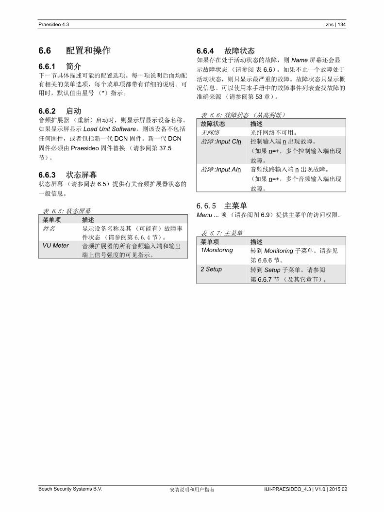
Praesideo 4.3 zhs | 134
Bosch Security Systems B.V. IUI-PRAESIDEO_4.3 | V1.0 | 2015.02安装说明和用户指南
6.6 配置和操作
6.6.1 简介下一节具体描述可能的配置选项。每一项说明后面均配
有相关的菜单选项,每个菜单项都带有详细的说明。可
用时,默认值由星号(*)指示。
6.6.2 启动音频扩展器(重新)启动时,则显示屏显示设备名称。
如果显示屏显示 Load Unit Software,则该设备不包括
任何固件,或者包括新一代 DCN 固件。新一代 DCN
固件必须由 Praesideo 固件替换(请参阅第 37.5
节)。
6.6.3 状态屏幕状态屏幕(请参阅表 6.5)提供有关音频扩展器状态的
一般信息。
6.6.4 故障状态如果存在处于活动状态的故障,则 Name 屏幕还会显
示故障状态(请参阅 表 6.6)。如果不止一个故障处于
活动状态,则只显示 严重的故障。故障状态只显示概
况信息。可以使用本手册中的故障事件列表查找故障的
准确来源(请参阅第 53 章)。
6.6.5 主菜单Menu ... 项(请参阅图 6.9)提供主菜单的访问权限。
表 6.5: 状态屏幕
菜单项 描述
姓名 显示设备名称及其(可能有)故障事
件状态(请参阅第 6.6.4 节)。
VU Meter 音频扩展器的所有音频输入端和输出
端上信号强度的可见指示。
表 6.6: 故障状态(从高到低)
故障状态 描述
无网络 光纤网络不可用。
故障 :Input CIn 控制输入端 n 出现故障。
(如果 n=+,多个控制输入端出现
故障。
故障 :Input AIn 音频线路输入端 n 出现故障。
(如果 n=+,多个音频输入端出现
故障。
表 6.7: 主菜单
菜单项 描述
1Monitoring 转到 Monitoring 子菜单。请参见
第 6.6.6 节。
2 Setup 转到 Setup 子菜单。请参阅
第 6.6.7 节(及其它章节)。

Praesideo 4.3 zhs | 135
Bosch Security Systems B.V. IUI-PRAESIDEO_4.3 | V1.0 | 2015.02安装说明和用户指南
6.6.6 设置监控选项Monitoring 子菜单用于设置将哪个信号发送到监控耳
机。可以发送其中一个音频输入端上的信号、可以发送
其中一个音频输出端上的信号,也可以根本不发送任何
信号。此外,该屏幕还提供电平表,用于对实际信号强
度进行可见识别。
6.6.7 查看版本信息Serial Number、 HW Version 和 SW Version 菜单项用
于获取有关音频扩展器的版本信息。
表 6.8:Monitoring 子菜单
菜单项 选项 值 1 值 2 描述
1Monitoring 源:
- Input (输入
端) n
输入端数:
1 至 4
音量:
-31 到 0 dB
音频输入端 n 的信号可用于耳机输
出端。
- Output (输出
端) n
输出端数:
1 至 4
音量:
-31 到 0 dB
音频输出端 n 的信号可用于耳机输
出端。
- Off* 耳机输出端在正常操作中处于关闭
状态。
表 6.9: 版本信息菜单项
菜单项 值(只读) 描述
2A Serial Number 例如:12.0.0030C 显示 16 进制序列号。
2B HW Version 例如:15.00 显示硬件版本。
2C FW Version 例如:3.00.1419 显示固件版本号。系统所有设备的固件版本号必须相同。
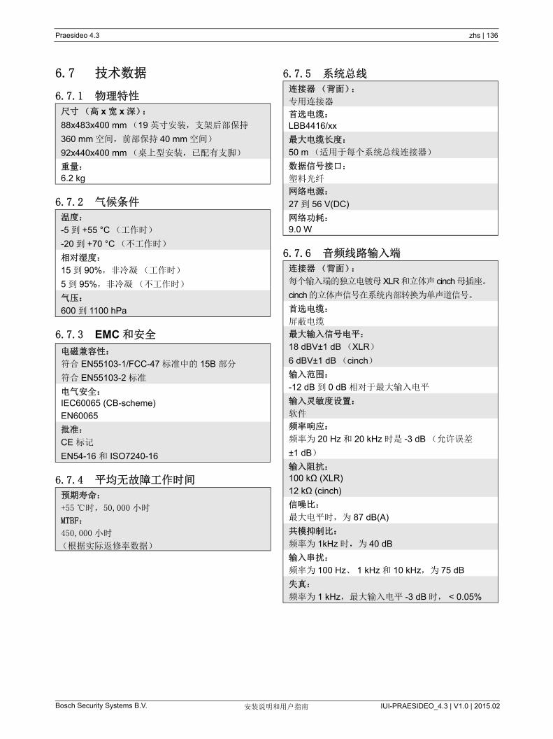
Praesideo 4.3 zhs | 136
Bosch Security Systems B.V. IUI-PRAESIDEO_4.3 | V1.0 | 2015.02安装说明和用户指南
6.7 技术数据
6.7.1 物理特性
6.7.2 气候条件
6.7.3 EMC 和安全
6.7.4 平均无故障工作时间
6.7.5 系统总线
6.7.6 音频线路输入端
尺寸(高 x 宽 x 深):
88x483x400 mm (19 英寸安装,支架后部保持
360 mm 空间,前部保持 40 mm 空间)
92x440x400 mm (桌上型安装,已配有支脚)
重量:
6.2 kg
温度:
-5 到 +55 °C (工作时)
-20 到 +70 °C (不工作时)
相对湿度:
15 到 90%,非冷凝(工作时)
5 到 95%,非冷凝(不工作时)
气压:
600 到 1100 hPa
电磁兼容性:
符合 EN55103-1/FCC-47 标准中的 15B 部分
符合 EN55103-2 标准
电气安全:
IEC60065 (CB-scheme)
EN60065
批准:
CE 标记
EN54-16 和 ISO7240-16
预期寿命:
+55 时,50,000 小时
MTBF:
450,000 小时
(根据实际返修率数据)
连接器(背面):
专用连接器
首选电缆:
LBB4416/xx
大电缆长度:
50 m (适用于每个系统总线连接器)
数据信号接口:
塑料光纤
网络电源:
27 到 56 V(DC)
网络功耗:
9.0 W
连接器(背面):
每个输入端的独立电镀母XLR和立体声 cinch母插座。
cinch的立体声信号在系统内部转换为单声道信号。
首选电缆:
屏蔽电缆
大输入信号电平:
18 dBV±1 dB (XLR)
6 dBV±1 dB (cinch)
输入范围:
-12 dB 到 0 dB 相对于 大输入电平
输入灵敏度设置:
软件
频率响应:
频率为 20 Hz 和 20 kHz 时是 -3 dB (允许误差
±1 dB)
输入阻抗:
100 kΩ (XLR)
12 kΩ (cinch)
信噪比:
大电平时,为 87 dB(A)
共模抑制比:
频率为 1kHz 时,为 40 dB
输入串扰:
频率为 100 Hz、 1 kHz 和 10 kHz,为 75 dB
失真:
频率为 1 kHz, 大输入电平 -3 dB 时, < 0.05%

Praesideo 4.3 zhs | 137
Bosch Security Systems B.V. IUI-PRAESIDEO_4.3 | V1.0 | 2015.02安装说明和用户指南
6.7.7 音频话筒输入端(输入端 1和输入端 2专用)
6.7.8 音频输出端
连接器(背面):
每个输入端的独立电镀母 XLR
首选电缆:
屏蔽电缆
额定输入电平:
-57 dBV,取决于灵敏度为 2 mV/Pa 的话筒的
91 dBSPL,正常响度的男性播音以及演讲人与话筒
的 0.15m 距离
余量:
30 dB
输入范围:
-7 dB 到 +8 dB,与额定输入端电平相对
(限制器极限)
输入灵敏度设置:
软件
频率响应:
频率为 300 Hz 和 20kHz 时是 -3 dB (允许误差
±1 dB)
频率为 300 Hz 的一阶高通语音滤波器
输入阻抗:
1360 W
信噪比:
> 62 dB(A),带 25 dB 的余量
共模抑制比:
频率为 100 Hz 时,大于 55 dB
频率为 1 kHz 和 10 kHz 时,大于 65 dB
幻象电源:
12 V ± 1 V ( 大 15 mA)
限制器:
模拟限制器,声压级为 -8 dB,相对于 大声压级 l
• 触发时间::1 ms
• 衰减时间:300 ms
• 额定输入电平时的极限
(仅适用于 HW15/xx 和更高版本的音频扩展器。硬
件信息可以从前面板菜单上获取)
连接器(背面):
每个输出端均配有一个独立电镀 XLR 和一个立体声
(双声道) cinch
首选电缆:
屏蔽电缆
大输出电平:
+ 18 dBV ± 1 dB (XLR)
+ 6 dBV ± 1 dB (cinch)
输出范围:
-30 dB 到 0 dB 相对于 大输出电平
输出电平设置:
软件
频率响应:
频率为 20 Hz 和 20 kHz 时是 -3 dB (允许误差
±1 dB)
输出阻抗:
< 100W
信噪比:
大电平时 > 89 dB(A)
输出串扰:
< -85 dB
失真:
频率为 1 kHz, 大输入信号为 -3 dB 时, < 0.05%
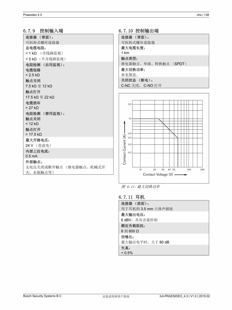
Praesideo 4.3 zhs | 138
Bosch Security Systems B.V. IUI-PRAESIDEO_4.3 | V1.0 | 2015.02安装说明和用户指南
6.7.9 控制输入端 6.7.10 控制输出端
6.7.11 耳机
连接器(背面):
可拆卸式螺丝连接器
总电缆电阻:
< 1 kΩ (含线路监视)
< 5 kΩ(不含线路监视)
电阻检测(启用监视):
电缆短路
< 2.5 kΩ
触点关闭
7.5 kΩ 至 12 kΩ
触点打开
17.5 kΩ 至 22 kΩ
电缆损坏
> 27 kΩ
电阻检测(禁用监视):
触点关闭
< 12 kΩ
触点打开
> 17.5 kΩ
大开路电压:
24 V (直流电)
内部上拉电流:
0.5 mA
外部触点:
无电压关闭或断开触点(继电器触点、机械式开
关、水银触点等)
连接器(背面):
可拆卸式螺丝连接器
大电缆长度:
1 km
触点类型:
继电器触点、单级、转换触点(SPDT)
大切换功率:
参见图表。
关闭状态(断电):
C-NC 关闭, C-NO 打开
图 6.11: 大切换功率
连接器(前面):
用于耳机的 3.5 mm 立体声插座
大输出电压:
6 dBV,具有音量控制
额定负载阻抗:
8 到 600 Ω
信噪比:
大输出电平时,大于 80 dB
失真:
< 0.5%
Con
tact
Cur
rent
(A
)
Contact Voltage (V)10 20 30 40 50 200100
0.2
0.3
0.4
0.5
1.0
2.0

Praesideo 4.3 zhs | 139
Bosch Security Systems B.V. IUI-PRAESIDEO_4.3 | V1.0 | 2015.02安装说明和用户指南
7 LBB4404/00CobraNet 接口
7.1 简介LBB4404/00CobraNet 接口用于连接 CobraNet 和
Praesideo。 CobraNet 接口 多可以将 4 个 Praesideo
的音频通道转换到 CobraNet,并同时将 4 个
CobraNet 的音频通道转换到 Praesideo。有关
CobraNet 接口的方框图,请参阅图 7.1。
CobraNet 结合了软件、硬件和网络协议,允许将实
时、优质数字音频发送到以太网。 CobraNet 受转换的
以太网变量支持。 CobraNet 采用标准以太网包和网络
基础架构(控制器、交换机和电缆连接等),操作时符
合快速以太网的 IEEE802.30u 规范。快速以太网距离
限制适用于 CobraNet 安装:100 米长的 5 类铜质电
缆, 2 千米长的多模光纤。专用快速以太网通过单模光
纤解决方案可以使传输距离更远。
通过单个 100Mb 链路,CobraNet 可以在各个方向向多
达 64 个 48kHz 的通道发送 20 位音频。这些通道以成
束的方式接地。
欲获得更多 CobraNet 的相关信息,包括网络设计、网
络安装、网络冗余及故障排除,请登录
www.cobranet.info。
注
CobraNetTM 为 CirrusLogic 公司分部
PeakAudio 的注册商标。
图 7.1:Cobranet 接口的结构图
CobraNetInterface
Sample rateconversion D/A
Networkprocessor
+ DSP
CAT5
CAT5
Control inputs
POF
POF
Control outputs
Networkredundancyswitching
I O
Display + Control
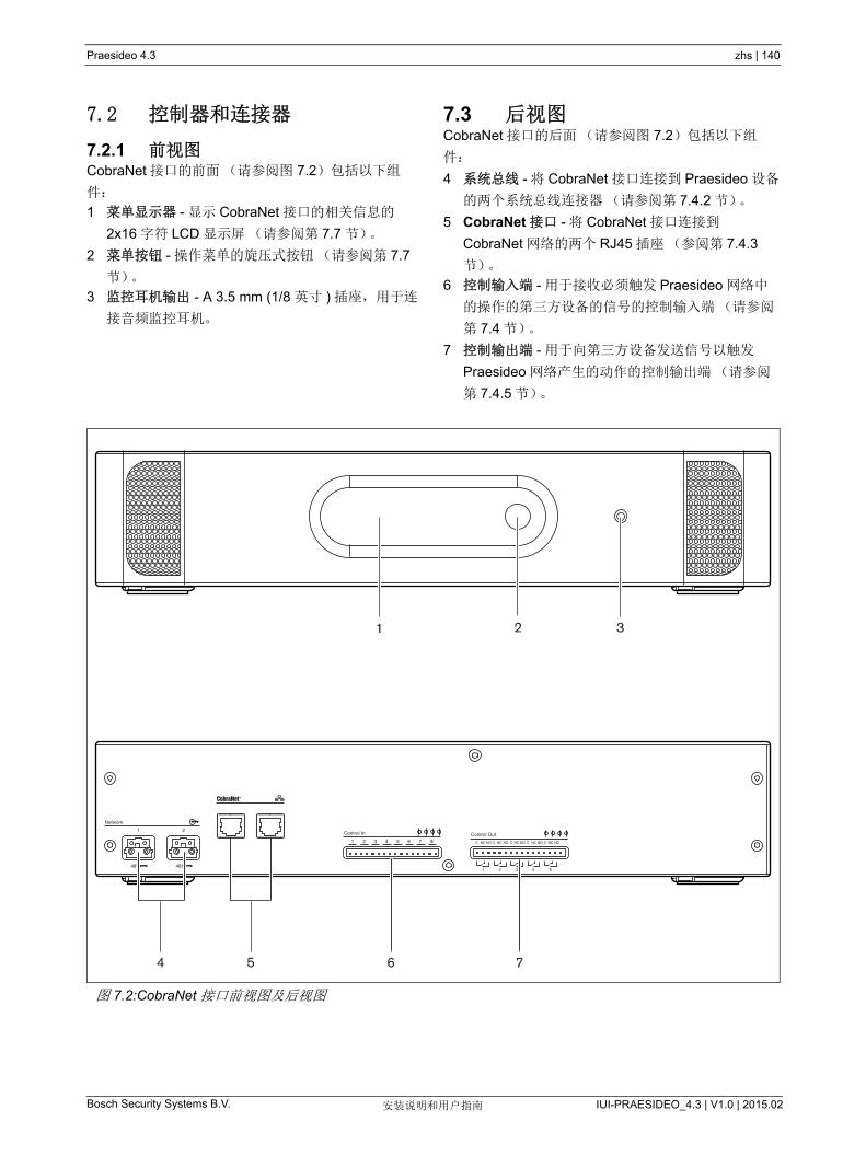
Praesideo 4.3 zhs | 140
Bosch Security Systems B.V. IUI-PRAESIDEO_4.3 | V1.0 | 2015.02安装说明和用户指南
7.2 控制器和连接器
7.2.1 前视图CobraNet 接口的前面(请参阅图 7.2)包括以下组
件:
1 菜单显示器 - 显示 CobraNet 接口的相关信息的
2x16 字符 LCD 显示屏 (请参阅第 7.7 节)。
2 菜单按钮 - 操作菜单的旋压式按钮(请参阅第 7.7
节)。
3 监控耳机输出 - A 3.5 mm (1/8 英寸 ) 插座,用于连
接音频监控耳机。
7.3 后视图CobraNet 接口的后面(请参阅图 7.2)包括以下组
件:
4 系统总线 - 将 CobraNet 接口连接到 Praesideo 设备
的两个系统总线连接器(请参阅第 7.4.2 节)。
5 CobraNet 接口 - 将 CobraNet 接口连接到
CobraNet 网络的两个 RJ45 插座(参阅第 7.4.3
节)。
6 控制输入端 - 用于接收必须触发 Praesideo 网络中
的操作的第三方设备的信号的控制输入端(请参阅
第 7.4 节)。
7 控制输出端 - 用于向第三方设备发送信号以触发
Praesideo 网络产生的动作的控制输出端(请参阅
第 7.4.5 节)。
图 7.2:CobraNet 接口前视图及后视图
Network
Control In
1 2 3 4 5 6 7 8 C NC NO C NC NO C NC NO C NC NO C NC NO
1 2
48V
Control Out
1 2 3 4 548V
4 6 75
21 3

Praesideo 4.3 zhs | 141
Bosch Security Systems B.V. IUI-PRAESIDEO_4.3 | V1.0 | 2015.02安装说明和用户指南
7.4 连接
7.4.1 简介本节概述使用 CobraNet 接口实现的一般系统连接。
• 连接 Praesideo 网络(请参阅第 7.4.2 节)。
• 连接 CobraNet 网络(请参阅第 7.4.3 节)。
• 连接控制输入端(请参阅第 7.4 节)。
• 连接控制输出端(请参阅第 7.4.5 节)。
7.4.2 连接 Praesideo 网络使用系统总线连接器和 LBB4416 网络电缆将
CobraNet 接口连接到 Praesideo 系统。两个连接器可
互换。
该设备由网络控制器通过 Praesideo 系统总线供电。
7.4.3 连接 CobraNet 网络使用以太网连接器和 5 类以太网电缆将 CobraNet 接口
连接到 CobraNet 系统。将一个 5 类电缆连接用于正常
的以太网连接,或将两个 5 类电缆连接用于冗余连接。
以太网支持使用自修复拓扑结构的开关之间的冗余连
接。每个连接均带有两个指示灯:
• 对于以太网链接,右侧的指示灯呈绿色亮起;对于
以太网活动,右侧的指示灯呈绿色闪烁。
• 如果左侧指示灯呈黄色亮起,说明该端口正在使用
中;如果接口为主导,正在使用的端口将呈黄色闪
烁。
注
要符合 EN54-16 标准,LBB4404/00 必须连接
到相同机柜中 Belden/Hirschmann RSR20-
0800M2M2T1UCCHPHH 类型的以太网开关
(扩展温度版本 RSR20-
0800M2M2T1SCCHPHH)。
小心
Praesideo 网络接口不提供广泛的安全措施来
保护系统免受恶意网络攻击或广播数据风暴。
此类措施不足以长期有效,因为 Praesideo 系
统的运作不太可能通过定期更新来修复安全漏
洞。如果通过 CobraNet 接口或 OMNEO 接口
在以太网上建立了音频连接,则这些接口必须
连接到单独的网络上,其他人不可访问。或使
用具有 VLAN 功能的以太网交换机设置
Praesideo 专用 VLAN,以将网络划分为多个
广播域,其中的一个域专门分配给
Praesideo。因为以太网上的音频连接要占用
大量的网络带宽,而且不像物理上独立的网
络, VLAN 要共享带宽, VLAN 树干可能需要
聚合链接和 / 或高质量的服务优先级排序。

Praesideo 4.3 zhs | 142
Bosch Security Systems B.V. IUI-PRAESIDEO_4.3 | V1.0 | 2015.02安装说明和用户指南
7.4.4 连接控制输入端CobraNet 接口配有 8 个控制输入端。控制输入端可以
接收必须触发 Praesideo 系统中动作的第三方设备的信
号。控制输入端可以配置用于执行触点接通或中断
(请参阅第 43.9 节)。此控制输入端还可以检测短路和
开路连接情况(请参阅图 7.3 和图 7.4)。控制输入是
否真正受到检测,配置中已有定义。 7.4.5 连接控制输出端CobraNet 接口配有 5 个控制输出端。这些控制输出端
可用于向第三方设备发送信号以触发动作。每个控制输
出连接都带有 3 个引脚(请参阅图 7.5)。
控制输出端的普通引脚(C)应始终连接。所连接的其
它引脚是常闭型(NC)还是常开型(NO),取决于
控制输出端处于活动状态时所启用的动作(请参阅
表 7.1)。
在此配置中,控制输出端必须附有用途说明,指示控制
输出端激活时要启用的动作(请参阅表 44.6)。
图 7.3: 受检测的控制输入端
图 7.4: 未受检测的控制输入端
警告
切勿将直流或交流信号连接到控制输入端,否
则可能会损坏输入电路。只能使用无电压触
点。
10kΩ
10kΩ
RTN Control input
RTN Control input
注
切勿将多个控制输入端的控制输入线联合使用
(如,请勿使用公共回路线)。
图 7.5: 控制输出端
表 7.1: 控制输出端详细信息
连接 缩写 描述
常闭型 NC 默认情况下 ,NC 触点与常用触
点 C 相连。输出被激活时,则
打开 NC 触点。
常开型 NO 默认情况下, NO 触点并不与
常用触点 C 相连。输出被激活
时, NO 触点关闭。
Out 1 Out 2 Out 3 Out 4 Out 5
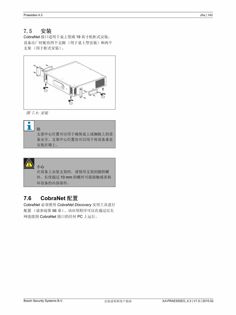
Praesideo 4.3 zhs | 143
Bosch Security Systems B.V. IUI-PRAESIDEO_4.3 | V1.0 | 2015.02安装说明和用户指南
7.5 安装CobraNet 接口适用于桌上型或 19 英寸机柜式安装。
设备出厂时配有四个支脚(用于桌上型安装)和两个
支架(用于柜式安装)。
7.6 CobraNet 配置CobraNet 必须使用 CobraNet Discovery 实用工具进行
配置(请参阅第 56 章)。该应用程序可以在通过以太
网连接到 CobraNet 接口的任何 PC 上运行。
图 7.6: 安装
注
支架中心位置可以用于确保桌上或搁板上的设
备安全。支架中心位置也可以用于将设备垂直
安装在墙上。
小心
在设备上安装支架时,请使用支架的随附螺
丝。长度超过 10 mm 的螺丝可能接触或者损
坏设备的内部部件。
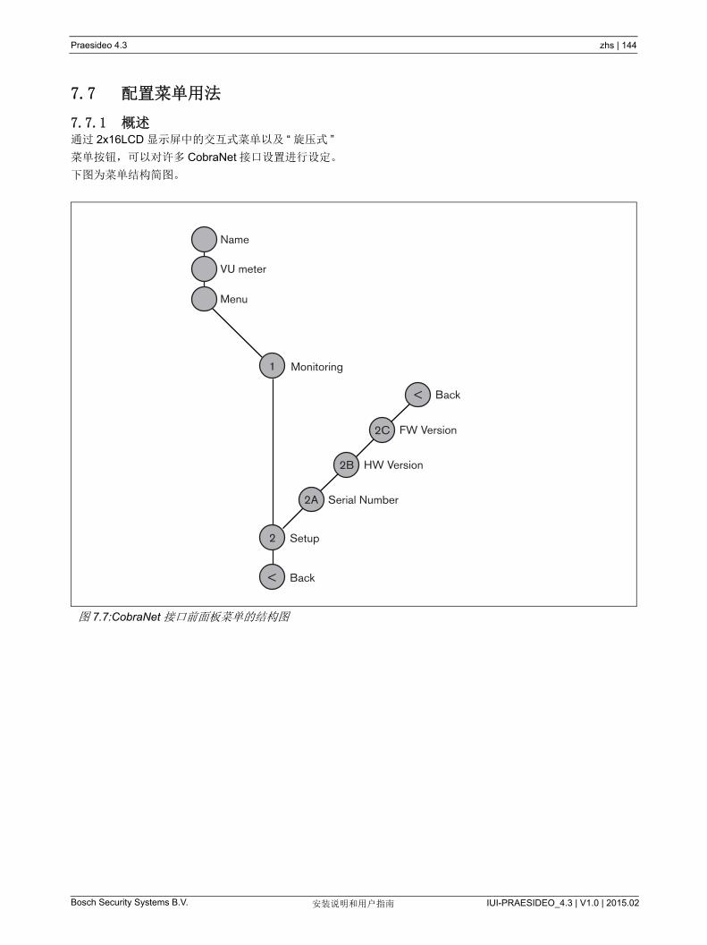
Praesideo 4.3 zhs | 144
Bosch Security Systems B.V. IUI-PRAESIDEO_4.3 | V1.0 | 2015.02安装说明和用户指南
7.7 配置菜单用法
7.7.1 概述通过 2x16LCD 显示屏中的交互式菜单以及 “ 旋压式 ”
菜单按钮,可以对许多 CobraNet 接口设置进行设定。
下图为菜单结构简图。
图 7.7:CobraNet 接口前面板菜单的结构图
Name
VU meter
Menu
Monitoring
Setup
Serial Number
HW Version
FW Version
Back
1
2
<
2A
2B
2C
Back<

Praesideo 4.3 zhs | 145
Bosch Security Systems B.V. IUI-PRAESIDEO_4.3 | V1.0 | 2015.02安装说明和用户指南
7.7.2 菜单导航操作菜单就是一系列的菜单旋转和按压动作:
旋转按钮完成以下操作:
• 在菜单的各项间循环。
• 转到菜单项中的可设定选项(闪烁光标在菜单屏幕
上移动)。
• 在可设定选项(值闪烁)的可用值间循环。
按下按钮完成以下操件:
• 确定选择的菜单项(出现闪烁光标)。
• 转到子菜单(子菜单项字符开始闪烁)。
• 确定对可设定选项所作的选择(光标消失选项值开
始闪烁)。
• 确定从可设定选项中选择的值(选择值停止闪烁,
光标再现)。
每个菜单以数字或数字加字符的方式进行标识(请参
阅图 7.8)。项目标识可以在第一行的开头找到,可用
于在子菜单间导航。大多数菜单项都有一个或一个以上
的可设定选项。选择可用值列表中的值可以更改一个选
项的值。
要在状态屏幕中导航:
1 旋转按钮以在状态屏幕(即:Name、 VU meter 和
Menu ... 屏幕)上移动。
要在主菜单中导航:
1 在状态屏幕中导航至 Menu...。
2 按下按钮转到主菜单。菜单项编号开始闪烁。
3 旋转按钮以选择另一个菜单项的编号。
4 按下按钮确定所作的选择。
要跳到子菜单:
1 导航至带有三个圆点的选(如:Setup...)。
2 按下按钮转到子菜单。子菜单项字符开始闪烁。
3 旋转按钮以选择另一个菜单项的编号。
4 按下按钮确定所作的选择。
要在子菜单中导航:
1 旋转按钮,将光标移到子菜单选项字符。
2 按下按钮。选项字符和标题开始闪烁。
3 旋转按钮以选择另一子菜单项的字符。
4 按下按钮确定所作的选择。
要更改选项值:
1 导航至可用的菜单项。
2 旋转按钮,将光标移至要更改的选项值。
3 按下按钮激活选项。选项开始闪烁。
4 旋转按钮以选择新选项值。
5 按下按钮确定新的值。选项值停止闪烁。
6 旋转按钮,将光标移至另一个可设定的选项(可用
时),然后重复第 3 到第 5 步。
图 7.8: 菜单项屏幕元素
1 Monitoring
Input 1 -10dB
main menuitem number
option values
main itemtitle
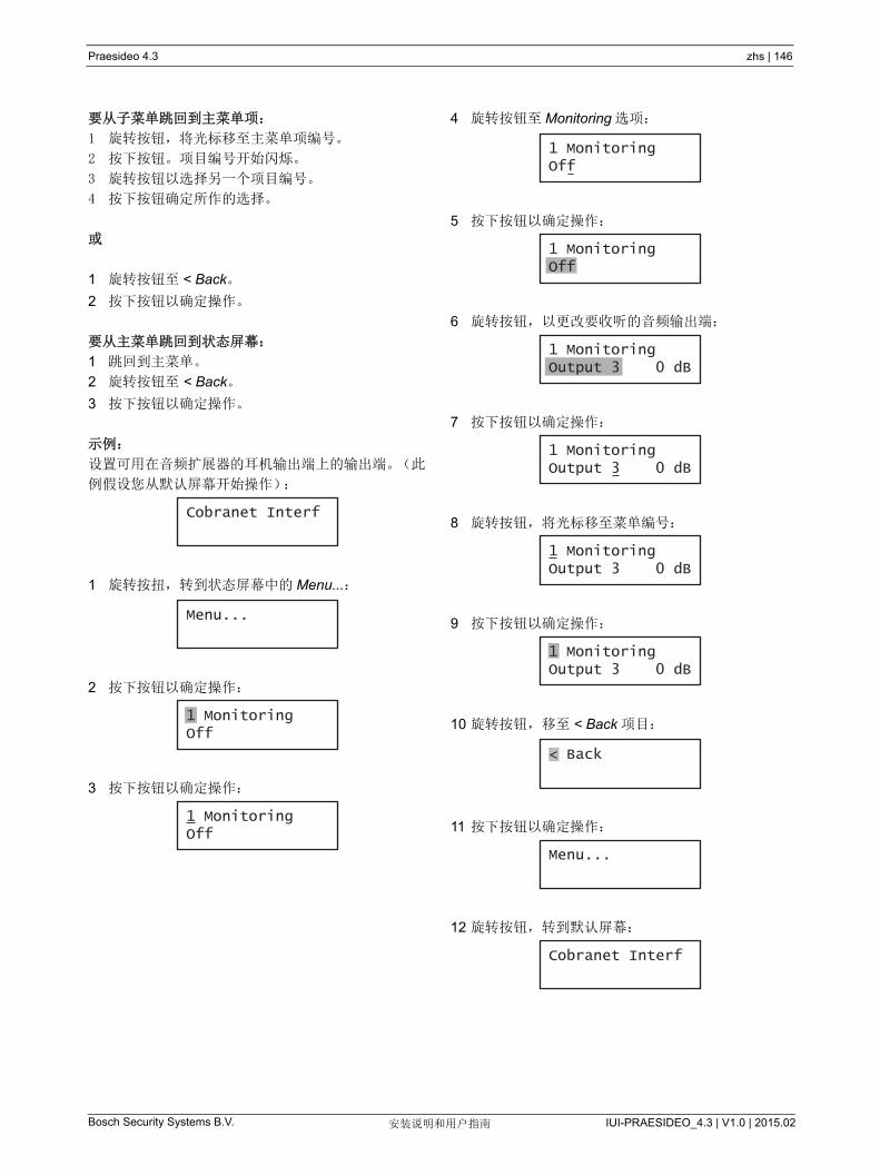
Praesideo 4.3 zhs | 146
Bosch Security Systems B.V. IUI-PRAESIDEO_4.3 | V1.0 | 2015.02安装说明和用户指南
要从子菜单跳回到主菜单项:
1 旋转按钮,将光标移至主菜单项编号。
2 按下按钮。项目编号开始闪烁。
3 旋转按钮以选择另一个项目编号。
4 按下按钮确定所作的选择。
或
1 旋转按钮至 < Back。
2 按下按钮以确定操作。
要从主菜单跳回到状态屏幕:
1 跳回到主菜单。
2 旋转按钮至 < Back。
3 按下按钮以确定操作。
示例:
设置可用在音频扩展器的耳机输出端上的输出端。(此
例假设您从默认屏幕开始操作):
1 旋转按扭,转到状态屏幕中的 Menu...:
2 按下按钮以确定操作:
3 按下按钮以确定操作:
4 旋转按钮至 Monitoring 选项:
5 按下按钮以确定操作:
6 旋转按钮,以更改要收听的音频输出端:
7 按下按钮以确定操作:
8 旋转按钮,将光标移至菜单编号:
9 按下按钮以确定操作:
10 旋转按钮,移至 < Back 项目:
11 按下按钮以确定操作:
12 旋转按钮,转到默认屏幕:
Cobranet Interf
Menu...
1 MonitoringOff
1 MonitoringOff
1 MonitoringOff
1 MonitoringOff
1 MonitoringOutput 3 0 dB
1 MonitoringOutput 3 0 dB
1 MonitoringOutput 3 0 dB
1 MonitoringOutput 3 0 dB
< Back
Menu...
Cobranet Interf

Praesideo 4.3 zhs | 147
Bosch Security Systems B.V. IUI-PRAESIDEO_4.3 | V1.0 | 2015.02安装说明和用户指南
7.8 配置和操作
7.8.1 简介下一节具体描述可能的配置选项。每一项说明后面均配
有相关的菜单选项,每个菜单项都带有详细的说明。可
用时,默认值由星号(*)指示。
7.8.2 启动CobraNet 接口(重新)启动时,显示屏显示设备的名
称。如果显示屏显示 Load Unit Software,则该设备不
包括任何固件,或者包括新一代 DCN 固件。新一代
DCN 固件必须由 Praesideo 固件替换(请参阅第 37.5
节)。
7.8.3 状态屏幕状态屏幕(请参阅表 7.2)提供有关 CobraNet 接口状
态的一般信息。
7.8.4 故障状态如果存在处于活动状态的故障,则 Name 屏幕还会显
示故障状态(请参阅 表 7.3)。如果不止一个故障处于
活动状态,则只显示 严重的故障。故障状态只显示概
况信息。可以使用本手册中的故障事件列表查找故障的
准确来源(请参阅第 46 章)。
7.8.5 主菜单Menu ... 项(请参阅表 7.4)提供主菜单的访问权限。
表 7.2: 状态屏幕
菜单项 描述
姓名 显示设备名称及其(可能)故障状态
(请参阅第 7.8.4 节)。
VU Meter CobraNet 接口的所有音频输入端和
输出端上信号强度的可见指示。
表 7.3: 故障状态(严重程度:从高到低)
故障状态 描述
无网络 光纤网络不可用。
故障:CobraNet
CobraNet 网络发生故障。
故障 :Internal CobraNet 接口发生故障。
故障 :Input CIn 控制输入端 n 出现故障。
(如果 n=+,多个控制输入端出现
故障。
表 7.4: 主菜单
菜单项 描述
1Monitoring 转到 Monitoring 子菜单。
请参阅第 7.8.6 节。
2 Setup 转到 Setup 子菜单。
请参阅第 7.8.7 节。
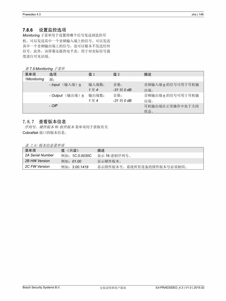
Praesideo 4.3 zhs | 148
Bosch Security Systems B.V. IUI-PRAESIDEO_4.3 | V1.0 | 2015.02安装说明和用户指南
7.8.6 设置监控选项Monitoring 子菜单用于设置将哪个信号发送到监控耳
机。可以发送其中一个音频输入端上的信号、可以发送
其中一个音频输出端上的信号,也可以根本不发送任何
信号。此外,该屏幕还提供电平表,用于对实际信号强
度进行可见识别。
7.8.7 查看版本信息 序列号、 硬件版本 和 软件版本 菜单项用于获取有关
CobraNet 接口的版本信息。
表 7.5:Monitoring 子菜单
菜单项 选项 值 1 值 2 描述
1Monitoring 源:
- Input (输入端) n 输入端数:
1 至 4
音量:
-31 到 0 dB
音频输入端 n 的信号可用于耳机输
出端。
- Output (输出端) n 输出端数:
1 至 4
音量:
-31 到 0 dB
音频输出端 n 的信号可用于耳机输
出端。
- Off* 耳机输出端在正常操作中处于关闭
状态。
表 7.6: 版本信息菜单项
菜单项 值(只读) 描述
2A Serial Number 例如:1C.0.0030C 显示 16 进制序列号。
2B HW Version 例如:01.00 显示硬件版本。
2C FW Version 例如:3.00.1419 显示固件版本号。系统所有设备的固件版本号必须相同。

Praesideo 4.3 zhs | 149
Bosch Security Systems B.V. IUI-PRAESIDEO_4.3 | V1.0 | 2015.02安装说明和用户指南
7.9 技术数据
7.9.1 物理特性
7.9.2 气候条件
7.9.3 EMC 和安全
7.9.4 平均无故障工作时间
7.9.5 系统总线
7.9.6 控制输入端
尺寸(高 x 宽 x 深):
88 x 483 x 400 mm (19" 安装,已配有支脚,
支架背后 360 mm 深度,支架前面 40 mm)
92x440x40 0mm (桌上型安装,已配有支脚)
重量:
6 kg
温度:
-5 到 +55 °C (工作时)
-20 到 +70 °C (不工作时)
相对湿度:
15 到 90%,非冷凝(工作时)
5 到 95%,非冷凝(不工作时)
气压:
600 到 1100 hPa
电磁兼容性:
符合 EN55103-1/FCC-47 标准中的 15B 部分
符合 EN55103-2 标准
EN50121-4
EN50130-4
快速瞬变抗扰性:
根据 EN61000-4-4 的快速瞬变脉冲期间, Cobranet
音频信号可能会丢失。脉冲过后,信号自动恢复。
电气安全:
IEC60065 (CB-scheme)
EN60065
批准:
CE 标记
EN54-16 和 ISO7240-16
预期寿命:
+55 °C 时, 50,000 小时
MTBF:
450,000 小时
(根据实际返修率数据)
连接器(背面):
专用连接器
首选电缆:
LBB4416/xx
大电缆长度:
50 m (适用于每个系统总线连接器)
数据信号接口:
塑料光纤
网络功耗:
11 W
连接器(背面):
可拆卸式螺丝连接器
总电缆电阻:
< 1 kΩ (含线路监视)
< 5 kΩ (不含线路监视)
电阻检测(启用监视):
电缆短路
< 2.5 kΩ
触点关闭
7.5 kΩ 至 12 kΩ
触点打开
17.5 kΩ 至 22 kΩ
电缆损坏
> 27 kΩ
电阻检测(禁用监视):
触点关闭
< 12 kΩ
触点打开
> 17.5 kΩ
大开路电压:
24 V (直流电)
内部上拉电流:
0.5 mA
外部触点:
无电压关闭或断开触点(继电器触点、机械式开
关、水银触点等)
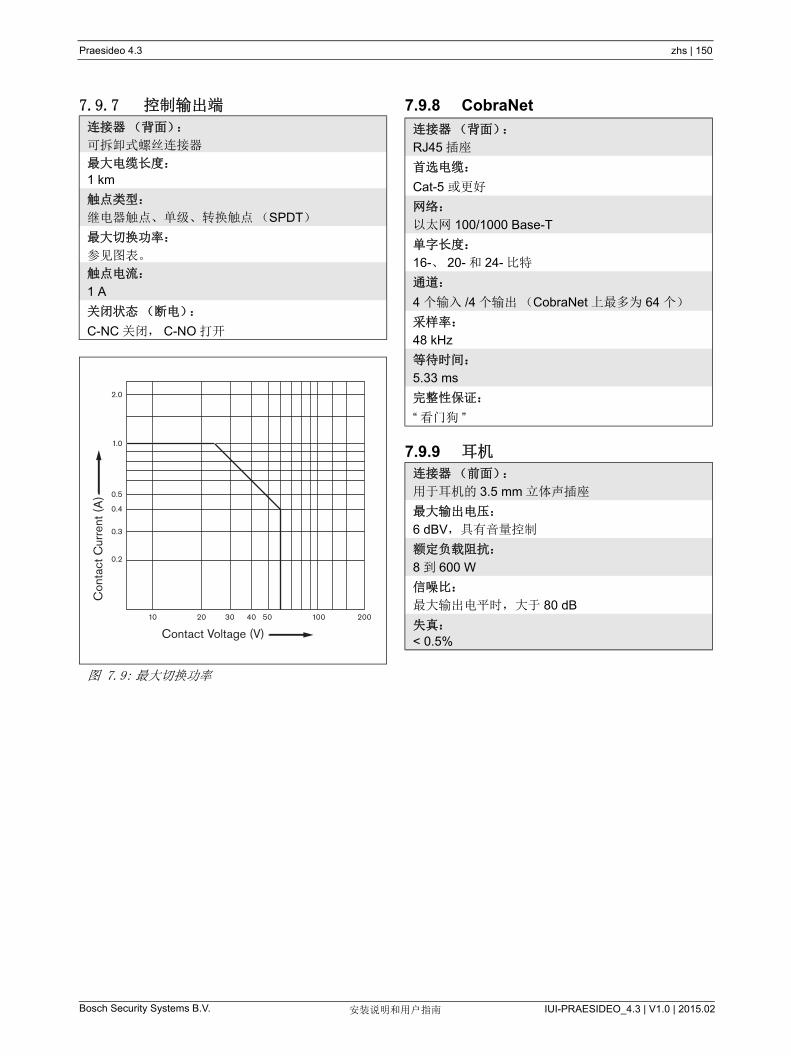
Praesideo 4.3 zhs | 150
Bosch Security Systems B.V. IUI-PRAESIDEO_4.3 | V1.0 | 2015.02安装说明和用户指南
7.9.7 控制输出端 7.9.8 CobraNet
7.9.9 耳机
连接器(背面):
可拆卸式螺丝连接器
大电缆长度:
1 km
触点类型:
继电器触点、单级、转换触点(SPDT)
大切换功率:
参见图表。
触点电流:
1 A
关闭状态(断电):
C-NC 关闭, C-NO 打开
图 7.9: 大切换功率
Con
tact
Cur
rent
(A
)
Contact Voltage (V)10 20 30 40 50 200100
0.2
0.3
0.4
0.5
1.0
2.0
连接器(背面):
RJ45 插座
首选电缆:
Cat-5 或更好
网络:
以太网 100/1000 Base-T
单字长度:
16-、 20- 和 24- 比特
通道:
4 个输入 /4 个输出(CobraNet 上 多为 64 个)
采样率:
48 kHz
等待时间:
5.33 ms
完整性保证:
“ 看门狗 ”
连接器(前面):
用于耳机的 3.5 mm 立体声插座
大输出电压:
6 dBV,具有音量控制
额定负载阻抗:
8 到 600 W
信噪比:
大输出电平时,大于 80 dB
失真:
< 0.5%

Praesideo 4.3 zhs | 151
Bosch Security Systems B.V. IUI-PRAESIDEO_4.3 | V1.0 | 2015.02安装说明和用户指南
8 PRS-4OMI4 OMNEO 接口
8.1 简介PRS-4OMI4 OMNEO 接口用于 OMNEO 或 Dante 网
络和 Praesideo 之间的接口。OMNEO 接口 多可以将
4 个 Praesideo 的音频通道转换到 OMNEO,并同时将
4 个 OMNEO 的音频通道转换到 Praesideo。 有关
OMNEO 接口的方框图,请参阅 图 8.1 。
OMNEO 是一个开放式媒体网络体系结构,由 Bosch
Security Systems 进行开发。通过使用标准的通信协
议, OMNEO 提供了两个主要组成部分:提供低延迟、
高质量多路媒体流交换的媒体程序传输协议套件和一个
强大的系统控制协议套件,为各种规模的媒体网络提供
可靠安全的控制和监测。
OMNEO 通过业内标准的 IP 设备进行操作,并允许采
用现有局域网执行高性能的媒体系统。
OMNEO 的程序传输组件是 Bosch Security Systems
与 Audinate Pty 之间进行合作的结晶, OMNEO 采用
Audinate 的 Dante 网络技术来提供基于标准的、可路
由的 IP 媒体传输。 OMNEO 的系统控制组件是一个开
放式控制体系结构,由 Bosch Security Systems 开发
的,称之为 OCA。它包含了众多功能,可实现灵活
性、可靠性、安全性和兼容性的增长。
因为所有的 Praesideo 产品采用 Praesideo 网络控制器
作为系统控制器的一种专有 Praesideo 控制协议,出于
兼容性的原因,PRS-4OMI4 只能执行 OMNEO 的程序
运输组件。 PRS-4OMI4 的使用方式可以与
LBB4404/00 CobraNet 接口相似,但不是使用
CobraNet,它能采用 OMNEO 与其他设备进行音频接
口或使用 Dante 的设备进行音频接口。它采用
OMNEO/Dante 48 kHz 采样速率模式,可用于 24 位字
长的未压缩数字音频。它比 LBB4404/00 CobraNet 接
口具有更多的额外优势,因其具有以太网的双冗余网络
连接,内置以太网交换机,可实现多台设备的菊花链并
支持快速生成树协议,可提供 大的可靠性。
在一台 PC 上安装 Audinate 的 Dante 虚拟声卡
(DVS)能使 PC 用于配备 PRS-4OMI4 的 Praesideo
系统的音频源。以此方式,连接到 PC (或内部的电脑
麦克风)的麦克风可用作 Praesideo 呼叫站的麦克风,
而无需使用正常的 Praesideo 呼叫站。此外,通过
Windows 媒体播放器从 PC 上播放的多个背景音乐
(BGM)流可通过 DVS 和 PRS-4OMI4 路由到
Praesideo 系统中。
图 8.1:OMNEO 接口的结构图
OMNEOInterface
Sample rateconversion D/A
Networkprocessor
+ DSP
CAT5
Control inputs
POF
Control outputs
Networkredundancyswitching
I O
Display + Control
CAT5
POF

Praesideo 4.3 zhs | 152
Bosch Security Systems B.V. IUI-PRAESIDEO_4.3 | V1.0 | 2015.02安装说明和用户指南
8.2 控制器和连接器
8.2.1 前视图OMNEO 接口的前面(请参阅 图 8.2)包括以下组件:
1 菜单显示 - A 2x16 字符液晶显示提供 OMNEO 接口
的信息 ( 见第 8.7 节 )。
2 菜单按钮 - 操作菜单的旋压式按钮(请参阅第 8.7
节)。
3 监控耳机输出 - A 3.5 mm (1/8 英寸 ) 插座,用于连
接音频监控耳机。
8.3 后视图OMNEO 接口的后面(请参阅 图 8.2)包括以下组件:
4 系统总线 - 将 OMNEO 接口连接到其他 Praesideo
设备上的两个系统总线连接器(请参阅第 8.4.2
节)。
5 OMNEO 接口 - 两个 RJ45 插座将 OMNEO 接口连
接到具有 OMNEO 或 Dante 音频传输的以太网网上
(请参阅第 8.4.3 节 )。
6 控制输入端 - 用于接收必须触发 Praesideo 网络中
的操作的第三方设备的信号的控制输入端(请参阅
第 8.4.4 节)。
7 控制输出端 - 用于向第三方设备发送信号以触发
Praesideo 网络产生的动作的控制输出端(请参阅
第 8.4.5 节)。
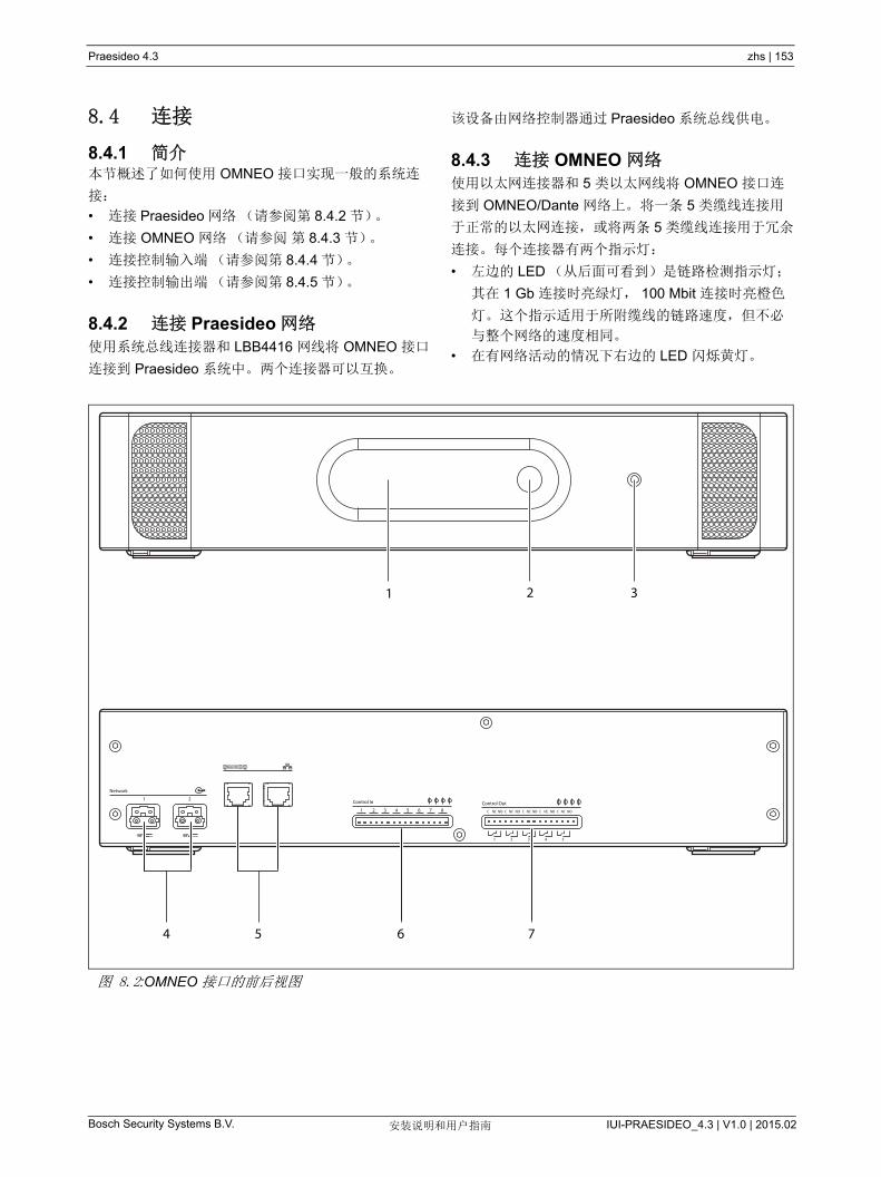
Praesideo 4.3 zhs | 153
Bosch Security Systems B.V. IUI-PRAESIDEO_4.3 | V1.0 | 2015.02安装说明和用户指南
8.4 连接
8.4.1 简介本节概述了如何使用 OMNEO 接口实现一般的系统连
接:
• 连接 Praesideo 网络(请参阅第 8.4.2 节)。
• 连接 OMNEO 网络(请参阅 第 8.4.3 节)。
• 连接控制输入端(请参阅第 8.4.4 节)。
• 连接控制输出端(请参阅第 8.4.5 节)。
8.4.2 连接 Praesideo 网络使用系统总线连接器和 LBB4416 网线将 OMNEO 接口
连接到 Praesideo 系统中。 两个连接器可以互换。
该设备由网络控制器通过 Praesideo 系统总线供电。
8.4.3 连接 OMNEO 网络使用以太网连接器和 5 类以太网线将 OMNEO 接口连
接到 OMNEO/Dante 网络上。 将一条 5 类缆线连接用
于正常的以太网连接, 或将两条 5 类缆线连接用于冗余
连接。 每个连接器有两个指示灯:
• 左边的 LED (从后面可看到)是链路检测指示灯;
其在 1 Gb 连接时亮绿灯, 100 Mbit 连接时亮橙色
灯。这个指示适用于所附缆线的链路速度,但不必
与整个网络的速度相同。
• 在有网络活动的情况下右边的 LED 闪烁黄灯。
图 8.2:OMNEO 接口的前后视图
Network
Control In
1 2 3 4 5 6 7 8 C NC NO C NC NO C NC NO C NC NO C NC NO
1 2
48V
Control Out
1 2 3 4 548V
4 6 75
21 3
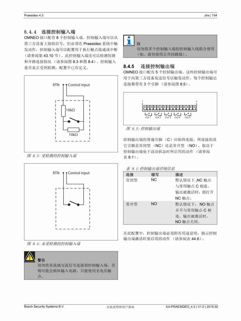
Praesideo 4.3 zhs | 154
Bosch Security Systems B.V. IUI-PRAESIDEO_4.3 | V1.0 | 2015.02安装说明和用户指南
8.4.4 连接控制输入端OMNEO 接口配有 8 个控制输入端。 控制输入端可以从
第三方设备上接收信号,但必须在 Praesideo 系统中触
发动作。 控制输入端可以配置用于执行触点接通或中断
(请参阅第 43.10 节)。此控制输入端还可以检测短路
和开路连接情况(请参阅图 8.3 和图 8.4)。控制输入
是否真正受到检测,配置中已有定义。 8.4.5 连接控制输出端OMNEO 接口配有 5 个控制输出端。 这些控制输出端可
用于向第三方设备发送信号以触发动作。 每个控制输出
连接都带有 3 个引脚(请参阅图 8.5)。
控制输出端的普通引脚(C)应始终连接。所连接的其
它引脚是常闭型(NC)还是常开型(NO),取决于
控制输出端处于活动状态时所启用的动作(请参阅
表 8.1)。
在此配置中,控制输出端必须附有用途说明,指示控制
输出端激活时要启用的动作(请参阅表 44.6)。
图 8.3: 受检测的控制输入端
图 8.4: 未受检测的控制输入端
警告
切勿将直流或交流信号连接到控制输入端,否
则可能会损坏输入电路。只能使用无电压触
点。
10kΩ
10kΩ
RTN Control input
RTN Control input
注
切勿将多个控制输入端的控制输入线联合使用
(如,请勿使用公共回路线)。
图 8.5: 控制输出端
表 8.1: 控制输出端详细信息
连接 缩写 描述
常闭型 NC 默认情况下 ,NC 触点
与常用触点 C 相连。
输出被激活时,则打开
NC 触点。
常开型 NO 默认情况下, NO 触点
并不与常用触点 C 相
连。输出被激活时,
NO 触点关闭。
Out 1 Out 2 Out 3 Out 4 Out 5

Praesideo 4.3 zhs | 155
Bosch Security Systems B.V. IUI-PRAESIDEO_4.3 | V1.0 | 2015.02安装说明和用户指南
8.5 安装OMNEO 接口适用于桌面或 19 英寸机柜式安装。 设备
出厂时配有四个支脚( 用于桌面安装)和两个支架
(用于机架式安装)。
PRS-4OMI4 交付时配有 Snap Ferrite
(Würth 742 717 22),请参阅图 8.7。所有通往控制输
入触点和来自控制输出触点的电线必须通过拉断线束周
围的铁氧体通过此铁氧体馈入。
8.6 OMNEO 配置必须使用 Dante 控制器 实用程序(见第 57 章)配置
OMNEO。该应用程序可以在任何 PC 上运行,并通过
以太网连接到 OMNEO 接口上。
图 8.6: 安装
注
支架中心位置可以用于确保桌上或搁板上的设
备安全。支架中心位置也可以用于将设备垂直
安装在墙上。
小心
在设备上安装支架时,请使用支架的随附螺
丝。长度超过 10 mm 的螺丝可能接触或者损
坏设备的内部部件。
图 8.7:Snap Ferrite
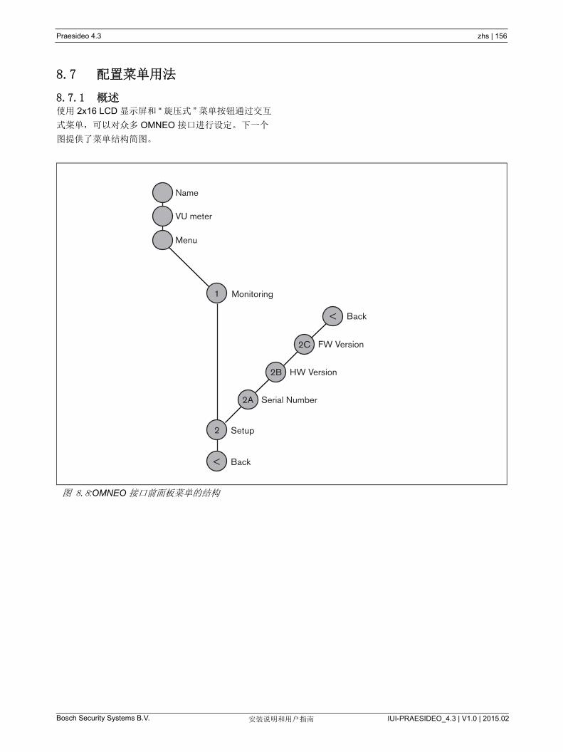
Praesideo 4.3 zhs | 156
Bosch Security Systems B.V. IUI-PRAESIDEO_4.3 | V1.0 | 2015.02安装说明和用户指南
8.7 配置菜单用法
8.7.1 概述使用 2x16 LCD 显示屏和 “ 旋压式 ” 菜单按钮通过交互
式菜单,可以对众多 OMNEO 接口进行设定。 下一个
图提供了菜单结构简图。
图 8.8:OMNEO 接口前面板菜单的结构
Name
VU meter
Menu
Monitoring
Setup
Serial Number
HW Version
FW Version
Back
1
2
<
2A
2B
2C
Back<

Praesideo 4.3 zhs | 157
Bosch Security Systems B.V. IUI-PRAESIDEO_4.3 | V1.0 | 2015.02安装说明和用户指南
8.7.2 菜单导航操作菜单就是一系列的菜单旋转和按压动作:
旋转按钮完成以下操作:
• 在菜单的各项间循环。
• 转到菜单项中的可设定选项(闪烁光标在菜单屏幕
上移动)。
• 在可设定选项(值闪烁)的可用值间循环。
按下按钮完成以下操件:
• 确定选择的菜单项(出现闪烁光标)。
• 转到子菜单(子菜单项字符开始闪烁)。
• 确定对可设定选项所作的选择(光标消失选项值开
始闪烁)。
• 确定从可设定选项中选择的值(选择值停止闪烁,
光标再现)。
每个菜单以数字或数字加字符的方式进行标识(请参
阅图 8.8)。项目标识可以在第一行的开头找到,可用
于在子菜单间导航。大多数菜单项都有一个或一个以上
的可设定选项。选择可用值列表中的值可以更改一个选
项的值。
要在状态屏幕中导航:
1 旋转按钮以在状态屏幕(即:Name、 VU meter 和
Menu ... 屏幕)上移动。
要在主菜单中导航:
1 在状态屏幕中导航至 Menu...。
2 按下按钮转到主菜单。菜单项编号开始闪烁。
3 旋转按钮以选择另一个菜单项的编号。
4 按下按钮确定所作的选择。
要跳到子菜单:
1 导航至带有三个圆点的选(如:Setup...)。
2 按下按钮转到子菜单。子菜单项字符开始闪烁。
3 旋转按钮以选择另一个菜单项的编号。
4 按下按钮确定所作的选择。
要在子菜单中导航:
1 旋转按钮,将光标移到子菜单选项字符。
2 按下按钮。选项字符和标题开始闪烁。
3 旋转按钮以选择另一子菜单项的字符。
4 按下按钮确定所作的选择。
要更改选项值:
1 导航至可用的菜单项。
2 旋转按钮,将光标移至要更改的选项值。
3 按下按钮激活选项。选项开始闪烁。
4 旋转按钮以选择新选项值。
5 按下按钮确定新的值。选项值停止闪烁。
6 旋转按钮,将光标移至另一个可设定的选项(可用
时),然后重复第 3 到第 5 步。
图 8.9: 菜单项屏幕元素
1 Monitoring
Input 1 -10dB
main menuitem number
option values
main itemtitle

Praesideo 4.3 zhs | 158
Bosch Security Systems B.V. IUI-PRAESIDEO_4.3 | V1.0 | 2015.02安装说明和用户指南
要从子菜单跳回到主菜单项:
1 旋转按钮,将光标移至主菜单项编号。
2 按下按钮。项目编号开始闪烁。
3 旋转按钮以选择另一个项目编号。
4 按下按钮确定所作的选择。
或
1 旋转按钮至 < Back。
2 按下按钮以确定操作。
要从主菜单跳回到状态屏幕:
1 跳回到主菜单。
2 旋转按钮至 < Back。
3 按下按钮以确定操作。
示例:
设置可用在音频扩展器的耳机输出端上的输出端。(此
例假设您从默认屏幕开始操作):
1 旋转按扭,转到状态屏幕中的 Menu...:
2 按下按钮以确定操作:
3 按下按钮以确定操作:
4 旋转按钮至 Monitoring 选项:
5 按下按钮以确定操作:
6 旋转按钮,以更改要收听的音频输出端:
7 按下按钮以确定操作:
8 旋转按钮,将光标移至菜单编号:
9 按下按钮以确定操作:
10 旋转按钮,移至 < Back 项目:
11 按下按钮以确定操作:
12 旋转按钮,转到默认屏幕:
OMNEO Interface
Menu...
1 MonitoringOff
1 MonitoringOff
1 MonitoringOff
1 MonitoringOff
1 MonitoringOutput 3 0 dB
1 MonitoringOutput 3 0 dB
1 MonitoringOutput 3 0 dB
1 MonitoringOutput 3 0 dB
< Back
Menu...
OMNEO Interface

Praesideo 4.3 zhs | 159
Bosch Security Systems B.V. IUI-PRAESIDEO_4.3 | V1.0 | 2015.02安装说明和用户指南
8.8 配置和操作
8.8.1 简介下一节具体描述可能的配置选项。每一项说明后面均配
有相关的菜单选项,每个菜单项都带有详细的说明。可
用时,默认值由星号(*)指示。
8.8.2 启动OMNEO 接口( 重新 )启动时,显示屏显示设备的名
称。 如果显示屏显示 Load Unit Software,则该设备不
包括任何固件,或者包括新一代 DCN 固件。新一代
DCN 固件必须由 Praesideo 固件替换(请参阅第 37.5
节)。
8.8.3 状态屏幕状态屏幕(请参阅表 8.2)提供有关 CobraNet 接口状
态的一般信息。
8.8.4 故障状态如果存在处于活动状态的故障,则 Name 屏幕还会显
示故障状态(请参阅表 8.3)。如果不止一个故障处于
活动状态,则只显示 严重的故障。故障状态只显示概
况信息。可以使用本手册中的故障事件列表查找故障的
准确来源(请参阅第 46 章)。
8.8.5 主菜单Menu ... 项(请参阅表 8.4)提供主菜单的访问权限。
表 8.2: 状态屏幕
菜单项 描述
姓名 显示设备名称及其(可能)故障状态
(请参阅第 8.8.4 节)。
VU Meter OMNEO 接口的所有音频输入端和音
频输出端上信号强度的可见指示。
表 8.3: 故障状态(严重程度:从高到低)
故障状态 描述
无网络 光纤网络不可用。
故障 :
OMNEO
OMNEO (以太网)网络中的故
障。
故障 :Internal OMNEO 接口发生故障。
故障 :Input CIn 控制输入端 n 出现故障。
(如果 n=+,多个控制输入端出现
故障。
表 8.4: 主菜单
菜单项 描述
1Monitoring 转到 Monitoring 子菜单。
请参见第 8.8.6 节。
2 Setup 转到 Setup 子菜单。
请参阅第 8.8.7 节。
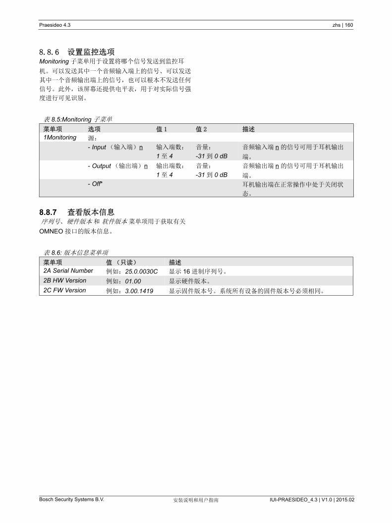
Praesideo 4.3 zhs | 160
Bosch Security Systems B.V. IUI-PRAESIDEO_4.3 | V1.0 | 2015.02安装说明和用户指南
8.8.6 设置监控选项Monitoring 子菜单用于设置将哪个信号发送到监控耳
机。可以发送其中一个音频输入端上的信号、可以发送
其中一个音频输出端上的信号,也可以根本不发送任何
信号。此外,该屏幕还提供电平表,用于对实际信号强
度进行可见识别。
8.8.7 查看版本信息 序列号、 硬件版本 和 软件版本 菜单项用于获取有关
OMNEO 接口的版本信息。
表 8.5:Monitoring 子菜单
菜单项 选项 值 1 值 2 描述
1Monitoring 源:
- Input (输入端) n 输入端数:
1 至 4
音量:
-31 到 0 dB
音频输入端 n 的信号可用于耳机输出
端。
- Output (输出端) n 输出端数:
1 至 4
音量:
-31 到 0 dB
音频输出端 n 的信号可用于耳机输出
端。
- Off* 耳机输出端在正常操作中处于关闭状
态。
表 8.6: 版本信息菜单项
菜单项 值(只读) 描述
2A Serial Number 例如:25.0.0030C 显示 16 进制序列号。
2B HW Version 例如:01.00 显示硬件版本。
2C FW Version 例如:3.00.1419 显示固件版本号。系统所有设备的固件版本号必须相同。

Praesideo 4.3 zhs | 161
Bosch Security Systems B.V. IUI-PRAESIDEO_4.3 | V1.0 | 2015.02安装说明和用户指南
8.9 技术数据
8.9.1 物理特性
8.9.2 气候条件
8.9.3 EMC 和安全
8.9.4 平均无故障工作时间
8.9.5 系统总线
8.9.6 控制输入端
尺寸(高 x 宽 x 深):
88 x 483 x 400 mm (19" 安装,已配有支脚,
支架背后 360 mm 深度,支架前面 40 mm)
92x440x400 mm (桌上型安装,已配有支脚)
重量:
6 kg
温度:
-5 到 +55 °C (工作时)
-20 到 +70 °C (不工作时)
相对湿度:
15 到 90%,非冷凝(工作时)
5 到 95%,非冷凝(不工作时)
气压:
600 到 1100 hPa
电磁兼容性:
符合 EN55103-1/FCC-47 标准中的 15B 部分
符合 EN55103-2 标准
EN50121-4
EN50130-4
电气安全:
IEC60065 (CB-scheme)
EN60065
批准:
CE 标记
EN54-16 和 ISO7240-16
预期寿命:
+55 °C 时, 50,000 小时
MTBF:
450,000 小时
(根据实际返修率数据)
连接器(背面):
专用连接器
首选电缆:
LBB4416/xx
大电缆长度:
50m (适用于每个系统总线连接器)
数据信号接口:
塑料光纤
网络功耗:
10 W
连接器(背面):
可拆卸式螺丝连接器
总电缆电阻:
< 1 kΩ (含线路监视)
< 5 kΩ (不含线路监视)
电阻检测(启用监视):
电缆短路
< 2.5 kΩ
触点关闭
7.5 kΩ 至 12 kΩ
触点打开
17.5 kΩ 至 22 kΩ
电缆损坏
> 27 kΩ
电阻检测(禁用监视):
触点关闭
< 12 kΩ
触点打开
> 17.5 kΩ
大开路电压:
24 V (直流电)
内部上拉电流:
0.5 mA
外部触点:
无电压关闭或断开触点(继电器触点、机械式开
关、水银触点等)
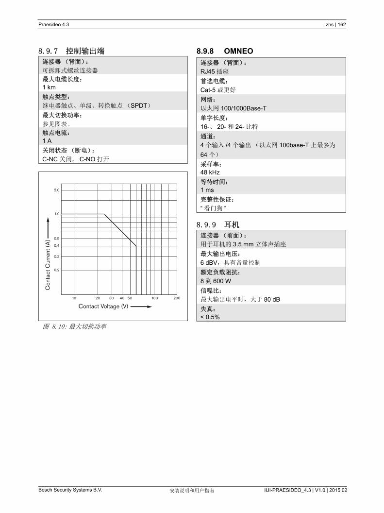
Praesideo 4.3 zhs | 162
Bosch Security Systems B.V. IUI-PRAESIDEO_4.3 | V1.0 | 2015.02安装说明和用户指南
8.9.7 控制输出端 8.9.8 OMNEO
8.9.9 耳机
连接器(背面):
可拆卸式螺丝连接器
大电缆长度:
1 km
触点类型:
继电器触点、单级、转换触点(SPDT)
大切换功率:
参见图表。
触点电流:
1 A
关闭状态(断电):
C-NC 关闭, C-NO 打开
图 8.10: 大切换功率
Con
tact
Cur
rent
(A
)
Contact Voltage (V)10 20 30 40 50 200100
0.2
0.3
0.4
0.5
1.0
2.0
连接器(背面):
RJ45 插座
首选电缆:
Cat-5 或更好
网络:
以太网 100/1000Base-T
单字长度:
16-、 20- 和 24- 比特
通道:
4 个输入 /4 个输出(以太网 100base-T 上 多为
64 个)
采样率:
48 kHz
等待时间:
1 ms
完整性保证:
“ 看门狗 ”
连接器(前面):
用于耳机的 3.5 mm 立体声插座
大输出电压:
6 dBV,具有音量控制
额定负载阻抗:
8 到 600 W
信噪比:
大输出电平时,大于 80 dB
失真:
< 0.5%

Praesideo 4.3 zhs | 163
Bosch Security Systems B.V. IUI-PRAESIDEO_4.3 | V1.0 | 2015.02安装说明和用户指南
9 功率放大器
9.1 简介PRS-1P500、 PRS-2P250 和 PRS-4P125 功率放大器
是 LBB4421/10、 LBB4422/10 和 LBB4424/10 的改进
型。主要差别在于新放大器的效率更高,因此在输出功
率相同时,它们的功耗更低。在空闲模式和待机或省电
模式下,这尤其明显,在允许的情况下可节省可观的电
池电量(不适用于 EN54-16 规范安全)。
功率放大器的主要功能是对扬声器音频信号进行放大。
该放大器是高效 D 类放大器,带有切换模式的电源。
该功率放大器具有防过载,防过热和防短路功能。有关
功率放大器的方框图,请参阅图 9.1。
功率放大器具有可配置的音频处理功能,如参数化均
衡、音频延时以及自动噪音音量控制 (AVC) 等。
注
输入端、备用放大器连接、扬声器线路和控制
输出端的数量取决于功率放大器的类型。
图 9.1: 功率放大器方框图
A/DD/A(1..8)
Class D(1..8)
NetworkProcessor
+ DSP
Display + Control
Power Supply
Loudspeaker Out
Audio Inputs
Control Inputs
POF
POF
Mains
Control Outputs (1..8)
NetworkRedundancy
Switching
I O
48 V Back-up
Spare Amplifier
Praesideo 4.3 zhs | 164
Bosch Security Systems B.V. IUI-PRAESIDEO_4.3 | V1.0 | 2015.02安装说明和用户指南
9.2 控制器、连接器和指示器
9.2.1 前视图功率放大器的前面(请参阅图 9.2)包括以下组件:
1 菜单显示器 -2x16 字符的 LCD 显示屏,显示功率放
大器的相关信息(请参阅第 9.7 节)。
2 菜单按扭 - 操作菜单的旋压式按钮(请参阅第 9.7
节)。
3 监控耳机输出 - A 3.5 mm (1/8 英寸 ) 插座,用于连
接音频监控耳机。
9.2.2 后视图功率放大器的后面(请参阅图 9.2)包括以下组件:
4 接地 - 使功率放大器带电接地的连接。
5 控制输入端 - 控制输入端用于接收第三方设备的信
号,该设备须触发 Praesideo 网络中的操作(请参
阅第 9.3.7 节)。
6 音频输入端 - 音频输入端可从模拟音频源接收音频
信号(请参阅 9.3.6 节)。
7 备用电源 - 连接备用电源的插座(请参阅第 9.3.8
节)。
8 电源开 / 关开关 - 打开和关闭功率放大器电源的开关
(请参阅 9.3.2 节)。
9 保险丝盒 - 装有保护功率放大器电源的保险丝的保
险丝盒(请参阅第 9.3.2 节)。
10 系统总线 - 两个系统总线连接器,将功率放大器连
接到其它的 Praesideo 设备上。
11 放大器通道 - 每个功率放大器设备包含 1 到 8 个完
全独立和可配置的放大器通道。放大器通道的数量
取决于功率放大器的类型(请参阅第 9.3.5 节)。
12 主电源插槽 - 将功率放大器连接到主电源的主电源
插座(请参阅第 9.3.2 节)。
13 Signal Ground - 将信号接地连接到安全地面的开
关 ( 请参阅第 9.3.4 节 )。
14 电压选择器 - 选择本地主电源电压的开关(请参阅
第 9.3.2 节)。

Praesideo 4.3 zhs | 165
Bosch Security Systems B.V. IUI-PRAESIDEO_4.3 | V1.0 | 2015.02安装说明和用户指南
图 9.2: 功率放大器的前视图和后视图(所有类型)
21 3
10
PRS-xPxxx, LBB4428/00Power Amplifier
PRS-1P500, PRS-2P250, PRS-4P125Power Amplifier
LBB4428/00Power Amplifier
11
22
3 4 5
48V
6 7 8 1 2 3 4
0 0
Control In Audio InNetwork
48V
2 4
48VBattery Mains
T6.3A H250V
100-240V
0 0
6 8
C
Control Out Spare In Lsp Out
NO NC 0V 50V
1 3C
Control Out Spare In Lsp Out
NO NC 0V 50V C
Control Out Spare In Lsp Out
NO NC 0V 50V C
Control Out Spare In Lsp Out
NO NC 0V 50V
5 7
Avis
CautionRisk of electric shock.
Do not open.
Risk of electric shock.Do not open.
11
54 6
12
8 97
0+
Control In1 2 3 4 5 6 7 8 1 2
Audio In
Network 1 2
++– –Control Out Spare In Lsp Out
C NO NC 0V 50V
4 3++– –
Control Out Spare In Lsp Out
C NO NC 0V 50V++– –Control Out Spare In Lsp Out
C NO NC 0V 50V
2 1++– –
Control Out Spare In Lsp Out
C NO NC 0V 50V
GroundedSignal Ground
Floating
Mains
48V 48V
Battery 48V 12ANon-isolated input 0+
115:100-120V 50-60Hz 230:220-240V 50-60Hz T6.3A 250V
T6.3A 250V
Caution
AvisRisq of electric shock
Do not open
Risque de choc electrique.Ne pas ouvrir
+ 0 – + 0 –
Class 2 Wiring
10 11
54 6
127
8 914 13

Praesideo 4.3 zhs | 166
Bosch Security Systems B.V. IUI-PRAESIDEO_4.3 | V1.0 | 2015.02安装说明和用户指南
9.3 连接
9.3.1 简介本节概述如何使用功率放大器实现一般系统连接。
• 连接主电源(请参阅第 9.3.2 节)。
• 连接网络(请参阅第 9.3.3 节)。
• 接地连接(请参阅第 9.3.4 节)。
• 连接放大器通道(请参阅 9.3.5 节)。
• 连接音频输入端(请参阅第 9.3.6 节)。
• 连接控制输入端(请参阅第 9.3.7 节)。
连接备用电源(请参阅第 9.3.8 节)。
9.3.2 连接主电源将功率放大器连接到主电源的过程如下:
1 将正确类型的保险丝安装到功率放大器中(请参阅
表 9.1 和表 9.2)。
2 将主电源线连接到功率放大器。
3 将主电源线连接到经过当地批准的主电源插座。
9.3.3 连接网络采用系统总线连接器和 LBB4416 网络电缆将功率放大
器连接到 Praesideo 系统。两个连接器可互换。
9.3.4 接地仅对于 LBB4428/00:接地跳线塞可以将信号接地端连
接到安全接地端。此跳线塞是位于印刷电路板上的
X3。将跳线塞设置为连接引脚 2 和 3,以将信号接地端
连接到安全接地端。将跳线塞设置为连接引脚 1 和 2,
以将信号接地端绝缘。
出厂设置用作浮动接地端,并且跳线塞连接引脚 1 和
2。如果使用放大器的音频线路或话筒输入端,并且连
接的音频源未接地,则可以在引脚 2 和 3 之间连接跳
线塞以减少发生外部 RF 干扰的可能性。如果音频源已
将信号接地端连接到安全接地端,则请将跳线塞连接到
引脚 1 和 2, 以避免产生可能会引起嘈杂声的接地回
路。
图 9.3: 接地连接器
对于 PRS-1P500、 PRS-2P250 和 PRS-4P125:利用
后部开关(图 8.2 中的 13),信号接地端可以连接到
安全接地端。
表 9.1: 电压选择器和保险丝 (PRS-xPxxx)
选择器 主电源电压
V (AC)
保险丝
115 100 - 120 T6.3AH250V
(IEC60127 或
UL248)
230 220 - 240 T6.3AH250V
(IEC60127)
表 9.2: 电压范围和保险丝 (LBB4428/00)
电压范围 保险丝
100-240V (AC) T6.3AH250V
(IEC60127 或 UL248)
警告
为降低触电风险,除非取得相关资质,否则不
得执行操作说明范围之外的任何维修工作。参
见章节 1.2 目标受众。
123
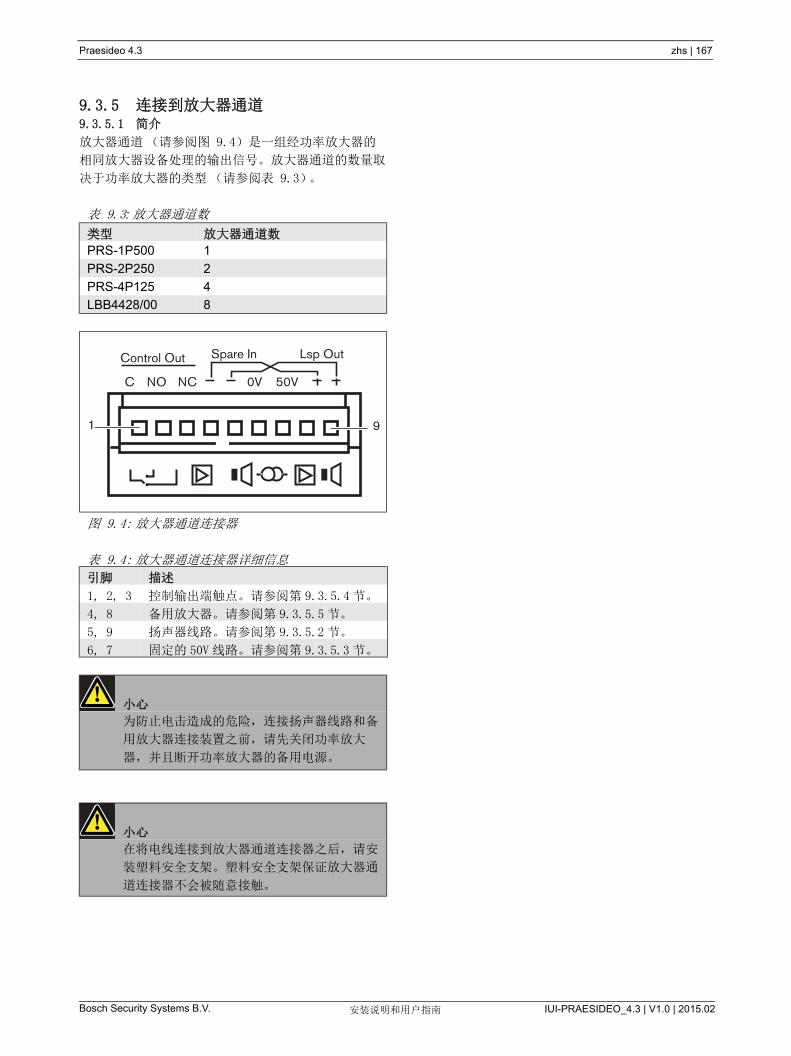
Praesideo 4.3 zhs | 167
Bosch Security Systems B.V. IUI-PRAESIDEO_4.3 | V1.0 | 2015.02安装说明和用户指南
9.3.5 连接到放大器通道9.3.5.1 简介
放大器通道(请参阅图 9.4)是一组经功率放大器的
相同放大器设备处理的输出信号。放大器通道的数量取
决于功率放大器的类型(请参阅表 9.3)。
表 9.3: 放大器通道数
类型 放大器通道数
PRS-1P500 1
PRS-2P250 2
PRS-4P125 4
LBB4428/00 8
图 9.4: 放大器通道连接器
表 9.4: 放大器通道连接器详细信息
引脚 描述
1, 2, 3 控制输出端触点。请参阅第 9.3.5.4 节。
4, 8 备用放大器。请参阅第 9.3.5.5 节。
5, 9 扬声器线路。请参阅第 9.3.5.2 节。
6, 7 固定的 50V 线路。请参阅第 9.3.5.3 节。
小心
为防止电击造成的危险,连接扬声器线路和备
用放大器连接装置之前,请先关闭功率放大
器,并且断开功率放大器的备用电源。
小心
在将电线连接到放大器通道连接器之后,请安
装塑料安全支架。塑料安全支架保证放大器通
道连接器不会被随意接触。
C
Control Out Spare In Lsp Out
NO NC 0V 50V
1 9
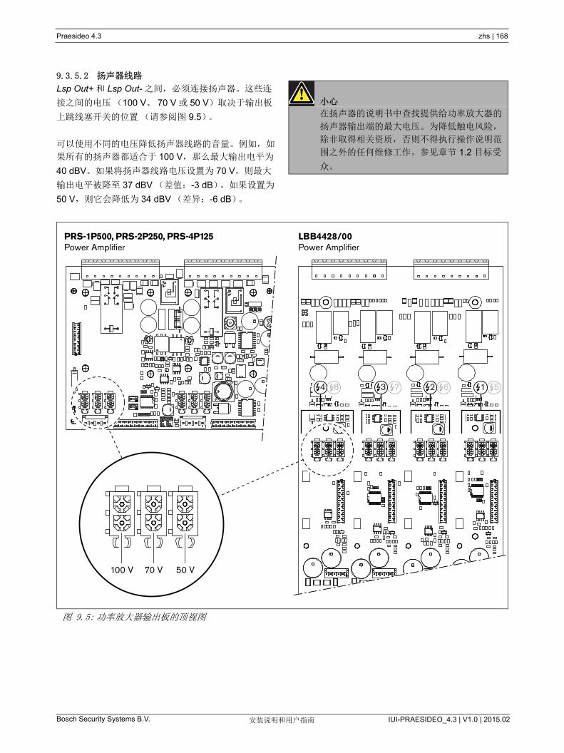
Praesideo 4.3 zhs | 168
Bosch Security Systems B.V. IUI-PRAESIDEO_4.3 | V1.0 | 2015.02安装说明和用户指南
9.3.5.2 扬声器线路
Lsp Out+ 和 Lsp Out- 之间,必须连接扬声器。这些连
接之间的电压(100 V、 70 V 或 50 V)取决于输出板
上跳线塞开关的位置(请参阅图 9.5)。
可以使用不同的电压降低扬声器线路的音量。例如,如
果所有的扬声器都适合于 100 V,那么 大输出电平为
40 dBV。如果将扬声器线路电压设置为 70 V,则 大
输出电平被降至 37 dBV (差值:-3 dB)。如果设置为
50 V,则它会降低为 34 dBV (差异:-6 dB)。
小心
在扬声器的说明书中查找提供给功率放大器的
扬声器输出端的 大电压。为降低触电风险,
除非取得相关资质,否则不得执行操作说明范
围之外的任何维修工作。参见章节 1.2 目标受
众。
图 9.5: 功率放大器输出板的顶视图
100 V 70 V 50 V
PRS-1P500, PRS-2P250, PRS-4P125Power Amplifier
LBB4428/00Power Amplifier
8 7 6 54 3 2 1

Praesideo 4.3 zhs | 169
Bosch Security Systems B.V. IUI-PRAESIDEO_4.3 | V1.0 | 2015.02安装说明和用户指南
9.3.5.3 50V 输出
放大器通道提供的 50 V 输出端实际上是扬声器线路电
压为 50 伏时的分支插接。50 伏线路是否可用并不依赖
于所选择的扬声器电压,因为分支插接安装在跳线塞的
前面(请参阅图 9.6)。
如果 50 V 电压接地,则可以创建扬声器电压的 “ 平衡 ”
输出。这种情况下,扬声器线路和接地设备之间的 大
电压始终小于 50 V (请参阅图 9.6)。扬声器线路与地
面之间的实际电压取决于跳线塞开关的位置。
如果故意将 50 V 电压接地,则放大器输出端的接地检
测须通过配置软件禁用(请参阅 44.3.4)。
9.3.5.4 控制输出端
每个放大器通道配有一个控制输出端。控制输出端可以
用于向第三方设备发送信号以触发动作。每个控制输出
端配有三个引脚(请参阅图 9.4)。控制输出端的普通
引脚(C)应始终连接。所连接的引脚是常闭型
(NC)还是常开型(NO),取决于控制输出端处于活
动状态时要启用的动作(请参阅表 9.5)。
在此配置中,控制输出必须附有用途说明,指示控制输
出端激活时要启用的动作(请参阅表 44.6)。例如,
功率放大器控制输出端可以配置为 Volumeoverride
(音量强切)输出端以创建音量强切。
9.3.5.5 备用放大器
如果功率放大器出现故障,所有扬声器线路会自动切换
到备用放大器(如果连接和设置了备用放大器)。有关
连接图的详细信息,请参阅图 9.7。牢记以下事项:
• 主功率放大器和备用功率放大器的类型必须一致。
如果主功率放大器是 PRS-4P125,则备用功率放大
器也必须是 PRS-4P125。
• 扬声器线路与备用放大器的连接方式必须与其与主
扬声器的连接方式相同。例如,如果扬声器线路使
用主放大器的固定 50 V 输出端,则它们也必须连接
到备用放大器的固定 50 V 输出端。
图 9.6:50V 输出端
表 9.5: 控制输出端详细信息
性能 缩写 描述
常闭型 NC 默认情况下, NC 触点与常
用触点 C 相连。输出被激活
时,则打开 NC 触点。
常开型 NO 默认情况下, NO 触点并不
与常用触点 C 相连。输出被
激活时, NO 触点关闭。
100 V
70 V
Spare In +
Lsp Out +
50 V 100 V50 V
50 V
0 V
Spare In -
Lsp Out -
50 V
图 9.7: 连接备用放大器
注
允许将一个备用功率放大器连接到一个以上的
主功率放大器。
++– –Control Out Spare In Lsp Out
C NO NC 0V 50V
++– –Control Out Spare In Lsp Out
C NO NC 0V 50V
1
1
Control In1 2 3 4 5 6 7 8 1 2
Audio In
Network 1 2
++– –Control Out Spare In Lsp Out
C NO NC 0V 50V
4 3++– –
Control Out Spare In Lsp Out
C NO NC 0V 50V++– –Control Out Spare In Lsp Out
C NO NC 0V 50V
2 1++– –
Control Out Spare In Lsp Out
C NO NC 0V 50V
GroundedSignal Ground
Floating
Mains
48V 48V
Battery 48V 12ANon-isolated input 0+
115:100-120V 50-60Hz 230:220-240V 50-60Hz T6.3A 250V
T6.3A 250V
.
+ 0 – + 0 –
Class 2 Wiring Caution
AvisRisq of electric shock
Do not open
Risque de choc electrique.Ne pas ouvrir
Control In1 2 3 4 5 6 7 8 1 2
Audio In
Network 1 2
++– –Control Out Spare In Lsp Out
C NO NC 0V 50V
4 3++– –
Control Out Spare In Lsp Out
C NO NC 0V 50V++– –Control Out Spare In Lsp Out
C NO NC 0V 50V
2 1++– –
Control Out Spare In Lsp Out
C NO NC 0V 50V
GroundedSignal Ground
Floating
Mains
48V 48V
Battery 48V 12ANon-isolated input 0+
115:100-120V 50-60Hz 230:220-240V 50-60Hz T6.3A 250V
T6.3A 250V
+ 0 – + 0 –
Class 2 Wiring Caution
AvisRisq of electric shock
Do not open
Risque de choc electrique.Ne pas ouvrir
1
2
Spare
Main

Praesideo 4.3 zhs | 170
Bosch Security Systems B.V. IUI-PRAESIDEO_4.3 | V1.0 | 2015.02安装说明和用户指南
实际的备用切换由继电器执行。有关备用切换前的详
情,请参阅图 9.8 ;有关备用切换后的详情,请参阅
图 9.9。只要主功率放大器(1)运转正常,则给此继
电器加电(请参阅图 9.8),并且将音频发送到扬声器
线路(Lsp Out+ 和 Lsp Out- 终端)。备用放大器
(2)不发送任何音频,因为它未与任何扬声器线路相
连。
当主放大器 (1) 下降时,继电器被断电,开关转到其默
认位置:备用输入 - 和 备用输入 + (参见 图 9.9)。这
意味着备用放大器(2)的音频输出端通过主放大器
(1)路由到扬声器线路中。音频输出端的配置设置
(请参阅 第 44.3 节)从主功率放大器传输到备用功率
放大器。音频输入端、控制输入端和控制输出端的配置
设置未传输到备用功率放大器。
如果 LBB4428/00 放大器已被备用功率放大器取代,则
该放大器将处于待机状态,并且音频和控制输入端不工
作。输入端上的 AVC 话筒设置为 OFF,并且所有需要
分区的呼叫音量达到 大。
如果 PRS-1P500、 PRS-2P250 或 PRS-4P125 放大器
已被备用功率放大器取代,该放大器将处于待机状态;
音频输入端不工作,但是控制输入端和输出端仍然处于
活动状态。
通常,每个主放大器的机柜中配用一个备用放大器。要
将同一型号的多个主放大器与同一型号的备用放大器相
连,请完成以下操作:
• 将备用放大器的扬声器输出连接到第一个主放大器
的备用输出端。
• 将第一个主放大器的备用输入再连回到其它主放大
器的备用输入端。请注意,如果出现故障的主功率
放大器数增加,则备用放大器的扬声器负载相应增
加。这可以导致功率放大器过载。同时请注意: 发
送到所有出现故障的功率放大器的扬声器线路上的
音频取决于第一个出现故障的功率放大器的配置设
置,因为只有第一个出现故障的功率放大器的配置
设置才会传输到备用功率放大器。
图 9.8: 功率放大器,备用切换前
100 V
70 V
Spare In +
Lsp Out +
50 V
0 V
Spare In -
Lsp Out -
50 V
100 V
70 V
Spare In +Lsp Out +
50 V
0 V
Spare In -Lsp Out -
50 V
1
2 图 9.9: 功率放大器,备用切换后
100 V
70 V
Spare In +
Lsp Out +
50 V
0 V
Spare In -
Lsp Out -
50 V
100 V
70 V
Spare In +Lsp Out +
50 V
0 V
Spare In -Lsp Out -
50 V
1
2

Praesideo 4.3 zhs | 171
Bosch Security Systems B.V. IUI-PRAESIDEO_4.3 | V1.0 | 2015.02安装说明和用户指南
9.3.6 连接音频输入端音频输入端的数量取决于功率放大器的类型。
音频输入端用于连接模拟音频源。每个音频输入端都可
以用于连接线路,也可以用于连接话筒。
可以连接非平衡信号和平衡信号。非平衡信号可以连接
0 (GND)和 + 或 - 引脚(请参阅图 9.10)。剩余的
非连接引脚并非一定要连接到 0 号引脚。应该在音频输
入端的 + 和 - 之间连接平衡信号。
如有必要, 0 (接地)引脚可以连接到信号电缆的屏蔽
件上。然而,并非必须如此。
9.3.7 连接控制输入端每个类型的功率放大器配有 8 个控制输入端。控制输入
端可以接收必须触发 Praesideo 系统中动作的第三方设
备的信号。控制输入端可以配置用于执行触点接通或中
断(请参阅第 44.3 节)。此控制输入端还可以检测短
路和开路连接情况(请参阅图 9.11 和图 9.12)。控制
输入是否真正受到检测,配置中已有定义。
表 9.6: 音频输入端的数量
类型 音频输入端
PRS-1P500 2
PRS-2P250 2
PRS-4P125 2
LBB4428/00 4
图 9.10: 音频输入连接器
1 2
0
Audio In
0
图 9.11: 受检测的控制输入端
图 9.12: 未受检测的控制输入端
Control In
1 2 3 4 5 6 7 8
10kΩ
10kΩ
Control In
1 2 3 4 5 6 7 8
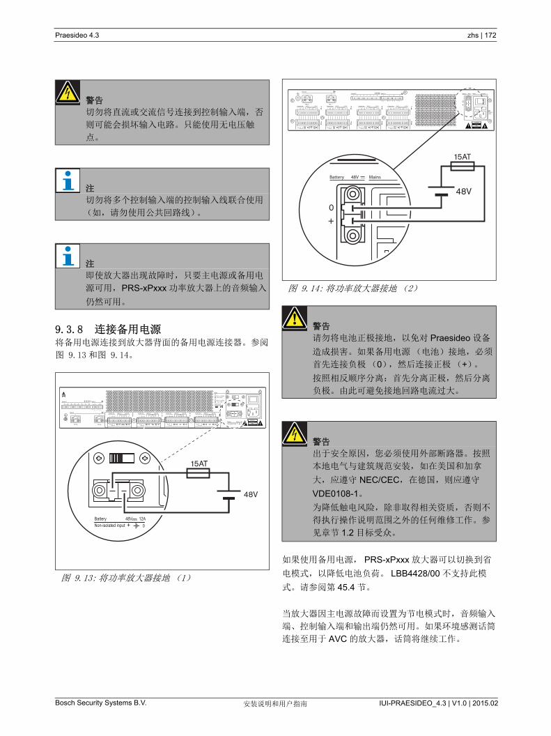
Praesideo 4.3 zhs | 172
Bosch Security Systems B.V. IUI-PRAESIDEO_4.3 | V1.0 | 2015.02安装说明和用户指南
9.3.8 连接备用电源将备用电源连接到放大器背面的备用电源连接器。参阅
图 9.13 和图 9.14。
如果使用备用电源, PRS-xPxxx 放大器可以切换到省
电模式,以降低电池负荷。 LBB4428/00 不支持此模
式。请参阅第 45.4 节。
当放大器因主电源故障而设置为节电模式时,音频输入
端、控制输入端和输出端仍然可用。如果环境感测话筒
连接至用于 AVC 的放大器,话筒将继续工作。
警告
切勿将直流或交流信号连接到控制输入端,否
则可能会损坏输入电路。只能使用无电压触
点。
注
切勿将多个控制输入端的控制输入线联合使用
(如,请勿使用公共回路线)。
注
即使放大器出现故障时,只要主电源或备用电
源可用,PRS-xPxxx 功率放大器上的音频输入
仍然可用。
图 9.13: 将功率放大器接地(1)
Control In1 2 3 4 5 6 7 8 1 2
Audio In
Network 1 2
++– –Control Out Spare In Lsp Out
C NO NC 0V 50V
4 3++– –
Control Out Spare In Lsp Out
C NO NC 0V 50V++– –Control Out Spare In Lsp Out
C NO NC 0V 50V
2 1++– –
Control Out Spare In Lsp Out
C NO NC 0V 50V
GroundedSignal Ground
Floating
Mains
48V 48V
Battery 48V 12ANon-isolated input 0+
115:100-120V 50-60Hz 230:220-240V 50-60Hz T6.3A 250V
T6.3A 250V
+ 0 – + 0 –
Class 2 Wiring Caution
AvisRisq of electric shock
Do not open
Risque de choc electrique.Ne pas ouvrir
Battery 48V 12ANon-isolated input 0+
48V
15AT
图 9.14: 将功率放大器接地(2)
警告
请勿将电池正极接地,以免对 Praesideo 设备
造成损害。如果备用电源(电池)接地,必须
首先连接负极(0),然后连接正极(+)。
按照相反顺序分离:首先分离正极,然后分离
负极。由此可避免接地回路电流过大。
警告
出于安全原因,您必须使用外部断路器。按照
本地电气与建筑规范安装, 如在美国和加拿
大,应遵守 NEC/CEC, 在德国,则应遵守
VDE0108-1。
为降低触电风险,除非取得相关资质,否则不
得执行操作说明范围之外的任何维修工作。参
见章节 1.2 目标受众。
11
22
3 4 5
48V
6 7 8 1 2 3 4
0 0
Control In Audio InNetwork
48V
2 4
48VBattery Mains
T6.3A H250V
100-240V
0 0
6 8
C
Control Out Spare In Lsp Out
NO NC 0V 50V
1 3C
Control Out Spare In Lsp Out
NO NC 0V 50V C
Control Out Spare In Lsp Out
NO NC 0V 50V C
Control Out Spare In Lsp Out
NO NC 0V 50V
5 7
Avis
CautionRisk of electric shock.
Do not open.
Risk of electric shock.Do not open.
0+
48VBattery Mains
48V
0+
15AT
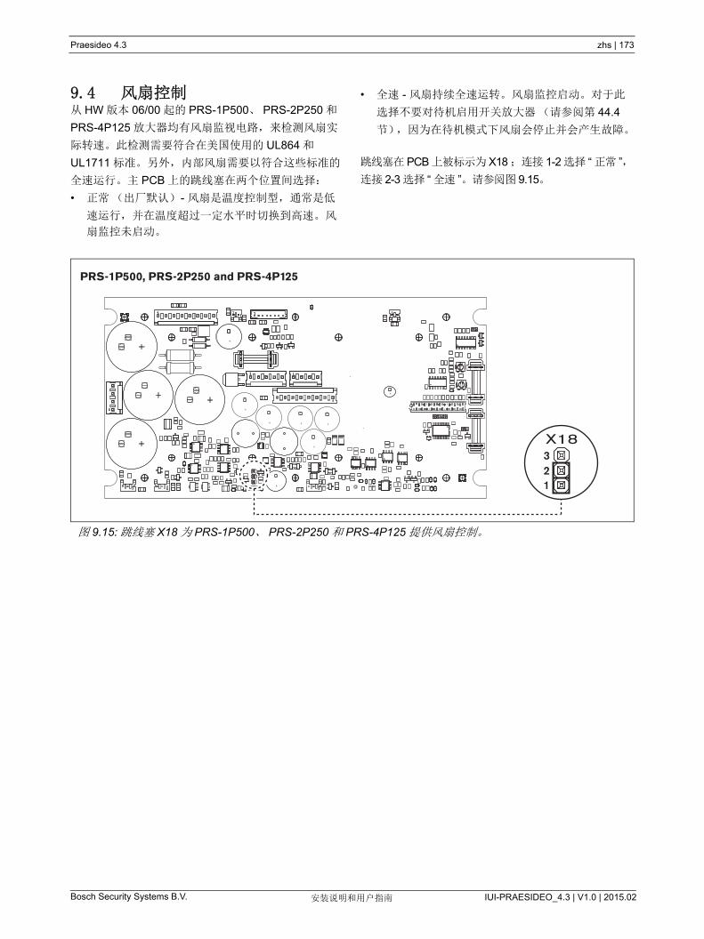
Praesideo 4.3 zhs | 173
Bosch Security Systems B.V. IUI-PRAESIDEO_4.3 | V1.0 | 2015.02安装说明和用户指南
9.4 风扇控制从 HW 版本 06/00 起的 PRS-1P500、 PRS-2P250 和
PRS-4P125 放大器均有风扇监视电路,来检测风扇实
际转速。此检测需要符合在美国使用的 UL864 和
UL1711 标准。另外,内部风扇需要以符合这些标准的
全速运行。主 PCB 上的跳线塞在两个位置间选择:
• 正常(出厂默认) - 风扇是温度控制型,通常是低
速运行,并在温度超过一定水平时切换到高速。风
扇监控未启动。
• 全速 - 风扇持续全速运转。风扇监控启动。对于此
选择不要对待机启用开关放大器(请参阅第 44.4
节),因为在待机模式下风扇会停止并会产生故障。
跳线塞在 PCB 上被标示为 X18 ;连接 1-2 选择 “ 正常 ”,
连接 2-3 选择 “ 全速 ”。请参阅图 9.15。
图 9.15: 跳线塞 X18 为 PRS-1P500、 PRS-2P250 和 PRS-4P125 提供风扇控制。
PRS-1P500, PRS-2P250 and PRS-4P125
123X18

Praesideo 4.3 zhs | 174
Bosch Security Systems B.V. IUI-PRAESIDEO_4.3 | V1.0 | 2015.02安装说明和用户指南
9.5 用于线路隔离器系统Praesideo 功率放大器还可以用于 Bosch 路线隔离器系
统,其包含 PM1 LISM6 主机和从设备 PM1-LISS 和
PM1-LISD。参考 PM1 LISM6 的安装和用户说明中的
详细信息。与 Praesideo 相结合的线路隔离器系统经
EN54-16 认证。
9.6 安装功率放大器适于桌上型或 19 英寸机柜式安装。设备出
厂时配有四个支脚(用于桌上型安装)和两个支架
(用于柜式安装)。
确保有足够的空间让冷气流流入功率放大器、暧气流流出
功率放大器。理想情况是,功率放大器安装在封闭的
19 英寸的机柜中,此机柜配有一个滤尘器保护下的冷气
流入口,可以防止灰尘进入设备(请参阅图 9.17)。
小心
由于功率放大器的重量,需要两个人抬起将其
安装在 19 英寸支架上。
图 9.16: 安装
图 9.17:19 英寸机柜内的气流
小心
在设备上安装支架时,请使用支架的随附螺丝
(四只长螺丝,两只短螺丝)。在每个支架的
正面使用两只螺纹长度为 7.5 mm 的螺丝,在
每个支架的背面使用一只螺纹长度为 5.2 mm
的螺丝。不得在正面位置使用螺纹长度为
10 mm 以上的螺丝;不得在背面位置使用螺纹
长度为 5.7 mm 以上的螺丝;较长的螺丝可能
接触或者损坏设备的内部部件。
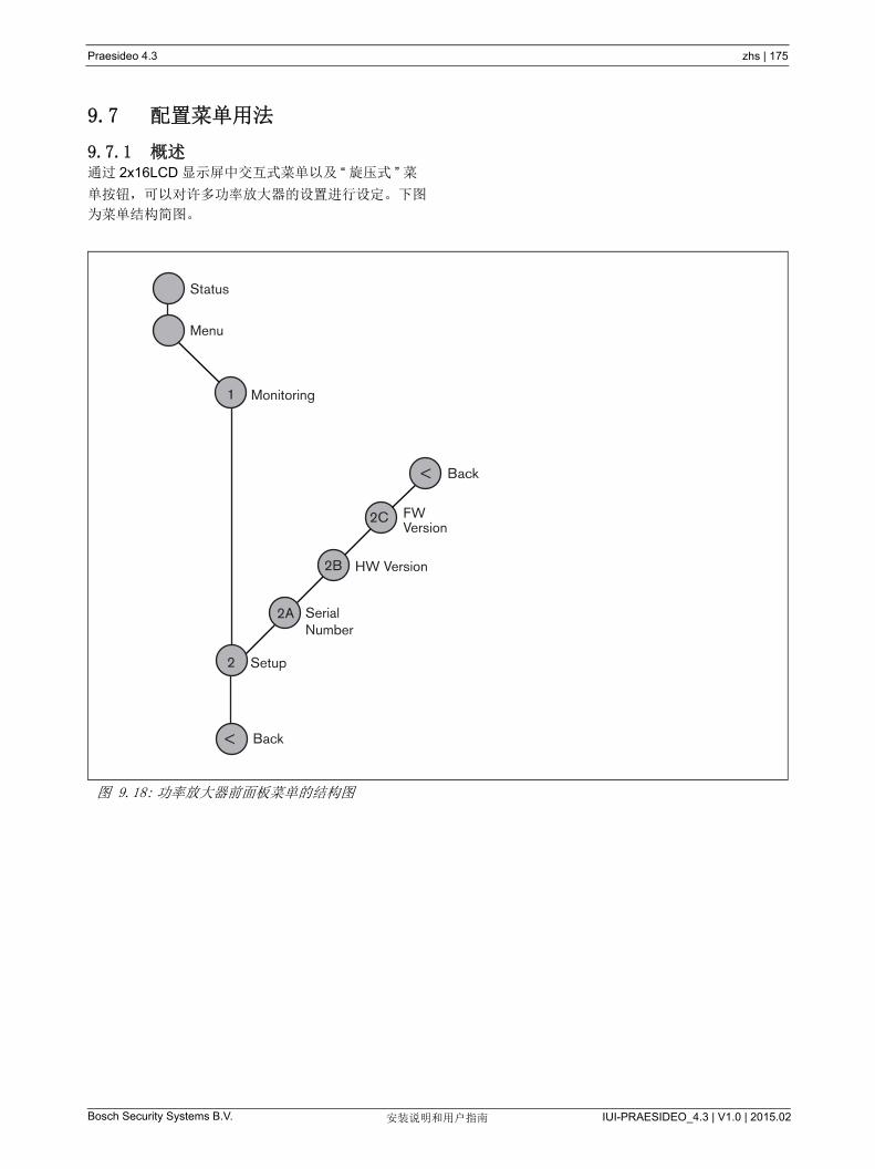
Praesideo 4.3 zhs | 175
Bosch Security Systems B.V. IUI-PRAESIDEO_4.3 | V1.0 | 2015.02安装说明和用户指南
9.7 配置菜单用法
9.7.1 概述通过 2x16LCD 显示屏中交互式菜单以及 “ 旋压式 ” 菜
单按钮,可以对许多功率放大器的设置进行设定。下图
为菜单结构简图。
图 9.18: 功率放大器前面板菜单的结构图
Status
Menu
Monitoring
Setup
HW Version
FWVersion
SerialNumber
Back
1
2
<
2A
2B
2C
Back<
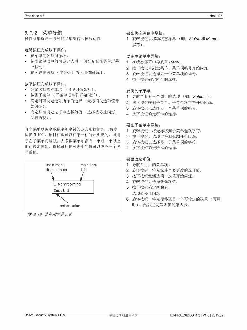
Praesideo 4.3 zhs | 176
Bosch Security Systems B.V. IUI-PRAESIDEO_4.3 | V1.0 | 2015.02安装说明和用户指南
9.7.2 菜单导航操作菜单就是一系列的菜单旋转和按压动作:
旋转按钮完成以下操作:
• 在菜单的各项间循环。
• 转到菜单项中的可设定选项(闪烁光标在菜单屏幕
上移动)。
• 在可设定选项(值闪烁)的可用值间循环。
按下按钮完成以下操件:
• 确定选择的菜单项(出现闪烁光标)。
• 转到子菜单(子菜单项字符开始闪烁)。
• 确定对可设定选项所作的选择(光标消失选项值开
始闪烁)。
• 确定从可设定选项中选择的值(选择值停止闪烁,
光标再现)。
每个菜单以数字或数字加字符的方式进行标识(请参
阅图 9.19)。项目标识可以在第一行的开头找到,可用
于在子菜单间导航。大多数菜单项都有一个或一个以上
的可设定选项。选择可用值列表中的值可以更改一个选
项的值。
要在状态屏幕中导航:
1 旋转按钮以移动状态屏幕(即:Status 和 Menu...
屏幕)。
要在主菜单中导航:
1 在状态屏幕中导航至 Menu...。
2 按下按钮转到主菜单。菜单项编号开始闪烁。
3 旋转按钮以选择另一个菜单项的编号。
4 按下按钮确定所作的选择。
要跳到子菜单:
1 导航至具有三个圆点的选项(如:Setup...)。
2 按下按钮转到子菜单。子菜单项字符开始闪烁。
3 旋转按钮以选择另一个菜单项的编号。
4 按下按钮确定所作的选择。
要在子菜单中导航:
1 旋转按钮,将光标移到子菜单选项字符。
2 按下按钮。选项字符和标题开始闪烁。
3 旋转按钮以选择另一子菜单项的字符。
4 按下按钮确定所作的选择。
要更改选项值:
1 导航至可用的菜单项。
2 旋转按钮,将光标移至要更改的选项值。
3 按下按钮激活选项。选项开始闪烁。
4 旋转按钮以选择新选项值。
5 按下按钮确定新的值。
选项值停止闪烁。
6 旋转按钮,将光标移至另一个可设定的选项(可用
时),然后重复第 3 步到第 5 步。
图 9.19: 菜单项屏幕元素
1 Monitoring
Input 1
main menuitem number
option value
main itemtitle
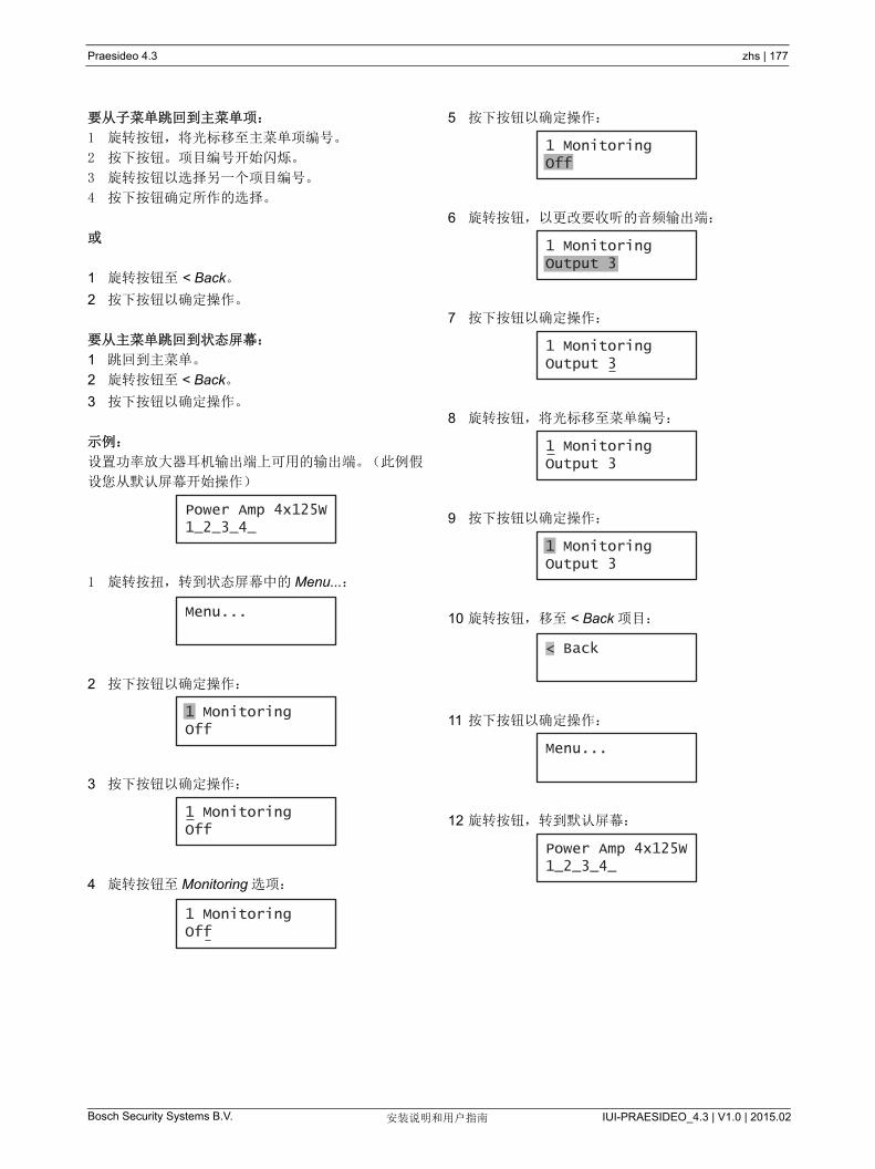
Praesideo 4.3 zhs | 177
Bosch Security Systems B.V. IUI-PRAESIDEO_4.3 | V1.0 | 2015.02安装说明和用户指南
要从子菜单跳回到主菜单项:
1 旋转按钮,将光标移至主菜单项编号。
2 按下按钮。项目编号开始闪烁。
3 旋转按钮以选择另一个项目编号。
4 按下按钮确定所作的选择。
或
1 旋转按钮至 < Back。
2 按下按钮以确定操作。
要从主菜单跳回到状态屏幕:
1 跳回到主菜单。
2 旋转按钮至 < Back。
3 按下按钮以确定操作。
示例:
设置功率放大器耳机输出端上可用的输出端。(此例假
设您从默认屏幕开始操作)
1 旋转按扭,转到状态屏幕中的 Menu...:
2 按下按钮以确定操作:
3 按下按钮以确定操作:
4 旋转按钮至 Monitoring 选项:
5 按下按钮以确定操作:
6 旋转按钮,以更改要收听的音频输出端:
7 按下按钮以确定操作:
8 旋转按钮,将光标移至菜单编号:
9 按下按钮以确定操作:
10 旋转按钮,移至 < Back 项目:
11 按下按钮以确定操作:
12 旋转按钮,转到默认屏幕:
Power Amp 4x125W1_2_3_4_
Menu...
1 MonitoringOff
1 MonitoringOff1 MonitoringOff
1 MonitoringOff
1 MonitoringOff
1 MonitoringOutput 3
1 MonitoringOutput 3
1 MonitoringOutput 3
1 MonitoringOutput 3
< Back
Menu...
Power Amp 4x125W1_2_3_4_
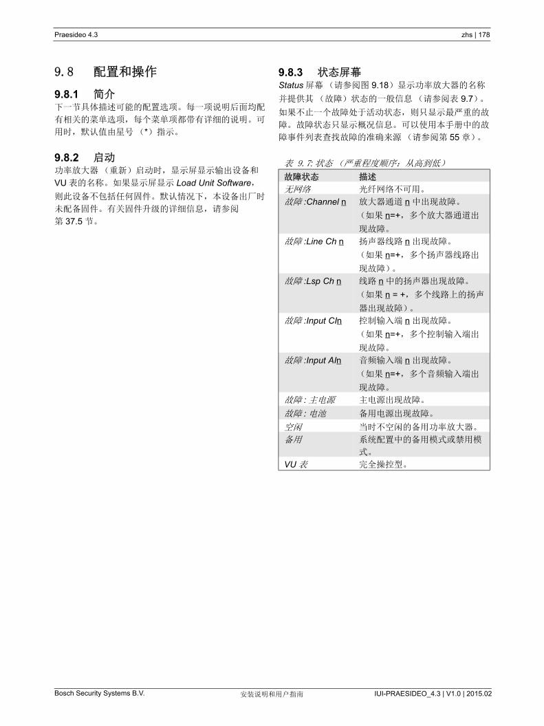
Praesideo 4.3 zhs | 178
Bosch Security Systems B.V. IUI-PRAESIDEO_4.3 | V1.0 | 2015.02安装说明和用户指南
9.8 配置和操作
9.8.1 简介下一节具体描述可能的配置选项。每一项说明后面均配
有相关的菜单选项,每个菜单项都带有详细的说明。可
用时,默认值由星号(*)指示。
9.8.2 启动功率放大器(重新)启动时,显示屏显示输出设备和
VU 表的名称。如果显示屏显示 Load Unit Software,
则此设备不包括任何固件。默认情况下,本设备出厂时
未配备固件。有关固件升级的详细信息,请参阅
第 37.5 节。
9.8.3 状态屏幕Status 屏幕(请参阅图 9.18)显示功率放大器的名称
并提供其(故障)状态的一般信息(请参阅表 9.7)。
如果不止一个故障处于活动状态,则只显示 严重的故
障。故障状态只显示概况信息。可以使用本手册中的故
障事件列表查找故障的准确来源(请参阅第 55 章)。
表 9.7: 状态(严重程度顺序:从高到低)
故障状态 描述
无网络 光纤网络不可用。
故障 :Channel n 放大器通道 n 中出现故障。
(如果 n=+,多个放大器通道出
现故障。
故障 :Line Ch n 扬声器线路 n 出现故障。
(如果 n=+,多个扬声器线路出
现故障)。
故障 :Lsp Ch n 线路 n 中的扬声器出现故障。
(如果 n = +,多个线路上的扬声
器出现故障)。
故障 :Input CIn 控制输入端 n 出现故障。
(如果 n=+,多个控制输入端出
现故障。
故障 :Input AIn 音频输入端 n 出现故障。
(如果 n=+,多个音频输入端出
现故障。
故障 : 主电源 主电源出现故障。
故障 : 电池 备用电源出现故障。
空闲 当时不空闲的备用功率放大器。
备用 系统配置中的备用模式或禁用模
式。
VU 表 完全操控型。

Praesideo 4.3 zhs | 179
Bosch Security Systems B.V. IUI-PRAESIDEO_4.3 | V1.0 | 2015.02安装说明和用户指南
9.8.4 主菜单通过 Menu... 项可以进入主菜单。
9.8.5 设置监控选项Monitoring 子菜单用于设置将哪个信号发送到监控耳
机。可以发送其中一个音频输出端上的信号,也可以根
本不发送任何信号。无法设置监控耳机上音频输出端的
音量。这意味着从音频输出端上听到声音始终与播放时
的音量相同。
9.8.6 查看版本信息Serial Number、 HW Version 和 SW Version 子菜单用
于获取功率放大器的相关版本信息。
表 9.8: 主菜单
菜单项 描述
1Monitoring 转到 Monitoring 子菜单。请参阅
第 9.8.5 节。
2 Setup 转到 Setup 子菜单。请参阅
第 9.8.6 节(及其它章节)。
表 9.9:Monitoring 子菜单
菜单项 选项 值 1 描述
1Monitoring 源:
- Output (输出端) n 输出端数:
1 至 8
音频输出端 n 的信号可用于监控耳机输出
端上。
- Off* 监控耳机输出端处于关闭状态。
表 9.10: 版本信息菜单项
菜单项 值(只读) 描述
2A Serial Number 例如:07.0.0025B 显示 16 进制序列号。
2B HW Version 例如:01.01 显示硬件版本。
2C FW Version 例如:3.00.1419 显示固件版本号。系统所有设备的固件版本号必须相同。

Praesideo 4.3 zhs | 180
Bosch Security Systems B.V. IUI-PRAESIDEO_4.3 | V1.0 | 2015.02安装说明和用户指南
9.9 技术数据
9.9.1 物理特性
9.9.2 气候条件
9.9.3 EMC和安全
9.9.4 平均无故障工作时间
9.9.5 系统总线
9.9.6 电源
9.9.7 备用电源
尺寸(高 x 宽 x 深):
88x483x400 mm (19 英寸安装,支架后部保持
360 mm 空间,前部保持 40 mm 空间)
92x440x400 mm (桌上型安装,已配有支脚)
重量:
PRS-1P500
13.7 kg
PRS-2P250
14.5 kg
PRS-4P125
16.1 kg
LBB4428/00
16.2 kg
温度:
-5 到 +55 °C (工作时)
-20 到 +70 °C (不工作时)
相对湿度:
15 到 90%,非冷凝(工作时)
5 到 95%,非冷凝(不工作时)
气压:
600 到 1100 hPa
电磁兼容性:
符合EN55103-1/FCC-47 标准中的 15B 部分
符合EN55103-2 标准
EN50121-4
EN50130-4
电气安全:
IEC60065 (CB-scheme)
EN60065
批准:
CE 标记
EN54-16 和 ISO7240-16
预期寿命:
+55 °C 时, 32,000 小时
MTBF:
500,000 小时
(根据实际返修率数据)
连接器(背面):
专用母连接器
首选电缆:
LBB4416/xx
大电缆长度:
50m (适用于每个系统总线连接器)
数据信号接口:
塑料光纤
网络功耗:
0 W
连接器(背面):
带有保险线盒的IEC公电源插槽
首选电缆:
符合 CE 标准的主电源线
电压选择器:
115 V(AC) / 230 V(AC),对于 PRS-xPxxx
额定输入电压范围:
PRS-xPxxx
115 V (典型值):100 - 120 V(AC), 50 - 60 Hz
230 V (典型值):220 - 240 V(AC), 50 - 60 Hz
LBB4428/00
100 - 240 V(AC), 50 - 60 Hz
输入电压限制:
PRS-xPxxx
115 V (典型值):90 - 132 V(AC), 50 - 60 Hz
230 V (典型值):198 - 264 V(AC), 50 - 60 Hz
LBB4428/00
90 - 264 V(AC), 50 - 60 Hz
打开 / 关闭开关:
位于背面
功率因数 (PF):
> 0.6 ( 用于 PRS-xPxxx)
> 0.95 (用于 LBB4428/00)
连接器(背面):
用于可拆卸式螺丝连接器的2极头
输入电压:
48 V (直流电)
输入电压范围:
43.5 到 56 V(DC)
额定输出功率的输入电压范围:
53 到 56 V (DC)
大电流:12 A
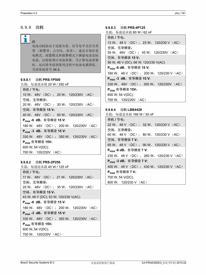
Praesideo 4.3 zhs | 181
Bosch Security Systems B.V. IUI-PRAESIDEO_4.3 | V1.0 | 2015.02安装说明和用户指南
9.9.8 功耗
9.9.8.1 功耗 PRS-1P500
负载:每通道承载 20 W / 250 nF
9.9.8.2 功耗 PRS-2P250
负载:每通道承载 40 W / 125 nF
9.9.8.3 功耗 PRS-4P125
负载:每通道承载 80 W / 62 nF
9.9.8.4 功耗 LBB4428
负载:每通道承载 166 W / 30 nF
注
电池功耗取决于连接负荷、信号电平及信号类
型(报警音、占空比、语音)。建议分别在省
电模式、闲置模式和报警模式下测量电池实际
电流,以检验预计电池容量。当计算电池容量
时,还应将考虑到使用过程中电池电量降低。
另请参阅章节 34.3。
待机 / 节电:
10 W, 48V (DC); 20 W, 120/230V (AC)
空闲,无导频音:
20 W, 48V (DC); 30 W, 120/230V (AC)
空闲,有导频音 15 V:
40 W, 48V (DC); 50 W, 120/230V (AC)
Pmax -6 dB,有导频音 15 V:
180 W, 48V (DC); 200 W, 120/230V (AC)
Pmax -3 dB,有导频音 15 V:
330 W, 48V (DC); 350 W, 120/230V (AC)
Pmax 有导频音 15V:
600 W, 54 V(DC);
700 W, 120/230V (AC)
待机 / 节电:
11 W, 48V (DC); 21 W, 120/230V (AC)
空闲,无导频音:
25 W, 48V (DC); 35 W, 120/230V (AC)
空闲,有导频音 15 V:
43 W, 48 V (DC); 53 W, 120/230 V(AC)
Pmax -6 dB,有导频音 15 V:
180 W, 48V (DC); 200 W, 120/230V (AC)
Pmax -3 dB,有导频音 15 V:
330 W, 48V (DC); 350 W, 120/230V (AC)
Pmax 有导频音 15V:
600 W, 54 V(DC);
700 W, 120/230V (AC)
待机 / 节电:
13 W, 48 V (DC); 23 W, 120/230 V (AC)
空闲,无导频音:
35 W, 48V (DC); 45 W, 120/230V (AC)
空闲,有导频音 15 V:
56 W, 48 V (DC); 66 W, 120/230 V(AC)
Pmax -6 dB,有导频音 15 V:
180 W, 48 V(DC); 200 W,120/230 V(AC)
Pmax -3 dB,有导频音 15 V:
330 W, 48V (DC); 350 W, 120/230V (AC)
Pmax 有导频音 15V:
600 W, 54 V(DC);
700 W, 120/230V (AC)
待机 / 节电:
22 W, 48 V (DC); 32 W, 120/230 V (AC)
空闲,无导频音:
60 W, 48 V (DC); 80 W, 120/230 V (AC)
空闲,有导频音 7 V:
65 W, 48 V (DC); 90 W, 120/230 V (AC)
Pmax -6 dB,有导频音 7 V:
230 W, 48 V(DC); 260 W,120/230 V(AC)
Pmax -3 dB,有导频音 7 V:
400 W, 48 V(DC); 430 W,120/230 V(AC)
Pmax 有导频音 7 V:
700 W, 54 V(DC);
800 W, 120/230 V (AC)
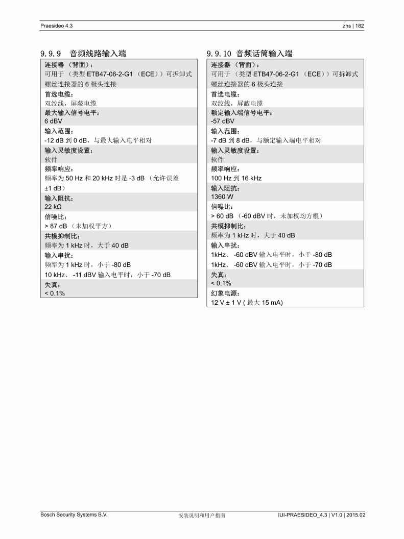
Praesideo 4.3 zhs | 182
Bosch Security Systems B.V. IUI-PRAESIDEO_4.3 | V1.0 | 2015.02安装说明和用户指南
9.9.9 音频线路输入端 9.9.10 音频话筒输入端
连接器(背面):
可用于(类型 ETB47-06-2-G1 (ECE))可拆卸式
螺丝连接器的 6 极头连接
首选电缆:
双绞线,屏蔽电缆
大输入信号电平:
6 dBV
输入范围:
-12 dB 到 0 dB,与 大输入电平相对
输入灵敏度设置:
软件
频率响应:
频率为 50 Hz 和 20 kHz 时是 -3 dB (允许误差
±1 dB)
输入阻抗:
22 kΩ
信噪比:
> 87 dB (未加权平方)
共模抑制比:
频率为 1 kHz 时,大于 40 dB
输入串扰:
频率为 1 kHz 时,小于 -80 dB
10 kHz、 -11 dBV 输入电平时,小于 -70 dB
失真:
< 0.1%
连接器(背面):
可用于(类型 ETB47-06-2-G1 (ECE))可拆卸式
螺丝连接器的 6 极头连接
首选电缆:
双绞线,屏蔽电缆
额定输入端信号电平:
-57 dBV
输入范围:
-7 dB 到 8 dB,与额定输入端电平相对
输入灵敏度设置:
软件
频率响应:
100 Hz 到 16 kHz
输入阻抗:
1360 W
信噪比:
> 60 dB (-60 dBV 时,未加权均方根)
共模抑制比:
频率为 1 kHz 时,大于 40 dB
输入串扰:
1kHz、 -60 dBV 输入电平时,小于 -80 dB
1kHz、 -60 dBV 输入电平时,小于 -70 dB
失真:
< 0.1%
幻象电源:
12 V ± 1 V ( 大 15 mA)

Praesideo 4.3 zhs | 183
Bosch Security Systems B.V. IUI-PRAESIDEO_4.3 | V1.0 | 2015.02安装说明和用户指南
9.9.11 扬声器输出端和备用输入端
a 1 kHz 且额定主电源或者电池电压大于 53 V 时,失
真小于 1%, 长 1 分钟(依据 IEC 60268-3)。
b 在 55 的环境温度下, 1 kHz 且主电源或者电池电
压大于 50 V 时,失真小于 1%, 长 1 分钟(依据
EN54-16)。
c 在 55 的环境温度下, 1 kHz 且电池电压为 48 V
时,失真小于 1%, 长 1 分钟。
d 报警音电平 - 在 55 的环境温度下, 1 kHz 且主电
源或电池电压大于 43.5 V 时,失真小于 0.3%,
长 30 分钟。
e 在 30 的环境温度下, 1 kHz 且主电源或电池电压
大于 43.5 V 时,失真小于 0.3%,连续。
f 在 55 °C 的环境温度下, 1 kHz 且主电源或电池电
压大于 43. 5V 时,失真小于 0.3%,连续。
连接器(背面):
1 个 9 极头(型号 ETB43-09-2-G1 (ECE)),配
有可拆卸式螺丝连接器(共用控制输出端)
电压:
100 V、 70 V、 50 V (跳线塞设置)
大无负载电压:
200 V 峰值
额定负载阻抗:
@ 100/70/50 V 输出
PRS-1P500
20/10/5 W
PRS-2P250
40/20/10 W
PRS-4P125
80/40/20 W
LBB4428
166/83/42 W
额定负载电容:
@ 100/70/50 V 输出
PRS-1P500
250/500/1000 nF
PRS-2P250
125/250/500 nF
PRS-4P125
60/125/250 nF
LBB4428
30/60/120 nF
额定输出功率:
在 a/b/c/d/e/f 工况下
PRS-1P500
1 x 500/425/275/185/185/125 W
PRS-2P250
2 x 250/210/150/105/105/60 W
PRS-4P125
4 x 125/105/65/60/60/30 W
LBB4428
8 x 60/50/40/30/30/15 W
失真:
1kHz 和 50% 的额定输出功率时,小于等于 0.3%
100% 输出功率时小于 1%
从无负载到全负载的输出调整:
50、 70 和 100V 输出频率小于 1.2 dB
频率响应:
60 Hz 到 19 kHz (-3 dB), -10 dB 的 大容性负
载和额定负载阻抗
功率带宽:
50% 的额定输出功率时, 60 Hz-19 kHz (-3 dB,
失真小于 1%)
信噪比:
导频音关闭时大于 85 dB(A)
放大器输出极限:
软削波
接地短路检测电阻:
<50 kΩ
噪声级:
1 m 时小于 NR35,半速风扇,桌上型
1 m 时小于 NR40,全速风扇,桌上型
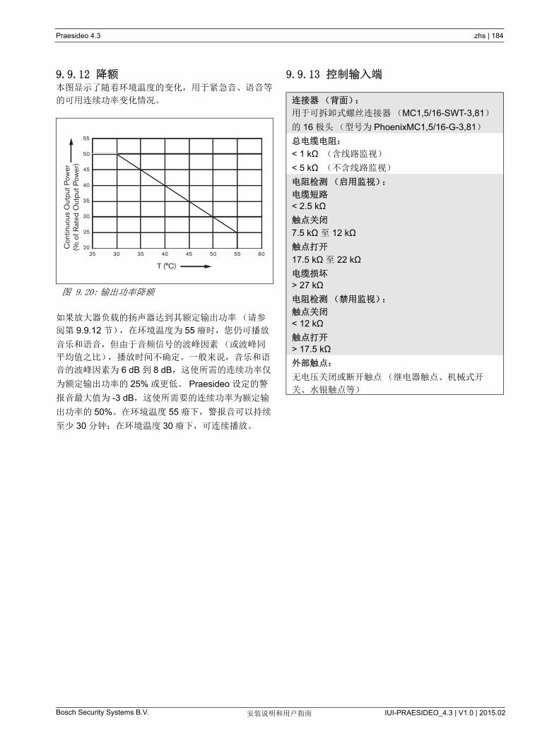
Praesideo 4.3 zhs | 184
Bosch Security Systems B.V. IUI-PRAESIDEO_4.3 | V1.0 | 2015.02安装说明和用户指南
9.9.12 降额本图显示了随着环境温度的变化,用于紧急音、语音等
的可用连续功率变化情况。
如果放大器负载的扬声器达到其额定输出功率(请参
阅第 9.9.12 节),在环境温度为 55 癈时,您仍可播放
音乐和语音,但由于音频信号的波峰因素(或波峰同
平均值之比),播放时间不确定。一般来说,音乐和语
音的波峰因素为 6 dB 到 8 dB,这使所需的连续功率仅
为额定输出功率的 25% 或更低。 Praesideo 设定的警
报音 大值为 -3 dB,这使所需要的连续功率为额定输
出功率的 50%。在环境温度 55 癈下,警报音可以持续
至少 30 分钟;在环境温度 30 癈下,可连续播放。
9.9.13 控制输入端
图 9.20: 输出功率降额
55
25 30 35 40 45 50 55 60
50
45
40
35
30
25
20Con
tinuo
us O
utpu
t Pow
er(%
of R
ated
Out
put P
ower
)
T (°C)
连接器(背面):
用于可拆卸式螺丝连接器(MC1,5/16-SWT-3,81)
的 16 极头(型号为 PhoenixMC1,5/16-G-3,81)
总电缆电阻:
< 1 kΩ (含线路监视)
< 5 kΩ (不含线路监视)
电阻检测(启用监视):
电缆短路
< 2.5 kΩ
触点关闭
7.5 kΩ 至 12 kΩ
触点打开
17.5 kΩ 至 22 kΩ
电缆损坏
> 27 kΩ
电阻检测(禁用监视):
触点关闭
< 12 kΩ
触点打开
> 17.5 kΩ
外部触点:
无电压关闭或断开触点(继电器触点、机械式开
关、水银触点等)
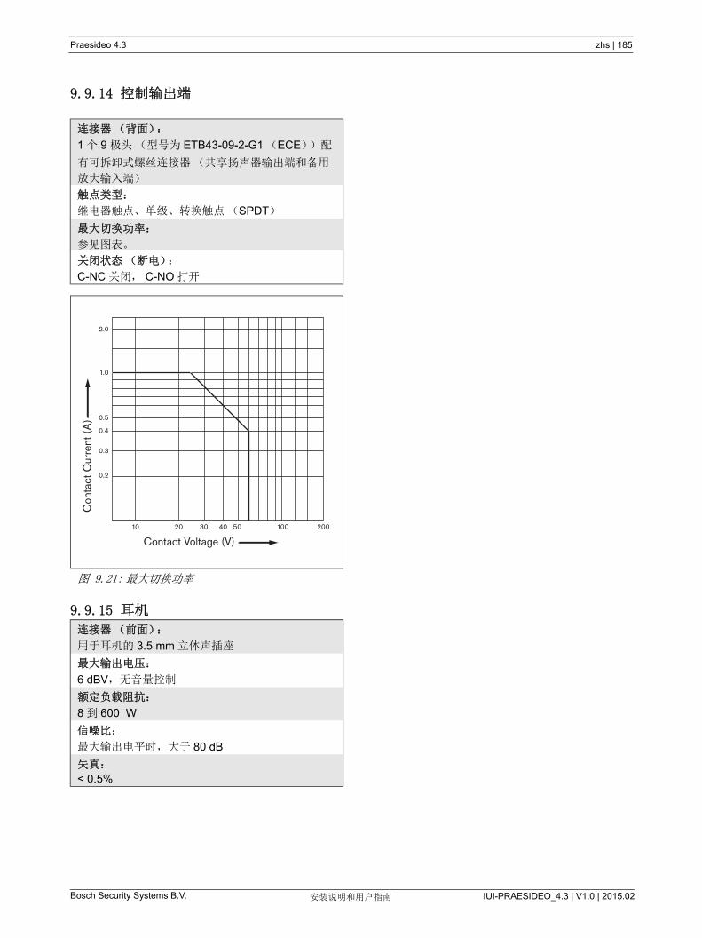
Praesideo 4.3 zhs | 185
Bosch Security Systems B.V. IUI-PRAESIDEO_4.3 | V1.0 | 2015.02安装说明和用户指南
9.9.14 控制输出端
9.9.15 耳机
连接器(背面):
1 个 9 极头(型号为 ETB43-09-2-G1 (ECE))配
有可拆卸式螺丝连接器(共享扬声器输出端和备用
放大输入端)
触点类型:
继电器触点、单级、转换触点(SPDT)
大切换功率:
参见图表。
关闭状态(断电):
C-NC 关闭, C-NO 打开
图 9.21: 大切换功率
连接器(前面):
用于耳机的 3.5 mm 立体声插座
大输出电压:
6 dBV,无音量控制
额定负载阻抗:
8 到 600 W
信噪比:
大输出电平时,大于 80 dB
失真:
< 0.5%
Con
tact
Cur
rent
(A
)
Contact Voltage (V)10 20 30 40 50 200100
0.2
0.3
0.4
0.5
1.0
2.0
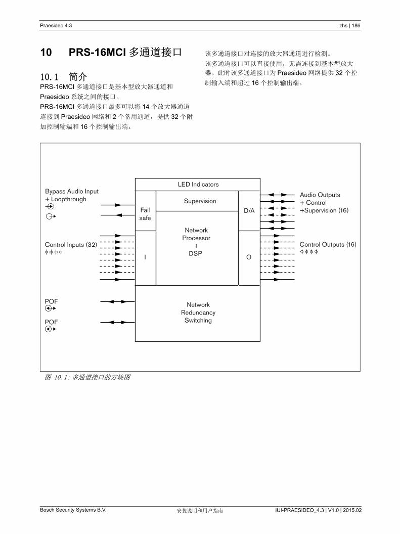
Praesideo 4.3 zhs | 186
Bosch Security Systems B.V. IUI-PRAESIDEO_4.3 | V1.0 | 2015.02安装说明和用户指南
10 PRS-16MCI 多通道接口
10.1 简介PRS-16MCI 多通道接口是基本型放大器通道和
Praesideo 系统之间的接口。
PRS-16MCI 多通道接口 多可以将 14 个放大器通道
连接到 Praesideo 网络和 2 个备用通道,提供 32 个附
加控制输端和 16 个控制输出端。
该多通道接口对连接的放大器通道进行检测。
该多通道接口可以直接使用,无需连接到基本型放大
器。此时该多通道接口为 Praesideo 网络提供 32 个控
制输入端和超过 16 个控制输出端。
图 10.1: 多通道接口的方块图
Failsafe
D/A
NetworkProcessor
+DSP
Bypass Audio Input+ Loopthrough
Control Inputs (32)
POF
POF
Control Outputs (16)
NetworkRedundancy
Switching
I O
LED Indicators
Audio Outputs+ Control+Supervision (16)
Supervision

Praesideo 4.3 zhs | 187
Bosch Security Systems B.V. IUI-PRAESIDEO_4.3 | V1.0 | 2015.02安装说明和用户指南
10.2 控制、连接和指示
10.2.1 前视图多通道接口的前面(请参见 图 10.2)包括以下组件:
1 放大器通道状态 - 音频通道指示器 1 至 14 指示已连
接放大器通道的状态。
2 备用通道状态 - 音频通道指示器 15 和 16 指示备用
通道的状态。
3 网络状态 - 网络的状态。
10.2.2 后视图多通道接口的后面(请参阅图 10.2)包括以下组件:
4 控制输入端 -32 个控制输入端可用于接收必须在
Praesideo 网络中触发动作的第三方设备的信号
(请参阅图 10.3.5)。
5 控制输出端 -16 个控制输出端可用于发送信号以触
发 Praesideo 网络生成的动作(请参阅第 10.3.6
节)。
6 系统总线 - 将多通道接口连接到其他 Praesideo 设
备的两个系统总线连接器。
7 旁路输入端 - 网络控制器的多通道接口旁路输入端。
请参见第 10.3.4 节。
8 旁路输出端 - 用于连接下一个多通道接口的多通道
接口旁路输出端。
9 放大器连接器 1-14- 连接到基本型放大器通道以提
供音频和控制信号,并接收功率和检测的连接设备
(请参阅第 10.3.2 节)。
10 放大器连接器 15-16- 连接到备用基本型放大器通道
的连接设备。
11 接地 - 将设备带电接地的连接器(请参阅第 10.3.7
节)。
图 10.2: 多通道接口的前视图和后视图
Network
1
1-8 9-16
17-24 25-32
2
1 2 3 4 5 6 7 8 9 10 11 12 13 14 15 16
48V48V
Bypass In Bypass Out
Praesideo Power Amplifiers Only Praesideo Power Amplifiers Only
C NC NO C NC NO C NC NO C NC NO C NC NO C NC NO C NC NO C NC NO
Control Out
1 2 3 4 5 6 7 8
C NC NO C NC NO C NC NO C NC NO C NC NO C NC NO C NC NO C NC NO
9 10 11 12 13 14 15 16
Control OutControl In
1 2 3 4 5 6 7 8
17 18 19 20 21 22 23 24
9 10 11 12 13 14 15 16
25 26 27 28 29 30 31 32
54321 6 7 8 9 10 11 12 13 14 15 16
13 2
8
4 5
6 7 9 1110
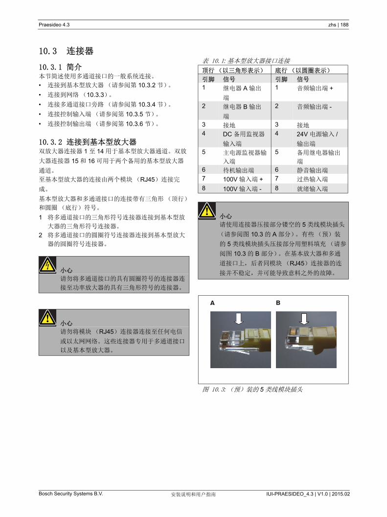
Praesideo 4.3 zhs | 188
Bosch Security Systems B.V. IUI-PRAESIDEO_4.3 | V1.0 | 2015.02安装说明和用户指南
10.3 连接器
10.3.1 简介本节简述使用多通道接口的一般系统连接。
• 连接到基本型放大器(请参阅第 10.3.2 节)。
• 连接到网络(10.3.3)。
• 连接多通道接口旁路(请参阅第 10.3.4 节)。
• 连接控制输入端(请参阅第 10.3.5 节)。
• 连接控制输出端(请参阅第 10.3.6 节)。
10.3.2 连接到基本型放大器双放大器连接器 1 至 14 用于基本型放大器通道。双放
大器连接器 15 和 16 可用于两个备用的基本型放大器
通道。
至基本型放大器的连接由两个模块(RJ45)连接完
成。
基本型放大器和多通道接口的连接带有三角形(顶行)
和圆圈(底行)符号。
1 将多通道接口的三角形符号连接器连接到基本型放
大器的三角形符号连接器。
2 将多通道接口的圆圈符号连接器连接到基本型放大
器的圆圈符号连接器。
小心
请勿将多通道接口的具有圆圈符号的连接器连
接至功率放大器的具有三角形符号的连接器。
小心
请勿将模块(RJ45)连接器连接至任何电信
或以太网网络。这些连接器专用于多通道接口
以及基本型放大器。
表 10.1: 基本型放大器接口连接
顶行(以三角形表示) 底行(以圆圈表示)
引脚 信号 引脚 信号
1 继电器 A 输出
端
1 音频输出端 +
2 继电器 B 输出
端
2 音频输出端 -
3 接地 3 接地
4 DC 备用监视器
输入端
4 24V 电源输入 /
输出端
5 主电源监视器输
入端
5 备用继电器输出
端
6 待机输出端 6 静音输出端
7 100V 输入端 + 7 过热输入端
8 100V 输入端 - 8 就绪输入端
小心
请使用连接器压接部分镂空的 5 类线模块插头
(请参阅图 10.3 的 A 部分)。有些(预)装
的 5 类线模块插头压接部分用塑料填充(请参
阅图 10.3 的 B 部分)。在基本放大器和多通
道接口上,后者同模块(RJ45)连接器的连
接并不稳定,并可能导致意料之外的故障。
图 10.3: (预)装的 5 类线模块插头
BA
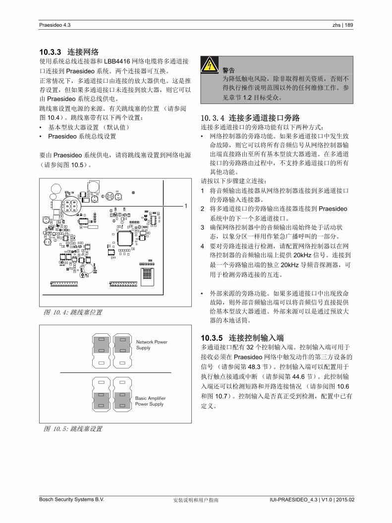
Praesideo 4.3 zhs | 189
Bosch Security Systems B.V. IUI-PRAESIDEO_4.3 | V1.0 | 2015.02安装说明和用户指南
10.3.3 连接网络使用系统总线连接器和 LBB4416 网络电缆将多通道接
口连接到 Praesideo 系统。两个连接器可互换。
正常情况下,多通道接口由连接的放大器供电。这是推
荐设置,但如果多通道接口未连接到放大器,则它可以
由 Praesideo 系统总线供电。
跳线塞设置电源的来源。有关跳线塞的位置(请参阅
图 10.4)。跳线塞带有以下两个设置:
• 基本型放大器设置(默认值)
• Praesideo 系统总线设置
要由 Praesideo 系统供电,请将跳线塞设置到网络电源
(请参阅图 10.5)。
10.3.4 连接多通道接口旁路连接多通道接口的旁路功能有以下两种方式:
• 网络控制器的旁路功能。如果多通道接口中发生致
命故障,则它可以将所有音频信号从网络控制器输
出端直接路由至所有基本型放大器通道。在多通道
接口的旁路路由过程中,不支持多通道接口的所有
其他功能。
请按以下步骤建立连接:
1 将音频输出连接器从网络控制器连接到多通道接口
的旁路输入连接器。
2 将多通道接口的旁路输出连接器连接到 Praesideo
系统中的下一个多通道接口。
3 确保网络控制器中的音频输出端始终处于活动状
态,以象分区一样用作紧急广播呼叫的一部分。
4 要对旁路连接进行检测,请配置网络控制器以在网
络控制器的音频输出端上提供 20kHz 信号。连接到
一个旁路输出端的独立 20kHz 导频音探测器,可
用于检测旁路连接的互连。
• 外部来源的旁路功能。如果多通道接口中出现致命
故障,则外部音频输出端可以将音频信号直接提供
给基本型放大器通道。外部来源可以是通过预放大
器的本地话筒。
10.3.5 连接控制输入端多通道接口配有 32 个控制输入端。控制输入端可用于
接收必须在 Praesideo 网络中触发动作的第三方设备的
信号(请参阅第 48.3 节)。控制输入端可以配置用于
执行触点接通或中断(请参阅第 44.6 节)。此控制输
入端还可以检测短路和开路连接情况(请参阅图 10.6
和图 10.7)。控制输入是否真正受到检测,配置中已有
定义。
图 10.4: 跳线塞位置
图 10.5: 跳线塞设置
1
Network PowerSupply
Basic AmplifierPower Supply
警告
为降低触电风险,除非取得相关资质,否则不
得执行操作说明范围以外的任何维修工作。 参
见章节 1.2 目标受众。
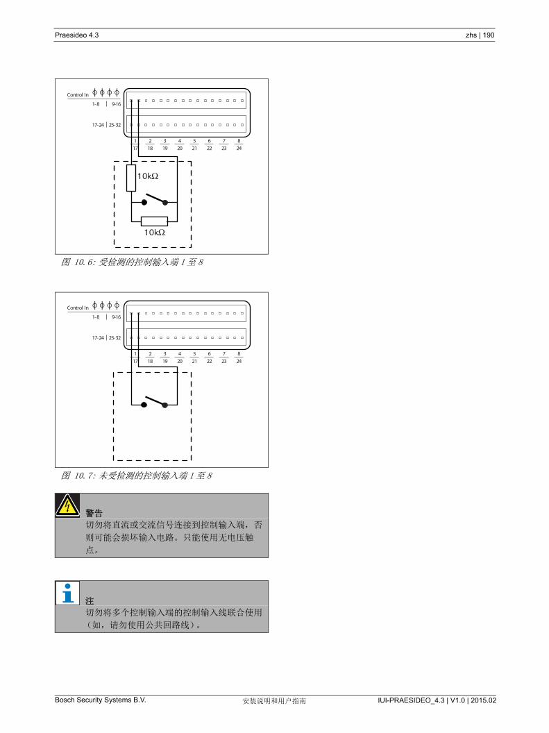
Praesideo 4.3 zhs | 190
Bosch Security Systems B.V. IUI-PRAESIDEO_4.3 | V1.0 | 2015.02安装说明和用户指南
图 10.6: 受检测的控制输入端 1至 8
图 10.7: 未受检测的控制输入端 1至 8
警告
切勿将直流或交流信号连接到控制输入端,否
则可能会损坏输入电路。只能使用无电压触
点。
注
切勿将多个控制输入端的控制输入线联合使用
(如,请勿使用公共回路线)。
1-8 9-16
17-24 25-32
Control In
1 2 3 4 5 6 7 8
17 18 19 20 21 22 23 24
10kΩ
10kΩ
1-8 9-16
17-24 25-32
Control In
1 2 3 4 5 6 7 8
17 18 19 20 21 22 23 24
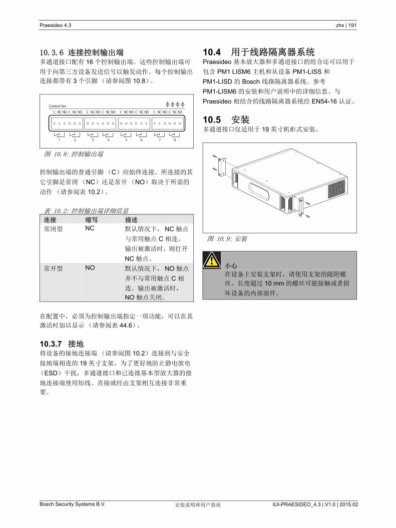
Praesideo 4.3 zhs | 191
Bosch Security Systems B.V. IUI-PRAESIDEO_4.3 | V1.0 | 2015.02安装说明和用户指南
10.3.6 连接控制输出端多通道接口配有 16 个控制输出端。这些控制输出端可
用于向第三方设备发送信号以触发动作。每个控制输出
连接都带有 3 个引脚(请参阅图 10.8)。
控制输出端的普通引脚(C)应始终连接。所连接的其
它引脚是常闭(NC)还是常开(NO)取决于所需的
动作(请参阅表 10.2)。
在配置中,必须为控制输出端指定一项功能,可以在其
激活时加以显示(请参阅表 44.6)。
10.3.7 接地将设备的接地连接端(请参阅图 10.2)连接到与安全
接地端相连的 19 英寸支架。为了更好地防止静电放电
(ESD)干扰,多通道接口和已连接基本型放大器的接
地连接端使用短线、直接或经由支架相互连接非常重
要。
10.4 用于线路隔离器系统Praesideo 基本放大器和多通道接口的组合还可以用于
包含 PM1 LISM6 主机和从设备 PM1-LISS 和
PM1-LISD 的 Bosch 线路隔离器系统。参考
PM1-LISM6 的安装和用户说明中的详细信息。与
Praesideo 相结合的线路隔离器系统经 EN54-16 认证。
10.5 安装多通道接口仅适用于 19 英寸机柜式安装。
图 10.8: 控制输出端
表 10.2: 控制输出端详细信息
连接 缩写 描述
常闭型 NC 默认情况下, NC 触点
与常用触点 C 相连。
输出被激活时,则打开
NC 触点。
常开型 NO 默认情况下, NO 触点
并不与常用触点 C 相
连。输出被激活时,
NO 触点关闭。
C NC NO C NC NO C NC NO C NC NO C NC NO C NC NO C NC NO C NC NO
Control Out
1 2 3 4 5 6 7 8
图 10.9: 安装
小心
在设备上安装支架时,请使用支架的随附螺
丝。长度超过 10 mm 的螺丝可能接触或者损
坏设备的内部部件。

Praesideo 4.3 zhs | 192
Bosch Security Systems B.V. IUI-PRAESIDEO_4.3 | V1.0 | 2015.02安装说明和用户指南
10.6 配置和操作
10.6.1 概述多通道接口具有以下功能:
• 在多通道接口启动以后将旁路模式更改为正常模
式。请参阅 10.6.2。
• 监视每个基本型放大器的状态。请参阅 10.6.3。
• 监视基本型放大器的电源。
• 监视线路和扬声器检测设备。
• 如果放大器通道出现故障,决定是否启用备用放大
器。请参阅 10.6.3。
• 将基本型放大器的模式更改为节电模式(若需
要)。请参阅第 45 章)。
10.6.2 失效安全在默认或未供电状态下,旁路输入端切换到基本型放大
器通道。在电源打开或连网时,多通道接口将转到正常
操作。
10.6.3 多通道接口和基本型放大器协作多通道接口监视基本型放大器的功能。在某些条件下,
基本型放大器通道发生故障时,将设置备用放大器通道
作为主放大器通道。
发生故障的主放大器不必用于将用作主放大器的备用放
大器。软件确保备用放大器通道和它替换的主放大器通
道具有相同的设置。如果主放大器通道在此配置中禁
用,则备用放大器通道不会成为主放大器通道。
备用放大器通道替换的主放大器通道数将不会超过 1
个。如果备用通道已经用作主通道,并且另一个主通道
报告故障,则第二个主通道将被放在备用放大器通道的
等待列表上。如果连接到相同备用通道的主通道数超过
2 个,则报告故障的第一个放大器通道将接收备用通
道。
在第一个放大器通道可以再次使用时,备用通道将替换
第二个主通道的功能,直到第二个主通道可用。
10.6.4 多通道接口与线路隔离器系统协作要实现包含了 PM1-LISM6 主机和从设备 PM1-LISS 和
PM1-LISD 的线路隔离器系统的正常运行,多通道接口
PRS-16MCI 必须具有 HW 04/15 或更新的硬件版本。
较旧的硬件版本将会发生接地短路故障。此外,
Praesideo 软件版本应为 4.1 或更高。
10.6.5 前面板 LED 指示多通道接口的前面板配有显示已连接放大器通道状态和
网络状态的 LED 指示灯。有关 LED 状态的描述,请参
阅表 10.3 和表 10.4。
表 10.3: 状态 LED 指示灯
通道 LED 指
示灯
基本型放大器通道
绿色 通道在配置中已启用,无故障
黄色 通道在配置中已启用,有故障(即
使操作者未对故障进行确认或重
置,解决故障时,LED 将再次变为
绿色。
关 通道在配置中已禁用或未配置
表 10.4: 网络 LED 指示灯
网络 LED 指
示灯
多通道接口
绿色 已连接网络
黄色 与网络断开连接
关 断开电源
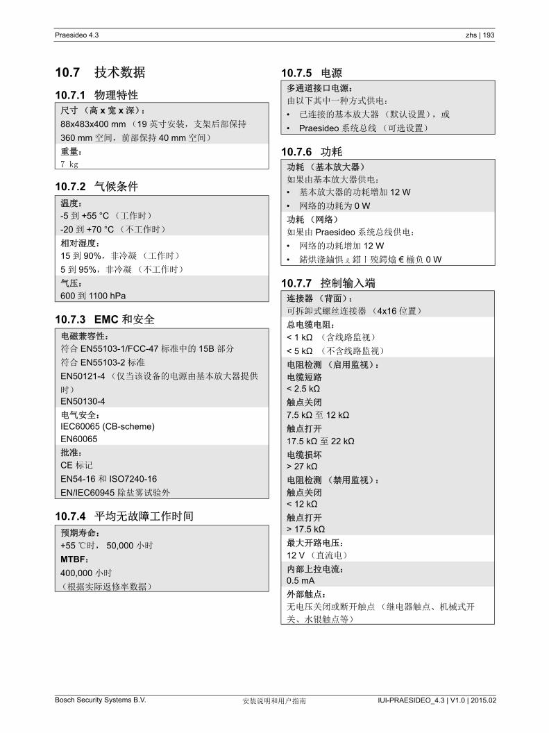
Praesideo 4.3 zhs | 193
Bosch Security Systems B.V. IUI-PRAESIDEO_4.3 | V1.0 | 2015.02安装说明和用户指南
10.7 技术数据
10.7.1 物理特性
10.7.2 气候条件
10.7.3 EMC 和安全
10.7.4 平均无故障工作时间
10.7.5 电源
10.7.6 功耗
10.7.7 控制输入端
尺寸(高 x 宽 x 深):
88x483x400 mm (19 英寸安装,支架后部保持
360 mm 空间,前部保持 40 mm 空间)
重量:
7 kg
温度:
-5 到 +55 °C (工作时)
-20 到 +70 °C (不工作时)
相对湿度:
15 到 90%,非冷凝(工作时)
5 到 95%,非冷凝(不工作时)
气压:
600 到 1100 hPa
电磁兼容性:
符合 EN55103-1/FCC-47 标准中的 15B 部分
符合 EN55103-2 标准
EN50121-4 (仅当该设备的电源由基本放大器提供
时)
EN50130-4
电气安全:
IEC60065 (CB-scheme)
EN60065
批准:
CE 标记
EN54-16 和 ISO7240-16
EN/IEC60945 除盐雾试验外
预期寿命:
+55 时, 50,000 小时
MTBF:
400,000 小时
(根据实际返修率数据)
多通道接口电源:
由以下其中一种方式供电:
• 已连接的基本放大器(默认设置),或
• Praesideo 系统总线(可选设置)
功耗(基本放大器)
如果由基本放大器供电:
• 基本放大器的功耗增加 12 W
• 网络的功耗为 0 W
功耗(网络)
如果由 Praesideo 系统总线供电:
• 网络的功耗增加 12 W
• 鍩烘湰鏀惧ぇ鍣ㄧ殑鍔熻 € 椾负 0 W
连接器(背面):
可拆卸式螺丝连接器(4x16 位置)
总电缆电阻:
< 1 kΩ (含线路监视)
< 5 kΩ (不含线路监视)
电阻检测(启用监视):
电缆短路
< 2.5 kΩ
触点关闭
7.5 kΩ至 12 kΩ
触点打开
17.5 kΩ 至 22 kΩ
电缆损坏
> 27 kΩ
电阻检测(禁用监视):
触点关闭
< 12 kΩ
触点打开
> 17.5 kΩ
大开路电压:
12 V (直流电)
内部上拉电流:
0.5 mA
外部触点:
无电压关闭或断开触点(继电器触点、机械式开
关、水银触点等)
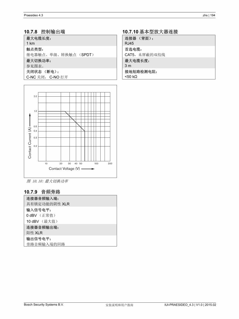
Praesideo 4.3 zhs | 194
Bosch Security Systems B.V. IUI-PRAESIDEO_4.3 | V1.0 | 2015.02安装说明和用户指南
10.7.8 控制输出端
10.7.9 音频旁路
10.7.10 基本型放大器连接
大电缆长度:
1 km
触点类型:
继电器触点、单级、转换触点(SPDT)
大切换功率:
参见图表。
关闭状态(断电):
C-NC 关闭, C-NO 打开
图 10.10: 大切换功率
连接器音频输入端:
具有锁定功能的阴性 XLR
输入信号电平:
0 dBV (正常值)
10 dBV ( 大值)
连接器音频输出端:
阳性 XLR
输出信号电平:
旁路音频输入端的回路
Con
tact
Cur
rent
(A
)
Contact Voltage (V)10 20 30 40 50 200100
0.2
0.3
0.4
0.5
1.0
2.0
连接器(背面):
RJ45
首选电缆:
CAT5,未屏蔽的双绞线
大电缆长度:
3 m
接地短路检测电阻:
<50 kΩ
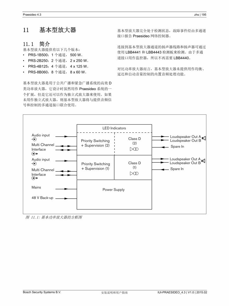
Praesideo 4.3 zhs | 195
Bosch Security Systems B.V. IUI-PRAESIDEO_4.3 | V1.0 | 2015.02安装说明和用户指南
11 基本型放大器
11.1 简介基本型放大器提供有以下几个版本:
• PRS-1B500:1 个通道, 500 W。
• PRS-2B250:2 个通道, 2 x 250 W。
• PRS-4B125:4 个通道, 4 x 125 W。
• PRS-8B060:8 个通道, 8 x 60 W。
基本型放大器是用于公共广播和紧急广播系统的高效 D
类功率放大器,它设计时虽然用作 Praesideo 系统的一
个扩展,但是它还可以作为独立式放大器来使用。如果
未用作独立式放大器,则基本型放大器将与提供音频信
号和控制的多通道接口联合使用。
基本型放大器完全处于检测状态,故障事件经由多通道
接口报告 Praesideo 网络控制器。
连接到基本型放大器通道的扬声器线路和扬声器可通过
使用 LBB4441 和 LBB4443 检测板来检测。由于多通
道接口用作监控器,所以不再需要 LBB4440。
对比功率放大器而言,基本型放大器未提供用作均衡、
延迟和自动音量控制的内置音频处理功能。
图 11.1: 基本功率放大器的方框图
LED Indicators
Loudspeaker Out AAudio input
Power Supply
Multi Channel Interface
Audio input
Multi Channel Interface
Priority Switching+ Supervision (2)
Priority Switching+ Supervision (1)
Loudspeaker Out B
Spare In
Loudspeaker Out ALoudspeaker Out B
Spare In
Mains
48 V Back-up
Class D(2)
Class D(1)
Praesideo 4.3 zhs | 196
Bosch Security Systems B.V. IUI-PRAESIDEO_4.3 | V1.0 | 2015.02安装说明和用户指南
11.2 控制、连接和指示
11.2.1 前面基本放大器的前视图(请参阅图 11.2)包括以下组
件:
1 主电源状态 - 显示主电源连接和电源的状态(请参
阅第 11.6 节)。
2 电池状态 - 显示电池备用电源的状态(请参阅
第 11.6 节)。
3 放大器状态 - 显示每个音频输出通道的音频电平和
状态(请参阅第 11.6 节)。
11.2.2 后面基本放大器的后面(请参阅图 11.2)包括以下组件:
4 音频输入端 - 本地音频输入端(请参阅第 11.3.6
节)。
5 灵敏度控制 - 本地音频输入端音量的电位计(请参
阅第 11.3.6 节)。
6 MCI-2xJ145-8 引脚多通道接口连接(请参阅
第 11.3.3 节)。
7 备用输入端 - 备用放大器通道的备用切换输入端
(请参阅第 11.3.5.3 节)。
8 LSP 输出端 - 连接至扬声器的 A 和 B 输出端(请参
阅第 11.3.5 节)。
9 检测 - 主电源和电池检测
10 信号接地端 - 将信号接地端连接至安全接地端的开
关(请参阅第 11.3.4 节)。
11 备用电源 - 连接备用电源的插座(请参阅第 11.3.7
节)。
12 主电源插槽 - 将放大器连接至主电源的主电源插槽
(请参阅第 11.3.2 节)。
13 电压选择器 - 选择本地主电源电压的开关(请参阅
第 11.3.2 节)。
14 接地端 - 将设备带电接电的连接器(请参阅
第 11.3.4 节)。

Praesideo 4.3 zhs | 197
Bosch Security Systems B.V. IUI-PRAESIDEO_4.3 | V1.0 | 2015.02安装说明和用户指南
图 11.2: 基本放大器的前视图和后视图
1
1
2
Battery 48V
0+0+0+
0+
115/230V
Audio InMCI MCI
MCI
Audio In
21
Only MCI Only A B A B–– –
+ –+ –+ –+ –+ –+ –
Spare In
Class 2 wiring
Lsp OutSpare In Lsp Out
1 2 Grounded
Signal Ground
Floating
Mains
115:100-120V 50-60Hz T6.3A H 250V
230:220-240V 50-60Hz T6.3A H 250V
On
SupervisionMainsBattery
PRS-xBxxxBasic Amplifier
PRS-1B500, PRS-2B250Basic Amplifier
PRS-4B125Basic Amplifier
PRS-8B060Basic Amplifier
1
4 6 7 8 95
2 3
4 65
4 65
121110
13
7 8 13 14
7 8 13 14
14
9 121110
9 121110
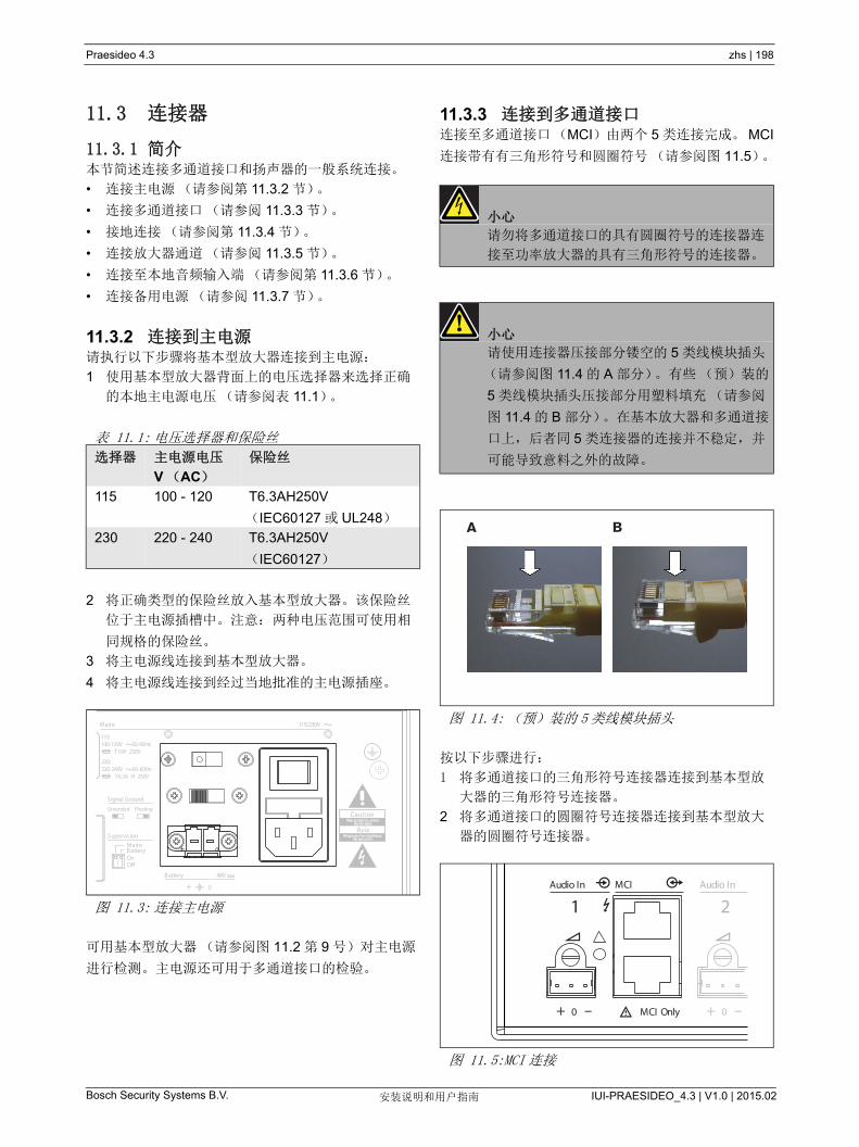
Praesideo 4.3 zhs | 198
Bosch Security Systems B.V. IUI-PRAESIDEO_4.3 | V1.0 | 2015.02安装说明和用户指南
11.3 连接器
11.3.1 简介本节简述连接多通道接口和扬声器的一般系统连接。
• 连接主电源(请参阅第 11.3.2 节)。
• 连接多通道接口(请参阅 11.3.3 节)。
• 接地连接(请参阅第 11.3.4 节)。
• 连接放大器通道(请参阅 11.3.5 节)。
• 连接至本地音频输入端(请参阅第 11.3.6 节)。
• 连接备用电源(请参阅 11.3.7 节)。
11.3.2 连接到主电源请执行以下步骤将基本型放大器连接到主电源:
1 使用基本型放大器背面上的电压选择器来选择正确
的本地主电源电压(请参阅表 11.1)。
2 将正确类型的保险丝放入基本型放大器。该保险丝
位于主电源插槽中。注意: 两种电压范围可使用相
同规格的保险丝。
3 将主电源线连接到基本型放大器。
4 将主电源线连接到经过当地批准的主电源插座。
可用基本型放大器(请参阅图 11.2 第 9 号)对主电源
进行检测。主电源还可用于多通道接口的检验。
11.3.3 连接到多通道接口连接至多通道接口(MCI)由两个 5 类连接完成。 MCI
连接带有有三角形符号和圆圈符号(请参阅图 11.5)。
按以下步骤进行:
1 将多通道接口的三角形符号连接器连接到基本型放
大器的三角形符号连接器。
2 将多通道接口的圆圈符号连接器连接到基本型放大
器的圆圈符号连接器。
表 11.1: 电压选择器和保险丝
选择器 主电源电压
V (AC)
保险丝
115 100 - 120 T6.3AH250V
(IEC60127 或 UL248)
230 220 - 240 T6.3AH250V
(IEC60127)
图 11.3: 连接主电源
Battery 48V
0+
0+
115/230V
Grounded
Signal Ground
Floating
Mains
115:100-120V 50-60Hz T10A 250V
230:220-240V 50-60Hz T6.3A H 250V
On
Supervision
MainsBattery
小心
请勿将多通道接口的具有圆圈符号的连接器连
接至功率放大器的具有三角形符号的连接器。
小心
请使用连接器压接部分镂空的 5 类线模块插头
(请参阅图 11.4 的 A 部分)。有些(预)装的
5 类线模块插头压接部分用塑料填充(请参阅
图 11.4 的 B 部分)。在基本放大器和多通道接
口上,后者同 5 类连接器的连接并不稳定,并
可能导致意料之外的故障。
图 11.4: (预)装的 5类线模块插头
图 11.5:MCI 连接
BA
0+0+
Audio InMCI
MCI
Audio In
21
Only ––
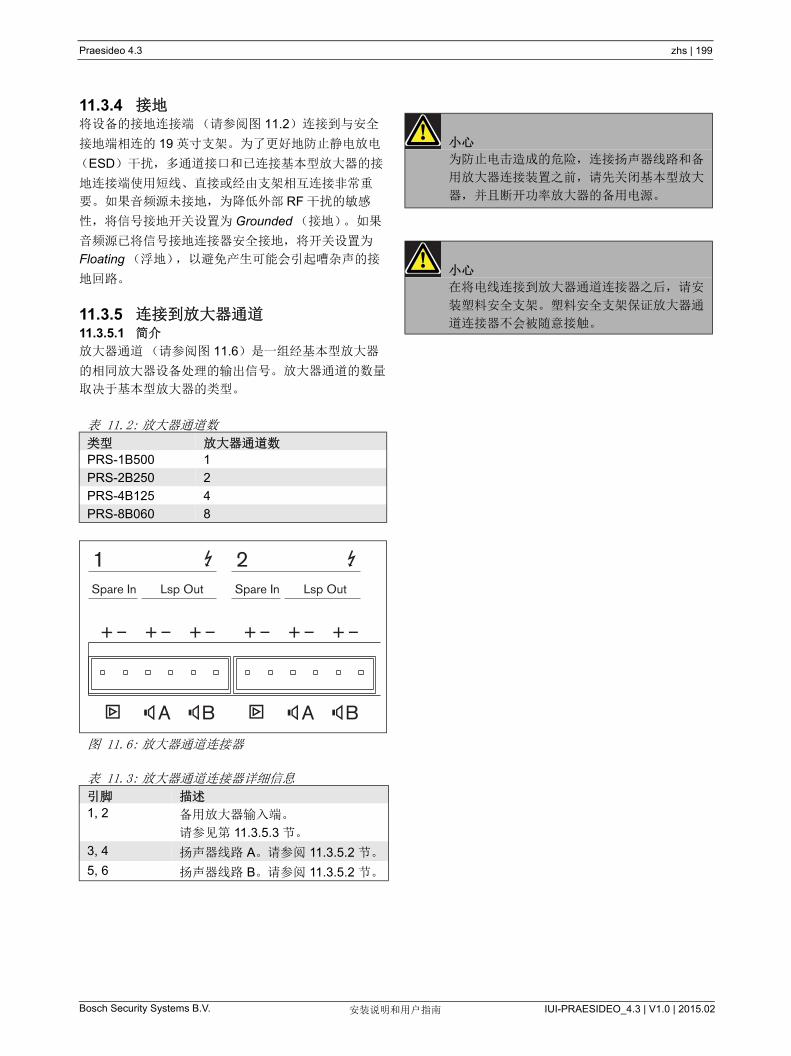
Praesideo 4.3 zhs | 199
Bosch Security Systems B.V. IUI-PRAESIDEO_4.3 | V1.0 | 2015.02安装说明和用户指南
11.3.4 接地将设备的接地连接端(请参阅图 11.2)连接到与安全
接地端相连的 19 英寸支架。为了更好地防止静电放电
(ESD)干扰,多通道接口和已连接基本型放大器的接
地连接端使用短线、直接或经由支架相互连接非常重
要。如果音频源未接地,为降低外部 RF 干扰的敏感
性,将信号接地开关设置为 Grounded (接地)。如果
音频源已将信号接地连接器安全接地,将开关设置为
Floating (浮地),以避免产生可能会引起嘈杂声的接
地回路。
11.3.5 连接到放大器通道11.3.5.1 简介
放大器通道(请参阅图 11.6)是一组经基本型放大器
的相同放大器设备处理的输出信号。放大器通道的数量
取决于基本型放大器的类型。
表 11.2: 放大器通道数
类型 放大器通道数
PRS-1B500 1
PRS-2B250 2
PRS-4B125 4
PRS-8B060 8
图 11.6: 放大器通道连接器
表 11.3: 放大器通道连接器详细信息
引脚 描述
1, 2 备用放大器输入端。
请参见第 11.3.5.3 节。
3, 4 扬声器线路 A。请参阅 11.3.5.2 节。
5, 6 扬声器线路 B。请参阅 11.3.5.2 节。
A B A B
+ –+ –+ –+ –+ –+ –
Spare In Lsp OutSpare In Lsp Out
1 2
小心
为防止电击造成的危险,连接扬声器线路和备
用放大器连接装置之前,请先关闭基本型放大
器,并且断开功率放大器的备用电源。
小心
在将电线连接到放大器通道连接器之后,请安
装塑料安全支架。塑料安全支架保证放大器通
道连接器不会被随意接触。
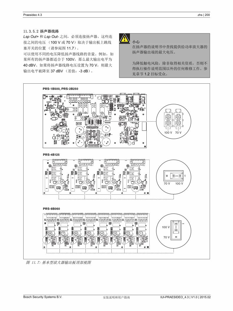
Praesideo 4.3 zhs | 200
Bosch Security Systems B.V. IUI-PRAESIDEO_4.3 | V1.0 | 2015.02安装说明和用户指南
11.3.5.2 扬声器线路
Lsp Out+ 和 Lsp Out- 之间,必须连接扬声器。这些连
接之间的电压(100 V 或 70 V)取决于输出板上跳线
塞开关的位置(请参阅图 11.7)。
可以使用不同的电压降低扬声器线路的音量。例如,如
果所有的扬声器都适合于 100V,那么 大输出电平为
40 dBV。如果将扬声器线路电压设置为 70 V,则 大
输出电平被降至 37 dBV (差值:-3 dB)。
小心
在扬声器的说明书中查找提供给功率放大器的
扬声器输出端的 大电压。
为降低触电风险,除非取得相关资质,否则不
得执行操作说明范围以外的任何维修工作。参
见章节 1.2 目标受众。
图 11.7: 基本型放大器输出板顶部视图
+
+
+
+
+
+
+
++
+
A 2.5
1
11 1
375m
A
+
1
+
375
mA
375
mA
1
375
mA
375
mA
81
916
81
916
- +
- +
- +
-+
-+
-+
- +
-+
-+
B
B
BB
+-
1
12
24
1
1
1
11
375
mA
X100
X10
3
R140
X101X1
R190
X3
X15
1
X500
X155
X300F251
F250
F451
F450
X153
X4X6
R352R356
X550
S350
X400
R405
X402
X651
100V70V
X303X404X405
X403
100V70V
X305 X304
X5X401
6.3A
X301
F300F400
F750
X2
X650
R305
X302
F50 100 V 70 V
12
100 V
1
1
70 V4 3 2 1
12345678
100 V
70 V
PRS-1B500, PRS-2B250
PRS-4B125
PRS-8B060
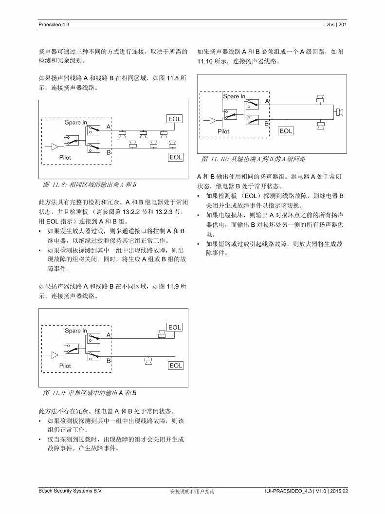
Praesideo 4.3 zhs | 201
Bosch Security Systems B.V. IUI-PRAESIDEO_4.3 | V1.0 | 2015.02安装说明和用户指南
扬声器可通过三种不同的方式进行连接,取决于所需的
检测和冗余级别。
如果扬声器线路 A 和线路 B 在相同区域,如图 11.8 所
示,连接扬声器线路。
此方法具有完整的检测和冗余。A 和 B 继电器处于常闭
状态,并且检测板(请参阅第 13.2.2 节和 13.2.3 节,
用 EOL 指示)连接到 A 和 B 组。
• 如果发生放大器过载,则多通道接口将控制 A 和 B
继电器,以绝缘过载和保持其它组正常工作。
• 如果检测板探测到其中一组中出现线路故障,则出
现故障的组将关闭。同时,将生成 A 组或 B 组的故
障事件。
如果扬声器线路 A 和线路 B 在不同区域,如图 11.9 所
示,连接扬声器线路。
此方法不存在冗余。继电器 A 和 B 处于常闭状态。
• 如果检测板探测到其中一组中出现线路故障,则该
组仍正常工作。
• 仅当探测到过载时,出现故障的组才会关闭并生成
故障事件。产生故障事件。
如果扬声器线路 A 和 B 必须组成一个 A 级回路,如图
11.10 所示,连接扬声器线路。
A 和 B 输出使用相同的扬声器组。继电器 A 处于常闭
状态,继电器 B 处于常开状态。
• 如果检测板(EOL)探测到线路故障,则继电器 B
关闭并生成故障事件以指示该切换。
• 如果电缆损坏,则输出 A 对损坏点之前的所有扬声
器供电,而输出 B 对损坏处另一侧的所有扬声器供
电。
• 如果短路或过载引起线路故障,则放大器将生成故
障事件。
图 11.8: 相同区域的输出端 A和 B
图 11.9: 单独区域中的输出 A 和 B
Pilot
Spare InA
BEOL
EOL
Pilot
Spare InA
BEOL
EOL
图 11.10: 从输出端 A 到 B 的 A 级回路
A
BEOLPilot
Spare In

Praesideo 4.3 zhs | 202
Bosch Security Systems B.V. IUI-PRAESIDEO_4.3 | V1.0 | 2015.02安装说明和用户指南
11.3.5.3 备用放大器通道
备用放大器通道可用作所有基本型放大器的所有通道的
备用通道。唯一的限制条件就是,所有基本型放大器必
须连接至相同的多通道接口。备用放大器通道的连接可
以通过环路连接至基本型放大器的所有通道。
确保备用放大器通道的额定功率大于或等于主通道的额
定功率。
备用和主放大器通道可以是相同放大器的一部分。使用
备用电源,以避免电源出现单点故障。
连接至 后一个备用输入连接的检测板对备用通道进行
检测。
如果图 11.11 中的通道 2 出现故障,则备用通道将处于
活动状态并支持通道 2 的所有设置。如果图 11.11 中的
通道 1 再出现故障,则备用通道不支持通道 1,但支持
通道 2。
要将备用通道连接至基本型放大器通道,请执行以下步
骤:
1 +A Lsp 输出端从备用放大器通道连接基本型放大器
的 + 备用输入连接通道 N。
2 将 -A Lsp 输出端从从备用放大器通道连接至基本型
放大器的 - 备用输入连接通道 N。
3 建立至需要备用通道备用装置的基本型放大器的所
有通道的回路连接。
4 可选:将检测板连接至 后一个通道备用输入连
接。
图 11.11: 备用放大器和扬声器连接
图 11.12: 基本型放大器输出端和备用通道输入端
Spare input
A
B
Channel 16
Spare input
Channel 1
Channel 2
Signal from active spare
EOL 2AEOL S
EOL 2B
EOL 1B
EOL 1A
Active spare channel
Channel 1
Spare inputChannel 2
A
B
A
B
A B A B
+ –+ –+ –+ –+ –+ –
Spare In Lsp OutSpare In Lsp Out
1 2
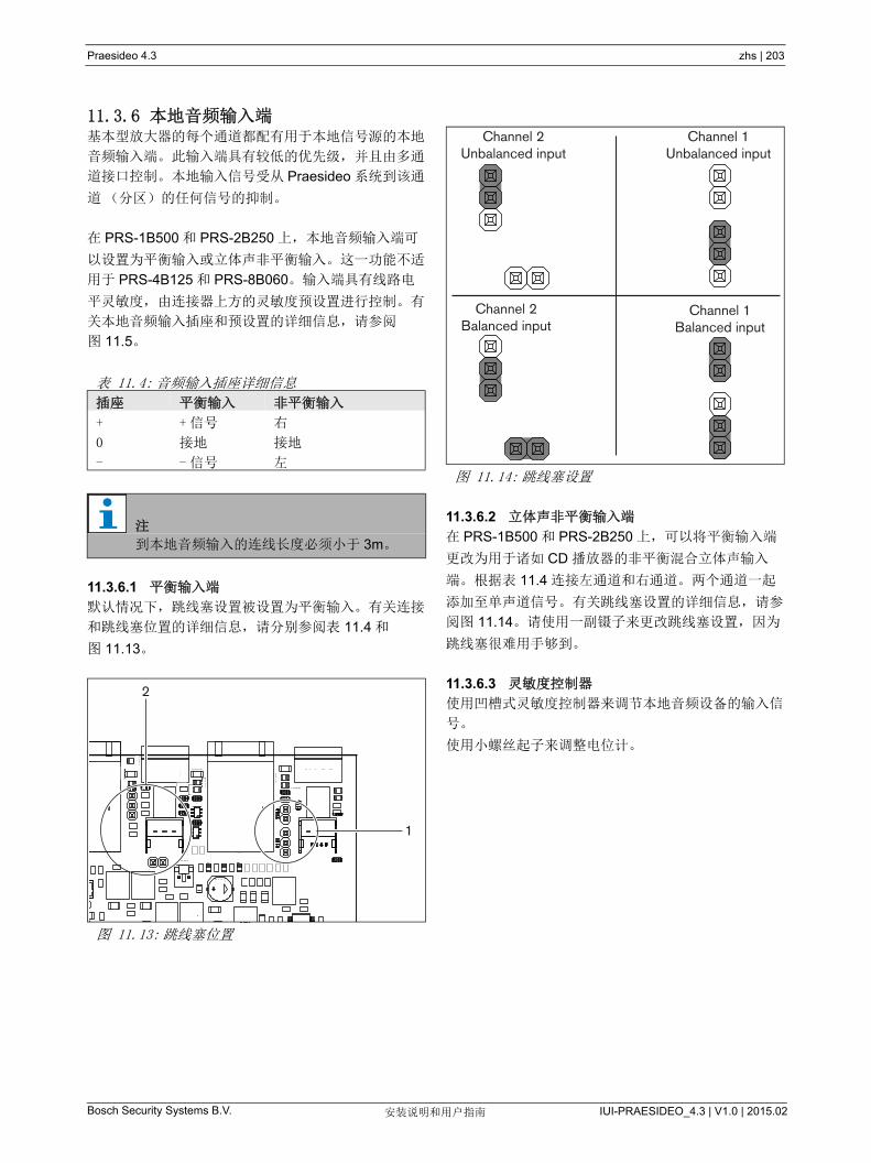
Praesideo 4.3 zhs | 203
Bosch Security Systems B.V. IUI-PRAESIDEO_4.3 | V1.0 | 2015.02安装说明和用户指南
11.3.6 本地音频输入端基本型放大器的每个通道都配有用于本地信号源的本地
音频输入端。此输入端具有较低的优先级,并且由多通
道接口控制。本地输入信号受从 Praesideo 系统到该通
道(分区)的任何信号的抑制。
在 PRS-1B500 和 PRS-2B250 上,本地音频输入端可
以设置为平衡输入或立体声非平衡输入。这一功能不适
用于 PRS-4B125 和 PRS-8B060。输入端具有线路电
平灵敏度,由连接器上方的灵敏度预设置进行控制。有
关本地音频输入插座和预设置的详细信息,请参阅
图 11.5。
11.3.6.1 平衡输入端
默认情况下,跳线塞设置被设置为平衡输入。有关连接
和跳线塞位置的详细信息,请分别参阅表 11.4 和
图 11.13。
11.3.6.2 立体声非平衡输入端
在 PRS-1B500 和 PRS-2B250 上,可以将平衡输入端
更改为用于诸如 CD 播放器的非平衡混合立体声输入
端。根据表 11.4 连接左通道和右通道。两个通道一起
添加至单声道信号。有关跳线塞设置的详细信息,请参
阅图 11.14。请使用一副镊子来更改跳线塞设置,因为
跳线塞很难用手够到。
11.3.6.3 灵敏度控制器
使用凹槽式灵敏度控制器来调节本地音频设备的输入信
号。
使用小螺丝起子来调整电位计。
表 11.4: 音频输入插座详细信息
插座 平衡输入 非平衡输入
+ + 信号 右
0 接地 接地
- - 信号 左
注
到本地音频输入的连线长度必须小于 3m。
图 11.13: 跳线塞位置
1
2
1
2
图 11.14: 跳线塞设置
Channel 1Unbalanced input
Channel 2Balanced input
Channel 2Unbalanced input
Channel 1Balanced input
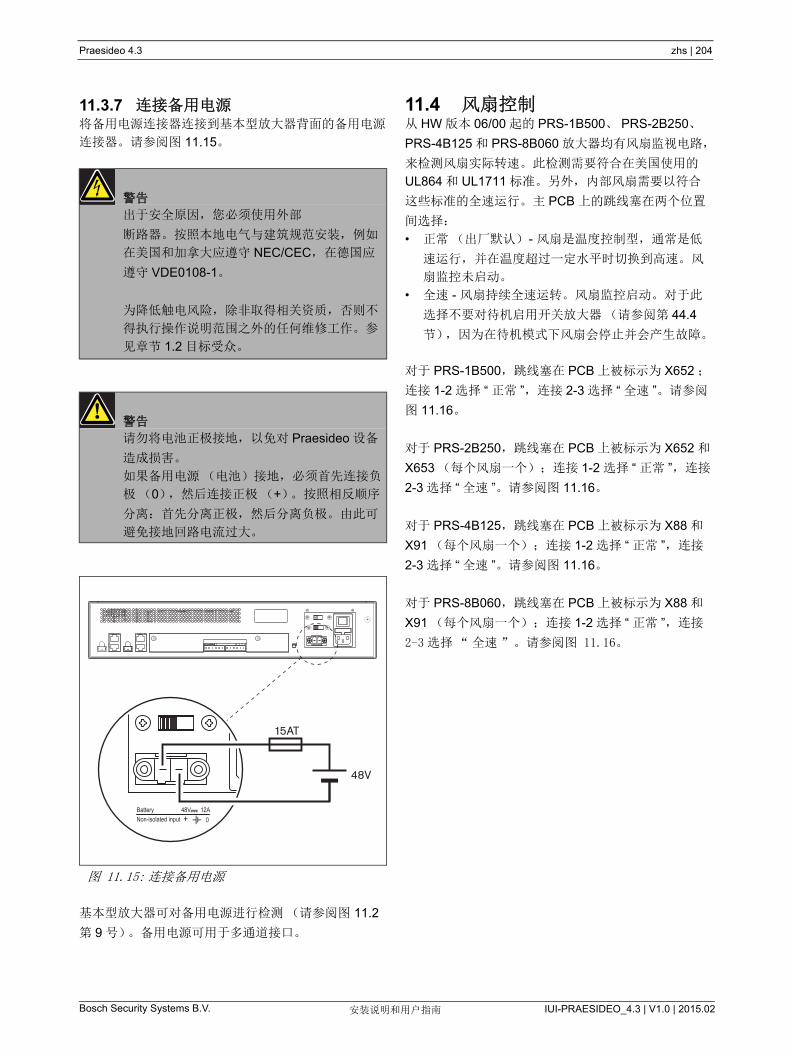
Praesideo 4.3 zhs | 204
Bosch Security Systems B.V. IUI-PRAESIDEO_4.3 | V1.0 | 2015.02安装说明和用户指南
11.3.7 连接备用电源将备用电源连接器连接到基本型放大器背面的备用电源
连接器。请参阅图 11.15。
基本型放大器可对备用电源进行检测(请参阅图 11.2
第 9 号)。备用电源可用于多通道接口。
11.4 风扇控制从 HW 版本 06/00 起的 PRS-1B500、 PRS-2B250、
PRS-4B125 和 PRS-8B060 放大器均有风扇监视电路,
来检测风扇实际转速。此检测需要符合在美国使用的
UL864 和 UL1711 标准。另外,内部风扇需要以符合
这些标准的全速运行。主 PCB 上的跳线塞在两个位置
间选择:
• 正常(出厂默认) - 风扇是温度控制型,通常是低
速运行,并在温度超过一定水平时切换到高速。风
扇监控未启动。
• 全速 - 风扇持续全速运转。风扇监控启动。对于此
选择不要对待机启用开关放大器(请参阅第 44.4
节),因为在待机模式下风扇会停止并会产生故障。
对于 PRS-1B500,跳线塞在 PCB 上被标示为 X652 ;
连接 1-2 选择 “ 正常 ”,连接 2-3 选择 “ 全速 ”。请参阅
图 11.16。
对于 PRS-2B250,跳线塞在 PCB 上被标示为 X652 和
X653 (每个风扇一个);连接 1-2 选择 “ 正常 ”,连接
2-3 选择 “ 全速 ”。请参阅图 11.16。
对于 PRS-4B125,跳线塞在 PCB 上被标示为 X88 和
X91 (每个风扇一个);连接 1-2 选择 “ 正常 ”,连接
2-3 选择 “ 全速 ”。请参阅图 11.16。
对于 PRS-8B060,跳线塞在 PCB 上被标示为 X88 和
X91 (每个风扇一个);连接 1-2 选择 “ 正常 ”,连接
2-3 选择“全速”。请参阅图 11.16。
警告
出于安全原因,您必须使用外部
断路器。按照本地电气与建筑规范安装,例如
在美国和加拿大应遵守 NEC/CEC,在德国应
遵守 VDE0108-1。
为降低触电风险,除非取得相关资质,否则不
得执行操作说明范围之外的任何维修工作。参
见章节 1.2 目标受众。
警告
请勿将电池正极接地,以免对 Praesideo 设备
造成损害。
如果备用电源(电池)接地,必须首先连接负
极(0),然后连接正极(+)。按照相反顺序
分离:首先分离正极,然后分离负极。由此可
避免接地回路电流过大。
图 11.15: 连接备用电源
Battery 48V 12ANon-isolated input 0+
48V
15AT

Praesideo 4.3 zhs | 205
Bosch Security Systems B.V. IUI-PRAESIDEO_4.3 | V1.0 | 2015.02安装说明和用户指南
图 11.16: 提供风扇控制的跳线塞输出板的顶部视图
PRS-1B500
PRS-2B250
PRS-4B125
PRS-8B060
123
X652
123
X652
3 2 1
X88
3 2 1
X91
321
X88
321
X91
123
X653
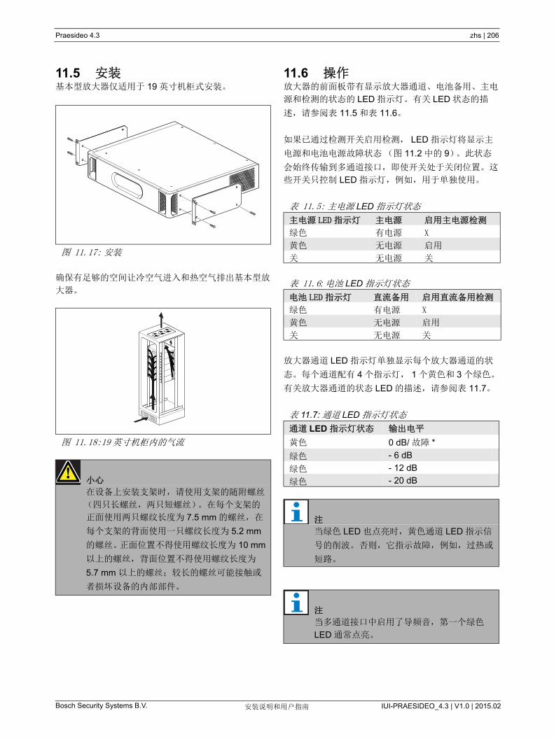
Praesideo 4.3 zhs | 206
Bosch Security Systems B.V. IUI-PRAESIDEO_4.3 | V1.0 | 2015.02安装说明和用户指南
11.5 安装基本型放大器仅适用于 19 英寸机柜式安装。
确保有足够的空间让冷空气进入和热空气排出基本型放
大器。
11.6 操作放大器的前面板带有显示放大器通道、电池备用、主电
源和检测的状态的 LED 指示灯。有关 LED 状态的描
述,请参阅表 11.5 和表 11.6。
如果已通过检测开关启用检测, LED 指示灯将显示主
电源和电池电源故障状态(图 11.2 中的 9)。此状态
会始终传输到多通道接口,即使开关处于关闭位置。这
些开关只控制 LED 指示灯,例如,用于单独使用。
放大器通道 LED 指示灯单独显示每个放大器通道的状
态。每个通道配有 4 个指示灯, 1 个黄色和 3 个绿色。
有关放大器通道的状态 LED 的描述,请参阅表 11.7。
图 11.17: 安装
图 11.18:19 英寸机柜内的气流
小心
在设备上安装支架时,请使用支架的随附螺丝
(四只长螺丝,两只短螺丝)。在每个支架的
正面使用两只螺纹长度为 7.5 mm 的螺丝,在
每个支架的背面使用一只螺纹长度为 5.2 mm
的螺丝。正面位置不得使用螺纹长度为 10 mm
以上的螺丝,背面位置不得使用螺纹长度为
5.7 mm 以上的螺丝;较长的螺丝可能接触或
者损坏设备的内部部件。
表 11.5: 主电源 LED 指示灯状态
主电源 LED 指示灯 主电源 启用主电源检测
绿色 有电源 X
黄色 无电源 启用
关 无电源 关
表 11.6: 电池 LED 指示灯状态
电池 LED 指示灯 直流备用 启用直流备用检测
绿色 有电源 X
黄色 无电源 启用
关 无电源 关
表 11.7: 通道 LED 指示灯状态
通道 LED 指示灯状态 输出电平
黄色 0 dB/ 故障 *
绿色 - 6 dB
绿色 - 12 dB
绿色 - 20 dB
注
当绿色 LED 也点亮时,黄色通道 LED 指示信
号的削波。 否则,它指示故障,例如,过热或
短路。
注
当多通道接口中启用了导频音,第一个绿色
LED 通常点亮。

Praesideo 4.3 zhs | 207
Bosch Security Systems B.V. IUI-PRAESIDEO_4.3 | V1.0 | 2015.02安装说明和用户指南
11.7 技术数据
11.7.1 物理特性
11.7.2 气候条件
11.7.3 EMC 和安全
11.7.4 平均无故障工作时间
11.7.5 MCI 连接
11.7.6 电源
11.7.7 备用电源
尺寸(高 x 宽 x 深):
88x483x400 mm (19 英寸安装,支架后部保持
360 mm 空间,前部保持 40 mm 空间)
重量:
PRS-1B500
12 kg
PRS-2B250
14 kg
PRS-4B125
15 kg
PRS-8B060
13.7 kg
温度:
-5 到 +55 °C (工作时)
-20 到 +70 °C (不工作时)
相对湿度:
15 到 90%,非冷凝(工作时)
5 到 95%,非冷凝(不工作时)
气压:
600 到 1100 hPa
电磁兼容性:
符合 EN55103-1/FCC-47 标准中的 15B 部分
符合 EN55103-2 标准
EN50121-4
EN50130-4
电气安全:
IEC60065 (CB-scheme)
EN60065
批准:
CE 标记
EN54-16 和 ISO7240-16
预期寿命:
+55 时, 50,000 小时
MTBF:
430,000 小时
(根据实际返修率数据)
连接器(背面):
2 識 J45
首选电缆:
2 證 AT5 直线
大电缆长度:
3 m
连接器(背面):
带有保险线盒的 IEC 公电源插槽
首选电缆:
符合 CE 标准的主电源线
电压选择器(背面):
115V (AC) /230V (AC)
额定输入电压范围:
115 V (典型值):100 - 120 V(AC), 50 - 60 Hz
230 V (典型值):220 - 240 V(AC), 50 - 60 Hz
输入电压限制:
115 V (典型值):90 - 132 V(AC), 50 - 60 Hz
230 V (典型值):198 - 264 V(AC), 50 - 60 Hz
打开 / 关闭开关:
位于背面
功率因数 (PF):
> 0.6
连接器(背面):
用于可拆卸式螺丝连接器的 2 极头
输入电压:
48 V (直流电)
输入电压范围:
43.5 到 56 V(DC)
大电流:
12 A
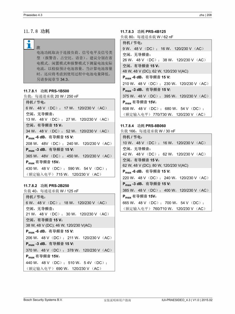
Praesideo 4.3 zhs | 208
Bosch Security Systems B.V. IUI-PRAESIDEO_4.3 | V1.0 | 2015.02安装说明和用户指南
11.7.8 功耗
11.7.8.1 功耗 PRS-1B500
负载:每通道承载 20 W / 250 nF
11.7.8.2 功耗 PRS-2B250
负载 40:每通道承载 W / 125 nF
11.7.8.3 功耗 PRS-4B125
负载 80:每通道承载 W / 62 nF
11.7.8.4 功耗 PRS-8B060
负载 166:每通道承载 W / 30 nF
注
电池功耗取决于连接负荷、信号电平及信号类
型(报警音、占空比、语音)。建议分别在省
电模式、闲置模式和报警模式下测量电池实际
电流,以检验预计电池容量。当计算电池容量
时,还应将考虑到使用过程中电池电量降低。
另请参阅章节 34.3。
待机 / 节电:
6 W, 48 V (DC); 17 W, 120/230 V (AC)
空闲,无导频音:
13 W, 48 V (DC); 27 W, 120/230 V (AC)
空闲,有导频音 15 V:
34 W, 48 V (DC); 52 W, 120/230 V (AC)
Pmax -6 dB,有导频音 15 V:
208 W, 48V (DC); 240 W, 120/230 V (AC)
Pmax -3 dB,有导频音 15 V:
365 W, 48V (DC); 450 W, 120/230 V (AC)
Pmax 有导频音 15V:
430 W, 48 V (DC); 590 W, 54 V (DC);
(额定输入电平) 715 W, 120/230 V (AC)
待机 / 节电:
6 W, 48 V (DC); 18 W, 120/230 V (AC)
空闲,无导频音:
21 W, 48 V (DC); 30 W, 120/230 V (AC)
空闲,有导频音 15 V:
38 W, 48 V (DC); 46 W, 120/230 V(AC)
Pmax -6 dB,有导频音 15 V:
206 W, 48 V(DC); 211 W, 120/230 V(AC)
Pmax -3 dB,有导频音 15 V:
370 W, 48 V(DC); 378 W,120/230 V(AC)
Pmax 有导频音 15V:
440 W, 48 V (DC); 510 W, 5 4V (DC);
(额定输入电平) 690 W, 120/230 V (AC)
待机 / 节电:
9 W, 48 V (DC); 16 W, 120/230 V (AC)
空闲,无导频音:
26 W, 48 V (DC); 38 W, 120/230 V (AC)
空闲,有导频音 15 V:
48 W, 48 V (DC); 62 W, 120/230 V(AC)
Pmax -6 dB,有导频音 15 V:
210 W, 48 V(DC); 230 W,120/230 V(AC)
Pmax -3 dB,有导频音 15 V:
375 W, 48 V(DC); 395 W,120/230 V(AC)
Pmax 有导频音 15V:
608 W, 48 V (DC); 680 W, 54 V (DC);
(额定输入电平) 770/730 W, 120/230 V (AC)
待机 / 节电:
10 W, 48 V (DC); 16 W, 120/230 V (AC)
空闲,无导频音:
42 W, 48 V (DC); 62 W, 120/230 V (AC)
空闲,有导频音 15 V:
62 W, 48 V (DC); 80 W, 120/230 V(AC)
Pmax -6 dB,有导频音 15 V:
220 W, 48 V(DC); 240 W,120/230 V(AC)
Pmax -3 dB,有导频音 15 V:
385 W, 48 V(DC); 400 W,120/230 V(AC)
Pmax 有导频音 15V:
665 W, 48 V (DC); 700 W, 54 V (DC);
(额定输入电平) 760/710 W, 120/230 V (AC)

Praesideo 4.3 zhs | 209
Bosch Security Systems B.V. IUI-PRAESIDEO_4.3 | V1.0 | 2015.02安装说明和用户指南
11.7.9 音频线路输入端 11.7.10扬声器输出端和备用输入端
连接器(背面):
用于可拆卸式螺丝连接器的 3 极头
首选电缆:
双绞线,屏蔽电缆
输入信号电平:
0 dBV (正常值)
18 dBV ( 大值)
输入灵敏度设置:
小于 -40 到 0 dB (具有预设置控制)
频率响应:
频率为 50 Hz 和 20kHz 时是 -3 dB (允许误差
±1 dB)
输入阻抗:
22 kΩ
信噪比:
> 87 dB (未加权平方)
共模抑制比:
频率为 1 kHz 时,大于 40 dB
输入串扰:
频率为 1 kHz 时,小于 -70 dB
连接器(背面):
1 个 6 极头,配有可拆卸式螺丝连接器
电压:
100 V、 70 V (跳线塞设置)
大无负载电压:
200 V 峰值
额定负载阻抗:
@ 100/70 V 输出
PRS-1B500
20/10 Ω
PRS-2B250
40/20 Ω
PRS-4B125
80/40 Ω
PRS-8 B060
166/83Ω
额定负载电容:
@ 100/70 V 输出
PRS-1B500
250/500 nF
PRS-2B250
125/250 nF
PRS-4B125
60/125 nF
PRS-8B060
30/60 nF
额定输出功率:
在 a/b/c/d/e/f 工况下
PRS-1B500
1 x 500/400/275/180/180/125 W
PRS-2B250
2 x 250/210/150/110/110/60 W
PRS-4B125
4 x 125/105/65/60/60/30 W
PRS-8B060
8 x 60/50/40/30/30/15 W
失真:
1 kHz 和 50% 的额定输出功率时,小于等于 0.3%
100% 输出功率时小于 1%
从无负载到全负载的输出调整:
小于 1.2 dB (对于 70 和 100 V 输出)

Praesideo 4.3 zhs | 210
Bosch Security Systems B.V. IUI-PRAESIDEO_4.3 | V1.0 | 2015.02安装说明和用户指南
a 1 kHz 且额定主电源或者电池电压大于 53 V 时,失
真小于 1%, 长 1 分钟(依据 IEC 60268-3)。
b 在 55 的环境温度下, 1 kHz 且主电源或者电池电
压大于 50 V 时,失真小于 1%, 长 1 分钟(依据
EN54-16)。
c 在 55 的环境温度下, 1 kHz 且电池电压为 48 V
时,失真小于 1%, 长 1 分钟。
d 报警音电平 - 在 55 的环境温度下, 1 kHz 且主电
源或电池电压大于 43.5V 时,失真小于 0.3%, 长
30 分钟。
e 在 30 的环境温度下, 1 kHz 且主电源或电池电压
大于 43.5V 时,失真小于 0.3%,连续。
f 在 55 的环境温度下, 1 kHz 且主电源或电池电压
大于 43.5 V 时,失真小于 0.3%,连续。
11.7.11降额本图显示了随着环境温度的变化,用于紧急语音、话音
等的可用连续功率变化情况。
如果放大器负载的扬声器达到其额定输出功率(请参
阅第 11.7.10 节),在环境温度为 55 癈时,您仍可播
放音乐和语音,但由于音频信号的波峰因素(或波峰
同平均值之比),播放时间不确定。一般来说,音乐和
语音的波峰因素为 6 dB 到 8 dB,这使所需的连续功率
仅为额定输出功率的 25% 或更低。 Praesideo 设定的
警报音 大值为 -3 dB,这使所需要的连续功率为额定
输出功率的 50%。在环境温度 55 癈下,警报音可以持
续至少 30 分钟;在环境温度 30 癈下,可连续播放。
频率响应:
PRS-1B500, PRS-2B250, PRS-4B125
60 Hz 到 19 kHz(-3 dB), -10 dB 的 大容性负载
和额定负载阻抗
PRS-8B060
80 Hz 到 19kHz (-3 dB), -10 dB 的 大容性负载
和额定负载阻抗
功率带宽:
50% 的额定输出功率时, 60Hz-19 kHz (-3 dB,失
真小于 1%)
信噪比:
导频音关闭时大于 85 dB(A)
放大器输出极限:
软削波
噪声级:
1 m 时小于 NR35,中速风扇
1 m 时小于 NR40,全速风扇图 11.19: 大切换功率
55
25 30 35 40 45 50 55 60
50
45
40
35
30
25
20Con
tinuo
us O
utpu
t Pow
er(%
of R
ated
Out
put P
ower
)
T (°C)

Praesideo 4.3 zhs | 211
Bosch Security Systems B.V. IUI-PRAESIDEO_4.3 | V1.0 | 2015.02安装说明和用户指南
12 单个扬声器线路检测
12.1 简介单个扬声器线路检测仅适用于 PRS-xPxxx 功率放大
器,而不适用于基本型放大器。
LBB4442/00 线路检测套件包括检测主控 PCB 和检测
从属 PCB。使用此套件,可以检测扬声器器线路的终
端。
检测主控 PCB 必须安装在受到检测的放大器通道的输
出板上,而检测副板必须连接到受到检测的扬声器线路
中的 后一个扬声器。
因此,对于每个扬声器线路,需要一个套件。检测从属
PCB 由功率放大器的 20 kHz 导频音供电,并且通过扬
声器线路与检测主板进行听觉外的通信。不需要附加的
连线。扬声器线路故障在 100 秒内予以报告。通信不
受扬声器线路上音频信号的影响。
推荐多线电缆切勿与线路检测一起使用,因为音频通道
之间的串扰可能影响线路检测。
请查看有关如何确定一套扬声器及相关布线的负载阻抗
的其他信息,检查 Bosch WLS 扬声器阻抗测量的应用
注释。是否使用的是细线布线或高电容布线(如耐火
布线),或扬声器并非由 Bosch 所造,这一点尤其重
要。
12.2 控制器、连接器和指示器
12.2.1 检测主板检测主板括以下组件:
1 连接器 -将检测主板带电连接到放大器通道的输出
板上的设备(请参阅第 12.3.1 节)
12.2.2 检测副板检测副板包括以下组件:
1 连接器 -将检测副板连接到扬声器线路的设备。
检测副板配有双连接器,允许将检测副板安装在扬声器
线路的任何位置(请参阅图 12.3)。通常,检测副板
安装在扬声器线路的末端。
注
使用多分支扬声器线路检测(请参阅第 13
章)可以检测扬声器线路和扬声器本身中的支
路终端。
注
要使线路检测套件能正常工作,则必须将放大
器设置为 70V 或 100V 输出。不允许设置为
50V。
由于只对 100 V 输出的 Praesideo 放大器执行
了 EN54-16 标准认证,因此,安装人员在欧
洲只应将 100 V 输出的 Praesideo 用于紧急广
播系统。
图 12.1: 检测主板的组件端
图 12.2: 检测副板的组件端
1
+-
+-
+-
1
+
-
+
-
+
1
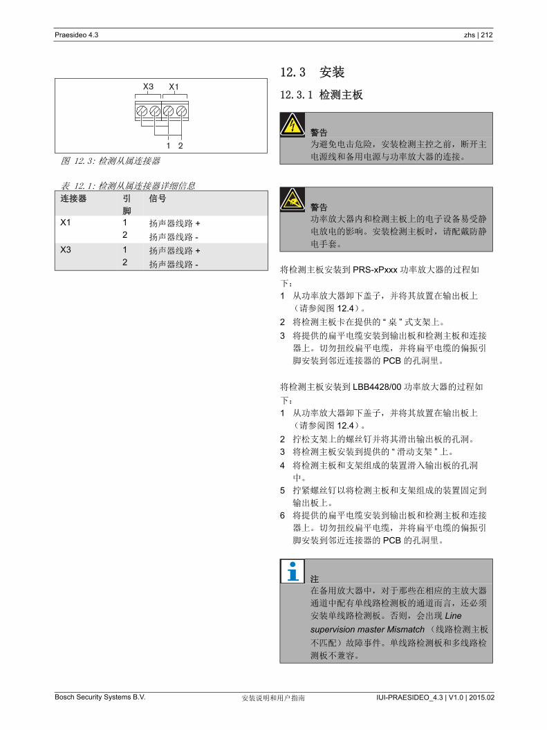
Praesideo 4.3 zhs | 212
Bosch Security Systems B.V. IUI-PRAESIDEO_4.3 | V1.0 | 2015.02安装说明和用户指南
12.3 安装
12.3.1 检测主板
将检测主板安装到 PRS-xPxxx 功率放大器的过程如
下:
1 从功率放大器卸下盖子,并将其放置在输出板上
(请参阅图 12.4)。
2 将检测主板卡在提供的 “ 桌 ” 式支架上。
3 将提供的扁平电缆安装到输出板和检测主板和连接
器上。切勿扭绞扁平电缆,并将扁平电缆的偏振引
脚安装到邻近连接器的 PCB 的孔洞里。
将检测主板安装到 LBB4428/00 功率放大器的过程如
下:
1 从功率放大器卸下盖子,并将其放置在输出板上
(请参阅图 12.4)。
2 拧松支架上的螺丝钉并将其滑出输出板的孔洞。
3 将检测主板安装到提供的 “ 滑动支架 ” 上。
4 将检测主板和支架组成的装置滑入输出板的孔洞
中。
5 拧紧螺丝钉以将检测主板和支架组成的装置固定到
输出板上。
6 将提供的扁平电缆安装到输出板和检测主板和连接
器上。切勿扭绞扁平电缆,并将扁平电缆的偏振引
脚安装到邻近连接器的 PCB 的孔洞里。
图 12.3: 检测从属连接器
表 12.1: 检测从属连接器详细信息
连接器 引
脚
信号
X1 1
2扬声器线路 +
扬声器线路 -
X3 1
2扬声器线路 +
扬声器线路 -
X3 X1
1 2警告
为避免电击危险,安装检测主控之前,断开主
电源线和备用电源与功率放大器的连接。
警告
功率放大器内和检测主板上的电子设备易受静
电放电的影响。安装检测主板时,请配戴防静
电手套。
注
在备用放大器中,对于那些在相应的主放大器
通道中配有单线路检测板的通道而言,还必须
安装单线路检测板。否则,会出现 Line
supervision master Mismatch (线路检测主板
不匹配)故障事件。单线路检测板和多线路检
测板不兼容。

Praesideo 4.3 zhs | 213
Bosch Security Systems B.V. IUI-PRAESIDEO_4.3 | V1.0 | 2015.02安装说明和用户指南
图 12.4: 检测主板的安装
+
+ +
-+++
+
PRS-1P500, PRS-2P250, PRS-4P125Power Amplifier
LBB4428/00Power Amplifier
8
1 3 2 4
7 6 54 3 2 1
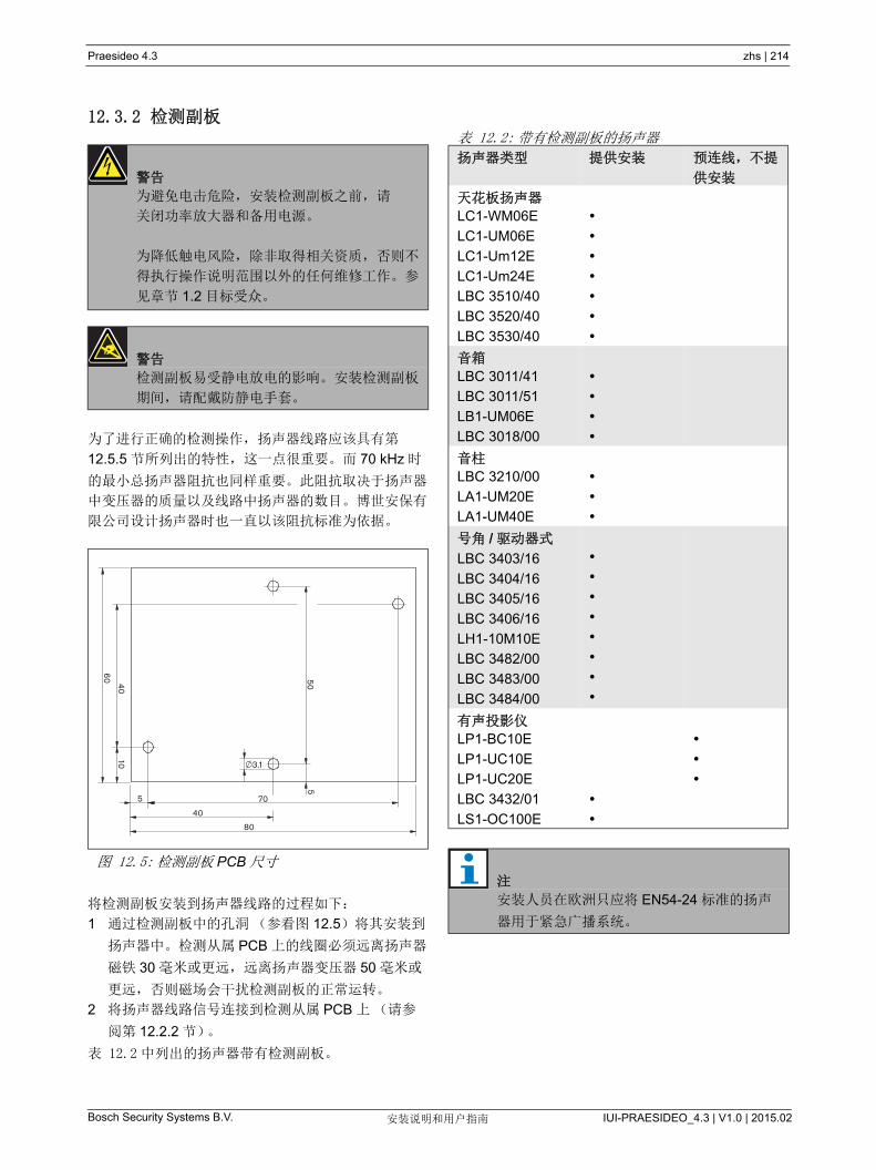
Praesideo 4.3 zhs | 214
Bosch Security Systems B.V. IUI-PRAESIDEO_4.3 | V1.0 | 2015.02安装说明和用户指南
12.3.2 检测副板
为了进行正确的检测操作,扬声器线路应该具有第
12.5.5 节所列出的特性,这一点很重要。而 70 kHz 时
的 小总扬声器阻抗也同样重要。此阻抗取决于扬声器
中变压器的质量以及线路中扬声器的数目。博世安保有
限公司设计扬声器时也一直以该阻抗标准为依据。
将检测副板安装到扬声器线路的过程如下:
1 通过检测副板中的孔洞(参看图 12.5)将其安装到
扬声器中。检测从属 PCB 上的线圈必须远离扬声器
磁铁 30 毫米或更远,远离扬声器变压器 50 毫米或
更远,否则磁场会干扰检测副板的正常运转。
2 将扬声器线路信号连接到检测从属 PCB 上(请参
阅第 12.2.2 节)。
表 12.2 中列出的扬声器带有检测副板。
警告
为避免电击危险,安装检测副板之前,请
关闭功率放大器和备用电源。
为降低触电风险,除非取得相关资质,否则不
得执行操作说明范围以外的任何维修工作。参
见章节 1.2 目标受众。
警告
检测副板易受静电放电的影响。安装检测副板
期间,请配戴防静电手套。
图 12.5: 检测副板 PCB 尺寸
80
40
705
1040
50
603.1
5
表 12.2: 带有检测副板的扬声器
扬声器类型 提供安装 预连线,不提
供安装
天花板扬声器
LC1-WM06E
LC1-UM06E
LC1-Um12E
LC1-Um24E
LBC 3510/40
LBC 3520/40
LBC 3530/40
音箱
LBC 3011/41
LBC 3011/51
LB1-UM06E
LBC 3018/00
音柱
LBC 3210/00
LA1-UM20E
LA1-UM40E
号角 / 驱动器式
LBC 3403/16
LBC 3404/16
LBC 3405/16
LBC 3406/16
LH1-10M10E
LBC 3482/00
LBC 3483/00
LBC 3484/00
有声投影仪
LP1-BC10E
LP1-UC10E
LP1-UC20E
LBC 3432/01
LS1-OC100E
注
安装人员在欧洲只应将 EN54-24 标准的扬声
器用于紧急广播系统。
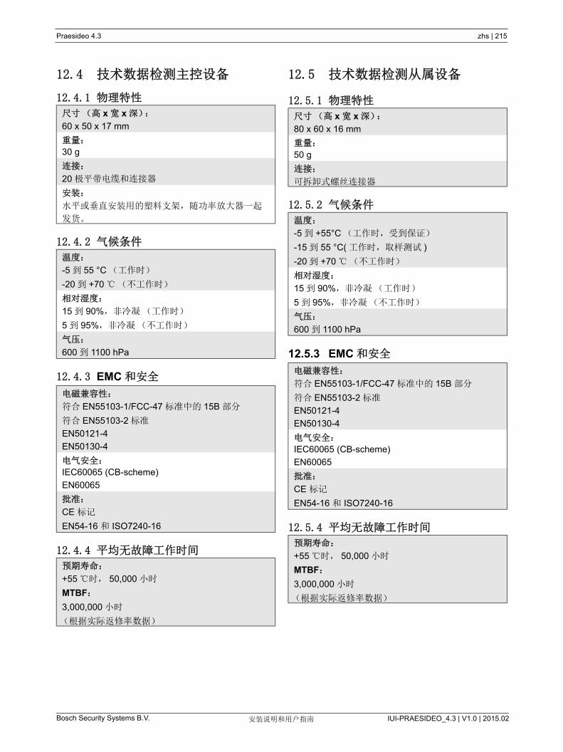
Praesideo 4.3 zhs | 215
Bosch Security Systems B.V. IUI-PRAESIDEO_4.3 | V1.0 | 2015.02安装说明和用户指南
12.4 技术数据检测主控设备
12.4.1 物理特性
12.4.2 气候条件
12.4.3 EMC 和安全
12.4.4 平均无故障工作时间
12.5 技术数据检测从属设备
12.5.1 物理特性
12.5.2 气候条件
12.5.3 EMC 和安全
12.5.4 平均无故障工作时间
尺寸(高 x 宽 x 深):
60 x 50 x 17 mm
重量:
30 g
连接:
20 极平带电缆和连接器
安装:
水平或垂直安装用的塑料支架,随功率放大器一起
发货。
温度:
-5 到 55 °C (工作时)
-20 到 +70 (不工作时)
相对湿度:
15 到 90%,非冷凝(工作时)
5 到 95%,非冷凝(不工作时)
气压:
600 到 1100 hPa
电磁兼容性:
符合 EN55103-1/FCC-47 标准中的 15B 部分
符合 EN55103-2 标准
EN50121-4
EN50130-4
电气安全:
IEC60065 (CB-scheme)
EN60065
批准:
CE 标记
EN54-16 和 ISO7240-16
预期寿命:
+55 时, 50,000 小时
MTBF:
3,000,000 小时
(根据实际返修率数据)
尺寸(高 x 宽 x 深):
80 x 60 x 16 mm
重量:
50 g
连接:
可拆卸式螺丝连接器
温度:
-5 到 +55°C (工作时,受到保证)
-15 到 55 °C( 工作时,取样测试 )
-20 到 +70 (不工作时)
相对湿度:
15 到 90%,非冷凝(工作时)
5 到 95%,非冷凝(不工作时)
气压:
600 到 1100 hPa
电磁兼容性:
符合 EN55103-1/FCC-47 标准中的 15B 部分
符合 EN55103-2 标准
EN50121-4
EN50130-4
电气安全:
IEC60065 (CB-scheme)
EN60065
批准:
CE 标记
EN54-16 和 ISO7240-16
预期寿命:
+55 时, 50,000 小时
MTBF:
3,000,000 小时
(根据实际返修率数据)
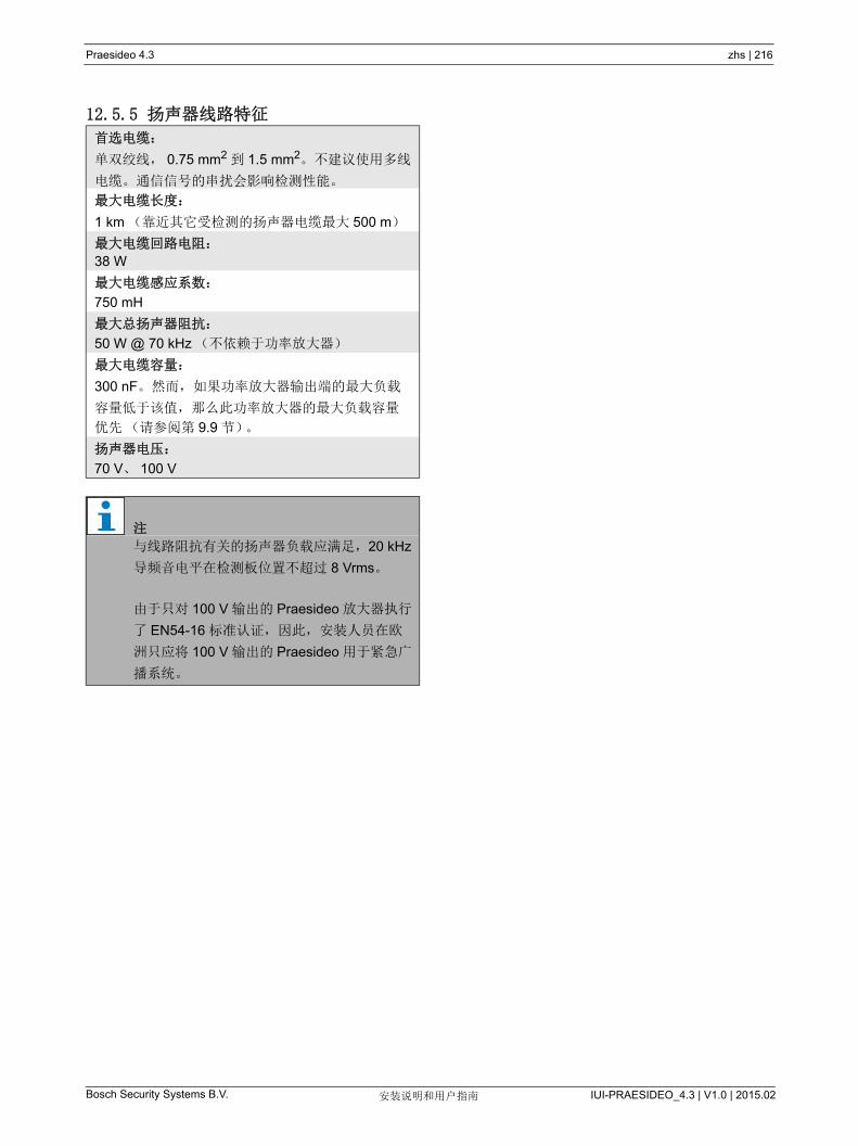
Praesideo 4.3 zhs | 216
Bosch Security Systems B.V. IUI-PRAESIDEO_4.3 | V1.0 | 2015.02安装说明和用户指南
12.5.5 扬声器线路特征
首选电缆:
单双绞线, 0.75 mm2 到 1.5 mm2。不建议使用多线
电缆。通信信号的串扰会影响检测性能。
大电缆长度:
1 km (靠近其它受检测的扬声器电缆 大 500 m)
大电缆回路电阻:
38 W
大电缆感应系数:
750 mH
大总扬声器阻抗:
50 W @ 70 kHz (不依赖于功率放大器)
大电缆容量:
300 nF。然而,如果功率放大器输出端的 大负载
容量低于该值,那么此功率放大器的 大负载容量
优先(请参阅第 9.9 节)。
扬声器电压:
70 V、 100 V
注
与线路阻抗有关的扬声器负载应满足,20 kHz
导频音电平在检测板位置不超过 8 Vrms。
由于只对 100 V 输出的 Praesideo 放大器执行
了 EN54-16 标准认证,因此,安装人员在欧
洲只应将 100 V 输出的 Praesideo 用于紧急广
播系统。

Praesideo 4.3 zhs | 217
Bosch Security Systems B.V. IUI-PRAESIDEO_4.3 | V1.0 | 2015.02安装说明和用户指南
13 多分支扬声器线路检测
13.1 简介多分支扬声器线路检测可用于以下放大器:
• PRS-1P500 功率放大器
• PRS-2P250 功率放大器
• PRS-4P125 功率放大器
• PRS-1B500 基本型放大器
• PRS-2B250 基本型放大器
• PRS-4B125 基本型放大器
• PRS-8B060 基本型放大器
将 LBB4440/00 监控板、 LBB4441/00 扬声器检测板和
LBB4443/00 扬声器线路检测板用于多分支扬声器线路
检测。通过这些检测板,可以检测扬声器线路(包括
扬声器线路不同分支的末端)上的多达 80 个扬声器。
LBB4441/00 扬声器检测板检查扬声器是否完好无损,
而 LBB4443/00 EOL (线路终端)检测板检查扬声器
线路是否完好无损。 两种类型的监控板都由
LBB4440/00 功率放大器的 20 kHz 导频音供电,并且
与控制 Praesideo 和检测板之间通讯的 LBB4440/00 监
控板进行听觉外的通信。不需要额外布线。
通信不受扬声器音频信号的任何影响。可以在 100 秒
之内报告扬声器和扬声器线路中的故障。不推荐多线电
缆与线路检测一起使用,因为音频通道之间的串扰可能
影响线路检测。
功率放大器在每个通道都配有一个监控板
LBB4440/00。已连接扬声器线路检测板和扬声器检测
板的地址对于该通道必须是唯一的。
基本型放大器 PRS-xBxxx 的多分支扬声器线路检测并
不需要 LBB4440/00 监控板。基本型放大器与已包含所
有已连接基本型放大器的监控板功能的多通道接口配合
使用。根据需要使用 LBB4441/00 和 LBB4443/00 检测
板。无需将监控板安装到基本型放大器中。
对于基本型放大器而言,地址范围中的地址由使用相同
多通道接口的所有已连接放大器通道共享。
确保通过基本型放大器连接到相同多通道接口的所有扬
声器线路检测板和扬声器检测板具有唯一地址。
注
多分支扬声器线路检测不可以与 LBB4428/00
功率放大器一起使用。
注
为了线路检测套件正常工作,必需将放大器设
置为 70V 或 100V 输出。不允许设置为 50V。
由于只对 100 V 输出的 Praesideo 放大器执行
了 EN54-16 标准认证,因此,安装人员在欧
洲只应将 100 V 输出的 Praesideo 用于紧急广
播系统。
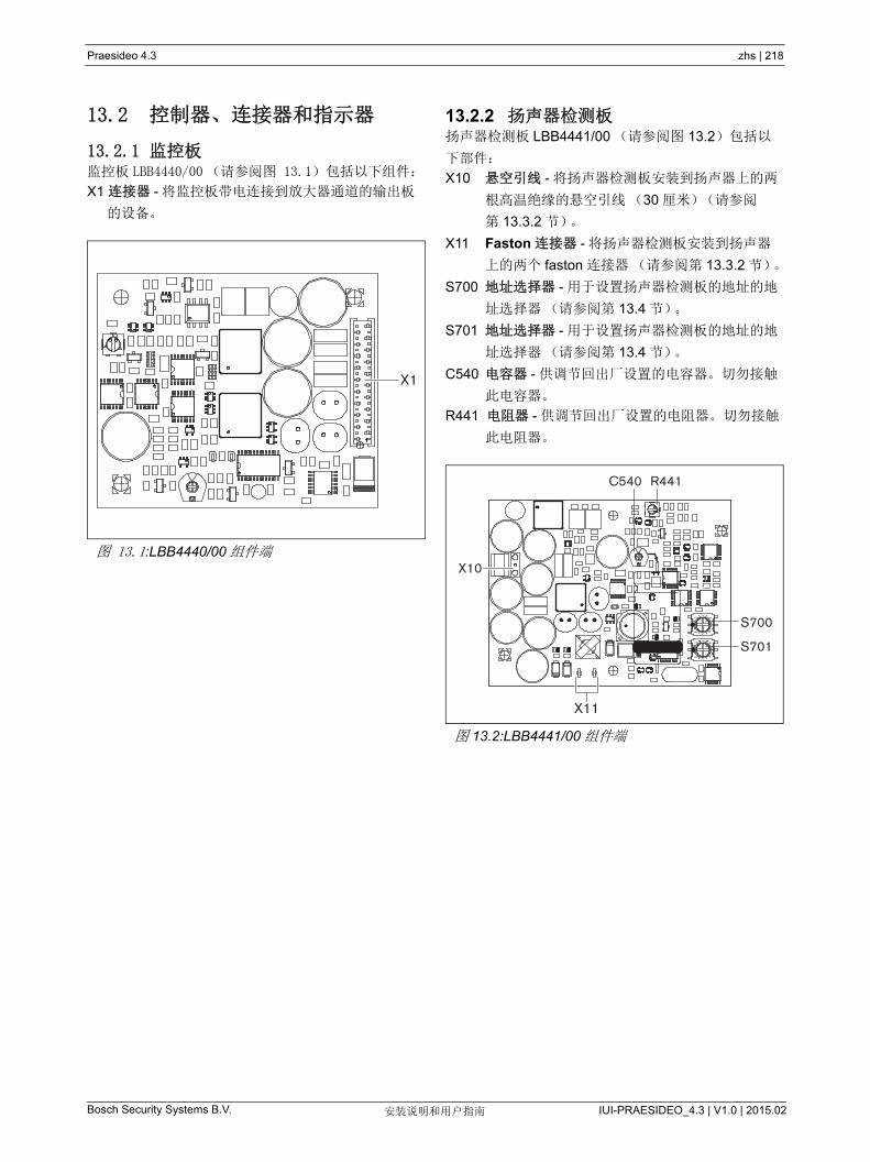
Praesideo 4.3 zhs | 218
Bosch Security Systems B.V. IUI-PRAESIDEO_4.3 | V1.0 | 2015.02安装说明和用户指南
13.2 控制器、连接器和指示器
13.2.1 监控板监控板 LBB4440/00 (请参阅图 13.1)包括以下组件:
X1 连接器 - 将监控板带电连接到放大器通道的输出板
的设备。
13.2.2 扬声器检测板扬声器检测板 LBB4441/00 (请参阅图 13.2)包括以
下部件:
X10 悬空引线 - 将扬声器检测板安装到扬声器上的两
根高温绝缘的悬空引线(30 厘米)(请参阅
第 13.3.2 节)。
X11 Faston 连接器 - 将扬声器检测板安装到扬声器
上的两个 faston 连接器(请参阅第 13.3.2 节)。
S700 地址选择器 - 用于设置扬声器检测板的地址的地
址选择器(请参阅第 13.4 节)。
S701 地址选择器 - 用于设置扬声器检测板的地址的地
址选择器(请参阅第 13.4 节)。
C540 电容器 - 供调节回出厂设置的电容器。切勿接触
此电容器。
R441 电阻器 - 供调节回出厂设置的电阻器。切勿接触
此电阻器。
图 13.1:LBB4440/00 组件端
-
X600
X1
图 13.2:LBB4441/00 组件端
S701
S700
C540 R441
88
2E
2E
64C A
64
A
C
-
X11
X10
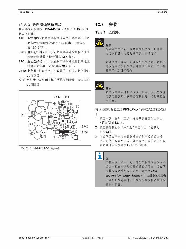
Praesideo 4.3 zhs | 219
Bosch Security Systems B.V. IUI-PRAESIDEO_4.3 | V1.0 | 2015.02安装说明和用户指南
13.2.3 扬声器线路检测板扬声器线路检测板 LBB4443/00 (请参阅图 13.3)包
括以下组件:
X10 悬空引线 - 将扬声器检测板安装到扬声器上的两
根高温绝缘的悬空引线(30 厘米)(请参阅
第 13.3.3 节)。
S700 地址选择器 - 用于设置扬声器线路检测板的地址
的地址选择器(请参阅第 13.4 节)。
S701 地址选择器 - 用于设置扬声器线路检测板的地址
的地址选择器(请参阅第 13.4 节)。
C540 电容器 - 供调节回出厂设置的电容器。切勿接触
此电容器。
R441 电阻器 - 供调节回出厂设置的电阻器。切勿接触
此电阻器。
13.3 安装
13.3.1 监控板
将检测控制板安装到 PRS-xPxxx 功率放大器的过程如
下:
1 从功率放大器卸下盖子,并将其放置在输出板上
(请参阅图 13.4)。
2 从检测控制面板卡入 “ 桌 ” 式支架上(请参阅
图 13.4)。
3 将提供的扁平电缆安装到输出板和监控板的连接
器。切勿扭绞扁平电缆,并将扁平电缆的偏振引脚
安装到邻近连接器的 PCB 的孔洞里。图 13.3:LBB4443/00 组件端
88
2E
2E
4 6
C A
4 6
C
A
-
C540
X10
S701
S700
R441
警告
为避免电击危险,安装监控板之前,断开主
电源线和备用电源与功率放大器的连接。
为降低触电风险,除非取得相关资质,否则不
得执行操作说明范围以外的任何维修工作。参
见章节 1.2 目标受众。
警告
功率放大器内部和监控板上的电子设备易受静
电放电的影响。安装监控制板时,请配戴防静
电手套。
注
在备用放大器中,对于那些在相应的主放大器
通道中配有多线路检测板的通道而言,还必须
安装多线路检测板。否则,会出现 Line
supervision master Mismatch (线路检测主板
不匹配)故障事件。单线路检测板和多线路检
测板不兼容。
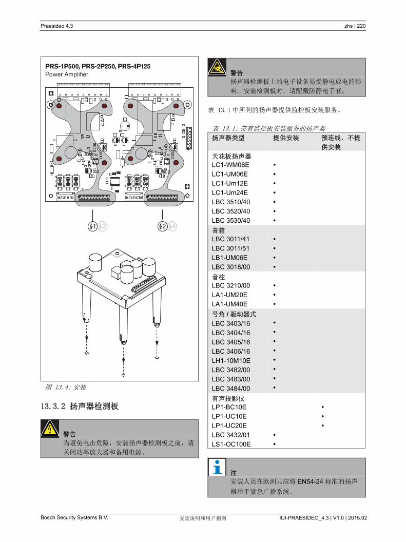
Praesideo 4.3 zhs | 220
Bosch Security Systems B.V. IUI-PRAESIDEO_4.3 | V1.0 | 2015.02安装说明和用户指南
13.3.2 扬声器检测板
表 13.1 中所列的扬声器提供监控板安装服务。
图 13.4: 安装
警告
为避免电击危险,安装扬声器检测板之前,请
关闭功率放大器和备用电源。
+
+ +
-+++
+
PRS-1P500, PRS-2P250, PRS-4P125Power Amplifier
1 3 2 4
警告
扬声器检测板上的电子设备易受静电放电的影
响。安装检测板时,请配戴防静电手套。
表 13.1: 带有监控板安装服务的扬声器
扬声器类型 提供安装 预连线,不提
供安装
天花板扬声器
LC1-WM06E
LC1-UM06E
LC1-Um12E
LC1-Um24E
LBC 3510/40
LBC 3520/40
LBC 3530/40
音箱
LBC 3011/41
LBC 3011/51
LB1-UM06E
LBC 3018/00
音柱
LBC 3210/00
LA1-UM20E
LA1-UM40E
号角 / 驱动器式
LBC 3403/16
LBC 3404/16
LBC 3405/16
LBC 3406/16
LH1-10M10E
LBC 3482/00
LBC 3483/00
LBC 3484/00
有声投影仪
LP1-BC10E
LP1-UC10E
LP1-UC20E
LBC 3432/01
LS1-OC100E
注
安装人员在欧洲只应将 EN54-24 标准的扬声
器用于紧急广播系统。

Praesideo 4.3 zhs | 221
Bosch Security Systems B.V. IUI-PRAESIDEO_4.3 | V1.0 | 2015.02安装说明和用户指南
为了进行正确的检测操作,扬声器线路应该具有
第 13.6.5 节所列出的特性,这一点很重要。而 70 kHz
时的 小总扬声器阻抗也同样重要。此阻抗取决于扬声
器中变压器的质量以及线路中扬声器的数目。博世安保
有限公司设计扬声器时也一直以该阻抗标准为依据。
与扬声器监控配合使用的任何扬声器的额定功率必须在
0.75 W 和 60 W 之间。
请查看有关如何确定一套扬声器及相关布线的负载阻抗
的其他信息,检查 Bosch WLS 扬声器阻抗测量的应用
注释。是否使用的是细线布线或高电容布线(如耐火
布线),或扬声器并非由 Bosch 所造,这一点尤其重
要。
将扬声器检测板安装到扬声器中的过程如下:
1 通过 S700 和 S701 地址选择器设置检测板的地址
(请参阅第 13.4 节)。
2 使用检测板中的拐角孔洞(请参阅图 13.5)将其安
装到扬声器中。 PCB 上的线圈必须远离扬声器磁铁
30 毫米或更远,远离扬声器变压器 50 毫米或更
远,否则磁场会干扰监控板的正常运转。
3 通过悬空引线和 faston 连接器将检测板连接到扬声
器(请参阅图 13.6)。
注
有关详情,请参阅扬声器的安装说明。
注
例如,要将检测板安装到某个箱子中,请使用
通用支架 (LBB4446/00)。通过中间的孔洞连
接检测板与支架(请参阅图 13.5)。
图 13.5: 尺寸
注
使用扬声器内的一种 faston 电缆和配备的
faston 电缆连接检测板与扬声器。
注
检测板必须连接到配有温度保险丝的陶瓷接线
端子之后。万一发生火灾,温度保险丝将烧
断,并且检测板与扬声器线路断开连接。连接
到陶瓷接线端子上的温度保险丝的断路点低于
检测板上焊接材料的熔点,以防止检测板和扬
声器线路中发生短路。
注
扬声器未配备带有温度保险丝的陶瓷接线端子
时,请使用 LBC1256/00 EVAC 连接适配器
(请参阅第 15 章)。
78
40
705
1040
50
60
3.1
5
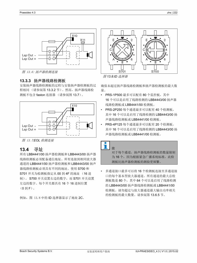
Praesideo 4.3 zhs | 222
Bosch Security Systems B.V. IUI-PRAESIDEO_4.3 | V1.0 | 2015.02安装说明和用户指南
13.3.3 扬声器线路检测板安装扬声器线路检测板的过程与安装扬声器检测板的过
程相同(请参阅第 13.3.2 节)。然而,扬声器线路检
测板不包含 faston 连接器(请参阅图 13.7)。
13.4 寻址所有 LBB4441/00 扬声器检测板和 LBB4443/00 扬声器
线路检测板必须配备通信地址。所有连接到相同放大器
通道的 LBB4441/00 扬声器检测板和 LBB4443/00 扬声
器线路检测板必须具有不同的地址。使用 S700 和
S701 开关为检测板指定从 00 到 4F 的地址(16 进
制)。 S700 开关设置右边的数字,而 S701 开关设置
左边的数字。每个开关都具有 16 个 16 进制位置
(0 到 F)。
例如,图 13.8 中的 ID 选择器显示了地址 2C。
确保未超过扬声器线路检测板和扬声器检测板的 大数
量。
• PRS-1P500 多可以配有 80 个监控板,其中
16 个可以是启用了线路检测的 LBB4443/00 扬声器
线路检测板或 LBB4441/00 检测板。
• PRS-2P250 每个通道 多可以配有 40 个检测板,
其中 16 个可以是启用了线路检测的 LBB4443/00 扬
声器线路检测板或 LBB4441/00 检测板。
• PRS-4P125 每个通道 多可以配有 20 个检测板,
其中 16 个可以是启用了线路检测的 LBB4443/00 扬
声器线路检测板或 LBB4441/00 检测板。
• 多通道接口 多可以将 16 个检测板连接至多通道接
口的每个基本型放大器通道。所有通道的 大总检
测板数是 80 个,其中 64 个可以是启用了线路检测
的 LBB4443/00 扬声器线路检测板或 LBB4441/00
检测板。请勿超过与放大器通道 大输出功率相关
的检测板的 大数量。请参阅第 13.6.5 节。
图 13.6: 扬声器检测连接
图 13.7:EOL 检测连接
Lsp OutLsp Out +
_
X10X11
Lsp OutLsp Out +
_
X10
图 13.8:ID 选择器
注
对于每个通道,扬声器线路检测板的数量限制
为 16 个,因为根据紧急广播系统标准,此检
测板比扬声器检测板的测验更频繁。
2E
6A8
S701 S700
C 4
2E
6A8
C 4

Praesideo 4.3 zhs | 223
Bosch Security Systems B.V. IUI-PRAESIDEO_4.3 | V1.0 | 2015.02安装说明和用户指南
13.5 技术数据监控板
13.5.1 物理特性
13.5.2 气候条件
13.5.3 EMC 和安全
13.5.4 平均无故障工作时间
13.6 技术数据扬声器检测板
13.6.1 物理特性
13.6.2 气候条件
13.6.3 EMC 和安全
13.6.4 平均无故障工作时间
尺寸(高 x 宽 x 深):
60 x 50 x 17 mm
重量:
30 g
连接:
20 极平带电缆和连接器
安装:
水平或垂直安装用的塑料支架,随功率放大器一起
发货。
温度:
-5 到 55 °C (工作时)
-20 到 +70 °C (不工作时)
相对湿度:
15 到 90%,非冷凝(工作时)
5 到 95%,非冷凝(不工作时)
气压:
600 到 1100 hPa
电磁兼容性:
符合 EN55103-1/FCC-47 标准中的 15B 部分
符合 EN55103-2 标准
EN50121-4
EN50130-4
电气安全:
IEC60065 (CB-scheme)
EN60065
批准:
CE 标记
EN54-16 和 ISO7240-16
预期寿命:
+55 °C 时, 50,000 小时
MTBF:
3,000,000 小时
(根据实际返修率数据)
尺寸(高 x 宽 x 深):
78 x 60 x 22 mm
重量:
80 g
连接:
可拆卸式螺丝连接器
温度:
-5 到 55 °C (工作时,受到保证)
-15 到 55 °C( 工作时,取样测试 )
-20 到 +70°C (不工作时)
相对湿度:
15 到 90%,非冷凝(工作时)
5 到 95%,非冷凝(不工作时)
气压:
600 到 1100h Pa
电磁兼容性:
符合 EN55103-1/FCC-47 标准中的 15B 部分
符合 EN55103-2 标准
EN50121-4
EN50130-4
电气安全:
IEC60065 (CB-scheme)
EN60065
批准:
CE 标记
EN54-16 和 ISO7240-16
预期寿命:
+55 °C 时, 50,000 小时
MTBF:
3,000,000 小时
(根据实际返修率数据)
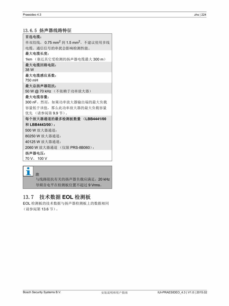
Praesideo 4.3 zhs | 224
Bosch Security Systems B.V. IUI-PRAESIDEO_4.3 | V1.0 | 2015.02安装说明和用户指南
13.6.5 扬声器线路特征
13.7 技术数据 EOL 检测板EOL 检测板的技术数据与扬声器检测板上的数据相同
(请参阅第 13.6 节)。
首选电缆:
单双绞线, 0.75 mm2 到 1.5 mm2。不建议使用多线
电缆。通信信号的串扰会影响检测性能。
大电缆长度:
1km (靠近其它受检测的扬声器电缆 大 300 m)
大电缆回路电阻:
38 W
大电缆感应系数:
750 mH
大总扬声器阻抗:
50 W @ 70 kHz (不依赖于功率放大器)
大电缆容量:
300 nF。然而,如果功率放大器输出端的 大负载
容量低于该值,那么此功率放大器的 大负载容量
优先(请参阅第 9.9 节)。
每个放大器通道的 多检测板数量(LBB4441/00
和 LBB4443/00):
500 W 放大器通道:
80250 W 放大器通道:
40125 W 放大器通道:
2060 W 放大器通道(仅限 PRS-8B060):
扬声器电压:
70 V、 100 V
注
与线路阻抗有关的扬声器负载应满足,20 kHz
导频音电平在检测板位置不超过 9 Vrms。
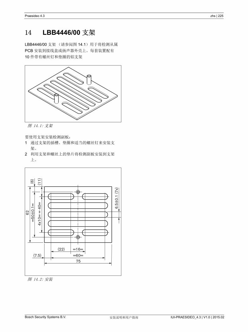
Praesideo 4.3 zhs | 225
Bosch Security Systems B.V. IUI-PRAESIDEO_4.3 | V1.0 | 2015.02安装说明和用户指南
14 LBB4446/00 支架
LBB4446/00 支架(请参阅图 14.1)用于将检测从属
PCB 安装到接线盒或扬声器外壳上。每套装置配有
10 件带有螺丝钉和垫圈的铝支架
要使用支架安装检测副板:
1 通过支架的插槽、垫圈和适当的螺丝钉来安装支
架。
2 利用支架和螺丝上的垫片将检测副板安装到支架
上。
图 14.1: 支架
图 14.2: 安装
62(6
)
(11)
(7.5)
(22) =16=
=60=75
6.5±
0.1
(7x)
=50
±0.
1=
4x10
= =
40=
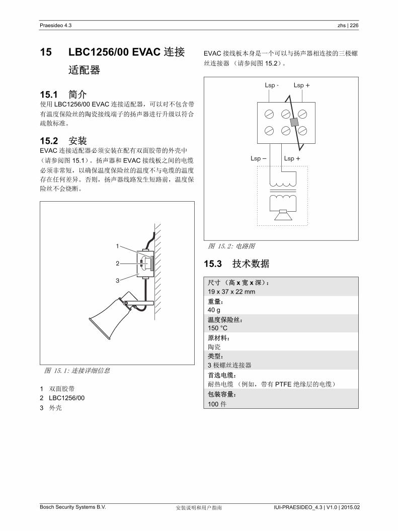
Praesideo 4.3 zhs | 226
Bosch Security Systems B.V. IUI-PRAESIDEO_4.3 | V1.0 | 2015.02安装说明和用户指南
15 LBC1256/00 EVAC 连接
适配器
15.1 简介使用 LBC1256/00 EVAC 连接适配器,可以对不包含带
有温度保险丝的陶瓷接线端子的扬声器进行升级以符合
疏散标准。
15.2 安装EVAC 连接适配器必须安装在配有双面胶带的外壳中
(请参阅图 15.1)。扬声器和 EVAC 接线板之间的电缆
必须非常短,以确保温度保险丝的温度不与电缆的温度
存在任何差异。否则,扬声器线路发生短路前,温度保
险丝不会烧断。
1 双面胶带
2 LBC1256/00
3 外壳
EVAC 接线板本身是一个可以与扬声器相连接的三极螺
丝连接器(请参阅图 15.2)。
15.3 技术数据
图 15.1: 连接详细信息
1
2
3
图 15.2: 电路图
尺寸(高 x 宽 x 深):
19 x 37 x 22 mm
重量:
40 g
温度保险丝:
150 °C
原材料:
陶瓷
类型:
3 极螺丝连接器
首选电缆:
耐热电缆(例如,带有 PTFE 绝缘层的电缆)
包装容量:
100 件
Lsp - Lsp +
Lsp +Lsp

Bosch Security Systems B.V. IUI-PRAESIDEO_4.3 | V1.0 | 2015.02安装说明和用户指南
Praesideo 4.3 zhs | 227
16 LBB4430/00 呼叫站
16.1 简介LBB4430/00 基本呼叫站用于向任何预定分区发送现场
实时语音播报或预先录制的公告,或者执行任何预定的
操作。 此呼叫站配有内置限制器和语音滤波器,可提高
语音清晰度。 有关呼叫站的方框图,请参阅图 16.1。
图 16.1: 方框图
A/D D/A
Power/Fault
NetworkProcessor
+ DSP
Keypad Keypad
(max. 16)
Headset
Microphone
PTT
POF
POF
NetworkRedundancy
Switching
I O Call Status
System Status

Bosch Security Systems B.V. IUI-PRAESIDEO_4.3 | V1.0 | 2015.02安装说明和用户指南
Praesideo 4.3 zhs | 228
16.2 控制器、连接器和指示器呼叫站(请参阅图 16.3、图 16.4)包括以下组件:
1 头戴式送受话器连接 - 连接头戴式送受话器的
3.5 mm (1/8 英寸)插座。连接头戴式送受话器
时,扩音器 (5) 和话筒处于静音状态(请参阅第
16.3.3 节)。
2 音量控制器 - 调整内部扬声器和头戴式送受话器音
量的控件。
3 “ 按下讲话 ” 按键 (PTT)- 呼叫启动键。
4 状态 LED- 提供呼叫站的信息和 Praesideo 系统状
态的三个双色状态 LED 指示灯。(请参阅第 16.5
节)。
5 扬声器 - 用于音频监控的扬声器。头戴式送受话器
与头戴式送受话器连接(1)相连时,扬声器和话
筒处于静音状态。只有 PTT 键,或呼叫站的呼叫激
活键,或其中一个键盘(请参阅第 48.3.3 节)激活
的钟声或讯息才通过呼叫站扬声器播放。记录呼
叫,利用呼叫堆栈进行时间切换广播。 还可对该呼
叫进行监测。
6 系统总线 - 将呼叫站连接其它 Praesideo 设备的两
个系统总线连接器(请参阅第 16.3.2 节)。
7 接口连接器 - 将呼叫站连接到呼叫站键盘的扁平电
缆连接器。
16.3 连接
16.3.1 简介本节概述如何使用网络控制器实现一般系统连接。
• 连接网络(请参阅第 16.3.2 节)。
• 连接头戴式送受话器(请参阅第 16.3.3 节)。
16.3.2 连接网络使用系统总线连接器和 LBB4416 网络电缆将呼叫站连
接到 Praesideo 系统。两个连接器可互换。
该设备由网络控制器通过 Praesideo 系统总线供电。
16.3.3 连接头戴式送受话器下图显示头戴式送受话器连接器上的信号及其与
3.5 mm 连接器部件之间的对应关系。
图 16.2: 头戴式送受话器连接器
注
头戴式送受话器线的长度不能超过 3 米。
5V
microphoneheadphone
GND
2K2

Bosch Security Systems B.V. IUI-PRAESIDEO_4.3 | V1.0 | 2015.02安装说明和用户指南
Praesideo 4.3 zhs | 229
图 16.3: 远程呼叫站的前视图和后视图
1 2
4
3
5
6
图 16.4: 仰视图
7
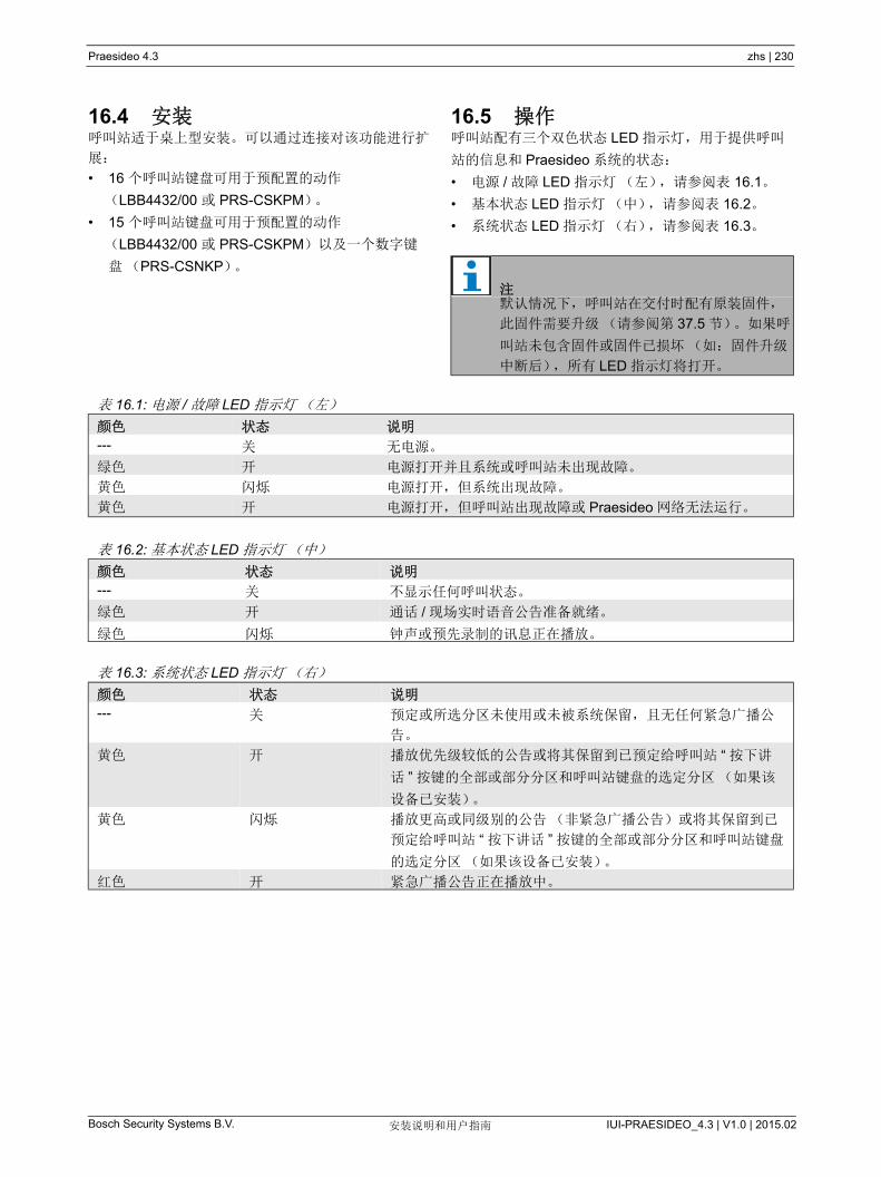
Bosch Security Systems B.V. IUI-PRAESIDEO_4.3 | V1.0 | 2015.02安装说明和用户指南
Praesideo 4.3 zhs | 230
16.4 安装呼叫站适于桌上型安装。可以通过连接对该功能进行扩
展:
• 16 个呼叫站键盘可用于预配置的动作
(LBB4432/00 或 PRS-CSKPM)。
• 15 个呼叫站键盘可用于预配置的动作
(LBB4432/00 或 PRS-CSKPM)以及一个数字键
盘(PRS-CSNKP)。
16.5 操作呼叫站配有三个双色状态 LED 指示灯,用于提供呼叫
站的信息和 Praesideo 系统的状态:
• 电源 / 故障 LED 指示灯(左),请参阅表 16.1。
• 基本状态 LED 指示灯(中),请参阅表 16.2。
• 系统状态 LED 指示灯(右),请参阅表 16.3。
注默认情况下,呼叫站在交付时配有原装固件,
此固件需要升级(请参阅第 37.5 节)。如果呼
叫站未包含固件或固件已损坏(如:固件升级
中断后),所有 LED 指示灯将打开。
表 16.1: 电源 / 故障 LED 指示灯(左)
颜色 状态 说明
--- 关 无电源。
绿色 开 电源打开并且系统或呼叫站未出现故障。
黄色 闪烁 电源打开,但系统出现故障。
黄色 开 电源打开,但呼叫站出现故障或 Praesideo 网络无法运行。
表 16.2: 基本状态 LED 指示灯(中)
颜色 状态 说明
--- 关 不显示任何呼叫状态。
绿色 开 通话 / 现场实时语音公告准备就绪。
绿色 闪烁 钟声或预先录制的讯息正在播放。
表 16.3: 系统状态 LED 指示灯(右)
颜色 状态 说明
--- 关 预定或所选分区未使用或未被系统保留,且无任何紧急广播公
告。
黄色 开 播放优先级较低的公告或将其保留到已预定给呼叫站 “ 按下讲
话 ” 按键的全部或部分分区和呼叫站键盘的选定分区(如果该
设备已安装)。
黄色 闪烁 播放更高或同级别的公告(非紧急广播公告)或将其保留到已
预定给呼叫站 “ 按下讲话 ” 按键的全部或部分分区和呼叫站键盘
的选定分区 (如果该设备已安装)。
红色 开 紧急广播公告正在播放中。
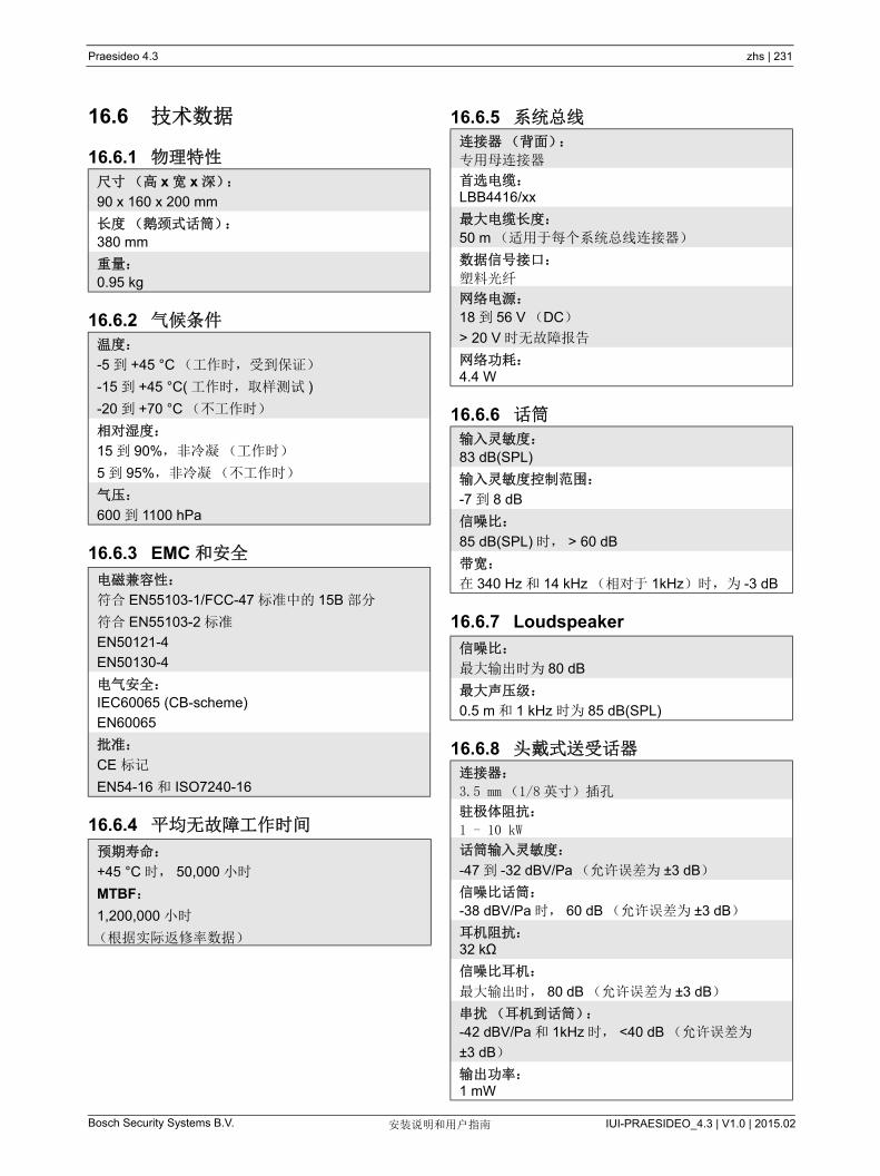
Bosch Security Systems B.V. IUI-PRAESIDEO_4.3 | V1.0 | 2015.02安装说明和用户指南
Praesideo 4.3 zhs | 231
16.6 技术数据
16.6.1 物理特性
16.6.2 气候条件
16.6.3 EMC 和安全
16.6.4 平均无故障工作时间
16.6.5 系统总线
16.6.6 话筒
16.6.7 Loudspeaker
16.6.8 头戴式送受话器
尺寸(高 x 宽 x 深):
90 x 160 x 200 mm
长度(鹅颈式话筒):
380 mm
重量:
0.95 kg
温度:
-5 到 +45 °C (工作时,受到保证)
-15 到 +45 °C( 工作时,取样测试 )
-20 到 +70 °C (不工作时)
相对湿度:
15 到 90%,非冷凝(工作时)
5 到 95%,非冷凝(不工作时)
气压:
600 到 1100 hPa
电磁兼容性:
符合 EN55103-1/FCC-47 标准中的 15B 部分
符合 EN55103-2 标准
EN50121-4
EN50130-4
电气安全:
IEC60065 (CB-scheme)
EN60065
批准:
CE 标记
EN54-16 和 ISO7240-16
预期寿命:
+45 °C 时, 50,000 小时
MTBF:
1,200,000 小时
(根据实际返修率数据)
连接器(背面):
专用母连接器
首选电缆:LBB4416/xx
大电缆长度:
50 m (适用于每个系统总线连接器)
数据信号接口:
塑料光纤
网络电源:
18 到 56 V (DC)
> 20 V 时无故障报告
网络功耗:4.4 W
输入灵敏度:
83 dB(SPL)
输入灵敏度控制范围:
-7 到 8 dB
信噪比:
85 dB(SPL) 时, > 60 dB
带宽:
在 340 Hz 和 14 kHz (相对于 1kHz)时,为 -3 dB
信噪比:
大输出时为 80 dB
大声压级:
0.5 m 和 1 kHz 时为 85 dB(SPL)
连接器:
3.5 mm (1/8 英寸)插孔
驻极体阻抗:
1 - 10 kW
话筒输入灵敏度:
-47 到 -32 dBV/Pa (允许误差为 ±3 dB)
信噪比话筒:
-38 dBV/Pa 时, 60 dB (允许误差为 ±3 dB)
耳机阻抗:32 kΩ
信噪比耳机:
大输出时, 80 dB (允许误差为 ±3 dB)
串扰 (耳机到话筒):
-42 dBV/Pa 和 1kHz 时, <40 dB (允许误差为
±3 dB)
输出功率:1 mW
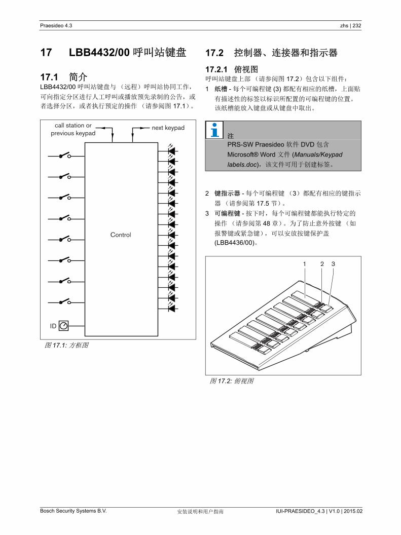
Bosch Security Systems B.V. IUI-PRAESIDEO_4.3 | V1.0 | 2015.02安装说明和用户指南
Praesideo 4.3 zhs | 232
17 LBB4432/00 呼叫站键盘
17.1 简介LBB4432/00 呼叫站键盘与(远程)呼叫站协同工作,
可向指定分区进行人工呼叫或播放预先录制的公告,或
者选择分区,或者执行预定的操作(请参阅图 17.1)。
17.2 控制器、连接器和指示器
17.2.1 俯视图呼叫站键盘上部(请参阅图 17.2)包含以下组件:
1 纸槽 - 每个可编程键 (3) 都配有相应的纸槽,上面贴
有描述性的标签以标识所配置的可编程键的位置。
该纸槽能放入键盘或从键盘中取出。
2 键指示器 - 每个可编程键(3)都配有相应的键指示
器(请参阅第 17.5 节)。
3 可编程键 - 按下时,每个可编程键都能执行特定的
操作(请参阅第 48 章)。为了防止意外按键(如
报警键或紧急键),可以安放按键保护盖
(LBB4436/00)。
图 17.1: 方框图
Control
ID
next keypadcall station orprevious keypad 注
PRS-SW Praesideo 软件 DVD 包含
Microsoft® Word 文件 (Manuals/Keypad
labels.doc),该文件可用于创建标签。
图 17.2: 俯视图
1 2 3
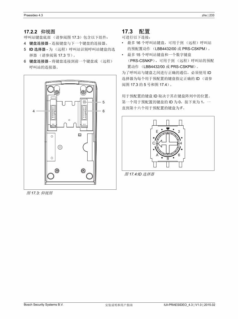
Bosch Security Systems B.V. IUI-PRAESIDEO_4.3 | V1.0 | 2015.02安装说明和用户指南
Praesideo 4.3 zhs | 233
17.2.2 仰视图呼叫站键盘底部(请参阅图 17.3)包含以下组件:
4 键盘连接器 - 连接键盘与下一个键盘的连接器。
5 ID 选择器 - 为(远程)呼叫站识别呼叫站键盘的选
择器(请参阅第 17.3 节)。
6 键盘连接器 - 将键盘连接到前一个键盘或(远程)
呼叫站的连接器。
17.3 配置可进行以下连接:
• 多 16 个呼叫站键盘,可用于到(远程)呼叫站
的预配置动作(LBB4432/00 或 PRS-CSKPM)。
• 多 15 个呼叫站键盘和一个数字键盘
(PRS-CSNKP),可用于到(远程)呼叫站的预配
置动作(LBB4432/00 或 PRS-CSKPM)。
为了呼叫站与键盘之间进行正确的通信,必须使用 ID
选择器为每个用于预配置的键盘指定正确的 ID (请参
阅图 17.3 的 5 号和图 17.4)。
用于预配置的键盘 ID 取决于其在键盘阵列中的位置。
第一个用于预配置的键盘的 ID 为 0,接下来为 1,一
直到第十六个用于预配置的键盘为 F。
图 17.3: 仰视图
4 6
5
图 17.4:ID 选择器
2E
6A8
C 4

Bosch Security Systems B.V. IUI-PRAESIDEO_4.3 | V1.0 | 2015.02安装说明和用户指南
Praesideo 4.3 zhs | 234
17.4 安装该键盘适于桌上型安装。该键盘可与(远程)呼叫站
或已与(远程)呼叫站相连的键盘相连。过程如下
(请参阅图 17.5):
1 向左滑动卸掉盖子,并从键盘中取出。
2 连接扁平电缆和键盘连接器,并为键盘指定正确的
ID。短的扁平电缆用于键盘间连接;长的扁平电缆
(同呼叫站一同提供)用于呼叫站同键盘的连接。
3 将接线板滑入键盘的底部。
4 使用三个螺丝固定接线板。
5 向右滑动放回盖子, 并将其装入键盘。
小心
在您将系统电缆与键盘相连之前,断开其与
(远程)呼叫站以及备用电源之间的连接。键
盘与通电的(远程)呼叫站相连可以对(远
程)呼叫站造成损害。
图 17.5: 安装
1 2
34
5

Bosch Security Systems B.V. IUI-PRAESIDEO_4.3 | V1.0 | 2015.02安装说明和用户指南
Praesideo 4.3 zhs | 235
17.5 操作呼叫站键盘配有八个(软件)可编程键。每个键都配
有一个双色 LED 指示灯以进行状态指示(请参阅
表 17.1)。然而,状态指示取决于已指定给可编程键的
功能(请参阅 44.5.8 节和 48.3 节):
• 对于配置为路由选择器(如 Zone selection (分区
选择))的那些键,指示器用于路由选择指示。
• 对于为某些功能配置的那些键,象 Priority (优先
级) Call macro (呼叫宏)等,该指示器用作选择
指示器。只要选择是有效的,该指示器就处于打开
状态。
• 对于为某些功能配置的键而言,象 Cancel (取
消)、 Reset (重置)、 Recall (重拨)、 BGM
volume (BGM 音量)等,该指示器用作键激活指
示器。只要按下键,该指示器就处于打开状态。
17.6 技术数据
17.6.1 物理尺寸
17.6.2 气候条件
17.6.3 EMC 和安全
17.6.4 平均无故障工作时间
17.6.5 系统总线
表 17.1: 路由选择器 LED 指示灯指示。
颜色 状态 说明
黄色 开 表示选定源被优先级较低的公
告所占用。
黄色 闪烁 表示选定源被更高或同等优先
级的公告所占用。
绿色 开 选定源可用。
尺寸(高 x 宽 x 深):
70 x 95 x 200 mm
重量:
0.4 kg
扁平电缆 大长度:
5 m (所有键盘的电缆加在一起)
温度:
-5 到 +45 °C (工作时,受到保证)
-15 到 +45 °C( 工作时,取样测试 )
-20 到 +70 °C (不工作时)
相对湿度:
15 到 90%,非冷凝(工作时)
5 到 95%,非冷凝(不工作时)
气压:
600 到 1100 hPa
电磁兼容性:
符合 EN55103-1/FCC-47 标准中的 15B 部分
符合 EN55103-2 标准
EN50121-4
EN50130-4
电气安全:
IEC60065 (CB-scheme)
EN60065
批准:
CE 标记
EN54-16 和 ISO7240-16
预期寿命:
+45 °C 时, 100,000 小时
MTBF:
1,200,000 小时
(根据实际返修率数据)
网络电源:
18 到 56 V (DC)
> 20 V 时无故障报告
网络功耗:
1.3 W
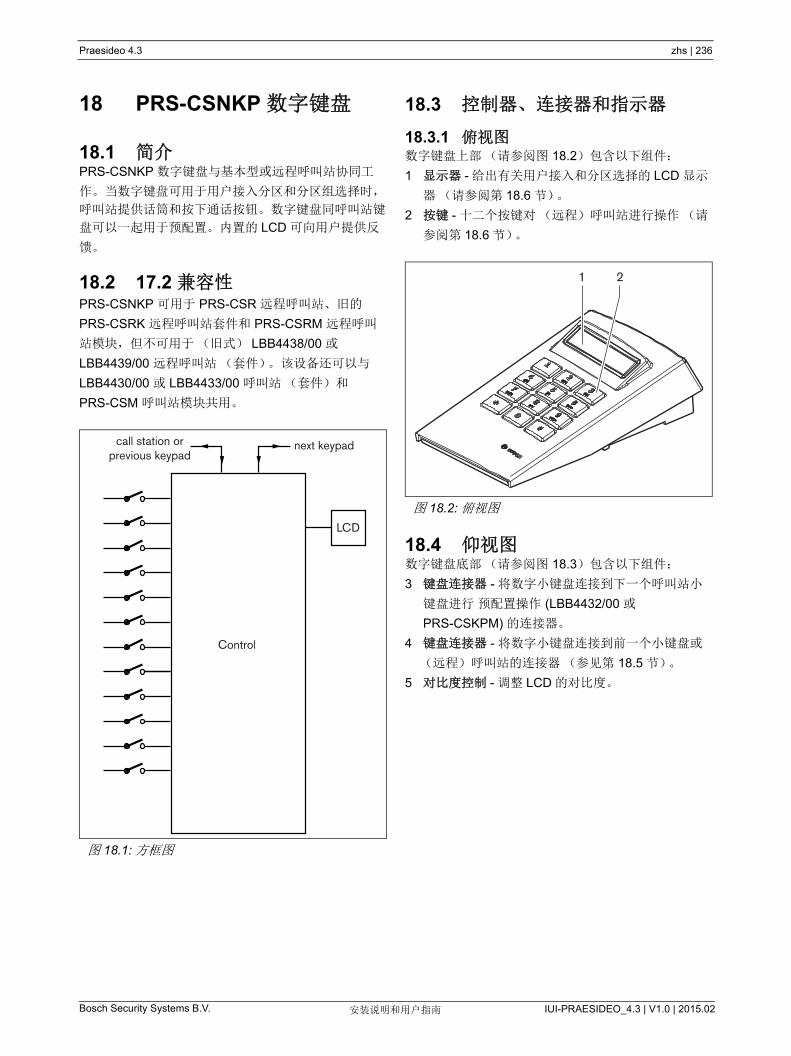
Bosch Security Systems B.V. IUI-PRAESIDEO_4.3 | V1.0 | 2015.02安装说明和用户指南
Praesideo 4.3 zhs | 236
18 PRS-CSNKP 数字键盘
18.1 简介PRS-CSNKP 数字键盘与基本型或远程呼叫站协同工
作。当数字键盘可用于用户接入分区和分区组选择时,
呼叫站提供话筒和按下通话按钮。数字键盘同呼叫站键
盘可以一起用于预配置。内置的 LCD 可向用户提供反
馈。
18.2 17.2 兼容性PRS-CSNKP 可用于 PRS-CSR 远程呼叫站、旧的
PRS-CSRK 远程呼叫站套件和 PRS-CSRM 远程呼叫
站模块,但不可用于(旧式) LBB4438/00 或
LBB4439/00 远程呼叫站(套件)。该设备还可以与
LBB4430/00 或 LBB4433/00 呼叫站(套件)和
PRS-CSM 呼叫站模块共用。
18.3 控制器、连接器和指示器
18.3.1 俯视图数字键盘上部(请参阅图 18.2)包含以下组件:
1 显示器 - 给出有关用户接入和分区选择的 LCD 显示
器(请参阅第 18.6 节)。
2 按键 - 十二个按键对(远程)呼叫站进行操作(请
参阅第 18.6 节)。
18.4 仰视图数字键盘底部(请参阅图 18.3)包含以下组件:
3 键盘连接器 - 将数字小键盘连接到下一个呼叫站小
键盘进行 预配置操作 (LBB4432/00 或
PRS-CSKPM) 的连接器。
4 键盘连接器 - 将数字小键盘连接到前一个小键盘或
(远程)呼叫站的连接器(参见第 18.5 节)。
5 对比度控制 - 调整 LCD 的对比度。
图 18.1: 方框图
Control
LCD
next keypadcall station orprevious keypad
图 18.2: 俯视图
1 2
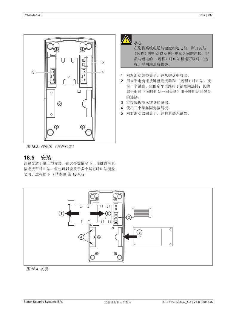
Bosch Security Systems B.V. IUI-PRAESIDEO_4.3 | V1.0 | 2015.02安装说明和用户指南
Praesideo 4.3 zhs | 237
18.5 安装该键盘适于桌上型安装。在大多数情况下,该键盘可直
接连接至呼叫站,但也可以安放于多个其它呼叫站键盘
之间。过程如下(请参见 图 18.4):
1 向左滑动卸掉盖子,并从键盘中取出。
2 用扁平电缆连接键盘连接器和(远程)呼叫站,或
前一个键盘。短的扁平电缆用于键盘间连接;长的
扁平电缆(同呼叫站一同提供)用于呼叫站同键盘
的连接。
3 将接线板滑入键盘的底部。
4 使用三个螺丝固定接线板。
5 向右滑动放回盖子, 并将其装入键盘。
图 18.3: 仰视图(打开后盖)
3 4
5
小心
在您将系统电缆与键盘相连之前,断开其与
(远程)呼叫站以及备用电源之间的连接。键
盘与通电的(远程)呼叫站相连可以对(远
程)呼叫站造成损害。
图 18.4: 安装
12
34
5
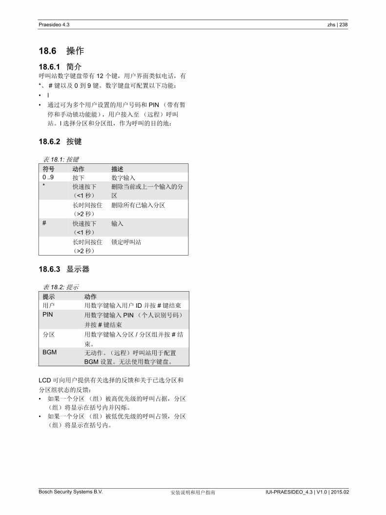
Bosch Security Systems B.V. IUI-PRAESIDEO_4.3 | V1.0 | 2015.02安装说明和用户指南
Praesideo 4.3 zhs | 238
18.6 操作
18.6.1 简介呼叫站数字键盘带有 12 个键,用户界面类似电话,有
*、 # 键以及 0 到 9 键。数字键盘可配置以下功能:
• l
• 通过可为多个用户设置的用户号码和 PIN (带有暂
停和手动锁功能能),用户接入至(远程)呼叫
站。 l 选择分区和分区组,作为呼叫的目的地:
18.6.2 按键
18.6.3 显示器
LCD 可向用户提供有关选择的反馈和关于已选分区和
分区组状态的反馈:
• 如果一个分区(组)被高优先级的呼叫占据,分区
(组)将显示在括号内并闪烁。
• 如果一个分区(组)被低优先级的呼叫占领,分区
(组)将显示在括号内。
表 18.1: 按键
符号 动作 描述
0 ..9 按下 数字输入
* 快速按下
(<1 秒)
删除当前或上一个输入的分
区
长时间按住
(>2 秒)
删除所有已输入分区
# 快速按下
(<1 秒)
输入
长时间按住
(>2 秒)
锁定呼叫站
表 18.2: 提示
提示 动作
用户 用数字键输入用户 ID 并按 # 键结束
PIN 用数字键输入 PIN (个人识别号码)
并按 # 键结束
分区 用数字键输入分区 / 分区组并按 # 结
束。
BGM 无动作。(远程)呼叫站用于配置
BGM 设置。无法使用数字键盘。

Bosch Security Systems B.V. IUI-PRAESIDEO_4.3 | V1.0 | 2015.02安装说明和用户指南
Praesideo 4.3 zhs | 239
18.7 技术数据
18.7.1 物理尺寸
18.7.2 气候条件
18.7.3 EMC 和安全
18.7.4 平均无故障工作时间
18.7.5 系统总线
尺寸(高 x 宽 x 深):
70 x 95 x 200 mm
重量:
0.4 kg
扁平电缆 大长度:
5 m (所有键盘的电缆加在一起)
温度:
-5 到 +45 °C (工作时,受到保证)
-15 到 +55 °C( 工作时,取样测试 )
-20 到 +70 °C (不工作时)
相对湿度:
15 到 90%,非冷凝(工作时)
5 到 95%,非冷凝(不工作时)
气压:
600 到 1100 hPa
电磁兼容性:
符合 EN55103-1/FCC-47 标准中的 15B 部分
符合 EN55103-2 标准
EN50121-4
EN50130-4
电气安全:
IEC60065 (CB-scheme)
EN60065
批准:
CE 标记
EN54-16 和 ISO7240-16
预期寿命:
+45 °C 时, 100,000 小时
MTBF:
1,200,000 小时
(根据实际返修率数据)
网络电源:
18 到 56V (DC)
> 20V 时无故障报告
网络功耗:
1.6 W
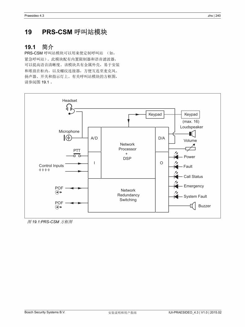
Bosch Security Systems B.V. IUI-PRAESIDEO_4.3 | V1.0 | 2015.02安装说明和用户指南
Praesideo 4.3 zhs | 240
19 PRS-CSM 呼叫站模块
19.1 简介PRS-CSM 呼叫站模块可以用来使定制呼叫站 (如,
紧急呼叫站)。此模块配有内置限制器和语音滤波器,
可以提高语音清晰度。 该模块具有金属外壳,易于安装
和堆放在柜内,以及螺纹连接器,方便互连至麦克风、
扬声器、开关和指示灯上。有关呼叫站模块的方框图,
请参阅图 19.1 。
图 19.1:PRS-CSM 方框图
A/D D/ANetwork
Processor+
DSP
Keypad Keypad
(max. 16)
Headset
Microphone
PTT
POF
Control Inputs
POF
NetworkRedundancy
Switching
I OPower
Loudspeaker
Volume
System Fault
Emergency
Call Status
Fault
Buzzer
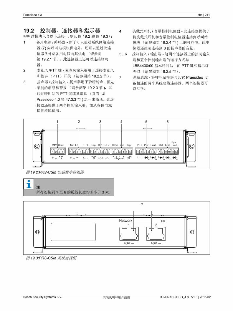
Bosch Security Systems B.V. IUI-PRAESIDEO_4.3 | V1.0 | 2015.02安装说明和用户指南
Praesideo 4.3 zhs | 241
19.2 控制器、连接器和指示器呼叫站模块包含以下连接(参见 图 19.2 和 图 19.3):
1 备用电源 / 蜂鸣器 - 除了可以通过系统网络连接
器 (7) 向呼叫站模块供电外,还可以通过此连
接器从外部备用电源向其供电(请参阅
第 19.2.1 节)。此连接器上还可以连接蜂鸣
器。
2 麦克风 /PTT 键 - 麦克风输入端用于连接麦克风
和按讲(PTT)开关(请参阅第 19.2.2 节)。
3 扬声器 / 控制输入 - 扬声器用于聆听铃声、预先
录制的消息和警报(请参阅第 19.2.3 节 ),其
通过呼叫站的 PTT 键或其键盘(参看 IUI
Praesideo 4.0 第 47.3.3 节 ) 之一来激活。此连
接器还提供了两个控制输入端,如从备份电源
接收故障输出。
4 头戴式耳机 / 音量控制电位器 - 此连接器提供了
将头戴式耳机和音量控制电位器连接到呼叫站
模块(请参阅第 19.2.4 节 ) 上的可能性。此电
位器还控制连接到 3 的扬声器的音量。
5、6 控制输入 / 输出端 - 这两个连接器上的控制输入
端和五个控制输出端的运行方式与
LBB4430/00 基本呼叫站上的 PTT 键和指示灯
类似(请参阅第 19.2.5 节)。
7 系统总线 - 将呼叫站模块与其它 Praesideo 设
备相连的两个系统总线连接器。两个连接器可
以互换。
图 19.2:PRS-CSM 安装程序前视图
24V Buzz Mic PTT Lsp CI 1 CI 2 Hmic Vol Hlsp PTT Pwr Fault Call Emg Fault Syst
+ +
1 2 3 4 1 2 3 4 5 6 1 2 3 4 5 6 1 2 3 4 5 6 1 2 3 4 5 6 7 8 9 10 11 12
1 2 3 4 5 6
注
所有连接到 1 至 6 的缆线长度均须小于 3 米。
图 19.3:PRS-CSM 系统前视图
48V 48V
Network 1 2
7
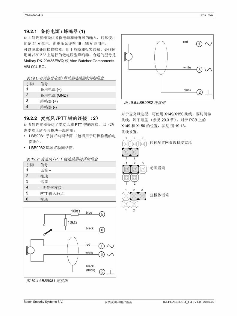
Bosch Security Systems B.V. IUI-PRAESIDEO_4.3 | V1.0 | 2015.02安装说明和用户指南
Praesideo 4.3 zhs | 242
19.2.1 备份电源 / 蜂鸣器 (1)此 4 针连接器提供备份电源和蜂鸣器的输入。通常使用
的是 24 V 供电,但电压允许在 18 - 56 V 范围内。
可以在此处连接蜂鸣器,用于故障和报警通知。必须使
用可以在 3 V 上运行的低电压型蜂鸣器。合适的型号是
Mallory PK-20A35EWQ 或 Alan Butcher Components
ABI-004-RC。
19.2.2 麦克风 /PTT 键的连接(2)此 6 针连接器提供了麦克风和 PTT 键的连接。以下动
态麦克风适合与模块一起使用:
• LBB9081 手持式动圈话筒(包括用于切换检测的电
阻器)。
• LBB9082 鹅颈式动圈话筒。
对于麦克风选型,可使用 X149/X150 跳线。要访问该
跳线,卸下顶盖(参见 20.3 节)。对于 PCB 上的
X149 和 X150 的位置,参见 图 19.13。
跳线设置:
通过配置网页选择麦克风
动圈话筒
驻极体话筒
表 19.1:有关备份电源 /蜂鸣器连接器的详细信息
引脚 信号
1 备用电源 (+)
2 备用电源 (GND)
3 蜂鸣器 (+)
4 蜂鸣器 (-)
表 19.2: 麦克风 / PTT 键连接器的详细信息
引脚 信号
1 话筒 +
2 接地
3 话筒 -
4 - 无任何连接 -
5 PTT 输入触点
6 接地
图 19.4:LBB9081 连接图
10k
10k blue
black
red
white
black(thick)
5
6
1
3
2
图 19.5:LBB9082 连接图
3
1
2black
white
red
1 2
1 2
3
1 2
1 2
3
1 2
1 2
3

Bosch Security Systems B.V. IUI-PRAESIDEO_4.3 | V1.0 | 2015.02安装说明和用户指南
Praesideo 4.3 zhs | 243
19.2.3 扬声器 / 控制输入端 (3)此 6 针连接器提供到扬声器和两个控制输入端的连接。
控制输入端可以配置用于触点接通或中断(请参阅 IUI
Praesidio 4.0 第 43.4.7 节)。此控制输入端还可以检测
缆线的短路和开路连接情况(请参阅 图 19.6 和
图 19.7)。控制输入是否真正受到检测,配置中已有定
义。
19.2.4 耳机 / 音量控制(4)此 6 针连接器提供到耳机和音量控制的连接。此音量控
制还控制连接到连接 3 的扬声器的音量。
线性电位器 R (典型值: 100 kΩ) 用于创建电源电压
的控制电压。
如果不需要音量控制, 则引脚 2 和引脚 3 必须相互连
接。 此时, 耳机或扬声器的音量达到 大值。
表 19.3: 扬声器 / 控制输入端连接器的详细信息
引脚 信号
1 扬声器
2 扬声器
3 控制输入端 1
4 返回控制输入端 1
5 控制输入端 2
6 返回控制输入端 2
图 19.6: 受检测的控制输入端
图 19.7: 未受检测的控制输入端
10kΩ
10kΩ
RTN Control input
RTN Control input
警告
切勿将直流或交流信号连接到控制输入端,否
则可能会损坏输入电路。只能使用无电压触
点。
注
切勿将多个控制输入端的控制输入线联合使用
(如,请勿使用公共回路线)。
表 19.4: 耳机 / 音量控制连接器的详细信息
引脚 信号
1 耳机(麦克风 +)
2 接地(麦克风 -)
3 音量控制电压
4 3.3 V 电源输出端
5 接地(耳机 -)
6 听筒 +
图 19.8: 头戴式送受话器连接图
Microphone
R
Earphone
Volume Headset
1
2
3
4
5
6

Bosch Security Systems B.V. IUI-PRAESIDEO_4.3 | V1.0 | 2015.02安装说明和用户指南
Praesideo 4.3 zhs | 244
19.2.5 控制输入 / 输出端 (5, 6)这两个 6 针连接器为 PTT 键的一个控制输入端和 LED
指示灯的五个控制输出端提供连接。
此连接器上的 PTT 输入触点与连接器 2 上的 PTT 输入
触点并行。使用其中之一。
有关连接图的详细信息,请参阅图 19.9。必须在电路
中接入两个电阻器,因为触点始终受系统软件的检测。
如 图 19.10 LED 驱动电路所示。
指示灯的典型颜色为:
• 绿色用于电源和呼叫状态指示灯;
• 黄色用于故障和系统故障指示灯;
• 红色用于紧急指示灯。
表 19.5: 控制输入 / 输出端连接器的详细信息
引脚 信号
1 PTT 输入触点
2 接地
3 LED 电源指示灯 +/ 阳极
4 LED 电源指示灯 -/ 阴极
5 LED 故障指示灯 +/ 阳极
6 LED 故障指示灯 -/ 阴极
7 LED 呼叫状态指示灯 +/ 阳极
8 LED 呼叫状态指示器 -/ 阴极
9 LED 紧急指示灯 +/ 阳极
10 LED 紧急指示灯 -/ 阴极
11 LED 系统故障指示灯 +/ 阳极
12 LED 系统故障指示灯 -/ 阴极
警告
切勿将直流或交流信号连接到控制输入端, 否
则可能会损坏输入电路。 只能使用无电压触
点。
图 19.9:“ 按下讲话 ”(PTT) 按键
GND
5V
PTT InputContact 10 kΩ10 kΩ
10 kΩ
图 19.10: 内部供电的 LED
Pwr: 电源指示灯
故障 : 故障指示灯
Call: 呼叫状态指示灯
Emg: 紧急指示灯
系统故障:系统故障指示器
+5V, 30 mA
62V 62V
3
4 6 8
7
10
9
12
115
Pwr Fault Call Systfault
Emg
62V 62V 62V
330 330 330 330 330

Bosch Security Systems B.V. IUI-PRAESIDEO_4.3 | V1.0 | 2015.02安装说明和用户指南
Praesideo 4.3 zhs | 245
还可以连接外部供电的指示灯或 LED (见图 19.11),
或外部供电的中继器(见图 19.12)。将连接器 5 引脚
2 用作 GND (接地)
图 19.10 中电阻器 R 的值取决于外部电源的电压、
LED 指示灯的正向电压和通过 LED 指示灯的电流:
例如,外部电源电压是 24 V, LED 指示灯的正向电压
是 2 V,通过 LED 指示灯的电流是 10 mA,那么:
图 19.11: 外部供电的 LED
图 19.12: 外部供电的继电器
Max. 56VR
LEDindicator -/cathode
GND
I < 100 mA
RVsource Vforward–
I---------------------------------------------=
R24 2–
10 103–
--------------------- 2200 = =
LEDindicator -/cathode
GND
Max. 56V
I < 100 mA

Bosch Security Systems B.V. IUI-PRAESIDEO_4.3 | V1.0 | 2015.02安装说明和用户指南
Praesideo 4.3 zhs | 246
19.2.6 键盘接口 (X143)其他键盘或键盘模块可通过 16 位扁平排线连接到此呼
叫站模块上,连接到 X143 上。此扁平排线配有小键盘
或小键盘模块。
16 个小键盘和 / 或小键盘模块可以串连(环接)。参
阅第 20.3 节。
图 19.13:PRS-CSM 的组件侧 PCB
X149 1
1 2
3.
X14321
1615
.. .. .. .. .. .. ..
X150

Bosch Security Systems B.V. IUI-PRAESIDEO_4.3 | V1.0 | 2015.02安装说明和用户指南
Praesideo 4.3 zhs | 247
19.3 安装呼叫站模块配有支架和螺丝孔,方便安装。请参阅
图 19.14。
一定要为电缆和连接器留下足够的空间。
尤其要遵守 Praesideo 网线的 小弯曲半径(见 IUI
Praesidio 4.0 第 31.6 节)。
图 19.14:PRS-CSM 安装尺寸
*:精确布局取决于模块的类型
* *
183
174
38.4
19.2
162
9037
174
164
42.6
4.2

Bosch Security Systems B.V. IUI-PRAESIDEO_4.3 | V1.0 | 2015.02安装说明和用户指南
Praesideo 4.3 zhs | 248
19.4 技术数据
19.4.1 物理特性
19.4.2 气候条件
19.4.3 EMC 和安全
19.4.4 平均无故障工作时间
19.4.5 系统总线
19.4.6 备用电源
19.4.7 话筒
19.4.8 Loudspeaker
尺寸(高 x 宽 x 深):
43 x 183 x 164 mm
重量:
0.8 kg
温度:
-5 到 +55 °C (工作时,受到保证)
-15 到 +55 °C( 工作时,取样测试 )
-20 到 +70 °C (不工作时)
相对湿度:
15 到 90%,非冷凝(工作时)
5 到 95%,非冷凝(不工作时)
气压:
600 到 1100 hPa
电磁兼容性:
符合 EN55103-1/FCC-47 标准中的 15B 部分
符合 EN55103-2 标准
EN50121-4
EN50130-4
电气安全:
IEC60065 (CB-scheme)
EN60065
批准:
CE 标记
EN54-16 和 ISO7240-16
EN/IEC60945 除了盐雾试验外
预期寿命:
+55 °C 时, 50,000 小时
MTBF:
500,000 小时
(根据实际返修率数据)
网络电源:
18 到 56 V (DC)
> 20 V 时无故障报告
网络功耗:
6.2 W
备用电压:
18 到 56 V(DC)
> 20 V 时无故障报告
备用电流:
大 2 A ( 配 大数目的键盘)
话筒输入灵敏度:
-55 dBV (平衡)
输入控制范围:
-7 到 8 dB
信噪比:
额定灵敏度时, 小为 60 dB
余量:
额定灵敏度时, 小为 30 dB
带宽:
340 至 14000 Hz (-3 dB 参考 1 kHz)
检测限制:
180 至 14000 W (动圈话筒)
0.2 至 4.8 mA (驻极体话筒)
阻抗:
8 到 32 Ω
信噪比:
大输出时,通常为 80 dB (允许误差为 ±3 dB)
输出功率:
通常为 100 mW, 大 300 mW

Bosch Security Systems B.V. IUI-PRAESIDEO_4.3 | V1.0 | 2015.02安装说明和用户指南
Praesideo 4.3 zhs | 249
19.4.9 头戴式送受话器 19.4.10 控件
19.4.11 蜂鸣器
话筒输入灵敏度:
-44 dBV
输入灵敏度控制范围:
-7 到 8 dB
麦克风耳机检测电流:
0.15 到 0.8 mA
信噪比:
额定灵敏度时,为 60 dB (麦克风)
80 dB ( 耳机 )
耳机阻抗:
少 16 W (一般为 32 W)
串扰(耳机到话筒):
大 -40 dB
带宽:
340 至 14000 Hz (-3 dB 参考 1 kHz)
输出功率 :
0.1 到 30 mW (一般为 1 mW)
音量控制电压:
0 到 3.3 V
扬声器和耳机的音量
音量控制电压:
0 到 3.3 V
控制输入端 1、 2 和 PTT 输入触点
电阻检测(启用监视):
电缆短路
< 2.5 kΩ
触点关闭
7.5 kΩ 至 12 kΩ
触点打开
17.5 kΩ 至 22 kΩ
电缆损坏
> 27 kΩ
电阻检测(禁用监视):
触点关闭
< 12 kΩ
触点打开
> 17.5 kΩ
控制输出端
输出类型:
集电极 / 漏极开路
内部输出电源电流:
大 10 mA (每引脚)
大 30 mA
(合计同时 多亮起 3 个 LED)
输出电压:
大 56 V (每引脚)
输出反向电流:
大 100 mA (每个输出开关引脚)
蜂音器电压:
3.3 V
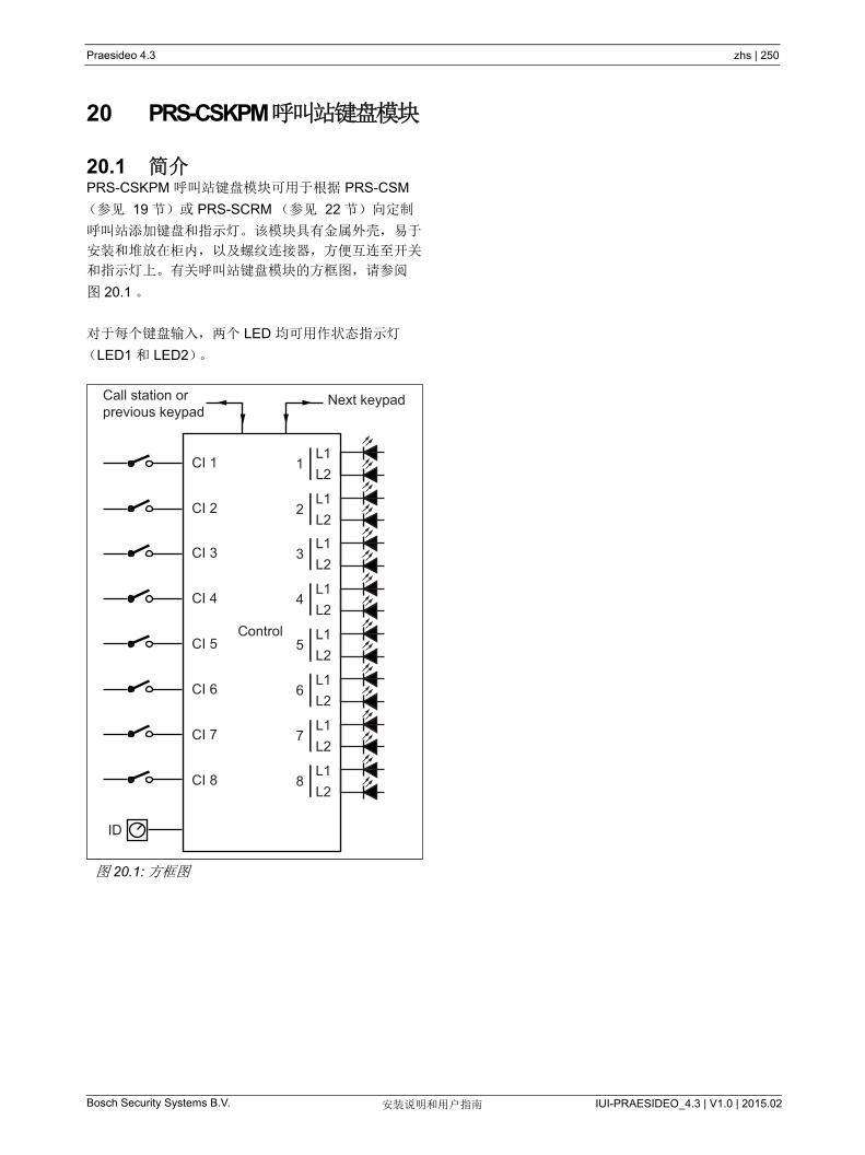
Bosch Security Systems B.V. IUI-PRAESIDEO_4.3 | V1.0 | 2015.02安装说明和用户指南
Praesideo 4.3 zhs | 250
20 PRS-CSKPM 呼叫站键盘模块
20.1 简介PRS-CSKPM 呼叫站键盘模块可用于根据 PRS-CSM
(参见 19 节)或 PRS-SCRM (参见 22 节)向定制
呼叫站添加键盘和指示灯。该模块具有金属外壳,易于
安装和堆放在柜内,以及螺纹连接器,方便互连至开关
和指示灯上。有关呼叫站键盘模块的方框图,请参阅
图 20.1 。
对于每个键盘输入,两个 LED 均可用作状态指示灯
(LED1 和 LED2)。
图 20.1: 方框图
Control
ID
Next keypadCall station orprevious keypad
CI 1L1L2
1
CI 2L1L2
2
CI 3L1L2
3
CI 4L1L2
4
CI 5L1L2
5
CI 6L1L2
6
CI 7L1L2
7
CI 8L1L2
8
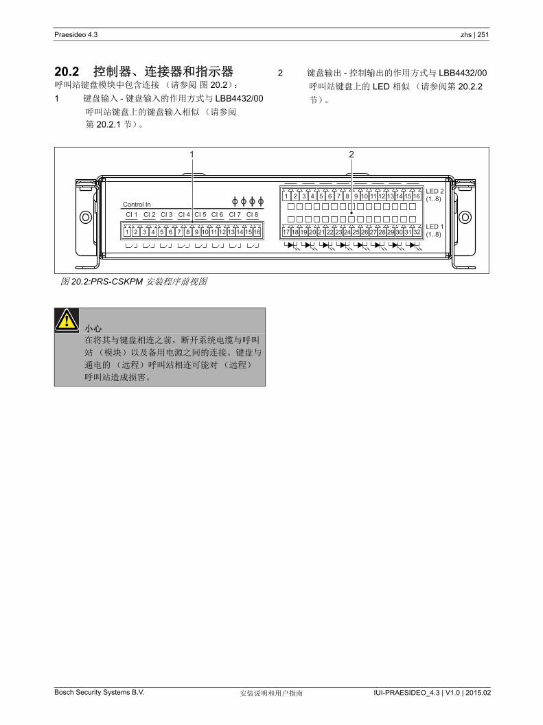
Bosch Security Systems B.V. IUI-PRAESIDEO_4.3 | V1.0 | 2015.02安装说明和用户指南
Praesideo 4.3 zhs | 251
20.2 控制器、连接器和指示器呼叫站键盘模块中包含连接(请参阅 图 20.2):
1 键盘输入 - 键盘输入的作用方式与 LBB4432/00
呼叫站键盘上的键盘输入相似(请参阅
第 20.2.1 节)。
2 键盘输出 - 控制输出的作用方式与 LBB4432/00
呼叫站键盘上的 LED 相似(请参阅第 20.2.2
节)。
图 20.2:PRS-CSKPM 安装程序前视图
Control In CI 1 CI 2 CI 3 CI 4 CI 5 CI 6 CI 7 CI 8
LED 2 (1..8)
LED 1 (1..8)
1 2
1 2 3 4 5 6 7 8 9 10 11 12 13 14 15 16
1 2 3 4 5 6 7 8 9 10 11 12 13 14 15 16
17 18 19 20 21 22 23 24 25 26 27 28 29 30 31 32
小心
在将其与键盘相连之前,断开系统电缆与呼叫
站(模块)以及备用电源之间的连接。键盘与
通电的(远程)呼叫站相连可能对(远程)
呼叫站造成损害。
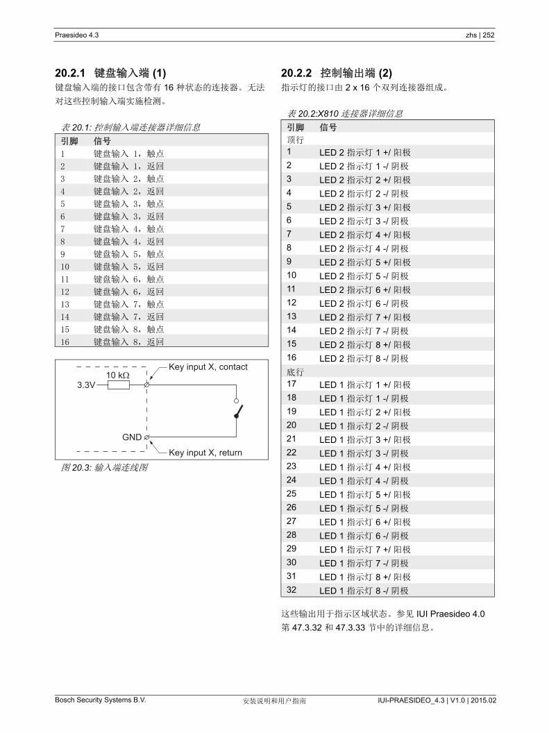
Bosch Security Systems B.V. IUI-PRAESIDEO_4.3 | V1.0 | 2015.02安装说明和用户指南
Praesideo 4.3 zhs | 252
20.2.1 键盘输入端 (1)键盘输入端的接口包含带有 16 种状态的连接器。 无法
对这些控制输入端实施检测。
20.2.2 控制输出端 (2)指示灯的接口由 2 x 16 个双列连接器组成。
这些输出用于指示区域状态。参见 IUI Praesideo 4.0
第 47.3.32 和 47.3.33 节中的详细信息。
表 20.1: 控制输入端连接器详细信息
引脚 信号
1 键盘输入 1,触点
2 键盘输入 1,返回
3 键盘输入 2,触点
4 键盘输入 2,返回
5 键盘输入 3,触点
6 键盘输入 3,返回
7 键盘输入 4,触点
8 键盘输入 4,返回
9 键盘输入 5,触点
10 键盘输入 5,返回
11 键盘输入 6,触点
12 键盘输入 6,返回
13 键盘输入 7,触点
14 键盘输入 7,返回
15 键盘输入 8,触点
16 键盘输入 8,返回
图 20.3: 输入端连线图
3.3V
GND
10 kKey input X, contact
Key input X, return
表 20.2:X810 连接器详细信息
引脚 信号
顶行
1 LED 2 指示灯 1 +/ 阳极
2 LED 2 指示灯 1 -/ 阴极
3 LED 2 指示灯 2 +/ 阳极
4 LED 2 指示灯 2 -/ 阴极
5 LED 2 指示灯 3 +/ 阳极
6 LED 2 指示灯 3 -/ 阴极
7 LED 2 指示灯 4 +/ 阳极
8 LED 2 指示灯 4 -/ 阴极
9 LED 2 指示灯 5 +/ 阳极
10 LED 2 指示灯 5 -/ 阴极
11 LED 2 指示灯 6 +/ 阳极
12 LED 2 指示灯 6 -/ 阴极
13 LED 2 指示灯 7 +/ 阳极
14 LED 2 指示灯 7 -/ 阴极
15 LED 2 指示灯 8 +/ 阳极
16 LED 2 指示灯 8 -/ 阴极
底行
17 LED 1 指示灯 1 +/ 阳极
18 LED 1 指示灯 1 -/ 阴极
19 LED 1 指示灯 2 +/ 阳极
20 LED 1 指示灯 2 -/ 阴极
21 LED 1 指示灯 3 +/ 阳极
22 LED 1 指示灯 3 -/ 阴极
23 LED 1 指示灯 4 +/ 阳极
24 LED 1 指示灯 4 -/ 阴极
25 LED 1 指示灯 5 +/ 阳极
26 LED 1 指示灯 5 -/ 阴极
27 LED 1 指示灯 6 +/ 阳极
28 LED 1 指示灯 6 -/ 阴极
29 LED 1 指示灯 7 +/ 阳极
30 LED 1 指示灯 7 -/ 阴极
31 LED 1 指示灯 8 +/ 阳极
32 LED 1 指示灯 8 -/ 阴极
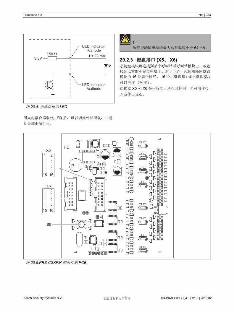
Bosch Security Systems B.V. IUI-PRAESIDEO_4.3 | V1.0 | 2015.02安装说明和用户指南
Praesideo 4.3 zhs | 253
用光电耦合器取代 LED 后,可以切换外部荷载,并通
过外部电源供电。
20.2.3 键盘接口 (X5、 X6)小键盘模块可连接到某个呼叫站或呼叫站模块上,或连
接到以前的小键盘模块上。对于互连,应使用随附键盘
模块的 16 位扁平排线。 16 个小键盘和 / 或小键盘模块
可以串连(环接)。
连接器 X5 和 X6 是平行的,所以其任何一个可用作传
入或传出互连。
图 20.4: 内部供电的 LED
3.3V I < 22 mA150
LED indicator-/cathode
LED indicator +/anode
注
所有控制输出端的 大总负载应小于 64 mA。
图 20.5:PRS-CSKPM 的组件侧 PCB
62
+
E A
-
+
-
C4
1
8
+
+
X811
S9
X6 1 2
15 16
X51 2
15 16
.. .. .. .. .. .. ..
.. .. .. .. .. .. ..

Bosch Security Systems B.V. IUI-PRAESIDEO_4.3 | V1.0 | 2015.02安装说明和用户指南
Praesideo 4.3 zhs | 254
20.2.4 ID 选择器 (S9)可进行以下连接:
• 多有 16 个呼叫站键盘连接到(远程)呼叫站。
• 多有 15 个呼叫站和 1 个数字键盘 (PRS-CSNKP)
可连接到(远程)呼叫站。
对于呼叫站与其键盘之间的通信,必须使用 ID 选择器
为每个键盘指定正确的 ID (请参阅 图 20.5, S9 号和
图 20.6)。
键盘 ID 取决于其在键盘阵列中的位置。 第一个键盘的
ID 为 0, 接下来为 1,一直到第十六个键盘为 F (十六
进制表示法)。
图 20.6:ID 选择器
2E
6A8
C 4

Bosch Security Systems B.V. IUI-PRAESIDEO_4.3 | V1.0 | 2015.02安装说明和用户指南
Praesideo 4.3 zhs | 255
20.3 安装呼叫站模块配有支架和螺丝孔,方便安装。请参见 图 20.7。
图 20.7:PRS-CSKPM 安装尺寸
* 精确布局取决于模块的类型
* *
183
174
38.4
19.2
162
9037
174
164
42.6
4.2
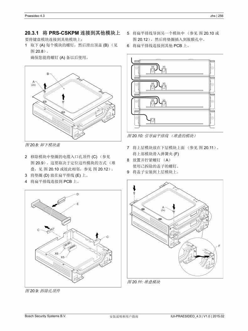
Bosch Security Systems B.V. IUI-PRAESIDEO_4.3 | V1.0 | 2015.02安装说明和用户指南
Praesideo 4.3 zhs | 256
20.3.1 将 PRS-CSKPM 连接到其他模块上要将键盘模块连接到其他模块上:
1 取下 (A) 每个模块的螺钉,然后滑出顶盖 (B) (见
图 20.8)。
确保您能将螺钉 (A) 备以后使用。
图 20.8: 卸下模块盖
2 移除模块中垫圈的电缆入口孔顶件 (C) (参见
图 20.9)。这要取决于定位这些模块的方式(堆
叠,见 图 20.10 或彼此相邻,参见 图 20.12)。
3 将垫圈 (D) 放在扁平排线 (E) 上。
4 将扁平排线连接到 PCB 上。
图 20.9: 拆除孔顶件
5 将扁平排线导到另一个模块中(参见 图 20.10 或
图 20.12),然后将垫圈插入到脱膜孔中。
6 将扁平排线连接到其他 PCB 上。
图 20.10: 引导扁平排线(堆叠的模块)
7 将上层模块放在下层模块上面(参见 图 20.11)。
将上部模块滑入弹簧夹 (F)
8 放置并拧紧螺钉(A)
使用已拆除的盖子的螺钉。
9 将盖子安装到上层模块上。
图 20.11: 堆叠模块
(2x)A
B
C
C
E
D
X6X5
X6 X5
X6 X5
X6 X5
(2x)A
F
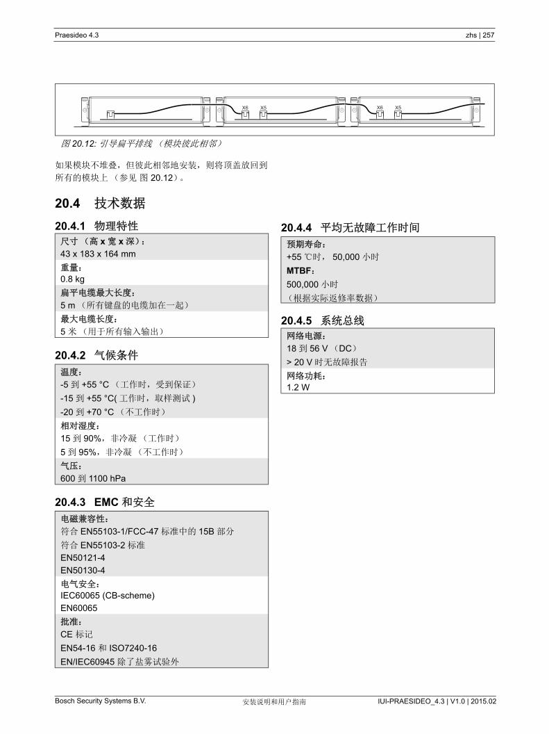
Bosch Security Systems B.V. IUI-PRAESIDEO_4.3 | V1.0 | 2015.02安装说明和用户指南
Praesideo 4.3 zhs | 257
如果模块不堆叠,但彼此相邻地安装,则将顶盖放回到
所有的模块上(参见 图 20.12)。
20.4 技术数据
20.4.1 物理特性
20.4.2 气候条件
20.4.3 EMC 和安全
20.4.4 平均无故障工作时间
20.4.5 系统总线
图 20.12: 引导扁平排线(模块彼此相邻)
X6 X5 X6 X5
尺寸(高 x 宽 x 深):
43 x 183 x 164 mm
重量:
0.8 kg
扁平电缆 大长度:
5 m (所有键盘的电缆加在一起)
大电缆长度:
5 米(用于所有输入输出)
温度:
-5 到 +55 °C (工作时,受到保证)
-15 到 +55 °C( 工作时,取样测试 )
-20 到 +70 °C (不工作时)
相对湿度:
15 到 90%,非冷凝(工作时)
5 到 95%,非冷凝(不工作时)
气压:
600 到 1100 hPa
电磁兼容性:
符合 EN55103-1/FCC-47 标准中的 15B 部分
符合 EN55103-2 标准
EN50121-4
EN50130-4
电气安全:
IEC60065 (CB-scheme)
EN60065
批准:
CE 标记
EN54-16 和 ISO7240-16
EN/IEC60945 除了盐雾试验外
预期寿命:
+55 时, 50,000 小时
MTBF:
500,000 小时
(根据实际返修率数据)
网络电源:
18 到 56 V (DC)
> 20 V 时无故障报告
网络功耗:
1.2 W

Bosch Security Systems B.V. IUI-PRAESIDEO_4.3 | V1.0 | 2015.02安装说明和用户指南
Praesideo 4.3 zhs | 258
21 PRS-CSR 远程呼叫站
21.1 简介PRS-CSR 远程呼叫站用于向任何预定分区发送现场实
时语音播报或预先录制的公告,或者执行任何预定操
作。远程呼叫站通过带有 5 类电缆的 PRS-CSI 呼叫站
接口连接到系统。这样,远程呼叫站可以从远端操作系
统。有关远程呼叫站的方框图,请参阅图 21.1。
PRS-CSR 远程呼叫站是 LBB4438/00 远程呼叫站的后
续产品。您只能将 PRS-CSR 同 PRS-CSI 呼叫站接口
组合使用。但不可将 PRS-CSR 同(旧式)
LBB4437/00 呼叫站接口组合使用。您仅能用
LBB4437/00 将 LBB4438/00 和 LBB4439/00 远程呼叫
站连接至系统。
图 21.1: 方框图
A/D D/A
Power/FaultProcessor
+ DSP
KeypadExternalPower Keypad
(max. 16)
Headset
Microphone
Cat-5 NetworkInterface
I O Call Status
System Status
PTT
Control Inputs
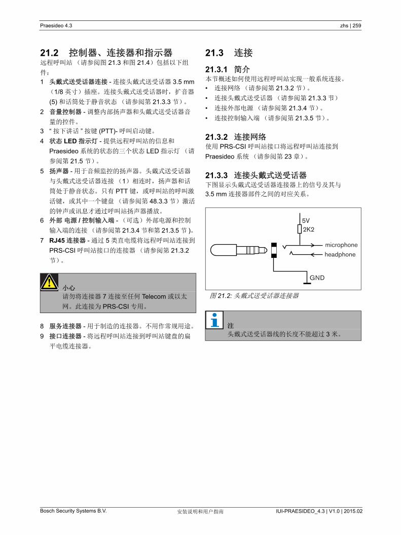
Bosch Security Systems B.V. IUI-PRAESIDEO_4.3 | V1.0 | 2015.02安装说明和用户指南
Praesideo 4.3 zhs | 259
21.2 控制器、连接器和指示器远程呼叫站(请参阅图 21.3 和图 21.4)包括以下组
件:
1 头戴式送受话器连接 - 连接头戴式送受话器 3.5 mm
(1/8 英寸)插座。连接头戴式送受话器时,扩音器
(5) 和话筒处于静音状态(请参阅第 21.3.3 节)。
2 音量控制器 - 调整内部扬声器和头戴式送受话器音
量的控件。
3 “ 按下讲话 ” 按键 (PTT)- 呼叫启动键。
4 状态 LED 指示灯 - 提供远程呼叫站的信息和
Praesideo 系统的状态的三个状态 LED 指示灯(请
参阅第 21.5 节)。
5 扬声器 - 用于音频监控的扬声器。头戴式送受话器
与头戴式送受话器连接(1)相连时,扬声器和话
筒处于静音状态。只有 PTT 键,或呼叫站的呼叫激
活键,或其中一个键盘(请参阅第 48.3.3 节)激活
的钟声或讯息才通过呼叫站扬声器播放。
6 外部 电源 / 控制输入端 - (可选)外部电源和控制
输入端的连接(请参阅第 21.3.4 节和第 21.3.5 节 )。
7 RJ45 连接器 - 通过 5 类直电缆将远程呼叫站连接到
PRS-CSI 呼叫站接口的连接器(请参阅第 21.3.2
节)。
8 服务连接器 - 用于制造的连接器。不用作常规用途。
9 接口连接器 - 将远程呼叫站连接到呼叫站键盘的扁
平电缆连接器。
21.3 连接
21.3.1 简介本节概述如何使用远程呼叫站实现一般系统连接。
• 连接网络(请参阅第 21.3.2 节)。
• 连接头戴式送受话器(请参阅第 21.3.3 节)
• 连接外部电源(请参阅第 21.3.4 节)。
• 连接控制输入端(请参阅第 21.3.5 节)。
21.3.2 连接网络使用 PRS-CSI 呼叫站接口将远程呼叫站连接到
Praesideo 系统(请参阅第 23 章)。
21.3.3 连接头戴式送受话器下图显示头戴式送受话器连接器上的信号及其与
3.5 mm 连接器部件之间的对应关系。
小心
请勿将连接器 7 连接至任何 Telecom 或以太
网。此连接为 PRS-CSI 专用。
图 21.2: 头戴式送受话器连接器
注
头戴式送受话器线的长度不能超过 3 米。
5V
microphoneheadphone
GND
2K2
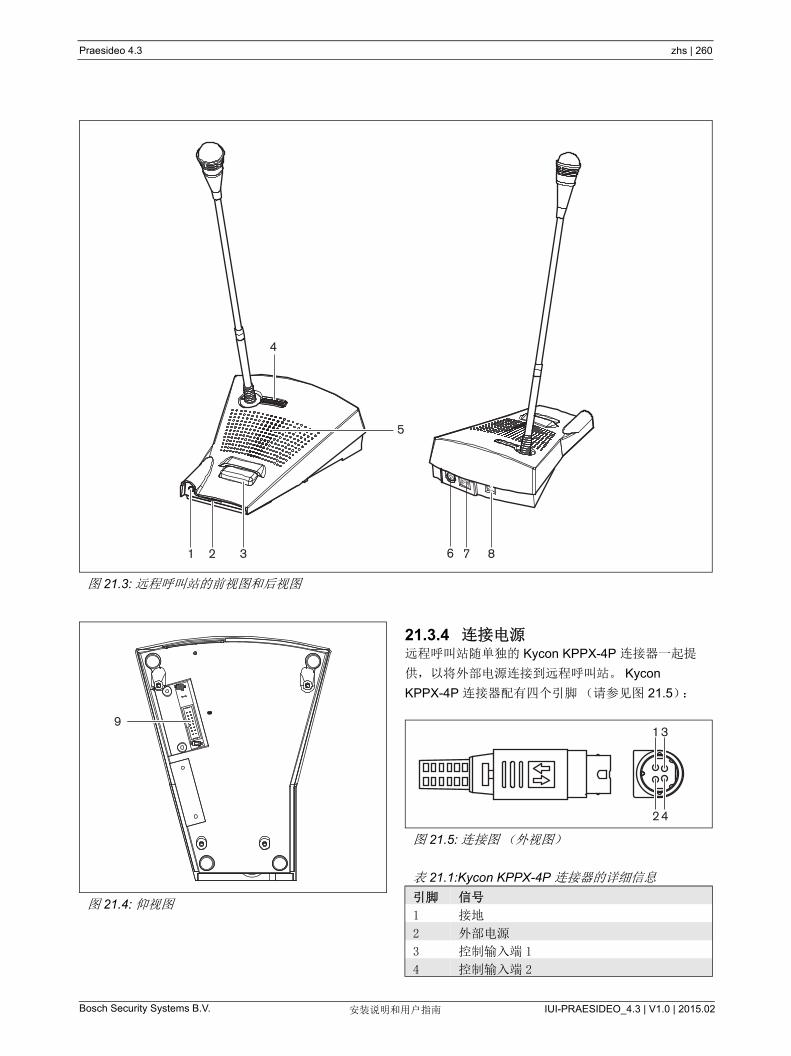
Bosch Security Systems B.V. IUI-PRAESIDEO_4.3 | V1.0 | 2015.02安装说明和用户指南
Praesideo 4.3 zhs | 260
21.3.4 连接电源远程呼叫站随单独的 Kycon KPPX-4P 连接器一起提
供,以将外部电源连接到远程呼叫站。 Kycon
KPPX-4P 连接器配有四个引脚(请参见图 21.5):
图 21.3: 远程呼叫站的前视图和后视图
1 2
4
3 6 7
5
8
图 21.4: 仰视图
9
图 21.5: 连接图(外视图)
表 21.1:Kycon KPPX-4P 连接器的详细信息
引脚 信号
1 接地
2 外部电源
3 控制输入端 1
4 控制输入端 2
42
31
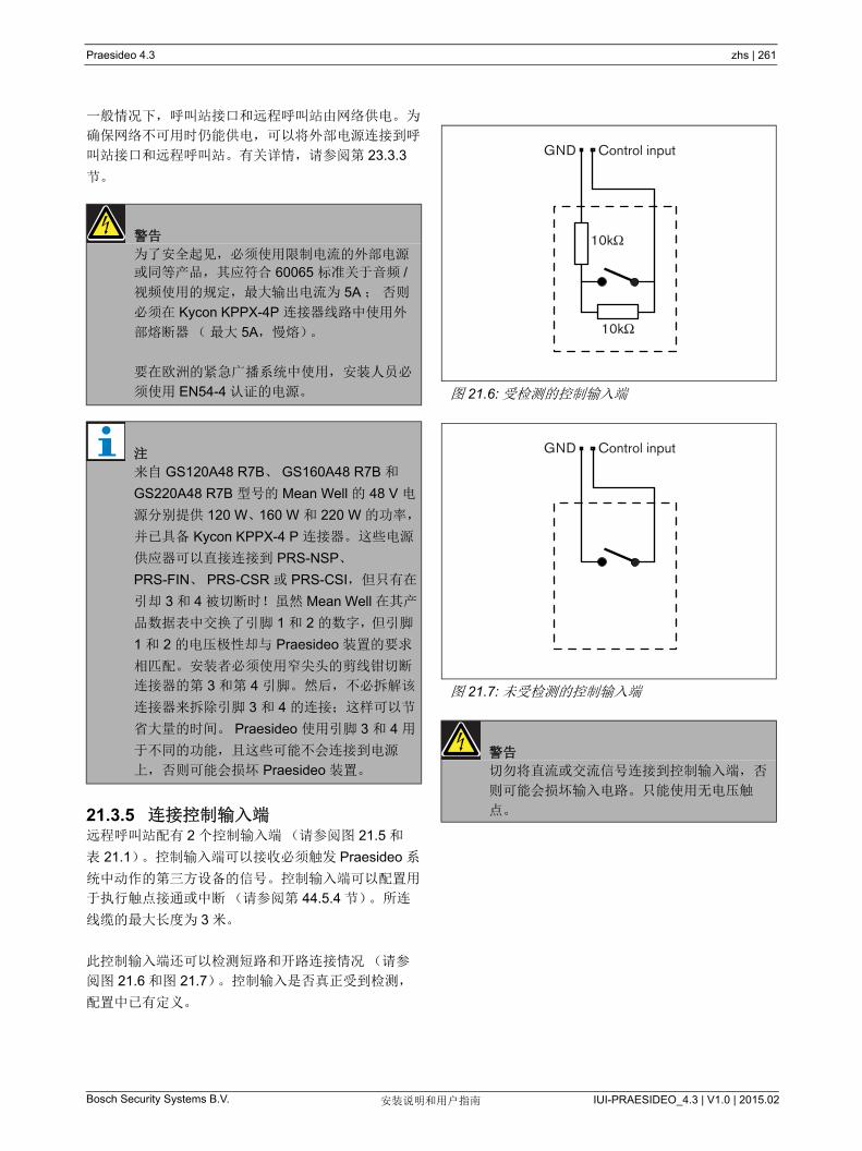
Bosch Security Systems B.V. IUI-PRAESIDEO_4.3 | V1.0 | 2015.02安装说明和用户指南
Praesideo 4.3 zhs | 261
一般情况下,呼叫站接口和远程呼叫站由网络供电。为
确保网络不可用时仍能供电,可以将外部电源连接到呼
叫站接口和远程呼叫站。有关详情,请参阅第 23.3.3
节。
21.3.5 连接控制输入端远程呼叫站配有 2 个控制输入端(请参阅图 21.5 和
表 21.1)。控制输入端可以接收必须触发 Praesideo 系
统中动作的第三方设备的信号。控制输入端可以配置用
于执行触点接通或中断(请参阅第 44.5.4 节)。所连
线缆的 大长度为 3 米。
此控制输入端还可以检测短路和开路连接情况(请参
阅图 21.6 和图 21.7)。控制输入是否真正受到检测,
配置中已有定义。
警告
为了安全起见,必须使用限制电流的外部电源
或同等产品,其应符合 60065 标准关于音频 /
视频使用的规定, 大输出电流为 5A ; 否则
必须在 Kycon KPPX-4P 连接器线路中使用外
部熔断器 ( 大 5A,慢熔)。
要在欧洲的紧急广播系统中使用,安装人员必
须使用 EN54-4 认证的电源。
注
来自 GS120A48 R7B、 GS160A48 R7B 和
GS220A48 R7B 型号的 Mean Well 的 48 V 电
源分别提供 120 W、160 W 和 220 W 的功率,
并已具备 Kycon KPPX-4 P 连接器。这些电源
供应器可以直接连接到 PRS-NSP、
PRS-FIN、 PRS-CSR 或 PRS-CSI,但只有在
引却 3 和 4 被切断时!虽然 Mean Well 在其产
品数据表中交换了引脚 1 和 2 的数字,但引脚
1 和 2 的电压极性却与 Praesideo 装置的要求
相匹配。安装者必须使用窄尖头的剪线钳切断
连接器的第 3 和第 4 引脚。然后,不必拆解该
连接器来拆除引脚 3 和 4 的连接;这样可以节
省大量的时间。 Praesideo 使用引脚 3 和 4 用
于不同的功能,且这些可能不会连接到电源
上,否则可能会损坏 Praesideo 装置。
图 21.6: 受检测的控制输入端
图 21.7: 未受检测的控制输入端
警告
切勿将直流或交流信号连接到控制输入端,否
则可能会损坏输入电路。只能使用无电压触
点。
10kΩ
10kΩ
GND Control input
GND Control input

Bosch Security Systems B.V. IUI-PRAESIDEO_4.3 | V1.0 | 2015.02安装说明和用户指南
Praesideo 4.3 zhs | 262
21.4 安装呼叫站适于桌上型安装。可以通过连接对该功能进行扩
展:
• 16 个呼叫站键盘可用于预配置的动作
(LBB4432/00 或 PRS-CSKPM)。
• 15 个呼叫站键盘可用于预配置的动作
(LBB4432/00 或 PRS-CSKPM)以及一个数字键
盘(PRS-CSNKP)。
21.5 操作远程呼叫站配有三个双色状态 LED 指示灯,用于提供
远程呼叫站的信息和 Praesideo 系统的状态:
• 电源 / 故障 LED 指示灯(左),请参阅表 21.2。
• 基本状态 LED 指示灯(中),请参阅表 21.3。
• 系统状态 LED 指示灯(右),请参阅表 21.4。
表 21.2: 电源 / 故障 LED 指示灯(左)
颜色 状态 说明
--- 关 无电源。
绿色 开 电源打开并且系统或远程呼叫站未出现故障。
黄色 闪烁 电源打开,但系统出现故障。
黄色 开 电源打开,但远程呼叫站出现故障或 Praesideo 网络无法运行。
表 21.3: 基本状态 LED 指示灯(中)
颜色 状态 说明
---- 关 不显示任何呼叫状态。
绿色 开 通话 / 现场实时语音公告准备就绪。
绿色 闪烁 钟声或预先录制的讯息正在播放。
表 21.4: 系统状态 LED 指示灯(右)
颜色 状态 说明
--- 关 预定或所选分区未使用或未被系统保留,且无任何紧急广播公
告。
黄色 开 播放优先级较低的公告或将其保留到已预定给远程呼叫站 “ 按
下讲话 ” 按键的全部或部分分区和呼叫站键盘的选定分区(如
果该设备已安装)。
黄色 闪烁 播放更高或相同优先级的公告(非紧急广播公告)或将其保留
到已预定给远程呼叫站 “ 按下讲话 ” 按键的全部或部分分区和呼
叫站键盘的选定分区(如果该设备已安装)。
红色 开 紧急广播公告正在播放中。向独立分区播放常规公告。

Bosch Security Systems B.V. IUI-PRAESIDEO_4.3 | V1.0 | 2015.02安装说明和用户指南
Praesideo 4.3 zhs | 263
21.6 技术数据
21.6.1 物理特性
21.6.2 气候条件
21.6.3 EMC 和安全
21.6.4 平均无故障工作时间
21.6.5 外部电源
21.6.6 呼叫站接口
21.6.7 话筒
21.6.8 Loudspeaker
尺寸(高 x 宽 x 深):
90 x 160 x 200 mm
长度(鹅颈式话筒):
380 mm
重量:
0.95 kg
温度:
-5 到 +45 °C (工作时,受到保证)
-15 到 +45 °C( 工作时,取样测试 )
-20 到 +70 °C (不工作时)
相对湿度:
15 到 90%,非冷凝(工作时)
5 到 95%,非冷凝(不工作时)
气压:
600 到 1100 hPa
电磁兼容性:
符合 EN55103-1/FCC-47 标准中的 15B 部分
符合 EN55103-2 标准
EN50121-4
EN50130-4
电气安全:
IEC60065 (CB-scheme)
EN60065
批准:
CE 标记
EN54-16 和 ISO7240-16
EN/IEC60945 除盐雾试验外
预期寿命:
+45 °C 时, 50,000 小时
MTBF:
1,200,000 小时
(根据实际返修率数据)
连接器:
KyconKPJ-4S
输入电压范围:
18 到 56 V (DC)
> 20 V 时无故障报告
功耗:
48 V 时为 2.9 W (键盘除外)
连接器(背面):
RJ45
电缆类型:
5 类(4 根双绞线、直线)
大电缆长度:
1000 m
网络电源:
18 到 56 V(DC)
> 20 V 时无故障报告
网络功耗:
48 V 时为 2.9 W (键盘除外)
输入灵敏度:
83 dB(SPL)
输入灵敏度控制范围:
-7 到 8 dB
信噪比:
85 dB(SPL) 时, > 60 dB
带宽:
在 340 Hz 和 14 kHz (相对于 1 kHz)时,为 -3 dB
信噪比:
大输出时为 80 dB
大声压级:
0.5 m 和 1 kHz 时为 85 dB(SPL)
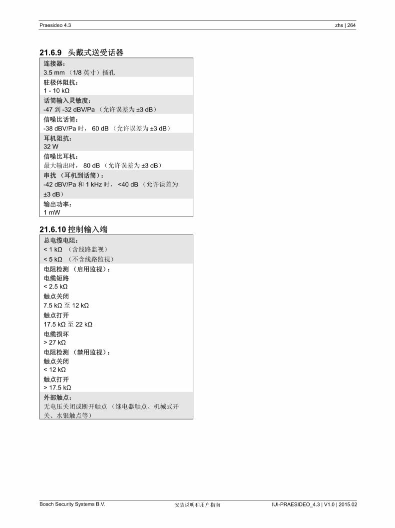
Bosch Security Systems B.V. IUI-PRAESIDEO_4.3 | V1.0 | 2015.02安装说明和用户指南
Praesideo 4.3 zhs | 264
21.6.9 头戴式送受话器
21.6.10 控制输入端
连接器:
3.5 mm (1/8 英寸)插孔
驻极体阻抗:
1 - 10 kΩ
话筒输入灵敏度:
-47 到 -32 dBV/Pa (允许误差为 ±3 dB)
信噪比话筒:
-38 dBV/Pa 时, 60 dB (允许误差为 ±3 dB)
耳机阻抗:
32 W
信噪比耳机:
大输出时, 80 dB (允许误差为 ±3 dB)
串扰(耳机到话筒):
-42 dBV/Pa 和 1 kHz 时, <40 dB (允许误差为
±3 dB)
输出功率:
1 mW
总电缆电阻:
< 1 kΩ (含线路监视)
< 5 kΩ (不含线路监视)
电阻检测(启用监视):
电缆短路
< 2.5 kΩ
触点关闭
7.5 kΩ 至 12 kΩ
触点打开
17.5 kΩ 至 22 kΩ
电缆损坏
> 27 kΩ
电阻检测(禁用监视):
触点关闭
< 12 kΩ
触点打开
> 17.5 kΩ
外部触点:
无电压关闭或断开触点(继电器触点、机械式开
关、水银触点等)

Bosch Security Systems B.V. IUI-PRAESIDEO_4.3 | V1.0 | 2015.02安装说明和用户指南
Praesideo 4.3 zhs | 265
22 PRS-CSRM 远程呼叫站模
块
22.1 简介PRS-CSRM 远程呼叫站模块可用于创建自定义远程呼
叫站(如:远程紧急呼叫站)。此模块配有内置限制器
和语音滤波器, 可以提高语音清晰度。 该模块具有金属
外壳,易于安装和堆放在柜内,以及螺纹连接器,方便
互连至麦克风、扬声器、开关和指示灯上。有关远程呼
叫站模块的方框图,请参阅 图 22.1 。
图 22.1:PRS-CSRM 方框图
A/D D/ANetwork
Processor+
DSP
Keypad Keypad
(max. 16)
Headset
Microphone
PTT
Control Inputs
Cat-5Network
RedundancySwitching
I OPower
Loudspeaker
Volume
System Fault
Emergency
Call Status
Fault
Buzzer
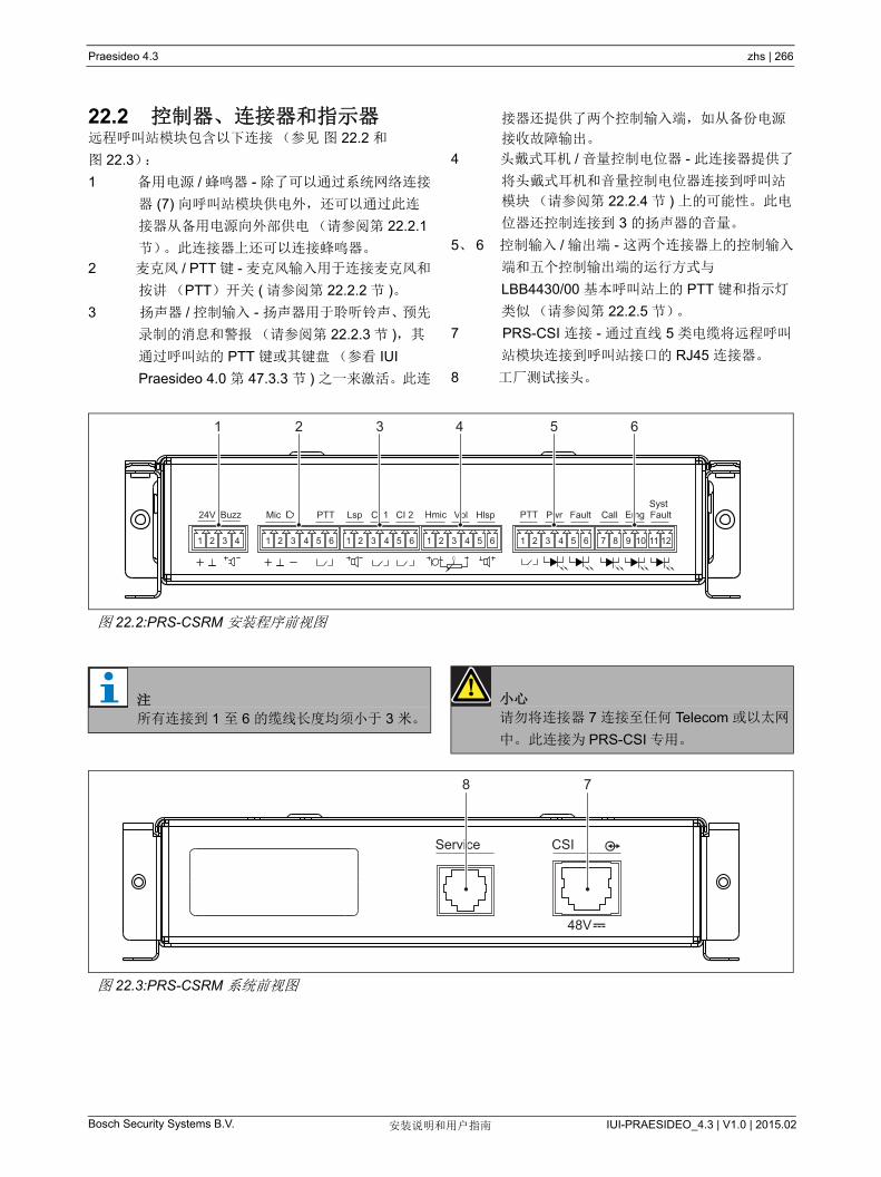
Bosch Security Systems B.V. IUI-PRAESIDEO_4.3 | V1.0 | 2015.02安装说明和用户指南
Praesideo 4.3 zhs | 266
22.2 控制器、连接器和指示器远程呼叫站模块包含以下连接(参见 图 22.2 和
图 22.3):
1 备用电源 / 蜂鸣器 - 除了可以通过系统网络连接
器 (7) 向呼叫站模块供电外,还可以通过此连
接器从备用电源向外部供电(请参阅第 22.2.1
节)。此连接器上还可以连接蜂鸣器。
2 麦克风 / PTT 键 - 麦克风输入用于连接麦克风和
按讲(PTT)开关 ( 请参阅第 22.2.2 节 )。
3 扬声器 / 控制输入 - 扬声器用于聆听铃声、预先
录制的消息和警报(请参阅第 22.2.3 节 ),其
通过呼叫站的 PTT 键或其键盘(参看 IUI
Praesideo 4.0 第 47.3.3 节 ) 之一来激活。此连
接器还提供了两个控制输入端,如从备份电源
接收故障输出。
4 头戴式耳机 / 音量控制电位器 - 此连接器提供了
将头戴式耳机和音量控制电位器连接到呼叫站
模块(请参阅第 22.2.4 节 ) 上的可能性。此电
位器还控制连接到 3 的扬声器的音量。
5、 6 控制输入 / 输出端 - 这两个连接器上的控制输入
端和五个控制输出端的运行方式与
LBB4430/00 基本呼叫站上的 PTT 键和指示灯
类似(请参阅第 22.2.5 节)。
7 PRS-CSI 连接 - 通过直线 5 类电缆将远程呼叫
站模块连接到呼叫站接口的 RJ45 连接器。
8 工厂测试接头。
图 22.2:PRS-CSRM 安装程序前视图
24V Buzz Mic PTT Lsp CI 1 CI 2 Hmic Vol Hlsp PTT Pwr Fault Call Emg Fault Syst
+ +
1 2 3 4 1 2 3 4 5 6 1 2 3 4 5 6 1 2 3 4 5 6 1 2 3 4 5 6 7 8 9 10 11 12
1 2 3 4 5 6
注
所有连接到 1 至 6 的缆线长度均须小于 3 米。
小心
请勿将连接器 7 连接至任何 Telecom 或以太网
中。 此连接为 PRS-CSI 专用。
图 22.3:PRS-CSRM 系统前视图
Service CSI
48V
8 7
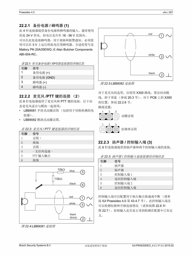
Bosch Security Systems B.V. IUI-PRAESIDEO_4.3 | V1.0 | 2015.02安装说明和用户指南
Praesideo 4.3 zhs | 267
22.2.1 备份电源 / 蜂鸣器 (1)此 4 针连接器提供备份电源和蜂鸣器的输入。通常使用
的是 24 V 供电,但电压允许在 18 - 56 V 范围内。
可以在此处连接蜂鸣器,用于故障和报警通知。必须使
用可以在 3 V 上运行的低电压型蜂鸣器。合适的型号是
Mallory PK-20A35EWQ 或 Alan Butcher Components
ABI-004-RC。
22.2.2 麦克风 /PTT 键的连接(2)此 6 针连接器提供了麦克风和 PTT 键的连接。以下动
态麦克风适合与模块一起使用:
• LBB9081 手持式动圈话筒(包括用于切换检测的电
阻器)。
• LBB9082 鹅颈式动圈话筒。
对于麦克风的选型,应使用 X300 跳线。要访问该跳
线,卸下顶盖(参阅 20.3 节)。对于 PCB 上的 X300
的位置,参阅 22.2.6 节。
跳线设置:
动圈话筒
驻极体话筒
22.2.3 扬声器 / 控制输入端 (3)此 6 针连接器提供到扬声器和两个控制输入端的连接。
控制输入端可以配置用于执行触点接通或中断(请参
阅 IUI Praesideo 4.0 第 43.4.7 节)。此控制输入端还
可以检测短路和开路连接情况(请参阅图 22.6 和
图 22.7)。控制输入是否真正受到检测在配置中已有定
义。
表 22.1:有关备份电源 /蜂鸣器连接器的详细信息
引脚 信号
1 备用电源 (+)
2 备用电源 (GND)
3 蜂鸣器 (+)
4 蜂鸣器 (-)
表 22.2: 麦克风 / PTT 键连接器的详细信息
引脚 信号
1 话筒 +
2 接地
3 话筒 -
4 - 无任何连接 -
5 PTT 输入触点
6 接地
图 22.4:LBB9081 连接图
10k
10k blue
black
red
white
black(thick)
5
6
1
3
2
图 22.5:LBB9082 连接图
表 22.3: 扬声器 / 控制输入端连接器的详细信息
引脚 信号
1 扬声器
2 扬声器
3 控制输入端 1
4 返回控制输入端
5 控制输入端 2
6 返回控制输入端
3
1
2black
white
red
1 2 3
1 2 3
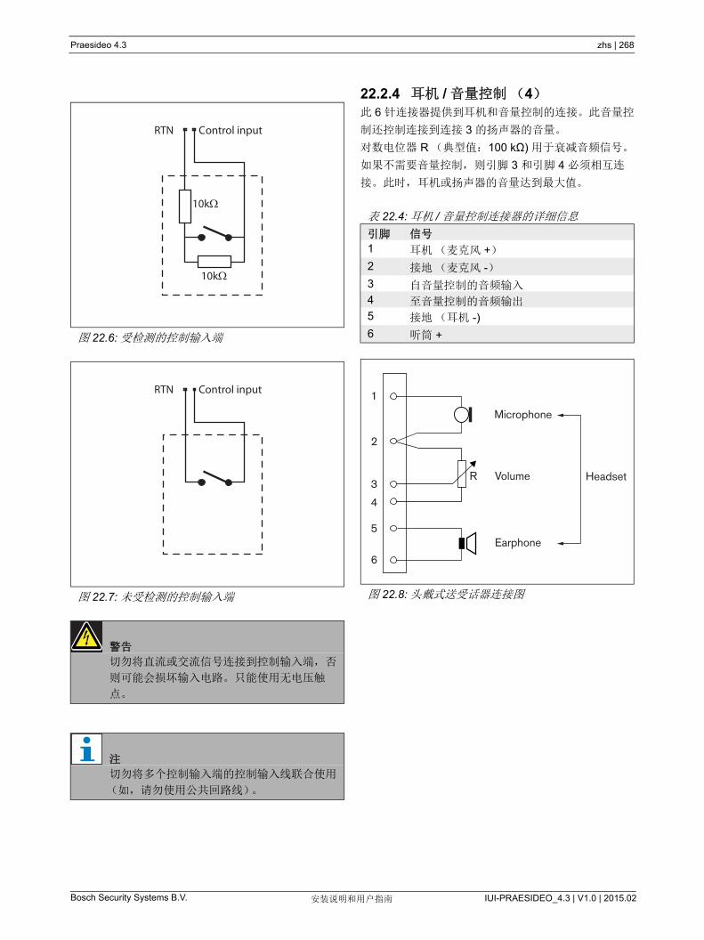
Bosch Security Systems B.V. IUI-PRAESIDEO_4.3 | V1.0 | 2015.02安装说明和用户指南
Praesideo 4.3 zhs | 268
22.2.4 耳机 / 音量控制(4)此 6 针连接器提供到耳机和音量控制的连接。此音量控
制还控制连接到连接 3 的扬声器的音量。
对数电位器 R (典型值:100 kΩ) 用于衰减音频信号。
如果不需要音量控制, 则引脚 3 和引脚 4 必须相互连
接。此时, 耳机或扬声器的音量达到 大值。
图 22.6: 受检测的控制输入端
图 22.7: 未受检测的控制输入端
警告
切勿将直流或交流信号连接到控制输入端,否
则可能会损坏输入电路。只能使用无电压触
点。
注
切勿将多个控制输入端的控制输入线联合使用
(如,请勿使用公共回路线)。
10kΩ
10kΩ
RTN Control input
RTN Control input
表 22.4: 耳机 / 音量控制连接器的详细信息
引脚 信号
1 耳机(麦克风 +)
2 接地(麦克风 -)
3 自音量控制的音频输入
4 至音量控制的音频输出
5 接地(耳机 -)
6 听筒 +
图 22.8: 头戴式送受话器连接图
Microphone
R
Earphone
Volume Headset
1
2
3
4
5
6
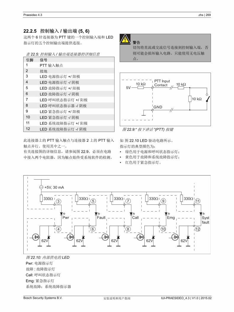
Bosch Security Systems B.V. IUI-PRAESIDEO_4.3 | V1.0 | 2015.02安装说明和用户指南
Praesideo 4.3 zhs | 269
22.2.5 控制输入 / 输出端 (5, 6)这两个 6 针连接器为 PTT 键的一个控制输入端和 LED
指示灯的五个控制输出端提供连接。
此连接器上的 PTT 输入触点与连接器 2 上的 PTT 输入
触点并行。使用其中之一。
有关连接图的详细信息,请参阅图 22.9。必须在电路
中接入两个电阻器,因为触点始终受系统软件的检测。
如 图 22.10 LED 驱动电路所示。
指示灯的典型颜色为:
• 绿色用于电源和呼叫状态指示灯;
• 黄色用于故障和系统故障指示灯;
• 红色用于紧急指示灯。
表 22.5: 控制输入 / 输出端连接器的详细信息
引脚 信号
1 PTT 输入触点
2 接地
3 LED 电源指示灯 +/ 阳极
4 LED 电源指示灯 -/ 阴极
5 LED 故障指示灯 +/ 阳极
6 LED 故障指示灯 -/ 阴极
7 LED 呼叫状态指示灯 +/ 阳极
8 LED 呼叫状态指示器 -/ 阴极
9 LED 紧急指示灯 +/ 阳极
10 LED 紧急指示灯 -/ 阴极
11 LED 系统故障指示灯 +/ 阳极
12 LED 系统故障指示灯 -/ 阴极
警告
切勿将直流或交流信号连接到控制输入端, 否
则可能会损坏输入电路。只能使用无电压触
点。
图 22.9:“ 按下讲话 ”(PTT) 按键
GND
5V
PTT InputContact 10 kΩ10 kΩ
10 kΩ
图 22.10: 内部供电的 LED
Pwr: 电源指示灯
故障 : 故障指示灯
Call: 呼叫状态指示灯
Emg: 紧急指示灯
系统故障:系统故障指示器
+5V, 30 mA
62V 62V
3
4 6 8
7
10
9
12
115
Pwr Fault Call Systfault
Emg
62V 62V 62V
330 330 330 330 330
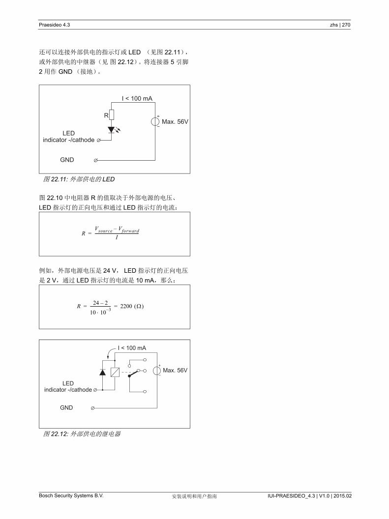
Bosch Security Systems B.V. IUI-PRAESIDEO_4.3 | V1.0 | 2015.02安装说明和用户指南
Praesideo 4.3 zhs | 270
还可以连接外部供电的指示灯或 LED (见图 22.11),
或外部供电的中继器(见 图 22.12)。将连接器 5 引脚
2 用作 GND (接地)。
图 22.10 中电阻器 R 的值取决于外部电源的电压、
LED 指示灯的正向电压和通过 LED 指示灯的电流:
例如,外部电源电压是 24 V, LED 指示灯的正向电压
是 2 V,通过 LED 指示灯的电流是 10 mA,那么:
图 22.11: 外部供电的 LED
图 22.12: 外部供电的继电器
Max. 56VR
LEDindicator -/cathode
GND
I < 100 mA
RVsource Vforward–
I---------------------------------------------=
R24 2–
10 103–
--------------------- 2200 = =
LEDindicator -/cathode
GND
Max. 56V
I < 100 mA

Bosch Security Systems B.V. IUI-PRAESIDEO_4.3 | V1.0 | 2015.02安装说明和用户指南
Praesideo 4.3 zhs | 271
22.2.6 键盘接口 (X1)其他键盘或键盘模块可通过 16 位扁平排线连接到此呼
叫站模块上,连接到 X1 上。此扁平排线配有小键盘或
小键盘模块。
16 个小键盘和 / 或小键盘模块可以串连(环接)。另
参阅第 20.3 节。
图 22.13:PRS-CSPM 的组件侧 PCB
X11 2
15 16
.. .. .. .. .. .. ..
X30031 .
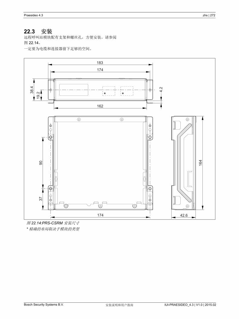
Bosch Security Systems B.V. IUI-PRAESIDEO_4.3 | V1.0 | 2015.02安装说明和用户指南
Praesideo 4.3 zhs | 272
22.3 安装远程呼叫站模块配有支架和螺丝孔,方便安装。请参阅
图 22.14。
一定要为电缆和连接器留下足够的空间。
图 22.14:PRS-CSRM 安装尺寸
* 精确的布局取决于模块的类型
* *
183
174
38.4
19.2
162
9037
174
164
42.6
4.2
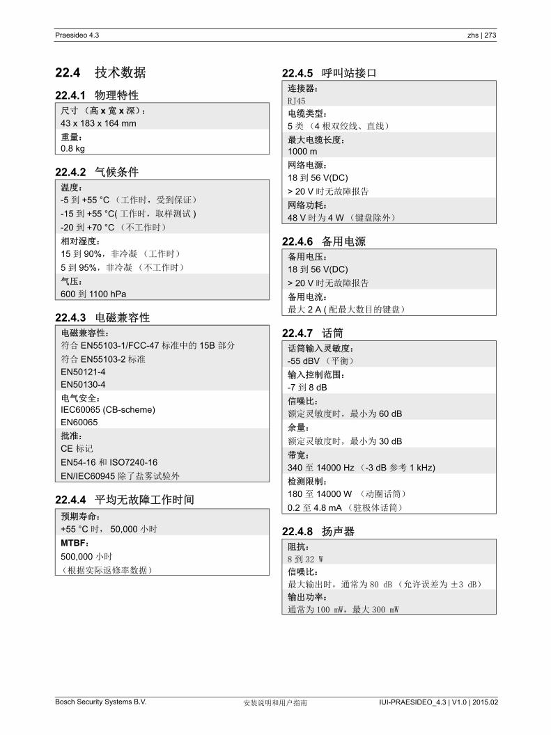
Bosch Security Systems B.V. IUI-PRAESIDEO_4.3 | V1.0 | 2015.02安装说明和用户指南
Praesideo 4.3 zhs | 273
22.4 技术数据
22.4.1 物理特性
22.4.2 气候条件
22.4.3 电磁兼容性
22.4.4 平均无故障工作时间
22.4.5 呼叫站接口
22.4.6 备用电源
22.4.7 话筒
22.4.8 扬声器
尺寸(高 x 宽 x 深):
43 x 183 x 164 mm
重量:
0.8 kg
温度:
-5 到 +55 °C (工作时,受到保证)
-15 到 +55 °C( 工作时,取样测试 )
-20 到 +70 °C (不工作时)
相对湿度:
15 到 90%,非冷凝(工作时)
5 到 95%,非冷凝(不工作时)
气压:
600 到 1100 hPa
电磁兼容性:
符合 EN55103-1/FCC-47 标准中的 15B 部分
符合 EN55103-2 标准
EN50121-4
EN50130-4
电气安全:
IEC60065 (CB-scheme)
EN60065
批准:
CE 标记
EN54-16 和 ISO7240-16
EN/IEC60945 除了盐雾试验外
预期寿命:
+55 °C 时, 50,000 小时
MTBF:
500,000 小时
(根据实际返修率数据)
连接器:
RJ45
电缆类型:
5 类(4 根双绞线、直线)
大电缆长度:
1000 m
网络电源:
18 到 56 V(DC)
> 20 V 时无故障报告
网络功耗:
48 V 时为 4 W (键盘除外)
备用电压:
18 到 56 V(DC)
> 20 V 时无故障报告
备用电流:
大 2 A ( 配 大数目的键盘)
话筒输入灵敏度:
-55 dBV (平衡)
输入控制范围:
-7 到 8 dB
信噪比:
额定灵敏度时, 小为 60 dB
余量:
额定灵敏度时, 小为 30 dB
带宽:
340 至 14000 Hz (-3 dB 参考 1 kHz)
检测限制:
180 至 14000 W (动圈话筒)
0.2 至 4.8 mA (驻极体话筒)
阻抗:
8到 32 W
信噪比:
大输出时,通常为 80 dB (允许误差为±3 dB)
输出功率:
通常为 100 mW, 大 300 mW

Bosch Security Systems B.V. IUI-PRAESIDEO_4.3 | V1.0 | 2015.02安装说明和用户指南
Praesideo 4.3 zhs | 274
22.4.9 头戴式送受话器 22.4.10 控件
22.4.11 蜂鸣器
话筒输入灵敏度:
-44 dBV
输入灵敏度控制范围:
-7 到 8 dB
麦克风耳机检测电流:
> 0.15 mA
信噪比:
额定灵敏度时,为 60 dB (麦克风)
80 dB ( 耳机 )
耳机阻抗:
少 16 W (一般为 32 W)
串扰(耳机到话筒):
大 -40 dB
带宽:
340 至 14000 Hz (-3 dB 参考 1 kHz)
输出功率 :
0.1 到 30 mW (一般为 1 mW)
扬声器和耳机的音量
音量控制电位器:
100 kW 对数(典型值)
控制输入端 1、 2 和 PTT 输入触点
电阻检测(启用监视):
电缆短路
< 2.5 kΩ
触点关闭
7.5 kΩ 至 12 kΩ
触点打开
17.5 kΩ 至 22 kΩ
电缆损坏
> 27 kΩ
电阻检测(禁用监视):
触点关闭
< 12 kΩ
触点打开
> 17.5 kΩ
控制输出端
输出类型:
集电极 / 漏极开路
内部输出电源电流:
大 10 mA (每引脚)
大 30 mA
(合计同时 多亮起 3 个 LED)
输出电压:
大 56 V (每引脚)
输出反向电流:
大 100 mA (每个输出开关引脚)
蜂音器电压:
3.3 V

Bosch Security Systems B.V. IUI-PRAESIDEO_4.3 | V1.0 | 2015.02安装说明和用户指南
Praesideo 4.3 zhs | 275
23 PRS-CSI 呼叫站接口
23.1 简介PRS-CSI 呼叫站接口用于将 PRS-CSR 远程呼叫站、
(旧的)PRS-CSRK 远程呼叫站套件或 PRS-CSRM 远
程呼叫站模块连接至系统。有关呼叫站接口的方框图,
见图 22.1。
PRS-CSI 呼叫站接口取代了 LBB4437/00 呼叫站接口。
只能将 PRS-CSI 同 PRS-CSR (K/M)远程呼叫站结
合使用。但不可用 PRS-CSI 与(旧式) LBB4438/00
和 LBB4439/00 远程呼叫站结合使用。
图 23.1: 方框图
Fault Power
UTPInterface
NetworkProcessor
+ DSP
POF
Cat.5
NetworkRedundancy
Switching
I
PowerSupply
POF
Control Inputs
External (back-up)Power 18 - 56 V
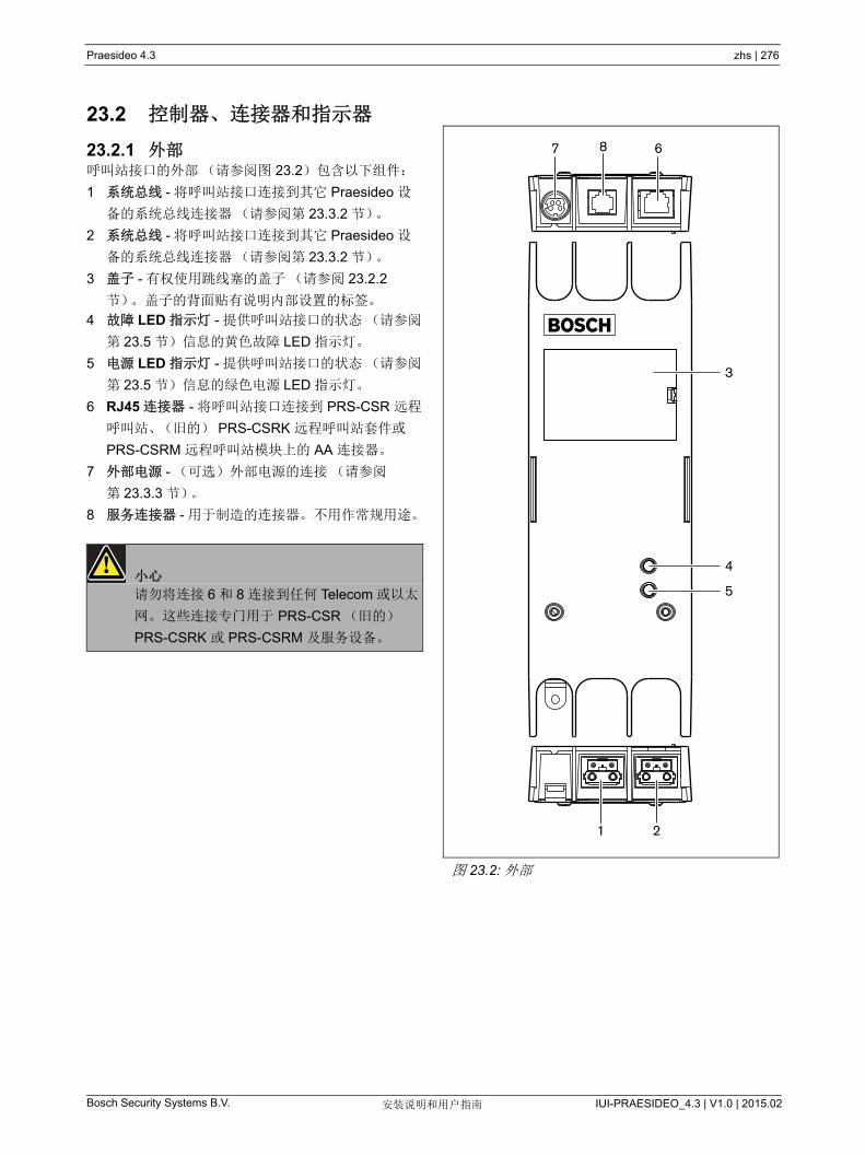
Bosch Security Systems B.V. IUI-PRAESIDEO_4.3 | V1.0 | 2015.02安装说明和用户指南
Praesideo 4.3 zhs | 276
23.2 控制器、连接器和指示器
23.2.1 外部呼叫站接口的外部(请参阅图 23.2)包含以下组件:
1 系统总线 - 将呼叫站接口连接到其它 Praesideo 设
备的系统总线连接器(请参阅第 23.3.2 节)。
2 系统总线 - 将呼叫站接口连接到其它 Praesideo 设
备的系统总线连接器(请参阅第 23.3.2 节)。
3 盖子 - 有权使用跳线塞的盖子(请参阅 23.2.2
节)。盖子的背面贴有说明内部设置的标签。
4 故障 LED 指示灯 - 提供呼叫站接口的状态(请参阅
第 23.5 节)信息的黄色故障 LED 指示灯。
5 电源 LED 指示灯 - 提供呼叫站接口的状态(请参阅
第 23.5 节)信息的绿色电源 LED 指示灯。
6 RJ45 连接器 - 将呼叫站接口连接到 PRS-CSR 远程
呼叫站、(旧的) PRS-CSRK 远程呼叫站套件或
PRS-CSRM 远程呼叫站模块上的 AA 连接器。
7 外部电源 - (可选)外部电源的连接(请参阅
第 23.3.3 节)。
8 服务连接器 - 用于制造的连接器。不用作常规用途。
小心
请勿将连接 6 和 8 连接到任何 Telecom 或以太
网。这些连接专门用于 PRS-CSR (旧的)
PRS-CSRK 或 PRS-CSRM 及服务设备。
图 23.2: 外部
1 2
67
4
3
5
8
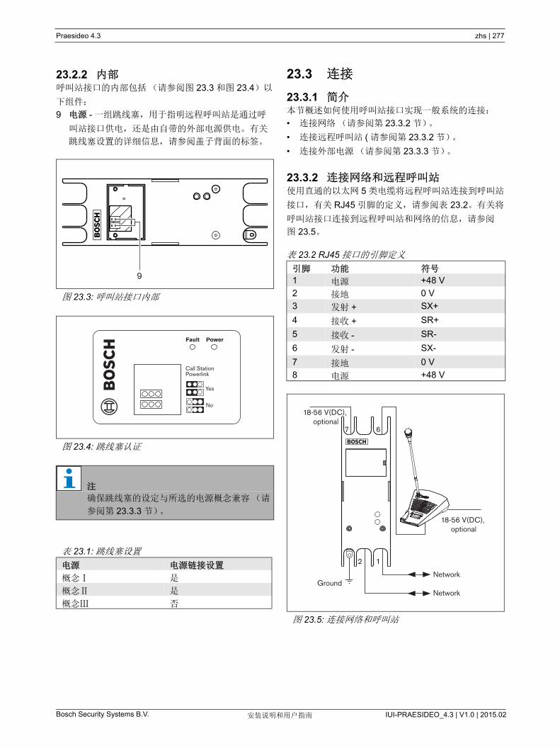
Bosch Security Systems B.V. IUI-PRAESIDEO_4.3 | V1.0 | 2015.02安装说明和用户指南
Praesideo 4.3 zhs | 277
23.2.2 内部呼叫站接口的内部包括(请参阅图 23.3 和图 23.4)以
下组件:
9 电源 - 一组跳线塞,用于指明远程呼叫站是通过呼
叫站接口供电,还是由自带的外部电源供电。有关
跳线塞设置的详细信息,请参阅盖子背面的标签。
23.3 连接
23.3.1 简介本节概述如何使用呼叫站接口实现一般系统的连接:
• 连接网络(请参阅第 23.3.2 节)。
• 连接远程呼叫站 ( 请参阅第 23.3.2 节)。
• 连接外部电源(请参阅第 23.3.3 节)。
23.3.2 连接网络和远程呼叫站使用直通的以太网 5 类电缆将远程呼叫站连接到呼叫站
接口,有关 RJ45 引脚的定义,请参阅表 23.2。有关将
呼叫站接口连接到远程呼叫站和网络的信息,请参阅
图 23.5。
图 23.3: 呼叫站接口内部
图 23.4: 跳线塞认证
注
确保跳线塞的设定与所选的电源概念兼容(请
参阅第 23.3.3 节)。
表 23.1: 跳线塞设置
电源 电源链接设置
概念Ⅰ 是
概念Ⅱ 是
概念Ⅲ 否
9
Fault Power
Yes
No
Call Station Powerlink
表 23.2 RJ45 接口的引脚定义
引脚 功能 符号
1 电源 +48 V
2 接地 0 V
3 发射 + SX+
4 接收 + SR+
5 接收 - SR-
6 发射 - SX-
7 接地 0 V
8 电源 +48 V
图 23.5: 连接网络和呼叫站
18-56 V(DC), optional
7 6
12
Network
Network
18-56 V(DC), optional
Ground

Bosch Security Systems B.V. IUI-PRAESIDEO_4.3 | V1.0 | 2015.02安装说明和用户指南
Praesideo 4.3 zhs | 278
23.3.3 连接电源一般情况下,呼叫站接口和远程呼叫站由 Praesideo 网
络供电。还可以通过外部电源向远程呼叫站和呼叫站接
口供电。例如,出现下列情况时:
• 呼叫站接口连接到不带有外部电源的光纤接口。
• 远程呼叫站和呼叫站接口间的电缆很长,并且很多
呼叫站键盘连接到远程呼叫站。
所支持的电源概念如下:
• 概念Ⅰ
呼叫站接口通过 Praesideo 网络的直流电源向自身
及所连接的远程呼叫站供电。在 Praesideo 网络上
的电压下降到 18 V (直流)以下时,呼叫站接口和
远程呼叫站通过呼叫站接口的外部电源的直流电源
供电。有关跳线塞设置的详细信息,请参阅图 23.4
和表 23.1。
• 概念Ⅱ
呼叫站接口通过 Praesideo 网络的直流电源向自身
及所连接的远程呼叫站供电。在 Praesideo 网络上
的电压下降到 18V (直流)以下时,呼叫站接口和
远程呼叫站通过远程呼叫站的外部电源的直流电源
供电。远程呼叫站的外部电源是远程呼叫站和呼叫
站接口的备用电源。有关跳线塞设置的详细信息,
请参阅图 23.4 和表 23.1。
• 概念Ⅲ
呼叫站接口通过 Praesideo 网络的直流电源向自身
供电。在 Praesideo 网络上的电压下降到 18V (直
流)以下时,呼叫站接口通过外部电源的直流电源
供电。在此概念中,远程呼叫站始终拥有自身的外
部电源。有关跳线塞设置的详细信息,请参阅
图 23.4 和表 23.1。
远程呼叫站和呼叫站接口交付时配有单独的 Kycon
KPPX-4P 连接器,以连接外部电源。
图 23.6: 连接图(外视图)
42
31
表 23.3:Kycon KPPX-4P 连接器的详细信息
引脚 信号
1 接地
2 本地电源供电
( 大 48 V/1.2 A)
3 输入触点 1
4 输入触点 2
注
指示器的内部还显示引脚数量。有关详细的连
接器装置说明,请参阅附录 B。
警告为了安全起见,必须使用限制电流的外部电源
或同等产品,其应符合 60065 标准关于音频 /
视频使用的规定, 大输出电流为 5A ; 否则
必须在 Kycon KPPX-4P 连接器线路中使用外
部熔断器( 大 5A,慢熔)。
要在欧洲的紧急广播系统中使用,安装人员必
须使用 EN54-4 认证的电源。
注
来自 GS120A48 R7B、 GS160A48 R7B 和
GS220A48 R7B 型号的 Mean Well 的 48 V 电
源分别提供 120 W、160 W 和 220 W 的功率,
并已具备 Kycon KPPX-4P 连接器。这些电源
供应器可以直接连接到 PRS-NSP、
PRS-FIN、 PRS-CSR 或 PRS-CSI,但只有在
引却 3 和 4 被切断时!虽然 Mean Well 在其产
品数据表中交换了引脚 1 和 2 的数字,但引脚
1 和 2 的电压极性却与 Praesideo 装置的要求
相匹配。安装者必须使用窄尖头的剪线钳切断
连接器的第 3 和第 4 引脚。然后,不必拆解该
连接器来拆除引脚 3 和 4 的连接;这样可以节
省大量的时间。 Praesideo 采用引脚 3 和 4 用
于不同的功能,这些可能未连接到电源上,否
则可能会损坏 Praesideo 装置。

Bosch Security Systems B.V. IUI-PRAESIDEO_4.3 | V1.0 | 2015.02安装说明和用户指南
Praesideo 4.3 zhs | 279
23.3.4 连接控制输入端呼叫站接口配有 2 个控制输入端(请参阅图 23.6 和
表 23.3)。控制输入端可以接收必须触发 Praesideo 系
统中动作的第三方设备的信号。可以通过远程呼叫站的
配置网页配置控制输入端(请参阅第 44.5.4 节)。所
连线缆的 大长度为 3 米。
此控制输入端还可以检测短路和开路连接情况(请参
阅图 23.7 和图 23.8)。控制输入是否真正受到检测,
配置中已有定义。
23.3.5 接地要降低电磁场和静电放电的干扰,我们建议将外壳接
地。请使用呼叫站接口的接地连接器。请参阅图 23.5。
23.4 安装通过支架,呼叫站接口可以安装在墙壁或其它任何平面
上(请参阅图 23.9)。支架中孔洞间的距离 (d) 为
40 mm。
在将该支架和装置安装在干墙板结构上时,要求使用
小螺纹长度为 22 mm (7/8")和 小直径为 2.5 mm
(3/32")的螺丝。仅针对在干墙表面上的使用情况对安
装进行评估。
图 23.7: 受检测的控制输入端
图 23.8: 未受检测的控制输入端
警告
切勿将直流或交流信号连接到控制输入端,否
则可能会损坏输入电路。只能使用无电压触
点。
10kΩ
10kΩ
GND Control input
GND Control input
图 23.9: 安装
d
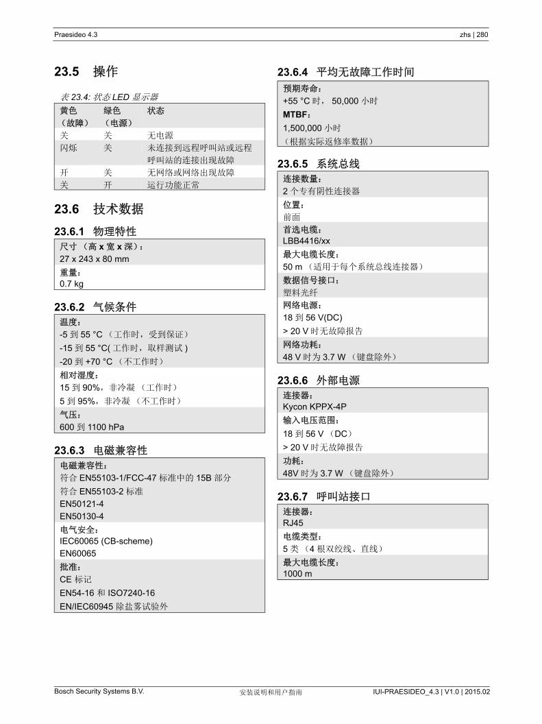
Bosch Security Systems B.V. IUI-PRAESIDEO_4.3 | V1.0 | 2015.02安装说明和用户指南
Praesideo 4.3 zhs | 280
23.5 操作
23.6 技术数据
23.6.1 物理特性
23.6.2 气候条件
23.6.3 电磁兼容性
23.6.4 平均无故障工作时间
23.6.5 系统总线
23.6.6 外部电源
23.6.7 呼叫站接口
表 23.4: 状态 LED 显示器
黄色
(故障)
绿色
(电源)
状态
关 关 无电源
闪烁 关 未连接到远程呼叫站或远程
呼叫站的连接出现故障
开 关 无网络或网络出现故障
关 开 运行功能正常
尺寸(高 x 宽 x 深):
27 x 243 x 80 mm
重量:
0.7 kg
温度:
-5 到 55 °C (工作时,受到保证)
-15 到 55 °C( 工作时,取样测试 )
-20 到 +70 °C (不工作时)
相对湿度:
15 到 90%,非冷凝(工作时)
5 到 95%,非冷凝(不工作时)
气压:
600 到 1100 hPa
电磁兼容性:
符合 EN55103-1/FCC-47 标准中的 15B 部分
符合 EN55103-2 标准
EN50121-4
EN50130-4
电气安全:
IEC60065 (CB-scheme)
EN60065
批准:
CE 标记
EN54-16 和 ISO7240-16
EN/IEC60945 除盐雾试验外
预期寿命:
+55 °C 时, 50,000 小时
MTBF:
1,500,000 小时
(根据实际返修率数据)
连接数量:
2 个专有阴性连接器
位置:
前面
首选电缆:
LBB4416/xx
大电缆长度:
50 m (适用于每个系统总线连接器)
数据信号接口:
塑料光纤
网络电源:
18 到 56 V(DC)
> 20 V 时无故障报告
网络功耗:
48 V 时为 3.7 W (键盘除外)
连接器:
Kycon KPPX-4P
输入电压范围:
18 到 56 V (DC)
> 20 V 时无故障报告
功耗:
48V 时为 3.7 W (键盘除外)
连接器:
RJ45
电缆类型:
5 类(4 根双绞线、直线)
大电缆长度:
1000 m
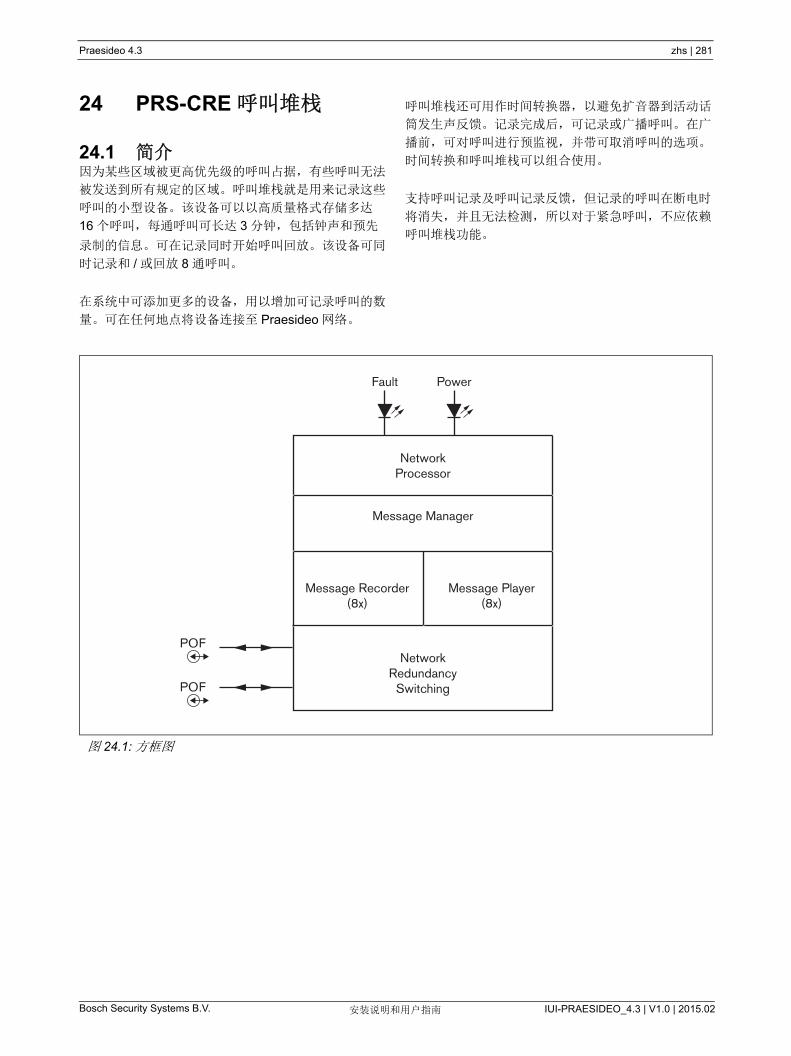
Bosch Security Systems B.V. IUI-PRAESIDEO_4.3 | V1.0 | 2015.02安装说明和用户指南
Praesideo 4.3 zhs | 281
24 PRS-CRE 呼叫堆栈
24.1 简介因为某些区域被更高优先级的呼叫占据,有些呼叫无法
被发送到所有规定的区域。呼叫堆栈就是用来记录这些
呼叫的小型设备。该设备可以以高质量格式存储多达
16 个呼叫,每通呼叫可长达 3 分钟,包括钟声和预先
录制的信息。可在记录同时开始呼叫回放。该设备可同
时记录和 / 或回放 8 通呼叫。
在系统中可添加更多的设备,用以增加可记录呼叫的数
量。可在任何地点将设备连接至 Praesideo 网络。
呼叫堆栈还可用作时间转换器,以避免扩音器到活动话
筒发生声反馈。记录完成后,可记录或广播呼叫。在广
播前,可对呼叫进行预监视,并带可取消呼叫的选项。
时间转换和呼叫堆栈可以组合使用。
支持呼叫记录及呼叫记录反馈,但记录的呼叫在断电时
将消失,并且无法检测,所以对于紧急呼叫,不应依赖
呼叫堆栈功能。
图 24.1: 方框图
Fault Power
NetworkProcessor
Message Manager
POFNetwork
RedundancySwitching
Message Recorder(8x)
Message Player(8x)
POF
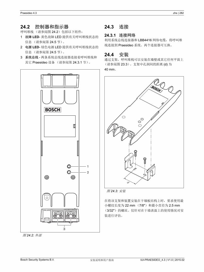
Bosch Security Systems B.V. IUI-PRAESIDEO_4.3 | V1.0 | 2015.02安装说明和用户指南
Praesideo 4.3 zhs | 282
24.2 控制器和指示器呼叫堆栈(请参阅图 24.2)包括以下组件:
1 故障 LED- 黄色故障 LED 提供有关呼叫堆栈状态的
信息(请参阅第 24.5 节)。
2 电源 LED- 绿色电源 LED 提供有关呼叫堆栈状态的
信息(请参阅第 24.5 节)。
3 系统总线 - 两条系统总线连接器连接着呼叫堆栈和
其它 Praesideo 设备(请参阅第 24.3.1 节)。
24.3 连接
24.3.1 连接网络利用系统总线连接器和 LBB4416 网络电缆,将呼叫堆
栈连接到 Praesideo 系统。两个连接器可互换。
24.4 安装通过支架,呼叫堆栈可以安装在墙壁或其它任何平面上
(请参阅图 23.3)。支架中孔洞间的距离 (d) 为
40 mm。
在将该支架和装置安装在干墙板结构上时,要求使用
小螺纹长度为 22 mm (7/8")和 小直径为 2.5 mm
(3/32")的螺丝。仅针对在干墙表面上的使用情况对安
装进行评估。
图 24.2: 外部
3
1
2
图 24.3: 安装
d
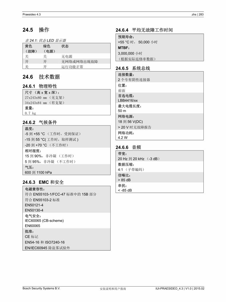
Bosch Security Systems B.V. IUI-PRAESIDEO_4.3 | V1.0 | 2015.02安装说明和用户指南
Praesideo 4.3 zhs | 283
24.5 操作
24.6 技术数据
24.6.1 物理特性
24.6.2 气候条件
24.6.3 EMC 和安全
24.6.4 平均无故障工作时间
24.6.5 系统总线
24.6.6 音频
表 24.1: 状态 LED 显示器
黄色
(故障)
绿色
(电源)
状态
关 关 无电源
开 开 无网络或网络出现故障
关 开 运行功能正常
尺寸(高 x宽 x 深):
27x243x80 mm (无支架)
34x243x84 mm (有支架)
重量:
0.7 kg
温度:
-5 到 +55 °C (工作时,受到保证)
-15 到 55 °C( 工作时,取样测试 )
-20 到 +70 °C (不工作时)
相对湿度:
15 到 90%,非冷凝(工作时)
5 到 95%,非冷凝(不工作时)
气压:
600 到 1100 hPa
电磁兼容性:
符合 EN55103-1/FCC-47 标准中的 15B 部分
符合 EN55103-2 标准
EN50121-4
EN50130-4
电气安全:
IEC60065 (CB-scheme)
EN60065
批准:
CE 标记
EN54-16 和 ISO7240-16
EN/IEC60945 除盐雾试验外
预期寿命:
+55 °C 时, 50,000 小时
MTBF:
3,000,000 小时
(根据实际返修率数据)
连接数量:
2 个专有阴性连接器
位置:
前面
首选电缆:
LBB4416/xx
大电缆长度:
50 m
网络电源:
18 到 56 V(DC)
> 20 V 时无故障报告
网络功耗:
4.2 W
带宽:
20 Hz 到 20 kHz (-3 dB)
数据压缩:
4:1 (子带编码)
信噪比:
> 85 dB
串扰:
< -85 dB
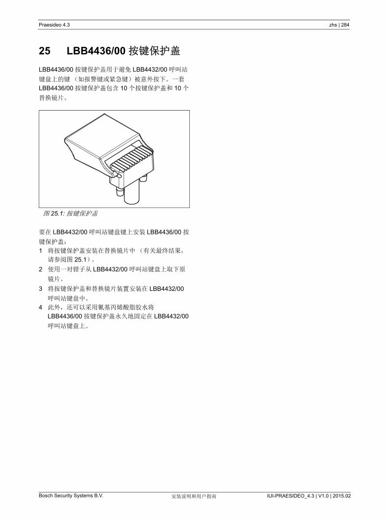
Bosch Security Systems B.V. IUI-PRAESIDEO_4.3 | V1.0 | 2015.02安装说明和用户指南
Praesideo 4.3 zhs | 284
25 LBB4436/00 按键保护盖
LBB4436/00 按键保护盖用于避免 LBB4432/00 呼叫站
键盘上的键(如报警键或紧急键)被意外按下。一套
LBB4436/00 按键保护盖包含 10 个按键保护盖和 10 个
替换镜片。
要在 LBB4432/00 呼叫站键盘键上安装 LBB4436/00 按
键保护盖:
1 将按键保护盖安装在替换镜片中(有关 终结果,
请参阅图 25.1)。
2 使用一对钳子从 LBB4432/00 呼叫站键盘上取下原
镜片。
3 将按键保护盖和替换镜片装置安装在 LBB4432/00
呼叫站键盘中。
4 此外,还可以采用氰基丙烯酸脂胶水将
LBB4436/00 按键保护盖永久地固定在 LBB4432/00
呼叫站键盘上。
图 25.1: 按键保护盖
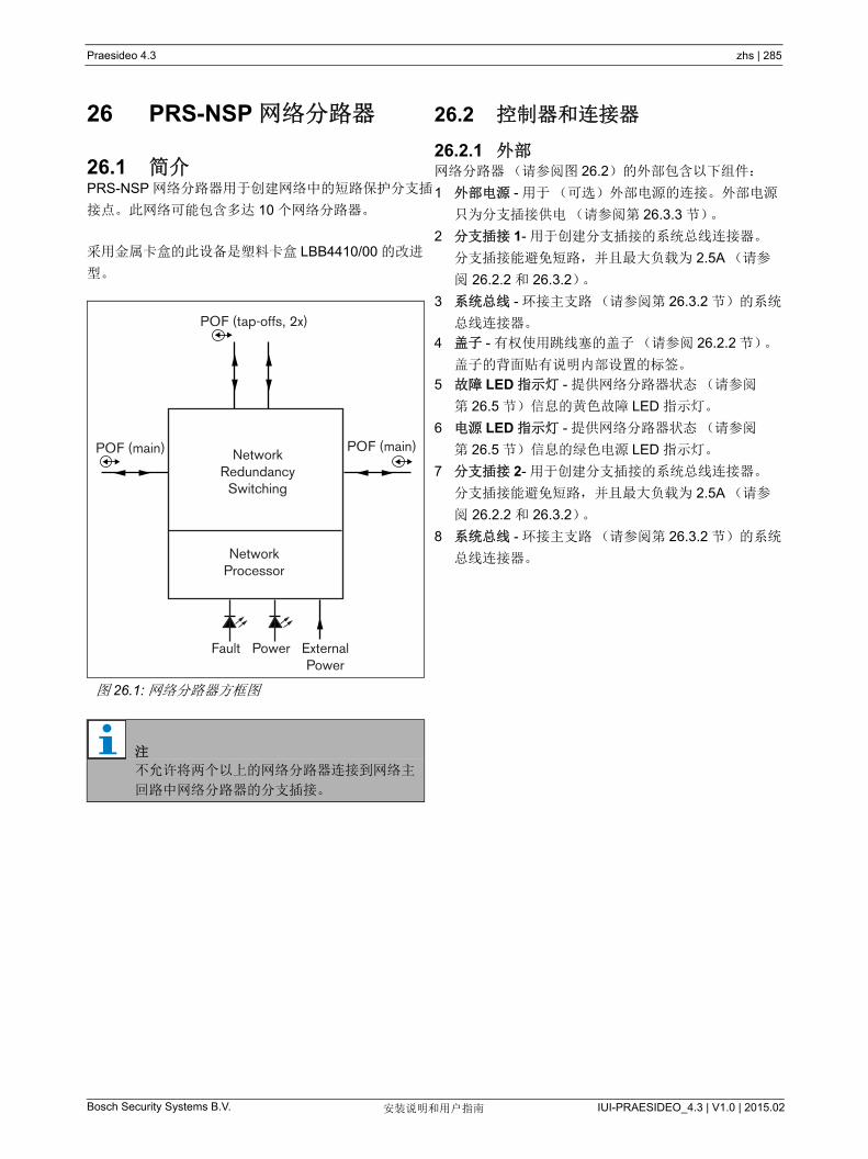
Praesideo 4.3 zhs | 285
Bosch Security Systems B.V. IUI-PRAESIDEO_4.3 | V1.0 | 2015.02安装说明和用户指南
26 PRS-NSP 网络分路器
26.1 简介PRS-NSP 网络分路器用于创建网络中的短路保护分支插
接点。此网络可能包含多达 10 个网络分路器。
采用金属卡盒的此设备是塑料卡盒 LBB4410/00 的改进
型。
26.2 控制器和连接器
26.2.1 外部网络分路器(请参阅图 26.2)的外部包含以下组件:
1 外部电源 - 用于(可选)外部电源的连接。外部电源
只为分支插接供电(请参阅第 26.3.3 节)。
2 分支插接 1- 用于创建分支插接的系统总线连接器。
分支插接能避免短路,并且 大负载为 2.5A (请参
阅 26.2.2 和 26.3.2)。
3 系统总线 - 环接主支路(请参阅第 26.3.2 节)的系统
总线连接器。
4 盖子 - 有权使用跳线塞的盖子(请参阅 26.2.2 节)。
盖子的背面贴有说明内部设置的标签。
5 故障 LED 指示灯 - 提供网络分路器状态(请参阅
第 26.5 节)信息的黄色故障 LED 指示灯。
6 电源 LED 指示灯 - 提供网络分路器状态(请参阅
第 26.5 节)信息的绿色电源 LED 指示灯。
7 分支插接 2- 用于创建分支插接的系统总线连接器。
分支插接能避免短路,并且 大负载为 2.5A (请参
阅 26.2.2 和 26.3.2)。
8 系统总线 - 环接主支路(请参阅第 26.3.2 节)的系统
总线连接器。
图 26.1: 网络分路器方框图
注
不允许将两个以上的网络分路器连接到网络主
回路中网络分路器的分支插接。
NetworkProcessor
POF (main)
POF (tap-offs, 2x)
Fault Power ExternalPower
NetworkRedundancy
Switching
POF (main)

Praesideo 4.3 zhs | 286
Bosch Security Systems B.V. IUI-PRAESIDEO_4.3 | V1.0 | 2015.02安装说明和用户指南
图 26.2: 网络分路器的内部
7 8
321
5
4
6
图 26.3: 网络分路器的外部
910
12
11

Praesideo 4.3 zhs | 287
Bosch Security Systems B.V. IUI-PRAESIDEO_4.3 | V1.0 | 2015.02安装说明和用户指南
26.2.2 内部网络分路器的内部(请参阅图 26.3 和图 26.4)包含以
下组件:
9 分支插接电源 - 指明分支插接是由主网络支路供电,
还是由与网络分路器相连的外部电源供电的跳线
塞。有关跳线塞设置的详细信息,请参阅盖子背面
的标签。
10 外部电源 - 打开。(此设置用于 Praesideo)
11 分支插接 2 限制器 - 限制分支插接 2 电流的跳线
塞。如果分支插接要求超出允许的电流,分支插接
会被关闭。有关跳线塞设置的详细信息,请参阅盖
子背面的标签。
12 分支插接 1 限制器 - 限制分支插接 1 电流的跳线
塞。如果分支插接要求超出允许的电流,分支插接
会被关闭。有关跳线塞设置的详细信息,请参阅盖
子背面的标签。
注
图 26.4 中的编号与图 26.2 和图 26.3 中的编号
不同。
图 26.4: 跳线塞认证
910
3 4 5
11 12
6 7 81 2
Tap-off poweredfrom:
Current limitTap-off 1
Current limitTap-off 2
External power
Main network
Main
network
External
power
Tap off 1M
ain
netw
ork
Tap
off 2
External power0.8 A1.6 A2.5 A0.8 A1.6 A2.5 AOnfollowsMain networkFaultPower
12345678910
1112
LED
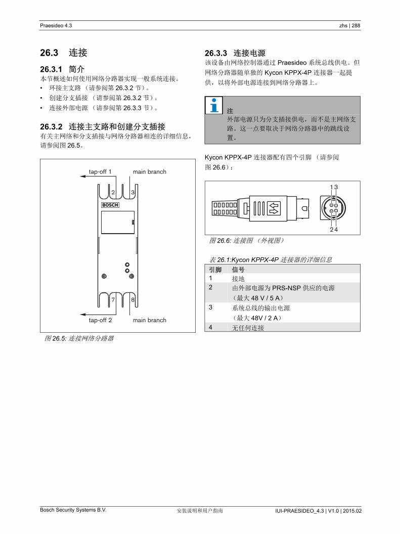
Praesideo 4.3 zhs | 288
Bosch Security Systems B.V. IUI-PRAESIDEO_4.3 | V1.0 | 2015.02安装说明和用户指南
26.3 连接
26.3.1 简介本节概述如何使用网络分路器实现一般系统连接。
• 环接主支路(请参阅第 26.3.2 节)。
• 创建分支插接(请参阅第 26.3.2 节)。
• 连接外部电源(请参阅第 26.3.3 节)。
26.3.2 连接主支路和创建分支插接有关主网络和分支插接与网络分路器相连的详细信息,
请参阅图 26.5。
26.3.3 连接电源该设备由网络控制器通过 Praesideo 系统总线供电。但
网络分路器随单独的 Kycon KPPX-4P 连接器一起提
供,以将外部电源连接到网络分路器上。
Kycon KPPX-4P 连接器配有四个引脚(请参阅
图 26.6):
图 26.5: 连接网络分路器
tap-off 2
7 8
2 3
tap-off 1
main branch
main branch
注
外部电源只为分支插接供电,而不是主网络支
路。这一点要取决于网络分路器中的跳线设
置。
图 26.6: 连接图(外视图)
表 26.1:Kycon KPPX-4P 连接器的详细信息
引脚 信号
1 接地
2 由外部电源为 PRS-NSP 供应的电源
( 大 48 V / 5 A)
3 系统总线的输出电源
( 大 48V / 2 A)
4 无任何连接
42
31
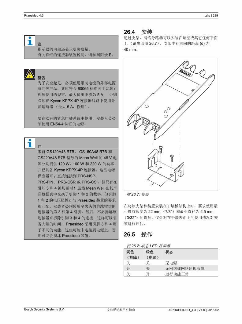
Praesideo 4.3 zhs | 289
Bosch Security Systems B.V. IUI-PRAESIDEO_4.3 | V1.0 | 2015.02安装说明和用户指南
26.4 安装通过支架,网络分路器可以安装在墙壁或其它任何平面
上(请参阅图 26.7)。支架中孔洞间的距离 (d) 为
40 mm。
在将该支架和装置安装在干墙板结构上时,要求使用
小螺纹长度为 22 mm (7/8")和 小直径为 2.5 mm
(3/32")的螺丝。仅针对在干墙表面上的使用情况对安
装进行评估。
26.5 操作
注
指示器的内部还显示引脚数量。
有关详细的连接器装置说明,请参阅附录 B。
警告
为了安全起见,必须使用限制电流的外部电源
或同等产品,其应符合 60065 标准关于音频 /
视频使用的规定, 大输出电流为 5 A ; 否则
必须在 Kycon KPPX-4P 连接器线路中使用外
部熔断器( 大 5 A,慢熔)。
要在欧洲的紧急广播系统中使用,安装人员必
须使用 EN54-4 认证的电源。
注
来自 GS120A48 R7B、 GS160A48 R7B 和
GS220A48 R7B 型号的 Mean Well 的 48 V 电
源分别提供 120 W、160 W 和 220 W 的功率,
并已具备 Kycon KPPX-4P 连接器。这些电源
供应器可以直接连接到 PRS-NSP、
PRS-FIN、 PRS-CSR 或 PRS-CSI,但只有在
引却 3 和 4 被切断时!虽然 Mean Well 在其产
品数据表中交换了引脚 1 和 2 的数字,但引脚
1 和 2 的电压极性却与 Praesideo 装置的要求
相匹配。安装者必须使用窄尖头的剪线钳切断
连接器的第 3 和第 4 引脚。然后,不必拆解该
连接器来拆除引脚 3 和 4 的连接;这样可以节
省大量的时间。 Praesideo 采用引脚 3 和 4 用
于不同的功能,这些可能未连接到电源上,否
则可能会损坏 Praesideo 装置。
图 26.7: 安装
表 26.2: 状态 LED 显示器
黄色
(故障)
绿色
(电源)
状态
关 关 无电源
开 关 无网络或网络出现故障
关 开 运行功能正常
d
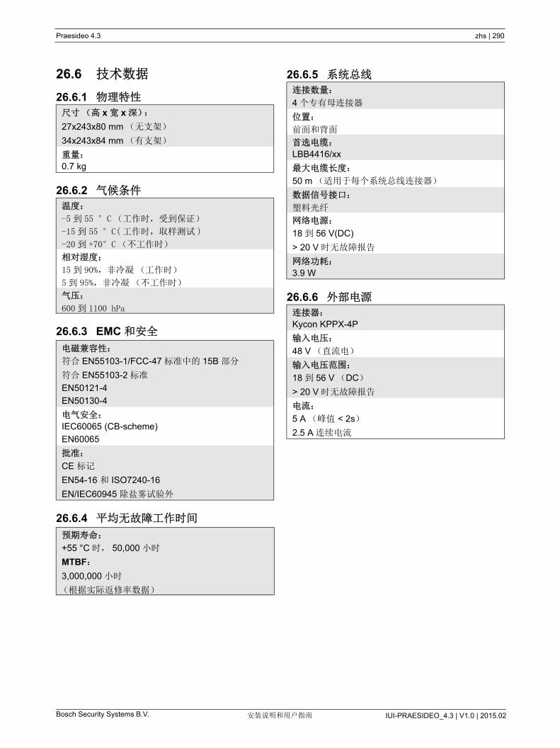
Praesideo 4.3 zhs | 290
Bosch Security Systems B.V. IUI-PRAESIDEO_4.3 | V1.0 | 2015.02安装说明和用户指南
26.6 技术数据
26.6.1 物理特性
26.6.2 气候条件
26.6.3 EMC 和安全
26.6.4 平均无故障工作时间
26.6.5 系统总线
26.6.6 外部电源
尺寸(高 x 宽 x 深):
27x243x80 mm (无支架)
34x243x84 mm (有支架)
重量:
0.7 kg
温度:
-5 到 55 °C (工作时,受到保证)
-15 到 55 °C( 工作时,取样测试 )
-20 到 +70°C (不工作时)
相对湿度:
15 到 90%,非冷凝(工作时)
5到 95%,非冷凝(不工作时)
气压:
600 到 1100 hPa
电磁兼容性:
符合 EN55103-1/FCC-47 标准中的 15B 部分
符合 EN55103-2 标准
EN50121-4
EN50130-4
电气安全:
IEC60065 (CB-scheme)
EN60065
批准:
CE 标记
EN54-16 和 ISO7240-16
EN/IEC60945 除盐雾试验外
预期寿命:
+55 °C 时, 50,000 小时
MTBF:
3,000,000 小时
(根据实际返修率数据)
连接数量:
4 个专有母连接器
位置:
前面和背面
首选电缆:
LBB4416/xx
大电缆长度:
50 m (适用于每个系统总线连接器)
数据信号接口:
塑料光纤
网络电源:
18 到 56 V(DC)
> 20 V 时无故障报告
网络功耗:
3.9 W
连接器:
Kycon KPPX-4P
输入电压:
48 V (直流电)
输入电压范围:
18 到 56 V (DC)
> 20 V 时无故障报告
电流:
5 A (峰值 < 2s)
2.5 A 连续电流

Praesideo 4.3 zhs | 291
Bosch Security Systems B.V. IUI-PRAESIDEO_4.3 | V1.0 | 2015.02安装说明和用户指南
27 PRS-FIN、 PRS-FINNA、
PRS-FINS 光纤接口
27.1 简介PRS-FIN、 PRS-FINNA 或 PRS-FINS 光纤接口用于将
塑料光纤(POF)转换成玻璃光纤(GOF)以及相反
的转换,为了覆盖更远的距离。下列类型可用:
PRS-FINNA 光纤接口只能从 POF 转换成 GOF。此接
口在 多有 63 个节点的系统(请参阅表 32.2)中不占
用节点。换句话说,该接口主要用于节点数超过 大值
的系统。然而,该组件影响系统的 大电缆长度,就像
是一个普通节点(请参阅图 32.5)。
在紧急广播系统中,切勿采用该类型的光纤接口向远端设
备供电。既然该接口未配备任何控制输入端,所以无法对
外部电源(如果连接)进行检测。但是,可以将
PRS-FINNA 光纤接口用作与网络相连的近端光纤接口。
采用金属卡盒的这些设备是塑料卡盒 LBB4414/00、
LBB4414/10 和 PRS-FINMO 的改进型。
27.2 控制器、连接器和指示器光纤接口(请参阅图 27.2)包含以下组件:
1 外部电源 - 用于(可选)外部电源的连接。外部电
源为干线 Praesideo 系统供电(请参阅第 27.3.3
节)。
2 控制输入端 - 控制输入端用于接收第三方设备的信
号,该设备须触发 Praesideo 网络中的操作(请参
阅 27.3.4 节)。
3 POF 连接器 - 将光纤接口连接到 POF 电缆的 POF
连接器(请参阅第 27.3.2 节)。
4 电源 LED - 绿色电源 LED 提供有关光纤接口状态的
信息(请参阅第 27.3.5 节)。
5 故障 LED 指示灯 - 提供光纤接口状态(请参阅第
27.3.5 节)信息的黄色故障 LED 指示灯。
6 GOF 连接器 - 将光纤接口连接到 GOF 电缆的 GOF
连接器(请参阅第 27.3.2 节)。
类型 描述
PRS-FIN 不带控制输入端的光纤接口(多模)
PRS-FINNA 不带控制输入接口的光纤接口(多
模)
PRS-FINS 带控制输入接口的光纤接口(单模)
图 27.1: 光纤接口方框图
NetworkProcessor
POF
Control Inputs
GOF
Fault
I
Power ExternalPower

Praesideo 4.3 zhs | 292
Bosch Security Systems B.V. IUI-PRAESIDEO_4.3 | V1.0 | 2015.02安装说明和用户指南
图 27.2: 光纤接口的外部
321
4
5
6
31
6
PRS-FIN, PRS-FINS1
PRS-FINNA
4
5

Praesideo 4.3 zhs | 293
Bosch Security Systems B.V. IUI-PRAESIDEO_4.3 | V1.0 | 2015.02安装说明和用户指南
27.3 连接
27.3.1 简介本节概述如何使用光纤接口实现一般系统的连接:
• 连接塑料光纤电缆(请参阅第 27.3.2 节)。
• 连接玻璃光纤电缆(请参阅第 27.3.2 节)。
• 连接外部电源(请参阅第 27.3.3 节)。
27.3.2 连接塑料光纤和玻璃光纤电缆光纤接口从塑料光纤转换成玻璃光纤以连接相隔 50m
远的两件设备。通常情况下,这两种光纤成对使用。第
一次是从塑料光纤转换到玻璃光纤,而第二次是从玻璃
光纤转换回为塑料光纤(请参阅图 27.3)。
GOF 连接器(请参阅 图 27.4)是采用不可见红外线
灯 (1300 nm) 的 SC 连接器。
27.3.3 连接电源该设备由网络控制器通过 Praesideo 系统总线供电。但
光纤接口随单独的 Kycon KPPX-4P 连接器一起提供,
以将外部电源连接到光纤接口上。 Kycon KPPX-4P 连
接器配有四个引脚(请参阅图 27.6):
图 27.3: 连接光纤接口
图 27.4:GOF 连接器
POF
GOF ( > 50m)
POF
3 3
7 7
Tx Rx
表 27.1:GOF 连接器引脚
引脚 描述
Tx 发射器
Rx 接收器
图 27.5:SC 连接
图 27.6: 连接图(外视图)
表 27.2:Kycon KPPX-4P 连接器的详细信息
引脚 信号
1 接地
2 由外部电源为 PRS-FINxx 供应的电源
( 大 48 V / 5 A)
3 系统总线的输出电源
( 大 48 V / 2 A)
4 无任何连接
注
指示器的内部还显示引脚数量。
有关详细的连接器装置说明,请参阅附录 B
42
31

Praesideo 4.3 zhs | 294
Bosch Security Systems B.V. IUI-PRAESIDEO_4.3 | V1.0 | 2015.02安装说明和用户指南
27.3.4 连接控制输入端光纤接口配有两个控制输入端(请参阅 图 27.7)。控
制输入端可以用于接收必须能在 Praesideo 系统内触发
操作的第三方设备发出的信号。 控制输入端可以配置用
于执行触点接通或中断(请参阅第 44.8 节)。
警告
为了安全起见,必须使用限制电流的外部电源
或同等产品,其应符合 60065 标准关于音频 /
视频使用的规定, 大输出电流为 5A ; 否则
必须在 Kycon KPPX-4P 连接器线路中使用外
部熔断器( 大 5A,慢熔)。
要在欧洲的紧急广播系统中使用,安装人员必
须使用 EN54-4 认证的电源。
注
来自 GS120A48 R7B、 GS160A48 R7B 和
GS220A48 R7B 型号的 Mean Well 的 48 V 电
源分别提供 120 W、160 W 和 220 W 的功率,
并已具备 Kycon KPPX-4 P 连接器。这些电源
供应器可以直接连接到 PRS-NSP、
PRS-FIN、 PRS-CSR 或 PRS-CSI,但只有在
引却 3 和 4 被切断时!虽然 Mean Well 在其产
品数据表中交换了引脚 1 和 2 的数字,但引脚
1 和 2 的电压极性却与 Praesideo 装置的要求
相匹配。安装者必须使用窄尖头的剪线钳切断
连接器的第 3 和第 4 引脚。然后,不必拆解该
连接器来拆除引脚 3 和 4 的连接;这样可以节
省大量的时间。 Praesideo 采用引脚 3 和 4 用
于不同的功能,这些可能未连接到电源上,否
则可能会损坏 Praesideo 装置。
图 27.7: 控制输入端连接器
表 27.3: 控制输入端连接器详细信息
引脚 信号
1 输入触点 1
2 输入触点 1,接地
3 输入触点 2
4 输入触点 2,接地
表 27.4: 控制输入端技术数据
控制输入端 1 和控制输入端 2
电阻检测(启用检测):
电缆短路
< 2.5 kΩ
触点关闭
7.5 kΩ 至 12 kΩ
触点打开
17.5 kΩ 至 22 kΩ
电缆损坏
> 27 kΩ
电阻检测(禁用监视):
触点关闭
< 12 kΩ
触点打开
> 17.5 kΩ
1 2 3 4

Praesideo 4.3 zhs | 295
Bosch Security Systems B.V. IUI-PRAESIDEO_4.3 | V1.0 | 2015.02安装说明和用户指南
此控制输入端还可以检测短路和开路连接的情况(请
参阅图 27.8 和 图 27.9)。控制输入端是否真正受到检
测,配置中已有定义。
27.3.5 操作光纤接口上的两个 LED 指示灯提供光纤接口的状态信
息。
图 27.8: 受检测的控制输入端
小心
切勿将直流或交流信号连接到控制输入端,否
则可能会损坏输入电路。
图 27.9: 未受检测的控制输入端
10kΩ
10kΩ
表 27.5: 状态 LED 显示器
黄色
(故障)
绿色
(电源)
状态
关 关 关;无外部电源可用。
开 关 待机;与 POF (塑料光纤)
相连的外部电源已关闭。
开 开 操作进行中;与 POF (塑料
光纤)相连的外部电源已打
开。
关 开 操作进行中;除了 POF (塑
料光纤)端的电源外,无外
部电源可用。
关 闪烁 故障,无外部电源可用,且
未收到任何协议。
开 闪烁 故障,外部电源可用,且未
收到任何协议。
注
PRS-FINNA 无法检测是否接收到正确的协
议。因此它的绿色 LED 不会显示表 27.5 的故
障状态。

Praesideo 4.3 zhs | 296
Bosch Security Systems B.V. IUI-PRAESIDEO_4.3 | V1.0 | 2015.02安装说明和用户指南
27.4 安装通过支架,光纤接口可以安装在墙壁或其它任何平面上
(请参阅图 27.10)。支架中孔洞间的距离为 40mm。
在将该支架和装置安装在干墙板结构上时,要求使用
小螺纹长度为 22 mm (7/8")和 小直径为 2.5 mm
(3/32")的螺丝。仅针对在干墙表面上的使用情况对安
装进行评估。
27.5 技术数据
27.5.1 物理特性
27.5.2 气候条件
27.5.3 EMC 和安全
27.5.4 平均无故障工作时间
图 27.10: 安装
6
d
尺寸(高 x 宽 x 深):
27x243x80 mm (无支架)
34x243x84 mm (有支架)
重量:
0.7 kg
温度:
-5 到 +55 °C (工作时,受到保证)
-15 到 55 °C( 工作时,取样测试 )
-20 到 +70 °C (不工作时)
相对湿度:
15 到 90%,非冷凝(工作时)
5 到 95%,非冷凝(不工作时)
气压:
600 到 1100 hPa
电磁兼容性:
符合 EN55103-1/FCC-47 标准中的 15B 部分
符合 EN55103-2 标准
EN50121-4
EN50130-4
电气安全:
IEC60065 (CB-scheme)
EN60065
批准:
CE 标记
EN54-16 和 ISO7240-16
EN/IEC60945 除盐雾试验外
预期寿命:
+55 时, 50,000 小时
MTBF:
1,500,000 小时
(根据实际返修率数据)
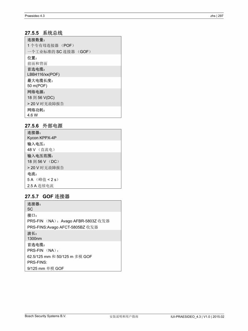
Praesideo 4.3 zhs | 297
Bosch Security Systems B.V. IUI-PRAESIDEO_4.3 | V1.0 | 2015.02安装说明和用户指南
27.5.5 系统总线
27.5.6 外部电源
27.5.7 GOF 连接器
连接数量:
1 个专有母连接器(POF)
一个工业标准的 SC 连接器(GOF)
位置:
前面和背面
首选电缆:
LBB4116/xx(POF)
大电缆长度:
50 m(POF)
网络电源:
18 到 56 V(DC)
> 20 V 时无故障报告
网络功耗:
4.6 W
连接器:
Kycon KPPX-4P
输入电压:
48 V (直流电)
输入电压范围:
18 到 56 V (DC)
> 20 V 时无故障报告
电流:
5 A (峰值 < 2 s)
2.5 A 连续电流
连接器:
SC
接口:
PRS-FIN (NA):Avago AFBR-5803Z 收发器
PRS-FINS:Avago AFCT-5805BZ 收发器
波长:
1300nm
首选电缆:
PRS-FIN (NA):
62.5/125 mm 和 50/125 m 多模 GOF
PRS-FINS:
9/125 mm 单模 GOF

Praesideo 4.3 zhs | 298
Bosch Security Systems B.V. IUI-PRAESIDEO_4.3 | V1.0 | 2015.02安装说明和用户指南
28 LBB4416/xx 网络电缆
28.1 简介所有 LBB4416/xx 网络电缆都配有两条用于数据通信的
塑料光纤和两根用于供电的铜芯。所有电缆
(LBB4416/00 除外)都配有组装好的网络连接器。
要相互连接延长电缆,可以采用电缆耦合器
(LBB4419/00)。
28.2 连接器除了 LBB4416/00,所有电缆在两个末端上都有专有公
连接器来进行终结处理。有关连接器详细信息,请参阅
图 28.3。
图 28.1: 网络电缆
表 28.1: 网络电缆
型号 电缆长度
LBB4416/00 100 m
LBB4416/01 0.5 m
LBB4416/02 2 m
LBB4416/05 5 m
LBB4416/10 10 m
LBB4416/20 20 m
LBB4416/50 50 m
BO
SC
H
BO
SC
H
图 28.2: 连接器(带有防尘盖)
图 28.3: 连接器详细信息
表 28.2: 连接器详细信息
引脚 信号 缆线
E1 +48 V (直流电) 铜线
E2 接地 铜线
O1 数据 光纤
O2 数据 光纤
E1
O1 O2
E2
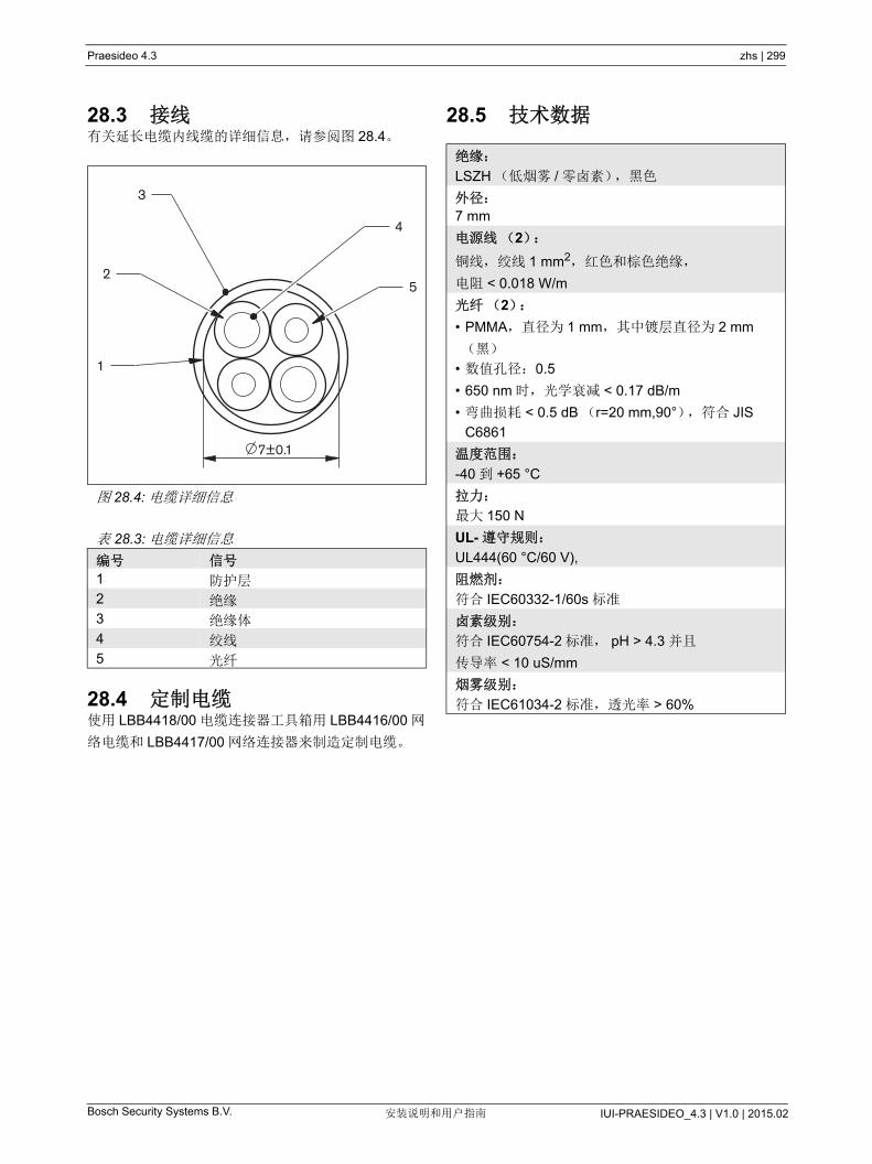
Praesideo 4.3 zhs | 299
Bosch Security Systems B.V. IUI-PRAESIDEO_4.3 | V1.0 | 2015.02安装说明和用户指南
28.3 接线有关延长电缆内线缆的详细信息,请参阅图 28.4。
28.4 定制电缆使用 LBB4418/00 电缆连接器工具箱用 LBB4416/00 网
络电缆和 LBB4417/00 网络连接器来制造定制电缆。
28.5 技术数据
图 28.4: 电缆详细信息
表 28.3: 电缆详细信息
编号 信号
1 防护层
2 绝缘
3 绝缘体
4 绞线
5 光纤
7±0.1
3
2
1
5
4
绝缘:
LSZH (低烟雾 / 零卤素),黑色
外径:
7 mm
电源线(2):
铜线,绞线 1 mm2,红色和棕色绝缘,
电阻 < 0.018 W/m
光纤(2):
• PMMA,直径为 1 mm,其中镀层直径为 2 mm
(黑)
• 数值孔径:0.5
• 650 nm 时,光学衰减 < 0.17 dB/m
• 弯曲损耗 < 0.5 dB (r=20 mm,90°),符合 JIS
C6861
温度范围:
-40 到 +65 °C
拉力:
大 150 N
UL- 遵守规则:
UL444(60 °C/60 V),
阻燃剂:
符合 IEC60332-1/60s 标准
卤素级别:
符合 IEC60754-2 标准, pH > 4.3 并且
传导率 < 10 uS/mm
烟雾级别:
符合 IEC61034-2 标准,透光率 > 60%

Praesideo 4.3 zhs | 300
Bosch Security Systems B.V. IUI-PRAESIDEO_4.3 | V1.0 | 2015.02安装说明和用户指南
29 LBB4417/00 网络连接器
LBB4417/00 网络连接器用于与 LBB4416/00 网线
(100 m) 以及 LBB4418/00 电缆连接器工具包一起来制
造定制电缆。
型号 LBB4417/00 包含 10 件网络连接器所用的部件,
对于 5 条延长电缆已经足够了。
图 29.1: 连接器
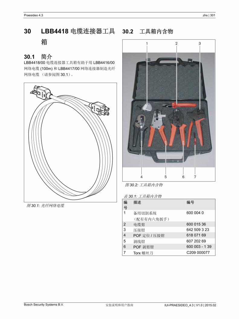
Praesideo 4.3 zhs | 301
Bosch Security Systems B.V. IUI-PRAESIDEO_4.3 | V1.0 | 2015.02安装说明和用户指南
30 LBB4418 电缆连接器工具
箱
30.1 简介LBB4418/00 电缆连接器工具箱有助于用 LBB4416/00
网络电缆 (100m) 和 LBB4417/00 网络连接器制造光纤
网络电缆(请参阅图 30.1)。
30.2 工具箱内含物
图 30.1: 光纤网络电缆
BO
SC
H
BO
SC
H
图 30.2: 工具箱内含物
表 30.1: 工具箱内含物
编
号
描述 编号
1 备用切割系统
(配有有内六角扳手)
600 004 0
2 电缆剪 600 015 36
3 压接钳 642 509 3 23
4 POF 定位 / 压接钳 618 071 69
5 剥线钳 607 202 69
6 POF 剥剪钳 600 003 - 1 39
7 Torx 螺丝刀 C209 000077
4 5
1 2 3
6 7
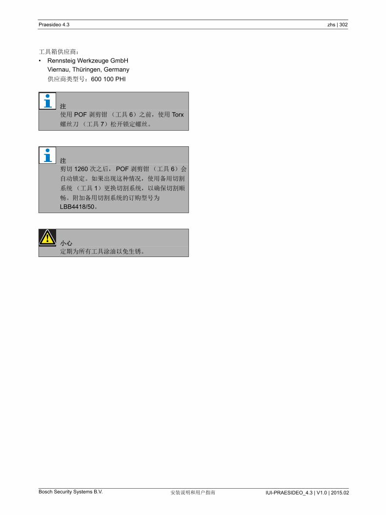
Praesideo 4.3 zhs | 302
Bosch Security Systems B.V. IUI-PRAESIDEO_4.3 | V1.0 | 2015.02安装说明和用户指南
工具箱供应商:
• Rennsteig Werkzeuge GmbH
Viernau, Thüringen, Germany
供应商类型号:600 100 PHI
注
使用 POF 剥剪钳(工具 6)之前,使用 Torx
螺丝刀(工具 7)松开锁定螺丝。
注
剪切 1260 次之后, POF 剥剪钳(工具 6)会
自动锁定。 如果出现这种情况,使用备用切割
系统(工具 1)更换切割系统,以确保切割顺
畅。附加备用切割系统的订购型号为
LBB4418/50。
小心
定期为所有工具涂油以免生锈。

Praesideo 4.3 zhs | 303
Bosch Security Systems B.V. IUI-PRAESIDEO_4.3 | V1.0 | 2015.02安装说明和用户指南
30.3 连接器组件每个光纤网络连接器 (LBB4417/00) 都包含 10 个组件
(请参阅图 30.3 和图 30.4)。
图 30.3: 连接器装配图
1 2
3
4
5
7
8
6
图 30.4: 连接器组件
2 75
1 3 4 6 8
表 30.2: 连接器组件
否 描述
1 防尘盖
2 Torx 螺丝钉
3 正面卡盒
4 卡线盒
5 铜芯套筒
6 光纤套筒
7 压接衬套
8 背面卡盒

Praesideo 4.3 zhs | 304
Bosch Security Systems B.V. IUI-PRAESIDEO_4.3 | V1.0 | 2015.02安装说明和用户指南
30.4 电缆连接器安装
30.4.1 简介本章将逐步对电缆连接器的装配过程进行描述。此过程
包含以下步骤:
• 准备(请参阅第 30.4.3 节)。
• 压接衬套(请参阅第 30.4.4 节)。
• 剥离铜芯(请参阅第 30.4.5 节)。
• 安装铜芯套筒(请参阅第 30.4.6 节)。
• 剥离光纤(请参阅第 30.4.7 节)。
• 安装光纤套筒(请参阅第 30.4.8 节)。
• 装配连接器(请参阅第 30.4.9 节)。
30.4.2 电缆类型光纤网络电缆有两种类型:
• 塑料光纤相互靠近的 A 型电缆 (请参阅图 30.5,显
示两个电缆末端)。
• 塑料光纤处于相对位置的 B 型电缆 (请参阅
图 30.5,两个电缆末端相同)。
30.4.3 准备按以下步骤进行:
1 使用电缆剪(工具 2)将光纤网络电缆剪成需要的
长度。
2 确定电缆类型(请参阅第 30.4.2 节),因为电缆连
接器装配过程中的某些步骤取决于电缆类型。
3 分拆网络连接器。网络控制器由 10 部分组成(请
参阅第 30.3 节)。
4 将背面卡盒滑到电缆上(请参阅图 30.6)。
5 将电缆插入剥线钳(工具 5)中,使其顶住堵头,
然后用剥线钳剥掉电缆的外皮(请参阅图 30.7)。
图 30.5: 电缆类型
A B
A
BB
R
= Red= Brown
R
RBRB
注
考虑到光损耗,光纤网络电缆的长度必须小于
50 m。
图 30.6: 电缆上的背面机架
图 30.7: 剥离电缆

Praesideo 4.3 zhs | 305
Bosch Security Systems B.V. IUI-PRAESIDEO_4.3 | V1.0 | 2015.02安装说明和用户指南
30.4.4 压接衬套按以下步骤进行:
6 将压接衬套滑动到电缆上,滑到线端处。
7 使用压接钳(工具 3,请参阅图 30.9)将衬套压接
在线端处。压接衬套能防止电缆在连接器中滑动旋
转。
30.4.5 剥离铜芯按以下步骤进行:
8 使用电缆剪(工具 2)和剥线钳(工具 5)将铜 线
剪成需要的长度。 后,将压接衬套置于位置 I,而
在位置 II 处剪切铜线(请参阅图 30.10)。
注
在下一步中,使用压接钳(工具 3)和压接衬套
将外皮末端处的圆形电缆横截面压制成六边形。
在压接衬套之前,确保两根塑料光纤平行于六边
形横截面的某一条直边(参见图 30.8)。
图 30.8: 横断面变形图
A B
A
RB
BRB
R
= Red= Brown
RB
图 30.9: 压接衬套
图 30.10: 剪切铜线
II
I

Praesideo 4.3 zhs | 306
Bosch Security Systems B.V. IUI-PRAESIDEO_4.3 | V1.0 | 2015.02安装说明和用户指南
9 将红色和棕色两根铜线推到剥线钳(工具 5,请参
阅图 30.11)的两个堵头上,从而剥离开铜线。
30.4.6 安装铜芯套筒按以下步骤进行:
10 将铜芯套筒放在压接钳(工具 3,请参阅图 30.12)
中。压接钳(请参阅图 30.13)的上部有一个供铜
芯套筒定位用的脊痕。
图 30.11: 剥离铜线
图 30.12: 压接铜芯套筒 (1)
图 30.13: 定位铜芯套筒
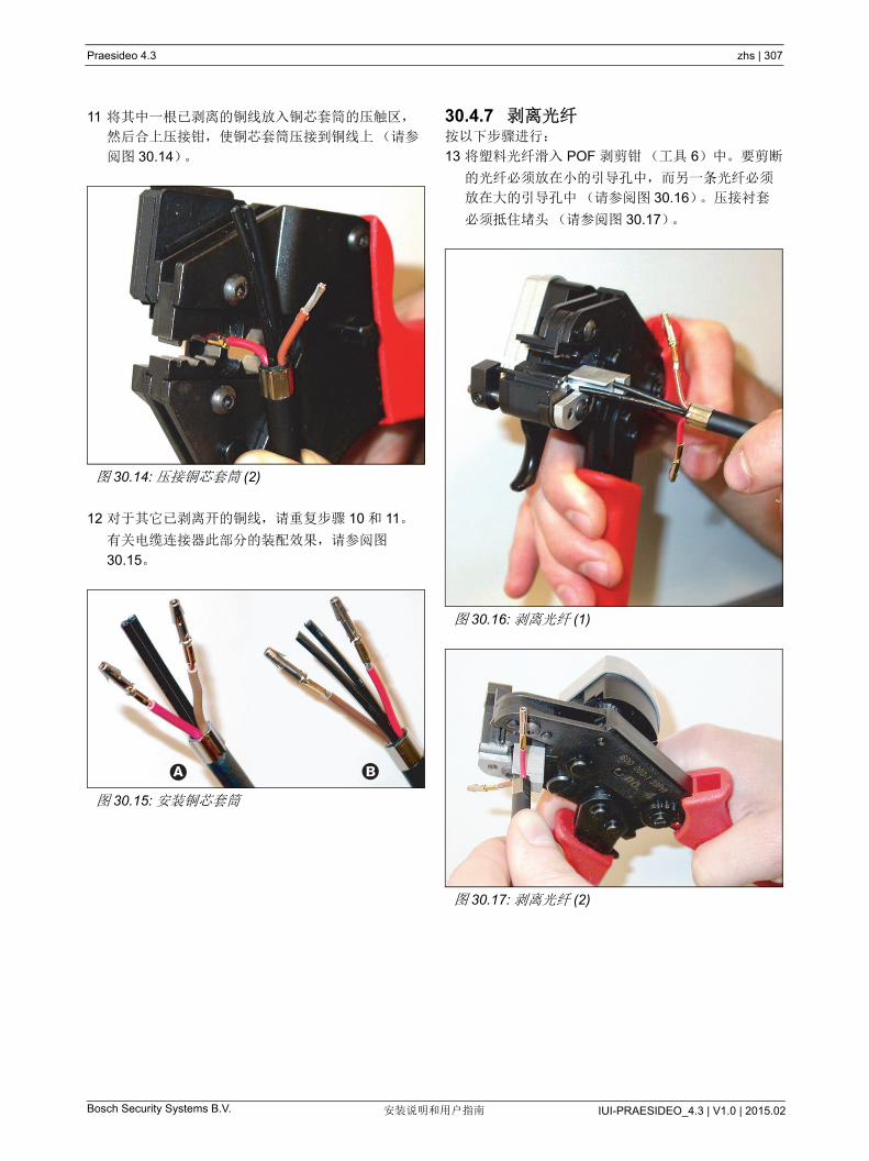
Praesideo 4.3 zhs | 307
Bosch Security Systems B.V. IUI-PRAESIDEO_4.3 | V1.0 | 2015.02安装说明和用户指南
11 将其中一根已剥离的铜线放入铜芯套筒的压触区,
然后合上压接钳,使铜芯套筒压接到铜线上(请参
阅图 30.14)。
12 对于其它已剥离开的铜线,请重复步骤 10 和 11。
有关电缆连接器此部分的装配效果,请参阅图
30.15。
30.4.7 剥离光纤按以下步骤进行:
13 将塑料光纤滑入 POF 剥剪钳(工具 6)中。要剪断
的光纤必须放在小的引导孔中,而另一条光纤必须
放在大的引导孔中(请参阅图 30.16)。压接衬套
必须抵住堵头(请参阅图 30.17)。
图 30.14: 压接铜芯套筒 (2)
图 30.15: 安装铜芯套筒
A B
图 30.16: 剥离光纤 (1)
图 30.17: 剥离光纤 (2)

Praesideo 4.3 zhs | 308
Bosch Security Systems B.V. IUI-PRAESIDEO_4.3 | V1.0 | 2015.02安装说明和用户指南
14 合上剥剪钳以紧固电缆,然后扣动 “ 扳机 ” 剪切光纤
(请参见图 30.18)。
15 对于电缆中的其它塑料光纤,请重复步骤 13 和
14。现在,两条光线都达到了需要的长度。
16 将其中一条光纤滑入 POF 剥剪钳(工具 6,请参阅
图 30.19)的前端。
17 合上剥剪钳,向外拉光纤,从而将其外皮剥掉。
18 对于电缆中的其它光纤,请重复步骤 16 和 17。有
关电缆连接器此部分的装配效果,请参阅图 30.20。
图 30.18: 剥离光纤 (3)
图 30.19: 剥离光纤
注
切勿忘记清除工具中的外皮。
图 30.20: 剥离光纤
A B
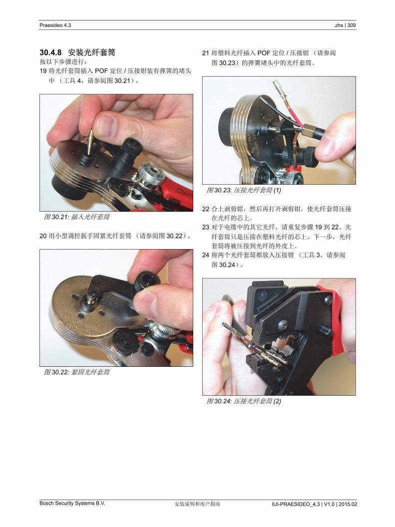
Praesideo 4.3 zhs | 309
Bosch Security Systems B.V. IUI-PRAESIDEO_4.3 | V1.0 | 2015.02安装说明和用户指南
30.4.8 安装光纤套筒按以下步骤进行:
19 将光纤套筒插入 POF 定位 / 压接钳装有弹簧的堵头
中(工具 4,请参阅图 30.21)。
20 用小型调控扳手固紧光纤套筒(请参阅图 30.22)。
21 将塑料光纤插入 POF 定位 / 压接钳(请参阅
图 30.23)的弹簧堵头中的光纤套筒。
22 合上剥剪钳,然后再打开剥剪钳,使光纤套筒压接
在光纤的芯上。
23 对于电缆中的其它光纤,请重复步骤 19 到 22。光
纤套筒只是压接在塑料光纤的芯上。下一步,光纤
套筒将被压接到光纤的外皮上。
24 将两个光纤套筒都放入压接钳(工具 3,请参阅
图 30.24)。
图 30.21: 插入光纤套筒
图 30.22: 紧固光纤套筒
图 30.23: 压接光纤套筒 (1)
图 30.24: 压接光纤套筒 (2)
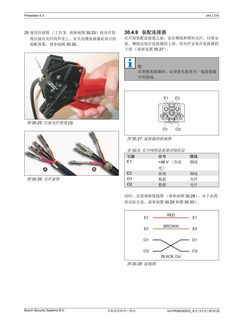
Praesideo 4.3 zhs | 310
Bosch Security Systems B.V. IUI-PRAESIDEO_4.3 | V1.0 | 2015.02安装说明和用户指南
25 使用压接钳(工具 3,请参阅图 30.25)将光纤套
筒压接在光纤的外皮上。有关电缆连接器此部分的
装配效果,请参阅图 30.26。
30.4.9 装配连接器在开始装配连接器之前,定位铜线和塑料光纤,以便安
装。铜线安装在连接器的上部,而光纤安装在连接器的
下部(请参见图 30.27)。
同时,还要观察接线图(请参阅图 30.28)。对于此图
的实际含意,请参阅图 30.29 和图 30.30)。
图 30.25: 压接光纤套筒 (3)
图 30.26: 光纤套筒
A B
注
在更换连接器时,必须首先检查另一端连接器
中的接线。
图 30.27: 连接器的前视图
表 30.3: 光学网络连接器详细信息
引脚 信号 缆线
E1 +48 V (直流
电)
铜线
E2 接地 铜线
O1 数据 光纤
O2 数据 光纤
图 30.28: 接线图
E1
O1 O2
E2
E1RED
E1
BROWNE2
O1
BLACK (2x)O2
E2
O1
O2
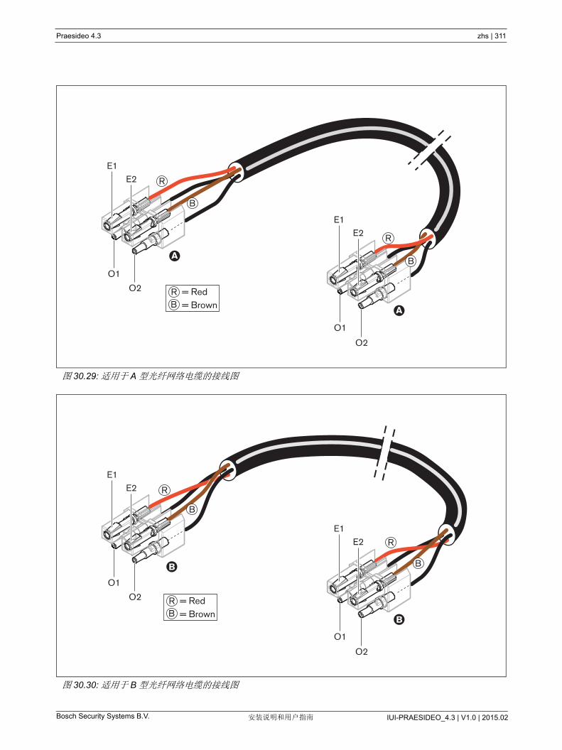
Praesideo 4.3 zhs | 311
Bosch Security Systems B.V. IUI-PRAESIDEO_4.3 | V1.0 | 2015.02安装说明和用户指南
图 30.29: 适用于 A 型光纤网络电缆的接线图
O1
O2
O1
O2
A
A
E1E2
E1E2
R
R
B
B
RB
= Red= Brown
图 30.30: 适用于 B 型光纤网络电缆的接线图
O1
O2
O1
O2
B
B
E1E2
E1E2
R
R
B
RB
= Red= Brown
B
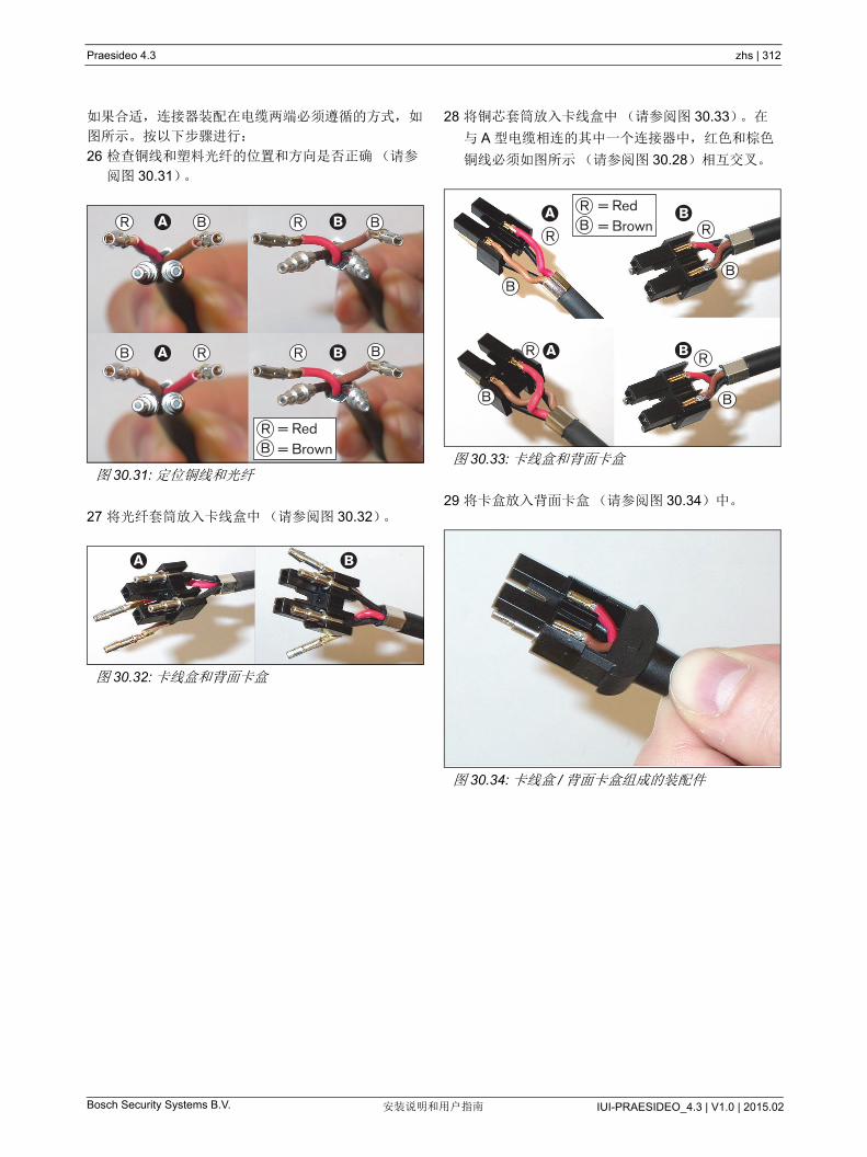
Praesideo 4.3 zhs | 312
Bosch Security Systems B.V. IUI-PRAESIDEO_4.3 | V1.0 | 2015.02安装说明和用户指南
如果合适,连接器装配在电缆两端必须遵循的方式,如
图所示。按以下步骤进行:
26 检查铜线和塑料光纤的位置和方向是否正确(请参
阅图 30.31)。
27 将光纤套筒放入卡线盒中(请参阅图 30.32)。
28 将铜芯套筒放入卡线盒中(请参阅图 30.33)。在
与 A 型电缆相连的其中一个连接器中,红色和棕色
铜线必须如图所示(请参阅图 30.28)相互交叉。
29 将卡盒放入背面卡盒(请参阅图 30.34)中。
图 30.31: 定位铜线和光纤
图 30.32: 卡线盒和背面卡盒
A B
A B
R B
B R R B
R B
RB
= Red= Brown
A B
图 30.33: 卡线盒和背面卡盒
图 30.34: 卡线盒 / 背面卡盒组成的装配件
A B
A B
BB
R
B
R
R
B
R
RB
= Red= Brown
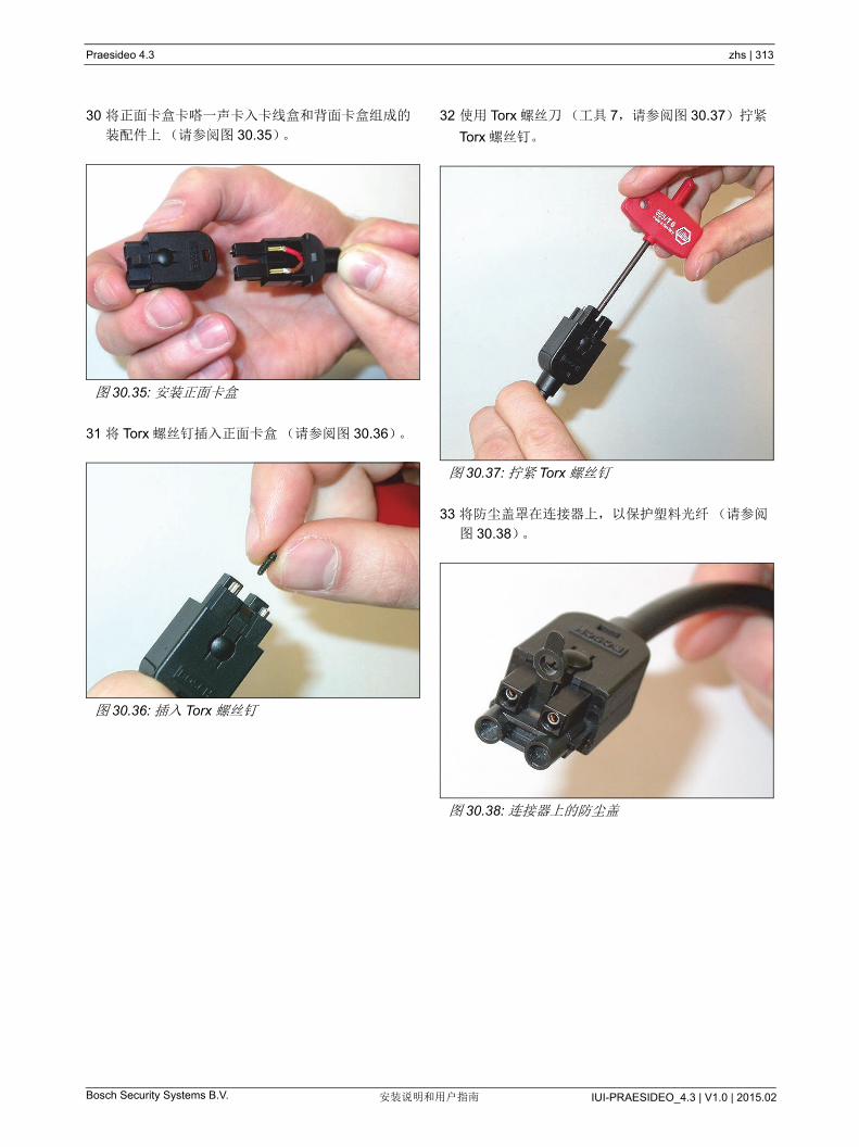
Praesideo 4.3 zhs | 313
Bosch Security Systems B.V. IUI-PRAESIDEO_4.3 | V1.0 | 2015.02安装说明和用户指南
30 将正面卡盒卡嗒一声卡入卡线盒和背面卡盒组成的
装配件上(请参阅图 30.35)。
31 将 Torx 螺丝钉插入正面卡盒(请参阅图 30.36)。
32 使用 Torx 螺丝刀(工具 7,请参阅图 30.37)拧紧
Torx 螺丝钉。
33 将防尘盖罩在连接器上,以保护塑料光纤(请参阅
图 30.38)。
图 30.35: 安装正面卡盒
图 30.36: 插入 Torx 螺丝钉
图 30.37: 拧紧 Torx 螺丝钉
图 30.38: 连接器上的防尘盖
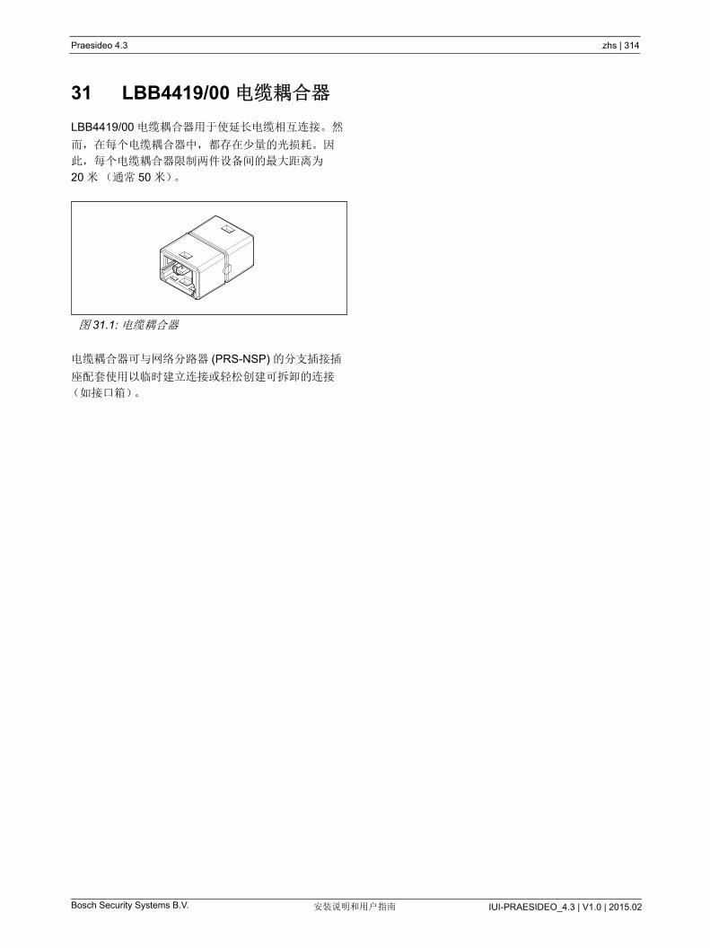
Praesideo 4.3 zhs | 314
Bosch Security Systems B.V. IUI-PRAESIDEO_4.3 | V1.0 | 2015.02安装说明和用户指南
31 LBB4419/00 电缆耦合器
LBB4419/00 电缆耦合器用于使延长电缆相互连接。然
而,在每个电缆耦合器中,都存在少量的光损耗。因
此,每个电缆耦合器限制两件设备间的 大距离为
20 米(通常 50 米)。
电缆耦合器可与网络分路器 (PRS-NSP) 的分支插接插
座配套使用以临时建立连接或轻松创建可拆卸的连接
(如接口箱)。
图 31.1: 电缆耦合器

Bosch Security Systems B.V. IUI-PRAESIDEO_4.3 | V1.0 | 2015.02安装说明和用户指南
Praesideo 4.3 zhs | 315
32 电缆连接
32.1 简介Praesideo 系统中的多个组件形成菊花链。因此,所有设
备都配有两个可互换使用的系统总线连接器(请参阅
图 32.1)。使用这些连接器中的某一个连接器来连接此
设备与链中的前一个设备,使用其它连接器连接此设备
与链中的下一个设备。
因为这些设备是采用菊花链连接的,所以可以在网络中
的任何地方添加或拆除设备而不影响其它设备的性能,
假若其它网络连接可用。
32.2 系统总线系统总线电缆(请参阅图 32.2)配有两根塑料光纤
(POF)“ 电线 ” 和两根铜丝。 POF 电线可以传输 28 个同
时发生的音频通道和 Praesideo 控制数据,而铜线则向
设备供电。
注
两个系统连接器相同。
l
图 32.1: 菊花链
Network Ethernet
Control In
Audio In 3
1 2 3 4 5 6 7 8
C NC NO C NC NO C NC NO C NC NO C NC NO
1 2
48V
Audio Out 3 Audio In 4 Audio Out 4
Audio In 1 Audio Out 1 Audio In 2 Audio Out 2
115: 100-120V~ 50-60Hz
Mains
T2.5A 250V
Control Out
RS 232
1 2 3 4 548V
Avis
CautionRisk of electric shock.
Do not open.
Risk of electric shock.Do not open.
230
O I
230: 220-240V~ 50-60Hz T1.25A H 250V
1 2
48V 48V
l
图 32.2: 系统总线连接器
表 32.1: 系统总线电缆详细信息
编号 颜色 材料 描述
E1 红色 铜线 电源 ,+(48V)
E2 棕色 铜线 电源 ,-( 接地 )
O1 黑色 POF 数据
O2 黑色 POF 数据
O1
E1
O2
E2

Bosch Security Systems B.V. IUI-PRAESIDEO_4.3 | V1.0 | 2015.02安装说明和用户指南
Praesideo 4.3 zhs | 316
32.3 防尘盖保护未使用防尘盖的系统电缆和连接器中的 POF 部
件。防尘盖还可以防止红光通过光纤接口,这种红光可
能看得见并起干扰作用。
32.4 大距离由于光损耗,两件设备之间 POF 电缆连接(也是系统总
线电缆)的 大长度为 50 米。如果两件设备之间的距离
超过 50 米,则必须使用 PRS-FIN(NA) 或 PRS-FINS 光纤
接口和玻璃光纤 (GOF) (请参阅图 32.4)。
如果使用 GOF 电缆,确保它们满足以下要求:
• 多模 GOF 电缆(PRS-FINS 支持单模 GOF 电缆);
• 大衰减为 2 dB/km;
• 适合于波长为 1300 nm 的光 ;
• 以标准的SC 连接器为终端。
注
安装和运行期间,POF 电缆连接的温度不应该
超过 65 °C。高温可以损害光纤。
注
Praesideo 设备上系统总线连接器的 POF 部件
符合 F05 和 F07。这意味着如果只须 传输数
据,则可以使用工业标准的 F05 或 F07 连接
器。如果两个设备之间只使用 POF 电缆连接,
则在这些设备之间不传输功率。
图 32.3: 防尘盖
图 32.4: 使用光纤接口
注
还可以通过每 50 m 或小于 50 m 插入
PRS-NSP 网络分路器来将设备之间的距离增
加到 50 米以上。尽管不需要任何分支插接,
但网络分路器会重新产生网络信号以覆盖另外
50 米。
POF
GOF ( > 50m)
POF
3 3
7 7

Bosch Security Systems B.V. IUI-PRAESIDEO_4.3 | V1.0 | 2015.02安装说明和用户指南
Praesideo 4.3 zhs | 317
32.5 大电缆长度系统中所有光纤(POF 和 GOF)加在一起的 大长度
取决于系统中的节点数量。每件设备都指定有节点。
此图表(请参阅图 32.5)显示系统中的节点数与系统
中 大光纤长度之间的关系。
表 32.2: 节点
型号 描述 节点
PRS-4AEX4 音频扩展器 1
LBB4404/00 CobraNet 接口 1
PRS-4OMI4 OMNEO 接口 1
PRS-NSP 网络分路器 1
PRS-FIN (S)
PRS-FINNA
光纤接口
光纤接口
1
0/1
PRS-1P500
PRS-2P250
PRS-4P125
LBB4428/00
功率放大器 1x500 瓦
功率放大器 2x250 瓦
功率放大器 4x125 瓦
功率放大器 8x60 瓦
1
1
1
2
LBB4430/00 呼叫站基本要素 1
LBB4432/00 呼叫站键盘 0
PRS-CSNKP 数字键盘 0
PRS-CSM 呼叫站模块 1
PRS-CSKPM 呼叫站键盘模块 0
PRS-CSI 呼叫站接口 1
PRS-CRF 呼叫堆栈 1
PRS-16MCI 多通道接口 1
PRS-NCO3 网络控制器 3
注
系统中包含的节点数可能超过 63 个。
注
如果系统中的节点数不超过 63 个,
PRS-FINNA 不占用节点,但如果对于 大光
纤长度,占用 1 个节点。因此,直线中的虚线
部分仅适用于 PRS-FINNA 光纤接口。
图 32.5: 大光纤长度 VS. 节点数
850
1050
1150
950
750
1250
1350
1450
1550
1650
1750
1850
1950
2050
2150
Max
imum
cab
le le
ngth
(m
)
650
50 10 15 20 25
Number of nodes
30 35 40 45 50 55 60 65 70 75 80
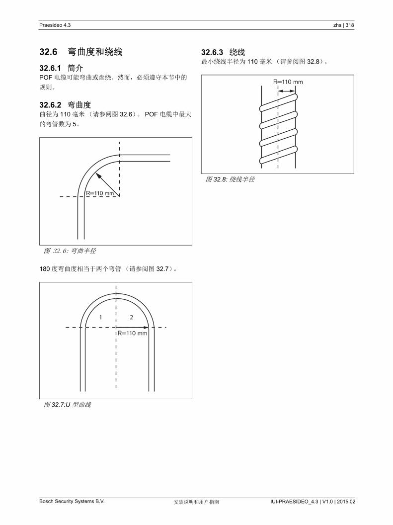
Bosch Security Systems B.V. IUI-PRAESIDEO_4.3 | V1.0 | 2015.02安装说明和用户指南
Praesideo 4.3 zhs | 318
32.6 弯曲度和绕线
32.6.1 简介POF 电缆可能弯曲或盘绕。然而,必须遵守本节中的
规则。
32.6.2 弯曲度曲径为 110 毫米(请参阅图 32.6)。 POF 电缆中 大
的弯管数为 5。
180 度弯曲度相当于两个弯管(请参阅图 32.7)。
32.6.3 绕线小绕线半径为 110 毫米(请参阅图 32.8)。
图 32.6: 弯曲半径
图 32.7:U 型曲线
R=110 mm
21
R=110 mm
图 32.8: 绕线半径
R=110 mm

Bosch Security Systems B.V. IUI-PRAESIDEO_4.3 | V1.0 | 2015.02安装说明和用户指南
Praesideo 4.3 zhs | 319
33 结构
33.1 简介Praesideo 系统的具体布局依赖于组成系统的设备数量
和类型。本章包含一些 Praesideo 系统的易懂事例
(非常简单)以阐释此可能性。
33.2 基本系统有关基本系统的示例,请参阅图 33.1。
33.3 冗余电缆连接此基本系统没有冗余电缆连接。如果呼叫站和功率放大
器之间的电缆断裂,则无法播放呼叫或背景音乐。可以
通过创建冗余电缆系统解决此问题(请参阅图 33.2)。
基本系统与这种冗余电缆基本系统之间的唯一不同就是
功率放大器和网络控制器之间的连接。现在,设备形成
环形。如果电缆断裂,系统仍能正常运转。
图 33.1: 基本系统
注
在本章的其余部分, “ 基本系统 ” 指图 33.1 中
的系统。
PRS-NCO3Network Controller
PRS-4P125Power Amplifier
LBB4430Call Station Basic
LBB4432Call Station Keypad
background music
图 33.2: 冗余电缆基本系统
注
在本章的其余部分, “ 基本冗余系统 ” 指
图 33.2 中的系统。
PRS-NCO3Network Controller
PRS-4P125PowerAmplifier
LBB4430Call Station Basic
LBB4432Call Station Keypad
background music
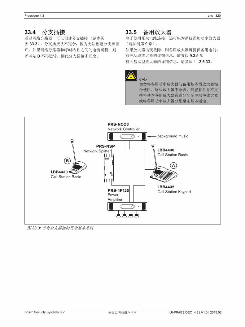
Bosch Security Systems B.V. IUI-PRAESIDEO_4.3 | V1.0 | 2015.02安装说明和用户指南
Praesideo 4.3 zhs | 320
33.4 分支插接通过网络分路器,可以创建分支插接(请参阅
图 33.3)。分支插接从不冗余,因为无法创建分支插接
环。如果网络分路器和呼叫站 B 之间的电缆断裂,则
呼叫站 B 不再运转,因此分支插接不冗余。
33.5 备用放大器除了使用冗余电缆连接,还可以为系统添加功率放大器
(请参阅第 9 章)。
如果放大器出现故障,则备用放大器可提供备用电能。
有关功率放大器的详细信息,请参阅 9.3.5.5。
有关基本型放大器的详细信息,请参阅 11.3.5.33。
小心
切勿将备用功率放大器与备用基本型放大器混
合使用。这些放大器不兼容,配置软件并不支
持将基本备用放大器通道分配至主功率放大器
或将备用功率放大器分配至主基本通道。
图 33.3: 带有分支插接的冗余基本系统
PRS-NCO3Network Controller
PRS-NSPNetwork Splitter LBB4430
Call Station Basic
LBB4430Call Station Basic
LBB4432PRS-4P125 CPowerAmplifier
all Station Keypad
A
background music
B

Bosch Security Systems B.V. IUI-PRAESIDEO_4.3 | V1.0 | 2015.02安装说明和用户指南
Praesideo 4.3 zhs | 321
33.6 CobraNetCobraNet 是通过以太网传输多个数字未压缩音频通道
的一种标准。许多公共广播和专业音频设备的生产商支
持该标准。 CobraNet 集中了以太网的所有优点:使用
5 类电缆和玻璃光纤覆盖远距离的结构化电缆连接和便
宜的网络组件。在 Praesideo 系统中, LBB4404/00
CobraNet 接口用于连接 CobraNet 和 Praesideo。这些
CobraNet 接口可以用于以下操作:
• 连接 Praesideo 系统(有关事例,请参阅图 33.4)。
• 受益于已经存在的以太基础架构。
• 传输音频至更远距离。
只要使用受管理的以太网交换机, PC 数据,如
Praesideo 开放式接口,就可以与 CobraNet 共存于相
同的以太网网络上请参阅:
http://www.cobranet.info/en/support/cobranet/design/
由于延迟变量,不允许将 7 个以上的交换机串联。
快速以太网距离限制适用于 CobraNet 安装:100 米长
的 5 类铜质电缆, 2 千米长的多模光纤。专用快速以太
网通过单模光纤解决方案可以使传输距离更远。
注
CobraNet 接口不传输控制功能。这些功能只
能通过 Praesideo 开放式接口在以太网上传
输。网络控制器总是开放式接口从属设备,必
须由 PC 呼叫站等开放式系统主控设备控制。
图 33.4: 连接系统
Praesideo Praesideo
Ethernet backbone
Switch Switch
CAT-5/GOF (long distance)
EthernetCobraNet
EthernetTCP/IP Ethernet
CobraNetEthernetTCP/IP
EthernetTCP/IP
Con
trol
Aud
io
Con
trol
PC Call station
PRS-NCO3Network Controller
LBB4404/00CobraNet Interface
LBB4404/00CobraNet Interface
PRS-NCO3Network Controller

Bosch Security Systems B.V. IUI-PRAESIDEO_4.3 | V1.0 | 2015.02安装说明和用户指南
Praesideo 4.3 zhs | 322
33.7 故障安全
33.7.1 简介Praesideo 系统必须用作紧急广播系统时,网络布局必
须为故障安全结构。即使网络控制器出现故障,故障安
全网络也能允许播放呼叫。为此,系统中必须安装 “ 紧
急 ” 呼叫站。然而,不能将此呼叫站安装于系统的随意
地方。
33.7.2 规则创建故障安全布局时请遵守以下规则:
1 通过 Web 接口的配置部件将呼叫站标为 “ 紧急 ” 呼
叫站(请参阅表 44.13)。
2 紧急呼叫站必须配备检测备用电源。如果网络控制
器出现故障,则无法再为系统总线供电。然而,呼
叫站必须保持运转,因此必须由另一电源对其供
电。因此,通过使用检测外部电源或外部供电的呼
叫站套件连接紧急呼叫站和网络。
3 切勿将设备安装在紧急呼叫站和功率放大器之间:
• 通常情况下,使用系统总线提供的电源,并且
• 未连接任何备用电源。
假如网络控制器出现故障,那么这些设备将无法运
转,因为它们未连接任何电源。这样产生的后果是
这些设备无法路由信号,因而其不应安装在紧急呼
叫站与功率放大器之间。
4 切勿将紧急呼叫站安装在分支插接中。紧急呼叫站
必须安装在主网络中。这是保证可以向所有分区发
送呼叫的唯一方式。
5 即使本地音量控制系统配有音量强切设备,也不允
许将其连接到扬声器上。如果没有网络控制器,则
用于激活音量强切系统的控制输出端不再被激活
(即使控制输出端位于功率放大器或音频扩展器
上)。此外,本地音量控制系统干扰线路检测操作。
线路检测套件使用扬声器线路。线路中的任何音量
控制都会削弱检测主板 20kHz 的导频音,对于检测
副板正常运行,这实在太多。
33.8 IP 地址在 Praesideo 网络中,对于网络控制器、带有
Praesideo 软件(如记录服务器、记录查看器)的
PC、 CobraNet 接口等,请勿使用以下的 IP 地址:
• 主机部分为 0 的所有 IP 地址。例如,如果子网掩为
255.255.255.0,请不要使用地址 x.x.x.0。
• 主机部分为 255 的所有 IP 地址。例如,如果子网掩
为 255.255.255.0,请不要使用地址 x.x.x.255。
• 127.0.0.1
• 14.0.0.1 - 14.0.0.254
• 24.0.0.1 - 24.0.0.254
• 39.0.0.1 - 39.0.254
• 128.0.0.1 - 128.0.255.254
• 169.254.0.1 - 169.254.255.254
• 172.16.0.1 - 172.16.15.254
• 191.255.0.1 - 191.255.255.254
• 192.0.0.1 - 192.0.255.254
• 192.88.99.1 - 192.88.255.254
您可以使用以下的 IP 地址,但切记不能用这些地址访
问因特网:
• 10.0.0.1 - 10.255.255.254
• 172.16.16.1 - 172.31.255.254
• 192.168.0.1 - 192.168.255.254
• 224.0.0.1 - 239.255.255.254
如果在 Praesideo 软件中输入 IP 地址,请切记省略开
头的 0,否则将引起网络错误。例如,请将
192.068.000.010. 省略为 192.68.0.10。
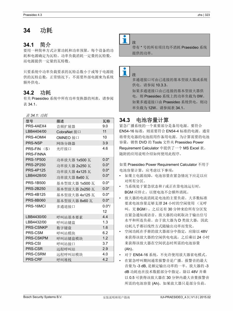
Bosch Security Systems B.V. IUI-PRAESIDEO_4.3 | V1.0 | 2015.02安装说明和用户指南
Praesideo 4.3 zhs | 323
34 功耗
34.1 简介要用一种简单方式计算功耗和功率预算,每个设备的功
耗和电源确定为瓦特。功率负载消耗一定量的瓦特数,
而电源提供一定量的瓦特数。
只要系统中功率负载要求的瓦特总数小于或等于电源提
供的瓦特总数,正常情况下,不需要外部电源来为系统
额外供电。
34.2 功耗有关 Praesideo 系统中所有功率变换器的列表,请参阅
表 34.1。
34.3 电池容量计算紧急广播系统的一个重要部分是备用电源。要符合
EN54-16 标准,则需要符合 EN54-4 标准的电源。通常
将带充电器的电池组用作备用电源。为计算需要的电池
容量,销售 DVD 的 Tools 文件夹 Praesideo Power
Requirement Calculator 中提供了一个 MS Excel 表。
随附的应用说明介绍如何使用此程序。
如果 Praesideo Power Requirement Calculator 不用于
电池容量计算,应考虑以下事项:
• 如果主电源故障,电池容量在紧急情况下应足以应
对所有分区。
• 当系统处于紧急状态和 / 或正在靠电池运行时,
BGM 应停止,以便电池不会额外消耗。
• 放大器的电流消耗是电池的主要负荷。大多数标准
要求电池容量足够支撑 24 小时的空闲使用(无呼
叫,无 BGM),之后还有 30 分钟来给所有分区发
出紧急通知或语音。放大器的功耗取决于输出信号
水平和所连负荷。由于放大器为 D 类放大器,因此
功耗几乎都以线性方式随输出功率而变化。
• 空闲功耗在手册的放大器部分中指定,应除以 48V
来获得该放大器的空闲供电电流,之后乘以 24 小时
来获得该放大器在空间状态时所需的电池容量
(Ah)。
• 对于 EN54-16 系统,不允许使用放大器省电模式。
• 在紧急呼叫期间通常报警音是广播。报警音的 大
音量为 -3 dB, 是额定输出功率的一半。放大器的 -3
dB 功耗也在技术数据部分中指定。除以 48V 并乘
以 0.5 可获得该放大器在 30 分钟内 大音量报警音
所需的电池容量 (Ah)。如果放大器只是部分负荷,
表 34.1: 功耗
型号 描述 瓦特
PRS-4AEX4 音频扩展器 9.0
LBB4404/00 CobraNet 接口 11
PRS-4OMI4 OMNEO 接口 10
PRS-NSP 网络分路器 3.9
PRS-FIN (S)
PRS-FINNA
光纤接口 4.6
PRS-1P500
PRS-2P250
PRS-4P125
LBB4428/00
功率放大器 1x500 瓦
功率放大器 2x250 瓦
功率放大器 4x125 瓦
功率放大器 8x60 瓦
0.0*
0.0*
0.0*
0.0*
PRS-1B500 基本型放大器 1x500 瓦 0.0*
PRS-2B250 基本型放大器 2x250 瓦 0.0*
PRS-4B125 基本型放大器 4x125 瓦 0.0*
PRS-8B060 基本型放大器 8x60 瓦 0.0*
PRS-16MCI 多通道接口 0.0*/
12
LBB4430/00 呼叫站基本要素 4.4
LBB4432/00 呼叫站键盘 1.3
PRS-CSNKP 数字键盘 1.6
PRS-CSM 呼叫站模块 6.2
PRS-CSKPM 呼叫站键盘模块 1.2
PRS-CSI 呼叫站接口 3.7
PRS-CSR 远程呼叫站 2.9
PRS-CSRM 远程呼叫站模块 4.0
PRS-CRF 呼叫堆栈 4.2
注
带有 * 号的所有项目均不消耗 Praesideo 系统
提供的功率。
注
多通道接口可由已连接的基本型放大器或系统
供电。请参阅 10.3.3。
如果多通道接口由已连接的基本型放大器供
电,则 Praesideo 系统上的功率负载为 0W。
如果多通道接口由 Praesideo 系统供电,则功
率负载为 12W。请参阅表 34.1。

Bosch Security Systems B.V. IUI-PRAESIDEO_4.3 | V1.0 | 2015.02安装说明和用户指南
Praesideo 4.3 zhs | 324
则可相应减少电池容量。如果是现场实时语音播报
或语音讯息,则容量可以再减半,因为完全输出时
语音的 rms 输出水平通常小于 -6 dB。如果报警音
的占空比小于 100% (即:包含静音周期),则容
量可以相应减少。如果输出水平小于 大输出水
平,则容量还可以相应减少。
• 对于备用放大器,只应考虑空闲电流消耗。
• 在第 34.2 节中提供了由网络控制器供电的所有设备
的功耗。将所有连接的设备加起来,除以 48V 并乘
以 bij 24.5 小时可获得这些设备所需要的电池容量
(Ah)。
• 将所有已算出电池容量加起来并乘以 1.25,作为一
个余量来补偿由于电池老化而导致的电池容量损
失。
为减少出错风险,强烈建议使用 Praesideo Power
Requirement Calculator。
34.4 电源默认情况下,系统中的唯一电源是网络控制器。网络控
制器后面的每个系统总线连接器提供 55 瓦。
如果需要更多的功率,必须使用外部电源向系统供电。
以下设备配有连接外部电源的设备:
• PRS-NSP 网络分路器。连接到网络分路器的外部
电源仅为分支插接供电。
• PRS-FIN (S)、 PRS-FINNA 光纤接口。连接到光
纤接口的外部电源仅为 Praesideo 系统总线供电。
• PRS-CSM 呼叫站模块。连接到呼叫站模块的外部
电源仅为呼叫站模块供电。
• PRS-CSI 呼叫站接口。连接到呼叫站接口的外部电
源仅为呼叫站接口供电,但也可为所连接的远程呼
叫站(模块)供电。
• PRS-CSR 远程呼叫站。连接到远程呼叫站的外部
电源仅为远程呼叫站供电,但也可为所连接的呼叫
站接口供电。
• PRS-CSRM 远程呼叫站模块。连接到远程呼叫站模
块的外部电源仅为远程呼叫站模块供电,但也可为
所连接的呼叫站接口供电。
外部电源提供的瓦特量按以下方式计算:
P = 功率 (W)
U = 直流电压 (V)
I = 直流电流 (A)
因为所有 Praesideo 设备都配有内置切换模式电源,功
耗实际上是一个常量,并且在一定范围内独立于电源电
压 V。电压 V 越低,电流 I 越高。
注
如果您创建冗余环,并且不使用额外电源,则
您 多可以将 55 瓦连接到网络控制器。这将
确保邻近网络控制器其中一个系统总线连接器
的网络出现故障时,其它系统总线连接器仍能
给整个网络供电。
P U I=
Bosch Security Systems B.V. IUI-PRAESIDEO_4.3 | V1.0 | 2015.02安装说明和用户指南
Praesideo 4.3 zhs | 325
34.5 制冷能力可以用一个简单的公式计算安装了 Praesideo 设备的技
术室中空调所需的制冷能力。由于房间里只有功率放大
器和基本型放大器产生热量,其它 Praesideo 设备产生
的热量可以忽略不计。 Praesideo 架装设备的 大环境
温度为 55 。
能量等于功率乘以时间。能量的单位是焦耳。焦耳等于
瓦特 * 秒。因此,在一秒钟时间内,机架内每消耗 1 瓦
特,将产生 1 焦耳能量。
由于其它的放大器都比 LBB4428 更节能,以 LBB4428
计算。一台 LBB4428 在全功率工作的情况下,消耗
800W,因此一个输出端为 480 W (8 个 60 W 的通
道),放大器的消耗为两者之差(320 W)。设备内以
热量形式产生的理论能量为 320 瓦特 *3600 秒 =1,
152 千焦 / 小时,即每天(24 小时) 27, 648 千焦。
实际的能量将会少很多。 Praesideo 放大器仅可以:
• 全功率运行 1 分钟
• 半功率(-3 dB)情况下,为紧急音运行 30 分钟。
• 1/4 功率(-6 dB)情况下,为呼叫或紧急告示,或
为 BGM 连续运行。
连续的 1/4 功率的限制为在限制器上很好地使用放大器
提供了充分的余量,因为语音的波峰因数大约为
8..10 dB,音乐的波峰因数 小为 6 dB,为 坏情况下
的安全余量。
据此,每日(24 小时)产生的 大热能为:
(800 W-480 W)*1 分钟 +(397 W-240 W)*30 分钟
+ (228 W-120 W) *1400 分钟 =320 W*60s+157 W*
1800s+108 W * 84,000 s=9,373,800 Ws=9,374 千焦
对于任何型号的 Praesideo 放大器,一个放大器产生能
量相当于一个 110W 的灯泡。放大器散发的能量应当
相加。若换算成 BTU (英制热单位),则将千焦 (kJ)
的量除以 1.055。若换算成千卡 (kcal),则将千焦 (kJ)
的量除以 4.184。若换算为每小时产生的热量,除以
24。
所以 9,400 kJ/ 天 =9.4 MJ/ 天 =2,240 kcal/ 天 =
8,900 BTU/ 天 = 390 kJ/ 小时 = 93 kcal/ 小时。

Bosch Security Systems B.V. IUI-PRAESIDEO_4.3 | V1.0 | 2015.02安装说明和用户指南
Praesideo 4.3 zhs | 326
35 预防性维护
该系统所需要的维护 少。为了保持系统处于良好 的
运行状态,请执行以下步骤:
35.1 清洁进气口功率放大器因内部装有风扇可能会聚集灰尘。您应该每
年 1 次使用真空吸尘器来清洁 19 英寸机架中所有部件
的进气口。
35.2 更换电池网络控制器主板上的电池在出现故障之前应进行更换。
8 年更换 1 次电池。电池的型号为 3.0V Cr2032。在给
电池充电前将设备断电。更换电池后, PRS-NCO3 的
时间和日期设置将丢失,必须重新输入(请参阅
第 5.6.8 节)。
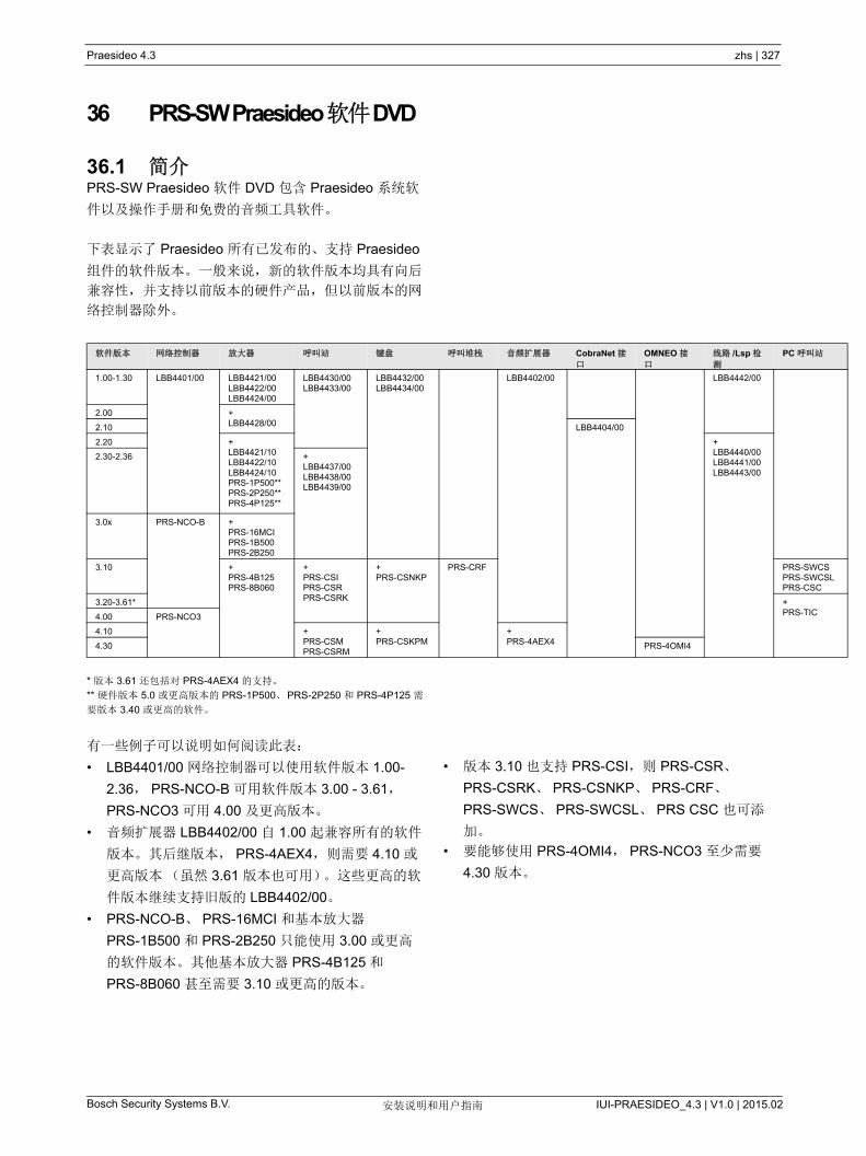
Praesideo 4.3 zhs | 327
Bosch Security Systems B.V. IUI-PRAESIDEO_4.3 | V1.0 | 2015.02安装说明和用户指南
36 PRS-SW Praesideo 软件 DVD
36.1 简介PRS-SW Praesideo 软件 DVD 包含 Praesideo 系统软
件以及操作手册和免费的音频工具软件。
下表显示了 Praesideo 所有已发布的、支持 Praesideo
组件的软件版本。一般来说,新的软件版本均具有向后
兼容性,并支持以前版本的硬件产品,但以前版本的网
络控制器除外。
* 版本 3.61 还包括对 PRS-4AEX4 的支持。
** 硬件版本 5.0 或更高版本的 PRS-1P500、PRS-2P250 和 PRS-4P125 需
要版本 3.40 或更高的软件。
有一些例子可以说明如何阅读此表:
• LBB4401/00 网络控制器可以使用软件版本 1.00-
2.36, PRS-NCO-B 可用软件版本 3.00 - 3.61,
PRS-NCO3 可用 4.00 及更高版本。
• 音频扩展器 LBB4402/00 自 1.00 起兼容所有的软件
版本。其后继版本, PRS-4AEX4,则需要 4.10 或
更高版本(虽然 3.61 版本也可用)。这些更高的软
件版本继续支持旧版的 LBB4402/00。
• PRS-NCO-B、 PRS-16MCI 和基本放大器
PRS-1B500 和 PRS-2B250 只能使用 3.00 或更高
的软件版本。其他基本放大器 PRS-4B125 和
PRS-8B060 甚至需要 3.10 或更高的版本。
• 版本 3.10 也支持 PRS-CSI,则 PRS-CSR、
PRS-CSRK、 PRS-CSNKP、 PRS-CRF、
PRS-SWCS、 PRS-SWCSL、 PRS CSC 也可添
加。
• 要能够使用 PRS-4OMI4, PRS-NCO3 至少需要
4.30 版本。
软件版本 网络控制器 放大器 呼叫站 键盘 呼叫堆栈 音频扩展器 CobraNet 接口
OMNEO 接口
线路 /Lsp 检
测
PC 呼叫站
1.00-1.30 LBB4401/00 LBB4421/00LBB4422/00LBB4424/00
LBB4430/00LBB4433/00
LBB4432/00LBB4434/00
LBB4402/00 LBB4442/00
2.00 +LBB4428/002.10 LBB4404/00
2.20 +LBB4421/10LBB4422/10LBB4424/10PRS-1P500**PRS-2P250**PRS-4P125**
+LBB4440/00LBB4441/00LBB4443/00
2.30-2.36 +LBB4437/00LBB4438/00LBB4439/00
3.0x PRS-NCO-B +PRS-16MCIPRS-1B500PRS-2B250
3.10 +PRS-4B125PRS-8B060
+PRS-CSIPRS-CSRPRS-CSRK
+PRS-CSNKP
PRS-CRF PRS-SWCSPRS-SWCSLPRS-CSC
3.20-3.61* +PRS-TIC4.00 PRS-NCO3
4.10 +PRS-CSMPRS-CSRM
+PRS-CSKPM
+PRS-4AEX44.30 PRS-4OMI4
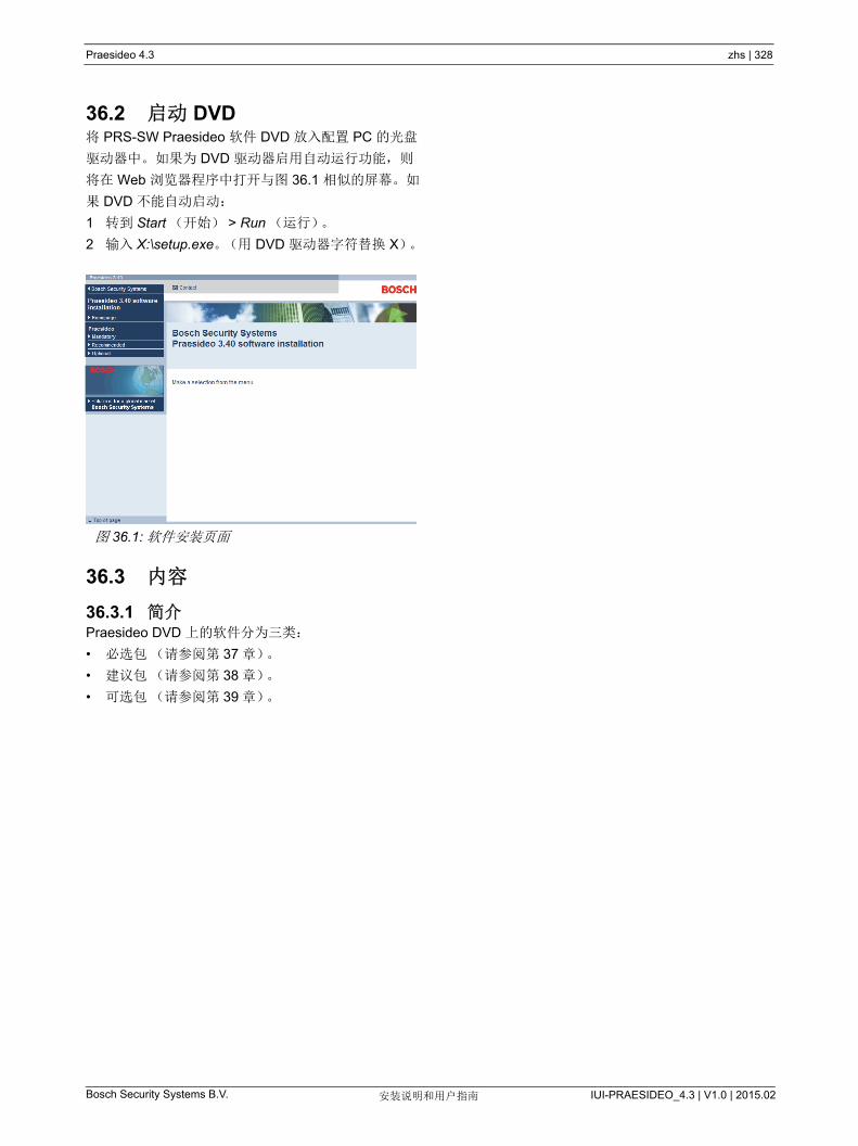
Praesideo 4.3 zhs | 328
Bosch Security Systems B.V. IUI-PRAESIDEO_4.3 | V1.0 | 2015.02安装说明和用户指南
36.2 启动 DVD将 PRS-SW Praesideo 软件 DVD 放入配置 PC 的光盘
驱动器中。如果为 DVD 驱动器启用自动运行功能,则
将在 Web 浏览器程序中打开与图 36.1 相似的屏幕。如
果 DVD 不能自动启动:
1 转到 Start (开始) > Run (运行)。
2 输入 X:\setup.exe。(用 DVD 驱动器字符替换 X)。
36.3 内容
36.3.1 简介Praesideo DVD 上的软件分为三类:
• 必选包(请参阅第 37 章)。
• 建议包(请参阅第 38 章)。
• 可选包(请参阅第 39 章)。
图 36.1: 软件安装页面
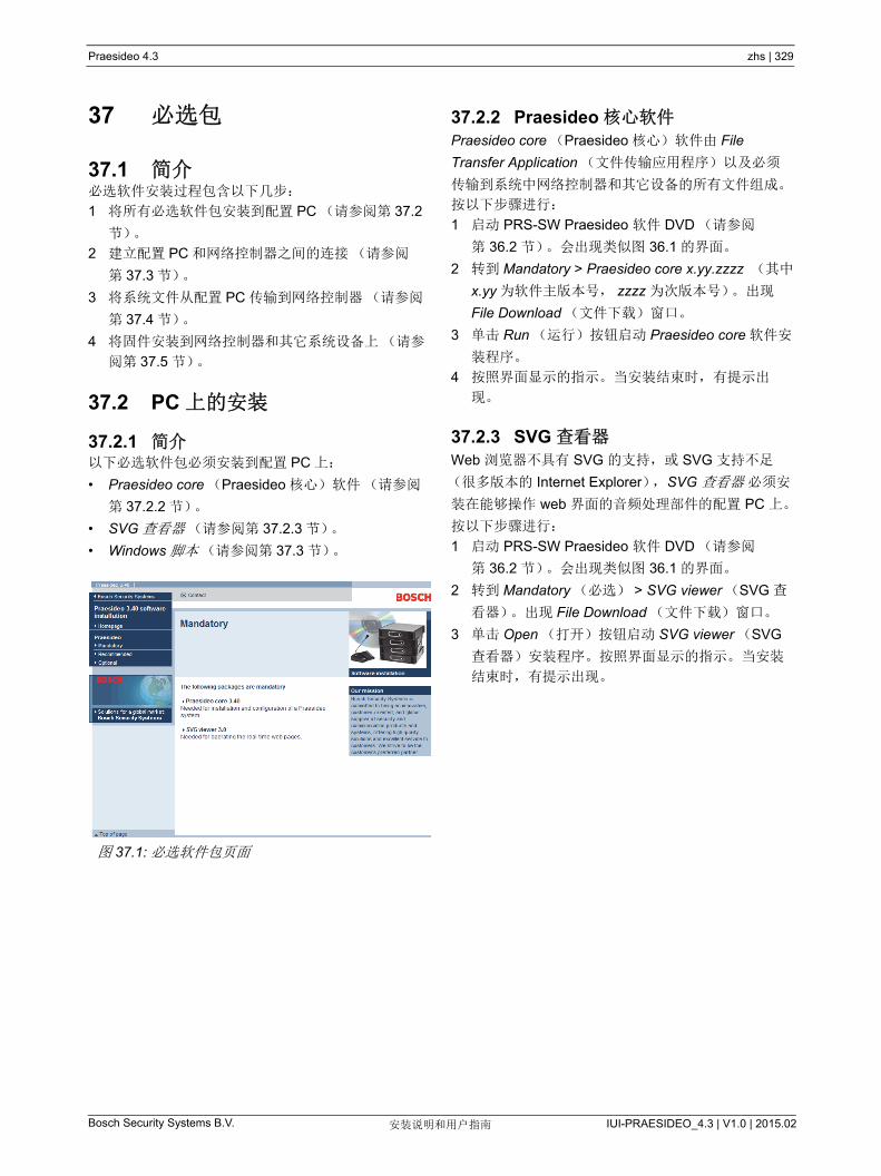
Praesideo 4.3 zhs | 329
Bosch Security Systems B.V. IUI-PRAESIDEO_4.3 | V1.0 | 2015.02安装说明和用户指南
37 必选包
37.1 简介必选软件安装过程包含以下几步:
1 将所有必选软件包安装到配置 PC (请参阅第 37.2
节)。
2 建立配置 PC 和网络控制器之间的连接(请参阅
第 37.3 节)。
3 将系统文件从配置 PC 传输到网络控制器(请参阅
第 37.4 节)。
4 将固件安装到网络控制器和其它系统设备上(请参
阅第 37.5 节)。
37.2 PC 上的安装
37.2.1 简介以下必选软件包必须安装到配置 PC 上:
• Praesideo core (Praesideo 核心)软件(请参阅
第 37.2.2 节)。
• SVG 查看器 (请参阅第 37.2.3 节)。
• Windows 脚本 (请参阅第 37.3 节)。
37.2.2 Praesideo 核心软件Praesideo core (Praesideo 核心)软件由 File
Transfer Application (文件传输应用程序)以及必须
传输到系统中网络控制器和其它设备的所有文件组成。
按以下步骤进行:
1 启动 PRS-SW Praesideo 软件 DVD (请参阅
第 36.2 节)。会出现类似图 36.1 的界面。
2 转到 Mandatory > Praesideo core x.yy.zzzz (其中
x.yy 为软件主版本号, zzzz 为次版本号)。出现
File Download (文件下载)窗口。
3 单击 Run (运行)按钮启动 Praesideo core 软件安
装程序。
4 按照界面显示的指示。当安装结束时,有提示出
现。
37.2.3 SVG 查看器Web 浏览器不具有 SVG 的支持,或 SVG 支持不足
(很多版本的 Internet Explorer), SVG 查看器 必须安
装在能够操作 web 界面的音频处理部件的配置 PC 上。
按以下步骤进行:
1 启动 PRS-SW Praesideo 软件 DVD (请参阅
第 36.2 节)。会出现类似图 36.1 的界面。
2 转到 Mandatory (必选) > SVG viewer (SVG 查
看器)。出现 File Download (文件下载)窗口。
3 单击 Open (打开)按钮启动 SVG viewer (SVG
查看器)安装程序。按照界面显示的指示。当安装
结束时,有提示出现。
图 37.1: 必选软件包页面

Praesideo 4.3 zhs | 330
Bosch Security Systems B.V. IUI-PRAESIDEO_4.3 | V1.0 | 2015.02安装说明和用户指南
37.3 建立连接必选软件安装到配置 PC 之后(请参阅第 37.2 节),
配置 PC 必须与网络控制器建立连接,目的是为了能够
将系统文件传输到系统中的网络控制器和其它设备
(请参阅第 37.4 节)。按以下步骤进行:
1 如果网络控制器连接到现存的以太网,可以向网络
管理员咨询以下信息:
• 网络控制器的 IP 地址。
• 适当的子网掩码。
• 网络控制器默认网关的 IP 地址。
2 转到网络控制器菜单显示的屏幕 2Ba,设置网络控
制器的 IP 地址。有关配置菜单的详细情况,请参阅
第 5.5 节。
3 转到网络控制器菜单显示的屏幕 2Bb,设置网络控
制器的子网掩码。
4 转到网络控制器菜单显示的屏幕 2Bc,设置网络控
制器默认网关。
5 将网络控制器连接到现有的以太网上,或直接连接
到配置 PC 上。
6 在配置 PC 上,转到 Start (开始) > Run (运
行),然后输入 cmd 打开命令提示符窗口。
7 Ping 网络控制器。例如,如果网络控制器的 IP 地
址是 192.168.0.15,则输入 ping 192.168.0.15。
• 如果连接不成功,则出现与图 37.2 相似的屏幕。
• 如果可以建立连接,则出现与图 37.3 相似的屏
幕。
8 转到开始 > 程序 > Bosch > Praesideo > FT
Application 以启动 File Transfer Application。会出
现类似图 37.4 的界面。
9 在 NCO address (NCO 地址)字段中输入网络控
制器的 IP 地址。
10 在 Username (用户名)字段中输入正确的用户
名,并在 Password (密码)字段中输入正确的密
码。
• 如果以前没有将软件传输到网络控制器,则默认
用户名为 target,默认密码为 password。
• 如果以前已将软件传输到网络控制器,则默认 用
户名为 admin,默认密码为 admin。
11 单击 Connect to NC (连接到 NC)按钮,与网络
控制器建立连接。出现提示。
图 37.2: 错误通信
Microsoft Windows 2000 [Version 5.00.2195](C) Copyright 1985-2000 Microsoft Corp.
C:\>ping 192.168.0.15
Pinging 192.168.0.15 with 32 bytes of data:
Request timed outRequest timed outRequest timed outRequest timed out
Ping statistics for 192.168.0.15: Packets: Sent = 4, Received = 0, Loss = 4 (100% loss)
Approximate round trip in milli-seconds: Minimum = 0 ms, Maximum = 0 ms, Average = 0 ms
图 37.3: 正确通信
图 37.4: 连接到网络控制器
Microsoft Windows 2000 [Version 5.00.2195](C) Copyright 1985-2000 Microsoft Corp.
C:\>ping 192.168.0.15
Pinging 192.168.0.15 with 32 bytes of data:
Reply from 192.168.0.15: bytes = 32 time<10 ms TTL=128Reply from 192.168.0.15: bytes = 32 time<10 ms TTL=128Reply from 192.168.0.15: bytes = 32 time<10 ms TTL=128Reply from 192.168.0.15: bytes = 32 time<10 ms TTL=128
Ping statistics for 192.168.0.15: Packets: Sent = 4, Received = 4, Loss = 0 (0% loss)
Approximate round trip in milli-seconds: Minimum = 0 ms, Maximum = 0 ms, Average = 0 ms
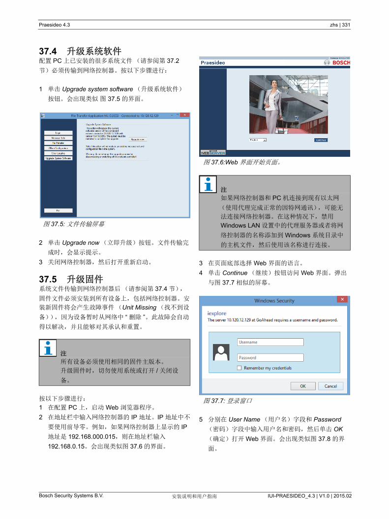
Praesideo 4.3 zhs | 331
Bosch Security Systems B.V. IUI-PRAESIDEO_4.3 | V1.0 | 2015.02安装说明和用户指南
37.4 升级系统软件配置 PC 上已安装的很多系统文件(请参阅第 37.2
节)必须传输到网络控制器。按以下步骤进行:
1 单击 Upgrade system software (升级系统软件)
按钮。会出现类似 图 37.5 的界面。
2 单击 Upgrade now (立即升级)按钮。文件传输完
成时,会显示提示。
3 关闭网络控制器,然后打开重新启动。
37.5 升级固件系统文件传输到网络控制器后(请参阅第 37.4 节),
固件文件必须安装到所有设备上,包括网络控制器。安
装新固件将会产生故障事件(Unit Missing (找不到设
备)),因为设备暂时从网络中 “ 删除 ”。此故障会自动
得以解决,并且能够对其承认和重置。
按以下步骤进行:
1 在配置 PC 上,启动 Web 浏览器程序。
2 在地址栏中输入网络控制器的 IP 地址。IP 地址中不
要使用前导零。例如,如果网络控制器上显示的 IP
地址是 192.168.000.015,则在地址栏输入
192.168.0.15。会出现类似图 37.6 的界面。
3 在页面底部选择 Web 界面的语言。
4 单击 Continue (继续)按钮访问 Web 界面。弹出
与图 37.7 相似的屏幕。
5 分别在 User Name (用户名)字段和 Password
(密码)字段中输入用户名和密码,然后单击 OK
(确定)打开 Web 界面。会出现类似图 37.8 的界
面。
图 37.5: 文件传输屏幕
注
所有设备必须使用相同的固件主版本。
升级固件时,切勿使用系统或打开 / 关闭设
备。
图 37.6:Web 界面开始页面。
注
如果网络控制器和 PC 机连接到现有以太网
(使用代理完成正常的因特网通讯),可能无
法连接网络控制器。在这种情况下,禁用
Windows LAN 设置中的代理服务器或者将网
络控制器的名称添加到 Windows 系统目录中
的主机文件,然后使用该名称进行连接。
图 37.7: 登录窗口

Praesideo 4.3 zhs | 332
Bosch Security Systems B.V. IUI-PRAESIDEO_4.3 | V1.0 | 2015.02安装说明和用户指南
6 在导航栏中单击 Upgrade unit firmware (升级设备
固件)按钮,打开 Upgrade unit firmware (升级设
备固件)菜单。会出现类似图 37.9 的界面。页面标
题显示了系统支持的固件主版本号。固件版本字段
显示当前正在运行的固件的主版本号。
7 在 Upgrade unit firmware (升级设备固件)字段中
单击 Upgrade unit firmware (升级设备固件)按
钮,升级设备的固件。 Progress (进度)字段中显
示升级过程的进度。
8 出现故障时,请单击 Web 界面上导航栏中的
Undefined (未定义),查看固件升级失败的所有设
备的列表。断开并重新连接这些设备,在重新尝试
软件升级之前,请刷新或重新加载 Undefined (未
定义)页面。
9 若升级不成功,请尝试以下一种或多种动作:
• 重启网络控制器。
• 将发生故障的设备的电源关闭后再打开。
• 刷新网页
• 在未定义列表中为所有设备升级设备固件。
• 为所有状态为 “ 不正确版本 ” 的设备更新设备固件。
• 联系您当地的服务部门。
注
默认用户名是 admin,默认密码是 admin。
图 37.8:Web 界面开始页面。
注
网络控制器启动后 5 分钟内,无法升级固件。
注
PRS-FINNA 光纤接口不包含固件,并且在系
统中未被识别。配置页面中只显示 PRS-
FIN(S) 光纤接口。
图 37.9: 升级设备固件页面

Praesideo 4.3 zhs | 333
Bosch Security Systems B.V. IUI-PRAESIDEO_4.3 | V1.0 | 2015.02安装说明和用户指南
37.6 清理记录事件使用配置软件对系统进行配置后(请参阅第 41 章),
File Transfer Application (文件传输应用程序)可以用
于删除网络控制器中的所有记录事件,以便将清理过的
记录数据库发送给客户。按以下步骤进行:
1 在导航栏内单击 Clear logging (清理记录)按钮。
会出现类似图 37.10 的界面。
2 如果必须从网络控制器中删除故障事件,请在 Fault
events (故障事件)复选框内作上复选标记。
3 如果必须从网络控制器中删除一般事件,请在
General events (故障事件)复选框内作上复选标
记。
4 如果必须从网络控制器中删除呼叫事件,请在 Call
events (呼叫事件)复选框内作上复选标记。
5 单击 Apply (应用)按钮并重新启动系统以删除网
络控制器中所选类型的事件。
图 37.10: 清除记录
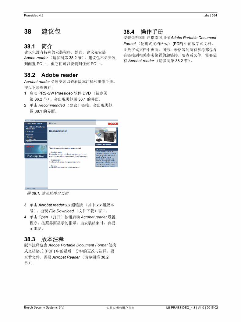
Praesideo 4.3 zhs | 334
Bosch Security Systems B.V. IUI-PRAESIDEO_4.3 | V1.0 | 2015.02安装说明和用户指南
38 建议包
38.1 简介建议包没有特殊的安装程序。然而,建议先安装
Adobe reader (请参阅第 38.2 节)。建议包不必安装
到配置 PC 上;但它们可以安装到任何 PC 上。
38.2 Adobe readerAcrobat reader 必须安装以查看版本注释和操作手册。
按以下步骤进行:
1 启动 PRS-SW Praesideo 软件 DVD (请参阅
第 36.2 节)。会出现类似图 36.1 的界面。
2 单击 Recommended (建议)链接。会出现类似
图 38.1 的界面。
3 单击 Acrobat reader x.x 超链接(其中 x.x 指版本
号)。出现 File Download (文件下载)窗口。
4 单击 Open (打开)按钮启动 Acrobat reader 设置
程序。按照界面显示的指示。当安装结束时,有提
示出现。
38.3 版本注释版本注释包含 Adobe Portable Document Format 便携
式文档格式 (PDF) 中的 后一分钟的更改与注释。要
查看文件,需要 Acrobat Reader (请参阅第 38.2
节)。
38.4 操作手册安装说明和用户指南可用作Adobe Portable Document
Format (便携式文档格式) (PDF) 中的数字式文档。
此数字式文档中页面、图形、表格等的所有参考都包含
有链接到相关参考位置的超链接。要查看文件,需要装
有 Acrobat reader (请参阅第 38.2 节)。
图 38.1: 建议软件包页面
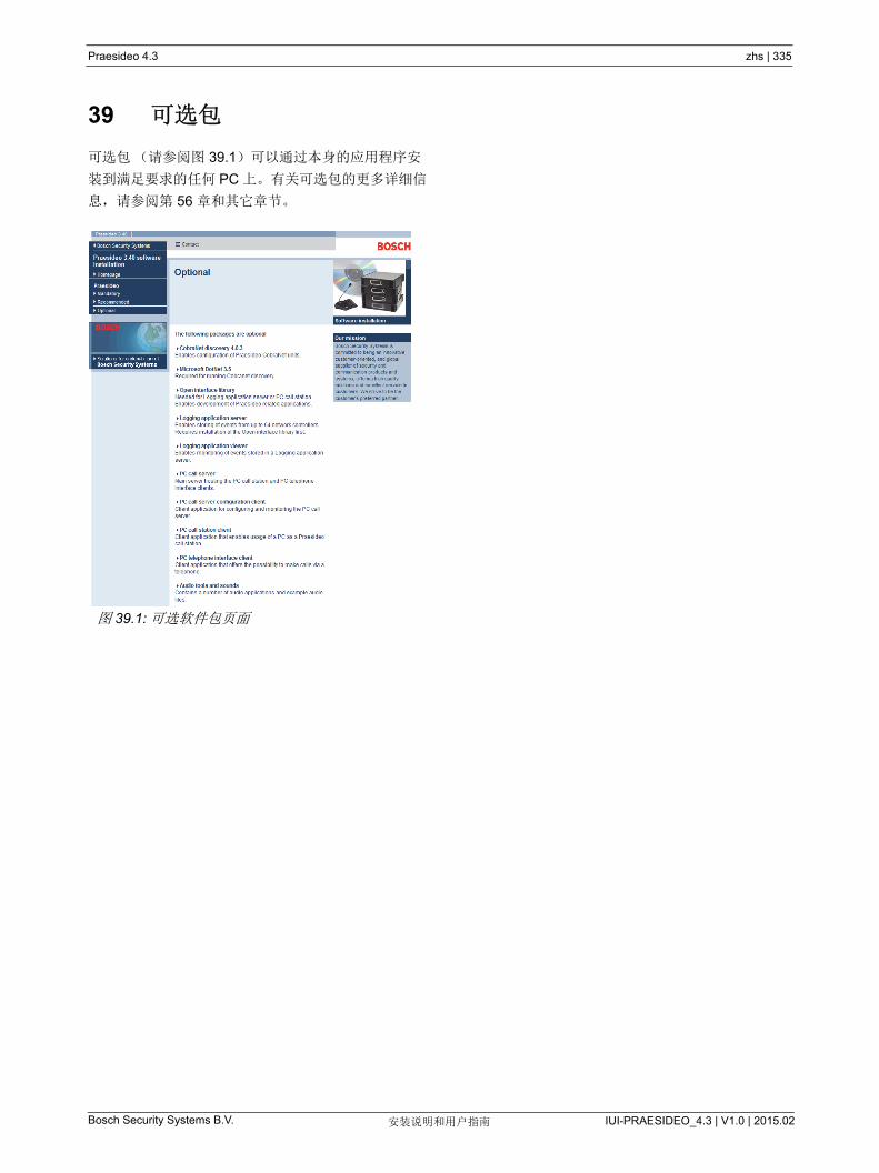
Praesideo 4.3 zhs | 335
Bosch Security Systems B.V. IUI-PRAESIDEO_4.3 | V1.0 | 2015.02安装说明和用户指南
39 可选包
可选包(请参阅图 39.1)可以通过本身的应用程序安
装到满足要求的任何 PC 上。有关可选包的更多详细信
息,请参阅第 56 章和其它章节。
图 39.1: 可选软件包页面
Praesideo 4.3 zhs | 336
Bosch Security Systems B.V. IUI-PRAESIDEO_4.3 | V1.0 | 2015.02安装说明和用户指南
40 故障排除
40.1 简介多个 Web 浏览器设置都关系着 Praesideo 系统配置
Web 页面的正确运行。其中 重要的是安全设置和连
接设置。请注意,网络管理员可以修改或限制这些设
置。网络管理员对用于配置 Praesideo 系统的网络和 /
或 PC 负责。
40.2 安全设置例如,安全设置会阻止 Internet Explorer 中 SVG 查看
器的执行,而系统需要使用该查看器在 Web 页面显示
均衡器响应。较为可取的解决方案是,通过输入网络控
制器的 IP 号码,将 Praesideo 系统添加至信任站点列
表中。可在开始 > 控制面板 > Internet 选项 ....> 安全 >
站点中找到此列表。您还可以降低信任站点的保护等
级。列表外站点的保护等级不受影响。
40.3 连接局域网设置(开始 > 控制面板 > Internet 选项 ... > 连
接 > LAN 设置 ...)可能会影响全面接入 Praesideo 系
统的能力。出于安全考虑, Praesideo 只能同时接受一
种连接。当使用 Proxy 服务器时,无法保证一直使用相
同连接。因此, Praesideo 系统的地址应在 Proxy 服务
器配置上定义为本地地址。在网络管理员提供的配置脚
本中,这点应特别注意,或者 Proxy 服务器应一同禁
用。
其它问题可能源于病毒检查器、弹出框、反间谍软件和
防火墙。请尝试在 Praesideo 配置过程中禁用该类型软
件,或通过接受 Praesideo 系统为信任站点的方法,进
行配置。
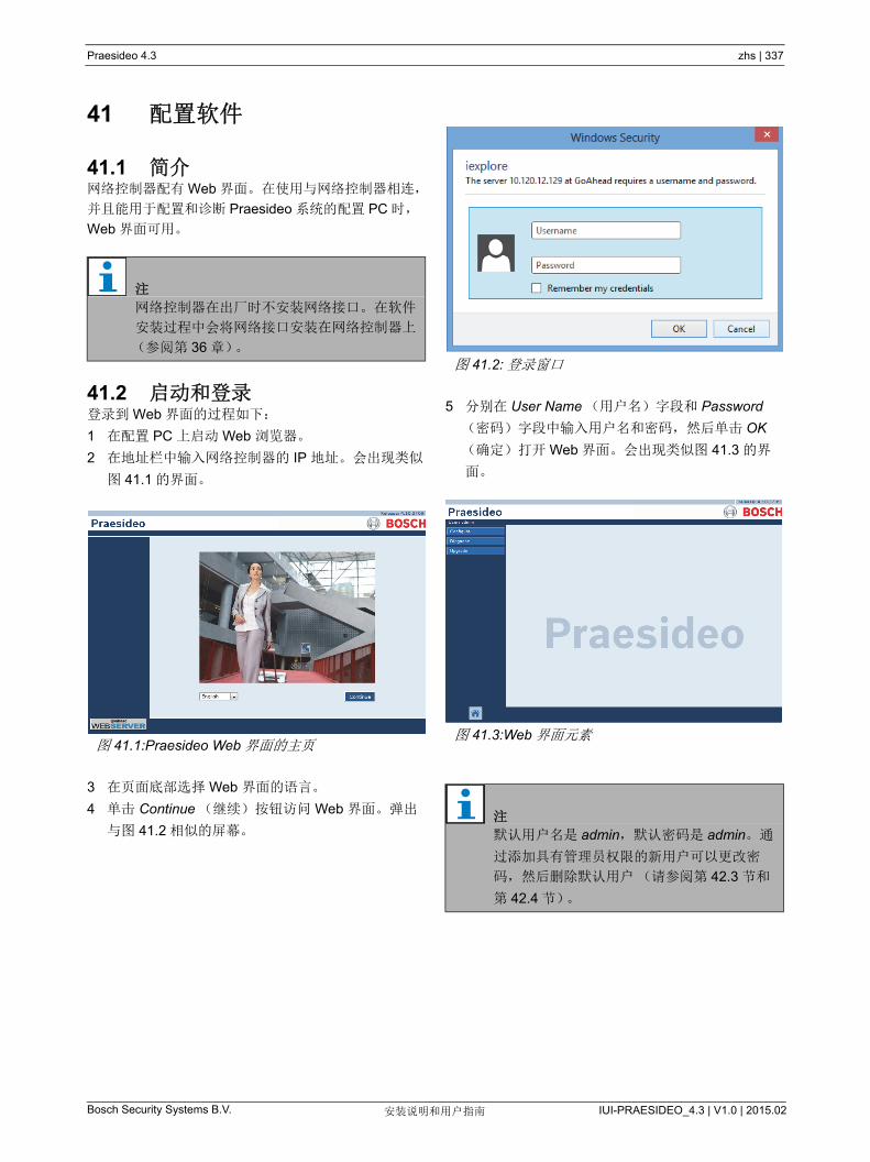
Praesideo 4.3 zhs | 337
Bosch Security Systems B.V. IUI-PRAESIDEO_4.3 | V1.0 | 2015.02安装说明和用户指南
41 配置软件
41.1 简介网络控制器配有 Web 界面。在使用与网络控制器相连,
并且能用于配置和诊断 Praesideo 系统的配置 PC 时,
Web 界面可用。
41.2 启动和登录登录到 Web 界面的过程如下:
1 在配置 PC 上启动 Web 浏览器。
2 在地址栏中输入网络控制器的 IP 地址。会出现类似
图 41.1 的界面。
3 在页面底部选择 Web 界面的语言。
4 单击 Continue (继续)按钮访问 Web 界面。弹出
与图 41.2 相似的屏幕。
5 分别在 User Name (用户名)字段和 Password
(密码)字段中输入用户名和密码,然后单击 OK
(确定)打开 Web 界面。会出现类似图 41.3 的界
面。
注
网络控制器在出厂时不安装网络接口。在软件
安装过程中会将网络接口安装在网络控制器上
(参阅第 36 章)。
图 41.1:Praesideo Web 界面的主页
图 41.2: 登录窗口
图 41.3:Web 界面元素
注
默认用户名是 admin,默认密码是 admin。通
过添加具有管理员权限的新用户可以更改密
码,然后删除默认用户(请参阅第 42.3 节和
第 42.4 节)。

Praesideo 4.3 zhs | 338
Bosch Security Systems B.V. IUI-PRAESIDEO_4.3 | V1.0 | 2015.02安装说明和用户指南
41.3 概述Web 界面(请参阅图 41.3)包含以下元素:
• 配置 - 打开 Web 界面配置部分的按钮(请参阅
第 41.4 节)。
• 诊断 - 打开 Web 界面(参阅第 51 节)诊断部分的
按钮。
• 升级 - 打开 Web 界面升级固件的按钮(请参阅
第 41.6 节)。
• 主框窗 - 显示请求页面的框架。有关 Configure (配
置)部分屏幕的详细说明,请参阅第 42 章到第 49
章;有关 Diagnose (诊断)部分页面的详细说明,
请参阅第 51 章。
41.4 配置部分简介
可以使用 Web 界面的 Configure (配置)部分对
Praesideo 系统进行配置。 Configure (配置)部分中
菜单项的顺序 - 点击 Configure (配置)按钮时打开
(请参阅图 41.4) - 表示建议的 Praesideo 系统配置工
作流程。
41.4.1 简介Configure (配置)部分包含以下几组页面(请参阅
图 41.4):
• 在 User management (用户管理)页面上,可以
对有权访问 Praesideo Web 界面的帐户进行管理
(请参阅第 42 章)。
• 在 System definition (系统定义)页面上,可以对
系统包含的设备进行注册(请参阅第 43 章)。
• 在 Equipment configuration (设备配置)页面上,
可以对利用 System definition (系统定义 ) 页面添
加的每件设备进行配置(请参阅第 44 章 )。
• 在 System wide settings (整个系统的设定)页面
上,可以对许多普通的、整个系统的设定进行配置
(参阅第 45 章)。
• 在 Zone & amplifier (分区和放大器)页面上,可
以对分区和放大器进行配置(请参阅第 47 章 )。
• 在 Call characteristics (呼叫特性)页面上 , 可以对
呼叫宏进行配置(请参阅第 47 章)。
• 在 Action programming (动作编程)页面上,可以
对键盘上的键和控制输入端进行配置。(请参阅
第 48 章)。
• 在 Audio processing (音频处理)页面上,可以对
系统中音频输入和输出的音频处理参数进行设置
(请参阅第 49 章)。
• 在 Save (保存)页面上,可以对当前配置进行保
存(请参阅第 41.4.4 节)。
41.4.2 脱机配置可以使用配置 PC 在脱机状态下对 Praesideo 系统进行
配置,或对现有配置进行编辑:
1 转到开始 > ( 所有 ) 程序 > Bosch > Praesideo > FT
Application 以启动 Praesideo File Transfer 应用程
序。
2 单击 Offline Config (脱机配置)按钮。出现一窗
口,其中可以选择用于脱机配置的配置文件。此
外,还可以创建新的空配置文件。默认子目录为
<data directory>\Bosch\Praesideo
<release>\Programs\FT Application,默认文件名
为 Praesideo.cfg。 Windows 英文版本中 <data
directory> 的位置是 Users\<user>\Documents\。
单击 OK (确定)按钮后,出现一个与图 41.1 相似的
屏幕。登录到脱机版的 Web 界面与登录到 “ 实际的
”Web 界面相似。
图 41.4: 配置部分
Configure
User management
System definition
Equipment configuration
System wide settings
Zone & amplifier
Call characteristics
Action programming
Audio processing
Save
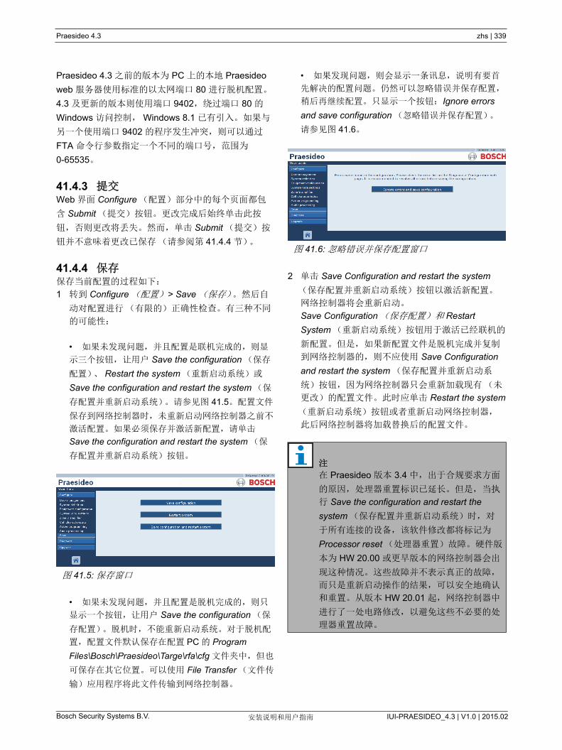
Praesideo 4.3 zhs | 339
Bosch Security Systems B.V. IUI-PRAESIDEO_4.3 | V1.0 | 2015.02安装说明和用户指南
Praesideo 4.3 之前的版本为 PC 上的本地 Praesideo
web 服务器使用标准的以太网端口 80 进行脱机配置。
4.3 及更新的版本则使用端口 9402,绕过端口 80 的
Windows 访问控制, Windows 8.1 已有引入。如果与
另一个使用端口 9402 的程序发生冲突,则可以通过
FTA 命令行参数指定一个不同的端口号,范围为
0-65535。
41.4.3 提交Web 界面 Configure (配置)部分中的每个页面都包
含 Submit (提交)按钮。更改完成后始终单击此按
钮,否则更改将丢失。然而,单击 Submit (提交)按
钮并不意味着更改已保存(请参阅第 41.4.4 节)。
41.4.4 保存保存当前配置的过程如下:
1 转到 Configure (配置) > Save (保存)。然后自
动对配置进行(有限的)正确性检查。有三种不同
的可能性:
• 如果未发现问题,并且配置是联机完成的,则显
示三个按钮,让用户 Save the configuration (保存
配置)、 Restart the system (重新启动系统)或
Save the configuration and restart the system (保
存配置并重新启动系统)。请参见图 41.5。配置文件
保存到网络控制器时,未重新启动网络控制器之前不
激活配置。如果必须保存并激活新配置,请单击
Save the configuration and restart the system (保
存配置并重新启动系统)按钮。
• 如果未发现问题,并且配置是脱机完成的,则只
显示一个按钮,让用户 Save the configuration (保
存配置)。脱机时,不能重新启动系统。对于脱机配
置,配置文件默认保存在配置 PC 的 Program
Files\Bosch\Praesideo\Targe\rfa\cfg 文件夹中,但也
可保存在其它位置。可以使用 File Transfer (文件传
输)应用程序将此文件传输到网络控制器。
• 如果发现问题,则会显示一条讯息,说明有要首
先解决的配置问题。仍然可以忽略错误并保存配置,
稍后再继续配置。只显示一个按钮:Ignore errors
and save configuration (忽略错误并保存配置)。
请参见图 41.6。
2 单击 Save Configuration and restart the system
(保存配置并重新启动系统)按钮以激活新配置。
网络控制器将会重新启动。
Save Configuration (保存配置) 和 Restart
System (重新启动系统)按钮用于激活已经联机的
新配置。但是,如果新配置文件是脱机完成并复制
到网络控制器的,则不应使用 Save Configuration
and restart the system (保存配置并重新启动系
统)按钮,因为网络控制器只会重新加载现有(未
更改)的配置文件。此时应单击 Restart the system
(重新启动系统)按钮或者重新启动网络控制器,
此后网络控制器将加载替换后的配置文件。
图 41.5: 保存窗口
图 41.6: 忽略错误并保存配置窗口
注
在 Praesideo 版本 3.4 中,出于合规要求方面
的原因,处理器重置标识已延长。但是,当执
行 Save the configuration and restart the
system (保存配置并重新启动系统)时,对
于所有连接的设备,该软件修改都将标记为
Processor reset (处理器重置)故障。硬件版
本为 HW 20.00 或更早版本的网络控制器会出
现这种情况。这些故障并不表示真正的故障,
而只是重新启动操作的结果,可以安全地确认
和重置。从版本 HW 20.01 起,网络控制器中
进行了一处电路修改,以避免这些不必要的处
理器重置故障。

Praesideo 4.3 zhs | 340
Bosch Security Systems B.V. IUI-PRAESIDEO_4.3 | V1.0 | 2015.02安装说明和用户指南
41.4.5 允许字符输入组件、输入端、输出端、讯息、分区、分区组合等
的名称时,请注意只能使用以下字符:
• 字母:A 到 Z 和 a 到 z
• 数字:0 到 9
• 特殊字符:# .( ) [ ] _ - + : 和 < 空格 >
41.4.6 唯一性名称输入组件、输入端、输出端、讯息、分区、分区组合等
的名称时,请注意输入的所有名称都是唯一的:不得将
名称用于一个以上的项目。名称不仅必须在一组项目
(如组件名)中具有唯一性,还必须在完整的系统配置
中也具有唯一性(如分区组合与分区必须具有不同的
名称)。名称不唯一将会在配置数据库中引起冲突。这
些冲突反过来会导致不可预料的系统操作。
41.4.7 初始值配置项的参数值为 <None> 时,说明还未对参数设置任
何值。例如,第一次打开 Call macro (呼叫宏)键中
的 Action programming (动作编程)页面时(请参阅
第 48.3.7 节), Call macro (呼叫宏)字段的值为
<None>。
配置项的参数为 <Default> 时,说明将参数设置为默认
值。例如,如果呼叫宏(请参阅第 47.2 节)的音频输
入为 <Default>,配置的音频输入就是启动呼叫宏的呼
叫站中的话筒。
41.4.8 撤消更改大多数 Configure (配置)部分中的页面都包含
Cancel (取消)按钮。单击 Cancel (取消)按钮,可
取消页面上的任何更改。
41.4.9 启用的项目利用复选框可以启用和禁用配置项。如果启用配置项,
故障出现时系统能够产生故障事件。如果禁用配置项,
故障出现时系统无法产生故障事件。在选择列表中,
Web 界面将禁用的配置项放在括弧内。例如,禁用的
配置项 AudioIn01 在选择列表中显示为 (AudioIn01)。
41.4.10 删除项删除配置项时,与删除的配置项有关的所有配置项也将
删除。例如,从系统定义中删除功率放大器时(请参
阅第 43.4 节),功率放大器的所有音频输入也将从配
置中删除。
41.4.11 音频输入端不得将音频输入端和输出端用于多个目的,因为这会在
配置数据库中引起冲突。这些冲突反过来会导致不可预
料的系统操作。例如:
• 如果音频输入已是呼叫宏(请参阅第 47.2 节)的
一部分,则不得再将其用在 BGM 通道中(请参阅
第 46.5 节 )。
• 功率放大器的音频输出不能指定给一个以上的分
区。
41.4.12 下载配置配置数据库可以下载到 PC (请参阅第 57 章)。
注
当单击 Audio Processsing (音频处理)页面
上的 Submit Equalizer (提交均衡器)按钮
时,音频处理参数将会立即更改。尽管这些更
改听得见,但是要注意到它们不能自动保存非
常重要。如果这些更改未保存,则它们网络控
制器复位时将丢失。
注
不得使用其它字符。
注
在不保存更改的条件下重新启动网络控制器将
撤消所有更改。

Praesideo 4.3 zhs | 341
Bosch Security Systems B.V. IUI-PRAESIDEO_4.3 | V1.0 | 2015.02安装说明和用户指南
41.4.13 配置打印实用程序必选 Praesideo 软件(请参阅第 37.1 节)也安装有配
置打印实用程序。此实用程序可以从 1.1 和更高版本的
配置文件中读取信息。配置打印实用程序以格式化的方
式在屏幕上显示信息,以对文件上的配置进行检查和 /
或存档。
41.5 诊断部分通过 Diagnose (诊断)部分可以对系统安装和配置的
一致性进行诊断(请参阅第 51 章)。
41.6 升级部分使用 Upgrade unit software (升级设备软件)部分,
可以将 Praesideo 系统中设备的固件从网络控制器传输
到设备(请参阅第 37.5 章)。
图 41.7: 配置打印实用程序
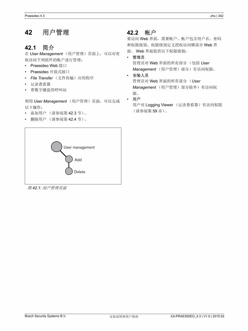
Praesideo 4.3 zhs | 342
Bosch Security Systems B.V. IUI-PRAESIDEO_4.3 | V1.0 | 2015.02安装说明和用户指南
42 用户管理
42.1 简介在 User Management (用户管理)页面上,可以对有
权访问下列组件的帐户进行管理:
• Praesideo Web 接口
• Praesideo 开放式接口
• File Transfer (文件传输)应用程序
• 记录查看器
• 带数字键盘的呼叫站
利用 User Management (用户管理)页面,可以完成
以下操作:
• 添加用户(请参阅第 42.3 节)。
• 删除用户(请参阅第 42.4 节)。
42.2 帐户要访问 Web 界面,需要帐户。帐户包含用户名、密码
和权限级别。权限级别定义授权访问哪部分 Web 界
面。 Web 界面提供以下权限级别:
• 管理员
管理员对 Web 界面的所有部分(包括 User
Management (用户管理)部分)有访问权限。
• 安装人员
管理员对 Web 界面的所有部分(User
Management (用户管理)部分除外)有访问权
限。
• 用户
用户对 Logging Viewer (记录查看器)有访问权限
(请参阅第 59 章)。
图 42.1: 用户管理页面
User management
Add
Delete
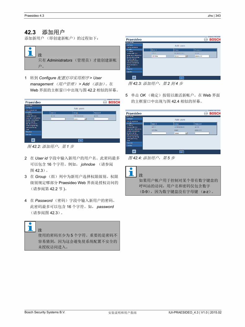
Praesideo 4.3 zhs | 343
Bosch Security Systems B.V. IUI-PRAESIDEO_4.3 | V1.0 | 2015.02安装说明和用户指南
42.3 添加用户添加新用户(即创建新帐户)的过程如下:
1 转到 Configure 配置打印实用程序 > User
management (用户管理) > Add (添加)。在
Web 界面的主框窗口中出现与图 42.2 相似的屏幕。
2 在 User id 字段中输入新用户的用户名。此密码 多
可以包含 16 个字符。例如, johndoe (请参阅
图 42.3)。
3 在 Group (组)列中为新用户选择权限级别。权限
级别规定哪部分 Praesideo Web 界面是授权访问的
(请参阅第 42.2 节 )。
4 在 Password (密码)字段中输入新用户的密码。
此密码 多可以包含 16 个字符。如, password
(请参阅图 42.3)。
5 单击 OK (确定)按钮以激活新帐户。在 Web 界面
的主框窗口中出现与图 42.4 相似的屏幕。
注
只有 Administrators (管理员)才能创建新帐
户。
图 42.2: 添加用户,第 1 步
注
使用的密码至少为 5 个字符。重要的是密码不
容易猜到,因为这会避免使系统配置不安全的
未授权访问进入。
图 42.3: 添加用户,第 2 到 4 步
图 42.4: 添加用户,第 5 步
注
如果用户帐户用于控制对某个带有数字键盘的
呼叫站的访问,用户名和密码仅包含数字
(0-9),因为数字键盘没有字母键(a-z)。
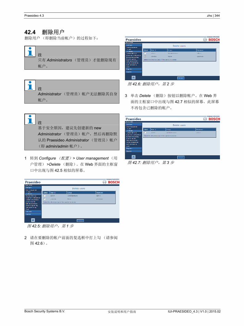
Praesideo 4.3 zhs | 344
Bosch Security Systems B.V. IUI-PRAESIDEO_4.3 | V1.0 | 2015.02安装说明和用户指南
42.4 删除用户删除用户(即删除当前帐户)的过程如下:
1 转到 Configure (配置) > User management (用
户管理) >Delete (删除)。在 Web 界面的主框窗
口中出现与图 42.5 相似的屏幕。
2 请在要删除的帐户前面的复选框中打上勾(请参阅
图 42.6)。
3 单击 Delete (删除)按钮以删除帐户。在 Web 界
面的主框窗口中出现与图 42.7 相似的屏幕。此屏幕
不再包含已删除的帐户。
注
只有 Administrators (管理员)才能删除现有
帐户。
注
Administrator (管理员)帐户无法删除其自身
帐户。
注
基于安全原因,建议先创建新的 new
Administrator (管理员)帐户,然后再删除默
认的 Praesideo Administrator (管理员)帐户
(即 admin/admin 帐户)。
图 42.5: 删除用户,第 1 步
图 42.6: 删除用户,第 2 步
图 42.7: 删除用户,第 3 步

Praesideo 4.3 zhs | 345
Bosch Security Systems B.V. IUI-PRAESIDEO_4.3 | V1.0 | 2015.02安装说明和用户指南
43 系统定义
43.1 简介在 System definition (系统定义)页面上,可以对系统
包含的设备进行注册。利用 System definition (系统定
义)页面,可以对下列设备进行注册(添加)和注销
(删除):
• 网络控制器(请参阅第 43.3 节)。
• 功率放大器(请参阅第 43.4 节)。
• 多通道接口(请参阅第 43.5 节)。
• 呼叫站(请参阅第 43.6 节)。
• 呼叫堆栈(请参阅第 43.7 节)。
• 音频扩展器(请参阅第 43.8 节)。
• CobraNet 接口(请参阅第 43.9 节)。
• 光纤接口(请参阅第 43.10 节)。
• 光纤接口(请参阅第 43.11 节)。
• TCP/IP 设备(请参阅第 43.12 节)。
43.2 序列号每个 Praesideo 设备都带有在系统中注册时所需的序列
号。此序列号可以在设备的标签上找到(请参阅
图 43.2)。
设备的十六进制序列号包含 8 位(从 0 到 F)。通过第
一位和第二位可以识别设备的类型。
注
不必对 系统定义 页面中未列出的设备进行配
置(如,网络分路器)。
图 43.1: 系统定义页面
System definition
Network controller
Power amplifier
Call station
Audio expander
CobraNet interface
TCP/IP device
Multi channel interface
Call stacker
OMNEO interface
Fiber interface
图 43.2: 组件标签
表 43.1: 序列号范围(可寻址设备)
型号 描述 ID
PRS-NCO3 网络控制器 11
PRS-16MCI 多通道接口 1B
PRS-4AEX4 音频扩展器 12
LBB4404/00 CobraNet 接口 1C
PRS-4OMI4 OMNEO 接口 25
PRS-NSP 网络分路器 14
PRS-FIN (S)
PRS-FINNA
光纤接口 15
PRS-1P500
PRS-2P250
PRS-4P125
LBB4428/00
功率放大器 1 x 500 W
功率放大器 2 x 250 W
功率放大器 4 x 125 W
功率放大器 8 x 60 W
0B
0A
09
08
LBB4430/00
PRS-CSM呼叫站基本要素
呼叫站模块
0C
0E
PRS-CSI 远程呼叫站
(呼叫站接口)
1D
PRS-CRF 呼叫堆栈 1F
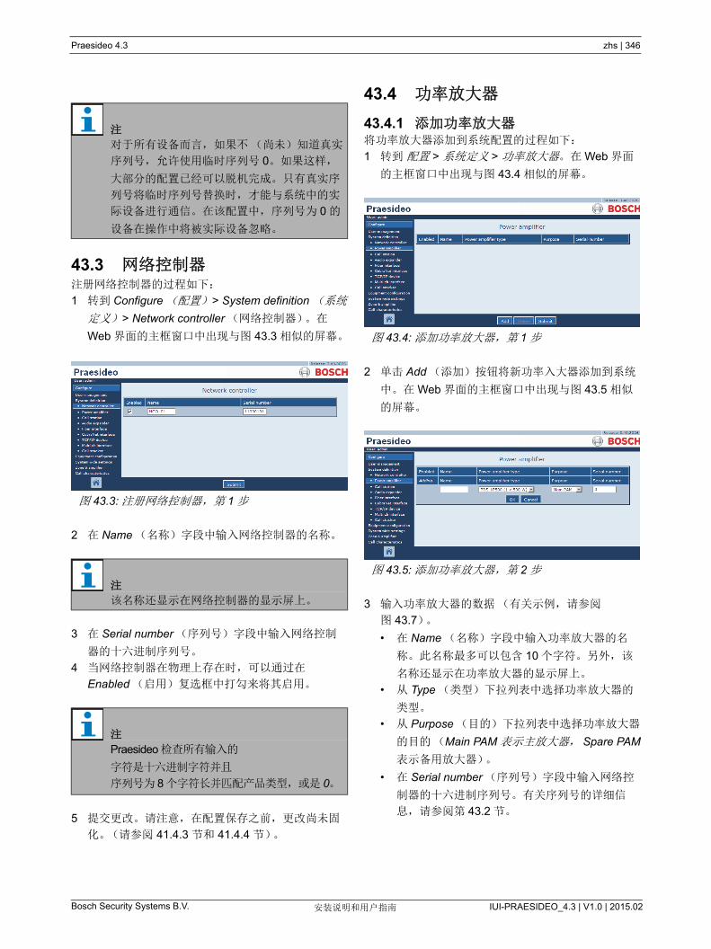
Praesideo 4.3 zhs | 346
Bosch Security Systems B.V. IUI-PRAESIDEO_4.3 | V1.0 | 2015.02安装说明和用户指南
43.3 网络控制器 注册网络控制器的过程如下:
1 转到 Configure (配置) > System definition (系统
定义) > Network controller (网络控制器)。在
Web 界面的主框窗口中出现与图 43.3 相似的屏幕。
2 在 Name (名称)字段中输入网络控制器的名称。
3 在 Serial number (序列号)字段中输入网络控制
器的十六进制序列号。
4 当网络控制器在物理上存在时,可以通过在
Enabled (启用)复选框中打勾来将其启用。
5 提交更改。请注意,在配置保存之前,更改尚未固
化。(请参阅 41.4.3 节和 41.4.4 节)。
43.4 功率放大器
43.4.1 添加功率放大器将功率放大器添加到系统配置的过程如下:
1 转到 配置 > 系统定义 > 功率放大器。在 Web 界面
的主框窗口中出现与图 43.4 相似的屏幕。
2 单击 Add (添加)按钮将新功率入大器添加到系统
中。在 Web 界面的主框窗口中出现与图 43.5 相似
的屏幕。
3 输入功率放大器的数据(有关示例,请参阅
图 43.7)。
• 在 Name (名称)字段中输入功率放大器的名
称。此名称 多可以包含 10 个字符。另外,该
名称还显示在功率放大器的显示屏上。
• 从 Type (类型)下拉列表中选择功率放大器的
类型。
• 从 Purpose (目的)下拉列表中选择功率放大器
的目的(Main PAM 表示主放大器, Spare PAM
表示备用放大器)。
• 在 Serial number (序列号)字段中输入网络控
制器的十六进制序列号。有关序列号的详细信
息,请参阅第 43.2 节。
注
对于所有设备而言,如果不(尚未)知道真实
序列号,允许使用临时序列号 0。如果这样,
大部分的配置已经可以脱机完成。只有真实序
列号将临时序列号替换时,才能与系统中的实
际设备进行通信。在该配置中,序列号为 0 的
设备在操作中将被实际设备忽略。
图 43.3: 注册网络控制器,第 1 步
注
该名称还显示在网络控制器的显示屏上。
注
Praesideo 检查所有输入的
字符是十六进制字符并且
序列号为 8 个字符长并匹配产品类型,或是 0。
图 43.4: 添加功率放大器,第 1 步
图 43.5: 添加功率放大器,第 2 步
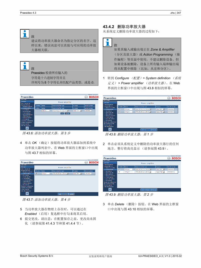
Praesideo 4.3 zhs | 347
Bosch Security Systems B.V. IUI-PRAESIDEO_4.3 | V1.0 | 2015.02安装说明和用户指南
4 单击 OK (确定)按钮将功率放大器添加到系统中
功率放大器列表中。在 Web 界面的主框窗口中出现
与图 43.7 相似的屏幕。
5 当功率放大器在物理上存在时,可以通过在
Enabled (启用)复选框中打勾来将其启用。
6 提交更改。请注意:在配置保存之前,更改尚未固
化(请参阅第 41.4.3 节和第 41.4.4 节)。
43.4.2 删除功率放大器从系统定义删除功率放大器的过程如下:
1 转到 Configure (配置) > System definition (系统
定义) > Power amplifier (功率放大器)。在 Web
界面的主框窗口中出现与图 43.8 相似的屏幕。
2 单击必须从系统定义中删除的功率放大器行的任何
地方。整行将高亮显示(请参阅图 43.9)。
3 单击 Delete (删除)按钮。在 Web 界面的主框窗
口中出现与图 43.10 相似的屏幕。
注
建议将功率放大器命名为指定分区的名字。这
样以来,错误讯息可以直接与可应用的功率放
大器相关联。
注
Praesideo 检查所有输入的
字符是十六进制字符并且
序列号为 8 个字符长并匹配产品类型,或是 0。
图 43.6: 添加功率放大器,第 3 步
图 43.7: 添加功率放大器,第 4 步
注
如果其输入或输出端正在 Zone & Amplifier
(分区及放大器)或 Action Programming (操
作编程)等页面中使用,不建议删除设备。但
如果设备被删除,设备上所有输入端和输出端
将从配置中移除(比如,从宏和分区)。
图 43.8: 删除功率放大器,第 1 步
图 43.9: 删除功率放大器,第 2 步
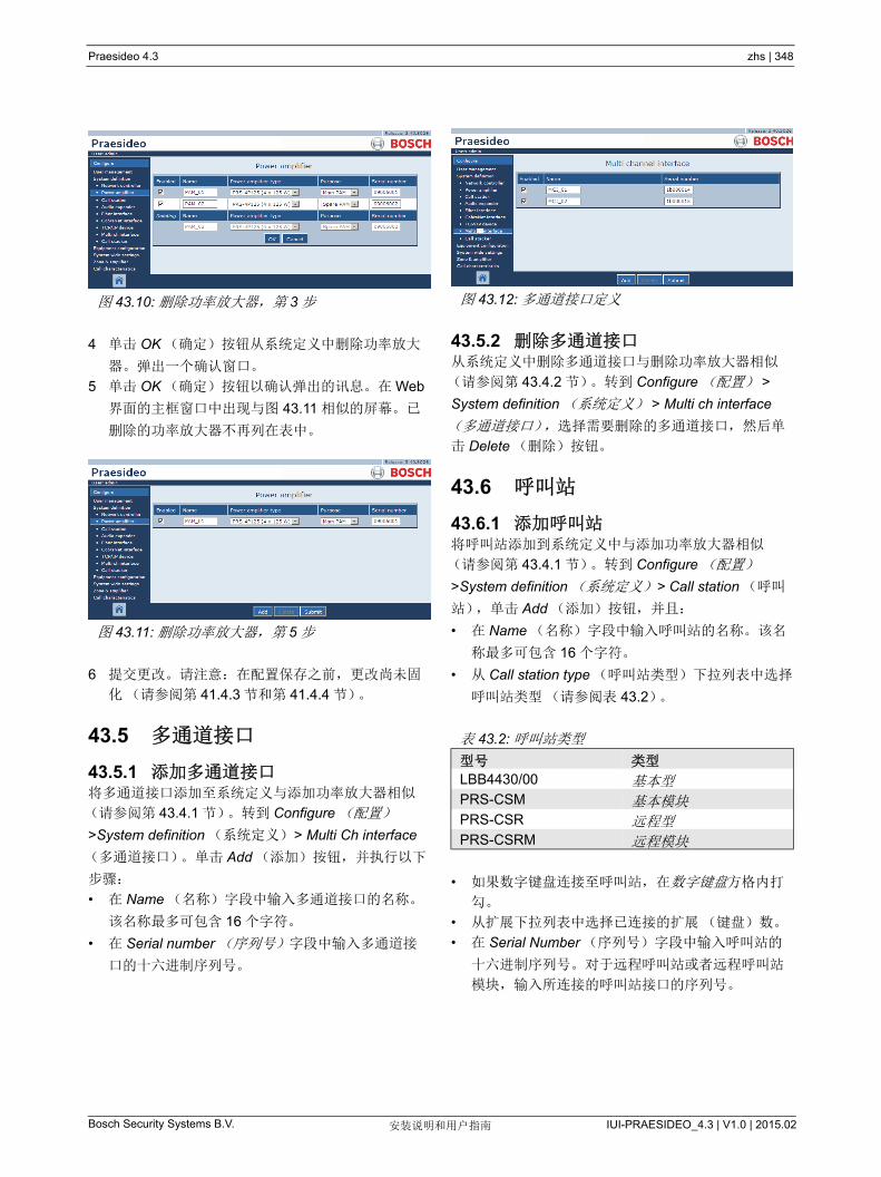
Praesideo 4.3 zhs | 348
Bosch Security Systems B.V. IUI-PRAESIDEO_4.3 | V1.0 | 2015.02安装说明和用户指南
4 单击 OK (确定)按钮从系统定义中删除功率放大
器。弹出一个确认窗口。
5 单击 OK (确定)按钮以确认弹出的讯息。在 Web
界面的主框窗口中出现与图 43.11 相似的屏幕。已
删除的功率放大器不再列在表中。
6 提交更改。请注意:在配置保存之前,更改尚未固
化(请参阅第 41.4.3 节和第 41.4.4 节)。
43.5 多通道接口
43.5.1 添加多通道接口将多通道接口添加至系统定义与添加功率放大器相似
(请参阅第 43.4.1 节)。转到 Configure (配置)
>System definition (系统定义) > Multi Ch interface
(多通道接口)。单击 Add (添加)按钮,并执行以下
步骤:
• 在 Name (名称)字段中输入多通道接口的名称。
该名称 多可包含 16 个字符。
• 在 Serial number (序列号)字段中输入多通道接
口的十六进制序列号。
43.5.2 删除多通道接口从系统定义中删除多通道接口与删除功率放大器相似
(请参阅第 43.4.2 节)。转到 Configure (配置) >
System definition (系统定义) > Multi ch interface
(多通道接口),选择需要删除的多通道接口,然后单
击 Delete (删除)按钮。
43.6 呼叫站
43.6.1 添加呼叫站将呼叫站添加到系统定义中与添加功率放大器相似
(请参阅第 43.4.1 节)。转到 Configure (配置)
>System definition (系统定义) > Call station (呼叫
站),单击 Add (添加)按钮,并且:
• 在 Name (名称)字段中输入呼叫站的名称。该名
称 多可包含 16 个字符。
• 从 Call station type (呼叫站类型)下拉列表中选择
呼叫站类型(请参阅表 43.2)。
• 如果数字键盘连接至呼叫站,在数字键盘方格内打
勾。
• 从扩展下拉列表中选择已连接的扩展(键盘)数。
• 在 Serial Number (序列号)字段中输入呼叫站的
十六进制序列号。对于远程呼叫站或者远程呼叫站
模块,输入所连接的呼叫站接口的序列号。
图 43.10: 删除功率放大器,第 3 步
图 43.11: 删除功率放大器,第 5 步
图 43.12: 多通道接口定义
表 43.2: 呼叫站类型
型号 类型
LBB4430/00 基本型PRS-CSM 基本模块PRS-CSR 远程型PRS-CSRM 远程模块

Praesideo 4.3 zhs | 349
Bosch Security Systems B.V. IUI-PRAESIDEO_4.3 | V1.0 | 2015.02安装说明和用户指南
43.6.2 删除呼叫站从系统定义中删除呼叫站与删除功率放大器相似(请
参阅第 43.4.2 节)。转到 Configure(配置) > System
definition (系统定义) > Call station (呼叫站),选择
需要删除的呼叫站,然后单击 Delete (删除)按钮。
43.7 呼叫堆栈
43.7.1 添加呼叫堆栈将呼叫堆栈添加至系统定义与添加功率放大器相似
(请参阅第 43.4.1 节)。转到 Configure (配置)
>System definition (系统定义) > Call stacker (呼叫
堆栈)。单击 Add (添加)按钮,并执行以下步骤:
• 在 Name (名称)字段中输入呼叫堆栈的名称。该
名称 多可包含 16 个字符。
• 在 Serial Number (序列号)字段中输入呼叫堆栈
的十六进制序列号。
43.7.2 删除呼叫堆栈从系统定义中删除呼叫堆栈与删除功率放大器相似
(请参阅第 43.4.2 节)。转到 Configure (配置) >
System definition (系统定义) > Call stacker (呼叫
堆栈),选择需要删除的呼叫堆栈,然后单击 Delete
(删除)按钮。
43.8 音频扩展器
43.8.1 添加音频扩展器将音频扩展器添加到系统定义中与添加功率放大器相似
(请参阅第 43.4.1 节)。转到 Configure (配置) >
System definition (系统定义) > Audio expander (音
频扩展器),单击 Add (添加)按钮,并且:
• 在 Name (名称)字段中输入音频扩展器的名称。
此名称 多可以包含 16 个字符。另外,该名称还显
示在音频扩展器的显示屏上。
• 在 Serial number (序列号)字段中输入音频扩展
器的十六进制序列号。
43.8.2 删除音频扩展器从配置中删除音频扩展器与删除功率放大器相似 ( 请参
阅第 43.4.2 节)。转到 Configure (配置) > System
definition (系统定义) > Audio expander (音频扩展
器),选择必须删除的音频扩展器,单击 Delete (删
除)按钮。
图 43.13: 呼叫站定义
图 43.14: 呼叫堆栈定义
注
当 后一个呼叫堆栈从配置系统中移除时,所
有使用呼叫堆栈的呼叫宏,其路由及计时模式
将更新为默认模式。
图 43.15: 音频扩展器定义

Praesideo 4.3 zhs | 350
Bosch Security Systems B.V. IUI-PRAESIDEO_4.3 | V1.0 | 2015.02安装说明和用户指南
43.9 CobraNet 接口
43.9.1 添加 CobraNet 接口将 CobraNet 接口添加到系统定义与添加功率放大器相
似(请参阅第 43.4.1 节)。转到 Configure (配置)
>System definition (系统定义 ) >Cobranet 接口,单
击 Add (添加)按钮,并且:
• 在 Name (名称)字段中输入 CobraNet 接口的名
称。此名称 多可以包含 16 个字符。另外,该名称
还显示在 Cobranet 接口的显示屏上。
• 在 Serial number (序列号)字段中输入 CobraNet
接口的十六进制序列号。
43.9.2 删除 CobraNet 接口从系统定义中删除 CobraNet 接口与删除功率放大器相
似(请参阅第 43.4.2 节)。转到 Configure(配置)>
System definition (系统定义) > Cobranet Interface
(Cobranet 接口),选择必须删除的 CobraNet 接口,
单击 Delete (删除)按钮。
43.10 OMNEO 接口
43.10.1 添加 OMNEO 接口将 OMNEO 接口添加到系统定义中与添加功率放大器
相似(请参阅第 43.4.1 节)。转到 配置 > 系统定义 >
OMNEO 接口,单击 添加 按钮并且:
• 在 名称 字段中输入 OMNEO 的名称。该名称 多
可包含 16 个字符。 该名称还显示在 OMNEO 接口
的显示屏上。
• 在 序列号 字段中输入 OMNEO 接口的十六进制序
列号。
43.10.2 删除 OMNEO 接口从系统定义中删除 OMNEO 接口与删除功率放大器相
似(请参阅第 43.4.2 节)。转到 配置 > 系统定义 >
OMNEO 接口,选择已被删除的 OMNEO 接口,然后
单击 删除 按钮。
图 43.16:CobraNet 接口定义
图 43.17:OMNEO 接口的定义
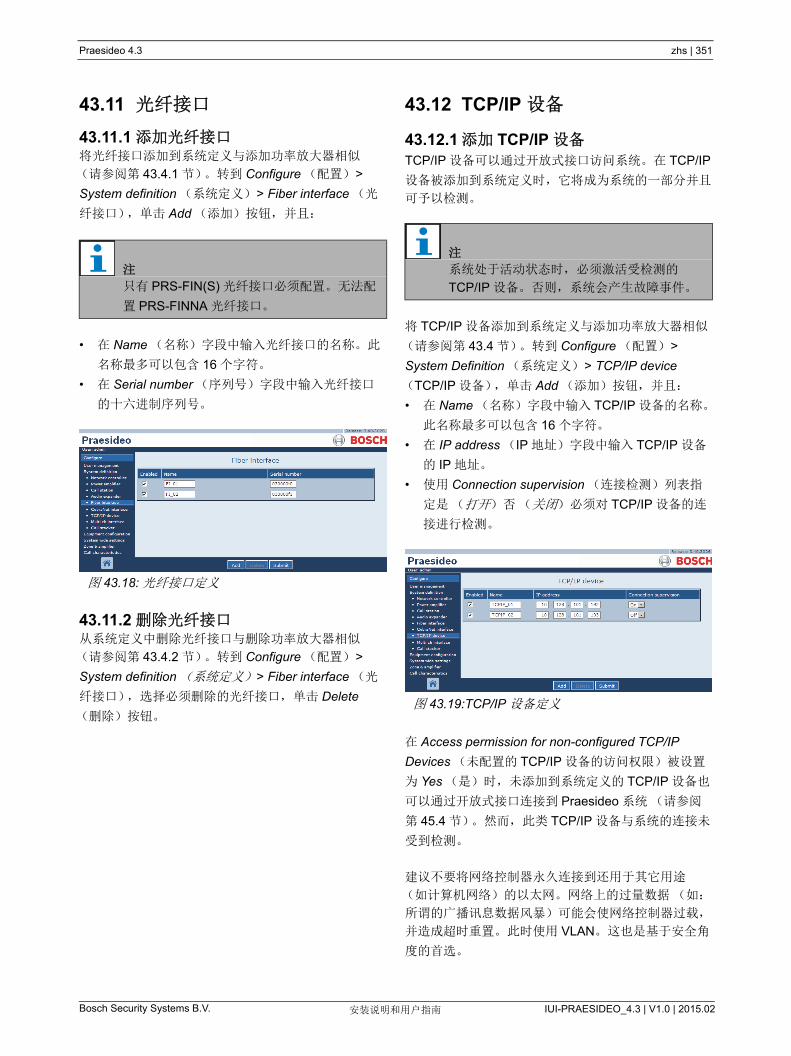
Praesideo 4.3 zhs | 351
Bosch Security Systems B.V. IUI-PRAESIDEO_4.3 | V1.0 | 2015.02安装说明和用户指南
43.11 光纤接口
43.11.1 添加光纤接口将光纤接口添加到系统定义与添加功率放大器相似
(请参阅第 43.4.1 节)。转到 Configure (配置) >
System definition (系统定义) > Fiber interface (光
纤接口),单击 Add (添加)按钮,并且:
• 在 Name (名称)字段中输入光纤接口的名称。此
名称 多可以包含 16 个字符。
• 在 Serial number (序列号)字段中输入光纤接口
的十六进制序列号。
43.11.2 删除光纤接口从系统定义中删除光纤接口与删除功率放大器相似
(请参阅第 43.4.2 节)。转到 Configure (配置) >
System definition (系统定义) > Fiber interface (光
纤接口),选择必须删除的光纤接口,单击 Delete
(删除)按钮。
43.12 TCP/IP 设备
43.12.1 添加 TCP/IP 设备TCP/IP 设备可以通过开放式接口访问系统。在 TCP/IP
设备被添加到系统定义时,它将成为系统的一部分并且
可予以检测。
将 TCP/IP 设备添加到系统定义与添加功率放大器相似
(请参阅第 43.4 节)。转到 Configure (配置) >
System Definition (系统定义) > TCP/IP device
(TCP/IP 设备),单击 Add (添加)按钮,并且:
• 在 Name (名称)字段中输入 TCP/IP 设备的名称。
此名称 多可以包含 16 个字符。
• 在 IP address (IP 地址)字段中输入 TCP/IP 设备
的 IP 地址。
• 使用 Connection supervision (连接检测)列表指
定是(打开)否(关闭)必须对 TCP/IP 设备的连
接进行检测。
在 Access permission for non-configured TCP/IP
Devices (未配置的 TCP/IP 设备的访问权限)被设置
为 Yes (是)时,未添加到系统定义的 TCP/IP 设备也
可以通过开放式接口连接到 Praesideo 系统(请参阅
第 45.4 节)。然而,此类 TCP/IP 设备与系统的连接未
受到检测。
建议不要将网络控制器永久连接到还用于其它用途
(如计算机网络)的以太网。网络上的过量数据(如:
所谓的广播讯息数据风暴)可能会使网络控制器过载,
并造成超时重置。此时使用 VLAN。这也是基于安全角
度的首选。
注
只有 PRS-FIN(S) 光纤接口必须配置。无法配
置 PRS-FINNA 光纤接口。
图 43.18: 光纤接口定义
注
系统处于活动状态时,必须激活受检测的
TCP/IP 设备。否则,系统会产生故障事件。
图 43.19:TCP/IP 设备定义
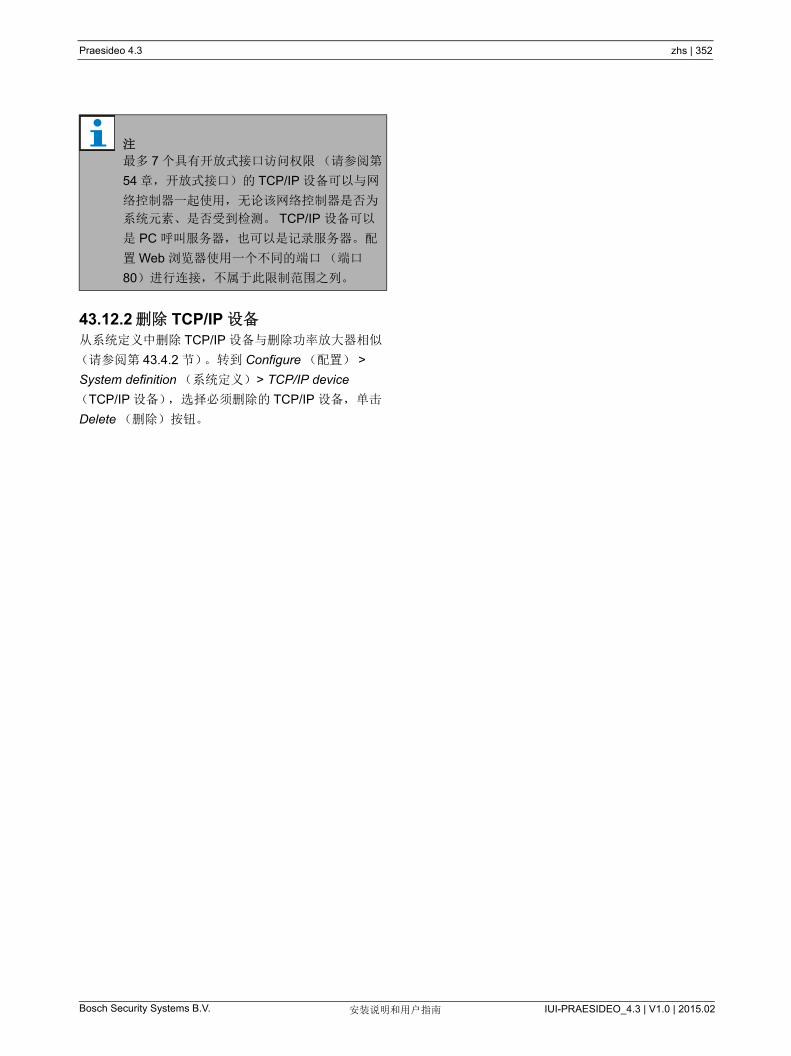
Praesideo 4.3 zhs | 352
Bosch Security Systems B.V. IUI-PRAESIDEO_4.3 | V1.0 | 2015.02安装说明和用户指南
43.12.2 删除 TCP/IP 设备从系统定义中删除 TCP/IP 设备与删除功率放大器相似
(请参阅第 43.4.2 节)。转到 Configure (配置) >
System definition (系统定义) > TCP/IP device
(TCP/IP 设备),选择必须删除的 TCP/IP 设备,单击
Delete (删除)按钮。
注
多 7 个具有开放式接口访问权限(请参阅第
54 章,开放式接口)的 TCP/IP 设备可以与网
络控制器一起使用,无论该网络控制器是否为
系统元素、是否受到检测。 TCP/IP 设备可以
是 PC 呼叫服务器,也可以是记录服务器。配
置 Web 浏览器使用一个不同的端口(端口
80)进行连接,不属于此限制范围之列。

Praesideo 4.3 zhs | 353
Bosch Security Systems B.V. IUI-PRAESIDEO_4.3 | V1.0 | 2015.02安装说明和用户指南
44 设备配置
44.1 简介在 Equipment configuration (设备配置)页面上,可
以对利用 System definition (系统定义)页面添加的每
件设备进行配置。利用 Equipment Configuration (设
备配置)页面,可以配置以下设备:
• 网络控制器(请参阅第 44.2 节)。
• 功率放大器(请参阅第 44.3 节)。
• 多通道接口(请参阅第 45 节)。
• 呼叫站(请参阅第 44.5 节)。
• 音频扩展器(请参阅第 44.6 节)。
• CobraNet 接口(请参阅第 45 节)。
• 光纤接口(请参阅第 44.8 节)。
• 光纤接口(请参阅第 44.8 节)。
44.2 网络控制器
44.2.1 步骤配置网络控制器的过程如下:
1 转到 Configure (配置) >Equipment configuration
(设备配置) >Network controller (网络控制器)。
在 Web 界面的主框窗口中出现与图 44.2 相似的屏
幕。
2 单击必须配置的网络控制器名称。在 Web 界面的主
框窗口中出现与图 44.3 相似的屏幕。
3 打开 一般 类别,配置功率监测设置(见第 44.2.2
节)。
4 打开 音频输入端 类别,配置网络控制器的音频输入
端(请参阅第 44.2.3 节)。
5 打开 音频输出端 类别,配置网络控制器的音频输出
端(请参阅第 44.2.4 节)。
6 打开 控制输入端 类别,配置网络控制器的控制输入
端(请参阅第 44.2.5 节)。
7 打开 控制输出端 类别,配置网络控制器的控制输出
端(请参阅第 44.2.6 节)。
8 提交更改。 请注意:在配置保存之前,更改尚未固
化(请参阅第 41.4.3 节和第 41.4.4 节)。
图 44.1: 设备配置页面
System definition
Network controller
Power amplifier
Call station
Audio expander
CobraNet interface
Multi channel interface
OMNEO interface
Fiber interface
图 44.2: 配置网络控制器,第 1 步
图 44.3: 配置网络控制器,第 2 步

Praesideo 4.3 zhs | 354
Bosch Security Systems B.V. IUI-PRAESIDEO_4.3 | V1.0 | 2015.02安装说明和用户指南
44.2.2 概要
图 44.4: 配置网络控制器,第 3 步
表 44.1: 常规配置
项目 值 描述
主电源检测 开
关
指明主电源是否必须受到检测。在主电源检测打开并且
主电源发生故障时,会产生故障事件。在使用主电源
时,如果将主电源检测设置为关,则系统不会探测到主
电源故障。
备用电源检测 开
关
指明备用电源是否必须受到检测。在备用电源检测打开
并且备用电源发生故障时,会产生故障事件。在使用备
用电源时,如果将备用电源检测设置为关,则系统不会
探测到备用电源故障。

Praesideo 4.3 zhs | 355
Bosch Security Systems B.V. IUI-PRAESIDEO_4.3 | V1.0 | 2015.02安装说明和用户指南
44.2.3 音频输入端
图 44.5: 配置网络控制器,第 4 步
小心
只在音频类型是与音频输入端的 XLR 连接器
相连的电容器话筒时,才打开幻象。
表 44.2: 音频输入配置
项目 值 描述
输入 音频输入端的唯一名称。可以使用复选框启用和禁用输
入。
音频类型 线路
话筒
设置音频源的类型。该类型或者是线路(线路)或者是
话筒(话筒)。
输入增益 -8 到 7 dB (话筒)
0 到 12 dB (线路)
为 XLR 输入和 Cinch 输入(仅用于线路)设置输入增
益,参考额定输入电平。
输入功能 辅助AVC
设置话筒功能。辅助话筒(Auxiliary)可用于发送呼
叫。而 AVC 话筒(AVC)则用于测量环境噪音级。请注
意:连接到网络控制器或音频扩展器的话筒未受到检
测。如果需要检测,请将话筒连接到功率放大器。
幻象 开,关 指定话筒接收(开)还是不接收(关)幻象电源。只有
将 (2) 设置为话筒类型,该项才是可用的。仅当对呼叫激
活话筒输入时,幻象电源才是可用的。
连接检测 开,关 指定是否启用(开)或禁用(关)输入端的 20 kHz 导
频音探测器。只有当 Audio type (音频类型)设置为
Line (线路)时,该功能才可用。如果源使用导频音,
它可以提供电缆和连接检测。检测极限为 -40 dB,相对
于完全输出的线路输入的输入灵敏度。

Praesideo 4.3 zhs | 356
Bosch Security Systems B.V. IUI-PRAESIDEO_4.3 | V1.0 | 2015.02安装说明和用户指南
44.2.4 音频输出端
图 44.6: 配置网络控制器,第 4 步
表 44.3: 音频输出端配置
项目 值 描述
输出端 音频输出端的唯一名称。可以使用复选框启用和禁用输出。
电平 -18到 12 dB 为XLR输出和Cinch输出设置输出电平,参考额定输出电
平。
导频音 开 , 关 打开 (On)或关闭 (Off)20 kHz导频音。导频音用于检测与另
一个公共广播系统或设备相连的模拟音频连接。检测和故障
报告应由随后的系统或设备(如Bosch Intellivox扬声器)
来完成。
导频音电平 -38到 -18 dB 为导频音设置电平,参考额定输出电平。
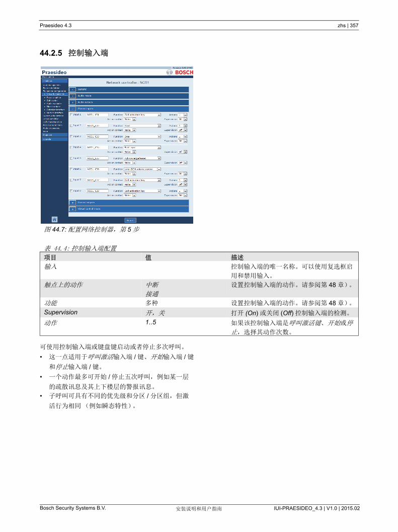
Praesideo 4.3 zhs | 357
Bosch Security Systems B.V. IUI-PRAESIDEO_4.3 | V1.0 | 2015.02安装说明和用户指南
44.2.5 控制输入端
可使用控制输入端或键盘键启动或者停止多次呼叫。
• 这一点适用于呼叫激活输入端 / 键、开始输入端 / 键
和停止输入端 / 键。
• 一个动作 多可开始 / 停止五次呼叫,例如某一层
的疏散讯息及其上下楼层的警报讯息。
• 子呼叫可具有不同的优先级和分区 / 分区组,但激
活行为相同(例如瞬态特性)。
图 44.7: 配置网络控制器,第 5 步
表 44.4: 控制输入端配置
项目 值 描述
输入 控制输入端的唯一名称。可以使用复选框启
用和禁用输入。
触点上的动作 中断
接通
设置控制输入端的动作。请参阅第 48 章)。
功能 多种 设置控制输入端的动作。请参阅第 48 章)。
Supervision 开,关 打开 (On) 或关闭 (Off) 控制输入端的检测。
动作 1..5 如果该控制输入端是呼叫激活键、开始或停
止,选择其动作次数。
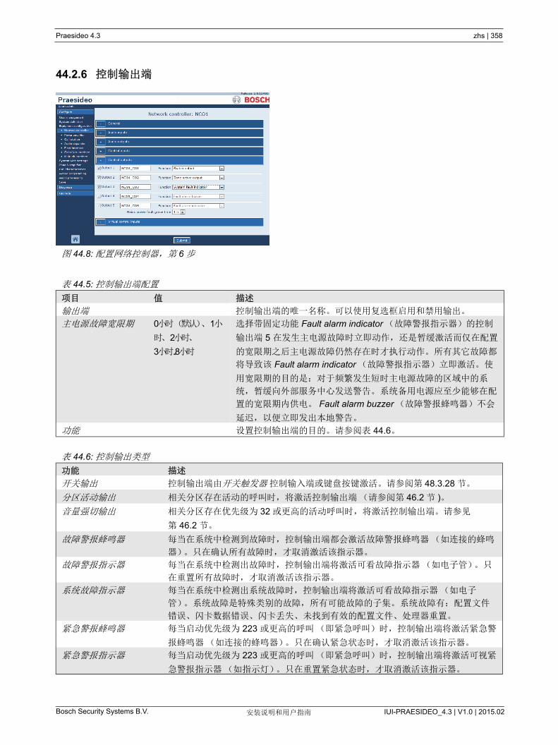
Praesideo 4.3 zhs | 358
Bosch Security Systems B.V. IUI-PRAESIDEO_4.3 | V1.0 | 2015.02安装说明和用户指南
44.2.6 控制输出端
图 44.8: 配置网络控制器,第 6 步
表 44.5: 控制输出端配置
项目 值 描述
输出端 控制输出端的唯一名称。可以使用复选框启用和禁用输出。
主电源故障宽限期 0 小时(默认)、1 小
时、2 小时、
3 小时 ...8 小时
选择带固定功能 Fault alarm indicator (故障警报指示器)的控制
输出端 5 在发生主电源故障时立即动作,还是暂缓激活而仅在配置
的宽限期之后主电源故障仍然存在时才执行动作。所有其它故障都
将导致该 Fault alarm indicator (故障警报指示器)立即激活。使
用宽限期的目的是:对于频繁发生短时主电源故障的区域中的系
统,暂缓向外部服务中心发送警告。系统备用电源应至少能够在配
置的宽限期内供电。 Fault alarm buzzer (故障警报蜂鸣器)不会
延迟,以便立即发出本地警告。
功能 设置控制输出端的目的。请参阅表 44.6。
表 44.6: 控制输出类型
功能 描述
开关输出 控制输出端由开关触发器 控制输入端或键盘按键激活。请参阅第 48.3.28 节。
分区活动输出 相关分区存在活动的呼叫时,将激活控制输出端(请参阅第 46.2 节 )。
音量强切输出 相关分区存在优先级为 32 或更高的活动呼叫时,将激活控制输出端。请参见
第 46.2 节。
故障警报蜂鸣器 每当在系统中检测到故障时,控制输出端都会激活故障警报蜂鸣器(如连接的蜂鸣
器)。只在确认所有故障时,才取消激活该指示器。
故障警报指示器 每当在系统中检测出故障时,控制输出端将激活可看故障指示器(如电子管)。只
在重置所有故障时,才取消激活该指示器。
系统故障指示器 每当在系统中检测出系统故障时,控制输出端将激活可看故障指示器(如电子
管)。系统故障是特殊类别的故障,所有可能故障的子集。系统故障有:配置文件
错误、闪卡数据错误、闪卡丢失、未找到有效的配置文件、处理器重置。
紧急警报蜂鸣器 每当启动优先级为 223 或更高的呼叫(即紧急呼叫)时,控制输出端将激活紧急警
报蜂鸣器(如连接的蜂鸣器)。只在确认紧急状态时,才取消激活该指示器。
紧急警报指示器 每当启动优先级为 223 或更高的呼叫(即紧急呼叫)时,控制输出端将激活可视紧
急警报指示器(如指示灯)。只在重置紧急状态时,才取消激活该指示器。
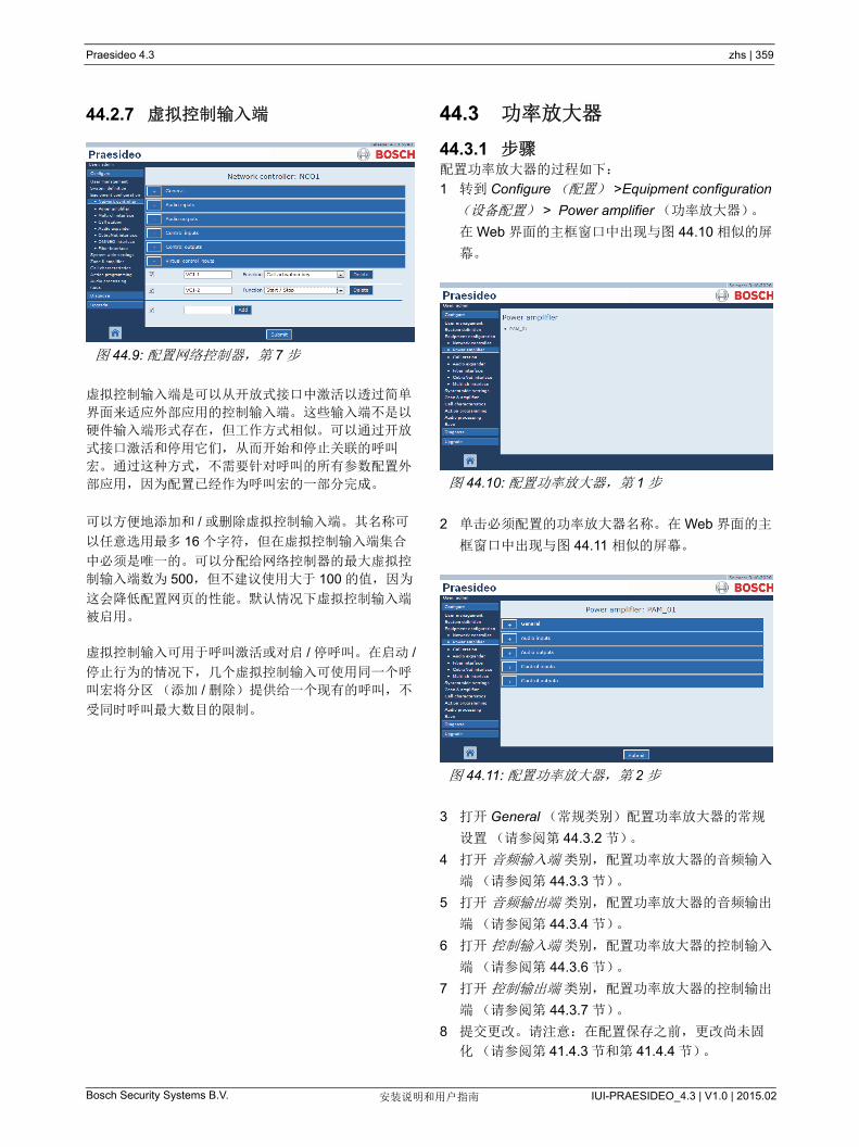
Praesideo 4.3 zhs | 359
Bosch Security Systems B.V. IUI-PRAESIDEO_4.3 | V1.0 | 2015.02安装说明和用户指南
44.2.7 虚拟控制输入端
虚拟控制输入端是可以从开放式接口中激活以透过简单
界面来适应外部应用的控制输入端。这些输入端不是以
硬件输入端形式存在,但工作方式相似。可以通过开放
式接口激活和停用它们,从而开始和停止关联的呼叫
宏。通过这种方式,不需要针对呼叫的所有参数配置外
部应用,因为配置已经作为呼叫宏的一部分完成。
可以方便地添加和 / 或删除虚拟控制输入端。其名称可
以任意选用 多 16 个字符,但在虚拟控制输入端集合
中必须是唯一的。可以分配给网络控制器的 大虚拟控
制输入端数为 500,但不建议使用大于 100 的值,因为
这会降低配置网页的性能。默认情况下虚拟控制输入端
被启用。
虚拟控制输入可用于呼叫激活或对启 / 停呼叫。在启动 /
停止行为的情况下,几个虚拟控制输入可使用同一个呼
叫宏将分区 (添加 / 删除)提供给一个现有的呼叫,不
受同时呼叫 大数目的限制。
44.3 功率放大器
44.3.1 步骤配置功率放大器的过程如下:
1 转到 Configure (配置) >Equipment configuration
(设备配置) > Power amplifier (功率放大器)。
在 Web 界面的主框窗口中出现与图 44.10 相似的屏
幕。
2 单击必须配置的功率放大器名称。在 Web 界面的主
框窗口中出现与图 44.11 相似的屏幕。
3 打开 General (常规类别)配置功率放大器的常规
设置(请参阅第 44.3.2 节)。
4 打开 音频输入端 类别,配置功率放大器的音频输入
端(请参阅第 44.3.3 节)。
5 打开 音频输出端 类别,配置功率放大器的音频输出
端(请参阅第 44.3.4 节)。
6 打开 控制输入端 类别,配置功率放大器的控制输入
端(请参阅第 44.3.6 节)。
7 打开 控制输出端 类别,配置功率放大器的控制输出
端(请参阅第 44.3.7 节)。
8 提交更改。请注意:在配置保存之前,更改尚未固
化(请参阅第 41.4.3 节和第 41.4.4 节)。
图 44.9: 配置网络控制器,第 7 步
图 44.10: 配置功率放大器,第 1 步
图 44.11: 配置功率放大器,第 2 步
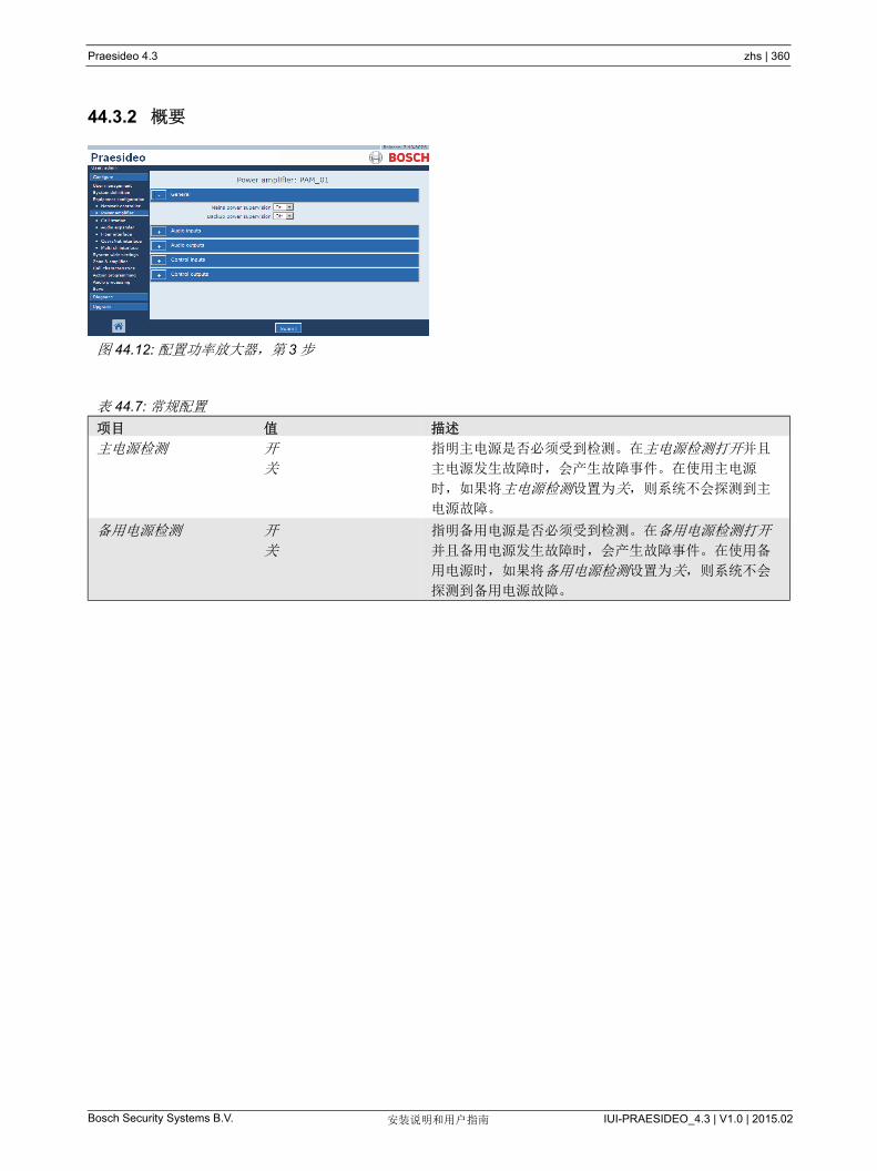
Praesideo 4.3 zhs | 360
Bosch Security Systems B.V. IUI-PRAESIDEO_4.3 | V1.0 | 2015.02安装说明和用户指南
44.3.2 概要
图 44.12: 配置功率放大器,第 3 步
表 44.7: 常规配置
项目 值 描述
主电源检测 开
关
指明主电源是否必须受到检测。在主电源检测打开并且
主电源发生故障时,会产生故障事件。在使用主电源
时,如果将主电源检测设置为关,则系统不会探测到主
电源故障。
备用电源检测 开
关
指明备用电源是否必须受到检测。在备用电源检测打开
并且备用电源发生故障时,会产生故障事件。在使用备
用电源时,如果将备用电源检测设置为关,则系统不会
探测到备用电源故障。
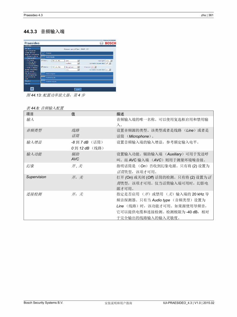
Praesideo 4.3 zhs | 361
Bosch Security Systems B.V. IUI-PRAESIDEO_4.3 | V1.0 | 2015.02安装说明和用户指南
44.3.3 音频输入端
图 44.13: 配置功率放大器,第 4 步
表 44.8: 音频输入配置
项目 值 描述
输入 音频输入端的唯一名称。可以使用复选框启用和禁用输
入。
音频类型 线路
话筒
设置音频源的类型。该类型或者是线路(Line)或者是
话筒(Microphone)。
输入增益 -8 到 7 dB (话筒)
0 到 12 dB (线路)
设置音频输入端的输入增益,参考额定输入电平。
输入功能 辅助AVC
设置输入功能。辅助输入端(Auxiliary)可用于发送呼
叫。而 AVC 输入端(AVC)则用于测量环境噪音级。
幻象 开 , 关 指明话筒是(On)否收到幻象电源。只有将 (2) 设置为
话筒类型,该项才可用。
Supervision 开,关 打开 (On) 或关闭 (Off) 话筒的检测。只有将 (2) 设置为话
筒类型,该项才可用。仅当话筒输入端可用时,幻影电
源才可用。
连接检测 开,关 指定是否启用(开)或禁用(关)输入端的 20 kHz 导
频音探测器。只有当 Audio type (音频类型)设置为
Line (线路)时,该功能才可用。如果源使用导频音,
它可以提供电缆和连接检测。检测极限为 -40 dB,相对
于完全输出的线路输入的输入灵敏度。

Praesideo 4.3 zhs | 362
Bosch Security Systems B.V. IUI-PRAESIDEO_4.3 | V1.0 | 2015.02安装说明和用户指南
44.3.4 音频输出端
配置为备用放大器的功率放大器不带有延迟(距离)
设置。当功率放大器处于活动状 态时,从此备用放大
器要替换的主放大器中接管此设置。仅当备用放大器处
于备用状态时,其输出配置才有效。
当备用放大器接管主放大器时,会复制主放大器的配
置。线路 /LSP 检测可用于检测备用放大器和已连接主
放大器之间的相互连接。
如果已连接的主放大器使用单个线路 /Lsp 检测,则备
用放大器禁止使用多个线路 /Lsp 检测,否则当备用放
大器接管主放大器时,检测从属板之间将产生冲突。
如果已连接主放大器使用多个线路 /Lsp 检测,则备用
放大器还可以使用多个线路 /Lsp 检测。
图 44.14: 配置功率放大器,第 5 步
表 44.9: 音频输出端配置
项目 值 描述
输出端 音频输出端的唯一名称。可以使用复选框启用和禁用输出。
延迟 0 到 95108 ms (PRS-1P500)
0 到 47554 ms (PRS-2P250)
0 到 23777 ms (PRS-4P125)
0 到 1479 ms (LBB4428/00)
将扬声器设置为定位时间,并以距离(米和英尺)来表示。
放大器检测 /
导频音
开 , 关 打开 (On) 或关闭 (Off)20 kHz 导频音。该导频音用于检测放大器通
道是否出现故障,还可检测扬声器线路和扬声器。
如果设置为打开(On),则导频音将启用检测并且内部校准会保持
导频音处于 佳效果。如果线路上的负载因添加或拆除扬声器而发
生变化,则导频音将保持 佳效果。
GND 检测 开 , 关 打开 (On)和关闭(Off)扬声器线路的接地检测。在与 Bosch 线
路隔离器系统(LIS)相结合时,放大器通道和备用放大器通道的
接地监测必须关闭,因为线路隔离器系统要执行这项功能。
线路 /LSP 检测 无
PRS-SVSET (单个)
PRS-SVCO (多个)
设置线路或扬声器检测的类型。
配置检测设备 打开屏幕配置 LBB4441 和 LBB4443 副板 (请参阅第 44.3.5 节)。
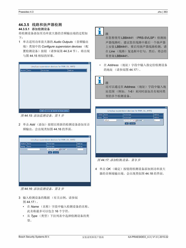
Praesideo 4.3 zhs | 363
Bosch Security Systems B.V. IUI-PRAESIDEO_4.3 | V1.0 | 2015.02安装说明和用户指南
44.3.5 线路和扬声器检测44.3.5.1 添加检测设备
将检测设备添加至功率放大器的音频输出端的过程如
下:
1 单击适用功率放大器的 Audio Outputs (音频输出
端)类别中的 Configure supervision devices (配
置检测设备)按钮(请参阅第 44.3.4 节)。将出现
与图 44.15 相似的屏幕。
2 单击 Add (添加)按钮以将新的检测设备添加至音
频输出。会出现类似图 44.16 的界面。
3 输入检测设备的数据(有关示例,请参阅
图 44.17)。
• 在 Name (名称)字段中输入检测设备的名称。
此名称 多可以包含 16 个字符。
• 从 Type (类型)下拉列表中选择检测设备的类
型。
• 在 Address (地址)字段中输入指定给检测设备
的地址(请参阅图 44.17)。
4 单击 OK (确定)按钮将检测设备添加到功率放大
器的音频端输出端。会出现类似图 44.18 的界面。
图 44.15: 添加监测设备,第 1 步
图 44.16: 添加监测设备,第 2 步
注
在您想使用 LBB4441 (PRS-SVLSP)检测扬
声器线路时,建议您在线路中 后一个扬声器
上安装 LBB4441。要启用扬声器线路检测,请
在 Line (线路)复选框中打勾。然后,将会经
常查询 LBB4441。
注
还可以通过在 Address (地址)字段中输入地
址范围(例如, 1-6)来同时添加具有相同类
型的多个检测设备。
图 44.17: 添加检测设备,第 3 步
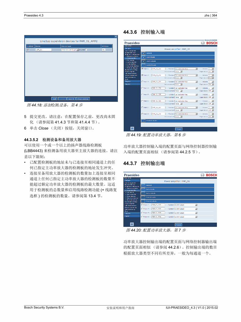
Praesideo 4.3 zhs | 364
Bosch Security Systems B.V. IUI-PRAESIDEO_4.3 | V1.0 | 2015.02安装说明和用户指南
5 提交更改。请注意:在配置保存之前,更改尚未固
化(请参阅第 41.4.3 节和第 41.4.4 节)。
6 单击 Close (关闭)按钮,关闭窗口。
44.3.5.2 检测设备和备用放大器
可以使用一个或一个以上的扬声器线路检测板
(LBB4443) 来检测备用放大器至主放大器的连接。请注
意以下限制:
• 已配置检测板的地址未与已连接至相同通道上的任
何已指定主功率放大器的检测板的地址发生冲突。
• 连接至备用放大器的检测板的数量加上连接至相同
通道上任何已指定主功率放大器的检测板的数量不
能超过额定功率放大器的检测板的 大数量。这适
用于检测板的总数量和启用线路检测功能 (+ 线路复
选框 ) 的检测板的数量。请参阅第 13.4 节。
44.3.6 控制输入端
功率放大器控制输入端的配置页面与网络控制器控制输
入端的配置页面相似(请参阅第 44.2.5 节)。
44.3.7 控制输出端
功率放大器控制输出端的配置页面与网络控制器输出端
的配置页面相似(请参阅 44.2.6)。控制输出端的数目
根据放大器类型不同有所差异,一般为每通道一个。
图 44.18: 添加检测设备,第 4 步
图 44.19: 配置功率放大器,第 6 步
图 44.20: 配置功率放大器,第 7 步
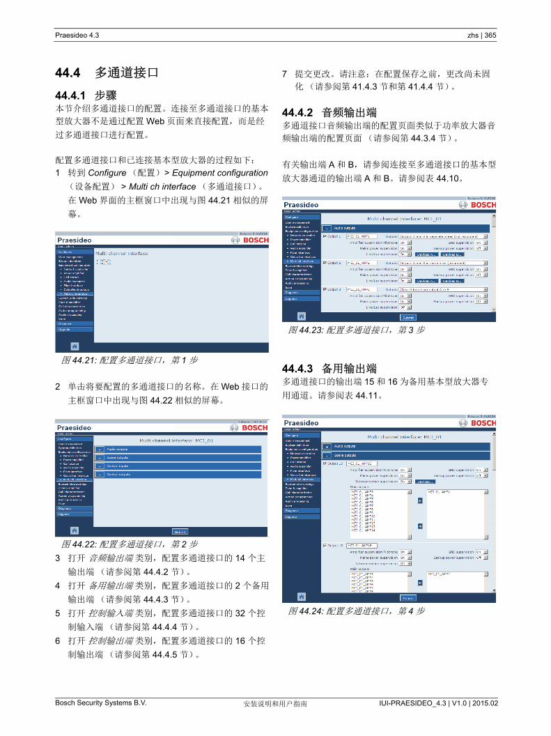
Praesideo 4.3 zhs | 365
Bosch Security Systems B.V. IUI-PRAESIDEO_4.3 | V1.0 | 2015.02安装说明和用户指南
44.4 多通道接口
44.4.1 步骤本节介绍多通道接口的配置。连接至多通道接口的基本
型放大器不是通过配置 Web 页面来直接配置,而是经
过多通道接口进行配置。
配置多通道接口和已连接基本型放大器的过程如下:
1 转到 Configure (配置) > Equipment configuration
(设备配置) > Multi ch interface (多通道接口)。
在 Web 界面的主框窗口中出现与图 44.21 相似的屏
幕。
2 单击将要配置的多通道接口的名称。在 Web 接口的
主框窗口中出现与图 44.22 相似的屏幕。
3 打开 音频输出端 类别,配置多通道接口的 14 个主
输出端(请参阅第 44.4.2 节)。
4 打开 备用输出端 类别,配置多通道接口的 2 个备用
输出端(请参阅第 44.4.3 节)。
5 打开 控制输入端 类别,配置多通道接口的 32 个控
制输入端(请参阅第 44.4.4 节)。
6 打开 控制输出端 类别,配置多通道接口的 16 个控
制输出端(请参阅第 44.4.5 节)。
7 提交更改。请注意:在配置保存之前,更改尚未固
化(请参阅第 41.4.3 节和第 41.4.4 节)。
44.4.2 音频输出端多通道接口音频输出端的配置页面类似于功率放大器音
频输出端的配置页面(请参阅第 44.3.4 节)。
有关输出端 A 和 B,请参阅连接至多通道接口的基本型
放大器通道的输出端 A 和 B。请参阅表 44.10。
44.4.3 备用输出端多通道接口的输出端 15 和 16 为备用基本型放大器专
用通道。请参阅表 44.11。
图 44.21: 配置多通道接口,第 1 步
图 44.22: 配置多通道接口,第 2 步
图 44.23: 配置多通道接口,第 3 步
图 44.24: 配置多通道接口,第 4 步
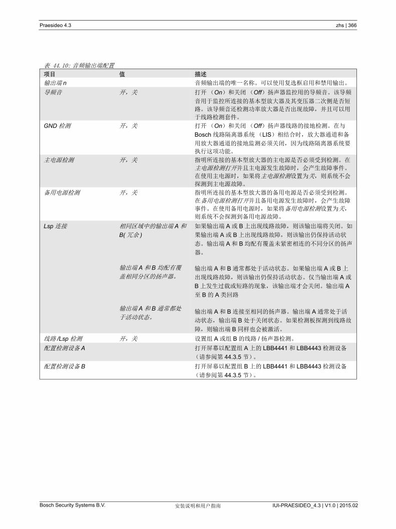
Praesideo 4.3 zhs | 366
Bosch Security Systems B.V. IUI-PRAESIDEO_4.3 | V1.0 | 2015.02安装说明和用户指南
表 44.10: 音频输出端配置
项目 值 描述
输出端 n 音频输出端的唯一名称。可以使用复选框启用和禁用输出。
导频音 开,关 打开(On)和关闭 (Off)扬声器监控用的导频音。该导频
音用于监控所连接的基本型放大器及其变压器二次侧是否短
路。该导频音还检测功率放大器是否出现故障,并且可以用
于线路检测套件。
GND 检测 开,关 打开(On)和关闭 (Off)扬声器线路的接地检测。在与
Bosch 线路隔离器系统(LIS)相结合时,放大器通道和备
用放大器通道的接地监测必须关闭,因为线路隔离器系统要
执行这项功能。
主电源检测 开,关 指明所连接的基本型放大器的主电源是否必须受到检测。在
主电源检测打开并且主电源发生故障时,会产生故障事件。
在使用主电源时,如果将主电源检测设置为关,则系统不会
探测到主电源故障。
备用电源检测 开,关 指明所连接的基本型放大器的备用电源是否必须受到检测。
在备用电源检测打开并且备用电源发生故障时,会产生故障
事件。在使用备用电源时,如果将备用电源检测设置为关,
则系统不会探测到备用电源故障。
Lsp 连接 相同区域中的输出端 A 和
B( 冗余 )
输出端 A 和 B 均配有覆
盖相同分区的扬声器。
输出端 A 和 B 通常都处
于活动状态。
如果输出端 A 或 B 上出现线路故障,则该输出端将关闭。如
果输出端 A 或 B 上出现线路故障,则该输出仍保持活动状
态。输出端 A 和 B 均配有覆盖未紧密相连的不同分区的扬声
器。
输出端 A 和 B 通常都处于活动状态。如果输出端 A 或 B 上
出现线路故障,则该输出仍保持活动状态。仅当输出端 A 或
B 上发生过载或短路的现象,该输出端才会关闭。输出端 A
至 B 的 A 类回路
输出端 A 和 B 连接至相同的扬声器。输出端 A 通常处于活
动状态,输出端 B 处于关闭状态。如果检测板探测到线路故
障,则输出端 B 同样也会被激活。
线路 /Lsp 检测 开,关 设置组 A 或组 B 的线路 / 扬声器检测。
配置检测设备 A 打开屏幕以配置组 A 上的 LBB4441 和 LBB4443 检测设备
(请参阅第 44.3.5 节)。
配置检测设备 B 打开屏幕以配置组 B 上的 LBB4441 和 LBB4443 检测设备
(请参阅第 44.3.5 节)。
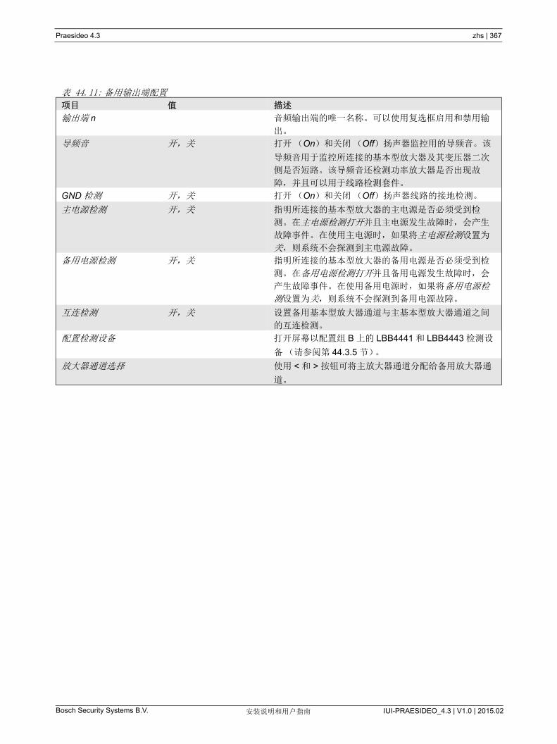
Praesideo 4.3 zhs | 367
Bosch Security Systems B.V. IUI-PRAESIDEO_4.3 | V1.0 | 2015.02安装说明和用户指南
表 44.11: 备用输出端配置
项目 值 描述
输出端 n 音频输出端的唯一名称。可以使用复选框启用和禁用输
出。
导频音 开,关 打开(On)和关闭(Off)扬声器监控用的导频音。该
导频音用于监控所连接的基本型放大器及其变压器二次
侧是否短路。该导频音还检测功率放大器是否出现故
障,并且可以用于线路检测套件。
GND 检测 开,关 打开(On)和关闭(Off)扬声器线路的接地检测。
主电源检测 开,关 指明所连接的基本型放大器的主电源是否必须受到检
测。在主电源检测打开并且主电源发生故障时,会产生
故障事件。在使用主电源时,如果将主电源检测设置为
关,则系统不会探测到主电源故障。
备用电源检测 开,关 指明所连接的基本型放大器的备用电源是否必须受到检
测。在备用电源检测打开并且备用电源发生故障时,会
产生故障事件。在使用备用电源时,如果将备用电源检
测设置为关,则系统不会探测到备用电源故障。
互连检测 开,关 设置备用基本型放大器通道与主基本型放大器通道之间
的互连检测。
配置检测设备 打开屏幕以配置组 B 上的 LBB4441 和 LBB4443 检测设
备(请参阅第 44.3.5 节)。
放大器通道选择 使用 < 和 > 按钮可将主放大器通道分配给备用放大器通
道。
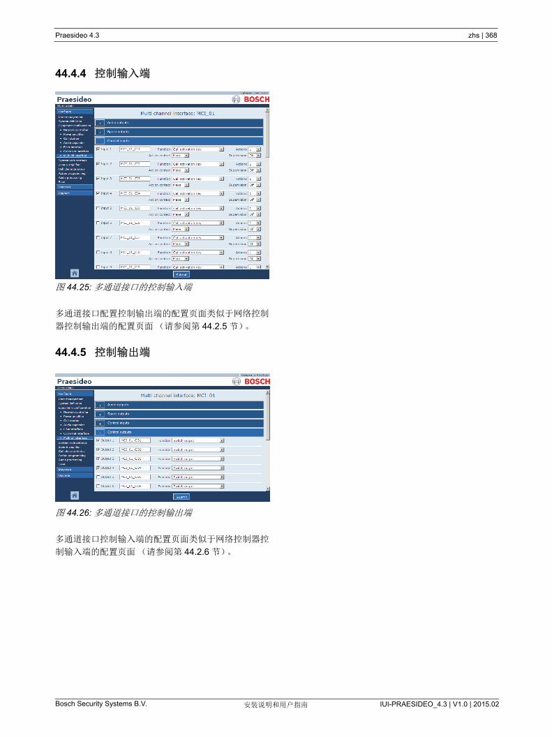
Praesideo 4.3 zhs | 368
Bosch Security Systems B.V. IUI-PRAESIDEO_4.3 | V1.0 | 2015.02安装说明和用户指南
44.4.4 控制输入端
图 44.25: 多通道接口的控制输入端
多通道接口配置控制输出端的配置页面类似于网络控制
器控制输出端的配置页面(请参阅第 44.2.5 节)。
44.4.5 控制输出端
图 44.26: 多通道接口的控制输出端
多通道接口控制输入端的配置页面类似于网络控制器控
制输入端的配置页面(请参阅第 44.2.6 节)。
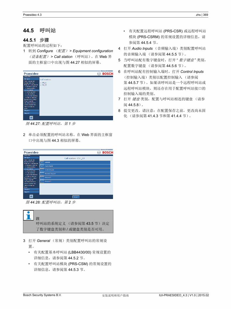
Praesideo 4.3 zhs | 369
Bosch Security Systems B.V. IUI-PRAESIDEO_4.3 | V1.0 | 2015.02安装说明和用户指南
44.5 呼叫站
44.5.1 步骤配置呼叫站的过程如下:
1 转到 Configure (配置) > Equipment configuration
(设备配置) > Call station (呼叫站)。在 Web 界
面的主框窗口中出现与图 44.27 相似的屏幕。
2 单击必须配置的呼叫站名称。在 Web 界面的主框窗
口中出现与图 44.3 相似的屏幕。
3 打开 General (常规)类别配置呼叫站的常规设
置。
• 有关配置基本呼叫站 (LBB4430/00) 常规设置的
详细信息,请参阅第 44.5.2 节。
• 有关配置呼叫站模块 (PRS-CSM) 的常规设置的
详细信息,请参阅第 44.5.3 节。
• 有关配置远程呼叫站 (PRS-CSR) 或远程呼叫站
模块 (PRS-CSRM) 的常规设置的详细信息,请
参阅第 44.5.4 节。
4 打开 Audio Inputs (音频输入端)类别配置呼叫站
的音频输入端(请参阅第 44.5.5 节)。
5 当呼叫站配有数字键盘时,打开 “ 数字键盘 ” 类别,
配置数字键盘(请参阅第 44.5.6 节)。
6 在呼叫站配有控制输入端时,打开 Control Inputs
(控制输入端)类别以配置控制输入(请参阅
第 44.5.7 节)。如果该呼叫站是一个远程呼叫站或
远程呼叫站模块,则还存在用于配置呼叫站接口的
控制输入端的类别。
7 打开 键盘 类别,配置与呼叫站相连的键盘(请参
阅 44.5.8)。
8 提交更改。请注意:在配置保存之前,更改尚未固
化(请参阅第 41.4.3 节和第 41.4.4 节)。
图 44.27: 配置呼叫站,第 1 步
图 44.28: 配置呼叫站,第 2 步
注
呼叫站的系统定义(请参阅第 43.5 节)决定
了数字键盘类别和 / 或键盘类别是否可用。

Praesideo 4.3 zhs | 370
Bosch Security Systems B.V. IUI-PRAESIDEO_4.3 | V1.0 | 2015.02安装说明和用户指南
44.5.2 概要 (LBB4430/00)
图 44.29: 配置呼叫站,第 3 步
表 44.12: 常规配置设置 (LBB4430/00)
项目 值 描述
等级 正常
紧急
设置呼叫站的优先级范围。它为正常(对于 32 到 223)
或紧急(对于 32 到 255)。当等级为紧急时,呼叫站可
以执行失效安全呼叫。
呼叫后清除选择 是
否
选择为呼叫所做的键盘选择(分区选择、优先级选择、
声音选择和讯息选择)是在呼叫结束后清除,还是为下
次呼叫保留。
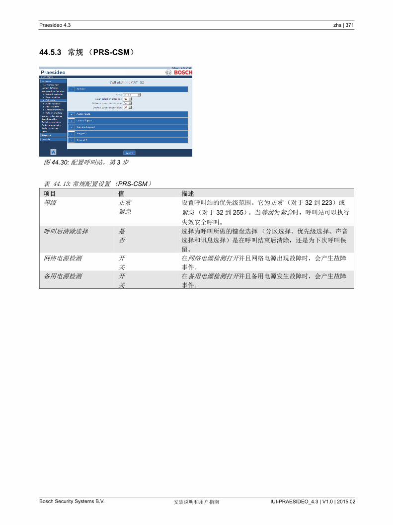
Praesideo 4.3 zhs | 371
Bosch Security Systems B.V. IUI-PRAESIDEO_4.3 | V1.0 | 2015.02安装说明和用户指南
44.5.3 常规(PRS-CSM)
图 44.30: 配置呼叫站,第 3 步
表 44.13: 常规配置设置(PRS-CSM)
项目 值 描述
等级 正常
紧急
设置呼叫站的优先级范围。它为正常(对于 32 到 223)或
紧急(对于 32 到 255)。当等级为紧急时,呼叫站可以执行
失效安全呼叫。
呼叫后清除选择 是
否
选择为呼叫所做的键盘选择(分区选择、优先级选择、声音
选择和讯息选择)是在呼叫结束后清除,还是为下次呼叫保
留。
网络电源检测 开
关
在网络电源检测打开并且网络电源出现故障时,会产生故障
事件。
备用电源检测 开
关
在备用电源检测打开并且备用电源发生故障时,会产生故障
事件。
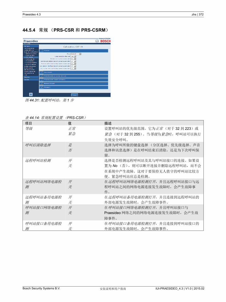
Praesideo 4.3 zhs | 372
Bosch Security Systems B.V. IUI-PRAESIDEO_4.3 | V1.0 | 2015.02安装说明和用户指南
44.5.4 常规(PRS-CSR 和 PRS-CSRM)
图 44.31: 配置呼叫站,第 1 步
表 44.14: 常规配置设置(PRS-CSR)
项目 值 描述
等级 正常
紧急
设置呼叫站的优先级范围。它为正常(对于 32 到 223)或
紧急(对于 32 到 255)。当等级为紧急时,呼叫站可以执行
失效安全呼叫。
呼叫后清除选择 是
否
选择为呼叫所做的键盘选择(分区选择、优先级选择、声音
选择和讯息选择)是在呼叫结束后清除,还是为下次呼叫保
留。
远程呼叫站检测 开
关
选择是否检测远程呼叫站及其与呼叫站接口的连接。如果设
置为 No (否),则可以断开连接并删除远程呼叫站,而不会
在系统中产生故障。这对于要保持无人值守的呼叫站比较方
便。紧急呼叫站应总是检测。
远程呼叫站网络电源检
测
开
关
在远程呼叫站网络电源检测打开,并且远程呼叫站接口与远
程呼叫站之间的网络电源连接发生故障时,会产生故障事
件。
远程呼叫站备用电源检
测
开
关
在远程呼叫站备用电源检测打开,并且连接到远程呼叫站的
外部电源发生故障时,会产生故障事件。
呼叫站接口网络电源检
测
开
关
在呼叫站接口网络电源检测打开,并且呼叫站接口与
Praesideo 网络之间的网络电源连接发生故障时,会产生故
障事件。
呼叫站接口备用电源检
测
开
关
在呼叫站接口备用电源检测打开,并且连接到呼叫站接口的
外部电源发生故障时,会产生故障事件。

Praesideo 4.3 zhs | 373
Bosch Security Systems B.V. IUI-PRAESIDEO_4.3 | V1.0 | 2015.02安装说明和用户指南
44.5.5 音频输入端
图 44.32: 配置呼叫站,第 4 步
表 44.15: 音频输入端配置设置
项目 值 描述
输入 话筒(音频输入端)的唯一名称。可以使用复选框启用和禁
用话筒(音频输入端)。
Supervision 开
关
打开(On)和关闭(Off)话筒的检测
输入增益 -8 到 7 dB 设置输入增益。

Praesideo 4.3 zhs | 374
Bosch Security Systems B.V. IUI-PRAESIDEO_4.3 | V1.0 | 2015.02安装说明和用户指南
44.5.6 数字键盘
图 44.33: 配置呼叫站,第 5 步
表 44.16: 控制输入端配置设置
项目 值 描述
访问控制 否
是
指定数字键盘用于 ( 是 ) 还是不用于 ( 否 ) 访
问控制。
访问暂停 否
是
指明数字键盘在暂停时间结束后是否自动锁定。
在 System wide settings (整个系统的设定)中
设置暂停时间。请参阅 45.4。
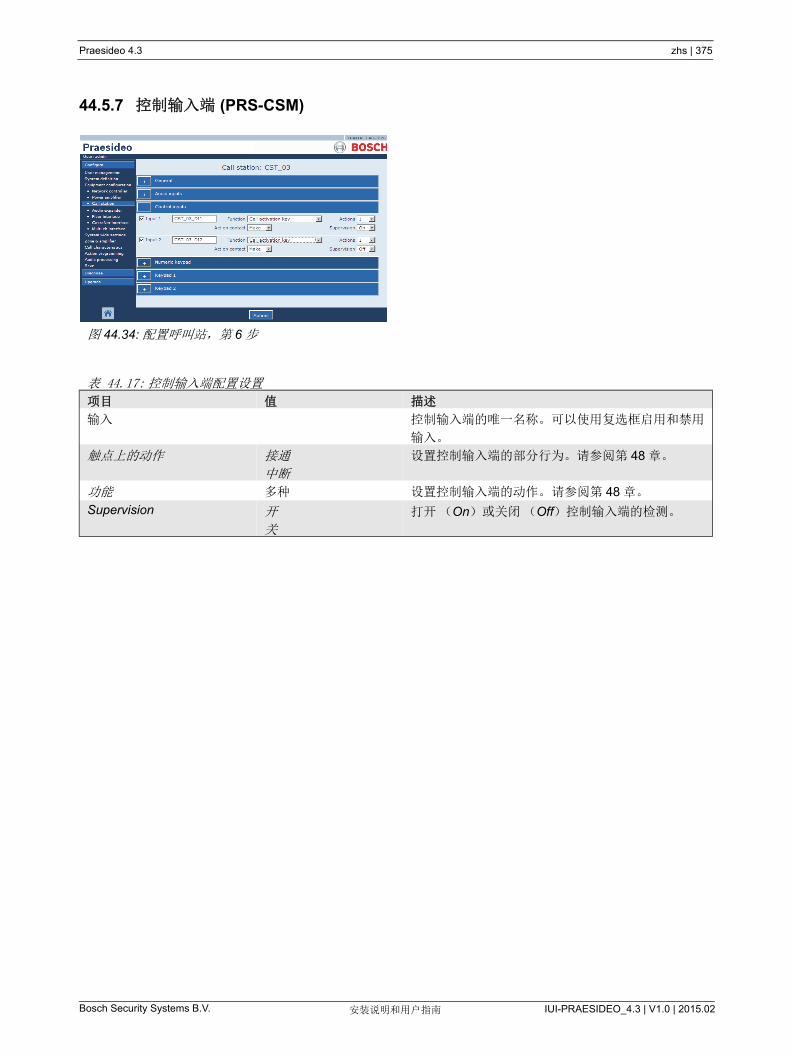
Praesideo 4.3 zhs | 375
Bosch Security Systems B.V. IUI-PRAESIDEO_4.3 | V1.0 | 2015.02安装说明和用户指南
44.5.7 控制输入端 (PRS-CSM)
图 44.34: 配置呼叫站,第 6 步
表 44.17: 控制输入端配置设置
项目 值 描述
输入 控制输入端的唯一名称。可以使用复选框启用和禁用
输入。
触点上的动作 接通
中断
设置控制输入端的部分行为。请参阅第 48 章。
功能 多种 设置控制输入端的动作。 请参阅第 48 章。
Supervision 开
关
打开(On)或关闭(Off)控制输入端的检测。
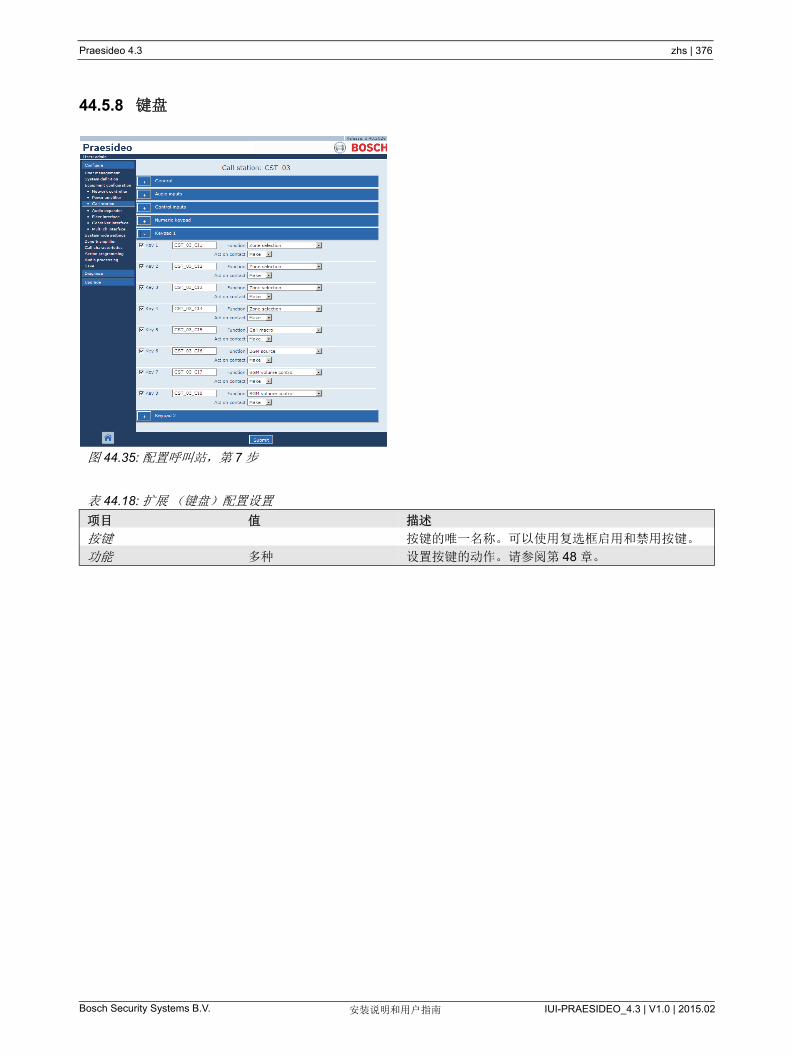
Praesideo 4.3 zhs | 376
Bosch Security Systems B.V. IUI-PRAESIDEO_4.3 | V1.0 | 2015.02安装说明和用户指南
44.5.8 键盘
图 44.35: 配置呼叫站,第 7 步
表 44.18: 扩展(键盘)配置设置
项目 值 描述
按键 按键的唯一名称。可以使用复选框启用和禁用按键。
功能 多种 设置按键的动作。请参阅第 48 章。
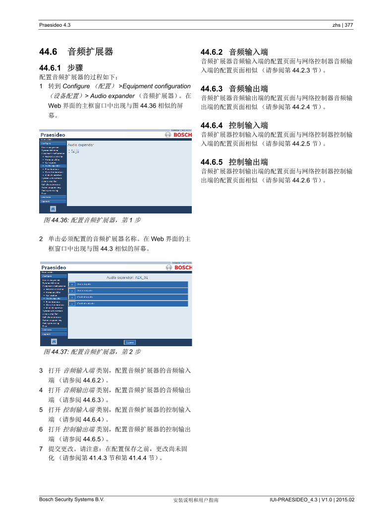
Praesideo 4.3 zhs | 377
Bosch Security Systems B.V. IUI-PRAESIDEO_4.3 | V1.0 | 2015.02安装说明和用户指南
44.6 音频扩展器
44.6.1 步骤配置音频扩展器的过程如下:
1 转到 Configure (配置) >Equipment configuration
(设备配置) > Audio expander (音频扩展器)。在
Web 界面的主框窗口中出现与图 44.36 相似的屏
幕。
2 单击必须配置的音频扩展器名称。在 Web 界面的主
框窗口中出现与图 44.3 相似的屏幕。
3 打开 音频输入端 类别,配置音频扩展器的音频输入
端(请参阅 44.6.2)。
4 打开 音频输出端 类别,配置音频扩展器的音频输出
端(请参阅 44.6.3)。
5 打开 控制输入端 类别,配置音频扩展器的控制输入
端(请参阅 44.6.4)。
6 打开 控制输出端 类别,配置音频扩展器的控制输出
端(请参阅 44.6.5)。
7 提交更改。请注意:在配置保存之前,更改尚未固
化(请参阅第 41.4.3 节和第 41.4.4 节)。
44.6.2 音频输入端音频扩展器音频输入端的配置页面与网络控制器音频输
入端的配置页面相似(请参阅第 44.2.3 节)。
44.6.3 音频输出端音频扩展器音频输出端的配置页面与网络控制器音频输
出端的配置页面相似(请参阅第 44.2.4 节)。
44.6.4 控制输入端音频扩展器控制输入端的配置页面与网络控制器控制输
入端的配置页面相似(请参阅第 44.2.5 节)。
44.6.5 控制输出端音频扩展器控制输出端的配置页面与网络控制器控制输
出端的配置页面相似(请参阅第 44.2.6 节)。
图 44.36: 配置音频扩展器,第 1 步
图 44.37: 配置音频扩展器,第 2 步
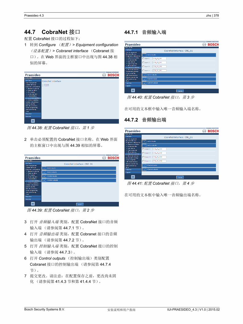
Praesideo 4.3 zhs | 378
Bosch Security Systems B.V. IUI-PRAESIDEO_4.3 | V1.0 | 2015.02安装说明和用户指南
44.7 CobraNet 接口配置 CobraNet 接口的过程如下:
1 转到 Configure (配置) > Equipment configuration
(设备配置) > Cobranet interface (Cobranet 接
口)。在 Web 界面的主框窗口中出现与图 44.38 相
似的屏幕。
2 单击必须配置的 CobraNet 接口名称。在 Web 界面
的主框窗口中出现与图 44.39 相似的屏幕。
3 打开 音频输入端 类别,配置 CobraNet 接口的音频
输入端(请参阅第 44.7.1 节)。
4 打开 音频输出端 类别,配置 Cobranet 接口的音频
输出端(请参阅第 44.7.2 节)。
5 打开 控制输入端 类别,配置 CobraNet 接口的控制
输入端(请参阅 44.7.3)。
6 打开 Control outputs (控制输出端)类别配置
Cobranet 接口的控制输出端(请参阅第 44.7.4
节)。
7 提交更改。请注意:在配置保存之前,更改尚未固
化(请参阅第 41.4.3 节和第 41.4.4 节)。
44.7.1 音频输入端
在可用的文本框中输入唯一音频输入端名称。
44.7.2 音频输出端
在可用的文本框中输入唯一音频输出端名称。
图 44.38: 配置 CobraNet 接口,第 1 步
图 44.39: 配置 CobraNet 接口,第 2 步
图 44.40: 配置 CobraNet 接口,第 3 步
图 44.41: 配置 CobraNet 接口,第 4 步
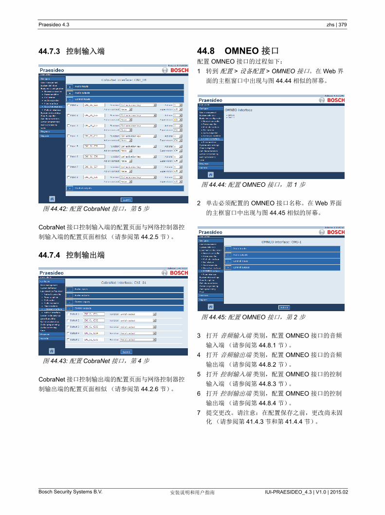
Praesideo 4.3 zhs | 379
Bosch Security Systems B.V. IUI-PRAESIDEO_4.3 | V1.0 | 2015.02安装说明和用户指南
44.7.3 控制输入端
CobraNet 接口控制输入端的配置页面与网络控制器控
制输入端的配置页面相似(请参阅第 44.2.5 节)。
44.7.4 控制输出端
CobraNet 接口控制输出端的配置页面与网络控制器控
制输出端的配置页面相似(请参阅第 44.2.6 节)。
44.8 OMNEO 接口配置 OMNEO 接口的过程如下:
1 转到 配置 > 设备配置 > OMNEO 接口。在 Web 界
面的主框窗口中出现与图 44.44 相似的屏幕。
2 单击必须配置的 OMNEO 接口名称。在 Web 界面
的主框窗口中出现与图 44.45 相似的屏幕。
3 打开 音频输入端 类别,配置 OMNEO 接口的音频
输入端(请参阅第 44.8.1 节)。
4 打开 音频输出端 类别,配置 OMNEO 接口的音频
输出端(请参阅第 44.8.2 节)。
5 打开 控制输入端 类别,配置 OMNEO 接口的控制
输入端(请参阅第 44.8.3 节)。
6 打开 控制输出端 类别,配置 OMNEO 接口的控制
输出端(请参阅第 44.8.4 节)。
7 提交更改。请注意:在配置保存之前,更改尚未固
化(请参阅第 41.4.3 节和第 41.4.4 节)。
图 44.42: 配置 CobraNet 接口,第 5 步
图 44.43: 配置 CobraNet 接口,第 4 步
图 44.44: 配置 OMNEO 接口,第 1 步
图 44.45: 配置 OMNEO 接口,第 2 步

Praesideo 4.3 zhs | 380
Bosch Security Systems B.V. IUI-PRAESIDEO_4.3 | V1.0 | 2015.02安装说明和用户指南
44.8.1 音频输入端
在可用的文本框中输入音频输入端的唯一名称。
44.8.2 音频输出端
在可用的文本框中输入音频输出端的唯一名称。
44.8.3 控制输入端
OMNEO 接口控制输入端的配置页面与网络控制器控制
输出端的配置页面相似(请参阅第 节 44.2.5)。
44.8.4 控制输出端
OMNEO 接口控制输出端的配置页面与网络控制器控制
输出端的配置页面相似(请参阅第 44.2.6 节)。
图 44.46: 配置 OMNEO 接口,第 3 步
图 44.47: 配置 OMNEO 接口,第 4 步
图 44.48: 配置 OMNEO 接口,第 5 步
图 44.49: 配置 OMNEO 接口,第 6 步
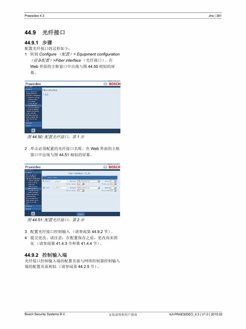
Praesideo 4.3 zhs | 381
Bosch Security Systems B.V. IUI-PRAESIDEO_4.3 | V1.0 | 2015.02安装说明和用户指南
44.9 光纤接口
44.9.1 步骤配置光纤接口的过程如下:
1 转到 Configure (配置) > Equipment configuration
(设备配置) >Fiber interface (光纤接口)。在
Web 界面的主框窗口中出现与图 44.50 相似的屏
幕。
2 单击必须配置的光纤接口名称。在 Web 界面的主框
窗口中出现与图 44.51 相似的屏幕。
3 配置光纤接口控制输入(请参阅第 44.9.2 节)。
4 提交更改。请注意:在配置保存之前,更改尚未固
化(请参阅第 41.4.3 节和第 41.4.4 节)。
44.9.2 控制输入端光纤接口控制输入端的配置页面与网络控制器控制输入
端的配置页面相似(请参阅第 44.2.5 节)。
图 44.50: 配置光纤接口,第 1 步
图 44.51: 配置光纤接口,第 2 步
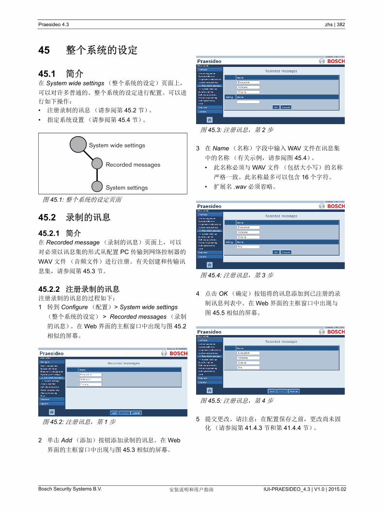
Praesideo 4.3 zhs | 382
Bosch Security Systems B.V. IUI-PRAESIDEO_4.3 | V1.0 | 2015.02安装说明和用户指南
45 整个系统的设定
45.1 简介在 System wide settings (整个系统的设定)页面上,
可以对许多普通的、整个系统的设定进行配置。可以进
行如下操作:
• 注册录制的讯息(请参阅第 45.2 节)。
• 指定系统设置(请参阅第 45.4 节)。
45.2 录制的讯息
45.2.1 简介在 Recorded message (录制的讯息)页面上,可以
对必须以讯息集的形式从配置 PC 传输到网络控制器的
WAV 文件(音频文件)进行注册。有关创建和传输讯
息集,请参阅第 45.3 节。
45.2.2 注册录制的讯息注册录制的讯息的过程如下:
1 转到 Configure (配置) > System wide settings
(整个系统的设定) > Recorded messages (录制
的讯息)。在 Web 界面的主框窗口中出现与图 45.2
相似的屏幕。
2 单击 Add (添加)按钮添加录制的讯息。在 Web
界面的主框窗口中出现与图 45.3 相似的屏幕。
3 在 Name (名称)字段中输入 WAV 文件在讯息集
中的名称(有关示例,请参阅图 45.4)。
• 此名称必须与 WAV 文件(包括大小写)的名称
严格一致。此名称 多可以包含 16 个字符。
• 扩展名 .wav 必须省略。
4 点击 OK (确定)按钮将的讯息添加到已注册的录
制讯息列表中。在 Web 界面的主框窗口中出现与
图 45.5 相似的屏幕。
5 提交更改。请注意:在配置保存之前,更改尚未固
化(请参阅第 41.4.3 节和第 41.4.4 节)。
图 45.1: 整个系统的设定页面
图 45.2: 注册讯息,第 1 步
System wide settings
Recorded messages
System settings
图 45.3: 注册讯息,第 2 步
图 45.4: 注册讯息,第 3 步
图 45.5: 注册讯息,第 4 步

Praesideo 4.3 zhs | 383
Bosch Security Systems B.V. IUI-PRAESIDEO_4.3 | V1.0 | 2015.02安装说明和用户指南
45.2.3 注销录制的讯息注销录制的讯息的过程如下:
1 转到 Configure (配置) > System wide settings
(整个系统的设定) > Recorded messages (录制
的讯息)打开 Recorded messages (录制的讯息)
页面。在 Web 界面的主框窗口中出现与图 45.6 相
似的屏幕。
2 单击必须删除的录制讯息行的任何地方。整行将高
亮显示(请参阅图 45.7)。
3 单击 Delete (删除)按钮。弹出一个要求确认这种
选择的窗口。
4 单击 OK (确定)按钮以确认讯息是否必须从列表
中删除。在 Web 界面的主框窗口中出现与图 45.8
相似的屏幕。
5 提交更改。请注意:在配置保存之前,更改尚未固
化(请参阅第 41.4.3 节和第 41.4.4 节)。
45.3 讯息集
45.3.1 简介讯息集是包含一个或多个单声道、 16 位、 44.1kHz
WAV (音频)文件。讯息集用于将 WAV 文件存储在
网络控制器内的 CF 卡中。可以使用 File Transfer (文
件传输)应用程序在 PC 上创建讯息集(请参阅
第 45.3.2 节),并将它们传输到网络控制器(请参阅
第 45.3.4 节)。
存储的消息集 多可容纳 1024 条讯息。该系统 多可
同时播放讯息集(呼叫的一部分)中的四条讯息。所
有此类呼叫均可以使用相同讯息(如果需要),预定讯
息或非预定讯息。
45.3.2 创建消息集创建讯息集的过程如下:
1 转到开始 > (所有)程序 > Bosch > Praesideo >
FT Application 以启动 Praesideo File Transfer 应用
程序。
2 在 File Transfer (文件传输)应用程序中,单击
Message Sets (讯息集)按钮。会出现类似
图 45.9 的界面。
3 单击 New (新建)单选按钮。
图 45.6: 注销讯息,第 1 步
图 45.7: 注销讯息,第 2 步
图 45.8: 注册讯息,第 4 步
图 45.9: 创建讯息集

Praesideo 4.3 zhs | 384
Bosch Security Systems B.V. IUI-PRAESIDEO_4.3 | V1.0 | 2015.02安装说明和用户指南
4 浏览必须添加到讯息集的 WAV 文件,并对其进行选
择。
5 单击 > 按钮将 WAV 文件添加到讯息集。
6 重复第 4 步和第 5 步将附加的 WAV 文件添加到讯
息集。可以使用 Up (向上)和 Down (向下)按
钮更改讯息在集中的次序。
7 在 Message Set (讯息集)字段中输入讯息集的名
称。
8 单击 Save Message Set as (讯息集另存为)按钮
将讯息集保存在配置 PC 上。讯息集的创建已完成。
有关将讯息集传输到网络控制器的详细说明,请参
阅第 45.3.4 节。
45.3.3 高效警报音在随附 DVD 中 \Tools\Audio Tools and Sounds\High
efficiency alarm tones 文件夹下有四种不同的高效警报
音。由于音调过于复杂, Praesideo 系统无法实时产生
开始音或结束音,这些警报音设计成特殊的多正弦 wav
文件并应作为讯息在呼叫宏中使用。
警报音的声音很大并且有 -6 dBFS 的限制 RMS 值,因
此可以连续播放而不会使放大器过热。另外,与普通正
弦警报音相比,放大器的能耗减少 50% (Praesideo
中的换算值为 -3 dBFS)。不过,尽管这些高效警报音
的声音比普通正弦波声音大,但是 dBSPL 测量不会显
示这一点。这是因为普通 dBSPL 测量不考虑适用的心
理声学因素。对于背景噪音大,普通正弦波很容易被屏
蔽的环境,高效警报音特别有用。
45.3.4 传输讯息集传输讯息的过程如下:
1 在 File Transfer (文件传输)应用程序中先登录,
然后单击 File Transfer (文件传输)按钮。会出现
类似图 45.10 的界面。
2 单击 Message Set (讯息集)单选按钮。
3 在 Local PC (本地 PC 框)文本框中选择讯息集。
此文件将高亮显示,并且 > 按钮可用。
4 单击 > 按钮将文件从 PC 传输到网络控制器。弹出
一个显示文件传输过程讯息的屏幕。
5 传输完成时,在 Network Controller (网络控制器)
文本框中可以看到传输的文件。
注
使用 Message set mode (讯息集模式)单选
按钮,也可以将 File Transfer 应用程序讯息集
屏幕设为 View (查看)模式(查看现有的讯
息集)或 Edit (编辑)模式(编辑现有的讯
息集)。
图 45.10: 传输讯息集
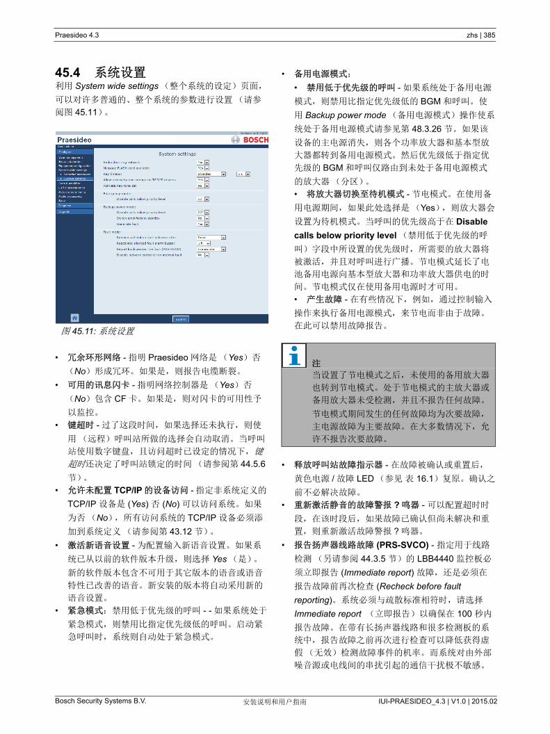
Praesideo 4.3 zhs | 385
Bosch Security Systems B.V. IUI-PRAESIDEO_4.3 | V1.0 | 2015.02安装说明和用户指南
45.4 系统设置利用 System wide settings (整个系统的设定)页面,
可以对许多普通的、整个系统的参数进行设置(请参
阅图 45.11)。
• 冗余环形网络 - 指明 Praesideo 网络是(Yes)否
(No)形成冗环。如果是,则报告电缆断裂。
• 可用的讯息闪卡 - 指明网络控制器是(Yes)否
(No)包含 CF 卡。如果是,则对闪卡的可用性予
以监控。
• 键超时 - 过了这段时间,如果选择还未执行,则使
用(远程)呼叫站所做的选择会自动取消。当呼叫
站使用数字键盘,且访问超时已设定的情况下,键
超时还决定了呼叫站锁定的时间(请参阅第 44.5.6
节)。
• 允许未配置 TCP/IP 的设备访问 - 指定非系统定义的
TCP/IP 设备是 (Yes) 否 (No) 可以访问系统。如果
为否(No),所有访问系统的 TCP/IP 设备必须添
加到系统定义(请参阅第 43.12 节)。
• 激活新语音设置 - 为配置输入新语音设置。如果系
统已从以前的软件版本升级,则选择 Yes (是)。
新的软件版本包含不可用于其它版本的语音或语音
特性已改善的语音。新安装的版本将自动采用新的
语音设置。
• 紧急模式:禁用低于优先级的呼叫 - - 如果系统处于
紧急模式,则禁用比指定优先级低的呼叫。启动紧
急呼叫时,系统则自动处于紧急模式。
• 备用电源模式:
• 禁用低于优先级的呼叫 - 如果系统处于备用电源
模式,则禁用比指定优先级低的 BGM 和呼叫。使
用 Backup power mode (备用电源模式)操作使系
统处于备用电源模式请参见第 48.3.26 节。如果该
设备的主电源消失,则各个功率放大器和基本型放
大器都转到备用电源模式。然后优先级低于指定优
先级的 BGM 和呼叫仅路由到未处于备用电源模式
的放大器(分区)。
• 将放大器切换至待机模式 - 节电模式。在使用备
用电源期间,如果此处选择是(Yes),则放大器会
设置为待机模式。当呼叫的优先级高于在 Disable
calls below priority level (禁用低于优先级的呼
叫)字段中所设置的优先级时,所需要的放大器将
被激活,并且对呼叫进行广播。节电模式延长了电
池备用电源向基本型放大器和功率放大器供电的时
间。节电模式仅在使用备用电源时才可用。
• 产生故障 - 在有些情况下,例如,通过控制输入
操作来执行备用电源模式,来节电而非由于故障。
在此可以禁用故障报告。
• 释放呼叫站故障指示器 - 在故障被确认或重置后,
黄色电源 / 故障 LED (参见 表 16.1)复原。确认之
前不必解决故障。
• 重新激活静音的故障警报 ? 鸣器 - 可以配置超时时
段,在该时段后,如果故障已确认但尚未解决和重
置,则重新激活故障警报 ? 鸣器。
• 报告扬声器线路故障 (PRS-SVCO) - 指定用于线路
检测(另请参阅 44.3.5 节)的 LBB4440 监控板必
须立即报告 (Immediate report) 故障,还是必须在
报告故障前再次检查 (Recheck before fault
reporting)。系统必须与疏散标准相符时,请选择
Immediate report (立即报告)以确保在 100 秒内
报告故障。在带有长扬声器线路和很多检测板的系
统中,报告故障之前再次进行检查可以降低获得虚
假(无效)检测故障事件的机率。而系统对由外部
噪音源或电线间的串扰引起的通信干扰极不敏感。
图 45.11: 系统设置
注
当设置了节电模式之后,未使用的备用放大器
也转到节电模式。处于节电模式的主放大器或
备用放大器未受检测,并且不报告任何故障。
节电模式期间发生的任何故障均为次要故障,
主电源故障为主要故障。在大多数情况下,允
许不报告次要故障。
Praesideo 4.3 zhs | 386
Bosch Security Systems B.V. IUI-PRAESIDEO_4.3 | V1.0 | 2015.02安装说明和用户指南
• 发生内部故障时禁用网络控制器 - 该功能用于带有
冗余网络控制器的系统。如果内部故障发生在主网
络控制器上(例如,闪存卡错误),主网络控制器
将被禁用,由备份网络控制器接管被禁用网络控制
器的任务。如果系统仅带有一个网络控制器,选择 “
否 ”。
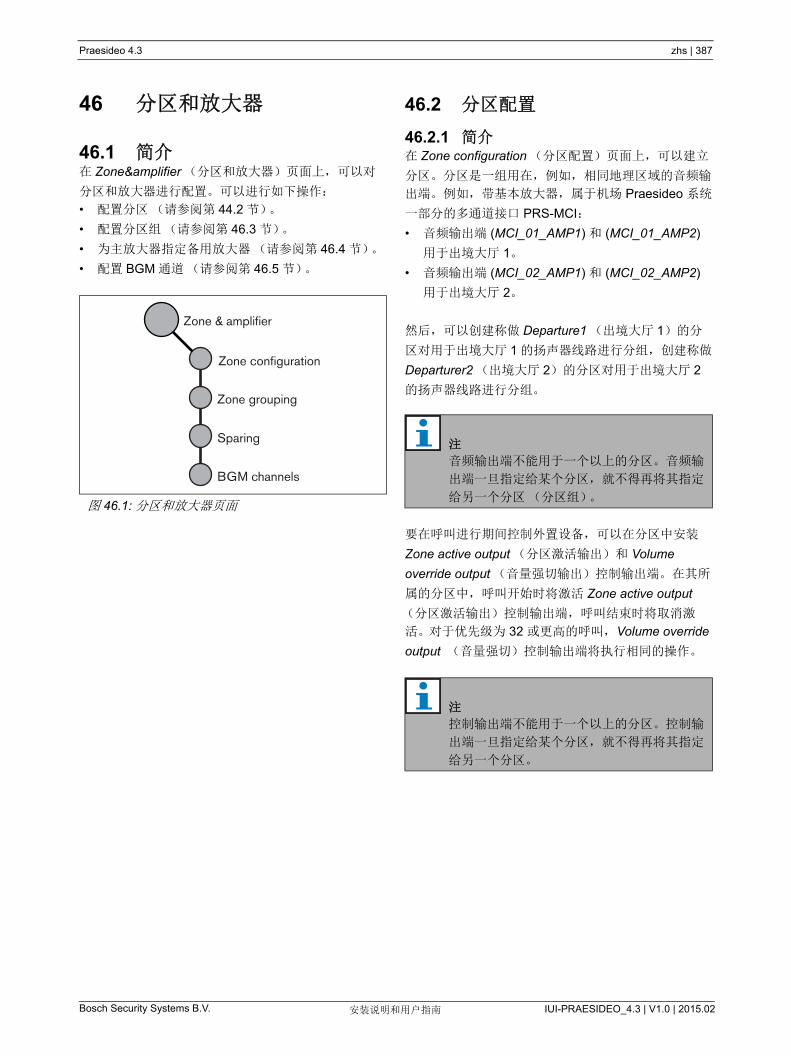
Praesideo 4.3 zhs | 387
Bosch Security Systems B.V. IUI-PRAESIDEO_4.3 | V1.0 | 2015.02安装说明和用户指南
46 分区和放大器
46.1 简介在 Zone&lifier (分区和放大器)页面上,可以对
分区和放大器进行配置。可以进行如下操作:
• 配置分区(请参阅第 44.2 节)。
• 配置分区组(请参阅第 46.3 节)。
• 为主放大器指定备用放大器(请参阅第 46.4 节)。
• 配置 BGM 通道(请参阅第 46.5 节)。
46.2 分区配置
46.2.1 简介在 Zone configuration (分区配置)页面上,可以建立
分区。分区是一组用在,例如,相同地理区域的音频输
出端。例如,带基本放大器,属于机场 Praesideo 系统
一部分的多通道接口 PRS-MCI:
• 音频输出端 (MCI_01_AMP1) 和 (MCI_01_AMP2)
用于出境大厅 1。
• 音频输出端 (MCI_02_AMP1) 和 (MCI_02_AMP2)
用于出境大厅 2。
然后,可以创建称做 Departure1 (出境大厅 1)的分
区对用于出境大厅 1 的扬声器线路进行分组,创建称做
Departurer2 (出境大厅 2)的分区对用于出境大厅 2
的扬声器线路进行分组。
要在呼叫进行期间控制外置设备,可以在分区中安装
Zone active output (分区激活输出)和 Volume
override output (音量强切输出)控制输出端。在其所
属的分区中,呼叫开始时将激活 Zone active output
(分区激活输出)控制输出端,呼叫结束时将取消激
活。对于优先级为 32 或更高的呼叫,Volume override
output (音量强切)控制输出端将执行相同的操作。
图 46.1: 分区和放大器页面
Zone & amplifier
Zone configuration
Zone grouping
Sparing
BGM channels
注
音频输出端不能用于一个以上的分区。音频输
出端一旦指定给某个分区,就不得再将其指定
给另一个分区(分区组)。
注
控制输出端不能用于一个以上的分区。控制输
出端一旦指定给某个分区,就不得再将其指定
给另一个分区。

Praesideo 4.3 zhs | 388
Bosch Security Systems B.V. IUI-PRAESIDEO_4.3 | V1.0 | 2015.02安装说明和用户指南
46.2.2 简介Zone configuration (分区配置)页(请参阅图 46.2)
包含以下项:
• 名称 - 显示分区名称
• 可用的输出 - 显示可用的音频和控制输出端。使用
下拉列表选择显示的输出类型。
• 指定的输出 - 显示指定给在(1)中显示的分区的输
出。
• 添加 / 删除按钮 - 使用 > 和 < 按钮,可将选定的输
出添加到 Assigned outputs (指定的输出)或从中
删除。
• 音量设置 - 打开 Volume settings (音量设置)类别
配置分区的音量设置(请参阅第 46.2.4 节)。
• AVC 设置 - 打开 AVC settings (AVC 设置)类别配
置分区的 AVC 设置(请参阅第 50 章)。
• 添加 - 利用此按钮,可以将新的分区添加到系统配
置。
• 删除 - 利用此按钮,可以从系统中删除现有的分区
组。
• 提交 - 利用此按钮将更改提交给网络控制器。
• 重命名 - 使用该按钮可重命名现有的分区。配置中
使用该分区的所有地方,此名称都将被自动替换。
46.2.3 创建分区创建新分区的过程如下:
1 转到 Configure (配置) > Zone&lifier (分区和
放大器) > Zone configuration (分区配置)。在
Web 界面的主框窗口中出现与图 46.3 相似的屏幕。
2 单击 Add (添加)按钮并在页面底部的文本框中输
入新分区的名称。例如, Departure2 (出境大厅
2)(请参阅图 46.4)。此名称 多可以包含 16 个
字符。
3 单击 OK (确定)按钮。
4 从左侧的文本框选择必须添加到分区的输出。例
如, MCI_02_AMP1。
图 46.2: 分区配置,概述
注
一个分区可以包含音频输出端及控制输出端。
即使指定给分区的单个控制输出为有效配置,
分区也不可能为空。
括号里的音频输出端的名称以及控制输出端的
名称表示这些输出端还未在配置中启动。禁用
的输出端可以被分配但无法工作。
注
只指定一个控制输出端的分区允许在分区中使
用呼叫激活外部警报(例如报警器)。
图 46.3: 添加分区,第 1 步
图 46.4: 添加分区,第 2 步
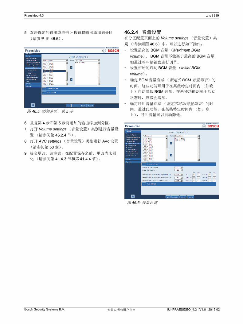
Praesideo 4.3 zhs | 389
Bosch Security Systems B.V. IUI-PRAESIDEO_4.3 | V1.0 | 2015.02安装说明和用户指南
5 双击选定的输出或单击 > 按钮将输出添加到分区
(请参见 图 46.5)。
6 重复第 4 步和第 5 步将附加的输出添加到分区。
7 打开 Volume settings (音量设置)类别进行音量设
置(请参阅第 46.2.4 节)。
8 打开 AVC settings (音量设置)类别进行 AVc 设置
(请参阅第 50 章)。
9 提交更改。请注意:在配置保存之前,更改尚未固
化(请参阅第 41.4.3 节和第 41.4.4 节)。
46.2.4 音量设置在分区配置页面上的 Volume settings (音量设置)类
别(请参阅图 46.6)中,可以进行如下操作:
• 设置 高的 BGM 音量(Maximum BGM
volume)。 BGM 音量不能高于 高的 BGM 音量,
如通过呼叫站键盘进行调节。
• 设置初始的启动 BGM 音量(Initial BGM
volume)。
• 确定 BGM 音量衰减(预定的 BGM 音量调节)的
时间。这些功能可用于在某些特定时间内(如晚
上)自动降低 BGM 音量。在两种功能均处于活动
状态时,衰减会增加。
• 确定呼叫音量衰减(预定的呼叫音量调节)的时
间。通过此功能,在某些特定时间内(如,晚
上),呼叫音量可以自动降低。图 46.5: 添加分区,第 5 步
图 46.6: 音量设置

Praesideo 4.3 zhs | 390
Bosch Security Systems B.V. IUI-PRAESIDEO_4.3 | V1.0 | 2015.02安装说明和用户指南
46.2.5 删除分区删除分区的过程如下:
1 转到 Configure (配置) > (配置)(分区和放大
器) > Zone configuration (分区配置)。会出现类
似图 46.7 的界面。
2 选择必须从 Name (名称)下拉列表中删除的分
区。例如, Departure 2 (出境大厅 2)。
3 单击 Delete (删除)按钮删除分区。弹出一个要求
确认这种选择的窗口。
4 单击 OK (确定)按钮确认必须删除的分区。已删
除的分区在 Name (名称)下拉列表中不再可用。
该分区也将从配置中使用它的所有场合删除。
5 提交更改。请注意:在配置保存之前,更改尚未固
化(请参阅第 41.4.3 节和第 41.4.4 节)。
46.2.6 重命名分区重命名分区的过程如下:
1 转到 Configure (配置) > (配置)(分区和放大
器) > Zone configuration (分区配置)。
2 从 Name (名称)下拉列表中选择要重命名的分
区。
3 单击 Rename (重命名)按钮以重命名分区。会出
现类似图 46.8 的界面。
4 在 edit (编辑)字段中更改名称(名称 多由 16
个字符组成)并单击 OK (确定)按钮。配置中所
有使用该分区的场合,其名称都将被更改。
5 提交更改。请注意:在配置保存之前,更改尚未固
化(请参阅第 41.4.3 节和第 41.4.4 节)。
图 46.7: 删除分区,第 1 步图 46.8: 重命名分区,第 3 步

Praesideo 4.3 zhs | 391
Bosch Security Systems B.V. IUI-PRAESIDEO_4.3 | V1.0 | 2015.02安装说明和用户指南
46.3 分区分组
46.3.1 简介在 Zone grouping (分区分组)页面上,可以建立分区
组。分区组是一组用在,例如,相同地理区域的分区。
例如,有四个分区的小型机场:出境大厅 1、出境大厅
2、到达大厅 1 和 到达大厅 2。 Departure 1 (出境大
厅 1)和 Departure 2 (出境大厅 2)分区配有分别进
入出境大厅 1 和出境大厅 2 的扬声器线路。 Arrival 1
(入境大厅 1)和 Arrival 2 (入境大厅 2)分区配有分
别进入入境大厅 1 和入境大厅 2 的扬声器线路。
然后,可以创建称做 Departure Halls (出境大厅)的
分区组对属于出境大厅的分区进行分组,创建称做
Arrival Halls (入境大厅)的分区组对属于入境大厅的
分区进行分组。
46.3.2 简介Zone grouping (分区分组)页(请参阅图 46.9)包
含以下项目:
• 名称 - 显示分区组名称。
• 可用分区 - 显示可用的音频分区。可以在 Zone
Configuration (分区配置)页面上创建分区(请
参阅第 46.2 节)。
• 指定的分区 - 显示指定给(1)中显示的分区组的分
区。
• 添加 / 删除按钮 - 使用 > 和 < 按钮,可将选定的分
区添加到 Assigned zones (指定的分区)或从中删
除。
• 添加 - 利用此按钮,可以将新的分区组添加到系统。
• 删除 - 利用此按钮,可以从系统中删除现有的分区
组。
• 提交 - 利用此按钮将更改提交给网络控制器。
• 重命名 - 使用该按钮可重命名现有的分区组。配置
中使用该分区组的所有地方,此名称都将被自动替
换。
46.3.3 添加分区组创建分区组的过程与创建分区的过程(请参阅
第 46.2.3 节)相似。
46.3.4 删除分区组删除分区组的过程与删除分区的过程(请参阅
第 46.2.5 节)相似。
46.3.5 重命名分区组重命名分区组的过程与重命名分区的过程相似(请参
阅 46.2.6 节)。
46.4 备用
46.4.1 简介备用功能可用于使用备用放大器(若可用)来替换有
故障的主放大器。即使主功率放大器是多通道设备,并
且只有一个通道发生故障,备用放大器也会替代整个主
放大器。 备用放大器可以连接到一个以上的主放大器
上。然而,备用放大器只替换第一个有故障的主放大
器。
在 Sparing power amplifier (备用功率放大器)页面
上,可以将主放大器指定给备用放大器。例如,在小型
机场配置 LBB4424/10 功率放大器(4x125W)。其中
两个功率放大器为主放大器 (PAM_01 和 PAM_03),而
其它功率放大器为备用放大器 (PAM_02 和 PAM_04)。
然后,可以将 PAM_04 配置为 PAM_03 的备用放大
器。
图 46.9: 分区分组,概述
注
有关连接备用放大器的详细信息,请参阅第
9.3.5 节。

Praesideo 4.3 zhs | 392
Bosch Security Systems B.V. IUI-PRAESIDEO_4.3 | V1.0 | 2015.02安装说明和用户指南
46.4.2 简介Sparing power amplifier (备用功率放大器)页面(请
参阅图 46.10)包含以下内容:
• 名称 - 必须为其指定主放大器的备用放大器的名称。
• 主放大器 - 可以指定给备用放大器的主放大器列表。
• 指定的放大器 - 指定给所选备用放大器的主放大器
的列表。
• 添加 / 删除按钮 - 使用 > 和 < 按钮,可将选定的主
放大器添加到 Assigned amplifiers (指定的放大
器)或从中删除。
• 提交 - 利用此按钮将更改提交给网络控制器。
46.4.3 步骤将放大器指定给备用放大器的过程如下:
1 转到 Configure (配置) > Zone&lifier (分区和
放大器) > Sparing (备用)。在 Web 界面的主框
窗口中出现与图 46.11 相似的屏幕。
2 从 Power Amplifier (功率放大器)下拉列表中选择
必须为其指定主放大器的备用放大器。例如,
PAM_04 (见 图 46.12)。
3 从左侧文本框中选择必须指定给备用放大器的主放
大器(请参阅图 46.13)。
4 双击选择的主放大器或单击 > 按钮将主放大器指定
给备用放大器。在 Web 界面的主框窗口中出现与
图 46.14 相似的屏幕。
5 提交更改。请注意:在配置保存之前,更改尚未固
化(请参阅第 41.4.3 节和第 41.4.4 节)。
图 46.10: 备用,概述
图 46.11: 备用,第 1 步
图 46.12: 备用,第 2 步
图 46.13: 备用,第 3 步
图 46.14: 备用,第 4 步
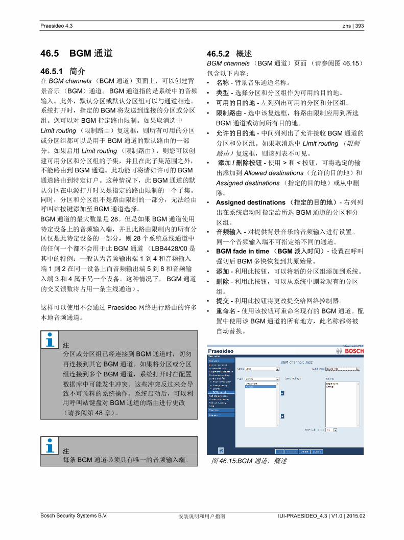
Praesideo 4.3 zhs | 393
Bosch Security Systems B.V. IUI-PRAESIDEO_4.3 | V1.0 | 2015.02安装说明和用户指南
46.5 BGM 通道
46.5.1 简介在 BGM channels (BGM 通道)页面上,可以创建背
景音乐(BGM)通道。BGM 通道指的是系统中的音频
输入。此外,默认分区或默认分区组可以与通道相连。
系统打开时,指定的 BGM 将发送到连接的分区或分区
组。您可以对 BGM 指定路由限制。如果取消选中
Limit routing (限制路由)复选框,则所有可用的分区
或分区组都可以是用于 BGM 通道的默认路由的一部
分。如果启用 Limit routing (限制路由),则您可以创
建可用分区和分区组的子集,并且在此子集范围之外,
不能路由到 BGM 通道。此功能可将诸如许可的 BGM
通道路由到特定订户。这种情况下,此 BGM 通道的默
认分区在电源打开时又是指定的路由限制的一个子集。
同时,分区和分区组不是路由限制的一部分,无法经由
呼叫站按键添加至 BGM 通道选择。
BGM 通道的 大数量是 28。但是如果 BGM 通道使用
特定设备上的音频输入端,并且此路由限制内的所有分
区仅是此特定设备的一部分,则 28 个系统总线通道中
的任何一个都不会用于此 BGM 通道(LBB4428/00 是
其中的特例:一般认为音频输出端 1 到 4 和音频输入
端 1 到 2 在同一设备上而音频输出端 5 到 8 和音频输
入端 3 和 4 属于另一个设备。这种情况下, BGM 通道
的交叉馈数将占用一条主线通道)。
这样可以使用不会通过 Praesideo 网络进行路由的许多
本地音频通道。
46.5.2 概述BGM channels (BGM 通道)页面(请参阅图 46.15)
包含以下内容:
• 名称 - 背景音乐通道名称。
• 类型 - 选择分区和分区组作为可用的目的地。
• 可用的目的地 - 左列列出可用的分区和分区组。
• 限制路由 - 选中该复选框,将路由限制应用到所选
BGM 通道或访问所有目的地。
• 允许的目的地 - 中间列列出了允许接收 BGM 通道的
分区和分区组。如果取消选中 Limit routing (限制
路由)复选框,则该列表不可见。
• 添加 / 删除按钮 - 使用 > 和 < 按钮,可将选定的输
出添加到 Allowed destinations(允许的目的地)和
Assigned destinations (指定的目的地)或从中删
除。
• Assigned destinations (指定的目的地) - 右列列
出在系统启动时指定给所选 BGM 通道的分区和分
区组。
• 音频输入 - 对提供背景音乐的音频输入进行设置。
同一个音频输入端不可指定给不同的通道。
• BGM fade in time (BGM 淡入时间) - 设置在呼叫
强切后 BGM 多快恢复到其原始量。
• 添加 - 利用此按钮,可以将新的分区组添加到系统。
• 删除 - 利用此按钮,可以从系统中删除现有的分区
组。
• 提交 - 利用此按钮将更改提交给网络控制器。
• 重命名 - 使用该按钮可重命名现有的 BGM 通道。配
置中使用该 BGM 通道的所有地方,此名称都将被
自动替换。
注
分区或分区组已经连接到 BGM 通道时,切勿
再连接到其它 BGM 通道。如果将分区或分区
组连接到多个 BGM 通道,系统打开时在配置
数据库中可能发生冲突。这些冲突反过来会导
致不可预料的系统操作。系统启动后,可以利
用呼叫站键盘对 BGM 通道的路由进行更改
(请参阅第 48 章)。
注
每条 BGM 通道必须具有唯一的音频输入端。 图 46.15:BGM 通道,概述

Praesideo 4.3 zhs | 394
Bosch Security Systems B.V. IUI-PRAESIDEO_4.3 | V1.0 | 2015.02安装说明和用户指南
46.5.3 添加 BGM 通道创建 BGM 通道的过程与创建分区的过程(请参阅
第 46.2.3 节)相似。
46.5.4 删除 BGM 通道删除 BGM 通道的过程与删除分区的过程相似(请参阅
第 46.2.5 节)。
46.5.5 重命名 BGM 通道重命名 BGM 通道的过程与重命名分区的过程相似(请
参阅 46.2.6 节)。

Praesideo 4.3 zhs | 395
Bosch Security Systems B.V. IUI-PRAESIDEO_4.3 | V1.0 | 2015.02安装说明和用户指南
47 呼叫特性
47.1 简介使用 Call characteristics (呼叫特性)页,可以定义呼
叫宏(请参阅第 44.2 节)。
47.2 呼叫宏
47.2.1 简介在 Call macro (呼叫宏)页面上,可以定义呼叫宏。
呼叫宏可用于发送呼叫。
47.2.2 创建呼叫宏创建新呼叫宏的过程如下:
1 转到 Configure (配置) > Call characteristics (呼
叫特性) > Call macro (呼叫宏)。在 Web 界面的
主框窗口中出现与图 47.2 相似的屏幕。
2 单击 Add (添加)按钮添加新的呼叫宏。在 Web
界面的主框窗口中出现与图 47.3 相似的屏幕。
3 在 Name (名称)字段中输入新呼叫宏的名称(有
关示例请参阅图 47.4)。此名称 多可以包含 16 个
字符。
4 单击 OK (确定)按钮将呼叫宏添加到系统中呼叫
宏列表中。在 Web 界面的主框窗口中出现与
图 47.5 相似的屏幕。
图 47.1: 呼叫特性页面
图 47.2: 添加呼叫宏,第 1 步
Call characteristics
Call macro
图 47.3: 添加呼叫宏,第 2 步
图 47.4: 添加呼叫宏,第 3 步
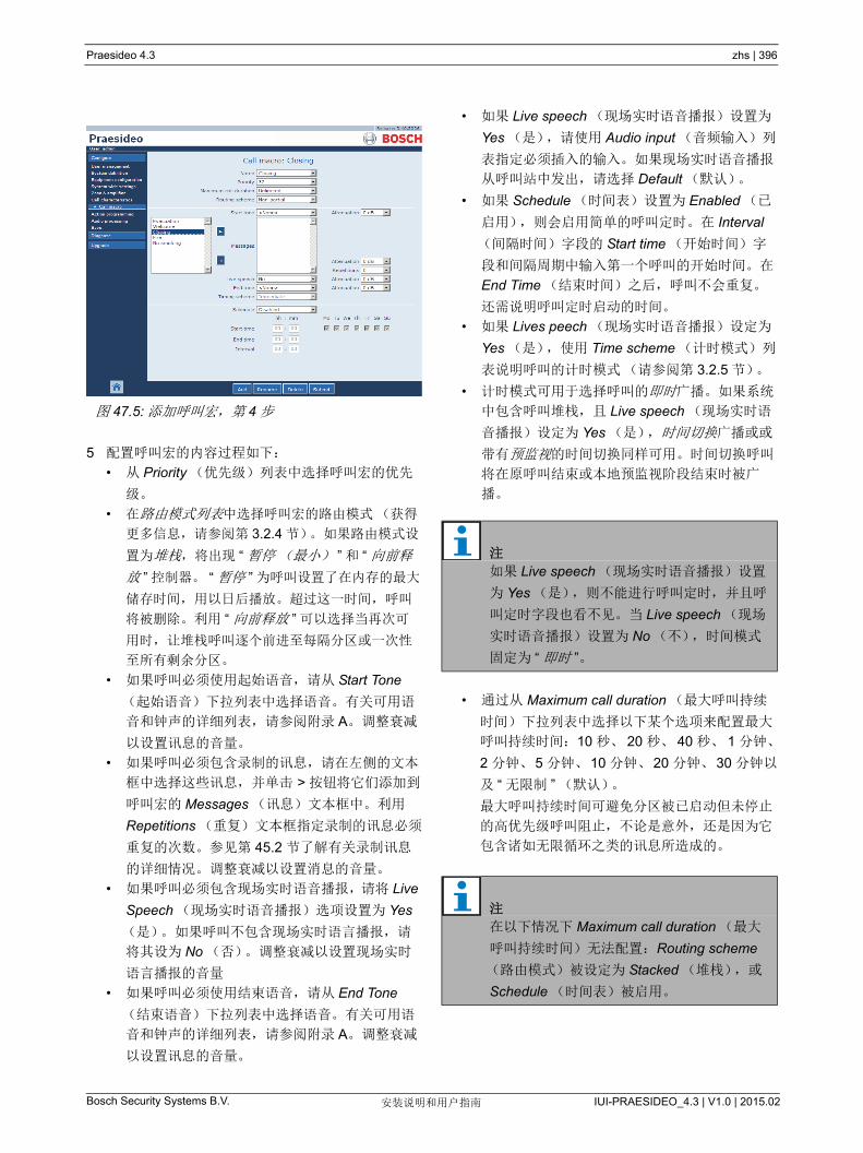
Praesideo 4.3 zhs | 396
Bosch Security Systems B.V. IUI-PRAESIDEO_4.3 | V1.0 | 2015.02安装说明和用户指南
5 配置呼叫宏的内容过程如下:
• 从 Priority (优先级)列表中选择呼叫宏的优先
级。
• 在路由模式列表中选择呼叫宏的路由模式 (获得
更多信息,请参阅第 3.2.4 节)。如果路由模式设
置为堆栈,将出现 “ 暂停( 小) ” 和 “ 向前释
放 ” 控制器。 “ 暂停 ” 为呼叫设置了在内存的 大
储存时间,用以日后播放。超过这一时间,呼叫
将被删除。利用 “ 向前释放 ” 可以选择当再次可
用时,让堆栈呼叫逐个前进至每隔分区或一次性
至所有剩余分区。
• 如果呼叫必须使用起始语音,请从 Start Tone
(起始语音)下拉列表中选择语音。有关可用语
音和钟声的详细列表,请参阅附录 A。调整衰减
以设置讯息的音量。
• 如果呼叫必须包含录制的讯息,请在左侧的文本
框中选择这些讯息,并单击 > 按钮将它们添加到
呼叫宏的 Messages (讯息)文本框中。利用
Repetitions (重复)文本框指定录制的讯息必须
重复的次数。参见第 45.2 节了解有关录制讯息
的详细情况。调整衰减以设置消息的音量。
• 如果呼叫必须包含现场实时语音播报,请将 Live
Speech (现场实时语音播报)选项设置为 Yes
(是)。如果呼叫不包含现场实时语言播报,请
将其设为 No (否)。调整衰减以设置现场实时
语言播报的音量
• 如果呼叫必须使用结束语音,请从 End Tone
(结束语音)下拉列表中选择语音。有关可用语
音和钟声的详细列表,请参阅附录 A。调整衰减
以设置讯息的音量。
• 如果 Live speech (现场实时语音播报)设置为
Yes (是),请使用 Audio input (音频输入)列
表指定必须插入的输入。如果现场实时语音播报
从呼叫站中发出,请选择 Default (默认)。
• 如果 Schedule (时间表)设置为 Enabled (已
启用),则会启用简单的呼叫定时。在 Interval
(间隔时间)字段的 Start time (开始时间)字
段和间隔周期中输入第一个呼叫的开始时间。在
End Time (结束时间)之后,呼叫不会重复。
还需说明呼叫定时启动的时间。
• 如果 Lives peech (现场实时语音播报)设定为
Yes (是),使用 Time scheme (计时模式)列
表说明呼叫的计时模式(请参阅第 3.2.5 节)。
• 计时模式可用于选择呼叫的即时广播。如果系统
中包含呼叫堆栈,且 Live speech (现场实时语
音播报)设定为 Yes (是),时间切换广播或或
带有预监视的时间切换同样可用。时间切换呼叫
将在原呼叫结束或本地预监视阶段结束时被广
播。
• 通过从 Maximum call duration ( 大呼叫持续
时间)下拉列表中选择以下某个选项来配置 大
呼叫持续时间:10 秒、 20 秒、 40 秒、 1 分钟、
2 分钟、5 分钟、10 分钟、20 分钟、30 分钟以
及 “ 无限制 ” (默认)。
大呼叫持续时间可避免分区被已启动但未停止
的高优先级呼叫阻止,不论是意外,还是因为它
包含诸如无限循环之类的讯息所造成的。
图 47.5: 添加呼叫宏,第 4 步
注
如果 Live speech (现场实时语音播报)设置
为 Yes (是),则不能进行呼叫定时,并且呼
叫定时字段也看不见。当 Live speech (现场
实时语音播报)设置为 No (不),时间模式
固定为 “ 即时 ”。
注
在以下情况下 Maximum call duration ( 大
呼叫持续时间)无法配置:Routing scheme
(路由模式)被设定为 Stacked (堆栈),或
Schedule (时间表)被启用。

Praesideo 4.3 zhs | 397
Bosch Security Systems B.V. IUI-PRAESIDEO_4.3 | V1.0 | 2015.02安装说明和用户指南
6 提交更改。请注意:在配置保存之前,更改尚未固
化(请参阅第 41.4.3 节和第 41.4.4 节)。
47.2.3 删除呼叫宏删除呼叫宏的过程如下:
1 转到 Configure (配置) > Call characteristics (呼
叫特性) > Call macro (呼叫宏)打开 Call macro
(呼叫宏)页面。
2 选择必须从 Name (名称)下拉列表中删除的呼叫
宏。
3 单击 Delete (删除)按钮以删除呼叫宏。弹出一个
要求确认这种选择的窗口。
4 单击 OK (确定)按钮确认必须删除的呼叫宏。
Name (名称)下拉列表中删除的呼叫宏不再可用。
5 提交更改。请注意:在配置保存之前,更改尚未固
化(请参阅第 41.4.3 节和第 41.4.4 节)。

Praesideo 4.3 zhs | 398
Bosch Security Systems B.V. IUI-PRAESIDEO_4.3 | V1.0 | 2015.02安装说明和用户指南
48 动作编程
48.1 简介在 Action programming (动作编程)页面上,可以对
键盘上的键和控制输入端进行配置。配置键或控制输入
端分为两步:
1 指定行为(请参阅第 48.2 节)。
2 指定动作(请参阅第 48.3 节)。
48.2 行为
48.2.1 简介行为指明控制输入端如何处理进入信号,键被按下时如
何反应。下列行为是可用的:
• 接通或断开的瞬态(请参阅第 48.2.2 节)。
• 接通或断开的单激发态(请参阅第 48.2.3 节)。
• 接通或断开的双态(请参阅第 48.2.4 节)。
48.2.2 瞬态行为48.2.2.1 瞬态
如果行为是瞬时的,在外置触点关闭期间,与控制输入
端或按键相连的动作处于活动状态。
48.2.2.2 立即中止的瞬态
如果是立即中止的瞬态行为,在外置触点关闭期间,与
控制输入端或按键相连的动作处于活动状态。有关示
例,请参见图 48.2。当外置触点打开时,动作立刻中
止。
48.2.2.3 阶段完成,再次按下中止的瞬态
如果是阶段完成,再次按下中止的瞬态行为,在外置触
点关闭期间,与控制输入端与按键相连的动作处于活动
状态。有关示例,请参见图 48.3。当外置触点打开时,
在当前阶段完成以后,动作停止。
当动作仍在运动时,若外置触点再次关闭,动作立刻中
止。相关实例,请参阅图 48.4。图 48.1: 瞬态行为
make
break
action
图 48.2: 立刻中止的瞬态
图 48.3: 阶段完成,再次按下中止的瞬态(1)
图 48.4: 阶段完成,再次按下中止的瞬态(2)
make
break
action
start/stopstart call abort
make
break
action
start/stopstart call stop
make
break
action
start/stopstart call stop abort

Praesideo 4.3 zhs | 399
Bosch Security Systems B.V. IUI-PRAESIDEO_4.3 | V1.0 | 2015.02安装说明和用户指南
48.2.3 单激发态行为48.2.3.1 单激发
如果是单激发态行为,当外置触点关闭时,动作启动。
通过立刻中止的单激发(请参阅第 48.2.3.2 节)或阶
段完成的单激发(请参阅第 48.2.3.3 节),动作停止。
通常,单激发行为用于触发事件(例如,取消某个选
择)和持续时间重要的事件(如,呼叫)。
48.2.3.2 立即中止的单激发
如果是立即中止的单激发行为,当外置接触点关闭时,
动作停止。该类型的行为用于停止由单激发引发的动作
(请参阅第 48.2.3.1 节)。
48.2.3.3 阶段完成的单激发
如果是阶段完成的单激发行为,当外置接触点关闭时,
动作停止。该类型的行为用于停止由单激发引发的动作
(请参阅第 48.2.3.1 节)。
48.2.4 双态48.2.4.1 双态
如果是双态行为,当外部触点关闭时,与控制输入端或
按键关联的动作将启动;当外部触点再次关闭时,动作
停止(请参见图 48.6)。
48.2.4.2 立刻中止的双态
如果是立即中止的双态行为,在外置触点关闭期间,与
控制输入端或按键相连的动作启动。 当外置触点再次关
闭,动作立刻中止。相关实例,请参阅图 48.7。
48.2.4.3 阶段完成,再次按下中止的双态
如果是阶段完成,再次按下中止的双态行为,与控制输
入端或按键相连的动作启动。相关实例,请参阅
图 48.8。当外部触点再次关闭,当前阶段完成后,动
作停止。
当动作仍在运行时,若外置触点第三次关闭,动作立刻
中止。相关实例,请参阅图 48.9。
图 48.5: 单激发
图 48.6: 双态
make
break
action
start/stopstart call
make
break
action
图 48.7: 立刻中止的双态
图 48.8: 阶段完成,再次按下中止的双态(1)
图 48.9: 阶段完成,再次按下中止的双态(2)
make
break
action
start/stopstart call abort
make
break
action
start/stopstart call stop
make
break
action
start/stopstart call stop abort

Praesideo 4.3 zhs | 400
Bosch Security Systems B.V. IUI-PRAESIDEO_4.3 | V1.0 | 2015.02安装说明和用户指南
48.3 动作
48.3.1 简介动作决定如果控制输入端或按键处于活动状态时触发哪
种动作。因为某些动作组合和行为是无用途的,所以指
定到控制端或是按键的行为取决于动作类型(请参阅
第 48.3.2 节)。
注
呼叫站或呼叫站工具包的 Action programming
(动作编程)页面始终包含一个 General (常
规)部分和多达 16 个键盘部分。在 General
(常规)部分中可以定义呼叫站的 PTT 键属
性。始终将此键为 Press-to-talk (按下讲话)
(PTT)动作。
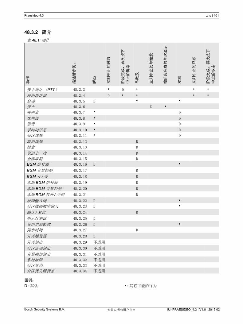
Praesideo 4.3 zhs | 401
Bosch Security Systems B.V. IUI-PRAESIDEO_4.3 | V1.0 | 2015.02安装说明和用户指南
48.3.2 简介
图例:
D : 默认 : 其它可能的行为
表 48.1: 动作
动作
描述
请参
阅:
瞬态
立刻
中止
的瞬
态
阶段
完成
,再
次按
下
中止
的瞬
态
单激
发
立刻
中止
的单
激发
按阶
段完
成的
单次
显示
双态
立刻
中止
的双
态
阶段
完成
,再
次按
下
中止
的双
态
按下通话(PTT) 48.3.3 D
呼叫激活键 48.3.4 D
启动 48.3.5 D
停止 48.3.6 D
呼叫宏 48.3.7 D
优先级 48.3.8 D
语音 48.3.9 D
录制的讯息 48.3.10 D
分区选择 48.3.11 D
取消选择 48.3.12 D
检索 48.3.13 D
取消上一次 48.3.14 D
全部取消 48.3.15 D
BGM 信号源 48.3.16 D
BGM 音量控制 48.3.17 D
BGM 开 / 关 48.3.18 D
本地 BGM 信号源 48.3.19 D
本地 BGM 音量控制 48.3.20 D
本地 BGM 打开 / 关闭 48.3.21 D
故障输入端 48.3.22 D
分区线路故障输入 48.3.23 D
确认 / 复位 48.3.24 D
指示灯测试 48.3.25 D
备用电源模式 48.3.26 D
同步时间 48.3.27 D
开关触发器 48.3.28 D
开关输出 48.3.29 不适用
分区活动输出 48.3.30 不适用
音量强切输出 48.3.31 不适用
系统故障 48.3.32 不适用
分区状态 48.3.33 不适用
分区优先级状态 48.3.34 不适用
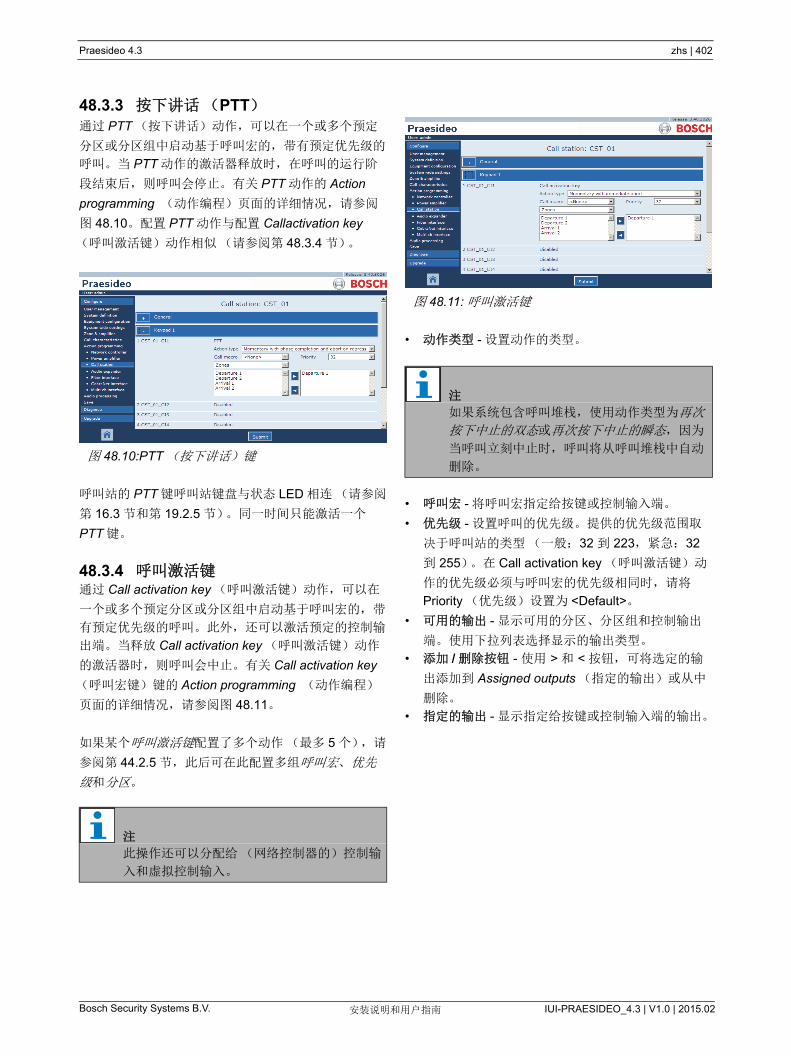
Praesideo 4.3 zhs | 402
Bosch Security Systems B.V. IUI-PRAESIDEO_4.3 | V1.0 | 2015.02安装说明和用户指南
48.3.3 按下讲话(PTT)通过 PTT (按下讲话)动作,可以在一个或多个预定
分区或分区组中启动基于呼叫宏的,带有预定优先级的
呼叫。当 PTT 动作的激活器释放时,在呼叫的运行阶
段结束后,则呼叫会停止。有关 PTT 动作的 Action
programming (动作编程)页面的详细情况,请参阅
图 48.10。配置 PTT 动作与配置 Callactivation key
(呼叫激活键)动作相似(请参阅第 48.3.4 节)。
呼叫站的 PTT 键呼叫站键盘与状态 LED 相连(请参阅
第 16.3 节和第 19.2.5 节)。同一时间只能激活一个
PTT 键。
48.3.4 呼叫激活键通过 Call activation key (呼叫激活键)动作,可以在
一个或多个预定分区或分区组中启动基于呼叫宏的,带
有预定优先级的呼叫。此外,还可以激活预定的控制输
出端。当释放 Call activation key (呼叫激活键)动作
的激活器时,则呼叫会中止。有关 Call activation key
(呼叫宏键)键的 Action programming (动作编程)
页面的详细情况,请参阅图 48.11。
如果某个呼叫激活键配置了多个动作( 多 5 个),请
参阅第 44.2.5 节,此后可在此配置多组呼叫宏、优先
级和分区。
• 动作类型 - 设置动作的类型。
• 呼叫宏 - 将呼叫宏指定给按键或控制输入端。
• 优先级 - 设置呼叫的优先级。提供的优先级范围取
决于呼叫站的类型(一般:32 到 223,紧急:32
到 255)。在 Call activation key (呼叫激活键)动
作的优先级必须与呼叫宏的优先级相同时,请将
Priority (优先级)设置为 <Default>。
• 可用的输出 - 显示可用的分区、分区组和控制输出
端。使用下拉列表选择显示的输出类型。
• 添加 / 删除按钮 - 使用 > 和 < 按钮,可将选定的输
出添加到 Assigned outputs (指定的输出)或从中
删除。
• 指定的输出 - 显示指定给按键或控制输入端的输出。
图 48.10:PTT (按下讲话)键
注
此操作还可以分配给(网络控制器的)控制输
入和虚拟控制输入。
图 48.11: 呼叫激活键
注
如果系统包含呼叫堆栈,使用动作类型为再次
按下中止的双态或再次按下中止的瞬态,因为
当呼叫立刻中止时,呼叫将从呼叫堆栈中自动
删除。

Praesideo 4.3 zhs | 403
Bosch Security Systems B.V. IUI-PRAESIDEO_4.3 | V1.0 | 2015.02安装说明和用户指南
48.3.5 开始Start (开始)动作主要用于阶段疏散时播放紧急呼叫。
Start (开始)动作根据呼叫宏来启动预定的分区或分
区组中的呼叫。呼叫的优先级与呼叫宏的优先级相同,
并且不能更改。有关 Start (开始)键的 Action
programming (动作编程)页面的详细情况,请参阅
图 48.12。
如果某个 Start (开始)键或控制输入端配置了多个动
作( 多 5 个),请参阅第 44.2.5 节,此后可在此配
置多组呼叫宏和分区。
通常情况下,有多个 Start (开始)动作使用相同的呼
叫宏,但是会发送到其分区或分区组。如果需要阶段疏
散,可以使用不同的 Start (开始)动作来增大呼叫正
在运行的区域。
在 Start (开始)动作的激活器释放时,与该动作相连
的分区或分区组中正在运行的呼叫也随之停止。如果需
要阶段疏散,释放不同的 Start (开始)动作则可以用
于缩小呼叫正在运行的区域。
48.3.6 停止Stop (停止)动作主要用于阶段疏散时中断紧急呼叫。
Stop (停止)动作会中止基于定义的呼叫宏的所有呼
叫。有关 Stop (停止)键的 Action programming (动
作编程)页面的详细情况,请参阅图 48.13。
如果某个 Stop (停止)键或控制输入端配置了多个动
作( 多 5 个),请参阅第 44.2.5 节,此后也可在此
配置多个呼叫宏。
图 48.12: 开始动作键
注
此操作还可以分配给控制输入端。
联合的启动 / 停止操作可以分配给网络控制器
的虚拟控制输入。
图 48.13: 停止活动按键
注
此操作还可以分配给控制输入端。
联合的启动 / 停止操作可以分配给网络控制器
的虚拟控制输入。
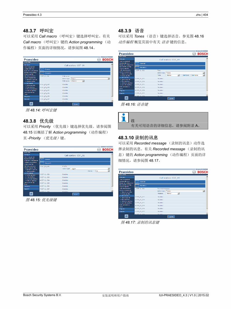
Praesideo 4.3 zhs | 404
Bosch Security Systems B.V. IUI-PRAESIDEO_4.3 | V1.0 | 2015.02安装说明和用户指南
48.3.7 呼叫宏可以采用 Call macro (呼叫宏)键选择呼叫宏。有关
Call macro (呼叫宏)键的 Action programming (动
作编程)页面的详细情况,请参阅图 48.14。
48.3.8 优先级可以采用 Priority (优先级)键选择优先级。请参阅图
48.15 以概括了解 Action programming (动作编程)
页 -Priority (优先级)键。
48.3.9 语音可以采用 Tones (语音)键选择语音。参见图 48.16
动作编程 概览页面中有关 语音 键的信息。
48.3.10 录制的讯息可以采用 Recorded message (录制的讯息)动作选
择录制的讯息。有关 Recorded message (录制的讯
息)键的 Action programming (动作编程)页面的详
细情况,请参阅图 48.17。
图 48.14: 呼叫宏键
图 48.15: 优先级键
图 48.16: 语音键
注
有关可用语音的详细信息,请参阅附录 A。
图 48.17: 录制的讯息键

Praesideo 4.3 zhs | 405
Bosch Security Systems B.V. IUI-PRAESIDEO_4.3 | V1.0 | 2015.02安装说明和用户指南
48.3.11 分区选择可以使用 Zone selection (分区选择)键选择一个或多
个分区和 / 或一个或多个分区组。有关 Zone selection
(分区选择)键的 Action programming (动作编程)
页面的详细情况,请参阅图 48.18。
• 动作类型 - 设置动作的类型。
• 可用的输出 - 显示可用的分区、分区组和控制输出
端。使用下拉列表选择显示的输出类型。
• 添加 / 删除按钮 - 使用 > 和 < 按钮,可将选定的输
出添加到 Assigned outputs (指定的输出)或从中
删除。
• 指定的输出端 - 显示指定给按键的输出端。
48.3.12 取消选择Cancel selection (取消选择)动作用于取消已经做出
的选择。有关 Cancel selection (取消选择)键的
Action programming (动作编程)页面的详细情况,
请参阅图 48.19 。
48.3.13 重拨Recall (重拨)动作用于重拨已做出的选择。有关
Recall (重拨)键的 Action programming (动作编
程)页面的详细信息,请参阅图 48.20。
图 48.18: 分区选择
注
有关创建分区和分区组的详细信息,请参阅
第 46.2 节。
图 48.19: 取消选择键
图 48.20: 重拨键
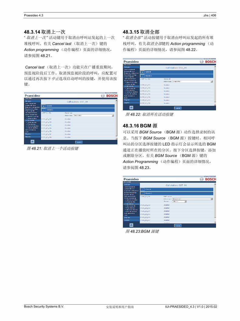
Praesideo 4.3 zhs | 406
Bosch Security Systems B.V. IUI-PRAESIDEO_4.3 | V1.0 | 2015.02安装说明和用户指南
48.3.14 取消上一次“ 取消上一次 ” 活动键用于取消由呼叫站发起的上一次
堆栈呼叫。有关 Cancel last (取消上一次)键的
Action programming (动作编程)页面的详细情况,
请参阅图 48.21。
Cancel last (取消上一次)功能只在广播重放期间,
预监视阶段后工作。取消预监视阶段的呼叫,应配置可
以通过再次按下中止选项启动呼叫的按键,并使用该按
键。
48.3.15 取消全部“ 取消全部 ” 活动按键用于取消由呼叫站发起的所有堆
栈呼叫。有关取消全部键的 Action programming (动
作编程)页面的详细情况,请参阅图 48.22。
48.3.16 BGM 源可以采用 BGM Source (BGM 源)动作选择录制的讯
息。当按下 BGM Source (BGM 源)按键时,相同呼
叫站的分区选择按键的 LED 指示灯会显示所选的 BGM
通道正在播放时所在的分区。按下分区选择按键,添加
或删除分区。有关 BGM Source (BGM 源)键的
Action Programming (动作编程)页面的详细情况,
请参阅图 48.23。
图 48.21: 取消上一个活动按键
图 48.22: 取消所有活动按键
图 48.23:BGM 源键

Praesideo 4.3 zhs | 407
Bosch Security Systems B.V. IUI-PRAESIDEO_4.3 | V1.0 | 2015.02安装说明和用户指南
48.3.17 BGM 音量控制采用 BGM volume control (BGM 音量控制)动作可以
控制背景音乐音量。音量调节的步进为 3 dB。有关
BGM volume control (BGM 音量控制)键的 Action
programming (动作编程)页面的详细情况,请参阅
图 48.24。
可以通过使用分区键(请参阅第 48.3.11 节)选择分
区,然后按下 BGM volume control (BGM 音量控制)
键来调节某个分区的 BGM 音量。如果按下 BGM
source (BGM 源)键,那么指派给该背景音乐源(若
有)的所有分区的指示器将变亮。在这些分区中,可以
调节音量。调节音量前还可以将分区添加到选择或从选
择中删除分区。如果 BGM 源的选择只对分区组产生局
部影响,那么该分区组的指示器将是黄色而非绿色。
若按下 BGM 源键,并有一台数字显示器连接于同一呼
叫站,其 LCD 显示屏将显示 “BGM”,此时数字键盘无
法使用(请参阅 18.6.3)。
48.3.18 BGM 打开 / 关闭BGM 打开 / 关闭动作用于打开或关闭预选分区中的背
景音乐。有关 BGM 打开 / 关闭键的 Action
programming (动作编程)页面的详细情况,请参阅
图 48.25。
图 48.24:BGM 音量控制键
图 48.25:BGM 打开 / 关闭键

Praesideo 4.3 zhs | 408
Bosch Security Systems B.V. IUI-PRAESIDEO_4.3 | V1.0 | 2015.02安装说明和用户指南
48.3.19 本地 BGM 源Local BGM source (本地 BGM 源)动作用于覆盖指
定分区(组)中所有可用的 BGM 源,包括已被插入的
“BGM 关 ” 位置。有关 Local BGM source (本地 BGM
源)键的 Action programming (动作编程)页面的详
细情况,请参阅图 48.26。
• 动作类型 - 设置动作类型。
• 可用的输出 - 显示可用的分区和分区组。使用下拉
列表选择显示的输出类型。
• 添加 / 删除按钮 - 使用 > 和 < 按钮,可将选定的输
出添加到 Assigned outputs (指定的输出)或从中
删除。
• 指定的输出端 - 显示指定给按键的输出端。
48.3.20 本地 BGM 音量控制Local BGM volume control (本地 BGM 音量控制)动
作用于控制指定分区(组)中 BGM 的音量。
此动作在 -96 dB 与 0 dB 之间的步进为 3 dB。有关
Local BGM volume control (本地 BGM 音量控制)键
的 Action Programming (动作编程)页面的详细情
况,请参阅图 48.26。
• 动作类型 - 设置动作类型。
• 音量控制 - 设置音量控制的类型。要增大音量,请
选择 Volume up (增大音量)。要减小音量,请选
择 Volume down (减小音量)。
• 可用的输出 - 显示可用的分区和分区组。使用下拉
列表选择显示的输出类型。
• 添加 / 删除按钮 - 使用 > 和 < 按钮,可将选定的输
出添加到 Assigned outputs (指定的输出)或从中
删除。
• 指定的输出端 - 显示指定给按键的输出端。
注
此操作还可以指派给控制输入端。
图 48.26: 本地 BGM 源键
注
此操作还可以指派给控制输入端。
图 48.27: 本地 BGM 音量控制键
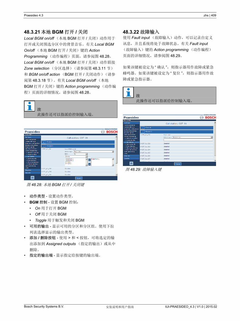
Praesideo 4.3 zhs | 409
Bosch Security Systems B.V. IUI-PRAESIDEO_4.3 | V1.0 | 2015.02安装说明和用户指南
48.3.21 本地 BGM 打开 / 关闭Local BGM on/off (本地 BGM 打开 / 关闭)动作用于
打开或关闭预选分区中的背景音乐。有关 Local BGM
On/off (本地 BGM 打开 / 关闭)键的 Action
Programming (动作编程)页面,请参阅图 48.28。
Local BGM on/off (本地 BGM 打开 / 关闭)动作联接
Zone selection (分区选择)(请参阅第 48.3.11 节)
和 BGM on/off action (BGM 打开 / 关闭动作)(请参
阅第 48.3.18 节)。有关 Local BGM on/off (本地
BGM 打开 / 关闭)键的 Action programming (动作编
程)页面的详细情况,请参阅图 48.28。
• 动作类型 - 设置动作类型。
• BGM 控制 - 设置 BGM 控制:
• On 用于打开 BGM
• Off 用于关闭 BGM
• Toggle 用于触发和关闭 BGM
• 可用的输出 - 显示可用的分区和分区组。使用下拉
列表选择显示的输出类型。
• 添加 / 删除按钮 - 使用 > 和 < 按钮,可将选定的输
出添加到 Assigned outputs (指定的输出)或从中
删除。
• 指定的输出端 - 显示指定给按键的输出端。
48.3.22 故障输入使用 Fault input (故障输入)动作,可以记录自定义
讯息,并且系统将处于故障状态。有关 Fault input
(故障输入)键的 Action programming (动作编程)
页面的详细情况,请参阅图 48.29。
如果该键被设定为 “ 确认 ”,则指示器用作故障或紧急
蜂鸣器。如果该键被设定为 “ 复位 ”,则指示器用作故
障或紧急指示器。
注
此操作还可以指派给控制输入端。
图 48.28: 本地 BGM 打开 / 关闭键
注
此操作还可以指派给控制输入端。
图 48.29: 故障输入键
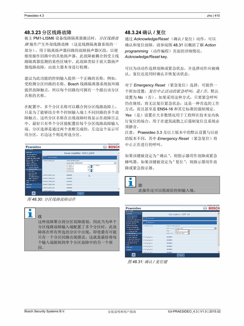
Praesideo 4.3 zhs | 410
Bosch Security Systems B.V. IUI-PRAESIDEO_4.3 | V1.0 | 2015.02安装说明和用户指南
48.3.23 分区线路故障被主 PM1-LISM6 设备线路隔离器激活时, 分区线路故
障 操作产生外部线路故障(这是线路隔离器系统的一
部分),用于隔离扬声器回路的故障扬声器区段,以便
继续操作回路中的其他扬声器。此故障被耦合到受主线
路隔离器监测的某些区域中。此故障类似于放大器扬声
器线路故障,由放大器本身进行检测。
建议为此功能的控制输入提供一个正确的名称,例如,
受检测分区回路的名称。Bosch 线路隔离器系统按环路
提供故障触点,所以每个回路均可拥有一个源自该分区
名称的名称。
在配置中,多个分区名称可以耦合到分区线路故障上,
只是为了能够结合单个控制输入端上不同回路的多个故
障触点。这些分区名称在出现故障时将显示在故障日志
中。 好只有单个分区能配置给每个分区线路故障输入
端。分区选择是通过两个表框完成的,左边这个显示可
用分区,右边这个则是所选分区。
48.3.24 确认 / 复位通过 Acknowledge/Reset (确认 / 复位)动作,可以
确认和复位故障。请参阅图 48.31 以概括了解 Action
programming (动作编程)页面的详细情况,
Acknowledge/Reset key.
可以为该动作选择故障或紧急状态,并选择动作应被确
认、复位还是同时确认并恢复该状态。
对于 Emergency Reset (紧急复位)选择,可提供一
个附加设置:复位中止活动的紧急呼叫:是 / 否。默认
设置为 No (否)。如果采用这种方式,只要紧急呼叫
仍在继续,将无法复位紧急状态;这是一种首选的工作
方式,而且甚至是 EN54-16 和其它标准的强制规定。
Yes (是)设置在大多数情况用于工程师在技术室内执
行复位的场合,用于在建筑疏散之后强制复位且系统必
须静音。
注意, Praesideo 3.3 及以上版本中的默认设置与以前
的版本不同,其中 Emergency Reset (紧急复位)将
中止正在进行的呼叫。
如果该键被设定为 “ 确认 ”,则指示器用作故障或紧急
蜂鸣器。如果该键被设定为 “ 复位 ”,则指示器用作故
障或紧急指示器。
图 48.30: 分区线路故障动作
注
这种故障聚合到分区故障级别,因此当为单个
分区线路故障输入端配置了多个分区时,此故
障将在所有所选的分区中出现,即使 有可能
只有一个分区回路出现错误。这就是 好将每
个输入端限制到单个分区故障中的另一个原
因。
注
此操作还可以指派给控制输入端。
图 48.31: 确认 / 复位键

Praesideo 4.3 zhs | 411
Bosch Security Systems B.V. IUI-PRAESIDEO_4.3 | V1.0 | 2015.02安装说明和用户指南
48.3.25 指示器测试 指示器测试 操作可配置用于呼叫站键盘或键盘模块上
的键。激活后,该呼叫站上的所有指示灯及其连接的所
有键盘均开启,以便目视检查指示灯。 双色指示器在两
种颜色之间切换。呼叫站扬声器将发出单声钟声,优先
级为 223。如果数字键盘连接到呼叫站,则其 LCD 显
示测试模式来视觉检查所有像素。
确保用于可视指示器之外的键盘模块的输出端在通过
指示灯测试激活时不会导致意外行为。
48.3.26 备用电源模式Backup power mode (备用电源模式)动作用于使系
统处于备用电源模式。在此模式下,比规定优先级
(请参阅第 45.4 节)低的所有呼叫将中断。有关
Backup Power mode (备用电源模式)键的 Action
programming (动作编程)页面的详细情况,请参阅
图 48.33。
图 48.32: 指示器测试键
注
配置为分区活动输出、音量强切输出或开关输
出 的键盘输出端不在指示器测试范围之内,因
为它们一般用于驱动外部继电器,而不是面板
指示器。
注
此操作还可以指派给控制输入端。
图 48.33: 备用电源模式键
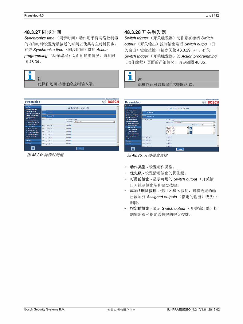
Praesideo 4.3 zhs | 412
Bosch Security Systems B.V. IUI-PRAESIDEO_4.3 | V1.0 | 2015.02安装说明和用户指南
48.3.27 同步时间Synchronize time (同步时间)动作用于将网络控制器
的内部时钟设置为 接近的时间以使其与主时钟同步。
有关 Synchronize time (同步时间)键的 Action
programming (动作编程)页面的详细情况,请参阅
图 48.34。
48.3.28 开关触发器Switch trigger (开关触发器)动作意在激活 Switch
output (开关输出)控制输出端或 Switch outpu (开
关输出)键盘按键(请参阅第 48.3.29 节)。有关
Switch trigger (开关触发器)的 Action programming
(动作编程)页面的详细情况,请参阅图 48.35。
• 动作类型 - 设置动作类型。
• 优先级 - 设置活动输出的优先级。
• 可用的输出 - 显示可用的 Switch output (开关输
出)控制输出端和键盘按键。
• 添加 / 删除按钮 - 使用 > 和 < 按钮,可将选定的输
出添加到 Assigned outputs (指定的输出)或从中
删除。
• 指定的输出 - 显示 Switch output (开关输出端)控
制输出端和指定给按键的键盘按键。
注
此操作还可以指派给控制输入端。
图 48.34: 同步时间键
注
此操作还可以指派给控制输入端。
图 48.35: 开关触发器键

Praesideo 4.3 zhs | 413
Bosch Security Systems B.V. IUI-PRAESIDEO_4.3 | V1.0 | 2015.02安装说明和用户指南
48.3.29 开关输出 开关输出 意在用于控制输出端和呼叫站键盘或呼叫站
键盘模块。按键 / 输入本身并不为此操作所使用;只激
活附在该键上的指示灯 / 输出端。 Switch output (开关
输出)动作由 Switch trigger (开关触发器)动作激活
(请参阅第 48.3.28 节)。有关 Switch output (开关输
出)键的 Action programming (动作编程)页面,请
参阅图 48.36。
48.3.30 分区活动输出端分区活动输出端 意在用于控制输出端和呼叫站键盘或呼
叫站键盘模块。按键 / 输入本身并不为此操作所使用;
只激活附在该键上的指示灯 / 输出端。 Zone active
output (分区活动输出)键可分配给一个分区(请参
阅第 46.2 节),并在呼叫或 BGM 发送到分区时激活。
有关 Zone active Output(分区活动输出)键的 Action
programming (动作编程)页面的详细情况,请参阅
图 48.37。
48.3.31 音量强切输出
音量强切输出 操作意在用于控制输出端和呼叫站键盘
或呼叫站键盘模块。按键 / 输入本身并不为此操作所使
用;只激活附在该键上的指示灯 / 输出端。 音量强切输
出 键可指定给分区 (请参见第 46.2 节)并在优先级等
于或大于 32 的呼叫发送到该分区时变成活动的。有关
Volume override output (音量强切输出)键的 Action
programming (动作编程)页的概述,请参见
图 48.38。
48.3.32 系统故障 系统故障 操作意在用于控制输出端和呼叫站键盘或呼
叫站键盘模块。此动作不使用按键 / 输入自身;存在系
统故障时,只激活附在按键上的第二个输出端或黄色指
示器。系统故障有:
• 配置文件出错
• 讯息名称
• 闪卡数据出错
• 找不到有效配置文件
• 处理器复位
48.3.33 分区状态 分区状态 操作旨在用于 PRS-CSKPM 呼叫站键盘模
块。此操作并不使用按键 / 输入本身;只激活附在按键
上的指示灯 / 输出端。 如果满足特定条件,分区状态动
作激活键的指示器 / 输出。它有两个作用:
1 如果呼叫至少一个配置分区或者分区组(优先级不
小于已配置的优先级),则该键指示灯的第二个输
出( 通常为黄色 LED) 在 PRS-CSKPM 呼叫站键
盘模块上被激活。 如果用于指示这些分区或者分区
组中的紧急呼叫,则该输出端应连接一个红色
LED。 每个紧急分区 好使用一个专用指示器。在
大多数紧急广播系统标准中,该指示器的颜色规定
为红色,例如 EN54-16。如果规定的优先级为
224,而且向该分区发送的是紧急呼叫(优先级等
于或大于 224),分区状态指示器将变亮。有关
Zone status (分区状态)键的 Action programming
(动作编程)页面的详细情况,请参阅图 48.32。
图 48.36: 开关输出键
图 48.37: 分区活动输出键
图 48.38: 音量强切输出端键

Praesideo 4.3 zhs | 414
Bosch Security Systems B.V. IUI-PRAESIDEO_4.3 | V1.0 | 2015.02安装说明和用户指南
2 如果为该操作配置的分区中存在故障,则该键指示
灯(通常为绿色 LED)的第一个输出端在
PRS-CSKPM 呼叫站键盘模拟上被激活(闪烁)。
这表明与该分区相关的设备或者连接中存在一个或
者多个故障事件。 应将黄色 LED 连接到该输出端。
在大多数紧急广播系统标准中都定义了该指示器的
颜色,例如 EN54-16。分区故障是指导致呼叫无法
继续联系分区(或部分分区)的故障。这种指示可
代表 16 种不同的故障,这些故障可能导致无法全面
联系分区,例如,线路故障、过热和过载故障。如
果故障已在内部解决(如,备用放大器替代出现出
故障的放大器),则不会导致与分区相关的故障,
只会产生一个出于备用放大器开关原因的具体故
障。 同样,如果采用冗余扬声器线路配置,单独的
GroupAFault 或者 GroupBFault 不会产生分区故障
状态,因为分区仍可寻址(电平为 -3 dB)。此处
假设该分区内的扬声器在 A 组与 B 组之间均 分
配。在所有影响分区故障状态的故障都已得到解决
时,即使尚未复位,也会取消分区故障状态。
以下故障会影响分区故障状态(请参阅第 55 节故障事
件列表中的详情):
• (通道)
• 放大器出现故障或过载(仅限 LBB4428/00)
• 放大器初始化失败
• 放大器扬声器线路出现故障(对于单个扬声器线
路检测)
• 放大器扬声器线路出现故障(对于多个扬声器线
路检测)
• 放大器丢失
• 放大器过热:静音
• 放大器过载
• 放大器短路
• A 级替换
• A 组故障
• 线路 A 或 B 故障
• B 组故障
• Incompatible hardware version (硬件版本不兼
容)
• Pilot tone calibration failure (导频音校准出现故
障)
• 设备丢失
• 分区线路故障
(由线路隔离器系统生成)
将激活分区故障指示器的分区相关故障列表不包括扬声
器故障,因此必须使用扬声器线端检测,或者依照
EN54-16 的规定。这是因为在 Praesideo 中,扬声器
故障并未指定给特定的放大器输出端或者分区,而只是
指定给扬声器本身。
还可以在 LBB4432/00 呼叫站键盘上配置该 分区状态
功能,但在出现活动的优先级呼叫时,第二个黄色
LED 会点亮。如果出现分区故障,则第一个绿色 LED
将闪烁。 在大多数情况下,这些颜色都不可用,因此
好使用配有专用指示器的 PRS-CSKPM。 此外,在
LBB4432/00 键盘上,这些指示器不可与 Zone
selection (分区选择)键组合使用,该键配置专用双
色指示器。在自定义面板上,使用 PRS-CSKPM 呼叫
站键盘模块, 分区选择 键的指示灯和开关,以及 分区
状态 指示灯可分为一组,以便清楚地进行选择。
• 优先级 - 如果优先级等于或大于指定的优先级 , 则会
激活此动作。
• 可用的输出 - 显示可用的分区、分区组和控制输出
端。使用下拉列表选择显示的输出类型。
• 添加 / 删除按钮 - 使用 > 和 < 按钮,可将选定的输
出添加到 Assigned outputs (指定的输出)或从中
删除。
• 指定的输出端 - 显示指定给按键的输出端。
图 48.39: 分区状态键
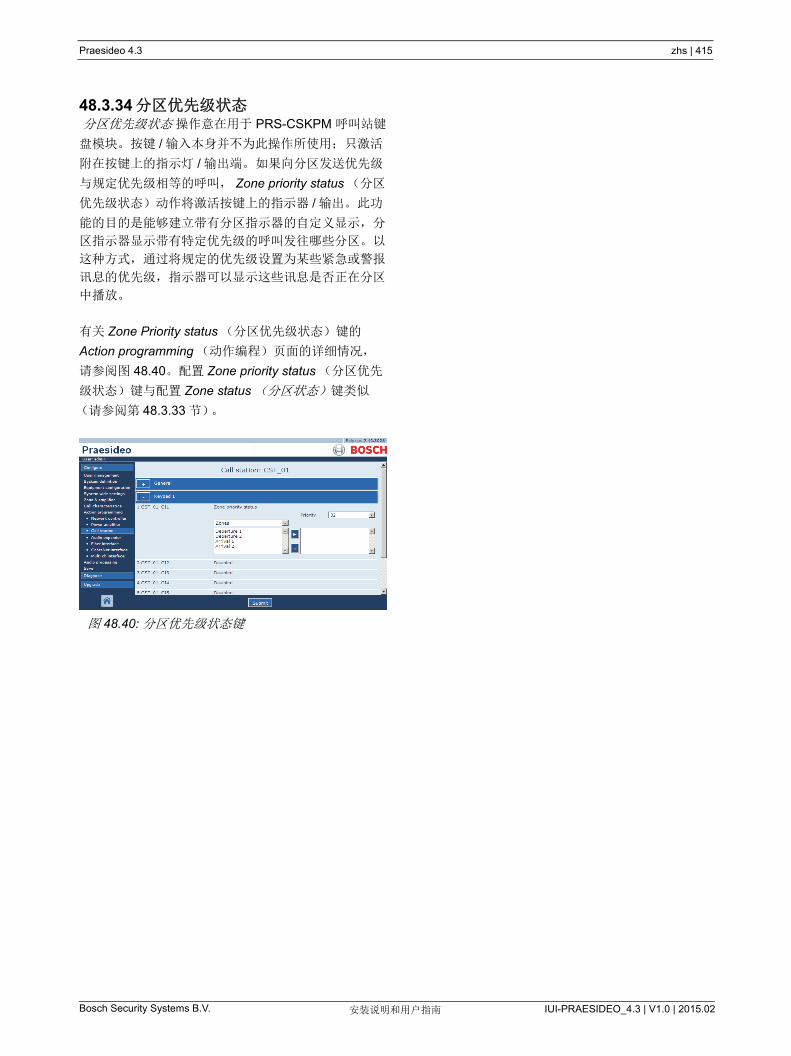
Praesideo 4.3 zhs | 415
Bosch Security Systems B.V. IUI-PRAESIDEO_4.3 | V1.0 | 2015.02安装说明和用户指南
48.3.34 分区优先级状态 分区优先级状态 操作意在用于 PRS-CSKPM 呼叫站键
盘模块。按键 / 输入本身并不为此操作所使用;只激活
附在按键上的指示灯 / 输出端。 如果向分区发送优先级
与规定优先级相等的呼叫, Zone priority status (分区
优先级状态)动作将激活按键上的指示器 / 输出。此功
能的目的是能够建立带有分区指示器的自定义显示,分
区指示器显示带有特定优先级的呼叫发往哪些分区。以
这种方式,通过将规定的优先级设置为某些紧急或警报
讯息的优先级,指示器可以显示这些讯息是否正在分区
中播放。
有关 Zone Priority status (分区优先级状态)键的
Action programming (动作编程)页面的详细情况,
请参阅图 48.40。配置 Zone priority status (分区优先
级状态)键与配置 Zone status (分区状态)键类似
(请参阅第 48.3.33 节)。
图 48.40: 分区优先级状态键

Praesideo 4.3 zhs | 416
Bosch Security Systems B.V. IUI-PRAESIDEO_4.3 | V1.0 | 2015.02安装说明和用户指南
49 音频处理
49.1 简介在 Audio Processing (音频处理) 页中,可以设置系
统中所有正常音频输入和输出的音频处理参数(请参
阅第 49.2 节)。配置为 AVC 输入的音频输入必须利用
Audio Processing (音频处理)页面(请参阅第 49.3
节)进行校准。
当单击 Audio Processsing (音频处理)页面上的
Submit Equalizer (提交均衡器)按钮时,音频处理参
数将会立即更改。尽管这些更改听得见,但是要注意到
它们不能自动保存非常重要。如果这些更改未保存,则
它们网络控制器复位时将丢失。有关配置保存设置的详
细信息,请参阅第 41.4.4 节。
49.2 音频处理参数
49.2.1 均衡器有关常规音频输入和输出端的均衡器选项的概述,请参
阅图 49.1。
图 49.1 中从左侧到右侧:
• 高通滤波器 - 带有固定品质因数和斜率的高通滤波
器。
• 坡型滤波器 - 带有固定品质因数的低频坡型滤波器。
• 全参数段 - 三个配有可调节品质因数、增益和频率
的全参数段。
• 坡型滤波器 -带有固定品质因数的低频坡型滤波器。
• 低通滤波器 - 带有固定品质因数和斜率的低通滤波
器。
49.2.2 均衡器设置配置滤波器的过程如下:
1 从 Freq 下拉列表中选择滤波器的频率。可用频率的
列表根据部分而有所差异,每 10 个提供 24 频率的
分辨率。
2 从 G 下拉列表中选择滤波器的增益。可用增益的范
围从 -20 dB 到 +12 dB,步进为 1 dB。
3 从 Q 下拉列表中选择滤波器的品质因数。可用的品
质因数范围根据分段而有所差异。对于全参数段,
范围从 0.2 到 10。
4 在滤波器的 Active (活动)对话框中打勾以启用滤
波器。
5 单击 Submit Equalizer (提交均衡器)按钮提交更
改。这些更改立即应用于音频输入或输出。
49.2.3 音量设置对于音频输出端,参数均衡器和音量按钮可用于调节音
频输出端的音量。多通道接口未为每个输出端提供均衡
器,但却为每个启用的输出端提供音量控制按钮,以控
制已连接基本型放大器的音量。
49.2.4 备用功率放大器备用功率放大器未为输出提供音量和均衡器设置。因为
主放大器由备用放大器替换,所以这些设置会自动设置
在相同位置。
备用功率放大器配有常用的音频输入端,这些输入端带
有均衡器或 AVC 校准按钮,取决于已配置的输入功
能。当备用功率放大器替换出现故障的主功率放大器
时,这些音频输入仍保持活动状态。
图 49.1: 音频处理 - 概述
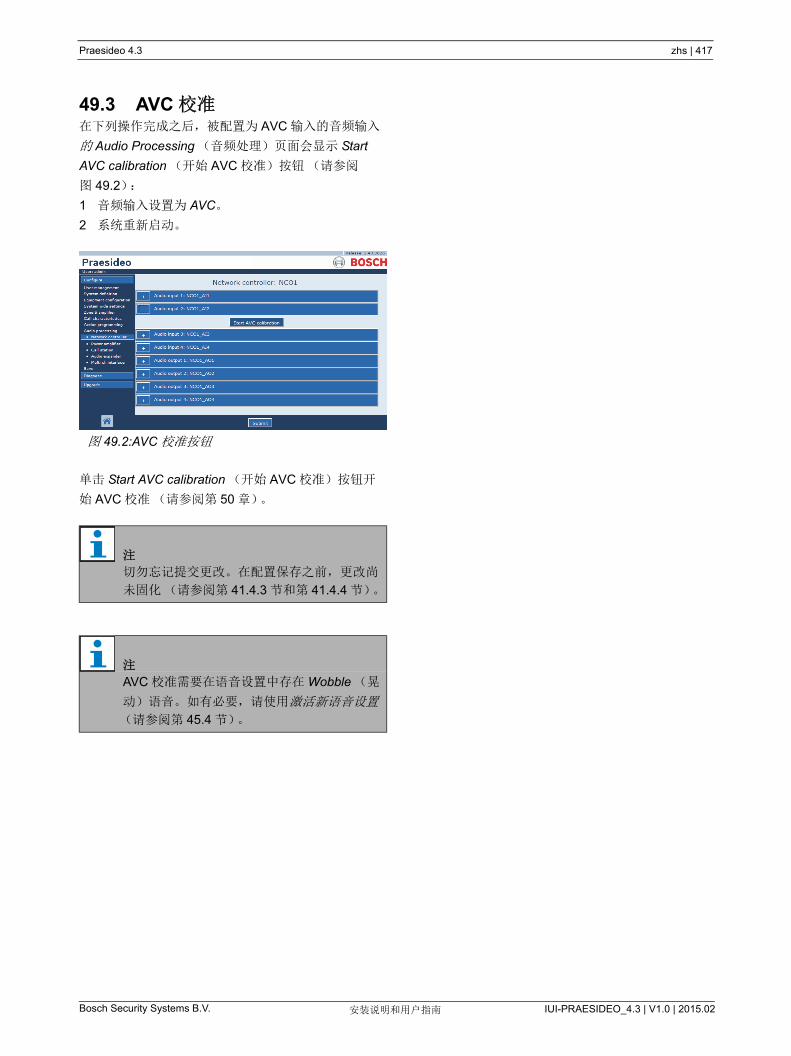
Praesideo 4.3 zhs | 417
Bosch Security Systems B.V. IUI-PRAESIDEO_4.3 | V1.0 | 2015.02安装说明和用户指南
49.3 AVC 校准在下列操作完成之后,被配置为 AVC 输入的音频输入
的 Audio Processing (音频处理)页面会显示 Start
AVC calibration (开始 AVC 校准)按钮(请参阅
图 49.2):
1 音频输入设置为 AVC。
2 系统重新启动。
单击 Start AVC calibration (开始 AVC 校准)按钮开
始 AVC 校准(请参阅第 50 章)。
图 49.2:AVC 校准按钮
注
切勿忘记提交更改。在配置保存之前,更改尚
未固化(请参阅第 41.4.3 节和第 41.4.4 节)。
注
AVC 校准需要在语音设置中存在 Wobble (晃
动)语音。如有必要,请使用激活新语音设置
(请参阅第 45.4 节)。

Praesideo 4.3 zhs | 418
Bosch Security Systems B.V. IUI-PRAESIDEO_4.3 | V1.0 | 2015.02安装说明和用户指南
50 自动音量控制
50.1 简介在吵杂环境中,自动音量控制(AVC)能提高呼叫的
清晰度和 BGM 的可听度。此功能调节分区中的呼叫音
量以补偿环境噪音。通过与功率放大器的任何音频输出
相连的感测话筒来测量环境噪音。尽管可以将环境感测
话筒连接到系统的其他输入端,但只有功率放大器输入
端提供话筒检测。另外,其他输入端具有内置音频限制
器,当信号水平相对较高时(如,来自驻极体话筒
时),将与 AVC 交互。
50.2 感测话筒
50.2.1 简介在分区中启用 AVC 时,感测话筒将会不断地测量环境
噪音。系统采用均值滤波器获取感测话筒信号的平均环
境噪音级。
50.2.2 类型使用配有优质电缆的感测话筒,因为感测话筒一般安装
在难以接近的地方。无需使用优质话筒。选择单指向话
筒还是全指向话筒取决于当地状况。
50.2.3 Supervision可以对系统与感测话筒之间的连接进行检测(请参阅
第 44.3.3 节)。在分区的感测话筒出现故障时,分区中
的所有呼叫将以 大音量发送以符合疏散标准。在分区
的感测话筒出现故障时,BGM 的衰减将设置为 AVC 范
围(请参阅图 50.1)。要避免意外的检测故障,请确
保:
• 电容器话筒的供电电流在 0.5mA 与 5A 之间
• 有线话筒的话筒阻抗在 120W 与 1300W。
50.2.4 安装要确保感测话筒测量的环境噪音级正确,请将其安装在
具有典型环境噪音级的地方。此外:
• 保持感测话筒的电缆与高能电缆(如主电源电缆)
相互独立。干扰可以扰乱环境噪音的测量。
• 切勿将感测话筒安装在预期噪音源附近。大的或非
常集中的噪音可以扰乱环境噪音的测量。
• 切勿将感测话筒安装通风孔或空调附近。气流可以
干扰环境噪音的测量。
• 切勿将感测话筒安装在建筑物的任何部分。建筑物
的振动可以扰乱环境噪音的测量。
50.3 连接感测话筒可以与包含 AVC 分区的音频输出的设备相
连,与也可以与其它放大器相连。在感测话筒连接到其
它放大器并且用于 AVC 分区中时,它可以长期占用数
字通道。结果是可用于呼叫的数字音频通道数减少。
50.4 配置在分区中配置 AVC 之前:
• 确保环境感测话筒与系统的连接正确。
• 确保所有扬声器连接到系统,功率级别设置正确,
安装目的明确(如果需要),并且处于工作状态。
• 将分区中所有音频输出的额定输出电平调节为 大
环境噪音时获得合适语音清晰度所需要的电平。
• 确保适用的功率放大器输出的音频延迟设置小于 2
秒。执行音频延迟校准后,可设置回正确的值。时
间很长的延迟设置(例如,用于隧道应用程序)可
能会导致错误的校准结果。
配置 AVC 的过程如下:
1 转到 Zone Configuration (分区配置)页面的 AVC
Settings (AVC 设置)类别。在 Web 界面的主框窗
口中出现与图 50.1 相似的屏幕。
注
呼叫开始和结束之间,AVC 功能不处理感测话
筒的信号。
注
在感测话筒的信号不是通过光纤网络路由时,
备用放大器无法接收出现故障的主放大器的感
测话筒。
图 50.1:AVC 设置
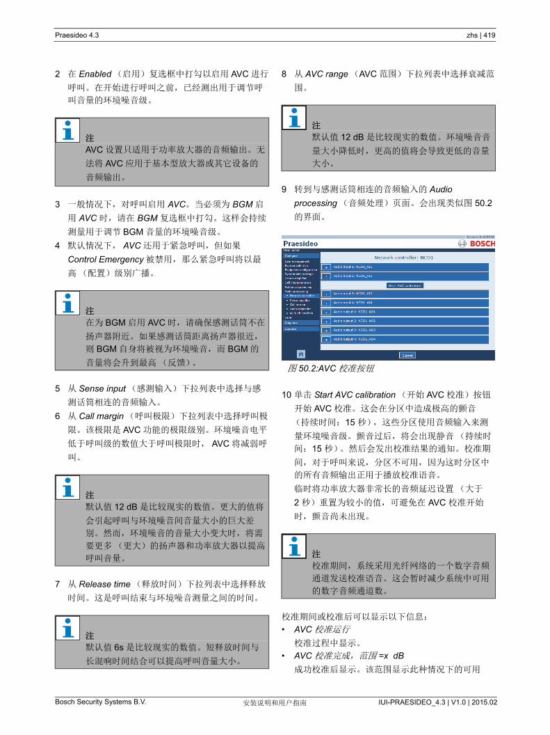
Praesideo 4.3 zhs | 419
Bosch Security Systems B.V. IUI-PRAESIDEO_4.3 | V1.0 | 2015.02安装说明和用户指南
2 在 Enabled (启用)复选框中打勾以启用 AVC 进行
呼叫。在开始进行呼叫之前,已经测出用于调节呼
叫音量的环境噪音级。
3 一般情况下,对呼叫启用 AVC。当必须为 BGM 启
用 AVC 时,请在 BGM 复选框中打勾。这样会持续
测量用于调节 BGM 音量的环境噪音级。
4 默认情况下, AVC 还用于紧急呼叫,但如果
Control Emergency 被禁用,那么紧急呼叫将以
高(配置)级别广播。
5 从 Sense input (感测输入)下拉列表中选择与感
测话筒相连的音频输入。
6 从 Call margin (呼叫极限)下拉列表中选择呼叫极
限。该极限是 AVC 功能的极限级别。环境噪音电平
低于呼叫级的数值大于呼叫极限时, AVC 将减弱呼
叫。
7 从 Release time (释放时间)下拉列表中选择释放
时间。这是呼叫结束与环境噪音测量之间的时间。
8 从 AVC range (AVC 范围)下拉列表中选择衰减范
围。
9 转到与感测话筒相连的音频输入的 Audio
processing (音频处理)页面。会出现类似图 50.2
的界面。
10 单击 Start AVC calibration (开始 AVC 校准)按钮
开始 AVC 校准。这会在分区中造成极高的颤音
(持续时间:15 秒),这些分区使用音频输入来测
量环境噪音级。颤音过后,将会出现静音(持续时
间:15 秒)。然后会发出校准结果的通知。校准期
间,对于呼叫来说,分区不可用,因为这时分区中
的所有音频输出正用于播放校准语音。
临时将功率放大器非常长的音频延迟设置(大于
2 秒)重置为较小的值,可避免在 AVC 校准开始
时,颤音尚未出现。
校准期间或校准后可以显示以下信息:
• AVC 校准运行
校准过程中显示。
• AVC 校准完成,范围 =x dB
成功校准后显示。该范围显示此种情况下的可用
注
AVC 设置只适用于功率放大器的音频输出。无
法将 AVC 应用于基本型放大器或其它设备的
音频输出。
注
在为 BGM 启用 AVC 时,请确保感测话筒不在
扬声器附近。如果感测话筒距离扬声器很近,
则 BGM 自身将被视为环境噪音,而 BGM 的
音量将会升到 高(反馈)。
注
默认值 12 dB 是比较现实的数值。更大的值将
会引起呼叫与环境噪音间音量大小的巨大差
别。然而,环境噪音的音量大小变大时,将需
要更多(更大)的扬声器和功率放大器以提高
呼叫音量。
注
默认值 6s 是比较现实的数值。短释放时间与
长混响时间结合可以提高呼叫音量大小。
注
默认值 12 dB 是比较现实的数值。环境噪音音
量大小降低时,更高的值将会导致更低的音量
大小。
图 50.2:AVC 校准按钮
注
校准期间,系统采用光纤网络的一个数字音频
通道发送校准语音。这会暂时减少系统中可用
的数字音频通道数。

Praesideo 4.3 zhs | 420
Bosch Security Systems B.V. IUI-PRAESIDEO_4.3 | V1.0 | 2015.02安装说明和用户指南
AVC 范围。为分区配置的 AVC 范围与呼叫余量应
该小于指示的可用范围。
• AVC 校准失败:感测信号过高
过高的环境感测信号引起的输出超载。使用低敏感
度话筒、衰减器,或者选择不同的感测位置。
• AVC 校准失败: 可用范围太小
测量的带有和不带有校准语音的环境感测信号之间
的差别小于 6 dB。 在感测位置中,与现存的环境
噪音相比,可用的 Praesideo 输出电平过低。
• AVC 校准失败:环境感测输入或其设备出现故障或
被禁用。
对于环境感测信号,如果音频输入出现故障或禁
用, AVC 校准和 AVC 无法进行。
• AVC 校准失败:无任何 AVC 输出可用
未使用此感测音频输入为 AVC 配置分区, AVC 校
准和 AVC 将无法进行。无法播放校准语音。
注
AVC 校准需要在语音设置中存在 Wobble (晃
动)语音。如有必要,请使用激活新语音设置
(请参阅第 45.4 节)。

Praesideo 4.3 zhs | 421
Bosch Security Systems B.V. IUI-PRAESIDEO_4.3 | V1.0 | 2015.02安装说明和用户指南
51 诊断安装
51.1 简介使用 Web 界面 Diagnose (诊断)部分中的
Installation (安装)页面(请参见图 51.1),可以诊
断系统安装。
51.2 电缆长度余量如果网络控制器的硬件版本为 20.00 或更高版本,则可
以检查电缆长度余量。如 32.5 节中所述, 大电缆长
度主要取决于系统中的节点数。对于系统循环,允许一
定的 大数据延迟,以保证操作正常。大部分延迟是电
缆的传输延迟,但每个节点都会引入一些额外的延迟,
这在一定程度上取决于设备的温度。较高的设备温度会
造成更多的延迟,缩短 大电缆长度。网络控制器会测
量数据延迟并计算剩余的时间。该时间余量会转换成电
缆长度余量,即可以在系统中使用的电缆长度。由于受
温度影响,该余量会随温度变化,而且取决于系统中的
节点数。因此,给出了额外的质量指标:安全、危急或
不稳定。安全意味着不需要操作,因为有足够的余量。
在危急情况下,应在 高的期望温度下检查余量,确保
仍然留有余量。在不稳定的情况下,应通过减少节点数
或电缆长度来缩小系统规模。
当使用冗余循环拓扑时,应检查两个删除节点之间的
短链接。这是 糟糕的情况。
51.3 节点数如果网络控制器的硬件版本为 20.00 或更高版本,则可
以检查所连接的可寻址节点的数量。请参见 表 32.2 以
了解每个设备的节点数。 大节点数为 63。
51.4 光学网络诊断光学网络的过程如下:
1 通过降低 Half power (半功率)的光学电平检查所
有网络连接的光动力裕度。
2 降低电平检查故障事件。如果未出现相应故障,则
重新启动网络控制器恢复正常操作。否则,请检查
临界连接。
图 51.1: 安装页面
注
尽管可以通过选择 Full power (全功率)恢复
正常操作,但是强烈建议您重新启动网络控制
器。若动力裕度几乎处于临界状态,此设备将
不再接受 Full Power (全功率)命令。
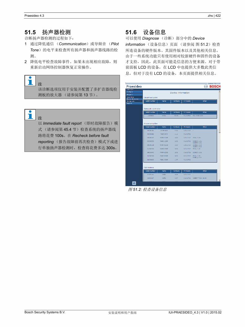
Praesideo 4.3 zhs | 422
Bosch Security Systems B.V. IUI-PRAESIDEO_4.3 | V1.0 | 2015.02安装说明和用户指南
51.5 扬声器检测诊断扬声器检测的过程如下:
1 通过降低通信(Communication)或导频音(Pilot
Tone)的电平来检查所有扬声器和扬声器线路的检
测。
2 降低电平检查故障事件。如果未出现相应故障,则
重新启动网络控制器恢复正常操作。
51.6 设备信息可以使用 Diagnose (诊断)部分中的 Device
information (设备信息)页面(请参阅 图 51.2)检查
所连设备的硬件版本、其固件版本以及其他相关信息。
由于一些系统功能只有使用相对较新硬件和固件的设备
才支持,因此,此页面可能是信息的方便来源。对于带
前面板 LCD 的设备,在 LCD 中也提供大多数此类信
息,但对于没有 LCD 的设备,本页面提供相关信息。
注
该诊断选项仅用于安装并配置了多扩音器线检
测板的放大器(请参阅第 13 节)。
注
以 Immediate fault report (即时故障报告)模
式(请参阅第 45.4 节)检查系统的扬声器线
路将花费 100s。在 Recheck before fault
reporting (报告故障前再次检查)模式下或进
行单独扬声器检测时,检查将花费多达 300s。
图 51.2: 检查设备信息
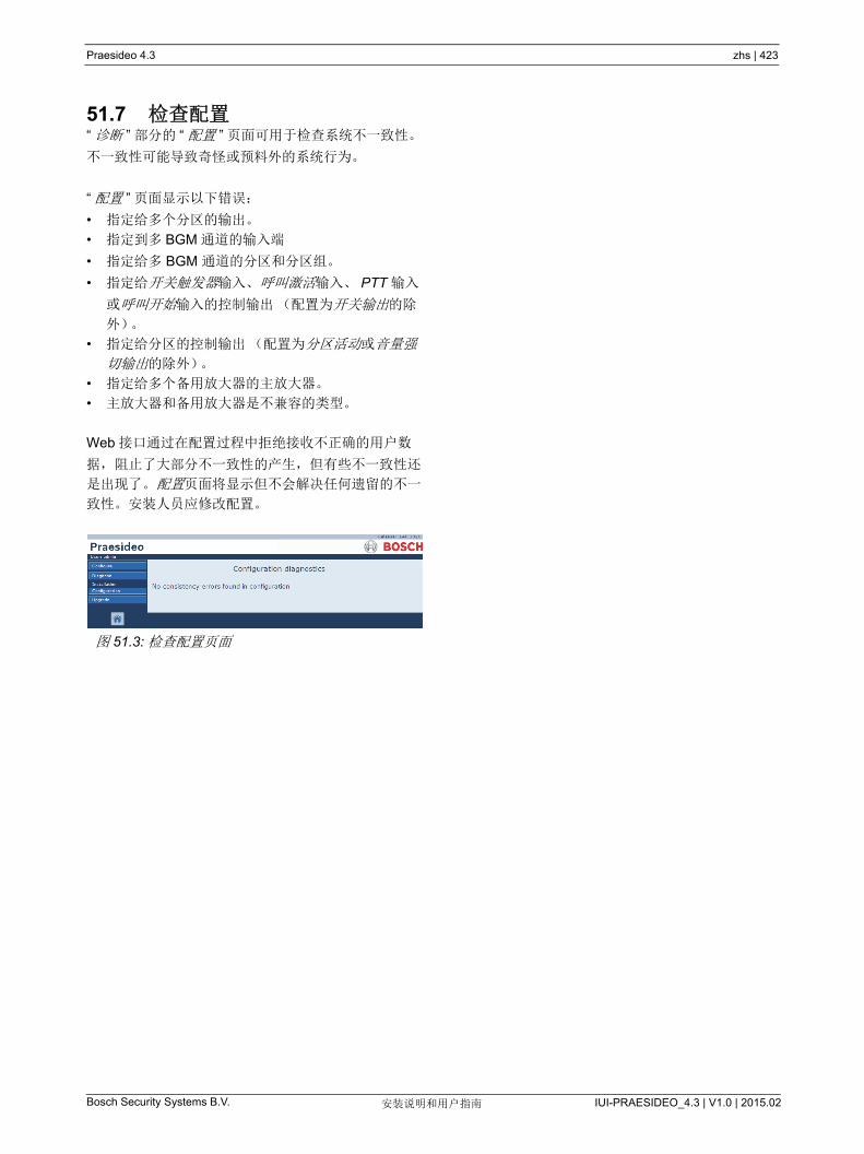
Praesideo 4.3 zhs | 423
Bosch Security Systems B.V. IUI-PRAESIDEO_4.3 | V1.0 | 2015.02安装说明和用户指南
51.7 检查配置“ 诊断 ” 部分的 “ 配置 ” 页面可用于检查系统不一致性。
不一致性可能导致奇怪或预料外的系统行为。
“ 配置 ” 页面显示以下错误:
• 指定给多个分区的输出。
• 指定到多 BGM 通道的输入端
• 指定给多 BGM 通道的分区和分区组。
• 指定给开关触发器输入、呼叫激活输入、 PTT 输入
或呼叫开始输入的控制输出(配置为开关输出的除
外)。
• 指定给分区的控制输出(配置为分区活动或音量强
切输出的除外)。
• 指定给多个备用放大器的主放大器。
• 主放大器和备用放大器是不兼容的类型。
Web 接口通过在配置过程中拒绝接收不正确的用户数
据,阻止了大部分不一致性的产生,但有些不一致性还
是出现了。配置页面将显示但不会解决任何遗留的不一
致性。安装人员应修改配置。
图 51.3: 检查配置页面

Praesideo 4.3 zhs | 424
Bosch Security Systems B.V. IUI-PRAESIDEO_4.3 | V1.0 | 2015.02安装说明和用户指南
52 简介
52.1 简介
52.2 常规事件常规事件包含与特殊情况有关的信息。例如,设备与系
统的连接。有关所有常规事件的列表,请参阅第 53
章。
52.3 呼叫事件呼叫事件包含系统中的呼叫信息。例如,呼叫的开始。
有关所有呼叫事件的列表,请参阅第 54 章。
52.4 故障事件
52.4.1 简介故障事件包含系统中的故障信息。例如,功率放大器的
超载。有关所有故障事件的列表,请参阅第 55 章。
52.4.2 状态每种故障都有状态(请参阅表 52.1)。
52.4.3 确认故障事件52.4.3.1 简介
可采用以下方法确认新的故障事件:
• 采用网络连接器(请参阅第 52.4.3.2 节)。
• 采用控制输入或按键(请参阅第 52.4.3.3 节)。
• 采用开放式接口(请参阅第 52.4.3.4 节)。
• 采用 Logging Viewer (记录查看器)(请参阅第 59
章)。
52.4.3.2 网络控制器
可以使用网络控制器的 故障 ... 菜单确认新故障事件
(请参阅 5.6.5)。通过此菜单,可以确认系统中的个别
故障事件和所有新故障事件。
52.4.3.3 控制输入和按键
可以使用为其指定 Acknowledge/Reset (确认 / 复位)
动作的控制输入或按键确认新故障事件(请参阅第
48.3.23 节)。然而,这样的控制输入或按键确认系统
中的所有新故障事件。通过控制输入或按键无法确认个
别故障。
52.4.3.4 开放式接口
可以使用开放式接口确认新故障事件(请参阅开放式
接口编程指令)。
52.4.4 解决故障事件复位确认的故障事件之前,必须首先解决它们。当故障
情形不再存在时,系统会自动解决大部分的故障事件。
其它事件需要人工解决。
对于出现后无法再次检测到的故障(如放大器超载),
需要对它们进行人工解决。故障解决后,必须人工将些
故障事件的故障状态复位 Resolved (已解决)。这可
以通过复位故障来完成,复位故障后系统将再次检查故
障是否出现。如果故障已不存在,故障事件的状态则设
置为 Resolved (已解决)和 Reset (重置)。如果故
障仍然存在,故障事件的状态则保持为 Acknowledge
(确认)。
故障事件(请参阅第 55 章)的信息描述如何解决故障
事件。
表 52.1 故障事件状态
状态 描述
新的 故障事件是新故障事件。所有
故障输出都处于活动状态。
已确认 新故障事件已确认。如果系统
中所有故障已确认,则取消激
活所有故障警报蜂鸣器输出。
已解决 确认的故障事件已解决。
Reset (重新设
置)
解决的故障事件已复位。如果
系统中所有故障已重置,则取
消激活所有故障警报指示器输
出。
注
故障输出是已配置为 Fault alarm sounder(故
障警报蜂鸣器)或 Fault alarm indicator (故
障警报指示器)的控制输出(请参见
表 44.6)。
注
当所有故障被确认后, Fault alarm buzzer
(故障警报蜂鸣器)输出被停用。
Praesideo 4.3 zhs | 425
Bosch Security Systems B.V. IUI-PRAESIDEO_4.3 | V1.0 | 2015.02安装说明和用户指南
52.4.5 重置故障事件52.4.5.1 简介
可通过以下操作重置已解决的故障事件:
• 采用网络连接器(请参阅第 52.4.5.2 节)。
• 采用控制输入或按键(请参阅第 52.4.5.3 节)。
• 采用开放式接口(请参阅第 52.4.5.4 节)。
• 采用 Logging Viewer (记录查看器)(请参阅第 59
章)。
52.4.5.2 网络控制器
可以使用网络控制器的 Faults... (故障 ...)菜单重置
已解决的故障事件(请参阅第 5.6.5 节)。通过此菜
单,可以重置系统中的个别故障事件和所有已解决的故
障事件。
52.4.5.3 控制输入和按键
可以使用为其指定 Acknowledge/Reset (确认 / 复位)
动作的控制输入或按键重置已解决的故障事件(请参
阅第 48.3.23 节)。然而,这样的控制输入或按键重置
系统中的所有已解决的故障事件。通过控制输入或按键
无法重置个别故障。
52.4.5.4 开放式接口
可以使用开放式接口重置已解决的故障事件(请参阅
开放式接口编程指令)。
注
所有故障已重置时,将取消激活 Fault alarm
indicator (故障警报指示器)输出。
Praesideo 4.3 zhs | 426
Bosch Security Systems B.V. IUI-PRAESIDEO_4.3 | V1.0 | 2015.02安装说明和用户指南
53 一般事件列表
按字母顺序排列的一般事件如下:
事件讯息:
Amplifier resumes operation (放大器恢复操作)
引发故障的设备:
恢复操作的主功率放大器。
附加信息:
备用放大器的序列号和名称。
描述:
记录备用功率放大器切换到主功率放大器的讯息。
建议的动作:
----
事件讯息:
Amplifier spare switch (放大器备用切换)
引发故障的设备:
停止运转的主功率放大器。
附加信息:
备用放大器的序列号和名称。
描述:
记录主功率放大器切换到备用功率放大器的讯息。
建议的动作:
检查主功率放大器的故障事件,并尝试解决这些故
障。
事件讯息:
Call logging events discarded due to logging queue
overflow (调用因记录队列溢出而删除的记录事件)
引发故障的设备:
----
附加信息:
----
描述:
呼叫事件的记录因网络控制器内输入队列的溢出而
挂起。此事件不显示在网络控制器的显示器上。
建议的动作:
发送少量的强切呼叫。
事件讯息:
Device connected via Open Interface (通过开放式
接口相连的设备)
引发故障的设备:
所连接的开放式接口客户端。
附加信息:
----
描述:
记录开放式接口客户端与系统的连接。
建议的动作:
----
事件讯息:
Device disconnected via Open Interface(通过开放
式接口断开的设备)
引发故障的设备:
所断开的开放式接口客户端。
附加信息:
----
描述:
记录开放式接口客户端与系统的断开。
建议的动作:
----
Praesideo 4.3 zhs | 427
Bosch Security Systems B.V. IUI-PRAESIDEO_4.3 | V1.0 | 2015.02安装说明和用户指南
事件讯息:
Emergency state acknowledge (紧急状态确认)
引发故障的设备:
确认紧急状态的开放式接口客户端或设备。
附加信息:
----
描述:
记录紧急状态的确认讯息。
建议的动作:
----
事件讯息:
Emergency state active (紧急状态激活)
引发故障的设备:
激活紧急状态的开放式接口客户端或设备。
附加信息:
----
描述:
记录紧急状态的激活讯息。
建议的动作:
----
事件讯息:
Emergency state reset (紧急状态重置)
引发故障的设备:
重置紧急状态的开放式接口客户端或设备。
附加信息:
----
描述:
记录紧急状态的重置讯息。
建议的动作:
----
事件讯息:
Logging of call events resumed (已恢复呼叫事件
的记录)
引发故障的设备:
----
附加信息:
----
描述:
呼叫事件的记录已恢复。此事件不显示在网络控制
器的显示器上。
建议的动作:
----
事件讯息:
记录服务器已启动
引发故障的设备:
----
附加信息:
----
描述:
表示记录服务器启动
建议的动作:
----
事件讯息:
记录服务器已停止
引发故障的设备:
----
附加信息:
----
描述:
表示记录服务器关闭
建议的动作:
----
事件讯息:
Network connections set to half optical power (设
置为半光功率的网络连接)
引发故障的设备:
----
附加信息:
----
描述:
记录光学网络半功率模式的启动。
建议的动作:
----
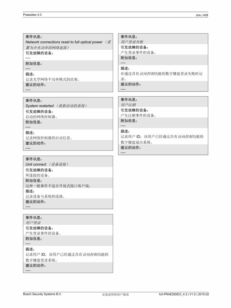
Praesideo 4.3 zhs | 428
Bosch Security Systems B.V. IUI-PRAESIDEO_4.3 | V1.0 | 2015.02安装说明和用户指南
事件讯息:
Network connections reset to full optical power (重
置为全光功率的网络连接)
引发故障的设备:
----
附加信息:
----
描述:
记录光学网络半功率模式的结束。
建议的动作:
----
事件讯息:
System restarted (重新启动的系统)
引发故障的设备:
启动的网络控制器。
附加信息:
----
描述:
记录网络控制器的启动信息。
建议的动作:
----
事件讯息:
Unit connect (设备连接)
引发故障的设备:
所连接的设备。
附加信息:
这种一般事件不适合开放式接口客户端。
描述:
记录设备与系统的连接。
建议的动作:
----
事件讯息:
用户登录
引发故障的设备:
产生登录事件的设备。
附加信息:
----
描述:
记录用户 ID,该用户已经通过具有访问控制功能的
数字键盘登录系统。
建议的动作:
----
事件讯息:
用户登录失败
引发故障的设备:
产生登录事件的设备。
附加信息:
----
描述:
在通过具有访问控制功能的数字键盘登录失败时记
录。
建议的动作:
----
事件讯息:
用户注销
引发故障的设备:
产生注销事件的设备。
附加信息:
----
描述:
记录用户 ID,该用户已经通过具有访问控制功能的
数字键盘退出系统。
建议的动作:
----

Praesideo 4.3 zhs | 429
Bosch Security Systems B.V. IUI-PRAESIDEO_4.3 | V1.0 | 2015.02安装说明和用户指南
54 呼叫事件列表
按字母顺序排列的呼叫事件如下:
事件讯息:
Call change (呼叫更改)
引发故障的设备:
导致更改的控制输入、开放式接口客户端或设备。
附加信息:
从路由中删除的输出名和添加到路由中的输出名。
描述:
记录呼叫路由中的变化。
建议的动作:
----
事件讯息:
Call end (呼叫结束)
引发故障的设备:
导致呼叫结束的控制输入、开放式接口客户端或设
备。
如果是被取消的呼叫、丢失的资源或者系统决定结
束呼叫,网络控制器为源设备。
附加信息:
如果呼叫已经被源设备停止,则显示完成的呼叫阶
段。
如果呼叫已经被中止,则显示完成的呼叫阶段以及
发出中止命令的设备。
描述:
记录呼叫的结束。
建议的动作:
----
事件讯息:
Call start (呼叫启动)
引发故障的设备:
启动呼叫的控制输入、按键、开放式接口客户端或
设备。
附加信息:
如果是重拨呼叫,则通过原始呼叫的呼叫 ID 参考原
始呼叫。
依次显示呼叫的宏名、呼叫的优先级、路由方案、
计时方案、起始钟声名、讯息名、讯息重复次数、
语音播放(如果呼叫为现场实时语音播报)、结束
钟声名和呼叫的路由。
描述:
记录呼叫的开始。请注意,即使广播呼叫为局部的,
预先警告呼叫也总是非局部的。 这是因为预先警告
呼叫仅发送到监视扩音器。
建议的动作:
----
事件讯息:
Call timeout (呼叫暂停)
引发故障的设备:
网络控制器。
附加信息:
堆栈呼叫未被发送至的分区列表
描述:
描述记录堆栈呼叫的暂停。
建议的动作:
----
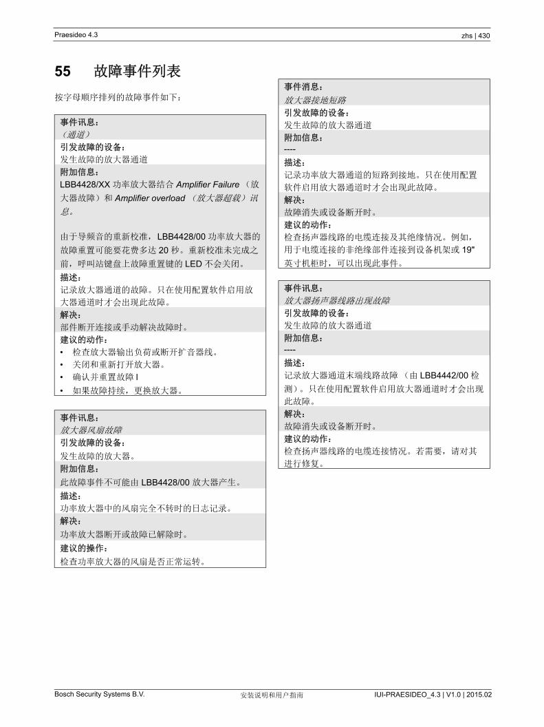
Praesideo 4.3 zhs | 430
Bosch Security Systems B.V. IUI-PRAESIDEO_4.3 | V1.0 | 2015.02安装说明和用户指南
55 故障事件列表
按字母顺序排列的故障事件如下:
事件讯息:
(通道)
引发故障的设备:
发生故障的放大器通道
附加信息:
LBB4428/XX 功率放大器结合 Amplifier Failure (放
大器故障)和 Amplifier overload (放大器超载)讯
息。
由于导频音的重新校准,LBB4428/00 功率放大器的
故障重置可能要花费多达 20 秒。重新校准未完成之
前,呼叫站键盘上故障重置键的 LED 不会关闭。
描述:
记录放大器通道的故障。只在使用配置软件启用放
大器通道时才会出现此故障。
解决:
部件断开连接或手动解决故障时。
建议的动作:
• 检查放大器输出负荷或断开扩音器线。
• 关闭和重新打开放大器。
• 确认并重置故障 l
• 如果故障持续,更换放大器。
事件讯息:
放大器风扇故障
引发故障的设备:
发生故障的放大器。
附加信息:
此故障事件不可能由 LBB4428/00 放大器产生。
描述:
功率放大器中的风扇完全不转时的日志记录。
解决:
功率放大器断开或故障已解除时。
建议的操作:
检查功率放大器的风扇是否正常运转。
事件消息:
放大器接地短路
引发故障的设备:
发生故障的放大器通道
附加信息:
----
描述:
记录功率放大器通道的短路到接地。只在使用配置
软件启用放大器通道时才会出现此故障。
解决:
故障消失或设备断开时。
建议的动作:
检查扬声器线路的电缆连接及其绝缘情况。例如,
用于电缆连接的非绝缘部件连接到设备机架或 19"
英寸机柜时,可以出现此事件。
事件讯息:
放大器扬声器线路出现故障
引发故障的设备:
发生故障的放大器通道
附加信息:
----
描述:
记录放大器通道末端线路故障(由 LBB4442/00 检
测)。只在使用配置软件启用放大器通道时才会出现
此故障。
解决:
故障消失或设备断开时。
建议的动作:
检查扬声器线路的电缆连接情况。若需要,请对其
进行修复。
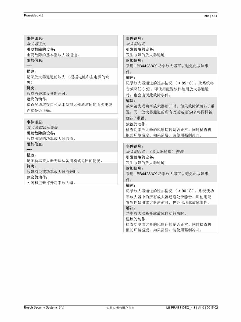
Praesideo 4.3 zhs | 431
Bosch Security Systems B.V. IUI-PRAESIDEO_4.3 | V1.0 | 2015.02安装说明和用户指南
事件讯息:
放大器丢失
引发故障的设备:
出现故障的基本型放大器通道。
附加信息:
----
描述:
记录放大器通道的缺失(根据电池和主电源的缺
失)
解决:
故障消失或设备断开时。
建议的动作:
检查多通道接口和基本型放大器通道间的 5 类电缆
连接是否正确。
事件讯息:
放大器初始化失败
引发故障的设备:
故障出现的功率放大器通道。
附加信息:
----
描述:
记录功率放大器无法从备用模式返回的情况。
解决:
故障消失或功率放大器断开时。
建议的动作:
关闭和重新打开功率放大器。
事件讯息:
放大器过热
引发故障的设备:
发生故障的放大器通道
附加信息:
采用 LBB4428/XX 功率放大器可以避免此故障事
件。
描述:
记录放大器通道的过热情况( > 85 °C)。此系统将
音频降低 3 dB。即使用配置软件禁用放大器通道
时,也会出现此故障事件。
解决:
故障消失或功率放大器断开时。如果故障被确认 / 重
置,同一放大器通道的所有冗余电源 24V 将同样被
确认 / 重置。
建议的动作:
检查功率放大器的风扇运转是否正常。同时检查机
柜的环境温度。如果需要,请使用强制冷却。
事件讯息:
放大器过热:(放大器通道)静音
引发故障的设备:
发生故障的放大器通道
附加信息:
采用 LBB4428/XX 功率放大器可以避免此故障事
件。
描述:
记录放大器通道的过热情况( > 90 °C)。系统使功
率放大器中的所有放大器通道处于静音。即使用配
置软件禁用放大器通道时,也会出现此故障事件。
解决:
功率放大器断开或故障自动解除时。
建议的动作:
检查功率放大器的风扇运转是否正常。同时检查机
柜的环境温度。如果需要,请使用强制冷却。
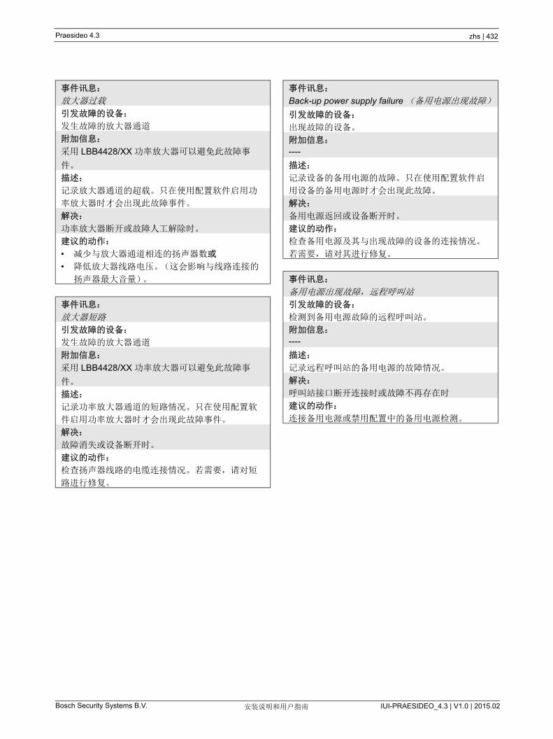
Praesideo 4.3 zhs | 432
Bosch Security Systems B.V. IUI-PRAESIDEO_4.3 | V1.0 | 2015.02安装说明和用户指南
事件讯息:
放大器过载
引发故障的设备:
发生故障的放大器通道
附加信息:
采用 LBB4428/XX 功率放大器可以避免此故障事
件。
描述:
记录放大器通道的超载。只在使用配置软件启用功
率放大器时才会出现此故障事件。
解决:
功率放大器断开或故障人工解除时。
建议的动作:
• 减少与放大器通道相连的扬声器数或
• 降低放大器线路电压。(这会影响与线路连接的
扬声器 大音量)。
事件讯息:
放大器短路
引发故障的设备:
发生故障的放大器通道
附加信息:
采用 LBB4428/XX 功率放大器可以避免此故障事
件。
描述:
记录功率放大器通道的短路情况。只在使用配置软
件启用功率放大器时才会出现此故障事件。
解决:
故障消失或设备断开时。
建议的动作:
检查扬声器线路的电缆连接情况。若需要,请对短
路进行修复。
事件讯息:
Back-up power supply failure (备用电源出现故障)
引发故障的设备:
出现故障的设备。
附加信息:
----
描述:
记录设备的备用电源的故障。只在使用配置软件启
用设备的备用电源时才会出现此故障。
解决:
备用电源返回或设备断开时。
建议的动作:
检查备用电源及其与出现故障的设备的连接情况。
若需要,请对其进行修复。
事件讯息:
备用电源出现故障,远程呼叫站
引发故障的设备:
检测到备用电源故障的远程呼叫站。
附加信息:
----
描述:
记录远程呼叫站的备用电源的故障情况。
解决:
呼叫站接口断开连接时或故障不再存在时
建议的动作:
连接备用电源或禁用配置中的备用电源检测。

Praesideo 4.3 zhs | 433
Bosch Security Systems B.V. IUI-PRAESIDEO_4.3 | V1.0 | 2015.02安装说明和用户指南
事件讯息:
呼叫站音频路径出现故障
引发故障的设备:
故障出现的呼叫站。
附加信息:
----
描述:
记录呼叫站的音频路径故障情况
解决:
当设备断开或故障人工解除时。
建议的动作:
更换呼叫站
事件讯息:
A 级替换
引发故障的设备:
故障出现的多通道接口的输出通道和已连接至基本
型放大器通道的输出通道。
附加信息:
----
描述:
记录在 A 类模式中第二个(B)继电器已关闭的情
况
解决:
部件断开连接或手动解决故障时。
建议的动作:
检查输出 A 至 B 的回路中的扬声器连接。
事件讯息:
Cobranet interface fault (Cobranet 接口出现故障)
或
Cobranet network fault (Cobranet 网络出现故障)
引发故障的设备:
出现故障的设备。
附加信息:
CobraNet 接口报告的错误代码
描述:
LBB4404/00 CobraNet 接口中的内部故障或
CobraNet 网络故障。大多数的常见故障是网络故
障,如冲突引起的接收和传输故障、过多的网络延
迟和广播流量。其它故障可能与配置有关。
解决:
故障不再存在或在同一设备上出现另一个 CobraNet
故障时
建议的动作:
• 确保 CobraNet 接口不是通过集线器与以太网相
连。只使用(受管理的)以太网开关。中继器网
络引起冲突。
• 确保以太网网络不包含任何循环。
• 检查以太网连接和以太网电缆的长度。
• 如果以太网也用于传输计算机数据,请在开关上
为 CobraNet 所用的端口配置高优先级。
• 请检查指定的束数和通道数是否正确。同时,请
检查是否至少有一个 CobraNet 设备的导体优先
级不为零。
• 如果一个以上的发射器使用该设备,请检查每束
编号。
• (临时)断开与网络相连的其它设备以检查这些
设备是否因传输破坏的数据包而发生故障。
专家专用:故障码是 CobraNet 故障描述的参考,欲
了解 CobraNet 故障描述的详细信息,请参阅
CobraNet 技术数据表的故障码参考部分。此数据表
可以从
http://www.cobranet.info/sites/default/files/CobraNe
t_Programmer_Manual_PM25.pdf

Praesideo 4.3 zhs | 434
Bosch Security Systems B.V. IUI-PRAESIDEO_4.3 | V1.0 | 2015.02安装说明和用户指南
事件讯息:
配置文件出错
引发故障的设备:
----
附加信息:
只有当网络控制器启动时,才能产生此故障事件。
此故障事件累积成系统故障。
描述:
记录配置文件中的一致性故障。(将加载默认配置文
件)
解决:
确认之后,立即执行。
建议的动作:
• 用配置打印工具打开配置文件并检查错误。
• 用配置打印工具显示的信息创建新的配置文件。
事件讯息:
Configuration file version mismatch (配置文件版本
不匹配)
引发故障的设备:
----
附加信息:
配置文件的版本和系统软件的版本。
只在启动网络控制器时,且配置文件的版本为 1.4
或更高版本,才会出现此故障事件。
描述:
记录配置文件版本号和系统软件版本号的不匹配情
况。
解决:
确认之后,立即执行。
建议的动作:
• 用配置打印工具打开配置文件并检查错误。
• 用配置打印工具显示的信息创建新的配置文件。
事件讯息:
控制输入线路出现故障:(控制输入端)
引发故障的设备:
故障出现的控制输入。
附加信息:
LBB4430/00 呼叫站基本要素和开放式接口客户端无
法产生此故障事件。
描述:
记录检测控制输出的故障。
解决:
故障消失或设备断开时。
建议的动作:
请检查控制输入以及与其相连的电缆。若需要,请
对其进行修复。
事件讯息:
外线故障
引发故障的设备:
收到分区线路故障的控制输入。
附加信息:
分区的名称。
描述:
激活了外线故障输入的日志记录。
解决:
当输入被停用或者装置断开连接时(以防该事件发
生在装置中)。
建议的操作:
检查指定分区的扬声器线路。

Praesideo 4.3 zhs | 435
Bosch Security Systems B.V. IUI-PRAESIDEO_4.3 | V1.0 | 2015.02安装说明和用户指南
事件消息:
故障输入端
引发故障的设备:
产生故障事件的控制输入、按键或开放式接口客户
端。
附加信息:
利用配置软件输入的描述。
描述:
记录配置为 Fault input (故障输入)的控制输入或
按键的激活情况,或生成 report Fault (报告故障)
命令的开放式接口客户端的激活情况。
解决:
• 如果控制输入或按键出现故障:Fault Input (故
障输入)取消激活或设备断开。
• 如果开放式接口客户端出现故障:开放式接口客
户端报告故障已解决时,或开放式接口客户端断
开时。
建议的动作:
建议的动作取决于配置指定的控制输入、按键或开
放式接口客户端的目的。
事件讯息:
讯息名称
引发故障的设备:
出现故障的设备。
附加信息:
此故障事件累积成系统故障。
描述:
记录闪卡检验和中的故障。只在使用配置软件启用
闪卡的可用性或闪卡丢失时,才会出现此故障事件。
解决:
故障消失时。
建议的动作:
• 通过 File Transfer (文件传输)应用程序替换闪
卡上的消息集,或者
• 替换闪卡。
事件讯息:
闪卡数据出错
引发故障的设备:
出现故障的设备。
附加信息:
此故障事件累积成系统故障。
描述:
记录闪卡的丢失。只在使用配置软件启用闪卡的可
用性时,才会出现此故障。
解决:
故障消失并且网络控制器重新启动时。
建议的动作:
请检查设备中是否已安装闪卡。若安装,请重新连
接闪卡,或者替换它,并且重新启动网络控制器。
事件讯息:
A 组故障
引发故障的设备:
故障出现的多通道接口的输出通道和已连接至基本
型放大器通道的输出通道。
附加信息:
----
描述:
对于具有 A/B 切换或 A 类连线的音频输出记录组 A
中的故障情况。
解决:
部件断开连接或手动解决故障时。
建议的动作:
检查基本型放大器通道的 A 组输出上的扬声器连
接。

Praesideo 4.3 zhs | 436
Bosch Security Systems B.V. IUI-PRAESIDEO_4.3 | V1.0 | 2015.02安装说明和用户指南
事件讯息:
线路 A 或 B 故障
引发故障的设备:
故障出现的多通道接口的输出通道和已连接至基本
型放大器通道的输出通道。
附加信息:
----
描述:
记录组 A/B 连线模式中的扬声器线路故障情况,繁
忙决定是否必须生成组 A 或组 B 故障事件。
解决:
部件断开连接或手动解决故障时,或故障的实际原
因已知时(并且已生成组 A 或组 B 故障事件)。
建议的动作:
等待组 A 或组 B 故障,并检查相应的扬声器线路。
事件讯息:
B 组故障
引发故障的设备:
故障出现的多通道接口的输出通道和已连接至基本
型放大器通道的输出通道。
附加信息:
----
描述:
对于具有 A/B 切换或 B 类连线的音频输出记录组 A
中的故障情况。
解决:
部件断开连接或手动解决故障时。
建议的动作:
检查基本型放大器通道的 B 组输出上的扬声器连
接。
事件讯息:
Incompatible hardware version (硬件版本不兼容)
引发故障的设备:
出现故障的设备。
附加信息:
使用已配置的功能所需的已安装硬件的版本号和
低版本号。
描述:
记录设备硬件的版本号与所需的硬件版本号不匹配
的情况。不匹配取决于已配置的设备功能。只在硬
件无法处理配置的功能时,才会出现此故障事件。
一般地,在多分支扬声器线路检测与 /00 功率放大
器一起使用时,将会出现此事件。
解决:
设备断开时。
建议的动作:
• 使用导致故障的设备的较新版本,或者
• 降级为较低的软件版本
事件讯息:
无效固件版本
引发故障的设备:
固件版本无效的设备。
附加信息:
设备的当前固件版本号和固件的 低要求版本号。
描述:
记录设备固件版本号与 低要求版本号的不匹配情
况。
解决:
升级设备时。
建议的动作:
更新固件。可在配置 Web 页面中执行该操作。
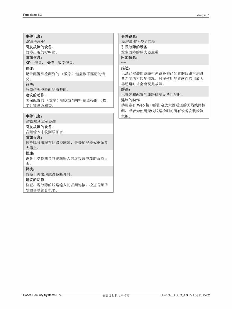
Praesideo 4.3 zhs | 437
Bosch Security Systems B.V. IUI-PRAESIDEO_4.3 | V1.0 | 2015.02安装说明和用户指南
事件讯息:
键盘不匹配
引发故障的设备:
故障出现的呼叫站。
附加信息:
KP:键盘, NKP:数字键盘。
描述:
记录配置和检测到的(数字)键盘数不匹配的情
况。
解决:
故障消失或呼叫站断开时。
建议的动作:
确保配置的(数字)键盘数与呼叫站连接的(数
字)键盘数相等。
事件讯息:
线路输入出现故障
引发故障的设备:
音频输入未收到导频音。
附加信息:
该故障只出现在网络控制器、音频扩展器或电源放
大器上。
描述:
设备上受检测音频线路输入的连接或电缆的故障日
志。
解决:
故障不再出现或设备断开时。
建议的动作:
检查出现故障的线路输入的音频连接。检查音频信
号源和导频音电平。
事件讯息:
线路检测主控不匹配
引发故障的设备:
发生故障的放大器通道
附加信息:
----
描述:
记录已安装的线路检测设备和已配置的线路检测设
备之间的不匹配情况。只在使用配置软件启用放大
器通道时才会出现此故障。
解决:
已安装和配置的线路检测设备匹配时。
建议的动作:
禁用带有 Web 接口的指定放大器通道的无线线路检
测,或者为使用无线线路检测的所有设备安装检测
主板。
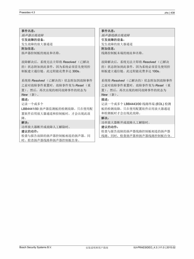
Praesideo 4.3 zhs | 438
Bosch Security Systems B.V. IUI-PRAESIDEO_4.3 | V1.0 | 2015.02安装说明和用户指南
事件讯息:
扬声器出现故障
引发故障的设备:
发生故障的放大器通道
附加信息:
扬声器控制板的地址和名称。
故障解决后,系统无法立即将 Resolved (已解决
的)状态附加到此事件,因为系统必须首先使用控
制板建立通信链。此过程能花费多达 300s。
系统将 Resolved (已解决的)状态附加到故障事件
之前对故障事件重置时,故障事件变为 Reset (重
置)。然后,再次出现的相同故障事件的状态为
New (新)。
描述:
记录一个或多个
LBB4441/00 扬声器监测板的检测故障。只在使用配
置软件启用放大器通道和控制板时,才会出现此故
障。
解决:
功率放大器断开或故障人工解除时。
建议的动作:
检查与报告故障的扬声器控制板相连的扬声器。同
时,检查扬声器线路和扬声器控制板自身。
事件讯息:
扬声器线路出现故障
引发故障的设备:
发生故障的放大器通道
附加信息:
线路控制板末端的地址和名称。
故障解决后,系统无法立即将 Resolved (已解决
的)状态附加到此事件,因为系统必须首先使用控
制板建立通信链。此过程能花费多达 100s。
系统将 Resolved (已解决的)状态附加到故障事件
之前对故障事件重置时,故障事件变为 Reset (重
置)。然后,再次出现的相同故障事件的状态为
New (新)。
描述:
记录一个或多个 LBB4443/00 线路终端 (EOL) 检测
板的检测故障。只在使用配置软件启用放大器通道
和检测板时才会出现此故障。
解决:
功率放大器断开或故障人工解除时。
建议的动作:
检查与报告故障的扬声器线路控制板相连的扬声器
线路。同时,检查扬声器和扬声器线路控制板自身。

Praesideo 4.3 zhs | 439
Bosch Security Systems B.V. IUI-PRAESIDEO_4.3 | V1.0 | 2015.02安装说明和用户指南
事件讯息:
主电源出现故障
引发故障的设备:
出现故障的设备。
附加信息:
----
描述:
记录主电源的故障。
解决:
主电源返回或设备断开时。
建议的动作:
检查主电源及其与出现故障的设备的连接情况。
事件讯息:
Messages missing (讯息丢失)
引发故障的设备:
出现故障的设备。
附加信息:
配置中存在但闪卡上不存在的讯息名称。
描述:
在闪卡中记录已配置和检测到的讯息不匹配的情况。
只在使用配置软件启用闪卡的可用性和重新启动网
络控制器时,才会出现此故障事件。
解决:
故障消失时。
建议的动作:
检查文件名。(这些文件大小写敏感。)如果讯息名
配置正确,请重新上传讯息集并重新启动网络控制
器。
事件讯息:
Flash 存储器
引发故障的设备:
出现故障的设备。
附加信息:
闪存是否有故障, EEPROM 存储器是否有故障。
开放式接口客户端无法产生此故障事件。
描述:
记录存储器故障。
解决:
故障消失或设备断开时。 EEPROM 内存故障在确认
后立即解决。
建议的动作:
• 重新启动网络控制器,或者
• 关闭出现故障的设备,或者
• 替换出现故障的设备。
事件讯息:
Microphone failure (话筒出现故障)
引发故障的设备:
出现故障的音频输入端。
附加信息:
只有呼叫站和功率放大器才能产生此故障事件。
描述:
记录设备上或与设备相连的话筒故障。
解决:
故障消失或设备断开时。
建议的动作:
记录话筒及其与系统的连接。若需要,请对其进行
修复。
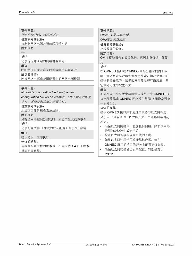
Praesideo 4.3 zhs | 440
Bosch Security Systems B.V. IUI-PRAESIDEO_4.3 | V1.0 | 2015.02安装说明和用户指南
事件讯息:
网络电源故障,远程呼叫站
引发故障的设备:
检测到网络电源故障的远程呼叫站
附加信息:
----
描述:
记录远程呼叫站的网络电源故障。
解决:
呼叫站接口断开连接时或故障不再存在时
建议的动作:
连接网络电源或禁用配置中的网络电源检测
事件讯息:
No valid configuration file found; a new
configuration file will be created. (找不到有效配置
文件;系统将创建新的配置文件。
引发故障的设备:
此故障事件累积成系统故障。
附加信息:
只有当网络控制器启动时,才能产生此故障事件。
描述:
记录配置文件(加载的默认配置)的丢失 / 损害。
解决:
确认之后,立即执行。
建议的动作:
请检查配置文件的版本号。不再支持 1.4 以下版本。
重新配置系统。
事件讯息:
OMNEO 接口故障 或
OMNEO 网络故障
引发故障的设备:
出现故障的设备。
附加信息:
OM-1 模块报告的故障代码。代码本身仅供内部使
用。
描述:
在 OMNEO 接口或 OMNEO 网络出错时的内部故
障。大多数常见故障均为网络故障,如冲突引起的
接收和传输故障、过多的网络延迟和广播流量。 其
它故障可能与配置有关。
解决:
如果在同一个装置中故障消失或另一个 OMNEO 接
口出现故障或 OMNEO 网络发生故障(无论是否第
一次发生)。
建议的操作:
确保 OMNEO 接口并非通过集线器与以太网相连。
只使用(受管理的)以太网开关。 中继器网络引起
冲突。
• 确保以太网网络中不包含任何回路,除非该网络
采用的是快速生成树协议。
• 检查以太网连接和以太网线的长度。
• 如果以太网还用于传输计算机数据,请在
OMNEO 所用的端口的开关上配置高优先级。
• 确保以太网交换机已正确配置,特别是对于
RSTP。

Praesideo 4.3 zhs | 441
Bosch Security Systems B.V. IUI-PRAESIDEO_4.3 | V1.0 | 2015.02安装说明和用户指南
事件消息:
Pilot tone calibration failure (导频音校准出现故
障)
引发故障的设备:
发生故障的放大器通道
附加信息:
----
描述:
记录放大器通道的导频音校准故障。只在使用配置
软件启用放大器通道时才会出现此故障。
解决:
故障消失或设备断开时。
建议的动作:
关闭产生故障的设备,然后重新打开以允许对其进
行校准。如果这样无法解决故障,说明与指定的放
大器通道相连的扬声器线路中出现故障(线路检测
主 / 从不匹配、扬声器线路出现故障)。
事件讯息:
处理器复位
引发故障的设备:
出现故障的设备。
附加信息:
引起复位的处理器类型。此故障事件累积成系统故
障。
描述:
记录处理器的看门狗复位。
只有已启动的设备才能产生此故障事件。开放式接
口客户端无法产生该故障事件。
解决:
确认之后,立即执行。
建议的动作:
• 对于执行 Save the configuration and restart the
system (保存配置并重新启动系统)操作时,所
有连接的设备均出现该故障的情况,可能是因为
使用 HW 版本 20.00 或更早版本的网络控制器与
Praesideo 版本 3.4 或更新版本的组合。请参阅
41.4.4 节中的注释。只需确认并重置故障。
• 检查网络故障。例如,报告上显示缺失或处于半
功率模式(请参阅第 51.4 节)的设备。在诊断 /
安装中可通过半功率模式查找重要的网络连接。
• 确保所有设备包含正确固件。
• 检查显示为配置文件损坏的故障(例如,配置文
件错误或配置文件版本不匹配)。
尤其注意检查带有问号标识的音频平衡器设置缺
失,然后创建新的配置文件。
• 检查显示为闪卡损坏的故障。
• 将设备关闭再重新打开,或断开设备后重新连
接。
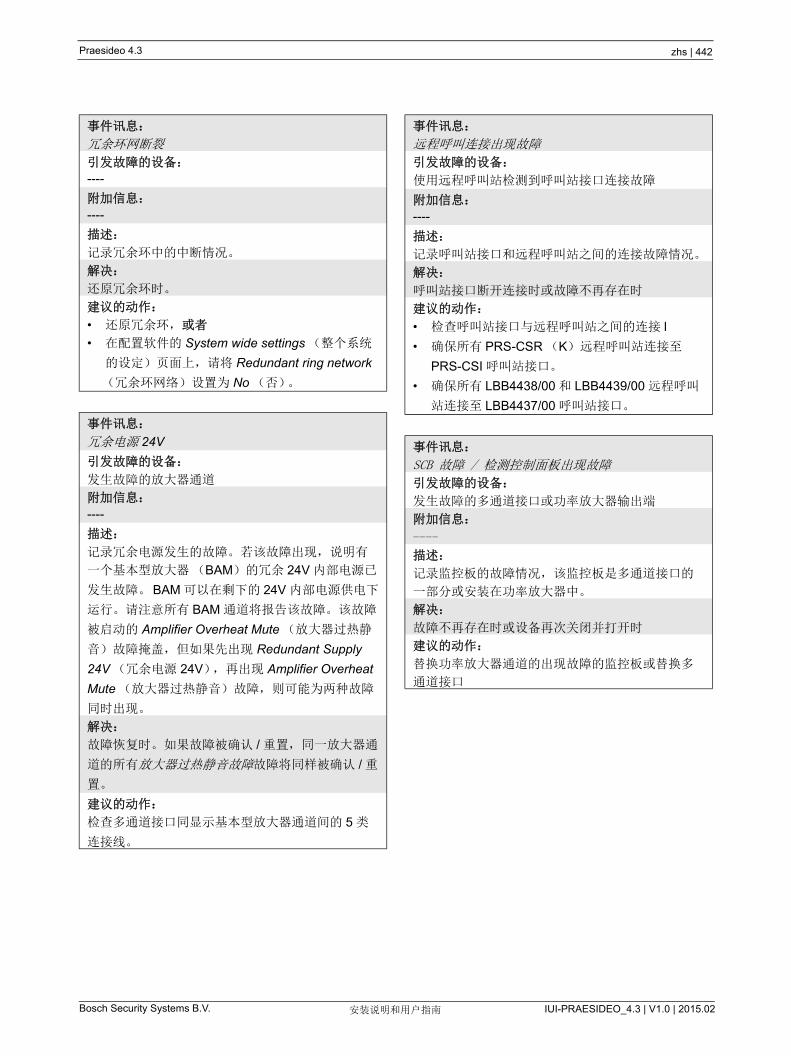
Praesideo 4.3 zhs | 442
Bosch Security Systems B.V. IUI-PRAESIDEO_4.3 | V1.0 | 2015.02安装说明和用户指南
事件讯息:
冗余环网断裂
引发故障的设备:
----
附加信息:
----
描述:
记录冗余环中的中断情况。
解决:
还原冗余环时。
建议的动作:
• 还原冗余环,或者
• 在配置软件的 System wide settings (整个系统
的设定)页面上,请将 Redundant ring network
(冗余环网络)设置为 No (否)。
事件讯息:
冗余电源 24V
引发故障的设备:
发生故障的放大器通道
附加信息:
----
描述:
记录冗余电源发生的故障。若该故障出现,说明有
一个基本型放大器(BAM)的冗余 24V 内部电源已
发生故障。BAM 可以在剩下的 24V 内部电源供电下
运行。请注意所有 BAM 通道将报告该故障。该故障
被启动的 Amplifier Overheat Mute (放大器过热静
音)故障掩盖,但如果先出现 Redundant Supply
24V (冗余电源 24V),再出现 Amplifier Overheat
Mute (放大器过热静音)故障,则可能为两种故障
同时出现。
解决:
故障恢复时。如果故障被确认 / 重置,同一放大器通
道的所有放大器过热静音故障故障将同样被确认 / 重
置。
建议的动作:
检查多通道接口同显示基本型放大器通道间的 5 类
连接线。
事件讯息:
远程呼叫连接出现故障
引发故障的设备:
使用远程呼叫站检测到呼叫站接口连接故障
附加信息:
----
描述:
记录呼叫站接口和远程呼叫站之间的连接故障情况。
解决:
呼叫站接口断开连接时或故障不再存在时
建议的动作:
• 检查呼叫站接口与远程呼叫站之间的连接 l
• 确保所有 PRS-CSR (K)远程呼叫站连接至
PRS-CSI 呼叫站接口。
• 确保所有 LBB4438/00 和 LBB4439/00 远程呼叫
站连接至 LBB4437/00 呼叫站接口。
事件讯息:
SCB 故障 / 检测控制面板出现故障
引发故障的设备:
发生故障的多通道接口或功率放大器输出端
附加信息:
----
描述:
记录监控板的故障情况,该监控板是多通道接口的
一部分或安装在功率放大器中。
解决:
故障不再存在时或设备再次关闭并打开时
建议的动作:
替换功率放大器通道的出现故障的监控板或替换多
通道接口
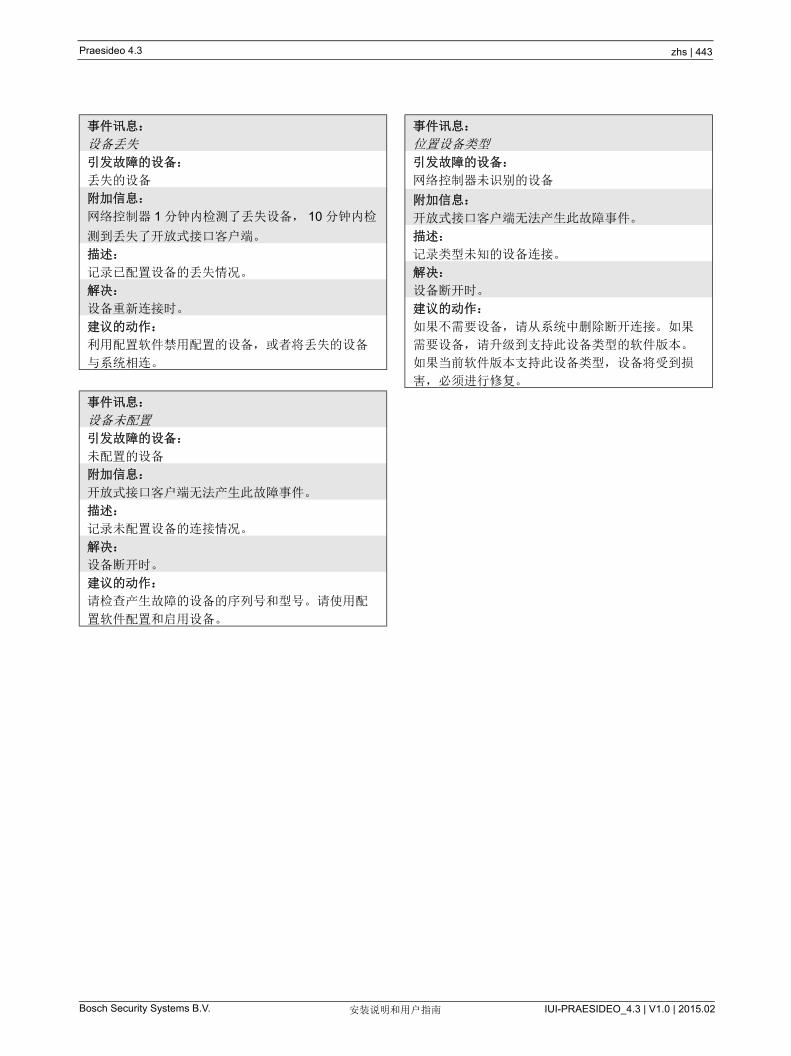
Praesideo 4.3 zhs | 443
Bosch Security Systems B.V. IUI-PRAESIDEO_4.3 | V1.0 | 2015.02安装说明和用户指南
事件讯息:
设备丢失
引发故障的设备:
丢失的设备
附加信息:
网络控制器 1 分钟内检测了丢失设备, 10 分钟内检
测到丢失了开放式接口客户端。
描述:
记录已配置设备的丢失情况。
解决:
设备重新连接时。
建议的动作:
利用配置软件禁用配置的设备,或者将丢失的设备
与系统相连。
事件讯息:
设备未配置
引发故障的设备:
未配置的设备
附加信息:
开放式接口客户端无法产生此故障事件。
描述:
记录未配置设备的连接情况。
解决:
设备断开时。
建议的动作:
请检查产生故障的设备的序列号和型号。请使用配
置软件配置和启用设备。
事件讯息:
位置设备类型
引发故障的设备:
网络控制器未识别的设备
附加信息:
开放式接口客户端无法产生此故障事件。
描述:
记录类型未知的设备连接。
解决:
设备断开时。
建议的动作:
如果不需要设备,请从系统中删除断开连接。如果
需要设备,请升级到支持此设备类型的软件版本。
如果当前软件版本支持此设备类型,设备将受到损
害,必须进行修复。

Praesideo 4.3 zhs | 444
Bosch Security Systems B.V. IUI-PRAESIDEO_4.3 | V1.0 | 2015.02安装说明和用户指南
56 CobraNet Discovery
56.1 简介3.3 版本之前的 Praesideo CD 光盘中包含用于为连接
的 CobraNet 接口设备分配 IP 地址的 CobraNet
Discovery 程序,以及用于更改连接的 CobraNet 设备
的 CobraNet 参数值的 CNConfig 程序。
从 3.3 版本开始, Praesideo 配置了更新版本的
CobraNet Discovery,该程序还能够更改 CobraNet 参
数值,不再需要 CNConfig 了。 因此 Praesideo 不再提
供该程序。 CobraNet Discovery 只有英语版本。
本手册适用于 CobraNet Discovery 版本 3.4.5
CobraNet Discovery 在 Windows PC 上运行,并通过
PC 机的标准以太网接口卡(NIC)与 CobraNet 网络
通信。 CobraNet Discovery 的主要功能是探测并监控
CobraNet 设备的状态。也可用于为设备分配 IP 地址、
更新固件、控制和监控设备的配置以及生成状态报告。
此版本发布时, CobraNet Discovery 工具的 新版本
是版本 4.0.5,其包含在安装 DVD 中。访问 http://
www.cobranet.info/downloads/disco 了解 新的版本。
56.2 安装CobraNet Discovery 3.4.5 已在 Windows NT 4.0、
2000、 XP 和 Vista 中经过测试,可得到这些系统的支
持。 Windows 95、 98 和 ME 则不支持该程序。 版本
4.0.5 支持 Windows 7、 Vista 和 XP。运行 CobraNet
Discovery 的 PC 机必须配备正确配置的以太网接口
卡。
由于 Discovery 安装和使用设备驱动程序发送及接收
CobraNet 数据包,因此要求使用管理权限安装和运行
Discovery。
按照安装向导在 PC 机上安装 CobraNet Discovery。如
果以前安装过旧版 Discovery ,可能必须首先选择选项
删除所有已安装的功能,然后重新启动安装程序。
可安全忽略卸载过程中关于删除只读文件的警告讯息。
某些旧版本的 Discovery 可能在只读模式中错误地安装
了系统文件。
Discovery 安装过程会产生一个默认程序文件夹
C:\Program Files\Cirrus Logic\CobraNet Discovery,
其中也包括了具体的 Discovery 版本注释和更全面的手
册。
注
在配置 CobraNet 设备之前,必须掌握
CobraNet 网络和技术的基础知识。 Praesideo
DVD 光盘中的 \Manuals 包含一些关于
CobraNet 技术的文档。详情请访问
www.cobranet.info,您还可在该站点找到 新
版本的 CobraNet Discovery。该网站由
CobraNet 的所有者 Cirrus Logic 负责维护。
注
如果网络包含的 CobraNet 设备超过 20 个,可
能必须在 cndisco.ini 文件中添加
"[configuration]Age To Die = 30000" 条目以稳
定 Discovery 的显示。该文件位于程序文件夹
中。
Praesideo 4.3 zhs | 445
Bosch Security Systems B.V. IUI-PRAESIDEO_4.3 | V1.0 | 2015.02安装说明和用户指南
56.3 网络适配器配置家用或者商用 PC 机网络上的网络适配器通常都配置为
从连接的网络自动获取 IP 地址。这些地址服务通常由
网络上的因特网网关或者服务器计算机提供。尽管某些
先进的音频网络可能提供这些服务,但专用 CobraNet
网络通常没有这些服务。因此,您的网络适配器在大多
数情况下应人工分配 IP 地址。
56.3.1 IP 地址分配推荐为 CobraNet 网络分配以下 IP 地址。
• 192.168.100.1 至 192.168.100.199 - CobraNet 设
备(由 CobraNet Discovery 分配的默认 IP 地址)
• 192.168.100.200 至 192.168.100.219 - 网络交换机
和基础架构。
• 192.168.100.220 至 192.168.100.254 - 计算机
在采用以上建议时,应为您的计算机分配一个
192.168.100.220 至 192.168.100.254 范围内未使用的
IP 地址。关于 IP 地址的限制,另请参阅第 33.8 节。
56.3.2 分配 IP地址1 在控制面板中打开网络连接。
2 右击将用于连接 CobraNet 网络的以太网适配器,
然后选择属性。
3 在服务列表中查找因特网协议(TCP/IP)。
4 按属性 按钮。
5 在因特网协议(TCP/IP)属性对话框,选择使用以
下 IP 地址。
6 输入 IP 地址。
7 在子网掩码中输入 255.255.255.0。
8 将默认网关保留空白。
9 该对话框的另一半部分对于 Discovery 的运行而言
不重要。首选 DNS 服务器和备选 DNS 服务器字段
可保留空白。
10 单击所有对话框上的确定,保存设置。在 Windows
NT 和 2000 上,在新的设置生效之前系统可能要求
重新启动。
注
CobraNet Discovery 4.0.5 不正式支持
Windows 8。然而,采取了一些措施后可以在
Windows 8 下运行 CobraNet Discovery。
CobraNet Discovery 4.0.5 使用 Microsoft.NET
Framework 3.5,参考 Microsoft 网站上
Windows 7 的设置来安装此框架。在 Windows
8 下,无需安装,但是 .NET Framework 3.5
只需要在控制面板中启用即可。从 “ 开始 ” 屏
幕中选择控制面板,然后选择 “ 程序 ”,然后选
择 “ 打开或关闭 Windows 功能 ”,然后选择
.NET Framework 3.5 (包括 .NET 2.0 和 3.0)
复选框。
此外,在由某一公司更新服务器维护的 PC
上,请您的管理员联系以启用该策略,以使用
Windows Update 而不是 Windows Server
Update Services (WSUS)。有关更多详细信
息,请参阅 http://msdn.microsoft.com/en-us/
library/hh506443(v=vs.110).aspx
注
如需在以后恢复自动分配设置,返回 Internet
Protocol (TCP/IP) Properties 对话框,然后 选
择 自动获取 IP 地址。
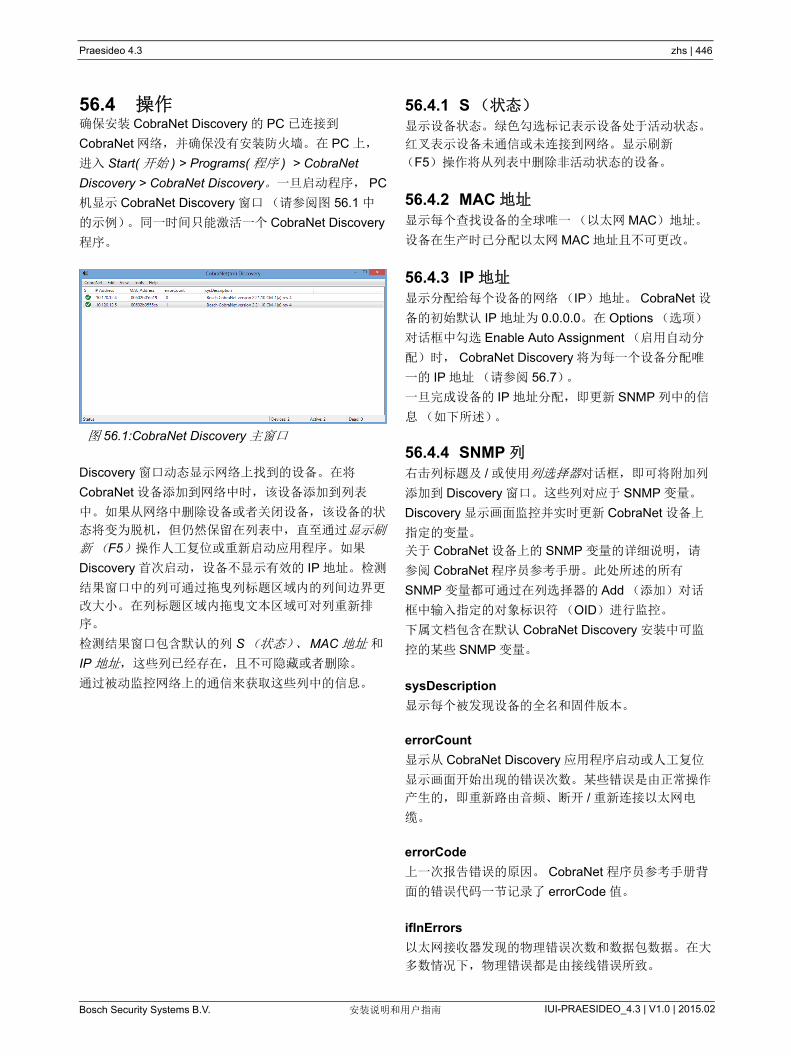
Praesideo 4.3 zhs | 446
Bosch Security Systems B.V. IUI-PRAESIDEO_4.3 | V1.0 | 2015.02安装说明和用户指南
56.4 操作确保安装 CobraNet Discovery 的 PC 已连接到
CobraNet 网络,并确保没有安装防火墙。在 PC 上,
进入 Start( 开始 ) > Programs( 程序 ) > CobraNet
Discovery > CobraNet Discovery。一旦启动程序, PC
机显示 CobraNet Discovery 窗口(请参阅图 56.1 中
的示例)。同一时间只能激活一个 CobraNet Discovery
程序。
Discovery 窗口动态显示网络上找到的设备。在将
CobraNet 设备添加到网络中时,该设备添加到列表
中。如果从网络中删除设备或者关闭设备,该设备的状
态将变为脱机,但仍然保留在列表中,直至通过显示刷
新(F5)操作人工复位或重新启动应用程序。如果
Discovery 首次启动,设备不显示有效的 IP 地址。检测
结果窗口中的列可通过拖曳列标题区域内的列间边界更
改大小。在列标题区域内拖曳文本区域可对列重新排
序。
检测结果窗口包含默认的列 S(状态)、MAC 地址 和
IP 地址,这些列已经存在,且不可隐藏或者删除。
通过被动监控网络上的通信来获取这些列中的信息。
56.4.1 S (状态)显示设备状态。绿色勾选标记表示设备处于活动状态。
红叉表示设备未通信或未连接到网络。显示刷新
(F5)操作将从列表中删除非活动状态的设备。
56.4.2 MAC 地址显示每个查找设备的全球唯一(以太网 MAC)地址。
设备在生产时已分配以太网 MAC 地址且不可更改。
56.4.3 IP 地址显示分配给每个设备的网络(IP)地址。 CobraNet 设
备的初始默认 IP 地址为 0.0.0.0。在 Options (选项)
对话框中勾选 Enable Auto Assignment (启用自动分
配)时, CobraNet Discovery 将为每一个设备分配唯
一的 IP 地址(请参阅 56.7)。
一旦完成设备的 IP 地址分配,即更新 SNMP 列中的信
息(如下所述)。
56.4.4 SNMP 列右击列标题及 / 或使用列选择器对话框,即可将附加列
添加到 Discovery 窗口。这些列对应于 SNMP 变量。
Discovery 显示画面监控并实时更新 CobraNet 设备上
指定的变量。
关于 CobraNet 设备上的 SNMP 变量的详细说明,请
参阅 CobraNet 程序员参考手册。此处所述的所有
SNMP 变量都可通过在列选择器的 Add (添加)对话
框中输入指定的对象标识符(OID)进行监控。
下属文档包含在默认 CobraNet Discovery 安装中可监
控的某些 SNMP 变量。
sysDescription
显示每个被发现设备的全名和固件版本。
errorCount
显示从 CobraNet Discovery 应用程序启动或人工复位
显示画面开始出现的错误次数。某些错误是由正常操作
产生的,即重新路由音频、断开 / 重新连接以太网电
缆。
errorCode
上一次报告错误的原因。 CobraNet 程序员参考手册背
面的错误代码一节记录了 errorCode 值。
ifInErrors
以太网接收器发现的物理错误次数和数据包数据。在大
多数情况下,物理错误都是由接线错误所致。
图 56.1:CobraNet Discovery 主窗口
Praesideo 4.3 zhs | 447
Bosch Security Systems B.V. IUI-PRAESIDEO_4.3 | V1.0 | 2015.02安装说明和用户指南
Rx1 至 Rx4
数据包接收器状态。 CobraNet 设备通常带有四个数据
包接收器。这四个变量显示了每个接收器的状态。
三种规格在显示时以斜线(/)分隔。这三个值如下:
• 数据包号(rxBundle)
• 接收状态(rxStatus)。如果收到音频数据,显示
1,否则显示 0。如果没有收到, 常见的原因是因
为没有任何发送器发送该数据包。
• 接收丢失(rxDropouts)。统计从接收到未接受的
转变次数。虽然在特意重新路由音频时也会出现丢
失现象,但连续丢失可能表示存在网络问题。
Tx1 至 Tx4
数据包发送器状态。 CobraNet 设备通常带有四个数据
包发送器。这四个变量显示了每个发送器的状态。
三种规格在显示时以斜线(/)分隔。这三个值如下:
• 数据包号(txBundle)
• 该发送器服务的接收器的数量(txReceivers)。
• 发送丢失(txDropouts)。统计从发送到未发送的
转变次数。虽然在特意中断或重新路由音频时也会
出现丢失现象,但连续丢失可能表示存在网络问
题。
56.5 菜单Discovery 窗口包含一个可用于执行附加功能的菜单
栏。
56.5.1 CobraNet• 更新固件 ...
更新选定 CobraNet 设备的固件。 Discovery 将首先
上传现有固件,以便在已知固件版本的数据库中识
别该固件。此后显示固件更新对话框。
固件更新从数据库位置中的二进制文件开始执行。
CobraNet Discovery 不提供固件文件。必须从相应
的 CobraNet 设备制造商处获取固件。对于
Praesideo CobraNet 接口, Praesideo DVD 上的
\Tools\CobraNet\Discovery\Firmware 目录中提供了
新固件版本。
• 新 IP 地址 ...
为选定设备分配一个新的 IP 地址。该功能可在禁用
自动分配时分配 IP 地址,或者强切自动分配机制提
供的 IP 地址。
• 关闭
关闭并退出应用程序。
56.5.2 编辑• 复制
以逗号为间隔符,将 Discovery 窗口的内容复制到
剪贴板。此后可将信息粘贴到文本编辑程序中,保
存为 .csv 文件,然后在电子表格应用程序中打开。
• 全选
选择(高亮显示) Discovery 窗口中的所有设备。
选定设备可执行更新固件、新 IP 地址以及报告 操
作。
56.5.3 视图• 刷新
清除列表中的所有数据并重新启动检测过程。这使
得所有的计数器值均可被设置为 0。任何非通信设
备(在其 S 列中带红色 X)的设备将被从检测窗口
中删除。
• 列选择器 ...
打开列选择器对话框。
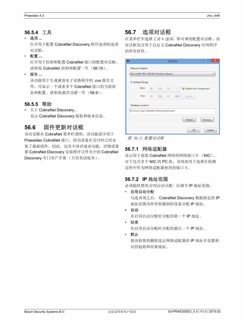
Praesideo 4.3 zhs | 448
Bosch Security Systems B.V. IUI-PRAESIDEO_4.3 | V1.0 | 2015.02安装说明和用户指南
56.5.4 工具• 选项 ...
打开用于配置 CobraNet Discovery 程序选项的选项
对话框。
• 配置 ...
打开用于控制和配置 CobraNet 接口的配置对话框。
请参阅 CobraNet 控制和配置一节(56.10)。
• 报告 ...
该功能用于生成兼容电子表格程序的 .cvs 报告文
件,可显示一个或者多个 CobraNet 接口的当前状
态和配置。请参阅报告功能一节(56.9)。
56.5.5 帮助• 关于 CobraNet Discovery...
显示 CobraNet Discovery 版权和版本信息。
56.6 固件更新对话框 该对话框从 CobraNet 菜单栏调用。该功能很少用于
Praesideo CobraNet 接口,因为设备在交付时已经安
装了 新固件。因此,这里不再详述该功能。详情请查
看 CobraNet Discovery 安装程序文件夹中的 CobraNet
Discovery 专门用户手册(只有英语版本)。
56.7 选项对话框 在菜单栏中选择工具 > 选项,即可调用配置对话框。该
对话框包含用于自定义 CobraNet Discovery 应用程序
的所有控件。
56.7.1 网络适配器 显示用于连接 CobraNet 网络的网络接口卡(NIC)。
对于包含多个 NIC 的 PC 机,该列表用于选择在检测
过程中作为网络适配器使用的接口卡。
56.7.2 IP 地址范围 必须临时禁用启用自动分配,以调节 IP 地址范围。
• 启用自动分配
勾选该项之后, CobraNet Discovery 根据指定的 IP
地址范围为所有检测到的设备分配 IP 地址。
• 启动
在启用自动分配时分配的第一个 IP 地址。
• 结束
在启用自动分配时分配的 后一个 IP 地址。
• 默认
按该按钮将删除选定网络适配器的 IP 地址并设置相
应的起始和结束地址。
图 56.2: 配置对话框
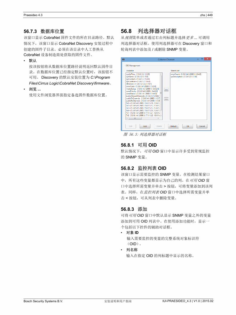
Praesideo 4.3 zhs | 449
Bosch Security Systems B.V. IUI-PRAESIDEO_4.3 | V1.0 | 2015.02安装说明和用户指南
56.7.3 数据库位置 该窗口显示 CobraNet 固件文件的所在目录路径。默认
情况下,该窗口显示 CobraNet Discovery 安装过程中
创建的固件子目录。必须在该目录中人工替换从
CobraNet 设备制造商处获取的固件文件。
• 默认
按该按钮将从数据库位置路径说明返回默认固件目
录。在数据库位置已经指定默认位置时,该按钮不
可用。 Discovery 的默认安装位置为 C:\Program
Files\Cirrus Logic\CobraNet Discovery\firmware。
• 浏览 ...
使用文件浏览器界面指定备选固件数据库位置。
56.8 列选择器对话框 从视图菜单或者通过右击列标题并选择更多 ... 可调用
列选择器对话框。使用列选择器可在 Discovery 窗口和
轮询列表中添加及 / 或删除 SNMP 变量。
56.8.1 可用 OID 默认情况下,可用 OID 窗口中显示许多受到常规监控
的 SNMP 变量。
56.8.2 监控列表 OID 该窗口显示需要监控的 SNMP 变量。在检测结果窗口
中,所有这些变量都显示为自己的列。在可用 OID 窗
口中选择所需变量并单击 > 按钮,可将变量添加到该列
表。同样,在监控列表 OID 窗口中选择所需变量并单
击 < 按钮,可从列表中删除变量。
56.8.3 添加 可将可用 OID 窗口中默认显示 SNMP 变量之外的变量
添加到可用 OID 列表中。在使用添加功能时,显示一
个包括以下控件的辅助对话框。
• 对象 ID
输入需要监控的变量的完整系统对象标识符
(OID)。
• 列名称
输入在指定 OID 的列标题中显示的名称。
图 56.3: 列选择器对话框
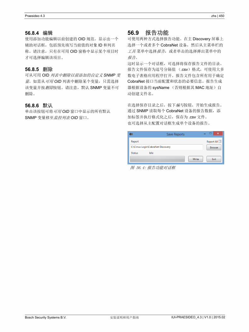
Praesideo 4.3 zhs | 450
Bosch Security Systems B.V. IUI-PRAESIDEO_4.3 | V1.0 | 2015.02安装说明和用户指南
56.8.4 编辑使用添加功能编辑以前创建的 OID 规范。显示出一个
辅助对话框,包括预先填写当前值的对象 ID 和列名
称。请注意,只有在可用 OID 窗格中显示某个项目时
才可选择编辑该项目。
56.8.5 删除可从可用 OID 列表中删除以前添加的自定义 SNMP 变
量。如需从可用 OID 列表中删除某个变量,只需选择
该变量并按删除按钮。请注意,默认 SNMP 变量不可
删除。
56.8.6 默认单击该按钮可将可用 OID 窗口中显示的所有默认
SNMP 变量移至监控列表 OID 窗口。
56.9 报告功能可使用两种方式选择报告功能。在主 Discovery 屏幕上
选择一个或者多个 CobraNet 设备,然后从主菜单栏的
工具 菜单中选择报告,或者单击的选择弹出菜单中的
报告。
这时显示一个对话框,可选择将保存报告文件的目录。
报告文件保存为逗号分隔值(.csv)格式,可使用大多
数电子表格应用程序打开。报告文件包含所有用于确定
CobraNet 接口当前配置和状态的必要信息。报告生成
器根据设备的 sysName (否则根据其 MAC 地址)自
动创建文件名。
在选择保存目录之后,按下编写按钮,开始生成报告。
通过 SNMP 读取每个 CobraNet 设备的报告数据,添
加标签并执行格式化之后,保存为 .csv 文件。
也可选择从主配置对话框生成单个设备的报告。
图 56.4: 报告功能对话框
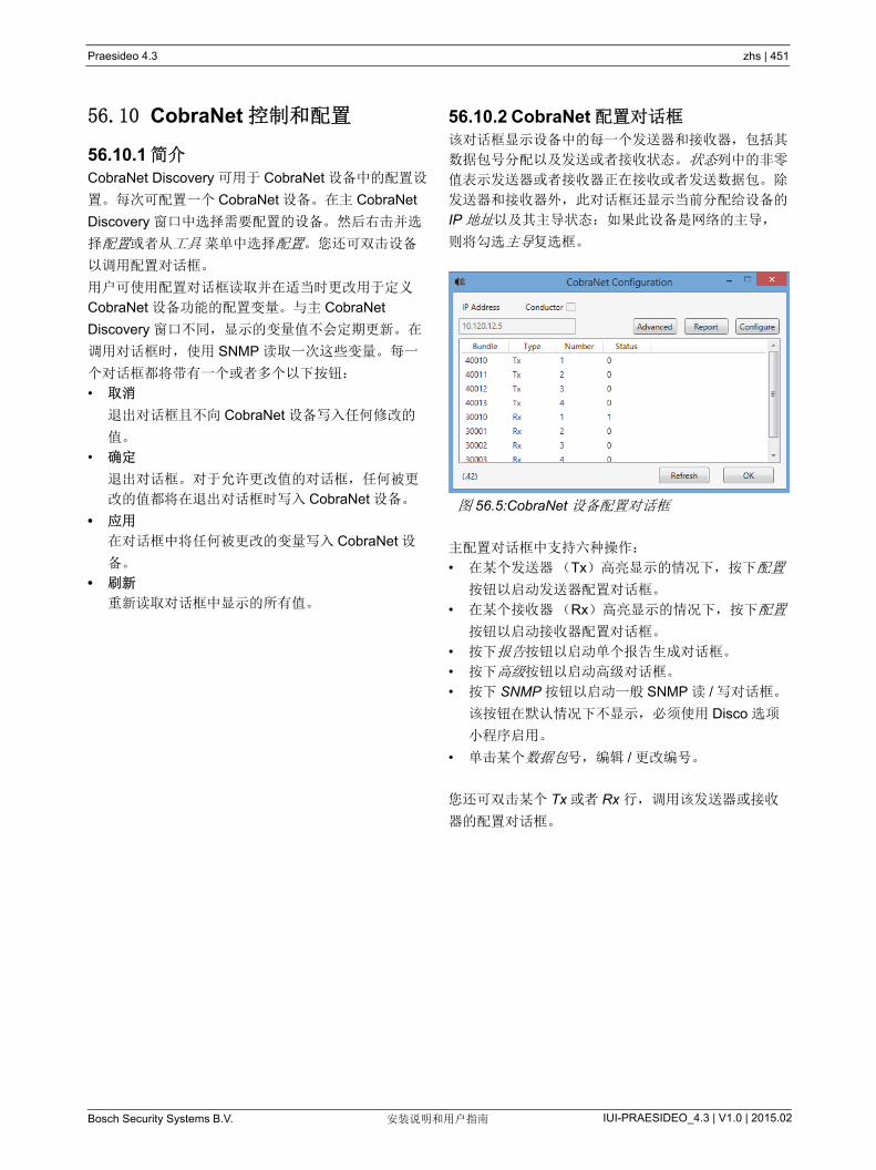
Praesideo 4.3 zhs | 451
Bosch Security Systems B.V. IUI-PRAESIDEO_4.3 | V1.0 | 2015.02安装说明和用户指南
56.10 CobraNet 控制和配置
56.10.1 简介 CobraNet Discovery 可用于 CobraNet 设备中的配置设
置。每次可配置一个 CobraNet 设备。在主 CobraNet
Discovery 窗口中选择需要配置的设备。然后右击并选
择配置或者从工具 菜单中选择配置。您还可双击设备
以调用配置对话框。
用户可使用配置对话框读取并在适当时更改用于定义
CobraNet 设备功能的配置变量。与主 CobraNet
Discovery 窗口不同,显示的变量值不会定期更新。在
调用对话框时,使用 SNMP 读取一次这些变量。每一
个对话框都将带有一个或者多个以下按钮:
• 取消
退出对话框且不向 CobraNet 设备写入任何修改的
值。
• 确定
退出对话框。对于允许更改值的对话框,任何被更
改的值都将在退出对话框时写入 CobraNet 设备。
• 应用
在对话框中将任何被更改的变量写入 CobraNet 设
备。
• 刷新
重新读取对话框中显示的所有值。
56.10.2 CobraNet 配置对话框 该对话框显示设备中的每一个发送器和接收器,包括其
数据包号分配以及发送或者接收状态。状态列中的非零
值表示发送器或者接收器正在接收或者发送数据包。除
发送器和接收器外,此对话框还显示当前分配给设备的
IP 地址以及其主导状态:如果此设备是网络的主导,
则将勾选主导复选框。
主配置对话框中支持六种操作:
• 在某个发送器(Tx)高亮显示的情况下,按下配置
按钮以启动发送器配置对话框。
• 在某个接收器(Rx)高亮显示的情况下,按下配置
按钮以启动接收器配置对话框。
• 按下报告按钮以启动单个报告生成对话框。
• 按下高级按钮以启动高级对话框。
• 按下 SNMP 按钮以启动一般 SNMP 读 / 写对话框。
该按钮在默认情况下不显示,必须使用 Disco 选项
小程序启用。
• 单击某个数据包号,编辑 / 更改编号。
您还可双击某个 Tx 或者 Rx 行,调用该发送器或接收
器的配置对话框。
图 56.5:CobraNet 设备配置对话框
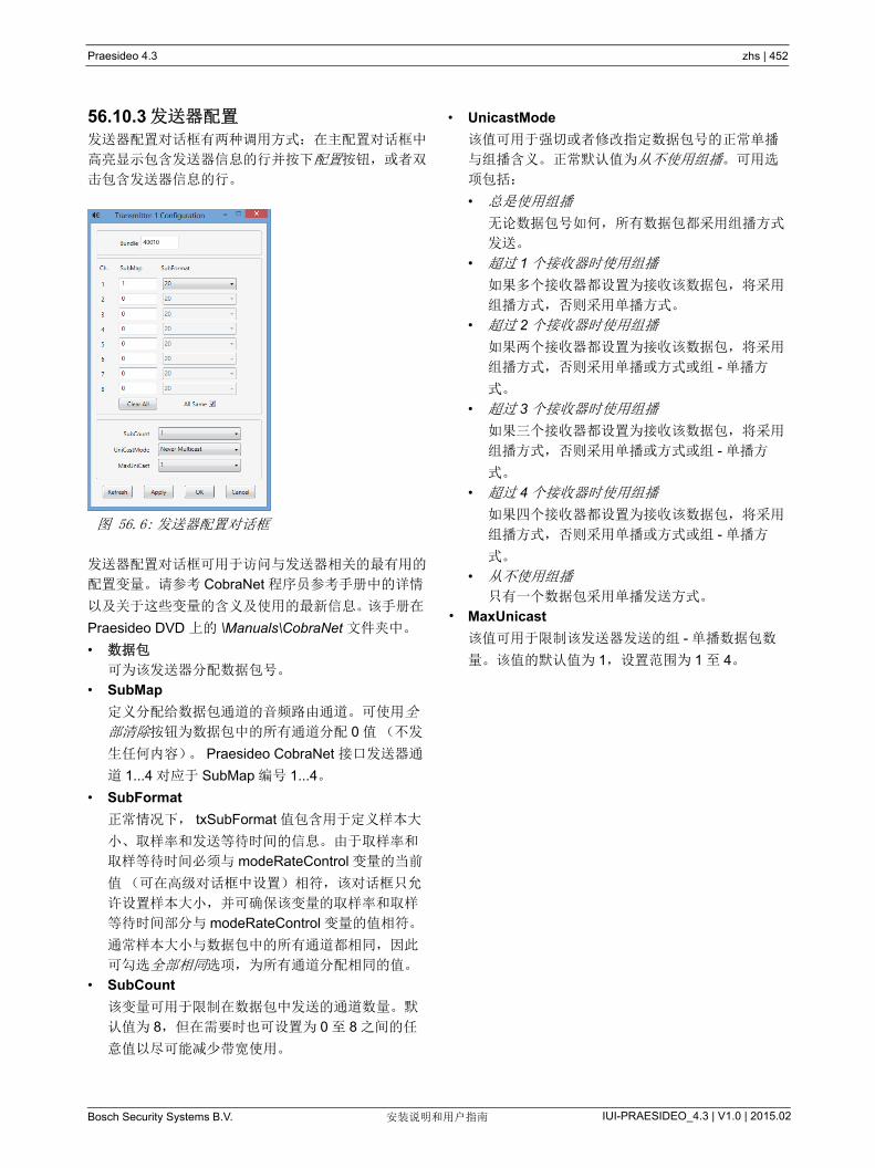
Praesideo 4.3 zhs | 452
Bosch Security Systems B.V. IUI-PRAESIDEO_4.3 | V1.0 | 2015.02安装说明和用户指南
56.10.3 发送器配置 发送器配置对话框有两种调用方式:在主配置对话框中
高亮显示包含发送器信息的行并按下配置按钮,或者双
击包含发送器信息的行。
发送器配置对话框可用于访问与发送器相关的 有用的
配置变量。请参考 CobraNet 程序员参考手册中的详情
以及关于这些变量的含义及使用的 新信息。该手册在
Praesideo DVD 上的 \Manuals\CobraNet 文件夹中。
• 数据包
可为该发送器分配数据包号。
• SubMap
定义分配给数据包通道的音频路由通道。可使用全
部清除按钮为数据包中的所有通道分配 0 值(不发
生任何内容)。 Praesideo CobraNet 接口发送器通
道 1...4 对应于 SubMap 编号 1...4。
• SubFormat
正常情况下, txSubFormat 值包含用于定义样本大
小、取样率和发送等待时间的信息。由于取样率和
取样等待时间必须与 modeRateControl 变量的当前
值(可在高级对话框中设置)相符,该对话框只允
许设置样本大小,并可确保该变量的取样率和取样
等待时间部分与 modeRateControl 变量的值相符。
通常样本大小与数据包中的所有通道都相同,因此
可勾选全部相同选项,为所有通道分配相同的值。
• SubCount
该变量可用于限制在数据包中发送的通道数量。默
认值为 8,但在需要时也可设置为 0 至 8 之间的任
意值以尽可能减少带宽使用。
• UnicastMode
该值可用于强切或者修改指定数据包号的正常单播
与组播含义。正常默认值为从不使用组播。可用选
项包括:
• 总是使用组播
无论数据包号如何,所有数据包都采用组播方式
发送。
• 超过 1 个接收器时使用组播
如果多个接收器都设置为接收该数据包,将采用
组播方式,否则采用单播方式。
• 超过 2 个接收器时使用组播
如果两个接收器都设置为接收该数据包,将采用
组播方式,否则采用单播或方式或组 - 单播方
式。
• 超过 3 个接收器时使用组播
如果三个接收器都设置为接收该数据包,将采用
组播方式,否则采用单播或方式或组 - 单播方
式。
• 超过 4 个接收器时使用组播
如果四个接收器都设置为接收该数据包,将采用
组播方式,否则采用单播或方式或组 - 单播方
式。
• 从不使用组播
只有一个数据包采用单播发送方式。
• MaxUnicast
该值可用于限制该发送器发送的组 - 单播数据包数
量。该值的默认值为 1,设置范围为 1 至 4。
图 56.6: 发送器配置对话框
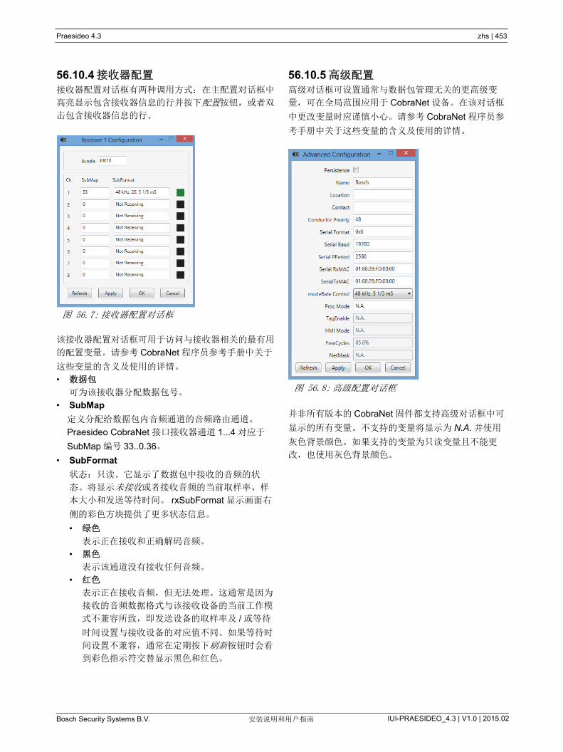
Praesideo 4.3 zhs | 453
Bosch Security Systems B.V. IUI-PRAESIDEO_4.3 | V1.0 | 2015.02安装说明和用户指南
56.10.4 接收器配置 接收器配置对话框有两种调用方式:在主配置对话框中
高亮显示包含接收器信息的行并按下配置按钮,或者双
击包含接收器信息的行。
该接收器配置对话框可用于访问与接收器相关的 有用
的配置变量。请参考 CobraNet 程序员参考手册中关于
这些变量的含义及使用的详情。
• 数据包
可为该接收器分配数据包号。
• SubMap
定义分配给数据包内音频通道的音频路由通道。
Praesideo CobraNet 接口接收器通道 1...4 对应于
SubMap 编号 33..0.36。
• SubFormat
状态:只读。它显示了数据包中接收的音频的状
态。将显示未接收或者接收音频的当前取样率、样
本大小和发送等待时间。 rxSubFormat 显示画面右
侧的彩色方块提供了更多状态信息。
• 绿色
表示正在接收和正确解码音频。
• 黑色
表示该通道没有接收任何音频。
• 红色
表示正在接收音频,但无法处理。这通常是因为
接收的音频数据格式与该接收设备的当前工作模
式不兼容所致,即发送设备的取样率及 / 或等待
时间设置与接收设备的对应值不同。如果等待时
间设置不兼容,通常在定期按下刷新按钮时会看
到彩色指示符交替显示黑色和红色。
56.10.5 高级配置 高级对话框可设置通常与数据包管理无关的更高级变
量,可在全局范围应用于 CobraNet 设备。在该对话框
中更改变量时应谨慎小心。请参考 CobraNet 程序员参
考手册中关于这些变量的含义及使用的详情。
并非所有版本的 CobraNet 固件都支持高级对话框中可
显示的所有变量。不支持的变量将显示为 N.A. 并使用
灰色背景颜色。如果支持的变量为只读变量且不能更
改,也使用灰色背景颜色。
图 56.7: 接收器配置对话框
图 56.8: 高级配置对话框

Praesideo 4.3 zhs | 454
Bosch Security Systems B.V. IUI-PRAESIDEO_4.3 | V1.0 | 2015.02安装说明和用户指南
56.11 DiscoOptionsDiscoOptions 是一个与 CobraNet Discovery 一同安装
的小程序,用于更改配置功能的运行参数。
56.11.1 一般用途该小程序可方便更改配置功能使用的运行参数。在任何
时候都可启动小程序,但在启动时只有配置对话框可读
取这些值。因此,该小程序应在配置对话框处于非活动
状态时使用。
默认值可在大多数情况下实现正常运行,除特殊情况或
者极端情况之外,无需更改。
在非常繁忙的网络访问某个设备或设备本身负荷极大
时, 好增加超时和重试次数值。
只有在按下确定时才可保存更改。按下取消或者关闭对
话框都将直接退出且不保存任何更改。
56.11.2 DiscoOptions 对话框字段• 读权限共同体
SNMP 读权限共同体。始终不必更改。默认:
public
• 写权限共同体
SNMP 写权限共同体。始终不必更改。默认:
private
• 超时
在中止运行之前等待 SNMP 响应的时间。该值以毫
秒为单位。 小允许值为 150 (0.15 秒),程序可
自动将所有值圆整至 近的 10 mS 值。默认:1500
• 重试次数
在出现故障时, SNMP 操作的 大重试次数。默
认:2
• 延时
SNMP 访问之间的等待时间(毫秒)。CobraNet 接
口要求使用延时。除极少数情况(被访问的设备承
受极大负荷)以外,不必更改默认值 10。绝对不得
将此值设置为低于 10。高于 80 的值将自动被减小
为 80。默认:10
• 启用配置
勾选该复选框可整体启用配置功能。如果不勾选该
复选框,无法从主 CobraNet Discovery 对话框启动
配置对话框。默认:勾选
• 启用报告
勾选该复选框可激活(转变为可见状态)配置对话
框中的报告按钮。默认:勾选
• 启用高级
勾选该复选框可激活(转变为可见状态)配置对话
框中的高级按钮。默认:勾选
• 启用 SNMP
勾选该复选框可激活(转变为可见状态)配置对话
框中的 SNMP 按钮。默认:不勾选
图 56.9:Discovery 配置对话框

Praesideo 4.3 zhs | 455
Bosch Security Systems B.V. IUI-PRAESIDEO_4.3 | V1.0 | 2015.02安装说明和用户指南
57 Dante 控制器的 OMNEO 配置
57.1 简介对于 OMNEO 接口的设置和配置,PRS-4OMI4 信息和
工具在三个地点的 Praesideo 安装 DVD 上均可用:
• 可选软件包列表中,可以选择 Dante 控制器。这是
可以下载 新版本的 Dante 控制器的 Audinate 网站
的链接。为了遵守 Audinate 的许可协议, Dante 控
制器程序本身并不在 DVD 上。发行 Praesideo 版本
4.3 时, Dante 控制器的 新版本是 Dante 控制器
v3.5.6.2 (Windows)。此程序用于配置和路由
OMNEO 和(或) Dante 的音频通道。
• 在 \Manuals 文件夹,用户指南可用于 Dante 控制
器和 Dante 虚拟声卡。
• 在 \Tools\PRS-4OMI4 配置工具文件夹中,安装程
序都可用来更改 OMNEO 接口的工厂固件。出厂时
安装的固件,内置以太网交换机可进行编程,进行
环接以太网布线。通过替换工厂固件就可以使
PRS-4OMI4 支持快速生成树协议(RSTP),进行
冗余的以太网连接,并从链路故障中自动恢复。
57.2 Dante 控制器Dante 控制器是由 Audinate 提供的应用软件,使用户
能配置和路由 Dante 网络周围的音频。其可用于
Windows 和 OS X。
一旦您在您的 PC 或 Mac 上安装了 Dante 控制器并将
其连接到网络上,您可以使用 Dante 控制器:
• 查看网络上所有的 Dante 启用的音频设备及其通道
• 查看 Dante 启用的设备时钟和网络设置
• 在这些设备上传送音频,并查看现有的音频路由的
状态
• 将音频通道的标签从数字更改为适当的名称
• 自定义接收延迟(播放前的等待时间)
• 保存音频路由预设值
• 应用先前保存的预设值
• 编辑脱机预设值,并将作为新的网络部署的配置加
以应用
• 按设备配置选项查看和设置
• 查看网络状态信息,包括网络中的多播带宽,然后
传输和接收每个设备的带宽
• 查看设备的性能信息,包括延迟统计和数据包错误
• 查看每个设备的时钟状态信息,包括频率偏移历史
记录和时钟事件日志
57.3 安装或更新 Dante 控制器若要安装 Dante 控制器,则需要使用管理员权限登录。
不需要在安装更新之前卸载以前的版本。因为
Windows 的 Dante 控制器 V3.4.0, Apple Bonjour 服
务不再用于 Windows 的 Dante 控制器的设备发现,则
现在改用 Audinate 的 ‘Dante Discovery’。 Windows 下
的 Dante Discovery 是自动安装的。
若要安装 Dante 控制器:
• 请确保您是以管理员身份登录到您的计算机的。
• 导航并双击下载的 Dante 控制器安装程序文件。
• 阅读许可协议。如果您同意条款,请选择 ‘ 我同意 '
复选框,然后单击 “ 安装 ”。如果您不同意条款,则
单击 “ 关闭 ”。
• 确认所显示的任何 Windows 安全提示。
• 安装以后需要重新启动电脑。
Praesideo 手册的这一节作为 Dante 控制器的快速入
门。更多的信息可以 Dante 控制器用户指南中找到。
下列 低 PC 要求适用于:
• 1 GHz 处理器或以上版本
• Microsoft® Windows® 7 SP1 及以上、Windows 8
或 Windows 8.1
• 1 GB RAM
• 有线以太网连接:100 BASE-T 或 1000 BASE-T。
不支持 Wi-Fi 网络连接。
图 57.1: 可选软件包 Dante 控制器
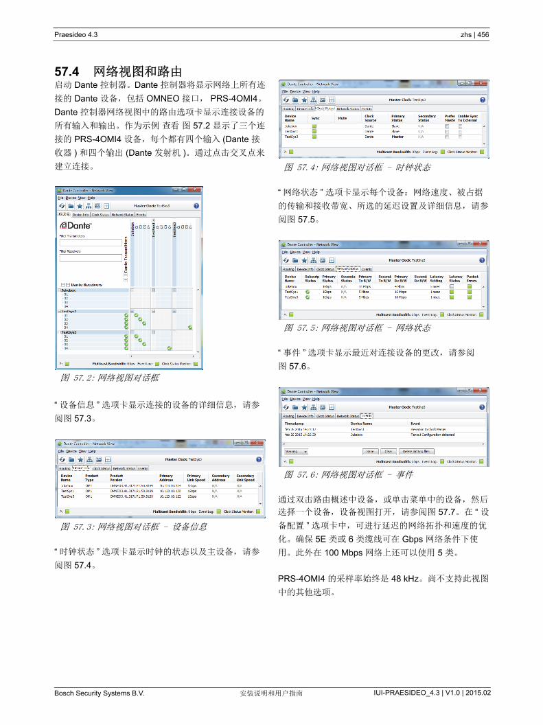
Praesideo 4.3 zhs | 456
Bosch Security Systems B.V. IUI-PRAESIDEO_4.3 | V1.0 | 2015.02安装说明和用户指南
57.4 网络视图和路由启动 Dante 控制器。Dante 控制器将显示网络上所有连
接的 Dante 设备,包括 OMNEO 接口, PRS-4OMI4。
Dante 控制器网络视图中的路由选项卡显示连接设备的
所有输入和输出。作为示例 查看 图 57.2 显示了三个连
接的 PRS-4OMI4 设备,每个都有四个输入 (Dante 接
收器 ) 和四个输出 (Dante 发射机 )。通过点击交叉点来
建立连接。
“ 设备信息 ” 选项卡显示连接的设备的详细信息, 请参
阅图 57.3。
“ 时钟状态 ” 选项卡显示时钟的状态以及主设备, 请参
阅图 57.4。
“ 网络状态 ” 选项卡显示每个设备:网络速度、被占据
的传输和接收带宽、所选的延迟设置及详细信息, 请参
阅图 57.5。
“ 事件 ” 选项卡显示 近对连接设备的更改, 请参阅
图 57.6。
通过双击路由概述中设备,或单击菜单中的设备,然后
选择一个设备,设备视图打开, 请参阅图 57.7。在 “ 设
备配置 ” 选项卡中,可进行延迟的网络拓扑和速度的优
化。确保 5E 类或 6 类缆线可在 Gbps 网络条件下使
用。此外在 100 Mbps 网络上还可以使用 5 类。
PRS-4OMI4 的采样率始终是 48 kHz。尚不支持此视图
中的其他选项。
图 57.2: 网络视图对话框
图 57.3: 网络视图对话框 - 设备信息
图 57.4: 网络视图对话框 - 时钟状态
图 57.5: 网络视图对话框 - 网络状态
图 57.6: 网络视图对话框 - 事件

Praesideo 4.3 zhs | 457
Bosch Security Systems B.V. IUI-PRAESIDEO_4.3 | V1.0 | 2015.02安装说明和用户指南
“ 网络配置 ” 选项卡显示设备的 IP 设置和设备是否支持
RSTP 以实现网络冗余, 请参阅 图 57.8。工厂设置是
非 RSTP。需要上传一个新的固件,来更改此设置,请
参阅第 57.5 节。
“ 状态 ” 选项卡显示设备的信息,包括软件的版本信息
和被占据的接口网络带宽,请参阅 图 57.9。
.
图 57.7: 设备视图对话框 - 设备配置
图 57.8: 设备视图对话框 - 网络配置
图 57.9: 设备视图对话框 - 状态
注
已成为 Bosch 会议系统(DCNm)一部分的
PRS-4OMI4 设备使用不同的音频编码和加密。
这些设备不能用于 Praesideo 系统。

Praesideo 4.3 zhs | 458
Bosch Security Systems B.V. IUI-PRAESIDEO_4.3 | V1.0 | 2015.02安装说明和用户指南
57.5 更新 OMNEO 固件在 Praesideo 的发行 DVD 上, \Tools\PRS-4OMI4 配
置 文件夹中工具安装程序(安装程序)可用于更改
OMNEO 接口的工厂固件。 出厂时安装的固件,内置以
太网交换机可进行编程,进行环接以太网布线。通过替
换工厂固件就可以使 PRS-4OMI4 支持快速生成树协议
(RSTP),进行冗余的以太网连接,并从链路故障中
自动恢复。请与您的系统管理员一起检查网络是否支持
RSTP。
存在以下安装程序文件:
• SetupOMNEOFirmwareUploadTool.msi
• SetupOMNEOFirmwareUploadTool64.msi
• PRS-4OMI4 Network Firmware V4.30.xxxx.msi
Windows 32 位操作系统下运行
SetupOMNEOFirmwareUploadTool.msi ; Windows
64 位操作系统下运行
SetupOMNEOFirmwareUploadTool64.msi。这将安装
OMNEO 固件上载工具。为此,您需要 Windows 管理
员权限。
然后运行 PRS 4OMI4 网络固件 V4.30.xxxx.msi。此安
装程序将两个固件文件复制到正确的位置上,让固件上
传工具找到它们,其位于
\ProgramData\Bosch\OMNEO\Firmware。
现在,启动固件上传工具,像图 57.10 之类的闪屏会出
现在网络适配器选择器框中,请参阅图 57.11。
选择连接到 OMNEO 网络上的 PC 机的网络适配器。
然后出现主窗口,显示连接的 OMNEO 设备,请参阅
图 57.12。
“ 角色 ” 列显示每个设备中的 OMNEO 网络适配器是否
支持 RSTP 在 RSTP 网络中使用。本概述中显示的列
可以通过菜单栏中的 “ 视图 ” 进行更改,请参阅
图 57.13。
选择需要不同固件的设备,请参阅 图 57.14。可以使用
Ctrl 键或 Shift 键选择多个设备进行单个操作中的同时
上传。图 57.10:OMNEO 固件上传工具
图 57.11: 网络适配器选择对话框
图 57.12: 连接的 OMNEO 设备对话框
图 57.13: 选择设备列表列对话框
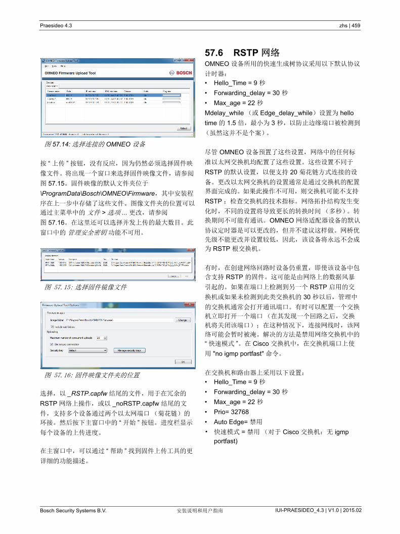
Praesideo 4.3 zhs | 459
Bosch Security Systems B.V. IUI-PRAESIDEO_4.3 | V1.0 | 2015.02安装说明和用户指南
按 “ 上传 ” 按钮,没有反应,因为仍然必须选择固件映
像文件。将出现一个窗口来选择固件映像文件,请参阅
图 57.15。固件映像的默认文件夹位于
\ProgramData\Bosch\OMNEO\Firmware,其中安装程
序在上一步中存储了这些文件。图像文件夹的位置可以
通过主菜单中的 文件 > 选项 ... 更改,请参阅
图 57.16。在这里还可以选择并发上传的 大数目。此
窗口中的 管理安全密钥 功能不可用。
选择,以 _RSTP.capfw 结尾的文件,用于在冗余的
RSTP 网络上操作,或以 _noRSTP.capfw 结尾的文
件,支持多个设备通过两个以太网端口(菊花链)的
环接。然后按下主窗口中的 “ 开始 ” 按钮。进度栏显示
每个设备的上传进度。
在主窗口中,可以通过 “ 帮助 ” 找到固件上传工具的更
详细的功能描述。
57.6 RSTP 网络OMNEO 设备所用的快速生成树协议采用以下默认协议
计时器:
• Hello_Time = 9 秒
• Forwarding_delay = 30 秒
• Max_age = 22 秒
Mdelay_while (或 Edge_delay_while)设置为 hello
time 的 1.5 倍, 小为 3 秒,以防止边缘端口被检测到
(虽然这并不是个案)。
尽管 OMNEO 设备预置了这些设置,网络中的任何标
准以太网交换机均配置了这些设置。这些设置不同于
RSTP 的默认设置,以便支持 20 菊花链方式连接的设
备。更改以太网交换机的设置通常是通过交换机的配置
界面完成的。如果此操作不可用,则交换机可能不支持
RSTP ;检查交换机的技术指标。网络拓扑结构发生变
化时,不同的设置将导致更长的转换时间(多秒)。转
换期间不可能有通讯。OMNEO 网络适配器设备的默认
协议定时器是可以更改的,但并不建议这样做。网桥优
先级不能更改并设置较低,因此,该设备将永远不会成
为 RSTP 根交换机。
有时,在创建网络回路时设备仍重置,即使该设备中包
含支持 RSTP 的固件。这可能是由网络上的数据风暴
引起的。如果在端口上检测到另一个 RSTP 启用的交
换机或如果未检测到此类交换机的 30 秒以后,管理中
的交换机通常会打开通讯端口。有时可以配置一个交换
机立即打开一个端口(在其发现一个回路之后,交换
机将关闭该端口);在这种情况下,连接网线时,该网
络可能会暂时被淹。解决的方法是禁用网络交换机中的
“ 快速模式 ”。在 Cisco 交换机中,在交换机端口上使
用 "no igmp portfast" 命令。
在交换机和路由器上采用以下设置:
• Hello_Time = 9 秒
• Forwarding_delay = 30 秒
• Max_age = 22 秒
• Prio= 32768
• Auto Edge= 禁用
• 快速模式 = 禁用(对于 Cisco 交换机:无 igmp
portfast)
图 57.14: 选择连接的 OMNEO 设备
图 57.15: 选择固件镜像文件
图 57.16: 固件映像文件夹的位置
Praesideo 4.3 zhs | 460
Bosch Security Systems B.V. IUI-PRAESIDEO_4.3 | V1.0 | 2015.02安装说明和用户指南
57.7 Dante 虚拟声卡Dante 虚拟声卡(DVS)可从 Audinate 上购买。其可
从其网站上下载:https://www.audinate.com/products/
software/dante-virtual-soundcard.DVS 并不是 Bosch
Security Systems 的产品,也不受 Bosch Security
Systems 的支持。放在这里仅仅作为一个选项与
PRS 4OMI4 一起使用。
此程序打开 PC,并安装到一个多通道 Dante 启用的音
频设备中。这意味着,比如内置的 PC 麦克风,或连接
到 PC 的音频输入端的麦克风或 USB 麦克风连接到
USB 端口之一的 USB 麦克风,均可用作 Praesideo
PC 呼叫站的麦克风。在这种情况下, PRS-4OMI4 通
过 Dante 接收该麦克风信号,并且其相应的 Praesideo
输入端应配置为从 PC 呼叫站启动的呼叫的音频源。然
后,单独布线的 Praesideo 基本呼叫站需要作为音频
源。
DVS 还可以与 PC 机上的多个音乐和媒体播放器相结
合,用于创建进入 Praesideo 的背景音乐流或消息流。
警告
重新启动电脑后, DVS 并不总是自动恢复操
作,也可能需要用户手动进行干预。

Praesideo 4.3 zhs | 461
Bosch Security Systems B.V. IUI-PRAESIDEO_4.3 | V1.0 | 2015.02安装说明和用户指南
58 记录服务器
58.1 简介通过 Logging Server( 记录服务器 ),可以记录 多
64 个系统产生的事件。一般地, Logging Server( 记录
服务器 ) 在与记录事件的所有系统相连的 PC 上运行。
Logging Server (记录服务器)将事件储存在数据库
中。
58.2 要求Logging Server (记录服务器)可以在满足以下 低要
求的任何 PC 上运行:
• 操作系统:
Microsoft® Windows 7、 8 或 8.1
• 网络连接:100 base-T
• 1 GB RAM
• 空闲的磁盘空间:取决于须存储的事件数,但建议
至少留出 10 GB 的空闲磁盘空间。
• 经常用 新的 Windows 更新版本来更新 PC 是良好
的习惯做法。这可确保 PC 包含 Logging Server
(记录服务器)所使用的 Microsoft® Jet 4.0 数据库
的 新版本和服务包。 ( 请参阅 http://support
.microsoft .com/common/international.aspx)。
58.3 安装按以下步骤进行:
1 启动 PRS-SW Praesideo 软件 DVD (请参阅
第 36.2 节)。
2 2 单击 Optional( 可选 ) > Logging Application
Server( 记录应用程序服务器 )。出现 File Download
(文件下载)窗口。
3 单击 Open( 打开 ) 按钮启动 Logging Server( 记录
录服务器 ) 的安装程序。会出现类似图 58.1 的界
面。
4 按照界面显示的指示。当安装结束时,有提示出
现。
记录服务器的界面可以提供不同的语言。在记录服务器
的安装过程中,已将大量语言文件夹安装在了以下位
置:
\Program Files\Bosch\Praesideo\Programs\ Logging
Serve。
语言文件夹按 2 字母国际语言代码(ISO639)来命
名,例如, ‘en’ 表示英语, ‘ru’ 表示俄语。
5 检查此文件夹,以查看是否提供了您所需要的语
言。如果适用于已安装 Windows 操作系统的语言的
语言文件夹存在,则该语言即为记录服务器的语
言。如果需要另外一种语言,并且该语言的语言文
件夹存在,则请执行以下步骤:
6 将语言参数添加至记录服务器程序。该参数是 2 个
字母的语言缩写,例如, “fi”,也就是语言代码之后
空格。对于记录服务器,请转至启动文件夹,以添
加参数:Start( 开始 )> Programs( 程序 )> Startup
(启动) > Logging Server (记录服务器)。
图 58.1: 记录服务器设置

Praesideo 4.3 zhs | 462
Bosch Security Systems B.V. IUI-PRAESIDEO_4.3 | V1.0 | 2015.02安装说明和用户指南
7 右键单击记录服务器,选择属性并选择 Tab 快捷方
式。
8 将 “fi” 参数添加至以 .exe 〞结尾的目标描述,即双
引号之后。
9 如果未将记录服务器安装成自动启动,并且不存在
于启动文件夹中,则请创建程序文件的快捷方式,
然后右键单击该快捷方式(也可以放在桌面上),
单击属性并选择 Tab 快捷方式。
10 将 “fi” 参数添加至以 .exe 〞结尾的目标描述,即双
引号之后。使用快捷方式启动程序。当然,请使用
您所选择的语言缩写来替换 “fi”。
58.4 开始Windows 启动时, PC 自动启动 Logging Server (记
录服务器)。为了指示 Logging Server (记录服务器)
已启动并且工作正常, Windows 任务栏的系统盘中出
现一图标(请参阅图 58.2)。
Logging Server( 记录服务器 ) 已启动,并且 Praesideo
和记录系统之间的通信出现故障时,此图标将被标上红
叉(请参阅图 58.3)。
PC 未自动启动 Logging Server (记录服务器)时,人
工将其启动的过程如下:
1 进入 “ 开始 ”>“ 程序 ”>“Bosch”>“Praesideo”
2 单击 Logging Server (记录服务器)。 Windows 任
务栏的系统盘中出现新图标(请参阅图 58.2 和
图 58.3)。
图 58.2: 记录服务器图标(正常运行)
图 58.3: 记录服务器图标(出现故障)
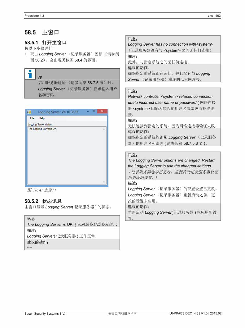
Praesideo 4.3 zhs | 463
Bosch Security Systems B.V. IUI-PRAESIDEO_4.3 | V1.0 | 2015.02安装说明和用户指南
58.5 主窗口
58.5.1 打开主窗口按以下步骤进行:
1 双击 Logging Server (记录服务器)图标(请参阅
图 58.2)。会出现类似图 58.4 的界面。
58.5.2 状态讯息主窗口显示 Logging Server( 记录服务器 ) 的状态。
注
启用服务器验证(请参阅第 58.7.5 节)时,
Logging Server (记录服务器)要求输入用户
名和密码。
图 58.4: 主窗口
讯息:
The Logging Server is OK. ( 记录服务器准备就绪。)
描述:
Logging Server( 记录服务器 ) 工作正常。
建议的动作:
----
讯息:
Logging Server has no connection with<system>
(记录服务器没有与 <system> 之间无任何连接)
描述:
此外,与指定系统之间无任何连接。
建议的动作:
确保指定的系统正在运行,并且配有与 Logging
Server (记录服务器)相连的以太网连接。
讯息:
Network controller <system> refused connection
dueto incorrect user name or password.( 网络连接
器 <system> 因输入错误的用户名或密码而拒绝连
接。
描述:
无法连接到指定的系统,因为网络连接器验证失败。
建议的动作:
确保指定的系统能识别 Logging Server (记录服务
器)的用户名和密码 ( 请参阅第 58.7.5.3 节 )。
讯息:
The Logging Server options are changed. Restart
the Logging Server to use the changed settings.
(记录服务器选项已更改。重新启动记录服务器以应
用更改的设置。)
描述:
Logging Server (记录服务器)的配置设置已更改。
Logging Server (记录服务器)重新启动之前,更
改的设置未应用。
建议的动作:
重新启动 Logging Server( 记录服务器 ) 以应用新设
置。
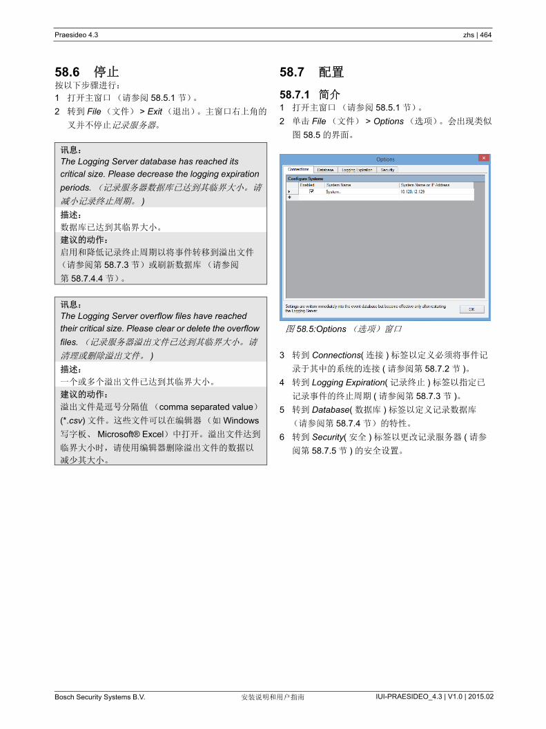
Praesideo 4.3 zhs | 464
Bosch Security Systems B.V. IUI-PRAESIDEO_4.3 | V1.0 | 2015.02安装说明和用户指南
58.6 停止按以下步骤进行:
1 打开主窗口(请参阅 58.5.1 节)。
2 转到 File(文件) > Exit(退出)。主窗口右上角的
叉并不停止记录服务器。
58.7 配置
58.7.1 简介1 打开主窗口(请参阅 58.5.1 节)。
2 单击 File (文件) > Options (选项)。会出现类似
图 58.5 的界面。
3 转到 Connections( 连接 ) 标签以定义必须将事件记
录于其中的系统的连接 ( 请参阅第 58.7.2 节 )。
4 转到 Logging Expiration( 记录终止 ) 标签以指定已
记录事件的终止周期 ( 请参阅第 58.7.3 节 )。
5 转到 Database( 数据库 ) 标签以定义记录数据库
(请参阅第 58.7.4 节)的特性。
6 转到 Security( 安全 ) 标签以更改记录服务器 ( 请参
阅第 58.7.5 节 ) 的安全设置。
讯息:
The Logging Server database has reached its
critical size. Please decrease the logging expiration
periods. (记录服务器数据库已达到其临界大小。请
减小记录终止周期。 )
描述:
数据库已达到其临界大小。
建议的动作:
启用和降低记录终止周期以将事件转移到溢出文件
(请参阅第 58.7.3 节)或刷新数据库(请参阅
第 58.7.4.4 节)。
讯息:
The Logging Server overflow files have reached
their critical size. Please clear or delete the overflow
files. (记录服务器溢出文件已达到其临界大小。请
清理或删除溢出文件。 )
描述:
一个或多个溢出文件已达到其临界大小。
建议的动作:
溢出文件是逗号分隔值(comma separated value)
(*.csv) 文件。这些文件可以在编辑器(如 Windows
写字板、 Microsoft® Excel)中打开。溢出文件达到
临界大小时,请使用编辑器删除溢出文件的数据以
减少其大小。
图 58.5:Options (选项)窗口

Praesideo 4.3 zhs | 465
Bosch Security Systems B.V. IUI-PRAESIDEO_4.3 | V1.0 | 2015.02安装说明和用户指南
58.7.2 连接58.7.2.1 简介
Logging Server (记录服务器)可以记录多达 64 个系
统产生的事件。系统的连接必须在 Connections (连
接)标签上进行定义。
58.7.2.2 添加系统
按以下步骤进行:
1 单击以星号 (*) 标记的行中的 Enabled (启用)字
段。新行添加到系统列表(请参阅图 58.6)。
2 单击 System Name (系统名)字段,输入必须与
Logging Server (记录服务器)相连的系统名。此
名称 多可以包含 16 个字符。如, System4 (系
统 4)(请参阅图 58.7)。
3 单击 System Name( 系统名 ) 或 IP Address (IP 地
址)字段,输入必须与 Logging Server (记录服务
器)相连的系统的网络控制器的名称和 IP 地址。
如, 192.168.0.18 (请参阅图 58.8)。
58.7.2.3 禁用系统的事件记录
要禁用系统的事件记录,请去掉其 Enabled( 禁用 ) 复
选框中的复选标记。
图 58.6: 添加系统 (1)
图 58.7: 添加系统 (2)
注
如果未使用网络控制器的名称,那么网络控制
器的 IP 地址必须存储在 Windows hosts
file(Windows 主机文件 )(WINNT\system32\
drivers\etc.) 中。可以使用记事本编辑此文件。
图 58.8: 添加系统 (3)
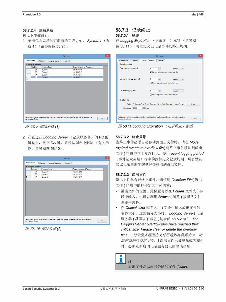
Praesideo 4.3 zhs | 466
Bosch Security Systems B.V. IUI-PRAESIDEO_4.3 | V1.0 | 2015.02安装说明和用户指南
58.7.2.4 删除系统
按以下步骤进行:
1 单击包含系统的行前面的字段。如, System4 (系
统 4)(请参阅图 58.9)。
2 在正运行 Logging Server (记录服务器)的 PC 的
键盘上,按下 Del 键。系统从列表中删除(有关示
例,请参阅图 58.10)。
58.7.3 记录终止58.7.3.1 概述
在 Logging Expiration (记录终止)标签(请参阅
图 58.11),可以定义已记录事件的终止周期。
58.7.3.2 终止周期
当终止事件必须自动移动到溢出文件时,请在 Move
expired events to overflow file( 将终止事件移动到溢出
文件 ) 字段中作上复选标记。使用 event logging period
(事件记录周期)行中的控件定义记录周期。所有默认
的比记录周期早的事件都移动到溢出文件。
58.7.3.3 溢出文件
溢出文件包含已终止事件。请使用 Overflow File( 溢出
文件 ) 区块中的控件定义下列内容:
• 溢出文件的位置。此位置可以在 Folder( 文件夹 ) 字
段中输入,也可以利用 Browse( 浏览 ) 按钮从文件
系统中选择。
• 在 Critical size( 临界大小 ) 字段中输入溢出文件的
临界大小。达到临界大小时, Logging Server( 记录
服务器 ) 显示以下讯息 ( 请参阅 58.5.2 节 ):The
Logging Server overflow files have reached their
critical size. Please clear or delete the overflow
files. (记录服务器溢出文件已达到其临界大小。请
清理或删除溢出文件。) 溢出文件已被删除或者减少
时,必须重新启动记录服务器以删除该讯息。
图 58.9: 删除系统 (1)
图 58.10: 删除系统 (2)
图 58.11:Logging Expiration (记录终止)标签
注
溢出文件是以逗号分隔的文件 (*.csv)。

Praesideo 4.3 zhs | 467
Bosch Security Systems B.V. IUI-PRAESIDEO_4.3 | V1.0 | 2015.02安装说明和用户指南
58.7.4 数据库58.7.4.1 概述
在 Database (数据库)标签(请参阅图 58.12)上,
可以定义记录数据库的特性。
58.7.4.2 新事件
使用 Recent events( 新事件 ) 区块定义 Logging
Viewer( 记录查看器 ) 中显示的 新事件数 ( 请参阅
59.6.2.3)。
58.7.4.3 数据库文件
请使用 Database file (数据库文件)区块中的控件定
义下列内容:
• 记录数据库的位置。此位置可以在上面的文本框中
输入。
• 记录数据库的临界大小。达到临界大小时,Logging
Server( 记录服务器 ) 显示以下讯息 ( 请参阅 58.5.2
节 ) :The Logging Server database has reached
its critical size. Please decrease the logging
expiration periods. (记录服务器数据库已达到其临
界大小。请减小记录终止周期。 )
可以制作记录数据库的备份(即使记录服务器正在运
行)。当制作正在运行的记录服务器的备份时,建议您
稍等片刻,这段时间可能会出现一些事件 ( 即几乎不存
在正在运行呼叫时 )。制作备份期间出现的事件不会复
制到记录数据库。然而,可以通过标准的 Windows 事
件查看器 (Windows 事件查看器 )(Start > Settings >
Control panel > Administrative Tools > Event Viewer)
来查看备份过程中出现的事件。
58.7.4.4 刷新事件
使用 Flush events (刷新事件)区块中的控件刷新记
录数据库中的事件。按以下步骤进行:
1 如果必须从记录数据库中删除故障事件,请在 Fault
events( 故障事件 ) 复选框内作上复选标记。
2 如果必须从记录数据库中删除一般事件,请在
General events( 一般事件 ) 复选框内作上复选标
记。
3 如果必须从记录数据库中删除呼叫事件,请在 Call
events( 呼叫事件 ) 复选框内作上复选标记。
4 单击 Flush now (立即刷新)按钮以刷新记录数据
库中所选类型的事件。
• 如果 Logging Expiration (记录过期)选项卡上
所选类型的事件的 Move expired events to
overflow file (将已过期的事件移动到溢出文件)
字段包含复选标记(请参阅 58.7.3 节),则所
选类型的事件会存入到溢出文件。
• 如果 Logging Expiration (记录过期)选项卡上
所选类型的事件的 Move expired events to
overflow file (将已过期的事件移动到溢出文件)
字段未带有复选标记(请参阅 58.7.3 节),则
所选类型的事件会从数据库中删除。
58.7.5 安全
图 58.12:Database (数据库)标签
注
仅供专家使用:记录数据库是 Microsoft®
Access 文件,该文件可通过 Microsoft®
Access 打开。无论数据库因何种原因损坏并
且记录服务器无法访问数据库,可通过
Microsoft® Access 修复该数据库。
关闭 Logging Server( 记录服务器 ) 应用程序。
使用 Microsoft® Access 打开数据库。
选择:工具 > 数据库实用工具 > 压缩和修复数
据库。
注
刷新数据库并重新启动 Logging Server ( 记录
服务器 ) 时,从已启用的网络控制器中检索到
的事件将加载到数据库。每个已启用的网络控
制器都保存有内部列表,对于每种类型,此列
表 多可以包含 200 个事件。使用 File
Transfer( 文件传输 ) 应用程序以清理内部列表
( 请参阅第 37.6 节 )。

Praesideo 4.3 zhs | 468
Bosch Security Systems B.V. IUI-PRAESIDEO_4.3 | V1.0 | 2015.02安装说明和用户指南
58.7.5.1 概述
在 Security (安全)标签(请参阅图 58.13)上,可
以定义安全设置。
58.7.5.2 服务器验证
请使用 Server authentication (服务器验证)区块中的
控件完成以下操作:
• 使用 Use authentication (使用验证)复选框启用
和禁用服务器验证。启用服务器验证时,必须输入
用户名和密码以访问主窗口(请参阅 58.5.1 节)。
• 利用 Change User Name/Password(更改用户名 \
密码)按钮设置密码和用户名以访问 Logging
Server (记录服务器)。启用服务器验证时才可以
设置密码和用户名。密码必须包含至少五个 (5) 字
符。用户名必须包含至少四个 (4) 字符。
58.7.5.3 查看器 / 网络控制器验证
请使用 Viewer/Network controller authentication( 查看
器 / 网络控制器验证 ) 区块中控件设置密码和用户名,
这些密码和用户名具有下列功能:
• 向 Logging Viewer( 记录查看器 ) 赋于对 Logging
Server( 记录服务器 )( 请参阅 59.6.2.5 节 ) 的访问权
限。
• 向 Logging Server (记录服务器)赋于对所有已连
接的网络连接器的访问权限。
图 58.13:Security (安全)标签
注
确保所有系统在 Viewer/Network controller( 查
看器 / 网络连接器 ) 区块中带有包含用户名和
密码的帐户 ( 请参阅第 41.2 节 )。否则,
Logging Server( 记录服务器 ) 无法连接到系
统。

Praesideo 4.3 zhs | 469
Bosch Security Systems B.V. IUI-PRAESIDEO_4.3 | V1.0 | 2015.02安装说明和用户指南
59 记录查看器
59.1 简介通过 Logging Viewer( 记录查看器 ) 可以查看 Logging
Server( 记录服务器 ) 在数据库中记录的事件。一般
地, Logging Viewer( 记录查看器 ) 在与 Logging
Server( 记录服务器 )( 请参阅第 57 章 ) 所运行的 PC 相
连的 PC 上运行。数据库与记录服务器位于相同的 PC
中。
59.2 要求Logging Viewer (记录查看器)可以在满足以下 低
要求的任何 PC 上运行:
• 操作系统:
Microsoft® Windows 7、 8 或 8.1
• 网络连接:100 base-T
• 1 GB RAM
59.3 安装按以下步骤进行:
1 启动 PRS-SW Praesideo 软件 DVD (请参阅 36.2
节)。
2 单击 Optional( 可选 ) > Logging Application Viewer
(记录应用程序查看器)。出现 File Download (文
件下载)窗口。
3 单击 Open( 打开 ) 按钮启动 Logging Viewer( 记录
查看器 ) 的安装程序。会出现类似图 59.1 的界面。
4 按照界面显示的指示。当安装结束时,有提示出
现。
记录查看器能够以不同语言来显示其用户界面和记录事
件。在记录查看器的安装过程中,已将大量语言文件夹
安装在以下位置:
Program Files\Bosch\Praesideo\Programs\Logging
Viewer。语言文件夹按 2 字母国际语言代码 (ISO639)
来命名,例如, ‘en’ 表示英语, ‘ru’ 表示俄语。
5 检查此文件夹,以查看是否提供了您所需要的语
言。如果适用于已安装 Windows 操作系统的语言的
语言文件夹存在,则该语言即为记录服务器的语
言。如果需要另外一种语言,并且该语言的语言文
件夹存在,则请执行以下步骤:
6 将语言参数添加至记录查看器程序。该参数是 2 个
字母的语言缩写,例如, “fi”,也就是语言代码之后
空格。对于记录查看器,请创建程序文件的快捷方
式,然后右键单击该快捷方式 ( 也可以放在桌面上
),单击属性并选择 Tab 快捷方式。
7 将 “fi” 参数添加至以 .exe 〞结尾的目标描述,即双
引号之后。使用快捷方式启动程序。当然,请使用
您所选择的语言缩写来替换 “fi”。
59.4 开始按以下步骤进行:
1 进入 “ 开始 ”>“ 程序 ”>“Bosch”>“Praesideo”
2 单击 Logging Viewer( 记录查看器 )。会出现类似
图 59.4 的界面。
• Logging Viewer (记录查看器)已启动并出现故
障时,其图标会显示故障情况(请参见
图 59.2)。
图 59.1: 记录查看器设置
图 59.2:Logging Viewer( 记录查看器 ) 图标 ( 出现故
障 )
注
在 Windows 中,任务栏按钮应配置为 “ 从不
合并 ” 相似的任务栏按钮。 否则,故障情况将
不会显示在任务栏上。

Praesideo 4.3 zhs | 470
Bosch Security Systems B.V. IUI-PRAESIDEO_4.3 | V1.0 | 2015.02安装说明和用户指南
59.5 配置配置 Logging Viewer (记录查看器)的过程如下:
1 转到 File (文件) > Options (选项)。会出现类似
图 59.3 的界面。
2 输入 Logging Server (记录服务器)正在运行到
Logging Viewer (记录查看器)必须连接的 PC 的
IP 地址。
如果 DNS 服务器自动提供 IP 地址,或如果 PC 的
IP 地址自动储存在 Windows 主机文件
(WINNT\system32\drivers\ etc) 中。该文件可用记
事本编辑。
图 59.3:Options (选项)窗口
注
如果使用 PC 的名称,则 PC 的 IP 地址必须存
储在 Windows hosts file(Windows 主机文件
)(WINNT\system32\drivers\etc.) 中。可以使用
记事本编辑此文件。
注
如果 Logging Viewer( 记录查看器 ) 与 Logging
Server( 记录服务器 ) 安装在相同的 PC 上,在
Options( 选项 ) 窗口中允许将 Local host 用作
服务器名。
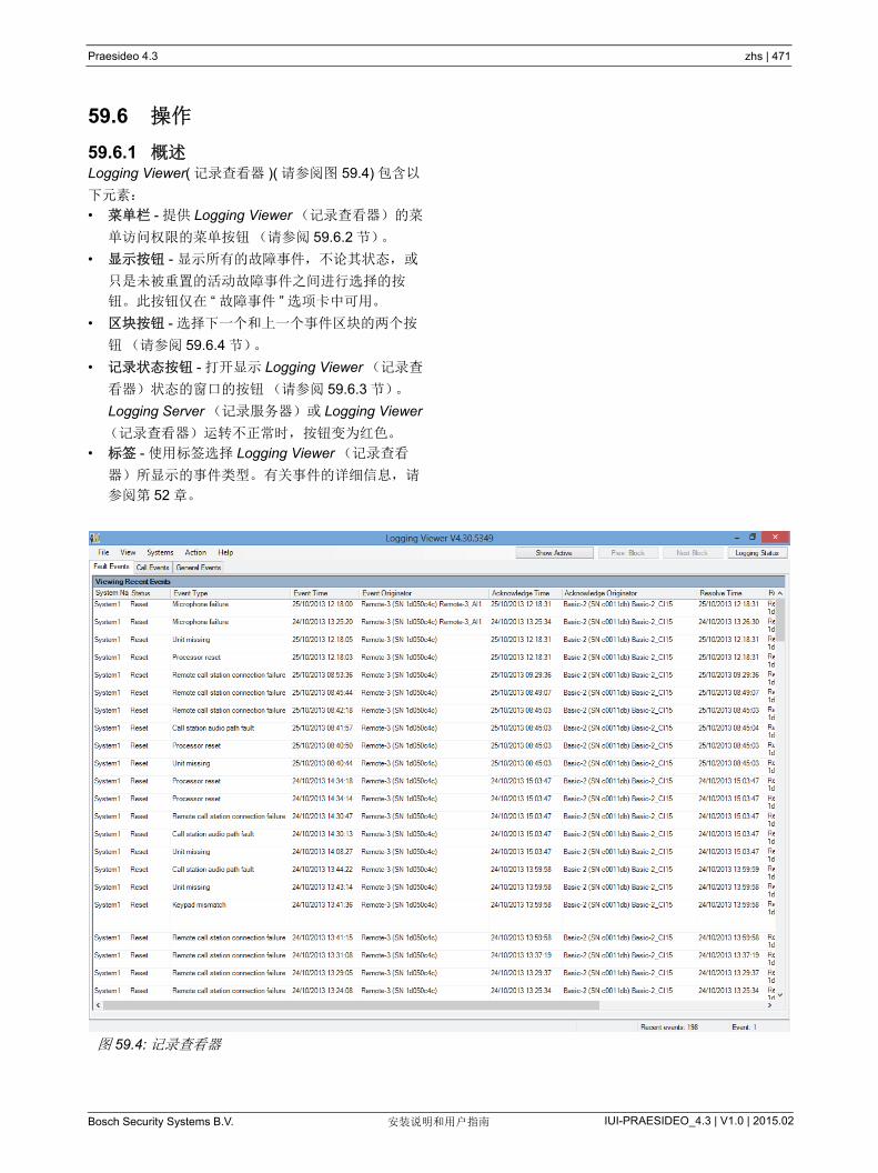
Praesideo 4.3 zhs | 471
Bosch Security Systems B.V. IUI-PRAESIDEO_4.3 | V1.0 | 2015.02安装说明和用户指南
59.6 操作
59.6.1 概述Logging Viewer( 记录查看器 )( 请参阅图 59.4) 包含以
下元素:
• 菜单栏 - 提供 Logging Viewer (记录查看器)的菜
单访问权限的菜单按钮(请参阅 59.6.2 节)。
• 显示按钮 - 显示所有的故障事件,不论其状态,或
只是未被重置的活动故障事件之间进行选择的按
钮。此按钮仅在 “ 故障事件 ” 选项卡中可用。
• 区块按钮 - 选择下一个和上一个事件区块的两个按
钮(请参阅 59.6.4 节)。
• 记录状态按钮 - 打开显示 Logging Viewer (记录查
看器)状态的窗口的按钮(请参阅 59.6.3 节)。
Logging Server (记录服务器)或 Logging Viewer
(记录查看器)运转不正常时,按钮变为红色。
• 标签 - 使用标签选择 Logging Viewer (记录查看
器)所显示的事件类型。有关事件的详细信息,请
参阅第 52 章。
图 59.4: 记录查看器

Praesideo 4.3 zhs | 472
Bosch Security Systems B.V. IUI-PRAESIDEO_4.3 | V1.0 | 2015.02安装说明和用户指南
59.6.2 菜单栏59.6.2.1 简介
菜单栏包含以下菜单:
• File (文件)菜单(请参阅 59.6.2.2 节)。
• View (视图)菜单(请参阅 59.6.2.3 节)。
• System (系统)菜单(请参阅 59.6.2.4 节)。
• Action (动作)菜单(请参阅 59.6.2.5 节)。
• Help (帮助)菜单(请参阅 59.6.2.6 节)。
59.6.2.2 文件
File (文件)菜单中项用于输出和打印事件,而且还用
于配置 Logging Viewer (记录查看器)。包含以下项
目:
• 选项
打开用于配置 Logging Viewer (记录查看器)(请
参阅 59.5 节)的 Options (选项)窗口。
• Export (导出)
将当前事件视图中的所有事件导出到逗号分隔值文
件 (*.csv)。此文件可以用 Microsoft® Excel 等程序
打开。
• Print (打印)
打印当前事件视图中的所有事件或打印所选的连续
事件区块。 ( 要选择事件区块:单击第一个事件,然
后按住 <Shift> 键单击 后一个事件。
• Exit (退出)
关闭 Logging Viewer (记录查看器)。
59.6.2.3 视图
View (视图)菜单中的项目用于设置事件视图选项。
包含以下项目:
• Recent ( 新)
显示所有 新事件。显示的 新事件数由 Logging
Server (记录服务器)窗口定义(请参阅
第 58.7.4.2 节)。
• Historical (历史)
显示历史事件。这些事件从记录数据库(请参阅第
58.7.4 节)中检索得到。选中该项时,则出现日
历,在其中可以选择 Start Date( 开始日期 ) 和 End
Date( 结束日期 )。历史事件数大于 10000 时,
Logging Server (记录服务器)将区块中的事件发
送到 Logging Viewer (记录查看器)。采用 Next
Block (下一区块)和 Prev Block (上一区块)按
钮滚动区块(请参阅第 59.6.4 节)。
• 刷新
刷新事件列表。
59.6.2.4 系统
System (系统)菜单中的项目用于选择显示事件的系
统。可用系统列表由与 Logging Viewer (记录查看
器)相连的 Logging Server (记录服务器)(请参阅
第 58.7.2 节 ) 生成。选择 All (全部)时,则显示所有
系统中的事件,包含已禁用和未配置系统和事件。可以
单独选择 Logging Server (记录服务器)自身生成的
事件。
59.6.2.5 动作
Action (动作)菜单用于确认和复位故障事件。包含以
下项目:
• Acknowledge All Fault Events (确认所有故障事
件)
确认与 Logging Server (记录服务器)相连的所有
系统中的所有新故障事件。用户必须登录到
Logging Server( 记录服务器 ) 确认故障事件。
• Reset All Fault Events( 复位所有故障事件 )
复位与 Logging Server (记录服务器)相连的所有
系统中的所有已确认故障事件。用户必须登录到
Logging Server( 记录服务器 ) 复位故障事件。
• 注销
从 Logging Server (记录服务器)注销用户。
59.6.2.6 帮助
Help( 帮助 ) 菜单中的项目提供关于 Logging Viewer
(记录查看器)的版本信息。
注
新事件只显示在 Recent ( 新)视图中。
Historical (历史)视图不显示新事件。

Praesideo 4.3 zhs | 473
Bosch Security Systems B.V. IUI-PRAESIDEO_4.3 | V1.0 | 2015.02安装说明和用户指南
59.6.3 记录状态按钮Logging Status( 记录状态 ) 窗口显示 Logging Viewer
(记录查看器)的状态。
59.6.4 区块当前视图是 Historical view( 历史视图 )( 请参阅第
59.6.2.3 节 ) 并且历史事件数大于 10000 时, Logging
Server( 记录服务器 ) 将区块中的事件发送到 Logging
Viewer( 记录查看器 )。
• 如果下一区块可用,则启用 Next Block( 下一区块 )
按钮。下一区块包含比当前显示的事件更新的事
件。
• 如果上一区块可用,则启用 Prev Block( 上一区块 )
按钮。上一区块包含比当前显示的事件更久的事
件。
讯息:
The Logging Server and Viewer are OK.( 记录服务
器和查看器准备就绪。 )
描述:
记录服务器和记录查看器运转正常。
建议的动作:
----
讯息:
Logging Server has no connection with<system>
(记录服务器没有与 <system> 之间无任何连接)
描述:
此外,与指定系统之间无任何连接。
建议的动作:
确保指定的系统正在运行,并且配有与 Logging
Server (记录服务器)相连的以太网连接。
讯息:
The Logging Viewer has lost contact with the
Logging Server (记录查看器与记录服务器失去联
系)
描述:
此外 , 与 Logging Server( 记录服务器 ) 之间无任何
连接。
建议的动作:
确保 Logging Server( 记录服务器 ) 正在运行,并且
Logging Server (记录服务器)配有与 Logging
Viewer( 记录查看器 ) 相连的以太网连接。
讯息:
The Logging Server options are changed. Restart
the Logging Server to use the changed settings.
(记录服务器选项已更改。重新启动记录服务器以应
用更改的设置。)
描述:
Logging Server (记录服务器)的配置设置已更改。
Logging Server (记录服务器)重新启动之前,更
改的设置未应用。
建议的动作:
重新启动 Logging Server( 记录服务器 ) 以应用新设
置。
讯息:
The Logging Server database has reached its
critical size. Please decrease the logging expiration
periods. (记录服务器数据库已达到其临界大小。请
减小记录终止周期。 )
描述:
数据库已达到其临界大小。
建议的动作:
启用和降低记录终止周期以将事件转移到溢出文件
(请参阅第 58.7.3 节)或刷新数据库 ( 请参阅
第 58.7.4.4 节)。
讯息:
The Logging Server overflow files have reached
their critical size. Please clear or delete the overflow
files. (记录服务器溢出文件已达到其临界大小。请
清理或删除溢出文件。 )
描述:
一个或多个溢出文件已达到其临界大小。
建议的动作:
溢出文件是逗号分隔值(comma separated value)
(*.csv) 文件。这些文件可以在编辑器(如 Windows
写字板、 Microsoft® Excel)中打开。溢出文件达到
临界大小时,请使用编辑器删除溢出文件的数据以
减少其大小。

Praesideo 4.3 zhs | 474
Bosch Security Systems B.V. IUI-PRAESIDEO_4.3 | V1.0 | 2015.02安装说明和用户指南
60 PC 呼叫服务器
60.1 简介PC 呼叫服务器 是一种连接到一个或者多个已配置网络
控制器的 Windows 服务。它可处理来自 PC 呼叫站客
户端 及 / 或 PC 电话接口客户端的所有工作请求。 PC
呼叫服务器 由 PC 呼叫服务器配置客户端进行配置;
为安全起见,该客户端与 PC 呼叫服务器在同一台计算
机上运行。 PC 呼叫服务器没有自己的用户接口。
60.2 要求PC 呼叫服务器可以在任何符合以下 低要求的 PC 上
运行:
• 操作系统:
Microsoft® Windows 7、 8 或 8.1
• 网络连接:100 base-T
• 1 GB RAM
60.3 安装1 启动 PRS-SW Praesideo 软件 DVD (请参阅 36.2
节)。
2 单击 Optional (可选) > PC call server (PC 呼叫
服务器)。出现 File Download (文件下载)窗口。
3 点击打开按钮,开始 PC 呼叫服务器的设置程序。
会出现类似图 60.1 的界面。
4 按照界面显示的指示。当安装结束时,有提示出
现。
注
确保 Praesideo 系统的软件版本与 PC 呼叫服
务器、 PC 呼叫站以及 PC 电话接口客户端的版
本始终相同。建议更新到 新版本。图 60.1:PC 呼叫服务器设置程序
注
安装之后, PC 呼叫服务器 将在 Windows 防
火墙中自动注册,允许执行网络通信。如果
PC 使用非标准 Windows 防火墙, PC 呼叫服
务器必须在防火墙中手动注册,以免该防火墙
自行阻止网络通信。被阻止的网络通信会加剧
故障。
注
确保运行 PC 呼叫服务器的系统中的 Windows
选项网络发现和文件共享已激活。否则,来自
PC 呼叫服务器配置客户端、PC 呼叫站客户端
或 PC 电话接口客户端的连接可能会失败。
在 Windows 中,这些选项可以通过 开始 > 控
制面板 > 全部控制面板项 > 网络和共享中心 >
更改高级共享设置来设置。然后选择启用网络
发现并选择启用文件和打印机共享。
Praesideo 4.3 zhs | 475
Bosch Security Systems B.V. IUI-PRAESIDEO_4.3 | V1.0 | 2015.02安装说明和用户指南
60.4 开始Windows 启动时, PC 自动启动 PC 呼叫服务器。
重要事件会记录在 Windows 事件日志中:
• 启动和关闭服务
• 关于许可证有效性的错误讯息
• 导致服务关闭的异常(故障)错误
60.5 配置使用 PC 呼叫服务器配置客户端来配置 PC 呼叫服务
器。
60.6 防火墙PC 呼叫服务器和相关程序 PC 呼叫站客户端以及 PC
电话接口客户端使用端口 TCP 9452。如果使用防火
墙,应启用该端口。如果需要,该端口号也可通过编辑
XML 文件 < 应用程序名 >.exe.config, ,为每一个应用
程序单独编辑该端口号。这些文件在应用程序的安装路
径中。
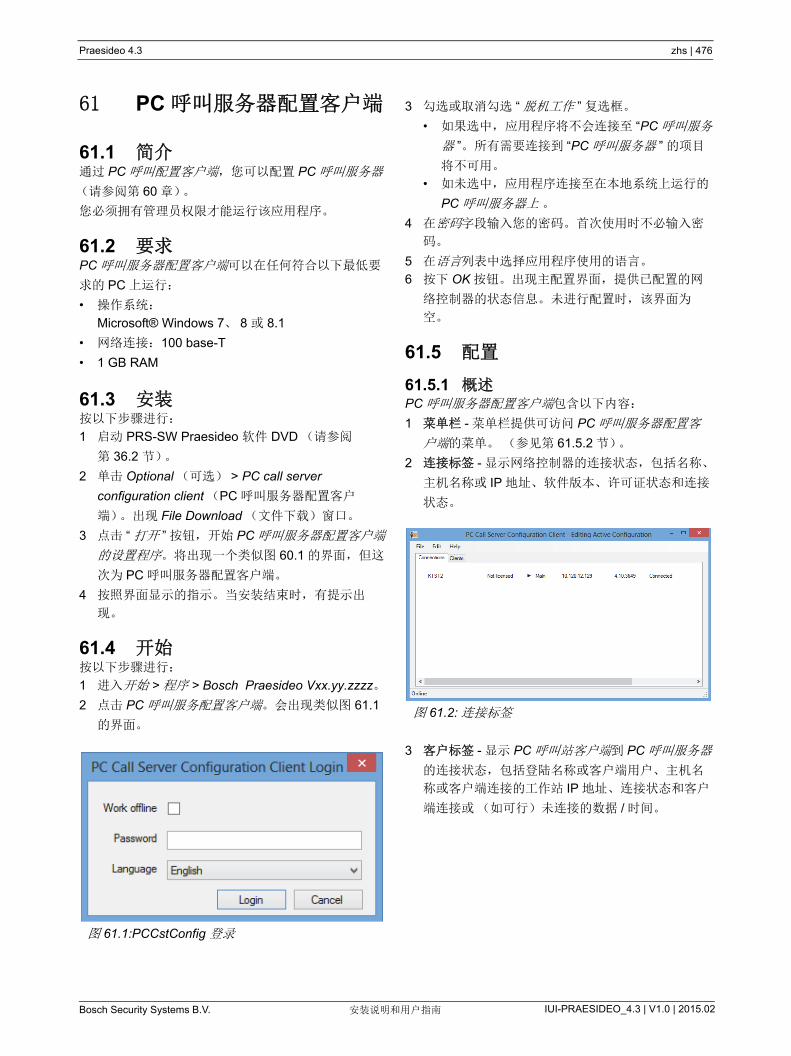
Praesideo 4.3 zhs | 476
Bosch Security Systems B.V. IUI-PRAESIDEO_4.3 | V1.0 | 2015.02安装说明和用户指南
61 PC 呼叫服务器配置客户端
61.1 简介通过 PC 呼叫配置客户端,您可以配置 PC 呼叫服务器
(请参阅第 60 章)。
您必须拥有管理员权限才能运行该应用程序。
61.2 要求PC 呼叫服务器配置客户端可以在任何符合以下 低要
求的 PC 上运行:
• 操作系统:
Microsoft® Windows 7、 8 或 8.1
• 网络连接:100 base-T
• 1 GB RAM
61.3 安装按以下步骤进行:
1 启动 PRS-SW Praesideo 软件 DVD (请参阅
第 36.2 节)。
2 单击 Optional (可选) > PC call server
configuration client (PC 呼叫服务器配置客户
端)。出现 File Download (文件下载)窗口。
3 点击 “ 打开 ” 按钮,开始 PC 呼叫服务器配置客户端
的设置程序。将出现一个类似图 60.1 的界面,但这
次为 PC 呼叫服务器配置客户端。
4 按照界面显示的指示。当安装结束时,有提示出
现。
61.4 开始按以下步骤进行:
1 进入开始 > 程序 > Bosch Praesideo Vxx.yy.zzzz。
2 点击 PC 呼叫服务配置客户端。会出现类似图 61.1
的界面。
3 勾选或取消勾选 “ 脱机工作 ” 复选框。
• 如果选中,应用程序将不会连接至 “PC 呼叫服务
器 ”。所有需要连接到 “PC 呼叫服务器 ” 的项目
将不可用。
• 如未选中,应用程序连接至在本地系统上运行的
PC 呼叫服务器上 。
4 在密码字段输入您的密码。首次使用时不必输入密
码。
5 在语言列表中选择应用程序使用的语言。
6 按下 OK 按钮。出现主配置界面,提供已配置的网
络控制器的状态信息。未进行配置时,该界面为
空。
61.5 配置
61.5.1 概述PC 呼叫服务器配置客户端包含以下内容:
1 菜单栏 - 菜单栏提供可访问 PC 呼叫服务器配置客
户端的菜单。 (参见第 61.5.2 节)。
2 连接标签 - 显示网络控制器的连接状态,包括名称、
主机名称或 IP 地址、软件版本、许可证状态和连接
状态。
3 客户标签 - 显示 PC 呼叫站客户端到 PC 呼叫服务器
的连接状态,包括登陆名称或客户端用户、主机名
称或客户端连接的工作站 IP 地址、连接状态和客户
端连接或(如可行)未连接的数据 / 时间。
图 61.1:PCCstConfig 登录
图 61.2: 连接标签
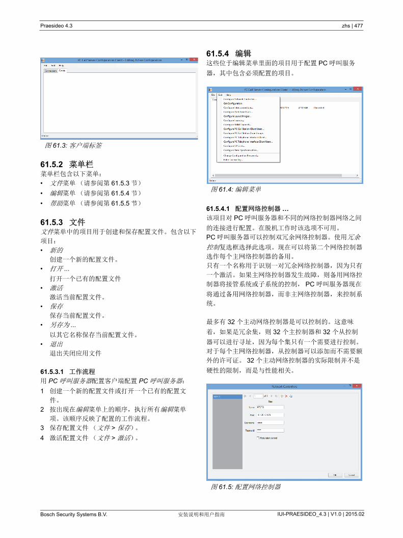
Praesideo 4.3 zhs | 477
Bosch Security Systems B.V. IUI-PRAESIDEO_4.3 | V1.0 | 2015.02安装说明和用户指南
61.5.2 菜单栏菜单栏包含以下菜单:
• 文件菜单(请参阅第 61.5.3 节)
• 编辑菜单(请参阅第 61.5.4 节)
• 帮助菜单(请参阅第 61.5.5 节)
61.5.3 文件文件菜单中的项目用于创建和保存配置文件。包含以下
项目:
• 新的
创建一个新的配置文件。
• 打开 ...
打开一个已有的配置文件
• 激活
激活当前配置文件。
• 保存
保存当前配置文件。
• 另存为 ...
以其它名称保存当前配置文件。
• 退出
退出关闭应用文件
61.5.3.1 工作流程
用 PC 呼叫服务器配置客户端配置 PC 呼叫服务器:
1 创建一个新的配置文件或打开一个已有的配置文
件。
2 按出现在编辑菜单上的顺序,执行所有编辑菜单
项。该顺序反映了配置的工作流程。
3 保存配置文件(文件 > 保存)。
4 激活配置文件(文件 > 激活)。
61.5.4 编辑这些位于编辑菜单里面的项目用于配置 PC 呼叫服务
器,其中包含必须配置的项目。
61.5.4.1 配置网络控制器 …
该项目对 PC 呼叫服务器和不同的网络控制器网络之间
的连接进行配置。在脱机工作时该选项不可用。
PC 呼叫服务器可以控制双冗余网络控制器。使用冗余
控制复选框选择此选项。现在可以将第二个网络控制器
选作每个主网络控制器的备用。
只有一个名称用于识别一对冗余网络控制器,因为只有
一个激活。如果主网络控制器发生故障,则备用网络控
制器将接管系统或子系统的控制, PC 呼叫服务器现在
将通过备用网络控制器,而非主网络控制器,来控制系
统。
多有 32 个主动网络控制器是可以控制的。这意味
着,如果是冗余集,则 32 个主控制器和 32 个从控制
器可以进行寻址,因为每个集只有一个需要进行控制。
对于每个主网络控制器,从控制器可以添加而不需要额
外的许可证。 32 个主动网络控制器的实际限制并不是
硬性的限制,而是与性能相关。
图 61.3: 客户端标签
图 61.4: 编辑菜单
图 61.5: 配置网络控制器

Praesideo 4.3 zhs | 478
Bosch Security Systems B.V. IUI-PRAESIDEO_4.3 | V1.0 | 2015.02安装说明和用户指南
使用 Add new (新添加)图标添加网络控制器或网络
控制器对,请参阅 图 61.6。为该网络控制器填写唯一
名称和 IP 地址或其主机名称及有效的用户名称和密
码。使用 “Delete” (删除)图标,从网络控制器列表中
删除网络控制器。 “Copy to new” (另复制为)图标创
建一份新的当前网络控制器,以便后续编辑。
“ 冗余网络控制器 ” 应用说明介绍如何将冗余网络控制
器、备用 NCO 连接到 Praesideo 系统,以便在主
NCO 故障时系统能够维持完全功能。使用以下步骤来
建立一个包含主和备用网络控制器的 Praesideo 系统:
• 主 NCO 和备用 NCO 必须具有不同的 IP 地址和 / 或
主机名。
• 确保主 NCO 和备用 NCO 使用相同的软件版本,并
兼容 PC 呼叫站服务器。
• 在主 NCO 创建新的系统配置;暂时忽略备用
NCO。
• 将配置文件复制到所连 PC,并将此配置文件从 PC
复制到备用 NCO。
• 通过将 NCO 的序列号更改为备用 NCO 的序列号更
新备用 NCO 的配置。
• 确保配置中使用的所有预录信息出现在主 NCO 和
备用 NCO 上。
• 记住,对主 NCO 配置文件的后续更改应对备用
NCO 重复。
• 基于记录目的,将主 NCO 的 “ 故障警报蜂鸣器 ” 控
制输出连接到备用 NCO 的控制输入 - 已配置为包含
自定义消息(如:主 NCO 故障) 的 “ 故障输入 ”。
• 对于主 NCO,将 “ 系统设置 ” 中的 “ 内部故障时禁
用网络控制器 ” 设置为 “ 是 ”。
• 对 NCO 配置进行更改后,对每个 NCO 执行 “ 保存
配置并重新启动系统 ” 操作。
• 重要:如果是只更改备用 NCO 配置,对备用和主
NCO 都执行 “ 保存配置并重新启动系统 ” 操作。
61.5.4.2 获得配置
该项目从已配置的网络控制器中恢复相关的配置数据,
例如,分区名称、讯息、语音、输入端等。 恢复过程将
显示。当传输完成时,您可以接收或拒绝数据。后续配
置将需要该数据。如果所有网络控制器上的声音设置和
讯息设置不完全相同,将显示一条警告讯息,因为这会
限制连接客户端上的声音和讯息选择,请参阅 61.5.4.4
节。
在脱机工作时该选项不可用。
图 61.6: 新添加、删除和另复制为新图标
图 61.7: 开始配置

Praesideo 4.3 zhs | 479
Bosch Security Systems B.V. IUI-PRAESIDEO_4.3 | V1.0 | 2015.02安装说明和用户指南
61.5.4.3 配置内部连接 ...
该项目用于配置不同网络控制器之间的内部连接。
这些内部链接是系统间用于音频传输的实际硬件连接,
用于将呼叫从一个 Praesideo 子系统传输至另一个子系
统。网络控制器之间不一定需要连接,以一个系统的某
一已配置分区作为源控制器,另一个系统中的一个音频
输入端作为目标控制器,同样可以进行传输。分区可以
在网络控制器或音频放大器上进行线输出;通过 XLR
电缆,在此类通设备上输入端也可进行线输入,但也可
通过以太网连接 CobraNet 接口的输入端和输出端。在
相同的子系统内连接输入端和输出端是不可行(也无
用途)的。使用 Add new (新添加)和 Delete (删
除)图标可创建新的连接并为其指定唯一的名称,以便
参考。
这些内部连接仅用于常规呼叫和紧急呼叫,不适用于
BGM。
用于连接的输出端(分区)无法再被选为布局配置的
分区输出端,请参阅 61.5.4.7 节。
用于连接的输入端无法再被选为现场实时语音播报的音
频输入端,
请参阅 61.5.4.4 节。
61.5.4.4 配置 PC 呼叫站分区组 ...
该项目配置特殊的 PC 呼叫站分区组。
PC 呼叫站分区组只存在于 PC 呼叫站上,不存在于连
接的 NCO 上。可以将已经在 NCO 上定义的一般分区
或分区组添加到这样的组。此功能使 PC 呼叫站分区组
可包括来自不同 NCO 的分区组,即使是多 NCO 的全
部呼叫分区组也可以。就像一般分区和 NCO 分区组一
样,可以为预定义的呼叫配置 PC 呼叫站分区组。
图 61.8: 配置内部连接图 61.9: 配置 PC 呼叫站分区组
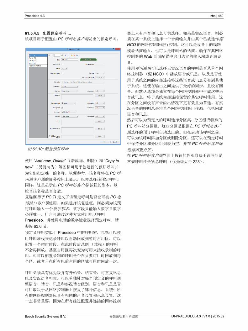
Praesideo 4.3 zhs | 480
Bosch Security Systems B.V. IUI-PRAESIDEO_4.3 | V1.0 | 2015.02安装说明和用户指南
61.5.4.5 配置预定呼叫 ...
该项目用于配置由 PC 呼叫站客户端发出的预定呼叫。
使用 “Add new, Delete” (新添加、删除)和 “Copy to
new” (另复制为)等图标可用于创建新的预订呼叫并
为它们指定唯一的名称,以便参考。该名称将在 PC 呼
叫站客户端的屏幕按钮上显示,以便选择该预定呼叫。
同样,这里显示出 PC 呼叫站客户端 按钮的副本,以
检查该名称是否合适。
复选框用于 PC TI 定义了该预定呼叫是否也可被 PC 电
话接口客户端使用。如果选择该复选框,则必须为该预
定呼叫输入一个数字别名。该字段只能输入数字且数字
必须唯一。用户可通过这种方式使用电话呼叫
Praesideo,并使用电话的数字键盘选择预定呼叫。请
参阅 63.6 节。
预定义呼叫类似于 Praesideo 中的呼叫宏,包括可以使
用呼叫堆栈来记录呼叫以自动回放到暂时占用区。可以
配置一个超时时段,在此时段后录制(堆栈)的呼叫
不会再回放,甚至占用区再次变为可用来接收录制的呼
叫。也可以配置录制的呼叫是否在只要可用时回放到每
个区,或者只在所有以前占用的区域可用时回放一次。
呼叫必须具有优先级并有开始音、结束音、可重复讯息
以及实况语音相位。可以单独针对每个预定义的呼叫调
整语音、话音、讯息和实况话音级别。语音和讯息是否
可用取决于从网络控制器上恢复了哪种信息。系统中所
有的网络控制器应具有相同的声音设置和讯息设置,这
一点非常重要,因为在所有经过配置并连接的网络控制
器上只有声音和讯息可供选择。如果是实况语音,则必
须在某一系统上选择一个音频输入并由某个已被选作源
NCO 的网路控制器进行控制。这可以是设备上的线路
或者话筒输入,也可以是呼叫站的话筒。确保在其网络
控制器的 Web 页面配置中启用选定的输入端或者源设
备。
使用呼叫路由可以选择无实况语音的呼叫是否从单个网
络控制器(源 NCO)中播放语音或讯息,以及是否使
用子系统之间的内部连接将这些语音或讯息分布到其他
子系统。这便在输出之间提供了 好的同步,且没有回
音。但默认选项是独立在每个网络控制器中生成这些语
音或讯息,将子系统内部连接保留给其它呼叫使用。这
在分区之间没有声音溢出情况下更有效且为首选。有实
况语音的呼叫总是将单个网络控制器用作源,包括回放
语音和讯息。
然后可以为预定义的呼叫选择分区集、分区组或特殊的
PC 呼叫站分区组。这些分区是根据在 PC 呼叫站客户
端选择的预订呼叫自动选出的。但在启动该呼叫之前,
可以为该呼叫添加分区或删除分区。还可以在预定呼叫
中保持分区和分区组列表为空,并在 PC 呼叫站客户端
选择闲置分区。
在 PC 呼叫站客户端界面上按钮的外观取决于该呼叫是
常规呼叫还是紧急呼叫(优先级大于 223)。
图 61.10: 配置预订呼叫

Praesideo 4.3 zhs | 481
Bosch Security Systems B.V. IUI-PRAESIDEO_4.3 | V1.0 | 2015.02安装说明和用户指南
61.5.4.6 配置布局图 ...
该项目可配置布局图,用作 PC 呼叫站客户端不同标签
的背景。 在布局图上还设有分区图标和分区组图标。通
过这种方法,可以进行大致布局,方便地选取分区和分
区组。使用 Add new (新添加)和 Delete (删除)图
标可创建新的布局图连接并为其指定唯一的名称,以便
参考。同一布局图可多次使用。
图像未放大到窗口大小,但如果大小不合适,将出现滚
动条。
61.5.4.7 配置布局 ...
该项目可在布局图上配置分区和分区组的位置。
使用 Add new(新添加)、 Delete(删除)和 Copy to
new (另复制为)图标,可创建新的布局,并为其指定
唯一名称,以便参考。 该名称将出现在 PC 呼叫站客
户端 分区选择窗格中的标签上,以便选择该布局。用
鼠标将分区或分区组从列表拖拽至布局,可在布局上创
建分区图标和分区组图标。图标可在方格中排列。您可
以点击图标下的标签,为图标指定默认名称外的其它名
称。 默认名称是网络控制器名称和在 Praesideo 中的分
区名称的组合。如果目的地明确,可从布局图中删除名
称。可以排列相同分区或分区组图表多次。通过右键单
击,然后点击 Remove (移除),或选中后,按
Delete (删除)键,可删除图标。按住 Ctrl 键时选择
图标,可选择多个图标。要选择同一图标的所有出现情
况,请右键单击某个图标并选择 Select all occurrences
(选择所有出现情况)以展开选择至包含属于当前所选
图标副本的所有图标。
图 61.11: 配置布局图
图 61.12: 配置布局

Praesideo 4.3 zhs | 482
Bosch Security Systems B.V. IUI-PRAESIDEO_4.3 | V1.0 | 2015.02安装说明和用户指南
61.5.4.8 配置 BGM 通道 ...
通过从 PC 呼叫站客户端进行选择,该项目可配置背景
音乐通道。
使用 Add new (新添加)和 Delete (删除)图标可创
建新的 BGM 通道并为其指定唯一的名称,以便参考。
该名称会出现在 PC 呼叫站客户端的 BGM 选择按钮
上。在该配置窗口中,该名称还出现在屏幕图标副本
上,以检查文本是否合适。
使用 “Selected” (选择)按钮,在不同的网络控制器上
指定 Praesideo BGM 通道,并以该通道为源通道。
BGM 音频不能通过已配置的内部网络在网络控制器之
间传输,所以在每个带有网络控制器的子系统中,单一
的音频输入端应指定给该 BGM 通道,并在网络控制器
上配置。因为 BGM 通道一般是固定的、非动态的,所
以可通过子系统间的 XLR 电缆,使用固定内部连接,
进行 BGM 传输 ; 或使用 CobraNet 接口用于 BGM 传
输。随后,这些连接通过配置 web 页面在 Praesideo
中进行正常配置。
61.5.4.9 配置 PC 呼叫站客户端用户 ...
该项目为系统所有 PC 呼叫站客户端用户配置权限。
使用 “Add new” (新添加)、 “Delete” (删除)和
“Copy to new” (另复制为)图标,可创建用户,并为
其指定唯一名称,以便参考。用户使用该名称登录到
PC 呼叫站客户端。可为每个用户创建一个密码。 您可
在此为每个用户单独配置启动按钮操作。这些选件为:
• 拨动,再次按下中止
• 拨动,再次按下不中止
• 瞬时按动,再次按下中止
• 瞬时按动,再次按下不中止
请注意,对于拨动动作,通过鼠标向上移动实现按键激
活(鼠标按钮释放)。对于瞬时按动,通过鼠标向下
(鼠标按钮点击)和鼠标向上移动实现按钮激活。
每个用户可从已创建的预定义呼叫和布局列表中选择预
定义呼叫和布局列表。这样,某些用户可得到更广泛的
选择范围。按选择 可打开预定呼叫选择窗口,选择预
订呼叫。 15 添加和删除按钮执行该操作,或者直接将
可用呼叫列表中的项目拖放到选定呼叫列表中。列表中
选定预定呼叫的顺序决定了这些呼叫在 PC 呼叫站客户
端屏幕中的显示顺序。可使用鼠标将右列中的预定呼叫
拖放到不同位置以更改顺序。
Default call (默认呼叫)可从预定义呼叫的列表中选
择或设置为 <none> (无)。配置的 Timeout (超时)
到期时,会自动选择默认呼叫。可选择介于 10 秒到
60 秒的超时时长。每次预定义呼叫被选中或分区选择
窗格中的分区或分区组被选中时,超时定时器会重新启
动。当选定的预定义呼叫正在执行时,超时定时器不会
过期,但会在呼叫完成 5 秒后过期。以便用户在遗忘
图 61.13: 配置 BGM 通道
图 61.14: 配置 PC 呼叫站客户端用户
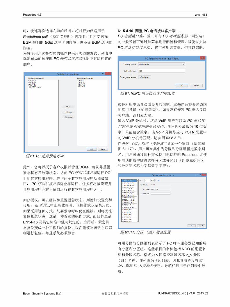
Praesideo 4.3 zhs | 483
Bosch Security Systems B.V. IUI-PRAESIDEO_4.3 | V1.0 | 2015.02安装说明和用户指南
时,快速再次选择之前的呼叫。超时行为仅适用于
Predefined call (预定义呼叫)选项卡并且不受选择
BGM 控制的 BGM 选项卡的影响,也不受 BGM 选项的
影响。
为每个用户选择布局的操作也采用类似的方式。列表中
选定布局的顺序即 PC 呼叫站客户端视图中布局标签的
顺序。
此外,您可以授予客户权限以管理 BGM、确认并重置
紧急状态及故障状态、访问 PC 呼叫站客户端运行 PC
上的其它应用程序。若访问至其它应用程序功能被禁
用, PC 呼叫站客户端将全屏运行,任务栏将被隐藏并
且应用程序会将主窗口运行在其它应用程序之上。
如获授权,可以确认和重置紧急状态,则附加设置变得
可用:在 重置上中止疏散呼叫。该操作默认是禁用的。
如果采用这种方式,只要紧急呼叫仍在继续,则将无法
复位紧急状态;这是一种首选的操作方式,而且甚至是
EN54-16 及其它标准中强制规定的。 启用后,紧急状
态复位变成一种工程师的复位,以在建筑物疏散之后强
制进行复位,并且系统必须静音。
61.5.4.10 配置 PC 电话接口客户端 ...
PC 电话接口客户端(可与 PC 呼叫服务器一同安装)
的一般设置可通过该菜单进行配置和管理。即使未安装
PC 电话接口客户端 ,仍可使用该菜单,但可以忽略。
选择所用电话音必须参考的国家。这些声音将参照该国
的常用设置(忙音等等)。如果没有安装 PC 电话接口
客户端,该列表为空。
输入 VoIP 分机号。这是 VoIP 用户在联系 PC 电话接
口客户端 时使用的电话号码。该分机号 长为 10 位数
字,只能包含数字。 该 VoIP 分机号应与 PSTN 配置中
的 VoIP 分机号匹配。请参阅 63.8.3 节。
在分区(组)别名中按配置可显示一个窗口(请参阅
图 61.17),用户可在其中为分区和分区组指定数字别
名。用户可通过这种方式使用电话呼叫 Praesideo 并使
用电话的数字键盘选择分区或分区组(即使原始分区
和分区组名称为字母数字字符)。
可用分区与分区组列表显示了 PC 呼叫服务器已知的所
有分区和分区组。这些项目的名称包括 NCO 的配置名
称和分区名称,格式为 < 网络控制器名称 >_< 分区
(组)名称。该列表为只读列表,因此导航栏没有添
加、删除 和 另复制为按钮。导航栏只用于在列表中导
航。
图 61.15: 选择预定呼叫
图 61.16:PC 电话接口客户端配置
图 61.17: 分区(组)别名配置
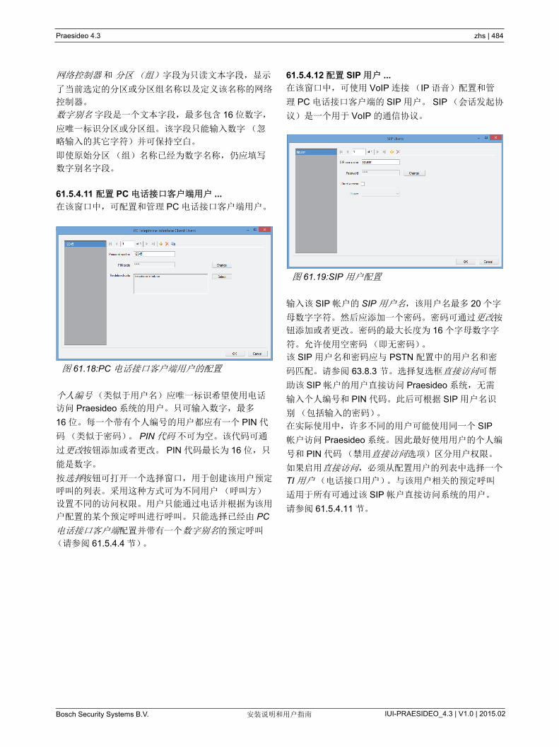
Praesideo 4.3 zhs | 484
Bosch Security Systems B.V. IUI-PRAESIDEO_4.3 | V1.0 | 2015.02安装说明和用户指南
网络控制器 和 分区(组) 字段为只读文本字段,显示
了当前选定的分区或分区组名称以及定义该名称的网络
控制器。
数字别名 字段是一个文本字段, 多包含 16 位数字,
应唯一标识分区或分区组。该字段只能输入数字(忽
略输入的其它字符)并可保持空白。
即使原始分区(组)名称已经为数字名称,仍应填写
数字别名字段。
61.5.4.11 配置 PC 电话接口客户端用户 ...
在该窗口中,可配置和管理 PC 电话接口客户端用户。
个人编号(类似于用户名)应唯一标识希望使用电话
访问 Praesideo 系统的用户。只可输入数字, 多
16 位。每一个带有个人编号的用户都应有一个 PIN 代
码(类似于密码)。 PIN 代码 不可为空。该代码可通
过更改按钮添加或者更改。 PIN 代码 长为 16 位,只
能是数字。
按选择按钮可打开一个选择窗口,用于创建该用户预定
呼叫的列表。采用这种方式可为不同用户(呼叫方)
设置不同的访问权限。用户只能通过电话并根据为该用
户配置的某个预定呼叫进行呼叫。只能选择已经由 PC
电话接口客户端配置并带有一个数字别名的预定呼叫
(请参阅 61.5.4.4 节)。
61.5.4.12 配置 SIP 用户 ...
在该窗口中,可使用 VoIP 连接(IP 语音)配置和管
理 PC 电话接口客户端的 SIP 用户。 SIP (会话发起协
议)是一个用于 VoIP 的通信协议。
输入该 SIP 帐户的 SIP 用户名,该用户名 多 20 个字
母数字字符。然后应添加一个密码。密码可通过更改按
钮添加或者更改。密码的 大长度为 16 个字母数字字
符。允许使用空密码(即无密码)。
该 SIP 用户名和密码应与 PSTN 配置中的用户名和密
码匹配。请参阅 63.8.3 节。选择复选框直接访问可帮
助该 SIP 帐户的用户直接访问 Praesideo 系统,无需
输入个人编号和 PIN 代码。此后可根据 SIP 用户名识
别(包括输入的密码)。
在实际使用中,许多不同的用户可能使用同一个 SIP
帐户访问 Praesideo 系统。因此 好使用用户的个人编
号和 PIN 代码(禁用直接访问选项)区分用户权限。
如果启用直接访问,必须从配置用户的列表中选择一个
TI 用户(电话接口用户)。与该用户相关的预定呼叫
适用于所有可通过该 SIP 帐户直接访问系统的用户。
请参阅 61.5.4.11 节。
图 61.18:PC 电话接口客户端用户的配置
图 61.19:SIP 用户配置

Praesideo 4.3 zhs | 485
Bosch Security Systems B.V. IUI-PRAESIDEO_4.3 | V1.0 | 2015.02安装说明和用户指南
61.5.4.13 配置时间同步 ...
在项目中,您可以启动(默认)或禁用已连接和已配
置的网络控制器的时间同步。它以 PC 呼叫服务器时间
为主时间。
按下立即同步按钮(仅当客户端同 PC 呼叫服务器相
连时启动),将使所有已连接的网络控制器立刻实现时
间同步。
61.5.4.14 更改配置密码 ...
利用该项目,您可以更改配置密码。在 PC 呼叫服务器
安装后,默认密码为空。密码的 大长度为 16 个字
符,无 小值。您应该先填写旧的密码以及新的密码,
以供确认。在脱机工作时该选项不可用。
61.5.4.15 输入许可证密钥 ...
在该项目,您可以输入许可证密钥,激活应用程序的全
部功能。在脱机工作时该选项不可用。
许可证密钥识别可控制的网络控制器号码以及 PC 呼叫
站 (同 Praesideo 核心发布相匹配)的主软件版本号。
许可证密钥窗口显示了当前软件版本号(如果之前没
有输入有效的密钥则显示 “-”)、授权的网络控制器号
(当之前没有输入有效密钥则显示 “0”)以及当前连接
至 PC 的解密器序列号(若无有效解密器连接则显示
“-”)。
注册 PC 呼叫服务器授权代码、其它网络控制器的授权
号(如果系统包含多个网络控制器)以及 PC 呼叫站
客户端授权号及 / 或 PC 电话接口客户端授权号后,你
可以从博世安保有限公司的注册网站上获取所需的许可
证密钥。该密钥同解密器(与 PC 呼叫服务器配套)
唯一的序列号相连。该密钥同解密器(与 PC 呼叫服
务器配套)唯一的序列号相连。
只有在呼叫服务器 PC 的 USB 接口上插入正确的解密
器,应用软件才可以实现全部功能。
未授权的 PC 呼叫站客户端仅能监视系统中正在进行的
呼叫,无法启动呼叫。若将解密器从授权系统中移除,
倒数计时器启动,在该时间以后, PC 呼叫站客户端将
不再能启动呼叫。未经授权的 PC 电话接口客户端不可
用于通过电话进行呼叫。它只能向呼叫方发出(语音)
应答,说明缺少有效许可证。
图 61.23 是一个带有授权号的证书示例。
图 61.20: 配置时间同步
图 61.21: 更改配置密码
图 61.22: 输入许可证密钥
图 61.23: 证书
PraesideoPC Telephone Interface Client
TYPE PRS-TICNC F.01U.079.817
Authorization number:
To register please visit https://license.boschsecurity.com
xxx xxxxx xxxxx xxx
F.01U.089.636 - Bosch Security Systems BV All rights reserved by Robert Bosch GmbH Printed in the Netherlands 27-8-2008
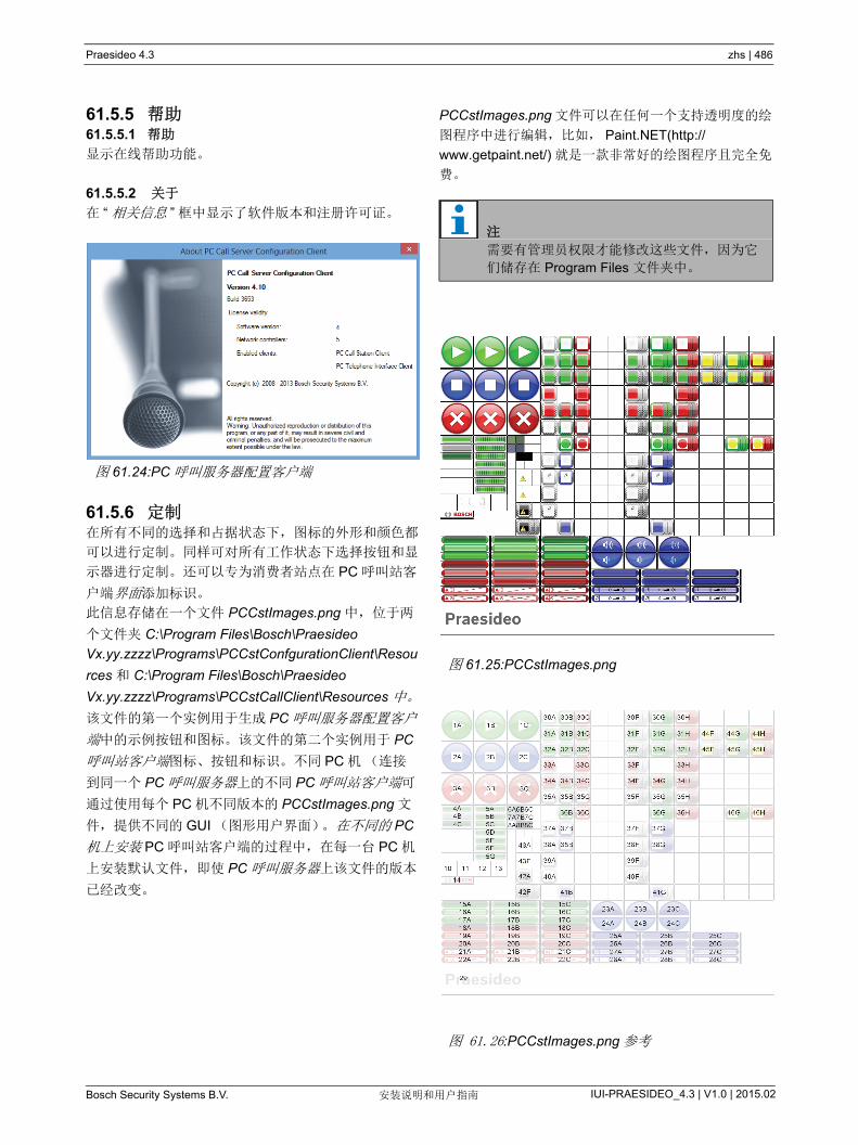
Praesideo 4.3 zhs | 486
Bosch Security Systems B.V. IUI-PRAESIDEO_4.3 | V1.0 | 2015.02安装说明和用户指南
61.5.5 帮助61.5.5.1 帮助
显示在线帮助功能。
61.5.5.2 关于
在 “ 相关信息 ” 框中显示了软件版本和注册许可证。
61.5.6 定制在所有不同的选择和占据状态下,图标的外形和颜色都
可以进行定制。同样可对所有工作状态下选择按钮和显
示器进行定制。还可以专为消费者站点在 PC 呼叫站客
户端界面添加标识。
此信息存储在一个文件 PCCstImages.png 中,位于两
个文件夹 C:\Program Files\Bosch\Praesideo
Vx.yy.zzzz\Programs\PCCstConfgurationClient\Resou
rces 和 C:\Program Files\Bosch\Praesideo
Vx.yy.zzzz\Programs\PCCstCallClient\Resources 中。
该文件的第一个实例用于生成 PC 呼叫服务器配置客户
端中的示例按钮和图标。该文件的第二个实例用于 PC
呼叫站客户端图标、按钮和标识。不同 PC 机(连接
到同一个 PC 呼叫服务器上的不同 PC 呼叫站客户端可
通过使用每个 PC 机不同版本的 PCCstImages.png 文
件,提供不同的 GUI (图形用户界面)。在不同的 PC
机上安装 PC 呼叫站客户端的过程中,在每一台 PC 机
上安装默认文件,即使 PC 呼叫服务器上该文件的版本
已经改变。
PCCstImages.png 文件可以在任何一个支持透明度的绘
图程序中进行编辑,比如, Paint.NET(http://
www.getpaint.net/) 就是一款非常好的绘图程序且完全免
费。
图 61.24:PC 呼叫服务器配置客户端
注
需要有管理员权限才能修改这些文件,因为它
们储存在 Program Files 文件夹中。
图 61.25:PCCstImages.png
图 61.26:PCCstImages.png 参考
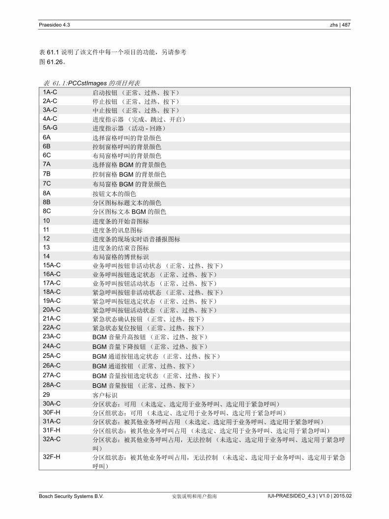
Praesideo 4.3 zhs | 487
Bosch Security Systems B.V. IUI-PRAESIDEO_4.3 | V1.0 | 2015.02安装说明和用户指南
表 61.1 说明了该文件中每一个项目的功能,另请参考
图 61.26。
表 61.1:PCCstImages 的项目列表
1A-C 启动按钮(正常、过热、按下)
2A-C 停止按钮(正常、过热、按下)
3A-C 中止按钮(正常、过热、按下)
4A-C 进度指示器(完成、跳过、开启)
5A-G 进度指示器(活动 - 回路)
6A 选择窗格呼叫的背景颜色
6B 控制窗格呼叫的背景颜色
6C 布局窗格呼叫的背景颜色
7A 选择窗格 BGM 的背景颜色
7B 控制窗格 BGM 的背景颜色
7C 布局窗格 BGM 的背景颜色
8A 按钮文本的颜色
8B 分区图标标题文本的颜色
8C 分区图标文本 BGM 的颜色
10 进度条的开始音图标
11 进度条的讯息图标
12 进度条的现场实时语音播报图标
13 进度条的结束音图标
14 布局窗格的博世标识
15A-C 业务呼叫按钮非活动状态(正常、过热、按下)
16A-C 业务呼叫按钮选定状态(正常、过热、按下)
17A-C 业务呼叫按钮活动状态(正常、过热、按下)
18A-C 紧急呼叫按钮非活动状态(正常、过热、按下)
19A-C 紧急呼叫按钮选定状态(正常、过热、按下)
20A-C 紧急呼叫按钮活动状态(正常、过热、按下)
21A-C 紧急状态确认按钮(正常、过热、按下)
22A-C 紧急状态复位按钮(正常、过热、按下)
23A-C BGM 音量升高按钮(正常、过热、按下)
24A-C BGM 音量下降按钮(正常、过热、按下)
25A-C BGM 通道按钮选定状态(正常、过热、按下)
26A-C BGM 通道按钮(正常、过热、按下)
27A-C BGM 音量按钮选定状态(正常、过热、按下)
28A-C BGM 音量按钮(正常、过热、按下)
29 客户标识
30A-C 分区状态:可用(未选定、选定用于业务呼叫、选定用于紧急呼叫)
30F-H 分区组状态:可用(未选定、选定用于业务呼叫、选定用于紧急呼叫)
31A-C 分区状态:被其他业务呼叫占用(未选定、选定用于业务呼叫、选定用于紧急呼叫)
31F-H 分区组状态:被其他业务呼叫占用(未选定、选定用于业务呼叫、选定用于紧急呼叫)
32A-C 分区状态:被其他业务呼叫占用,无法控制(未选定、选定用于业务呼叫、选定用于紧急呼
叫)
32F-H 分区组状态:被其他业务呼叫占用,无法控制(未选定、选定用于业务呼叫、选定用于紧急
呼叫)

Praesideo 4.3 zhs | 488
Bosch Security Systems B.V. IUI-PRAESIDEO_4.3 | V1.0 | 2015.02安装说明和用户指南
该文件 PCCstImageDef.xml, 见 图 61.27,位于文件
夹 C:\Program Files\Bosch\Praesideo
Vx.yy.zzzz\Programs\PCCstConfgurationClient\ 和
C:\Program Files\Bosch\Praesideo
Vx.yy.zzzz\Programs\PCCstClient\ 中,包含有关
PCCstImages.png 文件中的按钮、图标和指示灯的实
际位置和大小的信息。修改该 xml 文件可更改
PCCstImages.png 文件中各项目的大小或者位置,因
为它可用作 png 文件中实际项目的坐标参考。在同一
路径下文件 PCCstImageDef.xml 和 PCCstImages.png
相互关联。
33A/C 分区状态:被其他紧急呼叫占用(未选定、选定用于紧急呼叫)
33F/H 分区组状态:被其他紧急呼叫占用(未选定、选定用于紧急呼叫)
34A-C 分区状态:被其他紧急呼叫占用,无法控制(未选定、选定用于业务呼叫、选定用于紧急呼
叫)
34F-H 分区组状态:被其他紧急呼叫占用,无法控制(未选定、选定用于业务呼叫、选定用于紧急
呼叫)
35A-C 分区状态:可用,无法控制(未选定、选定用于业务呼叫、选定用于紧急呼叫)
35F-H 分区组状态:可用,无法控制(未选定、选定用于业务呼叫、选定用于紧急呼叫)
36B/C 分区状态:执行自身呼叫(业务、紧急)
36G/H 分区组状态:执行自身呼叫(业务、紧急)
37A/B 分区状态:BGM (未选定、选定)
37F/G 分区组状态:BGM (未选定、选定)
38A/B 分区状态:本地 BGM (未选定、选定)
38F/G 分区组状态:本地 BGM (未选定、选定)
39A 分区状态:BGM,无法控制
39F 分区组状态:BGM,无法控制
40A 分区状态:本地 BGM,无法控制
40F 分区组状态:本地 BGM,无法控制
41B 分区状态:被选定 BGM 通道占用
41G 分区组状态:被选定 BGM 通道占用
42A 分区状态:因通信错误无法获取状态
42F 分区组状态:因通信错误无法获取状态
43A 分区状态:分区故障的图标覆盖
43F 分区组状态:分区故障的图标覆盖
44F-H 分区组状态:部分被其它呼叫占用,可以进行某些控制(未选定、选定用于业务呼叫、选定
用于紧急呼叫)
45F-H 分区组状态:部分被其它呼叫占用,不能控制(未选定、选定用于业务呼叫、选定用于紧急
呼叫)
46G/H 分区组状态:执行自身部分呼叫(业务、紧急)
表 61.1:PCCstImages 的项目列表
图 61.27:PCCstImageDef.xml
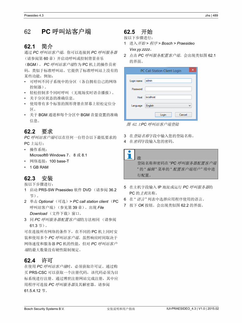
Praesideo 4.3 zhs | 489
Bosch Security Systems B.V. IUI-PRAESIDEO_4.3 | V1.0 | 2015.02安装说明和用户指南
62 PC 呼叫站客户端
62.1 简介通过 PC 呼叫站客户端,你可以连接到 PC 呼叫服务器
(请参阅第 60 章)并启动呼叫或控制背景音乐
(BGM)。 PC 呼叫站客户端作为 PC 机上的操作员密
码,类似于标准呼叫站。它提供了标准呼叫站上没有的
某些功能,例如:
• 可呼叫不同子系统中的分区(各自拥有自己的网络
控制器)。
• 轻松控制多个同时呼叫(无现场实时语音播报)。
• 关于分区状态的准确信息。
• 使用带有多个标签的图形背景在屏幕上轻松定位分
区。
• 关于 BGM 通道和每个分区中 BGM 音量设置的准确
信息。
62.2 要求PC 呼叫站客户端可以在任何一台符合以下 低要求的
PC 上运行:
• 操作系统:
Microsoft® Windows 7、 8 或 8.1
• 网络连接:100 base-T
• 1 GB RAM
62.3 安装按以下步骤进行:
1 启动 PRS-SW Praesideo 软件 DVD (请参阅 36.2
节)。
2 单击 Optional (可选) > PC call station client (PC
呼叫站客户端)(参见第 39 章)。出现 File
Download (文件下载)窗口。
3 同 PC 呼叫服务器配置客户端的方法相同(请参阅
61.3 节)。
可在连接所有网络的条件下,在不同的 PC 机上同时安
装和使用多个 PC 呼叫站客户端。虽然响应时间取决于
网络速度和服务器 PC 机的性能,但对 PC 呼叫站客户
端的 大数量没有硬性限制规定。
62.4 许可在使用 PC 呼叫站客户端时,必须获取许可证。通过购
买 PRS-CSC 可以获取一个注册代码, 该代码必须为目
标系统进行注册。 通过博世注册网站完成注册,其中应
用程序可连接 PC 呼叫服务器及其解密器。请参阅
61.5.4.12 节。
62.5 开始按以下步骤进行:
1 进入开始 > 程序 > Bosch > Praesideo
Vxx.yy.zzzz。
2 点击 PC 呼叫服务配置客户端。会出现类似图 62.1
的界面。
3 在登陆名称字段中输入您的登陆名称。
4 在密码字段输入您的密码。
5 在主机字段输入 IP 地址或运行 PC 呼叫服务器的
PC 的主机名称。
6 在 “ 语言 ” 列表中选择应用程序使用的语言。
7 按下 OK 按钮。会出现类似图 62.2 的界面。
图 62.1:PC 呼叫站客户端登陆
注
登陆名称和密码在 “PC 呼叫服务器配置客户端
” 的 “ 编辑 ” 菜单的 “ 配置客户端用户 ” 项中进
行配置。
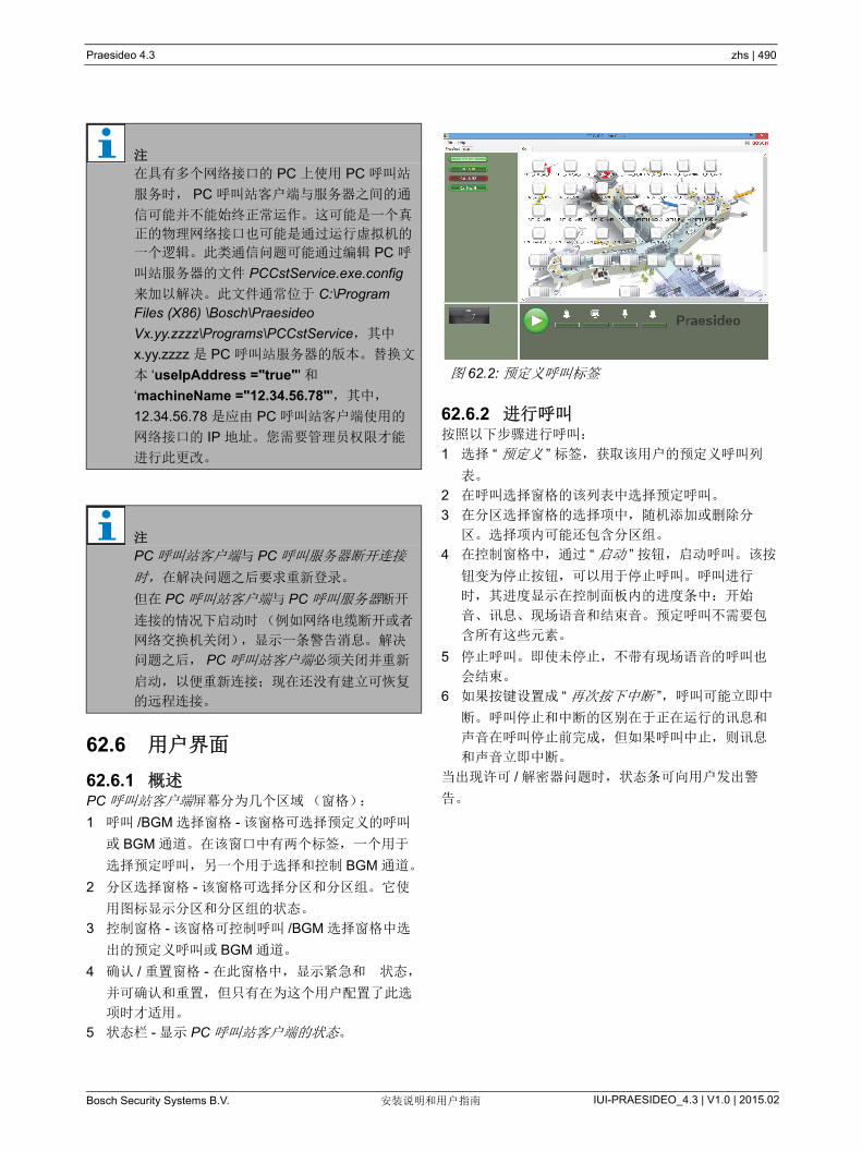
Praesideo 4.3 zhs | 490
Bosch Security Systems B.V. IUI-PRAESIDEO_4.3 | V1.0 | 2015.02安装说明和用户指南
62.6 用户界面
62.6.1 概述PC 呼叫站客户端屏幕分为几个区域(窗格):
1 呼叫 /BGM 选择窗格 - 该窗格可选择预定义的呼叫
或 BGM 通道。在该窗口中有两个标签,一个用于
选择预定呼叫,另一个用于选择和控制 BGM 通道。
2 分区选择窗格 - 该窗格可选择分区和分区组。它使
用图标显示分区和分区组的状态。
3 控制窗格 - 该窗格可控制呼叫 /BGM 选择窗格中选
出的预定义呼叫或 BGM 通道。
4 确认 / 重置窗格 - 在此窗格中,显示紧急和 状态,
并可确认和重置,但只有在为这个用户配置了此选
项时才适用。
5 状态栏 - 显示 PC 呼叫站客户端的状态。
62.6.2 进行呼叫按照以下步骤进行呼叫:
1 选择 “ 预定义 ” 标签,获取该用户的预定义呼叫列
表。
2 在呼叫选择窗格的该列表中选择预定呼叫。
3 在分区选择窗格的选择项中,随机添加或删除分
区。选择项内可能还包含分区组。
4 在控制窗格中,通过 “ 启动 ” 按钮,启动呼叫。该按
钮变为停止按钮,可以用于停止呼叫。呼叫进行
时,其进度显示在控制面板内的进度条中:开始
音、讯息、现场语音和结束音。预定呼叫不需要包
含所有这些元素。
5 停止呼叫。即使未停止,不带有现场语音的呼叫也
会结束。
6 如果按键设置成 “ 再次按下中断 ”,呼叫可能立即中
断。呼叫停止和中断的区别在于正在运行的讯息和
声音在呼叫停止前完成,但如果呼叫中止,则讯息
和声音立即中断。
当出现许可 / 解密器问题时,状态条可向用户发出警
告。
注
在具有多个网络接口的 PC 上使用 PC 呼叫站
服务时, PC 呼叫站客户端与服务器之间的通
信可能并不能始终正常运作。这可能是一个真
正的物理网络接口也可能是通过运行虚拟机的
一个逻辑。此类通信问题可能通过编辑 PC 呼
叫站服务器的文件 PCCstService.exe.config
来加以解决。此文件通常位于 C:\Program Files (X86) \Bosch\Praesideo
Vx.yy.zzzz\Programs\PCCstService,其中
x.yy.zzzz 是 PC 呼叫站服务器的版本。替换文
本 ‘useIpAddress ="true"' 和
‘machineName ="12.34.56.78"',其中,
12.34.56.78 是应由 PC 呼叫站客户端使用的
网络接口的 IP 地址。您需要管理员权限才能
进行此更改。
注
PC 呼叫站客户端与 PC 呼叫服务器断开连接
时, 在解决问题之后要求重新登录。
但在 PC 呼叫站客户端与 PC 呼叫服务器断开
连接的情况下启动时(例如网络电缆断开或者
网络交换机关闭),显示一条警告消息。解决
问题之后, PC 呼叫站客户端必须关闭并重新
启动,以便重新连接;现在还没有建立可恢复
的远程连接。
图 62.2: 预定义呼叫标签
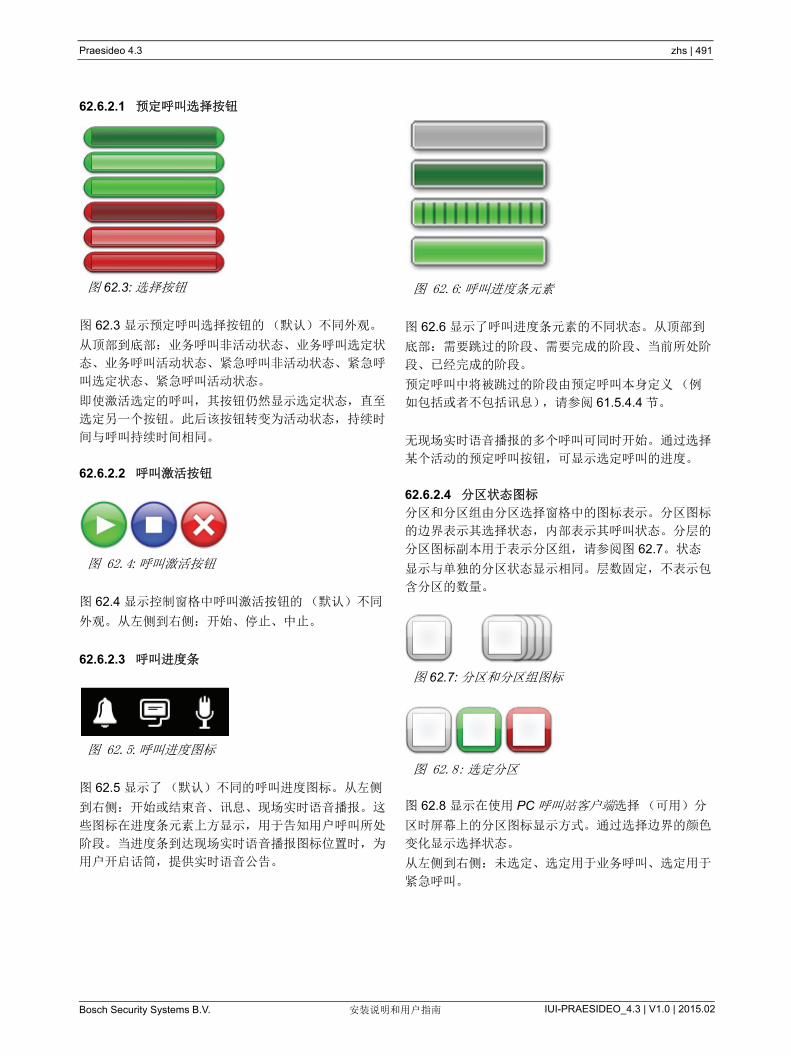
Praesideo 4.3 zhs | 491
Bosch Security Systems B.V. IUI-PRAESIDEO_4.3 | V1.0 | 2015.02安装说明和用户指南
62.6.2.1 预定呼叫选择按钮
图 62.3 显示预定呼叫选择按钮的(默认)不同外观。
从顶部到底部:业务呼叫非活动状态、业务呼叫选定状
态、业务呼叫活动状态、紧急呼叫非活动状态、紧急呼
叫选定状态、紧急呼叫活动状态。
即使激活选定的呼叫,其按钮仍然显示选定状态,直至
选定另一个按钮。此后该按钮转变为活动状态,持续时
间与呼叫持续时间相同。
62.6.2.2 呼叫激活按钮
图 62.4 显示控制窗格中呼叫激活按钮的(默认)不同
外观。从左侧到右侧:开始、停止、中止。
62.6.2.3 呼叫进度条
图 62.5 显示了(默认)不同的呼叫进度图标。从左侧
到右侧:开始或结束音、讯息、现场实时语音播报。这
些图标在进度条元素上方显示,用于告知用户呼叫所处
阶段。当进度条到达现场实时语音播报图标位置时,为
用户开启话筒,提供实时语音公告。
图 62.6 显示了呼叫进度条元素的不同状态。从顶部到
底部:需要跳过的阶段、需要完成的阶段、当前所处阶
段、已经完成的阶段。
预定呼叫中将被跳过的阶段由预定呼叫本身定义(例
如包括或者不包括讯息),请参阅 61.5.4.4 节。
无现场实时语音播报的多个呼叫可同时开始。通过选择
某个活动的预定呼叫按钮,可显示选定呼叫的进度。
62.6.2.4 分区状态图标
分区和分区组由分区选择窗格中的图标表示。分区图标
的边界表示其选择状态,内部表示其呼叫状态。分层的
分区图标副本用于表示分区组,请参阅图 62.7。状态
显示与单独的分区状态显示相同。层数固定,不表示包
含分区的数量。
图 62.8 显示在使用 PC 呼叫站客户端选择(可用)分
区时屏幕上的分区图标显示方式。通过选择边界的颜色
变化显示选择状态。
从左侧到右侧:未选定、选定用于业务呼叫、选定用于
紧急呼叫。
图 62.3: 选择按钮
图 62.4: 呼叫激活按钮
图 62.5: 呼叫进度图标
图 62.6: 呼叫进度条元素
图 62.7: 分区和分区组图标
图 62.8: 选定分区
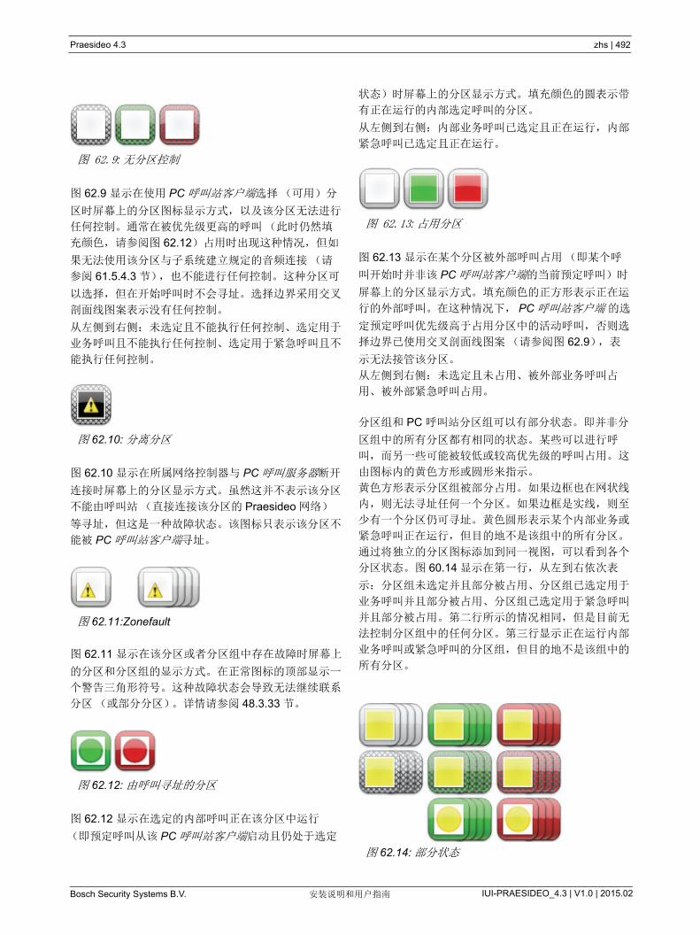
Praesideo 4.3 zhs | 492
Bosch Security Systems B.V. IUI-PRAESIDEO_4.3 | V1.0 | 2015.02安装说明和用户指南
图 62.9 显示在使用 PC 呼叫站客户端选择(可用)分
区时屏幕上的分区图标显示方式,以及该分区无法进行
任何控制。通常在被优先级更高的呼叫(此时仍然填
充颜色,请参阅图 62.12)占用时出现这种情况,但如
果无法使用该分区与子系统建立规定的音频连接(请
参阅 61.5.4.3 节),也不能进行任何控制。这种分区可
以选择,但在开始呼叫时不会寻址。选择边界采用交叉
剖面线图案表示没有任何控制。
从左侧到右侧:未选定且不能执行任何控制、选定用于
业务呼叫且不能执行任何控制、选定用于紧急呼叫且不
能执行任何控制。
图 62.10 显示在所属网络控制器与 PC 呼叫服务器断开
连接时屏幕上的分区显示方式。虽然这并不表示该分区
不能由呼叫站(直接连接该分区的 Praesideo 网络)
等寻址,但这是一种故障状态。该图标只表示该分区不
能被 PC 呼叫站客户端寻址。
图 62.11 显示在该分区或者分区组中存在故障时屏幕上
的分区和分区组的显示方式。在正常图标的顶部显示一
个警告三角形符号。这种故障状态会导致无法继续联系
分区(或部分分区)。详情请参阅 48.3.33 节。
图 62.12 显示在选定的内部呼叫正在该分区中运行
(即预定呼叫从该 PC 呼叫站客户端启动且仍处于选定
状态)时屏幕上的分区显示方式。填充颜色的圆表示带
有正在运行的内部选定呼叫的分区。
从左侧到右侧:内部业务呼叫已选定且正在运行,内部
紧急呼叫已选定且正在运行。
图 62.13 显示在某个分区被外部呼叫占用(即某个呼
叫开始时并非该 PC 呼叫站客户端的当前预定呼叫)时
屏幕上的分区显示方式。填充颜色的正方形表示正在运
行的外部呼叫。在这种情况下, PC 呼叫站客户端 的选
定预定呼叫优先级高于占用分区中的活动呼叫,否则选
择边界已使用交叉剖面线图案(请参阅图 62.9),表
示无法接管该分区。
从左侧到右侧:未选定且未占用、被外部业务呼叫占
用、被外部紧急呼叫占用。
分区组和 PC 呼叫站分区组可以有部分状态。即并非分
区组中的所有分区都有相同的状态。某些可以进行呼
叫,而另一些可能被较低或较高优先级的呼叫占用。这
由图标内的黄色方形或圆形来指示。
黄色方形表示分区组被部分占用。如果边框也在网状线
内,则无法寻址任何一个分区。如果边框是实线,则至
少有一个分区仍可寻址。黄色圆形表示某个内部业务或
紧急呼叫正在运行,但目的地不是该组中的所有分区。
通过将独立的分区图标添加到同一视图,可以看到各个
分区状态。图 60.14 显示在第一行,从左到右依次表
示:分区组未选定并且部分被占用、分区组已选定用于
业务呼叫并且部分被占用、分区组已选定用于紧急呼叫
并且部分被占用。第二行所示的情况相同,但是目前无
法控制分区组中的任何分区。第三行显示正在运行内部
业务呼叫或紧急呼叫的分区组,但目的地不是该组中的
所有分区。
图 62.9: 无分区控制
图 62.10: 分离分区
图 62.11:Zonefault
图 62.12: 由呼叫寻址的分区
图 62.13: 占用分区
图 62.14: 部分状态

Praesideo 4.3 zhs | 493
Bosch Security Systems B.V. IUI-PRAESIDEO_4.3 | V1.0 | 2015.02安装说明和用户指南
图 60.15 从左到右显示用于以下各项的按钮外观:无故
障和无紧急状态、存在故障和存在紧急状态 (未确
认),以及存在故障和存在紧急状态 (已确认)。只要
故障或紧急状态未经确认, PC 呼叫站客户端就会激活
提示语音,并在确认状态后静音。
重复的提示语音已作为 Fault alarm.wav 和 Emergency
alarm.wav 安装在 PC 上,并且可以用相同文件名的其
它语音替换它们。
62.6.3 更改 BGM 设置
使用以下步骤,更改 BGM 设定(仅适用于授权用
户):
1 选择 BGM 标签,获取 BGM 通道列表以及改变
BGM 音量的按钮。
2 从列表中选择 BGM 通道。现在,所有 BGM 通道处
于活动状态的分区和分区组都由分区控制窗格中的
图标表示。
3 在分区选择窗格的 BGM 通道选择项中,添加或移
除分区。选择项内还可包含分区组,但不建议采用
这个方法(请参阅 62.6.3.3 节中的注释)。
4 在控制窗格中使用音量增大和减小按钮,同时改变
BGM 通道处于活动状态的所有分区的音量。每个分
区的音量设定都将在分区图标中显示。
5 为了更改与某个 BGM 通道无关的各分区的音量,
在呼叫 /BGM 选择窗格中选择音量按钮,而不是某
个 BGM 通道。然后在分区选择窗格中选择某个分
区, 后的使用控制窗格中的音量增大和减小按钮
调整音量。
62.6.3.1 BGM 选择按钮
图 62.17 显示 BGM 选择按钮的(默认)不同外观。
从顶部到底部:BGM 通道选定状态、 BGM 通道、
BGM 音量模式按钮选定状态、 BGM 音量模式按钮。
62.6.3.2 BGM 音量按钮
图 62.18 显示控制窗格中 BGM 音量控制按钮的(默
认)不同外观。
从顶部到底部:BGM 音量增大、 BGM 音量减小。
62.6.3.3 BGM 分区状态图标
图 62.19 显示在该分区正在播放当前选定 BGM 通道
时,分区选择窗格中的分区图标显示方式。
图 62.15: 确认和重置
图 62.16:BGM 标签
图 62.17: 选择按钮
图 62.18: 音量增大和减小按钮
图 62.19: 带有选定 BGM 通道的分区
图 62.20: 选定分区
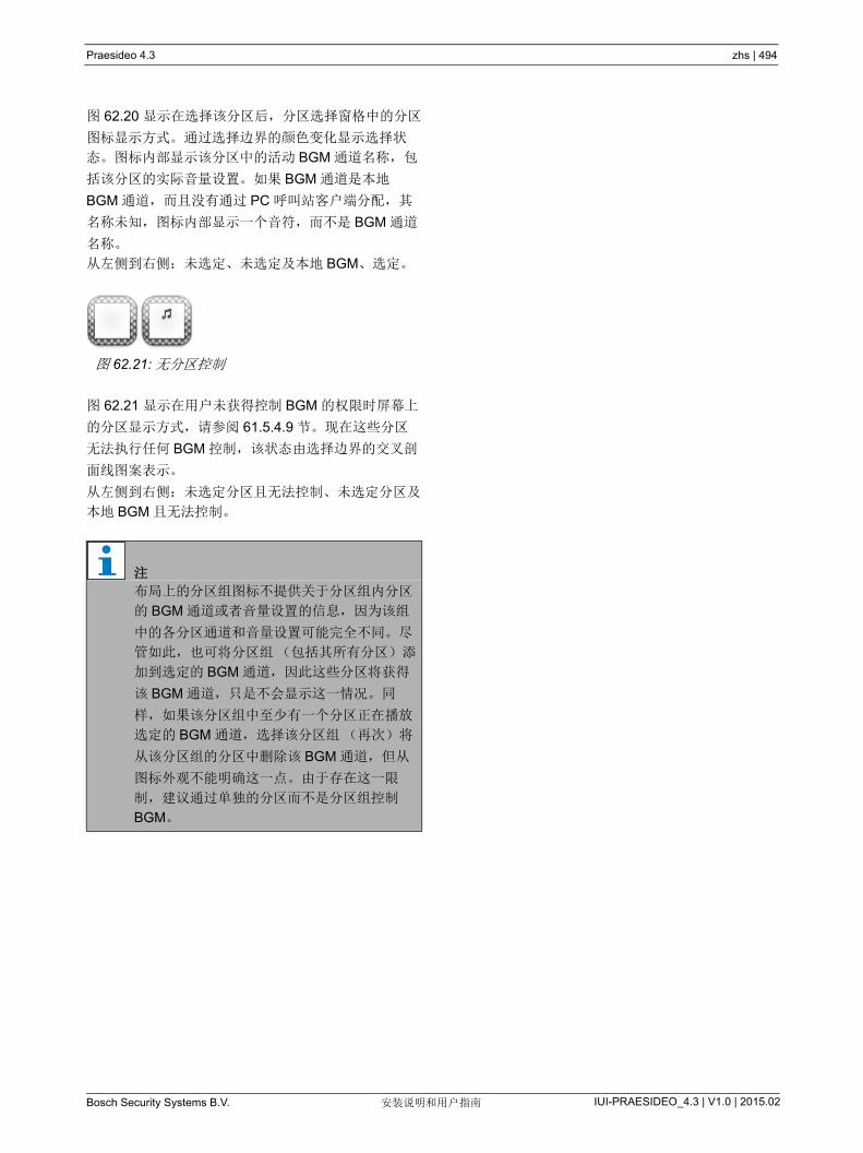
Praesideo 4.3 zhs | 494
Bosch Security Systems B.V. IUI-PRAESIDEO_4.3 | V1.0 | 2015.02安装说明和用户指南
图 62.20 显示在选择该分区后,分区选择窗格中的分区
图标显示方式。通过选择边界的颜色变化显示选择状
态。图标内部显示该分区中的活动 BGM 通道名称,包
括该分区的实际音量设置。如果 BGM 通道是本地
BGM 通道,而且没有通过 PC 呼叫站客户端分配,其
名称未知,图标内部显示一个音符,而不是 BGM 通道
名称。
从左侧到右侧:未选定、未选定及本地 BGM、选定。
图 62.21 显示在用户未获得控制 BGM 的权限时屏幕上
的分区显示方式,请参阅 61.5.4.9 节。现在这些分区
无法执行任何 BGM 控制,该状态由选择边界的交叉剖
面线图案表示。
从左侧到右侧:未选定分区且无法控制、未选定分区及
本地 BGM 且无法控制。
图 62.21: 无分区控制
注
布局上的分区组图标不提供关于分区组内分区
的 BGM 通道或者音量设置的信息,因为该组
中的各分区通道和音量设置可能完全不同。尽
管如此,也可将分区组(包括其所有分区)添
加到选定的 BGM 通道,因此这些分区将获得
该 BGM 通道,只是不会显示这一情况。同
样,如果该分区组中至少有一个分区正在播放
选定的 BGM 通道,选择该分区组(再次)将
从该分区组的分区中删除该 BGM 通道,但从
图标外观不能明确这一点。由于存在这一限
制,建议通过单独的分区而不是分区组控制
BGM。

Praesideo 4.3 zhs | 495
Bosch Security Systems B.V. IUI-PRAESIDEO_4.3 | V1.0 | 2015.02安装说明和用户指南
63 PC 电话接口客户端
63.1 简介用户可使用电话通过 Praesideo PC 电话接口客户端接
入 Praesideo 系统。电话键盘用于执行呼叫方识别、预
定呼叫选择和分区及 / 或分区组选择。预定呼叫包含关
于优先级、开始和结束音、预先录制的信息以及初始选
定分区的信息。此后用户可通过电话键盘添加其它分
区。呼叫也可包括现场实时语音播报,该语音将在使用
电话时录制。
PC 电话接口客户端是 Praesideo PC 呼叫服务器的一
个软件客户端。该客户端与 PC 呼叫服务器安装在同一
个 PC 机上,属于部分 PC 呼叫服务器配置。
PC 电话接口客户端既可处理来自 VoIP 电话(软件电
话或者硬件电话)的来电呼叫,也可通过附加语音网关
(例如 Linksys SPA3102)处理来自 POTS 电话(本
地或者远程电话)的来电呼叫。运行 PC 电话接口客户
端 的 PC 机通过模拟音频线路从 PC 机声卡将呼叫的现
场实时语音播报部分发送到 Praesideo 系统。
VoIP 电话也可通过 WAN 或因特网呼入 PC 电话接口
客户端。
63.2 要求PC 电话接口客户端可以在任何一台符合以下 低要求
的 PC 上运行:
• 操作系统:
Microsoft® Windows 7 (Windows 8 和 8.1 不能用
于 PRS-TIC,因为其依赖于 AsteriskWin)
• 网络连接:100 base-T
• 1 GB RAM
63.3 安装按以下步骤进行:
1 启动 PRS-SW Praesideo 软件 DVD (请参阅 36.2
节)。
2 单击 可选 > PC 电话接口 (请参阅第 39 节)。出
现 File Download (文件下载)窗口。
3 同 PC 呼叫服务器配置客户端的方法相同(请参阅
61.3 节)。
63.4 许可在使用 PC 电话接口客户端时,必须获取许可证。通过
购买 PRS-TIC,可获取一个注册代码,该代码必须为
目标系统注册。通过博世注册网站完成注册,其中应用
程序可连接 PC 呼叫服务器及其解密器。请参阅
第 61.5.4.15 节。
63.5 开始类似于 PC 呼叫服务器,在 Windows 启动时 PC 机将
自动启动 PC 电话接口客户端服务。重要事件会记录在
Windows 事件日志中:
• 启动和关闭服务
• 关于许可证有效性的错误讯息
• 导致服务关闭的异常(故障)错误
注
为避免呼叫终端,不得在运行 PC 电话接口客
户端的 PC 机上运行其它对处理器要求较高的
应用程序。
Praesideo 4.3 zhs | 496
Bosch Security Systems B.V. IUI-PRAESIDEO_4.3 | V1.0 | 2015.02安装说明和用户指南
63.6 操作在通过 PC 电话接口客户端进行呼叫时,要求用户按照
一个语音应答菜单操作。 PC 电话接口使用在 PC 呼叫
服务器中预先定义的呼叫选择呼叫属性。这些呼叫总是
局部呼叫。首先录制 PC 电话接口呼叫的现场实时语音
播报部分,然后在成功完成呼叫之后广播。
如果将进行带现场实时语音播报的呼叫,则运行 PC 电
话接口 的 PC 机的声卡音频输出端连接到 Praesideo
系统的音频输入端上。确保电话所用的所有预定呼叫
(带有现场实时语音播报)将该音频输入端配置为现场
实时语音播报输入。
这表示, PC 呼叫站客户端 和 PC 电话接口客户端使用
的预定呼叫不应包含现场实时语音播报,因为这些客户
端在现场实时语音播报中使用不同的 Praesideo 音频输
入端。如果该预定呼叫应包含现场实时语音播报,则该
预定呼叫(名称不同)的两个几乎完全相同的版本应
配置到 PC 呼叫服务器上,一个用于 PC 呼叫站客户端
(例如,呼叫站话筒作为输入端),另一个用于 PC 电
话客户端 (线路输入端配置为现场实时语音播报源并
连接到 PC 机声卡输出端上)。
为 PC 电话接口客户端配置端口号 5060, 以便通过
ZoIPer (www.zoiper.com)等软件电话直接接入。
63.7 语音应答菜单语音应答菜单可引导呼叫方输入进行呼叫的必要数据。
为此,提供了许多使用英语的不同 gsm 文件。 gsm 文
件格式通常用于此类电话应用程序。这是一种压缩声音
文件格式。用户或者安装人员可将这些声音文件替换为
更方便目标用户使用的文件,例如使用本地语言、更详
尽或更精简。为此, Praesideo 销售 DVD 光盘上提供
了声音文件编辑器和转换器。用户可使用这些编辑器
(例如 WavePad、 Audacity)录制未压缩的 wav 文
件。此后可使这些文件达到 高规范化程度及 / 或使用
其它优化方式,确保便于理解。建议使用高通滤波器消
除 300 Hz 以下的频率,因为这些低频信号会严重降低
gsm 文件的可理解性。 后必须将这些文件转换(使
用 SoX 或者 WavePad)为 gsm 文件格式,取样率为
8kHz。应使用表 63.1 显示的名称,因为 PC 电话接口
客户端要求使用这些名称。不可翻译或者更改这些文件
名。
使用 SoX 在命令行上将 wav 文件格式转换为 gsm 文件
格式的方法如下:
sox.exe "< 源文件名 >.wav" -r 8000 "< 目标文件名
>.gsm"
由于电话接口基于 Asterisk 电话通信平台,而该平台设
计在 Linux 系统上运行,因此在 MS Windows 系统上
安装了一个 Cygwin 环境,声音文件位于
\<AsteriskRoot>\var\lib\sounds 文件夹中。该文件夹通
常为 C:\cygroot\asterisk\var\lib\sounds。
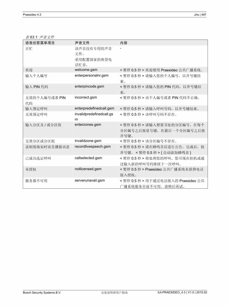
Praesideo 4.3 zhs | 497
Bosch Security Systems B.V. IUI-PRAESIDEO_4.3 | V1.0 | 2015.02安装说明和用户指南
表 63.1: 声音文件
语音应答菜单项目 声音文件 内容
正忙 该声音没有专用的声音
文件。
采用配置国家的典型电
话忙音。
-
欢迎 welcome.gsm < 暂停 0.5 秒 > 欢迎使用 Praesideo 公共广播系统。
输入个人编号 enterpersonalnr.gsm < 暂停 0.5 秒 > 请输入您的个人编号,以井号键结
束。
输入 PIN 代码 enterpincode.gsm < 暂停 0.5 秒 > 请输入您的 PIN 代码,以井号键结
束。
无效的个人编号或者 PIN
代码
incorrect.gsm < 暂停 0.5 秒 > 该个人编号或者 PIN 代码不正确。
输入预定呼叫 enterpredefinedcall.gsm < 暂停 0.5 秒 > 请输入呼叫号码,以井号键结束。
无效预定呼叫 invalidpredefinedcall.gs
m< 暂停 0.5 秒 > 该呼叫号码不存在。
输入分区及 / 或分区组 enterzones.gsm < 暂停 0.5 秒 > 请输入想要寻址的分区编号,在每个
分区编号之后按星号键,在 后一个分区编号之后按
井号键。
无效分区或分区组 invalidzone.gsm < 暂停 0.5 秒 > 该分区编号不存在。
录制现场实时语音播报讯息 recordlivespeech.gsm < 暂停 0.5 秒 > 请在蜂鸣音后进行公告。完成后,按
井号键。 < 暂停 0.5 秒 > 自动添加蜂鸣音
已成功选定呼叫 callselected.gsm < 暂停 0.5 秒 > 将处理您的呼叫。您可现在挂机或通
过输入新的呼叫号码继续下一次呼叫。
未授权 notlicensed.gsm < 暂停 0.5 秒 > Praesideo 公共广播系统未获得电话
接入授权。
服务器不可用 serverunavail.gsm < 暂停 0.5 秒 > 用于通过电话接入的 Praesideo 公共
广播系统服务目前不可用。请稍后再试。
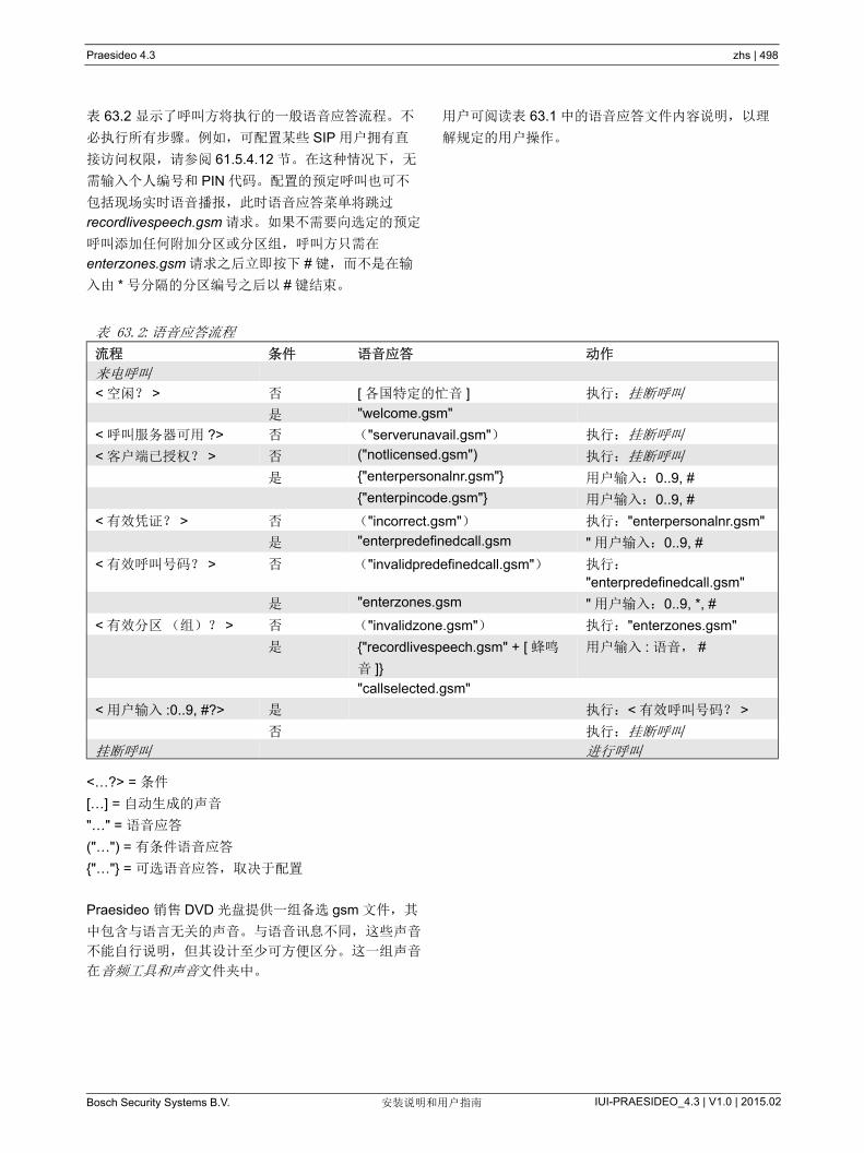
Praesideo 4.3 zhs | 498
Bosch Security Systems B.V. IUI-PRAESIDEO_4.3 | V1.0 | 2015.02安装说明和用户指南
表 63.2 显示了呼叫方将执行的一般语音应答流程。不
必执行所有步骤。例如,可配置某些 SIP 用户拥有直
接访问权限,请参阅 61.5.4.12 节。在这种情况下,无
需输入个人编号和 PIN 代码。配置的预定呼叫也可不
包括现场实时语音播报,此时语音应答菜单将跳过
recordlivespeech.gsm 请求。如果不需要向选定的预定
呼叫添加任何附加分区或分区组,呼叫方只需在
enterzones.gsm 请求之后立即按下 # 键,而不是在输
入由 * 号分隔的分区编号之后以 # 键结束。
用户可阅读表 63.1 中的语音应答文件内容说明,以理
解规定的用户操作。
<…?> = 条件
[…] = 自动生成的声音
"…" = 语音应答
("…") = 有条件语音应答
"…" = 可选语音应答,取决于配置
Praesideo 销售 DVD 光盘提供一组备选 gsm 文件,其
中包含与语言无关的声音。与语音讯息不同,这些声音
不能自行说明,但其设计至少可方便区分。这一组声音
在音频工具和声音文件夹中。
表 63.2: 语音应答流程
流程 条件 语音应答 动作
来电呼叫
< 空闲? > 否 [ 各国特定的忙音 ] 执行:挂断呼叫
是 "welcome.gsm"
< 呼叫服务器可用 ?> 否 ("serverunavail.gsm") 执行:挂断呼叫
< 客户端已授权? > 否 ("notlicensed.gsm") 执行:挂断呼叫
是 "enterpersonalnr.gsm" 用户输入:0..9, #
"enterpincode.gsm" 用户输入:0..9, #
< 有效凭证? > 否 ("incorrect.gsm") 执行:"enterpersonalnr.gsm"
是 "enterpredefinedcall.gsm " 用户输入:0..9, #
< 有效呼叫号码? > 否 ("invalidpredefinedcall.gsm") 执行:
"enterpredefinedcall.gsm"
是 "enterzones.gsm " 用户输入:0..9, *, #
< 有效分区(组)? > 否 ("invalidzone.gsm") 执行:"enterzones.gsm"
是 "recordlivespeech.gsm" + [ 蜂鸣
音 ]
用户输入 : 语音, #
"callselected.gsm"
< 用户输入 :0..9, #?> 是 执行:< 有效呼叫号码? >
否 执行:挂断呼叫
挂断呼叫 进行呼叫
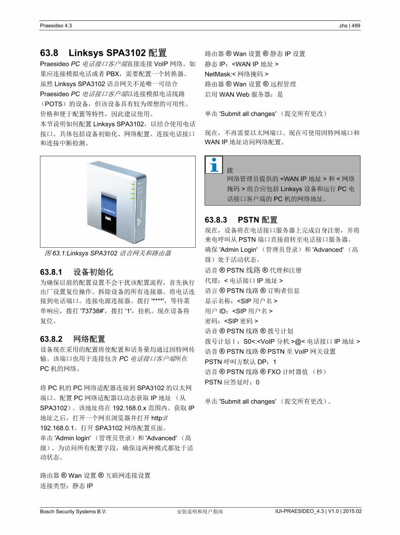
Praesideo 4.3 zhs | 499
Bosch Security Systems B.V. IUI-PRAESIDEO_4.3 | V1.0 | 2015.02安装说明和用户指南
63.8 Linksys SPA3102 配置Praesideo PC 电话接口客户端直接连接 VoIP 网络。如
果应连接模拟电话或者 PBX,需要配置一个转换器。
虽然 Linksys SPA3102 语音网关不是唯一可结合
Praesideo PC 电话接口客户端以连接模拟电话线路
(POTS)的设备,但该设备具有较为理想的可用性、
价格和便于配置等特性,因此建议使用。
本节说明如何配置 Linksys SPA3102,以结合使用电话
接口。具体包括设备初始化、网络配置、连接电话接口
和连接中断检测。
63.8.1 设备初始化为确保以前的配置设置不会干扰该配置流程,首先执行
出厂设置复位操作。拆除设备的所有连接器。将电话连
接到电话端口。连接电源连接器。拨打 '****',等待菜
单响应,拨打 '73738#',拨打 '1',挂机。现在设备将
复位。
63.8.2 网络配置设备现在采用的配置将使配置和话务量均通过因特网传
输。该端口也用于连接包含 PC 电话接口客户端所在
PC 机的网络。
将 PC 机的 PC 网络适配器连接到 SPA3102 的以太网
端口。配置 PC 网络适配器以动态获取 IP 地址(从
SPA3102)。该地址将在 192.168.0.x 范围内。获取 IP
地址之后,打开一个网页浏览器并打开 http://
192.168.0.1。打开 SPA3102 网络配置页面。
单击 'Admin login' (管理员登录)和 'Advanced' (高
级)。为访问所有配置字段,确保这两种模式都处于活
动状态。
路由器 ® Wan 设置 ® 互联网连接设置
连接类型:静态 IP
路由器 ® Wan 设置 ® 静态 IP 设置
静态 IP:<WAN IP 地址 >
NetMask:< 网络掩码 >
路由器 ® Wan 设置 ® 远程管理
启用 WAN Web 服务器:是
单击 'Submit all changes' (提交所有更改)
现在,不再需要以太网端口。现在可使用因特网端口和
WAN IP 地址访问网络配置。
63.8.3 PSTN 配置现在,设备将在电话接口服务器上完成自身注册,并将
来电呼叫从 PSTN 端口直接前转至电话接口服务器。
确保 'Admin Login' (管理员登录)和 'Advanced' (高
级)处于活动状态。
语音 ® PSTN 线路 ® 代理和注册
代理:< 电话接口 IP 地址 >
语言 ® PSTN 线路 ® 订购者信息
显示名称:<SIP 用户名 >
用户 ID:<SIP 用户名 >
密码:<SIP 密码 >
语音 ® PSTN 线路 ® 拨号计划
拨号计划1:S0<:<VoIP 分机 >@< 电话接口 IP 地址 >
语音 ® PSTN 线路 ® PSTN 至 VoIP 网关设置
PSTN 呼叫方默认 DP:1
语音 ® PSTN 线路 ® FXO 计时器值(秒)
PSTN 应答延时:0
单击 'Submit all changes' (提交所有更改)。
图 63.1:Linksys SPA3102 语音网关和路由器
注
网络管理员提供的 <WAN IP 地址 > 和 < 网络
掩码 > 组合应包括 Linksys 设备和运行 PC 电
话接口客户端的 PC 机的网络地址。

Praesideo 4.3 zhs | 500
Bosch Security Systems B.V. IUI-PRAESIDEO_4.3 | V1.0 | 2015.02安装说明和用户指南
63.8.4 连接中断检测不同国家有多种电话连接中断方法。为使设备与电话接
口结合使用,必须配置正确方法,这一点非常重要。关
于连接中断方法的信息,请咨询您的电话服务供应商。
Linksys SPA3102 支持以下方法:
• CPC,短暂切断正负极线间电压;
• 极性倒置;
• 长时间静音;
• 断开声音识别。
大多数欧洲的电话服务供应商都不使用线路电压或者极
性倒置方法。 SPA3102 必须识别该地区的中断音。例
如在荷兰,中断音由一段 500ms 440Hz 的声音和
500ms 静音循环构成。
该声音的配置语法为:440@-30,440@-30;
2(.5/.5/1+2).
Web 配置(确保 'Admin Login' (管理员登录)和
'Advanced' (高级)处于活动状态):
语音 ® PSTN 线路 ® PSTN 连接中断检测
连接中断音:440@-30,440@-30;2(.5/.5/1+2).
单击 'Submit all changes' (提交所有更改)。
63.8.5 ISDN 电话数字 ISDN 电话可通过本地 PBX (提供连接语音网关
的模拟线路)使用。在这种情况下,必须配置本地
PBX 以在收到按下按钮对应的 ISDN 命令时立即产生
DTMF 声音。这些 DTMF 声音规定用于识别通过电话
发送到 Linksys SPA3102 语音网关的用户输入(例如
呼叫选择和分区选择)。
注
Linksys SPA3102 将 **# 序列作为一个特殊命
令处理,以断开 PSTN 线路连接。因此,在语
音应答流程中,用户不应输入该序列(请参阅
表 63.2)。在输入分区编号时可能因遗漏某些
数字键而造成这种错误,因为这些编号是由 *
分隔的,而且是以 # 结尾的。

Praesideo 4.3 zhs | 501
Bosch Security Systems B.V. IUI-PRAESIDEO_4.3 | V1.0 | 2015.02安装说明和用户指南
64 开放式接口
64.1 简介Praesideo 开放式接口基于 Visual Basic 工具和
Microsoft 所描述的 COM 技术(OLE 自动子集)。
好使用 .NET 来实现 Praesideo 开放式接口。 .NET
是对 COM、 COM+ 和 DCOM 的继承,堪与这些接口
相提并论。当前的 COM 接口可以用于 .NET 环境。很
多编程语言识别 .NET,这使得第三方开发用户接口更
加简便。
目前, Praesideo 开放式接口采用 COM 来实现与当前
未内置于 .NET 的系统进行连接。当前大多数的第三方
系统支持 COM,但不支持 .NET。然而,不久的将来,
博世安保有限公司将把 COM 接口转换为 .NET。
在 .NET 环境中可能目前已经能方便地开发第三方程序
( 如 PC 呼叫站 )。这些 .NET 应用程序可以与当前的
COM 接口进行通信,而没有任何问题,而且将来基于
.NET 时也不会出现任何问题。如果应用程序是基于
COM 环境开发的,那么在接口基于 .NET 时就必须重
新编程。
尽管开放式接口连接 ( 即 Internet 连接 ) 被视为是开放
式连接,但这需要额外的安全预防措施。例如,设置防
火墙来防止未经授权的人员擅自使用 / 滥用系统。该系
统还可以限制 TCP/IP 设备的访问权限 ( 请参阅第
43.12 节 )。
使用开放式接口可能会导致 Praesideo 系统不再符合已
经通过 TÜV 标准认证的疏散标准。 如果那样, TÜ 失
效。
64.2 范围如前面所述,开放式接口手册描述了如何与 Visual
Basic 一起使用 Praesideo 开放式接口。为了理解本手
册的内容,必须掌握下述各个方面的知识:
• Visual Basic 6.0 编程语言及其开发环境。
• COM 接口原理和 OLE 自动原理。
• Praesideo 系统及其安装。
本章的目标读者是期望使用 Praesideo 开放式接口的用
户。但是,从与编程接口有关的本手册内容中并不能获
得任何权限。引入新的 Praesideo 版本时,就会实施对
开放式接口的扩展和改进。由于本手册的目标读者为程
序员,因此只提供英语版本。
尽管开放式接口 DLL 包含以前版本的开放式接口 (符
合向后兼容性),本手册只描述开放式接口 3.4 版。
DLL 中的接口是通过扩展名来加以识别的。原版本不带
扩展名。
注
COM 接口并非局限于 Visual Basic。它也可以
用于其它支持 COM 的编程语言。 VisualBasic
在此仅用作示例。
注
一个网络控制器 多可结合使用 5 个具有开放
式接口访问权限的 TCP/IP 设备,例如 PC 呼
叫服务器或者记录服务器。配置 Web 浏览器
使用一个不同的端口(端口 80)进行连接,
不属于此限制范围之列。
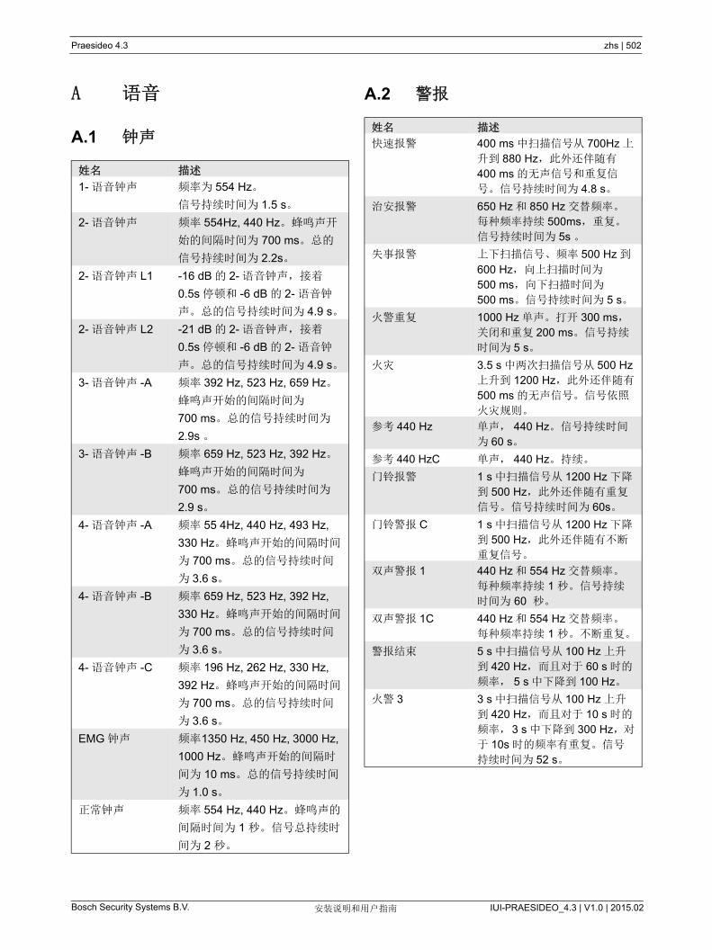
Praesideo 4.3 zhs | 502
Bosch Security Systems B.V. IUI-PRAESIDEO_4.3 | V1.0 | 2015.02安装说明和用户指南
A 语音
A.1 钟声
A.2 警报
姓名 描述
1- 语音钟声 频率为 554 Hz。
信号持续时间为 1.5 s。
2- 语音钟声 频率 554Hz, 440 Hz。蜂鸣声开
始的间隔时间为 700 ms。总的
信号持续时间为 2.2s。
2- 语音钟声 L1 -16 dB 的 2- 语音钟声,接着
0.5s 停顿和 -6 dB 的 2- 语音钟
声。总的信号持续时间为 4.9 s。
2- 语音钟声 L2 -21 dB 的 2- 语音钟声,接着
0.5s 停顿和 -6 dB 的 2- 语音钟
声。总的信号持续时间为 4.9 s。
3- 语音钟声 -A 频率 392 Hz, 523 Hz, 659 Hz。
蜂鸣声开始的间隔时间为
700 ms。总的信号持续时间为
2.9s 。
3- 语音钟声 -B 频率 659 Hz, 523 Hz, 392 Hz。
蜂鸣声开始的间隔时间为
700 ms。总的信号持续时间为
2.9 s。
4- 语音钟声 -A 频率 55 4Hz, 440 Hz, 493 Hz,
330 Hz。蜂鸣声开始的间隔时间
为 700 ms。总的信号持续时间
为 3.6 s。
4- 语音钟声 -B 频率 659 Hz, 523 Hz, 392 Hz,
330 Hz。蜂鸣声开始的间隔时间
为 700 ms。总的信号持续时间
为 3.6 s。
4- 语音钟声 -C 频率 196 Hz, 262 Hz, 330 Hz,
392 Hz。蜂鸣声开始的间隔时间
为 700 ms。总的信号持续时间
为 3.6 s。
EMG 钟声 频率1350 Hz, 450 Hz, 3000 Hz,
1000 Hz。蜂鸣声开始的间隔时
间为 10 ms。总的信号持续时间
为 1.0 s。
正常钟声 频率 554 Hz, 440 Hz。蜂鸣声的
间隔时间为 1 秒。信号总持续时
间为 2 秒。
姓名 描述
快速报警 400 ms 中扫描信号从 700Hz 上
升到 880 Hz,此外还伴随有
400 ms 的无声信号和重复信
号。信号持续时间为 4.8 s。
治安报警 650 Hz 和 850 Hz 交替频率。
每种频率持续 500ms,重复。
信号持续时间为 5s 。
失事报警 上下扫描信号、频率 500 Hz 到
600 Hz,向上扫描时间为
500 ms,向下扫描时间为
500 ms。信号持续时间为 5 s。
火警重复 1000 Hz 单声。打开 300 ms,关闭和重复 200 ms。信号持续
时间为 5 s。
火灾 3.5 s 中两次扫描信号从 500 Hz上升到 1200 Hz,此外还伴随有
500 ms 的无声信号。信号依照
火灾规则。
参考 440 Hz 单声, 440 Hz。信号持续时间
为 60 s。
参考 440 HzC 单声, 440 Hz。持续。
门铃报警 1 s 中扫描信号从 1200 Hz 下降
到 500 Hz,此外还伴随有重复
信号。信号持续时间为 60s。
门铃警报 C 1 s 中扫描信号从 1200 Hz 下降
到 500 Hz,此外还伴随有不断
重复信号。
双声警报 1 440 Hz 和 554 Hz 交替频率。
每种频率持续 1 秒。信号持续
时间为 60 秒。
双声警报 1C 440 Hz 和 554 Hz 交替频率。
每种频率持续 1 秒。不断重复。
警报结束 5 s 中扫描信号从 100 Hz 上升
到 420 Hz,而且对于 60 s 时的
频率, 5 s 中下降到 100 Hz。
火警 3 3 s 中扫描信号从 100 Hz 上升
到 420 Hz,而且对于 10 s 时的
频率,3 s 中下降到 300 Hz,对
于 10s 时的频率有重复。信号
持续时间为 52 s。

Praesideo 4.3 zhs | 503
Bosch Security Systems B.V. IUI-PRAESIDEO_4.3 | V1.0 | 2015.02安装说明和用户指南
解除报警 3 s 中扫描信号从 1000 Hz 下降到 650 Hz,此外还伴随有 2s 的无声信号和重复信号。持续时间为 60 s。
解除警报 C 3 s 中扫描信号从 1000 Hz 下降到 650 Hz,此外还伴随有 2s 的无声信号。持续重复。
快速报警 UK 400 ms 中扫描信号从 700Hz 上升到 880 Hz,此外还伴随有400 ms 的无声信号和重复信号。信号持续时间为 60 s。
快速报警 UK C 400 ms 中扫描信号从 700 Hz 上升到 880 Hz,此外还伴随有400 ms 的无声信号。持续重复。
双声警报 2 650 Hz 和 850 Hz 交替频率。每种频率持续 500 ms,重复。信号持续时间为 60 s。
双声警报 2C 650 Hz 和 850 Hz 交替频率。每种频率持续 500 ms。持续重复。
失事 UK 500 ms 中扫描信号从 500Hz 上升到 600 Hz,500 ms 中扫描信号下降到 500 Hz 并伴有重复信号。信号持续时间为 60 s。
失事 UK C 500 ms 中扫描信号从 500Hz 上升到 600 Hz,500 ms 中扫描信号下降到 500 Hz。持续重复。
火警 1 1000 Hz 单声。打开 300 ms,关闭和重复 200 ms。信号持续时间为 60 s。
火灾警报 1C 1000 Hz 单声。300 ms 打开、200 ms 关闭。持续重复。
空袭 2.5 s 中扫描信号从 900 Hz 上升到 1000 Hz,2.5s 中扫描信号下降到 900 Hz 并伴有重复信号。信号持续时间为 60 s。
空袭 C 2.5 s 中扫描信号从 900 Hz 上升到 1000 Hz,2.5 s 中扫描信号下降到 900 Hz 并伴有不断重复信号。
废弃平台 1000 Hz 单声。信号持续时间为60s。
废弃 C 1000 Hz 单声。持续。
莫尔斯电码中的 F 1000 Hz 语音 100ms 打开、100 ms 关闭、100ms 打开、100 ms 关闭、300ms 打开、100 ms 关闭、100ms 打开、500 ms 关闭。重复信号,持续时间为 60.2 s。
莫尔斯电码 C 中的F
1000 Hz 100ms 打开、100 ms 关闭、100 ms 打开、100 ms 关闭、300 ms 打开、100 ms 关闭、100 ms 打开、500 ms 关闭。持续重复。
缓慢警报 3.5s 中扫描信号从 500 Hz 上升到 1200 Hz,此外还伴随有500 ms 的无声信号和重复信号。信号持续时间为 60 s。
缓慢警报 C 3.5 s 中扫描信号从 500 Hz 上升到 1200 Hz,此外还伴随有500 ms 的无声信号。持续重复。
NBC 警报 2.5 s 中扫描信号从 900 Hz 上升到 1000 Hz,2.5 s 中扫描信号下降到 900 Hz 并伴有重复信号。信号持续时间为 60 s。
NBC 警报 C 2.5 s 中扫描信号从 900 Hz 上升到 1000 Hz,2.5 s 中扫描信号下降到 900 Hz 并伴有不断重复信号。
迫击炮袭击 300 秒内扫描信号从 2000 Hz 降至 1700 Hz,此外还伴随有重复信号。信号持续时间为60s。
迫击炮袭击 C 300 秒内扫描信号从 2000 Hz 降至 1700 Hz。持续重复。
集合警报 650 Hz 单声。7 次 1 秒开、1 秒关;接着是 650Hz 的连续信号。信号持续时间为 60 s。
集合警报 C 650 Hz 单声。7 次 1 秒开、1 秒关;接着是 46 秒开,然后是重复信号。持续。
船只火灾 C 800 Hz 单声。7 次 1 秒开、1 秒关;接着是 2 秒开、1 秒关。持续重复。
灾难 440 Hz 单声。7 秒开,接着是 19 次,3 秒关,4 秒开。信号持续时间为 140 s。
一般警报 440 Hz 单声。信号持续时间为140s。
火警 2 频率为 400 Hz。25s 打开,10s关闭。持续重复。
重要讯息 600 Hz 单声。 5 次 6 秒开、
12 秒关;接着是 6 秒开。信号
持续时间为 96 s。
解除警报 2 600 Hz 单声。信号持续时间为
30 s。
直接危险 600 Hz 单声。 200 ms 打开、
200ms 关闭。信号持续时间为
60 s。
直接危险短路 600 Hz 单声。 200 ms 打开、
200 ms 关闭。信号持续时间为
10 s。

Praesideo 4.3 zhs | 504
Bosch Security Systems B.V. IUI-PRAESIDEO_4.3 | V1.0 | 2015.02安装说明和用户指南
H2S 报警 C 向上和向下扫描信号 600 Hz 到
782 Hz。向上扫描时间为
100 ms,向下扫描时间为
100 ms,伴随 50 ms 的无声信
号。持续重复。
毒气警报 1C 向上和向下扫描信号 500 Hz 到
800 Hz。向上扫描时间为
500 ms,向下扫描时间为
500 ms。持续重复。
DP 警报 C 向上和向下扫描信号 500 Hz 到
800 Hz。 2 次 250 ms 向上扫
描, 250ms 向下扫描,然后伴
随 1 s 的无声信号。持续重复。
滴答语音 C 单声,1800 Hz。1 s 打开,2 s无声信号。持续重复。
集合警报 2C 1 s 中扫描信号从 1200 Hz 下降
到 500 Hz,此外还伴随有不断
重复信号。
一般警报 C 1000 Hz 单声。 1 s 打开, 1 s关闭。持续重复。
毒气警报 2C 1000 Hz 单声。 5 次 100 ms 打
开, 100 ms 关闭。持续重复。
解除警报 3C 2000 Hz 单声。 3 次 500 ms 打
开, 200 ms 关闭,然后伴随
2.8 s 的无声信号。持续重复。
废弃警报 C 钟音, 4 声钟声,频率
6793 Hz、 2580 Hz、 3821 Hz和 1507 Hz。持续重复。
火警和毒气 1C 钟音, 4 声钟声,频率
6793 Hz、 2580 Hz、 3821 Hz和 1507 Hz。 1 秒开, 1 秒关。
持续重复。
火警和毒气 2C 钟音, 4 声钟声,频率
6793 Hz、 2580 Hz、 3821 Hz和 1507 Hz。 3 s 打开, 1 s 关
闭。持续重复。
火警和毒气 3C 钟音, 4 声钟声,频率
6793 Hz、 2580 Hz、 3821 Hz和 1507 Hz。 1 秒开、 1 秒关;
接着是 1 秒开、3 秒关。持续重
复。
Emg 1 ISO8201 C 500 ms 中扫描信号从 700 Hz上升到 880 Hz,此外还伴随有
500 ms 的静音。重复 3 次, 伴随 1 秒静音。 持续重复。
Emg 2 ISO8201 C 单声 554 Hz (持续时间为 250 ms),伴随 440 Hz 单声
(持续时间为 250 ms),伴随 500 ms 静音。 重复 3 次, 伴随 1 秒静音。持续重复。
Emg 3 ISO8201 C 1 kHz 单声,伴随 500 ms 静音。 重复 3 次, 伴随 1 秒静音。
持续重复。
Emg 4 ISO8201 C 600 Hz 单声,伴随 500 ms 静音。重复 3 次, 伴随 1 秒静音。
持续重复。
Emg 5 ISO8201 C 向上和向下扫描信号, 250 ms 内从 500 Hz 升至 800 Hz,250 ms 内从 800 Hz 降至 500 Hz,伴随 500 ms 静音。重
复 3 次, 伴随 1 秒静音。持续
重复。
静音 2s 静音周期为 2 s。
静音 4s 静音周期为 4 s。
静音周期 C 连续静音
静音周期 1 m 静音周期 1 分钟
静音周期 2 m 静音周期 2 分钟
静音周期 3 m 静音周期 3 分钟
静音周期 4 m 静音周期 4 分钟
静音周期 5 m 静音周期 5 分钟
静音周期 10 s 静音周期 10 分钟
静音周期 20 s 静音周期 20 分钟
静音周期 30 s 静音周期 30 分钟
静音周期 40 s 静音周期 40 分钟
静音周期 50 s 静音周期 50 分钟
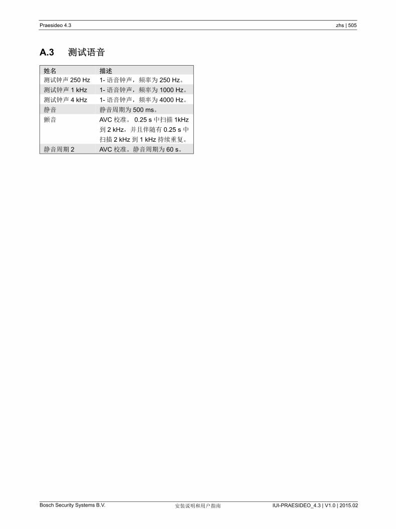
Praesideo 4.3 zhs | 505
Bosch Security Systems B.V. IUI-PRAESIDEO_4.3 | V1.0 | 2015.02安装说明和用户指南
A.3 测试语音
姓名 描述
测试钟声 250 Hz 1- 语音钟声,频率为 250 Hz。
测试钟声 1 kHz 1- 语音钟声,频率为 1000 Hz。
测试钟声 4 kHz 1- 语音钟声,频率为 4000 Hz。
静音 静音周期为 500 ms。
颤音 AVC 校准。 0.25 s 中扫描 1kHz
到 2 kHz,并且伴随有 0.25 s 中
扫描 2 kHz 到 1 kHz 持续重复。
静音周期 2 AVC 校准。静音周期为 60 s。
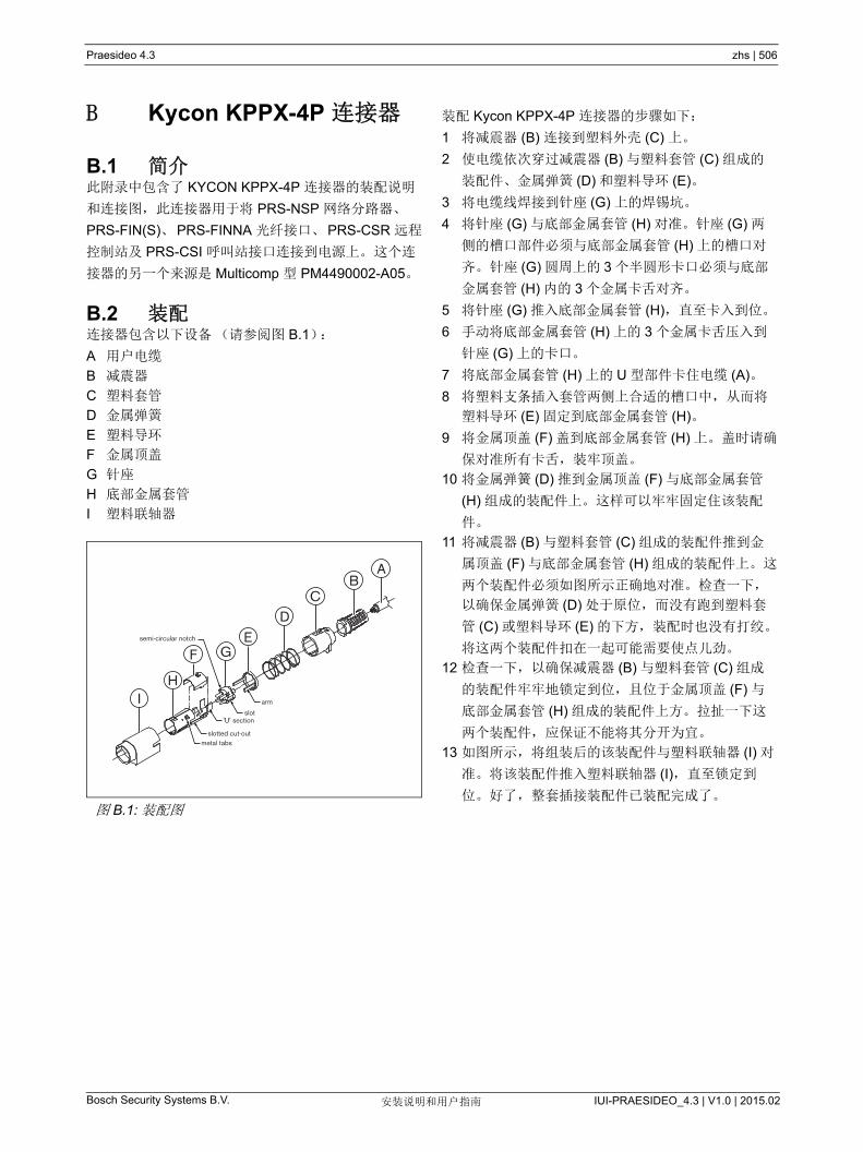
Praesideo 4.3 zhs | 506
Bosch Security Systems B.V. IUI-PRAESIDEO_4.3 | V1.0 | 2015.02安装说明和用户指南
B Kycon KPPX-4P 连接器
B.1 简介此附录中包含了 KYCON KPPX-4P 连接器的装配说明
和连接图,此连接器用于将 PRS-NSP 网络分路器、
PRS-FIN(S)、PRS-FINNA 光纤接口、PRS-CSR 远程
控制站及 PRS-CSI 呼叫站接口连接到电源上。 这个连
接器的另一个来源是 Multicomp 型 PM4490002-A05。
B.2 装配连接器包含以下设备(请参阅图 B.1):
A 用户电缆
B 减震器
C 塑料套管
D 金属弹簧
E 塑料导环
F 金属顶盖
G 针座
H 底部金属套管
I 塑料联轴器
装配 Kycon KPPX-4P 连接器的步骤如下:
1 将减震器 (B) 连接到塑料外壳 (C) 上。
2 使电缆依次穿过减震器 (B) 与塑料套管 (C) 组成的
装配件、金属弹簧 (D) 和塑料导环 (E)。
3 将电缆线焊接到针座 (G) 上的焊锡坑。
4 将针座 (G) 与底部金属套管 (H) 对准。针座 (G) 两
侧的槽口部件必须与底部金属套管 (H) 上的槽口对
齐。 针座 (G) 圆周上的 3 个半圆形卡口必须与底部
金属套管 (H) 内的 3 个金属卡舌对齐。
5 将针座 (G) 推入底部金属套管 (H),直至卡入到位。
6 手动将底部金属套管 (H) 上的 3 个金属卡舌压入到
针座 (G) 上的卡口。
7 将底部金属套管 (H) 上的 U 型部件卡住电缆 (A)。
8 将塑料支条插入套管两侧上合适的槽口中,从而将
塑料导环 (E) 固定到底部金属套管 (H)。
9 将金属顶盖 (F) 盖到底部金属套管 (H) 上。盖时请确
保对准所有卡舌,装牢顶盖。
10 将金属弹簧 (D) 推到金属顶盖 (F) 与底部金属套管
(H) 组成的装配件上。这样可以牢牢固定住该装配
件。
11 将减震器 (B) 与塑料套管 (C) 组成的装配件推到金
属顶盖 (F) 与底部金属套管 (H) 组成的装配件上。这
两个装配件必须如图所示正确地对准。检查一下,
以确保金属弹簧 (D) 处于原位,而没有跑到塑料套
管 (C) 或塑料导环 (E) 的下方,装配时也没有打绞。
将这两个装配件扣在一起可能需要使点儿劲。
12 检查一下,以确保减震器 (B) 与塑料套管 (C) 组成
的装配件牢牢地锁定到位,且位于金属顶盖 (F) 与
底部金属套管 (H) 组成的装配件上方。拉扯一下这
两个装配件,应保证不能将其分开为宜。
13 如图所示,将组装后的该装配件与塑料联轴器 (I) 对
准。将该装配件推入塑料联轴器 (I),直至锁定到
位。好了,整套插接装配件已装配完成了。图 B.1: 装配图
AB
CD
EGF
semi-circular notch
arm
HI
slot
slotted cut-outmetal tabs
'U' section

Praesideo 4.3 zhs | 507
Bosch Security Systems B.V. IUI-PRAESIDEO_4.3 | V1.0 | 2015.02安装说明和用户指南
C 产品索引
表 C.1: 产品索引
型号 代码 产品名 参考页数
PRS-NCO3 PRS-NCO3 网络控制器 Page 103
PRS-4AEX4 PRS-4AEX4 音频扩展器模拟 Page 126
LBB4404/00 PRS-4CIN4 CORBRANET 接口 Page 139
PRS-4OMI4 PRS-4OMI4 OMNEO 接口 Page 151
PRS-NSP PRS-NSP 网络分路器 Page 285
PRS-FIN PRS-FIN 光纤接口 Page 291
PRS-FINNA PRS-FINNA 光纤接口(不可寻址) Page 291
PRS-FINS PRS-FINS 光纤接口,单模 Page 291
LBB4416/00 PRS-CB100 网络电缆 100M Page 298
LBB4416/01 PRS-CA0M5 网络电缆 ASSY 0.5M Page 298
LBB4416/02 PRS-CA002 网络电缆 ASSY 2M Page 298
LBB4416/05 PRS-CA005 网络电缆 ASSY 5M Page 298
LBB4416/10 PRS-CA010 网络电缆 ASSY 10M Page 298
LBB4416/20 PRS-CA020 网络电缆 ASSY 20M Page 298
LBB4416/50 PRS-CA050 网络电缆 ASSY 50M Page 298
LBB4417/00 PRS-CBCON 设置网络 CONN 20 PCS Page 300
LBB4418/00 PRS-CBTK 电缆 / 连接器工具包 Page 301
LBB4418/50 PRS-CBTKC 备用切割工具 2 PCS Page 314
LBB4419/00 PRS-CBCPL 设置电缆耦合器 10 PCS Page 314
PRS-1P500 PRS-1P500 功率放大器 1 个 500W Page 163
PRS-2P250 PRS-2P2500 功率放大器 2 个 250W Page 163
PRS-4P125 PRS-4P125 功率放大器 4 个 125W Page 163
LBB4428/00 PRS-8P060 功率放大器 8 个 60W Page 163
PRS-1B500 PRS-1B500 基本型放大器 1 个 500W Page 195
PRS-2B250 PRS-2B250 基本型放大器 2 个 250W Page 195
PRS-4B125 PRS-4B125 基本型放大器 4 个 125W Page 195
PRS-8B060 PRS-8B060 基本型放大器 8 个 60W Page 195
PRS-16MCI PRS-16MCI 多通道接口 Page 186
LBB4430/00 PRS-CS 呼叫站 Page 227
LBB4432/00 PRS-CSKP 呼叫站键盘 Page 232
PRS-CSNKP PRS-CSNKP 数字键盘 Page 236
PRS-CSM PRS-CSM 呼叫站模块 Page 240
PRS-CSKPM PRS-CSKPM 呼叫站键盘模块 Page 250
LBB4436/00 PRS-CSKPC 设置按键保护盖 10 PCS Page 281
PRS-CSI PRS-CSI 呼叫站接口 Page 275
PRS-CSR PRS-CSR 远程呼叫站 Page 258
PRS-CSRM PRS-CSRM 远程呼叫站模块 Page 265
PRS-CRF PRS-CRF 呼叫堆栈 Page 281
LBB4440/00 PRS-SVCO 监控板 Page 217
LBB4441/00 PRS-SVLSP LSP 控制板 Page 217
LBB4442/00 PRS-SVSET 线路检测设置 Page 217
LBB4443/00 PRS-SVLN 线路检测板 Page 217

Praesideo 4.3 zhs | 508
Bosch Security Systems B.V. IUI-PRAESIDEO_4.3 | V1.0 | 2015.02安装说明和用户指南
LBB4446/00 PRS-SVB 设置 SV 机架 10 PCS Page 225
PRS-SW PRS-SW PRAESIDEO 软件 Page 337
PRS-SWCS PRS-SWCS PC 呼叫服务器 Page 476
PRS-SWCSL PRS-SWCSL PC 呼叫服务器 NCO 许可证 Page 476
PRS-CSC PRS-CSC PC 呼叫站客户端 Page 489
PRS-TIC PRS-TIC PC 电话接口客户端 Page 495
表 C.1: 产品索引


Bosch Security Systems B.V.Torenallee 495617 BA Eindhoven
The Netherlandswww.boschsecurity.com
© Bosch Security Systems B.V., 2015