Practical radio - Index of
255
PRACTICAL RADIO INCLUDING THE TESTING OF RADIO RECEIVING SETS BY JAMES A. MOYER, S.B., A.M. Director of University Extension, Massachusetts Department of Education, Felloiv of the American Association for the Advancement of Science: Fellow of the Royal Society of Arts; Mitglied des Vereiiies Deutscher Ingenieure; Memhre Titulairc Associaton Internationale du Froid; Member of the Franklin Institute; Am,erican Society of Mechanical Engineers; Society of Auto- motive Engineers; Institute of Electrical Engineers, etc. AND JOHN F. WOSTREL Instructor in Radio, and in Charge of Industrial Subjects, Dioision of Unii'crsity Extension, Massachusetts Department of Education First Edition THE AUTHOR RECEIVES NO ROYALTY OR COM- IVIISSION ON THIS BOOK McGRAW-HILL BOOK COMPANY, Inc. NEW YORK: 370 SEVENTH AVENUE LONDON: G & S BOUVERIE ST., E. C. 4 1924
-
Upload
khangminh22 -
Category
Documents
-
view
0 -
download
0
Transcript of Practical radio - Index of

PRACTICAL RADIOINCLUDING THE TESTING OF
RADIO RECEIVING SETS
BY
JAMES A. MOYER, S.B., A.M.Director of University Extension, Massachusetts Department of Education,
Felloiv of the American Association for the Advancement of Science:
Fellow of the Royal Society of Arts; Mitglied des Vereiiies Deutscher
Ingenieure; Memhre Titulairc Associaton Internationale duFroid; Member of the Franklin Institute; Am,erican
Society of Mechanical Engineers; Society of Auto-
motive Engineers; Institute of Electrical
Engineers, etc.
AND
JOHN F. WOSTRELInstructor in Radio, and in Charge of Industrial Subjects, Dioision of
Unii'crsity Extension, Massachusetts Department of Education
First Edition
THE AUTHOR RECEIVESNO ROYALTY OR COM-IVIISSION ON THIS BOOK
McGRAW-HILL BOOK COMPANY, Inc.
NEW YORK: 370 SEVENTH AVENUELONDON: G & S BOUVERIE ST., E. C. 4
1924

Copyright, 1924, by the
McGraw-Hill Book Company, Inc.
PRINTED IN THE UNITED STATES OF AMERICA
THE MAPLE PRESS COMPANY, YORK, PA.

PREFACE
Radio is an electrical science; but its development, unlike
that in most branches of science during recent years, has
been more or less by *'hit-or-miss" methods. Many accom-
plishments of first importance in radio were obtained for the
first time as a result of chance or unorganized experiment.
This groping progress of radio science is, however, rapidly
giving way to systematic research; and the many problems
which remain to be solved will doubtless receive the con-
centrated attention of experts.
Popular interest in radio has been established mainly
through the introduction of radio broadcasts. This form of
communication has been developed to such an extent that
in nearly every large city there are powerful transmitting
stations which broadcast for the benefit of millions of receiv-
ing sets distributed all over the ' country. In addition, a
chain of very large transmitting stations, circling the globe,
has been organized to give a thoroughly dependable world-
wide communication by radio, twenty-four hours a day, the
year around.
Much that has been written on the subject of radio has been
so technical, so brief, that the average reader is unable to get
a clear understanding of even the fundamental principles.
It is the object of this book to present the fundamentals of
the subject so simply and clearly that any person of average
training will be able to read, understand, and apply them.
Above all, the intention has been to make this book practical,
as the name indicates; and in furtherance of this idea, in
one of the chapters, working drawings are given for a numberof popular, typical radio receiving sets. All of these receiv-
ing sets have been actually constructed so that there can be
no question as to the exactness of details. It is believed

VI r/U'jFAc/'j
also thai/ .sufrici(;nily ('A)ir\\)]('U) infoiHiaiion is ji;iv('ri so thai i\\('.
roador will havo v(;ry liUJc; (Jifficiilty in consir-uniinj^ his ownreceiving s(jt if h(! wishcss to do so.
The authors an; (!Sp(!cially indcjl^tod to C^harlc^s W. Tlobbs,
Massachijs(;tts Division of University JOxtcnsion, and to
Professor Raymond U. Fittz of the Engineering Departmentof Tufts (U)]](\^() at Medford Hillside, Massachusetts, wh(;re
so much ])\(}i\.(t()r work in radio investigation and Ijroadcast-
ing has In'cjn done. Acknowledgment should also be madeto Ralph (JrcjenJeaf and Miss TFelcin M(;inhold for assistance
in thf; i)reparation of drawings and fnanuscrii)t.
The authors arc; always glad to answer correspondence witli
t(;achers in regard to the; difficulti(;s of students in understand-
ing this su})j(!ct.
Tui': AiJTffojis.
Statio JIochk,
lioH'I'ON, MAHHACiriTHK'J'I'S,
July, 1024.

CONTENTSPage
Preface v
Chapter
I. What is Radio? An I^^xplanation 1
II. Tiiio Antenna 9
'^III. Radio Electuicity Explained 25
IV. Telephone Receivers and Crystal Receiving Sets . . 35
V. Vacuum Tube Receiving Sets 51
VI. Sources of Electricity for Vacuum Tubes 77
VII. Atdio-krequency Amplification 05
VIII. Radio-frequency Amplification li;3
IX. Selection, Operation and Care of Radio Receiving
Sets 139
X. Radio Telephone and Telegraph Transmission .... 159
XI. Construction and Testing of Receiving Instruments. 179
XII. Common Troubles and Their Remedies 217
XIII. The Future of Radio 229
Appendix 237
Index 245


PRACTICAL RADIOCHAPTER I
WHAT IS RADIO?—AN EXPLANATION
Electricity in its most familiar form is the electric current
carried by wires to light buildings and streets and to operate
machinery, telegraphs, and telephones. Radio^ another kind
of electricity, has in recent years attracted wide-spread atten-
tion, and this form of electricity, like the lightning of a thunder
storm, goes through the air in waves extending in every direc-
tion, without the assistance of wires; for this reason the trans-
mission of telephone and telegraph messages by radio waves
is sometimes referred to as wireless. Because of its freedom
from wire connections, radio has almost unlimited possibilities,
as compared with the telephone and telegraph. It has
possibilities of the same magnitude that the airplane has in
comparison with a railroad train on tracks.
Radio waves are much like sound waves in that they also
spread out through the air in all directions, and can be heard
at the same time by any number of listeners within the range
of the radio transmitting station. Light, also, is like radio,
but where we can detect light or sound directly by means of
our eyes or ears, radio waves can be detected only by special
receiving apparatus. The effect of radio, for all practical
purposes, is instantaneous, since it travels at the speed of
186,000 miles per second, which is the same as the speed of
light.
Later it will be shown how the action of an electric current
in the apparatus at a transmitting station produces radio
waves. If the electric current at a radio transmitting station
is varied as it is by the transmitter of a telephone or according
1

2 PRACTICAL RADIO
to the dots and dashes used in the telegraphy, the resulting
radio waves will have similar variations.
Radio and Sound Waves Interchangeable.—In the ordinary
telephone the sound of the speaker's voice at the transmitting
end produces certain variations in an electric current. This
variable current flows along the connecting wires to the
receiver at the other end, and the receiver changes the variable
current back again into sound. The radio process is similar
to this, since at the transmitting end sound is changed into
radio waves and at the receiving end, radio waves are changed
back again into sound. The great difference, however, is
that its action depends upon the radio waves which pass
through the air^ instead of the electric current which goes along
a telephone wire.
Radio Broadcasting.-—The most important use of radio is
for broadcasting the human voice. Indeed radio did not
attract the interest of the general public until it began to be
utilized for broadcasting definite programs, and this interest
grew as the scope of the service was increased. For years
government stations have sent out in the Morse code weather
forecasts and market information by radio telegraph (wire-
less). Recently, however, the government stations began to
transmit such information for farmers by radio telephone; and
manufacturing concerns, newspapers, schools, and others,
seeing the possibilities in this form of service, obtained per-
mission to broadcast music and lectures. Radio broadcasting
is now carried on at regular schedules by various stations which
are so distributed that in most sections of the country an
^ In these introductory pages, for the sake of simplicity of statement,
radio waves are represented as passing through air. 0])viously, however,
these radio waves pass readily through material objects and liquids as
well. Radio transmission is sometimes referred to as wave propagation
through the ether.
Steinmetz and some other scientists have stated that there are no
ether waves. They believe light and radio waves to be merely properties
of an alternating electro-magnetic field offorce extending around the earth.
Einstein, however, in a lecture on the ether and the theory of relativity
has stated that according to the general theory of relativity space is
endowed with physical qualities, and that in such a sense the ether exists,
because without it propagation of light would be impossible.

WHAT IS RADIO?—AN EXPLANATION 3
interesting program may be received on relatively cheap and
simple radio receiving apparatus. By the use of amplifiers
and loud speakers this service may also be made available to
large gatherings of people.
The ideal night to establish long-distance radio records
is during the time in winter when the days are shortest and
there is a cold, clean atmophere just after a storm when the
low hanging clouds have cleared away. Broadcasting just
at dusk, during cloudy conditions, which may have covered
a radius of three hundred miles, may be followed less than
an hour later, after darkness has set it, by broadcasting from
the same transmitter which may be heard for one thousand
miles. Moonlight has a slight tendency to weaken signals.
Aurora borealis has only a slight effect upon radio transmission.
Kinds of Broadcasting.—Many stations now broadcast
music, lectures, theatrical entertainments, speeches, church
services, weather forecasts, market prices, sporting events and
time signals. By sending out entertaining programs, radio
has become a valuable supplement to the music hall, the news-
paper, the theater, the phonograph, and the classroom.
Indeed several colleges now offer correspondence courses in
which the instruction material is transmitted by radio.
A few years ago, before there was such demand for radio
services, government information was transmitted at one
radio wave length and all popular programs were sent out at a
standard wave length. As the number of transmitting
stations increased, it became necessary to assign different
wave lengths to the various stations in order to reduce the
interference of one station with another. Receiving sets
must now be sufficiently selective so that, over a wide range of
wave lengths, any one transmitting station may be picked upand all others excluded. This is made possible by tuning the
receiving set. The effect of tuning is that, by turning a dial
or dials on the receiving set to different positions, the operator
can make his set respond to waves of different lengths.
Wave Length Explained.—The general idea of wave length
can be understood readily by comparison with water or sound
waves, or even with the wave in a rope as shown in Fig. 1,

4 PRACTICAL RADIO
where the wave travels from one end of the rope to the other.
We cannot see radio waves as we see the waves on a pond,
but neither can we see sound waves. Yet we know that whena tuning fork is struck it gives off sound waves which travel
out into the air in all directions. These sound waves are
caused by the to-and-fro motion, or vibration, of the prong of
the tuning fork. As the prong vibrates it causes the air next
Fig. 1.—Example of wave motion.
to it to vibrate. This vibration is passed on to the surround-
ing air. Just as the tuning fork causes a to-and-fro motion, or
alternating motion, of the air surrounding it, so an alternating
electric current flowing in a wire causes an alternating electric
pressure in the air around the wire, which spreads out in the
same way as a sound wave.
Ajfanee Traveled/h OneSecond
L Wave J^"Length "^
Fig. 2.—Wave cycle.
One complete to-and-fro motion or alternation is called a
cycle and the number of these cycles per second is called the
frequency of the wave. Wave length is the distance, measured
in meters^ from the top of one wave to the top of the next
wave. If we represent a wave motion as in Fig. 2, then the
wave will pass through one cycle when it has gone through
^ A meter is approximately 39 inches.

WHAT IS RADIO?—AN EXPLANATION 5
the changes shown between any two points such as A and B.
This wave has a frequency of 6, since there are six cycles or
alternations in one second. The wave length^ is shown clearly.
At the suggestion of the United States Bureau of Standards,
the Second National Radio Conference which met in March,
1923, introduced the kilocycle method of designating radio
waves. The word kilocycle, which is formed by combining
''kilo" which means one thousand and ''cycle" which is the
unit of frequency, means that the electric current goes through
one thousand cycles per second. The wave length in meters of a
transmitting station can readily be converted into equivalent
kilocycles per second thus
:
Kilocycles (kc.) = —:.—
-, ttt-'^ meters (wave length)
All radio and other electric waves travel through the air at a
speed of 300,000,000 meters per second, but at different fre-
quencies. The difference in their frequencies gives to each
its characteristic properties. The higher the frequency the
more effectively the waves radiate and spread out. Highfrequencies, therefore, must be employed in radio so that a
wave will travel most effectively through the air.
Essential Parts of a Radio Receiving Set.—No matter howsimple the type of apparatus it is necessary to have the follow-
ing parts: (1) The antenna,"^ a wire or group of wires without
insulating covering which must be elevated from the ground
and which may be located either out-of-doors on poles or may1 Numerically, the length of a wave is equal to its velocity divided
by its frequency. Since the velocity of all electric waves is 186,000 miles
or 300,000,000 meters per second, the wave length in meters equals
300,000,000 divided by frequency. Thus, a radio wave of 400 meters
goes through 750,000 frequency alternations or cycles per second, that is,
the frequency is 750,000 cycles per second. Electric currents in ordinary
telephone service have wave lengths of between 100,000 and 20,000,000
meters, so that the corresponding frequencies of ordinary telephone
messages vary from 15 to 3,000. In this connection it is interest-
ing to note that the frequencies of heat, light, and x-rays vary from tril-
lions to quintillions of cycles per second.
2 Sometimes it is possible to substitute for the outdoor antenna, a
radio loop which will be described in another chapter. No ground wire
is required when a loop is employed.
6 PRACTICAL RADIO
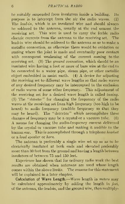
be suitably suspended from insulators inside a building. Its
purpose is to intercept from the air the radio waves. (2)
The lead-in, which is an insulated wire and should always
be soldered to the antenna, usually at the end nearest the
receiving set. This wire is used to carry the feeble radio
electric currents from the antenna to the receiving set. Thelead-in wire should be soldered to the antenna so as to make a
metallic connection, as otherwise there would be oxidation or
rusting where the joint is made and eventually poor contact
with consequent weakening of the current coming to the
receiving set. (3) The ground connection, which should be an
insulated wire having a foot or more of bare wire at the end to
be connected to a water pipe, steam pipe, or other metallic
object embedded in moist earth. (4) A device for adjusting
the receiving set to different wave lengths so that radio waves
of any desired frequency may be intercepted to the exclusion
of radio waves of some other frequency. This adjustment of
the receiving set for a desired wave length is called tuning.
(5) The ^^ detector ^^ for changing the frequency of the radio
waves at the receiving set from high frequency (too high to be
heard) to audio frequency (audible frequency so that they
may be heard). The ^'detector" which accomplishes these
changes of frequency may be a crystal or a vacuum tube. (6)
A means for changing the audio-frequency current delivered
by the crystal or vacuum tube and making it audible to the
human ear. This is accomplished through a telephone headset
or a loud speaker or horn.
The antenna is preferably a single wire set up so as to be
electrically insulated at both ends and elevated preferably
more than 30 feet from the ground and having a length between
insulators of between 75 and 150 feet.
Experience has shown that for ordinary radio work the best
results are obtained when antennas are used whose length
comes within the above limits. The reasons for this statement
will be explained in a later chapter.
Calculation of Wave Length.—Wave length in meters maybe calculated approximately by adding the length in feet,
of the antenna, the lead-in, and the ground wire, then multiply-

WHAT IS RADIO?—AN EXPLANATION 7
ing the total length of all three by 1.5. For example if the
antenna is 100 feet long, lead-in 30 feet, and ground wire 20
feet, the total length is 150 feet. Multiplying the 150 by
1.5, the result is 225, the natural period or wave length of the
antenna in meters.
QUESTIONS
1. In what way is a radio wave similar to a sound wave?2. How fast does a radio wave travel?
3. Explain and illustrate the term wave length.
4. What is the meaning of cycle and frequency?
5. Name the essential parts of a radio receiving set and describe the
purpose of each one.


CHAPTER II
THE ANTENNA
In radio communication it is necesary to have a single wire or
a set of wires for broadcasting radio waves into the air at the
transmitting station, and also for picking up these waves from
the air at the receiving instrument. This wire or set of wires
is now usually called an antenna, although many people still
call it an aerial especially when it is of the elevated outside
variety. Generally the location in which the antenna is to be
erected determines its form and dimensions. An antenna may
BB"BFig. 3.—Simple outside antenna.
be either the ordinary elevated outside wire type, or the coil or
loop type. There are, of course, many variations of each of
these types. In the construction of an antenna, the only infor-
mation required is about the length, size, material, andinsulation of the wire used, the ground connections, andHghtning protection.
For use at the receiving instrument, the elevated outside
wire is usually most satisfactory. A good form of such an9

10 PRACTICAL RADIO
antenna is a single wire about 75 to 100 feet long and raised
30 to 50 feet above the ground (Fig. 3). The greater the
height, the better. With this construction, the addition of
more wires is not of much advantage. If the antenna must
Fig, 4.—Double wire antenna.
be shorter than 75 feet, it may be made with two parallel wires
spaced about 3 feet apart, as in Fig. 4. In this case the wires
at each end of the line should be connected together as shown.
C%t^
Fig. 5.—Typical outside antenna. Fig. 6.— Typical outside antenna.
The lead-in wire, which goes to the binding post markedantenna on the receiving set, is soldered to the antenna at the
near end as shown in Fig. 3. Sometimes it is necessary to
attach the lead-in at the center of the antenna. When this

THE ANTENNA II
is done the effective length of the antenna is decreased and
other means must be used to offset the reduction in length,
such as more turns on the coils of wire in the receiving set.
Nevertheless, the strength of the radio waves will be lessened
somewhat. Several other ways of setting up antennas are
Fig. 7.—Typical outside antenna.
shown in Figs. 5 to 9. When the wires are placed inside the
house as in a garret, they should be kept away from surround-
ing objects as much as possible. The antenna wire should
never be run close to electric power lines, as the greater the
Fig. 8.—Typical outside antenna.
distance from such lines, the less will be the interference from
that source.
Very frequently a braided, seven-strand, No. 22 wire of hard
drawn copper, or of phosphor bronze, is used for the antenna.
A No. 14 or larger solid copper wire also has proved satis-

12 PRACTICAL RADIO
factory. To prevent rusting it is best to use tinned wires.
Enameled wires are equally good but are more expensive.
Between each end of the antenna wire and the supports to
which it is fastened insulators must be placed in order to
prevent current leakage. An insulator is made of some
material which is a non-conductor of electricity, such as glazed
porcelain, glass, or wood (especially prepared by soaking in
melted paraffin). Any material which will absorb moisture
is not suitable for insulation. It should be remembered also
that an insulator must be strong enough mechanically to
stand the strain put upon it, especially in windy or icy weather.
Fig. 9.—Typical outside antenna.
Figure 9 shows some details of a single-wire antenna. If the
antenna is not accessible from a window, one end (beyond the
insulator) has sometimes a rope and pulley arrangement bywhich the antenna may be raised or lowered. The lead-in
wire is kept well away from the building and must pass through
some form of hollow insulator where it enters the building.
Usually a porcelain tube, placed in a hole drilled through the
wall or window sash is easily installed. Remember, how-
ever, that the hole should be bored at such an angle that

THE ANTENNA 13
the outside end of the insulator tube which is exposed to the
weather is lower than the end inside the building. This
Antenna.
\-Wfre fo Receiving Set
Fig. 10.— Extension antenna used as lead-in wire.
downward slant prevents rain from entering the building byway of the insulator tube. When a covered lead-in wire is
Insuh-horv-'Anienna
Fig. 11.— Substantial pole for attachment of antenna.
used instead of the bare wire, the same precautions as to insula-
tion must be observed because it is not safe to rely upon the
14 PRACTICAL RADIO
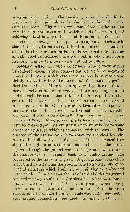
covering of the wire. The receiving apparatus should be
placed as near as possible to the place where the lead-in wire
enters the room. Figure 10 shows a way of passing the antenna
wire through the insulator I, which avoids the necessity of
soldering a lead-in wire to the end of the antenna. Sometimes
it becomes necessary to use a pole for a support. Such a pole
should be of sufficient strength for this purpose, not only to
secure durable construction but to do away with the sagging
and slip-shod appearance when too small a pole is used for a
support. Figure 11 shows a safe method to follow.
Soldered Wire.—All wire connections in radio work should
be soldered, except where connections are made by means of
screws and nuts in which case the nuts may be turned up so
tightly as to bite into the metal and thus make a perfect
electrical contact. Merely twisting wires together is not suffi-
cient as radio currents are very small and anything short of
perfect metallic connection is likely to interrupt them alto-
gether. Especially is this true of antenna and ground
connections. Radio soldering is not difficult if certain precau-
tions are taken. It is a good idea to practice a little on odds
and ends of wire before actually beginning on a real job.
Ground Wire.—Most receiving sets have a binding post or
terminal marked ground from which a wire must be led to some
object or structure which is connected with the earth. Thepurpose of the ground wire is to complete the electrical cir-
cuit for the radio waves. This circuit is from the transmitting
station through the air to the antenna, and parts of the receiv-
ing set, through the ground wire to the ground, which takes
the minute electric currents back to a similar ground wire
connected to the transmitting set. A good ground connection
is obtained by attaching the ground wire to a water pipe or to
a metal structure which itself is grounded, that is, embedded
in the earth. In some cases the use of several different ground
connections may result in louder signals. It has been found,
however, that when one of the several ground wires is very
long and makes a poor connection, the strength of the radio
current may be weaker than if a single wire with a reasonably
good ground connection were used. A pipe or rod, driven

THE ANTENNA 15
into moist earth, makes a satisfactory ground, but if the
soil around the pipe becomes dry, the connection will not give
good results. The ground wire should be as short as possible,
avoiding any sharp bends or turns, and to get good electrical
contact, the connection between ground wire and the pipe or
other object to which it is connected should be soldered.
It is advisable always to scrape or sandpaper both the wire
and the surface on the grounding system, where the connection
is made. When an approved ground connecting clamp is
used, soldering is not necessary. A gas-pipe system must not
be used as a ground.
Counterpoise.—Where a good ground is not convenient,
it may be replaced by a counterpoise. This consists of a set of
wires which is similar in dimensions and construction to the
antenna. Sometimes the counterpoise is made by running the
wires out in several directions from the radio set, supported
about a foot above the ground and insulated from it. Thewires are placed below the antenna and should cover an area
at least as great as that of the antenna. As a protection
against lightning, both the antenna and counterpoise wires
must be grounded through some approved protective device,
The counterpoise may be used with good results in places
where the ground is very dry or when a receiving set is located
near the top of a tall building where the distance to the ground
is considerable. However, the counterpoise device is used
more commonly at transmitting than at receiving stations.
Sometimes the conditions of the surroundings at a transmitting
station are such that both a ground connection and a counter-
poise may be used to advantage.
It has been observed that a long, low antenna has somedirectional action; that is, the signal strength is improved
when the lead-in end of the antenna points toward the station
from which radio currents are received. This action is not
noticeable in short antennas, which may point in any direction
with equally good results.
Loop Antenna.—Under some conditions the coil or loop
gives satisfactory reception. This type of antenna construc-
tion consists of several turns of wire wound on a wooden frame

16 PRACTICAL RADIO
varying in size from about 1 foot to 4 feet square. Such an
antenna requires no ground connections. Figures 12, 13, 14,
Fig. 12.—Typical radio loop. Typical radio loop.
and 15 show the loop construction. Because of its small size*,
the loop cannot be used for receiving
from distant stations unless some kind
of signal amplifier or magnifier is used
with it. The loop has, however,
several good features to recommend its
use on nearby stations, especially
where amplification is available. Its
most important advantage is its ad-
justability to directional action. Thus,
the signal strength is loudest whenthe loop is turned so that its flat side
points in the direction of the trans-
mitting station. If the plane of the
loop is at right angles to this direction,
very weak radio currents, or none
Thus, messages may be received
To Receiving
6ei-
Fig. 14.— Typicalloop.
radio
at all, are received.

THE ANTENNA 17
from one station while those from another are avoided, even
though both stations are transmitting on the same wave length.
The amount of electrical energy received by a loop is very
small, but, because of its greater freedom from interference,
this energy may usually be sufficiently amplified to give louder
and clearer radio waves than can be received by any other
type of antenna.
Fig. 15.—Typical radio loop around a window.
Lightning Arresters.—The installation of an approved
device for protection against lightning is required by the
Fire Underwriter's rules which may be found at the end of
this chapter. As shown in Fig. 16, a lightning arrester Lis attached to a bared (uninsulated) portion of the lead-in
wire A, and has an outside ground connection which serves in
case of lightning storms, to carry electric discharge directly
from the antenna into the ground.
If the receiving set is near the place where the lead-in
enters, the arrester may be mounted on the set, although this

18 PRACTICAL RADIO
^'\\
Ground ConneefionfL ighini'n^ Arrester
Receiving
6ef
Fig. 16.—Method of attachment of lightning arrester.
Handle ofKnife Swi'fch
Or
Receiving
Set
Ground Wii-e
ofReceiving Sei
Ground
^YiG. 17.—Combined knife-switch and lightning arrester.

THE ANTENNA 19
method is not recommended. A single-pole double-throw
knife switch may be used in addition to, but not in place of,
the lightning arrester. The connections for such an installa-
tion are shown in Fig. 17.
Transmitting Antenna.—A radio transmitting station
requires a more complicated antenna (sometimes called
aerial) than a receiving set. Transmitting antennas are madein several forms as shown in Fig. 18. They generally consist
of several long parallel horizontal wires with the lead-in wire
attached either at the middle or at one end of the antenna
wires.
When the lead-in wire is attached at the middle of the hori-
zontal antenna wires, because of its resemblance to the letter
T, the arrangement is called a T-antenna; and when attached
to one end an L-antenna. A fan or harp antenna is madeof a number of wires spreading upward from a common point.
Where tall supporting structures are available, a good arrange-
ment is the cage antenna. This is made of a number of parallel
wires separated by spreaders or by a hoop, and may be placed
either vertically or horizontally. For receiving, none of these
types are better than the single wire. When the same antenna
must serve for both receiving and transmitting, the usual
construction is the flat-top multiple-wire type with either the
T or L connections.
Transmitting antennas must be insulated very carefully
because of the high voltages which are produced in the
antenna. The antenna and lead-in must be supported at
least 5 inches away from the building. A lightning arrester
is not required on transmitting sets but a ground switch must
be used which will carry a current of 60 amperes and has a
space of 5 inches or more from the knife hinge to the end clip.
FIRE underwriters' REGULATIONS FOR RADIO EQUIPMENT
The requirements of this article shall not apply to equipment installed
on shipboard. Transformers, voltage reducers, keys and other devices
employed shall be of types expressly approved for radio operation.
For Receiving Stations Only.—Antenna and counterpoise outside build-
ings shall be kept well away from all electric light or power wires of anycircuit of more than 600 volts, and from railway, trolley or feeder wires,

20 PRACTICAL RADIO
Lead-in
Single Wire Type
Lead-in

THE ANTENNA 21
so as to avoid the possibility of contact between the antenna or counter-
poise and such wires under accidental conditions.
Antenna and counterpoise where placed in proximity to electric light
or power wires of less than 600 volts, or signal wires, shall be constructed
and installed in a strong and durable manner, and shall be so located andprovided with suitable clearances as to prevent accidental contact withsuch wires by sagging or swinging.
SpHces and joints in the antenna span shall be soldered unless madewith approved splicing devices.
The preceding paragraphs shall not apply to light and power circuits
used as receiving antenna, but the devices used to connect the light andpower wires to radio receiving sets shall be of approved type.
Lead-in conductors shall be of copper, approved copper-clad steel or
other metal which will not corrode excessively, and in no case shall they
be smaller than No. 14, except that bronze or copper-clad steel not less
than No. 17 may be used.
Lead-in conductors on the outside of buildings shall not come nearer
than 4 inches to electric light and power wires unless separated there-
from by a continuous and firmly fixed non-conductor which will maintainpermanent separation. The non-conductor shall be in addition to anyinsulating covering on the wire.
Lead-in conductors shall enter the building through a non-combustible,
non-absorptive insulating bushing slanting upward toward the inside.
Each lead-in conductor shall be provided with an approved protective
device (lightning arrester) which will operate at a voltage of 500 volts or
less, properly connected and located either inside the building at somepoint between the entrance and the set which is convenient to a ground,
or outside the building as near as practicable to the point of entrance.
The protector shall not be placed in the immediate vicinity of easily
ignitible stuff, or where exposed to inflammable gases or dust or flyings
of combustible materials.
If the antenna grounding switch is employed it shall in its closed
position form a shunt around the protective device. Such a switch shall
not be used as a substitute for the protective device.
It is recommended that an antenna grounding switch be employed,
and that in addition a switch rated at not less than 30 amperes,
250 volts, be located between the lead-in conductor and the receiver
set.
If fuses are used, they shall not be placed in the circuit from the
antenna through the protective device to ground.
Fuses are not required.
The protective grounding conductor may be bare and shall be of
copper, bronze or approved copper-clad steel. The grounding conduc-tor shall be not smaller than the lead-in conductor and in no case shall
be smaller than No. 14 if copper, nor smaller than No. 17 if of bronzeor copper-clad steel. The grounding conductor shall be run in as straight

22 PRACTICAL RADIO
a line as possible from the protective device to a good permanent ground.
Preference shall be given to water piping. Other permissible grounds
are grounded steel frames of buildings or other grounded metal work in
the building, and artificial grounds such as driven pipes, rods, plates,
cones, etc. Gas piping shall not be used for the ground.
The protective grounding conductor shall be guarded where exposed
to mechanical injury. An approved ground clamp shall be used where
the grounding conductor is connected to pipes or piping.
The grounding conductor may be run either inside or outside the
building. The protective grounding conductor and ground, installed
as prescribed in the preceding paragraphs may be used as the operating
ground.
It is recommended that in this case the operating grounding
conductor be connected to the ground terminal of the protective
device.
If desired, a separate operating grounding connection and ground
may be used, the grounding conductor being either bare or provided
with an insulating covering.
Wires inside buildings shall be securely fastened in a workmanlike
manner and shall not come nearer than 2 inches to any electric light
or power wire not in conduit unless separated therefrom by some contin-
uous and firmly fixed non-conductor, such as porcelain tubes or approved
flexible tubing, making a permanent separation. This non-conductor
shall be in addition to any regular insulating covering on the wire.
Storage battery leads shall consist of conductors having approved rubber
insulation.
It is recommended that the circuit from the storage battery
be properly protected by fuses as near as possible to the battery.
For Transmitting Stations Only.—Antenna and counterpoise outside
buildings shall be kept well away from all electric light or power wires
of any circuit of more than 600 volts, and from railway, trolley or feeder
wires, so as to avoid the possibility of contact between the antenna or
counterpoise and such wires under accidental conditions.
Antenna and counterpoise where placed in proximity to electric light
or power wires of less than 600 volts, or signal wires, shall be constructed
and installed in a strong and durable manner, and shall be so located and
provided with suitable clearances as to prevent accidental contact with
such wires by sagging or swinging.
Splices and joints in the antenna and counterpoise span shall be
soldered unless made with approved splicing devices.
Lead-in conductors shall be of copper, bronze, approved copper-clad
steel or other metal which will not corrode excessively and in no case
shall be smaller than No. 14.
Antenna and counterpoise conductors and wires leading therefrom to
ground switch, where attached to buildings, shall be firmly mounted 5
inches clear of the surface of the building, on non-absorptive insulating

THE ANTENNA 23
supports such as treated pins or brackets, equipped with insulators
having not less than 5 inches creepageand air-gap distance to inflammable
or conducting material. Suspension type insulators may be used.
In passing the antenna or counterpoise lead-in into the building a tubeor bushing of non-absorptive insulating material, slanting upward towardthe inside, shall be used and shall be so insulated as to have a creepage
and air-gap distance of at least 5 inches to any extraneous bod3^ If
porcelain or other fragile material is used it shall be protected whereexposed to mechanical injury. A drilled window pane may be used in
place of a bushing provided 5 inches creepage and air-gap distance is
maintained.
A double-throw knife switch having a break distance of at least 4inches and a blade not less than }i inch by ^i inch shall be used to join
the antenna and counterpoise lead-in to the grounding conductor. Theswitch may be located inside or outside the building. The base of theswitch shall be of non-absorptive insulating material. This switch shall
be so mounted that its current-carrying parts will be at least 5 inches
clear of the building wall or other conductors. The conductor fromgrounding switch to ground shall be securely supported.
It is recommended that the switch be located in the most direct
line between the lead-in conductors and the point where groundingconnection is made.
Antenna and counterpoise conductors shall be effectively and perma-nently grounded at all times when station is not in actual operation andunattended, by a conductor at least as large as the lead-in and in nocase smaller than No. 14 copper, bronze, or approved copper-clad steel.
This grounding conductor need not have an insulated covering or bemounted on insulating supports. The grounding conductor shall be runin as straight a line as possible to a good permanent ground. Preferenceshall be given to water piping. Other permissible grounds are thegrounded steel frames of building and other grounded metal work in
buildings and artificial grounding devices such as driven pipes, rodsplates, cones, etc. The grounding conductor shall be protected whereexposed to mechanical injury. A suitable approved ground clamp shall
be used where the ground conductor is connected to pipes or piping.
Gas piping shall not be used for the ground.
It is recommended that the protective ground conductor be runoutside the building.
The radio operating grounding conductor shall be of copper strip notless than % inch wide by 3^32 inch thick, or of copper, bronze, or approvedcopper-clad steel having a periphery, or girth of at least % inch, such asa No. 2 wire, and shall be firmly secured in place throughout its length.
The operating grounding conductor shall be connected to a goodpermanent ground. Preference shall be given to water piping. Otherpermissible grounds are grounded steel frames of buildings or othergrounded metal work in the building, and artificial grounding devices

24 PRACTICAL RADIO
such as driven pipes, rods, plates, cones, etc. Gas piping shall not be
used for the ground.
When the current supply is obtained directly from lighting or power
circuits, the conductors whether or not lead covered shall be installed
in approved metal conduit, armored cable or metal raceways.
In order to protect the supply system from high-potential surges and
kick-backs there shall be installed in the supply line as near as possible
to each radio-transformer, rotary spark gap, motor and generator in
motor-generator sets and other auxiliary apparatus one of the following
:
1. Two condensers (each of not less than V2 microfarad capacity and
capable of withstanding 600-volt test) in series across the line with mid-
point between condensers grounded; across (in parallel with) each of
these condensers shall be connected a shunting fixed spark-gap capable
of not more than 3^:32 inch separation.
2. Two vacuum tube type protectors in series across the line with the
mid-point grounded.
3. Resistors having practically zero inductance connected across
the line with mid-point grounded.
It is recommended that this third method be not employed where
there is a circulation of power current between the mid-point of the
resistors and the protective ground of the power circuit.
4. Electrolytic lightning arresters such as the aluminum-cell type.
QUESTIONS
1. Write briefly on the following topics pertaining to the straight-wire
antenna: number, length, size, position and insulation of wires.
2. (a) Why is it necessary to solder the joints?
(6) Where should the lead-in be connected to the antenna?
3. How should the ground connection be installed?
4. What device is required as protection against lightning and how mayit be installed?
5. What are the advantages of a loop antenna?

CHAPTER III
RADIO ELECTRICITY EXPLAINED
Eledn'c
Bell
Buffon
Radio waves are produced by an electric current at the
transmitting station and, at the receiving set, these waves are
changed into an electric current again. Indeed one cannot go
far in the study of radio without understanding the action of
electric currents.
Electric Currents.—When the two ends of a piece of wire are
connected to the terminals of an ordinary dry cell battery, an
electric current is said to flow in the wire.
But no current will flow unless there is a
continuous or uninterrupted path for the
current to flow in; under such conditions
the path or electrical circuit is said to be
closed. That is, the connections must be
such that current can flow out from one
terminal of the battery, through the wire,
and back to the battery at the other ter-
minal. Conversely, when the path is in-
terrupted, or broken, the circuit is said to
be open.
If a bell and battery are connected as in
Fig. 19, the current will always flow out
from the 'positive (+) terminal of the
battery, through the wire to the bell,
through the bell, and through the wire to the negative ( —
)
terminal of the battery. If the ends of the wires at the
battery terminals are interchanged, the current willj flow
through the bell circuit in the opposite direction. The push
button is used to control the ringing of the bell, since when
it is on, the circuit is closed and when it is off, the circuit is
open.
25
BaHer^
Fig. 10.— Elect r;c
bell and battery.'

26 PRACTICAL RADIO
Amperes.—A useful illustration of an electric circuit is a
closed pipe line, full of water, and provided with a pump, as
shown in Fig. 20. Electricity in a circuit acts much Hke the
water in the pipe line. With a water meter we can easily
measure the quantity of water flowing through the pipe in a
certain time and express it as so many gallons per second for
example. In electrical work, the quantity of electricity flow-
ing per second is indicated by an instrument called an ammeter.
^^Puf
t\
Wafer-
Pi'pe
^
+ .Dr^Cell
'ElQcfn'c Wire
^Fig. 20.—Pump and pipe line to illustrate electric circuit.
Thus a reading of 5 on such an instrument means that electri-
city is flowing at the rate of 5 amperes. An ammeter, indicat-
ing rate of flow in amperes, corresponds to a speedometer
indicating speed, in miles per hour. If the terminals of an
Iammeter are touched to the terminals of a dry cell, a reading of
^5 to 35 amperes will be observed.
Volts.—So far we have said nothing about what makes the
electricity flow. In the pipe line (Fig. 20) the water will not
flow unless some force such as the pump pushes it. Likewise,
electricity will not flow in a circuit unless there is, in the circuit,
a source of electrical pressure, such as a battery. If the
pressure of the pump is increased more water will flow and if
more batteries are connected into the circuit, more electricity

RADIO ELECTRICITY EXPLAINED 27
will flow. This electrical pressure or voltage is measured in
volts by an instrument called a voltmeter. If the terminals of
a voltmeter are touched to the terminals of a new dry cell
the reading ought to be 1.5 volts.
Resistance—Ohms.—The water pressure at the end of a
long pipe line is much less than at the pump. This loss in
pressure is due to the friction or resistance of the pipe. Andwe have noticed also that we can cut down on the quantity
Fig. 21.—Pipes connected in series.
of water flowing by introducing more resistance as by partly
closing a valve or faucet. In an electric circuit this friction
is called resistance, and it causes a voltage drop and acts as a
control on the current flow. The resistance of a wire depends
upon the material of which it is made and varies directly with
the length, but inversely with the cross-section. The unit of
resistance is the oh7n. The three
quantities, pressure, current and
resistance, are so related that pres-
sure equals the product of current
and resistance, or, in terms of the
units,
volts = amperes X ohmsThis equation holds true for any
circuit or part of a circuit. When the equation is used for a
part of a circuit, the values of voltage, current and resistance
must apply to that part only. The flow of current in a circuit
may be increased by either increasing the voltage or decreas-
ing the resistance, or both.
Series and Parallel Circuits.—In radio work the units of
apparatus may be connected in series or in parallel. If the
Fig. 22.—Pipes connected in
[parallel.

28 PRACTICAL RADIO
various parts of a circuit are connected in such a way that the
total current must flow through each part, the parts are said
to be in series. This corresponds to the pipe Kne shown in
Fig. 21, in which pipes of various sizes and lengths are con-
nected in series. If the various parts are connected in such a
way that the total current is subdivided, the parts are said
to be in parallel. The corresponding condition in the pipe line
is shown in Fig. 22. If each of the four paths offer the same
resistance to current flow, then the total current at A will be
divided into four equal parts, which come together again at B.
Direct Current.—The electric current which is supplied
by all kinds of batteries is direct current. That is, it flows in
one direction through the circuit. In Fig. 19, for instance, if
the pressure or voltage of the battery is steady, the current will
be steady and will flow from the + terminal of the battery,
through the circuit to the — terminal of the battery. If
the voltage is pulsating, that is, if it rises and falls in strength,
but acts in one direction only, then the current also rises and
falls in strength and is called a pulsating current.
Alternating Current.—When radio waves are changed into an
electric current by means of the receiving apparatus, this
current instead of flowing in one direction, not only changes its
direction at a definite rate, but also varies in strength. Such
a current is called an alternating current. If there is an
alternating voltage in a circuit, the variations in both strength
and direction of the electric current correspond to the varia-
tions of the voltage. The flow of an alternating current is
like the flow of water which would be produced in the pipe
line in Fig. 20, when the water is agitated by a paddle moving
back and forth rapidly over a short distance. In that case,
the water simply surges, first in one direction, then in the
other direction. It no sooner gets up speed in one direction
than it is compelled to slow up and then get up speed in the
opposite direction, and so on, over and over again. An object
placed in the water will not travel around the pipe circuit,
but simply oscillates back and forth.
The alternating current which is used for electric fights
changes it direction, or alternates, 60 times per second.

RADIO ELECTRICITY EXPLAINED 29
That is, it is said to have a frequency of 60 cycles per second.
The radio currents most used, however, may have frequencies
ranging from 10,000 to 30,000,000, corresponding to wavelengths of 30,000 and 10 meters, respectively.
In order to distinguish the directions of flow, we call one
direction the 'positive (+), and the other the negative ( —
)
direction. During the flow in one direction, the strength of
the current varies from zero to a ma^mum and back to zero
again. Figure 23 shows a simple way of indicating the varia-
tions in strength, direction and time when an alternating
current is considered. The positive direction of flow is from
A to C; the negative from C to E, During the flow from A to
Fig. 23.—Variations in strength and direction (positive and negative) of
alternating current.
C, the strength of the current varies from zero to a maximum,and again to zero, as shown by the curve ABC.Magnetic Field.—It is well known that an ordinary horse-
shoe magnet will attract a piece of iron or steel. If iron filings
are sprinkled on a piece of paper placed over a magnet, they
act in a way which proves the existence of a condition, in
the space or region all around the magnet, which is called a
magnetic field. The presence of this field can be shown also
by the behavior of the needle of a compass when brought near
the magnet. Whenever an electric current fiows in a wire,
there is a magnetic field around the wire as shown in Fig. 24.
The importance of the magnetic effect of an electric current
cannot be overestimated. Magnetic action makes possible

30 PRACTICAL RADIO
the operation of the telephone and telegraph, as well as electric
bells, electric motors and the like.
Induction.—If the current in a wire is steady then the
magnetic field will also be steady, that is, its strength will not
vary. If the current varies the magnetic field will vary also.
It' is obvious, therefore, that an alternating current will
produce a magnetic field which is also of alternating strength,
meaning that it acts first in one direction, then in the other,
varying in magnetic strength at the same time. If a wire is
moved through a magnetic field, or if a magnetic field is moved
OjreefionofLinesofForce"
Direcfion
ofCurrenir
Baiieru
Fig. 24.—Magnetic field produced Fig. 25.—Electric current inducedby electric current in a wire. ' in a wire by a magnetic field.
SO that it passes over a wire, a voltage is induced in the wire and
will cause a current to flow. This effect is called induction.
The practical application of this principle of induction is as
follows: If a single closed circuit which forms a loop is movedthrough a magnetic field, as in Fig. 25, a voltage is produced or
induced in the circuit and causes a fiow of current in the circuit.^
The same result would be obtained if the magnetic field is
moved over the loop. As we shall see later, this explains the
action of the antenna.
^ If a length of wire is wound in the form of a coil, the character of the
magnetic field resulting from current flow may be represented as in
Fig. 25. The direction of the field is such that if you look at one end
of the coil and observe that the current is flowing in a clockwise direction
(like the hands of the clock), then the end next to you is the south pole
of the magnetic field.
RADIO ELECTRICITY EXPLAINED 31
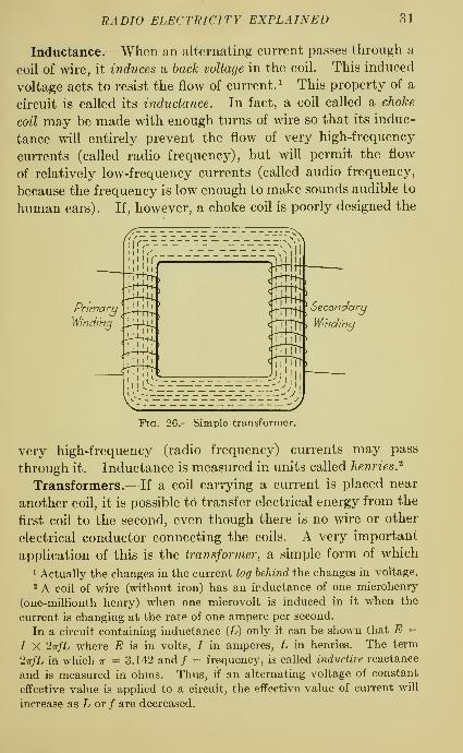
Inductance.—When an alternating current passes through a
coil of wire, it induces sl hack voltage in the coil. This induced
voltage acts to resist the flow of current. ^ This property of a
circuit is called its inductance. In fact, a coil called a choke
coil may be made with enough turns of wire so that its induc-
tance will entirely prevent the flow of very high-frequency
currents (called radio frequency), but will permit the flow
of relatively low-frequency currents (called audio frequency,
because the frequency is low enough to make sounds audible to
human ears) . If, however, a choke coil is poorly designed the
Winding <^J^^ Winding
c-fTTiTti
Fig. 26.—Simple transformer.
very high-frequency (radio frequency) currents may pass
through it. Inductance is measured in units called henries.'^
Transformers.—If a coil carrying a current is placed near
another coil, it is possible to transfer electrical energy from the
first coil to the second, even though there is no wire or other
electrical conductor connecting the coils. A very important
application of this is the transformer, a simple form of which
1 Actually the changes in the current lag behind the changes in voltage.
2 A coil of wire (without iron) has an inductance of one microhenry
(one-millionth henry) when one microvolt is induced in it when the
current is changing at the rate of one ampere per second.
In a circuit containing inductance (L) only it can be shown that E =
/ X 2irfL where E is in volts, / in amperes, L in henries. The term
27r/L in which w = 3.142 and/ = frequency, is called inductive reactance
and is measured in ohms. Thus, if an alternating voltage of constant
effective value is applied to a circuit, the effective value of current will
increase as L or / are decreased.

32 PRACTICAL RADIO
is shown in Fig. 26. In most cases, a transformer is used to
change or transform alternating current of low voltage and
comparatively large current to alternating current of high
voltage and small current and vice versa^
Condensers.—A simple electric condenser consists of two
metal plates separated by some insulating material. Figure 27
shows a diagram of a simple type of condenser and Fig. 28 is
'^' Terminals '^
Sia'Honarij
P/afes 1
MovablePlates
Convenfional MefhodofR<spreseniing aVariable Condenser
Fig. 27.—Diagram of a simple condenser.
an illustration of a commercial type with several movable
plates (with only air for the insulating material). Theeffectiveness of a condenser to store electricity is called capac-
ity. Since an insulator (air or electric insulating material)
is between every two adjoining plates, it is easy to see that
there is no flow of electric current through a condenser. With
direct current this is literally true, that is, no current can flow
past the condenser, but with alternating current there is an
apparent flow. This action of a condenser is similar to the
conditions which exist in the pipe Hne as shown in Fig. 29.
1 The action of a transformer may be expressed by the equation
N2 ~ Ei" /i
in which
Ni = number of turns on the primary coil,
A''2 = number of turns on the secondary coil,
7i = primary current, amperes,
li = secondary current, amperes.
El = voltage induced in the primary, volts,
E2 = voltage induced in the secondary, volts.
From this it is obvious that Ei X Ii = E2 X h.

RADIO ELECTRICITY EXPLAINED 33
The system is full of water and as the piston in the cylinder
moves back and forth, it pushes the water first in one direction
and then in the other. There is no flow past the partition
but due to the pressure of the water in the direction A to B,
SHAFT ON WHICH /v\OVABL£'PLATES AR£ MOUNTED
STATIONARYPLATES
MOVABLE PLATES
Fig. 28.—Commercial type of condenser.
the partition stretches toward B as shown. When the piston
moves in the opposite direction, the partition stretches toward
A. Thus there is a surge of water back and forth through the
Ct^f/hder . y'Pfsfon
^C
Fig. 29.—Partition in a pipe line to illustrate action of a condenser.
pipe line. The insulating material of a condenser corresponds
to this partition. The comparison helps to show that while
there is no flow of current, the current does alternate in the
circuit itself.^
1 When an alternating voltage is impressed on a condenser, the cur-
rent reaches its maximum value before the voltage and we say the
current leads the voltage. In other words, the capacity effect of the

34 PRACTICAL RADIO
Capacity is measured in units called farads. But this unit
is too large for practical radio work, so we use the microfarad
(mf.) which is one-millionth of a farad. Since capacity in a
circuit produces an effect which is the opposite of the effect
produced by inductance, the amounts of inductance and capacity
may he proportioned so that one will just neutralize the other.
When this is done, the only limitating influence to the flow of
current is the resistance.
Commercial Types of Condensers.—A fixed condenser is
one in which the value of capacity stays constant while a
variable condenser has a large range of capacity.
QUESTIONS
1. Explain the terms, electric current, ampere, volt and resistance, bycomparison with the flow of water.
2. State the relation between volts, amperes and ohms.
3. (a) Draw a series connection of three coils of wire.
(6) Draw a parallel connection of four wires.
4. (a) What is the difference between direct current and alternating
current ?
(b) Draw a diagram to represent an alternating current.
5. Mention a few properties of a magnetic field.
6. Explain induction and show how it applies to the transformer.
7. (a) When inductance is introduced into a circuit what effect has it
upon the relation between current and voltage?
(b) How is this relation affected by the introduction of capacity?
condenser is just the opposite of the inductance effect which causes the
current to lag behind the voltage.
When an alternating current is applied to a circuit containing only
capacity, it can be shown that E = tt'tti where C is the capacity in faradsZttJU
and the other units are used as before. The term 2wfC is measured in
ohms and is called the capacity reactance. If the value of voltage is
kept constant, then the value of the current varies directly with the
frequency and capacity. When a circuit contains resistance R, induc-
tance L, and capacity C, the relation between voltage and current maybe shown by the equation
E = I X yJR^+ l2.fL - ^)

CHAPTER IV
TELEPHONE RECEIVERS AND CRYSTAL RECEIVINGSETS
These principles of inductance and capacity as explained in
Chap. Ill will now be applied in studying the practical opera-
tion of a radio receiving set. When radio waves cross a wire,
a voltage is induced in that wire and causes a radio current
to flow if the circuit is complete. This explains how an electric
current is produced in the antenna wire. This radio current
will have a frequency which is the same as that of the radio
wave carrying it. A telephone receiver, however, would not
respond to such a radio current if it were connected directly
to the lead-in wire of an antenna. In order to understand
Iron Pole Piece
Diaphragm Winding Ear Piece
PermanenMagnei- Case Iron Pole Piece
Fig. 30.—Typical telephone receiver.
this, we must examine carefully the operation of the telephone
receiver in relation to radio waves.
Figure 30 shows the construction of a typical telephone
receiver. It has two coils of wire each wound in many layers
around an iron core to produce two electromagnets. A metal
diaphragm is so supported that it may be attracted by the
magnet poles or released depending upon the strength of
magnetism in the poles. An increase of current through the
35

36 PRACTICAL RADIO
windings causes the diaphragm to be attracted and a decrease
of current causes it to be released, because the strength of the
magnetic attraction is hkewise increased and decreased.
When the diaphragm is alternately attracted and released it
will vibrate, and if the frequency of vibration is between 15 and
15,000 vibrations per second, the air waves created will be
audible. In other words, electric current vibrations between
15 and 15,000 per second are audio-irequency vibrations.
Higher frequencies (not audible) are radio-frequency vibra-
tions. The more rapid the vibration, the higher the pitch of
the sound produced.
Telephone receivers designed for radio service have more
wire wound on the magnets than those used in ordinary
telephone service, so that a small current will produce a louder
sound. As a measure of the amount of wire used, telephone
receivers are rated by the resistance (ohms) of the winding.
Thus there are 1,000, 2,000 and 3,000 ohm receivers. It is not
possible to judge performance by resistance alone, however, as
many other factors must be considered in determining the
most effective operation.
Alternating electric currents having a high frequency of
vibration as in radio waves would tend to cause motion of the
diaphragm of the telephone receiver, but the diaphragm
cannot be made to follow the very rapid back and forth
variations of such a current. Alternating current has the
effect of tending to make the diaphragm go both ways at once,
because the current alternates in direction so rapidly, with the
result that no appreciable motion takes place.
Crystal Detector.—Our problem, then, is to change alter-
nating current in such a way that the diaphragm of the tele-
phone receiver will be attracted in only one direction. This is
accomplished by putting into the circuit, including the antenna
and the telephone receivers, a device which permits the radio
current to flow in one direction only, that is, making it direct
current. A crystal detector acts in this way and consequently
the radio current flowing from the detector to the telephone
receivers is really a pulsating direct current. For all practical
purposes, this action may be represented as in Fig. 31. It will

TELEPHONE RECEIVERS—CRYSTAL RECEIVING SETS 37
be noticed that even now the variation of the telephone current
is so rapid that the diaphragm cannot follow it exactly.
Actually, however, one-half of a cycle of current variation will
produce only a small effect on the diaphragm of a telephone
receiver compared with the effect of a complete cycle of current
variation. Thus the net effect of a series of current changes
on the movement of the diaphragm is shown by the dotted
line in the chart marked B in this figure, and the full line in
the chart marked C.
. Anfenna^ • Current
n Telephone' Current
^ Diaphrq^m' Movement
11
J-ltVA-A-n . .JiAA/V^ n
Fig. 31.—Action of crystal detector on radio currents.
Simple Receiving Equipment.—The simplest radio receiving
equipment consists obviously of a detector and a telephone
receiver. The detector of course is a device which changes
the incoming radio waves so that they may be heard in the
telephone receiver.
Crystal Receiving Sets.—The least complicated and most
inexpensive radio outfit is the so-called crystal receiving set,
which makes use of a crystal mineral having the property
of changing the high-frequency radio waves to electric impulses
of varying strength, traveling in one direction^ and capable of
operating a telephone receiver. The crystal mineral which is
most used is galena (lead sulphide). This is a silver-gray
mineral, which breaks in squares with mirror-like surfaces.

38 PRACTICAL RADIO
In its essential parts a crystal detector consists of a piece
of galena crystal mounted in such a way that a fine piece of
wire attached to a flexible handle can be made to touch the
surface of the mineral. Crystals of this mineral are not
uniformly sensitive so that there are some spots which are not
as sensitive as others. In the operation of a crystal detector,
therefore, the wire must be shifted with its flexible handle on
the surface of the galena, until a highly sensitive contact is
found. If, however, the instrument is jarred the sensitive
contact may be lost and even with use, the sensitiveness of any
particular spot is likely to change. No adjustment for receiv-
ing radio currents from only one transmitting station (tuning)
is possible with a simple crystal receiving set as all near-by
signals come in at the same time. There are usually, however,
few difficulties in its use because its range is very limited.
On the other hand, it is very satisfactory for picking up radio
broadcasting from powerful nearby stations.
The simplest type of radio receiving set consists of an
antenna, lead-in wire, crystal, telephone receiver and ground
wire. The lead-in wire is fastened to the crystal and the
flexibly supported wire resting on the surface of the crystal
is connected to the telephone receivers. In this apparatus
the circuit of the radio (alternating) current is from the
antenna and lead-in wire to the surface of the crystal. The
flexibly supported wire on the crystal takes the radio current
now changed to direct current to the telephone receivers, to
which also the ground wire is connected. Finally the radio
current (although changed to direct current) from the ground
wire finds its way back to the transmitting station through
the ground, thus completing the circuit.
In radio telephony the electric generator (dynamo) at a
transmitting station furnishes an antenna current having
constant amplitude, or strength, which produces a so-called
continuous wave called the carrier wave of radio, and the sound
waves of the voice or of music are used to modify this con-
tinuous wave so that the resultant wave is similar to that
shown in Fig. 32. The alternating current which produces
the carrier wave must have a higher frequency than that to

TELEPHONE RECEIVERS—CRYSTAL RECEIVING SETS 39
which the ear will respond (radio frequency). Otherwise a
sound would be produced at the transmitting instruments
which would interfere with the spoken words or music whichare being transmitted. The frequency of sound waves created
Fig. 32.—Carrier radio wave modulated by sound waves.
by the human voice averages around 800 per second, butconstantly increases and decreases with the pitch of the tone.
In the case of music every change in tone also means a changein the frequency. If the sound of the vowel a as in father is
Fig. 33.— Sound wave of letter "a."
spoken, the sound wave is as illustrated in Fig. 33. Theresult of superimposing such a voice wave upon the radio-
frequency carrier wave is given in Fig. 32. The alternations
of the radio wave are shown by full lines and the dotted out-
line shows how the amplitude or strength of the radio waveis made to vary in accordance with the voice wave.

40 PRACTICAL RADIO
Tuning.—In general, radio waves from any particular
transmitting station have only one wave length, and the
frequency of the antenna current at the receiving set is the
same as that of the radio waves. But unless the antenna
circuit is tuned to this same frequency, the radio current will
not have its maximum strength. That is, the receiving circuit
must be arranged to respond to the frequency of the trans-
mitting circuit and of its radio waves. This idea of tuning
may be illustrated by the use of two tuning forks of the
same pitch, or frequency of vibration. If one is struck and
caused to vibrate, the other will vibrate also, producing a note
having the same pitch as that of the first tuning fork. Now,
if the second fork is put out of tune with the first, as, for example,
by sticking on a piece of wax, the second fork will not respond
when the first is made to vibrate. You can see then that, if
the receiving circuit is so arranged that it can be tuned to
various frequencies, it may be possible to pick out any desired
radio wave to the exclusion of all other
waves of different frequencies, and, at
the same time, get the greatest possible
strength of that wave.
Tuning with an Inductance Coil.—Byproviding a simple tuning device the
efficiency of a crystal detector and tele-
FiG. 34.- -Simple inductance coil for tuningantenna circuit.
Fig. 35.—Diagram of con-nections of inductance coil
for tuning.
phone receiver can be very much improved . One of these tuning
devices is a single tuning inductance coil which consists of a
large number of turns of bare copper wire wound in a single
layer on a suitable tube, with provision for varying the number

TELEPHONE RECEIVERS—CRYSTAL RECEIVING SETS 41
FixedCondense!
^Variable
Condenser
Crysia/
Deiecfor
Vacuum Tube
Ground
HIIIIIIBaHe,y
vyyvw^
Ond Condenser andVariable Grid Leak
Ko Vo
Coupled InduciancewifhTiclilerCoil(T)
Telephone Receivers
Anfenna
o< k2>
0< WD'
Radio Frequence/
Transformer
Audio Frecfuenctf
Transformer
Wires Jc
InducianceCoil
Induciancewith Iron Core
W\AA/\/VResisfance
Variable
Coupling ofCoils
Fig. 36.—Conventional radio symbols.

42 PRACTICAL RADIO
of turns of wire which are to be used. When such a coil is
used in a simple crystal detector set the lead-in wire is con-
nected to one end of the coil and the other end is attached to
the wire connected to the crystal. In some devices of this
kind a sliding contact is provided which maybe moved over the
bare section of the wire. A coil of this kind is shown in Fig. 34.
Another method of using a tuning inductance coil is in
connection with a switch with contact points so arranged as to
cut out, say, every ten turns of wire. A tuning inductance
coil may be connected conveniently, as shown in Fig. 35. In
this way there are two sliding contacts, which really have the
effect of making two separate circuits; one for the crystal
and one for the antenna to ground. Usually a small fixed
condenser is placed across the telephone receiver. The reason
for using the condenser is that the telephone offers too much
resistance to the passage of high-frequency current from the
crystal, and the use of a condenser has the effect of reducing
this resistance. A Hst of the symbols used in radio work is
given in Fig. 36 and should be consulted freely.
Tuning with a Variometer.^—^The tuning device shown in
Fig. 37 is called a variometer, and consists of a fixed set of coils
Fig. 37.—Variometer for tuning antenna circuit.
and a movable set of coils. The movable coils are attached
to a graduated dial. When the dial of the variometer is turned,
the position, with respect to each other, of the fixed and
the movable coils is changed. At the maximum reading of the
dial, which usually is marked 180, the coils are so arranged
TELEPHONE RECEIVERS—CRYSTAL RECEIVING SETS 43
that the current will flow in the same direction in each set of
coils, thus adding wave length to the circuit, in which the vari-
ometer is used. On the other hand, when the dial is set at zero,
the fixed and the movable coils will be arranged so that the
current will flow in opposite directions, and in this position
they carry opposing currents or are bucking each other, so that
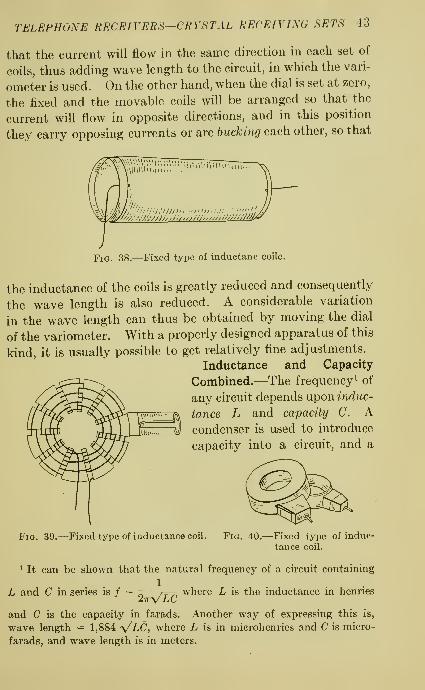
r\\l\uilniiii..
wP-^j/'JjlJ''JiJ,:'////J^^
Fig. 38.—Fixed type of inductanc coile.
the inductance of the coils is greatly reduced and consequently
the wave length is also reduced. A considerable variation
in the wave length can thus be obtained by moving the dial
of the variometer. With a properly designed apparatus of this
kind, it is usually possible to get relatively fine adjustments.
Inductance and Capacity
Combined.—The frequency ^ of
any circuit depends uponmdi^c-
iance L and capacity C. Acondenser is used to introduce
capacity into a circuit, and a
Fig. 39.—Fixed type of inductance coil. Fig. 40.—Fixed type of induc-
tance coil.
^ It can be shown that the natural frequency of a circuit containing
1
L and C in series is / = where L is the inductance in henries27rVLC
and C is the capacity in farads. Another way of expressing this is,
wave length = 1,884 -y/LC, where L is in microhenries and C is micro-
farads, and wave length is in meters.

44 PRACTICAL RADIO
coil of wire is used to' introduce inductance. Inductance maybe either fixed or variable; the fixed types are shown in Figs.
38 to 40, and variable types in Figs. 41 and 42. The addition
Fig. 41.—Variable type of inductance coils.
of inductance increases the natural wave length of a circuit.
Thus by adding inductance to a circuit, as in Fig. 43, it maybe tuned to various wave lengths. But even under the best
-Variable type of inductance coils.
conditions the current which will flow is small because boththe crystal and the telephone receivers offer a high resistance.
A condenser, however, offers low resistance to radio-frequency

TELEPHONE RECEIVERS—CRYSTAL RECEIVING SETS 45
currents. If then, a fixed condenser is connected across, or in
parallel with the telephone receivers, the resistance to the
flow of the high-frequency current is reduced, and a greater
current will flow. A condenser in parallel with the telphone
receivers, in some cases, is considered as a storage for electric-
ity with an action as follows: When current flows through the
crystal the condenser accumulates a charge of electricity which
discharges through the telephone receivers during the interval
Antenna
Coil-
rifs ia\
Defecior
^^ Telephone^-J/ Receivers
'(bround
k Anienna
Crystal
Dehcfor
Condenser
^ 0\ Telephone
Receiverst^
. Ground
Fig. 43.—Inductance coil in
antenna circuit for .tuning.
Fig. 44.—Crystal detector in secondarycircuit.
when no current flows through the crystal. This action occurs
once in every cycle and its effect is to increase the strength of
the current. A telephone cord, which consists of two insu-
lated wires, has some condenser action and this may be suflfi-
cient for some cases so that no additional condenser effect is
required.
Since the crystal of a detector has a high resistance, and is
in the direct path of the antenna current, better results will

46 PRACTICAL RADIO
be obtained by having the crystal and telephone in a circuit bythemselves, as in Fig. 44. Here the antenna circuit includes
all the turns of wire on the coil between T and P while the
secondary circuit, containing the crystal and telephone
receivers includes the turns between T and B. By this arrange-
ment both the antenna and the secondary circuits may be
tuned to the proper frequency. ^
Double Circuit Wiring Diagram.—A circuit has now been
described which operates very well except when very close
WAnienna
iriocoup
Primary
'
Wind
'-= Orounal
O
IV
VariableCondenser
Crush! Dei-echr4
Fixed
Condenser
Secondi
Windany
"3
'ephone
Receivers
Fig. 45.—Diagram of primary circuit (antenna) and secondary circuit
(including inductance, capacity and telephone receivers).
tuning is necessary to separate signals from two stations on
nearly the same wave lengths. This difficulty can be overcome
by separating entirely the antenna circuit and the secondary
circuit as indicated in Fig. 45. This arrangement is called a
double circuit to distinguish it from the single circuit con-
sidered above. Energy is transferred by induction from the
1 In order to understand the action we need only to apply the concep-
tion of voltage drop. Since there is a current flowing in the antenna
circuit, we know from the relation E = IR (where R is the resistance to
alternating current) that there will be a certain drop in voltage across
the coil. The location of the point B determines the value of the voltage
which is used to force a current through the secondary circuit.

TELEPHONE RECEIVERS—CRYSTAL RECEIVING SETS 47
primary to the secondary circuit. The variable condenser Cwhich is placed across the secondary coil gives sharp tuning
because it makes possible a very fine adjustment of the
frequency of the secondary circuit. When the circuit con-
taining the inductance L and the capacity C is tuned exactly,
the voltage across its terminals will be a maximum and will
cause a maximum current to flow in the telephone receivers.
Coupling.—In comparing the single and double circuits, wemust first consider the purpose of this tuning system. This
has two objects; first, to adjust the frequency of the primary
circuit, and second, to provide the proper transformer action
so that the greatest possible amount of energy is transferred
to the secondary circuit. In the single circuit, the frequency
adjustment depends upon the amount of inductance L and
capacity C, while the transformer adjustment depends upon the
ratio of L to C This is true also for the double circuit with
the advantage that the transformer action may be adjusted
also by the coupling^ that is, by the relative position of the two
coils, meaning the primary and secondary of the tuner. It
is important to remember that when the distance between
these coils is increased, the coupling is loose and sharper
tuning results than with close coupling. The process of coup-
ling may be looked upon as a sort of filtering scheme. Theantenna circuit partly filters out the desired wave and the
process of filtering is carried still further by the secondary
circuit. The single circuit gives comparatively loud signals
with poor selectivity. The double circuit, with loose coupling,
has good selectivity, but will give a weaker signal than the
single circuit unless the voltage actuating the secondary
circuit is increased enough by having a large number of turns
on the secondary coil to offset the effect of loose coupling.^
^ From the relations E varies as ^, for the single circuit, in which Etip
is the voltage acting and Rp the resistance of the primary, and the
relation E varies as , — for the double circuit, in which Rs is theVRp X Rs
resistance of the secondary circuit, it can be seen that by reducing
the secondary resistance better results will be obtained with the double
circuit, for given antenna circuits.

48 PRACTICAL RADIO
Variable Condenser in Series and Parallel Circuits.—If it is
desired to receive radio currents of a wave length shorter than
the wave length corresponding to the length of the antenna
and coil, a variable condenser must be connected in series
with the ground lead, as shown at Ci in Fig. 46. As the capac-
ity of this condenser is decreased, that is, as the plates are
moved farther apart, the wave length of the circuit decreases.
If, on the other hand, the antenna circuit is short, and, even
r- Anienna
Variable
CondenseiCoil
I ^
TT. Variable
Condenser
Ground
Fig. 46.—Variable antenna condensers for tuning.
with the antenna inductance coil, will not tune up to a high
wave length, it is necessary to use a variable condenser
connected in parallel^ with the coil as shown by the dotted line
at C2.
By keeping these relations in mind, and remembering that
the antenna to ground circuit forms a condenser with one plate
^ It is interesting to note that the total capacity of two condensers
Ci and C2, connected in parallel, is equal to Ci + C2, while the total capac-C ^ C
ity for a series connection of Ci and C2 is J^ . >r- This is just the
opposite of the case with inductance, or resistance.

TELEPHONE RECEIVERS—CRYSTAL RECEIVING SETS 49
(antenna) connected to one side of the receiving set and the
other plate (ground) to the other side of the set, it is easy to
understand the effect of series and parallel condensers in the
antenna circuit on wave length. Thus, a parallel condenser
increases the capacity and consequently the wave length,
while the opposite is true for the series condenser. In deter-
mining upon the size of a condenser, use the smallest size which
will do the work. A larger size will serve, but will be harder
to adjust. The smaller condenser, not so critical in adjust-
ment, adds capacity more slowly and brings in a given signal
over a wider adjustment of the plates. In a crystal set the
antenna condenser may be placed in the ground lead with the
movable plates grounded.
QUESTIONS
1. Explain, how an electric current is produced in the antenna.
2. Why is a detector necessary in a receiver?
3. Tell what you can of the process by which a sound wave at the
transmitting station is sent out as a radio wave and changed into a
sound wave again at the receiving station.
4. What happens when you tune your receiver?
5. How are inductance and capacity used in tuning?
6. Describe the purpose of the telephone condenser.
7. Why do we use a separate circuit for the detector and telephone
receivers ?
8. Explain the meaning of double circuit and coupling?
9. If it is necessary to change the wave-length range of a circuit howwould you connect a variable condenser in the circuit to get
(a) a lower minimum?(5) a higher maximum?


CHAPTER V
VACUUM-TUBE RECEIVING SETS
The operation of the vacuum tube as used in radio sets wasdiscoverd by Edison. He learned that when an electric lampfilament is cold no current passes through the vacuum betweenthe filament and an extra wire or plate inserted in the bulb,
but that when a lamp filament of this kind is brought up to
incandescence, a current passes readily through the vacuumbetween the filament and the extra wire or plate. An electric
current, however, can pass through a vacuum tube in only
one direction, and for this reason the tube is called a rectifier of
alternating current . It allows the electric current to flow in one
direction only, and therefore converts alternating current into
pulsating direct current. Vacuum tubes for this purpose are
made, however, with still one other part, which is called the
grid. The grid surrounds the filament and is thus a separating
surface between the filament and the plate. Now, if the wire
at the base of the vacuum tube, which is connected to the grid,
is connected to a source of electricity, as for example a dry cell,
there will be possible by this means a control of the flow of
electricity. The grid is usually a piece of wire bent in a
zig-zag form or it may be a wire in the shape of a spiral spring
so placed as to surround the filament and act as a separating
surface between the filament and the plate.
A vacuum tube is so sensitive that when there is even a small
change in the voltage in the wire connected to the grid, it mayproduce a considerable change in the amount of current flowing
between the filament and the plate. This, therefore, is the
general method adopted in radio practice to regulate a large
current by means of a small current. In this case, a small
current is due to the radio waves which are brought from the
antenna by the lead-in wire to the grid, where it serves to con-
51

52 PRACTICAL RADIO
trol the amount of current which passes through the vacuum
tube to the telephone receivers. In this way the radio waves
are changed into audible sounds which may be heard in the
telephone receivers of the headset. . Thus, much louder and
clearer signals are obtained by the use of vacuum tubes than
could possibly be secured with any of the simple devices in
which a crystal detector is used.
The construction of a typical vacuum tube is shown in Fig.
47. It resembles an ordinary electric light bulb. In addition
to the filament, it contains a spiral wire, previously described
Glass Wa/fof Tube
Filameni- Supporj-
Plai<?(Por iion Cuf Awa^)
Gr'idSupporf
?^ Wire Seal
Leadi'nj-In Wires
,. Ba6e
P F F 6
Fig. 47.—-Typical vacuum tube.
as the grid which surrounds the filament, and a cylindrical
metal plate, which surrounds the grid and filament. The tube
from which all the air possible is drawn (hence the name
—
vacuum tube) is provided with a base which fits into sockets of
standard size. At the bottom of the base, there are four
terminals, two of which (marked F) lead to the ends of the
filament, a third (marked G), leads to the grid, and the fourth
(marked P) leads to the plate. The conventional way of
representing a vacuum tube is shown in Fig. 48.
"A" and "B" Batteries.—The vacuum tube requires for its
operation 2^ filament or ''A'' battery and a plate or '^B" battery.
In the action of the vacuum tube the electric energy of a
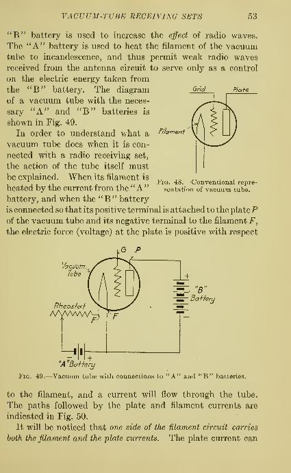
Ond Plaie
VACUUM-TUBE RECEIVING SETS 53
"B" battery is used to increase the effect of radio waves.
The ''A" battery is used to heat the filament of the vacuumtube to incandescence, and thus permit weak radio wavesreceived from the antenna circuit to serve only as a control
on the electric energy taken from
the '^B" battery. The diagram
of a vacuum tube with the neces-
sary ''A" and ^'B'' batteries is
shown in Fig. 49.
In order to understand what a
vacuum tube does when it is con-
nected with a radio receiving set,
the action of the tube itself must
be explained. When its filament is
heated by the current from the "A"battery, and when the ''B" battery
is connected so that its positive terminal is attached to the platePof the vacuum tube and its negative terminal to the filament F,
the electric force (voltage) at the plate is positive with respect
F/'/amefrf
Fig, 48.—Conventional repre-
sentation of vacuum tube.
(5 .P
VacuumTube
"A"BaHerLj
Fig. 49.—Vacuum tube with connections to "A" and "B" batteries.
to the filament, and a current will flow through the tube.
The paths followed by the plate and filament currents are
indicated in Fig. 50.
It will be noticed that one side of the iUament circuit carries
both the filament and the plate currents. The plate current can

54 PRACTICAL RADIO
be increased by either increasing the ''B" battery voltage, or byincreasing the filament current from the ''A" battery, which is
controlled by a variable resistance called a rheostat. If the plate
voltage is too high there will be a blue glow inside the vacuumtube; and when this occurs, the action of the tube is very
erratic, and the volume of sound in the telephone receivers is
reduced. Too much plate voltage shortens the life of the tube;
in fact, if the blue glow is allowed to remain, the tube will
burn out. Likewise, the filament current cannot be increased
very much without injuring temporarily or burning out the
filament. In its practical operation, the filament is heated to
VacuumTube
"
Rheosiai ^>
Baiiern
Fig. 50.—^Plate and filament currents in vacuum tube.
a moderate temperature, as determined by the manufacturer,
and the plate voltage is adjusted for best results by variation
of the voltage of the '^B" battery.
If, however, the negative terminal of the ^'B" battery is
connected to the plate, there will be no current flowing in the
plate circuit. When the direction of the electric force (voltage)
between the plate and the filament is thus changed, there is
no flow of current. Thus the action of the tube, so far, is
similar to that of the crystal detector, since it will allow current
to flow in one direction only.
The grid is placed between the filament and the plate to
increase the power of the vacuum tube. Since the grid and

VACUUM-TUBE RECEIVING SETS 55
filament are very much nearer together than the plate and
filament, it can be seen that when an electric force (voltage)
is established between the grid and the filament, it will have
more effect upon the plate current than when there is the same
electric force between the plate and filament. As a result of
this, a small electric force between grid and filament controls a
comparatively large flow of current in the plate circuit. It is
this effect which makes the tube far more sensitive as a detector
than the crystal. In a crystal set, only the original current
produces sounds in the telephone receivers, while in a vacuum-tube set, the incoming radio current merely controls a muchstronger current.
Probably in most cases, the ''A'' battery is rated at 5 or 6
volts, as 5-volt vacuum tubes are used a great deal. A battery
of this kind as a rule consists of a storage battery of three cells
each giving 2 volts, making a total of 6 volts, or four dry cells,
'
each giving 13-^ volts when new, making 6 volts in all. There
are, however, some vacuum tubes which operate on very low
voltages from 1.1 to 1.4 volts, and use only J^ ampere of
current. Vacuum tubes of this low voltage are ideally suited
for operation with a single dry cell for the ''A" battery.
Very many vacuum tubes rated at 5 volts require a current of
one ampere, and when tubes of this large capacity are used,
it is extravagant to operate with dry cells, because with a 1-
ampere current drawn from the battery no dry cell will last
long. For any receiving set, having more than one vacuumtube it is generally considered economical to use a storage
battery for the ''A" current supply.
Storage Batteries.—It is desirable that storage batteries
used for radio work, should be in rubber boxes or cases so as to
prevent leakage of acid upon floors, rugs and carpets, andalso to avoid the noises caused by leakage of acid either from
one of the cells to the ground or from one cell to another cell.
Storage batteries for radio service may well be made somewhatsmaller in capacity than those used for automobile starting
and lighting. These small sizes are cheaper and more con-
venient to handle than the larger ones ordinarily used in
automobiles. Also, when electric lighting current is avail-

56 PRACTICAL RADIO
able, it is desirable to have a recharging device for the storage
battery if the radio set includes several vacuum tubes. Anumber of vacuum tubes are a considerable drain on the
battery and unless provision is made for more or less constant
recharging, there will be a great deal of inconvenience and
expense when the storage battery must be taken out frequently
for recharging. Further, with a recharging apparatus always
at hand the storage battery will be kept well charged and its
life and general serviceability will be very much increased.
The '^B" battery, or high-voltage battery, is now generally
made in compact units of 22J^ volts, and these units are made in
both small and large sizes and the large sizes should, by all
means, be used where there is a more or less constant use of the
receiving set. Most small-size units have no provision for
taking less than 223-^ volts from the unit, while the large
units are generally made with a suitable number of lugs or
binding posts which are arranged to permit a considerable
variation of voltage which is taken from the cells. This
variable type of ''B" battery is especially useful for vacuum
tubes requiring fine adjustment of the ^^B" voltage. Each of
these units, whether large or small, consists of 15 dry cells
each intended to give IJ^ volts when new.^
Uses of Vacuum Tubes.—A vacuum tube as used in radio
sets for both receiving and transmitting purposes has a number
of uses. The most important of these are the following:
1. Changing the alternating current to pulsating direct
current.
2. Controlling a large electric current by means of a rela-
tively small current.
The first of these uses has been clearly explained in the
preceding pages. The second use is, however, just as impor-
tant and in general is referred to as amplification, which means
that a weak current, brought to the receiving set from the
1 In a receiving set consisting of a simple detector having a single
vacuum tube one "B" battery (223^ volts) is sufficient, but if there is
also an amplifier used in connection with the detector, two of these
units (45 volts) are needed. If a loud speaker is also a part of the
equipment, in addition to the amplifier, three or four units (67 ?>^ or 90
volts) may be needed.

VACUUM-TUBE RECEIVING SETS 57
antenna, may have its characteristics impressed on a current
several times as powerful, usually called ''B" current, in such a
way that the powerful current will communicate to a telephone
receiver all the characteristics of a weak current. The principle
of amplification is the same as that applied in telephone repeat-
ers which are employed in long-distance telephone lines for the
purpose of receiving a telephone message with a weak current
and sending it on at a much stronger current to a great distance.
Vacuum tubes are made in a number of sizes and with slightly
different characteristics^ depending upon the service for which
they are to be used. The smallest vacuum tubes use about J^ampere at 1.1 volts which means that these smallest tubes are
rated about J^^ watt, and the largest tubes are rated at about
250 watts.
Storage Batteries for "B" Currents.—The ''B" batteries
referred to in the preceding explanation consist of dry cells.
Instead of the compact units of dry cells just referred to, some''B" batteries which are in almost constant use consist of
storage batteries. Such storage batteries may be recharged
from time to time with the same recharging apparatus that is
used for ''A" batteries. It is claimed that the operating cost
of "B" storage batteries is less than when dry cells are used.
Dry cells of course, when they become reduced in voltage are
practically valueless and are usually thrown away.^
A receiving set provided with a vacuum tube and '^A" and
''B" batteries is shown in Fig. 51. In the operation of this
set, the antenna circuit is first tuned to the radio waves from
a transmitting station by manipulation of the dials, so that a
maximum current flows in the primary circuit. Then, byinduction in the transformers, the electric energy is transferred
to the secondary circuit. When the secondary circuit LCis tuned, a maximum current will flow in it and the voltage
across the terminals of the condenser C will likewise be a
1 When the voltage of a 223'^-volt dry cell unit becomes lower than
17 volts it is not very satisfactory and begins to make trouble particularly
in the way of increasing unpleasant noise during reception. When the
voltage has been reduced to this amount, however, these units may be
satisfactorily used for electric bell and private telephone circuits, as well
as for regulators for therrhostatic controls.

58 PRACTICAL RADIO
Anienna
Secondary Windingof Transformer
"C Bafferu Vacuum Tube
TelephoneReceivers
WindingofTransfortnet
'Ground
Fig. 51.—Simple vacuum tube receiving set with "A" and "B" batteries.
trAnj-enna
SeconcfarLi q^;^ CondenserWinding and Grid Leak
PfimargWinding
ofTransfermi r
0(\ Telephone
-=- "B"~mr BaHerg
- Ground
Fig. 52.—Diagram illustrating use of grid leak and grid condenser.

VACUVM-TUBE RECEIVING' SETS 59
maximum. This alternating voltage being impressed on the
grid-filament circuit will act, as explained before, so as to
control the flow of current in the plate circuit. In this way,
the alternations of the grid voltage resulting from the original
weak current in the antenna, will cause corresponding fluctua-
SecondaryWinding
VacuumTube
Fig. 53.—Combined use of potentiometer and "C" battery.
tions in the much stronger current flowing from the ''B"
battery through the plate circuit.
In the diagram (Fig. 51), the electric force between plate and
filament acts in a direction which is called positive. The force
between grid and filament will be positive during the interval
Fig. 54.—Combined grid leak andgrid condenser.
Fig. 55.—Combined grid leak andgrid condenser.
of time when the impressed alternating voltage is positive, and,
during this interval, it will act in connection with the positive
plate to filament voltage to increase the flow of ylate current.
Likewise, during the interval when the impressed voltage is
negative, the grid to filament voltage will be negative and will
actjn the opposite direction to the positive plate to filament
voltage, to decrease the flow of plate current. The difficulty

60 PRACTICAL RADIO
comes from the fact that since the grid periodically becomespositive with respect to the filament, it will at those periods
allow a current to flow in the grid circuit. This is not desirable
because it causes distortion^ and weakens the action of the
vacuum tube. With many tubes, louder signals result whena grid leak and grid condenser are used as in Fig. 52. Twotypes of a combination grid leak and grid condenser are shownin Figs. 54 and 55. Two types of rheostats are shown in
Figs. 56 and 57.
Fig. 56. -Typical resistancerheostat.
Fig. 57. -Typical resistancerheostat.
Current from Electric Lighting Circuits.—In some cities
where direct current is distributed for lighting purposes those
operating radio receiving sets have been tempted to try to use
the city current for the ''A" and ''B" current, but such
attempts have not yet been successful. The reason is that
in making radio adjustments very small variations in current
and voltage are necessary. For example, if the voltage of
the '^A" or filament current varies even the slightest amount
^ Sound distortion caused by periodic changes of voltage direction in
the grid may be prevented by connecting the grid-circuit return to the
negative end of the filament in order to produce a permanent negative
force at the grid to insure that the grid will never become positive dueto the impressed voltage. If this does not prove sufficient it may benecessary to use a "C" battery as shown in Fig. 51, or in combinationwith a potentiometer P, as in Fig. 53.

VACUUM-TUBE RECEIVING SETS 61
from instant to instant, there will be disagreeable noises in
the telephone receivers. In order to secure quiet radio service,
it is necessary to have a steady supply of direct current such
as can only be supplied by some form of dry-cell unit or stor-
age battery. In any event, the direct current from a lighting
circuit has much too high voltage to be applied directly and
there would always be a very large loss in reducing the
relatively high voltage to the voltage required for most
receiving sets.
Soft and Hard Vacuum Tubes.—Vacuum tubes which
require adjustment of voltage to suit the service for which
they are used are called soft or gas-content tubes. Such tubes
are particularly suited for use in detectors. On the other
hand, vacuum tubes which are not intended to require adjust-
ment of voltage are called hard tubes and are best suited for
use in amplifiers. Soft tubes require critical adjustment of
both the ''B" or plate voltage and of the ''A" or the filament
current. When such tubes are properly adjusted for voltage
and current they tend to make the operation of a detector
very sensitive. The amount of the '^A" or filament current
is usually varied as necessary for best results by means of a
rheostat which is nothing more than a variable type of elec-
trical resistance, which is placed in series with the circuit
carrying the current which lights the filament of the vacuumtubes. The '^B" or plate voltage is not so conveniently
adjusted as it must be varied as a rule in steps of 1.5 volts,
the voltage of a single dry cell.^
The voltage from the ^'B" battery which will give the best
result can only be determined by actual trial, that is by the
method of temporarily touching the wire from the plate of the
vacuum tube to the various lugs or terminals of the 22j^-volt
unit, and thus finding by trial the position for the attach-
ment of this wire to the lug which gives the greatest sensitive-
ness of the detector. After this best position of sensitiveness
has been determined, as a rule, no further adjustment of the
''B" or plate voltage will be necessary for some time. Most^ There are usually 15 of these cells in a 223'^-volt unit, but the adjust-
ment of voltage is usually only between 163-^ and 22^^ volts.

62 PRACTICAL RADIO
of the vacuum tubes intended for use in detectors operate
best when the ''B" voltage is between 16^ and 223^ volts,
and in '^B" batteries of the variable voltage type, variations
of voltage between these limits are obtained by attachment
to any one of the intervening lugs, or outer terminals, which
are provided. Very many operators, however, get satisfactory
results by using a fixed voltage ''B " battery on detector tubes,
but obviously they get their best results when the tube happens
to be one that gives its best service at 223^ volts or some
multiple of that number of volts.
So-called hard vacuum tubes which are also called ampHfier
tubes, are exactly hke the soft or detector tubes, as regards
external appearance, and differ only in electrical characteristics;
and the most important of these characteristics is the absence
of critical adjustment in the hard tubes. As a rule, hard or
amplifier tubes operate successfully on plate voltages varying
from 40 to 90^ volts. In receiving sets having three or four
vacuum tubes it may be necessary to use three or four 22.5-
volt units connected in series, with the connecting wires so
arranged that the full voltage will be impressed on the vacuum
tubes in the ampUfiers while a variable voltage from this same
series of batteries will be used for the detector tube.
The ''soft" tube, which is recommended for use as a
detector, does not have a high degree of vacuum and hence
contains some gas. The ''hard" tube, which is used both as a
detector and as an amplifier, has a high vacuum and needs a
higher plate voltage. The terms "hard" and "soft" as
applied to vacuum tubes originated with the development of
the x-ray tube. An rc-ray tube which produces feeble rays
and contains some gas is said to be a "soft" tube. An ic-ray
tube which produces very penetrating rays ("hard" rays)
and has a high vacuum is said to be a "hard " tube and needs a
higher plate voltage.
1 Some receiving sets are operated with plate voltages on the tubes of
the amplifier receiving electric current at more than 100 volts with the
result that they get very loud reception, but there is also the disadvantage
that such a high voltage also increases the noises which may be very
objectionable, especially in the telephone receivers.

VACUUM-TUBE RECEIVING SETS 63
In the case of the soft vacuum tube, the presence of gas in
the tube changes the action. The grid current in a soft tube
tends to flow at a much lower value of positive force between
the grid and filament. Although a grid current is necessary,
too much is harmful and for this reason the return wire from
the grid is connected to the negative side of the ''A" battery.
The proper connections for the various cases are given in the
following table
:

64 PRACTICAL RADIO
recommend the use of hard or amphfier tubes in both the
detector and amphfier for the reason that the wiring has been
laid out in such a way that the detector and amphfier use the
same plate voltage and filament current. The object of this
arrangement is to simplify the construction and the operation
of the set, but simplification of wiring is accomplished only
with the sacrifice of most efficient operation.
Grid Leak.—In many of the simple types of receiving sets a
very high-resistance coil called a grid leak together with a small
fixed condenser are placed in series with the tuner. In all
cases when a vacuum tube is to be connected into a radio
circuit it is very necessary that careful attention be given
to connecting the positive and negative terminals of both the
''A" and ''B" batteries to the proper points in the circuit
where they are intended to be used.
Loose Couplers and Vario Couplers.—In many receiving sets
the relatively weak antenna current scarcely more than gets
to the operating parts of the receiving sets; that is, the antenna
current enters from the lead-in wire, passes through a single
coil in the receiving set, and then passes out through the
ground wire. When this is the case, the relatively weakcurrent in the antenna circuit is made to develop an induced
current in another winding very close to the one carrying
the antenna current. One form of such windings in close
contact with each other is called a loose coupler, and another
form is called a vario coupler. The loose coupler consists of
a large tube on which a large number of turns of wire are
wound. This winding is called the primary coil, and in a
detector is connected at one end with the antenna by meansof the lead-in wire and at the other to the ground wire. Inside
this larger tube is a smaller tube on which there are woundvery many turns of wire and this smaller tube with its winding
is arranged to slide in and out of the larger tube. A vario
coupler differs from the loose coupler just described in that
it consists of a large tube on which are wound a large numberof turns of wire, to which the antenna is connected by meansof the lead-in and the other end is connected to the ground
wire. Inside this large tube is a ball or a similarly shaped

VACUUM-TUBE RECEIVING SETS 65
form, made usually of wood or fibre on which very manyturns of wire are wound. The ball with its winding is moun-
ted on a small shaft which has a suitable handle for rotation.
In either of these devices, the wire on the large tube is called
the primary coil and, the wire on the smaller tube or ball,
is called a secondary coil, which is connected (in a receiv-
ing set equipped with vacuum tubes) to the wires leading to
the tubes and related apparatus.
Honeycomb and Spider-web Inductance Coils.—Until
recently most forms of inductance coils were large and clumsy,
but recently such coils have been developed which are quite
compact and therefore much more convenient to use than the
older forms. One kind of this compact inductance coil, is the
honeycomb coil, shown in Fig. 40. Each coil of this kind is fixed
as regards its wave-length value, but there are usually several
coils of this kind which may be used interchangeably so that
the operator may shift from one coil to the other and thus
vary the wave length in large amounts, and depend for smaller
variations of wave length on the use of the variometer or a
variable condenser.
Compact inductance of still another type, called spider-web
inductance is shown in Fig. 39. In essential parts this form
of inductance consists of a sheet of insulating material such as
fiber or hard rubber in which radial slots have been cut and
the wire to carry the current is wound in a compact spiral in
and out of these slots. Because of its shape it is also some-
times called a pancake inductance. Two inductance sheets
of this form make a satisfactory loose coupler when mounted
so that one sheet is fixed and the other hinged so that the
distance between them may be varied.
Descriptions of Radio Receiving Sets.—It will be remem-
bered that the plate current in a simple detector set having a
single vacuum tube is at radio frequency, but is varied at audio
frequency or voice rate; and that the telephone receivers of
the head set respond to the audio variations but not to the
radio-frequency variations.
The following descriptions of radio receiving sets are
detailed and in many respects somewhat technical. On

66 PRACTICAL RADIO
this account they are not intended for detailed study or for
special attention on the part of the readers. The information
given here regarding these sets is especially for those making
a study of one of the sets described.
Feed Back Regeneration.—In a regenerative receiving set,
radio-frequency current is used to increase considerably the
strength of the sounds in the telephone receivers by being
fed hack to the grid circuit. It has been shown that any
variation in the voltage impressed on the grid produces a
corresponding variation of the plate current and hence if one
unit of the radio current received from the antenna is thus
fed hack to the grid circuit, several times that amount—say
ten times—may be available in the plate circuit. Now, if
we so arrange the parts of a radio receiving set that part of
the current in the plate circuit is impressed back on the grid
circuit, the sound effects in the telephone receivers will
be nearly doubled. This action can be repeated and thus
enormously increases the volume of speech or music in the tele-
phone receivers. The limit is reached when so much of the
plate current is fed back to the grid circuit that very objec-
tionable noises result.
Tickler Coil Regeneration.—This feed hack of the plate
current to the grid circuit is accomplished by coupling the
plate circuit to the grid circuit either by induction or by
capacity effects. The action is easily understood by consider-
ing the double circuit shown in Fig. 58, in which the plate
circuit is coupled hy induction to the secondary of the tuning
device. In this arrangement an extra tickler coil is con-
nected to the plate circuit so that it may be brought near to
the primary winding of the detector circuit. The current
flowing in this tickler coil sets up a magnetic field which, byinduction, reacts upon the coil in the grid circuit and induces
in it a voltage. This voltage is such that it adds its effect
to that already acting in the grid circuit, and the result is
that the variations in plate current are increased. This
increased plate current again reacts on the grid which again
increases the plate current. This amplifying action will
continue until the limit is reached when the tube starts to

VACUUM-TUBE RECEIVING SETS 67
oscillate or act as a generator of electric current on its own
account. The regenerative action is controlled by the tickler
coil coupling, which is made variable, and is increased by
increasing the coupling. To obtain maximum voltage on the
grid, the grid circuit should have large inductance and small
capacity, for this particular type of coupling.
-An^-enna
Telephone
Receivers
PrimaryWindina
Ground
Fig. 58.—Plate circuit coupled by induction to secondary winding.
The tickler coil may be the movable coil of a vario coupler,
or one of a set of honeycomb, or spider web coils. In order,
then, to get regeneration, the plate current must pass through
the tickler coil in such a direction that the voltage induced
in the grid circuit will increase the voltage already impressed
on the grid. If it is not flowing in this direction, its effect
will be to decrease the voltage on the grid, and so reduce the
strength of the sounds in the telephone receivers. If this
happens with a coil which cannot be rotated, it is necessary
merely to interchange the wires leading to and from the tickler
coil. It will be noticed that as the coupling effect is increased,
the radio currents become more and more distorted because
the amplification due to the jeed hack is uneven. If the coup-

68 PRACTICAL RADIO
ling effect is increased still more, a dull click will be heard and
the signals will probably disappear. This indicates that the
tube is oscillating or acting as a generator. This oscillating
action is not difficult to understand. We have seen how,
starting with a given amount of energy in the grid circuit,
some of the plate circuit energy can be fed back thus increasing
the plate current. If this action is increased more and more,
and then if the original source of energy which supplies the
grid circuit, be removed, the tube will continue to operate
and, essentially, its action is that of a generator. The alternat-
ing current thus produced in the plate circuit will have a
frequency determined by the values of inductance and capacity
in the grid circuit. From this viewpoint, the tube may be
considered as a converter of direct-current energy, supplied
by the battery, into alternating-current energy.
If the original source of energy is not removed, as would be
the case when we are receiving signals, then we have several
currents flowing in the apparatus. One current is that due to
the incoming signal, a second current is the local one which is
produced when the tube begins to oscillate, and the third
current is the result of interaction between the other two.
This action will be considered more in detail when the super-
heterodyne receiving set is discussed.
Oscillating Tubes.—The oscillation^ of a tube may be started
by several causes, such as, a slight jar, the effect of body
capacity, a sudden change in the signals, stray currents picked
up by the antenna, or most commonly, by an increase in the
inductance or capacity of the plate current when the regenera-
tive action is already strong. In other words, the regeneration
is so great that the feed back becomes violent upon a slight
variation of grid voltage. When a receiving set is adjusted
to this oscillating condition it may become a very troublesome
source of interference to receiving stations near by, since it is
then acting as a weak transmitter.
Experiments have been made which would seem to indicate
that a one-tube regenerative set using a tickler coil gives about
^ Oscillation of a vacuum tube circuit does not mean that there is
any physical "oscillation" of the filament, plate or grid in the tube.

VACUUM-TUBE RECEIVING SETS 69
the same response as a two-stage radio-frequency amplifier
with detector. A number of ways of obtaining feed back have
been employed, but the most satisfactory and popular forms
are by tickler coil regeneration which has just been explained,
and by tuned plate regeneration, which we shall now consider.
Tuned Plate Regeneration.—Regeneration with a tuned
plate circuit is obtained from the arrangement shown in Fig.
59. Any form of variable inductance may be used, in series
with the plate circuit, for regeneration, but the variometer is
Pn'maruWinc/ihcf
Telephone
Rec(si'vers
Fig. 59.— Regeneration with tuned plate circuit.
most popular because of the smooth and fine control it gives of
the inductance. Likewise there are many forms of double-
circuit and of single-circuit inductance which can be used for
the tuning arrangement shown here. With this arrangement,
feed back takes place, not by inductive coupling, as with a
tickler, but by capacity coupling. In a tube the conducting
wires which connect to the grid, the filament and the plate,
are sealed into the glass at the base, fairly close together, with a
layer of glass between. This produces a considerable capacity
effect as illustrated by the dotted lines in Fig. 60. In a tube,
the capacity between filament and grid is coupled to the

70 PRACTICAL RADIO
capacity between filament and plate, and thus the grid and
plate circuits are coupled together. The feed-back action
depends also upon the capacity of grid to plate, and often
may be improved by connecting a variable condenser of about
0.0001 microfarad, as in Fig. 61. One disadvantage of the tuned
plate method of obtaining regeneration is that the adjustments
for regeneration and for tuning are not entirely independent of
each other. This does not apply to the tickler coil circuit
in which the plate inductance does not vary.
VariableCondenser
Fflamenf
Fig. 60.—^Capacity effect in vacu-um tube.
'Fiiamenf
Fig. 61.^—^Variable condenser forincreasing feed-back action.
Armstrong Super-regenerative Receiver.—A super-regenera-
tive set compares favorably with sets using radio-frequency
amplification and produces the same results with fewer tubes.
The set is so sensitive and powerful, that noises from both
within and without the apparatus cause some interference.
The use of a loop is advisable because it increases the selectivity
and reduces the re-radiation as compared with the antenna.
It must be stated here that the adjustment and operation of
this set is rather complicated and that not many experimenters
have been able to duplicate the results obtained by Armstrong.
In ordinary regeneration, the amplification of the sound in
the telephone receivers increases as the amount of feed-back
coupling is increased, up to the point where the vacuum tube
starts to oscillate and beyond this point the speech and music
in the telephone receivers are distorted and these sounds maydisappear entirely. In super-regeneration the feed back can be

VACUUM-TUBE RECEIVING SETS 71
carried much farther than the point at which oscillation starts
in a regenerative set. Investigation proved that the oscilla-
tion current does not reach its final value instantly, butrequires a definite time to build up. The problem, then, wasto control the feed back in such a way that the benefit of the
high feed-back current was retained but that the tube did
not oscillate. This is done by varying the amount of feed
back above and below the amount required for oscillation.
Thus, the feed back is first increased so that the current builds
up almost to the point of oscillation. In the simple regenera-
tive set it is impossible to control the circuit so near the point
of oscillation, and the operation is necessarily so far below that
the full value of the action is lost.
In the super-regenerative set, however, the control is so
accurate that the current builds up to a much greater amount.Before the tube begins to oscillate the feed back is reduced
and the current begins to decrease. This variation in the
feed back takes place so rapidly that it does not interfere
with the signal.
The amount of feed back may be controlled in several ways.
Thus, a decrease in plate voltage below a certain point will
decrease the feed back and an increase will cause the current to
build up. Also, if the grid voltage is alternately made positive
and then negative with respect to its normal value, the feed
back will alternately become greater and smaller.
In order to preserve clarity of tone it is essential that the
time between the building up periods be very short. Thenecessarily rapid variations in grid voltage or plate voltage are
obtained most conveniently by using a vacuum tube acting as
an oscillator at the required frequency. The variation in
grid voltage is accomplished by the arrangement shown in
Fig. 62. In this circuit the two tubes are in parallel, that is,
the grid and the filament of one tube are '^ shunted" with the
grid and filament of the other. The circuit of tube is so
adjusted that the tube generates current at a frequency which
is lower than that being received, while the first tube acts as a
regenerator and detector. A grid or '' C " battery of 2 to 6 volts
may be necessary and should be connected between the grid

72 PRACTICAL RADIO
terminal of the tube and the secondary condenser in such a
way that the grid is negative. At the instant when the grid
of tube is negative, it acts to increase the grid voltage of
tube Q in a negative direction, and likewise when the grid of
tube is positive, the voltage of tube Q will be increased in a
positive direction. Tube Q is adjusted so that it will cause an
increase in the feed back action if its grid voltage is increased
in the positive direction but the feed back will decrease if its
grid voltage is increased in the negative direction. Thus the
signal that is present at the instant when the grid voltage
begins to increase positively will be amplified until the action
is stopped by the decrease in grid voltage.
TelephoneReceivers
Fig. 62.— Vacuum tube acting as oscillator in super-regenerative circuit.
The telephone receivers might also be placed at the point A,
in which case, tube would act as both oscillator and detector.
In fact super-regeneration may be used in a variety of forms.
The duties of regenerator, oscillator, and detector may each
be performed in separate tubes; they may be combined in
various ways, or they may all be performed by one tube.
The frequency of the oscillator must be as low as possible,
in order that enough time may be allowed for building upthe current yet not so low as to produce noises in the telephone
leceivers.
Instructions for Operation of Receiving Sets.—In order to
save both time and patience, it is desirable to write down the
settings of the various dials for stations of different wavelengths. In most sets, when a station is located in this way,it can always be found again at the same setting.

VACUUM-TUBE RECEIVING SETS 73
Before starting to operate a set, it is necessary to make sure
that antenna and ground connections are made. In a crystal
set, the crystal can be adjusted later, by trial. In a vacuum-tube set, the tube is lighted by turning the rheostat knob, or,
in some cases, by inserting the phone plug. In no case should
the voltage on the filament be increased beyond the manu-facturer's recommendations. A voltmeter is useful in locating
the position of the rheostat which gives this allowable voltage.
If no voltmeter is available, increase the brightness until a
faint hiss is heard in the telephone receivers and then turn
back the rheostat slightly until the noise is gone. It is impor-
tant to remember that excessive filament current will shorten
the life of the tube and that the tube should be operated at the
Griol Plah
Gn3_Refurn
"A "Baiien/
I
PlafeRe-turn
"B
MilBaffenu
Fig, 63.—Potentiometer for fine adjustment of plate voltage.
lowest temperature that will give satisfactory results. For a
given value of filament current there is a value of plate voltage
which will give best results, so that it is advisable to adjust
the plate voltage after the filament current is fixed. However,
whenever one is changed, the other should be changed also.
Adjustment of plate voltage finer than the taps on the ''B"
battery may be obtained by the use of a potentiometer P con-
nected as shown in Fig. 63. Since this potentiometer connec-
tion draws current, one end of the ''A" battery should be
disconnected when the set is not in use.

74 PRACTICAL RADIO
In a single-circuit crystal set, having a single control, the
only care necessary in tuning is to make changes gradually so
that one does not pass over a transmitting station. Thedouble-circuit crystal set usually has two controls, one for the
antenna circuit which we shall call the primary, and one for
the coupled circuit, which we shall call the secondary. Whenthe coupling is fixed, the range of broadcasting wave lengths
may be explored by moving the primary control slightly
each time and the secondary control over the whole range for
each setting of the primary. If the coupling effect is variable,
the first move is to get maximum coupling, that is, to get the
coils as close together as possible. Then proceed as above for
the double-circuit set. After a transmitting station has been
located, a decrease in the coupling effect will help to tune out
interference from other stations. The primary and secondary
controls may then be readjusted slightly until best results are
secured.
In tuning a three-circuit set (tuned plate) there are four
adjustments to make after the tube filament current is regu-
lated. The first step is to set the coupling control at about
midway. Then the primary control is adjusted approximately.
Finally, using both hands, the secondary and the plate controls
are moved over the entire range. It will be noticed that for a
given setting of the secondary there is a definite position of the
plate control at which the set will oscillate, that is, produce a
sort of sizzling or roaring sound. After a little experience the
operator can become familiar with these relative settings so
that he will rotate both controls over the entire range and keep
them at the proper relation so that oscillation is avoided.
Then the primary control is again moved slightly and the
secondary and plate controls rotated . After a signal is located
,
the coupling is reduced until the signal is faint, and the pri-
mary control changed until the signal is clear of interference.
Then the adjustment for volume is made by the coupling
control.
In a set which has a tickler coil control, this should be in its
minimum position until tuning is completed. When a signal
has been located, the volume of sound is increased by turning

VACUUM-TUBE RECEIVING SETS 75
the tickler control towards maximum, until distortion begins.
The control should then be turned back enough to get rid of
the distortion.
Super-regenerative Set Operation.—It is not possible to give
operating details for the super-regenerative set, since local
conditions will affect these to a considerable extent. In
general, the tuning of the first vacuum tube is accomplished
by means of the turns of wire on the loop and the secondary
condenser. The grid battery voltage must be adjusted care=
fully to the type of tube used. The coupling on all the coils
is very close. The proper frequency of the oscillating device is
obtained by adjustment of the inductance and capacity in the
circuit containing the oscillating tube.
A vernier is used to make fine adjustments in tuning. It
may consist of a slow-motion attachment on either the induc-
tance or capacity controls, or it may be a small additional con-
denser which allows small changes in capacity for relatively
large movements of the control. After the operator has
become familiar with the controls, a little experimenting with
the grid leak may improve results. The changes should be
small and considerable time should elapse between adjustments
in order that the results may be compared effectively.
QUESTIONS
1. Explain the detector action of a vacuum tube.
2. (a) Why are batteries used with a vacuum tube?
(6) Show by means of a sketch how these batteries are connected
to the tube.
3. Draw a diagram of a complete receiving set using a vacuum tube
as a detector and tell what happens when a signal is received.
4. What is the difference between a soft and a hard tube?
5. Where would you connect the grid return wire of a circuit in which
a hard tube is used as an amplifier?
6. Name and illustrate two forms of inductance used in radio work.
7. How does regeneration in a regenerative receiving set increase the
volume of sound?
8. (a) Name two methods by which regeneration may be obtained.
(6) Draw a diagram of a circuit using one of these methods.
9. What is meant by an oscillating tube?
10. Describe briefly the steps which are necessary in the operation of a
regenerative receiving set having a tickler coil.


CHAPTER VI
SOURCES OF ELECTRICITY FOR VACUUM TUBES
In the application of vacuum tubes to receiving sets, elec-
tricity is required to light the filament and also to make the
plate of the tube positive in voltage. Electricity for this purpose
may be obtained usually by the use of some kind of battery,
the action of which depends upon the chemical energy of the
substance employed.
Filament or "A" Battery.—A battery for electric service
consists of a number of units called cells. Each cell is com-
posed of two terminals and a supply of
chemicals. When the terminals are con-
nected by a wire, an electric current flows
in the wire. The two kinds of batteries most
commonly used are the dry battery and the
storage battery.
Actually the dry battery is not dry since it
is filled with a material moistened with the
active liquid. The center terminal which is
made of carbon, is positive; and the side termi-
nal, which is negative, is connected to the zinc
container. The most common form of dry cell
as shown in Fig. 64, is 2}4 inches in diameter
and about 6 inches high, known as the No. 6
size. In this figure A is the zinc container; J is the negative
terminal; B is the carbon rod; C is a pulp board lining; D is a
mixture of powdered carbon and manganese dioxide moistened
with a solution of salammoniac; £" is a water-tight seal;
F is a layer of paper (for expansion); G is a layer of sand;
H is Si layer of sawdust. The positive terminal is marked (+ )
and the negative terminal (— ). A dry cell has an open-
circuit voltage of about 1.5 volts and the maximum of
77
Fig. 64.— Con-struction of ordi-
nary dry cells.

78 PRACTICAL RADIO
short-circuit current is 25 to 35 amperes. Dry cells are
intended primarily for intermittent use, but may be used
continuously for small currents. The current which can be
supplied economically depends upon the duration of its use.
This is shown as follows:
Period of use Amperes
2 hours per day4 to 8 hours per day
Continuous service.
.
0.50
0.25
0.10
Dry cells deteriorate even when not in use. For average radio
work about 0.25 ampere can be taken from the cell. A curve
showing the relation between
service and rate of discharge is
given in Fig. 65.
Testing the "A" Battery. -
Lacking a suitable instrument for
measuring volts or amperes, the
best guide to the condition of the
^'A" battery is the brilliance of
the filament. If that is less than
usual and does not increase per-
ceptibly as the rheostat is
adjusted, and the sounds in the
telephone receivers are noticeably
weak, the ''A" battery is ex-
hausted. It is best to test dry
cells with an ammeter and when the reading of this
instrument is less than 5 amperes, new dry cells are needed.
A satisfactory ammeter may be purchased for a dollar or two.
Another cause of weak signals is the exhaustion of the tube
filaments. The WD-11, WD-12, UV-199, C-299, UV-301Aand C-301A vacuum tubes, (see table, page 79) have a special
filament which generally becomes dimmed or useless by the
exhaustion of certain active material and not by actual burning
100
^ 80
"^ GO

SOURCES OF ELECTRICITY FOR VACUUM TUBES 79
out. If the tubes of a receiving set have been in use for a long
period, a weakening in signals may be an indication that new
ones are needed.
Vacuum Receiving Tubes
Kind
Filament
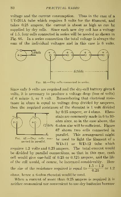
80 PRACTICAL RADIO
voltage and the current consumption. Thus in the case of a
UV-201A tube which requires 5 volts for the filament, and
takes 0.25 ampere, the current is about as high as can be
supplied by dry cells. Since each new dry cell has a voltage
of 1.5, four cells connected in series will be needed as shown in
Fig. 66. In a series connection the total voltage is always the
sum of the individual voltages and in this case is 6 volts.
"^Voffs+
Fig. 66.—Dry cells connected in series.
Since only 5 volts are required and the dry-cell battery gives 6
volts, it is necessary to produce a voltage drop (loss of volts)
of 6 minus 5, or 1 volt. Remembering that electrical resis-
tance in ohms is equal to voltage drop divided by amperes,
then the required resistance of the rheostat is 1 volt divided
__^ by 0.25 ampere, or 4 ohms. Rheo-
Jj^ ; stats are commonly made in 6 to 30-
(^g ^ : ohm sizes, so in the case above, the
vly f-5Volh 6-ohm size will be sufficient. Figure
67 shows two cells connected in
parallel. This arrangement mightFig. 67.—Dry cells con- ^^ ^gg^^ ^^ ligh^ the filament of a
nected in paralleL ^,^-r^ . . ^^t^ . ^ , , i • iWD-11 or WD-12 tube which
requires 1.2 volts and 0.25 ampere. The total current would
be divided by parallel connections, so that in this case, each
cell would give one-half of 0.25 or 0.125 ampere, and the life
of the cell would, of course, be increased considerably. • Here
1 . . , . . , . , 1-5 -1.2 , ^the size ot the resistance required is equal to
—
Ty^^— o^* 1-^
ohms, hence a 6-ohm rheostat would be used.
When a current of more than 0.25 ampere is required it is
neither economical nor convenient to use dry batteries because

SOURCES OF ELECTRICITY FOR VACUUM TUBES 81
they last but a short time. For such purposes the storage
battery is generally used. The essential difference between a
dry battery and a storage battery is that in a dry battery the
operation depends entirely upon the chemical energy of the
materials and when this energy is used up the battery must
be replaced by a fresh one, while in a storage battery the
chemical energy can be built up by the process of passing an
electric current through the battery, which is called charging.
After a storage battery is charged, a current can be drawn from
it, and when it is discharged its chemical energy can be built
up again by charging^ it once more. Storage batteries are now
rated in ampere-hours, and sometimes a definite period of
discharge is stated. Thus, a battery having a capacity of 60
ampere-hours at 5 hours will deliver 12 amperes for 5 hours.
If the discharge is greater or less than this rate, the capacity
is decreased or increased somewhat. Thus, a flow of 60 amperes
would discharge the battery in less than one hour while a flow
of one ampere could continue for somewhat more than 60
hours. A 60-ampere-hour battery would supply for example,
four UV-201A vacuum tubes for more than 60 hours.
The size of battery to use depends largely upon the rate at
which current is taken out and how often the battery is charged.
For currents of 1 to 3 amperes a 60-ampere-hour storage
battery is generally used, while for currents as small as about
0. 1 ampere, a special low-capacity storage battery can be used
which is much smaller and cheaper than the large size; or even
dry cells may be economically used.
The two general types of storage batteries are the lead-plate
batteries, using an acid as the active liquid and the nickel-iron
batteries, using an alkali. Lead batteries consist of lead
plates placed in a sulphuric acid solution. The container is
usually made of hard rubber. The lead plates are generally
of the pasted type consisting of a frame into which lead oxide
paste is pressed. These plates are then formed by charging
^ The amount of electrical energy required in charging is measured in
watt-hours (a watt-hour is equal to the product of voltage in volts, cur-
rent in amperes and time in hours). Since an ampere represents rate of
flow of electricity, the product of amperes and hours, called ampere-
hours, gives a measure of the amount of electricity used in charging.

82 PRACTICAL RADIO
with direct current. During this process the lead oxide of the
plates intended for ''positives" changes to lead peroxide which
is brown in color, while the oxide of the other plates is changed
to sponge lead which is grey. To prevent contact between
plates, wood or rubber separators are inserted. The complete
Terminal-
Filler Can and Veni (: I- r^ JI Oeal/nq LOmnQund
Siran
Posiii've
Plate
Slotted Rubber.Separator
Wood ^
Separator
Bottom ofPosih've Plate
Cover-
NegativePlate
Bottom ofNegativePlate
Supports^ SedimenlSpacPS
Fig. 68.—Typical lead-plate storage battery.
cells are joined together to form a battery by connectors which
are welded to the terminal posts. A lead-plate battery is
shown in Fig. 68.
The positive plates of nickel-iron batteries are made of
steel and contain nickel oxide while the negative plates contain

SOURCES OF ELECTRICITY FOR VACUUM TUBES 83
a finely divided iron. The active liquid is a potassium hydrox-
ide solution. The container of this battery is of steel and the
cells are joined together to form a battery by means of copper
connectors. Since the container is a conductor the cells must
be insulated. This is done by a tray which keeps the cells
separated by means of suspension bosses on the sides of the
cells. This type of battery is shown in Fig. 69.
Negafive TerminalHard Rubber-
Cap
Negafive Gridl-~^
Neqafive Pockei ..,
Pin Insula for...
Side Insulahr-.
Sleel Conf-ainer
Valve Pos'ifive Terminal
Cover
acing Washer
onneciing Rodii ve Grid
Grid 6eparafor
amiess 6leel Rings
live Tubes
Suspension Boss
Cell Boftorn
Fig. 69.—Typical nickel-iron storage battery.
The positive terminal of a storage battery is sometimes
marked +, or with the letters POS, or by a spot of red paint,
or by a red bushing around the positive terminal post. If
none of these are to be seen, the polarity can be determined
by connecting a voltmeter to the two battery terminals. If
the needle of the meter swings to the right, then the battery
terminal which is connected to the positive terminal of the
voltmeter, is positive. Another method is to attach a copper
wire to each of the terminals of the storage battery and then
put the free ends of the wires a short distance apart in a glass

84 PRACTICAL RADIO
vessel containing water in which a little salt has been dis-
solved—about a teaspoonfiil to a pint of water. The electric
current will decompose the water and bubbles of hydrogen
gas will collect at the wire connected to the positive (+)terminal of the battery. This test must be made with great
care that the two wires do not touch each other
either when in salt water solution or outside,
as a short-circuited current would heat the wires
to redness and might cause painful burns.
The open-circuit voltage of each cell of a lead-
plate battery is 2.0 volts, but when discharge is
at a normal rate, the voltage gradually falls to
about 1.75 at which point the complete capacity
has been delivered. The voltage of a nickel-iron
battery ranges from an open-circuit value of
about 1.45 to 1.52 volts, to about 0.9 volt, at
which point the capacity has been delivered.
The voltage of the nickel-iron battery falls more
rapidly than that of the lead-plate battery.
Since this requires frequent adjustment of the
filament rheostat, the lead plate is better suited
then the nickel-iron battery for lighting the
vacuum tubes.
The state of charge of the nickel-iron battery
cannot be ascertained by the specific gravity
of the liquid, as is the case with the lead-plate
battery. The specific gravity of a lead-plate
battery may be obtained by means of a syringe
hydrometer (Fig. 70), which consists of a
weighted float with a graduated scale in a glass
Fig. 70.—Hy- tube. The tube is open at one end and has a
fn°Ttlrm°e' bat"^^^^^^^' ^^^^^ ^^' ^'^^ ^^'^^^^ ^^ ^'^^^' ^^^ battery
teries. liquid may be sucked up into the tube. Whenthis is done the float will take a certain position
and the reading on the graduated scale of the float at the
surface of the liquid corresponds to the specific gravity
of the Hquid. The specific gravity ranges from 1.275 to
1.300 when the battery is fully charged, and is 1.140 at complete
IW
f.300

SOURCES OF ELECTRICITY FOR VACUUM TUBES 85
discharge. The readings should be taken frequently (once a
week) and the battery recharged when the specific gravity falls
to 1.200. The supply of liquid should be kept 3^ inch abovethe plates by adding distilled water. Acid should be addedonly when some of the liquid has been spilled. The distilled
water and acid can be obtained at drug stores, automobileand battery service stations.
The cost of having a battery charged at a service station is
rather high and the inconvenience of moving the battery is
considerable. For these reasons many people prefer to dotheir own charging. The type of charging equipment dependsupon the source of power. If the electric service is direct
current, the battery may be charged from a lamp socket
provided that a suitable rheostat or a number of lamps is
mSw/'fch
-vVVWYV
Mi! 1
no Voifs
Swi+ch
Fuses
BafieryAmmeier
40-Waffamps
Baffery
Fig. 71.—Device for charging storage batteries with direct current
placed in the circuit to control the amount of current, as shownin Fig. 71.
Rectifiers.— For charging storage batteries, an alternating-
current supply must first be rectified and its voltage reduced to
about 12 to 15 volts by means of a device called a rectifier.
This kind of apparatus does not change an alternating currentto a direct current but it has the effect of cutting in two thealternating-current wave, so that only one-half of the current

86 PRACTICAL RADIO
wave passes through the instrument. The other half of the
wave does not get through, and yet is not wasted. This means
that the electric current delivered at the terminals of the
instrument comes along in pulsations which are so rapid,
however, as to be effective for charging storage batteries. Nocurrent is wasted in this device because no current flows into
the battery during the off half of the wave, and therefore no
energy is taken from the supply circuit.
There are several types of rectifiers, among which are the
chemical or electrolytic, the mechanical or magnetic or vibra-
ting, and the vacuum-tube rectifiers. The vibrating type is the
most economical but requires some care in adjustment and is
somewhat noisy. The chemical type is cheap, easy to makeand gives fairly satisfactory operation. It is less efficient than
the vibrating type and moreover has the objection that the
solution may spill over or leak out. The vacuum-tube type
such as the ^'tungar" and ''rectigon" is the least efficient,
and costs more. In deciding upon the type of rectifier,
however, efficiency is not so important a consideration as the
ease and constancy of operation and the amount of adjustment
required. From this point of view the vacuum-tube rectifier
is the most desirable.
The positive terminal of the charging device must be con=
nected to the positive terminal of the battery. Failure to
observe this will result in injury to the battery.
The vacuum-tube type of rectifier consists of a bulb, not
unlike a bulb of an electric light, which is attached at the
bottom to a socket or screw base connected electrically to
tungsten wires, separating near the middle of the bulb into
a short filament of special Tungsten alloy. A short rod of
nickel is fused into the top of the bulb and has on its lower end
a small graphite plate inside the bulb already described. Therectifier must include a transformer which serves to reduce the
voltage, usually from about 115 volts to 30 volts for small
outfits and to 75 volts for larger ones. For a storage battery
an impressed voltage of 23-^ volts per cell is necessary so that
the transformer voltage is reduced from 30 volts or 75 volts
as the case inay be, to the number of volts necessary for the

SOURCES OF ELECTRICITY FOR VACUUM TUBES 87
number of storage cells being charged, by adjusting a suitable
resistance which serves to reduce the current, as necessary in
order to make the maximum voltage per cell about 2}4- Thesmall sizes of these instruments have an equivalent direct-
current rating of 2 amperes for a three-cell battery, and IJ-^
amperes for a six-cell battery, and for any number of cells up to
12 in the battery, the cells can be charged in series at propor-
tionately reduced current rates. Although this rating is best
on a normal line voltage of 115 volts, satisfactory operation will
be obtained on an alternating-current circuit of from 105 to
125 volts. A small 2-ampere outfit is ideal for private use,
as a small direct current will not injure the storage battery if
the charging outfit is connected longer than the usual period.
It is not intended, 'however, for service where a full charge
nmst be given overnight. It should rather be used as a tank to
refresh the battery as occasion demands. By frequent use of
2-ampere outfits in connection with the generator of an auto-
mobile, for example, the cells of the storage battery of an
automobile can be kept in fully charged condition, thus pro-
longing the useful life of the battery.
On the other hand, where it is necessary to supply a large
amount of current to provide for nearly a full charge overnight,
a larger outfit (probably 5-ampere capacity) should be used.
However, a 2-ampere size will deliver sufficient electrical
energy overnight to revive a rundown battery so that it can
be used the next day.
Most automobiles and radio sets have batteries ranging in
rated capacity from 80 to 150 ampere-hours, which require for
a full charge approximately 120 per cent of the rated ampere-
hours. Since the ampere-hours delivered to the charging
circuit are the product of the amperes flowing and the time in
hours, it is obvious that the 2-ampere outfit will deliver 2
amperes per hour to a three-cell storage battery. Thecharging time, therefore, for a 100-ampere-hour battery will
be about (100 X 1.20) -^ 2, or about 60 hours. The long
time required to supply a full charge to the average automobile
or radio '^ A^' battery has led some people to believe that a full
charge would not be obtained with the small number of amperes
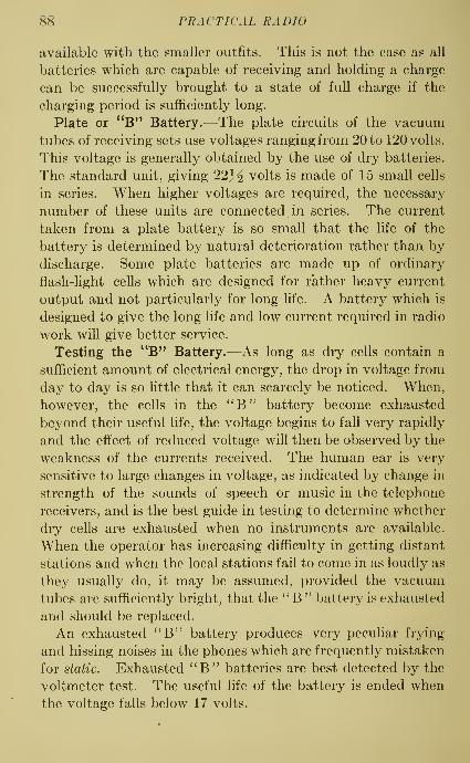
88 PRACTICAL RADIO
available with the smaller outfits. This is not the case as all
batteries which are capable of receiving and holding a charge
can be successfully brought to a state of full charge if the
charging period is sufficiently long.
Plate or "B" Battery.—The plate circuits of the vacuumtubes of receiving sets use voltages ranging from 20 to 120 volts.
This voltage is generally obtained by the use of dry batteries.
The standard unit, giving 22J^ volts is made of 15 small cells
in series. When higher voltages are required, the necessary
number of these units are connected in series. The current
taken from a plate battery is so small that the life of the
battery is determined by natural deterioration rather than by
discharge. Some plate batteries are made up of ordinary
flash-light cells which are designed for rather heavy current
output and not particularly for long life. A battery which is
designed to give the long life and low current required in radio
work will give better service.
Testing the "B" Battery.—As long as dry cells contain a
sufficient amount of electrical energy, the drop in voltage from
day to day is so little that it can scarcely be noticed. When,
however, the cells in the ''B" battery become exhausted
beyond their useful life, the voltage begins to fall very rapidly
and the effect of reduced voltage will then be observed by the
weakness of the currents received. The human ear is very
sensitive to large changes in voltage, as indicated by change in
strength of the sounds of speech or music in the telephone
receivers, and is the best guide in testing to determine whether
dry cells are exhausted when no instruments are available.
When the operator has increasing difficulty in getting distant
stations and when the local stations fail to come in as loudly as
they usually do, it may be assumed, provided the vacuumtubes are sufficiently bright, that the '' B " battery is exhausted
and should be replaced.
An exhausted ''B" battery produces very pecuhar frying
and hissing noises in the phones which are frequently mistaken
for static. Exhausted ^^B" batteries are best detected by the
voltmeter test. The useful life of the battery is ended when
the voltage falls below 17 volts.

SOURCES OF ELECTRICITY FOR VACUUM TUBES 89
A *'B" storage battery for use in plate circuits may be
obtained. Such batteries are made with a capacity of about
2 ampere-hours and have a voltage of about 24.
Charging Radio '*B" Batteries.—On a line voltage of about
115 volts an eleven- or twelve-cell radio ''B" storage battery
can be charged at an approximate rate of 0.4 ampere, with the
small 2-ampere outfit. Since the voltage of the eleven- or
twelve-cell battery approaches quite closely (especially toward
the end of its charge) to the standard voltage of the small
outfits, that is 30 volts, there is practically no resistance in a
transformer circuit during the charging period. It should be
noted that in case of exceptionally low line voltage, as for
^-^wju<mmmmmmumm(^
i\ Ba/b
Idle
Fig. 72.—Vacuum tube rectifier for charging "B" batteries.
example below 100 volts, an oufit of this kind may fail to start.
It is always desirable when charging storage batteries to have
a rheostat for adjusting the current and an ammeter for
reading the current in series with the battery. It is easy to
provide for charging ''B" batteries up to 45 volts by leav-
ing idle and taping the regular positive lead and running a
special wire to the other side of the alternating-current line as
shown in Fig. 72. This gives an increased voltage and hence
a mazda lamp of suitable rating, as given in the table below,
should be connected as a resistance unit to cut down the
amount of current flowing. This extra wire may be connected

90 PRACTICAL RADIO
to one side by an extra separable plug shown dotted in Fig.
72, and by using a double socket, in which case the line
connections can be changed by simply reversing the prongs of
the plug. When the connections are correctly made the lamp
will light but will not reach full brilliancy as the current will
always be less than the rated current of the lamp. If the lamp
glows dimly or entirely fails to light, the wire to the lamp is
connected to the wrong side of the line circuit.
Table I.
—
Charging Rates of Radio "B" Storage Batteries withVarious Sizes of Lamps

SOURCES OF ELECTRICITY FOR VACUUM TUBES 91
batteries is to be charged it is most economical to use a motor-
generator set. This is arranged so that the motor, operating
on the alternating-current line, runs the generator which
delivers direct current.
Direct Current for Filament and Plate.—The voltage of the
ordinary direct-current power line is constant in value, for all
ordinary purposes. Actually it has small variations or ripples
in value which would produce a hum in the telephone receivers
of the receiving set. In using a direct-current source of powerfor the filament and plate circuits it is necessary to insert
the proper amount of resistance in order that the voltage
may be reduced to the required value, and also, to use someform of filter for the purpose of smoothing out reasonably well
the ripples in the current. Suitable forms of filters are
mentioned later in this chapter. Very often the expense of a
suitable filter system is too high to justify its use. It is often
difficult to obtain the high value of direct-current voltage
which is required for plate circuits (particularly in transmitting
sets) . This difficulty is remedied by using a system including
a transformer, a rectifier, and a filter intended for alternating
current.
Alternating Current for Filament and Plate.—If the filament
of a vacuum tube is lighted by means of a proper transformer
from an alternating-current circuit (batteries being used for
the plate current) radio telephone currents will be received but
will be accompanied by a loud humming noise, which is due
to the alternations of the current. If, on the other hand, the
alternating current is applied, through a transformer, to the
plate circuit, the signals will be unintelligible, since the plate
is made alternately positive and negative; thus first allowing
and then blocking, the flow of current.
In the case of the filament, the difficulty can be overcome byusing the arrangement shown in Fig. 73 in which the grid
return wire is connected to the movable arm of the potenti-
ometer P (which may have a value of about 1,000 ohms).
If the grid return wire is connected to the filament, the voltage
variations will be transmitted to the grid and will thus cause
fluctuations in the plate current which produce the hum

92 PRACTICAL RADIO
mentioned above. But with the arrangement shown, a neutral
point may be found, by adjusting the potentiometer, at which
Antenna
Fixed
Condenser ...Vacuum Tube
-Alfernafing"Current
llOVolis--^ Supply
Fig. 73.—Potentiometer connections for alternating current.
the voltage variations, due to the drop in the filament, are not
introduced into the grid and plate circuits. The same result
Rheos-f-atI—MAAjVVV
TransformerSecondary
Fig. 74.—Transformer connections for alternating current.
can be accomplished by the arrangement shown in Fig. 74
in which the grid and plate connections are made to the mid-

SOURCES OF ELECTRICITY FOR VACUUM TUBES 93
point of the filament transformer (secondary). Note that in
each arrangement a ground connection is indicated at G.
In the case of the plate circuit, the difficulty can be over-
come by using some device which will change the alternating
current into a direct current. Such a result is accomplished
approximately by utilizing, first, a rectifier,- to change the
alternating current to a pulsating direct current, and second,
a filter system to change the pulsating direct current into a
form approaching that of a ''pure" direct current.
FixedCondenser
W
BFig. 75.—Devices for reducing hum.
One arrangement for producing this result is shown in Fig.
73. Here A and B are rectifier tubes which are connected so
that they utilize both halves of the current cycle and which
deliver a pulsating direct current. This pulsating direct
current is smoothed out by the combination of inductances
and capacities in the filter F, and is then delivered to the plate
circuit.
Sometimes the hum may be further reduced by replacing the
phones as shown at A (Fig. 75) by the arrangement at B, in
which T is a telephone or output transformer and C sl condenser
of about 0.001 microfarad. This has the effect of blocking any
94 PRACTICAL RADIO
low-frequency variations due to the alternating-current supply
which may still be present.
QUESTIONS
1. How would you test the condition of an "A" battery, and what
should be the value of the readings obtained?
2. Show the method by which you can determine the proper size of
rheostat to use with a UV-199 tube.
3. What is meant by the ampere-hour capacity of a storage battery?
4. Describe the use of a vacuum-tube rectifier in charging a battery.
5. (a) How would you test a "B" battery?
(6) When should this battery be replaced?
6. What precautions are necessary when a direct-current source of supply
is to be used for the filament and plate circuits?
7. What precautions are necessary when an alternating-current source
of supply is to be used for:
(a) the filament circuit?
(6) the plate circuit?

CHAPTER VII
AUDIO-FREQUENCY AMPLIFICATION
Stages of Amplification.—It has been shown that feeble
voltage variations in the grid circuit of a vacuum tube produce
comparatively large changes in the plate current. In a con-
tinuation of this method, it is obvious -that the increased or
amplified current from one vacuum tube may be passed into a
second tube which will still further increase or amplify the
radio current and then again the current from the second tube
may be passed into a third tube and amplified still more.
Each one of these tubes with its related apparatus gives one
stage of amplification. By means of amplification spoken
words and music may be heard in the telephone receivers,
which are too weak to be heard without such amplification.
Any of the hard tubes now sold commercially may be used for
amplification. As a rule, a vacuum tube when used for ampli-
fication requires a much higher plate voltage than when used
in a detector. The plate voltage depends upon the kind of
tube and also upon its position in the circuit. Thus the
plate voltage for a tube in the second stage of amplification maybe two or three times as great as that for the first tube. Like-
wise the voltage on the plate of the third-stage tube may be
greater than that on the second tube.
Types of Amplifiers.—There are two general types of ampli-
fiers; first, those which amplify the radio current before it has
passed through the detector; and second, those which amplify
the radio current after it has passed through the detector.
Those of the first type are called radio-frequency amplifiers
and those of the second type, andio-freqiiency amplifiers.
The position of these amplifiers in a receiving set may be
represented as in Fig. 76.
The principle of operation is the same for both types of
amplifiers, but the fact that the one deals with a high-fre-
95
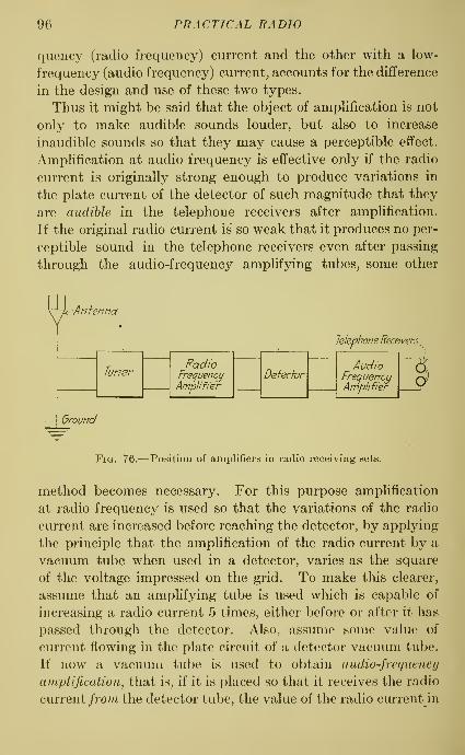
96 PRACTICAL RADIO
quency (radio frequency) current and the other with a low-
frequency (audio frequency) current, accounts for the difference
in the design and use of these two types.
Thus it might be said that the object of amphfication is not
only to make audible sounds louder, but also to increase
inaudible sounds so that they may cause a perceptible effect.
Amplification at audio frequency is effective only if the radio
current is originally strong enough to produce variations in
the plate current of the detector of such magnitude that they
are audible in the telephone receivers after amplification.
If the original radio current is so weak that it produces no per-
ceptible sound in the telephone receivers even after passing
through the audio-frequency amplifying tubes, some other
Ground
Telephone Feceivers.
Fig. 76.— Position of amplifiers in radio receiving sets.
method becomes necessary. For this purpose amplification
at radio frequency is used so that the variations of the radio
current are increased before reaching the detector, by applying
the principle that the amplification of the radio current by a
vacuum tube when used in a detector, varies as the square
of the voltage impressed on the grid. To make this clearer,
assume that an amplifying tube is used which is capable of
increasing a radio current 5 times, either before or after it has
passed through the detector. Also, assume some value of
current flowing in the plate circuit of a detector vacuum tube.
If now a vacuum tube is used to obtain audio-frequency
amplification, that is, if it is placed so that it receives the radio
current /ro?/i the detector tube, the value of the radio currentin

AUDIO-FREQUENCY AMPLIFICATION 97
the plate circuit of the amplifier will be 5 times as large as the
current which flows m the plate circuit of the detector vacuum
tube. If, however, the vacuum tube is used for radio-fre-
quency amplification, that is, if the tube is placed so that the
radio current coming from it will be passed on to the detector
tube, the voltage at the detector tube will be 5 times the value
of the voltage at the amplifier tube. Now, since the plate
current of a detector varies as the square of the impressed
voltage, the current in the plate circuit of the detector tube
as used in radio-frequency amplification is now 5 times 5, or
25 times the original value.
But, particularly at the wave lengths required, radio-fre-
quency amplifiers cannot be constructed to operate as well
as those for audio frequency, because of the effect of the grid-
filament capacity of the vacuum tube upon the degree of
amplification. On the other hand, the audio-frequency
amplifier increases not only the volume of the spoken words or
music in the telphone receivers, but also all the low-frequency
noises which may arise in the set whether they come from
the outside such as regenerative noises, or from the inside,
such as battery and vacuum tube noises. For these reasons,
audio-frequency amplification is used more extensively at pres-
ent than radio-frequency amplification.
Types of Audio-frequency Amplifiers.—In actual practice it
is not possible to connect the plate terminal of one vacuum tube
directly to the grid terminal of the next tube. This will be
understood readily when we remember that the plate circuit
requires a battery to produce a current flow, while the grid is
used to introduce variations in voltage. Thus it is necessary
to use a device which includes a '^B" battery in the plate
circuit of one vacuum tube and passes on only the voltage
variations to the grid of the next vacuum tube. Amplifiers
are classified according to the type of device used for connect-
ing or coupling one vacuum tube to the next. The three types
are:
1. Transformer coupling,
2. Resistance coupling,
3. Inductance coupling.

98 PRACTICAL RADIO
Whether an amplifier is made in the form of a separate unit or
whether it is built into the receiving set is a matter of construc-
tion only and will not affect the discussion here. A set may be
Ankntia ^'''^ CondenserandVariable Orid Leak
Telephone
Receivers
Primary
Winding
—^Variable Condenser
Ground
Fig. 77.—Audio-frequency amplification by transformer coupling.
provided with either audio- or radio-frequency amplifiers, or
both, either built in or in separate units.
Transformer Coupling. —An arrangement using one stage of
audio-frequency amplification is shown in Fig. 77. In order to
show the connections and action
more clearly, separate batteries are
indicated. In the figures to follow,
the same ''A" and ''B" batteries
will be used on the detector and
the amplifier. The audio-fre-
quency transformer, as shown in
Fig. 78, is made up of two coils,
a primary and a secondary, placed
on an insulated form and having
an iron core. The secondary
winding has more turns than the
primary in order to increase or s^ep
uy the voltage. The usual ratio
of the number of turns in the coils
is 3 or 4 to 1, but transformers
with a ratio of 10 to 1 may be obtained. The best value of this
ratio depends upon the design of the set and the kind of tube.
The primary winding P is placed in the opiate circuit of the
detector, and the secondary winding & in the grid circuit of the
Fig. 78.—Audio-frequencytransformer with iron core.

AUDIO-FREQUENCY AMPLIFICATION 99
amplifier. The grid circuit of the detector may have any type
of tuner—the double-circuit variety is shown here. Thecondenser^ C serves as a by-pass for any radio-frequency
current.
In the operation of this set, the current in the primary
winding P of the transformer induces a voltage in the secondary
winding S which is impressed on the grid of the vacuum tube
of the amplifier and produces magnified current variations
in the plate circuit. A steady current from the ''5" battery
in passing through the primary winding of the transformer
does not induce any current in the secondary winding since
only a varying current in one winding will induce a current in
the other. Because of this, it is not possible to transfer a
steady current, but an alternating current will pass readily.
The ratio of the secondary to the primary voltage is the sameas the ratio of turns of wire in the secondary winding to turns
of wire in the primary winding.
If more volume of sound in the telephone receivers is desired,
one or two more stages of amplification may be added. This, of
course, means correspondingly greater magnification of noises
due to induction, static, and physical vibration and unless
great care is taken the noises will be louder than speech or
music in the telephone receivers.
It is possible also to combine regeneration with audio-fre-
quency amplification. A circuit using a tickler coil for regen-
eration and two stages of audio-frequency amplification is
shown in Fig. 79. Note that the grid return of the detector
is connected to the positive side of the filament, while the grid
returns of the two vacuum tubes of the amplifier are connected
to the negative side of the filament. In the case of the ampli-
fier tubes even this connection may not make the grid negative
enough for satisfactory operation. This difficulty may be
overcome by the use of a potentiometer or of a '^C" battery.
On pages 151 (table) and 226, will be found the values of ''C"
voltage to use for various plate voltages on different types of
vacuum tubes. One disadvantage of transformer coupling is
1 In many cases the distributed capacity of the transformer windings
is large enough and will serve instead of the condenser.

100 PRACTICAL RADIO
that the ampHfying power of the ordinary transformer varies
at different frequencies, which leads to some distortion.
The reason for this variation is that the transformer has a point
of resonance at a certain frequency and thus one or a few
frequencies come through more easily than others. Somemanufacturers claim that they can produce a transformer which
amplifies consistently over a wide range of wave lengths.
Equal amplifying power over the required range of frequencies
may be obtained in several ways, some of which, however,
decrease the amplification. In some amplifiers with morethan two stages of amplification it is claimed that the trans-
formers may be so chosen that the resonance points occur at
PrimaryWihding
Telephone
Receivers
Fig. 79.—Tickler coil for regeneration with audio-frequency amplification.
various frequencies over the entire range. This gives an
approximation of the ideal equal amplification.
Resistance Coupling.—The type of coupling for vacuum
tubes which uses a simple resistance for this purpose is nearly
independent of variations of the frequency of the radio currents
and amplifies without appreciable distortion the low-frequency
current coming from the detector. At the high frequencies,
however, of some of the wave lengths now commonly used, the
resistance included in the coupling may be practically short-
circuited by the capacity action between the vacuum tube
elements. This effect is somewhat less noticeable at high wave
lengths, but, as a rule, other methods of coupling give better

A UDIO-FREQUENCY AMPLIFICA TION 101
results. The application of the resistance method of coupling
vacuum tubes in an amplifier is shown in Fig. 80, for two stages
of audio-frequency amplification. Here the variation of the
plate current in the resistance Ri produces across it a varying
voltage drop which actuates the grid of the vacuum tube of
the amplifier. In order that the plate voltage of the detector
tube is not impressed on the grid of the amplifier it is necessary
to insert a so-called blocking condenser C. The grid is kept
negative by means of the resistance r, and, if necessary, bythe use of a ''C" battery. The voltage drop in the plate
circuit lowers the normal plate voltage and hence the ''B"
I I
JAnfenna ^ , r ,\A Ona Condenser
^ andOr/d Leak
Winding to '^^
"A" "B"
Fig. 80.—Audio-frequency amplification by resistance coupling.
battery voltage must be increased enough to compensate for
the loss. One of the most important disadvantages of this
method of coupling is the high ^'B" battery voltage needed.
The resistance r is of the standard variable grid-leak form and
the coupling resistance 7? imay have a value of from 10,000 ohmsup. For maximum voltage output the resistance used in
the plate circuit may have a value equal to 2 or 3 times the
average internal resistance of the vacuum tube between the
filament and the plate. With the vacuum tubes ordinarily
available, resistance coupling does not give so high a degree of
amplification as some of the other methods.
Inductance Coupling.^—This method uses an inductance
instead of a resistance in the plate circuit. The theory of

102 PRACTICAL RADIO
the action is the same as that for the resistance coupled
ampUfier. Two stages of amplification are shown in Fig. 81.
The inductance L may be of any form. The small blocking
condensers Ci and C2 and the grid-leak resistances, r, perform
the same function as in the resistance coupling. The first
plate circuit is tuned by means of the condenser C and the
selectivity is thus increased. In this method of coupling, as
in the preceding, the amplification in one stage cannot be
greater than that of the vacuum tube itself. It has the advan-
tage that the inductance^ offers very little resistance to direct-
current flow. Therefore, the amount of direct-current energy
lost is small and the ^'B" battery voltage need not be so high.
"A'Batfey "B"Battery
Fig. 81.—Audio-frequency amplification by inductance coupling.
In this type the variation of amplification with changes of
frequency is greater than in the transformer coupling.
In general, then, it can be said that if a good transformer is
available which amplifies equally well and without much dis-
tortion over the required range, the transformer coupling is
better suited for use with audio-frequency amplification.
Loud Speakers.—A loud-speaking device may be used in
place of the telephone receivers. Such devices may be divided
into two classes, first, the sound distributor, and second the
sound producer. The first class utilizes the ordinary telphone
receiver as part of the equipment and uses a horn, megaphone,^ Inductance coils for this purpose are generally made with an iron core
and must have low iron losses and a small capacity effect between the
turns of wire.

AUDIO-FREQUENCY AMPLIFICATION 103
or phonograph sound-box to concentrate and direct the sound.
The diaphragm of the ordinary telephone receiver is not
designed for currents of very great amplitude and distortion
results when the telephone receiver is used with any type of
loud speaker of the sound-distributor type. This type is
illustrated in diagrammatic form in Fig. 82. It is sometimes
found that more sound volume is obtained by using only one
of the telephone receivers with a sound distributor than whenboth receivers are used. This may often be overcome by
D/'cfphra^/77^
Fig. 82.—Diagram of loud speaker (sound distributor type).
reversing the wires which are connected inside the casing
of the distributor. Better results are obtained from instru-
ments which use specially constructed receivers, in connection
with the distributor. These receivers allow a wider range of
movement of the diaphragm and in some the distance between
diaphragm and magnet can be varied to control chattering
and noisy operation. The volume of sound may be increased
by using a power tuhe^ of, say, 5 watts of electric power, in
^ A radio power tube is a vacuum tube designed to operate with
considerably more electric power than an ordinary vacuum tube. Anordinary vacuum tube operating at 5 volts and 0,25 ampere uses only
1.25 watts.
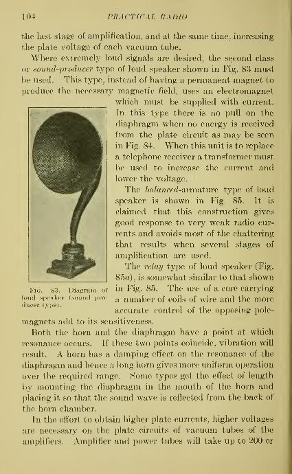
104 PRACTICAL RADIO
the last stage of amplification, and at the same time, increasing
the plate voltage of each vacuum tube.
Where extremely loud signals are desired, the second class
or sound-producer type of loud speaker shown in Fig. 83 must
be used. This type^ instead of having a permanent magnet to
produce the necessary magnetic field, uses an electromagnet
which must be supplied with current.
In this type there is no pull on the
diaphragm when no energy is received
from the plate circuit as may be seen
in Fig. 84. When this unit is to replace
a telephone receiver a transformer must
be used to increase the current and
lower the voltage.
The 6a/anced-armature type of loud
speaker is shown in Fig. 85. It is
claimed that this construction gives
good response to very weak radio cur-
rents and avoids most of the chattering
that results when several stages of
amplification are used.
The relay type of loud speaker (Fig.
85a), is somewhat similar to that shown
in Fig. 85. The use of a core carrying
a number of coils of wire and the more
accurate control of the opposing pole-
magnets add to its sensitiveness.
Both the horn and the diaphragm have a point at which
resonance occurs. If these two points coincide, vibration will
result. A horn has a damping effect on the resonance of the
diaphragm and hence a long horn gives more uniform operation
over the required range. Some types get the effect of length
by mounting the diaphragm in the mouth of the horn and
placing it so that the sound wave is reflected from the back of
the horn chamber.
In the effort to obtain higher plate currents, higher voltages
are necessary on the plate circuits of vacuum tubes of the
amplifiers. Amplifier and power tubes will take up to 200 or
Fig. 83.—Diagram of
loud speaker (sound pro-
ducer type).

.4 VDIO-FREQUENCY AMPLIFICA TION
Diaphragm-
\rmafure
105
Siep DownTransformer
^

106 PRACTICAL RADIO
300 volts but the usual amplifying transformers are limited to
about 125 volts. Thus the plate voltage in amplification is
limited by the allowable current in the transformers.
Figure 86 shows a loud speaker of unusual design. It
consists of a 26-inch flat conducting disc, in a magnetic field,
MagnQJ--Coils
Pole
Pieces
Fig. 85a.—Loud speaker (relay type).
the vibrations of which correspond to the voice currents
and reproduce the sound waves without the use of a horn.
In the operation of this device, the feeble electric forces of
the radio waves are applied to the grid
of a vacuum tube in the receiving set
and cause relatively large variations in
the electric current flowing between the
filament and the plate, which in turn
are used to secure larger electric forces
to be applied to the grid of another
vacuum tube. By the use of several
amplifjdng vacuum tubes the original
feeble electric currents are multiplied
several thousand times and supplied to
the loud speaker which reproduces the original sounds with
many times the original volume and great faithfulness of
quality. To operate this amplifier requires a direct current
of several hundred volts. This may be obtained by first
transforming power from the ordinary alternating current
Fig. 86.—Loud speaker for
which no horn is needed.

A UDIO-FREQUENCY AMPLIFICATION 107
lighting circuit to a relatively high voltage, next ''rectifying"
this high-voltage alternating current to a direct current by
means of a vacuum-tube rectifier, and finally smoothing out
this pulsating direct current by means of appropriate electric
circuits.
The high degree of faithfulness of reproduction realized in
this loud speaker is due partly to the absence of a horn, elimi-
nating horn resonance (one of the usual sources of distortion
in a speech reproducer), and partly to the method of vibrating
the diaphragm by forces which are distributed fairly uniformly
over its surface, instead of acting upon it in a very limited
region, as is the case in most other loud speakers. This
Push-Pull Amplifier
"B"Baffey
Fig. 87.—Push-pull amplifier.
feature eliminates rattling and ringing of the diaphragm or
the production of high overtones by the diaphragm vibrating
in its partial nodes.
Push-pull Amplifier.—The current in the last stage of an
amplifier may be so large that the vacuum tube in that stage of
amplification is overloaded. One way to avoid the resulting
distortion is to use a power tube, as mentioned above. Another
way is to replace the vacuum tube in the last stage of amplifica-
tion by two tubes in parallel. The most popular method,
however, is using the ''push-pull" amplifier which generally
replaces the second stage of amplification. The circuit is
shown in Fig. 87. The regular vacuum tubes for ampUfication
may be used but even more volume is obtained with power
tubes.

108 PRACTICAL RADIO
The first transformer shown is of the ordinary audio-fre-
quency type while the other two are special transformers, T\
having a tap at the center of the secondary winding, and Ti
a tap at the center of the primary winding. In such a con-
struction the voltage across the secondary winding of trans-
former Ti is divided equally between the two vacuum tubes,
and the resulting plate currents combine in their effect uponthe secondary winding of transformer T^. Therefore, the
secondary winding of Ti can be constructed so that it gives a
voltage twice as large as that ordinarily required for one
vacuum tube and when the total voltage variation is doubled,
the total plate current increases in proportion. The important
point to notice is that this increase has been obtained without
overloading the vacuum tube and consequently less distortion
results. A stage of push-pull amplification will not remove the
distortion from previous stages but will give further amplifica-
tion without distortion.
Jacks for Vacuum Tubes.—Often it is desirable to control
the filaments of vacuum tubes automatically by means of
jacks. The construction of a 5-spring jack and plug for this
Fig. 88.—Five-spring jack for vacuum tubes.
purpose is shown in Fig. 88. This method adds to the cost
and complicates the wiring. The use of 5- and 3-spring jacks
is indicated in Fig. 89. The telephone receivers or the loud
speaker are connected to the plug of the jack and when this
plug is inserted in the detector jack, only the vacuum tube of
the detector will be lighted. When it is inserted into amplifier
No. 1 jack, the first two vacuum tubes will be lighted, and
when inserted into the last jack, all the vacuum tubes will be
lighted. There is no need of controlling the plate circuit in
Fig. 89 because no plate current flows when the filament is
cold. There are many kinds of jacks made for the control of
the filament or plate circuits. Another type of jack is shown in

AUDIO-FREQUENCY AMPLIFICATION 109
MMMI
[I [ Pe feefor Amplifier fl/of Ampli fier ^o. 2
Fig. 89.—Five-and-three spring jacks for vacuum tube filament circuit.
Fig. 90.—Typical jack for vacuum tube plate circuit.
/s/. u/cT^f T, pndSfage
Fig. 91.—Control of vacuum tube plate circuit with jacks.

no PRACTICAL RADIO
Fig. 90 and its use in Fig. 91. All these jacks have no control
over the filaments of the tubes. Jack No. 1 completes the
plate circuit of the vacuum tube of the detector. Jack No. 2
completes the plate circuit of the vacuum tube of the first
stage of amplification. Jack No. 3 opens the plate circuit
of the vacuum tube of the second stage of amphfication.
When the plug is inserted in jack No. 3, all the circuits are
complete and the entire receiving set may be operated.
When the plug is inserted in jack No. 1, only the vacuum tube
of the detector is acting, because as the contact points in the
jack are separated the primary winding of transformer Ti
is opened and the vacuum tube in the first stage of amphfica-
tion becomes inactive. When the plug is inserted in jack No.
2, the vacuum tubes in both the detector and in the first stage
of amplification will operate.
Audio-frequency Amplifiers.—But little need be said con-
cerning the operation of audio-frequency amplifiers. The''A^' battery voltage is adjusted to suit the vacuum tube.
In order to get individual control of the filament current of the
vacuum tubes, it is desirable to use a rheostat for each tube.
The filament should be operated at the lowest temperature
that will give good results. In general it may be said that, for a
given value of plate voltage there is one value of filament cur-
rent at which the operation is most satisfactory. The "B"battery voltage depends upon the tube as well as the loudness
of the sounds desired from the amphfier. The plate voltage
requirement of an amplifying tube depends upon the voltage
impressed on its grid. Thus the plate voltage for the second
stage is from 2 to 3 times the plate voltage of the first stage.
The plate voltage for the third stage is increased similarly.
The strength of signals can be controlled by the filament
current to some extent, but it is better to do this by adjusting
the ''B" battery voltage or by the use of jacks and stages,
so that a stage may be added or cut out as desired. Theimportance of the '^C^' battery has already been emphasized.
Squealing of Audio-frequency Amplifiers.—The squeals
and howls in an amplifier are more the result of design and
construction than of operation. At present it is necessary

AUDIO-FREQUENCY AMPLIFICATION 111
only to understand the cause of such disturbances. If energy
from any plate or grid circuit of the amplifying tubes is fed
back into any previous plate or grid circuit, a form of regenera-
tion results, meaning that a part of the radio current on its
way to the telephones is turned back and re-impressed on the
grid of the vacuum tubes. If the amount of regeneration is
sufficient, the circuit or parts of it may be caused to oscillate
and thus produce a distorting effect. The feed back or regen-
eration in such cases is due to some form of coupling which
may be one of the following types
:
a. magnetic (inductive),
h. capacity,
c. resistance.
Magnetic or inductive coupUng is that which exists between
the wires of the different stages of amplification and between
the coils of different stages.
Capacity coupling is largely the result of the capacity effect
between the grid and plate of each vacuum tube. This
effect is not confined to one tube since the feed back from one
may affect all the others.
Resistance coupling occurs when one '^B" battery is used
for all tubes. Here the battery resistance forms a part of
each tube circuit and hence such circuits are coupled directly.
Also, if the receiving set includes a potentiometer and only
one is used for all the vacuum tubes, there is the same condi-
tion of feed back or regeneration due to resistance coupling.
In audio-frequency amplification the disturbance due to
feed-back or regeneration is not serious and may be minimized
by careful construction. In the next chapter we shall see
how high frequencies increase such feed-back or regenerative
effects, and how important it is to observe every detail which
may bear on the subject.
QUESTIONS
1. Explain briefly how a stage of audio-frequency amplification increases
the volume of sound.
2. Compare the relative advantages of audio-frequency and of radio-
frequency amplification.
112 PRACTICAL RADIO
3. By means of diagrams, show the essential parts of the three methodsof coupHng audio-frequency ampHfier stages which are mentioned in
the text.
4. In your opinion which method is the most suitable for this work,
and why?5. Explain the use of the -push-pull amplifier and draw a diagram of
connections.
6. After studying Fig. 89 draw two sketches to show how the jack of the
first amplifier tube operates when the plug is out and also when it is in,
7. What precautions should be observed in operating the audio-frequency
amplifier?
8. In general, what are the causes of squeals and howls in an audio-
frequency amplifier?

CHAPTER VIII
RADIO-FREQUENCY AMPLIFICATION
Amplification at radio (high) frequency occurs before the
radio current from the antenna comes to the detector of a
receiving set. This kind of ampHfication is used when the radio
current is too weak to produce good results in the telephone
receivers. The advantage of amplification by this method is
apparent when it is remembered that a radio current coming
from a detector is proportional to the square of the radio
current which it receives. Also, amplification at radio
frequency amplifies the radio current to which the circuit
is tuned without amplifying interfering signals and local
noises due to the method of coupling the vacuum tubes. Thus
the advantages obtained by amplification at radio frequency
instead of audio frequency are greater sensitiveness, freedom
from distortion and from interference.
When radio currents of varying frequency are amplified
there is always some distortion. In a radio-frequency amplifica-
tion such distortion cannot occur, because the frequency of
the carrier wave from a transmitting station is constant. But in
audio-frequency work the range of voice and music frequency
may be from about 30 to over 10,000 cycles per second and
distortion is almost unavoidable. However, distortion mayoccur in a radio-frequency amplifier if too much regeneration
takes place. In that case, there will be radio currents of
different intensities and these will be amplified unequally
with consequent distortion.
Amplification of this kind can be carried out very easily at
low frequencies (high wave lengths) but is difficult at high fre-
quencies (500,000 cycles per second corresponds to a wave length
of 600 meters) . Much progress, however, has been made along
this line and very satisfactory results have been obtained.
113

114 PRACTICAL RADIO
The very high frequencies involved in radio-frequency amplifi-
cation present the main obstacle. This is due to the fact that
the capacity effects between wires and between the elements
of vacuum tubes make a path of easy flow for high-frequency
currents. This capacity effect increases directly with increase
in the frequency of the radio currents; and, at high frequencies,
such capacity effects act almost like short circuits for the
currents of radio frequency.
The three types of devices for coupling the vacuum tube of
one stage of radio-frequency amplification to the next stage are
:
1. resistance coupling,
2. inductance coupling,
3. transformer coupling.
Resistance Coupling.^—Radio-frequency amplifiers with
resistance coupling have been unsatisfactory on wave lengths
Telephone
Receivers
-^-Baffery
Fig. 92.—^Radio-frequency amplification by resistance coupling.
under 500 meters because of the high frequency. A typical
device including resistance coupling is shown in Fig. 92, where
two other paths for the radio current besides the designed path
through the coupling resistance R are indicated. The first
of these other paths is made possible by the plate-filament
capacity of the first vacuum tube, and the second path bythe grid-filament capacity of the second vacuum tube. Athigh frequencies (radio frequencies) the low opposition offered

RADIO-FREQUENCY AMPLIFICATION 115
by these paths to current flow will cause the resistance coupling
to be non-effective. Furthermore, the grid-plate capacity of
the second vacuum tube produces a harmful feed-back or
regenerative action. Note that separate batteries are used in
this case and some essential parts are omitted in order to simplify
the diagram. Several types of vacuum tubes, such as the
Myers, for example, have been designed to minimize the
capacity effects between the vacuum tube elements. How-ever, in spite of its advantage in uniform amplification at
moderate frequencies, resistance coupling is not generally
satisfactory, for the reasons already stated, and also because of
the small amplification that is possible for each vacuum tube
used and the high plate voltages that are required for the
vacuum tubes.
In Europe where longer wave lengths (lower frequencies)
are more generally used and where vacuum tubes for ampli-
fication with low internal capacity may be obtained, radio-
frequency amplifiers operating with resistance coupKng have
been extensively developed.
Inductance Coupling.—A diagram of an ampUfier for radio-
frequency currents, arranged for inductance coupling is shown
in Fig. 93. This circuit contains the capacity C and the
inductance L which are tuned to the desired wave length to
increase both selectivity and amplification. ^ If the inductance
L has Si fixed value, this circuit will give maximum amplification
on one wave length only, or at best, on a very narrow band.
Further, when the coupling inductance is varied in tuning,
the feed back or regenerative action due to the capacity of
the vacuum tube may be quite large and may even start
oscillations. In fact, the tendency to oscillate as resonance
is approached is one of the serious disadvantages of this method.
To avoid this tendency to oscillate some form of stabilizer
(potentiometer) is necessary, which, however, decreases the
amplification which is obtainable. Another disadvantage of
this type of coupling is that it is necessary to use grid con-
densers and grid leaks which may cause trouble due to the
high frequencies used. With this arrangement regeneration
1 This cannot be greater than the amplification factor of the tube itself.

116 PRACTICAL RADIO
may be obtained by opening the plate circuit of the ampUfier
and inserting an extra coil of wire, as for example a tickler
'elephone
Receivers
"B BaHertj
Fig. 93.—Radio-frequency amplification by inductance coupling.
Fig. 94.—Radio-frequency amplification with plate variometer.
coil, to be coupled inductively to the inductance L. In somecases regeneration from feed back due to the grid-plate capac-
i

RA DIO-FREQUENCY AMPLIFICA TION 117
ity of the vacuum tube may be obtained by using a vari-
ometer in the plate circuit of the vacuum tube in the detector.
When a receiving set with a single vacuum tube obtains
regeneration by the use of a plate variometer (tuned plate),
the addition of one stage of radio-frequency amplification
becomes very simple and satisfactory. Such a combination
is shown in Fig. 94. A single-circuit tuner, as illustrated in
Fig. 95, can be used to advantage with this arrangement,
although it decreases the selectivity. The condenser C is
used to isolate the grid of the vacuum tube of the amplifier.
When the inductance L is tuned it is
possible to get not only a maximum voltage
drop to impress on the grid of the vacuumtube in the amplifier, but also a regenera-
tive or feed-back action due to the grid-
plate capacity. The grid leak, r, may be
used to control oscillation in the vacuumtubes—that is, to give stability. Several
stages of amplification with this variometer
coupling can be used with satisfactory
results. The disadvantages are the in-
creased number of adjustments required
and the use of a potentiometer.
Another method of controlhng oscilla-
tion is by means of resistance in the plate
circuit which would have but little effect
upon amplification. Such a resistance
might be introduced by using fine wire for
the inductance, or by utilizing an iron core.
In the next paragraphs both tuned and untuned transformer
couplings for radio-frequency amplifiers will be explained.
In general it may be said that amplifiers with inductance
couplings give less amplification, more selectivity, and require
more controls than coupled amphfiers with untuned trans-
former couplings.
Transformer Coupling.—Transformer coupling is cominginto general use for several reasons. By using a suitably
designed transformer, an overall amphfication several times
Fig. 95.—Radio-fre-quency amplificationwith single circuittuner.

118 PRACTICAL RADIO
the normal amplification of the vacuum tube may be obtained.
Unless, however, the transformer is very carefully designed,
the capacity effect between the windings will allow only a
small stepping up of the voltage. This type of couphng
does not require a high ^^B" battery voltage. In a good
transformer, the uniformity of amplification may be made as
good as that in inductance coupling. Finally, less auxihary
apparatus is required, since the grid condenser and grid leak
are not needed.
Transformers of the air-core type when properly made and
used, give more ampHfication than those with an iron core,
but the amplification is not uniform. That is, the amplifica-
tion curve shows a peak occurring usually at a narrow band
of frequencies as compared with a more or less fiat curve for
the iron-core type. While the use of iron gives more uniform
amplification, the losses introduced by its use decrease the
amplification. On the other hand, the repeating action of
the air-core transformer is poor on wave lengths other than
the natural wave length of the transformer. The wave length
of an air-core transformer can be decreased by separating the
coils or by removing some of the turns of wire.
An air-core transformer may be tuned by using a variable
condenser across the secondary winding. In this way a
resonance peak may be obtained at each wave-length setting.
Then not only is high amplification possible but the selectivity
is increased since, at any particular setting, the amplification
of wave lengths, other than the one desired, is small. In
most of such transformers the primary winding has relatively
few turns and this helps in reducing the tendency to oscillate.
When the secondary winding is tuned it reacts on the primary
winding in such a way that the latter is tuned also to some
extent. Just as the tuning of the secondary winding increases
the selectivity, so the tuning of the primary winding by
reaction increases the selectivity, and this increase is obtained
without introducing another control. The tuning of a
transformer may be accomplished also by varying the
inductance, instead of using a variable condenser with a
fixed inductance.

RADIO-FREQUENCY AMPLIFICATION 119
In a tuned plate regenerative receiver the tuning of the plate
circuit produced regeneration through the capacity of the
vacuum tube. The tuning of a transformer coupling has the
same effect. In addition to the regeneration by means of
the grid-plate capacity, there were given, in Chap. VII,
various other ways by which regeneration occurs because of
interaction among the various parts of a circuit, namely,
regeneration from resistance coupling and from magnetic
coupling. The regeneration from these several causes must
be controlled in order that oscillation will not take place,
with the resulting distortion and decrease of amplification.
To minimize the regeneration due to the resistance coupling
resulting from the use of a common ''B" battery, experi-
menters recommend that a 1.0 microfarad condenser be
connected across the ''B" battery terminals. The magnetic
coupling between stages may be decreased by using a metal
container with metal partitions so that each stage is entirely
enclosed. Small holes in the partitions are necessary for the
passage of the connecting wires. A more practical but less
efficient method is to space the stages quite a distance apart
and tilt the coils or place transformers at right angles, so
that the induction is reduced. The wiring may be shielded
by enclosing it in grounded flexible metallic tubing.
Potentiometer Control of Regeneration.—The regeneration
due to grid-plate capacity is an important cause of trouble
in ampUfication, so that the methods devised to control this
regeneration should be explained. One method depends
upon a brake action in that, by Hmiting amplification it
reduces regeneration. This result is secured by the use of grid
potentiometers, shunt resistances on transformers, high-
resistance transformer windings, and iron-core transformers.
The most popular of these is the method of control by a grid
potentiometer as shown in Fig. 96.
A common stabiHzer for all the radio-frequency stages is
generally sufficient. The two grid returns of the vacuum tubes
for radio-frequency amplifying are connected to the poten-
tiometer P. In some cases a better arrangement is that
shown in Fig. 97 in which the grid return of the vacuum tube

120 PRACTICAL RADIO
Radio FrecjuerrcLj Tubes
No. I i \ No.2r^WWi Defedor Tube
i-iul
Fig. 96.—Grid-potentiometer for regeneration control.
Vacuum Tubes
No.f /'\ Mo.2
Fig. 97.—Grid-potentiometer for regeneration control.
Fig. 98.—Grid-potentiometer for regeneration control.

RADIO-FREQUENCY AMPLIFICATION 121
marked No. 1 is connected to the potentiometer and that of
tube No. 2 to the negative side of the filament. The least
harmful use of a potentiometer is that illustrated in Fig. 98
which gives greater selectivity than the other connections.
In fact, one great weakness in all the types of this method for
controlling regeneration is the lack of sensitivity. The only
point in favor of this general method of controlling regenera-
tion by reducing amplification is that it is easily applied.
Tickler Coil Control of Regeneration in "Superdyne"
Receiver.—The object of the various types in the second
method of controlling regeneration is either to compensate
for, or to prevent the feed-back action through the grid-
Jelephone
Receivers
A batfey
Fig. 99.—Tickler coil for regeneration control.
plate capacity of the vacuum tube. The most easily applied
type of this method is the one used in the Tuska superdyne
receiver. This uses a tickler or feed-back coil T, as indicated
in Fig. 99, which is reversed in its action so as to decrease
regeneration. Thus the amount of regeneration produced
by the tickler coil T may be made just equal to that due
to grid-plate capacity. Since the two actions are opposite
in their effects, oscillation is prevented and the circuit can
be operated at the point of resonance. A disadvantage of
this type of control is that the setting of the reversed tickler
is not permanent but must be changed for each wave length.

122 PRACTICAL RADIO
Operation of "Superdyne" Receiver.—Starting with the
plates of the variable condensers nearest together and the
tickler coil at an angle of about 75 degrees with the secondary-
winding of the tuning coil, the position of the plates of the
condensers should be varied until the desired transmitting
station is obtained. Then the tickler coil should be adjusted
for maximum strength. After this it will be necessary to
readjust the first condenser. If two stages of radio-frequency
amplification are used, the condensers in the two stages should
be rotated in tuning, the settings being kept at the same
value. If it is found that best results are obtained when one
Fig. 100.—Reversed capacity for regeneration control.
condenser setting varies a fixed amount from the other,
the dials can be shifted to correspond.
The range of any set is limited by local induction and atmos-
pheric disturbances. The high amplification of sets using
radio-frequency stages increases the volume of such inter-
ference. This is one of the reasons for the use of a loop with
radio-frequency amplifiers.
Reversed Capacity Control of Regeneration. "Neutrodyne"
Receiver.—Another popular type of control is the reversed
capacity back-coupling as used in Hazeltine's neutrodyne
receiver. The circuit in Fig. 100 shows two stages of radio-
frequency amplification and a detector.
The voltage induced in the secondary winding S is opposite
to that in the primary winding P. Hence by choosing a
suitable value of the neutrahzing condenser C, the effect of a

RADIO-FREQUENCY AMPLIFICATION 123
current flowing in one direction through the grid-plate capacity
of the vacuum tube can be balanced by the effect of the current
flowing through the neutralizing circuit. If the voltage in
S is always opposite to that in P at all wave lengths, the
neutralizing adjustment, once made, would not be effected
by tuning at different frequencies. In practice, however,
this condition is very difficult to obtain and hence the neutrali-
zation when made at one frequency, often does not produce an
exact balance at other frequencies.
The neutralizing condensers are of very small capacity,
depending upon the tube capacity and the ratio of the number
of turns of wire in the secondary and primary windings of the
transformer, and are usually made up of an insulated wire
inside a metal tube, although a variable plate condenser would
be more convenient. The secondary windings of the trans-
formers are generally wound outside the primaries. This
lessens the interaction which would otherwise exist between
the primary coil of one stage and the secondary circuit of the
preceding stage.
The adjustment of each neutrahzing capacity is made by
tuning to the radio current of some transmitting station, turn-
ing out the filament of the vacuum tube to be neutralized (but
not removing the tube) and adjusting the capacity until all
the sounds in the telephone receivers disappear. If the adjust-
ment is not correct, capacity coupling will exist and the sounds
will still be transmitted.
The addition of regeneration in the form of a plate vari-
ometer does not increase signal strength for wave lengths which
are over 360 meters. The reflex arrangement in which a
vacuum tube acts as both radio- and audio-frequency amplifier
has not been very successful with the neutrodyne receiver.
A properly adjusted neutrodyne receiver does not radiate
energy and hence causes no interference with nearby receivers.
In the non-regenerative type there is no oscillation and in the
regenerative type oscillation exits in the detector circuit
only. Each stage should be thoroughly shielded from the
adjacent stages by grounded metal partitions and grounded
metal linings in the cabinet.

124 PRACTICAL RADIO
Operation of "Neutrodyne'* Receiver.—The neutrodyne
works best on an antenna but may be used on a loop. Theobject of tuning is to get each circuit tuned to the wavelength desired. The second and third condenser dials maybe set so that their readings will be identical. The first
condenser dial setting depends somewhat on the type of
antenna, and also on the type of tuner, that is, single circuit
or double circuit. In calibrating a neutrodyne receiver it is
advisable to start with a transmitting station at the low end
of the wave-length range and also one at the high end. Thena chart can be made as shown in Fig. 101 by connecting the
300 350 400 4S0 500.
Wave Lengfhs, mefers
Fig. 101.-—Unart for locating radio transmitting stations by wave length.
high and low points with a straight line, in order to makeeasier the process of locating a desired station. Thus, a station
on 400 meters would-be obtained by the approximate setting
of 73 for dial 1 and 112 for dials 2 and 3.^ A chart of this
kind is desirable for any kind of receiving set.
Other Methods of Control of Regeneration.—It has been
suggested that the type of control of regeneration shown in
Fig. 102 is more convenient than some others since it allows
the use of but one compensated radio-frequency stage, andthe coupling T may be of any form desired. The inductance
^ The values used in making this chart are assumed and cannot beapplied to a receiver in tuning.

RADIO-FREQUENCY AMPLIFICATION 125
coils Li and L2 have very close coupling and are wound in
opposite directions.
In France, the type shown in Fig. 103 has been quite widely
used for controlling regeneration due to vacuum-tube capacity.
Fig. 102.—Inductance coupling for regeneration control.
The plate of one of the radio-frequency amplifier tubes is
coupled by means of a capacity to the grid of the two previous
tubes. When M is moved toward Si the feed-back due to the
Fig. 103.—Capacity for regeneration control.
capacity betweenM and Si is such that it weakens regeneration
and thus oscillation is prevented. Regeneration is increased
by moving M toward S^.

126 PRACTICAL RADIO
Another general method of control which depends upon the
establishment of a balance between the different parts of the
== ^
Fig. 104.—Balanced circuit for regeneration control.
Fig. 105.—Rice (balanced) circuit for regeneration control.
circuit, such that the control of the feed-back current is exact,
is illustrated in Fig. 104. Here the coupling in the tuning

RADIO-FREQUENCY AMPLIFICATION 127
device T must be close. A tap M must be provided at the
center of the secondary winding so that this point may be
connected to the negative side of the filament of the vacuumtube. The compensating condenser is adjusted as in previous
methods. This arrangement is based on the Rice circuit and
can be explained with the aid of Fig. 105 which represents a
radio-frequency stage adapted from Fig. 104. The parts
have been rearranged but no change has been made except to
introduce Cgp which represents the grid-plate capacity of the
amplifier tube. The adjustment may be made by moving
the connection at A when Cgp and C are equal, or by varying Cwhen the connection A is placed at the mid-point of the coil.
When a condition of balance is obtained, any feed-back
current will be balanced by an equal and opposite current
through the circuit containing the condenser C. The control
is then permanent and independent of the wave length. Thus
the tuning of the circuits has no effect upon the control.
Reflex Circuits.—In the amplifier circuits so far considered
the vacuum tube of an amplifier had but one duty to perform.
If used in an audio-frequency amplifier it amplified the radio
current after detection and in a radio-frequency ampUfier it
amplified the radio current before it came to the detector.
Thus if two stages of radio-frequency amphfication and two of
audio-frequency amplification are desired, four tubes are
needed, in addition to the detector tube. In a reflex circuit
with a crystal detector, all this is accomplished with two vacuumtubes, or, if a tube detector is used, it is accomplished with
three vacuum tubes. The advantages claimed for combining
radio-frequency and audio-frequency amplifications in this
way are (1) economy in the use of vacuum tubes, (2) better
efficiency than can be obtained from the equivalent number of
separate amplifier stages, (3) fewer controls, and (4) easier
construction. On the other hand, in most commercial appli-
cations of the reflex arrangement, iron-core radio-frequency
transformers are used together with potentiometer control
on the vacuum-tube grids. The potentiometer, by putting a
positive voltage on the grids, prevents oscillation. When,however, the grid is thus made positive, a condition results

128 PRACTICAL RADIO
which is very unfavorable to good audio amplification. Hencea potentiometer should not be used on a vacuum tube which
is serving for both radio-frequency and audio-frequency
amphfication.
In receiving sets having a single vacuum tube some other
means of control should be used such as the reversed tickler,
grid resistance, or plate resistance.
Various arrangements of circuits having one vacuum tube
are shown in Figs. 106 to 108. In these cases the vacuum tube
Fig. 106.—Acme reflex circuit.
may be considered to act first as a radio-frequency amplifier.
When the radio-frequency plate current passes through the
primary winding P of the radio-frequency transformer Ti,
a current is induced in the secondary winding *S. This current
in passing through the crystal D is rectified (making it pulsating
direct current) and flows through the primary winding Pof the audio-frequency transformer T2. The voltage induced
in the secondary winding S is, of course, a rectified voltage,
which, when impressed on the grid of the vacuum tube pro-

RADIO-FREQUENCY AMPLIFICATION 129
duces similar variations of the plate current. In this way the
strength or amplitude of the plate current is increased con-
siderably thus producing more volume. The Acme receiving
set shown in Fig. 106, uses a double-circuit tuner. The resis-
tance R is varied to prevent oscillation. C2 is a by-pass for
radio-frequency currents. In the Harkness receiving set
(Fig. 107), the antenna is untuned, the grid of the vacuum
tube is tuned by Ci and oscillations are prevented by C2
which serves also as a by-pass.
Fig. 107.—Harkness reflex circuit.
In the Erla receiver (Fig. 108) the connection from the
antenna to the lower end of the secondary winding of the tuner
T, makes it possible to control oscillation by means of the
coupling.
The four-tube circuit shown in Fig. 109 has three stages of
radio-frequency amplification and three stages of audio-
frequency amplification. A loop may be used and should be
connected to the two points marked X after the tuning unit Thas b'een removed.

130 PRACTICAL RADIO
The addition of a stage of tuned radio frequency, using the
arrangement shown in Fig. 110 will increase the range and
the selectivity.
Fig. 108.—Erla reflex circuit.
Fig. 109.—Four-tube Acme reflex circuit.
From Fig. 109 it can be seen that in a reflex circuit the tubes
are not all loaded aUke. Thus tube No. 1 carries a relatively
weak radio-frequency current; tube No. 2 carries a stronger

RADIO-FREQUENCY AMPLIFICATION 131
radio-frequency current and a weak audio-frequency current;
tube No. 3 carries a still stronger radio-frequency and a strong
audio-frequency current; tube No. 4 carries only a very strong
audio-frequency current. As a result, some of the tubes may
() i i 6
Fig. 110.—Tuned radio-frequency circuit.
be overloaded and others not loaded enough. Furthermore,
extreme care must be taken to prevent feed back due to mag-netic coupling, and to prevent the amplification in the audio-
frequency stages (which precede the detector) of interference
Fig. 111.—Grimes inverse duplex circuit (reflex).
from power lines and machinery. The Grimes inverse duplex
circuit as shown in Fig. Ill is intended to overcome some of
these difficulties. This circuit uses two vacuum tubes for
amplification and another vacuum tube in the detector,

132 PRACTICAL RADIO
giving two stages of radio-frequency amplification and two of
audio-frequency amplification. A crystal may be used in
the detector in place of the vacuum tube.
In the arrangement shown in Fig. Ill the radio-frequency
current passes through the vacuum tubes in the conventional
way, that is, through tubes 1, 2, and 3, in the order given,
to the detector. From here, however, the rectified current
goes first through tube 2, then through tube 1, and the tele-
phone receivers are in the plate circuit of tube 1 . The advan-
tages of this arrangement are that the stability of the circuit
is increased, overloading of the tubes is reduced, and audio-
frequency noises are decreased. The location of the by-pass
condensers allows radio-frequency currents to return directly
to the tube without going through the ''B" battery or.around
the audio transformers. The circuit is operated in the same
manner as the ordinary reflex, since there is one control for
L,|.^|.|l|ll|.|lll^
Fig. 112.—Receiving set applying both regeneration and reflex action.
tuning, one for the vacuum tubes, and one for stability.
When the radio currents are strong the resistance R should
be cut in to prevent overloading the vacuum tubes with radio-
frequency currents and thus avoid distortion and howling.
In some cases it may be found necessary to use "C" batteries
in order to maintain the proper negative grid voltage.
Manufacturers are showing a tendency toward economy in
the number of vacuum tubes and toward the use of regenera-
tion and reflexing the radio-frequency and audio-frequency
RADIO-FREQUENCY AMPLIFICATION 133
stages. A good example of this tendency is shown in Fig. 112.
This circuit has three vacuum tubes; the first vacuum tube
gives one stage of tuned radio-frequency amphfication and
one stage of audio-frequency amphfication by a reflex arrange-
ment. The second vacuum tube is in the detector and gives
regeneration by means of the tickler coil in its plate circuit.
The third vacuum tube gives the second stage of audio-
frequency amplification. Such circuits can be improved
greatly by using some method of controlling the undesirable
feed-back due to the grid-plate capacity of the first vacuumtube.
*
'Super-heterodyne" Amplification.—Because of the diffi-
culty of designing and constructing amplifiers for high fre-
quencies, Armstrong produced a method of amplification
called the super-heterodyne. In this method the high
frequency of the radio current from the antenna is changed
to a lower frequency more suitable for amplification. This
change in frequency is made with but little distortion and with-
out losing any of the original characteristics. The methoddepends upon the heterodyne principle in which a local genera-
tor or oscillator is used to add to the original radio current
another radio current at a slightly different frequency. These
two radio currents will then combine in such a way that the
amplitude of the resulting third radio current varies at a rate
equal to the difference between the other two frequencies. Theso-called heat current has a wave form indicated by the varia-
tions of the amplitudes of the frequency of this third radio
current. The difference between the received and local fre-
quencies should be about 100,000^ cycles per second. This
action is illustrated in Fig. 113, in which it is assumed that the
incoming wave has a frequency of 1,000,000 cycles per second
(300 meters) and that the heterodyne or local generator is
adjusted to give a frequency of 900,000 cycles. Then the
difference between these frequencies is a beat current having a
frequency of 100,000 cycles per second. At this low frequency
the feed-back is so small that it is incapable of causing oscilla-
1 There is a difference of opinion on this. Some manufacturers are
making intermediate transformers for a frequency of 30 kilocycles.

134 PRACTICAL RADIO
tion. The local frequency may be either greater or less than
the received frequency. The original radio current has, of
course, been modulated by the voice or music at the transmit-
ting station. The beat current retains this modulation and
thus the radio current from the second detector is a rectified
modulated direct current.
The purpose of all this complexity is to make possible the
satisfactory use of an amplifier with several stages of amplifica-
ll
/. - Received Frequency-100(^000 CyclesperSecond
2 -Local FrecjuencLj - 900,000 Cycles perSecond
3.- Resuliani Frequency-100,000 CyclesperSecond
Fig. 113,—Heterodyne action.
tion, designed for a frequency of say 100,000 cycles (3,000
meters), which will not have the limitations of a radio-fre-
quency amplifier (1,000,000 cycles for the received signal) or
of an audio-frequency amplifier. In the radio-frequency
amplifier, these limitations are due to the capacity effects of
a high-frequency current, and, in the audio-frequency amplifier,
to the amplification of vacuum tube or battery noises, and
external electrical disturbances. After sufficient amplification
has been obtained in the long-wave, low-frequency stages the
radio current is rectified in the usual way by the vacuum tube

RADIO-FREQUENCY AMPLIFICATION 135

136 PRACTICAL RADIO
in the detector. After this the radio current may be ampKfied
at audio frequency as desired.
The original Armstrong super-heterodyne receiver was madewith 8 vacuum tubes which were arranged as follows: one
vacuum tube in the detector; one tube in the oscillator; three
tubes in the three stages of long-wave (6,000 meter) amplifica-
tion; one tube in the second detector; and two tubes in twostages of audio-frequency amplification. A typical diagram
of this circuit is shown in Fig. 114. There are in this case
four stages of long-wave amplification. Regeneration in the
vacuum tube of the first detector may be used if desired.
Operation of Super-heterodyne Receiving Set.—In the
operation of the '^super-heterodyne" receiving set, the trans-
FiG. 114a.-—Self-heterodyne detector.
formers T, must be tuned to the wave length used (which is
3,000 meters in the case assumed above) and then this adjust-
ment may be made permanent. There are but two controls
—
the condenser C which tunes the loop circuit to the radio cur-
rent of the desired transmitting station—and the condenser
Ci,which is used to vary the heterodyne current.
The tuning of the transformers must not be too sharp as
then they will not transmit effectively the side-band oscilla-
tions. The modulated wave may be considered to consist
of the original carrier wave and two side-bands, one with
frequencies less than that of the carrier, and the other with
greater frequencies. Each side-band consists of the range of

RADIO-FREQUENCY AMPLIFICATION 137
frequencies (about 200 to 3,000 cycles) resulting from voice and
music modulation.
A self-heterodyning detector could be used if the frequencies
of the incoming radio current and of the oscillator circuit are
far enough apart so that no interaction exists. If the received
radio current is, for example, at 600,000 cycles and if the ampli-
fiers are adjusted for 50,000 cycles, the heterodyne frequency
must be 550,000 or 650,000 cycles. Under these conditions
Fig. 1146.—Super-heterodyne circuit with reflex arrangement.
it can be seen from Fig. 114a that the tuning of the loop con-
denser C to the desired radio current will affect the setting of
the heterodyne control Ci. Likewise the tuning of the con-
denser Ci to 550,000 or 650,000 cycles will react on the loop
circuit.^
^ To avoid this difficulty the second harmonic of the oscillator was usedfor heterodyning. The vacuum tube generates not only a currentof one fundamental frequency, but also produces upper harmonics.These are currents at frequencies of 2, 3, 4, etc. times the fundamentalfrequency, corresponding to the 2d, 3d, 4th, etc., harmonics. When asin the case given, the second harmonic is used, the oscillator should beadjusted for a fundamental frequency of 275,000 or 325,000 cycles, givinga second harmonic of 550,000 or 650,000 cycles. Tuning the grid circuit
to 275,000 cycles will not affect the tuning of the loop at 600,000 cycles.
Incidentally, this eliminates one tube.

138 PRACTICAL RADIO
The next development in the Armstrong super-heterodyne
was the reflex arrangement and the use of an oscillator-detector
tube, as indicated in Fig. 114&.
The radio current from the oscillator-detector tube is passed
by means of transformer T, to the first vacuum tube. Thusthe first vacuum tube amplifies not only the original current
but also the beat current. This eliminates the use of another
tube.
One make of super-heterodyne uses 6 vacuum tubes which
are arranged to give one stage of radio-frequency amplification,
two detectors, two stages of intermediate-frequency (long-
wave) amplification and two stages of audio-frequency amplifi-
cation. Tuning is accomplished by two variable condensers.
QUESTIONS
1. What is the main obstacle to the successful use of radio-frequency
amplification?
2. Why is the transformer method of coupling used so generally?
3. What is the principal feature of the neutrodyne receiving set, andwhat is its purpose?
4. Describe the arrangement used in the superdyne receiving set for the
control of undesired regeneration.
5. Describe briefly the action of a single-tube reflex circuit, using a crystal
detector, and illustrate by means of a diagram.
6. What is the essential difference between the standard reflex and the
Grimes inverse duplex arrangement?
7. Explain the action of the "super-heterodyne" receiving set.
8. Name a few of the other methods used for the control of the undesired
regeneration.

CHAPTER IX
SELECTION, OPERATION AND CARE OF RADIORECEIVING APPARATUS
The distance at which a radio transmitting station can be
received varies with the season, the period at which trans-
mission is carried on such as day or night, atmospheric condi-
tions, the character and location of the antenna, the power
of the transmitter, the sensitiveness and selectiveness of the
receivers, and the skill of the operator.
Radio reception in the summer is hindered by electrical
disturbances in the atmosphere, called strays or static. Thepossibility of getting a clear sound in the telephone receiver
depends upon the relative strength of the radio currents and
the static. Signals received at night are, in general, stronger
than those received in the daytime. However, the intensity
or strength of night signals is often variable. The nature
of the space between the transmitter and receiver also plays an
important part in reception.
Atmospheric Conditions. ''Fading."—Certain localities
seem to be dead spots as far as reception is concerned. This
might be due to the weakening of the radio waves because
of geographical or atmospheric conditions, or geological forma-
tions. An antenna placed in such a dead spot would pick uponly a very small amount of radio current, if any at all. Along high antenna with the lead-in toward the desired station
gives better results than a short low antenna with its lead-in
pointing away from a station. It is evident that the power of
the transmitter has some bearing on the range, for the more
power there is transmitted, the more there will be available at
a given point. A study of fading, meaning varying strength
of radio currents during short intervals, which was made bythe U. S. Bureau of Standards with the assistance of the Ameri-
139

140 PRACTICAL RADIO
can Radio Relay League, shows the principal conclusions in
the following table
:
Fading
Wave length Slightly more fading with
short wave lengths.
Barometric More fading along a re-
pressure gion in which the baro-
metric pressure is rising
or falling.
Strength of Radio Current
Slightly stronger radio
currents at short wavelengths.
Stronger radio currents
along a region of constant
barometric pressure.
Temperature Slightly more fading
along a region in which
the temperature is rising
or falling.
Stronger radio currents
along a region of constant
temperature.
Figure 115 is a ''Radio Air Map" of the vicinity of NewYork City. The system of curves on the map indicates the
Fig. 115.—Radio air map of New York City and vicinity.
relative strength of radio reception on the basis of 100 as a
maximum. The high buildings at the lower end of ManhattanIsland (just below the center of the map) obstruct the move-
ment of the radio waves. The fact that the radio waves travel
better over water than over land is shown by the elongation

RADIO RECEIVING APPARATUS 141
of the curves over the rivers on each side of Manhattan.
The irregularities in the curves gradually correct themselves
at considerable distance.
Another radio map is shown in Fig. 116 which is intended to
show the variability of radio transmission in the vicinity of
Washington, D. C.
Fig. 116. -Map showing radio transmission in the vicinity of Washington,D. C.
Selecting a Receiving Set.—Three qualities which are
desirable in a radio receiving set are (1) selectiveness, (2)
sensitiveness and (3) accurate reproduction. The selectiveness
of a receiving set is its ability to select any particular wave
length to the exclusion of others, that is, a fine control of tuning.
Thus the selectiveness of a single-circuit receiving set can be
increased by using a wave trap, a double circuit arrangement,
or a stage of radio-frequency amplification. The sensitive-
ness of a receiving set may be considered as a measure of the
possible range, since it refers to the smallest radio current

142 PRACTICAL RADIO
which may be satisfactory to reproduce sounds in the tele-
phone receivers.
The sensitiveness depends upon the design of the circuit in
the receiving set, the quahty of the apparatus used, including
the workmanship and the type of the vacuum tubes. Thus,
a soft tube is more sensitive than a hard one but requires
more care in operation so that other means of increasing
sensitiveness have found more favor. Sensitiveness may be
increased to some extent by adding one stage of audio-fre-
quency ampUfication which also, of course, gives more volume
of sound. The addition of a second stage of amplification
increases volume of sound only. The addition of a single
well-constructed and designed stage of radio-frequency ampli-
fication will not give much better results than can be secured
from a regenerative detector. If, however, such a stage is
compensated for feed-back, a considerable increase in sensitive-
ness is obtained and several stages give an enormous increase
in range.
Accurate reproduction is not possible when distortion is
present. Such distortion may come from outside the receiving
set and may enter at a point along the path of the current
through the instrument. The various causes of distortion
and their remedies will be considered in Chap. XII. Obviously
it would be futile to add any form of amplification to a receiving
set which itself produces distortion.
It must be obvious that the practice of specifying a definite
range for a receiver is misleading, to say the least. No such
specification can take into account the various factors which
affect radio reception. The most sensitive and selective
instrument yet produced will not give consistent reception at
any time of day, in any month of the year, or in any locality.
At best it can be said that with a good receiving set radio
reception from broadcasting stations within 100 miles is
possible at any hour of the day over the entire year, with
perhaps the exception of a week or two in mid-summer.
Reception from stations within 500 miles is possible during
the evening hours for 9 or 10 months of the year. Signals
from stations within 2,000 miles may be received with fair

RADIO RECEIVING APPARATUS 143
intensity during a few hours late at night (around midnight)
for three or four months in mid-winter. At distances over
2,000 miles, satisfactory reception is possible only during one
or two hours very late at night for a few weeks in mid-winter.
It must be understood that these are average conditions since,
in some places, even a one-tube regenerative receiver will
occasionally get signals of fair intensity from stations several
thousand miles away.
With all but a few types of instruments the skill of the
operator has much to do with the results obtained as to
sensitiveness, selectiveness and clearness. The operation of
particular types of receiving sets has already been considered
and a few general observations, which apply to all receivers,
will be taken up later in this chapter.
In selecting a receiving set the price is an important factor.
The cost of apparatus varies considerably and is affected,
among other things, by the quality of the parts and the
cabinet, by patent rights, by quantity production, by service
charges, and by performance. The prices quoted usually
include only the receiving instrument proper, and, in addition
to the set itself, it is necessary to buy the antenna outfit
(in some cases), vacuum tubes, batteries, telephones, and loud
speaker. At the present time, prices for the complete receiving
sets range from about $15 for a crystal set, $25 to $30 for a
single-tube set to about $450 for a super-heterodyne in a
suitable cabinet.
It is advisable to keep in mind also the operation of the
receiving set, that is, the number of adjustments which must
be made in receiving, and the character of such adjustments.
For equal performance a receiving set with but one or two
controls which are not critical in adjustment and can be easily
made, is preferable to one which requires a very careful setting
of several controls.
If one has decided to buy a receiving set instead of con-
structing one it is wise to compare the performance of different
instruments before making a final choice. The ideal arrange-
ment for such a comparison is to try out the two or three
instruments in question under the same conditions in each test.
144 PRACTICAL RADIO
The nearest approach to such conditions is to try one of the
receiving sets on a given station and then the others in turn,
using the same antenna and ground connection. Then in the
tests observe the relative selectiveness, sensitiveness, and
ease of operation, as well as the quality of speech and music.
Finally, the instruments should be compared as to the numberand kinds of tubes, battery requirements, initial cost, and
probable cost of operation.
In deciding upon the type of circuit to use in constructing a
receiving set, one must rely entirely upon his own judgment
and the published accounts of performance. Any of the
popular receiving sets, if constructed carefully of well-made
parts, will give satisfactory results. However, it must be
remembered that there are not many people who can pattern a
receiving set so closely to the manufactured article that
equally good results will be obtained. If the performance
of a receiving set depends upon a delicate and accurate
balance of electrical constants, the construction is best left to
the manufacturer. The amateur constructor who is willing
to experiment with different arrangements and has some facili-
ties for testing can duplicate any instrument provided that the
necessary parts are available. Some indication of the interest
shown in the construction of receiving sets may be inferred
from statistics which show that 80 per cent of the receipts of
dealers in radio equipment is from the sale of parts, while
only 20 per cent is from the sale of complete receiving sets.
Selection of Parts for Receiving Sets.—The choice of anypart to be used in making a radio receiving set should depend
upon a consideration of its electrical properties, mechanical
properties, and cost. In the selection of a condenser, for
example, the kind of service for which it is to be used is impor-
tant. In the j&rst place, is a fixed condenser or a variable
condenser to be used? A fixed condejiser is one in which the
value of capacity stays constant. For best results, therefore,
the construction and materials must be such that this capacity
does not change. One very good type uses mica as the insulat-
ing material (dielectric) and when completed is put under
high pressure which is maintained by means of a metal case, or

RADIO RECEIVING APPARATUS 145
by impregnating with wax so that the shape and characteris-
tics will not vary. Fixed condensers using a paper insulating
material have large losses, and are likely to be unstable because
they are affected by changes in weather conditions.
In a variable condenser the moving plates, when revolved,
must not touch the stationary plates and the spacing should
not vary throughout the revolution. Large plates of thin
metal are less desirable than thicker plates of smaller diameter.
A pig-tail connection between the shaft and bearing is an
advantage, though not essential. End plates, not less than
J4 inch thick of bakelite, hard rubber, or cast aluminum are
much preferable to end plates of iron or of an unknown molded
insulation. If the construction of the condenser frame is not
rigid, sagging and twisting will take place. This together
with side play from worn bearings will affect the accuracy of
operation in tuning.
The losses in a condenser are due to absorption of electric
power in the insulating materials, in the plates of the condenser,
and in the contacts. Such losses are least in the condenser
with air spaces for insulation, somewhat greater in the mica
type and quite considerable in the paper type. To reduce
the loss in the plates, a metal of low resistance, such as
aluminum or brass, should be used, and the joints between the
contact posts and the plates of the condenser should be sol-
dered. The soldered construction has the additional advantage
of holding the plates firmly in place. A satisfactory form
of vernier condenser is the three-plate type mounted on the end
of the main condenser.
For the usual commercial sizes of condensers the relation
between capacity and number of plates is as follows:
Capacity Number(Microfarads) of Plates
0.00025 11
0.0005 23
0.001 43
0.0015 65
Construction of Variocouplers and Variometers.—In a
coil of wire which is to have low losses it is not advisable to

146 PRACTICAL RADIO
use a winding frame of any kind of molded insulation. Evenbakelite and similar materials are far from perfect. A thin-
wall cardboard tube soaked in paraffin gives good results. Aself-supporting coil is best but, of course, offers considerable
difficulty in construction. In the construction of vario-
couplers and variometers, in order to keep the resistance low a
solid wire of about No. 12 or No. 14 wire gage is used. Of
the commercial types of these instruments the most efficient
has the primary winding on the inside of a hollow rounded
stationary form and the secondary on the outside of a ball-
shaped rotor. The frame should be rigid and so made that the
moving coil will rotate evenly and will not touch the station-
ary coil at any point during a revolution. Pig-tail connections
in place of spring or friction contacts are desirable. The type
in which the primary winding is placed on the outside of the
stationary part of the frame, and the one in which the primary
is wound on a cylinder are in general use but are less efficient
than the type first mentioned. There should be as little solid
insulating material as possible in the space surrounding the
wires of the two windings because the presence of such material
causes a loss of power and a reduction in the strength of radio
currents. Some insulation, however, is necessary to prevent
contact and cotton is the most desirable as well as the cheapest
;
while shellac or varnish in any form is to be avoided. Evenenamel or silk insulation introduces a loss.
Resistance Units: Rheostats and Potentiometers.—In
resistance units such as rheostats and potentiometers, the con-
tact arm should slide easily over the coil of wire used for
resistance, but at the same time should make good contact
at all points. The turns of wire should be wound tightly
enough so that the w^ire does not move as the sKder passes
over it and each end of the resistance wire should be fastened
firmly to its binding post, not merely wound around it. Thewire must be properly exposed and spaced so that it will cool
quickly. A vernier rheostat is necessary only with a soft
vacuum tube, as used in a detector. A very good type of
rheostat operates by variable pressure on a column of graphite
disks and thus gives an extremely fine regulation. This type

RADIO RECEIVING APPARATUS 147
of construction has been applied also to grid leaks, 'potenti-
ometers and high-resistance units.
Vacuum Tube Sockets.—The best sockets for vacuum tubes
are made entirely of bakelite, except for the contact parts
which are of bronze. These are preferable to the kind having
a metal receptacle. The metal contacts at the bottom of the
receptacle should be fairly stiff and springy so that a good,
firm connection is made with the wire terminals of the vacuumtube. One form of construction, which has some advantages,
places the contact springs in such a position that the pressure
is on the side rather than on the bottom of the terminals of
the vacuum tube. Sockets mounted on a base of sponge
rubber help to reduce noises from jarring of the tube in places
where there is much vibration of the receiving set due to
persons walking on weak floors, nearby machinery, etc.
Audio Transformers.—An audio transformer must give as
much amplification as possible without producing distortion.
Moreover, this amplification must be fairly uniform over the
voice and musical range of frequency which is from about 50
to 5,000 cycles per second. An important consideration in
the selection of audio transformers is the ability to respond to
sudden changes in frequency and voltage. While such factors
can be determined only by trial, no transformer should be
chosen without some information about the shape of its ampli-
fication curve and the degree of amplification. When the
ratio of the number of turns on the secondary winding to the
number of turns on the primary winding is 4 or 5 to 1, the best
results are likely to be obtained. Also, the primary winding
must be large enough to carry the plate current of the vacuumtube to which it is connected, and the insulation of this wind-
ing must be sufficiently good to withstand the plate voltage.
It is desirable to enclose the windings of these transformers so
that the magnetic field due to them will not affect other parts
of the receiving set.
Lightning Arresters.—Insurance regulations state that
only devices which have been approved by the Board of Fire
Underwriters are acceptable. There are two kinds of arresters,
one which can be used indoors and the other outdoors. In

148 PRACTICAL RADIO
some places the insurance companies will not pass the indoor
kind even though it is approved by the underwriters. Themethod of construction of a lightning arrester is not impor-
tant provided it has a stamp stating that it has been approved
by the Board of Fire Underwriters.
Fig. 117.—Brach lightning arrester (type 223).
Inside the body of the lightning arrester there are two small
metal disks separated by an air gap. Through the connecting
wires inside the arrester and by means of the outside terminals,
the antenna lead-in wire is joined to one of the disks and the
Fig. 118.—Brach lightning arrester (type 200).
ground wire to the other. It is claimed that the type of
construction which uses the gap in a vacuum is the most
efficient. The ordinary radio current will not flow across
an air gap, but if an excessive amount of atmospheric elec-
tricity collects on the antenna, it can escape to the ground

RADIO RECEIVING APPARATUS 149
across the gap. Several types of approved arresters are
shown in Figs. 117 to 120.
The Brach type 223, shown in Fig. 117, operates on the
vacuum principle and is approved for either indoor or outdoor
Fig. 119.—Keystone lightning arrester.
mounting. The body containing the gap is removable.
The Brach type 200, shown in Fig. 118, operates on the vac-
uum principle and is approved for indoor mounting. This
type also has a removable body. The Keystone arrester
Fig. 120.—Frost lightning arrester.
(Fig. 119) is another well-known type for outdoor use, and the
Frost arrester (Fig. 120) is used for indoor mounting.
Panels and Insulating Materials.—Hard rubber and resin
compounds are most generally used for insulating purposes.
A rubber panel must be fastened to a cabinet or to some

150 PRACTICAL RADIO
permanent support to prevent warping. Some of the vul-
canized fibre panels are not satisfactory for some purposes
because it is difficult to drill holes in them, and are objection-
able because they absorb moisture. Molded forms made of
insulating material for radio units must have high mechanical
strength and the best possible insulating properties—bothhard rubber and the resin compounds have these properties.
Selecting Telephone Receivers.—If telephone receivers are
to be used with a loud speaker (horn) or one or two stages of
audio-frequency ampHfication^ it is preferable to use a type
having diaphragms made of mica rather than those made of
metal. When the sound volume is large, metal diaphragmswill rattle against the magnets in the telephone receivers andcause a chattering noise. ^ They must give high sensitiveness
and clearness of tone over the usual range of frequencies rather
than exceptional response over a narrow range of frequencies.
It is a good precaution to buy telephone receivers or loud
speakers on the basis of actual performance and comparsion
with other makes. The resistance rating is no measure of the
sensitiveness. In some cases an improvement is noted whenthe two wires connecting the telephone receivers to the
receiving set are interchanged at either points of attachmentto the receiving set or to the telephone receiver. Most of the
apparatus required for radio receiving sets has been standard-
ized to a considerable extent. If the purchaser can describe
the type of receiving set he intends to use, and can give
information as to whether he intends to cover very great
distances, a reliable dealer is usually able to recommendseveral makes which will give satisfactory results.
Selecting Vacuum Tubes.—The choice of vacuum tubes
depends on the type of receiving set in which they are to be
used, and the method of obtaining the electric current for the
operation of the tubes. Thus a vacuum tube may be required
1 In a good headset the two telephone receivers should be matchedin tone and should have an impedance about equal to that of the tubeor transformer with which they are used. Impedance is the resistance
of a circuit carrying an alternating-current circuit. It corresponds
to the ohmic resistance of a circuit carrying direct current.

RADIO RECEIVING APPARATUS 151
asTJXO
OT3
3 Q,O "
Q, OT
»000>0
iCO »0 lO lO
Tjt <0 Tj< Tt< Tf* OiCiO»00iCOOiOiO t-( i-l i-H tH C>
ofaoot:ooJ-t!OOoooOboCooooo.tioooo.i2.b.!2.boOc300c800o3e300oOOC>cSO<»OOOoOo30CiOoc3cac3c39
t3^
,73^3-13 73 OOo.tlCiQOwt-J K»^ (J U Lj C-i l- *-^ ^
.t:.«.l5C?5.;:;o^^ooooooooo.tiOO.t:j:,'o.Soob.SCiQOwo3o3e3<UXo30c!3«OOooOOCiCiOc300c3ajXo300ocSOOOX
Oooooo •ooooo-*(N(N(NiN<MO XJ.J,
ooo1 I I I I I 1 i I I I
<N(N(M(NlN'-H(NiO»OiO.-i
odd
oiC >co(NC^ •OOOOO
Ioo>o• -iMoooo
ooooooooooooooooooooooooooooooooooooooooooooo
oolOiOOO(M<N(N •ooooooo
IOOOLO• • (NOOOOoo
lO
i-^iOiCiCOiCO
OOOOOOOO(M (NOOOOOOOOO Oo o
OOOOOOiO. -(MOOO
iCiCO(N(N •OOOOOOO
o
7313 .^ -C„ „ J o o ^.b.i:.!- o.^
oobO
-Ct3 ^'_.t o o «- ^o 73'Caj , 'O'd''U'o 0) "Cv a; a> ,
"^ D IB a> tj_ _ _ >^ _.« O O 0.2 O o o o.S Ooo o .S^ O 0"3 oOc300><!c300><!X(5jO><!X><!c3
ooooooooo»c»oo)-*CD00OOOO) <M ^ --H —I O O O
J00000C500000<N (M
<lNCOt^
OO ooo
ooooo • OOooooo • OOOiOiOOO • OOO Tt< CO 00 05 05O (N r-l .-H .-( rH
C300000oooooTf<(NCOt^t^
ooo
iCOO(NOO
oOO°sO -o?o
OOOO
OO OOO oooOOrftOiMOOOiOOOO'CiCOC^lOCD-^Cv^,-!—lOOOiGOi-li-KNOOMiM^t-i^
iCiAiOiOOOOOOOOOiOiOOOOrt<r-n-irf^-^'M(N-^ lN <NlN—i^Tt<^ M
±543 M MbCbObtMMW^^ 03 c3o3c3o3c3o3o3•-ii_ii-i(.4(n mb^^ u f-> i-> i-i t^ t-i %^oooo:::3:S^ooCi^sOoooooocoracrtcugggajaiaioo'"''^'"'""''"'"
(U (B a> bMM Mica 03 03^
b'o'o'o
(NcO«3«DCOCO.-iCOCO0C!tD'
O O o; OOOiCTt^OfNOOCOOiO
CDOOiOiAoOOOCOOOOO—I CM (N --H *! Tt< TX(M(Nr-lTH(N(NO< _
o a; ^ o oM mJ3 M Mc3 03^ o3 eSt- tH tj tn ^< ^j
«"^ « o o o "^ o « « g,"^
JH-ooo^H^b^SSo bboo o o o o o boo'0>.>>073T3'^00>'dT3>>>'>>>->'T3>l>_^_ _^1 ^,-N c^ ^*-\m *v^ —
r/-^ rnm fo ^ ^ ^ ^ ^^ ^ <Q -^ ^ C^ CO CO CO CO »~^
'OTj'd t>T3 o o o >— -- ICCOQOCCD
ddi-Hi-nddddodddd
tOOOOOCOiO CO iC lO >0 lO(MOOOO<NO<NO(N(NCO(M<N
iC iCOOLOCOiCiO -"OOOOOt^00(NOO(NO<M(MO(NT-irH^OddoFH>-(Ooooicd--HrH.-H.-I
•_ • -o • ^oo" ooo o
• >CiCOOO . • .
OOOOOO'-lOOOC0lN<NOOOi0C0C0OiCOOOOi-li-<C0i-ii0»0iCOeodio»ou:5ecr-<eoiOT)HO^>-Hdco>cooo-*Nio»ciceo.--it-H6.-lM^
•2^000
66600QQQ :PqSSS
s a a i s
H I—I 10
<10'-H<-lO|.oooa>„„^n
" w .N- w»j^ c3 ; ; ; c_. ; d fl fl o e oO O O H O H
^^fl'S'a p's-5 3 1=1 fl fl 3 c04'Z n a ^A n
^S S S-g o o o o o^^ g , E-m 2^ o «WHf4WH

152 PRACTICAL RADIO
for use in a detector or in an amplifier or in an oscillator (for
transmission) ; and any of these requirements may be for radio
sets used for either portable or stationary services. Whether
the tubes are to receive current from a storage battery or from
dry cells is also very important. Soft tubes are suitable only
for use in a detector, and are not recommended for portable
work since they need a storage battery to deliver the amount
of current they require. They are very sensitive, sometimes
noisy and demand critical adjustment. Hard vacuum tubes
are more quiet, less critical, and are made for various battery
requirements. Hard tubes are used for amplification^ and
also as power tubes and oscillators in transmitting apparatus.
The following table gives all the necessary data for a number
of power tubes.
Power Txjbe Data

RADIO RECEIVING APPARATUS 153
is used, it should have fine regulation over a range of from J:^ to
10 megohms and must stay constant in value when adjusted.
Batteries.—When purchasing batteries be sure to get those
which are designed expressly for radio service. Radio storage
batteries for both filament and plate circuits can be obtained.
The table on page 151 shows under what conditions it is
advisable to use a storage battery rather than dry cells for
the '^ A" batteries used for the filaments of vacuum tubes. In
portable sets, and when space and weight must be considered,
the small sizes of '^B" batteries are allowable, but on a basis
of hours of service per dollar of price, the large sizes of ^^B"
batteries are the most economical. A large size of '^B"
batteries of good make will give from 1,000 to 1,500 hours of
service before the voltage reaches the minimum of 17 volts.
This drop in voltage is gradual and continues at a nearly
constant rate during the life of the battery (at certain specified
rates of discharge). For use in *'A" batteries dry cells have
the advantage of light weight, portability, low initial cost,
no care, no danger from acids, and a fairly low maintenance
cost on low-current tubes. However, the combination of a
storage battery and a charging apparatus (current rectifier)
ensures at all times a constant value of voltage.
Radio-frequency Transformers.—The tendency is toward
the use of the air-core type of radio-frequency transformers in
which the primary and secondary windings are on cardboard or
bakelite tubes with comparatively close coupling. The sec-
ondary winding is tuned by means of a variable condenser.
When tuned ^ transformers are selected the same type of
transformer may be used in each stage. The requirements
as to current-carrying capacity and insulation strength as
stated for audio-frequency transformers apply here also.
1 The untuned type of radio-frequency transformers must be so chosen
that the interaction of the individual sharp ampHfication curves gives a
resultant which is more or less flat in shape. In most circuits in which
there is no compensation for vacuum tube capacity a turn ratio of about
1 to 1 is used. This gives no step-up action and serves merely as a
coupling. When. the tube capacity effect is compensated a higher turn
ratio may be used. Thus a 4 to 1 ratio for the neutrodyne transformers
is recommended.

154 PRACTICAL RADIO
General Instructions for Operation of Receiving Sets.—Specific directions for tuning various types of radio apparatus
have been given so that the following information is in the
nature of general instructions which are intended to apply to
all receiving sets. Before starting to locate a transmitting
station it is best to check all the external connections, noting
especially whether the lead-in wire from the antenna and the
ground wire are connected on to the proper terminals. Makecertain that all the wires from the batteries to the parts of the
receiving set are connected firmly and that the nuts on the
battery terminals are tight since some of them are likely to get
loose. Review the directions and description prepared by the
manufacturer or the designer of your receiver.
The first step in the operation of a receiving set having
vacuum tubes, is to light these tubes and increase the brilliancy
of the filaments until a slight hiss is heard in the telephone
receivers. The rheostat controlHng the filament current in the
vacuum tubes should then be turned back (increasing resis-
tance) until the hiss disappears. In general it may be said
that a filament should be burned at the voltage recommended
by the manufacturer of the vacuum tube. This can be checked
by the use of a voltmeter connected across the filament termi-
nals. In tuning it is absolutely impossible to locate any
transmitting station when the control dials are movedrapidly. Turn the dials slowly, only a few degrees at a time.
The operator is urged again to make a chart or table showing
the dial settings for various wave lengths. If one has trouble
in locating some distant station, and finds after tuning in to
the carrier wave, that he is receiving squeals and whistles
from other receivers which are also having difficulty, it is best
to give up the effort and turn to some other station which
offers less interference. If a regenerative receiving set is
being used, one should avoid increasing the tickler coupling
or plate variometer feed back to a point at which the vacuumtube begins to oscillate and interfere with other receivers.
As the feed-back is increased the regeneration increases until a
hissing noise is heard which is a sign of oscillation. A further
increase of feed-back will produce a very loud squeal in the

RADIO RECEIVING APPARATUS 155
telephone receivers. The correct operating position is at a
point just below the appearance of the hissing noise. Some-
times this does not appear and oscillation must then be
detected in some other way. In that case, a good test is to
place the thumb on a filament terminal and a finger on some
part of the grid circuit (preferably the grid terminal). This
acts to stop the oscillations and will produce a click in the tele-
phone receivers. When the finger is removed from the grid a
second click is heard. If the vacuum tube is oscillating the
two clicks will be of practically equal strength. If the tube
is not oscillating the first click will be stronger than the second,
the difference being most marked when large grid condensers
are used.
Avoid jarring the receiving set since this may not only
produce noise but may also change your adjustments. Finally,
try to learn the peculiarities of the receiving set, so that it mayget a real trial before necessary changes are made.
Care of Batteries.—The use of the hydrometer in testing the
storage battery, and the use of a charging outfit have already
been considered. For testing '^B" batteries a voltmeter maybe used. It is best to test each block separately. A 223-^-
volt battery should be discarded when its voltage drops to
17 volts. An exact value of " B " battery voltage is not neces-
sary since the strength of the sounds in the telephone receivers
will not vary much with a small voltage decrease (except with
soft tubes). But a marked decrease in the strength of the
sounds of speech and music in the telephone receivers is to be
expected when the battery is nearly discharged since then the
voltage drops rapidly. There is no gain in a series connection
of a number of rundown batteries because of the large resis-
tance thus introduced into the battery circuit. When one por-
tion of a series of '' B " batteries must supply more current than
the others, it is advisable to interchange the batteries occasion-
ally so that the demand for current is more equally distributed.
Voltmeters may be obtained with various ranges of voltage
such as to 3, to 10, to 16, to 30, to 50 volts, and so on.
Some types combine in one casing the connections for a small
and also a large range and be used for testing ''A," '^B,"
156 PRACTICAL RADIO
and ^'C" batteries. Another type combines in one casing, a
voltmeter and an ammeter.
When dry cells are used to supply current to the filaments of
vacuum tubes, it is best to test the cells by means of a low-
range voltmeter. In doing this, light the filaments of all the
vacuum tubes so that they are burning at the normal rate.
Then the voltmeter, connected in turn across each cell, should
read but slightly less than 1.5 volts, and the voltage across the
group of cells should be greater than the voltage requirement
of one of the vacuum tubes. The usual short-circuit test with
an ammeter in series gives an approximate indication of the
condition of a battery; but the voltage test is more important.
Try to avoid accidental short circuits on the batteries since
such a sudden and large flow of current may cause much harm.
All dry batteries will depreciate when stored away for long
periods, even though they are idle, and this depreciation is
more marked in small than in large cells.
Care of Vacuum Tubes.—Successful operation requires a
constant voltage across the filament of a vacuum tube. Con-
stant current is not good practice since after a tube has been in
use for some time the condition of the filament varies in such a
way that less and less current is required for best results. Whena decided increase in filament voltage becomes suddenly
necessary, the usefulness of the tube is nearly gone. If an
excessive voltage is applied to a tungsten filament (without
burning it out,) the vacuum tube may refuse to respond. In
most cases it may be restored to service by burning the filament
at the standard voltage for the vacuum tube for about 20
minutes with the plate circuit open.
Until better facihties are at hand, it is a risky matter to
have a vacuum tube repaired by anyone but the manufac-
turer. Without sensitive instruments the amateur is not
able to check the performance of a repaired tube with its
specifications. Usually the current consumption of a repaired
tube is considerably greater than the original requirement.
Care of Telephone Receivers and Loud Speakers.—Sooner
or later abuse will affect the sensitiveness of telephone receivers
and loud speakers. They should not be allowed to fall on

RADIO RECEIVING APPARATUS 157
floors, and should not be handled roughly, because sudden
shocks may demagnetize the magnets, distort the diaphragm,
or otherwise disturb the adjustments made at the factory. Thecap of the casings of these instruments should be removedonly by an experienced person when it is necessary to examinethe interior. The diaphragm of a telephone receiver should
not be pulled away forcibly from the attraction of the magnets,
but should be pushed sideways so that it will slide off the case.
This simple precaution will prevent bending the diaphragm.
Care of Receiving Sets.—The most important precaution to
observe in handling a receiving set is to avoid jarring. Occa-
sional jarring and handling may not only loosen some of the
connections but may even change the value of the electrical
constants. Trouble introduced in this way is very hard to
locate. The receiving set should be protected from moisture,
the presence of which in some parts of the set will lead to
electrical leakage losses. Dust may cause such leakage losses
also and, in a condenser, may short-circuit some of the plates,
or, in a coil, it may short-circuit some of the turns of wire.
Keep

158 PRACTICAL RADIO
2. Explain the meaning of three quaUties which a receiving set should
3. How would you determine a pair of good telephone receivers?
4. What are a few of the precautions to be observed in connection with
the care of a receiving set?
5. What care do the vacuum tubes require?
6. Name some of the general instructions which apply to the operation
of receiving sets.
7. If you were asked to compare the performance of two receivers, whatitems would receive your attention?

CHAPTER X
RADIO TELEPHONE AND TELEGRAPH TRANSMISSION
The purpose of a transmitting station is to vary an electric
current in such a way that it bears the characteristics of a
message and then to utiUze this current for the propagation
of radio waves. The essentials of a transmitting station are,
first, a source of electrical energy; second, a means of con-
verting this energy into a form having high voltage and high
frequency; third, some device for interrupting, or modulating
this energy; and finally an aeriaP or antenna to act as a dis-
tributor of the energy.
Systems of transmission may be classified according to the
type of wave transmitted. Spark transmitting stations
produce damped waves of radio frequency which consist of
series or trains of waves repeated at regular intervals at an
audible rate of frequency. The succeeding waves in each series
are of decreasing amplitude. Undamped waves, also known as
continuous waves (C.W.) are produced by transmitting stations
using a high-frequency alternator, an electric arc, or a vacuum
tube designed for high-frequency currents. Undamped waves
are not broken up into series or trains, but are continuous,
that is, one cycle follows the other at constant frequency,
except when interrupted by the key in telegraphy, or when
varied in amplitude by the interrupter in I.C.W. (interrupted-
continuous-wave) telegraphy, or by the device used in radio
telephony for modulating the continuous waves by spoken words
or music in a telephone transmitter called a microphone.
"Spark" or Damped-wave System.—The spark transmitting
station is a survival of the early days of radio when the spark
1 Some authors make the distinction in the use of the words aerial and
antenna that aerial should be the name for the wire or system of wires
transmitting radio waves and antenna should be used for the wire at the
receiving end of a radio S3^stem.
159

160 PRACTICAL RADIO
method of producing high-frequency currents was the only
satisfactory one. Although this system is convenient and
economical in operation and construction, the fact that it
causes considerable interference, and that devices for the
production of high-frequency continuous waves have been
developed to a high degree of perfection, is leading to a gradual
replacement by the continuous-wave system. Any of the
usual types of crystal or vacuum-tube receiving sets may be
used to receive damped-wave signals.
Continuous-wave Systems.—The use by a radio transmit-
ting station of a continuous carrier wave having a constant
frequency permits the very sharp tuning of the receiving set,
and also reduces the interference at other transmitting stations.
Since the oscillations of the radio waves in this system are
continuous and not intermittent as in the case of damped or
spark waves, the value of current need not be so great and
smaller voltages may be used. In other words, a continuous-
wave (C.W.) transmitter has a greater range with a given
amount of power than a damped-wave or spark transmitter.
In radio telegraphy, the receiving operator can control the
tone of the signals so that they may be distinguished from
others and from atmospheric interference. Finally, the
whole development of radio telephony rests on the use of the
continuous-wave system.
The high-frequency currents used in the continuous-wave
system are usually produced by a high-frequency alternator,
by an oscillating electric arc, or by a vacuum tube oscillator.
The alternator is used in long-wave transmitting stations of
high power, and electric arcs, or vacuum-tube oscillators are
used in the short-wave transmitting stations of smaller power.
The expense of the electric arc method practically limits the
amateur transmitter to the use of the vacuum tubes for the
production of high-frequency currents; hence, the vacuum-
tube method only will be considered here.
Vacuum-tube Oscillator.—In its use for producing high-
frequency currents, the vacuum tube operates on its feed-
hack action, which is obtained by coupling the grid and plate
of the vacuum tube. In this respect it is like the using

RADIO TELEPHONE AND TELEGRAPH TRANSMISSION 161
of the vacuum tube in a regenerative receiving set in which
some of the current in the plate circuit is fed back to reinforce
the incoming radio current. In a transmitter using this
method, however, the original disturbance ma}^ be due to the
small amount of current flow caused by the closing of a battery
circuit, or to a slight variation of capacity, and so on. Once
this has started the feed-back action will begin and the values
Fig. 121.—Alternating current super-imposed upon direct current.
of the currents flowing will increase. If a correct portion of
the current in the plate circuit is fed back to the grid, the
pulsating current wave in the plate circuit will be continuous.
This pulsating current may be considered as made up of an
alternating current superimposed upon a direct current, as
Fig. 122.—Control of tube oscillator.
shown in Fig. 121. In this way the action of a vacuum tube
converts part of the energy of a battery supplying current to it
into an alternating current. The frequency of this alternating
current is determined by the adjustment of the inductance Land the capacity C, in Fig. 122. In a transmission system
the plate circuit of the vacuum tube is coupled to the antenna

162 PRACTICAL RADIO
circuit so that the plate energy is transferred to the antenna
for the purpose of sending out the continuous radio wave.
The power vacuum tubes used in transmission are similar to
receiving vacuum tubes, but, for large outputs, require someprovision for carrying awaj^ the heat such as air blast or water
cooling. The apparatus used in transmitting sets must carry
much larger currents than that used in receiving and hence
the construction of the parts is somewhat different.
The difference between circuits for the transmission of radio
telegraphy and those for radio telephony is mainly in the arrange-
ment by which the continuous current is modulated to follow
the variations of the telegraph code or those of the voice.
The sources of power are similar to those used in radio receiving
instruments. As has already been shown, alternating current
may be used for lighting the filament of the vacuum tubes bymeans of suitable transformers, and, in transmitting work,
is preferable to direct current for this purpose. Direct
current for the plate circuit is sometimes obtained from batte-
ries but usually from the 60-cycle alternating-current distribu-
tion lines. This is converted into direct current by means of a
motor-generator set, or by the use of an arrangement including
a transformer, a rectifier, and a filter. Alternating current
may be apphed directly to the plate in continuous wavetelegraphy (not telephony), but is not advisable because it
produces an audible note in a receiving set and causes consider-
able interference. In the circuit diagrams in this chapter the
source of electric current will be indicated but not specified.
Radio Telegraphy.—In radio telegraphy the dots and dashes
of the Morse code are impressed upon the grid circuit as shownin Fig. 123, but continuous waves, even when rectified will
produce clicks and not musical tones in the telephones unless
they are broken up at an audio-frequency rate. This is
accomplished by a rapid interruption of the current at either
the transmitting or the receiving end. At the transmitting
end the interruption may be produced by placing a circuit
breaker or chopper in the antenna wire. Th.e chopper
may be used also to short-circuit some of the turns of the
antenna inductance, which causes a change in frequency.

RADIO TELEPHONE AND TELEGRAPH TRANSMISSION 163
In the buzzer method which is sometimes employed the radio-
frequency oscillations are modified at an audio-frequency rate.
Thus if transmission by radio telephone is effective over a
certain range, then, transmission by radio telegraph using
interrupted continuous waves (C.W.) may double that
range, while by radio telegraph transmission using con-
tinuous waves without interruption may triple the range.
^^<o—^A/vvv—
I
w
Fig. 123.—Telegraph key in grid circuit.
At the receiving end the continuous wave may be broken up
by:
1. A chopper in series with the detector and telephone
receivers.
2. A variable, rotating (by mechanical means) plate con-
denser in the secondary circuit.
3. A tikker instead of a detector.
4. The use of a separate heterodyne (see page 133).
When the key at the transmitter is pressed down, the resulting
series of waves produces one click in the phones. When the
key is released another click is heard. A short interval
between clicks corresponds to a dot at the transmitter while a
longer interval corresponds to a dash. When any of the
methods mentioned above are employed the signal appears
as long and short musical tones of constant pitch. In the
first three devices' the interruption is produced mechanically
and at an audible rate, so that a group of waves intercepted
at the receiver will be broken up at the same rate. The pitch
of the tone produced in the telephone receivers depends, then,

164 PRACTICAL RADIO
upon the frequency of the rate of interruption. Heterodyne
action has been described and need not be considered again.
The relation between the type of receiving set, the character
of the received signal, and the kind of message is indicated in
the following table
:
Message

RADIO TELEPHONE AND TELEGRAPH TRANSMISSION 165
tubes; but when the resistance of the plate circuit becomes very
low it is best to use a larger tube. Some data on power
vacuum tubes are given in the table on page 152. When a
vacuum tube is to be connected in parallel to another tube,
I + - - -t-
fi'/amenf Fbufer Plah Power
_^i^FiG. 124.—Meissner circuit for radio telegraphy.
its grid is joined to the grid of the other, its plate to the other
plate, and its filament terminals to the corresponding filament
terminals of the other tube. Figure 125 shows two vacuum
tubes in parallel, using one grid leak and grid-condenser.
Fig. 125.—Parallel connections of vacuum tubes.
Operation of Radio Telegraph Apparatus.—For the most
satisfactory results the adjustments of the transmitting
apparatus for radio telegraphy must be such that, at the
required wave length, the radio current in the antenna is as

166 PRACTICAL RADIO
large as possible. Under these conditions the current pass-
ing through the vacuum tube has its highest value. In
making the adjustments it is necessary, first, to set the circuit
for the desired wave length and then to vary the coupHng
between the plate and antenna circuits for maximum current
and to maintain the feed back at a proper value. The several
controls are not independent so that the original setting for
wave length may have to be readjusted.
In detail, the process is carried out in the following order
:
First disconnect the antenna and ground. Then put the radio
telegraph set into operation by lighting the tubes and adjust-
ing the condenser Co in the secondary circuit until the desired
wave length is obtained. Then connect the antenna and
ground wires to the instrument and set the coupling between
the antenna and the secondary at some preliminary value
while the antenna is being tuned to the proper wave length
by adjustment of its inductance coil. This condition will
be indicated when an ammeter in the antenna circuit shows a
maximum reading.
The coupling is then made closer until two points of reso-
nance appear. Now the coupling must be loosened until the
wave is pure, or, in other words, until there is but one point
of resonance. Finally it is necessary to re-check the wave-
length readings.
To assist the operator in making the adjustments and in
operating the instrument it is advisable to use the following
instruments
:
1. Filament ammeter, as a check on filament current.
2. Plate ammeter, in order not to exceed the rated output
(watts) of the tube.
3. Plate voltmeter, as a check on the source of current.
4. Ammeter to measure antenna current, as a measure of
the radiation (losses).
Radio Telephony.—In order to produce speech-modulated
waves of radio frequency, there must be a means of causing
variations in the current of the radio-frequency generator
supplying the electric current, which will follow accurately
the low-frequency variations of the sounds to be transmitted.

BADIO TELEPHONE AND TELEGRAPH TRANSMISSION 167
Methods of Modulation.—The simplest method of modula-
tion, which may be used only on small powers, utilizes a
microphone coupled either directly or inductively to the antenna
circuit, as in Fig. 126. The couphng has the effect of decreas-
ing the effective resistance of the microphone which should be
equal to that of the antenna circuit. Here the radio-frequency
current is divided between the antenna and microphone resis-
tances. In order to use this method for
larger powers the power absorbing effect of
the microphone must be increased. This
has been done in the so-called audion
amplifier and in the magnetic modulator.
Modulation is also accomplished by
attaching the secondary of the trans-
former in a microphone circuit to the
grid connection of the vacuum tube.
Figure 127 illustrates an application of this
method to the Meissner circuit. Thesecondary S of the modulation transformer
T takes the place of a grid resistance
across the condenser C. A Ford spark coil
may be used instead of a transformer,
since this method of modulation is suitable
only for a small current. This system,
while simple and economical, is not very effective since
the current delivered is not appreciably affected by changes
in grid voltage. Better modulation is obtained if the
vacuum tube is operated at reduced current. If the grid
voltage is reduced below the range of stable operation, how-
ever, the vacuum tube may cease to oscillate, and the antenna
current will fall to zero. Fairly satisfactory operation maybe secured by careful settings of the circuit and of the modulat-
ing voltage limits.
The most efficient method of tube modulation is by varia-
tion of the current delivered to the plate of the vacuum tube.
Here there is a nearly direct relation between the variation in
microphone current and the antenna current over a wide
range. The microphone in itself is not capable of controlling
Fig. 126.
—
Micro-phone in antennacircuit.

168 PRACTICAL RADIO
Filamenf Plafe
Fig. 127.—Microphone in grid circuit.
+ - - +Filameni PlaiQ
Fig. 128.—Heising system (modulator tube).

RADIO TELEPHONE AND TELEGRAPH TRANSMISSION 169
the current supplied by the oscillating tube, and hence its
effect must be increased by the use of another vacuum tube
called a modulator tube. Such an arrangement, known as the
Heising system, is shown in Fig. 128. In this system, the two
vacuum tubes should be the same type and as nearly electri-
FiG. 129.—UV-204 vacuum tube for radio transmission.
cally identical as is possible. The choke coil X should have an
impedance which is equal to the resistance of one of the tubes.
The resistance, jR (1 to 2 megohms), decreases distortion byreason of its control of secondary voltage. It serves also as a
Fig. 130.—Oscillation transformer.
grid leak. The ''C" battery furnishes current for the micro-
phone circuit, and is used to maintain the proper negative
voltage of the grid. The "C voltage necessary to accomplish
this varies from about 25 volts for 5-watt power tubes to 60
volts for 50-watt tubes.

170 PRACTICAL RADIO
The choke coil X and the modulation transformer T may be
constructed by the amateur, but generally more satisfactory
results are obtained with commercial types.
The difference in design and construction between transmit-
ting apparatus and receiving apparatus may be seen from the
Fig. 131.—Transmission rheostat.
illustrations in the following figures. In most cases the size of
the unit depends upon the rating of the vacuum tube which is
used. Figure 129 shows a UV-204 tube, whose characteristics
have been described in Chap. IX. Figure 130 is an oscillation
Fig. 132.—Sending key.
transformer with 25 turns of 0.060- by %-inch nickel-plated
copper strip, having rounded edges and mounted on a wooden
base. The dimensions are about 8 by 6 by 10 inches. The
transmitting rheostat in Fig. 131 is designed for use
with UV-203 and UV-204 vacuum tubes and gives four dif-

RADIO TELEPHONE AND TELEGRAPH TRANSMISSION 171
ferent values of resistance depending upon the connections.
Figure 132 shows a sending key made of brass with sterhng
silver removable contacts. The overall dimensions are 5 by
2J4 inches.
Fig. 133.-—Microphone transformer.
The microphone transformer which was mentioned in con-
nection with the Heisiiig method of modulation is illustrated in
Fig. 133. This is of about the same size as the transformers
used in receiving sets. The choke
coil used in the plate circuit with
modulator tubes is similar in con-
struction to a microphone trans-
former.
Figure 134 shows a variable con-
denser designed for use in series
with the antenna. It is rated at
4,000 volts, 0.0012 microfarads
(maximum), 0.0001 microfarad
(minimum), and will stand 5
amperes at maximum capacity.
The overall dimensions are about
5 by 5 by 4 inches. These con-
densers may be used in receiving sets as well as in trans-
mitting apparatus.
A grid leak for use with 50- and 250-watt Radiotron tubes
is shown in Fig. 135. This has a resistance of 5,000 ohms
Fig. 134.—Variable condenser for
transmission antenna circuit.

172 PRACTICAL RADIO
with a connection at the center to give 2,500 ohms. The size
of this unit is 8^ by l},i inches. Transformers for filament
heating and plate supply, and for use on an alternating-
source of electric current, are shown in Fig. 136.
Figure 137 shows the construction of the ordinary low-
capacity microphone or transmitter for radio telephone work.
Fig. 135.—Grid-leak for transmission circuit.
This does not differ essentially from the transmitter used in
telephone work and, in fact, the latter can be used in radio.
The diaphragm D, is connected to the carbon block C. Atthe back of the casing is another carbon block Ci, and the
Fig. 136.—Transformers for filament heating and plate supply.
space between the two blocks is filled with small grains of
carbon G. Now if a source of power is connected to the block
C and the block Ci, a current will flow through the carbon
grains. On speaking into the transmitter, the diaphragm
vibrates and the vibration is transferred to the carbon block C.
This vibration of the block C varies the pressure on the
carbon grains and hence changes the resistance and the

RADIO TELEPHONE AND TELEGRAPH TRANSMISSION 173
current. The fluctuations of the current follow the vibrations
produced by the voice and the current is said to be modulated
by the voice.
High-capacity transmitters may consist of several ordinary
microphones connected in series-parallel, or may use the car-
bon grain construction with some mechanical device for cooling
the grains of carbon. Other types of high-capacity trans-
mitters have been developed, the action of which depends
Fig. 137.—Low-capacity microphone for transmitter.
upon the change in area of a current path in a conducting
hquid.
Government regulations state that every radio transmitting
station must be inspected and licensed. Aside from the
station license, a person who desires to operate a radio trans-
mitting set must have an operator's license. Requests for
information and applications for operating or station licenses
should be addressed to the inspector of the district in which
the applicant or station is located, thus;
Radio Inspector
Custom House
(City)
(State)
The region covered by the inspector of each district is
given in the following list:
1. Boston, Mass.—Maine, New Hampshire, Vermont,
Massachusetts, Rhode Island, Connecticut.

174 PRACTICAL RADIO
2. Neiv York, N. Y.—New York (Counties of New York,
Staten Island, Long Island and those on Hudson River to and
including Schenectady, Albany and Rensselaer), New Jersey
(Counties of Berger, Passaic, Essex, Union, Middlesex, Mon-mouth, Hudson and Ocean).
3. Baltimore, Md.—New Jersey (Counties not in district 2),
Pennsylvania (Counties of Philadelphia, Delaware, Franklin,
and those south of the Blue Mountains), Delaware, Maryland.
4. Savannah, Ga.—North Carolina, South CaroKna, Georgia,
Florida, Porto Rico.
5. New Orleans, La.—Alabama, Mississippi, Louisanna,
Texas, Tennessee, Arkansas, Oklahoma, New Mexico.
6. San Franciso, Cal.—California, Hawaii, Nevada, Utah,
Arizona.
7. Seattle, Wash.—Oregon, Washington, Alaska, Idaho,
Montana, Wyoming.
8. Detroit, Mich.—New York (Counties not in district 2),
Pennsylvania (Counties not in district 3), West Virginia, Ohio,
Michigan (lower peninsula).
9. Chicago, III.—Indianna, Illinois, Wisconsin, Michigan
(upper peninsula), Minnesota, Kentucky, Missouri, Kansas,
Colorado, Iowa, Nebraska, South Dakota, North Dakota.
The pamphlet entitled Radio Communication Laws of the
United States may obtained from the Superintendent of Docu-
ments, Government Printing Office, Washington, D. C. Call
letters are assigned to stations at the time the hcense is granted.
A fist of such stations together with their call letters is given
in the pamphlets Amateur Radio Stations of the United States,
and Commercial and Government Radio Stations of the United
States which may also be obtained from the Superintendent of
Documents. Supplements to these lists are issued monthly
in a pamphlet called Radio Service Bulletin which gives also
information about changes in radio regulations.^
The tables on page 175 give the international Morse Code
with signals and abbreviations used in radio communication:
1 A price list of all radio publications issued by the Government may
be obtained without charge from the Superintendent of Public
Documents.

RADIO TELEPHONE AND TELEGRAPH TRANSMISSION 175
Department of commerceBUREAU OF NAVIGATION
RADIO SERVICE
INTERNATIONAL MORSE CODE AND CONVENTIONAL SIGNALSTO BE USED FOR ALL GENERAL PUBLIC SERVICE RADIO COMMUNICATION
1. A dash la equal to three dots.
2. The space betwee;! parts of the same letter Is equal to one dot.
3. The space between two letters is equal to three dots.
4. The space between two words is equal to five dots.
A (German) . — . —i or A (Spanish-Scandinavian)
CH (German-Spanish)
6 (French) . . — . .
fi (Spanish) .
b (German) — .
D (German) . .
Period . . .•
Semicolon
Comma
Colon
Interrogation
Exclamation point
Apostrophe
Hyphen
Bar indicating fraction.
ParentheiU
Inverted commas
Underline
Doable dash
Distress Call
General InqoiiT call
From (de)
Invitation to transmit (go ahead).
Warning—high power
Qnestlon (please repeat after )
—
Interraptlng long messages
Walt
Break (Bk.) (double dash)
Understand
Error
Becelved (0. K.)
Position report (to precede all position
messages)
End of each message (cross)
Transmission flnlsbed (end of work)(eonduslon of correspondence)

176 PRACTICAL RADIO
Department of CommerceBUREAU OF NAVIGATION
RADIO SERVICE
INTERNATIONAL RADIOTELEGRAPHIC CONVENTION
LIST OF ABBREVIATIONS TO BE USED IN RADIO COMMUNICATION
QUESTION ANSWER OR NOTIC&
QSP
Do von wish fo communicate by means of theI ntornalional Signal Codef
What ship or coast station la that!What Is your dlstanrelWhat Is your true bcarln?tWhere are you bound for?
W here ate yon bound fromtWhat line do you bclone to? ".
What Is iour wave length in met«rstHow many words have yon to send?How do yen receive me?Are you receiving badly? ShaU I send 20? .
.
for adjnstmenttAre yon being Interfered with?Are the atmospherics strong?Shall I Increase power?Shall I decrease powerTShall I send faster?Shall I send slower?Shall I stop sending?Have you anything for me?Are yon ready?Are you busy?
Shall I stand byTW hen will be my turn?Are my signals weak?Are my signals strong?Ts my tone bad?[Is my spark bad?Is my spacing bad?What Is your time?Is transmUsloa to be In alt«nute order <
series?
What rate shall! collect forIs the last radiogram canceledDid you get my receipt?W hat Is yonr true course?Are you In communication with land?Are yon In communication with any ship or
station (or: with )?
Shall 1 UUorm tlut yos are callingbimt
Is calllncr metWIU yon forward the radlogramtKave you received the general call?
Please call me when you bave flnlsbed (or:
at o'clock)?Is pnbllc correspondence being haildledT . .
.
Shall I Increase my spark frequency?Shall I decrease my spark frequency?Shall I send on a wave length of
meters?
What is my true be«rlngt
.
What Is my position?
I wish to commnnlrate by means of th«Inlematlonal (signal Code.
This Is
My distance Is
My trae bearing Is degrees.I am bound for
1 am bound fromI belong to the Line.My wave length Is meters,I bave words to send.I am receiving well.
I am receiving badly. Please send 20.
for adjustment;I am being Interfered with.Atmospherics are very stroOf.Increase power.Decrease power.Send faster.Send slower.Stop sending.I bave nothing for yon.I am ready. All right now.I am busy (or: I am busy with }.
Please do not Interfere.Stand by. I will call you when required.Yonr turn will be NoYonr signals ar« weak.Your signals are strong.The tone Is bad.The spark Is bad.Yonr spacing Is bad.
Transmission will be In series of 5 messaee".Transmission will be in series of 10 messagi*.Collect^The last radiogram Is canceled.Please acknowledge.My true course Is degrees.I am not In comronnlcstloB with land.I am in eommnnlcatlon with
(throngh ).
Inform that I am calling him.
Ton are being called byI will forward the radiogram.General call to all stations.WIU caU when I have finished.
Public correspondence Is being haqdled.Please do not Interfere.
Increase your spark frequency.Decl^ase yonr spark frequency.Let ns change to the wave length of
meters.8«nd each word twice. I have difficulty In
receiving yon.Repeat the Last radiogram.Yonr true bearing is degrees fromYonrposltlonU.... latitude .... longitude.
•Public correspondence is any radio work, official or private, handled on com-mercial wave lengths.
When an abbreviation is followed by a mark of interrogation, it refers to the ques-
tion indicated for that abbreviation. n—ssco

RADIO TELEPHONE AND TELEGRAPH TRANSMISSION 177
QUESTIONS
1. What are the essentials of a transmitting station?
2. Name some of the advantages of the continuous-wave system of
communication as compared with the damped-wave system.
3. Describe the action of a vacuum-tube oscillator as used for the
production of high-frequency currents.
4. In radio telegraphy how are the variations of the Morse code impressed
upon the current which causes the radio wave.
5. Explain why a continuous wave does not produce a musical tone in
the telephone receiver.
6. What methods are used at the receiving station to interrupt a contin-
uous-wave signal at an audio-frequency rate?
7. Draw a diagram of a circuit which may be used for the transmission
of radio telegraph signals.
8. Describe and illustrate one method of modulation for radio telephony.
9. What are the principal points which must be observed in the opera-
tion of a transmitting set?

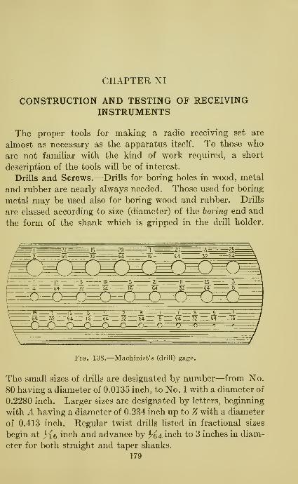
CHAPTER XI
CONSTRUCTION AND TESTING OF RECEIVINGINSTRUMENTS
The proper tools for making a radio receiving set are
almost as necessary as the apparatus itself. To those who
are not familiar with the kind of work required, a short
description of the tools will be of interest.
Drills and Screws.—Drills for boring holes in wood, metal
and rubber are nearly always needed. Those used for boring
metal may be used also for boring wood and rubber. Drills
are classed according to size (diameter) of the boring end and
the form of the shank which is gripped in the drill holder.
Fig. 138.—Machinist's (drill) gage.
The small sizes of drills are designated by number—from No.
80 having a diameter of 0.0135 inch, to No. 1 with a diameter of
0.2280 inch. Larger sizes are designated by letters, beginning
with A having a diameter of 0.234 inch up to Z with a diameter
of 0.413 inch. Regular twist drills listed in fractional sizes
begin at J^e inch and advance by 3-^4 inch to 3 inches in diam-
eter for both straight and taper shanks.
179

180 PRACTICAL RADIO
31
SII»»ia«»-

CONSTRUCTION OF RECEIVING INSTRUMENTS 181
Usually the size of a drill is stamped on the shank, except
in small sizes. If the size is not marked on the shank, it
can be determined by the use of the gage shown in Fig. 138.
A straight shank drill and a bit stock drill are shown at Aand B in Fig. 139. A bit such as shown at C in Fig. 139 is
used on soft materials such as wood, but never on metal.
A center punch which can be obtained in various sizes is
shown at D in Fig. 139.
It is not necessary to buy a full assortment of drill and bit
sizes, but only those which are actually needed, and usually
these are mentioned somewhere in the directions for building a
receiving set. The holder for a drill is called a hand drill
and that for a bit is a brace; both of these are shown at E and Fin Fig. 139.
Screws are classified as wood screws and as machine screws.
A wood screw is used in wood; a machine screw principally
in metal. Two kinds of each of these screws are shown at
G and H in Fig. 139.
A small wood screw can be screwed into the material directly
but in the case of large screws, a small hole should be bored
first to prevent splitting.
Ordinarily metal does not have to be bored in making a radio-
receiving set, but the following information is given to help in
meeting such emergencies as may arise. The hole for a brass
machine screw must be drilled, and then tapped in order to
take the threads on the screw.
The table below gives the sizes (number) of tap drills and
clearance drills which are necessary for certain standard
machine screws. The first column indicates the number and
threads per inch of the screw and also of the tap to be used in
cutting the threads for the screw. Thus ''2-56" means a
No. 2 size with 56 threads per inch. The second column
gives the size (number) of the drill which is used to bore a
hole for the use of the tap. The third column (clearance
drill) gives the size (number) of the drill for boring a hole
which is large enough to take or pass the machine screw when
it is unnecessary to have a thread in the hole.

182 PRACTICAL RADIO
Screw Vthread

CONSTRUCTION OF RECEIVING INSTRUMENTS 183
Solder in the form of wire with a flux core may be obtained
and will save much time on the job; otherwise the flux (rosin,
not acid) must be applied before beginning to solder. Nowmelt some solder on the tip of the iron and spread it so that
a thin coating covers the tip; this is called tinning the iron.
When you are ready to make the joint, place the hot iron
against the wires to be soldered and keep it there until the
wires get so hot that the solder will melt on them and not
freeze or harden without sticking. Then when a drop of
solder is applied it will flow readily to form the required joint
which should be held firmly with a pair of pliers until the
Fig. 140.—Tools for radio construction.
solder is cool. Do not use any more solder than is necessary
since the amount of solder on a joint is no indication of its
efficiency.
In making a joint with solder be sure that the solder actually
unites with both the pieces of metal which are to be joined.
Sometimes the two pieces of metal appear to be united when in
fact they are only temporarily stuck together by the rosin in
the flux. Such a joint ordinarily soon pulls apart, but even if
it holds together, no radio current can pass through it.

184 PRACTICAL RADIO
Pliers are necessary for work which requires any cutting,
shaping or gripping. A pair of long-nose pUers and a pair of
combination cutting phers as shown at A and B in Fig. 140,
will cover all the usual requirements. The 6-inch size is
ordinarily most convenient, but this, of course, is a matter of
preference.
With the aid of a wiring diagram and a guide for the drilling
of the panel, it is possible for even a very inexperienced person
to build a receiving set which will function in a satisfactory
manner. The general precautions to be observed are not
many and can readily be applied.
Panels.—Many radio dealers will drill panels to order and
can supply cabinets in a variety of sizes. Also, it is possible
to obtain panels already drilled for many of the popular cir-
cuits. If this procedure is to be followed it is necessary to
get a wiring diagram for the type of receiver in question. In
the construction data which follows the panels are all of
standard size, but the spacing of holes is special and hence the
drilling must be done either at home or as a special job. Use
a center punch for laying out the holes. Holes should be
drilled from the front of the panel with metal twist drills, and
should be countersunk with a reamer or larger-sized drill.
Arrangement of Parts.—The arrangement of parts should be
such that the connecting wires are as short as possible. Induc-
tance units, such as grid and plate variometers, and trans-
formers, should not be placed too close together because the
magnetic fields which they create may conflict, and produce
distortion of signals, that is, inaccurate reproduction of sound.
Inductance switches should be close to the coil taps.
A rheostat is mounted on the panel in front of the socket
it serves in order that the leads may be short. Battery wires
can be run along the panel and will not give any trouble from
capacity because there is not much voltage difference between
them and the ground.
Recent designs put the ^'A" and '^B" battery connections
at the back of the receiver, leaving only the phone connections
on the panel.

CONSTRUCTION OF RECEIVING INSTRUMENTS 185
Grid and plate leads inust be short and should be run along
the back of the cabinet, and not parallel to each other.
The variable grid leak and condenser can be placed close
to the grid terminal of the socket.
When the wiring is done with heavy bus wire of about No. 14
size and is self-supporting, there is no need for insulation,
otherwise a small tubing called spaghetti should be used to
avoid contacts.
If it is seen, after the receiver is completed, that a different
arrangement of parts would allow the use of shorter wiring,
it is advisable to make the change, rather than to take a chance.
The antenna condenser in a single-circuit receiver should
be in the antenna lead and should have the movable plates
connected to the antenna. In a double-circuit receiver the
antenna condenser may be put in the ground lead with the
movable plates grounded. A condenser used in the grid cir-
cuit should have its movable plates connected to the ''A"
battery, while a condenser used in the plate circuit should have
the movable plates connected to the '^B" battery. These
arrangements are necessary to reduce the effect of body capacity.
Shielding.—If you have had much to do with receiving sets
while they were in operation you have doubtless noticed that
in some instances when you place your hand upon or near the
instrument, the signals are made louder or weaker. This
effect is due to what is technically known as body capacity.
Shielding is a term usually applied to the use of a sheet of
tin foil or of copper foil placed on the back of the panel for
the purpose of reducing the effects of body capacity. Thesame result can be accomplished if those parts of the receiver
which must be touched are kept at a low voltage. In the
case of the condenser this is done by the proper connections
of the fixed and movable plates as explained in the preceding
paragraph.
Wave Trap.—The utility of a wave trap in reducing inter-
ference from local broadcasting stations has been mentioned on
page 141. A suitable form of wave trap may be made by con-
necting a condenser and a coil in parallel. The method of
connection is shown in Fig. 141 in which C is a condenser of

186 PRACTICAL RADIO
0.0005 microfarad capacity, Li is a coil having about 45
turns of No. 28 double cotton covered wire on a 4-inch tube.
1,2 is a coil of 8 to 12 turns of No. 22 wire wound over a piece of
paraffin paper which has been wrapped around the coil L^.
Reci
Fig. 141.—Radio wave trap.
In using a wave trap, the first step is to tune in on the sta-
tion which causes interference until the signals are strongest.
Then adjust the condenser C until the signals are weakest.
The trap is now adjusted to absorb energy on this particular
wave length. Then when another
station is tuned in, very little interfer-
ence is experienced.
After a number of trials with several
stations a chart can be made for this
apparatus showing the wave length
corresponding to any setting of the
condenser.
Wave Meter.—The wave trap described above may be used
to tune a transmitter. To do this a crystal detector and a pair
of telephone receivers are added as shown in Fig. 142. This
apparatus is called a wave meter.
Fig. 142,—Radiometer.

CONSTRUCTION OF RECEIVING INSTRUMENTS 187
The antenna and ground of the transmitter are then discon-
nected and the wave meter placed near the secondary of the
oscillation transformer. The wave meter is then set to the
desired wave length and the inductance of the oscillation
transformer is varied until a maximum response in the tele-
phone receivers is obtained.
The wave-length range of any circuit, such as coil and con-
denser, or transformer and condenser may be ascertained by
making the wave meter into a transmitter. This is done by
adding an interrupter or buzzer and a battery as indicated in
Fig. 143.
The circuit whose wave-length range is to be measured is
arranged as in Fig. 144 with a crystal detector and phones.
Fig. .143.—Radio wave meter with inter-
rupter and battery.
Fig. 144.—Measuring rangeof wave length.
When the wave-meter switch is closed, the instrument acts
as a transmitter using a wave length determined by the setting
of the wave-meter condenser C. By working over the required
range and noting the response in the phones, the wave-length
range of the circuit in question can be determined and the
design changed, if necessary.
Loop.—A loop is a special form of the antenna. It is merely
an enlarged coil, consisting of several turns of wire on a wooden
frame about 2 feet square. Detail directions for building a set
are given later in this chapter.
The method of connecting a loop to a receiving set depends
upon the wiring inside the set. If the set has a coil and con-
denser connected in series, then the loop is attached as shown in

188 PRACTICAL RADIO
Fig. 145. If the receiving set has a coil only, then a condenser
must be placed so that one of its terminals is attached to the
loop and the other to the ground connection of the set. Thenthe other end of the loop is connected as shown in Fig. 146. Aloop and condenser may be used also to replace the tuning

CONSTRUCTION OF RECEIVING INSTRUMENTS 189
can be used over the entire broadcasting range. If the size of
the square is made less, the number of turns must be increased.
Fig. 147.—Radio loop and condenser to replace tuner.
Fig. 148.—Small radio loop.
Thus for a 20-inch square there should be about 20 turns. One
form of small loop is shown in Fig. 148, In general about 100

190 PRACTICAL RADIO
feet of wire may be wound on a loop irrespective of the size.
If a clip is used on one of the wires leading from the set to the
loop, the number of turns may be selected as desired.
If this is done it will be noticed that the dead or unused turns
do affect the others since the results are not the same when, for
example, a loop of 6 turns is compared with one of 10 having 4
turns cut out. It is evident that as the size of the loop is
decreased, it approaches the conventional tuning coil.
22
20
13
IG
14

CONSTRUCTION OF RECEIVING INSTRUMENTS 191
20 inches to the 1-inch spacing curve and from there to the
left. This shows about 20 turns; 18 turns are needed for ^^-
inch spacing; 15 for J^-inch spacing and 12 for J^-inch spacing.
It will be noticed that for a large coil the number of turns is
not affected much by the spacing.
Construction of Receiving Sets.—In the following pages
complete constructional data for several typical receiving sets
are given. The list includes the following:
1. Crystal receiver.
2. Single-tube regenerative receiver.
3. Two-stage audio-frequency amplifier.
4. Two-stage radio-frequency amplifier.
5. Single-tube reflex receiver with crystal detector.
6. Four-tube reflex receiver with crystal detector.
7. Three-tube neutrodyne receiver.
8. Six-tube super-heterodyne.
The first four receiving sets are designed in such a way that
the experimenter can begin with a simple crystal set and add to
it, as opportunity allows, until he has a 5-tube receiving set in
which almost all of the apparatus from the previous receivers
can be utilized. This is a factor of considerable importance
and should be considered carefully by the amateur before he
makes the decision to build any type of receiving set.
This flexibility in design applies also to the two reflex
receivers. The neutrodyne receiver uses two stages of radio-
frequency amplification with air-core transformer coupling and
a detector tube. The two-stage audio-frequency amplifier
can be used with it to increase both the range and volume.
The transformers used in the neutrodyne can be rewound
for the proper wave-length and. are then suitable for the
super-heterodyne
.
Crystal Detector Receiving Set.—This is a single-circuit
arrangement, using a variometer for tuning. By noting the
size of the panel (as given in the list of materials) and measur-
ing the drilling templet as shown in Fig. 151 it is a simple
matter to locate the holes which must be drilled. The drills
required are. No. 25, No. 18, and J^e inch.

192 PRACTICAL RADIO
dZB^^
Tesi Tips
U^^i Tesi Tips
Fig. 150.—Practical radio testing outfit.
^*35
,^5m
fenote: Boxh bemade
of%"wood
*25 ^18
Ground Phone
^#^5
Fig. 151.—Drilling templet for crystal detector receiving set.

CONSTRUCTION OF RECEIVING INSTRUMENTS 193
The diagram in Fig. 152 shows the wiring as it would appear
if the panel was removed.
List of Materials for Crystal Detector Receiving Set
1 5M- by 53>i-inch panel. 1 Phone condenser, 0.002 micro-
farad.
1 Variometer. 1 Dial (3 inch).
1 Crystal detector. 4 Binding posts.
1 Series fixed condenser, 0.00015-
0.00025 microfarad. 3 Feet of bus wire.
It will be noticed that the material lists do not call for
batteries, cabinets, lugs, screws, tools, telephone receivers,
loud speaker and the antenna system. These items are
classed as accessories and are not included as parts of a receiv-
ing set.
Testing the Crystal Receiver.—After the various units cf
the receiving set have been connected, it is a worth while
precaution to test the assembly for faults. A simple testing
outfit which is sometimes necessary in locating short or open
circuits may be made conveniently with a dry cell and the
telephone receivers of a headset, or a flash-light bulb, as
shown in Fig. 150. The bulb-testing outfit is not, however,
as sensitive as the telephone receivers, since the latter will
indicate the presence of very small currents. It is advisable
to use insulated wire to prevent contacts with other wiring
than that which is being tested. When the tips of the test
outfit are touched to the ends of a circuit which has no breaks
in it, a click will be heard in the phones, or the bulb will
light. On an open circuit no click will be heard, or the bulb
will not light. In testing any unit it may be necessary to
disconnect its terminals from the receiver in order to be sure
that no other path for the current is provided. In some
poorly constructed rheostats, an open, or a loose connection
is due to the fact that the end of the resistance wire is merely
wrapped around its binding post, instead of being fastened
firmly to it.
When the test tips are touched to the points 1 and 2, as
indicated in Fig. 152, no click should be noticed. If a click
does occur the fixed condenser has a short circuit, meaning

194 PRACTICAL RADIO
that some current finds its way through the condenser. If
this is the case a new condenser must be obtained.
It is necessary to bear in mind that even a perfect condenser
will produce a very faint click in the test telephone. This,
however, is due to the momentary ^'charging" current of the
condenser and cannot be mistaken for the sharp, loud click
which occurs with a short circuit.
Ph
Senes Fi'xecJ Condenser ^\^a OOO/S-0. 00025m fd. ^
oTurtiM^ Variomej-er
_5i
Phone
Condenser
6.002mfd
L_Q__J
Ground^6
Phone
Fig. 152.—Wiring diagram for crystal receiving set.
If no clicks are heard when the tips are touched to 3 and
4 there is an open circuit or a break in the wiring of the vario-
meter which must be repaired.
It is not advisable to test the crystal in this way because
the comparatively large current which would pass through
might injure the crystal. The crystal is best adjusted by
trial while the receiving set is in operation.
The testing of the ''phone" condenser brings out a point
which must be observed very carefully. In testing any part
of a circuit make certain that there is no other path for the
test current than the one which you are testing. If the test
tips are touched to points 5 and 6 a click will be heard, even

CONSTRUCTION OF RECEIVING INSTRUMENTS 195
though the condenser is perfect, because the current can flow
through the path between points 5 and 6 by way of the crystal
and the variometer. Hence it is necessary to disconnect the
condenser at one side, say at point 5, and then touch the test
tips to point 6 and to the disconnected condenser terminal.
A click indicates the presence of a short circuit in the condenser.
In the same manner tests may be made for an open circuit
in the various parts of the connecting wires, such as betweenpoints 6 and 7, 7 and 8, and so on.
As far as concerns the operation of the crystal itself there
is no choice in the matter of placing it in a circuit. That is,
AnfennaMark
"^^ Counfersitik
^ W) ^i^
MarkPlafeTap
*I8\
Plafe Vahomekr
"A5af.
Rheosiat Pofenfiomeier
Fig. 153.—Drilling templet for single-tube receiving set.
the crystal may be placed before the flexible wire (or cat-
whisker) or the flexible wire may be placed before the crystal.
However, it may be found that the effect of body capacity
does produce a difference in results. Thus in radio-frequency
circuits, the unit is placed so that the crystal is tow^ard the
radio-frequency side.
Single-tube Receiving Set Using Regeneration.—The drill-
ing templet for this arrangement is shown in Fig. 153. Thedrills required are No. 25, No. 18, ^^e-inch, and a countersink.
A variometer is used for tuning, and regeneration is controlled
by another variometer in the plate circuit.

196 PRACTICAL RADIO
The diagram in Fig. 154 shows the wiring as it would appear
if the panel was removed. The socket for the tube is shown
tipped up, instead of being in its normal position, in order
that the wiring may be visible. The plate-tap connection
as shown in the upper right corner of the wiring diagram plays
no part in the action of this receiving set but is needed if
radio-frequency amplification is to be added.
Anfenna Plate Tap
Fig. 154.—Wiring diagram for single-tube receiving set.
List of Materials for the Single-tube Receiving Set Using
Regeneration
1 7- by 12-inch panel.
2 Variometers.
1 Potentiometer.
1 Rheostat to suit vacuum tube.
1 Socket for vacuum tube.
1 Grid condenser and grid leak,
1 Fixed condenser, . 00015-0 . 00025
microfarad.
1 Phone condenser,
farad.
2 Dials (3-inch).
1 Socket bracket.
9 Binding posts.
10 Feet of bus wire.
1 Vacuum tube.
0.005 micro-
Testing the Single-tube Regenerative Receiver.—At the
time the vacuum tube for this receiver is purchased the
buyer should be shown that the filament lights when the
tube is put into the test socket at the store. No other test
than that of actual performance in the receiving set can be
made on the tube.
CONSTRUCTION OF RECEIVING INSTRUMENTS 197
To prepare the receiving set for testing, remove the antenna
and ground conections, take the tube out of its socket and
disconnect all battery wires at the binding posts on the set.
The battery wires should be turned back out of the way and
placed in such a position that no short circuit on the batteries
can occur. An accidental contact of this kind, even though it
may last for but a few minutes, will cause considerable harm
to the battery.
The fixed antenna condenser is tested by touching the test
tips of the simple testing outfit (page 193) to the points 1
and 2. No cUck should be noticed. A click shows that
there is a short circuit in the condenser. Such a defective
condenser should be replaced.
An open circuit in the tuning variometer is indicated by
the absence of a click when the test tips are touched to points
3 and 4. An open circuit in a variometer is found most fre-
quently at the flexible connections between the rotating and
stationary windings. The plate variometer may be examined
in a similar manner by using the test tips between points 9
and 10.
If the grid condenser and grid leak cannot be separated, that
is, if they have been made in one unit, the use of the test tips
between points 5 and 6 will produce a click if there is no open
circuit in the grid leak. This test, however, is of no value as
regards the grid condenser. If the two parts can be separated
from each other then the usual test for open circuit can be
applied to each.
The rheostat may be tested by touching the test tips to
points 7 and 8. No click should be heard while the moving
arm is in the ''off" position.
When the test tips are touched to points 10 and 11 for
testing the phone condenser no click should result. If there
is a sound there is a short circuit in this condenser and it must
be replaced.
Finally, a click should be obtained at any position of the
movable arm of the potentiometer when the test tips are touched
to points 12 and 13, and 12 and 14. In the latter test the
rheostat must be turned ''on" in order to complete the circuit.

198 PRACTICAL RADIO
Two-stage Audio-frequency Amplifier.—The drilling tem-
plet for the panel is drawn in Fig. 155. The drills required are
No. 25, No. 18, ^6-inch, and a countersink.
~^ Jo Receiver
%8
*18
#18
m DrillandCounfersihk
Rheosiais'
fl8
Phones
P/8^
Fig. 155.—Drilling templet for two-stage audio-frequency amplifier.
® ones onReceiver r"
/?^^^
y- Brackeh ^,^
Transformers- ^\-Pffon
QLPr,\ ^S^
^:
Q I I
"Sockefs 'IM
^^^^t^^- Rheostats \f£^^^Bafierys
Fig. 156.—Wiring diagram for two-stage audio-frequency amplifier.
The diagram in Fig. 156 shows the wiring as it would appear
to anyone looking down into the inside of the receiver. The

CONSTRUCTION OF RECEIVING INSTRUMENTS 199
telephone receiver and battery connections may be as sliown
or may be placed on the front of the panel.
List of Materials for Two-stage Audio-frequency Amplifier
1 7- by 9-mch panel. 2 Sockets for vacuum tubes.
2 Brackets. 8 Binding posts.
2 Audio-frequency transformers. 8 Feet of bus wire.
2 Rheostats for vacuum tubes. 2 Vacuum tubes.
Testing the Two-stage Audio-frequency Amplifier.
—
Remove the connections between the amplifier and receiving
set, and disconnect the battery wires.
It is not possible to detect a short circuit in either winding
of a transformer by means of the simple testing outfit (page 193)
but an open circuit in either the primary winding or the secon-
dary winding is readily observed. If no click is noticed whenthe test tips are touched to points 1 and 2 of each transformer
there is an open circuit in the primary winding of the trans-
former for which the testing outfit gives no sound. A break
in the secondary winding of a transformer is indicated by the
absence of a click when the test tips are touched to points
3 and 4. It is not advisable to attempt to repair transformer
windings. A new transformer should be obtained.
The rheostats are tested by touching the test tips to points
5 and 6; first on one rheostat and then on the other. Noclick should be heard while the arm of the rheostat is in the
^^ofi" position.
When the same ''B" batteries are used for both the receiv-
ing set and the amplifier, a short circuit may result in the
battery wiring if the connections do not follow the diagram.
It will be noticed that the point 5 of the '^B" battery binding
post on the amplifier is connected through wire 7 to point 5
which is the positive (+ ) binding post for the ''A" battery.
This binding post is, in turn, connected to the positive (+)binding post for the ''A" battery on the receiving set, and fromthis point there is, as a rule, a connecting wire going to the
negative (— ) terminal of the ''B" battery. Hence it is
essential to make certain that point 5, which is the ''B"
battery positive (+ ) binding post on the ampHfier^ is connected

200 PRACTICAL RADIO
to the terminal of the ''B" battery which is joined to the
negative (— ) binding post for the '' B " battery on the receiving
set.
If the rheostat is in proper condition and if there is no break
in the wiring between the filament terminals on the socket
and the ''A" battery binding posts on the receiving set, the
vacuum tube should light when it is inserted in the socket and
the ''A" battery connected to the proper binding posts. If it
does not light, examine the spring contacts at the bottom of
the socket and see that they press firmly on the tube contacts.
If all other parts of the filament circuit have been tested, and
the tube does not light, the trouble is in the tube filament. The
tube filament may be tested by touching the test tips to the
filament contacts at the bottom of the base of the tube.
If no click is observed the filament is burned out and a newtube is required. If a click is noticed, the tube probably is
paralyzed. Ordinarily the activity of the filament may be
regained by lighting it at the proper voltage for about half
an hour with the plate voltage off.
There is no simple test for detecting a poor connection
between the spring and the tube grid contact, or between the
spring and the tube plate contact. In order to avoid trouble
from this source, it is advisable to remove the tubes occasion-
ally and bend the springs in the socket by pushing them up
with the fingers from below the socket base, or by pulling
them up with a device like a buttonhook. If it is suspected
that there is something wrong with the grid or the plate of
the tube, the most satisfactory test is to try out the tube in
another receiving set.
The wiring leading to the terminals on the tube socket maybe checked with our test outfit. To test the connection at
''P" of the socket for the first tube remove the tube and the
batteries, then touch the test tips to the plate wire and the
spring which is attached to '' P, " If no click is heard there is a
break somewhere between the two points. The connection
at ''G" of the socket is tested between the point 3 and the
spring which is attached to ''G". The connections at ''F+ "
and ''F— " are correct if the tube lights. It is possible also

CONSTRUCTION OF RECEIVING INSTRUMENTS 201
to check these connections with the test outfit. The connec-
tions at ''F+" may be tested between the points 8 and the
spring attached to ''F+". Likewise the connection at
^'F— " may be tested between the point 9 and the spring
attached to ^^F-".
Two-stage Radio-frequency Amplifier.—The drilHng tem-
plet for the panel is drawn in Fig. 157. The drills required are
No. 25, No. 18, ^{Q-inch, and a countersink.
F/afe Tap
^ \l8Drill
m"B Bat
x^"A"Bat
^18 Drill and Countersink ^ /
-^^Phones ^
Variomeier
Rheoslat Rheostat*e£
Fig. 157.—Drilling templet for two-stage radio-frequency amplifier.
This radio-frequency amplifier is designed to be added to
the single-tube receiving set using regeneration. When this is
done the telephone binding posts on the single-tube set mustbe joined together and a connection must be made between the
binding post labelled 'Opiate tap" on the amphfier and the
''plate tap" on the single-tube set. Then the single-tube set
becomes the first radio-frequency stage and the first tube of
the amplifier acts as the second radio-frequency stage. Thesecond tube of the amplifier unit then acts as the detector.
The diagram in Fig. 158 shows the wiring as it would appear
to anyone looking down into the receiver. The various bind-
ing posts ma}^ be brought out to the front of the panel.
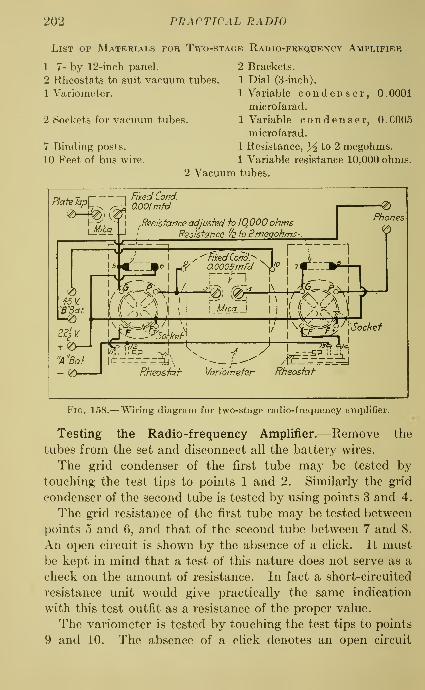
202 PRACTICAL RADIO
List of Materials for Two-stage Radio-frequency Amplifier
1 7- by 12-iiich panel. 2 Brackets.
2 Rheostats to suit vacuum tubes. 1 Dial (3-inch).
1 Variometer. 1 Variable condenser, 0.0001
microfarad.
2 Sockets for vacuum tubes. 1 Variable condenser, 0.0005
microfarad.
7 Binding posts. 1 Resistance, }i to 2 megohms.
10 Feet of bus wire. 1 Variable resistance 10,000 ohms.
2 Vacuum tubes.
PlafeTap\^_
Mica
s^
45 V.
"B"Baf.
«-€)
22^ V.
5,
Fixed Cond.
0.001mfd
.Resistance adjusfed h /Q000 ohms] RQsisfance '/bjv ^megohms
Phones
^^'"Fixed Co,
0.0005mfdTo^d>7\5_mfd ^0
j
7,
"1
_jaI
^ 0_000_5mfd ^0j
7«i-„-:»g-p-|
+ ^£>—• r
- (^ 1 Rheosiah Varioinefer Rheoskch
Fig. 158.— Wiring diagram for two-stage radio-frequency amplifier.
Testing the Radio-frequency Amplifier.—Remove the
tubes from the set and disconnect all the battery wires.
The grid condenser of the first tube may be tested bytouching the test tips to points 1 and 2. Similarly the grid
condenser of the second tube is tested by using points 3 and 4.
The grid resistance of the first tube may be tested between
points 5 and 6, and that of the second tube between 7 and 8.
An open circuit is shown by the absence of a click. It must
be kept in mind that a test of this nature does not serve as a
check on the amount of resistance. In fact a short-circuited
resistance unit would give practically the same indication
with this test outfit as a resistance of the proper value.
The variometer is tested by touching the test tips to points
9 and 10. The absence of a chck denotes an open circuit

CONSTRUCTION OF RECEIVING INSTRUMENTS 203
which occurs most commonly at the flexible connections
between the rotating and stationary windings. A short
circuit in the windings can not be detected with this test
outfit. In most types of variometers the turns of wire are
spaced so that it is possible to follow the wire from one terminal
to the other. If there is a short circuit in the wiring of the
variometer, an examination of this kind will disclose it.
The rheostat for the first tube is checked by touching the
test tips to points 11 and 12. The rheostat for the second
tube is tested between points 13 and 14. In each case the
arm of the rheostat should be moved over its entire range.
The absence of a click denotes an open circuit. An open
circuit in a rheostat may be caused by poor contact between
the wire and the movable arm, by a break in the resistance
wire, and by a loose or broken connection between the end of
ffheoskrf- Pofent/omefer
Fig. 159.—Drilling templet for single-tube reflex receiving set.
the resistance wire and the terminal on the rheostat. A short
circuit between points 11 and 12, or 13 and 14 would be indi-
cated by the fact that the tube remains lighted even when
the arm of the rheostat is in the ''off" position.
It will be noticed that the grid leak connections are not made
in the conventional way. In this circuit it is necessary to insure
a sufficient positive voltage on the grid. For this reason one
end of the grid leak is led to the wire connecting with the
positive binding post for the ''A" battery on the receiving set.

204 PRACTICAL RADIO
Single-tube Reflex Receiving Set with Crystal Detector.—In this arrangement the crystal serves as the detector and the
tube acts as an amplifier of both radio-frequency and audio-
frequency currents. A variometer is used for tuning. Thedrilling templet is drawn in Fig. 159. The drills required are,
No. 25, No. 18, J^6-inch and a countersink.
The diagram in Fig. 160 shows the wiring as it would appear
if the panel was removed. Notice that in order to make the
connections plain, the various condensers and transformers
have been swung up toward the panel.
Anfenna ^^Cond~]^
Wound -,1 I
^'I
I
y:| Vanotnei-er tj
, Cond.I
l>i ^^i^ )) Lor.
RheosiaJ-" Poieniiomemr
Fig. 160.—Wiring diagram for single-tube reflex reeeving set.
List of Materials for Single-tube Reflex Receiving Set withCrystal Detector
1 7- by 12-inch Panel. 8 Binding posts.
1 Rheostat to suit vacuum tube, 1 Dial (3-inch).
1 Potentiometer. 1 Socket bracket.
1 Variometer. 1 Socket for vacuum tube.
1 Acme R-2 radio-frequency trans- 1 Crystal detector,
former.^
1 Audio-frequency transformer. 1 Series condenser 0.0002 micro-
farad.
2 Variable condensers, 0.002 micro- 1 Vacuum tube,
farad.
10 Feet bus wire.
' Or a radio-frequency transformer with equivalent properties.

CONSTRUCTION OF RECEIVING INSTRUMENTS 205
Testing the Single-tube Reflex Receiver.—Remove the
tube, the antenna and ground connections, and the battery
wires.
A short circuit in the antenna condenser is indicated by a
cHck when the test tips are touched to points 1 and 2.
If there is a break in the variometer no cHck will be heard
when the test tips are touched to points 3 and 4.
When the test tips are touched to points 5 and 6 no click
will be observed if there is an open circuit in the radio-frequency
transformer winding. This simple test however will not indi-
cate a short circuit in a transformer winding. In order to
test the secondary winding of this transformer for a break it
is necessary to open the circuit somewhere, say at point 8,
so that the only path for the testing current is through the
transformer. The test tips may then be touched to point 7
and the disconnected transformer terminal 8. The absence of
a click denotes an open circuit.
The telephone by-pass condenser may be tested by using
the outfit between points 9 and 10. In testing the twoby-pass condensers on the audio-frequency transformer it is
necessary to disconnect one terminal of the condenser fromthe circuit. Thus, disconnect the wiring at point 12 andtouch the test tips to point 11 and the free condenser terminal.
Similarly, for the other condenser, disconnect at point 14
and test between point 13 and the free condenser terminal.
In each case no click should be obtained if the condenser is
in good condition.
Before beginning a test on the audio-frequency transformer
it is best to disconnect the wiring at one terminal of each
winding, say at point 16 and at point 18. Then the primarywinding can be tested between point 15 and the free terminal
16. The secondary winding can be tested between the point
17 and the free terminal 18.
In testing the rheostat the test tips can be touched to
points 19 and 20. Likewise the potentiometer is tested
between points 21 and 22 and also between 22 and 23. Duringthese tests the arm should be moved over the entire range.

206 PRACTICAL RADIO
As in the tests of other receiving sets, it is advisable to try
out each portion of the connecting wires in order to makecertain that there is no break or loose contact.
Four-tube Reflex Receiving Set with Crystal Detector.—The drilling templet for this arrangement is drawn in Fig. 161.
Note that the receiver is designed for use with a loop which
No. 18 Drilland Couniersink
^IS f'S^
^ QrtjsiaI Defector >note: Makesure thaitheholeson the femplefarein fheproperposifion to fiftheinsfrumenhyou intend fo use
Phones
"B"Baftery
- ^18
'A"Bafferu*^
Fig. 161.—Drilling templet for four-tube reflex receiving set.
should be connected across the binding posts marked ''Input."
If it is desired to try an antenna with the receiver, a tuning
device of some kind, such as a vario-coupler, must be added.
The diagram in Fig. 162 shows the wiring as it would appear
to anyone looking down into the inside of the receiver. Thevarious binding posts may be brought out to the front of the
panel.
List of Materials for Four-tube Receiving Set with a CrystalDetector
1 Acme R-4 radio-frequency trans-
former.
4 Sockets for Vacuum tubes.
4 UV-201A Radiotron vacuumtubes.
1 Rheostat, 6-ohnis.
1 Potentiometer.
4 Socket brackets.
3 Acme A-2 audio-frequency trans-
formers.^
1 Acme R-2 radio-frequency trans-
former. ^
1 Acme R-3 radio-frequency trans-
former.^
' Or transformers of equivalent properties,
1 23-plate variable condenser.
8 Binding posts.
1 Dial (3-inch).
1 7- by 18-inch panel.
1 Crystal detector.
2 Condensers, 0.00025 microfarad.
1 Condenser, . 002 microfarad.
1 Condenser, 0.005 microfarad.
25 Feet bus wire.

CONSTRUCTION OF RECEIVING INSTRUMENTS 207
Testing the Four-tube Reflex Receiving Set.—Remove the
tubes from their sockets, disconnect the input wires, and the
battery wires.
T-r-i I Iilpri^lt?/% ^^^^
^C^i
n^f?o^cJ^t®^rf
X, I
1 i
t_£
The input variable condenser is tested by touching the
test tips to points 1 and 2. During this test the plates of
the condenser should be turned throughout their range in
order to detect a possible short circuit due to contact betweenstationary and movable plates. If this does occur the bent

208 PRACTICAL RADIO
plate can be pushed back into place by inserting a screw
driver between it and a stationary plate. The connection
between the movable plates and their terminal on the conden-
ser frame should be tested for loose contact while the plates
are turned.
A poor contact of this kind results in an interrupted current
flow and produces a series of clicks in the test phones.
The rheostat is tested in the usual way between points 3 and
4. During the test the arm should be moved over its range.
The potentiometer may be checked by testing between
points 5 and 6, and also between 6 and 7. In each test the
arm is to be moved over its entire range.
The fixed by-pass condenser across the secondary of the
first audio-frequency transformer must be disconnected at
one end, sa}^ at point 9, before it can be tested. After this
is done the test tips are touched to point 8 and the free terminal
of the condenser at 9. A short circuit is indicated by a click
in the test phones. The condenser across the secondary of
the second audio transformer must be disconnected at, say,
point 11 and then tested between point 10 and the free
terminal of the condenser. Likewise, the third by-pass
condenser is disconnected at point 12 and tested between
point 13 and the free terminal of the condenser. The phone
condenser may be tested directly by touching the test tips to
points 14 and 15. If a condenser of this type shows a short
circuit, it is best to replace it with a good one instead of
attempting to make repairs.
The primary winding of the first radio-frequency trans-
former is tested between points 16 and 17. An open circuit
is denoted by the absence of a click, but a short circuit can-
not be detected with this outfit. The secondary winding
is tested between points 18 and 19. In the same manner the
primary winding of the second radio transformer is tested
between points 20 and 21, and the secondary winding between
22 and 23. The primary winding of the third radio trans-
former is tested between points 24 and 25. Before the secon-
dary of this transformer can be tested it is necessary to remove
one of the connecting wires, say at point 27. Then the test

CONSTRUCTION OF RECEIVING INSTRUMENTS 209
tips can be touched to point 26 and the free terminal of the
transformer at 27. Most transformers are wound with a
small wire which is not very strong. Rough handling mayresult in a broken wire which will make the transform.er useless.
The primary of the first audio-frequency transformer must
be disconnected at one side, say at point 29, before it can
be tested. After this is done, the test tips are touched to
point 28 and the free terminal of the transformer. If no
click is heard there is a break somewhere in the primary
winding. Since the condenser across the secondary of this
transformer was disconnected at one side for a previous test,
the secondary winding of the transformer may be tested
directly. To do this touch the test tip to points 30 and 31.
The absence of a click indicates an open circuit in the winding.
The primary winding of the second transformer is tested
between points 32 and 33. The secondary winding of this
transformer may be tested between points 34 and 35, provided
that the condenser which is placed across this winding has
been left disconnected at point 11. Here again the absence
of a click means an open circuit in the winding.
The primary winding of the third transformer is tested
between points 36 and 37, and the secondary winding between
points 38 and 39. The tests on these windings may be madedirectly as there is no other path over which the test current
can flow.
The various connecting wires between the parts may nowbe tested. In order to avoid omitting some of the wires
it is a good plan to trace over a wire on the diagram with
a pencil or crayon as soon as it has been tested. In this
way it is a simple matter to see which circuits have been tested
and also those which have not been checked.
Three-tube Neutrodyne Receiver.—This arrangement gives
two stages of neutralized radio-frequency amplification and a
detector. If a large volume of sound is desired, it is necessary
to add the two-stage ampHfier which has been described earlier
in this chapter. The drilling templet is drawn in Fig. 163.
The diagram in Fig. 164 shows the wiring as it would appear
to anyone looking down into the receiver. The various bind-

110 PRACTICAL RADIO
ing posts must be brought out to the front of the panel. For
the sake of clearness the two rheostats have been swung upout of their normal position.
The tuner is a single-circuit arrangement with no provision
for adjustment. Although it would appear that the primary-
turns of wire are untuned, as a matter of fact, the effect of
the secondary turns upon the primary turns serves the purpose
^ Allholes mdnll..^ ;•'" coantersonk
*25
-mGround
AmpKfKoskif ^.^zsv,
- i'DriiL^-^ r-^
'/«JDef.Rheostat yr ^
Fig. 163.—Drilling templet for three-tube neutrodyne receiver.
of tuning. Perhaps this can be understood more clearly byconsidering a double-circuit tuner with an untuned ^primary.
It is then simple to see that w^hen the secondary is tuned,
its reaction upon the primary serves to tune the primary.
It has been shown that an untuned primary gives greater signal
strength. But since close coupling is necessary under these
conditions, we obtain greater signal strength at a sacrifice of
selectiveness.
List of Materials for Three-tube Neutrodyne Recefver
3 Socket brackets.
3 Condenser shields.
1 7- by 24-inch panel.
3 Xeutroformers (tuned secondary
radio-frequency transformers).
3 Variable condensers (11 plates).
3 Sockets for vacuum tubes.
3 Dials (3-inch).
2 Rheostats suitable for vacuumtubes.
2 Neutrodons (neutralizing conden-
sers).
9 Binding posts.
3 UV-201A or UV-199 vacuumtubes.
1 Fixed condenser, 0.001 micro-
farad.
1 Fixed condenser, 0.006 micro-
farad.
1 Fixed condenser, 1 . microfarad.
1 Condenser, 0.00025 microfarad.
1 Grid leak (suitable for detector
tube).
25 Feet of bus wire.
1 Shield for panel.

CONSTRUCTION OF RECEIVING INSTRUMENTS 211
Testing the Neutrodyne Receiving Set.—Remove the tubes
from their sockets and disconnect the antenna, ground, and
battery wires.
The testing of this instrument
is much simplified by making the
necessary breaks, in the connec-
tions to the parts, all at one time,
and before the actual testing is
begun.
The secondary of the first trans-
former is to be disconnected at
point 3. The secondary of the
second transformer is to be dis-
connected at point 12. The sec-
ondary of the third transformer is
to be disconnected at point 21.
The first neutralizing condenser is
to be disconnected at point 7, and
the second neutralizing condenser
at point 16. This completes the
arrangement for testing.
In testing the secondary of the
first transformer, touch the test
tips between points 1 and 2. If
no click is obtained there' is 'a
break in the winding between the
connections at 1 and 2. Then test
between point 2 and the. free ter-
minal of the secondary winding.
If there is no break in the circuit a
click will be noted in the test
phones.
The first variable condenser is
tested between the points 4 and 5. If a click is obtained, it
is due to a short circuit which may be caused by two adjacent
plates touching, or by a piece of metal caught between adjacent
plates. These faults can be located and remedied very easily.
During the test the dial should be turned in order to detect

212 PRACTICAL RADIO
a possible poor connection between the movable plates and
their terminal on the frame.
The first neutralizing condenser is tested between point
6 and the free terminal of the condenser. A short circuit
would result if the two inside ends of the wires were in contact
either with each other or with a piece of metal, or if the two
wires were touching the hollow metal tube which slides over
them. The setting should not be disturbed as otherwise
the process of neutralization must be repeated. It is best
to solder the neutralizing tube in place to prevent accidental
shifting.
The primary winding of the second transformer is tested
between points 8 and 9. If no click is noticed the turns
of wire should be examined for a break. The secondary wind-
ing is tested first between points 10 and 11 and then between
point 11 and the free terminal of the secondary winding.
The absence of a click in either test denotes a break in the
winding which can be discovered readily by examining the
turns of wire.
The second variable condenser is tested between points 13
and 14. A short circuit is indicated by a click in the test
phones. While dust on the plates does not ordinarily produce
a short circuit, it may cause noises, interfering with reception,
which are hard to trace. To avoid this trouble the condenser
plates should be wiped occasionally.
The second neutralizing condenser is tested between point
15 and the free terminal of the condenser. As before, the
presence of a click indicates a short circuit.
In hke manner the primary winding of the third transformer
is tested between points 17 and 18. The secondary winding
is tested between points 19 and 20, and also between point 20
and the free end of the winding.
The large fixed condenser is tested between points 22 and
23. If a short circuit is found, as shown by a click in the test
phones, it is better to get a new unit than to attempt repairs.
The third variable condenser is tested between points 24
and 25. No new feature is met with here, so that the preced-
ing remarks on the variable condenser apply equally well.

CONSTRUCTION OF RECEIVING INSTRUMENTS 213
The small fixed condenser in this stage is tested between
points 30 and 31 and should not show any click in
the phones. Sometimes a short circuit is due to a piece of
solder running over and connecting one side with the other.
A fixed condenser which has absorbed considerable moisture
also may indicate a short circuit.
The condenser across the ''A" battery binding posts is
tested by touching the test tips to points 36 and 37.
If possible the grid leak and condenser should be discon-
nected from each other so that each may be tested separately.
If the wiring at point 28 is disconnected, the grid condenser
may be tested between points 26 and 27. A click in the test
phones is an indication of a short circuit which means that the
condenser must be replaced. The only test which can be
made on the grid leak is for an open circuit. This is indicated
by the absence of a click when the test tips are touched to
points 28 and 29.
The two rheostats are tested between the points 32 and 33,
and 34 and 35. As the arm is moved from the '^off " to the
''on" position, a cHck should be observed. If there is a break
in the winding another chck will be heard when the circuit
is interrupted.
The success of the neutrodyne circuit depends upon the
care with which the feed-back capacity of the tubes is reduced
or neutralized. To adjust the neutrahzing condenser, tune
in on a strong signal. Then disconnect the filament of the
tube which is being neutralized by placing a piece of heavy
paper between each filament spring contact in the socket and
the corresponding filament terminal of the tube. Now adjust
the neutralizing condenser of this tube until the signal dis-
appears entirely. Then remove the paper from the tube
socket, replace the tube and test the next tube in the same
manner. If any change is made in the setting of the neutraliz-
ing condensers it may be necessary to relocate the positions of
the operating dials for various wave lengths.
Six-tube Super-heterodyne.—This arrangement consists of
an oscillator tube, three stages of intermediate-frequency
amphfication and a second detector tube. The two-stage

214 PRACTICAL RADIO
Anh.na^ | ^^|

CONSTRUCTION OF RECEIVING INSTRUMENTS 215
audio-frequency amplifier, which has already been described,
must be added in order to get volume of sound. The drilling
templet is drawn in Fig. 165.
The diagram in Fig. 166 shows the wiring as it would appear
to anyone looking down into the receiver.
List of Materials for Six-tube Super-heterodyne
A 6 Vacuum tubes.
B 4 Transformers-type No. 271 (when installed the case should be
grounded to shield).
2 Variable condensers^ type No. 247-H, .0001 microfarad.
1 Fixed coil 10 turns No. 26 SCC on 3-inch tube.
1 Fixed coil 60 turns No. 26 SCC on 3-inch tube.
1 Fixed coil 2 turns No. 26 SCC on 3-inch tube.
2 Fixed coil 30 turns each No. 26 SCC on 3-inch tube.
2 Grid leak, 1 megohm.2 Fixed condensers, 0.0005 microfarad.
1 Paper condenser, type No. 236, 0.4 microfarad.
1 Rheostat, type No. 301, 10 ohms.
1 Potentiometer, type No. 301, 200 ohms.
1 Shield for panel.
7 Binding posts.
I 7- by 18-inch panel.
• The transformers and condensers listed are made by the General Radio Company.
QUESTIONS
1. What are some of the tools required for the construction of receiving
sets?
2. Describe the procedure to follow in making a soldered joint.
3. What is the purpose of shielding and how is this result obtained?
4. (a) Explain the construction of a wave trap.
(6) How is this type of wave trap used ?
5. As determined from the chart in this chapter, how many turns of wire
and what spacing would be used on a 24-inch loop?
6. If you constructed one of the receiving sets described in this chatper
what difficulties did you have?


CHAPTER XII
COMMON TROUBLES AND THEIR REMEDIES
The owner of a receiving set soon finds that it does not per-
form its duty unless all the parts are in working order. Thetroubles to which the instrument is susceptible have certain
very definite and characteristic symptoms which will be
described in detail. Moreover, at the present stage of devel-
opment a receiving set will detect not only the desired broad-
casting, but also any extraneous electrical disturbance which
comes within its range.
Kinds of Radio Interference.—A classification of the differ-
ent kinds of interference will help in determining what a receiv-
ing set can do under certain conditions, and also in locating the
source of trouble in the instrument itself. Improper reception
may be due to interference from outside, or from inside the
receiving set.
External interference comes from faulty tuning at either the
transmitter or receiver and can be remedied by providing
means for sharper adjustments. Spark transmitting stations
and power transmission lines are another source of interference.
The interference of spark transmitting stations may be dimin-
ished by loose coupling between the primary and secondary
circuits of the receiving set, by reducing the regeneration,
or by a wave trap^ in the ground wire of the receiving set. Theinterference of power transmission fines will usually disappear
when the antenna is placed at right angles to the power trans-
mission line. If this is not possible, good results are obtained,
in some cases, by connecting in series with the antenna, a loop
which can be adjusted both vertically and horizontally to a
position at which the interference is a minimum.Interference from continuous-wave (C.W.) transmitting
stations or from radiating receiving sets produces a whisthng1 See page 185.
217

218 PRACTICAL RADIO
sound or a continuous musical tone. If the pitch of the tone
changes as the receiving set is tuned, the receiving set itself
is in a state of oscillation. Fading if due to conditions which do
not exist in the receiving set, cannot be remedied.
Atmospheric Conditions : Static.—Another kind of inter-
ference is caused by atmospheric conditions and the faulty
operation of electrical apparatus such as arc lights, industrial
motors, motors in vacuum cleaners, electric fans, violet-ray
machines, elevators and trolley wheels on electric cars. The
noises from electrical apparatus vary considerably but are
similar to those from atmospheric conditions. A discharge
of lightning produces a loud and sudden click, while charged
clouds give a continuous hissing noise like that of a rain storm,
or a flow of water. Another characteristic noise due to static is
a continuous, rattling one like the sound of pebbles thrown
against a wall. The irregular noises coming from atmospheric
conditions are more common in summer than in winter, and,
in the tropics, are more frequent as well as more active, than
in places farther north. The most satisfactory methods for
reducing the effects of static are the use of very loosely
coupled circuits, small antennas, or loops, together with sensi-
tive amplifiers. Much has been said and more written about
devices for the elimination of static. So far, however, such
devices have proved successful under conditions of operation,
but they are so elaborate that the cost is prohibitive.
Testing Receiving Sets.—To determine whether the source
of trouble is in the receiving set or whether it is external,
light the vacuum tubes and use the telephone receivers in order
to find out, first, whether noises of interference are present.
If the filament fails to light or flickers, there is an open circuit
or a loose connection in the filament circuit. In the order of
common occurrence the fault may be at the ''A" battery termi-
nals, the spring contacts in the tube socket, the rheostat,
or the tube terminals. If a tube burns dimly, the *'A"
battery voltage is low. It must not be inferred that an open
circuit can occur only at the places mentioned, because a
break may be found at any point around the complete
circuit.

COMMON TROUBLES AND THEIR REMEDIES 219
If the reception is clear it is advisable to postpone the testing
until poor results are again experienced. If interference is
present, disconnect the lead-in wire from the antenna and the
ground wire when the vacuum tubes are lighted with no change
in the settings. If the noise then disappears, the trouble is
either in the antenna to ground circuit, or is due to some form
of external interference which has already been described.
Antenna trouble may be located by inspection. Look over
the system to make sure that there is no contact anywhere
between the antenna or lead-in and any nearby object such as
a tree, building, guy wire, or telephone line, and that the lead-
in is insulated from the building at the place of entry. Leaky
insulators, or a break in an insulated (covered) lead-in wire
will also prove troublesome.
To test the effectiveness of the ground connection, tune in
the " whistle " of some station and then tap the ground binding
post several times with a finger. If the ground is poor, a
decided variation in the pitch of the ''whistle" will be noticed
as the binding post is tapped. It is well to examine occasion-
ally the clamp which is used to attach the ground wire to
the ground connection and to scrape it clean if it gets corroded.
Noises resulting from trouble in the receiving set would be
rather difficult to locate were it not for the fact that certain
faults produce characteristic sounds. This narrows the search
from a complete test to an examination of but a few circuits.
To the amateur the most baffling type of trouble is the one
in which no response whatever is perceived in the telephone
receivers. The most common cause is an opeii or break in any
one of the circuits such as the antenna, ground, grid, plate,
telephone and filament circuits. It may be due also to a
crystal which is out of adjustment, a short circuit in the tele-
phone receivers, or to exhausted batteries. A tuner which is not
designed to respond to either the upper or lower range of wavelengths obviously will not be able satisfactorily to receive
radio waves which are out of its range.
An open circuit is caused by broken wires, wrong connections
and poor or loose contacts. A short circuit is the result of
contact between wires, wrong connections, contact between a

220 PRACTICAL RADIO
fixed and a movable plate in a condenser, particles of dust or
other material between condenser plates, and a leakage path
due to the effects of corrosive flux. Sometimes a piece of wire,
or a screw driver, screw, washer or even a piece of tin foil will
fall across two wires and short-circuit them very effectively.
After the antenna, ground, and filament circuits have been
found in working order, the tester may often save much time
by going over all the terminals and binding posts to makecertain that there are no loose connections. Poor or loose
connections may be detected by tapping the wiring with a
pencil and listening in on the telephone receivers. An increase
in noise when a wire is tapped shows the presence of a faulty
connection in that wire. A condenser which is short-circuited
from any way whatever will show a flow of current when
tested. Soldering flux between the sheets of a fixed mica
condenser is a common source of trouble. When a short
circuit occurs between two wires which should not have any
part in common, a testing current will find a path through the
short. To test the plate circuit, first check the plate battery
voltage, then Hght the tubes and disconnect one of the ^'B"
battery wires, touching its several times to its terminal.
If a series of clicks is heard in the telephone receivers, the
plate circuit is complete, but if no clicks are heard, there is an
open somewhere in the circuit. Telephone receivers may be
tested by touching the tips of the cord to the terminals of a
dry cell. If no clicks are heard the circuit is open.
Before a home-made receiving set is tried out it is best to
check each branch circuit in the set with the wiring diagram.
When one branch is verified, mark the corresponding circuit
on the diagram with colored ink or crayon so that the tracing
process may be simplified. At the time the checking is being
done, see that all connections are firm and clean; that contact
is not prevented by insulation of a wire caught under a ter-
minal or binding post; that no wires are touching; that there is
no extra wiring which does not appear on the diagram and
that no part of any insulated wire has any concealed breaks.
Take each vacuum tube out of its socket and make certain
that the tube terminals and the spring contacts in the socket

COMMON TROUBLES AXD THEIR REMEDIES 221
are clean; if the springs are not making contact, bend them in
the proper direction to increase the pressure against the tubeterminals.
When imperfect reception is experienced, the imperfections
may be listed as follows:
1. Weak reception,
(a) accompanied by a rasping, scratchy, fuzzy noise.
(b) very dull and muffled in tone.
(c) accompanied by a humming sound of low pitch.
(d) accompanied by a loud whistling tone.
2. Reception of normal strength, accompanied by intermittent soundswhich may be described as hissing, frying, rasping, scratching andcracking.
3. Reception of normal strength, breaking off periodically with apopping sound followed by a few seconds of silence.
4. Reception of normal strength, accompanied by squealing, howling,
roaring sounds.
Weak reception, accompanied by a rasping, scratchy,
fuzzy noise may be caused by a telephone condenser, or by agrid condenser, which does not have enough capacity. Theconnection of the grid return of the detector vacuum tube to
the positive terminal of its filament is a remedy in some cases.
An oscillating receiving set acts in this manner and the remedyhere is simple, being merely a reduction of regeneration. If
too much feed-back is still present, even after the control dial is
in its minimum position, it is necessary to try one or more of
the following expedients—less ''B" battery voltage on the
detector tube, a lower filament current, fewer turns on the
tickler coil, or a grid leak having less resistance. Curiously
enough, the same trouble is caused when the amount of feed
back is too small. The feed-back can be increased by addingmore turns to the tickler coil, or by using a larger plate vari-
ometer or a coupling condenser. If the volume decreases as
the tickler coupHng is increased, the feed-back is reversed andacts in the wrong direction. Interchanging the tickler
connections is the solution for this trouble. In general, the
failure to obtain oscillation may be caused by too loose coup-ling between the tickler and secondary coils, reversed tickler
connections, reversed ''B" or ''A" battery leads, low "B"

222 PRACTICAL RADIO
battery voltage (which in turn may be due to a defective cell),
a by-pass condenser whose capacity is too small, a grid con-
denser which is not suited to the vacuum tube used, and a
defective tube. Poor telephone receivers give very ragged
reproduction, especially if the diaphragm is distorted in any
way.
In applying the above remedies care must be taken not to
introduce too great a change in value, otherwise the only differ-
ence will be the appearance of another kind of noise. Thus,
weak signals which are dull and muffled in tone are the result
of a telephone or grid condenser with too much capacity, or a
grid leak having too little resistance. Certain defects in the
telephone receivers and in the grid condenser also will destroy
the quality of reception. An open or poor connection in the
ground circuit will make the reception very faint regardless
of the tuning.
Weak radio currents (or none at all) with a humming sound
of low pitch are usually traced to an open in the grid circuit.
This may occur at the grid terminal of the vacuum tube, the
grid-leak resistance, the secondary tuning coil, the grid-return
connection, the spring contacts in the tube socket and at the
flexible lead of a grid variometer.
A sound like that of water flowing through the receiver maybe due to an excessive flow of current in the tube. This will
disappear when the filament current and plate voltage are
reduced, or when a ''C" battery is used.
Reception of normal strength accompanied by intermittent
noises like the sound of hissing, frying, rasping, scratching
and cracking probably occur more frequently than any
other. This peculiar type of interference may come from
without the receiver and also from within it. External sources
of interference have been enumerated at the beginning of this
chapter. Interference from this source may also cause a
sound like that of an electric motor when running, or just a
plain hum, and sometimes a series of clicks.
In the receiving set a common cause of this trouble is a run
down or defective ''B" battery. A new battery which is in
good condition will produce only a cHck in a receiving headset

COMMON TROUBLES AND THEIR REMEDIES 223
connected across its terminals. If the battery is defective, a
series of scratchy noises will be heard in addition to the clicks.
Some detector vacuum tubes (especially soft tubes) are noisy
in operation, no matter what precautions are taken, and such
tubes had best be discarded. Above a certain value of fila-
ment current, even a good soft detector tube produces a
hissing sound, while a further increase in current will result in a
frying noise. If a vacuum tube is noisy because of vibration
of its elements, a base of sponge rubber under the socket and
the use of short, heavy, rigid wires will minimize the vibration.
The tube noise has a ringing sound which appears when the
receiver is jarred or knocked in any way. Poor contact
between the vacuum-tube terminals and the spring contacts
in the socket often causes noise. Indeed, loose connections
in any part of the receiver such as the grid, filament or plate
circuits are responsible for much of the intermittent irregular
interference. And again, at other times, no bad effect is
noticed, or else the signal is merely weak. Loose connections
in the filament circuit result in changes of intensity rather
than in noise. A flexible lead from the proper terminal
of the rheostat to the shaft will overcome poor contact between
shaft and bushing. Loose connections in the plate generally
are much noisier than those in the grid circuit.
Some forms of grid-leak resistance are constructed so that
the shghtest jar disturbs the setting very shghtly. Such a
grid leak, as well as a defective grid condenser should be
replaced by reliable apparatus which is not affected by weather
conditions or by shaking. Few amateurs think of suspecting
the phone cord. If any increase in noise is observed whenthe cord is shaken it should be taken apart and examined for
partial breaks.
Normal radio currents which break off with a popping sound
and disappear entirely for a few seconds, then come back and
again stop with a pop are found when there is an open in the
grid circuit, or when the grid-leak resistance is too high.
The action of the vacuum tube may be blocked entirely if the
grid-condenser capacity and the grid-leak resistance are not
properly proportioned. The correct values to use with a tube
224 PRACTICAL RADIO
are stated by the tube manufacturers. There is no need for
experimenting because all this has been done very thoroughly
by the commercial laboratories.
Radio reception of normal strength, accompanied by roaring,
howhng, whistHng, and squeaHng noises, indicates an oscillating
circuit somewhere in the receiver, or heterodyne action on a
wave length near the one being received. When the vacuumtube itself is oscillating a clear musical whisthng tone is noticed
the pitch of which changes as the set is tuned. The whistle
is the result of beats formed by the interaction of the incomingand locally generated frequencies, and the remedy is to reduce
the feed-back. When regeneration is increased a gentle hiss
is first heard, and, as the increase continues, a loud squeal
results. The correct point of operation is just below the place
at which the hiss occurs. A receiver, in which the proper
operating position hes very near the squealing position, is
hard to adjust. This is due to much regeneration which maybe reduced by using fewer turns on the tickler, or a grid leak
having a lower resistance. If the pitch of the tone does not
change with tuning the interference is from a continuous-wave
(C.W.) transmitting station, or from nearby radiating receiv-
ing sets. In this case the beats are due to interaction betweenthe two incoming frequencies. Interference from a C.W.station can usually be reduced by the use of loose coupling,
and by a wave-trap. Interference from radiating receivers is
difficult to handle, because, as such a radiating receiver is
tuned over the range of wave lengths, the frequency of the
radiated wave varies also. In some cases such interference
produces a continuous whistle, while in others the whistle is
momentary. The only remedy is correct operation which
means that the feed-back must be kept below the value at
which oscillation begins. Interference between two stations,
each of which is producing signals of about the same strength
and nearly the same wave length, cannot be overcome.
Squealing due to body-capacity effects on grid condensers maj^
be remedied by connecting the condenser so that the stationary
plates are attached to the grid and the movable plates to the
grid return.

COMMON TROUBLES AND THEIR REMEDIES 225
In an audio-frequency amplifier, squealing may be due to an
open in the grid circuit, or to magnetic coupling between the
transformers. This can be overcome by spacing the trans-
formers 4 or 5 inches apart and placing them in such a position
that their cores are at right angles. When both the telephones
and the loud speaker are connected into a receiver, howling
may take place from the effect of the diaphragm of the one
upon the diaphragm of the other. This action is similar to
that in the ordinary telephone system in which a roaring sound
is heard when the transmitter and receiver are placed close
together.
In home-made receiving sets the constructor discovers very
frequently, upon the first trial, that the audio-frequency ampli-
fier does not function properly, or, in other words, it does not
amplify. The most common cause of this is an open circuit
in the secondary winding of one of the transformers. Such a
fault cannot be repaired by the amateur, so that if the manu-facturer does not have any repair service, it is necessary to get
a new transformer. A cheap transformer may not give anyvoltage amplification at all, being merely a form of coupler.
It has been found that a poor unit may even step down the
voltage so that the amplifier acts as a very eflScient reducer.
There is no standard method of marking transformer terminals
so the experimenter is often in doubt as to the proper connec-
tions. The outside lead of the secondary winding should be
connected to the grid of the amplifier tube, and the inside lead
of the secondary to the negative terminal of the ''A" battery.
The grid leads should be as short as possible and should not be
run near the plate leads. Howling is often due to long and
carelessly arranged leads. If the amplifier oscillates at a
frequency above audibility, no noise is heard, but the amplifica-
tion is poor. A 0.001 microfarad fixed condenser connected
between the grid and filament of the second audio-frequency
stage will prevent this action and often will improve reception
even when there is no howling. It is best to try the primary
winding connections both ways, that is, connect them one wayand note the results, and then notice if any improvement is
gained when the connections are reversed. Grounding the

226 PRACTICAL RADIO
cores of transformers will reduce capacity effects. Loose
connections or an open in any of the circuits, or poor contact
i^ the jacks will cause improper performance. Sometimes
poor signals are the result of a short circuit in the transformer
due to leakage paths made by the effects of corrosive flux used
in soldering. Exahusted batteries will give very poor
amplification. Although an exact value of '^B" voltage is
not essential, the amplifier is very sensitive to changes in
voltage after the voltage has dropped considerably. Proper
values of ''C" batteries have been given on page 151, but a
variation in both directions from the value given should be
tried in order to take care of possible differences in the tubes.
A negative voltage having a maximum value of about 1.0
volt may be applied to the grid by connecting the grid-return
wire to the negative terminal of the ''A'^ battery. Up to
about 40 volts in the plate circuit this method is satisfactory,
but beyond that a greater value of negative voltage is needed.
This may be obtained by means of a "C" battery which is
connected in the grid-return wire with the negative terminal
toward the grid. Approximately one volt oi"C" battery maybe used for each 10 to 15 volts of ''B" battery above the value
of 40 volts. Ordinarily not more than 6 volts of "C" battery
or 100 volts of '^B'' battery should be used.
To get the best results from vacuum tubes, they should be
placed in such an order that the best one is in the first stage,
while the poorest one is in the last stage. The testing of the
tubes can be done by trying them out, one after another, in
the first stage of amplification, with the other stages cut out.
The vacuum tube giving best results should be left in the first
stage, and then the remaining tubes should be tested in the
second stage, with the first stage working, and so on. With
sHght modifications this procedure can be followed also in the
case of tubes used in radio-frequency work.
Trouble with the radio-frequency amplifying stages, in the
receiving set of an amateur, usually is the result of faulty
arrangement, and improper design. Under this heading maybe included the use of condensers having high losses, not
enough inductance in the primary and secondary of the vario

COMMON TROUBLES AND THEIR REMEDIES 227
coupler, tubes not suitable for radio-frequency amplification,
high-resistance leads, grid leads too long and placed too near
the plate leads, jacks in the radio-frequency circuits, the use of
regeneration (either tickler coil or plate variometer) in the
radio-frequency stages, and the choice of unsuitable trans-
formers. Other causes, which are common to any kind of
receiving apparatus, are, a short-circuited Hghtning arrester,
loose connections in the antenna, a poor ground or high-resis-
tance connections, loose connections or short circuits in the
secondary of the detector, dirty or weak tube contacts, anopen in the stabilizing circuit, leakage due to the use of corro-
sive flux in soldering, poorly soldered joints, and exhausted
batteries.
An oscillating circuit in a receiver may often be located bythe howl which is apparent when the hand is brought near that
circuit. Such oscillations may be prevented by the use of
proper by-pass condensers and by arranging the apparatus so
that feed-back is decreased.
QUESTIONS
1. What external conditions may cause interference in reception?
2. Describe one form of testing outfit and show how it may be used in
detecting
(a) an open circuit,
(b) a short circuit.
3. Suppose that your receiving set shows a complete lack of response.
Make a list of the places at which the trouble might occur and state
how you would proceed to locate the fault.
4. (a) What are the causes of squealing and howling in audio-frequency
amplifiers ?
(b) How may these causes be removed?


CHAPTER XIII
THE FUTURE OF RADIO
The first important application of radio was its use at sea.
This work covers regular messages between ships and land,
reports of positions, weather and general news, and is con-
sidered so vahiable that the use of radio on board ships is
compulsory.
On commercial aircraft, radio is used almost universally
and, in bad weather, is just as necessary as on a ship at sea.
Due to recent developments a conversation can be carried on
from a telephone in a house with an airplane or ship.
By means of radio telephonj^ in transoceanic communication,
persons on different continents can converse directly instead
of by code as is necessary with the ocean cables. It must be
admitted, however, that, for the present at least, messages
sent in this way can be picked up at any place in all directions
by anyone with the necessary apparatus.
On land, radio is used for communication only where the
regular means are impracticable, or have failed in an emer-
gency. An extensive communication system has been formed
in the United States by amateurs in the relaying of messages
across the country.
Radio is used also in automatic signahng beacons for ships
and aircraft and for signahng devices at aircraft landings.
It makes possible the distant control of machiner^^ since radio
signals can be emploj-ed to operate local relays which in turn
control a set of machines. This method of absent control
has been used on aircraft, armored cars ("tanks"), and ships
with complete success. Considerable progress has already
been made in the transmission of photographs, thumb prints
and handwritings by radio.
An interesting and recently developed apparatus including
vacuum tubes as essential parts, is used for transmitting photo-
229

230 PRACTICAL RADIO
graphs over telephone wires on a commercial scale. Theprinciples involved in its construction are not new and have
been known for some time. The perfection of the apparatus
is due largely to the development and perfection of certain
devices, such as vacuum-tube amplifiers, photo-electric cells,
and synchronizing equipment which heretofore have not been
available. These devices, which have been used widely in
the telegraph, telephone and radio fields, have merely been
readapted to this new use.
A diagram illustrating the principles of the process is shownin Fig. 168. The heart of the system is the photo-electric
cell. This is a small vacuum tube which has the property of
Iron
®
Fig. 167.—Thermo-electric battery.
varying the electric current through it in direct proportion to
the intensity of light falling upon it.
This cell is placed inside of a revolving glass cylinder similar
to the cylinder on a dictaphone machine, around which the
photographic film (negative) to be transmitted is wrapped.
The cylinder advances in the same manner as the cylinder on a
dictaphone or old style phonograph. A small but intense
beam of light is focused through the film on the photo-electric
cell within the cylinder so that as the cylinder rotates and
advances, each minute portion of the picture in turn affects
the intensity of the beam of light reaching the cell. It is
apparent, therefore, that the current through the cell will vary
in exact accordance with the light and dark portions of the film.
This current is amplified by means of an ordinary audio-
frequency amplifier, such as is used in radio work and is then
passed through a modulator, where a 1,000 cycle current is

THE FUTURE OF RADIO 231
modulated in accordance with the variations of the picture
current.
At the receiving end, the 1,000-cycle modulated current
passes through what may be termed a light valv^e. This is an
electromagnetic device which causes a beam of light passing
through it to vary in exact proportion to the wave shape of
Lenses Phofo-Elecfnc Cell
Audio Frequence/ \
Amplifier
Sourceofbghi
Film lo be iransm'ifled
IS wrappedaround ^
fhis Cylinder
-yodulafo^^^
L.
TRANSMITTER AT NEW YORK
<•- Driving Motor
400 Cycle SymhroniimgApparoifus
RECE1V£R AT CHICAGO
400 Cycle
'Synchroni2ing
Jl. Apparalus
Filier
Mofoh
Unexposeol
Phofogroiphic
Film
Li^ht Valve
SourceofUghl-
Fig. 168.—Photographic apparatus for radio transmission.
the modulated current. This beam of light is focused upon a
photographic film wrapped around a rotating cylinder similar
to the one used at the transmitting end.
The cylinder at the receiving end rotates in synchronism
with the transmitting cylinder and as each portion of the
photographic film passes before the varying spot of light
emitted by the light valve, a picture is recorded (Fig. 169)
which is a copy of the film wrapped around the cylinder at
the transmitting end.

232 PRACTICAL RADIO
The future of radio is more difficult to deal with. Aside
from expansion and improvement in broadcasting, we can be
certain that its use as a means of entertainment and a source of
news for passengers on ships and long-run trains, will be greatly
extended. In the field of education, radio has already won a
place for itself because of the ease with which oral instruction
can be given by our most gifted teachers and lecturers to
large numbers of people scattered over a vast territory.
The development of remote control by radio shows increasing
possibilities. This method has, however, the serious dis-
advantage that the receiving apparatus must be in continuous
operation with the consequent consumption of power. For
certain purposes this expense is not large enough to be
prohibitive.
Some of the problems of radio, namely the lack of secrecy and
the disadvantage of the fact that radio waves spread out in all
directions, can be solved by the use of '^guided-wave telephony'*
also called ''wired wireless," "carrier-frequency telephony"
and "wire-radio telephony." These names are given to the
process of guiding radio waves along wires between the trans-
mitting and receiving stations. Such wires can be used at the
same time for telegraph and telephone work and for the trans-
mission of electric power. In the process a transmitting set
is connected to one end of a wire just as it ordinarily is con-
nected to an antenna, and the receiving set is connected to the
other end of the wire. In this way the range for a given power
is increased from 10 to 20 times. By proper tuning arrange-
ments at each end, a number of messages may be carried
simultaneously by a pair of wires. It seems unquestionable
that this method will be used considerably as a supplement to
the regular telephone system. An installation of this kind
should be made only by an expert because of the danger of
interrupting the normal service and of making wrong connec-
tions which might cause serious injury or damage.
At the present time a radio message may be picked up by any-
one who has the proper apparatus. In order to provide
secrecy in radio communications, methods are being devel-
oped whereby the only persons who can receive certain kinds

THE FUTURE OF RADIO 233
of messages will be those who are provided with a special
receiving apparatus which is designed to work with the
transmitting apparatus. It is likely that these developments
may carried far enough so that secret communication will be
possible between any two individuals who may desire to talk
with one another.
Improvements in radio apparatus, naturally, will obtain the
best attention of radio engineers. One of the most important
of these is the replacement of storage batteries or dry cells by a
device which uses alternating current as a source of power. As
amplifiers become more sensitive the form of antenna is not
so essential. In fact many sets operate effectively with a loop
at the present time. The tendency along this line will be to
decrease the size of the loop. It will never be possible to ehmi-
nate the antenna, or some form of it, entirely, since some
device will always be necessary to receive the radio wave.
Good results have been obtained in some cases by the use of
a special connecting plug which fits into the electric light
socket, utihzing the electric wiring for an antenna.
A device intended to eliminate the use of batteries for receiv-
ing sets utilizes the action of a thermocouple, which consists of
two unlike metals (as for example iron and copper) connected
as shown in Fig. 167. When one of the junctions is heated,
there is set up at the junction point a feeble voltage which
produces the flow of a small electric current in the direction
shown by the arrows. A larger value of voltage can be
obtained by connecting a number of such units as illustrated.
The junctions in this device intended to be heated are placed
near a resistance coil which is kept hot by alternating or direct
current passing through the coil.
In the design of amplifiers, more progress will be made on
those which are intended for radio-frequency currents, than on
those for audio-frequency currents. The audio-frequency
currents are those which alternate at frequencies which can
be detected by the Kuman ear. Radio currents of audible fre-
quencies ranging between 16 to 10,000 cycles per second
correspond to the sound wave frequencies which are produced
by musical instruments and by the human voice. Radio-fre-

234 PRACTICAL RADIO
quency currents are all those above 10,000 cycles per second.
The design of audio-frequency amplifiers is well standardized
Fig. 169.—Radio photograph.
because amplification at low frequencies presents no special
technical difficulties. At high frequencies, however, it has

THE FUTURE OF RADIO 235
been difficult to design apparatus which works effectively over
the entire range.
Much attention and study has been given to the prevention
of the occurrence of noises in the receiving set which are caused
by electrical disturbances in the atmosphere, usually called
"static," "strays," and "atmospherics," which form the most
serious Hmitations on radio at the present time, and also the
peculiar phenomenon called "fading."
Many methods have been produced to decrease the effect of
static, or to increase signal strength without at the same tim-
increasing the strength of the static disturbance. The inter-
ference from spark sets is being reduced in proportion to the
number of such sets which are replaced by continuous-wave
transmitters.
Recent experiments have shown that short wave, high
frequency transmission is effective over greater distances for a
given amount of power than long wave transmission. More-
over, daylight has but little effect on the carrying power of
short waves. The Westinghouse station KDKA is broadcast-
ing its regular program on 326 meters, while a 94 meter wave
is broadcast for re-transmission at higher wave lengths from
other distant stations. This short wave program has been
picked up at London with complete success. Even more
encouraging results have been obtained with short wave trans-
mission in radio telegraphy by methods giving complete direc-
tional effects. 1
With directive reception, in which a receiver is so constructed
that it is sensitive to waves coming from only one direction,
the effects of atmospheric disturbance, so-called ^'static,"
have been eliminated almost entirely.
Supervision of Radio Broadcasting.—As the usefulness of
radio broadcasting increases, it will become necessary to put
this service under careful supervision. Careful consideration
of this subject leads many to believe that such supervision
should be in the hands of the Federal Government. One of the
^ Interesting discussions of this subject will be found in Journal of
Roijal Society of Arts (article by Marconi), July 25, 1924; and General
Electric Review (article by Alexanderson), June, 1924.

236 PRACTICAL RADIO
suggestions which has been offered is that authority should be
granted to provide for the estabUshment, in a given center, of
a certain number of broadcasting stations. These stations
would all operate at the same time, but on different wavelengths and each would furnish a different type of service.
At present, broadcasting stations are classified as A, B, or C.
Class A stations use up to 500 watts of power on a wave-
length range of 222 to 300 meters. Class B stations use from
500 to 1,000 watts on a range of 300 to 345 and 375 to 545
meters. Class C stations cover all those originally licensed for
360 meters and, in this class, no new licenses will be issued on
360 meters.
APPENDIX
IMPORTANT EVENTS IN RADIO—PEAKS IN THE WAVES OFWIRELESS PROGRESS
1831.—Farady discovered electromagnetic induction between twoentirely separate circuits.
1838.—Steinheil discovered the use of the earth return.
1840.—Henry first produced high-frequency electric oscillations and
pointed out that the discharge of a condenser is oscillatory.
1842.—Morse made wireless experiments by electric conduction
through water.
1845.—Lindsay made experiments in transmitting messages across
the River Tay by means of electricity without submerging wires, using
the water as a conductor.
1862.—Heyworth patented a method of conveying electric signals
without the intervention of any continuous artificial conductor.
1867.—Maxwell read a paper before the Royal Society in which he
laid dow^n the theory of electromagnetism, which he developed morefully in 1873 in his great treatise on electricity and magnetism. Hepredicted the existence of the electric waves that are now used in wireless
telegraphy.
1879.—Hughes discovered the phenomena on which depend the action
of the coherer. The coherer was later used practically by Marconi.
1880.—Professor John Trowbridge (Harvard University) found that
signaling might be carried on over considerable distances by electric
conduction through the earth or water between places not metallically
connected.
1882.—Experiments with Trowbridge's method carried out by Alex-
ander Graham Bell on the Potomac River resulted in the detection of
signals at a distance of 13^ miles.
Professor Dolbear (Tufts College) was awarded a United States patent
in March, 1882, for wireless apparatus in connection with which he madethe statement that "electrical communication, using this apparatus,
might be established between points certainly more than one-half mile
apart, but how much farther I cannot say." It appeared that Professor
Dolbear made an approach to the method that was, subsequently, in
the hands of Marconi, to be crowned with success.
1885.—Edison, assisted by Gillilaud, Phelps and Smith worked out a
system of communication between railway stations and moving trains
by means of induction aii4 ^yitliout the use of conducting wires. Edison
237

238 PRACTICAL RADIO
took out only one patent on long-distance telegraphy without wires.
The application was filed May 23, 1885, at the time he was working on
induction telegraphy, but the patent (No. 465971) was not issued until
Dec. 29, 1891. In 1903 it was purchased from him by the Marconi
Wireless Telegraph Co.
1887.—Hertz showed that electromagnetic waves are in complete
accordance with the waves of light and heat, and founded the theory upon
which all modern radio signaling devices are based.
1891.—Trowbridge suggested that by means of magnetic induction
between two separate and completely insulated circuits communication
could be effected between points a considerable distance apart.
1892.—Preece adopted a method which united both conduction and
induction as the means of affecting one circuit by the current in another.
In this way he established communication between two points on the
Bristol Channel and at Lochness in Scotland.
Branly devised an appliance for detecting electromagnetic waves,
which was known as a coherer.
1895.—Marconi's investigation led him to the conclusion that Hertzian
waves could be used for telegraphing without wires.
1896.—Marconi lodged his application for the first British patent for
wireless telegraphy. He conducted experiments in communicating over
a distance of 1^^ miles successfully.
1897.—March: Marconi demonstrated communication being estab-
lished over a distance of 4 miles.
March 17: Ballons were first used for the suspension of wireless aerials.
July 10-18: Marconi maintained communication between the shore
and a ship at sea at distances up to 10 miles.
September and October: Apparatus was erected at Bath, England, and
signals received from Salisbury, 34 miles distant.
November 1: First Marconi station erected at the Needles, Alum Bay,
Isle of Wight. Experiments were conducted covering a range of 14)^
miles.
December 6: Signals transmitted from shore to a ship at sea, 18
miles distant.
December 7: First floating wireless station was completed.
1898.—July 20-22: Events of the Kingstown regatta in Dublin
reported by wireless for Dublin newspaper from steamer Flying Huntress.
1899.—April 22: The first French gunboat was fitted with wireless
telegraph apparatus at Boulogne.
July: During the naval manoeuvres three British warships equipped
with Marconi apparatus interchanged messages at distances up to 74
nautical miles (about 85 land miles).
1900.—February 18: The first German commercial wireless station
was opened on Borkum Island.
February -28: The first German liner fitted with wireless apparatus
communicated with Borkum Island over a range of 60 miles.
APPENDIX 239
November 2: The first wireless land station in Belgium was finished at
Lapanne.
Between 1900 and 1905 Dr. DeForest was granted numerous patents
in the United States and other countries for inventions connected with
wireless telegraphy.
1901.—January 1 : The bark Medora was reported bj^ wireless as water-
logged on Ratel Bank. Assistance was immediately sent.
January 19: The Princesse Clementine ran ashore, and news of the
accident was telegraphed to Ostend by wireless.
February 11: Communication was established between Niton Station,
Isle of Wight, and the Lizard station, a distance of 196 miles.
March 1 : A public wireless telegraph service was inaugurated between
the five principal islands of the Hawaiian group, viz., Oahu, Kauai,
Molaki, Maui, and Hawaii.
October 15: The first fan aerials were erected for experiments between
Poldhu and Newfoundland.
December 12: The letter S was received by Marconi from Poldhu,
England, at St. Johns, Newfoundland, a distance of 1,800 miles.
September 28: Professor R. A. Fessenden (formerly of Universitj^ of
Pittsburgh, now of Newton Centre, Mass.) applied for a United States
patent for "Improvements in apparatus for the wirelesss transmission of
electromagnetic waves, said improvements relating more especially to
the transmission and reproduction of words or other audible signals."
It appears that in connection with this apparatus there was contemplated
the use of an alternating-current generator having a frequency of 50,000
cycles per second. Professor Fessenden was granted a number of U. S.
patents between 1899 and 1905 covering devices used in connection with
radio telegraphy.
1902.—February: Steamship Philadelphia, American Line, received
messages a distance of 1,551 3^^ statute miles and received Morse signals
up to a distance of 2,099 statute miles from Poldhu station, Cornwall,
England.
July 14-16: Marconi received messages from Poldhu on the Italian
cruiser Carlo Alberto, lying at Cape Skagen, a distance of 800 miles; and
at Kronstadt, 1,600 miles.
December 17: The first wireless message was transmitted across the
Atlantic. On the eighteenth wireless messages were despatched from
Cape Breton station to King Edward VII.
1903.—January 19: President Roosevelt sent a transatlantic radiogram
to King Edward via Cape Cod and Poldhu stations.
March 30 : First transoceanic radiogram was published in the London
Times.
August 4: First International Radiotelegraphic Conference w^as held
at Berlin.
Poulsen patented the improved arc oscillation generator, using a hydro-
carbon atmosphere and a magnetic field.

240 PRACTICAL RADIO
1904.—January 20: The first press message was transmitted across
the Atlantic.
August 15: The Wireless Telegraph Act of Great Britain was passed.
November 16: Professor J. Ambrose Fleming took out his original
patent No. 24850 for thermionic valves.
1906.—January 18: De Forest was granted a patent for a vacuumrectifier, commercially known as the audion.
Second International Radio Telegraphic Convention was held at Berlin,
and a convention was signed by a majority of the principal countries of
the world.
General Dunwoody (U. S. A.) discovered the rectifying properties of
carborundum crystals and Pickard discovered the similar properties of
silicon crystals. These discoveries formed the basis of the widely usedcrystal detectors.
1907.—October 17: Transatlantic stations at Clifden and Glace Baywere opened for limited public service.
1908.—February 3: Transatlantic radio stations were opened to the
general public for the transmission of messages between the UnitedKingdom and the principal towns of Canada.
In carrying out his invention Professor Fessenden constructed a high-
frequency alternator with an output of 2.5 kilowatts and 225 volts andwith a frequency of 70,000 cycles per second. Later Professor Fessendenreported successful wireless telephonic communication between his
station located at Brant Rock, Mass., and Washington, D. C, a distance
of about 600 miles.
1909.—The steamship Republic, after colliding with the steamship
Florida off the coast of the United States on Jan. 23, succeeded in calling
assistance by wireless, with the result that all her passengers and crewwere saved before the vessel sank.
1910.—The steamship Principessa Mafalda received messages fromClifden at a distance of 4,000 miles by day and 6,735 miles by night. OnApr. 23 the Marconi Transatlantic (Europe-America) service wasopened.
June 24: Act approved by the United States Government requiring
radio equipment and operators on certain passenger-carrying vessels.
1911.—July 1: Radio service organized in Department of Commerceand Labor to enforce the act of June 24, 1910.
1912.—F. A. Kolster (Bureau of Standards) invented and developed
the Kolster decremeter, which is used to make direct measurements of
wave length and logarithmic decrement. This instrument has beenused by the radio service of the Department of Commerce since it wasinvented.
Early in the year the American Marconi Co. absorbed the United
Wireless Co., of the United States.
In February the Marconi Co., procured the patents of Bellini and Tosi,
including those for the wireless direction finder.

APPENDIX 241
On Feb. 9 the Australian Commonwealth station was opened.
On Apr. 15 the steamship Titanic, on her maiden voyage, struck an
iceberg and sank, but, owing to the prompt wireless call for assistance,
the lives of more than 700 of her passengers were saved.
The International Radiotelegraphic Conference opened in London onJune 4 and approved important regulations to have uniformity of prac-
tice in wireless telegraph services. On July 5 the International Radio-
telegraphic Convention was signed at London.
July 23: Act approved by the United States Government extending
act of June 24, 1910, to cover cargo vessels and requiring auxiliary source
of power, efficient communication between the radio room and the
bridge, and two or more skilled radio operators in charge of the apparatus
on certain passenger-carrying vessels.
August 13: Act approved by the United States Government licensing
radio operators and transmitting stations.
1913.—F. A. Kolster submitted to the Government a paper pointing
out the advantages of certain applications of radio signaling for use at
lighthouse, lightships, and life-saving stations, especially in time of fog.
In June a wireless telegraph bill was presented to the Ottawa Parlia-
ment and passed under the title "Radiotelegraph act of Canada."
On Oct. 11 the Volturno was burned in mid-atlantic, and in response
to the wireless appeal 10 vessels came to the rescue, 521 lives being
saved.
On Nov. 24 the first practical trials with wireless apparatus on trains
were made on a train belonging to the Delaware, Lackawanna & Western
Railroad.
The station at Macquerie Island was the means of keeping Doctor
Mauson the Australian explorer, in touch with the outer world. Radiodespatches were published in a small journal which was established, called
the Adelle Blizzard.
1914.—Experiments in wireless telephony were carried out between
several vessels lying at anchor five-eighths of a mile apart, ordinary
receivers being used with success. The wireless telephone experiments
were continued between two warships on the high seas, and the reception
was consistently good over a distance of 181-^ miles. Successful wireless
telephone communications were effected later, using only very limited
energy between vessels on the high seas 44 miles apart.
High-powered transoceanic stations were completed at Carnarvon,
Wales, Belmar, Honolulu, and San Francisco during the autumn of 1914.
The Honolulu-San Francisco stations were opened to public service Sept.
24. The Tuckerton-Eilvese and Sayville-Nauen stations were in oper-
ation about this time.
Most of these stations made use of the latest developments in the art,
using undamped and long waves as produced by the Poulsen arc and the
radio-frequency alternator.

242 PRACTICAL RADIO
On Oct. 6, E. H. Armstrong was issued a patent covering the regener-
ative circuit also known as the feed-back and the self-heterodyne circuit.
1916.—During the course of a severe blizzard in the United States dur-
ing February wireless telegraphy was extensively used for train dis-
patching as the telegraph wires were down.
The determination of the difference in longitude between Paris andWashington with the aid of radio which had been in progress since Oct.,
1913, was completed during May, the result, expressed in terms of time,
being 5 hours 17 minutes 35.67 seconds, and has a probable accuracy of
the order of 0.01 second.
The initiation of the newly established trans pacific wireless service
between the United States and Japan was celebrated on Nov. 5, by an
interchange of messages between the Mikado and President Wilson.
1917.—June 2 marked the '^coming of age" of wireless telegraphy in
England, that is, that 21 years had elapsed since the registration of patent
12039 in 1896.
1918.—The trend of progress toward continuous-wave communication
as distinct from that by damped waves was very marked during this
year, a particular impetus being given by the continued development
of the electron tube as an efficient receiver and generator of undampedoscillations. Steady improvement was also evident in the arc form of
generator which was installed in many new high-power stations.
Wireless telephony also progressed to a marked extent, particularly in
the direction of reliability and increase of range, due mainly to the
development of valve generator and receivers.
At the end of the year a high-power station, erected by the United
States Government, was opened at Croix d'Hins, near Bordeaux.
In the Argentine the erection of a station destined for direct communi-cation with the North American continent was commenced in the
vicinity of Buenos Aires.
On July 31 the United States Government took over all wireless land
stations in the United States, with the exception of certain high-power
stations, which remained under the control of commercial companies.
On Sept. 22 messages transmitted from Carnarvon were received in
Sydney, 12,000 miles away. Cable confirmations of these messages were
sent forward at the same time but were received some hours later than
the corresponding radio telegrams.
In April a high-power station was opened at Stavanger, Norway, for
the use of the Norwegian Government. The station communicates
with the United States.
1919.—During the year the Radio Corporation took over the radio
interests of the American Marconi Co.
The war-time ban on private and experimental wireless stations was
removed.

APPENDIX 243
1920.—The steady development of continuous-wave wireless stations
was continued during the year and some further progress made in the
commercial application of tube apparatus.
On Jan. 25 a new high-power stations was opened at Monte Grande,
Argentine, call letters LPZ.Bordeaux, France, high-power station opened.
1921.—The Nobel Prize for physics was awarded this year to Professor
Edouard Branly (Paris) for his researches in Radio.
The progress made in amateur and experimental wireless is exemplified
by the attempts made in February and December of this year to effect
communication on short wave lengths between the wireless amateurs of
the United States and Great Britain. The first attempt was unsuc-
cessful, but during the second test signals from many American amateur
stations were heard both by British radio amateurs and by the represen-
tative of the American Radio Relay League who was sent over for the
tests. The signals were also heard in Holland.
The American Radio Relay League held its first annual convention in
Chicago, Aug. 30-Sept. 3, at which many thousands of amateurs of the
United States were present.
The first licenses for broadcasting stations were issued in September of
this year.
New York radio central station opened on Long Island.
1922.—During this year broadcasting stations increased rapidly in
keeping with the great interest taken in the art.
On June 7, E. H. Armstrong read a paper before the Institute of Radio
Engineers on some recent developments by him of regenerative circuits.
Professor Armstrong was granted a patent for the super-regenerative
circuit.
Experiments in radio telephoning from ship to shore were conducted
during this year. In tests from the steamship America it was proved
possible to communicate with land telephone stations more than 400 miles
distant from the ship.
1923.—On Mar. 2, L. A. Hazeltine (Stevens Institute of Technology)
presented a paper before the Radio Club of America on tuned radio-
frequency amplification with neutralization of capacity coupling. Pro-
fessor Hazeltine was granted a patent for the non-radiating neutrodyne
receiver.
Great progress was made during the year in the development of vacuumtubes.
Short wave lengths were used to greater advantage than heretofore.
The McMillan expedition to the polar regions had radio for their only
means of direct communication. Using low power and short wavelengths their vessel, Boivdoin, communicated with several stations in the
United States while they were frozen in thousands of miles away. Broad-
casting concerts from United States stations were heard during the long
dark nights of the arctic zone.

244 PRACTICAL RADIO
During the year foreign countries became interested in radio-telephone
broadcasting.
Broadcasting in United States heard in England, and vice versa.
1924.—In January radio was used in the region of the Great Lakesduring a blizzard for dispatching trains.
An expedition from the United States, under the leadership of HamiltonRice, which will explore the Amazon and Orinoco Rivers in Brazil andVenezuela in the interest of geographical science in general, will haveradio as their only means of communication.
On Feb. 5 a radio program broadcast in the United States from Pitts-
burgh station of Westinghouse Electric Manufacturing Co. was received
and re-broadcast in England for the benefit of English stations.
On Feb. 23 a concert broadcast by the same station and relayed fromLondon was heard clearly in Calcutta, India.
Roger Babson, economist, estimates that during this year the Americanpeople will spend approximately $350,000,000 for radio equipment. Sales
of radio equipment are running nearly twice as large as all kinds of sport-
ing goods.
A wireless lighthouse has been set up on an island in the Firth of Forth,
Scotland. Wireless waves are concentrated by reflectors into a beamwhich can be sent 100 miles, giving ships their position in a fog.

INDEX
"A" battery, 52, 55, 77
Abbreviations, radio, 41, 176
Acme receiving set, 129
Aerial, 9, 19
Alternating current, 4, 28, 38, 161
for filament and plate, 91, 92
Ammeter, 26
Ampere-hour, 81
Amperes, 26
Amplification, 56
audio frequency, 95, 110, 198
radio frequency, 95, 113, 201
stages of, 95, 110
Amplifiers, 94, 97, 110, 198, 201
Antenna, 5, 6, 7, 9, 19, 20, 48
condensers, 48
construction of, 10, 11, 13
loop, 15, 187
transmitting, 19
wave length of, 6
Appendix, 237
Armstrong super-regenerative cir-
cuit, 70
super-heterodyne circuit, 135
Arresters, lightning, 17, 147
Atmospheric conditions, 3, 139
Audio frequency, 31, 36
amplification, 95, 110, 198
Audio transformers, 147
Audion amplifer, 167
Aurora borealis, 3
B
•'B" battery, 52, 56, 88, 153, 184,
222
Back voltage, 31
Balanced circuit, 126
Batteries, 25, 55, 153
care of, 155
charging, 81, 85, 89
Battery, "A" or filament, 52, 77
"B" or plate, 52, 88, 184
"C," 60, 99, 132, 169
parallel connection, 80
series connection, 80
storage, 55, 81
for "B" current, 57
types of, 81
testing, 78, 84, 88
Blocking condenser, 101, 102
Broadcasting, radio, 2, 3
"C" battery, 60, 63, 99, 101, 132,
151, 169, 222, 226
Capacity, 32, 69
reactance, 34
Care of batteries, 155
loud speaker, 156
receiving set, 157
telephone receivers, 156
vacuum tubes, 156
Carrier wave, 38, 113
Charging battery, 81, 85, 87, 89
rates of battery, 90
Chart for locating stations, 124
Choke coil, 31
Chopper, 163
Circuits, double, 46
reflex, 127, 137
series and parallel, 27
Code, international signal, 175
Coil, choke. 31
245

246' INDEX
Coil, inductance, 48, 65
tickler, 66, 99, 121
Condensers, 32, 34
blocking, 101
fixed, 34, 42, 144
grid, 60, 63, 152
variable, 33, 34, 48, 145, 171
vernier, 145
Construction of receiving sets, 179-
215
Continuous waves, 160
Cost of sets and parts, 143
Counterpoise, 15, 22
Couplers, loose, 47, 64
vario, 64, 125
Coupling, 47
capacity, 69, 111
inductance, 66, 97, 101, 111, 115
loose, 47
magnetic. 111
resistance, 97, 100, 114
transformer, 97, 98, 117
Crystal detector, 36, 38, 191, 204
receiving sets, 37, 191
Current, alternating, 4, 28, 38, 91
direct, 28, 38, 91
electric, 2, 25
from lighting circuits, 91
heterodyne, 136
pulsating, 28
Cycle, 4
D
Damped waves, 159
Detector, 6
crystal, 36, 127
Dielectric, 144
Direct current, 28
for filament and plate, 91
Directional action, 15, 16
Distortion, sound, 60
Double circuit tuning, 46, 47
Drills, 179
Dry batteries, 77
E
Electric bell, 25
lighting circuits, 60
Electricity, definition of, 1-25
sources of, 77
Erla receiver, 129
Ether, 2
Events, important, 237
Fading, 139
Farads, 34
Feedback, 66, 111, 126, 133, 224
Filament, 51
exhaustion of, 78
voltage, 110
Filter, radio wave, 47, 93
Fire underwriters' regulations, 17,
19, 148
Fixed condenser, 34, 144
Frequency, 4, 5, 31, 100
audio, 31, 36
radio, 31, 36
Future of radio, 229
Galena, 37
Gas content vacuum tubes, 61
Government use of radio, 2, 3
Grid, 51
condenser, 60, 63, 151, 152
leak, 60, 63, 64, 147, 152, 171,
223
resistance, 152
return, 63, 99
Grimes circuit, 131
Ground connection, 6, 14, 21, 219
H
Hard vacuum tubes, 61, 95
Harkness circuit, 129
Harmonics, 137

INDEX 247
Head sets, 6
Heat waves, 5
Heising sj^stem of modulation, 169
Henries, 31
Heterodyne principle, 133
Honeycomb inductance coil, 65
Horn, loud speaking, 6
Hydrometer, use of, 84
Impedance, 150, 169
Important events, 237
Inductance, 31
coupling, 66, 97, 101, 111, 115
fixed, 43
honeycomb, 65
spider web, 65
tuning with, 40, 45
variable, 44
Induction, 30
Insulating, materials for, 149
Insulator, 12, 23
Interference, kinds of, 217
Jacks for vacuum tubes, 108
K
Kilocycle, 5
Kinds of broadcasting, 2
M
Magnetic field, 29
modulator, 167
Materials for panels and insulation,
149
Megohms, 169
Meissner circujt for transmission,
164
Meter, length of, 4
wave, 186
Microfarad, 34
Microhenry, 31
Microphone, 167
transformer, 171
Microvolt, 31
Modulated waves, 39
Modulation, methods of, 167
Modulator, magnetic, 167
tube, 169
Moonlight, 3
N
Neutrod3^ne circuit, 122, 209
Noises in receiving sets, 217-227
O
Ohms, 27
Operation radio receiving set, 72,
154
radio telegraph apparatus, 165
Oscillating tubes, 68, 71, 138, 160
L-antenna, 19
Lead-in, 6, 10, 13, 21, 22, 38
Lead sulphide, 37
Licenses, applications for, 173
Light waves, 5
Lightning arresters, 17, 21, 24, 147
Lighting current for radio, 60
Loop antenna, 15, 187
Loose coupler, 47, 64
Loud speaker, 6, 102, 156
Panels and insulating materials,
149, 184
Parallel circuit, condenser in, 48
Parallel resistances, 27
Parts for receiving sets, 144
Pig tail connections, 146
Plate of vacuum tube, 51
Plate battery, 88
Polarity of battery, 83

248 INDEX
Potentiometer, 73, 92, 99, 115, 119,
146
control of regeneration, 119
Power tubes, 79, 103, 107
Primary circuit, 47
Primary winding, 31
Pulsating current, 28
Push-pull amplifier, 107
Radio, a form of electricity, 1, 25
Radio air map, 140, 141
broadcasting, 2
frequency, 31, 36, 113
frequency transformers, 153
frequency amplifiers, 95, 114,
138, 201
interference, kinds of, 217
laws, 174
license, application for, 173
map, 140, 141
photographic transmission, 230
service bulletin (U. S.), 174
signals, 175
supervision, 235
symbols, 41, 175
telegraphy, 162
telephony, 166
transmission, 159
waves, 4
Range of receiving sets, 142
Rates of charging for batteries, 90
Reactance, 31, 34
Receivers, telephone, 35, 156
Receiving sets, crystal, 37, 191
care of, 157
construction of, 179-215
essential parts of, 5, 144
operation of, 154
selecting, 141
testing, 193-213
vacuum tube, 51, 65
Receiving tubes, 79, 151
Rectifier, 51, 85, 90, 153
Reflex circuits, 127, 138, 204
Regeneration, feedback, 66, 111
tuned plate, 69
control of, 119, 121, 122, 124
Regenerative receiving set, 66
Relativity, theory of, 2
Resistance coupling, 97, 100, 114
grid, 151, 152
units, 27, 146
Reversed capacity, 122
Rheostat, 54, 146
required size of, 79
Rice circuit, 126
S
Secondary circuit, 47
Secondary winding, 31
Selecting receiving sets, 141
telephone receivers, 150
transformers, 153
vacuum tubes, 150
Selectiveness, 139, 141
Series circuit, condenser in, 48
Series resistances, 27
Shielding, 185
Signals, 175
Sockets, vacuum tube, 147
Soft vacuum tubes, 61, 62
Soldering, 14, 182
Sound distortion, 60
distributor, 102
producer, 102, 104
waves, 1, 2
Spark coil, 167
interference, 217
transmission, 159, 217
Speed of radio waves, 1
Spider-web inductance coil, 65
Squealing of amplifiers, 110, 225
Static, 88, 218
Storage battery, 55, 81
"B" current, 57
charging, 81, 85, 87, 89
types, 81

INDEX 249
Superdyne receiver, 121
Super-heterodyne amplification,
133
circuit, 213
Super-regenerative receiver, 70, 75
Symbols, standard radio, 41, 175
Tuning, with inductance, 40, 45, 73
instructions for, 73, 154
with variometer, 42, 74
U
Undamped waves, 159
Underwriter's regulations, 19
T-antenna, 19
Telephone receivers, 35
care of, 156
transformer, 93
Telegraphy, radio, 162
Telephonj", radio, 166
Testing batteries, 78, 84, 88, 222
outfits, 193
receiving sets, 193-213, 217-227
transformers, 225
vacuum tubes, 196, 222, 223
Thermo-electric battery, 230
Tickler coil, 66, 99, 121
Tikker, 163
Tools, 182
Transformer, 31, 32, 47, 92
audio-frequency, 147
coupling, 47, 97, 98, 117
radio-frequency, 153
selection of, 153
Transmission, radio, 159
rheostat, 170
Trap, wave, 185, 217
Troubles and remedies, 217
Tubes, gas content, 61
hard and soft, 61, 95
modulator, 169
power, 79, 103,
oscillating, 68, 72, 115, 138, 160
receiving, table, 79, 151
sockets, 147
vacuum, 51, 55
Tuned plate regeneration, 69
Tuning, 3, 6, 38, 40, 47, 64, 99, 137,
217
Vacuum tube, 51, 55, 151
care of, 156
jacks for, 108
oscillating, 72
rheostat for, 79
selecting, 151
sockets, 147
soft and hard, 61, 95, 152
table of, 79, 151, 152
Variable condenser, 34, 48, 145, 171
Vario coupler, 64, 146
Variometer, 42, 69, 146
Velocity of electric waves, 5
Vernier condenser, 75, 145
rheostat, 146
Volts, 26
Voltmeter, use of, 27, 73
WWatt-hour, 81
Wave cycle, 4
length, 3, 6
meters, 186
traps, 185, 217
Waves, continuous, 160
damped, 159
radio, 1, 4
undamped, 159
Weather reports, 2
Wire for antenna, 11
X-rays, 5, 62