PowerArm PAW Series | Global Automation
32
New Products PowerArm PAW Series CC-1418A Carries, holds, lifts 1
-
Upload
khangminh22 -
Category
Documents
-
view
1 -
download
0
Transcript of PowerArm PAW Series | Global Automation
New Products
PowerArm PAW Series
CC-1418A
Carries, holds, lifts
1

● The center of gravity is far from the area of operation (transported item), making operation difficult. (Starts and stops are a strain)
Belt-type assistive devices
Status quo of workers in the manufacturing industry● 64% of workers are 40 years
of age or older.● Back pain accounts for more
than half of work-related injuries.
* From the Ministry of Internal Affairs and Communications "2017 Annual Report on the Labour Force Survey"* From the Ministry of Health, Labour and Welfare "2017 Survey on the State of Occupational Illness, Etc."
● Compact storage is difficult, requiring a large space.
● Use of the arm is hampered by interference with the ceiling or walls.
Arm-type assistive devices
New pneumatic pressure balancer enables assistance from the downward direction
PowerArm
For your safety at work, for the future of manufacturing, the assistive device takes this formThe PowerArm shares the payload for a safer workplace. The new model is now even safer and easier to use.
< GOOD DESIGN AWARD 2019 >

Achieving a wider range of movementExtension arms (extension axes) can be used for multi-axis specification types to enable an even wider range of motion.
Wide range of motion to suit the applicationFreely combine single-axis and multi-axis specifications to suit your applications and worksites.
Transform workstyles with assistive devices.
2.3m
2.6m*When combiningø80,ø100,and ø125
* When combining ø100, ø125, and SCARA
Max load capacity:
50kg* At 0.5 MPa
Single-axis
Multi-axis
SCARA arm
Max load capacity:
30kg* At 0.5 MPa
Arm extension
Further
With arm extension (axis extension)
Without arm extension (axis extension)
Arm variations tailored to the specific workpieceThe arm can be selected from 3 types according to the workpiece load.
Wide
Variation
50kg
80kg
30kg
* When supplied at 0.5 MPa.
ø100 ø125ø80

Compact
Safety
Holds position when motor power (air, electric power) is downIn addition to a position-locking function (standard equipment) via block valve, a rotation lock can be mounted on the normally closed type (option). Position holding is possible during emergency stops.
Snag preventionFingers, etc., do not fit into the joint gaps.
In addition, the space remaining when the joints are closed keeps fingers from being snagged.
CompactEven the multi-axis specification, foldable for storage, is more compact and easier to store than arm or belt types.
Customers can easily incorporate armsWith the simple structure, arm combinations can be flexibly changed by the customer.
Simple assistive mechanism based on pneumatic pressure control
Uses a pneumatic pressure cylinder in part of the body.The simple mechanism can be easily handled.
* The European Safety Standards CE marking applies only to the Power Arm body.
Rotation lock (normally closed type)
Simple
Flexible
900mm
650mm
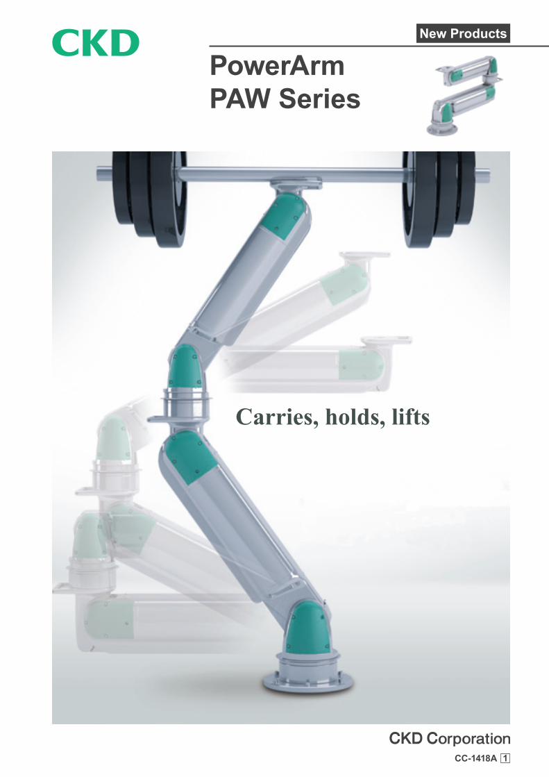
Compatible as an assistive systemIn addition to the assistive components as single units, we address requests including attachments, controllers, and movable type dollies. Contact CKD for details.
Vacuum
Clamp
Dolly / anchor
Materials bag
Movable type Anchor fixed type
Plate-shaped workpieces, glass, etc.
Hook
Hanger
Roll material Round objects / containers / food trays
Internal diameter clamp External clamp

Example of controller interior.Let us go over your needs with you.
Vacuum
Clamp
Dolly / anchor
Materials bag
Movable type Anchor fixed type
Plate-shaped workpieces, glass, etc.
Hook
Hanger
Roll material Round objects / containers / food trays
Internal diameter clamp External clamp
Automatically balances in accordance with the detected weight
Controller design and manufactureWe propose ideal air circuits for various assistance mechanisms. Easy transport is possible with the ideal control method for your transported items. We also offer air circuits within the controller.
Operating pressure fixing control systemSuitable for assisting with the weight of jigs and tools.Control that maintains balance at a constant weight.
Automatic operating pressure regulating control systemSuitable for transport of various types of workpieces of differing weights.Control which detects the transported item weight at the tip, and automatically adjusts the operating pressure in response to weight changes.
Introduction to PowerArm onlineWe have prepared a PowerArm introductory site.* Depending on your smartphone environment, it may not be displayed correctly.
DemonstrationsWe perform demonstrations so that you can experience the actual PowerArm devices.We offer demonstrations at various locations. Contact CKD for details.
Compatible with FP Series for secure food manufacturing processes *
NSF H1 grease for
foodstuffs is used
This logo represents CKD’s stance to provide you with safe components for supporting your food manufacturing processes.
* Contact CKD for details.

PowerArm
PAW Series● Bore size: ø80/ø100/ø125
SpecificationsDescriptions PAW
Bore size mm ø80 ø100 ø125Working fluid Compressed airMax. working pressure MPa 0.7Min. working pressure MPa 0.25Proof pressure MPa 1.05Ambient temperature °C 5 to 60Cushion Rubber cushionLubrication Not availableLoad capacity (0.5 MPa pressurized) kg 30 50 80Air consumption ℓ/min (ANR) 7 13 24Note: Values are at air consumption 1 cycle/min. and working pressure 0.7 MPa.
Movable range·With single-axis
Model No.Movable rangeVertical (mm)
PAW-S-8 (ø80) 520PAW-S-X (ø100) 580PAW-S-Z (ø125) 650
·With multi-axis
Model No.Movable range
Vertical (mm) Horizontal (mm)PAW-M-8S 520 1200PAW-M-XS 580 1400PAW-M-ZS 650 1600PAW-M-8X 1100 1300PAW-M-XZ 1230 1500
PAW-M-8XS 1100 2000PAW-M-XZS 1230 2300PAW-M-8XZ 1750 2100
Note: Horizontal movable range is the maximum value at the descending edge of the vertical movable range. See the external dimensions for more information on the movable range.
Weight
Model No. Weight (kg)Optional additional weight (kg)
L (rotation lock mechanism) R (tip rotation mechanism) LRPAW-M-8 27 0.5 4 5PAW-M-X 38 0.5 5.5 6.5PAW-M-Z 71 0.5 7.5 8.5
PAW-M-8S 46 1.0 4 5.5PAW-M-XS 77 1.0 5.5 7PAW-M-ZS 123 1.0 7.5 9PAW-M-8X 58 1.0 4 5.5PAW-M-XZ 102 1.0 5.5 7
PAW-M-8XS 96 1.5 4 6PAW-M-XZS 154 1.5 5.5 7.5PAW-M-8XZ 121 1.5 4 6
1

PAW SeriesHow to order
How to order
Load capacity under pressure
80
100
120
60
40
20
00.2 0.3 0.4 0.5 0.6 0.7 0.8
Pressure (MPa)
*1: Indicates the load capacity with the optional tip rotation mechanism mounted.*2: Attachment weight is not included.*3: While the load capacity has properties such that it alters slightly according to the arm rise angle, this graph shows the
lower limit values.
PAW-S-ZPAW-M-ZS
PAW-S-XPAW-M-XS
PAW-S-8PAW-M-8S
Number of sections
A
M
Combination contentsB
OptionC
R8XLo
ad c
apac
ity (k
g)
C Option: Bending directionBlank C
For 2-axis configuration For 3-axis configuration For 2-axis configuration For 3-axis configuration
* C is not available for single axis (PAW-S).
C Option: Piping leadout directionBlank U
* Piping holes at the mounting surface center are required for U.
PAW-M-8XPAW-M-8XSPAW-M-8XZ
PAW-M-XZPAW-M-XZS
A Number of sectionsSingle-
axisMulti-axis
Code Content S MB Combination contents
8 ø80 single-axis ●X ø100 single-axis ●Z ø125 single-axis ●
8S ø80 + SCARA arm ●XS ø100 + SCARA arm ●ZS ø125 + SCARA arm ●8X ø80 + ø100 ●XZ ø100 + ø125 ●
8XS ø80 + ø100 + SCARA arm ●XZS ø100 + ø125 + SCARA arm ●8XZ ø80 + ø100 + ø125 ●
C OptionL Rotation lock mechanism ● ●R Tip rotation mechanism ● ●
C Bending direction (Refer to the figure at left) ●
U Piping leadout direction(Refer to the figure at left) ● ●
PAW
2
PAW Series
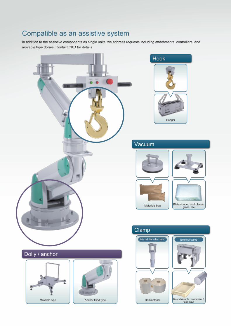
Dimensions (single-axis)
● PAW-S-8-R (ø80 single-axis)
● PAW-S-X-R (ø100 single axis)
160
160
300°
300°
300
391
600
700
354
55
416
281
335
1919
Verti
cal m
ovab
le ra
nge
520
Verti
cal m
ovab
le ra
nge
580
Point P
Point P
R600
R700
160
160
80
50
30
76
30
5080
76
ø260
ø260
4-ø12
4-ø12
ø36 +0.10 depth 6
ø46 +0.1 0 depth 6
ø36 0-0.2
ø46 0-0.2
P.C.D. 52
P.C.D. 62
4-M8 depth 16
4-M8 depth 16
8-M8 depth 16
8-M8 depth 20
45°
45°
45°
45°
* Refer to page 13 for the optional dimensions of the tip rotation mechanism (R) option.
Top without tip rotation mechanism R
Top without tip rotation mechanism R
Shows dimensions with tip rotation mechanism R.Plane view shows movable view at the descending edge.Structurally, the movable range changes according to the rising height.
Shows dimensions with tip rotation mechanism R.Plane view shows movable view at the descending edge.Structurally, the movable range changes according to the rising height.
3

PAW SeriesDimensions (single-axis)
Dimensions (single-axis)● PAW-S-Z-R (ø125 single axis)
260
300°
468
800
489
396
22
Verti
cal m
ovab
le ra
nge
650
Point PR800
300150
60 100
ø340
6-ø14
ø56 +0.1 0 depth 6
ø56 0-0.2
P.C.D. 774-M10 depth 20
8-M10 depth 18
45° 45°
* Refer to page 13 for the optional dimensions of the tip rotation mechanism (R) option.
Top without tip rotation mechanism R
Shows dimensions with tip rotation mechanism R.Plane view shows movable view at the descending edge.Structurally, the movable range changes according to the rising height.
60
100
5
4

Dimensions (multi-axis)
● PAW-M-8S-R (upper section ø80 + lower section SCARA arm)
PAW Series
* Refer to page 13 for the optional dimensions of the tip rotation mechanism (R) option.* For the bending direction (C) option, the movable direction is laterally symmetrical.
160
520
600 600
1200
552
2
449
19
Vertic
al mo
vable
rang
e 520
Horizontal movable range 600Point P
R1200
R600
R600
160
300 300
300
80
30
30 80
ø260
4-ø12
ø36 +0.1 0 depth 6
ø36 0-0.2
P.C.D. 524-M8 depth 16
8-M8 depth 16
45° 45°
Shows dimensions with tip rotation mechanism R.Plane view shows movable view at the point P descending edge.Structurally, the movable range changes according to the point P rising height.
Top without tip rotation mechanism R
Enlarged view
5

Dimensions (multi-axis)
● PAW-M-XS-R (upper section ø100 + lower section SCARA arm)
PAW SeriesDimensions (multi-axis)
* Refer to page 13 for the optional dimensions of the tip rotation mechanism (R) option.* For the bending direction (C) option, the movable direction is laterally symmetrical.
130
130
606
700 700
1400
562
854
7
22
Vertic
al mo
vable
rang
e 580
Horizontal movable range 783
Point P
R1400
R700
R70
0
300150
350 350
309
7650
50 76
ø340
6-ø14
ø46 +0.1 0 depth 6
ø36 0-0.2
P.C.D. 624-M8 depth 16
8-M8 depth 20
45° 45°
Shows dimensions with tip rotation mechanism R.Plane view shows movable view at the point P descending edge.Structurally, the movable range changes according to the point P rising height.
Top without tip rotation mechanism R
Enlarged view
6
Dimensions (multi-axis)
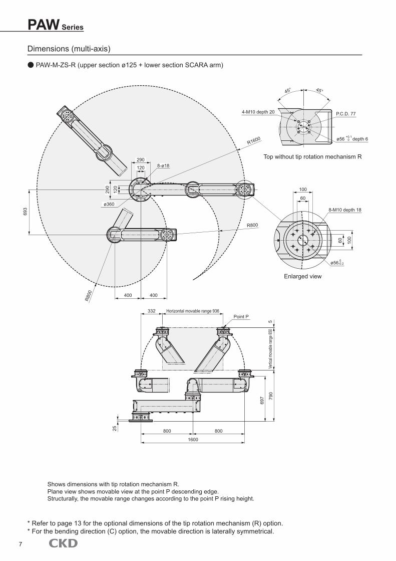
● PAW-M-ZS-R (upper section ø125 + lower section SCARA arm)
PAW Series
290
120
693
800 800
1600
579
0
697
25
Vertic
al mo
vable
rang
e 650
Horizontal movable range 936Point P
R1600
R800
R80
0
290
120
400 400
332
100
60
60 100
ø360
8-ø18
ø56 +0.1 0 depth 6
ø56 0-0.2
P.C.D. 774-M10 depth 20
8-M10 depth 18
45° 45°
Shows dimensions with tip rotation mechanism R.Plane view shows movable view at the point P descending edge.Structurally, the movable range changes according to the point P rising height.
Top without tip rotation mechanism R
Enlarged view
* Refer to page 13 for the optional dimensions of the tip rotation mechanism (R) option.* For the bending direction (C) option, the movable direction is laterally symmetrical.
7

Dimensions (multi-axis)
● PAW-M-8X-R (upper section ø80 + lower section ø100)
PAW SeriesDimensions (multi-axis)
160
606
700 600
1300
567
0
597
19
Verti
cal m
ovab
le ra
nge
1100
Horizontal movable range 591Point P
R1300
R600
R60
0
160
350 350
100
80
30
30 80
ø260
4-ø12
ø36 +0.1 0 depth 6
ø36 0-0.2
P.C.D. 524-M8 depth 16
8-M8 depth 16
45° 45°
Shows dimensions with tip rotation mechanism R.Plane view shows movable view at the point P descending edge.Structurally, the movable range changes according to the point P rising height.
Top without tip rotation mechanism R
Enlarged view
* Refer to page 13 for the optional dimensions of the tip rotation mechanism (R) option.* For the bending direction (C) option, the movable direction is laterally symmetrical.
8

Dimensions (multi-axis)
● PAW-M-XZ-R (upper section ø100 + lower section ø125)
PAW Series
Shows dimensions with tip rotation mechanism R.Plane view shows movable view at the point P descending edge.Structurally, the movable range changes according to the point P rising height.
260
693
800 700
1500
579
3
712
22
Verti
cal m
ovab
le ra
nge
1230
Horizontal movable range 758
Point P
R1500
R700
R700
300
150
400 400
100
76
50
50 76
ø340
6-ø14
ø46 +0.1 0 depth 6
ø46 0-0.2
P.C.D. 624-M8 depth 16
8-M8 depth 20
45° 45°
Top without tip rotation mechanism R
Enlarged view
* Refer to page 13 for the optional dimensions of the tip rotation mechanism (R) option.* For the bending direction (C) option, the movable direction is laterally symmetrical.
9
PAW SeriesDimensions (multi-axis)
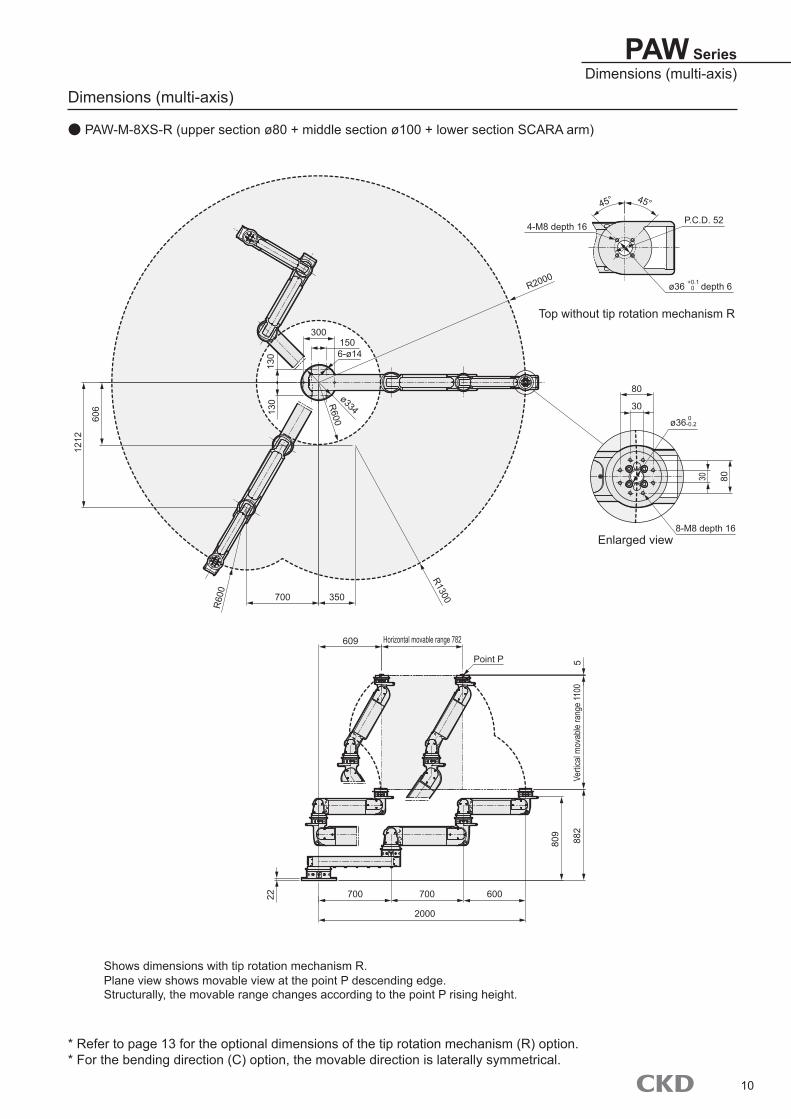
Dimensions (multi-axis)
● PAW-M-8XS-R (upper section ø80 + middle section ø100 + lower section SCARA arm)
130
130
606
1212
700 700 600
2000
588
2
809
22
Verti
cal m
ovab
le ra
nge
1100
Horizontal movable range 782
Point P
R2000
R600
R1300
R60
0
300150
700 350
609
80
30
30 80
ø334
6-ø14
ø36 +0.1 0 depth 6
ø36 0-0.2
P.C.D. 524-M8 depth 16
8-M8 depth 16
45° 45°
Shows dimensions with tip rotation mechanism R.Plane view shows movable view at the point P descending edge.Structurally, the movable range changes according to the point P rising height.
Top without tip rotation mechanism R
Enlarged view
* Refer to page 13 for the optional dimensions of the tip rotation mechanism (R) option.* For the bending direction (C) option, the movable direction is laterally symmetrical.
10
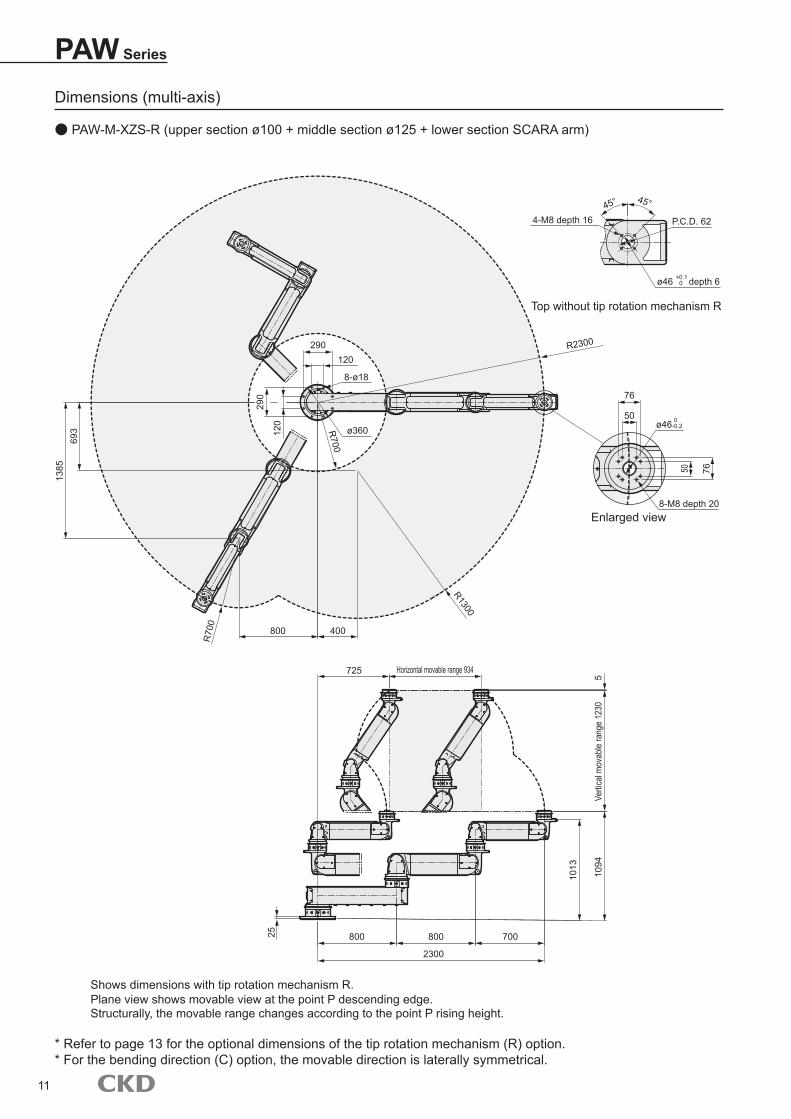
PAW Series
Dimensions (multi-axis)
● PAW-M-XZS-R (upper section ø100 + middle section ø125 + lower section SCARA arm)
120
290
693
1385
800 800 700
2300
510
94
1013
25
Verti
cal m
ovab
le ra
nge
1230
Horizontal movable range 934
R2300
R700
R1300
R70
0
290120
800 400
725
76
50
50 76
ø360
8-ø18
ø46 +0.1 0 depth 6
ø46 0-0.2
P.C.D. 624-M8 depth 16
8-M8 depth 20
45° 45°
Shows dimensions with tip rotation mechanism R.Plane view shows movable view at the point P descending edge.Structurally, the movable range changes according to the point P rising height.
Top without tip rotation mechanism R
Enlarged view
* Refer to page 13 for the optional dimensions of the tip rotation mechanism (R) option.* For the bending direction (C) option, the movable direction is laterally symmetrical.
11
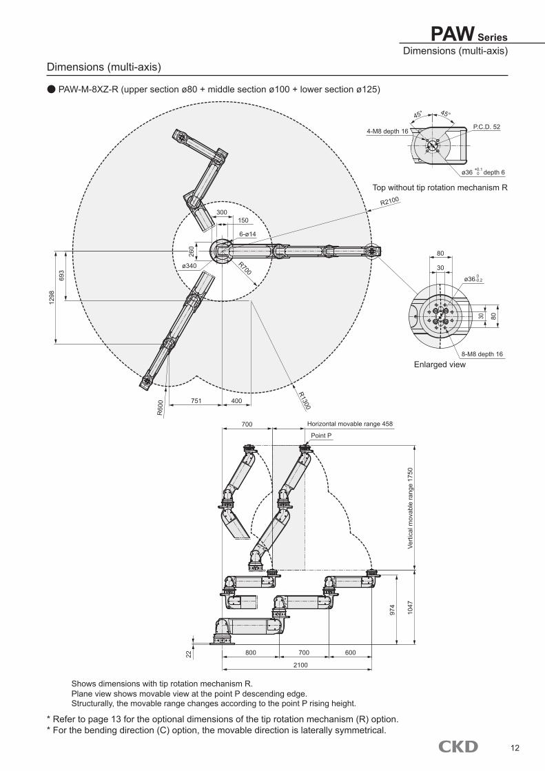
PAW SeriesDimensions (multi-axis)
Dimensions (multi-axis)
● PAW-M-8XZ-R (upper section ø80 + middle section ø100 + lower section ø125)
260
693
1298
800 700 600
2100
1047
974
22
Verti
cal m
ovab
le ra
nge
1750
Horizontal movable range 458
R2100
R700
R1300
R60
0
300150
751 400
700
80
30
30 80
ø340
6-ø14
ø36 +0.1 0 depth 6
ø36 0-0.2
P.C.D. 524-M8 depth 16
8-M8 depth 16
45° 45°
Shows dimensions with tip rotation mechanism R.Plane view shows movable view at the point P descending edge.Structurally, the movable range changes according to the point P rising height.
Top without tip rotation mechanism R
Enlarged view
Point P
* Refer to page 13 for the optional dimensions of the tip rotation mechanism (R) option.* For the bending direction (C) option, the movable direction is laterally symmetrical.
12

Optional dimensions
PAW Series
● Tip rotation mechanism (R)
·For PAW-S-Z-R PAW-M-ZS-R
·For PAW-S-8-R PAW-M-8S-R PAW-M-8X-R PAW-M-8XS-R PAW-M-8XZ-R
·For PAW-S-X-R PAW-M-XS-R PAW-M-XZ-R PAW-M-XZS-R
ø120
ø170
ø140
ø156
ø206
ø176
73
90
81
80
100
76
80
100
76
30
60
50
30
60
50
5
5
5
8-M8 depth 16
8-M10 depth 18
8-M8 depth 20
ø36 0-0.2
ø56 0-0.2
ø46 0-0.2
13

Discrete unit model No.
PAW SeriesDiscrete unit model No.
PowerArm unit
PAW-AU-( )8 ø80X ø100Z ø125
SCARA arm unit
PAW-SU-( )8S For AU-8 (AU-8 lower part)XS For AU-X (AU-X lower part)ZS For AU-Z (AU-Z lower part)
Rotation lock unit
PAW-LU...Common to each rotation unit (1 unit is required for each rotation unit location)
·Refer to the Instruction Manual for details about assembly and piping. An air tube must be prepared separately.·A bolt and washer for fastening is attached with each unit.
Example: When configuring PAW-M-XZS-R
Rotation unit
PAW-RU-( )T AU-8 tip part8 AU-8 base part / AU-X tip partX AU-X base part / AU-Z tip partZ AU-Z base part
ZS SU-Z base part
Base plate
PAW-BP-( )8 AU-8 base part (assembled to RU-8)X AU-X base part (assembled to RU-X)Z AU-Z base part (assembled to RU-Z)
ZS SU-Z base part (assembled to RU-ZS)
PAW-AU-X
PAW-RU-ZS
PAW-SU-ZS
PAW-RU-X
PAW-BP-ZS
PAW-RU-8
PAW-AU-Z
PAW-RU-Z
14

PAW Series
Anchor work
Product model No. Chemical anchor types Anchor bar dimensions No. of
units
(1) PAW-S-8,PAW-S-X PAW-M-8X,PAW-M-8S
R-10N or R-10LN
W3/8’’ or M10 4
(2)PAW-S-Z,PAW-M-XZ
PAW-M-8XZ,PAW-M-XS PAW-M-8XS
R-12N or R-12LN
W1/2’’ or M12 6
(3) PAW-M-ZS PAW-M-XZS
R-16N or R-16LN
W5/8’’ or M16 8
· If mounting to a frame or dolly, etc., use 10.8 or 12.9 category bolt strength, and check that the screw insertion depth is 1.5D or more.· When installing the product, make sure that the installation surface is accurately leveled. If not level, position holding may become impossible due to arm tip tilting or arm imbalance.
· Installation must be performed by a professional.
· When installing on an existing concrete floor (which must include reinforcing bars [ø6 or more]), use a chemical anchor (made by Nihon Decoluxe Co., Ltd.).
· For chemical anchor types, anchor bar dimensions, No. of units, and installation dimensions, refer to the table and figures below. Perform installation (drilling) as shown in the chemical anchor Instruction Manual.
Installation dimensions
Rotating movable range Rotating movable rangeRotating movable range
160
150120
300290
(1)
(2) (3)
160
120
290
130
130
15

PAW SeriesExtension arm
Extension armWhen a wider movable range must be secured, or when the workpiece is suspended for transport, an extension arm can be installed on the arm upper part.When designing the attachment, refer to page 17, and be careful to maintain the allowable moment or below.
Example: Movable range when the arm extension is installed on PAW-M-XZ (upper section ø100 + lower section ø125)
260
693
1299
800 700 1000
2500
971
893
22
715
73
5Ve
rtical
mova
ble ra
nge 1
230
Horizontal movable range 758Extension arm
R2500
R1050
R1700
R10
00
300150
750 400
1100
80
30
30 80
ø3406-ø14
ø36 0-0.2
8-M8 depth 16
4-M8 depth 12
P.C.D. 52
45° 45°ø36
Shows dimensions with tip rotation mechanism R.Plane view shows movable view at the point P descending edge.Structurally, the movable range changes according to the point P rising height.
Contact CKD for details.
Bottom or top without tip rotation mechanism (selectable)
Tip rotation mechanism can also be mounted to
the upper side
Enlarged view of bottom (if mounting the tip rotation
mechanism to the top, enlarged view of top)
Point P
16

PAW Series
Moment load
When mounting the extension arm
M1=(m1+W)×L+m2×L/2
m1: Attachment/operation box weight m2: Extension arm weight W: Weight of workpiece L: Distance from the PowerArm mounting part
to the center of gravity of the attachment/workpiece
When mounting the extension arm (1) Moment applied to the upper section M1=(m1+W)×L+m2×L/2 (2) Moment applied to the lower section M2= (m1+W)×(L+X)+m2×(L/2+X)
+m3×X/2+m4×X
m1: Attachment/operation box weight m2: Extension arm weight m3: PowerArm weight
PAW-AU-8: 14kg PAW-AU-X: 23kg PAW-AU-Z: 42kg
m4: Rotation unit weightPAW-RU-T: 4kg PAW-RU8: 5kgPAW-RU-X: 8kg
W: Weight of workpiece L: Distance from the PowerArm mounting part to the
center of gravity of the attachment/workpiece X: PowerArm length
PAW-AU-8: 600mm, PAW-AU-X: 700mm
When the attachment is offset (1) Moment applied to the upper sectionM1=m1×L1+W×L
(2) Moment applied to the lower sectionM2= W×(L+X)+m1×(L1+X)+m3×X/2
+m4×X
m1: Attachment/operation box weight m3: PowerArm weight
PAW-AU-8: 14kg PAW-AU-X: 23kg PAW-AU-Z: 42kg
m4: Rotation unit weightPAW-RU-T: 4kg PAW-RU-8: 5kgPAW-RU-X: 8kg
W: Weight of workpiece L1: Distance from the PowerArm mounting part to the
center of gravity of the attachment/operation box L: Distance from the PowerArm mounting part
to the center of gravity of the workpiece X: PowerArm length
PAW-AU-8: 600mm, PAW-AU-X: 700mm
When the attachment is offset
M1=m1×L1+W×L
m1: Attachment/operation box weight W: Weight of workpiece L1: Distance from the PowerArm mounting
part to the center of gravity of the attachment/operation box
L: Distance from the PowerArm mounting part to the center of gravity of the workpiece
[When upper and lower movable arms are single-axis]
[When upper and lower movable arms are 2-axis]
Model No. M1(N ·m)PAW-S-8 350PAW-S-X 550PAW-S-Z 900PAW-M-8S 350PAW-M-XS 550PAW-M-ZS 900* Design the workpiece, attachment,
and extension arm so that the moment load is at or below the value in the table.
* Calculate the movable arm part only.
Model No. Upper section M1 (N ·m)
Lower section M2 (N ·m)
PAW-M-8X 350 550PAW-M-XZ 550 900PAW-M-8XS 350 550PAW-M-XZS 550 900* Design the workpiece, attachment, and extension arm so that the moment load is at or below the value in the table.* Calculate the movable arm part only.
L Extension arm
Attachment/ operation box
L L
L
L/2M1 M1
L/2 L1
Lower section Lower section
Upper section Upper section
L1
m2
m1m2
m3 m3
m1
m1+W
X X
X/2 X/2
W
W
M2 M2
M1m4
M1m4
m1+W
17

PAW SeriesTechnical data
Moment load
When the attachment is offset (1) Moment applied to the upper section M1=m1×L1+W×L (2) Moment applied to the middle section M2= W×(L+X)+m1×(L1+X)+m3×X/2+m4×X (3) Moment applied to the lower section M3= W×(L+X+Y)+m1×(L1+X+Y)+m3×(X/2+Y)+m4×(X+Y)+m5×Y/2+m6×Y
m1: Attachment/operation box weight m3: PowerArm weight; PAW-AU-8: 14 kg m4: Rotation unit weight; PAW-RU-T: 4 kg m5: PowerArm weight; PAW-AU-X: 23 kg m6: Rotation unit weight; PAW-RU-8: 5 kg W: Weight of workpiece L1: Distance from the PowerArm mounting part to the center of gravity of the attachment/operation box L: Distance from the PowerArm mounting part to the center of gravity of the workpiece X: PowerArm length; PAW-AU-8: 600 mm Y: PowerArm length; PAW-AU-X: 700 mm
[When upper and lower movable arms are 3-axis]
Model No. Upper sectionM1(N ·m)
Middle sectionM2(N ·m)
Lower sectionM3(N ·m)
PAW-M-8XZ 350 550 900* Design the workpiece, attachment, and extension arm so that the moment load is at or below the value in the table.* Calculate the movable arm part only.
L
Y/2
L1XY
X/2
Lower section
Upper section
Upper sectionm1
m3
m5
M1
M2
M3
Wm4
m6
18

Safety PrecautionsBe sure to read this section before use.
When designing and manufacturing equipment using CKD products, the manufacturer is obligated to ensure that the safety of the mechanism, pneumatic control circuit and/or water control circuit and the system that runs the electrical controls are secured.It is important to select, use, handle and maintain CKD products appropriately to ensure their safe usage.Observe warnings and precautions to ensure device safety.Check that device safety is ensured, and manufacture a safe device.
1 This product is designed and manufactured as a general industrial machine part.It must be handled by an operator having sufficient knowledge and experience.
2 Use this product in accordance with specifications.This product must be used within its stated specifications. In addition, never modify or additionally machine this product.This product is intended for use in general industrial machinery equipment or parts. It is not intended for use outdoors (except for products with outdoor specifications) or for use under the following conditions or environments.(Note that this product can be used when CKD is consulted prior to its usage and the customer consents to CKD product specifications. The customer should provide safety measures to avoid danger in the event of problems.)1 Use for applications requiring safety, including nuclear energy, railways, aircraft, marine vessels, vehicles, medical
devices, devices or applications in contact with beverages or foodstuffs, amusement devices, emergency cutoff circuits, press machines, brake circuits, or safety devices or applications.
2 Use for applications where life or assets could be significantly affected, and special safety measures are required.3 Observe organization standards and regulations, etc., related to the safety of the device
design and control, etc.ISO4414, JIS B 8370 (General rules for pneumatic systems) JFPS2008 (Principles for pneumatic cylinder selection and use) Including High Pressure Gas Safety Act, Industrial Safety and Health Act, other safety rules, body standards and regulations, etc.
4 Do not handle, pipe, or remove devices before confirming safety.1 Inspect and service the machine and devices after confirming safety of all systems related to this product.2 Note that there may be hot or charged sections even after operation is stopped.3 When inspecting or servicing the device, turn OFF the energy source (air supply or water supply), and turn OFF
power to the facility. Discharge any compressed air from the system, and pay attention to possible water leakage and leakage of electricity.
4 When starting or restarting a machine or device that incorporates pneumatic components, make sure that the system safety, such as pop-out prevention measures, is secured.
5 Observe the warnings and cautions on the following pages to prevent accidents.
■ Precautions are ranked as “DANGER”, “WARNING”, and “CAUTION” in this section.
DANGER: In the case where the product operation is mishandled and/or when the urgency of a dangerous situation is high, it may lead to fatalities or serious injuries.
WARNING: A dangerous situation may occur if handling is mistaken, leading to fatal or serious injuries.
CAUTION: A dangerous situation may occur if handling is mistaken, leading to minor injuries or property damage.
Note that some items indicated with “CAUTION” may lead to serious results depending on the conditions.All items contain important information and must be observed.
Limited warranty and disclaimer1 Warranty period
This warranty is valid for one (1) year after delivery to the customer’s designated site.2 Scope of warranty
In case any defect clearly attributable to CKD is found during the warranty period, CKD shall, at its own discretion, repair the defect or replace the relevant product in whole or in part and at no cost, according to its own judgment.Note that the following failures are excluded from the warranty scope:(1) Failures due to use outside the conditions and environments set forth in the catalog or these specifications.(2) Failures resulting from factors other than this product.(3) Failures caused by improper use of the product.(4) Failures resulting from modifications or repairs made without CKD consent.(5) Failures caused by matters that could not be predicted with the technologies in practice when the product was
delivered.(6) Failures resulting from natural disasters or accidents for which CKD is not liable.The warranty covers the actual delivered product, as a single unit, and does not cover any damages resulting from losses induced by malfunctions in the delivered product.
3 Compatibility checkThe customer is responsible for confirming the compatibility of CKD products with the customer’s systems, machines and equipment.
WARNING
19

■ Design/selection
■ Use/maintenance
■ Design/selection
[Pneumatic source]● Prepare pneumatic pressure supplied to the PowerArm in
the range of operating pneumatic pressure (balance pressure) + 0.05 MPa to 0.7 MPa.
● Prepare clean air ([standard air circuit] compressed air quality class: 1.5.1 to 1.6.1 equivalent) for supplied air.
● Securely connect pneumatic piping, so that it does not come out while working.
[Recommended air circuit]● To prevent sudden rising and falling during air supply, use
the recommended circuit below.
■ Air 1 pressure controlControl that maintains balance at a constant weight.Suitable for assisting with the weight of heavy jigs and tools.
■ Air 2 pressure controlGiven balance preset with and without transported objects, the control can be changed between them using switch operation.This is well suited to batch production, such as continuous transport of identical products.
■ Automatic pneumatic pressure adjustment controlThis control supports random weights by detecting the weight of transported objects at the tip.It is suitable for handling multi-model transported objects.
[During adjustment]● Each PowerArm unit has a block valve built in.
The block valve serves as a vertical lock which is released by pressurization. If malfunctions, etc., cause the primary pressure (source pressure) to increase sharply and activate the block valve, once the primary pressure has been restored and balance pressure supplied to the cylinder port, pressurize the lock release port to release the lock. Releasing the lock without supplying balance pressure is dangerous, as the arm may fall.
● Each unit single item cannot be disassembled. Do not disassemble, as it could impair the original performance and accuracy.
● For an overhaul of unit single items, contact a CKD representative.
[Tip hazards]● Do not use in excess of the maximum load capacity.● Do not use in excess of the moment load.
[Dolly mounting use hazards]● Do not use in excess of the tipping moment load.● Use on a firmly paved, flat surface.● Install a brake mechanism to the dolly casters, and apply
the brakes when performing product and device operation.● For an outrigger dolly, install an interlock mechanism that
enables product and device operation only when the outrigger is completely extended.
● Move the dolly when the arm tip is completely lowered; for multiple axes, move only with the product folded into its most compact state.
● Do not move the dolly when the arm tip part (including mounted attachments and jigs, etc.) is carrying transported items.
● This product is a pneumatic assistive device, intended for use as a machine with a jig, attachment, etc. mounted to the arm tip. For use, be sure to implement a risk assessment for the machine overall, and confirm safety before use. In addition, the end user should perform a risk assessment on the user side, based on residual risk information for the machine overall, and stipulate a safe operating method for use.
● During attachment manufacture and control circuit design, mount an interlock circuit for detecting whether a workpiece is present, preventing unforeseen action of the arm.
● If vibrations, noise, or other abnormalities occur, first assure your own safety, and then, if possible in safety, apply the lock. A fatal accident or total damage to the device may occur.
● Do not modify the product or device without the manufacturer's approval.● Do not put hands or fingers into product or device gaps.● When placing transported items on the arm tip part (including
mounted attachments and jigs, etc.), do not stack lopsidedly or so as to tip the load over.
● During work or transport operation, never move away from the product or device. When releasing contact, always be sure to apply the lock, even if it is in a balanced state.
PAW SeriesSafety precautions
WARNING
CAUTION
Safety precautions (excerpt) Be sure to read the Instruction Manual before use.
Compressor Surge tank Refrigeration air dryer
After cooler
Main line filter
Filter Oil mist separator
Regulator
Standard air circuit
Block valve
Lock release port When pressurized: Locking is released When released: Locking is on
Cylinder port
[Circuit example]
Operating section
Pressure adjustment
section
Operating section
Built-in block valve
[Circuit example]
Operating section
Pressure adjustment
section
Operating section
Built-in block valve
[Circuit example]
Load cell
PLC Operation switchAmplifier
Built-in block valve
20

øL
W
HH
FL
A
BC
D
2. Shape/weight/type of workpiece to be transportedFill in the shape dimensions.
3. PAW tip attachment* If CKD is selected as the manufacturer, detailed dimensions of the workpiece are required.
When manufactured by customer
(CKD/customer)
4. PAW control box
5. PAW power source* For air supply pressure, fill in the pressure which can be supplied by the customer.
6. PAW installation method
7. PAW working environment
8. PAW operating frequency
Start point
Workpiece
Workpiece
DollyDolly
Conveyor
End point
■9. Work layout
(6) Type Type
* For multiple workpieces, attach the shape dimensions separately.
■ Pneumatic supply pressure V
(Required / Not required)
mm
mm
kg(5) Weight
■ Fixed on floor / Movable on floor (dolly) / Other ( )
■ Water drops (Yes / No) ■ Dust (Yes / No) ■ Other ( )
mm
Customer company name
Address
1. Enter details of work in progress and purpose of use for PAW.
mm(1) Height
PAW Order Sheet (Basic Specifications)
(4) Diameter ø =
Contact
Date
ContactOffice manager
Sales office
(2) Width
kg
■ Control method
MPa
■ Summary weight
(3) Depth
H =
W =
L =
■ Power
■ Manufacturer
times/day days/month
Approx.
Fork / Chuck / Vacuum suction / Other ( )■ Grip method
■ Manufacturer
(Manual pressure regulating control system / Automatic pressure regulating control system)
Examples of shape dimensions
When considering the arm shaft configuration, we need to confirm the vertical and horizontal movable range required.
Provide layout dimensions with the workpiece start and end points indicated.* Attach drawings if available.
The figure below is an example of layout dimensions showing the start and end point height positions.
Layout diagram showing the start and end point heights when picking workpieces up off the conveyor and stacking them in 4 rows 4 deep on a transport dolly
A: Workpiece start point height B: Workpiece end point maximum height C: Workpiece end point minimum height D: Dolly table height
21
øL
W
HH
FL
A
BC
D
2. Shape/weight/type of workpiece to be transportedFill in the shape dimensions.
3. PAW tip attachment* If CKD is selected as the manufacturer, detailed dimensions of the workpiece are required.
When manufactured by customer
(CKD/customer)
4. PAW control box
5. PAW power source* For air supply pressure, fill in the pressure which can be supplied by the customer.
6. PAW installation method
7. PAW working environment
8. PAW operating frequency
Start point
Workpiece
Workpiece
DollyDolly
Conveyor
End point
■9. Work layout
(6) Type Type
* For multiple workpieces, attach the shape dimensions separately.
■ Pneumatic supply pressure V
(Required / Not required)
mm
mm
kg(5) Weight
■ Fixed on floor / Movable on floor (dolly) / Other ( )
■ Water drops (Yes / No) ■ Dust (Yes / No) ■ Other ( )
mm
Customer company name
Address
1. Enter details of work in progress and purpose of use for PAW.
mm(1) Height
PAW Order Sheet (Basic Specifications)
(4) Diameter ø =
Contact
Date
ContactOffice manager
Sales office
(2) Width
kg
■ Control method
MPa
■ Summary weight
(3) Depth
H =
W =
L =
■ Power
■ Manufacturer
times/day days/month
Approx.
Fork / Chuck / Vacuum suction / Other ( )■ Grip method
■ Manufacturer
(Manual pressure regulating control system / Automatic pressure regulating control system)
Examples of shape dimensions
When considering the arm shaft configuration, we need to confirm the vertical and horizontal movable range required.
Provide layout dimensions with the workpiece start and end points indicated.* Attach drawings if available.
The figure below is an example of layout dimensions showing the start and end point height positions.
Layout diagram showing the start and end point heights when picking workpieces up off the conveyor and stacking them in 4 rows 4 deep on a transport dolly
A: Workpiece start point height B: Workpiece end point maximum height C: Workpiece end point minimum height D: Dolly table height
9-1. Workpiece start point/end point position layout diagram (cross-section)
9-2. Workpiece start point/end point position layout diagram (plane figure) * Indicate the desired arm arrangement if applicable.
Include detailed dimensions, including peripheral equipment, in the layout diagram.10. Remarks and notes
PAW Order Sheet (Work Layout Diagram)
22

PAW Series
Related products
Ultra low friction balance cylinder BBS Series With position locking mechanism for safety concerns (BBS-OU)
Special packing and treatment for low sliding Compatible with lateral load as well (BBS-OS/OU-B)
Catalog No. CC-1212A
Precision regulator RP2000 Series High-precision pressure control
Repeatability: Within ±0.5% of full scale Sensitivity: Within 0.2% of full scale regardless of the flow rate.
Long service life Low-sliding packing used for moving parts. Also uses grease resistant to dry air.
Stable flow characteristics with minimal pressure drop Large relief flow rate
Catalog No. CC-1072A
Digital electro pneumatic regulator EVD Series Catalog No. CB-024SA
Balancer unit BBS Series A maximum load of 200 kg can be balanced with just 5 kg, and workpieces can be lifted with very little force
Brake equipped as standard. Safety mechanism that ensures workpieces do not fall even if the air is cut off
Retains optimal balance by automatically recognizing weight differences between workpieces (BBS-A)
Compatible with all-air method not requiring electricity. Specifications for explosion-proof environments also available
Catalog No. CC-960A
Superior operability and installability Digital display mounted to make control status visible at a glance Parallel input type equipped as standard Compact design Two-way connection possible with D sub-connector Enabling module connection
Built-in microcomputer for higher functionality Error display function Zero/span adjustment function Direct memory function Switch output function
High accuracy, quick response pressure control Eco-friendly design
Lead-free/PVC-free Materials display Auto power OFF function equipped to save energy
23

Air supply unit ASU Series
2 flow rates (72 ℓ/min, 25 ℓ/min)
Localized supply is enabled with easy installation.
Filter, drain separator, dryer, etc., converted to one unit (300 W only)
Pressure source for emergency use (supports BCP)
Catalog No. CC-1284A
PAW SeriesRelated products
Made-to-order product
24

( 器 ) 世界カ (19.6.1)A-51.ai
TAIWAN CKD CORPORATION
CKD USA CORPORATION
CKD UK OFFICE
CKD EUROPE B.V.CKD EUROPE BRANCH
CKD FRANKFURTOFFICE
CKD CZECH OFFICE
CKD KOREA CORPORATION
CKD SINGAPORE PTE. LTD.CKD CORPORATION BRANCH OFFICE
CKD VIETNAM ENGINEERING CO.,LTD
PT CKD TRADING INDONESIA
M-CKD PRECISION SDN.BHD.
CKD THAI CORPORATION LTD.
CKD INDIA PRIVATE LTD.CKD INDIA PRIVATE LTD. BANGALORE OFFICE
CKD(SHANGHAI) CORPORATION
:Distributors
CKD MEXICO, S. DE R.L. DE C.V.
●Specifications are subject to change without notice.2019.10.CAC
CKD Corporation 2019 All copy rights reserved.
Website https://www.ckd.co.jp/U.S.A.CKD USA CORPORATION●CHICAGO HEADQUARTERS
1605 Penny Lane, Schaumburg, IL 60173, USAPHONE +1-847-648-4400 FAX +1-847-565-4923
・LEXINGTON OFFICE・SAN ANTONIO OFFICE・SAN JOSE OFFICE/ TECHNICAL CENTER・DETROIT OFFICE・BOSTON OFFICE
MexicoCKD MEXICO, S. DE R.L. DE C.V.
Cerrada la Noria No. 200 Int. A-01, Querétaro Park II, Parque Industrial Querétaro, Santa Rosa Jáuregui, Querétaro, C.P. 76220, MéxicoPHONE +52-442-161-0624EuropeCKD EUROPE B.V.
Beechavenue 125A, 1119 RB Schiphol-Rijk, the NetherlandsPHONE +31-23-554-1490
・GERMANY OFFICECKD CORPORATION EUROPE BRANCH●SALES HEADQUARTERS
Beechavenue 125A, 1119 RB Schiphol-Rijk, the NetherlandsPHONE +31-23-554-1490
・CZECH.O.Z.・UK OFFICE
MalaysiaM-CKD PRECISION SDN.BHD.●HEAD OFFICE
Lot No.6,Jalan Modal 23/2, Seksyen 23, Kawasan MIEL,Fasa 8, 40300 Shah Alam,Selangor Darul Ehsan, MalaysiaPHONE +60-(0)3-5541-1468 FAX +60-(0)3-5541-1533
・JOHOR BAHRU BRANCH OFFICE・PENANG BRANCH OFFICE
ThailandCKD THAI CORPORATION LTD.●SALES HEADQUARTERS
19th Floor, Smooth Life Tower, 44 North Sathorn Road, Silom, Bangrak, Bangkok 10500, ThailandPHONE +66-(0)2-267-6300 FAX +66-(0)2-267-6304-5
・RAYONG OFFICE・NAVANAKORN OFFICE・EASTERN SEABOARD OFFICE・LAMPHUN OFFICE・KORAT OFFICE・AMATANAKORN OFFICE・PRACHINBURI OFFICE・SARABURI OFFICE
SingaporeCKD SINGAPORE PTE. LTD.
No.33 Tannery Lane #04-01 Hoesteel Industr ial Building, Singapore 347789, Singapore PHONE +65-67442623 FAX +65-67442486CKD CORPORATION BRANCH OFFICE
No.33 Tannery Lane #04-01 Hoesteel Industr ial Building, Singapore 347789, Singapore PHONE +65-67447260 FAX +65-68421022IndiaCKD INDIA PRIVATE LTD.
Unit No. 607, 6th Floor, Welldone Tech Park, Sector 48, Sohna Road, Gurgaon-122018, Haryana, IndiaPHONE +91-(0)124-418-8212
CKD INDIA PRIVATE LTD. BANGALORE OFFICENovel Business Park, No. 57, 13th Cross Hosur Road, Anepalya, Bangalore-560047, IndiaPHONE +91-(0)80-4291-1144IndonesiaPT CKD TRADING INDONESIA●SALES HEADQUARTERS
Menara Bidakara 2, 18th Floor, Jl. Jend. Gatot Subroto Kav.71-73, Pancoran, Jakarta 12870, IndonesiaPHONE +62-(0)21-2938-6601 FAX +62-(0)21-2906-9470・BEKASI OFFICE・KARAWANG OFFICE・SURABAYA OFFICE
VietnamCKD VIETNAM ENGINEERING CO.,LTD.
18th Floor, CMC Tower, Duy Tan Street, Cau Giay District, Hanoi, Vietnam PHONE +84-(0)24-3795-7631 FAX +84-(0)24-3795-7637Taiwan台湾喜開理股 有限公司TAIWAN CKD CORPORATION
16F-3, No. 7, Sec. 3, New Taipei Blvd., Xinzhuang Dist., New Taipei City 242, TaiwanPHONE +886-(0)2-8522-8198 FAX +886-(0)2-8522-8128・新竹営業所(HSINCHU OFFICE)・台中営業所(TAICHUNG OFFICE)・台南営業所(TAINAN OFFICE)・高雄営業所(KAOHSIUNG OFFICE)
China喜開理(上海)機器有限公司CKD(SHANGHAI)CORPORATION●営業部 /上海浦西事務所(SALES HEADQUARTERS / SHANGHAI PUXI OFFICE)
Room 601, 6th Floor, Yuanzhongkeyan Building, No. 1905 Hongmei Road, Xinhui District, Shanghai 200233, ChinaPHONE +86-(0)21-61911888 FAX +86-(0)21-60905356・上海浦東事務所(SHANGHAI PUDONG OFFICE)・寧波事務所(NINGBO OFFICE)・杭州事務所(HANGZHOU OFFICE)・無錫事務所(WUXI OFFICE)・昆山事務所(KUNSHAN OFFICE)・蘇州事務所(SUZHOU OFFICE)・南京事務所(NANJING OFFICE)・合肥事務所(HEFEI OFFICE)・成都事務所(CHENGDU OFFICE)・武漢事務所(WUHAN OFFICE)・鄭州事務所(ZHENGZHOU OFFICE)・長沙事務所(CHANGSHA OFFICE)・重慶事務所(CHONGQING OFFICE)・西安事務所(XIAN OFFICE)・広州事務所(GUANGZHOU OFFICE)・中山事務所(ZHONGSHAN OFFICE)・深圳西事務所(WEST SHENZHEN OFFICE)・深圳東事務所(EAST SHENZHEN OFFICE)・東莞事務所(DONGGUAN OFFICE)・厦門事務所(XIAMEN OFFICE)・福州事務所(FUZHOU OFFICE)・瀋陽事務所(SHENYANG OFFICE)・長春事務所(CHANGCHUN OFFICE)・大連事務所(DALIAN OFFICE)・北京事務所(BEIJING OFFICE)・天津事務所(TIANJIN OFFICE)・青島事務所(QINGDAO OFFICE)・潍坊事務所(WEIFANG OFFICE)・済南事務所(JINAN OFFICE)・烟台事務所(YANTAI OFFICE)
KoreaCKD KOREA CORPORATION●HEADQUARTERS(3rd Floor), 44, Sinsu-ro, Mapo-gu, Seoul 04088, KoreaPHONE +82-(0)2-783-5201~5203 FAX +82-(0)2-783-5204・水原営業所(SUWON OFFICE)・天安営業所(CHEONAN OFFICE)・蔚山営業所(ULSAN OFFICE)
□ 2-250 Ouji, Komaki City, Aichi 485-8551, Japan□ PHONE +81-568-74-1338 FAX +81-568-77-3461
The goods and/or their replicas, the technology and/or software found in this catalog are subject to complementary export regulations by Foreign Exchange and Foreign Trade Law of Japan. If the goods and/or their replicas, the technology and/or software found in this catalog are to be exported from Japan, Japanese laws require the exporter makes sure that they will never be used for the development and/or manufacture of weapons for mass destruction.