AC30 series Variable Speed Drive - Momentum Automation
520
AC30 series Variable Speed Drive HA503711U003 Issue 4: Software Reference aerospace climate control electromechanical filtration fluid & gas handling hydraulics pneumatics process control sealing & shielding ENGINEERING YOUR SUCCESS.
-
Upload
khangminh22 -
Category
Documents
-
view
0 -
download
0
Transcript of AC30 series Variable Speed Drive - Momentum Automation

AC30 series Variable Speed Drive
HA503711U003 Issue 4: Software Reference
aerospaceclimate controlelectromechanicalfiltrationfluid & gas handlinghydraulicspneumaticsprocess controlsealing & shielding
ENGINEERING YOUR SUCCESS.

FAILURE OR IMPROPER SELECTION OR IMPROPER USE OF THE PRODUCTS DESCRIBED HEREIN OR RELATED ITEMS CAN CAUSE DEATH, PERSONAL INJURY AND PROPERTY DAMAGE.
This document and other information from Parker Hannifin Corporation, its subsidiaries and authorized distributors provide product or system options for further investigation by users having technical expertise.
The user, through its own analysis and testing, is solely responsible for making the final selection of the system and components and assuring that all performance, endurance, maintenance, safety and warning requirements of the application are met. The user
must analyze all aspects of the application, follow applicable industry standards, and follow the information concerning the product in the current product catalogue and in any other materials provided from Parker Hannifin Corporation or its subsidiaries or authorized
distributors.
To the extent that Parker Hannifin Corporation or its subsidiaries or authorized distributors provide component or system options based upon data or specifications provided by the user, the user is responsible for determining that such data and specifications are suitable
and sufficient for all applications and reasonably foreseeable uses of the components or systems.
The above disclaimer is being specifically brought to the user’s attention and is in addition to and not in substitution to the Exclusions and Limitations on Liability which are set out in the terms and conditions of sale.

AC30 Series Software ReferenceHA503711U003 Issue 4Compatible with Firmware versions X.19 onwards
2019 © Parker Hannifin Manufacturing Limited.
All rights strictly reserved. No part of this document may be stored in a retrieval system, or transmitted in any form or by any means to persons not employed by a Parker Hannifin Manufacturing Limited company without written permission from Parker Hannifin Manufacturing Ltd. Although every effort has been taken to ensure the accuracy of this document it may be necessary, without notice, to make amendments or correct omissions Parker Hannifin Manufacturing Limited cannot accept responsibility for damage, injury, or expenses resulting therefrom.
WARRANTYThe general terms and conditions of sale of goods and/or services of Parker Hannifin Europe Sàrl, Luxembourg, Switzerland Branch, Etoy, apply to this contract unless otherwise agreed. The terms and conditions are available on our website: www.parker.com/termsandconditons/switzerland
Parker Hannifin Manufacturing Limited reserved the right to change the content and product specification without notice.

Contents 1 Contents ....................................................................................... Page No. Contents .......................................................................................... Page No.
AC30 series Variable Speed Inverter
Chapter 1: Safety ............................................................. 1-1
Requirements .................................................................................... 1-1 Intended Users .......................................................................................... 1-1 Application Area ........................................................................................ 1-1 Personnel ................................................................................................... 1-2 Hazards ...................................................................................................... 1-2
Chapter 2: Introduction ................................................... 2-1
About this Manual ............................................................................ 2-1
Chapter 3: Product Overview .......................................... 3-1
Product Range .................................................................................. 3-1
Power Stack Features ...................................................................... 3-2
Functional Overview ........................................................................ 3-3
AC30 Series Control Features ......................................................... 3-7
Chapter 4: The Graphical Keypad .................................. 4-1
Overview ............................................................................................ 4-2
Keypad ............................................................................................... 4-3
LED Status Indication ...................................................................... 4-4 The Display........................................................................................ 4-5
Top Line - Inverter Status Summary ........................................................ 4-5 Bottom Line – Soft Key Action Indication ............................................... 4-6
The Menu System ............................................................................. 4-7
Trips and other information displays ............................................. 4-8
Setting the display language ........................................................... 4-8
Setup Wizard ..................................................................................... 4-9
Firmware Update ............................................................................ 4-10
Chapter 5: Menu Organisation ........................................ 5-1
Menu Map .......................................................................................... 5-1 Menu Map Summary .................................................................................. 5-1
Menu Descriptions ........................................................................... 5-2 Control Screen ........................................................................................... 5-2 Setup ........................................................................................................... 5-2 Monitor ........................................................................................................ 5-2 Favourites ................................................................................................... 5-2
Parameters ........................................................................................ 5-3 Parameter Map ........................................................................................... 5-3
Chapter 6: Setup Wizard .................................................. 6-1
GKP Setup Wizard ............................................................................ 6-1 Setup Wizard Stages ................................................................................. 6-2 Application selection ................................................................................. 6-3 Input and Output Option ........................................................................... 6-4 Analog Input and Output ........................................................................... 6-4 Motor Data .................................................................................................. 6-5 Fieldbus Options........................................................................................ 6-6 Autotune Parameters ................................................................................. 6-8 Finalising Setup ......................................................................................... 6-8
Set Up PMAC Motor Control - Sensorless ..................................... 6-9
Set Up PMAC Motor Control – Encoder Feedback ...................... 6-10
Set Up PMAC Motor Control – Pos Alignment after Power-up .. 6-12 Parker Drive Quicktool (PDQ) PC Software ................................. 6-13
Installation ................................................................................................ 6-13 Starting the Wizard .................................................................................. 6-15 Task selection .......................................................................................... 6-16 Application Macro .................................................................................... 6-19 Drive Hardware......................................................................................... 6-20 Motor Setup .............................................................................................. 6-21 Motor Control Strategy ............................................................................ 6-22 I/O .............................................................................................................. 6-23 Communications ...................................................................................... 6-24 Monitor the Drive ..................................................................................... 6-26

2 Contents
Contents ....................................................................................... Page No. Contents .......................................................................................... Page No.
AC30 series Variable Speed Inverter
Chapter 7: Trips & Fault Finding .................................... 7-1
What Happens when a Trip Occurs ................................................ 7-1 Keypad Indications ................................................................................... 7-1
Resetting a Trip Condition ............................................................... 7-1
Using the Keypad to Manage Trips ................................................ 7-2 Trip Messages ........................................................................................... 7-2
Hexadecimal Representation of Trips ............................................ 7-8
Runtime Alerts .................................................................................. 7-9
Autotune Alerts ............................................................................... 7-11
Other Alerts ..................................................................................... 7-12
Fault Finding ................................................................................... 7-14 Black Box Feature .......................................................................... 7-15
Black Box File Format............................................................................. 7-15 Diagnostic LEDs ............................................................................. 7-17
Chapter 8: Ethernet.......................................................... 8-1
Connecting to the Inverter ............................................................... 8-1 Recommended Cable ................................................................................ 8-1 AC30V......................................................................................................... 8-1 AC30P or AC30D ....................................................................................... 8-2
Ethernet Setup .................................................................................. 8-3 Configuration ............................................................................................. 8-3 Advanced Configuration ........................................................................... 8-3 Typical Wiring Configurations ................................................................. 8-6 Ethernet Parameter Summary .................................................................. 8-9 Troubleshooting the Ethernet ................................................................ 8-12
Web (HTTP) Server ......................................................................... 8-15 Web Pages ............................................................................................... 8-15 Web Server Parameter Summary ........................................................... 8-17 Troubleshooting the Web Server ........................................................... 8-18
Simple Network Time Protocol (SNTP) Client ............................. 8-19 SNTP Client Parameter Summary .......................................................... 8-19
SNTP Client Operation ............................................................................ 8-19 SNTP Relationship with time zone and Daylight Saving ...................... 8-19
Simple Network Time Protocol (SNTP) Server ............................ 8-20 SNTP Server Parameter Summary ......................................................... 8-20 SNTP Server Operation ........................................................................... 8-20
Precision Time Protocol (PTP) ...................................................... 8-21 Configuration ........................................................................................... 8-21 Advanced Configuration ......................................................................... 8-21 PTP Parameter Summary ........................................................................ 8-24
Peer to Peer ..................................................................................... 8-28 Configuration ........................................................................................... 8-28 Peer to Peer Parameter Summary .......................................................... 8-30
Chapter 2: Fire Mode ....................................................... 2-1
Configuration .................................................................................... 2-2
Functional Description ..................................................................... 2-3
Trips and Auto Restart ..................................................................... 2-4
Appendix A: Fieldbuses ................................................. A-1
Modbus TCP ..................................................................................... A-1 Introduction ............................................................................................... A-1 Fixed Parameter Mapping ........................................................................ A-2 User-Defined Parameter Mapping ........................................................... A-5 Password Protection ................................................................................ A-6 Supported Modbus Functions ................................................................. A-7 Modbus Exception Codes ........................................................................ A-8 Process Active and Lost Communications Trip..................................... A-8 Parameter Summary ................................................................................. A-9
EtherNet/IP Adapter ....................................................................... A-11 Introduction ............................................................................................. A-11 Inverter Configuration ............................................................................ A-12 Example PLC Configurations ................................................................ A-15 Explicit Access of Parameters ............................................................... A-24 Lost Communications Trip .................................................................... A-24 Troubleshooting and Tips ...................................................................... A-25

Contents 3 Contents ....................................................................................... Page No. Contents .......................................................................................... Page No.
AC30 series Variable Speed Inverter
CIP Objects .............................................................................................. A-26 Parameter Summary ............................................................................... A-30
PROFINET IO Device ..................................................................... A-32 Introduction ............................................................................................. A-32 Inverter Configuration............................................................................. A-33 Example PLC Configurations ................................................................. A-37 Acyclic Access of Inverter Parameters ................................................. A-48 Lost Communications Trip ..................................................................... A-51 Troubleshooting and Tips ...................................................................... A-51 Parameter Summary ............................................................................... A-52
Chapter 2: Sequencing Logic ......................................... 2-1
Drive State Machine ......................................................................... 2-1 DS402 ......................................................................................................... 2-1 Sequencing State ...................................................................................... 2-1 Sequencing Diagram................................................................................. 2-2 State Transitions ....................................................................................... 2-3 Control Word ............................................................................................. 2-5 Status Word ............................................................................................... 2-6
Appendix C: Parameter Reference ................................. C-1
Parameter Descriptions .................................................................. C-1 Active Front End (AFE) ............................................................................. C-2 App Info .................................................................................................... C-13 Auto Restart ............................................................................................. C-15 Autotune .................................................................................................. C-20 BACnet IP Option .................................................................................... C-24 BACnet MSTP Option.............................................................................. C-25 Black Box ................................................................................................. C-26 Braking ..................................................................................................... C-27 CANopen Option ..................................................................................... C-29 Clone ........................................................................................................ C-30 Communications Options ....................................................................... C-34 Configure, (Phase Control) ..................................................................... C-35 Control Mode ........................................................................................... C-38 ControlNet Option ................................................................................... C-42 Current Limit ............................................................................................ C-43 Current Loop .......................................................................................... C-44
Current Sensor Trip ................................................................................ C-45 Data Logger ............................................................................................. C-46 DC Link Volts Limit ................................................................................. C-51 Device Commands .................................................................................. C-53 Device State ............................................................................................ C-54 DeviceNet Option .................................................................................... C-56 Drive info ................................................................................................. C-57 Encoder ................................................................................................... C-62 Energy Meter ........................................................................................... C-64 EtherCAT Option ..................................................................................... C-66 Ethernet ................................................................................................... C-67 EtherNet IP Adapter ................................................................................ C-67 EtherNet IP Option .................................................................................. C-67 Fan Control .............................................................................................. C-68 Feedbacks ............................................................................................... C-69 Fieldbus Mapping ................................................................................... C-73 Filter On Torque Dmd ............................................................................. C-74 Flash File System.................................................................................... C-77 Fluxing VHz ............................................................................................. C-78 Flycatching .............................................................................................. C-83 General Purpose IO ................................................................................ C-85 Graphical Keypad ................................................................................... C-87 Induction Motor Data .............................................................................. C-90 Inj Braking ............................................................................................... C-92 IO Configure ............................................................................................ C-94 IO Option Common ............................................................................... C-100 IO Values ............................................................................................... C-102 Keypad Override ................................................................................... C-105 Local Control ......................................................................................... C-106 Maintenance Monitor ............................................................................ C-107 Minimum Speed .................................................................................... C-109 Modbus .................................................................................................. C-110 Modbus RTU Option ............................................................................. C-111 Modbus TCP Option ............................................................................. C-112 Motor Load ............................................................................................ C-113 Motor Nameplate ................................................................................... C-116 Motor Sequencer................................................................................... C-118 MRAS ..................................................................................................... C-119 Parameter Backup ................................................................................ C-121 Pattern Generator ................................................................................. C-122 Peer to Peer ........................................................................................... C-124

4 Contents
Contents ....................................................................................... Page No. Contents .......................................................................................... Page No.
AC30 series Variable Speed Inverter
PID .......................................................................................................... C-125 PMAC Flycatching ................................................................................. C-127 PMAC Motor Advanced ......................................................................... C-129 PMAC Motor Data .................................................................................. C-130 PMAC SVC ............................................................................................. C-134 Pos Fbk Alignment ................................................................................ C-142 Power Loss Ride Thru .......................................................................... C-150 Precision Time Protocol (PTP) ............................................................. C-153 Preset Speeds ....................................................................................... C-154 Profibus DP-V1 Option .......................................................................... C-156 PROFINET IO Option ............................................................................. C-157 Raise Lower ........................................................................................... C-158 Ramp ...................................................................................................... C-160 Real Time Clock .................................................................................... C-166 Resolver ................................................................................................. C-167 Runtime Statistics ................................................................................. C-172 SB Digital IO .......................................................................................... C-174 SB Encoder ............................................................................................ C-177 SB Encoder Slot 1 ................................................................................. C-180 SB Encoder Slot 2 ................................................................................. C-182 SB Retransmit ....................................................................................... C-183 Scale Setpoint ....................................................................................... C-186 SD Card .................................................................................................. C-187 Sequencing ............................................................................................ C-188 Setup Wizard ......................................................................................... C-192 Skip Frequencies .................................................................................. C-194 Slew Rate ............................................................................................... C-197 Slip Compensation ................................................................................ C-198 SNTP Client ............................................................................................ C-199 SNTP Server .......................................................................................... C-199 Soft Menus ............................................................................................. C-200 Spd Direct Input .................................................................................... C-202 Spd Loop Diagnostics .......................................................................... C-203 Spd Loop Settings................................................................................. C-204 Speed Error Trip .................................................................................... C-208 Speed Ref ............................................................................................... C-209 Stabilisation ........................................................................................... C-210 Stack Inv Time ....................................................................................... C-211 Stall Trip ................................................................................................. C-214 System Board Option............................................................................ C-215 Thermistor ............................................................................................. C-216
Torque Limit .......................................................................................... C-217 Tr Adaptation ........................................................................................ C-220 Trips History .......................................................................................... C-221 Trips Status ........................................................................................... C-222 VDC Ripple ............................................................................................ C-227 Voltage Control ..................................................................................... C-228 Web Server ............................................................................................ C-229
Parameter Tables ......................................................................... C-230 Parameters Defined in the Firmware ................................................... C-232 Parameters Defined in the Default Application .................................. C-265
Table of Parameters in Alphabetical Order ............................... C-266
Power Dependent Parameter Defaults ...................................... C-271
Appendix D: AC30 Series Product Codes ..................... D-1
Understanding the Product Code .................................................. D-1 AC30 Series Control Module .................................................................... D-1 AC30 Series Power Stack ......................................................................... D-2 Configured AC30 Series Inverter ............................................................. D-3 AC30 Series Regenerative Supply Unit ................................................... D-4
Appendix E: Library Function Blocks ............................ E-1
Introduction ...................................................................................... E-1
Function Block List ......................................................................... E-2 Blocks in “AC30 Standard” library .......................................................... E-2
Function Block Descriptions .......................................................... E-3 Abnormal Load Detect .............................................................................. E-3 Application Alert ....................................................................................... E-6 Application Trips....................................................................................... E-7 Application Trips Text .............................................................................. E-8 Brake Control ............................................................................................ E-9 Data Logger Int........................................................................................ E-11 Data Logger Real .................................................................................... E-11 Filter & Filter 2 ......................................................................................... E-13 Fire Mode ................................................................................................. E-14 Home ........................................................................................................ E-15

Contents 5 Contents ....................................................................................... Page No. Contents .......................................................................................... Page No.
AC30 series Variable Speed Inverter
KTY 84 130 Converter ............................................................................. E-16 Linear Fit .................................................................................................. E-17 Linear Fit 2 ............................................................................................... E-18 Linear Ramp ............................................................................................ E-20 Minimum Speed2 ..................................................................................... E-22 NTC Thermistor Converter ..................................................................... E-23 NTC Trip Levels ....................................................................................... E-24 PID ............................................................................................................ E-25 Position .................................................................................................... E-27 Presets2 ................................................................................................... E-28 PT1000 Converter .................................................................................... E-29 PT1000 Trip Levels .................................................................................. E-29 Queue Parameter Write........................................................................... E-30 Queued Write Control ............................................................................. E-30 Raise Lower ............................................................................................. E-32 Read Data From SD Card ........................................................................ E-33 Sequencing Logic2 ................................................................................. E-34 Skip Frequencies .................................................................................... E-36 Speed Sensor Fault Ride Through......................................................... E-38 S Ramp ..................................................................................................... E-39 Time Of Day Select .................................................................................. E-41 Welcome Screen ..................................................................................... E-43 Write Data to SD Card & Write Data to SD Card V2 .............................. E-44 Zero Speed ............................................................................................... E-45

6 Contents
Contents ....................................................................................... Page No. Contents .......................................................................................... Page No.
AC30 series Variable Speed Inverter
Safety 1-1
AC30 series Variable Speed Inverter
Chapter 1: Safety
Safety Information
IMPORTANT Please read these important Safety notes before installing and operating this equipment
CAUTION CAUTION notes in the manual warn of danger to equipment.
WARNING NOTES IN THE MANUAL WARN OF DANGER TO PERSONEL
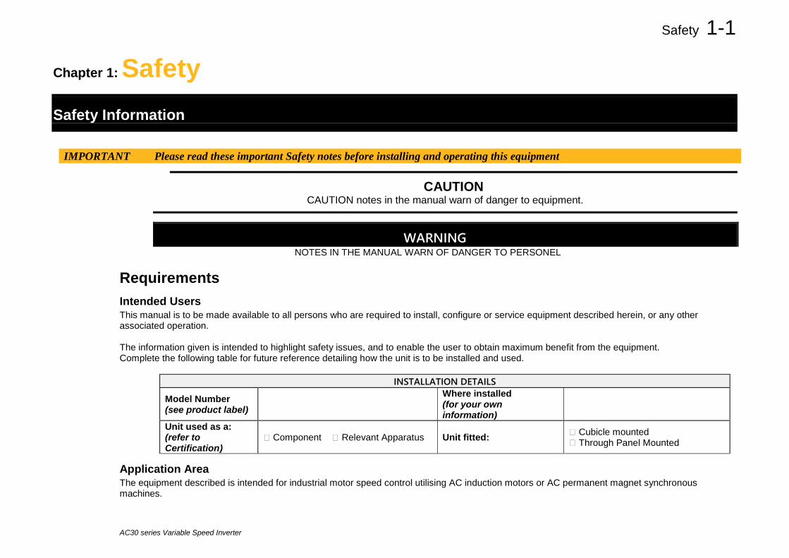
Requirements Intended Users This manual is to be made available to all persons who are required to install, configure or service equipment described herein, or any other associated operation. The information given is intended to highlight safety issues, and to enable the user to obtain maximum benefit from the equipment. Complete the following table for future reference detailing how the unit is to be installed and used.
INSTALLATION DETAILS
Model Number (see product label)
Where installed (for your own information)
Unit used as a: (refer to Certification)
Component Relevant Apparatus Unit fitted: Cubicle mounted Through Panel Mounted
Application Area The equipment described is intended for industrial motor speed control utilising AC induction motors or AC permanent magnet synchronous machines.

1-2 Safety
AC30 series Variable Speed Inverter
Personnel Installation, operation and maintenance of the equipment should be carried out by competent personnel. A competent person is someone who is technically qualified and familiar with all safety information and established safety practices; with the installation process, operation and maintenance of this equipment; and with all the hazards involved.
DANGER Risk of electric shock
WARNING Hot surfaces
Caution Refer to documentation
Earth/Ground Protective Conductor Terminal
Hazards
DANGER! - Ignoring the following may result in injury
1. This equipment can endanger life by exposure to rotating machinery and high voltages.
2. The equipment must be permanently earthed due to the high earth leakage current, and the inverter motor must be connected to an appropriate safety earth.
3. Ensure all incoming supplies are isolated before working on the equipment. Be aware that there may be more than one supply connection to the inverter.
4. There may still be dangerous voltages present at power terminals (motor output, supply input phases, DC bus and the brake, where fitted) when the motor is at standstill or is stopped.
5. For measurements use only a meter to IEC 61010 (CAT III or higher). Always begin using the highest range. CAT I and CAT II meters must not be used on this product.
6. Allow at least 5 minutes for the inverter's capacitors to discharge to safe voltage levels (<50V). Use the specified meter capable of measuring up to 1000V dc & ac rms to confirm that less than 50V is present between all power terminals and between power terminals and earth.
7. Unless otherwise stated, this product must NOT be dismantled. In the event of a fault the inverter must be returned. Refer to "Routine Maintenance and Repair".
Safety 1-3
AC30 series Variable Speed Inverter
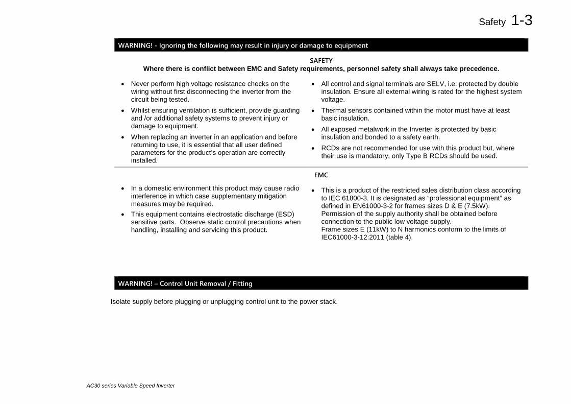
WARNING! - Ignoring the following may result in injury or damage to equipment
SAFETY Where there is conflict between EMC and Safety requirements, personnel safety shall always take precedence.
• Never perform high voltage resistance checks on the wiring without first disconnecting the inverter from the circuit being tested.
• Whilst ensuring ventilation is sufficient, provide guarding and /or additional safety systems to prevent injury or damage to equipment.
• When replacing an inverter in an application and before returning to use, it is essential that all user defined parameters for the product’s operation are correctly installed.
• All control and signal terminals are SELV, i.e. protected by double insulation. Ensure all external wiring is rated for the highest system voltage.
• Thermal sensors contained within the motor must have at least basic insulation.
• All exposed metalwork in the Inverter is protected by basic insulation and bonded to a safety earth.
• RCDs are not recommended for use with this product but, where their use is mandatory, only Type B RCDs should be used.
EMC
• In a domestic environment this product may cause radio interference in which case supplementary mitigation measures may be required.
• This equipment contains electrostatic discharge (ESD) sensitive parts. Observe static control precautions when handling, installing and servicing this product.
• This is a product of the restricted sales distribution class according to IEC 61800-3. It is designated as “professional equipment” as defined in EN61000-3-2 for frames sizes D & E (7.5kW). Permission of the supply authority shall be obtained before connection to the public low voltage supply. Frame sizes E (11kW) to N harmonics conform to the limits of IEC61000-3-12:2011 (table 4).
WARNING! – Control Unit Removal / Fitting
Isolate supply before plugging or unplugging control unit to the power stack.

1-4 Safety
AC30 series Variable Speed Inverter
CAUTION!
APPLICATION RISK
• The specifications, processes and circuitry described herein are for guidance only and may need to be adapted to the user’s specific application. We can not guarantee the suitability of the equipment described in this Manual for individual applications.
RISK ASSESSMENT
Under fault conditions, power loss or unintended operating conditions, the inverter may not operate as intended. In particular:
• Stored energy might not discharge to safe levels as quickly as suggested, and can still be present even though the inverter appears to be switched off
• The motor's direction of rotation might not be controlled
• The motor speed might not be controlled
• The motor might be energised
An inverter is a component within an inverter system that may influence its operation or effects under a fault condition. Consideration must be given to:
• Stored energy • Supply disconnects • Sequencing logic • Unintended operation

Introduction 2-1
AC30 series Variable Speed Inverter
Chapter 2: Introduction About this Manual Who is this Manual aimed at? This Manual is intended for use by the user and programmer of the AC30 series inverters. It assumes a reasonable level of understanding in these two disciplines. There are separate hardware installation references - HA503711U001 ‘AC30 Series Hardware Installation Manual: Frames D - J’ and HA503711U002 ‘AC30 Series Hardware Installation Manual: Frames K - N’ that are intended for use by the installer of the AC30 series inverters. Note: It is important to always pass on this Manual to any new user of the AC30 series inverter. How the Manual is Organised? This Software Reference Manual is organised into chapters, indicated by the numbering on the edge of each page. If the manual is to be printed it is designed so that it should be printed double-sided using the short-edge for binding. Information for the operation and programming of the AC30V, AC30P, AC30D & AC30A control modules is detailed in this Manual. The control module must be mounted on any one of the Frame D, E, F, G, H, J, K, L, M & N power stacks for intended operation. These two components – control module and power stack, are collectively referred to as “the Inverter” or “drive” throughout the manual. Product coding: Any “x” within a product code indicates there are variants, see the ‘Appendix D: AC30 Series Product Codes’ section for more information. Any text placed in a highlighted area as this sample shows, only refers to the AC30P, AC30D and AC30A control modules. Parker Hannifin Manufacturing Limited is referred to as “Parker” throughout the manual.
IMPORTANT
Please read all Safety information before proceeding with the operation of this unit.
AC30P AC30D AC30A
2-2 Introduction
AC30 series Variable Speed Inverter
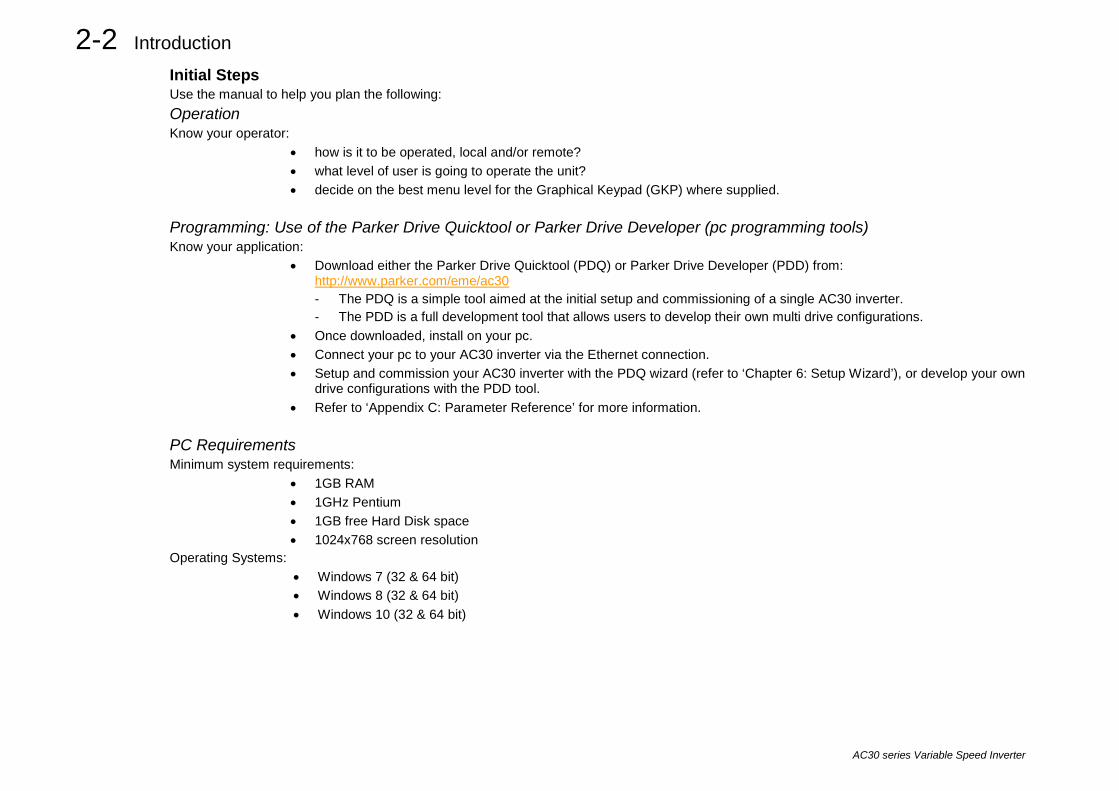
Initial Steps Use the manual to help you plan the following: Operation Know your operator:
• how is it to be operated, local and/or remote? • what level of user is going to operate the unit? • decide on the best menu level for the Graphical Keypad (GKP) where supplied.
Programming: Use of the Parker Drive Quicktool or Parker Drive Developer (pc programming tools) Know your application:
• Download either the Parker Drive Quicktool (PDQ) or Parker Drive Developer (PDD) from: http://www.parker.com/eme/ac30 - The PDQ is a simple tool aimed at the initial setup and commissioning of a single AC30 inverter. - The PDD is a full development tool that allows users to develop their own multi drive configurations.
• Once downloaded, install on your pc. • Connect your pc to your AC30 inverter via the Ethernet connection. • Setup and commission your AC30 inverter with the PDQ wizard (refer to ‘Chapter 6: Setup Wizard’), or develop your own
drive configurations with the PDD tool. • Refer to ‘Appendix C: Parameter Reference’ for more information.
PC Requirements Minimum system requirements:
• 1GB RAM • 1GHz Pentium • 1GB free Hard Disk space • 1024x768 screen resolution
Operating Systems: • Windows 7 (32 & 64 bit) • Windows 8 (32 & 64 bit) • Windows 10 (32 & 64 bit)
Product Overview 3-1
AC30 series Variable Speed Inverter
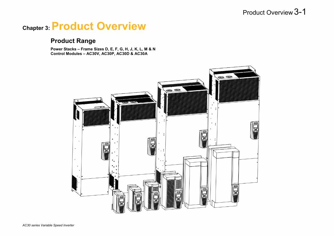
Chapter 3: Product Overview Product Range Power Stacks – Frame Sizes D, E, F, G, H, J, K, L, M & N Control Modules – AC30V, AC30P, AC30D & AC30A
3-2 Product Overview
AC30 series Variable Speed Inverter
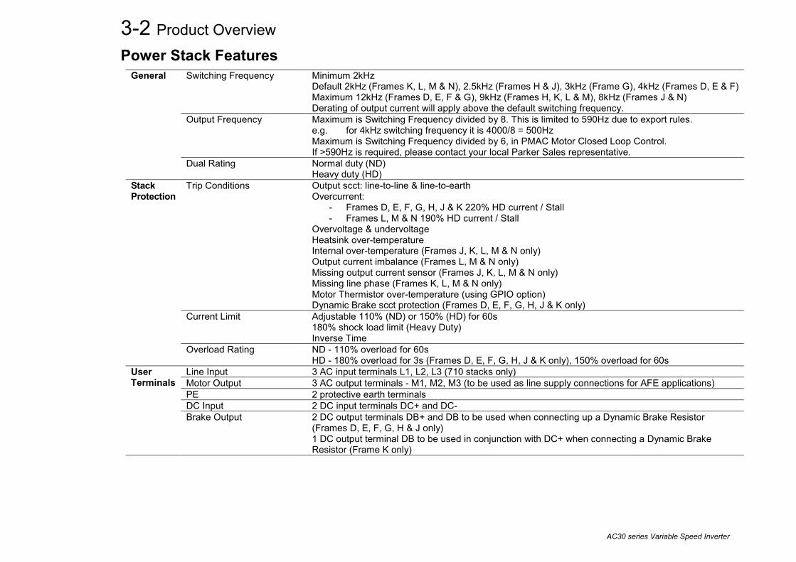
Power Stack Features General Switching Frequency Minimum 2kHz
Default 2kHz (Frames K, L, M & N), 2.5kHz (Frames H & J), 3kHz (Frame G), 4kHz (Frames D, E & F) Maximum 12kHz (Frames D, E, F & G), 9kHz (Frames H, K, L & M), 8kHz (Frames J & N) Derating of output current will apply above the default switching frequency.
Output Frequency Maximum is Switching Frequency divided by 8. This is limited to 590Hz due to export rules. e.g. for 4kHz switching frequency it is 4000/8 = 500Hz Maximum is Switching Frequency divided by 6, in PMAC Motor Closed Loop Control. If >590Hz is required, please contact your local Parker Sales representative.
Dual Rating Normal duty (ND) Heavy duty (HD)
Stack Protection
Trip Conditions Output scct: line-to-line & line-to-earth Overcurrent:
- Frames D, E, F, G, H, J & K 220% HD current / Stall - Frames L, M & N 190% HD current / Stall
Overvoltage & undervoltage Heatsink over-temperature Internal over-temperature (Frames J, K, L, M & N only) Output current imbalance (Frames L, M & N only) Missing output current sensor (Frames J, K, L, M & N only) Missing line phase (Frames K, L, M & N only) Motor Thermistor over-temperature (using GPIO option) Dynamic Brake scct protection (Frames D, E, F, G, H, J & K only)
Current Limit Adjustable 110% (ND) or 150% (HD) for 60s 180% shock load limit (Heavy Duty) Inverse Time
Overload Rating ND - 110% overload for 60s HD - 180% overload for 3s (Frames D, E, F, G, H, J & K only), 150% overload for 60s
User Terminals
Line Input 3 AC input terminals L1, L2, L3 (710 stacks only) Motor Output 3 AC output terminals - M1, M2, M3 (to be used as line supply connections for AFE applications) PE 2 protective earth terminals DC Input 2 DC input terminals DC+ and DC- Brake Output 2 DC output terminals DB+ and DB to be used when connecting up a Dynamic Brake Resistor
(Frames D, E, F, G, H & J only) 1 DC output terminal DB to be used in conjunction with DC+ when connecting a Dynamic Brake Resistor (Frame K only)

Product Overview 3-3
AC30 series Variable Speed Inverter
Functional Overview
Block Diagram for Frames D, E, F

3-4 Product Overview
AC30 series Variable Speed Inverter
Block Diagram for Frames G, H, J
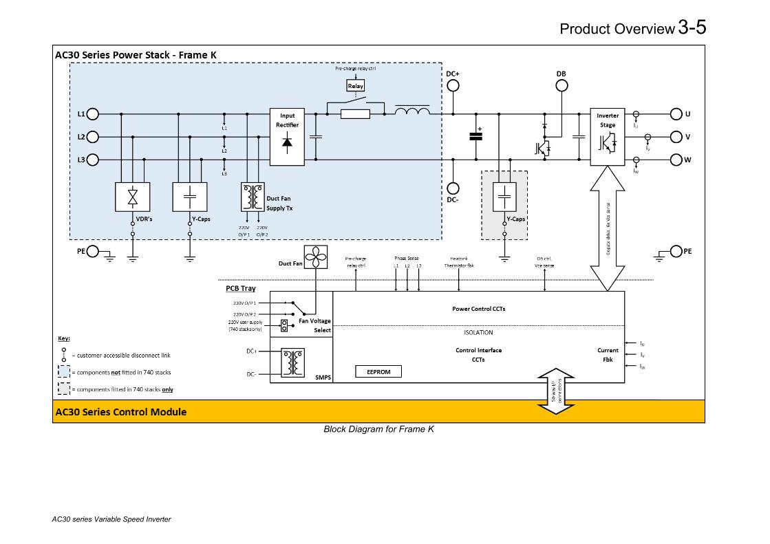
Product Overview 3-5
AC30 series Variable Speed Inverter
Block Diagram for Frame K

3-6 Product Overview
AC30 series Variable Speed Inverter
Block Diagram for Frames L - N

Product Overview 3-7
AC30 series Variable Speed Inverter
AC30 Series Control Features The inverter is fully featured when controlled using the optional Keypad (or a suitable pc programming tool).
General Motor Control Modes Induction motor: - V/F control - Sensorless Vector Control - Closed Loop Vector Control (with encoder option) - Closed Loop Vector Control (with resolver option)
PMAC motor: - Sensorless Vector Control - Closed Loop Vector Control (with encoder option) - Closed Loop Vector Control (with resolver option), though with power constraints
AFE Mode 4Q Regen Control (with encoder option) Voltage Boost for V/F control 0-25% Skip Frequencies Skip frequencies with adjustable skip band width Preset Speeds User selectable preset speeds Stopping Modes Ramp, Coast, DC Injection, Quickstop S Ramp and Linear Ramp Symmetric or asymmetric ramp up and down rates Raise/Lower Programmable MOP function Jog Programmable jog speed Diagnostics Full diagnostic and monitoring facilities
Inputs/ Outputs
Analog Inputs 2 configurable inputs: 1 voltage or current, 1 voltage only Analog Outputs 2 configurable outputs: 1 unipolar voltage or current, 1 bipolar voltage only Digital Inputs 3 configurable 24V dc inputs System Board Digital Inputs 3 configurable 24V dc inputs (AC30D & AC30A only) Digital I/O 4 configurable 24V dc current sourcing outputs/digital inputs System Board Digital I/O 3 configurable 24V dc current sourcing outputs/digital inputs (AC30A only) Relay Outputs 2 configurable relay outputs (AC30V only) Reference Voltages +/-10V dc outputs, user +24V dc output Aux Supply +24V dc input Encoder Inputs 2 separate encoder input channels: A, /A, B, /B, Z, /Z (AC30D only) 1 sin/cos encoder input channel: sin+, sin-, cos+, cos-, Z, /Z & 1 Endat 2.1 encoder input
channel: Data+, Data-, Clock+, Clock- (AC30A only) Encoder Supply Outputs 1 selectable encoder output supply voltage (AC30D & AC30A only) Encoder Outputs 1 encoder transmit channel: A, /A, B, /B, Z, /Z (AC30D & AC30A only)
Comms On-board Ethernet 1 port (AC30V only) 2 ports

3-8 Product Overview
AC30 series Variable Speed Inverter

The Graphical Keypad 4-1
AC30 series Variable Speed Inverter
Chapter 4: The Graphical Keypad The inverter is fitted with a Graphical Keypad referred to throughout as GKP. It provides for local control of the inverter, monitoring, and complete access for application programming. Insert the Keypad into the front of the inverter (replacing the blank cover); or if supplied separately to be used remotely, up to 3 meters away, use the mounting kit with connection lead.

4-2 The Graphical Keypad
AC30 series Variable Speed Inverter
Overview
• The top line of the display is used to show the inverter status
• The central region of the display shows the selected parameters or navigation menu
• The bottom line of the display indicates the action associated with the soft keys
• The actions of the soft keys are context dependent
• The central navigation and editing keys are referred to as UP, DOWN, LEFT, RIGHT and OK
• The Run, (green), and Stop, (red), keys are used to start and stop the motor when the inverter is in local control mode.

The Graphical Keypad 4-3
AC30 series Variable Speed Inverter
Keypad The GKP has a total of nine keys. They can be divided into three groups:
1. Operation keys (LED illuminated pushbuttons) 2. Soft keys 3. Navigation / Editing keys
Key Function Operating Keys (only active when Local control mode is active)
RUN Runs the inverter.
STOP Stops the inverter when running / Resets or Acknowledges trips.
Soft Keys (function changes depending on which screen is displayed)
Soft Key 1 Return / Abort / Setup Wizard shortcut
Soft Key 2 Locks password / Save changes / Toggles between ‘Local’ or ‘Remote’ control mode / Changes motor rotation direction (‘Local’ control mode only) / Add or Removes parameters to or from the ‘Favourites’ menu.
Navigation / Editing Keys
OK
Enters into the next menu level or parameter / Enters into parameter edit mode / Accepts the value of the parameter being edited / Displays parameter information (key press held >1s) / Selects parameter as default at power up (key press held >2s)
UP Moves ‘up’ through the parameters of the menu list / Increments the value of the
parameter being edited.
DOWN Moves ‘down’ through the parameters of the menu list / Decrements the value of
the parameter being edited.
LEFT Moves ‘back’ to the previous menu list / Selects the digit of the parameter being edited.
RIGHT Moves ‘into’ the next menu list or parameter / Selects the digit of the parameter being edited.

4-4 The Graphical Keypad
AC30 series Variable Speed Inverter
LED Status Indication The GKP has two LED illuminated pushbuttons – the green ‘Run’ key and the red ‘Stop’ key. The status of each of these LED illuminated pushbuttons indicates the real time operation of the inverter:
LED Status Inverter Status:
Run Key Stop Key OFF ON STOPPED ON OFF RUNNING OFF FLASHING STOPPING
FLASHING OFF AUTO RESTART PENDING
FLASHING (IN SYNC) NOT IN AN OPERATIONAL STATE
FLASHING (ALTERNATING) FAULT STATE Note: The LED operation can be over-ridden by the application.

The Graphical Keypad 4-5
AC30 series Variable Speed Inverter
The Display The display is divided into three areas:
1. Top line: shows a summary of the inverter status. 2. Centre region: is the main work area where menus and parameters are displayed. 3. Bottom line: is used to indicate the action associated with the soft keys.
Top Line - Inverter Status Summary The top line of the display shows a summary of the inverter status. This is divided into four regions. Each region is dedicated to a particular status indication, as shown.
Run, stop and direction Trip Ethernet Control Source
Running +ve direction
Inverter Tripped
(flashing)
IP address missing
(flashing)
Local: Start / Stop from GKP
Running -ve direction
Warning (solid)
IP address configured
(solid)
Remote: Start / Stop from control
terminals
Stopped (ready to run in +ve direction)
Maintenance
required
IP Address configured, PTP
clock synchronised
Comms: Start / Stop from comms
master
Stopped (ready to run in -ve direction)
4-6 The Graphical Keypad
AC30 series Variable Speed Inverter
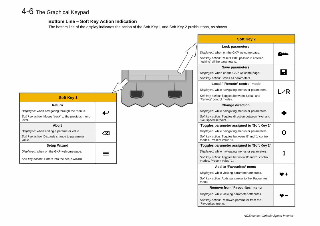
Bottom Line – Soft Key Action Indication The bottom line of the display indicates the action of the Soft Key 1 and Soft Key 2 pushbuttons, as shown.
Soft Key 2
Lock parameters
Displayed: when on the GKP welcome page.
Soft key action: Resets GKP password entered, ‘locking’ all the parameters.
Save parameters
Displayed: when on the GKP welcome page. Soft key action: Saves all parameters.
‘Local’/ ‘Remote’ control mode
Displayed: while navigating menus or parameters.
Soft Key 1 Soft key action: Toggles between ‘Local’ and ‘Remote’ control modes.
Return
Change direction
Displayed: when navigating through the menus. Displayed: while navigating menus or parameters.
Soft key action: Moves ‘back’ to the previous menu level.
Soft key action: Toggles direction between ‘+ve’ and ‘-ve’ speed setpoint.
Abort
Toggles parameter assigned to ‘Soft Key 2’
Displayed: when editing a parameter value. Displayed: while navigating menus or parameters.
Soft key action: Discards change to parameter value.
Soft key action: Toggles between ‘0’ and ‘1’ control modes. Present value ‘0’.
Setup Wizard
Toggles parameter assigned to ‘Soft Key 2’
Displayed: when on the GKP welcome page. Displayed: while navigating menus or parameters.
Soft key action: Enters into the setup wizard. Soft key action: Toggles between ‘0’ and ‘1’ control modes. Present value ‘1’.
Add to ‘Favourites’ menu
Displayed: while viewing parameter attributes.
Soft key action: Adds parameter to the ‘Favourites’ menu.
Remove from ‘Favourites’ menu
Displayed: while viewing parameter attributes.
Soft key action: Removes parameter from the ‘Favourites’ menu.

The Graphical Keypad 4-7
AC30 series Variable Speed Inverter
The Menu System Navigating the Menu System The Menu System can be thought of as a map which is navigated using the direction keys.
• Use the left and right keys to navigate through the menu levels. • Use the up and down keys to scroll through the Menu and Parameter lists
Menus can contain sub-menus or a list of parameters. The keys can be used as above to select a parameter. A parameter has a selection, (ie: TRUE / FALSE), or a value displayed below the parameter name. HINT: Remember that because the Menu and Parameter lists are looped, the UP key can quickly move you to the last Menu or Parameter in the loop. The keys will repeat if you hold them down. This is an easy way to step through and view a menu’s contents.
Read-only Parameter Indication A ‘:’ symbol to the left of the parameter value. indicates that a parameter is read-only.
Changing a Parameter Value With the parameter you want to change selected, press the center OK key to change to Edit mode. In this mode the arrow keys now perform different functions.
• Change a selection, (i.e. TRUE / FALSE) using the UP and DOWN keys. • Change a value as follows:
o The UP and DOWN keys increment / decrement the selected digit. o The LEFT and RIGHT keys move the digit selection. o The selected digit is indicated by the cursor.
The UP and DOWN keys will repeat if you hold them down. When changing a value, if the abort icon ( ) is shown over Soft Key 1, pressing this key will abort the edit, leaving the value unchanged. To accept the edited value, press the center OK key. Refer to Chapter 5 for a description of the menu items

4-8 The Graphical Keypad
AC30 series Variable Speed Inverter
Trips and other information displays An information message will be displayed when the unit is tripped. To clear the message from the display, press Soft key 1.
To reset the trip, allowing the inverter to respond to a start command, press the STOP key. See Chapter 10 Trips & Fault Finding.
Setting the display language The GKP supports multiple languages. The language to be used may be selected as the second entry in the GKP Wizard, (see chapter 9). The language is also available as a parameter 1005 Language.
When changing language, there may will be a short delay while the updated text is transferred to the GKP. During this period the GKP will be unresponsive. An information message “UPDATING LANGUAGE” is displayed during this process.
The GKP has the following language files built in as standard:
English French German Spanish Italian

The Graphical Keypad 4-9
AC30 series Variable Speed Inverter
Setup Wizard The purpose of the Setup Wizard is to configure the inverter in a clear and concise manner. Starting the Setup Wizard The Setup Wizard is automatically invoked when the inverter is reset to factory default settings. Alternatively, the Setup Wizard may be invoked at any other time by navigating to the ‘Welcome Screen’ at the top of the menu tree and pressing Soft Key 1, as shown by the Setup Wizard indicator. Note: It is always recommended that the Setup Wizard is completed once started. Navigating the Setup Wizard At each step of the Setup Wizard, pressing the OK key selects the displayed value and also moves on to the next step. Pressing Soft Key 1 moves back a step. Pressing the UP and DOWN keys modifies the parameter value. Note: Accepting each choice without change by pressing OK will result in no change to the inverter’s configuration. Setup Wizard Stages The Setup Wizard starts by asking what user view level is required for the GKP, followed by a list of languages for which the user selects their preference. The user will then be asked if they would like to continue and run the Wizard. If ‘yes’, the first option is to “Set Factory Defaults”. Changing this parameter to TRUE then pressing OK resets all parameters back to the default value determined by the inverters hardware configuration. In most case, this is recommended. If this choice is left FALSE the setup wizard starts with all parameters with their previously set values. The rest of the Setup Wizard consists of several sections, each of which corresponds to a functional component of the inverter, for example:
- Application selection - IO Option, (includes the Encoder) - Analog input and output ranges. - Motor Data
- Motor Control - Fieldbus options - On-board Ethernet - Auto tune
If not required, any section may be skipped. The default setting for all parameters depends on earlier answers and on the physical configuration of the inverter. All data entered is automatically saved without the need for any additional commands. Finalising Setup Once the Setup Wizard has been run to completion, the feature is automatically disabled. Power cycling to the inverter will not cause the Setup Wizard to be run again, though If this is required, this can be achieved as detailed above in ‘Starting the Setup Wizard’. Refer to chapter 6 for a more detailed explanation of the Setup Wizard

4-10 The Graphical Keypad
AC30 series Variable Speed Inverter
Firmware Update The inverter firmware will need to be updated in order to take advantage of new product features, bug fixes or new hardware support. To do this: Prepare the SD card Download the latest AC30 firmware from the Parker website: http://www.parker.com/eme/ac30 Alternatively, the latest firmware can be copied through the Parker Drive Quicktool (PDQ), using the ‘Drive Maintenance’ task. Copy the firmware onto an SD card. The file must be named firmware.30x for the AC30V, or firmware.30p for the AC30P and AC30D. Install the SD card Insert the SD card into the slot in the upper moulding of the control module. Perform the Firmware upgrade With the SD card installed in the AC30 control module, navigate to the ‘Setup Wizard’ as detailed on page 9-6. There will now be an additional ‘Update Firmware’ step as the user goes through the Setup Wizard process. To start the update, change the value from FALSE to TRUE. The ‘Firmware Update In Progress’ message will appear, followed by an egg timer.
CAUTION: DO NOT REMOVE POWER FROM THE INVERTER DURING THE FIRMWARE UPDATE. The inverter will restart once the process is complete and return to the normal menu screen.

Menu Organisation 5-1
AC30 series Variable Speed Inverter
Chapter 5: Menu Organisation Menu Map The Menu System consists of a series of menus and sub-menus organised into a “tree” structure. Navigate around the tree on the GKP using the UP, DOWN, LEFT and RIGHT keys. Individual parameters may be present in the menu tree at more than one location. Parameters and/or menus that are not required or are empty are automatically hidden on the GKP and web page.
Menu Map Summary Control Screen Clone Setup Environment
Quick Setup Monitor Application Quick Monitor Motor Control Application Control & Type Motor & Drive Motor Nameplate Inputs and Outputs Motor Data PMAC System Board Auto Restart Encoder Slot 1 Autotune Encoder Slot 2 SVC PMAC Communications Pos Fbk Alignment Base Ethernet Regen Control Base Modbus Inputs and Outputs Base Ethernet IP
Base IO Option Option PTP
System Board Option Peer to Peer SB Encoder Slot1 Energy Meter SB Encoder Slot2 Trips
Communications Regen Control Base Ethernet Favourites Base Modbus Parameters*
Base Ethernet IP Option PTP Peer to Peer
* The “Parameters” menu is intended for expert use only, see Appendix D
5-2 Menu Organisation
AC30 series Variable Speed Inverter
Menu Descriptions Control Screen In local sequencing mode the Control Screen menu shows the Local Setpoint, the Seed Feedback and configuration of the action of the Run key and direction. When the inverter is not in local sequencing mode this menu shows the operating speed. The contents of the Control Screen can be modified by the configuration.
Setup Parameters that may require modification once the Setup Wizard is complete.
Monitor This menu contains parameters commonly used to verify the correct operation of the inverter and the process.
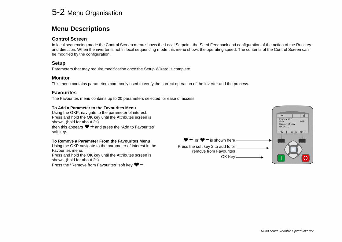
Favourites The Favourites menu contains up to 20 parameters selected for ease of access. To Add a Parameter to the Favourites Menu Using the GKP, navigate to the parameter of interest. Press and hold the OK key until the Attributes screen is shown, (hold for about 2s) then this appears and press the “Add to Favourites” soft key. To Remove a Parameter From the Favourites Menu Using the GKP navigate to the parameter of interest in the Favourites menu. Press and hold the OK key until the Attributes screen is shown, (hold for about 2s). Press the “Remove from Favourites” soft key, .
or is shown here Press the soft key 2 to add to or
remove from Favourites OK Key

Menu Organisation 5-3
AC30 series Variable Speed Inverter
Parameters A complete collection of all the parameters in the inverter. This menu is intended for expert use.
Parameter Map The following table shows the parameters as they appear in order on the Web page and GKP. Also shown is the Parameter Number, PNO. This is a unique reference for each parameter. For more details about each parameter refer to Appendix C.
Control Screen Setup
Quick Setup Application Motor Control Control and Type Motor Type or AFE 0511 Control Strategy 0512 Control Type 1533 Encoder Feedback 1743 100% Speed in RPM 0464 Acceleration Time 0486 Deceleration Time 0487 Current Limit 0305 Main Torque Lim 0417 Seq Stop Method SVC 1257 Seq Stop Method VHz 0484 Stop Ramp Time 0504 VHz Shape 0422 Fixed Boost 0447 Duty Selection 0390 Motor Nameplate Base Frequency 0457 Rated Motor Current 0455 Motor Poles 0458 Base Voltage 0456 Nameplate Speed 0459 Power Factor 0461 Motor Power 0460 Motor Data PMAC PMAC Max Speed 0555 PMAC Max Current 0556 PMAC Rated Current 0557 PMAC Rated Torque 0558 PMAC Motor Poles 0559 PMAC Back Emf Const KE 0560 PMAC Base Volt 1387
PMAC Winding Resistance 0561 PMAC Winding Inductance 0562 PMAC Torque Const KT 0563 PMAC Encoder Offset 1808 PMAC Wiring 1809 PMAC Therm Time Const 0565 PMAC Motor Inertia 0564 Auto Restart AR Enable 1469 AR Mode 1470 AR Max Restarts 1471 AR Trip Mask 1472 AR Trip Mask 2 0796 AR Initial Delay 1505 AR Repeat Delay 1506 Autotune Autotune Enable 0255 Autotune Mode 0256 Nameplate Mag Current 1550 Autotune Test Disable 0257 Autotune Ramp Time 0274 ATN PMAC Test Disable 1388 ATN PMAC Ls Test Freq 1405 SVC PMAC PMAC SVC Start Cur 0478 PMAC SVC Start Speed 0479 Pos Fbk Alignment Alignment Enable 1798 Alignment On Power On 1796 Alignment Method 1797 Alignment Level 1799 Alignment Ramp Time 1800 Alignment On Motor 1801 Regen Control Motor Type or AFE 0511 AFE Inductance 1730 AFE VDC Demand 1711 AFE Current Control 1693

Menu Organisation 5-4
AC30 series Variable Speed Inverter
AFE Iq Demand 1705 AFE Id Demand 1704 Inputs and Outputs Base IO Anin 01 Type 0001 Anin 01 Offset 0957 Anin 01 Scale 0958 Anin 02 Type 0002 Anin 02 Offset 0959 Anin 02 Scale 0960 Anout 01 Type 0003 Anout 01 Scale 0686 Anout 01 Offset 1108 Anout 01 ABS 1441 Anout 02 Type 0004 Anout 02 Scale 1460 Anout 02 Offset 1467 Anout 02 ABS 1468 Option Option IO Required 1178 Thermistor Type 1184 Encoder Supply 1511 Encoder Lines 1512 Encoder Invert 1513 Encoder Type 1514 Encoder Single Ended 1515 Encoder Count Reset 1517 Resolver Frequency 1791 Resolver Voltage 1790 Resolver Ratio 1792 Resolver Max Speed 1825 Resolver Poles 1793 Resolver Built-In Gear 1822 Resolver Invert 1810 Resolver Speed Filter 1815 Resolver Min Filter 1851 Resolver Resolution 1816 Anin 11 Offset 1461 Anin 11 Scale 1462 Anin 12 Offset 1463 Anin 12 Scale 1464 Anin 13 Offset 1465 Anin 13 Scale 1466 System Board Option System Board Required 1739 Output Enable 1678 Output Source 1679 Output Voltage 1680
Output A 1756 Output B 1757 Output Z 1758 Synth Encoder Lines 1696 Synth Encoder Speed 1698 Synth Encoder Invert 1702 SB Encoder Slot1 Encoder Supply 1663 Encoder Lines 1664 Encoder Invert 1665 Encoder Type 1666 High Input Threshold 1667 Encoder Count Reset 1669 SB Encoder Slot2 Encoder Lines 1671 Encoder Invert 1672 Encoder Type 1673 High Input Threshold 1674 Encoder Count Reset 1676 Communications Base Ethernet DHCP 0929 Auto IP 0930 User IP Address 0933 User Subnet Mask 0934 User Gateway Address 0935 Web Access 0944 Base Modbus Maximum Connections 0939 High Word First 0940 Modbus Timeout 0941 Modbus Trip Enable 0942 Modbus Mapping[16] 1567 Modbus TCP Password 1659 Base Ethernet IP Ethernet IP Enable 3128 Ethernet IP Trip 3129 Input Mapping 3000 Output Mapping 3064 Option Comms Required 0044 BACnet MAC Address 1091 BACnet MSTP Device ID 1092 BACnet Baud Rate 1093 BACnet MSTP Timeout 1094 BACnet IP Device ID 0209 BACnet IP Timeout 0210 CANopen Node Address 0212
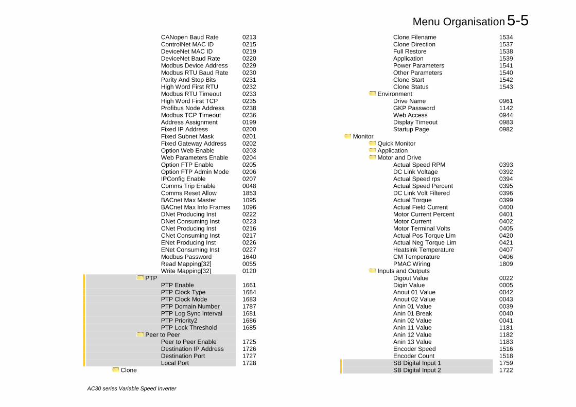
Menu Organisation 5-5
AC30 series Variable Speed Inverter
CANopen Baud Rate 0213 ControlNet MAC ID 0215 DeviceNet MAC ID 0219 DeviceNet Baud Rate 0220 Modbus Device Address 0229 Modbus RTU Baud Rate 0230 Parity And Stop Bits 0231 High Word First RTU 0232 Modbus RTU Timeout 0233 High Word First TCP 0235 Profibus Node Address 0238 Modbus TCP Timeout 0236 Address Assignment 0199 Fixed IP Address 0200 Fixed Subnet Mask 0201 Fixed Gateway Address 0202 Option Web Enable 0203 Web Parameters Enable 0204 Option FTP Enable 0205 Option FTP Admin Mode 0206 IPConfig Enable 0207 Comms Trip Enable 0048 Comms Reset Allow 1853 BACnet Max Master 1095 BACnet Max Info Frames 1096 DNet Producing Inst 0222 DNet Consuming Inst 0223 CNet Producing Inst 0216 CNet Consuming Inst 0217 ENet Producing Inst 0226 ENet Consuming Inst 0227 Modbus Password 1640 Read Mapping[32] 0055 Write Mapping[32] 0120 PTP PTP Enable 1661 PTP Clock Type 1684 PTP Clock Mode 1683 PTP Domain Number 1787 PTP Log Sync Interval 1681 PTP Priority2 1686 PTP Lock Threshold 1685 Peer to Peer Peer to Peer Enable 1725 Destination IP Address 1726 Destination Port 1727 Local Port 1728 Clone
Clone Filename 1534 Clone Direction 1537 Full Restore 1538 Application 1539 Power Parameters 1541 Other Parameters 1540 Clone Start 1542 Clone Status 1543 Environment Drive Name 0961 GKP Password 1142 Web Access 0944 Display Timeout 0983 Startup Page 0982
Monitor Quick Monitor Application Motor and Drive Actual Speed RPM 0393 DC Link Voltage 0392 Actual Speed rps 0394 Actual Speed Percent 0395 DC Link Volt Filtered 0396 Actual Torque 0399 Actual Field Current 0400 Motor Current Percent 0401 Motor Current 0402 Motor Terminal Volts 0405 Actual Pos Torque Lim 0420 Actual Neg Torque Lim 0421 Heatsink Temperature 0407 CM Temperature 0406 PMAC Wiring 1809 Inputs and Outputs Digout Value 0022 Digin Value 0005 Anout 01 Value 0042 Anout 02 Value 0043 Anin 01 Value 0039 Anin 01 Break 0040 Anin 02 Value 0041 Anin 11 Value 1181 Anin 12 Value 1182 Anin 13 Value 1183 Encoder Speed 1516 Encoder Count 1518 SB Digital Input 1 1759 SB Digital Input 2 1722

Menu Organisation 5-6
AC30 series Variable Speed Inverter
SB Digital Input 3 1723 Resolver Speed % 1814 resolver position 1824 Resolver Turns 1811 Resolver Fraction Turns 1812 System Board Encoder Slot 1 Encoder Speed 1668 Encoder Count 1670 Encoder Slot 1 Encoder Speed 1675 Encoder Count 1677 Communications Base Ethernet Ethernet State 0919 MAC Address 0920 IP Address 0926 Subnet Mask 0927 Gateway Address 0928 Base Modbus Open Connections 1241 Process Active 0943 Mapping Valid 1632 Base Ethernet IP Ethernet IP State 3130 Ethernet IP Diag 3131 Option Comms Fitted 0045 BACnet MSTP State 1089 BACnet IP State 0208 Profibus State 0237 EtherNet IP State 0225 Modbus TCP State 0234 Modbus RTU State 0228 EtherCAT State 0224 PROFINET State 0239 PROFINET Device Name 0240 CANopen State 0211 ControlNet State 0214 DeviceNet State 0218 CANopen Actual Baud 1251 DeviceNet Actual Baud 0221 Comms Supervised 0047
Comms Event Active 0186 Option MAC Address 0189 Option IP Address 0195 Option Subnet Mask 0196 Option Gateway 0197 Option DHCP Enabled 0198 Comms Module Version 0049 Comms Module Serial 0050 Comms Diagnostic 0051 Comms Diagnostic Code 0052 Comms Exception 0053 Comms Net Exception 0054 PTP PTP State 1689 PTP Clock 1699 PTP Offset 1687 PTP Locked 1688 Peer to Peer Peer to Peer State 1729 Energy Meter Energy kWh 0383 Power kW 0380 Power HP 0381 Reactive Power 0382 Power Factor Est 0385 Trips First Trip 0696 Active 1 - 32 0763 Active 33 - 64 0513 Warnings 1 - 32 0829 Warnings 33 - 64 0514 RTA Code 0998 RTA Data 0999 Regen Control AFE Sync Frequency 1703 AFE Status 1721 DC Link Voltage 0392 Favourites

Setup Wizard 6-1
AC30 series Variable Speed Inverter
Chapter 6: Setup Wizard GKP Setup Wizard Purpose of the Setup Wizard The purpose of the setup wizard is to configure the inverter in a clear and concise manner.
First familiarize yourself with Chapter 4 Graphical Keypad, for the keypad functions.
Starting the Setup Wizard The Setup Wizard is automatically invoked when first powered up. The setup wizard may be invoked at any other time by pressing the set-up key ( ). This is shown on the Welcome Screen, (at the “top” of the MMI menu structure). The Setup Wizard is also invoked by changing the parameter “Run Wizard?” to YES (you will find this under the “Parameters: Device Manager: Setup Wizard" menu).
Running the Setup Wizard At each point in the wizard pressing the OK key selects the displayed value and moves on to the next step. Pressing Soft key 1 moves back a step. Pressing the UP and DOWN keys modifies the selected value. The default setting for all parameters depends on earlier answers and on the physical configuration of the inverter so pressing OK repeatedly will result in no parameter values being altered. All data entered is automatically saved without the need for any additional commands.
Information that you will need in order to set up the motor control When you run the setup wizard you will be asked for various items of information in order to set up the motor control.
OK key Soft Key 1

6-2 Setup Wizard
AC30 series Variable Speed Inverter
Setup Wizard Stages The Setup Wizard is divided into sections. With the exception of the first group of parameters, each section may be skipped. The first group of parameters sets the inverter operating environment. PNO Parameter Comment 1141 View Level Select the view level, Operator, Technician or Engineer. 1005 Language Select the required language to be used on the GKP. There may be a slight pause while the inverter adopts the
selected language. 1002 Update Firmware Select YES to update the inverter’s firmware. Only visible in Engineering view mode with a firmware file on the
SD Card. 1006 Run Wizard Select YES to continue. Select NO to exit with the new settings for View Level and Language 1000 Reset to Defaults Changing this parameter to TRUE then pressing OK resets all parameters back to the default value determined
by the inverters hardware configuration. If this choice is left FALSE all parameters retain their previously set values.
987 Power Stack Required Only shown if the control module is not attached to a matching power stack. 1186 Time and Date Only shown if an IO option with RTC hardware is fitted. 0944 Web Access Set to FULL to allow access to parameter values via the web page. 1738 Enable Auto Save Set to TRUE to automatically save parameter values as they are entered on the GKP and Web page. Set to
FALSE to enable the manual save feature. All parameters are saved on completion of the GKP wizard regardless of the setting of this parameter. Also, this parameter is always saved when changed.
0961 Drive Name Defaults to show the Ethernet MAC address
6-3 Setup Wizard
AC30 series Variable Speed Inverter
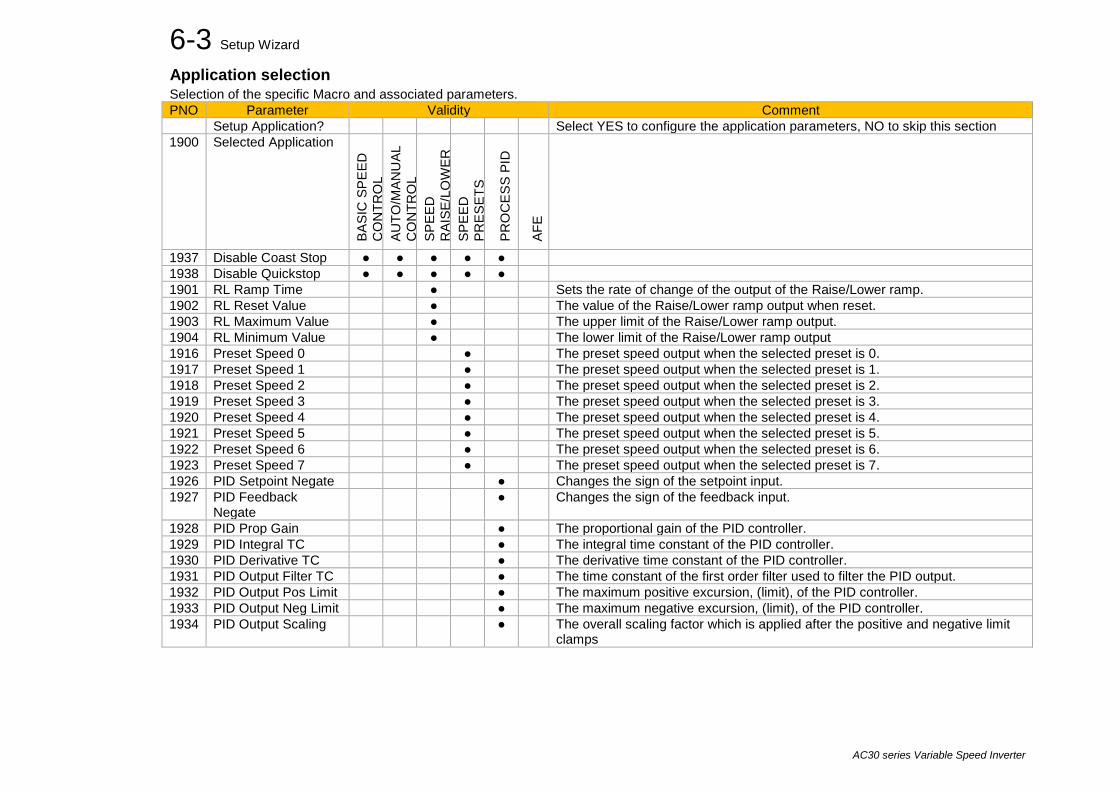
Application selection Selection of the specific Macro and associated parameters. PNO Parameter Validity Comment
Setup Application? Select YES to configure the application parameters, NO to skip this section 1900 Selected Application
BASI
C S
PEED
C
ON
TRO
L AU
TO/M
ANU
AL
CO
NTR
OL
SPEE
D
RAI
SE/L
OW
ER
SPEE
D
PRES
ETS
PRO
CES
S PI
D
AFE
1937 Disable Coast Stop ● ● ● ● ● 1938 Disable Quickstop ● ● ● ● ● 1901 RL Ramp Time ● Sets the rate of change of the output of the Raise/Lower ramp. 1902 RL Reset Value ● The value of the Raise/Lower ramp output when reset. 1903 RL Maximum Value ● The upper limit of the Raise/Lower ramp output. 1904 RL Minimum Value ● The lower limit of the Raise/Lower ramp output 1916 Preset Speed 0 ● The preset speed output when the selected preset is 0. 1917 Preset Speed 1 ● The preset speed output when the selected preset is 1. 1918 Preset Speed 2 ● The preset speed output when the selected preset is 2. 1919 Preset Speed 3 ● The preset speed output when the selected preset is 3. 1920 Preset Speed 4 ● The preset speed output when the selected preset is 4. 1921 Preset Speed 5 ● The preset speed output when the selected preset is 5. 1922 Preset Speed 6 ● The preset speed output when the selected preset is 6. 1923 Preset Speed 7 ● The preset speed output when the selected preset is 7. 1926 PID Setpoint Negate ● Changes the sign of the setpoint input. 1927 PID Feedback
Negate ● Changes the sign of the feedback input.
1928 PID Prop Gain ● The proportional gain of the PID controller. 1929 PID Integral TC ● The integral time constant of the PID controller. 1930 PID Derivative TC ● The derivative time constant of the PID controller. 1931 PID Output Filter TC ● The time constant of the first order filter used to filter the PID output. 1932 PID Output Pos Limit ● The maximum positive excursion, (limit), of the PID controller. 1933 PID Output Neg Limit ● The maximum negative excursion, (limit), of the PID controller. 1934 PID Output Scaling ● The overall scaling factor which is applied after the positive and negative limit
clamps

6-4 Setup Wizard
AC30 series Variable Speed Inverter
Input and Output Option Configuration of the type and settings for the available IO options. PNO Parameter Comment
Setup Option IO? Select TRUE to configure the IO Option. Set to FALSE to skip this section Only shown if an IO option is fitted, or if one has been previously configured.
1178 Option IO Required Select the required IO Option type. 1184 Thermistor Type Select the required thermistor type. 1511 Encoder Supply For the Pulse Encoder option, configures the encoder supply output. 1512 Encoder Lines For the Pulse Encoder option, configures the number of pulses per revolution 1514 Encoder Type For the Pulse Encoder option, configures the encoder type 1515 Encoder Single Ended For the Pulse Encoder option, configures whether the input is single ended or differential. 1791 Resolver Frequency Frequency of the Resolver excitation in kHz 1790 Resolver Voltage Voltage supply of the Resolver excitation in Vrms 1792 Resolver Ratio Resolver Ratio, corresponding to the ratio between excitation voltage and max sin and cos voltages 1825 Resolver Max Speed Mechanical Resolver max speed in rpm 1793 Resolver Poles Resolver poles number -Should be an even number 1822 Resolver Built-In Gear Number of shaft mechanical turns for 1 Resolver turn 1810 Resolver Invert To change the count direction of the Resolver 1815 Resolver Speed Filter Speed filter action, in % of the actual speed value in Hz 1851 Resolver Min Filter Minimum filter value applied to the speed information. The filter value is at leat equal to this value 1816 Resolver Resolution Resolver resolution selection, in bits per electrical turns (eg: 16 bits is 65536 counts per electrical resolver turn)
Analog Input and Output Configuration of the ranges for the analog inputs and outputs. Also selects the thermistor type if an IO option is fitted. PNO Parameter Comment
Setup Input/Output? Select TRUE to configure the analog input and output ranges. Set to FALSE to skip this section 0001 Anin 01 Type Select the hardware range for analog input 1 0002 Anin 02 Type Select the hardware range for analog input 2 0003 Anout 01 Type Select the hardware range for analog output 1 0004 Anout 02 Type Select the hardware range for analog output 2

6-5 Setup Wizard
AC30 series Variable Speed Inverter
Motor Data Selection of the motor type, control mode and setting the motor control and process control parameters. The Validity column indicates which parameters are shown, dependent on the control mode.
PNO Parameter Validity
Comment IM VHz
IM VECT PMAC AFE
Setup Motor? Select TRUE to configure the motor parameters, FALSE to skip this section
0511 Motor Type or AFE ● ● ● ● Selects the motor type.
0512 Control Strategy ● ● Selects between Volts/Hz and Vector Control. 1533 Control Type ● ● Only visible if Vector Control is selected.
Selects between Sensorless Control, and Closed Loop Control (with encoder).
1743 Encoder Feedback ● ● 0976 Nominal Supply ● ● Defines the default value for the motor frequency parameters. 0457 Base Frequency ● ● The base frequency on the motor name plate 0456 Base Voltage ● ● The rated voltage on the motor name plate 0458 Motor Poles ● ● The number of motor poles. Always enter an even number. 0455 Rated Motor Current ● ● Current rating from the motor name plate. 0460 Motor Power ● ● Power rating from the motor name plate. 0459 Nameplate Speed ● ● Nominal speed from the motor name plate. 0461 Power Factor ● Power factor from the motor name plate, (often shown as φ). If this is
not available then leave this at the default value. 0555 PMAC Max Speed ● The motor’s maximum speed. 0556 PMAC Max Current ● The motor’s maximum current 0557 PMAC Rated Current ● The motor’s rated current. 0558 PMAC Rated Torque ● The motor’s rated torque 0559 PMAC Motor Poles ● The number of motor poles. Always enter an even number. 0560 PMAC Back EMF Const KE ● The motor’s Back EMF line to line, rms value (Ke, Volts rms per 1000
rpm) 1387 PMAC Base Volt ● Rated motor rated voltage in Volt rms 0561 PMAC Winding Resistance ● The motor’s resistance, line to line at 25 °C. 0562 PMAC Winding Inductance ● The motor’s inductance line to line at maximum current 0563 PMAC Torque Const KT ● Torque constant (Kt, Nm/A rms). 1808 PMAC Encoder Offset ● 1809 PMAC Wiring ● 0565 PMAC Therm Time Const ● The motor’s thermal time constant 0564 PMAC Motor Inertia ● The motor’s inertia 0478 PMAC SVC Start Cur ● The current level during the startup procedure.

6-6 Setup Wizard
AC30 series Variable Speed Inverter
PNO Parameter Validity
Comment IM VHz
IM VECT PMAC AFE
0479 PMAC SVC Start Speed ● The speed setpoint at which the speed control is switched from an open loop mode to a closed loop mode during the startup procedure
0464 100% Speed in RPM ● ● ● This is the speed in rpm at which the motor will turn when given a speed demand of 100%.
0486 Acceleration Time ● ● ● The time that the inverter will take to ramp the setpoint from 0.00% to 100.00% when Ramp Type is LINEAR.
0487 Deceleration Time ● ● ● The time that the inverter will take to ramp the setpoint from 100.00% to 0.00% when Ramp Type is LINEAR.
1257 Seq Stop Method VHz ● Selects stopping mode that the controller will use once the run command has been removed when in Volts/Hertz control mode,
0484 Seq Stop Method SVC ● Selects stopping mode that the controller will use once the run command has been removed when in Sensorless Vector or Closed Loop Vector control mode.
0422 VHz Shape ● Selects the Volts to Frequency curve. 0390 Duty Selection ● ● ● Selects the inverter rating. Affects the ratio of nominal current
compared with maximum overload current. 1730 AFE Inductance ● Total inductance (3% + 5%) in the AFE configuration. 1711 AFE VDC Demand ● DC Link level demand in voltage control mode. 1693 AFE Current Control ● Sets AFE in current control mode. 1705 AFE Iq Demand ● Reactive power current demand. 1704 AFE Id Demand ● Active power current demand.
Fieldbus Options This section is only shown if a communications option is fitted. PNO Parameter Comment 0044 Comms Required This defaults to match the communications option that is fitted. If no option is required select NONE. Selecting
a different option will result in a configuration error. These parameters are shown when the CANopen option is fitted. PNO Parameter Comment 0044 Comms Required CANOPEN Refer to CANopen Technical Manual HA501841U001 0212 CANopen Node Address ● 0213 CANopen Baud Rate ● 0048 Comms Trip Enable ● These parameters are shown when the DeviceNet option is fitted. PNO Parameter Comment 0044 Comms Required DEVICENET Refer to DeviceNet Technical Manual HA501840U001

6-7 Setup Wizard
AC30 series Variable Speed Inverter
PNO Parameter Comment 0219 DeviceNet MAC ID ● 0220 DeviceNet Baud Rate ● 0048 Comms Trip Enable ● These parameters are shown when the Ethernet IP option is fitted. PNO Parameter Comment 0044 Comms Required ETHERNET IP Refer to EtherNet IP Technical Manual HA501842U001 0199 Address Assignment ● 0200 Fixed IP Address ● 0201 Fixed Subnet Mask ● 0202 Fixed Gateway Address ● 0203 Option Web Enable ● 0048 Comms Trip Enable ● These parameters are shown when the Modbus RTU option is fitted. PNO Parameter Comment 0044 Comms Required MODBUS RTU Refer to Modbus RTU Technical Manual HA501839U001 0229 Modbus Device Address ● 0230 Modbus RTU Baud Rate ● 0231 Parity And Stop Bits ● 0232 High Word First RTU ● 0233 Modbus RTU Timeout ● 0048 Comms Trip Enable ● These parameters are shown when the Profibus DPV1 option is fitted. PNO Parameter Comment 0044 Comms Required PROFIBUS DPV1 Refer to Profibus DP-V1 Technical Manual HA501837U001 0238 Profibus Node Address ● 0048 Comms Trip Enable ● These parameters are shown when the Profinet IO option is fitted. PNO Parameter Comment 0044 Comms Required PROFINET IO Refer to Profinet IO Technical Manual HA501838U001 0199 Address Assignment ● 0200 Fixed IP Address ● 0201 Fixed Subnet Mask ● 0202 Fixed Gateway Address ● 0203 Option Web Enable ● 0048 Comms Trip Enable ●
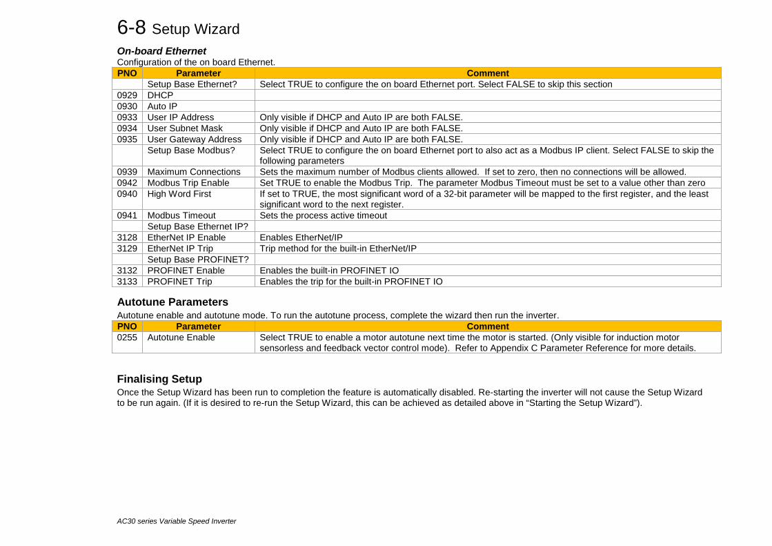
6-8 Setup Wizard
AC30 series Variable Speed Inverter
On-board Ethernet Configuration of the on board Ethernet. PNO Parameter Comment
Setup Base Ethernet? Select TRUE to configure the on board Ethernet port. Select FALSE to skip this section 0929 DHCP 0930 Auto IP 0933 User IP Address Only visible if DHCP and Auto IP are both FALSE. 0934 User Subnet Mask Only visible if DHCP and Auto IP are both FALSE. 0935 User Gateway Address Only visible if DHCP and Auto IP are both FALSE.
Setup Base Modbus? Select TRUE to configure the on board Ethernet port to also act as a Modbus IP client. Select FALSE to skip the following parameters
0939 Maximum Connections Sets the maximum number of Modbus clients allowed. If set to zero, then no connections will be allowed. 0942 Modbus Trip Enable Set TRUE to enable the Modbus Trip. The parameter Modbus Timeout must be set to a value other than zero 0940 High Word First If set to TRUE, the most significant word of a 32-bit parameter will be mapped to the first register, and the least
significant word to the next register. 0941 Modbus Timeout Sets the process active timeout Setup Base Ethernet IP? 3128 EtherNet IP Enable Enables EtherNet/IP 3129 EtherNet IP Trip Trip method for the built-in EtherNet/IP
Setup Base PROFINET? 3132 PROFINET Enable Enables the built-in PROFINET IO 3133 PROFINET Trip Enables the trip for the built-in PROFINET IO
Autotune Parameters Autotune enable and autotune mode. To run the autotune process, complete the wizard then run the inverter. PNO Parameter Comment 0255 Autotune Enable Select TRUE to enable a motor autotune next time the motor is started. (Only visible for induction motor
sensorless and feedback vector control mode). Refer to Appendix C Parameter Reference for more details.
Finalising Setup Once the Setup Wizard has been run to completion the feature is automatically disabled. Re-starting the inverter will not cause the Setup Wizard to be run again. (If it is desired to re-run the Setup Wizard, this can be achieved as detailed above in “Starting the Setup Wizard”).

6-9 Setup Wizard
AC30 series Variable Speed Inverter
Set Up PMAC Motor Control - Sensorless Minimum steps ( and list of parameters ) for setting a PMAC motor control in Sensorless mode are given below :
0511 Motor Type
0555 PMAC Max Speed0556 PMAC Max Current0557 PMAC Rated Current0558 PMAC Rated Torque0559 PMAC Motor Poles0564 PMAC Motor Inertia1387 PMAC Base Volt
Enter basic motor parameters
0464 100% Speed in RPM
0478 PMAC SVC Start Cur0479 PMAC SVC Start Speed
Speed unstable ?
0486 Acceleration Time0487 DecelerationTime
1257 Seq Stop Method SVC
Motion too smooth ?
Reduce speed loop bandwidth
Increase speed loop bandwidth
1247 Ratio Load Mot Inertia01248 Speed Loop Bandwidth
Y
Y
Y
Set Acceleration – Deceleration rate
Choose Stopping mode
Enter 100% speed setpoint
1st motor run
Set SVC PMAC
PMAC Control Selected?
End of minimum settings
Select stack overload capability 0390 Duty Selection
/Control Mode
/Motor Control / PMAC Motor Data
/Motor Control /Scale Setpoint
/Motor Control /Ramp
/Motor Control /Ramp
/Motor Control /PMAC SVC
/Motor Control / Feedbacks
/Motor Control / PMAC Motor Data 0564 PMAC Motor Inertia
/Motor Control / Spd Loop Settings
/Motor Control/Control & Type
/Motor Control/Motor Data PMAC
/Motor Control/Motor Data PMAC
/Motor Control/Control & Type
/Motor Control/Control & Type
/Motor Control/SVC PMAC
/Motor Control/Control & Type
/Motor Control/Control & Type
OR
OR
OR
OR
OR
OR
OR
OR
Setup Menu Parameters Menu ( if (1141 View Level = Engineer) ) Parameters
Sensorless?
Y
Enter Control mode /Motor Control/Control & Type 1533 Control Type = SENSORLESSOR /Control Mode
N
Setup speed control
Autotune
First Run
0560 PMAC Back Emf Const KE0561 PMAC Winding Resistance0562 PMAC Winding Inductance0563 PMAC Torque Const KT
Run Auto-tune ?
Enter Motor models parameters from datasheet
/Motor Control / PMAC Motor Data/Motor Control/Motor Data PMAC OR
Y /Motor Control/Autotune /Motor Control/Autotune 255 Autotune Enable
N
Motor models parameters identified by autotune
See PMAC Encoder Feedback diagram

6-10 Setup Wizard
AC30 series Variable Speed Inverter
Set Up PMAC Motor Control – Encoder Feedback Minimum steps ( and list of parameters ) for setting a PMAC motor control in Closed Loop mode are given below :
0511 Motor Type
0555 PMAC Max Speed0556 PMAC Max Current0557 PMAC Rated Current0558 PMAC Rated Torque0559 PMAC Motor Poles0564 PMAC Motor Inertia1387 PMAC Base Volt
Enter basic PMAC Motor parameters
/Control Mode
/Motor Control / PMAC Motor Data
/Motor Control/Control & Type
/Motor Control/Motor Data PMAC
OR
OR
Setup Menu Parameters Menu ( if (1141 View Level = Engineer) ) Parameters
Sensorless?
N
Enter Control mode /Motor Control/Control & Type 1533 Control Type = ENCODER FEEDBACKOR /Control Mode
/Motor Control/Control & Type 1743 Encoder Feedback/Control Mode
Resolver?
Pulse Encoder
1178 Option IO Required/Inputs and Outputs/Option /Inputs and Outputs/Option IO
1790 Resolver Voltage1791 Resolver Frequency1792 Resolver Ratio1793 Resolver Poles1822 Resolver Built In Gear1810 Resolver Invert1816 Resolver Resolution
/Inputs and Outputs/SB Encoder Slot1
/Inputs and Outputs/Resolver
1511 Encoder Supply1512 Encoder Lines1513 Encoder Invert1515 Encoder Single Ended
1739 System Board Required
1663 Encoder Supply1664 Encoder Lines1665 Encoder Invert1666 Encoder Type
1761 Encoder Supply1671 Encoder Lines1672 Encoder Invert1673 Encoder Type
/System Board/Encoder Slot 1
/System Board/Encoder Slot 2/Inputs and Outputs/SB Encoder Slot2
No
No
Encoder Slot 1?
Encoder Slot 1?
Y
No
No
Y
Y
Y
Y
No
Select PMAC
Setup Active Speed Feedback
/Inputs and Outputs/Resolver
/Inputs and Outputs/Option
/Inputs and Outputs/Option
Setup Type and control mode
See PMAC Sensorless diagram
Select Active Speed Feedback
I/O Option?
System Board Encoder?

6-11 Setup Wizard
AC30 series Variable Speed Inverter
0560 PMAC Back Emf Const KE0561 PMAC Winding Resistance0562 PMAC Winding Inductance0563 PMAC Torque Const KT
Speed unstable ?
Motion too smooth ?
Reduce speed loop bandwidth
Increase speed loop bandwidth
1247 Ratio Load Mot Inertia01248 Speed Loop Bandwidth
Y
Y
Run Auto-tune ?
Enter Motor models parameters from datasheet
1st motor run
End of minimum settings
/Motor Control / PMAC Motor Data
/Motor Control / PMAC Motor Data 0564 PMAC Motor Inertia
/Motor Control / Spd Loop Settings
/Motor Control/Motor Data PMAC
/Motor Control/Motor Data PMAC
OR
OR
Y /Motor Control/Autotune /Motor Control/Autotune 255 Autotune Enable
N
Run Pos Algnment ? /Motor Control/Pos Fbk Alignment
1808 PMAC Encoder Offset
1809 PMAC Wiring
/Motor Control/Motor Data PMAC
/Motor Control/Motor Data PMAC
Motor Control/PMAC Motor Data
Motor Control/PMAC Motor Data
OR
Motor Control/Pos Fbk Alignment
1798 Alignment Enable
1797 Alignment Method
1799 Alignment Level
Y
Setup pos alignment
Enter by hand PMAC Encoder Offset and PMAC wiring
1257 Seq Stop Method SVCChoose Stopping mode /Motor Control /Ramp/Motor Control/Control & Type OR
0486 Acceleration Time0487 DecelerationTime
Set Acceleration – Deceleration rate
/Motor Control /Ramp/Motor Control/Control & Type OR
Setup speed control
Autotune
Pos Alignment
First Run
Enter 100% speed setpoint /Motor Control / Scale Setpoint/Motor Control/Control & Type 0464 100% Speed in RPM
Select stack overload capability
0390 Duty Selection/Motor Control / Feedbacks/Motor Control/Control & Type OR
Motor models parameters identified by autotune

6-12 Setup Wizard
AC30 series Variable Speed Inverter
Set Up PMAC Motor Control – Pos Alignment after Power-up Vector Control of a PMAC motor needs to know the relative position between the rotor and the stator. Pos Alignment sequence allows to synchronise encoder position to Motor Back EMF. This feature is used to automatically calculate any offset between the encoder absolute position and the motor back EMF, as well as selecting the correct wiring of the motor ( U, V, W sequence ) with the encoder position. The feature needs to be run after each power cycle with a PMAC motor associated to a non absolute encoder type ( pulse encoder ) The feature is run on a motor free of rotation, no load attached to the motor shaft. Depending of the Alignment Method selected, the motor is moving during the sequence.
Below is a simple example on how to force the system to run a Pos Alignment sequence on the first start after power_up :
Alignment Method is set to Manual ( It could have been set to AUTOMATIC ).
Alignment Enable is TRUE from Start-up.
The first start command will run the Pos Alignment sequence.
A running and successfully sequence resets Alignment_Enable to FALSE.
A 1s negative pulse is generated at the end of the sequence. This information can be used to toggle any command to start the system.
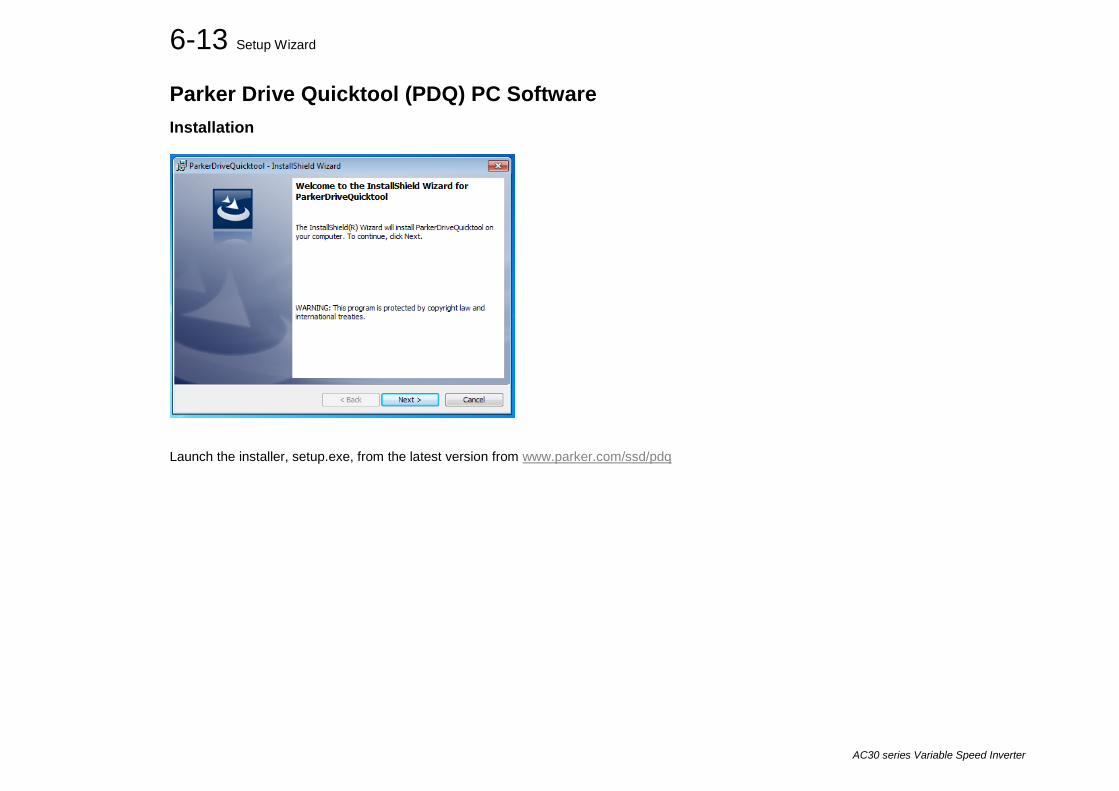
6-13 Setup Wizard
AC30 series Variable Speed Inverter
Parker Drive Quicktool (PDQ) PC Software Installation
Launch the installer, setup.exe, from the latest version from www.parker.com/ssd/pdq
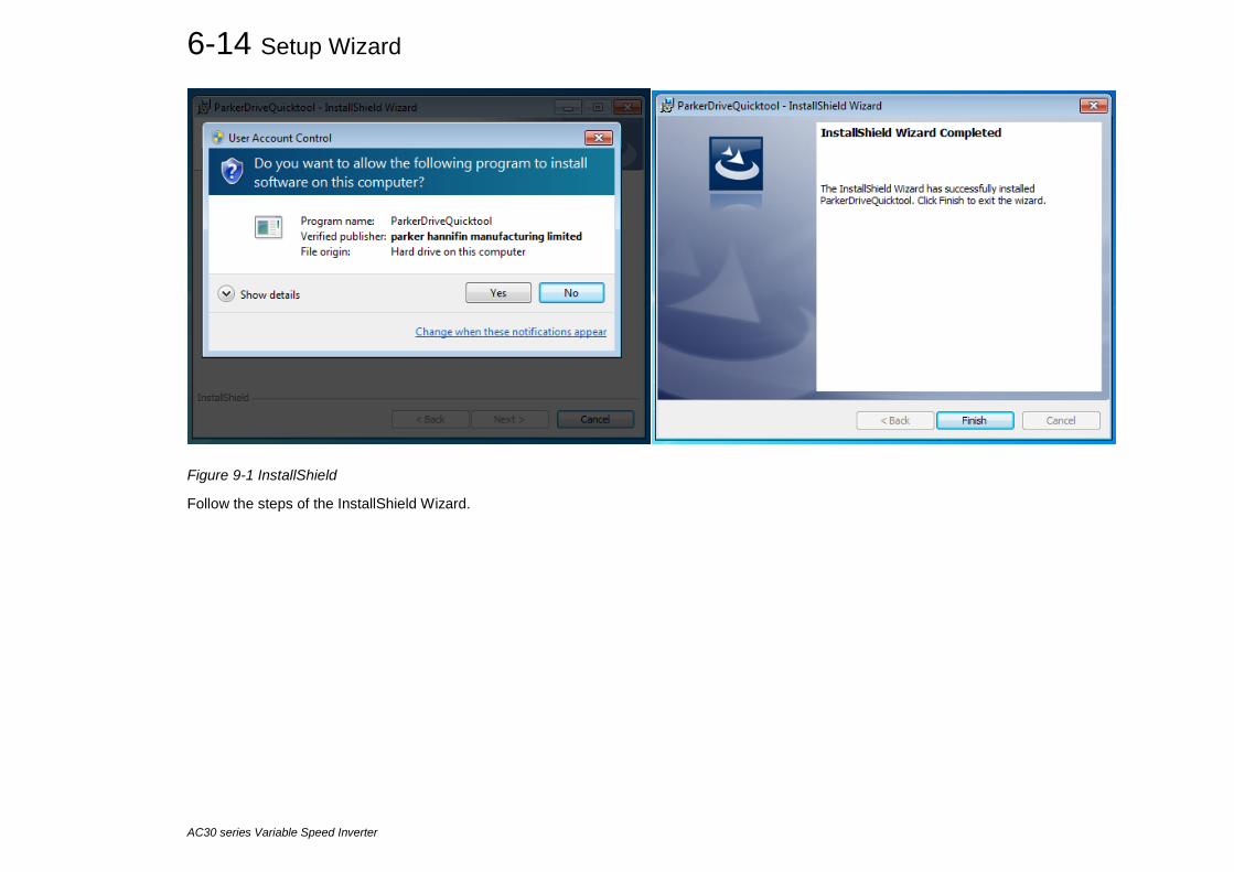
6-14 Setup Wizard
AC30 series Variable Speed Inverter
Figure 9-1 InstallShield
Follow the steps of the InstallShield Wizard.

6-15 Setup Wizard
AC30 series Variable Speed Inverter
Starting the Wizard
Figure 9-2 Desktop shortcut
Once the InstallShield completes, run the PDQ from the “Start” menu as shown or from the desktop shortcut as shown in
Figure 9-3 Start the Wizard
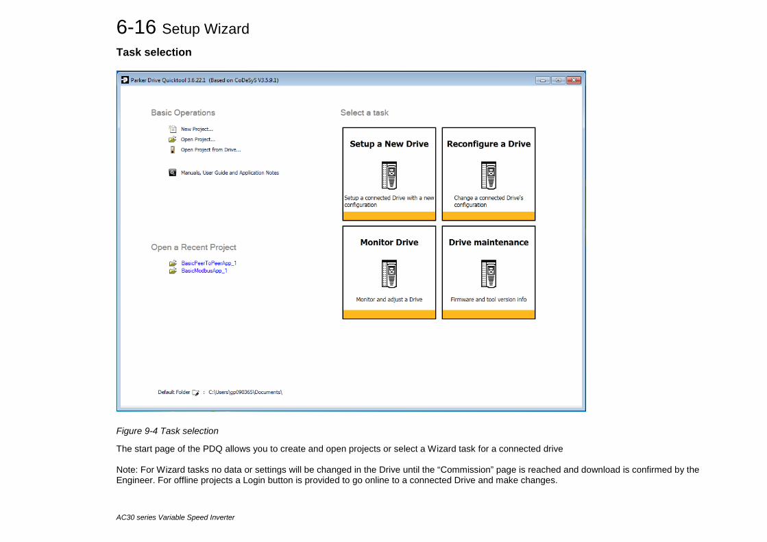
6-16 Setup Wizard
AC30 series Variable Speed Inverter
Task selection
Figure 9-4 Task selection
The start page of the PDQ allows you to create and open projects or select a Wizard task for a connected drive Note: For Wizard tasks no data or settings will be changed in the Drive until the “Commission” page is reached and download is confirmed by the Engineer. For offline projects a Login button is provided to go online to a connected Drive and make changes.

6-17 Setup Wizard
AC30 series Variable Speed Inverter
All the Wizard Tasks use a similar sequence of pages to find and program a Drive. The following page shows the Setup a New Drive wizard and the Find a Drive page
Figure 9-5 Automatic Drive detection
The wizard will automatically detect all the inverters that are visible to the PC via it’s Ethernet connections. This normally takes 10 seconds, during which time the user interface will go grey and will not respond to you. Once the inverter detection is complete, find your inverter in the list and click on it with the mouse. Information about the selected Drive will be displayed in the status area at the bottom of the screen. Ensure you have selected the correct Drive before continuing. If Drive Brake Switch is not fitted it will be indicted by the symbol as shown in Figure 9-5.

6-18 Setup Wizard
AC30 series Variable Speed Inverter
Note: The selected drive’s name will match that shown on the GKP home screen. Click on the “Next” button to begin Commissioning this Drive.
Troubleshooting Drive Detection Problem Possible cause Solution Drive not found Drive not connected to the same physical Ethernet
network as the PC Connect Drive and PC to the same network or directly to each other
Drive found but no information displayed
Another person has their PC connected to the Drive Disconnect the other PC

6-19 Setup Wizard
AC30 series Variable Speed Inverter
Application Macro
Figure 9-6 Macro selection
Select the desired Application Macro from the drop down list. Adjust any parameters that are needed for your specific application. To make changes to the application logic choose the Custom button.

6-20 Setup Wizard
AC30 series Variable Speed Inverter
Drive Hardware
On the Drive Hardware page there are 4 tabs for Motor setup, Motor Control Strategy, IO setup and Communication setup.

6-21 Setup Wizard
AC30 series Variable Speed Inverter
Motor Setup
Figure 9-7 Motor selection from database
The Motor Setup tab allows the engineer to define the motor parameters or use the built in motor database to search and select known motor data. Other parameters such as acceleration and deceleration can also be entered here.
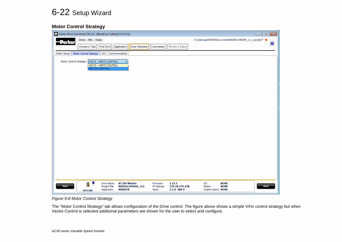
6-22 Setup Wizard
AC30 series Variable Speed Inverter
Motor Control Strategy
Figure 9-8 Motor Control Strategy
The “Motor Control Strategy” tab allows configuration of the Drive control. The figure above shows a simple V/Hz control strategy but when Vector Control is selected additional parameters are shown for the user to select and configure.
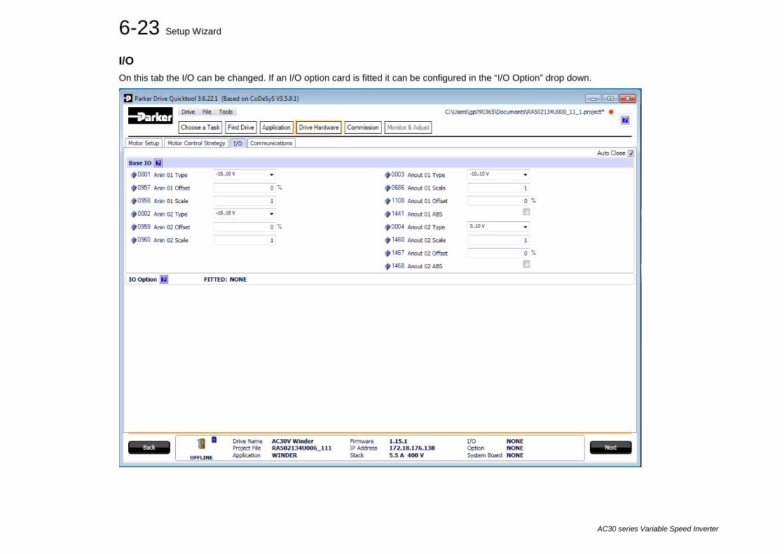
6-23 Setup Wizard
AC30 series Variable Speed Inverter
I/O On this tab the I/O can be changed. If an I/O option card is fitted it can be configured in the “I/O Option” drop down.

6-24 Setup Wizard
AC30 series Variable Speed Inverter
Communications On this tab the Communication to and from the Drive can be configured.
Figure 9-9 Drive Communications setup
If required, the built in Modbus can be setup from, the “Base Modbus Communication” selection.
If an optional Fieldbus is fitted, it can be configured from the “Comms Option” selection.

6-25 Setup Wizard
AC30 series Variable Speed Inverter
Commission the Drive
Figure 9-10 Programming the Drive
The “Commission” page is used to commission the Drive with the Selected macro and motor settings chosen during the Wizard session.
There are two steps that are performed to finalise the Commissioning of the Drive.
1. Enter the Project File name and the Drive’s name in the left of the screen.
2. “Program Drive”. This step writes your settings to the Drive and overwrites any existing configuration in the Drive.
After these steps, the Drive is ready to use.
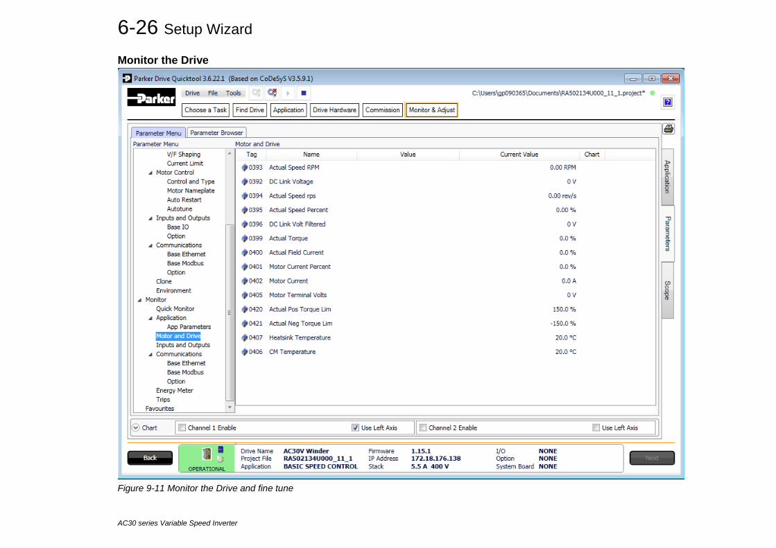
6-26 Setup Wizard
AC30 series Variable Speed Inverter
Monitor the Drive
Figure 9-11 Monitor the Drive and fine tune

6-27 Setup Wizard
AC30 series Variable Speed Inverter
Figure 9-16 Scoping Drive Parameters

6-28 Setup Wizard
AC30 series Variable Speed Inverter

Trips & Fault Finding 7-1
AC30 series Variable Speed Inverter
Chapter 7: Trips & Fault Finding What Happens when a Trip Occurs When a trip occurs, the drive’s power stage is immediately disabled causing the motor and load to coast to a stop. The trip is latched until action is taken to reset it. This ensures that trips due to transient conditions are captured and the drive is disabled, even when the original cause of the trip is no longer present.
Keypad Indications If a trip condition is detected the activated alarm is displayed on the GKP display.
Resetting a Trip Condition All trips must be reset before the drive can be re-enabled. A trip can only be reset once the trip condition is no longer active, i.e. a trip due to a heatsink over-temperature will not reset until the temperature is below the trip level. You can reset the trip as follows:
1. Press the (STOP) key to reset the trip and clear the alarm from the display.
2. In remote terminal sequencing mode, create a 0 to 1 transition on the RESET TRIP bit, (bit 7), in the App Control Word parameter.
3. In remote communications sequencing mode, create a 0 to 1 transition on the RESET TRIP bit, (bit 7), in the Comms Control Word parameter.

7-2 Trips & Fault Finding
AC30 series Variable Speed Inverter
Using the Keypad to Manage Trips Trip Messages If the drive trips, then the display immediately shows a message indicating the reason for the trip. The possible trip messages are given in the table below.
ID Trip Name Possible Reason for Trip Criteria for Warning
1 OVER VOLTAGE The drive internal dc link voltage is too high: • The supply voltage is too high • Trying to decelerate a large inertia load too quickly; DECEL TIME time too short
The brake resistor is open circuit To help prevent this trip, enable the DC Link Volts Limit feature
Internal dc link voltage has reached midway between the over voltage trip level and the dynamic braking resistor control voltage.
2 UNDER VOLTAGE DC link low trip: • Supply is too low/power down
Internal dc link voltage has reached midway between the lowest expected instantaneous voltage and the under voltage trip level.
3 OVER CURRENT The motor current being drawn from the drive is too high: • Trying to accelerate a large inertia load too quickly; ACCEL TIME time too short • Trying to decelerate a large inertia load too quickly; DECEL TIME time too short • Application of shock load to motor • Short circuit between motor phases • Short circuit between motor phase and earth • Motor output cables too long or too many parallel motors connected to the drive • FIXED BOOST level set too high
The over current trip makes up of a multiple-attempt strategy. The warning is triggered if two or more consecutive overcurrent events are encountered (whereas five consecutive events are required for a Trip to occur).
4 STACK FAULT Stack self protection • Instantaneous overcurrent detected by the power stack. Refer to OVERCURRENT
in this table. • Instantaneous over voltage event. Refer to OVER VOLTAGE in this table
Not applicable.
5 STACK OVER CURRENT
The motor current exceeded the capabilities of the power stack. • Instantaneous overcurrent detected by the power stack. Refer to OVERCURRENT
in this table.
Not applicable.
6 CURRENT LIMIT V/Hz mode only: If the current exceeds 200% of stack rated current for a period of 1 second, the drive will trip. This is caused by shock loads
Not applicable.

Trips & Fault Finding 7-3
AC30 series Variable Speed Inverter
ID Trip Name Possible Reason for Trip Criteria for Warning 7 MOTOR STALL The motor has stalled (not rotating) Drive in current limit >200 seconds:
• Motor loading too great • FIXED BOOST level set too high
The stall condition has been detected for more than half of the configured Stall Time.
8 INVERSE TIME A prolonged overload condition, exceeding the Inverse Time allowance, has caused the trip: • Remove the overload condition
An overload condition has exceeded one half of the Inverse Time allowance.
9 MOTOR I2T Only for PMAC Motor: A prolonged load condition, exceeding the motor rated current, has caused the trip. The estimated motor load has reached a value of 105%
An overload condition has exceeded one half of the motor Inverse Time allowance.
10 LOW SPEED I The motor is drawing too much current (>100%) at zero output frequency: • FIXED BOOST level set too high
Not applicable.
11 HEATSINK OVERTEMP
Drive heatsink temperature too high • The ambient air temperature is too high • Poor ventilation or spacing between drives • Check heatsink fan is rotating
The drive heatsink has exceeded the warning temperature level (which is approx. 10°C below the trip temperature).
12 INTERNAL OVERTEMP
Processor temperature or ambient temperature within the power stage too high • The ambient temperature in the drive is too high
The drive processor temperature has exceeded the warning temperature level (which is approx. 10°C below the trip temperature).
13 MOTOR OVERTEMP
The motor temperature is too high, (required IO Option card) • Excessive load • Motor voltage rating incorrect • FIXED BOOST level set too high • Prolonged operation of the motor at low speed without forced cooling • Break in motor thermistor connection
The motor has been over temperature for 7.5 seconds.
14 EXTERNAL TRIP The external (application) trip input is high: • Refer to the application description to identify the source of the signal
Not applicable.
15 BRAKE SHORT CCT
External dynamic brake resistor has been overloaded: • The external dynamic brake has developed a short circuit. • Wiring fault
Not applicable.

7-4 Trips & Fault Finding
AC30 series Variable Speed Inverter
ID Trip Name Possible Reason for Trip Criteria for Warning 16 BRAKE RESISTOR External dynamic brake resistor has been overloaded:
• Trying to decelerate a large inertia too quickly or too often The power calculation for the external resistor has exceeded one half of the Brake Overrating allowance.
17 BRAKE SWITCH Internal dynamic braking switch has been overloaded: • Trying to decelerate a large inertia too quickly or too often
The power calculation for the internal dynamic braking switch has exceeded one half of the its overrating allowance.
18 LOCAL CONTROL Keypad has been disconnected from drive whilst drive is running in Local Control: • GKP accidentally disconnected from drive
Not applicable.
19 COMMS BREAK Lost option communications: • A break in option communications has been detected. Refer to option
communications manual.
Not applicable.
20 LINE CONTACTOR DC Link failed to reach the undervoltage trip level within the contactor feedback time. • The Line contactor failed to connect. • Missing 3-phase line supply
Not applicable.
21 PHASE FAIL • Indicates a missing input phase, for Frame K, L and M drives. Disable this trip for DC fed units.
Not applicable.
22 VDC RIPPLE The DC link ripple voltage is too high: • Check for a missing input phase • Repetitive start / stop or forward reverse action.
The dc link ripple has exceeded 75% of the trip level.
23 BASE MODBUS BREAK
Lost Base Modbus communications: • A break in the Base Modbus communications has been detected. Refer to
“Appendix A Fieldbuses
Not applicable.
24 24V OVERLOAD 24V rail is low • Output overload due to excess current being drawn from the 24v terminal.
Not applicable.
25 PMAC SPEED ERROR
Only for PMAC motor : When using the Start feature in Sensorless Vector Control, the real speed hasn’t reached the speed setpoint after 5 seconds to move from open to closed loop control or to move from closed to open loop
Not applicable.
26 OVERSPEED Overspeed: • >150% base speed when in Sensorless Vector mode
Not applicable.
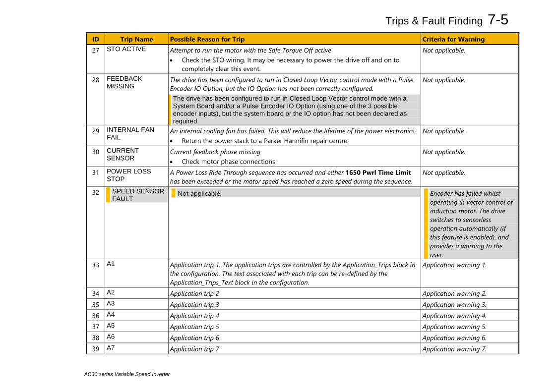
Trips & Fault Finding 7-5
AC30 series Variable Speed Inverter
ID Trip Name Possible Reason for Trip Criteria for Warning 27 STO ACTIVE Attempt to run the motor with the Safe Torque Off active
• Check the STO wiring. It may be necessary to power the drive off and on to completely clear this event.
Not applicable.
28 FEEDBACK MISSING
The drive has been configured to run in Closed Loop Vector control mode with a Pulse Encoder IO Option, but the IO Option has not been correctly configured. The drive has been configured to run in Closed Loop Vector control mode with a System Board and/or a Pulse Encoder IO Option (using one of the 3 possible encoder inputs), but the system board or the IO option has not been declared as required.
Not applicable.
29 INTERNAL FAN FAIL
An internal cooling fan has failed. This will reduce the lifetime of the power electronics. • Return the power stack to a Parker Hannifin repair centre.
Not applicable.
30 CURRENT SENSOR
Current feedback phase missing • Check motor phase connections
Not applicable.
31 POWER LOSS STOP
A Power Loss Ride Through sequence has occurred and either 1650 Pwrl Time Limit has been exceeded or the motor speed has reached a zero speed during the sequence.
Not applicable.
32 SPEED SENSOR FAULT
Not applicable. Encoder has failed whilst operating in vector control of induction motor. The drive switches to sensorless operation automatically (if this feature is enabled), and provides a warning to the user.
33 A1 Application trip 1. The application trips are controlled by the Application_Trips block in the configuration. The text associated with each trip can be re-defined by the Application_Trips_Text block in the configuration.
Application warning 1.
34 A2 Application trip 2 Application warning 2. 35 A3 Application trip 3 Application warning 3. 36 A4 Application trip 4 Application warning 4. 37 A5 Application trip 5 Application warning 5. 38 A6 Application trip 6 Application warning 6. 39 A7 Application trip 7 Application warning 7.
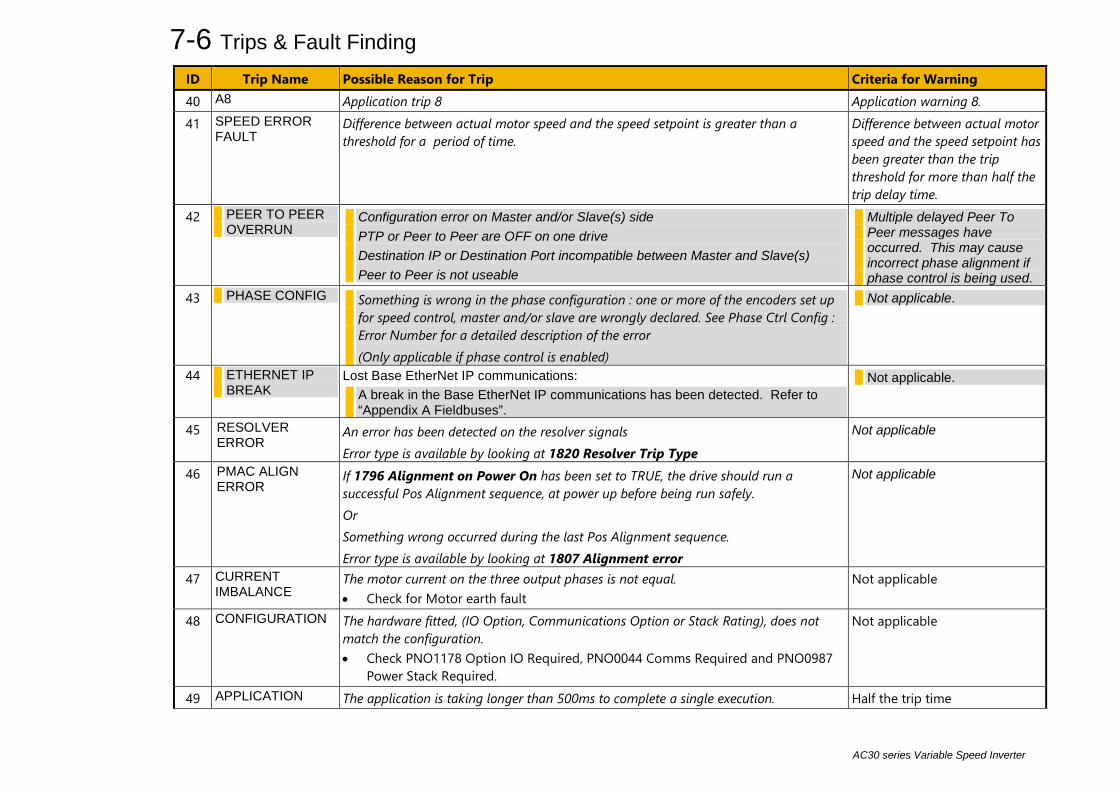
7-6 Trips & Fault Finding
AC30 series Variable Speed Inverter
ID Trip Name Possible Reason for Trip Criteria for Warning 40 A8 Application trip 8 Application warning 8. 41 SPEED ERROR
FAULT Difference between actual motor speed and the speed setpoint is greater than a threshold for a period of time.
Difference between actual motor speed and the speed setpoint has been greater than the trip threshold for more than half the trip delay time.
42 PEER TO PEER OVERRUN
Configuration error on Master and/or Slave(s) side PTP or Peer to Peer are OFF on one drive Destination IP or Destination Port incompatible between Master and Slave(s) Peer to Peer is not useable
Multiple delayed Peer To Peer messages have occurred. This may cause incorrect phase alignment if phase control is being used.
43 PHASE CONFIG Something is wrong in the phase configuration : one or more of the encoders set up for speed control, master and/or slave are wrongly declared. See Phase Ctrl Config : Error Number for a detailed description of the error (Only applicable if phase control is enabled)
Not applicable.
44 ETHERNET IP BREAK
Lost Base EtherNet IP communications: A break in the Base EtherNet IP communications has been detected. Refer to “Appendix A Fieldbuses”.
Not applicable.
45 RESOLVER ERROR
An error has been detected on the resolver signals Error type is available by looking at 1820 Resolver Trip Type
Not applicable
46 PMAC ALIGN ERROR
If 1796 Alignment on Power On has been set to TRUE, the drive should run a successful Pos Alignment sequence, at power up before being run safely. Or Something wrong occurred during the last Pos Alignment sequence. Error type is available by looking at 1807 Alignment error
Not applicable
47 CURRENT IMBALANCE
The motor current on the three output phases is not equal. • Check for Motor earth fault
Not applicable
48 CONFIGURATION The hardware fitted, (IO Option, Communications Option or Stack Rating), does not match the configuration. • Check PNO1178 Option IO Required, PNO0044 Comms Required and PNO0987
Power Stack Required.
Not applicable
49 APPLICATION The application is taking longer than 500ms to complete a single execution. Half the trip time

Trips & Fault Finding 7-7
AC30 series Variable Speed Inverter
ID Trip Name Possible Reason for Trip Criteria for Warning 50 AC30A ENCODER Missing sin and/or cos signals Not applicable 51 CPU USAGE Combination of high switching frequency, high network traffic and complicated
configuration. Run the application at a slower task rate, reduce the Ethernet load or reduce the switching frequency.
Time based, warning issued at least 0.5s before the trip.

7-8 Trips & Fault Finding
AC30 series Variable Speed Inverter
Hexadecimal Representation of Trips Each trip has a unique, eight-digit hexadecimal number as shown in the tables below. This number is referred to as the trip mask. The trip masks are used in the Enable, Active and Warnings parameters in the Trips module. ID Trip Name
Mask User
Disable 1 OVER VOLTAGE 00000001 2 UNDER VOLTAGE 00000002 3 OVER CURRENT 00000004 4 STACK FAULT 00000008 5 STACK OVER CURRENT 00000010 6 CURRENT LIMIT 00000020 7 MOTOR STALL 00000040 8 INVERSE TIME 00000080 9 MOTOR I2T 00000100 10 LOW SPEED I 00000200 11 HEATSINK OVERTEMP 00000400 12 AMBIENT OVERTEMP 00000800 13 MOTOR OVERTEMP 00001000 14 EXTERNAL TRIP 00002000 15 BRAKE SHORT CCT 00004000 16 BRAKE RESISTOR 00008000 17 BRAKE SWITCH 00010000 18 LOCAL CONTROL 00020000 19 COMMS BREAK 00040000 20 LINE CONTACTOR 00080000 21 PHASE FAIL 00100000 22 VDC RIPPLE 00200000 23 BASE MODBUS BREAK 00400000 24 24V OVERLOAD 00800000 25 PMAC SPEED ERROR 01000000 26 OVERSPEED 02000000
ID Trip Name
Mask User Disable
27 SAFE TORQUE OFF 04000000 28 FEEDBACK MISSING 08000000 31 POWER LOSS STOP 40000000 32 SPEED SENSOR FAULT 80000000 33 A1 00000001* 34 A2 00000002* 35 A3 00000004* 36 A4 00000008* 37 A5 00000010* 38 A6 00000020* 39 A7 00000040* 40 A8 00000080* 41 SPEED ERROR FAULT 00000100* 42 PEER TO PEER OVERRUN 00000200* 43 PHASE CONFIG 00000400* 44 ETHERNET IP BREAK 00000800* 45 RESOLVER ERROR 00001000* 46 PMAC ALIGN ERROR 00002000* 47 STACK IMBALANCE 00004000* 48 CONFIGURATION 00008000* 49 APPLICATION 00010000* 50 AC30A ENCODER 00020000* 51 CPU Usage 00040000* * These masks apply to parameter words “33 – 64”

Trips & Fault Finding 7-9
AC30 series Variable Speed Inverter
Runtime Alerts A Runtime Alert is a fault that indicates a permanent hardware error. The Runtime Alert display is of the form
RUNTIME ALERT CODE 00000000 xx
CODE is a number in the range 0 to 65000. The following value is used to provide additional information to assist Parker Hannifin Technical Support personnel.
CODE ERROR Possible Reason for Error
1 to 255
Internal exception
• VCM not secured to power stack • Option not secured correctly to VCM control card • Earth bonding failure. • Fault during firmware upgrade
12 Memory access • Attempt to read or write to protected memory. Most likely this will be due to a configuration error. Press
OK several times until the drive resets correctly, then replace the configuration using PDQ. • Record the error message and contact Technical Support
1001 to
1003 Processor overload
• Select a lower switching frequency, (Parameters::Motor Control::Pattern Generator::Stack Frequency) • Record the error message and contact Technical Support
1006 Memory overflow • Reduce the complexity of the application • Reduce the number of parameters being accessed via the on board Modbus TCP protocol • Reduce the number of parameters being accessed by the fieldbus communications option.
1007 Uninitialized pointer • Record the error message and contact Technical Support 1010, 1101
to 1113
Initialization error • Record the error message and contact Technical Support
1200 to
1299
Communications option error
• Ensure the communications option is correctly fitted • Update the firmware in the inverter. • Replace the communications option
1300 Ethernet fault • Record the error message and contact Technical Support

7-10 Trips & Fault Finding
AC30 series Variable Speed Inverter
CODE ERROR Possible Reason for Error 1301 Modbus server • Record the error message and contact Technical Support 1302 HTTP server fault • Record the error message and contact Technical Support 1303 DCT server fault • Record the error message and contact Technical Support 1311 Ethernet PHY • Record the error message and contact Technical Support
1312 Precision Time Protocol • Record the error message and contact Technical Support
1313 EtherNet IP • Record the error message and contact Technical Support 1314 PROFINET • Record the error message and contact Technical Support 1401 1402
Control Module test • Control module self-test error
1403 1404
Power stack test • VCM not secured to power stack • Power stack self-test error
1501 1502 1503
IO Option identity IO Option processor Unknown IO Option
• Ensure the IO option is correctly fitted • Update the firmware in the inverter. • Replace the IO option
1504 IO Option watchdog • The IO Option has become disconnected • Option reset problem. Upgrade drive firmware to 1.11 or greater to improve the option reset control.
1601 Stack internal fault • Return the power stack to Parker Hannifin repair center. 1602 Incompatible stack • Return the power stack to Parker Hannifin repair center.
1801 Heatsink thermsistor unplugged • Return the power stack to Parker Hannifin repair center.
1901 System Board Data • The identifying data on the system board is corrupt
1902 System Board Type • The system board type is not recognized by this version of drive firmware. Update the firmware to the
latest version. 2001 Unimplemented Function • Record the error message and contact Technical Support 2002 Memory allocation error • Record the error message and contact Technical Support

Trips & Fault Finding 7-11
AC30 series Variable Speed Inverter
Autotune Alerts If the autotune fails to complete for any reason, an alert will be displayed and the autotune abandoned. Alerts are as follows:
Alert message Possible Cause Remedy LEAKAGE L TIMEOUT The autotune has attempted to determine the leakage
inductance of the motor, but cannot make the required test current.
Problem with motor connection.
MOTOR TURNING ERROR
The autotune is trying to find the encoder direction by spinning the motor, but the motor is already spinning.
Wait till the motor stops.
NEGATIVE SLIP FREQ Autotune has calculated a negative slip frequency, which is not valid. Nameplate rpm may have been set to a value higher than the base speed of the motor.
Check nameplate rpm, base frequency, and pole pairs are correct.
TR TOO LARGE The calculated value of rotor time constant is too large. Check the values of Nameplate Speed and Base Frequency. TR TOO SMALL The calculated value of rotor time constant is too small. Check the values of Nameplate Speed and Base Frequency. MAX SPEED TOO LOW During Autotune the motor is required to run at the
nameplate speed of the motor. If 100% Speed in RPM parameter limits the speed to less than this value, an error will be reported.
Increase the value of 100% Speed in RPM parameter up to the nameplate rpm of the motor (as a minimum). It may be reduced, if required, after the Autotune is complete.
SUPPLY VOLTS LOW The autotune will compensate for low supply volts, down to 70% of motor rated volts. Below this value it will stop the autotune and raise an alert.
Re-try when mains volts are within specification.
NOT AT SPEED The motor was unable to reach the required speed to carry out the Autotune.
Possible reasons include: motor shaft not free to turn; the motor data is incorrect.
MAG CURRENT ERROR It was not possible to find a suitable value of magnetising current to achieve the required operating condition for the motor.
Check the motor data is correct, especially nameplate rpm and motor volts. Also check that the motor is correctly rated for the drive.
KE TOO LARGE Ke value calculated during the autotune (stationary) is too large (the max value is 840V)
Check the motor data is correct, especially nameplate rpm, rated amps and motor volts. If low speed motor with a Ke value higher than 840V, enter by hand the corresponding value after the autotune completion.
KE TOO SMALL Ke value calculated during the autotune (stationary) is too small (the min value is 1V)
Check the motor data is correct, especially nameplate rpm, rated amps and motor volts.
ALL TESTS DISABLED All auto tune tests are disabled Check parameter 0257: Autotune Test Disable
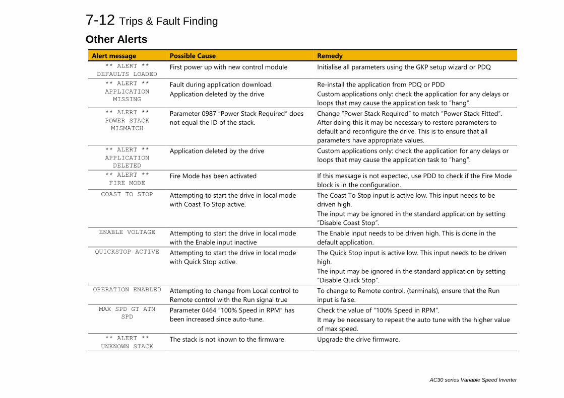
7-12 Trips & Fault Finding
AC30 series Variable Speed Inverter
Other Alerts Alert message Possible Cause Remedy
** ALERT ** DEFAULTS LOADED
First power up with new control module Initialise all parameters using the GKP setup wizard or PDQ
** ALERT ** APPLICATION
MISSING
Fault during application download. Application deleted by the drive
Re-install the application from PDQ or PDD Custom applications only: check the application for any delays or loops that may cause the application task to “hang”.
** ALERT ** POWER STACK MISMATCH
Parameter 0987 “Power Stack Required” does not equal the ID of the stack.
Change “Power Stack Required” to match “Power Stack Fitted”. After doing this it may be necessary to restore parameters to default and reconfigure the drive. This is to ensure that all parameters have appropriate values.
** ALERT ** APPLICATION
DELETED
Application deleted by the drive Custom applications only: check the application for any delays or loops that may cause the application task to “hang”.
** ALERT ** FIRE MODE
Fire Mode has been activated If this message is not expected, use PDD to check if the Fire Mode block is in the configuration.
COAST TO STOP Attempting to start the drive in local mode with Coast To Stop active.
The Coast To Stop input is active low. This input needs to be driven high. The input may be ignored in the standard application by setting “Disable Coast Stop”.
ENABLE VOLTAGE Attempting to start the drive in local mode with the Enable input inactive
The Enable input needs to be driven high. This is done in the default application.
QUICKSTOP ACTIVE Attempting to start the drive in local mode with Quick Stop active.
The Quick Stop input is active low. This input needs to be driven high. The input may be ignored in the standard application by setting “Disable Quick Stop”.
OPERATION ENABLED Attempting to change from Local control to Remote control with the Run signal true
To change to Remote control, (terminals), ensure that the Run input is false.
MAX SPD GT ATN SPD
Parameter 0464 “100% Speed in RPM” has been increased since auto-tune.
Check the value of “100% Speed in RPM”. It may be necessary to repeat the auto tune with the higher value of max speed.
** ALERT ** UNKNOWN STACK
The stack is not known to the firmware Upgrade the drive firmware.
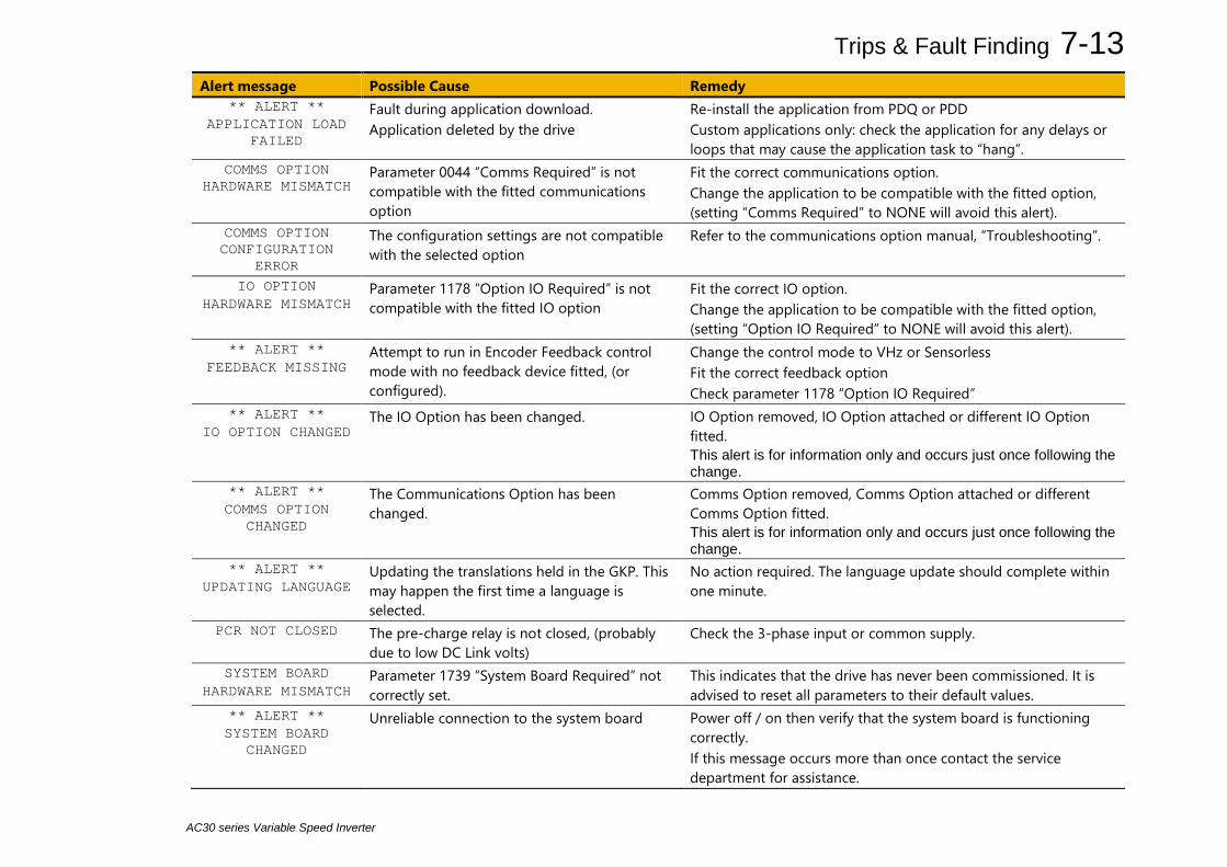
Trips & Fault Finding 7-13
AC30 series Variable Speed Inverter
Alert message Possible Cause Remedy ** ALERT **
APPLICATION LOAD FAILED
Fault during application download. Application deleted by the drive
Re-install the application from PDQ or PDD Custom applications only: check the application for any delays or loops that may cause the application task to “hang”.
COMMS OPTION HARDWARE MISMATCH
Parameter 0044 “Comms Required” is not compatible with the fitted communications option
Fit the correct communications option. Change the application to be compatible with the fitted option, (setting “Comms Required” to NONE will avoid this alert).
COMMS OPTION CONFIGURATION
ERROR
The configuration settings are not compatible with the selected option
Refer to the communications option manual, “Troubleshooting”.
IO OPTION HARDWARE MISMATCH
Parameter 1178 “Option IO Required” is not compatible with the fitted IO option
Fit the correct IO option. Change the application to be compatible with the fitted option, (setting “Option IO Required” to NONE will avoid this alert).
** ALERT ** FEEDBACK MISSING
Attempt to run in Encoder Feedback control mode with no feedback device fitted, (or configured).
Change the control mode to VHz or Sensorless Fit the correct feedback option Check parameter 1178 “Option IO Required”
** ALERT ** IO OPTION CHANGED
The IO Option has been changed. IO Option removed, IO Option attached or different IO Option fitted. This alert is for information only and occurs just once following the change.
** ALERT ** COMMS OPTION
CHANGED
The Communications Option has been changed.
Comms Option removed, Comms Option attached or different Comms Option fitted. This alert is for information only and occurs just once following the change.
** ALERT ** UPDATING LANGUAGE
Updating the translations held in the GKP. This may happen the first time a language is selected.
No action required. The language update should complete within one minute.
PCR NOT CLOSED The pre-charge relay is not closed, (probably due to low DC Link volts)
Check the 3-phase input or common supply.
SYSTEM BOARD HARDWARE MISMATCH
Parameter 1739 “System Board Required” not correctly set.
This indicates that the drive has never been commissioned. It is advised to reset all parameters to their default values.
** ALERT ** SYSTEM BOARD
CHANGED
Unreliable connection to the system board Power off / on then verify that the system board is functioning correctly. If this message occurs more than once contact the service department for assistance.

7-14 Trips & Fault Finding
AC30 series Variable Speed Inverter
Fault Finding Problem Possible Cause Remedy Drive will not power-up Fuse blown Check supply details, fit correct fuse.
Check Product Code against Model No. Faulty cabling Check all connections are correct/secure.
Check cable continuity Drive fuse keeps blowing Faulty cabling or connections wrong Check for problem and rectify before replacing with
correct fuse Faulty drive Contact Parker Cannot obtain power-on state Incorrect or no supply available Check supply details Motor will not run at switch-on Motor jammed Stop the drive and clear the jam
Safe Torque Off circuit active. Check the STO connections then power the drive off and on to clear any latched STO fault.
Motor runs and stops Motor becomes jammed Stop the drive and clear the jam Open circuit speed reference
potentiometer Check terminal
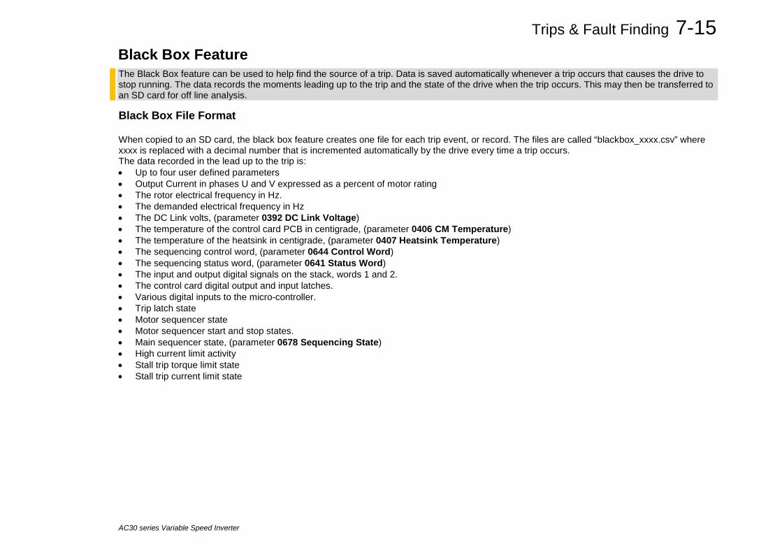
Trips & Fault Finding 7-15
AC30 series Variable Speed Inverter
Black Box Feature The Black Box feature can be used to help find the source of a trip. Data is saved automatically whenever a trip occurs that causes the drive to stop running. The data records the moments leading up to the trip and the state of the drive when the trip occurs. This may then be transferred to an SD card for off line analysis.
Black Box File Format When copied to an SD card, the black box feature creates one file for each trip event, or record. The files are called “blackbox_xxxx.csv” where xxxx is replaced with a decimal number that is incremented automatically by the drive every time a trip occurs. The data recorded in the lead up to the trip is: • Up to four user defined parameters • Output Current in phases U and V expressed as a percent of motor rating • The rotor electrical frequency in Hz. • The demanded electrical frequency in Hz • The DC Link volts, (parameter 0392 DC Link Voltage) • The temperature of the control card PCB in centigrade, (parameter 0406 CM Temperature) • The temperature of the heatsink in centigrade, (parameter 0407 Heatsink Temperature) • The sequencing control word, (parameter 0644 Control Word) • The sequencing status word, (parameter 0641 Status Word) • The input and output digital signals on the stack, words 1 and 2. • The control card digital output and input latches. • Various digital inputs to the micro-controller. • Trip latch state • Motor sequencer state • Motor sequencer start and stop states. • Main sequencer state, (parameter 0678 Sequencing State) • High current limit activity • Stall trip torque limit state • Stall trip current limit state
7-16 Trips & Fault Finding
AC30 series Variable Speed Inverter
The data recorded at the instant of the trip is output at the end of the file. This consists of: • Control module serial number, (parameter 0977 Control Module Serial) • Time of the trip. This is either the control board age, or the time from the optional Real Time Clock if fitted. • State of all other trips, active or warning. • Count of total motor starts, (parameter 1732 Motor Start Count) • Count of total times the 3-phase has been powered • For each trip, a count of the total times that trip has been activated. • A record of near trip events for Over Current, Over Voltage and Under Voltage. • The product code of the drive, expressed as a number in internal format. • The IO Option fitted, (parameter 1179 Option IO Fitted) • The Communications Option fitted, (parameter 0045 Comms Fitted) • The System board type, (parameter 1740 System Board Fitted) • The motor control type, (parameter 0511 Motor Type or AFE) • The control strategy, (parameter 0512 Control Stragegy) • The control type, (parameter 1533 Control Type) • The firmware version • The version of CoDeSys used to create the application.

Trips & Fault Finding 7-17
AC30 series Variable Speed Inverter
Diagnostic LEDs There are two diagnostic LEDs fitted next to the SD Card slot. The Health LED is on the left, closest to the connector for the GKP. The flash period is 1s when the drive firmware is active and 2s in the Firmware Update mode
HEALTH LED RUN LED
STOPPED
RUNNING
STOPPING, (NORMAL)
QUICKSTOPPING
FAULTED
INITIALISING
CONFIGURATION MODE
CONFIGURATION FAULT
FIRMWARE UPDATE – Idle
FIRMWARE UPDATE - Erasing firmware
FIRMWARE UPDATE – Writing firmware

7-18 Trips & Fault Finding
AC30 series Variable Speed Inverter
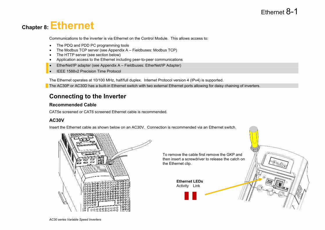
Ethernet 8-1
AC30 series Variable Speed Inverters
To remove the cable first remove the GKP and then insert a screwdriver to release the catch on the Ethernet clip.
Ethernet LEDs Activity Link
Chapter 8: Ethernet Communications to the inverter is via Ethernet on the Control Module. This allows access to:
• The PDQ and PDD PC programming tools • The Modbus TCP server (see Appendix A – Fieldbuses: Modbus TCP) • The HTTP server (see section below) • Application access to the Ethernet including peer-to-peer communications • EtherNet/IP adapter (see Appendix A – Fieldbuses: EtherNet/IP Adapter) • IEEE 1588v2 Precision Time Protocol The Ethernet operates at 10/100 MHz, half/full duplex. Internet Protocol version 4 (IPv4) is supported. The AC30P or AC30D has a built-in Ethernet switch with two external Ethernet ports allowing for daisy chaining of inverters.
Connecting to the Inverter Recommended Cable CAT5e screened or CAT6 screened Ethernet cable is recommended.
AC30V Insert the Ethernet cable as shown below on an AC30V. Connection is recommended via an Ethernet switch.

8-2 Ethernet
AC30 series Variable Speed Inverters
AC30P or AC30D
Insert the Ethernet cable on an AC30P or AC30D as shown below.
Port 1 LEDs
Activity
Link
Port 2 LEDs
Activity
Link
DO NOT TOUCH
DO NOT touch the board surface via the aperture shown

Ethernet 8-3
AC30 series Variable Speed Inverters
Ethernet Setup Configuration To enable communications over the Ethernet an IP address must be set. With the default setting, an attempt at automatically obtaining an IP address will be made.
Note: The IP address will be obtained or modified when an Ethernet cable is connected or the inverter is powered-up. For the AC30P or AC30D if one port is already connected to a network, the IP address of the inverter will not be modified when the other port is connected to a network.
The state of the Ethernet can be monitored using the parameter 0919 Ethernet State and from the Ethernet icon on the GKP status bar.
The current IP settings of the inverter can be monitored using the following parameters:
0926 IP Address 0927 Subnet Mask 0928 Gateway Address The MAC address of the Ethernet port is fixed at the factory and can be read using the parameter 0945 MAC Address
Advanced Configuration The IP address on the inverter may be set using the following methods:
• Manually to a fixed address
• Automatically by a DHCP server connected on the network
• Automatically by the inverter to a link-local address using Auto-IP (also known as Automatic Private IP Addressing)
The parameters 0929 DHCP and 0930 Auto IP are used to determine how the IP address is set. The default of these two parameters is TRUE.
The parameter 0936 Setting Lock, when set to TRUE, prevents a configuration tool from modifying the IP settings.

8-4 Ethernet
AC30 series Variable Speed Inverters
Manually Setting the IP Address Parameter Setting 0929 DHCP FALSE 0930 Auto IP FALSE 0933 User IP Address Preferred IP Address 0934 User Subnet Mask Preferred Subnet Mask 0935 User Gateway Address Preferred Gateway Address
To set the IP address manually both the DHCP and Auto-IP must be disabled. The IP address, subnet mask and gateway address will be set from the values in the parameters 0933 User IP Address, 0934 User Subnet Mask, 0935 User Gateway Address.
If the network does not have a gateway to another network then the gateway address may be set to 0.0.0.0
Automatically Assigning an IP Address using DHCP Parameter Setting 0929 DHCP TRUE 0930 Auto IP FALSE
If the network on which the inverter is connected has a DHCP (Dynamic Host Configuration Protocol) server then the IP address may be assigned by this server. The DHCP must be enabled. The inverter will then request an IP address, subnet mask and gateway address from the DHCP server.
Note: There is no guarantee that the DHCP server will provide the same IP address each time. The IP address is requested by the inverter when the Ethernet port is connected to a network or when the inverter is powered up.
Automatically Assigning an IP Address using Auto-IP Parameter Setting 0929 DHCP FALSE 0930 Auto IP TRUE
The inverter may assign itself a link-local address automatically using Auto-IP. This would be used where an automatic address is required but where no DHCP server is available, such as a small local network or when connecting an inverter directly to a PC (point to point). The Auto-IP must be enabled. The inverter will choose an IP address randomly from the link-local range 169.254.*.*. The AC30 checks that no other Ethernet device on the network is using the address before allocating it. The Inverter will store this IP address (in parameter 0931 Last Auto IP Address) and attempt to use it next time Auto-IP is used. The gateway address is fixed to 0.0.0.0

Ethernet 8-5
AC30 series Variable Speed Inverters
Using Both DHCP and Auto-IP Parameter Setting 0929 DHCP TRUE 0930 Auto IP TRUE
If both the DHCP and Auto-IP are enabled then an IP address will be obtained automatically depending on the network. This is the default setting.
The inverter will take a link-local address in the range 169.254.*.* if no DHCP server is discovered on the network. If a DHCP server is available (or becomes subsequently available) then the inverter will take the IP address from the server. Note that the DHCP has precedence.

8-6 Ethernet
AC30 series Variable Speed Inverters
Typical Wiring Configurations On the AC30P or AC30D either Ethernet port may be used.
Point to Point Connection
When connecting a PC directly to an inverter either:
• Both sides use local-link addresses 169.254.*.* (recommended) , or
• Both sides are set with a fixed IP address (each must be different and on the same subnet)
When using local-link addresses the parameter 0930 Auto IP must be set to TRUE (see the section Automatically Assigning an IP Address using Auto-IP). Normally the PC is already configured to allow for an Automatic Private IP address. However if problems are encountered check the PC’s network settings (see the section Troubleshooting the Ethernet – Changing the Ethernet settings on the PC).
Note: It may take some PCs up to 2 minutes to obtain an Automatic private IP address when the Ethernet cable is plugged in.

Ethernet 8-7
AC30 series Variable Speed Inverters
Local Network with a DHCP Server
For the inverter, the parameter 0929 DHCP must be set to TRUE (see the section Automatically Assigning an IP Address using DHCP).
Local Network without a DHCP Server
Devices on the network either: • Use fixed addresses, in which case the parameters 0929 DHCP
and 0930 Auto IP must be set to FALSE (see the section Advanced Configuration - Manually Setting the IP Address), or
• Use link-local addresses, in which case the parameter 0930 Auto
IP must be set to TRUE (see the section Advance Configuration - Automatically Assigning an IP Address using Auto-IP).
Ethernet Daisy Chaining The Ethernet on the AC30P or AC30D may be daisy-chained. The order of the ports is not important, but it is recommended to follow the order of, for example, Port 2 on the left-hand side inverter to Port 1 on the right-hand side inverter. However, an Ethernet loop MUST be avoided.
Ethernet Switch
DHCP Server
Ethernet Switch
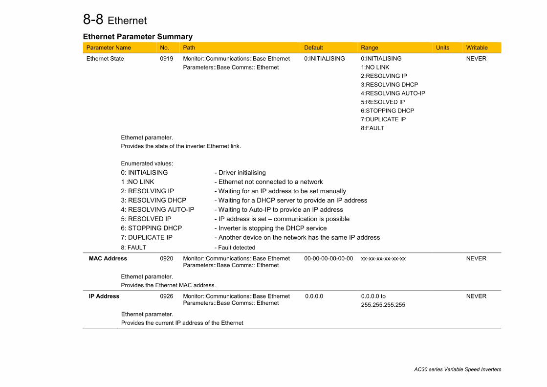
8-8 Ethernet
AC30 series Variable Speed Inverters
Ethernet Parameter Summary Parameter Name No. Path Default Range Units Writable
Ethernet State 0919 Monitor::Communications::Base Ethernet Parameters::Base Comms:: Ethernet
0:INITIALISING
0:INITIALISING 1:NO LINK 2:RESOLVING IP 3:RESOLVING DHCP 4:RESOLVING AUTO-IP 5:RESOLVED IP 6:STOPPING DHCP 7:DUPLICATE IP 8:FAULT
NEVER
Ethernet parameter. Provides the state of the inverter Ethernet link. Enumerated values: 0: INITIALISING - Driver initialising 1 :NO LINK - Ethernet not connected to a network 2: RESOLVING IP - Waiting for an IP address to be set manually 3: RESOLVING DHCP - Waiting for a DHCP server to provide an IP address 4: RESOLVING AUTO-IP - Waiting to Auto-IP to provide an IP address 5: RESOLVED IP - IP address is set – communication is possible 6: STOPPING DHCP - Inverter is stopping the DHCP service 7: DUPLICATE IP - Another device on the network has the same IP address 8: FAULT - Fault detected
MAC Address
0920 Monitor::Communications::Base Ethernet Parameters::Base Comms:: Ethernet
00-00-00-00-00-00 xx-xx-xx-xx-xx-xx NEVER
Ethernet parameter. Provides the Ethernet MAC address.
IP Address 0926 Monitor::Communications::Base Ethernet Parameters::Base Comms:: Ethernet
0.0.0.0 0.0.0.0 to 255.255.255.255
NEVER
Ethernet parameter. Provides the current IP address of the Ethernet
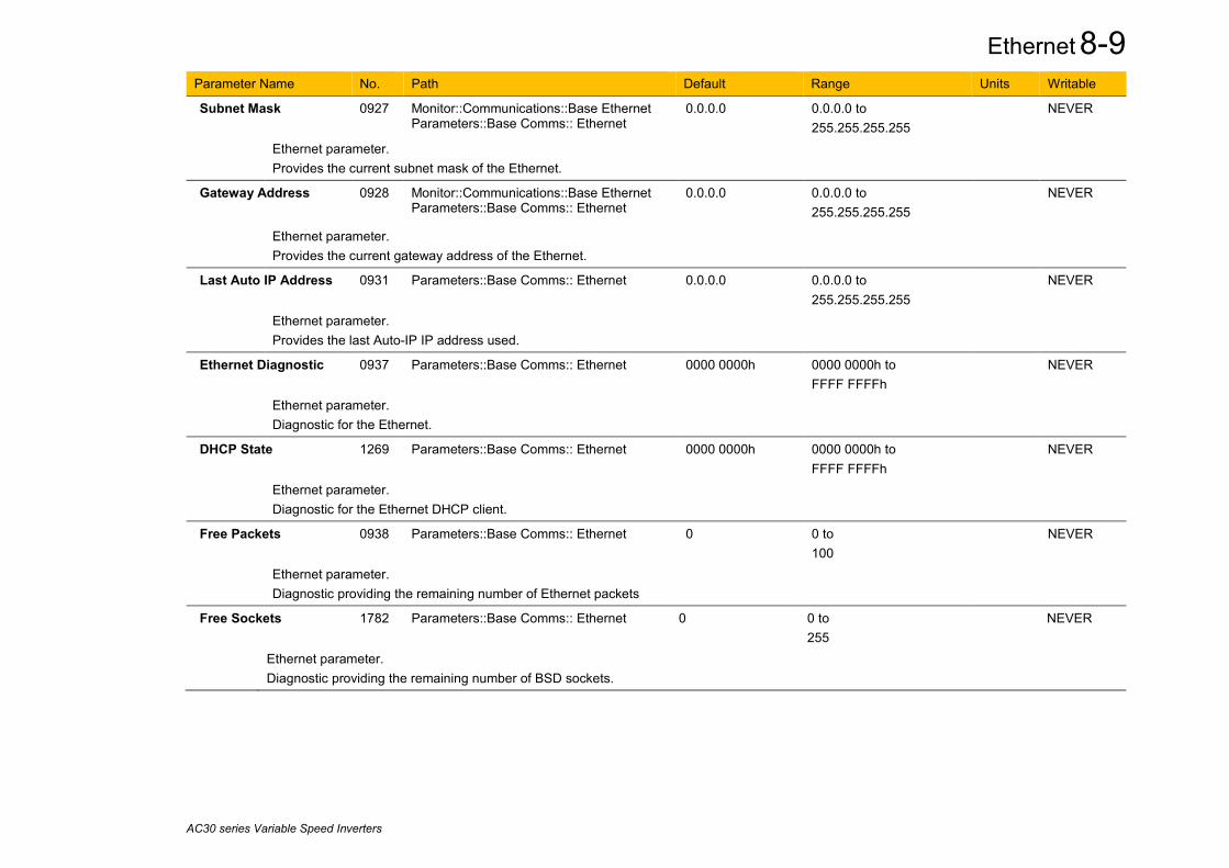
Ethernet 8-9
AC30 series Variable Speed Inverters
Parameter Name No. Path Default Range Units Writable
Subnet Mask 0927 Monitor::Communications::Base Ethernet Parameters::Base Comms:: Ethernet
0.0.0.0 0.0.0.0 to 255.255.255.255
NEVER
Ethernet parameter. Provides the current subnet mask of the Ethernet.
Gateway Address 0928 Monitor::Communications::Base Ethernet Parameters::Base Comms:: Ethernet
0.0.0.0 0.0.0.0 to 255.255.255.255
NEVER
Ethernet parameter. Provides the current gateway address of the Ethernet.
Last Auto IP Address 0931 Parameters::Base Comms:: Ethernet 0.0.0.0 0.0.0.0 to 255.255.255.255
NEVER
Ethernet parameter. Provides the last Auto-IP IP address used.
Ethernet Diagnostic 0937 Parameters::Base Comms:: Ethernet 0000 0000h 0000 0000h to FFFF FFFFh
NEVER
Ethernet parameter. Diagnostic for the Ethernet.
DHCP State 1269 Parameters::Base Comms:: Ethernet 0000 0000h 0000 0000h to FFFF FFFFh
NEVER
Ethernet parameter. Diagnostic for the Ethernet DHCP client.
Free Packets 0938 Parameters::Base Comms:: Ethernet 0 0 to 100
NEVER
Ethernet parameter. Diagnostic providing the remaining number of Ethernet packets
Free Sockets 1782 Parameters::Base Comms:: Ethernet 0 0 to 255
NEVER
Ethernet parameter. Diagnostic providing the remaining number of BSD sockets.
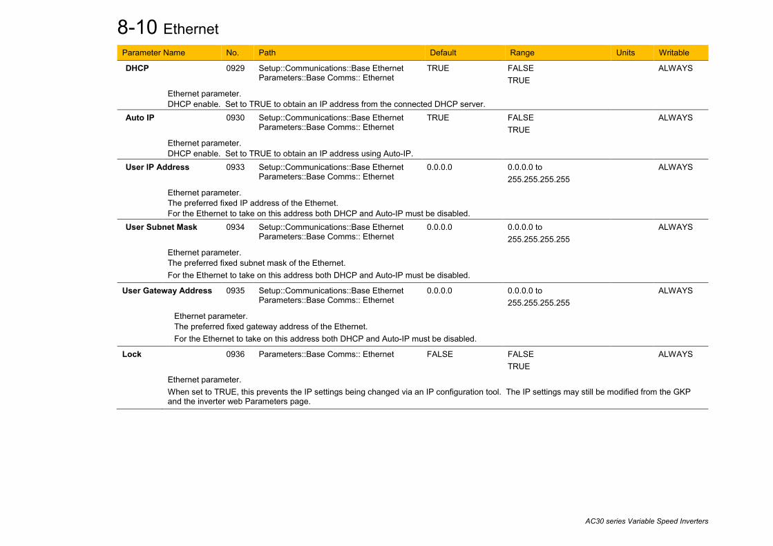
8-10 Ethernet
AC30 series Variable Speed Inverters
Parameter Name No. Path Default Range Units Writable
DHCP
0929 Setup::Communications::Base Ethernet Parameters::Base Comms:: Ethernet
TRUE FALSE TRUE
ALWAYS
Ethernet parameter. DHCP enable. Set to TRUE to obtain an IP address from the connected DHCP server.
Auto IP
0930 Setup::Communications::Base Ethernet Parameters::Base Comms:: Ethernet
TRUE FALSE TRUE
ALWAYS
Ethernet parameter. DHCP enable. Set to TRUE to obtain an IP address using Auto-IP.
User IP Address
0933 Setup::Communications::Base Ethernet Parameters::Base Comms:: Ethernet
0.0.0.0 0.0.0.0 to 255.255.255.255
ALWAYS
Ethernet parameter. The preferred fixed IP address of the Ethernet. For the Ethernet to take on this address both DHCP and Auto-IP must be disabled.
User Subnet Mask
0934 Setup::Communications::Base Ethernet Parameters::Base Comms:: Ethernet
0.0.0.0 0.0.0.0 to 255.255.255.255
ALWAYS
Ethernet parameter. The preferred fixed subnet mask of the Ethernet. For the Ethernet to take on this address both DHCP and Auto-IP must be disabled.
User Gateway Address 0935 Setup::Communications::Base Ethernet Parameters::Base Comms:: Ethernet
0.0.0.0 0.0.0.0 to 255.255.255.255
ALWAYS
Ethernet parameter. The preferred fixed gateway address of the Ethernet. For the Ethernet to take on this address both DHCP and Auto-IP must be disabled.
Lock 0936 Parameters::Base Comms:: Ethernet FALSE
FALSE TRUE
ALWAYS
Ethernet parameter. When set to TRUE, this prevents the IP settings being changed via an IP configuration tool. The IP settings may still be modified from the GKP and the inverter web Parameters page.

Ethernet 8-11
AC30 series Variable Speed Inverters
Troubleshooting the Ethernet The following parameters are useful for monitoring the IP settings: 0929 IP Address 0928 Subnet Mask 0931 Gateway Address The state of the Ethernet can be monitored using the parameter 944 Ethernet State, normal operation is when the state is RESOLVED IP, and from the GKP icon
No IP address - flashing GKP icon Normally, once the inverter is connected to a network, the GKP Ethernet icon will flash for a short period as the IP address is being resolved, and then will become a solid icon indicating an IP address has been set. If the icon continues to flash for more than 1 – 2 minutes this can indicate a problem. Check the parameter 0919 Ethernet State. Resolving IP The inverter is waiting for a valid IP address to be set automatically, or manually using the parameters: 0933 User IP Address 0934 User Subnet Mask 0935 User Gateway Address Note that the IP address must be set to a non-zero value. Resolving DHCP The inverter is waiting for a DHCP server to provide an IP address. If there is no DHCP server detected on the network then the Ethernet will stay in this state. If there is no DHCP server the IP address may be obtained using Auto-IP or set manually. Duplicate IP Another device on the network with the same IP address has been detected. This will cause communication issues. The Duplicate IP warning will clear after approximately 1 minute once the conflicting device has been removed or the IP address changed. Fault An Ethernet loop has been detected. To clear the fault, break the loop by removing an Ethernet cable from one of the ports.
8-12 Ethernet
AC30 series Variable Speed Inverters
An IP address is set but there is no communication If there is an IP address set but there are problems communicating with other devices (say a PC) then the IP address may not match the subnet on which it is connected. The range of the IP address permitted on a network depends upon the particular network. Normally if the IP address is obtained automatically then the settings will be correct for the network. If connecting to a PC, the PC settings should also be checked – see the section Changing the Ethernet settings on the PC. The administrator of a network should be aware of what IP settings are required.
Link detection When the inverter Ethernet is connected to a network or other device, the Ethernet Link LED will be on and the Ethernet Activity LED will be flickering. When first connected, the inverter will attempt to determine the speed and duplex of the Ethernet link. This is done using a method call auto-negotiation. Some older devices or hubs do not support auto-negotiation, in which case the inverter will use parallel detection. As parallel detection will only provide the link speed, the inverter will default to half-duplex.
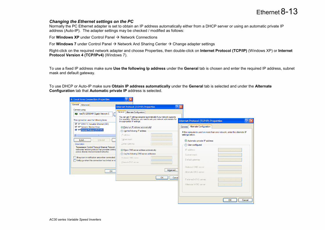
Ethernet 8-13
AC30 series Variable Speed Inverters
Changing the Ethernet settings on the PC Normally the PC Ethernet adapter is set to obtain an IP address automatically either from a DHCP server or using an automatic private IP address (Auto-IP). The adapter settings may be checked / modified as follows:
For Windows XP under Control Panel Network Connections
For Windows 7 under Control Panel Network And Sharing Center Change adapter settings
Right-click on the required network adapter and choose Properties, then double-click on Internet Protocol (TCP/IP) (Windows XP) or Internet Protocol Version 4 (TCP/IPv4) (Windows 7).
To use a fixed IP address make sure Use the following Ip address under the General tab is chosen and enter the required IP address, subnet mask and default gateway.
To use DHCP or Auto-IP make sure Obtain IP address automatically under the General tab is selected and under the Alternate Configuration tab that Automatic private IP address is selected.

8-14 Ethernet
AC30 series Variable Speed Inverters
Web (HTTP) Server The inverter has a built-in web server. To access the web server the parameter 0944 Web Access must be set to LIMITED (default) or FULL. To access the inverter, enter the IP address into a web browser. The following browsers are suitable: • Internet Explorer 10 or above • Mozilla Firefox 33 or above • Google Chrome 48 or above
Web Pages A number of built-in web pages can be accessed from the inverter.
Summary Page The Summary page displays a summary of the inverter.
Parameters Page The Parameters page provides access to the inverter parameters similar to the GKP. This page may only be accessed when the parameter 0944 Web Access is set to FULL. The view level of the parameters may be modified using the parameter 0945 Web View Level. Parameters may be modified from this web page. If a parameter is successfully modified, and supports save, it will be saved if the parameter 1738 Enable Auto Save is set to TRUE. If Enable Auto Save is set to FALSE then the Save button will appear in the parameter menu navigation bar. Pressing the Save button will save all parameters. Some parameters may only be modified when in configuration mode, in which case the parameter number will be highlighted orange. Some parameters may only be modified when the motor is stopped, in which case the parameter number will be highlighted purple. It is recommended to use the refresh button provided on the parameter menu navigation bar, rather than on the browser itself, to view the latest parameter values. Parameters may be continuously monitored by clicking on the “monitoring” button on the parameter menu navigation bar. If a web access password is set (see Services Page section below) then this must be entered in the pop-up box on the browser correctly to be able to gain full access to the web page. If the pop-up box is cancelled then a read-only Parameters page will be shown. The read-only web page allows parameters to be viewed but not changed.

Ethernet 8-15
AC30 series Variable Speed Inverters
Services Page The Services page allows the Web Password to be changed. The password provides a means of restricting access to the web pages using Basic Authenticate. By default the password is cleared providing unrestricted access. The username is fixed to “ac30”. Note 1. Basic Authenticate is a very low level of defence against unauthorized access. It is the responsibility of the system administrator to assess the network security and provide adequate protection. Note 2. The username and password are case sensitive. Note 3. If passwords are lost, they may only be cleared by a return to defaults of all the parameters.
Put the inverter into operational or configuration mode
Change parameter web view level
Parameter menu navigation bar
Inverter status
Refresh parameter values
Enable / disable continual monitoring of parameters
Application status

8-16 Ethernet
AC30 series Variable Speed Inverters
Web Server Parameter Summary Parameter Name No. Path Default Range Units Writable
Web Access 0944 Setup::Communications::Base Ethernet Parameters::Base Comms::Web Server
1:LIMITED
0:DISABLED 1:LIMITED 2:FULL
ALWAYS
Web Server parameter. Enables access to the inverter web server. Enumerated values: 0: DISABLED – a web browser is prevented from accessing the inverter web server. 1: LIMITED – a web browser may access a limited set of pages on the inverter web server. 2: FULL – a web browser has full access to the pages on the inverter web server, however authentication will be required if a password has been set.
Web View Level
0945 Parameters::Base Comms::Web Server 1:TECHNICIAN
0:OPERATOR 1:TECHNICIAN 2:ENGINEER
ALWAYS
Web Server parameter. Sets the view level when accessing parameters via the web server. Enumerated values: 0: OPERATOR 1: TECHNICIAN 2: ENGINEER
Web Password
0946 Parameters::Base Comms::Web Server none - ALWAYS
Web Server parameter. Sets the password for access to restricted inverter web pages such as the Parameters Page. This may only be changed on the web Services page.

Ethernet 8-17
AC30 series Variable Speed Inverters
Troubleshooting the Web Server Troubleshooting of the Ethernet in general is described in the section Troubleshooting below. If the inverter web page still cannot be accessed then this may be due to the browser’s proxy server settings, especially if the PC has been used on a corporate network. To check the settings, access the Internet Options dialog from within the browser and click on the Connections tab, then click on LAN settings. Make sure the Proxy server checkbox is cleared, alternatively click on Advanced and add the IP address of the inverter to the Exceptions list. Contact your network administrator before making any changes to your browser settings.
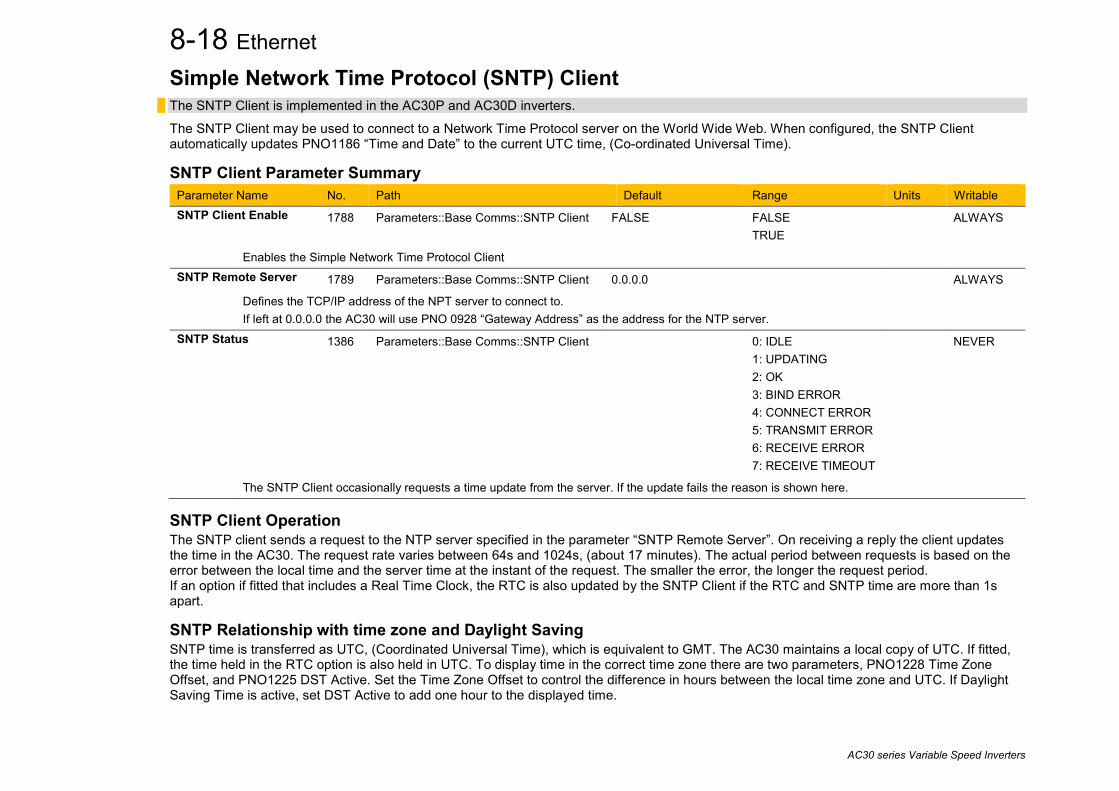
8-18 Ethernet
AC30 series Variable Speed Inverters
Simple Network Time Protocol (SNTP) Client The SNTP Client is implemented in the AC30P and AC30D inverters.
The SNTP Client may be used to connect to a Network Time Protocol server on the World Wide Web. When configured, the SNTP Client automatically updates PNO1186 “Time and Date” to the current UTC time, (Co-ordinated Universal Time).
SNTP Client Parameter Summary Parameter Name No. Path Default Range Units Writable SNTP Client Enable 1788 Parameters::Base Comms::SNTP Client FALSE
FALSE TRUE
ALWAYS
Enables the Simple Network Time Protocol Client SNTP Remote Server 1789 Parameters::Base Comms::SNTP Client 0.0.0.0 ALWAYS
Defines the TCP/IP address of the NPT server to connect to. If left at 0.0.0.0 the AC30 will use PNO 0928 “Gateway Address” as the address for the NTP server.
SNTP Status 1386 Parameters::Base Comms::SNTP Client 0: IDLE 1: UPDATING 2: OK 3: BIND ERROR 4: CONNECT ERROR 5: TRANSMIT ERROR 6: RECEIVE ERROR 7: RECEIVE TIMEOUT
NEVER
The SNTP Client occasionally requests a time update from the server. If the update fails the reason is shown here.
SNTP Client Operation The SNTP client sends a request to the NTP server specified in the parameter “SNTP Remote Server”. On receiving a reply the client updates the time in the AC30. The request rate varies between 64s and 1024s, (about 17 minutes). The actual period between requests is based on the error between the local time and the server time at the instant of the request. The smaller the error, the longer the request period. If an option if fitted that includes a Real Time Clock, the RTC is also updated by the SNTP Client if the RTC and SNTP time are more than 1s apart.
SNTP Relationship with time zone and Daylight Saving SNTP time is transferred as UTC, (Coordinated Universal Time), which is equivalent to GMT. The AC30 maintains a local copy of UTC. If fitted, the time held in the RTC option is also held in UTC. To display time in the correct time zone there are two parameters, PNO1228 Time Zone Offset, and PNO1225 DST Active. Set the Time Zone Offset to control the difference in hours between the local time zone and UTC. If Daylight Saving Time is active, set DST Active to add one hour to the displayed time.

Ethernet 8-19
AC30 series Variable Speed Inverters
Simple Network Time Protocol (SNTP) Server The SNTP Server is implemented in the AC30P and AC30D inverters.
The SNTP Server may be used to share the time and date within a local network.
SNTP Server Parameter Summary Parameter Name No. Path Default Range Units Writable SNTP Server Enable 1891 Parameters::Base Comms::SNTP Server FALSE
FALSE TRUE
ALWAYS
Enables the Simple Network Time Protocol Server
SNTP Server Operation The server requires no configuration other than a simple enable / disable. It will respond to requests from SNTP clients, returning the time from the local parameter PNO1186 “Time and Date”. This may be useful in a local network that has no access to the World Wide Web or any other PC or Ethernet device that has a local time source. In this case the AC30 with the server enabled should be fitted with a Real Time Clock to allow the time to be preserved during a power outage. The local RTC hardware only tracks time to the nearest second. This limits the precision of the AC30 SNTP server. The SNTP server transmits UTC time, see above for a description of the relationship between UTC time, the local time zone and daylight saving.

8-20 Ethernet
AC30 series Variable Speed Inverters
Precision Time Protocol (PTP) The Precision Time Protocol (IEEE 1588v2 or IEEE 1588-2008) is implemented in the AC30P and AC30D inverters. The PTP will synchronize the internal clocks over the Ethernet to better than 1 microsecond. No external master is required for the PTP network; any of the inverters may become a PTP master. The initial use of the PTP is for shaft locking applications using the Virtual Master or Real Master control. Note: Currently up to 16 inverters are supported on a PTP network.
Configuration The two Ethernet ports provide a means of daisy chaining the inverters. The port order is not important, but an Ethernet loop must be avoided. An external Ethernet switch should not be used, unless it is an IEEE 1588v2 transparent switch, as this will reduce the synchronization accuracy by an indeterminate amount. Ethernet cables should be kept to a minimum length possible. To enable the PTP set the parameter 1661 PTP Enable to TRUE on all inverters participating. In a PTP network, one device will be a master clock and the others will be slave clocks. On the AC30P or AC30D any inverter can become a master or a slave clock. The decision on which inverter becomes the master is automatic when using the default parameter configuration. However, it is possible to influence which becomes a master or slave by changing the PTP parameters. Whilst the inverter is synchronising the icon on the GKP status bar will flash. Once an inverter has become synchronised to the master clock or has become the master clock, the diagnostic parameter 1688 PTP Locked will be set to TRUE and he GKP icon will stop flashing.
Advanced Configuration PTP Modes One-Step and Two-Step modes: In one-step mode the hardware timestamping directly modifies the network packets, in two-step mode the timestamps are stored and sent in a second step. End-to-End (E2E) and Peer-to-Peer (P2P) Delay modes: In E2E mode the slaves determine the delay between them and the master over the whole network from end to end. In P2P mode each device only determines the delay to their nearest neighbour and adds this to the packets. Standard Ethernet switches may be used with the E2E mode but is not recommended as it can add an indeterminate delay between clocks.
Address and ports The PTP protocol uses the multicast IP address 224.0.1.129 and UDP ports 319 (event) and 320 (general).

Ethernet 8-21
AC30 series Variable Speed Inverters
PTP Profile Each PTP device has a set of attributes as define by IEEE1588-2008. On the inverter the default attributes values are set as follows. Note that some may be modified by a parameter. Attribute Description Inverter default value Modified by parameter domainNumber
A domain consists of one or more PTP devices communicating with each other. Devices on the same domain will have the same domain number.
0 1787 PTP Domain Number
slaveOnly
When slaveOnly is TRUE the PTP device may only be a slave and not become a master clock.
FALSE
1684 PTP Clock Type
logAnnounceInterval
A port in the MASTER state will periodically transmit an Announce message.
Announce messages will be transmitted such that the logarithm to the base 2 of the mean value of the interval in seconds between message transmissions is the value of the logAnnounceInterval.
1 (2 seconds)
-
logSyncInterval
A port in the MASTER state will periodically transmit a Sync message.
Sync messages will be transmitted such that the logarithm to the base 2 of the mean value of the interval in seconds between message transmissions is the value of the logSyncInterval.
-1 (0.5 seconds)
1681 PTP Log Sync Interval
logMinDelayReqInterval
The logMinDelayReqInterval will specify the minimum permitted mean time interval between successive Delay_Req messages.
This value is determined and advertised by a master clock based on the ability of the master clock to process the Delay_Req message traffic.
0 -
announceReceiptTimeout
The value of announceReceiptTimeout will specify the number of announceInterval that has to pass without receipt of an Announce message
3 -

8-22 Ethernet
AC30 series Variable Speed Inverters
The following attributes are used to determine the best master clock. They are listed in order of precedence. Attribute Description Inverter Default Value Modified by parameter priority1
Lower values of Priority1 take precedence. 128 -
clockClass
Used to define a clock’s TAI traceability. 248 or 255 (slave only)
-
clockAccuracy
Indicates the expected accuracy of a clock. Given as an enumerated value.
FEh -
offsetScaledLogVariance
This defines the stability of the clock. FFFFh (not computed)
-
priority2
Lower values of Priority2 take precedence. 128 1686 PTP Priority2
clockIdentity The clockIdentity identifies a clock. The clockIdentity is an 8-octet identifier created from the Ethernet MAC address in the format: First 3 octets – most significant octets of MAC address Next 2 octets – have values FFh and FEh respectively Last 3 octets – least significant octets of MAC address The clockIdentity is used as a tie-breaker for the master clock.
- 0920 MAC Address

Ethernet 8-23
AC30 series Variable Speed Inverters
PTP Parameter Summary Note: The value of the PTP configuration parameters only become active when the PTP module initialises, i.e. on inverter power-up, on transition of the parameter 1661 PTP Enable to TRUE or connection of one or more Ethernet cables.
Parameter Name No. Path Default Range Units Writable PTP Enable 1661 Setup::Communications::PTP
Parameters::Base Comms::PTP FALSE
FALSE TRUE
ALWAYS
PTP parameter. Enables the precision time protocol.
PTP Clock Type 1684 Setup::Communications::PTP Parameters::Base Comms::PTP
0: MASTER OR SLAVE 0:MASTER OR SLAVE 1:SLAVE ONLY
ALWAYS
PTP parameter Sets if the inverter can become a master or slave clock, or a slave clock only. Enumerated values:
0: MASTER OR SLAVE - the device clock will become a Master if it is determined to be the best master in a network, otherwise it will become a Slave
1: SLAVE ONLY - the device clock can only become a Slave
PTP Clock Mode 1683 Setup::Communications::PTP Parameters::Base Comms::PTP
0:E2E 0:E2E ALWAYS
PTP parameter. Sets the PTP clock mode to either end-to-end (E2E) or peer-to-peer (P2P). See description in section Advanced Users for more details. Note that currently E2E is only available. Enumerated values: 0: E2E
PTP Domain Number 1787 Setup::Communications::PTP Parameters::Base Comms::PTP
0 0 to 127
ALWAYS
PTP parameter. Sets the Domain Number of the inverter. A PTP device will only communicate with other PTP devices that have the same domain number even if it is on the same physical network.
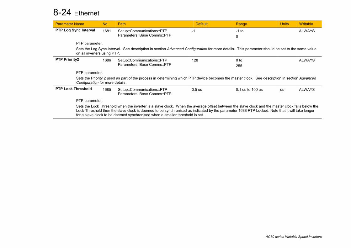
8-24 Ethernet
AC30 series Variable Speed Inverters
Parameter Name No. Path Default Range Units Writable PTP Log Sync Interval 1681 Setup::Communications::PTP
Parameters::Base Comms::PTP -1 -1 to
0 ALWAYS
PTP parameter. Sets the Log Sync Interval. See description in section Advanced Configuration for more details. This parameter should be set to the same value on all inverters using PTP.
PTP Priority2 1686 Setup::Communications::PTP Parameters::Base Comms::PTP
128 0 to 255
ALWAYS
PTP parameter. Sets the Priority 2 used as part of the process in determining which PTP device becomes the master clock. See description in section Advanced Configuration for more details.
PTP Lock Threshold 1685 Setup::Communications::PTP Parameters::Base Comms::PTP
0.5 us 0.1 us to 100 us us ALWAYS
PTP parameter. Sets the Lock Threshold when the inverter is a slave clock. When the average offset between the slave clock and the master clock falls below the Lock Threshold then the slave clock is deemed to be synchronised as indicated by the parameter 1688 PTP Locked. Note that it will take longer for a slave clock to be deemed synchronised when a smaller threshold is set.
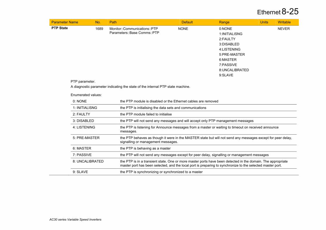
Ethernet 8-25
AC30 series Variable Speed Inverters
Parameter Name No. Path Default Range Units Writable PTP State 1689 Monitor::Communications::PTP
Parameters::Base Comms::PTP NONE 0:NONE
1:INITIALISNG 2:FAULTY 3:DISABLED 4:LISTENING 5:PRE-MASTER 6:MASTER 7:PASSIVE 8:UNCALIBRATED 9:SLAVE
NEVER
PTP parameter. A diagnostic parameter indicating the state of the internal PTP state machine. Enumerated values:
0: NONE the PTP module is disabled or the Ethernet cables are removed
1: INITIALISNG the PTP is initialising the data sets and communications
2: FAULTY the PTP module failed to initialise
3: DISABLED the PTP will not send any messages and will accept only PTP management messages
4: LISTENING the PTP is listening for Announce messages from a master or waiting to timeout on received announce messages.
5: PRE-MASTER the PTP behaves as though it were in the MASTER state but will not send any messages except for peer delay, signalling or management messages.
6: MASTER the PTP is behaving as a master
7: PASSIVE the PTP will not send any messages except for peer delay, signalling or management messages
8: UNCALIBRATED the PTP is in a transient state. One or more master ports have been detected in the domain. The appropriate master port has been selected, and the local port is preparing to synchronize to the selected master port.
9: SLAVE the PTP is synchronizing or synchronized to a master

8-26 Ethernet
AC30 series Variable Speed Inverters
Parameter Name No. Path Default Range Units Writable PTP Clock 1699 Monitor::Communications::PTP
Parameters::Base Comms::PTP 1970/01/01 00:00:00 - NEVER
PTP parameter. Diagnostic parameter giving the current value of the PTP clock to 1 second accuracy. Note this is not intended to represent the actual date and time.
PTP Offset 1687 Monitor::Communications::PTP Parameters::Base Comms::PTP
0 ns -2000000000 to 2000000000
NEVER
PTP parameter. Diagnostic parameter giving the average offset in nanoseconds between the PTP clock and the master clock.
PTP Locked 1688 Monitor::Communications::PTP Parameters::Base Comms::PTP
FALSE FALSE TRUE
NEVER
PTP parameter. Diagnostic parameter indicating when the inverter is a slave that the PTP clock has synchronised to a master clock determined by parameter 1685 PTP Locked Threshold. If the inverter is a master then this parameter will be set to TRUE.

Ethernet 8-27
AC30 series Variable Speed Inverters
Peer to Peer The Peer to Peer module is implemented in the AC30P and AC30D inverters and provides Ethernet communications between inverters. The data sent is not accessible to the user. The initial use of the Peer to Peer module is for shaft locking applications using the Virtual Master or Real Master control and used in conjunction with the Precision Time Protocol (PTP). Note: The Peer to Peer module broadcasts data at a high rate, as such, when the Peer to Peer module is enabled it is recommended not to connect the inverters to a corporate or other sensitive network.
Configuration To enable the Peer to Peer module set the parameter 1725 Peer to Peer Enable to TRUE on all inverters participating. For most applications the default settings may be used. An inverter would be configured as a master (sending data) or a slave (receiving data). It is also possible that an inverter may be both a master and a slave. Typical configurations would be: • Unicast – a master sends to a single slave. The master sends data to the host IP address of the slave. • Broadcast – a master sends to all slaves. The master sends data using the broadcast IP address of 255.255.255.255 • Multicast – a master sends to a group of slaves. The master sends data using a multicast IP address. The range of 239.0.0.0 to
239.255.255.255 is permitted. Slaves must join the group to listen to a particular master sending multicast data. For further information about configuring the module see the section Peer to Peer Parameter Summary.

8-28 Ethernet
AC30 series Variable Speed Inverters
Example Configurations Unicast – inverter 1 is a master to inverter 2
Broadcast - inverter 1 is a master to inverters 2 and 3 (note that this could also be done as a multicast)
Multicast – inverter 1 is a master to inverter 2 and 3, also inverter 3 is a master to inverters 4 and 5
Inverter 1 (IP Address 192.168.1.11) Master
Dest IP Address: 192.168.1.12 Dest Port: 1250 Group IP Address: 0.0.0.0 Local Port: 1250
Inverter 2 (IP Address 192.168.1.12) Slave
Dest IP Address: 0.0.0.0 Dest Port: 0 Group IP Address: 0.0.0.0 Local Port: 1250
Inverter 1 (IP Address 192.168.1.11) Master
Dest IP Address: 255.255.255.255 Dest Port: 1250 Group IP Address: 0.0.0.0 Local Port: 1250
Inverter 2 (IP Address 192.168.1.12) Slave
Dest IP Address: 0.0.0.0 Dest Port: 0 Group IP Address: 0.0.0.0 Local Port: 1250
Inverter 3 (IP Address 192.168.1.13) Slave
Dest IP Address: 0.0.0.0 Dest Port: 0 Group IP Address: 0.0.0.0 Local Port: 1250
Inverter 1 (IP Address 192.168.1.11) Master
Dest IP Address: 239.200.20.1 Dest Port: 1251 Group IP Address: 0.0.0.0 Local Port: 1251
Inverter 2 (IP Address 192.168.1.12) Slave
Dest IP Address: 0.0.0.0 Dest Port: 0 Group IP Address: 239.200.20.1 Local Port: 1251
Inverter 3 (IP Address 192.168.1.13) Slave & Master
Dest IP Address: 239.200.20.2 Dest Port: 1252 Group IP Address: 239.200.20.1 Local Port: 1251
Inverter 4 (IP Address 192.168.1.14) Slave
Dest IP Address: 0.0.0.0 Dest Port: 0 Group IP Address: 239.200.20.2 Local Port: 1252
Inverter 5 (IP Address 192.168.1.15) Slave
Dest IP Address: 0.0.0.0 Dest Port: 0 Group IP Address: 239.200.20.2 Local Port: 1252

Ethernet 8-29
AC30 series Variable Speed Inverters
Peer to Peer Parameter Summary Note: The value of the Peer to Peer configuration parameters only become active when the Peer to Peer module initialises, i.e. on inverter power-up or transition of the parameter 1725 Peer to Peer Enable to TRUE.
Parameter Name No. Path Default Range Units Writable
Peer to Peer Enable 1725 Setup::Communications::Peer to Peer Parameters::Base Comms::Peer to Peer
FALSE FALSE TRUE
ALWAYS
Peer to Peer Parameter. Enables the Peer to Peer module.
Destination IP Address 1726 Setup::Communications::Peer to Peer Parameters::Base Comms::Peer to Peer
255.255.255.255 0.0.0.0 to 255.255.255.255
ALWAYS
Peer to Peer Parameter. Sets the destination IP address of the data when the Peer to Peer module is sending as a master. If the inverter is not sending data then this may be set to 0.0.0.0 • If the Destination IP Address is set to a unicast address then the sent data is only received by the slave inverter that has this IP address. • If the Destination IP Address is set to 255.255.255.255 then the sent data is broadcast and all slave inverters will receive the data. • If the Destination IP address is set to 239.x.x.x then the data is sent as a multicast and all slave inverters listening to this multicast address will
receive the data. See Group IP Address below.
Destination Port 1727 Setup::Communications::Peer to Peer Parameters::Base Comms::Peer to Peer
1250 0 to 65535
ALWAYS
Peer to Peer Parameter. Sets the UDP port number the Peer to Peer module sends data to. This will be set the same as the Local Port receiving the data. If the inverter is not sending data then this may be set to zero.

8-30 Ethernet
AC30 series Variable Speed Inverters
Parameter Name No. Path Default Range Units Writable
Group IP Address 0114 Setup::Communications::Peer to Peer Parameters::Base Comms::Peer to Peer
0.0.0.0 0.0.0.0 to 255.255.255.255
ALWAYS
Peer to Peer Parameter. Sets the group (multicast) IP address to join. The inverter will accept multicast data sent by a master to this multicast IP address. Only the multicast IP address range 239.x.x.x is permitted. If the inverter is receiving unicast or multicast data then this parameter should be set to its default of 0.0.0.0
Local Port 1728 Setup::Communications::Peer to Peer Parameters::Base Comms::Peer to Peer
1250 1 to 65535
ALWAYS
Peer to Peer Parameter. Sets the UDP port number the Peer to Peer module receives the data on. This will be set to the same value as the Destination Port of the master sending the data. If the inverter is a master only and not receiving data then this may be set to the same value as its own Destination Port.
Peer to Peer State 1729 Monitor::Communications::Peer to Peer Parameters::Base Comms::Peer to Peer
DISABLED DISABLED ACTIVE ERROR
NEVER
Peer to Peer Parameter. A diagnostic parameter indicating the state of the Peer to Peer module. Enumerated values:
0: DISABLED - the Peer to Peer module is disabled.
1: ACTIVE - the Peer to Peer module is enabled and ready for communications.
2: ERROR - the Peer to Peer module is in an error state and communications could not be established.

Fire Mode 9-1
AC30 series Variable Speed Drive
Chapter 9: Fire Mode
Caution When Fire Mode is active the Drive and Motor protection trips are disabled. The use of Fire Mode itself increases the risk of causing a fire by overloading the drive or motor, so it must only be used after assessing the risks.
Intended Use Fire mode is intended for use in critical situations where it is imperative for the motor to be kept running if at all possible. In such a situation it may be reasonable to override the drive’s normal protective functions. An example of a critical situation may be a ventilation fan in a stairwell, where continued operation in the event of a fire may assist the safe evacuation of personnel. Summary When Fire Mode is enabled the drive firmware attempts to keep the drive running wherever possible. If the drive was running when Fire Mode was activated it will continue to run. If the drive was stopped when Fire Mode was activated then the Fire Mode firmware will attempt to start it. While Fire Mode is enabled the majority of trips will be ignored, (possibly leading to damage to the drive, motor or attached equipment). If one of the remaining enabled trips does occur then the Fire Mode firmware will wait until the trip source has become inactive and will then restart the drive.
When Fire Mode is deactivated the drive will return to its previous sequencing mode. If the drive was running in Local mode the motor will be stopped. If the drive was running in remote terminals or remote communications mode the drive will continue running according to the relevant control word, (refer to Appendix B).

9-2 Fire Mode
AC30 series Variable Speed Drive
Configuration The parameters used to configure Fire Mode are detailed in Appendix C. This description is partially duplicated here for convenience.
PNO* Parameter Descriptions Activate
A Boolean input. Set to TRUE to enable Fire Mode according to the Fire Mode parameter. This input parameter may only be set by connection to a digital input. Default value FALSE
1961* Setpoint A reference value to be used when Fire Mode is active. Setting a negative setpoint will cause the drive to rotate in reverse direction. Default value 0.0%. Range -100% to 100%
1962* Level An enumerated input parameter. Selects the mode of operation when Fire Mode is enabled
0. DISABLED 1. PARTIAL 2. FULL
Default value is DISABLED. 1963* Restart Delay
Specifies the time to wait before attempting to reset a trip. 1964* Activated
A Boolean output that indicates when Fire Mode is active. This is TRUE when Level is either PARTIAL or FULL, the Setpoint is not 0.0% and Activate is TRUE.
1965* Ready A Boolean output that indicates when Fire Mode will be activated if Activate is set TRUE. This is TRUE when Level is either PARTIAL or FULL and the Setpoint is not 0.0%.
1966* Last Activated A Data and Time output parameter that records the last time that the fire mode became active. This may be used to validate that the fire mode has been tested. This value is recorded in non-volatile memory. The value will be reset if an application is loaded that does not implement Fire Mode.
1967* Activation Count An integer output parameter that records the number of times the fire mode has become active. This value is saved in non-volatile memory. The activation count will be reset if an application is loaded that does not implement Fire Mode.
∗ These PNO values are correct for the Fan Application. Custom configurations may assign the Fire Mode parameter to different PNOs.
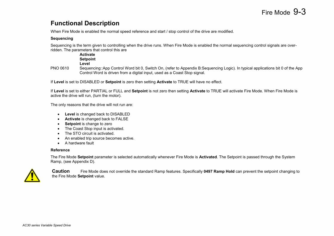
Fire Mode 9-3
AC30 series Variable Speed Drive
Functional Description When Fire Mode is enabled the normal speed reference and start / stop control of the drive are modified.
Sequencing Sequencing is the term given to controlling when the drive runs. When Fire Mode is enabled the normal sequencing control signals are over-ridden. The parameters that control this are Activate Setpoint Level PNO 0610 Sequencing::App Control Word bit 0, Switch On, (refer to Appendix B:Sequencing Logic). In typical applications bit 0 of the App
Control Word is driven from a digital input, used as a Coast Stop signal. If Level is set to DISABLED or Setpoint is zero then setting Activate to TRUE will have no effect. If Level is set to either PARTIAL or FULL and Setpoint is not zero then setting Activate to TRUE will activate Fire Mode. When Fire Mode is active the drive will run, (turn the motor). The only reasons that the drive will not run are:
• Level is changed back to DISABLED • Activate is changed back to FALSE • Setpoint is change to zero • The Coast Stop input is activated. • The STO circuit is activated. • An enabled trip source becomes active. • A hardware fault
Reference The Fire Mode Setpoint parameter is selected automatically whenever Fire Mode is Activated. The Setpoint is passed through the System Ramp, (see Appendix D).
Caution Fire Mode does not override the standard Ramp features. Specifically 0497 Ramp Hold can prevent the setpoint changing to the Fire Mode Setpoint value.
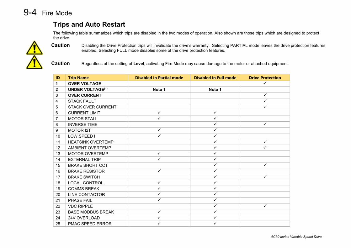
9-4 Fire Mode
AC30 series Variable Speed Drive
Trips and Auto Restart The following table summarizes which trips are disabled in the two modes of operation. Also shown are those trips which are designed to protect the drive.
Caution Disabling the Drive Protection trips will invalidate the drive’s warranty. Selecting PARTIAL mode leaves the drive protection features enabled. Selecting FULL mode disables some of the drive protection features.
Caution Regardless of the setting of Level, activating Fire Mode may cause damage to the motor or attached equipment.
ID Trip Name Disabled in Partial mode Disabled in Full mode Drive Protection 1 OVER VOLTAGE 2 UNDER VOLTAGE(1) Note 1 Note 1 3 OVER CURRENT 4 STACK FAULT 5 STACK OVER CURRENT 6 CURRENT LIMIT 7 MOTOR STALL 8 INVERSE TIME 9 MOTOR I2T 10 LOW SPEED I 11 HEATSINK OVERTEMP 12 AMBIENT OVERTEMP 13 MOTOR OVERTEMP 14 EXTERNAL TRIP 15 BRAKE SHORT CCT 16 BRAKE RESISTOR 17 BRAKE SWITCH 18 LOCAL CONTROL 19 COMMS BREAK 20 LINE CONTACTOR 21 PHASE FAIL 22 VDC RIPPLE 23 BASE MODBUS BREAK 24 24V OVERLOAD 25 PMAC SPEED ERROR

Fire Mode 9-5
AC30 series Variable Speed Drive
ID Trip Name Disabled in Partial mode Disabled in Full mode Drive Protection 26 OVERSPEED 27 SAFE TORQUE OFF 28 FEEDBACK MISSING 29 INTERNAL FAN FAIL 30 CURRENT SENSOR 31 POWER LOSS STOP 32 SPEED SENSOR FAULT 33 A1 34 A2 35 A3 36 A4 37 A5 38 A6 39 A7 40 A8 41 SPEED ERROR FAULT 42 PEER TO PEER OVERRUN 43 PHASE CONFIG 44 ETHERNET IP BREAK 45 RESOLVER ERROR 46 PMAC ALIGN ERROR 47 CURRENT IMBALANCE 48 CONFIGURATION Note 1. The Under Voltage trip is enabled when Fire Mode is active, but the trip level is reduced by 50%.
If a trip source becomes active when the associated trip is disabled the drive will continue to run. This is also the normal behavior of the drive, (when Fire Mode is not active). If the associated trip is designed for drive protection, this will be recorded in non-volatile memory. The recorded values are available to view in the Trips History parameter block, (refer to Appendix C). When Fire Mode is activated and a trip source becomes active and the associated trip is enabled, the drive will trip, causing the motor to stop. This is similar to the normal behavior of the drive, (when Fire Mode is not active). However, when Fire Mode is active the drive firmware continues to monitor the trip source, once the trip source has become inactive the drive automatically resets the trip condition and restarts the drive. The Fly catching feature can be used to allow the drive to smoothly resume control of a moving load on restart. The operation of Fire Mode is independent of the motor type motor and the control mode, (Open Loop or Sensorless Vector control).

9-6 Fire Mode
AC30 series Variable Speed Drive

Fieldbuses A-1
AC30 series Variable Speed Inverter
Appendix A: Fieldbuses Modbus TCP Introduction The inverters built-in Ethernet includes a Modbus TCP server. The Modbus registers are mapped to the inverters parameters. Up to 3 simultaneous connections to Modbus clients are possible. TCP port 502 is used.
Making a connection to the Ethernet and setting an IP address on the inverter is described in Chapter 12 (Ethernet). If the Modbus TCP is used as part of a process control it is recommended a dedicated network be used with fixed IP addresses for the inverter.
To allow Modbus TCP connections to the inverter, the parameter 0939 Maximum Connections must be set to a value greater than zero.
Modbus Register Mapping Summary The inverter parameters are mapped to the Holding Registers and Input Registers, either as a fixed mapping or as a user-defined mapping. There is no mapping to Coils or Discrete Inputs.
Holding Register Address Input Register Address Description
00001 - 00256 00001 - 00256 User-defined mapping to the inverter parameter values.
00257 - 00528 00257 - 00528 Reserved area.
Do not write into this register range.
00529 - onwards 00529 - onwards Fixed mapping to the inverter parameter values.

A-2 Fieldbuses
AC30 series Variable Speed Inverter
Fixed Parameter Mapping Each parameter number is mapped onto two consecutive Modbus registers regardless of the parameter data type. The relationship between the Holding Register or Input Register is given as:
Register number = (parameter number - 1) * 2 + 529
• If the parameter has a data type that uses one byte then it will occupy the low byte of the first register and the high byte will be zero, i.e. the register will not be sign extended.
• If the parameter has a data type that uses two bytes then it will occupy the first register.
• Unused register locations will read zero; writing to that location will have no effect.
• The word order of 32-bit parameters is determined by the inverter parameter 0940 High Word First.
• Writable 32-bit parameters will only accept a change in value if both registers mapped to the parameter are written to in the same request.
Fixed Parameter Mapping - Arrays Some parameters have multiple elements and are classified as parameter arrays. A parameter array has a parameter number that represents the whole of the array, but also has parameter numbers that represent each element of the array. An example is given below.
Array Example A parameter array called Recent Trips has 10 elements.
Parameter Number Parameter – Recent Trips 895 Whole array 896 index 0 897 index 1 905 index 9
If the parameter number of the whole array is 895, then the parameter number of the element index 0 of the array will be 896, the parameter number of the element index 1 will be 897, etc. Note: String array parameters access their elements via parameter numbers that are calculated in a different way (see Fixed Parameter Mapping - Strings).
Accessing the parameter arrays via the parameter number that represents the whole array is not recommended. This will access only the first four bytes (2 registers) of the array. The array should rather be accessed via its elements.

Fieldbuses A-3
AC30 series Variable Speed Inverter
Fixed Parameter Mapping - Strings Strings parameters have a parameter number that represents the whole string. This parameter number is mapped to two registers so limits access to the first four characters. Additional contiguous parameter numbers are set aside so that the whole string can be accessed: one additional parameter number for each four characters. The strings are packed into the registers low byte first.
String Example A string parameter called My String has a string length of 12 characters (plus the null terminator). This will have one parameter number allocated for the whole string (in this example 161) and 3 further parameter numbers for the string fragments (162-164).
If the value of the string is “0123456789AB”: Parameter Number
Represents Register Number
Register Value hi-byte lo-byte
0161
whole string “0123456789AB”
00849 ‘1’ ‘0’ 00850 ‘3’ ‘2’
0162
Fragment “0123”
00851 ‘1’ ‘0’ 00852 ‘3’ ‘2’
0163
fragment “4567”
00853 ‘5’ ‘4’ 00854 ‘7’ ‘6’
0164
fragment “89AB”
00855 ‘9’ ‘8’ 00856 ‘B’ ‘A’
Note: This is example is not a real parameter.
As each inverter parameter maps to two registers, if the registers that represent the whole string are accessed then only the first four characters will appear. To access the whole string over Modbus use the registers that map to the parameter number of the whole array plus one, in this example 0162 (register 00851). A multiple read or write of registers will then provide access to the whole string.

A-4 Fieldbuses
AC30 series Variable Speed Inverter
String Array Example A string array parameter called My String Array has 2 elements of string length 5 characters (plus the null terminator) each. In this example the parameter number of the whole array is 175.
If the values of the array elements are “12345” and “abc”: Parameter Number
Represents Register Number
Register Value hi-byte lo-byte
0175 whole array [“12345”, “abc”]
00877 ‘2’ ‘1’ 00878 ‘4’ ‘3’
0176
1st element “12345”
00879 ‘2’ ‘1’ 00880 ‘4’ ‘3’
0177 fragment “1234”
00881 ‘2’ ‘1’ 00882 ‘4’ ‘3’
0178 fragment “5”
00883 null ‘5’ 00884 undefined undefined
0179 2nd element “abc”
00885 ‘b’ ‘a’ 00886 null ‘c’
0180 fragment “abc”
00887 ‘b’ ‘a’ 00888 null ‘c’
0181 fragment “”
00889 undefined undefined 00890 undefined undefined
Note: This example is not a real parameter.
To access the first element of the array over Modbus then parameter number 0177 (register 00881) would be used. To access the second element then parameter number 0180 (register 00887) would be used.

Fieldbuses A-5
AC30 series Variable Speed Inverter
User-Defined Parameter Mapping The inverter parameters may be mapped to the user-defined register area (00001 – 00256). This allows parameters to be grouped together so that they may be accessed through a single Modbus request.
To map parameters add the required parameter numbers to the user mapping table using parameter 1567 Modbus Mapping. The following applies:
• The mapping starts at register 00001.
• Any valid fixed or application parameter may be added excluding password parameters and parameter arrays - individual elements of the array may be added however.
• Parameter strings may be added.
• The mapping ends on the first mapping entry of zero or when the mapping table is full.
Note: The mapping may be modified at any time. However no Modbus requests should be made when the mapping is being modified to avoid indeterminate response data.
Unlike the fixed mapping, the user-defined parameter mapping will only use as many registers as necessary to accommodate the parameter. An example is given below:
Mapping Table Parameter Name Data Type No. of Registers Start Register End Register
0 0627 Comms Control Word WORD 1 00001 00001
1 0681 Comms Reference REAL 2 00002 00003
2 0696 First Trip USINT 1 00004 00004
3 0661 Status Word WORD 1 00005 00005
4 0395 Actual Speed Percent REAL 2 00006 00007
5 0961 Drive Name 23-character STRING 12 00008 00019
6 0000
The mapping table is continually checked for valid entries. The diagnostic parameter 1632 Mapping Valid will be TRUE if all entries in the table are valid parameters. If the diagnostic parameter is FALSE, meaning there are invalid entries, then Modbus requests are still accepted but the invalid entries will be skipped over and will occupy no registers in the mapping.
A-6 Fieldbuses
AC30 series Variable Speed Inverter
The following applies to user-mapped parameters:
• If the parameter has a data type that uses one byte then it will occupy the low byte of the Modbus register and the high byte will be zero, i.e. the register will not be sign extended.
• The word order of 32-bit parameters is determined by the inverter parameter 0940 High Word First.
• Writable 32-bit parameters will only accept a change in value if both registers mapped to the parameter are written to in the same request.
• String parameters are packed into the registers low byte first.
• Writable string parameters will only accept a change if the first register is included in the request. If the string is not null terminated, then a null termination will be added automatically.
Password Protection Write access to parameters via the fixed mapping registers may be restricted by setting the parameter 1659 Modbus TCP Password. Note that there is no restriction to parameters via the user-defined mapping registers.
When this password is set to a value other than zero, writing to parameters will only be possible when the password is unlocked. If the password is not unlocked then writes will be ignored.
To unlock the password write to the Modbus register 00518 the value set in the parameter 1659 Modbus TCP Password. Write access will be available until a subsequent write to the Modbus register 00518 of value 0000.
Note the following:
• A read of Modbus register 00518 will always respond with a value of 0000 regardless of the password being locked or unlocked.
• Locking and unlocking the password will apply to all Modbus connections.
• When all Modbus connections are closed, write access will returned back to the locked state if a password is set.

Fieldbuses A-7
AC30 series Variable Speed Inverter
Supported Modbus Functions Four Modbus functions are supported:
Read Holding Registers (#3) This function allows multiple Input registers to be read. Up to 125 registers may be read. As the Holding registers and Input registers map to the same inverter parameters this will return the same values as the Read Input Registers function.
Read Input Registers (#4) This function allows multiple Holding registers to be read. Up to 125 registers may be read. As the Holding registers and Input registers map to the same inverter parameters this will return the same values as the Read Holding Registers function.
Write Single Register (#6) This function allows a single Holding register to be written to. Note that this function may only be used on registers that map to 1-byte or 2-byte inverter parameters. An attempt to write to a register that maps to a 4-byte parameter will have no effect on the parameter.
Write Multiple Registers (#16) This function allows a contiguous block of Holding registers to be written to. Up to 120 registers may be written. Note that when writing to registers that map to 4-byte inverter parameters both registers must be written to. Writing to one-half of a 4-byte parameter will have no effect on the parameter.

A-8 Fieldbuses
AC30 series Variable Speed Inverter
Modbus Exception Codes Three Modbus exception codes are supported:
Illegal Function (01) The Modbus function is not supported by the slave.
Illegal Data Address (02) If the register data address contained in the Modbus request maps to an inverter parameter that is outside the range of parameter numbers then this exception will occur.
Illegal Data Value (03) If the number of bytes or words contained in the Modbus request field is out of range then this exception will occur.
Process Active and Lost Communications Trip
Process Active Flag The Process Active flag is represented by the inverter parameter 0943 Process Active. This parameter changes to TRUE on the first valid Modbus request.
If the parameter 0941 Modbus Timeout is set to a non-zero value then the Process Active parameter will subsequently change to FALSE if a Modbus request is not received within the timeout period.
Trip If enabled, a break in the Modbus communications can be used to generate a trip. The 0943 Process Active parameter is used to generate the trip. If this parameter transitions from TRUE to FALSE then a trip will event will be generated.
To enable the base communications Modbus trip, the parameter 0942 Modbus Trip Enable must be set to TRUE and the BASE MODBUS BREAK bit set in the parameter 0697 Enable 1-32. The parameter 0941 Modbus Timeout must be set to a value other than zero.
For information on enabling trips see Chapter 10 Trips & Fault Finding.
Connection Timeout The parameter 1241 Open Connections indicates the number of open connections to the inverter Modbus TCP server.
A connection receive timeout may be set using the parameter 1458 Modbus Conn Timeout. If this is set to a value other than zero, then the connection will be closed by the server if no data has been received within the timeout period. This is useful, for example, if the link between the server and client is lost, otherwise the connection may remain open indefinitely.

Fieldbuses A-9
AC30 series Variable Speed Inverter
Parameter Summary The following parameters are relevant to the Modbus TCP.
Parameter Name No. Path Default Range Writable Maximum Connections 0939 Setup::Communications::Base Modbus
Parameters::Base Comms::Modbus * 0 - 3 ALWAYS
Modbus TCP parameter. Sets the maximum number of Modbus clients allowed. If set to zero, then no connections will be allowed. * The default value is set to the value of Open Connections, PNO1241. This is typically 0.
High Word First 0940 Setup::Communications::Base Modbus Parameters::Base Comms::Modbus
FALSE FALSE TRUE
ALWAYS
Modbus TCP parameter. If set to TRUE, the most significant word of a 32-bit parameter will be mapped to the first register, and the least significant word to the next register.
Modbus Timeout 0941 Setup::Communications::Base Modbus Parameters::Base Comms::Modbus
3.0 seconds 0.0 – 65.0 seconds ALWAYS
Modbus TCP parameter. Sets the process active timeout.
Modbus Trip Enable 0942 Setup::Communications::Base Modbus Parameters::Base Comms::Modbus
TRUE FALSE TRUE
ALWAYS
Modbus TCP parameter. Set TRUE to enable the Modbus Trip. The parameter Modbus Timeout must be set to a value other than zero
Open Connections 1241 Monitor::Communications::Base Modbus Parameters::Base Comms::Modbus
0 0 - 3 NEVER
Modbus TCP parameter. Indicates the number of open connections to the inverter Modbus TCP server.
Process Active 0943 Monitor::Communications::Base Modbus Parameters::Base Comms::Modbus
FALSE FALSE TRUE
NEVER
Modbus TCP parameter. Indicates that a Modbus request addressed to this node has been received within the period set by the parameter Modbus Timeout, or if no timeout is specified, this parameter will stay active after the first received Modbus request.

A-10 Fieldbuses
AC30 series Variable Speed Inverter
Parameter Name No. Path Default Range Writable Modbus Conn Timeout
1458 Setup::Communications::Base Modbus Parameters::Base Comms::Modbus
66 seconds 0 – 100,000 seconds ALWAYS
Modbus TCP parameter. Sets the Modbus connection timeout. If this parameter is set to zero then the connection will not timeout.
Modbus Mapping
1567 Setup::Communications::Base Modbus Parameters::Base Comms::Modbus
none 0 Last parameter number
ALWAYS
Modbus TCP parameter. User-defined Modbus parameter mapping table. Each entry in the table represents the required parameter number.
Mapping Valid
1632 Monitor::Communications::Base Modbus Parameters::Base Comms::Modbus
TRUE FALSE TRUE
NEVER
Modbus TCP parameter. Status of the user defined mapping area. This will be set to TRUE if all entries in the mapping table are valid.
Modbus TCP Password 1659 Setup::Communications::Base Modbus Parameters::Base Comms::Modbus
0000 0000 FFFF
ALWAYS
Modbus TCP parameter. Modbus password. When set to a value other than zero, write access to parameters via the fixed mapping registers will be restricted. To unlock the password, write to the Modbus register 00518 the value set in this password. A subsequent write of value 0000 to Modbus register 00518 will lock the password.

Fieldbuses A-11
AC30 series Variable Speed Inverter
EtherNet/IP Adapter Introduction The built-in EtherNet/IP adapter (slave/server) is implemented in the AC30P and AC30D inverters.
To make use of this feature, firmware version V3.x.x needs to be installed in the inverter. The firmware may be updated by downloading the firmware file from the Parker website (see section Firmware Update in Chapter 4) or installed from the latest version of PDQ. With version V3.x.x firmware installed, the AC30EIPS CoDeSys (PDQ/PDD) device is required. Note: V3.x.x firmware has no AFE support and an application size of 128Kbytes (rather than 192Kbytes).
Features The following EtherNet/IP features are implemented:
• Class 1 and Class 3 connections • One input assembly instance of up to 500 bytes • One output assembly instance of up to 496 bytes • Input mapping of up to 32 inverter parameters • Output mapping of up to 32 inverter parameters • Unicast or multicast communications • Requested Packet Interval (RPI) down to 2ms • Explicit access of inverter parameters (read and write)
Identity The EtherNet/IP adapter has the following identity: Vendor ID 4 (Parker-Hannifin) Product Code 306 (Parker AC30 Drive)

A-12 Fieldbuses
AC30 series Variable Speed Inverter
Inverter Configuration
Enabling To enable the EtherNet/IP adapter set the parameter 3128 EtherNet IP Enable to TRUE.
The current state of the EtherNet/IP adapter is given by the parameter 3130 EtherNet IP State.
Note the EtherNet/IP adapter is only active when the inverter is in the Operational state.
IP Settings The IP settings are set up from the inverter using the Ethernet parameters described in Chapter 12. The IP settings of the inverter cannot be set via the PLC.
The current IP settings are monitored using the parameters: 0926 IP Address 0927 Subnet Mask 0928 Gateway Address
If parameter 0929 DHCP is set to TRUE, then the IP address will be set from the DHCP server on the network, if one is available.
If parameter 0930 Auto IP is set to TRUE, then the IP address will be automatically be assigned a link-local address.
If both parameters 0929 DHCP and 0930 Auto IP are FALSE, then the IP address, subnet mask and gateway address will be set from the values in the parameters: 0933 User IP Address 0934 User Subnet Mask 0935 User Gateway Address
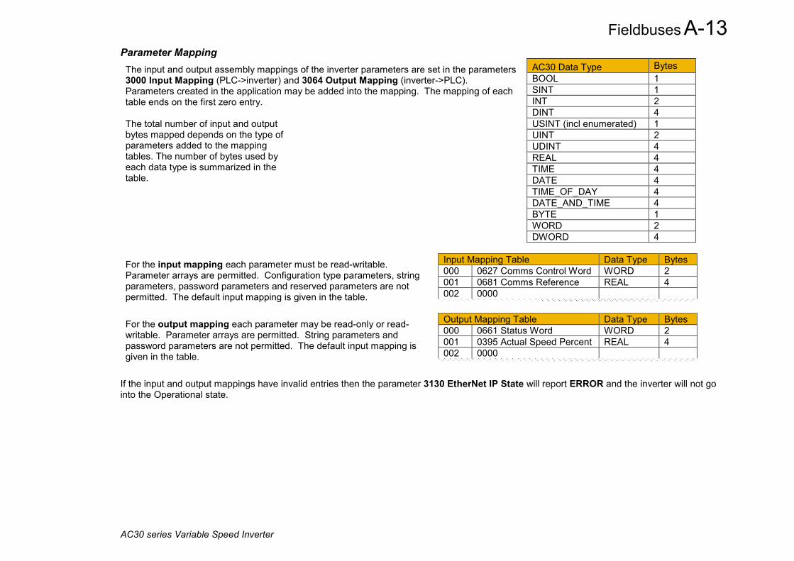
Fieldbuses A-13
AC30 series Variable Speed Inverter
Parameter Mapping The input and output assembly mappings of the inverter parameters are set in the parameters 3000 Input Mapping (PLC->inverter) and 3064 Output Mapping (inverter->PLC). Parameters created in the application may be added into the mapping. The mapping of each table ends on the first zero entry. The total number of input and output bytes mapped depends on the type of parameters added to the mapping tables. The number of bytes used by each data type is summarized in the table.
AC30 Data Type Bytes BOOL 1 SINT 1 INT 2 DINT 4 USINT (incl enumerated) 1 UINT 2 UDINT 4 REAL 4 TIME 4 DATE 4 TIME_OF_DAY 4 DATE_AND_TIME 4 BYTE 1 WORD 2 DWORD 4
For the input mapping each parameter must be read-writable. Parameter arrays are permitted. Configuration type parameters, string parameters, password parameters and reserved parameters are not permitted. The default input mapping is given in the table.
Input Mapping Table Data Type Bytes 000 0627 Comms Control Word WORD 2 001 0681 Comms Reference REAL 4 002 0000
For the output mapping each parameter may be read-only or read-writable. Parameter arrays are permitted. String parameters and password parameters are not permitted. The default input mapping is given in the table.
Output Mapping Table Data Type Bytes 000 0661 Status Word WORD 2 001 0395 Actual Speed Percent REAL 4 002 0000
If the input and output mappings have invalid entries then the parameter 3130 EtherNet IP State will report ERROR and the inverter will not go into the Operational state.

A-14 Fieldbuses
AC30 series Variable Speed Inverter
Assembly Instances The assembly instance numbers are:
Electronic Data Sheet (EDS) File The latest EtherNet/IP EDS file for the inverter may be downloaded from www.parker.com
The EDS file may also be downloaded directly from the drive via a web browser. To access this make sure the parameter 0944 Web Access is set to LIMITED or FULL.
Enter the inverter IP address into the web browser and access the web page “Services” and under EtherNet/IP EDS file click the Download button. Alternatively type the following into the browser address bar (replacing ip_address with the inverter’s IP address): ip_address/eds/eips.zip
Assembly Instance Number Input (T2O) 100 Output (O2T) 150 Input only 198 Listen Only 199

Fieldbuses A-15
AC30 series Variable Speed Inverter
Example PLC Configurations
Using RSLogix 5000 The example in this section uses the default parameter mapping of the inverter described under Parameter Mapping in the Inverter Configuration section above:
A CompactLogic L32E controller is used.
1. Start a new project from within RSLogix 5000 and select the required controller.
Input Mapping Table Data Type Bytes 000 0627 Comms Control Word WORD 2 001 0681 Comms Reference REAL 4 002 0000
Output Mapping Table Data Type Bytes 000 0661 Status Word WORD 2 001 0395 Actual Speed Percent REAL 4 002 0000

A-16 Fieldbuses
AC30 series Variable Speed Inverter
2. Open the Ethernet Port properties and enter the IP address of the Controller.
3. Right-click on the Ethernet Port and select New Module. Under Communications select the Generic Ethernet Module.

Fieldbuses A-17
AC30 series Variable Speed Inverter
4. Enter the Name and IP address of the inverter. Set the Comm Format as Data – SINT. The Input Assembly Instance is 100 and in this
example the data size is a total of 6 bytes. The Output Assembly Instance is 150 and in this example the data size is a total of 6 bytes. The mapping sizes on the inverter MUST match that on the PLC. Set the Configuration Assembly Instance to 128 size 0.
5. Within the Controller Tags the communications data arrays are automatically created:

A-18 Fieldbuses
AC30 series Variable Speed Inverter
6. Additional tags can be created to represent the actual data on the AC30.
7. The data can be transferred between the communication data arrays and the program data using the Synchronous Copy File (CPS) copy instruction as shown in the ladder diagram. Note that the CPS function is not interrupted until the copy is done.
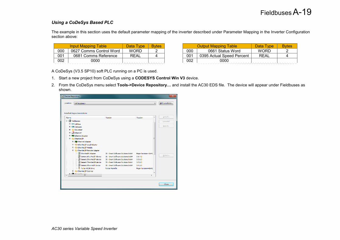
Fieldbuses A-19
AC30 series Variable Speed Inverter
Using a CoDeSys Based PLC The example in this section uses the default parameter mapping of the inverter described under Parameter Mapping in the Inverter Configuration section above:
Input Mapping Table Data Type Bytes 000 0627 Comms Control Word WORD 2 001 0681 Comms Reference REAL 4 002 0000
Output Mapping Table Data Type Bytes 000 0661 Status Word WORD 2 001 0395 Actual Speed Percent REAL 4 002 0000
A CoDeSys (V3.5 SP10) soft PLC running on a PC is used.
1. Start a new project from CoDeSys using a CODESYS Control Win V3 device.
2. From the CoDeSys menu select Tools->Device Repository… and install the AC30 EDS file. The device will appear under Fieldbuses as shown.

A-20 Fieldbuses
AC30 series Variable Speed Inverter
3. Under Devices, select the CODESYS Control Win 3 device, right click and select Add Device…, then add an Ethernet Adapter. Under the Ethernet device add an EtherNet/IP Scanner. Under the EtherNet/IP Scanner add a Parker AC30 Drive.
4. Double-click on CODESYS Control Win 3 and under Communications Settings tab select Scan Network... and select the required PC (note the softPLC on the PC must be started).
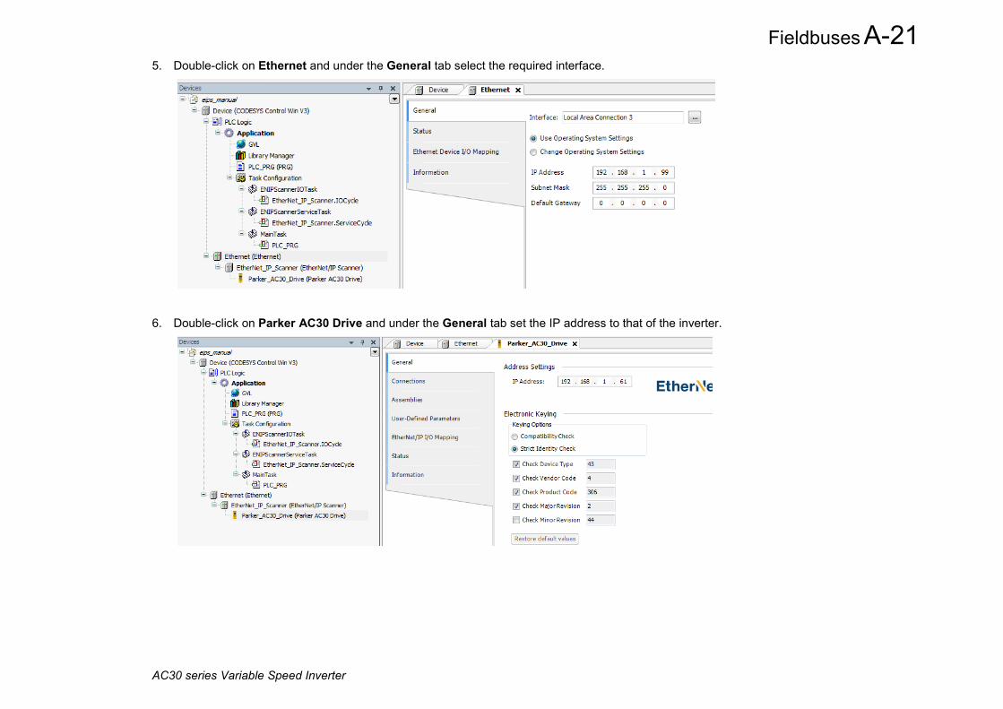
Fieldbuses A-21
AC30 series Variable Speed Inverter
5. Double-click on Ethernet and under the General tab select the required interface.
6. Double-click on Parker AC30 Drive and under the General tab set the IP address to that of the inverter.

A-22 Fieldbuses
AC30 series Variable Speed Inverter
7. Under the Connections tab edit the connection if necessary. The input mapping uses a total of 6 bytes (O->T) and the output mapping also uses a total of 6 bytes (T->O). The mapping sizes on the inverter MUST match that on the PLC. The RPI (Requested Packet Interval) may also be changed.

Fieldbuses A-23
AC30 series Variable Speed Inverter
8. Under the EtherNet/IP IO Mapping tab the mappings can be seen.
%IB0 will be the first byte of the Status Word and %IB2 will be the first byte of the Actual Speed Percent %QB0 will be the first byte of the Comms Control Word and %QB2 will be the first byte of the Comms Reference
9. In the application program the IO mappings can be accessed as variables as shown in this example.
A-24 Fieldbuses
AC30 series Variable Speed Inverter
Explicit Access of Parameters Explicit access of the AC30 parameters is possible via the vendor specific object. Details of this are given in the section CIP Objects – Vendor Specific Object.
A parameter value may be read or written via Class 64h, Attribute 5h. The instance number is the same as the parameter number (PNO). The supported services are Get Attribute Single and Set Attribute Single.
Strings parameters use the SHORT_STRING format – the string is preceded by a single byte that specifies the length of the string.
Parameter Arrays Parameter arrays may be accessed either as a whole or as a single element.
Using the parameter number (instance number) that represents the whole array with attribute 5h will return or modify the contents of all parameters.
Using the parameter number that represents a single element will return or modify only that element.
String arrays may not be accessed as a whole array, but may be accessed via each element.
Using a CoDeSys Based PLC CoDeSys based PLCs can access parameters explicitly using the function blocks Get_Attribute_Single and Set_Attribute_Single from the library EtherNetIP Services.
Lost Communications Trip A trip may be issued by the inverter on the loss of all Class1 connections of the EtherNet/IP adapter. To enable this, set the parameter 3129 EtherNet IP Trip to LOSS OF CONNECTION and set the ETHERNET IP BREAK bit in the parameter 0730 ENABLE 33 – 64.

Fieldbuses A-25
AC30 series Variable Speed Inverter
Troubleshooting and Tips
The inverter fails to come out of configuration mode The input or output mapping tables have invalid parameter mappings. The parameter 3130 EtherNet IP State will report ERROR. Check the parameter 3131 EtherNet IP Diag to determine which mapping table has the incorrect mapping. Note the input mapping table may only contain read-writable parameters.
Failure to make a connection A connection between scanner and the adapter will not be made if:
• the input and output assembly data sizes of the scanner do not match the input and output mapping data sizes of the inverter
• the Requested Packet Interval (RPI) of the scanner is set to less than 2ms
Requested Packet Interval (RPI) When mapping a large amount of data use an RPI of at least 10ms.

A-26 Fieldbuses
AC30 series Variable Speed Inverter
CIP Objects The following CIP objects are supported: 01h Identity 02h Message Router 04h Assembly 06h Connection Manager 64h Vendor Specific F5h TCP/IP Interface F6h Ethernet Link
Class Attributes Each object has the following class attributes. Attribute Description Type Access 1 Revision UINT Get 2 Maximum Instance UINT Get 3 Number of Instances UINT Get 4 Optional Attribute List UINT Get 5 Optional Service List UINT Get 6 Maximum Class Attribute UINT Get 7 Maximum Instance Attribute UINT Get Supported Service Code Service Name 0Eh Get_Attribute_Single
Identity Object – 01h Instance Attribute Description Type Value Access 1 1 Vendor UINT 0004h (Parker Hannifin) Get
2 Device Type UINT 002Bh (Generic) Get 3 Product Code UINT 306 Get 4 Product Revision UINT 02C02h (minor/major) Get 5 Status WORD 0 Get 6 Serial Number UDINT Last 4 bytes of inverter MAC address Get 7 Product Name SHORT STRING “Parker AC30 Drive” Get
Supported Service Code Service Name 01h Get_Attribute_All 05h Reset - Type 0 and Type 1 Reset are supported 1 0Eh Get_Attribute_Single
1. Both Type 0 and Type 1 Reset will restart DHCP if enabled.

Fieldbuses A-27
AC30 series Variable Speed Inverter
Message Router Object – 02h Instance Attribute Description Type Value Access 1 1 Object List - - Get
2 Total connections UINT - Get 3 Active connections UINT - Get
Supported Service Code Service Name 01h Get_Attribute_All 0Eh Get_Attribute_Single
Assembly Object – 04h Instance Attribute Description Type Value Access 100 3 Input USINT[500] Parameter mapped values Get 150 3 Output USINT[496] Parameter mapped values Get/Set Supported Service Code Service Name 0Eh Get_Attribute_Single 10h Set_Attribute_Single
Connection manager – 06h There are no attributes for the Connection Manager.

A-28 Fieldbuses
AC30 series Variable Speed Inverter
TCP/IP Interface Object – F5h Instance Attribute Description Type Value Access 1
1 Status UINT 0 Interface Configuration not configured
1 Interface Configuration comes from DHCP
2 Interface Configuration comes from non-CIP settings
Get
2 Configuration capability
DWORD Bit 2 – DHCP capable (1) Bit 5 – non-CIP setting capable (1)
Get
3 Configuration control DWORD - If DHCP is disabled then writing a value of 0 is allowed
- If DHCP is enabled then writing a value is 2 is allowed
Get/Set
4 Physical Link Object Structure of:
Path Size Path
UINT Array of WORD
2 20F6h 2401h
Get
5 Interface Configuration Structure of:
IP Address Network Address Gateway Address
Name Server Name Server 2
Domain Server Size Domain Name
UDINT UDINT UDINT UDINT UDINT UINT STRING
Inverter IP address Inverter network mask Inverter gateway address 0 0 Returns the Domain Name if DHCP is enabled and the DHCP server has provided it.
Get
6 Host Name Structure of:
Size Host Name
UINT STRING
If DHCP is enabled and bound, returns the Host Name if the DHCP server has provided it, otherwise returns the default Host Name derived from the AC30 MAC address.
Get
13 Encap TMO UINT Inactivity TMO seconds. On Type 1 Reset this value will revert to a value of 120.
Get/Set
Supported Service Code Service Name 01h Get_Attribute_All 0Eh Get_Attribute_Single 10h Set_Attribute_Single

Fieldbuses A-29
AC30 series Variable Speed Inverter
Ethernet Link Object – F6h Instance Attribute Description Type Value Access 1 2
1 Interface Speed UDINT 10 or 100 Get 2 Interface Flags DWORD Link status Get 3 Physical address USINT[6] MAC address Get 10 Interface label SHORT STRING “Port 1” or “Port 2” Get 11 Interface capability
Structure of: Capability bits
Speed/duplex array count
DWORD USINT
Auto-negotiation and MDIX supported (6) 0
Get
Supported Service Code Service Name 01h Get_Attribute_All 0Eh Get_Attribute_Single
Vendor Specific Object – 64h The vendor specific object allows explicit access to AC30 parameters, including string parameters but excluding string arrays. Instance Attribute Description Type Access PNO 1 Parameter Name SHORT STRING Get
2 CIP data type 1 USINT Get 3 Number of parameter
elements 2 USINT Get
4 Parameter qualifier Bit 0: Gettable Bit 1: Settable
BYTE Get
5 Parameter value Depends on parameter Get/Set 6 Parameter min value Depends on parameter Get 7 Parameter max value Depends on parameter Get
Supported Service Code Service Name 01h Get_Attribute_All 0Eh Get_Attribute_Single
1. Equivalent CIP data types – Volume 1 CIP Specification, Chapter 5A 14.2.1.2 2. For a standard parameter the number of elements will be 1, for a parameter array it will be the number elements in the array, and for a string parameter it will be the maximum
number of characters.

A-30 Fieldbuses
AC30 series Variable Speed Inverter
Parameter Summary The following parameters are relevant to the EtherNet/IP adapter. Parameter Name No. Path Default Range Writable EtherNet IP Enable
3128 Setup::Communications::Base EtherNet IP Parameters::Base Comms::EtherNet IP Adapter
FALSE FALSE TRUE
CONFIG
EtherNet/IP adapter parameter. / Enables the built-in EtherNet/IP adapter. EtherNet IP Trip 3129 Setup::Communications::Base EtherNet
IP Parameters::Base Comms::EtherNet IP Adapter
LOSS OF CONNECTION
0: DISABLED 1: LOSS OF
CONNECTION
CONFIG
EtherNet/IP adapter parameter. / Enables the EtherNet/IP trip on loss of connection. Enumerated values: 0: DISABLED the trip is disabled 1: LOSS OF CONNECTION the inverter will trip on the loss of all Class 1 connections
EtherNet IP State
3130 Monitor::Communications::Base EtherNet IP Parameters::Base Comms::EtherNet IP Adapter
SETUP 0: SETUP 1: NW_INIT 2: WAITING TO
CONNECT 3: CONNECTION IDLE 4: CONNECTION
ACTIVE 5: ERROR 6, 7: Reserved 8: NONE
NEVER
EtherNet/IP adapter parameter. Diagnostic indicating the state of the EtherNet/IP adapter. Enumerated values: 0: SETUP EtherNet/IP adapter enabled – the inverter is in the configuration state 1: NW_INIT network initialization 2: WAITING TO CONNECT waiting for a Class 1 connection 3: CONNECTION IDLE Class 1 connection made with scanner in Idle mode 4: CONNECTION ACTIVE Class 1 connection made with scanner in Run mode 5: ERROR configuration error 8: NONE EtherNet/IP adapter disabled

Fieldbuses A-31
AC30 series Variable Speed Inverter
Parameter Name No. Path Default Range Writable EtherNet IP Diag
3131 Monitor::Communications::Base EtherNet IP Parameters::Base Comms::EtherNet IP Adapter
NONE 0: NONE 1: INPUT MAPPING FAILED 2: OUTPUT MAPPING FAILED
NEVER
EtherNet/IP adapter parameter. Diagnostic indicating if there is a configuration error. Enumerated Values: 0: NONE no configuration error 1: INPUT MAPPING FAILED invalid input mapping 2: OUTPUT MAPPING FAILED invalid output mapping
Input Mapping 3000 Setup::Communications::Base EtherNet IP Parameters::Base Comms::Fieldbus Mapping
0627 0681 0000 …
0000 Maximum parameter number
NEVER
EtherNet/IP adapter parameter. List of PNOs for the built-in fieldbus input parameter mapping.
Output Mapping 3064 Setup::Communications::Base EtherNet IP Parameters::Base Comms::Fieldbus Mapping
0661 0395 0000 …
0000 Maximum parameter number
NEVER
EtherNet/IP adapter parameter. List of PNOs for the built-in fieldbus output parameter mapping.
A-32 Fieldbuses
AC30 series Variable Speed Inverter
PROFINET IO Device Introduction The built-in PROFINET IO device (slave) is implemented in the AC30P/D inverters.
To make use of this feature, firmware version V4.x.x needs to be installed in the inverter. The firmware may be updated by downloading the firmware file from the Parker website (see section Firmware Update in Chapter 4) or installed from the latest version of PDQ. With version V4.x.x firmware installed, the AC30PNIO CoDeSys (PDQ/PDD) device is required. Note: V4.x.x firmware has no AFE support and an application size of 96Kbytes (rather than 192Kbytes). The switching frequency is limited to 10kHz for induction motor control and 8kHz for PMAC motor control.
Features The following PROFINET IO features are implemented:
• Minimum cyclic update time of 8ms • Up to 64 slots • Input mapping of up to 32 inverter parameters • Output mapping of up to 32 inverter parameters • Access of inverter parameters via read and write records • Local or DCP address assignment
Identity The PROFINET IO device has the following identity: Vendor ID: 0x010F Vendor Name: Parker Hannifin Product Code 0xAC30

Fieldbuses A-33
AC30 series Variable Speed Inverter
Inverter Configuration
Enabling To enable the PROFINET IO device set the parameter 3132 PROFINET Enable to TRUE. Note the PROFINET IO device will only operate when the inverter is the Operational state.
The current state of the PROFINET IO device is given by the parameter 3143 PROFINET State.
Station Name A station name must be assigned to the PROFINET device. This is set using a PROFINET configuration program. Typically this is done from within the PC program used to program the PROFINET PLC. The station name is stored in non-volatile memory within the inverter.
The station name should consist of only alpha-numeric, period (.) and hyphen (-) characters. The diagnostic parameter 3136 PROFINET Station Name shows the first 21 characters of the station name.
Update Time The cyclic I/O update time is set by the PLC. Update times allowed are calculated by multiples (8, 16, …, 512) of the send clock (1ms). Thus the lowest update time is 8ms. However due to constraints in the inverter the update time is further restricted by the switching frequency, as given in the table below.
Note: If an update time that exceeds the restrictions is attempted then a connection by the PLC will be rejected by the inverter and the parameter 3144 PROFINET Diagnostic will be in the CONNECTION REJECTED state.
Minimum I/O Update Time
Switching Frequency 2-4kHz 4-6kHz 6-8kHz 8-10kHz Induction motor control 8ms 8ms 16ms 32ms PMAC motor control 8ms 16ms 32ms Not permitted It is recommended to increase the update time for larger mapped cyclic I/O data.

A-34 Fieldbuses
AC30 series Variable Speed Inverter
IP Address Assignment Local and DCP IP address assignment is supported.
Local assignment refers to setting the IP address via the GKP, using the tools PDQ or PDD, or from within the inverter’s application. For the AC30, local assignment also can refer to the use of DHCP or Auto-IP.
DCP assignment refers to setting the IP address via a PROFINET configuration tool or from the PLC itself when a connection is made. This is either marked as permanent or temporary.
The current IP settings of the inverter are monitored using the parameters: 0926 IP Address 0927 Subnet Mask 0928 Gateway Address
Local Assignment If parameter 0929 DHCP is set to TRUE, then the IP address will be set from the DHCP server on the network, if one is available.
If parameter 0930 Auto IP is set to TRUE, then the IP address will be automatically be assigned a link-local address.
If both parameters 0929 DHCP and 0930 Auto IP are FALSE, then the IP address, subnet mask and gateway address will be set from the values in the parameters: 0933 User IP Address 0934 User Subnet Mask 0935 User Gateway Address
DCP Assignment When the IP address is set via DCP then the parameters 0929 DHCP and 930 Auto IP will both automatically be set to FALSE.
Note: The enabling of DHCP via DCP is not possible.
The IP address is stored in non-volatile memory and marked as temporary or permanent when the IP address is assigned via DCP. If the IP address is marked as temporary, when the PROFINET device is re-enabled or power-cycled the IP address will be 0.0.0.0 as per the PROFINET specification. If it is preferred that this does not happen then the parameter 3134 PROFINET Use Drive IP should be set to TRUE. In this case, on enabling the PROFINET device the last IP address of the inverter will be used.
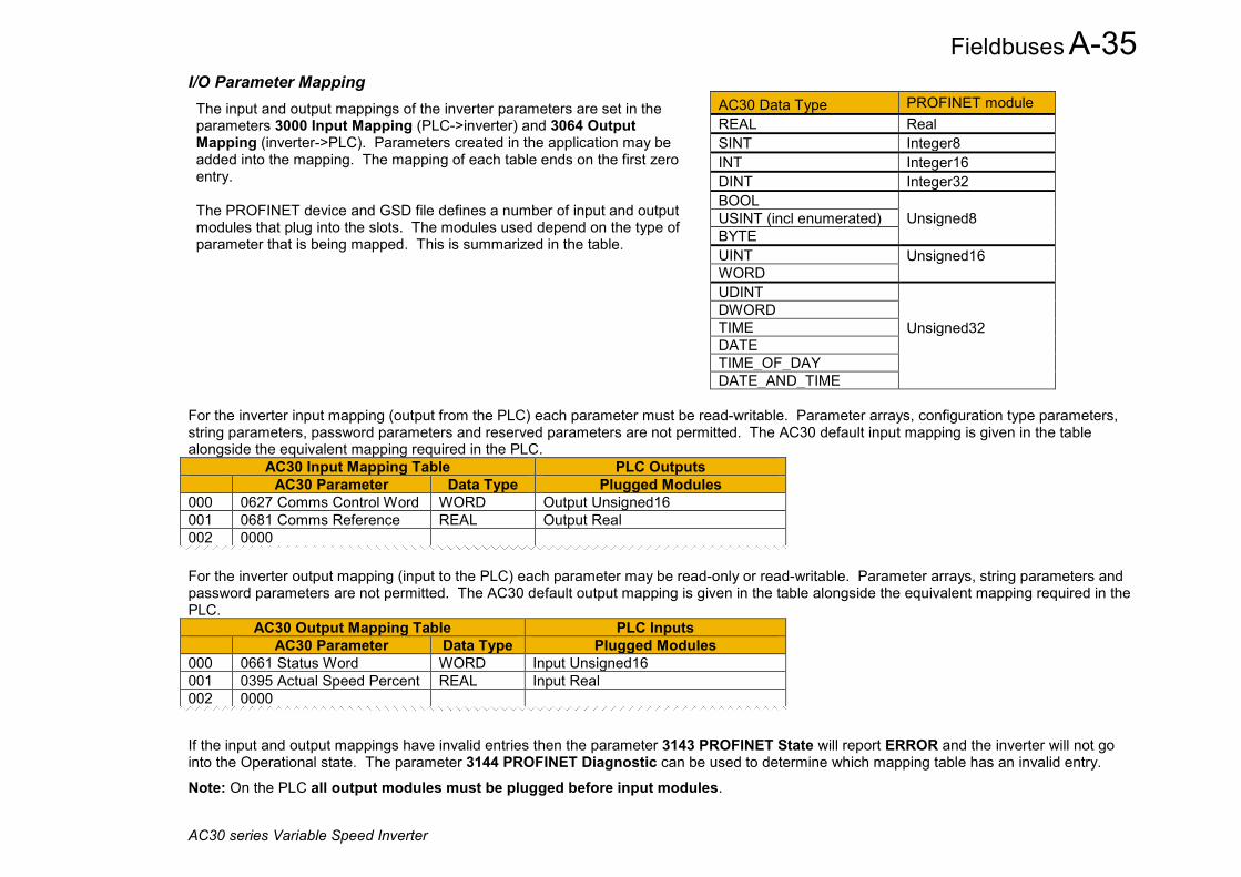
Fieldbuses A-35
AC30 series Variable Speed Inverter
I/O Parameter Mapping The input and output mappings of the inverter parameters are set in the parameters 3000 Input Mapping (PLC->inverter) and 3064 Output Mapping (inverter->PLC). Parameters created in the application may be added into the mapping. The mapping of each table ends on the first zero entry. The PROFINET device and GSD file defines a number of input and output modules that plug into the slots. The modules used depend on the type of parameter that is being mapped. This is summarized in the table.
AC30 Data Type PROFINET module REAL Real SINT Integer8 INT Integer16 DINT Integer32 BOOL
Unsigned8 USINT (incl enumerated) BYTE UINT Unsigned16
WORD UDINT
Unsigned32
DWORD TIME DATE TIME_OF_DAY DATE_AND_TIME
For the inverter input mapping (output from the PLC) each parameter must be read-writable. Parameter arrays, configuration type parameters, string parameters, password parameters and reserved parameters are not permitted. The AC30 default input mapping is given in the table alongside the equivalent mapping required in the PLC.
AC30 Input Mapping Table PLC Outputs AC30 Parameter Data Type Plugged Modules
000 0627 Comms Control Word WORD Output Unsigned16 001 0681 Comms Reference REAL Output Real 002 0000 For the inverter output mapping (input to the PLC) each parameter may be read-only or read-writable. Parameter arrays, string parameters and password parameters are not permitted. The AC30 default output mapping is given in the table alongside the equivalent mapping required in the PLC.
AC30 Output Mapping Table PLC Inputs AC30 Parameter Data Type Plugged Modules
000 0661 Status Word WORD Input Unsigned16 001 0395 Actual Speed Percent REAL Input Real 002 0000
If the input and output mappings have invalid entries then the parameter 3143 PROFINET State will report ERROR and the inverter will not go into the Operational state. The parameter 3144 PROFINET Diagnostic can be used to determine which mapping table has an invalid entry.
Note: On the PLC all output modules must be plugged before input modules.
A-36 Fieldbuses
AC30 series Variable Speed Inverter
GSD File The latest PROFINET GSD file for the inverter may be downloaded from www.parker.com
The GSD file may also be downloaded directly from the drive via a web browser. To access this make sure the parameter 0944 Web Access is set to LIMITED or FULL.
Enter the inverter IP address into the web browser and access the web page “Services” and under PROFINET GSDML file click the Download button. Altenatively type the following into the browser address bar (replacing ip_address with the inverter’s IP address): ip_address/eds/pnio.zip
The GSD file has the default mapping modules are ready plugged. This may be modified within the PLC configuration tool as required.
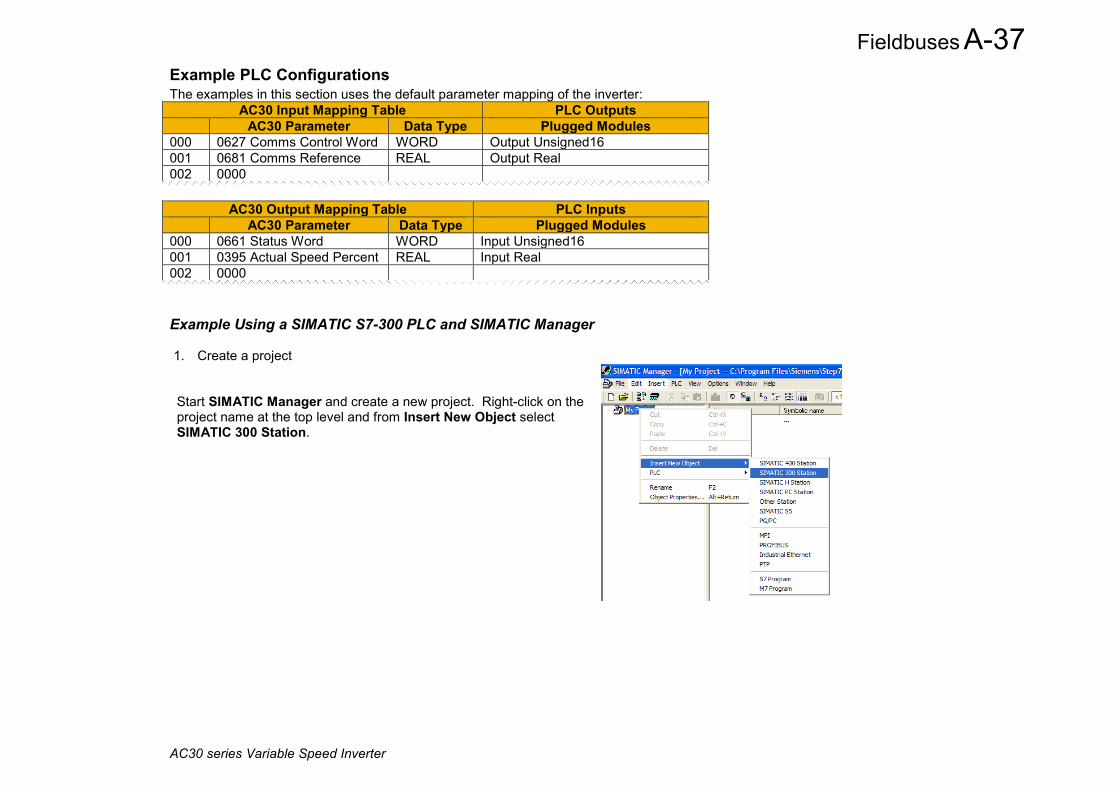
Fieldbuses A-37
AC30 series Variable Speed Inverter
Example PLC Configurations The examples in this section uses the default parameter mapping of the inverter:
AC30 Input Mapping Table PLC Outputs AC30 Parameter Data Type Plugged Modules
000 0627 Comms Control Word WORD Output Unsigned16 001 0681 Comms Reference REAL Output Real 002 0000
AC30 Output Mapping Table PLC Inputs AC30 Parameter Data Type Plugged Modules
000 0661 Status Word WORD Input Unsigned16 001 0395 Actual Speed Percent REAL Input Real 002 0000
Example Using a SIMATIC S7-300 PLC and SIMATIC Manager 1. Create a project
Start SIMATIC Manager and create a new project. Right-click on the project name at the top level and from Insert New Object select SIMATIC 300 Station.
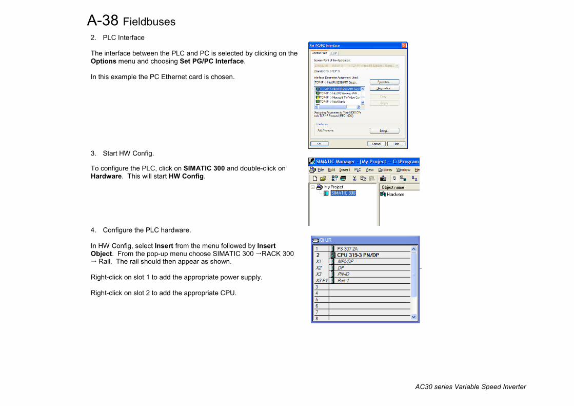
A-38 Fieldbuses
AC30 series Variable Speed Inverter
2. PLC Interface The interface between the PLC and PC is selected by clicking on the Options menu and choosing Set PG/PC Interface. In this example the PC Ethernet card is chosen.
3. Start HW Config.
To configure the PLC, click on SIMATIC 300 and double-click on Hardware. This will start HW Config.
4. Configure the PLC hardware.
In HW Config, select Insert from the menu followed by Insert Object. From the pop-up menu choose SIMATIC 300 RACK 300 Rail. The rail should then appear as shown. Right-click on slot 1 to add the appropriate power supply. Right-click on slot 2 to add the appropriate CPU.

Fieldbuses A-39
AC30 series Variable Speed Inverter
5. Install the GSD file.
Install the PROFINET IO GSD XML file. This can be downloaded from http://www.parker.com or from the inverter’s web server. From the Options menu select Install GSD File…
This will then become available in the catalogue shown on the right-hand side of the window under PROFIBUS IO Additional Field Devices Drives AC30

A-40 Fieldbuses
AC30 series Variable Speed Inverter
6. Add the PROFINET Controller.
Double-click on the PROFINET IO (PN-IO) Controller module to reveal the dialog box. Click on Properties… to set up the IP address and Subnet mask.
Click on New… to create a new network and select this.
Right-click on the PROFINET IO (PN-IO) Controller module and select Insert PROFINET IO System.

Fieldbuses A-41
AC30 series Variable Speed Inverter
7. Add the slave.
Click and drag the AC30 device from the catalogue and drop onto the PROFINET IO System. Two Device Access Points (DAPs) are available: AC30 and AC30 DAP V2.2 • Normally the AC30 DAP would be used. • For older controllers that do not support extended PROFINET
diagnostics, AC30 DAP V2.2 should be used.
Double click on the PROFINET slave device to configure it. Set the Device Name (Station Name) of the slave. If the IP address of the slave is to be set by the PLC via DCP, check the Assign IP address via IO controller and click on Ethernet… to configure.

A-42 Fieldbuses
AC30 series Variable Speed Inverter
8. Assign the Device Name of the PROFINET Slave
Double-click on the PROFINET IO-System to reveal the dialog box. Make sure the checkbox Use Name in IO-Device / Controller is cleared, otherwise the device name will require a dot extension.
If the Station Name (Device Name) of the slave is not yet set or is to be changed then select PLC from the menu and choose Assign Device Name… to reveal the dialog box. To carry out this task, an Ethernet interface must be used between the PC and PLC (see part 2 above). Make sure the slave device is connected to the network.
The Device name drop down contains a list of all the device names of the slaves in the PLC configuration. The Available devices list show all connected slaves. Match the device name with the available device and click on Assign name. The slave will then take on its device name. This can be seen on the inverter parameter 3143 PROFINET Station Name. To help identify the slave click on Flashing on. The AC30 GKP will flash.

Fieldbuses A-43
AC30 series Variable Speed Inverter
9. Configure the process data for the slave.
By clicking on the slave, the input and output process data may be configured. This must match the configuration set up in the AC30. The appropriate input and output modules may be dragged from the catalogue and dropped into the appropriate slot. All output modules must come before the input modules. The default modules will be seen already plugged. These may be changed as necessary.
10. Set the required update time.
Double click on the PROFINET IO System and click on the Update Time tab. The update time of the AC30 may be changed.
11. Save, compile and download.
Make sure the PC/PLC interface is connected. Select Station from the menu and Save and Compile then select PLC and Download…

A-44 Fieldbuses
AC30 series Variable Speed Inverter
Example Using a CoDeSys Based PLC A CoDeSys (V3.5 SP11) soft PLC running on a PC is used.
1. Start a new project from CoDeSys using a CODESYS Control Win V3 device.
2. From the CoDeSys menu select Tools->Device Repository… and install the AC30 GSD file. The device will appear under Fieldbuses as shown. Two device access points (DAPs) are given: AC30 and AC30 DAP V2.2 Normally AC30 DAP would be used.

Fieldbuses A-45
AC30 series Variable Speed Inverter
3. Under Devices, select the CODESYS Control Win 3 device, right click and select Add Device…, then add an Ethernet Adapter. Under the Ethernet device add a PN-Controller.
4. Under the PN-Controller right-click add the AC30 device. The default output and input modules will be added. These may be changed as required. Double-click on the AC30 device to modify the station name, IP address and update rate as required.

A-46 Fieldbuses
AC30 series Variable Speed Inverter
5. Double-click on CODESYS Control Win 3 and under Communications Settings tab select Scan Network... and select the required PC (note the soft PLC on the PC must be started).
6. The Output and Input modules may be mapped to application variables in the PLC program. Double click on the required module and select
the PNIO Module I/O Mapping tab. Under Variable click on the ellipses to select the required application variable.

Fieldbuses A-47
AC30 series Variable Speed Inverter
7. Set the Station Name of the inverter if it is not already set: Make sure the inverter is connected to the network and PROFINET is enabled. Go online with the PLC and right-click on the PN-Controller and select Scan for Devices… The Station Name of the required device can be modified. Select Set Name+IP for this to take effect. Note that the device may also be added from this dialog box rather than adding it manually.
8. Build the project and go online.
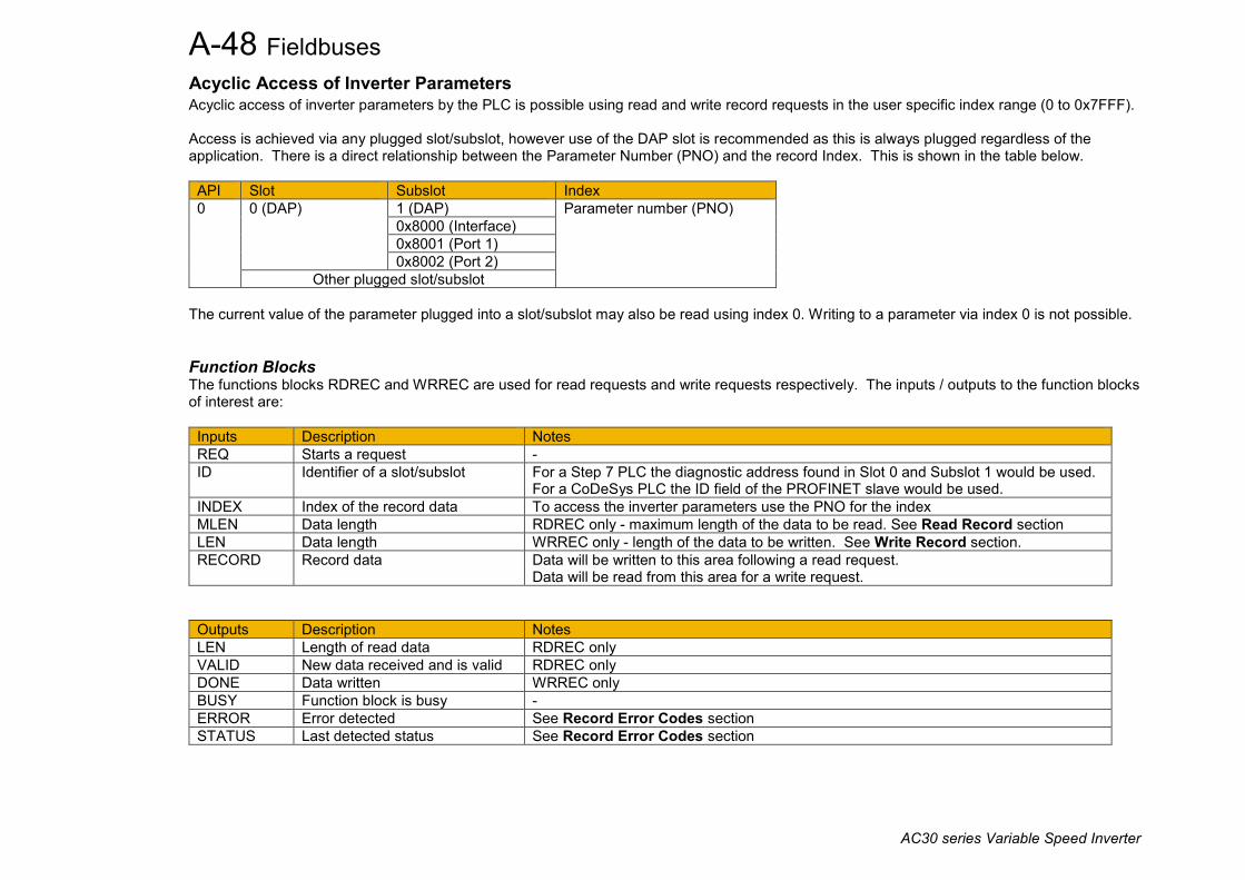
A-48 Fieldbuses
AC30 series Variable Speed Inverter
Acyclic Access of Inverter Parameters Acyclic access of inverter parameters by the PLC is possible using read and write record requests in the user specific index range (0 to 0x7FFF). Access is achieved via any plugged slot/subslot, however use of the DAP slot is recommended as this is always plugged regardless of the application. There is a direct relationship between the Parameter Number (PNO) and the record Index. This is shown in the table below.
API Slot Subslot Index 0 0 (DAP) 1 (DAP) Parameter number (PNO)
0x8000 (Interface) 0x8001 (Port 1) 0x8002 (Port 2)
Other plugged slot/subslot The current value of the parameter plugged into a slot/subslot may also be read using index 0. Writing to a parameter via index 0 is not possible.
Function Blocks The functions blocks RDREC and WRREC are used for read requests and write requests respectively. The inputs / outputs to the function blocks of interest are:
Inputs Description Notes REQ Starts a request - ID Identifier of a slot/subslot For a Step 7 PLC the diagnostic address found in Slot 0 and Subslot 1 would be used.
For a CoDeSys PLC the ID field of the PROFINET slave would be used. INDEX Index of the record data To access the inverter parameters use the PNO for the index MLEN Data length RDREC only - maximum length of the data to be read. See Read Record section LEN Data length WRREC only - length of the data to be written. See Write Record section. RECORD Record data Data will be written to this area following a read request.
Data will be read from this area for a write request.
Outputs Description Notes LEN Length of read data RDREC only VALID New data received and is valid RDREC only DONE Data written WRREC only BUSY Function block is busy - ERROR Error detected See Record Error Codes section STATUS Last detected status See Record Error Codes section

Fieldbuses A-49
AC30 series Variable Speed Inverter
Read Record The RDREC function block is used to read a record. The record data and MLEN input must be at least the size of the parameter being read: • For a standard parameter either 1,2 or 4 bytes respectively • For an array parameter the total number of bytes of all elements • For a string parameter the maximum number of characters allowed for the string plus 1 for the null terminator
Write Record The WRREC function block is used to write to a record. The LEN input must be equal to the size as the parameter being written to unless it is a string parameter: • For a standard parameter either 1,2 or 4 bytes respectively • For an array parameter the total number of bytes of all elements • For a string parameter LEN should be no more than the maximum number of characters allowed for the string plus 1 for the null terminator
Endian The endian type for acyclic read and write requests of AC30 parameters is set using parameter 3135 PROFINET Acyclic Endn. This does not apply to the cyclic I/O data which is always Big Endian.
Record Error Codes If the inverter cannot process a parameter read or write request then the ERROR output of the function block will be set TRUE and the STATUS output will be set to one of the following error codes:
Code 0xDE Read Response 0xDF Write Response
Decode 0x80 PNIO Read/Write Code 1 0x80 Invalid Index
0x81 Write Length Error 0x82 Invalid Slot or Subslot 0x84 Invalid Area API 0x86 Access Denied 0x87 Invalid Range 0x8B User Specific (record length not big enough)
Code 2 0 -

A-50 Fieldbuses
AC30 series Variable Speed Inverter
Example Acyclic Access of Parameters A CoDeSys (V3.5 SP11) soft PLC running on a PC is used. In this example, two parameters are accessed: • Reading from parameter 0005 Digin Value of data type WORD • Writing to parameter 0305 Current Limit of data type REAL
Example structured text code to access these parameters acyclically is shown below.
Fieldbuses A-51
AC30 series Variable Speed Inverter
Lost Communications Trip A trip may be issued by the inverter on the loss of connection to the PLC. To enable this, set the parameter 3133 PROFINET Trip to ENABLED and set the FIELDBUS BREAK bit in the parameter 0730 ENABLE 33 – 64. With the motor running, the trip will occur when the parameter 3143 PROFINET State transitions from the CONNECTED state to any other state.
Troubleshooting and Tips
Inverter fails to come out of configuration mode • Check the parameter 3144 PROFINET Diagnostic for INPUT MAPPING FAILED or OUTPUT MAPPING FAILED. See Parameter Mapping
section.
Inverter fails to come out of Waiting for Connection PROFINET state • Check that the Station Name has been set. See Station Name section. • Make sure the Update Time is set to an appropriate rate for the control mode / switching frequency. Check the parameter 3144 PROFINET
Diagnostic for CONNECTION REJECTED state. See Update Time section.
PLC reports incorrect module • Check the parameter 3144 PROFINET Diagnostic for MAPPING MISMATCH state. Make sure the parameter mappings on the inverter
match those of the PLC (see Parameter Mapping section). The inverter Input Mapping table must match the plugged Output Modules of the PLC The inverter Output Mapping table must match the plugged Input Modules of the PLC All Output Modules must be plugged before the Input Modules on the PLC
The inverter loses its IP address at startup • When the IP address is set with a temporary flag using DCP, the IP address will startup as 0.0.0.0 when the inverter is power-cycled or
PROFINET is enabled. The IP address is subsequently set when the PLC next makes a connection. This behavior is part of the PROFINET standard. However, this may be overridden by setting the parameter 3134 PROFINET Use Drive IP to TRUE so that the last IP address used will be set at startup. See DCP Assignment section.

A-52 Fieldbuses
AC30 series Variable Speed Inverter
Parameter Summary Parameter Name No. Path Default Range Writable PROFINET Enable 3132 Setup::Communications::Base PROFINET
Parameters::Base Comms::PROFINET IO Device FALSE FALSE
TRUE CONFIG
PROFINET IO parameter. Enables the built-in PROFINET IO Device.
PROFINET Trip 3133 Setup::Communications::Base PROFINET Parameters::Base Comms:: PROFINET IO Device
ENABLED 0: DISABLED 1: ENABLED
CONFIG
PROFINET IO parameter. Enables the FIELDBUS BREAK trip on loss of connection. Enumerated values: 0: DISABLED the trip is disabled 1: ENABLED the inverter will trip on the loss of connection to the PLC
PROFINET Use Drive IP
3134 Setup::Communications::Base PROFINET Parameters::Base Comms:: PROFINET IO Device
FALSE FALSE TRUE
CONFIG
PROFINET IO parameter. Determines the IP address after PROFINET is enabled or the AC30 is power-cycled. If set to FALSE then the behaviour is that of the PROFINET standard and the IP address will be set to zero if the IP address were previously set by DCP with the temporary setting. If set to TRUE then the IP address will be the last IP address set.
PROFINET Acyclic Endn
3135 Setup::Communications::Base PROFINET Parameters::Base Comms:: PROFINET IO Device
BIG ENDIAN 0: LITTLE ENDIAN 1: BIG ENDIAN
WRITABLE
PROFINET IO parameter. Sets the endian type for acyclic read and write requests of AC30 parameters. This does not apply to the cyclic I/O data which is always Big Endian. Enumerated values: 0: LITTLE ENDIAN The least significant byte (LSB) of the data is sent first. 1: BIG ENDIAN The most significant byte (MSB) of the data is sent first.
PROFINET Station Name
3136 Monitor::Communications::Base PROFINET Parameters::Base Comms::PROFINET IO Device
- - NEVER
PROFINET IO parameter. Indicates the PROFINET device Station Name. Only the first 21 characters are displayed.

Fieldbuses A-53
AC30 series Variable Speed Inverter
Parameter Name No. Path Default Range Writable PROFINET State 3143 Monitor::Communications::Base PROFINET
Parameters::Base Comms::PROFINET IO Device NONE 0: SETUP
1: NW_INIT 2: WAITING TO
CONNECT 3: STOP MODE 4: CONNECTED 5: ERROR 6, 7: Reserved 8: NONE
NEVER
PROFINET IO parameter. Diagnostic indicating the state of the PROFINET IO Device. Enumerated values: 0: SETUP PROFINET IO enabled – the inverter is in the configuration state 1: NW_INIT Network initialization 2: WAITING TO CONNECT Waiting for a connection to a PLC 3: STOP MODE Connection made in Stop Mode – inverter parameters will not be written to by the PLC 4: CONNECTED Connection made in Run mode 5: ERROR Configuration error 8: NONE PROFINET IO disabled
PROFINET Diagnostic 3144 Monitor::Communications::Base PROFINET Parameters::Base Comms::PROFINET IO Device
NONE
0: NONE 1: INPUT MAPPING
FAILED 2: OUTPUT MAPPING
FAILED 3: CONNECTION
REJECTED 4: MAPPING MISMATCH
NEVER
PROFINET IO parameter. Diagnostic indicating if there is a configuration error. Enumerated Values: 0: NONE No configuration error 1: INPUT MAPPING FAILED Invalid input mapping 2: OUTPUT MAPPING FAILED Invalid output mapping 3: CONNECTION REJECTED Inverter has rejected a connection attempt from the PLC due to invalid switching
frequency and update time combination. 4: MAPPING MISMATCH The mapping between the PLC and inverter does not match. A connection may still be
allowed in this state.

A-54 Fieldbuses
AC30 series Variable Speed Inverter
Parameter Name No. Path Default Range Writable Input Mapping 3000 Setup::Communications::Base PROFINET
Parameters::Base Comms::Fieldbus Mapping 0627 0681 0000 …
0000 Maximum parameter number
NEVER
PROFINET IO parameter. List of PNOs for the built-in fieldbus input parameter mapping. These map to the PLC output modules.
Output Mapping 3064 Setup::Communications::Base PROFINET Parameters::Base Comms::Fieldbus Mapping
0661 0395 0000 …
0000 Maximum parameter number
NEVER
PROFINET IO parameter. List of PNOs for the built-in fieldbus output parameter mapping. These map to the PLC input modules.

Sequencing Logic B-1
AC30 series Variable Speed Inverter
Appendix B: Sequencing Logic Drive State Machine DS402 The sequencing of the inverter is based on the DS402 / DriveCOM / IEC 61800-7 standard as used by most industrial fieldbuses . This allows it to be easily controlled and monitored by a PLC using the standards’ Control Word and Status Word.
Sequencing State The sequencing state of the unit is indicated by an enumerated value given by the 0678 Sequencing State parameter.
Value DS402 Sequencing State Description 0 NOT READY TO SWITCH ON Not ready to switch on. The drive is initialising or being configured.
1 SWITCH ON DISABLED The Drive will not accept a switch on command
2 READY TO SWITCH ON The Drive will accept a switch on command.
3 SWITCHED ON The Drive will accept an Operation Enable (Run or Jog) command. - Power stage of the Drive is ready to operate. - Voltage has not yet been applied to the motor terminals.
4 OPERATIONAL ENABLED Normal operational state of the drive. This state includes Running, Jogging, Stopping (Disabling Operation) and Shutting Down (Switching Off). - Voltage applied to the motor terminals.
5 QUICKSTOP ACTIVE Emergency stop (Fast stop) is active
6 FAULT REACTION ACTIVE The Drive is processing a trip event
7 FAULTED The Drive is tripped awaiting trip reset

B-2 Sequencing Logic
AC30 series Variable Speed Inverter
Sequencing Diagram
NOT READY TO SWITCH ON
SWITCH ON DISABLED
SWITCHED ON
READY TO SWITCH ON
OPERATION ENABLED
No Power
FAULT REACTION ACTIVE
FAULTED
QUICKSTOP ACTIVE
From all states
2
3
4 5
6
7
8
1
10
11 12
13
14
15
0
9
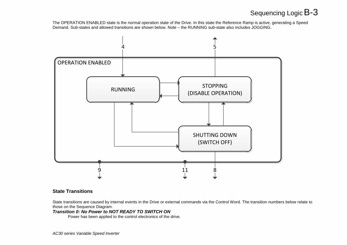
Sequencing Logic B-3
AC30 series Variable Speed Inverter
The OPERATION ENABLED state is the normal operation state of the Drive. In this state the Reference Ramp is active, generating a Speed Demand. Sub-states and allowed transitions are shown below. Note – the RUNNING sub-state also includes JOGGING.
OPERATION ENABLED OPERATION ENABLED
RUNNING STOPPING(DISABLE OPERATION)
SHUTTING DOWN(SWITCH OFF)
4
89 11
5
State Transitions State transitions are caused by internal events in the Drive or external commands via the Control Word. The transition numbers below relate to those on the Sequence Diagram. Transition 0: No Power to NOT READY TO SWITCH ON Power has been applied to the control electronics of the drive.

B-4 Sequencing Logic
AC30 series Variable Speed Inverter
Transition 1: NOT READY TO SWITCH ON to SWITCH ON DISABLED Automatic transition when initialisation has been completed and application has been loaded. Transition 2: SWITCH ON DISABLED to READY TO SWITCH ON Shutdown command received from control device or local signal.
Transition 3: READY TO SWITCH ON to SWITCHED ON Switch On command received from control device or local signal.
Transition 4: SWITCHED ON to OPERATION ENABLED Enable Operation (Run Forward, Run Reverse or Jog) command received from control device or local signal.
Transition 5: OPERATION ENABLED to SWITCHED ON Disable Operation (Stop) command received from control device or local signal and Disabling (Stopping) function completed.
Transition 6: SWITCHED ON to READY TO SWITCH ON Shutdown command received from control device or local signal.
Transition 7: READY TO SWITCH ON to SWITCH ON DISABLED Quick Stop or Disable Voltage command received from control device or local signal.
Transition 8: OPERATION ENABLED to READY TO SWITCH ON Shutdown command received from control device or local signal and Shutdown function completed.
Transition 9: OPERATION ENABLED to SWITCH ON DISABLED Disable Voltage command received from control device or local signal.
Transition 10: SWITCHED ON to SWITCH ON DISABLED Disable Voltage or Quick Stop command received from control device or local signal.
Transition 11: OPERATION ENABLED to QUICKSTOP ACTIVE Quick Stop command received from control device or local signal.
Transition 12: OPERATION ENABLED to QUICKSTOP ACTIVE Automatic transition when the Quick Stop function is completed or Disable Voltage command received.
Transition 13: any state to FAULT REACTION ACTIVE Fault (Trip) occurred.
Transition 14: FAULT REACTION ACTIVE to FAULT Automatic transition when Fault Reaction function completed or Disable Voltage command received.
Transition 15: FAULT to SWITCH ON DISABLED Fault Reset command received from control device or local signal and there are no active faults.
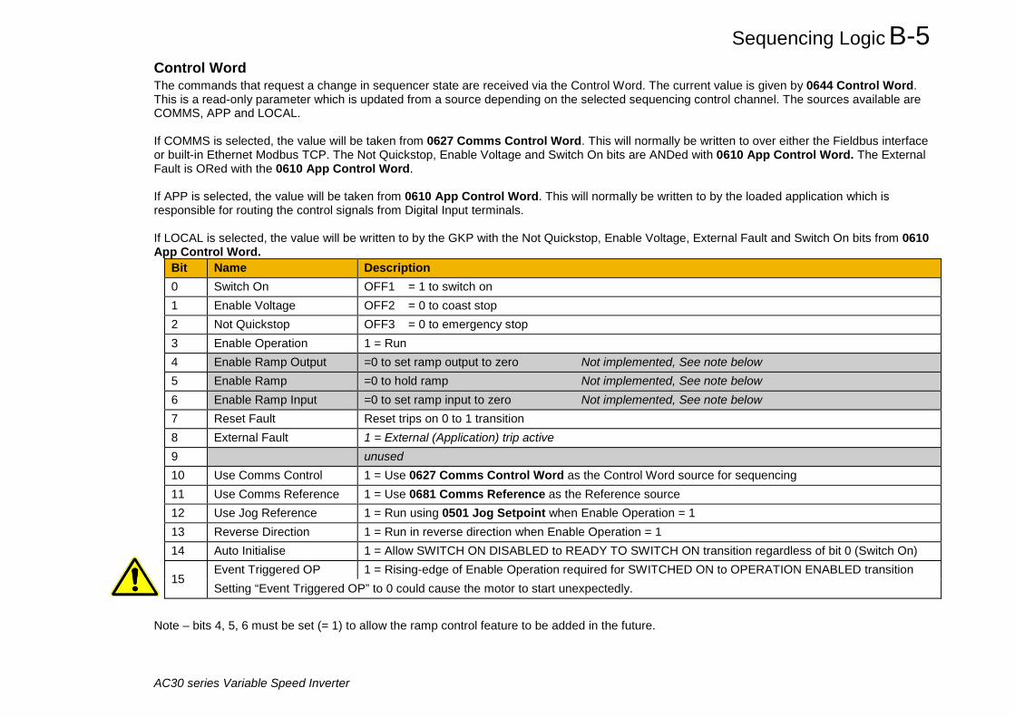
Sequencing Logic B-5
AC30 series Variable Speed Inverter
Control Word The commands that request a change in sequencer state are received via the Control Word. The current value is given by 0644 Control Word. This is a read-only parameter which is updated from a source depending on the selected sequencing control channel. The sources available are COMMS, APP and LOCAL. If COMMS is selected, the value will be taken from 0627 Comms Control Word. This will normally be written to over either the Fieldbus interface or built-in Ethernet Modbus TCP. The Not Quickstop, Enable Voltage and Switch On bits are ANDed with 0610 App Control Word. The External Fault is ORed with the 0610 App Control Word. If APP is selected, the value will be taken from 0610 App Control Word. This will normally be written to by the loaded application which is responsible for routing the control signals from Digital Input terminals. If LOCAL is selected, the value will be written to by the GKP with the Not Quickstop, Enable Voltage, External Fault and Switch On bits from 0610 App Control Word.
Bit Name Description 0 Switch On OFF1 = 1 to switch on 1 Enable Voltage OFF2 = 0 to coast stop 2 Not Quickstop OFF3 = 0 to emergency stop 3 Enable Operation 1 = Run 4 Enable Ramp Output =0 to set ramp output to zero Not implemented, See note below 5 Enable Ramp =0 to hold ramp Not implemented, See note below 6 Enable Ramp Input =0 to set ramp input to zero Not implemented, See note below 7 Reset Fault Reset trips on 0 to 1 transition 8 External Fault 1 = External (Application) trip active 9 unused 10 Use Comms Control 1 = Use 0627 Comms Control Word as the Control Word source for sequencing 11 Use Comms Reference 1 = Use 0681 Comms Reference as the Reference source 12 Use Jog Reference 1 = Run using 0501 Jog Setpoint when Enable Operation = 1 13 Reverse Direction 1 = Run in reverse direction when Enable Operation = 1 14 Auto Initialise 1 = Allow SWITCH ON DISABLED to READY TO SWITCH ON transition regardless of bit 0 (Switch On)
15 Event Triggered OP 1 = Rising-edge of Enable Operation required for SWITCHED ON to OPERATION ENABLED transition Setting “Event Triggered OP” to 0 could cause the motor to start unexpectedly.
Note – bits 4, 5, 6 must be set (= 1) to allow the ramp control feature to be added in the future.

B-6 Sequencing Logic
AC30 series Variable Speed Inverter
Example Comms Control Words (hexadecimal):
CC77 STOP (Normal) or go to SWITCHED ON state CC7F RUN CC7B QUICKSTOP CC7D COAST STOP CCF0 FAULT RESET
Status Word The Status Word provides the detailed status of the sequencer. Regardless of the source of the Control Word, this is always available as 0661 Status Word.
Bit Name Description 0 Ready To Switch On Drive initialised and not in Configuration mode
1 Switched On Drive in SWITCHED ON or OPERATION ENABLED state
2 Operation Enabled Running (or stopping)
3 Faulted Unacknowledged fault present
4 Voltage Enabled Line supply present
5 Quickstop Inactive = 0 when reacting to a Quickstop request
6 Switch On Disabled Drive in SWITCH ON DISABLED state 7 unused 8 unused
9 Control From Comms Using 0627 Comms Control Word as the Control Word source 10 unused 11 unused
12 Jog Operation Using Jog Reference or will use Jog Reference when Operation Enabled
13 Reverse Operation Running backwards or will run backward when Operation Enabled
14 Reference From Comms Using 0681 Comms Reference as the Reference source
15 Stopping Operation Enable command removed or Quickstop active

Parameter Reference C-1
AC30 series Variable Speed Drive
Appendix C: Parameter Reference Parameter Descriptions The parameter descriptions in this section are arranged alphabetically; however, they are also listed below by Category as on the GKP and web page. Engineer view level must be selected to see all the parameters listed under the Parameters menu.
Control Mode Control Mode C-38 Motor Control Auto Restart C-15 Autotune C-20 Braking C-27 Current Limit C-43 Current Loop C-44 DC Link Volts Limit C-51 Energy Meter C-64 Fan Control C-68 Feedbacks C-69 Filter On Torque Dmd C-74 Fluxing VHz C-78 Flycatching C-83 Induction Motor Data C-90 Inj Braking C-92 Motor Load C-112 Motor Nameplate C-115 Motor Sequencer C-117 MRAS C-118 Pattern Generator C-121 PMAC Flycatching C-126 PMAC Motor Advanced C-128 PMAC Motor Data C-129 PMAC SVC C-133 Pos Fbk Alignment C-141 Power Loss Ride Thru C-149 Ramp C-159 Scale Setpoint C-185 Sequencing C-187
Slew Rate C-196 Slip Compensation C-197 Spd Direct Input C-201 Spd Loop Diagnostics C-202 Spd Loop Settings C-203 Speed Ref C-208 Stabilisation C-209 Stack Inv Time C-210 Torque Limit C-216 Tr Adaptation C-219 Voltage Control C-227 Regen Control AFE C-2 Inputs And Outputs IO Configure C-94 IO Values C-101 Option IO IO Option Common C-99 General Purpose IO C-85 Encoder C-62 Resolver C-166 Thermistor C-215 Base Comms Ethernet C-67 Modbus C-109 EtherNet IP Adapter C-67 Profinet IO Device C-156 Fieldbus Mapping C-73 Peer to Peer C-123 Precision Time Protocol C-152 SNTP Client C-198
SNTP Server C-198 Web Server C-228 Option Comms Communications Options C-34 Read Process 1
Write Process 1 Event 1 Option Ethernet 1 BACnet IP Option C-24 BACnet MSTP Option C-25 CANopen Option C-29 ControlNet Option C-42 DeviceNet Option C-56 EtherCAT Option C-66 EtherNet IP Option C-67 Modbus RTU Option C-110 Modbus TCP Option C-111 Profibus DP-V1 Option C-155 Profinet IO Option C-156 Trips Trips Status C-221 Trips History C-220 Stall Trip C-213 VDC Ripple C-226 Current Sensor Trip C-45 Speed Error Trip C-207 Black Box Recorder C-26 Maintenance Monitor C-106 Keypad Graphical Keypad C-87 Local Control C-105
Keypad Override C-104 Application App Info C-13 Minimum Speed C-108 PID C-124 Preset Speeds C-153 Raise Lower C-157 Skip Frequencies C-193 System Board System Board Option C-214 SB Encoder C-176 SB Encoder Slot 1 C-179 SB Encoder Slot 2 C-181 SB Retransmit C-182 SB Digital IO C-173 Phase Control Configure C-35 Device Manager Device State C-54 Device Commands C-53 Drive info C-57 Clone C-30 Parameter Backup C-120 Data Logger C-46 Flash File System C-77 SD Card C-186 Real Time Clock C-165 Runtime Statistics C-171 Setup Wizard C-191 Soft Menus C-199
1. Refer to the appropriate fieldbus communications option.
For additional parameter details refer to the Parameter Table at the end of this appendix. The Parameter Number, (PNO), provided next to each parameter description may be used to find the corresponding entry in the Parameter Table.

C-2 Parameter Reference
AC30 series Variable Speed Drive
Active Front End (AFE) Control Screen Setup:: Regen Control Monitor:: Regen Control Active Front End (AFE) is a mode of operation of the drive required for full 4-Q regeneration capabilities. AFE control mode allows a single AC30P/AC30D drive to act as a 4-Q power supply unit that is capable of drawing (motoring) and supplying (regenerating) sinusoidal, near-unity power factor current from the supply. The output from the 4-Q Regen drive acts as a DC supply which is used to power other drives on a common DC Bus system.
AFE Control Mode is available as a standard option in the AC30P/AC30D firmware, however set-up and installation requirements need to be adhered to in order to use a drive as 4-Q regen unit. These requirements are described in more detail in the paragraphs that follow. Hardware Requirements The figure below shows the typical installation configuration of the drive operating in AFE control mode.
Optional EMC Filter
-
U (M1)
V (M2)
W (M3)
DC +
DC +
WVU WVU
DC Link Fuses
LCL Filter3 – ph Supply
3 – ph Input
Contactor
AC30P 4-Q
Line Fuses
External Pre-charge
DC -
Common DC Link
3 – ph Output
Contactor
DC - DC + DC -
AC30 AC30
Motor Motor
Encoder Option Card7004-04-00
Line sync cardLA471892U001

Parameter Reference C-3
AC30 series Variable Speed Drive
The correct installation requires the following components: - LCL filter
o 3% and 5% chokes (as part of an LCL filter, custom designed ) o Capacitor panel (as part of an LCL filter, custom designed)
- Pre-charge resistor with external pre charge control - Thee phase contactors - EMC filter (optional) - AC Line fuses - DC Link fuses - Line sync card (LA471892U001) - Encoder option card (7004-04-00)
Drive Set-up Typically the system will contain an AC30P/AC30D regen drive providing 4-Q power supply, and one or more drives on the common DC bus.
ALL drives in the system MUST have their internal EMC “Y” caps to earth disconnected.
A 4-Q regen drive is set into AFE control mode by setting the Control Mode “Motor Type or AFE” parameter to AFE as shown in picture below.
This setting must be accompanied by selection of an appropriate AFE macro from the default application:
If the “Motor Type or AFE” and “Selected Application” do not match, it would not be possible to operate the drive correctly.Both these settings are necessary for proper configuration of the drive to work as an active front end.
When drive is in AFE mode, its current rating is limited to 85% of the equivalent set up current rating when in one of the motor modes.
The standard set of AFE parameters required to finalise the drive AFE configuration are located within Setup/Regen Control menu. Based on the “AFE Current Control” bit, AFE would operate in voltage control mode (left), or current control mode (right):

C-4 Parameter Reference
AC30 series Variable Speed Drive
AFE inductance parameter must be set to the value of the total line choke inductance.
AFE VDC Demand parameter sets the required DC link voltage for the common DC link bus. Recommended level for nominal drive voltage rating of 400V (with 820V overvoltage trip level and 410V undervoltage trip level) is 720V.
AFE VDC Min Level parameter defines the level of DC link voltage at which external precharge closure is instigated. By default it is equal to undervoltage trip level.
For any additional adjustments (if required) the full set of the AFE related parameters can be found in the Parameters::Regen Control::AFE menu.
Other (non-AFE) drives, supplied through common DC bus MUST have the following set-up:
DC Link volts limit feature disabled
If in V/Hz mode the Terminal Voltage Mode parameter set to FIXED

Parameter Reference C-5
AC30 series Variable Speed Drive
AFE Application A standard AFE macro (App_5_AFE_Control) is included as part of the default application. It provides necessary application layer logic to operate in AFE control mode. This macro can be modified (if necessary) using standard AC30 PDQ or PDD tools. It enables the user immediate operation without any additional diagram logic wiring, providing that electrical connections to digital inputs and outputs are the same as in default AFE macro.
The default macro requires the following electrical wiring diagram for AC30P/AC30D control board. Use of different inputs will need to be accompanied by the appropriate change in the application.

C-6 Parameter Reference
AC30 series Variable Speed Drive

Parameter Reference C-7
AC30 series Variable Speed Drive

C-8 Parameter Reference
AC30 series Variable Speed Drive
AFE Start Up Sequence In order to minimise the potential occurrence of initial current transients when AFE is switched on, an “AFE Start Settings” block was included in the default macro. It works in conjunction with the following four soft parameters:
- 1943 AFE Current Limit - 1944 AFE Current Loop P Gain - 1945 AFE Stack Frequency - 1946 AFE Default Stack Frequency
AFE Default Macro Setup Parameters
These soft parameters have to be populated with the values that are required for operation in normal running mode, before first start of AFE mode is attempted!
Start up values are set as constants within the macro, and can only be changed by reprogramming AFE application into the drive. Soft parameter 1946 AFE Default Stack Frequency allows the user to specify if drive should operate (post start up) with its default switching frequency, or with a different one, as specified in soft parameter 1945.
It is, by default, set that start up is finished after 1.5 seconds since the run command has taken effect.

Parameter Reference C-9
AC30 series Variable Speed Drive
Line Synchronisation Typically the system will contain an AC30P/AC30D regen drive providing 4-Q power supply, and one or more drives on the common DC bus. However, in order for the AFE control procedures to operate correctly, a synchronization of the IGBT firing sequence to the three phase mains supply voltage frequency, angle, and direction of rotation need to be performed. This is achieved by using a line sync card (LA471892U001), connected to a standard AC30 encoder option board (7004-04-00). Failure to successfully synchronise could cause significant supply distortion, poor power factor, or even catastrophic failure.
AFE Parameter List The full set of AFE related parameters are given in a table below:
Parameter Name No. Path Default Range Units Writable AFE Inductance
1730
Setup::Regen Control Parameters::Regen Control::AFE
0.00
0.00 to 1000.00
mH
ALWAYS
Total inductance (3% + 5%) from the LCL filter in the AFE configuration.
AFE PF Angle Demand
1693
Parameters::Regen Control::AFE
0.00
-90.00 to 90.00
deg
ALWAYS
Sets AFE in current control mode (TRUE) or leaves it in voltage control mode (FALSE).
AFE Id Demand
1705
Same as PNO 1693
0.10
-1.50 to 1.50
ALWAYS
Iq current demand. Set directly in both current control mode, or voltage control mode.
AFE Id Demand
1704
Same as PNO 1693
0.10
-1.50 to 1.50
ALWAYS
Id current demand. Set directly only in current control mode. In voltage control mode set by dc link voltage loop.
AFE Max Current
1706
Parameters::Regen Control::AFE
1.50
0.00 to 1.50
ALWAYS
Maximum allowed current in AFE mode.
AFE Close Ext PCR
1690
Parameters::Regen Control::AFE
FALSE
ALWAYS
Link to digital output to send command to close external pre charge

C-10 Parameter Reference
AC30 series Variable Speed Drive
Parameter Name No. Path Default Range Units Writable AFE Ext PCR Closed
1691
Parameters::Regen Control::AFE
FALSE
ALWAYS
Link to digital input to provide information if external pcr is closed.
AFE Sync Frequency
1703
Monitor::Regen Control Parameters::Regen Control::AFE
Hz
NEVER
Mains frequency as measured by the AFE module.
AFE Sync Angle
1718
Parameters::Regen Control::AFE
deg
NEVER
Mains angle as measured by the AFE module.
AFE PLL Kp
1694
Parameters::Regen Control::AFE
5.48
0.00 to 30.00
ALWAYS
PLL proportional gain.
AFE PLL Ti
1695
Parameters::Regen Control::AFE
0.0318
0.0000 to 3.0000
ALWAYS
PLL integral term.
AFE VDC Kp
1707
Parameters::Regen Control::AFE
8.27
0.00 to 300.00
ALWAYS
DC link voltage loop proportional gain.
AFE VDC Ti
1708
Parameters::Regen Control::AFE
0.0319
0.0000 to 3.0000
ALWAYS
DC link voltage loop integral term.
AFE VDC Demand
1711
Same as PNO 1693
720
340 to 820
V
ALWAYS
DC link voltage demand, setpoint for voltage control loop.
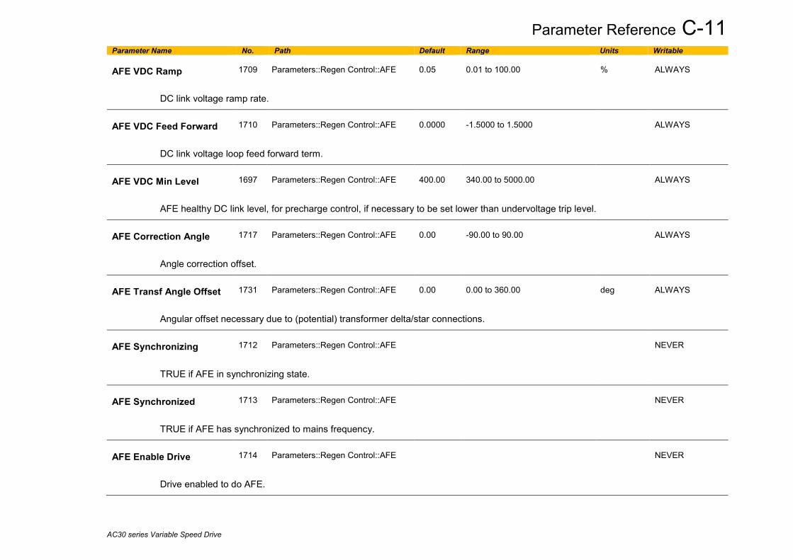
Parameter Reference C-11
AC30 series Variable Speed Drive
Parameter Name No. Path Default Range Units Writable AFE VDC Ramp
1709
Parameters::Regen Control::AFE
0.05
0.01 to 100.00
%
ALWAYS
DC link voltage ramp rate.
AFE VDC Feed Forward
1710
Parameters::Regen Control::AFE
0.0000
-1.5000 to 1.5000
ALWAYS
DC link voltage loop feed forward term.
AFE VDC Min Level
1697
Parameters::Regen Control::AFE
400.00
340.00 to 5000.00
ALWAYS
AFE healthy DC link level, for precharge control, if necessary to be set lower than undervoltage trip level.
AFE Correction Angle
1717
Parameters::Regen Control::AFE
0.00
-90.00 to 90.00
ALWAYS
Angle correction offset.
AFE Transf Angle Offset
1731
Parameters::Regen Control::AFE
0.00
0.00 to 360.00
deg
ALWAYS
Angular offset necessary due to (potential) transformer delta/star connections.
AFE Synchronizing
1712
Parameters::Regen Control::AFE
NEVER
TRUE if AFE in synchronizing state.
AFE Synchronized
1713
Parameters::Regen Control::AFE
NEVER
TRUE if AFE has synchronized to mains frequency.
AFE Enable Drive
1714
Parameters::Regen Control::AFE
NEVER
Drive enabled to do AFE.

C-12 Parameter Reference
AC30 series Variable Speed Drive
Parameter Name No. Path Default Range Units Writable AFE PF Angle Demand
1692
Parameters::Regen Control::AFE
0.00
-90.00 to 90.00
deg
ALWAYS
Power factor angle demand.
AFE Phase Loss
1715
Parameters::Regen Control::AFE
NEVER
Indicates if phase loss occurred.
AFE Brake Mode
1716
Parameters::Regen Control::AFE
FALSE
ALWAYS
Sets AFE control into brake mode.
AFE Status
1721
Same as PNO 1703
0:INACTIVE 1:SYNCHRONIZING 2:SYCHRONIZED 3:SUPPLY FREQ HIGH 4:SUPPLY FREQ LOW 5:SYNC FAILED
NEVER
AFE module status reporting.
NOTES
1 – To correctly set up AFE mode for frame K - phase fail trip needs to be disable in AFE mode - parameter 1707 needs to be set at 0.75 - parameter 1708 needs to be set at 0.02

Parameter Reference C-13
AC30 series Variable Speed Drive
App Info Parameters::Application::App Info
Details of the Application loaded in the Drive. An Application is built as part of a project using a suitable programming tool. When downloaded into the Drive an Application within the Project can be selected to run. Some Projects only contain a single Application, so in this case will always be selected. Parameter Name No. Path Default Range Units Writable Project File Name
1040
Parameters::Application::App Info
NEVER
The name of the file on the programming PC used to store the application. (This does not include the project or projectarchive file name extension.)
Archive Flags
0410
Parameters::Application::App Info
NEVER
Indicates if the source code corresponding to the loaded configuration in saved in the drive as an archive. For the AC30V the this archive must be saved on the SD Card. On the AC30P the archive can be saved internally or on the SD Card.
Bit 0 Indicates that the project archive file on the SD card matches the loaded application Bit 4 Indicates that the language file on the SD card for the selected language matches the loaded application Bit 8 Indicates that the project archive file stored internally matches the loaded application
Last Modification
1047
Parameters::Application::App Info
1970/01/01 to 2038/01/19
NEVER
Timestamp of when the loaded Project was last modified. (Note - the RTC option is not required for this.)
IDE Version
1048
Parameters::Application::App Info
NEVER
The version of programming tool (Interactive Development Environment) used to create the loaded Project.
Project Author
1054
Parameters::Application::App Info
NEVER
The Author of the loaded Project as entered in the programming tool when it was created
Project Version
1061
Parameters::Application::App Info
NEVER
The Project version of the loaded Project as entered by the programmer when creating the Project.
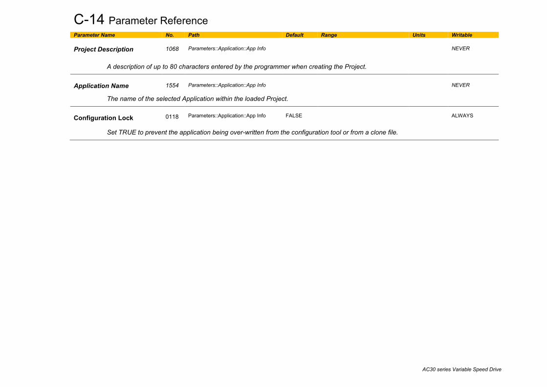
C-14 Parameter Reference
AC30 series Variable Speed Drive
Parameter Name No. Path Default Range Units Writable Project Description
1068
Parameters::Application::App Info
NEVER
A description of up to 80 characters entered by the programmer when creating the Project.
Application Name
1554
Parameters::Application::App Info
NEVER
The name of the selected Application within the loaded Project.
Configuration Lock
0118
Parameters::Application::App Info
FALSE
ALWAYS
Set TRUE to prevent the application being over-written from the configuration tool or from a clone file.

Parameter Reference C-15
AC30 series Variable Speed Drive
Auto Restart Setup:: Motor Control::Auto Restart Parameters::Motor Control::Auto Restart
The Auto Restart feature provides the facility to automatically reset a choice of trip events and restart the drive with a programmed number of attempts. The number of attempted restarts is monitored. A manual or remote trip reset is required if the drive is not successfully restarted within the maximum number of restarts. The purpose of this feature is to allow automatic recovery from trip conditions. This is especially useful on remote or unmonitored sites.
Parameter Name No. Path Default Range Units Writable AR Enable
1469
Setup::Motor Control::Auto Restart Parameters::Motor Control::Auto Restart
FALSE
ALWAYS
Enables the auto restart function.
AR Mode
1470
Same as PNO 1469
1
0:TRIP RESET 1:AUTO RESTART 2:AUTO START
ALWAYS
Defines the action that the AR function will take following a trip.
0. TRIP RESET Trips will be reset when the trip sources are inactive. The drive will not be restarted. 1. AUTO RESTART If it was running the drive will be restarted when the trip sources are inactive and run is active. 2. AUTO START The drive will be started when the trip sources are inactive if the run signal is high
Refer to the Functional Description below for more details.
AR Max Restarts
1471
Same as PNO 1469
10
1 to 20
ALWAYS
Defines the maximum number of restart attempts permitted before the AR function disables itself.

C-16 Parameter Reference
AC30 series Variable Speed Drive
Parameter Name No. Path Default Range Units Writable AR Trip Mask
1472
Same as PNO 1469
FFFFFFFF
0:01 OVER VOLTAGE 1:02 UNDER VOLTAGE 2:03 OVER CURRENT 3:04 STACK FAULT 4:05 STACK OVER CURRENT 5:06 CURRENT LIMIT 6:07 MOTOR STALL 7:08 INVERSE TIME 8:09 MOTOR I2T 9:10 LOW SPEED I 10:11 HEATSINK OVERTEMP 11:12 INTERNAL OVERTEMP 12:13 MOTOR OVERTEMP 13:14 EXTERNAL TRIP 14:15 BRAKE SHORT CCT 15:16 BRAKE RESISTOR 16:17 BRAKE SWITCH 17:18 LOCAL CONTROL 18:19 COMMS BREAK 19:20 LINE CONTACTOR 20:21 PHASE FAIL 21:22 VDC RIPPLE 22:23 BASE MODBUS BREAK 23:24 24 V OVERLOAD 24:25 PMAC SPEED ERROR 25:26 OVERSPEED 26:27 STO ACTIVE 27:28 FEEDBACK MISSING 28:29 INTERNAL FAN FAIL 29:30 CURRENT SENSOR 30:31 POWER LOSS STOP 31:32 SPEED SENSOR
ALWAYS
AR Trip Mask 2
0796
Setup::Motor Control::Auto Restart Parameters::Motor Control::Auto Restart
FFFFFFFF
0:33 A1 1:34 A2 2:35 A3 3:36 A4 4:37 A5 5:38 A6 6:39 A7 7:40 A8 8:41 SPEED ERROR 9:42 PEERTOPEER OVERRUN 10:43 PHASE CONFIG 11:44 FIELDBUS BREAK 18:51 CPU USAGE
ALWAYS
Defines the trip causes that the AR feature will attempt to automatically reset, followed by an attempt to restart the drive if appropriate.
Refer to Chapter 7 “Trips and Fault Finding” for details of the value corresponding to each trip.
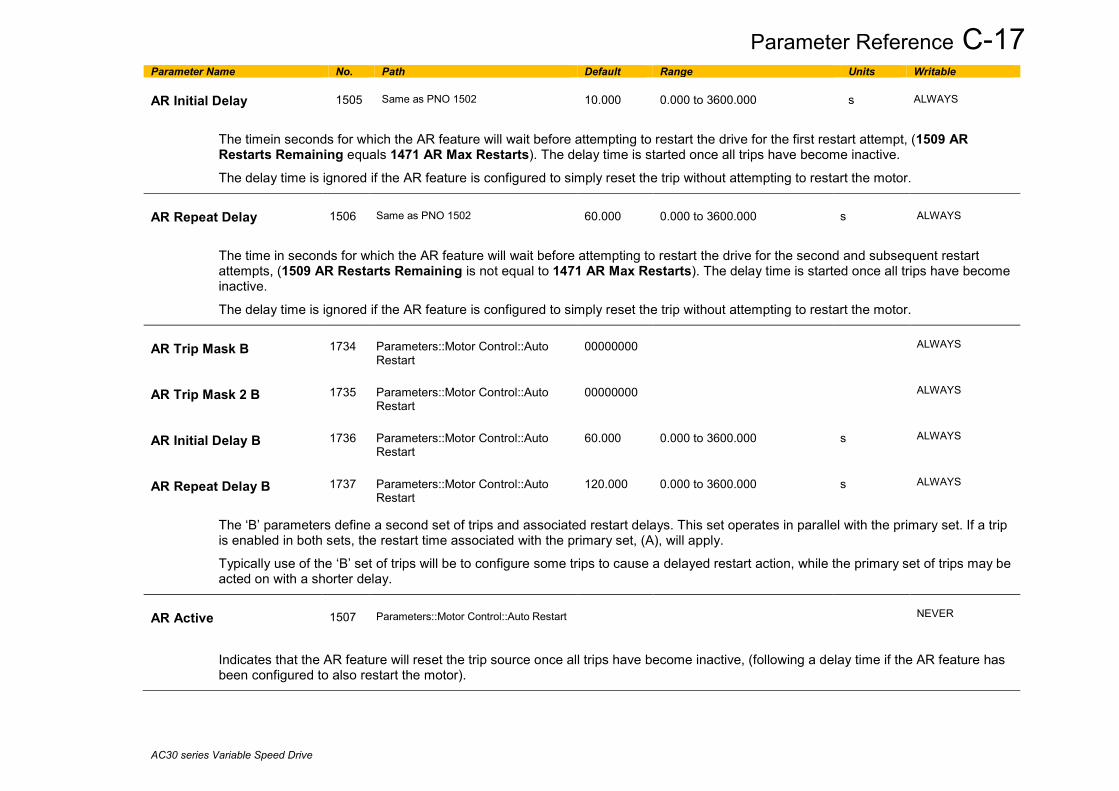
Parameter Reference C-17
AC30 series Variable Speed Drive
Parameter Name No. Path Default Range Units Writable AR Initial Delay
1505
Same as PNO 1502
10.000
0.000 to 3600.000
s
ALWAYS
The timein seconds for which the AR feature will wait before attempting to restart the drive for the first restart attempt, (1509 AR Restarts Remaining equals 1471 AR Max Restarts). The delay time is started once all trips have become inactive.
The delay time is ignored if the AR feature is configured to simply reset the trip without attempting to restart the motor.
AR Repeat Delay
1506
Same as PNO 1502
60.000
0.000 to 3600.000
s
ALWAYS
The time in seconds for which the AR feature will wait before attempting to restart the drive for the second and subsequent restart attempts, (1509 AR Restarts Remaining is not equal to 1471 AR Max Restarts). The delay time is started once all trips have become inactive.
The delay time is ignored if the AR feature is configured to simply reset the trip without attempting to restart the motor.
AR Trip Mask B
1734
Parameters::Motor Control::Auto Restart
00000000
ALWAYS
AR Trip Mask 2 B
1735
Parameters::Motor Control::Auto Restart
00000000
ALWAYS
AR Initial Delay B
1736
Parameters::Motor Control::Auto Restart
60.000
0.000 to 3600.000
s
ALWAYS
AR Repeat Delay B
1737
Parameters::Motor Control::Auto Restart
120.000
0.000 to 3600.000
s
ALWAYS
The ‘B’ parameters define a second set of trips and associated restart delays. This set operates in parallel with the primary set. If a trip is enabled in both sets, the restart time associated with the primary set, (A), will apply.
Typically use of the ‘B’ set of trips will be to configure some trips to cause a delayed restart action, while the primary set of trips may be acted on with a shorter delay.
AR Active
1507
Parameters::Motor Control::Auto Restart
NEVER
Indicates that the AR feature will reset the trip source once all trips have become inactive, (following a delay time if the AR feature has been configured to also restart the motor).

C-18 Parameter Reference
AC30 series Variable Speed Drive
Parameter Name No. Path Default Range Units Writable AR Restart Pending
1508
Parameters::Motor Control::Auto Restart
NEVER
Indicates that the AR feature will reset the trip source and attempt to restart the motor once all trips have become inactive and the relevant delay timer has expired.
AR Restarts Remaining
1509
Parameters::Motor Control::Auto Restart
0 to 20
NEVER
Indicates the number of restart attempts remaining before the AR feature disables itself.
This count is reset to 1471 AR Max Restarts after a successful manual or remote trip reset. This includes any restart or trip reset performed due the the configuration taking some programmed action. The count is also reset after a period of trip free operation. This period is the longer of 5 minutes, or 5 * AR Repeat Delay B.
AR Time Remaining
1510
Parameters::Motor Control::Auto Restart
0.000 to 3600.000
s
NEVER
Indicates the time remaining before a restart attempt will be made. This value starts to count down once all trip sources are inactive.
Functional Description The AR feature can be configured to operate in one of three modes via the parameter 1470 AR Mode. In all modes the AR feature becomes active when the drive trips on one of the trips selected by one of the Trip Mask parameters. If the drive trips due to a trip not selected in one of these parameters the AR feature will remain in the idle state. Setting parameter 1469 AR Enable to FALSE will disable the AR feature regardless of its current state.
1470 AR Mode 0: Trip Reset
In Trip Reset mode, once the AR feature becomes active it monitors all possible trip sources. Once all trip sources are inactive the AR feature will attempt to reset the trip event, moving the Sequencing State from the FAULTED state, (see Appendix B: Sequencing Logic). The AR feature resets the trip as soon as possible, it does not wait for either 1505 Initial Delay or 1506 AR Repeat Delay. In this mode the AR feature will not attempt to restart the motor. This mode may be used when an external supervisiory system is monitoring the Faulted bit in 0661 Status Word. This bit will be cleared once all trip sources are inactive and the trip has been successfully cleared, indicating that the drive may be started.

Parameter Reference C-19
AC30 series Variable Speed Drive
1470 AR Mode 1: Auto Restart
Caution: when Auto Restart is selected the motor may run unexpectedly. In Auto Restart mode, once the AR feature becomes active it monitors all possible trip sources. Once all trip sources are inactive the AR feature starts the programmed delay. Once the delay timer expires the AR feature attempts to reset the trip and to restart the motor. The AR feature will not restart the motor if it was not running at the time of the trip, nor will it restart the motor if the run signal has been removed at any time since the trip, (even if it is subsequently re-applied). When a motor restart will not be attempted the AR feature will act as if it had been configured for Trip Reset only. If a motor restart will be attempted the parameter 1508 AR Restart Pending is set TRUE. Each time a restart is attempted the value in 1509 Restarts Remaining is decremented. Once this value reaches zero, any further trip selected for auto restart will cause the AR feature to disable itself.
1470 AR Mode 2: Auto Start
Caution: when Auto Start is selected the motor may run unexpectedly. In Auto Start mode, once the AR feature becomes active it monitors all possible trip sources. Once all trip sources are inactive the AR feature starts the programmed delay. Once the delay timer expires the AR feature attempts to reset the trip and to restart the motor. The AR feature will attempt to start the motor even if it was not running at the time of the trip, as long as the Sequencing Logic parameter 0644 Control Word is configured to run, (typically bits 0, 1, 2 and 3 all set), see Appendix B: Sequencing Logic. In this mode the parameter 1508 AR Restart Pending is set TRUE. Each time a restart is attempted the value in 1509 Restarts Remaining is decremented. Once this value reaches zero, any further trip selected for auto restart will cause the AR feature to disable itself.
Recovery from Self Disabled state
The AR feature will remain in the Self Disabled state indefinitely. It may be re-activated by the trip condition being reset by some other means, (ie. Manually by pressing the stop key on the GKP, or remotely using trip reset). Alternatively the AR feature may be re-enabled by setting 1469 AR Enable to FALSE then back to TRUE.
Indication
When the AR feature is activated the parameter 1507 AR Active is set TRUE. While a restart is pending the parameter 1508 AR Restart Pending is set TRUE. In addition the green LED illuminating the run key on the GKP will flash. All indicators are reset once the restart, (or trip reset), attempt has been completed or if the AR feature is disabled.

C-20 Parameter Reference
AC30 series Variable Speed Drive
Autotune Setup:: Motor Control::Autotune Parameters::Motor Control::Autotune The autotune is an automatic test sequence performed by the Drive to identify motor model parameters. The motor model is used by the Vector control modes.
If an induction motor is used, and the control mode is set to vector control, you MUST perform an autotune before operating the Drive. It the control mode is set to Open Loop (V/Hz) mode an autotune is not necessary. Whether the drive is in Vector Control mode or in Open Loop mode is determined by the parameter 0512 Control Strategy in menu Control Mode (see page D-40). Induction motor nameplate parameters must be entered before running the autotune procedures in order for them to correctly measure motor model parameters.
The motor must be allowed to spin freely. It is acceptable for the motor to be connected to a load during autotune, provided that the load is purely inertia, with negligible friction, and does not require the motor to produce torque in order to turn.
If stationary autotune is selected in the AC30V variant, a parameter Nameplate Mag Current will appear. The user must enter the motor magnetising current into this parameter before proceeding with the stationary autotune. Stationary autotune in AC30V should be avoided if possible: first, because the magnetising current may not be accurate; second, because operation above base speed requires the rotating autotune to map the motor characteristics in the field weakening region, and if this is not done, operation may not be possible above base speed.
If stationary autotune is selected in the AC30P/D variant, a test procedure will be invoked that will attempt to calculate all the necessary motor model parameters from injected tests signals, without rotation. The success rate of this procedure during development has been around 80% (i.e. there were 20% of motors whose parameters were not successfully extracted by this method, and they couldn’t be controlled in vector mode unless rotating autotuned was performed…), so its use has to be considered with caution. If there are practical difficulties performing rotating autotune with fully free motor shaft (e.g. gearbox, pump, compressor, lift, etc., already mounted) then stationary autotuned is to be attempted. However, if the obtained set of values does not result in a full, smooth speed or torque control, or if it isn’t even sufficient to rotate the motor at all, a rotating autotune has to be performed. It is recommended that the stationary autotune is not used for the motors above 30kW. Also, if operation above base speed in the field weakening region is required, a rotating autotune needs to be performed.
If a permanent magnet motor is used and there is no datasheet available from your motor provider, You MUST perform an autotune before operating the Drive in the Vector control mode . Before running the autotune, some PMAC Motor parameters should be set. Some are available on the motor nameplate :
- 0555 PMAC Max Speed :motor rated speed - 0557 PMAC Rated Current : motor rated current - 0558 PMAC Rated Torque : motor rated torque - 1387 PMAC Base Volts : motor voltage - 0556 PMAC Max Current : motor max current ( if not known, set it to the same value as 0557 PMAC Rated Current) - 0559 PMAC Motor Poles : motor number of poles ( should be an even number ) - 0564 PMAC Motor Inertia : motor inertia : try to set good estimated value, the speed loop will use it for setting correct control parameters
If a permanent magnet motor is used and there is datasheet available from your motor provider, You must either perform an autotune before operating the Drive in the Vector control mode or enter the required motor parameters from the datasheet.
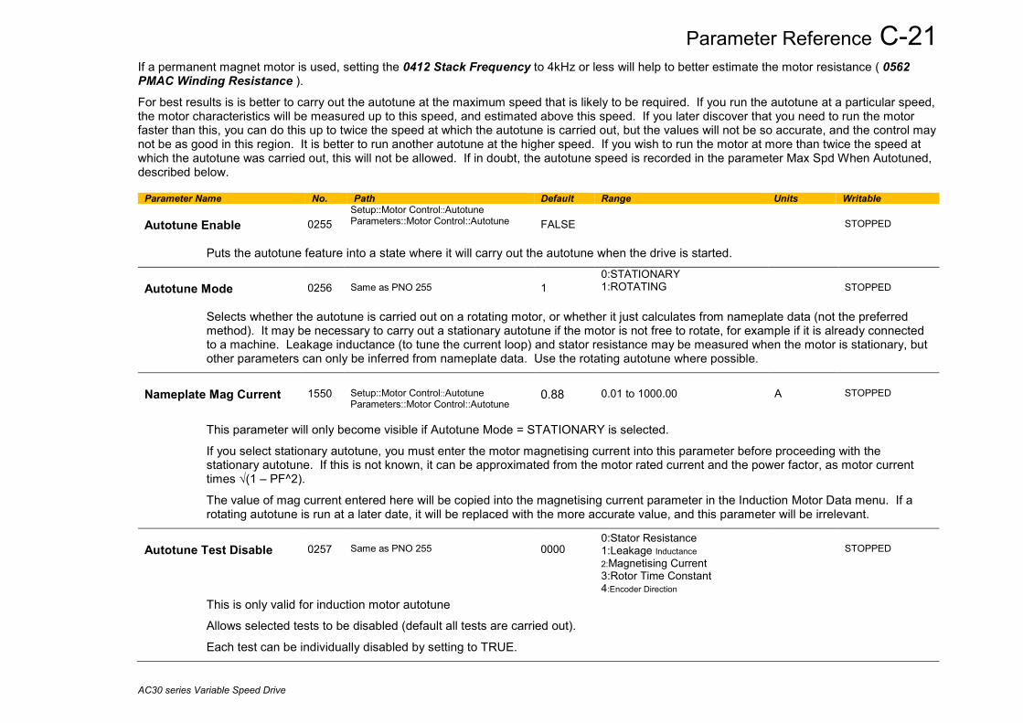
Parameter Reference C-21
AC30 series Variable Speed Drive
If a permanent magnet motor is used, setting the 0412 Stack Frequency to 4kHz or less will help to better estimate the motor resistance ( 0562 PMAC Winding Resistance ).
For best results is is better to carry out the autotune at the maximum speed that is likely to be required. If you run the autotune at a particular speed, the motor characteristics will be measured up to this speed, and estimated above this speed. If you later discover that you need to run the motor faster than this, you can do this up to twice the speed at which the autotune is carried out, but the values will not be so accurate, and the control may not be as good in this region. It is better to run another autotune at the higher speed. If you wish to run the motor at more than twice the speed at which the autotune was carried out, this will not be allowed. If in doubt, the autotune speed is recorded in the parameter Max Spd When Autotuned, described below.
Parameter Name No. Path Default Range Units Writable Autotune Enable
0255
Setup::Motor Control::Autotune Parameters::Motor Control::Autotune
FALSE
STOPPED
Puts the autotune feature into a state where it will carry out the autotune when the drive is started.
Autotune Mode
0256
Same as PNO 255
1
0:STATIONARY 1:ROTATING
STOPPED
Selects whether the autotune is carried out on a rotating motor, or whether it just calculates from nameplate data (not the preferred method). It may be necessary to carry out a stationary autotune if the motor is not free to rotate, for example if it is already connected to a machine. Leakage inductance (to tune the current loop) and stator resistance may be measured when the motor is stationary, but other parameters can only be inferred from nameplate data. Use the rotating autotune where possible.
Nameplate Mag Current
1550
Setup::Motor Control::Autotune Parameters::Motor Control::Autotune
0.88
0.01 to 1000.00
A
STOPPED
This parameter will only become visible if Autotune Mode = STATIONARY is selected.
If you select stationary autotune, you must enter the motor magnetising current into this parameter before proceeding with the stationary autotune. If this is not known, it can be approximated from the motor rated current and the power factor, as motor current times √(1 – PF^2).
The value of mag current entered here will be copied into the magnetising current parameter in the Induction Motor Data menu. If a rotating autotune is run at a later date, it will be replaced with the more accurate value, and this parameter will be irrelevant.
Autotune Test Disable
0257
Same as PNO 255
0000
0:Stator Resistance 1:Leakage Inductance 2:Magnetising Current 3:Rotor Time Constant 4:Encoder Direction
STOPPED
This is only valid for induction motor autotune
Allows selected tests to be disabled (default all tests are carried out).
Each test can be individually disabled by setting to TRUE.
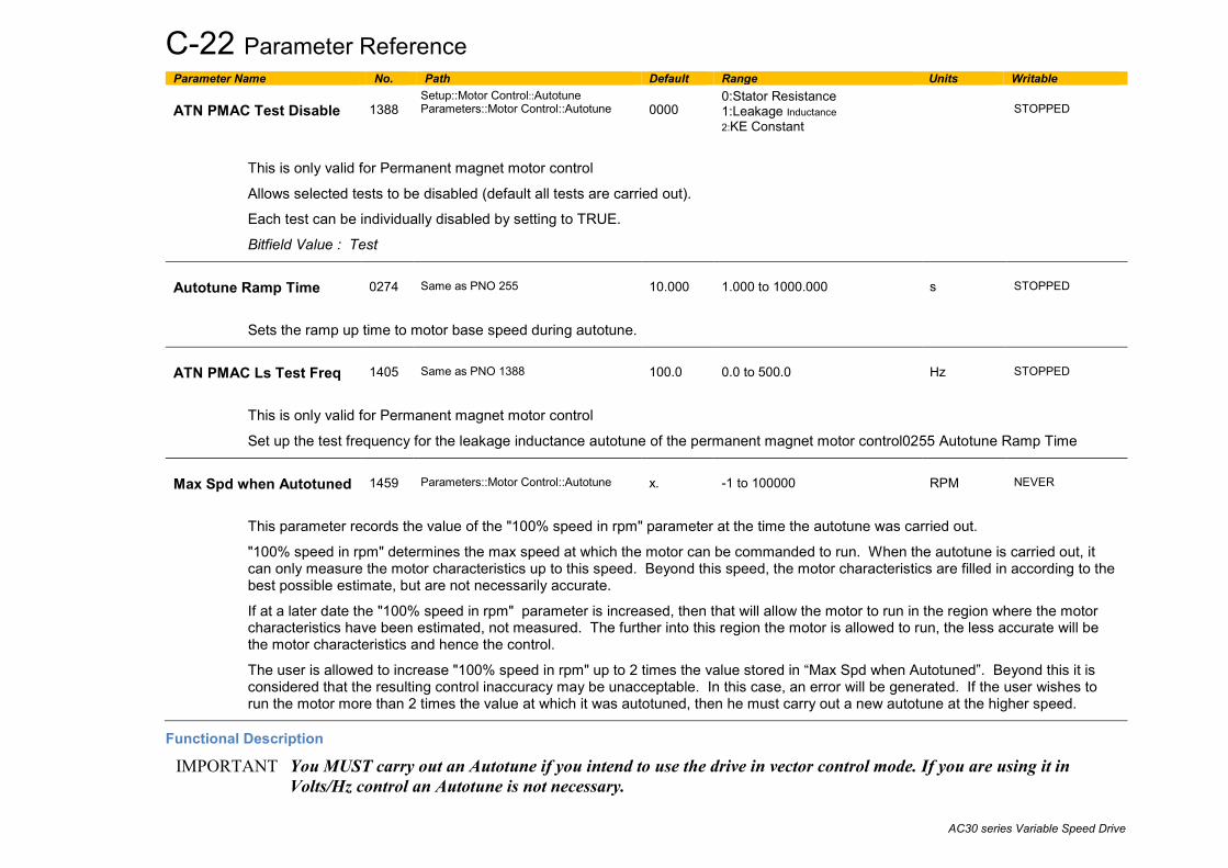
C-22 Parameter Reference
AC30 series Variable Speed Drive
Parameter Name No. Path Default Range Units Writable ATN PMAC Test Disable
1388
Setup::Motor Control::Autotune Parameters::Motor Control::Autotune
0000
0:Stator Resistance 1:Leakage Inductance 2:KE Constant
STOPPED
This is only valid for Permanent magnet motor control
Allows selected tests to be disabled (default all tests are carried out).
Each test can be individually disabled by setting to TRUE.
Bitfield Value : Test
Autotune Ramp Time
0274
Same as PNO 255
10.000
1.000 to 1000.000
s
STOPPED
Sets the ramp up time to motor base speed during autotune.
ATN PMAC Ls Test Freq
1405
Same as PNO 1388
100.0
0.0 to 500.0
Hz
STOPPED
This is only valid for Permanent magnet motor control
Set up the test frequency for the leakage inductance autotune of the permanent magnet motor control0255 Autotune Ramp Time
Max Spd when Autotuned
1459
Parameters::Motor Control::Autotune
x.
-1 to 100000
RPM
NEVER
This parameter records the value of the "100% speed in rpm" parameter at the time the autotune was carried out.
"100% speed in rpm" determines the max speed at which the motor can be commanded to run. When the autotune is carried out, it can only measure the motor characteristics up to this speed. Beyond this speed, the motor characteristics are filled in according to the best possible estimate, but are not necessarily accurate.
If at a later date the "100% speed in rpm" parameter is increased, then that will allow the motor to run in the region where the motor characteristics have been estimated, not measured. The further into this region the motor is allowed to run, the less accurate will be the motor characteristics and hence the control.
The user is allowed to increase "100% speed in rpm" up to 2 times the value stored in “Max Spd when Autotuned”. Beyond this it is considered that the resulting control inaccuracy may be unacceptable. In this case, an error will be generated. If the user wishes to run the motor more than 2 times the value at which it was autotuned, then he must carry out a new autotune at the higher speed.
Functional Description
IMPORTANT You MUST carry out an Autotune if you intend to use the drive in vector control mode. If you are using it in Volts/Hz control an Autotune is not necessary.

Parameter Reference C-23
AC30 series Variable Speed Drive
Autotune can only be initiated from the “stopped” condition. When the test is complete, the stack is disabled and Autotune Enable is set to FALSE.
Note Refer to the Chapter 6: Setup Wizard for details on how to perform an Autotune.
Standard Autotune If an induction motor is fitted, the autotune will identify parameters as follows. Parameter Description Note MAG CURRENT Magnetising current Not measured by Stationary Autotune STATOR RES Per phase stator resistance LEAKAGE INDUC Per phase stator leakage inductance MUTUAL INDUC Per phase mutual inductance ROTOR TIME CONST Rotor time constant This will be identified while the motor is spinning, while measuring the
magnestising current. If stationary autotune is selected, it will be identified from magnetising current and motor nameplate rpm
♦ The Rotating autotune sequence rotates the motor up to the user-programmed MAX SPEED (Scale Setpoint function) in order to
identify these parameters. (A rotating autotune is required if the motor is to be operated above base speed).
♦ The Stationary autotune sequence does not rotate the motor and requires the correct value of MAG CURRENT to be entered. (Stationey Autotune should only be considered if roatating autotune is not possible to execute).
If a permanent magnet motor is fitted, the autotune will identify parameters as follows. Parameter Description Note STATOR RES Phase to phase stator resistance LEAKAGE INDUC Phase to phase stator leakage inductance KE CONSTANT Back-emf constant This will be identified while the motor is spinning. If stationary autotune
is selected, it will be identified from motor nameplate parameters
♦ The Stationary autotune sequence does not rotate the motor and requires the correct permanant magnet nameplate value to be entered.
♦ The Rotating autotune sequence rotates the motor up to the half of the rated motor speed in order to identify these parameters.

C-24 Parameter Reference
AC30 series Variable Speed Drive
BACnet IP Option Monitor::Communications::Option Setup::Communications::Option Parameters::Option Comms::Comms Parameters::Option Comms::Write Process Parameters::Option Comms::Option Ethernet Parameters::Option Comms::BACnet IP
Refer to BACnet IP Technical Manual HA501939U001
Parameter Reference C-25
AC30 series Variable Speed Drive
BACnet MSTP Option Monitor::Communications::Option Setup::Communications::Option Parameters::Option Comms::Comms Parameters::Option Comms::Write Process Parameters::Option Comms::BACnet MSTP
Refer to BACnet MSTP Technical Manual HA501940U001

C-26 Parameter Reference
AC30 series Variable Speed Drive
Black Box Parameters::Trips::Black Box Recorder The Black Box Recorder feature captures the state of the drive in the moments leading up to a trip, and at the moment of the trip. This data is saved in the drive’s internal memory. The captured data may be transferred to an SD card for investigation.
Parameter Name No. Path Default Range Units Writable Black Box PNOs[0]
1831
Parameters::Trips::Black Box Recorder
0829
0000 to 3145
ALWAYS
Black Box PNOs[1]
1832
Parameters::Trips::Black Box Recorder
0514
0000 to 3145
ALWAYS
Black Box PNOs[2]
1833
Parameters::Trips::Black Box Recorder
1022
0000 to 3145
ALWAYS
Black Box PNOs[3]
1834
Parameters::Trips::Black Box Recorder
0393
0000 to 3145
ALWAYS
Select up to four parameters that are recorded leading up to a trip along with the fixed set of data.
Copy to SD Card
1829
Parameters::Trips::Black Box Recorder
FALSE
ALWAYS
When a usable SD Card is inserted in the drive, changing this parameter from FALSE to TRUE will start the process of copying the black box records from internal memory to the SD card. Each record is created as a separate file on the SD card.
Once started, the copy process will continue until all the records have been transferred, this can take up to a minute. To ensure that the ERROR status is correctly displayed, it is recommended that this value is left at TRUE until the copy has completed.
This parameter is not saved. It is initialised to FALSE when the drive powers on.
Copy Status
1852
Parameters::Trips::Black Box Recorder
0:IDLE 1:ACTIVE 2:DISABLED
NEVER
Indicates the status of the copy process. Once the copy is complete the status will return to IDLE. The ERROR status is cleared on changing the parameter “Clone to SD Card” back to FALSE.
Functional Description
Refer to chapter 7 “Trips and Fault Finding” for further information.

Parameter Reference C-27
AC30 series Variable Speed Drive
Braking Parameters::Motor Control::Braking The braking function controls the rate at which energy from a regenerating motor is dumped into a resistive load. This dumping prevents the dc link voltage reaching levels which would cause an Overvoltage trip.
Parameter Name No. Path Default Range Units Writable Braking Enable
0249
Parameters::Motor Control::Braking
TRUE
ALWAYS
Enables operation of the dynamic braking feature.
Brake Resistance
0251
Parameters::Motor Control::Braking
100.00
0.01 to 1000.00
Ohm
STOPPED
The value of the dynamic braking load resistance.
Brake Rated Power
0252
Parameters::Motor Control::Braking
0.11
0.10 to 510.00
kW
STOPPED
The power that the load resistance may continually dissipate.
Brake Overrating
0253
Parameters::Motor Control::Braking
25.00
1.00 to 40.00
STOPPED
Multiplier that may be applied to Brake Power for power overloads lasting no more than 1 second.
Braking Active
0254
Parameters::Motor Control::Braking
NEVER
A read-only parameter indicating the state of the brake switch.
Functional Description
When enabled, the Braking feature monitors the internal dc link voltage every millisecond and sets the state of the brake switch accordingly. When using braking, the brake resistor information must be entered it ordered for the resistor protection to operate. The Braking feature operates even when the motor output is not enabled. This allows the function to continually monitor the energy dumped into the braking resistor, and the energy dissipated across the brake switch. With this information the Drive is able to deduce the loading on the brake resistor.

C-28 Parameter Reference
AC30 series Variable Speed Drive
If the instantaneous braking power is greater than the Brake Rated Power parameter then this overload is accumulated. If the overload area (power excess x time) reaches the level set in the Brake Overrating parameter then the brake switch is automatically disabled. This can then lead to an overvoltage trip protecting the inverter. The voltage level at which braking occurs is nominally 764V, but rises linearly to 773V as the overload area rises to the Brake Overrating limit. This improves the brake energy sharing in a multi-brake common d.c. bus system, which can be effected by variation in the exact braking voltage level in each inverter.
The Braking feature also provides a control signal that is used by the Slew Rate limit feature. This causes the setpoint to be temporarily frozen whenever the brake is operating because the dc link voltage exceeds the internal comparison level. This allows the stop rate to be automatically tuned to the characteristics of the load, motor, Drive and brake resistor.
Brake Overrating x Brake Rated Power
Brake Rated Power
0 1s Time
Overload Area 773V 764V
Nominal Braking Voltage Level
(Brake Overating-1) x Brake Rated Power
0 Overload Area (kWs)
Power

Parameter Reference C-29
AC30 series Variable Speed Drive
CANopen Option Monitor::Communications::Option Setup::Communications::Option Parameters::Option Comms::Comms Parameters::Option Comms::Read Process Parameters::Option Comms::Write Process Parameters::Option Comms::Event Parameters::Option Comms::CANopen
Refer to CANopen Technical Manual HA501841U001

C-30 Parameter Reference
AC30 series Variable Speed Drive
Clone Setup::Clone Parameters::Device Manager::Clone The clone feature allows the drive configuration (application and parameters) to be saved to an SD card and subsequently loaded to the same or a different drive. All parameters fall into one of the following cloning categories listed in the parameter table at the end of this appendix:
• Never: This type of parameter would never be copied to a new drive. This category includes parameters that are not saved and parameters that contain information such as runtime statistics.
• Drive Unique: This type of parameter is normally unique to the drive, such as the drive name. • Power: This type of parameter is related to the power stack of the drive or to the motor connected to the drive. • Other: Any saved parameter that is not in the other cloning categories. This category is the majority of the parameters
including the application parameters. The visibility of the following cloning parameters on the GKP may depend on the selection of other cloning parameters and whether an SD card is fitted.
Parameter Name No. Path Default Range Units Writable Clone Filename
1534
Setup::Clone Parameters::Device Manager::Clone
clone
ALWAYS
The filename used for saving or loading the clone file. The file extension for clone files is “.cln” and will be added to the filename if it is not provided by the user.
A single file contains the information for the parameters and the application.
Clone Direction
1537
Same as PNO 1534
0
0:SAVE TO FILE 1:LOAD FROM FILE
ALWAYS
Sets whether a clone save or a clone load should be performed.

Parameter Reference C-31
AC30 series Variable Speed Drive
Parameter Name No. Path Default Range Units Writable Full Restore
1538
Same as PNO 1534
0
0:YES 1:PARTIAL
ALWAYS
If the parameter 1537 Clone Direction is set to LOAD FROM FILE, then the parameter Full Restore determines if a full restore or a partial restore is required from the file specified.
If YES is chosen then all the saved parameters and the saved application will be loaded including ‘drive unique’ parameters.
If PARTIAL is chosen then the user has the choice of what to restore, however ‘drive unique’ parameters will keep their current values. The following clone parameters apply:
1539 Application
1541 Power Parameters 1540 Other parameters Notes:
If the power stack of the drive is different to the power stack from which the clone file was saved and the user chooses YES then the clone load will not be permitted. However the clone load will be permitted if the control module on which the user is restoring is not attached to a power stack, or if PARTIAL is chosen instead.
The power parameters cannot be restored from a clone file that was saved on a control module with the parameter 0989 Power Stack Required set to NONE.
Application
1539
Same as PNO 1534
0
0:LOAD FROM FILE 1:LEAVE CURRENT APP
ALWAYS
If the parameter 1538 Full Restore is set to PARTIAL, then the parameter Application allows the user to either load the application from the file or to leave the currently installed application.
Power Parameters
1541
Same as PNO 1534
0
Same as PNO 1540
ALWAYS
If the parameter 1538 Full Restore is set to PARTIAL, then the parameter Power Parameters allows the user to load the ‘power’ parameters from the file, leave the current values or set the values to the defaults.
Notes:
If the power stack of the drive is different to the power stack from which the clone file was saved and the user chooses LOAD FROM FILE then the clone load will not be permitted. However the clone load will be permitted if the control module on which the user is restoring is not attached to a power stack, or if LEAVE CURRENT VALUES or SET TO DEFAULT VALUES is chosen instead.
The power parameters cannot be restored from a clone file that was saved on a control module with the parameter 0989 Power Stack

C-32 Parameter Reference
AC30 series Variable Speed Drive
Parameter Name No. Path Default Range Units Writable Required set to NONE.
Enumerated Value : Power Parameters
0 : LOAD FROM FILE
1: LEAVE CURRENT VALUES
2 : SET TO DEFAULT VALUES
Other Parameters
1540
Same as PNO 1534
0
0:LOAD FROM FILE 1:LEAVE CURRENT VALUES 2:SET TO DEFAULT VALUES
ALWAYS
If the parameter 1538 Full Restore is set to PARTIAL, then the parameter Other Parameters allows the user to load the ‘other’ parameters from the file, leave the current values or set the values to the defaults.
Enumerated Value : Power Parameters
Clone Start
1542
Same as PNO 1534
FALSE
ALWAYS
When TRUE this parameter starts the cloning process, either saving or loading depending on the parameter 1537 Clone Direction.
The cloning process will only start if the parameter 1543 Clone Status is IDLE.
Once the cloning has completed the parameter 1543 Clone Status will be DONE. Set the Clone Start parameter back to FALSE to return to the IDLE state.
Clone Status
1543
Same as PNO 1534
0:IDLE 1:SAVING 2:RESTORING 3:VERIFYING 4:DONE 5:CANNOT START 6:FAILED 7:NO SD CARD 8:VERIFY FAILED 9:FILE NOT OPENED 10:FILE INCOMPATIBLE 11:FILE FAILURE 12:POWER MISMATCH 13:APPLICATION FAILURE 14:PARAMETERS FAILURE 15:PNET SECTION MISSING 16: CARD FAULT
NEVER

Parameter Reference C-33
AC30 series Variable Speed Drive
Parameter Name No. Path Default Range Units Writable
This parameter indicates the status of the cloning process.
Enumerated Value :
0. IDLE Waiting for the user to start the cloning process. 1. SAVING In the process of saving the drive configuration to file. 2. RESTORING I the process of loading the configuration from file. 3. VERIFYING In the process of verifying the clone file either before a load or after a save. 4. DONE Ihe cloning process has completed successfully either for a load or a save. 5. CANNOT START The cloning process cannot start. When restoring a configuration the drive must be stopped. 6. FAILED General failure of the cloning process. 7. NO SD CARD No SD card is fitted. 8. VERIFY FAILED Could not restore the parameters. E.g. the parameters are missing from the clone file. 9. FILE NOT OPENED Could not open the file, possibly because the file is already open or the file name is incorrect. 10. FILE INCOMPATIBLE Source file was saved by a different major version of firmware, ie: AC30P version 2.x trying to read
a file saved using version 1.x AC30V. 11. FILE FAILURE Unable to save to the cone file on the SD Card. 12. POWER MISMATCH Stack saved in the clone file is unknown to this drive. 13. APPLICATION FAILURE On a save, the application was not found. On a load the application was not recognized or could
not be run. 14. PARAMETERS FAILURE Parameter data in the clone file is not in the expacted format. 15. PNET SECTION MISSING Only relevant for Profinet build. The data containing the station name was not found. 16. CARD FAULT Problem with the SD card. Try a different type of SD card.
Notes:
1) The clone file only contains the parameters that were stored in non-volatile memory on the drive when a clone save was performed. When performing a clone load and a full restore is performed or a LOAD FROM FILE is used for the parameters, then any parameter not previously saved in the file will be set to its defaults.
2) Each application parameter is restored only if the parameter definition on the target drive matches the saved parameter. 3) The clone saving process will take between 3 – 15 seconds depending on the type of SD card used. 4) When saving a file with the same filename as an existing file on the SD card, the existing file will be overwritten. To prevent
this, use a PC to set the read-only attribute of the file. 5) During the clone loading process the GKP screen may blank momentarily.

C-34 Parameter Reference
AC30 series Variable Speed Drive
Communications Options Monitor::Communications::Option Setup::Communications::Option Parameters::Option Comms::Comms Parameters::Option Comms::Event Parameters::Option Comms::Read Process Parameters::Option Comms::Write Process Parameters::Option Comms::Option Ethernet *
Refer to any of the following Technical Manuals:
Product Code Description Part Number
7003-PB-00 Profibus DP-V1 HA501837U001
7003-PN-00 PROFINET IO * HA501838U001
7003-DN-00 DeviceNet HA501840U001
7003-CN-00 ControlNet HA501936U001
7003-CB-00 CANopen HA501841U001
7003-IP-00 EtherNet IP * HA501842U001
7003-EC-00 EtherCAT HA501938U001
7003-BI-00 BACnet IP * HA501939U001
7003-BN-00 BACnet MSTP HA501940U001
7003-RS-00 Modbus RTU HA501839U001
7003-IM-00 Modbus TCP * HA501937U001

Parameter Reference C-35
AC30 series Variable Speed Drive
Configure, (Phase Control) Parameters::Phase Control::Configure Used to select Master and slave encoder source. Gives a diagnostics of the configuration related to the encoder selection for the motor control, the Master ( Reference ) and the Slave.
Parameter Name No. Path Default Range Units Writable Master Position Src
1745
Parameters::Phase Control::Configure
3
0:MAIN SPD FEEDBACK 1:SYSTEM BOARD SLOT 1 2:SYSTEM BOARD SLOT 2 3:NONE
STOPPED
Specifies the encoder to be used as the Master, (Reference) input :
MAIN SPEED FEEDBACK: corresponds to the I/O feedback option SYSTEM BOARD SLOT 1: corresponds to the Slot 1 of the system board option SYSTEM BOARD SLOT 2: corresponds to the Slot 2 of the system board option NONE : no Master selected
Slave Position Src
1744
Parameters::Phase Control::Configure
0
0:SAME AS MOTOR FBK 1:MAIN SPD FEEDBACK 2:SYSTEM BOARD SLOT 1 3:SYSTEM BOARD SLOT 2 4:OTHER
STOPPED
Specifies the encoder to be used as the Slave input. Normally this will be the same as the speed feedback.
SAME AS MOTOT FBK : the Slave encoder is the encoder used as the motor feedback. MAIN SPEED FEEDBACK : corresponds to the I/O feedback option SYSTEM BOARD SLOT 1 : corresponds to the Slot 1 of the system board option SYSTEM BOARD SLOT 2 : corresponds to the Slot 2 of the system board option
By default, the value SAME AS MOTOT FBK is selected.
If the Slave and the Motor Feedback are the same encoder, use SAME AS MOTOT FBK, otherwise, an error 301 or 302 or 303 will occur : Motor speed feedback and position feedback ( slave ) cannot be the same.
Setup Successful
1749
Parameters::Phase Control::Configure
NEVER
The configuration of the master, slave and Speed loop encoders is correct

C-36 Parameter Reference
AC30 series Variable Speed Drive
Parameter Name No. Path Default Range Units Writable Error Number
1750
Parameters::Phase Control::Configure
-32768 to 32767
NEVER
Indicates the nature of the fault giving an error 0. No error. SetUpSuccessful is TRUE 1. Feedback vector mode selected, but speed feedback source set to NONE 2. Encoder feedback requested via the I/O option encoder board, but no hardware is fitted. 3. Encoder feedback requested via System Board Encoder Slot1, but no system board is fitted. 4. Encoder feedback requested via System Board Encoder Slot2, but no system board is fitted. 5. Reference encoder requested via the I/O option encoder board, but no hardware is fitted. 6. Reference encoder requested via System Board Encoder Slot1, but no hardware is fitted. 7. Reference encoder requested via System Board Encoder Slot2, but no system board is fitted. 8. Position loop feedback requested via the I/O option encoder board, but no hardware is fitted. 9. Position loop feedback requested via System Board Encoder Slot1, but no system board is fitted. 10. Position loop feedback requested via System Board Encoder Slot2, but no system board is fitted. 101. Conflict between selected motor speed feedback and position reference (cannot be the same!) : I/O option encoder board 102. Conflict between selected motor speed feedback and position reference (cannot be the same!) : System Board Encoder Slot1 103. Conflict between selected motor speed feedback and position reference (cannot be the same!) : System Board Encoder Slot2 201. Conflict between selected position reference and position feedback (cannot be the same!) : I/O option encoder board 202. Conflict between selected position reference and position feedback (cannot be the same!) : System Board Encoder Slot1 203. Conflict between selected position reference and position feedback (cannot be the same!) : System Board Encoder Slot2 301. Conflict between selected motor speed feedback and position feedback (cannot be the same!). : I/O option encoder board 302. Conflict between selected motor speed feedback and position feedback (cannot be the same!) : System Board Encoder Slot1 303. Conflict between selected motor speed feedback and position feedback (cannot be the same!) : System Board Encoder Slot2
Master Encoder
1751
Parameters::Phase Control::Configure
0:EMPTY FUNC 1:ESTIMATOR 2:PRIMARY 3:SYSTEM BOARD SLOT 1 4:SYSTEM BOARD SLOT 2 5:OTHER
NEVER
Diagnostic giving the encoder set up as the master encoder • SB SLOT1 • SB SLOT2 • PRIMARY ( I/O option encoder board )
Slave Encoder
1752
Parameters::Phase Control::Configure
Same as PNO 1751
NEVER
Diagnostic giving the encoder set up as the slave encoder • SB SLOT1 • SB SLOT2 • PRIMARY (I/O option encoder board)

Parameter Reference C-37
AC30 series Variable Speed Drive
Parameter Name No. Path Default Range Units Writable Spd Loop Encoder
1753
Parameters::Phase Control::Configure
Same as PNO 1751
NEVER
Diagnostic giving the encoder set up for the speed loop control • SB SLOT1 • SB SLOT2 • PRIMARY (I/O option encoder board)

C-38 Parameter Reference
AC30 series Variable Speed Drive
Control Mode Setup:: Motor Control::Control & Type:: Control Strategy Parameters::Motor Control::Control & Type::Control Strategy The control mode block provides the means for selecting the type of motor and the desired method of controlling the motor.
Parameter Name No. Path Default Range Units Writable Motor Type or AFE
0511
Setup::Motor Control::Control and Type Setup::Regen Control Parameters::Control Mode::Control Mode
0
0:INDUCTION MOTOR 1:PMAC MOTOR 2:AFE
STOPPED
Motor type selection parameter
Allows the user to select the type of motor.
Control Strategy
0512
Setup::Motor Control::Control and Type Parameters::Control Mode::Control Mode
0
0:VOLTS - HERTZ CONTROL 1:VECTOR CONTROL
STOPPED
This parameter will only become visible if an induction motor is selected. If a PMAC motor is selected, the Control Strategy will automatically be set to Vector Control.
Select control strategy selection parameter.
Allows the user to select the method of controlling the motor.
Control Type
1533
Setup::Motor Control::Control and Type Parameters::Control Mode::Control Mode
0
0:SENSORLESS 1:ENCODER FEEDBACK
STOPPED
This parameter will only become visible if Control Strategy is set to Vector Control. If the encoder option is not fitted, selecting ENCODER FEEDBACK will give a trip.
This parameter allows selects between sensorless control, and control using encoder feedback.
If an encoder feedback is available, it would normally be the preferred choice as it gives better speed control and higher performance.
Encoder Feedback
1743
Setup::Motor Control::Control and Type Parameters::Control Mode::Control Mode
0
0:MAIN SPD FEEDBACK 1:SYSTEM BOARD SLOT 1 2:SYSTEM BOARD SLOT 2 3:NONE
STOPPED
This parameter will only become visible if Control Strategy is set to Vector Control and Control Type is set to Encoder Feedback, and the drive is

Parameter Reference C-39
AC30 series Variable Speed Drive
Parameter Name No. Path Default Range Units Writable an AC30P/D The parameter selects between encoder inputs : MAIN SPD FEEDBACK : encoder option fitted or resolver option fitted. It corresponds to the option fitted in the I/O options. If selected, the I/O option has to be set up in the corresponding option ( Resolver or Encoder ) SYSTEM BOARD SLOT 1 : encoder connected on SLOT1 if AC30D
encoder connected on AC30A SYSTEM BOARD SLOT 2 : encoder connected on SLOT 2 if AC30D NONE : no encoder connected – corresponds to SENSORLESS control selected If an encoder is available, encoder feedback control would normally be the preferred choice as it gives better speed control and higher performance. Startup Alignment
1885
Setup::Motor Control::Control and Type Parameters::Control Mode::Control Mode
0
0:DISABLED 1:ONCE 2:ALWAYS
ALWAYS
Only available for PMAC motor if Encoder Feedback control type selected. 0:DISABLED : Start up aligment feature disabled. No action. 1: ONCE : Start up alignment run once from a cold start state. At the end of the sequence, the drive is in Full Closed loop Vector control. A position Offset has been calculated and set up in 1808 PMAC Encoder Offset parameter. Only a trip condition will reset the system to run again the sequence. Changing this value will also reset the system and will cause the drive to run again the sequence on the next start. 2: ALWAYS : At each motor start ( Torque OFF to Torque ON condition ), the drive goes through the Pseudo PMAC sequence and a new position offset is calculated, which will remain valid until next Torque OFF condition. Actual Control Type
1886
Monitor::Motor and Drive Parameters::Control Mode::Control Mode
Same as PNO 1533
NEVER
Only visible for PMAC motor if Encoder Feedback control type selected.Default: Equals to Control Type While the sequence is running, gives the drive actual control type. Start Align Done
1887
Same as PNO 1886
NEVER

C-40 Parameter Reference
AC30 series Variable Speed Drive
Parameter Name No. Path Default Range Units Writable
Only available for PMAC motor if Encoder Feedback control type selected. Only appears if Startup Alignment set to ONCE. Set to TRUE when the method has been run successfully. Reset to FALSE after a cold start and/or a trip condition.
Functional Description The motor selection is the first step in setting the control mode. The selection of control strategy comes next, with the permitted settings as follows:
- Induction motors can be run in either volts hertz mode or vector mode - Permanent magnet motors can only be run in vector control mode
If vector control is selected, and an encoder option or a resolver option is fitted, it is then necessary to choose whether to select vector control with encoder feedback for improved performance.
Pseudo PMAC control
To make the PMAC control compatible with incremental encoder type ( pulse encoder, sin-cos, etc) which does not give absolute position information, a Virtual Zero Position needs to be determined, creating a position offset which changes the incremental encoder position to an absolute encoder position. After either a drive OFF or a trip condition situation, this offset is no longer valid and should be extracted again.
The method to align the encoder to the motor back EMF uses the AC30V Sensorless Vector Control motor scheme to start the motor ( the meaning of ‘to align’ is determine the Virtual Zero Position ). The absolute motor position is estimated by the sensorless control when the motor is turning. At least, reaching a motor speed of 5% is needed to have a good estimation of the absolute position. ( 5% is the default and recommended threshold value to move from a VHz motor control to a sensorless closed loop control mode in the actual AC30V sensorless Vector Control mode )
Once the motor is rotating at a higher speed than the threshold value, a position offset is calculated. This position offset is then used in real Closed Loop Vector Control. The incremental position from the encoder is now processed as an absolute position.
The method should be enabled if the drive is in speed control mode. ( In torque control mode, the method won’t give correct and accurate position offset ).
The method is run until the final state :

Parameter Reference C-41
AC30 series Variable Speed Drive
- if the speed setpoint is set to a higher value than 5% ( the speed threshold appearing in the PMAC SVC block ). A time out of 5s allows to trip if the estimated speed stays below 5%.
If the speed setpoint is set to a lower value than 5%, then the drive stays in open loop (VHZ ) as long as the setpoint is kept below 5%.
- If the speed from the estimator is the same sign as the speed from the encoder feedback. If not, the drive trips.
- If the speed value from the estimator and the speed from the actual encoder feedback follow the same gradient. Considering a speed error betwen speed estimator an speed feedback of less than 0.5 Hz ( Electrical speed ) as a target provides a good criterion.
If not, a time out of 1s allows to trip the drive.
Because of timing constraint, especially when the pwm frequency is set to a high value ( 8kHz for high speed motors ), the method will force the pwm to run at 4kHz, no random pattern.

C-42 Parameter Reference
AC30 series Variable Speed Drive
ControlNet Option Monitor::Communications::Option Setup::Communications::Option Parameters::Option Comms::Comms Parameters::Option Comms::Read Process Parameters::Option Comms::Write Process Parameters::Option Comms::Event Parameters::Option Comms::ControlNet
Refer to ControlNet Technical Manual HA501936U001

Parameter Reference C-43
AC30 series Variable Speed Drive
Current Limit Parameters::Motor Control::Current Limit Designed for all Motor Control Modes This function allows you to set the maximum level of motor rated current (as a % of the user-set Motor Current) which is allowed to flow before current limit action occurs. If the measured motor current exceeds the current limit value with a motoring load, the motor speed is reduced to control the excess load. If the measured motor current exceeds the current limit value with a regenerating load, the motor speed is increased up to a maximum of 100% Speed in RPM (Scale Setpoint). The maximum value of current limit for a particular motor is limited by the AC30V current rating. If a motor of larger rating than the AC30V is connected, then the current limit max value is limited by the AC30V current rating. If a motor of lower rating than the AC30V is connected, then the current limit max value is limited to 300% (if compatible with the AC30V current rating) for an induction motor (IM) and to the ratio PMAC Max Current to PMAC Rated Current for a PMAC motor. % are always expressed as % of the user set Motor Current (rated current of PMAC or IM Motor).
Parameter Name No. Path Default Range Units Writable Current Limit
0305
Setup::Motor Control::Control and Type Parameters::Motor Control::Current Limit
150.0
0.0 to 600.0
%
ALWAYS
This parameter sets the level of motor current, as a % of Motor Current (refer to the relevant MOTOR definition , PMAC or IM function) at which the Drive begins to take current limit action.
Regen Limit Enable
0307
Parameters::Motor Control::Current Limit
TRUE
ALWAYS
This parameter enables or disables regenerative current limit action. Note that this parameter only works in open-loop VOLTS / Hz motor control mode.
Functional Description
Internal limit : output of the Stack Inv Time module + reduction as a function of electrical low speed ( < 3Hz ) and as function of heatsink temperature
minimum
Current limit
Internal limit
Current Limit Output
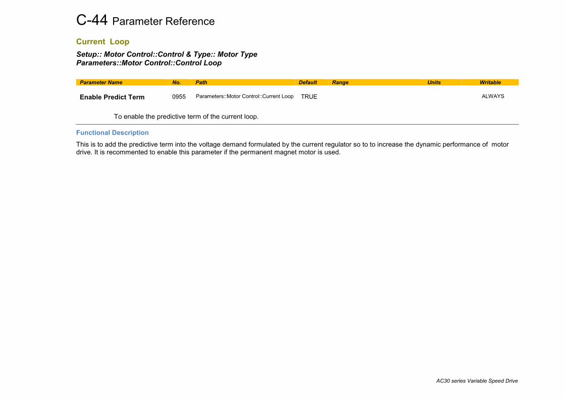
C-44 Parameter Reference
AC30 series Variable Speed Drive
Current Loop Setup:: Motor Control::Control & Type:: Motor Type Parameters::Motor Control::Control Loop
Parameter Name No. Path Default Range Units Writable Enable Predict Term
0955
Parameters::Motor Control::Current Loop
TRUE
ALWAYS
To enable the predictive term of the current loop.
Functional Description This is to add the predictive term into the voltage demand formulated by the current regulator so to to increase the dynamic performance of motor drive. It is recommented to enable this parameter if the permanent magnet motor is used.
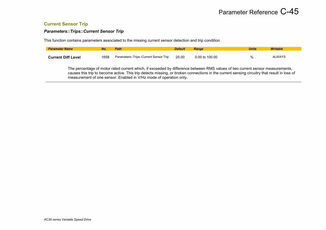
Parameter Reference C-45
AC30 series Variable Speed Drive
Current Sensor Trip Parameters::Trips::Current Sensor Trip This function contains parameters associated to the missing current sensor detection and trip condition
Parameter Name No. Path Default Range Units Writable Current Diff Level
1658
Parameters::Trips::Current Sensor Trip
25.00
0.00 to 100.00
%
ALWAYS
The percentage of motor rated current which, if exceeded by difference between RMS values of two current sensor measurements, causes this trip to become active. This trip detects missing, or broken connections in the current sensing circuitry that result in loss of measurement of one sensor. Enabled in V/Hz mode of operation only.

C-46 Parameter Reference
AC30 series Variable Speed Drive
Data Logger Parameters::Device Manager::Data Logger Regularly log the value of the selected parameters to the SD Card
Parameter Name No. Path Default Range Units Writable Log Enable
1835
Parameters::Device Manager::Data Logger
FALSE
ALWAYS
Set to TRUE to enable the data logger
Log Period
1836
Parameters::Device Manager::Data Logger
1.000
0.500 to 86400.000
s
ALWAYS
Defines the period between each set of data. The maximum value is equivalent to 24 hours.
Log File Name
1837
Parameters::Device Manager::Data Logger
logfile_
ALWAYS
Defines the first characters of the log file name. The Data Logger automatically appends this name with a 4 digit sequence number and the extension “.csv”.
Log to New File
1838
Parameters::Device Manager::Data Logger
FALSE
ALWAYS
On a change from FALSE to TRUE the Data Logger creates a new log file and starts saving data to this. The log file sequence number is automatically incremented each time a new file is created.
If TRUE when Log Enable is set to TRUE then a new log file will be created.
This parameter is not saved.
Log New File On Reset
1839
Parameters::Device Manager::Data Logger
FALSE
ALWAYS
If TRUE the Data Logger will create a new log file each time the drive is powered up.
Log Now
1868 Parameters::Device Manager::Data Logger
FALSE
ALWAYS
When data logging is enabled, a change from FALSE to TRUE forces a log record to be captured and written.

Parameter Reference C-47
AC30 series Variable Speed Drive
Parameter Name No. Path Default Range Units Writable Limit Log File Size
1840
Parameters::Device Manager::Data Logger
FALSE
ALWAYS
When TRUE the data logger limits the maximum log file size to 10 M Bytes. When this size is reached the Data Logger creates a new log file and starts saving data to this. The log file sequence number is automatically incremented each time a new file is created.
Log Parameters[0] to Log Parameters[7]
1843 to 1850
Parameters::Device Manager::Data Logger
0000
0000 to 3145
ALWAYS
Defines up to 8 parameters to log. The list of parameters may be extended in the application by adding the Data_Logger_Int and / or the Data_Logger_Real blocks, see below.
Log File Size
1841
Parameters::Device Manager::Data Logger
NEVER
The size of the currently active log file. This may be used in the application together with “1836 Log to new File” to force the Data Logger to create a new log file when the current file reaches an arbitrary size. This value is zero when 1835 Log Enable is FALSE.
Functional Description The Log file is designed to be easy to read in either a text editor or a spreadsheet application, such as Microsoft Excel. The file format has the extension “csv” which stands for Comma Separated Variables. Once each period, the drive records the nominated parameter values and writes these to a line in the log file. The data values are separated by columns, and the line is terminated with a carriage return line feed.

C-48 Parameter Reference
AC30 series Variable Speed Drive
Below is an example configuration for the Data Logger.
The first few rows of the log file corresponding to this setting would be: Serial Number,123456789012345 Date and Time,Notes,392 DC Link Voltage,393 Actual Speed RPM,406 CM Temperature,407 Heatsink Temperature,,,,, 2016/02/20 10:19:20.279,Continuation,643.6444,0.0000,31.0000,60.0364,,,,, 2016/02/20 10:19:21.274,,643.6700,0.0000,31.0000,60.0397,,,,, 2016/02/20 10:19:22.274,,643.7726,0.0000,31.0000,60.0397,,,,, 2016/02/20 10:19:23.274,,643.6445,0.0000,31.0000,60.0429,,,,, 2016/02/20 10:19:24.279,,643.6444,0.0000,31.0000,60.0405,,,,, When viewed in Excel the data is organized into columns:
Row 1 The control module serial number Row 2 column headings Row 3... Time stamp, Notes and the data points.

Parameter Reference C-49
AC30 series Variable Speed Drive
Time stamp The Time stamp format depends whether the parameter 1186 Time and Date is valid and updating. This will typically be the case if an option with a Real Time Clock is fitted. It is also possible to keep this parameter valid over Ethernet. If the time and date is valid the time stamp will be in the format illustrated above. To display this format correctly in Excel it may be necessary to force the format of this column to be Custom, using this format string: “dd/mm/yyyy hh:mm:ss.000”. If the time and date value is not valid, the time stamp will be the age of the control card, expressed as a value in seconds with three decimal places, (giving resolution to one milli-second). Notes The notes column indicates a log event. The notes are:
Note Description Power On Power has been applied to the control module. Log Start Log Enable changed from FALSE to TRUE. Continuation A new log file has been created due to:
• changing 1838: Log to New File from FALSE to TRUE • file size exceeding 10 MB and 1840: Limit Log File Size is TRUE.
Changed setup A change to one or more of the selected parameters to log. This also causes a new log file to be created. New file name A change to the file name, causing a new log file to be created. Data values The output data values are organized into columns with a header in row 2 indicating the parameter number and name. The values are output in a formate determined by the parameter data type. String data types are not supported. Enumerated data types are output as integers, with 0 corresponding to the first enumeration in the list.

C-50 Parameter Reference
AC30 series Variable Speed Drive
Extending the list of parameters If it is necessary to log more than 8 parameters then the number of parameters to be logged may be increased to 40 in total, (an additional 32), by adding the Data_Logger_Int and / or the Data_Logger_Real blocks. The variables to be logged are to be gathered into an array of Long Integers, or an array of Reals and attached to the logger blocks, as illustrated here:
Here, the RealArray and IntArray variables are initialized with values, but in practice the values will be updated from application variables and fixed parameter values as part of the application program.

Parameter Reference C-51
AC30 series Variable Speed Drive
DC Link Volts Limit Parameters::Motor Control::DC Link Volts Limit This function prevents over-voltage faults occurring due to a rapidly changing setpoint.
Parameter Name No. Path Default Range Units Writable VDC Lim Enable
1641
Parameters::Motor Control::DC Link Volts Limit
FALSE
STOPPED
nable DC Link Volts Limit during a fast deceleration to prevent overvoltage trip
VDC Lim Level
1642
Parameters::Motor Control::DC Link Volts Limit
91.0
78.0 to 100.0
%
STOPPED
Determines the dc link volts at which the DC Link Volts Limit sequence is started.
Entered as a percentage of the max DC link voltage (drive overvoltage level = 100%).
VDC Lim Active
1643
Parameters::Motor Control::DC Link Volts Limit
NEVER
Set True when the deceleration ramp is paused in order to limit the DC link voltage
VDC Lim Output
1644
Parameters::Motor Control::DC Link Volts Limit
x.x
Min to Max
Hz
NEVER
This diagnostic represents the speed setpoint output of the DC Link Volts limit Feature in Electrical Hz

C-52 Parameter Reference
AC30 series Variable Speed Drive
Functional Description During a fast deceleration, the kinetic energy of the motor load is regenerated to the drive, charging the DC link capacitors. When the VDC Lim Level is reached, the speed septoint is held, waiting for the DC link to go below VDC Lim Level. When the DC link falls below this level, the speed setpoint is released and is ramped down using system ramp deceleration. This sequence is run until the speed septoint reaches the user speed demand. By Default, VDC Lim Level is set to the same value as the braking threshold. This feature is run at a rate of 1 milli-second.
Ramp Power Loss Ride Thru
DC Link Volts Limit
Slew Rate (V/Hz only)
Speed Setpoint path
User Speed control loop

Parameter Reference C-53
AC30 series Variable Speed Drive
Device Commands Parameters::Device Manager::Device Commands
Parameter Name No. Path Default Range Units Writable Update Firmware
1002
Parameters::Device Manager::Device Commands
FALSE
STOPPED
This parameter is only visible when an SD card with a firmware update file is inserted into the drive. Changing this parameter to TRUE will start the firmware update procedure.
Following a firmware update it is advisable to power re-run the Setup Wizard, D-61
Save All Parameters
1001
Parameters::Device Manager::Device Commands
FALSE
ALWAYS
When a parameter is modified via the GKP or via the built-in web page the parameter value is saved automatically. When a parameter is modified via another source, (for example via the Modbus TCP/IP communications protocol), the value will not be saved automatically. In this case a save may be instigated by changing this parameter from FALSE to TRUE.

C-54 Parameter Reference
AC30 series Variable Speed Drive
Device State Parameters::Device Manager::Device State
Parameter Name No. Path Default Range Units Writable Target State
0988
Parameters::Device Manager::Device State
3:PREOPERATIONAL 7:OPERATIONAL
STOPPED
The requested operating state. This may be set from the Web Page or GKP. The PDQ configuration tool changes the operating state of the drive using a different mechanism.
Actual State
0989
Parameters::Device Manager::Device State
0:INITIALISING 1:INITIALISED 2:PREPARING PREOP 3:PREOPERATIONAL 4:PREPARING OP 5:FAILED TO READY 6:READY FOR OP 7:OPERATIONAL 8:FAULTED 9:FATAL ERROR RECOVER
NEVER
Reports the actual operating state of the drive.
Application FE State
0990
Parameters::Device Manager::Device State
Same as PNO 989
NEVER
Base IO FE State
0991
Parameters::Device Manager::Device State
Same as PNO 989
NEVER
Basic Drive FE State
0992
Parameters::Device Manager::Device State
Same as PNO 989
NEVER
Ethernet FE State
0993
Parameters::Device Manager::Device State
Same as PNO 989
NEVER
Keypad FE State
0994
Parameters::Device Manager::Device State
Same as PNO 989
NEVER
Comms Option FE State
0995
Parameters::Device Manager::Device State
Same as PNO 989
NEVER
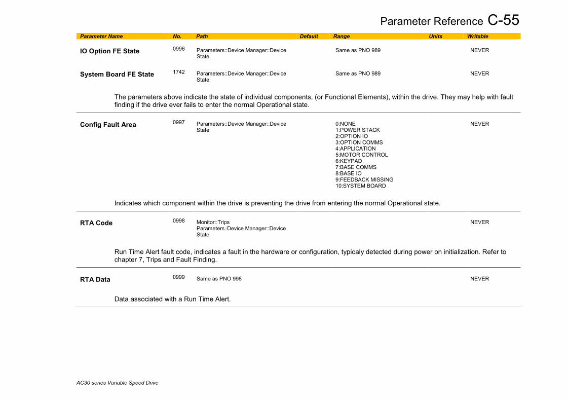
Parameter Reference C-55
AC30 series Variable Speed Drive
Parameter Name No. Path Default Range Units Writable IO Option FE State
0996
Parameters::Device Manager::Device State
Same as PNO 989
NEVER
System Board FE State
1742
Parameters::Device Manager::Device State
Same as PNO 989
NEVER
The parameters above indicate the state of individual components, (or Functional Elements), within the drive. They may help with fault finding if the drive ever fails to enter the normal Operational state.
Config Fault Area
0997
Parameters::Device Manager::Device State
0:NONE 1:POWER STACK 2:OPTION IO 3:OPTION COMMS 4:APPLICATION 5:MOTOR CONTROL 6:KEYPAD 7:BASE COMMS 8:BASE IO 9:FEEDBACK MISSING 10:SYSTEM BOARD
NEVER
Indicates which component within the drive is preventing the drive from entering the normal Operational state.
RTA Code
0998
Monitor::Trips Parameters::Device Manager::Device State
NEVER
Run Time Alert fault code, indicates a fault in the hardware or configuration, typicaly detected during power on initialization. Refer to chapter 7, Trips and Fault Finding.
RTA Data
0999
Same as PNO 998
NEVER
Data associated with a Run Time Alert.
C-56 Parameter Reference
AC30 series Variable Speed Drive
DeviceNet Option Monitor::Communications::Option Setup::Communications::Option Parameters::Option Comms::Comms Parameters::Option Comms::Read Process Parameters::Option Comms::Write Process Parameters::Option Comms::Event Parameters::Option Comms::ControlNet
Refer to DeviceNet Technical Manual HA501840U001
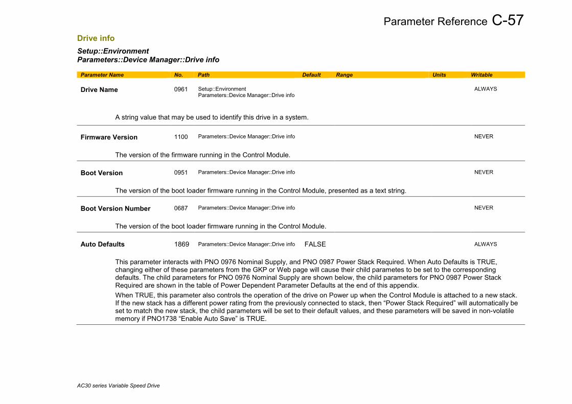
Parameter Reference C-57
AC30 series Variable Speed Drive
Drive info Setup::Environment Parameters::Device Manager::Drive info
Parameter Name No. Path Default Range Units Writable Drive Name
0961
Setup::Environment Parameters::Device Manager::Drive info
ALWAYS
A string value that may be used to identify this drive in a system.
Firmware Version
1100
Parameters::Device Manager::Drive info
NEVER
The version of the firmware running in the Control Module. Boot Version
0951
Parameters::Device Manager::Drive info
NEVER
The version of the boot loader firmware running in the Control Module, presented as a text string. Boot Version Number
0687
Parameters::Device Manager::Drive info
NEVER
The version of the boot loader firmware running in the Control Module. Auto Defaults
1869 Parameters::Device Manager::Drive info
FALSE
ALWAYS
This parameter interacts with PNO 0976 Nominal Supply, and PNO 0987 Power Stack Required. When Auto Defaults is TRUE, changing either of these parameters from the GKP or Web page will cause their child parametes to be set to the corresponding defaults. The child parameters for PNO 0976 Nominal Supply are shown below, the child parameters for PNO 0987 Power Stack Required are shown in the table of Power Dependent Parameter Defaults at the end of this appendix. When TRUE, this parameter also controls the operation of the drive on Power up when the Control Module is attached to a new stack. If the new stack has a different power rating from the previously connected to stack, then “Power Stack Required” will automatically be set to match the new stack, the child parameters will be set to their default values, and these parameters will be saved in non-volatile memory if PNO1738 “Enable Auto Save” is TRUE.

C-58 Parameter Reference
AC30 series Variable Speed Drive
Parameter Name No. Path Default Range Units Writable Nominal Supply
0976 Parameters::Device Manager::Drive info
0
0:50 Hz 1:60 Hz
STOPPED
Defines the default supply frequency. In the GKP Setup Wizard, this parameter controls the default values for this child parameters:
PNO Parameter 50Hz 60Hz
0464 100% Speed in RPM 1500 1800
0456 Base Voltage 400 460
0457 Base Frequency 50 60
0459 Nameplate Speed 1450 1750
When this parameter is changed from the GKP or Web page when PNO1869 “Auto Defaults” is TRUE then the child parameters are set to their corresponding default values, (and saved if PNO1738 “Enable Auto Save” is TRUE).
Power Stack Required
0987
Parameters::Device Manager::Drive info
0
Same as PNO 543
CONFIG
The rating of the power electronics for the configuration loaded in the drive. This controls the default value for the child parameters listed in the Power Dependent Parameter Defaults table at the end of this appendix. If 0987 Power Stack Required is different from 0543 Power Stack Fitted the drive will be prevented from running until the configuration is corrected. If Power Stack Required is set to NONE, then it is automatically reset to match Power Stack Fitted on the next power on. This does not automatically modify any of the child parameters. To do this, set PNO 1869 Auto Defaults to TRUE.
Power Stack Fitted
0543
Parameters::Device Manager::Drive info
0:NONE 1:3.5 A 400 V 2:4.5 A 400 V 3:5.5 A 400 V 4:7.5 A 400 V 5:10.0 A 400 V 6:12.0 A 400 V 7:16.0 A 400 V 8:23.0 A 400 V 9:32.0 A 400 V 10:38.0 A 400 V 11:45.0 A 400 V R1(1) 12:60.0 A 400 V R1(1) 13:73.0 A 400 V R1(1) 14:87.0 A 400 V 15:105 A 400 V
NEVER
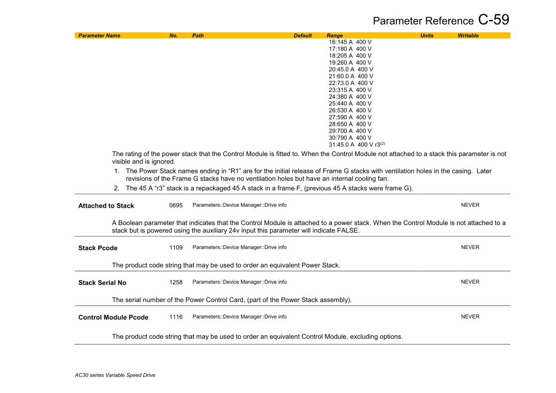
Parameter Reference C-59
AC30 series Variable Speed Drive
Parameter Name No. Path Default Range Units Writable 16:145 A 400 V 17:180 A 400 V 18:205 A 400 V 19:260 A 400 V 20:45.0 A 400 V 21:60.0 A 400 V 22:73.0 A 400 V 23:315 A 400 V 24:380 A 400 V 25:440 A 400 V 26:530 A 400 V 27:590 A 400 V 28:650 A 400 V 29:700 A 400 V 30:790 A 400 V 31:45.0 A 400 V r3(2)
The rating of the power stack that the Control Module is fitted to. When the Control Module not attached to a stack this parameter is not visible and is ignored. 1. The Power Stack names ending in “R1” are for the initial release of Frame G stacks with ventilation holes in the casing. Later
revisions of the Frame G stacks have no ventilation holes but have an internal cooling fan. 2. The 45 A “r3” stack is a repackaged 45 A stack in a frame F, (previous 45 A stacks were frame G).
Attached to Stack
0695
Parameters::Device Manager::Drive info
NEVER
A Boolean parameter that indicates that the Control Module is attached to a power stack. When the Control Module is not attached to a stack but is powered using the auxiliary 24v input this parameter will indicate FALSE.
Stack Pcode
1109
Parameters::Device Manager::Drive info
NEVER
The product code string that may be used to order an equivalent Power Stack. Stack Serial No
1258
Parameters::Device Manager::Drive info
NEVER
The serial number of the Power Control Card, (part of the Power Stack assembly). Control Module Pcode
1116
Parameters::Device Manager::Drive info
NEVER
The product code string that may be used to order an equivalent Control Module, excluding options.

C-60 Parameter Reference
AC30 series Variable Speed Drive
Parameter Name No. Path Default Range Units Writable Control Module Serial
0977
Parameters::Device Manager::Drive info
NEVER
The serial number of the Control Module.
Comms Option Pcode
1121
Parameters::Device Manager::Drive info
NEVER
The product code string that may be used to order an equivalent Communications Option, (only visible when a Communications Option is selected).
Comms Option Serial
1129
Parameters::Device Manager::Drive info
NEVER
The serial number of the fitted Communications Option, (only visible when a Communications Option is selected).
IO Option Pcode
1125
Parameters::Device Manager::Drive info
NEVER
The product code string that may be used to order an equivalent IO Option, (only visible when an IO Option is selected).
IO Option Serial No
1134
Parameters::Device Manager::Drive info
NEVER
The serial number of the fitted IO Option, (only visible when an IO Option is selected).
IO Option SW Version
1254
Parameters::Device Manager::Drive info
NEVER
For intellilgent IO options this parameter shows the version of the firmware running in the option.
Drive Diagnostic
0688
Parameters::Device Manager::Drive info
0:OK 1:STACK NOT CONNECTED 2:STACK DATA CORRUPT 3:UNKNOWN STACK 4:STACK MISMATCH
NEVER
Indicates the health of the drive configuration. When the drive configuration includes a mutually conflicting requirement, this parameter indicates the problem; for example, it attempting to run in Closed Loop Vector control mode when no feedback option is configured.

Parameter Reference C-61
AC30 series Variable Speed Drive
Parameter Name No. Path Default Range Units Writable Product Code Flags
1551
Parameters::Device Manager::Drive info
NEVER
Manufacturing flags byte read from the power electronics stack.
Bit 0 When set, indicates that the dynamic brake switch power electronics is fitted. On larger frame sizes the brake switch is a factory fit option. On frames C,D,E,F and G this bit is ignored.
Bit 1 – 7 Reserved
Manufacturing Flags
1636
Parameters::Device Manager::Drive info
NEVER
Manufacturing flags word read from the control module.
Bit 0 When set, indicates that the drive is a special build.
Bits 1 – 15 Reserved
OEM ID
1256
Parameters::Device Manager::Drive info
NEVER
A 16-bit integer set in the factory, that identifies the equipment manufacturer. This may be used to lock or tailor an application to a given manufacturer. To obtain a unique ID apply to Parker Hannifin Electomechanical Drives Business Unit.
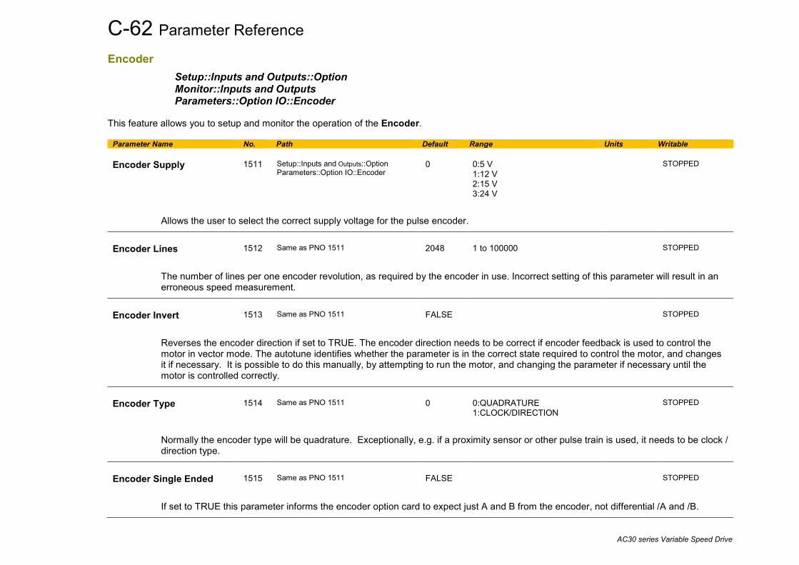
C-62 Parameter Reference
AC30 series Variable Speed Drive
Encoder Setup::Inputs and Outputs::Option Monitor::Inputs and Outputs Parameters::Option IO::Encoder
This feature allows you to setup and monitor the operation of the Encoder.
Parameter Name No. Path Default Range Units Writable Encoder Supply
1511
Setup::Inputs and Outputs::Option Parameters::Option IO::Encoder
0
0:5 V 1:12 V 2:15 V 3:24 V
STOPPED
Allows the user to select the correct supply voltage for the pulse encoder.
Encoder Lines
1512
Same as PNO 1511
2048
1 to 100000
STOPPED
The number of lines per one encoder revolution, as required by the encoder in use. Incorrect setting of this parameter will result in an erroneous speed measurement.
Encoder Invert
1513
Same as PNO 1511
FALSE
STOPPED
Reverses the encoder direction if set to TRUE. The encoder direction needs to be correct if encoder feedback is used to control the motor in vector mode. The autotune identifies whether the parameter is in the correct state required to control the motor, and changes it if necessary. It is possible to do this manually, by attempting to run the motor, and changing the parameter if necessary until the motor is controlled correctly.
Encoder Type
1514
Same as PNO 1511
0
0:QUADRATURE 1:CLOCK/DIRECTION
STOPPED
Normally the encoder type will be quadrature. Exceptionally, e.g. if a proximity sensor or other pulse train is used, it needs to be clock / direction type.
Encoder Single Ended
1515
Same as PNO 1511
FALSE
STOPPED
If set to TRUE this parameter informs the encoder option card to expect just A and B from the encoder, not differential /A and /B.

Parameter Reference C-63
AC30 series Variable Speed Drive
Parameter Name No. Path Default Range Units Writable Encoder Speed
1516
Monitor::Inputs and Outputs Parameters::Option IO::Encoder
x.
Min to Max
RPM
NEVER
The speed measured by the encoder, in revolutions per minute.
Encoder Count Reset
1517
Same as PNO 1511
FALSE
ALWAYS
If set to TRUE resets the encoder count. Encoder Count Init
1783
Parameters::Option IO::Encoder
TRUE
ALWAYS
If set to TRUE the encoder count is reset to zero when the drive powers up.
Encoder Count
1518
Same as PNO 1516
Min to Max
NEVER
This parameter shows the encoder count, which is a 32 bit counter that will increment and decrement with the encoder pulses, up to 2^31 or down to -2^31.

C-64 Parameter Reference
AC30 series Variable Speed Drive
Energy Meter Monitor::Energy Meter Parameters::Motor Control::Energy Meter This feature measures the electrical energy used by the motor.
Parameter Name No. Path Default Range Units Writable Power kW
0380
Monitor::Energy Meter Parameters::Motor Control::Energy Meter
x.xx
0.00 to 1000000.00
kW
NEVER
This diagnostic shows the power being delivered to the load in kilowatts.
Power HP
0381
Same as PNO 380
x.xx
0.00 to 1000000.00
HP
NEVER
This diagnostic shows the power being delivered to the load in horsepower.
Reactive Power
0382
Same as PNO 380
x.xx
0.00 to 1000000.00
kVAr
NEVER
This diagnostic shows the reactive power being delivered to the load in kilo volt-amperes reactive.
Energy kWh
0383
Same as PNO 380
x.xx
0.00 to 10000000.00
kWh
NEVER
This diagnostic shows the total energy consumed by the load in kilowatt hours.
Power Factor Est
0385
Same as PNO 380
x.xx
0.00 to 1.00
NEVER
This diagnostic shows the power factor estimate (between 0 and 1).
Power Factor Angle Est
0386
Parameters::Motor Control::Energy Meter
x.xx
0.00 to 90.00
deg
NEVER
This diagnostic shows the power factor angle estimate.
Reset Energy Meter
0389
Parameters::Motor Control::Energy Meter
FALSE
ALWAYS

Parameter Reference C-65
AC30 series Variable Speed Drive
Parameter Name No. Path Default Range Units Writable
When Reset Energy Meter is set to TRUE, the Energy KWh parameter is reset to zero automatically when the maximum value is reached.
When Reset Energy Meter is set to FALSE, the Energy KWh parameter is held at the maximum value when the maximum value has been reached
Changing this from FALSE to TRUE at anytime will cause the Energy KWh parameter to be reset to zero.
C-66 Parameter Reference
AC30 series Variable Speed Drive
EtherCAT Option Monitor::Communications::Option Setup::Communications::Option Parameters::Option Comms::Comms Parameters::Option Comms::Read Process Parameters::Option Comms::Write Process Parameters::Option Comms::Event Parameters::Option Comms::EtherCAT
Refer to EtherCAT Technical Manual HA501938U001

Parameter Reference C-67
AC30 series Variable Speed Drive
Ethernet Monitor::Communications::Base Ethernet Setup::Communications::Base Ethernet Parameters::Base Comms::Ethernet
Refer to Chapter 8 Ethernet
EtherNet IP Adapter Setup::Communications:: Base EtherNet IP Monitor::Communications::Base Ethernet IP Parameters::Base Comms::Ethernet IP Adapter
Refer to Appendix A
EtherNet IP Option Monitor::Communications::Option Setup::Communications::Option Parameters::Option Comms::Comms Parameters::Option Comms::Read Process Parameters::Option Comms::Write Process Parameters::Option Comms::Event Parameters::Option Comms::Option Ethernet Parameters::Option Comms::EtherNet IP
Refer to EtherNet IP Technical Manual HA501842U001
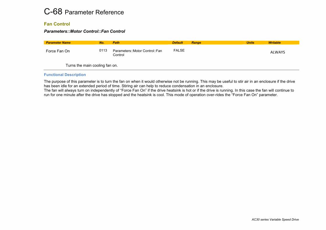
C-68 Parameter Reference
AC30 series Variable Speed Drive
Fan Control Parameters::Motor Control::Fan Control
Parameter Name No. Path Default Range Units Writable Force Fan On
0113
Parameters::Motor Control::Fan Control
FALSE
ALWAYS
Turns the main cooling fan on.
Functional Description The purpose of this parameter is to turn the fan on when it would otherwise not be running. This may be useful to stir air in an enclosure if the drive has been idle for an extended period of time. Stiring air can help to reduce condensation in an enclosure. The fan will always turn on independently of “Force Fan On” if the drive heatsink is hot or if the drive is running. In this case the fan will continue to run for one minute after the drive has stopped and the heatsink is cool. This mode of operation over-rides the “Force Fan On” parameter.

Parameter Reference C-69
AC30 series Variable Speed Drive
Feedbacks Parameters::Motor Control::Feedbacks The Feedbacks feature allows you to view speed feedback and motor current related diagnostics.
Parameter Name No. Path Default Range Units Writable Duty Selection
0390
Setup::Motor Control::Control and Type Parameters::Motor Control::Feedbacks
1
0:HEAVY DUTY 1:NORMAL DUTY
STOPPED
Heavy Duty ( typically 150%, 60s).
Normal Duty allowing higher continuous ratings with less overload capability ( typically 110%, 60s).
% are related to the Drive/stack ratings.
For example, a 12A drive ( @4kHz ) under Normal Duty becomes a 10A drive ( @4kHz) under Heavy Duty
DC Link Voltage
0392
Monitor::Motor and Drive Monitor::Regen Control Parameters::Motor Control::Feedbacks
x.
0 to 1000
V
NEVER
This shows the voltage across the dc link capacitors.
Actual Speed RPM
0393
Monitor::Motor and Drive Parameters::Motor Control::Feedbacks
x.xx
-100000.00 to 100000.00
RPM
NEVER
This parameter changes according to the Control Strategy:
• In Vector Control mode the parameter shows the calculated mechanical speed of the motor shaft in rpm.
• In Volts-Hertz Control mode the parameter shows motor synchronous speed in rpm.

C-70 Parameter Reference
AC30 series Variable Speed Drive
Parameter Name No. Path Default Range Units Writable Actual Speed rps
0394
Same as PNO 393
x.xx
-1500.00 to 1500.00
rev/s
NEVER
This parameter changes according to the Control Strategy:
• In Vector Control mode the parameter shows the calculated mechanical speed of the motor shaft in revolutions per second.
• In Volts-Hertz Control mode, the parameter shows the motor synchronous speed in revolutions per second.
Actual Speed Percent
0395
Same as PNO 393
x.xx
-200.00 to 200.00
%
NEVER
This parameter changes according to the Control Strategy
• In Vector Control mode the parameter shows the calculated mechanical speed of the motor shaft as a percentage of the user maximum speed setting (100% Speed in RPM in the Scale Setpoint function).
• In Volts-Hertz Control mode, the parameter shows the electrical drive output frequency as a percentage of the user maximum speed setting (100% Speed in RPM in the Scale Setpoint function).
Actual Position
1213
Same as PNO 393
x.x
-180.0 to 180.0
deg
NEVER
This parameter is visible when the system ir run in Vector Control Mode with a feedback selected.
This parameter is the feedback position in degrees ( the feedback is selected in the Control Mode menu )
DC Link Volt Filtered
0396
Same as PNO 393
x.
0 to 1000
V
NEVER
This shows the filtered voltage across the dc link capacitors.
DC Link Volts Trim
0119
Parameters::Motor Control::Feedbacks
0
-20 to 20
V
ALWAYS
Specifies a trim to add to the DC Link voltage feedback. This is useful when it is necessary for all the drives in a system to read exactly the same DC Link voltage.
id
0397
Parameters::Motor Control::Feedbacks
x.x
-600.0 to 600.0
%
NEVER
Current in the flux axis (Vector Control)
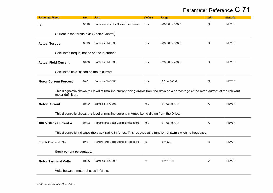
Parameter Reference C-71
AC30 series Variable Speed Drive
Parameter Name No. Path Default Range Units Writable iq
0398
Parameters::Motor Control::Feedbacks
x.x
-600.0 to 600.0
%
NEVER
Current in the torque axis (Vector Control)
Actual Torque
0399
Same as PNO 393
x.x
-600.0 to 600.0
%
NEVER
Calculated torque, based on the Iq current.
Actual Field Current
0400
Same as PNO 393
x.x
-200.0 to 200.0
%
NEVER
Calculated field, based on the Id current.
Motor Current Percent
0401
Same as PNO 393
x.x
0.0 to 600.0
%
NEVER
This diagnostic shows the level of rms line current being drawn from the drive as a percentage of the rated current of the relevant motor definition.
Motor Current
0402
Same as PNO 393
x.x
0.0 to 2000.0
A
NEVER
This diagnostic shows the level of rms line current in Amps being drawn from the Drive.
100% Stack Current A
0403
Parameters::Motor Control::Feedbacks
x.x
0.0 to 2000.0
A
NEVER
This diagnostic indicates the stack rating in Amps. This reduces as a function of pwm switching frequency.
Stack Current (%)
0404
Parameters::Motor Control::Feedbacks
x.
0 to 500
%
NEVER
Stack current percentage.
Motor Terminal Volts
0405
Same as PNO 393
x.
0 to 1000
V
NEVER
Volts between motor phases in Vrms.

C-72 Parameter Reference
AC30 series Variable Speed Drive
Parameter Name No. Path Default Range Units Writable CM Temperature
0406
Same as PNO 393
x.x
-25.0 to 200.0
°C
NEVER
Temperature of Control Module in o Centigrade.
Heatsink Temperature
0407
Same as PNO 393
x.x
-25.0 to 200.0
°C
NEVER
Power stack heatsink temperature in o Centigrade.
Elec Rotor Speed
0408
Parameters::Motor Control::Feedbacks
x.x
-1500.0 to 1500.0
Hz
NEVER
Mechanical speed (shaft speed in rev/s) x number of motor pole pairs. This parameter is not filtered.

Parameter Reference C-73
AC30 series Variable Speed Drive
Fieldbus Mapping Parameters::Base Comms::Fieldbus Mapping
Refer to Appendix A

C-74 Parameter Reference
AC30 series Variable Speed Drive
Filter On Torque Dmd Parameters::Motor Control::Filter On Torque Dmd This feature allows to select the type of filter applied to the Torque setpoint:
- Either the output of the speed loop PI corrector if the speed loop is active - Or the torque Setpoint .
The general structure of the filter is given below :
or 𝑦𝑦𝑛𝑛 =
PI Controller
Torque Limits
Filter On Torque Dmd
Speed Demand
Speed Feedback
Torque Setpoint
Speed or Torque Control
Torque Demand
a0
a1
a2
-b1
-b2
Z-1
Z-1
X(n) Y(n)
22
11
22
110
..1..)( −−
−−
++++
=zbzbzazaazH
211122110 −−−− ⋅−⋅−⋅+⋅+⋅ nnnnn ybybxaxaxa

Parameter Reference C-75
AC30 series Variable Speed Drive
Parameter Name No. Path Default Range Units Writable Filter Type
1544
Parameters::Motor Control::Filter On Torque Dmd
0
0:NONE 1:MAX ATTENUATION 2:MINIMUM PHASE 3:PHASE ADVANCE 4:NOTCH
ALWAYS
NONE : no filter applied – no parameter selection
MAX ATTENUATION : First Order Low Pass Filter (Butterworth form). 3dB attenuation frequency given by Cut Off Frequency.
MINIMUM PHASE : First Order Low Pass Fitler (similar to preceeding, but with less phase shift and less efficient roll off characteristics). 3dB attenuation frequency given by Cut Off Frequency.
PHASE ADVANCE : Gives a phase advance between Frequency 1 and Frequency 2.
NOTCH : Zero transmission notch at a frequency given by Cut Off Frequency. The damping factor is given by Factor.
1
110
.11)(
11)( 1
−
−
++
=⋅+
= −
zbzaazH
ssH
τ
10
.11)(
11)( 1
−+=
⋅+= −
zbazH
ssH
τ
1
110
2
1
.11)(
11)( 1
−
−
++
=⋅+⋅+
= −
zbzaazH
sssH
ττ
22
11
22
110
2
2
2
2
22
22
.1)(
21
1
2.1)( 1
−−
−−
⋅++⋅++
=++
+=
+++
= −
zbzbzazaazH
ss
s
ssssH
ωωξ
ωωξω
ω

C-76 Parameter Reference
AC30 series Variable Speed Drive
Parameter Name No. Path Default Range Units Writable Cut Off Frequency
1545
Parameters::Motor Control::Filter On Torque Dmd
2000
20 to 6000
Hz
ALWAYS
3dB attenuation frequency if Filter Type is MAX ATTENUATION or MINIMUM PHASE
Frequency of Zero transmission if Filter Type is NOTCH
Frequency 1
1546
Parameters::Motor Control::Filter On Torque Dmd
2000
20 to 6000
Hz
ALWAYS
Frequency 1 if Filter Type is PHASE ADVANCE
Frequency 2
1547
Parameters::Motor Control::Filter On Torque Dmd
2000
20 to 6000
Hz
ALWAYS
Frequency 2 if Filter Type is PHASE ADVANCE
Factor
1548
Parameters::Motor Control::Filter On Torque Dmd
0.20
0.10 to 1.00
ALWAYS
Damping factor if Filter Type is NOTCH

Parameter Reference C-77
AC30 series Variable Speed Drive
Flash File System Parameters::Device Manager::Flash File System
Parameter Name No. Path Default Range Units Writable Free Space (kBytes)
1754
Parameters::Device Manager::Flash File System
NEVER
Indicates the remaning space available in the internal file system, (not on AC30V).
Functional Description The internal file system on the AC30P / AC30D is primarily used to store the source code for applications. The total space available in 12MB.

C-78 Parameter Reference
AC30 series Variable Speed Drive
Fluxing VHz Parameters::Motor Control::Fluxing VHz Designed for VOLTS/Hz motor Control Mode. This function allows user parameterisation of the conventional (volts/hertz) fluxing strategy of the Drive. This is achieved through three flexible Volts-to-frequency templates. Starting torque performance can also be tailored through the Fixed Boost, Acceleration Boost and Auto Boost parameters.
Parameter Name No. Path Default Range Units Writable VHz Shape
0422
Setup::Motor Control::Control and Type Parameters::Motor Control::Fluxing VHz
0
0:LINEAR LAW 1:FAN LAW 2:USER DEFINED 3:APPLICATION DEFINED
STOPPED
Type of volts to frequency template to flux the motor. The choices for this parameter are:
Enumerated Value : VHz Shape
0 : LINEAR LAW This gives a constant flux characteristic up to the Base Frequency (see Motor Nameplate function).
1 : FAN LAW This gives a quadratic flux characteristic up to the Base Frequency. This matches the load requirement for fan and most pump applications 2 : USER DEFINED This gives a user defined flux characteristic up to the Base Frequency.
3 : APPLICATION DEFINED This gives a user the ability to set up and apply fluxing law from the application layer.
V/F SHAPE
Fixed Boost
0447
Same as PNO 422
0.0
0.0 to 25.0
%
ALWAYS
LINEAR
FREQUENCY
= BASE FREQUENCY
100%
CONSTANT
POWER RANGE(field weakening)
OUTPUT VOLTS
f B f B
QUADRATIC LAW
CONSTANTTORQUERANGE

Parameter Reference C-79
AC30 series Variable Speed Drive
Parameter Name No. Path Default Range Units Writable
This parameter allows for no-load stator resistance voltage drop compensation. This correctly fluxes the motor (under no-load conditions) at low output frequencies, thereby increasing available motor torque. Fixed boost can be set in addition to auto boost and acceleration boost.
Auto Boost
0448
Parameters::Motor Control::Fluxing VHz
0.0
0.0 to 25.0
%
ALWAYS
This parameter allows for load dependent stator resistance voltage drop compensation. This correctly fluxes the motor (under load conditions) at low output frequencies, thereby increasing available motor torque. Auto Boost can be set in addition to Fixed Boost. The value of the Auto Boost parameter determines level of additional volts supplied to the motor for 100% load.
Setting the value of auto boost too high can cause the Drive to enter current limit. If this occurs, the Drive will be unable to ramp up in speed. Reducing the value of auto boost will eliminate this problem.
Acceleration Boost
0450
Parameters::Motor Control::Fluxing VHz
0.0
0.0 to 25.0
%
ALWAYS
Additional amount of fixed boost when the drive is accelerating.
Energy Saving Enable
0451
Parameters::Motor Control::Fluxing VHz
FALSE
ALWAYS
Enable/Disable energy saving mode to minimize energy consumption.
BASE FREQUENCY 0
100%
V
f
BOOST = 10%

C-80 Parameter Reference
AC30 series Variable Speed Drive
Parameter Name No. Path Default Range Units Writable VHz User Freq
0423
Parameters::Motor Control::Fluxing VHz
%
STOPPED
Array of user defined frequency for V/f control
VHz User Volts
0435
Parameters::Motor Control::Fluxing VHz
0.0 to 100.0
%
STOPPED
Array of VHz User Volts for V/f control
Application User Boost
1633
Parameters::Motor Control::Fluxing VHz
0.00
0.00 to 25.00
%
ALWAYS
User boost for V/Hz control from application
Application Volts
1549
Parameters::Motor Control::Fluxing VHz
0.00
0.00 to 150.00
%
ALWAYS
Volts for V/Hz control, if fluxing law is done in the application
Energy Saving Lower Lim
1526
Parameters::Motor Control::Fluxing VHz
0.00
0.00 to 1.00
ALWAYS
Energy Saving Lower Limit for application defined fluxing
Vsd Demand
0453
Parameters::Motor Control::Fluxing VHz
x.x
%
NEVER
The amount of voltage applied in the direct or flux axis
Vsq Demand
0454
Parameters::Motor Control::Fluxing VHz
x.x
%
NEVER
The amount of voltage applied in the quadrature or torque axis
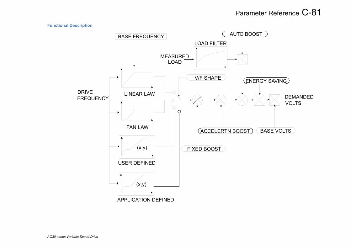
Parameter Reference C-81
AC30 series Variable Speed Drive
Functional Description
LINEAR LAW
FAN LAW
LOAD FILTER
DEMANDEDDRIVE
MEASURED LOAD
V/F SHAPE
BASE FREQUENCY AUTO BOOST
FIXED BOOST
BASE VOLTS
USER DEFINED
(x,y)
ACCELERTN BOOST
ENERGY SAVING
VOLTSFREQUENCY
APPLICATION DEFINED
(x,y)
C-82 Parameter Reference
AC30 series Variable Speed Drive
V/F Shape The function allows the user to parameterise the Drive’s conventional V/F motor fluxing scheme. Four V/F shapes are available, LINEAR LAW, FAN LAW, USER DEFINED, and APPLICATION DEFINED:
♦ Linear Law V/F shape should be used in applications requiring constant motor torque though out the speed range (e.g. machine tools or hoists).
♦ Fan Law V/F shape provides less torque capabilities for lower speeds, which means some energy savings can be achieved for fan or pump applications when they operate at lower speed/load setpoints. When choosing fan law shape the user should carefully consider if such profile is suitable for the overall load cycle of their application.
♦ User Defined V/F shape provides a method for the user to define any profile. 10 user definable (x,y) points are provided. Linear interpolation is used between each point. The drive also assumes the following points - (0%,0%) and (100%,100%) - though these may be overridden. For example, (USER FREQ 1 = 0%, USER VOLTAGE 1 = 5%) takes precedence over (0%, 0%).
♦ Application Defined V/F shape provides a method for the user to define any fluxing profile within the application layer. In the application the user can set desired voltage level for any operating frequency, and the application will dynamically provide that value to the firmware, via the “Application Volts” parameter. If this mode is used, it is recommended that such application is executed in 1ms time frame.
For any of these V/F shapes the Base Frequency parameter (in the Motor Nameplate function) which is the value of Drive output frequency at which maximum output volts is provided, can be set by the user.
Boost Parameters ♦ Correct no-load motor fluxing at low Drive output frequencies can be achieved by setting the Fixed Boost parameter. ♦ Correct motor fluxing under load conditions is achieved by setting the Auto Boost parameter. The motor is correctly fluxed when the
Actual Field Current diagnostic in the Feedbacks function reads 100.0% . ♦ Additional Fixed Boost can be applied during acceleration by setting the Acceleration Boost parameter. This can be useful for starting
heavy/high stiction loads.
Saving Energy An Energy Saving mode is provided to allow the user to choose to optimize energy consumption under low load conditions in steady state. As soon as the load is increased or acceleration is required, the drive suspends energy saving mode, and returns to it only if the load conditions are such that it is allowed to do so. If enabled, energy saving mode is reducing the voltage of the motor to a level required to maintain specific setpoint speed at a particular low load. For sustained low load conditions it is not necessary to keep the motor fluxed for rated torque capabilities, so the motor voltage is reduced to a level that will still provide required torque, but not much more torque. This operation on the cusp of required torque is also the biggest weakness of energy saving mode. Energy saving procedure does monitor torque demand and as soon as it detects its rise the drive switches from energy saving mode to normal mode of operation. However, sudden increases in load may be too quick to be dealt with by energy saving mode, and may lead to stall or trip conditions. This will occur if the time to correctly re-flux the motor takes longer than the time of load increase, when there can be a window of time when the motor is simply not able to generate sufficient torque necessary for the new, increased load conditions. For this reason the user has to be very careful when choosing to utilize energy saving mode. Energy saving mode should ideally be used in applications where there are prolonged periods of low load operation, with no fast excursions towards rated torque. The user always has to be certain that the overall load cycle for their application would still be correctly serviced if the energy saving mode is enabled, and that energy saving mode is not being incorrectly used at the expence of required performance.

Parameter Reference C-83
AC30 series Variable Speed Drive
Flycatching Parameters::Motor Control::Flycatching Only available if IM MOTOR selected in Control Mode This feature performs a directional speed search. It allows the Drive to seamlessly catch a spinning motor before controlling the motor to the desired setpoint. This is especially useful for large inertia fan loads, where drafts in building air ducts can cause a fan to `windmill’.
Parameter Name No. Path Default Range Units Writable VHz Flying Start Enable
0310
Parameters::Motor Control::Flycatching
FALSE
ALWAYS
Enable flycatching in V/Hz control mode when TRUE VC Flying Start Enable
0311
Parameters::Motor Control::Flycatching
FALSE
ALWAYS
Enable flycatching in Vector control mode when TRUE Flying Start Mode
0312
Parameters::Motor Control::Flycatching
0
0:ALWAYS 1:TRIP OR POWER UP 2:TRIP
ALWAYS
Mode of operation - V/Hz control Search Mode
0313
Parameters::Motor Control::Flycatching
0
0:BIDIRECTIONAL 1:UNIDIRECTION
ALWAYS
The type of speed search carried out by the flycatching sequence. Search Volts
0314
Parameters::Motor Control::Flycatching
9.0
0.0 to 100.0
%
ALWAYS
Only under VHz control The percentage level of the search volts applied to the motor during the speed search phase of the flycatching sequence. Increasing this parameter improves the accuracy of the discovered motor speed but increases the braking influence of the speed search on the rotating motor.
Search Boost
0315
Parameters::Motor Control::Flycatching
40.0
0.0 to 50.0
%
ALWAYS
Only under VHz control

C-84 Parameter Reference
AC30 series Variable Speed Drive
Parameter Name No. Path Default Range Units Writable The level of search boost applied to the motor during the speed search phase of the flycatching sequence.
Search Time
0316
Parameters::Motor Control::Flycatching
5.000
0.100 to 60.000
s
ALWAYS
Only under VHz Control The search rate during the speed search phase of the flycatching sequence. Performing the flycatching speed search too quickly can cause the drive to inaccurately identify the motor speed. Refluxing at an inaccurate motor speed can cause the drive to trip on overvoltage. If this occurs, increasing this parameter will reduce the risk of tripping.
Min Search Speed
0317
Parameters::Motor Control::Flycatching
5
0 to 500
Hz
ALWAYS
Only under VHz Control The lowest search speed before the speed search phase of the flycatching sequence is considered to have failed.
Flying Reflux Time
0318
Parameters::Motor Control::Flycatching
3.000
0.100 to 10.000
s
ALWAYS
Only under VHz Control The rate of rise of volts from the search level to the working level after a successful speed search. Refluxing the motor too quickly can cause the Drive to trip on either overvoltage or overcurrent. In either case, increasing this parameter will reduce the risk of tripping.
Functional Description The flycatching function enables the drive to be restarted smoothly into a spinning motor. It applies small search voltages to the motor whilst ramping the Drive frequency from maximum speed to zero. When the motor load goes from motoring to regenerating, the speed search has succeeded and is terminated. If the search frequency falls below the minimum search speed, the speed search has failed and the Drive will ramp to the speed setpoint from zero. The flycatching sequence can be triggered by different starting conditions: ALWAYS: All starts (after controlled or uncontrolled stop, or after a power-up) TRIP or POWER-UP: After uncontrolled stop, i.e. trip or coast, or after a power-up TRIP: After uncontrolled stop, i.e. trip or coast The type of speed sequence may be Bi-directional or Unidirectional: Bi-directional Initially, the search is performed in the direction of the speed setpoint. If the drive fails to identify the motor speed in this direction, a second speed search is performed in the reverse direction. Unidirectional The search is performed only in the direction of the speed setpoint.

Parameter Reference C-85
AC30 series Variable Speed Drive
General Purpose IO Monitor::Inputs and Outputs Parameters::Option IO::General Purpose IO The General Purpose IO parameters configure the use of the four IO Options. This group of parameters is only visible when an IO Option is selected.
Parameter Name No. Path Default Range Units Writable Anin 11 Value
1181
Monitor::Inputs and Outputs Parameters::Option IO::General Purpose IO
x.xx
-100.00 to 100.00
%
NEVER
(Terminal X21.2) - The input value expressed as a percentage of range, (+/- 100%), following Offset and Scale. Anin 12 Value
1182
Same as PNO 1181
x.xx
-100.00 to 100.00
%
NEVER
(Terminal X21.3) - The input value expressed as a percentage of range, (+/- 100%), following Offset and Scale. Anin 13 Value
1183
Same as PNO 1181
x.xx
-100.00 to 100.00
%
NEVER
(Terminal X21.4) - The input value expressed as a percentage of range, (+/- 100%), following Offset and Scale. Anin 11 Offset
1461
Setup::Inputs and Outputs::Option Parameters::Option IO::General Purpose IO
0.00
Min to Max
%
ALWAYS
The offset is expressed as a percentage of the hardware range. For example an offset of 10% is equivalent to 1V on the input. The offset is added to the measured value.
Anin 11 Scale
1462
Same as PNO 1461
1.0000
Min to Max
ALWAYS
The scale is a simple multiplication factor. The input voltage is converted to a percentage value. 1461 Anin 11 Offset is added and the result is multiplied by Scale. The result is presented in parameter 1181 Anin 11 Value.
Anin 12 Offset
1463
Same as PNO 1461
0.00
Min to Max
%
ALWAYS
The offset is expressed as a percentage of the hardware range. For example an offset of 10% is equivalent to 1V on the input. The offset is added to the measured value.
Anin 12 Scale
1464
Same as PNO 1461
1.0000
Min to Max
ALWAYS

C-86 Parameter Reference
AC30 series Variable Speed Drive
Parameter Name No. Path Default Range Units Writable
The scale is a simple multiplication factor. The input voltage is converted to a percentage value. 1463 Anin 12 Offset is added and the result is multiplied by Scale. The result is presented in parameter 1182 Anin 12 Value.
Anin 13 Offset
1465
Same as PNO 1461
0.00
Min to Max
%
ALWAYS
The offset is expressed as a percentage of the hardware range. For example an offset of 10% is equivalent to 1V on the input. The offset is added to the measured value.
Anin 13 Scale
1466
Same as PNO 1461
1.0000
Min to Max
ALWAYS
The scale is a simple multiplication factor. The input voltage is converted to a percentage value. 1465 Anin 13 Offset is added and the result is multiplied by Scale. The result is presented in parameter 1183 Anin 13 Value.
RTC Trim
1187
Parameters::Option IO::General Purpose IO
0
-40 to 40
ALWAYS
A trim value that may be used to speed up or slow down the Real Time Clock on the IO option. A positive trim value will cause the RTC to run faster, an negative value causes the RTC to run slower. Refer to the AC30V General Purpose I/O Option manual for more details. Once programmed, the RTC trim affects the operation of the RTC both in battery backed up mode and normal running mode.
Analog input Scale and Offset
The input signal is converted to a percentage of the hardware range, that is -10V…10V is represented as -100 to 100%. The Offset is then added to this input and the result of this is multiplied by the Scale factor. The result is presented in the Value parameter.
+Offset %
Input-100...100% x
Scale
Value

Parameter Reference C-87
AC30 series Variable Speed Drive
Graphical Keypad Setup::Environment Parameters::Keypad::Graphical Keypad
Parameter Name No. Path Default Range Units Writable View Level
1141
Parameters::Keypad::Graphical Keypad
1
Same as PNO 945
ALWAYS
The view level may be used as a convenient method to hide menus and parameters not currently required. The view levels are:
0. Operator – only the “Control Screen”, “Favourites”, “Setup” and “Monitor” menus are visible. 1. Technician – additional menus are visible in the “Setup” and “Monitor” menus 2. Engineer – the “Parameters” menu is visible in addition to the above.
Startup Page
0982
Setup::Environment Parameters::Keypad::Graphical Keypad
80000000
ALWAYS
On power-up the GKP briefly displays the drive name, rating and software version. After a short timeout the display automatically changes to the menu defined here. To set Startup Page, navigate to the position in the menu structure that is required, then press and hold the centre blue OK key for about 4 seconds, until the message “Startup Page” is shown.
The following special cases are defined for compatibility with previous versions of firmware.
80000000 Default 80000001 Control Screen 80000002 Favourites 80000003 Monitor
When Startup Page is set to “Default” the first menu will be: • The “Control Screen” menu if the drive is in local sequencing mode, otherwise • The “Favourites” menu if the Favourites menu is not empty, otherwise • The “Monitor” menu.
Display Timeout
0983
Same as PNO 982
0.000
0.000 to 86400.000
s
ALWAYS
When the GKP is idle, (no keys pressed), for a period longer than the Display Timeout, the display will automatically revert to the menu defined in the Startup Page parameter.
Setting the Display Timeout to zero defeats this feature.
GKP Password
1142
Setup::Environment Parameters::Keypad::Graphical Keypad
0000
ALWAYS

C-88 Parameter Reference
AC30 series Variable Speed Drive
Parameter Name No. Path Default Range Units Writable
Defines the password to be entered to allow modification to parameters using the GKP. This password does not affect access via the web page. A value of 0000, (the default value), inhibits the password feature. Entering a value other than 0000 causes the GKP to prompt for the password before proceeding to the parameter edit mode.
Once a password has been entered the GKP remains unlocked. To re-lock the password return to the top of the menu tree then press Soft Key 1.
Password in Favourite
1097
Parameters::Keypad::Graphical Keypad
FALSE
ALWAYS
When the GKP Password is active this parameter may be used to selectively defeat the password feature in the Favourites menu. By default this parameter is FALSE, meaning that the password is ignored when modifying Favourites parameters.
Password in Local
1098
Parameters::Keypad::Graphical Keypad
FALSE
ALWAYS
When the GKP Password is active this parameter may be used to selectively defeat the password feature in the Control Screen menu. By default this parameter is FALSE, meaning that the password is ignored when modifying the Local Setpoint and other related parameters.
Technician Password
1099
Parameters::Keypad::Graphical Keypad
0000
ALWAYS
The password required to change from Operator View level to Technician View Level. If this is zero then no password is required.
Engineer Password
1637
Parameters::Keypad::Graphical Keypad
0000
ALWAYS
The password required to change from Operator or Technician View level to Engineer View Level. If this is zero then no password is required.
Version
1143
Parameters::Keypad::Graphical Keypad
NEVER
Indicates the firmware version of the attached GKP.
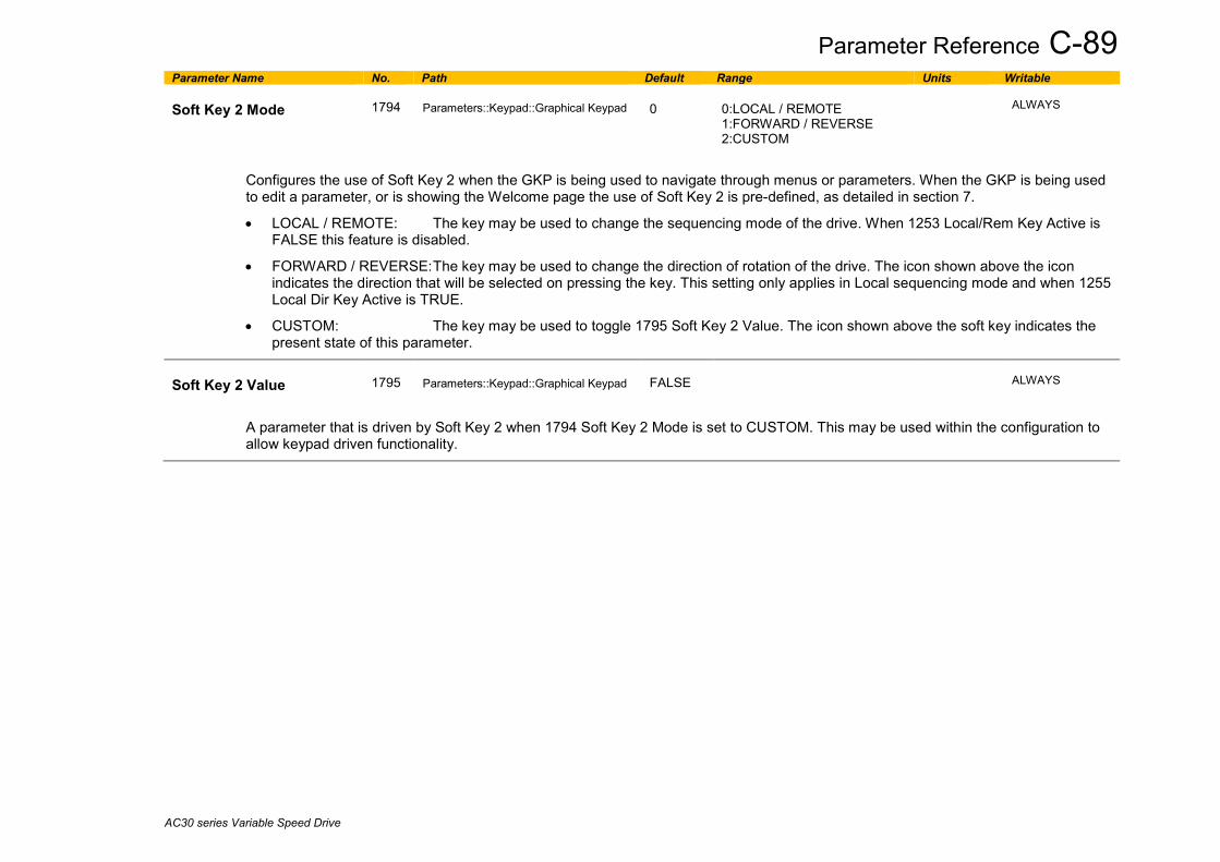
Parameter Reference C-89
AC30 series Variable Speed Drive
Parameter Name No. Path Default Range Units Writable Soft Key 2 Mode
1794
Parameters::Keypad::Graphical Keypad
0
0:LOCAL / REMOTE 1:FORWARD / REVERSE 2:CUSTOM
ALWAYS
Configures the use of Soft Key 2 when the GKP is being used to navigate through menus or parameters. When the GKP is being used to edit a parameter, or is showing the Welcome page the use of Soft Key 2 is pre-defined, as detailed in section 7.
• LOCAL / REMOTE: The key may be used to change the sequencing mode of the drive. When 1253 Local/Rem Key Active is FALSE this feature is disabled.
• FORWARD / REVERSE: The key may be used to change the direction of rotation of the drive. The icon shown above the icon indicates the direction that will be selected on pressing the key. This setting only applies in Local sequencing mode and when 1255 Local Dir Key Active is TRUE.
• CUSTOM: The key may be used to toggle 1795 Soft Key 2 Value. The icon shown above the soft key indicates the present state of this parameter.
Soft Key 2 Value
1795
Parameters::Keypad::Graphical Keypad
FALSE
ALWAYS
A parameter that is driven by Soft Key 2 when 1794 Soft Key 2 Mode is set to CUSTOM. This may be used within the configuration to allow keypad driven functionality.

C-90 Parameter Reference
AC30 series Variable Speed Drive
Induction Motor Data Setup::Motor Control::Induction Motor Data Parameters::Motor Control::Induction Motor Data Only available if IM MOTOR selected in Control Mode
Parameter Name No. Path Default Range Units Writable Magnetising Current
0568
Parameters::Motor Control::Induction Motor Data
1.00
0.00 to 10000.00
A
ALWAYS
The no load current of the induction motor, defined as rotor flux / magnetising inductance, usually given the title "imr".
Rotor Time Constant
0569
Parameters::Motor Control::Induction Motor Data
0.100
0.005 to 100.000
s
ALWAYS
Induction Motor rotor time constant.
Leakage Inductance
0570
Parameters::Motor Control::Induction Motor Data
1.000
0.000 to 1000.000
mH
ALWAYS
Induction motor leakage inductance. Displayed as star or delta equivalent value according to "Per Phase Parameters" setting.
Stator Resistance
0571
Parameters::Motor Control::Induction Motor Data
0.0000
0.0000 to 100.0000
Ohm
ALWAYS
Induction motor stator resistance. Displayed as star or delta equivalent value according to "Per Phase Parameters" setting.
Stator Resistance
0571
Parameters::Motor Control::Induction Motor Data
0.0000
0.0000 to 100.0000
Ohm
ALWAYS
Induction motor rotor resistance. Displayed as an interim “by-product” of stationary autotune procedure. Not used in control functions.
Mutual Inductance
0572
Parameters::Motor Control::Induction Motor Data
100.00
0.00 to 10000.00
mH
ALWAYS
Induction motor mutual inductance. Displayed as star or delta equivalent value according to "Per Phase Parameters" setting.
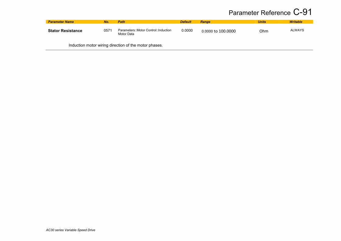
Parameter Reference C-91
AC30 series Variable Speed Drive
Parameter Name No. Path Default Range Units Writable Stator Resistance
0571
Parameters::Motor Control::Induction Motor Data
0.0000
0.0000 to 100.0000
Ohm
ALWAYS
Induction motor wiring direction of the motor phases.

C-92 Parameter Reference
AC30 series Variable Speed Drive
Inj Braking Parameters::Motor Control::Inj Braking Designed for VOLTS/Hz Motor Control Mode. The injection braking feature provides a method of stopping spinning induction motors without returning the kinetic energy of the motor and load back in to the dc link of the Drive. This is achieved by running the motor highly inefficiently so that all the energy stored in the load is dissipated in the motor. Thus, high inertia loads can be stopped without the need for an external dynamic braking resistor.
Parameter Name No. Path Default Range Units Writable DC Inj Deflux Time
0324
Parameters::Motor Control::Inj Braking
0.500
0.100 to 20.000
s
ALWAYS
Motor defluxed duration before starting injection braking
DC Inj Frequency
0325
Parameters::Motor Control::Inj Braking
9
1 to 500
Hz
ALWAYS
Max frequency applied to the motor
DC Inj Current Limit
0326
Parameters::Motor Control::Inj Braking
100.0
50.0 to 150.0
%
ALWAYS
Motor current value
DC Pulse Time
0327
Parameters::Motor Control::Inj Braking
2.000
0.000 to 100.000
s
ALWAYS
Duration of dc pulse for motor speed below 20% of base speed
Final DC Pulse Time
0328
Parameters::Motor Control::Inj Braking
1.000
0.000 to 10.000
s
ALWAYS
Duration of the final dc holding pulse
DC Current Level
0329
Parameters::Motor Control::Inj Braking
3.0
0.0 to 25.0
%
ALWAYS
Level of dc pulse applied

Parameter Reference C-93
AC30 series Variable Speed Drive
Parameter Name No. Path Default Range Units Writable DC Inj Timeout
0330
Parameters::Motor Control::Inj Braking
90.000
0.000 to 600.000
s
ALWAYS
Maximum time in the low frequency injection braking state
DC Inj Base Volts
0331
Parameters::Motor Control::Inj Braking
100.00
0.00 to 115.47
%
ALWAYS
Maximum volts applied at base speed
Note: DC injection braking procedure has higher percentage of successful stoppages for the lower power range (frames D-G), than at higher power range (frames H-K).

C-94 Parameter Reference
AC30 series Variable Speed Drive
IO Configure Setup::Inputs and Outputs Parameters::Inputs And Outputs::IO Configure These parameters are used to configure the input signal processing.
Parameter Name No. Path Default Range Units Writable Anin 01 Type
0001
Setup::Inputs and Outputs::Base IO Parameters::Inputs And Outputs::IO Configure
0
0:-10..10 V 1:0..10 V 2:0..20 mA 3:4..20 mA
ALWAYS
Analog input 1 is associated with terminal X11.1
The signal processing electronics for analog input 1 supports four input ranges.
Anin 01 Offset
0957
Setup::Inputs and Outputs::Base IO Parameters::Inputs And Outputs::IO Configure
0.00
Min to Max
%
ALWAYS
The offset is expressed as a percentage of the hardware range selected by 0001 Anin 01 Type. For example, with the 4..20mA range an offset of 10% is equivalent to 1.6mA on the input.
The offset is added to the measured value.
Anin 01 Scale
0958
Same as PNO 957
1.0000
Min to Max
ALWAYS
The scale is a simple multiplication factor. The input voltage or current is converted to a percentage value. 0957 Anin 01 Offset is added and the result is multiplied by 0958 Anin 01 Scale. The result is presented in parameter 0039 Anin 01 Value.
Anin 02 Type
0002
Same as PNO 1
0
0:-10..10 V 1:0..10 V
ALWAYS
Analog input 2 is associated with terminal X11.2
The signal processing electronics for analog input 2 supports two input ranges.

Parameter Reference C-95
AC30 series Variable Speed Drive
Parameter Name No. Path Default Range Units Writable Anin 02 Offset
0959
Same as PNO 957
0.00
Min to Max
%
ALWAYS
The offset is expressed as a percentage of the hardware range selected by 0002 Anin 02 Type. For example, with the -10..10V range an offset of 10% is equivalent to 1v on the input.
The offset is added to the measured value.
Anin 02 Scale
0960
Same as PNO 957
1.0000
Min to Max
ALWAYS
The scale is a simple multiplication factor. The input voltage is converted to a percentage value. 0959 Anin 02 Offset is added and the result is multiplied by 0960 Anin 02 Scale. The result is presented in parameter 0041 Anin 02 Value.
Anout 01 Type
0003
Same as PNO 1
0
0:-10..10 V 1:0..10 V 4:TORQUE OUT -10..10 V
ALWAYS
Analog output 1 is associated with terminal X11.3 The signal processing electronics for analog output 1 supports two output ranges: 0. -10..10V 1. 0..10V 4. TORQUE OUT : output of the speed loop ( torque setpoint) directly feeding the analog output 1. No delay.
Anout 01 Scale
0686
Setup::Inputs and Outputs::Base IO Parameters::Inputs And Outputs::IO Configure
1.0000
Min to Max
ALWAYS
The scale is a simple multiplication factor applied to 0042 Anout 01 Value.
Anout 01 Offset
1108
Setup::Inputs and Outputs::Base IO Parameters::Inputs And Outputs::IO Configure
0.00
Min to Max
%
ALWAYS
The offset is expressed as a percentage of the hardware range selected by 0003 Anout 01 Type. For example, with the -10..10V range an offset of 10% is equivalent to 1v on the output.
The demand value 0042 Anout 01 Value is multiplied by 0686 Anout 01 Scale then added to the Offset. The resultant value is then limited to -100 to 100%, (for the -10..10V type) or 0..100%, (for the 0..10V range).

C-96 Parameter Reference
AC30 series Variable Speed Drive
Parameter Name No. Path Default Range Units Writable Anout 01 ABS
1441
Setup::Inputs and Outputs::Base IO Parameters::Inputs And Outputs::IO Configure
FALSE
ALWAYS
When ABS is set TRUE, the absolute value of the result of combining 0042 Anout 01 Value, 0686 Anout 01 Scale and 1108 Anout 01 Offset is used to drive the output electronics.
Anout 02 Type
0004
Same as PNO 1
1
1:0..10 V 2:0..20 mA 3:4..20 mA
ALWAYS
Analog output 1 is associated with terminal X11.4
The signal processing electronics for analog output 2 supports the three output ranges
Anout 02 Scale
1460
Same as PNO 1441
1.0000
Min to Max
ALWAYS
The scale is a simple multiplication factor applied to 0043 Anout 02 Value.
Anout 02 Offset
1467
Same as PNO 1441
0.00
Min to Max
%
ALWAYS
The offset is expressed as a percentage of the hardware range selected by 0004 Anout 02 Type. For example, with the 4..20mA range an offset of 10% is equivalent to 1.6mA on the output.
The demand value 0043 Anout 02 Value is multiplied by 1460 Anout 02 Scale then added to the Offset. The resultant value is then limited to 0..100%.
Anout 02 ABS
1468
Same as PNO 1441
FALSE
ALWAYS
When ABS is set TRUE, the absolute value of the result of combining 0043 Anout 02 Value, 1460 Anout 02 Scale and 1467 Anout 02 Offset is used to drive the output electronics.
Digin Invert
1294
Setup::Inputs and Outputs::Base IO Parameters::Inputs And Outputs::IO Configure
0000
ALWAYS
Inverts all the digital inputs to the drive as a 16-bit word. The bits within the word may be accessed individually, or the entire word may be accessed as a group.

Parameter Reference C-97
AC30 series Variable Speed Drive
Parameter Name No. Path Default Range Units Writable Bit Signal name Terminal Comment PNO for individual bit access 0 Inv Digin 01 X13.2 1295 1 Inv Digin 02 X13.3 1296 2 Inv Digin 03 X13.4 1297 3 Inv Digin 04 X12.1 Common terminal with digital output 1 1298 4 Inv Digin 05 X12.2 Common terminal with digital output 2 1299 5 Inv Digin 06 X12.3 Common terminal with digital output 3 1300 6 Inv Digin 07 X12.4 Common terminal with digital output 4 1301 7 Inv STO Inactive X10 1302 8 Inv Digin 11 X20.1 GPIO option 1303 9 Inv Digin 12 X20.2 GPIO option 1304 10 Inv Digin 13 X20.3 GPIO option 1305 11 Inv Digin 14 X20.4 GPIO option 1306 12 Inv Run Key - GKP Run key pressed* 1307 13 Inv Not Stop Key - GKP Stop key not pressed* 1308 14 Inv Stop Key - GKP Stop key pressed* 1309
Digout Invert
1335
Setup::Inputs and Outputs::Base IO Parameters::Inputs And Outputs::IO Configure
0000
ALWAYS
Inverts the digital outputs from the drive as a 16-bit word. The bits within the word may be accessed individually, or the entire word may be accessed as a group.
Bit Signal Name Terminal Comment PNO for individual bit access 0 Inv Digout 01 X12.1 Common terminal with digital input 4 1336 1 Inv Digout 02 X12.2 Common terminal with digital input 5 1337 2 Inv Digout 03 X12.3 Common terminal with digital input 6 1338 3 Inv Digout 04 X12.4 Common terminal with digital input 7 1339 4 Inv Relay 01 X14.1&2 1340 5 Inv Relay 02 X14.3&4 1341 8 Inv Digout 11 X20.1 GPIO option 1344 9 Inv Digout 12 X20.2 GPIO option 1345
10 Inv Digout 13 X20.3 GPIO option 1346 11 Inv Digout 14 X20.4 GPIO option 1347 14 Inv Relay 11 X23.1 & 2 GPIO option 1350 15 Inv Relay 12 X23.3 & 4 GPIO option 1351

C-98 Parameter Reference
AC30 series Variable Speed Drive
Functional Description The values associated with each terminal are shown in the IO Values parameter (D-61).
Analog input
The input signal is converted to a percentage of the selected hardware range. For the -10V…10V range the input is represented as -100 to 100%, for all other ranges the input is represented as 0 to 100%. The Offset value is then added to this input and the result of this is multiplied by the scale factor. The result is presented in the Value parameter.
Analog output
The output demand value is multiplied by Scale before being added to the Offset. If ABS is TRUE the absolute value of this result is used. The output demand value is expressed as a percentage of the selected range.
+Offset %
Input0...100%
or-100...100% x
Scale
Value
xScale
Value % +Offset ABS
Demand0...100%
or-100...100%
|Result|

Parameter Reference C-99
AC30 series Variable Speed Drive
IO Option Common Parameters::Option IO:: Option IO
Parameter Name No. Path Default Range Units Writable Option IO Required
1178
Setup::Inputs and Outputs::Option Parameters::Option IO::Option IO
0
0:NONE 1:GENERAL PURPOSE 2:THERMISTOR 3:RTC AND THERMISTOR 4:PULSE ENCODER 5:RESOLVER AND THERMIST
STOPPED
Defines the type of IO option required by the configuration.
Option IO Fitted
1179
Parameters::Option IO::Option IO
Same as PNO 1178
NEVER
Indicates the type of IO option that is currently fitted
Option IO Diagnostic
1180
Parameters::Option IO::Option IO
0:OK 1:OPTION NOT FITTED 2:TYPE MISMATCH 3:TYPE UNKNOWN 4:HARDWARE FAULT
NEVER
Indicates the status of the IO option
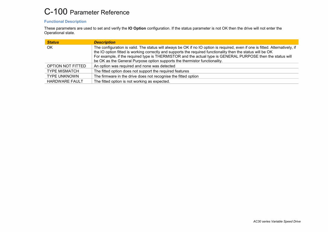
C-100 Parameter Reference
AC30 series Variable Speed Drive
Functional Description These parameters are used to set and verify the IO Option configuration. If the status parameter is not OK then the drive will not enter the Operational state.
Status Description OK The configuration is valid. The status will always be OK if no IO option is required, even if one is fitted. Alternatively, if
the IO option fitted is working correctly and supports the required functionality then the status will be OK For example, if the required type is THERMISTOR and the actual type is GENERAL PURPOSE then the status will be OK as the General Purpose option supports the thermistor functionality.
OPTION NOT FITTED An option was required and none was detected TYPE MISMATCH The fitted option does not support the required features TYPE UNKNOWN The firmware in the drive does not recognise the fitted option HARDWARE FAULT The fitted option is not working as expected.
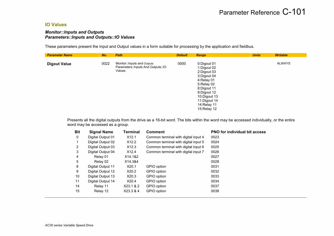
Parameter Reference C-101
AC30 series Variable Speed Drive
IO Values Monitor::Inputs and Outputs Parameters::Inputs and Outputs::IO Values These parameters present the Input and Output values in a form suitable for processing by the application and fieldbus.
Parameter Name No. Path Default Range Units Writable Digout Value
0022
Monitor::Inputs and Outputs Parameters::Inputs And Outputs::IO Values
0000
0:Digout 01 1:Digout 02 2:Digout 03 3:Digout 04 4:Relay 01 5:Relay 02 8:Digout 11 9:Digout 12 10:Digout 13 11:Digout 14 14:Relay 11 15:Relay 12
ALWAYS
Presents all the digital outputs from the drive as a 16-bit word. The bits within the word may be accessed individually, or the entire word may be accessed as a group.
Bit Signal Name Terminal Comment PNO for individual bit access 0 Digital Output 01 X12.1 Common terminal with digital input 4 0023 1 Digital Output 02 X12.2 Common terminal with digital input 5 0024 2 Digital Output 03 X12.3 Common terminal with digital input 6 0025 3 Digital Output 04 X12.4 Common terminal with digital input 7 0026 4 Relay 01 X14.1&2 0027 5 Relay 02 X14.3&4 0028 8 Digital Output 11 X20.1 GPIO option 0031 9 Digital Output 12 X20.2 GPIO option 0032
10 Digital Output 13 X20.3 GPIO option 0033 11 Digital Output 14 X20.4 GPIO option 0034 14 Relay 11 X23.1 & 2 GPIO option 0037 15 Relay 12 X23.3 & 4 GPIO option 0038

C-102 Parameter Reference
AC30 series Variable Speed Drive
Parameter Name No. Path Default Range Units Writable Digin Value
0005
Monitor::Inputs and Outputs Parameters::Inputs And Outputs::IO Values
0:Digin 01 1:Digin 02 2:Digin 03 3:Digin 04 4:Digin 05 5:Digin 06 6:Digin 07 7:STO Inactive 8:Digin 11 9:Digin 12 10:Digin 13 11:Digin 14 12:Run Key 13:Not Stop Key 14:Stop Key
NEVER
Presents all the digital inputs to the drive as a 16-bit word. The bits within the word may be accessed individually, or the entire word may be accessed as a group.
Bit Signal name Terminal Comment PNO for individual bit access 0 Digital Input 01 X13.2 0006 1 Digital Input 02 X13.3 0007 2 Digital Input 03 X13.4 0008 3 Digital Input 04 X12.1 Common terminal with digital output 1 0009 4 Digital Input 05 X12.2 Common terminal with digital output 2 0010 5 Digital Input 06 X12.3 Common terminal with digital output 3 0011 6 Digital Input 07 X12.4 Common terminal with digital output 4 0012 7 STO Inactive X10 0013 8 Digital Input 11 X20.1 GPIO option 0014 9 Digital Input 12 X20.2 GPIO option 0015 10 Digital Input 13 X20.3 GPIO option 0016 11 Digital Input 14 X20.4 GPIO option 0017 12 Run Key - GKP Run key pressed* 0018 13 Not Stop Key - GKP Stop key not pressed* 0019 14 Stop Key - GKP Stop key pressed* 0020
* If the GKP is not fitted then both “Not Stop Key” and “Stop Key” will be 0. This condition may be used to detect a disconnected GKP.

Parameter Reference C-103
AC30 series Variable Speed Drive
Parameter Name No. Path Default Range Units Writable Anin 01 Value
0039
Same as PNO 38
x.x
-100.0 to 100.0
%
NEVER
Terminal X11.1
The value returned by the signal processing electronics. For unipolar ranges, (all except -10..10V), the value is expressed as a percentage of the hardware range. For the -10..10V range the full range signal is expressed as -100% to +100%.
Anin 01 Break
0040
Same as PNO 38
NEVER
When the input range is set to 4..20mA a break is defined as an input signal less than 3mA. Otherwise this parameter is set to FALSE.
Anin 02 Value
0041
Same as PNO 38
x.x
-100.0 to 100.0
%
NEVER
Terminal X11.2
The value returned by the signal processing electronics. For the 0..10V range the value is expressed as a percentage of the hardware range, (0 to 100%). For the -10..10V range the full range signal is expressed as -100% to +100%.
Anout 01 Value
0042
Same as PNO 38
0.00
Min to Max
%
ALWAYS
Terminal X11.3
The desired output value expressed as a percentage of the output range. Range Mapping 0..10V 0% gives 0V, 100% gives 10V 0..20MA 0% gives 0mA, 100% gives 20mA 4..20MA 0% gives 4mA, 100% gives 20mA
Anout 02 Value
0043
Same as PNO 38
0.00
Min to Max
%
ALWAYS
Terminal X11.4
The desired output value expressed as a percentage of the output range. Range Mapping -10..10V -100% gives -10V, 100% gives 10V 0..10V 0% gives 0V, 100% gives 10V

C-104 Parameter Reference
AC30 series Variable Speed Drive
Keypad Override Parameters::Keypad::Keypad Override These parameters may be used to modify the behaviour of the Display/Keypad.
Parameter Name No. Path Default Range Units Writable Green LED Force On
1862 Parameters::Keypad::Keypad Override
FALSE
ALWAYS
When TRUE, turns the LED under the RUN key on. It is not possible to force this LED off when the drive is running.
Red LED Force Off
1863 Parameters::Keypad::Keypad Override
FALSE
ALWAYS
When TRUE, turns the LED under the STOP key off. It is not possible to force this LED on when the drive is running.
Disable Keys
1865 Parameters::Keypad::Keypad Override
0000
ALWAYS
Mask to disable the normal operation of the selected keys. The corresponding bits are 2 - UP, 3 - DOWN, 4 - LEFT, 5 - RIGHT, 6 - OK. The mask is ignored when a parameter is being edited, or when an alert message or password entry is active. This parameter is not saved.
Key Press
1866 Parameters::Keypad::Keypad Override
NEVER
Indicates which key(s) are pressed on the GKP. The corresponding bits are 0 - STOP, 1 - START, 2 - UP, 3 - DOWN, 4 - LEFT, 5 - RIGHT, 6 - OK, 7 - SOFT KEY 1, 8 - SOFT KEY 2
Selected Parameter
1867 Parameters::Keypad::Keypad Override
NEVER
Shows the PNO of the parameter selected on the GKP. The value is zero when no parameter is selected, or when a parameter is being edited.

Parameter Reference C-105
AC30 series Variable Speed Drive
Local Control Parameters::Keypad::Local Control These parameters configure the use of the GKP keys for local start / stop control of the drive.
Parameter Name No. Path Default Range Units Writable
Run Key Action
1140
Parameters::Keypad::Local Control
0
0:RUN 1:JOG
STOPPED
Defines the use of the green run key in local mode.
When RUN is selected, pressing the green Run key will start the drive using Local Reference as the active setpoint. To stop the drive press the RED Stop key.
When JOG is selected, pressing the green Run key will start the drive running using the Jog Setpoint as the active setpoint. The drive will stop when the key is released.
Local/Rem Key Active
1253
Parameters::Keypad::Local Control
TRUE
ALWAYS
Enables the L/R soft key function. This is used to change between Local and Remote sequencing modes from the GKP.
Local Dir Key Active
1255
Parameters::Keypad::Local Control
TRUE
ALWAYS
Enables the ability to change the direction from the GKP when running in local sequencing mode. When FALSE the direction will always be positive.
Local Run Key Active
1239
Parameters::Keypad::Local Control
TRUE
ALWAYS
Enables the green Run key function when in local sequencing mode. When FALSE the Run key is ignored, (for both RUN and JOG modes).
Local Reverse
1240
Parameters::Keypad::Local Control
FALSE
ALWAYS
Used to change the direction the motor will rotate when in local sequencing mode. When FALSE the direction will be “Forwards”. When TRUE the direction will be reverse.
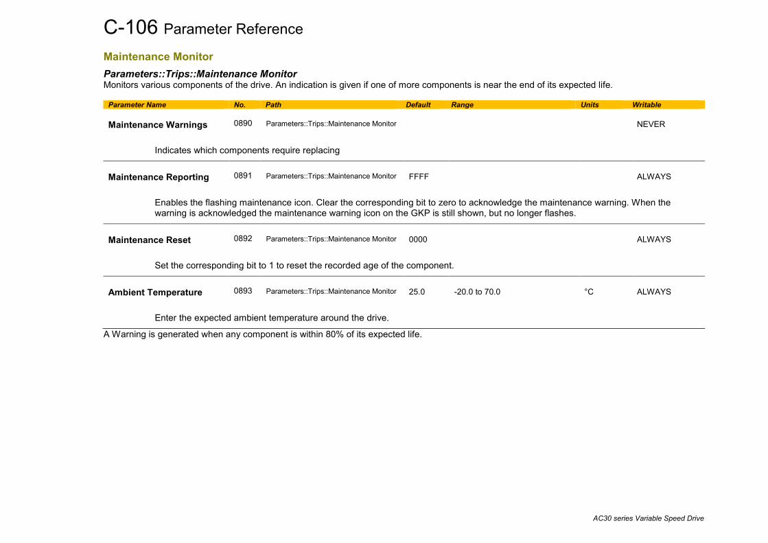
C-106 Parameter Reference
AC30 series Variable Speed Drive
Maintenance Monitor Parameters::Trips::Maintenance Monitor Monitors various components of the drive. An indication is given if one of more components is near the end of its expected life.
Parameter Name No. Path Default Range Units Writable Maintenance Warnings
0890
Parameters::Trips::Maintenance Monitor
NEVER
Indicates which components require replacing
Maintenance Reporting
0891
Parameters::Trips::Maintenance Monitor
FFFF
ALWAYS
Enables the flashing maintenance icon. Clear the corresponding bit to zero to acknowledge the maintenance warning. When the warning is acknowledged the maintenance warning icon on the GKP is still shown, but no longer flashes.
Maintenance Reset
0892
Parameters::Trips::Maintenance Monitor
0000
ALWAYS
Set the corresponding bit to 1 to reset the recorded age of the component.
Ambient Temperature
0893
Parameters::Trips::Maintenance Monitor
25.0
-20.0 to 70.0
°C
ALWAYS
Enter the expected ambient temperature around the drive.
A Warning is generated when any component is within 80% of its expected life.

Parameter Reference C-107
AC30 series Variable Speed Drive
Identification of drive components Each of the monitored drive components is represented by a bit in the 16-bit words, “Maintenance Warnings” and “Maintenance Reset”. Only the bottom 6 bits of these words have any meaning, the other bits are ignored. The table below indicates which components are selected for a given value.
Value
IO O
ption R
elays
Control Board
Relays
Main Fan
Auxilliary Fan
DC
Link C
apacitors(1)
xxx0 x x x x xxx1 x x x xxx2 x x x xxx3 x x xxx4 x x x xxx5 x x xxx6 x x xxx7 x xxx8 x x x xxx9 x x xxxA x x xxxB x xxxC x x xxxD x xxxE x xxxF xx0x x xx1x
(1) For future use. The DC Link Capacitors are not monitored in version x.16

C-108 Parameter Reference
AC30 series Variable Speed Drive
Minimum Speed Setup::Application::Minimum Speed Function availability depends on macro selected. The minimum speed function is used to determine how the AC30V will follow a reference.
Parameter Name No. Path Default Range Units Writable
Minimum Speed Value 1906 Setup::Application::Minimum Speed -100.0 -100.0 to 100.0 % ALWAYS
Specifies the minimum output value.
Minimum Speed Mode 1907 Setup::Application::Minimum Speed 0 0:PROP WITH MINIMUM
1:LINEAR ALWAYS
There are two modes of operation.
Functional Description
There are two operating modes for the MINIMUM SPEED function:
PROP WITH MINIMUM (proportional with minimum) In this mode the MINIMUM SPEED function behaves like a simple clamp. The Minimum Speed Value has the valid range -100% to 100% and the output is always greater than or equal to the Minimum Speed Value.
LINEAR In this mode the MINIMUM SPEED function first clamps the input to zero then rescales the input such that the output goes linearly between minimum and 100% for an input that goes from 0 to 100%. Note the constraints:- min >= 0 input >= 0 max = 100%
Min
0 100%
100
-100
input
output

Parameter Reference C-109
AC30 series Variable Speed Drive
Modbus Monitor::Communications::Base Modbus Setup::Communications::Base Modbus Parameters::Base Comms::Modbus
Refer to Appendix A Fieldbuses
C-110 Parameter Reference
AC30 series Variable Speed Drive
Modbus RTU Option Monitor::Communications::Option Setup::Communications::Option Parameters::Option Comms::Comms Parameters::Option Comms::Read Process Parameters::Option Comms::Write Process Parameters::Option Comms::Event Parameters::Option Comms::Modbus RTU
Refer to Modbus RTU Technical Manual HA501839U001

Parameter Reference C-111
AC30 series Variable Speed Drive
Modbus TCP Option Monitor::Communications::Option Setup::Communications::Option Parameters::Option Comms::Comms Parameters::Option Comms::Read Process Parameters::Option Comms::Write Process Parameters::Option Comms::Event Parameters::Option Comms::Option Ethernet Parameters::Option Comms::Modbus TCP
Refer to Modbus TCP Technical Manual HA501937U001

C-112 Parameter Reference
AC30 series Variable Speed Drive
Motor Load Parameters::Motor Control::Motor Load Motor Protection, function of the motor type. The Motor Load parameters determines the allowed level of motor overload. This can be especially useful when operating with motors smaller than the drive rating.
For an IM, an IxT protection is used and provides a current reduction if the max overload level is reached.
The max overload level is calculated based on a 150% for 60s. For a PMAC motor, the motor load is calculated using the rated motor current and the thermal time constant (2 parameters of the PMAC motor module). The Thermal time constant is used as the constant time of a simple 1st order low pass filter. % Are all related to rated motor current.
Parameter Name No. Path Default Range Units Writable 100% Mot Current
0332
Parameters::Motor Control::Motor Load
x.x
0.0 to 10000.0
NEVER
Motor current in Amps rms corresponding to 100%
Mot Inv Time Overload
0333
Parameters::Motor Control::Motor Load
x.
0 to 500
%
NEVER
Only available for IM motor
Overload % of the motor inverse time protection
Mot Inv Time Delay
0334
Parameters::Motor Control::Motor Load
6.000 to 60.000
s
ALWAYS
Only available for IM motor
Overload time of the motor inverse time protection from cold state

Parameter Reference C-113
AC30 series Variable Speed Drive
Parameter Name No. Path Default Range Units Writable Mot Inv Time Warning
0335
Parameters::Motor Control::Motor Load
NEVER
Only available for IM motor
Output information. Becomes TRUE when the overload is 5% of the maximum value before reducing the current
Mot Inv Time Active
0336
Parameters::Motor Control::Motor Load
NEVER
Only available for IM motor
Output information. Becomes TRUE when overload reaches 100% of the overload limit
Mot Inv Time Output %
0337
Parameters::Motor Control::Motor Load
x.x
0.0 to 600.0
%
NEVER
Only available for IM motor Actual output limit of the inverse time motor protection.
This value is compared to the Stack Inv Time current limit output to provide the internal limit to the current limit module.
Mot I2T TC
0338
Parameters::Motor Control::Motor Load
0.000 to 1000000.000
s
NEVER
Only available for PMAC motor
Time constant of the motor, define in the PMAC Motor Data module
Mot I2T Active
0340
Parameters::Motor Control::Motor Load
NEVER
Only available for PMAC motor
Motor load has reached 105%
Mot I2T Warning
0341
Parameters::Motor Control::Motor Load
NEVER
Only available for PMAC motor
Motor load has reached 95%

C-114 Parameter Reference
AC30 series Variable Speed Drive
Parameter Name No. Path Default Range Units Writable Mot I2T Enable
0342
Parameters::Motor Control::Motor Load
NEVER
Only available for PMAC motor
Output information : Motor I2T protection is active.
Functional Description
150 %
105 %
60s
Current Limit
Time
Im magnitude
I* T Limit Profile
Motor current limit
Current Feedback In Motor % IxT motor %
IM Motor
Rms Current Feedback In Motor %
Motor load estimation
Motor load in %
Trip information
PMAC motor

Parameter Reference C-115
AC30 series Variable Speed Drive
Motor Nameplate Setup::Motor Control::Motor Nameplate Parameters::Motor Control::Motor Nameplate Only available if IM MOTOR selected in Control Mode. In this function you enter the details of the motor under control and any available motor nameplate information. Refer to Induction Motor Data parameters which are determined by the Auto Tune feature for example the Magnetising Current, Stator Resistance, Leakage Inductance, Mutual Inductance and Rotor time Constant for model parameters.
Note Do not attempt to control motors whose rated current is less than 25% of the drive rated current. Poor motor control or Autotune problems may occur if you do.
Parameter Name No. Path Default Range Units Writable Rated Motor Current
0455
Setup::Motor Control::Motor Nameplate Parameters::Motor Control::Motor Nameplate
1.56
0.00 to 10000.00
A
STOPPED
Rated motor current on the name plate
Base Voltage
0456
Same as PNO 455
400.00
0.00 to 1000.00
V
STOPPED
The rated motor voltage on the name plate
Base Frequency
0457
Same as PNO 455
50.00
0.00 to 1000.00
Hz
STOPPED
The base motor frequency on the name plate
Motor Poles
0458
Same as PNO 455
4,
2 to 1000
STOPPED
Motor poles on the nameplate
Nameplate Speed
0459
Same as PNO 455
1450.00
0.00 to 100000.00
RPM
STOPPED
Rated motor speed on the name plate

C-116 Parameter Reference
AC30 series Variable Speed Drive
Parameter Name No. Path Default Range Units Writable Motor Power
0460
Same as PNO 455
0.75
0.00 to 3000.00
kW
STOPPED
Motor power rating
Power Factor
0461
Same as PNO 455
0.71
0.00 to 1.00
STOPPED
Only under VHz Control
Motor power factor on the name plate
Automatic Pole Pairs
1214
Same as PNO 455
TRUE
STOPPED
If TRUE Motor Poles (458) calculated automatically from Nameplate Speed (459). If FALSE the user has to input Motor Poles.
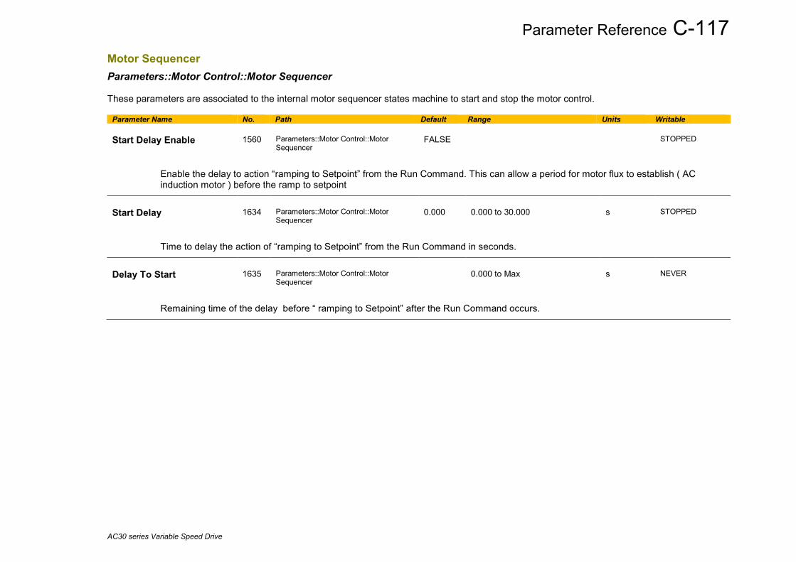
Parameter Reference C-117
AC30 series Variable Speed Drive
Motor Sequencer Parameters::Motor Control::Motor Sequencer These parameters are associated to the internal motor sequencer states machine to start and stop the motor control.
Parameter Name No. Path Default Range Units Writable Start Delay Enable
1560
Parameters::Motor Control::Motor Sequencer
FALSE
STOPPED
Enable the delay to action “ramping to Setpoint” from the Run Command. This can allow a period for motor flux to establish ( AC induction motor ) before the ramp to setpoint
Start Delay
1634
Parameters::Motor Control::Motor Sequencer
0.000
0.000 to 30.000
s
STOPPED
Time to delay the action of “ramping to Setpoint” from the Run Command in seconds.
Delay To Start
1635
Parameters::Motor Control::Motor Sequencer
0.000 to Max
s
NEVER
Remaining time of the delay before “ ramping to Setpoint” after the Run Command occurs.

C-118 Parameter Reference
AC30 series Variable Speed Drive
MRAS Parameters::Motor Control::MRAS These parameters are associated to the internal induction motor speed estimator (MRAS) module.
Parameter Name No. Path Default Range Units Writable MRAS Speed Percent
286
Parameters::Motor Control::MRAS
x.xx
Min to Max
%
NEVER
Diagnostic parameter that dispays speed calculated by the estimator as percent.
MRAS Speed RPM
1634
Parameters::Motor Control::MRAS
x.xx
0.000 to 30.000
s
NEVER
Diagnostic parameter that dispays speed calculated by the estimator as RPM.
MRAS Field Frequency
1635
Parameters::Motor Control::MRAS
x.xx
0.000 to 30.000
Hz
NEVER
Diagnostic parameter that dispays field frequency (electrical frequency) that the estimator provides for vector rotation.
MRAS Torque Percent
1560
Parameters::Motor Control::MRAS
x.xx
Min to Max
%
NEVER
Diagnostic parameter that dispays torque calculated by the estimator as percent.
MRAS Torque
1634
Parameters::Motor Control::MRAS
x.xx
0.000 to 30.000
Nm
NEVER
Diagnostic parameter that dispays torque calculated by the estimator as Nm.
Switchover Enable
1701 1635
Parameters::Motor Control::MRAS
ALWAYS
A boolean that enables or disables the ability to automatically switch into sensorless operation in the case of an encoder failure. Not on the AC30V
Parameter Reference C-119
AC30 series Variable Speed Drive
Functional Description The Switchover Enable parameter (1701) provides the user with the option to automatically, and as seamlessly as possible, continue operating in sensorless mode in case of an encoder failure. The MRAS estimator tracks the speed of the motor even if the drive uses encoder as its primary feedback for control. If the discrepancy between the speed measured by encoder and the estimated speed is greater than 300 RPM it is assumed that the encoder has malfunctioned and the control will automatically be transferred to use estimated speed as its feedback signal. The drive will continue to work in sensorless mode until the next stop cycle. There will be no attempt to ‘reconnect’ encoder on the fly even if its signal recovers. Upon the move to sensorless operation a warning will be issued that this has taken place. The switchover will not be performed, even if enabled, during autotune sequence, if the flycathcing is enabled, until the estimator converges to correct speed (typically within first 50-100ms after starting the drive), and until the motor has accelerated to 95% of its initial speed setpoint. The switchover will also not be performed if the setpoint speed is lower than the switchover threshold of 300 RPM.

C-120 Parameter Reference
AC30 series Variable Speed Drive
Parameter Backup Parameters::Device Manager::Parameter Backup The parameter backup feature allows you to take a snapshot of a working set of parameters. This may be of particular interest after a successful auto-tune. The parameters may be restored as a complete set or as partial pre-defined groups. The parameter backup feature does not save the drive’s configuration.
Parameter Name No. Path Default Range Units Writable Backup Action
0182
Parameters::Device Manager::Parameter Backup
0
0:SAVE 1:LOAD ALL 2:LOAD POWER 3:LOAD OTHER 4:LOAD AUTOTUNE
ALWAYS
Defines the action that will be started on a change of FALSE to TRUE of Backup-Restore Start. The restore groups are identified in the NOTES in the parameter table at the end of this appencix.
Backup-Restore Start
0183
Parameters::Device Manager::Parameter Backup
FALSE
ALWAYS
Initiates the selected Backup Action on a change from FALSE to TRUE
Backup-Restore Status
0184
Parameters::Device Manager::Parameter Backup
0:IDLE 1:SAVING 2:RESTORING 3:VERIFYING 4:DONE 6:FAILED 8:VERIFY FAILED 15:PNET SECTION MISSING
NEVER
Indicates the progress of the backup or restore action.

Parameter Reference C-121
AC30 series Variable Speed Drive
Pattern Generator Parameters::Motor Control::Pattern Generator The pattern generator function allows you to configure the Drive’ PWM (Pulse Width Modulator) operation.
Parameter Name No. Path Default Range Units Writable Stack Frequency
0412
Parameters::Motor Control::Pattern Generator
4.00
2.00 to 16.00
kHz
ALWAYS
This parameter selects the PWM switching frequency of the output power stack. The higher the switching frequency, the lower the level of motor audible noise. However, this is only achieved at the expense of increased drive losses and reduced stack current rating. Max value is Control Mode dependant. Max value is also Stack size dependant. Max value is also configuration dependant. 8kHz If a Resolver option board is fitted, 9kHz if an AC30A encoder – sincos type is fitted
Max PWM Frequency ( kHz )
VHz PMAC no option
IM no option
PMAC with pulse encoder
IM with pulse encoder
PMAC or IM with resolver
PMAC with Profinet
IM with Profinet
AC30V 12 10 12 10 12 8
AC30P 12 9 10 9 10 8 8 10
AC30D 12 8 10 8 10 8 8 10
AC30A 12 9 9 9 9 8 8 9
If the Peer To Peer feature is enabled, then the switching frequency is limited to 8kHz Max value may also be adapted by the user related to the drive load in term of processing, due to application size and hardware settings. The user may have to reduce it to get the system working. Random Pattern IM
0413
Parameters::Motor Control::Pattern Generator
TRUE
ALWAYS
This parameter selects between random pattern (quiet motor noise) or the more conventional fixed carrier PWM strategies, for induction motor only. When TRUE, random pattern is enabled. For Induction Motor Control, random pattern is only suitable for Stack Frequency <=12kHz.Default value for induction motors is TRUE.
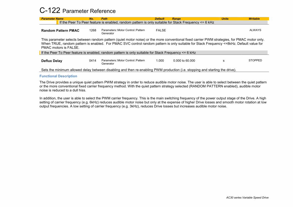
C-122 Parameter Reference
AC30 series Variable Speed Drive
Parameter Name No. Path Default Range Units Writable If the Peer To Peer feature is enabled, random pattern is only suitable for Stack Frequency <= 6 kHz
Random Pattern PMAC
1268
Parameters::Motor Control::Pattern Generator
FALSE
ALWAYS
This parameter selects between random pattern (quiet motor noise) or the more conventional fixed carrier PWM strategies, for PMAC motor only. When TRUE, random pattern is enabled. For PMAC SVC control random pattern is only suitable for Stack Frequency <=8kHz. Default value for PMAC motors is FALSE. If the Peer To Peer feature is enabled, random pattern is only suitable for Stack Frequency <= 6 kHz Deflux Delay
0414
Parameters::Motor Control::Pattern Generator
1.000
0.000 to 60.000
s
STOPPED
Sets the minimum allowed delay between disabling and then re-enabling PWM production (i.e. stopping and starting the drive).
Functional Description The Drive provides a unique quiet pattern PWM strategy in order to reduce audible motor noise. The user is able to select between the quiet pattern or the more conventional fixed carrier frequency method. With the quiet pattern strategy selected (RANDOM PATTERN enabled), audible motor noise is reduced to a dull hiss. In addition, the user is able to select the PWM carrier frequency. This is the main switching frequency of the power output stage of the Drive. A high setting of carrier frequency (e.g. 6kHz) reduces audible motor noise but only at the expense of higher Drive losses and smooth motor rotation at low output frequencies. A low setting of carrier frequency (e.g. 3kHz), reduces Drive losses but increases audible motor noise.

Parameter Reference C-123
AC30 series Variable Speed Drive
Peer to Peer Setup::Communications::Peer to Peer Monitor:: Communications::Peer to Peer Parameters::Base Comms::Peer to Peer Refer to Chapter 8 “Ethernet”.
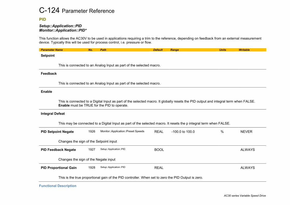
C-124 Parameter Reference
AC30 series Variable Speed Drive
PID Setup::Application::PID Monitor::Application::PID* This function allows the AC30V to be used in applications requiring a trim to the reference, depending on feedback from an external measurement device. Typically this will be used for process control, i.e. pressure or flow.
Parameter Name No. Path Default Range Units Writable
Setpoint
This is connected to an Analog Input as part of the selected macro.
Feedback
This is connected to an Analog Input as part of the selected macro.
Enable
This is connected to a Digital Input as part of the selected macro. It globally resets the PID output and integral term when FALSE. Enable must be TRUE for the PID to operate.
Integral Defeat
This may be connected to a Digital Input as part of the selected macro. It resets the p integral term when FALSE.
PID Setpoint Negate 1926 Monitor::Application::Preset Speeds REAL -100.0 to 100.0 % NEVER
Changes the sign of the Setpoint input
PID Feedback Negate 1927 Setup::Application::PID BOOL ALWAYS
Changes the sign of the Negate input
PID Proportional Gain 1928 Setup::Application::PID REAL ALWAYS
This is the true proportional gain of the PID controller. When set to zero the PID Output is zero.
Functional Description

Parameter Reference C-125
AC30 series Variable Speed Drive
Kp(1+sTi)(1+sTd)sTi(1+sTf)
D TIME CONST
I TIME CONST
P GAIN
ENABLE
INTEGRAL DEFEAT
X PID OUTPUT
OUTPUT NEG LIMIT
OUTPUT POS LIMIT OUTPUT SCALING
SETPOINT
FEEDBACK
SETPOINT NEGATE
FEEDBACK NEGATE
+100.00%
-100.00%
PID ERROR
sign change
sign change

C-126 Parameter Reference
AC30 series Variable Speed Drive
PMAC Flycatching Parameters::Motor Control::PMAC Flycatching Only available if PMAC MOTOR selected in Control Mode. This block performs a directional speed search. It allows the Drive to seamlessly catch a spinning motor before controlling the motor to the desired setpoint. This is especially useful for large inertia fan loads, where drafts in building air ducts can cause a fan to `windmill’.
Parameter Name No. Path Default Range Units Writable PMAC Flycatching Enable
0689
Parameters::Motor Control::PMAC Flycatching
FALSE
ALWAYS
Enable the flycatching for PMAC motor
PMAC Fly Search Mode
0690
Parameters::Motor Control::PMAC Flycatching
0
Same as PNO 312
ALWAYS
The PMAC Flycatching sequence can be triggered by different starting conditions:
ALWAYS: All starts (after controlled or uncontrolled stop, or after a power-up)
TRIP or POWER-UP: After uncontrolled stop, i.e. trip or coast, or after a power-up
TRIP: After uncontrolled stop, i.e. trip or coast
PMAC Fly Search Time
0691
Parameters::Motor Control::PMAC Flycatching
0.200
0.100 to 60.000
s
ALWAYS
PMAC Fly Search Time to catch the right speed
PMAC Fly Load Level
0692
Parameters::Motor Control::PMAC Flycatching
5.0
-50.0 to 50.0
%
ALWAYS
PMAC Fly Load Level during fly catching
PMAC Fly Active
0693
Parameters::Motor Control::PMAC Flycatching
NEVER
Diagnostic to show if the PMAC fly catching is active or inactive

Parameter Reference C-127
AC30 series Variable Speed Drive
Parameter Name No. Path Default Range Units Writable PMAC Fly Setpoint
0694
Parameters::Motor Control::PMAC Flycatching
x.
-1000 to 1000
Hz
NEVER
PMAC Fly Setpoint
Functional Description The flycatching function enables the drive to be restarted smoothly into a spinning motor.

C-128 Parameter Reference
AC30 series Variable Speed Drive
PMAC Motor Advanced Parameters::Motor Control::PMAC Motor Advanced Only available if PMAC Motor selected in Control Mode. The PMAC Motor Advanced allows to move the current setpoint of a PMAC Motor to the D and Q axis, adding a predictive phase shift to the current. The phase shift is proportional to the current level. By default, values are set to Zero. Only change values if data are from the motor manufacturer.
Parameter Name No. Path Default Range Units Writable Phase at Rated Curent
1858
Parameters::Motor Control::PMAC Motor Advanced
0.0
0.0 to 90.0
deg
STOPPED
Phase advance in electrical degrees on current at rated current level. The value applied is proportional to the current level.
The current setpoint is separated into D and Q axis :
Cos of the angle is applied to the Q axis.
Sin of the angle is applied to the D axis.
Max Phase
1859
Same as PNO 1858
0.0
0.0 to 90.0
deg
STOPPED
Max phase advance applied to the current.
current
Rated Current
Phase at Rated Current
Max Phase
Angle ( deg )
Id
IqIsetpoint
Angle
Iq = Isetpoint*cos(angle)Id = -Isetpoint*sin(angle )
Isetpoint
Id
Iq

Parameter Reference C-129
AC30 series Variable Speed Drive
PMAC Motor Data Setup::Motor Control::MotorData PMAC Parameters::Motor Control::PMAC Motor Data Only available if PMAC Motor selected in Control Mode. The PMAC Motor Data contains the parameters needed to run and control of a PMAC motor. A PMAC motor is a Permanent Magnet AC Motor with sinusoidal back EMF.
Parameter Name No. Path Default Range Units Writable PMAC Max Speed
0555
Setup::Motor Control::Motor Data PMAC Parameters::Motor Control::PMAC Motor Data
3000
0 to 100000
RPM
ALWAYS
Set the motor’s rated speed in rpm.
PMAC Max Current
0556
Same as PNO 555
4.50
0.00 to 5000.00
A
ALWAYS
Set the motor’s maximum current ( Amps rms ).
PMAC Rated Current
0557
Same as PNO 555
4.50
0.00 to 5000.00
A
ALWAYS
Set the motor’s rated current ( Amps rms ).
Refer to Motor Current Percent in the Feedbacks function. A value of 100% = PMAC rated Current.
PMAC Rated Torque
0558
Same as PNO 555
4.50
0.00 to 30000.00
Nm
ALWAYS
Set the motor’s rated torque.
Refer to Actual Torque in the Feedbacks function. A value of 100% = PMAC Rated Torque.
PMAC Motor Poles
0559
Same as PNO 555
10
0 to 400
ALWAYS
Set the number of motor poles, e.g. for a 4 poles motor enter "4".
PMAC Back Emf Const KE
0560
Same as PNO 555
60.0
0.0 to 30000.0
V
ALWAYS

C-130 Parameter Reference
AC30 series Variable Speed Drive
Parameter Name No. Path Default Range Units Writable
Set the motor’s Back EMF line to line, rms value (Ke, Volts rms per 1000 rpm)
PMAC Winding Resistance
0561
Same as PNO 555
6.580
0.000 to 500.000
Ohm
ALWAYS
Set the motor’s resistance, line to line at 25 °C.
PMAC Winding Inductance
0562
Same as PNO 555
20.00
0.00 to 1000.00
mH
ALWAYS
Set the motor’s inductance line to line at maximum current. This parameter is used within the current loop and is related to the overall proportional gain.
PMAC Torque Const KT
0563
Same as PNO 555
1.00
0.00 to 10000.00
Nm/A
ALWAYS
Torque constant (Kt, Nm/A rms).
This parameter is used to compute the current demand given a torque demand :
Torque demand = KT x Current demand
PMAC Motor Inertia
0564
Same as PNO 555
0.00100
0.00000 to 100.00000
kgm²
ALWAYS
Rotor inertia of motor.
PMAC Therm Time Const
0565
Same as PNO 555
62.000
0.000 to 10000.000
s
ALWAYS
Copper Thermal Time constant(s). If not known set to 300s.
This parameter is used for the motor thermal protection : Refer to Motor Load module.
It represents the time needed to reach 63% of the rated load of the motor if 100% of the rated current is applied to the motor (typical time constant of a first order low pass filter).

Parameter Reference C-131
AC30 series Variable Speed Drive
Parameter Name No. Path Default Range Units Writable PMAC Base Volt
1387
Setup::Motor Control::Motor Data PMAC Parameters::Motor Control::PMAC Motor Data
400.00
0.00 to 1000.00
V
ALWAYS
Rated motor rated voltage in Volt rms
PMAC Encoder Offset
1808
Setup::Motor Control::Motor Data PMAC Parameters::Motor Control::PMAC Motor Data
0.0
-180.0 to 180.0
deg
ALWAYS
Only available if 1533 Control Type = ENCODER FEEDBACK
Electrical position Offset between encoder Zero position and motor Back EMF
Automatically set up if Alignment sequence runs and completed
PMAC Wiring
1809
Setup::Motor Control::Motor Data PMAC Monitor::Motor and Drive Parameters::Motor Control::PMAC Motor Data
0
Same as PNO 1804
ALWAYS
Only available if 1533 Control Type = ENCODER FEEDBACK
Wiring direction of the motor phase :
- STANDARD : U V W
- REVERSE : U W V
Allow to change connection of phase V and W internally to the drive. No external action required.
Automatically set up if Alignment sequence runs and completed.
Changing this parameter will change the direction of motor rotation. Please verify if the new direction is compatible with your application.

C-132 Parameter Reference
AC30 series Variable Speed Drive
Functional Description By definition, the motor Vector Control is based on the assumption that the back EMF is crossing the 0V line in a positive direction when the electrical position is also crossing the 0° line in a positive way. Another requirement is to insure a positive ‘encoder/resolver’ rotation with a positive electrical motor rotation ( U, V, W ).
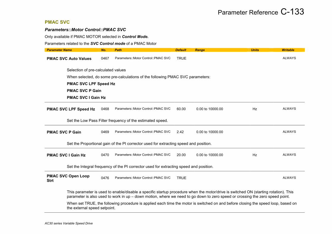
Parameter Reference C-133
AC30 series Variable Speed Drive
PMAC SVC Parameters::Motor Control::PMAC SVC Only available if PMAC MOTOR selected in Control Mode. Parameters related to the SVC Control mode of a PMAC Motor
Parameter Name No. Path Default Range Units Writable PMAC SVC Auto Values
0467
Parameters::Motor Control::PMAC SVC
TRUE
ALWAYS
Selection of pre-calculated values
When selected, do some pre-calculations of the following PMAC SVC parameters:
PMAC SVC LPF Speed Hz PMAC SVC P Gain PMAC SVC I Gain Hz
PMAC SVC LPF Speed Hz
0468
Parameters::Motor Control::PMAC SVC
60.00
0.00 to 10000.00
Hz
ALWAYS
Set the Low Pass Filter frequency of the estimated speed.
PMAC SVC P Gain
0469
Parameters::Motor Control::PMAC SVC
2.42
0.00 to 10000.00
ALWAYS
Set the Proportional gain of the PI corrector used for extracting speed and position.
PMAC SVC I Gain Hz
0470
Parameters::Motor Control::PMAC SVC
20.00
0.00 to 10000.00
Hz
ALWAYS
Set the Integral frequency of the PI corrector used for extracting speed and position. PMAC SVC Open Loop Strt
0476
Parameters::Motor Control::PMAC SVC
TRUE
ALWAYS
This parameter is used to enable/disable a specific startup procedure when the motor/drive is switched ON (starting rotation). This parameter is also used to work in up – down motion, where we need to go down to zero speed or crossing the zero speed point.
When set TRUE, the following procedure is applied each time the motor is switched on and before closing the speed loop, based on the external speed setpoint.
C-134 Parameter Reference
AC30 series Variable Speed Drive
Parameter Name No. Path Default Range Units Writable The drive must be used in speed loop mode.
When the drive is switched ON, the system is placed in open loop control.
Step 1: For a time equal to the ‘PMAC SVC Start Time’ parameter, the current is ramped to the PMAC SVC Start Cur value. The sign is dependent upon the speed loop setpoint. A normal value is between 0.5 to 1s.
Step 2: Once Step 1 is complete, the position is ramped in such a way as to follow the speed setpoint generated, based on the configuration (ramp, etc…), until the PMAC SVC Start Speed value is reached. The speed loop is then closed.
The ramp value must be kept low to ensure the motor follows the speed setpoint.
For a positive speed setpoint when the drive is switched ON :

Parameter Reference C-135
AC30 series Variable Speed Drive
Parameter Name No. Path Default Range Units Writable
Torque ON
Open Loop
Closed loop
Current setpoint (3)
Startup speed
Speed input (1)
Ramp (4)
Startup time (6)
Startup time (5)
(1) : User speed setpoint(2) : Internal speed setpoint(3) ; Internal current setpoint(4) : ramps are generated based on ramp parameters (5) : startup procedure : a current is smoothly installed into the motor(6) : startup procedure : the motor is rotated for one electrical turn

C-136 Parameter Reference
AC30 series Variable Speed Drive
Parameter Name No. Path Default Range Units Writable For a negative speed setpoint when the drive is switched ON :
Torque ON
Open Loop
Closed loop
Speed setpoint (2)
Current setpoint (3)
Startup speed
Startup current
Speed input (1)
Ramp (4)
Startup time (6)
Startup time (5)
(1) : User speed setpoint(2) : Internal speed setpoint(3) ; Internal current setpoint(4) : ramps are generated based on ramp parameters (5) : startup procedure : a current is smoothly installed into the motor(6) : startup procedure : the motor is rotated for one electrical turn
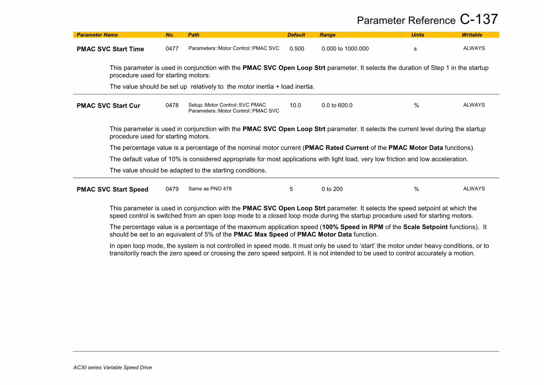
Parameter Reference C-137
AC30 series Variable Speed Drive
Parameter Name No. Path Default Range Units Writable PMAC SVC Start Time
0477
Parameters::Motor Control::PMAC SVC
0.500
0.000 to 1000.000
s
ALWAYS
This parameter is used in conjunction with the PMAC SVC Open Loop Strt parameter. It selects the duration of Step 1 in the startup procedure used for starting motors:
The value should be set up relatively to the motor inertia + load inertia.
PMAC SVC Start Cur
0478
Setup::Motor Control::SVC PMAC Parameters::Motor Control::PMAC SVC
10.0
0.0 to 600.0
%
ALWAYS
This parameter is used in conjunction with the PMAC SVC Open Loop Strt parameter. It selects the current level during the startup procedure used for starting motors.
The percentage value is a percentage of the nominal motor current (PMAC Rated Current of the PMAC Motor Data functions).
The default value of 10% is considered appropriate for most applications with light load, very low friction and low acceleration.
The value should be adapted to the starting conditions.
PMAC SVC Start Speed
0479
Same as PNO 478
5
0 to 200
%
ALWAYS
This parameter is used in conjunction with the PMAC SVC Open Loop Strt parameter. It selects the speed setpoint at which the speed control is switched from an open loop mode to a closed loop mode during the startup procedure used for starting motors.
The percentage value is a percentage of the maximum application speed (100% Speed in RPM of the Scale Setpoint functions). It should be set to an equivalent of 5% of the PMAC Max Speed of PMAC Motor Data function.
In open loop mode, the system is not controlled in speed mode. It must only be used to ‘start’ the motor under heavy conditions, or to transitorily reach the zero speed or crossing the zero speed setpoint. It is not intended to be used to control accurately a motion.

C-138 Parameter Reference
AC30 series Variable Speed Drive
Parameter Name No. Path Default Range Units Writable Up and Down Motion - Positive speed
Torque ON
Open Loop
Closed loop
Speed setpoint (2)
Current setpoint (3)
Startup speed0.75 * Startup speed
Startup current
Startup time(5)
Speed input (1)
Ramp (4)
(1) : User speed setpoint(2) : Internal speed setpoint(3) ; Internal current setpoint(4) : ramps are generated based on ramp parameters (5) : startup procedure : a current is smoothly installed into the motor

Parameter Reference C-139
AC30 series Variable Speed Drive
Parameter Name No. Path Default Range Units Writable Negative Speed
Torque ON
Open Loop
Closed loop
Speed setpoint (2)
Current setpoint (3)
Startup speed0.75 * Startup speed
Startup current
Startup time(5)
Speed input (1)
ramp (4)
(1) : User speed setpoint(2) : Internal speed setpoint(3) ; Internal current setpoint(4) : ramps are generated based on ramp parameters (5) : startup procedure : a current is smoothly installed into the motor

C-140 Parameter Reference
AC30 series Variable Speed Drive
Parameter Name No. Path Default Range Units Writable Crossing zero speed
Torque ON
Open Loop
Closed loop
Speed setpoint (2)
Current setpoint (3)
Startup speed0.75 * Startup speed
Startup current
Speed input (1)
Startup current
0.75 * Startup speed Startup speed
Ramp (4)
Startup time (5)
(1) : User speed setpoint(2) : Internal speed setpoint(3) ; Internal current setpoint(4) : ramps are generated based on ramp parameters (5) : startup procedure : a current is smoothly installed into the motor(6) : zero crossing for the speed input : the current must be inverted into the motor

Parameter Reference C-141
AC30 series Variable Speed Drive
Pos Fbk Alignment Parameters::Motor Control::Pos Fbk Alignment
Only available if PMAC MOTOR selected in Control Mode and Control Type set to ENCODER FEEDBACK . Vector Control of a PMAC motor needs to know the relative position between the rotor and the stator. By definition, the AC30 Vector Control for a PMAC Motor is based on the assumption that the motor back EMF is crossing the 0V line in a positive direction when the electrical position is also crossing the 0° line in a positive way. Another requirement is to insure a positive ‘encoder/resolver’ rotation with a positive electrical motor rotation ( U, V, W ).
This feature is used to automatically calculate any offset between the encoder absolute position and the motor back EMF, as well as selecting the correct wiring of the motor ( U, V, W sequence ) with the encoder position. The feature needs to be run at least once with a PMAC motor associated to an absolute encoder type. The feature needs to be run after each power cycle with a PMAC motor associated to a relative encoder type ( pulse encoder for example ) The feature is run on a motor free to rotate, no load attached to the motor shaft. Regardless of the Alignment Method selected, the motor should move during the sequence. If Alignment Method is set to AUTOMATIC, it is possible that the direction of motor rotation for a positive setpoint could be reversed. The parameter 1809 PMAC Wiring can be changed and overwritten by the sequence if an incompatibility of direction between the encoder and the motor phases wiring is found.
Parameter Name No. Path Default Range Units Writable Alignment Enable
1798
Setup::Motor Control::Pos Fbk Alignment Parameters::Motor Control::Pos Fbk Alignment
FALSE
STOPPED
Enable the Alignment sequence.
Alignment On Power On
1796
Setup::Motor Control::Pos Fbk Alignment Parameters::Motor Control::Pos Fbk Alignment
FALSE
STOPPED

C-142 Parameter Reference
AC30 series Variable Speed Drive
Parameter Name No. Path Default Range Units Writable
Set to TRUE, this parameter automatically trips the drive after a power up on a Start command until an Alignment sequence is run and completed successfully.
This is useful when the PMAC motor is associated to a relative encoder type and the position synchronism between encoder and motor is lost due to power off.
Alignment On Power On
1797
Setup::Motor Control::Pos Fbk Alignment Parameters::Motor Control::Pos Fbk Alignment
FALSE
0 : MANUAL 1 : AUTOMATIC 2 : DIRECTION TEST
STOPPED
Each Method is extensively described in the Functionnal Description. MANUAL :
allows to place the motor in the selected position defined by the parameter “Alignment On Motor”. This method should be selected for multi poles resolver with non integer value. AUTOMATIC: Sequence runs automatically by the drive, on a start command from the user. Allows to set up correctly the ‘encoder/resolver’ and the motor by : - Changing the motor phase connection of phase V and W internally to the drive if a mismatch is found between ‘encoder/resolver’ positive direction and positive motor electrical position - Automatically calculate the offset of position to align zero ‘encoder/resolver’ to U motor phase. DIRECTION TEST : Allows to verify the direction of positive electrical position by slowly rotating the motor. A correct wiring of the motor phases should turn the motor in a clockwise direction looking at the front shaft of the motor
Alignment Level
1799
Same as PNO 1796
50
0 to 150
%
ALWAYS
Level of current applied to the motor. Motor amps% of rated motor amps, limited to rated drive amps

Parameter Reference C-143
AC30 series Variable Speed Drive
Parameter Name No. Path Default Range Units Writable Alignment Ramp Time
1800
Same as PNO 1796
1.000
0.000 to 30.000
s
ALWAYS
Time to install the amps into the motor phase with a linear ramp.
Alignment On Motor
1801
Same as PNO 1796
0
0:PHASE U 1:PHASE V 2:PHASE W
ALWAYS
Selection of the motor phase when MANUAL method is selected. Can be PHASE U : “Alignment Elec Pos” should be 90° - PHASE V : “Alignment Elec Pos” should be 210° or -150° PHASE W : “Alignment Elec Pos” should be 330° or -30°
Alignment Offset
1802
Parameters::Motor Control::Pos Fbk Alignment
x.x
-180.0 to 180.0
deg
NEVER
Represents the offset value needed to align Zero position to motor Back EMF MANUAL : Value is calculated and passed back to 1808 PMAC Encoder Offset. AUTOMATIC : Value that has been applied to align the ‘encoder/resolver’ to the motor phase U with controls on position and motor phases. If the Alignment is completed, then this parameter is written back to 1808 PMAC Encoder Offset
Alignment Elec Pos
1803
Parameters::Motor Control::Pos Fbk Alignment
x.x
-180.0 to 180.0
deg
NEVER
Actual electrical position
Alignment Direction
1804
Parameters::Motor Control::Pos Fbk Alignment
0:STANDARD 1:REVERSE
NEVER
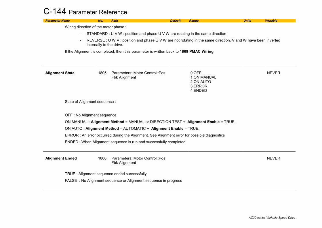
C-144 Parameter Reference
AC30 series Variable Speed Drive
Parameter Name No. Path Default Range Units Writable
Wiring direction of the motor phase :
- STANDARD : U V W : position and phase U V W are rotating in the same direction
- REVERSE : U W V : position and phase U V W are not rotating in the same direction. V and W have been inverted internally to the drive.
If the Alignment is completed, then this parameter is written back to 1809 PMAC Wiring
Alignment State
1805
Parameters::Motor Control::Pos Fbk Alignment
0:OFF 1:ON MANUAL 2:ON AUTO 3:ERROR 4:ENDED
NEVER
State of Alignment sequence :
OFF : No Alignment sequence
ON MANUAL : Alignment Method = MANUAL or DIRECTION TEST + Alignment Enable = TRUE.
ON AUTO : Alignment Method = AUTOMATIC + Alignment Enable = TRUE.
ERROR : An error occurred during the Alignment. See Alignment error for possible diagnostics
ENDED : When Alignment sequence is run and successfully completed
Alignment Ended
1806
Parameters::Motor Control::Pos Fbk Alignment
NEVER
TRUE : Alignment sequence ended successfully.
FALSE : No Alignment sequence or Alignment sequence in progress

Parameter Reference C-145
AC30 series Variable Speed Drive
Parameter Name No. Path Default Range Units Writable Alignment Error
1807
Parameters::Motor Control::Pos Fbk Alignment
0:NO ERROR 1:SHAFT LOCKED 2:AMPS 3:LOAD 4:POLES 5:MOTOR UNCONNECTED 6:ENCODER 7:INIT NEEDED
NEVER
Details of the last error recorded.
Reset to NO ERROR by running a new Alignment sequence.
NO ERROR : Everything ok. Alignment sequence is running
SHAFT LOCKED : the drive is locked in position.
AMPS : Not enough Amps to move the motor. Alignment Level too small LOAD : Not enough Amps to move the motor. Is the motor free to rotate? Is there a load on the motor?
POLES : Bad motor poles number.
MOTOR UNCONNECTED : Motor phases disconnected. Verify the motor wiring
ENCODER : Something wrong detected on encoder speed and/or position.
INIT NEEDED : When Aligmnent On Power On = TRUE and a Start command has been detected. The drive should have tripped on 46 PMAC ALIGN ERROR

C-146 Parameter Reference
AC30 series Variable Speed Drive
Functional Description The feature needs to be run after each power cycle with a PMAC motor associated to a relative encoder type ( pulse encoder for example ). The feature is run on a motor free to rotate, no load attached to the motor shaft. Regardless of the Alignment Method selected, the motor should move during the sequence. The sequence is validated by Alignment Enable input. The drive waits for a START condition to start the cycle. The sequence can be stopped by a STOP command anywhere during the cycle. A successful sequence sets Alignment Ended = TRUE. A TORQUE OFF command is needed to stop the sequence. If Alignment Method is set to AUTOMATIC, it is possible that the direction of motor rotation for a positive setpoint could be reversed. The parameter PMAC Wiring can be changed by the sequence if an incompatibility of direction between the encoder and the motor phases wiring is found. Alignment Method = MANUAL The motor is moved to an electrical position corresponding to the motor phase selected by Alignment On Motor parameter. This electrical position depends on the PMAC Wiring type selected and on the real motor phase wiring. PMAC Encoder Offset is calculated by looking at real position from the active encoder compared to theoretical position where the motor is. So, it depends also on the encoder settings ( inverted or not ). For standard connections ( correct U, V, W motor wiring sequence and position from encoder varying in a positive way looking at the motor front shaft ), position offset is extracted and written back into PMAC Encoder Offset. Correct connection of the encoder means that a clockwise rotation of the motor front shaft equals a positive position variation. Correct motor wiring means phase U, V, W rotating in a correct sequence for a clock wise rotation of the motor front shaft. Considering a standard connection, the following table gives possible encoder and PMAC Wiring settings and results on speed control :
1809 PMAC Wiring Active Encoder Invert* Correct speed control Positive Speed setpoint ** STANDARD FALSE YES Clockwise direction STANDARD TRUE NO*** REVERSE FALSE NO*** REVERSE TRUE YES Counter clockwise direction
* Active Encoder Invert refers to the active speed feedback invert parameter. ** Looking the front shaft of the motor *** The motor is uncontrolled. It could overspeed, be stalled, or running at constant speed without any control.

Parameter Reference C-147
AC30 series Variable Speed Drive
Alignment Method = DIRECTION TEST The motor is slowly rotates with the following sequence U, V, W, U, V, W….. It allows to verify the rotation direction and detect any wiring inversion on the motor phases. Active encoder Invert parameter has no effect during this test. Looking at the position form the active encoder may help to know if the active encoder is correctly wired. Considering a correct connection of the motor phases :
1809 PMAC Wiring Motor Rotation direction STANDARD Clockwise REVERSE Counter Clockwise
When running this Method, either set 1257 Seq Stop Method to DISABLE VOLTAGE or 0505 Zero Speed Threshold to 1%otherwise you may end up with a motor rotating at slow speed for 60s without any possibility to stop it.
Alignment Method = AUTOMATIC In case of a correct wiring of encoder and/or motor phases, the sequence is as follows :
During the final state ( 11 ) , the Alignment Offset is automatically calculated and is passed back to 1808 PMAC Encoder Offset Also 1809 PMAC Wiring is set to STANDARD
Current%
Elec pos
1 2 3 4 5 6 7 8 9 10 11 12States
210°
-30°
90°

C-148 Parameter Reference
AC30 series Variable Speed Drive
In the case of a wrong wiring of encoder and/or motor phases, the sequence is as follows :
From State 4 to 9, a wrong direction as been detected, and the direction should be reverted. Alignment Direction is set to REVERSE. During the final state ( 17 ), the Alignment Offset is automatically calculated and is passed back to 1808 PMAC Encoder Offset Also 1809 PMAC Wiring is set to REVERSE. In that case, the direction of motor rotation has been changed during the Pos Alignment sequence. Please verify if the new direction is compatible with your application. If you want to change it, please change the Invert parameter of the active encoder used to control the motor and run again the Pos alignment sequence. Drive settings during Pos Algnment : Some errors may occur during the Alignment sequence which are related to the setting of the drive. Please be aware of the following
- It’s better to run it with a speed setpoint at 0% ( Speed Error could end up the sequence before end )
- When running Alignment Method = DIRECTION TEST, either set 1257 Seq Stop Method to DISABLE VOLTAGE or 0505 Zero Speed Threshold to 1%
- When a resolver is used, the filter on the speed should be left at default values or set to good known values.
Current%
Elec pos
1 2 3 4 5 6 7 8 9 10 11 12 13 14 15 16 17 18States
210°
-30°
90°
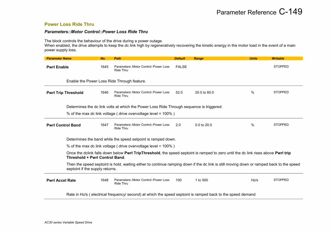
Parameter Reference C-149
AC30 series Variable Speed Drive
Power Loss Ride Thru Parameters::Motor Control::Power Loss Ride Thru The block controls the behaviour of the drive during a power outage. When enabled, the drive attempts to keep the dc link high by regeneratively recovering the kinetic energy in the motor load in the event of a main power supply loss.
Parameter Name No. Path Default Range Units Writable Pwrl Enable
1645
Parameters::Motor Control::Power Loss Ride Thru
FALSE
STOPPED
Enable the Power Loss Ride Through feature.
Pwrl Trip Threshold
1646
Parameters::Motor Control::Power Loss Ride Thru
52.0
20.0 to 60.0
%
STOPPED
Determines the dc link volts at which the Power Loss Ride Through sequence is triggered.
% of the max dc link voltage ( drive overvoltage level = 100% )
Pwrl Control Band
1647
Parameters::Motor Control::Power Loss Ride Thru
2.0
0.0 to 20.0
%
STOPPED
Determines the band while the speed setpoint is ramped down.
% of the max dc link voltage ( drive overvoltage level = 100% )
Once the dclink falls down below Pwrl TripThreshold, the speed septoint is ramped to zero until the dc link rises above Pwrl trip Threshold + Pwrl Control Band.
Then the speed septoint is hold, waiting either to continue ramping down if the dc link is still moving down or ramped back to the speed septoint if the supply returns.
Pwrl Accel Rate
1648
Parameters::Motor Control::Power Loss Ride Thru
100
1 to 500
Hz/s
STOPPED
Rate in Hz/s ( electrical frequency/ second) at which the speed septoint is ramped back to the speed demand
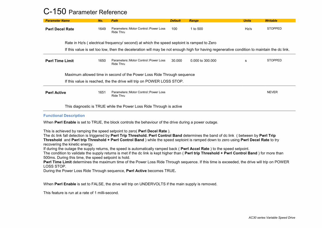
C-150 Parameter Reference
AC30 series Variable Speed Drive
Parameter Name No. Path Default Range Units Writable Pwrl Decel Rate
1649
Parameters::Motor Control::Power Loss Ride Thru
100
1 to 500
Hz/s
STOPPED
Rate in Hz/s ( electrical frequency/ second) at which the speed septoint is ramped to Zero
If this value is set too low, then the deceleration will may be not enough high for having regenerative condition to maintain the dc link.
Pwrl Time Limit
1650
Parameters::Motor Control::Power Loss Ride Thru
30.000
0.000 to 300.000
s
STOPPED
Maximum allowed time in second of the Power Loss Ride Through sequence
If this value is reached, the the drive will trip on POWER LOSS STOP.
Pwrl Active
1651
Parameters::Motor Control::Power Loss Ride Thru
NEVER
This diagnostic is TRUE while the Power Loss Ride Through is active
Functional Description When Pwrl Enable is set to TRUE, the block controls the behaviour of the drive during a power outage. This is achieved by ramping the speed setpoint to zero( Pwrl Decel Rate ). The dc link fall detection is triggered by Pwrl Trip Threshold. Pwrl Control Band determines the band of dc link ( between by Pwrl Trip Threshold and Pwrl trip Threshold + Pwrl Control Band ) while the speed septoint is ramped down to zero using Pwrl Decel Rate to try recovering the kinetic energy. If during the outage the supply returns, the speed is automatically ramped back ( Pwrl Accel Rate ) to the speed setpoint. The condition to validate the supply returns is met if the dc link is kept higher than ( Pwrl trip Threshold + Pwrl Control Band ) for more than 500ms. During this time, the speed setpoint is hold. Pwrl Time Limit determines the maximum time of the Power Loss Ride Through sequence. If this time is exceeded, the drive will trip on POWER LOSS STOP. During the Power Loss Ride Through sequence, Pwrl Active becomes TRUE. When Pwrl Enable is set to FALSE, the drive will trip on UNDERVOLTS if the main supply is removed. This feature is run at a rate of 1 milli-second.
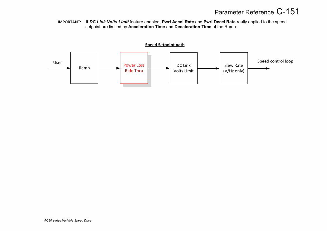
Parameter Reference C-151
AC30 series Variable Speed Drive
IMPORTANT: If DC Link Volts Limit feature enabled, Pwrl Accel Rate and Pwrl Decel Rate really applied to the speed setpoint are limited by Acceleration Time and Deceleration Time of the Ramp.
Ramp Power Loss Ride Thru
DC Link Volts Limit
Slew Rate (V/Hz only)
Speed Setpoint path
User Speed control loop

C-152 Parameter Reference
AC30 series Variable Speed Drive
Precision Time Protocol (PTP) Setup::Communications::PTP Monitor:: Communications::PTP Parameters::Base Comms::PTP Refer to Chapter 8 “Ethernet”.

Parameter Reference C-153
AC30 series Variable Speed Drive
Preset Speeds Setup::Application::Preset Speeds Monitor::Application::Preset Speeds*
This function is available when the Presets macro is selected. The Presets function selects 1 of 8 values to be used as a reference.
Parameter Name No. Path Default Range Units Writable
Preset Speed 0 1916 Setup::Application::Preset Speeds 0.0 -100.0 to 100.0 % ALWAYS Preset Speed Output when Selected Preset equals 0
Preset Speed 1 1917 Setup::Application::Preset Speeds 0.0 -100.0 to 100.0 % ALWAYS Preset Speed Output when Selected Preset equals 1
Preset Speed 2 1918 Setup::Application::Preset Speeds 0.0 -100.0 to 100.0 % ALWAYS Preset Speed Output when Selected Preset equals 2
Preset Speed 3 1919 Setup::Application::Preset Speeds 0.0 -100.0 to 100.0 % ALWAYS Preset Speed Output when Selected Preset equals 3
Preset Speed 4 1920 Setup::Application::Preset Speeds 0.0 -100.0 to 100.0 % ALWAYS Preset Speed Output when Selected Preset equals 4
Preset Speed 5 1921 Setup::Application::Preset Speeds 0.0 -100.0 to 100.0 % ALWAYS Preset Speed Output when Selected Preset equals 5
Preset Speed 6 1922 Setup::Application::Preset Speeds 0.0 -100.0 to 100.0 % ALWAYS Preset Speed Output when Selected Preset equals 6
Preset Speed 7 1923 Setup::Application::Preset Speeds 0.0 -100.0 to 100.0 % ALWAYS Preset Speed Output when Selected Preset equals 7
Selected Preset* 1924 Monitor::Application::Preset Speeds 0 to 7 NEVER Monitor showing selected preset number
Preset Speed Output 1925 Monitor::Application::Preset Speeds -100.0 to 100.0 % NEVER Monitor showing selected preset value Select 0 This is connected to a Digital Input as part of the selected macro. It provides bit 0 of the Selected Preset number. Select 1 This is connected to a Digital Input as part of the selected macro. It provides bit 1 of the Selected Preset number. Select 2 This is connected to a Digital Input as part of the selected macro. It provides bit 2 of the Selected Preset number.
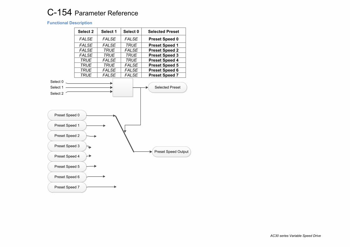
C-154 Parameter Reference
AC30 series Variable Speed Drive
Functional Description
Select 2 Select 1 Select 0 Selected Preset
FALSE FALSE FALSE Preset Speed 0 FALSE FALSE TRUE Preset Speed 1 FALSE TRUE FALSE Preset Speed 2 FALSE TRUE TRUE Preset Speed 3 TRUE FALSE TRUE Preset Speed 4 TRUE TRUE FALSE Preset Speed 5 TRUE FALSE FALSE Preset Speed 6 TRUE FALSE FALSE Preset Speed 7
Preset Speed Output
Preset Speed 0
Preset Speed 1
Preset Speed 2
Preset Speed 3
Preset Speed 4
Preset Speed 5
Preset Speed 6
Preset Speed 7
Selected PresetSelect 0Select 1Select 2
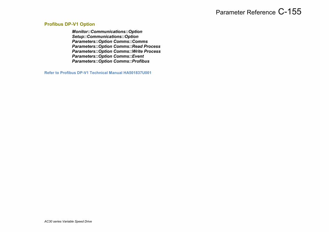
Parameter Reference C-155
AC30 series Variable Speed Drive
Profibus DP-V1 Option Monitor::Communications::Option Setup::Communications::Option Parameters::Option Comms::Comms Parameters::Option Comms::Read Process Parameters::Option Comms::Write Process Parameters::Option Comms::Event Parameters::Option Comms::Profibus
Refer to Profibus DP-V1 Technical Manual HA501837U001

C-156 Parameter Reference
AC30 series Variable Speed Drive
PROFINET IO Option Monitor::Communications::Option Setup::Communications::Option Parameters::Option Comms::Comms Parameters::Option Comms::Read Process Parameters::Option Comms::Write Process Parameters::Option Comms::Event Parameters::Option Comms::Option Ethernet Parameters::Option Comms::PROFINET IO
Refer to Profinet IO Technical Manual HA501838U001

Parameter Reference C-157
AC30 series Variable Speed Drive
Raise Lower Setup::Application::Raise Lower Monitor::Application::Raise Lower* Appears when the Raise/Lower macro is selected. The Raise/Lower function acts as an internal motorised potentiometer (MOP) used as a reference source.
Parameter Name No. Path Default Range Units Writable
RL Ramp Time 1901 Setup::Application::Raise Lower 10.0 0.0 to 600.0 s ALWAYS
Rate of change of the Output. Defined as the time to change from 0.00% to 100.00% . Note that the raise and lower rates are always the same.
RL Reset Value 1902 Setup::Application::Raise Lower 0.0 -500.0 to 500.0 % ALWAYS
The value Output is set to when the Reset Input is TRUE.
RL Maximum Value 1903 Setup::Application::Raise Lower 100.0 -500.0 to 500.0 % ALWAYS
The maximum value to which Output will ramp up to.
RL Minimum Value 1904 Setup::Application::Raise Lower -100.0 -500.0 to 500.0 %
ALWAYS
The minimum value to which Output will ramp down to.
Reset Input
This is connected to a Digital Input as part of the selected Macro. When TRUE forces Output to track Reset Value.
Raise Input
This is connected to a Digital Input as part of the selected Macro. When TRUE causes Output to ramp up.

C-158 Parameter Reference
AC30 series Variable Speed Drive
Parameter Name No. Path Default Range Units Writable
Lower Input
This is connected to a Digital Input as part of the selected Macro. When TRUE causes Output to ramp down.
Raise Lower Output 1905 Monitor::Application::Raise Lower 0.0 -500.0 to 500.0 NEVER
The ramp output monitor. Output is preserved during the power-down of the Drive.
Functional Description The table below describes how Output is controlled by Raise Input, Lower Input and Reset Input. Reset Raise Input Lower Input Action
TRUE Any Any Output tracks Reset Value FALSE TRUE FALSE Output ramps up to Maximum Value at Ramp Time FALSE FALSE TRUE Output ramps down to Minimum Value at Ramp Time FALSE FALSE FALSE Output not changed. * FALSE TRUE TRUE Output not changed. *
* If Output is greater than Maximum Value the Output will ramp down to Maximum Value at Ramp Time. If Output is less than Minimum Value the Output will ramp up to Minimum Value at Ramp Time.
IMPORTANT: If Maximum Value is less than or equal to Minimum Value, then Output is set to Maximum Value.

Parameter Reference C-159
AC30 series Variable Speed Drive
Ramp Parameters::Motor Control::Ramp
This function forms part of the reference generation. It provides the facility to control the rate at which the Drive will respond to a changing setpoint demand.
Parameter Name No. Path Default Range Units Writable Seq Stop Method VHz
0484
Setup::Motor Control::Control and Type Parameters::Motor Control::Ramp
1
0:DISABLED VOLTAGE 1:RAMP 2:STOP RAMP 3:DC INJECTION
ALWAYS
Volts/Hz control mode only
Selects stopping mode that the controller will use once the run command has been removed. The choices are:
Enumerated Value : Stopping Mode
Seq Stop Method SVC
1257
Setup::Motor Control::Control and Type Parameters::Motor Control::Ramp
1
0:DISABLED VOLTAGE 1:RAMP 2:STOP RAMP
ALWAYS
All Control modes except Volts/Hz
Selects stopping mode that the controller will use once the run command has been removed. The choices are:
Enumerated Value : Stopping Mode
When DISABLED VOLTAGE ( COAST ) is selected the motor will free-wheel. When RAMP is selected the Drive will decelerate using the reference ramp deceleration time, provided it is non-zero. When STOP RAMP is selected the motor will decelerate in Stop Ramp Time.
Acceleration Time
0486
Same as PNO 484
10.000
0.000 to 3000.000
s
ALWAYS
The time that the Drive will take to ramp the setpoint from 0.00% to 100.00% when Ramp Type is LINEAR.
Deceleration Time
0487
Same as PNO 484
10.000
0.000 to 3000.000
s
ALWAYS
The time that the Drive will take to ramp the setpoint from 100.00% to 0.00% when Ramp Type is LINEAR.
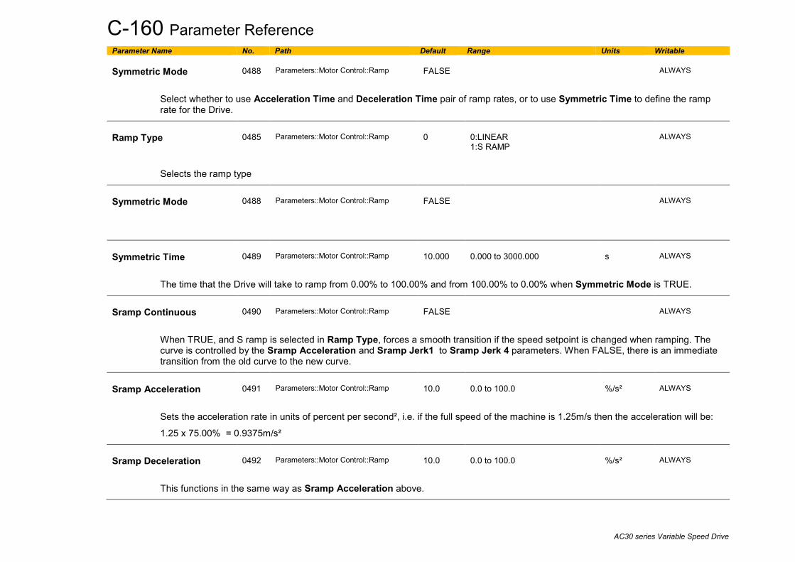
C-160 Parameter Reference
AC30 series Variable Speed Drive
Parameter Name No. Path Default Range Units Writable Symmetric Mode
0488
Parameters::Motor Control::Ramp
FALSE
ALWAYS
Select whether to use Acceleration Time and Deceleration Time pair of ramp rates, or to use Symmetric Time to define the ramp rate for the Drive.
Ramp Type
0485
Parameters::Motor Control::Ramp
0
0:LINEAR 1:S RAMP
ALWAYS
Selects the ramp type
Symmetric Mode
0488
Parameters::Motor Control::Ramp
FALSE
ALWAYS
Symmetric Time
0489
Parameters::Motor Control::Ramp
10.000
0.000 to 3000.000
s
ALWAYS
The time that the Drive will take to ramp from 0.00% to 100.00% and from 100.00% to 0.00% when Symmetric Mode is TRUE.
Sramp Continuous
0490
Parameters::Motor Control::Ramp
FALSE
ALWAYS
When TRUE, and S ramp is selected in Ramp Type, forces a smooth transition if the speed setpoint is changed when ramping. The curve is controlled by the Sramp Acceleration and Sramp Jerk1 to Sramp Jerk 4 parameters. When FALSE, there is an immediate transition from the old curve to the new curve.
Sramp Acceleration
0491
Parameters::Motor Control::Ramp
10.0
0.0 to 100.0
%/s²
ALWAYS
Sets the acceleration rate in units of percent per second², i.e. if the full speed of the machine is 1.25m/s then the acceleration will be:
1.25 x 75.00% = 0.9375m/s²
Sramp Deceleration
0492
Parameters::Motor Control::Ramp
10.0
0.0 to 100.0
%/s²
ALWAYS
This functions in the same way as Sramp Acceleration above.
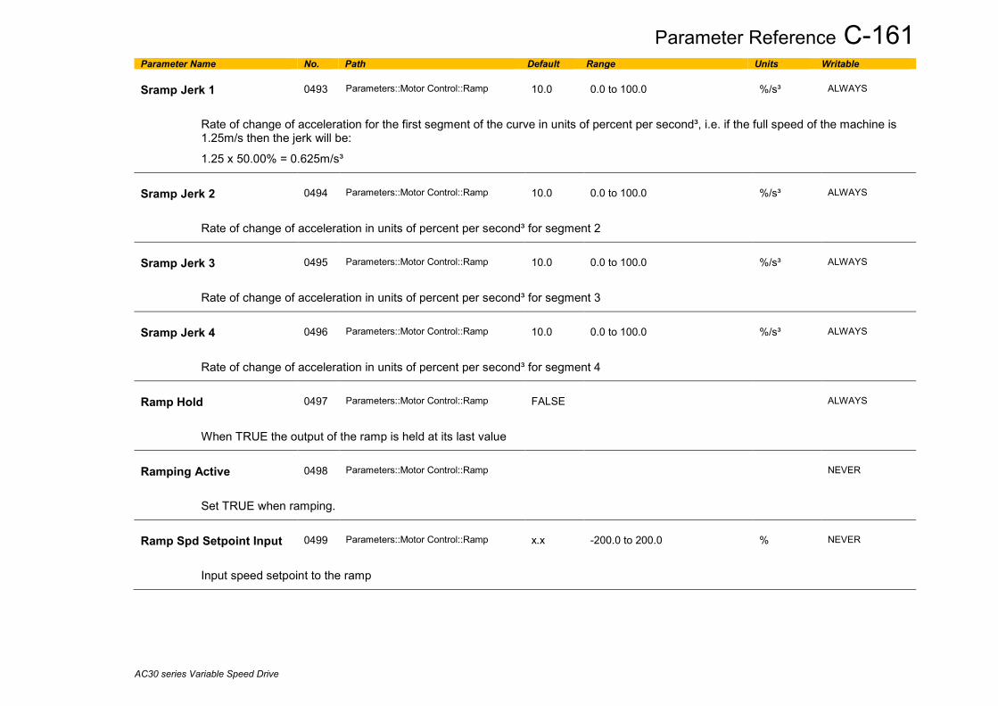
Parameter Reference C-161
AC30 series Variable Speed Drive
Parameter Name No. Path Default Range Units Writable Sramp Jerk 1
0493
Parameters::Motor Control::Ramp
10.0
0.0 to 100.0
%/s³
ALWAYS
Rate of change of acceleration for the first segment of the curve in units of percent per second³, i.e. if the full speed of the machine is 1.25m/s then the jerk will be:
1.25 x 50.00% = 0.625m/s³
Sramp Jerk 2
0494
Parameters::Motor Control::Ramp
10.0
0.0 to 100.0
%/s³
ALWAYS
Rate of change of acceleration in units of percent per second³ for segment 2
Sramp Jerk 3
0495
Parameters::Motor Control::Ramp
10.0
0.0 to 100.0
%/s³
ALWAYS
Rate of change of acceleration in units of percent per second³ for segment 3
Sramp Jerk 4
0496
Parameters::Motor Control::Ramp
10.0
0.0 to 100.0
%/s³
ALWAYS
Rate of change of acceleration in units of percent per second³ for segment 4
Ramp Hold
0497
Parameters::Motor Control::Ramp
FALSE
ALWAYS
When TRUE the output of the ramp is held at its last value
Ramping Active
0498
Parameters::Motor Control::Ramp
NEVER
Set TRUE when ramping.
Ramp Spd Setpoint Input
0499
Parameters::Motor Control::Ramp
x.x
-200.0 to 200.0
%
NEVER
Input speed setpoint to the ramp

C-162 Parameter Reference
AC30 series Variable Speed Drive
Parameter Name No. Path Default Range Units Writable Ramp Speed Output
0500
Parameters::Motor Control::Ramp
x.x
-200.0 to 200.0
%
NEVER
Output speed
Jog Setpoint
0501
Parameters::Motor Control::Ramp
10.0
0.0 to 100.0
%
ALWAYS
The setpoint is the target reference that the Drive will ramp to
Jog Acceleration Time
0502
Parameters::Motor Control::Ramp
1.000
0.000 to 3000.000
s
ALWAYS
The time that the Drive will take to ramp the jog setpoint from 0.00% to 100.00%.
Jog Deceleration Time
0503
Parameters::Motor Control::Ramp
1.000
0.000 to 3000.000
s
ALWAYS
The time that the Drive will take to ramp the jog setpoint from 100.00% to 0.00%.
Stop Ramp Time
0504
Same as PNO 484
10.000
0.000 to 600.000
s
ALWAYS
Rate at which the demand is ramped to zero after the ramp has been quenched
Zero Speed Threshold
0505
Parameters::Motor Control::Ramp
0.1
0.0 to 100.0
%
ALWAYS
Hold for zero speed detection used by stop sequences
Zero Speed Stop Delay
0506
Parameters::Motor Control::Ramp
0.500
0.000 to 30.000
s
ALWAYS
Sets the time at which the Drive holds zero speed before quenching after a normal stop or a jog stop. This may be particularly useful if a mechanical brake requires time to operate at zero speed, or for jogging a machine to position

Parameter Reference C-163
AC30 series Variable Speed Drive
Parameter Name No. Path Default Range Units Writable Quickstop Time Limit
0507
Parameters::Motor Control::Ramp
30.000
0.000 to 3000.000
s
ALWAYS
Maximum time that the Drive will try to Quickstop, before quenching
Quickstop Ramp Time
0508
Parameters::Motor Control::Ramp
0.100
0.000 to 600.000
s
ALWAYS
Rate at which the Speed Demand is ramped to zero when Quickstop is active
Final Stop Rate
0509
Parameters::Motor Control::Ramp
1200
1 to 4800
Hz/s
ALWAYS
Rate at which any internally generated setpoint trims are removed. For example, the trim due to the slip compensation in Volts/Hz control mode.

C-164 Parameter Reference
AC30 series Variable Speed Drive
Functional Description The s-ramp output takes the form shown below.
-20
-10
0
10
20
30
40
50
60
Time (secs)
%
Jerk Acceleration Velocity
Jerk 3
Jerk 4
Jerk 2
Jerk 1
Acceleration Deceleration

Parameter Reference C-165
AC30 series Variable Speed Drive
Real Time Clock Parameters::Device Manager::Real Time Clock
Parameter Name No. Path Default Range Units Writable Time and Date
1186
Parameters::Device Manager::Real Time Clock
1970/01/01
1970/01/01 to 2038/01/19
ALWAYS
Time and Date in the format yyyy/mm/dd hh:mm:ss
Time Zone Offset
1228
Parameters::Device Manager::Real Time Clock
0.00
-14.00 to 14.00
ALWAYS
A value in hours that defines the difference between Coordinated Universal Time, (UTC), and local time. UTC is equivalent to Grenwich Mean Time, (GMT). This value is required when the time is to be set from a network source using the SNTP client.
DST Active
1225
Parameters::Device Manager::Real Time Clock
FALSE
ALWAYS
When TRUE, one hour is added to the internal time before being presented as the value in “Time and Date”.
Functional Description IO Option Fitted with Real Time Clock When an IO Option is fitted, (part number 7004-01-00 or 7004-02-00), “Time and Date” reports the time from the associated Real Time Clock hardware. On receiving an IO Option from the factory the time is not set and the value will be fixed at 1970/01/01 00:00:00. To set the correct time write to parameter 1186, or enable the SNTP client if an NTP master is available. Once set the RTC hardware on the IO option will maintain the time even when power to the drive is removed.
SNTP Client When the SNTP client is enabled, “Time and Date” is updated from the NTP master, adjusted for Time Zone and DST.
SNTP Server When the SNTP server is enabled, the value of “Time and Date” is adjusted for Time Zone and DST then transmitted to any requesting clients.
No IO Option When no IO Option is fitted “Time and Date” may be used as the destination of a broadcast time from a communications master.

C-166 Parameter Reference
AC30 series Variable Speed Drive
Resolver Setup::Inputs and Outputs::Option Parameters::Option IO::Resolver
Parameter Name No. Path Default Range Units Writable Resolver Voltage
1790
Setup::Inputs and Outputs::Option Parameters::Option IO::Resolver
4
0:0V 1:4V 2:5V 3:6V 4:7V 5:8V 6:9V 7:10V 8:11V 9:12V
STOPPED
The r.m.s. amplitude of the sinusoidal excitation voltage output. This is set to the resolver’s requirement. Setting 0V will disable the excitation output.
Resolver Frequency
1791
Same as PNO 1790
8.0
2.0 to 20.0
kHz
STOPPED
The frequency of the sinusoidal excitation voltage output. This is set to the resolver’s requirement.
Resolver Ratio
1792
Same as PNO 1790
0.50
0.15 to 3.00
STOPPED
The ratio of the amplitudes of the sine / cosine feedbacks to the excitation voltage output. This is set to the resolver’s characteristic.
Resolver Max Speed
1825
Setup::Inputs and Outputs::Option Parameters::Option IO::Resolver
20000
0 to 120000
RPM
STOPPED
The maximum operating resolver shaft speed required. This is set to the application requirements, which must be no greater than the resolver rating. If the resolver is not the active feedback, this is used to auto-select the best possible speed / position resolution.

Parameter Reference C-167
AC30 series Variable Speed Drive
Parameter Name No. Path Default Range Units Writable Resolver Poles
1793
Same as PNO 1790
2,
2 to 100
STOPPED
The number of poles in the resolver. This is set to the resolver’s characteristic A 2-pole resolver has one sine / cosine amplitude cycle for each mechanical rotation of the shaft. Resolver Speed Hz
1822
Parameters::Option IO::Resolver
x.x
Hz
NEVER
The mechanical gearing of the resolver, reflecting resolver shaft turns per resolver coil turn. This is set to the resolver’s characteristic. For example, a multi-turn 2-pole resolver, that requires 10 resolver shaft rotations for each sine / cosine amplitude cycle, would use value 10.0. Resolver Invert
1810
Same as PNO 1790
FALSE
STOPPED
Used to set the direction of rotation which results in the position increasing positively, and the speed reporting as positive. Resolver Position
1824
Same as PNO 1811
NEVER
(ENGINEER view level only.) Actual resolver coil position, expressed as a count value, where one complete amplitude cycle is 65536 counts. Resolver Turns
1811
Monitor::Inputs and Outputs Parameters::Option IO::Resolver
NEVER
The integer number of completed resolver shaft mechanical turns. Resolver Fraction Turns
1812
Same as PNO 1811
NEVER
The fractional part of the number of resolver shaft mechanical turns. Resolver Speed Filter
1815
Same as PNO 1790
1000
10 to 10000
%
ALWAYS
The corner frequency of the speed-tracking, single-order filter applied to the raw resolver speed, before it is reported in the Resolver Speed parameters or used as speed feedback. Expressed in terms of the ratio of filter corner frequency to raw resolver cycle frequency. Used to remove speed ripple caused by the resolver measurement, particularly when the option is used as a reference speed input.

C-168 Parameter Reference
AC30 series Variable Speed Drive
Parameter Name No. Path Default Range Units Writable Resolver Min Filter
1851
Same as PNO 1825
100
10 to 1000
Hz
ALWAYS
Limit applied as the minimum corner frequency of the speed-tracking, single-order filter applied to the raw resolver speed. Used to prevent the speed-tracking filter from causing control instabilities at low speed. Resolver Actual Filter
1826
Parameters::Option IO::Resolver
x.
20 to 8000
Hz
NEVER
The actual corner frequency being used for the speed-tracking, single-order filter applied to the raw resolver speed. The actual filter corner frequency is limited to 8000Hz maximum. Resolver Speed RPM
1813
Parameters::Option IO::Resolver
x.x
RPM
NEVER
Resolver mechanical speed diagnostic / output. Resolver Speed %
1814
Same as PNO 1811
x.x
%
NEVER
Resolver mechanical speed diagnostic / output. Resolver Speed Hz
1821
Parameters::Option IO::Resolver
x.x
Hz
NEVER
Resolver mechanical speed diagnostic / output. Resolver Speed Ripple
1823
Parameters::Option IO::Resolver
x.xx
0.00 to 1000.00
%
NEVER
The peak-to-peak ripple in resolver speed samples. Used to assist the trimming process which gain matches the sine to cosine inputs. Calculated from max. speed – min. speed over last 128 samples on a 1ms sampling interval. % is scaled by 464 100% Speed in RPM Resolver Resolution
1816
Same as PNO 1790
0
0:AUTO 1:12 BITS 2:14 BITS 3:16 BITS
STOPPED
The target resolution setting for the speed / position feedback. See ‘Specifications’ for limitations, prior to changing this parameter. The ‘AUTO’ setting is used to automatically select the best, allowable resolution, given other parameter settings. The resolution setting affects the dynamic performance of the feedback. In ‘AUTO’ mode, the actual resolution in use may be different from the target resolution, depending on other parameter settings Only change this parameter when motor is stopped / torque is off.

Parameter Reference C-169
AC30 series Variable Speed Drive
Parameter Name No. Path Default Range Units Writable Resolver Active Resol
1827
Parameters::Option IO::Resolver
Same as PNO 1816
NEVER
The actual resolution setting for the speed / position feedback. The resolution setting affects the dynamic performance of the feedback. In ‘AUTO’ mode, the actual resolution in use may be different from the target resolution, depending on other parameter settings : 12 BITS only use for excitation between 6kHz and 20kHz. 14 BITS only use for excitation between 3kHz and 12kHz, and max. speed parameter set < 30000rpm. Max speed* set up < 30000RPM 16 BITS only use for excitation between 2kHz and 10kHz, and max. speed parameter set < 7500rpm. Max speed* set up < 7500RPM (*) : if the option is the active feedback, then Max speed = 464 100% Speed in RPM If the opion is not the active feedback, then Max speed = 1825 Resolver Max Speed Resolver State
1817
Parameters::Option IO::Resolver
0:POWER_ON 1:RESET 2:ACTIVE 3:TRIPPED 4:RESTART
NEVER
The state of the Resolver Feedback Option. ACTIVE = Operating TRIPPED = Not-Operating due to a detected fault (see parameter Resolver Trip Type). 1A fault detected when the option is being used as the active feedback will cause a drive trip, stopping the motor. Resolver Turns Reset
1818
Parameters::Option IO::Resolver
FALSE
ALWAYS
Used to reset both the Resolver Turns and Fraction Turns to zero, and Resolver Trip Type. The turns count parameters are held at zero whilst this parameter is held TRUE. The state of this parameter does not affect the operation of the resolver as a speed / position feedback, it only affects the turn count diagnostics. Resolver Reset Power On
1819
Parameters::Option IO::Resolver
FALSE
STOPPED
When TRUE the Resolver Turns and Resolver Fraction Turns parameters are reset to zero on drive power-on. When FALSE the Resolver Turns and Resolver Fraction Turns parameters will persist through power cycling. The absolute shaft position with be retained, provided that no more than 180° of resolver coil rotation has occurred during the power-off state.

C-170 Parameter Reference
AC30 series Variable Speed Drive
Parameter Name No. Path Default Range Units Writable Resolver Trip Type
1820
Parameters::Option IO::Resolver
0:NONE 1:PARITY 2:PHASE ERROR 3:MAX VELOCITY 4:TRACKING ERROR 5:SIN COS MISMATCH 6:SIN COS OVERRANGE 7:SIN COS BELOW LOS 8:SIN COS CLIPPED
NEVER
Diagnostic that indicates the current (or most recent) trip type on the resolver option. May be reset to NONE by using parameter ‘Resolver Turns Reset’. Value meanings: PARITY : Parity error in the configuration register of the option. Contact Parker for assistance. PHASE ERROR : Phase lag from excitation output to sin / cos inputs exceeds operating limit. Check resolver specification. MAX VELOCITY : Velocity exceeds maximum tracking rate. Select resolver with built-in gearing to reduce resolver velocity. TRACKING ERROR : Position tracking phase locked loop has exceeded its maximum error limit. Use a lower acceleration rate or select a lower target resolution. SIN COS MISMATCH : The amplitudes of the sine and cosine inputs differ excessively. Check input connections, and gain matching potentiometer setting. SIN COS OVERRANGE : One or both of the sine / cosine input signals is overrange. Check that the Resolver Ratio parameter is set correctly, and that the input signals do not exceed 12.5Vrms. SIN COS BELOW LOS : One or both of the sine / cosine input signals is underrange. Check that the Resolver Ratio parameter is set correctly, and that the input signals are at least 1.6Vrms. SIN COS CLIPPED : One or both of the sine / cosine input signals is overrange and being clipped. Check that the Resolver Ratio parameter is set correctly, and that the input signals do not exceed 12.5Vrms.

Parameter Reference C-171
AC30 series Variable Speed Drive
Runtime Statistics Parameters::Device Manager::Runtime Statistics
Parameter Name No. Path Default Range Units Writable Control Board Up Time
1139
Parameters::Device Manager::Runtime Statistics
0 to Max
s
NEVER
The total time in seconds for which the control module has been powered, either by 24v or from the 3-phase supply. Set to zero during manufacture.
Time Since Power-On
1733
Parameters::Device Manager::Runtime Statistics
0.000 to Max
s
NEVER
The time in seconds since power was applied to the control module, either by 24v or from the 3-phase supply.
HV SMPS Up Time
1252
Parameters::Device Manager::Runtime Statistics
0 to Max
s
NEVER
The time in seconds for which the drive has been powered from the 3-phase supply.
HV Power On Count
1406
Parameters::Device Manager::Runtime Statistics
0 to 65535
NEVER
The number of times that the drive has been powered up from the 3-phase supply
Motor Run Time
1407
Parameters::Device Manager::Runtime Statistics
0 to Max
s
NEVER
The time in seconds for which the drive has been controlling a motor
Motor Start Count
1732
Parameters::Device Manager::Runtime Statistics
0 to Max
NEVER
The total number of motor starts, (from when the control card was manufactured).

C-172 Parameter Reference
AC30 series Variable Speed Drive
Parameter Name No. Path Default Range Units Writable Time Since Power-On
1733
Parameters::Device Manager::Runtime Statistics
0.000 to Max
s
NEVER
The time in seconds since power was applied to the control module, (either 24v or 3-phase power).
Functional Description The Runtime Statistics group of parameters indicate the working age of the drive. The Control Board Up Time value is used as a reference when recording the time at which a trip occurs. Similarly, the HV SMPS Up Time is used as a reference when recording the time at which a disabled trip event occurs when the drive is operating in Fire Mode, (see Chapter 13: Fire Mode, and HA502134U002 “Fan Control Application” manual).

Parameter Reference C-173
AC30 series Variable Speed Drive
SB Digital IO Parameters::System Board:: SB Digital IO
Parameter Name No. Path Default Range Units Writable SB Digital Input 1
1759
Monitor::Inputs and Outputs Parameters::System Board::SB Digital IO
NEVER
Digital input from X30.1, TRUE for a high voltage and FALSE for a low voltage.
SB Digital Input 2
1722
Monitor::Inputs and Outputs Parameters::System Board::SB Digital IO
NEVER
Digital input from X30.2, TRUE for a high voltage and FALSE for a low voltage.
SB Digital Input 3
1723
Same as PNO 1722
NEVER
Digital input from X30.3, TRUE for a high voltage and FALSE for a low voltage.
SB Digital Input 4
1365
Monitor::Inputs and Outputs Parameters::System Board::SB Digital IO
NEVER
Digital input from X34.5, TRUE for a high voltage and FALSE for a low voltage. Shared with SB Digital Output 1
SB Digital Input 5
1366
Same as PNO 1365
NEVER
Digital input from X34.6, TRUE for a high voltage and FALSE for a low voltage. Shared with SB Digital Output 2
SB Digital Input 6
1367 Same as PNO 1365
NEVER
Digital input from X34.7, TRUE for a high voltage and FALSE for a low voltage. Shared with SB Digital Output 3

C-174 Parameter Reference
AC30 series Variable Speed Drive
Parameter Name No. Path Default Range Units Writable SB Digital In 1 Invert
1332
Parameters::System Board::SB Digital IO
FALSE
ALWAYS
Inverts the value of SB Digital Input 1
SB Digital In 2 Invert
1333
Parameters::System Board::SB Digital IO
FALSE
ALWAYS
Inverts the value of SB Digital Input 2
SB Digital In 3 Invert
1334
Parameters::System Board::SB Digital IO
FALSE
ALWAYS
Inverts the value of SB Digital Input 3
SB Digital In 4 Invert
1368
Parameters::System Board::SB Digital IO
FALSE
ALWAYS
Inverts the value of SB Digital Input 4
SB Digital In 5 Invert
1369
Parameters::System Board::SB Digital IO
FALSE
ALWAYS
Inverts the value of SB Digital Input 5
SB Digital In 6 Invert
1370
Parameters::System Board::SB Digital IO
FALSE
ALWAYS
Inverts the value of SB Digital Input 6
SB Digital Output 1
1371
Parameters::System Board::SB Digital IO
FALSE
ALWAYS
The value to output on X34.5. TRUE for a high voltage, FALSE for zero volts. Shares the terminal with SB Digital Input 4.

Parameter Reference C-175
AC30 series Variable Speed Drive
Parameter Name No. Path Default Range Units Writable SB Digital Output 2
1372
Parameters::System Board::SB Digital IO
FALSE
ALWAYS
The value to output on X34.6. TRUE for a high voltage, FALSE for zero volts. Shares the terminal with SB Digital Input 5.
SB Digital Output 3
1373
Parameters::System Board::SB Digital IO
FALSE
ALWAYS
The value to output on X34.7. TRUE for a high voltage, FALSE for zero volts. Shares the terminal with SB Digital Input 6.
SB Dig Out 1 Invert
1374
Parameters::System Board::SB Digital IO
FALSE
ALWAYS
Inverts the value to be used for SB Digital Output 1
SB Dig Out 2 Invert
1375
Parameters::System Board::SB Digital IO
FALSE
ALWAYS
Inverts the value to be used for SB Digital Output 2
SB Dig Out 3 Invert
1376
Parameters::System Board::SB Digital IO
FALSE
ALWAYS
Inverts the value to be used for SB Digital Output 2
Functional Description These parameters are used to configure the system board outputs and to monitor the system board inputs.

C-176 Parameter Reference
AC30 series Variable Speed Drive
SB Encoder Setup:: Inputs and Outputs::SB Encoder Monitor::SB Encoder Parameters::System Board::SB Encoder The AC30A Encoder block provides the means for selecting the type of Encoder connected on the AC30A system board type
Parameter Name No. Path Default Range Units Writable Encoder Supply
1874
Setup::Inputs and Outputs::SB Encoder Parameters::System Board::SB Encoder
0
0:5V 1:10V
STOPPED
Allows the user to select the correct supply voltage for the pulse encoder.
Encoder Type
1875
Same as PNO 1874
0
0:SIN COS 1: ENDAT 2.1 ST 2: ENDAT 2.1 MT
STOPPED
Allows the user to select the encoder type connected.
SINCOS type is incremental encoder type. Associated to a PMAC motor, setting up the position offset needs to be done at each drive power on or after a trip related to the encoder. ENDAT 2.1 ST is endat single turn encoder type. ENDAT2.1 MT is endat mutli turn encoder type.
Encoder Lines
1876
Same as PNO 1874
512
1 to 1048576
STOPPED
Allows the user to select the correct number of lines per one encoder revolution.
Encoder Invert
1877
Same as PNO 1874
FALSE
STOPPED
Reverses the encoder direction if set to TRUE. The encoder direction needs to be correct if encoder feedback is used to control the motor in vector mode. The autotune identifies whether the parameter is in the correct state required to control the motor, and changes it if necessary ( for Induction motor only ). It is possible to do this manually, by attempting to run the motor, and changing the parameter if necessary until the motor is controlled correctly.
Encoder Speed
1892
Same as PNO 1878
x.
RPM
NEVER
The encoder mechanical speed measured by the encoder, in revolutions per minute.

Parameter Reference C-177
AC30 series Variable Speed Drive
Parameter Name No. Path Default Range Units Writable Encoder Speed Percent
1893
Parameters::System Board::SB Encoder
x.xx
%
NEVER
The encoder mechanical speed measured by the encoder, in %. 100% refers to 100% Speed in RPM ( 0464 )
Encoder Count
1878
Monitor::System Board::SB Encoder Parameters::System Board::SB Encoder
NEVER
The encoder count will increment and decrement with the encoder lines multiplied by 4, up to encoder lines by 4 or down to zero. It provides the line count on one mechanical encoder revolution and is the absolute position in case of Absolute encoder.
Encoder Rev Count
1879
Same as PNO 1878
NEVER
The encoder count is a 32 bit counter which will increment and decrement with the encoder rev.
When using a SinCos, the count may vary between 0 to 4095.
Encoder Position
1310
Parameters::System Board::SB Encoder
x.xx
-180.00 to 180.00
deg
NEVER
Mechanical encoder position in degrees on one mechanical encoder turn
Enc To Mot Shaft Ratio
1231
Setup::Inputs and Outputs::SB Encoder Parameters::System Board::SB Encoder
1
1 to 50
STOPPED
Ratio between encoder turn and shaft motor turn in case of pulley belt system. Represents the number of encoder turn for a shaft motor turn. This value must be compatible with the number of motor poles : dividing the number of motor poles by this number should give an integer value.
Motor Count
1898
Parameters::System Board::SB Encoder
NEVER
32 bit counter reflecting the motor equivalent encoder lines count times 4 and times the encoder to motor shaft ratio. Reset when Reset Motor Count is active.
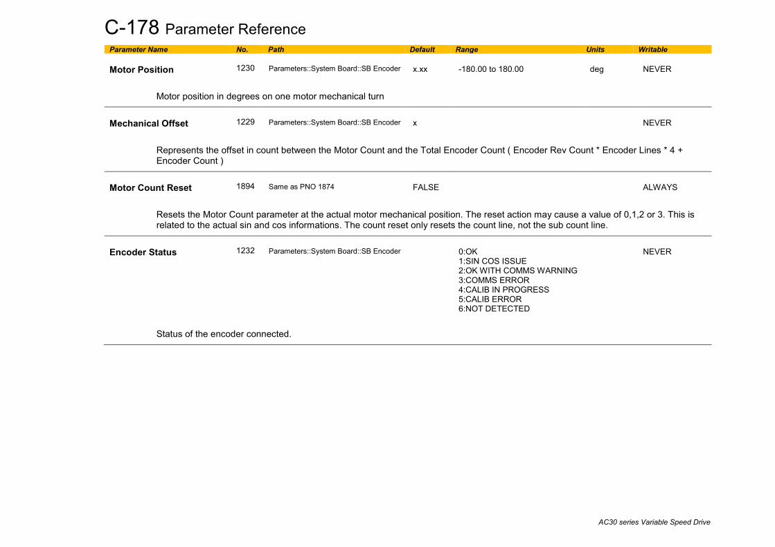
C-178 Parameter Reference
AC30 series Variable Speed Drive
Parameter Name No. Path Default Range Units Writable Motor Position
1230
Parameters::System Board::SB Encoder
x.xx
-180.00 to 180.00
deg
NEVER
Motor position in degrees on one motor mechanical turn
Mechanical Offset
1229
Parameters::System Board::SB Encoder
x
NEVER
Represents the offset in count between the Motor Count and the Total Encoder Count ( Encoder Rev Count * Encoder Lines * 4 + Encoder Count )
Motor Count Reset
1894
Same as PNO 1874
FALSE
ALWAYS
Resets the Motor Count parameter at the actual motor mechanical position. The reset action may cause a value of 0,1,2 or 3. This is related to the actual sin and cos informations. The count reset only resets the count line, not the sub count line.
Encoder Status
1232
Parameters::System Board::SB Encoder
0:OK 1:SIN COS ISSUE 2:OK WITH COMMS WARNING 3:COMMS ERROR 4:CALIB IN PROGRESS 5:CALIB ERROR 6:NOT DETECTED
NEVER
Status of the encoder connected.

Parameter Reference C-179
AC30 series Variable Speed Drive
SB Encoder Slot 1 Parameters::System Board::Encoder Slot 1 This feature allows you to setup and monitor the operation of the encoder attached to slot 1 of the system board.
Parameter Name No. Path Default Range Units Writable Encoder Supply
1663
Setup::Inputs and Outputs::SB Encoder Slot1 Parameters::System Board::SB Encoder Slot 1
0
0:5 V 1:12 V 2:15 V 3:20 V
STOPPED
Configures the encoder supply for both Encoder 1 and Encoder 2
Encoder Lines
1664
Same as PNO 1663
2048
1 to 100000
STOPPED
The number of lines per encoder revolution
Encoder Invert
1665
Same as PNO 1663
FALSE
STOPPED
Reverses the encoder direction if TRUE.
Encoder Type
1666
Same as PNO 1663
0
0:QUADRATURE 1:CLOCK/DIRECTION
Normally the encoder will be quadrature. Exceptionally, eg if a proximity sensor or other pulse train is used, it needs to be clock / direction.
High Input Threshold
1667
Same as PNO 1663
FALSE
STOPPED
Changes the threshold level for the encoder pulses between 1.8 V and 6.5 V typical. For encoders powered from 5 V the low theshold should be used. For other supply voltages the high threshold will provide greater noise immunity.
Encoder Speed
1668
Monitor::System Board::SB Encoder Slot 1 Parameters::System Board::SB Encoder Slot 1
RPM
NEVER
The speed measured by the encoder, in revolutions per minute.

C-180 Parameter Reference
AC30 series Variable Speed Drive
Parameter Name No. Path Default Range Units Writable Encoder Speed Percent
1855 Parameters::Option IO::Encoder
%
NEVER
The speed measured by the encoder, as a percentage of 100% Speed.
Encoder Count Reset
1669
Same as PNO 1663
FALSE
ALWAYS
Resets the encoder count.
Encoder Count
1670
Same as PNO 1668
Min to Max
NEVER
The encoder count is a 32 bit count which will increment and decrement with the encoder pulses, up to (or down to) 2^31.
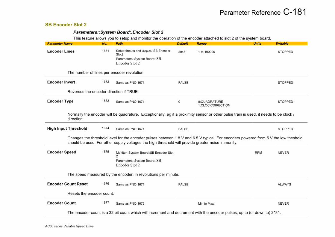
Parameter Reference C-181
AC30 series Variable Speed Drive
SB Encoder Slot 2 Parameters::System Board::Encoder Slot 2 This feature allows you to setup and monitor the operation of the encoder attached to slot 2 of the system board.
Parameter Name No. Path Default Range Units Writable Encoder Lines
1671
Setup::Inputs and Outputs::SB Encoder Slot2 Parameters::System Board::SB Encoder Slot 2
2048
1 to 100000
STOPPED
The number of lines per encoder revolution Encoder Invert
1672
Same as PNO 1671
FALSE
STOPPED
Reverses the encoder direction if TRUE. Encoder Type
1673
Same as PNO 1671
0
0:QUADRATURE 1:CLOCK/DIRECTION
STOPPED
Normally the encoder will be quadrature. Exceptionally, eg if a proximity sensor or other pulse train is used, it needs to be clock / direction.
High Input Threshold
1674
Same as PNO 1671
FALSE
STOPPED
Changes the threshold level for the encoder pulses between 1.8 V and 6.5 V typical. For encoders powered from 5 V the low theshold should be used. For other supply voltages the high threshold will provide greater noise immunity.
Encoder Speed
1675
Monitor::System Board::SB Encoder Slot 2 Parameters::System Board::SB Encoder Slot 2
RPM
NEVER
The speed measured by the encoder, in revolutions per minute. Encoder Count Reset
1676
Same as PNO 1671
FALSE
ALWAYS
Resets the encoder count. Encoder Count
1677
Same as PNO 1675
Min to Max
NEVER
The encoder count is a 32 bit count which will increment and decrement with the encoder pulses, up to (or down to) 2^31.

C-182 Parameter Reference
AC30 series Variable Speed Drive
SB Retransmit Parameters::System Board::System Board IO
Parameter Name No. Path Default Range Units Writable Output Enable
1678
Setup::Inputs and Outputs::System Board Option Parameters::System Board::SB Retransmit
FALSE
ALWAYS
Turns on the system board A, B and Z outputs.
Output Source
1679
Same as PNO 1678
0
0:SYSTEM BOARD SLOT 1 1:SYSTEM BOARD SLOT 2 2:SYNTHETIC ENCDR 3:DIGITAL OUTPUTS 4:MAIN SPD FEEDBACK
STOPPED
Selects the source of the retransmit output. i.e. Slot 1, Slot 2, synthetic encoder, or the Encoder fitted into the main speed feedback.
If SYSTEM BOARD SLOT 1 or SYSTEM BOARD SLOT 2 is selected, the output number of lines is a copy of the source number of lines.
If MAIN SPD FEEDBACK is selected, then the output number of lines can be set up independantly of the source number of lines ( limited to a max value of 16384 )
Output Voltage
1680
Same as PNO 1678
0
0:5 V 1:12 V 2:15 V 3:20 V
ALWAYS
Sets the voltage output of the system board encoder retransmit.
Synth Encoder Lines
1696
Same as PNO 1678
2048
1 to 15000000
ALWAYS
Number of lines per revolution to be simulated by the synthetic encoder function. This affects the Z output pulse.
Synth Encoder Speed
1698
Same as PNO 1678
0
0 to 15000000
RPM
ALWAYS
Simulated speed to output when the synthetic encoder mode is selected.

Parameter Reference C-183
AC30 series Variable Speed Drive
Parameter Name No. Path Default Range Units Writable Synth Encoder Invert
1702
Same as PNO 1678
FALSE
ALWAYS
Sets the direction of the synthetic encoder rotation.
Z Pulse
1870
Setup::Inputs and Outputs::System Board Option Parameters::System Board::SB Retransmit
FALSE
ALWAYS
Only available is Output Source is set to SYNTHETIC ENCDR or MAIN SPD FEEDBACK
Allows to set up the Z pulse signals. It occurs on the falling edge ( TRUE to FALSE ) of this parameter.
Z Pulse Init Done
1872
Setup::Inputs and Outputs::System Board Option Parameters::System Board::SB Retransmit
FALSE
ALWAYS
Only available is Output Source is set to MAIN SPD FEEDBACK
TRUE if initialisation of Z pulse position has been run successfully. FALSE during initialisation phase : at start up or during selection of a new Z pulse position.
Output A
1756
Setup::Inputs and Outputs::System Board Option Parameters::System Board::SB Retransmit
FALSE
ALWAYS
Value presented on terminal X33.1 with respect to X33.2 when "1679 Output Source" is set to DIGITAL OUTPUTS
Output B
1757
Same as PNO 1756
FALSE
ALWAYS
Value presented on terminal X33.3 with respect to X33.4 when "1679 Output Source" is set to DIGITAL OUTPUTS
Output Z
1758
Same as PNO 1756
FALSE
ALWAYS
Value presented on terminal X33.5 with respect to X33.6 when "1679 Output Source" is set to DIGITAL OUTPUTS
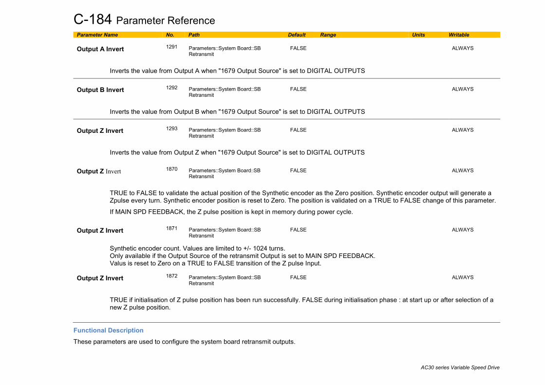
C-184 Parameter Reference
AC30 series Variable Speed Drive
Parameter Name No. Path Default Range Units Writable Output A Invert
1291
Parameters::System Board::SB Retransmit
FALSE
ALWAYS
Inverts the value from Output A when "1679 Output Source" is set to DIGITAL OUTPUTS
Output B Invert
1292
Parameters::System Board::SB Retransmit
FALSE
ALWAYS
Inverts the value from Output B when "1679 Output Source" is set to DIGITAL OUTPUTS
Output Z Invert
1293
Parameters::System Board::SB Retransmit
FALSE
ALWAYS
Inverts the value from Output Z when "1679 Output Source" is set to DIGITAL OUTPUTS Output Z Invert
1870
Parameters::System Board::SB Retransmit
FALSE
ALWAYS
TRUE to FALSE to validate the actual position of the Synthetic encoder as the Zero position. Synthetic encoder output will generate a Zpulse every turn. Synthetic encoder position is reset to Zero. The position is validated on a TRUE to FALSE change of this parameter.
If MAIN SPD FEEDBACK, the Z pulse position is kept in memory during power cycle. Output Z Invert
1871
Parameters::System Board::SB Retransmit
FALSE
ALWAYS
Synthetic encoder count. Values are limited to +/- 1024 turns. Only available if the Output Source of the retransmit Output is set to MAIN SPD FEEDBACK. Valus is reset to Zero on a TRUE to FALSE transition of the Z pulse Input.
Output Z Invert
1872
Parameters::System Board::SB Retransmit
FALSE
ALWAYS
TRUE if initialisation of Z pulse position has been run successfully. FALSE during initialisation phase : at start up or after selection of a new Z pulse position.
Functional Description These parameters are used to configure the system board retransmit outputs.

Parameter Reference C-185
AC30 series Variable Speed Drive
Scale Setpoint Parameters::Motor Control::Scale Setpoint This function defines 100% speed in RPM.
Parameter Name No. Path Default Range Units Writable 100% Speed in RPM
464
Setup::Motor Control::Control and Type Parameters::Motor Control::Scale Setpoint
1500.0
0.0 to 100000.0
RPM
ALWAYS
Speed in RPM equivalent to a setpoint of 100%
Speed Demand RPM
465
Parameters::Motor Control::Scale Setpoint
x.x
RPM
NEVER
Setpoint scaled to RPM
Speed Demand Hz
466
Parameters::Motor Control::Scale Setpoint
x.x
Hz
NEVER
Setpoint scaled to electrical Hz.
Functional Description The Drive is commanded to run the motor at a certain speed, which is derived from various sources, such as comms, analog inputs, commands from the keypad, etc. All these speed commands are expressed as a percentage. The percentage is referenced to parameter PNO 0464. So, for example, if PNO 0464 is set to 3000 rpm, and the user commands 100% speed, then the motor should turn at 3000rpm.
The user should be aware of what PNO 0464 means for different control options:
- For vector control (both for PMAC and IM) for 100% demand the motor will provide the actual shaft speed of the value that is set in PNO 0464.
- For V/Hz control (IM only) for 100% demand the actual shaft speed will be the value set in this parameter less than the slip of the motor. So, in order to achieve rated speed at rated torque in V/Hz mode, the user should set PNO 0464 to an RPM value that corresponds to the base frequency of the motor with the number of pole pairs taken into account, or in other words, ‘100% Speed in RPM’ should be set to synchronous speed. (For example, a 50Hz, 4 pole induction motor, with rated speed of 1450RPM, should have its ‘100% Speed in RPM’ value set to 1500. This will ensure that in V/Hz mode when the motor is loaded with rated load the actual speed of the shaft will be 1450 RPM!)
This parameter also represents the maximum speed available, since (apart from a small allowance for process trims) the speed commands are not allowed to exceed 100%.

C-186 Parameter Reference
AC30 series Variable Speed Drive
SD Card Parameters::Device Manager::SD Card Details of the SD Card fitted in the Drive. Parameter Name No. Path Default Range Units Writable Card State
1033
Parameters::Device Manager::SD Card
0:NO CARD 1:INITIALISING 2:READY 3:CARD FAULT
NEVER
The state of the SD Card will either be:
0: NO CARD no card detected in slot 1: INITIALISING a card has been detected but is still preparing for use 2: READY the card inserted can be used 3: CARD FAULT the card inserted is faulty and cannot be used. Check “Extended Support” below.
Card Name
1034
Parameters::Device Manager::SD Card
NEVER
The Volume Label read from the card. This is normally entered when formatting the card. It may be left blank.
Firmware
1038
Parameters::Device Manager::SD Card
NEVER
TRUE indicates that the firmware upgrade file (firmware.30x) is present on the inserted SD Card.
Application Archive
1039
Parameters::Device Manager::SD Card
NEVER
TRUE indicates that the project archive file (archive.prj) is present on the inserted SD Card and that the contents of this file matches the loaded Project. FALSE indicates that either the project archive file is not on the SD Card or that the archive file does not contain the archive of the loaded Project.
Extended Support
0117
Parameters::Device Manager::SD Card
TRUE
ALWAYS
Set TRUE to support a wider range of SD Cards. This parameter is ignored if Precision Time Protocol, (PTP), is enabled.

Parameter Reference C-187
AC30 series Variable Speed Drive
Sequencing Parameters::Motor Control::Sequencing These parameters allow the user of the AC30V to monitor the status and affect the behaviour of the DS402 drive state machine as described in detail in Appendix B “Sequencing Logic”.
Parameter Name No. Path Default Range Units Writable Local
0591
Parameters::Motor Control::Sequencing
FALSE
STOPPED
Local (GKP) of Control and Reference.
Local Power Up Mode
1565
Parameters::Motor Control::Sequencing
0
0:AS WHEN POWERED DOWN 1:LOCAL 2:REMOTE
ALWAYS
The initial value of 0591 Local can be selected by the User using this enumerated parameter.
0: AS WHEN POWERED DOWN the state when the Drive was powered down (default) 1: LOCAL always powers up with 0591 Local set to TRUE 2: REMOTE always powers up with 0591 Local set to FALSE
Local Reference
0592
Parameters::Motor Control::Sequencing
0.00
0.00 to 100.00
%
ALWAYS
Local Reference from GKP.
App Control Word
0610
Parameters::Motor Control::Sequencing
0000
0:SWITCH ON 1:ENABLE VOLTAGE 2:NOT QUICKSTOP 3:ENABLE OPERATION 7:RESET FAULT 8:EXTERNAL FAULT 12:USE JOG REFERENCE 13:REVERSE DIRECTION 14:AUTO INITIALISE 15:EVENT TRIGGERED OP
ALWAYS
Control Word from Application (Terminals).

C-188 Parameter Reference
AC30 series Variable Speed Drive
Parameter Name No. Path Default Range Units Writable Comms Control Word
0627
Parameters::Motor Control::Sequencing
0000
0:SWITCH ON 1:ENABLE VOLTAGE 2:NOT QUICKSTOP 3:ENABLE OPERATION 7:RESET FAULT 8:EXTERNAL FAULT 10:USE COMMS CONTROL 11:USE COMMS REFERENCE 12:USE JOG REFERENCE 13:REVERSE DIRECTION 14:AUTO INITIALISE 15:EVENT TRIGGERED OP
ALWAYS
Control Word from Fieldbus.
Control Word
0644
Parameters::Motor Control::Sequencing
0:SWITCH ON 1:ENABLE VOLTAGE 2:NOT QUICKSTOP 3:ENABLE OPERATION 7:RESET FAULT 8:EXTERNAL FAULT 10:USE COMMS CONTROL 11:USE COMMS REFERENCE 12:USE JOG REFERENCE 13:REVERSE DIRECTION 14:AUTO INITIALISE 15:EVENT TRIGGERED OP
NEVER
Monitor (read-only) Control Word updated from the active source.
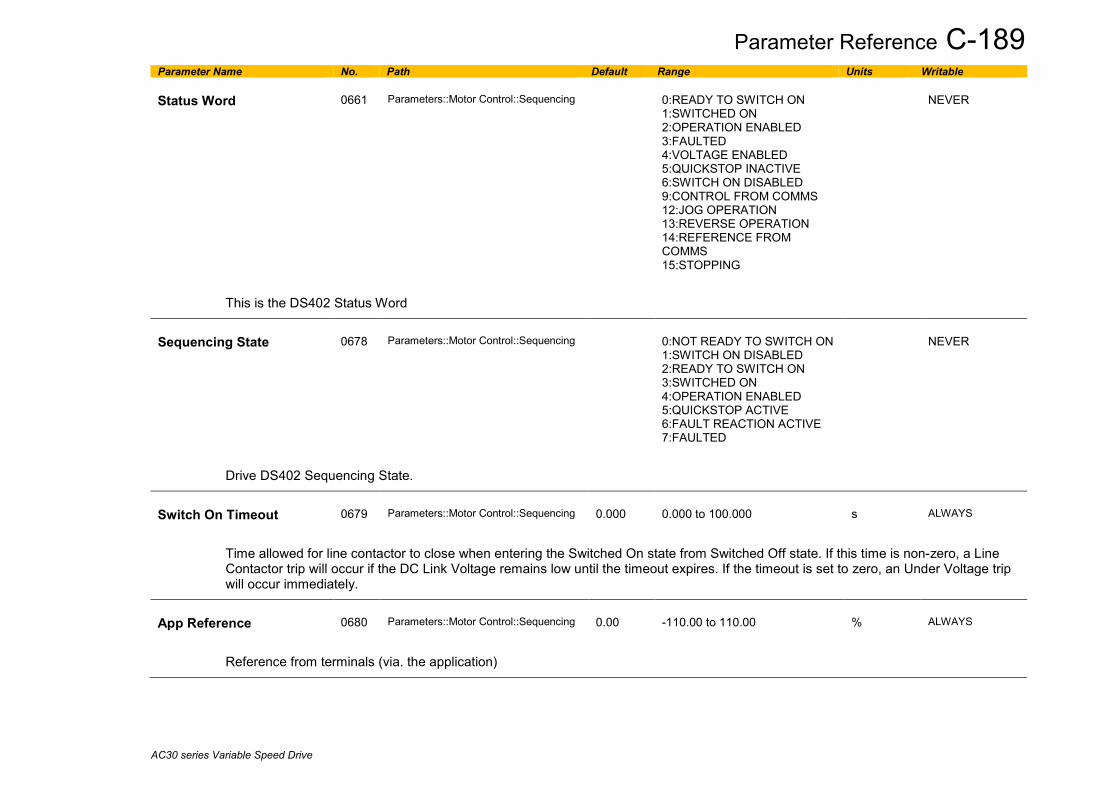
Parameter Reference C-189
AC30 series Variable Speed Drive
Parameter Name No. Path Default Range Units Writable Status Word
0661
Parameters::Motor Control::Sequencing
0:READY TO SWITCH ON 1:SWITCHED ON 2:OPERATION ENABLED 3:FAULTED 4:VOLTAGE ENABLED 5:QUICKSTOP INACTIVE 6:SWITCH ON DISABLED 9:CONTROL FROM COMMS 12:JOG OPERATION 13:REVERSE OPERATION 14:REFERENCE FROM COMMS 15:STOPPING
NEVER
This is the DS402 Status Word
Sequencing State
0678
Parameters::Motor Control::Sequencing
0:NOT READY TO SWITCH ON 1:SWITCH ON DISABLED 2:READY TO SWITCH ON 3:SWITCHED ON 4:OPERATION ENABLED 5:QUICKSTOP ACTIVE 6:FAULT REACTION ACTIVE 7:FAULTED
NEVER
Drive DS402 Sequencing State.
Switch On Timeout
0679
Parameters::Motor Control::Sequencing
0.000
0.000 to 100.000
s
ALWAYS
Time allowed for line contactor to close when entering the Switched On state from Switched Off state. If this time is non-zero, a Line Contactor trip will occur if the DC Link Voltage remains low until the timeout expires. If the timeout is set to zero, an Under Voltage trip will occur immediately.
App Reference
0680
Parameters::Motor Control::Sequencing
0.00
-110.00 to 110.00
%
ALWAYS
Reference from terminals (via. the application)

C-190 Parameter Reference
AC30 series Variable Speed Drive
Parameter Name No. Path Default Range Units Writable Comms Reference
0681
Parameters::Motor Control::Sequencing
0.00
-110.00 to 110.00
%
ALWAYS
Reference from Fieldbus
Reference
0682
Parameters::Motor Control::Sequencing
x.xx
-110.00 to 110.00
%
NEVER
Monitor (read-only) Reference updated from the active source. This will either be the value of the 0592 Local Reference, 0680 App Reference (terminals) or 0681 Comms Reference depending on which source is currently selected.

Parameter Reference C-191
AC30 series Variable Speed Drive
Setup Wizard Parameters::Device Manager::Setup Wizard These parameters configure the operation of the Setup Wizard.
Parameter Name No. Path Default Range Units Writable Enable Auto Save
1738
Parameters::Device Manager::Setup Wizard
TRUE
ALWAYS
Control how parameter values are saved when modified via the GKP or the Web Page. TRUE: Parameter values are saved automatically when they are entered. FALSE: Parameter values are not saved automatically. To save parameters using the GKP navigate to the Welcome page by
pressing the soft left key repeatedly, then press the save icon for approximately 1s. (Note: If the GKP password is active and unlocked it will be necessary to lock the GKP password before the save icon is presented).
Auto Hide
1779
Parameters::Device Manager::Setup Wizard
TRUE
ALWAYS
In normal operation, parameters that are not relevant to the configuration are saved. For example, parameters relating to the Thermistor IO option are only visible when that option is enabled. Clearing “Parameter Auto Hide” shows all parameters in the drive at ENGINEER view level. At other view levels the Auto Hide feature is always enabled.
Scaled PNO Access
1861
Parameters::Device Manager::Setup Wizard
0
0:BASE UNITS 1:SELECTED UNITS
ALWAYS
This parameter may be used when the application makes use of selectable units, (for example: to display a value in either °C or °F). When Scaled PNO Access is “BASE UNITS” the value returned when reading a rescaled parameter over fieldbus communications is always in the base, (unscaled), units. When Scaled PNO Access is “SELECTED UNITS” the value returned when reading a rescaled parameter over fieldbus communications is in the selected units.
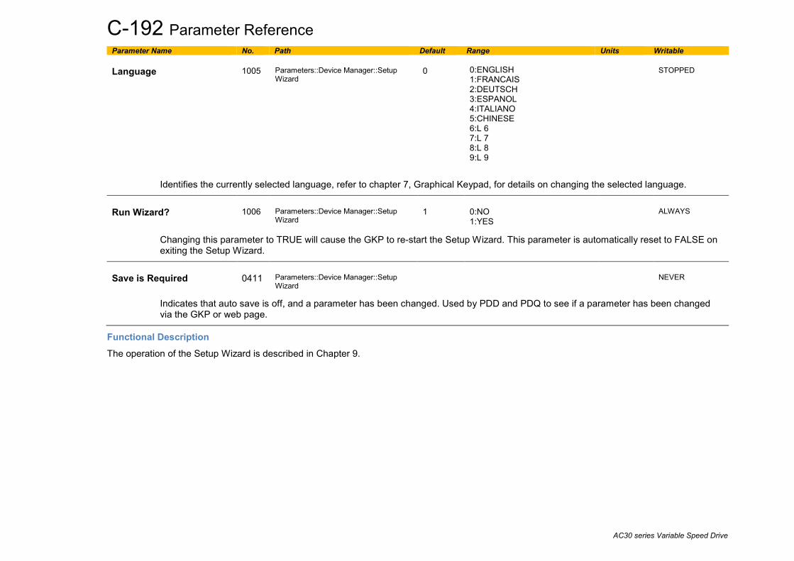
C-192 Parameter Reference
AC30 series Variable Speed Drive
Parameter Name No. Path Default Range Units Writable Language
1005
Parameters::Device Manager::Setup Wizard
0
0:ENGLISH 1:FRANCAIS 2:DEUTSCH 3:ESPANOL 4:ITALIANO 5:CHINESE 6:L 6 7:L 7 8:L 8 9:L 9
STOPPED
Identifies the currently selected language, refer to chapter 7, Graphical Keypad, for details on changing the selected language.
Run Wizard?
1006
Parameters::Device Manager::Setup Wizard
1
0:NO 1:YES
ALWAYS
Changing this parameter to TRUE will cause the GKP to re-start the Setup Wizard. This parameter is automatically reset to FALSE on exiting the Setup Wizard.
Save is Required
0411
Parameters::Device Manager::Setup Wizard
NEVER
Indicates that auto save is off, and a parameter has been changed. Used by PDD and PDQ to see if a parameter has been changed via the GKP or web page.
Functional Description The operation of the Setup Wizard is described in Chapter 9.
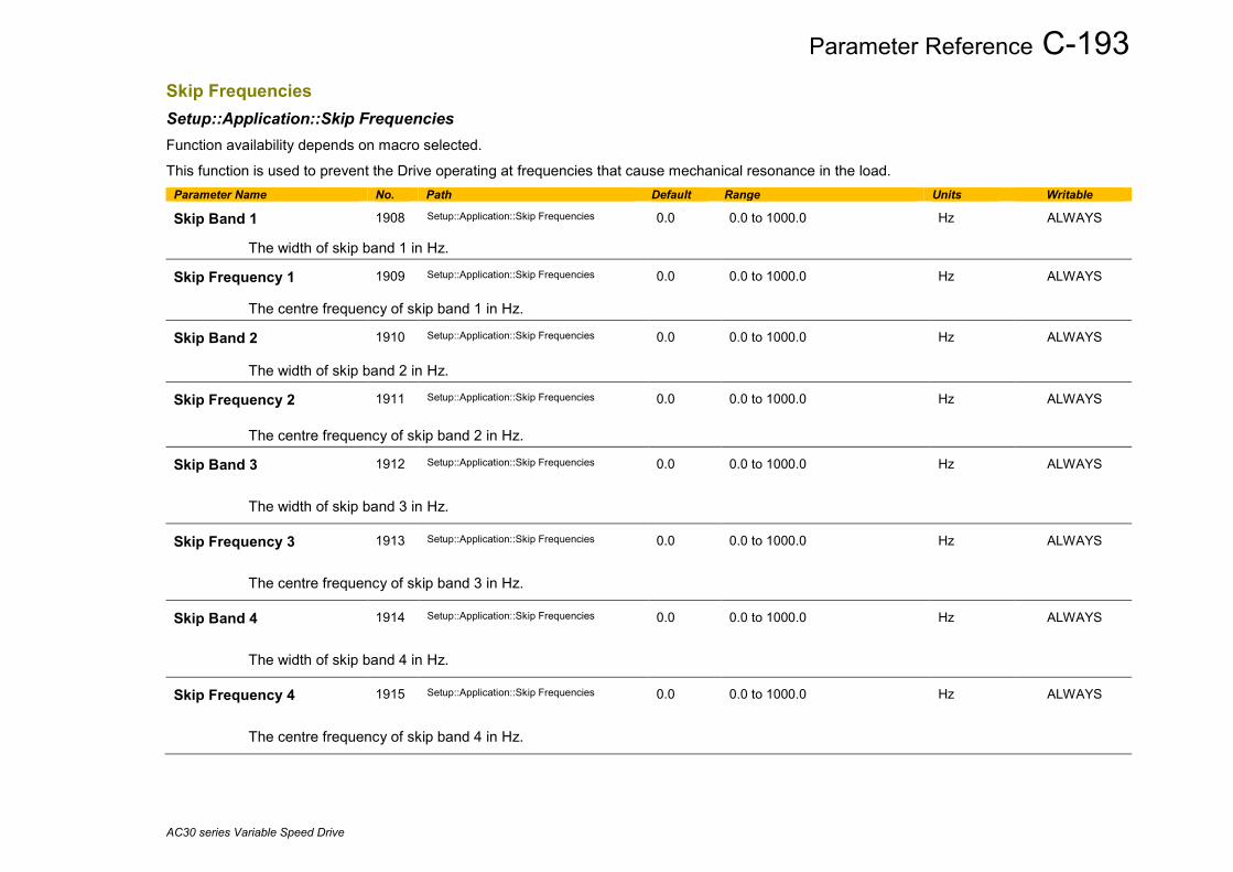
Parameter Reference C-193
AC30 series Variable Speed Drive
Skip Frequencies Setup::Application::Skip Frequencies Function availability depends on macro selected. This function is used to prevent the Drive operating at frequencies that cause mechanical resonance in the load.
Parameter Name No. Path Default Range Units Writable
Skip Band 1 1908 Setup::Application::Skip Frequencies 0.0 0.0 to 1000.0 Hz ALWAYS
The width of skip band 1 in Hz.
Skip Frequency 1 1909 Setup::Application::Skip Frequencies 0.0 0.0 to 1000.0 Hz ALWAYS
The centre frequency of skip band 1 in Hz.
Skip Band 2 1910 Setup::Application::Skip Frequencies 0.0 0.0 to 1000.0 Hz ALWAYS
The width of skip band 2 in Hz.
Skip Frequency 2 1911 Setup::Application::Skip Frequencies 0.0 0.0 to 1000.0 Hz ALWAYS
The centre frequency of skip band 2 in Hz.
Skip Band 3 1912 Setup::Application::Skip Frequencies 0.0 0.0 to 1000.0 Hz ALWAYS
The width of skip band 3 in Hz.
Skip Frequency 3 1913 Setup::Application::Skip Frequencies 0.0 0.0 to 1000.0 Hz ALWAYS
The centre frequency of skip band 3 in Hz.
Skip Band 4 1914 Setup::Application::Skip Frequencies 0.0 0.0 to 1000.0 Hz ALWAYS
The width of skip band 4 in Hz.
Skip Frequency 4 1915 Setup::Application::Skip Frequencies 0.0 0.0 to 1000.0 Hz ALWAYS
The centre frequency of skip band 4 in Hz.
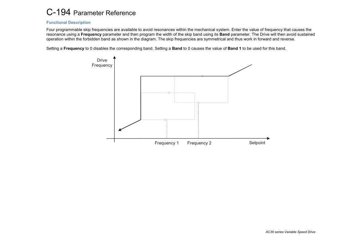
C-194 Parameter Reference
AC30 series Variable Speed Drive
Functional Description Four programmable skip frequencies are available to avoid resonances within the mechanical system. Enter the value of frequency that causes the resonance using a Frequency parameter and then program the width of the skip band using its Band parameter. The Drive will then avoid sustained operation within the forbidden band as shown in the diagram. The skip frequencies are symmetrical and thus work in forward and reverse. Setting a Frequency to 0 disables the corresponding band. Setting a Band to 0 causes the value of Band 1 to be used for this band.
Setpoint
DriveFrequency
Frequency 1 Frequency 2
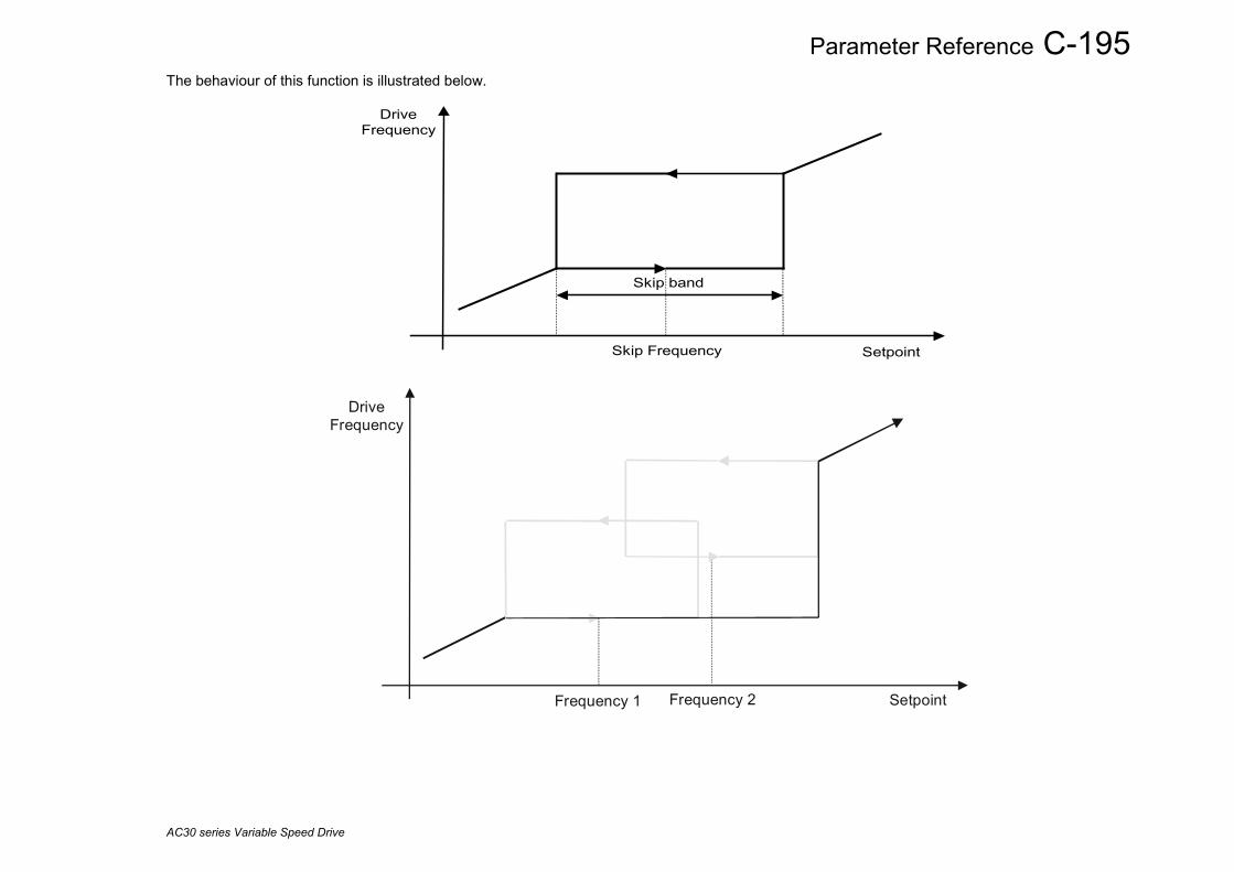
Parameter Reference C-195
AC30 series Variable Speed Drive
The behaviour of this function is illustrated below.
Skip band
Skip Frequency Setpoint
DriveFrequency
Setpoint
DriveFrequency
Frequency 1 Frequency 2

C-196 Parameter Reference
AC30 series Variable Speed Drive
Slew Rate Parameters::Motor Control::Slew Rate Designed for VOLTS/Hz motor Control Mode. This function prevents over-current and over-voltage faults occurring due to a rapidly changing setpoint.
Parameter Name No. Path Default Range Units Writable Slew Rate Enable
0360
Parameters::Motor Control::Slew Rate
TRUE
ALWAYS
Enable/Disable slew rate limit
Slew Rate Accel Limit
0361
Parameters::Motor Control::Slew Rate
500
1 to 1200
Hz/s
ALWAYS
Maximum rate at which the setpoint can be changed away from zero
Slew Rate Decel Limit
0362
Parameters::Motor Control::Slew Rate
500
1 to 1200
Hz/s
ALWAYS
Maximum rate at which the setpoint can be changed towards zero
Functional Description The Slew Rate limit obtains the setpoint from the output of the application, correctly scaled by the Reference feature and already processed by the Power Loss Ride Thru and the DC Link Volts Limit features ( if enabled ). The rate of change limits are applied and the setpoint is then passed on for further processing. When the braking feature determines that the internal dc link voltage is too high it issues a Hold signal. This causes the Slew Rate limit function to hold the setpoint at its current value. This typically lasts for only 1ms, time for the excess energy to be dumped into the dynamic braking resistor.
Ramp Power Loss Ride Thru
DC Link Volts Limit
Slew Rate (V/Hz only)
Speed Setpoint path
User Speed control loop
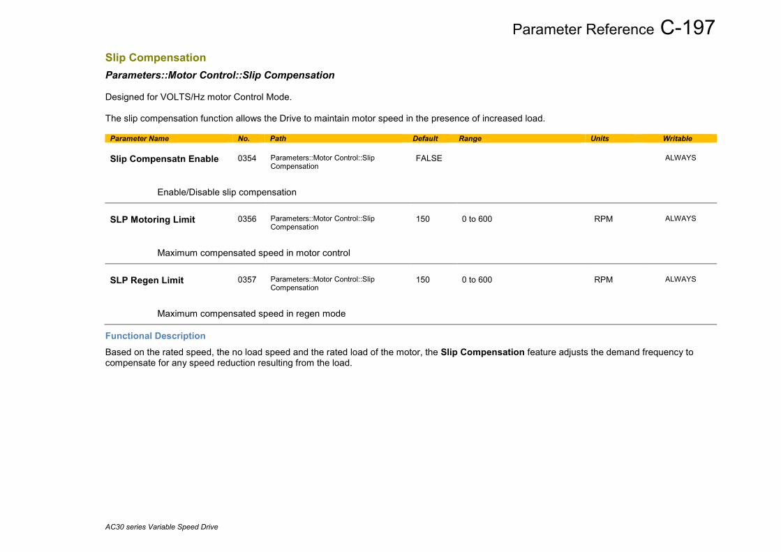
Parameter Reference C-197
AC30 series Variable Speed Drive
Slip Compensation Parameters::Motor Control::Slip Compensation Designed for VOLTS/Hz motor Control Mode. The slip compensation function allows the Drive to maintain motor speed in the presence of increased load.
Parameter Name No. Path Default Range Units Writable Slip Compensatn Enable
0354
Parameters::Motor Control::Slip Compensation
FALSE
ALWAYS
Enable/Disable slip compensation
SLP Motoring Limit
0356
Parameters::Motor Control::Slip Compensation
150
0 to 600
RPM
ALWAYS
Maximum compensated speed in motor control
SLP Regen Limit
0357
Parameters::Motor Control::Slip Compensation
150
0 to 600
RPM
ALWAYS
Maximum compensated speed in regen mode
Functional Description Based on the rated speed, the no load speed and the rated load of the motor, the Slip Compensation feature adjusts the demand frequency to compensate for any speed reduction resulting from the load.

C-198 Parameter Reference
AC30 series Variable Speed Drive
SNTP Client Parameters::Base Comms::STNP Client Refer to Chapter 8: Ethernet
SNTP Server Parameters::Base Comms::STNP Server Refer to Chapter 8: Ethernet

Parameter Reference C-199
AC30 series Variable Speed Drive
Soft Menus Parameters::Device Manager::Soft Menus
Parameter Name No. Path Default Range Units Writable Control Screen Mode
0908
Parameters::Device Manager::Soft Menus
1
0:DISABLED 1:AUTO 2:CUSTOM
STOPPED
Defines the operation of the Control Screen
0. DISABLED
1. AUTO
2. CUSTOM
When set to DISABLED, the Control Screen menu is hidden.
When set to AUTO, the contents of the Control Screen menu depends on the sequencing mode of the drive, (local, remote or communications).
When set to CUSTOM, the contents of the Control Screen may be defined by writing parameter numbers to the elements of the 1352 Control Screen array. Note that the contents of the 1352 Control Screen array are not saved in non-volatile memory, so the values need to be initialised following a power-on reset.
Control Screen
1352
Parameters::Device Manager::Soft Menus
ALWAYS
An array of PNOs that identifies the parameters to be shown in the Control Screen. The contents of this screen are set automatically by the AC30 firmware when the control mode is changed.
Favourites
1188
Parameters::Device Manager::Soft Menus
ALWAYS
An array of PNOs that identifies the parameters to be shown in the Favourites menu
Setup
1311
Parameters::Device Manager::Soft Menus
ALWAYS
An array of PNOs that identifies the parameters to be shown in the Setup menu

C-200 Parameter Reference
AC30 series Variable Speed Drive
Parameter Name No. Path Default Range Units Writable Monitor
1270
Parameters::Device Manager::Soft Menus
ALWAYS
An array of PNOs that identifies the parameters to be shown in the Monitor menu
Functional Description The Soft Menus group of parameters are used to populate the associated menus depending on the associated application, (Control Screen, Setup and Monitor) or the requirements of the location, (Favourites). The contents of the Setup and Monitor menus may only be set by the application itself. The contents of the Favourites menu may be set by writing to the parameters in the Favourites array. Alternatively parameters may be added to or removed from the Favourites menu by use of the GKP. Navigate to the parameter of interest and hold the OK key until the attributes screen is shown. If the parameter is not already in the Favourites menu a pressing Soft Key 2 adds the parameter to Favourites. This operation is indicated by the icon . Similarly, to remove a parameter from Favourites, navigate to the parameter in the Favourites menu then press OK until the parameter attributes are shown. Remove the parameter from Favourites by pressing Soft Key 2. This operation is indicated by the icon .

Parameter Reference C-201
AC30 series Variable Speed Drive
Spd Direct Input Parameters::Motor Control::Spd Direct Input Only apply to SVC control mode, IM or PMAC.
Parameter Name No. Path Default Range Units Writable Direct Input Select
0528
Parameters::Motor Control::Spd Direct Input
0
0:NONE 1:ANIN1 2:ANIN2
ALWAYS
The direct input to the speed loop is an analog input which is sampled synchronously with the speed loop. This ensures that the speed loop always has the most up-to-date value of the input, allowing it to respond faster. Either of the two analog inputs can be selected as the direct input. If NONE is selected, the input is set to zero. When not in use, it should be disabled by selecting NONE.
Direct Input Ratio
0529
Parameters::Motor Control::Spd Direct Input
1.0000
-10.0000 to 10.0000
ALWAYS
The Direct Input is multiplied by this parameter.
Direct Input Pos Lim
0530
Parameters::Motor Control::Spd Direct Input
110.00
-600.00 to 600.00
%
ALWAYS
This limits the upper value of the Direct Input.
Direct Input Neg Lim
0531
Parameters::Motor Control::Spd Direct Input
-110.00
-600.00 to 600.00
%
ALWAYS
This limits the lower value of the Direct Input.
Functional Description The Drive is commanded to run the motor at a certain speed, which is derived from various sources, such as comms, analog inputs, commands from the keypad, etc. Most of these are derived from sources which respond relatively slowly, eg every 1ms. For processes which require a faster response, the direct input is provided. This is an analog input which is sampled synchronously with the speed loop, as described above. It is added on to the other sources of speed command to give a total speed command.

C-202 Parameter Reference
AC30 series Variable Speed Drive
Spd Loop Diagnostics Parameters::Motor Control::Spd Loop Diagnostics Refer to the diagram in Spd Loop Settings function. Only applies to SVC control mode, IM or PMAC.
Parameter Name No. Path Default Range Units Writable Total Spd Demand RPM
0533
Parameters::Motor Control::Spd Loop Diagnostics
x.xx
-100000.00 to 100000.00
RPM
NEVER
This diagnostic shows the final values of the speed demand in rpm obtained after summing all sources. This is the value which is presented to the speed loop
Total Spd Demand %
0534
Parameters::Motor Control::Spd Loop Diagnostics
x.xx
-200.00 to 200.00
%
NEVER
This diagnostic shows the final values of the speed demand as a % of 100% Speed in RPM of the Scale Setpoint obtained after summing all sources. This is the value which is presented to the speed loop.
Speed Loop Error
0535
Parameters::Motor Control::Spd Loop Diagnostics
x.xx
-600.00 to 600.00
%
NEVER
This diagnostic shows the difference between the total speed demand and the speed feedback
Speed PI Output
0536
Parameters::Motor Control::Spd Loop Diagnostics
x.xx
-600.00 to 600.00
%
NEVER
This diagnostic shows the difference between the total speed demand and the speed feedback
Speed Limiter Active
0536
Parameters::Motor Control::Spd Loop Diagnostics
x.xx
-600.00 to 600.00
%
NEVER
This diagnostic is TRUE if the drive is in Torque Control mode ( i.e. Sel Torq Ctrl Only is TRUE ), the speed limiter validated ( i.e. Spd Limiter Torq Ctrl is TRUE ) and the drive is in speed limit condition.

Parameter Reference C-203
AC30 series Variable Speed Drive
Spd Loop Settings Parameters::Motor Control::Spd Loop Settings This function block controls the speed of the motor by comparing the actual speed to the demanded speed, and applying more or less torque in response to the error. Only applies to SVC control mode, IM or PMAC.
Parameter Name No. Path Default Range Units Writable Speed Loop Auto Set
1246
Parameters::Motor Control::Spd Loop Settings
TRUE
ALWAYS
Only for PMAC Motor
TRUE : Allows to automatically calculate speed loop control parameters : Speed Loop Pgain and Speed Loop I Time.
To do a correct estimation, Ratio Load Mot Inert should be correctly filled in.
FALSE : no automatic calculation
Ratio Load Mot Inert
1247
Parameters::Motor Control::Spd Loop Settings
1.0
0.1 to 100.0
ALWAYS
Only for PMAC Motor
Enter the correct inertia ratio between the load and the motor (For a no load condition, a value of 0.1 should be used).
This is used to automatically estimate the correct Speed Loop Pgain and Speed Loop I Time.
Speed Loop Bandwidth
1248
Parameters::Motor Control::Spd Loop Settings
1
0:LOW 1:MEDIUM 2:HIGH
ALWAYS
Only for PMAC Motor
When Speed Loop Auto Set is TRUE, allows to select the speed loop bandwidth level :
Low :provides a low speed loop bandwidth
Medium : provides a medium speed loop bandwidth
High : provides a high speed loop bandwidth
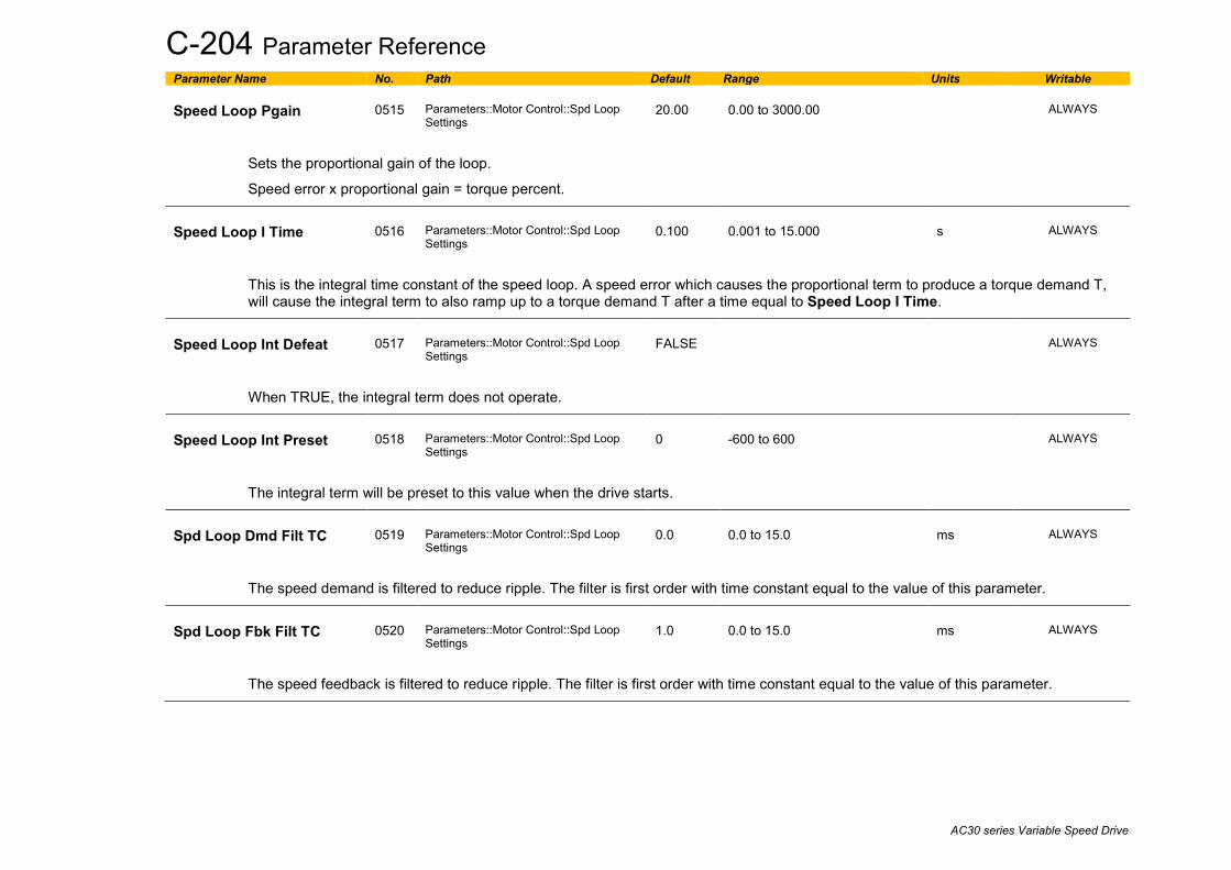
C-204 Parameter Reference
AC30 series Variable Speed Drive
Parameter Name No. Path Default Range Units Writable Speed Loop Pgain
0515
Parameters::Motor Control::Spd Loop Settings
20.00
0.00 to 3000.00
ALWAYS
Sets the proportional gain of the loop.
Speed error x proportional gain = torque percent.
Speed Loop I Time
0516
Parameters::Motor Control::Spd Loop Settings
0.100
0.001 to 15.000
s
ALWAYS
This is the integral time constant of the speed loop. A speed error which causes the proportional term to produce a torque demand T, will cause the integral term to also ramp up to a torque demand T after a time equal to Speed Loop I Time.
Speed Loop Int Defeat
0517
Parameters::Motor Control::Spd Loop Settings
FALSE
ALWAYS
When TRUE, the integral term does not operate.
Speed Loop Int Preset
0518
Parameters::Motor Control::Spd Loop Settings
0
-600 to 600
ALWAYS
The integral term will be preset to this value when the drive starts.
Spd Loop Dmd Filt TC
0519
Parameters::Motor Control::Spd Loop Settings
0.0
0.0 to 15.0
ms
ALWAYS
The speed demand is filtered to reduce ripple. The filter is first order with time constant equal to the value of this parameter.
Spd Loop Fbk Filt TC
0520
Parameters::Motor Control::Spd Loop Settings
1.0
0.0 to 15.0
ms
ALWAYS
The speed feedback is filtered to reduce ripple. The filter is first order with time constant equal to the value of this parameter.

Parameter Reference C-205
AC30 series Variable Speed Drive
Parameter Name No. Path Default Range Units Writable Spd Loop Aux Torq Dmd
0521
Parameters::Motor Control::Spd Loop Settings
0.00
-600.00 to 600.00
%
ALWAYS
When the drive is operating in speed control mode, the value of this parameter is added on to the torque demand produced by the speed loop PI. When the drive is operating in torque control mode (i.e. Set Torq Ctrl Only is TRUE) the speed loop PI does not operate, and the torque demand becomes the sum of this parameter plus the DIRECT INPUT (if selected).
Spd Loop Adapt Thres
0523
Parameters::Motor Control::Spd Loop Settings
0.00
0.00 to 10.00
%
ALWAYS
If the speed demand is less than the Spd Loop Adapt Thres, the speed loop proportional gain is the Spd Loop Adapt Pgain.
Spd Loop Adapt Pgain
0524
Parameters::Motor Control::Spd Loop Settings
20.00
0.00 to 300.00
ALWAYS
Proportional gain used if speed demand < Spd Loop Adapt Thres.
Spd Demand Pos Lim
0525
Parameters::Motor Control::Spd Loop Settings
110.00
-110.00 to 110.00
%
ALWAYS
This sets the upper limit of the speed demand.
Spd Demand Neg Lim
0526
Parameters::Motor Control::Spd Loop Settings
-110.00
-110.00 to 110.00
%
ALWAYS
This sets the lower limit of the speed demand.
Sel Torq Ctrl Only
0527
Parameters::Motor Control::Spd Loop Settings
FALSE
ALWAYS
Selects between Speed Control mode and Torque Control mode. When TRUE, (Torque Control mode) the torque demand output from the speed loop feature is the sum of the Direct Input plus the Spd Loop Aux Torq Dmd parameter.

C-206 Parameter Reference
AC30 series Variable Speed Drive
Parameter Name No. Path Default Range Units Writable Spd Limiter Torq Ctrl
1781
Parameters::Motor Control::Spd Loop Settings
FALSE
ALWAYS
When set to TRUE, and the drive is in Torque Control mode, this parameter prevents operation outside the speed limits defined in Spd Demand Pos Lim and Spd Demand Neg Lim. The torque setpoint is compensated if the motor speed reaches these speed limits.
Functional Description The speed error (speed demand minus speed feedback) is calculated and processed via a proportional + integral (PI) controller. The output of the PI controller is a torque demand, which is passed directly to the torque control feature. When the drive is in SENSORLESS VEC mode, the speed feedback is calculated from the voltages and currents flowing in the motor, and the motor model.
Speed reference %
Direct input
Aux torque demand %
Speed limiter
Filter on Torque Demand
Speed Feedback Hz
Sel Torq Ctrl Only
Compensated torque reference
PI
Pos torque % Neg torque %
x (scaling/100)
x 1/100
x 1/100
-300%
300%
300%
-300%
Neg speed Hz
Pos speed Hz
Spd demand Neg Lim %
Spd demand Pos Lim %
-110%
110%
% to Hz :
x ( scaling/100 )
525
526
464
speed
torque
534
x (100/scaling) x100
535 536
scaling = 100% Speed in RPM/60
Hz
1.0 = 100% Torque521
anin1anin2 Volts/amps to %
530
531
TorqueLimit
In torque limit
x100536
Spd Limiter Active 1781Spd Limiter Torq Ctrl1780
TORQUE CONTROL
SPEED CONTROL
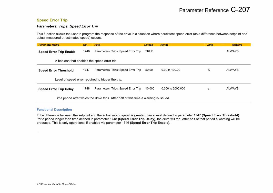
Parameter Reference C-207
AC30 series Variable Speed Drive
Speed Error Trip Parameters::Trips::Speed Error Trip This function allows the user to program the response of the drive in a situation where persistent speed error (as a difference between setpoint and actual measured or estimated speed) occurs.
Parameter Name No. Path Default Range Units Writable Speed Error Trip Enable
1746
Parameters::Trips::Speed Error Trip
TRUE
ALWAYS
A boolean that enables the speed error trip.
Speed Error Threshold
1747
Parameters::Trips::Speed Error Trip
50.00
0.00 to 100.00
%
ALWAYS
Level of speed error required to trigger the trip.
Speed Error Trip Delay
1748
Parameters::Trips::Speed Error Trip
10.000
0.000 to 2000.000
s
ALWAYS
Time period after which the drive trips. After half of this time a warning is issued.
Functional Description If the difference between the setpoint and the actual motor speed is greater than a level defined in parameter 1747 (Speed Error Threshold) for a period longer than time defined in parameter 1748 (Speed Error Trip Delay), the drive will trip. After half of that period a warning will be produced. This is only operational if enabled via parameter 1746 (Speed Error Trip Enable). .
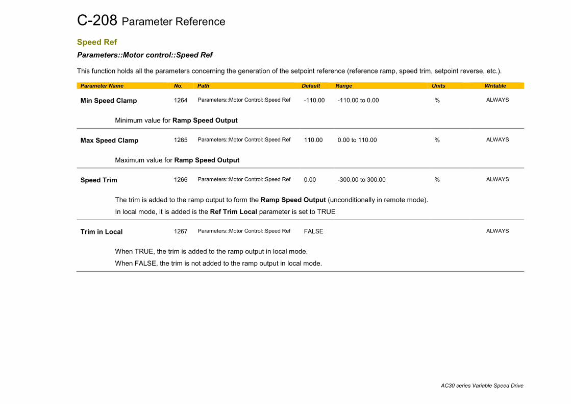
C-208 Parameter Reference
AC30 series Variable Speed Drive
Speed Ref Parameters::Motor control::Speed Ref This function holds all the parameters concerning the generation of the setpoint reference (reference ramp, speed trim, setpoint reverse, etc.).
Parameter Name No. Path Default Range Units Writable Min Speed Clamp
1264
Parameters::Motor Control::Speed Ref
-110.00
-110.00 to 0.00
%
ALWAYS
Minimum value for Ramp Speed Output
Max Speed Clamp
1265
Parameters::Motor Control::Speed Ref
110.00
0.00 to 110.00
%
ALWAYS
Maximum value for Ramp Speed Output
Speed Trim
1266
Parameters::Motor Control::Speed Ref
0.00
-300.00 to 300.00
%
ALWAYS
The trim is added to the ramp output to form the Ramp Speed Output (unconditionally in remote mode).
In local mode, it is added is the Ref Trim Local parameter is set to TRUE
Trim in Local
1267
Parameters::Motor Control::Speed Ref
FALSE
ALWAYS
When TRUE, the trim is added to the ramp output in local mode.
When FALSE, the trim is not added to the ramp output in local mode.

Parameter Reference C-209
AC30 series Variable Speed Drive
Stabilisation Parameters::Motor Control::Stabilisation Designed for VOLTS/Hz motor Control Mode.
Parameter Name No. Path Default Range Units Writable Stabilisation Enable
0364
Parameters::Motor Control::Stabilisation
TRUE
ALWAYS
Enable/Disable stabilisation
Functional Description Enabling this function reduces the problem of unstable running in induction motors. This can be experienced at approximately half full speed, and under low load conditions.

C-210 Parameter Reference
AC30 series Variable Speed Drive
Stack Inv Time Parameters::Motor Control::Stack Inv Time The purpose of the inverse time is to automatically reduce the drive current limit in response to prolonged overload conditions. For a short time given by Short Overload Time, the drive is able to provide the Short Overload Level For a long time given by Long Overload Time, the drive is able to provide the Long Overload Level These 2 protections work in parallel, the output limit current is the maximum value if Inv Time Active = False. If Inv Time Active = True, the current limit is determined by Long Overload Level the current limit is not yet ramped down. If already ramped down, the current limit is due to the long overload. When the maximum overload value is reached, the inverse time current limit is ramped down. The rate at which the inverse time current limit is ramped to the Inv Aiming Point is defined by Inv Time Down Rate. When the overload condition disappears, the inverse time current limit is ramped up. The rate at which the inverse time current limit is ramped to the maximum value is defined by Inv Time Up Rate. % Are all referring to drive/stack ratings. Parameter Name No. Path Default Range Units Writable 100% Stk Current
0343
Parameters::Motor Control::Stack Inv Time
x.x
0.0 to 10000.0
A
NEVER
Stack rating in rms amps corresponding to 100% stack current
Long Overload Level
0344
Parameters::Motor Control::Stack Inv Time
x.
0 to 200
%
NEVER
Overload value in % of the stack amps for long overload condition(*)
Long Overload Time
0345
Parameters::Motor Control::Stack Inv Time
0.000 to 100000.000
s
NEVER
Maximum duration under long overload condition (typically 60s)

Parameter Reference C-211
AC30 series Variable Speed Drive
Parameter Name No. Path Default Range Units Writable Short Overload Level
0346
Parameters::Motor Control::Stack Inv Time
x.
0 to 200
%
NEVER
Overload value in % of the stack amps for short overload condition(*)
Short Overload Time
0347
Parameters::Motor Control::Stack Inv Time
0.000 to 10000.000
s
NEVER
Maximum duration under short overload condition (typically 3s)
Inv Time Aiming Point
0348
Parameters::Motor Control::Stack Inv Time
105.00
0.00 to 125.00
%
ALWAYS
Current in % where the power stack can undertake the load current permanently
Inv Time Output
0349
Parameters::Motor Control::Stack Inv Time
x.
0 to 600
%
NEVER
Actual output current limit as a % of the stack current
Inv Time Up Rate
0350
Parameters::Motor Control::Stack Inv Time
5.000
0.000 to 120.000
s
STOPPED
Ramp value to ramp up current when overload condition disappears
Inv Time Down Rate
0351
Parameters::Motor Control::Stack Inv Time
5.000
0.000 to 120.000
s
STOPPED
Ramp value to reach the aiming point under prolonged overload condition
Inv Time Warning
0352
Parameters::Motor Control::Stack Inv Time
NEVER
The protection starts to integrate overload conditions

C-212 Parameter Reference
AC30 series Variable Speed Drive
Parameter Name No. Path Default Range Units Writable Inv Time Active
0353
Parameters::Motor Control::Stack Inv Time
NEVER
The drive protection is limiting the output current
(*) : Depending on the frame size, overload capabilities are reduced when the electrical speed is below 3Hz and with the heatsink temperature. Refer to Parker Hannifin Manufacturing for detailed values. Above 3Hz electrical speed, overload capabilities are those defined by the 0390 Duty Selection.
Functional Description
Short Overload : is using 180% of the Heavy Duty rating, for 3s. Long Overload : is using the overload mode selected in 0390 Duty Selection. Inv Time in Motor % is used to limit the current. It is one of the inputs of the Current Limit Function features
Stack Short overload
Stack Long overload
arbitration
Motor overload ( 150%, 60s)
Min
Feedback Amps
Move to Stack %
Convert to Motor %
Convert to Motor %
Motor Load (Only for IM Motor)
Inv Time in Motor %
Inv Time Output

Parameter Reference C-213
AC30 series Variable Speed Drive
Stall Trip Parameters::Trips::Stall Trip
The function protects the motor from damage that may be caused by continuous operation beyond specification.
Parameter Name No. Path Default Range Units Writable Stall Limit Type
0906
Parameters::Trips::Stall Trip
2
0:TORQUE 1:CURRENT 2:TORQUE OR CURRENT
ALWAYS
This parameter determines whether the stall trip operates on motor toque, on motor current, on motor torque or motor current.
Stall Time
0907
Parameters::Trips::Stall Trip
90.000
0.100 to 2000.000
s
ALWAYS
The time after which a stall condition will cause a trip.
Stall Torque Active
0909
Parameters::Trips::Stall Trip
NEVER
TRUE if tripped under torque trip operation
Stall Current Active
0910
Parameters::Trips::Stall Trip
NEVER
TRUE is tripped under current trip operation
Stall Speed Feedback
0911
Parameters::Trips::Stall Trip
x.
-200 to 200
%
NEVER
A copy of the speed Feedback in Hz
Functional Description If Stall Limit Type is set to TORQUE and the estimated load exceeds the active TORQUE LIMIT for a time greater than Stall Time, then the stall trip will become active. If the Stall Limit Type is set to CURRENT and the measured current exceeds the active Current Limit for a time greater than Stall Time, then the stall trip will become active.
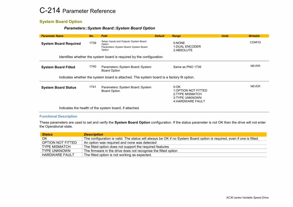
C-214 Parameter Reference
AC30 series Variable Speed Drive
System Board Option Parameters::System Board::System Board Option
Parameter Name No. Path Default Range Units Writable System Board Required
1739
Setup::Inputs and Outputs::System Board Option Parameters::System Board::System Board Option
0:NONE 1:DUAL ENCODER 2:ABSOLUTE
CONFIG
Identifies whether the system board is required by the configuration.
System Board Fitted
1740
Parameters::System Board::System Board Option
Same as PNO 1739
NEVER
Indicates whether the system board is attached. The system board is a factory fit option.
System Board Status
1741
Parameters::System Board::System Board Option
0:OK 1:OPTION NOT FITTED 2:TYPE MISMATCH 3:TYPE UNKNOWN 4:HARDWARE FAULT
NEVER
Indicates the health of the system board, if attached.
Functional Description These parameters are used to set and verify the System Board Option configuration. If the status parameter is not OK then the drive will not enter the Operational state.
Status Description OK The configuration is valid. The status will always be OK if no System Board option is required, even if one is fitted. OPTION NOT FITTED An option was required and none was detected TYPE MISMATCH The fitted option does not support the required features TYPE UNKNOWN The firmware in the drive does not recognise the fitted option HARDWARE FAULT The fitted option is not working as expected.
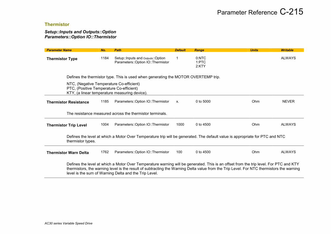
Parameter Reference C-215
AC30 series Variable Speed Drive
Thermistor Setup::Inputs and Outputs::Option Parameters::Option IO::Thermistor
Parameter Name No. Path Default Range Units Writable Thermistor Type
1184
Setup::Inputs and Outputs::Option Parameters::Option IO::Thermistor
1
0:NTC 1:PTC 2:KTY
ALWAYS
Defines the thermistor type. This is used when generating the MOTOR OVERTEMP trip.
NTC, (Negative Temperature Co-efficient) PTC, (Positive Temperature Co-efficient) KTY, (a linear temperature measuring device).
Thermistor Resistance
1185
Parameters::Option IO::Thermistor
x.
0 to 5000
Ohm
NEVER
The resistance measured across the thermistor terminals.
Thermistor Trip Level
1004
Parameters::Option IO::Thermistor
1000
0 to 4500
Ohm
ALWAYS
Defines the level at which a Motor Over Temperature trip will be generated. The default value is appropriate for PTC and NTC thermistor types.
Thermistor Warn Delta
1762
Parameters::Option IO::Thermistor
100
0 to 4500
Ohm
ALWAYS
Defines the level at which a Motor Over Temperature warning will be generated. This is an offset from the trip level. For PTC and KTY thermistors, the warning level is the result of subtracting the Warning Delta value from the Trip Level. For NTC thermistors the warning level is the sum of Warning Delta and the Trip Level.

C-216 Parameter Reference
AC30 series Variable Speed Drive
Torque Limit Parameters::Motor Control::Torque Limit This function allows you to set the maximum level of motor rated torque which is allowed before torque limit action occurs. If the estimated motor torque is greater than the Actual Pos Torque Lim value, the motor speed is controlled to maintain the torque at this level. A similar situation occurs if the estimated motor torque is less than the Actual Neg Torque Lim value. The torque limit function has separate positive and negative torque limits. In addition, a symmetric main torque limit is also provided. The lowest positive and negative torque limits (including any current limit or inverse time current limit action) is indicated in the Actual Pos Torque Lim and Actual Neg Torque Lim diagnostic. These values determine the absolute motor torque limits.
Parameter Name No. Path Default Range Units Writable Positive Torque Lim
0415
Parameters::Motor Control::Torque Limit
150.0
-600.0 to 600.0
%
ALWAYS
This parameter sets the maximum allowed level of positive motor torque.
Negative Torque Lim
0416
Parameters::Motor Control::Torque Limit
-150.0
-600.0 to 600.0
%
ALWAYS
This parameter sets the maximum allowed level of negative motor torque
Main Torque Lim
0417
Setup::Motor Control::Control and Type Parameters::Motor Control::Torque Limit
150.0
0.0 to 600.0
%
ALWAYS
This parameter sets the symmetric limit on the maximum allowed motor torque.
Fast Stop Torque Lim
0418
Parameters::Motor Control::Torque Limit
150.0
0.0 to 600.0
%
ALWAYS
This parameter sets the torque limit used during a Quickstop.
Symmetric Torque Lim
0419
Parameters::Motor Control::Torque Limit
FALSE
ALWAYS
When TRUE, the Negative Torque Lim is forced to reflect the Positive Torque Lim parameter.
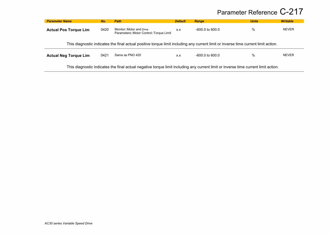
Parameter Reference C-217
AC30 series Variable Speed Drive
Parameter Name No. Path Default Range Units Writable Actual Pos Torque Lim
0420
Monitor::Motor and Drive Parameters::Motor Control::Torque Limit
x.x
-600.0 to 600.0
%
NEVER
This diagnostic indicates the final actual positive torque limit including any current limit or inverse time current limit action.
Actual Neg Torque Lim
0421
Same as PNO 420
x.x
-600.0 to 600.0
%
NEVER
This diagnostic indicates the final actual negative torque limit including any current limit or inverse time current limit action.

C-218 Parameter Reference
AC30 series Variable Speed Drive
Functional Description
Pos torque lim
Neg Torque lim
-1
-1
-1
Positive Torque Lim
Main Torque Lim
Negative Torque Lim
Symmetric Torque Lim
Torque Limit
Values in %, as a % of motor rated torque
Internal torque limit
Actual Pos Torque Lim
Actual Neg Torque Lim

Parameter Reference C-219
AC30 series Variable Speed Drive
Tr Adaptation Parameters::Motor Control::Tr Adaptation When the motor control strategy is set to Closed Loop vector, i.e. using encoder feedback, it is important to know the actual value of the rotor time constant. This value is measured by the autotune, but it will change as the motor temperature changes. The purpose of this module is to track the changing value of the rotor time constant, and to use all available feedback information to make the best possible estimate of its actual value at any given time.
Parameter Name No. Path Default Range Units Writable Actual Rotor T Const
1520
Parameters::Motor Control::Tr Adaptation
x.
1 to 100000
ms
NEVER
This diagnostic shows the actual value of rotor time constant used by the motor control. This value is the nominal value stored in the Induction Motor Data, modified by this module to give a value as close as possible to the real value.
Tr Adaptation Output
1521
Parameters::Motor Control::Tr Adaptation
x.
1 to 500
%
NEVER
This diagnostic shows the factor by which the nominal rotor time constant is multiplied, in order to give the actual rotor time constant passed to the motor control.
Demanded Terminal Volts
1528
Parameters::Motor Control::Tr Adaptation
x.
0 to 1000
V
NEVER
In order to maintain constant flux for a given load, the motor terminal volts must be controlled. This diagnostic gives the terminal volts demand used by the control loop.
Terminal Volts
1529
Parameters::Motor Control::Tr Adaptation
x.
0 to 1000
V
NEVER
This diagnostic shows motor terminal volts. It is included here for convenience, to compare with the demanded terminal volts to make sure that the terminal volts control loop is able to close the loop to the demanded value.
Max Available Volts
1527
Parameters::Motor Control::Tr Adaptation
x.
0 to 10000
V
NEVER
This diagnostic shows the maximum achievable value of motor terminal volts. So for example, when running at rated load, the required motor terminal volts may be 400v. But if the mains is low, the maximum achievable volts may only be 390v. This diagnostic shows what is achievable at any particular time, and may be useful to explain why the motor volts may be lower than expected.

C-220 Parameter Reference
AC30 series Variable Speed Drive
Trips History Parameters::Trips::Trips History
Parameter Name No. Path Default Range Units Writable Recent Trips
0895
Parameters::Trips::Trips History
NEVER
The Recent Trips array is a record of the last 10 faults that caused the drive to disable the stack. Each entry has the same format as the First Trip parameter, (see Trips Status). The most recent fault is the first entry in the array, (Recent Trips[0]).
Recent Trip Times
1442
Parameters::Trips::Trips History
NEVER
The time of each of the recent trips. If PNO1186 Time and Date is valid then this value is used, otherwise the time used is a snapshot of the Control Board Up Time, see Runtime Statistics.
Warranty Trips
0968
Parameters::Trips::Trips History
NEVER
The Warranty Trips array is a record of the last 3 drive protection trips that were ignored due to the trip being disabled. This will usually be because Fire Mode (see Chapter 13) is enabled. Each entry has the same format as the First Trip parameter, (see Trips Status). The most recent fault is the first entry in the array, (Warranty Trips[0]).
Warranty Trip Time
0972
Parameters::Trips::Trips History
NEVER
The time of each of the Warranty Trips. The time saved is a shapshot of the HV SMPS Up Time, see Runtime Statistics.
Warranty Trips Record
1408
Parameters::Trips::Trips History
0:01 OVER VOLTAGE 2:03 OVER CURRENT 3:04 STACK FAULT 4:05 STACK OVER CURRENT 7:08 INVERSE TIME 10:11 HEATSINK OVERTEMP 11:12 INTERNAL OVERTEMP 14:15 BRAKE SHORT CCT 16:17 BRAKE SWITCH 21:22 VDC RIPPLE
NEVER
Records all drive protection trip event that have been ignored due to the trip being disabled. This will usually be because Fire Mode is enabled. Each entry has the same format as the Active 1 – 32 parameter, (see Trips Status).
Functional Description These parameters indicate the fault history of the drive. They are preserved through a power failure. The Warranty Trip parameters are also saved on the power stack. If the Control Module is attached to a power stack when it is powered on then the Warranty Trip parameter values are loaded from non-volatile memory on the power stack.
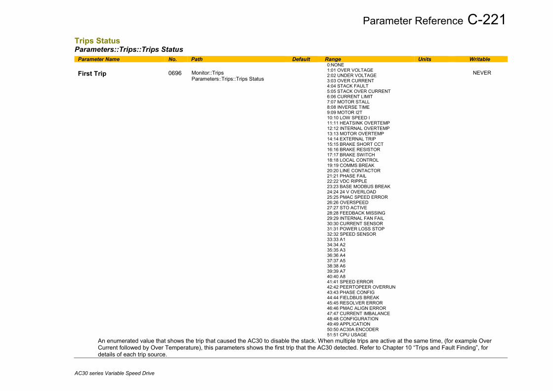
Parameter Reference C-221
AC30 series Variable Speed Drive
Trips Status Parameters::Trips::Trips Status
Parameter Name No. Path Default Range Units Writable First Trip
0696
Monitor::Trips Parameters::Trips::Trips Status
0:NONE 1:01 OVER VOLTAGE 2:02 UNDER VOLTAGE 3:03 OVER CURRENT 4:04 STACK FAULT 5:05 STACK OVER CURRENT 6:06 CURRENT LIMIT 7:07 MOTOR STALL 8:08 INVERSE TIME 9:09 MOTOR I2T 10:10 LOW SPEED I 11:11 HEATSINK OVERTEMP 12:12 INTERNAL OVERTEMP 13:13 MOTOR OVERTEMP 14:14 EXTERNAL TRIP 15:15 BRAKE SHORT CCT 16:16 BRAKE RESISTOR 17:17 BRAKE SWITCH 18:18 LOCAL CONTROL 19:19 COMMS BREAK 20:20 LINE CONTACTOR 21:21 PHASE FAIL 22:22 VDC RIPPLE 23:23 BASE MODBUS BREAK 24:24 24 V OVERLOAD 25:25 PMAC SPEED ERROR 26:26 OVERSPEED 27:27 STO ACTIVE 28:28 FEEDBACK MISSING 29:29 INTERNAL FAN FAIL 30:30 CURRENT SENSOR 31:31 POWER LOSS STOP 32:32 SPEED SENSOR 33:33 A1 34:34 A2 35:35 A3 36:36 A4 37:37 A5 38:38 A6 39:39 A7 40:40 A8 41:41 SPEED ERROR 42:42 PEERTOPEER OVERRUN 43:43 PHASE CONFIG 44:44 FIELDBUS BREAK 45:45 RESOLVER ERROR 46:46 PMAC ALIGN ERROR 47:47 CURRENT IMBALANCE 48:48 CONFIGURATION 49:49 APPLICATION 50:50 AC30A ENCODER 51:51 CPU USAGE
NEVER
An enumerated value that shows the trip that caused the AC30 to disable the stack. When multiple trips are active at the same time, (for example Over Current followed by Over Temperature), this parameters shows the first trip that the AC30 detected. Refer to Chapter 10 “Trips and Fault Finding”, for details of each trip source.

C-222 Parameter Reference
AC30 series Variable Speed Drive
Parameter Name No. Path Default Range Units Writable Enable 1 - 32
0697
Parameters::Trips::Trips Status
FFFFFF7F
5:06 CURRENT LIMIT 6:07 MOTOR STALL 7:08 INVERSE TIME 8:09 MOTOR I2T 9:10 LOW SPEED I 11:12 INTERNAL OVERTEMP 12:13 MOTOR OVERTEMP 13:14 EXTERNAL TRIP 14:15 BRAKE SHORT CCT 15:16 BRAKE RESISTOR 16:17 BRAKE SWITCH 17:18 LOCAL CONTROL 18:19 COMMS BREAK 19:20 LINE CONTACTOR 20:21 PHASE FAIL 21:22 VDC RIPPLE 22:23 BASE MODBUS BREAK 23:24 24 V OVERLOAD 24:25 PMAC SPEED ERROR 25:26 OVERSPEED 28:29 INTERNAL FAN FAIL 29:30 CURRENT SENSOR 30:31 POWER LOSS STOP 31:32 SPEED SENSOR
ALWAYS
A 32-bit word that can be used to enable, (or disable), individual trips. Refer to Chapter 10 “Trips and Fault Finding” for details of the value corresponding to each trip.
Enable 33 - 64
0730
Parameters::Trips::Trips Status
FFFFFFFF
0:33 A1 1:34 A2 2:35 A3 3:36 A4 4:37 A5 5:38 A6 6:39 A7 7:40 A8 8:41 SPEED ERROR 9:42 PEERTOPEER OVERRUN 10:43 PHASE CONFIG 11:44 FIELDBUS BREAK 14:47 CURRENT IMBALANCE 16:49 APPLICATION 18:51 CPU USAGE
ALWAYS
A 32-bit word that can be used to enable, (or disable), individual trips. Bit 0 of this word corresponds to trip 33, up to bit 31 of this word which corresponds to trip 64. Refer to Chapter 10 “Trips and Fault Finding” for details of the value corresponding to each trip.
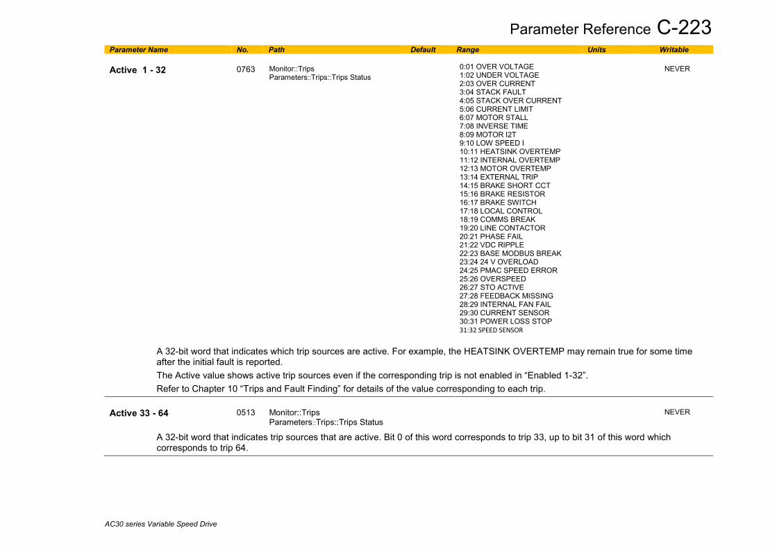
Parameter Reference C-223
AC30 series Variable Speed Drive
Parameter Name No. Path Default Range Units Writable Active 1 - 32
0763
Monitor::Trips Parameters::Trips::Trips Status
0:01 OVER VOLTAGE 1:02 UNDER VOLTAGE 2:03 OVER CURRENT 3:04 STACK FAULT 4:05 STACK OVER CURRENT 5:06 CURRENT LIMIT 6:07 MOTOR STALL 7:08 INVERSE TIME 8:09 MOTOR I2T 9:10 LOW SPEED I 10:11 HEATSINK OVERTEMP 11:12 INTERNAL OVERTEMP 12:13 MOTOR OVERTEMP 13:14 EXTERNAL TRIP 14:15 BRAKE SHORT CCT 15:16 BRAKE RESISTOR 16:17 BRAKE SWITCH 17:18 LOCAL CONTROL 18:19 COMMS BREAK 19:20 LINE CONTACTOR 20:21 PHASE FAIL 21:22 VDC RIPPLE 22:23 BASE MODBUS BREAK 23:24 24 V OVERLOAD 24:25 PMAC SPEED ERROR 25:26 OVERSPEED 26:27 STO ACTIVE 27:28 FEEDBACK MISSING 28:29 INTERNAL FAN FAIL 29:30 CURRENT SENSOR 30:31 POWER LOSS STOP 31:32 SPEED SENSOR
NEVER
A 32-bit word that indicates which trip sources are active. For example, the HEATSINK OVERTEMP may remain true for some time after the initial fault is reported. The Active value shows active trip sources even if the corresponding trip is not enabled in “Enabled 1-32”. Refer to Chapter 10 “Trips and Fault Finding” for details of the value corresponding to each trip.
Active 33 - 64
0513
Monitor::Trips Parameters::Trips::Trips Status
NEVER
A 32-bit word that indicates trip sources that are active. Bit 0 of this word corresponds to trip 33, up to bit 31 of this word which corresponds to trip 64.

C-224 Parameter Reference
AC30 series Variable Speed Drive
Parameter Name No. Path Default Range Units Writable Warnings 1 - 32
0829
Monitor::Trips Parameters::Trips::Trips Status
0:01 OVER VOLTAGE 1:02 UNDER VOLTAGE 2:03 OVER CURRENT 3:04 STACK FAULT 4:05 STACK OVER CURRENT 5:06 CURRENT LIMIT 6:07 MOTOR STALL 7:08 INVERSE TIME 8:09 MOTOR I2T 9:10 LOW SPEED I 10:11 HEATSINK OVERTEMP 11:12 INTERNAL OVERTEMP 12:13 MOTOR OVERTEMP 13:14 EXTERNAL TRIP 14:15 BRAKE SHORT CCT 15:16 BRAKE RESISTOR 16:17 BRAKE SWITCH 17:18 LOCAL CONTROL 18:19 COMMS BREAK 19:20 LINE CONTACTOR 20:21 PHASE FAIL 21:22 VDC RIPPLE 22:23 BASE MODBUS BREAK 23:24 24 V OVERLOAD 24:25 PMAC SPEED ERROR 25:26 OVERSPEED 26:27 STO ACTIVE 27:28 FEEDBACK MISSING 28:29 INTERNAL FAN FAIL 29:30 CURRENT SENSOR 30:31 POWER LOSS STOP 31:32 SPEED SENSOR
NEVER
A 32-bit word that indicates trip sources that are close to a fault condition. For example, the heat sink fault monitoring firmware reports a HEATSINK OVERTEMP warning when the heat sink temperature gets close to the heat sink fault level. The Warnings value is not affected by the trip enable mask, “Enabled 1-32”. Refer to Chapter 10 “Trips and Fault Finding” for details of the value corresponding to each trip.

Parameter Reference C-225
AC30 series Variable Speed Drive
Parameter Name No. Path Default Range Units Writable Warnings 33 - 64
0514
Same as PNO 513
NEVER
A 32-bit word that indicates trip sources that are close to a fault condition. Bit 0 of this word corresponds to trip 33, up to bit 31 of this word which corresponds to trip 64. The Warnings value is not affected by the corresponding trip enable mask, “Enabled 33-64”. Refer to Chapter 10 “Trips and Fault Finding” for details of the value corresponding to each trip.
Show Warnings 1 - 32
0115
Parameters::Trips::Trips Status
FFFFFFFF
ALWAYS
A 32-bit word that defines which warnings are to be displayed on the GKP. The bit definitions match those of PNO 0829. This parameter is over-ridden by setting PNO 1760 “Display Warnings” to FALSE.
Show Warnings 33 - 64
0116
Parameters::Trips::Trips Status
FFFFFFFF
ALWAYS
A 32-bit word that defines which warnings are to be displayed on the GKP. The bit definitions match those of PNO 0514. This parameter is over-ridden by setting PNO 1760 “Display Warnings” to FALSE.
Display Warnings
1760
Parameters::Trips::Trips Status
TRUE
ALWAYS
When this parameter is TRUE, warnings are reported on the GKP as a message that hides any parameter display, (until the message is manuall acknowledged). Set this parameter to FALSE to prevent warning messages being shown on the GKP.

C-226 Parameter Reference
AC30 series Variable Speed Drive
VDC Ripple Parameters::Trips::VDC Ripple This function contains parameters and data associated to the VDC ripple detection and trip condition
Parameter Name No. Path Default Range Units Writable VDC Ripple Filter TC
0912
Parameters::Trips::VDC Ripple
1.000
0.100 to 100.000
s
ALWAYS
Time constant of the First order Low pass filter applied to the raw VDC Ripple VDC Ripple Trip Hyst
0915
Parameters::Trips::VDC Ripple
10
0 to 50
V
ALWAYS
Hysteresis on the VDC ripple level for trip condition.
VDC Ripple Sample
0916
Parameters::Trips::VDC Ripple
0.009
0.001 to 0.100
s
ALWAYS
Time Windows for peak to peak VDC voltage capture and ripple calculation
Max VDC Ripple
0913
Parameters::Trips::VDC Ripple
x.
0 to 500
V
NEVER
Voltage ripple trigger value associated to the VDC ripple trip
VDC Ripple Trip Delay
0914
Parameters::Trips::VDC Ripple
0.000 to 300.000
s
NEVER
Delay to trip if trip condition detected VDC Ripple Level
917
Parameters::Trips::VDC Ripple
0 to 500
V
NEVER
Actual raw VDC ripple level Filtered VDC Ripple
0918
Parameters::Trips::VDC Ripple
x.
0 to 500
V
NEVER
Actual filtered VDC ripple level

Parameter Reference C-227
AC30 series Variable Speed Drive
Voltage Control Parameters::Motor Control::Voltage Control
Designed for VOLTS/Hz motor Control Mode. This function allows the motor output volts to be controlled in the presence of dc link voltage variations. This is achieved by controlling the level of PWM modulation as a function of measured dc link volts. The dc link volts may vary either due to supply variations or regenerative braking by the motor. Three control modes are available, None, Fixed and Automatic.
Parameter Name No. Path Default Range Units Writable Terminal Voltage Mode
0371
Parameters::Motor Control::Voltage Control
0
0:NONE 1:FIXED 2:AUTOMATIC
ALWAYS
Selection of voltage control mode
Motor Base Volts
0374
Parameters::Motor Control::Voltage Control
100.00
0.00 to 115.47
%
ALWAYS
Scale of the output voltage

C-228 Parameter Reference
AC30 series Variable Speed Drive
Web Server Setup::Communications::Base Ethernet Setup::Environment Parameters::Base Comms::Web Server Refer to Chapter 8 “Ethernet”.
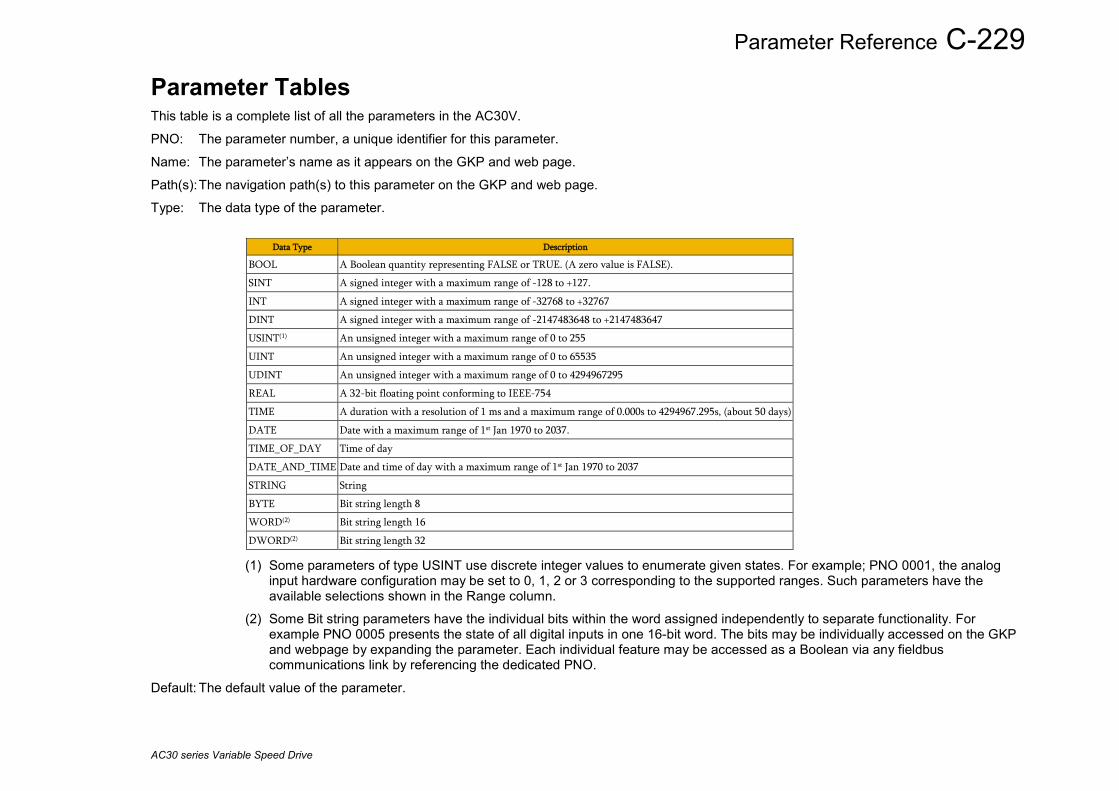
Parameter Reference C-229
AC30 series Variable Speed Drive
Parameter Tables This table is a complete list of all the parameters in the AC30V.
PNO: The parameter number, a unique identifier for this parameter.
Name: The parameter’s name as it appears on the GKP and web page.
Path(s): The navigation path(s) to this parameter on the GKP and web page.
Type: The data type of the parameter.
Data Type Description
BOOL A Boolean quantity representing FALSE or TRUE. (A zero value is FALSE).
SINT A signed integer with a maximum range of -128 to +127.
INT A signed integer with a maximum range of -32768 to +32767
DINT A signed integer with a maximum range of -2147483648 to +2147483647
USINT(1) An unsigned integer with a maximum range of 0 to 255
UINT An unsigned integer with a maximum range of 0 to 65535
UDINT An unsigned integer with a maximum range of 0 to 4294967295
REAL A 32-bit floating point conforming to IEEE-754
TIME A duration with a resolution of 1 ms and a maximum range of 0.000s to 4294967.295s, (about 50 days)
DATE Date with a maximum range of 1st Jan 1970 to 2037.
TIME_OF_DAY Time of day
DATE_AND_TIME Date and time of day with a maximum range of 1st Jan 1970 to 2037
STRING String
BYTE Bit string length 8
WORD(2) Bit string length 16
DWORD(2) Bit string length 32
(1) Some parameters of type USINT use discrete integer values to enumerate given states. For example; PNO 0001, the analog input hardware configuration may be set to 0, 1, 2 or 3 corresponding to the supported ranges. Such parameters have the available selections shown in the Range column.
(2) Some Bit string parameters have the individual bits within the word assigned independently to separate functionality. For example PNO 0005 presents the state of all digital inputs in one 16-bit word. The bits may be individually accessed on the GKP and webpage by expanding the parameter. Each individual feature may be accessed as a Boolean via any fieldbus communications link by referencing the dedicated PNO.
Default: The default value of the parameter.
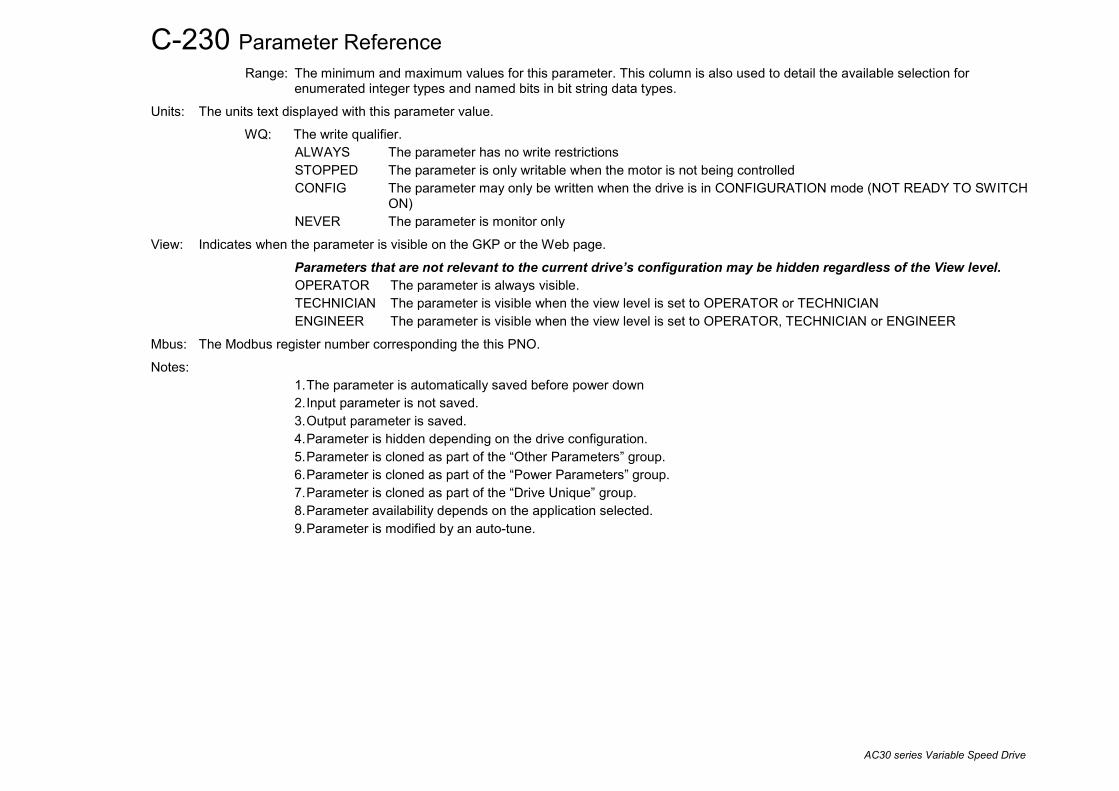
C-230 Parameter Reference
AC30 series Variable Speed Drive
Range: The minimum and maximum values for this parameter. This column is also used to detail the available selection for enumerated integer types and named bits in bit string data types.
Units: The units text displayed with this parameter value.
WQ: The write qualifier. ALWAYS The parameter has no write restrictions STOPPED The parameter is only writable when the motor is not being controlled CONFIG The parameter may only be written when the drive is in CONFIGURATION mode (NOT READY TO SWITCH
ON) NEVER The parameter is monitor only
View: Indicates when the parameter is visible on the GKP or the Web page.
Parameters that are not relevant to the current drive’s configuration may be hidden regardless of the View level. OPERATOR The parameter is always visible. TECHNICIAN The parameter is visible when the view level is set to OPERATOR or TECHNICIAN ENGINEER The parameter is visible when the view level is set to OPERATOR, TECHNICIAN or ENGINEER
Mbus: The Modbus register number corresponding the this PNO.
Notes: 1. The parameter is automatically saved before power down 2. Input parameter is not saved. 3. Output parameter is saved. 4. Parameter is hidden depending on the drive configuration. 5. Parameter is cloned as part of the “Other Parameters” group. 6. Parameter is cloned as part of the “Power Parameters” group. 7. Parameter is cloned as part of the “Drive Unique” group. 8. Parameter availability depends on the application selected. 9. Parameter is modified by an auto-tune.

Parameter Reference C-231
AC30 series Variable Speed Drive
Parameters Defined in the Firmware PNO Name Path Type Default Range Units WQ View Notes MBus 0001 Anin 01 Type Setup::Inputs and Outputs::Base IO
Parameters::Inputs And Outputs::IO Configure USINT (enum)
0 0:-10..10 V 1:0..10 V 2:0..20 mA 3:4..20 mA
ALWAYS OPERATOR 00529
0002 Anin 02 Type Same as PNO 1 USINT (enum)
0 0:-10..10 V 1:0..10 V
ALWAYS OPERATOR 00531
0003 Anout 01 Type Same as PNO 1 USINT (enum)
0 0:-10..10 V 1:0..10 V 4:TORQUE OUT -10..10 V
ALWAYS OPERATOR 00533
0004 Anout 02 Type Same as PNO 1 USINT (enum)
1 1:0..10 V 2:0..20 mA 3:4..20 mA
ALWAYS OPERATOR 00535
0005 Digin Value Monitor::Inputs and Outputs Parameters::Inputs And Outputs::IO Values
WORD (bitfield)
0:Digin 01 1:Digin 02 2:Digin 03 3:Digin 04 4:Digin 05 5:Digin 06 6:Digin 07 7:STO Inactive 8:Digin 11 9:Digin 12 10:Digin 13 11:Digin 14 12:Run Key 13:Not Stop Key 14:Stop Key
NEVER OPERATOR 00537
0006 Digin Value.Digin 01 Same as PNO 5 BOOL NEVER OPERATOR 00539 0007 Digin Value.Digin 02 Same as PNO 5 BOOL NEVER OPERATOR 00541 0008 Digin Value.Digin 03 Same as PNO 5 BOOL NEVER OPERATOR 00543 0009 Digin Value.Digin 04 Same as PNO 5 BOOL NEVER OPERATOR 00545 0010 Digin Value.Digin 05 Same as PNO 5 BOOL NEVER OPERATOR 00547 0011 Digin Value.Digin 06 Same as PNO 5 BOOL NEVER OPERATOR 00549 0012 Digin Value.Digin 07 Same as PNO 5 BOOL NEVER OPERATOR 00551 0013 Digin Value.STO Inactive Same as PNO 5 BOOL NEVER OPERATOR 00553 0014 Digin Value.Digin 11 Same as PNO 5 BOOL NEVER OPERATOR 00555 0015 Digin Value.Digin 12 Same as PNO 5 BOOL NEVER OPERATOR 00557 0016 Digin Value.Digin 13 Same as PNO 5 BOOL NEVER OPERATOR 00559 0017 Digin Value.Digin 14 Same as PNO 5 BOOL NEVER OPERATOR 00561 0018 Digin Value.Run Key Same as PNO 5 BOOL NEVER OPERATOR 00563 0019 Digin Value.Not Stop Key Same as PNO 5 BOOL NEVER OPERATOR 00565 0020 Digin Value.Stop Key Same as PNO 5 BOOL NEVER OPERATOR 00567 0022 Digout Value Same as PNO 5 WORD
(bitfield) 0000 0:Digout 01
1:Digout 02 2:Digout 03 3:Digout 04 4:Relay 01 5:Relay 02 8:Digout 11 9:Digout 12 10:Digout 13 11:Digout 14 14:Relay 11 15:Relay 12
ALWAYS OPERATOR 2 00571
0023 Digout Value.Digout 01 Same as PNO 5 BOOL FALSE ALWAYS OPERATOR 2 00573 0024 Digout Value.Digout 02 Same as PNO 5 BOOL FALSE ALWAYS OPERATOR 2 00575 0025 Digout Value.Digout 03 Same as PNO 5 BOOL FALSE ALWAYS OPERATOR 2 00577 0026 Digout Value.Digout 04 Same as PNO 5 BOOL FALSE ALWAYS OPERATOR 2 00579 0027 Digout Value.Relay 01 Same as PNO 5 BOOL FALSE ALWAYS OPERATOR 2 00581 0028 Digout Value.Relay 02 Same as PNO 5 BOOL FALSE ALWAYS OPERATOR 2 00583 0031 Digout Value.Digout 11 Same as PNO 5 BOOL FALSE ALWAYS OPERATOR 2 00589 0032 Digout Value.Digout 12 Same as PNO 5 BOOL FALSE ALWAYS OPERATOR 2 00591 0033 Digout Value.Digout 13 Same as PNO 5 BOOL FALSE ALWAYS OPERATOR 2 00593 0034 Digout Value.Digout 14 Same as PNO 5 BOOL FALSE ALWAYS OPERATOR 2 00595 0037 Digout Value.Relay 11 Same as PNO 5 BOOL FALSE ALWAYS OPERATOR 2 00601 0038 Digout Value.Relay 12 Monitor::Inputs and Outputs BOOL FALSE ALWAYS OPERATOR 2 00603
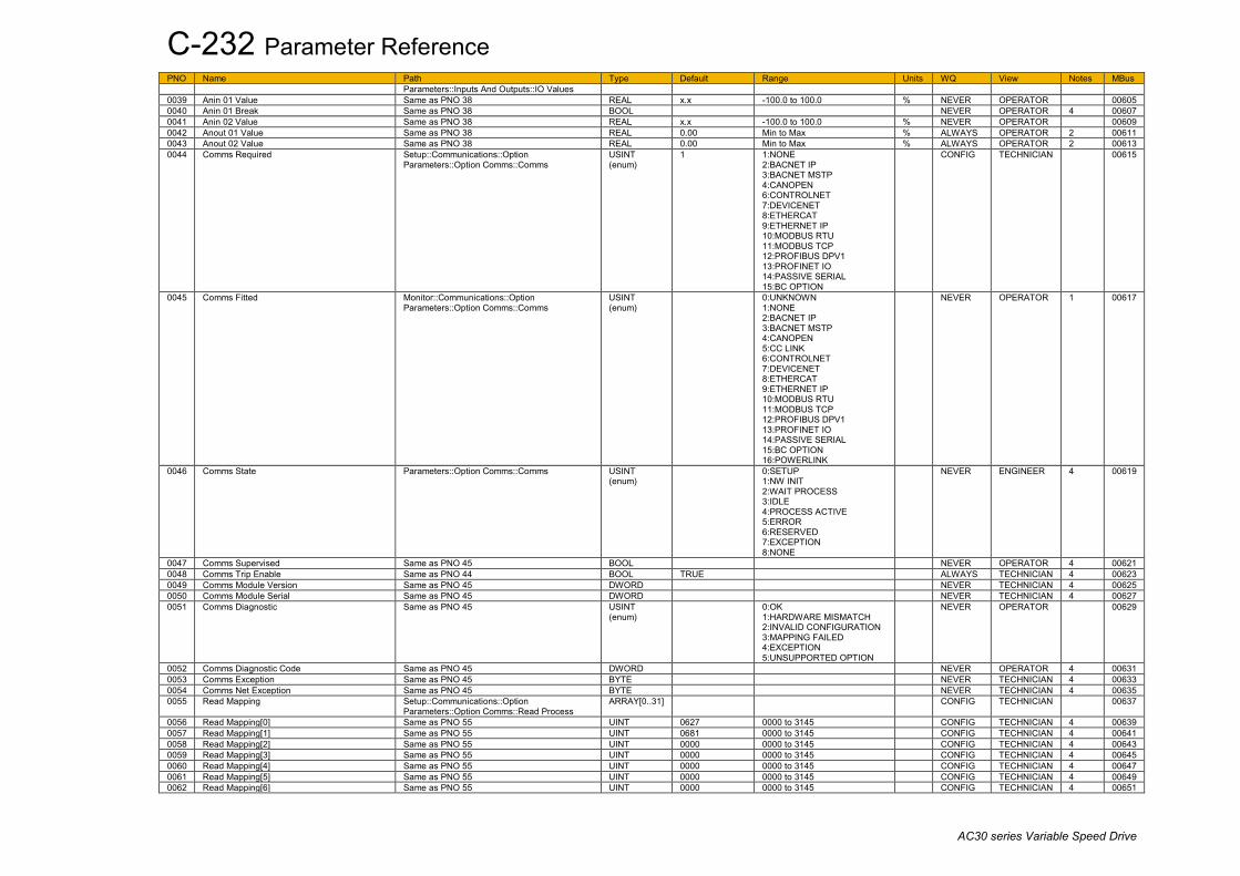
C-232 Parameter Reference
AC30 series Variable Speed Drive
PNO Name Path Type Default Range Units WQ View Notes MBus Parameters::Inputs And Outputs::IO Values
0039 Anin 01 Value Same as PNO 38 REAL x.x -100.0 to 100.0 % NEVER OPERATOR 00605 0040 Anin 01 Break Same as PNO 38 BOOL NEVER OPERATOR 4 00607 0041 Anin 02 Value Same as PNO 38 REAL x.x -100.0 to 100.0 % NEVER OPERATOR 00609 0042 Anout 01 Value Same as PNO 38 REAL 0.00 Min to Max % ALWAYS OPERATOR 2 00611 0043 Anout 02 Value Same as PNO 38 REAL 0.00 Min to Max % ALWAYS OPERATOR 2 00613 0044 Comms Required Setup::Communications::Option
Parameters::Option Comms::Comms USINT (enum)
1 1:NONE 2:BACNET IP 3:BACNET MSTP 4:CANOPEN 6:CONTROLNET 7:DEVICENET 8:ETHERCAT 9:ETHERNET IP 10:MODBUS RTU 11:MODBUS TCP 12:PROFIBUS DPV1 13:PROFINET IO 14:PASSIVE SERIAL 15:BC OPTION
CONFIG TECHNICIAN 00615
0045 Comms Fitted Monitor::Communications::Option Parameters::Option Comms::Comms
USINT (enum)
0:UNKNOWN 1:NONE 2:BACNET IP 3:BACNET MSTP 4:CANOPEN 5:CC LINK 6:CONTROLNET 7:DEVICENET 8:ETHERCAT 9:ETHERNET IP 10:MODBUS RTU 11:MODBUS TCP 12:PROFIBUS DPV1 13:PROFINET IO 14:PASSIVE SERIAL 15:BC OPTION 16:POWERLINK
NEVER OPERATOR 1 00617
0046 Comms State Parameters::Option Comms::Comms USINT (enum)
0:SETUP 1:NW INIT 2:WAIT PROCESS 3:IDLE 4:PROCESS ACTIVE 5:ERROR 6:RESERVED 7:EXCEPTION 8:NONE
NEVER ENGINEER 4 00619
0047 Comms Supervised Same as PNO 45 BOOL NEVER OPERATOR 4 00621 0048 Comms Trip Enable Same as PNO 44 BOOL TRUE ALWAYS TECHNICIAN 4 00623 0049 Comms Module Version Same as PNO 45 DWORD NEVER TECHNICIAN 4 00625 0050 Comms Module Serial Same as PNO 45 DWORD NEVER TECHNICIAN 4 00627 0051 Comms Diagnostic Same as PNO 45 USINT
(enum) 0:OK
1:HARDWARE MISMATCH 2:INVALID CONFIGURATION 3:MAPPING FAILED 4:EXCEPTION 5:UNSUPPORTED OPTION
NEVER OPERATOR 00629
0052 Comms Diagnostic Code Same as PNO 45 DWORD NEVER OPERATOR 4 00631 0053 Comms Exception Same as PNO 45 BYTE NEVER TECHNICIAN 4 00633 0054 Comms Net Exception Same as PNO 45 BYTE NEVER TECHNICIAN 4 00635 0055 Read Mapping Setup::Communications::Option
Parameters::Option Comms::Read Process ARRAY[0..31] CONFIG TECHNICIAN 00637
0056 Read Mapping[0] Same as PNO 55 UINT 0627 0000 to 3145 CONFIG TECHNICIAN 4 00639 0057 Read Mapping[1] Same as PNO 55 UINT 0681 0000 to 3145 CONFIG TECHNICIAN 4 00641 0058 Read Mapping[2] Same as PNO 55 UINT 0000 0000 to 3145 CONFIG TECHNICIAN 4 00643 0059 Read Mapping[3] Same as PNO 55 UINT 0000 0000 to 3145 CONFIG TECHNICIAN 4 00645 0060 Read Mapping[4] Same as PNO 55 UINT 0000 0000 to 3145 CONFIG TECHNICIAN 4 00647 0061 Read Mapping[5] Same as PNO 55 UINT 0000 0000 to 3145 CONFIG TECHNICIAN 4 00649 0062 Read Mapping[6] Same as PNO 55 UINT 0000 0000 to 3145 CONFIG TECHNICIAN 4 00651

Parameter Reference C-233
AC30 series Variable Speed Drive
PNO Name Path Type Default Range Units WQ View Notes MBus 0063 Read Mapping[7] Same as PNO 55 UINT 0000 0000 to 3145 CONFIG TECHNICIAN 4 00653 0064 Read Mapping[8] Same as PNO 55 UINT 0000 0000 to 3145 CONFIG TECHNICIAN 4 00655 0065 Read Mapping[9] Same as PNO 55 UINT 0000 0000 to 3145 CONFIG TECHNICIAN 4 00657 0066 Read Mapping[10] Same as PNO 55 UINT 0000 0000 to 3145 CONFIG TECHNICIAN 4 00659 0067 Read Mapping[11] Same as PNO 55 UINT 0000 0000 to 3145 CONFIG TECHNICIAN 4 00661 0068 Read Mapping[12] Same as PNO 55 UINT 0000 0000 to 3145 CONFIG TECHNICIAN 4 00663 0069 Read Mapping[13] Same as PNO 55 UINT 0000 0000 to 3145 CONFIG TECHNICIAN 4 00665 0070 Read Mapping[14] Same as PNO 55 UINT 0000 0000 to 3145 CONFIG TECHNICIAN 4 00667 0071 Read Mapping[15] Same as PNO 55 UINT 0000 0000 to 3145 CONFIG TECHNICIAN 4 00669 0072 Read Mapping[16] Same as PNO 55 UINT 0000 0000 to 3145 CONFIG TECHNICIAN 4 00671 0073 Read Mapping[17] Same as PNO 55 UINT 0000 0000 to 3145 CONFIG TECHNICIAN 4 00673 0074 Read Mapping[18] Same as PNO 55 UINT 0000 0000 to 3145 CONFIG TECHNICIAN 4 00675 0075 Read Mapping[19] Same as PNO 55 UINT 0000 0000 to 3145 CONFIG TECHNICIAN 4 00677 0076 Read Mapping[20] Same as PNO 55 UINT 0000 0000 to 3145 CONFIG TECHNICIAN 4 00679 0077 Read Mapping[21] Same as PNO 55 UINT 0000 0000 to 3145 CONFIG TECHNICIAN 4 00681 0078 Read Mapping[22] Same as PNO 55 UINT 0000 0000 to 3145 CONFIG TECHNICIAN 4 00683 0079 Read Mapping[23] Same as PNO 55 UINT 0000 0000 to 3145 CONFIG TECHNICIAN 4 00685 0080 Read Mapping[24] Same as PNO 55 UINT 0000 0000 to 3145 CONFIG TECHNICIAN 4 00687 0081 Read Mapping[25] Same as PNO 55 UINT 0000 0000 to 3145 CONFIG TECHNICIAN 4 00689 0082 Read Mapping[26] Same as PNO 55 UINT 0000 0000 to 3145 CONFIG TECHNICIAN 4 00691 0083 Read Mapping[27] Same as PNO 55 UINT 0000 0000 to 3145 CONFIG TECHNICIAN 4 00693 0084 Read Mapping[28] Same as PNO 55 UINT 0000 0000 to 3145 CONFIG TECHNICIAN 4 00695 0085 Read Mapping[29] Same as PNO 55 UINT 0000 0000 to 3145 CONFIG TECHNICIAN 4 00697 0086 Read Mapping[30] Same as PNO 55 UINT 0000 0000 to 3145 CONFIG TECHNICIAN 4 00699 0087 Read Mapping[31] Same as PNO 55 UINT 0000 0000 to 3145 CONFIG TECHNICIAN 4 00701 0113 Force Fan On Parameters::Fan Control BOOL FALSE ALWAYS OPERATOR 2 00753 0114 Group IP Address Setup::Communications::Peer to Peer
Parameters::Base Comms::Peer to Peer DWORD (IP addr)
000.000.000.000 ALWAYS ENGINEER 00755
0115 Show Warnings 1 - 32 Parameters::Trips::Trips Status DWORD FFFFFFFF ALWAYS TECHNICIAN 4 00757 0116 Show Warnings 33 - 64 Parameters::Trips::Trips Status DWORD FFFFFFFF ALWAYS TECHNICIAN 4 00759 0117 Extended Support Parameters::Device Manager::SD Card BOOL TRUE ALWAYS TECHNICIAN 00761 0118 Configuration Lock Parameters::Application::App Info BOOL FALSE ALWAYS TECHNICIAN 00763 0119 DC Link Volts Trim Parameters::Motor Control::Feedbacks REAL 0 -20 to 20 V ALWAYS TECHNICIAN 00765 0120 Write Mapping Setup::Communications::Option
Parameters::Option Comms::Write Process ARRAY[0..31] CONFIG TECHNICIAN 00767
0121 Write Mapping[0] Same as PNO 120 UINT 0661 0000 to 3145 CONFIG TECHNICIAN 4 00769 0122 Write Mapping[1] Same as PNO 120 UINT 0395 0000 to 3145 CONFIG TECHNICIAN 4 00771 0123 Write Mapping[2] Same as PNO 120 UINT 0000 0000 to 3145 CONFIG TECHNICIAN 4 00773 0124 Write Mapping[3] Same as PNO 120 UINT 0000 0000 to 3145 CONFIG TECHNICIAN 4 00775 0125 Write Mapping[4] Same as PNO 120 UINT 0000 0000 to 3145 CONFIG TECHNICIAN 4 00777 0126 Write Mapping[5] Same as PNO 120 UINT 0000 0000 to 3145 CONFIG TECHNICIAN 4 00779 0127 Write Mapping[6] Same as PNO 120 UINT 0000 0000 to 3145 CONFIG TECHNICIAN 4 00781 0128 Write Mapping[7] Same as PNO 120 UINT 0000 0000 to 3145 CONFIG TECHNICIAN 4 00783 0129 Write Mapping[8] Same as PNO 120 UINT 0000 0000 to 3145 CONFIG TECHNICIAN 4 00785 0130 Write Mapping[9] Same as PNO 120 UINT 0000 0000 to 3145 CONFIG TECHNICIAN 4 00787 0131 Write Mapping[10] Same as PNO 120 UINT 0000 0000 to 3145 CONFIG TECHNICIAN 4 00789 0132 Write Mapping[11] Same as PNO 120 UINT 0000 0000 to 3145 CONFIG TECHNICIAN 4 00791 0133 Write Mapping[12] Same as PNO 120 UINT 0000 0000 to 3145 CONFIG TECHNICIAN 4 00793 0134 Write Mapping[13] Same as PNO 120 UINT 0000 0000 to 3145 CONFIG TECHNICIAN 4 00795 0135 Write Mapping[14] Same as PNO 120 UINT 0000 0000 to 3145 CONFIG TECHNICIAN 4 00797 0136 Write Mapping[15] Same as PNO 120 UINT 0000 0000 to 3145 CONFIG TECHNICIAN 4 00799 0137 Write Mapping[16] Same as PNO 120 UINT 0000 0000 to 3145 CONFIG TECHNICIAN 4 00801 0138 Write Mapping[17] Same as PNO 120 UINT 0000 0000 to 3145 CONFIG TECHNICIAN 4 00803 0139 Write Mapping[18] Same as PNO 120 UINT 0000 0000 to 3145 CONFIG TECHNICIAN 4 00805 0140 Write Mapping[19] Same as PNO 120 UINT 0000 0000 to 3145 CONFIG TECHNICIAN 4 00807 0141 Write Mapping[20] Same as PNO 120 UINT 0000 0000 to 3145 CONFIG TECHNICIAN 4 00809 0142 Write Mapping[21] Same as PNO 120 UINT 0000 0000 to 3145 CONFIG TECHNICIAN 4 00811 0143 Write Mapping[22] Same as PNO 120 UINT 0000 0000 to 3145 CONFIG TECHNICIAN 4 00813 0144 Write Mapping[23] Same as PNO 120 UINT 0000 0000 to 3145 CONFIG TECHNICIAN 4 00815 0145 Write Mapping[24] Same as PNO 120 UINT 0000 0000 to 3145 CONFIG TECHNICIAN 4 00817 0146 Write Mapping[25] Same as PNO 120 UINT 0000 0000 to 3145 CONFIG TECHNICIAN 4 00819 0147 Write Mapping[26] Same as PNO 120 UINT 0000 0000 to 3145 CONFIG TECHNICIAN 4 00821 0148 Write Mapping[27] Same as PNO 120 UINT 0000 0000 to 3145 CONFIG TECHNICIAN 4 00823 0149 Write Mapping[28] Same as PNO 120 UINT 0000 0000 to 3145 CONFIG TECHNICIAN 4 00825 0150 Write Mapping[29] Same as PNO 120 UINT 0000 0000 to 3145 CONFIG TECHNICIAN 4 00827 0151 Write Mapping[30] Same as PNO 120 UINT 0000 0000 to 3145 CONFIG TECHNICIAN 4 00829

C-234 Parameter Reference
AC30 series Variable Speed Drive
PNO Name Path Type Default Range Units WQ View Notes MBus 0152 Write Mapping[31] Same as PNO 120 UINT 0000 0000 to 3145 CONFIG TECHNICIAN 4 00831 0182 Backup Action Parameters::Device Manager::Parameter
Backup USINT (enum)
0 0:SAVE 1:LOAD ALL 2:LOAD POWER 3:LOAD OTHER 4:LOAD AUTOTUNE
ALWAYS OPERATOR 2 00891
0183 Backup-Restore Start Parameters::Device Manager::Parameter Backup
BOOL FALSE ALWAYS OPERATOR 2 00893
0184 Backup-Restore Status Parameters::Device Manager::Parameter Backup
USINT (enum)
0:IDLE 1:SAVING 2:RESTORING 3:VERIFYING 4:DONE 6:FAILED 8:VERIFY FAILED
NEVER OPERATOR 00895
0185 Comms Event Code Parameters::Option Comms::Event BYTE 00 ALWAYS ENGINEER 2,4 00897 0186 Comms Event Active Monitor::Communications::Option
Parameters::Option Comms::Event BOOL NEVER OPERATOR 4 00899
0187 Comms Event Set Parameters::Option Comms::Event BOOL FALSE ALWAYS ENGINEER 2,4 00901 0188 Comms Event Clear Parameters::Option Comms::Event BOOL FALSE ALWAYS ENGINEER 2,4 00903 0189 Option MAC Address Monitor::Communications::Option
Parameters::Option Comms::Option Ethernet STRING[18] NEVER TECHNICIAN 4 00905
0195 Option IP Address Same as PNO 189 DWORD (IP addr)
NEVER OPERATOR 4 00917
0196 Option Subnet Mask Same as PNO 189 DWORD (IP addr)
NEVER OPERATOR 4 00919
0197 Option Gateway Same as PNO 189 DWORD (IP addr)
NEVER OPERATOR 4 00921
0198 Option DHCP Enabled Same as PNO 189 BOOL NEVER TECHNICIAN 4 00923 0199 Address Assignment Setup::Communications::Option
Parameters::Option Comms::Option Ethernet USINT (enum)
0 0:FIXED 1:EXTERNAL 2:DHCP
CONFIG TECHNICIAN 4 00925
0200 Fixed IP Address Same as PNO 199 DWORD (IP addr)
000.000.000.000 CONFIG TECHNICIAN 7,4 00927
0201 Fixed Subnet Mask Same as PNO 199 DWORD (IP addr)
000.000.000.000 CONFIG TECHNICIAN 7,4 00929
0202 Fixed Gateway Address Same as PNO 199 DWORD (IP addr)
000.000.000.000 CONFIG TECHNICIAN 7,4 00931
0203 Option Web Enable Same as PNO 199 BOOL TRUE CONFIG TECHNICIAN 4 00933 0204 Web Parameters Enable Same as PNO 199 BOOL TRUE CONFIG TECHNICIAN 4 00935 0205 Option FTP Enable Same as PNO 199 BOOL TRUE CONFIG ENGINEER 4 00937 0206 Option FTP Admin Mode Same as PNO 199 BOOL TRUE CONFIG ENGINEER 4 00939 0207 IPConfig Enable Same as PNO 199 BOOL TRUE CONFIG ENGINEER 4 00941 0208 BACnet IP State Monitor::Communications::Option
Parameters::Option Comms::BACnet IP USINT (enum)
Same as PNO 46 NEVER OPERATOR 4 00943
0209 BACnet IP Device ID Setup::Communications::Option Parameters::Option Comms::BACnet IP
UDINT 0 0 to 4194302 CONFIG TECHNICIAN 7,4 00945
0210 BACnet IP Timeout Same as PNO 209 TIME 3.000 0.000 to 65.000 s CONFIG TECHNICIAN 4 00947 0211 CANopen State Monitor::Communications::Option
Parameters::Option Comms::CANopen USINT (enum)
0:SETUP 1:NW INIT 2:PRE-OPERATIONAL 3:STOP 4:OPERATIONAL 5:BUS OFF 6:RESERVED 7:EXCEPTION 8:NONE
NEVER OPERATOR 4 00949
0212 CANopen Node Address Setup::Communications::Option Parameters::Option Comms::CANopen
USINT 1 1 to 127 CONFIG TECHNICIAN 7,4 00951
0213 CANopen Baud Rate Same as PNO 212 USINT (enum)
9 0:10 KBPS 1:20 KBPS 2:50 KBPS 3:100 KBPS 4:125 KBPS 5:250 KBPS 6:500 KBPS 7:800 KBPS 8:1000 KBPS
CONFIG TECHNICIAN 4 00953

Parameter Reference C-235
AC30 series Variable Speed Drive
PNO Name Path Type Default Range Units WQ View Notes MBus 9:AUTO
0214 ControlNet State Monitor::Communications::Option Parameters::Option Comms::ControlNet
USINT (enum)
0:SETUP 1:NW INIT 2:WAITING TO CONNECT 3:CONNECTION IDLE 4:CONNECTION ACTIVE 5:ERROR 6:RESERVED 7:EXCEPTION 8:NONE
NEVER OPERATOR 4 00955
0215 ControlNet MAC ID Setup::Communications::Option Parameters::Option Comms::ControlNet
USINT 0 0 to 99 CONFIG TECHNICIAN 7,4 00957
0216 CNet Producing Inst Same as PNO 215 WORD 0064 CONFIG TECHNICIAN 4 00959 0217 CNet Consuming Inst Same as PNO 215 WORD 0096 CONFIG TECHNICIAN 4 00961 0218 DeviceNet State Monitor::Communications::Option
Parameters::Option Comms::DeviceNet USINT (enum)
Same as PNO 214 NEVER OPERATOR 4 00963
0219 DeviceNet MAC ID Setup::Communications::Option Parameters::Option Comms::DeviceNet
USINT 0 0 to 63 CONFIG TECHNICIAN 7,4 00965
0220 DeviceNet Baud Rate Same as PNO 219 USINT (enum)
3 0:125 KBPS 1:250 KBPS 2:500 KBPS 3:AUTO
CONFIG TECHNICIAN 4 00967
0221 DeviceNet Actual Baud Same as PNO 218 USINT (enum)
Same as PNO 220 NEVER OPERATOR 4 00969
0222 DNet Producing Inst Same as PNO 219 WORD 0064 CONFIG TECHNICIAN 4 00971 0223 DNet Consuming Inst Same as PNO 219 WORD 0096 CONFIG TECHNICIAN 4 00973 0224 EtherCAT State Monitor::Communications::Option
Parameters::Option Comms::EtherCAT USINT (enum)
0:SETUP 1:NW INIT 2:INIT OR PREOP 3:SAFE OPERATIONAL 4:OPERATIONAL 5:ERROR 6:RESERVED 7:EXCEPTION 8:NONE
NEVER OPERATOR 4 00975
0225 EtherNet IP State Monitor::Communications::Option Parameters::Option Comms::EtherNet IP
USINT (enum)
Same as PNO 214 NEVER OPERATOR 4 00977
0226 ENet Producing Inst Setup::Communications::Option Parameters::Option Comms::EtherNet IP
WORD 0064 CONFIG TECHNICIAN 4 00979
0227 ENet Consuming Inst Same as PNO 226 WORD 0096 CONFIG TECHNICIAN 4 00981 0228 Modbus RTU State Monitor::Communications::Option
Parameters::Option Comms::Modbus RTU USINT (enum)
Same as PNO 46 NEVER OPERATOR 4 00983
0229 Modbus Device Address Setup::Communications::Option Parameters::Option Comms::Modbus RTU
USINT 1 1 to 247 CONFIG TECHNICIAN 7,4 00985
0230 Modbus RTU Baud Rate Same as PNO 229 USINT (enum)
4 0:1200 BPS 1:2400 BPS 2:4800 BPS 3:9600 BPS 4:19200 BPS 5:38400 BPS 6:57600 BPS 7:76800 BPS 8:115200 BPS
CONFIG TECHNICIAN 4 00987
0231 Parity And Stop Bits Same as PNO 229 USINT (enum)
0 0:EVEN, 1 STOP 1:ODD, 1 STOP 2:NONE, 2 STOP 3:NONE, 1 STOP
CONFIG TECHNICIAN 4 00989
0232 High Word First RTU Same as PNO 229 BOOL FALSE CONFIG TECHNICIAN 4 00991 0233 Modbus RTU Timeout Same as PNO 229 TIME 3.000 0.000 to 65.000 s CONFIG TECHNICIAN 4 00993 0234 Modbus TCP State Monitor::Communications::Option
Parameters::Option Comms::Modbus TCP USINT (enum)
Same as PNO 46 NEVER OPERATOR 4 00995
0235 High Word First TCP Setup::Communications::Option Parameters::Option Comms::Modbus TCP
BOOL FALSE CONFIG TECHNICIAN 4 00997
0236 Modbus TCP Timeout Same as PNO 235 TIME 3.000 0.000 to 65.000 s CONFIG TECHNICIAN 4 00999 0237 Profibus State Monitor::Communications::Option
Parameters::Option Comms::Profibus USINT (enum)
Same as PNO 46 NEVER OPERATOR 4 01001
0238 Profibus Node Address Setup::Communications::Option Parameters::Option Comms::Profibus
USINT 0 0 to 126 CONFIG TECHNICIAN 7,4 01003

C-236 Parameter Reference
AC30 series Variable Speed Drive
PNO Name Path Type Default Range Units WQ View Notes MBus 0239 PROFINET State Monitor::Communications::Option
Parameters::Option Comms::PROFINET IO USINT (enum)
0:SETUP 1:NW INIT 2:WAITING TO CONNECT 3:STOP MODE 4:CONNECTED 5:ERROR 6:RESERVED 7:EXCEPTION 8:NONE
NEVER OPERATOR 4 01005
0240 PROFINET Device Name Same as PNO 239 STRING[32] NEVER OPERATOR 4 01007 0249 Braking Enable Parameters::Motor Control::Braking BOOL TRUE ALWAYS TECHNICIAN 6 01025 0251 Brake Resistance Parameters::Motor Control::Braking REAL 100.00 0.01 to 1000.00 Ohm STOPPED TECHNICIAN 6 01029 0252 Brake Rated Power Parameters::Motor Control::Braking REAL 0.11 0.10 to 510.00 kW STOPPED TECHNICIAN 6 01031 0253 Brake Overrating Parameters::Motor Control::Braking REAL 25.00 1.00 to 40.00 STOPPED ENGINEER 6 01033 0254 Braking Active Parameters::Motor Control::Braking BOOL NEVER TECHNICIAN 01035 0255 Autotune Enable Setup::Motor Control::Autotune
Parameters::Motor Control::Autotune BOOL FALSE STOPPED TECHNICIAN 2,4 01037
0256 Autotune Mode Same as PNO 255 USINT (enum)
1 0:STATIONARY 1:ROTATING
STOPPED TECHNICIAN 6,4 01039
0257 Autotune Test Disable Same as PNO 255 WORD (bitfield)
0000 0:Stator Resistance 1:Leakage Inductance 2:Magnetising Current 3:Rotor Time Constant 4:Encoder Direction
STOPPED TECHNICIAN 6,4 01041
0258 Autotune Test Disable.Stator Resistance Same as PNO 255 BOOL FALSE STOPPED TECHNICIAN 6,4 01043 0259 Autotune Test Disable.Leakage Inductance Same as PNO 255 BOOL FALSE STOPPED TECHNICIAN 6,4 01045 0260 Autotune Test Disable.Magnetising Current Same as PNO 255 BOOL FALSE STOPPED TECHNICIAN 6,4 01047 0261 Autotune Test Disable.Rotor Time Constant Same as PNO 255 BOOL FALSE STOPPED TECHNICIAN 6,4 01049 0262 Autotune Test Disable.Encoder Direction Same as PNO 255 BOOL FALSE STOPPED TECHNICIAN 6,4 01051 0274 Autotune Ramp Time Same as PNO 255 TIME 10.000 1.000 to 1000.000 s STOPPED TECHNICIAN 6,4 01075 0286 MRAS Speed Percent Parameters::Motor Control::MRAS REAL x.xx Min to Max % NEVER ENGINEER 4 01099 0287 MRAS Speed RPM Parameters::Motor Control::MRAS REAL x.xx Min to Max RPM NEVER ENGINEER 4 01101 0289 MRAS Field Frequency Parameters::Motor Control::MRAS REAL x.xx Min to Max Hz NEVER ENGINEER 4 01105 0290 MRAS Torque Percent Parameters::Motor Control::MRAS REAL x.xx Min to Max % NEVER ENGINEER 4 01107 0291 MRAS Torque Parameters::Motor Control::MRAS REAL x.xx Min to Max Nm NEVER ENGINEER 4 01109 0305 Current Limit Setup::Motor Control::Control and Type
Parameters::Motor Control::Current Limit REAL 150.0 0.0 to 600.0 % ALWAYS TECHNICIAN 01137
0307 Regen Limit Enable Parameters::Motor Control::Current Limit BOOL TRUE ALWAYS ENGINEER 4 01141 0310 VHz Flying Start Enable Parameters::Motor Control::Flycatching BOOL FALSE ALWAYS TECHNICIAN 4 01147 0311 VC Flying Start Enable Parameters::Motor Control::Flycatching BOOL FALSE ALWAYS TECHNICIAN 4 01149 0312 Flying Start Mode Parameters::Motor Control::Flycatching USINT
(enum) 0 0:ALWAYS
1:TRIP OR POWER UP 2:TRIP
ALWAYS TECHNICIAN 4 01151
0313 Search Mode Parameters::Motor Control::Flycatching USINT (enum)
0 0:BIDIRECTIONAL 1:UNIDIRECTION
ALWAYS TECHNICIAN 4 01153
0314 Search Volts Parameters::Motor Control::Flycatching REAL 9.0 0.0 to 100.0 % ALWAYS TECHNICIAN 6,4 01155 0315 Search Boost Parameters::Motor Control::Flycatching REAL 40.0 0.0 to 50.0 % ALWAYS TECHNICIAN 6,4 01157 0316 Search Time Parameters::Motor Control::Flycatching TIME 5.000 0.100 to 60.000 s ALWAYS TECHNICIAN 6,4 01159 0317 Min Search Speed Parameters::Motor Control::Flycatching REAL 5 0 to 500 Hz ALWAYS TECHNICIAN 4 01161 0318 Flying Reflux Time Parameters::Motor Control::Flycatching TIME 3.000 0.100 to 10.000 s ALWAYS TECHNICIAN 6,4 01163 0324 DC Inj Deflux Time Parameters::Motor Control::Inj Braking TIME 0.500 0.100 to 20.000 s ALWAYS TECHNICIAN 6,4 01175 0325 DC Inj Frequency Parameters::Motor Control::Inj Braking REAL 9 1 to 500 Hz ALWAYS TECHNICIAN 6,4 01177 0326 DC Inj Current Limit Parameters::Motor Control::Inj Braking REAL 100.0 50.0 to 150.0 % ALWAYS TECHNICIAN 6,4 01179 0327 DC Pulse Time Parameters::Motor Control::Inj Braking TIME 2.000 0.000 to 100.000 s ALWAYS TECHNICIAN 6,4 01181 0328 Final DC Pulse Time Parameters::Motor Control::Inj Braking TIME 1.000 0.000 to 10.000 s ALWAYS TECHNICIAN 6,4 01183 0329 DC Current Level Parameters::Motor Control::Inj Braking REAL 3.0 0.0 to 25.0 % ALWAYS TECHNICIAN 6,4 01185 0330 DC Inj Timeout Parameters::Motor Control::Inj Braking TIME 90.000 0.000 to 600.000 s ALWAYS TECHNICIAN 6,4 01187 0331 DC Inj Base Volts Parameters::Motor Control::Inj Braking REAL 100.00 0.00 to 115.47 % ALWAYS TECHNICIAN 6,4 01189 0332 100% Mot Current Parameters::Motor Control::Motor Load REAL x.x 0.0 to 10000.0 NEVER TECHNICIAN 01191 0333 Mot Inv Time Overload Parameters::Motor Control::Motor Load REAL x. 0 to 500 % NEVER TECHNICIAN 4 01193 0334 Mot Inv Time Delay Parameters::Motor Control::Motor Load TIME 60.000 6.000 to 60.000 s ALWAYS TECHNICIAN 6,4 01195 0335 Mot Inv Time Warning Parameters::Motor Control::Motor Load BOOL NEVER TECHNICIAN 4 01197 0336 Mot Inv Time Active Parameters::Motor Control::Motor Load BOOL NEVER TECHNICIAN 4 01199 0337 Mot Inv Time Output % Parameters::Motor Control::Motor Load REAL x.x 0.0 to 600.0 % NEVER TECHNICIAN 4 01201 0338 Mot I2T TC Parameters::Motor Control::Motor Load TIME 0.000 to 1000000.000 s NEVER TECHNICIAN 4 01203 0339 Actual Mot I2T Output Parameters::Motor Control::Motor Load REAL x.x 0.0 to 600.0 % NEVER TECHNICIAN 4 01205 0340 Mot I2T Active Parameters::Motor Control::Motor Load BOOL NEVER OPERATOR 4 01207
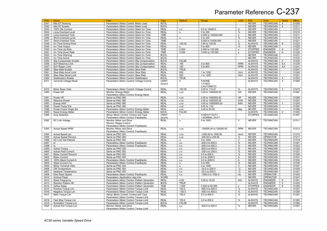
Parameter Reference C-237
AC30 series Variable Speed Drive
PNO Name Path Type Default Range Units WQ View Notes MBus 0341 Mot I2T Warning Parameters::Motor Control::Motor Load BOOL NEVER TECHNICIAN 4 01209 0342 Mot I2T Enable Parameters::Motor Control::Motor Load BOOL NEVER TECHNICIAN 4 01211 0343 100% Stk Current Parameters::Motor Control::Stack Inv Time REAL x.x 0.0 to 10000.0 A NEVER TECHNICIAN 01213 0344 Long Overload Level Parameters::Motor Control::Stack Inv Time REAL x. 0 to 200 % NEVER TECHNICIAN 01215 0345 Long Overload Time Parameters::Motor Control::Stack Inv Time TIME 0.000 to 100000.000 s NEVER TECHNICIAN 01217 0346 Short Overload Level Parameters::Motor Control::Stack Inv Time REAL x. 0 to 200 % NEVER TECHNICIAN 01219 0347 Short Overload Time Parameters::Motor Control::Stack Inv Time TIME 0.000 to 10000.000 s NEVER TECHNICIAN 01221 0348 Inv Time Aiming Point Parameters::Motor Control::Stack Inv Time REAL 105.00 0.00 to 125.00 % ALWAYS TECHNICIAN 6 01223 0349 Inv Time Output Parameters::Motor Control::Stack Inv Time REAL x. 0 to 600 % NEVER TECHNICIAN 01225 0350 Inv Time Up Rate Parameters::Motor Control::Stack Inv Time TIME 5.000 0.000 to 120.000 s STOPPED ENGINEER 6 01227 0351 Inv Time Down Rate Parameters::Motor Control::Stack Inv Time TIME 5.000 0.000 to 120.000 s STOPPED ENGINEER 6 01229 0352 Inv Time Warning Parameters::Motor Control::Stack Inv Time BOOL NEVER TECHNICIAN 01231 0353 Inv Time Active Parameters::Motor Control::Stack Inv Time BOOL NEVER TECHNICIAN 01233 0354 Slip Compensatn Enable Parameters::Motor Control::Slip Compensation BOOL FALSE ALWAYS TECHNICIAN 4 01235 0356 SLP Motoring Limit Parameters::Motor Control::Slip Compensation REAL 150 0 to 600 RPM ALWAYS TECHNICIAN 6,4 01239 0357 SLP Regen Limit Parameters::Motor Control::Slip Compensation REAL 150 0 to 600 RPM ALWAYS TECHNICIAN 6,4 01241 0360 Slew Rate Enable Parameters::Motor Control::Slew Rate BOOL TRUE ALWAYS TECHNICIAN 01247 0361 Slew Rate Accel Limit Parameters::Motor Control::Slew Rate REAL 500 1 to 1200 Hz/s ALWAYS TECHNICIAN 01249 0362 Slew Rate Decel Limit Parameters::Motor Control::Slew Rate REAL 500 1 to 1200 Hz/s ALWAYS TECHNICIAN 01251 0364 Stabilisation Enable Parameters::Motor Control::Stabilisation BOOL TRUE ALWAYS TECHNICIAN 4 01255 0371 Terminal Voltage Mode Parameters::Motor Control::Voltage Control USINT
(enum) 0 0:NONE
1:FIXED 2:AUTOMATIC
ALWAYS TECHNICIAN 4 01269
0374 Motor Base Volts Parameters::Motor Control::Voltage Control REAL 100.00 0.00 to 115.47 % ALWAYS TECHNICIAN 4 01275 0380 Power kW Monitor::Energy Meter
Parameters::Motor Control::Energy Meter REAL x.xx 0.00 to 1000000.00 kW NEVER TECHNICIAN 01287
0381 Power HP Same as PNO 380 REAL x.xx 0.00 to 1000000.00 HP NEVER TECHNICIAN 01289 0382 Reactive Power Same as PNO 380 REAL x.xx 0.00 to 1000000.00 kVAr NEVER TECHNICIAN 01291 0383 Energy kWh Same as PNO 380 REAL x.xx 0.00 to 10000000.00 kWh NEVER TECHNICIAN 1 01293 0385 Power Factor Est Same as PNO 380 REAL x.xx 0.00 to 1.00 NEVER TECHNICIAN 01297 0386 Power Factor Angle Est Parameters::Motor Control::Energy Meter REAL x.xx 0.00 to 90.00 deg NEVER TECHNICIAN 01299 0389 Reset Energy Meter Parameters::Motor Control::Energy Meter BOOL FALSE ALWAYS TECHNICIAN 2 01305 0390 Duty Selection Setup::Motor Control::Control and Type
Parameters::Motor Control::Feedbacks USINT (enum)
1 0:HEAVY DUTY 1:NORMAL DUTY
STOPPED TECHNICIAN 01307
0392 DC Link Voltage Monitor::Motor and Drive Monitor::Regen Control Parameters::Motor Control::Feedbacks
REAL x. 0 to 1000 V NEVER TECHNICIAN 01311
0393 Actual Speed RPM Monitor::Motor and Drive Parameters::Motor Control::Feedbacks
REAL x.xx -100000.00 to 100000.00 RPM NEVER TECHNICIAN 01313
0394 Actual Speed rps Same as PNO 393 REAL x.xx -1500.00 to 1500.00 rev/s NEVER TECHNICIAN 01315 0395 Actual Speed Percent Same as PNO 393 REAL x.xx -200.00 to 200.00 % NEVER OPERATOR 01317 0396 DC Link Volt Filtered Same as PNO 393 REAL x. 0 to 1000 V NEVER TECHNICIAN 01319 0397 id Parameters::Motor Control::Feedbacks REAL x.x -600.0 to 600.0 % NEVER TECHNICIAN 01321 0398 iq Parameters::Motor Control::Feedbacks REAL x.x -600.0 to 600.0 % NEVER TECHNICIAN 01323 0399 Actual Torque Same as PNO 393 REAL x.x -600.0 to 600.0 % NEVER TECHNICIAN 01325 0400 Actual Field Current Same as PNO 393 REAL x.x -200.0 to 200.0 % NEVER TECHNICIAN 01327 0401 Motor Current Percent Same as PNO 393 REAL x.x 0.0 to 600.0 % NEVER TECHNICIAN 01329 0402 Motor Current Same as PNO 393 REAL x.x 0.0 to 2000.0 A NEVER TECHNICIAN 01331 0403 100% Stack Current A Parameters::Motor Control::Feedbacks REAL x.x 0.0 to 2000.0 A NEVER TECHNICIAN 01333 0404 Stack Current (%) Parameters::Motor Control::Feedbacks REAL x. 0 to 500 % NEVER TECHNICIAN 01335 0405 Motor Terminal Volts Same as PNO 393 REAL x. 0 to 1000 V NEVER TECHNICIAN 01337 0406 CM Temperature Same as PNO 393 REAL x.x -25.0 to 200.0 °C NEVER TECHNICIAN 01339 0407 Heatsink Temperature Same as PNO 393 REAL x.x -25.0 to 200.0 °C NEVER TECHNICIAN 01341 0408 Elec Rotor Speed Parameters::Motor Control::Feedbacks REAL x.x -1500.0 to 1500.0 Hz NEVER OPERATOR 01343 0410 Archive Flags Parameters::Application::App Info WORD NEVER OPERATOR 01347 0412 Stack Frequency Parameters::Motor Control::Pattern Generator REAL 4.00 2.00 to 16.00 kHz ALWAYS ENGINEER 6 01351 0413 Random Pattern IM Parameters::Motor Control::Pattern Generator BOOL TRUE ALWAYS ENGINEER 4 01353 0414 Deflux Delay Parameters::Motor Control::Pattern Generator TIME 1.000 0.000 to 60.000 s STOPPED ENGINEER 6 01355 0415 Positive Torque Lim Parameters::Motor Control::Torque Limit REAL 150.0 -600.0 to 600.0 % ALWAYS TECHNICIAN 01357 0416 Negative Torque Lim Parameters::Motor Control::Torque Limit REAL -150.0 -600.0 to 600.0 % ALWAYS TECHNICIAN 01359 0417 Main Torque Lim Setup::Motor Control::Control and Type
Parameters::Motor Control::Torque Limit REAL 150.0 0.0 to 600.0 % ALWAYS TECHNICIAN 01361
0418 Fast Stop Torque Lim Parameters::Motor Control::Torque Limit REAL 150.0 0.0 to 600.0 % ALWAYS TECHNICIAN 01363 0419 Symmetric Torque Lim Parameters::Motor Control::Torque Limit BOOL FALSE ALWAYS TECHNICIAN 01365 0420 Actual Pos Torque Lim Monitor::Motor and Drive
Parameters::Motor Control::Torque Limit REAL x.x -600.0 to 600.0 % NEVER TECHNICIAN 01367

C-238 Parameter Reference
AC30 series Variable Speed Drive
PNO Name Path Type Default Range Units WQ View Notes MBus 0421 Actual Neg Torque Lim Same as PNO 420 REAL x.x -600.0 to 600.0 % NEVER TECHNICIAN 01369 0422 VHz Shape Setup::Motor Control::Control and Type
Parameters::Motor Control::Fluxing VHz USINT (enum)
0 0:LINEAR LAW 1:FAN LAW 2:USER DEFINED 3:APPLICATION DEFINED
STOPPED TECHNICIAN 4 01371
0423 VHz User Freq Parameters::Motor Control::Fluxing VHz ARRAY[0..10] STOPPED ENGINEER 01373 0424 VHz User Freq[0] Parameters::Motor Control::Fluxing VHz REAL 0.0 0.0 to 100.0 % STOPPED ENGINEER 4 01375 0425 VHz User Freq[1] Parameters::Motor Control::Fluxing VHz REAL 10.0 0.0 to 100.0 % STOPPED ENGINEER 4 01377 0426 VHz User Freq[2] Parameters::Motor Control::Fluxing VHz REAL 20.0 0.0 to 100.0 % STOPPED ENGINEER 4 01379 0427 VHz User Freq[3] Parameters::Motor Control::Fluxing VHz REAL 30.0 0.0 to 100.0 % STOPPED ENGINEER 4 01381 0428 VHz User Freq[4] Parameters::Motor Control::Fluxing VHz REAL 40.0 0.0 to 100.0 % STOPPED ENGINEER 4 01383 0429 VHz User Freq[5] Parameters::Motor Control::Fluxing VHz REAL 50.0 0.0 to 100.0 % STOPPED ENGINEER 4 01385 0430 VHz User Freq[6] Parameters::Motor Control::Fluxing VHz REAL 60.0 0.0 to 100.0 % STOPPED ENGINEER 4 01387 0431 VHz User Freq[7] Parameters::Motor Control::Fluxing VHz REAL 70.0 0.0 to 100.0 % STOPPED ENGINEER 4 01389 0432 VHz User Freq[8] Parameters::Motor Control::Fluxing VHz REAL 80.0 0.0 to 100.0 % STOPPED ENGINEER 4 01391 0433 VHz User Freq[9] Parameters::Motor Control::Fluxing VHz REAL 90.0 0.0 to 100.0 % STOPPED ENGINEER 4 01393 0434 VHz User Freq[10] Parameters::Motor Control::Fluxing VHz REAL 100.0 0.0 to 100.0 % STOPPED ENGINEER 4 01395 0435 VHz User Volts Parameters::Motor Control::Fluxing VHz ARRAY[0..10] STOPPED ENGINEER 01397 0436 VHz User Volts[0] Parameters::Motor Control::Fluxing VHz REAL 0.0 0.0 to 100.0 % STOPPED ENGINEER 4 01399 0437 VHz User Volts[1] Parameters::Motor Control::Fluxing VHz REAL 10.0 0.0 to 100.0 % STOPPED ENGINEER 4 01401 0438 VHz User Volts[2] Parameters::Motor Control::Fluxing VHz REAL 20.0 0.0 to 100.0 % STOPPED ENGINEER 4 01403 0439 VHz User Volts[3] Parameters::Motor Control::Fluxing VHz REAL 30.0 0.0 to 100.0 % STOPPED ENGINEER 4 01405 0440 VHz User Volts[4] Parameters::Motor Control::Fluxing VHz REAL 40.0 0.0 to 100.0 % STOPPED ENGINEER 4 01407 0441 VHz User Volts[5] Parameters::Motor Control::Fluxing VHz REAL 50.0 0.0 to 100.0 % STOPPED ENGINEER 4 01409 0442 VHz User Volts[6] Parameters::Motor Control::Fluxing VHz REAL 60.0 0.0 to 100.0 % STOPPED ENGINEER 4 01411 0443 VHz User Volts[7] Parameters::Motor Control::Fluxing VHz REAL 70.0 0.0 to 100.0 % STOPPED ENGINEER 4 01413 0444 VHz User Volts[8] Parameters::Motor Control::Fluxing VHz REAL 80.0 0.0 to 100.0 % STOPPED ENGINEER 4 01415 0445 VHz User Volts[9] Parameters::Motor Control::Fluxing VHz REAL 90.0 0.0 to 100.0 % STOPPED ENGINEER 4 01417 0446 VHz User Volts[10] Parameters::Motor Control::Fluxing VHz REAL 100.0 0.0 to 100.0 % STOPPED ENGINEER 4 01419 0447 Fixed Boost Same as PNO 422 REAL 0.0 0.0 to 25.0 % ALWAYS TECHNICIAN 6,4 01421 0448 Auto Boost Parameters::Motor Control::Fluxing VHz REAL 0.0 0.0 to 25.0 % ALWAYS TECHNICIAN 6,4 01423 0450 Acceleration Boost Parameters::Motor Control::Fluxing VHz REAL 0.0 0.0 to 25.0 % ALWAYS TECHNICIAN 4 01427 0451 Energy Saving Enable Parameters::Motor Control::Fluxing VHz BOOL FALSE ALWAYS TECHNICIAN 4 01429 0453 Vsd Demand Parameters::Motor Control::Fluxing VHz REAL x.x Min to Max % NEVER TECHNICIAN 4 01433 0454 Vsq Demand Parameters::Motor Control::Fluxing VHz REAL x.x Min to Max % NEVER TECHNICIAN 4 01435 0455 Rated Motor Current Setup::Motor Control::Motor Nameplate
Parameters::Motor Control::Motor Nameplate REAL 1.56 0.00 to 10000.00 A STOPPED TECHNICIAN 6,4 01437
0456 Base Voltage Same as PNO 455 REAL 400.00 0.00 to 1000.00 V STOPPED TECHNICIAN 6,4 01439 0457 Base Frequency Same as PNO 455 REAL 50.00 0.00 to 1000.00 Hz STOPPED TECHNICIAN 6,4 01441 0458 Motor Poles Same as PNO 455 INT 4, 2 to 1000 STOPPED TECHNICIAN 6,4 01443 0459 Nameplate Speed Same as PNO 455 REAL 1450.00 0.00 to 100000.00 RPM STOPPED TECHNICIAN 6,4 01445 0460 Motor Power Same as PNO 455 REAL 0.75 0.00 to 3000.00 kW STOPPED TECHNICIAN 6,4 01447 0461 Power Factor Same as PNO 455 REAL 0.71 0.00 to 1.00 STOPPED TECHNICIAN 6,4 01449 0464 100% Speed in RPM Setup::Motor Control::Control and Type
Parameters::Motor Control::Scale Setpoint REAL 1500.0 0.0 to 100000.0 RPM ALWAYS TECHNICIAN 01455
0465 Speed Demand RPM Parameters::Motor Control::Scale Setpoint REAL x.x 0.0 to 100000.0 RPM NEVER TECHNICIAN 01457 0466 Speed Demand Hz Parameters::Motor Control::Scale Setpoint REAL x.x 0.0 to 60000.0 Hz NEVER TECHNICIAN 01459 0467 PMAC SVC Auto Values Parameters::Motor Control::PMAC SVC BOOL TRUE ALWAYS TECHNICIAN 6,4 01461 0468 PMAC SVC LPF Speed Hz Parameters::Motor Control::PMAC SVC REAL 60.00 0.00 to 10000.00 Hz ALWAYS TECHNICIAN 6,4 01463 0469 PMAC SVC P Gain Parameters::Motor Control::PMAC SVC REAL 2.42 0.00 to 10000.00 ALWAYS TECHNICIAN 6,4 01465 0470 PMAC SVC I Gain Hz Parameters::Motor Control::PMAC SVC REAL 20.00 0.00 to 10000.00 Hz ALWAYS TECHNICIAN 6,4 01467 0476 PMAC SVC Open Loop Strt Parameters::Motor Control::PMAC SVC BOOL TRUE ALWAYS TECHNICIAN 4 01479 0477 PMAC SVC Start Time Parameters::Motor Control::PMAC SVC TIME 0.500 0.000 to 1000.000 s ALWAYS TECHNICIAN 4 01481 0478 PMAC SVC Start Cur Setup::Motor Control::SVC PMAC
Parameters::Motor Control::PMAC SVC REAL 10.0 0.0 to 600.0 % ALWAYS TECHNICIAN 4 01483
0479 PMAC SVC Start Speed Same as PNO 478 REAL 5 0 to 200 % ALWAYS TECHNICIAN 4 01485 0484 Seq Stop Method VHz Setup::Motor Control::Control and Type
Parameters::Motor Control::Ramp USINT (enum)
1 0:DISABLED VOLTAGE 1:RAMP 2:STOP RAMP 3:DC INJECTION
ALWAYS TECHNICIAN 4 01495
0485 Ramp Type Parameters::Motor Control::Ramp USINT (enum)
0 0:LINEAR 1:S RAMP
ALWAYS TECHNICIAN 01497
0486 Acceleration Time Same as PNO 484 TIME 10.000 0.000 to 3000.000 s ALWAYS TECHNICIAN 6 01499 0487 Deceleration Time Same as PNO 484 TIME 10.000 0.000 to 3000.000 s ALWAYS TECHNICIAN 6 01501 0488 Symmetric Mode Parameters::Motor Control::Ramp BOOL FALSE ALWAYS TECHNICIAN 6 01503 0489 Symmetric Time Parameters::Motor Control::Ramp TIME 10.000 0.000 to 3000.000 s ALWAYS TECHNICIAN 01505

Parameter Reference C-239
AC30 series Variable Speed Drive
PNO Name Path Type Default Range Units WQ View Notes MBus 0490 Sramp Continuous Parameters::Motor Control::Ramp BOOL FALSE ALWAYS TECHNICIAN 01507 0491 Sramp Acceleration Parameters::Motor Control::Ramp REAL 10.0 0.0 to 100.0 %/s² ALWAYS OPERATOR 01509 0492 Sramp Deceleration Parameters::Motor Control::Ramp REAL 10.0 0.0 to 100.0 %/s² ALWAYS TECHNICIAN 01511 0493 Sramp Jerk 1 Parameters::Motor Control::Ramp REAL 10.0 0.0 to 100.0 %/s³ ALWAYS TECHNICIAN 01513 0494 Sramp Jerk 2 Parameters::Motor Control::Ramp REAL 10.0 0.0 to 100.0 %/s³ ALWAYS TECHNICIAN 01515 0495 Sramp Jerk 3 Parameters::Motor Control::Ramp REAL 10.0 0.0 to 100.0 %/s³ ALWAYS TECHNICIAN 01517 0496 Sramp Jerk 4 Parameters::Motor Control::Ramp REAL 10.0 0.0 to 100.0 %/s³ ALWAYS TECHNICIAN 01519 0497 Ramp Hold Parameters::Motor Control::Ramp BOOL FALSE ALWAYS TECHNICIAN 01521 0498 Ramping Active Parameters::Motor Control::Ramp BOOL NEVER TECHNICIAN 01523 0499 Ramp Spd Setpoint Input Parameters::Motor Control::Ramp REAL x.x -200.0 to 200.0 % NEVER TECHNICIAN 01525 0500 Ramp Speed Output Parameters::Motor Control::Ramp REAL x.x -200.0 to 200.0 % NEVER TECHNICIAN 01527 0501 Jog Setpoint Parameters::Motor Control::Ramp REAL 10.0 0.0 to 100.0 % ALWAYS TECHNICIAN 01529 0502 Jog Acceleration Time Parameters::Motor Control::Ramp TIME 1.000 0.000 to 3000.000 s ALWAYS TECHNICIAN 01531 0503 Jog Deceleration Time Parameters::Motor Control::Ramp TIME 1.000 0.000 to 3000.000 s ALWAYS TECHNICIAN 01533 0504 Stop Ramp Time Same as PNO 484 TIME 10.000 0.000 to 600.000 s ALWAYS TECHNICIAN 01535 0505 Zero Speed Threshold Parameters::Motor Control::Ramp REAL 0.1 0.0 to 100.0 % ALWAYS TECHNICIAN 01537 0506 Zero Speed Stop Delay Parameters::Motor Control::Ramp TIME 0.500 0.000 to 30.000 s ALWAYS TECHNICIAN 01539 0507 Quickstop Time Limit Parameters::Motor Control::Ramp TIME 30.000 0.000 to 3000.000 s ALWAYS TECHNICIAN 01541 0508 Quickstop Ramp Time Parameters::Motor Control::Ramp TIME 0.100 0.000 to 600.000 s ALWAYS TECHNICIAN 01543 0509 Final Stop Rate Parameters::Motor Control::Ramp REAL 1200 1 to 4800 Hz/s ALWAYS TECHNICIAN 01545 0511 Motor Type or AFE Setup::Motor Control::Control and Type
Setup::Regen Control Parameters::Control Mode::Control Mode
USINT (enum)
0 0:INDUCTION MOTOR 1:PMAC MOTOR 2:AFE
STOPPED TECHNICIAN 6 01549
0512 Control Strategy Setup::Motor Control::Control and Type Parameters::Control Mode::Control Mode
USINT (enum)
0 0:VOLTS - HERTZ CONTROL 1:VECTOR CONTROL
STOPPED TECHNICIAN 6,4 01551
0513 Active 33 - 64 Monitor::Trips Parameters::Trips::Trips Status
DWORD NEVER OPERATOR 01553
0514 Warnings 33 - 64 Same as PNO 513 DWORD NEVER OPERATOR 01555 0515 Speed Loop Pgain Parameters::Motor Control::Spd Loop Settings REAL 20.00 0.00 to 3000.00 ALWAYS TECHNICIAN 4 01557 0516 Speed Loop I Time Parameters::Motor Control::Spd Loop Settings TIME 0.100 0.001 to 15.000 s ALWAYS TECHNICIAN 4 01559 0517 Speed Loop Int Defeat Parameters::Motor Control::Spd Loop Settings BOOL FALSE ALWAYS TECHNICIAN 4 01561 0518 Speed Loop Int Preset Parameters::Motor Control::Spd Loop Settings REAL 0 -600 to 600 ALWAYS TECHNICIAN 4 01563 0519 Spd Loop Dmd Filt TC Parameters::Motor Control::Spd Loop Settings REAL 0.0 0.0 to 15.0 ms ALWAYS TECHNICIAN 4 01565 0520 Spd Loop Fbk Filt TC Parameters::Motor Control::Spd Loop Settings REAL 1.0 0.0 to 15.0 ms ALWAYS TECHNICIAN 4 01567 0521 Spd Loop Aux Torq Dmd Parameters::Motor Control::Spd Loop Settings REAL 0.00 -600.00 to 600.00 % ALWAYS TECHNICIAN 4 01569 0523 Spd Loop Adapt Thres Parameters::Motor Control::Spd Loop Settings REAL 0.00 0.00 to 10.00 % ALWAYS TECHNICIAN 4 01573 0524 Spd Loop Adapt Pgain Parameters::Motor Control::Spd Loop Settings REAL 20.00 0.00 to 300.00 ALWAYS TECHNICIAN 4 01575 0525 Spd Demand Pos Lim Parameters::Motor Control::Spd Loop Settings REAL 110.00 -110.00 to 110.00 % ALWAYS TECHNICIAN 4 01577 0526 Spd Demand Neg Lim Parameters::Motor Control::Spd Loop Settings REAL -110.00 -110.00 to 110.00 % ALWAYS TECHNICIAN 4 01579 0527 Sel Torq Ctrl Only Parameters::Motor Control::Spd Loop Settings BOOL FALSE ALWAYS TECHNICIAN 4 01581 0528 Direct Input Select Parameters::Motor Control::Spd Direct Input USINT
(enum) 0 0:NONE
1:ANIN1 2:ANIN2
ALWAYS TECHNICIAN 4 01583
0529 Direct Input Ratio Parameters::Motor Control::Spd Direct Input REAL 1.0000 -10.0000 to 10.0000 ALWAYS TECHNICIAN 4 01585 0530 Direct Input Pos Lim Parameters::Motor Control::Spd Direct Input REAL 110.00 -600.00 to 600.00 % ALWAYS TECHNICIAN 4 01587 0531 Direct Input Neg Lim Parameters::Motor Control::Spd Direct Input REAL -110.00 -600.00 to 600.00 % ALWAYS TECHNICIAN 4 01589 0533 Total Spd Demand RPM Parameters::Motor Control::Spd Loop
Diagnostics REAL x.xx -100000.00 to 100000.00 RPM NEVER TECHNICIAN 4 01593
0534 Total Spd Demand % Parameters::Motor Control::Spd Loop Diagnostics
REAL x.xx -200.00 to 200.00 % NEVER TECHNICIAN 4 01595
0535 Speed Loop Error Parameters::Motor Control::Spd Loop Diagnostics
REAL x.xx -600.00 to 600.00 % NEVER TECHNICIAN 4 01597
0536 Speed PI Output Parameters::Motor Control::Spd Loop Diagnostics
REAL x.xx -600.00 to 600.00 % NEVER TECHNICIAN 4 01599
0543 Power Stack Fitted Parameters::Device Manager::Drive info USINT (enum)
0:NONE 1:3.5 A 400 V 2:4.5 A 400 V 3:5.5 A 400 V 4:7.5 A 400 V 5:10.0 A 400 V 6:12.0 A 400 V 7:16.0 A 400 V 8:23.0 A 400 V 9:32.0 A 400 V 10:38.0 A 400 V 11:45.0 A 400 V R1 12:60.0 A 400 V R1
NEVER TECHNICIAN 01613
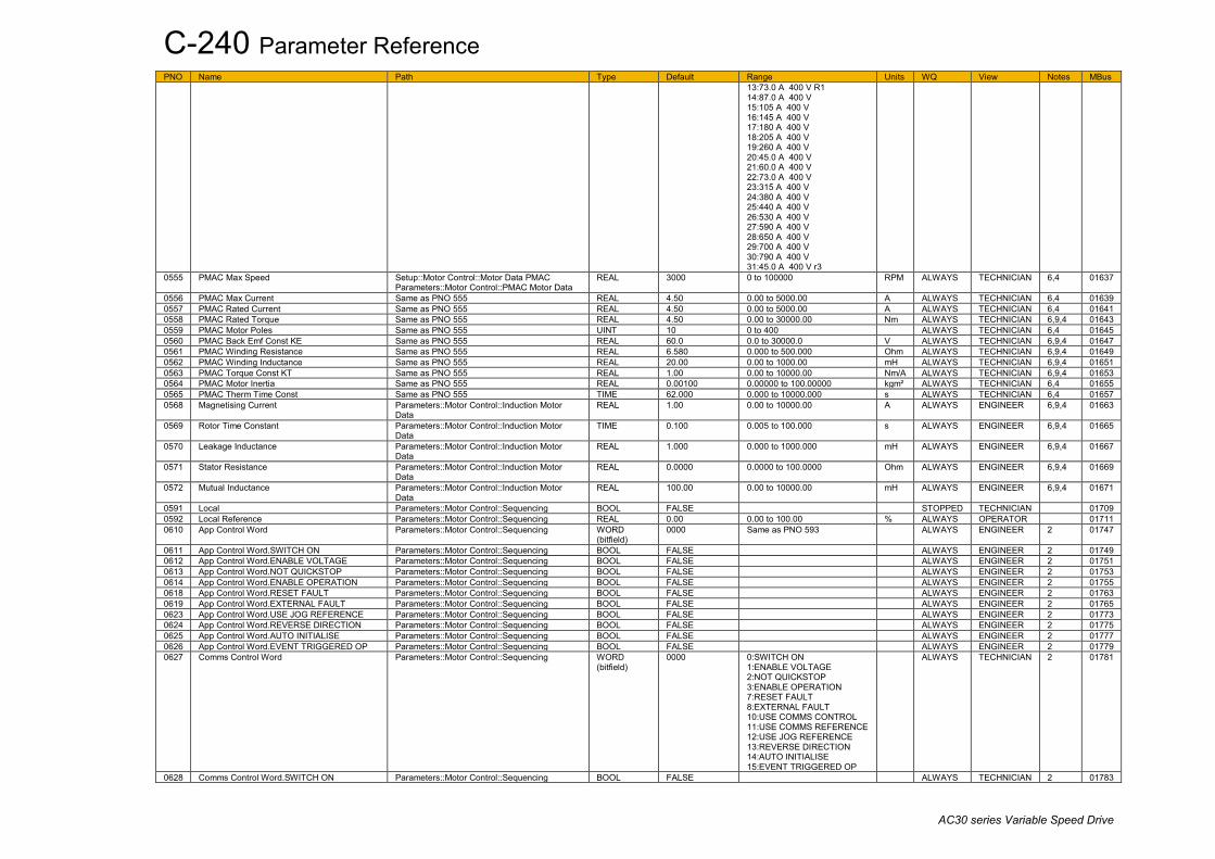
C-240 Parameter Reference
AC30 series Variable Speed Drive
PNO Name Path Type Default Range Units WQ View Notes MBus 13:73.0 A 400 V R1 14:87.0 A 400 V 15:105 A 400 V 16:145 A 400 V 17:180 A 400 V 18:205 A 400 V 19:260 A 400 V 20:45.0 A 400 V 21:60.0 A 400 V 22:73.0 A 400 V 23:315 A 400 V 24:380 A 400 V 25:440 A 400 V 26:530 A 400 V 27:590 A 400 V 28:650 A 400 V 29:700 A 400 V 30:790 A 400 V 31:45.0 A 400 V r3
0555 PMAC Max Speed Setup::Motor Control::Motor Data PMAC Parameters::Motor Control::PMAC Motor Data
REAL 3000 0 to 100000 RPM ALWAYS TECHNICIAN 6,4 01637
0556 PMAC Max Current Same as PNO 555 REAL 4.50 0.00 to 5000.00 A ALWAYS TECHNICIAN 6,4 01639 0557 PMAC Rated Current Same as PNO 555 REAL 4.50 0.00 to 5000.00 A ALWAYS TECHNICIAN 6,4 01641 0558 PMAC Rated Torque Same as PNO 555 REAL 4.50 0.00 to 30000.00 Nm ALWAYS TECHNICIAN 6,9,4 01643 0559 PMAC Motor Poles Same as PNO 555 UINT 10 0 to 400 ALWAYS TECHNICIAN 6,4 01645 0560 PMAC Back Emf Const KE Same as PNO 555 REAL 60.0 0.0 to 30000.0 V ALWAYS TECHNICIAN 6,9,4 01647 0561 PMAC Winding Resistance Same as PNO 555 REAL 6.580 0.000 to 500.000 Ohm ALWAYS TECHNICIAN 6,9,4 01649 0562 PMAC Winding Inductance Same as PNO 555 REAL 20.00 0.00 to 1000.00 mH ALWAYS TECHNICIAN 6,9,4 01651 0563 PMAC Torque Const KT Same as PNO 555 REAL 1.00 0.00 to 10000.00 Nm/A ALWAYS TECHNICIAN 6,9,4 01653 0564 PMAC Motor Inertia Same as PNO 555 REAL 0.00100 0.00000 to 100.00000 kgm² ALWAYS TECHNICIAN 6,4 01655 0565 PMAC Therm Time Const Same as PNO 555 TIME 62.000 0.000 to 10000.000 s ALWAYS TECHNICIAN 6,4 01657 0568 Magnetising Current Parameters::Motor Control::Induction Motor
Data REAL 1.00 0.00 to 10000.00 A ALWAYS ENGINEER 6,9,4 01663
0569 Rotor Time Constant Parameters::Motor Control::Induction Motor Data
TIME 0.100 0.005 to 100.000 s ALWAYS ENGINEER 6,9,4 01665
0570 Leakage Inductance Parameters::Motor Control::Induction Motor Data
REAL 1.000 0.000 to 1000.000 mH ALWAYS ENGINEER 6,9,4 01667
0571 Stator Resistance Parameters::Motor Control::Induction Motor Data
REAL 0.0000 0.0000 to 100.0000 Ohm ALWAYS ENGINEER 6,9,4 01669
0572 Mutual Inductance Parameters::Motor Control::Induction Motor Data
REAL 100.00 0.00 to 10000.00 mH ALWAYS ENGINEER 6,9,4 01671
0591 Local Parameters::Motor Control::Sequencing BOOL FALSE STOPPED TECHNICIAN 01709 0592 Local Reference Parameters::Motor Control::Sequencing REAL 0.00 0.00 to 100.00 % ALWAYS OPERATOR 01711 0610 App Control Word Parameters::Motor Control::Sequencing WORD
(bitfield) 0000 Same as PNO 593 ALWAYS ENGINEER 2 01747
0611 App Control Word.SWITCH ON Parameters::Motor Control::Sequencing BOOL FALSE ALWAYS ENGINEER 2 01749 0612 App Control Word.ENABLE VOLTAGE Parameters::Motor Control::Sequencing BOOL FALSE ALWAYS ENGINEER 2 01751 0613 App Control Word.NOT QUICKSTOP Parameters::Motor Control::Sequencing BOOL FALSE ALWAYS ENGINEER 2 01753 0614 App Control Word.ENABLE OPERATION Parameters::Motor Control::Sequencing BOOL FALSE ALWAYS ENGINEER 2 01755 0618 App Control Word.RESET FAULT Parameters::Motor Control::Sequencing BOOL FALSE ALWAYS ENGINEER 2 01763 0619 App Control Word.EXTERNAL FAULT Parameters::Motor Control::Sequencing BOOL FALSE ALWAYS ENGINEER 2 01765 0623 App Control Word.USE JOG REFERENCE Parameters::Motor Control::Sequencing BOOL FALSE ALWAYS ENGINEER 2 01773 0624 App Control Word.REVERSE DIRECTION Parameters::Motor Control::Sequencing BOOL FALSE ALWAYS ENGINEER 2 01775 0625 App Control Word.AUTO INITIALISE Parameters::Motor Control::Sequencing BOOL FALSE ALWAYS ENGINEER 2 01777 0626 App Control Word.EVENT TRIGGERED OP Parameters::Motor Control::Sequencing BOOL FALSE ALWAYS ENGINEER 2 01779 0627 Comms Control Word Parameters::Motor Control::Sequencing WORD
(bitfield) 0000 0:SWITCH ON
1:ENABLE VOLTAGE 2:NOT QUICKSTOP 3:ENABLE OPERATION 7:RESET FAULT 8:EXTERNAL FAULT 10:USE COMMS CONTROL 11:USE COMMS REFERENCE 12:USE JOG REFERENCE 13:REVERSE DIRECTION 14:AUTO INITIALISE 15:EVENT TRIGGERED OP
ALWAYS TECHNICIAN 2 01781
0628 Comms Control Word.SWITCH ON Parameters::Motor Control::Sequencing BOOL FALSE ALWAYS TECHNICIAN 2 01783
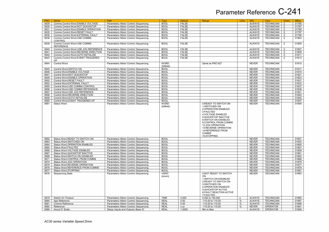
Parameter Reference C-241
AC30 series Variable Speed Drive
PNO Name Path Type Default Range Units WQ View Notes MBus 0629 Comms Control Word.ENABLE VOLTAGE Parameters::Motor Control::Sequencing BOOL FALSE ALWAYS TECHNICIAN 2 01785 0630 Comms Control Word.NOT QUICKSTOP Parameters::Motor Control::Sequencing BOOL FALSE ALWAYS TECHNICIAN 2 01787 0631 Comms Control Word.ENABLE OPERATION Parameters::Motor Control::Sequencing BOOL FALSE ALWAYS TECHNICIAN 2 01789 0635 Comms Control Word.RESET FAULT Parameters::Motor Control::Sequencing BOOL FALSE ALWAYS TECHNICIAN 2 01797 0636 Comms Control Word.EXTERNAL FAULT Parameters::Motor Control::Sequencing BOOL FALSE ALWAYS TECHNICIAN 2 01799 0638 Comms Control Word.USE COMMS
CONTROL Parameters::Motor Control::Sequencing BOOL FALSE ALWAYS TECHNICIAN 2 01803
0639 Comms Control Word.USE COMMS REFERENCE
Parameters::Motor Control::Sequencing BOOL FALSE ALWAYS TECHNICIAN 2 01805
0640 Comms Control Word.USE JOG REFERENCE Parameters::Motor Control::Sequencing BOOL FALSE ALWAYS TECHNICIAN 2 01807 0641 Comms Control Word.REVERSE DIRECTION Parameters::Motor Control::Sequencing BOOL FALSE ALWAYS TECHNICIAN 2 01809 0642 Comms Control Word.AUTO INITIALISE Parameters::Motor Control::Sequencing BOOL FALSE ALWAYS TECHNICIAN 2 01811 0643 Comms Control Word.EVENT TRIGGERED
OP Parameters::Motor Control::Sequencing BOOL FALSE ALWAYS TECHNICIAN 2 01813
0644 Control Word Parameters::Motor Control::Sequencing WORD (bitfield)
Same as PNO 627 NEVER TECHNICIAN 01815
0645 Control Word.SWITCH ON Parameters::Motor Control::Sequencing BOOL NEVER TECHNICIAN 01817 0646 Control Word.ENABLE VOLTAGE Parameters::Motor Control::Sequencing BOOL NEVER TECHNICIAN 01819 0647 Control Word.NOT QUICKSTOP Parameters::Motor Control::Sequencing BOOL NEVER TECHNICIAN 01821 0648 Control Word.ENABLE OPERATION Parameters::Motor Control::Sequencing BOOL NEVER TECHNICIAN 01823 0652 Control Word.RESET FAULT Parameters::Motor Control::Sequencing BOOL NEVER TECHNICIAN 01831 0653 Control Word.EXTERNAL FAULT Parameters::Motor Control::Sequencing BOOL NEVER TECHNICIAN 01833 0655 Control Word.USE COMMS CONTROL Parameters::Motor Control::Sequencing BOOL NEVER TECHNICIAN 01837 0656 Control Word.USE COMMS REFERENCE Parameters::Motor Control::Sequencing BOOL NEVER TECHNICIAN 01839 0657 Control Word.USE JOG REFERENCE Parameters::Motor Control::Sequencing BOOL NEVER TECHNICIAN 01841 0658 Control Word.REVERSE DIRECTION Parameters::Motor Control::Sequencing BOOL NEVER TECHNICIAN 01843 0659 Control Word.AUTO INITIALISE Parameters::Motor Control::Sequencing BOOL NEVER TECHNICIAN 01845 0660 Control Word.EVENT TRIGGERED OP Parameters::Motor Control::Sequencing BOOL NEVER TECHNICIAN 01847 0661 Status Word Parameters::Motor Control::Sequencing WORD
(bitfield) 0:READY TO SWITCH ON
1:SWITCHED ON 2:OPERATION ENABLED 3:FAULTED 4:VOLTAGE ENABLED 5:QUICKSTOP INACTIVE 6:SWITCH ON DISABLED 9:CONTROL FROM COMMS 12:JOG OPERATION 13:REVERSE OPERATION 14:REFERENCE FROM COMMS 15:STOPPING
NEVER TECHNICIAN 01849
0662 Status Word.READY TO SWITCH ON Parameters::Motor Control::Sequencing BOOL NEVER TECHNICIAN 01851 0663 Status Word.SWITCHED ON Parameters::Motor Control::Sequencing BOOL NEVER TECHNICIAN 01853 0664 Status Word.OPERATION ENABLED Parameters::Motor Control::Sequencing BOOL NEVER TECHNICIAN 01855 0665 Status Word.FAULTED Parameters::Motor Control::Sequencing BOOL NEVER TECHNICIAN 01857 0666 Status Word.VOLTAGE ENABLED Parameters::Motor Control::Sequencing BOOL NEVER TECHNICIAN 01859 0667 Status Word.QUICKSTOP INACTIVE Parameters::Motor Control::Sequencing BOOL NEVER TECHNICIAN 01861 0668 Status Word.SWITCH ON DISABLED Parameters::Motor Control::Sequencing BOOL NEVER TECHNICIAN 01863 0671 Status Word.CONTROL FROM COMMS Parameters::Motor Control::Sequencing BOOL NEVER TECHNICIAN 01869 0674 Status Word.JOG OPERATION Parameters::Motor Control::Sequencing BOOL NEVER TECHNICIAN 01875 0675 Status Word.REVERSE OPERATION Parameters::Motor Control::Sequencing BOOL NEVER TECHNICIAN 01877 0676 Status Word.REFERENCE FROM COMMS Parameters::Motor Control::Sequencing BOOL NEVER TECHNICIAN 01879 0677 Status Word.STOPPING Parameters::Motor Control::Sequencing BOOL NEVER TECHNICIAN 01881 0678 Sequencing State Parameters::Motor Control::Sequencing USINT
(enum) 0:NOT READY TO SWITCH
ON 1:SWITCH ON DISABLED 2:READY TO SWITCH ON 3:SWITCHED ON 4:OPERATION ENABLED 5:QUICKSTOP ACTIVE 6:FAULT REACTION ACTIVE 7:FAULTED
NEVER TECHNICIAN 01883
0679 Switch On Timeout Parameters::Motor Control::Sequencing TIME 0.000 0.000 to 100.000 s ALWAYS TECHNICIAN 01885 0680 App Reference Parameters::Motor Control::Sequencing REAL 0.00 -110.00 to 110.00 % ALWAYS TECHNICIAN 01887 0681 Comms Reference Parameters::Motor Control::Sequencing REAL 0.00 -110.00 to 110.00 % ALWAYS TECHNICIAN 01889 0682 Reference Parameters::Motor Control::Sequencing REAL x.xx -110.00 to 110.00 % NEVER OPERATOR 01891 0686 Anout 01 Scale Setup::Inputs and Outputs::Base IO REAL 1.0000 Min to Max ALWAYS OPERATOR 01899

C-242 Parameter Reference
AC30 series Variable Speed Drive
PNO Name Path Type Default Range Units WQ View Notes MBus Parameters::Inputs And Outputs::IO Configure
0687 Boot Version Number Parameters::Device Manager::Drive info WORD NEVER ENGINEER 01901 0688 Drive Diagnostic Parameters::Device Manager::Drive info USINT
(enum) 0:OK
1:STACK NOT CONNECTED 2:STACK DATA CORRUPT 3:UNKNOWN STACK 4:STACK MISMATCH
NEVER OPERATOR 01903
0689 PMAC Flycatching Enable Parameters::Motor Control::PMAC Flycatching BOOL FALSE ALWAYS TECHNICIAN 4 01905 0690 PMAC Fly Search Mode Parameters::Motor Control::PMAC Flycatching USINT
(enum) 0 Same as PNO 312 ALWAYS TECHNICIAN 4 01907
0691 PMAC Fly Search Time Parameters::Motor Control::PMAC Flycatching TIME 0.200 0.100 to 60.000 s ALWAYS TECHNICIAN 4 01909 0692 PMAC Fly Load Level Parameters::Motor Control::PMAC Flycatching REAL 5.0 -50.0 to 50.0 % ALWAYS TECHNICIAN 4 01911 0693 PMAC Fly Active Parameters::Motor Control::PMAC Flycatching BOOL NEVER TECHNICIAN 4 01913 0694 PMAC Fly Setpoint Parameters::Motor Control::PMAC Flycatching REAL x. -1000 to 1000 Hz NEVER TECHNICIAN 4 01915 0695 Attached to Stack Parameters::Device Manager::Drive info BOOL NEVER ENGINEER 01917 0696 First Trip Monitor::Trips
Parameters::Trips::Trips Status USINT (enum)
0:NONE 1:01 OVER VOLTAGE 2:02 UNDER VOLTAGE 3:03 OVER CURRENT 4:04 STACK FAULT 5:05 STACK OVER CURRENT 6:06 CURRENT LIMIT 7:07 MOTOR STALL 8:08 INVERSE TIME 9:09 MOTOR I2T 10:10 LOW SPEED I 11:11 HEATSINK OVERTEMP 12:12 INTERNAL OVERTEMP 13:13 MOTOR OVERTEMP 14:14 EXTERNAL TRIP 15:15 BRAKE SHORT CCT 16:16 BRAKE RESISTOR 17:17 BRAKE SWITCH 18:18 LOCAL CONTROL 19:19 COMMS BREAK 20:20 LINE CONTACTOR 21:21 PHASE FAIL 22:22 VDC RIPPLE 23:23 BASE MODBUS BREAK 24:24 24 V OVERLOAD 25:25 PMAC SPEED ERROR 26:26 OVERSPEED 27:27 STO ACTIVE 28:28 FEEDBACK MISSING 29:29 INTERNAL FAN FAIL 30:30 CURRENT SENSOR 31:31 POWER LOSS STOP 32:32 SPEED SENSOR 33:33 A1 34:34 A2 35:35 A3 36:36 A4 37:37 A5 38:38 A6 39:39 A7 40:40 A8 41:41 SPEED ERROR 42:42 PEERTOPEER OVERRUN 43:43 PHASE CONFIG 44:44 FIELDBUS BREAK 45:45 RESOLVER ERROR 46:46 PMAC ALIGN ERROR 47:47 CURRENT IMBALANCE 48:48 CONFIGURATION 49:49 APPLICATION 50:50 AC30A ENCODER 51:51 CPU USAGE
NEVER OPERATOR 01919
0697 Enable 1 - 32 Parameters::Trips::Trips Status DWORD FFFFFF7F 5:06 CURRENT LIMIT ALWAYS TECHNICIAN 01921

Parameter Reference C-243
AC30 series Variable Speed Drive
PNO Name Path Type Default Range Units WQ View Notes MBus (bitfield) 6:07 MOTOR STALL
7:08 INVERSE TIME 8:09 MOTOR I2T 9:10 LOW SPEED I 11:12 INTERNAL OVERTEMP 12:13 MOTOR OVERTEMP 13:14 EXTERNAL TRIP 14:15 BRAKE SHORT CCT 15:16 BRAKE RESISTOR 16:17 BRAKE SWITCH 17:18 LOCAL CONTROL 18:19 COMMS BREAK 19:20 LINE CONTACTOR 20:21 PHASE FAIL 21:22 VDC RIPPLE 22:23 BASE MODBUS BREAK 23:24 24 V OVERLOAD 24:25 PMAC SPEED ERROR 25:26 OVERSPEED 28:29 INTERNAL FAN FAIL 29:30 CURRENT SENSOR 30:31 POWER LOSS STOP 31:32 SPEED SENSOR
0703 Enable 1 - 32.06 CURRENT LIMIT Parameters::Trips::Trips Status BOOL TRUE ALWAYS TECHNICIAN 01933 0704 Enable 1 - 32.07 MOTOR STALL Parameters::Trips::Trips Status BOOL TRUE ALWAYS TECHNICIAN 01935 0705 Enable 1 - 32.08 INVERSE TIME Parameters::Trips::Trips Status BOOL FALSE ALWAYS TECHNICIAN 01937 0706 Enable 1 - 32.09 MOTOR I2T Parameters::Trips::Trips Status BOOL TRUE ALWAYS TECHNICIAN 01939 0707 Enable 1 - 32.10 LOW SPEED I Parameters::Trips::Trips Status BOOL TRUE ALWAYS TECHNICIAN 01941 0709 Enable 1 - 32.12 INTERNAL OVERTEMP Parameters::Trips::Trips Status BOOL TRUE ALWAYS TECHNICIAN 01945 0710 Enable 1 - 32.13 MOTOR OVERTEMP Parameters::Trips::Trips Status BOOL TRUE ALWAYS TECHNICIAN 01947 0711 Enable 1 - 32.14 EXTERNAL TRIP Parameters::Trips::Trips Status BOOL TRUE ALWAYS TECHNICIAN 01949 0712 Enable 1 - 32.15 BRAKE SHORT CCT Parameters::Trips::Trips Status BOOL TRUE ALWAYS TECHNICIAN 01951 0713 Enable 1 - 32.16 BRAKE RESISTOR Parameters::Trips::Trips Status BOOL TRUE ALWAYS TECHNICIAN 01953 0714 Enable 1 - 32.17 BRAKE SWITCH Parameters::Trips::Trips Status BOOL TRUE ALWAYS TECHNICIAN 01955 0715 Enable 1 - 32.18 LOCAL CONTROL Parameters::Trips::Trips Status BOOL TRUE ALWAYS TECHNICIAN 01957 0716 Enable 1 - 32.19 COMMS BREAK Parameters::Trips::Trips Status BOOL TRUE ALWAYS TECHNICIAN 01959 0717 Enable 1 - 32.20 LINE CONTACTOR Parameters::Trips::Trips Status BOOL TRUE ALWAYS TECHNICIAN 01961 0718 Enable 1 - 32.21 PHASE FAIL Parameters::Trips::Trips Status BOOL TRUE ALWAYS TECHNICIAN 01963 0719 Enable 1 - 32.22 VDC RIPPLE Parameters::Trips::Trips Status BOOL TRUE ALWAYS TECHNICIAN 01965 0720 Enable 1 - 32.23 BASE MODBUS BREAK Parameters::Trips::Trips Status BOOL TRUE ALWAYS TECHNICIAN 01967 0721 Enable 1 - 32.24 24 V OVERLOAD Parameters::Trips::Trips Status BOOL TRUE ALWAYS TECHNICIAN 01969 0722 Enable 1 - 32.25 PMAC SPEED ERROR Parameters::Trips::Trips Status BOOL TRUE ALWAYS TECHNICIAN 01971 0723 Enable 1 - 32.26 OVERSPEED Parameters::Trips::Trips Status BOOL TRUE ALWAYS TECHNICIAN 01973 0726 Enable 1 - 32.29 INTERNAL FAN FAIL Parameters::Trips::Trips Status BOOL TRUE ALWAYS TECHNICIAN 01979 0727 Enable 1 - 32.30 CURRENT SENSOR Parameters::Trips::Trips Status BOOL TRUE ALWAYS TECHNICIAN 01981 0728 Enable 1 - 32.31 POWER LOSS STOP Parameters::Trips::Trips Status BOOL TRUE ALWAYS TECHNICIAN 01983 0729 Enable 1 - 32.32 SPEED SENSOR Parameters::Trips::Trips Status BOOL TRUE ALWAYS TECHNICIAN 01985 0730 Enable 33 - 64 Parameters::Trips::Trips Status DWORD
(bitfield) FFFFFFFF 0:33 A1
1:34 A2 2:35 A3 3:36 A4 4:37 A5 5:38 A6 6:39 A7 7:40 A8 8:41 SPEED ERROR 9:42 PEERTOPEER OVERRUN 10:43 PHASE CONFIG 11:44 FIELDBUS BREAK 14:47 CURRENT IMBALANCE 16:49 APPLICATION 18:51 CPU USAGE
ALWAYS TECHNICIAN 01987
0731 Enable 33 - 64.33 A1 Parameters::Trips::Trips Status BOOL TRUE ALWAYS TECHNICIAN 01989 0732 Enable 33 - 64.34 A2 Parameters::Trips::Trips Status BOOL TRUE ALWAYS TECHNICIAN 01991 0733 Enable 33 - 64.35 A3 Parameters::Trips::Trips Status BOOL TRUE ALWAYS TECHNICIAN 01993 0734 Enable 33 - 64.36 A4 Parameters::Trips::Trips Status BOOL TRUE ALWAYS TECHNICIAN 01995 0735 Enable 33 - 64.37 A5 Parameters::Trips::Trips Status BOOL TRUE ALWAYS TECHNICIAN 01997

C-244 Parameter Reference
AC30 series Variable Speed Drive
PNO Name Path Type Default Range Units WQ View Notes MBus 0736 Enable 33 - 64.38 A6 Parameters::Trips::Trips Status BOOL TRUE ALWAYS TECHNICIAN 01999 0737 Enable 33 - 64.39 A7 Parameters::Trips::Trips Status BOOL TRUE ALWAYS TECHNICIAN 02001 0738 Enable 33 - 64.40 A8 Parameters::Trips::Trips Status BOOL TRUE ALWAYS TECHNICIAN 02003 0739 Enable 33 - 64.41 SPEED ERROR Parameters::Trips::Trips Status BOOL TRUE ALWAYS TECHNICIAN 02005 0740 Enable 33 - 64.42 PEERTOPEER OVERRUN Parameters::Trips::Trips Status BOOL TRUE ALWAYS TECHNICIAN 02007 0741 Enable 33 - 64.43 PHASE CONFIG Parameters::Trips::Trips Status BOOL TRUE ALWAYS TECHNICIAN 02009 0742 Enable 33 - 64.44 FIELDBUS BREAK Parameters::Trips::Trips Status BOOL TRUE ALWAYS TECHNICIAN 02011 0745 Enable 33 - 64.47 CURRENT IMBALANCE Parameters::Trips::Trips Status BOOL TRUE ALWAYS TECHNICIAN 02017 0747 Enable 33 - 64.49 APPLICATION Parameters::Trips::Trips Status BOOL TRUE ALWAYS TECHNICIAN 02021 0749 Enable 33 - 64.51 CPU USAGE Parameters::Trips::Trips Status BOOL TRUE ALWAYS TECHNICIAN 02025 0763 Active 1 - 32 Monitor::Trips
Parameters::Trips::Trips Status DWORD (bitfield)
0:01 OVER VOLTAGE 1:02 UNDER VOLTAGE 2:03 OVER CURRENT 3:04 STACK FAULT 4:05 STACK OVER CURRENT 5:06 CURRENT LIMIT 6:07 MOTOR STALL 7:08 INVERSE TIME 8:09 MOTOR I2T 9:10 LOW SPEED I 10:11 HEATSINK OVERTEMP 11:12 INTERNAL OVERTEMP 12:13 MOTOR OVERTEMP 13:14 EXTERNAL TRIP 14:15 BRAKE SHORT CCT 15:16 BRAKE RESISTOR 16:17 BRAKE SWITCH 17:18 LOCAL CONTROL 18:19 COMMS BREAK 19:20 LINE CONTACTOR 20:21 PHASE FAIL 21:22 VDC RIPPLE 22:23 BASE MODBUS BREAK 23:24 24 V OVERLOAD 24:25 PMAC SPEED ERROR 25:26 OVERSPEED 26:27 STO ACTIVE 27:28 FEEDBACK MISSING 28:29 INTERNAL FAN FAIL 29:30 CURRENT SENSOR 30:31 POWER LOSS STOP 31:32 SPEED SENSOR
NEVER OPERATOR 02053
0764 Active 1 - 32.01 OVER VOLTAGE Same as PNO 763 BOOL NEVER OPERATOR 02055 0765 Active 1 - 32.02 UNDER VOLTAGE Same as PNO 763 BOOL NEVER OPERATOR 02057 0766 Active 1 - 32.03 OVER CURRENT Same as PNO 763 BOOL NEVER OPERATOR 02059 0767 Active 1 - 32.04 STACK FAULT Same as PNO 763 BOOL NEVER OPERATOR 02061 0768 Active 1 - 32.05 STACK OVER CURRENT Same as PNO 763 BOOL NEVER OPERATOR 02063 0769 Active 1 - 32.06 CURRENT LIMIT Same as PNO 763 BOOL NEVER OPERATOR 02065 0770 Active 1 - 32.07 MOTOR STALL Same as PNO 763 BOOL NEVER OPERATOR 02067 0771 Active 1 - 32.08 INVERSE TIME Same as PNO 763 BOOL NEVER OPERATOR 02069 0772 Active 1 - 32.09 MOTOR I2T Same as PNO 763 BOOL NEVER OPERATOR 02071 0773 Active 1 - 32.10 LOW SPEED I Same as PNO 763 BOOL NEVER OPERATOR 02073 0774 Active 1 - 32.11 HEATSINK OVERTEMP Same as PNO 763 BOOL NEVER OPERATOR 02075 0775 Active 1 - 32.12 INTERNAL OVERTEMP Same as PNO 763 BOOL NEVER OPERATOR 02077 0776 Active 1 - 32.13 MOTOR OVERTEMP Same as PNO 763 BOOL NEVER OPERATOR 02079 0777 Active 1 - 32.14 EXTERNAL TRIP Same as PNO 763 BOOL NEVER OPERATOR 02081 0778 Active 1 - 32.15 BRAKE SHORT CCT Same as PNO 763 BOOL NEVER OPERATOR 02083 0779 Active 1 - 32.16 BRAKE RESISTOR Same as PNO 763 BOOL NEVER OPERATOR 02085 0780 Active 1 - 32.17 BRAKE SWITCH Same as PNO 763 BOOL NEVER OPERATOR 02087 0781 Active 1 - 32.18 LOCAL CONTROL Same as PNO 763 BOOL NEVER OPERATOR 02089 0782 Active 1 - 32.19 COMMS BREAK Same as PNO 763 BOOL NEVER OPERATOR 02091 0783 Active 1 - 32.20 LINE CONTACTOR Same as PNO 763 BOOL NEVER OPERATOR 02093 0784 Active 1 - 32.21 PHASE FAIL Same as PNO 763 BOOL NEVER OPERATOR 02095 0785 Active 1 - 32.22 VDC RIPPLE Same as PNO 763 BOOL NEVER OPERATOR 02097 0786 Active 1 - 32.23 BASE MODBUS BREAK Same as PNO 763 BOOL NEVER OPERATOR 02099 0787 Active 1 - 32.24 24 V OVERLOAD Same as PNO 763 BOOL NEVER OPERATOR 02101 0788 Active 1 - 32.25 PMAC SPEED ERROR Same as PNO 763 BOOL NEVER OPERATOR 02103 0789 Active 1 - 32.26 OVERSPEED Same as PNO 763 BOOL NEVER OPERATOR 02105

Parameter Reference C-245
AC30 series Variable Speed Drive
PNO Name Path Type Default Range Units WQ View Notes MBus 0790 Active 1 - 32.27 STO ACTIVE Same as PNO 763 BOOL NEVER OPERATOR 02107 0791 Active 1 - 32.28 FEEDBACK MISSING Same as PNO 763 BOOL NEVER OPERATOR 02109 0792 Active 1 - 32.29 INTERNAL FAN FAIL Same as PNO 763 BOOL NEVER OPERATOR 02111 0793 Active 1 - 32.30 CURRENT SENSOR Same as PNO 763 BOOL NEVER OPERATOR 02113 0794 Active 1 - 32.31 POWER LOSS STOP Same as PNO 763 BOOL NEVER OPERATOR 02115 0795 Active 1 - 32.32 SPEED SENSOR Same as PNO 763 BOOL NEVER OPERATOR 02117 0796 AR Trip Mask 2 Setup::Motor Control::Auto Restart
Parameters::Motor Control::Auto Restart DWORD (bitfield)
FFFFFFFF 0:33 A1 1:34 A2 2:35 A3 3:36 A4 4:37 A5 5:38 A6 6:39 A7 7:40 A8 8:41 SPEED ERROR 9:42 PEERTOPEER OVERRUN 10:43 PHASE CONFIG 11:44 FIELDBUS BREAK 18:51 CPU USAGE
ALWAYS TECHNICIAN 02119
0797 AR Trip Mask 2.33 A1 Same as PNO 796 BOOL TRUE ALWAYS TECHNICIAN 02121 0798 AR Trip Mask 2.34 A2 Same as PNO 796 BOOL TRUE ALWAYS TECHNICIAN 02123 0799 AR Trip Mask 2.35 A3 Same as PNO 796 BOOL TRUE ALWAYS TECHNICIAN 02125 0800 AR Trip Mask 2.36 A4 Same as PNO 796 BOOL TRUE ALWAYS TECHNICIAN 02127 0801 AR Trip Mask 2.37 A5 Same as PNO 796 BOOL TRUE ALWAYS TECHNICIAN 02129 0802 AR Trip Mask 2.38 A6 Same as PNO 796 BOOL TRUE ALWAYS TECHNICIAN 02131 0803 AR Trip Mask 2.39 A7 Same as PNO 796 BOOL TRUE ALWAYS TECHNICIAN 02133 0804 AR Trip Mask 2.40 A8 Same as PNO 796 BOOL TRUE ALWAYS TECHNICIAN 02135 0805 AR Trip Mask 2.41 SPEED ERROR Same as PNO 796 BOOL TRUE ALWAYS TECHNICIAN 02137 0806 AR Trip Mask 2.42 PEERTOPEER OVERRUN Same as PNO 796 BOOL TRUE ALWAYS TECHNICIAN 02139 0807 AR Trip Mask 2.43 PHASE CONFIG Same as PNO 796 BOOL TRUE ALWAYS TECHNICIAN 02141 0808 AR Trip Mask 2.44 FIELDBUS BREAK Same as PNO 796 BOOL TRUE ALWAYS TECHNICIAN 02143 0815 AR Trip Mask 2.51 CPU USAGE Same as PNO 796 BOOL TRUE ALWAYS TECHNICIAN 02157 0829 Warnings 1 - 32 Monitor::Trips
Parameters::Trips::Trips Status DWORD (bitfield)
Same as PNO 763 NEVER OPERATOR 02185
0830 Warnings 1 - 32.01 OVER VOLTAGE Same as PNO 829 BOOL NEVER OPERATOR 02187 0831 Warnings 1 - 32.02 UNDER VOLTAGE Same as PNO 829 BOOL NEVER OPERATOR 02189 0832 Warnings 1 - 32.03 OVER CURRENT Same as PNO 829 BOOL NEVER OPERATOR 02191 0833 Warnings 1 - 32.04 STACK FAULT Same as PNO 829 BOOL NEVER OPERATOR 02193 0834 Warnings 1 - 32.05 STACK OVER CURRENT Same as PNO 829 BOOL NEVER OPERATOR 02195 0835 Warnings 1 - 32.06 CURRENT LIMIT Same as PNO 829 BOOL NEVER OPERATOR 02197 0836 Warnings 1 - 32.07 MOTOR STALL Same as PNO 829 BOOL NEVER OPERATOR 02199 0837 Warnings 1 - 32.08 INVERSE TIME Same as PNO 829 BOOL NEVER OPERATOR 02201 0838 Warnings 1 - 32.09 MOTOR I2T Same as PNO 829 BOOL NEVER OPERATOR 02203 0839 Warnings 1 - 32.10 LOW SPEED I Same as PNO 829 BOOL NEVER OPERATOR 02205 0840 Warnings 1 - 32.11 HEATSINK OVERTEMP Same as PNO 829 BOOL NEVER OPERATOR 02207 0841 Warnings 1 - 32.12 INTERNAL OVERTEMP Same as PNO 829 BOOL NEVER OPERATOR 02209 0842 Warnings 1 - 32.13 MOTOR OVERTEMP Same as PNO 829 BOOL NEVER OPERATOR 02211 0843 Warnings 1 - 32.14 EXTERNAL TRIP Same as PNO 829 BOOL NEVER OPERATOR 02213 0844 Warnings 1 - 32.15 BRAKE SHORT CCT Same as PNO 829 BOOL NEVER OPERATOR 02215 0845 Warnings 1 - 32.16 BRAKE RESISTOR Same as PNO 829 BOOL NEVER OPERATOR 02217 0846 Warnings 1 - 32.17 BRAKE SWITCH Same as PNO 829 BOOL NEVER OPERATOR 02219 0847 Warnings 1 - 32.18 LOCAL CONTROL Same as PNO 829 BOOL NEVER OPERATOR 02221 0848 Warnings 1 - 32.19 COMMS BREAK Same as PNO 829 BOOL NEVER OPERATOR 02223 0849 Warnings 1 - 32.20 LINE CONTACTOR Same as PNO 829 BOOL NEVER OPERATOR 02225 0850 Warnings 1 - 32.21 PHASE FAIL Same as PNO 829 BOOL NEVER OPERATOR 02227 0851 Warnings 1 - 32.22 VDC RIPPLE Same as PNO 829 BOOL NEVER OPERATOR 02229 0852 Warnings 1 - 32.23 BASE MODBUS BREAK Same as PNO 829 BOOL NEVER OPERATOR 02231 0853 Warnings 1 - 32.24 24 V OVERLOAD Same as PNO 829 BOOL NEVER OPERATOR 02233 0854 Warnings 1 - 32.25 PMAC SPEED ERROR Same as PNO 829 BOOL NEVER OPERATOR 02235 0855 Warnings 1 - 32.26 OVERSPEED Same as PNO 829 BOOL NEVER OPERATOR 02237 0856 Warnings 1 - 32.27 STO ACTIVE Same as PNO 829 BOOL NEVER OPERATOR 02239 0857 Warnings 1 - 32.28 FEEDBACK MISSING Same as PNO 829 BOOL NEVER OPERATOR 02241 0858 Warnings 1 - 32.29 INTERNAL FAN FAIL Same as PNO 829 BOOL NEVER OPERATOR 02243 0859 Warnings 1 - 32.30 CURRENT SENSOR Same as PNO 829 BOOL NEVER OPERATOR 02245 0860 Warnings 1 - 32.31 POWER LOSS STOP Same as PNO 829 BOOL NEVER OPERATOR 02247

C-246 Parameter Reference
AC30 series Variable Speed Drive
PNO Name Path Type Default Range Units WQ View Notes MBus 0861 Warnings 1 - 32.32 SPEED SENSOR Same as PNO 829 BOOL NEVER OPERATOR 02249 0890 Maintenance Warnings Parameters::Trips::Maintenance Monitor WORD NEVER OPERATOR 02307 0891 Maintenance Reporting Parameters::Trips::Maintenance Monitor WORD FFFF ALWAYS TECHNICIAN 02309 0892 Maintenance Reset Parameters::Trips::Maintenance Monitor WORD 0000 ALWAYS ENGINEER 2 02311 0893 Ambient Temperature Parameters::Trips::Maintenance Monitor REAL 25.0 -20.0 to 70.0 °C ALWAYS TECHNICIAN 02313 0894 IM Wiring Parameters::Motor Control::Induction Motor
Data BOOL FALSE STOPPED OPERATOR 6 02315
0895 Recent Trips Parameters::Trips::Trips History ARRAY[0..9] NEVER OPERATOR 02317 0896 Recent Trips[0] Parameters::Trips::Trips History USINT
(enum) Same as PNO 696 NEVER OPERATOR 1 02319
0897 Recent Trips[1] Parameters::Trips::Trips History USINT (enum)
Same as PNO 696 NEVER OPERATOR 1 02321
0898 Recent Trips[2] Parameters::Trips::Trips History USINT (enum)
Same as PNO 696 NEVER OPERATOR 1 02323
0899 Recent Trips[3] Parameters::Trips::Trips History USINT (enum)
Same as PNO 696 NEVER OPERATOR 1 02325
0900 Recent Trips[4] Parameters::Trips::Trips History USINT (enum)
Same as PNO 696 NEVER OPERATOR 1 02327
0901 Recent Trips[5] Parameters::Trips::Trips History USINT (enum)
Same as PNO 696 NEVER OPERATOR 1 02329
0902 Recent Trips[6] Parameters::Trips::Trips History USINT (enum)
Same as PNO 696 NEVER OPERATOR 1 02331
0903 Recent Trips[7] Parameters::Trips::Trips History USINT (enum)
Same as PNO 696 NEVER OPERATOR 1 02333
0904 Recent Trips[8] Parameters::Trips::Trips History USINT (enum)
Same as PNO 696 NEVER OPERATOR 1 02335
0905 Recent Trips[9] Parameters::Trips::Trips History USINT (enum)
Same as PNO 696 NEVER OPERATOR 1 02337
0906 Stall Limit Type Parameters::Trips::Stall Trip USINT (enum)
2 0:TORQUE 1:CURRENT 2:TORQUE OR CURRENT
ALWAYS TECHNICIAN 02339
0907 Stall Time Parameters::Trips::Stall Trip TIME 90.000 0.100 to 2000.000 s ALWAYS TECHNICIAN 6 02341 0908 Control Screen Mode Parameters::Device Manager::Soft Menus USINT
(enum) 1 0:DISABLED
1:AUTO 2:CUSTOM
STOPPED ENGINEER 02343
0909 Stall Torque Active Parameters::Trips::Stall Trip BOOL NEVER TECHNICIAN 02345 0910 Stall Current Active Parameters::Trips::Stall Trip BOOL NEVER TECHNICIAN 02347 0911 Stall Speed Feedback Parameters::Trips::Stall Trip REAL x. -200 to 200 % NEVER ENGINEER 02349 0912 VDC Ripple Filter TC Parameters::Trips::VDC Ripple TIME 1.000 0.100 to 100.000 s ALWAYS ENGINEER 02351 0913 Max VDC Ripple Parameters::Trips::VDC Ripple REAL x. 0 to 500 V NEVER ENGINEER 02353 0914 VDC Ripple Trip Delay Parameters::Trips::VDC Ripple TIME 0.000 to 300.000 s NEVER ENGINEER 02355 0915 VDC Ripple Trip Hyst Parameters::Trips::VDC Ripple REAL 10 0 to 50 V ALWAYS ENGINEER 02357 0916 VDC Ripple Sample Parameters::Trips::VDC Ripple TIME 0.009 0.001 to 0.100 s ALWAYS ENGINEER 02359 0917 VDC Ripple Level Parameters::Trips::VDC Ripple REAL x. 0 to 500 V NEVER ENGINEER 02361 0918 Filtered VDC Ripple Parameters::Trips::VDC Ripple REAL x. 0 to 500 V NEVER ENGINEER 02363 0919 Ethernet State Monitor::Communications::Base Ethernet
Parameters::Base Comms::Ethernet USINT (enum)
0:INITIALISING 1:NO LINK 2:RESOLVING IP 3:RESOLVING DHCP 4:RESOLVING AUTO 5:RESOLVED IP 6:STOPPING DHCP 7:DUPLICATE IP 8:FAULT
NEVER OPERATOR 02365
0920 MAC Address Same as PNO 919 STRING[17] NEVER OPERATOR 02367 0926 IP Address Same as PNO 919 DWORD
(IP addr) NEVER OPERATOR 02379
0927 Subnet Mask Same as PNO 919 DWORD (IP addr)
NEVER OPERATOR 02381
0928 Gateway Address Same as PNO 919 DWORD (IP addr)
NEVER OPERATOR 02383
0929 DHCP Setup::Communications::Base Ethernet Parameters::Base Comms::Ethernet
BOOL TRUE ALWAYS TECHNICIAN 02385
0930 Auto IP Same as PNO 929 BOOL TRUE ALWAYS TECHNICIAN 02387 0931 Last Auto IP Address Parameters::Base Comms::Ethernet DWORD
(IP addr) NEVER ENGINEER 3 02389
0933 User IP Address Same as PNO 929 DWORD 000.000.000.000 ALWAYS TECHNICIAN 7,4 02393
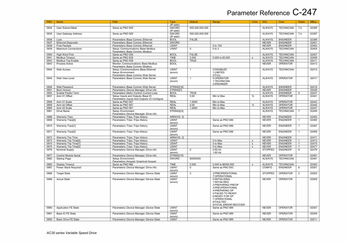
Parameter Reference C-247
AC30 series Variable Speed Drive
PNO Name Path Type Default Range Units WQ View Notes MBus (IP addr)
0934 User Subnet Mask Same as PNO 929 DWORD (IP addr)
000.000.000.000 ALWAYS TECHNICIAN 7,4 02395
0935 User Gateway Address Same as PNO 929 DWORD (IP addr)
000.000.000.000 ALWAYS TECHNICIAN 7,4 02397
0936 Lock Parameters::Base Comms::Ethernet BOOL FALSE ALWAYS ENGINEER 02399 0937 Ethernet Diagnostic Parameters::Base Comms::Ethernet DWORD NEVER ENGINEER 02401 0938 Free Packets Parameters::Base Comms::Ethernet UDINT 0 to 100 NEVER ENGINEER 02403 0939 Maximum Connections Setup::Communications::Base Modbus
Parameters::Base Comms::Modbus USINT 0 0 to 3 ALWAYS TECHNICIAN 02405
0940 High Word First Same as PNO 939 BOOL FALSE ALWAYS TECHNICIAN 02407 0941 Modbus Timeout Same as PNO 939 TIME 3.000 0.000 to 65.000 s ALWAYS TECHNICIAN 02409 0942 Modbus Trip Enable Same as PNO 939 BOOL TRUE ALWAYS TECHNICIAN 02411 0943 Process Active Monitor::Communications::Base Modbus
Parameters::Base Comms::Modbus BOOL NEVER OPERATOR 02413
0944 Web Access Setup::Communications::Base Ethernet Setup::Environment Parameters::Base Comms::Web Server
USINT (enum)
1 0:DISABLED 1:LIMITED 2:FULL
ALWAYS TECHNICIAN 02415
0945 Web View Level Parameters::Base Comms::Web Server USINT (enum)
1 0:OPERATOR 1:TECHNICIAN 2:ENGINEER
ALWAYS OPERATOR 02417
0946 Web Password Parameters::Base Comms::Web Server STRING[16] ALWAYS ENGINEER 02419 0951 Boot Version Parameters::Device Manager::Drive info STRING[7] NEVER ENGINEER 02429 0955 Enable Predict Term Parameters::Motor Control::Current Loop BOOL TRUE ALWAYS ENGINEER 4 02437 0957 Anin 01 Offset Setup::Inputs and Outputs::Base IO
Parameters::Inputs And Outputs::IO Configure REAL 0.00 Min to Max % ALWAYS OPERATOR 02441
0958 Anin 01 Scale Same as PNO 957 REAL 1.0000 Min to Max ALWAYS OPERATOR 02443 0959 Anin 02 Offset Same as PNO 957 REAL 0.00 Min to Max % ALWAYS OPERATOR 02445 0960 Anin 02 Scale Same as PNO 957 REAL 1.0000 Min to Max ALWAYS OPERATOR 02447 0961 Drive Name Setup::Environment
Parameters::Device Manager::Drive info STRING[23] ALWAYS TECHNICIAN 7 02449
0968 Warranty Trips Parameters::Trips::Trips History ARRAY[0..2] NEVER ENGINEER 02463 0969 Warranty Trips[0] Parameters::Trips::Trips History USINT
(enum) Same as PNO 696 NEVER ENGINEER 1 02465
0970 Warranty Trips[1] Parameters::Trips::Trips History USINT (enum)
Same as PNO 696 NEVER ENGINEER 1 02467
0971 Warranty Trips[2] Parameters::Trips::Trips History USINT (enum)
Same as PNO 696 NEVER ENGINEER 1 02469
0972 Warranty Trip Time Parameters::Trips::Trips History ARRAY[0..2] NEVER ENGINEER 02471 0973 Warranty Trip Time[0] Parameters::Trips::Trips History UDINT 0 to Max s NEVER ENGINEER 1 02473 0974 Warranty Trip Time[1] Parameters::Trips::Trips History UDINT 0 to Max s NEVER ENGINEER 1 02475 0975 Warranty Trip Time[2] Parameters::Trips::Trips History UDINT 0 to Max s NEVER ENGINEER 1 02477 0976 Nominal Supply Parameters::Device Manager::Drive info USINT
(enum) 0 0:50 Hz
1:60 Hz STOPPED ENGINEER 6 02479
0977 Control Module Serial Parameters::Device Manager::Drive info STRING[15] NEVER OPERATOR 02481 0982 Startup Page Setup::Environment
Parameters::Keypad::Graphical Keypad DWORD 80000000 ALWAYS TECHNICIAN 02491
0983 Display Timeout Same as PNO 982 TIME 0.000 0.000 to 86400.000 s ALWAYS TECHNICIAN 02493 0987 Power Stack Required Parameters::Device Manager::Drive info USINT
(enum) 0 Same as PNO 543 CONFIG ENGINEER 6 02501
0988 Target State Parameters::Device Manager::Device State USINT (enum)
3 3:PREOPERATIONAL 7:OPERATIONAL
STOPPED OPERATOR 2 02503
0989 Actual State Parameters::Device Manager::Device State USINT (enum)
0:INITIALISING 1:INITIALISED 2:PREPARING PREOP 3:PREOPERATIONAL 4:PREPARING OP 5:FAILED TO READY 6:READY FOR OP 7:OPERATIONAL 8:FAULTED 9:FATAL ERROR RECOVER
NEVER OPERATOR 02505
0990 Application FE State Parameters::Device Manager::Device State USINT (enum)
Same as PNO 989 NEVER OPERATOR 02507
0991 Base IO FE State Parameters::Device Manager::Device State USINT (enum)
Same as PNO 989 NEVER OPERATOR 02509
0992 Basic Drive FE State Parameters::Device Manager::Device State USINT Same as PNO 989 NEVER OPERATOR 02511

C-248 Parameter Reference
AC30 series Variable Speed Drive
PNO Name Path Type Default Range Units WQ View Notes MBus (enum)
0993 Ethernet FE State Parameters::Device Manager::Device State USINT (enum)
Same as PNO 989 NEVER OPERATOR 02513
0994 Keypad FE State Parameters::Device Manager::Device State USINT (enum)
Same as PNO 989 NEVER OPERATOR 02515
0995 Comms Option FE State Parameters::Device Manager::Device State USINT (enum)
Same as PNO 989 NEVER OPERATOR 02517
0996 IO Option FE State Parameters::Device Manager::Device State USINT (enum)
Same as PNO 989 NEVER OPERATOR 02519
0997 Config Fault Area Parameters::Device Manager::Device State USINT (enum)
0:NONE 1:POWER STACK 2:OPTION IO 3:OPTION COMMS 4:APPLICATION 5:MOTOR CONTROL 6:KEYPAD 7:BASE COMMS 8:BASE IO 9:FEEDBACK MISSING 10:SYSTEM BOARD
NEVER OPERATOR 02521
0998 RTA Code Monitor::Trips Parameters::Device Manager::Device State
UINT 0 to 65535 NEVER OPERATOR 4 02523
0999 RTA Data Same as PNO 998 DWORD NEVER OPERATOR 4 02525 1000 Reset to Defaults Parameters::Device Manager::Device
Commands BOOL FALSE CONFIG TECHNICIAN 2 02527
1001 Save All Parameters Parameters::Device Manager::Device Commands
BOOL FALSE ALWAYS OPERATOR 2 02529
1002 Update Firmware Parameters::Device Manager::Device Commands
BOOL FALSE STOPPED TECHNICIAN 2,4 02531
1003 RTA Thread Priority Parameters::Device Manager::Device State SINT -128 to 127 NEVER OPERATOR 4 02533 1004 Thermistor Trip Level Parameters::Option IO::Thermistor REAL 1000 0 to 4500 Ohm ALWAYS TECHNICIAN 4 02535 1005 Language Parameters::Device Manager::Setup Wizard USINT
(enum) 0 0:ENGLISH
1:FRANCAIS 2:DEUTSCH 3:ESPANOL 4:ITALIANO 5:CHINESE 6:L 6 7:L 7 8:L 8 9:L 9
STOPPED TECHNICIAN 02537
1006 Run Wizard? Parameters::Device Manager::Setup Wizard USINT (enum)
1 0:NO 1:YES
ALWAYS TECHNICIAN 4 02539
1033 Card State Parameters::Device Manager::SD Card USINT (enum)
0:NO CARD 1:INITIALISING 2:READY 3:CARD FAULT
NEVER OPERATOR 02593
1034 Card Name Parameters::Device Manager::SD Card STRING[11] NEVER OPERATOR 02595 1038 Firmware Parameters::Device Manager::SD Card BOOL NEVER OPERATOR 02603 1039 Application Archive Parameters::Device Manager::SD Card BOOL NEVER OPERATOR 02605 1040 Project File Name Parameters::Application::App Info STRING[23] NEVER TECHNICIAN 02607 1047 Last Modification Parameters::Application::App Info DT 1970/01/01 to 2038/01/19 NEVER TECHNICIAN 02621 1048 IDE Version Parameters::Application::App Info STRING[20] NEVER TECHNICIAN 02623 1054 Project Author Parameters::Application::App Info STRING[23] NEVER TECHNICIAN 02635 1061 Project Version Parameters::Application::App Info STRING[23] NEVER TECHNICIAN 02649 1068 Project Description Parameters::Application::App Info STRING[80] NEVER TECHNICIAN 02663 1089 BACnet MSTP State Monitor::Communications::Option
Parameters::Option Comms::BACnet MSTP USINT (enum)
Same as PNO 46 NEVER OPERATOR 4 02705
1091 BACnet MAC Address Setup::Communications::Option Parameters::Option Comms::BACnet MSTP
USINT 0 0 to 127 CONFIG TECHNICIAN 7,4 02709
1092 BACnet MSTP Device ID Same as PNO 1091 UDINT 0 0 to 4194302 CONFIG TECHNICIAN 7,4 02711 1093 BACnet Baud Rate Same as PNO 1091 USINT
(enum) 0 0:9600 BPS
1:19200 BPS 2:38400 BPS 3:76800 BPS
CONFIG TECHNICIAN 4 02713
1094 BACnet MSTP Timeout Same as PNO 1091 TIME 3.000 0.000 to 65.000 s CONFIG TECHNICIAN 4 02715 1095 BACnet Max Master Same as PNO 1091 USINT 127 1 to 127 CONFIG ENGINEER 4 02717 1096 BACnet Max Info Frames Same as PNO 1091 USINT 1 1 to 255 CONFIG ENGINEER 4 02719

Parameter Reference C-249
AC30 series Variable Speed Drive
PNO Name Path Type Default Range Units WQ View Notes MBus 1097 Password in Favourite Parameters::Keypad::Graphical Keypad BOOL FALSE ALWAYS TECHNICIAN 02721 1098 Password in Local Parameters::Keypad::Graphical Keypad BOOL FALSE ALWAYS TECHNICIAN 02723 1099 Technician Password Parameters::Keypad::Graphical Keypad WORD 0000 ALWAYS OPERATOR 02725 1100 Firmware Version Parameters::Device Manager::Drive info STRING[21] NEVER OPERATOR 02727 1108 Anout 01 Offset Setup::Inputs and Outputs::Base IO
Parameters::Inputs And Outputs::IO Configure REAL 0.00 Min to Max % ALWAYS OPERATOR 02743
1109 Stack Pcode Parameters::Device Manager::Drive info STRING[23] NEVER OPERATOR 02745 1116 Control Module Pcode Parameters::Device Manager::Drive info STRING[15] NEVER OPERATOR 02759 1121 Comms Option Pcode Parameters::Device Manager::Drive info STRING[11] NEVER OPERATOR 4 02769 1125 IO Option Pcode Parameters::Device Manager::Drive info STRING[11] NEVER OPERATOR 4 02777 1129 Comms Option Serial Parameters::Device Manager::Drive info STRING[15] NEVER OPERATOR 4 02785 1134 IO Option Serial No Parameters::Device Manager::Drive info STRING[15] NEVER OPERATOR 4 02795 1139 Control Board Up Time Parameters::Device Manager::Runtime
Statistics UDINT 0 to Max s NEVER OPERATOR 1 02805
1140 Run Key Action Parameters::Keypad::Local Control USINT (enum)
0 0:RUN 1:JOG
STOPPED OPERATOR 4 02807
1141 View Level Parameters::Keypad::Graphical Keypad USINT (enum)
1 Same as PNO 945 ALWAYS OPERATOR 02809
1142 GKP Password Setup::Environment Parameters::Keypad::Graphical Keypad
WORD 0000 ALWAYS TECHNICIAN 02811
1143 Version Parameters::Keypad::Graphical Keypad WORD NEVER OPERATOR 02813 1178 Option IO Required Setup::Inputs and Outputs::Option
Parameters::Option IO::Option IO USINT (enum)
0 0:NONE 1:GENERAL PURPOSE 2:THERMISTOR 3:RTC AND THERMISTOR 4:PULSE ENCODER 5:RESOLVER AND THERMIST
STOPPED TECHNICIAN 02883
1179 Option IO Fitted Parameters::Option IO::Option IO USINT (enum)
Same as PNO 1178 NEVER OPERATOR 1 02885
1180 Option IO Diagnostic Parameters::Option IO::Option IO USINT (enum)
0:OK 1:OPTION NOT FITTED 2:TYPE MISMATCH 3:TYPE UNKNOWN 4:HARDWARE FAULT
NEVER OPERATOR 02887
1181 Anin 11 Value Monitor::Inputs and Outputs Parameters::Option IO::General Purpose IO
REAL x.xx -100.00 to 100.00 % NEVER OPERATOR 4 02889
1182 Anin 12 Value Same as PNO 1181 REAL x.xx -100.00 to 100.00 % NEVER OPERATOR 4 02891 1183 Anin 13 Value Same as PNO 1181 REAL x.xx -100.00 to 100.00 % NEVER OPERATOR 4 02893 1184 Thermistor Type Setup::Inputs and Outputs::Option
Parameters::Option IO::Thermistor USINT (enum)
1 0:NTC 1:PTC 2:KTY
ALWAYS TECHNICIAN 4 02895
1185 Thermistor Resistance Parameters::Option IO::Thermistor REAL x. 0 to 5000 Ohm NEVER TECHNICIAN 4 02897 1186 Time and Date Parameters::Device Manager::Real Time Clock DT 1970/01/01 1970/01/01 to 2038/01/19 ALWAYS OPERATOR 2 02899 1187 RTC Trim Parameters::Option IO::General Purpose IO SINT 0 -40 to 40 ALWAYS ENGINEER 2,4 02901 1188 Favourites Parameters::Device Manager::Soft Menus ARRAY[0..19] ALWAYS OPERATOR 02903 1189 Favourites[0] Favourites
Parameters::Device Manager::Soft Menus UINT 0000 0000 to 3145 ALWAYS OPERATOR 02905
1190 Favourites[1] Same as PNO 1189 UINT 0000 0000 to 3145 ALWAYS OPERATOR 02907 1191 Favourites[2] Same as PNO 1189 UINT 0000 0000 to 3145 ALWAYS OPERATOR 02909 1192 Favourites[3] Same as PNO 1189 UINT 0000 0000 to 3145 ALWAYS OPERATOR 02911 1193 Favourites[4] Same as PNO 1189 UINT 0000 0000 to 3145 ALWAYS OPERATOR 02913 1194 Favourites[5] Same as PNO 1189 UINT 0000 0000 to 3145 ALWAYS OPERATOR 02915 1195 Favourites[6] Same as PNO 1189 UINT 0000 0000 to 3145 ALWAYS OPERATOR 02917 1196 Favourites[7] Same as PNO 1189 UINT 0000 0000 to 3145 ALWAYS OPERATOR 02919 1197 Favourites[8] Same as PNO 1189 UINT 0000 0000 to 3145 ALWAYS OPERATOR 02921 1198 Favourites[9] Same as PNO 1189 UINT 0000 0000 to 3145 ALWAYS OPERATOR 02923 1199 Favourites[10] Same as PNO 1189 UINT 0000 0000 to 3145 ALWAYS OPERATOR 02925 1200 Favourites[11] Same as PNO 1189 UINT 0000 0000 to 3145 ALWAYS OPERATOR 02927 1201 Favourites[12] Same as PNO 1189 UINT 0000 0000 to 3145 ALWAYS OPERATOR 02929 1202 Favourites[13] Same as PNO 1189 UINT 0000 0000 to 3145 ALWAYS OPERATOR 02931 1203 Favourites[14] Same as PNO 1189 UINT 0000 0000 to 3145 ALWAYS OPERATOR 02933 1204 Favourites[15] Same as PNO 1189 UINT 0000 0000 to 3145 ALWAYS OPERATOR 02935 1205 Favourites[16] Same as PNO 1189 UINT 0000 0000 to 3145 ALWAYS OPERATOR 02937 1206 Favourites[17] Same as PNO 1189 UINT 0000 0000 to 3145 ALWAYS OPERATOR 02939 1207 Favourites[18] Same as PNO 1189 UINT 0000 0000 to 3145 ALWAYS OPERATOR 02941 1208 Favourites[19] Same as PNO 1189 UINT 0000 0000 to 3145 ALWAYS OPERATOR 02943 1213 Actual Position Monitor::Motor and Drive REAL x.x -180.0 to 180.0 deg NEVER TECHNICIAN 4 02953
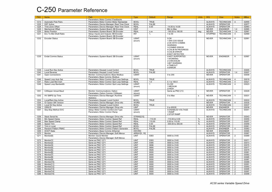
C-250 Parameter Reference
AC30 series Variable Speed Drive
PNO Name Path Type Default Range Units WQ View Notes MBus Parameters::Motor Control::Feedbacks
1214 Automatic Pole Pairs Parameters::Motor Control::Motor Nameplate BOOL TRUE ALWAYS TECHNICIAN 4 02955 1225 DST Active Parameters::Device Manager::Real Time Clock BOOL FALSE ALWAYS OPERATOR 02977 1228 Time Zone Offset Parameters::Device Manager::Real Time Clock REAL 0.00 -14.00 to 14.00 ALWAYS OPERATOR 02983 1229 Mechanical Offset Parameters::System Board::SB Encoder DINT Min to Max NEVER ENGINEER 1,4 02985 1230 Motor Position Parameters::System Board::SB Encoder REAL x.xx -180.00 to 180.00 deg NEVER TECHNICIAN 1,4 02987 1231 Enc To Mot Shaft Ratio Setup::Inputs and Outputs::SB Encoder
Parameters::System Board::SB Encoder INT 1, 1 to 50 STOPPED TECHNICIAN 4 02989
1232 Encoder Status Parameters::System Board::SB Encoder USINT (enum)
0:OK 1:SIN COS ISSUE 2:OK WITH COMMS WARNING 3:COMMS ERROR 4:CALIB IN PROGRESS 5:CALIB ERROR 6:NOT DETECTED
NEVER TECHNICIAN 4 02991
1235 Endat Comms Status Parameters::System Board::SB Encoder USINT (enum)
0:NOT SUPPORTED 1:WORKING 2:CHECKSUM 3:BIT WARNING 4:TIMEOUT 5:ERROR
NEVER ENGINEER 4 02997
1239 Local Run Key Active Parameters::Keypad::Local Control BOOL TRUE ALWAYS TECHNICIAN 03005 1240 Local Reverse Parameters::Keypad::Local Control BOOL FALSE ALWAYS OPERATOR 1,4 03007 1241 Open Connections Monitor::Communications::Base Modbus
Parameters::Base Comms::Modbus USINT 0 to 255 NEVER OPERATOR 03009
1246 Speed Loop Auto Set Parameters::Motor Control::Spd Loop Settings BOOL TRUE ALWAYS TECHNICIAN 4 03019 1247 Ratio Load Mot Inert Parameters::Motor Control::Spd Loop Settings REAL 1.0 0.1 to 100.0 ALWAYS TECHNICIAN 4 03021 1248 Speed Loop Bandwidth Parameters::Motor Control::Spd Loop Settings USINT
(enum) 1 0:LOW
1:MEDIUM 2:HIGH
ALWAYS TECHNICIAN 4 03023
1251 CANopen Actual Baud Monitor::Communications::Option Parameters::Option Comms::CANopen
USINT (enum)
Same as PNO 213 NEVER OPERATOR 4 03029
1252 HV SMPS Up Time Parameters::Device Manager::Runtime Statistics
UDINT 0 to Max s NEVER TECHNICIAN 1 03031
1253 Local/Rem Key Active Parameters::Keypad::Local Control BOOL TRUE ALWAYS TECHNICIAN 03033 1254 IO Option SW Version Parameters::Device Manager::Drive info WORD NEVER OPERATOR 4 03035 1255 Local Dir Key Active Parameters::Keypad::Local Control BOOL TRUE ALWAYS TECHNICIAN 03037 1256 OEM ID Parameters::Device Manager::Drive info UINT 0 to 65535 NEVER ENGINEER 03039 1257 Seq Stop Method SVC Setup::Motor Control::Control and Type
Parameters::Motor Control::Ramp USINT (enum)
1 0:DISABLED VOLTAGE 1:RAMP 2:STOP RAMP
ALWAYS TECHNICIAN 4 03041
1258 Stack Serial No Parameters::Device Manager::Drive info STRING[15] NEVER OPERATOR 03043 1264 Min Speed Clamp Parameters::Motor Control::Speed Ref REAL -110.00 -110.00 to 0.00 % ALWAYS OPERATOR 03055 1265 Max Speed Clamp Parameters::Motor Control::Speed Ref REAL 110.00 0.00 to 110.00 % ALWAYS OPERATOR 03057 1266 Speed Trim Parameters::Motor Control::Speed Ref REAL 0.00 -300.00 to 300.00 % ALWAYS OPERATOR 03059 1267 Trim in Local Parameters::Motor Control::Speed Ref BOOL FALSE ALWAYS OPERATOR 03061 1268 Random Pattern PMAC Parameters::Motor Control::Pattern Generator BOOL FALSE ALWAYS ENGINEER 4 03063 1269 DHCP State Parameters::Base Comms::Ethernet DWORD NEVER ENGINEER 03065 1270 Monitor Parameters::Device Manager::Soft Menus ARRAY[0..19] ALWAYS OPERATOR 03067 1271 Monitor[0] Monitor::Quick Monitor
Parameters::Device Manager::Soft Menus UINT 0383 0000 to 3145 ALWAYS OPERATOR 2 03069
1272 Monitor[1] Same as PNO 1271 UINT 0393 0000 to 3145 ALWAYS OPERATOR 2 03071 1273 Monitor[2] Same as PNO 1271 UINT 0395 0000 to 3145 ALWAYS OPERATOR 2 03073 1274 Monitor[3] Same as PNO 1271 UINT 0696 0000 to 3145 ALWAYS OPERATOR 2 03075 1275 Monitor[4] Same as PNO 1271 UINT 0895 0000 to 3145 ALWAYS OPERATOR 2 03077 1276 Monitor[5] Same as PNO 1271 UINT 0926 0000 to 3145 ALWAYS OPERATOR 2 03079 1277 Monitor[6] Same as PNO 1271 UINT 0000 0000 to 3145 ALWAYS OPERATOR 2 03081 1278 Monitor[7] Same as PNO 1271 UINT 0000 0000 to 3145 ALWAYS OPERATOR 2 03083 1279 Monitor[8] Same as PNO 1271 UINT 0000 0000 to 3145 ALWAYS OPERATOR 2 03085 1280 Monitor[9] Same as PNO 1271 UINT 0000 0000 to 3145 ALWAYS OPERATOR 2 03087 1281 Monitor[10] Same as PNO 1271 UINT 0000 0000 to 3145 ALWAYS OPERATOR 2 03089 1282 Monitor[11] Same as PNO 1271 UINT 0000 0000 to 3145 ALWAYS OPERATOR 2 03091 1283 Monitor[12] Same as PNO 1271 UINT 0000 0000 to 3145 ALWAYS OPERATOR 2 03093 1284 Monitor[13] Same as PNO 1271 UINT 0000 0000 to 3145 ALWAYS OPERATOR 2 03095 1285 Monitor[14] Same as PNO 1271 UINT 0000 0000 to 3145 ALWAYS OPERATOR 2 03097 1286 Monitor[15] Same as PNO 1271 UINT 0000 0000 to 3145 ALWAYS OPERATOR 2 03099
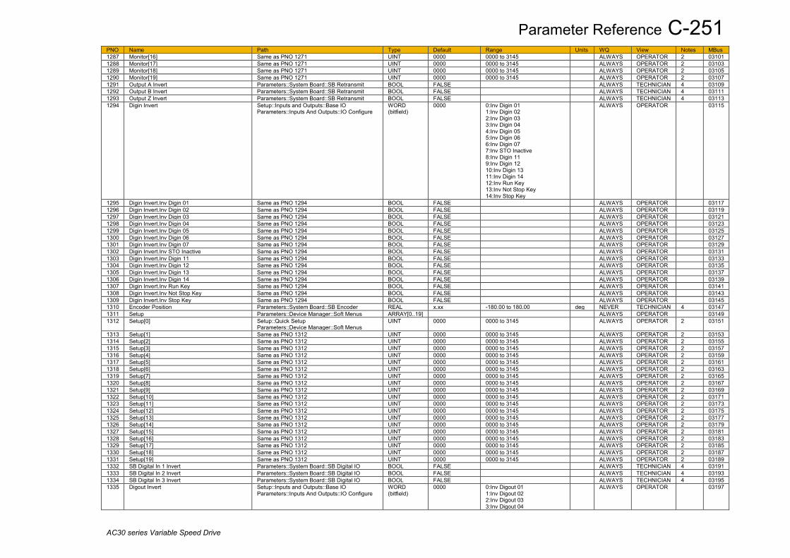
Parameter Reference C-251
AC30 series Variable Speed Drive
PNO Name Path Type Default Range Units WQ View Notes MBus 1287 Monitor[16] Same as PNO 1271 UINT 0000 0000 to 3145 ALWAYS OPERATOR 2 03101 1288 Monitor[17] Same as PNO 1271 UINT 0000 0000 to 3145 ALWAYS OPERATOR 2 03103 1289 Monitor[18] Same as PNO 1271 UINT 0000 0000 to 3145 ALWAYS OPERATOR 2 03105 1290 Monitor[19] Same as PNO 1271 UINT 0000 0000 to 3145 ALWAYS OPERATOR 2 03107 1291 Output A Invert Parameters::System Board::SB Retransmit BOOL FALSE ALWAYS TECHNICIAN 4 03109 1292 Output B Invert Parameters::System Board::SB Retransmit BOOL FALSE ALWAYS TECHNICIAN 4 03111 1293 Output Z Invert Parameters::System Board::SB Retransmit BOOL FALSE ALWAYS TECHNICIAN 4 03113 1294 Digin Invert Setup::Inputs and Outputs::Base IO
Parameters::Inputs And Outputs::IO Configure WORD (bitfield)
0000 0:Inv Digin 01 1:Inv Digin 02 2:Inv Digin 03 3:Inv Digin 04 4:Inv Digin 05 5:Inv Digin 06 6:Inv Digin 07 7:Inv STO Inactive 8:Inv Digin 11 9:Inv Digin 12 10:Inv Digin 13 11:Inv Digin 14 12:Inv Run Key 13:Inv Not Stop Key 14:Inv Stop Key
ALWAYS OPERATOR 03115
1295 Digin Invert.Inv Digin 01 Same as PNO 1294 BOOL FALSE ALWAYS OPERATOR 03117 1296 Digin Invert.Inv Digin 02 Same as PNO 1294 BOOL FALSE ALWAYS OPERATOR 03119 1297 Digin Invert.Inv Digin 03 Same as PNO 1294 BOOL FALSE ALWAYS OPERATOR 03121 1298 Digin Invert.Inv Digin 04 Same as PNO 1294 BOOL FALSE ALWAYS OPERATOR 03123 1299 Digin Invert.Inv Digin 05 Same as PNO 1294 BOOL FALSE ALWAYS OPERATOR 03125 1300 Digin Invert.Inv Digin 06 Same as PNO 1294 BOOL FALSE ALWAYS OPERATOR 03127 1301 Digin Invert.Inv Digin 07 Same as PNO 1294 BOOL FALSE ALWAYS OPERATOR 03129 1302 Digin Invert.Inv STO Inactive Same as PNO 1294 BOOL FALSE ALWAYS OPERATOR 03131 1303 Digin Invert.Inv Digin 11 Same as PNO 1294 BOOL FALSE ALWAYS OPERATOR 03133 1304 Digin Invert.Inv Digin 12 Same as PNO 1294 BOOL FALSE ALWAYS OPERATOR 03135 1305 Digin Invert.Inv Digin 13 Same as PNO 1294 BOOL FALSE ALWAYS OPERATOR 03137 1306 Digin Invert.Inv Digin 14 Same as PNO 1294 BOOL FALSE ALWAYS OPERATOR 03139 1307 Digin Invert.Inv Run Key Same as PNO 1294 BOOL FALSE ALWAYS OPERATOR 03141 1308 Digin Invert.Inv Not Stop Key Same as PNO 1294 BOOL FALSE ALWAYS OPERATOR 03143 1309 Digin Invert.Inv Stop Key Same as PNO 1294 BOOL FALSE ALWAYS OPERATOR 03145 1310 Encoder Position Parameters::System Board::SB Encoder REAL x.xx -180.00 to 180.00 deg NEVER TECHNICIAN 4 03147 1311 Setup Parameters::Device Manager::Soft Menus ARRAY[0..19] ALWAYS OPERATOR 03149 1312 Setup[0] Setup::Quick Setup
Parameters::Device Manager::Soft Menus UINT 0000 0000 to 3145 ALWAYS OPERATOR 2 03151
1313 Setup[1] Same as PNO 1312 UINT 0000 0000 to 3145 ALWAYS OPERATOR 2 03153 1314 Setup[2] Same as PNO 1312 UINT 0000 0000 to 3145 ALWAYS OPERATOR 2 03155 1315 Setup[3] Same as PNO 1312 UINT 0000 0000 to 3145 ALWAYS OPERATOR 2 03157 1316 Setup[4] Same as PNO 1312 UINT 0000 0000 to 3145 ALWAYS OPERATOR 2 03159 1317 Setup[5] Same as PNO 1312 UINT 0000 0000 to 3145 ALWAYS OPERATOR 2 03161 1318 Setup[6] Same as PNO 1312 UINT 0000 0000 to 3145 ALWAYS OPERATOR 2 03163 1319 Setup[7] Same as PNO 1312 UINT 0000 0000 to 3145 ALWAYS OPERATOR 2 03165 1320 Setup[8] Same as PNO 1312 UINT 0000 0000 to 3145 ALWAYS OPERATOR 2 03167 1321 Setup[9] Same as PNO 1312 UINT 0000 0000 to 3145 ALWAYS OPERATOR 2 03169 1322 Setup[10] Same as PNO 1312 UINT 0000 0000 to 3145 ALWAYS OPERATOR 2 03171 1323 Setup[11] Same as PNO 1312 UINT 0000 0000 to 3145 ALWAYS OPERATOR 2 03173 1324 Setup[12] Same as PNO 1312 UINT 0000 0000 to 3145 ALWAYS OPERATOR 2 03175 1325 Setup[13] Same as PNO 1312 UINT 0000 0000 to 3145 ALWAYS OPERATOR 2 03177 1326 Setup[14] Same as PNO 1312 UINT 0000 0000 to 3145 ALWAYS OPERATOR 2 03179 1327 Setup[15] Same as PNO 1312 UINT 0000 0000 to 3145 ALWAYS OPERATOR 2 03181 1328 Setup[16] Same as PNO 1312 UINT 0000 0000 to 3145 ALWAYS OPERATOR 2 03183 1329 Setup[17] Same as PNO 1312 UINT 0000 0000 to 3145 ALWAYS OPERATOR 2 03185 1330 Setup[18] Same as PNO 1312 UINT 0000 0000 to 3145 ALWAYS OPERATOR 2 03187 1331 Setup[19] Same as PNO 1312 UINT 0000 0000 to 3145 ALWAYS OPERATOR 2 03189 1332 SB Digital In 1 Invert Parameters::System Board::SB Digital IO BOOL FALSE ALWAYS TECHNICIAN 4 03191 1333 SB Digital In 2 Invert Parameters::System Board::SB Digital IO BOOL FALSE ALWAYS TECHNICIAN 4 03193 1334 SB Digital In 3 Invert Parameters::System Board::SB Digital IO BOOL FALSE ALWAYS TECHNICIAN 4 03195 1335 Digout Invert Setup::Inputs and Outputs::Base IO
Parameters::Inputs And Outputs::IO Configure WORD (bitfield)
0000 0:Inv Digout 01 1:Inv Digout 02 2:Inv Digout 03 3:Inv Digout 04
ALWAYS OPERATOR 03197
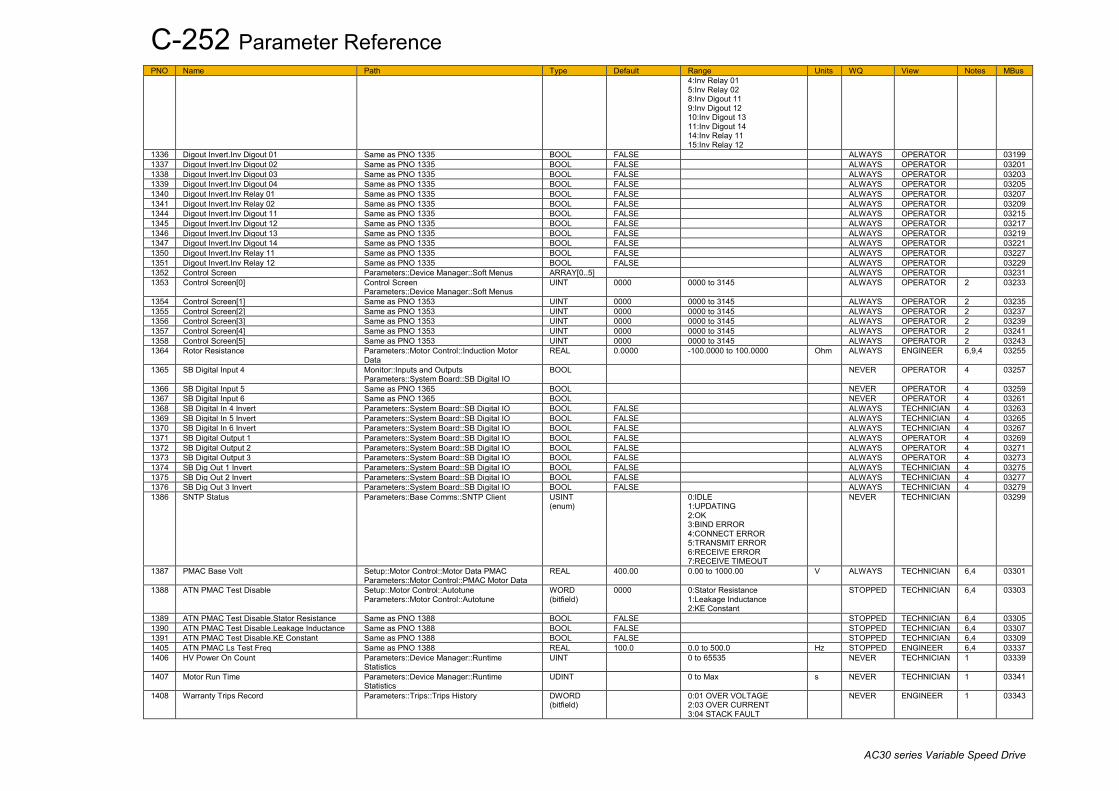
C-252 Parameter Reference
AC30 series Variable Speed Drive
PNO Name Path Type Default Range Units WQ View Notes MBus 4:Inv Relay 01 5:Inv Relay 02 8:Inv Digout 11 9:Inv Digout 12 10:Inv Digout 13 11:Inv Digout 14 14:Inv Relay 11 15:Inv Relay 12
1336 Digout Invert.Inv Digout 01 Same as PNO 1335 BOOL FALSE ALWAYS OPERATOR 03199 1337 Digout Invert.Inv Digout 02 Same as PNO 1335 BOOL FALSE ALWAYS OPERATOR 03201 1338 Digout Invert.Inv Digout 03 Same as PNO 1335 BOOL FALSE ALWAYS OPERATOR 03203 1339 Digout Invert.Inv Digout 04 Same as PNO 1335 BOOL FALSE ALWAYS OPERATOR 03205 1340 Digout Invert.Inv Relay 01 Same as PNO 1335 BOOL FALSE ALWAYS OPERATOR 03207 1341 Digout Invert.Inv Relay 02 Same as PNO 1335 BOOL FALSE ALWAYS OPERATOR 03209 1344 Digout Invert.Inv Digout 11 Same as PNO 1335 BOOL FALSE ALWAYS OPERATOR 03215 1345 Digout Invert.Inv Digout 12 Same as PNO 1335 BOOL FALSE ALWAYS OPERATOR 03217 1346 Digout Invert.Inv Digout 13 Same as PNO 1335 BOOL FALSE ALWAYS OPERATOR 03219 1347 Digout Invert.Inv Digout 14 Same as PNO 1335 BOOL FALSE ALWAYS OPERATOR 03221 1350 Digout Invert.Inv Relay 11 Same as PNO 1335 BOOL FALSE ALWAYS OPERATOR 03227 1351 Digout Invert.Inv Relay 12 Same as PNO 1335 BOOL FALSE ALWAYS OPERATOR 03229 1352 Control Screen Parameters::Device Manager::Soft Menus ARRAY[0..5] ALWAYS OPERATOR 03231 1353 Control Screen[0] Control Screen
Parameters::Device Manager::Soft Menus UINT 0000 0000 to 3145 ALWAYS OPERATOR 2 03233
1354 Control Screen[1] Same as PNO 1353 UINT 0000 0000 to 3145 ALWAYS OPERATOR 2 03235 1355 Control Screen[2] Same as PNO 1353 UINT 0000 0000 to 3145 ALWAYS OPERATOR 2 03237 1356 Control Screen[3] Same as PNO 1353 UINT 0000 0000 to 3145 ALWAYS OPERATOR 2 03239 1357 Control Screen[4] Same as PNO 1353 UINT 0000 0000 to 3145 ALWAYS OPERATOR 2 03241 1358 Control Screen[5] Same as PNO 1353 UINT 0000 0000 to 3145 ALWAYS OPERATOR 2 03243 1364 Rotor Resistance Parameters::Motor Control::Induction Motor
Data REAL 0.0000 -100.0000 to 100.0000 Ohm ALWAYS ENGINEER 6,9,4 03255
1365 SB Digital Input 4 Monitor::Inputs and Outputs Parameters::System Board::SB Digital IO
BOOL NEVER OPERATOR 4 03257
1366 SB Digital Input 5 Same as PNO 1365 BOOL NEVER OPERATOR 4 03259 1367 SB Digital Input 6 Same as PNO 1365 BOOL NEVER OPERATOR 4 03261 1368 SB Digital In 4 Invert Parameters::System Board::SB Digital IO BOOL FALSE ALWAYS TECHNICIAN 4 03263 1369 SB Digital In 5 Invert Parameters::System Board::SB Digital IO BOOL FALSE ALWAYS TECHNICIAN 4 03265 1370 SB Digital In 6 Invert Parameters::System Board::SB Digital IO BOOL FALSE ALWAYS TECHNICIAN 4 03267 1371 SB Digital Output 1 Parameters::System Board::SB Digital IO BOOL FALSE ALWAYS OPERATOR 4 03269 1372 SB Digital Output 2 Parameters::System Board::SB Digital IO BOOL FALSE ALWAYS OPERATOR 4 03271 1373 SB Digital Output 3 Parameters::System Board::SB Digital IO BOOL FALSE ALWAYS OPERATOR 4 03273 1374 SB Dig Out 1 Invert Parameters::System Board::SB Digital IO BOOL FALSE ALWAYS TECHNICIAN 4 03275 1375 SB Dig Out 2 Invert Parameters::System Board::SB Digital IO BOOL FALSE ALWAYS TECHNICIAN 4 03277 1376 SB Dig Out 3 Invert Parameters::System Board::SB Digital IO BOOL FALSE ALWAYS TECHNICIAN 4 03279 1386 SNTP Status Parameters::Base Comms::SNTP Client USINT
(enum) 0:IDLE
1:UPDATING 2:OK 3:BIND ERROR 4:CONNECT ERROR 5:TRANSMIT ERROR 6:RECEIVE ERROR 7:RECEIVE TIMEOUT
NEVER TECHNICIAN 03299
1387 PMAC Base Volt Setup::Motor Control::Motor Data PMAC Parameters::Motor Control::PMAC Motor Data
REAL 400.00 0.00 to 1000.00 V ALWAYS TECHNICIAN 6,4 03301
1388 ATN PMAC Test Disable Setup::Motor Control::Autotune Parameters::Motor Control::Autotune
WORD (bitfield)
0000 0:Stator Resistance 1:Leakage Inductance 2:KE Constant
STOPPED TECHNICIAN 6,4 03303
1389 ATN PMAC Test Disable.Stator Resistance Same as PNO 1388 BOOL FALSE STOPPED TECHNICIAN 6,4 03305 1390 ATN PMAC Test Disable.Leakage Inductance Same as PNO 1388 BOOL FALSE STOPPED TECHNICIAN 6,4 03307 1391 ATN PMAC Test Disable.KE Constant Same as PNO 1388 BOOL FALSE STOPPED TECHNICIAN 6,4 03309 1405 ATN PMAC Ls Test Freq Same as PNO 1388 REAL 100.0 0.0 to 500.0 Hz STOPPED ENGINEER 6,4 03337 1406 HV Power On Count Parameters::Device Manager::Runtime
Statistics UINT 0 to 65535 NEVER TECHNICIAN 1 03339
1407 Motor Run Time Parameters::Device Manager::Runtime Statistics
UDINT 0 to Max s NEVER TECHNICIAN 1 03341
1408 Warranty Trips Record Parameters::Trips::Trips History DWORD (bitfield)
0:01 OVER VOLTAGE 2:03 OVER CURRENT 3:04 STACK FAULT
NEVER ENGINEER 1 03343

Parameter Reference C-253
AC30 series Variable Speed Drive
PNO Name Path Type Default Range Units WQ View Notes MBus 4:05 STACK OVER CURRENT 7:08 INVERSE TIME 10:11 HEATSINK OVERTEMP 11:12 INTERNAL OVERTEMP 14:15 BRAKE SHORT CCT 16:17 BRAKE SWITCH 21:22 VDC RIPPLE
1409 Warranty Trips Record.01 OVER VOLTAGE Parameters::Trips::Trips History BOOL NEVER ENGINEER 1 03345 1411 Warranty Trips Record.03 OVER CURRENT Parameters::Trips::Trips History BOOL NEVER ENGINEER 1 03349 1412 Warranty Trips Record.04 STACK FAULT Parameters::Trips::Trips History BOOL NEVER ENGINEER 1 03351 1413 Warranty Trips Record.05 STACK OVER
CURRENT Parameters::Trips::Trips History BOOL NEVER ENGINEER 1 03353
1416 Warranty Trips Record.08 INVERSE TIME Parameters::Trips::Trips History BOOL NEVER ENGINEER 1 03359 1419 Warranty Trips Record.11 HEATSINK
OVERTEMP Parameters::Trips::Trips History BOOL NEVER ENGINEER 1 03365
1420 Warranty Trips Record.12 INTERNAL OVERTEMP
Parameters::Trips::Trips History BOOL NEVER ENGINEER 1 03367
1423 Warranty Trips Record.15 BRAKE SHORT CCT
Parameters::Trips::Trips History BOOL NEVER ENGINEER 1 03373
1425 Warranty Trips Record.17 BRAKE SWITCH Parameters::Trips::Trips History BOOL NEVER ENGINEER 1 03377 1430 Warranty Trips Record.22 VDC RIPPLE Parameters::Trips::Trips History BOOL NEVER ENGINEER 1 03387 1441 Anout 01 ABS Setup::Inputs and Outputs::Base IO
Parameters::Inputs And Outputs::IO Configure BOOL FALSE ALWAYS OPERATOR 4 03409
1442 Recent Trip Times Parameters::Trips::Trips History ARRAY[0..9] NEVER OPERATOR 03411 1443 Recent Trip Times[0] Parameters::Trips::Trips History UDINT 0 to Max s NEVER OPERATOR 1 03413 1444 Recent Trip Times[1] Parameters::Trips::Trips History UDINT 0 to Max s NEVER OPERATOR 1 03415 1445 Recent Trip Times[2] Parameters::Trips::Trips History UDINT 0 to Max s NEVER OPERATOR 1 03417 1446 Recent Trip Times[3] Parameters::Trips::Trips History UDINT 0 to Max s NEVER OPERATOR 1 03419 1447 Recent Trip Times[4] Parameters::Trips::Trips History UDINT 0 to Max s NEVER OPERATOR 1 03421 1448 Recent Trip Times[5] Parameters::Trips::Trips History UDINT 0 to Max s NEVER OPERATOR 1 03423 1449 Recent Trip Times[6] Parameters::Trips::Trips History UDINT 0 to Max s NEVER OPERATOR 1 03425 1450 Recent Trip Times[7] Parameters::Trips::Trips History UDINT 0 to Max s NEVER OPERATOR 1 03427 1451 Recent Trip Times[8] Parameters::Trips::Trips History UDINT 0 to Max s NEVER OPERATOR 1 03429 1452 Recent Trip Times[9] Parameters::Trips::Trips History UDINT 0 to Max s NEVER OPERATOR 1 03431 1458 Modbus Conn Timeout Parameters::Base Comms::Modbus TIME 66.000 0.000 to 100000.000 s ALWAYS TECHNICIAN 03443 1459 Max Spd when Autotuned Parameters::Motor Control::Autotune REAL x. -1 to 100000 RPM NEVER ENGINEER 3,6,9,4 03445 1460 Anout 02 Scale Same as PNO 1441 REAL 1.0000 Min to Max ALWAYS OPERATOR 03447 1461 Anin 11 Offset Setup::Inputs and Outputs::Option
Parameters::Option IO::General Purpose IO REAL 0.00 Min to Max % ALWAYS OPERATOR 4 03449
1462 Anin 11 Scale Same as PNO 1461 REAL 1.0000 Min to Max ALWAYS OPERATOR 4 03451 1463 Anin 12 Offset Same as PNO 1461 REAL 0.00 Min to Max % ALWAYS OPERATOR 4 03453 1464 Anin 12 Scale Same as PNO 1461 REAL 1.0000 Min to Max ALWAYS OPERATOR 4 03455 1465 Anin 13 Offset Same as PNO 1461 REAL 0.00 Min to Max % ALWAYS OPERATOR 4 03457 1466 Anin 13 Scale Same as PNO 1461 REAL 1.0000 Min to Max ALWAYS OPERATOR 4 03459 1467 Anout 02 Offset Same as PNO 1441 REAL 0.00 Min to Max % ALWAYS OPERATOR 03461 1468 Anout 02 ABS Same as PNO 1441 BOOL FALSE ALWAYS OPERATOR 03463 1469 AR Enable Setup::Motor Control::Auto Restart
Parameters::Motor Control::Auto Restart BOOL FALSE ALWAYS OPERATOR 03465
1470 AR Mode Same as PNO 1469 USINT (enum)
1 0:TRIP RESET 1:AUTO RESTART 2:AUTO START
ALWAYS OPERATOR 03467
1471 AR Max Restarts Same as PNO 1469 USINT 10 1 to 20 ALWAYS OPERATOR 03469 1472 AR Trip Mask Same as PNO 1469 DWORD
(bitfield) FFFFFFFF Same as PNO 763 ALWAYS TECHNICIAN 03471
1473 AR Trip Mask.01 OVER VOLTAGE Same as PNO 1469 BOOL TRUE ALWAYS TECHNICIAN 03473 1474 AR Trip Mask.02 UNDER VOLTAGE Same as PNO 1469 BOOL TRUE ALWAYS TECHNICIAN 03475 1475 AR Trip Mask.03 OVER CURRENT Same as PNO 1469 BOOL TRUE ALWAYS TECHNICIAN 03477 1476 AR Trip Mask.04 STACK FAULT Same as PNO 1469 BOOL TRUE ALWAYS TECHNICIAN 03479 1477 AR Trip Mask.05 STACK OVER CURRENT Same as PNO 1469 BOOL TRUE ALWAYS TECHNICIAN 03481 1478 AR Trip Mask.06 CURRENT LIMIT Same as PNO 1469 BOOL TRUE ALWAYS TECHNICIAN 03483 1479 AR Trip Mask.07 MOTOR STALL Same as PNO 1469 BOOL TRUE ALWAYS TECHNICIAN 03485 1480 AR Trip Mask.08 INVERSE TIME Same as PNO 1469 BOOL TRUE ALWAYS TECHNICIAN 03487 1481 AR Trip Mask.09 MOTOR I2T Same as PNO 1469 BOOL TRUE ALWAYS TECHNICIAN 03489 1482 AR Trip Mask.10 LOW SPEED I Same as PNO 1469 BOOL TRUE ALWAYS TECHNICIAN 03491 1483 AR Trip Mask.11 HEATSINK OVERTEMP Same as PNO 1469 BOOL TRUE ALWAYS TECHNICIAN 03493 1484 AR Trip Mask.12 INTERNAL OVERTEMP Same as PNO 1469 BOOL TRUE ALWAYS TECHNICIAN 03495 1485 AR Trip Mask.13 MOTOR OVERTEMP Same as PNO 1469 BOOL TRUE ALWAYS TECHNICIAN 03497

C-254 Parameter Reference
AC30 series Variable Speed Drive
PNO Name Path Type Default Range Units WQ View Notes MBus 1486 AR Trip Mask.14 EXTERNAL TRIP Same as PNO 1469 BOOL TRUE ALWAYS TECHNICIAN 03499 1487 AR Trip Mask.15 BRAKE SHORT CCT Same as PNO 1469 BOOL TRUE ALWAYS TECHNICIAN 03501 1488 AR Trip Mask.16 BRAKE RESISTOR Same as PNO 1469 BOOL TRUE ALWAYS TECHNICIAN 03503 1489 AR Trip Mask.17 BRAKE SWITCH Same as PNO 1469 BOOL TRUE ALWAYS TECHNICIAN 03505 1490 AR Trip Mask.18 LOCAL CONTROL Same as PNO 1469 BOOL TRUE ALWAYS TECHNICIAN 03507 1491 AR Trip Mask.19 COMMS BREAK Same as PNO 1469 BOOL TRUE ALWAYS TECHNICIAN 03509 1492 AR Trip Mask.20 LINE CONTACTOR Same as PNO 1469 BOOL TRUE ALWAYS TECHNICIAN 03511 1493 AR Trip Mask.21 PHASE FAIL Same as PNO 1469 BOOL TRUE ALWAYS TECHNICIAN 03513 1494 AR Trip Mask.22 VDC RIPPLE Same as PNO 1469 BOOL TRUE ALWAYS TECHNICIAN 03515 1495 AR Trip Mask.23 BASE MODBUS BREAK Same as PNO 1469 BOOL TRUE ALWAYS TECHNICIAN 03517 1496 AR Trip Mask.24 24 V OVERLOAD Same as PNO 1469 BOOL TRUE ALWAYS TECHNICIAN 03519 1497 AR Trip Mask.25 PMAC SPEED ERROR Same as PNO 1469 BOOL TRUE ALWAYS TECHNICIAN 03521 1498 AR Trip Mask.26 OVERSPEED Same as PNO 1469 BOOL TRUE ALWAYS TECHNICIAN 03523 1499 AR Trip Mask.27 STO ACTIVE Same as PNO 1469 BOOL TRUE ALWAYS TECHNICIAN 03525 1500 AR Trip Mask.28 FEEDBACK MISSING Same as PNO 1469 BOOL TRUE ALWAYS TECHNICIAN 03527 1501 AR Trip Mask.29 INTERNAL FAN FAIL Same as PNO 1469 BOOL TRUE ALWAYS TECHNICIAN 03529 1502 AR Trip Mask.30 CURRENT SENSOR Setup::Motor Control::Auto Restart
Parameters::Motor Control::Auto Restart BOOL TRUE ALWAYS TECHNICIAN 03531
1503 AR Trip Mask.31 POWER LOSS STOP Same as PNO 1502 BOOL TRUE ALWAYS TECHNICIAN 03533 1504 AR Trip Mask.32 SPEED SENSOR Same as PNO 1502 BOOL TRUE ALWAYS TECHNICIAN 03535 1505 AR Initial Delay Same as PNO 1502 TIME 10.000 0.000 to 3600.000 s ALWAYS OPERATOR 03537 1506 AR Repeat Delay Same as PNO 1502 TIME 60.000 0.000 to 3600.000 s ALWAYS OPERATOR 03539 1507 AR Active Parameters::Motor Control::Auto Restart BOOL NEVER OPERATOR 03541 1508 AR Restart Pending Parameters::Motor Control::Auto Restart BOOL NEVER OPERATOR 03543 1509 AR Restarts Remaining Parameters::Motor Control::Auto Restart USINT 0 to 20 NEVER OPERATOR 03545 1510 AR Time Remaining Parameters::Motor Control::Auto Restart TIME 0.000 to 3600.000 s NEVER OPERATOR 03547 1511 Encoder Supply Setup::Inputs and Outputs::Option
Parameters::Option IO::Encoder USINT (enum)
0 0:5 V 1:12 V 2:15 V 3:24 V
STOPPED TECHNICIAN 4 03549
1512 Encoder Lines Same as PNO 1511 DINT 2048 1 to 100000 STOPPED TECHNICIAN 4 03551 1513 Encoder Invert Same as PNO 1511 BOOL FALSE STOPPED TECHNICIAN 9,4 03553 1514 Encoder Type Same as PNO 1511 USINT
(enum) 0 0:QUADRATURE
1:CLOCK/DIRECTION STOPPED TECHNICIAN 4 03555
1515 Encoder Single Ended Same as PNO 1511 BOOL FALSE STOPPED TECHNICIAN 4 03557 1516 Encoder Speed Monitor::Inputs and Outputs
Parameters::Option IO::Encoder REAL x. Min to Max RPM NEVER OPERATOR 4 03559
1517 Encoder Count Reset Same as PNO 1511 BOOL FALSE ALWAYS TECHNICIAN 2,4 03561 1518 Encoder Count Same as PNO 1516 DINT Min to Max NEVER TECHNICIAN 1,4 03563 1520 Actual Rotor T Const Parameters::Motor Control::Tr Adaptation REAL x. 1 to 100000 ms NEVER ENGINEER 4 03567 1521 Tr Adaptation Output Parameters::Motor Control::Tr Adaptation REAL x. 1 to 500 % NEVER ENGINEER 4 03569 1526 Energy Saving Lower Lim Parameters::Motor Control::Fluxing VHz REAL 0.00 0.00 to 1.00 ALWAYS OPERATOR 4 03579 1527 Max Available Volts Parameters::Motor Control::Tr Adaptation REAL x. 0 to 10000 V NEVER ENGINEER 4 03581 1528 Demanded Terminal Volts Parameters::Motor Control::Tr Adaptation REAL x. 0 to 1000 V NEVER ENGINEER 4 03583 1529 Terminal Volts Parameters::Motor Control::Tr Adaptation REAL x. 0 to 1000 V NEVER ENGINEER 4 03585 1533 Control Type Setup::Motor Control::Control and Type
Parameters::Control Mode::Control Mode USINT (enum)
0 0:SENSORLESS 1:ENCODER FEEDBACK
STOPPED TECHNICIAN 6,4 03593
1534 Clone Filename Setup::Clone Parameters::Device Manager::Clone
STRING[24] clone ALWAYS TECHNICIAN 2 03595
1537 Clone Direction Same as PNO 1534 USINT (enum)
0 0:SAVE TO FILE 1:LOAD FROM FILE
ALWAYS TECHNICIAN 2,4 03601
1538 Full Restore Same as PNO 1534 USINT (enum)
0 0:YES 1:PARTIAL
ALWAYS TECHNICIAN 2,4 03603
1539 Application Same as PNO 1534 USINT (enum)
0 0:LOAD FROM FILE 1:LEAVE CURRENT APP
ALWAYS TECHNICIAN 2,4 03605
1540 Other Parameters Same as PNO 1534 USINT (enum)
0 0:LOAD FROM FILE 1:LEAVE CURRENT VALUES 2:SET TO DEFAULT VALUES
ALWAYS TECHNICIAN 2,4 03607
1541 Power Parameters Same as PNO 1534 USINT (enum)
0 Same as PNO 1540 ALWAYS TECHNICIAN 2,4 03609
1542 Clone Start Same as PNO 1534 BOOL FALSE ALWAYS TECHNICIAN 2,4 03611 1543 Clone Status Same as PNO 1534 USINT
(enum) 0:IDLE
1:SAVING 2:RESTORING 3:VERIFYING 4:DONE 5:CANNOT START
NEVER TECHNICIAN 03613

Parameter Reference C-255
AC30 series Variable Speed Drive
PNO Name Path Type Default Range Units WQ View Notes MBus 6:FAILED 7:NO SD CARD 8:VERIFY FAILED 9:FILE NOT OPENED 10:FILE INCOMPATIBLE 11:FILE FAILURE 12:POWER MISMATCH 13:APPLICATION FAILURE 14:PARAMETERS FAILURE 15:PNET SECTION MISSING 16:CARD FAULT
1544 Filter Type Parameters::Motor Control::Filter On Torque Dmd
USINT (enum)
0 0:NONE 1:MAX ATTENUATION 2:MINIMUM PHASE 3:PHASE ADVANCE 4:NOTCH
ALWAYS TECHNICIAN 4 03615
1545 Cut Off Frequency Parameters::Motor Control::Filter On Torque Dmd
REAL 2000 20 to 6000 Hz ALWAYS TECHNICIAN 4 03617
1546 Frequency 1 Parameters::Motor Control::Filter On Torque Dmd
REAL 2000 20 to 6000 Hz ALWAYS TECHNICIAN 4 03619
1547 Frequency 2 Parameters::Motor Control::Filter On Torque Dmd
REAL 2000 20 to 6000 Hz ALWAYS TECHNICIAN 4 03621
1548 Factor Parameters::Motor Control::Filter On Torque Dmd
REAL 0.20 0.10 to 1.00 ALWAYS TECHNICIAN 4 03623
1549 Application Volts Parameters::Motor Control::Fluxing VHz REAL 0.00 0.00 to 150.00 % ALWAYS OPERATOR 4 03625 1550 Nameplate Mag Current Setup::Motor Control::Autotune
Parameters::Motor Control::Autotune REAL 0.88 0.01 to 1000.00 A STOPPED TECHNICIAN 6,4 03627
1551 Product Code Flags Parameters::Device Manager::Drive info BYTE NEVER ENGINEER 03629 1554 Application Name Parameters::Application::App Info STRING[20] NEVER TECHNICIAN 03635 1560 Start Delay Enable Parameters::Motor Control::Motor Sequencer BOOL FALSE STOPPED TECHNICIAN 03647 1565 Local Power Up Mode Parameters::Motor Control::Sequencing USINT
(enum) 0 0:AS WHEN POWERED
DOWN 1:LOCAL 2:REMOTE
ALWAYS TECHNICIAN 03657
1567 Modbus Mapping Setup::Communications::Base Modbus Parameters::Base Comms::Modbus
ARRAY[0..15] ALWAYS ENGINEER 03661
1568 Modbus Mapping[0] Same as PNO 1567 UINT 0000 0000 to 3145 ALWAYS ENGINEER 03663 1569 Modbus Mapping[1] Same as PNO 1567 UINT 0000 0000 to 3145 ALWAYS ENGINEER 03665 1570 Modbus Mapping[2] Same as PNO 1567 UINT 0000 0000 to 3145 ALWAYS ENGINEER 03667 1571 Modbus Mapping[3] Same as PNO 1567 UINT 0000 0000 to 3145 ALWAYS ENGINEER 03669 1572 Modbus Mapping[4] Same as PNO 1567 UINT 0000 0000 to 3145 ALWAYS ENGINEER 03671 1573 Modbus Mapping[5] Same as PNO 1567 UINT 0000 0000 to 3145 ALWAYS ENGINEER 03673 1574 Modbus Mapping[6] Same as PNO 1567 UINT 0000 0000 to 3145 ALWAYS ENGINEER 03675 1575 Modbus Mapping[7] Same as PNO 1567 UINT 0000 0000 to 3145 ALWAYS ENGINEER 03677 1576 Modbus Mapping[8] Same as PNO 1567 UINT 0000 0000 to 3145 ALWAYS ENGINEER 03679 1577 Modbus Mapping[9] Same as PNO 1567 UINT 0000 0000 to 3145 ALWAYS ENGINEER 03681 1578 Modbus Mapping[10] Same as PNO 1567 UINT 0000 0000 to 3145 ALWAYS ENGINEER 03683 1579 Modbus Mapping[11] Same as PNO 1567 UINT 0000 0000 to 3145 ALWAYS ENGINEER 03685 1580 Modbus Mapping[12] Same as PNO 1567 UINT 0000 0000 to 3145 ALWAYS ENGINEER 03687 1581 Modbus Mapping[13] Same as PNO 1567 UINT 0000 0000 to 3145 ALWAYS ENGINEER 03689 1582 Modbus Mapping[14] Same as PNO 1567 UINT 0000 0000 to 3145 ALWAYS ENGINEER 03691 1583 Modbus Mapping[15] Same as PNO 1567 UINT 0000 0000 to 3145 ALWAYS ENGINEER 03693 1632 Mapping Valid Monitor::Communications::Base Modbus
Parameters::Base Comms::Modbus BOOL NEVER OPERATOR 03791
1633 Application User Boost Parameters::Motor Control::Fluxing VHz REAL 0.00 0.00 to 25.00 % ALWAYS OPERATOR 4 03793 1634 Start Delay Parameters::Motor Control::Motor Sequencer TIME 0.000 0.000 to 30.000 s STOPPED TECHNICIAN 03795 1635 Delay To Start Parameters::Motor Control::Motor Sequencer TIME 0.000 to Max s NEVER TECHNICIAN 03797 1636 Manufacturing Flags Parameters::Device Manager::Drive info WORD NEVER ENGINEER 03799 1637 Engineer Password Parameters::Keypad::Graphical Keypad WORD 0000 ALWAYS TECHNICIAN 03801 1640 Modbus Password Setup::Communications::Option
Parameters::Option Comms::Modbus RTU WORD 0000 ALWAYS TECHNICIAN 4 03807
1641 VDC Lim Enable Parameters::Motor Control::DC Link Volts Limit BOOL FALSE STOPPED TECHNICIAN 03809 1642 VDC Lim Level Parameters::Motor Control::DC Link Volts Limit REAL 91.0 78.0 to 100.0 % STOPPED TECHNICIAN 03811 1643 VDC Lim Active Parameters::Motor Control::DC Link Volts Limit BOOL NEVER TECHNICIAN 03813 1644 VDC Lim Output Parameters::Motor Control::DC Link Volts Limit REAL x.x Min to Max Hz NEVER ENGINEER 03815 1645 Pwrl Enable Parameters::Motor Control::Power Loss Ride
Thru BOOL FALSE STOPPED TECHNICIAN 03817
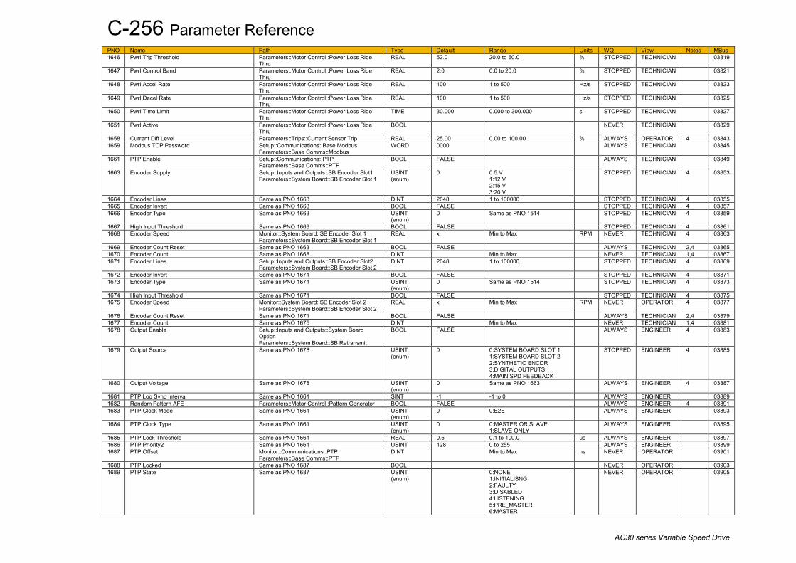
C-256 Parameter Reference
AC30 series Variable Speed Drive
PNO Name Path Type Default Range Units WQ View Notes MBus 1646 Pwrl Trip Threshold Parameters::Motor Control::Power Loss Ride
Thru REAL 52.0 20.0 to 60.0 % STOPPED TECHNICIAN 03819
1647 Pwrl Control Band Parameters::Motor Control::Power Loss Ride Thru
REAL 2.0 0.0 to 20.0 % STOPPED TECHNICIAN 03821
1648 Pwrl Accel Rate Parameters::Motor Control::Power Loss Ride Thru
REAL 100 1 to 500 Hz/s STOPPED TECHNICIAN 03823
1649 Pwrl Decel Rate Parameters::Motor Control::Power Loss Ride Thru
REAL 100 1 to 500 Hz/s STOPPED TECHNICIAN 03825
1650 Pwrl Time Limit Parameters::Motor Control::Power Loss Ride Thru
TIME 30.000 0.000 to 300.000 s STOPPED TECHNICIAN 03827
1651 Pwrl Active Parameters::Motor Control::Power Loss Ride Thru
BOOL NEVER TECHNICIAN 03829
1658 Current Diff Level Parameters::Trips::Current Sensor Trip REAL 25.00 0.00 to 100.00 % ALWAYS OPERATOR 4 03843 1659 Modbus TCP Password Setup::Communications::Base Modbus
Parameters::Base Comms::Modbus WORD 0000 ALWAYS TECHNICIAN 03845
1661 PTP Enable Setup::Communications::PTP Parameters::Base Comms::PTP
BOOL FALSE ALWAYS TECHNICIAN 03849
1663 Encoder Supply Setup::Inputs and Outputs::SB Encoder Slot1 Parameters::System Board::SB Encoder Slot 1
USINT (enum)
0 0:5 V 1:12 V 2:15 V 3:20 V
STOPPED TECHNICIAN 4 03853
1664 Encoder Lines Same as PNO 1663 DINT 2048 1 to 100000 STOPPED TECHNICIAN 4 03855 1665 Encoder Invert Same as PNO 1663 BOOL FALSE STOPPED TECHNICIAN 4 03857 1666 Encoder Type Same as PNO 1663 USINT
(enum) 0 Same as PNO 1514 STOPPED TECHNICIAN 4 03859
1667 High Input Threshold Same as PNO 1663 BOOL FALSE STOPPED TECHNICIAN 4 03861 1668 Encoder Speed Monitor::System Board::SB Encoder Slot 1
Parameters::System Board::SB Encoder Slot 1 REAL x. Min to Max RPM NEVER TECHNICIAN 4 03863
1669 Encoder Count Reset Same as PNO 1663 BOOL FALSE ALWAYS TECHNICIAN 2,4 03865 1670 Encoder Count Same as PNO 1668 DINT Min to Max NEVER TECHNICIAN 1,4 03867 1671 Encoder Lines Setup::Inputs and Outputs::SB Encoder Slot2
Parameters::System Board::SB Encoder Slot 2 DINT 2048 1 to 100000 STOPPED TECHNICIAN 4 03869
1672 Encoder Invert Same as PNO 1671 BOOL FALSE STOPPED TECHNICIAN 4 03871 1673 Encoder Type Same as PNO 1671 USINT
(enum) 0 Same as PNO 1514 STOPPED TECHNICIAN 4 03873
1674 High Input Threshold Same as PNO 1671 BOOL FALSE STOPPED TECHNICIAN 4 03875 1675 Encoder Speed Monitor::System Board::SB Encoder Slot 2
Parameters::System Board::SB Encoder Slot 2 REAL x. Min to Max RPM NEVER OPERATOR 4 03877
1676 Encoder Count Reset Same as PNO 1671 BOOL FALSE ALWAYS TECHNICIAN 2,4 03879 1677 Encoder Count Same as PNO 1675 DINT Min to Max NEVER TECHNICIAN 1,4 03881 1678 Output Enable Setup::Inputs and Outputs::System Board
Option Parameters::System Board::SB Retransmit
BOOL FALSE ALWAYS ENGINEER 4 03883
1679 Output Source Same as PNO 1678 USINT (enum)
0 0:SYSTEM BOARD SLOT 1 1:SYSTEM BOARD SLOT 2 2:SYNTHETIC ENCDR 3:DIGITAL OUTPUTS 4:MAIN SPD FEEDBACK
STOPPED ENGINEER 4 03885
1680 Output Voltage Same as PNO 1678 USINT (enum)
0 Same as PNO 1663 ALWAYS ENGINEER 4 03887
1681 PTP Log Sync Interval Same as PNO 1661 SINT -1 -1 to 0 ALWAYS ENGINEER 03889 1682 Random Pattern AFE Parameters::Motor Control::Pattern Generator BOOL FALSE ALWAYS ENGINEER 4 03891 1683 PTP Clock Mode Same as PNO 1661 USINT
(enum) 0 0:E2E ALWAYS ENGINEER 03893
1684 PTP Clock Type Same as PNO 1661 USINT (enum)
0 0:MASTER OR SLAVE 1:SLAVE ONLY
ALWAYS ENGINEER 03895
1685 PTP Lock Threshold Same as PNO 1661 REAL 0.5 0.1 to 100.0 us ALWAYS ENGINEER 03897 1686 PTP Priority2 Same as PNO 1661 USINT 128 0 to 255 ALWAYS ENGINEER 03899 1687 PTP Offset Monitor::Communications::PTP
Parameters::Base Comms::PTP DINT Min to Max ns NEVER OPERATOR 03901
1688 PTP Locked Same as PNO 1687 BOOL NEVER OPERATOR 03903 1689 PTP State Same as PNO 1687 USINT
(enum) 0:NONE
1:INITIALISNG 2:FAULTY 3:DISABLED 4:LISTENING 5:PRE_MASTER 6:MASTER
NEVER OPERATOR 03905

Parameter Reference C-257
AC30 series Variable Speed Drive
PNO Name Path Type Default Range Units WQ View Notes MBus 7:PASSIVE 8:UNCALIBRATED 9:SLAVE
1690 AFE Close Ext PCR Parameters::Regen Control::AFE BOOL FALSE ALWAYS OPERATOR 4 03907 1691 AFE Ext PCR Closed Parameters::Regen Control::AFE BOOL FALSE ALWAYS OPERATOR 4 03909 1692 AFE PF Angle Demand Parameters::Regen Control::AFE REAL 0.00 -90.00 to 90.00 deg ALWAYS OPERATOR 4 03911 1693 AFE Current Control Setup::Regen Control
Parameters::Regen Control::AFE BOOL FALSE ALWAYS OPERATOR 4 03913
1694 AFE PLL Kp Parameters::Regen Control::AFE REAL 5.48 0.00 to 30.00 ALWAYS OPERATOR 4 03915 1695 AFE PLL Ti Parameters::Regen Control::AFE REAL 0.0318 0.0000 to 3.0000 ALWAYS OPERATOR 4 03917 1696 Synth Encoder Lines Same as PNO 1678 DINT 2048 1 to 15000000 ALWAYS TECHNICIAN 4 03919 1697 AFE VDC Min Level Parameters::Regen Control::AFE REAL 400.00 340.00 to 5000.00 ALWAYS OPERATOR 4 03921 1698 Synth Encoder Speed Same as PNO 1678 REAL 0 0 to 15000000 RPM ALWAYS TECHNICIAN 4 03923 1699 PTP Clock Same as PNO 1687 DT 1970/01/01 to 2038/01/19 NEVER OPERATOR 03925 1701 Switchover Enable Parameters::Motor Control::MRAS BOOL FALSE ALWAYS ENGINEER 4 03929 1702 Synth Encoder Invert Same as PNO 1678 BOOL FALSE ALWAYS TECHNICIAN 4 03931 1703 AFE Sync Frequency Monitor::Regen Control
Parameters::Regen Control::AFE REAL x.xx Min to Max Hz NEVER OPERATOR 3,4 03933
1704 AFE Id Demand Same as PNO 1693 REAL 0.10 -1.50 to 1.50 ALWAYS OPERATOR 4 03935 1705 AFE Iq Demand Same as PNO 1693 REAL 0.00 -1.50 to 1.50 ALWAYS OPERATOR 4 03937 1706 AFE Max Current Parameters::Regen Control::AFE REAL 1.50 0.00 to 1.50 ALWAYS OPERATOR 4 03939 1707 AFE VDC Kp Parameters::Regen Control::AFE REAL 8.27 0.00 to 300.00 ALWAYS OPERATOR 4 03941 1708 AFE VDC Ti Parameters::Regen Control::AFE REAL 0.0319 0.0000 to 3.0000 ALWAYS OPERATOR 4 03943 1709 AFE VDC Ramp Parameters::Regen Control::AFE REAL 0.05 0.01 to 100.00 % ALWAYS OPERATOR 4 03945 1710 AFE VDC Feed Forward Parameters::Regen Control::AFE REAL 0.0000 -1.5000 to 1.5000 ALWAYS OPERATOR 4 03947 1711 AFE VDC Demand Same as PNO 1693 REAL 720 340 to 820 V ALWAYS OPERATOR 4 03949 1712 AFE Synchronizing Parameters::Regen Control::AFE BOOL NEVER OPERATOR 3,4 03951 1713 AFE Synchronized Parameters::Regen Control::AFE BOOL NEVER OPERATOR 3,4 03953 1714 AFE Enable Drive Parameters::Regen Control::AFE BOOL NEVER OPERATOR 3,4 03955 1715 AFE Phase Loss Parameters::Regen Control::AFE BOOL NEVER OPERATOR 3,4 03957 1716 AFE Brake Mode Parameters::Regen Control::AFE BOOL FALSE ALWAYS OPERATOR 4 03959 1717 AFE Correction Angle Parameters::Regen Control::AFE REAL 0.00 -90.00 to 90.00 ALWAYS OPERATOR 4 03961 1718 AFE Sync Angle Parameters::Regen Control::AFE REAL x.xx Min to Max deg NEVER OPERATOR 3,4 03963 1721 AFE Status Same as PNO 1703 USINT
(enum) 0:INACTIVE
1:SYNCHRONIZING 2:SYCHRONIZED 3:SUPPLY FREQ HIGH 4:SUPPLY FREQ LOW 5:SYNC FAILED
NEVER OPERATOR 3,4 03969
1722 SB Digital Input 2 Monitor::Inputs and Outputs Parameters::System Board::SB Digital IO
BOOL NEVER OPERATOR 4 03971
1723 SB Digital Input 3 Same as PNO 1722 BOOL NEVER OPERATOR 4 03973 1725 Peer to Peer Enable Setup::Communications::Peer to Peer
Parameters::Base Comms::Peer to Peer BOOL FALSE ALWAYS TECHNICIAN 03977
1726 Destination IP Address Same as PNO 1725 DWORD (IP addr)
255.255.255.255 ALWAYS ENGINEER 03979
1727 Destination Port Same as PNO 1725 UINT 1250 0 to 65535 ALWAYS ENGINEER 03981 1728 Local Port Same as PNO 1725 UINT 1250 1 to 65535 ALWAYS ENGINEER 03983 1729 Peer to Peer State Monitor::Communications::Peer to Peer
Parameters::Base Comms::Peer to Peer USINT (enum)
0:DISABLED 1:ACTIVE 2:ERROR
NEVER OPERATOR 03985
1730 AFE Inductance Setup::Regen Control Parameters::Regen Control::AFE
REAL 0.00 0.00 to 1000.00 mH ALWAYS OPERATOR 4 03987
1731 AFE Transf Angle Offset Parameters::Regen Control::AFE REAL 0.00 0.00 to 360.00 deg ALWAYS OPERATOR 4 03989 1732 Motor Start Count Parameters::Device Manager::Runtime
Statistics UDINT 0 to Max NEVER TECHNICIAN 1 03991
1733 Time Since Power-On Parameters::Device Manager::Runtime Statistics
TIME 0.000 to Max s NEVER TECHNICIAN 03993
1734 AR Trip Mask B Parameters::Motor Control::Auto Restart DWORD 00000000 ALWAYS TECHNICIAN 03995 1735 AR Trip Mask 2 B Parameters::Motor Control::Auto Restart DWORD 00000000 ALWAYS TECHNICIAN 03997 1736 AR Initial Delay B Parameters::Motor Control::Auto Restart TIME 60.000 0.000 to 3600.000 s ALWAYS OPERATOR 03999 1737 AR Repeat Delay B Parameters::Motor Control::Auto Restart TIME 120.000 0.000 to 3600.000 s ALWAYS OPERATOR 04001 1738 Enable Auto Save Parameters::Device Manager::Setup Wizard BOOL TRUE ALWAYS ENGINEER 04003 1739 System Board Required Setup::Inputs and Outputs::System Board
Option Parameters::System Board::System Board Option
USINT (enum)
0 0:NONE 1:DUAL ENCODER 2:ABSOLUTE
CONFIG TECHNICIAN 04005

C-258 Parameter Reference
AC30 series Variable Speed Drive
PNO Name Path Type Default Range Units WQ View Notes MBus 1740 System Board Fitted Parameters::System Board::System Board
Option USINT (enum)
Same as PNO 1739 NEVER OPERATOR 1 04007
1741 System Board Status Parameters::System Board::System Board Option
USINT (enum)
Same as PNO 1180 NEVER OPERATOR 04009
1742 System Board FE State Parameters::Device Manager::Device State USINT (enum)
Same as PNO 989 NEVER OPERATOR 04011
1743 Encoder Feedback Setup::Motor Control::Control and Type Parameters::Control Mode::Control Mode
USINT (enum)
0 0:MAIN SPD FEEDBACK 1:SYSTEM BOARD SLOT 1 2:SYSTEM BOARD SLOT 2 3:NONE
STOPPED TECHNICIAN 6,4 04013
1744 Slave Position Src Parameters::Phase Control::Configure USINT (enum)
0 0:SAME AS MOTOR FBK 1:MAIN SPD FEEDBACK 2:SYSTEM BOARD SLOT 1 3:SYSTEM BOARD SLOT 2 4:OTHER
STOPPED TECHNICIAN 6 04015
1745 Master Position Src Parameters::Phase Control::Configure USINT (enum)
3 0:MAIN SPD FEEDBACK 1:SYSTEM BOARD SLOT 1 2:SYSTEM BOARD SLOT 2 3:NONE 4:OTHER
STOPPED TECHNICIAN 6 04017
1746 Speed Error Trip Enable Parameters::Trips::Speed Error Trip BOOL TRUE ALWAYS TECHNICIAN 4 04019 1747 Speed Error Threshold Parameters::Trips::Speed Error Trip REAL 50.00 0.00 to 100.00 % ALWAYS TECHNICIAN 4 04021 1748 Speed Error Trip Delay Parameters::Trips::Speed Error Trip TIME 10.000 0.000 to 2000.000 s ALWAYS TECHNICIAN 4 04023 1749 Setup Successful Parameters::Phase Control::Configure BOOL NEVER TECHNICIAN 04025 1750 Error Number Parameters::Phase Control::Configure INT -32768 to 32767 NEVER TECHNICIAN 04027 1751 Master Encoder Parameters::Phase Control::Configure USINT
(enum) 0:EMPTY FUNC
1:ESTIMATOR 2:PRIMARY 3:SYSTEM BOARD SLOT 1 4:SYSTEM BOARD SLOT 2 5:OTHER
NEVER TECHNICIAN 04029
1752 Slave Encoder Parameters::Phase Control::Configure USINT (enum)
Same as PNO 1751 NEVER TECHNICIAN 04031
1753 Spd Loop Encoder Parameters::Phase Control::Configure USINT (enum)
Same as PNO 1751 NEVER TECHNICIAN 04033
1754 Free Space (kBytes) Parameters::Device Manager::Flash File System
UDINT 0 to Max NEVER ENGINEER 04035
1756 Output A Setup::Inputs and Outputs::System Board Option Parameters::System Board::SB Retransmit
BOOL FALSE ALWAYS OPERATOR 4 04039
1757 Output B Same as PNO 1756 BOOL FALSE ALWAYS OPERATOR 4 04041 1758 Output Z Same as PNO 1756 BOOL FALSE ALWAYS OPERATOR 4 04043 1759 SB Digital Input 1 Monitor::Inputs and Outputs
Parameters::System Board::SB Digital IO BOOL NEVER OPERATOR 4 04045
1760 Display Warnings Parameters::Trips::Trips Status BOOL TRUE ALWAYS OPERATOR 04047 1762 Thermistor Warn Delta Parameters::Option IO::Thermistor REAL 100 0 to 4500 Ohm ALWAYS TECHNICIAN 4 04051 1779 Auto Hide Parameters::Device Manager::Setup Wizard BOOL TRUE ALWAYS ENGINEER 04085 1780 Spd Limiter Torq Ctrl Parameters::Motor Control::Spd Loop Settings BOOL FALSE ALWAYS TECHNICIAN 4 04087 1781 Speed Limiter Active Parameters::Motor Control::Spd Loop
Diagnostics BOOL NEVER TECHNICIAN 4 04089
1782 Free Sockets Parameters::Base Comms::Ethernet UINT 0 to 65535 NEVER ENGINEER 04091 1783 Encoder Count Init Parameters::Option IO::Encoder BOOL TRUE ALWAYS TECHNICIAN 4 04093 1784 Encoder Count Init Parameters::System Board::SB Encoder Slot 1 BOOL TRUE ALWAYS TECHNICIAN 4 04095 1785 Encoder Count Init Parameters::System Board::SB Encoder Slot 2 BOOL TRUE ALWAYS TECHNICIAN 4 04097 1787 PTP Domain Number Setup::Communications::PTP
Parameters::Base Comms::PTP USINT 0 0 to 127 ALWAYS ENGINEER 04101
1788 SNTP Client Enable Parameters::Base Comms::SNTP Client BOOL FALSE ALWAYS TECHNICIAN 04103 1789 SNTP Remote Server Parameters::Base Comms::SNTP Client DWORD
(IP addr) 000.000.000.000 ALWAYS TECHNICIAN 04105
1790 Resolver Voltage Setup::Inputs and Outputs::Option Parameters::Option IO::Resolver
USINT (enum)
4 0:0V 1:4V 2:5V 3:6V 4:7V 5:8V 6:9V 7:10V 8:11V
STOPPED TECHNICIAN 4 04107

Parameter Reference C-259
AC30 series Variable Speed Drive
PNO Name Path Type Default Range Units WQ View Notes MBus 9:12V
1791 Resolver Frequency Same as PNO 1790 REAL 8.0 2.0 to 20.0 kHz STOPPED TECHNICIAN 4 04109 1792 Resolver Ratio Same as PNO 1790 REAL 0.50 0.15 to 3.00 STOPPED TECHNICIAN 4 04111 1793 Resolver Poles Same as PNO 1790 INT 2, 2 to 100 STOPPED TECHNICIAN 4 04113 1794 Soft Key 2 Mode Parameters::Keypad::Graphical Keypad USINT
(enum) 0 0:LOCAL / REMOTE
1:FORWARD / REVERSE 2:CUSTOM
ALWAYS OPERATOR 04115
1795 Soft Key 2 Value Parameters::Keypad::Graphical Keypad BOOL FALSE ALWAYS OPERATOR 2 04117 1796 Alignment On Power On Setup::Motor Control::Pos Fbk Alignment
Parameters::Motor Control::Pos Fbk Alignment BOOL FALSE STOPPED TECHNICIAN 6,4 04119
1797 Alignment Method Same as PNO 1796 USINT (enum)
0 0:MANUAL 1:AUTOMATIC 2:DIRECTION TEST
STOPPED TECHNICIAN 6,4 04121
1798 Alignment Enable Same as PNO 1796 BOOL FALSE STOPPED TECHNICIAN 2,4 04123 1799 Alignment Level Same as PNO 1796 REAL 50 0 to 150 % ALWAYS TECHNICIAN 6,4 04125 1800 Alignment Ramp Time Same as PNO 1796 TIME 1.000 0.000 to 30.000 s ALWAYS TECHNICIAN 6,4 04127 1801 Alignment On Motor Same as PNO 1796 USINT
(enum) 0 0:PHASE U
1:PHASE V 2:PHASE W
ALWAYS TECHNICIAN 6,4 04129
1802 Alignment Offset Parameters::Motor Control::Pos Fbk Alignment REAL x.x -180.0 to 180.0 deg NEVER TECHNICIAN 4 04131 1803 Alignment Elec Pos Parameters::Motor Control::Pos Fbk Alignment REAL x.x -180.0 to 180.0 deg NEVER TECHNICIAN 4 04133 1804 Alignment Direction Parameters::Motor Control::Pos Fbk Alignment USINT
(enum) 0:STANDARD
1:REVERSE NEVER TECHNICIAN 4 04135
1805 Alignment State Parameters::Motor Control::Pos Fbk Alignment USINT (enum)
0:OFF 1:ON MANUAL 2:ON AUTO 3:ERROR 4:ENDED
NEVER TECHNICIAN 4 04137
1806 Alignment Ended Parameters::Motor Control::Pos Fbk Alignment BOOL NEVER TECHNICIAN 4 04139 1807 Alignment Error Parameters::Motor Control::Pos Fbk Alignment USINT
(enum) 0:NO ERROR
1:SHAFT LOCKED 2:AMPS 3:LOAD 4:POLES 5:MOTOR UNCONNECTED 6:ENCODER 7:INIT NEEDED
NEVER TECHNICIAN 4 04141
1808 PMAC Encoder Offset Setup::Motor Control::Motor Data PMAC Parameters::Motor Control::PMAC Motor Data
REAL 0.0 -180.0 to 180.0 deg ALWAYS TECHNICIAN 1,6,9,4 04143
1809 PMAC Wiring Setup::Motor Control::Motor Data PMAC Monitor::Motor and Drive Parameters::Motor Control::PMAC Motor Data
USINT (enum)
0 Same as PNO 1804 ALWAYS TECHNICIAN 6,9,4 04145
1810 Resolver Invert Same as PNO 1790 BOOL FALSE STOPPED TECHNICIAN 4 04147 1811 Resolver Turns Monitor::Inputs and Outputs
Parameters::Option IO::Resolver DINT Min to Max NEVER TECHNICIAN 1,4 04149
1812 Resolver Fraction Turns Same as PNO 1811 DINT Min to Max NEVER TECHNICIAN 1,4 04151 1813 Resolver Speed RPM Parameters::Option IO::Resolver REAL x.x Min to Max RPM NEVER TECHNICIAN 4 04153 1814 Resolver Speed % Same as PNO 1811 REAL x.x Min to Max % NEVER TECHNICIAN 4 04155 1815 Resolver Speed Filter Same as PNO 1790 REAL 1000 10 to 10000 % ALWAYS TECHNICIAN 4 04157 1816 Resolver Resolution Same as PNO 1790 USINT
(enum) 0 0:AUTO
1:12 BITS 2:14 BITS 3:16 BITS
STOPPED TECHNICIAN 4 04159
1817 Resolver State Parameters::Option IO::Resolver USINT (enum)
0:POWER_ON 1:RESET 2:ACTIVE 3:TRIPPED 4:RESTART
NEVER TECHNICIAN 4 04161
1818 Resolver Turns Reset Parameters::Option IO::Resolver BOOL FALSE ALWAYS TECHNICIAN 2,4 04163 1819 Resolver Reset Power On Parameters::Option IO::Resolver BOOL FALSE STOPPED TECHNICIAN 4 04165 1820 Resolver Trip Type Parameters::Option IO::Resolver USINT
(enum) 0:NONE
1:PARITY 2:PHASE ERROR 3:MAX VELOCITY 4:TRACKING ERROR 5:SIN COS MISMATCH 6:SIN COS OVERRANGE 7:SIN COS BELOW LOS
NEVER TECHNICIAN 4 04167

C-260 Parameter Reference
AC30 series Variable Speed Drive
PNO Name Path Type Default Range Units WQ View Notes MBus 8:SIN COS CLIPPED
1821 Resolver Speed Hz Parameters::Option IO::Resolver REAL x.x Min to Max Hz NEVER TECHNICIAN 4 04169 1822 Resolver Built-In Gear Same as PNO 1790 REAL 1.0 0.1 to 1000.0 STOPPED TECHNICIAN 4 04171 1823 Resolver Speed Ripple Parameters::Option IO::Resolver REAL x.xx 0.00 to 1000.00 % NEVER TECHNICIAN 4 04173 1824 Resolver Position Same as PNO 1811 INT -32768 to 32767 NEVER ENGINEER 1,4 04175 1825 Resolver Max Speed Setup::Inputs and Outputs::Option
Parameters::Option IO::Resolver REAL 20000 0 to 120000 RPM STOPPED TECHNICIAN 4 04177
1826 Resolver Actual Filter Parameters::Option IO::Resolver REAL x. 20 to 8000 Hz NEVER TECHNICIAN 4 04179 1827 Resolver Active Resol Parameters::Option IO::Resolver USINT
(enum) Same as PNO 1816 NEVER ENGINEER 4 04181
1829 Copy to SD Card Parameters::Trips::Black Box Recorder BOOL FALSE ALWAYS TECHNICIAN 4 04185 1830 Black Box PNOs Parameters::Trips::Black Box Recorder ARRAY[0..3] ALWAYS TECHNICIAN 04187 1831 Black Box PNOs[0] Parameters::Trips::Black Box Recorder UINT 0829 0000 to 3145 ALWAYS TECHNICIAN 04189 1832 Black Box PNOs[1] Parameters::Trips::Black Box Recorder UINT 0514 0000 to 3145 ALWAYS TECHNICIAN 04191 1833 Black Box PNOs[2] Parameters::Trips::Black Box Recorder UINT 1022 0000 to 3145 ALWAYS TECHNICIAN 04193 1834 Black Box PNOs[3] Parameters::Trips::Black Box Recorder UINT 0393 0000 to 3145 ALWAYS TECHNICIAN 04195 1835 Log Enable Parameters::Device Manager::Data Logger BOOL FALSE ALWAYS TECHNICIAN 04197 1836 Log Period Parameters::Device Manager::Data Logger TIME 1.000 0.500 to 86400.000 s ALWAYS TECHNICIAN 04199 1837 Log File Name Parameters::Device Manager::Data Logger STRING[10] logfile_ ALWAYS TECHNICIAN 04201 1838 Log to New File Parameters::Device Manager::Data Logger BOOL FALSE ALWAYS TECHNICIAN 2 04203 1839 Log New File On Reset Parameters::Device Manager::Data Logger BOOL FALSE ALWAYS TECHNICIAN 04205 1840 Limit Log File Size Parameters::Device Manager::Data Logger BOOL FALSE ALWAYS TECHNICIAN 04207 1841 Log File Size Parameters::Device Manager::Data Logger UDINT 0 to Max NEVER TECHNICIAN 04209 1842 Log Parameters Parameters::Device Manager::Data Logger ARRAY[0..7] ALWAYS TECHNICIAN 04211 1843 Log Parameters[0] Parameters::Device Manager::Data Logger UINT 0000 0000 to 3145 ALWAYS TECHNICIAN 04213 1844 Log Parameters[1] Parameters::Device Manager::Data Logger UINT 0000 0000 to 3145 ALWAYS TECHNICIAN 04215 1845 Log Parameters[2] Parameters::Device Manager::Data Logger UINT 0000 0000 to 3145 ALWAYS TECHNICIAN 04217 1846 Log Parameters[3] Parameters::Device Manager::Data Logger UINT 0000 0000 to 3145 ALWAYS TECHNICIAN 04219 1847 Log Parameters[4] Parameters::Device Manager::Data Logger UINT 0000 0000 to 3145 ALWAYS TECHNICIAN 04221 1848 Log Parameters[5] Parameters::Device Manager::Data Logger UINT 0000 0000 to 3145 ALWAYS TECHNICIAN 04223 1849 Log Parameters[6] Parameters::Device Manager::Data Logger UINT 0000 0000 to 3145 ALWAYS TECHNICIAN 04225 1850 Log Parameters[7] Parameters::Device Manager::Data Logger UINT 0000 0000 to 3145 ALWAYS TECHNICIAN 04227 1851 Resolver Min Filter Same as PNO 1825 REAL 100 10 to 1000 Hz ALWAYS TECHNICIAN 4 04229 1852 Copy Status Parameters::Trips::Black Box Recorder USINT
(enum) 0:IDLE
1:ACTIVE 2:DISABLED
NEVER OPERATOR 4 04231
1853 Comms Reset Allow Setup::Communications::Option Parameters::Option Comms::Comms
BOOL FALSE ALWAYS TECHNICIAN 4 04233
1854 Update GKP Text Parameters::Keypad::Graphical Keypad BOOL FALSE ALWAYS TECHNICIAN 2 04235 1855 Encoder Speed Percent Parameters::Option IO::Encoder REAL x.xx Min to Max % NEVER OPERATOR 4 04237 1856 Encoder Speed Percent Parameters::System Board::SB Encoder Slot 1 REAL x.xx Min to Max % NEVER OPERATOR 4 04239 1857 Encoder Speed Percent Parameters::System Board::SB Encoder Slot 2 REAL x.xx Min to Max % NEVER OPERATOR 4 04241 1858 Phase at Rated Current Parameters::Motor Control::PMAC Motor
Advanced REAL 0.0 0.0 to 90.0 deg STOPPED ENGINEER 6,4 04243
1859 Max Phase Parameters::Motor Control::PMAC Motor Advanced
REAL 0.0 0.0 to 90.0 deg STOPPED ENGINEER 6,4 04245
1861 Scaled PNO Access Parameters::Device Manager::Setup Wizard USINT (enum)
0 0:BASE UNITS 1:SELECTED UNITS
ALWAYS TECHNICIAN 04249
1862 Green LED Force On Parameters::Keypad::Keypad Override BOOL FALSE ALWAYS TECHNICIAN 2 04251 1863 Red LED Force Off Parameters::Keypad::Keypad Override BOOL FALSE ALWAYS TECHNICIAN 2 04253 1865 Disable Keys Parameters::Keypad::Keypad Override WORD 0000 ALWAYS TECHNICIAN 2 04257 1866 Key Press Parameters::Keypad::Keypad Override WORD NEVER TECHNICIAN 04259 1867 Selected Parameter Parameters::Keypad::Keypad Override UINT 0000 to 3145 NEVER TECHNICIAN 04261 1868 Log Now Parameters::Device Manager::Data Logger BOOL FALSE ALWAYS TECHNICIAN 2 04263 1869 Auto Defaults Parameters::Device Manager::Drive info BOOL FALSE ALWAYS TECHNICIAN 04265 1870 Z Pulse Setup::Inputs and Outputs::System Board
Option Parameters::System Board::SB Retransmit
BOOL FALSE ALWAYS TECHNICIAN 2,4 04267
1871 Synth Encoder Count Monitor::System Board::Synthetic Encoder Parameters::System Board::SB Retransmit
DINT Min to Max NEVER TECHNICIAN 1,4 04269
1872 Z Pulse Init Done Parameters::System Board::SB Retransmit BOOL NEVER ENGINEER 4 04271 1874 Encoder Supply Setup::Inputs and Outputs::SB Encoder
Parameters::System Board::SB Encoder USINT (enum)
0 0:5V 1:10V
STOPPED TECHNICIAN 4 04275
1875 Encoder Type Same as PNO 1874 USINT (enum)
0 0:SIN COS 1:ENDAT 2.1 ST 2:ENDAT 2.1 MT
STOPPED TECHNICIAN 4 04277

Parameter Reference C-261
AC30 series Variable Speed Drive
PNO Name Path Type Default Range Units WQ View Notes MBus 1876 Encoder Lines Same as PNO 1874 DINT 512 1 to 1048576 STOPPED TECHNICIAN 4 04279 1877 Encoder Invert Same as PNO 1874 BOOL FALSE STOPPED TECHNICIAN 4 04281 1878 Encoder Count Monitor::System Board::SB Encoder
Parameters::System Board::SB Encoder DINT Min to Max NEVER TECHNICIAN 1,4 04283
1879 Encoder Rev Count Same as PNO 1878 DINT Min to Max NEVER TECHNICIAN 1,4 04285 1885 Startup Alignment Setup::Motor Control::Control and Type
Parameters::Control Mode::Control Mode USINT (enum)
0 0:DISABLED 1:ONCE 2:ALWAYS
ALWAYS TECHNICIAN 4 04297
1886 Actual Control Type Monitor::Motor and Drive Parameters::Control Mode::Control Mode
USINT (enum)
Same as PNO 1533 NEVER ENGINEER 4 04299
1887 Start Align Done Same as PNO 1886 BOOL NEVER TECHNICIAN 4 04301 1891 SNTP Server Enable Parameters::Base Comms::SNTP Server BOOL FALSE ALWAYS TECHNICIAN 04309 1892 Encoder Speed Same as PNO 1878 REAL x. Min to Max RPM NEVER OPERATOR 4 04311 1893 Encoder Speed Percent Parameters::System Board::SB Encoder REAL x.xx Min to Max % NEVER OPERATOR 4 04313 1894 Motor Count Reset Same as PNO 1874 BOOL FALSE ALWAYS TECHNICIAN 2,4 04315 1895 Calibration Error Parameters::System Board::SB Encoder USINT
(enum) 0:NONE
1:MOTOR NOT STOPPED 2:ENDAT TIMEOUT 3:ENDAT READ 4:ENDAT CHECKSUM FAIL 5:SINCOS AND ENDAT POS1 6:SINCOS AND ENDAT POS2 7:SINCOS AND ENDAT POS3 8:SINCOS AND ENDAT POS4 9:SINCOS AND ENDAT POS5 10:SINCOS AND ENDAT POS6 11:TIMEOUT 12:MASK CREATION 13:HW MISMATCH1 14:HW MISMATCH2 15:FAULTY ENCODER 16:WRONG ENCODER LINES 17:WRONG ENCODER TYPE 18:WARNING
NEVER TECHNICIAN 4 04317
1896 Absolute Calib Status Parameters::System Board::SB Encoder USINT (enum)
0:CAL NOT REQUIRED 1:DRIVE NOT STOPPED 2:MOTOR NOT STOPPED 3:ENDAT FAULT 4:CALIB IN PROGRESS 5:RECOVERING LOAD POS 6:CALIB COMPLETED 7:CALIB LOST 8:CALIB FAILED 9:CALIB WARNING
NEVER TECHNICIAN 4 04319
1897 Calib Fail Retry Same as PNO 1874 BOOL FALSE STOPPED TECHNICIAN 2,4 04321 1898 Motor Count Parameters::System Board::SB Encoder DINT Min to Max NEVER TECHNICIAN 1,4 04323 3000 Input Mapping Setup::Communications::Base EtherNet IP
Parameters::Base Comms::Fieldbus Mapping ARRAY[0..31] CONFIG ENGINEER 06527
3001 Input Mapping[0] Same as PNO 3000 UINT 0627 0000 to 3145 CONFIG ENGINEER 06529 3002 Input Mapping[1] Same as PNO 3000 UINT 0681 0000 to 3145 CONFIG ENGINEER 06531 3003 Input Mapping[2] Same as PNO 3000 UINT 0000 0000 to 3145 CONFIG ENGINEER 06533 3004 Input Mapping[3] Same as PNO 3000 UINT 0000 0000 to 3145 CONFIG ENGINEER 06535 3005 Input Mapping[4] Same as PNO 3000 UINT 0000 0000 to 3145 CONFIG ENGINEER 06537 3006 Input Mapping[5] Same as PNO 3000 UINT 0000 0000 to 3145 CONFIG ENGINEER 06539 3007 Input Mapping[6] Same as PNO 3000 UINT 0000 0000 to 3145 CONFIG ENGINEER 06541 3008 Input Mapping[7] Same as PNO 3000 UINT 0000 0000 to 3145 CONFIG ENGINEER 06543 3009 Input Mapping[8] Same as PNO 3000 UINT 0000 0000 to 3145 CONFIG ENGINEER 06545 3010 Input Mapping[9] Same as PNO 3000 UINT 0000 0000 to 3145 CONFIG ENGINEER 06547 3011 Input Mapping[10] Same as PNO 3000 UINT 0000 0000 to 3145 CONFIG ENGINEER 06549 3012 Input Mapping[11] Same as PNO 3000 UINT 0000 0000 to 3145 CONFIG ENGINEER 06551 3013 Input Mapping[12] Same as PNO 3000 UINT 0000 0000 to 3145 CONFIG ENGINEER 06553 3014 Input Mapping[13] Same as PNO 3000 UINT 0000 0000 to 3145 CONFIG ENGINEER 06555 3015 Input Mapping[14] Same as PNO 3000 UINT 0000 0000 to 3145 CONFIG ENGINEER 06557 3016 Input Mapping[15] Same as PNO 3000 UINT 0000 0000 to 3145 CONFIG ENGINEER 06559 3017 Input Mapping[16] Same as PNO 3000 UINT 0000 0000 to 3145 CONFIG ENGINEER 06561 3018 Input Mapping[17] Same as PNO 3000 UINT 0000 0000 to 3145 CONFIG ENGINEER 06563 3019 Input Mapping[18] Same as PNO 3000 UINT 0000 0000 to 3145 CONFIG ENGINEER 06565

C-262 Parameter Reference
AC30 series Variable Speed Drive
PNO Name Path Type Default Range Units WQ View Notes MBus 3020 Input Mapping[19] Same as PNO 3000 UINT 0000 0000 to 3145 CONFIG ENGINEER 06567 3021 Input Mapping[20] Same as PNO 3000 UINT 0000 0000 to 3145 CONFIG ENGINEER 06569 3022 Input Mapping[21] Same as PNO 3000 UINT 0000 0000 to 3145 CONFIG ENGINEER 06571 3023 Input Mapping[22] Same as PNO 3000 UINT 0000 0000 to 3145 CONFIG ENGINEER 06573 3024 Input Mapping[23] Same as PNO 3000 UINT 0000 0000 to 3145 CONFIG ENGINEER 06575 3025 Input Mapping[24] Same as PNO 3000 UINT 0000 0000 to 3145 CONFIG ENGINEER 06577 3026 Input Mapping[25] Same as PNO 3000 UINT 0000 0000 to 3145 CONFIG ENGINEER 06579 3027 Input Mapping[26] Same as PNO 3000 UINT 0000 0000 to 3145 CONFIG ENGINEER 06581 3028 Input Mapping[27] Same as PNO 3000 UINT 0000 0000 to 3145 CONFIG ENGINEER 06583 3029 Input Mapping[28] Same as PNO 3000 UINT 0000 0000 to 3145 CONFIG ENGINEER 06585 3030 Input Mapping[29] Same as PNO 3000 UINT 0000 0000 to 3145 CONFIG ENGINEER 06587 3031 Input Mapping[30] Same as PNO 3000 UINT 0000 0000 to 3145 CONFIG ENGINEER 06589 3032 Input Mapping[31] Same as PNO 3000 UINT 0000 0000 to 3145 CONFIG ENGINEER 06591 3064 Output Mapping Setup::Communications::Base EtherNet IP
Parameters::Base Comms::Fieldbus Mapping ARRAY[0..31] CONFIG ENGINEER 06655
3065 Output Mapping[0] Same as PNO 3064 UINT 0661 0000 to 3145 CONFIG ENGINEER 06657 3066 Output Mapping[1] Same as PNO 3064 UINT 0395 0000 to 3145 CONFIG ENGINEER 06659 3067 Output Mapping[2] Same as PNO 3064 UINT 0000 0000 to 3145 CONFIG ENGINEER 06661 3068 Output Mapping[3] Same as PNO 3064 UINT 0000 0000 to 3145 CONFIG ENGINEER 06663 3069 Output Mapping[4] Same as PNO 3064 UINT 0000 0000 to 3145 CONFIG ENGINEER 06665 3070 Output Mapping[5] Same as PNO 3064 UINT 0000 0000 to 3145 CONFIG ENGINEER 06667 3071 Output Mapping[6] Same as PNO 3064 UINT 0000 0000 to 3145 CONFIG ENGINEER 06669 3072 Output Mapping[7] Same as PNO 3064 UINT 0000 0000 to 3145 CONFIG ENGINEER 06671 3073 Output Mapping[8] Same as PNO 3064 UINT 0000 0000 to 3145 CONFIG ENGINEER 06673 3074 Output Mapping[9] Same as PNO 3064 UINT 0000 0000 to 3145 CONFIG ENGINEER 06675 3075 Output Mapping[10] Same as PNO 3064 UINT 0000 0000 to 3145 CONFIG ENGINEER 06677 3076 Output Mapping[11] Same as PNO 3064 UINT 0000 0000 to 3145 CONFIG ENGINEER 06679 3077 Output Mapping[12] Same as PNO 3064 UINT 0000 0000 to 3145 CONFIG ENGINEER 06681 3078 Output Mapping[13] Same as PNO 3064 UINT 0000 0000 to 3145 CONFIG ENGINEER 06683 3079 Output Mapping[14] Same as PNO 3064 UINT 0000 0000 to 3145 CONFIG ENGINEER 06685 3080 Output Mapping[15] Same as PNO 3064 UINT 0000 0000 to 3145 CONFIG ENGINEER 06687 3081 Output Mapping[16] Same as PNO 3064 UINT 0000 0000 to 3145 CONFIG ENGINEER 06689 3082 Output Mapping[17] Same as PNO 3064 UINT 0000 0000 to 3145 CONFIG ENGINEER 06691 3083 Output Mapping[18] Same as PNO 3064 UINT 0000 0000 to 3145 CONFIG ENGINEER 06693 3084 Output Mapping[19] Same as PNO 3064 UINT 0000 0000 to 3145 CONFIG ENGINEER 06695 3085 Output Mapping[20] Same as PNO 3064 UINT 0000 0000 to 3145 CONFIG ENGINEER 06697 3086 Output Mapping[21] Same as PNO 3064 UINT 0000 0000 to 3145 CONFIG ENGINEER 06699 3087 Output Mapping[22] Same as PNO 3064 UINT 0000 0000 to 3145 CONFIG ENGINEER 06701 3088 Output Mapping[23] Same as PNO 3064 UINT 0000 0000 to 3145 CONFIG ENGINEER 06703 3089 Output Mapping[24] Same as PNO 3064 UINT 0000 0000 to 3145 CONFIG ENGINEER 06705 3090 Output Mapping[25] Same as PNO 3064 UINT 0000 0000 to 3145 CONFIG ENGINEER 06707 3091 Output Mapping[26] Same as PNO 3064 UINT 0000 0000 to 3145 CONFIG ENGINEER 06709 3092 Output Mapping[27] Same as PNO 3064 UINT 0000 0000 to 3145 CONFIG ENGINEER 06711 3093 Output Mapping[28] Same as PNO 3064 UINT 0000 0000 to 3145 CONFIG ENGINEER 06713 3094 Output Mapping[29] Same as PNO 3064 UINT 0000 0000 to 3145 CONFIG ENGINEER 06715 3095 Output Mapping[30] Same as PNO 3064 UINT 0000 0000 to 3145 CONFIG ENGINEER 06717 3096 Output Mapping[31] Same as PNO 3064 UINT 0000 0000 to 3145 CONFIG ENGINEER 06719 3128 EtherNet IP Enable Setup::Communications::Base EtherNet IP
Parameters::Base Comms::EtherNet IP Adapter BOOL FALSE CONFIG TECHNICIAN 06783
3129 EtherNet IP Trip Same as PNO 3128 USINT (enum)
1 0:DISABLED 1:LOSS OF CONNECTION
CONFIG ENGINEER 06785
3130 EtherNet IP State Monitor::Communications::Base EtherNet IP Parameters::Base Comms::EtherNet IP Adapter
USINT (enum)
Same as PNO 214 NEVER OPERATOR 06787
3131 EtherNet IP Diag Same as PNO 3130 USINT (enum)
0:NONE 1:INPUT MAPPING FAILED 2:OUTPUT MAPPING FAILED
NEVER OPERATOR 06789
3132 PROFINET Enable Setup::Communications::Base PROFINET Parameters::Base Comms::PROFINET IO Device
BOOL FALSE CONFIG TECHNICIAN 06791
3133 PROFINET Trip Same as PNO 3132 USINT (enum)
1 0:DISABLED 1:ENABLED
CONFIG ENGINEER 06793
3134 PROFINET Use Drive IP Same as PNO 3132 BOOL FALSE CONFIG ENGINEER 06795 3135 PROFINET Acyclic Endn Same as PNO 3132 USINT
(enum) 1 0:LITTLE ENDIAN
1:BIG ENDIAN ALWAYS ENGINEER 06797
3136 PROFINET Station Name Monitor::Communications::Base PROFINET Parameters::Base Comms::PROFINET IO
STRING[21] NEVER OPERATOR 06799

Parameter Reference C-263
AC30 series Variable Speed Drive
PNO Name Path Type Default Range Units WQ View Notes MBus Device
3143 PROFINET State Same as PNO 3136 USINT (enum)
Same as PNO 239 NEVER OPERATOR 06813
3144 PROFINET Diagnostic Same as PNO 3136 USINT (enum)
0:NONE 1:INPUT MAPPING FAILED 2:OUTPUT MAPPING FAILED 3:CONNECTION REJECTED 4:MAPPING MISMATCH
NEVER OPERATOR 06815

C-264 Parameter Reference
AC30 series Variable Speed Drive
Parameters Defined in the Default Application PNO Name Path Type Default Range Units WQ View Notes MBus 1900 Selected Application USINT (enum) 0 0:BASIC SPEED
CONTROL 1:AUTO/MANUAL CONTROL 2:SPEED RAISE / LOWER 3:SPEED PRESETS 4:PROCESS PID
ALWAYS TECHNICIAN 5 04327
1901 RL Ramp Time Setup::Application::Raise Lower TIME 10.0 0.0 to 600.0 s ALWAYS TECHNICIAN 5,8 04329 1902 RL Reset Value Setup::Application::Raise Lower REAL 0.0 -500.0 to 500.0 % ALWAYS TECHNICIAN 5,8 04331 1903 RL Maximum Value Setup::Application::Raise Lower REAL 100.0 -500.0 to 500.0 % ALWAYS TECHNICIAN 5,8 04333 1904 RL Minimum Value Setup::Application::Raise Lower REAL -100.0 -500.0 to 500.0 % ALWAYS TECHNICIAN 5,8 04335 1905 Raise Lower Output Monitor::Application::Raise Lower REAL 0.0 -500.0 to 500.0 NEVER TECHNICIAN 1,8 04337 1906 Minimum Speed Value Setup::Application::Minimum Speed REAL -100.0 -100.0 to 100.0 % ALWAYS TECHNICIAN 5,8 04339 1907 Minimum Speed Mode Setup::Application::Minimum Speed USINT (enum) 0 0:PROP WITH MINIMUM
1:LINEAR
ALWAYS TECHNICIAN 5,8 04341
1908 Skip Band 1 Setup::Application::Skip Frequencies REAL 0.0 0.0 to 1000.0 Hz ALWAYS TECHNICIAN 5,8 04343 1909 Skip Frequency 1 Setup::Application::Skip Frequencies REAL 0.0 0.0 to 1000.0 Hz ALWAYS TECHNICIAN 5,8 04345 1910 Skip Band 2 Setup::Application::Skip Frequencies REAL 0.0 0.0 to 1000.0 Hz ALWAYS TECHNICIAN 5,8 04347 1911 Skip Frequency 2 Setup::Application::Skip Frequencies REAL 0.0 0.0 to 1000.0 Hz ALWAYS TECHNICIAN 5,8 04349 1912 Skip Band 3 Setup::Application::Skip Frequencies REAL 0.0 0.0 to 1000.0 Hz ALWAYS TECHNICIAN 5,8 04351 1913 Skip Frequency 3 Setup::Application::Skip Frequencies REAL 0.0 0.0 to 1000.0 Hz ALWAYS TECHNICIAN 5,8 04353 1914 Skip Band 4 Setup::Application::Skip Frequencies REAL 0.0 0.0 to 1000.0 Hz ALWAYS TECHNICIAN 5,8 04355 1915 Skip Frequency 4 Setup::Application::Skip Frequencies REAL 0.0 0.0 to 1000.0 Hz ALWAYS TECHNICIAN 5,8 04357 1916 Preset Speed 0 Setup::Application::Preset Speeds REAL 0.0 -100.0 to 100.0 % ALWAYS TECHNICIAN 5,8 04359 1917 Preset Speed 1 Setup::Application::Preset Speeds REAL 0.0 -100.0 to 100.0 % ALWAYS TECHNICIAN 5,8 04361 1918 Preset Speed 2 Setup::Application::Preset Speeds REAL 0.0 -100.0 to 100.0 % ALWAYS TECHNICIAN 5,8 04363 1919 Preset Speed 3 Setup::Application::Preset Speeds REAL 0.0 -100.0 to 100.0 % ALWAYS TECHNICIAN 5,8 04365 1920 Preset Speed 4 Setup::Application::Preset Speeds REAL 0.0 -100.0 to 100.0 % ALWAYS TECHNICIAN 5,8 04367 1921 Preset Speed 5 Setup::Application::Preset Speeds REAL 0.0 -100.0 to 100.0 % ALWAYS TECHNICIAN 5,8 04369 1922 Preset Speed 6 Setup::Application::Preset Speeds REAL 0.0 -100.0 to 100.0 % ALWAYS TECHNICIAN 5,8 04371 1923 Preset Speed 7 Setup::Application::Preset Speeds REAL 0.0 -100.0 to 100.0 % ALWAYS TECHNICIAN 5,8 04373 1924 Selected Preset Monitor::Application::Preset Speeds USINT 0 to 7 NEVER TECHNICIAN 8 04375 1925 Preset Speed Output Monitor::Application::Preset Speeds REAL -100.0 to 100.0 % NEVER TECHNICIAN 8 04377 1926 PID Setpoint Negate Setup::Application::PID BOOL TRUE ALWAYS TECHNICIAN 5,8 04379 1927 PID Feedback Negate Setup::Application::PID BOOL TRUE ALWAYS TECHNICIAN 5,8 04381 1928 PID Proportional Gain Setup::Application::PID REAL 1.0 ALWAYS TECHNICIAN 5,8 04383 1929 PID Integral TC Setup::Application::PID TIME 1.00 0.01 to 100.00 s ALWAYS TECHNICIAN 5,8 04385 1930 PID Derivative TC Setup::Application::PID TIME 0.000 0.000 to 10.000 s ALWAYS TECHNICIAN 5,8 04387 1931 PID Output Filter TC Setup::Application::PID TIME 0.100 0.000 to 10.000 s ALWAYS TECHNICIAN 5,8 04389 1932 PID Output Pos Limit Setup::Application::PID REAL 100.00 0.00 to 105.00 % ALWAYS TECHNICIAN 5,8 04391 1933 PID Output Neg Limit Setup::Application::PID REAL -100.00 -105.00 to 0.00 % ALWAYS TECHNICIAN 5,8 04393 1934 PID Output Scaling Setup::Application::PID REAL 1.000 -10.000 to 10.000 ALWAYS TECHNICIAN 5,8 04395 1935 PID Output Monitor::Application::PID REAL -105.00 to
105.00 % NEVER TECHNICIAN 8 04397
1936 PID Error Monitor::Application::PID REAL -105.00 to 105.00
% NEVER TECHNICIAN 8 04399
1937 Disable Coast Stop Setup::Application::Sequencing BOOL TRUE ALWAYS TECHNICIAN 8 04401 1938 Disable Quickstop Setup::Application::Sequencing BOOL TRUE ALWAYS TECHNICIAN 8 04403 1939 Feedback On ANIN1 Setup::Application::Input Selection BOOL FALSE ALWAYS TECHNICIAN 8 04405

Parameter Reference C-265
AC30 series Variable Speed Drive
Table of Parameters in Alphabetical Order This table is a list of all the parameters in the AC30V showing the parameter name, number and the section in this appendix in which the parameter is described.
PNO Name Section 0332 100% Mot Current Motor Load 0464 100% Speed in RPM Scale Setpoint 0403 100% Stack Current A Feedbacks 0343 100% Stk Current Stack Inv Time 1896 Absolute Calib Status SB Encoder 0450 Acceleration Boost Fluxing VHz 0486 Acceleration Time Ramp 0763 Active 1 - 32 Trips Status 0513 Active 33 - 64 Trips Status 1886 Actual Control Type Control Mode 0400 Actual Field Current Feedbacks 0339 Actual Mot I2T Output Motor Load 0421 Actual Neg Torque Lim Torque Limit 0420 Actual Pos Torque Lim Torque Limit 1213 Actual Position Feedbacks 1520 Actual Rotor T Const Tr Adaptation 0395 Actual Speed Percent Feedbacks 0393 Actual Speed RPM Feedbacks 0394 Actual Speed rps Feedbacks 0989 Actual State Device State 0399 Actual Torque Feedbacks 0199 Address Assignment Option Ethernet 1716 AFE Brake Mode AFE 1690 AFE Close Ext PCR AFE 1717 AFE Correction Angle AFE 1693 AFE Current Control AFE 1714 AFE Enable Drive AFE 1691 AFE Ext PCR Closed AFE 1704 AFE Id Demand AFE 1730 AFE Inductance AFE 1705 AFE Iq Demand AFE 1706 AFE Max Current AFE 1692 AFE PF Angle Demand AFE 1715 AFE Phase Loss AFE 1694 AFE PLL Kp AFE 1695 AFE PLL Ti AFE 1721 AFE Status AFE 1718 AFE Sync Angle AFE 1703 AFE Sync Frequency AFE 1713 AFE Synchronized AFE 1712 AFE Synchronizing AFE 1731 AFE Transf Angle Offset AFE 1711 AFE VDC Demand AFE 1710 AFE VDC Feed Forward AFE 1707 AFE VDC Kp AFE 1697 AFE VDC Min Level AFE 1709 AFE VDC Ramp AFE 1708 AFE VDC Ti AFE 1804 Alignment Direction Pos Fbk Alignment 1803 Alignment Elec Pos Pos Fbk Alignment 1798 Alignment Enable Pos Fbk Alignment
PNO Name Section 1806 Alignment Ended Pos Fbk Alignment 1807 Alignment Error Pos Fbk Alignment 1799 Alignment Level Pos Fbk Alignment 1797 Alignment Method Pos Fbk Alignment 1802 Alignment Offset Pos Fbk Alignment 1801 Alignment On Motor Pos Fbk Alignment 1796 Alignment On Power On Pos Fbk Alignment 1800 Alignment Ramp Time Pos Fbk Alignment 1805 Alignment State Pos Fbk Alignment 0893 Ambient Temperature Maintenance Monitor 0040 Anin 01 Break IO Values 0957 Anin 01 Offset IO Configure 0958 Anin 01 Scale IO Configure 0001 Anin 01 Type IO Configure 0039 Anin 01 Value IO Values 0959 Anin 02 Offset IO Configure 0960 Anin 02 Scale IO Configure 0002 Anin 02 Type IO Configure 0041 Anin 02 Value IO Values 1461 Anin 11 Offset General Purpose IO 1462 Anin 11 Scale General Purpose IO 1181 Anin 11 Value General Purpose IO 1463 Anin 12 Offset General Purpose IO 1464 Anin 12 Scale General Purpose IO 1182 Anin 12 Value General Purpose IO 1465 Anin 13 Offset General Purpose IO 1466 Anin 13 Scale General Purpose IO 1183 Anin 13 Value General Purpose IO 1441 Anout 01 ABS IO Configure 1108 Anout 01 Offset IO Configure 0686 Anout 01 Scale IO Configure 0003 Anout 01 Type IO Configure 0042 Anout 01 Value IO Values 1468 Anout 02 ABS IO Configure 1467 Anout 02 Offset IO Configure 1460 Anout 02 Scale IO Configure 0004 Anout 02 Type IO Configure 0043 Anout 02 Value IO Values 0610 App Control Word Sequencing 0680 App Reference Sequencing 1539 Application Clone 1039 Application Archive SD Card 0990 Application FE State Device State 1554 Application Name App Info 1633 Application User Boost Fluxing VHz 1549 Application Volts Fluxing VHz 1507 AR Active Auto Restart 1469 AR Enable Auto Restart 1505 AR Initial Delay Auto Restart 1736 AR Initial Delay B Auto Restart 1471 AR Max Restarts Auto Restart
PNO Name Section 1470 AR Mode Auto Restart 1506 AR Repeat Delay Auto Restart 1737 AR Repeat Delay B Auto Restart 1508 AR Restart Pending Auto Restart 1509 AR Restarts Remaining Auto Restart 1510 AR Time Remaining Auto Restart 1472 AR Trip Mask Auto Restart 0796 AR Trip Mask 2 Auto Restart 1735 AR Trip Mask 2 B Auto Restart 1734 AR Trip Mask B Auto Restart 0410 Archive Flags App Info 1405 ATN PMAC Ls Test Freq Autotune 1388 ATN PMAC Test Disable Autotune 0695 Attached to Stack Drive info 0448 Auto Boost Fluxing VHz 1869 Auto Defaults Drive info 1779 Auto Hide Setup Wizard 0930 Auto IP Ethernet 1214 Automatic Pole Pairs Motor Nameplate 0255 Autotune Enable Autotune 0256 Autotune Mode Autotune 0274 Autotune Ramp Time Autotune 0257 Autotune Test Disable Autotune 0182 Backup Action Parameter Backup 0183 Backup-Restore Start Parameter Backup 0184 Backup-Restore Status Parameter Backup 1093 BACnet Baud Rate BACnet MSTP 0209 BACnet IP Device ID BACnet IP 0208 BACnet IP State BACnet IP 0210 BACnet IP Timeout BACnet IP 1091 BACnet MAC Address BACnet MSTP 1096 BACnet Max Info Frames BACnet MSTP 1095 BACnet Max Master BACnet MSTP 1092 BACnet MSTP Device ID BACnet MSTP 1089 BACnet MSTP State BACnet MSTP 1094 BACnet MSTP Timeout BACnet MSTP 0457 Base Frequency Motor Nameplate 0991 Base IO FE State Device State 0456 Base Voltage Motor Nameplate 0992 Basic Drive FE State Device State 1830 Black Box PNOs Black Box Recorder 1831 Black Box PNOs[x] Black Box Recorder 0951 Boot Version Drive info 0687 Boot Version Number Drive info 0253 Brake Overrating Braking 0252 Brake Rated Power Braking 0251 Brake Resistance Braking 0254 Braking Active Braking 0249 Braking Enable Braking 1897 Calib Fail Retry SB Encoder 1895 Calibration Error SB Encoder

C-266 Parameter Reference
AC30 series Variable Speed Drive
PNO Name Section 1251 CANopen Actual Baud CANopen 0213 CANopen Baud Rate CANopen 0212 CANopen Node Address CANopen 0211 CANopen State CANopen 1034 Card Name SD Card 1033 Card State SD Card 1537 Clone Direction Clone 1534 Clone Filename Clone 1542 Clone Start Clone 1543 Clone Status Clone 0406 CM Temperature Feedbacks 0217 CNet Consuming Inst ControlNet 0216 CNet Producing Inst ControlNet 0627 Comms Control Word Sequencing 0051 Comms Diagnostic Comms 0052 Comms Diagnostic Code Comms 0186 Comms Event Active Event 0188 Comms Event Clear Event 0185 Comms Event Code Event 0187 Comms Event Set Event 0053 Comms Exception Comms 0045 Comms Fitted Comms 0050 Comms Module Serial Comms 0049 Comms Module Version Comms 0054 Comms Net Exception Comms 0995 Comms Option FE State Device State 1121 Comms Option Pcode Drive info 1129 Comms Option Serial Drive info 0681 Comms Reference Sequencing 0044 Comms Required Comms 1853 Comms Reset Allow Comms 0046 Comms State Comms 0047 Comms Supervised Comms 0048 Comms Trip Enable Comms 0997 Config Fault Area Device State 0118 Configuration Lock App Info 1139 Control Board Up Time Runtime Statistics 1116 Control Module Pcode Drive info 0977 Control Module Serial Drive info 1352 Control Screen Soft Menus 0908 Control Screen Mode Soft Menus 1353 Control Screen[x] Soft Menus 0512 Control Strategy Control Mode 1533 Control Type Control Mode 0644 Control Word Sequencing 0215 ControlNet MAC ID ControlNet 0214 ControlNet State ControlNet 1852 Copy Status Black Box Recorder 1829 Copy to SD Card Black Box Recorder 1658 Current Diff Level Current Sensor Trip 0305 Current Limit Current Limit 1545 Cut Off Frequency Filter On Torque Dmd 0329 DC Current Level Inj Braking 0331 DC Inj Base Volts Inj Braking 0326 DC Inj Current Limit Inj Braking 0324 DC Inj Deflux Time Inj Braking
PNO Name Section 0325 DC Inj Frequency Inj Braking 0330 DC Inj Timeout Inj Braking 0396 DC Link Volt Filtered Feedbacks 0392 DC Link Voltage Feedbacks 0119 DC Link Volts Trim Feedbacks 0327 DC Pulse Time Inj Braking 0487 Deceleration Time Ramp 0414 Deflux Delay Pattern Generator 1635 Delay To Start Motor Sequencer 1528 Demanded Terminal Volts Tr Adaptation 1726 Destination IP Address Peer to Peer 1727 Destination Port Peer to Peer 0221 DeviceNet Actual Baud DeviceNet 0220 DeviceNet Baud Rate DeviceNet 0219 DeviceNet MAC ID DeviceNet 0218 DeviceNet State DeviceNet 0929 DHCP Ethernet 1269 DHCP State Ethernet 1294 Digin Invert IO Configure 0005 Digin Value IO Values 1335 Digout Invert IO Configure 0022 Digout Value IO Values 0531 Direct Input Neg Lim Spd Direct Input 0530 Direct Input Pos Lim Spd Direct Input 0529 Direct Input Ratio Spd Direct Input 0528 Direct Input Select Spd Direct Input 1865 Disable Keys Keypad Override 0983 Display Timeout Graphical Keypad 1760 Display Warnings Trips Status 0223 DNet Consuming Inst DeviceNet 0222 DNet Producing Inst DeviceNet 0688 Drive Diagnostic Drive info 0961 Drive Name Drive info 1225 DST Active Real Time Clock 0390 Duty Selection Feedbacks 0408 Elec Rotor Speed Feedbacks 0697 Enable 1 - 32 Trips Status 0730 Enable 33 - 64 Trips Status 1738 Enable Auto Save Setup Wizard 0955 Enable Predict Term Current Loop 1231 Enc To Mot Shaft Ratio SB Encoder 1518 Encoder Count Encoder 1670 Encoder Count SB Encoder Slot 1 1677 Encoder Count SB Encoder Slot 2 1878 Encoder Count SB Encoder 1783 Encoder Count Init Encoder 1784 Encoder Count Init SB Encoder Slot 1 1785 Encoder Count Init SB Encoder Slot 2 1517 Encoder Count Reset Encoder 1669 Encoder Count Reset SB Encoder Slot 1 1676 Encoder Count Reset SB Encoder Slot 2 1743 Encoder Feedback Control Mode 1513 Encoder Invert Encoder 1665 Encoder Invert SB Encoder Slot 1 1672 Encoder Invert SB Encoder Slot 2 1877 Encoder Invert SB Encoder
PNO Name Section 1512 Encoder Lines Encoder 1664 Encoder Lines SB Encoder Slot 1 1671 Encoder Lines SB Encoder Slot 2 1876 Encoder Lines SB Encoder 1310 Encoder Position SB Encoder 1879 Encoder Rev Count SB Encoder 1515 Encoder Single Ended Encoder 1516 Encoder Speed Encoder 1668 Encoder Speed SB Encoder Slot 1 1675 Encoder Speed SB Encoder Slot 2 1892 Encoder Speed SB Encoder 1855 Encoder Speed Percent Encoder 1856 Encoder Speed Percent SB Encoder Slot 1 1857 Encoder Speed Percent SB Encoder Slot 2 1893 Encoder Speed Percent SB Encoder 1232 Encoder Status SB Encoder 1511 Encoder Supply Encoder 1663 Encoder Supply SB Encoder Slot 1 1874 Encoder Supply SB Encoder 1514 Encoder Type Encoder 1666 Encoder Type SB Encoder Slot 1 1673 Encoder Type SB Encoder Slot 2 1875 Encoder Type SB Encoder 1235 Endat Comms Status SB Encoder 0383 Energy kWh Energy Meter 0451 Energy Saving Enable Fluxing VHz 1526 Energy Saving Lower Lim Fluxing VHz 0227 ENet Consuming Inst EtherNet IP 0226 ENet Producing Inst EtherNet IP 1637 Engineer Password Graphical Keypad 1750 Error Number Configure 0224 EtherCAT State EtherCAT 0937 Ethernet Diagnostic Ethernet 0993 Ethernet FE State Device State 0225 EtherNet IP State EtherNet IP 0919 Ethernet State Ethernet 0117 Extended Support SD Card 1548 Factor Filter On Torque Dmd 0418 Fast Stop Torque Lim Torque Limit 1188 Favourites Soft Menus 1189 Favourites[x] Soft Menus 1544 Filter Type Filter On Torque Dmd 0918 Filtered VDC Ripple VDC Ripple 0328 Final DC Pulse Time Inj Braking 0509 Final Stop Rate Ramp 1038 Firmware SD Card 1100 Firmware Version Drive info 0696 First Trip Trips Status 0447 Fixed Boost Fluxing VHz 0202 Fixed Gateway Address Option Ethernet 0200 Fixed IP Address Option Ethernet 0201 Fixed Subnet Mask Option Ethernet 0318 Flying Reflux Time Flycatching 0312 Flying Start Mode Flycatching 0113 Force Fan On Fan Control 0938 Free Packets Ethernet

Parameter Reference C-267
AC30 series Variable Speed Drive
PNO Name Section 1782 Free Sockets Ethernet 1754 Free Space (kBytes) Flash File System 1546 Frequency 1 Filter On Torque Dmd 1547 Frequency 2 Filter On Torque Dmd 1538 Full Restore Clone 0928 Gateway Address Ethernet 1142 GKP Password Graphical Keypad 1862 Green LED Force On Keypad Override 0114 Group IP Address Base Comms 0407 Heatsink Temperature Feedbacks 1667 High Input Threshold SB Encoder Slot 1 1674 High Input Threshold SB Encoder Slot 2 0940 High Word First Modbus 0232 High Word First RTU Modbus RTU 0235 High Word First TCP Modbus TCP 1406 HV Power On Count Runtime Statistics 1252 HV SMPS Up Time Runtime Statistics 0397 id Feedbacks 1048 IDE Version App Info 0894 IM Wiring Induction Motor Data 0353 Inv Time Active Stack Inv Time 0348 Inv Time Aiming Point Stack Inv Time 0351 Inv Time Down Rate Stack Inv Time 0349 Inv Time Output Stack Inv Time 0350 Inv Time Up Rate Stack Inv Time 0352 Inv Time Warning Stack Inv Time 0996 IO Option FE State Device State 1125 IO Option Pcode Drive info 1134 IO Option Serial No Drive info 1254 IO Option SW Version Drive info 0926 IP Address Ethernet 0207 IPConfig Enable Option Ethernet 0398 iq Feedbacks 0502 Jog Acceleration Time Ramp 0503 Jog Deceleration Time Ramp 0501 Jog Setpoint Ramp 1866 Key Press Keypad Override 0994 Keypad FE State Device State 1005 Language Setup Wizard 0931 Last Auto IP Address Ethernet 1047 Last Modification App Info 0570 Leakage Inductance Induction Motor Data 1840 Limit Log File Size Data Logger 0591 Local Sequencing 1255 Local Dir Key Active Local Control 1728 Local Port Peer to Peer 1565 Local Power Up Mode Sequencing 0592 Local Reference Sequencing 1240 Local Reverse Local Control 1239 Local Run Key Active Local Control 1253 Local/Rem Key Active Local Control 0936 Lock Ethernet 1835 Log Enable Data Logger 1837 Log File Name Data Logger 1841 Log File Size Data Logger 1839 Log New File On Reset Data Logger
PNO Name Section 1868 Log Now Data Logger 1842 Log Parameters Data Logger 1843 Log Parameters[x] Data Logger 1836 Log Period Data Logger 1838 Log to New File Data Logger 0344 Long Overload Level Stack Inv Time 0345 Long Overload Time Stack Inv Time 0920 MAC Address Ethernet 0568 Magnetising Current Induction Motor Data 0417 Main Torque Lim Torque Limit 0891 Maintenance Reporting Maintenance Monitor 0892 Maintenance Reset Maintenance Monitor 0890 Maintenance Warnings Maintenance Monitor 1636 Manufacturing Flags Drive info 1632 Mapping Valid Modbus 1751 Master Encoder Configure 1745 Master Position Src Configure 1527 Max Available Volts Tr Adaptation 1859 Max Phase PMAC Motor Advanced 1459 Max Spd when Autotuned Autotune 1265 Max Speed Clamp Speed Ref 0913 Max VDC Ripple VDC Ripple 0939 Maximum Connections Modbus 1229 Mechanical Offset SB Encoder 0317 Min Search Speed Flycatching 1264 Min Speed Clamp Speed Ref 1458 Modbus Conn Timeout Modbus 0229 Modbus Device Address Modbus RTU 1567 Modbus Mapping Modbus 1568 Modbus Mapping[x] Modbus 1640 Modbus Password Modbus RTU 0230 Modbus RTU Baud Rate Modbus RTU 0228 Modbus RTU State Modbus RTU 0233 Modbus RTU Timeout Modbus RTU 1659 Modbus TCP Password Modbus 0234 Modbus TCP State Modbus TCP 0236 Modbus TCP Timeout Modbus TCP 0941 Modbus Timeout Modbus 0942 Modbus Trip Enable Modbus 1270 Monitor Soft Menus 1271 Monitor[x] Soft Menus 0340 Mot I2T Active Motor Load 0342 Mot I2T Enable Motor Load 0338 Mot I2T TC Motor Load 0341 Mot I2T Warning Motor Load 0336 Mot Inv Time Active Motor Load 0334 Mot Inv Time Delay Motor Load 0337 Mot Inv Time Output % Motor Load 0333 Mot Inv Time Overload Motor Load 0335 Mot Inv Time Warning Motor Load 0374 Motor Base Volts Voltage Control 1898 Motor Count SB Encoder 1894 Motor Count Reset SB Encoder 0402 Motor Current Feedbacks 0401 Motor Current Percent Feedbacks 0458 Motor Poles Motor Nameplate
PNO Name Section 1230 Motor Position SB Encoder 0460 Motor Power Motor Nameplate 1407 Motor Run Time Runtime Statistics 1732 Motor Start Count Runtime Statistics 0405 Motor Terminal Volts Feedbacks 0511 Motor Type or AFE Control Mode 0289 MRAS Field Frequency MRAS 0286 MRAS Speed Percent MRAS 0287 MRAS Speed RPM MRAS 0291 MRAS Torque MRAS 0290 MRAS Torque Percent MRAS 0572 Mutual Inductance Induction Motor Data 1550 Nameplate Mag Current Autotune 0459 Nameplate Speed Motor Nameplate 0416 Negative Torque Lim Torque Limit 0976 Nominal Supply Drive info 1256 OEM ID Drive info 1241 Open Connections Modbus 0198 Option DHCP Enabled Option Ethernet 0206 Option FTP Admin Mode Option Ethernet 0205 Option FTP Enable Option Ethernet 0197 Option Gateway Option Ethernet 1180 Option IO Diagnostic Option IO 1179 Option IO Fitted Option IO 1178 Option IO Required Option IO 0195 Option IP Address Option Ethernet 0189 Option MAC Address Option Ethernet 0196 Option Subnet Mask Option Ethernet 0203 Option Web Enable Option Ethernet 1540 Other Parameters Clone 1756 Output A SB Retransmit 1291 Output A Invert SB Retransmit 1757 Output B SB Retransmit 1292 Output B Invert SB Retransmit 1678 Output Enable SB Retransmit 1679 Output Source SB Retransmit 1680 Output Voltage SB Retransmit 1758 Output Z SB Retransmit 1293 Output Z Invert SB Retransmit 0231 Parity And Stop Bits Modbus RTU 1097 Password in Favourite Graphical Keypad 1098 Password in Local Graphical Keypad 1725 Peer to Peer Enable Peer to Peer 1729 Peer to Peer State Peer to Peer 1858 Phase at Rated Current PMAC Motor Advanced 0560 PMAC Back Emf Const KE PMAC Motor Data 1387 PMAC Base Volt PMAC Motor Data 1808 PMAC Encoder Offset PMAC Motor Data 0693 PMAC Fly Active PMAC Flycatching 0692 PMAC Fly Load Level PMAC Flycatching 0690 PMAC Fly Search Mode PMAC Flycatching 0691 PMAC Fly Search Time PMAC Flycatching 0694 PMAC Fly Setpoint PMAC Flycatching 0689 PMAC Flycatching Enable PMAC Flycatching 0556 PMAC Max Current PMAC Motor Data 0555 PMAC Max Speed PMAC Motor Data

C-268 Parameter Reference
AC30 series Variable Speed Drive
PNO Name Section 0564 PMAC Motor Inertia PMAC Motor Data 0559 PMAC Motor Poles PMAC Motor Data 0557 PMAC Rated Current PMAC Motor Data 0558 PMAC Rated Torque PMAC Motor Data 0467 PMAC SVC Auto Values PMAC SVC 0470 PMAC SVC I Gain Hz PMAC SVC 0468 PMAC SVC LPF Speed Hz PMAC SVC 0476 PMAC SVC Open Loop Strt PMAC SVC 0469 PMAC SVC P Gain PMAC SVC 0478 PMAC SVC Start Cur PMAC SVC 0479 PMAC SVC Start Speed PMAC SVC 0477 PMAC SVC Start Time PMAC SVC 0565 PMAC Therm Time Const PMAC Motor Data 0563 PMAC Torque Const KT PMAC Motor Data 0562 PMAC Winding Inductance PMAC Motor Data 0561 PMAC Winding Resistance PMAC Motor Data 1809 PMAC Wiring PMAC Motor Data 0415 Positive Torque Lim Torque Limit 0461 Power Factor Motor Nameplate 0386 Power Factor Angle Est Energy Meter 0385 Power Factor Est Energy Meter 0381 Power HP Energy Meter 0380 Power kW Energy Meter 1541 Power Parameters Clone 0543 Power Stack Fitted Drive info 0987 Power Stack Required Drive info 0943 Process Active Modbus 1551 Product Code Flags Drive info 0238 Profibus Node Address Profibus 0237 Profibus State Profibus 0240 PROFINET Device Name PROFINET IO 0239 PROFINET State PROFINET IO 1054 Project Author App Info 1068 Project Description App Info 1040 Project File Name App Info 1061 Project Version App Info 1699 PTP Clock PTP 1683 PTP Clock Mode PTP 1684 PTP Clock Type PTP 1787 PTP Domain Number PTP 1661 PTP Enable PTP 1685 PTP Lock Threshold PTP 1688 PTP Locked PTP 1681 PTP Log Sync Interval PTP 1687 PTP Offset PTP 1686 PTP Priority2 PTP 1689 PTP State PTP 1648 Pwrl Accel Rate Power Loss Ride Thru 1651 Pwrl Active Power Loss Ride Thru 1647 Pwrl Control Band Power Loss Ride Thru 1649 Pwrl Decel Rate Power Loss Ride Thru 1645 Pwrl Enable Power Loss Ride Thru 1650 Pwrl Time Limit Power Loss Ride Thru 1646 Pwrl Trip Threshold Power Loss Ride Thru 0508 Quickstop Ramp Time Ramp 0507 Quickstop Time Limit Ramp
PNO Name Section 0497 Ramp Hold Ramp 0499 Ramp Spd Setpoint Input Ramp 0500 Ramp Speed Output Ramp 0485 Ramp Type Ramp 0498 Ramping Active Ramp 1682 Random Pattern AFE Pattern Generator 0413 Random Pattern IM Pattern Generator 1268 Random Pattern PMAC Pattern Generator 0455 Rated Motor Current Motor Nameplate 1247 Ratio Load Mot Inert Spd Loop Settings 0382 Reactive Power Energy Meter 0055 Read Mapping Read Process 0056 Read Mapping[x] Read Process 1442 Recent Trip Times Trips History 1443 Recent Trip Times[x] Trips History 0895 Recent Trips Trips History 0896 Recent Trips[x] Trips History 1863 Red LED Force Off Keypad Override 0682 Reference Sequencing 0307 Regen Limit Enable Current Limit 0389 Reset Energy Meter Energy Meter 1000 Reset to Defaults Device Commands 1827 Resolver Active Resol Resolver 1826 Resolver Actual Filter Resolver 1822 Resolver Built-In Gear Resolver 1812 Resolver Fraction Turns Resolver 1791 Resolver Frequency Resolver 1810 Resolver Invert Resolver 1825 Resolver Max Speed Resolver 1851 Resolver Min Filter Resolver 1793 Resolver Poles Resolver 1824 Resolver Position Resolver 1792 Resolver Ratio Resolver 1819 Resolver Reset Power On Resolver 1816 Resolver Resolution Resolver 1814 Resolver Speed % Resolver 1815 Resolver Speed Filter Resolver 1821 Resolver Speed Hz Resolver 1823 Resolver Speed Ripple Resolver 1813 Resolver Speed RPM Resolver 1817 Resolver State Resolver 1820 Resolver Trip Type Resolver 1811 Resolver Turns Resolver 1818 Resolver Turns Reset Resolver 1790 Resolver Voltage Resolver 1364 Rotor Resistance Induction Motor Data 0569 Rotor Time Constant Induction Motor Data 0998 RTA Code Device State 0999 RTA Data Device State 1003 RTA Thread Priority Device State 1187 RTC Trim General Purpose IO 1140 Run Key Action Local Control 1006 Run Wizard? Setup Wizard 1001 Save All Parameters Device Commands 1374 SB Dig Out 1 Invert SB Digital IO 1375 SB Dig Out 2 Invert SB Digital IO
PNO Name Section 1376 SB Dig Out 3 Invert SB Digital IO 1332 SB Digital In 1 Invert SB Digital IO 1333 SB Digital In 2 Invert SB Digital IO 1334 SB Digital In 3 Invert SB Digital IO 1368 SB Digital In 4 Invert SB Digital IO 1369 SB Digital In 5 Invert SB Digital IO 1370 SB Digital In 6 Invert SB Digital IO 1759 SB Digital Input 1 SB Digital IO 1722 SB Digital Input 2 SB Digital IO 1723 SB Digital Input 3 SB Digital IO 1365 SB Digital Input 4 SB Digital IO 1366 SB Digital Input 5 SB Digital IO 1367 SB Digital Input 6 SB Digital IO 1371 SB Digital Output 1 SB Digital IO 1372 SB Digital Output 2 SB Digital IO 1373 SB Digital Output 3 SB Digital IO 1861 Scaled PNO Access Setup Wizard 0315 Search Boost Flycatching 0313 Search Mode Flycatching 0316 Search Time Flycatching 0314 Search Volts Flycatching 0527 Sel Torq Ctrl Only Spd Loop Settings 1867 Selected Parameter Keypad Override 1257 Seq Stop Method SVC Ramp 0484 Seq Stop Method VHz Ramp 0678 Sequencing State Sequencing 1311 Setup Soft Menus 1749 Setup Successful Configure 1312 Setup[x] Soft Menus 0346 Short Overload Level Stack Inv Time 0347 Short Overload Time Stack Inv Time 0115 Show Warnings 1 - 32 Trips Status 0116 Show Warnings 33 - 64 Trips Status 1752 Slave Encoder Configure 1744 Slave Position Src Configure 0361 Slew Rate Accel Limit Slew Rate 0362 Slew Rate Decel Limit Slew Rate 0360 Slew Rate Enable Slew Rate 0354 Slip Compensatn Enable Slip Compensation 0356 SLP Motoring Limit Slip Compensation 0357 SLP Regen Limit Slip Compensation 1788 SNTP Client Enable SNTP Client 1789 SNTP Remote Server SNTP Client 1891 SNTP Server Enable SNTP Server 1386 SNTP Status SNTP Client 1794 Soft Key 2 Mode Graphical Keypad 1795 Soft Key 2 Value Graphical Keypad 0526 Spd Demand Neg Lim Spd Loop Settings 0525 Spd Demand Pos Lim Spd Loop Settings 1780 Spd Limiter Torq Ctrl Spd Loop Settings 0524 Spd Loop Adapt Pgain Spd Loop Settings 0523 Spd Loop Adapt Thres Spd Loop Settings 0521 Spd Loop Aux Torq Dmd Spd Loop Settings 0519 Spd Loop Dmd Filt TC Spd Loop Settings 1753 Spd Loop Encoder Configure 0520 Spd Loop Fbk Filt TC Spd Loop Settings

Parameter Reference C-269
AC30 series Variable Speed Drive
PNO Name Section 0466 Speed Demand Hz Scale Setpoint 0465 Speed Demand RPM Scale Setpoint 1747 Speed Error Threshold Speed Error Trip 1748 Speed Error Trip Delay Speed Error Trip 1746 Speed Error Trip Enable Speed Error Trip 1781 Speed Limiter Active Spd Loop Diagnostics 1246 Speed Loop Auto Set Spd Loop Settings 1248 Speed Loop Bandwidth Spd Loop Settings 0535 Speed Loop Error Spd Loop Diagnostics 0516 Speed Loop I Time Spd Loop Settings 0517 Speed Loop Int Defeat Spd Loop Settings 0518 Speed Loop Int Preset Spd Loop Settings 0515 Speed Loop Pgain Spd Loop Settings 0536 Speed PI Output Spd Loop Diagnostics 1266 Speed Trim Speed Ref 0491 Sramp Acceleration Ramp 0490 Sramp Continuous Ramp 0492 Sramp Deceleration Ramp 0493 Sramp Jerk 1 Ramp 0494 Sramp Jerk 2 Ramp 0495 Sramp Jerk 3 Ramp 0496 Sramp Jerk 4 Ramp 0364 Stabilisation Enable Stabilisation 0404 Stack Current (%) Feedbacks 0412 Stack Frequency Pattern Generator 1109 Stack Pcode Drive info 1258 Stack Serial No Drive info 0910 Stall Current Active Stall Trip 0906 Stall Limit Type Stall Trip 0911 Stall Speed Feedback Stall Trip 0907 Stall Time Stall Trip 0909 Stall Torque Active Stall Trip 1887 Start Align Done Control Mode 1634 Start Delay Motor Sequencer 1560 Start Delay Enable Motor Sequencer 1885 Startup Alignment Control Mode 0982 Startup Page Graphical Keypad 0571 Stator Resistance Induction Motor Data 0661 Status Word Sequencing 0504 Stop Ramp Time Ramp
PNO Name Section 0927 Subnet Mask Ethernet 0679 Switch On Timeout Sequencing 1701 Switchover Enable MRAS 0488 Symmetric Mode Ramp 0489 Symmetric Time Ramp 0419 Symmetric Torque Lim Torque Limit 1871 Synth Encoder Count SB Retransmit 1702 Synth Encoder Invert SB Retransmit 1696 Synth Encoder Lines SB Retransmit 1698 Synth Encoder Speed SB Retransmit 1742 System Board FE State Device State 1740 System Board Fitted System Board Option 1739 System Board Required System Board Option 1741 System Board Status System Board Option 0988 Target State Device State 1099 Technician Password Graphical Keypad 0371 Terminal Voltage Mode Voltage Control 1529 Terminal Volts Tr Adaptation 1185 Thermistor Resistance Thermistor 1004 Thermistor Trip Level Thermistor 1184 Thermistor Type Thermistor 1762 Thermistor Warn Delta Thermistor 1186 Time and Date Real Time Clock 1733 Time Since Power-On Runtime Statistics 1228 Time Zone Offset Real Time Clock 0534 Total Spd Demand % Spd Loop Diagnostics 0533 Total Spd Demand RPM Spd Loop Diagnostics 1521 Tr Adaptation Output Tr Adaptation 1267 Trim in Local Speed Ref 1002 Update Firmware Device Commands 1854 Update GKP Text Graphical Keypad 0935 User Gateway Address Ethernet 0933 User IP Address Ethernet 0934 User Subnet Mask Ethernet 0311 VC Flying Start Enable Flycatching 1643 VDC Lim Active DC Link Volts Limit 1641 VDC Lim Enable DC Link Volts Limit 1642 VDC Lim Level DC Link Volts Limit 1644 VDC Lim Output DC Link Volts Limit 0912 VDC Ripple Filter TC VDC Ripple
PNO Name Section 0917 VDC Ripple Level VDC Ripple 0916 VDC Ripple Sample VDC Ripple 0914 VDC Ripple Trip Delay VDC Ripple 0915 VDC Ripple Trip Hyst VDC Ripple 1143 Version Graphical Keypad 0310 VHz Flying Start Enable Flycatching 0422 VHz Shape Fluxing VHz 0423 VHz User Freq Fluxing VHz 0424 VHz User Freq[x] Fluxing VHz 0435 VHz User Volts Fluxing VHz 0436 VHz User Volts[x] Fluxing VHz 1141 View Level Graphical Keypad 0453 Vsd Demand Fluxing VHz 0454 Vsq Demand Fluxing VHz 0829 Warnings 1 - 32 Trips Status 0514 Warnings 33 - 64 Trips Status 0972 Warranty Trip Time Trips History 0973 Warranty Trip Time[x] Trips History 0968 Warranty Trips Trips History 1408 Warranty Trips Record Trips History 0969 Warranty Trips[x] Trips History 0944 Web Access Web Server 0204 Web Parameters Enable Option Ethernet 0946 Web Password Web Server 0945 Web View Level Web Server 0120 Write Mapping Write Process 0121 Write Mapping[x] Write Process 1870 Z Pulse SB Retransmit 1872 Z Pulse Init Done SB Retransmit 0506 Zero Speed Stop Delay Ramp 0505 Zero Speed Threshold Ramp
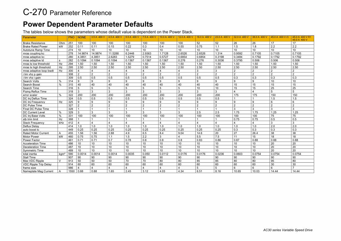
C-270 Parameter Reference
AC30 series Variable Speed Drive
Power Dependent Parameter Defaults The tables below shows the parameters whose default value is dependent on the Power Stack. Parameter PNO NONE 3.5 A 400 V 4.5 A 400 V 5.5 A 400 V 7.5 A 400 V 10.0 A 400 V 12.0 A 400 V 16.0 A 400 V 23.0 A 400 V 32.0 A 400 V 38.0 A 400 V 45.0 A 400 V r3 45.0 A 400 V R1
45.0 A 400 V Brake Resistance Ohm 251 100 100 100 100 100 100 100 52 52 26 26 17 17 Brake Rated Power kW 252 0.11 0.11 0.15 0.22 0.3 0.4 0.55 0.75 1.1 1.5 1.8 2.2 2.2 Autotune Ramp Time 274 10 10 10 10 10 10 10 10 10 10 10 10 10 mras coupling kc 278 14.9874 14.9874 11.5288 6.2448 2.9363 1.7128 2.6526 2.6526 1.314 0.9592 0.7105 0.7105 0.7105 mras adaptive kc 280 4.3851 4.3851 2.6283 1.5279 0.7514 0.5727 0.6854 0.6854 0.3198 0.3484 0.1792 0.1792 0.1792 mras adaptive td s 282 0.1094 0.1094 0.1094 0.1367 0.1367 0.1367 0.276 0.276 0.3036 0.3795 0.506 0.506 0.506 mras ls low threshold Hz 294 1.50 1.50 1.50 1.50 1.50 1.50 1.50 1.50 1.50 1.50 1.50 1.50 1.50 mras ls high threshold Hz 295 2.50 2.50 2.50 2.50 2.50 2.50 2.50 2.50 2.50 2.50 2.50 2.50 2.50 mras adaptive loop bwdt Hz 300 4 4 4 4 4 4 4 3 3 2 2 2 2 i lim vhz p gain 308 2 2 2 2 2 2 2 2 2 2 2 2 2 i lim vhz i gain 309 0.5 0.5 0.5 0.5 0.5 0.5 0.5 0.5 0.5 0.3 0.3 0.3 0.3 Search Volts % 314 9 9 9 9 9 9 9 9 9 9 9 10 10 Search Boost % 315 40 40 40 40 40 40 40 40 40 15 15 15 15 Search Time 316 5 5 5 5 5 5 5 10 10 15 15 25 25 Flying Reflux Time 318 3 3 3 3 3 3 3 3 3 4 4 5 5 error scaler % 322 200 200 200 200 200 200 200 200 200 175 175 150 150 DC Inj Deflux Time 324 0.5 0.5 0.5 0.5 0.5 0.5 0.5 0.5 0.5 1 1 1.5 1.5 DC Inj Frequency Hz 325 9 9 9 9 9 9 9 9 9 9 9 6 6 DC Pulse Time 327 2 2 2 2 2 2 2 2 2 2 2 2 2 Final DC Pulse Time 328 1 1 1 1 1 1 1 1 1 3 3 3 3 DC Current Level % 329 3 3 3 3 3 3 3 2.5 2.5 1.75 1.75 1.25 1.25 DC Inj Base Volts % 331 100 100 100 100 100 100 100 100 100 100 100 75 75 stb trim limit Hz 368 1 1 1 1 1 1 1 1 1 0.75 0.75 0.5 0.5 Stack Frequency kHz 412 4 4 4 4 4 4 4 4 4 4 4 3 3 Deflux Delay 414 1.0 1.0 1.0 1.0 1.0 1.0 1.0 1.0 1.0 1.0 1.0 2.0 2.0 auto boost tc 449 0.25 0.25 0.25 0.25 0.25 0.25 0.25 0.25 0.25 0.3 0.3 0.3 0.3 Rated Motor Current A 455 1.56 1.56 2.88 4.9 6.5 8.4 9.04 14.6 20 27 26.4 38 38 Motor Power kW 460 0.75 0.75 1.1 1.5 2.2 3 4 5.5 7.5 11 15 18 18 Power Factor 461 0.71 0.71 0.7 0.78 0.8 0.8 0.8 0.83 0.86 0.87 0.88 0.88 0.88 Acceleration Time 486 10 10 10 10 10 10 10 10 10 10 10 20 20 Deceleration Time 487 10 10 10 10 10 10 10 10 10 10 10 20 20 Symmetric Time 489 10 10 10 10 10 10 10 10 10 10 10 20 20 total inertia kgm² 590 0.0014 0.0014 0.0014 0.0035 0.050 0.0112 0.0176 0.0176 0.0236 0.0603 0.0754 0.0754 0.0754 Stall Time 907 90 90 90 90 90 90 90 90 90 90 90 90 90 Max VDC Ripple V 913 50 50 50 70 70 80 80 85 85 80 80 95 80 VDC Ripple Trip Delay 914 60 60 60 60 60 60 60 60 60 60 60 30 30 frame size 986 4 4 4 4 4 4 4 5 5 6 6 6 7 Nameplate Mag Current A 1550 0.88 0.88 1.65 2.45 3.12 4.03 4.34 6.51 8.16 10.65 10.03 14.44 14.44

Parameter Reference C-271
AC30 series Variable Speed Drive
Parameter PNO 60.0 A 400 V R1
60.0 A 400 V 73.0 A 400 V R1 73.0 A 400 V
87.0 A 400 V 105 A 400 V 145 A 400 V 180 A 400 V 205 A 400 V 260 A 400 V 315 A 400 V 380 A 400 V 440 A 400 V
Brake Resistance Ohm 251 17 17 8 8 8 4 4 4 0.75 0.75 0.75 Brake Rated Power kW 252 3.0 3.7 4.5 5.5 7.5 9 11 13.2 1.25 1.25 1.25 Autotune Ramp Time 274 10 10 10 10 10 20 20 20 2 2 2 mras coupling kc 278 0.5048 0.3553 0.2907 0.2428 0.1798 0.1453 0.127 0.1043 1 1 1 mras adaptive kc 280 0.305 0.2823 0.2974 0.2472 0.2226 0.1427 0.1343 0.1228 0.2 0.2 0.2 mras adaptive td s 282 0.3795 0.506 0.506 0.506 0.6073 0.6073 0.7591 1.5182 10 10 10 mras ls low threshold Hz 294 1.50 1.50 1.50 1.50 1.50 1.50 1.50 1.50 10 10 10 mras ls high threshold Hz 295 2.50 2.50 2.50 2.50 2.50 2.50 2.50 2.50 45 45 45 mras adaptive loop bwdt Hz 300 2 2 2 2 2 2 2 2 6 6 6 i lim vhz p gain 308 2 2 2 2 2 2 2 2 150 150 150 i lim vhz i gain 309 0.3 0.3 0.3 0.3 0.3 0.2 0.2 0.2 3 3 3 Search Volts % 314 10 10 10 10 10 10 10 10 4 4 4 Search Boost % 315 15 15 15 15 15 10 10 10 3 3 3 Search Time 316 25 25 30 30 30 40 40 40 5 5 5 Flying Reflux Time 318 5 5 6 6 6 6 6 6 1 1 1 error scaler % 322 150 150 150 150 150 150 150 150 50 50 50 DC Inj Deflux Time 324 1.5 1.5 3 3 3 3 3 3 0.5 0.5 0.5 DC Inj Frequency Hz 325 6 6 6 6 6 4 4 4 2 2 2 DC Pulse Time 327 2 2 2 2 2 3 3 3 6.0 8.0 8.0 Final DC Pulse Time 328 3 3 3 3 3 5 5 5 0.5 0.5 0.5 DC Current Level % 329 1.25 1.25 1.25 1.25 1.25 1 1 1 287 346 401 DC Inj Base Volts % 331 75 75 75 75 75 50 50 50 132 160 200 stb trim limit Hz 368 0.5 0.5 0.5 0.5 0.5 0.5 0.5 0.5 0.91 0.92 0.93 Stack Frequency kHz 412 3 3 2.5 2.5 2.5 2.5 2.5 2.5 50 50 50 Deflux Delay 414 2.0 2.0 3.0 3.0 3.0 3.5 3.5 3.5 50 50 50 auto boost tc 449 0.3 0.3 0.3 0.3 0.3 0.5 0.5 0.5 50 50 50 Rated Motor Current A 455 54 66 79 97 132 164 186 236 5.5 6.2 7 Motor Power kW 460 22 30 37 45 55 75 90 110 60 60 60 Power Factor 461 0.86 0.85 0.87 0.86 0.87 0.87 0.9 0.9 65 80 65 Acceleration Time 486 20 20 30 30 30 50 50 50 30 30 30 Deceleration Time 487 20 20 30 30 30 50 50 50 10 10 10 Symmetric Time 489 20 20 30 30 30 50 50 50 110 131 152 total inertia kgm² 590 0.1906 0.4750 0.7476 0.8904 1.4500 1.722 2.65 3.6 0.75 0.75 0.75 Stall Time 907 90 90 90 90 90 60 60 60 1.25 1.25 1.25 Max VDC Ripple V 913 80 80 80 80 80 80 80 80 2 2 2 VDC Ripple Trip Delay 914 30 30 30 30 30 30 30 30 1 1 1 frame size 986 7 7 8 8 8 9 9 9 0.2 0.2 0.2 Nameplate Mag Current A 1550 22.04 27.81 31.16 39.60 52.07 64 74 93 10 10 10

C-272 Parameter Reference
AC30 series Variable Speed Drive
Parameter PNO 530 A 400 V 590 A 400 V 650 A 400 V 700 A 400 V 790 A 400 V Brake Resistance Ohm 251 0.75 0.75 0.75 0.75 0.75 Brake Rated Power kW 252 1.25 1.25 1.25 1.25 1.25 Autotune Ramp Time 274 2 2 2 2 2 mras coupling kc 278 1 1 1 1 1 mras adaptive kc 280 0.2 0.2 0.2 0.2 0.2 mras adaptive td s 282 10 10 10 10 10 mras ls low threshold Hz 294 10 10 10 10 10 mras ls high threshold Hz 295 45 45 45 45 45 mras adaptive loop bwdt Hz 300 6 6 6 6 7 i lim vhz p gain 308 150 150 150 150 125 i lim vhz i gain 309 3 3 3 3 4 Search Volts % 314 4 4 4 4 3 Search Boost % 315 3 3 3 3 4 Search Time 316 5 5 5 5 7 Flying Reflux Time 318 1 1 1 1 1 error scaler % 322 50 50 50 50 50 DC Inj Deflux Time 324 0.5 0.5 0.5 0.5 0.35 DC Inj Frequency Hz 325 2 2 2 2 2 DC Pulse Time 327 10.0 10.0 12.0 12.0 12.0 Final DC Pulse Time 328 0.5 0.5 0.5 0.5 0.5 DC Current Level % 329 489 535 597 661 783 DC Inj Base Volts % 331 250 280 315 355 400 stb trim limit Hz 368 0.93 0.93 0.93 0.93 0.94 Stack Frequency kHz 412 50 50 50 50 50 Deflux Delay 414 50 50 50 50 50 auto boost tc 449 50 50 50 50 50 Rated Motor Current A 455 9.5 10 11 12.9 13.7 Motor Power kW 460 60 60 60 60 60 Power Factor 461 70 70 70 70 75 Acceleration Time 486 30 30 30 30 30 Deceleration Time 487 11 11 12 12 13 Symmetric Time 489 185 203 227 251 298 total inertia kgm² 590 0.75 0.75 0.75 0.75 0.75 Stall Time 907 1.25 1.25 1.25 1.25 1.25 Max VDC Ripple V 913 2 2 2 2 2 VDC Ripple Trip Delay 914 1 1 1 1 1 frame size 986 0.2 0.2 0.2 0.2 0.2 Nameplate Mag Current A 1550 10 10 10 10 10

AC30 Series Product Codes D-1
AC30 series Variable Speed Drive
Appendix D: AC30 Series Product CodesUnderstanding the Product Code The unit is fully identified using an alphanumeric code. This records how the inverter was calibrated, and its various settings when dispatched from the factory. This can also be referred to as the Product Code.
AC30 SERIES CONTROL MODULE
Typical example: 30V-2S-0000 (as shown in the “Order example” above). This shows the product is an AC30 series versatile controller, with Graphical Keypad fitted, standard 3C3 conformal coating and no special options. Note: This product code is for the control module only. The power stack must be ordered in addition to this (see page D-2).
1 2 3 4 530 V - 2 S - 0000
130 AC30 series control module only (no power stack)
2V Standard controllerP Advanced controllerD Advanced controller with dual encoder system optionA Advanced controller with absolute encoder system option
31 Blanking cover fitted2 Graphical keypad fitted
4S Standard 3C3 coating
50000 No special options
Order example
Special Options
Device Family
Industry
Graphical Keypad
Environmental Coating
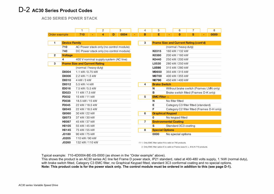
D-2 AC30 Series Product Codes
AC30 series Variable Speed Drive
AC30 SERIES POWER STACK
Typical example: 710-4D0004-BE-0S-0000 (as shown in the “Order example” above). This shows the product is an AC30 series AC line fed Frame D power stack, IP21 standard, rated at 400-480 volts supply, 1.1kW (normal duty), with brake switch fitted, Category C3 EMC filter, no Graphical Keypad fitted, standard 3C3 conformal coating and no special options. Note: This product code is for the power stack only. The control module must be ordered in addition to this (see page D-1).
1 2 4 5 6 7 8710 - 4 D 0004 - B E - 0 S - 0000
1 3710 AC Power stack only (no control module) (normal / heavy duty)740 DC Power stack only (no control module) K0315 160 kW / 132 kW
2 K0380 200 kW / 160 kW4 400 V nominal supply system (AC line) K0440 250 kW / 200 kW
3 L0530 280 kW / 250 kW(normal / heavy duty) L0590 315 kW / 280 kW
D0004 1.1 kW / 0.75 kW M0650 355 kW / 315 kWD0006 2.2 kW / 1.5 kW M0700 400 kW / 355 kWD0010 4 kW / 3 kW N0790 450 kW / 400 kWD0012 5.5 kW / 4 kW 4E0016 7.5 kW / 5.5 kW N Without brake switch (Frames LMN only)E0023 11 kW / 7.5 kW B Brake switch fitted (Frames D-K only)F0032 15 kW / 11 kW 5F0038 18.5 kW / 15 kW N No filter fitted F0045 22 kW / 18.5 kW E Category C3 filter fitted (standard) G0045 22 kW / 18.5 kW F Category C2 filter fitted (Frames D-H only)G0060 30 kW / 22 kW 6G0073 37 kW / 30 kW 0 No keypad fittedH0087 45 kW / 37 kW 7H0105 55 kW / 45 kW S Standard 3C3 coating H0145 75 kW / 55 kW 8J0180 90 kW / 75 kW 0000 No special optionsJ0205 110 kW / 90 kWJ0260 132 kW / 110 kW (1) 1. Only EMC filter option N is valid on 740 products.
(1) 2. Only EMC filter option E is valid on Frame sizes K, L, M & N 710 products.
Graphical Keypad
Environmental Coating
Special Options
Frame Size and Current Rating
Brake Switch
Frame Size and Current Rating (cont'd)
EMC Filter (1)
3Order example
Device Family
Voltage
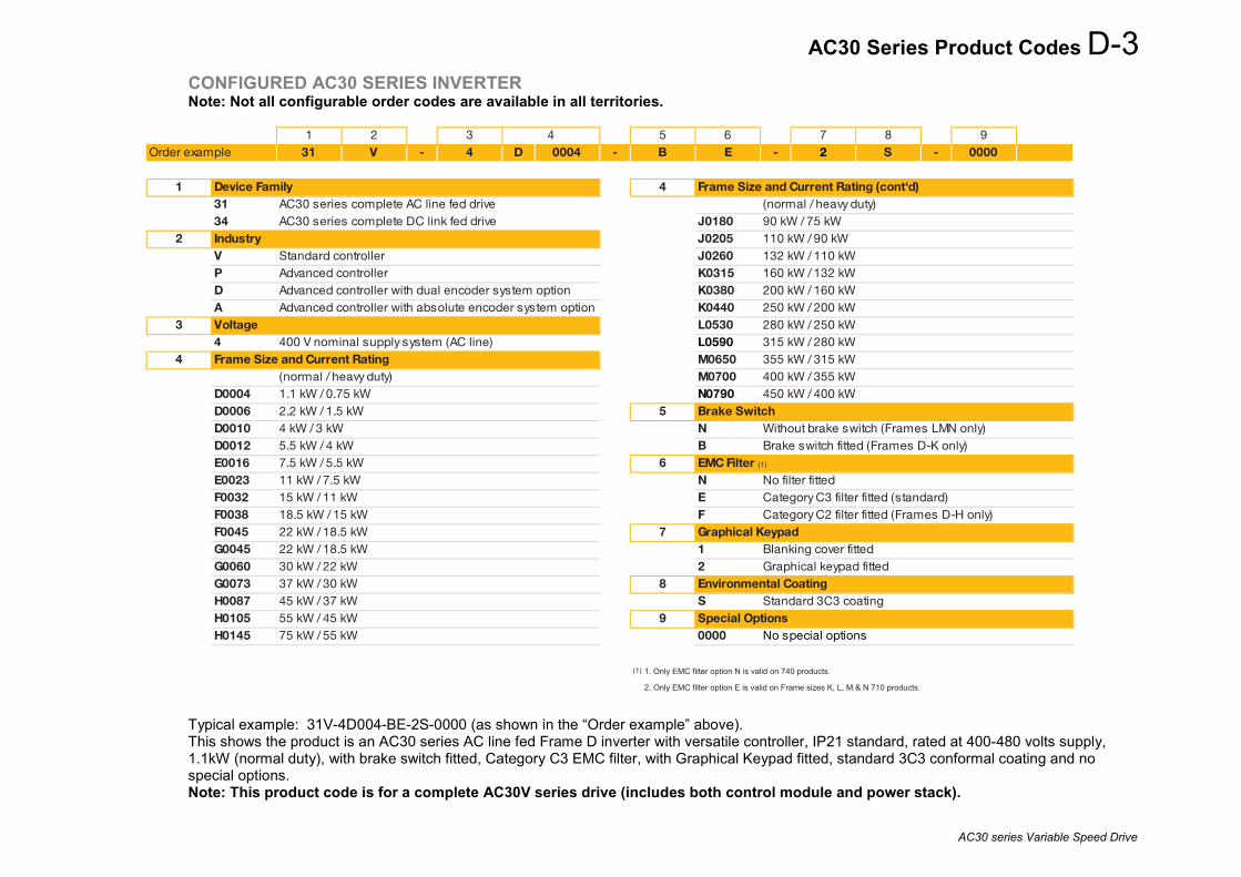
AC30 Series Product Codes D-3
AC30 series Variable Speed Drive
CONFIGURED AC30 SERIES INVERTER Note: Not all configurable order codes are available in all territories.
Typical example: 31V-4D004-BE-2S-0000 (as shown in the “Order example” above). This shows the product is an AC30 series AC line fed Frame D inverter with versatile controller, IP21 standard, rated at 400-480 volts supply, 1.1kW (normal duty), with brake switch fitted, Category C3 EMC filter, with Graphical Keypad fitted, standard 3C3 conformal coating and no special options. Note: This product code is for a complete AC30V series drive (includes both control module and power stack).
1 2 3 5 6 7 8 931 V - 4 D 0004 - B E - 2 S - 0000
1 431 AC30 series complete AC line fed drive (normal / heavy duty)34 AC30 series complete DC link fed drive J0180 90 kW / 75 kW
2 J0205 110 kW / 90 kWV Standard controller J0260 132 kW / 110 kWP Advanced controller K0315 160 kW / 132 kWD Advanced controller with dual encoder system option K0380 200 kW / 160 kWA Advanced controller with absolute encoder system option K0440 250 kW / 200 kW
3 L0530 280 kW / 250 kW4 400 V nominal supply system (AC line) L0590 315 kW / 280 kW
4 M0650 355 kW / 315 kW(normal / heavy duty) M0700 400 kW / 355 kW
D0004 1.1 kW / 0.75 kW N0790 450 kW / 400 kWD0006 2.2 kW / 1.5 kW 5D0010 4 kW / 3 kW N Without brake switch (Frames LMN only)D0012 5.5 kW / 4 kW B Brake switch fitted (Frames D-K only)E0016 7.5 kW / 5.5 kW 6E0023 11 kW / 7.5 kW N No filter fitted F0032 15 kW / 11 kW E Category C3 filter fitted (standard) F0038 18.5 kW / 15 kW F Category C2 filter fitted (Frames D-H only)F0045 22 kW / 18.5 kW 7G0045 22 kW / 18.5 kW 1 Blanking cover fittedG0060 30 kW / 22 kW 2 Graphical keypad fittedG0073 37 kW / 30 kW 8H0087 45 kW / 37 kW S Standard 3C3 coating H0105 55 kW / 45 kW 9H0145 75 kW / 55 kW 0000 No special options
(1) 1. Only EMC filter option N is valid on 740 products.
(1) 2. Only EMC filter option E is valid on Frame sizes K, L, M & N 710 products.
Graphical Keypad
Environmental Coating
Special Options
4Order example
Device Family
Industry
Frame Size and Current Rating
Voltage
Frame Size and Current Rating (cont'd)
Brake Switch
EMC Filter (1)

D-4 AC30 Series Product Codes
AC30 series Variable Speed Drive
AC30 SERIES REGENERATIVE SUPPLY UNIT
Typical example: 380-5R0094-NE-0000 (as shown in the “Order example” above). This shows the product is an AC30 series regenerative supply unit, rated at 400-500 volts supply, 94A output current rating – 60kW @ 500V, without a brake switch fitted, Category C3 compliant and no special options.
1 2 4 5 6380 - 5 R 0094 - N E - 0000
1 4380 AC30 series regenerative supply unit N Without brake switch (standard)
2 55 400 V - 500 V nominal E Category C3 compliant (standard)
3 60000 No special options
R0094 94 A / 60 kWR0157 157 A / 100 kWS0251 251 A / 160 kWS0394 394 A / 250 kWS0536 536 A / 340 kW
Output drive current rating / Nominal driving power @ 500V
Device Family
Voltage
Brake Switch
EMC Filter
Special OptionsFrame Size and Current Rating
3Order example

Library Function Blocks E-1
AC30 series Variable Speed Drive
Appendix E: Library Function Blocks
Introduction The AC30 drive is a highly flexible and configurable unit. While the functionality that is standard in the drive drive’s firmware is often adequate, this can be extended by writing additional code in the IEC6-1131-3 application. This appendix describes blocks that are made available as part of the AC30 libraries. These blocks can also be seen and selected in the list of blocks, typically visible to the right of the block diagram in PDQ and PDD, as shown below.
Other blocks shown in this area in PDQ represent collections of drive parameters. These parameters are described in Appendix C.

E-2 Library Function Blocks
AC30 series Variable Speed Drive
Function Block List BLOCKS IN “AC30 STANDARD” LIBRARY Abnormal Load Detect E-3 Application Alert E-6 Application Trips E-7 Application Trips Text E-8 Brake Control E-9 Data Logger Int E-11 Data Logger Real E-11 Filter E-13 Filter 2 E-13 Fire Mode E-14 Home E-15 KTY 84 130 Converter E-16
Linear Fit E-17 Linear Fit 2 E-18 Linear Ramp E-20 Minimum Speed2 E-22 NTC Thermistor Converter E-23 NTC Trip Levels E-24 PID E-25 Position E-27 Presets2 E-28 PT1000 Converter E-29 PT1000 Trip Levels E-29 Queued Write Control E-30
Queue Parameter Write E-30 Raise Lower E-32 Read Data From SD Card E-33 Sequencing Logic2 E-34 Skip Frequencies E-36 Speed Sensor Fault Ride Through E-38 S Ramp E-39 Time Of Day Select E-41 Welcome Screen E-43 Write Data to SD Card E-44 Write Data to SD Card V2 E-44 Zero Speed E-45

Library Function Blocks E-3
AC30 series Variable Speed Drive
Function Block Descriptions ABNORMAL LOAD DETECT The Abnormal Load Detect function block can be used to detect a sudden change in the behavior of the load. One use of this feature is described in the Pump Application manuals HA502134U001 and HA502134U005.
Parameters
Variable Description Speed_Demand The demanded speed in percent. Typically connected to parameter PNO 0500 Ramp Speed Output Actual_Load The measured or estimated load in percent. Typically connected to PNO 399 Actual Torque Running Set TRUE to indicate that the drive is running. Typically connected to the Running output from
Sequencing_Logic2. Enable Set TRUE to enable the feature Startup_Delay The duration from when the motor is started until the load monitoring is started. This allows for inaccurate
speed/load characterization and load estimation during start-up period. Fault_Delay The duration from when the load monitor detects a LOAD FAULT until the sequencer stops the motor. This allows
for inaccurate speed/load characterization and load estimation during start-up period. Speed These 10 parameters together with the 10 Load parameters below are used to characterize the expected load
curve for the actual Speed Load See above, Speed. Hi_Fault_Level The deviation of the actual load above the expected load which will cause a LOAD HIGH FAULT to be reported. Hi_Warning_Level The deviation of the actual load above the expected load which will cause a LOAD HIGH WARNING to be
reported. Lo_Warning_Level The deviation of the actual load below the expected load which will cause a LOAD LOW WARNING to be
reported.

E-4 Library Function Blocks
AC30 series Variable Speed Drive
Variable Description Lo_Fault_Level The deviation of the actual load below the expected load which will cause a LOAD LOW FAULT to be reported. Hi_Fault The actual Load is above Hi_Fault_Level. Hi_Warning The actual Load is above Hi_Warning_Level. Lo_Warning The actual Load is below Lo_Warning_Level. Lo_Fault The actual Load is below Lo_Fault_Level. State Reports whether the monitor is monitoring and, if so, if the Load is as expected. This is an enumerated value:
0 MONITORING DISABLED Either Enable is FALSE or Speed[0] = 0.0%. 1 MONITORING STOPPED Motor not running, so not monitoring. 2 MONITORING STARTING Motor started less than Startup_Delay ago, so not monitoring yet. 3 LOAD NORMAL The actual Load is within the expected range, so anomaly detected. 4 LOAD HIGH WARNING The actual Load is above Hi_Warning_Level but not higher than
Hi_Fault_Level. 5 LOAD LOW WARNING The actual Load is below Lo_Warning_Level but not lower than
Lo_Fault_Level. 6 LOAD HIGH FAULT The actual Load is above Hi_Fault_Level. 7 LOAD LOW FAULT The actual Load is below Lo_Fault_Level.
Expected_Load The calculated Load expected for the current Speed. This is determined from the load ‘curve’ specified by the Speed n and Load n parameters and is useful for checking if an unexpected warning or fault is reported.
Load_Error The difference between Actual Load and Expected Load. Delayed_Fault Indicates if actual Load has been above Hi_Fault_Level or below Lo_Fault_Level for longer than Fault_Delay.

Library Function Blocks E-5
AC30 series Variable Speed Drive
Functional Description An estimate of the expected Load for any given Speed is specified using the Speed n and Load n parameters. Each pair provide a point on the expected Load line. The Speed parameters must have increasing values. That is: Speed 1 < Speed 2 < Speed 3 < Speed 4 < Speed 5 < Speed 6 < Speed 7 < Speed 8 < Speed 9 < Speed 10. If not all points are required, a Speed may be set to zero to terminate the sequence. If the actual speed is greater than the last specified point, the line is extrapolated from the previous 2 points. Speed 1 must be non-zero, otherwise the abnormal load detection feature is disabled.
Load
%
Speed %
Speed 1 Speed 2 Speed 3 Speed 4
Load 4
Load 3
Load 2Load 1
Low Warning LevelLow Fault Level
High Warning LevelHigh Fault Level
The expected load line is defined by the entered Speed and Load values. The Warning and Fault detection threshold load lines are offset from the expected load line. The deviation from normal behavior is determined by the Hi_Fault_Level, Hi_Warning_Level, Lo_Warning_Level and Lo_Fault_Level parameters. For the feature to function correctly Hi_Fault_Level > Hi_Warning_Level > Lo_Warning_Level > Lo_Fault_Level. When running, the Load Monitor State diagnostic will show if the actual Load is in the NORMAL, WARNING or FAULT regions of the graph. If the actual Load remains in a FAULT region for longer than the duration specified by Fault Delay, the Drive will stop running. The Start Delay may be used to prevent incorrect warning or fault reports soon after the Run command is issued. The Load Monitor State diagnostic is reset when the Run command is removed.

E-6 Library Function Blocks
AC30 series Variable Speed Drive
APPLICATION ALERT The Application Alert function block may be used to create a message that will be displayed on the GKP.
Parameters
Variable Description ShowAlert The Alert is shown on the rising edge of this input ClearAlert Clear this alert. Acknowledging the alert on the GKP will also clear the alert. Line1 The text to show as the first line of the alert Line2 The text to show as the second line of the alert
Functional Description Create only one instance of the Application_Alert function block. The alert message is shown on the GKP, obscuring any other display except for a fault message. If more than one alert message is required, this can be achieved by selecting a different string for Line1 and Line2 while ShowAlert is FALSE. The message is latched on the GKP by the rising edge of the ShowAlert input.

Library Function Blocks E-7
AC30 series Variable Speed Drive
APPLICATION TRIPS The Application Trips feature may be used to generate a trip from the application. This is typically used to generate a trip in response to a fault detected in the process.
Parameters
Variable Description Trip_A1 to Trip_A8 The corresponding trip is active while this input is high. Application trip A1 corresponds to trip number 33.
Application trip A8 corresponds to trip number 40. Warning_A1 to Warning_A8
The corresponding trip warning is active while this input is high

E-8 Library Function Blocks
AC30 series Variable Speed Drive
APPLICATION TRIPS TEXT The Application Trips Text function block may be used in conjunction with the Application Trips function block to add customised text for the application trips and for the external trip.
Parameters
Variable Description Trip_A1_Text to Trip_A8_Text
Define alternative text for the application trip.
External_Trip_Text Define alternative text for the external trip.
Functional Description When a trip is detected, a message is displayed on the GKP in the form:
*** TRIPPED *** TRIP DESCRIPTION
The default text shown on the GKP and web page for the application trips is “33 A1” to “40 A8”. The default text for the external trip is “14 EXTERNAL TRIP”. The default text can be over-ridden by defining text using the Application Trips Text block. An alternate method to define alternate text for a trip is to use a custom language file. See application note “C013 Language Files” for details on how to create and use a custom language file.

Library Function Blocks E-9
AC30 series Variable Speed Drive
BRAKE CONTROL The Brake Control function block is used to control an electro-mechanical brake, typically in hoist and lift applications.
Parameters
Variable Description Enable Set to TRUE to enable the brake control feature. On_Load Load level in % at which the external motor brake is released. On_Frequency Output electrical frequency in Hz at which the external motor break is released. Off_Frequency Output electrical frequency in Hz at which the external motor break is applied. On_Hold_Time Duration of the pulse output on Hold when Release becomes TRUE. Off_Hold_Time Duration of the pulse output on Hold when Release becomes FALSE. Release Output to the brake. Release is forced false if Brake_Control is not enabled. Hold Becomes TRUE when Release changes from TRUE to FALSE or from FALSE to TRUE. It remains TRUE for the
duration set by On_Hold_Time and Off_Hold_Time. Load The load in %. Frequency The output electrical frequency in Hz.

E-10 Library Function Blocks
AC30 series Variable Speed Drive
Functional Description The operation of the Brake Control feature is illustrated below.

Library Function Blocks E-11
AC30 series Variable Speed Drive
DATA LOGGER INT
Parameters
Variable Description IntArrayAddr Address of the integer values to add to the data logger output. IntArrayLength Number of integer values to add to the data logger output. IntType Defines the integer type:
0 Signed 32-bit integer 1 Unsigned 32-bit integer 2 32-bit integer printed as a hexadecimal value.
Functional Description See below, Data Logger Real.
DATA LOGGER REAL
Parameters
Variable Description RealArrrayAddr Address of the real values to add to the data logger output. RealArrayLength Number of real values to add to the data logger output.

E-12 Library Function Blocks
AC30 series Variable Speed Drive
Functional Description The data logger blocks may be used to extend the parameters recorded by the standard data logger, refer to Appendix C. If it is necessary to log more than 8 parameters then the number of parameters to be logged may be increased to 40 in total, (an additional 32), by adding the Data_Logger_Int and / or the Data_Logger_Real blocks. The variables to be logged are to be gathered into an array of Long Integers, or an array of Reals and attached to the logger blocks, as illustrated here:
Here, the RealArray and IntArray variables are initialized with values, but in practice the values will be updated from application variables and fixed parameter values as part of the application program.

Library Function Blocks E-13
AC30 series Variable Speed Drive
FILTER FILTER 2 Filter_2 implements a single poll low pass filter. Filter_2 is identical to Filter, with a wider input range.
Parameters
Variable Description In The input value to be filtered, clamped to be between -32768.0 and 32768.0. TC The time constant with a range 0.01 to 300.00 seconds. Reset When TRUE, the internal filter variables are reset and Out is set to equal In. Out The output of the filter.
Functional Description The filter is implemented as a single poll filter. For a step change in the input, the time constant is the time the output takes to reach 63% of the change in the input value.
time
In
Out
t = TC
100%
63%
As with all blocks, the Filter_2 block is executed once each time the application is updated. The default application update rate is 5ms. The filter block will not operate correctly if the application update rate is longer than half the time constant.

E-14 Library Function Blocks
AC30 series Variable Speed Drive
FIRE MODE This block is used to configure the fire mode feature, detailed in chapter 9.
Parameters
Variable Description Activate Set to TRUE to enable Fire Mode according to the Fire Mode parameter. Intended to be connected to a digital
input. Setpoint A reference value to be used when Fire Mode is active. Setting a negative setpoint will cause the drive to rotate in
reverse direction. Default value 0.0%. Range -100% to 100%
Level An enumerated input parameter. Selects the mode of operation when Fire Mode is enabled 0. DISABLED 1. PARTIAL 2. FULL
Default value is DISABLED. Restart_Delay Specifies the time to wait before attempting to reset a trip. Activated Indicates when Fire Mode is active. This is TRUE when Level is either PARTIAL or FULL, the Setpoint is not 0.0%
and Activate is TRUE. Ready Indicates when Fire Mode will be activated if Activate is set TRUE. This is TRUE when Level is either PARTIAL or
FULL and the Setpoint is not 0.0%. Last_Activated Records the last time that the fire mode became active. This may be used to validate that the fire mode has been
tested. This value is recorded in non-volatile memory. The value will be reset if an application is loaded that does not implement Fire Mode.
Activation_Count Records the number of times the fire mode has become active. This value is saved in non-volatile memory. The activation count will be reset if an application is loaded that does not implement Fire Mode.
Functional Description The Fire Mode feature is described in Chapter 9.

Library Function Blocks E-15
AC30 series Variable Speed Drive
HOME To stop a drive in a set distance using a position loop.
Parameters
Variable Default Description Enable FALSE Changing Enable from FALSE to TRUE initiates a position home operation. Input 0.0 Speed input in %, limited internally to between -300.0% and 300.0%. Distance 1.0 Homing distance in revolutions: 1.0 corresponds to 65536 counts into PositionFromEncoder. Limited to
between 0.0 and 300.0 revolutions DistanceFine 0.0 Fine adjustment of homing distance. Limited to between 0.0 and 1.0 revolution. Gain 5.0 Gain of the position loop in closed loop homing. Limited to between 0.0 and 1000.0. CorrectionLimit 5.0 Maximum value of the closed loop position in %. Limited to between 0.0 and 100.0 %. DecelLimit 100.0 Maximum deceleration for Closed Loop homing. Limited to between 0.0 and 3000.0 %/s. PositionFromEncoder 0 Position feedback from the encoder, with a scaling of 65536 counts for 1 revolution Active Indicates that the homing feature is active. Output Speed demand in %. Connect this to a speed input, for example parameter PNO 1266 Speed Trim. Error TRUE if maximum deceleration exceeded ErrorCount Actual position error in counts, with 65536 = 1 revolution. Only valid when Homing is Active Done TRUE when position has been reached Deceleration Actual deceleration used during the Homing operation in %/s.
Functional Description For accurate positioning the drive must be in closed loop mode and the PositionFromEncoder input fed with position information If the drive is in any other mode, then an open loop home algorithm will be used The distance is set in revolutions, usually from a mark at a fixed distance from the home position. One revolution corresponding to 65536 counts on the PositionFromEncoder input. When using Home, the Output should override the System Ramp. When Home is not enabled, Output is set equal to Input, (with an update rate corresponding to the application update rate, default is 5ms).

E-16 Library Function Blocks
AC30 series Variable Speed Drive
KTY 84 130 CONVERTER KTY 84-130 conversion from resistance value to temperature in °C
Parameters
Variable Description Resistance Resistance of KTY thermistor in ohms Temperature Output, temperature in °C from resistance value input

Library Function Blocks E-17
AC30 series Variable Speed Drive
LINEAR FIT Linear approximation of an input to a general function.
Parameters
Variable Description Input Input value in percent. Expected to be in the range -100.0% to 100.0% M100PCNT Output value for -100.0% input M75PCNT Output value for -75.0% input M50PCNT Output value for -50.0% input M25PCNT Output value for -25.0% input _0PCNT Output value for 0.0% input P25PCNT Output value for 25.0% input P50PCNT Output value for 50.0% input P75PCNT Output value for 75.0% input P100PCNT Output value for 100.0% input Output The output value corresponding to Input.
Functional Description Performs a linear interpolation for inputs between these points. If Input is less than -100.0%, then Output is clamped to M100PCNT. Similarly, if Input is greater than 100.0%, then Output is clamped to P100PCNT.

E-18 Library Function Blocks
AC30 series Variable Speed Drive
LINEAR FIT 2 Linear approximation of an input to a general function.
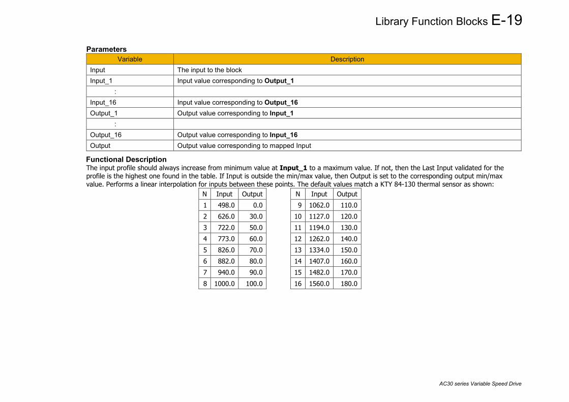
Library Function Blocks E-19
AC30 series Variable Speed Drive
Parameters Variable Description
Input The input to the block Input_1 Input value corresponding to Output_1 : Input_16 Input value corresponding to Output_16 Output_1 Output value corresponding to Input_1 : Output_16 Output value corresponding to Input_16 Output Output value corresponding to mapped Input
Functional Description The input profile should always increase from minimum value at Input_1 to a maximum value. If not, then the Last Input validated for the profile is the highest one found in the table. If Input is outside the min/max value, then Output is set to the corresponding output min/max value. Performs a linear interpolation for inputs between these points. The default values match a KTY 84-130 thermal sensor as shown:
N Input Output N Input Output 1 498.0 0.0 9 1062.0 110.0 2 626.0 30.0 10 1127.0 120.0 3 722.0 50.0 11 1194.0 130.0 4 773.0 60.0 12 1262.0 140.0 5 826.0 70.0 13 1334.0 150.0 6 882.0 80.0 14 1407.0 160.0 7 940.0 90.0 15 1482.0 170.0 8 1000.0 100.0 16 1560.0 180.0
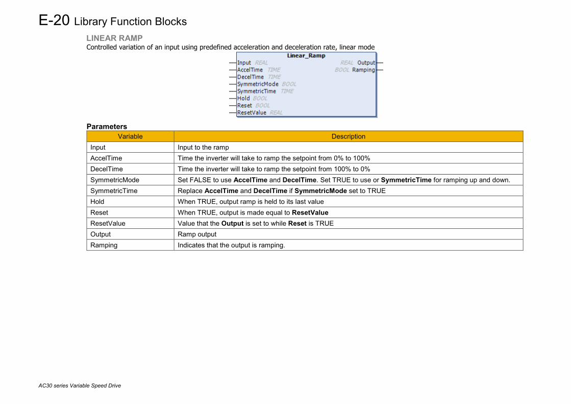
E-20 Library Function Blocks
AC30 series Variable Speed Drive
LINEAR RAMP Controlled variation of an input using predefined acceleration and deceleration rate, linear mode
Parameters
Variable Description Input Input to the ramp AccelTime Time the inverter will take to ramp the setpoint from 0% to 100% DecelTime Time the inverter will take to ramp the setpoint from 100% to 0% SymmetricMode Set FALSE to use AccelTime and DecelTime. Set TRUE to use or SymmetricTime for ramping up and down. SymmetricTime Replace AccelTime and DecelTime if SymmetricMode set to TRUE Hold When TRUE, output ramp is held to its last value Reset When TRUE, output is made equal to ResetValue ResetValue Value that the Output is set to while Reset is TRUE Output Ramp output Ramping Indicates that the output is ramping.

Library Function Blocks E-21
AC30 series Variable Speed Drive
Functional Description The linear ramp operates to ramp Output towards Input at a rate determined by AccelTime & DecelTime or SymmetricTime. Acceleration is defined as ramping away from zero. Deceleration is defined as ramping towards zero.
time
Input
Output
100%
t = AccelTime t = DecelTimeRamping

E-22 Library Function Blocks
AC30 series Variable Speed Drive
MINIMUM SPEED2 Determines how the reference will be followed.
Parameters
Variable Description Input The speed setpoint input as a percentage of maximum speed. Minimum The minimum limit, defaults to -100%. Mode Defines the minimum speed mode, see Functional Description below. Output The transformed speed setpoint output as a percentage of maximum speed.
Functional Description There are two operating modes for the MINIMUM SPEED function:
PROP WITH MINIMUM (proportional with minimum) In this mode the MINIMUM SPEED function behaves like a simple clamp. The Minimum Speed Value has the valid range -100% to 100% and the output is always greater than or equal to the Minimum Speed Value.
LINEAR In this mode the MINIMUM SPEED function first clamps the input to zero then rescales the input such that the output goes linearly between minimum and 100% for an input that goes from 0 to 100%. In both modes, note the constraints:
• Minimum >= -100 • Input >= -100 • Maximum = 100%
Min
0 100%
100
-100
input
output

Library Function Blocks E-23
AC30 series Variable Speed Drive
NTC THERMISTOR CONVERTER The NTC Thermistor Converter feature converts a resistance in ohms to a temperature in °C.
Parameters
Variable Description Resistance The measured resistance of the NTC thermistor in ohms. ReferenceTemperature The reference temperature for the NTC thermistor, usually 25 °C or 0 °C. ReferenceResistance The resistance of the NTC thermistor at the reference temperature. Beta The beta value for the NTC thermistor. Temperature The temperature corresponding to Resistance for the thermistor.
Functional Description The NTC Thermistor Converter uses the approximation formula
RT = RN * e β * (1/T – 1/TN)
or T = (1/ β * ln(RT/RN) + 1/TN)-1 Where:
• RT is the resistance at temperature T. • RN is the resistance at the reference temperature. • TN is the reference temperature • β is the beta value for the thermistor.

E-24 Library Function Blocks
AC30 series Variable Speed Drive
NTC TRIP LEVELS The NTC Trip Levels feature is designed to allow configuration of the thermistor trip block using temperature variables instead of the resistance values used by the drive parameters.
Parameters
Variable Description TripTemperature The temperature above which the thermistor trip should be active. WarningTemperature The temperature above which the thermistor temperature warning should be active. ReferenceTemperature The reference temperature for the NTC thermistor, usually 25 °C or 0 °C. ReferenceResistance The resistance of the NTC thermistor at the reference temperature. Beta The beta value for the NTC thermistor. ThermistorTripLevel The resistance in ohms corresponding to TripTemperature ThermistorWarnDelta The resistance in ohms corresponding to the difference between TripTemperature and WarningTemperature.
Functional Description The NTC Trip Levels block uses the approximation formula
RT = RN * e β * (1/T – 1/TN)
Where: • RT is the resistance at temperature T. • RN is the resistance at the reference temperature. • TN is the reference temperature • β is the beta value for the thermistor.
The outputs ThermistorTripLevel and ThermistorWarnDelta are designed to be connected to the Thermistor parameters, PNO1004 Thermistor Trip Level and PNO1762 Thermistor Warn Delta. This can be done in the application using the Thermistor_Input block.

Library Function Blocks E-25
AC30 series Variable Speed Drive
PID This function allows the AC30V to be used in applications requiring a trim to the reference, depending on feedback from an external measurement device. Typically, this will be used for process control, i.e. pressure or flow.
Parameters
Variable Description Setpoint The desired setpoint, typically connected to an Analog Input as part of the selected macro. Feedback The measured process variable, typically connected to an Analog Input as part of the selected macro. Enable Resets the PID output and integral term when FALSE. Enable must be TRUE for the PID to operate. Integral_Defeat Resets the p integral term when FALSE. Setpoint_Negate Changes the sign of the Setpoint input Feedback_Negate Changes the sign of the Feedback input Proportional_Gain This is the true proportional gain of the PID controller. When set to zero the PID_Output is zero. Integral_TC Integral term time constant Derivative_TC Derivative term time constant Output_Filter_TC Time constant for the first order filter applied to PID_Output. Output_Pos_Limit Upper limit on the output applied before the output scaling factor. Output_Neg_Limit Lower limit on the output applied before the output scaling factor. Output_Scaling Scaling factor applied to the output to create PID_Output PID_Output The output of the PID algorithm after limits and clamps. PID_Error Difference between Setpoint and Feedback, after negates. Limited to between -100.0 and 100.0

E-26 Library Function Blocks
AC30 series Variable Speed Drive
Functional Description The operation of the PID is as illustrated here.
Kp(1+sTi)(1+sTd)sTi(1+sTf)
D TIME CONST
I TIME CONST
P GAIN
ENABLE
INTEGRAL DEFEAT
X PID OUTPUT
OUTPUT NEG LIMIT
OUTPUT POS LIMIT OUTPUT SCALING
SETPOINT
FEEDBACK
SETPOINT NEGATE
FEEDBACK NEGATE
+100.00%
-100.00%
PID ERROR
sign change
sign change

Library Function Blocks E-27
AC30 series Variable Speed Drive
POSITION The Position FB counts the encoder position input from reset. It provides a scaled output. Counts input must be connected to an encoder count output.
Parameters
Variable Description Counts The input to the block, should be connected to the output counts from an encoder. Reset Reset Output to Zero and Scaled_Output to Preset when set to TRUE Preset The value to which Scaled_Output is set when Reset is TRUE Counts_Per_Unit The number of encoder counts that are equal to a Scaled_Output of 1.0 Limit_ A symmetric limit that clamps the value of Scaled_Output. Scaled_Output cannot be greater than Limit_ Output The number of encoder counts since the block was last reset. This output is preserved during power down of the
drive Scaled_Output An output scaled such as 1.0 = Counts / Counts_Per_Unit

E-28 Library Function Blocks
AC30 series Variable Speed Drive
PRESETS2 Selects one of 8 values.
Parameters
Variable Description Select Select which input to use as the Output, 0 to 7. Input_0 to Input_7 The discrete values to use for Output, depending on Select. Output Set to the selected input,
Functional Description The Preset block is used to select one of eight pre-defined values. If Select is set outside the range 0 … 7 then Output will be set to 0.0. The use of this block in the default application is shown in Appendix C

Library Function Blocks E-29
AC30 series Variable Speed Drive
PT1000 CONVERTER The PT1000 Converter feature converts a resistance in ohms to a temperature in °C for a PT1000 thermistor.
Parameters
Variable Description Resistance The measured resistance of the PT1000 thermistor in ohms. Temperature The temperature corresponding to Resistance for the thermistor.
Functional Description The PT1000 Converter uses the approximation formula
T = -244.91 + (0.23431 * R) + (0.000010623 * R2) Where:
• R is the resistance at temperature T.
PT1000 TRIP LEVELS The PT1000 Trip Levels feature is designed to allow configuration of the thermistor trip block using temperature variables instead of the resistance values used by the drive parameters.
Parameters
Variable Description TripTemperature The temperature above which the thermistor trip should be active. WarningTemperature The temperature above which the thermistor temperature warning should be active. ThermistorTripLevel The resistance in ohms corresponding to TripTemperature ThermistorWarnDelta The resistance in ohms corresponding to the difference between TripTemperature and WarningTemperature.
Functional Description The PT1000 Trip Levels block uses the approximation formula
R = 1000 + (3.9083 * T) - (0.0005775 * T2)
Where: • R is the resistance at temperature T.
The outputs ThermistorTripLevel and ThermistorWarnDelta are designed to be connected to the Thermistor parameters, PNO1004 Thermistor Trip Level and PNO1762 Thermistor Warn Delta. This can be done in the application using the Thermistor_Input block.
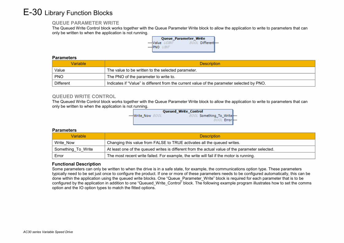
E-30 Library Function Blocks
AC30 series Variable Speed Drive
QUEUE PARAMETER WRITE The Queued Write Control block works together with the Queue Parameter Write block to allow the application to write to parameters that can only be written to when the application is not running.
Parameters
Variable Description Value The value to be written to the selected parameter. PNO The PNO of the parameter to write to. Different Indicates if “Value” is different from the current value of the parameter selected by PNO.
QUEUED WRITE CONTROL The Queued Write Control block works together with the Queue Parameter Write block to allow the application to write to parameters that can only be written to when the application is not running.
Parameters
Variable Description Write_Now Changing this value from FALSE to TRUE activates all the queued writes. Something_To_Write At least one of the queued writes is different from the actual value of the parameter selected. Error The most recent write failed. For example, the write will fail if the motor is running.
Functional Description Some parameters can only be written to when the drive is in a safe state, for example, the communications option type. These parameters typically need to be set just once to configure the product. If one or more of these parameters needs to be configured automatically, this can be done within the application using the queued write blocks. One “Queue_Parameter_Write” block is required for each parameter that is to be configured by the application in addition to one “Queued_Write_Control” block. The following example program illustrates how to set the comms option and the IO option types to match the fitted options.

Library Function Blocks E-31
AC30 series Variable Speed Drive
PROGRAM PLC_PRG VAR {attribute 'device_parameter' := '1178'} io_option_required : USINT; (* For information only *) {attribute 'device_parameter' := '1179'} io_option_fitted : USINT; {attribute 'device_parameter' := '44'} comms_option_required : USINT; (* For information only *) {attribute 'device_parameter' := '45'} comms_option_fitted : USINT; Queue_Parameter_Write_1178 : Queue_Parameter_Write; Queue_Parameter_Write_44 : Queue_Parameter_Write; END_VAR
This CFC diagram shows an example where Queued_Write_Control is activated automatically if either of the queued parameter values is different from the value in the drive. In this example the drive has no IO option fitted and a DEVICEnet communications option. Initially the required comms option is set to NONE, but this is automatically set to match the actual option fitted when the application starts. The queued write control feature works by stopping the application, executing the queued parameter writes then starting the application. This feature is not suitable for writing to parameters that may need to be frequently changed while the application is running. The feature will fail if the drive is running, (actively controlling a motor), as it is not permitted to stop the application in this case.

E-32 Library Function Blocks
AC30 series Variable Speed Drive
RAISE LOWER The Raise/Lower function acts as an internal motorized potentiometer (MOP) used as a reference source.
Parameters
Variable Description Raise When TRUE and Lower is FALSE, Output is ramped up to Maximum_Value Lower When TRUE and Raise is FALSE, Output is ramped down to Minimum_Value Reset When TRUE forces Output to track Reset Value, Ramp_Time Rate of change of the Output. Defined as the time to change from 0.00% to 100.00%. Note that the raise and
lower rates are always the same. Reset_Value Output is set to Reset_Value when Reset is TRUE. Maximum_Value The maximum value to which Output will ramp up to. If Minimum_Value is greater than Maximum_Value then
Output is set to Maximum_Value. Minimum_Value The minimum value to which Output will ramp down to. If Minimum_Value is greater than Maximum_Value then
Output is set to Maximum_Value. Output The output of the Raise Lower block, typically used as the motor speed setpoint.
Functional Description The table below describes how Output is controlled by Raise, Lower and Reset. Reset Raise Lower Action TRUE Any Any Output tracks Reset Value, clamped between Minimum_Value and Maximum_Value. FALSE TRUE FALSE Output ramps up to Maximum Value at Ramp Time FALSE FALSE TRUE Output ramps down to Minimum Value at Ramp Time FALSE FALSE FALSE Output not changed. * FALSE TRUE TRUE Output not changed. *
* If Output is greater than Maximum Value the Output will ramp down to Maximum Value at Ramp Time. If Output is less than Minimum Value the Output will ramp up to Minimum Value at Ramp Time.
If Maximum Value is less than or equal to Minimum Value, then Output is set to Maximum Value. The use of this block in the default application is described in Appendix C.

Library Function Blocks E-33
AC30 series Variable Speed Drive
READ DATA FROM SD CARD The Read_Data_From_SD_Card may be used to read a block of binary data from an SD Card into memory in the AC30 drive.
Parameters
Variable Description File_Name The name of the file on the SD Card. The file must be in the root of the SD Card. File_Offset The offset from the start of the file to start reading from. If the offset is beyond the end of the file then Bytes_Read
will return zero. Destination_Address The address of the buffer into which the data is to be read. This must be at least as long as the value in
Bytes_To_Read. Bytes_To_Read The number of bytes to attempt to read from the SD Card. Read_Now Changing this input from FALSE to TRUE starts the read. Changing Read_Now to FALSE before the read is
completed will abort the read. Typically, Read_Now should be set back to FALSE only when the read is complete.
Reading TRUE while the read is in progress. Bytes_Read Indicates how many bytes were read from the SD Card once the read is complete. Completed When TRUE, indicates that the read attempt has completed. This value is reset to FALSE when Read_Now is set
back to FALSE. Failed When TRUE, indicates that the read attempt failed. This value is reset to FALSE when Read_Now is set back to
FALSE.
Functional Description This block is intended for applications where a significant amount of data is required that is too large to be built into the application, or that needs to be updated independently from the application. An example that may make use of this feature could be a set of thermocouple linearization curves. Each curve could consist of 100 co-ordinates representing milli-volts and temperature. Saving each co-ordinate as a pair of REAL numbers would take 8 bytes per co-ordinate, or 800 bytes for the entire curve. Curves for 10 thermocouples would then create a file on the SD Card that would be 8000 bytes in size. Data for the first thermocouple would start at offset 0, the second would start at offset 800, e.t.c. To use the data, it needs to read into an array of 200 REAL values. The use of the data in the array must match the organization of the data in the file.

E-34 Library Function Blocks
AC30 series Variable Speed Drive
SEQUENCING LOGIC2 The Sequencing Logic2 block provides a simple interface to the sequencing logic in the drive for the application. The block interacts with parameters PNO 0610 App Control Word and PNO 0661 Status Word.
Parameters
Variable Description Run_Forward Combined with Run_Reverse and Jog to control bit 3 of App Control Word, Enable Operation. Run_Reverse Combined with Run_Reverse and Jog to control bit 3 of App Control Word, Enable Operation. Reverse Maps directly to bit 13 of App Control Word, Reverse Direction Jog Combined with Run_Forward and Run_Reverse to control bit 3 of App Control Word, Enable Operation. Not_Stop When TRUE latches the Run Forward and Run Reverse inputs. Enable Maps directly to bit 1 of App Control Word, Coast Stop, OFF2 Not_Coast_Stop Maps directly to bit 0 of App Control Word, Switch On, OFF1 Not_Quick_Stop Maps directly to bit 2 of App Control Word, Not Quickstop, OFF3 Trip_Reset Maps directly to bit 7 of App Control Word, Reset Fault. External_Trip Maps directly to bit 8 of App Control Word, External Fault Trip_Reset_By_Run When TRUE the Sequencing Logic2 will attempt to clear a trip by toggling bit 7 of App Control Word as part of the
start-up sequence. Power_Up_Start Inverted, then mapped to bit 15 of App Control Word, Event Triggered Operation
Setting Power_Up_Start could cause the motor to start unexpectedly.
Running Mapped directly from bit 2 of Status Word, Operation Enabled Tripped Mapped directly from bit 3 of Status Word, Faulted
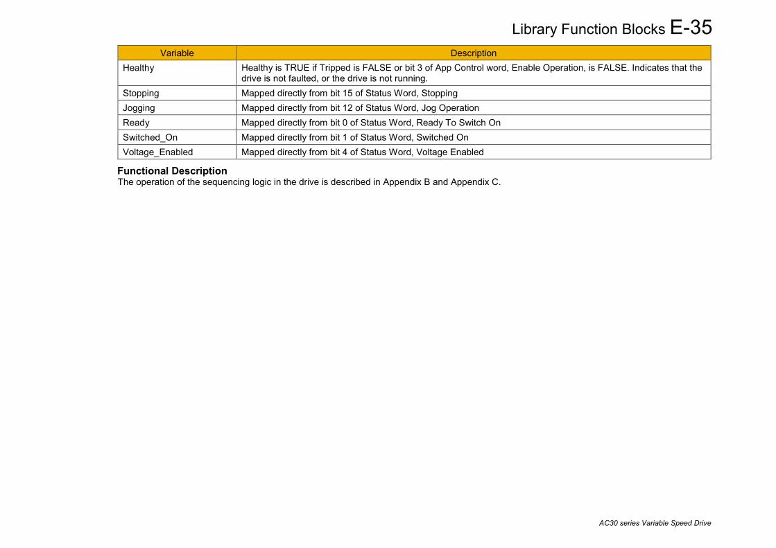
Library Function Blocks E-35
AC30 series Variable Speed Drive
Variable Description Healthy Healthy is TRUE if Tripped is FALSE or bit 3 of App Control word, Enable Operation, is FALSE. Indicates that the
drive is not faulted, or the drive is not running. Stopping Mapped directly from bit 15 of Status Word, Stopping Jogging Mapped directly from bit 12 of Status Word, Jog Operation Ready Mapped directly from bit 0 of Status Word, Ready To Switch On Switched_On Mapped directly from bit 1 of Status Word, Switched On Voltage_Enabled Mapped directly from bit 4 of Status Word, Voltage Enabled
Functional Description The operation of the sequencing logic in the drive is described in Appendix B and Appendix C.
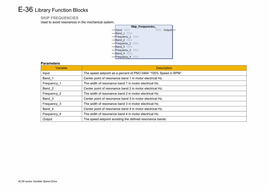
E-36 Library Function Blocks
AC30 series Variable Speed Drive
SKIP FREQUENCIES Used to avoid resonances in the mechanical system.
Parameters
Variable Description Input The speed setpoint as a percent of PNO 0464 “100% Speed in RPM”. Band_1 Center point of resonance band 1 in motor electrical Hz. Frequency_1 The width of resonance band 1 in motor electrical Hz. Band_2 Center point of resonance band 2 in motor electrical Hz. Frequency_2 The width of resonance band 2 in motor electrical Hz. Band_3 Center point of resonance band 3 in motor electrical Hz. Frequency_3 The width of resonance band 3 in motor electrical Hz. Band_4 Center point of resonance band 4 in motor electrical Hz. Frequency_4 The width of resonance band 4 in motor electrical Hz. Output The speed setpoint avoiding the defined resonance bands.

Library Function Blocks E-37
AC30 series Variable Speed Drive
Functional Description Four programmable skip frequencies are available to avoid resonances within the mechanical system. Enter the value of frequency that causes the resonance using a Frequency parameter and then program the width of the skip band using its Band parameter. The Drive will then avoid sustained operation within the forbidden band as shown in the diagram. The skip frequencies are symmetrical and thus work in forward and reverse. Setting a Frequency to 0 disables the corresponding band. Setting a Band to 0 causes the value of Band 1 to be used for this band.
When two or more bands overlap, the bands are effectively combined into a single larger range to avoid, as illustrated below.
The operation of the Skip Frequencies block in the default application is described in Appendix C.
Skip band
Skip Frequency Setpoint
DriveFrequency
Setpoint
DriveFrequency
Frequency 1 Frequency 2 Setpoint
DriveFrequency
Frequency 1 Frequency 2

E-38 Library Function Blocks
AC30 series Variable Speed Drive
SPEED SENSOR FAULT RIDE THROUGH Allows switching automatically to sensorless operation in case of a speed sensor failure
Parameters
Variable Default Description enable_switchover TRUE Enables/disables the ability to automatically switch to sensorless operation. Configures drive
parameter PNO 1701 Switchover Enable in the MRAS block switchover_rpm_threshold 300.0 Speed level in RPM required as difference between encoder and estimator to trigger switch. speed_sensor_warning TRUE if switch has occurred. feedback_speed_RPM Feedback speed value that is used in the control loops encoder_option_speed_RPM Encoder speed measurement - from option estimator_speed_RPM Estimator speed measurement encoder_slot1_speed_RPM Encoder speed measurement - from system board slot 1 encoder_slot2_speed_RPM Encoder speed measurement - from system board slot 2
Functional Description The Speed Sensor Fault Ride Through feature allows the drive to automatically, and as seamlessly as possible, continue operating in sensorless mode in case of an encoder failure. The MRAS estimator tracks the speed of the motor even if the drive uses an encoder as its primary feedback for control. If the discrepancy between the speed measured by the encoder and the estimated speed is greater than switchover_rpm_threshold it is assumed that the encoder has malfunctioned, and control will automatically be transferred to use estimated speed as its feedback signal. The drive will continue to work in sensorless mode until the next stop cycle. There will be no attempt to ‘reconnect’ the encoder on the fly even if its signal recovers. Upon the move to sensorless operation speed_sensor_warning is set TRUE. The switchover will not be performed, even if enabled
• during autotune sequence • if flycatching is enabled until the estimator converges to correct speed (typically within first 50-100ms after starting the drive), and until
the motor has accelerated to 95% of its initial speed setpoint. • if the setpoint speed is lower than switchover_rpm_threshold.

Library Function Blocks E-39
AC30 series Variable Speed Drive
S RAMP Controlled variation of an input using predefined acceleration and deceleration rate, using S ramp shape
Parameters
Variable Description Input Input to the ramp. Limited to between -100.0 and 100.0 %. Acceleration Acceleration rate in units of % per s² Deceleration Deceleration rate in units of % per s² Jerk_1 Rate of change of acceleration part1 Jerk_2 Rate of change of acceleration part2 Jerk_3 Rate of change of acceleration part3 Jerk_4 Rate of change of acceleration part4 Continuous When TRUE, forces a smooth transition if the ramp input is changed when ramping. The
curve is controlled by the Acceleration and Jerk_1 to Jerk_4 parameters. When FALSE, there is an immediate transition from the old curve to the new curve.
Hold When TRUE, the output of the ramp is help at its last value Reset When TRUE, Output = ResetValue ResetValue Value used for Output when Reset is TRUE. Output Output of the ramp. Ramping TRUE when ramping.
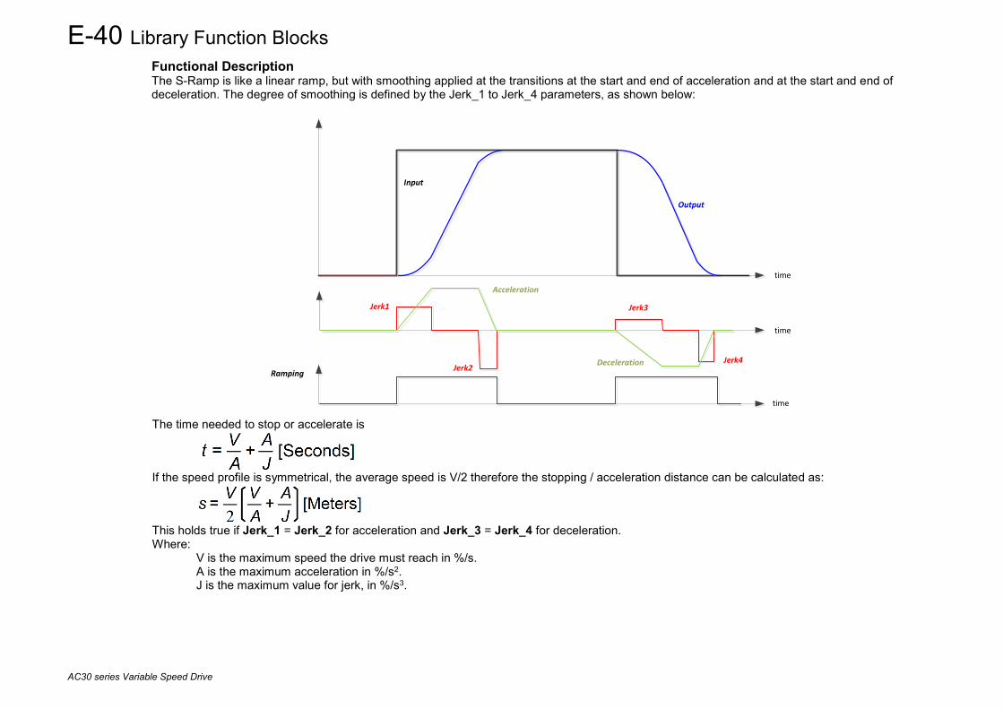
E-40 Library Function Blocks
AC30 series Variable Speed Drive
Functional Description The S-Ramp is like a linear ramp, but with smoothing applied at the transitions at the start and end of acceleration and at the start and end of deceleration. The degree of smoothing is defined by the Jerk_1 to Jerk_4 parameters, as shown below:
time
Input
Output
Ramping
Acceleration
Deceleration
Jerk1
Jerk2
Jerk3
Jerk4
time
time
The time needed to stop or accelerate is
If the speed profile is symmetrical, the average speed is V/2 therefore the stopping / acceleration distance can be calculated as:
This holds true if Jerk_1 = Jerk_2 for acceleration and Jerk_3 = Jerk_4 for deceleration. Where: V is the maximum speed the drive must reach in %/s. A is the maximum acceleration in %/s2. J is the maximum value for jerk, in %/s3.
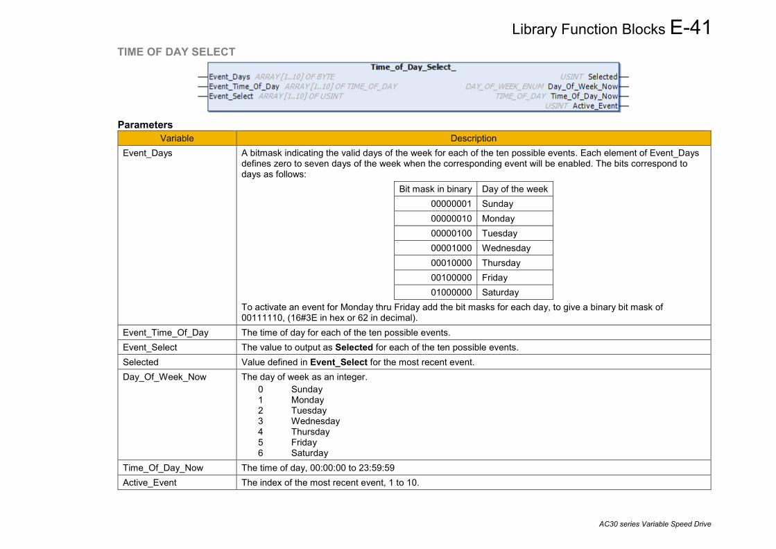
Library Function Blocks E-41
AC30 series Variable Speed Drive
TIME OF DAY SELECT
Parameters
Variable Description Event_Days A bitmask indicating the valid days of the week for each of the ten possible events. Each element of Event_Days
defines zero to seven days of the week when the corresponding event will be enabled. The bits correspond to days as follows:
Bit mask in binary Day of the week 00000001 Sunday 00000010 Monday 00000100 Tuesday 00001000 Wednesday 00010000 Thursday 00100000 Friday 01000000 Saturday
To activate an event for Monday thru Friday add the bit masks for each day, to give a binary bit mask of 00111110, (16#3E in hex or 62 in decimal).
Event_Time_Of_Day The time of day for each of the ten possible events. Event_Select The value to output as Selected for each of the ten possible events. Selected Value defined in Event_Select for the most recent event. Day_Of_Week_Now The day of week as an integer.
0 Sunday 1 Monday 2 Tuesday 3 Wednesday 4 Thursday 5 Friday 6 Saturday
Time_Of_Day_Now The time of day, 00:00:00 to 23:59:59 Active_Event The index of the most recent event, 1 to 10.
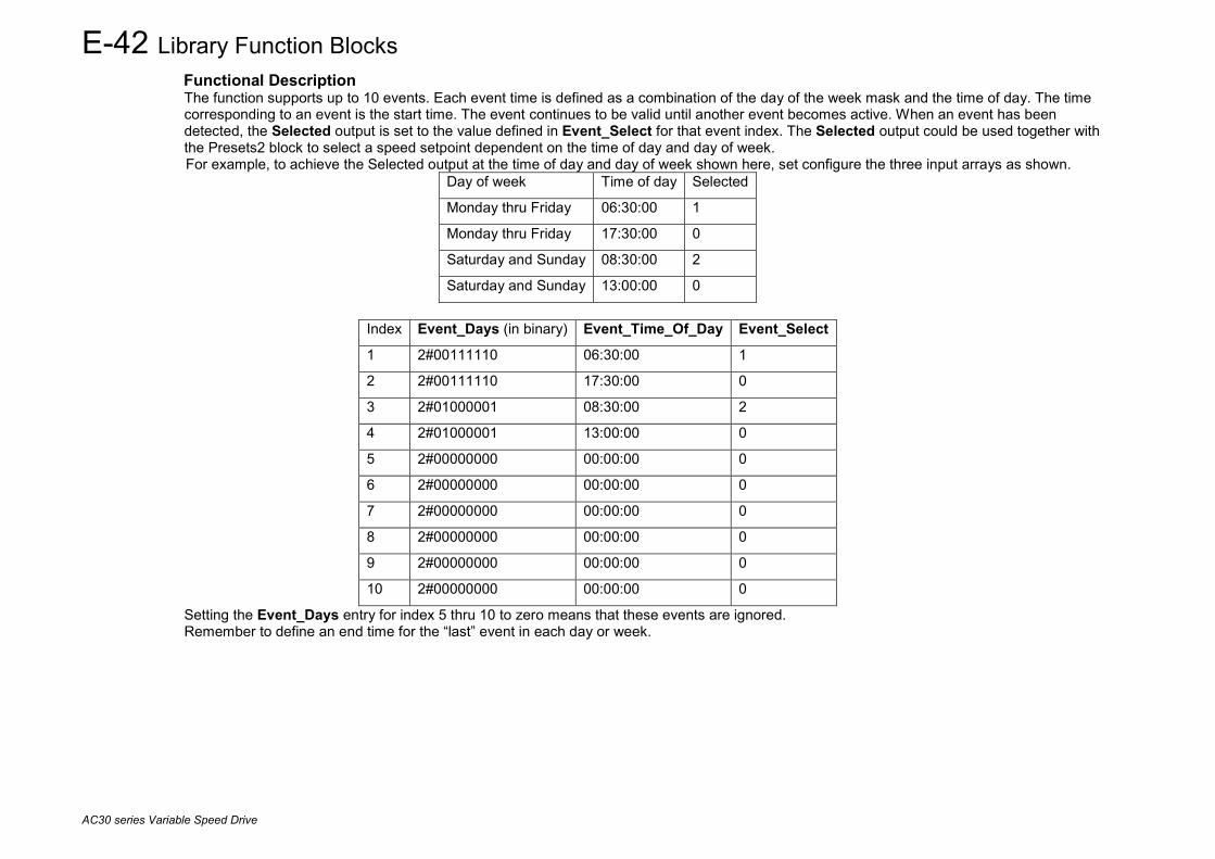
E-42 Library Function Blocks
AC30 series Variable Speed Drive
Functional Description The function supports up to 10 events. Each event time is defined as a combination of the day of the week mask and the time of day. The time corresponding to an event is the start time. The event continues to be valid until another event becomes active. When an event has been detected, the Selected output is set to the value defined in Event_Select for that event index. The Selected output could be used together with the Presets2 block to select a speed setpoint dependent on the time of day and day of week. For example, to achieve the Selected output at the time of day and day of week shown here, set configure the three input arrays as shown.
Day of week Time of day Selected
Monday thru Friday 06:30:00 1
Monday thru Friday 17:30:00 0
Saturday and Sunday 08:30:00 2
Saturday and Sunday 13:00:00 0
Index Event_Days (in binary) Event_Time_Of_Day Event_Select
1 2#00111110 06:30:00 1
2 2#00111110 17:30:00 0
3 2#01000001 08:30:00 2
4 2#01000001 13:00:00 0
5 2#00000000 00:00:00 0
6 2#00000000 00:00:00 0
7 2#00000000 00:00:00 0
8 2#00000000 00:00:00 0
9 2#00000000 00:00:00 0
10 2#00000000 00:00:00 0
Setting the Event_Days entry for index 5 thru 10 to zero means that these events are ignored. Remember to define an end time for the “last” event in each day or week.
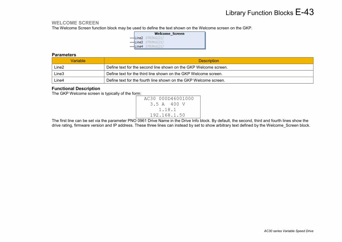
Library Function Blocks E-43
AC30 series Variable Speed Drive
WELCOME SCREEN The Welcome Screen function block may be used to define the text shown on the Welcome screen on the GKP.
Parameters
Variable Description Line2 Define text for the second line shown on the GKP Welcome screen. Line3 Define text for the third line shown on the GKP Welcome screen. Line4 Define text for the fourth line shown on the GKP Welcome screen.
Functional Description The GKP Welcome screen is typically of the form:
AC30 000D46001000 3.5 A 400 V 1.18.1 192.168.1.50
The first line can be set via the parameter PNO 0961 Drive Name in the Drive Info block. By default, the second, third and fourth lines show the drive rating, firmware version and IP address. These three lines can instead by set to show arbitrary text defined by the Welcome_Screen block.

E-44 Library Function Blocks
AC30 series Variable Speed Drive
WRITE DATA TO SD CARD WRITE DATA TO SD CARD V2 The Write_Data_To_SD_Card block can be used to save data from the application to a file on the SD Card.
Parameters
Variable Description File_Name The name of the file on the SD Card. The file must be in the root of the SD Card. Source_Address The address of the buffer from which the data is to be taken. This must be at least as long as Bytes_To_Write. Bytes_To_Write The number of bytes to add to the file. Write_Now Changing this value from FALSE to TRUE starts the write. Changing Write_Now to FALSE before the write is
completed will abort the operation. Typically, Write_Now should be set back to FALSE only when the write is complete.
Create_New Set TRUE before starting the write to force creation of a new file. If this parameter is FALSE then a new file will be created if File_Name does not exist on the SD Card. Otherwise the data will be appended to the end of the existing file.
Writing Indicates that the write operation is in progress. Bytes_Written Indicates the number of bytes written. This parameter is only valid once the operation is completed. Completed Indicates that the write operation has finished. Failed When TRUE, indicates that the write attempt failed. This value is reset to FALSE when Write_Now is set back to
FALSE.
Functional Description This block is intended for applications that need to record data for future analysis. The feature is of especial interest for remote installations where such data cannot be extracted by a local supervisory system. When designing the configuration, it should be noted that the write process can take 10s of milli-seconds. It is more efficient to occasionally write several hundred bytes of data than to frequently write a few tens of bytes. The write frequency needs to be balanced against the possibility of data loss due to a power failure.

Library Function Blocks E-45
AC30 series Variable Speed Drive
ZERO SPEED To detect if the speed is at or close to Zero, using threshold and hysteresis parameters
Parameters
Variable Description Hysteresis Defines a hysteresis band about which the outputs are stable.
If Hysteresis is >= Threshold then the On level is set to 2 times Hysteresis and the Off level is set to zero. Otherwise the On level is (Threshold + Hysteresis) and the Off level is (Threshold – Hysteresis).
Threshold The nominal level below which the outputs are set AtZeroSpeedFeedback TRUE when at zero speed, as defined by Threshold and Hysteresis.
AtZeroSpeedDmd TRUE when the speed demand is zero, as defined by Threshold and Hysteresis. AtStandstill TRUE when both AtZeroSpeedFeedback and AtZeroSpeedDmd are TRUE.

E-46 Library Function Blocks
AC30 series Variable Speed Drive
Functional Description The outputs AtZeroSpeedFeedback and AtZeroSpeedDmd are set according to the rule:
• FALSE if (abs(speed feedback) > On level). • TRUE if (abs(speed feedback) <= OFF level). • If neither of the above conditions is met, then the output is unchanged.
The example below illustrates the behavior when Hysteresis is 0.2%.

Index 1
AC30 series Variable Speed Inverter
Index 0001 5-4, 6-4, C-94, C-230, C-232, C-266 0002 5-4, 6-4, C-94, C-95, C-232, C-266 0003 5-4, 6-4, C-95, C-232, C-266 0004 5-4, 6-4, C-96, C-232, C-266 0005 5-5, A-50, C-103, C-230, C-232, C-267 0006 C-97, C-103 0007 C-103 0008 C-103 0009 C-103 0010 C-103 0011 C-103 0012 C-103 0013 C-103 0014 C-103 0015 C-103 0016 C-103 0017 C-103 0018 C-103 0019 C-103 0020 C-103 0022 5-5, C-102, C-232, C-267 0023 C-102 0024 C-102 0025 C-102 0026 C-102 0027 C-102 0028 C-102 0031 C-102 0032 C-102 0033 C-102 0034 C-102 0037 C-102 0038 C-102 0039 5-5, C-94, C-104, C-233, C-266 0040 5-5, C-104, C-233, C-266 0041 5-5, C-95, C-104, C-233, C-266 0042 5-5, C-95, C-96, C-104, C-233, C-266 0043 5-5, C-96, C-104, C-233, C-266 0044 5-4, 6-6, 6-7, 7-13, C-233, C-267 0045 5-6, 7-16, C-233, C-267
0046 C-233, C-267 0047 5-6, C-233, C-267 0048 5-5, 6-6, 6-7, C-233, C-267 0049 5-6, C-233, C-267 0050 5-6, C-233, C-267 0051 5-6, C-233, C-267 0052 5-6, C-233, C-267 0053 5-6, C-233, C-267 0054 5-6, C-233, C-267 0055 5-5, C-233, C-269 0056 C-233, C-269 0114 8-31, C-234, C-268 0115 C-226, C-234, C-269 0116 C-226, C-234, C-269 0117 C-187, C-234, C-267 0118 C-14, C-234, C-267 0119 C-70, C-234, C-267 0120 5-5, C-234, C-270 0121 C-234, C-270 0123 A-3 0182 C-121, C-235, C-266 0183 C-121, C-235, C-266 0184 C-121, C-235, C-266 0185 C-235, C-267 0186 5-6, C-235, C-267 0187 C-235, C-267 0188 C-235, C-267 0189 5-6, C-235, C-268 0195 5-6, C-235, C-268 0196 5-6, C-235, C-268 0197 5-6, C-235, C-268 0198 5-6, C-235, C-268 0199 5-5, 6-7, C-235, C-266 0200 5-5, 6-7, C-235, C-267 0201 5-5, 6-7, C-235, C-267 0202 5-5, 6-7, C-235, C-267 0203 5-5, 6-7, C-235, C-268 0204 5-5, C-235, C-270 0205 5-5, C-235, C-268 0206 5-5, C-235, C-268
0207 5-5, C-235, C-268 0208 5-6, C-235, C-266 0209 5-4, C-235, C-266 0210 5-4, C-235, C-266 0211 5-6, C-235, C-267 0212 5-4, 6-6, C-235, C-267 0213 5-5, 6-6, C-235, C-267 0214 5-6, C-236, C-267 0215 5-5, C-236, C-267 0216 5-5, C-236, C-267 0217 5-5, C-236, C-267 0218 5-6, C-236, C-267 0219 5-5, 6-7, C-236, C-267 0220 5-5, 6-7, C-236, C-267 0221 5-6, C-236, C-267 0222 5-5, C-236, C-267 0223 5-5, C-236, C-267 0224 5-6, C-236, C-267 0225 5-6, C-236, C-267 0226 5-5, C-236, C-267 0227 5-5, C-236, C-267 0228 5-6, C-236, C-268 0229 5-5, 6-7, C-236, C-268 0230 5-5, 6-7, C-236, C-268 0231 5-5, 6-7, C-236, C-268 0232 5-5, 6-7, C-236, C-268 0233 5-5, 6-7, C-236, C-268 0234 5-6, C-236, C-268 0235 5-5, C-236, C-268 0236 5-5, C-236, C-268, C-271 0237 5-6, C-236, C-269 0238 5-5, 6-7, C-236, C-269 0239 5-6, C-237, C-269 0240 5-6, C-237, C-269 0249 C-27, C-237, C-266 0251 C-27, C-237, C-266 0252 C-27, C-237, C-266 0253 C-27, C-237, C-266 0254 C-27, C-237, C-266 0255 5-3, 6-8, C-21, C-237, C-266
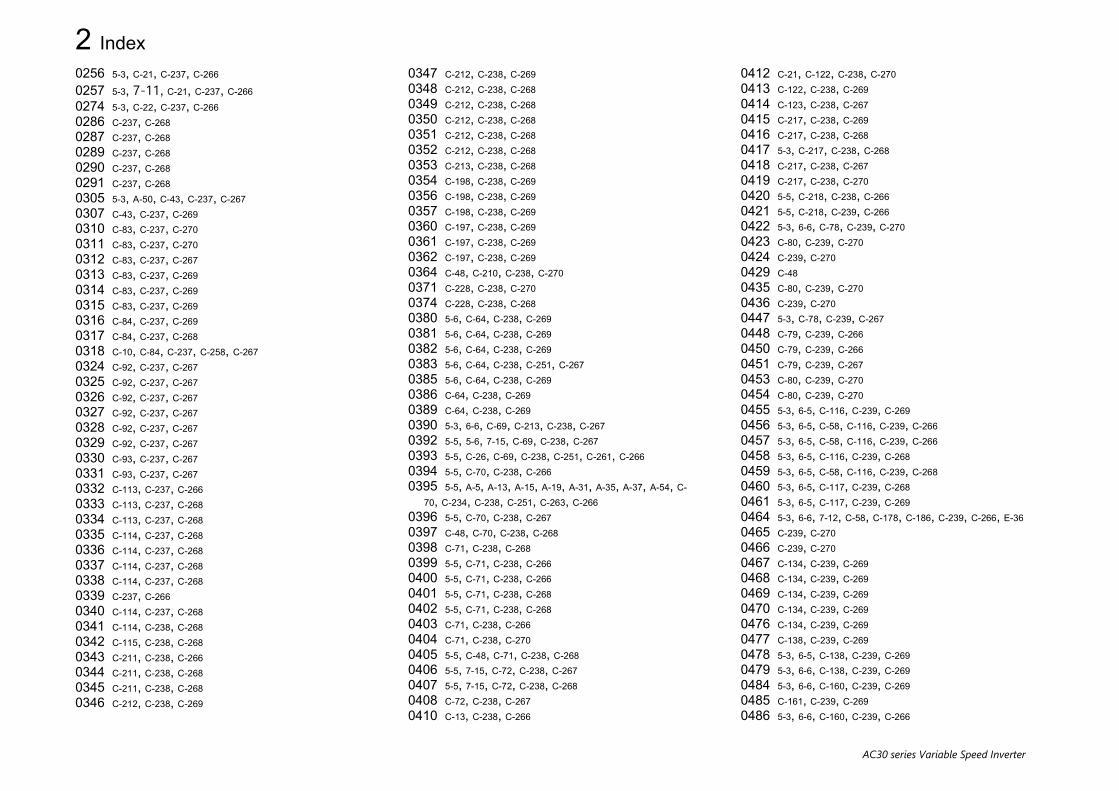
2 Index
AC30 series Variable Speed Inverter
0256 5-3, C-21, C-237, C-266 0257 5-3, 7-11, C-21, C-237, C-266 0274 5-3, C-22, C-237, C-266 0286 C-237, C-268 0287 C-237, C-268 0289 C-237, C-268 0290 C-237, C-268 0291 C-237, C-268 0305 5-3, A-50, C-43, C-237, C-267 0307 C-43, C-237, C-269 0310 C-83, C-237, C-270 0311 C-83, C-237, C-270 0312 C-83, C-237, C-267 0313 C-83, C-237, C-269 0314 C-83, C-237, C-269 0315 C-83, C-237, C-269 0316 C-84, C-237, C-269 0317 C-84, C-237, C-268 0318 C-10, C-84, C-237, C-258, C-267 0324 C-92, C-237, C-267 0325 C-92, C-237, C-267 0326 C-92, C-237, C-267 0327 C-92, C-237, C-267 0328 C-92, C-237, C-267 0329 C-92, C-237, C-267 0330 C-93, C-237, C-267 0331 C-93, C-237, C-267 0332 C-113, C-237, C-266 0333 C-113, C-237, C-268 0334 C-113, C-237, C-268 0335 C-114, C-237, C-268 0336 C-114, C-237, C-268 0337 C-114, C-237, C-268 0338 C-114, C-237, C-268 0339 C-237, C-266 0340 C-114, C-237, C-268 0341 C-114, C-238, C-268 0342 C-115, C-238, C-268 0343 C-211, C-238, C-266 0344 C-211, C-238, C-268 0345 C-211, C-238, C-268 0346 C-212, C-238, C-269
0347 C-212, C-238, C-269 0348 C-212, C-238, C-268 0349 C-212, C-238, C-268 0350 C-212, C-238, C-268 0351 C-212, C-238, C-268 0352 C-212, C-238, C-268 0353 C-213, C-238, C-268 0354 C-198, C-238, C-269 0356 C-198, C-238, C-269 0357 C-198, C-238, C-269 0360 C-197, C-238, C-269 0361 C-197, C-238, C-269 0362 C-197, C-238, C-269 0364 C-48, C-210, C-238, C-270 0371 C-228, C-238, C-270 0374 C-228, C-238, C-268 0380 5-6, C-64, C-238, C-269 0381 5-6, C-64, C-238, C-269 0382 5-6, C-64, C-238, C-269 0383 5-6, C-64, C-238, C-251, C-267 0385 5-6, C-64, C-238, C-269 0386 C-64, C-238, C-269 0389 C-64, C-238, C-269 0390 5-3, 6-6, C-69, C-213, C-238, C-267 0392 5-5, 5-6, 7-15, C-69, C-238, C-267 0393 5-5, C-26, C-69, C-238, C-251, C-261, C-266 0394 5-5, C-70, C-238, C-266 0395 5-5, A-5, A-13, A-15, A-19, A-31, A-35, A-37, A-54, C-
70, C-234, C-238, C-251, C-263, C-266 0396 5-5, C-70, C-238, C-267 0397 C-48, C-70, C-238, C-268 0398 C-71, C-238, C-268 0399 5-5, C-71, C-238, C-266 0400 5-5, C-71, C-238, C-266 0401 5-5, C-71, C-238, C-268 0402 5-5, C-71, C-238, C-268 0403 C-71, C-238, C-266 0404 C-71, C-238, C-270 0405 5-5, C-48, C-71, C-238, C-268 0406 5-5, 7-15, C-72, C-238, C-267 0407 5-5, 7-15, C-72, C-238, C-268 0408 C-72, C-238, C-267 0410 C-13, C-238, C-266
0412 C-21, C-122, C-238, C-270 0413 C-122, C-238, C-269 0414 C-123, C-238, C-267 0415 C-217, C-238, C-269 0416 C-217, C-238, C-268 0417 5-3, C-217, C-238, C-268 0418 C-217, C-238, C-267 0419 C-217, C-238, C-270 0420 5-5, C-218, C-238, C-266 0421 5-5, C-218, C-239, C-266 0422 5-3, 6-6, C-78, C-239, C-270 0423 C-80, C-239, C-270 0424 C-239, C-270 0429 C-48 0435 C-80, C-239, C-270 0436 C-239, C-270 0447 5-3, C-78, C-239, C-267 0448 C-79, C-239, C-266 0450 C-79, C-239, C-266 0451 C-79, C-239, C-267 0453 C-80, C-239, C-270 0454 C-80, C-239, C-270 0455 5-3, 6-5, C-116, C-239, C-269 0456 5-3, 6-5, C-58, C-116, C-239, C-266 0457 5-3, 6-5, C-58, C-116, C-239, C-266 0458 5-3, 6-5, C-116, C-239, C-268 0459 5-3, 6-5, C-58, C-116, C-239, C-268 0460 5-3, 6-5, C-117, C-239, C-268 0461 5-3, 6-5, C-117, C-239, C-269 0464 5-3, 6-6, 7-12, C-58, C-178, C-186, C-239, C-266, E-36 0465 C-239, C-270 0466 C-239, C-270 0467 C-134, C-239, C-269 0468 C-134, C-239, C-269 0469 C-134, C-239, C-269 0470 C-134, C-239, C-269 0476 C-134, C-239, C-269 0477 C-138, C-239, C-269 0478 5-3, 6-5, C-138, C-239, C-269 0479 5-3, 6-6, C-138, C-239, C-269 0484 5-3, 6-6, C-160, C-239, C-269 0485 C-161, C-239, C-269 0486 5-3, 6-6, C-160, C-239, C-266

Index 3
AC30 series Variable Speed Inverter
0487 5-3, 6-6, C-160, C-239, C-267 0488 C-161, C-239, C-270 0489 C-161, C-239, C-270 0490 C-161, C-240, C-270 0491 C-161, C-240, C-270 0492 C-161, C-240, C-270 0493 C-162, C-240, C-270 0494 C-162, C-240, C-270 0495 C-162, C-240, C-270 0496 C-162, C-240, C-270 0497 2-3, C-162, C-240, C-269 0498 C-162, C-240, C-269 0499 C-162, C-240, C-269 0500 C-163, C-240, C-269, E-3 0501 2-5, C-163, C-240, C-268 0502 C-163, C-240, C-268 0503 C-163, C-240, C-268 0504 5-3, C-163, C-240, C-270 0505 C-148, C-149, C-163, C-240, C-270 0506 C-163, C-240, C-270 0507 C-164, C-240, C-269 0508 C-164, C-240, C-269 0509 C-164, C-240, C-267 0511 5-3, 6-5, 7-16, C-38, C-240, C-268 0512 5-3, 6-5, 7-16, C-20, C-38, C-240, C-267 0513 5-6, C-224, C-240, C-266 0514 5-6, C-26, C-226, C-240, C-261, C-270 0515 C-205, C-240, C-270 0516 C-205, C-240, C-270 0517 C-205, C-240, C-270 0518 C-205, C-240, C-270 0519 C-205, C-240, C-269 0520 C-205, C-240, C-269 0521 C-206, C-240, C-269 0523 C-206, C-240, C-269 0524 C-206, C-240, C-269 0525 C-206, C-240, C-269 0526 C-206, C-240, C-269 0527 C-206, C-240, C-269 0528 C-202, C-240, C-267 0529 C-202, C-240, C-267 0530 C-202, C-240, C-267 0531 C-202, C-240, C-267
0533 C-203, C-240, C-270 0534 C-203, C-240, C-270 0535 C-203, C-240, C-270 0536 C-203, C-240, C-270 0543 C-58, C-240, C-269 0555 5-3, 6-5, C-20, C-129, C-130, C-241, C-268 0556 5-3, 6-5, C-20, C-129, C-130, C-241, C-268 0557 5-3, 6-5, C-20, C-130, C-241, C-269 0558 5-3, 6-5, C-20, C-130, C-241, C-269 0559 5-3, 6-5, C-20, C-130, C-241, C-269 0560 5-3, 6-5, C-130, C-241, C-268 0561 5-3, 6-5, C-131, C-241, C-269 0562 5-3, 6-5, C-21, C-131, C-241, C-269 0563 5-3, 6-5, C-131, C-241, C-269 0564 5-3, 6-5, C-20, C-131, C-241, C-269 0565 5-3, 6-5, C-131, C-241, C-269 0568 C-90, C-241, C-268 0569 C-90, C-241, C-269 0570 C-90, C-241, C-268 0571 C-90, C-91, C-241, C-270 0572 C-90, C-241, C-268 0591 C-188, C-241, C-268 0592 C-188, C-191, C-241, C-268 0610 2-3, 2-5, C-188, C-241, C-266, E-34 0627 A-5, A-13, A-15, A-19, A-31, A-35, A-37, A-54, 2-5, 2-
6, C-189, C-233, C-241, C-262, C-267 0644 7-15, 2-5, C-19, C-189, C-242, C-267 0661 A-5, A-13, A-15, A-19, A-31, A-35, A-37, A-54, 2-6, C-
18, C-190, C-234, C-242, C-263, C-270, E-34 0678 7-15, 2-1, C-190, C-242, C-269 0679 C-190, C-242, C-270 0680 C-190, C-191, C-242, C-266 0681 A-5, A-13, A-15, A-19, A-31, A-35, A-37, A-54, 2-5, 2-
6, C-191, C-233, C-242, C-262, C-267 0682 C-191, C-242, C-269 0686 5-4, C-95, C-96, C-242, C-266 0687 C-57, C-243, C-266 0688 C-60, C-243, C-267 0689 C-127, C-243, C-268 0690 C-127, C-243, C-268 0691 C-127, C-243, C-268 0692 C-127, C-243, C-268 0693 C-127, C-243, C-268
0694 C-128, C-243, C-268 0695 C-59, C-243, C-266 0696 5-6, A-5, C-222, C-243, C-251, C-267 0697 A-8, C-223, C-243, C-267 0730 A-24, A-51, C-223, C-244, C-267 0763 5-6, C-224, C-245, C-266 0796 5-3, C-16, C-246, C-266 0829 5-6, C-26, C-225, C-226, C-246, C-261, C-270 0890 C-107, C-247, C-268 0891 C-107, C-247, C-268 0892 C-107, C-247, C-268 0893 C-107, C-247, C-266 0894 C-247, C-268 0895 C-221, C-247, C-251, C-269 0896 C-247, C-269 0906 C-214, C-247, C-270 0907 C-214, C-247, C-270 0908 C-200, C-247, C-267 0909 C-214, C-247, C-270 0910 C-214, C-247, C-270 0911 C-214, C-247, C-270 0912 C-227, C-247, C-270 0913 C-227, C-247, C-268 0914 C-227, C-247, C-270 0915 C-227, C-247, C-270 0916 C-227, C-247, C-270 0917 C-247, C-270 0918 C-227, C-247, C-267 0919 5-6, 8-3, 8-9, 8-12, C-247, C-267 0920 5-6, 8-9, 8-23, C-247, C-268 0926 5-6, 8-3, 8-9, A-12, A-34, C-247, C-251, C-268 0927 5-6, 8-3, 8-10, A-12, A-34, C-247, C-270 0928 5-6, 8-3, 8-10, 8-12, 8-19, A-12, A-34, C-247, C-268 0929 5-4, 6-8, 8-3, 8-4, 8-5, 8-7, 8-11, 8-12, A-12, A-34,
C-247, C-267 0930 5-4, 6-8, 8-3, 8-4, 8-5, 8-6, 8-7, 8-11, A-12, A-34, C-
247, C-266 0931 8-4, 8-10, 8-12, C-247, C-268 0933 5-4, 6-8, 8-4, 8-11, 8-12, A-12, A-34, C-247, C-270 0934 5-4, 6-8, 8-4, 8-11, 8-12, A-12, A-34, C-248, C-270 0935 5-4, 6-8, 8-4, 8-11, 8-12, A-12, A-34, C-248, C-270 0936 8-3, 8-11, C-248, C-268 0937 8-10, C-248, C-267

4 Index
AC30 series Variable Speed Inverter
0938 8-10, C-248, C-267 0939 5-4, 6-8, A-1, A-9, C-248, C-268 0940 5-4, 6-8, A-2, A-6, A-9, C-248, C-268 0941 5-4, 6-8, A-8, A-9, C-248, C-268 0942 5-4, 6-8, A-8, A-9, C-248, C-268 0943 5-6, A-8, A-9, C-248, C-269 0944 5-4, 5-5, 6-2, 8-15, 8-17, A-14, A-36, C-248, C-270 0945 8-3, 8-15, 8-17, C-248, C-270 0946 8-17, C-248, C-270 0951 C-57, C-248, C-266 0955 C-44, C-248, C-267 0957 5-4, C-94, C-248, C-266 0958 5-4, C-94, C-248, C-266 0959 5-4, C-95, C-248, C-266 0960 5-4, C-95, C-248, C-266 0961 5-5, 6-2, A-5, C-57, C-248, C-267, E-43 0968 C-221, C-248, C-270 0969 C-248, C-270 0972 C-221, C-248, C-270 0973 C-248, C-270 0976 6-5, C-57, C-58, C-248, C-268 0977 7-16, C-60, C-248, C-267 0982 5-5, C-87, C-248, C-270 0983 5-5, C-87, C-248, C-267 0987 7-12, C-57, C-58, C-248, C-269 0988 C-54, C-248, C-270 0989 C-31, C-54, C-248, C-266 0990 C-54, C-248, C-266 0991 C-54, C-248, C-266 0992 C-54, C-248, C-266 0993 C-54, C-249, C-267 0994 C-54, C-249, C-268 0995 C-54, C-249, C-267 0996 C-55, C-249, C-268 0997 C-55, C-249, C-267 0998 5-6, C-55, C-249, C-269 0999 5-6, C-55, C-249, C-269 100% Mot Current C-113, C-237, C-266 100% Speed in RPM 5-3, 6-6, 7-11, 7-12, C-43, C-58,
C-70, C-138, C-169, C-170, C-178, C-186, C-203, C-239, C-266, E-36
100% Stack Current A C-71, C-238, C-266
100% Stk Current C-211, C-238, C-266 1000 6-2, 6-5, C-9, C-21, C-22, C-27, C-69, C-70, C-71, C-
90, C-116, C-128, C-131, C-132, C-138, C-168, C-169, C-194, C-216, C-220, C-235, C-237, C-238, C-239, C-241, C-243, C-249, C-253, C-255, C-256, C-258, C-260, C-261, C-265, C-269, E-15, E-19, E-29
1001 7-9, C-53, C-249, C-269 1002 6-2, C-53, C-249, C-270 1003 7-9, C-249, C-269 1004 C-216, C-249, C-270 1005 4-8, 6-2, C-193, C-249, C-268 1006 6-2, 7-9, C-193, C-249, C-269 1033 C-187, C-249, C-267 1034 C-187, C-249, C-267 1038 C-187, C-249, C-267 1039 C-187, C-249, C-266 1040 C-13, C-249, C-269 1047 C-13, C-249, C-268 1048 C-13, C-249, C-268 1054 C-13, C-249, C-269 1061 C-13, C-249, C-269 1068 C-14, C-249, C-269 1089 5-6, C-249, C-266 1091 5-4, C-249, C-266 1092 5-4, C-249, C-266 1093 5-4, C-249, C-266 1094 5-4, C-249, C-266, C-271 1095 5-5, C-249, C-266 1096 5-5, C-249, C-266 1097 C-88, C-250, C-268 1098 C-88, C-250, C-268 1099 C-88, C-250, C-270 1100 C-57, C-250, C-267 1108 5-4, C-95, C-96, C-250, C-266 1109 C-59, C-250, C-270 1116 C-59, C-250, C-267 1121 C-60, C-250, C-267 1125 C-60, C-250, C-268 1129 C-60, C-250, C-267 1134 C-60, C-250, C-268 1139 C-172, C-250, C-267 1140 C-106, C-250, C-269 1141 6-2, C-87, C-250, C-270
1142 5-5, C-87, C-250, C-268 1143 C-88, C-250, C-270 1178 5-4, 6-4, 7-13, C-100, C-250, C-268, E-31 1179 7-16, C-100, C-250, C-268, E-31 1180 C-100, C-250, C-259, C-268 1181 5-5, C-85, C-250, C-266 1182 5-5, C-85, C-86, C-250, C-266 1183 5-5, C-85, C-86, C-250, C-266 1184 5-4, 6-4, C-216, C-250, C-270 1185 C-216, C-250, C-270 1186 6-2, C-49, C-166, C-250, C-270 1187 C-86, C-250, C-269 1188 C-200, C-250, C-267 1189 C-250, C-267 1200 7-9 1213 C-70, C-250, C-266 1214 C-117, C-251, C-266 1225 C-166, C-251, C-267 1228 C-166, C-251, C-270, C-272 1229 C-179, C-251, C-268 1230 C-179, C-251, C-268 1231 C-178, C-251, C-267 1232 C-179, C-251, C-267 1235 C-251, C-267 1239 C-106, C-251, C-268 1240 C-106, C-251, C-268 1241 5-6, A-8, A-9, C-251, C-268 1246 C-204, C-251, C-270 1247 C-204, C-251, C-269 1248 C-204, C-251, C-270 1251 5-6, C-251, C-267 1252 C-172, C-251, C-268 1253 C-89, C-106, C-251, C-268 1254 C-60, C-251, C-268 1255 C-89, C-106, C-251, C-268 1256 C-61, C-251, C-268 1257 5-3, 6-6, C-148, C-149, C-160, C-251, C-269 1258 C-59, C-251, C-270 1264 C-209, C-251, C-268 1265 C-209, C-251, C-268 1266 C-209, C-251, C-270, E-15 1267 C-209, C-251, C-270 1268 C-123, C-251, C-269

Index 5
AC30 series Variable Speed Inverter
1269 8-10, C-251, C-267 1270 C-201, C-251, C-268 1271 C-251, C-252, C-268 1291 C-185, C-252, C-268 1292 C-185, C-252, C-268 1293 C-185, C-252, C-268 1294 C-96, C-252, C-267 1310 C-178, C-252, C-267 1311 7-10, C-200, C-252, C-269 1312 7-10, C-252, C-269 1313 7-10 1332 C-175, C-252, C-269 1333 C-175, C-252, C-269 1334 C-175, C-252, C-269, E-19 1335 C-98, C-252, C-253, C-267 1352 C-200, C-253, C-267 1353 C-253, C-267 1364 C-253, C-269 1365 C-174, C-253, C-269 1366 C-174, C-253, C-269 1367 C-174, C-253, C-269, C-271 1368 C-175, C-253, C-269 1369 C-175, C-253, C-269 1370 C-175, C-253, C-269 1371 C-175, C-253, C-269 1372 C-176, C-253, C-269 1373 C-176, C-253, C-269 1374 C-176, C-253, C-269 1375 C-176, C-253, C-269 1376 C-176, C-253, C-269 1386 8-19, C-253, C-269 1387 5-3, 6-5, C-20, C-132, C-253, C-268 1388 5-3, C-22, C-253, C-266 1405 5-3, C-22, C-253, C-266 1406 C-172, C-253, C-268 1407 C-172, C-253, C-268, E-19 1408 C-221, C-253, C-270 1441 5-4, C-96, C-254, C-266 1442 C-221, C-254, C-269 1443 C-254, C-269 1450 C-58, C-186 1458 A-8, A-10, C-254, C-268
1459 C-22, C-254, C-268 1460 5-4, C-96, C-254, C-266 1461 5-4, C-85, C-86, C-254, C-266 1462 5-4, C-85, C-254, C-266 1463 5-4, C-85, C-86, C-254, C-266 1464 5-4, C-85, C-254, C-266 1465 5-4, C-86, C-254, C-266 1466 5-4, C-86, C-254, C-266 1467 5-4, C-96, C-254, C-266 1468 5-4, C-96, C-254, C-266 1469 5-3, C-15, C-16, C-18, C-19, C-254, C-255, C-266 1470 5-3, C-15, C-18, C-19, C-254, C-266 1471 5-3, C-15, C-17, C-18, C-254, C-266 1472 5-3, C-16, C-254, C-266 1505 5-3, C-17, C-18, C-255, C-266 1506 5-3, C-17, C-18, C-255, C-266 1507 C-17, C-19, C-255, C-266 1508 C-18, C-19, C-255, C-266 1509 C-17, C-18, C-19, C-255, C-266 1510 C-18, C-255, C-266 1511 5-4, 6-4, C-62, C-63, C-255, C-267 1512 5-4, 6-4, C-62, C-255, C-267 1513 5-4, C-62, C-255, C-267 1514 5-4, 6-4, C-62, C-255, C-257, C-267 1515 5-4, 6-4, C-62, C-255, C-267 1516 5-5, C-63, C-255, C-267 1517 5-4, C-63, C-255, C-267 1518 5-5, C-63, C-255, C-267 1520 C-220, C-255, C-266 1521 C-220, C-255, C-270 1526 C-80, C-255, C-267 1527 C-220, C-255, C-268 1528 C-220, C-255, C-267 1529 C-220, C-255, C-270 1533 5-3, 6-5, 7-16, C-38, C-39, C-132, C-255, C-262, C-267 1534 5-5, C-30, C-31, C-32, C-255, C-267 1537 5-5, C-30, C-31, C-32, C-255, C-267 1538 5-5, C-31, C-32, C-255, C-268 1539 5-5, C-31, C-255, C-266 1540 5-5, C-31, C-32, C-255, C-268 1541 5-5, C-31, C-255, C-269 1542 5-5, C-32, C-255, C-267 1543 5-5, C-32, C-255, C-267
1544 C-75, C-256, C-267 1545 C-76, C-256, C-267 1546 C-76, C-256, C-268 1547 C-76, C-256, C-268 1548 C-76, C-256, C-267 1549 C-80, C-256, C-266 1550 5-3, C-21, C-256, C-268, C-271, C-272, C-273 1551 C-61, C-256, C-269 1554 C-14, C-256, C-266 1560 C-118, C-119, C-256, C-270, E-19 1565 C-188, C-256, C-268 1567 5-4, A-5, A-10, C-256, C-268 1568 C-256, C-268 1632 5-6, A-5, A-10, C-256, C-268 1633 C-80, C-256, C-266 1634 C-118, C-119, C-256, C-270 1635 C-118, C-119, C-256, C-267 1636 C-61, C-256, C-268 1637 C-88, C-256, C-267 1640 5-5, C-256, C-268 1641 C-51, C-256, C-270 1642 C-51, C-256, C-270 1643 C-51, C-256, C-270 1644 C-51, C-256, C-270 1645 C-150, C-256, C-269 1646 C-150, C-257, C-269 1647 C-150, C-257, C-269 1648 C-150, C-257, C-269 1649 C-151, C-257, C-269 1650 7-5, C-151, C-257, C-269 1651 C-151, C-257, C-269 1658 C-45, C-257, C-267 1659 5-4, A-6, A-10, C-257, C-268 1661 5-5, 8-21, 8-24, C-257, C-269 1663 5-4, C-180, C-181, C-257, C-267 1664 5-4, C-180, C-257, C-267 1665 5-4, C-180, C-257, C-267 1666 5-4, C-180, C-257, C-267 1667 5-4, C-180, C-257, C-268 1668 5-6, C-180, C-181, C-257, C-267 1669 5-4, C-181, C-257, C-267 1670 5-6, C-181, C-257, C-267 1671 5-4, C-182, C-257, C-267

6 Index
AC30 series Variable Speed Inverter
1672 5-4, C-182, C-257, C-267 1673 5-4, C-182, C-257, C-267 1674 5-4, C-182, C-257, C-268 1675 5-6, C-182, C-257, C-267 1676 5-4, C-182, C-257, C-267 1677 5-6, C-182, C-257, C-267 1678 5-4, C-183, C-184, C-257, C-258, C-268 1679 5-4, C-183, C-184, C-185, C-257, C-268 1680 5-4, C-183, C-257, C-268 1681 5-5, 8-22, 8-25, C-257, C-269 1682 C-257, C-269 1683 5-5, 8-24, C-257, C-269 1684 5-5, 8-19, 8-22, 8-24, C-257, C-269 1685 5-5, 8-25, 8-27, C-257, C-269 1686 5-5, 8-23, 8-25, C-257, C-269 1687 5-6, 8-27, C-257, C-258, C-269 1688 5-6, 8-21, 8-25, 8-27, C-257, C-269 1689 5-6, 8-26, C-257, C-269 1690 C-9, C-258, C-266 1691 C-10, C-258, C-266 1692 C-12, C-258, C-266 1693 5-3, 6-6, C-9, C-10, C-258, C-266 1694 C-10, C-258, C-266 1695 C-10, C-258, C-266 1696 5-4, C-183, C-258, C-270 1697 C-11, C-258, C-266 1698 5-4, C-183, C-258, C-270 1699 5-6, 8-27, C-258, C-269 1701 C-119, C-120, C-258, C-270, E-38 1702 5-4, C-184, C-258, C-270 1703 5-6, C-10, C-12, C-258, C-266 1704 5-4, 6-6, C-9, C-258, C-266 1705 5-4, 6-6, C-9, C-258, C-266 1706 C-9, C-258, C-266 1707 C-10, C-12, C-258, C-266 1708 C-10, C-12, C-258, C-266 1709 C-11, C-258, C-266 1710 C-11, C-258, C-266 1711 5-3, 6-6, C-10, C-258, C-266 1712 C-11, C-258, C-266 1713 C-11, C-258, C-266 1714 C-11, C-258, C-266 1715 C-12, C-258, C-266
1716 C-12, C-258, C-266 1717 C-11, C-258, C-266 1718 C-10, C-258, C-266 1721 5-6, C-12, C-258, C-266 1722 5-5, C-174, C-258, C-269 1723 5-6, C-174, C-258, C-269 1725 5-5, 8-28, 8-30, C-258, C-268 1726 5-5, 8-30, C-258, C-267 1727 5-5, 8-30, C-258, C-267 1728 5-5, 8-31, C-258, C-268 1729 5-6, 8-31, C-258, C-268 1730 5-3, 6-6, C-9, C-258, C-266 1731 C-11, C-258, C-266 1732 7-16, C-172, C-258, C-268 1733 C-172, C-173, C-258, C-270 1734 C-17, C-258, C-266 1735 C-17, C-258, C-266 1736 C-17, C-258, C-266 1737 C-17, C-258, C-266 1738 6-2, 8-15, C-192, C-258, C-267 1739 5-4, 7-13, C-215, C-258, C-259, C-270 1740 7-16, C-215, C-259, C-270 1741 C-215, C-259, C-270 1742 C-55, C-259, C-270 1743 5-3, 6-5, C-38, C-259, C-267 1744 C-35, C-259, C-269 1745 C-35, C-259, C-268 1746 C-208, C-259, C-270 1747 C-208, C-259, C-270 1748 C-208, C-259, C-270 1749 C-35, C-259, C-269 1750 C-36, C-58, C-259, C-267 1751 C-36, C-37, C-259, C-268 1752 C-36, C-259, C-269 1753 C-37, C-259, C-269 1754 C-68, C-77, C-259, C-268 1756 5-4, C-184, C-259, C-268 1757 5-4, C-184, C-259, C-268 1758 5-4, C-184, C-259, C-268 1759 5-5, C-174, C-259, C-269 1760 C-226, C-259, C-267 1762 C-216, C-259, C-270 1779 C-192, C-259, C-266
1780 C-259, C-269 1781 C-207, C-259, C-270 1782 8-10, C-259, C-268 1783 C-63, C-259, C-267 1784 C-259, C-267 1785 C-259, C-267 1787 5-5, 8-22, 8-24, C-259, C-269 1788 8-19, C-259, C-269 1789 8-19, C-259, C-269 1790 5-4, 6-4, C-167, C-168, C-169, C-259, C-260, C-261,
C-269 1791 5-4, 6-4, C-167, C-260, C-269 1792 5-4, 6-4, C-167, C-260, C-269, C-271 1793 5-4, 6-4, C-168, C-260, C-269 1794 C-89, C-260, C-269 1795 C-89, C-260, C-269 1796 5-3, 7-6, C-142, C-143, C-144, C-260, C-266 1797 5-3, C-143, C-260, C-266 1798 5-3, C-142, C-260, C-266, C-272 1799 5-3, C-143, C-260, C-266 1800 5-3, C-58, C-144, C-260, C-266 1801 5-3, 7-10, C-144, C-260, C-266 1802 C-144, C-260, C-266 1803 C-144, C-260, C-266 1804 C-132, C-144, C-260, C-266 1805 C-145, C-260, C-266 1806 C-145, C-260, C-266 1807 7-6, C-146, C-260, C-266 1808 5-3, 6-5, C-39, C-132, C-144, C-148, C-149, C-260, C-
268 1809 5-3, 5-5, 6-5, C-132, C-142, C-145, C-147, C-148, C-
149, C-260, C-269 1810 5-4, 6-4, C-168, C-260, C-269 1811 5-6, C-168, C-169, C-260, C-261, C-269 1812 5-6, C-168, C-260, C-269 1813 C-169, C-260, C-269 1814 5-6, C-169, C-260, C-269 1815 5-4, 6-4, C-168, C-260, C-269 1816 5-4, 6-4, C-169, C-170, C-260, C-261, C-269 1817 C-170, C-260, C-269 1818 C-170, C-260, C-269 1819 C-170, C-260, C-269 1820 7-6, C-171, C-260, C-269
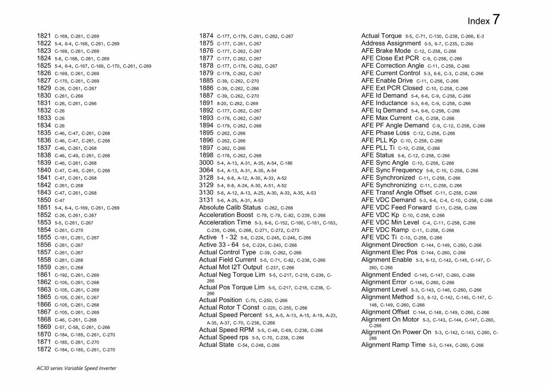
Index 7
AC30 series Variable Speed Inverter
1821 C-169, C-261, C-269 1822 5-4, 6-4, C-168, C-261, C-269 1823 C-169, C-261, C-269 1824 5-6, C-168, C-261, C-269 1825 5-4, 6-4, C-167, C-169, C-170, C-261, C-269 1826 C-169, C-261, C-269 1827 C-170, C-261, C-269 1829 C-26, C-261, C-267 1830 C-261, C-266 1831 C-26, C-261, C-266 1832 C-26 1833 C-26 1834 C-26 1835 C-46, C-47, C-261, C-268 1836 C-46, C-47, C-261, C-268 1837 C-46, C-261, C-268 1838 C-46, C-49, C-261, C-268 1839 C-46, C-261, C-268 1840 C-47, C-49, C-261, C-268 1841 C-47, C-261, C-268 1842 C-261, C-268 1843 C-47, C-261, C-268 1850 C-47 1851 5-4, 6-4, C-169, C-261, C-269 1852 C-26, C-261, C-267 1853 5-5, C-261, C-267 1854 C-261, C-270 1855 C-181, C-261, C-267 1856 C-261, C-267 1857 C-261, C-267 1858 C-261, C-268 1859 C-261, C-268 1861 C-192, C-261, C-269 1862 C-105, C-261, C-268 1863 C-105, C-261, C-269 1865 C-105, C-261, C-267 1866 C-105, C-261, C-268 1867 C-105, C-261, C-269 1868 C-46, C-261, C-268 1869 C-57, C-58, C-261, C-266 1870 C-184, C-185, C-261, C-270 1871 C-185, C-261, C-270 1872 C-184, C-185, C-261, C-270
1874 C-177, C-179, C-261, C-262, C-267 1875 C-177, C-261, C-267 1876 C-177, C-262, C-267 1877 C-177, C-262, C-267 1878 C-177, C-178, C-262, C-267 1879 C-178, C-262, C-267 1885 C-39, C-262, C-270 1886 C-39, C-262, C-266 1887 C-39, C-262, C-270 1891 8-20, C-262, C-269 1892 C-177, C-262, C-267 1893 C-178, C-262, C-267 1894 C-179, C-262, C-268 1895 C-262, C-266 1896 C-262, C-266 1897 C-262, C-266 1898 C-178, C-262, C-268 3000 5-4, A-13, A-31, A-35, A-54, C-186 3064 5-4, A-13, A-31, A-35, A-54 3128 5-4, 6-8, A-12, A-30, A-33, A-52 3129 5-4, 6-8, A-24, A-30, A-51, A-52 3130 5-6, A-12, A-13, A-25, A-30, A-33, A-35, A-53 3131 5-6, A-25, A-31, A-53 Absolute Calib Status C-262, C-266 Acceleration Boost C-78, C-79, C-82, C-239, C-266 Acceleration Time 5-3, 6-6, C-152, C-160, C-161, C-163,
C-239, C-266, C-268, C-271, C-272, C-273 Active 1 - 32 5-6, C-224, C-245, C-246, C-266 Active 33 - 64 5-6, C-224, C-240, C-266 Actual Control Type C-39, C-262, C-266 Actual Field Current 5-5, C-71, C-82, C-238, C-266 Actual Mot I2T Output C-237, C-266 Actual Neg Torque Lim 5-5, C-217, C-218, C-239, C-
266 Actual Pos Torque Lim 5-5, C-217, C-218, C-238, C-
266 Actual Position C-70, C-250, C-266 Actual Rotor T Const C-220, C-255, C-266 Actual Speed Percent 5-5, A-5, A-13, A-15, A-19, A-23,
A-35, A-37, C-70, C-238, C-266 Actual Speed RPM 5-5, C-48, C-69, C-238, C-266 Actual Speed rps 5-5, C-70, C-238, C-266 Actual State C-54, C-248, C-266
Actual Torque 5-5, C-71, C-130, C-238, C-266, E-3 Address Assignment 5-5, 6-7, C-235, C-266 AFE Brake Mode C-12, C-258, C-266 AFE Close Ext PCR C-9, C-258, C-266 AFE Correction Angle C-11, C-258, C-266 AFE Current Control 5-3, 6-6, C-3, C-258, C-266 AFE Enable Drive C-11, C-258, C-266 AFE Ext PCR Closed C-10, C-258, C-266 AFE Id Demand 5-4, 6-6, C-9, C-258, C-266 AFE Inductance 5-3, 6-6, C-9, C-258, C-266 AFE Iq Demand 5-4, 6-6, C-258, C-266 AFE Max Current C-9, C-258, C-266 AFE PF Angle Demand C-9, C-12, C-258, C-266 AFE Phase Loss C-12, C-258, C-266 AFE PLL Kp C-10, C-258, C-266 AFE PLL Ti C-10, C-258, C-266 AFE Status 5-6, C-12, C-258, C-266 AFE Sync Angle C-10, C-258, C-266 AFE Sync Frequency 5-6, C-10, C-258, C-266 AFE Synchronized C-11, C-258, C-266 AFE Synchronizing C-11, C-258, C-266 AFE Transf Angle Offset C-11, C-258, C-266 AFE VDC Demand 5-3, 6-6, C-4, C-10, C-258, C-266 AFE VDC Feed Forward C-11, C-258, C-266 AFE VDC Kp C-10, C-258, C-266 AFE VDC Min Level C-4, C-11, C-258, C-266 AFE VDC Ramp C-11, C-258, C-266 AFE VDC Ti C-10, C-258, C-266 Alignment Direction C-144, C-149, C-260, C-266 Alignment Elec Pos C-144, C-260, C-266 Alignment Enable 5-3, 6-12, C-142, C-145, C-147, C-
260, C-266 Alignment Ended C-145, C-147, C-260, C-266 Alignment Error C-146, C-260, C-266 Alignment Level 5-3, C-143, C-146, C-260, C-266 Alignment Method 5-3, 6-12, C-142, C-145, C-147, C-
148, C-149, C-260, C-266 Alignment Offset C-144, C-148, C-149, C-260, C-266 Alignment On Motor 5-3, C-143, C-144, C-147, C-260,
C-266 Alignment On Power On 5-3, C-142, C-143, C-260, C-
266 Alignment Ramp Time 5-3, C-144, C-260, C-266

8 Index
AC30 series Variable Speed Inverter
Alignment State C-145, C-260, C-266 Ambient Temperature C-107, C-247, C-266 Anin 01 Break 5-5, C-104, C-233, C-266 Anin 01 Offset 5-4, C-94, C-248, C-266 Anin 01 Scale 5-4, C-94, C-248, C-266 Anin 01 Type 5-4, 6-4, C-94, C-232, C-266 Anin 01 Value 5-5, C-94, C-104, C-233, C-266 Anin 02 Offset 5-4, C-95, C-248, C-266 Anin 02 Scale 5-4, C-95, C-248, C-266 Anin 02 Type 5-4, 6-4, C-94, C-95, C-232, C-266 Anin 02 Value 5-5, C-95, C-104, C-233, C-266 Anin 11 Offset 5-4, C-85, C-254, C-266 Anin 11 Scale 5-4, C-85, C-254, C-266 Anin 11 Value 5-5, C-85, C-250, C-266 Anin 12 Offset 5-4, C-85, C-86, C-254, C-266 Anin 12 Scale 5-4, C-85, C-254, C-266 Anin 12 Value 5-5, C-85, C-86, C-250, C-266 Anin 13 Offset 5-4, C-86, C-254, C-266 Anin 13 Scale 5-4, C-86, C-254, C-266 Anin 13 Value 5-5, C-85, C-86, C-250, C-266 Anout 01 ABS 5-4, C-96, C-254, C-266 Anout 01 Offset 5-4, C-95, C-96, C-250, C-266 Anout 01 Scale 5-4, C-95, C-96, C-242, C-266 Anout 01 Type 5-4, 6-4, C-95, C-232, C-266 Anout 01 Value 5-5, C-95, C-96, C-104, C-233, C-266 Anout 02 ABS 5-4, C-96, C-254, C-266 Anout 02 Offset 5-4, C-96, C-254, C-266 Anout 02 Scale 5-4, C-96, C-254, C-266 Anout 02 Type 5-4, 6-4, C-96, C-232, C-266 Anout 02 Value 5-5, C-96, C-104, C-233, C-266 App Control Word 7-1, 2-3, 2-5, C-188, C-241, C-266, E-
34 App Reference C-190, C-191, C-242, C-266 Application 4-9, 5-1, 5-3, 5-5, 6-3, 6-19, 7-2, 7-5, 7-6, 7-
12, 7-13, 8-1, 2-2, 2-5, C-1, C-3, C-5, C-13, C-14, C-31, C-54, C-80, C-82, C-109, C-125, C-154, C-158, C-159, C-173, C-187, C-188, C-194, C-234, C-238, C-248, C-249, C-255, C-256, C-265, C-266, E-2, E-3, E-6, E-7, E-8
Application XE "Application" Archive C-249 Application Archive C-187 Application Archive C-266 Application XE "Application" FE State C-248 Application FE State C-54
Application FE State C-266 Application XE "Application" Name C-256 Application Name C-14 Application Name C-266 Application XE "Application" User Boost C-256 Application User Boost C-80 Application User Boost C-266 Application XE "Application" Volts C-256 Application Volts C-80, C-82 Application Volts C-266 AR Active C-17, C-19, C-255, C-266 AR Enable 5-3, C-15, C-18, C-19, C-254, C-266 AR Initial Delay 5-3, C-17, C-255, C-258, C-266 AR Initial Delay XE "AR Initial Delay" B C-258 AR Initial Delay B C-17 AR Initial Delay B C-266 AR Max Restarts 5-3, C-15, C-17, C-18, C-254, C-266 AR Mode 5-3, C-15, C-18, C-19, C-254, C-266 AR Repeat Delay 5-3, C-17, C-18, C-255, C-258, C-266 AR Repeat Delay XE "AR Repeat Delay" B C-
258 AR Repeat Delay B C-17, C-18 AR Repeat Delay B C-266 AR Restart Pending C-18, C-19, C-255, C-266 AR Restarts Remaining C-17, C-18, C-255, C-266 AR Time Remaining C-18, C-255, C-266 AR Trip Mask 5-3, C-16, C-17, C-18, C-246, C-254, C-
255, C-258, C-266 AR Trip Mask XE "AR Trip Mask" 2 C-246 AR Trip Mask 2 5-3, C-16, C-17 AR Trip Mask 2 C-258 AR Trip Mask 2 C-266 AR Trip Mask 2 C-266 AR Trip Mask XE "AR Trip Mask" 2 XE "AR
Trip Mask 2" B C-258 AR Trip Mask 2 B C-17 AR Trip Mask 2 B C-266 AR Trip Mask XE "AR Trip Mask" B C-258 AR Trip Mask B C-17 AR Trip Mask B C-266 Archive Flags C-13, C-238, C-266 ATN PMAC Ls Test Freq 5-3, C-22, C-253, C-266 ATN PMAC Test Disable 5-3, C-22, C-253, C-266
Attached to Stack C-59, C-243, C-266 Auto Boost C-78, C-79, C-82, C-239, C-266 Auto Defaults C-57, C-58, C-261, C-266 Auto Hide C-192, C-259, C-266 Auto IP 5-4, 6-8, 8-3, 8-4, 8-5, 8-6, 8-7, 8-10, 8-11, A-12,
A-34, C-247, C-266, C-268 Automatic Pole Pairs C-117, C-251, C-266 Autotune Enable 5-3, 6-8, C-21, C-23, C-237, C-266 Autotune Mode 5-3, C-21, C-237, C-266 Autotune Ramp Time 5-3, C-22, C-237, C-266, C-271,
C-272, C-273 Autotune Test Disable 5-3, 7-11, C-21, C-237, C-266 Backup Action C-121, C-235, C-266 Backup-Restore Start C-121, C-235, C-266 Backup-Restore Status C-121, C-235, C-266 BACnet Baud Rate 5-4, C-249, C-266 BACnet IP Device ID 5-4, C-235, C-266 BACnet IP State 5-6, C-235, C-266 BACnet IP Timeout 5-4, C-235, C-266 BACnet MAC Address 5-4, C-249, C-266 BACnet Max Info Frames 5-5, C-249, C-266 BACnet Max Master 5-5, C-249, C-266 BACnet MSTP Device ID 5-4, C-249, C-266 BACnet MSTP State 5-6, C-249, C-266 BACnet MSTP Timeout 5-4, C-249, C-266 Base Frequency 5-3, 6-5, 7-11, C-58, C-78, C-82, C-
116, C-239, C-266 Base IO FE State C-54, C-248, C-266 Base Voltage 5-3, 6-5, C-58, C-116, C-239, C-266 Basic Drive FE State C-54, C-248, C-266 Black Box PNOs C-26, C-261, C-266 Black Box PNOs[x] C-266 Boot Version C-57, C-243, C-248, C-266 Boot Version XE "Boot Version" Number C-243 Boot Version Number C-57 Boot Version Number C-266 Brake Overrating 7-4, C-27, C-28, C-237, C-266 Brake Rated Power C-27, C-28, C-237, C-266, C-271,
C-272, C-273 Brake Resistance C-27, C-237, C-266, C-271, C-272, C-
273 Braking Active C-27, C-237, C-266 Braking Enable C-27, C-237, C-266

Index 9
AC30 series Variable Speed Inverter
Calib Fail Retry C-262, C-266 Calibration Error C-262, C-266 CANopen Actual Baud 5-6, C-251, C-267 CANopen Baud Rate 5-5, 6-6, C-235, C-267 CANopen Node Address 5-4, 6-6, C-235, C-267 CANopen State 5-6, C-235, C-267 Card Name C-187, C-249, C-267 Card State C-187, C-249, C-267 Clone Direction 5-5, C-30, C-31, C-32, C-255, C-267 Clone Filename 5-5, C-30, C-255, C-267 Clone Start 5-5, C-32, C-255, C-267 Clone Status 5-5, C-32, C-255, C-267 CM Temperature 5-5, 7-15, C-48, C-72, C-238, C-267 CNet Consuming Inst 5-5, C-236, C-267 CNet Producing Inst 5-5, C-236, C-267 Comms Control Word 7-1, A-5, A-13, A-15, A-19, A-23,
A-35, A-37, 2-5, 2-6, C-189, C-241, C-242, C-267 Comms Diagnostic 5-6, C-233, C-267 Comms Diagnostic XE "Comms Diagnostic"
Code C-233 Comms Diagnostic Code 5-6 Comms Diagnostic Code C-267 Comms Event Active 5-6, C-235, C-267 Comms Event Clear C-235, C-267 Comms Event Code C-235, C-267 Comms Event Set C-235, C-267 Comms Exception 5-6, C-233, C-267 Comms Fitted 5-6, 7-16, C-233, C-267 Comms Module Serial 5-6, C-233, C-267 Comms Module Version 5-6, C-233, C-267 Comms Net Exception 5-6, C-233, C-267 Comms Option FE State C-54, C-249, C-267 Comms Option Pcode C-60, C-250, C-267 Comms Option Serial C-60, C-250, C-267 Comms Reference A-5, A-13, A-15, A-19, A-23, A-35, A-
37, 2-5, 2-6, C-191, C-242, C-267 Comms Required 5-4, 6-6, 6-7, 7-6, 7-13, C-233, C-267 Comms Reset Allow 5-5, C-261, C-267 Comms State C-233, C-267 Comms Supervised 5-6, C-233, C-267 Comms Trip Enable 5-5, 6-6, 6-7, C-233, C-267 Config Fault Area C-55, C-249, C-267 Configuration Lock C-14, C-234, C-267
Control Board Up Time C-172, C-173, C-221, C-250, C-267
Control Module Pcode C-59, C-250, C-267 Control Module Serial 7-16, C-60, C-248, C-267 Control Screen 5-1, 5-2, 5-3, C-2, C-87, C-88, C-200, C-
201, C-247, C-253, C-267 Control Screen XE "Control Screen" Mode C-
247 Control Screen Mode C-200 Control Screen Mode C-267 Control Screen[x] C-267 Control Strategy 5-3, 6-5, 6-20, 6-22, C-20, C-38, C-69,
C-70, C-240, C-267 Control Type 5-3, 6-5, 7-16, C-38, C-39, C-132, C-142, C-
255, C-266, C-267 Control Word 7-15, 2-3, A-5, A-13, A-15, A-19, A-23, A-
35, A-37, 2-1, 2-3, 2-5, 2-6, C-19, C-188, C-189, C-242, C-266, C-267
ControlNet MAC ID 5-5, C-236, C-267 ControlNet State 5-6, C-236, C-267 Copy Status C-26, C-261, C-267 Copy to SD Card C-26, C-261, C-267 Current Diff Level C-45, C-257, C-267 Current Limit 5-3, A-50, C-1, C-8, C-43, C-92, C-213, C-
214, C-237, C-267, C-269 Cut Off Frequency C-75, C-76, C-256, C-267 DC Current Level C-92, C-237, C-267, C-271, C-272, C-
273 DC Inj Base Volts C-93, C-237, C-267, C-271, C-272, C-
273 DC Inj Current Limit C-92, C-237, C-267 DC Inj Deflux Time C-92, C-237, C-267, C-271, C-272,
C-273 DC Inj Frequency C-92, C-237, C-267, C-271, C-272, C-
273 DC Inj Timeout C-93, C-237, C-267 DC Link Volt Filtered 5-5, C-70, C-238, C-267 DC Link Voltage 5-5, 5-6, 7-15, C-48, C-69, C-190, C-
238, C-267 DC Link Volts Trim C-70, C-234, C-267 DC Pulse Time C-92, C-237, C-267, C-271, C-272, C-273 Deceleration Time 5-3, 6-6, C-152, C-160, C-161, C-163,
C-239, C-267, C-268, C-271, C-272, C-273 Deflux Delay C-123, C-238, C-267, C-271, C-272, C-273
Delay To Start C-118, C-256, C-267 Demanded Terminal Volts C-220, C-255, C-267 Destination IP Address 5-5, 8-30, C-258, C-267 Destination Port 5-5, 7-6, 8-30, 8-31, C-258, C-267 DeviceNet Actual Baud 5-6, C-236, C-267 DeviceNet Baud Rate 5-5, 6-7, C-236, C-267 DeviceNet MAC ID 5-5, 6-7, C-236, C-267 DeviceNet State 5-6, C-236, C-267 DHCP 5-4, 6-8, 8-3, 8-4, 8-5, 8-7, 8-9, 8-10, 8-11, 8-
12, 8-14, A-12, A-26, A-28, A-34, C-235, C-247, C-251, C-267, C-268
DHCP XE "DHCP" State C-251 DHCP State 8-10 DHCP State C-267 Digin Invert C-96, C-252, C-267 Digin Value 5-5, A-50, C-103, C-232, C-267 Digout Invert C-98, C-252, C-253, C-267 Digout Value 5-5, C-102, C-232, C-267 Direct Input Neg Lim C-202, C-240, C-267 Direct Input Pos Lim C-202, C-240, C-267 Direct Input Ratio C-202, C-240, C-267 Direct Input Select C-202, C-240, C-267 Disable Keys C-105, C-261, C-267 Display Timeout 5-5, C-87, C-248, C-267 Display Warnings C-226, C-259, C-267 DNet Consuming Inst 5-5, C-236, C-267 DNet Producing Inst 5-5, C-236, C-267 Drive Diagnostic C-60, C-243, C-267 Drive Name 5-5, 6-2, A-5, C-57, C-248, C-267, E-43 DST Active 8-19, C-166, C-251, C-267 Duty Selection 5-3, 6-6, C-69, C-213, C-238, C-267 Elec Rotor Speed C-72, C-238, C-267 Enable 1 - 32 C-223, C-243, C-244, C-267 Enable 33 - 64 C-223, C-244, C-245, C-267 Enable Auto Save 6-2, 8-15, C-57, C-58, C-192, C-258,
C-267 Enable Predict Term C-44, C-248, C-267 Enc To Mot Shaft Ratio C-178, C-251, C-267 Encoder Count 5-4, 5-5, 5-6, C-63, C-178, C-179, C-181,
C-182, C-255, C-257, C-259, C-262, C-267, C-270 Encoder Count XE "Encoder Count" Init C-259 Encoder Count Init C-63 Encoder Count Init C-267

10 Index
AC30 series Variable Speed Inverter
Encoder Count Init C-267 Encoder Count Init C-267 Encoder Count XE "Encoder Count" Reset C-
255, C-257 Encoder Count Reset 5-4, C-63, C-181, C-182 Encoder Count Reset C-267 Encoder Count Reset C-267 Encoder Count Reset C-267 Encoder Feedback 5-3, 6-5, 6-10, 7-13, C-38, C-39, C-
40, C-259, C-267 Encoder Invert 5-4, C-62, C-147, C-177, C-180, C-182, C-
184, C-255, C-257, C-262, C-267, C-270 Encoder Lines 5-4, 6-4, C-62, C-177, C-179, C-180, C-
182, C-183, C-255, C-257, C-262, C-267, C-270 Encoder Position C-178, C-252, C-267 Encoder Rev Count C-178, C-179, C-262, C-267 Encoder Single Ended 5-4, 6-4, C-62, C-255, C-267 Encoder Speed 5-5, 5-6, C-63, C-177, C-178, C-180, C-
181, C-182, C-183, C-255, C-257, C-261, C-262, C-267, C-270
Encoder Speed XE "Encoder Speed" Percent C-261, C-262
Encoder Speed Percent C-178, C-181 Encoder Speed Percent C-267 Encoder Speed Percent C-267 Encoder Speed Percent C-267 Encoder Speed Percent C-267 Encoder Status C-179, C-251, C-267 Encoder Supply 5-4, 6-4, C-62, C-177, C-180, C-255, C-
257, C-261, C-267 Encoder Type 5-4, 6-4, C-62, C-177, C-180, C-182, C-
255, C-257, C-261, C-267 Endat Comms Status C-251, C-267 Energy kWh 5-6, C-64, C-238, C-267 Energy Saving Enable C-79, C-239, C-267 Energy Saving Lower Lim C-80, C-255, C-267 ENet Consuming Inst 5-5, C-236, C-267 ENet Producing Inst 5-5, C-236, C-267 Engineer Password C-88, C-256, C-267 Error Number 7-6, C-36, C-259, C-267 EtherCAT State 5-6, C-236, C-267 Ethernet Diagnostic 8-10, C-248, C-267 Ethernet FE State C-54, C-249, C-267
EtherNet IP Diag A-25, A-31, A-53 EtherNet IP Enable 6-8, A-12, A-30, A-33, A-52 EtherNet IP State 5-6, A-12, A-13, A-25, A-30, A-33, A-
35, A-53, C-236, C-263, C-267 EtherNet IP Trip 6-8, A-24, A-30, A-51, A-52 Ethernet State 5-6, 8-3, 8-9, 8-12, C-247, C-267 Extended Support C-187, C-234, C-267 Factor C-64, C-75, C-76, C-117, C-256, C-267, C-269, C-
271, C-272, C-273 Fast Stop Torque Lim C-217, C-238, C-267 Favourites 4-3, 4-6, 5-1, 5-2, 5-6, C-87, C-88, C-200, C-
201, C-250, C-267 Favourites[x] C-267 Filter Type C-75, C-76, C-256, C-267 Filtered VDC Ripple C-227, C-247, C-267 Final DC Pulse Time C-92, C-237, C-267, C-271, C-272,
C-273 Final Stop Rate C-164, C-240, C-267 Firmware 4-10, 7-17, A-11, A-32, C-53, C-57, C-187, C-
232, C-249, C-250, C-264, C-267, C-270 Firmware XE "Firmware" Version C-250 Firmware Version C-57 Firmware Version C-267 First Trip 5-6, A-5, C-221, C-222, C-243, C-267 Fixed Boost 5-3, C-78, C-79, C-82, C-239, C-267 Fixed Gateway Address 5-5, 6-7, C-235, C-267 Fixed IP Address 5-5, 6-7, C-235, C-267 Fixed Subnet Mask 5-5, 6-7, C-235, C-267 Flying Reflux Time C-84, C-237, C-267, C-271, C-272,
C-273 Flying Start Mode C-83, C-237, C-267 Free Packets 8-10, C-248, C-267 Free Sockets 8-10, C-259, C-268 Free Space (kBytes) C-77, C-259, C-268 Frequency 1 C-75, C-76, C-194, C-256, C-265, C-268 Frequency 2 C-75, C-76, C-194, C-256, C-265, C-268 Full Restore 5-5, C-31, C-32, C-255, C-268 Gateway Address 5-6, 8-3, 8-4, 8-10, 8-11, 8-12, 8-
19, A-12, A-28, A-34, C-247, C-267, C-268, C-270 GKP Password 5-5, C-87, C-88, C-250, C-268 Green LED Force On C-105, C-261, C-268 Group IP Address 8-30, 8-31, C-234, C-268 Heatsink Temperature 5-5, 7-15, C-48, C-72, C-238, C-
268
High Input Threshold 5-4, C-180, C-182, C-257, C-268 High Word First 5-4, 5-5, 6-7, 6-8, A-2, A-6, A-9, C-236,
C-248, C-268 High Word First XE "High Word First" RTU C-
236 High Word First RTU 5-5, 6-7 High Word First RTU C-268 High Word First XE "High Word First" TCP C-
236 High Word First TCP 5-5 High Word First TCP C-268 HV Power On Count C-172, C-253, C-268 HV SMPS Up Time C-172, C-173, C-221, C-251, C-268 id C-70, C-238, C-268 IDE Version C-13, C-249, C-268 IM Wiring C-247, C-268 Input Mapping 5-4, A-13, A-15, A-19, A-31, A-35, A-37, A-
54 Inv Time Active C-114, C-211, C-213, C-238, C-268 Inv Time Aiming Point C-212, C-238, C-268 Inv Time Down Rate C-211, C-212, C-238, C-268 Inv Time Output C-114, C-212, C-238, C-268 Inv Time Up Rate C-211, C-212, C-238, C-268 Inv Time Warning C-114, C-212, C-238, C-268 IO Option FE State C-55, C-249, C-268 IO Option Pcode C-60, C-250, C-268 IO Option Serial No C-60, C-250, C-268 IO Option SW Version C-60, C-251, C-268 IP Address 4-5, 5-6, 8-3, 8-4, 8-6, 8-7, 8-9, 8-11, 8-12,
8-30, A-12, A-28, A-34, C-247, C-267, C-268, C-270 IPConfig Enable 5-5, C-235, C-268 iq C-71, C-238, C-268 Jog Acceleration Time C-163, C-240, C-268 Jog Deceleration Time C-163, C-240, C-268 Jog Setpoint 2-5, C-106, C-163, C-240, C-268 Key Press C-105, C-261, C-268 Keypad FE State C-54, C-249, C-268 Language 4-8, 6-2, C-193, C-249, C-268, E-8 Last Auto IP Address 8-4, 8-10, C-247, C-268 Last Modification C-13, C-249, C-268 Leakage Inductance C-21, C-22, C-90, C-116, C-237,
C-241, C-253, C-268 Limit Log File Size C-47, C-49, C-261, C-268

Index 11
AC30 series Variable Speed Inverter
Local 4-3, 4-5, 4-6, 5-2, 5-5, 7-4, 7-12, 8-7, 8-30, 8-31, 2-1, A-32, A-34, C-1, C-88, C-89, C-106, C-188, C-191, C-209, C-241, C-250, C-251, C-256, C-258, C-268, C-269, C-270
Local XE "Local" Dir Key Active C-251 Local Dir Key Active C-89, C-106 Local Dir Key Active C-268 Local XE "Local" Port 8-30, C-258 Local Port 5-5 Local Port 8-31 Local Port C-268 Local XE "Local" Power Up Mode C-256 Local Power Up Mode C-188 Local Power Up Mode C-268 Local XE "Local" Reference C-241 Local Reference C-106, C-188, C-191 Local Reference C-268 Local XE "Local" Reverse C-251 Local Reverse C-106 Local Reverse C-268 Local XE "Local" Run Key Active C-251 Local Run Key Active C-106 Local Run Key Active C-268 Local/ XE "Local" Rem Key Active C-251 Local/Rem Key Active C-89, C-106 Local/Rem Key Active C-268 Lock 4-6, 8-3, 8-11, 8-25, C-14, C-248, C-267, C-268, C-
269 Log Enable C-46, C-47, C-49, C-261, C-268 Log File Name C-46, C-261, C-268 Log File Size C-47, C-49, C-261, C-268 Log New File On Reset C-46, C-261, C-268 Log Now C-46, C-261, C-268 Log Parameters C-47, C-261, C-268 Log Parameters[x] C-268 Log Period C-46, C-261, C-268 Log to New File C-46, C-49, C-261, C-268 Long Overload Level C-211, C-238, C-268 Long Overload Time C-211, C-238, C-268 MAC Address 5-6, 8-3, 8-9, 8-23, C-247, C-266, C-268 Magnetising Current C-21, C-90, C-116, C-237, C-241,
C-268 Main Torque Lim 5-3, C-217, C-238, C-268 Maintenance Reporting C-107, C-247, C-268
Maintenance Reset C-107, C-108, C-247, C-268 Maintenance Warnings C-107, C-108, C-247, C-268 Manufacturing Flags C-61, C-256, C-268 Mapping Valid 5-6, A-5, A-10, C-256, C-268 Master Encoder C-36, C-259, C-268 Master Position Src C-35, C-259, C-268 Max Available Volts C-220, C-255, C-268 Max Phase C-261, C-268 Max Spd when Autotuned C-22, C-254, C-268 Max Speed Clamp C-209, C-251, C-268 Max VDC Ripple C-227, C-247, C-268, C-271, C-272, C-
273 Maximum Connections 5-4, 6-8, A-1, A-9, C-248, C-
268 Mechanical Offset C-179, C-251, C-268 Min Search Speed C-84, C-237, C-268 Min Speed Clamp C-209, C-251, C-268 Modbus Conn Timeout A-8, A-10, C-254, C-268 Modbus Device Address 5-5, 6-7, C-236, C-268 Modbus Mapping 5-4, A-5, A-10, C-256, C-268 Modbus Mapping[x] C-268 Modbus Password 5-5, C-256, C-268 Modbus RTU Baud Rate 5-5, 6-7, C-236, C-268 Modbus RTU State 5-6, C-236, C-268 Modbus RTU Timeout 5-5, 6-7, C-236, C-268 Modbus TCP Password 5-4, A-6, A-10, C-257, C-268 Modbus TCP State 5-6, C-236, C-268 Modbus TCP Timeout 5-5, C-236, C-268 Modbus Timeout 5-4, 6-8, A-8, A-9, C-248, C-268 Modbus Trip Enable 5-4, 6-8, A-8, A-9, C-248, C-268 Monitor 5-1, 5-2, 5-5, 6-26, 8-9, 8-10, 8-26, 8-27, 8-31, A-
9, A-10, A-30, A-31, A-52, A-53, C-1, C-2, C-10, C-24, C-25, C-29, C-34, C-39, C-42, C-55, C-56, C-62, C-63, C-64, C-66, C-67, C-69, C-85, C-87, C-102, C-103, C-107, C-110, C-111, C-112, C-124, C-125, C-132, C-153, C-154, C-156, C-157, C-158, C-159, C-168, C-174, C-177, C-178, C-180, C-182, C-189, C-191, C-201, C-218, C-222, C-224, C-225, C-232, C-233, C-235, C-236, C-237, C-238, C-240, C-243, C-245, C-246, C-247, C-248, C-249, C-250, C-251, C-252, C-253, C-255, C-256, C-257, C-258, C-259, C-260, C-261, C-262, C-263, C-265, C-266, C-268, E-5
Monitor[x] C-268 Mot I2T Active C-114, C-237, C-268
Mot I2T Enable C-115, C-238, C-268 Mot I2T TC C-114, C-237, C-268 Mot I2T Warning C-114, C-238, C-268 Mot Inv Time Active C-114, C-237, C-268 Mot Inv Time Delay C-113, C-237, C-268 Mot Inv Time Output % C-114, C-237, C-268 Mot Inv Time Overload C-113, C-237, C-268 Mot Inv Time Warning C-114, C-237, C-268 Motor Base Volts C-228, C-238, C-268 Motor Count C-178, C-179, C-262, C-268 Motor Count XE "Motor Count" Reset C-262 Motor Count Reset C-179 Motor Count Reset C-268 Motor Current 5-5, C-43, C-71, C-116, C-130, C-238, C-
268, C-269, C-271, C-272, C-273 Motor Current XE "Motor Current" Percent C-238 Motor Current Percent 5-5, C-71, C-130 Motor Current Percent C-268 Motor Poles 5-3, 6-5, C-20, C-116, C-117, C-130, C-239,
C-268, C-269 Motor Position C-179, C-251, C-268 Motor Power 5-3, 6-5, C-117, C-239, C-268, C-271, C-272,
C-273 Motor Run Time C-172, C-253, C-268 Motor Start Count 7-16, C-172, C-258, C-268 Motor Terminal Volts 5-5, C-71, C-238, C-268 Motor Type or AFE 5-3, 6-5, 7-16, C-3, C-38, C-240, C-
268 MRAS Field Frequency C-119, C-237, C-268 MRAS Speed Percent C-119, C-237, C-268 MRAS Speed RPM C-119, C-237, C-268 MRAS Torque C-119, C-237, C-268 MRAS Torque XE "MRAS Torque" Percent C-
237 MRAS Torque Percent C-119 MRAS Torque Percent C-268 Mutual Inductance C-90, C-116, C-241, C-268 Nameplate Mag Current 5-3, C-20, C-21, C-256, C-
268, C-271, C-272, C-273 Nameplate Speed 5-3, 6-5, 7-11, C-58, C-116, C-117,
C-239, C-268 Negative Torque Lim C-217, C-238, C-268 Nominal Supply 6-5, C-57, C-58, C-248, C-268

12 Index
AC30 series Variable Speed Inverter
OEM ID C-61, C-251, C-268 Open Connections 5-6, A-8, A-9, C-251, C-268 Option DHCP Enabled 5-6, C-235, C-268 Option FTP Admin Mode 5-5, C-235, C-268 Option FTP Enable 5-5, C-235, C-268 Option Gateway 5-6, C-235, C-268 Option IO Diagnostic C-100, C-250, C-268 Option IO Fitted 7-16, C-100, C-250, C-268 Option IO Required 5-4, 6-4, 7-6, 7-13, C-100, C-250,
C-268 Option IP Address 5-6, C-235, C-268 Option MAC Address 5-6, C-235, C-268 Option Subnet Mask 5-6, C-235, C-268 Option Web Enable 5-5, 6-7, C-235, C-268 Other Parameters 5-5, C-32, C-231, C-255, C-268 Output A 5-4, A-17, C-184, C-185, C-252, C-259, C-268 Output A XE "Output A" Invert C-252 Output A Invert C-185 Output A Invert C-268 Output B 5-4, C-184, C-185, C-252, C-259, C-268 Output B XE "Output B" Invert C-252 Output B Invert C-185 Output B Invert C-268 Output Enable 5-4, C-183, C-257, C-268 Output Mapping 5-4, A-13, A-15, A-19, A-31, A-35, A-37,
A-54 Output Source 5-4, C-183, C-184, C-185, C-257, C-268 Output Voltage 5-4, C-183, C-257, C-268 Output Z 5-4, C-184, C-185, C-252, C-259, C-268 Output Z XE "Output Z" Invert C-252 Output Z Invert C-185 Output Z Invert C-268 Parity And Stop Bits 5-5, 6-7, C-236, C-268 Password in Favourite C-88, C-250, C-268 Password in Local C-88, C-250, C-268 Peer to Peer Enable 5-5, 8-28, 8-30, C-258, C-268 Peer to Peer State 5-6, 8-31, C-258, C-268 Phase at Rated Current C-261, C-268 PMAC Back Emf Const KE 5-3, C-130, C-241, C-268 PMAC Base Volt 5-3, 6-5, C-20, C-132, C-253, C-268 PMAC Encoder Offset 5-3, 6-5, C-39, C-132, C-144, C-
147, C-148, C-149, C-260, C-268 PMAC Fly Active C-127, C-243, C-268
PMAC Fly Load Level C-127, C-243, C-268 PMAC Fly Search Mode C-127, C-243, C-268 PMAC Fly Search Time C-127, C-243, C-268 PMAC Fly Setpoint C-128, C-243, C-268 PMAC Flycatching Enable C-127, C-243, C-268 PMAC Max Current 5-3, 6-5, C-20, C-43, C-129, C-130,
C-241, C-268 PMAC Max Speed 5-3, 6-5, C-20, C-130, C-138, C-241,
C-268 PMAC Motor Inertia 5-3, 6-5, C-20, C-131, C-241, C-269 PMAC Motor Poles 5-3, 6-5, C-20, C-130, C-241, C-269 PMAC Rated Current 5-3, 6-5, C-20, C-43, C-130, C-
138, C-241, C-269 PMAC Rated Torque 5-3, 6-5, C-20, C-130, C-241, C-
269 PMAC SVC Auto Values C-134, C-239, C-269 PMAC SVC I Gain Hz C-134, C-239, C-269 PMAC SVC LPF Speed Hz C-134, C-239, C-269 PMAC SVC Open Loop Strt C-134, C-138, C-239, C-
269 PMAC SVC P Gain C-134, C-239, C-269 PMAC SVC Start Cur 5-3, 6-5, C-135, C-138, C-239, C-
269 PMAC SVC Start Speed 5-3, 6-6, C-135, C-138, C-
239, C-269 PMAC SVC Start Time C-135, C-138, C-239, C-269 PMAC Therm Time Const 5-3, 6-5, C-131, C-241, C-
269 PMAC Torque Const KT 5-3, 6-5, C-131, C-241, C-269 PMAC Winding Inductance 5-3, 6-5, C-131, C-241, C-
269 PMAC Winding Resistance 5-3, 6-5, C-21, C-131, C-
241, C-269 PMAC Wiring 5-3, 5-5, 6-5, C-132, C-142, C-145, C-147,
C-148, C-149, C-260, C-269 Positive Torque Lim C-217, C-238, C-269 Power Factor 5-3, 5-6, 6-5, C-64, C-117, C-238, C-239, C-
269, C-271, C-272, C-273 Power Factor XE "Power Factor" Angle Est C-
238 Power Factor Angle Est C-64 Power Factor Angle Est C-269 Power Factor XE "Power Factor" Est C-238 Power Factor Est 5-6, C-64 Power Factor Est C-269
Power HP 5-6, C-64, C-238, C-269 Power kW 5-6, C-64, C-238, C-269 Power Parameters 5-5, C-31, C-32, C-231, C-255, C-269 Power Stack Fitted 7-12, C-58, C-240, C-269 Power Stack Required 6-2, 7-6, 7-12, C-31, C-32, C-
57, C-58, C-248, C-269 Process Active 5-6, A-8, A-9, C-248, C-269 Product Code Flags C-61, C-256, C-269 Profibus Node Address 5-5, 6-7, C-236, C-269 Profibus State 5-6, C-236, C-269 PROFINET Device Name 5-6, C-237, C-269 PROFINET State 5-6, A-33, A-35, A-51, A-53, C-237, C-
264, C-269 Project Author C-13, C-249, C-269 Project Description C-14, C-249, C-269 Project File Name C-13, C-249, C-269 Project Version C-13, C-249, C-269 PTP Clock 5-5, 5-6, 8-22, 8-24, 8-27, C-257, C-258, C-269 PTP Clock XE "PTP Clock" Mode C-257 PTP Clock Mode 5-5, 8-19, 8-24 PTP Clock Mode C-269 PTP Clock XE "PTP Clock" Type C-257 PTP Clock Type 5-5, 8-19, 8-22, 8-24 PTP Clock Type C-269 PTP Domain Number 5-5, 8-22, 8-24, C-259, C-269 PTP Enable 5-5, 8-19, 8-20, 8-21, 8-24, C-257, C-269 PTP Lock Threshold 5-5, 8-25, C-257, C-269 PTP Locked 5-6, 8-21, 8-25, 8-27, C-257, C-269 PTP Log Sync Interval 5-5, 8-22, 8-25, C-257, C-269 PTP Offset 5-6, 8-27, C-257, C-269 PTP Priority2 5-5, 8-23, 8-25, C-257, C-269 PTP State 5-6, 8-26, C-257, C-269 Pwrl Accel Rate C-150, C-151, C-152, C-257, C-269 Pwrl Active C-151, C-257, C-269 Pwrl Control Band C-150, C-151, C-257, C-269 Pwrl Decel Rate C-151, C-152, C-257, C-269 Pwrl Enable C-150, C-151, C-256, C-269 Pwrl Time Limit 7-5, C-151, C-257, C-269 Pwrl Trip Threshold C-150, C-151, C-257, C-269 Quickstop Ramp Time C-164, C-240, C-269 Quickstop Time Limit C-164, C-240, C-269 Ramp Hold 2-3, C-162, C-240, C-269 Ramp Spd Setpoint Input C-162, C-240, C-269

Index 13
AC30 series Variable Speed Inverter
Ramp Speed Output C-163, C-209, C-240, C-269, E-3 Ramp Type 6-6, C-160, C-161, C-239, C-269 Ramping Active C-162, C-240, C-269 Random Pattern AFE C-257, C-269 Random Pattern IM C-122, C-238, C-269 Random Pattern PMAC C-123, C-251, C-269 Rated Motor Current 5-3, 6-5, C-116, C-239, C-269, C-
271, C-272, C-273 Ratio Load Mot Inert C-204, C-251, C-269 Reactive Power 5-6, C-64, C-238, C-269 Read Mapping 5-5, C-233, C-234, C-269 Read Mapping[x] C-269 Recent Trip Times C-221, C-254, C-269 Recent Trip Times[x] C-269 Recent Trips A-2, C-221, C-247, C-269 Recent Trips[0] C-221 Recent Trips[x] C-269 Red LED Force Off C-105, C-261, C-269 Ref Trim Local C-209 Reference 6-8, 2-3, A-5, A-13, A-15, A-19, A-23, A-35, A-
37, 2-3, 2-5, 2-6, C-1, C-35, C-36, C-106, C-188, C-190, C-191, C-197, C-242, C-266, C-267, C-268, C-269
Regen Limit Enable C-43, C-237, C-269 Reset Energy Meter C-64, C-65, C-238, C-269 Reset to Defaults 6-2, C-249, C-269 Resolver Active Resol C-170, C-261, C-269 Resolver Actual Filter C-169, C-261, C-269 Resolver Built-In Gear 5-4, 6-4, C-261, C-269 Resolver Fraction Turns 5-6, C-168, C-170, C-260, C-
269 Resolver Frequency 5-4, 6-4, C-167, C-260, C-269 Resolver Invert 5-4, 6-4, C-168, C-260, C-269 Resolver Max Speed 5-4, 6-4, C-167, C-170, C-261, C-
269 Resolver Min Filter 5-4, 6-4, C-169, C-261, C-269 Resolver Poles 5-4, 6-4, C-168, C-260, C-269 resolver position 5-6 Resolver Position C-168, C-261, C-269 Resolver Ratio 5-4, 6-4, C-167, C-171, C-260, C-269 Resolver Reset Power On C-170, C-260, C-269 Resolver Resolution 5-4, 6-4, C-169, C-260, C-269 Resolver Speed % 5-6, C-169, C-260, C-269 Resolver Speed Filter 5-4, 6-4, C-168, C-260, C-269
Resolver Speed Hz C-168, C-169, C-261, C-269 Resolver Speed Ripple C-169, C-261, C-269 Resolver Speed RPM C-169, C-260, C-269 Resolver State C-170, C-260, C-269 Resolver Trip Type 7-6, C-170, C-171, C-260, C-269 Resolver Turns 5-6, C-168, C-170, C-171, C-260, C-269 Resolver Turns XE "Resolver Turns" Reset C-
260 Resolver Turns Reset C-170, C-171 Resolver Turns Reset C-269 Resolver Voltage 5-4, 6-4, C-167, C-259, C-269 Rotor Resistance C-253, C-269 Rotor Time Constant C-21, C-90, C-237, C-241, C-269 RTA Code 5-6, C-55, C-249, C-269 RTA Data 5-6, C-55, C-249, C-269 RTA Thread Priority C-249, C-269 RTC Trim C-86, C-250, C-269 Run Key Action C-106, C-250, C-269 Run Wizard? 6-1, C-193, C-249, C-269 Save All Parameters C-53, C-249, C-269 SB Dig Out 1 Invert C-176, C-253, C-269 SB Dig Out 2 Invert C-176, C-253, C-269 SB Dig Out 3 Invert C-176, C-253, C-269 SB Digital In 1 Invert C-175, C-252, C-269 SB Digital In 2 Invert C-175, C-252, C-269 SB Digital In 3 Invert C-175, C-252, C-269 SB Digital In 4 Invert C-175, C-253, C-269 SB Digital In 5 Invert C-175, C-253, C-269 SB Digital In 6 Invert C-175, C-253, C-269 SB Digital Input 1 5-5, C-174, C-175, C-259, C-269 SB Digital Input 2 5-5, C-174, C-175, C-258, C-269 SB Digital Input 3 5-6, C-174, C-175, C-258, C-269 SB Digital Input 4 C-174, C-175, C-253, C-269 SB Digital Input 5 C-174, C-175, C-176, C-253, C-269 SB Digital Input 6 C-174, C-175, C-176, C-253, C-269 SB Digital Output 1 C-174, C-175, C-176, C-253, C-269 SB Digital Output 2 C-174, C-176, C-253, C-269 SB Digital Output 3 C-174, C-176, C-253, C-269 Scaled PNO Access C-192, C-261, C-269 Search Boost C-83, C-237, C-269, C-271, C-272, C-273 Search Mode C-83, C-127, C-237, C-268, C-269 Search Time C-84, C-127, C-237, C-268, C-269, C-271, C-
272, C-273
Search Volts C-83, C-237, C-269, C-271, C-272, C-273 Sel Torq Ctrl Only C-203, C-206, C-240, C-269 Selected Parameter C-105, C-261, C-269 Seq Stop Method SVC 5-3, 6-6, C-160, C-251, C-269 Seq Stop Method VHz 5-3, 6-6, C-160, C-239, C-269 Sequencing State 7-15, 2-1, C-18, C-190, C-242, C-269 Setup 4-3, 4-6, 4-9, 4-10, 5-1, 5-2, 5-3, 6-1, 6-2, 6-3, 6-4,
6-5, 6-8, 6-17, 6-21, 8-3, 8-11, 8-17, 8-24, 8-25, 8-30, 8-31, A-9, A-10, A-30, A-31, A-52, A-54, C-1, C-2, C-3, C-8, C-9, C-15, C-16, C-20, C-21, C-22, C-23, C-24, C-25, C-29, C-30, C-34, C-35, C-38, C-39, C-42, C-43, C-44, C-53, C-56, C-57, C-58, C-62, C-66, C-67, C-69, C-78, C-85, C-87, C-90, C-94, C-95, C-96, C-98, C-100, C-109, C-110, C-111, C-112, C-116, C-124, C-125, C-129, C-130, C-132, C-138, C-142, C-143, C-153, C-154, C-156, C-157, C-158, C-160, C-167, C-177, C-178, C-180, C-182, C-183, C-184, C-186, C-192, C-193, C-194, C-200, C-201, C-215, C-216, C-217, C-229, C-232, C-233, C-234, C-235, C-236, C-237, C-238, C-239, C-240, C-241, C-242, C-246, C-247, C-248, C-249, C-250, C-251, C-252, C-253, C-254, C-255, C-256, C-257, C-258, C-259, C-260, C-261, C-262, C-263, C-265, C-266, C-267, C-268, C-269
Setup XE "Setup" Successful C-259 Setup Successful C-35 Setup Successful C-269 Setup[x] C-269 Short Overload Level C-211, C-212, C-238, C-269 Short Overload Time C-211, C-212, C-238, C-269 Show Warnings 1 - 32 C-226, C-234, C-269 Show Warnings 33 - 64 C-226, C-234, C-269 Slave Encoder C-36, C-259, C-269 Slave Position Src C-35, C-259, C-269 Slew Rate Accel Limit C-197, C-238, C-269 Slew Rate Decel Limit C-197, C-238, C-269 Slew Rate Enable C-197, C-238, C-269 Slip Compensatn Enable C-198, C-238, C-269 SLP Motoring Limit C-198, C-238, C-269 SLP Regen Limit C-198, C-238, C-269 SNTP Client Enable 8-19, C-259, C-269 SNTP Remote Server 8-19, C-259, C-269 SNTP Server Enable 8-20, C-262, C-269 SNTP Status 8-19, C-253, C-269 Soft Key 2 Mode C-89, C-260, C-269

14 Index
AC30 series Variable Speed Inverter
Soft Key 2 Value C-89, C-260, C-269 Spd Demand Neg Lim C-206, C-207, C-240, C-269 Spd Demand Pos Lim C-206, C-207, C-240, C-269 Spd Limiter Torq Ctrl C-203, C-207, C-259, C-269 Spd Loop Adapt Pgain C-206, C-240, C-269 Spd Loop Adapt Thres C-206, C-240, C-269 Spd Loop Aux Torq Dmd C-206, C-240, C-269 Spd Loop Dmd Filt TC C-205, C-240, C-269 Spd Loop Encoder C-37, C-259, C-269 Spd Loop Fbk Filt TC C-205, C-240, C-269 Speed Demand Hz C-186, C-239, C-270 Speed Demand RPM C-186, C-239, C-270 Speed Error Threshold C-208, C-259, C-270 Speed Error Trip Delay C-208, C-259, C-270 Speed Error Trip Enable C-208, C-259, C-270 Speed Limiter Active C-203, C-259, C-270 Speed Loop Auto Set C-204, C-251, C-270 Speed Loop Bandwidth C-204, C-251, C-270 Speed Loop Error C-203, C-240, C-270 Speed Loop I Time C-204, C-205, C-240, C-270 Speed Loop Int Defeat C-205, C-240, C-270 Speed Loop Int Preset C-205, C-240, C-270 Speed Loop Pgain C-204, C-205, C-240, C-270 Speed PI Output C-203, C-240, C-270 Speed Trim C-209, C-251, C-270, E-15 Sramp Acceleration C-161, C-240, C-270 Sramp Continuous C-161, C-240, C-270 Sramp Deceleration C-161, C-240, C-270 Sramp Jerk 1 C-162, C-240, C-270 Sramp Jerk 2 C-162, C-240, C-270 Sramp Jerk 3 C-162, C-240, C-270 Sramp Jerk 4 C-161, C-162, C-240, C-270 Stabilisation Enable C-210, C-238, C-270 Stack Current (%) C-71, C-238, C-270 Stack Frequency 7-9, C-8, C-21, C-122, C-123, C-238,
C-270, C-271, C-272, C-273 Stack Pcode C-59, C-250, C-270 Stack Serial No C-59, C-251, C-270 Stall Current Active C-214, C-247, C-270 Stall Limit Type C-214, C-247, C-270 Stall Speed Feedback C-214, C-247, C-270 Stall Time 7-3, C-214, C-247, C-270, C-271, C-272, C-273 Stall Torque Active C-214, C-247, C-270
Start Align Done C-39, C-262, C-270 Start Delay C-118, C-256, C-270, E-5 Start Delay XE "Start Delay" Enable C-256 Start Delay Enable C-118 Start Delay Enable C-270 Startup Alignment C-39, C-40, C-262, C-270 Startup Page 5-5, C-87, C-248, C-270 Stator Resistance C-21, C-22, C-90, C-91, C-116, C-237,
C-241, C-253, C-270 Status Word 7-15, A-5, A-13, A-15, A-19, A-23, A-35, A-
37, 2-1, 2-6, C-18, C-190, C-242, C-270, E-34, E-35 Stop Ramp Time 5-3, C-160, C-163, C-240, C-270 Subnet Mask 5-6, 8-3, 8-4, 8-10, 8-11, 8-12, A-12, A-
34, C-247, C-267, C-268, C-270 Switch On Timeout C-190, C-242, C-270 Switchover Enable C-119, C-120, C-258, C-270, E-38 Symmetric Mode C-161, C-239, C-270 Symmetric Time C-161, C-239, C-270, C-271, C-272, C-
273 Symmetric Torque Lim C-217, C-238, C-270 Synth Encoder Count C-261, C-270 Synth Encoder Invert 5-4, C-184, C-258, C-270 Synth Encoder Lines 5-4, C-183, C-258, C-270 Synth Encoder Speed 5-4, C-183, C-258, C-270 System Board FE State C-55, C-259, C-270 System Board Fitted 7-16, C-215, C-259, C-270 System Board Required 5-4, 7-13, C-215, C-258, C-
270 System Board Status C-215, C-259, C-270 Target State C-54, C-248, C-270 Technician Password C-88, C-250, C-270 Terminal Voltage Mode C-4, C-228, C-238, C-270 Terminal Volts C-71, C-220, C-255, C-267, C-268, C-270 Thermistor Resistance C-216, C-250, C-270 Thermistor Trip Level C-216, C-249, C-270, E-24, E-29 Thermistor Type 5-4, 6-4, C-216, C-250, C-270 Thermistor Warn Delta C-216, C-259, C-270, E-24, E-
29 Time and Date 6-2, 8-19, 8-20, C-49, C-166, C-221, C-
250, C-270 Time Since Power-On C-172, C-173, C-258, C-270 Time Zone Offset 8-19, C-166, C-251, C-270 Total Spd Demand % C-203, C-240, C-270 Total Spd Demand RPM C-203, C-240, C-270
Tr Adaptation Output C-220, C-255, C-270 Trim in Local C-209, C-251, C-270 Update Firmware 4-10, 6-2, C-53, C-249, C-270 Update GKP Text C-261, C-270 User Gateway Address 5-4, 6-8, 8-4, 8-11, 8-12, A-
12, A-34, C-248, C-270 User IP Address 5-4, 6-8, 8-4, 8-11, 8-12, A-12, A-
34, C-247, C-270 User Subnet Mask 5-4, 6-8, 8-4, 8-11, 8-12, A-12, A-
34, C-248, C-270 VC Flying Start Enable C-83, C-237, C-270 VDC Lim Active C-51, C-256, C-270 VDC Lim Enable C-51, C-256, C-270 VDC Lim Level C-51, C-52, C-256, C-270 VDC Lim Output C-51, C-256, C-270 VDC Ripple Filter TC C-227, C-247, C-270 VDC Ripple Level C-227, C-247, C-270 VDC Ripple Sample C-227, C-247, C-270 VDC Ripple Trip Delay C-227, C-247, C-270, C-271, C-
272, C-273 VDC Ripple Trip Hyst C-227, C-247, C-270 Version 8-14, C-13, C-57, C-60, C-88, C-250, C-266, C-267,
C-268, C-269, C-270 VHz Flying Start Enable C-83, C-237, C-270 VHz Shape 5-3, 6-6, C-78, C-239, C-270 VHz User Freq C-80, C-239, C-270 VHz User Freq[x] C-270 VHz User Volts C-80, C-239, C-270 VHz User Volts[x] C-270 View Level 6-2, 8-15, 8-17, C-87, C-88, C-250, C-270 Vsd Demand C-80, C-239, C-270 Vsq Demand C-80, C-239, C-270 Warnings 1 - 32 5-6, C-225, C-246, C-247, C-270 Warnings 33 - 64 5-6, C-226, C-240, C-269, C-270 Warranty Trip Time C-221, C-248, C-270 Warranty Trip Time[x] C-270 Warranty Trips C-221, C-248, C-253, C-254, C-270 Warranty Trips XE "Warranty Trips" Record C-
253, C-254 Warranty Trips Record C-221 Warranty Trips Record C-270 Warranty Trips[0] C-221 Warranty Trips[x] C-270

Index 15
AC30 series Variable Speed Inverter
Web Access 5-4, 5-5, 6-2, 8-15, 8-17, A-14, A-36, C-248, C-270
Web Parameters Enable 5-5, C-235, C-270 Web Password 8-16, 8-17, C-248, C-270 Web View Level 8-15, 8-17, C-248, C-270
Write Mapping 5-5, C-234, C-235, C-270 Write Mapping[x] C-270 Z Pulse C-184, C-261, C-270 Z Pulse XE "Z Pulse" Init Done C-261 Z Pulse Init Done C-184
Z Pulse Init Done C-270 Zero Speed Stop Delay C-163, C-240, C-270 Zero Speed Threshold C-148, C-149, C-163, C-240, C-
270

16 Index
AC30 series Variable Speed Inverter

Parker Worldwide
Parker Hannifin Manufacuring LimitedAutomation Group, Electromechanical & Drives Division Europe,New Courtwick Lane,Littlehampton, West Sussex. BN17 7RZOffice: +44 (0)1903 737000Fax: +44 (0)1903 737100www.parker.com/eme
Europe, Middle East, AfricaAE – United Arab Emirates, Dubai Tel: +971 4 8127100 [email protected]
AT – Austria, Wiener Neustadt Tel: +43 (0)2622 23501-0 [email protected]
AT – Eastern Europe, Wiener Neustadt Tel: +43 (0)2622 23501 900 [email protected]
AZ – Azerbaijan, Baku Tel: +994 50 2233 458 [email protected]
BE/LU – Belgium, Nivelles Tel: +32 (0)67 280 900 [email protected]
BG – Bulgaria, Sofia Tel: +359 2 980 1344 [email protected]
BY – Belarus, Minsk Tel: +48 (0)22 573 24 00 [email protected]
CH – Switzerland, Etoy Tel: +41 (0)21 821 87 00 [email protected]
CZ – Czech Republic, Klecany Tel: +420 284 083 111 [email protected]
DE – Germany, Kaarst Tel: +49 (0)2131 4016 0 [email protected]
DK – Denmark, Ballerup Tel: +45 43 56 04 00 [email protected]
ES – Spain, Madrid Tel: +34 902 330 001 [email protected]
FI – Finland, Vantaa Tel: +358 (0)20 753 2500 [email protected]
FR – France, Contamine s/Arve Tel: +33 (0)4 50 25 80 25 [email protected]
GR – Greece, Athens Tel: +30 210 933 6450 [email protected]
HU – Hungary, Budaörs Tel: +36 23 885 470 [email protected]
IE – Ireland, Dublin Tel: +353 (0)1 466 6370 [email protected]
IL – Israel Tel: +39 02 45 19 21 [email protected]
IT – Italy, Corsico (MI) Tel: +39 02 45 19 21 [email protected]
KZ – Kazakhstan, Almaty Tel: +7 7273 561 000 [email protected]
NL – The Netherlands, Oldenzaal Tel: +31 (0)541 585 000 [email protected]
NO – Norway, Asker Tel: +47 66 75 34 00 [email protected]
PL – Poland, Warsaw Tel: +48 (0)22 573 24 00 [email protected]
PT – Portugal Tel: +351 22 999 7360 [email protected]
RO – Romania, Bucharest Tel: +40 21 252 1382 [email protected]
RU – Russia, Moscow Tel: +7 495 645-2156 [email protected]
SE – Sweden, Spånga Tel: +46 (0)8 59 79 50 00 [email protected]
SK – Slovakia, Banská Bystrica Tel: +421 484 162 252 [email protected]
SL – Slovenia, Novo Mesto Tel: +386 7 337 6650 [email protected]
TR – Turkey, Istanbul Tel: +90 216 4997081 [email protected]
UA – Ukraine, Kiev Tel: +48 (0)22 573 24 00 [email protected]
UK – United Kingdom, Warwick Tel: +44 (0)1926 317 878 [email protected]
ZA – South Africa, Kempton Park Tel: +27 (0)11 961 0700 [email protected]
North AmericaCA – Canada, Milton, Ontario Tel: +1 905 693 3000
US – USA, Cleveland Tel: +1 216 896 3000
Asia PacificAU – Australia, Castle Hill Tel: +61 (0)2-9634 7777
CN – China, Shanghai Tel: +86 21 2899 5000
HK – Hong Kong Tel: +852 2428 8008
IN – India, Mumbai Tel: +91 22 6513 7081-85
JP – Japan, Tokyo Tel: +81 (0)3 6408 3901
KR – South Korea, Seoul Tel: +82 2 559 0400
MY – Malaysia, Shah Alam Tel: +60 3 7849 0800
NZ – New Zealand, Mt Wellington Tel: +64 9 574 1744
SG – Singapore Tel: +65 6887 6300
TH – Thailand, Bangkok Tel: +662 186 7000
TW – Taiwan, Taipei Tel: +886 2 2298 8987
South AmericaAR – Argentina, Buenos Aires Tel: +54 3327 44 4129
BR – Brazil, Sao Jose dos Campos Tel: +55 800 727 5374
CL – Chile, Santiago Tel: +56 2 623 1216
MX – Mexico, Toluca Tel: +52 72 2275 4200
European Product Information Centre
Free phone: 00 800 27 27 5374
(from AT, BE, CH, CZ, DE, DK, EE, ES, FI,
FR, IE, IL, IS, IT, LU, MT, NL, NO, PL, PT, RU,
SE, SK, UK, ZA)
© 2019 Parker Hannifin Corporation. All rights reserved. AC30 Software Reference HA503711U003 I4 2019-08