AF-60 LPTM Micro Drive - Marshall Wolf Automation
72
AF-60 LP TM Micro Drive Operating Instructions GE Consumer & Industrial Electrical Distribution
-
Upload
khangminh22 -
Category
Documents
-
view
1 -
download
0
Transcript of AF-60 LPTM Micro Drive - Marshall Wolf Automation
The instructions do not purport to cover all details or variations in equipment nor to provide for every possible contingency to be met in connection with installation, operation or maintenance. Should further information be desired or should particular problems arise which are not covered sufficiently for the purchaser’s purposes, the matter should be referred to the GE company.
AF-60 LP is a trademark of the General Electric Company.
GE Consumer & Industrial41 Woodford AvenuePlainville, CT 06062
www.geelectrical.com/drives
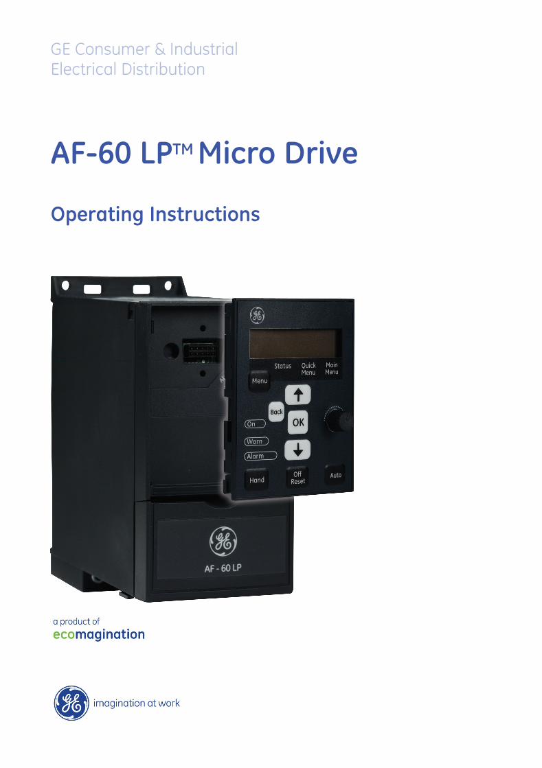
AF-60 LPTM Micro Drive
Operating Instructions
DET-579A132R0040
*MG02G202*
GE Consumer & IndustrialElectrical Distribution
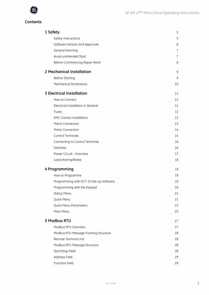
Contents
1 Safety 5
Safety Instructions 5
Software Version and Approvals 6
General Warning 7
Avoid unintended Start 7
Before Commencing Repair Work 8
2 Mechanical Installation 9
Before Starting 9
Mechanical Dimensions 10
3 Electrical Installation 11
How to Connect 11
Electrical Installation in General 11
Fuses 12
EMC-Correct Installation 13
Mains Connection 13
Motor Connection 14
Control Terminals 15
Connecting to Control Terminals 16
Switches 16
Power Circuit - Overview 17
Load sharing/Brake 18
4 Programming 19
How to Programme 19
Programming with DCT-10 Set-up Software 19
Programming with the Keypad 19
Status Menu 21
Quick Menu 21
Quick Menu Parameters 22
Main Menu 25
5 Modbus RTU 27
Modbus RTU Overview 27
Modbus RTU Message Framing Structure 28
Remote Terminal Unit 28
Modbus RTU Message Structure 28
Start/Stop Field 28
Address Field 29
Function Field 29
AF-60 LP™ Micro Drive Operating Instructions
DET-579A 1
Data Field 29
CRC Check Field 29
Coil/Register Addressing 29
How to Control the frequency converter 31
Function Codes Supported by Modbus RTU 31
Exception and Error Codes 31
How to Access Parameters 32
Parameter Handling 32
Storage of Data 32
IND 32
Text Blocks 32
Conversion Factor 32
Parameter Values 32
Examples 33
Read Coil Status (01HEX) 33
Force/Write Single Coil (05HEX) 33
Force/Write Multiple Coils (0FHEX) 34
Read Holding Registers (03HEX) 34
Preset Single Register (06HEX) 35
Preset Multiple Registers (10HEX) 36
GE Drive Control Profile 37
Control Word According to GE Drive Control Profile 37
Explanation of the Control Bits 37
Status Word According to GE Drive Control Profile (STW) 39
Explanation of the Status Bits 40
Bus Speed Reference Value 41
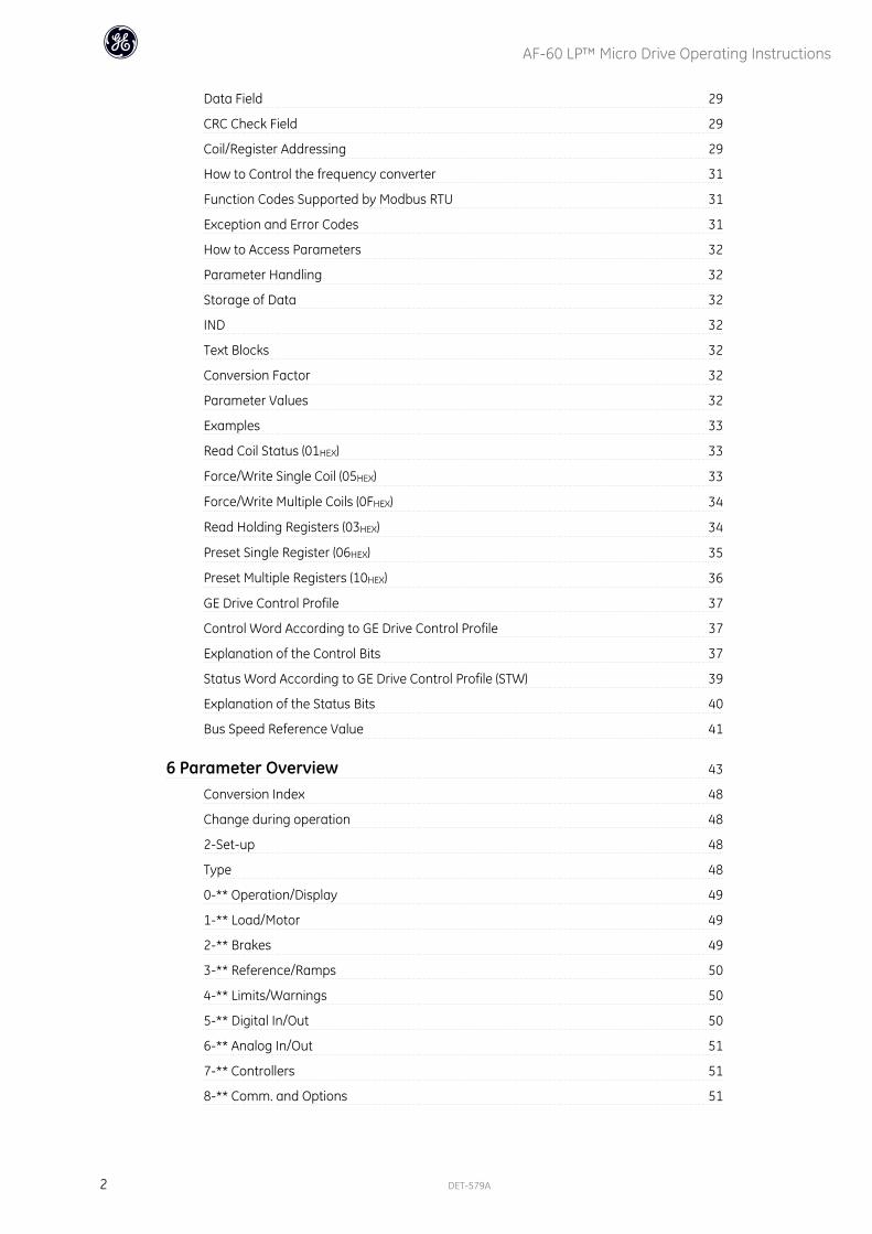
6 Parameter Overview 43
Conversion Index 48
Change during operation 48
2-Set-up 48
Type 48
0-** Operation/Display 49
1-** Load/Motor 49
2-** Brakes 49
3-** Reference/Ramps 50
4-** Limits/Warnings 50
5-** Digital In/Out 50
6-** Analog In/Out 51
7-** Controllers 51
8-** Comm. and Options 51
AF-60 LP™ Micro Drive Operating Instructions
2 DET-579A
13-** Logic Controller 52
14-** Special Functions 52
15-** Drive Information 52
16-** Data Readouts 53
7 Troubleshooting 55
Alarm, Warning and Extended Status Word 57
8 Specifications 59
Mains Supply 59
Other Specifications 62
Special Conditions 65
The Purpose of Derating 65
Derating for Ambient Temperature 65
Derating for Low Air Pressure 65
Derating for Running at Low Speeds 65
Options for AF-60 LP™ Micro Drive 66
Index 67
AF-60 LP™ Micro Drive Operating Instructions
DET-579A 3

AF-60 LP™ Micro Drive Operating Instructions
4 DET-579A
1
1 Safety
1.1.1 High Voltage Warning
The voltage of the frequency converter is dangerous whenever it is connected to mains. Incorrect installation of the motor or frequency
converter may cause damage to the equipment, serious injury or death. Consequently, it is essential to comply with the instructions in this
manual as well as local and national rules and safety regulations.
1.1.2 Safety Instructions
Prior to using functions directly or indirectly influencing personal safety (e.g. Fire Mode or other functions either forcing the motor to stop or
attempting to keep it functioning) a thorough risk analysis and system test must be carried through. The system tests must include testing
failure modes regarding the control signalling (analog and digital signals and serial communication.
• Make sure the frequency converter is properly connected to earth.
• Do not remove mains connections, motor connections or other power connections while the frequency converter is connected to power.
• Protect users against supply voltage.
• Protect the motor against overloading according to national and local regulations.
• The earth leakage current exceeds 3.5 mA.
• The [OFF] key is not a safety switch. It does not disconnect the frequency converter from mains.
AF-60 LP™ Micro Drive Operating Instructions
DET-579A 5
1
1.1.3 Software Version and Approvals
Software VersionOperating InstructionsAF-60 LP™ Micro Drive
Series
This Operating Instructions canbe used for all AF-60 LP™ Micro
Drive frequency converterswith software version 2.1x.
The software version numbercan be read in
parameter 15-43.
AF-60 LP™ Micro Drive Operating Instructions
6 DET-579A
1
1.1.4 General Warning
Warning:
Touching the electrical parts may be fatal - even after the equipment has been disconnected from mains.
Also make sure that other voltage inputs have been disconnected (such as external DC bus power supplies).
Be aware that there may be high voltage on the DC link even when the LEDs are turned off.
Before touching any potentially live parts of the frequency converter, wait at least 4 minutes for all sizes.
Shorter time is allowed only if indicated on the nameplate for the specific unit.
Leakage Current
The earth leakage current from the frequency converter exceeds 3.5 mA. According to IEC 61800-5-1 a reinforced Protective Earth connection
must be ensured by means of a min. 10mm² Cu or an addtional PE wire - with the same cable cross section as the Mains wiring - must be
terminated separately.
Residual Current Device
This product can cause a DC current in the protective conductor. Where a residual current device (RCD) is used for extra protection, only an
RCD of Type B (time delayed) shall be used on the supply side of this product.
Protective earthing of the frequency converter and the use of RCDs must always follow national and local regulations.
Motor overload protection is possible by setting Parameter 1-90 Motor thermal protection to the value Electronic overload trip. For the North
American market: Electronic overload functions provide class 20 motor overload protection, in accordance with NEC.
Installation in high altitudes:
For altitudes above 2 km, please contact GE .
1.1.5 IT Mains
IT Mains
Installation on isolated mains source, i.e. IT mains.
Max. supply voltage allowed when connected to mains: 440 V.
As an option, GE offers line filters for improved harmonics performance.
1.1.6 Avoid unintended Start
While the frequency converter is connected to mains, the motor can be started/stopped using digital commands, bus commands, references or via the drive
Keypad.
• Disconnect the frequency converter from mains whenever personal safety considerations make it necessary to avoid unintended start of any motors.
• To avoid unintended start, always activate the [OFF] key before changing parameters.
AF-60 LP™ Micro Drive Operating Instructions
DET-579A 7
1
1.1.7 Disposal Instruction
Equipment containing electrical components must not be disposed of together with domestic waste.
It must be separately collected with electrical and electronic waste according to local and currently valid legislation.
1.1.8 Before Commencing Repair Work
1. Disconnect AF-60 LP™ Micro Drive from mains (and external DC supply, if present.)
2. Wait for 4 minutes (M1, M2 and M3) and 15 minutes (M4 and M5) for discharge of the DC-link.
3. Disconnect DC bus terminals and brake terminals (if present)
4. Remove motor cable
AF-60 LP™ Micro Drive Operating Instructions
8 DET-579A
1

2 Mechanical Installation
2.1 Before Starting
2.1.1 Checklist
When unpacking the frequency converter, make sure that the unit is undam-
aged and complete. Check that the packaging contains the following:
• AF-60 LP™ Micro Drive
• Quick Guide
Illustration 2.1: Content of box.
2.2 Side-by-Side InstallationThe frequency converter can be mounted side-by-side for IP 20 rating units and requires 100 mm or 3.94 inclearance above and below for cooling. Regarding
surroundings in general, please see chapter 7. Specifications.
Illustration 2.2: Side-by-side installation.
AF-60 LP™ Micro Drive Operating Instructions
DET-579A 9
2
2.3.1 Mechanical Dimensions
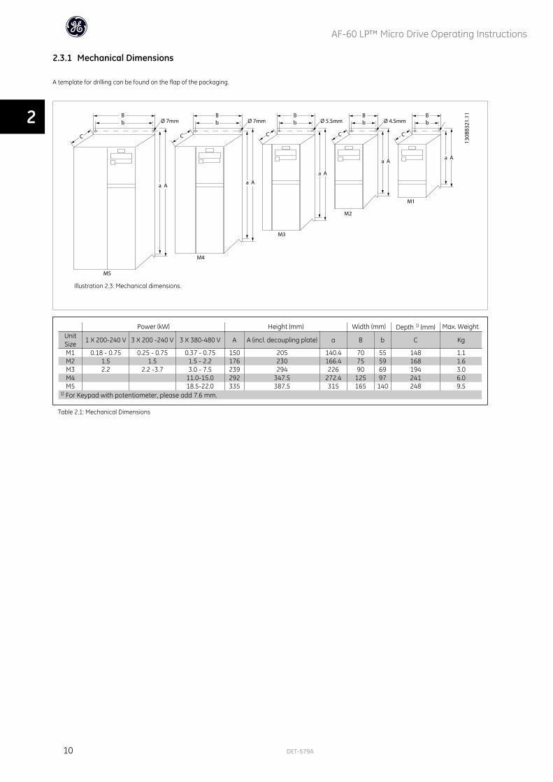
A template for drilling can be found on the flap of the packaging.
Illustration 2.3: Mechanical dimensions.
Power (kW) Height (mm) Width (mm) Depth 1) (mm) Max. WeightUnitSize 1 X 200-240 V 3 X 200 -240 V 3 X 380-480 V A A (incl. decoupling plate) a B b C Kg
M1 0.18 - 0.75 0.25 - 0.75 0.37 - 0.75 150 205 140.4 70 55 148 1.1M2 1.5 1.5 1.5 - 2.2 176 230 166.4 75 59 168 1.6M3 2.2 2.2 -3.7 3.0 - 7.5 239 294 226 90 69 194 3.0M4 11.0-15.0 292 347.5 272.4 125 97 241 6.0M5 18.5-22.0 335 387.5 315 165 140 248 9.5
1) For Keypad with potentiometer, please add 7.6 mm.
Table 2.1: Mechanical Dimensions
AF-60 LP™ Micro Drive Operating Instructions
10 DET-579A
2
3 Electrical Installation
3.1 How to Connect
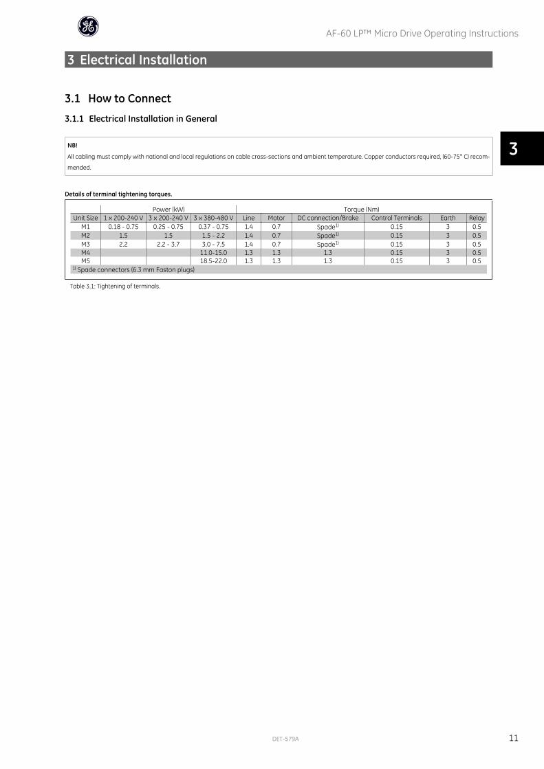
3.1.1 Electrical Installation in General
NB!
All cabling must comply with national and local regulations on cable cross-sections and ambient temperature. Copper conductors required, (60-75° C) recom-
mended.
Details of terminal tightening torques.
Power (kW) Torque (Nm)Unit Size 1 x 200-240 V 3 x 200-240 V 3 x 380-480 V Line Motor DC connection/Brake Control Terminals Earth Relay
M1 0.18 - 0.75 0.25 - 0.75 0.37 - 0.75 1.4 0.7 Spade1) 0.15 3 0.5M2 1.5 1.5 1.5 - 2.2 1.4 0.7 Spade1) 0.15 3 0.5M3 2.2 2.2 - 3.7 3.0 - 7.5 1.4 0.7 Spade1) 0.15 3 0.5M4 11.0-15.0 1.3 1.3 1.3 0.15 3 0.5M5 18.5-22.0 1.3 1.3 1.3 0.15 3 0.5
1) Spade connectors (6.3 mm Faston plugs)
Table 3.1: Tightening of terminals.
AF-60 LP™ Micro Drive Operating Instructions
DET-579A 11
3

3.1.2 Fuses
Branch circuit protection:
In order to protect the installation against electrical and fire hazard, all branch circuits in an installation, switch gear, machines etc., must be short-circuited and
overcurrent protected according to national/international regulations.
Short circuit protection:
GE Drive is suitable for a circuit capable of supplying a maximum of 100,000 Arms (symmetrical), 480 V maximum.
Overcurrent protection:
Provide overload protection to avoid overheating of the cables in the installation. Overcurrent protection must always be carried out according to national
regulations.
Non UL compliance:
If UL/cUL is not to be complied with, GE recommends using the fuses mentioned in the below table, which will ensure compliance with EN50178/IEC61800-5-1:
In case of malfunction, not following the fuse recommendation may result in damage to the frequency converter.
Max. fuses ULMax. fuses non ULBussmann Bussmann Bussmann Littel fuse Ferraz-
ShawmutFerraz-
Shawmut1 X 200-240 V
Type RK1 Type J Type T Type RK1 Type CC Type RK1 Type gG1/4 - 1/2 KTN-R15 JKS-15 JJN-15 KLN-R15 ATM-R15 A2K-15R 16A1 KTN-R25 JKS-25 JJN-25 KLN-R25 ATM-R25 A2K-25R 25A2 KTN-R35 JKS-35 JJN-35 KLN-R35 - A2K-35R 35A3 KTN-R50 JKS-50 JJN-50 KLN-R50 - A2K-50R 50A3 x 200-240 V1/3 KTN-R10 JKS-10 JJN-10 KLN-R10 ATM-R10 A2K-10R 10A1/2 KTN-R15 JKS-15 JJN-15 KLN-R15 ATM-R15 A2K-15R 16A1 KTN-R20 JKS-20 JJN-20 KLN-R20 ATM-R20 A2K-20R 20A2 KTN-R25 JKS-25 JJN-25 KLN-R25 ATM-R25 A2K-25R 25A3 KTN-R40 JKS-40 JJN-40 KLN-R40 ATM-R40 A2K-40R 40A5 KTN-R40 JKS-40 JJN-40 KLN-R40 - A2K-40R 40A3 x 380-480 V1/2 - 1 KTS-R10 JKS-10 JJS-10 KLS-R10 ATM-R10 A6K-10R 10A2 KTS-R15 JKS-15 JJS-15 KLS-R15 ATM-R15 A2K-15R 16A3 KTS-R20 JKS-20 JJS-20 KLS-R20 ATM-R20 A6K-20R 20A4 KTS-R40 JKS-40 JJS-40 KLS-R40 ATM-R40 A6K405R 40A5 KTS-R40 JKS-40 JJS-40 KLS-R40 ATM-R40 A6K-40R 40A7.5 KTS-R40 JKS-40 JJS-40 KLS-R40 - A6K-40R 40A10 KTS-R40 JKS-40 JJS-40 KLS-R40 - A6K-40R 40A15 KTS-R60 JKS-60 JJS-60 KLS-R60 - A6K-60R 63A20 KTS-R60 JKS-60 JJS-60 KLS-R60 - A6K-60R 63A25 KTS-R60 JKS-60 JJS-60 KLS-R60 - A6K-60R 80A30 KTS-R60 JKS-60 JJS-60 KLS-R60 - A6K-60R 80A
Table 3.2: Fuses
AF-60 LP™ Micro Drive Operating Instructions
12 DET-579A
3
3.1.3 EMC-Correct Installation
Following these guidelines is advised, where compliance with EN 61000-6-3/4, EN 55011 or EN 61800-3 First environment is required. If the installation is in EN
61800-3 Second environment, then it is acceptable to deviate from these guidelines. It is however not recommended.
Good engineering practice to ensure EMC-correct electrical installation:
• Use only braided screened/armoured motor cables and control cables.
The screen should provide a minimum coverage of 80%.The screen material must be metal, not limited to but typically copper, aluminium, steel or lead.
There are no special requirements for the mains cable.
• Installations using rigid metal conduits are not required to use screened cable, but the motor cable must be installed in conduit separate from the control
and mains cables. Full connection of the conduit from the drive to the motor is required. The EMC performance of flexible conduits varies a lot and
information from the manufacturer must be obtained.
• Connect the screen/armour/conduit to earth at both ends for motor cables and control cables.
• Avoid terminating the screen/armour with twisted ends (pigtails). Such a termination increases the high frequency impedance of the screen, which
reduces its effectiveness at high frequencies. Use low impedance cable clamps or glands instead.
• Ensure good electrical contact between the de-coupling plate and the metal chassis of the frequency converter, see Instruction
• Avoid using unscreened/unarmoured motor or control cables inside cabinets housing the drive(s), where possible.
3.2 Mains Connection
3.2.1 Connecting to Mains
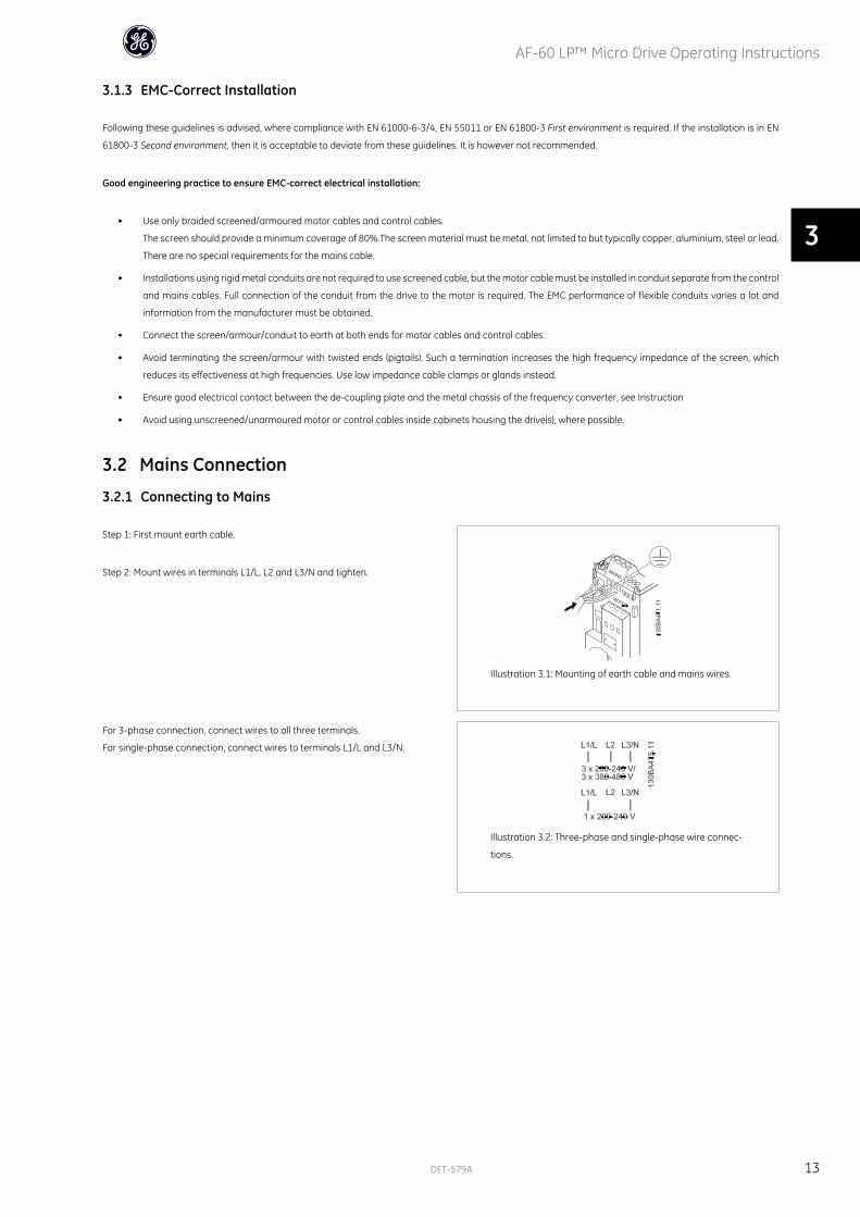
Step 1: First mount earth cable.
Step 2: Mount wires in terminals L1/L, L2 and L3/N and tighten.
Illustration 3.1: Mounting of earth cable and mains wires.
For 3-phase connection, connect wires to all three terminals.
For single-phase connection, connect wires to terminals L1/L and L3/N.
Illustration 3.2: Three-phase and single-phase wire connec-
tions.
AF-60 LP™ Micro Drive Operating Instructions
DET-579A 13
3
3.3 Motor Connection
3.3.1 How to Connect the Motor
See the chapter Specifications for correct dimensioning of motor cable cross-section and length.
• Use a shielded/armored motor cable to comply with EMC emission specifications, and connect this cable to both the decoupling plate and the motor
metal.
• Keep motor cable as short as possible to reduce the noise level and leakage currents.
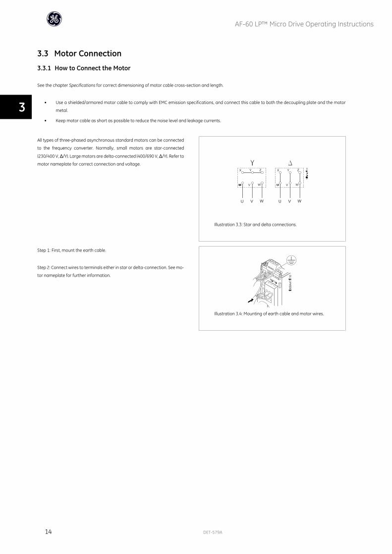
All types of three-phased asynchronous standard motors can be connected
to the frequency converter. Normally, small motors are star-connected
(230/400 V, Δ/Y). Large motors are delta-connected (400/690 V, Δ/Y). Refer to
motor nameplate for correct connection and voltage.
Illustration 3.3: Star and delta connections.
Step 1: First, mount the earth cable.
Step 2: Connect wires to terminals either in star or delta-connection. See mo-
tor nameplate for further information.
Illustration 3.4: Mounting of earth cable and motor wires.
AF-60 LP™ Micro Drive Operating Instructions
14 DET-579A
3
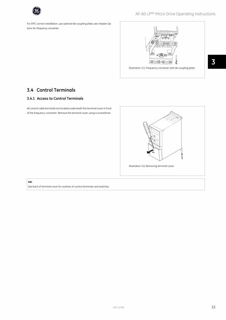
For EMC correct installation, use optional de-coupling plate, see chapter Op-
tions for frequency converter.
Illustration 3.5: Frequency converter with de-coupling plate
3.4 Control Terminals
3.4.1 Access to Control Terminals
All control cable terminals are located underneath the terminal cover in front
of the frequency converter. Remove the terminal cover using a screwdriver.
Illustration 3.6: Removing terminal cover.
NB!
See back of terminal cover for outlines of control terminals and switches.
AF-60 LP™ Micro Drive Operating Instructions
DET-579A 15
3
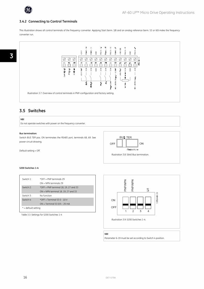
3.4.2 Connecting to Control Terminals
This illustration shows all control terminals of the frequency converter. Applying Start (term. 18) and an analog reference (term. 53 or 60) make the frequency
converter run.
Illustration 3.7: Overview of control terminals in PNP-configuration and factory setting.
3.5 Switches
NB!
Do not operate switches with power on the frequency converter.
Bus termination:
Switch BUS TER pos. ON terminates the RS485 port, terminals 68, 69. See
power circuit drawing.
Default setting = Off.
Illustration 3.8: S640 Bus termination.
S200 Switches 1-4:
Switch 1: *OFF = PNP terminals 29
ON = NPN terminals 29
Switch 2: *OFF = PNP terminal 18, 19, 27 and 33
ON = NPN terminal 18, 19, 27 and 33
Switch 3: No function
Switch 4: *OFF = Terminal 53 0 - 10 V
ON = Terminal 53 0/4 - 20 mA
* = default setting
Table 3.3: Settings for S200 Switches 1-4
Illustration 3.9: S200 Switches 1-4.
NB!
Parameter 6-19 must be set according to Switch 4 position.
AF-60 LP™ Micro Drive Operating Instructions
16 DET-579A
3
3.6 Power Circuit - Overview
3.6.1 Power Circuit - Overview
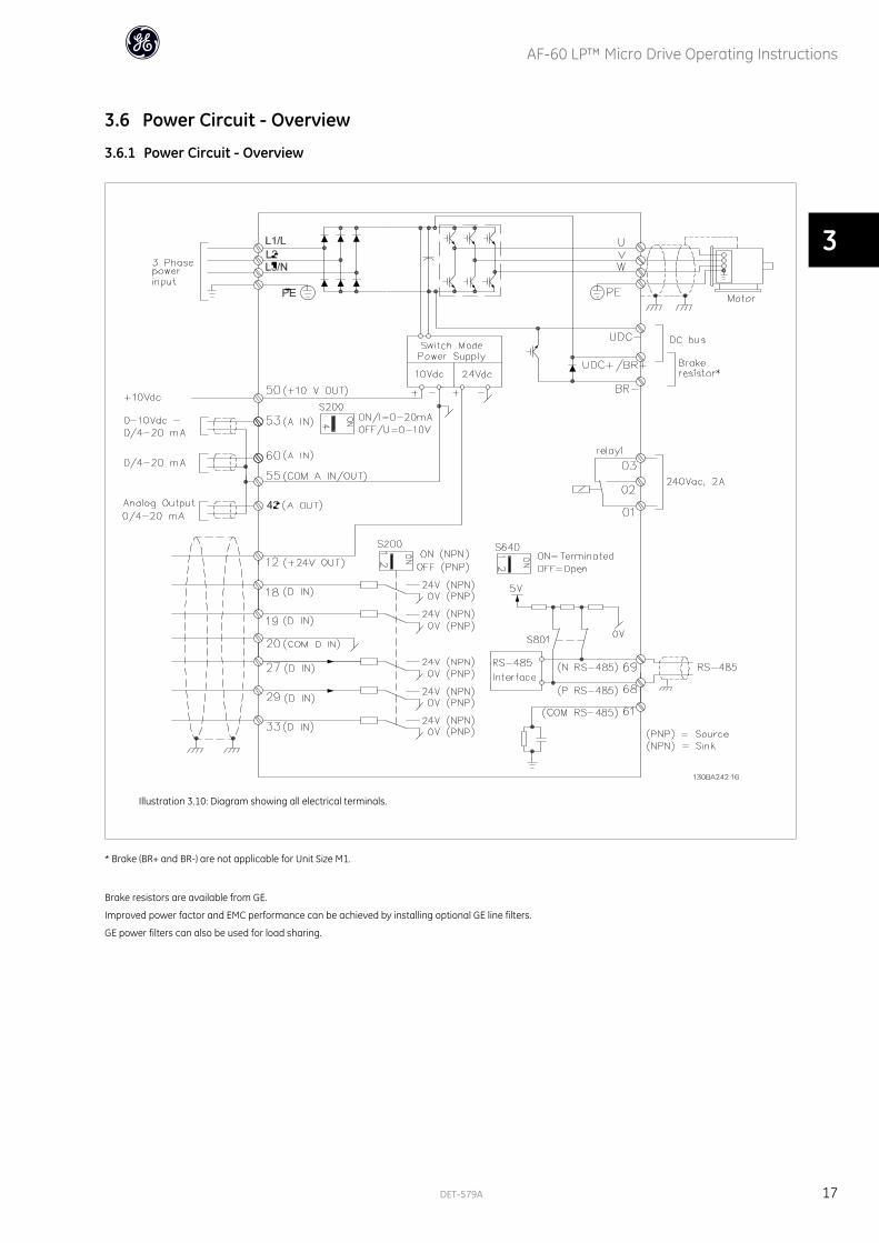
Illustration 3.10: Diagram showing all electrical terminals.
* Brake (BR+ and BR-) are not applicable for Unit Size M1.
Brake resistors are available from GE.
Improved power factor and EMC performance can be achieved by installing optional GE line filters.
GE power filters can also be used for load sharing.
AF-60 LP™ Micro Drive Operating Instructions
DET-579A 17
3

3.6.2 Load sharing/Brake
Use 6.3 mm insulated Faston Plugs designed for high voltage for DC (Load Sharing and brake).
Load sharing: Connect terminals UDC- and UDC/BR+.
Brake: Connect terminals BR- and UDC/BR+ (Not applicable for Unit Size M1).
Note that voltage levels of up to 850 V DC may occur between terminals
UDC+/BR+ and UDC-. Not short circuit protected.
AF-60 LP™ Micro Drive Operating Instructions
18 DET-579A
3
4 Programming
4.1 How to Programme
4.1.1 Programming with DCT-10 Set-up Software
The frequency converter can be programmed from a PC via RS485 com-port by installing the DCT-10 Set-up Software.
This software can be downloaded from the GE Web site: www.geelectrical.com/drives
4.1.2 Programming with the Keypad
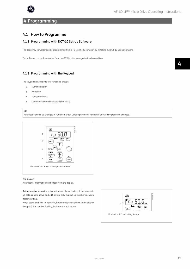
The Keypad is divided into four functional groups:
1. Numeric display.
2. Menu key.
3. Navigation keys.
4. Operation keys and indicator lights (LEDs).
NB!
Parameters should be changed in numerical order. Certain parameter values are affected by preceding changes.
Illustration 4.1: Keypad with potentiometer
The display:
A number of information can be read from the display.
Set-up number shows the active set-up and the edit set-up. If the same set-
up acts as both active and edit set-up, only that set-up number is shown
(factory setting).
When active and edit set-up differ, both numbers are shown in the display
(Setup 12). The number flashing, indicates the edit set-up.
Illustration 4.2: Indicating Set-up
AF-60 LP™ Micro Drive Operating Instructions
DET-579A 19
4
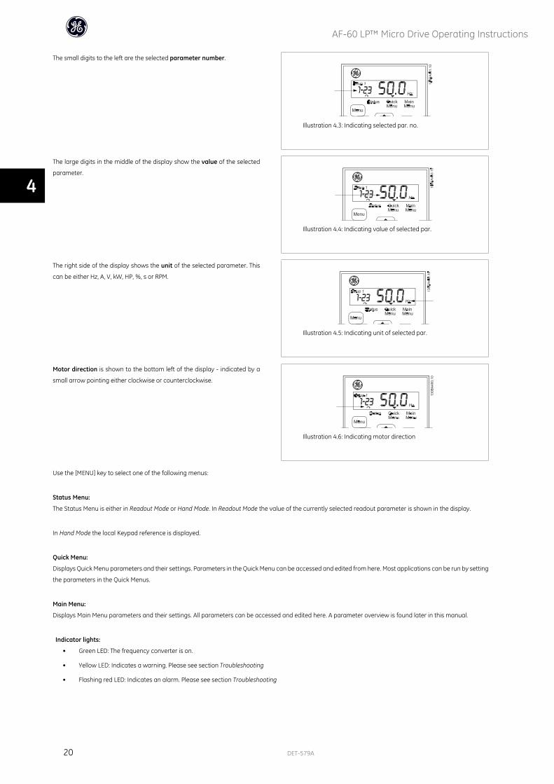
The small digits to the left are the selected parameter number.
Illustration 4.3: Indicating selected par. no.
The large digits in the middle of the display show the value of the selected
parameter.
Illustration 4.4: Indicating value of selected par.
The right side of the display shows the unit of the selected parameter. This
can be either Hz, A, V, kW, HP, %, s or RPM.
Illustration 4.5: Indicating unit of selected par.
Motor direction is shown to the bottom left of the display - indicated by a
small arrow pointing either clockwise or counterclockwise.
Illustration 4.6: Indicating motor direction
Use the [MENU] key to select one of the following menus:
Status Menu:
The Status Menu is either in Readout Mode or Hand Mode. In Readout Mode the value of the currently selected readout parameter is shown in the display.
In Hand Mode the local Keypad reference is displayed.
Quick Menu:
Displays Quick Menu parameters and their settings. Parameters in the Quick Menu can be accessed and edited from here. Most applications can be run by setting
the parameters in the Quick Menus.
Main Menu:
Displays Main Menu parameters and their settings. All parameters can be accessed and edited here. A parameter overview is found later in this manual.
Indicator lights:
• Green LED: The frequency converter is on.
• Yellow LED: Indicates a warning. Please see section Troubleshooting
• Flashing red LED: Indicates an alarm. Please see section Troubleshooting
AF-60 LP™ Micro Drive Operating Instructions
20 DET-579A
4
Navigation Keys:
[Back]: For moving to the previous step or layer in the navigation structure.
Arrows [] []: For maneuvering between parameter groups, parameters and within parameters.
[OK]: For selecting a parameter and for accepting changes to parameter settings.
Operation Keys:
A yellow light above the operation keys indicates the active key.
[Hand ]: Starts the motor and enables control of the frequency converter via the Keypad.
[Off/Reset]: The motor stops except in alarm mode. In that case the motor will be reset.
[Auto ]: The frequency converter is controlled either via control terminals or serial communication.
[Potentiometer] Keypad: The potentiometer works in two ways depending on the mode in which the frequency converter is running.
In Auto Mode the potentiometer acts as an extra programmable analog input.
In Hand Mode the potentiometer controls local reference.
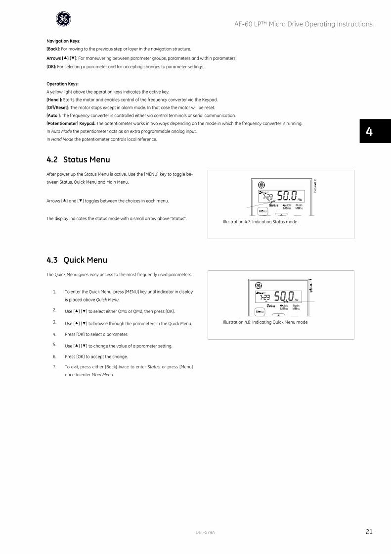
4.2 Status MenuAfter power up the Status Menu is active. Use the [MENU] key to toggle be-
tween Status, Quick Menu and Main Menu.
Arrows [] and [] toggles between the choices in each menu.
The display indicates the status mode with a small arrow above “Status”.Illustration 4.7: Indicating Status mode
4.3 Quick MenuThe Quick Menu gives easy access to the most frequently used parameters.
1. To enter the Quick Menu, press [MENU] key until indicator in display
is placed above Quick Menu.
2. Use [] [] to select either QM1 or QM2, then press [OK].
3. Use [] [] to browse through the parameters in the Quick Menu.
4. Press [OK] to select a parameter.
5. Use [] [] to change the value of a parameter setting.
6. Press [OK] to accept the change.
7. To exit, press either [Back] twice to enter Status, or press [Menu]
once to enter Main Menu.
Illustration 4.8: Indicating Quick Menu mode
AF-60 LP™ Micro Drive Operating Instructions
DET-579A 21
4
4.4 Quick Menu Parameters
4.4.1 Quick Menu Parameters - Basic Settings QM1
Below are descriptions of all parameters found in the Quick Menu.
* = Factory setting.
1-20 Motor Power [kW]/[HP] (Pm.n)
Option: Function:
Enter motor power from nameplate data.
Two sizes down, one size up from nominal AF-60 LP™ rating.
[1] 0.09 kW/0.12 HP
[2] 0.12 kW/0.16 HP
[3] 0.18kW/0.25 HP
[4] 0.25 kW/0.33 HP
[5] 0.37kW/0.50 HP
[6] 0.55 kW/0.75 HP
[7] 0.75 kW/1.00 HP
[8] 1.10 kW/1.50 HP
[9] 1.50 kW/2.00 HP
[10] 2.20 kW/3.00 HP
[11] 3.00 kW/4.00 HP
[12] 3.70 kW/5.00 HP
[13] 4.00 kW/5.40 HP
[14] 5.50 kW/7.50 HP
[15] 7.50 kW/10.0 HP
[16] 11.00 kW/15.00 HP
[17] 15.00 kW/20.00 HP
[18] 18.50 kW/25.00 HP
[19] 22.00 kW/29.50 HP
[20] 30.00 kW/40.00 HP
NB!
Changing this parameter affects par. 1-22 to 1-25, 1-30, 1-33 and 1-35.
1-22 Motor Voltage (U m.n)
Range: Function:
230/400 V [50 - 999 V] Enter motor voltage from nameplate data.
1-23 Motor Frequency (f m.n)
Range: Function:
60 Hz* [20-400 Hz] Enter motor frequency from nameplate data.
1-24 Motor Current (I m.n)
Range: Function:
M-type de-
pendent*
[0.01 - 100.00 A] Enter motor current from nameplate data.
AF-60 LP™ Micro Drive Operating Instructions
22 DET-579A
4
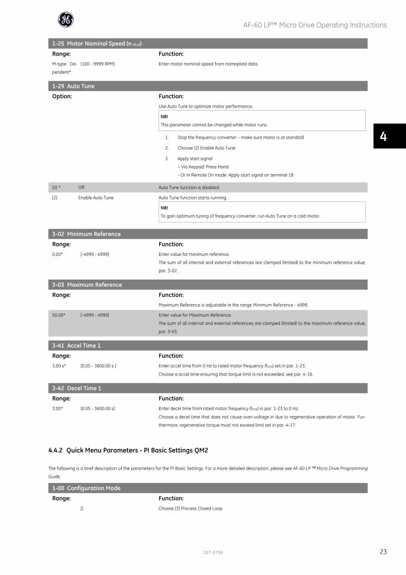
1-25 Motor Nominal Speed (n m.n)
Range: Function:
M-type De-
pendent*
[100 - 9999 RPM] Enter motor nominal speed from nameplate data.
1-29 Auto Tune
Option: Function:
Use Auto Tune to optimize motor performance.
NB!
This parameter cannot be changed while motor runs.
1. Stop the frequency converter – make sure motor is at standstill
2. Choose [2] Enable Auto Tune
3. Apply start signal
– Via Keypad: Press Hand
- Or in Remote On mode: Apply start signal on terminal 18
[0] * Off Auto Tune function is disabled.
[2] Enable Auto Tune Auto Tune function starts running.
NB!
To gain optimum tuning of frequency converter, run Auto Tune on a cold motor.
3-02 Minimum Reference
Range: Function:
0.00* [-4999 - 4999] Enter value for minimum reference.
The sum of all internal and external references are clamped (limited) to the minimum reference value,
par. 3-02.
3-03 Maximum Reference
Range: Function:
Maximum Reference is adjustable in the range Minimum Reference - 4999.
50.00* [-4999 - 4999] Enter value for Maximum Reference.
The sum of all internal and external references are clamped (limited) to the maximum reference value,
par. 3-03.
3-41 Accel Time 1
Range: Function:
3.00 s* [0.05 - 3600.00 s ] Enter accel time from 0 Hz to rated motor frequency (fM,N) set in par. 1-23.
Choose a accel time ensuring that torque limit is not exceeded, see par. 4-16.
3-42 Decel Time 1
Range: Function:
3.00* [0.05 - 3600.00 s] Enter decel time from rated motor frequency (fM,N) in par. 1-23 to 0 Hz.
Choose a decel time that does not cause over-voltage in due to regenerative operation of motor. Fur-
thermore, regenerative torque must not exceed limit set in par. 4-17.
4.4.2 Quick Menu Parameters - PI Basic Settings QM2
The following is a brief description of the parameters for the PI Basic Settings. For a more detailed description, please see AF-60 LP™ Micro Drive Programming
Guide.
1-00 Configuration Mode
Range: Function:
[] Choose [3] Process Closed Loop
AF-60 LP™ Micro Drive Operating Instructions
DET-579A 23
4

3-02 Min. Reference
Range: Function:
[-4999 - 4999] Sets limits for set-point and feedback.
3-03 Max. Reference
Range: Function:
[-4999 - 4999] Sets limits for set-point and feedback.
3-10 Preset Reference
Range: Function:
[-100.00 - 100.00] Preset [0] works as set-point.
4-12 Motor Speed Low Limit
Range: Function:
[0.0 - 400 Hz] Lowest possible output frequency.
4-14 Motor Speed High Limit
Range: Function:
[0.0 - 400.00 Hz] Highest possible output frequency.
6-22 Terminal 60 Low Current
Range: Function:
[0.00 - 19.99 mA] Normally set to 0 or 4 mA.
6-23 Terminal 60 High Current
Range: Function:
[0.01 - 20.00 mA] Normally (default) set to 20 mA.
6-24 Terminal 60 Low Feedback Value
Range: Function:
[-4999 - 4999] Value corresponding to P. 6-22 setting.
6-25 Terminal 60 High Feedback Value
Range: Function:
[-4999 - 4999] Value corresponding to P. 6-23 setting.
6-26 Terminal 60 Filter Time Constant
Range: Function:
[0.01 - 10.00 s] Filter for suppressing electrical noise.
7-20 Process CL Feedback Resource
Range: Function:
[] Choose [2] analog input 60.
7-30 Process PI Normal/Inverse
Range: Function:
[] Most PI controllers are “Normal”.
7-31 Process PI Anti Windup
Range: Function:
[] Leave Enabled normally.
7-32 Process PI Start Speed
Range: Function:
[0.0 - 200.0 Hz] Choose expected normal running speed.
AF-60 LP™ Micro Drive Operating Instructions
24 DET-579A
4
7-33 Process PI Proportional Gain
Range: Function:
[0.00 - 10.00] Enter the P-factor.
7-34 Process PI Integral Time
Range: Function:
[0.10 - 9999.00 s] Enter the I-factor.
7-38 Process Feed Forward Factor
Range: Function:
[0 - 400%] Only applicable with changing set-points.
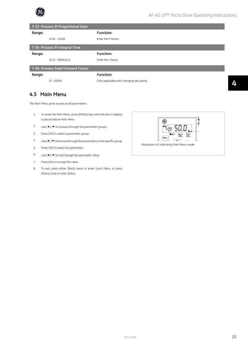
4.5 Main MenuThe Main Menu gives access to all parameters.
1. To enter the Main Menu, press [MENU] key until indicator in display
is placed above Main Menu.
2. Use [] [] to browse through the parameter groups.
3. Press [OK] to select a parameter group.
4. Use [] [] to browse through the parameters in the specific group.
5. Press [OK] to select the parameter.
6. Use [] [] to set/change the parameter value.
7. Press [OK] to accept the value.
8. To exit, press either [Back] twice to enter Quick Menu, or press
[Menu] once to enter Status.
Illustration 4.9: Indicating Main Menu mode
AF-60 LP™ Micro Drive Operating Instructions
DET-579A 25
4

AF-60 LP™ Micro Drive Operating Instructions
26 DET-579A
5
5 Modbus RTU
5.1 Modbus RTU Overview
5.1.1 Assumptions
These operating instructions assume that the installed controller supports the interfaces in this document and that all the requirements stipulated in the controller,
as well as the frequency converter, are strictly observed, along with all limitations therein.
5.1.2 What the User Should Already Know
The Modbus RTU (Remote Terminal Unit) is designed to communicate with any controller that supports the interfaces defined in this document. It is assumed that
the user has full knowledge of the capabilities and limitations of the controller.
5.1.3 Modbus RTU Overview
Regardless of the type of physical communication networks, the Modbus RTU Overview describes the process a controller uses to request access to another
device. This includes how it will respond to requests from another device, and how errors will be detected and reported. It also establishes a common format for
the layout and contents of message fields.
During communications over a Modbus RTU network, the protocol determines how each controller will learn its device address, recognise a message addressed
to it, determine the kind of action to be taken, and extract any data or other information contained in the message. If a reply is required, the controller will construct
the reply message and send it.
Controllers communicate using a master-slave technique in which only one device (the master) can initiate transactions (called queries). The other devices (slaves)
respond by supplying the requested data to the master, or by taking the action requested in the query.
The master can address individual slaves, or can initiate a broadcast message to all slaves. Slaves return a message (called a response) to queries that are
addressed to them individually. No responses are returned to broadcast queries from the master. The Modbus RTU protocol establishes the format for the master’s
query by placing into it the device (or broadcast) address, a function code defining the requested action, any data to be sent, and an error-checking field. The
slave’s response message is also constructed using Modbus protocol. It contains fields confirming the action taken, any data to be returned, and an error-checking
field. If an error occurs in receipt of the message, or if the slave is unable to perform the requested action, the slave will construct an error message and send it
in response, or a time-out will occur.
5.1.4 Frequency Converter with Modbus RTU
The frequency converter communicates in Modbus RTU format over the built-in RS-485 interface. Modbus RTU provides access to the Control Word and Bus
Reference of the frequency converter.
The Control Word allows the Modbus master to control several important functions of the frequency converter:
• Start
• Stop of the frequency converter in various ways:
Coast stop
Quick stop
DC Brake stop
Normal (accel/decel) stop
• Reset after a fault trip
• Run at a variety of preset speeds
• Run in reverse
• Change the active set-up
• Control the frequency converter’s built-in relay
The Bus Reference is commonly used for speed control. It is also possible to access the parameters, read their values, and where possible, write values to them.
This permits a range of control options, including controlling the setpoint of the frequency converter when its internal PI controller is used.
AF-60 LP™ Micro Drive Operating Instructions
DET-579A 27
5
5.2 Modbus RTU Message Framing Structure
5.2.1 Remote Terminal Unit
The controllers are set up to communicate on the Modbus network using RTU (Remote Terminal Unit) mode, with each 8-bit byte in a message containing two 4-
bit hexadecimal characters.
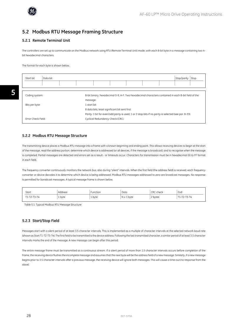
The format for each byte is shown below.
Start bit Data bit Stop/parity Stop
Coding system: 8-bit binary, hexadecimal 0-9, A-F. Two hexadecimal characters contained in each 8-bit field of the
message.
Bits per byte: 1 start bit
8 data bits, least significant bit sent first
Parity: 1 bit for even/odd parity is used; 1 or 2 stop bits if no parity is selected (see par. 8-33).
Error Check Field: Cyclical Redundancy Check (CRC).
5.2.2 Modbus RTU Message Structure
The transmitting device places a Modbus RTU message into a frame with a known beginning and ending point. This allows receiving devices to begin at the start
of the message, read the address portion, determine which device is addressed (or all devices, if the message is broadcast), and to recognise when the message
is completed. Partial messages are detected and errors set as a result - or timeouts occur. Characters for transmission must be in hexadecimal 00 to FF format
in each field.
The frequency converter continuously monitors the network bus, also during “silent” intervals. When the first field (the address field) is received, each frequency
converter or device decodes it to determine which device is being addressed. Modbus RTU messages addressed to zero are broadcast messages. No response
is permitted for boradcast messages. A typical message frame is shown below.
Start Address Function Data CRC check End
T1-T2-T3-T4 1 byte 1 byte N x 1 byte 2 bytes T1-T2-T3-T4
Table 5.1: Typical Modbus RTU Message Structure
5.2.3 Start/Stop Field
Messages start with a silent period of at least 3.5 character intervals. This is implemented as a multiple of character intervals at the selected network baud rate
(shown as Start T1-T2-T3-T4). The first field to be transmitted is the device address. Following the last transmitted character, a similar period of at least 3.5 character
intervals marks the end of the message. A new message can begin after this period.
The entire message frame must be transmitted as a continuous stream. If a silent period of more than 1.5 character intervals occurs before completion of the
frame, the receiving device flushes the incomplete message and assumes that the next byte will be the address field of a new message. Similarly, if a new message
begins prior to 3.5 character intervals after a previous message, the receiving device will ignore both messages. This will cause a time-out (no response from the
slave).
AF-60 LP™ Micro Drive Operating Instructions
28 DET-579A
5
5.2.4 Address Field
The address field of a message frame contains 1 byte. Valid slave device addresses are in the range of 0 - 247 decimal. The individual slave devices are assigned
addresses in the range of 1 - 247 (0 is reserved for broadcast mode, which all slaves recognise). A master addresses a slave by placing the slave address in the
address field of the message.
When the slave sends its response, it places its own address in this address field to let the master know which slave is responding.
5.2.5 Function Field
The function field of a message frame contains 1 byte. Function fields are used to send messages between master and slave. When a message is sent from a
master to a slave device, the function code field tells the slave what kind of action to perform. When the slave responds to the master, it uses the function code
field to indicate either a normal (error-free) response, or that some kind of error occurred (called an exception response).
For a normal response, the slave simply echoes the original function code. For an exception response, the slave returns a code that is equivalent to the original
code with its most significant bit set to logic 1. In addition, the slave places a unique code into the data field of the response message. This tells the master what
kind of error occurred, or the reason for the exception. Please also refer to the sections Function Codes Supported by Modbus RTU and Exception Codes.
5.2.6 Data Field
The data field is constructed using sets of two hexidecimal digits in the range of 00 to FF hexidecimal. These are made up of one RTU character. The data field of
messages sent from a master to a slave device contains additional information which the slave must use to take the action defined by the function code. This
can include items such as addresses of coils or registers, the quantity of items to be handled. and the count of actual data bytes in the field.
5.2.7 CRC Check Field
Messages include an error-checking field, operating on the basis of a Cyclical Redundancy Check (CRC) method. The CRC field checks the content of the entire
message. It is applied regardless of any parity check method used for the individual characters of the message.
The CRC value is calculated by the transmitting device, which appends the CRC as the last field in the message. The receiving device recalculates a CRC during
receipt of the message and compares the calculated value to the actual value received in the CRC field. If the two values are unequal, a bus time-out occurs. The
error-checking field contains a 16-bit binary value implemented as two 8-bit bytes. When this is done, the low-order byte of the field is appended first, followed
by the high-order byte. The CRC high-order byte is the last byte sent in the message.
5.2.8 Coil/Register Addressing
In Modbus, all data are organised in coils and holding registers. Coils hold a single bit, whereas holding registers hold a 2-byte word (i.e. 16 bits). All data addresses
in Modbus messages are referenced to zero. The first occurrence of a data item is addressed as item number zero.
Example:
The coil known as “coil 1” in programmable controller is addressed as coil 0000 in the data address field of a Modbus message. Coil 127 decimal is addressed as
coil 007EHEX (126 decimal).
Holding register 40001 is addressed as register 0000 in the data address field of the message. The function code field already specifies a “holding register”
operation. Therefore, the “4XXXX” reference is implicit. Holding register 40108 is addressed as register 006BHEX (107 decimal).
AF-60 LP™ Micro Drive Operating Instructions
DET-579A 29
5
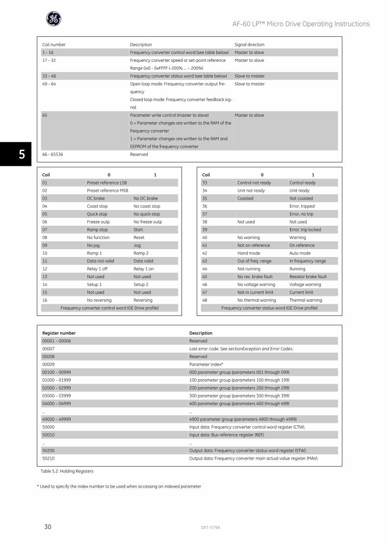
Coil number Description Signal direction
1 - 16 Frequency converter control word (see table below) Master to slave
17 - 32 Frequency converter speed or set-point reference
Range 0x0 - 0xFFFF (-200% ... ~ 200%)
Master to slave
33 - 48 Frequency converter status word (see table below) Slave to master
49 - 64 Open loop mode: Frequency converter output fre-
quency
Closed loop mode: Frequency converter feedback sig-
nal
Slave to master
65 Parameter write control (master to slave)
0 = Parameter changes are written to the RAM of the
frequency converter
1 = Parameter changes are written to the RAM and
EEPROM of the frequency converter
Master to slave
66 - 65536 Reserved
Coil 0 1
01 Preset reference LSB
02 Preset reference MSB
03 DC brake No DC brake
04 Coast stop No coast stop
05 Quick stop No quick stop
06 Freeze outp No freeze outp
07 Ramp stop Start
08 No function Reset
09 No jog Jog
10 Ramp 1 Ramp 2
11 Data not valid Data valid
12 Relay 1 off Relay 1 on
13 Not used Not used
14 Setup 1 Setup 2
15 Not used Not used
16 No reversing Reversing
Frequency converter control word (GE Drive profile)
Coil 0 1
33 Control not ready Control ready
34 Unit not ready Unit ready
35 Coasted Not coasted
36 Error, tripped
37 Error, no trip
38 Not used Not used
39 Error, trip locked
40 No warning Warning
41 Not on reference On reference
42 Hand mode Auto mode
43 Out of freq. range In frequency range
44 Not running Running
45 No res. brake fault Resistor brake fault
46 No voltage warning Voltage warning
47 Not in current limit Current limit
48 No thermal warning Thermal warning
Frequency converter status word (GE Drive profile)
Register number Description
00001 – 00006 Reserved
00007 Last error code. See sectionException and Error Codes.
00008 Reserved
00009 Parameter index*
00100 – 00999 000 parameter group (parameters 001 through 099)
01000 – 01999 100 parameter group (parameters 100 through 199)
02000 – 02999 200 parameter group (parameters 200 through 299)
03000 – 03999 300 parameter group (parameters 300 through 399)
04000 – 04999 400 parameter group (parameters 400 through 499)
… …
49000 – 49999 4900 parameter group (parameters 4900 through 4999)
50000 Input data: Frequency converter control word register (CTW).
50010 Input data: Bus reference register (REF).
… …
50200 Output data: Frequency converter status word register (STW).
50210 Output data: Frequency converter main actual value register (MAV).
Table 5.2: Holding Registers
* Used to specify the index number to be used when accessing an indexed parameter
AF-60 LP™ Micro Drive Operating Instructions
30 DET-579A
5
5.3 How to Control the frequency converterThis section describes codes which can be used in the function and data fields of a Modbus RTU message. For a complete description of all the message fields
please refer to the section Modbus RTU Message Framing Structure.
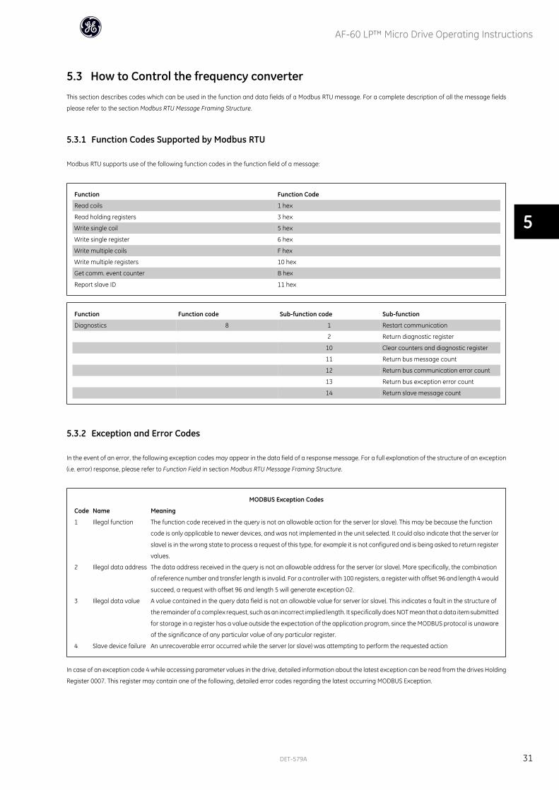
5.3.1 Function Codes Supported by Modbus RTU
Modbus RTU supports use of the following function codes in the function field of a message:
Function Function Code
Read coils 1 hex
Read holding registers 3 hex
Write single coil 5 hex
Write single register 6 hex
Write multiple coils F hex
Write multiple registers 10 hex
Get comm. event counter B hex
Report slave ID 11 hex
Function Function code Sub-function code Sub-function
Diagnostics 8 1 Restart communication
2 Return diagnostic register
10 Clear counters and diagnostic register
11 Return bus message count
12 Return bus communication error count
13 Return bus exception error count
14 Return slave message count
5.3.2 Exception and Error Codes
In the event of an error, the following exception codes may appear in the data field of a response message. For a full explanation of the structure of an exception
(i.e. error) response, please refer to Function Field in section Modbus RTU Message Framing Structure.
MODBUS Exception Codes
Code Name Meaning
1 Illegal function The function code received in the query is not an allowable action for the server (or slave). This may be because the function
code is only applicable to newer devices, and was not implemented in the unit selected. It could also indicate that the server (or
slave) is in the wrong state to process a request of this type, for example it is not configured and is being asked to return register
values.
2 Illegal data address The data address received in the query is not an allowable address for the server (or slave). More specifically, the combination
of reference number and transfer length is invalid. For a controller with 100 registers, a register with offset 96 and length 4 would
succeed, a request with offset 96 and length 5 will generate exception 02.
3 Illegal data value A value contained in the query data field is not an allowable value for server (or slave). This indicates a fault in the structure of
the remainder of a complex request, such as an incorrect implied length. It specifically does NOT mean that a data item submitted
for storage in a register has a value outside the expectation of the application program, since the MODBUS protocol is unaware
of the significance of any particular value of any particular register.
4 Slave device failure An unrecoverable error occurred while the server (or slave) was attempting to perform the requested action
In case of an exception code 4 while accessing parameter values in the drive, detailed information about the latest exception can be read from the drives Holding
Register 0007. This register may contain one of the following, detailed error codes regarding the latest occurring MODBUS Exception.
AF-60 LP™ Micro Drive Operating Instructions
DET-579A 31
5
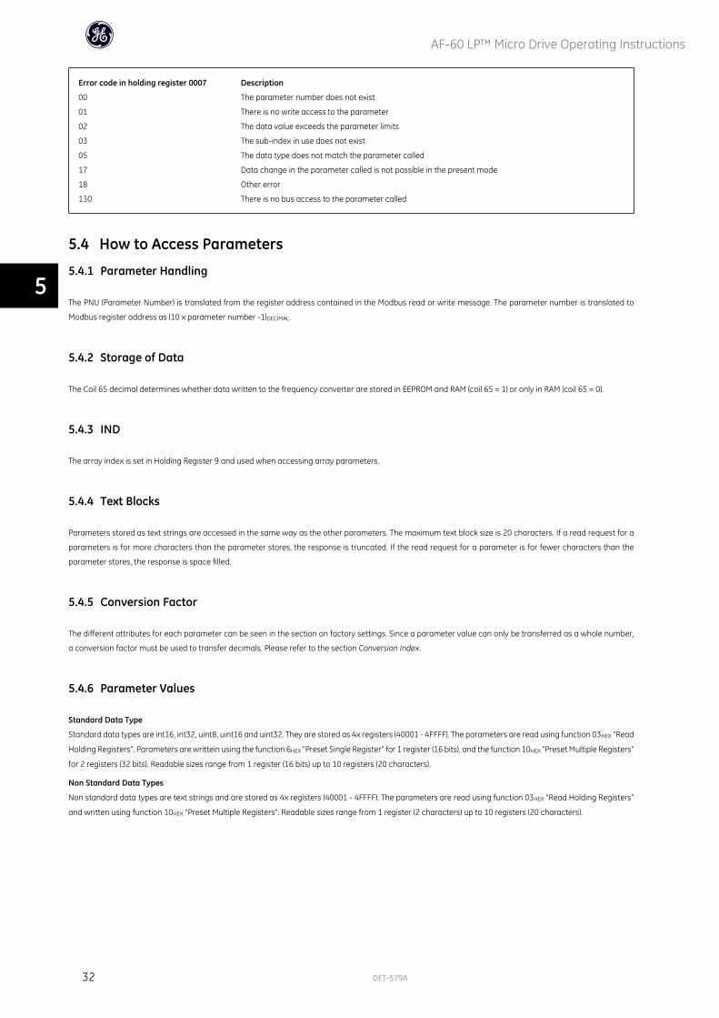
Error code in holding register 0007 Description
00 The parameter number does not exist
01 There is no write access to the parameter
02 The data value exceeds the parameter limits
03 The sub-index in use does not exist
05 The data type does not match the parameter called
17 Data change in the parameter called is not possible in the present mode
18 Other error
130 There is no bus access to the parameter called
5.4 How to Access Parameters
5.4.1 Parameter Handling
The PNU (Parameter Number) is translated from the register address contained in the Modbus read or write message. The parameter number is translated to
Modbus register address as (10 x parameter number -1)DECIMAL.
5.4.2 Storage of Data
The Coil 65 decimal determines whether data written to the frequency converter are stored in EEPROM and RAM (coil 65 = 1) or only in RAM (coil 65 = 0).
5.4.3 IND
The array index is set in Holding Register 9 and used when accessing array parameters.
5.4.4 Text Blocks
Parameters stored as text strings are accessed in the same way as the other parameters. The maximum text block size is 20 characters. If a read request for a
parameters is for more characters than the parameter stores, the response is truncated. If the read request for a parameter is for fewer characters than the
parameter stores, the response is space filled.
5.4.5 Conversion Factor
The different attributes for each parameter can be seen in the section on factory settings. Since a parameter value can only be transferred as a whole number,
a conversion factor must be used to transfer decimals. Please refer to the section Conversion Index.
5.4.6 Parameter Values
Standard Data Type
Standard data types are int16, int32, uint8, uint16 and uint32. They are stored as 4x registers (40001 - 4FFFF). The parameters are read using function 03HEX “Read
Holding Registers”. Parameters are writtein using the function 6HEX “Preset Single Register” for 1 register (16 bits), and the function 10HEX “Preset Multiple Registers”
for 2 registers (32 bits). Readable sizes range from 1 register (16 bits) up to 10 registers (20 characters).
Non Standard Data Types
Non standard data types are text strings and are stored as 4x registers (40001 - 4FFFF). The parameters are read using function 03HEX “Read Holding Registers”
and written using function 10HEX “Preset Multiple Registers”. Readable sizes range from 1 register (2 characters) up to 10 registers (20 characters).
AF-60 LP™ Micro Drive Operating Instructions
32 DET-579A
5
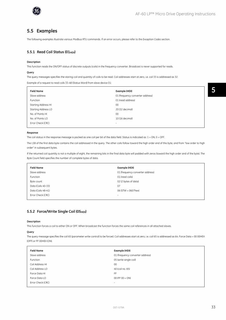
5.5 ExamplesThe following examples illustrate various Modbus RTU commands. If an error occurs, please refer to the Exception Codes section.
5.5.1 Read Coil Status (01HEX)
Description
This function reads the ON/OFF status of discrete outputs (coils) in the frequency converter. Broadcast is never supported for reads.
Query
The query messages specifies the staring coil and quantity of coils to be read. Coil addresses start at zero, i.e. coil 33 is addressed as 32.
Example of a request to read coils 33-48 (Status Word) from slave device 01:
Field Name Example (HEX)
Slave address 01 (frequency converter address)
Function 01 (read address)
Starting Address HI 00
Starting Address LO 20 (32 decimal)
No. of Points HI 00
No. of Points LO 10 (16 decimal)
Error Check (CRC) -
Response
The coil status in the response message is packed as one coil per bit of the data field. Status is indicated as: 1 = ON; 0 = OFF.
The LSB of the first data byte contains the coil addressed in the query. The other coils follow toward the high order end of this byte, and from “low order to high
order” in subsequent bytes.
If the returned coil quantity is not a multiple of eight, the remaining bits in the final data byte will padded with zeros (toward the high order and of the byte). The
Byte Count field specifies the number of complete bytes of data.
Field Name Example (HEX)
Slave address 01 (frequency converter address)
Function 01 (read coils)
Byte count 02 (2 bytes of data)
Data (Coils 40-33) 07
Data (Coils 48-41) 06 (STW = 0607hex)
Error Check (CRC) -
5.5.2 Force/Write Single Coil (05HEX)
Description
This function forces a coil to either ON or OFF. When broadcast the function forces the same coil references in all attached slaves.
Query
The query message specifies the coil 65 (parameter write control) to be forced. Coil addresses start at zero, i.e. coil 65 is addressed as 64. Force Data = 00 00HEX
(OFF) or FF 00HEX (ON).
Field Name Example (HEX)
Slave address 01 (frequency converter address)
Function 05 (write single coil)
Coil Address HI 00
Coil Address LO 40 (coil no. 65)
Force Data HI FF
Force Data LO 00 (FF 00 = ON)
Error Check (CRC) -
AF-60 LP™ Micro Drive Operating Instructions
DET-579A 33
5
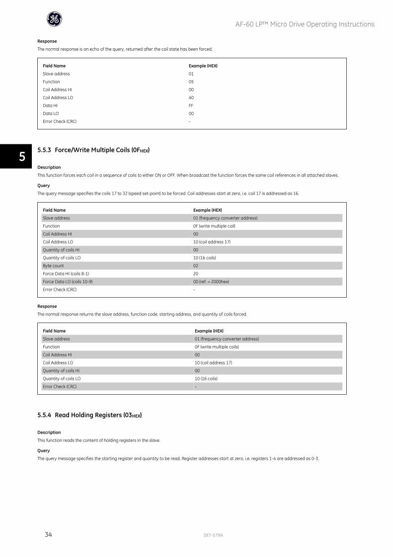
Response
The normal response is an echo of the query, returned after the coil state has been forced.
Field Name Example (HEX)
Slave address 01
Function 05
Coil Address HI 00
Coil Address LO 40
Data HI FF
Data LO 00
Error Check (CRC) -
5.5.3 Force/Write Multiple Coils (0FHEX)
Description
This function forces each coil in a sequence of coils to either ON or OFF. When broadcast the function forces the same coil references in all attached slaves.
Query
The query message specifies the coils 17 to 32 (speed set-point) to be forced. Coil addresses start at zero, i.e. coil 17 is addressed as 16.
Field Name Example (HEX)
Slave address 01 (frequency converter address)
Function 0F (write multiple coil)
Coil Address HI 00
Coil Address LO 10 (coil address 17)
Quantity of coils HI 00
Quantity of coils LO 10 (16 coils)
Byte count 02
Force Data HI (coils 8-1) 20
Force Data LO (coils 10-9) 00 (ref. = 2000hex)
Error Check (CRC) -
Response
The normal response returns the slave address, function code, starting address, and quantity of coils forced.
Field Name Example (HEX)
Slave address 01 (frequency converter address)
Function 0F (write multiple coils)
Coil Address HI 00
Coil Address LO 10 (coil address 17)
Quantity of coils HI 00
Quantity of coils LO 10 (16 coils)
Error Check (CRC) -
5.5.4 Read Holding Registers (03HEX)
Description
This function reads the content of holding registers in the slave.
Query
The query message specifies the starting register and quantity to be read. Register addresses start at zero, i.e. registers 1-4 are addressed as 0-3.
AF-60 LP™ Micro Drive Operating Instructions
34 DET-579A
5
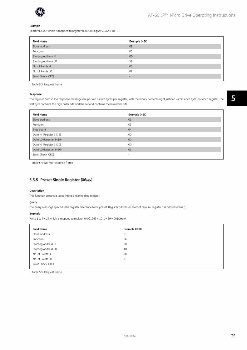
Example
Read PNU 342 which is mapped to register 0x0D5B(RegAdr = 342 x 10 - 1)
Field Name Example (HEX)
Slave address 01
Function 03
Starting Address HI 0D
Starting Address LO 5B
No. of Points HI 00
No. of Points LO 02
Error Check (CRC) -
Table 5.3: Request frame
Response
The register data in the response message are packed as two bytes per register, with the binary contents right justified within each byte. For each register, the
first byte contains the high order bits and the second contains the low order bits.
Field Name Example (HEX)
Slave address 01
Function 03
Byte count 04
Data HI (Register 3419) 00
Data LO (Register 3419) 00
Data HI (Register 3420) 00
Data LO (Register 3420) 03
Error Check (CRC) -
Table 5.4: Normal response frame
5.5.5 Preset Single Register (06HEX)
Description
This function presets a value into a single holding register.
Query
The query message specifies the register reference to be preset. Register addresses start at zero, i.e. register 1 is addressed as 0.
Example
Write 1 to PNU3 which is mapped to register 0x001D (3 x 10-1 = 29 = 001DHex)
Field Name Example (HEX)
Slave address 01
Function 06
Starting Address HI 00
Starting Address LO 1D
No. of Points HI 00
No. of Points LO 01
Error Check (CRC) -
Table 5.5: Request frame
AF-60 LP™ Micro Drive Operating Instructions
DET-579A 35
5
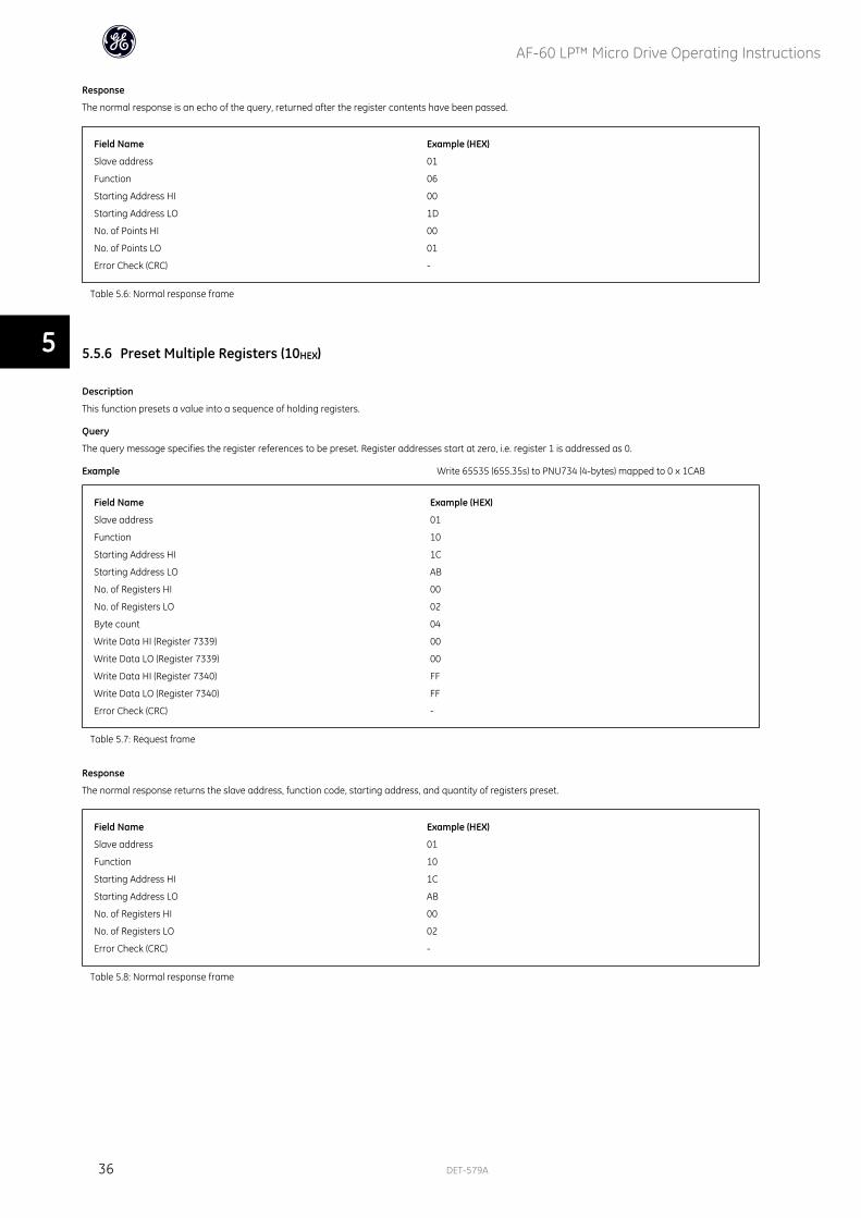
Response
The normal response is an echo of the query, returned after the register contents have been passed.
Field Name Example (HEX)
Slave address 01
Function 06
Starting Address HI 00
Starting Address LO 1D
No. of Points HI 00
No. of Points LO 01
Error Check (CRC) -
Table 5.6: Normal response frame
5.5.6 Preset Multiple Registers (10HEX)
Description
This function presets a value into a sequence of holding registers.
Query
The query message specifies the register references to be preset. Register addresses start at zero, i.e. register 1 is addressed as 0.
Example Write 65535 (655.35s) to PNU734 (4-bytes) mapped to 0 x 1CAB
Field Name Example (HEX)
Slave address 01
Function 10
Starting Address HI 1C
Starting Address LO AB
No. of Registers HI 00
No. of Registers LO 02
Byte count 04
Write Data HI (Register 7339) 00
Write Data LO (Register 7339) 00
Write Data HI (Register 7340) FF
Write Data LO (Register 7340) FF
Error Check (CRC) -
Table 5.7: Request frame
Response
The normal response returns the slave address, function code, starting address, and quantity of registers preset.
Field Name Example (HEX)
Slave address 01
Function 10
Starting Address HI 1C
Starting Address LO AB
No. of Registers HI 00
No. of Registers LO 02
Error Check (CRC) -
Table 5.8: Normal response frame
AF-60 LP™ Micro Drive Operating Instructions
36 DET-579A
5
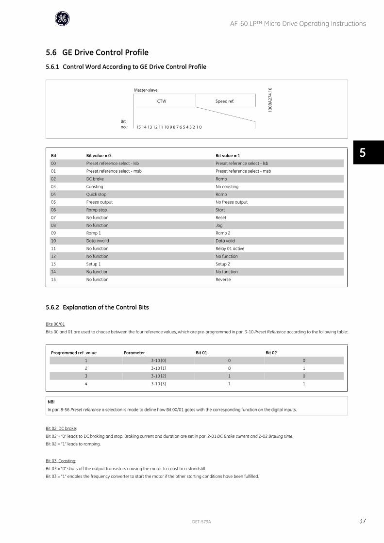
5.6 GE Drive Control Profile
5.6.1 Control Word According to GE Drive Control Profile
Bit Bit value = 0 Bit value = 1
00 Preset reference select - lsb Preset reference select - lsb
01 Preset reference select - msb Preset reference select - msb
02 DC brake Ramp
03 Coasting No coasting
04 Quick stop Ramp
05 Freeze output No freeze output
06 Ramp stop Start
07 No function Reset
08 No function Jog
09 Ramp 1 Ramp 2
10 Data invalid Data valid
11 No function Relay 01 active
12 No function No function
13 Setup 1 Setup 2
14 No function No function
15 No function Reverse
5.6.2 Explanation of the Control Bits
Bits 00/01
Bits 00 and 01 are used to choose between the four reference values, which are pre-programmed in par. 3-10 Preset Reference according to the following table:
Programmed ref. value Parameter Bit 01 Bit 02
1 3-10 [0] 0 0
2 3-10 [1] 0 1
3 3-10 [2] 1 0
4 3-10 [3] 1 1
NB!
In par. 8-56 Preset reference a selection is made to define how Bit 00/01 gates with the corresponding function on the digital inputs.
Bit 02, DC brake:
Bit 02 = “0” leads to DC braking and stop. Braking current and duration are set in par. 2-01 DC Brake current and 2-02 Braking time.
Bit 02 = “1” leads to ramping.
Bit 03, Coasting:
Bit 03 = “0” shuts off the output transistors causing the motor to coast to a standstill.
Bit 03 = “1” enables the frequency converter to start the motor if the other starting conditions have been fulfilled.
AF-60 LP™ Micro Drive Operating Instructions
DET-579A 37
5

NB!
In par. 8-50 Coasting select a selection is made to define how Bit 03 gates with the corresponding function on a digital input.
Bit 04, Quick stop:
Bit 04 = “0” causes a stop, in which the motor speed is ramped down to stop via 9ar. 3-81 Quick stop ramp time.
Bit 05, Hold output frequency:
Bit 05 = “0” causes the present output frequency (in Hz) to freeze. The frozen output frequency can then be changed only by means of the digital inputs (par. 5-10
to 5-15) programmed to Speed up and Speed down.
NB!
If Freeze output is active, the frequency converter can only be stopped by the following:
• Bit 03 Coasting stop
• Bit 02 DC braking
• Digital input (par. 5-10 to 5-15) programmed to DC braking, Coasting stop or Reset and coasting stop.
Bit 06, Ramp stop/start:
Bit 06 = “0” causes a stop, in which the motor speed is ramped down to stop via the selected ramp down parameter.
Bit 06 = “1” permits the frequency converter to start the motor, if the other starting conditions have been fulfilled.
NB!
In par. 8-53 Start select a selection is made to define how Bit 06 Ramp stop/start gates with the corresponding function on a digital input.
Bit 07, Reset:
Bit 07 = “0” does not cause a reset.
Bit 07 = “1” causes the reset of a trip. Reset is activated on the signal's leading edge, i.e. when changing from logic “0” to logic “1”.
Bit 08, Jog:
Bit 08 = “1” causes the output frequency to be determined by par. 3-19 Jog speed.
Bit 09, Selection of ramp 1/2:
Bit 09 = “0” means the ramp 1 is active (par. 3-40 to 3-47).
Bit 09 = ”1” means that ramp 2 (par. 3-50 to 3-57) is active.
Bit 10, Data not valid/Data valid:
Is used to tell the frequency converter whether the control word is to be used or ignored.
Bit 10 = “0” causes the control word to be ignored.
Bit 10 =”1” causes the control word to be used.
Bit 11, Relay 01:
Bit 11 = “0” Relay 01 not activated
Bit 11 = “1” Relay 01 is activated, provided Control word Bit 11 has been chosen in par. 5-40 Function relay.
AF-60 LP™ Micro Drive Operating Instructions
38 DET-579A
5
Bit 12:
Not used.
Bit 13, Selection of set-up:
Bit 13 = is used to choose the active set-up. The function is only possible when Multi set-ups is selected in par. 0-10 Active Set-up.
NB!
In par. 8-55 Set-up select a selection is made to define how Bit 13 gates with the corresponding function on the digital inputs.
Bit 14:
Not used.
Bit 15, Reverse:
Bit 15 = “0” causes no reversing.
Bit 15 = “1” causes reversing.
NB!
Depends on par. 8-54 Reversing select.
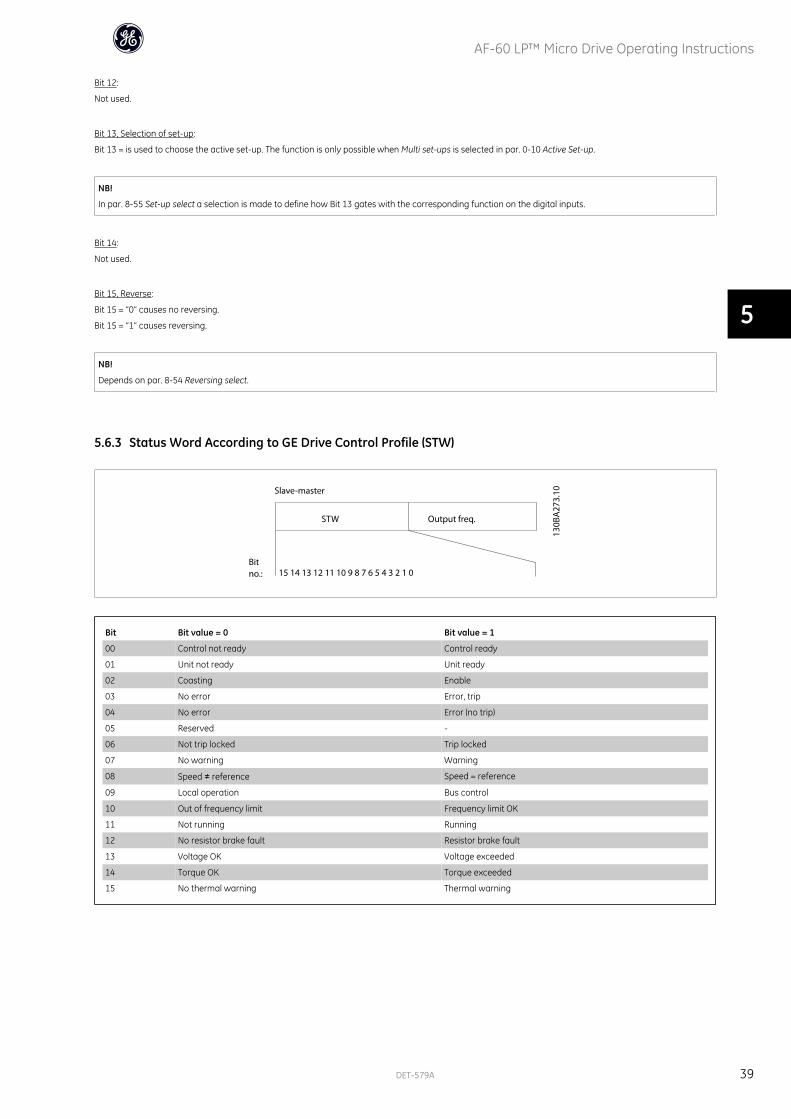
5.6.3 Status Word According to GE Drive Control Profile (STW)
Bit Bit value = 0 Bit value = 1
00 Control not ready Control ready
01 Unit not ready Unit ready
02 Coasting Enable
03 No error Error, trip
04 No error Error (no trip)
05 Reserved -
06 Not trip locked Trip locked
07 No warning Warning
08 Speed ≠ reference Speed = reference
09 Local operation Bus control
10 Out of frequency limit Frequency limit OK
11 Not running Running
12 No resistor brake fault Resistor brake fault
13 Voltage OK Voltage exceeded
14 Torque OK Torque exceeded
15 No thermal warning Thermal warning
AF-60 LP™ Micro Drive Operating Instructions
DET-579A 39
5
5.6.4 Explanation of the Status Bits
Bit 00, Control not ready/ready:
Bit 00 = “0” means that the frequency converter has tripped.
Bit 00 = “1” means that the frequency converter controls are ready, but that the power component is not necessarily receiving any power supply (in case of external
24 V supply to controls).
Bit 01, Frequency converter ready:
Bit 01 = “1”. The frequency converter is ready for operation, but there is an active coasting command via the digital inputs or via serial communication.
Bit 02, Coasting stop:
Bit 02 = “0”. The frequency converter released the motor.
Bit 02 = “1”. The frequency converter can start the motor when a start command is given.
Bit 03, No error/trip:
Bit 03 = “0” means that the frequency converter is not in fault mode.
Bit 03 = “1” means that the frequency converter is tripped, and that a reset signal is required to re-establish operation.
Bit 04, No error/error (trip):
Bit 04 = “0” means that the frequency converter is not in fault mode.
Bit 04 = “1” means that there is a frequency converter error but no trip.
Bit 05:
Not used.
Bit 06, No error/trip lock:
Bit 06 = “0” means that the frequency converter is not in fault mode.
Bit 06 = “1” means that the frequency converter is tripped and locked.
Bit 07, No warning/warning:
Bit 07 = “0” means that there are no warnings.
Bit 07 = “1” means that a warning has occurred.
Bit 08, Speed ≠ reference/speed = reference:
Bit 08 = “0” means that the motor is running, but that the present speed is different from the preset speed reference. For example, this might occur while the speed
is being ramped up/down during start/stop.
Bit 08 = “1” means that the present motor speed matches the preset speed reference.
Bit 09, Local operation/bus control:
Bit 09 = “0” means that [Stop/Reset] is activated on the control unit. It is not possible to control the frequency converter via serial communication.
Bit 09 = “1” means that it is possible to control the frequency converter via serial communication.
Bit 10, Out of frequency limit:
Bit 10 = “0”, if the output frequency has reached the value in par. 4-12 Motor speed low limit or par . 4-13 Motor speed high limit.
Bit 10 = “1” means that the output frequency is within the defined limits.
Bit 11, Running:
Bit 11 = “0” means that the motor is not running.
Bit 11 = “1” means that the frequency converter has a start signal or that the output frequency is higher than 0 Hz.
Bit 12, Resistor brake fault:
Bit 12 = “0” means that there is no resistor brake fault.
Bit 12 = “1” means that there is a resistor brake fault.
AF-60 LP™ Micro Drive Operating Instructions
40 DET-579A
5

Bit 13, Voltage OK/limit exceeded:
Bit 13 = “0” means that there are no voltage warnings.
Bit 13 = “1” means that the DC voltage in the frequency converter's intermediate circuit is too low or too high.
Bit 14, Torque OK/limit exceeded:
Bit 14 = “0” means that there are no current/torque warnings or errors.
Bit 14 = “1” means that there is a current/torque warning or error.
Bit 15, Thermal warning:
Bit 15 = “0” means that there is no thermal warning or error.
Bit 15 = “1” means that one of the thermal limits has been exceeded.
5.6.5 Bus Speed Reference Value
The speed reference value is transmitted to the frequency converter in a rel-
ative value in %.
The value is transmitted in the form of a 16-bit word; in integers (0-32767) the
value 16384 (4000 Hex) corresponds to 100%. Negative figures are formatted
by means of 2's complement.
The Actual Output Frequency (MAV) is scaled in the same way as the bus
reference.
The reference and MAV are scaled as follows:
AF-60 LP™ Micro Drive Operating Instructions
DET-579A 41
5

AF-60 LP™ Micro Drive Operating Instructions
42 DET-579A
6

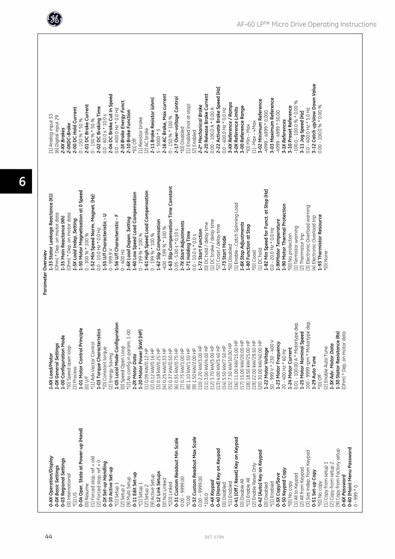
6 Parameter Overview
AF-60 LP™ Micro Drive Operating Instructions
DET-579A 43
6
Para
met
er O
verw
iev
0-XX
Ope
ratio
n/D
ispl
ay0-
0X B
asic
Set
tings
0-03
Reg
iona
l Set
tings
[0] I
nter
natio
nal
*[1]
US
0-04
Ope
r. S
tate
at P
ower
-up
(Han
d)[0
] Res
ume
[1] F
orce
d st
op, r
ef =
old
[2] F
orce
d st
op, r
ef =
00-
1X S
et-u
p H
andl
ing
0-10
Act
ive
Set-
up*[
1] S
etup
1[2
] Set
up 2
[9] M
ulti
Setu
p0-
11 E
dit S
et-u
p*[
1] S
etup
1[2
] Set
up 2
[9] A
ctiv
e Se
tup
0-12
Lin
k Se
tups
[0] N
ot L
inke
d*[
20] L
inke
d0-
31 C
usto
m R
eado
ut M
in S
cale
0.00
– 9
999.
00*0
.00
0-32
Cus
tom
Rea
dout
Max
Sca
le0.
00 –
999
9.00
*100
.00-
4X K
eypa
d0-
40 [H
and]
Key
on
Keyp
ad[0
] Dis
able
d*[
1] E
nabl
ed0-
41 [O
ff /
Rese
t] K
ey o
n Ke
ypad
[0] D
isab
le A
ll*[
1] E
nabl
e Al
l[2
] Ena
ble
Rese
t Onl
y0-
42 [A
uto]
Key
on
Keyp
ad[0
] Dis
able
d*[
1] E
nabl
ed0-
5X C
opy/
Save
0-50
Key
pad
Copy
*[0]
No
copy
[1] A
ll to
Key
pad
[2] A
ll fr
om K
eypa
d[3
] Siz
e in
dep.
from
Key
pad
0-51
Set
-up
Copy
*[0]
No
copy
[1] C
opy
from
set
up 1
[2] C
opy
from
set
up 2
[9] C
opy
from
Fac
tory
set
up0-
6X P
assw
ord
0-60
(Mai
n) M
enu
Pass
wor
d0
- 999
* 0
1-XX
Loa
d/M
otor
1-0X
Gen
eral
Set
tings
1-00
Con
figur
atio
n M
ode
*[0]
Spe
ed o
pen
loop
[3] P
roce
ss1-
01 M
otor
Con
trol
Pri
ncip
le[0
] U/f
*[1]
Adv
.Vec
tor C
ontr
ol1-
03 T
orqu
e Ch
arac
teri
stic
s*[
0] C
onst
ant t
orqu
e[2
] Ene
rgy
Savi
ng1-
05 L
ocal
Mod
e Co
nfig
urat
ion
[0] S
peed
Ope
n Lo
op*[
2] A
s co
nfig
in p
aram
. 1-0
01-
2X M
otor
Dat
a1-
20 M
otor
Pow
er [k
W] [
HP]
[1] 0
.09
kW/0
.12
HP
[2] 0
.12
kW/0
.16
HP
[3] 0
.18
kW/0
.25
HP
[4] 0
.25
kW/0
.33
HP
[5] 0
.37
kW/0
.50
HP
[6] 0
.55
kW/0
.75
HP
[7] 0
.75
kW/1
.00
HP
[8] 1
.10
kW/1
.50
HP
[9] 1
.50
kW/2
.00
HP
[10]
2.2
0 kW
/3.0
0 H
P[1
1] 3
.00
kW/4
.00
HP
[12]
3.7
0 kW
/5.0
0 H
P[1
3] 4
.00
kW/5
.40
HP
[14]
5.5
0 kW
/7.5
0 H
P[1
5] 7
.50
kW/1
0.00
HP
[16]
11.
00 k
W/1
5.00
HP
[17]
15.
00 k
W/2
0.00
HP
[18]
18.
50 k
W/2
5.00
HP
[19]
22.
00 k
W/2
9.50
HP
[20]
30.
00 k
W/4
0.00
HP
1-22
Mot
or V
olta
ge50
- 99
9 V
* 23
0 - 4
00 V
1-23
Mot
or F
requ
ency
20 -
400
Hz
* 60
Hz
1-24
Mot
or C
urre
nt0.
01 -
100.
00 A
* M
otor
type
dep
.1-
25 M
otor
Nom
inal
Spe
ed10
0 - 9
999
rpm
* M
otor
type
dep
.1-
29 A
uto
Tune
*[0]
Off
[2] E
nabl
e Au
to T
une
1-3X
Adv
. Mot
or D
ata
1-30
Sta
tor R
esis
tanc
e (R
s)[O
hm] *
Dep
. on
mot
or d
ata
1-33
Sta
tor L
eaka
ge R
eact
ance
(X1)
[Ohm
] * D
ep. o
n m
otor
dat
a1-
35 M
ain
Reac
tanc
e (X
h)[O
hm] *
Dep
. on
mot
or d
ata
1-5X
Loa
d In
dep.
Set
ting
1-50
Mot
or M
agne
tisat
ion
at 0
Spe
ed0
- 300
% *
100
%1-
52 M
in S
peed
Nor
m. M
agne
t. [H
z]0.
0 - 1
0.0
Hz
* 0.
0 H
z1-
55 U
/f C
hara
cter
istic
- U
0 - 9
99.9
V1-
56 U
/f C
hara
cter
istic
- F
0 - 4
00 H
z1-
6X L
oad
Dep
en. S
ettin
g1-
60 L
ow S
peed
Loa
d Co
mpe
nsat
ion
0 - 1
99 %
* 1
00 %
1-61
Hig
h Sp
eed
Load
Com
pens
atio
n0
- 199
% *
100
%1-
62 S
lip C
ompe
nsat
ion
-400
- 39
9 %
* 1
00 %
1-63
Slip
Com
pens
atio
n Ti
me
Cons
tant
0.05
- 5.
00 s
* 0
.10
s1-
7X S
tart
Adj
ustm
ents
1-71
Hol
ding
Tim
e0.
0 - 1
0.0
s *
0.0
s1-
72 S
tart
Fun
ctio
n[0
] DC
hold
/ de
lay
time
[1] D
C br
ake
/ del
ay ti
me
*[2]
Coa
st /
dela
y tim
e1-
73 S
tart
Mod
e*[
0] D
isab
led
[1] E
nabl
e - C
atch
Spi
nnin
g Lo
ad1-
8X S
top
Adju
stm
ents
1-80
Fun
ctio
n at
Sto
p*[
0] C
oast
[1] D
C ho
ld1-
82 M
in S
peed
for
Func
t. at
Sto
p [H
z]0.
0 - 2
0.0
Hz
* 0.
0 H
z1-
9XM
otor
Tem
pera
ture
1-90
Mot
or T
herm
al P
rote
ctio
n*[
0] N
o pr
otec
tion
[1] T
erm
isto
r war
ning
[2] T
herm
isto
r trip
[3] E
lect
roni
c O
verlo
ad w
arni
ng[4
] Ele
ctro
nic
Ove
rload
trip
1-93
The
rmis
tor R
esou
rce
*[0]
Non
e
[1] A
nalo
g in
put 5
3[6
] Dig
ital i
nput
29
2-XX
Bra
kes
2-0X
DC-
Brak
e2-
00 D
C H
old
Curr
ent
0 - 1
50 %
* 5
0 %
2-01
DC
Brak
e Cu
rren
t0
- 150
% *
50
%2-
02 D
C Br
akin
g Ti
me
0.0
- 60.
0 s
* 10
.0 s
2-04
DC
Brak
e Cu
t In
Spee
d0.
0 - 4
00.0
Hz
* 0.
0 H
z2-
1X B
rake
Ene
rgy
Func
t.2-
10 B
rake
Fun
ctio
n*[
0] O
ff[1
] Res
isto
r bra
ke[2
] AC
brak
e2-
11 B
rake
Res
isto
r (oh
m)
5 - 5
000
* 5
2-16
AC
Brak
e, M
ax c
urre
nt0
- 150
% *
100
%2-
17 O
ver-
volta
ge C
ontr
ol*[
0] D
isab
led
[1] E
nabl
ed (n
ot a
t sto
p)[2
] Ena
bled
2-2*
Mec
hani
cal B
rake
2-20
Rel
ease
Bra
ke C
urre
nt0.
00 -
100.
0 A
* 0.
00 A
2-22
Act
ivat
e Br
ake
Spee
d [H
z]0.
0 - 4
00.0
Hz
* 0.
0 H
z3-
XX R
efer
ence
/ Ra
mps
3-0X
Ref
eren
ce L
imits
3-00
Ref
eren
ce R
ange
*[0]
Min
- M
ax[1
] -M
ax -
+Max
3-02
Min
imum
Ref
eren
ce-4
999
- 499
9 *
0.00
03-
03 M
axim
um R
efer
ence
-499
9 - 4
999
* 50
.00
3-1X
Ref
eren
ces
3-10
Pre
set R
efer
ence
-100
.0 -
100.
0 %
* 0
.00
%3-
11 J
og S
peed
[Hz]
0.0
- 400
.0 H
z *
5.0
Hz
3-12
Cat
ch u
p/sl
ow D
own
Valu
e0.
00 -
100.
0 %
* 0
.00
%
AF-60 LP™ Micro Drive Operating Instructions
44 DET-579A
6

3-14
Pre
set R
elat
ive
Refe
renc
e-1
00.0
- 10
0.0
% *
0.0
0 %
3-15
Ref
eren
ce R
esou
rce
1[0
] No
func
tion
*[1]
Ana
log
Inpu
t 53
[2] A
nalo
g in
put 6
0[8
] Pul
se in
put 3
3[1
1] L
ocal
bus
ref
[21]
Key
pad
Pote
ntio
met
er3-
16 R
efer
ence
Res
ourc
e 2
[0] N
o fu
nctio
n[1
] Ana
log
Inpu
t 53
*[2]
Ana
log
inpu
t 60
[8] P
ulse
inpu
t 33
*[11
] Loc
al b
us re
f[2
1] K
eypa
d Po
tent
iom
eter
3-17
Ref
eren
ce R
esou
rce
3[0
] No
func
tion
[1] A
nalo
g In
put 5
3[2
] Ana
log
inpu
t 60
[8] P
ulse
inpu
t 33
*[11
] Loc
al b
us re
f[2
1] K
eypa
d Po
tent
iom
eter
3-18
Rel
ativ
e Sc
alin
g Re
f. Re
sour
ce*[
0] N
o fu
nctio
n[1
] Ana
log
Inpu
t 53
[2] A
nalo
g in
put 6
0[8
] Pul
se in
put 3
3[1
1] L
ocal
bus
ref
[21]
Key
pad
Pote
ntio
met
er3-
4X A
ccel
/Dec
el 1
3-40
Acc
el/D
ecel
1 P
atte
rn*[
0] L
inea
r[2
] S-S
hape
3-41
Acc
el T
ime
10.
05 -
3600
s *
3.0
0 s
(10.
00 s
1))
3-42
Dec
el T
ime
10.
05 -
3600
s *
3.0
0 s
(10.
00 s
1))
3-5X
Acc
el/D
ecel
23-
50 A
ccel
/Dec
el 2
Pat
tern
*[0]
Lin
ear
[2] S
-Sha
pe3-
51 A
ccel
Tim
e 2
0.05
- 36
00 s
* 3
.00
s (1
0.00
s 1)
)3-
52 D
ecel
Tim
e 2
0.05
- 36
00 s
* 3
.00
s (1
0.00
s1)
)3-
8X O
ther
Ram
ps
3-80
Jog
Acc
el a
nd D
ecel
Tim
e0.
05 -
3600
s *
3.0
0 s
(10.
00 s
1))
3-81
Qui
ck S
top
Dec
el T
ime
0.05
- 36
00 s
* 3
.00
s(10
.00
s1))
4-XX
Lim
its /
War
ning
s4-
1X M
otor
Lim
its4-
10 R
ever
se L
ock
[0] R
ever
se L
ock
[1] R
ever
se*[
2] B
oth
4-12
Mot
or S
peed
Low
Lim
it [H
z]0.
0 - 4
00.0
Hz
* 0.
0 H
z4-
14 M
otor
Spe
ed H
igh
Lim
it [H
z]0.
1 - 4
00.0
Hz
* 65
.0 H
z4-
16 T
orqu
e Li
mit
Mot
or M
ode
0 - 4
00 %
* 1
50 %
4-17
Tor
que
Lim
it G
ener
ator
Mod
e0
- 400
% *
100
%4-
5X A
dj. W
arni
ngs
4-50
War
ning
Cur
rent
Low
0.00
- 10
0.00
A *
0.0
0 A
4-51
War
ning
Cur
rent
Hig
h0.
00 -
100.
00 A
* 1
00.0
0 A
4-58
Mis
sing
Mot
or P
hase
Fun
ctio
n[0
] Off
*[1]
On
4-6X
Jum
p Fr
eque
ncie
s4-
61 J
ump
Freq
uenc
y Fr
om [H
z]0.
0 - 4
00.0
Hz
* 0.
0 H
z4-
63 J
ump
Freq
uenc
yTo
[Hz]
0.0
- 400
.0 H
z *
0.0
Hz
5-1X
Dig
ital I
nput
s5-
10 T
erm
inal
18
Dig
ital I
nput
[0] N
o fu
nctio
n[1
] Res
et[2
] Coa
st in
vers
e[3
] Coa
st a
nd re
set i
nv.
[4] Q
uick
sto
p in
vers
e[5
] DC-
brak
e in
v.[6
] Sto
p in
v*[
8] S
tart
[9] L
atch
ed s
tart
[10]
Rev
ersi
ng[1
1] S
tart
reve
rsin
g[1
2] E
nabl
e st
art f
orw
ard
[13]
Ena
ble
star
t rev
erse
[14]
Jog
[16-
18] P
rese
t ref
bit
0-2
[19]
Fre
eze
refe
renc
e[2
0] F
reez
e ou
tput
[21]
Spe
ed u
p[2
2] S
peed
dow
n[2
3] S
etup
sel
ect b
it 0
[28]
Cat
ch u
p[2
9] S
low
dow
n[3
4] R
amp
bit 0
[60]
Cou
nter
A (u
p)[6
1] C
ount
er A
(dow
n)[6
2] R
eset
cou
nter
A[6
3] C
ount
er B
(up)
[64]
Cou
nter
B (d
own)
[65]
Res
etCo
unte
r B5-
11 T
erm
inal
19
Dig
ital I
nput
See
par.
5-10
. * [1
0] R
ever
sing
5-12
Ter
min
al 2
7 D
igita
l Inp
utSe
e pa
r. 5-
10. *
[1] R
eset
5-13
Ter
min
al 2
9 D
igita
l Inp
utSe
e pa
r. 5-
10. *
[14]
Jog
5-15
Ter
min
al 3
3 D
igita
l Inp
utSe
e pa
r. 5-
10. *
[16]
Pre
set r
ef b
it 0
[26]
Pre
cise
Sto
p In
vers
e[2
7] S
tart
, Pre
cise
Sto
p[3
2] P
ulse
Inpu
t5-
4X R
elay
s5-
40 F
unct
ion
Rela
y*[
0] N
o op
reat
ion
[1] C
ontr
ol re
ady
[2] D
rive
read
y[3
] Driv
e re
ady,
Rem
ote
[4] E
nabl
e / N
o w
arni
ng[5
] Driv
e ru
nnin
g[6
] Run
ning
/ N
o w
arni
ng[7
] Run
in ra
nge
/ No
war
ning
[8] R
un o
n re
f / N
o w
arni
ng[9
] Ala
rm[1
0] A
larm
or w
arni
ng[1
2] O
ut o
f cur
rent
rang
e[1
3] B
elow
cur
rent
, low
[14]
Abo
ve c
urre
nt, h
igh
[21]
The
rmal
war
ning
[22]
Rea
dy, N
o th
erm
al w
arni
ng[2
3] R
emot
e re
ady,
No
ther
mal
war
ning
[24]
Rea
dy, V
olta
ge o
k
[25]
Rev
erse
[26]
Bus
ok
[28]
Bra
ke,N
oWar
n[2
9] B
rake
read
y/N
oFau
lt[3
0] B
rake
Faul
t (IG
BT)
[32]
Mec
h.br
ake
cont
rol
[36]
Con
trol
wor
d bi
t 11
[51]
Loc
al re
f. ac
tive
[52]
Rem
ote
ref.
activ
e[5
3] N
o al
arm
[54]
Sta
rt c
md
activ
e[5
5] R
unni
ng re
vers
e[5
6] D
rive
in h
and
mod
e[5
7] D
rive
in a
uto
mod
e[6
0-63
] Com
para
tor 0
-3[7
0-73
] Log
ic ru
le 0
-3[8
1] L
ogic
Con
trol
ler d
igita
l out
put B
5-5X
Pul
se In
put
5-55
Ter
min
al 3
3 Lo
w F
requ
ency
20 -
4999
Hz
* 20
Hz
5-56
Ter
min
al 3
3 H
igh
Freq
uenc
y21
- 50
00 H
z *
5000
Hz
5-57
Ter
m. 3
3 Lo
w R
ef./F
eedb
. Val
ue-4
999
- 499
9 *
0.00
05-
58 T
erm
. 33
Hig
h Re
f./Fe
edb.
Val
ue-4
999
- 499
9 *
50.0
006-
XX A
nalo
g In
/Out
6-0X
Ana
log
I/O
Mod
e6-
00 L
ive
Zero
Tim
eout
Tim
e1
- 99
s *
10 s
6-01
Liv
e Ze
ro T
imeo
utFu
nctio
n*[
0] O
ff[1
] Fre
eze
outp
ut[2
] Sto
p[3
] Jog
ging
[4] M
ax s
peed
[5] S
top
and
trip
6-1X
Ana
log
Inpu
t 16-
10 T
erm
inal
53
Low
Vol
tage
0.00
- 9.
99 V
* 0
.07
V6-
11 T
erm
inal
53
Hig
h Vo
ltage
0.01
- 10
.00
V *
10.0
0 V
6-12
Ter
min
al 5
3 Lo
w C
urre
nt0.
00 -
19.9
9 m
A *
0.14
mA
1) M
4 an
d M
5 on
ly
AF-60 LP™ Micro Drive Operating Instructions
DET-579A 45
6
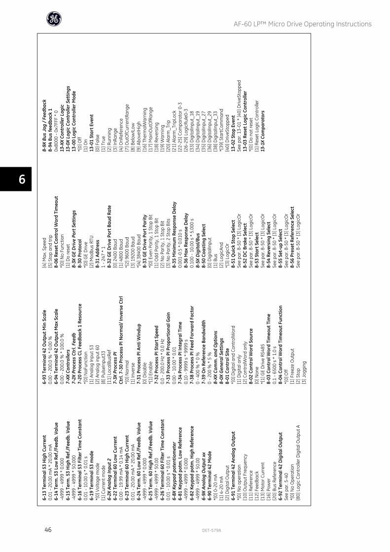
6-13
Ter
min
al 5
3 H
igh
Curr
ent
0.01
- 20
.00
mA
* 20
.00
mA
6-14
Ter
m. 5
3 Lo
w R
ef./
Feed
b. V
alue
-499
9 - 4
999
* 0.
000
6-15
Ter
m. 5
3 H
igh
Ref./
Feed
b. V
alue
-499
9 - 4
999
* 50
.000
6-16
Ter
min
al 5
3 Fi
lter T
ime
Cons
tant
0.01
- 10
.00
s *
0.01
s6-
19 T
erm
inal
53
mod
e*[
0] V
olta
ge m
ode
[1] C
urre
nt m
ode
6-2X
Ana
log
Inpu
t 26-
22 T
erm
inal
60
Low
Cur
rent
0.00
- 19
.99
mA
* 0.
14 m
A6-
23 T
erm
inal
60
Hig
h Cu
rren
t0.
01 -
20.0
0 m
A *
20.0
0 m
A6-
24 T
erm
. 60
Low
Ref
./Fe
edb.
Val
ue-4
999
- 499
9 *
0.00
06-
25 T
erm
. 60
Hig
h Re
f./Fe
edb.
Val
ue-4
999
- 499
9 *
50.0
06-
26 T
erm
inal
60
Filte
r Tim
e Co
nsta
nt0.
01 -
10.0
0 s
* 0.
01 s
6-8X
Key
pad
pote
ntio
met
er6-
81 K
eypa
d po
tm. L
ow R
efer
ence
-499
9 - 4
999
* 0.
000
6-82
Key
pad
potm
. Hig
h Re
fere
nce
-499
9 - 4
999
* 50
.00
6-9X
Ana
log
Out
put x
x6-
90 T
erm
inal
42
Mod
e*[
0] 0
-20
mA
[1] 4
-20
mA
[2] D
igita
l Out
put
6-91
Ter
min
al 4
2 An
alog
Out
put
*[0]
No
oper
atio
n[1
0] O
utpu
t Fre
quen
cy[1
1] R
efer
ence
[12]
Fee
dbac
k[1
3] M
otor
Cur
rent
[16]
Pow
er[2
0] B
us R
efer
ence
6-92
Ter
min
al 4
2 D
igita
l Out
put
See
par.
5-40
*[0]
No
Ope
ratio
n[8
0] L
ogic
Con
trol
ler D
igita
l Out
put A
6-93
Ter
min
al 4
2 O
utpu
t Min
Sca
le0.
00 -
200.
0 %
* 0
.00
%6-
94 T
erm
inal
42
Out
put M
ax S
cale
0.00
- 20
0.0
% *
100
.0 %
7-XX
Con
trol
lers
7-2X
Pro
cess
Ctr
l. Fe
edb
7-20
Pro
cess
CL
Feed
back
1 R
esou
rce
*[0]
NoF
unct
ion
[1] A
nalo
g In
put 5
3[2
] Ana
log
inpu
t 60
[8] P
ulse
Inpu
t33
[11]
Loc
alBu
sRef
7-3X
Pro
cess
PI
Ctrl
. 7-3
0 Pr
oces
s PI
Nor
mal
/ In
vers
e Ct
rl*[
0] N
orm
al[1
] Inv
erse
7-31
Pro
cess
PI A
nti W
indu
p[0
] Dis
able
*[1]
Ena
ble
7-32
Pro
cess
PI S
tart
Spe
ed0.
0 - 2
00.0
Hz
* 0.
0 H
z7-
33 P
roce
ss P
I Pro
port
iona
l Gai
n0.
00 -
10.0
0 *
0.01
7-34
Pro
cess
PI I
nteg
ral T
ime
0.10
- 99
99 s
* 9
999
s7-
38 P
roce
ss P
I Fee
d Fo
rwar
d Fa
ctor
0 - 4
00 %
* 0
%7-
39 O
n Re
fere
nce
Band
wid
th0
- 200
% *
5 %
8-XX
Com
m. a
nd O
ptio
ns8-
0X G
ener
al S
ettin
gs8-
01 C
ontr
ol S
ite*[
0] D
igita
l and
Con
trol
Wor
d[1
] Dig
ital o
nly
[2] C
ontr
olW
ord
only
8-02
Con
trol
Wor
d So
urce
[0] N
one
*[1]
GE
Driv
e RS
485
8-03
Con
trol
Wor
d Ti
meo
ut T
ime
0.1
- 650
0 s
* 1.
0 s
8-04
Con
trol
Wor
d Ti
meo
ut F
unct
ion
*[0]
Off
[1] F
reez
e O
utpu
t[2
] Sto
p[3
] Jog
ging
[4] M
ax. S
peed
[5] S
top
and
trip
8-06
Res
et C
ontr
ol W
ord
Tim
eout
*[0]
No
Func
tion
[1] D
o re
set
8-3X
GE
Dri
ve P
ort S
ettin
gs8-
30 P
roto
col
*[0]
GE
Driv
e[2
] Mod
bus
RTU
8-31
Add
ress
1 - 2
47 *
18-
32 G
E D
rive
Por
t Bau
d Ra
te[0
] 240
0 Ba
ud[1
] 480
0 Ba
ud*[
2] 9
600
Baud
[3] 1
9200
Bau
d*[
4] 3
8400
Bau
d8-
33 G
E D
rive
Por
t Par
ity*[
0] E
ven
Parit
y, 1
Sto
p Bi
t[1
] Odd
Par
ity, 1
Sto
p Bi
t[2
] No
Parit
y, 1
Sto
p Bi
t[3
] No
Parit
y, 2
Sto
p Bi
ts8-
35 M
inim
um R
espo
nse
Del
ay0.
001-
0.5
* 0.
010
s8-
36 M
ax R
espo
nse
Del
ay0.
100
- 10.
00 s
* 5
.000
s8-
5X D
igita
l/Bu
s8-
50 C
oast
ing
Sele
ct[0
] Dig
italIn
put
[1] B
us[2
] Log
icAn
d*[
3] L
ogic
Or
8-51
Qui
ck S
top
Sele
ctSe
e pa
r. 8-
50 *
[3] L
ogic
Or
8-52
DC
Brak
e Se
lect
See
par.
8-50
* [3
] Log
icO
r8-
53 S
tart
Sel
ect
See
par.
8-50
* [3
] Log
icO
r8-
54 R
ever
sing
Sel
ect
See
par.
8-50
* [3
] Log
icO
r8-
55 S
et-u
p Se
lect
See
par.
8-50
* [3
] Log
icO
r8-
56 P
rese
t Ref
eren
ce S
elec
tSe
e pa
r. 8-
50 *
[3] L
ogic
Or
8-9X
Bus
Jog
/ Fe
edba
ck8-
94 B
us fe
edba
ck 1
0x80
00 -
0x7F
FF *
013
-XX
Cont
rolle
r Log
ic13
-0X
Logi
c Co
ntro
ller S
ettin
gs13
-00
Logi
c Co
ntro
ller M
ode
*[0]
Off
[1] O
n13
-01
Star
t Eve
nt[0
] Fal
se[1
] Tru
e[2
] Run
ning
[3] I
nRan
ge[4
] OnR
efer
ence
[7] O
utO
fCur
rent
Rang
e[8
] Bel
owIL
ow[9
] Abo
veIH
igh
[16]
The
rmal
War
ning
[17]
Mai
nOut
OfR
ange
[18]
Rev
ersi
ng[1
9] W
arni
ng[2
0] A
larm
_Trip
[21]
Ala
rm_T
ripLo
ck[2
2-25
] Com
para
tor 0
-3[2
6-29
] Log
icRu
le0-
3[3
3] D
igita
lInpu
t_18
[34]
Dig
italIn
put_
19[3
5] D
igita
lInpu
t_27
[36]
Dig
italIn
put_
29[3
8] D
igita
lInpu
t_33
*[39
] Sta
rtCo
mm
and
[40]
Driv
eSto
pped
13-0
2 St
op E
vent
See
par.
13-0
1 *
[40]
Driv
eSto
pped
13-0
3 Re
set L
ogic
Con
trol
ler
*[0]
Do
not r
eset
[1] R
eset
Log
ic C
ontr
olle
r13
-1X
Com
para
tors
AF-60 LP™ Micro Drive Operating Instructions
46 DET-579A
6
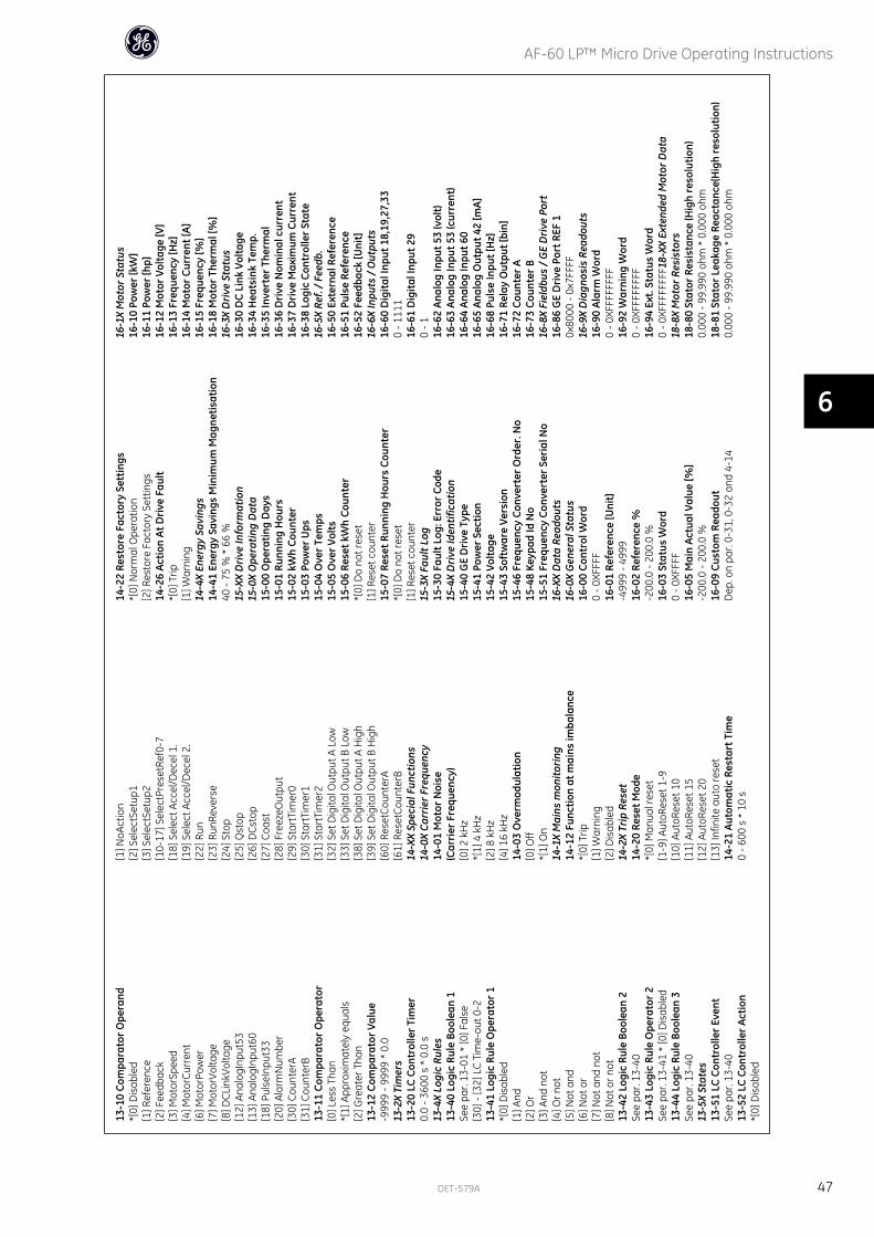
13-1
0 Co
mpa
rato
r Ope
rand
*[0]
Dis
able
d[1
] Ref
eren
ce[2
] Fee
dbac
k[3
] Mot
orSp
eed
[4] M
otor
Curr
ent
[6] M
otor
Pow
er[7
] Mot
orVo
ltage
[8] D
CLin
kVol
tage
[12]
Ana
logI
nput
53[1
3] A
nalo
gInp
ut60
[18]
Pul
seIn
put3
3[2
0] A
larm
Num
ber
[30]
Cou
nter
A[3
1] C
ount
erB
13-1
1 Co
mpa
rato
r Ope
rato
r[0
] Les
s Th
an*[
1] A
ppro
xim
atel
y eq
uals
[2] G
reat
er T
han
13-1
2 Co
mpa
rato
r Val
ue-9
999
- 999
9 *
0.0
13-2
X Ti
mer
s13
-20
LC C
ontr
olle
r Tim
er0.
0 - 3
600
s *
0.0
s13
-4X
Logi
c Ru
les
13-4
0 Lo
gic
Rule
Boo
lean
1Se
e pa
r. 13
-01
* [0
] Fal
se[3
0] -
[32]
LC
Tim
e-ou
t 0-2
13-4
1 Lo
gic
Rule
Ope
rato
r 1*[
0] D
isab
led
[1] A
nd[2
] Or
[3] A
nd n
ot[4
] Or n
ot[5
] Not
and
[6] N
ot o
r[7
] Not
and
not
[8] N
ot o
r not
13-4
2 Lo
gic
Rule
Boo
lean
2Se
e pa
r. 13
-40
13-4
3 Lo
gic
Rule
Ope
rato
r 2Se
e pa
r. 13
-41
* [0
] Dis
able
d13
-44
Logi
c Ru
le B
oole
an 3
See
par.
13-4
013
-5X
Stat
es13
-51
LC C
ontr
olle
r Eve
ntSe
e pa
r. 13
-40
13-5
2 LC
Con
trol
ler
Actio
n*[
0] D
isab
led
[1] N
oAct
ion
[2] S
elec
tSet
up1
[3] S
elec
tSet
up2
[10-
17] S
elec
tPre
setR
ef0-
7[1
8] S
elec
t Acc
el/D
ecel
1.
[19]
Sel
ect A
ccel
/Dec
el 2
.[2
2] R
un[2
3] R
unRe
vers
e[2
4] S
top
[25]
Qst
op[2
6] D
Csto
p[2
7] C
oast
[28]
Fre
ezeO
utpu
t[2
9] S
tart
Tim
er0
[30]
Sta
rtTi
mer
1[3
1] S
tart
Tim
er2
[32]
Set
Dig
ital O
utpu
t A L
ow[3
3] S
et D
igita
l Out
put B
Low
[38]
Set
Dig
ital O
utpu
t A H
igh
[39]
Set
Dig
ital O
utpu
t B H
igh
[60]
Res
etCo
unte
rA[6
1] R
eset
Coun
terB
14-X
X Sp
ecia
l Fun
ctio
ns14
-0X
Carr
ier F
requ
ency
14-0
1 M
otor
Noi
se(C
arri
er F
requ
ency
)[0
] 2 k
Hz
*[1]
4 k
Hz
[2] 8
kH
z[4
] 16
kHz
14-0
3 O
verm
odul
atio
n[0
] Off
*[1]
On
14-1
X M
ains
mon
itori
ng14
-12
Func
tion
at m
ains
imba
lanc
e*[
0] T
rip[1
] War
ning
[2] D
isab
led
14-2
X Tr
ip R
eset
14-2
0 Re
set M
ode
*[0]
Man
ual r
eset
[1-9
] Aut
oRes
et 1
-9[1
0] A
utoR
eset
10
[11]
Aut
oRes
et 1
5[1
2] A
utoR
eset
20
[13]
Infin
ite a
uto
rese
t14
-21
Auto
mat
ic R
esta
rt T
ime
0 - 6
00 s
* 1
0 s
14-2
2 Re
stor
e Fa
ctor
y Se
ttin
gs*[
0] N
orm
al O
pera
tion
[2] R
esto
re F
acto
ry S
ettin
gs14
-26
Actio
n At
Dri
ve F
ault
*[0]
Trip
[1] W
arni
ng14
-4X
Ener
gy S
avin
gs14
-41
Ener
gy S
avin
gs M
inim
um M
agne
tisat
ion
40 -
75 %
* 6
6 %
15-X
X D
rive
Info
rmat
ion
15-0
X O
pera
ting
Dat
a15
-00
Ope
ratin
g D
ays
15-0
1 Ru
nnin
g H
ours
15-0
2 kW
h Co
unte
r15
-03
Pow
er U
ps15
-04
Ove
r Tem
ps15
-05
Ove
r Vol
ts15
-06
Rese
t kW
h Co
unte
r*[
0] D
o no
t res
et[1
] Res
et c
ount
er15
-07
Rese
t Run
ning
Hou
rs C
ount
er*[
0] D
o no
t res
et[1
] Res
et c
ount
er15
-3X
Faul
t Log
15-3
0 Fa
ult L
og: E
rror
Cod
e15
-4X
Dri
ve Id
entif
icat
ion
15-4
0 G
E D
rive
Typ
e15
-41
Pow
er S
ectio
n15
-42
Volta
ge15
-43
Soft
war
e Ve
rsio
n15
-46
Freq
uenc
y Co
nver
ter O
rder
. No
15-4
8 Ke
ypad
Id N
o15
-51
Freq
uenc
y Co
nver
ter S
eria
l No
16-X
X D
ata
Read
outs
16-0
X G
ener
al S
tatu
s16
-00
Cont
rol W
ord
0 - 0
XFFF
F16
-01
Refe
renc
e [U
nit]
-499
9 - 4
999
16-0
2 Re
fere
nce
%-2
00.0
- 20
0.0
%16
-03
Stat
us W
ord
0 - 0
XFFF
F16
-05
Mai
n Ac
tual
Val
ue [%
]-2
00.0
- 20
0.0
%16
-09
Cust
om R
eado
utD
ep. o
n pa
r. 0-
31, 0
-32
and
4-14
16-1
X M
otor
Sta
tus
16-1
0 Po
wer
[kW
]16
-11
Pow
er [h
p]16
-12
Mot
or V
olta
ge [V
]16
-13
Freq
uenc
y [H
z]16
-14
Mot
or C
urre
nt [A
]16
-15
Freq
uenc
y [%
]16
-18
Mot
or T
herm
al [%
]16
-3X
Dri
ve S
tatu
s16
-30
DC
Link
Vol
tage
16-3
4 H
eats
ink
Tem
p.16
-35
Inve
rter
The
rmal
16-3
6 D
rive
Nom
inal
cur
rent
16-3
7 D
rive
Max
imum
Cur
rent
16-3
8 Lo
gic
Cont
rolle
r St
ate
16-5
X Re
f. / F
eedb
.16
-50
Exte
rnal
Ref
eren
ce16
-51
Puls
e Re
fere
nce
16-5
2 Fe
edba
ck [U
nit]
16-6
X In
puts
/ O
utpu
ts16
-60
Dig
ital I
nput
18,
19,2
7,33
0 - 1
111
16-6
1 D
igita
l Inp
ut 2
90
- 116
-62
Anal
og In
put 5
3 (v
olt)
16-6
3 An
alog
Inpu
t 53
(cur
rent
)16
-64
Anal
og In
put 6
016
-65
Anal
og O
utpu
t 42
[mA]
16-6
8 Pu
lse
Inpu
t [H
z]16
-71
Rela
y O
utpu
t [bi
n]16
-72
Coun
ter A
16-7
3 Co
unte
r B16
-8X
Fiel
dbus
/ G
E D
rive
Por
t16
-86
GE
Dri
ve P
ort R
EF 1
0x80
00 -
0x7F
FFF
16-9
X D
iagn
osis
Rea
dout
s16
-90
Alar
m W
ord
0 - 0
XFFF
FFFF
F16
-92
War
ning
Wor
d0
- 0XF
FFFF
FFF
16-9
4 Ex
t. St
atus
Wor
d0
- 0XF
FFFF
FFF1
8-XX
Ext
ende
d M
otor
Dat
a18
-8X
Mot
or R
esis
tors
18-8
0 St
ator
Res
ista
nce
(Hig
h re
solu
tion)
0.00
0 - 9
9.99
0 oh
m *
0.0
00 o
hm18
-81
Stat
or L
eaka
ge R
eact
ance
(Hig
h re
solu
tion)
0.00
0 - 9
9.99
0 oh
m *
0.0
00 o
hm
AF-60 LP™ Micro Drive Operating Instructions
DET-579A 47
6
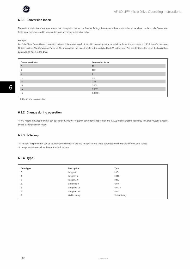
6.2.1 Conversion Index
The various attributes of each parameter are displayed in the section Factory Settings. Parameter values are transferred as whole numbers only. Conversion
factors are therefore used to transfer decimals according to the table below.
Example:
Par. 1-24 Motor Current has a conversion index of -2 (i.e. conversion factor of 0.01 according to the table below). To set the parameter to 2.25 A, transfer the value
225 via Modbus. The Conversion Factor of 0.01 means that the value transferred is multiplied by 0.01 in the drive. The vale 225 transferred on the bus is thus
perceived as 2.25 A in the drive.
Conversion index Conversion factor
2 10
1 100
0 1
-1 0.1
-2 0.01
-3 0.001
-4 0.0001
-5 0.00001
Table 6.1: Conversion table
6.2.2 Change during operation
“TRUE” means that the parameter can be changed while the frequency converter is in operation and “FALSE” means that the frequency converter must be stopped
before a change can be made.
6.2.3 2-Set-up
“All set-up”: The parameter can be set individually in each of the two set-ups, i.e. one single parameter can have two different data values.
”1 set-up”: Data value will be the same in both set-ups.
6.2.4 Type
Data Type Description Type
2 Integer 8 Int8
3 Integer 16 Int16
4 Integer 32 Int32
5 Unsigned 8 Uint8
6 Unsigned 16 Uint16
7 Unsigned 32 Uint32
9 Visible string VisibleString
AF-60 LP™ Micro Drive Operating Instructions
48 DET-579A
6

6.2.5 0-** Operation/Display
ParameterNumber
Parameter Description Default Value 2 Setup Change DuringOperation
Conver-sion
Index
Type
0 - 03 Regional Settings [1] US 1 set-up FALSE - Uint80 - 04 Operating State at Power-up (Hand) [1] Forced stop ref=old All set-ups TRUE - Uint80 - 10 Active Set-up [1] Set-up 1 1 set-up TRUE - Uint80 - 11 Edit Set-up [1] Set-up 1 1 set-up TRUE - Uint80 - 12 Link Setups [20] Linked All set-ups FALSE - Uint80 - 31 Custom Readout Min Scale 0 1 set-up TRUE -2 Int320 - 32 Custom Readout Max Scale 0 1 set-up TRUE -2 Int320 - 40 [Hand ] Key on Keypad [1] Enabled All set-ups TRUE - Uint80 - 41 [Off / Reset] Key on Keypad [1] Enable All All set-ups TRUE - Uint80 - 42 [Auto ] Key on Keypad [1] Enabled All set-ups TRUE - Uint80 - 50 Keypad Copy [0] No copy 1 set-up FALSE - Uint80 - 51 Set-up Copy [0] No copy 1 set-up FALSE - Uint80 - 60 Main Menu Password 0 1 set-up TRUE 0 Uint16
6.2.6 1-** Load/Motor
ParameterNumber
Parameter Description Default Value 2 Setup Change DuringOperation
Conver-sion
Index
Type
1 - 00 Configuration Mode [0] Speed open loop All set-ups TRUE - Uint81 - 01 Motor Control Principle [1] Adv. Vector Control All set-ups FALSE - Uint81 - 03 Torque Characteristics [0] Constant torque All set-ups TRUE - Uint81 - 05 Hand Mode Configuration [2] As mode par 1-00 All set-ups TRUE - Uint81 - 20 Motor Power All set-ups FALSE - Uint81 - 22 Motor Voltage All set-ups FALSE 0 Uint161 - 23 Motor Frequency All set-ups FALSE 0 Uint161 - 24 Motor Current All set-ups FALSE -2 Uint161 - 25 Motor Nominal Speed All set-ups FALSE 0 Uint161 - 29 Auto Tune [0] Off 1 set-up FALSE - Uint81 - 30 Stator Resistance (Rs) All set-ups FALSE -2 Uint161 - 33 Stator Leakage Reactance (X1) All set-ups FALSE -2 Uint321 - 35 Main Reactance (Xh) All set-ups FALSE -2 Uint321 - 50 Motor Magnetisation at Zero Speed 100% All set-ups TRUE 0 Uint161 - 52 Min Speed Normal Magnetising [Hz] 0 Hz All set-ups TRUE -1 Uint161 - 55 U/f Characteristic - U All set-ups TRUE 0 Uint161 - 56 U/f Characteristic - F All set-ups TRUE 0 Uint161 - 60 Low Speed Load Compensation 100% All set-ups TRUE 0 Uint161 - 61 High Speed Load Compensation 100% All set-ups TRUE 0 Uint161 - 62 Slip Compensation 100% All set-ups TRUE 0 Int161 - 63 Slip Compensation Time Constant 0.1 s All set-ups TRUE -2 Uint161 - 71 Holding Time 0 s All set-ups TRUE -1 Uint81 - 72 Start Function [2] Coast/delay time All set-ups TRUE - Uint81 - 73 Start Mode [0] Disabled All set-ups FALSE - Uint81 - 80 Function at Stop [0] Coast All set-ups TRUE - Uint81 - 82 Min Speed for Function at Stop [Hz] 0 Hz All set-ups TRUE -1 Uint161 - 90 Motor Thermal Protection [0] No protection All set-ups TRUE - Uint81 - 93 Thermistor Resource [0] None All set-ups FALSE - Uint8
6.2.7 2-** Brakes
ParameterNumber
Parameter Description Default Value 2 Setup Change DuringOperation
Conver-sion
Index
Type
2 - 00 DC Hold Current 50% All set-ups TRUE 0 Uint162 - 01 DC Brake Current 50% All set-ups TRUE 0 Uint162 - 02 DC Braking Time 10 s All set-ups TRUE -1 Uint162 - 04 DC Brake Cut In Speed 0 Hz All set-ups TRUE -1 Uint162 - 10 Brake Function [0] Off All set-ups TRUE - Uint82 - 11 Brake Resistor (ohm) All set-ups TRUE 0 Uint162 - 16 AC Brake, Max current 100% All set-ups TRUE 0 Uint162 - 17 Over-voltage Control [0] Disabled All set-ups TRUE - Uint82 - 20 Release Brake Current 0 A All set-ups TRUE -2 Uint322 - 22 Activate Brake Speed [Hz] 0 Hz All set-ups TRUE -1 Uint16
AF-60 LP™ Micro Drive Operating Instructions
DET-579A 49
6
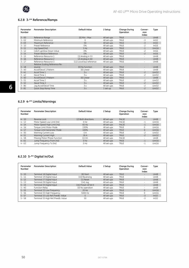
6.2.8 3-** Reference/Ramps
ParameterNumber
Parameter Description Default Value 2 Setup Change DuringOperation
Conver-sion
Index
Type
3 - 00 Reference Range [0] Min - Max All set-ups TRUE - Uint83 - 02 Minimum Reference 0 All set-ups TRUE -3 Int323 - 03 Maximum Reference 50 All set-ups TRUE -3 Int323 - 10 Preset Reference 0% All set-ups TRUE -2 Int163 - 11 Jog Speed [Hz] 5 Hz All set-ups TRUE -1 Uint163 - 12 Catch up/slow Down Value 0% All set-ups TRUE -2 Int163 - 14 Preset Relative Reference 0% All set-ups TRUE -2 Int163 - 15 Reference Resource 1 [1] Analog in 53 All set-ups TRUE - Uint83 - 16 Reference Resource 2 [2] Analog in 60 All set-ups TRUE - Uint83 - 17 Reference Resource 3 [11] Local bus reference All set-ups TRUE - Uint8
3 - 18Relative Scaling Reference Re-source [0] No function All set-ups TRUE - Uint8
3 - 40 Accel/Decel 1 Pattern [0] Linear All set-ups TRUE - Uint83 - 41 Accel Time 1 3 s All set-ups TRUE -2 Uint323 - 42 Decel Time 1 3 s All set-ups TRUE -2 Uint323 - 50 Accel/Decel 2 Pattern [0] Linear All set-ups TRUE - Uint83 - 51 Accel Time 2 3 s All set-ups TRUE -2 Uint323 - 52 Decel Time 2 3 s All set-ups TRUE -2 Uint323 - 80 Jog Accel/Decel Time 3 s All set-ups TRUE -2 Uint323 - 81 Quick Stop Ramp Time 3 s 1 set-up TRUE -2 Uint32
6.2.9 4-** Limits/Warnings
ParameterNumber
Parameter Description Default Value 2 Setup Change DuringOperation
Conver-sion
Index
Type
4 - 10 Reverse Lock [2] Both directions All set-ups FALSE - Uint84 - 12 Motor Speed Low Limit [Hz] 0 Hz All set-ups FALSE -1 Uint164 - 14 Motor Speed High Limit [Hz] 65 Hz All set-ups FALSE -1 Uint164 - 16 Torque Limit Motor Mode 150% All set-ups TRUE 0 Uint164 - 17 Torque Limit Generator Mode 100% All set-ups TRUE 0 Uint164 - 50 Warning Current Low 0 A All set-ups TRUE -2 Uint324 - 51 Warning Current High 26 A All set-ups TRUE -2 Uint324 - 58 Missing Motor Phase Function [1] On All set-ups FALSE - Uint84 - 61 Jump Frequency From [Hz] 0 Hz All set-ups TRUE -1 Uint164 - 63 Jump Frequency To [Hz] 0 Hz All set-ups TRUE -1 Uint16
6.2.10 5-** Digital In/Out
ParameterNumber
Parameter Description Default Value 2 Setup Change DuringOperation
Conver-sion
Index
Type
5 - 10 Terminal 18 Digital Input [8] Start All set-ups TRUE - Uint85 - 11 Terminal 19 Digital Input [10] Reversing All set-ups TRUE - Uint85 - 12 Terminal 27 Digital Input [1] Reset All set-ups TRUE - Uint85 - 13 Terminal 29 Digital Input [14] Jog All set-ups TRUE - Uint85 - 15 Terminal 33 Digital Input [16] Preset ref bit 0 All set-ups TRUE - Uint85 - 40 Function Relay [0] No operation All set-ups TRUE - Uint85 - 55 Terminal 33 Low Frequency 20 Hz All set-ups TRUE 0 Uint165 - 56 Terminal 33 High Frequency 5000 Hz All set-ups TRUE 0 Uint165 - 57 Terminal 33 Low Ref./Feedb. Value 0 All set-ups TRUE -3 Int325 - 58 Terminal 33 High Ref./Feedb. Value 50 All set-ups TRUE -3 Int32
AF-60 LP™ Micro Drive Operating Instructions
50 DET-579A
6
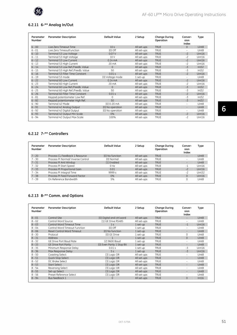
6.2.11 6-** Analog In/Out
ParameterNumber
Parameter Description Default Value 2 Setup Change DuringOperation
Conver-sion
Index
Type
6 - 00 Live Zero Timeout Time 10 s All set-ups TRUE 0 Uint86 - 01 Live Zero TimeoutFunction [0] Off All set-ups TRUE - Uint86 - 10 Terminal 53 Low Voltage 0.07 V All set-ups TRUE -2 Uint166 - 11 Terminal 53 High Voltage 10 V All set-ups TRUE -2 Uint166 - 12 Terminal 53 Low Current 0.14 mA All set-ups TRUE -2 Uint166 - 13 Terminal 53 High Current 20 mA All set-ups TRUE -2 Uint166 - 14 Terminal 53 Low Ref./Feedb. Value 0 All set-ups TRUE -3 Int326 - 15 Terminal 53 High Ref./Feedb. Value 50 All set-ups TRUE -3 Int326 - 16 Terminal 53 Filter Time Constant 0.01 s All set-ups TRUE -2 Uint166 - 19 Terminal 53 mode [0] Voltage mode 1 set-up TRUE - Uint86 - 22 Terminal 60 Low Current 0.14 mA All set-ups TRUE -2 Uint166 - 23 Terminal 60 High Current 20 mA All set-ups TRUE -2 Uint166 - 24 Terminal 60 Low Ref./Feedb. Value 0 All set-ups TRUE -3 Int326 - 25 Terminal 60 High Ref./Feedb. Value 50 All set-ups TRUE -3 Int326 - 26 Terminal 60 Filter Time Constant 0.01 s All set-ups TRUE -2 Uint166 - 81 Keypad potentiometer Low Ref. 0 All set-ups TRUE -3 Int326 - 82 Keypad potentiometer High Ref. 50 All set-ups TRUE -3 Int326 - 90 Terminal 42 Mode [0] 0-20 mA All set-ups TRUE - Uint86 - 91 Terminal 42 Analog Output [0] No operation All set-ups TRUE - Uint86 - 92 Terminal 42 Digital Output [0] No operation All set-ups TRUE - Uint86 - 93 Terminal 42 Output Min Scale 0% All set-ups TRUE -2 Uint166 - 94 Terminal 42 Output Max Scale 100% All set-ups TRUE -2 Uint16
6.2.12 7-** Controllers
ParameterNumber
Parameter Description Default Value 2 Setup Change DuringOperation
Conver-sion
Index
Type
7 - 20 Process CL Feedback 1 Resource [0] No function All set-ups TRUE - Uint87 - 30 Process PI Normal/ Inverse Control [0] Normal All set-ups TRUE - Uint87 - 31 Process PI Anti Windup [1] Enabled All set-ups TRUE - Uint87 - 32 Process PI Start Speed 0 Hz All set-ups TRUE -1 Uint167 - 33 Process PI Proportional Gain 0.01 All set-ups TRUE -2 Uint167 - 34 Process PI Integral Time 9999 s All set-ups TRUE -2 Uint327 - 38 Process PI Feed Forward Factor 0% All set-ups TRUE 0 Uint167 - 39 On Reference Bandwidth 5% All set-ups TRUE 0 Uint8
6.2.13 8-** Comm. and Options
ParameterNumber
Parameter Description Default Value 2 Setup Change DuringOperation
Conver-sion
Index
Type
8 - 01 Control Site [0] Digital and ctrl.word All set-ups TRUE - Uint88 - 02 Control Word Source [1] GE Drive RS485 All set-ups TRUE - Uint88 - 03 Control Word Timeout Time 1 s 1 set-up TRUE -1 Uint168 - 04 Control Word Timeout Function [0] Off 1 set-up TRUE - Uint88 - 06 Reset Control Word Timeout [0] No function 1 set-up TRUE - Uint88 - 30 Protocol [0] GE Drive 1 set-up TRUE 0 Uint88 - 31 Address 1 1 set-up TRUE 0 Uint88 - 32 GE Drive Port Baud Rate [2] 9600 Baud 1 set-up TRUE - Uint88 - 33 GE Drive Port Parity [0] Even Parity 1 Stop Bit 1 set-up TRUE - Uint88 - 35 Minimum Response Delay 0.01 s 1 set-up TRUE -3 Uint168 - 36 Max Response Delay 5 s 1 set-up TRUE -3 Uint168 - 50 Coasting Select [3] Logic OR All set-ups TRUE - Uint88 - 51 Quick Stop Select [3] Logic OR All set-ups TRUE - Uint88 - 52 DC Brake Select [3] Logic OR All set-ups TRUE - Uint88 - 53 Start Select [3] Logic OR All set-ups TRUE - Uint88 - 54 Reversing Select [3] Logic OR All set-ups TRUE - Uint88 - 55 Set-up Select [3] Logic OR All set-ups TRUE - Uint88 - 56 Preset Reference Select [3] Logic OR All set-ups TRUE - Uint88 - 94 Bus feedback 1 0 All set-ups TRUE 0 Int16
AF-60 LP™ Micro Drive Operating Instructions
DET-579A 51
6
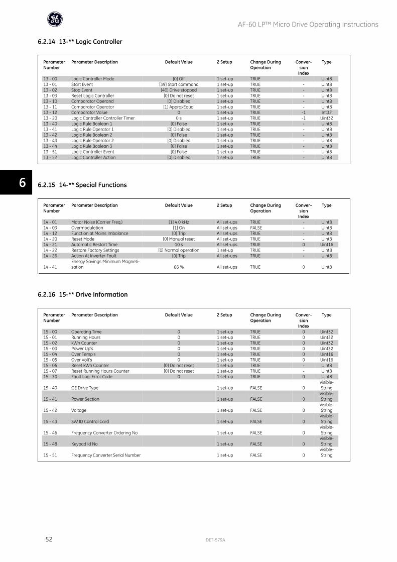
6.2.14 13-** Logic Controller
ParameterNumber
Parameter Description Default Value 2 Setup Change DuringOperation
Conver-sion
Index
Type
13 - 00 Logic Controller Mode [0] Off 1 set-up TRUE - Uint813 - 01 Start Event [39] Start command 1 set-up TRUE - Uint813 - 02 Stop Event [40] Drive stopped 1 set-up TRUE - Uint813 - 03 Reset Logic Controller [0] Do not reset 1 set-up TRUE - Uint813 - 10 Comparator Operand [0] Disabled 1 set-up TRUE - Uint813 - 11 Comparator Operator [1] ApproxEqual 1 set-up TRUE - Uint813 - 12 Comparator Value 0 1 set-up TRUE -1 Int3213 - 20 Logic Controller Controller Timer 0 s 1 set-up TRUE -1 Uint3213 - 40 Logic Rule Boolean 1 [0] False 1 set-up TRUE - Uint813 - 41 Logic Rule Operator 1 [0] Disabled 1 set-up TRUE - Uint813 - 42 Logic Rule Boolean 2 [0] False 1 set-up TRUE - Uint813 - 43 Logic Rule Operator 2 [0] Disabled 1 set-up TRUE - Uint813 - 44 Logic Rule Boolean 3 [0] False 1 set-up TRUE - Uint813 - 51 Logic Controller Event [0] False 1 set-up TRUE - Uint813 - 52 Logic Controller Action [0] Disabled 1 set-up TRUE - Uint8
6.2.15 14-** Special Functions
ParameterNumber
Parameter Description Default Value 2 Setup Change DuringOperation
Conver-sion
Index
Type
14 - 01 Motor Noise (Carrier Freq.) [1] 4.0 kHz All set-ups TRUE - Uint814 - 03 Overmodulation [1] On All set-ups FALSE - Uint814 - 12 Function at Mains Imbalance [0] Trip All set-ups TRUE - Uint814 - 20 Reset Mode [0] Manual reset All set-ups TRUE - Uint814 - 21 Automatic Restart Time 10 s All set-ups TRUE 0 Uint1614 - 22 Restore Factory Settings [0] Normal operation 1 set-up TRUE - Uint814 - 26 Action At Inverter Fault [0] Trip All set-ups TRUE - Uint8
14 - 41Energy Savings Minimum Magneti-sation 66 % All set-ups TRUE 0 Uint8
6.2.16 15-** Drive Information
ParameterNumber
Parameter Description Default Value 2 Setup Change DuringOperation
Conver-sion
Index
Type
15 - 00 Operating Time 0 1 set-up TRUE 0 Uint3215 - 01 Running Hours 0 1 set-up TRUE 0 Uint3215 - 02 kWh Counter 0 1 set-up TRUE 0 Uint3215 - 03 Power Up's 0 1 set-up TRUE 0 Uint3215 - 04 Over Temp's 0 1 set-up TRUE 0 Uint1615 - 05 Over Volt's 0 1 set-up TRUE 0 Uint1615 - 06 Reset kWh Counter [0] Do not reset 1 set-up TRUE - Uint815 - 07 Reset Running Hours Counter [0] Do not reset 1 set-up TRUE - Uint815 - 30 Fault Log: Error Code 0 1 set-up TRUE 0 Uint8
15 - 40 GE Drive Type 1 set-up FALSE 0Visible-String
15 - 41 Power Section 1 set-up FALSE 0Visible-String
15 - 42 Voltage 1 set-up FALSE 0Visible-String
15 - 43 SW ID Control Card 1 set-up FALSE 0Visible-String
15 - 46 Frequency Converter Ordering No 1 set-up FALSE 0Visible-String
15 - 48 Keypad Id No 1 set-up FALSE 0Visible-String
15 - 51 Frequency Converter Serial Number 1 set-up FALSE 0Visible-String
AF-60 LP™ Micro Drive Operating Instructions
52 DET-579A
6
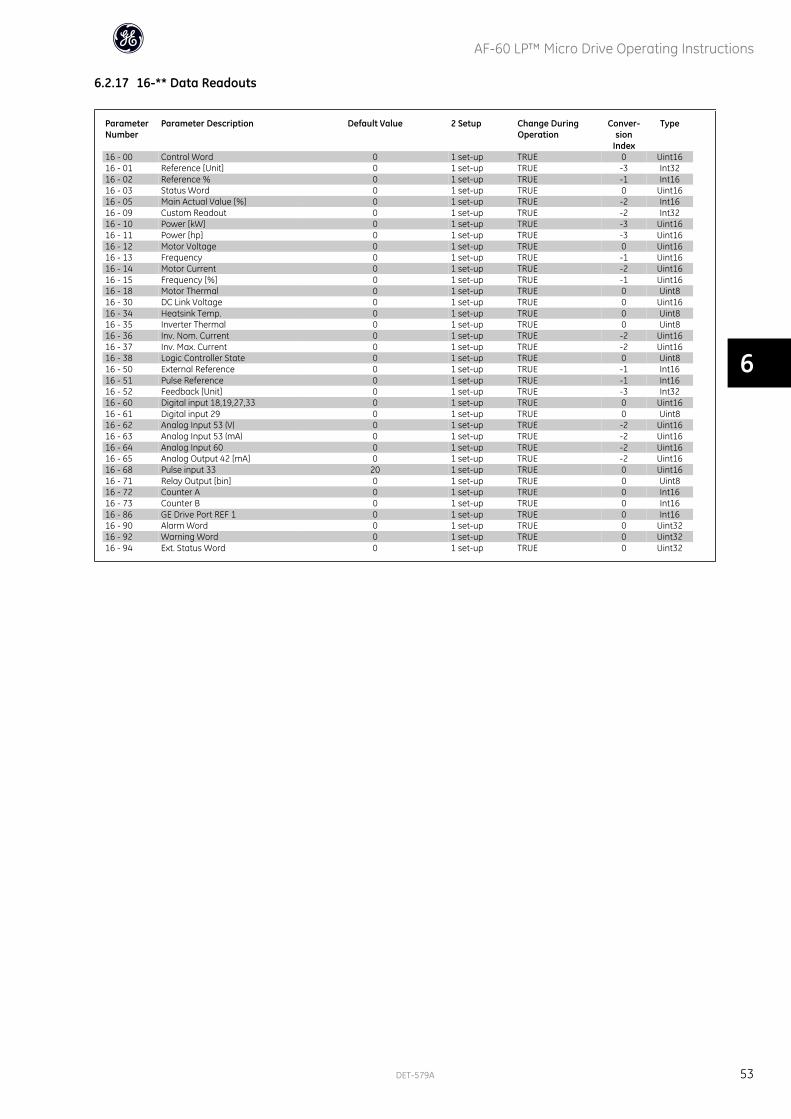
6.2.17 16-** Data Readouts
ParameterNumber
Parameter Description Default Value 2 Setup Change DuringOperation
Conver-sion
Index
Type
16 - 00 Control Word 0 1 set-up TRUE 0 Uint1616 - 01 Reference [Unit] 0 1 set-up TRUE -3 Int3216 - 02 Reference % 0 1 set-up TRUE -1 Int1616 - 03 Status Word 0 1 set-up TRUE 0 Uint1616 - 05 Main Actual Value [%] 0 1 set-up TRUE -2 Int1616 - 09 Custom Readout 0 1 set-up TRUE -2 Int3216 - 10 Power [kW] 0 1 set-up TRUE -3 Uint1616 - 11 Power [hp] 0 1 set-up TRUE -3 Uint1616 - 12 Motor Voltage 0 1 set-up TRUE 0 Uint1616 - 13 Frequency 0 1 set-up TRUE -1 Uint1616 - 14 Motor Current 0 1 set-up TRUE -2 Uint1616 - 15 Frequency [%] 0 1 set-up TRUE -1 Uint1616 - 18 Motor Thermal 0 1 set-up TRUE 0 Uint816 - 30 DC Link Voltage 0 1 set-up TRUE 0 Uint1616 - 34 Heatsink Temp. 0 1 set-up TRUE 0 Uint816 - 35 Inverter Thermal 0 1 set-up TRUE 0 Uint816 - 36 Inv. Nom. Current 0 1 set-up TRUE -2 Uint1616 - 37 Inv. Max. Current 0 1 set-up TRUE -2 Uint1616 - 38 Logic Controller State 0 1 set-up TRUE 0 Uint816 - 50 External Reference 0 1 set-up TRUE -1 Int1616 - 51 Pulse Reference 0 1 set-up TRUE -1 Int1616 - 52 Feedback [Unit] 0 1 set-up TRUE -3 Int3216 - 60 Digital input 18,19,27,33 0 1 set-up TRUE 0 Uint1616 - 61 Digital input 29 0 1 set-up TRUE 0 Uint816 - 62 Analog Input 53 (V) 0 1 set-up TRUE -2 Uint1616 - 63 Analog Input 53 (mA) 0 1 set-up TRUE -2 Uint1616 - 64 Analog Input 60 0 1 set-up TRUE -2 Uint1616 - 65 Analog Output 42 [mA] 0 1 set-up TRUE -2 Uint1616 - 68 Pulse input 33 20 1 set-up TRUE 0 Uint1616 - 71 Relay Output [bin] 0 1 set-up TRUE 0 Uint816 - 72 Counter A 0 1 set-up TRUE 0 Int1616 - 73 Counter B 0 1 set-up TRUE 0 Int1616 - 86 GE Drive Port REF 1 0 1 set-up TRUE 0 Int1616 - 90 Alarm Word 0 1 set-up TRUE 0 Uint3216 - 92 Warning Word 0 1 set-up TRUE 0 Uint3216 - 94 Ext. Status Word 0 1 set-up TRUE 0 Uint32
AF-60 LP™ Micro Drive Operating Instructions
DET-579A 53
6

AF-60 LP™ Micro Drive Operating Instructions
54 DET-579A
7

7 Troubleshooting
AF-60 LP™ Micro Drive Operating Instructions
DET-579A 55
7
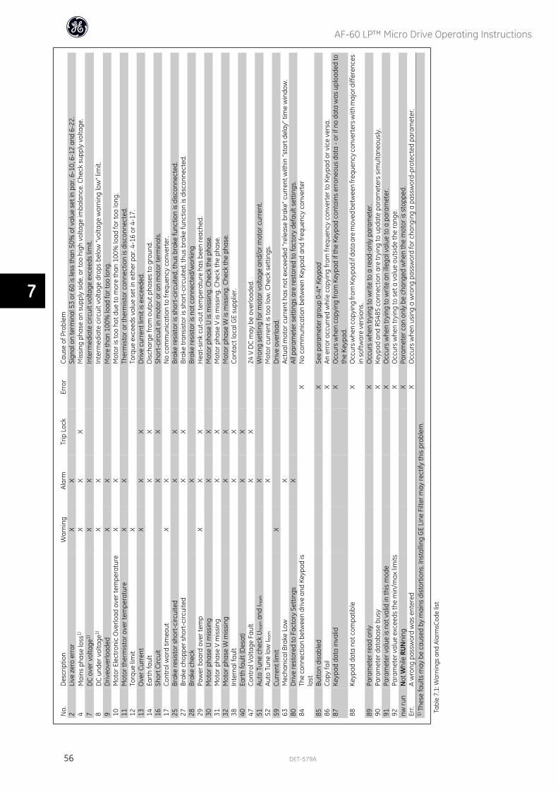
No.
Des
crip
tion
War
ning
Alar
mTr
ip L
ock
Erro
rCa
use
of P
robl
em2
Live
zer
o er
ror
XX
Sign
al o
n te
rmin
al 5
3 or
60
is le
ss th
an 5
0% o
f val
ue s
et in
par
. 6-1
0, 6
-12
and
6-22
.4
Mai
ns p
hase
loss
1)X
XX
M
issi
ng p
hase
on
supp
ly s
ide,
or t
oo h
igh
volta
ge im
bala
nce.
Che
ck s
uppl
y vo
ltage
.7
DC
over
vol
tage
1)X
X
In
term
edia
te c
ircui
t vol
tage
exc
eeds
lim
it.8
DC
unde
r vol
tage
1)X
X
In
term
edia
te c
ircui
t vol
tage
dro
ps b
elow
“vol
tage
war
ning
low
” lim
it.9
Driv
eove
rload
edX
X
M
ore
than
100
% lo
ad fo
r too
long
.10
Mot
or E
lect
roni
c O
verlo
ad o
ver t
empe
ratu
reX
X
M
otor
is to
o ho
t due
to m
ore
than
100
% lo
ad fo
r too
long
.11
Mot
or th
erm
isto
r ove
r tem
pera
ture
XX
Ther
mis
tor o
r the
rmis
tor c
onne
ctio
n is
dis
conn
ecte
d.12
Torq
ue li
mit
X
Torq
ue e
xcee
ds v
alue
set
in e
ither
par
. 4-1
6 or
4-1
7.13
Ove
r Cur
rent
XX
X
Driv
e cu
rren
t lim
it is
exc
eede
d.14
Eart
h fa
ult
X
X
Dis
char
ge fr
om o
utpu
t pha
ses
to g
roun
d.16
Shor
t Circ
uit
X
X
Shor
t-ci
rcui
t in
mot
or o
r on
mot
or te
rmin
als.
17Co
ntro
l wor
d tim
eout
XX
No
com
mun
icat
ion
to fr
eque
ncy
conv
erte
r.25
Brak
e re
sist
or s
hort
-circ
uite
d
XX
Br
ake
resi
stor
is s
hort
-circ
uite
d, th
us b
rake
func
tion
is d
isco
nnec
ted.
27Br
ake
chop
per s
hort
-circ
uite
d
XX
Br
ake
tran
sist
or is
sho
rt-c
ircui
ted,
thus
bra
ke fu
nctio
n is
dis
conn
ecte
d.28
Brak
e ch
eck
X
Brak
e re
sist
or is
not
con
nect
ed/w
orki
ng29
Pow
er b
oard
ove
r tem
pX
XX
H
eat-
sink
cut
-out
tem
pera
ture
has
bee
n re
ache
d.30
Mot
or p
hase
U m
issi
ng
XX
M
otor
pha
se U
is m
issi
ng. C
heck
the
phas
e.31
Mot
or p
hase
V m
issi
ng
XX
M
otor
pha
se V
is m
issi
ng. C
heck
the
phas
e.32
Mot
or p
hase
W m
issi
ng
XX
M
otor
pha
se W
is m
issi
ng. C
heck
the
phas
e.38
Inte
rnal
faul
t
XX
Co
ntac
t loc
al G
E su
pplie
r.40
Eart
h fa
ult (
Des
at)
X
X
47
Cont
rol V
olta
ge F
ault
X
X
24 V
DC
may
be
over
load
ed.
51Au
to T
une
chec
k U
nom
and
I nom
X
Wro
ng s
ettin
g fo
r mot
or v
olta
ge a
nd/o
r mot
or c
urre
nt.
52Au
to T
une
low
I nom
X
Mot
or c
urre
nt is
too
low
. Che
ck s
ettin
gs.
59Cu
rren
t lim
itX
D
rive
over
load
.63
Mec
hani
cal B
rake
Low
X
Actu
al m
otor
cur
rent
has
not
exc
eede
d “r
elea
se b
rake
” cur
rent
with
in “s
tart
del
ay” t
ime
win
dow
.80
Driv
e re
stor
ed to
Fac
tory
Set
tings
X
All p
aram
eter
set
tings
are
rest
ored
to fa
ctor
y de
faul
t set
tings
.84
The
conn
ectio
n be
twee
n dr
ive
and
Keyp
ad is
lost
X
No
com
mun
icat
ion
betw
een
Keyp
ad a
nd fr
eque
ncy
conv
erte
r
85Bu
tton
dis
able
d
XSe
e pa
ram
eter
gro
up 0
-4*
Keyp
ad86
Copy
fail
X
An e
rror
occ
urre
d w
hile
cop
ying
from
freq
uenc
y co
nver
ter t
o Ke
ypad
or v
ice
vers
a.87
Keyp
ad d
ata
inva
lid
XO
ccur
s w
hen
copy
ing
from
Key
pad
if th
e Ke
ypad
con
tain
s er
rone
ous
data
- or
if n
o da
ta w
as u
ploa
ded
toth
e Ke
ypad
.88
Keyp
ad d
ata
not c
ompa
tible
X
Occ
urs w
hen
copy
ing
from
Key
pad
if da
ta a
re m
oved
bet
wee
n fr
eque
ncy c
onve
rter
s with
maj
or d
iffer
ence
sin
sof
twar
e ve
rsio
ns.
89Pa
ram
eter
read
onl
y
XO
ccur
s w
hen
tryi
ng to
writ
e to
a re
ad-o
nly
para
met
er.
90Pa
ram
eter
dat
abas
e bu
sy
XKe
ypad
and
RS4
85 c
onne
ctio
n ar
e tr
ying
to u
pdat
e pa
ram
eter
s si
mul
tane
ousl
y.91
Para
met
er v
alue
is n
ot v
alid
in th
is m
ode
X
Occ
urs
whe
n tr
ying
to w
rite
an il
lega
l val
ue to
a p
aram
eter
.92
Para
met
er v
alue
exc
eeds
the
min
/max
lim
its
XO
ccur
s w
hen
tryi
ng to
set
a v
alue
out
side
the
rang
e.nw
run
Not
Whi
le R
UN
ning
X
Para
met
er c
an o
nly
be c
hang
ed w
hen
the
mot
or is
sto
pped
.Er
r.A
wro
ng p
assw
ord
was
ent
ered
X
Occ
urs
whe
n us
ing
a w
rong
pas
swor
d fo
r cha
ngin
g a
pass
wor
d-pr
otec
ted
para
met
er.
1) T
hese
faul
ts m
ay b
e ca
used
by
mai
ns d
isto
rtio
ns. I
nsta
lling
GE
Line
Filt
er m
ay re
ctify
this
pro
blem
.
Tabl
e 7.
1: W
arni
ngs
and
Alar
msC
ode
list
AF-60 LP™ Micro Drive Operating Instructions
56 DET-579A
7
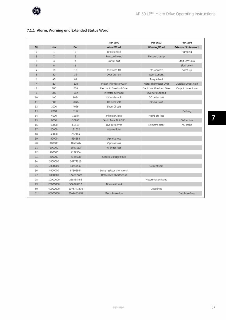
7.1.1 Alarm, Warning and Extended Status Word
Par 1690 Par 1692 Par 1694
Bit Hex Dec AlarmWord WarningWord ExtendedStatusWord
0 1 1 Brake check Ramping
1 2 2 Pwr.card temp Pwr.card temp
2 4 4 Earth Fault Start CW/CCW
3 8 8 Slow down
4 10 16 Ctrl.word TO Ctrl.word TO Catch up
5 20 32 Over Current Over Current
6 40 64 Torque limit
7 80 128 Motor Thermistor Over Motor Thermistor Over Output current high
8 100 256 Electronic Overload Over Electronic Overload Over Output current low
9 200 512 Inverter overload Inverter overload
10 400 1024 DC under volt DC under volt
11 800 2048 DC over volt DC over volt
12 1000 4096 Short Circuit
13 2000 8192 Braking
14 4000 16384 Mains ph. loss Mains ph. loss
15 8000 32768 "Auto Tune Not OK" OVC active
16 10000 65536 Live zero error Live zero error AC brake
17 20000 131072 Internal fault
18 40000 262144
19 80000 524288 U phase loss
20 100000 1048576 V phase loss
21 200000 2097152 W phase loss
22 400000 4194304
23 800000 8388608 Control Voltage Fault
24 1000000 16777216
25 2000000 33554432 Current limit
26 4000000 67108864 Brake resistor shortcircuit
27 8000000 134217728 Brake IGBT shortcircuit
28 10000000 268435456 MotorPhaseMissing
29 20000000 536870912 Drive restored
30 40000000 1073741824 Undefined
31 80000000 2147483648 Mech. brake low DatabaseBusy
AF-60 LP™ Micro Drive Operating Instructions
DET-579A 57
7

AF-60 LP™ Micro Drive Operating Instructions
58 DET-579A
8
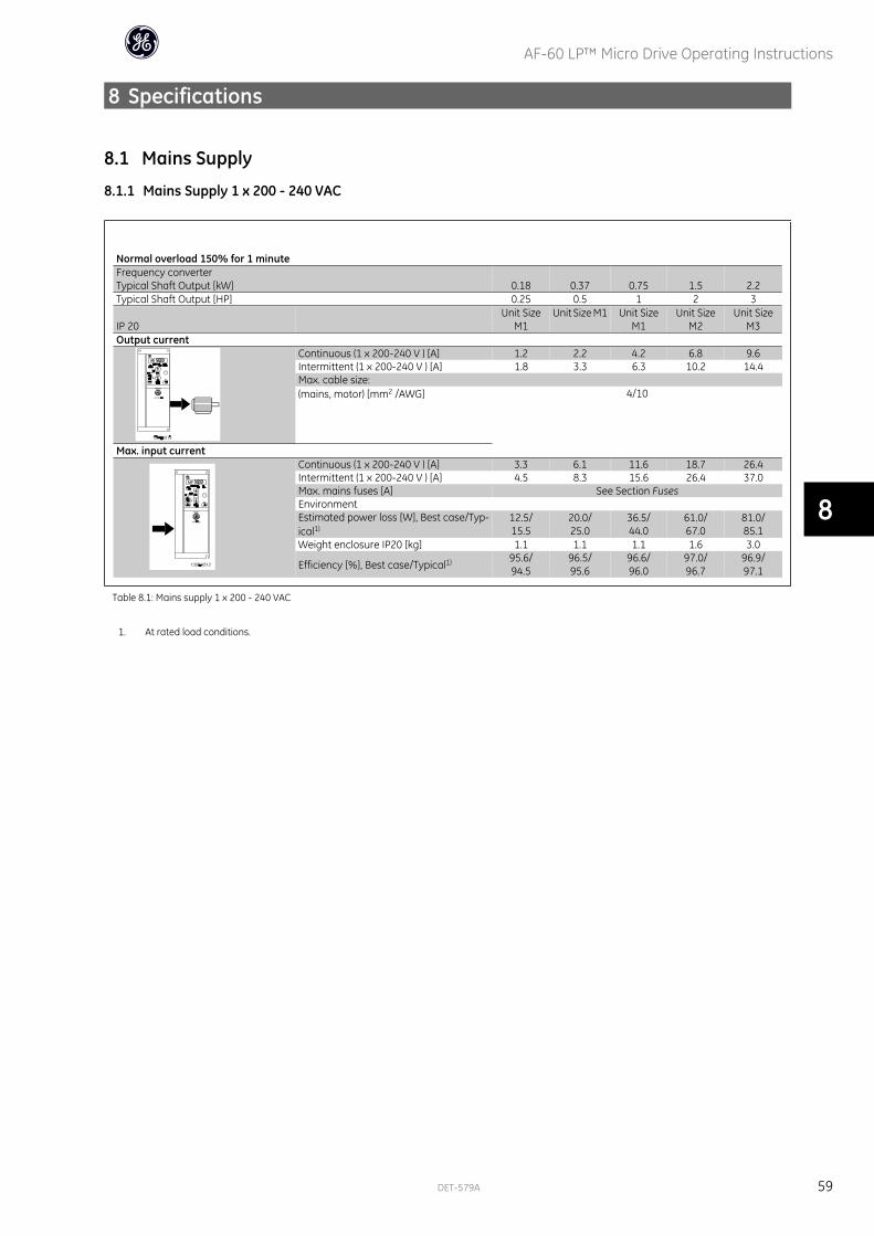
8 Specifications
8.1 Mains Supply
8.1.1 Mains Supply 1 x 200 - 240 VAC
Normal overload 150% for 1 minuteFrequency converterTypical Shaft Output [kW] 0.18 0.37 0.75 1.5 2.2Typical Shaft Output [HP] 0.25 0.5 1 2 3
IP 20 Unit Size
M1Unit Size M1 Unit Size
M1Unit Size
M2Unit Size
M3Output current
Continuous (1 x 200-240 V ) [A] 1.2 2.2 4.2 6.8 9.6Intermittent (1 x 200-240 V ) [A] 1.8 3.3 6.3 10.2 14.4Max. cable size:(mains, motor) [mm2 /AWG] 4/10
Max. input currentContinuous (1 x 200-240 V ) [A] 3.3 6.1 11.6 18.7 26.4Intermittent (1 x 200-240 V ) [A] 4.5 8.3 15.6 26.4 37.0Max. mains fuses [A] See Section FusesEnvironmentEstimated power loss [W], Best case/Typ-ical1)
12.5/15.5
20.0/25.0
36.5/44.0
61.0/67.0
81.0/85.1
Weight enclosure IP20 [kg] 1.1 1.1 1.1 1.6 3.0
Efficiency [%], Best case/Typical1) 95.6/94.5
96.5/95.6
96.6/96.0
97.0/96.7
96.9/97.1
Table 8.1: Mains supply 1 x 200 - 240 VAC
1. At rated load conditions.
AF-60 LP™ Micro Drive Operating Instructions
DET-579A 59
8
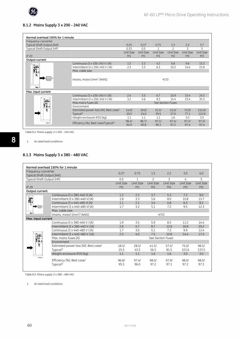
8.1.2 Mains Supply 3 x 200 - 240 VAC
Normal overload 150% for 1 minuteFrequency converterTypical Shaft Output [kW] 0.25 0.37 0.75 1.5 2.2 3.7Typical Shaft Output [HP] 0.33 0.5 1 2 3 5
IP 20 Unit Size
M1Unit Size
M1Unit Size
M1Unit Size
M2Unit Size
M3Unit Size
M3Output current
Continuous (3 x 200-240 V ) [A] 1.5 2.2 4.2 6.8 9.6 15.2Intermittent (3 x 200-240 V ) [A] 2.3 3.3 6.3 10.2 14.4 22.8Max. cable size:
(mains, motor) [mm2 /AWG] 4/10
Max. input current
Continuous (3 x 200-240 V ) [A] 2.4 3.5 6.7 10.9 15.4 24.3Intermittent (3 x 200-240 V ) [A] 3.2 4.6 8.3 14.4 23.4 35.3Max.mains fuses [A] See Section FusesEnvironment Estimated power loss [W], Best case/Typical1)
14.0/20.0
19.0/24.0
31.5/39.5
51.0/57.0
72.0/77.1
115.0/122.8
Weight enclosure IP20 [kg] 1.1 1.1 1.1 1.6 3.0 3.0
Efficiency [%], Best case/Typical1) 96.4/94.9
96.7/95.8
97.1/96.3
97.4/97.2
97.2/97.4
97.3/97.4
Table 8.2: Mains supply 3 x 200 - 240 VAC
1. At rated load conditions.
8.1.3 Mains Supply 3 x 380 - 480 VAC
Normal overload 150% for 1 minuteFrequency converterTypical Shaft Output [kW] 0.37 0.75 1.5 2.2 3.0 4.0
Typical Shaft Output [HP] 0.5 1 2 3 4 5
IP 20 Unit Size
M1Unit Size
M1Unit Size
M2Unit Size
M2Unit Size
M3Unit Size
M3Output current
Continuous (3 x 380-440 V) [A] 1.2 2.2 3.7 5.3 7.2 9.0Intermittent (3 x 380-440 V) [A] 1.8 3.3 5.6 8.0 10.8 13.7Continuous (3 x 440-480 V) [A] 1.1 2.1 3.4 4.8 6.3 8.2Intermittent (3 x 440-480 V) [A] 1.7 3.2 5.1 7.2 9.5 12.3Max. cable size:(mains, motor) [mm2/ AWG] 4/10
Max. input currentContinuous (3 x 380-440 V ) [A] 1.9 3.5 5.9 8.5 11.5 14.4Intermittent (3 x 380-440 V ) [A] 2.6 4.7 8.7 12.6 16.8 20.2Continuous (3 x 440-480 V ) [A] 1.7 3.0 5.1 7.3 9.9 12.4Intermittent (3 x 440-480 V ) [A] 2.3 4.0 7.5 10.8 14.4 17.5Max. mains fuses [A] See Section FusesEnvironmentEstimated power loss [W], Best case/Typical1)
18.5/25.5
28.5/43.5
41.5/56.5
57.5/81.5
75.0/101.6
98.5/133.5
Weight enclosure IP20 [kg] 1.1 1.1 1.6 1.6 3.0 3.0
Efficiency [%], Best case/Typical1)
96.8/95.5
97.4/96.0
98.0/97.2
97.9/97.1
98.0/97.2
98.0/97.3
Table 8.3: Mains supply 3 x 380 - 480 VAC
1. At rated load conditions.
AF-60 LP™ Micro Drive Operating Instructions
60 DET-579A
8
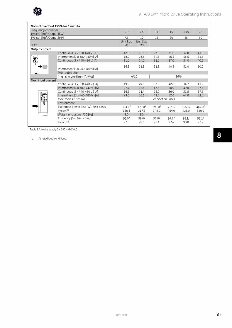
Normal overload 150% for 1 minuteFrequency converterTypical Shaft Output [kW] 5.5 7.5 11 15 18.5 22
Typical Shaft Output [HP] 7.5 10 15 20 25 30
IP 20 Unit Size
M3Unit Size
M3Output current
Continuous (3 x 380-440 V) [A] 12.0 15.5 23.0 31.0 37.0 43.0Intermittent (3 x 380-440 V) [A] 18.0 23.5 34.5 46.5 55.5 64.5Continuous (3 x 440-480 V) [A] 11.0 14.0 21.0 27.0 34.0 40.0
Intermittent (3 x 440-480 V) [A]16.5 21.3 31.5 40.5 51.0 60.0
Max. cable size:(mains, motor) [mm2/ AWG] 4/10 16/6
Max. input currentContinuous (3 x 380-440 V ) [A] 19.2 24.8 33.0 42.0 34.7 41.2Intermittent (3 x 380-440 V ) [A] 27.4 36.3 47.5 60.0 49.0 57.6Continuous (3 x 440-480 V ) [A] 16.6 21.4 29.0 36.0 31.5 37.5Intermittent (3 x 440-480 V ) [A] 23.6 30.1 41.0 52.0 44.0 53.0Max. mains fuses [A] See Section FusesEnvironmentEstimated power loss [W], Best case/Typical1)
131.0/166.8
175.0/217.5
290.0/342.0
387.0/454.0
395.0/428.0
467.0/520.0
Weight enclosure IP20 [kg] 3.0 3.0 Efficiency [%], Best case/Typical1)
98.0/97.5
98.0/97.5
97.8/97.4
97.7/97.4
98.1/98.0
98.1/97.9
Table 8.4: Mains supply 3 x 380 - 480 VAC
1. At rated load conditions.
AF-60 LP™ Micro Drive Operating Instructions
DET-579A 61
8

8.2 Other SpecificationsProtection and Features:
• Electronic thermal motor protection against overload.
• Temperature monitoring of the heatsink ensures that the frequency converter trips in case of overtemperature
• The frequency converter is protected against short-circuits on motor terminals U, V, W.
• If a motor phase is missing, the frequency trips and issues an alarm.
• If a mains phase is missing, the frequency converter trips or issues a warning (depending on the load).
• Monitoring of the intermediate circuit voltage ensures that the frequency converter trips if the intermediate circuit voltage is too low or too high.
• The frequency converter is protected against earth faults on motor terminals U, V, W.
Mains supply (L1/L, L2, L3/N):
Supply voltage 200-240 V ±10%
Supply voltage 380-480 V ±10%
Supply frequency 50/60 Hz
Max. imbalance temporary between mains phases 3.0 % of rated supply voltage
True Power Factor (λ) ≥ 0.4 nominal at rated load
Displacement Power Factor (cosφ) near unity (> 0.98)
Switching on input supply L1/L, L2, L3/N (power-ups) maximum 2 times/min.
Environment according to EN60664-1 overvoltage category III/pollution degree 2
The unit is suitable for use on a circuit capable of delivering not more than 100.000 RMS symmetrical Amperes, 240/480 V maximum.
Motor output (U, V, W):
Output voltage 0 - 100% of supply voltage
Output frequency 0-200 Hz (Advanced Vector Control), 0-400 Hz (u/f)
Switching on output Unlimited
Ramp times 0.05 - 3600 sec.
Cable lengths and cross sections:
Max. motor cable length, screened/armoured (EMC correct installation) 15 m
Max. motor cable length, unscreened/unarmoured 50 m
Max. cross section to motor, mains*
Connection to load sharing/brake (M1, M2, M3) 6.3 mm insulated Faston Plugs
Max. cross section to load sharing/brake (M4, M5) 16 mm2/6AWG
Maximum cross section to control terminals, rigid wire 1.5 mm2/16 AWG (2 x 0.75 mm2)
Maximum cross section to control terminals, flexible cable 1 mm2/18 AWG
Maximum cross section to control terminals, cable with enclosed core 0.5 mm2/20 AWG
Minimum cross section to control terminals 0.25 mm2
* See tables for mains supply for more information!
Digital inputs (Pulse/enocder inputs):
Programmable digital inputs (Pulse/encoder) 5 (1)
Terminal number 18, 19, 27, 29, 33,
Logic PNP or NPN
Voltage level 0 - 24 V DC
Voltage level, logic'0' PNP < 5 V DC
Voltage level, logic'1' PNP > 10 V DC
Voltage level, logic '0' NPN > 19 V DC
Voltage level, logic '1' NPN < 14 V DC
Maximum voltage on input 28 V DC
Input resistance, Ri approx. 4 k
Max. pulse frequency at terminal 33 5000 Hz
Min. pulse frequency at terminal 33 20 Hz
AF-60 LP™ Micro Drive Operating Instructions
62 DET-579A
8
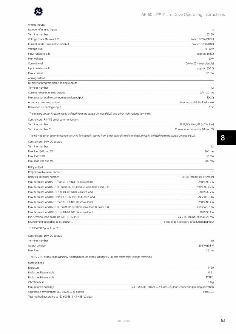
Analog inputs:
Number of analog inputs 2
Terminal number 53, 60
Voltage mode (Terminal 53) Switch S200=OFF(U)
Current mode (Terminal 53 and 60) Switch S200=ON(I)
Voltage level 0 -10 V
Input resistance, Ri approx. 10 kΩ
Max. voltage 20 V
Current level 0/4 to 20 mA (scaleable)
Input resistance, Ri approx. 200 Ω
Max. current 30 mA
Analog output:
Number of programmable analog outputs 1
Terminal number 42
Current range at analog output 0/4 - 20 mA
Max. resistor load to common at analog output 500 ΩAccuracy on analog output Max. error: 0.8 % of full scale
Resolution on analog output 8 bit
The analog output is galvanically isolated from the supply voltage (PELV) and other high-voltage terminals.
Control card, RS-485 serial communication:
Terminal number 68 (P,TX+, RX+), 69 (N,TX-, RX-)
Terminal number 61 Common for terminals 68 and 69
The RS-485 serial communication circuit is functionally seated from other central circuits and galvanically isolated from the supply voltage (PELV).
Control card, 24 V DC output:
Terminal number 12
Max. load (M1 and M2) 160 mA
Max. load (M3) 30 mA
Max. load (M4 and M5) 200 mA
Relay output:
Programmable relay output 1
Relay 01 Terminal number 01-03 (break), 01-02(make)
Max. terminal load (AC-1)1) on 01-02 (NO) (Resistive load) 250 V AC, 2 A
Max. terminal load (AC-15)1) on 01-02 (NO) (Inductive load @ cosφ 0.4) 250 V AC, 0.2 A
Max. terminal load (DC-1)1) on 01-02 (NO) (Resistive load) 30 V DC, 2 A
Max. terminal load (DC-13)1) on 01-02 (NO) (Inductive load) 24 V DC, 0.1A
Max. terminal load (AC-1)1) on 01-03 (NC) (Resistive load) 250 V AC, 2 A
Max. terminal load (AC-15)1) on 01-03 (NC) (Inductive load @ cosφ 0.4) 250 V AC, 0.2A
Max. terminal load (DC-1)1) on 01-03 (NC) (Resistive load) 30 V DC, 2 A
Min. terminal load on 01-03 (NC), 01-02 (NO) 24 V DC 10 mA, 24 V AC 20 mA
Environment according to EN 60664-1 overvoltage category III/pollution degree 2
1) IEC 60947 part 4 and 5
Control card, 10 V DC output:
Terminal number 50
Output voltage 10.5 V ±0.5 V
Max. load 25 mA
The 10 V DC supply is galvanically isolated from the supply voltage (PELV) and other high-voltage terminals.
Surroundings:
Enclosure IP 20
Enclosure kit available IP 21
Enclosure kit available TYPE 1
Vibration test 1.0 g
Max. relative humidity 5% - 95%(IEC 60721-3-3; Class 3K3 (non-condensing) during operation
Aggressive environment (IEC 60721-3-3), coated class 3C3
Test method according to IEC 60068-2-43 H2S (10 days)
AF-60 LP™ Micro Drive Operating Instructions
DET-579A 63
8
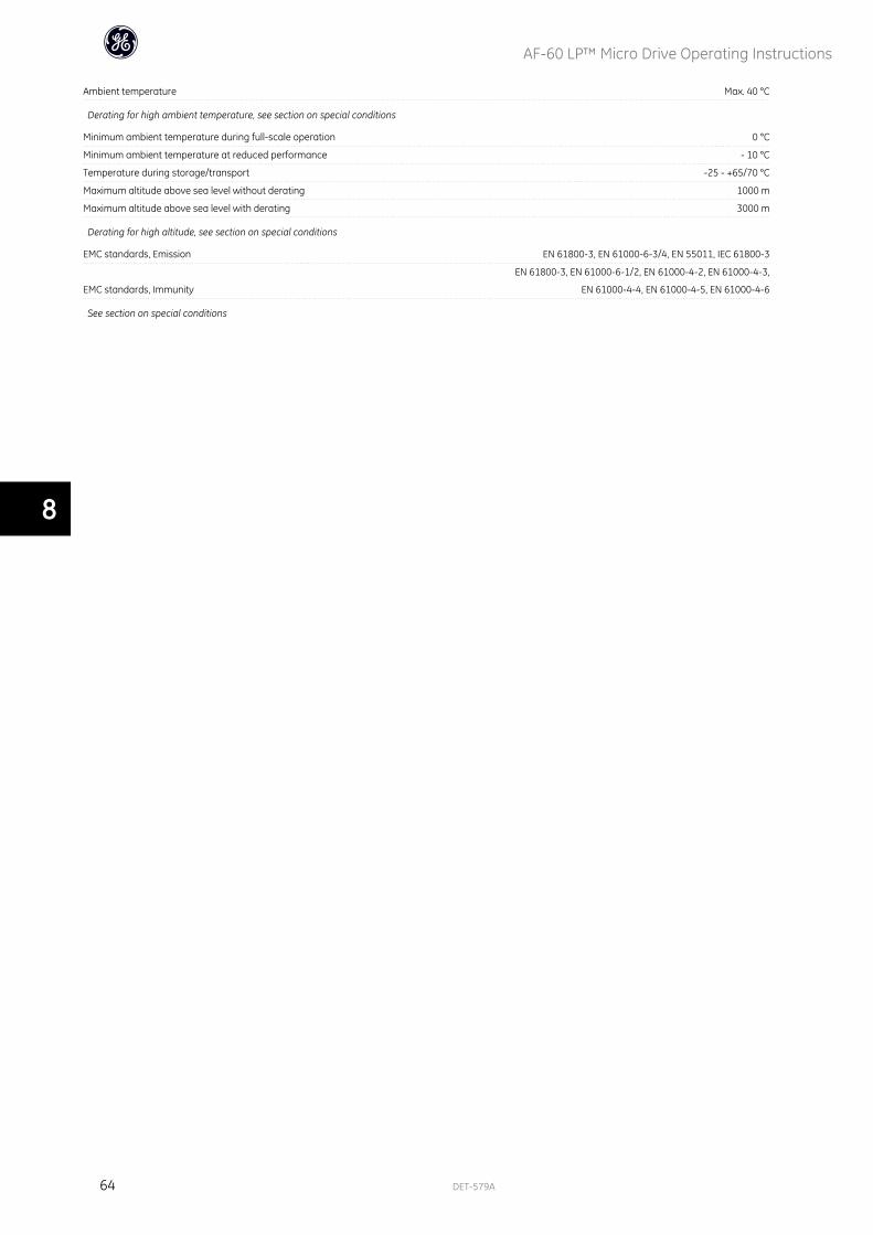
Ambient temperature Max. 40 °C
Derating for high ambient temperature, see section on special conditions
Minimum ambient temperature during full-scale operation 0 °C
Minimum ambient temperature at reduced performance - 10 °C
Temperature during storage/transport -25 - +65/70 °C
Maximum altitude above sea level without derating 1000 m
Maximum altitude above sea level with derating 3000 m
Derating for high altitude, see section on special conditions
EMC standards, Emission EN 61800-3, EN 61000-6-3/4, EN 55011, IEC 61800-3
EMC standards, Immunity
EN 61800-3, EN 61000-6-1/2, EN 61000-4-2, EN 61000-4-3,
EN 61000-4-4, EN 61000-4-5, EN 61000-4-6
See section on special conditions
AF-60 LP™ Micro Drive Operating Instructions
64 DET-579A
8
8.3 Special Conditions
8.3.1 The Purpose of Derating
Derating must be taken into account when using the frequency converter at low air pressure (heights), at low speeds or at high ambient temperature. The required
action is described in this section.
8.3.2 Derating for Ambient Temperature
The ambient temperature measured over 24 hours should be at least 5 °C lower than the max. ambient temperature.
If the frequency converter is operated at high ambient temperature, the continuous output current should be decreased.
The frequency converter has been designed for operation at max 50 °C ambient temperature with one motor size smaller than nominal. Continuous operation
at full load at 50 °C ambient temperature will reduce the lifetime of the frequency converter.
8.3.3 Derating for Low Air Pressure
The cooling capability of air is decreased at low air pressure.
For altitudes above 2000 m, please contact GE .
Below 1000 m altitude no de-rating is necessary but above 1000 m the ambient temperature or the maximum output current should be decreased.
Decrease the output by 1% per 100 m altitude above 1000 m or reduce the max. ambient temperature by 1 degree per 200 m
8.3.4 Derating for Running at Low Speeds
When a motor is connected to at frequency converter, it is necessary to check that the cooling of the motor is adequate.
A problem may occur at low speeds in constant torque applications. Running continuously at low speeds – below half the nominal motor speed – may require
additional air cooling. Alternatively, choose a larger motor (one size up).
AF-60 LP™ Micro Drive Operating Instructions
DET-579A 65
8
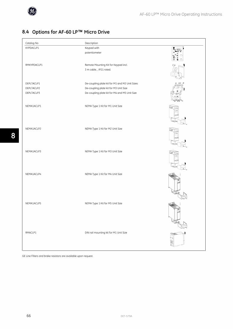
8.4 Options for AF-60 LP™ Micro Drive
Catalog No Description
KYPDACLP1 Keypad with
potentiometer
RMKYPDACLP1 Remote Mounting Kit for Keypad incl.
3 m cable, , IP21 rated.
DEPLTACLP1
DEPLTACLP2
DEPLTACLP3
De-coupling plate kit for M1 and M2 Unit Sizes
De-coupling plate kit for M3 Unit Size
De-coupling plate kit for M4 and M5 Unit Size
NEMA1ACLP1 NEMA Type 1 Kit for M1 Unit Size
NEMA1ACLP2 NEMA Type 1 Kit for M2 Unit Size
NEMA1ACLP3 NEMA Type 1 Kit for M3 Unit Size
NEMA1ACLP4 NEMA Type 1 Kit for M4 Unit Size
NEMA1ACLP5 NEMA Type 1 Kit for M5 Unit Size
RMACLP1 DIN rail mounting kit for M1 Unit Size
GE Line Filters and brake resistors are available upon request.
AF-60 LP™ Micro Drive Operating Instructions
66 DET-579A
8
IndexAActive Set-up 19
Active Set-up 44, 49
Alarm, Warning And Extended Status Word 57
Ambient Temperature 64
Analog In/out 51
Analog Inputs 63
Analog Inputs: 63
Analog Output 63
BBrake Resistor 49
Brake Resistor (ohm) 44
Brake Resistor Short-circuited 56
Brakes 49
Bus Termination 16
CCable Lengths And Cross Sections 62
Clearance 9
Comm. And Options 51
Configuration Mode 23
Control Card, 10 V Dc Output 63
Control Card, 24 V Dc Output 63
Control Card, Rs-485 Serial Communication: 63
Control Terminals 16
Control Word According To Fc Profile 37
Controllers 51
Conversion Index 48
DDanfoss Fc Control Profile 37
Data Readouts 53
Dc-brake 45
Dc-brake 44
De-coupling Plate Kit 66
Derating For Ambient Temperature 65
Derating For Low Air Pressure 65
Derating For Running At Low Speeds 65
Digital In/out 50
Digital Inputs (pulse/enocder Inputs): 62
Digital Inputs: 62
Din Rail Mounting Kit 66
Display 19
Disposal Instruction 8
Drive Information 52
EEarth Leakage Current 5, 7
Edit Set-up 19
Edit Set-up 44, 49
Electronic Waste 8
Emc-correct Installation 13
Explanation Of The Control Bits 37
Explanation Of The Status Bits 40
FFrequency Converter With Modbus Rtu 27
Function Codes Supported By Modbus Rtu 31
AF-60 LP™ Micro Drive Operating Instructions
DET-579A 67
HHand Mode 45
Hand Mode 49
How To Connect 11
IIndicator Lights 20
Isolated Mains Source 7
It Mains 7
LLcp 11 19
Lcp 12 19
Leakage Current 7
Limits/warnings 50
Load Compensation 44, 49
Load Sharing/brake 18
Load/motor 49
MMain Menu 20, 25
Mains Connection 13
Mains Supply 59, 60
Mains Supply (l1/l, L2, L3/n) 62
Mains Supply 1 X 200 - 240 Vac 59
Mains Supply 3 X 200 - 240 Vac 60
Mains Supply 3 X 380 - 480 Vac 60
Max. Reference 24
Maximum Reference 23
Mechanical Dimensions 10
Mechanical Installation 9
Min. Reference 23
Minimum Reference 23
Modbus Rtu 27
Modbus Rtu Message Framing Structure 28
Modbus Rtu Overview 27
Motor Connection 14
Motor Current 22
Motor Direction 20
Motor Frequency 22
Motor Nominal Speed 22
Motor Output (u, V, W): 62
Motor Overload Protection 7
Motor Phase 45, 50
Motor Power 22
Motor Protection 62
Motor Speed High Limit 24
Motor Speed Low Limit 24
Motor Temperature 44
Motor Voltage 22
NNavigation Keys 21
OOperation Keys 21
Operation/display 49
Options 66
Options For Vlt Micro Drive Fc 51 66
Other Specifications 62
Output Performance (u, V, W) 62
Overcurrent Protection 12
AF-60 LP™ Micro Drive Operating Instructions
68 DET-579A
Over-voltage Control 44, 49
PParameter Number 20
Parameter Overview 43
Power Circuit - Overview 17
Preset Reference 24
Process Cl Feedback Resource 24
Process Feed Forward Factor 25
Process Pi Anti Windup 24
Process Pi Integral Time 25
Process Pi Normal/inverse 24
Process Pi Proportional Gain 24
Process Pi Start Speed 24
Protection 12
Protection And Features 62
QQuick Menu 20, 21
Quick Menu Parameters 22
RReadout Mode 20
Reference/ramps 50
Relay Output 63
Remote Mounting Kit 66
Residual Current Device 7
SS200 Switches 1-4 16
Serial Communication 21
Set-up Number 19
Set-up Software 19
Side-by-side Installation 9
Slip Compensation 44, 49
Smart Logic 52
Special Conditions 65
Special Functions 52
Specifications 59
Status Menu 20, 21
Status Word According To Fc Profile (stw) 39
Surroundings 63
Switches 16
TTerminal 60 Filter Time Constant 24
Terminal 60 High Current 24
Terminal 60 High Feedback Value 24
Terminal 60 Low Current 24
Terminal 60 Low Feedback Value 24
Thermistor 44
Thermistor Resource 49
Troubleshooting 55
UUl Compliance 12
Unit 20
VValue 20
Voltage Level 62
AF-60 LP™ Micro Drive Operating Instructions
DET-579A 69

WWarnings And Alarms 55, 56
AF-60 LP™ Micro Drive Operating Instructions
70 DET-579A
The instructions do not purport to cover all details or variations in equipment nor to provide for every possible contingency to be met in connection with installation, operation or maintenance. Should further information be desired or should particular problems arise which are not covered sufficiently for the purchaser’s purposes, the matter should be referred to the GE company.
AF-60 LP is a trademark of the General Electric Company.
GE Consumer & Industrial41 Woodford AvenuePlainville, CT 06062
www.geelectrical.com/drives
AF-60 LPTM Micro Drive
Operating Instructions
DET-579A132R0040
*MG02G202*
GE Consumer & IndustrialElectrical Distribution