
Power System Stabilizer as a Part of a Generator MPC ... - MDPI
25
energies Article Power System Stabilizer as a Part of a Generator MPC Adaptive Predictive Control System Pawel Sokólski 1, *, Tomasz A. Rutkowski 2 , Bartosz Ceran 3 , Dariusz Horla 1 and Daria Zlotecka 3 Citation: Sokólski, P.; Rutkowski, T.A.; Ceran, B.; Horla, D.; Zlotecka, D. Power System Stabilizer as a Part of a Generator MPC Predictive Control System. Energies 2021, 14, 6631. https://doi.org/10.3390/en14206631 Academic Editor: Abu-Siada Ahmed Received: 8 August 2021 Accepted: 30 September 2021 Published: 14 October 2021 Publisher’s Note: MDPI stays neutral with regard to jurisdictional claims in published maps and institutional affil- iations. Copyright: © 2021 by the authors. Licensee MDPI, Basel, Switzerland. This article is an open access article distributed under the terms and conditions of the Creative Commons Attribution (CC BY) license (https:// creativecommons.org/licenses/by/ 4.0/). 1 Faculty of Automatic Control, Robotics and Electrical Engineering, Pozna ´ n University of Technology, ul. Piotrowo 3a, 60-965 Pozna ´ n, Poland; [email protected] 2 Faculty of Electrical and Control Engeneering, Gda ´ nsk University of Technology, ul. Gabriela Narutowicza 11/12, 80-233 Gda ´ nsk, Poland; [email protected] 3 Faculty of Environmental Engineering and Energy, Pozna´ n University of Technology, ul. Piotrowo 5, 61-138 Pozna ´ n, Poland; [email protected] (B.C.); [email protected] (D.Z.) * Correspondence: [email protected] Abstract: In this paper, a model predictive controller based on a generator model for prediction purposes is proposed to replace a standard generator controller with a stabilizer of a power system. Such a local controller utilizes an input-output model of the system taking into consideration not only a generator voltage U g but also an additional, auxiliary signal (e.g., α, P g , or ω g ). This additional piece of information allows for taking oscillations into account that occur in the system and minimizing their impact on the overall system performance. Parameters of models used by the controller are obtained on the basis of the introduced black-box models both for a turbine and a synchronous generator, parameters of which are estimated in an on line fashion using a RLS method. The aim of this paper is to compare the behavior of the classical generator control system with a power system stabilizer and a model predictive control with an additional feedback signal. The novelty of the paper is related to the use of the predictive controller instead of the classical controller/stabilizer system and its possibility of stabilizing the power system. Contrary to the solutions found in the literature, which are commonly-based on a fuzzy logic approach, the authors propose the use of an adaptive model predictive controller, which takes advantage of the knowledge concerning the plant in the form of a model and adapts itself to the operating point of the system using the model parameters estimation mechanism. Moreover, the adaptive predictive controller, unlike other solutions, automatically adjusts signal levels to changes in the plant. The proposed solution is able to calculate the best control signal regardless of whether these changes of the plant are caused by a change in the operating point, or resulting from operation, e.g., wear of mechanical parts. Keywords: system stabilizer; power system; model predictive control; recursive least squares; parameter estimation; synchronous generator 1. Introduction 1.1. Power Generation Problem at Large Today, the development of the society depends strongly on the quality of generation and supply of the electrical energy. The growth rate of economies of particular societies is mirrored by the expected level of generation of the electric power. As such, a continuously- increasing demand on growing efficiency of power plants is observed, as well as on the improvement in the quality of the quality of energy. In order to enable the readers to identify the scope of the word plant, common for control-oriented researchers, and occluded here by the power plant subject, it has been decided to refer to the plant to-be- controlled, in general, by simple ‘plant’, and, whenever the power plant needs to be related to, it has been left as ‘power plant’ in the remaining part of the paper. Currently, the power system in Poland is mostly based on coal-fired power plants, the share of which in the total electricity production in 2020 was over 70% (46.97% hard coal and 24.93% lignite) [1]. Energies 2021, 14, 6631. https://doi.org/10.3390/en14206631 https://www.mdpi.com/journal/energies
-
Upload
khangminh22 -
Category
Documents
-
view
4 -
download
0
Transcript of Power System Stabilizer as a Part of a Generator MPC ... - MDPI

energies
Article
Power System Stabilizer as a Part of a Generator MPC AdaptivePredictive Control System
Paweł Sokólski 1,*, Tomasz A. Rutkowski 2 , Bartosz Ceran 3 , Dariusz Horla 1 and Daria Złotecka 3
�����������������
Citation: Sokólski, P.; Rutkowski,
T.A.; Ceran, B.; Horla, D.; Złotecka, D.
Power System Stabilizer as a Part of a
Generator MPC Predictive Control
System. Energies 2021, 14, 6631.
https://doi.org/10.3390/en14206631
Academic Editor: Abu-Siada Ahmed
Received: 8 August 2021
Accepted: 30 September 2021
Published: 14 October 2021
Publisher’s Note: MDPI stays neutral
with regard to jurisdictional claims in
published maps and institutional affil-
iations.
Copyright: © 2021 by the authors.
Licensee MDPI, Basel, Switzerland.
This article is an open access article
distributed under the terms and
conditions of the Creative Commons
Attribution (CC BY) license (https://
creativecommons.org/licenses/by/
4.0/).
1 Faculty of Automatic Control, Robotics and Electrical Engineering, Poznan University of Technology,ul. Piotrowo 3a, 60-965 Poznan, Poland; [email protected]
2 Faculty of Electrical and Control Engeneering, Gdansk University of Technology,ul. Gabriela Narutowicza 11/12, 80-233 Gdansk, Poland; [email protected]
3 Faculty of Environmental Engineering and Energy, Poznan University of Technology, ul. Piotrowo 5,61-138 Poznan, Poland; [email protected] (B.C.); [email protected] (D.Z.)
* Correspondence: [email protected]
Abstract: In this paper, a model predictive controller based on a generator model for predictionpurposes is proposed to replace a standard generator controller with a stabilizer of a power system.Such a local controller utilizes an input-output model of the system taking into consideration not onlya generator voltage Ug but also an additional, auxiliary signal (e.g., α, Pg, or ωg). This additional pieceof information allows for taking oscillations into account that occur in the system and minimizingtheir impact on the overall system performance. Parameters of models used by the controller areobtained on the basis of the introduced black-box models both for a turbine and a synchronousgenerator, parameters of which are estimated in an on line fashion using a RLS method. The aim ofthis paper is to compare the behavior of the classical generator control system with a power systemstabilizer and a model predictive control with an additional feedback signal. The novelty of the paperis related to the use of the predictive controller instead of the classical controller/stabilizer system andits possibility of stabilizing the power system. Contrary to the solutions found in the literature, whichare commonly-based on a fuzzy logic approach, the authors propose the use of an adaptive modelpredictive controller, which takes advantage of the knowledge concerning the plant in the form of amodel and adapts itself to the operating point of the system using the model parameters estimationmechanism. Moreover, the adaptive predictive controller, unlike other solutions, automaticallyadjusts signal levels to changes in the plant. The proposed solution is able to calculate the best controlsignal regardless of whether these changes of the plant are caused by a change in the operating point,or resulting from operation, e.g., wear of mechanical parts.
Keywords: system stabilizer; power system; model predictive control; recursive least squares;parameter estimation; synchronous generator
1. Introduction1.1. Power Generation Problem at Large
Today, the development of the society depends strongly on the quality of generationand supply of the electrical energy. The growth rate of economies of particular societies ismirrored by the expected level of generation of the electric power. As such, a continuously-increasing demand on growing efficiency of power plants is observed, as well as onthe improvement in the quality of the quality of energy. In order to enable the readersto identify the scope of the word plant, common for control-oriented researchers, andoccluded here by the power plant subject, it has been decided to refer to the plant to-be-controlled, in general, by simple ‘plant’, and, whenever the power plant needs to be relatedto, it has been left as ‘power plant’ in the remaining part of the paper. Currently, the powersystem in Poland is mostly based on coal-fired power plants, the share of which in thetotal electricity production in 2020 was over 70% (46.97% hard coal and 24.93% lignite) [1].
Energies 2021, 14, 6631. https://doi.org/10.3390/en14206631 https://www.mdpi.com/journal/energies

Energies 2021, 14, 6631 2 of 25
According to the Energy Policy of Poland until 2040 [2], the generation system is to undergoa complete transformation. The goals set in the national energy and climate plan [3] makeit necessary to reduce the environmental impact of an energy sector, especially in termsof emissions of pollutants and greenhouse gases, and, moreover, to increase the share ofrenewable sources in the total energy production in the energy sector. The publication ofBest Available Techniques conclusions (BAT) [4], in 2017, was a milestone in reducing theimpact of conventional energy on the environment by introducing tight limits for emissionfor huge combustion plants. It contributed to the extensive modernization of flue gastreatment systems in the field of dust removal, denitrification, and flue gas desulfurization,also involving significant investment costs for energy companies.
In the coming years, Transmission System Operator (in Poland, PSE S.A.) anticipatesa significant number of shutdowns of conventional sources, not only due to the end ofthe limit operation time of power units but also due to the potential failure to meet theemission requirements contained in the BAT conclusions [5].
In the Forecast of Peak Demand for Power in 2016–2035 [2], it is estimated that, inyears 2016–2040, the cumulative volume of decommissioning of Centrally DispatchedGenerating Units will reach even 15 GW. The consequence of these steps would be asignificant reduction in CO2 emissions from fuels combustion, but, on the other hand, thisforecast presented against the background of growing demand for electricity indicates aserious threat to the energy security of the power system due to the deepening deficit ofinstalled power in the system and the loss of high-power units operating stably as a baseload power plant.
As an example, a serious accident at the Bełchatów Power Plant, which took placeon 17 May 2021, can be mentioned here. The Bełchatów Power Plant, based on lignitecombustion, currently operates on the basis of 12 power units with a total installed powerof 5.1 GW and, at the same time, is responsible for covering up to 20% of the total electricitydemand in the National Power System. On the day of the failure, as a result of an erroneousswitching operation at the power station, resulting in a single-phase short-circuit on the400 kV line, 10 out of 11 operating power units with a total capacity of 3.9 GW were out ofservice. Due to the significant loss of power, the effects of the failure were observed in thecontinental Europe power systems, i.e., the registered frequency decrease in the systemrated −158 mHz, which caused the dynamic response of the automatic frequency controlsystems (primary reserve) [6]. Thanks to the availability of spinning reserve of nationalunits, peaking power plants and interventional cross-border exchange, it was possibleto restore stable parameters of the system, without the need to introduce emergencyrestrictions and supply levels. The conclusions from the failure indicate the legitimacy ofcontinuous improvement of the automatic control systems of generating units not onlyin emergency conditions but also to ensure their safe operation in normal conditions,with particular emphasis on the quick response of the unit control systems to suddenload changes.
The aforementioned shutdowns of generating units, planned for subsequent years,necessitate the need to plan a new energy mix, conditioning:
• replacing the capacity of withdrawn sources in the power system,• taking over the role of sources working as a base load power plant,• covering the expected increase in demand, and• consistent reduction in the energy sector of the impact on the environment.
Therefore, according to Energy Policy of Poland, until 2040 [2], it is planned to intro-duce a greater number of power plants based on natural gas but, above all, a sweepingdevelopment of renewable energy sources (RES) and the introduction of nuclear energy.According to the Polish Nuclear Power Program, published in 2020 [7], the first powerblock of the nuclear power plant is to be commissioned in 2033. Increasing the share ofgas power and stations and combined cycle power plants in the generation structure isimportant for balancing the power system, due to the high flexibility of work. The dynamicdevelopment of RES is to concern primarily photovoltaics and off-shore wind farms, and a
Energies 2021, 14, 6631 3 of 25
gradual increase in installed capacity is expected–from 18% in 2015 to approximately 40%in 2030 and 50% in 2040. On the one hand, growing share of RES leads to CO2 emissionsdiminution from the energy sector, but it also has negative consequences. Photovoltaics orwind farms are unstable sources in power systems, with large fluctuations in the generatedpower, with simultaneous priority access to the grid. Such sudden changes in generationfrom renewable energy sources are associated with the need to control sudden changes involtage and frequency by generating units of conventional, gas, or nuclear units. The ongo-ing changes in energy transformation force the necessity to adapt the automatic controlsystems of generating units to meet the new challenges that will appear in the next years inthe Polish Power System.
The subject of nuclear power plant operation discussed in the literature largely coversthe issues of the nuclear fuel cycle for PWR reactors [8] or fourth generation reactors(GT-MHR) [9], as well as the issues of reactor operation safety. Nevertheless, from the pointof view of the safe operation of a nuclear power plant, the issue of the operation of nuclearpower plants in the power system under normal conditions, as well as the response of thecontrol systems to sudden load changes in the system, is also relevant.
Generally, when the safety of nuclear power plant operation is endangered, for exam-ple, as a result of dynamically progressing changes in frequency and voltage leading toa failure in the power system, from the point of view of generation capacity defense andstable operation of the reactor, the nuclear power plant will be shut down in an emergency.The priority task is to ensure the operation of the reactor core cooling systems in such away that the reactor and turbine can be safely shut down during the loss of all externalpower sources, as well as the operation of turbine rotators, and operation of lubricatingand sealing oil pumps; therefore, nuclear power plant units are equipped with backup,emergency power systems, most often based on Diesel generators. Under conditions ofa system failure with progressive voltage changes, in the automatic mode of the maingenerator voltage regulator, the generator will respond to voltage changes, changing thereactive power generation. The undervoltage protection guarantees safe operation of thenuclear power plant switching station and individual elements of the technological system(auxiliary equipment), in order to protect the reactor cooling water pumps, because thelack of cooling may damage the fuel elements and release radioactive material into theenvironment [10].
In Reference [11], the authors emphasized the legitimacy of installing energy storagesystems to improve the stability of the system and supporting the control systems of turbinesets, as a result of the simulations of the system with a large share of RES. The impactof disturbances in the power system with a large share of RES on the operation of thecontrol systems of a nuclear power plant operating with the PWR reactor is presented in thepaper [12]. In the simulations, the properties of Flexible AC Transmission Systems (FACTS)devices, e.g., static synchronous compensator (STATCOM) and static var compensator(SVC), were used to improve the stability of the grid operation, which allowed for anefficient and quick response of turbine regulators in a nuclear power plant to progressiveload changes. The regulation system based on Multiband Power System Stabilizer (MBPSS)in combination with STATCOM voltage regulation systems was characterized by a muchhigher effectiveness of regulation and oscillations suppression, compared to regulationbased on generic power stabilizer system (GPSS) in tandem with SVC. Furthermore, inReference [13], the authors pointed out that the growing share of RES in the installedcapacity in the power system reduces the rotational inertia available so far in conventionalunits. The authors pointed to the need to increase the flexibility of operation of nuclearpower plants as an opportunity to improve the stability of the power system in response todisturbances by using their inertia.
1.2. Generator-Related Control Problem
Standard generator control systems consist of an excitation controller constituting aseries of lead-lag blocks, an additional system stabilizer module and a number of limiters

Energies 2021, 14, 6631 4 of 25
and safety systems [14]. The system stabilizer is a supplementary system that implementsan additional feedback loop to ensure more effective damping of voltage oscillationsappearing in the power system. These circuits typically consist of one or more lead-lagtracks and may use different input signals, e.g., shaft speed, terminal frequency, andpower [14]. In the paper, the authors consider the use of a Model Predictive Controller(MPC) in the voltage regulation task of a synchronous generator. The proposed solutionsare aimed at stabilizing the voltage and minimizing its oscillations. Due to the existingrelationship between the frequency of the voltage and its amplitude, these goals arecontradictory. The faster the controller reacts to voltage changes and the faster it stabilizesthem, the greater the oscillations become. Therefore, an attempt was made to expand theMPC solution with additional signals to diminish this phenomenon. In classic generatorcontrol systems, an additional system stabilizer system is used for this purpose. In orderto avoid the introduction of an additional circuit, a similar effect is obtained by using theadditional power system stabilizer, and, to take full advantage of the advanced model-based control method, it was decided to feed the MPC controller with an additionalauxiliary signal. This allows, as in the case of the proportional integral derivative controller(PID) plus Power System Stabilizer system, to take into account the information about theinfluence of the control signal on the formation of oscillations. As in the case of classicsystem stabilizers, the addition of an extra feedback loop should reduce the occurrence of anegative oscillation phenomenon.
The generator control system is a subject of an ongoing research; see, e.g., Refer-ence [15–27], where modern control strategies are analyzed, including such approaches asfuzzy logic control, swarm algorithms, or H∞ robust control.
1.3. Existing Methods to Control Generators
The necessity to take changes in generator operating conditions into account is mostoften manifested by the use of fuzzy/switched excitation control or by the use of a systemstabilizer system operating on the basis of fuzzy switching mechanisms. In Reference [15],authors replace the PID controller by a Takagi–Sugeno one for the excitation system,whereas, in Reference [16], a fuzzy logic power system stabilizer (FLPSS) is proposed, i.e.,the authors use the fuzzy logic algorithms to calculate the auxiliary signal of the powersystem stabilizer. Reference [17] compares the results received from the simulation withthe classical excitation control structure with results from a fuzzy controlled system. In Ref-erence [17], the micro-controller based fuzzy control system is proposed. In Reference [18],the authors propose the complex approach of a fuzzy excitation control system (FECS),which takes into account both the automatic voltage regulator (AVR) and the power systemstabilizer (PSS), making the solution more complex. In Reference [19], the stability improve-ments that can be achieved by using fuzzy logic in both the voltage control and systemstabilizers loop are analyzed. Authors of Reference [20] introduce non-linear functions tothe excitation’s fuzzy controller and analyze the accuracy of the voltage control and thestabilization capabilities of the solution. In Reference [21], different types of a fuzzy systemstabilizers are compared. A monograph [21] shows all possible applications of the fuzzylogic in power system, including excitation and power system stabilization. Authors ofReference [24] combine fuzzy logic with neural networks to tune the parameters of the PIDexcitation controller. Reference [25] shows a similar approach, but, instead of FL-NN pair,the authors use fuzzy logic with particle swarm optimization (PSO) to tune parameters ofa PID controller.
In most cases, solutions using fuzzy logic (Takagi–Sugeno fuzzy model) calculatethe system stabilizer correction signal (also based on an auxiliary signals, such as ω orω), which is then used by the generator controller. In contrast, the proposed solutioninvolves replacing the entire regulator-stabilizer pair with only one controller responsiblefor both functions: that of the controller and of the system stabilizer. The article pro-poses the solution based on not only improving one of the components on the system but,rather, on complete change in the approach to generator control. There are also solutions

Energies 2021, 14, 6631 5 of 25
using feedforward mechanisms, H∞ robust controllers, or those that use computationalintelligence, i.e., swarm algorithms [22–26]. In Reference [22,23], the authors use swarmintelligence to tune parameters of the control system. In Reference [26], the authors focuson the robustness of the H∞ controllers. Some works [24,25], as mentioned above, com-bine other techniques with fuzzy logic that is most commonly proposed in the excitationcontrol studies.
1.4. Motivation
Among the disadvantages of the approaches previously discussed, one can list compu-tational complexity, the need to have a model for batch calculations, and the impossibilityof using it in real time when changing the model, as opposed to the parallel identifi-cation or adaptation proposed in the paper. Contrary to the systems proposed in theliterature [15–21,27], it is proposed to change a soft-switchable fuzzy controller preparedfor various operating points to a model predictive control system (MPC controller). Tomaintain the ability to adapt to a point of operation, it is proposed to use a model withparameters adapted to operating point changes. The operating point is understood as thechange of power with which the generator works. Due to the magnetic saturation, whichis one of the sources of model non-linearity, the generator parameters may change overtime (other reasons might include operational changes, e.g., mechanical wear of elements).Thanks to an online estimation, mechanism model parameters keep following changesin the object, which makes the model always up-to-date. It is also proposed to expandthe system with the possibility of using additional information, such as rotational speed,electrical power, or turbine’s control valve opening. These changes are to increase controlquality in a wide range of generator operating point changes. A synchronous generatoris a non-linear object, the parameters of which–and, therefore, also its behavior–dependon its state (change of rotational speed, degree of magnetic saturation). Therefore, thecontrol system selected optimally at one time may not work optimally in other conditions.Thanks to the continuous monitoring of changes in the plant and the continuous updatingof the model, the proposed control system adapts and changes its behavior according tothe changes. In order to take into account the above behavior and minimize the voltageoscillations appearing in the system, the paper proposes the use of MPC adaptive predictivecontrol with the auxiliary signal.
1.5. The Proposed Solution
Embedding the optimization task to the stabilizer results in obtaining superior per-formance of the system. However, the optimization-based techniques are usually com-putationally complicated, as mentioned above, though still attractive, solutions. As faras typical application to power system stabilizers are concerned, one can find a standardapplication of a PID controller to such a case in the literature, or even separate controllersto stabilizer and generator. However, as known, they require both proper tuning, cannotexchange information effectively, and offer decoupled control. In order to overcome thisproblem, optimization techniques are incorporated, using learning techniques. Amongthese, one can find neural network approach, which offers superior performance at the costof tedious training sessions, selection of multiple parameters and structure of the network,and, in addition, lack of applicability in the control regime required [28]. On the otherhand, one can use genetic algorithms, such as in Reference [29]. These, however, requireoffline calculations and are inapplicable in real time. Moreover, genetic algorithms may betrapped inside a local minimum. The case considered in the paper is tackled by a quadraticprogramming approach, and the problem itself is formulated as a quadratic programming,thus forming a convex optimization problem, in which a solution can be easily obtained,and offers global characteristics [30].
The potential limitations of the proposed approach are model availability and compu-tational burden. Firstly, by using estimation techniques, adaptive features are obtained,and the knowledge concerning the model is gained in an online fashion, to remove the first

Energies 2021, 14, 6631 6 of 25
potential drawback. Secondly, modern QP solvers offer remarkable precision and speed;see, for example, GUROBI, MOSEK, or CPLEX from the Yalmip package [31]. In addition,as known from event- or self-triggered MPC approaches, systems tolerate less frequentupdates from MPC-related controllers; thus, possible bottleneck of the MPC approachis eliminated in this way, offering a huge advantage over neural-, fuzzy-, or genetic-likeapproaches [32].
The methods to improve generator control quality, as well as the quality of the electri-cal energy, which is fed to the power system, are the main novelty of the paper. In order toensure this improvement, a couple of assumptions must be made. The first assumption isthat the synchronous generator’s classical excitation control system can be replaced witha model predictive controller (MPC) which utilizes the model of the generator with theparameters estimated on-line. This assumption was verified in our previous research [33].Additionally, an auxiliary input to the MPC controller was used in the form of the informa-tion concerning either speed, electrical power, or the steam-turbine control valve opening.The purpose of this piece of information injection was to exert a stabilizing action of apower system stabilizer–commonly used with the classical control structure–in the modelpredictive control system. The additional aim was to increase the damping ratio in thepower system and to increase the electric power quality.
The paper is a continuation of research on predictive control in a power plant. Pre-vious work concerned the analysis of turbine and generator control systems using fuzzylogic [34,35], gain scheduling [36], MPC control [37], and DMPC (Distributed MPC) predic-tive control [33]. The presented results are an extension of previous works by a detailedanalysis of the behavior of the generator controller and an additional system stabilizermodule proposed as a single model predictive controller with an additional input.
1.6. Contribution and Structure of the Paper
Classical excitation control systems are usually composed of the Automatic VoltageRegulator (AVR) and the Power System Stabilizer (PSS). They are built from dynamicalcompensating elements with integral or derivative characteristics, and the PSS aim is tointroduce an additional feedback correction loop over the control system. The visibleadvantage of this solution is the simplicity of application, as well as its fast reaction. Today,though, it is possible to use the well-developed microprocessor techniques to implementa more sophisticated control algorithms, e.g., the proposed predictive approach withsimultaneous model identification in an online fashion. This makes traditional approachesunattractive. Moreover, in order to improve the classical stabilizers, multi-input structuresare used now with multiple signal transmission paths, to give the advantage of self-tuningstabilizers over classical ones. In the paper, the increase in implementation complexity ofthe system, as a multiple input-multiple output with a cross connections system, is simplyreplaced by increase in complexity of calculations, which can be reduced by using fastdigital systems and powerful solvers.
To sum up, the main contribution of the proposed research can be summarizedas follows:
• adding adaptation features to a continuous monitoring framework,• MPC approach to obtain optimal interplay between actions exerted on a plant and on
a generator due to the introduction of the auxiliary signal, to minimize oscillations inthe system, and
• detailed analysis of the behavior of the generator controller and an additional systemstabilizer module proposed as a single model predictive controller with an addi-tional input.
It is to be borne in mind that only a sub-element of the turbine-generator controlsystem is addressed in the paper and, at the same time, is a part of a distributed system ofcooperating regulators in a power plant.
The paper is structured as follows: Section 2 presents the description of the problem,while Section 3 gives some details about a classical structure of the generator controllers,

Energies 2021, 14, 6631 7 of 25
and the proposed model predictive controller is presented. All simulation tests andresults are shown in Section 4, and the final section, Section 5, includes the summaryof the research.
2. Problem Description
In a nuclear power plant, the energy released during the reaction of uranium nuclei inthe fuel is converted into thermal energy, which is transferred to the coolant. Then, the heatenergy of the coolant in the primary circuit is transferred in the steam generator, where itis used to convert the feed water into steam. Its internal energy is partly used to heat thewater in the thermal system, and the rest is converted into kinetic energy for the rotation ofthe turbine. The kinetic energy, on the other hand, is further converted into electricity inthe generator and transferred to the power system.
Due to the fact that power plants as a part of power system are systems of criticalinfrastructure, it is problematic to conduct experimental research with the use of a realplant. In addition, the situation is getting more difficult by the fact that there is currently nonuclear power plant working in Poland operating in the power system (PS), which couldconstitute a source of measurement data for the purposes of analysis; moreover, data fromfacilities operating in other countries are difficult to access. Due to the limited access to thereal object defined in this way, for the purposes of this paper, it was decided to create avirtual plant in the form of complex, non-linear models of the turbine and generator, whichtake into account the greatest possible amount of details of the turbine set (non-linear natureof components, cooperation with the power system, and heat cogeneration). In order tocompare the obtained results with the actual behavior of the nuclear unit, the models werebuilt using the available data from the first Polish nuclear program in Zarnowiec. Based onsuch data, a virtual plant was developed in the form of a simulation model of the 4CK-465turbine and the GTHW-600 generator operating in the interconnected power system [38].As the first nuclear power plant of the VVER type (which was never completed) wasbeing built in Poland in the years 1982–1989, many studies and scientific materials wereprepared for this purpose. Based on these documents, containing a description of theoperating parameters of the planned devices, and on the basis of models of other turbinesand generators of this class, it is possible to develop appropriate mathematical models forfurther research. These models were verified by comparing the obtained results with theresults obtained for other generators/turbines and with the operating parameters tablesincluded in the studies of the planned power plant in Zarnowiec [38,39]. Moreover, theenergy transformation in Poland, assuming up to 50% share of renewable sources in theinstalled capacity in the power system, is associated with the risk of frequent fluctuationsin the generated power, which will consequently force quick and flexible responses of theautomatic control systems of power units of planned nuclear power plants.
3. Model & Methods3.1. Classical Generator Control
The classical control system of the generator consists of an excitation controller, whichchanges the excitation voltage E f d that keeps the value of the voltage of the generatoron a set value. There is also the power system stabilizer (PSS) in the considered controlsystem which, on the basis of the information concerning the active power (Ag), correctsthe set point value (reference voltage Ug,ref) fed to the generator’s controller, in order toeliminate the oscillations in the active power delivered to the power system, as a result ofthe operation of the excitation controller (see Figure 1).
PSS is a part of an additional control loop. It adds a correction signal to the generator’sexcitation controller using supplementary signal from the plant. As this auxiliary inputsignal for a power system stabilizer speed, voltage frequency or electrical power outputcan be used [14] (Figure 2).
The IEEE 421.5-2005 standard [14] describes numerous generator excitation controllers(e.g., the ST1A controller) and power system stabilizers [14] that form a simple PSS1A

Energies 2021, 14, 6631 8 of 25
stabilizer to a complex double-input PSS7C. The control systems listed in IEEE 421.5-2005consist of a number of lead-lag blocks; see Figures 2 and 3.
Figure 1. Structure of the classical generator control system.
Figure 2. Excitation controller ST1A [40].
Figure 3. System stabilizer PSS1A [40].
Additionally, apart from the relationship between the excitation voltage E f d and thegenerator voltage Ug, there is a relationship between the rotational speed in ωg and thevoltage Ug in the plant. This means that all rotational speed disturbances have an influenceon the voltage value and must be compensated by an appropriate variation in the excitationvoltage. Thanks to the additional information about the change in rotational speed, it ispossible to better react to these changes. Due to the fact that the rotational speed is equal tothe rotational speed of the turbine (common shaft) and, at the same time, also translatesinto the power transferred to the power system, it is possible to use a number of othersubstitute signals, i.e., active power of the generator, voltage frequency, or a change in theturbine power (e.g., opening angle of the control valve).
The classical generator control system consists of an excitation controller (PID-based),in which the task is to keep the generator voltage constant, and a system stabilizer, which,

Energies 2021, 14, 6631 9 of 25
by correcting the set-point (the value to which the object is to be brought by the controller),minimizes power oscillations caused by the operation of the excitation controller.
In the paper, as a simple background for the analyzed MPC controllers, the classicalgenerator control system was adopted. The standard [14] describes more complex struc-tures, but they are all based on integral-derivative blocks with constraints; therefore, asa simple excitation controller, a PID controller was used, with an addition of a lead-lagmodule constituting a simple power system stabilizer.
The proposed new solution must cooperate with the existing structure and must bothcooperate with the existing structure and ensure an equally high level of safety. Apart fromthe generator itself, the classical structure of generator control system (Figure 4) consistsof the excitation and excitation control system, and the system stabilizer discussed in thearticle, as well as a whole series of limiters and protections. This structure is designedto maintain the generator voltage set point, while ensuring the plant’s operational safetyand in such a way that it can replace classical solutions in accordance with the existingelements of the power system control. In order to be able to easily change the existingsolutions to the proposed solutions, an identical structure of the control system with anexcitation controller and an additional signal from the plant was adopted; see Figure 1.Thanks to this, the proposed solution uses exactly the same connections, and only theinternal implementation differs from classical solutions using different control algorithms,see Figure 5.
Figure 4. Standard synchronous generator control structure [14]. Considered parts of the systemmarked in gray (the controller and the power system stabilizer).
Figure 5. Generator’s control structures: (a) classic structure, (b) fuzzy logic controller, (c) modelpredictive controller.
The following subsections will describe the technologies used, i.e., recursive leastsquares method (RLS) and predictive control (MPC).

Energies 2021, 14, 6631 10 of 25
3.2. Recursive Least Squares Method
As the parameters of the object change during operation, it is necessary to modify themodel to make it correspond to reality. For this purpose, the predictive control algorithmproposed in the paper was extended to include online model identification. Identificationis a series of activities aimed at defining the mathematical description of the consideredreal plant (plant model). Unlike modeling, identification is based not on the laws ofphysics and known mathematical relationships but on experimental measurements ofthe quantities characterizing the inputs and outputs of an object [41]. On this basis, theinterrelating relationships between them are determined, creating an object model. Theidentification result may be a non-parametric model (a model without parameters, e.g.,in the form of a graph resulting from a spectral analysis) or a parametric model (definedby a set of parameters). The aim of parametric identification is to obtain a parametricmodel that describes the object dynamics well enough. The broad concept of identificationcovers many activities aimed at obtaining an unambiguous model, such as: designingthe experiment, determining the model structure, selecting the identification method,estimating parameters, and verifying the model obtained [6]. A concept narrower thanthe concept of identification, and included in it, is the concept of estimation, which is aprocess aimed at obtaining model parameters similar to the real parameters of the objectwith the assumed accuracy. Obtaining parameters equal to the real parameters of a perfectmodel is possible only under specific conditions, the determination of which is necessarywhen designing the experiment and determining the structure of the model. In order toobtain compliant estimates (values of model parameters), i.e., corresponding to the actualparameters of the object, it is necessary that the structure of the model corresponds to thestructure of the object, which is not always true (e.g., by reducing the model’s order tosimplify the calculations). In such a case, the obtained estimation error will not convergeto zero, regardless of the number of analyzed samples. Another important problem is theappropriate selection of the input signal at the design stage of the experiment. In order toobtain compatible parameters, assuming identical structures of the model and the object, itis necessary that the input signal is sufficiently exciting to enable precise determinationof the object dynamics on the basis of the obtained samples. In order to estimate theparameters of complex objects, an appropriately complex input signal capable of obtainingsufficient information on the dynamics of objects is necessary. White noise–having non-zerovalues at all points of its spectrum–is an ideal input signal for parameter estimation. Theproblem that arises in this case is the implementation of complex signals and the limitedpossibility of using them on real objects, in situations where a given signal is not physicallypossible to implement, or if its implementation would lead to, e.g., dangerous situations.In the case of cooperation with the controller, the estimation takes place under the feedbackconditions that affect the form of the input signal, which also limits the possibility ofobtaining an arbitrary input signal.
It follows that the design of the experiment and the selection of the appropriate modelstructure are an important element of the identification process. When selecting the modelclass, it is necessary to pay attention to [6]:
1. Flexibility, that is, extending the model in such a way that it is able to describe thelargest possible family of objects, i.e., the model has a sufficient number of parametersto describe the complex dynamics of identified objects.
2. Economy, the greatest possible simplification of the model and the number of param-eters in order to avoid a situation in which several models with a given structurecan describe the considered object, which leads to ambiguity, and also affects theextension of the calculation time.
3. Algorithm complexity, which has a significant impact on the time of its implementation.
The next step, after selecting the model structure, is to define the methods of parameterestimation. There are many methods of parameter estimation, such as: least squaresmethod, gradient method, instrumental variable methods, maximum likelihood method,

Energies 2021, 14, 6631 11 of 25
and others [42]. Only the first method was used in this work, namely the Least Squaresmethod, particularly its recursive version (Recursive Least Squares (RLS)).
It is necessary to clarify the distinction between estimation methods into recursivemethods and batch methods. Batch methods are methods that use a ready-made datasetwhen all data is available in advance, before proceeding with parameter estimation. Re-cursive methods, on the other hand, consist of the continuous updating of the obtainedresult with new measurements flowing in on a regular basis. Because the topic of this workis the synthesis of a controller capable of adapting to changing conditions, it is necessaryto apply methods that can update the values of model parameters on an ongoing basisin the event of their change. For this purpose, it is possible to use recursive online meth-ods performed in real time, or cyclical estimation with batch methods. Initial, one-timeestimation before starting the controller’s operation would not be able to take changesinto account taking place in the facility. Due to the fact that the implementation of batchmethods requires the storage of a significant amount of information about the previousvalues of the inputs and outputs of the object, a recursive method working online wasselected for the implementation.
In general, for a typical ARX or ARMAX model [43] with a vector of unknownparameters θ ∈ Rn, yt as the output signal sample, ut as the input, and ξt as the disturbancesample, and on the basis of the so-called regression model
yt = ϕ Tt θ + ξt , (1)
the RLS algorithm is as follows:
θ t = θ t−1 + k tεt , (2)
k t = Pt ϕ t =Pt−1 ϕ t
1 + ϕ Tt Pt−1 ϕ t
, (3)
Pt =
(Pt−1 −
Pt−1 ϕ t ϕ Tt Pt−1
λ + ϕ Tt Pt−1 ϕ t
)· 1
λ, (4)
εt = yt − ϕ Tt θ t−1 , (5)
with Pt as a covariance matrix, k t as a gain vector, εt as a prediction error, and, finally,0� λ ≤ 1 as a forgetting factor. On the basis of a proper use of this algorithm, subject toadditional potential requirements in the form of, e.g., exciting signal order, the estimatesare obtained.
The proposed black-box model for the generator’s QDMC controller purposes, in theform of a discrete-time model, is presented with following structure [33]:
Ug(k)=n
∑j=1
a(j)Ug(k− 1− j) +n
∑j=1
b(j)E f d(k− j) +n
∑j=1
c(j)X(k− j), (6)
where a, b, c are generator’s model parameters which are obtained using the RLS method,and X is an additional, auxiliary, external input.
In the paper, four different external auxiliary inputs X are considered:
• 0—no additional external auxiliary input is used,• ω—generator’s rotational speed,• Pg—generator’s active power, and• α—turbine’s control valve opening degree (this signal can be exchanged between
turbine’s and generator’s controllers without any additional measurements).
For further details on application of this model, please consult the next subsection.The full model of the generator can be found in Reference [36], whereas its discrete-timedescription can be found in Reference [33].

Energies 2021, 14, 6631 12 of 25
The last stage of the identification process is verification, which, in this case, consistsof comparing the responses of the model and the object to the same input signal. On thisbasis, the estimation error is calculated, which is a measure of the accuracy of mapping thereal object by the mathematical model. The model can be considered as representing thereality well if the obtained error is equal to zero or falls within the accepted error limits (if,for example, due to the structure not corresponding to the structure of the object, it is notpossible to achieve zero error). The verification of the operation of the implemented RLSalgorithm is presented in Reference [33,37,44], and a sample set of estimated parameters ispresented in Figure 6.
Figure 6. Model parameters estimated using RLS.
3.3. Model Predictive Control
Typical generator control system was described in Section 3.1. In this paper, instead oftypical integral-derivative blocks of the controller, the Quadratic Dynamic Matrix Control(QDMC) variant of an MPC controller for the purpose of control of a synchronous generatoris suggested [45]. In order to obtain an improved quality in the closed loop system, i.e.,the quality in a control loop binding the turbo-generator, one needs to introduce, to someextent, that exchange of information between the quadratic dynamic matrix controller andthe environment form an additional signal, i.e., rotational speed ω, active power Pg, orsteam turbine’s control valve opening degree α. Furthermore, to cope with constantlychanging operation point (the specific state of the facility in which it is located duringoperation) of the system, model adaptation using recursive least squares (RLS) algorithmis proposed.
Despite the fact that MPC control has become a standard method, it is not used in alarger scale in the power industry and in power plants control systems [46]. Changing thestandard solution based on PID control allows one to take into account the knowledge ofthe plant during the control process and, thus, to efficiently optimize this process. Oneof the main advantages on the MPC-based solution is the possibility of taking all theplant-related constraints into account [47]. In addition, the operation of the MPC controllercan be influenced by selecting appropriate parameters, i.e., control horizon, predictionhorizon, or sampling period. Thanks to this, the behavior of the controller can be shaped insuch a way as to best suit the requirements, e.g., quick control or smooth control withoutoscillations. As part of the research, the requirements for the excitation control systemwere analyzed, and the impact of changing the controller parameters on meeting theserequirements was verified. The obtained results are presented in the article.
The diagram of the solution with the MPC controller and parameter estimation (RLS)is shown in Figure 7.

Energies 2021, 14, 6631 13 of 25
Figure 7. Structure of a QDMC controller with RLS model estimation.
This solution will be compared to the solution with a simple PID controller, includinga standard stabilizing unit in a power system (Figure 8), which is a simplification of acommonly used standard (implemented as an integral-derivative block). It is to be stressedthat, despite the prior selection of a PID structure, the superior results have been obtainedfor no derivative action. In order not to narrow the scope of the discussion, the PIDreference in the figures has been left. The proposed solution will be eventually comparedwith the solution in the form of a simple PID-driven system, including a standard stabilizingunit in a PSS; see Figure 8. For the system presented in this figure, the considered PIDcontroller is fed with the generator’s voltage error and updated with the action exerted bya system stabilizer. There are many different structures of system stabilizers with differentparameters [48]. Each of them can give different results and a different quality of control.Nevertheless, one of the simplified control systems was adopted so that it could constitutea comparative background for the proposed solutions.
Figure 8. Structure of PID with a simple system stabilizer.
The linear model of the process is used in a classical QDMC method taking its non-parametric model of a step response model in order to predict its future behavior [45,49].The following equations can be easily traced back to the book of J. Maciejowski, as theyare related to building a composite response to non-zero initial conditions and non-zeroinput on the basis of the superposition rule [47]. Taking a classical representation for thesystem with multiple (s) inputs and multiple (r)outputs, related to measured signals, onecan introduce the following (7):
yk+1|k = y
k+1|k−1+ A∆u k + yd
k+1|k, (7)
where the sample number is denoted as k, the conditional information about the futuresample is denoted as y
k+1|k and calculated on the basis of the information available at
instant k, and yk+1|k denotes a rp×1 vector connected to the evolution of the future output
available at sample t = k in p steps ahead (8):
yk+1|k=[(y1(k+1|k), . . . , yr(k+1|k)), . . . , (y1(k+p|k), . . . , yr(k+p|k))]
T ; (8)

Energies 2021, 14, 6631 14 of 25
next, yk+1|k−1
denotes a rp×1 vector connected to the unforced output sequence (withcontrol signal held at its current prior value) (9):
yk+1|k−1
= [(y1(k+1|k−1), . . . , yr(k+1|k−1)), . . . , (y1(k+p|k−1), . . . , yr(k+p|k−1))]T, (9)
∆u k denotes a sm×1 is a sequence of control signal updates in m steps ahead (10):
∆u k = [(∆u1(k), . . . , ∆us(k)), . . . , (∆u1(k+m−1), . . . , ∆us(k+m−1))]T , (10)
and ydk+1|k denotes a rp×1 vector of the estimated disturbances, which simply boil down
to the difference between the true signal values and the free response of the model, withA as a rp×sm dynamic matrix comprising step response samples of the multiple-inputmultiple-output system (11):
A =
a1 0 0 . . . 0a2 a1 0 . . . 0...
......
. . ....
ap ap−1 ap−3 . . . ap−m+1
, (11)
with every entry ai being a r×s matrix with r ·s coefficients comprising step responseinformation. Each matrix al consists of all the step responses (12) [50]:
al =
a11
l a12l a13
l . . . a1sl
a21l a22
l a23l . . . a2s
l...
......
. . ....
ar1l ar2
l ar3l . . . ars
l
, (12)
where arsl are the coefficients of the step response in the sampling instant l, between input s
and output r (which are usually calculated iteratively).In order to calculate the optimal control signal update vector ∆u k, the solution to the
QDMC problem is found at every step k [45,49]
min∆uk
J = [yrefk− y
k+1|k]TΓ[yref
k− y
k+1|k] + [∆uk]TΛ[∆uk],
s.t. ymin≤ y
k−1|k ≤ ymax
, (13)
∆umin ≤ ∆u k ≤ ∆umax,
umin ≤ u k ≤ umax,
with u k being a sm×1 vector of control signals up to m steps ahead
u k = [(u1(k), . . . , us(k)), . . . , (u1(k+m−1), . . . , us(k+m−1))]T , (14)
and a square diagonal Γ > 0 comprising weights of control signals, and Λ ≥ 0 definingpenalizing coefficients for control signal updates. The notation from Table 1 is used for thedescribed model.
The constrained QP problem in (13) is used to obtain the optimal control signalupdates, with the first entries of the optimal control vector implemented to exert controlover the plant. Subsequently, the solution procedure to the optimization problem is soughtagain, to abide a receding horizon methodology.
A proper choice of the sampling period is found according to the documentation ofthe GTHW-600 generator [38], with the dominating time constant estimated at T = 0.0017 s(with generator’s time constants smaller in comparison to those of the turbine). As a result,sampling with T = 0.00001 s satisfies the engineering rule to have at list 10 sample hitsper the major time constant, to possibly minimize the possibility to give rise to errors in

Energies 2021, 14, 6631 15 of 25
simulating dynamical models. By doing so, one avoids typical problem related to averagingfeature of the predictive controller. In order to abide by this rule, the prediction horizonwill be in the range of 10÷ 20 (tuning of the prediction horizon will be discussed later on),which relates to times in the span of 0.0001÷ 0.0002 s.
Table 1. Integral quality indices.
outputs y = [Pg, Ug, ωg] power, voltage, frequencyset values yref = [Pg,ref, Ug,ref, ωg,ref] reference power,
constant set voltageand frequency values
control signals u = [α, E f d] control valve opening,excitation voltage
constraints α ∈ [0, 100], E f d ∈ [−0.1, 0.1] minimum/maximum:valve opening (0–100%),excitation system voltage (±10%)
The structure of functionality of synchronous generator’s QDMC is presented inFigure 9. The optimized controllers need only the time response model, estimated on thebasis of a black-box model, in a real time, whenever operating points of the set of a turbo-generator change. For this purpose, the recursive least-squares method is adopted [51], onthe basis of the data originating from the measurements.
The structure of the model used during the identification was selected on the basisof a complex, non-linear model of the power plant’s turbine-generator set. Based on theanalysis of the plant, the 7th order of the model was adopted [33], which should reflect theobject dynamics. Using the RLS method, the parameters of the (6) discrete input-outputmodel were identified.
Unfortunately, the QDMC algorithm uses a non-parametric object model in the formof a step response characteristic; thus, the actually identified model (6) data had to be usedfor recalculation purposes at each control step based on the said discrete model (Figure 9).
Figure 9. Model calculation for the generator QDMC controller [33].
The whole procedure of calculating the step response model for the proposed QDMCcontroller can be described as follows:
1. Determining the structure of the discrete input-output model (6).2. Identification of model parameters at each step of the algorithm operation (RLS,
Section 3.2).3. Calculation of the step response model based on the current discrete model at each
step of the algorithm operation.4. The use of the step response model in the algorithm of the MPC controller.

Energies 2021, 14, 6631 16 of 25
The number n of consecutive black-box model samples (Equation (6)) has been selectedad hoc to be n = 7 with relation to the order the model of the turbine-generator set in themost complex model path (α → Ug). The order has been chosen to mirror the trade-offbetween the simplicity of the model, building the overparametrized model. The selectedorder is a result of summing up the orders of all the elements of the system, i.e., a steamturbine (2) [40] and the order of the synchronous generator (5) [52]. As per the use of theauxiliary signal in the considered model, the final order of the model has been selected tobe equal to 7, to capture all the properties of the system.
On the other hand, the QDMC algorithm is based on solving the quadratic program-ming problem (QP), which, using modern numerical methods and fast computers, can besolved online during the operation of the turbo-generator set.
As for the QP problems considered, let us present one of the effective strategies totackle the problem out, namely the active set method. For the optimization problem with aquadratic term
minx
xT Ax + bTx + c
s.t.aTbound,ix = bbound,i (i = 1, 2, . . . , p) ,
aTbound,ix ≤ bbound,i (i = p + 1, p + 2, . . . , m) ,
an improved solution is sought:
x(k+1) = x(k) + αd(k)x .
Some inequality constraints in the current solution x(k) might be active and form theso-called active set, related to the indices
W(k) = {1, 2, . . . , p} ∪{
i : aTbound,ix
(k) = bbound,i, i = p + 1, p + 2, . . . , m}
.
The descent direction can be identified from
mind(k)
(x(k) + d(k)x
)TA(
x(k) + d(k)x
)+ bT
(x(k) + d(k)x
)+ c
s.t.aTbound,i
(x(k) + d(k)x
)= bbound,i (i ∈W(k))
or from
mind(k)
d(k)xT
Ad(k)x +(
2Ax(k) + b)T
d(k)x
s.t.aTbound,id
(k)x = bbound,i − aT
bound,ix(k) = 0 (i ∈W(k) ).
Having introduced the following:
g(k) = 2Ax(k) + b, Abound = [aTbound,1, aT
bound,2, . . .]T , i ∈W(k),
the final optimization problem is obtained
mind(k)
d(k)xT
Ad(k)x + g(k)T
d(k)x
s.t.Aboundd(k)x = 0 .

Energies 2021, 14, 6631 17 of 25
On the basis of the KKT conditions for such a problem, the sought direction ofimprovement satisfies [
2A ATbound
Abound 0
][d(k)xλ
]=
[−g(k)
0
].
As per aTbound,id
(k)x < 0 violating no constraints, the step length is obtained from
αaTbound,id
(k)x ≤ bbound,i − aT
bound,ix(k) , i /∈W(k) ,
α= minaTbound,id(k)x >0
i/∈W(k)
1,bbound,i − aT
bound,ix(k)
aTbound,id
(k)x
.
On the basis of the values of the Lagrange multipliers, inactive constraints are elim-inated, and the rest of them form the so-called active set. Summing up, the steps areas follows:
(1) obtain g(k) = 2Ax(k) + b;(2) solve[
2A ATbound
Abound 0
][d(k)xλ
]=
[−g(k)
0
];
(3) if d(k) = 0, proceed to the last step; otherwise, proceed to the next step;(4) calculate the step length
α = minaTbound,id(k)x >0
i/∈W(k)
1,bbound,i − aT
bound,ix(k)
aTbound,id
(k)x
,
and add the active constraint to the active set whenever α < 1;(5) improve the solution
x(k+1) = x(k) + αd(k)x ,
and substitute k := k + 1 and proceed to Step 1; and(6) check the sign of the Lagrange multipliers for inequality constraints: stop the algo-
rithm if no multiplier is nonnegative; otherwise, remove the constraint correspondingto the largest positive multiplier and proceed to Step 2.
Currently, research is carried out to implement real-time predictive control algorithmswith the use of microcontrollers or programmable FPGA gate arrays (Reference [53–55]).The results obtained so far allow us to state that the proposed solution is feasible, as well asthat the distributed DMPC control system of the nuclear power plant turbine set is possibleto implement and work in real time.
4. Simulation Test Results
During the simulation test studies, the developed synchronous generator’s controlalgorithms were verified. The analysis of the QDMC control system, which was consideredin the course of the research, was performed using a predictive controller instead of theclassical (according to the IEEE standard) controller of the generator. MPC controllers witha different additional signal each were compared with a simplified PID + PSS solution.
Five different cases were identified to be of interest:
• MPCα—an MPC controller with turbine’s control valve opening α as an externalauxiliary input,
• MPCω—an MPC controller with rotational speed ω as an external auxiliary input,• MPCPg —an MPC controller with active power Pg as an external auxiliary input,
Energies 2021, 14, 6631 18 of 25
• MPC0—an MPC controller without any external auxiliary input, and• PID + PSS—a simple controller based on PID and a simple system stabilizer.
As previously stated, each of the aforementioned signals allows for taking into accountindirectly changes in rotational speed in the generator voltage control algorithm. Thesesignals differ in the availability of measurements and in dynamics. The change of thecontrol valve opening set-point is a signal from another controller, so it is available withoutadditional measurements, while the speed and power are available by measurement. Onthe other hand, these measurements allow for determination of the actual change in speedcausing disturbances in the voltage waveform. The set point for valve opening causesthe speed to change; so, it is a signal with completely different dynamics. However, it isassumed that, due to the fact that the MPC controller has a model of the plant, it is able totake into account the dynamics of the turbine and correctly use this information. Such aset of signals was selected in order to verify the solution with the use of classical signals(rotational speed, power) and, at the same time, to verify the possibility of using a signalcoming not from the measurement but from another control system for the purposes ofcooperative control (valve opening set-point) [33]. As the background, for the comparisonpurposes, systems without an additional auxiliary signal and the classical PID + PSSsolution are used (Figure 8).
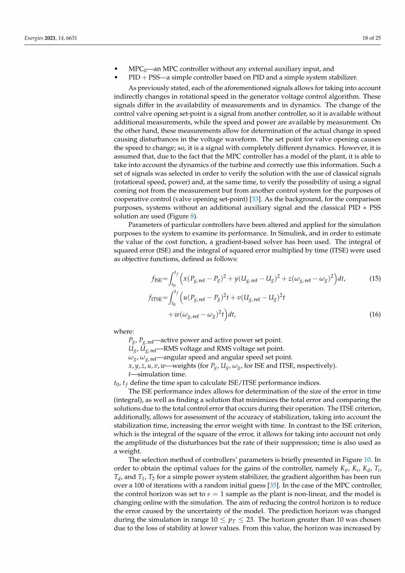
Parameters of particular controllers have been altered and applied for the simulationpurposes to the system to examine its performance. In Simulink, and in order to estimatethe value of the cost function, a gradient-based solver has been used. The integral ofsquared error (ISE) and the integral of squared error multiplied by time (ITSE) were usedas objective functions, defined as follows:
fISE=∫ t f
t0
(x(Pg, ref − Pg)
2 + y(Ug, ref −Ug)2 + z(ωg, ref −ωg)
2)
dt, (15)
fITSE=∫ t f
t0
(u(Pg, ref − Pg)
2t + v(Ug, ref −Ug)2t
+w(ωg, ref −ωg)2t)
dt, (16)
where:Pg, Pg, ref—active power and active power set point.Ug, Ug, ref—RMS voltage and RMS voltage set point.ωg, ωg, ref—angular speed and angular speed set point.x, y, z, u, v, w—weights (for Pg, Ug, ωg, for ISE and ITSE, respectively).t—simulation time.
t0, t f define the time span to calculate ISE/ITSE performance indices.The ISE performance index allows for determination of the size of the error in time
(integral), as well as finding a solution that minimizes the total error and comparing thesolutions due to the total control error that occurs during their operation. The ITSE criterion,additionally, allows for assessment of the accuracy of stabilization, taking into account thestabilization time, increasing the error weight with time. In contrast to the ISE criterion,which is the integral of the square of the error, it allows for taking into account not onlythe amplitude of the disturbances but the rate of their suppression; time is also used asa weight.
The selection method of controllers’ parameters is briefly presented in Figure 10. Inorder to obtain the optimal values for the gains of the controller, namely Kp, Ki, Kd, Ti,Td, and T1, T2 for a simple power system stabilizer, the gradient algorithm has been runover a 100 of iterations with a random initial guess [35]. In the case of the MPC controller,the control horizon was set to s = 1 sample as the plant is non-linear, and the model ischanging online with the simulation. The aim of reducing the control horizon is to reducethe error caused by the uncertainty of the model. The prediction horizon was changedduring the simulation in range 10 ≤ pT ≤ 23. The horizon greater than 10 was chosendue to the loss of stability at lower values. From this value, the horizon was increased by

Energies 2021, 14, 6631 19 of 25
analyzing the change in quality indices, up to the value of 23, at which the quality indicesstarted to decrease.
Figure 10. Tuning of controllers’ parameters.
Table 2 shows the ISE calculated for different prediction horizons pG (the controlhorizon in all cases was equal sG = 1), together with different values of the turbine’s MPCcontrol horizon pT (wit the control horizon sT = 1). To find the minimum of the ISE, takinginto account the behavior of the turbine (connected with the generator by a common shaft)and the generator, an extensive search, including 112 simulations, was performed (withoutany additional tuning optimizations procedures [56]).
Table 2. MPC tuning (ISE) (×10−2) in function of the turbine’s (pT) and generator’s (pG) QDMCcontroller’s prediction horizon.
pG\pT 40 41 42 43 44 45 46 47
10 2.4387 2.3790 2.4315 2.5688 2.7062 2.9677 3.2324 3.739311 2.0458 1.9942 2.0383 2.1829 2.3395 2.5497 2.8270 3.158712 1.0768 0.9138 1.6176 1.8004 1.9839 2.2141 2.4476 2.780313 0.9638 0.7808 0.6702 0.6220 1.6392 1.8816 2.1633 2.456014 0.9500 0.7409 0.6182 0.5472 0.5179 0.5505 1.8418 2.196815 0.9486 0.7307 0.5993 0.5207 0.4783 0.4673 0.5076 1.903716 0.9495 0.7288 0.5900 0.5067 0.4619 0.4432 0.4552 0.545117 0.9509 0.7288 0.5867 0.4990 0.4517 0.4308 0.4383 0.487118 0.9534 0.7300 0.5862 0.4956 0.4446 0.4231 0.4287 0.472119 0.9571 0.7320 0.5870 0.4940 0.4401 0.4173 0.4226 0.464620 0.9614 0.7346 0.5886 0.4942 0.4380 0.4137 0.4186 0.460421 0.9659 0.7375 0.5905 0.4951 0.4373 0.4116 0.4162 0.458422 0.9705 0.7404 0.5927 0.4967 0.4377 0.4107 0.4156 0.458323 0.9750 0.7435 0.5951 0.4987 0.4389 0.4112 0.4159 0.4596
Additionally, one more experiment was performed to check if, for the different types ofthe auxiliary input, different values of the prediction horizon should be chosen (Tables 3 and 4).Based on this results, it was decided to use the same prediction horizon for all the cases, asthe differences are negligible.
Table 3. MPC tuning for different auxiliary signal (ISE) (×10−3).
ISE\pG 21 22 23
MPCα 3.4 3.4 3.4MPCω 3.5 3.5 3.5MPCPg 3.5 3.5 3.5none 3.5 3.5 3.5

Energies 2021, 14, 6631 20 of 25
Table 4. MPC Tuning for different auxiliary signal (ITSE) (×10−3).
ITSE \ pG 21 22 23
MPCα 0.999 1.001 1.003MPCω 1.086 1.086 1.086MPCPg 1.098 1.098 1.098none 1.087 1.087 1.087
The parameters resulting from the aforementioned experiments are collected in theTable 5.
Table 5. Parameters of the controllers.
Kp Ki Kd T1 T2
PID + PSS [37] 12.82 29.03 0 0.65 1.74pT pG sT sG T diag(ΓT) Λ
MPC 45 22 1 1 0.01 1;1;1 0
During the experiments, it was established that the changing prediction horizonfor different MPC controllers (with a different additional input) does not influence theperformance; thus, for all further experiments, the same set of parameters was used.
The change of the power set by the power disposition was chosen as the test case. It isa case of normal operation of a power plant block, in which the control systems stabilizethe voltage and frequency of the voltage (Ug, ωg) in order to maintain its quality, and thepower (Pg) demand changes due to the connection/disconnection of loads.
The test experiment consisted in a step change of the active power set point valueby 10% every 20 s of the simulation. There are restrictions on control signals α ∈ [0, 100],E f d ∈ [−0.1, 0.1]. Figures 11–14 and Table 6 present the results of the simulation tests.A detailed description of the experiment can be found in Reference [37]. According inReference [57], p. 23, Table 4, which defines parameters for active power frequency response,the admissible dead-zone secures the case of neglectful oscillations visible in the figures.Besides, the amplitude of oscillations virtually vanishes for the un-zoomed case of the plot.
20 25 30 35 40 45 50 55 60
Time [s]
0.6
0.7
0.8
0.9
1
Pg
[p
.u.]
Electrical Power
Reference power
MPC
MPC
MPC 0
MPC Pg
PID+PSS 40 40.5 41 41.5 42
0.8
0.85
0.9
Figure 11. Electric power (set active power step).

Energies 2021, 14, 6631 21 of 25
Figure 12. Generator voltage (set active power step).
20 25 30 35 40 45 50 55 60
Time [s]
0.997
0.998
0.999
1
w [p.u
.]
Angular velocity
Reference velocity
MPC
MPC
MPC 0
MPC Pg
PID+PSS 40 40.5 41 41.5 42
0.9996
0.9997
0.9998
0.9999
1
Figure 13. Angular speed (set active power step).
Figure 14. Excitation voltage (set active power set step).
Table 6. Integral quality indices (×10−4)—superior results marked in bold.
ISE ITSE
MPCα 33.76 10.01MPCω 34.58 10.86MPCPg 34.69 10.98MPC0 34.59 10.87PID + PSS 36.43 19.70

Energies 2021, 14, 6631 22 of 25
The developed predictive controller ensures superior maintaining the set trajectory ofthe generator voltage in comparison to the PID + PSS controller and also takes into accountthe limitations existing in the model. The MPC regulator stabilizes the voltage value better,but—due to the relationship between the voltage value and the rotational speed of thegenerator—it causes larger oscillations of the rotational speed (voltage frequency). PID+ PSS is, therefore, better at damping oscillations but at the cost of voltage stabilization.Among the considered MPC regulators, the lowest ISE/ITSE value was achieved for thesolution using the turbine’s control valve opening as an auxiliary input α. This signal isthe only one available without measurement and can be sent directly from the turbineregulator to the generator regulator. Although the use of the MPC controller increasesthe oscillation in relation to the classic controller, the use of an additional input allows forreduction of this effect. The obtained results (influence of the auxiliary input, influence ofthe use of the turbine’s control valve opening signal) will be used in the continuation ofresearch on cooperative DMPC control [33], in which individual control systems exchangeinformation about the calculated control signals.
The conducted tests, the results of which are presented in the paper, also prove thevalidity of using the QDMC controller in place of the typically used controllers based onintegral-derivative blocks with system stabilizer, with no visible increase in the computa-tional burden, as a single decision at a single sampling instant takes milliseconds (and canbe reduced using an analytic solution to the MPC problem instead of solving a quadraticprogramming problem in every step), and fully enables one to use it in the real time, as it isthe order of the magnitude of the smallest time constant of the generator.
5. Conclusions
By extending the model used in the MPC control, it is possible to include an additionalsignal extending the controller’s knowledge of the plant. Due to the existing relationshipbetween the voltage and the rotational speed of the generator, adding α, ω, Pg signalsallows for taking this relationship into account when calculating the control signal. In thisway, it is possible to take into account the function of the system stabilizer, i.e., minimizesthe oscillations of the active power delivered to the power system caused by the operationof the excitation controller. The results of the simulation tests confirm the influence of theadditional control signal on the occurrence of power and voltage oscillations, and the useof various additional signals allows for achievement of different dynamics of the controller.Especially useful and promising is the turbine’s control valve opening α. Due to the factthat the control valve opening signal is calculated by the turbine controller and is directlyavailable from the computer system level (without additional measurements or estimation),it was used in Reference [33] as an additional signal when exchanging information betweenthe two QDMC controllers of the turbine and the generator (DMPC distributed modelpredictive controller of a turbine-generator set).
As standard PID-based control systems are used, these can be extended with anadditional element in the form of a system stabilizer used to minimize the oscillationsappearing in the power system. In order to improve the efficiency of this systems, morecomplex ones, consisting of a greater number of I or D blocks, or built with a greaternumber of parallel paths, are proposed. The literature suggests, e.g., solutions based onfuzzy logic [15–21]. The authors propose a different approach in the form of the MPCcontroller, taking the operation of the system stabilizer, thanks to an additional inputsignal, into account. This solution complements the research on the distributed controlof the turbine-generator unit [33]. The presented considerations constitute the basis ofthe distributed predictive control scheme proposed in earlier research with the auxiliarysignal exchanged between the control systems. The aforementioned turbine-generator set’scontrol system will be a prelude to further research.

Energies 2021, 14, 6631 23 of 25
Author Contributions: Conceptualization, P.S., B.C. and D.H.; methodology, P.S.; software, P.S.;validation, P.S., B.C., T.A.R., D.Z. and D.H.; formal analysis, D.H., P.S.; investigation, B.C., P.S.;resources, P.S., B.C.; writing—original draft preparation, P.S., B.C., D.H.; writing—review and editing,B.C., D.H., T.A.R., D.Z.; visualization, P.S.; supervision, D.H., B.C.; funding acquisition, D.H. Allauthors have read and agreed to the published version of the manuscript.
Funding: This research was funded in part by the Poznan University of Technology under Grant214/SBAD/0229.
Institutional Review Board Statement: Not applicable.
Informed Consent Statement: Not applicable.
Data Availability Statement: The study did not report any data.
Conflicts of Interest: The authors declare no conflict of interest.
References1. Polish Power Networks (In Polish: Polskie Sieci Elektroenergetyczne S.A.). Annual Reports. Available online: https://www.pse.
pl/dane-systemowe/funkcjonowanie-kse/raporty-roczne-z-funkcjonowania-kse-za-rok/raporty-za-rok-2020 (accessed on 13June 2021).
2. Energy Policy of Poland until 2040 Appendix 2 Conclusions from Forecast Analyses for the Energy Sector. Available online:https://www.gov.pl/web/klimat/polityka-energetyczna-polski (accessed on 20 June 2021).
3. National Energy and Climate Plans, Assessment of the Final National Energy and Climate Plan of Poland. Available online: https://ec.europa.eu/energy/sites/default/files/documents/staff_working_document_assessment_necp_poland_en.pdf (accessedon 25 June 2021).
4. Commission Implementing Decision (EU) 2017/ 1442-of 31 July 2017-Establishing Best Available Techniques (BAT) Conclusions,under Directive 2010/ 75/ EU of the European Parliament and of the Council, for Large Combustion Plants- (Notified UnderDocument C (2017) 5225). Available online: https://eur-lex.europa.eu/legal-content/EN/TXT/PDF/?uri=CELEX:32017D1442&from=EN (accessed on 25 June 2021).
5. Forecast of Peak Demand for Power in 2016–2035. Available online: https://www.pse.pl/-/prognoza-pokrycia-zapotrzebowania-szczytowego-na-moc-w-latach-2016-2035 (accessed on 27 June 2021). (In Polish)
6. Polish Power Networks (In Polish: Polskie Sieci Elektroenergetyczne S.A.). Daily Reports. Available online: https://www.pse.pl/dane-systemowe/funkcjonowanie-kse/raporty-dobowe-z-pracy-kse (accessed on 28 June 2021).
7. The Polish Nuclear Power Programme 2020. Available online: https://www.gov.pl/web/polski-atom/program-polskiej-energetyki-jadrowej (accessed on 27 June 2021).
8. Oettingen, M. Assessment of the Radiotoxicity of Spent Nuclear Fuel from a Fleet of PWR Reactors. Energies 2021, 14, 3094,[CrossRef]
9. Koltun, P.; Tsykalo, A.; Novozhilov, V. Life Cycle Assessment of the New Generation GT-MHR Nuclear Power Plant. Energies2018, 11, 3452. [CrossRef]
10. Sroka, K.; Grzadzielski, I. Nuclear power plants in conditions of a catastrophic failure of power system (in Polish) Elektrowniejadrowe w warunkach awarii katastrofalnej. Acta Energy 2011, 1, 5–10.
11. Hovsapian, R.; Osorio, J.D.; Panwar, M.; Chryssostomidis, C.; Ordonez, J.C. Grid-Scale Ternary-Pumped Thermal ElectricityStorage for Flexible Operation of Nuclear Power Generation under High Penetration of Renewable Energy Sources. Energies2021, 14, 3858, [CrossRef]
12. Vajpayee, V.; Top, E.; Becerra, V.M. Analysis of Transient Interactions between a PWR Nuclear Power Plant and a FaultedElectricity Grid. Energies 2021, 14, 1573, [CrossRef]
13. Peakman, A.; Merk, B.; Hesketh, K. The Potential of Pressurised Water Reactors to Provide Flexible Response in Future Electricity.Energies 2020, 13, 941, [CrossRef]
14. Power, I.; Society, E. IEEE Recommended Practice for Excitation System Models for Power System Stability Studies; IEEE Std 421.5-2016;IEEE: Piscataway, NJ, USA, 2016.
15. Tianshuo, S.; Ying, L.; Bin, H.; Dan, L.; Xiaoming, L. Simulation Study on Fuzzy Controller for Main Circuit of the ExcitationControl System. In Proceedings of the 2013 IEEE International Conference on Vehicular Electronics and Safety, Dongguan, China,28–30 July 2013.
16. Ramya, R.; Selvi, K. A Simple Fuzzy Excitation Control System for Synchronous Generator. In Proceedings of the 2011International Conference on Emerging Trends in Electrical and Computer Technology, Nagercoil, India, 23–24 March 2011.
17. Gunes, M.; Dogru, N. Fuzzy Control of Brushless Excitation System for Steam Turbogenerators. IEEE Trans. Energy Convers. 2010,25, 844–852. [CrossRef]
18. Kitauchi, Y.; Taniguchi, H. Experimental Verification of Fuzzy Excitation Control System for Multi-machine Power System. IEEETrans. Energy Convers. 1997, 12, 94–99. [CrossRef]

Energies 2021, 14, 6631 24 of 25
19. Hiyama, T.; Miyazaki, K.; Satoh, H. A Fuzzy Logic Excitation System for Stability Enhancement of Power Systems withMulti-mode Oscillations. IEEE Trans. Energy Convers. 1996, 11, 449–454. [CrossRef]
20. Cheng, Y.; Jiang, Z.; Xu, D.; Liu, Y. Nonlinear Analytical Fuzzy Logic Control of Generator Excitation. In Proceedings of the 2008Third International Conference on Electric Utility Deregulation and Restructuring and Power Technologies, Nanjing, China, 6–9April 2008.
21. Al-Turki, Y.A.; Attia, A.F.; Soliman, H.F. Optimization of Fuzzy Logic Controller for Supervisory Power System Stabilizers. ActaPolytech. 2012, 52, 7–16. [CrossRef]
22. Kim, K.; Rao, P.; Burnworth, J. Application of Swarm Intelligence to a Digital Excitation Control System. In Proceedings of the2008 IEEE Swarm Intelligence Symposium, St. Louis, MO, USA, 21–23 September 2008.
23. Hema’ndez, J.A.; Botero, H.A.; Ospina, J.D.; Perez, J.C. Excitation System Parameters Estimation Using Evolutionary Algorithms.In Proceedings of the 2006 IEEE/PES Transmission & Distribution Conference and Exposition: Latin America, Caracas, Venezuela,15–18 August 2006.
24. Gong, R.; Huang, Y.; Wei, H.; Meng, X.; Xie, L. Design of PID Excitation Controllers for Synchronous Generators Based on FuzzyRBF Neural Network. In Proceedings of the 2008 International Conference on Electrical Machines and Systems, Wuhan, China, 8August 2008.
25. He, H.; Zhou, J.; Lei, H.; Li, C.; Yang, L. Research on fuzzy-PID excitation controller of synchronous generator based on improvedPSO algorithm. In Proceedings of the Eighth International Conference on Machine Learning and Cybernetics, Baoding, China,12–15 July 2009.
26. Sun, L.; Feng, J.; Dimirovski, G.M.; Zhao, J. Adaptive Robust H∞ Control of the Generator Excitation System. In Proceedings ofthe 2009 American Control Conference, St. Louis, MO, USA, 10–12 June 2009.
27. Suminal, D.; Erceg, G.; Idzotic, T. Excitation control of a synchronous generator using fuzzy logic stabilizing controller. InProceedings of the 2005 European Conference on Power Electronics and Applications, Dresden, Germany, 11–14 September 2005.
28. Park, Y.M.; Choi, M.S.; Lee, K. A neural network-based power system stabilizer using power flow characteristics. IEEE Trans.Energy Convers. 1996, 11, 435–441. [CrossRef]
29. Keskes, S.; Bouchiba, N.; Sallem, S.; Chrifi-Alaoui, L.; Kammoun, M.B.A. Optimal tuning of power system stabilizer using geneticalgorithm to improve power system stability. In Proceedings of the 2017 International Conference on Green Energy ConversionSystems (GECS), Hammamet, Tunisia, 23–25 March 2017; pp. 1–5. [CrossRef]
30. Boyd, S.; Vandenberghe, L. Convex Optimization; Cambridge University Press: Cambridge, UK, 2004, [CrossRef]31. Löfberg, J. YALMIP: A Toolbox for Modeling and Optimization in MATLAB. In Proceedings of the 2004 IEEE International
Conference on Robotics and Automation, Taipei, Taiwan, 2–4 September 2004.32. Heemels, W.P.M.H.; Donkers, M.C.F.; Teel, A.R. Periodic Event-Triggered Control for Linear Systems. IEEE Trans. Autom. Control
2013, 58, 847–861. [CrossRef]33. Sokólski, P.; Rutkowski, T.; Duzinkiewicz, K. The distributed model predictive controller for the nuclear power plant turbo-
generator set. Adv. Intell. Syst. Comput. 2017, 577, 682–687.34. Sokolski, P.; Rutkowski, T.; Duzinkiewicz, K. Simplified, multiregional fuzzy model of a nuclear power plant steam turbine. In
Proceedings of the 21ST International Conference on Methods and Models in Automation and Robotics (MMAR), Miedzyzdroje,Poland, 29 August–1 September 2016; pp. 379–384.
35. Sokólski, P.; Kobylarz, A.; Kulkowski, K.; Duzinkiewicz, K.; Rutkowski, T.; Grochowski, M. Advanced control structures of turbogenerator system of nuclear power plant. Acta Energy 2015, 3, 83–96. [CrossRef]
36. Sokolski, P.; Rutkowski, T.; Duzinkiewicz, K. The excitation controller with gain scheduling mechanism for synchronous generatorcontrol. In Proceedings of the 2015 20TH International Conference on Methods and Models in Automation and Robotics (MMAR),Miedzyzdroje, Poland, 24–27 August 2015; pp. 23–28.
37. Sokólski, P.; Rutkowski, T.; Duzinkiewicz, K. The QDMC Model Predictive Controller for the Nuclear Power Plant Steam TurbineControl. In Krajowa Konferencja Automatyki; Advances in Intelligent Systems and Computing Book Series (AISC); SpringerInternational Publishing: Berlin/Heidelberg, Germany, 2017; Volume 577, pp. 241–250.
38. Imielinski, A. Mathematical Model of Synchronous Generator for Full-Scope Simulator; Gdansk University of Technology, Faculty ofElectrical and Control Engineering; Gdansk, Poland, 1987.
39. Perycz, S.; Próchnicki, W. The Mathematical Model of a Nuclear Power Plant VVER Block Steam Turbine Allowing to Study TransientProcesses with w = var; Gdansk University of Technology, Faculty of Electrical and Control Engineering: Gdansk, Poland, 1989.
40. Power System Dynamic Performance Committee. Dynamic Models for Turbine–Governors in Power System Studies. In IEEEPower & Energy Society; The Institute of Electrical and Electronic Engineers, Inc.: Piscataway, NJ, USA, 2013.
41. Soderstrom, T.; Stoica, P. System Identification; Prentice Hall: Hemel Hempstead, UK, 1989.42. Sokolski, P. Implementacja Krzepkich Metod Estymacji Dla Celów Regulacji Predykcyjnej Typu MPC. Bachelor’s Thesis,
Politechnika Gdanska, Gdansk, Poland, 2010. (In Polish)43. Söderström, T.; Ljung, L.; Gustavsson, I. A Theoretical Analysis of Recursive Identification Methods. Automatica 1978, 14, 231–244.
[CrossRef]44. Sokólski, P. Implementation of robust estimation methods for regulatory purposes predictive MPC type. Innov. Solut. Autom.
Area 2011, 22, 44–52.

Energies 2021, 14, 6631 25 of 25
45. Garcia, C.E.; Morshedi, A. Quadratic Programming Solution of Dynamic Matrix Control (QDMC). Chem. Eng. Commun. 1986,46, 73–87. [CrossRef]
46. Iranmanesh, H.; Afshar, A. MPC-Based Control of a Large-Scale Power System Subject to Consecutive Pulse Load Variations.IEEE Access 2017, 5, 26318–26327. [CrossRef]
47. Maciejowski, J.M. Predictive Control: With Constraints; Prentice Hall: London, UK, 2002.48. Ba-Muqabel, A.A.; Abido, M.A. Review of conventional power system stabilizer design methods. In Proceedings of the 2006
IEEE GCC Conference (GCC), Manama, Bahrain, 20–22 March 2006; pp. 1–7. [CrossRef]49. Camacho, E.; Alba, C. Model Predictive Control; Springer Science & Business Media: Berlin/Heidelberg, Germany, 2013.50. Tatjewski, P. Advanced Control of Industrial Processes; Springer: Berlin/Heidelberg, Germany, 2007.51. Hakvoort, R. System Identification for Robust Process Control: Nominal Models and Error Bounds. Ph.D. Thesis, Technische
Universitet Delft, Delft, The Netherlands, 1994.52. Loo, C.; Vanfretti, L.; Liceaga-Castro, E.; Acha, E.E. Synchronous Generators Modeling and Control Using the Framework of
Individual Channel Analysis and Design: Part 1. Int. J. Emerg. Electr. Power Syst. 2007, 8, 1–26.53. Wojtulewicz, A. Implementation of Dynamic Matrix Control Algorithm Using Field Programmable Gate Array: Preliminary Re-
sults. In Trends in Advanced Intelligent Control, Optimization and Automation; Springer International Publishing: Berlin/Heidelberg,Germany, 2017.
54. Wojtulewicz, A. Implementation of DMC algorithm in embedded controller-resources, memory and numerical modifications.In Trends in Advanced Intelligent Control, Optimization and Automation; Springer International Publishing: Berlin/Heidelberg,Germany, 2017.
55. Chaber, P.; Ławrynczuk, M. Implementation of Analytical Generalized Predictive Controller for Very Fast Applications UsingMicrocontrollers: Preliminary Results. In Trends in Advanced Intelligent Control, Optimization and Automation; Springer InternationalPublishing: Berlin/Heidelberg, Germany, 2017.
56. Nebeluk, R.; Ławrynczuk, M. Tuning of Multivariable Model Predictive Control for Industrial Tasks. Algorithms 2021, 14, 10.[CrossRef]
57. Commission Regulation (EU) 2016/631 of 14 April 2016 Establishing a Network Code on Requirements for Grid Connection ofGenerators. Available online: https://eur-lex.europa.eu/legal-content/en/ALL/?uri=CELEX%3A32016R0631 (accessed on 29September 2021).