Power System Operation and Control - GitHub
925
-
Upload
khangminh22 -
Category
Documents
-
view
0 -
download
0
Transcript of Power System Operation and Control - GitHub

POWERSYSTEMOPERATIONANDCONTROL
S.SivanagarajuAssociateProfessor
DepartmentofElectricalandElectronicsEngineering
UniversityCollegeofEngineeringJNTUKakinada
Kakinada,AndhraPradesh
G.SreenivasanAssociateProfessor
DepartmentofElectricalandElectronicsEngineering
INTELLEngineeringCollegeAnantapur,AndhraPradesh
Chennai•Delhi•Chandigarh

BriefContents
Chapter1EconomicAspects
Chapter2EconomicLoadDispatch-I
Chapter3EconomicLoadDispatch-II
Chapter4OptimalUnitCommitment
Chapter5OptimalPower-FlowProblem—SolutionTechnique
Chapter6Hydro-ThermalScheduling
Chapter7LoadFrequencyControl-I
Chapter8LoadFrequencyControl-II
Chapter9ReactivePowerCompensation
Chapter10VoltageControl
Chapter11ModelingofPrimeMoversandGenerators
Chapter12ModelingofSpeedGoverningandExcitationSystems
Chapter13PowerSystemSecurityandStateEstimation

Contents
Chapter1EconomicAspects
1.1Introduction
1.2LoadCurve
1.3Load–DurationCurve
1.4IntegratedLoad–DurationCurve
1.4.1UsesofIntegratedLoad–DurationCurve
1.5DefinitionofTermsandFactors
1.5.1ConnectedLoad
1.5.2MaximumDemand
1.5.3DemandFactor
1.5.4AverageLoad
1.5.5LoadFactor
1.5.6DiversityFactor
1.5.7PlantCapacity
1.5.8PlantCapacityFactor
1.5.9UtilizationFactor(orPlant-UseFactor)
1.5.10FirmPower
1.5.11PrimePower
1.5.12DumpPower
1.5.13SpillPower
1.5.14ColdReserve
1.5.15HotReserve
1.5.16SpinningReserve
1.6BaseLoadandPeakLoadonaPowerStation
1.7LoadForecasting
1.7.1PurposeofLoadForecasting
1.7.2ClassificationofLoadForecasting
1.7.3ForecastingProcedure
KeyNotes
ShortQuestionsandAnswers

Multiple-ChoiceQuestions
ReviewQuestions
Problems
Chapter2EconomicLoadDispatch-I
2.1Introduction
2.2CharacteristicsofPowerGeneration(Steam)Unit
2.3SystemVariables
2.3.1ControlVariables(P andQ )
2.3.2DisturbanceVariables(P andQ )
2.3.3StateVariables(Vandδ)
2.4ProblemofOptimumDispatch—Formulation
2.5Input–OutputCharacteristics
2.5.1UnitsofTurbineInput
2.6CostCurves
2.7IncrementalFuelCostCurve
2.8HeatRateCurve
2.9IncrementalEfficiency
2.10Non-SmoothCostFunctionswithMultivalveEffect
2.11Non-smoothCostFunctionswithMultipleFuels
2.12CharacteristicsofaHydro-PowerUnit
2.12.1EffectoftheWaterHeadonDischargeofWaterforaHydro-Unit
2.12.2IncrementalWaterRateCharacteristicsofHydro-Units
2.12.3IncrementalCostCharacteristicofaHydro-Unit
2.12.4ConstraintsofHydro-PowerPlants
2.13IncrementalProductionCosts
2.14ClassicalMethodsforEconomicOperationofSystemPlants
2.15OptimizationProblem—MathematicalFormulation(NeglectingtheTransmissionLosses)
2.15.1ObjectiveFunction
2.15.2ConstraintEquations
2.16MathematicalDeterminationofOptimalAllocationofTotalLoadAmongDifferentUnits
2.17ComputationalMethods
2.17.1AnalyticalMethod
2.17.2GraphicalMethod
2.17.3SolutionbyUsingaDigitalComputer
G G
D D

2.18EconomicDispatchNeglectingLossesandIncludingGeneratorLimits
2.19FlowchartforObtainingOptimalSchedulingofGeneratingUnitsbyNeglectingtheTransmissionLosses
2.20EconomicalLoadDispatch—InOtherUnits
2.20.1Nuclearunits
2.20.2Pumpedstoragehydro-units
2.20.3Hydro-plants
2.20.4Includingreactive-powerflows
KeyNotes
ShortQuestionsandAnswers
Multiple-ChoiceQuestions
ReviewQuestions
Problems
Chapter3EconomicLoadDispatch-II
3.1Introduction
3.2OptimalGenerationSchedulingProblem:ConsiderationofTransmissionLosses
3.2.1Mathematicalmodeling
3.3TransmissionLossExpressioninTermsofReal-PowerGeneration—Derivation
3.4MathematicalDeterminationofOptimumAllocationofTotalLoadwhenTransmissionLossesareTakenintoConsideration
3.4.1DeterminationofITLformula
3.4.2PenaltyFactor
3.5FlowchartfortheSolutionofanOptimizationProblemwhenTransmissionLossesareConsidered
KeyNotes
ShortQuestionsandAnswers
Multiple-ChoiceQuestions
ReviewQuestions
Problems
Chapter4OptimalUnitCommitment
4.1Introduction
4.2ComparisonwithEconomicLoadDispatch
4.3NeedforUC
4.4ConstraintsinUC
4.4.1SpinningReserve

4.4.2ThermalUnitConstraints
4.4.3Hydro-Constraints
4.4.4MustRun
4.4.5FuelConstraints
4.5CostFunctionFormulation
4.5.1Start-upCostConsideration
4.5.2Shut-downCostConsideration
4.6ConstraintsforPlantCommitmentSchedules
4.7UnitCommitment—SolutionMethods
4.7.1EnumerationScheme
4.7.2Priority-listMethod
4.7.3DynamicProgramming
4.8ConsiderationofReliabilityinOptimalUCProblem
4.8.1Patton’ssecurityfunction
4.9OptimalUCwithSecurityConstraint
4.9.1IllustrationofSecurityConstraintwithExample4.2
4.10Start-UpConsideration
KeyNotes
Multiple-ChoiceQuestions
ShortQuestionsandAnswers
ReviewQuestions
Problems
Chapter5OptimalPower-FlowProblem—SolutionTechnique
5.1Introduction
5.2OptimalPower-FlowProblemwithoutInequalityConstraints
5.2.1AlgorithmforComputationalProcedure
5.3OptimalPower-FlowProblemwithInequalityConstraints
5.3.1InequalityConstraintsonControlVariables
5.3.2InequalityConstraintsonDependentVariables—PenaltyFunctionMethod
KeyNotes
ShortQuestionsandAnswers
Multiple-ChoiceQuestions
ReviewQuestions
Chapter6Hydro-ThermalScheduling
6.1Introduction
6.2Hydro-ThermalCo-ordination
6.3SchedulingofHydro-UnitsinaHydro-ThermalSystem
6.4Co-ordinationofRun-offRiverPlantandSteamPlant
6.5Long-TermCo-ordination
6.6Short-TermCo-ordination
6.6.1ConstantHydro-GenerationMethod
6.6.2ConstantThermalGenerationMethod
6.6.3MaximumHydro-EfficiencyMethod
6.7GeneralMathematicalFormulationofLong-TermHydro-ThermalScheduling
6.7.1SolutionofProblem-DiscretizationPrinciple
6.7.2SolutionTechnique
6.7.3Algorithm
6.8SolutionofShort-TermHydro-ThermalSchedulingProblems—Kirchmayer’sMethod
6.9AdvantagesofOperationofHydro-ThermalCombinations
6.9.1Flexibility
6.9.2GreaterEconomy
6.9.3SecurityofSupply
6.9.4BetterEnergyConservation
6.9.5ReserveCapacityMaintenance
KeyNotes
ShortQuestionsandAnswers
Multiple-ChoiceQuestions
ReviewQuestions
Problems
Chapter7LoadFrequencyControl-I
7.1Introduction
7.2NecessityofMaintainingFrequencyConstant
7.3LoadFrequencyControl
7.4GovernorCharacteristicsofaSingleGenerator
7.5AdjustmentofGovernorCharacteristicofParallelOperatingUnits
7.6LFC:(P–fControl)
7.7Q–VControl
7.8GeneratorControllers(P–fandQ–VControllers)
7.9P–fControlversusQ–VControl
7.10DynamicInteractionBetweenP–fandQ–VLoops

7.11Speed-GoverningSystem
7.11.1Speed-GoverningSystemModel
7.12TurbineModel
7.12.1Non-reheat-typeSteamTurbines
7.12.2IncrementalorSmallSignalforaTurbine-GovernorSystem
7.12.3ReheatTypeofSteamTurbines
7.13Generator-LoadModel
7.14ControlAreaConcept
7.15IncrementalPowerBalanceofControlArea
7.16SingleAreaIdentification
7.16.1BlockDiagramRepresentationofaSingleArea
7.17SingleArea—Steady-StateAnalysis
7.17.1Speed-ChangerPositionisConstant(UncontrolledCase)
7.17.2LoadDemandisConstant(ControlledCase)
7.17.3SpeedChangerandLoadDemandareVariables
7.18StaticLoadFrequencyCurves
7.19DynamicAnalysis
7.20RequirementsoftheControlStrategy
7.20.1IntegralControl
7.21AnalysisoftheIntegralControl
7.22RoleofIntegralControllerGain(K )Setting
7.23ControlofGeneratorUnitPowerOutput
KeyNotes
ShortQuestionsandAnswers
Multiple-ChoiceQuestions
ReviewQuestions
Problems
Chapter8LoadFrequencyControl-II
8.1Introduction
8.2CompositeBlockDiagramofaTwo-AreaCase
8.3ResponseofaTwo-AreaSystem—UncontrolledCase
8.3.1StaticResponse
8.3.2DynamicResponse
8.4AreaControlError—Two-AreaCase
8.5CompositeBlockDiagramofaTwo-AreaSystem(ControlledCase)
8.5.1Tie-lineBiasControl
I

8.5.2Steady-StateResponse
8.5.3DynamicResponse
8.6OptimumParameterAdjustment
8.7LoadFrequencyandEconomicDispatchControls
8.8DesignofAutomaticGenerationControlUsingtheKalmanMethod
8.9Dynamic-State-VariableModel
8.9.1ModelofSingle-AreaDynamicSysteminaState-VariableForm
8.9.2OptimumControlIndex(I)
8.9.3OptimumControlProblemandStrategy
8.9.4DynamicEquationsofaTwo-AreaSystem
8.9.5State-VariableModelforaThree-AreaPowerSystem
8.9.6AdvantagesofState-VariableModel
KeyNotes
ShortQuestionsandAnswers
Multiple-ChoiceQuestions
ReviewQuestions
Problems
Chapter9ReactivePowerCompensation
9.1Introduction
9.2ObjectivesofLoadCompensation
9.2.1P.f.Correction
9.2.2VoltageRegulationImprovement
9.2.3LoadBalancing
9.3IdealCompensator
9.4SpecificationsofLoadCompensation
9.5TheoryofLoadCompensation
9.5.1P.f.correction
9.5.2VoltageRegulation
9.6LoadBalancingandp.f.ImprovementofUnsymmetricalThree-PhaseLoads
9.6.1P.f.Correction
9.6.2LoadBalancing
9.7UncompensatedTransmissionLines
9.7.1FundamentalTransmissionLineEquation
9.7.2CharacteristicImpedance

9.7.3SurgeImpedanceorNaturalLoading
9.8UncompensatedLinewithOpen-Circuit
9.8.1VoltageandCurrentProfiles
9.8.2TheSymmetricalLineatno-Load
9.8.3UnderexcitedOperationofGeneratorsDuetoLine-Charging
9.9TheUncompensatedLineUnderLoad
9.9.1RadiallinewithfixedSending-endVoltage
9.9.2ReactivePowerRequirements
9.9.3TheUncompensatedLineUnderLoadwithConsiderationofMaximumPowerandStability
9.10CompensatedTransmissionLines
9.11Sub-SynchronousResonance
9.11.1EffectsofSeriesandShuntCompensationofLines
9.11.2ConceptofSSRinLines
9.12ShuntCompensator
9.12.1Thyristor-ControlledReactor
9.12.2Thyristor-SwitchedCapacitor
9.13SeriesCompensator
9.14UnifiedPower-FlowController
9.15BasicRelationshipforPower-FlowControl
9.15.1WithoutLineCompensation
9.15.2WithSeriesCapacitiveCompensation
9.15.3WithShuntCompensation
9.15.4WithPhaseAngleControl
9.16ComparisonofDifferentTypesofCompensatingEquipmentforTransmissionSystems
9.17VoltageStability—Whatisit?
9.17.1VoltageStability
9.17.2VoltageCollapse
9.18Voltage-StabilityAnalysis
9.18.1P–VCurves
9.18.2ConceptofVoltageCollapseProximateIndicator
9.18.3Voltage-StabilityAnalysis:Q–VCurves
9.19DerivationforVoltage-StabilityIndex
KeyNotes
ShortQuestionsandAnswers
Multiple-ChoiceQuestions
ReviewQuestions
Problems
Chapter10VoltageControl
10.1Introduction
10.2NecessityofVoltageControl
10.3GenerationandAbsorptionofReactivePower
10.4LocationofVoltage-ControlEquipment
10.5MethodsofVoltageControl
10.5.1ExcitationControl
10.5.2ShuntCapacitorsandReactors
10.5.3SeriesCapacitors
10.5.4Tap-ChangingTransformers
10.5.5BoosterTransformers
10.5.6SynchronousCondensers
10.6RatingofSynchronousPhaseModifier
KeyNotes
ShortQuestionsandAnswers
Multiple-ChoiceQuestions
ReviewQuestions
Problems
Chapter11ModelingofPrimeMoversandGenerators
11.1Introduction
11.2HydraulicTurbineSystem
11.2.1ModelingofHydraulicTurbine
11.3SteamTurbineModeling
11.3.1Non-reheatType
11.3.2Reheattype
11.4SynchronousMachines
11.4.1Salient-pole-typeRotor
11.4.2Non-salient-pole-typeRotor
11.5SimplifiedModelofSynchronousMachine(NeglectingSaliencyandChangesinFluxLinkages)
11.6EffectofSaliency
11.7GeneralEquationofSynchronousMachine
11.8DeterminationofSynchronousMachineInductances
11.8.1Assumptions
11.9RotorInductances

11.9.1RotorSelf-Inductance
11.9.2StatortoRotorMutualInductances
11.10StatorSelf-Inductances
11.11StatorMutualInductances
11.12DevelopmentofGeneralMachineEquations—MatrixForm
11.13Blondel’sTransformation(or)Park’sTransformationto‘dqo’Components
11.14InversePark’sTransformation
11.15Power-InvariantTransformationin‘f-d-q-o’Axes
11.16FluxLinkageEquations
11.17VoltageEquations
11.18PhysicalInterpretationofEquations(11.62)and(11.68)
11.19GeneralizedImpedanceMatrix(Voltage–CurrentRelations)
11.20TorqueEquation
11.21SynchronousMachine—Steady-stateAnalysis
11.21.1Salient-poleSynchronousMachine
11.21.2Non-salient-poleSynchronous(CylindricalRotor)Machine
11.22DynamicModelofSynchronousMachine
11.22.1Salient-poleSynchronousGenerator—Sub-TransientEffect
11.22.2DynamicModelofSynchronousMachineIncludingDamperWinding
11.22.3EquivalentCircuitofSynchronousGenerator—IncludingDamperWindingEffect
11.23ModelingofSynchronousMachine—SwingEquation
KeyNotes
ShortQuestionsandAnswers
Multiple-ChoiceQuestions
ReviewQuestions
Chapter12ModelingofSpeedGoverningandExcitationSystems
12.1Introduction
12.2ModelingofSpeed-GoverningSystems
12.3ForSteamTurbines
12.3.1Mechanical–Hydraulic-ControlledSpeed-GoverningSystems
12.3.2Electro–Hydraulic-ControlledSpeed-GoverningSystems
12.3.3GeneralModelforSpeed-GoverningSystems
12.4ForHydro-Turbines

12.4.1Mechanical–Hydraulic-ControlledSpeed-GoverningSystems
12.4.2Electric–Hydraulic-ControlledSpeed-GoverningSystem
12.5ModelingwithLimits
12.5.1Wind-upLimiter
12.5.2Non-wind-upLimiter
12.6ModelingofaSteam-GovernorTurbineSystem
12.6.1ReheatSystemUnit
12.6.2BlockDiagramRepresentation
12.6.3TransferFunctionoftheSteam-GovernorTurbineModeling
12.7ModelingofaHydro-Turbine-SpeedGovernor
12.8ExcitationSystems
12.9EffectofVaryingExcitationofaSynchronousGenerator
12.9.1Explanation
12.9.2LimitationsofIncreaseinExcitation
12.10MethodsofProvidingExcitation
12.10.1CommonExcitationBusMethod
12.10.2IndividualExcitationMethod
12.10.3BlockDiagramRepresentationStructureofaGeneralExcitationSystem
12.11ExcitationControlScheme
12.12ExcitationSystems—Classification
12.12.1DCExcitationSystem
12.12.2ACExcitationSystem
12.12.3StaticExcitationSystem
12.13VariousComponentsandtheirTransferFunctionsofExcitationSystems
12.13.1PTandRectifier
12.13.2VoltageComparator
12.13.3Amplifiers
12.14Self-excitedExciterandAmplidyne
12.15DevelopmentofExcitationSystemBlockDiagram
12.15.1TransferFunctionoftheStabilizingTransformer
12.15.2TransferFunctionofSynchronousGenerator
12.15.3IEEEType-1ExcitationSystem
12.15.4TransferFunctionofOverallExcitationSystem
12.16GeneralFunctionalBlockDiagramofanExcitationSystem
12.16.1TerminalVoltageTransducerandLoadCompensation
12.16.2ExcitersandVoltageRegulators
12.16.3ExcitationSystemStabilizerandTransientGainReduction
12.16.4PowerSystemStabilizer
12.17StandardBlockDiagramRepresentationsofDifferentExcitationSystems
12.17.1DCExcitationSystem
12.17.2ACExcitationSystem
12.17.3StaticExcitationSystem
KeyNotes
ShortQuestionsandAnswers
Multiple-ChoiceQuestions
ReviewQuestions
Chapter13PowerSystemSecurityandStateEstimation
13.1Introduction
13.2TheConceptofSystemSecurity
13.2.1Long-TermPlanning
13.2.2OperationalPlanning
13.2.3On-lineOperation
13.3SecurityAnalysis
13.3.1DigitalSimulation
13.3.2HybridComputerSimulation
13.3.3LyapunovMethods
13.3.4PatternRecognition
13.4SecurityEnhancement
13.5SSSAnalysis
13.5.1RequirementsofanSSSAssessor
13.6TransientSecurityAnalysis
13.6.1DigitalSimulation
13.6.2PatternRecognition
13.6.3LyapunovMethod
13.7StateEstimation
13.7.1StateEstimator
13.7.2Static-StateEstimation
13.7.3ModelingofUncertainty
13.7.4SomeBasicFactsofStateEstimation
13.7.5LeastSquaresEstimation

13.7.6ApplicationsofStateEstimation
KeyNotes
ShortQuestionsandAnswers
Multiple-ChoiceQuestions
ReviewQuestions
AppendixA

Alsobythesameauthor
ElectricPowerTransmissionandDistributionisacomprehensivetextdesignedforundergraduatecourses.Apartoftheelectricalengineeringcurriculum,thisbookisdesignedtomeettherequirementsofstudentstakingelementarycoursesinelectricpowertransmissionanddistribution.Writteninasimple,easy-to-understandmanner,thisbookintroducesthereadertoelectrical,mechanicalandeconomicaspectsofthedesignandconstructionofpowertransmissionanddistributionsystems.

Toourparents

Preface
ThisbookentitledPowerSystemOperationandControlhasbeenintendedforusebyundergraduatestudentsinIndianuniversities.Withajudiciousmixofadvancedtopics,thebookmayalsobeusefulforsomeinstitutionsasafirstcourseforpostgraduates.Theorganizationofthisbookreflectsourdesiretoprovidethereaderwithathoroughunderstandingofthebasicprinciplesandtechniquesofpowersystemoperationandcontrol.Writtentoaddresstheneedforatextthatclearlypresentstheconceptofeconomicsystemoperationinamannerthatkindlesinterest,thetopicsaredealtwithusingalucidapproachthatmaybenefitbeginnersaswellasadvancedlearnersofthesubject.Ithasbeendesignedasafunctionalaidtohelpstudentslearnindependently.
Chapter1introducestheeconomicaspectsofpowersystemandprovidesdefinitionsforthevarioustermsusedinitsanalysis.Itexplainsreserverequirements,theimportanceofloadforecasting,anditsclassification.
Chapter2describessystemvariablesandtheirfunctions.Thecharacteristicsofthermalandhydro-powerunitsareillustratedinthisunit.Non-smoothcostfunctionswithmulti-valveeffectandwithmulti-fueleffectarebrieflydiscussed.Thischapterexplainsthemathematicalformulationofeconomicloaddispatchamongvariousunitsbyneglectingtransmissionlosses,anditalsogivesanoverviewoftheapplicationsofvariouscomputationalmethodstosolvetheoptimizationproblem.Theflowchartrequiredtoobtaintheoptimalschedulingofgeneratingunitsisalsodescribedhere.
Chapter3looksatthederivationoftheexpressionfortransmissionlossandexplainsthemathematical

determinationofeconomicloaddispatchtakingtransmissionlossintoconsideration.Thetheoryofincrementaltransmissionlossandpenaltyfactorisclearlydiscussed.Italsoanalyzestheoptimalschedulingofgeneratingunits,determinedwiththehelpofaflowchart.
Chapter4expoundsontheoptimalunitcommitmentproblemanditssolutionmethodsbytakingareliableexample.Reliabilityandstart-upconsiderationsinoptimalunitcommitmentproblemsareeffectivelydiscussed.
Chapter5explainstheoptimalpower-flowproblemanditssolutiontechniqueswithandwithoutinequalityconstraints.Inthischapter,inequalityconstraintsareconsideredfirstoncontrolvariables,andthenondependentvariables.Kuhn–Tuckerconditionsforthesolutionofanoptimalpowerflowarepresentedinthisunit.
Chapter6spellsouttheimportantprincipleofhydro-thermalschedulinganditsclassification.Itdiscussesthegeneralmathematicalformulationsandmethodsofsolvinglong-termandtheshort-termhydro-thermalschedulingproblems.
Chapter7dealswithsingle-arealoadfrequencycontrol.Itdescribesthecharacteristicsofthespeedgovernoranditsadjustmentincaseofparalleloperatingunits.Generatorcontrollers,namely,P–fandQ–Vcontrollers,thespeed-governingsystemmodel,theturbinemodel,andthegenerator–loadmodelandtheirblockdiagramrepresentationsareclearlydiscussed.Steady-anddynamic-stateanalysesofasingle-arealoadfrequencycontrolsystemarealsoexplained.Thechapteralsodiscussestheanalysisofintegralcontrolofasingle-arealoadfrequencycontrolsystem.
Chapter8dealswiththeresponseofatwo-arealoadfrequencycontrolforuncontrolledandcontrolledcases

veryeffectively.Adynamic-statevariablemodelforatwo-arealoadfrequencycontrolandforathree-arealoadfrequencycontrolsystemisderived.
Chapter9delineatesreactive-powercompensationalongwiththeobjectivesofloadcompensation.Thischapterdiscussesuncompensatedtransmissionlinesunderno-loadandloadconditions,andcompensatedtransmissionlineswiththeeffectsofseriesandshuntcompensationusingthyristor-controlledreactorsandcapacitors.ItalsoelucidatestheconceptofvoltagestabilityandmakesclearhowtheanalysisofvoltagestabilityiscarriedoutusingP–VcurvesandQ–Vcurves.
Therelationshipamongactivepower,reactivepower,andvoltageisderivedinChapter10.Thischapteralsospeaksaboutthemethodsofvoltagecontrolandthelocationofvoltage-controlequipments.
Chapter11dealswiththeprinciplesofmodelinghydro-turbinesandsteamturbines.Italsolooksatthemodelingofsynchronousmachinesincludingthesimplifiedmodelwiththeeffectofsaliency.Thedeterminationofself-inductanceandmutualinductance,andthedevelopmentofgeneralmachineequationsarediscussedinthischapter.Park’stransformationanditsinverse,thederivationsoffluxlinkageequationsandvoltageequationsofsynchronousmachines,andthesteady-stateanddynamic-statemodelanalysisareelucidated.
Chapter12offersaninsightintothemodelingofspeed-governingsystemsforsteam-andhydro-turbines.Mechanical–hydraulic-controlledspeed-governingsystems,electro–hydraulic-controlledspeed-governingsystems,andthegeneralmodelforspeed-governingsystemsforsteamturbinesareexplainedindetail.Itthrowslightonexcitationsystemmodelinginvariousaspectssuchasmethodsofprovidingexcitation,classificationofexcitationsystems,andvariouscomponentswiththeirtransferfunctions.Standard

blockdiagramrepresentationsforthedifferentexcitationsystemsareillustratedinthischapter.
Chapter13explainsthesteady-statesecurityanalysisandthetransientsecurityanalysisofapowersystem.Theconceptofstateestimationisdevelopedinthischapter,andthemethodofleastsquaresestimationofasystemstatehasbeenclearlyexplained.

1
EconomicAspects
OBJECTIVES
Afterreadingthischapter,youshouldbeableto
knowtheeconomicaspectsofpowersystems
analyzethevariousloadcurvesofeconomicpowergeneration
definethevarioustermsofeconomicpowergeneration
understandtheimportanceofloadforecasting
1.1INTRODUCTION
Apowersystemconsistsofseveralgeneratingstations,whereelectricalenergyisgenerated,andseveralconsumersforwhoseusetheelectricalenergyisgenerated.Theobjectiveofanypowersystemistogenerateelectricalenergyinsufficientquantitiesatthebest-suitedlocationsandtotransmitittothevariousloadcentersandthendistributeittothevariousconsumersmaintainingthequalityandreliabilityataneconomicprice.Qualityimpliesthatthefrequencybemaintainedconstantatthespecifiedvalue(50Hzinourcountry;though60-Hzsystemsarealsoprevailinginsomecountries)andthatthevoltagebemaintainedconstantatthespecifiedvalue.Further,theinterruptionstothesupplyofenergyshouldbeasminimumaspossible.
Oneimportantcharacteristicofelectricenergyisthatitshouldbeusedasitisgenerated;otherwiseitmaybestatedthattheenergygeneratedmustbesufficienttomeettherequirementsoftheconsumersatalltimes.Becauseofthediversifiednatureofactivitiesofthe

consumers(e.g.,domestic,industrial,agricultural,etc.),theloadonthesystemvariesfrominstanttoinstant.However,thegeneratingstationmustbeina‘stateofreadiness’tosupplytheloadwithoutanyintimationfromtheconsumer.This‘variableloadproblem’istobetackledeffectivelyeversincetheinceptionofapowersystem.Thisnecessitatesathoroughunderstandingofthenatureoftheloadtobesupplied,whichcanbereadilyobtainedfromtheloadcurve,load–durationcurve,etc.
1.2LOADCURVE
Aloadcurveisaplotoftheloaddemand(onthey-axis)versusthetime(onthex-axis)inthechronologicalorder.
Fromoutoftheloadconnected,aconsumerusesdifferentfractionsofthetotalloadatvarioustimesofthedayasperhis/herrequirements.Sinceapowersystemhastosupplyloadtoallsuchconsumers,theloadtobesuppliedvariescontinuouslywithtimeanddoesnotremainconstant.Iftheloadismeasured(inunitsofpower)atregularintervalsoftime,say,onceinanhour(orhalf-an-hour)andrecorded,wecandrawacurveknownastheloadcurve.
Atimeperiodofonly24hoursisconsidered,andtheresultingloadcurve,whichiscalleda‘Dailyloadcurve’,isshowninFig.1.1.However,topredicttheannualrequirementsofenergy,theoccurrenceofloadatdifferenthoursanddaysinayearandinthepowersupplyeconomics,‘Annualloadcurves’areused.

FIG.1.1Dailyloadcurve
Anannualloadcurveisaplotoftheloaddemandoftheconsumeragainsttimeinhoursoftheyear(1year=8,760hours).
Significance:FromthedailyloadcurveshowninFig.1.1,thefollowinginformationcanbeobtained:
Observethevariationofloadonthepowersystemduringdifferenthoursoftheday.Areaunderthiscurvegivesthenumberofunitsgeneratedinaday.Highestpointonthatcurveindicatesthemaximumdemandonthepowerstationonthatday.Theareaofthiscurvedividedby24hoursgivestheaverageloadonthepowerstationintheday.Ithelpsinselectionoftheratingandnumberofgeneratingunitsrequired.
1.3LOAD–DURATIONCURVE
Theload–durationcurveisaplotoftheloaddemands(inunitsofpower)arrangedinadescendingorderofmagnitude(onthey-axis)andthetimeinhours(onthex-axis).Theload–durationcurvecanbedrawnasshowninFig.1.2.

FIG.1.2Load–durationcurve
1.4INTEGRATEDLOAD–DURATIONCURVE
Theintegratedload–durationcurveisaplotofthecumulativenumberofunitsofelectricalenergy(onthex-axis)andtheloaddemand(onthey-axis).
Intheoperationofhydro-electricplants,itisnecessarytoknowtheamountofenergybetweendifferentloadlevels.Thisinformationcanbeobtainedfromtheload–durationcurve.Thus,letthedurationcurveofaparticularpowerstationbeasindicatedinFig.1.3(a);obviouslytheareaenclosedbytheload–durationcurverepresentsthedailyenergygenerated(inMWh).
Theminimumloadonthestationisd (MW).Theenergygeneratedduringthe24-hourperiodis24d(MWh),i.e.,theareaoftherectangleod b a .So,wecanassumethattheenergygeneratedvarieslinearlywiththeloaddemandfromzerotod tod MWasindicatedinFig.1.3(a).Astheloaddemandincreasesfromd todMW,thetotalenergygeneratedwillbelessthan24dMWh,sincetheloaddemandofd MWpersistsforadurationoflessthan24hours.Thetotalenergygeneratedisgivenbytheareaod b a .So,theenergygeneratedbetweentheloaddemandsofd andd is(area
1
1
1 1 1
1 2
1 2
2
2
2 2 1
2 1

od b a –areaod b a )=aread d b (showncross-latchedinFig.1.3(a)).
Now,ifthetotalnumberofunitsgeneratedwastobeplottedasabscissacorrespondingtoagivenload,weshallobtainwhatiscalledtheintegratedload–durationcurve.Thus,iftheareaod b a weredesignatedasc(MWh),thenpointphastheco-ordinates(e ,d )ontheintegratedload–durationcurveshowninFig.1.3(b).
Theintegratedload–durationcurveisalsotheplotofthecumulativeintegrationofareaundertheloadcurvestartingatzeroloadstotheparticularload.Itexhibitsanincreasingslopeuptothepeakload.
1.4.1Usesofintegratedload–durationcurve
1. Theamountofenergygeneratedbetweendifferentloadlevelscanbeobtained.
2. Fromacknowledgmentofthedailyenergyrequirements,theloadthatcanbecarriedonthebaseorpeakcanbeeasilydetermined.
FIG.1.3Integratedload–durationcurve
2 2 1 1 1 1 1 2 1
2 2 1 2
2 2
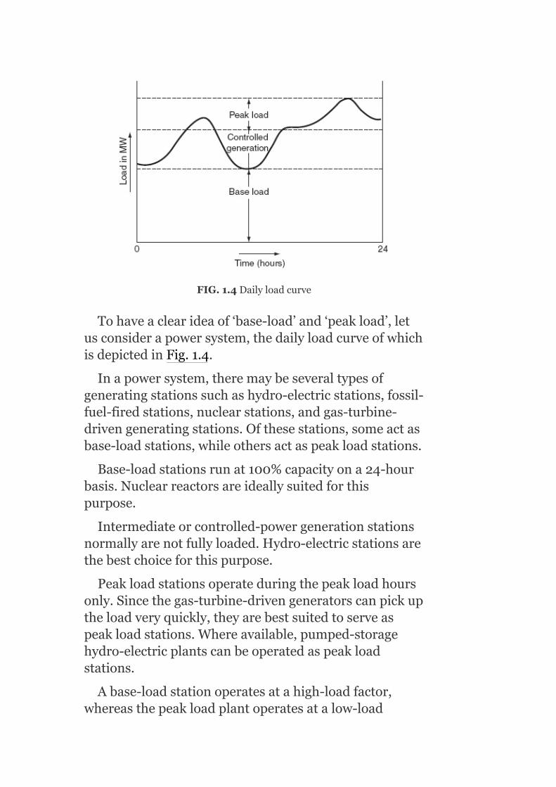
FIG.1.4Dailyloadcurve
Tohaveaclearideaof‘base-load’and‘peakload’,letusconsiderapowersystem,thedailyloadcurveofwhichisdepictedinFig.1.4.
Inapowersystem,theremaybeseveraltypesofgeneratingstationssuchashydro-electricstations,fossil-fuel-firedstations,nuclearstations,andgas-turbine-drivengeneratingstations.Ofthesestations,someactasbase-loadstations,whileothersactaspeakloadstations.
Base-loadstationsrunat100%capacityona24-hourbasis.Nuclearreactorsareideallysuitedforthispurpose.
Intermediateorcontrolled-powergenerationstationsnormallyarenotfullyloaded.Hydro-electricstationsarethebestchoiceforthispurpose.
Peakloadstationsoperateduringthepeakloadhoursonly.Sincethegas-turbine-drivengeneratorscanpickuptheloadveryquickly,theyarebestsuitedtoserveaspeakloadstations.Whereavailable,pumped-storagehydro-electricplantscanbeoperatedaspeakloadstations.
Abase-loadstationoperatesatahigh-loadfactor,whereasthepeakloadplantoperatesatalow-load
factor.So,thebase-loadstationshouldhavelowoperatingcosts.
1.5DEFINITIONOFTERMSANDFACTORS
Severaltermsareusedinconnectionwithpowersupplytoanarea,whetheritbeforthefirsttime(asisthecasewhentheareaisbeingelectrifiedforthefirsttime)orsubsequently(duetotheloadgrowth).Thesetermsareexplainedbelow.
1.5.1Connectedload
Aconsumer,forexample,adomesticconsumer,mayhaveseveralappliancesratedatdifferentwattages.Thesumoftheseratingsishis/herconnectedload.
Connectedloadisthesumoftheratings(W,kW,orMW)oftheapparatusinstalledonaconsumer’spremises.
1.5.2Maximumdemand
Itisthemaximumloadusedbyaconsumeratanytime.Itcanbelessthanorequaltotheconnectedload.Ifallthedevicesconnectedintheconsumer’shouseruntotheirfullestextentsimultaneously,thenthemaximumdemandwillbeequaltotheconnectedload.Butgenerally,theactualmaximumdemandwillbelessthantheconnectedloadsincealltheappliancesareneverusedatfullloadatatime.
Themaximumdemandisusuallymeasuredinunitsofkilowatts(kW)ormegawatts(MW)byamaximumdemandindicator.(Usually,inthecaseofhigh-tensionconsumers,themaximumdemandismeasuredintermsofkVAorMVA.)
1.5.3Demandfactor

Theratioofthemaximumdemandtotheconnectedloadiscalledthe‘demandfactor’:
Note:Maximumdemandandtheconnectedloadaretobeexpressedinthesameunits(W,kW,orMW).
1.5.4Averageload
IfthenumberofkWhsuppliedbyastationinonedayisdividedby24hours,thenthevalueobtainedisknownasthedailyaverageload:
Dailyaverageload
Monthlyaverageload
Yearlyaverageload
1.5.5Loadfactor
Theratiooftheaveragedemandtothemaximumdemandiscalledtheloadfactor:
Loadfactor(LF)
IftheplantisinoperationforaperiodT,
Loadfactor

Theloadfactormaybeadailyloadfactor,amonthlyloadfactor,oranannualloadfactor,ifthetimeperiodisconsideredinadayoramonthorayear,respectively.Loadfactorisalwayslessthanonebecauseaverageloadissmallerthanthemaximumdemand.Itplaysakeyroleindeterminingtheoverallcostperunitgenerated.Highertheloadfactorofthepowerstation,lesserwillbethecostperunitgenerated.
1.5.6Diversityfactor
Diversityfactoristheratioofthesumofthemaximumdemandsofagroupofconsumerstothesimultaneousmaximumdemandofthegroupofconsumers:
Diversityfactor
Apowersystemsuppliesloadtovarioustypesofconsumerswhosemaximumdemandsgenerallydonotoccuratthesametime.Therefore,themaximumdemandonthepowersystemisalwayslessthanthesumofindividualmaximumdemandsoftheconsumers.
Ahighdiversityfactorimpliedthatwithasmallermaximumdemandonthestation,itispossibletocatertotheneedsofseveralconsumerswithvaryingmaximumdemandsoccurringatdifferenthoursoftheday.Thelesserthemaximumdemand,thelesserwillbethecapitalinvestmentonthegenerators.Thishelpsinreducingtheoverallcostoftheunits(kWh)generated.
Thus,ahigherdiversityfactorandahigherloadfactorarethedesirablecharacteristicsoftheloadonapowerstation.Theloadfactorcanbeimprovedbyencouraging
theconsumerstousepowerduringoff-peakhourswithcertainincentiveslikeofferingareductioninthecostofenergyconsumedduringoff-peakhours.
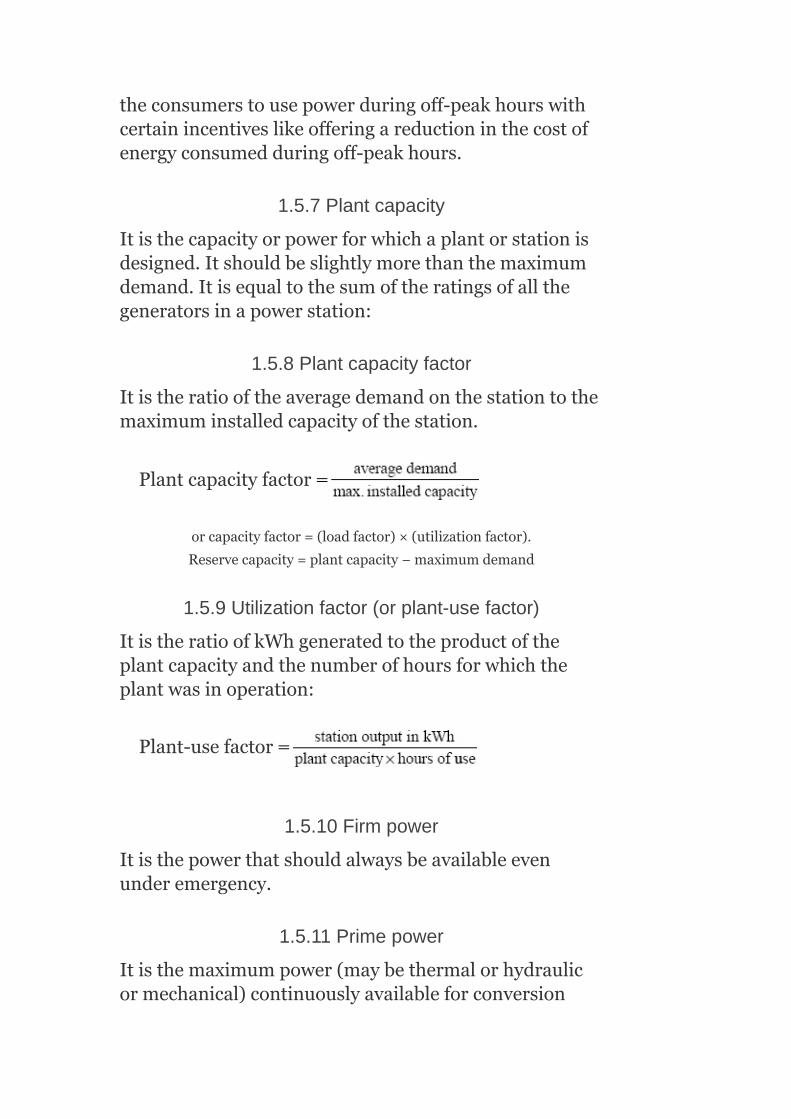
1.5.7Plantcapacity
Itisthecapacityorpowerforwhichaplantorstationisdesigned.Itshouldbeslightlymorethanthemaximumdemand.Itisequaltothesumoftheratingsofallthegeneratorsinapowerstation:
1.5.8Plantcapacityfactor
Itistheratiooftheaveragedemandonthestationtothemaximuminstalledcapacityofthestation.
Plantcapacityfactor
orcapacityfactor=(loadfactor)×(utilizationfactor).
Reservecapacity=plantcapacity−maximumdemand
1.5.9Utilizationfactor(orplant-usefactor)
ItistheratioofkWhgeneratedtotheproductoftheplantcapacityandthenumberofhoursforwhichtheplantwasinoperation:
Plant-usefactor
1.5.10Firmpower
Itisthepowerthatshouldalwaysbeavailableevenunderemergency.
1.5.11Primepower
Itisthemaximumpower(maybethermalorhydraulicormechanical)continuouslyavailableforconversion

intoelectricpower.
1.5.12Dumppower
Thisisthetermusuallyusedinhydro-electricplantsanditrepresentsthepowerinexcessoftheloadrequirements.Itismadeavailablebysurpluswater.
1.5.13Spillpower
Itisthepowerthatisproducedduringfloodsinahydro-powerstation.
1.5.14Coldreserve
Itisthereserve-generatingcapacitythatisnotinoperation,butcanbemadeavailableforservice.
1.5.15Hotreserve
Itisthereserve-generatingcapacitythatisinoperation,butnotinservice.
1.5.16Spinningreserve
Itisthereserve-generatingcapacitythatisconnectedtobusbarsandisreadytotaketheload.
1.6BASELOADANDPEAKLOADONAPOWERSTATION
Baseload:Itistheunvaryingloadthatoccursalmostduringthewholedayonthestation.
Peakload:Itisthevariouspeakdemandsofloadoverandabovethebaseloadofthestation.
Example1.1:Ageneratingstationhasamaximumdemandof35MWandhasaconnectedloadof60MW.Theannualgenerationofunitsis24×10 kWh.Calculatetheloadfactorandthedemandfactor.
Solution:
7

No.ofunitsgeneratedannually = 24×107kWh
No.ofhoursinayear(assuming365daysinayear)
= 365×24
= 8,760hours
∴Averageloadonthestation
∴LoadFactor
Demandfactor
Example1.2:Ageneratingstationsuppliesfourfeederswiththemaximumdemands(inMW)of16,10,12,and7MW.Theoverallmaximumdemandonthestationis20MWandtheannualloadfactoris45%.Calculatethediversityfactorandthenumberofunitsgeneratedannually.
Solution:
Sumofmaximumdemands=16+10+12+7=45MW
Simultaneousmaximumdemand=20MW
∴Diversityfactor

Averagedemand=(maximumdemand)×(loadfactor)
=20×0.45=9MW
∴No.ofunitsgeneratedannually=9×8,760=78,840MWh
Alternatively,
Annualloadfactor
i.e,
sothatthenumberofunitsgeneratedannually=0.45×20×8,760MWh
=78,840MWh
Example1.3:Theyearlyload–durationcurveofapowerplantisastraightline(Fig.1.5).Themaximumloadis30MWandtheminimumloadis20MW.Thecapacityoftheplantis35MW.Calculatetheplantcapacityfactor,theloadfactor,andtheutilizationfactor.
Solution:
No.ofunitsgeneratedperyear=AreaOACD=AreaOBCD+AreaBAC

∴Averageannualload
∴Loadfactor
Plantcapacityfactor
Utilizationfactor
Alternatively,
Utilizationfactor
FIG.1.5Load–durationcurve
Example1.4:Calculatethetotalannualenergygenerated,ifthemaximumdemandonapowerstationis120MWandtheannualloadfactoris50%.
Solution:
Maximumdemandonapowerstation=120MW
Annualloadfactor=50%

Loadfactor
∴Energygenerated/annum
= maximumdemand×LF×hoursinayear
= (120×103)×(0.5)×(24×365)kWh
= 525.6×10⁶kWh
Example1.5:Determinethedemandfactorandtheloadfactorofageneratingstation,whichhasaconnectedloadof50MWandamaximumdemandof25MW,theunitsgeneratedbeing40×10 /annum.
Solution:
Connectedload = 50MW
Maximumdemand = 25MW
Unitsgenerated = 40×106/annum
Demandfactor
Averagedemand
Loadfactor
6

Example1.6:Calculatetheannualloadfactorofa120MWpowerstation,whichdelivers110MWfor4hours,60MWfor10hours,andisshutdownfortherestofeachday.Forgeneralmaintenance,itisshutdownfor60daysperannum.
Solution:
Capacityofpowerstation = 120MW
Powerdelivered = 110MWfor4hours
= 60MWfor10hours
= 0fortherestofeachday
Andforgeneralmaintenance,itisshutdownfor60daysperannum.
Energysuppliedin1day=(110×4)+(60×10)=1,040MWh
No.ofworkingdaysinayear=365−60=305
Energysuppliedperyear=1,040×305=3,17,200MWh
Annualloadfactor
Example1.7:customer-connectedloadsare10lampsof60Weachandtwoheatersof1,500Weach.His/hermaximumdemandis2kW.Onaverage,he/sheuses10lamps,7hoursaday,andeachheaterfor5hoursaday.

Determinehis/her:(i)averageload,(ii)monthlyenergyconsumption,and(iii)loadfactor.
Solution:
Maximumdemand=2kW
Connectedload=10×60+2×1,500=3,600W
Dailyenergyconsumption=numberoflampsused×wattageofeachlamp×workinghoursperday+numberofheaters×wattageofeachheater×workinghoursperday
= 10×60×7+2×1,500×5
= 19.2kWh
1. Averageload
2.
Monthlyenergyconsumption
= dailyenergyconsumption×no.ofdaysinamonth
= 19.2×30=576kWh
= 576kWh
3. Monthlyloadfactor
Example1.8:Themaximumdemandonageneratingstationis20MW,aloadfactorof75%,aplantcapacity

factorof50%,andaplant-usefactorof80%.Calculatethefollowing:
1. dailyenergygenerated,2. reservecapacityoftheplant,3. maximumenergythatcouldbeproduceddailyiftheplantwereinuse
allthetime.
Solution:
Maximumdemand,MD
= 20MW
Loadfactor,LF = 75%
Powercapacityfactor = 50%
Plant-usefactor = 80%
Averageload = MD×LF
= 20×0.75=15MW
1. Dailyenergygenerated=averageload×24=15×24=360MWh2. Powerstationinstalledcapacity=
Plantreservecapacity=installedcapacity−maximumdemand
=30−20
=10MW
3. Themaximumenergythatcanbeproduceddailyiftheplantisrunningallthetime

Example1.9:Acertainpowerstation’sannualload–durationcurveisastraightlinefrom25to5MW(Fig.1.6).Tomeetthisload,threeturbine-generatorunits,tworatedat15MWeachandoneratedat7.5MWareinstalled.Calculatethefollowing:
1. installedcapacity;2. plantfactor;3. unitsgeneratedperannum;4. utilizationfactor.
Solution:
1. Installedcapacity=2×15+7.5
=37.5MW
2. Fromtheload–durationcurveshowninFig.1.6,
Averagedemand
∴Plantfactor
3. Unitsgeneratedperannum=area(inkWh)underload–durationcurve
4. Utilizationfactor

FIG.1.6Load–durationcurve
Example1.10:Aconsumerhasaconnectedloadof12lampseachof100Wathis/herpremises.His/herloaddemandisasfollows:
Frommidnightto5A.M.:200W.
5A.M.to6P.M.:noload.
6P.M.to7P.M.:700W.
7P.M.to9P.M.:1,000W.
9P.M.tomidnight:500W.
Drawtheloadcurveandcalculatethe(i)energyconsumptionduring24hours,(ii)demandfactor,(iii)averageload,(iv)maximumdemand,and(v)loadfactor.
Solution:
FromFig.1.7,
1. Electricalenergyconsumptionduringtheday=areaofloadcurve
=200×5+700×1+1,000×2+500×3
=5,200Wh
=5.2kWh
2. Averageload
3. Demandfactor

4. Maximumdemand=1,000W5. Loadfactor
FIG.1.7Loadcurve
Example1.11:Calculatethediversityfactorandtheannualloadfactorofageneratingstation,whichsuppliesloadstovariousconsumersasfollows:
Industrialconsumer=2,000kW;
Commercialestablishment=1,000kW
Domesticpower=200kW;
Domesticlight=500kW
andassumethatthemaximumdemandonthestationis3,000kW,andthenumberofunitsproducedperyearis50×10 .
Solution:
5

Loadindustrialconsumer =2,000kW
Loadcommercialestablishment =1,000kW
Domesticpowerload =200kW
Domesticlightingload =500kW
Maximumdemandonthestation =3,000kW
NumberofkWhgeneratedperyear
=50×10
Diversityfactor
Averagedemand
Loadfactor
Example1.12:Calculatethereservecapacityofageneratingstation,whichhasamaximumdemandof20,000kW,theannualloadfactoris65%,andthecapacityfactoris45%.
Solution:
Maximumdemand = 20,000kW
Annualloadfactor = 65%
5

Capacityfactor = 45%
Energygenerated/annum
= maximumdemandLFhoursinayear
= (20,000)×(0.65)×(8,760)kWh=113.88×10⁶kWh
Capacityfactor
0.45
∴Plantcapacity
Reservecapacity
= plantcapacity−maximumdemand
= 28,888.89−20,000=8,888.89kW
Example1.13:Themaximumdemandonapowerstationis600MW,theannualloadfactoris60%,andthecapacityfactoris45%.Findthereservecapacityoftheplant.
Solution:
Utilizationfactor

Plantcapacity
Reservecapacity
= plantcapacity−maximumdemand
= 800−600
= 200MW
Example1.14:Apowerstation’smaximumdemandis50MW,thecapacityfactoris0.6,andtheutilizationfactoris0.85.Calculatethefollowing:(i)reservecapacityand(ii)annualenergyproduced.
Solution:
Energygenerated/annum=maximumdemand×loadfactor×hoursinayear
=(50×LF×8,760)MWh
Loadfactor
Energygenerated/annum
= 50×0.706×8,760
= 3,09,228MWh=0.3×10⁶MWh
Plantcapacity
Reservecapacity = plantcapacity−maximumdemand
= 58.82−50
= 8.82MW
Example1.15:Apowerstationistofeedfourregionsofloadwhosepeakloadsare12,7,10,and8MW.Thediversityfactoratthestationis1.4andtheaverageannualloadfactoris65%.Determinethefollowing:(i)maximumdemandonthestation,(ii)annualenergysuppliedbythestation,and(iii)suggesttheinstalledcapacity.
Solution:
1. Maximumdemandonstation
2. Unitsgenerated/annum=max.demand×LF×houseinayear
=(26.43×10 )×0.65×8,760kWh
=150.49×10 kMh
3. Theinstalledcapacityofthestationshouldbe15%to20%morethanthemaximumdemandinordertomeetthefuturegrowthofload.
Takingtheinstalledcapacitytobe20%morethanthemaximumdemand,
Installedcapacity=1.2×max.demand
=1.2×26.43
=31.716≅32MW
1.7LOADFORECASTING
Electricalenergycannotbestored.Ithastobegeneratedwheneverthereisademandforit.Itis,therefore,imperativefortheelectricpowerutilitiesthattheloadon
3
6
theirsystemsshouldbeestimatedinadvance.Thisestimationofloadinadvanceiscommonlyknownasloadforecasting.Itisnecessaryforpowersystemplanning.
Powersystemexpansionplanningstartswithaforecastofanticipatedfutureloadrequirements.Theestimationofbothdemandandenergyrequirementsiscrucialtoaneffectivesystemplanning.Demandpredictionsareusedfordeterminingthegenerationcapacity,transmission,anddistributionsystemadditions,etc.Loadforecastsarealsousedtoestablishprocurementpoliciesforconstructioncapitalenergyforecasts,whichareneededtodeterminefuturefuelrequirements.Thus,agoodforecast,reflectingthepresentandfuturetrends,isthekeytoallplanning.
Ingeneral,thetermforecastreferstoprojectedloadrequirementsdeterminedusingasystematicprocessofdefiningfutureloadsinsufficientquantitativedetailtopermitimportantsystemexpansiondecisionstobemade.Unfortunately,theconsumerloadisessentiallyuncontrollablealthoughminorvariationscanbeaffectedbyfrequencycontrolandmoredrasticallybyloadshedding.Thevariationinloaddoesexhibitcertaindailyandyearlypatternrepetitions,andananalysisoftheseformsthebasisofseveralload-predictiontechniques.
1.7.1Purposeofloadforecasting
1. Forproperplanningofpowersystem;2. Forproperplanningoftransmissionanddistributionfacilities;3. Forproperpowersystemoperation;4. Forproperfinancing;5. Forpropermanpowerdevelopment;6. Forpropergridformation;7. Forproperelectricalsales.
(i)ForProperPlanningofPowerSystem
Todeterminethepotentialneedforadditionalnewgeneratingfacilities;Todeterminethelocationofunits;

Todeterminethesizeofplants;Todeterminetheyearinwhichtheyarerequired;Todeterminethattheyshouldprovideprimarypeakingcapacityorenergyorboth;TodeterminewhethertheyshouldbeconstructedandownedbytheCentralGovernmentorStateGovernmentorElectricityBoardsorbysomeotherautonomouscorporations.
(ii)ForProperPlanningofTransmissionandDistributionFacilities
Forplanningthetransmissionanddistributionfacilities,theloadforecastingisneededsothattherightamountofpowerisavailableattherightplaceandattherighttime.Wastageduetomisplanninglikepurchaseofequipment,whichisnotimmediatelyrequired,canbeavoided.
(iii)ForProperPowerSystemOperation
Loadforecastbasedoncorrectvaluesofdemandanddiversityfactorwillpreventoverdesigningofconductorsize,etc.aswellasoverloadingofdistributiontransformersandfeeders.Thus,theyhelptocorrectvoltage,powerfactor,etc.andtoreducethelossesinthedistributionsystem.
(iv)ForProperFinancing
TheloadforecastshelptheBoardstoestimatethefutureexpenditure,earnings,andreturnsandtoscheduleitsfinancingprogramaccordingly.
(v)ForProperManpowerDevelopment
AccurateloadforecastingannuallyreviewedwillcometotheaidoftheBoardsintheirpersonnelandtechnicalmanpowerplanningonalong-termbasis.SucharealisticforecastwillreduceunnecessaryexpenditureandputtheBoards’financesonasoundandprofitablefooting.
(vi)ForProperGridFormation
Interconnectionsbetweenvariousstategridsarenowbecomingmoreandmorecommonandtheaimistohavefullyinterconnectedregionalgridsandultimately

evenasupergridforthewholecountry.Theseexpensivehigh-voltageinterconnectionsmustbebasedonreliableloaddata,otherwisethegeneratorsconnectedtothegridmayfrequentlyfalloutofstepcausingpowertobeshutdown.
(vii)ForProperElectricalSales
Incountries,wherespinningreservesaremore,properplanningandtheexecutionofelectricalsalesprogramareaidedbyproperloadforecasting.
1.7.2Classificationofloadforecasting
Theloadforecastingcanbeclassifiedas:(i)demandforecastand(ii)energyforecast.
(i)DemandForecast
Thisisusedtodeterminethecapacityofthegeneration,transmission,anddistributionsystemadditions.Futuredemandcanbepredictedonthebasisoffastrateofgrowthofdemandfrompasthistoryandgovernmentpolicy.Thiswillgivetheexpectedrateofgrowthofload.
(ii)EnergyForecast
Thisisusedtodeterminethetypeoffacilitiesrequired,i.e.,futurefuelrequirements.
1.7.3Forecastingprocedure
Dependingonthetimeperiodofinterest,aspecificforecastingproceduremaybeclassifiedas:
Short-term.Medium(intermediate)-term.Long-termtechnique.
(1)Short-TermForecast
Forday-to-dayoperation,coveringonedayoraweek,short-termforecastingisneededinordertocommitenoughgeneratingcapacityformattingtheforecastingdemandandformaintainingtherequiredspinning

reserve.Hence,itisusuallydone24hoursaheadwhentheweatherforecastforthefollowingdaybecomesavailablefromthemeteorologicaloffice.Thismostlyconsistsofestimatingtheweather-dependentcomponentandthatduetoanyspecialeventorfestivalbecausethebaseloadforthedayisalreadyknown.
Thepowersupplyauthoritiescanbuildupaweatherloadmodelofthesystemforthispurposeorcanconsultsometables.Thefinalestimateisobviouslydoneafteraccountingthetransmissionanddistributionlossesofthesystem.Inadditiontothepredictionofhourlyvalues,ashort-termloadforecasting(STLF)isalsoconcernedwithforecastingofdailypeak-systemload,systemloadatcertaintimesofaday,hourlyvaluesofsystemenergy,anddailyandweeklysystemenergy.
ApplicationsofSTLFaremainly:
Todrivetheschedulingfunctionsthatdecidethemosteconomiccommitmentofgenerationsources.Toaccessthepowersystemsecuritybasedontheinformationavailabletothedispatcherstopreparethenecessarycorrectiveactions.Toprovidethesystemdispatcherwiththelatestweatherpredictionssothatthesystemcanbeoperatedbotheconomicallyandreliably.
(2)Long-TermForecast
Thisisdonefor1–5yearsinadvanceinordertopreparemaintenanceschedulesofthegeneratingunits,planningfutureexpansionofthegeneratingcapacity,enterintoanagreementforenergyinterchangewiththeneighboringutilities,etc.Basically,twoapproachesareavailableforthispurposeandarediscussedasfollows.
(a)PeakLoadApproach
Inthiscase,thesimplestapproachistoextrapolatethetrendcurve,whichisobtainedbyplottingthepastvaluesofannualpeaksagainstyearsofoperation.Thefollowinganalyticalfunctionscanbeusedtodeterminethetrendcurve.

1. Straightline,Y=a+bx2. Parabola,Y=a+bx+cx3. S-curve,Y=a+bx+cx +dx4. Exponential,Y=ce5. Gompertz,log Y=a+ce
Intheabove,Yrepresentspeakloadsandxrepresentstimeinyears.Themostcommonmethodoffindingcoefficientsa,b,c,anddistheleastsquarescurve-fittingtechnique.
Theeffectofweatherconditionscanbeignoredonthebasisthatweatherconditions,asinthepast,aretobeexpectedduringtheperiodunderconsiderationbuttheeffectofthechangeintheeconomicconditionshouldbeaccommodatedbyincludinganeconomicvariablewhenextrapolatingthetrendcurve.Theeconomicvariablemaybethepredictednationalincome,grossdomesticproduct,etc.
(b)EnergyApproach
Anothermethodistoforecastannualenergysalestodifferentclassesofcustomerslikeresidential,commercial,industrial,etc.,whichcanthenbeconvertedtoannualpeakdemandusingtheannualloadfactor.Adetailedestimationoffactorssuchasrateofhousebuilding,saleofelectricalappliances,growthinindustrialandcommercialactivitiesarerequiredinthismethod.Forecastingtheannualloadfactoralsocontributescriticallytothesuccessofthemethod.Boththesemethods,however,havebeenusedbytheutilitiesinestimatingtheirlong-termsystemload.
KEYNOTES
Aloadcurveisaplotoftheloaddemand(onthey-axis)versusthetime(onthex-axis)inthechronologicalorder.Theload–durationcurveisaplotoftheloaddemands(inunitsofpower)arrangedinadescendingorderofmagnitude(onthey-axis)andthetimeinhours(onthex-axis).Intheoperationofhydro-electricplants,itisnecessarytoknowtheamountofenergybetweendifferentloadlevels.Thisinformationcan
e
2
2 3
dx
dx

beobtainedfromtheload–durationcurve.Theintegratedload–durationcurveisalsotheplotofthecumulativeintegrationofareaundertheloadcurvestartingatzeroloadstotheparticularload.Abase-loadstationoperatesatahigh-loadfactorwhilethepeakloadplantoperatesata-lowloadfactor.Demandfactoristheratioofthemaximumdemandtotheconnectedload.Loadfactoristheratiooftheaveragedemandtothemaximumdemand.Highertheloadfactorofthepowerstation,lesserwillbethecostperunitgenerated.Diversityfactoristheratioofthesumofthemaximumdemandsofagroupofconsumersandthesimultaneousmaximumdemandofthegroupofconsumers.Baseloadistheunvaryingloadthatoccursalmostthewholedayonthestation.Peakloadisthevariouspeakdemandsofloadoverandabovethebaseloadofthestation.
SHORTQUESTIONSANDANSWERS
1. Whatismeantbyconnectedload?
Itisthesumoftheratingsoftheapparatusinstalledonaconsumer’spremises.
2. Definethemaximumdemand.
Itisthemaximumloadusedbyaconsumeratanytime.
3. Definethedemandfactor.
Theratioofthemaximumdemandtotheconnectedloadiscalledthedemandfactor.
4. Definetheaverageload.
IfthenumberofkWhsuppliedbeastationinonedayisdividedby24hours,thenthevalueobtainedisknownasthedailyaverageload.
5. Definetheloadfactor.
Itistheratiooftheaveragedemandtothemaximumdemand.
6. Definethediversityfactor.
Itistheratioofthesumofthemaximumdemandsofagroupofconsumerstothesimultaneousmaximumdemandofthegroupofconsumers.
7. Definetheplantcapacity.
Itisthecapacityorpowerforwhichaplantorstationisdesigned.
8. Definetheutilizationfactor.
ItistheratioofkWhgeneratedtotheproductoftheplantcapacityandthenumberofhoursforwhichtheplantwasin

operation.
9. Whatismeantbybaseload?
Itistheunvaryingloadthatoccursalmostthewholedayonthestation.
10. Whatismeantbypeakload?
Itisthevariouspeakdemandsofloadoverandabovethebaseloadofthestation.
11. Whatismeantbyloadcurve?
Aloadcurveisaplotoftheloaddemandversusthetimeinthechronologicalorder.
12. Whatismeantbyload–durationcurve?
Theload–durationcurveisaplotoftheloaddemandsarrangedinadescendingorderofmagnitudeversusthetimeinhours.
MULTIPLE-CHOICEQUESTIONS
1. Inordertohavealowcostofelectricalgeneration,
1. Theloadfactoranddiversityfactorarehigh.2. Theloadfactorshouldbelowbutthediversityfactorshouldbehigh.3. Theloadfactorshouldbehighbutthediversityfactorshouldbelow.4. Theloadfactorandthediversityfactorshouldbelow.
2. Apowerplanthavingmaximumdemandmorethantheinstalledcapacitywillhaveutilizationfactor:
1. Lessthan100%.2. Equalto100%.3. Morethan100%.4. Noneofthese.
3. Thechoiceofnumberandsizeofunitsinastationaregovernedbybestcompromisebetween:
1. Aplantloadfactorandcapacityfactor.2. Plantcapacityfactorandplant-usefactor.3. Plantloadfactorandusefactor.4. Noneofthese.
4. Ifaplanthaszeroreservecapacity,theplantloadfactoralways:
1. Equalsplantcapacityfactor.2. Isgreaterthanplantcapacityfactor.3. Islessthanplantcapacityfactor.4. Noneofthese.
5. Ifsomereserveisavailableinapowerplant,
1. Itsusefactorisalwaysgreaterthanitscapacityfactor.2. Itsusefactorequalsthecapacityfactor.3. Itsusefactorisalwayslessthanitscapacityfactor.4. Noneofthese.
6. Ahigherloadfactormeans:

1. Costperunitisless.2. Lessvariationinload.3. Thenumberofunitsgeneratedaremore.4. Allofthese.
7. Themaximumdemandoftwopowerstationsisthesame.Ifthedailyloadfactorsofthestationsare10and20%,thentheunitsgeneratedbythemareintheratio:
1. 2:1.2. 1:2.3. 3:3.4. 1:4.
8. Aplanthadanaverageloadof20MWwhentheloadfactoris50%.Itsdiversityfactoris20%.Thesumofmax.demandsofallloadsamountsto:
1. 12MW.2. 8MW.3. 6MW.4. 4MW.
9. Apeakloadstation:
1. Shouldhavealowoperatingcost.2. Shouldhavealowcapitalcost.3. Canhaveaoperatingcosthigh.4. (a)and(c).5. (b)and(c).
10. TwoareasAandBhaveequalconnectedloads;howevertheloaddiversityinareaAismorethaninB,then:
1. Maximumdemandoftwoareasissmall.2. MaximumdemandofAisgreaterthanthemaximumdemandofB.3. ThemaximumdemandofBisgreaterthanthemaximumdemandofA.4. ThemaximumdemandofAmoreorlessthanthatofB.
11. Theareaunderthedailyloadcurvegives
1. Thenumberofunitsgeneratedintheday.2. Theaverageloadoftheday.3. Theloadfactoroftheday.4. Thenumberofunitsgeneratedintheyear.
12. Theannualpeakloadona60-MWpowerstationis50MW.Thepowerstationsuppliesloadshavingaveragedemandsof9,10,17,and20MW.Theannualloadfactoris60%.Theaverageloadontheplantis:
1. 4,000kW.2. 30,000kW.3. 2,000kW.4. 1,000kW.
13. Ageneratingstationhasaconnectedloadof40MWandamaximumdemandof20MW.Thedemandfactoris:
1. 0.7.2. 0.6.3. 0.59.4. 0.4.

14. A100MWpowerplanthasaloadfactorof0.5andautilizationfactorof0.2.Itsaveragedemandis:
1. 10MW.2. 5MW.3. 7MW.4. 6MW.
15. Thevalueofthedemandfactorisalways:
1. Lessthanone.2. Equaltoone.3. Greaterthanone.4. Noneofthese.
16. Ifcapacityfactor=loadfactor,then:
1. Utilizationfactoriszero.2. Utilizationcapacityisnon-zero.3. Utilizationfactorisequaltoone.4. Noneofthese.
17. Ifcapacityfactor=loadfactor,thentheplant’s
1. Reservecapacityismaximum.2. Reservecapacityiszero.3. Reservescapacityisless.4. Noneofthese.
18. Installedcapacityofpowerplantis:
1. Morethanthemaximumdemand.2. Lessthanthemaximumdemand.3. Equaltothemaximumdemand.4. Bothand.
19. Inaninterconnectedsystem,diversityfactordetermining:
1. Decreases.2. Increases.3. Zero.4. Noneofthese.
20. Theknowledgeofdiversityfactorhelpsindetermining:
1. Plantcapacity.2. Reservecapacity.3. Maximumdemand.4. Averagedemand.
21. Apowerstationhasaninstalledcapacityof300MW.Itscapacityfactoris50%anditsloadfactoris75%.Itsmaximumdemandis:
1. 100MW.2. 150MW.3. 200MW.4. 250MW.
22. Theconnectedloadofaconsumeris2kWandhis/hermaximumdemandis1.5kW.Theloadfactoroftheconsumeris:
1. 0.75.2. 0.375.3. 1.33.4. noneofthese.
23. Themaximumdemandofaconsumeris2kWandhis/herdailyenergyconsumptionis20units.His/herloadfactoris:
1. 10.15%.2. 41.6%.3. 50%.4. 52.6%.
24. Inapowerplant,areserve-generatingcapacity,whichisnotinservicebutinoperationisknownas:
1. Hotreserve.2. Spinningreserve.3. Coldreserve.4. Firmpower.
25. Thepowerintendedtobealwaysavailableisknownas:
1. Hotreserve.2. Spinningreserve.3. Coldreserve.4. Firmpower.
26. Inapowerplant,areserve-generatingcapacity,whichisinservicebutnotinoperationis:
1. Hotreserve.2. Spinningreserve.3. Coldreserve.4. Firmpower.
27. Whichofthefollowingisacorrectfactor?
1. Loadfactor=capacity×utilizationfactor.2. Utilizationfactor=capacityfactor×loadfactor.3. Utilizationfactor=loadfactor/utilizationfactor.4. Capacityfactor=loadfactor×utilizationfactor.
28. Iftheratedplantcapacityandmaximumloadofgeneratingstationareequal,then:
1. Loadfactoris1.2. Capacityfactoris1.3. Loadfactorandcapacityfactorareequal.4. Utilizationfactorispoor.
29. Thecapitalcostofplantdependson:
1. Totalinstalledcapacityonly.2. Totalnumberofunitsonly.3. Bothand.4. Noneofthese.
30. Thereservecapacityinasystemisgenerallyequalto:
1. Capacityofthelargestgeneratingunit.2. Capacityoftwolargestgeneratingunits.3. Thetotalgeneratingcapacity.4. Noneoftheabove.
31. Themaximumdemandofaconsumeris5kWandhis/herdailyenergyconsumptionis24units.His/her%loadfactoris:
1. 5.

2. 20.3. 24.4. 48.
32. Ifloadfactorispoor,then:
1. Electricenergyproducedissmall.2. ChargeperkWhishigh.3. FixedchargesperkWhishigh.4. Alloftheabove.
33. Ifageneratingstationhadmaximumloadsforadayat100kWandaloadfactorof0.2,itsgenerationinthatdaywas:
1. 8.64MWh.2. 21.6units.3. 21.6units.4. 2,160kWh.
34. Theknowledgeofmaximumdemandisimportantasithelpsindetermining:
1. Installedcapacityoftheplant.2. Connectedloadoftheplant.3. Averagedemandoftheplant.4. Either(a)or(b).
35. Apowerstationisconnectedto4.5and6kW.Itsdailyloadfactorwascalculatedas0.2,whereitsgenerationonthatdaywas24units.Calculatethedemandfactor.
1. 2.6.2. 3.1.3. 3.0.4. 0.476.
36. A50-MWpowerstationhadproduced24unitsinadaywhenitsmaximumdemandwas50Mw.Itsplantloadfactorandcapacityfactorthatdayin%were:
1. 1and2.2. 2and3.3. 2and2.4. 4and3.
37. Loadcurveofapowergenerationstationisalways:
1. Negative.2. Zeroslope.3. Positive.4. Anycombinationof(a),(b),and(c).
38. Loadcurvehelpsindecidingthe:
1. Totalinstalledcapacityoftheplant.2. Sizeofthegeneratingunits.3. Operatingscheduleofthegeneratingunits.4. Alloftheabove.
39. Theloadfactorfordomesticloadsmaybetaken:
1. About85%.2. 50−60%.3. 25−50%.

4. 20−15%.
REVIEWQUESTIONS
1. Explainthesignificanceofthedailyloadcurve.2. Discussthedifferencebetweentheloadcurveandtheload–
durationcurve.3. Explainthedifferencesinoperationsofpeakloadandbase-load
stations.4. Explainthesignificanceoftheloadfactorandthediversityfactor.5. Definethefollowing:
1. Loadfactor,2. Demandfactor,3. Diversityfactor,4. Plantcapacityfactor,and5. Utilizationfactor.
6. Explaintheloadforecastingprocedures.
PROBLEMS
1. Calculatediversityfactorandannualloadfactorofageneratingstationthatsuppliesloadstovariousconsumersasfollows:
Industrialconsumer=1,500kW;
Commercialestablishment=7,500kW
Domesticpower=100kW;
Domesticlight=400kW
Inaddition,assumethatthemaximumdemandonthestationis2,500kWandthenumberofunitsproducedperyearis40×10 kWh.
2. Apowerstationistofeedfourregionsofloadwhosepeakloadsare10,5,14,and6MW,respectively.Thediversityfactoratthestationis1.3andtheaverageannualloadfactoris60%.Determinethefollowing:(i)maximumdemandonthestation,(ii)annualenergysuppliedbythestation,and(iii)suggesttheinstalledcapacity.
3. Acertainpowerstation’sannualload–durationcurveisastraightlinefrom20to7MW.Tomeetthisload,threeturbine-generatorunits,tworatedat12MWeachandoneratedat8MWareinstalled.Calculatethefollowing:
1. Installedcapacity,2. Plantfactor,3. Unitsgeneratedperannum,4. Utilizationfactor.
5

2
EconomicLoadDispatch-I
OBJECTIVES
Afterreadingthischapter,youshouldbeableto:
studythedifferentcharacteristicsofsteamandhydro-powergenerationunits
knowthemeaningofeconomicalloaddispatch
developthemathematicalmodelforeconomicalloaddispatch
discussthedifferentcomputationalmethodsforoptimization
2.1INTRODUCTION
Powersystemsneedtobeoperatedeconomicallytomakeelectricalenergycost-effectivetotheconsumerinthefaceofconstantlyrisingpricesoffuel,wages,salaries,etc.Newgenerator-turbineunitsaddedtoasteampowerplantoperatemoreefficientlythanotherolderunits.Thecontributionofnewerunitstothegenerationofpowerwillhavetobemore.Intheoperationofpowersystems,thecontributionfromeachloadandfromeachunitwithinaplantmustbesuchthatthecostofelectricalenergyproducedisaminimum.
2.2CHARACTERISTICSOFPOWERGENERATION(STEAM)UNIT
Inanalyzingtheeconomicoperationofathermalunit,input–outputmodelingcharacteristicsaresignificant.Forthisfunction,considerasingleunitconsistingofaboiler,aturbine,andageneratorasshowninFig.2.1.Thisunithastosupplypowernotonlytotheloadconnectedtothepowersystembutalsotothelocalneedsfortheauxiliariesinthestation,whichmayvaryfrom2%

to5%.Thepowerrequirementsforstationauxiliariesarenecessarytodriveboilerfeedpumps,fansandcondensercirculatingwaterpumps,etc.
ThetotalinputtothethermalunitcouldbeBritishthermalunit(Btu)/hrorCal/hrintermsofheatsuppliedorRs./hrintermsofthecostoffuel(coalorgas).ThetotaloutputoftheunitatthegeneratorbuswillbeeitherkWorMW.
FIG.2.1Thermalgenerationsystem
2.3SYSTEMVARIABLES
Toanalyzethepowersystemnetwork,thereisaneedofknowingthesystemvariables.Theyare:
1. Controlvariables.2. Disturbancevariables.3. Statevariables.
2.3.1Controlvariables(P andQ )
Therealandreactive-powergenerationsarecalledcontrolvariablessincetheyareusedtocontrolthestateofthesystem.
2.3.2Disturbancevariables(P andQ )
Therealandreactive-powerdemandsarecalleddemandvariablessincetheyarebeyondthesystemcontrolandarehenceconsideredasuncontrolledordisturbancevariables.
G G
D D

2.3.3Statevariables(Vandδ)
ThebusvoltagemagnitudeVanditsphaseangleδdispatchthestateofthesystem.Thesearedependentvariablesthatarebeingcontrolledbythecontrolvariables.
2.4PROBLEMOFOPTIMUMDISPATCH—FORMULATION
Schedulingistheprocessofallocationofgenerationamongdifferentgeneratingunits.Economicschedulingisacost-effectivemodeofallocationofgenerationamongthedifferentunitsinsuchawaythattheoverallcostofgenerationshouldbeminimum.Thiscanalsobetermedasanoptimaldispatch.
Letthetotalloaddemandonthestation=P andthetotalnumberofgeneratingunits=n.
TheoptimizationproblemistoallocatethetotalloadP amongthese‘n’unitsinanoptimalwaytoreducetheoverallcostofgeneration.
LetP ,P ,P ,…,P bethepowergeneratedbyeach
individualunittosupplyaloaddemandofP .
Toformulatethisproblem,itisnecessarytoknowthe‘input–outputcharacteristicsofeachunit’.
2.5INPUT–OUTPUTCHARACTERISTICS
Theidealizedformofinput–outputcharacteristicsofasteamunitisshowninFig.2.2.Itestablishestherelationshipbetweentheenergyinputtotheturbineandtheenergyoutputfromtheelectricalgenerator.Theinputtotheturbineshownontheordinatemaybeeitherintermsoftheheatenergyrequirement,whichisgenerallymeasuredinBtu/hrorkCal/hrorintermsofthetotalcostoffuelperhourinRs./hr.TheoutputisnormallythenetelectricalpoweroutputofthatsteamunitinkWorMW.
D
D
Gi G2 G3 Gn
D

Inpractice,thecurvemaynotbeverysmooth,andfrompracticaldata,suchanidealizedcurvemaybeinterpolated.Thesteamturbine-generatingunitcurveconsistsofminimumandmaximumlimitsinoperation,whichdependuponthesteamcycleused,thermalcharacteristicsofmaterial,theoperatingtemperature,etc.
FIG.2.2Input–outputcharacteristicofasteamunit
2.5.1Unitsofturbineinput
Intermsofheat,theunitis10 kcal/hr(or)Btu/hrorintermsoftheamountoffuel,theunitistonsoffuel/hr,whichbecomesmillionsofkCal/hr.
2.6COSTCURVES
Toconverttheinput–outputcurvesintocostcurves,thefuelinputperhourismultipliedwiththecostofthefuel(expressedinRs./millionkCal).
i.e.,
= millionkCal/hr×Rs./millionkCal
6
= Rs./hr
2.7INCREMENTALFUELCOSTCURVE
Fromtheinput–outputcurves,theincrementalfuelcost(IFC)curvecanbeobtained.
TheIFCisdefinedastheratioofasmallchangeintheinputtothecorrespondingsmallchangeintheoutput.
Incrementalfuelcost
where∆representssmallchanges.
Asthe∆quantitiesbecomeprogressivelysmaller,itis
seenthattheIFCis andisexpressedin
Rs./MWh.AtypicalplotoftheIFCversusoutputpowerisshowninFig.2.3(a).
Theincrementalcostcurveisobtainedbyconsideringthechangeinthecostofgenerationtothechangeinreal-powergenerationatvariouspointsontheinput–outputcurves,i.e.,slopeoftheinput–outputcurveasshowninFig.2.3(b).

FIG.2.3(a)Incrementalcostcurve;(b)Incrementalfuelcostcharacteristicintermsoftheslopeoftheinput–outputcurve
TheIFCisnowobtainedas
(IC) =slopeofthefuelcostcurve
i.e.,tanβ
i
th

TheIFC(IC)ofthei thermalunitisdefined,foragivenpoweroutput,asthelimitoftheratiooftheincreasedcostoffuelinput(Rs./hr)tothecorrespondingincreaseinpoweroutput(MW),astheincreasingpoweroutputapproacheszero.
whereC isthecostoffuelofthei unitandP isthe
powergenerationoutputofthati unit.
Mathematically,theIFCcurveexpressioncanbeobtainedfromtheexpressionofthecostcurve.
Cost-curveexpression,
(Second-degreepolynomial)
TheIFC,
(linearapproximation)foralli=1,
2,3,…,n
where istheratioofincrementalfuelenergyinputin
BtutotheincrementalenergyoutputinkWh,whichiscalled‘theincrementalheatrate’.
Thefuelcostisthemajorcomponentandtheremainingcostssuchasmaintenance,salaries,etc.willbeofverysmallpercentageoffuelcost;hence,theIFCis
i Gi
th
th
th
verysignificantintheeconomicloadingofageneratingunit.
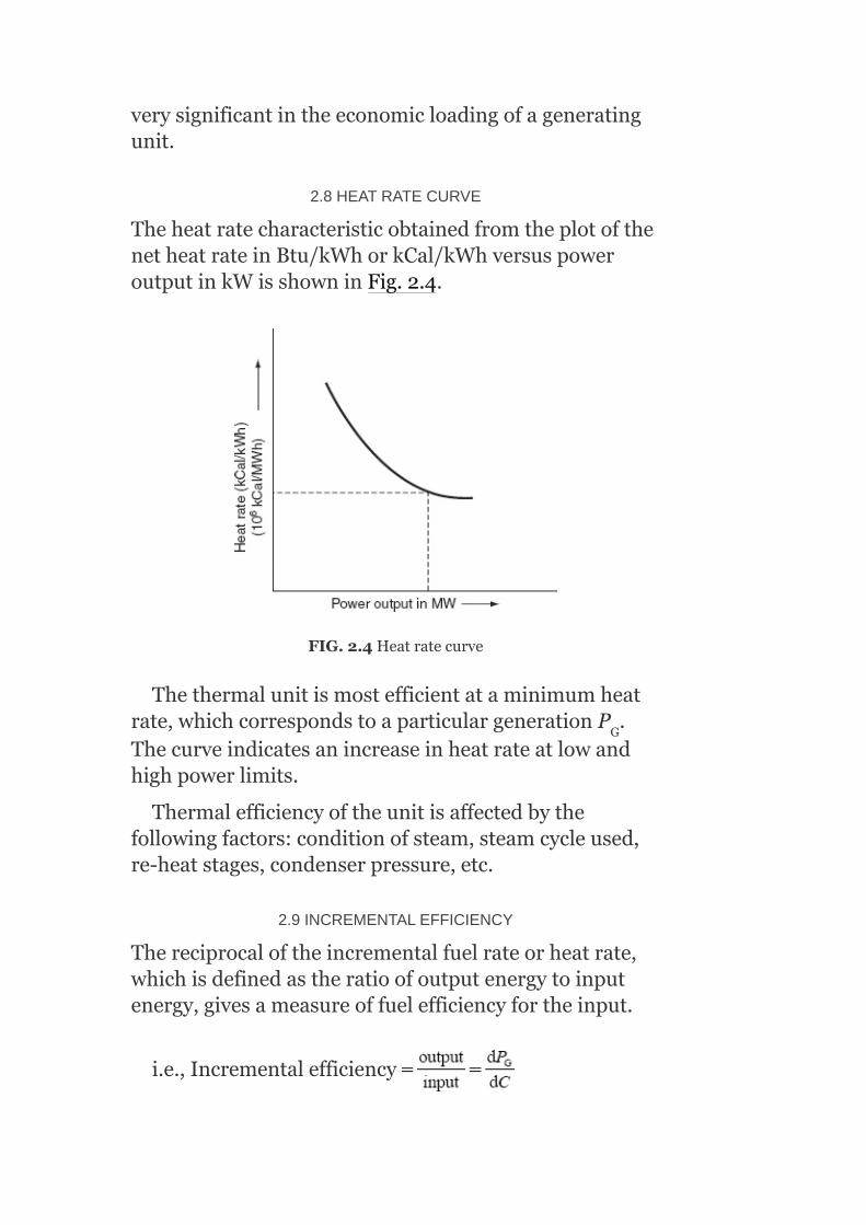
2.8HEATRATECURVE
TheheatratecharacteristicobtainedfromtheplotofthenetheatrateinBtu/kWhorkCal/kWhversuspoweroutputinkWisshowninFig.2.4.
FIG.2.4Heatratecurve
Thethermalunitismostefficientataminimumheatrate,whichcorrespondstoaparticulargenerationP .Thecurveindicatesanincreaseinheatrateatlowandhighpowerlimits.
Thermalefficiencyoftheunitisaffectedbythefollowingfactors:conditionofsteam,steamcycleused,re-heatstages,condenserpressure,etc.
2.9INCREMENTALEFFICIENCY
Thereciprocaloftheincrementalfuelrateorheatrate,whichisdefinedastheratioofoutputenergytoinputenergy,givesameasureoffuelefficiencyfortheinput.
i.e.,Incrementalefficiency
G

2.10NON-SMOOTHCOSTFUNCTIONSWITHMULTIVALVEEFFECT
Forlargesteamturbinegenerators,theinput–outputcharacteristicsareshowninFig.2.5(a).
Largesteamturbinegeneratorswillhaveanumberofsteamadmissionvalvesthatareopenedinsequencetoobtainanever-increasingoutputoftheunit.Figures2.5(a)and(b)showinput–outputandincrementalheatratecharacteristicsofaunitwithfourvalves.Astheunitloadingincreases,theinputtotheunitincreasesandtherebytheincrementalheatratedecreasesbetweentheopeningpointsforanytwovalves.However,whenavalveisfirstopened,thethrottlinglossesincreaserapidlyandtheincrementalheatraterisessuddenly.Thisgivesrisetothediscontinuoustypeofcharacteristicsinordertoschedulethesteamunit,althoughitisusuallynotdone.Thesetypesofinput–outputcharacteristicsarenon-convex;hence,theoptimizationtechniquethatrequiresconvexcharacteristicsmaynotbeusedwithimpunity.

FIG.2.5Characteristicsofasteamgeneratorunitwithmultivalveeffect:(a)Input–outputcharacteristicand(b)incrementalheatratecharacteristic
2.11NON-SMOOTHCOSTFUNCTIONSWITHMULTIPLEFUELS
Generally,apiece-wisequadraticfunctionisusedtorepresenttheinput–outputcurveofageneratorwithmultiplefuels.Figure2.6representstheincrementalheatratecharacteristicsofageneratorwithmultiplefuels.
2.12CHARACTERISTICSOFAHYDRO-POWERUNIT
Asimplehydro-powerplantisshowninFig.2.7(a).
Theinput–outputcharacteristicsofahydro-powerunitasshowninFig.2.7(b)canbeobtainedinthesamewayasforthesteamunitsassumingthewaterheadtobeconstant.Theordinatesarewaterinputordischarge(m /s)versusoutputpower(kWorMW).
3
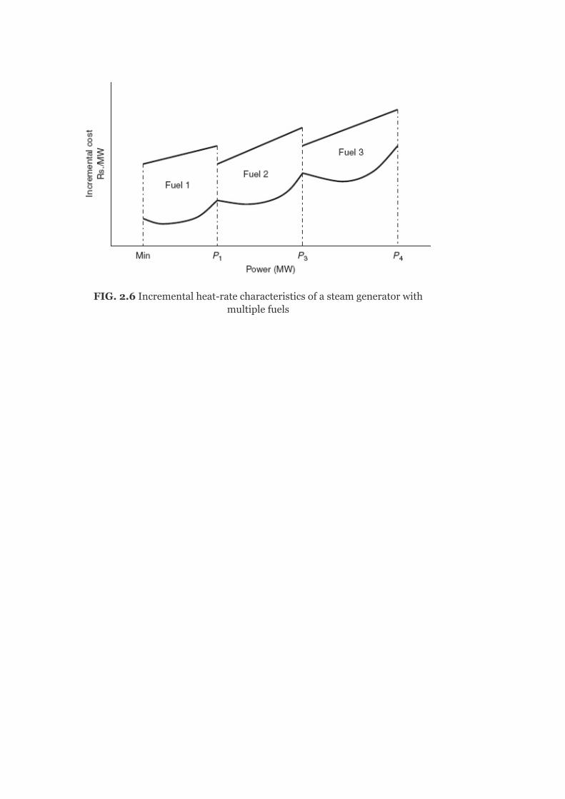
FIG.2.6Incrementalheat-ratecharacteristicsofasteamgeneratorwithmultiplefuels

FIG.2.7(a)Atypicalsystemofahydro-powerplant;(b)Input–outputcharacteristicsofahydro-unit;(c)Effectofwaterheadonwaterdischarge;(d)Incrementalwaterratecharacteristicofahydro-unit;(e)Incremental
costcharacteristicofahydro-unit
FromFig.2.7(b),itisobservedthatthereisalinearwaterrequirementuptotheratedloadandafterthat

greaterdischargeisneededtomeettheincreasedloaddemandsuchthattheefficiencyoftheunitdecreases.
2.12.1Effectofthewaterheadondischargeofwaterforahydro-unit
Figure2.7(c)showstheeffectofthewaterheadonwaterdischarge.Itisobservedthatwhentheheadofthewaterfalls,theinput–outputcharacteristicofahydro-powerplantmovesverticallyupwards,suchthatahigherdischargeofwaterisneededforthesamepowergeneration.Thereversewillhappenwhentheheadrises.
2.12.2incrementalwaterratecharacteristicsofhydro-units
AtypicalincrementalwaterratecharacteristicisshowninFig.2.7(d).Itcanbeobtainedfromtheinput–outputcharacteristicofahydro-unitasshowninFig.2.7(b).
FromFig.2.7(d),itisseenthatthecurveisastraighthorizontallineuptotheratedloadindicatingaconstantslopeandafterthatitrisesrapidly.Whentheloadincreasesmorethantherated,moreunitswillbeputintooperation(service).
2.12.3Incrementalcostcharacteristicofahydro-unit
Actually,theinputofahydro-plantisnotdependentonthecost.Buttheinputwaterflowcostsareduetothecapacityofstorage,requirementofwaterfortheagriculturalpurpose,andrunningoftheplantduringoffseason(dryseason).Theartificialstoragerequirement(i.e.,costofconstructionofdams,canals,conduits,gates,penstocks,etc.)imposesacostonthewaterinputtotheturbineaswellasthecostofcontrolonthewateroutputfromtheturbineduetoagriculturalneed.
TheincrementalcostcharacteristiccanbeobtainedfromtheincrementalwaterratecharacteristicbymultiplyingitwithcostofwaterinRs./m .
3
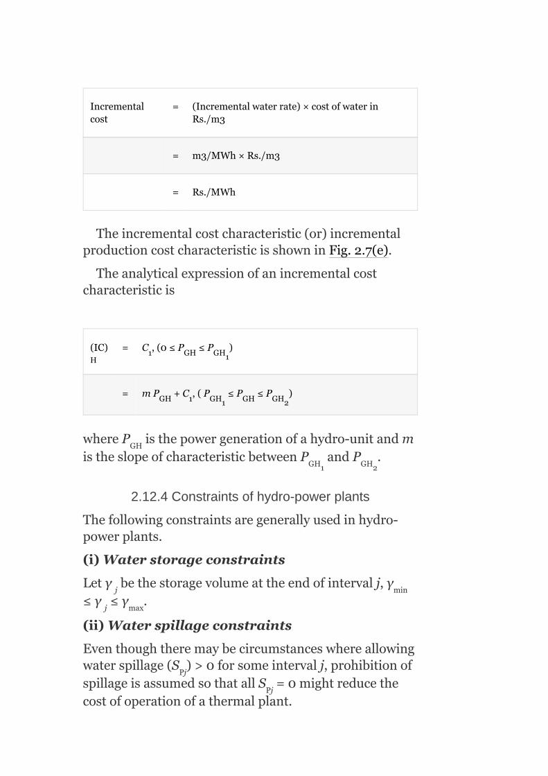
Incrementalcost
= (Incrementalwaterrate)×costofwaterinRs./m3
= m3/MWh×Rs./m3
= Rs./MWh
Theincrementalcostcharacteristic(or)incrementalproductioncostcharacteristicisshowninFig.2.7(e).
Theanalyticalexpressionofanincrementalcostcharacteristicis
(IC) = C ,(0≤P ≤P )
= mP +C ,(P ≤P ≤P )
whereP isthepowergenerationofahydro-unitandmistheslopeofcharacteristicbetweenP andP .
2.12.4Constraintsofhydro-powerplants
Thefollowingconstraintsaregenerallyusedinhydro-powerplants.
(i)Waterstorageconstraints
Letγ bethestoragevolumeattheendofintervalj,γ≤γ ≤γ .
(ii)Waterspillageconstraints
Eventhoughtheremaybecircumstanceswhereallowingwaterspillage(S )>0forsomeintervalj,prohibitionofspillageisassumedsothatallS =0mightreducethecostofoperationofathermalplant.
H1 GH GH1
GH 1 GH1 GH GH2
GH
GH1 GH2
j min
j max
Pj
Pj

(iii)Waterdischargeflowconstraints
Thedischargeflowmaybeconstrainedbothinrateandintotalas
2.13INCREMENTALPRODUCTIONCOSTS
TheincrementalproductioncostofagivenunitismadeupoftheIFCplustheincrementalcostofitemssuchaslabor,supplies,maintenance,andwater.
Itisnecessaryforarigorousanalysistobeabletoexpressthecostsoftheseproductionitemsasafunctionofoutput.However,nomethodsarepresentlyavailableforexpressingthecostoflabor,supplies,ormaintenanceaccuratelyasafunctionofoutput.
Arbitrarymethodsofdeterminingtheincrementalcostsoflabor,supplies,andmaintenanceareused,thecommonestofwhichistoassumethesecoststobeafixedpercentageoftheIFCs.
Inmanysystems,forpurposesofschedulinggeneration,theincrementalproductioncostisassumedtobeequaltotheIFC.
2.14CLASSICALMETHODSFORECONOMICOPERATIONOFSYSTEMPLANTS
Previously,thefollowingthumbruleswereadoptedforschedulingthegenerationamongvariousunitsofgeneratorsinapowerstation:
1. Baseloadingtocapacity:Theturbo-generatorsweresuccessivelyloadedtotheirratedcapacitiesintheorderoftheirefficiencies.
2. Baseloadingtomostefficientload:Theturbo-generatorunitsweresuccessivelyloadedtotheirmostefficientloadsintheincreasingorderoftheirheatrates.
3. Proportionalloadingtocapacity:Theturbo-generatorsetswereloadedinproportiontotheirratedcapacitieswithoutconsiderationtotheirperformancecharacteristics.
Iftheincrementalgenerationcostsaresubstantiallyconstantovertherangeofoperation,thenwithoutconsideringreserveandtransmissionlinelimitations,themosteconomicwayofschedulinggenerationistoloadeachunitinthesystemtoitsratedcapacityintheorderofthehighestincrementalefficiency.Thismethod,knownasthemeritorderapproachtoeconomicloaddispatching,requiresthepreparationoftheorderofmerittablesbasedupontheincrementalefficiencies,whichshouldbeupdatedregularlytoreflectthechangesinfuelcosts,plantcycleefficiency,plantavailability,etc.Activepowerschedulingtheninvolveslookingintothetableswithouttheneedforanycalculations.
2.15OPTIMIZATIONPROBLEM—MATHEMATICALFORMULATION(NEGLECTINGTHETRANSMISSIONLOSSES)
Anoptimizationproblemconsistsof:
1. Objectivefunction.2. Constraintequations.
2.15.1Objectivefunction
Theobjectivefunctionistominimizetheoverallcostofproductionofpowergeneration.
Costinthermalandnuclearstationsisnothingbutthecostoffuel.LetnbethenumberofunitsinthesystemandC thecostofpowergenerationofunit‘i’:
∴TotalcostC=C +C +C +…+C
i.e.,
Thecostofgenerationofeachunitinthermalpowerplantsismainlyafuelcost.Thegenerationcostdependsontheamountofrealpowergenerated,sincethereal-powergenerationisincreasedbyincreasingthefuelinput.
i
1 2 3 n

Thegenerationofreactivepowerhasnegligibleinfluenceonthecostofgeneration,sinceitiscontrolledbythefieldcurrent.
Therefore,thegenerationcostofthei unitisafunctionofreal-powergenerationofthatunitandhencethetotalcostisexpressedas
i.e.,C=C (P )+C (P )+C (P )+…+C (P )
Thisobjectivefunctionconsistsofthesummationofthetermsinwhicheachtermisafunctionofseparateindependentvariables.Thistypeofobjectivefunctioniscalledaseparableobjectivefunction.
Theoptimizationproblemistoallocatethetotalloaddemand(P )amongthevariousgeneratingunits,suchthatthecostofgenerationisminimizedandsatisfiesthefollowingconstraints.
2.15.2Constraintequations
Theeconomicpowersystemoperationneedstosatisfythefollowingtypesofconstraints.
(1)Equalityconstraints
Thesumofreal-powergenerationofallthevariousunitsmustalwaysbeequaltothetotalreal-powerdemandonthesystem.
i.e.,
or
1 G1 2 G2 3 G3 n Gn
D
th

where totalreal-powergenerationandP isthe
totalreal-powerdemand.Equation(2.2)isknownasthereal-powerbalanceequationwhenlossesareneglected.
(2)Inequalityconstraints
Theseconstraintsareconsideredinaneconomicpowersystemoperationduetothephysicalandoperationallimitationsoftheunitsandcomponents.
Theinequalityconstraintsareclassifiedas:
(a)Accordingtothenature
Accordingtonature,theinequalityconstraintsareclassifiedfurtherintothefollowingconstraints:
1. Hard-typeconstraints:Theseconstraintsaredefiniteandspecificinnature.Noflexibilitywilltakeplaceinviolatingthesetypesofconstraints.
e.g.,:Therangeoftappingofanon-loadtap-changingtransformer.
2. Soft-typeconstraints:Theseconstraintshavesomeflexibilitywiththeminviolating.
e.g.,:Magnitudesofnodevoltagesandthephaseanglebetweenthem.
Somepenaltiesareintroducedfortheviolationsofthesetypesofconstraints.
(b)Accordingtopowersystemparameters
Accordingtopowersystemparameters,inequalityconstraintsareclassifiedfurtherintothefollowingcategories.
1. Outputpowerconstraints:Eachgeneratingunitshouldnotoperateaboveitsratingorbelowsomeminimumgeneration.Thisminimumvalueofreal-powergenerationisdeterminedfromthetechnicalfeasibility.
P ≤P ≤P (2.3a)
Similarly,thelimitsmayalsohavetobeconsideredovertherangeofreactive-powercapabilitiesofthegeneratorunitrequiringthat:
D
Gi(min) Gi Gi(max)

Q ≤Q ≤Q fori=1,2,3,…,n(2.3b)
andtheconstraintP +Q ≤(S ) mustbesatisfied,whereS
istheratingofthegeneratingunitforlimitingtheoverheatingofstator.
2. Voltagemagnitudeandphase-angleconstraints:Formaintainingbettervoltageprofileandlimitingoverloadings,itisessentialthatthebusvoltagemagnitudesandphaseanglesatvariousbusesshouldvarywithinthelimits.Thesecanbeillustratedbyimposingtheinequalityconstraintsonbusvoltagemagnitudesandtheirphaseangles.
V ≤V ≤V fori=1,2,…,n
δ ≤δ ≤δ fori=1,2,…,n
wherej=1,2,…,m,j≠i,nisthenumberofunits,andmthenumberofloadsconnectedtoeachunit.
3. Dynamicconstraints:Theseconstantsmayconsiderwhenfastchangesingenerationarerequiredforpickingupthesheddingdownorincreasingofloaddemand.Theseconstraintsareoftheform:
Inaddition,intermsofreactive-powergeneration,
4. Sparecapacityconstraints:Theseconstraintsarerequiredtomeetthefollowingcriteria:
1. Errorsinloadprediction.2. Theunexpectedandfastchangesinloaddemand.3. Unplannedlossofscheduledgeneration,i.e.,theforcedoutagesofoneormore
unitsonthesystem.
Thetotalpowergenerationatanytimemustbemorethanthetotalloaddemandandsystemlossesbyanamountnotlessthanaspecifiedminimumsparecapacity(P )
i.e.,P ≥(P +P )+P
whereP isthetotalpowergeneration,P +P isthetotalload
demandandsystemlosses,andP isthespecifiedminimumspare
power.
5. Branchtransfercapacityconstraints:Thermalconsiderationsmayrequirethatthetransmissionlinesbesubjectedtobranchtransfercapacityconstraints:
Gi(min) Gi Gi(max)
Gi Gi irated i
i (min) i i (max)
ij (min) ij ij (max)
SP
G D L SP
G D L
SP
2 2 2

S ≤S ≤S fori=1,2,…,n
wheren isthenumberofbranchesandS thei branchtransfer
capacityinMVA.
6. Transformertapposition/settingsconstraints:Thetappositions(or)settingsofatransformer(T)mustliewithintheavailablerange:
T ≤T≤T
Foranautotransformer,thetapsettingconstraintsare:
0≤T≤1
wheretheminimumtapsettingiszeroandthemaximumtapsettingis1.
Fora2-windingtransformer,tapsettingconstraintsare0≤T≤K,whereKisthetransformation(turns)ratio.
Foraphase-shiftingtransformer,theconstraintsareofthetype:
θ ≤θ ≤θ
whereθ isthephaseshiftobtainedfromthei transformer.
7. Transmissionlineconstraints:Theactiveandreactivepowerflowingthroughthetransmissionlineislimitedbythethermalcapabilityofthecircuit.
TC ≤TC
whereTC isthemaximumloadingcapacityofthei line.
8. Securityconstraints:Powersystemsecurityandpowerflowsbetweencertainimportantbusesarealsoconsideredforthesolutionofanoptimizationproblem.
Ifthesystemisoperatingsatisfactorily,thereisanoutagethatmaybescheduledorforced,butsomeoftheconstraintsarenaturallyviolated.Itmaybementionedthatconsiderationofeachandeverypossiblebranchforanoutagewillnotbeafeasibleproportion.Whenalargesystemisunderstudy,thenetworksecurityismaintainedsuchthatcomputationistobemadewiththeoutageofonebranchatonetimeandthenthecomputationofagroupofbranchesorunitsatanothertime.
So,theoptimizationproblemwasstatedearlierasminimizingthecostfunction(C)givenbyEquation(2.1),whichissubjectedtotheequalityandinequalityconstraint(Equations(2.2)and(2.3)).
i (min) bi i (max) b
b bi
(min) (max)
i (min) i i (max)
i
i i (max)
i (max)
th
th
th

2.16MATHEMATICALDETERMINATIONOFOPTIMALALLOCATIONOFTOTALLOADAMONGDIFFERENTUNITS
Considerapowerstationhaving‘n’numberofunits.Letusassumethateachunitdoesnotviolatetheinequalityconstraintsandletthetransmissionlossesbeneglected.
Thecostofproductionofelectricalenergy
whereC isthecostfunctionofthei unit.
Thiscostistobeminimizedsubjecttotheequalityconstraintgivenby
whereP isthereal-powergenerationofthei unit.
Thisisaconstrainedoptimizationproblem.
Togetthesolutionfortheoptimizationproblem,wewilldefineanobjectivefunctionbyaugmentingEquation(2.4)withanequalityconstraint(Equation(2.5))throughtheLagrangianmultiplier(λ)as
Theconditionforoptimalityofsuchanaugmentedobjectivefunctionis
i
Gi
th
th

FromEquation(2.6),
SinceP isaconstantandisanuncontrolledvariable,
SincetheexpressionofCisinavariableseparableform,i.e.,theoverallcostisthesummationofcostofeachgeneratingunit,whichisafunctionofreal-powergenerationofthatunitonly:
D

InEquation(2.8),eachofthesederivativesrepresentstheindividualincrementalcostofeveryunit.Hence,theconditionfortheoptimalallocationofthetotalloadamongthevariousunits,whenneglectingthetransmissionlosses,isthattheincrementalcostsoftheindividualunitsareequal.Itacalledaco-ordinationequation.
Assumethatoneunitisoperatingatahigherincrementalcostthantheotherunits.Iftheoutputpowerofthatunitisreducedandtransferredtounitswithlowerincrementaloperatingcosts,thenthetotaloperatingcostdecreases.Thatis,reducingtheoutputoftheunitwiththehigherincrementalcostresultsinamoredecreaseincostthantheincreaseincostofaddingthesameoutputreductiontounitswithlowerincrementalcosts.Therefore,allunitsmustrunwithsameincrementaloperatingcosts.
Aftergettingtheoptimalsolution,inthecasethatthegenerationofanyoneunitisbelowitsminimumcapacityoraboveitsmaximumcapacity,thenitsgenerationbecomesthecorrespondinglimit.Forexample,ifthegenerationofanyunitviolatestheminimumlimit,thenthegenerationofthatunitissetatitsminimumspecifiedlimitandviceversa.Then,theremainingdemandis

allocatedamongtheremainingunitsasfortheabovecriteria.
Inthesolutionofanoptimizationproblemwithoutconsideringthetransmissionlosses,wemakeuseofequalincrementalcosts,i.e.,themachinesaresoloadedthattheincrementalcostofproductionofeachmachineisthesame.
Itcanbeseenthatthismethoddoesnotsensethelocationofchangesintheloads.Aslongasthetotalloadisfixed,irrespectiveofthelocationofloads,thesolutionwillalwaysbethesameand,infact,forthisreasonthesolutionmaybefeasibleinthesensethattheloadvoltagesmaynotbewithinspecifiedlimits.Thereactive-powergenerationrequiredmayalsonotbewithinlimits.
2.17COMPUTATIONALMETHODS
Differenttypesofcomputationalmethodsforsolvingtheaboveoptimizationproblemareasfollows:
1. Analyticalmethod.2. Graphicalmethod.3. Usingadigitalcomputer.
Themethodtobeadopteddependsonthefollowing:
1. ThemathematicalequationrepresentingtheIFCofeachunit,whichcanbedeterminedfromthecostofgenerationofthatunit.
Thecostofthei unitisgivenby
∴TheIFCofthei unit
(IC) =a P +b (Linearmodel)(2.10)
wherea istheslopeoftheIFCcurveandb theinterceptoftheIFC
curve.
2. Numberofunits(n).3. Needtorepresentthediscontinuities(ifanyduetosteamvalve
opening)intheIFCcurve.
i i Gi i
i i
th
th

2.17.1Analyticalmethod
Whenthenumberofunitsaresmall(either2or3),incrementalcostcurvesareapproximatedasalinearorquadraticvariationandnodiscontinuitiesarepresentintheincrementalcostcurves.
WeknowthattheIFCofthei unit
Foranoptimalsolution,theIFCofalltheunitsmustbethesame(neglectingthetransmissionlosses):
Theanalyticalmethodconsistsofthefollowingsteps:
1. Chooseaparticularvalueofλ.
i.e.,λ=a P +b
2. Compute
3. Findtotalreal-powergeneration foralli=1,2,…,n.
4. Repeattheprocedurefromstep(ii)fordifferentvaluesofλ.5. Plotagraphbetweentotalpowergenerationandλ.6. Foragivenpowerdemand(P ),estimatethevalueofλfromFig.2.8.
Thatvalueofλwillbetheoptimalsolutionforoptimizationproblem.
2.17.2Graphicalmethod
Forobtainingthesolutioninthismethod,thefollowingprocedureisrequired:
i G1 i
D
th

1. (i)Considertheincrementalcostcurvesofallunits:
i.e.,(IC) =a P +b foralli=1,2,…,n
andthetotalloaddemandP isgiven.
FIG.2.8Estimationofoptimumvalueofλ—analyticalmethod
FIG.2.9Graphicalmethod
2. Foreachunit,drawagraphbetweenP and(IC)asshowninFig.2.9.
3. Chooseaparticularvalueofλand∆λ.4. Determinethecorrespondingreal-powergenerationsofallunits:
i.e.,P ,P ,…,P
i i Gi i
D
G
G1 G2 Gn

5. Computethetotalreal-powergeneration
6. Checkthereal-powerbalanceofEquation(2)asfollows:
1. If ,thentheλchosenwillbetheoptimalsolutionand
incrementalcostsofallunitsbecomeequal.
2. If ,increaseλby∆λandrepeattheprocedurefromstep(iv).
3. If ,decreaseλby∆λandrepeattheprocedurefromstep(iv).
7. Thisprocessisrepeateduntil iswithinaspecified
tolerance(ε),say1MW.
2.17.3Solutionbyusingadigitalcomputer
Formorenumberofunits,theλ-iterativemethodismoreaccurateandincrementalcostcurvesofallunitsaretobestoredinmemory.
informationabouttheIFCcurvesisgivenforallunits:
i.e.,λ=(IC) =a P +b
or (whenlossesareneglected)
i i Gi i

andsoon.
∴P =α +β (IC) +γ (IC ) +…(2.14)
fori=1,2,…,n
Thenumberoftermsincludeddependsonthedegreeofaccuracyrequiredandcoefficientsα ,β ,andγ aretobetakenasinput.
Algorithmforλ–IterativeMethod
1. Guesstheinitialvalueofλ withtheuseofcost-curveequations.2. CalculateP ,accordingtoEquation(2.14),i.e.,P =α +β (λ ) +
γ (λ ) +…
3. Calculate
4. Checkwhether :
5. If setanewvalueforλ,i.e.,λ′=λ +∆λandrepeatfrom
step(ii)tillthetolerancevalueissatisfied.
6. If setanewvalueforλ,i.e.,λ′=λ –∆λandrepeatfrom
step(ii)tillthetolerancevalueissatisfied.7. Stop.
Example2.1:ThefuelcostfunctionsinRs./hrforthreethermalplantsaregivenby
C =400+8.4P +0.006P
C =600+8.93P +0.0042P
Gi i i i i i
i i i
G1 G1 i i i
i i
1 1 1
2 2 2
2
o
o o o
o 2
o
o
2
2
2

C =650+6.78P +0.004P
whereP ,P ,andP areinMW.Neglectinglinelossesandgeneratorlimits,determinetheoptimalschedulingofgenerationofeachloadingusingtheiterativemethod.
1. P =550MW.
2. P =820MW.
3. P =1,500MW.
Solution:
For(i)P =550MW:
3 3 3
1 2 3
D
D
D
D
2


For(ii)P =820MW:
For(iii)P =1,500MW:
GENERATINGUNIT OPTIMALGENERATION(MW)
D
D

2.18ECONOMICDISPATCHNEGLECTINGLOSSESANDINCLUDINGGENERATORLIMITS
Theoutputpowerofanygeneratorshouldneitherexceeditsratingnorshoulditbebelowthatnecessaryforthestableoperationofaboiler.Thus,thegenerationsarerestrictedtoliewithingivenminimumandmaximumlimits.Theproblemistofindtheactivepowergenerationofeachplantsuchthattheobjectivefunction(i.e.,totalproductioncost)isminimum,subjecttotheequalityconstraint,andtheinequalityconstraintsare
respectively.
ThesolutionalgorithmforthiscaseisthesameasdiscussedinSection2.17.3withminormodifications.Ifanygeneratingunitviolatestheaboveinequalityconstraints,setitsgenerationatitsrespectivelimitasgivenbelow.Inaddition,thebalanceoftheloadisthensharedbetweentheremainingunitsonthebasisofequalincrementalcost.
Thenecessaryconditionsforoptimaldispatchwhenlossesareneglected:
forP ≤P ≤PGi(min) Gi Gi(max)

forP =≤P
for≤P =≤P
Example2.2:ThefuelcostfunctionsinRs./hr.forthreethermalplantsaregivenby
C =400+8.4P , 100≤P ≤600
C =600+8.93P , 60≤P ≤300
C =650+6.78P , 300≤P ≤650
whereP ,P ,andP areinMW.Neglectinglinelossesandincludinggeneratorlimits,determinetheoptimalschedulingofgenerationofeachloadingusingtheiterativemethod.
1. P =550MW.
2. P =820MW.
3. P =1,500MW.
Solution:
For(i)P =550MW:
Gi Gi(max)
Gi Gi(min)
1 1 1
2 2 2
3 3 3
1 2 3
D
D
D
D
2
2
2


Resultsfor(i)P =550MW:
Resultsfor(ii)P =820MW:
d
d

Resultsfor(iii)P =1,500MW:d

2.19FLOWCHARTFOROBTAININGOPTIMALSCHEDULINGOFGENERATINGUNITSBYNEGLECTINGTHETRANSMISSIONLOSSES
TheoptimalschedulingofgeneratingunitsisrepresentedbytheflowchartasshowninFig.2.10.
2.20ECONOMICALLOADDISPATCH—INOTHERUNITS
Theeconomicalloaddispatchproblemhasbeensolvedforapowersystemareaconsistingoffossilfuelunits.Foranareaconsistingofamixofdifferenttypesofunits,i.e.—fossilfuelunits,nuclearunits,pumpedstoragehydro-units,hydro-units,etc.—solvingtheeconomicalloaddispatchproblemwillbecomedifferent.
2.20.1Nuclearunits
Fortheseunits,thefixedcostishighandoperatingcostsarelow.Assuch,nuclearunitsaregenerallybaseloadplantsattheirratedoutputs,i.e.,thereferencepowersettingofturbinegovernorsfornuclearunitsisheldconstantattheratedoutput.Therefore,theseunitsdonotparticipateineconomicalloaddispatch.
2.20.2Pumpedstoragehydro-units
Theseunitsareoperatedassynchronousmotorstopumpwaterduringoff-peakhours.Duringpeakloadhours,thewaterisreleasedandtheunitsareoperatedassynchronousgeneratorstosupplypower.Theeconomic

operationoftheareaisdonebypumpingduringoff-peakhourswhentheareaincrementalcost(λ)islow,andbygeneratingduringpeakloadhourswhenλishigh.Sometechniquesareavailableforincorporatingpumpedstoragehydro-unitsintotheeconomicdispatchoffossilunits.
2.20.3Hydro-plants
Foranareaconsistingofhydro-plantslocatedalongariver,theobjectiveoftheeconomicdispatchproblembecomesmaximizingthepowergenerationovertheyearlywatercycleratherthanminimizingthetotaloperatingcosts.Forthesetypesofplants,reservoirsareprovidedtostorethewaterduringrainyseasons.Therearesomeconstraintsonthelevelofwatersuchasflowofriver,irrigation,etc.Optimalstrategiesareavailableforco-ordinatingtheoutputsofsuchplantsalongariver.Therearealsosomeeconomicdispatchstrategiesavailableforthemixoffossilfuelandhydro-systems.
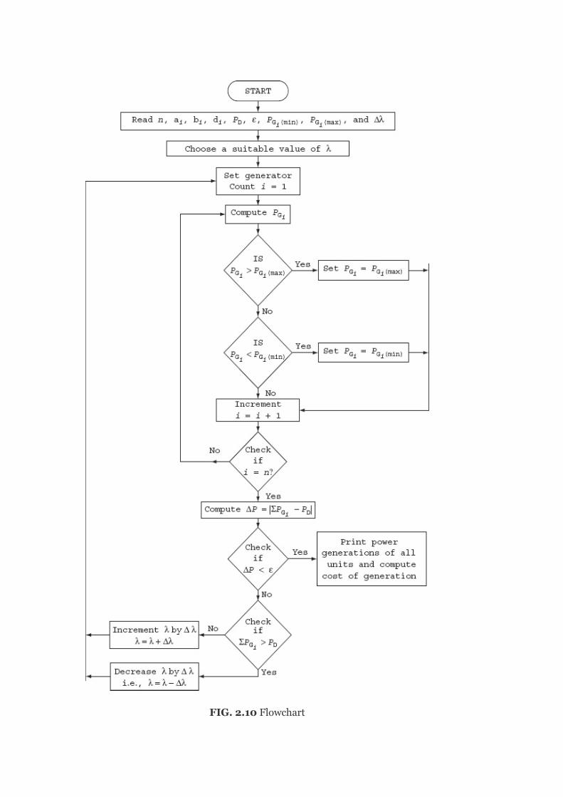
FIG.2.10Flowchart
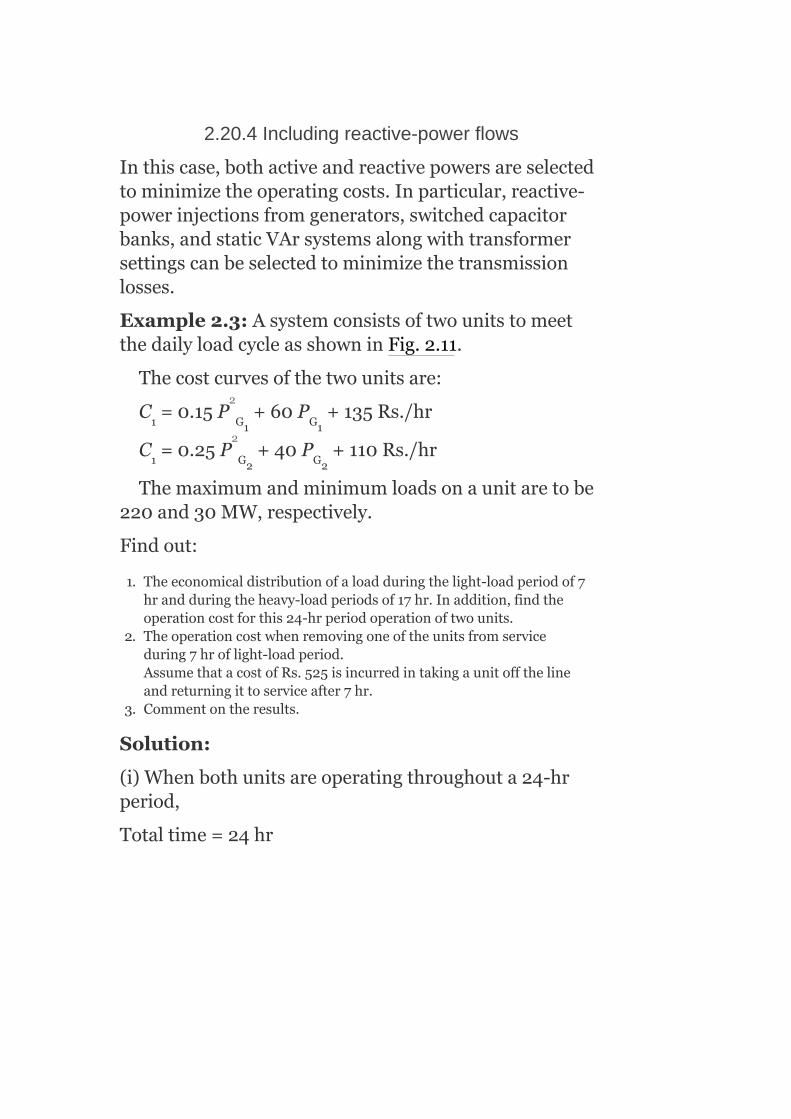
2.20.4Includingreactive-powerflows
Inthiscase,bothactiveandreactivepowersareselectedtominimizetheoperatingcosts.Inparticular,reactive-powerinjectionsfromgenerators,switchedcapacitorbanks,andstaticVArsystemsalongwithtransformersettingscanbeselectedtominimizethetransmissionlosses.
Example2.3:AsystemconsistsoftwounitstomeetthedailyloadcycleasshowninFig.2.11.
Thecostcurvesofthetwounitsare:
C =0.15P +60P +135Rs./hr
C =0.25P +40P +110Rs./hr
Themaximumandminimumloadsonaunitaretobe220and30MW,respectively.
Findout:
1. Theeconomicaldistributionofaloadduringthelight-loadperiodof7hrandduringtheheavy-loadperiodsof17hr.Inaddition,findtheoperationcostforthis24-hrperiodoperationoftwounits.
2. Theoperationcostwhenremovingoneoftheunitsfromserviceduring7hroflight-loadperiod.AssumethatacostofRs.525isincurredintakingaunitoffthelineandreturningittoserviceafter7hr.
3. Commentontheresults.
Solution:
(i)Whenbothunitsareoperatingthroughouta24-hrperiod,
Totaltime=24hr
1 G1 G1
1 G2 G2
2
2

FIG.2.11Dailyloadcycle
Totalload=84MWfor7hr+400MWfor17hr
(from4A.M.to11A.M.)(from11A.M.to4A.M.)
Foraheavyloadof400MW:
Heavy-loadperiod,t =17hr
load,P =400MW
Wehavetofindtheoptimalschedulingoftwounitswiththisload.
Wehavethecostcurvesoftwounits:
ForUnit1:
C =0.15P +60P +135Rs./hr
Incrementalfuelcost,
=0.3P +60Rs./MWh
ForUnit2:
C =0.25P +40P +110Rs./hr
h
Dh
1 G1 G1
G1
2 G2 G2
2
2
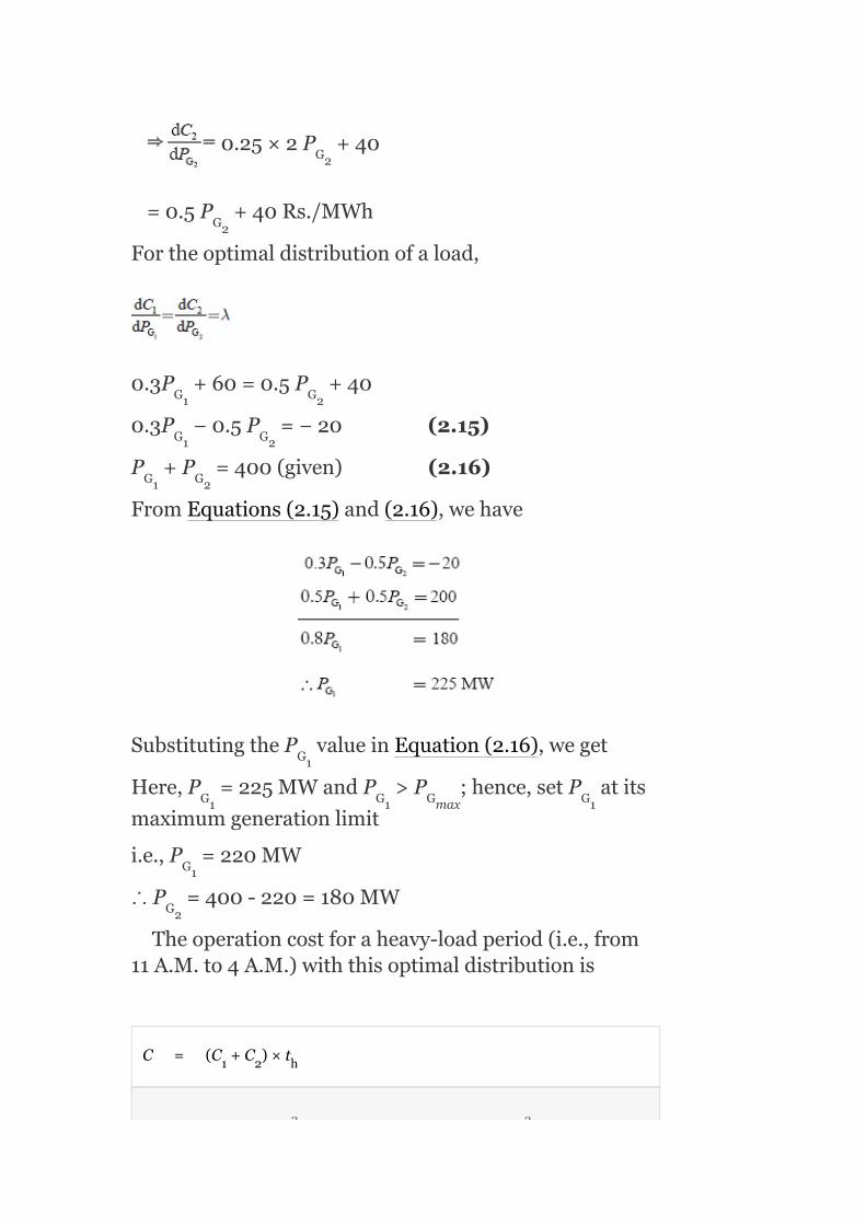
0.25×2P +40
=0.5P +40Rs./MWh
Fortheoptimaldistributionofaload,
0.3P +60=0.5P +40
0.3P −0.5P =−20(2.15)
P +P =400(given)(2.16)
FromEquations(2.15)and(2.16),wehave
SubstitutingtheP valueinEquation(2.16),weget
Here,P =225MWandP >P ;hence,setP atits
maximumgenerationlimit
i.e.,P =220MW
∴P =400-220=180MW
Theoperationcostforaheavy-loadperiod(i.e.,from11A.M.to4A.M.)withthisoptimaldistributionis
C = (C +C )×t
G2
G2
G1 G2
G1 G2
G1 G2
G1
G1 G1 Gmax G1
G1
G2
1 2 h
2 2

= [(0.15×220 +60×220+135)+(0.25×180 +40×180+110)]×17
= Rs.6,12,085
Foralightloadof84MW:
Period,t =7hr
load,P =84MW
Foroptimalloadsharing,
i.e.,0.3P +60=0.5P +40
0.3P −0.5P =−20(2.17)
P +P =84(2.18)
BysolvingEquations(2.17)and(2.18),weget
P =27.5MW;P =56.5MW
Here,P =27.5MW<P =30MW
Therefore,theloadsharedbyUnit-1issettoP =30
MWandP =84-30=54MW.
Theoperationcostforalight-loadperiod(i.e.,from4A.M.to11A.M.)withthisoptimaldistribution:
=[(0.15)×(30) +60×30+135)+(0.25×54 +40×54+110)]×7
=Rs.35,483
Hence,thetotalfuelcostwhenboththeunitsareoperatingthroughoutthe24-hrperiod
=Rs.(6,12,085+35,483)
=Rs.6,47,568
(ii)Ifonlyoneoftheunitsisrunduringthelight-loadperiod,
i.e.,Period,t =7hr
l
D
G1 G2
G1 G2
G1 G2
G1 G2
G1 Gmin
G1
G2
l
2 2
2 2

load,P =84MW
WhenUnit-1istoberun,
Costofoperation = C ×t
= [0.15×84 +60×84+135]×7
= Rs43,633.80
WhenUnit-2istoberun,
Costofoperation = C ×t
= [0.15×84 +40×84+110]×7
= Rs36,638
Fromtheabove,itisverifiedthatitiseconomicaltorunUnit-2duringalight-loadperiodandtoputoffUnit-1fromservice.
TheoperatingcostwithonlyUnit-2inoperation=Rs.36,638
Theoperatingcostfortheoperationofbothunitsinaheavy-loadperiodandUnit-2onlyinalight-loadperiod=Rs.(6,47,568+36,638)=Rs.6,48,723
Inaddition,giventhatacostofRs.525isincurredintakingaunitoffthelineandreturningittoserviceafter7hr,
Totaloperatingcost=operatingcost+start-upcost=Rs.(6,48,723+525)=Rs.6,49,248.
(iii)Totaloperatingcostfor(i)=Rs.6,47,568
D
1 1
2 1
2
2

Totaloperatingcostfor(ii)=Rs.6,49,248
Itisconcludedthatthetotaloperatingcostwhenbothunitsrunningthroughout24-hrperiodsislessthantheoperatingcostwhenoneoftheunitsisputofffromthelineandreturnedtotheserviceafteralight-loadperiod.Hence,itiseconomicaltorunbothunitsthroughout24hr.
Example2.4:Aconstantloadof400MWissuppliedbytwo210-MWgenerators1and2,forwhichthefuelcostcharacteristicsaregivenasbelow:
C =0.05P +20P +30.0Rs./hr
C =0.06P +15P +40.0Rs./hr
Thereal-powergenerationsofunitsP andP arein
MW.Determine:(i)themosteconomicalloadsharingbetweenthegenerators.(ii)ThesavinginRs./daytherebyobtainedcomparedtotheequalloadsharingbetweentwogenerators.
Solution:
TheIFCsare
=0.10P +20.0
=0.12P +15.0
(i)Foroptimalsharingofload,theconditionis
0.10P +20.0=0.12P +15.0
1 G1 G1
2 G2 G1
G1 G2
G1
G2
G1 G1
2
2

or 0.10P −0.12P =15.0−20.0
or 0.10P −0.12P =−5.0 (12.19)
Given:P +P =400 (12.20)
SolvingEquations(2.19)and(2.20),wehave
SubstitutingP =195.45MWinEquation(2.20),weget
P =400–195.45=204.55MW
Theloadof400MWiseconomicallysharedbythetwogeneratorswithP =195.45MWandP =204.55MW.
(ii)Whentheloadissharedbetweenthegeneratorsequally,then
P =200MWandP =200MW
Withthisequalsharingofload,theP valueis
increasedfrom195.45witheconomicalsharingto200MW.
∴Increaseinoperationcostofgenerator1
G1 G1
G1 G1
G1 G2
G1
G2
G1 G2
G1 G2
G1

TheP valueisdecreasedfrom204.55to200MW.
∴DecreaseinoperationcostofGenerator2
∴Savingincost=180.96–178.69=2.27Rs./hr
Thesavingincostperday=2.27×24
=56.75Rs./day
Example2.5:ConsiderthefollowingthreeICcurves:
P = −100+50(IC )+2(IC )
P = −150+60(IC )−2(IC )
P = −80+40(IC )−1.8(IC )
whereIC’sareinRs./MWhandP ’sareinMW.
Thetotalloadatacertainhourofthedayis400MW.Neglecttransmissionlossesanddevelopacomputerprogramforoptimumgenerationschedulingwithintheaccuracyof±0.05MW.
Note:AllP ’smustberealandpositive.
Solution:
α =−100, β =50, γ =2(∵Assumed ,d ,d are
neglected)
G2
G1 1 1
G2 2 2
G3 3 3
G
G
1 1 1 1 2 3
2
2
2
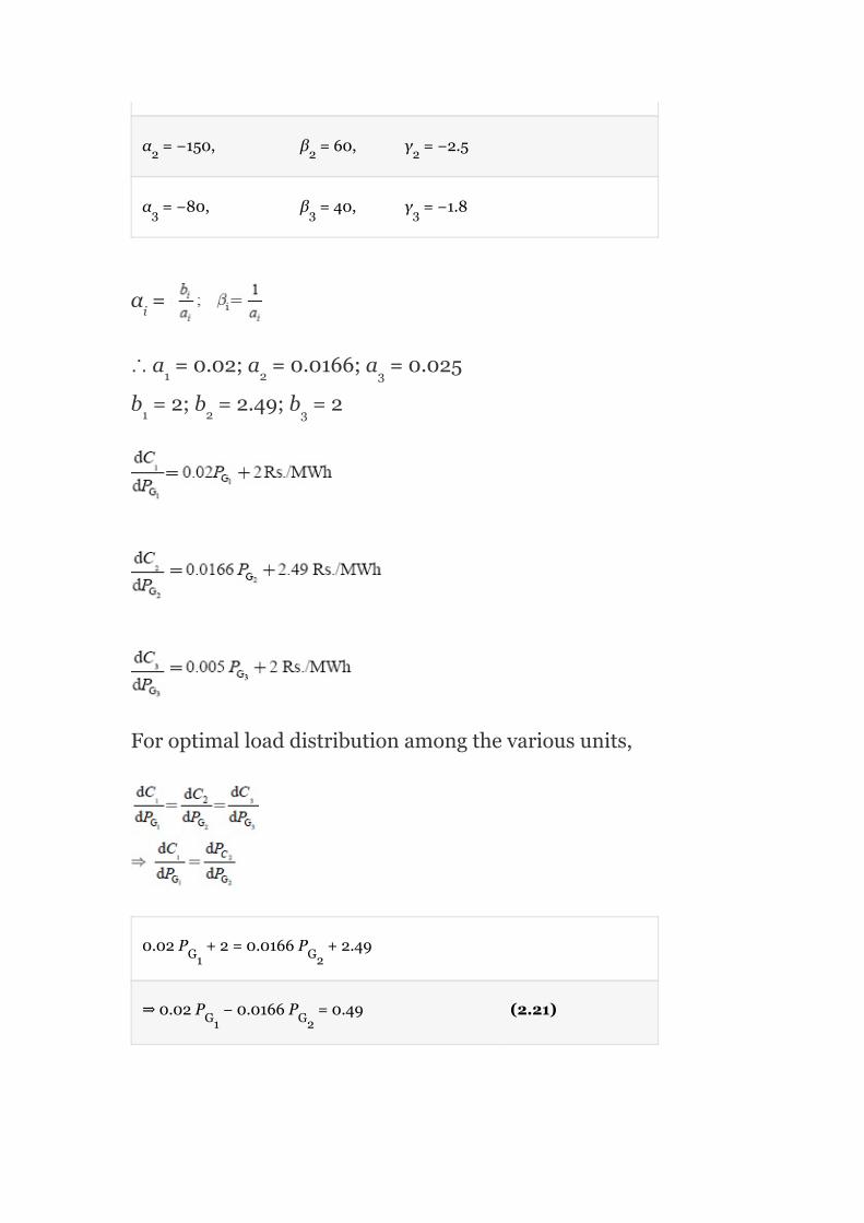
α =−150, β =60, γ =−2.5
α =−80, β =40, γ =−1.8
α =
∴a =0.02;a =0.0166;a =0.025
b =2;b =2.49;b =2
Foroptimalloaddistributionamongthevariousunits,
0.02P +2=0.0166P +2.49
⇒0.02P −0.0166P =0.49 (2.21)
2 2 2
3 3 3
i
1 2 3
1 2 3
G1 G2
G1 G2

0.0166P +2.49=0.025P +2
0.0166P −0.025P =−0.49 (2.22)
0.02P +2=0.025P +2
0.02P −0.025P =0(2.23)
Given:P +P +P =400(2.24)
orP +P =400−P (2.25)
SolvingEquations(2.22)and(2.25),wehave
0.0166P +0.0416P =7.13(2.26)
SolvingEquations(2.23)and(2.26),weget
G2 G3
G2 G3
G1 G3
G1 G3
G1 G2 G3
G2 G3 G1
G1 G3

SubstitutingP = 14.35MWin(2.26),weget
P = 142.9375MW
SubstitutingP = 142.9375MWandP =114.35MW
in(2.25),weget
P = 142.93175MW
Therefore,foroptimalgeneration,thethreeunitsmustshareatotalloadof400MWasfollows:
Costofgenerationof142.9375MWbyUnit-1
(C )= (142.9375) +2(142.9375)
C =490.186Rs./MWh
Similarly,
andC = ×0.025×(114.35) +(2×114.35)
=392.149Rs./MWh
Totalcostofgenerationof400MWwitheconomicalloadsharing
C=C +C +C
=490.186+525.359+392.149
=1,407.694Rs./MWh
G3
G1
G1 G3
G2
1
1
3
1 2 3
2
2

Costperday=1,407.694×24
=Rs.33,784.656/day
Totalcostperdaywithanequaldistributionofload
=1,412.838×24
=Rs.33,908.112/day
∴Savingincost=Rs.33,908.112–33,784.856=Rs.123.256/day
Example2.6:Thefuelcostoftwounitsaregivenby
C =C (P )=1.0+25P +0.2P Rs/hr
C =C (P )=1.5+35P +0.2P Rs/hr
Ifthetotaldemandonthegeneratorsis200MW,findtheeconomicloadschedulingofthetwounits.
Solution:
Theconditionforeconomicloadschedulingwhenneglectingthetransmissionlossesis
Foreconomicalloaddispatch,
1 1 G1 G1 G1
2 2 G2 G2 G2
2
2
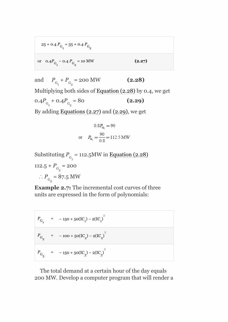
25+0.4P =35+0.4P
or0.4P −0.4P =10MW (2.27)
andP +P =200MW(2.28)
MultiplyingbothsidesofEquation(2.28)by0.4,weget
0.4P +0.4P =80(2.29)
ByaddingEquations(2.27)and(2.29),weget
SubstitutingP =112.5MWinEquation(2.28)
112.5+P =200
∴P =87.5MW
Example2.7:Theincrementalcostcurvesofthreeunitsareexpressedintheformofpolynomials:
P = −150+50(IC )−2(IC )
P = −100+50(IC )−2(IC )
P = −150+50(IC )−2(IC )
Thetotaldemandatacertainhourofthedayequals200MW.Developacomputerprogramthatwillrendera
G1 G2
G1 G2
G1 G2
G1 G2
G1
G2
G2
G1 1 1
G2 2 2
G3 3 3
2
2
2

solutionfortheoptimumallocationofloadamongthreeunits.
Solution:
Step1:Assumeλ =10.
Step2:ComputeP correspondingtoλ ,i=1,2,3.
P =−150+50λ −2(λ ) =−150+50(10)−2(100)=
150MW
P =−100+50λ −2(λ ) =−100+50(10)−2(100)=
200MW
P =−150+50λ −2(λ ) =−150+50(10)−2(100)=
150MW
Step3:Compute :
i.e.,P +P +P =500MW
Step4:Checkif :
Wefind
i.e.,500>200
Step5:ReduceλbyΔλ=3:
i.e.,λ′=λ –Δλ=10-3=7
Step6:NowfindthegenerationP ,andP
Step7:Gotostep4.
Byrepeatingtheaboveprocedure,thefollowingresultsareobtainedandtheaboveequationsconvergeatλ=5
G1
G1
G2
G3
G1 G2 G3
G ,P1 G2G3
o
(o) o
(0) o o 2
(0) o o 2
(0) o o 2
o o o
o
11
1

Example2.8:Twounitseachof200MWinathermalpowerplantareoperatingallthetimethroughouttheyear.Themaximumandminimumloadoneachunitis200and50MW,respectively.Theincrementalfuelcharacteristicsforthetwounitsaregivenas
Ifthetotalloadvariesbetween100and400MW,findtheIFCandallocationofloadbetweentwounitsforminimumfuelcostforvarioustotalloads.
Solution:
Fortheminimumloadof100MW,
P ==50MW,P =50MWG1 G2

FromEquations(2.30)and(2.31),itisnotedthatatatotalminimumloadof100MW,Unit-1isoperatingatahigherIFCthanUnit-2.Therefore,additionalloadonUnit-2shouldbeincreasedtill(IC) =λ=19andatthatpoint,
13+0.1P =19
∴P =60
Hence,thetotalloadbeingdeliveredatequalincrementalcostsof19Rs./MWhis110MW,i.e.,P =
50andP =60.
Goonincreasingtheloadoneachunitsothattheunitsoperateatthesameincrementalcost,andtheseoperatingconditionsarefoundbyassumingvariousvaluesofλandbycalculatingtheoutputforeachunit.
Example2.9:DeterminethesavinginfuelcostinRs./hrfortheeconomicdistributionofthetotalloadof100MWbetweentwounitsoftheplantasgiveninExample2.8.Comparewithequaldistributionofthesametotalload.
Solution:
2
G2
G2
G1
G2
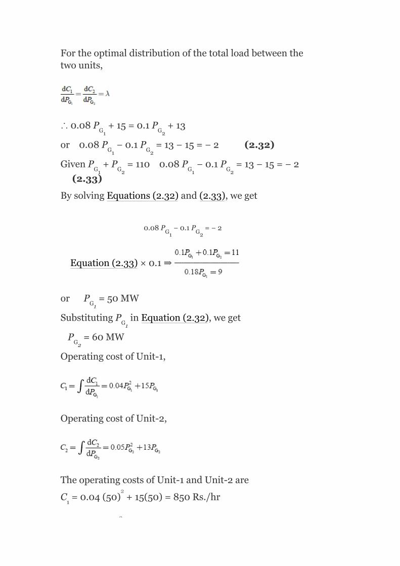
Fortheoptimaldistributionofthetotalloadbetweenthetwounits,
∴0.08P +15=0.1P +13
or0.08P −0.1P =13−15=−2(2.32)
GivenP +P =1100.08P −0.1P =13−15=−2
(2.33)
BysolvingEquations(2.32)and(2.33),weget
0.08P −0.1P =−2
Equation(2.33)×0.1⇒
orP =50MW
SubstitutingP inEquation(2.32),weget
P =60MW
OperatingcostofUnit-1,
OperatingcostofUnit-2,
TheoperatingcostsofUnit-1andUnit-2are
C =0.04(50) +15(50)=850Rs./hr
G1 G2
G1 G2
G1 G2 G1 G2
G1 G2
G1
G1
G2
1
2
2

C =0.05(60) +13(60)=960Rs./hr
Fortheequaldistributionofload⇒P =55MWandP
=55MW.
TheoperatingcostsofUnit-1andUnit-2are
C =0.04(55) +15(55)=946Rs./hr
C =0.05(55) +13(55)=866.25Rs./hr
TheincreaseincostforUnit-1whenthedeliveringpowerincreasesfrom50to55MWis946–850=96Rs./hrandforUnit-2decreasesincostduetodecreaseinpowergenerationfrom60to55MWis960–866.25=–93.75Rs./hr.
∴Savingincost=96–93.75=3.75Rs./hr.
Example2.10:Threepowerplantsofatotalcapacityof500MWarescheduledforoperationtosupplyatotalsystemloadof350MW.Findtheoptimumloadschedulingiftheplantshavethefollowingincrementalcostcharacteristicsandthegeneratorconstraints:
Solution:
Foreconomicloadschedulingamongthepowerplants,thenecessaryconditionis
2
G1 G2
1
2
2
2
2

Forthreeplants,
Giventotalload=P +P +P =350MW
(2.34)
40+0.25P =50+0.30P =20+0.20P =λ
(2.35)
⇒40+0.25P =50+0.30P
or0.25P −0.30P =50−40=10(2.36)
and40+0.25P =20+0.2P
or0.25P −0.2P =20−40=−20(2.37)
FromEquation(2.36),wehave
SubstitutingEquation(2.38)inEquation(2.34)
P +0.833P −33.33+P =350
or1.833P +P =383.33(2.39)
SolvingEquations(2.37)and(2.39)
G1 G2 G3
G1 G2 G3
G1 G2
G1 G1
G1 G1
G1 G1
G1 G1 G3
G1 G3

SubstitutingthevalueofP inEquation(2.39),
1.833×91.98+P =383.33G3
orP =214.73MW
SubstitutingthevaluesofP andP inEquation(2.34),
weget
91.98+P +214.73=350
orP =43.29MW
∴Foreconomicschedulingoftheload,thegenerationsofthreeplantsmustbe
P =91.98MW,P =43.29MW,andP =214.73MW
Example2.11:Thefuelcostoftwounitsaregivenby
C =0.1P =25P +1.6Rs./hr
C =0.1P +32P +2.1Rs./hr
Ifthetotaldemandonthegeneratorsis250MW,findtheeconomicalloaddistributionofthetwounits.
Solution:
Given
G1
G3
G3
G1 G2
G2
G2
G1 G2 G3
1 G1 G1
2 G2 G2
2
2

Giventhetotalload,P =250MW.Foreconomicaldistributionoftotalload,theconditionis
0.2P +25=0.2P +32
or0.2P −0.2P =7(2.40)
andP +P =250(Given)(2.41)
BysolvingEquations(2.40)and(2.41),weget
2P =285
orP =142.5MW
SubstitutingtheP valueinEquation(2.41),weget
P =250−P =107.5MW
Example2.12:Aplanthastwogeneratorssupplyingtheplantbus,andneitheristooperatebelow20orabove125MW.Incrementalcostsofthetwounitsare
Foreconomicdispatch,findtheplantcostofthereceivedpowerinRs./MWh(λ)whenP +P equals:
(a)40MW,(b)100MW,and(c)225MW.
Solution:
Foreconomicoperation,
D
G1 G2
G1 G2
G1 G2
G1
G1
G1
G2 G1
G1 G2

(a)WhenP +P =40MW2(2.42)
0.15P −20=0.225P +17.5
or0.15P −0.225P =−2.5(2.43)
Equation(2.42)×0.15⇒0.15P +0.15P =6.0
(2.44)
SolvingEquations(2.43)and(2.44),weget
−0.375P =−8.5
P =22.66MW
SubstitutingP =22.66MWinEquation(2.42)
P =40−22.666
=17.34MW
0.225P +17.5=λ
or0.225(226)+17.5=λ
∴=22.59Rs./MWh
(b)WhenP +P =100MW(2.45)
Equation(2.45)×0.15⇒0.15P +0.15P =15
(2.46)
BysolvingEquations(2.43)and(2.46),weget
G1 G2
G1 G2
G1 G2
G1 G2
G2
G2
G2
G1
G2
G1 G2
G1 G1

SubstitutingtheP valueinEquation(2.45),weget
P =53.34MW
∴0.15P +20=λor0.225P +17.5=λ
0.15(53.34)+20=λorλ=0.225(46.66)+17.5
⇒λ=28Rs./MWh;λ=28Rs./MWh
(c)WhenP +P =225MW(2.47)
Equation(2.47)×0.15⇒−015P +015P =3375
(2.48)
BysolvingEquations(2.43)and(2.48),weget
SubstitutingtheP valueinEquation(2.47),weget
P =128.34MW
∴λ=0.255P +17.5
=0.225(96.66)+17.5
=39.24Rs./MWh
Example2.13:Thecostcurvesoftwogeneratorsmaybeapproximatedbysecond-degreepolynomials:
C =0.1P +20P +α
G2
G1
G1 G2
G1 G2
G1 G2
G2
G1
G2
1 G1 G1 1
2
2

C =0.1P +30P +α
whereα andα areconstants
Ifthetotaldemandonthegeneratorsis200MW,findtheoptimumgeneratorsettings.Howmanyrupeesperhourwouldyouloseifthegeneratorswereoperatedabout15%oftheoptimumsettings?
Solution:
Foreconomicoperation,
0.2P +20=0.2P +30
or0.2P +0.2P =10
orP −P =50(2.49)
andgiventhatP +P =200(2.50)
SolvingEquations(2.49)and(2.50),weget
2P =250
orP =125MW
SubstitutingtheP valueinEquation(2.50),weget
P =200–125=75MW
Ifthegeneratorswereoperatedabout15%oftheoptimumsettings,
P =125−125× =125−18.75=106.25MW
andP =75− =75−11.25=63.75MW
ThedecreaseincostforGenerator-1is
2 G2 G2 2
1 2
G1 G2
G1 G2
G1 G2
G1 G2
G1
G1
G1
G2
G1
G2
2
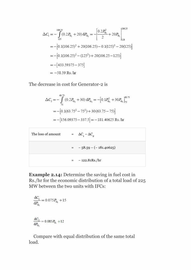
ThedecreaseincostforGenerator-2is
Thelossofamount = ΔC −ΔC
= −58.59−(−181.40625)
= −122.81Rs./hr
Example2.14:DeterminethesavinginfuelcostinRs./hrfortheeconomicdistributionofatotalloadof225MWbetweenthetwounitswithIFCs:
Comparewithequaldistributionofthesametotalload.
1 2

Solution:
Given:P +P =225MW(2.51)
Foroptimaloperation:
⇒0.075P +15=0.085P +12
or0.075P −0.085P =−3(2.52)
Equation(2.51)×0.085⇒0.085P +0.285P =225×
0.085=19.125(2.53)
BysolvingEquations(2.52)and(2.53),weget
0.16P =16.125
orP =100.78MW
SubstitutingtheP valueinEquation(2.51),weget
P =225–100.78=124.218MW
Withequaldistributionofthetotalload,
⇒P =112.5MWandP =112.5MW
TheincreaseincostforUnit-1is
ForUnit-2,
G1 G2
G1 G2
G1 G2
G1 G2
G1
G1
G1
G2
G1 G2

Thenegativesignindicatesadecreaseincost.
∴Savinginfuelcost=Rs.269.53656−258.505
=11.03156Rs./hr
Example2.15:Threeplantsofatotalcapacityof500MWarescheduledforoperationtosupplyatotalsystemloadof310MW.Evaluatetheoptimumloadschedulingiftheplantshavethefollowingcostcharacteristicsandthelimitation:
C =0.06P +30P +10,30≤P ≤150
C =0.10P +40P +15,20≤P ≤100
C =0.075P +10P +20,50≤P ≤250
Solution:
TheIFCsofthethreeplantsare
Foroptimumschedulingofunits,
1 G1 G1 G1
2 G2 G2 G2
3 G3 G3 G3
2
2
2

0.12P +30=0.20P +40=0.15P +10
⇒0.12P +30=0.15P +10
orP −0.15P =−20(2.54)
andgiventhatP +P =310−P (2.55)
SolvingEquations(2.54)and(2.55),wehave
or0.27P +0.15P =26.5(2.56)
and
0.12P +30=0.2P +40
0.12P −0.2P =10(2.57)
SolvingEquations(2.56)and(2.57),weget
SubstitutingtheP valueinEquation(2.54),weget
G1 G2 G3
G1 G3
G1 G2
G1 G3 G2
G1 G2
G1 G2
G1 G2
G1

0.12(94.444)−0.15P =−20
11.33−0.15P =−20
31.33=0.15P
orP =208.86MW
SubstitutingtheP andP valuesinEquation(2.55),we
get
94.44+208.86+P =310
∴P =6.7MW
Theoptimalpowergenerationis
P =94.44MW
P =6.7MW
andP =208.86MW
Itisobservedthatthereal-powergenerationofUnit-2is6.7MWanditisviolatingitsminimumgenerationlimit.Hence,wehavetofixitsvalueatitsminimumgeneration,i.e.,P =20MW.
Given:P +P +P =310MW
P +P =310−20=290MW
Theremainingloadof290MWistobedistributedoptimallybetweenUnit-1andUnit-3asfollows:
0.12P +30=0.15P +10
or0.12P −0.15P =−20(2.58)
andP +P =290(2.59)
SolvingEquations(2.58)and(2.59),weget:
1
G3
G3
G3
G3
G1 G3
G2
G2
G1
G2
G3
G2
G1 G2 G3
1 G3
G1 G3
G1 G2
G1 G3

SubstitutingtheP valueinEquation(2.59),weget
P =290−67.14=202.96MW
Thetotalloadof310MWisdistributedoptimallyamongtheunitsas
P =87.03MW
P =20MW
andP =202.96MW
Example2.16:Theincrementalcostcharacteristicsoftwothermalplantsaregivenby
Calculatethesharingofaloadof200MWformosteconomicoperations.Iftheplantsarerated150and250MW,respectively,whatwillbethesavingincostinRs./hrincomparisontotheloadinginthesameproportiontorating.
Solution:
Foreconomicoperation,
G1
G3
G1
G2
G3

0.2P +60=0.3P +40
or0.2P −0.3P =−20(2.60)
orP +P =200(given)(2.61)
SolvingEquations(2.60)and(2.61),weget
∴P =80MW
SubstitutingtheP valueinEquation(2.61),P =120
MW.Iftheplantsareloadedinthesameproportiontotherating,
i.e.,P =150MW,P =250MW
IncreaseintheoperationcostforPlant-1is
IncreaseintheoperationcostforPlant-2is
∴Savinginoperationcost=12,415−5,810=66Rs./hr
G1 G3
G1 G2
G1 G2
G1
G1 G2
G1 G2

Example2.17:TheIFCsoftwounitsinageneratingstationareasfollows:
Assumingcontinuousrunningwithatotalloadof150MW,calculatethesavingperhourobtainedbyusingthemosteconomicaldivisionofloadbetweentheunitsascomparedwithloadingeachequally.Themaximumandminimumoperationalloadingsarethesameforeachunitandare125and20MW,respectively.
Solution:
Given:
Totalload=P +P =150MW(2.62)
Foroptimality,
0.15P +35=0.20P +28
or0.15P −0.20P =−7(2.63)
SolvingEquations(2.62)and(2.63),weget
G1 G2
G1 G2
G1 G2

SubstitutingtheP valueinEquation(2.62),weget
Withanequalsharingofload,P =75MWandP =75
MW.
Withanequaldistributionofload,theloadonPlant-1isincreasedfrom65.714to75MW.
TheincreaseincostofoperationforPlant-1is
TheloadonPlant-2isdecreasedfrom84.286to75MW.
∴Thesolvingincost=423.01−407.921
=15.089Rs./hr
G1
G1 G2

Example2.18:Iftwoplantshavingcostcharacteristicsasgiven
C =0.1P +60P +135Rs./hr
C =0.15P +40P +100Rs./hr
havetomeetthefollowingdailyloadcycle:
0to6hrs–7MW
18to24hrs–70MW
findtheeconomicscheduleforthedifferentloadconditions.IfacostofRs.450isinvolvedintakingeitherplantoutofservicesortoreturntoservice,findwhetheritismoreeconomicaltokeepbothplantsinserviceforthewholedayortoremoveoneofthemduringlight-loadservice.
Solution:
For0–6hr:Totalload=7MW
i.e.,P +P =7MW(2.64)
Theconditionfortheoptimaldistributionofloadis
0.2P +60=0.3P +40
0.2P −0.3P =−40(2.65)
SolvingEquations(2.64)and(2.65),weget
1 G1 G1
1 G1 G2
G1 G2
G1 G2
G1 G2
2
2

Sincethereal-powergenerationofPlant-1isP =—
35.8MW,itviolatestheminimumgenerationlimit.Hence,tomeettheloaddemandof7MW,itisnecessarytorunUnit-2onlywithgenerationof7MW.
OperationcostofUnit-2during0–6hris
C =0.15(7) +40(7)+100
=7.35+280+100
=387.35Rs./hr
For18–24hr:
Totalload=70MW
i.e.,P +P =70MW(2.66)
SolvingEquations(2.66)and(2.65),weget
ThecostofoperationofPlant-1with2-MWgenerationis
C =0.1P +60P +135
=0.1(2) +60(2)+135=255.4Rs./hr
ThecostofoperationofPant-2with68-MWgenerationis
C =0.15(68) +40(68)+100=3,513.6Rs./hr
G1
2
G1 G2
1 G1 G1
2
2
2
2

Theoperatingcostduring18–24hr=255.4+3,513.6=3,769Rs./hr
Thetotaloperatingcostduringanentire24-hrperiodis
387.35×6+3,769×6=Rs.24,938.10
AcostofRs.450isincurredasthestart-upcost.
∴Totaloperatingcost=24,938.1+450=Rs.25,388.10
Example2.19:TheIFCsinrupeesperMWhforaplantconsistingoftwounitsare
CalculatetheextracostincreasedinRs./hr,ifaloadof220MWisscheduledasP =P =110M.
Solution:
Foroptimalschedulingofunits,
0.20P +40.0=0.25P +30
or0.20P −0.25P =10(2.67)
Given:P +P =220(2.68)
SolvingEquations(2.67)and(2.68),weget
G1 G2
G1 G2
G1 G2
G1 G2

SubstitutingtheP valueinEquation(2.68),weget
∴P =220−P =120MW
Foranequaldistributionofload,P =110MWandP
=110MW.TheoperationcostofUnit-1isincreasedastheloadsharedbyitisincreasedfrom100to110MW.
∴IncreaseinoperationcostofUnit-1
TheoperationcostofUnit-2isdecreasedastheloadsharedbyitisdecreasedfrom120to110MW.
∴DecreaseinoperationcostofUnit-2
TheextracostincurredinRs./hriftheloadisequallysharedbyUnit-1andUnit-2is
610–587.5=22.5Rs./hr
G1
G2 G1
G1 G2

Example2.20:Thefuelcostcharacteristicsoftwogeneratorsareobtainedasunder:
C (P )=1,000+50P +0.01P Rs./hr
C (P )=2,500+45P +0.005P Rs./hr
Ifthetotalloadsuppliedis1,000MW,findtheoptimalloaddivisionbetweentwogenerators.
Solution:
C (P )=1,000+50P +0.01P Rs./hr
C (P )=2,500+45P +0.005P Rs./hr
TheIFCcharacteristicsare
Theconditionforoptimalloaddivisionis
50+0.02P =45+0.01P
or0.02P +P =−5.0(2.69)
P +P =1,000(given)(2.70)
SolvingEquations(2.69)and(2.70),weget
1 G1 G1 G1
2 G2 G2 G2
1 G1 G1 G1
2 G2 G2 G1
G1 G2
G1 G2
G1 G2
2
2
2
2

SubstitutingtheP valueinEquation(2.70),weget
P =833MW
SubstitutingtheP andP valuesin
equation,weget
λ=53.33Rs./MWh
∴Thetotalloadof1,000MWoptimallydividedinbetweenthetwogeneratorsis
P =166MW
P =833MW
AndIFC,λ=53.33Rs./MWh
Example2.21:Determinetheeconomicoperationpointforthethreethermalunitswhendeliveringatotalof1,000MW:
UnitA: P =600MW,P =150MW
C =500+7P +0.0015P
UnitB: P =500MW,P =125MW
C =300+7.88P +0.002P
G1
G2
G1 G1
G1
G2
max min
A GA GA
max min
B GB GB
2
2

UnitC: P =300MW,P =75MW
C =80+7.99P +0.05P
Fuelcosts:
UnitA=1.1unitofprice/MBtu
UnitB=1.0unitofprice/MBtu
UnitC=1.0unitofprice/MBtu
FindthevaluesofP ,P andP foroptimaloperation.
Solution:
Costcurvesare:
C (P )=H ×1.1=550+7.7P +0.00165P
C (P )=H ×1.0=300+7.88P +0.002P
C (P )=H ×1.0=80+7.799P +0.005P
NowIFCsare:
Foraneconomicsystemoperation,
max min
C GC GC
GA GB GC
A GA A A A
B GB B B B
C GC C C C
2
2
2
2

7.7+0.0033P =7.99+0.001P
or0.0033P −0.01P =0.29(2.71)
P +P +P =1,000(given)
orP =1,000−(P +P )(2.72)
SubstitutingP fromEquation(2.72)inEquation(2.71),
weget
7.88+0.004P =7.99+0.01P
or0.004P +0.0133P =0.11(2.74)
SubstitutingtheP valueinEquation(2.73),weget
0.0033(366.16)+0.0133P =3.01
orP =135.464MW
SubstitutingP andP valuesinEquation(2.72),we
get
P =498.376MW
GA G1
GA GC
GA GB GC
GA GB GC
GA
GB GC
GB GC
GB
GC
GC
GB GC
GA

Foratotalloadof1,000MW,theeconomicschedulingofthreeunitsare:
P =498.376MW (150MW<P <600
MW)
P =366.16MW (125MW<P <500
MW)
andP =135.464MW (75MW<P <300MW)
Example2.22:Thefuelcostcurveoftwogeneratorsaregivenas:
C (P )=800+45P +0.01P
C (P )=200+43P +0.003P
andifthetotalloadsuppliedis700MW,findtheoptimaldispatchwithandwithoutconsideringthegeneratorlimitswherethelimitshavebeenexpressedas:
50MW≤P ≤200MW
50MW≤P ≤600MW
Comparethesystem’sincrementatcostwithandwithoutgeneratorlimitsconsidered.
Solution:
Foreconomicoperation,I =I =λ
GA GA
GB GB
GC GC
A GA GA GA
B GB GB GB
GA
GB
CA CB

Consideringalongwiththegivenconstraintequations:
λ = 45+0.02P
λ = 43+0.02P
P +P = 700MW
Solvingtheseequations,
λ=46.7
P =84.6MW
P =615.4MW
Intheaboveillustration,generatorlimitshavenotbeenincluded.Iftheselimitsarenowincluded,itmaybeseenthatGenerator-Bhasviolatedthelimit.Fixingitattheuppermostlimits,let
P = 600MW
Andobviouslybysothat P = 100MW(sinceP +P =
700MW)
∴ λ = 45+0.02×100=47
λ = 43+0.006×600=46.6
Hence,itisobservedthatλ ≠λ ,i.e.,economicoperationisnotstrictlymaintainedinthisparticularcondition;incrementalcostofUnit-Aisnowmarginally
GA
GB
GA GB
GA
GB
G
B
G
A
GA GB
A
B
A B

morethanthatofUnit-B.However,inpractice,thisdifferenceofλ andλ isnotmuch;hence,thesystemoperationisjustifiedunderthiscondition.
Example2.23:Thefuelcostcurveoftwogeneratorsaregivenas
C =625+35P +0.06P
C =175+30P +0.005P
ifthetotalloadsuppliedis550MW,findtheoptimaldispatchwithandwithoutconsideringthegeneratorlimits:
35MW≤P ≤175MW
35MW≤P ≤600MW
andalsocommentabouttheincrementalcostofbothcases.
Solution:
Giventhattotalload=P +P =550MW(2.75)
Costoffirstunit,C =625+35P +0.06P
TheIFCoffirstunit,
Costofsecondunit,C =175+30P +0.005P
TheIFCofsecondunit,
Case-I:Withoutconsideringgeneratorlimits:
Foroptimaldispatchofload,thenecessaryconditionis
A B
1 G1 G1
2 G2 G1
G1
G2
G1 G2
1 G1 G1
2 G2 G2
2
2
2
2

0.12P +35=0.01P +30
0.12P +0.01P =−5(2.76)
SolvingEquations(2.75)and(2.76),weget
SubstitutingtheP valueinEquation(2.75),weget
P =550−3.846=546.154MW
Theaboveresultsareforthecasewithoutconsideringthegeneratorlimits.
TheIFCsare
TheIFC,λ=35.46Rs./MWh
Case-II:Consideringthegeneratorlimits:
35MW≤P ≤175MW
30MW≤P ≤600MW
FromCase-I,theobtainedpowergenerationsare
P =3.846MW
P =546.154MW
Itisobservedthatthereal-powergenerationofUnit-1isviolatingtheminimumgenerationlimit.Toachievetheoptimumoperation,fixupthegenerationofthefirst
G1 G2
G2 G2
G1
G1
G1
G2
G1
G2

unitatitsminimumgeneration,i.e.,P =35MW.Hence,
fortheloadof550MW,P =35MWandP =550-35=
515MW.
Then,theIFCsare
Hence,itisobservedthatλ ≠λ ,i.e.,economicoperationisnotstrictlymaintainedinthisparticularcondition.
Commentontheresults:Whenthegeneratorlimitsarenotconsidered,theeconomicoperationofgeneratingunitsisobtainedatanIFCof33.45Rs./MWh.Theireconomicoperationisnotobtainedwhenconsideringthegenerationlimits,sincetheIFCofthefirstunitissomewhatmarginallygreaterthanthatofthesecondunit.
KEYNOTES
Economicoperationofapowersystemisimportantinordertomaintainthecostofelectricalenergysuppliedtoaconsumeratareasonablevalue.Inanalyzingtheeconomicoperationofathermalunit,input–outputmodelingcharacteristicsareofgreatsignificance.Foroperationalplanning,dailyoperation,andforeconomicscheduling,thedatanormallyrequiredareasfollows:
Foreachgenerator
Maximumandminimumoutputcapacities.Fixedandincrementalheatrate.Minimumshutdowntime.Minimumstableoutput.Maximumrun-upandrun-downrates.
Foreachstation
Costandcalorificvalueofthefuel.
G1
G1 G2
1 2

Factorsreflectingrecentoperationalperformanceofthestation.Minimumtimebetweenloadingandunloading.
Forthesystem
Loadcycle.Specifiedconstraintsimposedontransmissionsystemcapability.Sparecapacityrequirement.Transmissionsystemparametersincludingmaximumcapacitiesandreliabilityfactors.Toanalyzethepowersystemnetwork,thereisaneedofknowingthesystemvariables.Theyare:
1. Controlvariables.2. Disturbancevariables.3. Statevariables.
Schedulingistheprocessofallocationofgenerationamongdifferentgeneratingunits.Economicschedulingisthecost-effectivemodeofallocationofgenerationamongthedifferentunitsinsuchawaythattheoverallcostofgenerationshouldbeminimum.Input–outputcharacteristicsestablishtherelationshipbetweentheenergyinputtotheturbineandtheenergyoutputfromtheelectricalgenerator.Incrementalfuelcostisdefinedastheratioofasmallchangeintheinputtothecorrespondingsmallchangeintheoutput.Incrementalefficiencyisdefinedasthereciprocalofincrementalfuelrate.Theinput–outputcharacteristicsofhydro-powerunitco-ordinatesarewaterinputordischarge(m /s)versusoutputpower(kWorMW).
ConstraintEquations
Theeconomicpowersystemoperationneedstosatisfythefollowingtypesofconstraints:
1. Equalityconstraints.2. Inequalityconstraints.
(a)Accordingtothenature:
1. Hard-typeconstraints.2. Soft-typeconstraints.
(b)Accordingtothepowersystemparameters:
1. Outputpowerconstraints.2. Voltagemagnitudeandphase-angleconstraints.3. Transformertapposition/settingsconstraints.4. Transmissionlineconstraints.
3

SHORTQUESTIONSANDANSWERS
1. Justifytheproductioncostbeingconsideredasafunctionofreal-powergeneration.
Theproductioncostinthecaseofthermalandnuclearpowerstationsisafunctionoffuelinput.Thereal-powergenerationisafunctionoffuelinput.Hence,theproductioncostwouldbeafunctionofreal-powergeneration.
2. Givetheexpressionfortheobjectivefunctionusedforoptimizationofpowersystemoperation.
3. Statetheequalityandinequalityconstraintsontheoptimizationofproductcostofapowerstation.
Theequalityconstraintisthesumofreal-powergenerationofallthevariousunitsthatmustalwaysbeequaltothetotalreal-powerdemandonthesystem.
Theinequalityconstraintineachgeneratingunitshouldnotbeoperatingaboveitsratingorbelowsomeminimumgeneration.
i.e.,P ≤P ≤P ,
fori=1,2,3,…,n
4. Whatisanincrementalfuelcostandwhatareitsunits?
Incrementalfuelcostisthecostoftherateofincreaseoffuelinputwiththeincreaseinpowerinput.ItsunitisRs./MWh.
5. Howistheinequalityconstraintconsideredinthedeterminationofoptimumallocation?
Ifoneorseveralgeneratorsreachtheirlimitvalues,thebalancereal-powerdemand,whichisequaltothedifferencebetweenthetotaldemandandthesumofthelimitvalue,isoptimallydistributedamongtheremainingunitsbyapplyingtheequalincrementalfuelcostrule.
6. Onwhatfactorsdoesthechoiceofacomputationmethoddependonthedeterminationofoptimumdistributionofloadamongthe
Gi(min) Gi Gi (max)

units?
Thefactorsdependuponthefollowing:
1. Numberofgeneratingunits.2. ThedegreeofpolynomialrepresentingtheICcurve.3. ThepresenceofdiscontinuitiesintheICcurves.
7. Whatdoestheproductioncostofapowerplantcorrespondto?
Theproductioncostofapowerplantcorrespondstotheleastofminimumoroptimumproductioncostsofvariouscombinationsofunits,whichcansupplyagivenreal-powerdemandonthestation.
8. Togetthesolutiontoanoptimizationproblem,whatwillwedefineanobjective’sfunction?
Minimizethecostofproduction,minC′=minC(P )
9. Writetheconditionforoptimalityinallocatingthetotalloaddemandamongthevariousunits.
Theconditionforoptimalityistheincrementalfuelcost,
10. Writetheseparableobjectivefunctionandwhyitiscalledso.
Theaboveobjectivefunctionconsistsofasummationoftermsinwhicheachtermisafunctionofaseparateindependentvariable.Hence,itiscalledseparableobjectivefunction.
11. Brieflydiscusstheoptimizationproblem.
Minimizetheoverallcostofproduction,whichissubjectedtoequalityconstraintsandinequalityconstraints.
Equalityconstraintis:
Inequalityconstraintis
P ≤P ≤P
12. Whatisthereliableindicatorofacountry’sorstate’sdevelopment?
Gn
Gi(min) Gi Gi(max)

Itisthepercapitaconsumptionofelectricalenergy.
13. Stateinwordstheconditionforminimumfuelcostinapowersystemwhenlossesareneglected.
Theminimumfuelcostisobtainedwhentheincrementalfuelcostforallthestationsisthesameinthepowersystem.
14. Whatistheneedofsystemvariablesandwhatarethevariables?
Toanalyzethepowersystemnetwork,thereisaneedofknowingthesystemvariables.Theyare:
1. Controlvariables—P andQ
2. Disturbancevariables—P andQ
3. Statevariables—Vandδ.
15. Definethecontrolvariables.
Therealandreactive-powergenerationsarecalledcontrolvariablessincetheyareusedtocontrolthestateofthesystem.
16. Definethedisturbancevariables.
Therealandreactive-powerdemandsarecalleddemandvariablesandtheyarebeyondsystemcontrolandarehencecalleduncontrolledordisturbancevariables.
17. (Definethestatevariables.
ThebusvoltagemagnitudeVanditsphaseangleδdispatchthestateofthesystem.Theyaredependentvariablesthatarebeingcontrolledbythecontrolvariables.
18. Whatistheneedofinput–outputcharacteristicsofasteamunit?
Itestablishestherelationshipbetweentheenergyinputtotheturbineandtheenergyoutputfromtheelectricalgenerator.
19. Definetheincrementalfuelorheatratecurve.
Itisdefinedastheratioofasmallchangeintheinputtothecorrespondingsmallchangeintheoutput.
Incrementalfuelrate
20. Howdoyougetincrementalcostcurve?
Theincrementalcostcurveisobtainedbyconsideringatvariouspoints,thechangeincostofgenerationtothechangeinreal-powergeneration,i.e.,slopeoftheinput–outputcurve.
G G.
D D.

21. Howyougettheheatratecharacteristic?
TheheatratecharacteristicisobtainedfromtheplotofnetheatrateinkCal/kWhversuspoweroutputinkW.
22. Definetheincrementalefficiency.
Itisdefinedasthereciprocalofincrementalfuelrateandisgivenby
23. Whatarehard-typeconstraints?Giveexamples.
Hard-typeconstraintsaredefiniteandspecificinnature.Noflexibilitywillbetakenplaceinviolatingthesetypesofconstraints.
E.g.,Thetappingrangeofanon-loadtap-changingtransformer.
24. Whataresoft-typeconstraints?Giveexamples.
Soft-typeconstraintshavesomeflexibilitywiththeminviolatingthesetypeofconstraints.
E.g.,Magnitudesofnodevoltagesandthephaseanglebetweenthem.
25. Whatistheneedofsparecapacityconstraints?
Theseconstraintsarerequiredtomeet:
1. Errorsinloadprediction.2. Theunexpectedandfastchangesinloaddemand.3. Unplannedlossofscheduledgeneration,i.e.,theforcedoutagesofoneor
morealternatorsonthesystem.
MULTIPLE-CHOICEQUESTIONS
1. Inathermal-electricgeneratingplant,theoverallefficiencyisimprovedwhen:
1. Boilerpressureisincreased.2. Thedifferencebetweeninitialpressureandtemperatureandexhaust
pressureandtemperatureareheldatamaximum.3. Loadontheunitsisincreased.4. Itsoperatingtimeisincreased.
2. Whenloadonathermalunitisincreased,fuelinput:
1. Increases.2. Doesnotchange.3. Decreases.

4. Noneofthese.
3. Incrementalheatratecurves,forthermalgeneratingunits,areusedtodeterminethe:
1. Fuelcostinrupeesperhour.2. Valuesatwhichtheunitsshouldbeloadedtoresultinminimumfuelcosts.3. Costperunitofelectricaloutput.4. Heatproducedperhour.
4. Whengeneratingunitsareloadedtoequalincrementalcosts,itresultsin:
1. Minimumfuelcosts.2. Fuelcostsareatamaximum.3. Fuelcostsarenotaffected.4. Maximumloadingofgeneratingunits.
5. Oneadvantageofcomputercontrolofgeneratingunitsisthat:
1. Netoutputoftheunitsisminimized.2. Allunitsunderthecontrolofthecomputerwillbeloadedtothesameload.3. Loadingoftheunitswillbefrequentlyadjustedtomaintainthematequal
incrementalcosts.4. Both(b)and(c).
6. Ifthefuelcostofoneunit,operatinginparallelwithotherunits,isincreasedanditisdesiredtomaintainaveragefuelcost,theloadontheunitwillbe:
1. Increased.2. Heldconstant.3. Decreased.4. Noneofthese.
7. Inapowersystemusingbothhydro-andthermal-generation,theproportionofhydro-generationcanbeincreasedby:
1. Increasingtheprice(gamma)ofwater.2. Reducingthepriceofwater.3. Increasingthefieldcurrentsofthehydro-generators.4. Noneofthese.
8. Economicoperationofpowersystemis:
1. Unitcommitment.2. Loadscheduling.3. Controllingofvoltageanditsmagnitude.4. Both(a)and(b).
9. Lagrangianmultipliermethodconvertsanon-linearconstrainedoptimizationprobleminto_____non-linearoptimizationproblem.
1. Gradient.2. Linear.3. Unconstrained.4. Allofthese.
10. Unitofheatratecurveis_____.
1. MillionkCal/hr.2. Rs.-hr.3. Rs./MWh.

4. Rs./hr.
11. Powerbalanceequationis_____constraint.
1. Equality.2. Inequality.3. Securityconstraints.4. Branchtransfercapacityconstraint.
12. Optimizationproblemswithonlyobjectivefunctionandwithoutconstraintsisa_____function.
1. Single-valued.2. Multi-valued.3. Both(a)and(b).4. Either(a)or(b).
13. Unitofλis_____.
1. Rs./hr.2. Rs./MW.3. Rs./MWh.4. MW/Rs.
14. Whichofthefollowinghasanegligibleeffectontheproductioncost?
1. Generationofrealpower.2. Realandreactive-powerdemands.3. Systemvoltageandangle.4. Generationofreactivepower.
1. (i)and(ii).2. Except(iii).3. (ii)and(iv).4. Allofthese.
15. Ananalyticalmethodofgettingthesolutiontooptimizationproblem,thefollowinggraphistobedrawn:
1. Totalreal-powerdemandversusλ.2. Totalreal-powergenerationversustotalreal-powerdemand.3. Totalreal-powergenerationversusλ.4. Totalreal-powergenerationversusfuelinput.
16. Thecontrolvariablesare:
1. P andQ
2. P andQ
3. Vandδ
4. Qandδ
17. P andQ are:
1. Controlvariables.2. Statevariables.3. Disturbancevariables.4. Constants.
18. P andQ are:
1. Disturbancevariables.2. Demandvariables.3. Uncontrollablevariables.
D D.
G G.
.
.
D D
D D

4. Allofthese.
19. Costcurvescanbeobtainedby:
1. Multiplythefuelinputwithcostoffuel.2. Subtractthefuelinputwithcostoffuel.3. Addthefuelinputwithcostoffuel.4. Noneofthese.
20. Costcurvesareexpressedas:
1. Rs./millioncal.2. Millioncal/hr×Rs./millioncal.3. Rs./hr.4. (b)and(c).
21. Thecurveobtainedbyconsideringthechangeincostofgenerationtochangeinreal-powergenerationatvariouspointsis:
1. Fuelcostcurve.2. Input–outputcurve.3. Incrementalcostcurve.4. Allofthese.
22. Incrementalfuelcost,I isgivenby:
1. Rs./MWh.2. Slopeofthefuelcostcurve.3. Tanβ=∆C/∆P
4. ∆i/p/∆o/p.
1. (i)and(ii).2. (ii)and(iii).3. Allexcept(iv).4. Allofthese.
23. Incrementalproductioncostofagivenunitismadeupof:
1. IC-incrementalcostoflabor,supplies,maintenance,etc.2. IC+incrementalcostoflabor,supplies,maintenance,etc.3. IC×incrementalcostoflabor,supplies,maintenance,etc.4. IC%incrementalcostoflabor,supplies,maintenance,etc.
24. Theoptimizationproblemis:
1. Toallocatetotalloaddemandamongvariousunitssuchthatthecostofgenerationismaintainedconstant.
2. Toallocatetotalloaddemandamongvariousunitssuchthatthecostofgenerationisminimized.
3. Toallocatetotalloaddemandamongvariousunitssuchthatthecostofgenerationisenormouslyincreased.
4. Toallocatetotalloaddemandamongvariousunitssuchthatthereisnoeffectwithcostofgeneration.
25. Themethodadoptedtogetanoptimalsolutiontooptimalschedulingproblemdependson:
1. ThemathematicalequationrepresentingI .
2. No.ofunits.3. Needtorepresentanydiscontinuityinincrementalcostcurve.4. Changeinlocation.
1. Only(i).2. Only(ii).
C
G.
C

3. Allexpect(iv).4. Allexpect(ii).
26. Inadigitalcomputermethodofgettingthesolutiontoanoptimizationproblem,
1. Thenumberoftermsincludedinexpressionfor dependsonthedegree
ofaccuracy.2. α,β,γcoefficientsaretobetaken
asoutput.3. α,β,γcoefficientsaretobetakenasinput.
1. Both(i)and(ii).2. Both(i)and(iii).3. Only(i).4. Only(iii).
27. Ifthereal-powerinequalityconstraintsareviolatedforanygenerator,then:
1. Itistiedtothecorrespondinglimitandtherestoftheloadiseconomicallydistributedamongtheremainingunits.
2. Itistiedtothecorrespondinglimitandthetotalloadiseconomicallydistributedamongalltheunits.
3. Itisnotconsideredandthetotalloadiseconomicallydistributedamongalltheunits.
4. Anyoftheabovemethods.
28. Themethodofgettingthesolutiontoanoptimizationproblemwithneglectedtransmissionlosses:
1. Doessensethechangesintheloads.2. Doesnotsensethelocationofthechangesintheload.3. Doessensethechangesintheloadandthelocationofchangesintheloads.4. Doesnotsenseboththelocationandthechangesintheload.
1. (i)and(ii).2. Either(iii)or(iv).3. Only(iv).4. Only(iii).
29. Togetanoptimalsolutiontoanoptimizationproblem,wewilldefineanobjectivefunctionas:
1.
2.
3.
4.
30. Theconditionforoptimalityis:
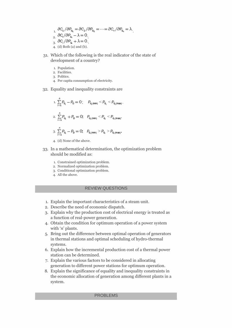
1. .
2. .
3. .4. (d)Both(a)and(b).
31. Whichofthefollowingistherealindicatorofthestateofdevelopmentofacountry?
1. Population.2. Facilities.3. Politics.4. Percapitaconsumptionofelectricity.
32. Equalityandinequalityconstraintsare
1.
2.
3.
4. (d)Noneoftheabove.
33. Inamathematicaldetermination,theoptimizationproblemshouldbemodifiedas:
1. Constrainedoptimizationproblem.2. Normalizedoptimizationproblem.3. Conditionaloptimizationproblem.4. Alltheabove.
REVIEWQUESTIONS
1. Explaintheimportantcharacteristicsofasteamunit.2. Describetheneedofeconomicdispatch.3. Explainwhytheproductioncostofelectricalenergyistreatedas
afunctionofreal-powergeneration.4. Obtaintheconditionforoptimumoperationofapowersystem
with‘n’plants.5. Bringoutthedifferencebetweenoptimaloperationofgenerators
inthermalstationsandoptimalschedulingofhydro-thermalsystems.
6. Explainhowtheincrementalproductioncostofathermalpowerstationcanbedetermined.
7. Explainthevariousfactorstobeconsideredinallocatinggenerationtodifferentpowerstationsforoptimumoperation.
8. Explainthesignificanceofequalityandinequalityconstraintsintheeconomicallocationofgenerationamongdifferentplantsinasystem.
PROBLEMS

1. Threepowerplantsofatotalcapacityof425MWarescheduledforoperationtosupplyatotalsystemloadof300MW.Findtheoptimumloadschedulingiftheplantshavethefollowingincrementalcostcharacteristicsandthegeneratorconstraints.
2. Aplantconsistsoftwounits.Theincrementalfuelcharacteristicsforthetwounitsaregivenas:
Findtheoptimalloadsharingoftwounitswhenatotalloadof300MWisconnectedtothesystem.AlsocalculatetheextracostincreasedinRs./hrifthetotalloadissharedequallybetweenthem.
3. Thecostcurvesofthethreeplantsaregivenasfollows:
C =0.04P +20P +230Rs./hr
C =0.06P +18P +200Rs./hr
C =0.05P +15P +180Rs./hr
Determinetheoptimumsharingofatotalloadof180MWforwhicheachplantwouldtakeupforminimuminputcostofreceivedpowerinRs/MWh.
4. TheincrementalfuelcostsinrupeesperMWhforaplantconsistingoftwounitsare:
1 G1 G1
2 G2 G2
3 G3 G3
2
2
2

CalculatetheextracostincreasedinRs./hr,ifaloadof210MWisscheduledasP =P =105MW.
G1 G2
3
EconomicLoadDispatch-II
OBJECTIVES
Afterreadingthischapter,youshouldbeableto:
developthemathematicalmodelforeconomicalloaddispatchwhenlossesareconsideredderivetransmissionlossexpressionstudytheoptimalallocationoftotalloadamongtheunitsdevelopaflowchartforthesolutionofoptimizationproblem
3.1INTRODUCTION
Incaseofanurbanareawheretheloaddensityisveryhighandthetransmissiondistancesareverysmall,thetransmissionlosscouldbeneglectedandtheoptimumstrategyofgenerationcouldbebasedontheequalincrementalproductioncost.Iftheenergyistobetransportedoverrelativelylargerdistanceswithlowloaddensity,thetransmissionlosses,insomecases,mayamounttoabout20–30%ofthetotalload;hence,itisessentialtotaketheselossesintoaccountwhenformulatinganeconomicloaddispatchproblem.
3.2OPTIMALGENERATIONSCHEDULINGPROBLEM:CONSIDERATIONOFTRANSMISSIONLOSSES
Inapracticalsystem,alargeamountofpowerisbeingtransmittedthroughthetransmissionnetwork,whichcausespowerlossesinthenetwork(P )asshowninFig.3.1.
Infindinganoptimalsolutionforeconomicschedulingproblem(allocationoftotalloadamongthegeneratingunits),itismorerealistictoconsiderthetransmission
L
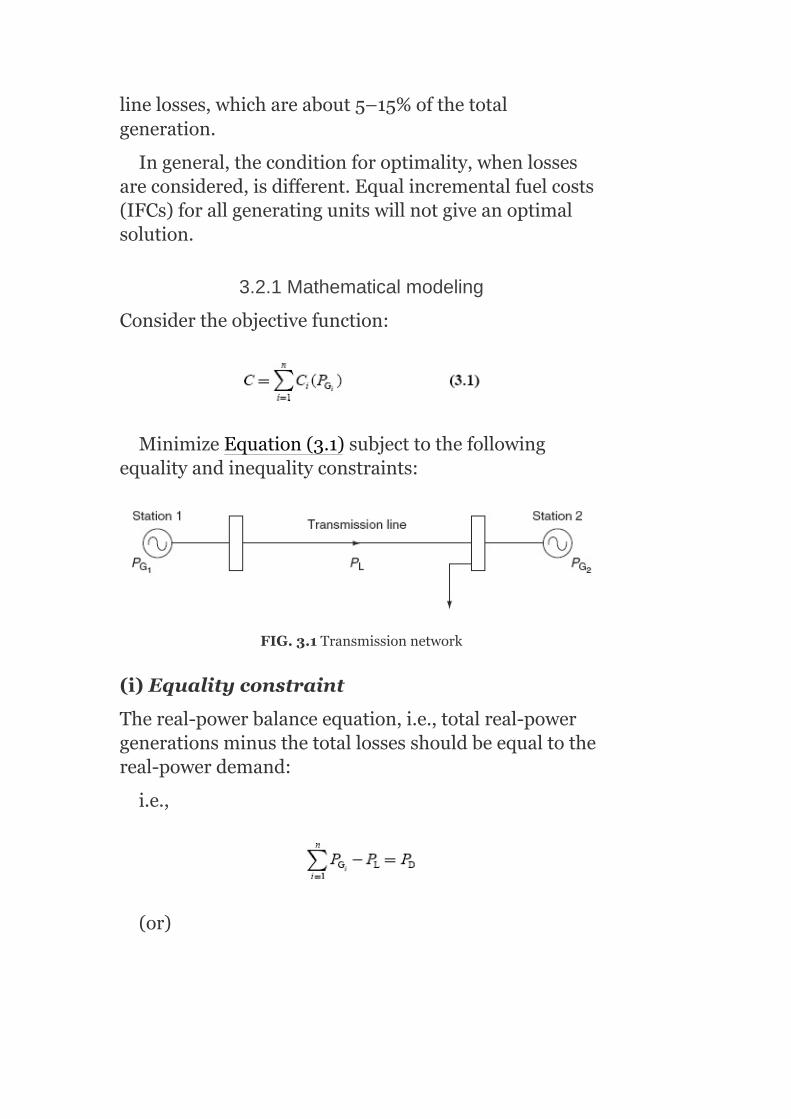
linelosses,whichareabout5–15%ofthetotalgeneration.
Ingeneral,theconditionforoptimality,whenlossesareconsidered,isdifferent.Equalincrementalfuelcosts(IFCs)forallgeneratingunitswillnotgiveanoptimalsolution.
3.2.1Mathematicalmodeling
Considertheobjectivefunction:
MinimizeEquation(3.1)subjecttothefollowingequalityandinequalityconstraints:
FIG.3.1Transmissionnetwork
(i)Equalityconstraint
Thereal-powerbalanceequation,i.e.,totalreal-powergenerationsminusthetotallossesshouldbeequaltothereal-powerdemand:
i.e.,
(or)

whereP isthetotaltransmissionlosses(MW),P thetotalreal-powerdemand(MW),andp thereal-powergenerationatthei unit(MW).
(ii)Inequalityconstraints
Alwaystherewillbeupperandlowerlimitsforrealandreactive-powergenerationateachofthestations.Theinequalityconstraintsarerepresented:
1. Intermsofreal-powergenerationas
P ≤P ≤P (3.3)
2. Intermsofreactive-powergenerationas
Q ≤Q ≤Q (3.4)
Thereactive-powerconstraintsaretobeconsideredsincethetransmissionlineresultsinlossisafunctionofrealandreactive-powergenerationsandalsothevoltageatthestationbus.
3. Inaddition,thevoltageateachofthestationsshouldbemaintainedwithincertainlimits:
i.e.,V ≤V ≤V (3.5)
TheoptimalsolutionshouldbeobtainedbyminimizingthecostfunctionsatisfyingconstraintEquations(3.2)–(3.5).
3.3TRANSMISSIONLOSSEXPRESSIONINTERMSOFREAL-POWERGENERATION–DERIVATION
TransmissionlossP isexpressedwithoutlossofaccuracyasafunctionofreal-powergenerations.ThepowerlossisexpressedusingB-coefficientsorlosscoefficients.
L D
Gi
Gi (min) Gi Gi (max)
Gi (min) Gi Gi (max)
i (min) i i (max)
L
th

TheexpressionfortransmissionpowerlossisderivedusingKron’smethodofreducingasystemtoanequivalentsystemwithasinglehypotheticalload.
Theexpressionisbasedonseveralassumptionsasfollows:
1. Allthelinesinthesystemhavethesame ratio.
2. Alltheloadcurrentshavethesamephaseangle.3. Alltheloadcurrentsmaintainaconstantratiotothetotalcurrent.4. Themagnitudeandphaseangleofbusvoltagesateachstationremain
constant.5. Powerfactorateachstationbusremainsconstant.
Wewillderiveanexpressionforthepowerlossofasystem,havingtwogeneratingstations,supplyinganarbitrarynumberofloadsthroughatransmissionnetworkasshowninFig.3.2(a).
Todeterminethecurrentinanyline,sayk line,applythesuperpositionprincipleanddeterminethecurrentpassingthroughtheline,I .
Thecurrentdistributionfactorofatransmissionlinew.r.t.apowersourceistheratioofthecurrentitwouldcarrytothecurrentthatthesourcewouldcarrywhenallothersourcesarerenderedinactive,i.e.,sourcesthatarenotsupplyinganycurrent.
Letusassumethattheentireloadcurrentissuppliedbygeneratingstation-1onlyasshowninFig.3.2(b).
Currentinthek line=I
Currentdistributionfactor,
IfweassumethattheentireloadissuppliedbythesecondgeneratingstationonlyasshowninFig.3.2(c):
Thecurrentflowingthroughthek line=I
k
k1
k1
th
th
th

Currentdistributionfactor,

FIG.3.2(a)Transmissionnetworkwithtwogeneratingstations;(b)loadsuppliedbygeneratingstation-1only;(c)loadsuppliedbygenerating
station-2only;(d)loadsuppliedbytwogeneratingstationssimultaneously;(e)sourcecurrentswithrespecttoreference;(f)currentink line
Becauseofassumptions(i)and(ii),thecurrentdistributionfactorswillberealnumbersratherthancomplexnumbers.
AndalsoassumingthatthetotalloadisbeingsuppliedbyboththestationsasshowninFig.3.2(d):
Thecurrentinthek line=I
∴I =I′ +I′
Fromtherelations,
Althoughthecurrentdistributionfactorsarerealnumbers,thevarioussourcecurrentssupplyingtotalloadwillnotbeinphase,i.e.,I andI arenotinphase.
LetthesourcecurrentsI andI beexpressedasI ∠σandI ∠σ asshowninFig.3.2(e).
Then,I =N I ∠σ +N I ∠σ withaphasedifferenceof(σ –σ )asshowninFig.3.2(f).
ByaddingI andI phasors,wehave
k
k k1 k2
1 2
1 2 1 1
2 2
k k1 1 1 k2 2 2
2 1
k1 k2
th
th
2 2 2
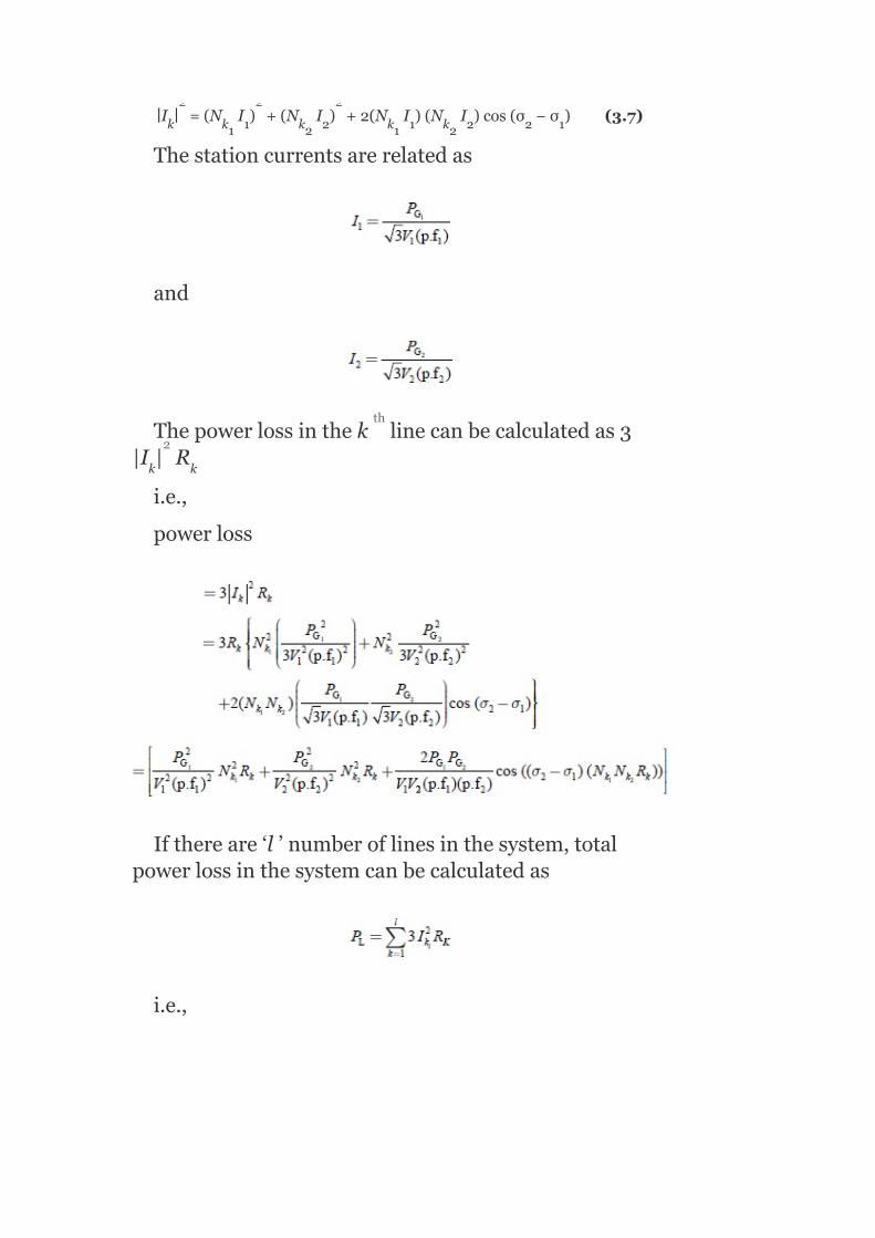
∣I ∣ =(N I ) +(N I ) +2(N I )(N I )cos(σ −σ )(3.7)
Thestationcurrentsarerelatedas
and
Thepowerlossinthek linecanbecalculatedas3|I | R
i.e.,
powerloss
Ifthereare‘l’numberoflinesinthesystem,totalpowerlossinthesystemcanbecalculatedas
i.e.,
k k1 1 k2 2 k1 1 k2 2 2 1
k k
2 2 2
th
2

Thisaboveexpressioncanbewrittenas
P =B P +B P +2B P P (3.8)
where
and
Equation(3.8)expressesthetotallossasafunctionofreal-powergenerations,P andP .
ThecoefficientsB ,B ,andB arecalledlosscoefficients(or)B-coefficientsandtheunitis(MW)andisalsoconsideredtobeaconstantinviewoftheassumptionsmade.
Thesameprocedurecanbeextendedforsystemshavingmorenumberofstations.Ifthesystemhas‘n’numberofstations,supplyingthetotalloadthroughtransmissionlines,thetransmissionlinelossisgivenby
whenn=2,
L 11 G1 22 G2 12 G1 G2
G1 G2
11 22 12
2 2
–1

Similarlyforn=3,
Sincethetransmissionlinesaresymmetrical,losscoefficientsB andB areequal,i.e.,B =B .
TheB coefficientsarelosscoefficientsandcanberepresentedinmatrixformofann-generatorsystemas
Thediagonalelementsofthesecoefficientsareallpositiveandstrong(sincegeneratingstationsareinterconnected)ascomparedwiththeoff-diagonalelements,whichmostlyarenegativeandarerelativelyweaker.
Thesecoefficientsaredeterminedforalargesystembyanelaboratedigitalcomputerprogramstartingfromtheassemblyoftheopen-circuitimpedancematrixofthetransmissionline,whichisquitelengthyandtime-consuming.Besides,theformulationsofB-coefficientsarebasedonseveralassumptionsanddonottakeintoaccounttheactualconditionsofthesystem;thesolution
pq qp pq qp
pq

fortheplantgenerationscannotbeexpectedtobethebestforminimumcostofgeneration.
3.4MATHEMATICALDETERMINATIONOFOPTIMUMALLOCATIONOFTOTALLOADWHENTRANSMISSIONLOSSESARETAKENINTO
CONSIDERATION
Considerapowerstationhaving‘n’numberofunits.Letusassumethateachunitdoesnotviolatetheinequalityconstraintsandletthetransmissionlossesbeconsidered.
Assumingthattheinequalityconstraintissatisfied,theobjectivefunctionisredefinedbyaugmentingEquation(3.1)withequalityconstraint(Equation(3.2))usingLagrangianmultiplier(λ)andisgivenby
Thisaugmentedobjectivefunctioniscalledconstrainedobjectivefunction.
Intheaboveobjectivefunction,thereal-powergenerationsarethecontrolvariablesandthecondition
foroptimalitybecomes
i.e.,
(or)

(or)
where representsthevariationoftotaltransmission
losswithrespecttoreal-powergenerationoftheistationandiscalledincrementaltransmissionloss(ITL)ofthei station.Equation(3.14)canbewrittenas
or
where andiscalledthepenaltyfactorof
thei station.Equation(3.15)canbeutilizedtoobtaintheoptimalcostofoperation.
TheconditionforoptimalitywhenthetransmissionlossesareconsideredisthattheIFCofeachplantmultipliedbyitspenaltyfactormustbethesameforalltheplants:
th
th
th

i.e.,
Equation(3.12)isasetofnequationswith(n+1)unknowns.Here,thepowersofngeneratorsareunknownandλisalsounknown.Theseequationsareknownasexactco-ordinationequationsbecausetheyco-ordinatetheITLwithIFC.
Thefollowingpointsshouldbekeptinmindforthesolutionofeconomicloaddispatchproblemswhentransmissionlossesareincludedandco-ordinated:
Althoughincrementalproductioncostofaplantisalwayspositive,ITLcaneitherbepositiveornegative.Theindividualunitswilloperateatdifferentincrementalproductioncosts.ThegenerationwiththehighestpositiveITLwilloperateatthelowestincrementalproductioncost.
ForasmallincreaseinreceivedloadbyΔP ,thei plantgenerationisonlychangedby∆P andthegenerations
oftheremainingunitsareunaffected.LetΔP bethechangeintransmissionloss,thepowerbalanceequationbecomes∆P −∆P =∆P .
Thus,
when istheincrementalcostofthereceived
powerofthei plantandthepenaltyfactor .This
D
G1
L
Gi L D
th
th

meansthatas∆P incrementhasalargerproportion
dissipatedasloss, approachesunityandthepenalty
factor‘L ’increaseswithoutbound.Thus,foralargerpenaltyfactor‘L ’,unit‘i’shouldbeoperatedatlowincrementalcostimplyingalowpoweroutput.
3.4.1DeterminationofITLformula
Whenasystemconsistsofthreegeneratingunits,i.e.,n=3,thetransmissionlossis
ITLofGenerator-1isobtainedas
Ingeneral,
WeknowthattheIFCofthei unitis
SubstituteEquations(3.17)and(3.18)inEquation(3.9);weget
Gi
i
i
th

Dividingtheaboveequationbyλ,weget
Tosolvethisallocationproblem,solvetheco-ordinationEquation(3.19)foraparticularvalueofλiterativelystartingwithaninitialsetofvaluesofP
(suchasallP settominimumvalues)andgetthe
solutionwithinaspecifiedtolerancetillallP ’s
converge,thencheckforpowerbalanceandifitistobesatisfied,thenitistheoptimalsolution.Ifthepowerbalanceequationisnotsatisfied,modifythevalueofλtoasuitablevalueandsolvetheco-ordinationequation.
3.4.2Penaltyfactor
ConsiderEquation(3.12):
Gi
Gi
Gi

Theaboveexpressioncanbewrittenas
or
where
iscalledthepenaltyfactorofthei station
Thepenaltyfactorofanyunitisdefinedastheratioofasmallchangeinpoweratthatunittothesmallchange
th

inreceivedpowerwhenonlythatunitsuppliesthissmallchangeinreceivedpower.
3.5FLOWCHARTFORTHESOLUTIONOFANOPTIMIZATIONPROBLEMWHENTRANSMISSIONLOSSESARECONSIDERED
Whentransmissionlossesaretakenintoaccount,thesolutionofanoptimizationproblemisrepresentedbythefollowingflowchart(Fig.3.3).
Example3.1:ThefuelcostfunctionsinRs./hrfortwothermalplantsaregivenby
C =420+9.2P +0.004P
C =350+8.5P +0.0029P
whereP ,P areinMW.Determinetheoptimalschedulingofgenerationifthetotalloadis640.82MW.Estimatevalueofλ=12Rs./MWh.Thetransmissionpowerlossisgivenbytheexpression
P =0.0346P +0.00643P
Solution:
1 1 2
2 2 2
1 2
L(pu) 1(pu) 2(pu)
2
2
2 2

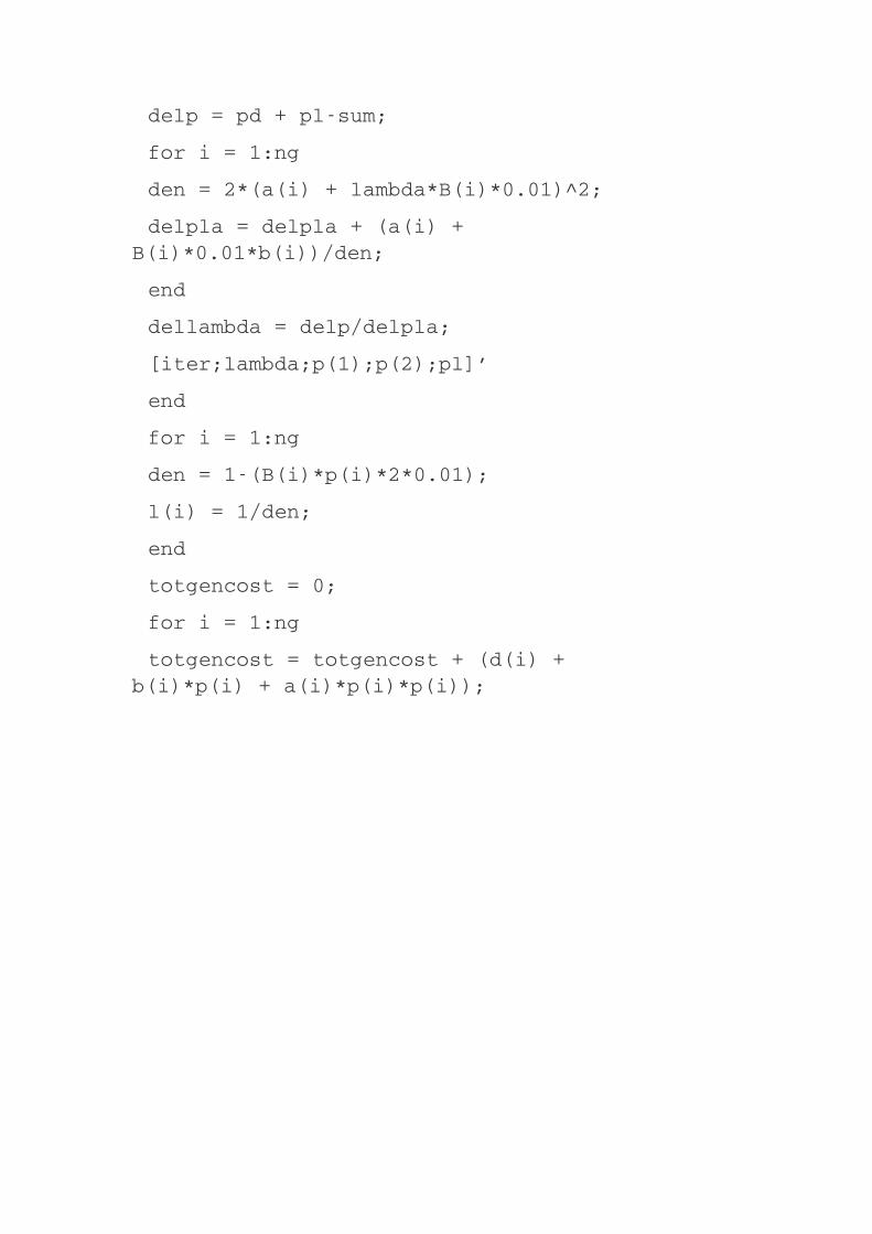

FIG.3.3Flowchart
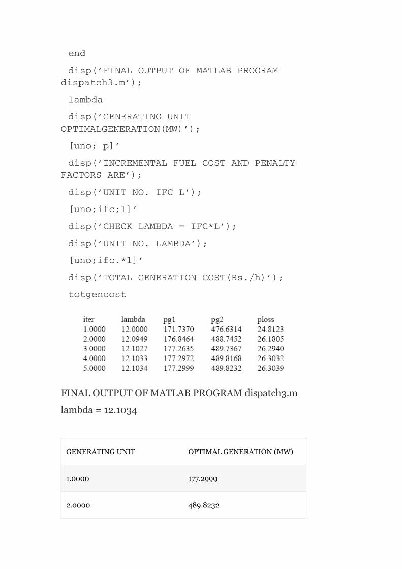
FINALOUTPUTOFMATLABPROGRAMdispatch3.m
lambda=12.1034
GENERATINGUNIT OPTIMALGENERATION(MW)
1.0000 177.2999
2.0000 489.8232
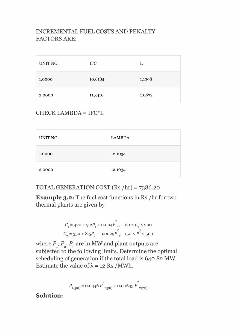
INCREMENTALFUELCOSTSANDPENALTYFACTORSARE:
UNITNO. IFC L
1.0000 10.6184 1.1398
2.0000 11.3410 1.0672
CHECKLAMBDA=IFC*L
UNITNO. LAMBDA
1.0000 12.1034
2.0000 12.1034
TOTALGENERATIONCOST(Rs./hr)=7386.20
Example3.2:ThefuelcostfunctionsinRs./hrfortwothermalplantsaregivenby
C =420+9.2P +0.004P ,100≤p ≤200
C =350+8.5P +0.0029P ,150≤P ≤500
whereP ,P ,P areinMWandplantoutputsaresubjectedtothefollowinglimits.Determinetheoptimalschedulingofgenerationifthetotalloadis640.82MW.Estimatethevalueofλ=12Rs./MWh.
P =0.0346P +0.00643P
Solution:
1 1 1 2
2 2 1
1 2 3
L(pu) 1(pu) 2(pu)
2
2 3
2 2


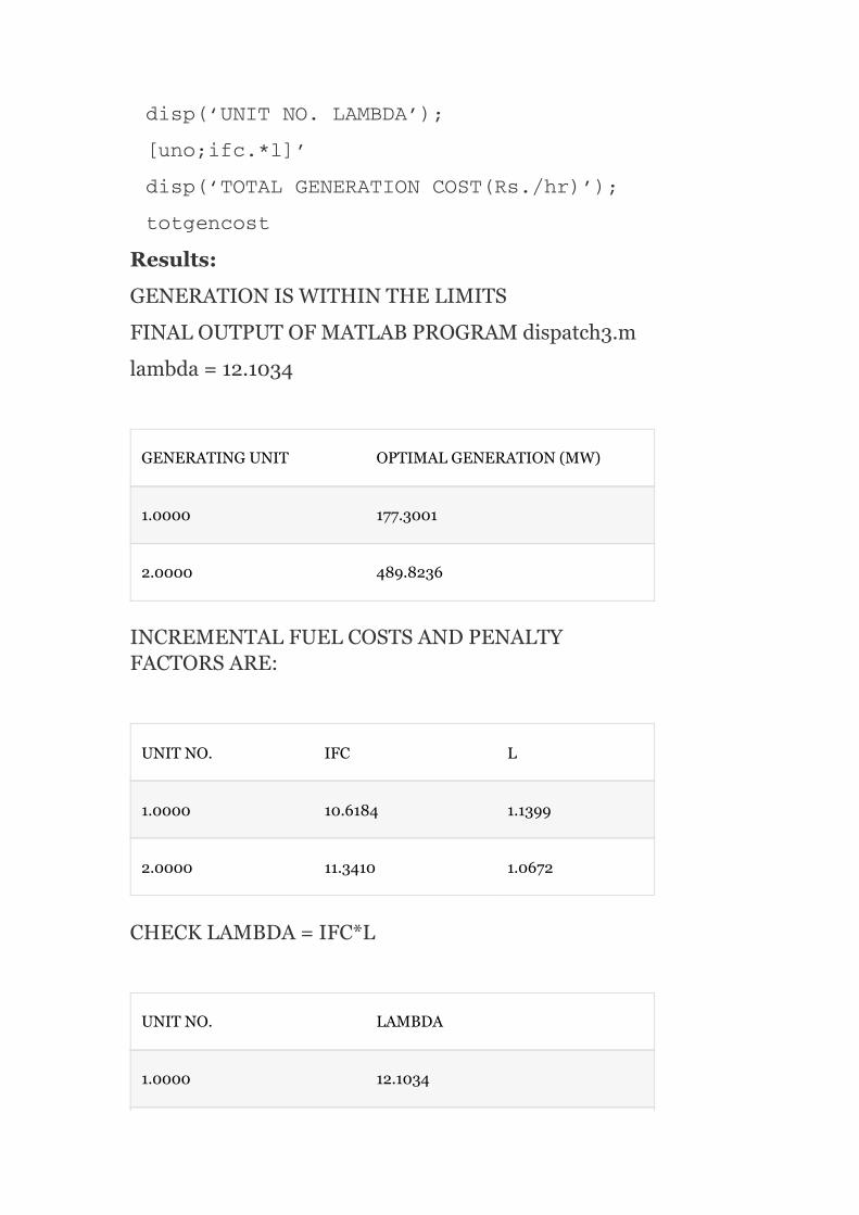
Results:
GENERATIONISWITHINTHELIMITS
FINALOUTPUTOFMATLABPROGRAMdispatch3.m
lambda=12.1034
GENERATINGUNIT OPTIMALGENERATION(MW)
1.0000 177.3001
2.0000 489.8236
INCREMENTALFUELCOSTSANDPENALTYFACTORSARE:
UNITNO. IFC L
1.0000 10.6184 1.1399
2.0000 11.3410 1.0672
CHECKLAMBDA=IFC*L
UNITNO. LAMBDA
1.0000 12.1034

2.0000 12.1034
TOTALGENERATIONCOST(Rs./hr)=7386.20
Example3.3TheIFCfortwoplantsare
Thelosscoefficientsaregivenas
B =0.0015/MW,B =−0.0004/MW,andB =0.0032/MWforλ=25Rs./MWh.Findthereal-powergenerations,totalloaddemand,andthetransmissionpowerloss.
Solution:
P +P =P +P
Andtransmissionloss,
Fornumberofplants,n=2,wehave
TheITLofPlant-1is
11 12 22
G1 G2 D L
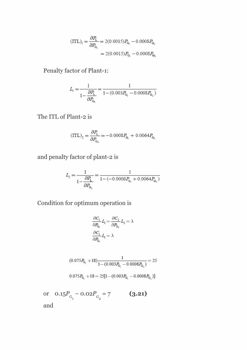
PenaltyfactorofPlant-1:
TheITLofPlant-2is
andpenaltyfactorofplant-2is
Conditionforoptimumoperationis
or0.15P −0.02P =7(3.21)
and
G1 G2

or0.02P −0.24P =−9(3.22)
SolvingEquations(3.21)and(3.22),
Equation(3.21)×0.24⇒0.036P −0.0048P =1.68
Equation(3.22)×0.02⇒0.0004P −0.0048P =
−0.18
0.0356P =1.86
∴P =52.247MW
SubstitutingtheP valueinEquation(3.21),weget
0.15(52.247)−0.02P =7
∴P =41.852MW
Transmissionloss,P
= 0.0015(52.247) −0.0008(52.247)(41.852)+0.0032(41.852)
= 7.95MW
Totalload,P
= P +P −P
= 52.247+41.852−7.95=86.149MW
Example3.4:Thecostcurvesoftwoplantsare
G1 G2
G1 G2
G1 G2
G1
G1
G1
G1
G2
L
D
G1 G2 L
2
2

C =0.05P +20P +150Rs./hr
C =(0.05P )+15P +180Rs./hr
ThelosscoefficientfortheabovesystemisgivenasB =0.0015/MW,B =B =–0.0004/MW,andB =0.0032/MW.Determinetheeconomicalgenerationschedulingcorrespondingtoλ=25Rs./MWhandthecorrespondingsystemloadthatcanbemetwith.Ifthetotalloadconnectedtothesystemis120MWtaking4%changeinthevalueofλ,whatshouldbethevalueofλinthenextiteration?
Solution:
Giventhatthecostcurvesoftwoplantsare
C =0.05P +20P +150Rs./hr
C =(0.05P )+15P +180Rs./hr
theincrementalcostsare
Transmissionloss,
Fortwoplants,n=2andwehave
1 G1 G1
2 G2 G1
11
12 21 22
1 G1 G1
2 G2 G1
2
2
2
2

TheITLofPlant-1is
TheITLofPlant-2is
ThepenaltyfactorofPlant-1is
andthepenaltyfactorofPlant-2is
Theconditionforoptimumoperationis

or1.09P −0.024P =10(3.23)
and
or0.024P −0.292P =−15(3.24)
SolvingEquations(3.23)and(3.24),weget
Equation(3.23)×0.024⇒0.02616P −0.000576P =
0.24
Equation(3.24)×1.09⇒0.02616P −0.31828P =
−16.36
0.3177P =16.6
∴P =52.25MW
SubstitutingtheP valueinEquation(3.23),weget
1.09P −0.024(52.25)=10
∴P =10.325MW
Transmissionloss,P = 0.0015(10.325) −0.0008(10.325)(52.25)+0.0032(52.25)
G1 G2
G1 G2
G1 G2
G1 G2
G1
G2
G1
G1
G1
L
2
2

= 8.465MW
Thecorrespondingsystemload,P
= P +P −P
= 10.325+52.25−8.465=54.11MW
For4%changeinvalueofλ,Δλ=4%of30=1.2Rs./MWh
Newloadconnectedtosystem,P =120MW
Changeinload,ΔP =120–54.11=65.89MW
Here,changeinload,ΔP >0;hence,togetanoptimumdispatchdecrementλbyΔλ,
Newvalueofλ=λ′=λ–Δλ=30–1.2=28.8Rs./MWh.
Example3.5:Asystemconsistsoftwopowerplantsconnectedbyatransmissionline.ThetotalloadlocatedatPlant-2isasshowninFig.3.4.Dataofevaluatinglosscoefficientsconsistofinformationthatapowertransferof100MWfromStation-1toStation-2resultsinatotallossof8MW.FindtherequiredgenerationateachstationandpowerreceivedbytheloadwhenλofthesysteminRs.100/MWh.TheIFCsofthetwoplantsaregivenby
Solution:
Totallossis
D
G1 G2 L
D
D
D

FIG.3.4IllustrationforExample3.5
Sincen=2,wehave
Sincepowertransferof100MWfromPlant-1toPlant-2(i.e.,P =100MW),P ,P ,B =0
∴P =B P
Given:P =8MW
∴8=B (100)
⇒B =8×10 MW
∴P =8×10 P
andthepenaltyfactorofPlant-1is
G1 G2 21 22
L 11 G1
L
11
11
L G1
2
2
−4 −1
−4 2

AndthepenaltyfactorofPlant-2is
Now,theconditionforoptimalityis
Forλ=100Rs./MWh
or0.12P +65=100(1−16×10 P )
or0.12P +0.16P =100−65
0.25P =35
amd0.25P +75=100
Powerreceivedbytheload = (P +P )−losses
= 125+100−8×10 ×P
G1 G1
G1 G1
G1
G2
G1 G2
G1
−4
−4 2
−4 2

= 125+100−8×10 ×125
= 225−12.5
= 212.5MW
Example3.6:ForExample.3.5,with212.5MWreceivedbytheload,findthesavingsinRs./hrobtainedbyco-ordinatingthetransmissionlossesratherthanneglectingindeterminingtheloaddivisionbetweentheplants.
Solution:
Byco-ordinatingthelossestosupplyaloadof212.5MW,thereal-powergenerationsatPlants1and2shouldbe125and100MW,respectively.
Whenlossesareneglected,totalload=212.5MWistobedistributedbetweenthetwoplantsmosteconomically.Conditionforoptimality,
Sincethelossesarenotco-ordinatedbutneglected,wehave
212.5P +0.49P −40−8×10 PG1 G1 G1
−4 2
−4 2

or8×10 P −1.48P 252.5=0
Bysolving,weget
P = 1,659.8MWand190.15MW
P = 1,659.8MW⇒isnottoberequiredtoovercomethatpowerdemandP
∴P = 190.15istoberequired
andP = 0.48×190.15−40
= 51.27MW
∴Powergeneration:withlossesarebeingco-ordinated,P =125MW,P =100MWwithlossesare
notbeingco-ordinated,P =190.15MW,P =51.27
MW.
IncreaseincostofPlant-1whenlossesareco-ordinated:
IncreaseincostofPlant-2,becauseincreaseingeneration:
G1 G1
G1
G1D
G1
G2
G1 G2
G1 G2
−4 2

SavingsinRs./hrbyco-ordinatingthelosses=5,466.67–4,576.17=890.50Rs./hr.
Example3.7:Onasystemconsistingoftwogeneratingplants,theincrementalcostsinRs./MWhwithP and
P inMWare
ThesystemisoperatingoneconomicdispatchwithP
=P =500MWamd Findthepenaltyfactorof
Plant-1.
Solution:
Giventhatthesystemoperatesoneconomicdispatchwithp =p =500MW,theconditionforthisoptimal
operationwhenconsideringthetransmissionlossis
andalsogiventhatITLofPlant-2,
G1
G2
G1
G2
G1 G2

ThepenaltyfactorofPlant-2,
∴Foroptimalcondition,
or
[(0.008×500)+80]L =(0.012×500+9.0)1.25
or
12L =18.75
or
L =1.5625
∴PenaltyfactorofPlant-1=1.5625.
Example3.8:DeterminetheincrementalcostofreceivedpowerandthepenaltyfactoroftheplantshowninFig.3.5iftheincrementalcostofproductionis
Solution:
Thepenaltyfactor
1
1
1

∴Costofreceivedpower
FIG.3.5IllustrationforExample3.8
Example3.9:A2-bussystemconsistsoftwopowerplantsconnectedbyatransmissionlineasshowninFig.3.6.
Thecost-curvecharacteristicsofthetwoplantsare:
C =0.015P +18P +20Rs./hr
C =0.03P +33P +40Rs./hr
Whenapowerof120MWistransmittedfromPlant-1totheload,alossof16.425MWisincurred.DeterminetheoptimalschedulingofplantsandtheloaddemandifthecostofreceivedpowerisRs.26/MWh.Solvetheproblemusingco-ordinationequationsandthepenaltyfactormethodapproach.
Solution:
1 G1 G1
1 G2 G2
2
2

Fortwounits,P =p B p +2p B p +p B p
.
SincetheloadislocatedatBus-2alone,thelossesinthetransmissionlinewillnotbeaffectedbythegeneratorofPlant-2.
i.e.,B =B =0andB =0
∴P =B P (3.25)
16.425=B ×120
B =0.00114MW
Usingtheco-ordinationequationmethod:
Theco-ordinationequationforPlant-1is
FIG.3.6IllustrationforExample3.9
PL=0.00114P
SubstituteEquations(3.27)and(3.28)inEquation(3.26);thentheequationforPlant-1becomes
L G1 11 G1 G1 12 G2 G2 21 G1
12 21 22
L 11 G1
11
11
G1
2
2
−1
2

Theco-ordinationequationforPlant-2is
∴Equation(3.29)becomes
∴Thetransmissionloss,P = B P
= 0.00114×(89.6)
= 9.15MW
∴Theload,P = P +P −P
= 89.6+66.67−9.15=147.12MW
L 11 G1
D G1 G2 L
2
2

Penaltyfactormethod:
ThepenaltyfactorofPlant-1is
Nowtheconditionforoptimalityis
ThepenaltyfactorofPlant-2,
Foroptimality,
Thetransmissionloss,P = B P
= 0.00114×(89.6)
= 9.15MW
L 11 G1
2
2

∴Theload,P = P +P −P
= 89.6+66.67−9.15=147.12MW.
Example3.10:AssumethatthefuelinputinBritishthermalunit(Btu)perhourforUnits1and2aregivenby
C =(8P +0.024P +80)10
C =(6P +0.024P +120)10
Themaximumandminimumloadsontheunitsare100and10MW,respectively.DeterminetheminimumcostofgenerationwhenthefollowingloadissuppliedasshowninFig.3.7.ThecostoffuelisRs.2permillionBtu.
FIG.3.7IllustrationforExample3.10
Solution:
D G1 G2 L
1 G1 G1
2 G1 G2
2 6
2 6

1. Whentheloadis50MW:
Conditionfortheeconomicschedulingis
0.048P +8=0.08P +6
0.048P −0.08P =−2(3.30)
andP +P =50(3.31)
BysolvingEquations(3.30)and(3.31),weget
p =15625MW
p =34375MW
∴C =210.868millionBtu/h
C =373.5millionBtu/h
2. Whentheloadis150MW,
FromEquation(3.30),0.048P −0.08P =−2(3.32)
P +P 150(3.33)
BysolvingEquations(3.32)and(3.33),weget
p =78126MW
p =71874MW
andC =851.496millionBtu/hr
C =757.87millionBtu/hr
∴Totalcost=Rs.(210.868+373.5+851.496+757.87)×2
=Rs.52,649.61/hr.
G1 G2
G1 G2
G1 G2
G1
G2
1
2
G1 G2
G1 G2
G1
G2
1
2

Example3.11:TwopowerplantsareconnectedtogetherbyatransmissionlineandloadatPlant-2asshowninFig.3.8.When100MWistransmittedfromPlant-1,thetransmissionlossis10MW.Thecostcharacteristicsoftwoplantsare
C =0.05P +13P Rs./hr
C =0.06P +12P Rs./hr
Findtheoptimumgenerationforλ=22,λ=25,andλ=30.
Solution:
C =0.05P +13P
C =0.06P +12P
TheIFCcharacteristicsare
Thetransmissionpowerloss,
Heren=2,
P =B P +B P +2B P P
SincetheloadisconnectedatBus-2andthepowertransferisfromPlant-1only,B =0andB =0.
∴P =B P
10=B (100)
1 G1 G1
2 G2 G2
1 G1 G1
2 G2 G2
L 11 G1 22 G2 12 G1 G2
22 12
L 11 G1
11
2
2
2
2
2 2
2
2

FIG.3.8Singlelinediagramrepresentingtwopowerplantsconnectedbyatransmissionline
TheITLofPlant-1is
ThepenaltyfactorofPlant-1is
(∵thetransmissionpowerlossisnotthe
functionofP )
ThepenaltyfactorofPlant-2is
Foroptimality,whentransmissionlossesareconsidered,theconditionis
G2

or0.0144P =9
∴P =62.5MW,
and(0.12P +12)1=22
∴P =83.33MW
Similarly,wehave
Forλ=25,
p =80MW,p =108.33MW
Forλ=30,
p =106.25MW,p =150MW
Example3.12:ForExample3.11,thedataforthelossequationsconsistoftheinformationthat200MWtransmittedfromPlant-1totheloadresultsinatransmissionlossof20MW.Findtheoptimumgenerationscheduleconsideringtransmissionlossestosupplyaloadof204.41MW.Alsoevaluatetheamountoffinanciallossthatmaybeincurredifatthetimeofschedulingtransmissionlossesarenotco-ordinated.AssumethattheIFCcharacteristicsofplantsaregivenby
Solution:
G1
G1
G2
G2
G1 G2
G1 G2
2 2

P =B P +2B P P +B P
∴TheloadisatPlant-2,henceB =B =0
∴P =B P
AndgiventhatP =200MW,P =20M
ThepenaltyfactorofPlant-1is
ThepenaltyfactorofPlant-2is
Foroptimality,
⇒0.025P =(1−0.001P )(0.05P +16)
⇒0.025P =(0.05P −0.00005P P +16−0.016P )
0.041P −0.05P +0.00005P P =16(3.34)
L 11 G1 12 G1 G2 22 G2
2 22
L 11 G1
G1 L
G1 G1 G2
G1 G2 G1 G2 G1
G1 G2 G1 G2
2 2
2
2
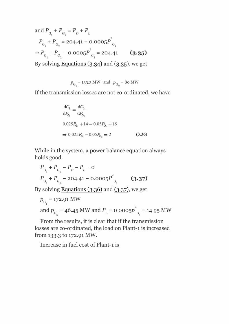
andP +P =P +P
P +P =204.41+0.0005P
⇒P +P −0.0005P =204.41(3.35)
BysolvingEquations(3.34)and(3.35),weget
p =133.3MWandp =80MW
Ifthetransmissionlossesarenotco-ordinated,wehave
Whileinthesystem,apowerbalanceequationalwaysholdsgood.
P +P −P −P =0
P +P −204.41−0.0005P (3.37)
BysolvingEquations(3.36)and(3.37),weget
p =172.91MW
andp =46.45MWandP =00005p =1495MW
Fromtheresults,itisclearthatifthetransmissionlossesareco-ordinated,theloadonPlant-1isincreasedfrom133.3to172.91MW.
IncreaseinfuelcostofPlant-1is
G1 G2 D L
G1 G2 G1
G1 G2 G1
G1 G2
G1 G2 D L
G1 G2 G1
G1
G2 L G1
2
2
2
2

TheloadonPlant-2isdecreasedfrom80to46.45MW.ThedecreaseinthefuelcostofPlant-2is
Thenetfinancialloss = ∆C −∆C =706.15−642.70
= 63.45Rs./hr
Example3.13:ForthesystemshowninFig.3.9,withBus-1asthereferencebuswithavoltageof1.0∟0°p.u.,findthelossformula(B )coefficientsifthebranchcurrentsandimpedancesare:
I =(1.00–j0.15)p.u.;Z =0.02+j0.15p.u.
I =(0.50–j0.05)p.u.;Z =0.03+j0.15p.u.
I =(0.20–j0.05)p.u.;Z =0.02+j0.25p.u.
Ifthebaseis100MVA,whatwillbethemagnitudesofB coefficientsinreciprocalMW?
Solution:
Theassumptionindevelopingtheexpressionfortransmissionlossisthatallloadcurrentsmaintainaconstantratiotothetotalcurrent:
i.e.,
1 2
pq
a a
b b
c c
pq

∴Thecurrentdistributionfactors:
whereI isthecurrentinbranch‘a’whenPlant-1isin
operation;andI thecurrentwhenPlant-2isin
operation.
N =0.6649;N =0.6649
N =0.3353;N =0.3359
N =–0.3353;N =0.6649
FIG.3.9IllustrationforExample3.13
VoltageatBus-1=V =1.0∠0°p.u.=(1.0+j0.0)p.u.
ThebusvoltageatBus-2is
V =V +I Z
=(1.00+j0.0)+(0.20–j0.05)(0.02+j0.25)
=1.0165+j0.049=1.0176∠2.76Theplantcurrentare
I =
a1
a2
a1 a2
b1 b2
c1 c2
1
2 1 c c
G1

I −I =(1.00−j0.15)−(0.20−j0.05)=0.80−j0.10=
0.8062∠−7.11°
I = I +I =(0.50−j0.10)+(0.20−j0.05)
= (0.70−j15)=0.7519∠−12.09°
Theplantcurrentsareintheformof
I =I ∠σ
I =I ∠σ
∴σ =−7.1°andσ =−12.09°
cos(σ −σ )=cos4.99°=0.996
Theplantp.f.sare
cosφ =cos7.1°=0.9923
cosφ =cos(anglebetweenV andI )
=cos(2.76°+12.09°)=0.9666
or
a c
G2 b c
1 1 1
2 2 2
1 2
2 1
1
2 2 G2
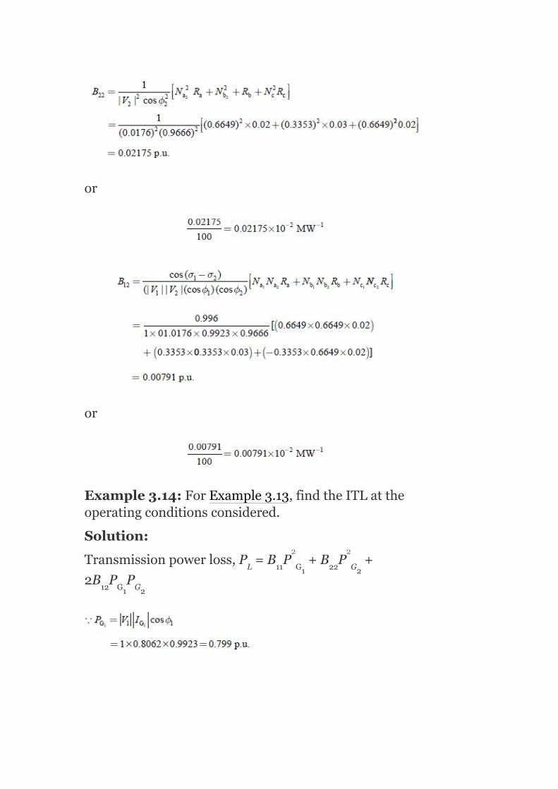
or
or
Example3.14:ForExample3.13,findtheITLattheoperatingconditionsconsidered.
Solution:
Transmissionpowerloss,P =B P +B P +
2B P PL 11 G1 22 G2
12 G1 G2
2 2

TheITLofPlant-1is
FIG.3.10IllustrationforExample3.15
Example3.15:ForthesystemshowninFig.3.10,withBus-3asthereferencebuswithavoltageof1.2∠0 p.u.,findthelossformula(B )coefficientsofthesystemin
pq
o

p.u.andinactualunits,ifthebranchcurrentsandimpedancesare
I =2.5–j1.0p.u.;Z =0.02+j0.08p.u.
I =1.8–j0.6p.u.;Z =0.03+j0.09p.u.
I =1.5–j0.5p.u.;Z =0.013+j0.05p.u.
I =3.0–j1.0p.u.;Z =0.015+j0.06p.u.
Considerthatthebasehas100MVA.
Solution:
Theassumptionindevelopingtheexpressionfortransmissionlossisthatallloadcurrentsmaintainaconstantratiotothetotalcurrent.
∴Currentdistributionfactorsare
N =1; N =0
N =0.575; N =0.425
N =−0.425; N =0.575
N =0.425; N =0.575
ThebusvoltageatreferenceBus‘3’=1.2+j0.0p.u.
ThebusvoltageatPlant-1, V = V +I Z
a a
b b
c c
d d
a1 a2
b1 b2
c1 c2
d1 d2
1ref a a

= 1.2+j0.0+(2.2−j1)(0.02+j0.08)
= 1.342∠7.7°p.u.
ThebusvoltageatPlant-2,
V = V +I Z
= 1.2+(1.5+j0.5)(0.013−j0.05)
= 1.246∠3.15°p.u.
Thecurrentphaseanglesattheplants=(I =I ,I =I +I )
Theplantpowerfactorsare
cosφ =cos(7.7 +21.8 )=0.87
cosφ =cos(3.5 +18.43 )=0.928
Thelosscoefficientsare
1
2ref c c
1 a 2 d
c
1
2
o o
o o

Forobtainingthelosscoefficientvaluesinreciprocalmegawatts,thelosscoefficientsinp.u.mustbedividedbythebasevalue(i.e.,100MVA):
Example3.16:Asystemconsistsoftwogeneratingplantswithfuelcostsof
C = 0.05P +20P +1.5
and C = 0.075P +22.5P +1.6
1 G1 G1
2 G2 G2
2
2

Thesystemoperatesoneconomicaldispatchwith100MWofpowergenerationbyeachplant.TheITLofPlant-2is0.2.FindthepenaltyfactorofPlant-1.
Solution:
Given
C = 0.05P +20P +1.5
C = 0.075P +22.5P +1.6
P = P =100MW
and
ThepenaltyfactorofPlant-2,
IncrementalfuelcostofPlant-1
IncrementalfuelcostofPlant-2
Foroptimality,theconditionis
1 G1 G1
2 G2 G2
G1 G2
2
2

⇒(0.1P +20)L = (0.15P +22.5)1.25
(0.1×100+20)L = (0.15×100+22.5)1.25
= (37.5)(1.25)
∴30L = 46.875
orL = 1.5625
i.e.,thepenaltyfactorofPlant-1=L =1.5625.
Example3.17:TwothermalplantsareinterconnectedandsupplypowertoaloadasshowninFig.3.11.
Thefollowingaretheincrementalproductioncostsoftheplants:
wherep andp areexpressedinp.u.in100-MVAbase.
Thetransmissionlossisgivenby
P =0.1P +0.2P +0.1P P p.u.
Iftheincrementalcostofreceivedpoweris50Rs./MWh,findtheoptimalgeneration.
G1 1 G2
1
1
1
1
G1 G2
L G1 G2 G1 G2
2 2

FIG.3.11IllustrationorExample3.17
Solution:
Given:
and P = 0.1P +0.2P +0.1P P p.u. (3.38)
Generally,
P = B P +B P +2B P P (3.39)
ComparingthecoefficientsofEquations(3.38)and(3.39),weget
Incrementalcostofreceivedpower,λ=50Rs./MWh
Theconditionforoptimumallocationoftotalloadwhentransmissionlossesareconsideredis
LG1 G2 G1 G2
L11 G1 22 G2 12 G1 G2
2 2
2 2

TheITLofPlant-1is
TheITLofPlant-2is
ThepenaltyfactorofPlant-1,
ThepenaltyfactorofPlant-2,
∴Foroptimumoperation:

or 20+10P =50−10P −5P
or 10P +10P +5P =30
20P +5P =30 (3.40)
SolvingEquations(3.40)and(3.41),wehave
∴P =0.95652p.u.
Substitutingthep valueinEquation(3.40),weget
20p +5(0.95652)=30
or20p +4.7826=30
G1 G1 G2
G1 G2 G2
G1 G2
G1
G2
G1
G1

∴p =1.26087p.u.
Substitutingthep andp valuesinEquation(3.38),we
have
P = 0.1(1.26087) +0.2(0.95652) +0.1(1.26087)(0.95652)
= 0.158979+0.182986+0.12060
= 0.46256p.u.
= 0.46256×100=46.256MW
P inMW=p.u.valur×baseMVA
P = 1.2608×100
= 126.08MW
and P = 95.652MW
Example3.18:Apowersystemoperatesaneconomicloaddispatchwithasystemλof60Rs./MWh.IfraisingtheoutputofPlant-2by100kW(whiletheotheroutputiskeptconstant)resultsinincreasedpowerlossesof12kWforthesystem,whatistheapproximateadditionalcostperhouriftheoutputofthisplantisincreasedby1MW?
Solution:
Foreconomicoperation:
G1
G1 G2
L
G1
G1
G2
2 2

IfthePlant-2outputisincreasedby1MW,i.e.,∂P =
1MW,theadditionalcost,∂C =?
Given:
λ=60Rs./MWh,∂P =100kW,and∂P =12kW:
ThepenaltyfactorofPlant-2,
Thefuelcostwhentheoutputisincreasedby1MWis
∂C =52.817×dP =52.817×1=52.817Rs./hr
Example3.19:Apowersystemissuppliedbyonlytwoplants,bothofwhichoperateoneconomicaldispatch.AtthebusofPlant-1,theincrementalcostis55Rs./MWhandatPlant-2is50Rs./MWh.Whichplanthasthehigherpenaltyfactor?WhatisthepenaltyfactorofPlant-1ifthecostperhourofincreasingtheloadonsystemby1MWis75Rs./hr?
Solution:
G2
2
G2 L
2 G2

Given
ThecostinRs./hrtoincreasethetotalsystemloadby1MWiscalledsystemλ:
λ=25Rs./MWh
or
∂P =1MWandRs./hr=75(given)
Foreconomicaloperation,bothplantsoperatingatcommonλ,i.e.,λ=75Rs./MWh
and
Therefore,L isgreaterthanL .
KEYNOTES
Whentheenergyistransportedoverrelativelylargerdistanceswithlowloaddensity,thetransmissionlossesinsomecasesmayamounttoabout20–30%ofthetotalload.Hence,itbecomesveryessentialtotaketheselossesintoaccountwhenformulatinganeconomicdispatchproblem.
G1
2 1

Considertheobjectivefunction:
Minimizetheabovefunctionsubjecttotheequalityandinequalityconstraints.
Equalityconstraints
Thereal-powerbalanceequation,i.e.,totalreal-powergenerationsminusthetotallossesshouldbeequaltoreal-powerdemand:
Inequalityconstraints
Theinequalityconstraintsarerepresentedas:
1. Intermsofreal-powergenerationas
P ≤P ≤P
2. Intermsofreactive-powergenerationas
Q ≤Q ≤Q
3. Inaddition,thevoltageateachofthestationsshouldbemaintainedwithincertainlimits.
i.e.,V ≤V ≤V
Currentdistributionfactorofatransmissionlinew.r.tapowersourceistheratioofthecurrentitwouldcarrytothecurrentthatthesourcewouldcarrywhenallothersourcesarerenderedinactivei.e.,thesourcesthatdonotsupplyanycurrent.Ifthesystemhas‘n’numberofstations,supplyingthetotalloadthroughtransmissionlines,thetransmissionlinelossisgivenby
ThecoefficientsB ,B andB arecalledlosscoefficientsorB-
coefficientsandareexpressedin(MW) .Thetransmissionlossisexpressedasafunctionofreal-power
G (min)i Gi G (max)i
G (min)i Gi G (max)i
i(min) i i(max)
11 12 22 −1

generations.
Theincrementaltransmissionlossisexpressedas .
Thepenaltyfactorofanyunitisdefinedastheratioofasmallchangeinpoweratthatunittothesmallchangeinreceivedpowerwhenonlythatunitsuppliesthissmallchangeinreceivedpowerandisexpressedas
Theconditionforoptimalitywhentransmissionlossesareconsideredis
SHORTQUESTIONSANDANSWERS
1. Stateinwordstheconditionforminimumfuelcostinapowersystemwhenlossesareconsidered.
Theminimumfuelcostisobtainedwhentheincrementalfuelcostofeachstationmultipliedbyitspenaltyfactoristhesameforallthestationsinthepowersystem.
2. Definethecurrentdistributionfactor.
Thecurrentdistributionfactorofatransmissionlinewithrespecttoapowersourceistheratioofthecurrentitwouldcarrytothecurrentthatthesourcewouldcarrywhenallothersourcesarerenderedinactive,i.e.,thesourcesthatarenotsupplyinganycurrent.
3. Writetheexpressionforthetotaltransmissionlossintermsofreal-powergenerationswhenn=2.
Forn=2,
4. Inthestudyofanoptimumallocationproblem,whataretheconsiderationsthatyouwillnoticeregardingequalityandinequalityconstraintsinthecaseoftransmissionloss

considerationandwhyarereactive-powerconstraintstaken?
Equalityconstraints,
Inequalityconstraints,
P ≤P ≤P and
Q ≤Q ≤Q
V ≤V ≤V
Reactive-powerconstraintsaretobetakensincethetransmissionlossesarefunctionsofrealandreactive-powergenerationsandalsothevoltageateachbus.
5. Whataretheassumptionsconsideredinderivingthetransmissionlossexpression?
Thefollowingassumptionsaretobeconsideredforderivingthetransmissionlossexpression:
1. Alllinesinthesystemhavethesame ratio.
2. Alltheloadcurrentshavethesamephaseangle.3. Alltheloadcurrentsmaintainaconstantratiotothetotalcurrent.4. Themagnitudeandphaseangleofbusvoltagesateachstationremain
constant.
6. Writethetransmissionlossexpressionforthek line,iftherearetwogeneratingstationsintermsofstationvoltages,real-powergenerations,andtheirpowerfactors.
7. Asimpletwo-plantsystemhastheIC’sthatare
dC /dp =0.01p +2.0
dC /dp =0.01p +1.5andthetotalloadonthesystemis
distributedoptimallybetweentwostationsasp =60MVand
p =110MW,correspondingtoλ=2.6andthelosscoefficients
ofthesystemaregivenas
p q B
G (min)i Gi G (max)i
G (min)i Gi G (max)i
(min)i i (max)i
1 G1 G1
2 G2 G2
G1
G2
pq
th

1 1 0.0015
1 2 –0.0015
2 2 0.0025
Determinethetransmissionloss.
Transmissionloss
= B P +2B P P +B P
= (0.0015)(60) +2(−0.0015)
×(60×110)+(0.0025)
×(110) =25.75MW
8. Whatisyouranalysisbyconsideringtheoptimizationproblemwithandwithouttransmissionlossconsideration?
Togetthesolutiontooptimizationproblem,i.e.,toallocatethetotalloadamongvariousunits:
Whentransmissionlossesareneglected,theconditionis
i.e.,theICofalltheunitsmustbethesame.
Whentransmissionlossesareconsidered,theconditionis
i.e.,theproductofICofanyunitanditspenaltyfactorgivestheoptimumsolution.
9. FindthepenaltyfactoroftheplantshowninFig.3.12.
= 59MW
11 G1 12 G1 G2 22 G2
2 2
2
2

Here,
p
P = 19MW
FIG.3.12IllustrationforQuestionnumber9
Penaltyfactor,
10. WritetheexpressionfortransmissionlossintermsofB
coefficientswhentherearethreegeneratingstations.
11. Writetheconditionforoptimalitywhenlossesaretakenintoconsideration.
i.e.,
G1
D
min

12. FindthepenaltyfactorsofboththeplantsshowninFig.3.13.
Given:p =125MW
p =75MW,B =0.0015
SincetheloadisatStation-2,thetransferofpowertotheloadisfromonlyStation-1andhenceB =B =B =0
P =B P +2B P P +B P
∴P =B P
FIG.3.13IllustrationforQuestionnumber12
=(0.0015)(125)2
=0.0015×P
PenaltyfactorofStation-1,
PenaltyfactorofStation-2,
G1
G2 11
12 22 21
L 11 G1 22 G1 G2 22 G2
L 11 G1
G1
2 2
2
2

13. Definetheoptimizationproblemwhentransmissionlossesareconsidered.
14. WhatdoyoumeanbyITLandpenaltyfactorofthesystem?Writeexpressionsforthem.
ITL=Incrementaltransmissionloss=
Itisdefinedastheratioofthechangeinreal-powerlosstothechangeinreal-powergeneration.
Penaltyfactor
15. Whyarethereactive-powerconstraintstobeconsideredasinequalityconstraintsinsolvinganoptimizationproblemwhentransmissionlossesareconsidered?
Thetransmissionlossisafunctionofrealandreactive-powergenerationssincereactivepowerisproportionaltothesquareofthevoltage.
16. IfthefuelcostinRs./hrofapowerstationisrelatedtothepowergeneratedinMWbyC =0.0002P +0.06P +300,whatis
theincrementalfuelcostatP =200MW?
17. Whatarethepointsthatshouldbekeptinmindforthesolutionofeconomicloaddispatchproblemswhentransmissionlossesareincludedandco-ordinated?
Thefollowingpointsshouldbekeptinmind:
1. Althoughtheincrementalproductioncostofaplantisalwayspositive,ITLcanbeeitherpositiveornegative.
2. Theindividualunitswilloperateatdifferentincrementalproductioncosts.3. ThegenerationwithhighestpositiveITLwilloperateatthelowest
incrementalproductioncost.
MULTIPLE-CHOICEQUESTIONS
1. Intheeconomicoperationofapowersystem,theeffectof
1 G G
G
3 2
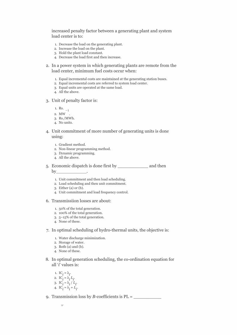
increasedpenaltyfactorbetweenageneratingplantandsystemloadcenteristo:
1. Decreasetheloadonthegeneratingplant.2. Increasetheloadontheplant.3. Holdtheplantloadconstant.4. Decreasetheloadfirstandthenincrease.
2. Inapowersysteminwhichgeneratingplantsareremotefromtheloadcenter,minimumfuelcostsoccurwhen:
1. Equalincrementalcostsaremaintainedatthegeneratingstationbuses.2. Equalincrementalcostsarereferredtosystemloadcenter.3. Equalunitsareoperatedatthesameload.4. Alltheabove.
3. Unitofpenaltyfactoris:
1. Rs.
2. MW .3. Rs./MWh.4. Nounits.
4. Unitcommitmentofmorenumberofgeneratingunitsisdoneusing:
1. Gradientmethod.2. Non-linearprogrammingmethod.3. Dynamicprogramming.4. Alltheabove.
5. Economicdispatchisdonefirstby___________andthenby___________.
1. Unitcommitmentandthenloadscheduling.2. Loadschedulingandthenunitcommitment.3. Either(a)or(b).4. Unitcommitmentandloadfrequencycontrol.
6. Transmissiionlossesareabout:
1. 50%ofthetotalgeneration.2. 100%ofthetotalgeneration.3. 5–15%ofthetotalgeneration.4. Noneofthese.
7. Inoptimalschedulingofhydro-thermalunits,theobjectiveis:
1. Waterdischargeminimization.2. Storageofwater.3. Both(a)and(b).4. Noneofthese.
8. Inoptimalgenerationscheduling,theco-ordinationequationforall‘i’valuesis:
1. IC =λ .
2. IC =λ L .
3. IC =λ /L .
4. IC =λ +L .
9. TransmissionlossbyB-coefficientsisPL=__________
i i
i i i
i i i
i i i
–1
T

1. P BP.
2. P B.3. BP.4. All.
10. Theconditionforoptimalitywithconsiderationoftransmissionlossis:
1. TheincrementalfuelcostsinRs./hrofalltheunitsmustbethesame.2. TheincrementalfuelcostsinRs./hrofalltheunitsmustbethesame.3. TheincrementaltransmissionlossesinRs./MWhofalltheunitsmustbe
thesame.4. Theincrementalfuelcostofeachmultipliedbyitspenaltyfactormustbe
thesameforallplants.
11. Expressionfortransmissionlossisderivedusing______________method.
1. Kron’s.2. Penaltyfunction.3. Kirchmayer’s.4. Kuhn-Tucker.
12.
1.
2.
3.
4.
13. Theequalityconstraint,whenthetransmissionlinelossesareconsidered,is:
1.
2.
3.
4.
14. Transmissionlossis:
T
T

1. Afunctionofreal-powergeneration.2. Independentofreal-powergeneration.3. Afunctionofreactive-powergeneration.4. Afunctionofbusvoltagemagnitudeanditsangle.
15. InKron’smethod,
1. Reducethesystemtoanequivalentsystemwithasinglehypotheticalload.2. Reducethesystemtoanequivalentsystemwithoutanyload.3. Reducethesystemtoanequivalentsystemwithalargenumberofloads.4. Enhancethesystemtoanequivalentsystemwithnopowerloss.
16. Thederivationoftransmissionlinelossisnotbasedonwhichassumption?
1. Alltheloadcurrentsmaintainaconstantratio.
2. Allthelinesinthesystemhavedifferent ratios.
3. Alltheloadcurrentshavesamephaseangle.4. Thepowerfactorateachstationremainsconstant.
17. ThelosscoefficientB isgivenby:
1.
2.
3.
4.
18. Whichofthefollowingiscorrect?
1.
2.
3.
4.
12
th
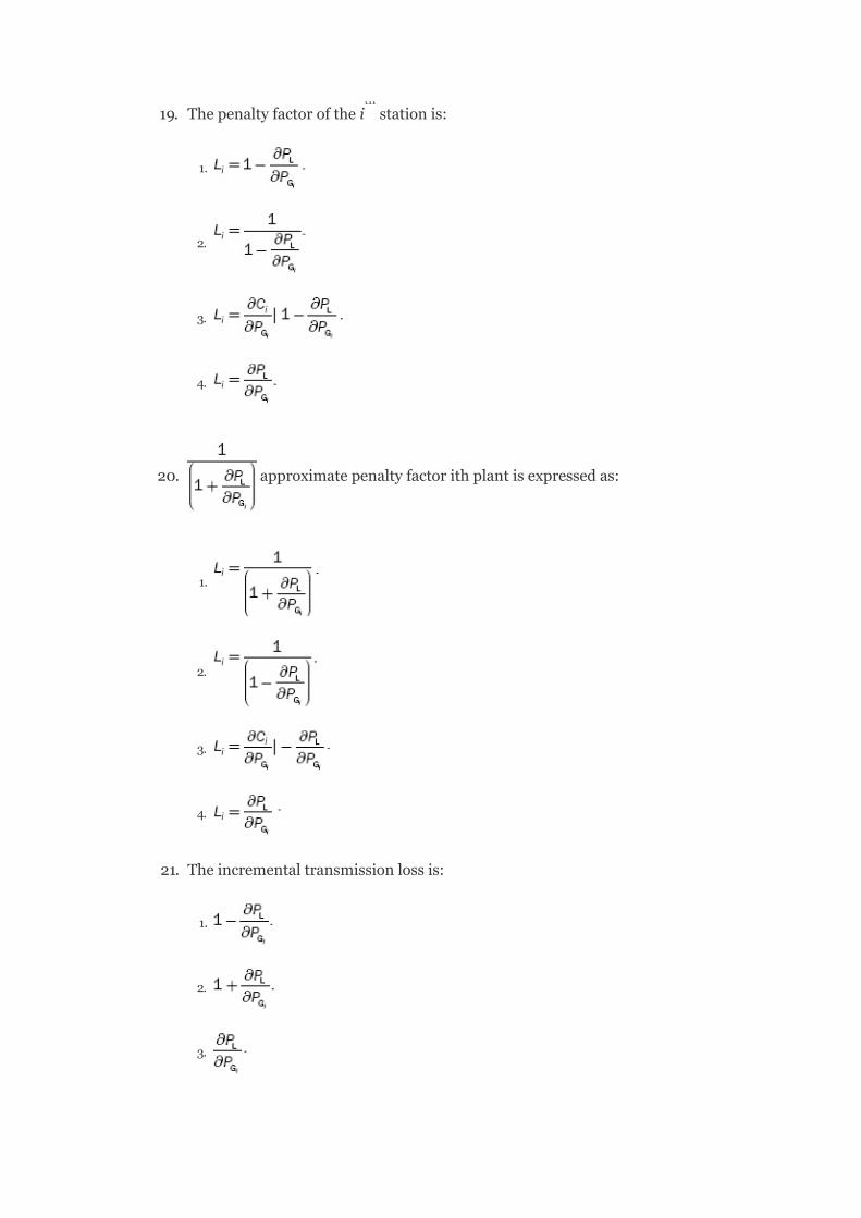
19. Thepenaltyfactorofthei stationis:
1.
2.
3.
4.
20. approximatepenaltyfactorithplantisexpressedas:
1.
2.
3.
4.
21. Theincrementaltransmissionlossis:
1.
2.
3.
th

4.
22. iscalledtheco-ordinationequationbecause:
1. Itco-ordinatesITLwithIC.2. Itco-ordinatesITLwithpenaltyfactor.3. Itco-ordinatesreal-powergenerationwithreactive-powergeneration.4. Itco-ordinatesbusvoltagemagnitudewithIC.
23. TheincrementalcostofreceivedpowerinRs./MWhoftheiplantis:
1.
2.
3.
4.
24. Insolvingoptimizationproblemwithtransmissionlossconsideration,theconditionforoptimalityisobtainedas:
1. TheICofalltheplantsmustbethesame.2. TheICofeachplantmultipliedwithitspenaltyfactormustbethesamefor
alltheplants.3. TheICofeachplantdividedbyitspenaltyfactormustbethesameforall
theplants.4. TheICofeachplantsubtractedfromitspenaltyfactormustbethesame
foralltheplants.
25. Thematrixformoftransmissionlossexpressionis:
1.
2.
3.
4.
26. Theexactco-ordinationequationofthei plantis:
th
th

1.
2.
3.
4.
27. Theoptimizationproblemissolvedbythecomputationalmethodwiththeexpressionforp whichisgivenas:
1.
2.
3.
4.
28. ThepenaltyfactoroftheplantshowninFig.3.14is:
1. 5.2. 5.25.3. 1.254. 12.5
FIG.3.14IllustrationforQuestionnumber28
Gi

29. Theincrementalcostofreceivedpowerfortheaboveplantif
Rs./MWhis:
1. 1.25.2. 16.82.3. 16.00.4. 12.80.
30. ForFig.3.15,whatisthepenaltyfactorofthesecondplantifapowerof125MWistransmittedfromthefirstplanttoloadwithanincurredlossof15.625MW?
1. 24.2. 1.25.3. Zero.4. 1.
31. Toderivethetransmissionlossexpression,whichofthefollowingassumptionsaretobetakenintoconsideration?
1. AllthelinesinthesystemhavethesameR/Xratio.2. P.f.ateachstationremainsconstant.3. Alltheloadcurrentsmaintainconstantratiotothetotalcurrent.4. Alltheloadcurrentshavetheirowndifferentphaseangles.
1. (i)and(ii).2. (ii)and(iii).3. Allexcept(iv).4. Allofthese.
FIG.3.15
32. Inderivingtheexpressionfortransmissionpowerloss,whichofthefollowingprinciplesareused?
1. Thevinin’stheorem.2. Kron’smethod.3. Max.power-transfertheorem.4. Superpositiontheorem.
1. (i)only.2. (ii)and(iii)only.3. (ii)and(iv)only.4. Allexcept(i).
33. Thetransmissionlossisexpressedas:
1.
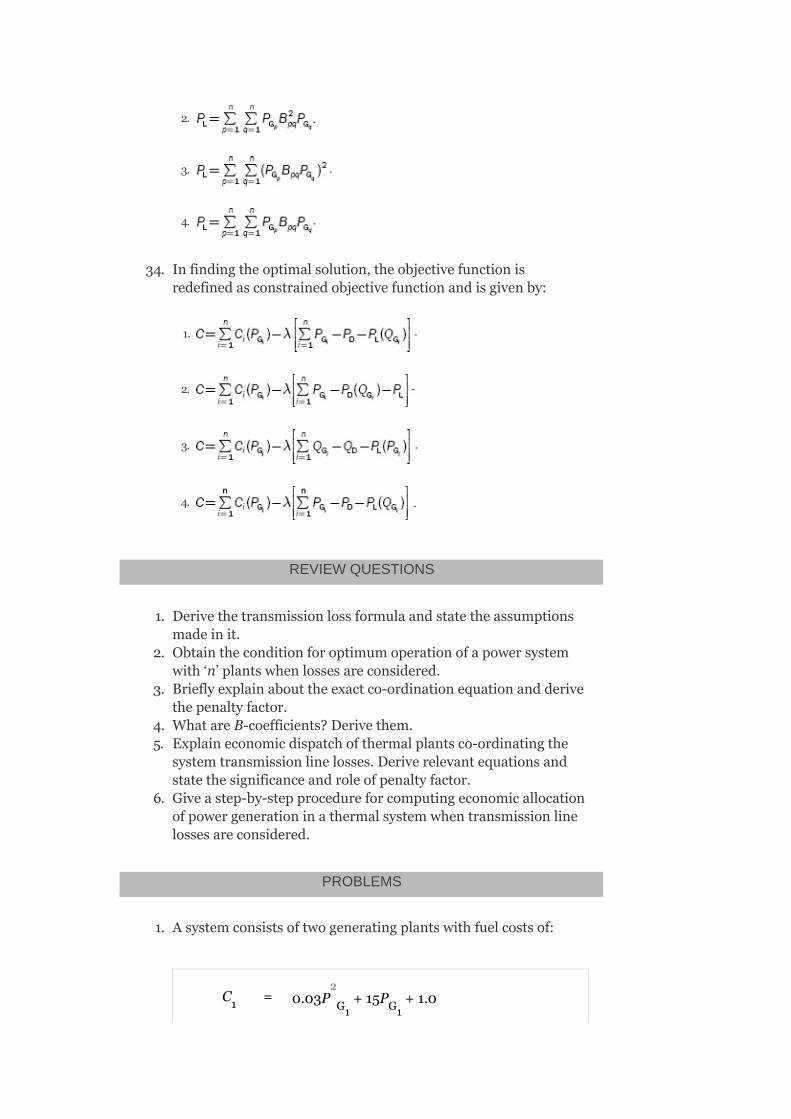
2.
3.
4.
34. Infindingtheoptimalsolution,theobjectivefunctionisredefinedasconstrainedobjectivefunctionandisgivenby:
1.
2.
3.
4.
REVIEWQUESTIONS
1. Derivethetransmissionlossformulaandstatetheassumptionsmadeinit.
2. Obtaintheconditionforoptimumoperationofapowersystemwith‘n’plantswhenlossesareconsidered.
3. Brieflyexplainabouttheexactco-ordinationequationandderivethepenaltyfactor.
4. WhatareB-coefficients?Derivethem.5. Explaineconomicdispatchofthermalplantsco-ordinatingthe
systemtransmissionlinelosses.Deriverelevantequationsandstatethesignificanceandroleofpenaltyfactor.
6. Giveastep-by-stepprocedureforcomputingeconomicallocationofpowergenerationinathermalsystemwhentransmissionlinelossesareconsidered.
PROBLEMS
1. Asystemconsistsoftwogeneratingplantswithfuelcostsof:
C = 0.03P +15P +1.01 G1 G1
2

and
C = 0.04P +21P +1.4
Thesystemoperatesoneconomicaldispatchwith120MWofpowergenerationbyeachplant.TheincrementaltransmissionlossofPlant-2is0.15.FindthepenaltyfactorofPlant-1.
2. Asystemconsistsoftwogeneratingplants.TheincrementalcostsinRs./MWhwithp andp inMWare:
Thesystemoperatesoneconomicdispatchwithp =p =400
MWand .FindthepenaltyfactorofPlant-1.
3. Thecostcurvesoftwoplantsareasfollows:
C =0.04P +25P +120
C =0.035P +10P +160
ThelosscoefficientfortheabovesystemisgivenasB =
0.001/MW,B =B =–0.0002/MWandB =0.003/MW.
Determinetheeconomicalgenerationschedulingcorrespondingtoλ=20Rs./MWhandcorrespondingsystemloadthatcanbemetwith.Ifthetotalloadconnectedtothesystemis110MWtaking3.5%changeinthevalueofλ,whatshouldbethevalueofλinthenextiteration?
2 G2 G2
G1 G2
G1 G2
1 G1 G2
2 G2 G1
11
12 21 22
2
2
2
4
OptimalUnitCommitment
OBJECTIVES
Afterreadingthischapter,youshouldbeableto:
knowtheneedofoptimalunitcommitment(UC)studythesolutionmethodsforUCsolvetheUCproblembydynamicprogramming(DP)approachpreparetheUCtablewithreliabilityandstart-upcostconsiderations
4.1INTRODUCTION
Thetotalloadofthepowersystemisnotconstantbutvariesthroughoutthedayandreachesadifferentpeakvaluefromonedaytoanother.Itfollowsaparticularhourlyloadcycleoveraday.TherewillbedifferentdiscreteloadlevelsateachperiodasshowninFig.4.1.
Duetotheabovereason,itisnotadvisabletorunallavailableunitsallthetime,anditisnecessarytodecideinadvancewhichgeneratorsaretostartup,whentoconnectthemtothenetwork,thesequenceinwhichtheoperatingunitsshouldbeshutdown,andforhowlong.Thecomputationalprocedureformakingsuchdecisionsiscalledunitcommitment(UC),andaunitwhenscheduledforconnectiontothesystemissaidtobecommitted.

FIG.4.1Discretelevelsofsystemloadofdailyloadcycle
TheproblemofUCisnothingbuttodeterminetheunitsthatshouldoperateforaparticularload.To‘commit’ageneratingunitisto‘turniton’,i.e.,tobringituptospeed,synchronizeittothesystem,andconnectit,sothatitcandeliverpowertothenetwork.
4.2COMPARISONWITHECONOMICLOADDISPATCH
Economicdispatcheconomicallydistributestheactualsystemloadasitrisestothevariousunitsthatarealreadyon-line.However,theUCproblemplansforthebestsetofunitstobeavailabletosupplythepredictedorforecastloadofthesystemoverafuturetimeperiod.
4.3NEEDFORUC
Theplantcommitmentandunit-orderingschedulesextendtheperiodofoptimizationfromafewminutestoseveralhours.Weeklypatternscanbedevelopedfromdailyschedules.Likewise,monthly,seasonal,andannualschedulescanbepreparedbytakingintoconsiderationtherepetitivenatureoftheloaddemandandseasonalvariations.Agreatdealofmoneycanbesavedbyturningofftheunitswhentheyarenotneededforthetime.Iftheoperationofthesystemistobe

optimized,theUCschedulesarerequiredforeconomicallycommittingunitsinplanttoservicewiththetimeatwhichindividualunitsshouldbetakenoutfromorreturnedtoservice.Thisproblemisofimportanceforschedulingthermalunitsinathermalplant;asforothertypesofgenerationsuchashydro,theiraggregatecosts(suchasstart-upcosts,operatingfuelcosts,andshut-downcosts)arenegligiblesothattheiron-offstatusisnotimportant.
4.4CONSTRAINTSINUC
TherearemanyconstraintstobeconsideredinsolvingtheUCproblem.
4.4.1Spinningreserve
Itisthetermusedtodescribethetotalamountofgenerationavailablefromallsynchronizedunitsonthesystemminusthepresentloadandlossesbeingsupplied.Here,thesynchronizedunitsonthesystemmaybenamedunitsspinningonthesystem.
LetP bethespinningreserve, thepowergeneration
ofthei synchronizedunit,P thetotalloadonthesystem,andp thetotallossofthesystem:
Thespinningreservemustbemaintainedsothatthefailureofoneormoreunitsdoesnotcausetoofaradropinsystemfrequency.Simply,ifoneunitfails,theremustbeanamplereserveontheotherunitstomakeupforthelossinaspecifiedtimeperiod.
Thespinningreservemustbeagivenapercentageofforecastedpeakloaddemand,oritmustbecapableof
Gsp
D
L
th

takingupthelossofthemostheavilyloadedunitinagivenperiodoftime.
Itcanalsobecalculatedasafunctionoftheprobabilityofnothavingsufficientgenerationtomeettheload.
Thereservesmustbeproperlyallocatedamongfast-respondingunitsandslow-respondingunitssuchthatthisallowstheautomaticgenerationcontrolsystemtorestorefrequencyandquicklyinterchangethetimeofoutageofageneratingunit.
Beyondthespinningreserve,theUCproblemmayconsidervariousclassesof‘scheduledreserves’oroff-linereserves.Theseincludequick-startdieselorgas-turbineunitsaswellasmosthydro-unitsandpumpedstoragehydro-unitsthatcanbebroughton-line,synchronized,andbroughtuptomaximumcapacityquickly.Assuch,theseunitscanbecountedintheoverallreserveassessmentaslongastheirtimetocomeuptomaximumcapacityistakenintoconsideration.Reservesshouldbespreadwellaroundtheentirepowersystemtoavoidtransmissionsystemlimitations(oftencalled‘bottling’ofreserves)andtoallowdifferentpartsofthesystemtorunas‘islands’,shouldtheybecomeelectricallydisconnected.
4.4.2Thermalunitconstraints
Athermalunitcanundergoonlygradualtemperaturechangesandthistranslatesintoatimeperiod(ofsomehours)requiredtobringtheunitontheline.Duetosuchlimitationsintheoperationofathermalplant,thefollowingconstraintsaretobeconsidered.
1. Minimumup-time:Duringtheminimumup-time,oncetheunitisoperating(upstate),itshouldnotbeturnedoffimmediately.
2. Minimumdown-time:Theminimumdown-timeistheminimumtimeduringwhichtheunitisin‘down’state,i.e.,oncetheunitisdecommitted,thereisaminimumtimebeforeitcanberecommitted.
3. Crewconstraints:Ifaplantconsistsoftwoormoreunits,theycannotbothbeturnedonatthesametimesincetherearenotenoughcrewmemberstoattendtobothunitswhilestartingup.
Start-upcost
Inadditiontotheaboveconstraints,becausethetemperatureandthepressureofthethermalunitmustbemovedslowly,acertainamountofenergymustbe

expendedtobringtheuniton-lineandisbroughtintotheUCproblemasastart-upcost.
Thestart-upcostmayvaryfromamaximum‘cold-start’valuetoaverysmallvalueiftheunitwasonlyturnedoffrecently,anditisstillrelativelyclosetotheoperatingtemperature.
Twoapproachestotreatingathermalunitduringits‘down’state:
Thefirstapproach(cooling)allowstheunit’sboilertocooldownandthenheatbackuptoaoperatingtemperatureintimeforascheduledturn-on.Thesecondapproach(banking)requiresthatsufficientenergybeinputtotheboilertojustmaintaintheoperatingtemperature.
FIG.4.2Time-dependentstart-upcosts
Thebestapproachcanbechosenbycomparingthecostsfortheabovetwoapproaches.
LetC bethecold-startcost(MBtu),Cthefuelcost,Cthefixedcost(includescrewexpensesandmaintainableexpenses),αthethermaltimeconstantfortheunit,Cthecostofmaintainingunitatoperatingtemperature(MBtu/hr),andtthetimetheunitwascooled(hr).
Start-upcostwhencooling=C (1–e )C+C ;
C F
t
c F
-t/α

Start-upcostwhenbanking=C ×t×C+C .
Uptoacertainnumberofhours,thecostofbanking<costofcoolingisshowninFig.4.2.
ThecapacitylimitsofthermalunitsmaychangefrequentlyduetomaintenanceorunscheduledoutagesofvariousequipmentsintheplantandthismustalsobetakenintoconsiderationintheUCproblem.
Theotherconstraintsareasfollows
4.4.3Hydro-constraints
AspointedoutalreadythattheUCproblemisofmuchimportancefortheschedulingofthermalunits,itisnotthemeaningofUCthatcannotbecompletelyseparatedfromtheschedulingofahydro-unit.
Thehydro-thermalschedulingwillbeexplainedasseparatedfromtheUCproblem.Operationofasystemhavingbothhydroandthermalplantsis,however,farmorecomplexashydro-plantshavenegligibleoperationcosts,butarerequiredtooperateunderconstraintsofwateravailableforhydro-generationinagivenperiodoftime.
Theproblemofminimizingtheoperatingcostofahydro-thermalsystemcanbeviewedasoneofminimizingthefuelcostofthermalplantsundertheconstraintofwateravailabilityforhydro-generationoveragivenperiodofoperation.
4.4.4Mustrun
Itisnecessarytogiveamust-runreorganizationtosomeunitsoftheplantduringcertaineventsoftheyear,bywhichweyieldthevoltagesupportonthetransmissionnetworkorforsuchpurposeassupplyofsteamforusesoutsidethesteamplantitself.
4.4.5Fuelconstraints
t F
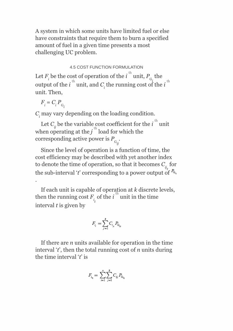
AsysteminwhichsomeunitshavelimitedfuelorelsehaveconstraintsthatrequirethemtoburnaspecifiedamountoffuelinagiventimepresentsamostchallengingUCproblem.
4.5COSTFUNCTIONFORMULATION
LetF bethecostofoperationofthei unit,P the
outputofthei unit,andC therunningcostoftheiunit.Then,
F =C P
C mayvarydependingontheloadingcondition.
LetC bethevariablecostcoefficientforthei unitwhenoperatingatthej loadforwhichthecorrespondingactivepowerisP .
Sincethelevelofoperationisafunctionoftime,thecostefficiencymaybedescribedwithyetanotherindextodenotethetimeofoperation,sothatitbecomesC for
thesub-interval‘t’correspondingtoapoweroutputof.
Ifeachunitiscapableofoperationatkdiscretelevels,thentherunningcostF ofthei unitinthetime
intervaltisgivenby
Iftherearenunitsavailableforoperationinthetimeinterval‘t’,thenthetotalrunningcostofnunitsduringthetimeinterval‘t’is
i Gi
i
i i Gi
i
ij
Gij
ijt
it
th
th th
th
th
th

Fortheentiretimeperiodofoptimization,havingTsub-intervalsoftime,theoverallrunningcostforalltheunitsmaybecome
4.5.1Start-upcostconsideration
Supposethatforaplanttobebroughtintoservice,anadditionalexpenditureC hastobeincurredinaddition
totherunningcost(i.e.,start-upcostofthei unit),thecostofstarting‘x’numberofunitsduringanysub-intervaltisgivenby
whereδ =1,ifthei unitisstartedinsub-interval‘t’
andotherwiseδ =0.
4.5.2Shut-downcostconsideration
Similarly,ifaplantistakenoutofserviceduringtheschedulingperiod,itisnecessarytoconsidertheshut-downcost.
If‘y’numberofunitsarebetoshutdownduringthesub-interval‘t’,theshut-downcostmayberepresentedas
whereσ =1,whenthei unitisthrownoutofservicein
sub-interval‘t’;otherwiseσ =0.
si
it
it
it
it
th
th
th

OverthecompleteschedulingperiodofTsub-intervals,thestart-upcostisgivenby
andtheshut-downcostis
Now,thetotalexpressionforthecostfunctionincludingtherunningcost,thestart-upcost,andtheshut-downcostiswrittenintheform:
Foreachsub-intervaloftimet,thenumberofgeneratingunitstobecommittedtoservice,thegeneratorstobeshutdown,andthequantizedpowerloadinglevelsthatminimizethetotalcosthavetobedetermined.
4.6CONSTRAINTSFORPLANTCOMMITMENTSCHEDULES
Asintheoptimalpointgenerationscheduling,theoutputofeachgeneratormustbewithintheminimumandmaximumvalueofcapacity:
i.e.,
Theoptimumschedulesofgenerationarepreparedfromtheknowledgeofthetotalavailableplantcapacity,whichmustbeinexcessoftheplant-generatingcapacityrequiredinmeetingthepredictedloaddemandin

satisfyingtherequirementsforminimumrunningreservecapacityduringtheentireperiodofscheduling:
whereS isthetotalavailablecapacityinanysub-interval‘t’,S theminimumrunningreservecapacity,
α =1,ifthei unitisinoperationduringsub-interval
‘t’;otherwiseα =0
Inaddition,forapredictedloaddemandP ,thetotalgenerationoutputinsub-interval‘t’mustbeinexcessoftheloaddemandbyanamountnotlessthantheminimumrunningreservecapacityS .
(withoutconsideringthe
transmissionlosses)
Incaseofconsiderationoftransmissionlosses,theaboveequationbecomes
Thegeneratorstart-upandshut-downlogicindicatorsδ andσ ,respectively,shouldbeunityduringthe
correspondingsub-intervalsofoperation
4.7UNITCOMMITMENT—SOLUTIONMETHODS
ThemostimportanttechniquesforthesolutionofaUCproblemare:
TAC
rmin
it
it
D
rmin
it it
th

1. Priority-listschemes.2. Dynamicprogramming(DP)method.3. Lagrange’srelaxation(LR)method.
Now,wewillexplainthepriority-listschemeandtheDPmethod.
Asimpleshut-downruleorpriority-listschemecouldbeobtainedafteranexhaustiveenumerationofallunitcombinationsateachloadlevel.
4.7.1Enumerationscheme
Astraightforwardbuthighlytime-consumingwayoffindingthemosteconomicalcombinationofunitstomeetaparticularloaddemandistotryallpossiblecombinationsofunitsthatcansupplythisload.Thisloadisdividedoptimallyamongtheunitsofeachcombinationbytheuseofco-ordinationequationssoastofindthemosteconomicaloperatingcostofthecombination.Then,thecombinationthathastheleastoperatingcostamongalltheseisdetermined.
SomecombinationswillbeinfeasibleifthesumofallmaximumMWfortheunitscommittedislessthantheloadorifthesumofallminimumMWfortheunitscommittedisgreaterthantheload.
Example4.1:Letusconsideraplanthavingthreeunits.Thecostcharacteristicsandminimumandmaximumlimitsofpowergeneration(MW)ofeachunitareasfollows:
Unit-1,
C =0.002842P +8.46P +600.0Rs./hr,200≤
P ≤650
Unit-2,
C =0.002936P +8.32P +420.0Rs./hr,150≤
P ≤450
Unit-3,
1 G1 G1
G1
2 G2 G2
G2
2
2
2

C =0.006449P +9.884P +110.0Rs./hr,100≤
P ≤300
Tosupplyatotalloadof600MWmosteconomically,thecombinationsofunitsandtheirgenerationstatusaretabulatedinTable4.1.
Numberofcombinations=2 =2 =8
TABLE4.1Combinationsoftheunitsandtheirstatusforthedispatchofa600-MWload
Note:Theleastexpensivewasnottosupplythegenerationwithallthreeunitsrunningorevenanycombinationinvolvingtwounits.Rather,theoptimumcommitmentwastorunonlyunit-1,themosteconomicunit.Byonlyrunningit,theloadcanbesuppliedbythatunitoperatingclosertoitsbestefficiency.Ifanotherunitiscommitted,bothUnit-1andtheotherunitwillbeloadedfurtherfromtheirbestefficiencypointssuchthatthenetcostisgreaterthanunit-1alone.
3 G3 G3
G3
2
n 3

FIG.4.3Simplepeak–valleyloadpattern
4.7.1.1UCoperationofsimplepeak–valleyloadpattern:shut-downrule
Letusassumethattheloadfollowsasimple‘peak–valley’patternasshowninFig.4.3.
Tooptimizethesystemoperation,someunitsmustbeshutdownastheloaddecreasesandisthenrecommitted(putintoservice)asitgoesbackup.
Oneapproachcalledthe‘shut-downrule’mustbeusedtoknowwhichunitstodropandwhentodropthem.Asimplepriority-listschemeistobedevelopedfromthe‘shut-downrule’.
Considertheexample,withtheloadvaryingfromapeakof1,400MWtoavalleyof600MW(Table4.2).Toobtaina‘shut-downrule’,wesimplyuseabrute-forcetechniquewhereinallcombinationsofunitswillbetriedforeachloadleveltakeninstepsofsomeMW(here50MW).

TABLE4.2Shut-downrulederivation
Fromtheabovetable,wecanobservethatfortheloadabove1,100MW,runningallthethreeunitsiseconomical;between1,100and700MWrunningthefirstandsecondunitsiseconomical.Forbelow700MW,runningofonlyUnit-1iseconomicalasshowninFig.4.4.

FIG.4.4UCscheduleusingtheshut-downrule
TABLE4.3Priorityorderingofunits
TABLE4.4Prioritylistforsupplyof1,400MW
Combinationofunits
ForcombinationP ForcombinationP
2,1,and3 50 1,400
2and1 350 1,100
2 150 450
4.7.2Priority-listmethod
Asimplebutsub-optimalapproachtotheproblemistoimposepriorityordering,whereinthemostefficientunit
Gmin Gmax

isloadedfirsttobefollowedbythelessefficientunitsinorderastheloadincreases.
Inthismethod,firstwecomputethefull-loadaverageproductioncostofeachunit.Then,intheorderofascendingcosts,theunitsarearrangedtocommittheloaddemand.
ForExample4.1,weconstructaprioritylistasfollows:
First,thefull-loadaverageproductioncostwillbecalculated.
Thefull-loadaverageproductioncostofUnit-1=9.79Rs./MWh.
Thefull-loadaverageproductioncostofUnit-2=9.48Rs./MWh.
Thefull-loadaverageproductioncostofUnit-3=11.188Rs./MWh.
Apriorityorderoftheseunitsbasedontheaverageproductionisasfollows(Table4.3):
Byneglectingminimumup-ordown-time,start-upcosts,etc.theloaddemandcanbemetbythepossiblecombinationsasfollows(Table4.4):
4.7.2.1Priority-listschemeversusshut-downsequence
Inshut-downsequence,Unit-2wasshutdownat700MWleavingUnit-1.Withthepriority-listscheme,bothunitswouldbeheldONuntiltheloadhadreached450MWandthenUnit-1wouldbedropped.
Manypriority-listschemesaremadeaccordingtoasimpleshut-downalgorithm,suchthattheywouldhavestepsforshuttingdownaunitasfollows:
1. Duringthedroppingofload,attheendofeachhour,determinewhetherthenextunitontheprioritylistwillhavesufficientgenerationcapacitytomeettheloaddemandandtosatisfytherequirementofthespinningreserve.Ifyesgotothenextstepandotherwisecontinuetheoperationwiththeunitasitis.
2. Determinethetimeinnumberofhours‘h’beforethedropped

unit(inStep1)willbeneededagainforservice.3. Ifthenumberofhours(h)islessthanminimumshut-downtime
fortheunit,thenkeepthecommitmentoftheunitasitisandgotoStep5;ifnot,gotothenextstep.
4. Now,calculatethefirstcost,whichisthesumofhourlyproductioncostsforthenext‘h’hourswiththeunitin‘up’state.Then,recalculatethesamesumassecondcostfortheunit‘down’stateandinthestart-upcostforeithercoolingtheunitorbankingit,whicheverislessexpensive.Iftherearesufficientsavingsfromshuttingdowntheunit,itshouldbeshutdown,otherwisekeepiton.
5. Repeattheaboveprocedureforthenextunitontheprioritylistandcontinueforthesubsequentunit.
Thevariousimprovementstothepriority-listschemescanbemadebygroupingofunitstoensurethatvariousconstraintsaremet.
4.7.3Dynamicprogramming
DynamicprogrammingisbasedontheprincipleofoptimalityexplainedbyBellmanin1957.Itstatesthat‘anoptimalpolicyhastheproperty,that,whatevertheinitialstateandtheinitialdecisionsare,theremainingdecisionsmustconstituteanoptimalpolicywithregardtothestateresultingfromthefirstdecision’.
Thismethodcanbeusedtosolveproblemsinwhichmanysequentialdecisionsarerequiredtobetakenindefiningtheoptimumoperationofasystem,whichconsistsofadistinctnumberofstages.However,itissuitableonlywhenthedecisionsatthelaterstagesdonotaffecttheoperationattheearlierstages.
4.7.3.1SolutionofanoptimalUCproblemwithDPmethod
Dynamicprogramminghasmanyadvantagesovertheenumerationscheme,themainadvantagebeingareductioninthesizeoftheproblem.
Theimpositionofaprioritylistarrangedinorderofthefull-loadaveragecostratewouldresultinacorrectdispatchandcommitmentonlyif
1. No–loadcostsarezero.2. Unitinput–outputcharacteristicsarelinearbetweenzerooutputand
fullload.3. Therearenootherlimitations.4. Start-upcostsareafixedamount.
IntheDPapproach,weassumethat:
1. Astateconsistsofanarrayofunitswithspecifiedoperatingunitsandtherestareatoff-line.
2. Thestart-upcostofaunitisindependentofthetimeifithasbeenoff-line.
3. Therearenocostsforshuttingdownaunit.4. Thereisastrictpriorityorderandineachintervalaspecified
minimumamountofcapacitymustbeoperating.
Afeasiblestateisoneatwhichthecommittedunitscansupplytherequiredloadandthatmeetstheminimumamountofcapacityineachperiod.
Practically,aUCtableistobemadeforthecompleteloadcycle.TheDPmethodismoreefficientforpreparingtheUCtableiftheavailableloaddemandisassumedtoincreaseinsmallbutfinitesizesteps.InDPitisnotnecessarytosolveco-ordinateequations,whileatthesametimetheunitcombinationsaretobetried.
ConsiderablecomputationalsavingcanbeachievedbyusingthebranchandboundtechniqueoraDPmethodforcomparingtheeconomicsofcombinationsascertaincombinationsneednotbetriedatall.
Thetotalnumberofunitsavailable,theirindividualcostcharacteristics,andtheloadcycleonthestationareassumedtobeknownapriori.Further,itshallbeassumedthattheloadoneachunitorcombinationofunitschangesinsuitablysmallbutuniformstepsofsize∆MW(say1MW).
ProcedureforpreparingtheUCtableusingtheDPapproach:
Step1: Startarbitrarilywithconsiderationofanytwounits.
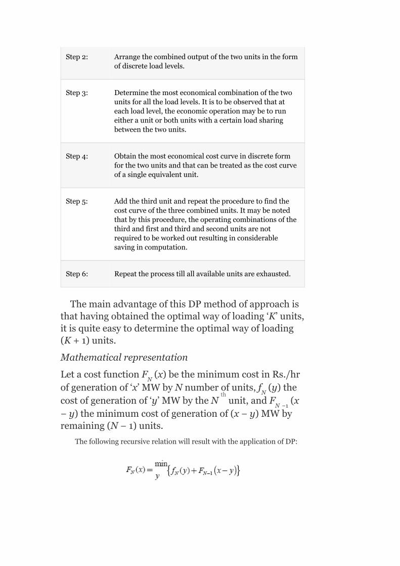
Step2: Arrangethecombinedoutputofthetwounitsintheformofdiscreteloadlevels.
Step3: Determinethemosteconomicalcombinationofthetwounitsforalltheloadlevels.Itistobeobservedthatateachloadlevel,theeconomicoperationmaybetoruneitheraunitorbothunitswithacertainloadsharingbetweenthetwounits.
Step4: Obtainthemosteconomicalcostcurveindiscreteformforthetwounitsandthatcanbetreatedasthecostcurveofasingleequivalentunit.
Step5: Addthethirdunitandrepeattheproceduretofindthecostcurveofthethreecombinedunits.Itmaybenotedthatbythisprocedure,theoperatingcombinationsofthethirdandfirstandthirdandsecondunitsarenotrequiredtobeworkedoutresultinginconsiderablesavingincomputation.
Step6: Repeattheprocesstillallavailableunitsareexhausted.
ThemainadvantageofthisDPmethodofapproachisthathavingobtainedtheoptimalwayofloading‘K’units,itisquiteeasytodeterminetheoptimalwayofloading(K+1)units.
Mathematicalrepresentation
LetacostfunctionF (x)betheminimumcostinRs./hrofgenerationof‘x’MWbyNnumberofunits,f (y)thecostofgenerationof‘y’MWbytheN unit,andF (x−y)theminimumcostofgenerationof(x−y)MWbyremaining(N−1)units.
ThefollowingrecursiverelationwillresultwiththeapplicationofDP:
N
N
N −1
th

Themostefficienteconomicalcombinationofunitscanefficientlybedeterminedbytheuseoftheaboverelation.Herethemosteconomicalcombinationofunitsissuchthatityieldstheminimumoperatingcost,fordiscreteloadlevelsrangesfromtheminimumpermissibleloadofthesmallestunittothesumofthecapacitiesofallavailableunits.
Inthisprocess,thetotalminimumoperatingcostandtheloadsharedbyeachunitoftheoptimalcombinationareautomaticallydeterminedforeachloadlevel.
Example4.2:Apowersystemnetworkwithathermalpowerplantisoperatingbyfourgeneratingunits.Determinethemosteconomicalunittobecommittedtoaloaddemandof8MW.Also,preparetheUCtablefortheloadchangesinstepsof1MWstartingfromtheminimumtothemaximumload.Theminimumandmaximumgeneratingcapacitiesandcost-curveparametersoftheunitslistedinatabularformaregiveninTable4.5.
Solution:
Weknowthat:
Thecostfunction,
Incrementalfuelcost,
Thetotalload=P =8MW(given)
Bycomparingthecost-curveparameters,wecometoknowthatthecostcharacteristicsofthefirstunitarethelowest.Ifonlyonesingleunitistobecommitted,Unit-1istobeemployed.
D

Now,findoutthecostofgenerationofpowerbythefirstunitstartingfromminimumtomaximumgeneratingcapacityofthatunit.
Let,
f (1)=themaincostinRs./hrforthegenerationof1MWbythefirstunit
f (2)=themaincostinRs./hrforthegenerationof2MWbythefirstunit
f (3)=themaincostinRs./hrforthegenerationof3MWbythefirstunit
f (4)=themaincostinRs./hrforthegenerationof4MWbythefirstunit
…..…..…..…..………………………
f (8)=themaincostinRs./hrforthegenerationof8MWbythefirstunit
TABLE4.5Capacitiesandcost-curveparametersoftheunits
1
1
1
1
1

ForthecommitmentofUnit-1only
Whenonlyoneunitistobecommittedtomeetaparticularloaddemand,i.e.,Unit-1inthiscaseduetoitslesscostparameters,thenF (x)=f (x).
where:
F (x)istheminimumcostofgenerationof‘x’MWbyonlyoneunit
f (x)istheminimumcostofgenerationof‘x’MWbyUnit-1
∴F (1)=f (1)=(0.37×1+22.9)1=23.27
F (2)=f (2)=(0.37×2+22.9)2=47.28
F (3)=f (3)=(0.37×3+22.9)3=72.03
Similarly,
F (4)=f (4)=97.52
F (5)=f (5)=123.75
F (6)=f (6)=150.72
F (7)=f (7)=178.43
F (8)=f (8)=206.88
WhenUnit-1istobecommittedtomeetaloaddemandof8MW,thecostofgenerationbecomes206.88Rs./hr.
Forthesecondunit
f (1)=min.costinRs./hrforthegenerationof1MWbythesecondunitonly
=(0.78P +25.9)P
1 1
1
1
1 1
1 1
1 1
1 1
1 1
1 1
1 1
1 1
2
G2 G2

=(0.78×1+25.9)1=26.68
Similarly,
f (2)=54.92
f (3)=84.72
f (4)=116.08
f (5)=149.0
f (6)=183.48
f (7)=219.52
f (8)=257.12
Byobservingf (8)andf (8),itisconcludedthatf (8)<f (8),i.e.,thecostofgenerationof8MWbyUnit-1isminimumthanthatbyUnit-2.
ForcommitmentofUnit-1andUnit-2combination
F (8)=Minimumcostofgenerationof8MWbythesimultaneousoperationoftwounits
i.e.,Units-1and2.
Inotherwords,theminimumcostofgenerationof8MWbythecombinationofUnit-1andUnit-2is205.11Rs./hrandforthisoptimalcost,Unit-1supplies7MWandUnit-2supplies1MW.
2
2
2
2
2
2
2
1 2 1
2
2

i.e.,theminimumcostofgenerationof7MWwiththecombinationofUnit-1(by6-MWsupply)andUnit-2(by1-MWsupply)is177.4Rs./hr.

F (2) = min[f (0)+F (2),f (1)+F (1),f (2)+F (0)]
= min[47.28,49.95,54.92]
∴F (2) = 47.28Rs./hr
F (1) = min[f (0)+F (1),f (1)+F (0)]
= min[23.27,26.68]
∴F (1) = 23.27Rs./hr
Now,thecostofgenerationbyUnit-3onlyis
f (0)=0; f (5)=169.625
f (1)=29.985; f (6)=209.46
f (2)=61.94; f (7)=251.265
f (3)=95.865; f (8)=295.04
f (4)=131.76;
2 2 1 2 1 2 1
2
2 2 1 2 1
2
3 3
3 3
3 3
3 3
3
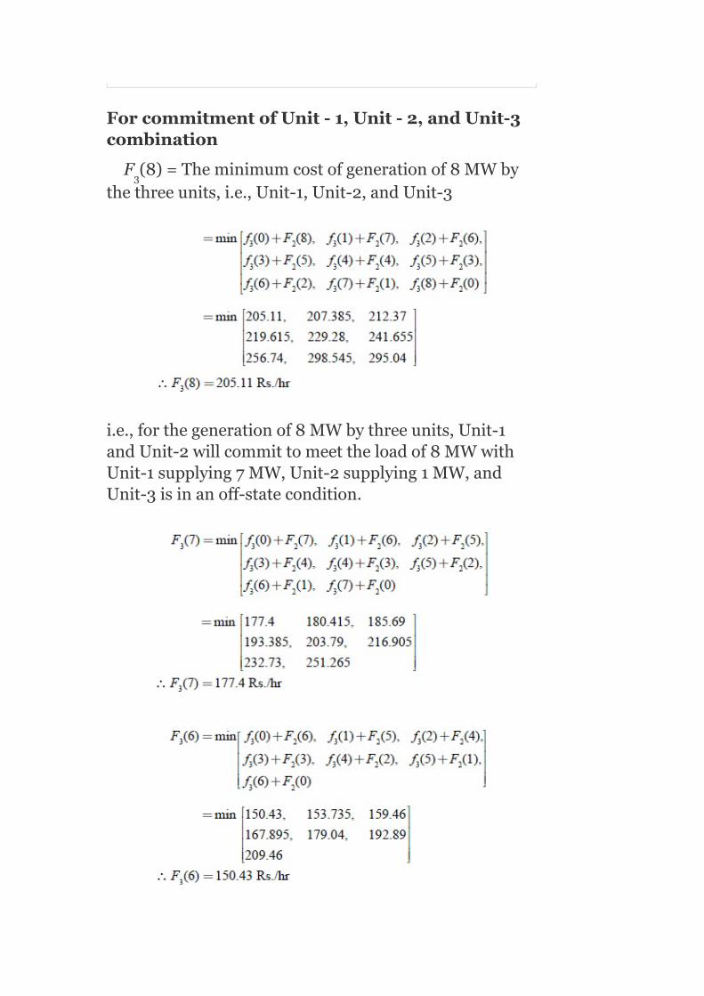
ForcommitmentofUnit-1,Unit-2,andUnit-3combination
F (8)=Theminimumcostofgenerationof8MWbythethreeunits,i.e.,Unit-1,Unit-2,andUnit-3
i.e.,forthegenerationof8MWbythreeunits,Unit-1andUnit-2willcommittomeettheloadof8MWwithUnit-1supplying7MW,Unit-2supplying1MW,andUnit-3isinanoff-statecondition.
3

F (2) = min[f (0)+F (2),f (1)+F (1),f (2)+F (0)]
= min[47.28,53.255,61.94]
∴F (2) = 47.28Rs./hr
F (1) = min[f (0)+F (1),f (1)+F (0)]
= min[23.27,29.958]
∴F (1) = 23.27Rs./hr
Costofgenerationbythefourthunit
3 3 2 3 2 3 2
3
3 3 2 3 2
3

f (0)=0
f (1)=31.88Rs./hr
f (2)=65.12Rs./hr
f (3)=99.72Rs./hr
f (4)=135.68Rs./hr
f (5)=173.0Rs./hr
f (6)=211.68Rs./hr
f (7)=251.72Rs./hr
f (8)=293.12Rs./hr
Minimumcostofgenerationbyfourunits,i.e.,Unit-1,Unit-2,Unit-3,andUnit-4
F (8)=Theminimumcostofgenerationof8MWbyfourunits
i.e.,forthegenerationof8MWbyfourunits,Unit-1andUnit-2willcommittomeettheloadof8MWwithUnit-1supplying7MW,Unit-2supplying1MW,andUnit-3aswellasUnit-4areinanoff-statecondition:
4
4
4
4
4
4
4
4
4
4


F (1) = min[f (0)+F (1),f (1)+F (0)]
= min[23.2731.88]
∴F (1) = 23.27Rs./hr
Fromtheabovecriteria,itisobservedthatforthegenerationof8MW,thecommitmentofunitsisasfollows:
f (8) = F (8)=theminimumcostofgenerationof8MWin
Rs./hrbyUnit-1only
= 206.88Rs./hr
F (8) = theminimumcostofgenerationof8MWbytwounitswithUnit-1supplying7MWandUnit-2supplying1MW
= 205.11Rs./hr
F (8) = theminimumcostofgenerationof8MWbythreeunitswithUnit-1supplying7MW,Unit-2supplying1MW,andUnit-3isinanoff-statecondition.
4 4 3 4 3
4
1 1
2
3
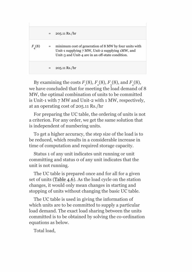
= 205.11Rs./hr
F (8) = minimumcostofgenerationof8MWbyfourunitswithUnit-1supplying7MW,Unit-2supplying1MW,andUnit-3andUnit-4areinanoff-statecondition.
= 205.11Rs./hr
ByexaminingthecostsF (8),F (8),F (8),andF (8),wehaveconcludedthatformeetingtheloaddemandof8MW,theoptimalcombinationofunitstobecommittedisUnit-1with7MWandUnit-2with1MW,respectively,atanoperatingcostof205.11Rs./hr
ForpreparingtheUCtable,theorderingofunitsisnotacriterion.Foranyorder,wegetthesamesolutionthatisindependentofnumberingunits.
Togetahigheraccuracy,thestepsizeoftheloadistobereduced,whichresultsinaconsiderableincreaseintimeofcomputationandrequiredstoragecapacity.
Status1ofanyunitindicatesunitrunningorunitcommittingandstatus0ofanyunitindicatesthattheunitisnotrunning.
TheUCtableispreparedonceandforallforagivensetofunits(Table4.6).Astheloadcycleonthestationchanges,itwouldonlymeanchangesinstartingandstoppingofunitswithoutchangingthebasicUCtable.
TheUCtableisusedingivingtheinformationofwhichunitsaretobecommittedtosupplyaparticularloaddemand.Theexactloadsharingbetweentheunitscommittedistobeobtainedbysolvingtheco-ordinationequationsasbelow.
Totalload,
4
1 2 3 4

P =P =8MW(given) (4.5)
⇒P =8−P
TABLE4.6TheUCtablefortheabove-consideredsystem
Foranoptimalloadsharing,
G1 G2
G2 G1

i.e.,loadsharedbythefirstunit,P =6.73MW
andP −8−P =8−6.73=1.27MW
i.e.,loadsharedbythesecondunit,P =1.27MW
Lagrangianmultiplier,λ = 0.74P +22.9=1.56P +
25.9
= 27.88Rs./MWh
G1
G2 G1
G2
G1 G2
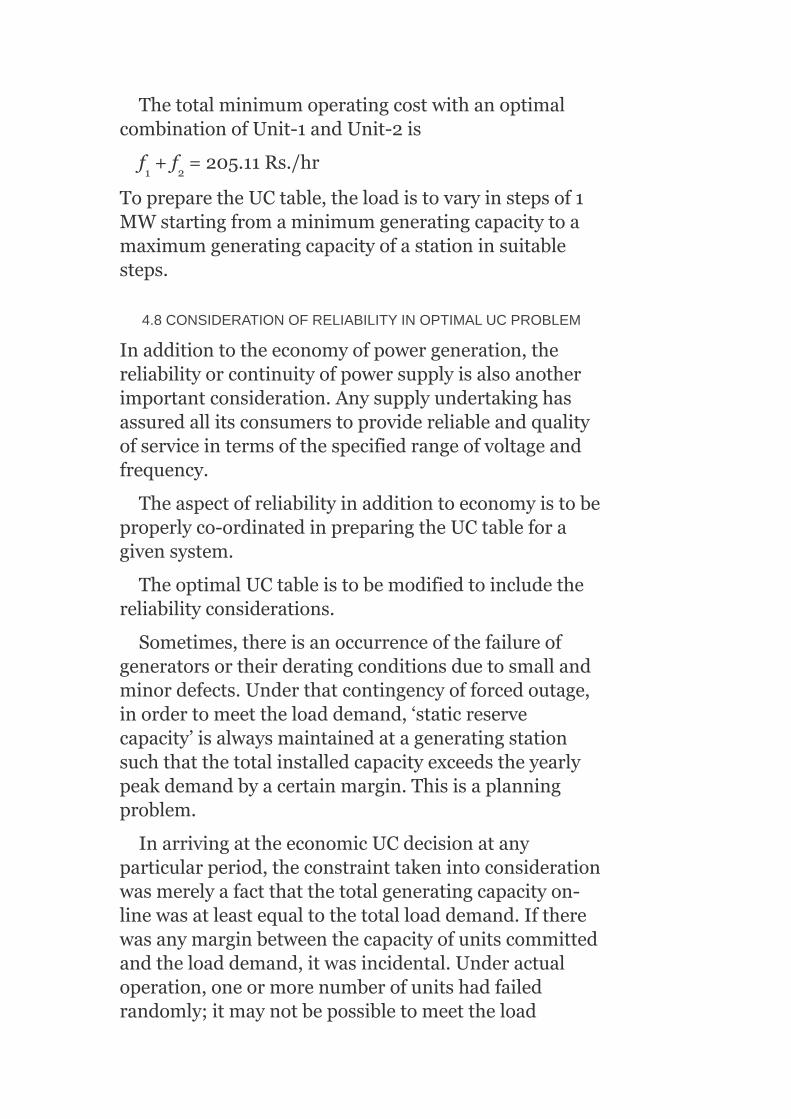
ThetotalminimumoperatingcostwithanoptimalcombinationofUnit-1andUnit-2is
f +f =205.11Rs./hr
TopreparetheUCtable,theloadistovaryinstepsof1MWstartingfromaminimumgeneratingcapacitytoamaximumgeneratingcapacityofastationinsuitablesteps.
4.8CONSIDERATIONOFRELIABILITYINOPTIMALUCPROBLEM
Inadditiontotheeconomyofpowergeneration,thereliabilityorcontinuityofpowersupplyisalsoanotherimportantconsideration.Anysupplyundertakinghasassuredallitsconsumerstoprovidereliableandqualityofserviceintermsofthespecifiedrangeofvoltageandfrequency.
Theaspectofreliabilityinadditiontoeconomyistobeproperlyco-ordinatedinpreparingtheUCtableforagivensystem.
TheoptimalUCtableistobemodifiedtoincludethereliabilityconsiderations.
Sometimes,thereisanoccurrenceofthefailureofgeneratorsortheirderatingconditionsduetosmallandminordefects.Underthatcontingencyofforcedoutage,inordertomeettheloaddemand,‘staticreservecapacity’isalwaysmaintainedatageneratingstationsuchthatthetotalinstalledcapacityexceedstheyearlypeakdemandbyacertainmargin.Thisisaplanningproblem.
InarrivingattheeconomicUCdecisionatanyparticularperiod,theconstrainttakenintoconsiderationwasmerelyafactthatthetotalgeneratingcapacityon-linewasatleastequaltothetotalloaddemand.Iftherewasanymarginbetweenthecapacityofunitscommittedandtheloaddemand,itwasincidental.Underactualoperation,oneormorenumberofunitshadfailedrandomly;itmaynotbepossibletomeettheload
1 2

demandforacertainperiodoftime.Tostartthespare(standby)thermalunitandtobringitonthelinetotakeuptheloadwillinvolvelongperiodsoftimeusuallyfrom2to8hrandalsosomestartingcost.Incaseofahydro-generatingunit,itcouldbebroughton-lineinafewminutestotakeuptheload.
Hence,toensurecontinuityofsupplytomeetrandomfailures,thetotalgeneratingcapacityon-linemusthaveadefinitemarginovertheloadrequirementsatanypointoftime.Thismarginiscalledthespinningreserve,whichensurescontinuallybymeetingthedemanduptoacertainextentofprobablelossofgeneratingcapacity.Whilerulesofthumbhavebeenused,basedonpastexperiencetodeterminethesystemspinningreserveatanytime,arecentbetterapproachcalledPatton’sanalyticalapproachisthemostpowerfulapproachtosolvethisproblem.
ConsiderthefollowingpointsintheaspectofreliabilityconsiderationintheUCproblem:
1. Theprobabilityofoutageofanyunitthatincreaseswithitsoperatingtimeandaunit,whichistoprovideaspinningreserveatanyparticulartime,hastobestartedseveralhourslater.Hence,thesecurityofsupplyproblemhastobetreatedintotalityoveraperiodofoneday.
2. Theloadsareneverknownwithcompletecertainty.3. Thespinningreservehastobefacilitatedatsuitablegenerating
stationsofthesystemandnotnecessarilyateachgeneratingstation.
Aunit’susefullifespanundergoesalternateperiodsofoperationandrepairasshowninFig.4.5.

FIG.4.5Randomoutagephenomenaofageneratingunitexcludingthescheduledoutages
Aunitoperatingtimeisalsocalledunit‘up-time’(t )anditsrepairtimeasits‘down-time’(t ).
Thelengthsofindividualoperatingandrepairperiodsarearandomphenomenonwithmuchlongerperiodsofoperationcomparedtorepairperiods.
Thisrandomphenomenonwithalongeroperatingperiodofaunitisdescribedbyusingthefollowingparameters.
Meantimetofailure(mean‘up’time):
Meantimetorepair(mean‘down’time):
∴Meancycletime=
TherateoffailureandtherateofrepaircanbedefinedbyinversingEquations(4.6)and(4.7)as
up
down

Rateoffailure failures/year
Rateofrepair repairs/year
Thefailureandrepairratesaretobeestimatedfromthepastdataofunitsorothersimilarunitselsewhere.
Theratesoffailureareaffectedbyrelativemaintenanceandtheratesofrepairareaffectedbythesize,composition,andskillofrepairteams.
Bymakinguseoftheratiodefinitionofgeneratingunits,theprobabilityofaunitbeinginan‘up’stateand‘down’statecanbeexpressedas
Probabilityoftheunitinthe‘up’stateis
Theprobabilityoftheunitinthe‘down’stateis
Obviously,P +P =1(4.10)
P andP arealsoknownasavailabilityandunavailabilityoftheunit.
up down
up down

Inanysystemwithknumberofunits,theprobabilityofthesystemstatechanges,i.e.,whenkunitsarepresentinasystem,thesystemstatechangesduetorandomoutages.
Therandomoutage(failure)ofaunitcanbeconsideredasaneventindependentofthestateoftheotherunit.
Letaparticularsystemstate‘i’,inwhichx unitsareinthe‘down’stateandy unitsareinthe‘up’state:
i.e.,x +y =k
Theprobabilityofthesystembeinginstate‘i’isexpressedas
Πindicatesprobabilitymultiplicationofthesystemstate.
4.8.1Patton’ssecurityfunction
Someintolerableorundesirableconditionofsystemoperationistermedasa‘breachofsystemsecurity’.
InanoptimalUCproblem,theonlybreachofsecurityconsideredistheinsufficientgeneratingcapacityofthesystemataparticularinstantoftime.
TheprobabilitythattheavailablegeneratingcapacityataparticulartimeislessthanthetotalloaddemandonthesystematthattimeiscomplicativelyestimatedbyonefunctionknownasPatton’ssecurityfunction.
Patton’ssecurityfunctionisdefinedas
i
i
i i

whereP istheprobabilityofthesystembeingintheistateandr istheprobabilitythatthesystemstateicausesabreachofsystemsecurity.
Inconsideringallpossiblesystemstatestodeterminethesecurityfunction,fromthepracticalpointofview,thissumistobetakenoverthestatesinwhichnotmorethantwounitsareonforcedoutage,i.e.,stateswithmorethantwounitsoutmaybeneglectedastheprobabilityoftheiroccurrencewillbetoosmall.
r =1,iftheavailablegeneratingcapacity(sumofcapacitiesofunitscommitted)islessthanthetotalload
demand,i.e., .Otherwiser=0.
ThesecurityfunctionSgivesaquantitativeestimationofsysteminsecurity.
4.9OPTIMALUCWITHSECURITYCONSTRAINT
Fromapurelyeconomicalpointofview,aUCtableispreparedfromwhichweknowwhichunitsarecommittedforagivenloadonthesystem.
Foreachperiod,wewillestimatethesecurityfunction
Foranysystem,wewilldefinemaximumtolerableinsecuritylevel(MTIL).Thisisamanagementdecisionandthevalueisbasedonpastexperience.
WheneverthesecurityfunctionexceedsMTIL(S>MTIL),itisnecessarytomodifytheUCtabletoincludetheaspectsofsecurity.Itisnormallyachievedbycommittingthenextmosteconomicalunittosupplytheload.Withthenewunitbeingcommitted,wewillestimatethesecurityfunctionandcheckwhetheritisS<MTIL.
i
i
i
i
th
TheprocedureofcommittingthenextmosteconomicalunitiscontinueduptoS<MTIL.IfS=MTIL,thesystemdoesnothaveproperreliability.Addingunitsgoesuptoonesteponlybecauseforanother,itisnotnecessarytoaddthenextunitsmorethanoneunitsincethereisapresenceofspinningreserve.
4.9.1IllustrationofsecurityconstraintwithExample4.2
ReconsiderExample4.2andthedailyloadcurvefortheabovesystemasgiveninFig.4.6.
TheeconomicallyoptimalUCforthisloadcurveisobtainedbytheuseoftheUCTable4.6(whichwaspreviouslyprepared)(Table4.7).
ConsideringperiodE,inwhichtheminimumloadis5MWandUnit-1isbeingcommittedtomeettheload.Wewillcheckforthisperiodwhetherthesystemissecureornot.
Assumetherateofrepair,µ=99repairs/year
Andrateoffailure,λ=1failure/yearforallfourunits
AndalsoassumethatMTIL=0.005
WehavetoestimatethesecurityfunctionSforthisperiodE:
Valueofr dependingonwhetherthereisabreachofsecurityornot.
TherearetwopossiblestatesforUnit-1:
operatingstate(or)‘up’state
(or)
forcedoutagestate(or)‘down’state
i

TheprobabilityofUnit-1beinginthe‘up’state,
FIG.4.6Dailyloadcurve
TABLE4.7EconomicallyoptimalUCtableforloadcurveshowninFig.4.4
r =0,sincethegenerationofUnit-1(max.capacity)isgreaterthantheload(i.e.,14MW>5MW).
ThereisnobreachofsecuritywhentheUnit-1isinthe‘up’state.
1

TheprobabilityofUnit-1beinginthe‘down’state:
r =1,sinceUnit-1isinthedownstate(P =0),the
loaddemandof5MWcannotbemet.
ThereisabreachofsecuritywhenUnit-1isinthe‘down’state.Now,findthevalueofthesecurityfunction.
whereirepresentsthestateofUnit-1.
Ifnisthenumberofunits,numberofstates=2
Forn=1,states=2 =2(i.e.,upanddownstates)
∴S=P r +P r
=P r +P r
=0.99×0+0.01×1
=0.01
Itisobservedthat0.01>0.005,i.e.,S>MTIL
Sinceinthiscase,S>MTILrepresentssysteminsecurity.Therefore,itisnecessarytocommitthenextmosteconomicalunit,i.e.,unit-2,toimprovethesecurity.WhenbothUnits-1and2areoperating,estimatethesecurityfunctionasfollows:
Here,numberofunits,n=2
∴Numberofstates=2 =2 =4
r =0,representsnobreachofsecurityand
r =1,representsbreachofsecurity
2 G1
1 1 2 2
1up 1 1down 2
i
i
n
1
n 2

TABLE4.8Representationofbreachofsecurityforthepossiblecombinations
Whentakingeitherupdownupcombinationsofstates,
downupup
thereisnobreachofsecurity,sincer=0
Forthecombinationdown
down,
thereisabreachofsecurity(Table4.8).
Itisobservedthat0.001<0.005
Therefore,thecombinationofUnit-1andUnit-2doesmeettheMTILof0.005.
Forallotherperiodsofaloadcycle,checkwhetherthesecurityfunctionislessthanMTIL.ItisalsofoundthatforallotherperiodsexceptE,thesecurityfunctionislessthanMTIL.Now,wewillobtaintheoptimalandsecurity-constrainedUCtableforExample4.2(Table4.9).
4.10START-UPCONSIDERATION
i

FromtheoptimalandsecuredUCtablegiveninTable4.9,dependingontheloadinaparticularperiod,itisobservedthatsomeunitsaretobedecommittedandrestartedinthenextperiod.Wheneveraunitistoberestarted,itinvolvessomecostaswellassometimebeforetheunitisputon-line.Forthermalunits,itisnecessarytobuildupcertaintemperatureandpressuregraduallybeforetheunitcansupplyanyloaddemand.ThecostinvolvedinrestartinganyunitafterthedecommittingperiodisknownasSTART-UPcost.
TABLE4.9OptimalandsecureUCtableforExample4.2
*Unitiscommittedfromthepointofviewofsecurityconsiderations.
Dependingontheconditionoftheunit,thestart-upcostswillbedifferent.Iftheunitistobestartedfromacoldconditionandbroughtuptonormaltemperatureandpressure,thestart-upcostswillbemaximumsincesomeenergyisrequiredtobuilduptherequiredpressureandtemperatureofthesteam.Sometimes,theunitmaybeswitchedoffandthetemperatureofsteammaynotbeinacoldcondition.Thisparticularconditioniscalledthebankingcondition.
FromtheUCtablegiveninTable4.7,itisobservedthatduringPeriodB,Unit-3isoperatingandduring

PeriodC,itisdecommitted.ItisrestartedduringPeriodD.
InPeriodC,checkwhetheritiseconomicaltorunonlytwounitsorallowallthethreeunits(Units-1,2,and3)tocontinuetorunsuchthatthestart-upcostsareeliminated.
Letusassumethatthestart-upcostofeachunit=Rs.500.
CaseA:Unit-3isnotinoperationinPeriodC,i.e.,onlytwoUnits-1and2areoperating.
ForPeriodBorD,totalload=15MW
Thisistobesharedbythreeunits,i.e.,P +P +P
=15
SubtractingEquation(4.14)fromEquation(4.13),weget
0.74P −1.56P =3(4.16)
SubtractingEquation(4.15)fromEquation(4.13),weget
0.74P −1.97P =6.1(4.17)
or0.74P −1.97(15−P −P )=6.1
or2.71P +1.97P =35.65(4.18)
G1 G2 G3
G1 G2
G1 G3
G1 G1 G2
G1 G2

BysolvingEquations(4.13)and(4.16),wehave
P =10.8MW,P =3.2MW
P =15−P −P =15−108−3.2=1MW
C =(0.37P +22.9)P =290.48Rs./hr
C =(0.78P +25.9)P =90.87Rs./hr
C =(0.985P +29)P =29.98Rs./hr
ForPeriodB,theoperatingtimeis4hr.
∴Totalcost,C=[C +C +C ]t
=[290.48+90.87+29.98]×4
=Rs.1,645.34
TotaloperatingcostduringPeriodBisRs.1,645.34.
InPeriodC,10MWofloadistobesharedbyUnits-1and2
i.e.,P +P =10MW(4.19)
BysolvingEquations(4.16)and(4.19),weget
P =8.086MWandP =1.913MW
TotaloperatingcostforPeriodC
=[(0.37P +22.9)P +(0.78P +25.9)P ]×4
=Rs.1,047.05.
ForperiodD,thetotaloperatingcostisthesameasthatofPeriodB=Rs.1,645.34.
Therefore,thetotaloperatingcostforPeriodsB,C,andDis
=Rs.[1,645.34+1,047.05+1,645.34]
=Rs.4,337.73.
InPeriodD,Unit-3isrestartedtocommittheload,hencethestart-upcostofUnit-3isaddedtothetotaloperatingcostforperiodsB,C,andD:
G1 G2
G3 G1 G2
1 G1 G1
2 G2 G2
3 G3 G3
1 2 3
G1 G2
G1 G2
G1 G1 G2 G2

Start-upcostforUnit-3=Rs.500(given)
∴TotalcostofoperatingofunitsduringperiodB,C,andDis
=4,337.73+500
=Rs.4,837.73
CaseB:Unit-3isallowedtoruninPeriodC.
Hence,10-MWloadistobesharedbyunits1,2,and3.
i.e.,P +P +P =10(4.20)
SubstitutingP fromEquation(4.20)inEquation
(4.17),weget
0.74P −1.97(10−P −P )=6.1(4.21)
or2.71P +1.97P =25.8(4.22)
BysolvingEquations(4.16)and(4.21),weget
P =8.1MW,P =1.9MW,andP =0MW
Fromtheabovepowers,itisobservedthatP violates
theminimumgenerationcapacity(i.e.,0<1).
Hence,setthegenerationcapacityofUnit-3atminimumcapacity,i.e.,P =1MW.
Thentheremaining9MWisoptimallysharedbyUnit-1andUnit-2as
P =7.4MW,P =1.6MW,andP =1MW
TheoperatingcostatPeriodC
=[(0.37P +22.9)P +(0.78P +25.9)P +
(0.985P +29)P ]×4hr
=Rs.1,048.57
TotalcostforPeriodsB,C,andD=Rs.1,645.34+Rs.1,048.57+Rs.1,645.34
=Rs.4,339.25.
G1 G2 G3
G3
G1 G1 G2
G1 G2
G1 G2 G3
G3
G3
G1 G2 G3
G1 G1 G2 G2
G3 G3

Rs.4,339.25<Rs.4,837.73
∴ItisconcludedthattorunUnit-3inPeriodCistheeconomicalway.
Now,theoptimalUCtableismodifiedas
*Unitiscommittedfromthepointofsecurityconsideration.
**Unitiscommittedfromthepointofstart-upconsiderations.
Hence,itiseconomicaltoallowallthethreeunitstocontinuetoruninPeriodsB,C,andD,i.e.,inPeriodCcontinuationofUnit-3iseconomical.
Example4.3:Apowersystemnetworkwithathermalpowerplantisoperatingbyfourgeneratingunits.Determinethemosteconomicalunitstobecommittedtoaloaddemandof10MW.AlsopreparetheUCtablefortheloadchangesinstepsof1MWstartingfromtheminimumtothemaximumload.Theminimumandmaximumgeneratingcapacitiesandcost-curveparametersoftheunitslistedinatabularformareasgiveninTable4.10.

Solution:
Weknow:
Thecostfunction,
Incrementalfuelcost,
Thetotalload=P =10MW(given)
Bycomparingthecost-curveparameters,wecometoknowthatthecostcharacteristicsofthefirstunitarethelowest.Ifonlyonesingleunitistobecommitted,unit-1istobeemployed.
TABLE4.10Capacitiesandcost-curveparametersoftheunits
Now,findthecost-of-generationofpowerbythefirstunitstartingfromtheminimumtothemaximumgeneratingcapacityofthatunit.
Let
f (1)=themaincostinRs./hrforthegenerationof1MWbythefirstunit
D
1

f (2)=themaincostinRs./hrforthegenerationof2MWbythefirstunit
f (3)=themaincostinRs./hrforthegenerationof3MWbythefirstunit
f (4)=themaincostinRs./hrforthegenerationof4MWbythefirstunit
…..…..…..…..…………………..…..…..……
f (10)=themaincostinRs./hrforthegenerationof10MWbythefirstunit
ForthecommitmentofUnit-1only
Whenonlyoneunitistobecommittedtomeetaparticularloaddemand,i.e.,Unit-1,inthiscase,duetoitslowcostparameters,thenF (x)=f (x).
where
F (x)istheminimumcostofgenerationof‘x’MWbyonlyoneunit
f (x)istheminimumcostofgenerationof‘x’MWbyUnit-1
∴F (1)=f (1)=(0.34×1+22.8)1+823=846.14
F (2)=f (2)=(0.34×2+22.8)2+823=869.96
F (3)=f (3)=(0.34×3+22.8)3+823=894.46
1
1
1
1
1 1
1
1
1 1
1 1
1 1

Similarly,
F (4)=f (4)=916.64
F (5)=f (5)=945.50
F (6)=f (6)=972.04
F (7)=f (7)=996.26
F (8)=f (8)=1,027.16
F (9)=f (9)=1,055.74
F (10)=f (10)=1,085.00
WhenUnit-1istobecommittedtomeetaloaddemandof10MW,thecostofgenerationbecomes1,085Rs./hr.
Forthesecondunit:
f (1) = minimumcostinRs./hrforthegenerationof1MWbythesecondunitonly
= (0.765P +25.9)P +120
= (0.765×1+25.9)1+120=146.665
Similarly,
f (2)=174.860
f (3)=204.585
f (4)=235.840
f (5)=268.625
f (6)=302.940
f (7)=338.785
f (8)=376.160
1 1
1 1
1 1
1 1
1 1
1 1
1 1
2
G2 G2
2
2
2
2
2
2
2

f (9)=415.065
f (10)=455.500
Byobservingf (10)andf (10),itisconcludedthatf (10)<f (10),i.e.,thecostofgenerationof10MWbyunit-1isminimumthanthatbyUnit-2.
Forcommitmentofunit-1andUnit-2combination
F (10)=Minimumcostofgenerationof10MWbythesimultaneousoperationoftwounits,i.e.,Units-1and2
Inotherwords,theminimumcostofgenerationof10MWbythecombinationofUnit-1andUnit-2is455.5Rs./hrandforthisoptimalcost,Unit-1supplies0MWandUnit-2supplies10MW.
2
2
1 2
1 2
2

i.e.,theminimumcostofgenerationof9MWwiththecombinationofUnit-1(by0-MWsupply)andUnit-2(by9-MWsupply)is415.065Rs./hr.
Similarly,
∴F (8)=376.16Rs./hr
∴F (7)=338.785Rs./hr
∴F (6)=338.785Rs./hr
∴F (5)=268.625Rs./hr
∴F (4)=235.84Rs./hr
F (3)=min[894.46,1,016.6251,0221204.585]
∴F (3)=204.585Rs./hr
2
2
2
2
2
2
2

F (2)=min[869.96,992.805174.86]
∴F (2)=174.86Rs./hr
F (1)=min[846.14146.665]
∴F (1)=146.665Rs./hr
Now,thecostofgenerationbyUnit-3only:
f (0)=0; f (5)=649.75;f (9)=821.19
f (1)=509.99; f (6)=689.64;f (10)=869.00
f (2)=541.96; f (7)=731.51
f (3)=575.91; f (8)=775.36
f (4)=611.84;
ForcommitmentofUnit-1,Unit-2,andunit-3combination:
F (10)=Theminimumcostofgenerationof10MWbythethreeunitsi.e.,Unit-1,Unit-2,andUnit-3
2
2
2
2
2
3 3 3
3 3 3
3 3
3 3
3
3

i.e.,forthegenerationof10MWbythreeUnits,unit-2alonewillcommittomeettheloadof10MWandUnits-1and3areinanoff-statecondition:

F (3)=min[204.585,684.85,688.625,575.91]
∴F (3)=204.585Rs./hr
F (2)=min[174.86,565.655,541.96]
∴F (2)=174.86Rs./hr
F (1)=min[509.99,146.665]
∴F (1)=146.665Rs./hr
Costofgenerationbythefourthunit
f (0)=0
f (1)=531.115Rs./hr
f (2)=564.46Rs./hr
f (3)=600.035Rs./hr
f (4)=637.84Rs./hr
f (5)=677.875Rs./hr
f (6)=720.14Rs./hr
f (7)=764.635Rs./hr
3
3
3
3
3
3
4
4
4
4
4
4
4
4

f (8)=811.36Rs./hr
f (9)=860.315Rs./hr
f (10)=911.5Rs./hr
Minimumcostofgenerationbyfourunits,i.e.,Unit-1,Unit-2,Unit-3,andUnit-4:
F (10)=Theminimumcostofgenerationof10MWbyfourunits
i.e.,forthegenerationof10MWbyfourunits,Unit-2willcommittomeettheloadof10MW,andUnit-1,Unit-3,andUnit4areinanoff-statecondition:
4
4
4
4

F (3)=min[204.585,705.975,711.125,600.035]
∴F (3)=204.585Rs./hr
F (2)=min[46.96,554.255,564.46]
∴F (2)=46.96Rs./hr
F (1)=min[23.14,531.115]
∴F (1)=23.14Rs./hr
Fromtheabovecriteria,itisobservedthatforthegenerationof10MW,thecommitmentofunitsisasfollows:
f (10)=F (10)=theminimumcostofgenerationof10MWinRs./hrbyUnit-1only
=1085Rs./hr
F (10)=theminimumcostofgenerationof10MWbytwounitswithUnit-1supplying0MWandUnit-2supplying10MW
4
4
4
4
4
4
1 1
2

=455.5Rs./hr
F (10)=theminimumcostofgenerationof10MWbythreeunitswithUnit-2supplying10MW,Unit-1andUnit-3isinanoff-statecondition
=455.5Rs./hr
F (10)=theminimumcostofgenerationof10MWbyfourunitswithUnit-2supplying10MW,andUnit-1,Unit-3andUnit-4areinanoff-statecondition
=455.5Rs./hr
ByexaminingthecostsF (10),F (10),F (10),andF (10),wehaveconcludedthatformeetingtheloaddemandof10MW,theoptimalcombinationofunitstobecommittedisUnit-1,Unit-3,andUnit-4inanoff-stateconditionandUnit-2supplyinga10-MWloadatanoperatingcostof455.5Rs./hr.
ForpreparingtheUCtable,theorderingofunitsisnotacriterion.Foranyorder,wegetthesamesolutionthatisindependentofnumberingunits.
TABLE4.11TheUCtablefortheabove-consideredsystem
Togetahigheraccuracy,thestepsizeoftheloadistobereduced,whichresultsinconsiderableincreaseintimeofcomputationandrequiredstoragecapacity.
Status1ofanyunitindicatesunitrunningorunitcommittingandStatus0ofanyunitindicatesunitnotrunning.
TheUCtableispreparedonceandforallforagivensetofunits(Table4.11).Astheloadcycleonthestation
3
4
1 2 3
4

changes,itwouldonlymeanchangesinstartingandstoppingofunitswithoutchangingthebasicUCtable.
KEYNOTES
Unitcommitmentisaproblemofdeterminingtheunitsthatshouldoperateforaparticularload.To‘commit’ageneratingunitisto‘turniton’.Theconstraintsconsideredforunitcommitmentare:
1. Spinningreserve.2. Thermalunitconstraints.3. Hydro-constraints.4. Must-runconstraints.5. Fuelconstraints.
ThesolutionmethodstoaUCproblemare:
1. Priority-listscheme.2. Dynamicprogrammingmethod(DP).3. Lagrange’srelaxationmethod(LR).
Inthepriorityorderingmethod,themostefficientunitisloadedfirsttobefollowedbythelessefficientunitsinorderastheloadincreases.ThemainadvantageoftheDPmethodisresolutioninthedimensionalityofproblems,i.e.,havingobtainedtheoptimalwayofloadingKnumberofunits,itisquiteeasytodeterminetheoptimalwayofloading(K+1)numberofunits.
MULTIPLE-CHOICEQUESTIONS
1. Duetotheloadvariation,itisnotadvisableto:
1. Runallavailableunitsatallthetimes.2. Runonlyoneunitateachdiscreteloadlevel.3. Both(a)and(b).4. Noneofthese.
2. Aunitwhenscheduledforconnectiontothesystemissaidtobe:
1. Loaded.2. Disconnected.3. Committed.4. Noneofthese.
3. Todeterminetheunitsthatshouldoperateforaparticularloadistheproblemof:
1. Unitcommitment.2. Optimalloadscheduling.3. Either(a)or(b).4. Noneofthese.
4. Tocommitageneratingunitis:
1. Tobringituptospeed.2. Tosynchronizeittothesystem.3. Toconnectitsothatitcandeliverpowertothenetwork.4. Allofthese.

5. Economicdispatchproblemisapplicabletovariousunits,Whichofthefollowingissuitable?
1. Theunitsarealreadyon-line.2. Tosupplythepredictedorforecastloadofthesystemoverafuturetime
period.3. Both(a)and(b).4. Noneofthese.
6. Unitcommitmentproblemplansforthebestsetofunitstobeavailable.Whichofthefollowingissuitable?
1. Theunitsarealreadyon-line.2. Tosupplythepredictedorforecastloadofthesystemoverafuturetime
period.3. Both(a)and(b).4. Noneofthese.
7. Spinningreserveisdefinedas:
1.
2.
3.
4. Noneofthese.
8. Spinningreservemustbe:
1. Maintainedsothatthefailureofoneormoreunitsdoesnotcausetoofaradropinsystemfrequency.
2. Capableoftakingupthelossofmostheavilyloadedunitinagivenperiodoftime.
3. Calculatedasafunctionoftheprobabilityofnothavingsufficientgenerationtomeettheload.
4. Allofthese.
9. Becauseoftemperatureandpressureofthermalunitthatmustbemovedslowly,acertainamountofenergymustbeexpendedtobringtheuniton-lineandisbroughtintotheUCproblemasa:
1. Runningcost.
2. Fixedcost.3. Fuelcost.4. Start-upcost.
10. Unitcommitmentproblemisofmuchimportancefor:
1. Schedulingofthermalunits.2. Schedulingofhydro-units.3. Schedulingofboththermalandhydro-units.4. Noneofthese.
11. ThermalunitconstraintsconsideredinaUCproblemare:
1. Minimumupandminimumdowntimes.2. Crewconstraints.3. Start-upcosts.4. Allofthese.
12. Thestart-upcostmayvaryfromamaximumcold-startvaluetoaverysmallvalueifthethermalunit:
1. Wasonlyturnedoffrecently.2. Isstillrelativelyclosetotheoperatingtemperature.3. Isstilloperatingatnormaltemperature.4. Both(a)and(b).
13. Unitcommitmentproblemis:
1. Ofmuchimportanceforschedulingofthermalunits.2. Cannotbecompletelyseparatedfromtheschedulingofhydro-units.3. Usedforhydro-thermalscheduling.4. Both(a)and(b).
14. TheconstraintsconsideredinaUCproblemare:
1. Thermalunitandhydro-unitconstraints.2. Spinningreserve.3. Must-runandfuelconstraints.4. Alltheabove.
15. ThemethodusedforobtainingthesolutiontoaUCproblemis:
1. Priority-listscheme.2. Dynamicprogrammingmethod.3. Lagrange’srelaxationmethod.4. Alltheabove.
16. Astraightforwardbuthighlytime-consumingwayoffindingthemosteconomicalcombinationofunitstomeetaparticularloaddemandis:
1. Enumerationscheme.2. Priority-listscheme.3. DPmethod.4. Allofthese.
17. Whichiscorrectregardingtheshut-downrule?
1. Toknowwhichunitstodropandwhen.2. Fromwhichasimplepriority-listschemeisdeveloped.3. Both(a)and(b).4. Toknowwhichunitstostartfromshut-downcondition.
18. Inthepriority-listmethodofsolvinganoptimalUCproblem:

1. Mostefficientunitisloadedfirsttobefollowedbythelessefficientunitinorderasloadincreases.
2. Lessefficientunitisloadedfirsttobefollowedbythemostefficientunitinorderasloadincreases.
3. Mostefficientunitisloadedfirsttobefollowedbythelessefficientunitinorderasloaddecreases.
4. Either(a)or(b).
19. Inthepriority-listmethod,theunitsarearrangedtocommittheloaddemandintheorderof:
1. Ascendingcostsofunits.2. Descendingcostsofunits.3. Either(a)or(b).4. Independentofcostsofunits.
20. ThechiefadvantageoftheDPmethodovertheenumerateschemeis:
1. Reductionintimeofcomputation.2. Reductioninthedimensionalityoftheproblem.3. Reductioninthenumberofunits.4. Allofthese.
21. IntheDPmethod,thecostfunctionF (x)represents:
1. MinimumcostinRs/hrofgenerationofNMWbyxnumberofunits.2. MinimumcostinRs/hrofgenerationofxMWbyNnumberofunits.
3. MinimumcostinRs/hrofgenerationofNMWbythex unit.
4. MinimumcostinRs/hrofgenerationofxMWbytheN unit.
22. IntheDPmethod,thecostfunctionF (y)represents:
1. CostofgenerationofNMWbyynumberofunits.2. CostofgenerationofyMWbyNnumberofunits.
3. CostofgenerationofNMWbythey unit.
4. CostofgenerationofyMWbytheN unit.
23. TherecursiverelationresultswiththeapplicationoftheDPmethodofsolvingtheUCproblemis:
1.
2.
3.
4.
24. ForpreparingtheUCtable,whichofthefollowingisnotacriterion?
1. Orderingofunits.2. Orderingofcostsofunits.3. Orderingofrangeofload.4. Allofthese.
25. InaUCtable,unitrunningorunitcommittingisindicatedby:
1. Status0.2. Status1.3. Status+.
N
N
th
th
th
th

4. Status>.
26. InaUCtable,thestatusoftheunitnotrunningisindicatedby:
1. Status0.2. Status0.3. Status+.4. Status−.
27. Theunscheduledormaintenanceoutagesofvariousequipmentsofathermalplantmustbetakenintoaccountin:
1. Optimalschedulingproblem.2. UCproblem.3. Loadfrequencycontrollingproblem.4. Allofthese.
28. Unitup-timeisnothingbut:
1. Aunitoperatingtime.2. Aunitrepairtime.3. Aunittotallifetime.4. Aunitdesigningtime.
29. Unitdown-timeisnothingbut:
1. Aunitoperatingtime.2. Aunitrepairtime.3. Aunittotallifetime.4. Aunitdesigningtime.
30. InreliabilityaspectsofaUCproblem,thelengthsofanindividualoperatingandrepairperiodsofaunitconsideredatarandomphenomenonwith:
1. Muchlongerperiodsofoperationcomparedtorepairperiods.2. Muchlongerperiodsofrepaircomparedtooperationperiods.3. Equalperiodsofoperationandrepair.4. Either(a)or(b).
31. Meanup-timeofaunit is:
1. Meantimetofailure.2. Meantimetorepair.3. Meanoffailureandrepairtimes.4. Meanoftotaltime.
32. Meandown-timeofaunit is:
1. Meantimetofailure.2. Meantimetorepair.3. Meanoffailureandrepairtimes.4. Meanoftotaltime.
33. Meancycletimeofaunitis:
1.
2.
3.
4.
34. Rateoffailureofaunitisexpressedas:

1.
2.
3.
4.
35. Rateofrepairofaunitisexpressedas:
1.
2.
3.
4.
36. Therateoffailureofaunitaffectedby:
1. Relativemaintenance.2. Size,compositionofrepairteam.3. Skillofrepairteam.4. Allofthese.
37. Therateofrepairofaunitisaffectedby:
1. Relativemaintenance.2. Size,compositionofrepairteam.3. Skillofrepairteam.4. Both(b)and(c).
38. P andP ofanyunitrepresent:
1. Unavailabilityandavailabilityofaunit.2. Availabilityandunavailabilityofaunit.3. Either(a)or(b).4. Both(a)and(b).
39. P +P =
1. Zero.2. 1.3. −1.4. Infinite.
up down
up down

40. AbreachofsystemsecurityconsideredinoptimalUCproblemis:
1. Sufficientgeneratingcapacityofthesystemataparticularinstantoftime.2. Insufficientgeneratingcapacityofthesystemataparticularinstantof
time.3. Insufficientgeneratingcapacityofthesystematalltimes.4. Either(a)or(b).
41. UseofPatton’ssecurityfunctionintheUCproblemistheestimationoftheprobabilitythattheavailablegeneratingcapacityataparticulartimeis:
1. Lessthanthetotalloaddemand.2. Morethanthetotalloaddemand.3. Equaltothetotalloaddemand.4. Independentofthetotalloaddemand.
42. Patton’ssecurityfunctionSgivesaquantitativeestimationof:
1. Systemsecurity.2. Systeminsecurity.3. Systemstability.4. Systemvariables.
43. ItisnecessarytomodifytheUCtabletoincludesecurityaspectsbycommittingthenextmosteconomicalunittosupplytheloadwhen:
1. S<MTIL.2. S>MTIL.3. S=MTIL.4. S=MTIL/2.
44. Theprocedureofcommittingamosteconomicalunit,toincludesecurityaspectintheUCtable,iscontinuedupto:
1. S<MTIL.2. S>MTIL.3. S=MTIL.4. S=MTIL/2.
45. Systeminsecurityisrepresentedby:
1. S<MTIL.2. S>MTIL.3. S=MTIL.4. S=MITL/2.
46. Iftheunitistobestartedfromacoldconditionandbroughtuptonormaltemperatureandpressure,thestart-upcostwillbe:
1. Minimum.2. Maximum.3. Havingnoeffect.4. Noneofthese.
47. WhenanyunitisintheUPstate,thereis:
1. Breachofsecurity.2. Nobreachofsecurity.3. Stability.4. Allofthese.
48. If theprobabilitythatthesystemstate‘i’causesabreachofsystemsecuritybecomes:
1. r =1.
2. r =0.
3. r =−1.
4. r =∞.
49. If theprobabilitythatthesystemstate‘i’causesabreachofsystemsecuritybecomes:
1. r =1.
2. r =0.
3. r =−1.
4. r =∞.
SHORTQUESTIONSANDANSWERS
1. WhatisaUCproblem?
Itisnotadvisabletorunallavailableunitsatalltimesduetothevariationofload.Itisnecessarytodecideinadvance:
1. Whichgeneratorstostartup.2. Whentoconnectthemtothenetwork.3. Thesequenceinwhichtheoperatingunitsshouldbeshutdownandfor
howlong.
ThecomputationalprocedureformakingtheabovesuchdecisionsiscalledtheproblemofUC.
2. Whatdoyoumeanbycommitmentofaunit?
TocommitageneratingunitistoturnitON,i.e.,tobringituptospeed,synchronizeittothesystem,andconnectit,sothatitcandeliverpowertothenetwork.
3. WhyistheUCproblemimportantforschedulingthermalunits?
Asforothertypesofgenerationsuchashydro,theaggregatecostssuchasstart-upcosts,operatingfuelcosts,andshut-downcostsarenegligiblesothattheirON–OFFstatusisnotimportant.
4. ComparetheUCproblemwitheconomicloaddispatch.
Economicloaddispatcheconomicallydistributestheactualsystemloadasitrisestothevariousunitsalreadyon-line.ButtheUCproblemplansforthebestsetofunitstobeavailabletosupplythepredictedorforecastloadofthesystemoverfuturetimeperiods.
5. Whatarethedifferentconstraintsthatcanbeplacedontheucproblem?
1. Spinningreserve.2. Thermalunitconstraints.3. Hydro-constraints.4. Must-runconstraints.5. Fuelconstraints.
i
i
i
i
i
i
i
i

6. WhatarethethermalunitconstraintsconsideredintheUCproblem?
ThethermalunitconstraintsconsideredintheUCproblemare:
1. Minimumup-time.2. Minimumdown-time.3. Crewconstraints.4. Start-upcost.
7. Whymustthespinningreservebemaintained?
Spinningreservemustbemaintainedsothatfailureofoneormoreunitsdoesnotcausetoofaradropinsystemfrequency,i.e.,ifoneunitfails,theremustbeamplereserveontheotherunitstomakeupforthelossinaspecifiedtimeperiod.
8. WhyarethermalunitconstraintsconsideredinaUCtable?
Athermalunitcanundergoonlygradualtemperaturechangesandthistranslatesintoatimeperiodofsomehoursrequiredtobringtheunitontheline.Duetosuchlimitationsintheoperationofathermalplant,thethermalunitconstraintsaretobeconsideredintheUCproblem.
9. Whatisastart-upcostandwhatisitssignificance?
Becauseoftemperatureandpressureofathermalunitthatmustbemovedslowly,acertainamountofenergymustbemovedslowly,acertainamountofenergymustbeexpendedtobringtheuniton-line,anditisbroughtintotheUCproblemasastart-upcost.
Thestart-upcostmayvaryfromamaximumcold-startvaluetoaverysmallvalueiftheunitwasonlyturnedoffrecentlyandisstillrelativelyclosetotheoperatingtemperature.
10. Writetheexpressionsofastart-upcostwhencoolingandwhenbanking.
Start-upcostwhencooling=C (1–e )C+C
Start-upcostwhenbanking=C ×t×C+C
whereC isthecold-startcost(MBtu),Cisthefuelcost,C isthe
fixedcost(includescrewexpensesandmaintainableexpenses),αisthethermaltimeconstantfortheunit,C isthecostof
maintainingaunitatoperatingtemperature(MBtu/hr),andtisthetimetheunitwascooled(hr).
11. WhatarethetechniquesusedforgettingthesolutiontotheUCproblem?
1. Priority-listscheme.2. Dynamicprogramming(DP)method.3. Lagrange’srelaxation(LR)method.
12. Whatarethestepsofanenumerationschemeoffindingthemosteconomicalcombinationofunitstomeetaloaddemand?
1. Totryallpossiblecombinationsofunitsthatcansupplytheload.
c F
t F
C F
t
–t/α

2. Todividethisloadoptimallyamongtheunitsofeachcombinationbytheuseofco-ordinationequations,soastofindthemosteconomicaloperatingcostofthecombination.
3. Thentodeterminethecombinationthathastheleastoperatingcostamongallthese.
13. Whatisashut-downruleoftheUCoperation?
Iftheoperationofthesystemistobeoptimized,unitsmustbeshutdownastheloadgoesdownandthenrecommittedasitgoesbackup.Toknowwhichunitstodropandwhen,oneapproachcalledtheshut-downrulemustbeusedfromwhichasimplepriority-listschemeisdeveloped.
14. Whatisapriority-listmethodofsolvingaUCproblem?
Inthismethod,firstthefull-loadaverageproductioncostofeachunit,whichissimplythenetheatrateatfullloadmultipliedbythefuelcost,iscomputed.Then,intheorderofascendingcosts,theunitsarearrangedtocommittheloaddemand.
15. Inapriority-listmethod,whichunitisloadedfirstandtobefollowedbywhichunits?
Themostefficientunitisloadedfirst,tobefollowedbythelessefficientunitsintheorderasloadincreases.
16. WhatisthechiefadvantageoftheDPmethodoverothermethodsinsolvingtheUCproblem?
Resolutioninthedimensionalityofproblems,i.e.,havingobtainedtheoptimalwayofloadingKnumberofunits,itisquiteeasytodeterminetheoptimalwayofloading(K+1)numberofunits.
17. Whatisthethermalconstraintminimumup-time?
Minimumup-timeisthetimeduringwhichiftheunitisrunning,itshouldnotbeturnedoffimmediately.
18. Whatisminimumdown-time?
Iftheunitisstopped,thereisacertainminimumtimerequiredtostartitandputitontheline.
19. Whatisspinningreserve?
Toensurethecontinuityofsupplytomeetrandomfailures,thetotalgeneratingcapacityon-linemusthaveadefinitemarginovertheloadrequirementsatanypointoftime.Thismarginiscalledspinningreserve,whichensurescontinuationbymeetingthedemanduptoacertainextentofprobablelossofgeneratingcapacity.
20. Whatdoyoumeanbyabreachofsystemsecurity?
Someintolerableorundesirableconditionsofsystemoperationistermedasabreachofsystemsecurity.
21. InanoptimalUCproblem,whatisconsideredasabreachofsecurity?

Insufficientgeneratingcapacityofthesystemataparticularinstantoftime.
22. WhatisPatton’ssecurityfunction?Giveitsexpression.
Patton’ssecurityfunctionestimatestheprobabilitythattheavailablegeneratingcapacityataparticulartimeislessthanthetotalloaddemandonthesystematthattime.
Itisexpressedas
whereP istheprobabilityofthesystembeinginthei stateand
r theprobabilitythatthesystemstate‘i’causesabreachof
systemsecurity.
23. HowtheoptimalUCtableismodifiedwithconsiderationofsecurityconstraints?
WheneverthesecurityfunctionexceedsMTIL(S>MTIL),theUCtableismodifiedbycommittingthenextmosteconomicunittosupplytheloads.Withthenewunitbeingcommitted,thesecurityfunctionisthenestimatedandcheckedwhetheritisS<MTILornot.
24. Whatisthesignificanceofmust-runconstraintsconsideredinpreparingtheUCtable?
Someunitsaregivenamust-runrecognizationduringcertaintimesoftheyearforthereasonofvoltagesupportonthetransmissionnetworkorforsuchpurposesassupplyofsteamforusesoutsidethesteamplantitself.
REVIEWQUESTIONS
1. UsingtheDPmethod,howdoyoufindthemosteconomicalcombinationoftheunitstomeetaparticularloaddemand?
2. ExplainthedifferentconstraintsconsideredinsolvingaUCproblem.
3. CompareanoptimalUCproblemwithaneconomicalloaddispatchproblem.
4. ExplaintheneedofanoptimalUCproblem.5. DescribethereliabilityconsiderationinanoptimalUCproblem.6. Describethestart-upcostconsiderationinanoptimalUC
problem.
PROBLEMS
1. Apowersystemnetworkwithathermalpowerplantisoperatingbyfourgeneratingunits.Determinethemosteconomicalunitto
i
i
th

becommittedtoaloaddemandof10MW.Preparetheunitcommitmenttablefortheloadchangesinstepsof1MWstartingfromminimumloadtomaximumload.Theminimumandmaximumgeneratingcapacitiesandcost-curveparametersofunitslistedinatabularformaregiveninthefollowingtable.
2. PreparetheunitcommitmenttablewiththeapplicationofDPapproachforthesystemhavingfourthermalgeneratingunits,whichhavethefollowingcharacteristicparameters.Alsoobtainthemosteconomicalstationoperatingcostforthecompleterangeofstationcapacity.
Generatingunitparameters
3. ForthepowerplantofProblem2,andforthedailyloadcyclegiveninthefigure,preparethereliabilityconstrainedoptimalunitcommitmenttable.Alsoincludethestart-upconsiderationfromthepointofviewofoveralleconomywiththestart-upcostofanyunitbeingRs.75.
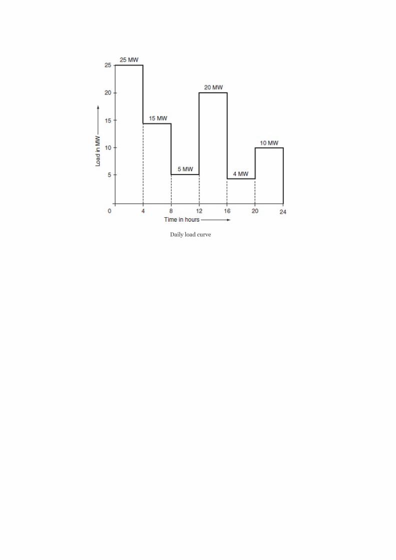
Dailyloadcurve

5
OptimalPower-FlowProblem—SolutionTechnique
OBJECTIVES
Afterreadingthischapter,youshouldbeableto:
knowtheoptimalpowerflowproblemconceptstudythemajorstepsforoptimalpowerflowsolutiontechniquesformulatethemathematicalmodelingforoptimalpowerflowproblemwithandwithoutinequalityconstraintsdevelopalgorithmsforoptimalpowerflowproblemswithandwithoutinequalityconstraints
5.1INTRODUCTION
Theproblemofoptimizingtheperformanceofapowersystemnetworkisformulatedasageneraloptimizationproblem.Itisrequiredtostatefromwhichaspecttheperformanceofthepowersystemnetworkisoptimized.
Inoptimizationproblem,theobjectivefunctionbecomes‘tominimizetheoverallcostofgenerationineconomicschedulingandunitcommitmentproblem’:
Itisbasedonallocatingthetotalloadonastationamongvariousunitsinanoptimalwaywithcasesbeingtakenintoconsiderationinaload-schedulingproblem.Itisbasedonallocatingthetotalloadonthesystemamongthevariousgeneratingstations.
Theoptimalpowerflowproblem:
referstotheloadflowthatgivesmaximumsystemsecuritybyminimizingtheoverloads,aimsatminimumoperatingcostandminimumlosses,shouldbebasedonoperationalconstraints,andisastaticoptimizationproblemwiththecostfunctionasascalarobjectivefunction.

ThesolutiontechniqueforanoptimalpowerflowproblemwasfirstproposedbyDommelandTinneyandhasfollowingthreemajorsteps:
1. ItisbasedontheloadflowsolutionbytheNewton–Raphson(N–R)method.
2. Afirst-ordergradientmethodconsistsofanalgorithmthatadjuststhegradientforminimizingtheobjectivefunction.
3. Useofpenaltyfunctionstoaccountforinequalityconstraintsondependentvariables.
Theoptimizationproblemofminimizingtheinstantaneousoperatingcostsintermsofrealandreactive-powerflowsisstudiedinthisunit.
Theoptimalpowerflowproblemwithoutconsideringconstraints,i.e.,unconstrainedoptimalpowerflowproblem,isfirststudiedandthentheoptimalpowerflowproblemwithinequalityconstraintsisstudied.Theinequalityconstraintsareintroducedfirstoncontrolvariablesandthenondependentvariables.
5.2OPTIMALPOWER-FLOWPROBLEMWITHOUTINEQUALITYCONSTRAINTS
Theprimaryobjectiveoftheoptimalpowerflowsolutionistominimizetheoverallcostofgeneration.Thisisrepresentedbyanobjectivefunction(or)costfunctionas:
subjecttopower(load)flowconstraints:

and
whereV =|V |∠δ isthevoltageatbus‘i’,V =|V |∠δthevoltageatbus‘j’,Y =|Y |∠θ themutualadmittancebetweenthei andj buses,P thespecifiedreal-poweratbusi,Q thespecifiedreactivepoweratbusi,thenetrealpowerinjectedintothesystematthei bus,P =P
–P ,andthenetreactivepowerinjectedintothesystem
atthei bus,Q =Q –Q .
Forloadbuses(or)P–Qbuses,PandQarespecifiedandhenceEquations(5.2)and(5.3)formtheequalityconstraints.
ForP–Vbuses,Pand|V|arespecifiedasthefunctionofsomevectorsandarerepresentedas:
f(x,y)=0
wherexisavectorofdependentvariablesandisrepresentedas
andyisavectorofindependentvariablesandisrepresentedas
i i i j j j
ij ij ij
i
i
i Gi
Di
i Gi Di
th th
th
th

Outoftheseindependentvariables(Equation(5.6)),certainvariablesarechosenascontrolvariables,whicharetobevariedtoyieldanoptimalvalueoftheobjectivefunction.Theremainingindependentvariablesarecalledfixedordisturbanceoruncontrollableparameters.
Let‘u’bethevectorofcontrolvariablesand‘p’thevectoroffixedordisturbancevariables.
Hence,thevectorofindependentvariablescanberepresentedasthecombinationofvectorofcontrolvariables‘u’andvectoroffixedordisturbanceoruncontrollablevariables‘p’andisexpressedas
Thechoiceof‘u’and‘p’dependsonwhataspectofpowersystemistobeoptimized.Thecontrolparametersmaybe:
1. voltagemagnitudeatP–Vbuses,2. P atgeneratorbuseswithcontrollablepower,
3. slackbusvoltageandregulatingtransformertapsettingasadditionalcontrolvariables,and
4. inthecaseofbuseswithreactive-powercontrol,Q istakenasa
controlvariable.
Now,theoptimalpowerflowproblemcanbestatedas
minC=C(x,u)(5.8)
Gi
Gi

subjecttoequalityconstraints:
f(x,u,p)=0(5.9)
DefinethecorrespondingLagrangianfunction byaugmentingtheequalityconstrainttotheobjectivefunctionthroughaLagrangianmultiplierλas
min· =C(x,u)+λ [f(x,u,p)](5.10)
whereλisavectoroftheLagrangianmultiplierofsuitabledimensionandisthesameasthatofequalityconstraint,f(x,u,p).
Thenecessaryconditionsforanoptimalsolutionareasfollows:
Equation(5.13)isthesameasequalityconstraints,
andtheexpressionsfor and arenotveryinvolved.
ConsiderthegeneralloadflowproblemoftheN–Rmethodbyconsideringasetof‘n’non-linearalgebraicequations,
f (x ,x …x )=0fori=1,2…n(5.14)
Letx ,x ,…x betheinitialvalues.
i 1 2 n
1 2 n
T
0 0 0
0 0 0
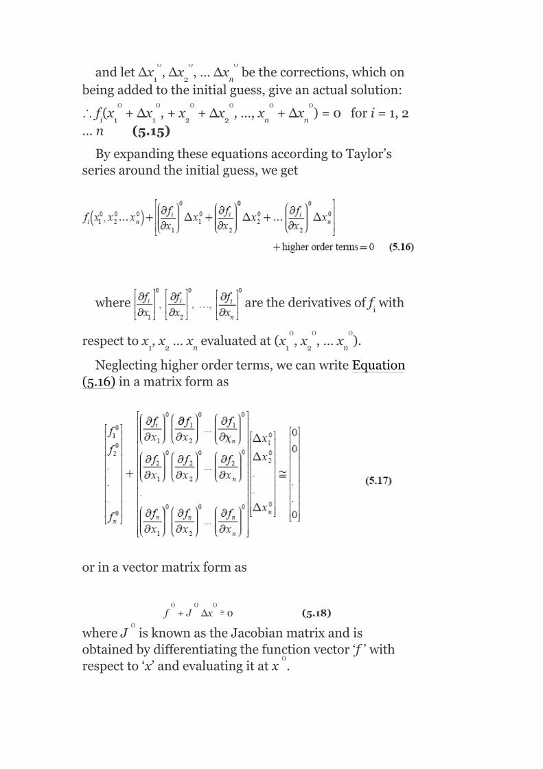
andlet∆x ,∆x ,…∆x bethecorrections,whichonbeingaddedtotheinitialguess,giveanactualsolution:
∴f (x +Δx ,+x +Δx ,…,x +Δx )=0fori=1,2…n(5.15)
ByexpandingtheseequationsaccordingtoTaylor’sseriesaroundtheinitialguess,weget
where arethederivativesoff with
respecttox ,x …x evaluatedat(x ,x ,…x ).
Neglectinghigherorderterms,wecanwriteEquation(5.16)inamatrixformas
orinavectormatrixformas
f +J Δx ≅0(5.18)
whereJ isknownastheJacobianmatrixandisobtainedbydifferentiatingthefunctionvector‘f’withrespectto‘x’andevaluatingitatx .
1 2 n
i 1 1 2 2 n n
i
1 2 n 1 2 n
0 0 0
0 0 0 0 0 0
0 0 0
0 0 0
0
0

BycomparingEquations(5.11),(5.12),and(5.13)with
Equations(5.17)and(5.18),itisobservedthat isthe
JacobianmatrixandthepartialderivativesofequalityconstraintswithrespecttodependentvariablesareobtainedasJacobianelementsinaloadflowsolution.
Theequalityconstraintsarebasicallythepowerflowequations,i.e.,realandreactive-powerflowequations:
equalityconstraintsforP–Qbus
P istheequalityconstraintforP–Vbus
‘x’isthedependentvariablelike|V |,δ
Then, maybeexpressedaspartialderivativesof
TheEquations(5.11),(5.12),and(5.13)arenon-linearalgebraicequationsandcanbesolvediterativelybyemployingasimpletechniquethatisa‘gradientmethod’andisalsocalledthesteepestdescentmethod.
Thebasictechniqueemployedinthesteepestdescentmethodistoadjustthecontrolparameters‘u’soastomovefromonefeasiblesolutionpointtoanewfeasiblesolutionpointinthedirectionofthesteepestdescent(ornegativegradient).Here,thestartingpointoffeasiblesolutionisonewhereasetofvalues‘x’(i.e.,dependentvariables)satisfiesEquation(5.13)forgiven‘u’and‘p’.Thenewfeasiblesolutionpointreferstoalocationwherethelowerobjectivefunctionisachieved.
i
i i

Thesemovesaretoberepeatedinthedirectionofnegativegradienttillminimumvalueisreached.Hence,thismethodofobtainingasolutiontonon-linearalgebraicisalsocalledthenegativegradientmethod.
5.2.1Algorithmforcomputationalprocedure
Thealgorithmforobtaininganoptimalsolutionbythesteepestdescentmethodisgivenbelow:
Step1:Makeaninitialguessforcontrolvariables(u ).
Step2:FindthefeasibleloadflowsolutionbytheN–Rmethod.TheN–Rmethodisaniterativemethodandthesolutiondoesnotsatisfytheconstraintequation(5.13).Hence,tosatisfyEquation(5.12),‘x’isimprovedasfollows:
x =x +Δx
∆xisobtainedbysolvingthesetoflinearequationsoftheJacobianmatrixofEquation(5.18)asgivenbelow:
f(x +Δx,y)=f(x ,y)+ (x ,y)Δx=0
ThefinalresultsofStep-2provideafeasiblesolutionof‘x’andtheJacobianmatrix.
Step3:SolveEquation(5.11)forλanditisobtainedas
0
r+1 r
r r r
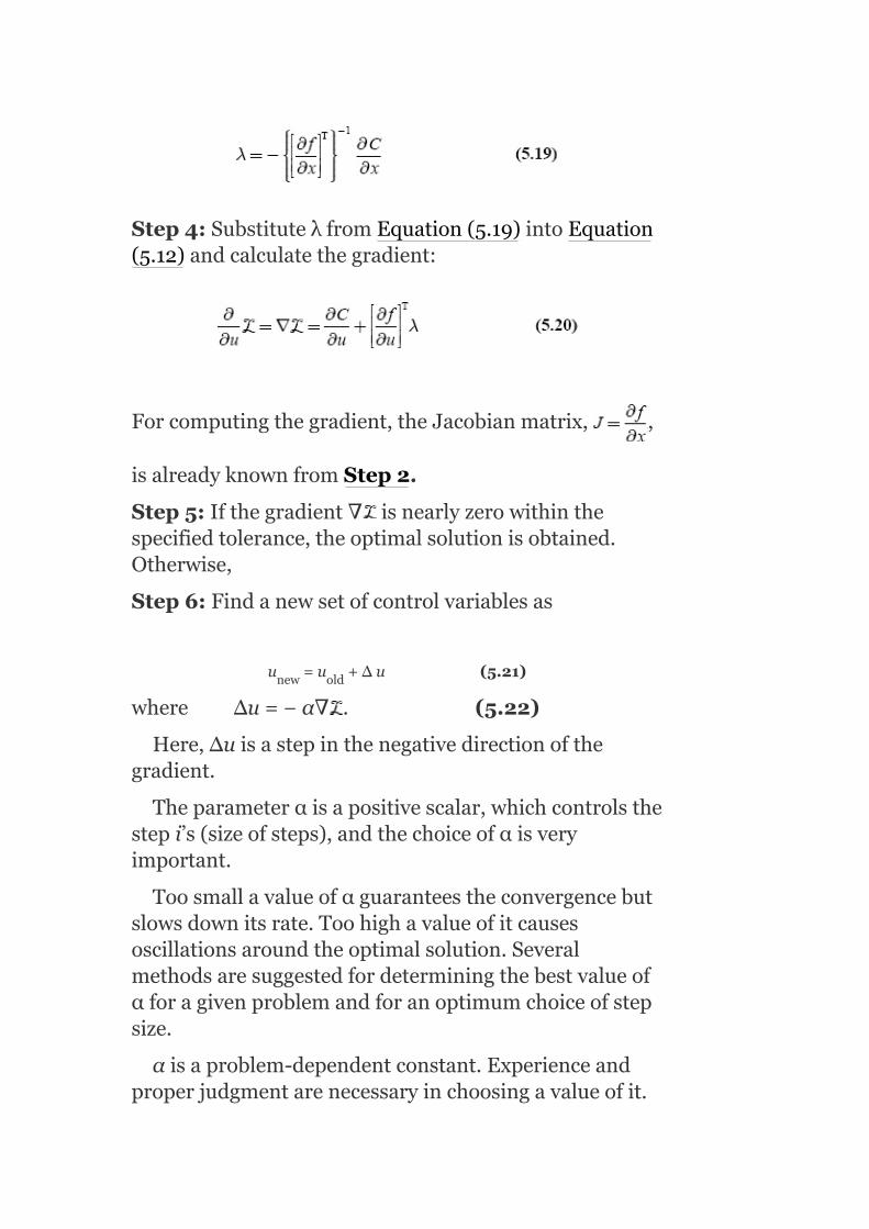
Step4:SubstituteλfromEquation(5.19)intoEquation(5.12)andcalculatethegradient:
Forcomputingthegradient,theJacobianmatrix, ,
isalreadyknownfromStep2.
Step5:Ifthegradient∇ isnearlyzerowithinthespecifiedtolerance,theoptimalsolutionisobtained.Otherwise,
Step6:Findanewsetofcontrolvariablesas
u =u +Δu(5.21)
whereΔu=−α∇ .(5.22)
Here,∆uisastepinthenegativedirectionofthegradient.
Theparameterαisapositivescalar,whichcontrolsthestepi’s(sizeofsteps),andthechoiceofαisveryimportant.
Toosmallavalueofαguaranteestheconvergencebutslowsdownitsrate.Toohighavalueofitcausesoscillationsaroundtheoptimalsolution.Severalmethodsaresuggestedfordeterminingthebestvalueofαforagivenproblemandforanoptimumchoiceofstepsize.
αisaproblem-dependentconstant.Experienceandproperjudgmentarenecessaryinchoosingavalueofit.
new old

Steps1,2,and5arerepeatedforanewvalueof‘u’tillanoptimalsolutionisreached.
5.3OPTIMALPOWER-FLOWPROBLEMWITHINEQUALITYCONSTRAINTS
5.3.1Inequalityconstraintsoncontrolvariables
InSection5.2,theunconstrainedoptimalpowerflowproblemandthecomputationalprocedureforobtainingtheoptimalsolutionarediscussed.Now,inthissection,theinequalityconstraintsareintroducedoncontrolvariables,andthenthemethodofobtainingasolutiontotheoptimalpowerflowproblemisdiscussed.
Thepermissiblevaluesofcontrolvariables,infact,arealwaysconstrained,suchthat
u ≤u≤u (5.23)
Forexample,iftherealpowerorreactive-powergenerationaretakenascontrolvariables,theninequalityconstraintsbecome
P ≤P ≤P
Q ≤Q ≤Q (5.24)
Infindingtheoptimalpowerflowsolution,Step6ofthealgorithmofSection5.2.1givesthechangeincontrolvariableas
Δu=−α∇
where andthenewcontrolvariable,u =u
+∆u.
min max
G (min)i Gi G (max)i
G (min)i Gi G (max)i
new old

Thisnewvalueofcontrolvariablemustbecheckedwhetheritviolatestheinequalityconstraintsonthecontrolvariableornot:
i.e.,u ≤u ≤u
Ifthecorrection∆ucausestoexceedoneofthelimits,‘u ’issetequaltothecorrespondinglimit,i.e.,thenewvalueofu isdeterminedas
otherwisesetu =u +∆u
Afteracontrolvariablereachesanyofthelimits,itscomponentinthegradientshouldcontinuetobecomputedinlateriteration,asthevariablemaycomewithinlimitsatsomelaterstages.
TheoptimalityconditionunderinequalityconstraintscanberewrittenasKuhn–Tuckerconditionsgivenbelow:
Therefore,now,inStep5ofthealgorithmofSection5.2.1,thegradientvectorhastosatisfytheoptimalityconditiongivenbyEquation(5.26).
5.3.2Inequalityconstraintsondependentvariables—penaltyfunctionmethod
i(min) i(new) i(max)
i
i
i(new) i(old) i

Inthissection,theoptimalsolutiontoanoptimalpowerflowproblemwillbeobtainedwiththeintroductionofinequalityconstraintsondependentvariablesandpenaltiesfortheirviolation.
Theinequalityconstraintsondependentvariablesspecifiedintermsofupperandlowerlimitsare
x ≤x≤x (5.27)
wherexisavectorofdependentvariables.
Forexample,ifthebusvoltagemagnitude|V |istakenasadependentvariable,theinequalityconstraintbecomes
|V| ≤|V|≤|V| onaP−Qbus(5.28)
Theabove-mentionedinequalityconstraintscanbehandledconvenientlybyamethodknownasthepenaltyfunctionmethod.Inthismethod,theobjectivefunctionisaugmentedbypenaltiesfortheviolationsofinequalityconstraints.Duetothisaugmentedobjectivefunction,thesolutionliessufficientlyclosetotheconstraintlimitswhentheviolationsoftheselimitshavetakenplace.Thepenaltyfunctionmethod,inthiscase,isvalidsincetheseconstraintsareseldomrigidlimitsinthestrictsensebutare,infact,softlimits(e.g.,|V|≤1.0onaP–Qbusreallymeans|V|shouldnotexceed1.0toomuchand|V|=1.01maystillbepermissible).
Wheninequalityconstraintsareviolated,theobjectivefunctioncanbemodifiedbyaugmentingpenaltiesas
whereω isthepenaltyintroducedforeachoftheviolatedinequalityconstraints.
Asuitablepenaltyfunctionisdefinedas
(min) (max)
i
min max
j

whereγ iscalledapenaltyfactorsinceitcontrolsthedegreeofpenaltyandisarealpositivenumber.
Aplotofthepenaltyfunction,whichisproposed,isshowninFig.5.1.Theplotclearlyindicateshowtherigidlimitsarereplacedbysoftlimits.Thenecessaryoptimalityconditions:
FIG.5.1Penaltyfunction
wouldnowbemodifiedasgivenbelow,whiletheconditionofEquation(5.13),i.e.,loadflowequations,remainsunchanged:
j

Intheaboveequations,thevector canbe
calculatedfromthepenaltyfunctionω .
Thevector canbeobtainedfromEquation(5.30)
andwouldcontainonenon-zerotermcorrespondingtodependentvariablex .
Thevector ,sincethepenaltyfunctionson
dependentvariablesareindependentofcontrolvariables.
Ifwechooseahighervalueforγ ,thepenaltyfunctionω canbemadesteepersothatthesolutionliesclosertotherigidlimits,buttheconvergencebecomespoorer.Innormalpractice,itisrequiredtostartwithalowervalueofγ andthenincreaseitduringtheoptimizationprocessifthesolutionviolatesconstraintsaboveacertaintolerancelimit.
ItisconcludedthatthesolutiontooptimalpowerflowproblemcanbeachievedbysuperimposingtheN–Rmethodofloadflowontheoptimalpowerflowproblemwithrespecttorelevantinequalityconstraints.Thesesolutionsareoftenrequiredforsystemplanningandoperation.
KEYNOTES
j
j
j
j
j

Theoptimalpowerflowproblem:
1. referstoloadflow,whichgivesmaximumsystemsecuritybyminimizingtheoverloads,
2. aimsatminimumoperatingcostandminimumlosses,3. shouldbebasedonoperationalconstraints,and4. isastaticoptimizationproblemwithcostfunctionasthescalarobjective
function.
ThesolutiontechniqueforoptimalpowerflowproblemproposedbyDommelandTinneyhasthefollowingthreemajorsteps:
1. itisbasedontheloadflowsolutionbytheN–Rmethod.2. afirst-ordergradientmethodconsistsofanalgorithmthatadjuststhegradient
forminimizingtheobjectivefunction.3. useofpenaltyfunctionstoaccountforinequalityconstraintsondependent
variables.
ForP–Vbuses,Pand|V|arespecifiedasfunctionsofsomevectorsandarerepresentedasf(x,y)=0wherexisavectorofdependentvariablesandyisavectorofindependentvariables.Thevectorofindependentvariablescanberepresentedasthecombinationofvectorofcontrolvariables‘u’andvectoroffixedor
disturbanceoruncontrollablevariables‘p’andisexpressedas
Thecontrolparametersare:
1. voltagemagnitudeatP–Vbuses,2. P atgeneratorbuseswithcontrollablepower,
3. slackbusvoltageandregulatingtransformertapsettingasadditionalcontrolvariables,and
4. inthecaseofbuseswithreactive-powercontrol,Q istakenascontrolvariable.
Optimalpowerflowproblemcanbestatedas
minC=C(x,u)
subjecttoequalityconstraints:
f(x,u,p)=0
SHORTQUESTIONSANDANSWERS
1. ThesolutiontechniqueproposedbyDommelandTinneyfortheoptimalpowerflowproblemisbasedonthreemajorsteps.Whatarethey?
1. LoadflowsolutionbyN–Rmethod.2. Afirst-ordergradientmethod.3. Useofpenaltyfunctionstoaccountforinequalityconstraintsondependent
variables.
2. Writetheexpressionsofpowerflowequalityconstraintsintermsofoptimalpowerflowproblem.
Gi
Gi

3. Writethenecessaryconditionsforobtaininganoptimalsolutiontotheoptimalpowerflowproblemwithoutinequalityconstraints.
4. Whatisanoptimalpowerflowproblem?
1. Ageneraloptimizationproblemreferstoloadflow,whichgivesmaximumsystemsecuritybyminimizingtheoverloads.
2. Optimalpowerflowproblemisastaticoptimizationproblemwithcostfunctionasascalarobjectivefunction.
5. WhichparametersareobtainedasJacobianelementsinanoptimalpowerflowproblem?
Partialderivativesofequalityconstraintswithrespectto
dependentvariables.i.e.,
6. Whatisthebasictechniqueemployedinthesteepestdescentmethod?
Toadjustthecontrolvariablessoastomovefromonefeasiblesolutionpointtoanewfeasiblesolutionpointwherethelowerobjectivefunctionisachieved.
7. Whythesteepestdescentmethodiscalledthenegativegradientmethod?
Themovesfromonefeasiblesolutionpointtoanewfeasiblepointaretoberepeatedinthedirectionofnegativegradienttillaminimumvalueisreached.
8. Whatistheeffectoftoosmallavalueofαandtoohighvalueofαontheconvergenceofasolution?
Thetoosmallvalueofαguaranteestheconvergencebutslowsdowntherateofconvergence,whereastoohighavalueofitcausesanoscillatorysolutionaroundtheoptimalsolution.
9. WhenwilltheKuhn–Tuckerconditionsbecomeoptimalityconditions?
Whileintroducinginequalityconstraintsoncontrolvariables.

10. Whenwillthepenaltyfunctionmethodbeadoptedinsolvingoptimalpower-flowproblem?
Whileintroducinginequalityconstraintsondependentvariables.
11. Whatistheeffectofchoosingahighervalueforγ thepenalty
factor?
Thepenaltyfunctionω canbemadesteepersothatthesolution
liesclosertotherigidlimits,butconvergencebecomespoorer.
MULTIPLE-CHOICEQUESTIONS
1. ThesolutiontechniqueforanoptimalpowerflowproblemproposedbyDommelandTinneyhasthestepsbasedon:
1. loadflowsolutionbytheN–Rmethod.2. afirst-ordergradientmethod.3. useofpenaltyfunctionstoaccountforinequalityconstraintsondependent
variables.4. non-linearitiespresentintheoperationmethods
1. (i)and(iii)2. (ii)and(iii)3. Allexcept(iii)4. Allexcept(iv).
2. AccordingtotheDommelandTinneytechnique,________methodisemployedforobtainingtheoptimalsolution.
1. Divergencemethod.2. Kuhn–Tuckermethod.3. First-ordergradientmethod.4. Lagrangianmultipliermethod.
3. Inanoptimalpowerflowsolution,theobjectivefunctionmin
subjecttotheequalityconstraints:
1.
2.
3.
j
j

4.
4. Theequalityconstraintsofanoptimalpowerflowproblemarespecifiedasfunctionf(x,y)=0,wherexis:
1. Vectorofdependentvariables.2. Vectorofindependentvariables.3. Vectorofcontrolvariables.4. Vectorofuncontrolledvariables.
5. Theequalityconstraintsofanoptimalpowerflowproblemarespecifiedasfunctionf(x,y)=0,whereyis:
1. Vectorofdependentvariables.2. Vectorofindependentvariables.3. Vectorofcontrolvariables.4. Vectorofuncontrolledvariables.
6. Theindependentvariablesare:
1. Controlvariables.2. Disturbancevariables.3. Both(a)and(b).4. Noneofthese.
7. Thecontrolparameterinanoptimalpowerflowproblemis:
1. VoltagemagnitudeattheP–Vbus.2. P andQ atthegeneratorbus.
3. Slackbusvoltage.4. Allofthese.
8. Ifxisthevectorofdependentvariables,yisthevectorofindependentvariables,uisthevectorofcontrolvariables,andpisthevectorofdisturbancevariables,thenamongthefollowingwhichiscorrect?
1.
2.
Gi Gi

3.
4. Noneofthese.
9. Inanoptimalpowerflowsolution,theequalityconstraintsarebasically:
1. Voltageequations.2. Powerflowequations.3. Currentflowequations.4. Both(a)and(c).
10. WhichofthefollowingisobtainedasJacobianelementsinaload-flowsolution?
1. Partialderivativesofequalityconstraintswithrespecttodependent
variables,
2. Partialderivativesofequalityconstraintswithrespecttoindependent
variables,
3. Partialderivativesofequalityconstraintswithrespecttocontrolvariables,
4. Partialderivativesofequalityconstraintswithrespecttocontrolled
variables,
11. Inanoptimalpowerflowproblem,thebasictechniqueistoadjustthecontrolvariableusoastomovefromonefeasiblesolutionpointtoanewsolutionpointwithalowervalueofobjectivefunction.Thistechniqueis:
1. Steepestdescentmethod.2. Negativegradientmethod.3. Either(a)or(b).4. Noneofthese.
12. Thenewsetofcontrolvariablesisu =u =+∆u.Thechange
incontrolvariable∆uisexpressedas
1. Δu=−α∇2. Δu=−α3. Δu=−∇α4. Noneofthese.
13. αisaparameterandtoosmallavalueofαresultsinthefollowing:
1. Guaranteestheconvergence.2. Slowsdowntherateofconvergence.3. Increasestherateofconvergence.
new old

1. Only(a).2. (b)Only.3. (a)and(c).4. (a)and(b).
14. ________valueofαcausesanoscillatorysolutionaroundtheoptimalsolution.
1. Toohigh.2. Toolow.3. Inbetweentoohighandtoolow.4. Noneofthese.
15. TheKuhn–Tuckercondition if
1. U ≤U ≤U .
2. U =U .
3. U =U .
4. Noneofthese.
16. if
1. U ≤U ≤U .
2. U =U .
3. U =U .
4. Noneofthese.
17. if
1. U ≤U ≤U .
2. U =U .
3. U =U .
4. Noneofthese.
18. Theinequalityconstraintsondependentvariablesareconvenientlyhandledby________method.
1. Penaltyfunction.2. Kuhn–Tucker.3. Newton–Raphson.4. Noneofthese.
19. Theinequalityconstraintlimitsareusuallynotvery________limit(soft/rigid)butareinfact________limits(soft/rigid).
20. Intheabove,thepenaltyintroduced(ω )foreachviolationof
________constraint.
1. Equality.2. Inequality.3. Either(a)or(b).4. Noneofthese.
21. Fortheoptimalpowerflowproblem,theequalityconstraintsare
i(min) i i(max)
i i(min)
i i(max)
i(min) i i(max)
i i(min)
i i(max)
i(min) i i(max)
i i(min)
i i(max)
j
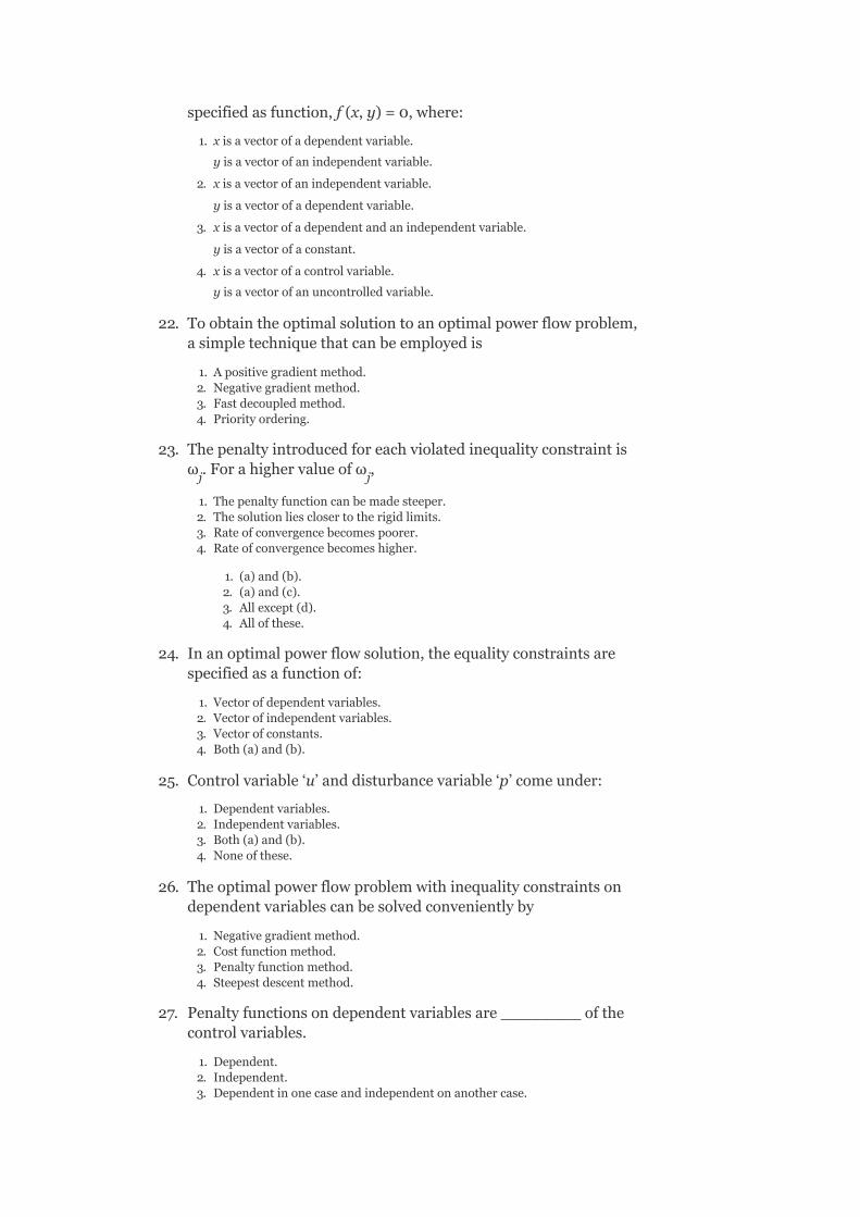
specifiedasfunction,f(x,y)=0,where:
1. xisavectorofadependentvariable.
yisavectorofanindependentvariable.
2. xisavectorofanindependentvariable.
yisavectorofadependentvariable.
3. xisavectorofadependentandanindependentvariable.
yisavectorofaconstant.
4. xisavectorofacontrolvariable.
yisavectorofanuncontrolledvariable.
22. Toobtaintheoptimalsolutiontoanoptimalpowerflowproblem,asimpletechniquethatcanbeemployedis
1. Apositivegradientmethod.2. Negativegradientmethod.3. Fastdecoupledmethod.4. Priorityordering.
23. Thepenaltyintroducedforeachviolatedinequalityconstraintisω .Forahighervalueofω ,
1. Thepenaltyfunctioncanbemadesteeper.2. Thesolutionliesclosertotherigidlimits.3. Rateofconvergencebecomespoorer.4. Rateofconvergencebecomeshigher.
1. (a)and(b).2. (a)and(c).3. Allexcept(d).4. Allofthese.
24. Inanoptimalpowerflowsolution,theequalityconstraintsarespecifiedasafunctionof:
1. Vectorofdependentvariables.2. Vectorofindependentvariables.3. Vectorofconstants.4. Both(a)and(b).
25. Controlvariable‘u’anddisturbancevariable‘p’comeunder:
1. Dependentvariables.2. Independentvariables.3. Both(a)and(b).4. Noneofthese.
26. Theoptimalpowerflowproblemwithinequalityconstraintsondependentvariablescanbesolvedconvenientlyby
1. Negativegradientmethod.2. Costfunctionmethod.3. Penaltyfunctionmethod.4. Steepestdescentmethod.
27. Penaltyfunctionsondependentvariablesare________ofthecontrolvariables.
1. Dependent.2. Independent.3. Dependentinonecaseandindependentonanothercase.
j j

4. Noneofthese.
28. Theoptimalpowerflowproblem:
1. Referstotheloadflowthatgivesmaximumsystemsecuritybyminimizingtheoverloads.
2. Aimsatminimumoperatingcostandminimumlosses.3. Shouldbebasedonoperationalconstraints.4. Allofthese.
29. Theoptimalpowerflowproblemis:
1. Astaticoptimizationproblemwiththecostfunctionasascalarobjectivefunction.
2. Adynamicoptimizationproblemwiththecostfunctionasascalarobjectivefunction.
3. Fullystaticandpartiallydynamicoptimizationproblemwiththecostfunctionasanobjectivefunction.
4. Noneofthese.
30. Forahighervalueofthepenaltyfactor,
1. Thepenaltyfunctioncanbemadesteeper.2. Thesolutionliesclosertotherigidlimit.3. Convergencebecomespoorer.4. Allofthese.
REVIEWQUESTIONS
1. Discussoptimalpowerflowproblemswithoutinequalityconstraints.
2. Obtainanoptimalpowerflowsolutionwithinequalityconstraintsoncontrolvariables.
3. Explainthepenaltyfunctionmethodofobtaininganoptimalpowerflowsolutionwithinequalityconstraintsondependentvariables.
4. Developanalgorithmforobtainingtheoptimalpowerflowsolutionwithoutinequalityconstraintsbythesteepestdescentmethod.
6
Hydro-ThermalScheduling
OBJECTIVES
Afterreadingthischapter,youshouldbeableto:
knowtheimportanceofhydro-thermalco-ordinationdevelopthemathematicalmodelingoflong-termhydro-thermalco-ordinationstudytheKirchmayer’smethodforshort-termhydro-thermalco-ordinationstudytheadvantagesofhydro-thermalplantscombination
6.1INTRODUCTION
Nostateorcountryisendowedwithplentyofwatersourcesorabundantcoalandnuclearfuel.Forminimumenvironmentalpollution,thermalgenerationshouldbeminimum.Hence,amixofhydroandthermal-powergenerationisnecessary.Thestatesthathavealargehydro-potentialcansupplyexcesshydro-powerduringperiodsofhighwaterrun-offtootherstatesandcanreceivethermalpowerduringperiodsoflowwaterrun-offfromotherstates.Thestates,whichhavealowhydro-potentialandlargecoalreserves,canusethesmallhydro-powerformeetingpeakloadrequirements.Thismakesthethermalstationstooperateathighloadfactorsandtohavereducedinstalledcapacitywiththeresulteconomy.Instates,whichhaveadequatehydroaswellasthermal-powergenerationcapacities,powerco-ordinationtoobtainamosteconomicaloperatingstateisessential.Maximumadvantageofcheaphydro-powershouldbetakensothatthecoalreservescanbeconservedandenvironmentalpollutioncanbeminimized.Thewholeorapartofthebaseloadcanbe

suppliedbytherun-offriverhydro-plants,andthepeakortheremainingloadisthenmetbyapropermixofreservoir-typehydro-plantsandthermalplants.Determinationofthisbyapropermixisthedeterminationofthemosteconomicaloperatingstateofahydro-thermalsystem.Thehydro-thermalco-ordinationisclassifiedintolong-termco-ordinationandshort-termco-ordination.
6.2HYDRO-THERMALCO-ORDINATION
Initially,thereweremostlythermalpowerplantstogenerateelectricalpower.Thereisaneedforthedevelopmentofhydro-powerplantsduetothefollowingreasons.
1. Duetotheincrementofpowerintheloaddemandfromallsidessuchasindustrial,agricultural,commercial,anddomestic.
2. Duetothehighcostoffuel(coal).3. Duetothelimitedrangeoffuel.
Thehydro-plantscanbestartedeasilyandcanbeassignedaloadinveryshorttime.However,inthecaseofthermalplants,itrequiresseveralhourstomaketheboilers,superheater,andturbinesystemreadytotaketheload.Forthisreason,thehydro-plantscanhandlefast-changingloadseffectively.Thethermalplantsincontrastareslowinresponse.Hence,duetothis,thethermalplantsaremoresuitabletooperateasbaseloadplants,leavinghydro-plantstooperateaspeakloadplants.
FIG.6.1Fundamentalhydro-thermalsystem

Themaximumadvantageofcheaphydro-powershouldbetakensothatthecoalreservescanbeconservedandenvironmentalpollutioncanbeminimized.Inahydro-thermalsystem,thewholeorapartofthebaseloadcanbesuppliedbytherun-offriverhydro-plantsandthepeakortheremainingloadisthenmetbyaproperco-ordinationofreservoir-typehydro-plantsandthermalplants.
Theoperatingcostofthermalplantsisveryhighandatthesametimeitscapitalcostislowwhencomparedwithahydro-electricplant.Theoperatingcostofahydro-electricplantislowanditscapitalcostishighsuchthatithasbecomeeconomicalaswellasconvenienttorunboththermalaswellashydro-plantsinthesamegrid.
Inthecaseofthermalplants,theoptimalschedulingproblemcanbecompletelysolvedatanydesiredinstantwithoutreferringtotheoperationatothertimes.Itisastaticoptimizationproblem.
Theoperationofasystemhavingbothhydroandthermalplantsismorecomplexashydro-plantshaveanegligibleoperatingcostbutarerequiredtorunundertheconstraintofavailabilityofwaterforhydro-generationduringagivenperiodoftime.Thisproblemisthe‘dynamicoptimizationproblem’wherethetimefactoristobeconsidered.
Theoptimalschedulingprobleminahydro-thermalsystemcanbestatedastominimizethefuelcostofthermalplantsundertheconstraintofwateravailabilityforhydro-generationoveragivenperiodofoperation.
Considerasimplehydro-thermalsystem,showninFig.6.1,whichconsistsofonehydroandonethermalplantsupplyingpowertoloadconnectedatthecenterinbetweentheplantsandisreferredtoasthefundamentalsystem.
Tosolvetheoptimizationprobleminthissystem,considertherealpowergenerationsoftwoplantsP
andP ascontrolvariables.Thetransmissionpower
lossisexpressedintermsoftheBcoefficientas
6.3SCHEDULINGOFHYDRO-UNITSINAHYDRO-THERMALSYSTEM
1. Incaseofhydro-unitswithoutthermalunitsinthesystem,theproblemissimple.Theeconomicschedulingconsistsofschedulingwaterreleasetosatisfythehydraulicconstraintsandtosatisfytheelectricaldemand.
2. Wherehydro-thermalsystemsarepredominantlyhydro,schedulingmaybedonebyschedulingthesystemtoproduceminimumcostforthethermalsystems.
3. Insystemswherethereisaclosebalancebetweenhydroandthermalgenerationandinsystemswherethehydro-capacityisonlyafractionofthetotalcapacity,itisgenerallydesiredtoschedulegenerationsuchthatthermalgeneratingcostsareminimized.
6.4CO-ORDINATIONOFRUN-OFFRIVERPLANTANDSTEAMPLANT
Arun-offriverhydro-plantoperatesasthewaterisavailableinneededquantities.Theseplantsareprovidedwithasmallpondageorreservoir,whichmakesitpossibletomeetthehourlyvariationofload.
Theratioofrun-offduringtherainyseasontotherun-offduringthedryseasonmaybeaslargeas100.Assuchtherun-offriverplantshaveverylittlefromcapacity.Theusefulnessoftheserun-offriverplantscanbeconsiderablyincreasedifsuchaplantisproperlyco-ordinatedwithathermalplant.Whensuchco-ordinationexists,thehydro-plantmaycarrythebaseloaduptoitsinstalledcapacityduringtheperiodofhighstreamflowsandthethermalplantmaycarrythepeakload.Duringtheperiodofleanflow,thethermalplantsuppliesthebaseloadandthehydro-plantsuppliesthepeakload.Thus,theloadmetbyathermalplantcanbeadjustedto
GThermal
GHydro

conformtotheavailableriverflow.Thistypeofco-ordinationofarun-offriverhydro-plantwithathermalplantresultsinagreaterutilizationfactoroftheriverflowandasavingintheamountoffuelconsumedinthethermalplant.
6.5LONG-TERMCO-ORDINATION
Typicallong-termco-ordinationmaybeextendedfromoneweektooneyearorseveralyears.Theco-ordinationoftheoperationofreservoirhydro-powerplantsandsteamplantsinvolvesthebestutilizationofavailablewaterintermsoftheschedulingofwaterreleased.Inotherwords,sincetheoperatingcostsofhydro-plantsareverylow,hydro-powercanbegeneratedatverylittleincrementalcost.Inacombinedoperationalsystem,thegenerationofthermalpowershouldbedisplacedbyavailablehydro-powersothatmaximumdecrementproductioncostswillberealizedatthesteamplant.Thelong-termschedulingprobleminvolvesthelong-termforecastingofwateravailabilityandtheschedulingofreservoirwaterreleasesforanintervaloftimethatdependsonthereservoircapacitiesandthechronologicalloadcurveofthesystem.Basedonthesefactorsduringdifferenttimesoftheyear,thehydroandsteamplantscanbeoperatedasbaseloadplantsandpeakloadplantsandviceversa.
Forthelong-termdrawdownschedule,abasicbestpolicyselectionmustbemade.Thebestpolicyisthatshouldthewaterbeusedundertheassumptionthatitwillbereplacedataratebasedonthestatisticallyexpectedrateorshouldthewaterbereleasedusingaworst-caseprediction?
Long-termschedulingismadebasedonanoptimizingpolicyinviewofstatisticallytreatedunknownssuchasload,hydraulicinflows,andunitavailability(i.e.,steamandhydro-plants).

Theusefultechniquesemployedforthistypeofschedulingproblemsinclude:
1. thesimulationofanentirelong-termoperationaltimeperiodforagivensetofoperatingconditionsbyusingthedynamicprogrammingmethod,
2. compositehydraulicsimulationmodels,and3. statisticalproductioncostmodels.
Forthelong-termschedulingofahydro-thermalsystem,thereshouldberequiredgenerationtomeettherequirementsofloaddemandandbothhydroandthermalgenerationsshouldbesoscheduledsoastomaintaintheminimumfuelcosts.Thisrequiresthattheavailablewatershouldbeputtoanoptimumuse.
6.6SHORT-TERMCO-ORDINATION
Theeconomicsystemoperationofthermalunitsdependsonlyontheconditionsthatexistfrominstanttoinstant.However,theeconomicschedulingofcombinedhydro-thermalsystemsdependsontheconditionsexistingovertheentireoperatingperiod.
Thistypeofhydro-thermalschedulingisrequiredforonedayoroneweek,whichinvolvesthehour-by-hourschedulingofallavailablegenerationsonasystemtogettheminimumproductioncostforthegiventime.Suchtypesofschedulingproblems,theload,hydraulicinflows,andunitavailabilitiesareassumedtobeknown.
Herealso,theproblemishowtosupplyload,aspertheloadcycleduringtheperiodofoperationsothatgenerationbythermalplantswillbeminimum.Thisconditionwillbesatisfiedwhenthevalueofhydro-powergenerationratherthanitsamountisamaximumoveracertainperiod.Thebasicproblemisthatdeterminingthedegreetowhichtheminimizedeconomyofoperatingthehydro-unitsatotherthanthemaximumefficiencyloadingmaybetoleratedforanincreasedeconomywithanincreasedloadorviceversatoresultinthelowest

totalthermalpowerproductioncostsoverthespecifiedoperatingperiod.
Thefactorsonwhichtheeconomicoperationofacombinedhydro-thermalsystemdependsareasfollows:
Loadcycle.Incrementalfuelcostsofthermalpowerstations.Expectedwaterinflowinhydro-powerstations.Waterheadthatisafunctionofwaterstorageinhydro-powerstations.Hydro-powergeneration.Incrementaltransmissionloss(ITL).
Thefollowingarethefewimportantmethodsforshort-termhydro-thermalco-ordination:
1. Constanthydro-generationmethod.2. Constantthermalgenerationmethod.3. Maximumhydro-efficiencymethod.4. Kirchmayer’smethod.
6.6.1Constanthydro-generationmethod
Inthismethod,ascheduledamountofwaterataconstantheadisusedsuchthatthehydro-powergenerationiskeptconstantthroughouttheoperatingperiod.
6.6.2Constantthermalgenerationmethod
Thermalpowergenerationiskeptconstantthroughouttheoperatingperiodinsuchawaythatthehydro-powerplantsuseaspecifiedandscheduledamountofwaterandoperateonvaryingpowergenerationschedulesduringtheoperatingperiod.
6.6.3Maximumhydro-efficiencymethod
Inthismethod,duringpeakloadperiods,thehydro-powerplantsareoperatedattheirmaximumefficiency;duringoff-peakloadperiodstheyoperateatanefficiencynearertotheirmaximum–efficiencywiththeuseofaspecifiedamountofwaterforhydro-powergeneration.

Kirchmayer’smethodisexplainedinSection6.8.
6.7GENERALMATHEMATICALFORMULATIONOFLONG-TERMHYDRO-THERMALSCHEDULING
Tomathematicallyformulatetheoptimalschedulingprobleminahydro-thermalsystem,thefollowingassumptionsaretobemadeforacertainperiodofoperationT(aday,aweek,orayear):
1. Thestorageofahydro-reservoiratthebeginningandattheendofperiodofoperationTarespecified.
2. Afteraccountingfortheirrigationpurpose,waterinflowtothereservoirandloaddemandonthesystemareknowndeterministicallyasfunctionsoftimewithcertainties.
Theoptimizationproblemhereistodeterminethewaterdischargerateq(t)soastominimizethecostofthermalgeneration.
Objectivefunctionis
Subjecttothefollowingconstraints:
(i)Therealpowerbalanceequation
P (t)+P (t)=P (t)+P (t)+P (t)
i.e.,P (t)+P (t)−P (t)−P (t)=0fort∈(0,T)(6.2)
where
P (t)istherealpowerthermalgenerationattime‘t’,
P (t)therealpowerhydrogenerationattime‘t’,
P (t)realpowerlossattime‘t’,and
GT GH L D D
GT GH L D
GT
GH
L

P (t)therealpowerdemandattime‘t’.
(ii)Wateravailabilityequation:
where
X′(t)isthewaterstorageattime‘t’,
X′(0)thewaterstorageatthebeginningofoperationtime,T,
X′(T)thewaterstorageattheendofoperationtime,T,
J(t)thewaterinflowrate,and
q(t)thewaterdischargerate.
(iii)Realpowerhydro-generation
Therealpowerhydro-generationP (t)isafunctionofwaterstorageX′(t)andwaterdischargerateq(t)
i.e.,P (t)=f(X′(t),q(t))(6.4)
6.7.1Solutionofproblem-discretizationprinciple
Bythediscretizationprinciple,theaboveproblemcanbeconvenientlysolved.TheoptimizationintervalTissub-dividedintoNequalsub-intervalsofΔttimelengthandovereachsub-interval,itisassumedthatallthevariablesremainfixedinvalue.
Thesameproblemcanbereformulatedas
D
GH
GH

subjecttothefollowingconstraints:
(i)Powerbalanceequation
P +P −P −P =0(6.6)
where
P isthethermalgenerationinKthinterval,
P thehydrogenerationinKthinterval,
P thetransmissionpowerlossinKthintervalandisexpressed
as
,and
P istheloaddemandintheKthinterval.
(ii)Wateravailabilityequation:
X′ −X′ −j Δt+q Δt=0(6.7)
whereX′ isthewaterstorageattheendofintervalK,jthewaterinflowrateinintervalK,andq thewaterdischargerateinintervalK.
DividingEquation(6.7)byΔt,itbecomes
X −X −j +q =0forK=1,2…N(6.8)
GT GH L D
GT
GH
L
D
K K K K
K
K
K
K
K (K−1) K K
K K
K
K K−1 K K

where isthewaterstorageindischargeunits.
x andx arespecifiedaswaterstorageratesatthebeginningandattheendoftheoptimizationinterval,respectively.
(iii)Therealpowerhydro-generationinanysub-intervalcanbewrittenas
P =h 1+0.5e(X +X )(q −ρ)(6.9)
where
h =9.81×10 h ′;
h ′isthebasicwaterheadwhichiscorrespondingtodead
storage,
ethewaterheadcorrectionfactortoaccountforthevariationinheadwithstorage,and
ρthenon-effectivedischarge(duetotheneedofwhichahydrogenerationcanrunatno-loadcondition).
Equation(6.9)canbeobtainedasfollows:
P =9.81×10 h (q −ρ)MW
where(q −ρ)istheeffectivedischargeinm /sandhistheaverageheadintheK intervalandisgivenas
whereAistheareaofcross-sectionofthereservoiratthegivenstorage
GH o
o o
o
GH av K
av
0 N
K K K−1 K
−3
K −3 K
K 3 K
th
K K K−1

h =h′ (1+0.5e(X +X ))
where ,whichistabulatedforvariousstorage
values
∴P =h 1+0.5e(X +X )(q
whereh =9.81×10 h′ .
Theoptimizationproblemismathematicallystatedforanysub-interval‘K’bytheobjectivefunctiongivenbyEquation(6.5),whichissubjectedtoequationconstraintsgivenbyEquations(6.6),(6.8),and(6.9).
Intheaboveoptimizationproblem,itisconvenienttochoosewaterdischargesinallsub-intervalsexceptonesub-intervalasindependentvariablesandhydro-generations,thermalgenerations,waterstoragesinallsub-intervalsandexceptwaterdischargeasdependentvariables;i.e.,independentvariablesarerepresentedbyq ,forK=2,3,…,NandforK≠1.DependentvariablesarerepresentedbyP ,P X ,andq ,forK=1,2,…,N.[Sincethewaterdischargeinonesub-intervalisadependentvariable.]
Equation(6.8)canbewrittenforallvaluesofK=1,2,…,N:
i.e.,X –X –j +q =0 forK=1
X –X –j +q =0 forK=2
X –X –j +q =0 fork=N interval
Byaddingtheabovesetofequations,weget
av o
GH o
o o
GT GH
K K K−1
K K K−1 K−ρ
–3
K
K K K 1
1 0 1 1
2 1 2 2
N (N–1) N N th
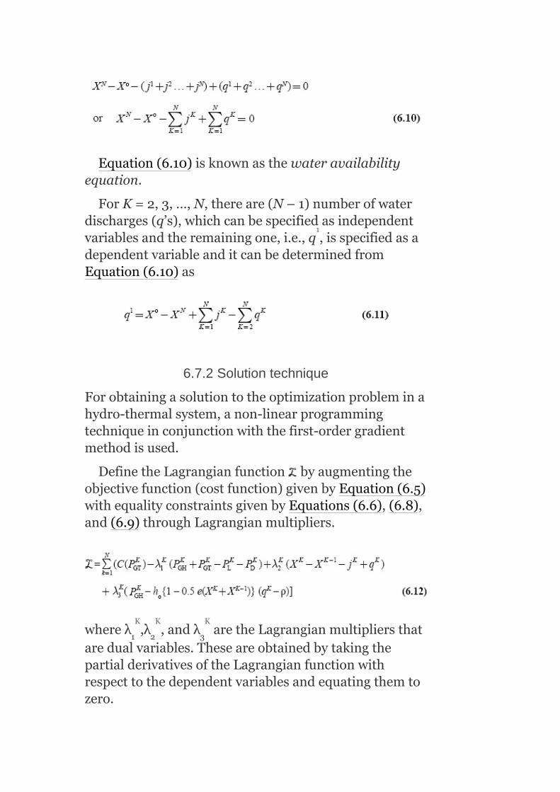
Equation(6.10)isknownasthewateravailabilityequation.
ForK=2,3,…,N,thereare(N–1)numberofwaterdischarges(q’s),whichcanbespecifiedasindependentvariablesandtheremainingone,i.e.,q ,isspecifiedasadependentvariableanditcanbedeterminedfromEquation(6.10)as
6.7.2Solutiontechnique
Forobtainingasolutiontotheoptimizationprobleminahydro-thermalsystem,anon-linearprogrammingtechniqueinconjunctionwiththefirst-ordergradientmethodisused.
DefinetheLagrangianfunction byaugmentingtheobjectivefunction(costfunction)givenbyEquation(6.5)withequalityconstraintsgivenbyEquations(6.6),(6.8),and(6.9)throughLagrangianmultipliers.
whereλ ,λ ,andλ aretheLagrangianmultipliersthataredualvariables.TheseareobtainedbytakingthepartialderivativesoftheLagrangianfunctionwithrespecttothedependentvariablesandequatingthemtozero.
1 2 3
1
K K K
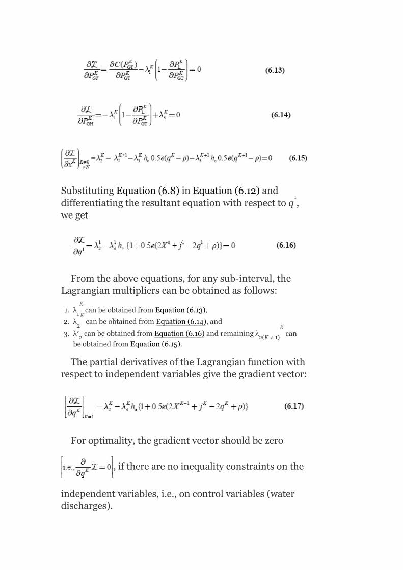
SubstitutingEquation(6.8)inEquation(6.12)anddifferentiatingtheresultantequationwithrespecttoq ,weget
Fromtheaboveequations,foranysub-interval,theLagrangianmultiplierscanbeobtainedasfollows:
1. λ canbeobtainedfromEquation(6.13),
2. λ canbeobtainedfromEquation(6.14),and
3. λ′ canbeobtainedfromEquation(6.16)andremainingλ can
beobtainedfromEquation(6.15).
ThepartialderivativesoftheLagrangianfunctionwithrespecttoindependentvariablesgivethegradientvector:
Foroptimality,thegradientvectorshouldbezero
,iftherearenoinequalityconstraintsonthe
independentvariables,i.e.,oncontrolvariables(waterdischarges).
1
2
2 2(K≠1)
1
K
K
K
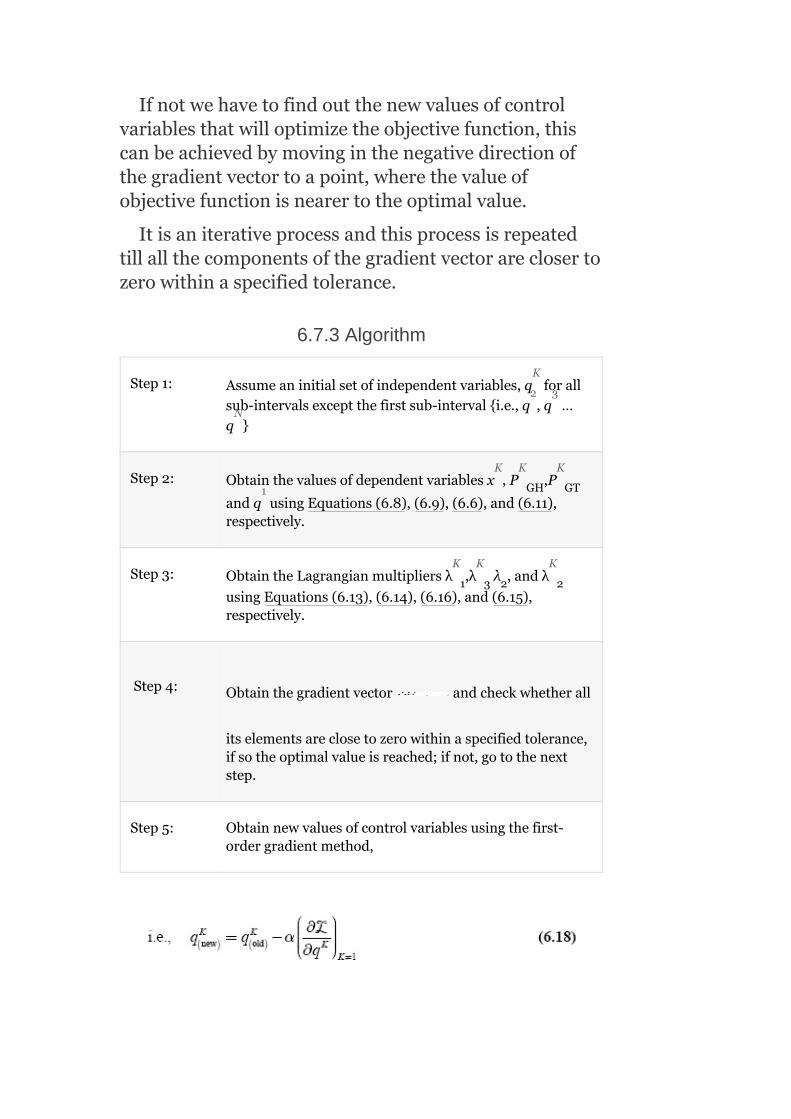
Ifnotwehavetofindoutthenewvaluesofcontrolvariablesthatwilloptimizetheobjectivefunction,thiscanbeachievedbymovinginthenegativedirectionofthegradientvectortoapoint,wherethevalueofobjectivefunctionisnearertotheoptimalvalue.
Itisaniterativeprocessandthisprocessisrepeatedtillallthecomponentsofthegradientvectorareclosertozerowithinaspecifiedtolerance.
6.7.3Algorithm
Step1: Assumeaninitialsetofindependentvariables,q forallsub-intervalsexceptthefirstsub-intervali.e.,q ,q …q
Step2: Obtainthevaluesofdependentvariablesx ,P ,P
andq usingEquations(6.8),(6.9),(6.6),and(6.11),respectively.
Step3: ObtaintheLagrangianmultipliersλ ,λ λ ,andλ
usingEquations(6.13),(6.14),(6.16),and(6.15),respectively.
Step4: Obtainthegradientvector andcheckwhetherall
itselementsareclosetozerowithinaspecifiedtolerance,ifsotheoptimalvalueisreached;ifnot,gotothenextstep.
Step5: Obtainnewvaluesofcontrolvariablesusingthefirst-ordergradientmethod,
GH GT
1 3 2 2
K
2 3
N
K K K
1
K K K

whereαisapositivescalar,whichdefinesthesteplength,andhavingavaluedependsontheproblemonhand,thengotoStep2andrepeattheprocess.
Theinequalityconstraintsoftheproblemondependentandindependentvariablescanbehandledinthecaseofanoptimalpowerflowsolution.InequalityconstraintsonindependentvariableschecktheKuhn–Tuckercondition(giveninoptimalpowerflow,ChapterV).Theinequalityconstraintsondependentvariablescanbehandledbyaugmentingtheobjectivefunctionthroughapenaltyfunction.
Theabove-mentionedsolutionmethodcanbedirectlyextendedtoasystemhavingmultihydroandmultithermalplants.
Drawback:Itrequireslargememorysincetheindependentvariables,dependentvariables,andgradientsneedtobestoredsimultaneously.
Amodifiedtechniqueknownasdecompositionovercomestheabovedrawback.Inthedecompositiontechnique,optimizationiscarriedoutovereachsub-intervalandacompletecycleofiterationisrepeated,ifthewateravailabilityequationdoesnotcheckattheendofthecycle.
Example6.1:Atypicalhydro-thermalsystemisshowninFig.6.2.Foratypicalday,theloadonthesystemvariesinstepsofeighthourseachas9,12,and8MW,respectively.Thereisnowaterinflowintothereservoirofthehydro-plant.Theinitialwaterstorageinthereservoiris120m /sandthefinalwaterstorageshouldbe75m /s,i.e.,thetotalwateravailableforhydro-generationduringthedayis30m /s.
3
3
3

FIG.6.2Fundamentalhydro-thermalsystem
Basicheadis30m.Waterheadcorrectionfactoreisgiventobe0.004.Assumeforsimplicitythatthereservoirisrectangularsothatedoesnotchangewithwaterstorage.Letthenon-effectivewaterdischargebeassumedas3m /s.Thefuelcost-curvecharacteristicsofthethermalplantisC =0.2P 50P 130Rs./hr.Findtheoptimumgenerationschedulebyassumingthetransmissionlossesneglected.
Solution:
Given:
Fuelcostofthethermalplant,C =0.2P +50P +130Rs./hr
Incrementalfuelcost,
Totaltimeofoperation,T =24hr
No.ofsub-intervals,N =3
Durationofeachsub-interval,Δt =8hr
Initialwaterstorageinreservoir,x′(0) =120m /s
Finalwaterstorage,x′(3) =75m /s
T GT GT+
T GT GT
3
2+
2
3
3
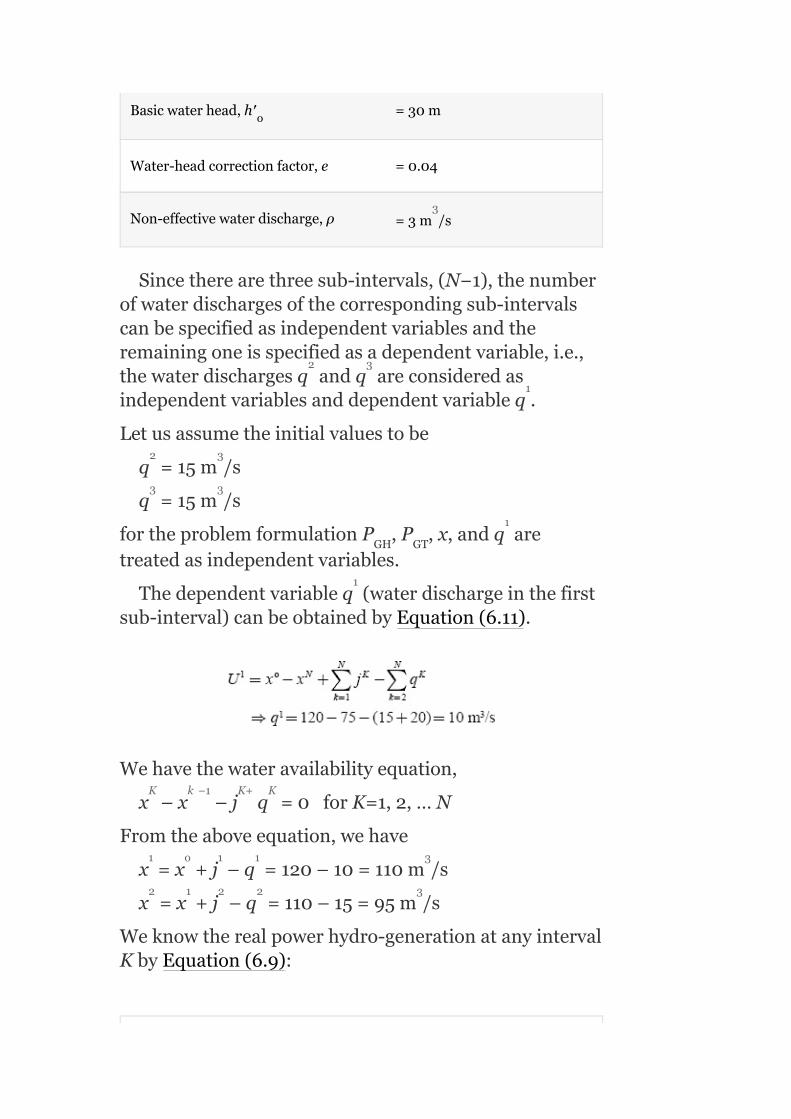
Basicwaterhead,h′ =30m
Water-headcorrectionfactor,e =0.04
Non-effectivewaterdischarge,ρ =3m /s
Sincetherearethreesub-intervals,(N−1),thenumberofwaterdischargesofthecorrespondingsub-intervalscanbespecifiedasindependentvariablesandtheremainingoneisspecifiedasadependentvariable,i.e.,thewaterdischargesq andq areconsideredasindependentvariablesanddependentvariableq .
Letusassumetheinitialvaluestobe
q =15m /s
q =15m /s
fortheproblemformulationP ,P ,x,andq aretreatedasindependentvariables.
Thedependentvariableq (waterdischargeinthefirstsub-interval)canbeobtainedbyEquation(6.11).
Wehavethewateravailabilityequation,
x –x –j q =0forK=1,2,…N
Fromtheaboveequation,wehave
x =x +j –q =120–10=110m /s
x =x +j –q =110–15=95m /s
Weknowtherealpowerhydro-generationatanyintervalKbyEquation(6.9):
o
GH GT
3
2 3
1
2 3
3 3
1
1
K k −1 K+ K
1 o 1 1 3
2 1 2 2 3

P = h 1+0.5e(x +x )(q −e)
= 9.81×10 h′ 1+0.5e(x +x )(q −ρ)
P = 9.81×10 ×301+0.5×0.004(x +x )q −ρ
= 9.81×10 ×301+0.5×0.004(110+120)(10−3)
= 3.0077MW
P = 9.81×10 ×301+0.5×0.004(x +x )q −ρ
= 9.81×10 ×301+0.5×0.004(95+110)(15−3)
= 4.9795MW
P = 9.81×10 ×301+0.5×0.004(x +x )q −ρ
= 9.81×10 ×301+0.5×0.004(75+95)(20−3)
= 6.7041MW
Thethermalpowergenerationsduringthesub-intervalsare
P =P −P =9−3.0077=5.9923MW
P =P −P =12−4.9795=7.0205MW
P =P −P =8−6.7041=1.2959MW
λ canbeobtainedfromEquation(6.13):
GH
o
o
GH
GH
GH
GT D GH
GT D GH
GT D GH
1
K K K−1 k
−3 K K−1 K
1 −3 1 o 1
−3
2 −3 2 1 2
−3
3 −3 3 2 2
−3
1 1 1
2 2 2
3 3 3
K

i.e.,
Byneglectingtransmissionlosses,wehave
⇒λ =0.4P +50=0.4×5.9923+50=52.3969Rs./MWh
λ =0.4P +50=0.4×7.0205+50=52.8082Rs./MWh
λ =0.4P +50=0.4×1.2959+50=50.5183Rs./MWh
FromEquation(6.14),
Byneglectingtransmissionlosses,wehave
⇒λ =λ
∴λ =λ =52.3969Rs./MWh
λ =λ =52.8082Rs./MWh
λ =λ =50.5183Rs./MWh
FromEquation(6.16),wehave
⇒λ =λ h 1+0.5e(2x +j −2q +ρ)
=52.3969×9.81×10 ×301+0.5×0.004(2×120−2×10+3)
(sincej=0)
1 GT
1 GT
1 GT
3 1
3 1
3 1
3 1
2 2 o
1 1
2 2
3 3
K K
1 1
2 2
3 3
1 1 o 1 1
−3
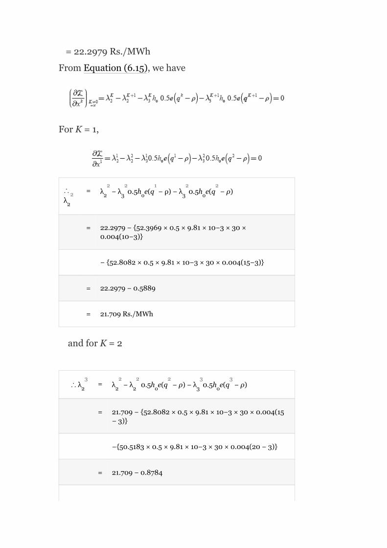
=22.2979Rs./MWh
FromEquation(6.15),wehave
ForK=1,
∴λ
= λ −λ 0.5h e(q −ρ)−λ 0.5h e(q −ρ)
= 22.2979−52.3969×0.5×9.81×10−3×30×0.004(10−3)
−52.8082×0.5×9.81×10−3×30×0.004(15−3)
= 22.2979−0.5889
= 21.709Rs./MWh
andforK=2
∴λ = λ −λ 0.5h e(q −ρ)−λ 0.5h e(q −ρ)
= 21.709−52.8082×0.5×9.81×10−3×30×0.004(15−3)
−50.5183×0.5×9.81×10−3×30×0.004(20−3)
= 21.709−0.8784
2
2 3 o 3 o
2 2 2 o 3 o
2
2 2 1 2 2
3 2 2 2 3 3
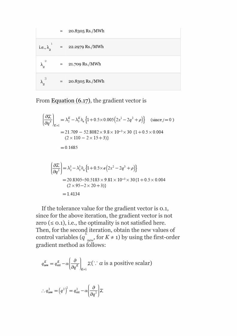
= 20.8305Rs./MWh
i.e.,λ = 22.2979Rs./MWh
λ = 21.709Rs./MWh
λ = 20.8305Rs./MWh
FromEquation(6.17),thegradientvectoris
Ifthetolerancevalueforthegradientvectoris0.1,sincefortheaboveiteration,thegradientvectorisnotzero(≤0.1),i.e.,theoptimalityisnotsatisfiedhere.Then,fortheseconditeration,obtainthenewvaluesofcontrolvariables(q ,forK≠1)byusingthefirst-ordergradientmethodasfollows:
(∵αisapositivescalar)
2
2
2
new
1
2
3
K

Letusconsiderα=0.5,
∴q =(q ) =15−0.5(0.1685)=14.9157m /s
Similarly,q =(q ) =15−0.5(1.4134)=19.2933m /s
andfromEquation(6.11),
⇒q =x –x –(q q )(sincej =0)
q =120–75–(14.9157+19.2933)
=10.791m /s
Toobtaintheoptimalgenerationscheduleinhydro-thermalco-ordination,theprocedureisrepeatedforthenextiterationandcheckedforagradientvector.Ifthegradientvectorbecomeszerowithinaspecifiedtolerance,thenthatwillbetheoptimumgenerationschedule,otherwisetheiterationsaretobecarriedout.
6.8SOLUTIONOFSHORT-TERMHYDRO-THERMALSCHEDULINGPROBLEMS—KIRCHMAYER’SMETHOD
Inthismethod,theco-ordinationequationsarederivedintermsofpenaltyfactorsofbothplantsforobtainingtheoptimumschedulingofahydro-thermalsystemandhenceitisalsoknownasthepenaltyfactormethodofsolutionofshort-termhydro-thermalschedulingproblems.
Let P bethepowergenerationofi thermalplantinMW,
new
new
GTi
2 2 1 3
3 3 1
3
1 o 3 2+ 3 K
1
3
th
th

P bethepowergenerationofj hydro-plantinMW,
betheincrementalfuelcostofi thermalplantin
Rs./MWh,
w bethequantityofwaterusedforpowergenerationatj
hydro-plantinm /s,
betheincrementalwaterrateofj hydro-plantin
m /s/MW,
betheincrementaltransmissionlossofi thermalplant,
betheincrementaltransmissionlossofj hydelplant,
λbetheLagrangianmultiplier,
γ betheconstantwhichconvertstheincrementalwaterrateof
hydelplantjintoanincrementalcost,
nbethetotalnumberofplants,
αbethenumberofthermalplants,
n−αbethenumberofhydro-plants,and
Tbethetimeintervalduringwhichtheplantoperationisconsidered.
GHj
j
j
th
th
th
3
th
3
th
th

Here,theobjectiveistofindthegenerationofindividualplants,boththermalaswellashydelthatthegenerationcost(costoffuelinthermal)isoptimumandatthesametimetotaldemand(P )andlosses(P )arecontinuouslymet.
Asitisashort-rangeproblem,therewillnotbeanyappreciablechangeinthelevelofwaterinthereservoirsduringtheinterval(i.e.,theeffectsofrainfallandevaporationareneglected)andhencetheheadofwaterinthereservoirwillbeassumedtobeconstant.
LetK bethespecifiedquantityofwater,whichmustbeutilizedwithintheintervalTateachhydro-stationj.
Problemformulation
Theobjectivefunctionistominimizethecostofgeneration:
i.e.,
subjecttotheequalityconstraints
and
wherew istheturbinedischargeinthej plantinm /sandK theamountofwaterinm utilizedduringthetimeperiodTinthej hydro-plant.
D L
j
j
j
th 3
3
th

Thecoefficientγmustbeselectedsoastousethespecifiedamountofwaterduringtheoperatingperiod.
Now,theobjectivefunctionbecomes
SubstitutingK fromEquation(6.21)intheaboveequation,weget
ForaparticularloaddemandP ,Equation(6.20)resultsas
Foraparticularhydro-plantx,Equation(6.23)canberewrittenas
Byrearrangingtheaboveequation,weget
FromEquation(6.22),theconditionforminimizationis
j
D

Theaboveequationcanbewrittenas
Forhydro-plantx,
Multiplyingtheaboveequationby ,
Substitutefor fromEquation(6.24)in
Equation(6.27),weget

Rewritingtheaboveequationas
∴ΔP ≠0andΔP ≠0,Equation(6.28)becomes
and
Equations(6.29)and(6.30)canbewrittenintheform:
and
GTi GHj

FromEquations(6.31)and(6.32),wehave
where(I ) istheincrementalfuelcostofthei thermalplantand(I ) theincrementalwaterrateofthejhydro-plant.
Equations(6.34)and(6.35)maybeexpressedapproximatelyas
C i
W j
th
th

where and aretheapproximate
penaltyfactorsofthei thermalplantandthej hydro-plant,respectively.
Equations(6.34)and(6.35)aretheco-ordinateequations,whichareusedtoobtaintheoptimalschedulingofthehydro-thermalsystemwhenconsideringthetransmissionlosses.
Intheaboveequations,thetransmissionlossP isexpressedas
Thepowergenerationofahydro-plantP isdirectly
proportionaltoitsheadanddischargeratew .
Whenneglectingthetransmissionlosses,theco-ordinationequationsbecome
Example6.2:Atwo-plantsystemhavingasteamplantneartheloadcenterandahydro-plantataremotelocationisshowninFig.6.3.Theloadis500MWfor16hradayand350–MW,for8hraday.
Thecharacteristicsoftheunitsare
C =120+45P +0.075P
w =0.6P +0.00283P m /s
Losscoefficient,B =0.001MW
L
GHj
j
1 GT GT
2 GH 2GH
22
th th
2
3
−1

Findthegenerationschedule,dailywaterusedbythehydro-plant,anddailyoperatingcostofthethermalplantforγ =85.5Rs./m -hr.
Solution:
Given:C =120+45P +0.075P
Co-ordinationequationforthermalunitis
45+0.15P +0.075P
FIG.6.3Atypicaltwo-planthydro-thermalsystem
Forthehydro-unit,theco-ordinationequationis
Sincetheloadisnearertothethermalplant,thetransmissionlossisonlyduetothehydro-plantandthereforeB =B =B =0:
j
1 GT GT
GT GT
TT TH HT
3
2
2
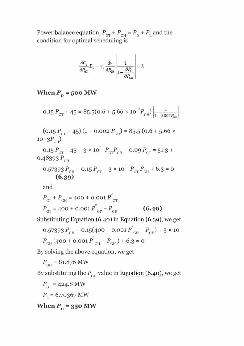
Powerbalanceequation,P +P =P +P andtheconditionforoptimalschedulingis
WhenP =500MW
0.15P +45=85.5(0.6+5.66×10 P )
(0.15P +45)(1−0.002P )=85.5(0.6+5.66×10⁻³P )
0.15P +45−3×10 P P −0.09P =51.3+0.48393P
0.57393P −0.15P +3×10 P P +6.3=0(6.39)
and
P +P =400+0.001P
P =400+0.001P −P (6.40)
SubstitutingEquation(6.40)inEquation(6.39),weget
0.57393P −0.15(400+0.001P −P )+3×10
P (400+0.001P −P )+6.3=0
Bysolvingtheaboveequation,weget
P =81.876MW
BysubstitutingtheP valueinEquation(6.40),weget
P =424.8MW
P =6.70367MW
WhenP =350MW
GT GH D L
D
GT GH
GT GH
GH
GT GT GH GT
GH
GH GT GT GH
GT GH GT
GT GT GH
GH GH GH
GH GH GH
GH
GH
GT
L
D
−3
−4
−4
2
2
2 −4
2

Equation(6.40)canbemodifiedas
P =350+0.001P −P (6.41)
SubstitutingEquation(6.41)inEquation(6.39),weget
0.57393P −0.15(350+0.001P −P )+3×10
P (350+0.001P −P )+6.3=0
Bysolvingtheaboveequation,weget
P =58.5851MW
BysubstitutingtheP valueinEquation(6.41),weget
P =294.847MW
P =3.43221MW
Dailywaterusedbythehydro-plant
w 0.6P +0.00283P m /s
= Dailywaterquantityusedfora500MWloadfor16hr+dailywaterquantityusedfora350MWloadfor8hr
= [0.6×81.876+0.00283×(81.876) ]×14+[0.6×58.586+0.00283×(58.586) ]×8×3600
= 5.21449×10 m
Dailyoperatingcostofthethermalplantis:
C =
(120+45P +0.075P )
= Operatingcostofthethermalplantformeetingthe500MWloadfor16hr+operatingcostofthethermalplantformeetingthe350MWloadfor8hr
GT GH GH
GH GH GH
GH GH GH
GH
GH
GT
L
GH GH
1GT GT
2
2 −4
2
2 3
2
2
6 3
2

= [120+45×424.8+0.075(424.8) ]×16+[120+45×294.85+0.075(424.8) ]×8
= Rs.6,83,589.96perday
Example6.3:Atwo-plantsystemthathasahydro-plantneartheloadcenterandasteamplantataremotelocationisshowninFig.6.4.Theloadis400MWfor14hradayand200MW,for10hraday.
Thecharacteristicsoftheunitsare
C =150+60P +0.1P Rs/hr
w =0.8P +0.000333P m3/s
FIG.6.4Atypicaltwo-planthydro-thermalsystem
Losscoefficient,B =0.001MW
Findthegenerationschedule,dailywaterusedbythehydro-plant,andthedailyoperatingcostofathermalplantforγ =77.5Rs./m hr.
Solution:
Equationsforthermalandhydro-plantsare
1 GT GT
2 GH GH
22
j
2
2
2
2
−1
3

Sincetheloadisnearertothehydro-plant,thetransmissionlossisonlyduetothethermalplantandthereforeB =B =B =0:
WhenP =400MW
Thepowerbalanceequationis
P +P = P +P
= 400+0.001P
P = 400+0.001P −P (6.42)
Theconditionforoptimalschedulingproblemis
0.2P +60=77.5(0.8+6.6×10 P )(1−0.002P )
0.2P +60=62+0.051615P −0.124P −1.032×10 P P
0.2P +0.124P +1.032×10 P P −0.0516P−2=0(6.43)
SubstitutingP fromEquation(6.42)inEquation(6.43),weget
HH TH HT
D
GT GH D L
GT
GH GT GT
GT GH
GT
GT GH GT
GH GT
GT GT GH GT GH
GH
2
2
−4
−4
−4
−4

0.2P +0.124P +1.032×10 P (400+0.001P −P )
−0.0516(400+0.001P −P )−2=0
Bysolvingtheaboveequation,weget
P =55.4MW
BysubstitutingtheP valueinEquation(6.42),weget
P =347.66MW
P =3.069MW
WhenP =200MW
FromEquation(6.42),thepowerbalanceequationbecomes
P =2000.001P −P (6.44)
SubstitutingP fromEquation(6.44)inEquation(6.43),weget
0.2P +0.124P +1.032×10 P (200+0.001P −P )
−0.0516(200+0.001P −P )−2=0
Bysolvingtheaboveequation,weget
P =31.575MW
BysubstitutingtheP valueinEquation(6.44),weget
P =169.421MW
P =0.9969MW
Dailyoperatingcostofthethermalplant
C = 150+60P +0.1P
= Dailyoperatingcostofthethermalplantformeetinga400MWloadfor14hr+dailyoperatingcostofthethermal
GT GT GT
GT GT
GT GT
GT
GT
GH
L
D
GH GT GT
GH
GT GT GT
GH GT
GT GT
GT
GH
GH
L
1GT GT
−4
2
2
2
−4
2
2
2

plantformeetinga200MWloadfor10hr
= [150+60×55.4+0.1×(55.4) ]×14+[150+60×31.575+0.1×(31.575) ]×10
= Rs.74,374.80
Dailyoperatingcostofthehydro-plant
w = 0.8P +0.000333P m /s
= Dailywaterquantityusedforthe400MWloadfor14hr+dailywaterquantityusedforthe200MWloadfor10hr
= [0.8×347.66+0.000333×(347.66) ]×14+[0.8×169.421+0.000333×(169.421) ]×10×3600
= 21.2696×10 m
Example6.4:Atwo-plantsystemthathasathermalstationneartheloadcenterandahydro-powerstationataremotelocationisshowninFig.6.5.
Thecharacteristicsofbothstationsare
C =(26+0.045P )P Rs./hr
w =(7+0.004P )P m /s
andγ =Rs.4×10 /m
Thetransmissionlosscoefficient,B =0.0025MW .
Determinethepowergenerationateachstationandthepowerreceivedbytheload
whenλ=65Rs./MWh.
Solution:
GH GH
1 GT GT
2 GH GH
2
22
2
2
2 3
2
2
6 3
3
−4 3
−1

Here,n=2
Transmissionloss,
Sincetheloadisnearthethermalstation,thepowerflowisfromthehydro-stationonly;therefore,B =B =0:
Forthethermalpowerstation,theco-ordinationequationis
FIG.6.5Two-plantsystem
Forahydro-powerstation,theco-ordinationequationis
12 11
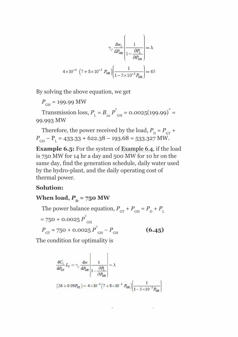
Bysolvingtheaboveequation,weget
P =199.99MW
Transmissionloss,P =B P =0.0025(199.99) =99.993MW
Therefore,thepowerreceivedbytheload,P =P +P −P =433.33+622.38−193.68=533.327MW.
Example6.5:ForthesystemofExample6.4,iftheloadis750MWfor14hradayand500MWfor10hronthesameday,findthegenerationschedule,dailywaterusedbythehydro-plant,andthedailyoperatingcostofthermalpower.
Solution:
Whenload,P =750MW
Thepowerbalanceequation,P +P =P +P
=750+0.0025P
P =750+0.0025P −P (6.45)
Theconditionforoptimalityis
GH
L 22 GH
D GT
GH L
D
GT GH D L
GH
GT GH GH
2 2
2
2
−3 −4
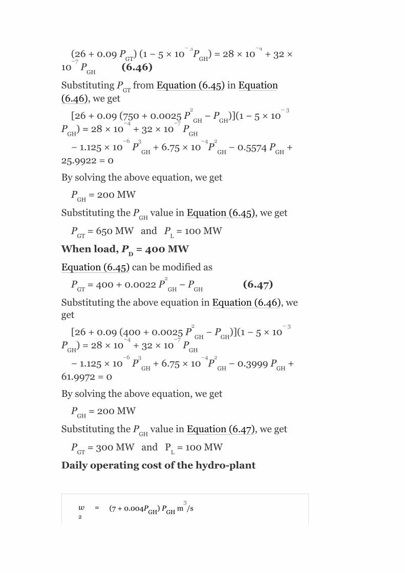
(26+0.09P )(1−5×10 P )=28×10 +32×10 P (6.46)
SubstitutingP fromEquation(6.45)inEquation(6.46),weget
[26+0.09(750+0.0025P −P )](1−5×10P )=28×10 +32×10 P
−1.125×10 P +6.75×10 P −0.5574P +25.9922=0
Bysolvingtheaboveequation,weget
P =200MW
SubstitutingtheP valueinEquation(6.45),weget
P =650MWandP =100MW
Whenload,P =400MW
Equation(6.45)canbemodifiedas
P =400+0.0022P −P (6.47)
SubstitutingtheaboveequationinEquation(6.46),weget
[26+0.09(400+0.0025P −P )](1−5×10P )=28×10 +32×10 P
−1.125×10 P +6.75×10 P −0.3999P +61.9972=0
Bysolvingtheaboveequation,weget
P =200MW
SubstitutingtheP valueinEquation(6.47),weget
P =300MWandP =100MW
Dailyoperatingcostofthehydro-plant
w = (7+0.004P )P m /s
GT GH
GH
GT
GH GH
GH GH
GH GH GH
GH
GH
GT L
D
GT GH GH
GH GH
GH GH
GH GH GH
GH
GH
GT L
2GH GH
−3 −4
−7
2 −3
−4 −7
−6 3 −4 2
2
2 −3
−4 −7
−6 3 −4 2
3

= Dailywaterquantityusedfora750MWloadfor14hr+dailywaterquantityusedfora400MWloadfor10hr
= [7×200+0.004×(200) ]×14+[7×200+0.004×(200) ]×10×3600
= 134.784×10 m
Dailyoperatingcostofthethermalplant
C = (26+0.045P )P Rs./hr
= Dailyoperatingcostofathermalplantformeetinga750MWloadfor14hr+dailyoperatingcostofthermalplantformeetinga400MWloadfor10hr
= [26×650+0.045×(650) ]×14+[26×300+0.045×(300) ]×10
= Rs.6,21,275
Example6.6:Aloadisfeededbytwoplants,oneisthermalandtheotherisahydro-plant.TheloadislocatednearthethermalpowerplantasshowninFig.6.6.Thecharacteristicsofthetwoplantsareasfollows:
C =0.04P +30P +20Rs./hr
w =0.0012P +7.5P m /s
γ =2.5×10 Rs./m
FIG.6.6Two-plantsystem
1GT GT
T GT GT
H GH GH
H
2
2
6 3
2
2
2
2 3
–5 3

Thetransmissionlossco-efficientisB =0.0015MW.Determinethepowergenerationofboththermalandhydro-plants,theloadconnectedwhenλ=45Rs./MWh.
Solution:
Given:
Transmissionloss,
Theloadislocatednearthethermalplants;hence,thepowerflowtotheloadisonlyfromthehydro-plant:
i.e.,B =B =0
∴P =B P =B P =0.0015P
Theincrementaltransmissionlossofthethermalplantis
22
11 12
L 22 G2 22 GH GH
−1
2 2 2

Penaltyfactorofthethermalplant,
Theincrementaltransmissionlossofthehydro-plantis
Penaltyfactorofthehydro-plant,
Theconditionforhydro-thermalco-ordinationis
and
or(0.000216P +0.675) = (1−0.003P )45
0.135216P = 44.325
GH GH
GH

∴P = 327.809MW
Transmissionloss,P =B P =0.0015(327.809) =161.188MW
Theloadconnected,P =P +P −P =187.5+327.809−161.188=354.121MW
Example6.7:ForExample6.6,determinethedailywaterusedbythehydro-plantandthedailyoperatingcostofthethermalplantwiththeloadconnectedfortotally24hr.
Solution:
FromExample6.6,
Theloadconnected,P =354.121MW
Generationofthethermalplant,P
=187.5MW
Generationofthehydro-plant,P
=327.809MW
Thedailywaterusedis
w = 0.0012P +7.5P m /s
= [0.0012P +7.5P ]×3,600m /hr
= [0.0012P +7.5P ]×3,600×24m /day
SubstitutingthevalueofP =327.809MWintheaboveequation,wehave
GH
L 22 GH
D GT GH L
D
GT
GH
HGH GH
GH GH
GH GH
GH
2 2
2 3
2 3
2 3

w = [0.0012(327.809) +7.5×327.809]×3,600×24
= 223.56×10 m
Dailyoperatingcostofthethermalplant
= (0.04P +30P +20)
Rs./h
= Rs.[0.04(187.5) +30(187.5)+20]×24
= Rs.1,69,230
Example6.8:Inatwo-plantoperationsystem,thehydro-plantoperatesfor8hrduringeachdayandthesteamplantoperatesthroughouttheday.Thecharacteristicsofthesteamandhydro-plantsare
C =0.025P +14P +12Rs./hr
w =0.002P +28P m /s
Whenbothplantsarerunning,thepowerflowfromthesteamplanttotheloadis190MWandthetotalquantityofwaterusedforthehydro-plantoperationduring8hris220×10 m .
Determinethegenerationofahydro-plantandcostofwaterused.Neglectthetransmissionlosses.
Solution:
Thecostofthethermalplantis
C =(0.025P +14P +12)Rs./hr
Theincrementalfuelcostofthethermalplantis
H
GT GT
T GT GT
H GH GH
T GT GT
2
6 3
2
2
2
2 3
6 3
2

andforthehydro-plant,w =(0.002P +28P )m /s
Theincrementalwaterflowis
Forhydro-thermalscheduling,theoptimalconditionis
(sincelossesareneglected,L =1)
Powerflowtotheloadfromthethermalplant,P =190MW(given).BysubstitutingthevalueofP =190MWintheaboveequation,weget
λ=0.05(190)+14=23.5Rs./MWh
Thetotalquantityofwaterusedduringaone-houroperationis
w =0.0012P +7.5P m /s
=[0.0012P +7.5P ]×3,600m /hr
Foran8-hroperation,thequantityofwaterusedis
H GH GH
T
GT
GT
HGH GH
GH GH
2
3
2 3
2 3

Letthecostofwaterbeγ Rs./hr/m /s.
FromEquation(6.48)
Example6.9:Atwo-plantsystemwithnotransmissionlossshowninFig.6.7(a)istosupplyaloadshowninFig.6.7(b).
Thedataofthesystemareasfollows:
C =(32+0.03P )P
w =(8+0.004P )P m /s
Themaximumcapacityofthehydro-plantandthesteamplantare450and250MW,respectively.Determinethegeneratingscheduleofthesystemsothat150.3478millionm waterisusedduringthe24-hrperiod.
H
1 GT GT
2 GH GH
3
3
3

FIG.6.7(a)Two-plantsystem;(b)dailyloadcurve
Solution:
(i)Constanthydro-generation
IfP isthehydro-powerinMWgeneratedin24hr,thenwehave
(8+0.004P )P ×24×60×60 = 150.3478×10
8P +0.004P = 1,740.136
0.004P +8P −1,740.136 = 0
Bysolvingtheaboveequation,weget
GH
GH GH
GH GH
GH GH
6
2
2
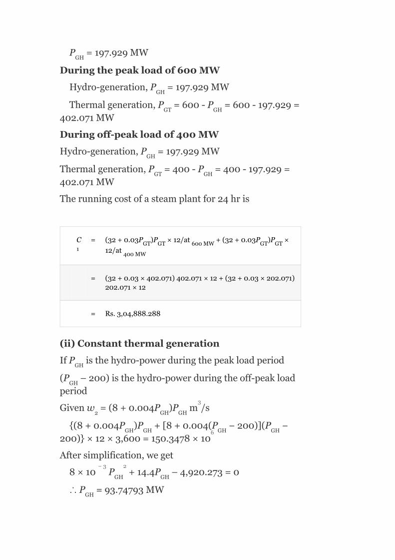
P =197.929MW
Duringthepeakloadof600MW
Hydro-generation,P =197.929MW
Thermalgeneration,P =600-P =600-197.929=402.071MW
Duringoff-peakloadof400MW
Hydro-generation,P =197.929MW
Thermalgeneration,P =400-P =400-197.929=402.071MW
Therunningcostofasteamplantfor24hris
C = (32+0.03P )P ×12/at +(32+0.03P )P ×
12/at
= (32+0.03×402.071)402.071×12+(32+0.03×202.071)202.071×12
= Rs.3,04,888.288
(ii)Constantthermalgeneration
IfP isthehydro-powerduringthepeakloadperiod
(P –200)isthehydro-powerduringtheoff-peakloadperiod
Givenw =(8+0.004P )P m /s
(8+0.004P )P +[8+0.004(P −200)](P −200)×12×3,600=150.3478×10
Aftersimplification,weget
8×10 P +14.4P –4,920.273=0
∴P =93.74793MW
GH
GH
GT GH
GH
GT GH
1GT GT 600MW GT GT
400MW
GH
GH
2 GH GH
GH GH GH GH
GH GH
GH
3
6
−3 2

Thegenerationschedulingisgivenasfollows:
Hydro Thermal(P –P )
Peak(600) 293.75MW 306.25MW
Off-peak(400)
93.75MW 306.25MW
Thesteamplantoperatingcostfor24hris
C = (32+0.03P )P
= (32+0.03×306.25)306.25×12+(32+0.03×306.25)306.25×12
= Rs.3,02,728.125
(iii)Equalincrementalplantcosts
LetP′ andP′ bethesteamgenerationandhydro-generationduringpeakloads,P″ andP″ thesteamgenerationandhydro-generationduringoff-peakloads,respectively.
Forpeakloadconditions:
Thevalueofλ′shouldbesochosenastomake
D GH
1GT GT
GT GH
GT GH

P′ +P′ =600(6.51)
Foroff-peakperiods:
Thevalueofλ″shouldbechosensoastomake
P″ +P″ (6.54)
Forthewholeoperatingperiod,γ shouldbechosensoastousethesamevalueofwater,i.e.,150.3478millionm duringthe24-hrperiod.
(8+0.004P′ )P′ +(8+0.004P″ )P″ ×12×3,600=150.3478×10 (6.55)
Alltheaboveequationscanbesolvedbyahit-and-trailoraniterativemethod:
P′ = 276.362MW,P′ =323.638MW
λ′ = 48.58172Rs./MWh
−(8+0.004×323.638)×323.638+3,480.273=(8+0004P‴ )P″
8P′ = +0.004P″ =472.2
Bysolvingtheaboveequation,weget
GT GH
GT GH
2
GH GH GH GH
GT GH
GH GH
GH GH
3
6
2

P″ +57.38MWP″ = 342.62MW
λ″ = 52.5572Rs./MWh
γ = 6.2131Rs./hr/m3/s
Thethermaloperatingcost
C = (32+0.03P )P
= (32+0.03×276.362)×276.362×12+(32+0.03×342.62)×342.62×12
= Rs.3,07,444.279
(iv)Maximumhydro-efficiencymethod
Letitbeassumedthatthemaximumefficiencyofahydro-unitoccursat275MW.Therefore,thehydro-powerplantsupplyis275MWduringthepeakload.Theamountofwaterusedduringpeakloadhours:
w =(8+0.004P )P m /s
=(8+0.004×275)×275×12×3,600=108.108×10
Wateravailableforoff-peakhydro-generation:
=totalwateravailable–wateravailableatpeakload
=150.34×10 −108.108×10 =42.2398×10 m
Therealpowergenerationofahydro-plantP duringoff-peakhoursisfoundbyusing
GH GT
2
1GT GT
2GH GH
GH
3
6
6 6 6 3
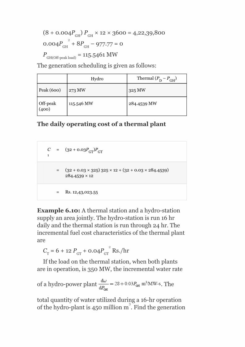
(8+0.004P )P ×12×3600=4,22,39,800
0.004P +8P –977.77=0
P =115.5461MW
Thegenerationschedulingisgivenasfollows:
Hydro Thermal(P –P )
Peak(600) 273MW 325MW
Off-peak(400)
115.546MW 284.4539MW
Thedailyoperatingcostofathermalplant
C = (32+0.03P )P
= (32+0.03×325)325×12+(32+0.03×284.4539)284.4539×12
= Rs.12,43,023.55
Example6.10:Athermalstationandahydro-stationsupplyanareajointly.Thehydro-stationisrun16hrdailyandthethermalstationisrunthrough24hr.Theincrementalfuelcostcharacteristicsofthethermalplantare
C =6+12P +0.04P Rs./hr
Iftheloadonthethermalstation,whenbothplantsareinoperation,is350MW,theincrementalwaterrate
ofahydro-powerplant .The
totalquantityofwaterutilizedduringa16-hroperationofthehydro-plantis450millionm .Findthegeneration
GH GH
GH GH
GH(Off-peakload)
D GH
1GT GT
T GT GT
2
2
3

ofthehydro-plantandcostofwateruse.Assumethatthetotalloadonthehydro-plantisconstantforthe16-hrperiod.
Solution:
Given:C =6+12P +0.04P
P =350MW(given)
∴12+0.08×350=λ
λ=40Rs./MWh
Thetotalquantityofwaterusedduring16hrofoperationofahydro-plantis
(28+0.03P )P ×16×3,600=450×10
0.03P +28P =7,812.5
0.03P +28P –7,812.5=0
Bysolvingtheaboveequation,weget
P =224.849MW
Ifthecostofwaterusedisγ,thenwehave
γ(28+0.03P )=λ
γ(28+0.03×224.849)=40
∴γ=1.15122Rs./hr/m /s
6.9ADVANTAGESOFOPERATIONOFHYDRO-THERMALCOMBINATIONS
Thefollowingadvantagesareobtainedbyoperationcombinationofhydro-thermalpowerplants.
6.9.1Flexibility
Thepowersystemreliabilityandsecuritycanbeobtainedbythecombinedoperationofhydroand
T GT GT
GT
GH GH
GH GH
GH GH
GH
GH
2
6
2
2
3

thermalunits.Itprovidesthereservecapacitytomeettherandomphenomenaofforcedoutageofunitsandunexpectedloadimpliedonasystem.
Thermalplantsrequireanappreciabletimeforstartingandforbeingputintoservice.Hydro-plantscanbestartedandputintooperationveryquicklywithloweroperatingcosts.Hence,itisrequiredtooperatehydro-plantseconomicallyasbase-loadplantsaswellaspeakloadplants.Hydro-plantsaremostpreferabletooperateaspeakloadplantssuchthattheiroperationimprovestheflexibilityofthesystemoperationandmakesthethermalplantoperationeasier.
6.9.2Greatereconomy
Therun-offriverhydro-plantswouldgenerallymeettheentireorpartofthebaseloads,andthermalplantsshouldbesetuptoincreasethefirmcapacityofthesystem.Theremainingpowerdemandcanbemetbyacombinationofreservoir-typehydro-plants,thermalplants,andnuclearplants.Ineverypowersystem,acertainratioofhydro-powertototalpowerdemandwillresultinaminimumoverallcostofsupply.
6.9.3Securityofsupply
Wateravailabilitymustdependontheseason.Itishighduringtherainyseasonandmaybereducedduetotheoccurrenceofdraughtduringlongerplants.Problemsariseinthethermalpowerplantoperationduetotransportationofcoal,unavailabilityoflabor,etc.Itisfoundthattheforcedoutagesofhydro-plantsarefewcomparedtothoseinthermalplants.
Theabovefactssuggestedtheoperationofhydro-thermalsystemstomaintainthereliabilityandsecurityofsupplytotheconsumers.
6.9.4Betterenergyconservation

Duringheavyrun-offperiods,thegenerationofhydro-powerismore,whichresultsintheconservationoffossilfuels.Duringdraughtperiods,moresteampowerhastobegeneratedsuchthattheavailabilityofwaterneedstheminimumneedslikedrinkingandagriculturalevents.
6.9.5Reservecapacitymaintenance
Fortheoperationofapowersystem,itisnecessarythateverysystemhassomecertainreservecapacitytomeettheforcedoutagesandunexpectedloaddemands.Bythecombinedoperationofhydroandthermalplants,thereservecapacitymaintenanceisreduced.
Example6.11:MATLABprogramonhydro-thermalschedulingwithoutinflowandwithoutloss.Findtheoptimumgenerationforahydro-thermalsystemforatypicalday,whereinloadvariesinthreestepsof8hreachas15,25,and8MW,respectively.Thereisnowaterinflowintothereservoirofthehydro-plant.Theinitialwaterstorageinthereservoiris180m /sandthefinalwaterstorageshouldbe100m /s.Thebasicheadis35mandthewater-headcorrectionfactoreis0.005.Assumeforsimplicitythatthereservoirisrectangularsothatρdoesnotchangewithwaterstorage.Letthenon-effectivewaterdischargebeassumedas4m /s.Theincrementalfuelcost(IFC)ofthethermal
powerplantis .Further
transmissionlossesmaybeneglected.
PROGRAMISUNDERTHEFILENAMEhydrothermal.m
3 3
3

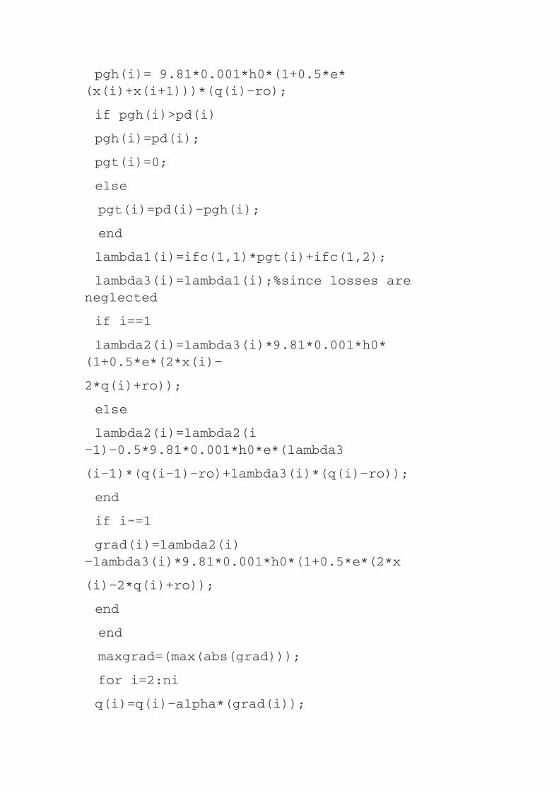

RESULTS:
pgh=12.4706 21.8178 5.4672
pgt=2.5294 3.1822 2.5328
netPG=15 25 8
iter=15
Example6.12:MATLABprogramonhydro-thermalschedulingwithinflowandwithoutlosses.Findtheoptimumgenerationforahydro-thermalsystemforatypicalday,whereinloadvariesinthreestepsof8hreachas15,25,and8MW,respectively.Thereiswaterinflowintothereservoirofthehydro-plantinthreeintervalsof2,4,and3m /s.Theinitialwaterstorageinthereservoiris180m /sandthefinalwaterstorageshouldbe100m /s.Thebasicheadis35–mandthewater-headcorrectionfactoreis0.005.Assumeforsimplicitythatthereservoirisrectangularsothatρdoesnotchangewithwaterstorage.Letthenon-effectivewaterdischargebeassumedas4m /s.TheIFC
ofthethermalpowerplantis
Furthertransmissionlossesmaybeneglected.
3
3
3
3

PROGRAMISUNDERTHEFILENAMEhydrothermalinflow.m

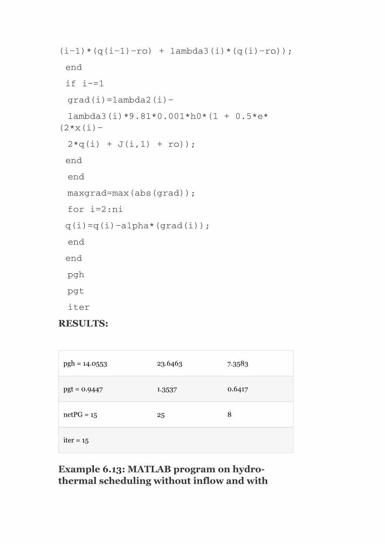
RESULTS:
pgh=14.0553 23.6463 7.3583
pgt=0.9447 1.3537 0.6417
netPG=15 25 8
iter=15
Example6.13:MATLABprogramonhydro-thermalschedulingwithoutinflowandwith
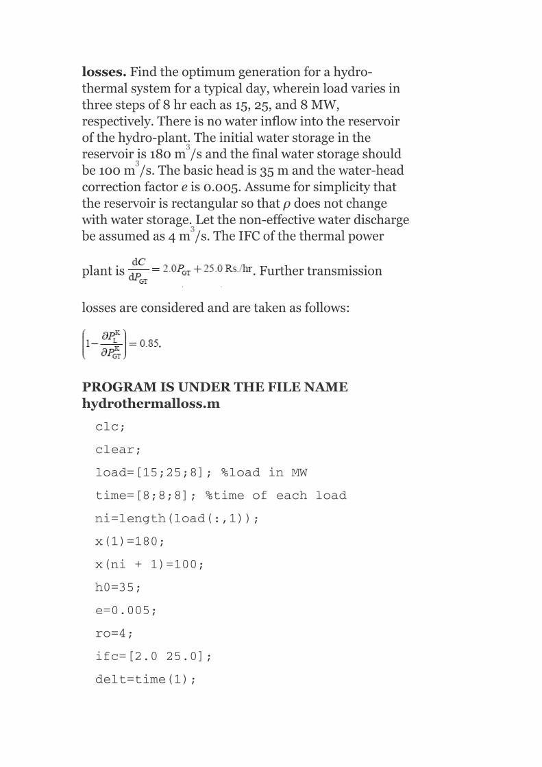
losses.Findtheoptimumgenerationforahydro-thermalsystemforatypicalday,whereinloadvariesinthreestepsof8hreachas15,25,and8MW,respectively.Thereisnowaterinflowintothereservoirofthehydro-plant.Theinitialwaterstorageinthereservoiris180m /sandthefinalwaterstorageshouldbe100m /s.Thebasicheadis35mandthewater-headcorrectionfactoreis0.005.Assumeforsimplicitythatthereservoirisrectangularsothatρdoesnotchangewithwaterstorage.Letthenon-effectivewaterdischargebeassumedas4m /s.TheIFCofthethermalpower
plantis .Furthertransmission
lossesareconsideredandaretakenasfollows:
.
PROGRAMISUNDERTHEFILENAMEhydrothermalloss.m
3
3
3


RESULTS:

pgh=12.4706 21.8178 5.4672
pgt=2.5294 3.1822 2.5328
grad=0 −0.0765 0.0826
netPG=15 25 8
iter=15
Example6.14:MATLABprogramonhydro-thermalschedulingwithinflowandwithlosses.Findtheoptimumgenerationforahydro-thermalsystemforatypicalday,whereinloadvariesinthreestepsof8hreachas15,25and8MW,respectively.Thereiswaterinflowintothereservoirofthehydro-plantinthreeintervalsof2,4,3m /s.Theinitialwaterstorageinthereservoiris180m /sandthefinalwaterstorageshouldbe100m /s.Thebasicheadis35mandthewater-headcorrectionfactoreis0.005.Assumeforsimplicitythatthereservoirisrectangularsothatρdoesnotchangewithwaterstorage.Letthenon-effectivewaterdischargebeassumedas4m /s.TheIFCofthe
thermalpowerplantis .Further
transmissionlossesareconsideredandaretakenas
follows:
PROGRAMISUNDERTHEFILENAMEhydrothermalinflowloss.m
3
3
3
3


RESULTS:
pgh=14.0553 23.6463 7.3583
pgt=0.9447 1.3537 0.6417
netPG=15 25 8
iter=15
KEYNOTES
Theoptimalschedulingprobleminthecaseofthermalplantscanbecompletelysolvedatanydesiredinstantwithoutreferringtotheoperationatothertimes.Itisastaticoptimizationproblem.

Theoptimalschedulingprobleminthehydro-thermalsystemisadynamicoptimizationproblemwherethetimefactoristobeconsidered.Theoptimalschedulingprobleminahydro-thermalsystemcanbestatedasminimizingthefuelcostofthermalplantsundertheconstraintofwateravailabilityforhydro-generationoveragivenperiodofoperation.Themethodsofhydro-thermalco-ordinationare:
Constanthydro-generationmethod.Constantthermalgenerationmethod.Maximumhydro-efficiencymethod.Kirchmayer’smethod.
Constanthydro-generationmethod—Ascheduledamountofwaterataconstantheadisusedsuchthatthehydro-powergenerationiskeptconstantthroughouttheoperatingperiod.Constantthermalgenerationmethod—Thermalpowergenerationiskeptconstantthroughouttheoperatingperiodinsuchawaythatthehydro-powerplantsuseaspecifiedandscheduledamountofwaterandoperateonvaryingpowergenerationscheduleduringtheoperatingperiod.Maximumhydro-efficiencymethod—Duringpeak-loadperiods,thehydro-powerplantsareoperatedattheirmaximumefficiency;duringoff-peakloadperiods,theyoperateatanefficiencynearertotheirmaximumefficiencywiththeuseofaspecifiedamountofwaterforhydro-powergeneration.Kirchmayer’smethod—Theco-ordinationequationsarederivedintermsofpenaltyfactorsofbothplantsforobtainingtheoptimumschedulingofthehydro-thermalsystemandhenceitisalsoknownasthepenaltyfactormethodofsolutionofshort-termhydro-thermalschedulingproblems.Long-termhydro-thermalschedulingproblemscanbesolvedbythediscretizationprinciple.Inthelong-termhydro-thermalschedulingproblem,itisconvenienttochoosewaterdischargesinallsub-intervalsexceptonesub-intervalasindependentvariablesandhydro-generations,thermalgenerations,waterstoragesinallsub-intervals,andexceptedwaterdischargeasdependentvariables,
i.e.,Independentvariablesarerepresentedbyq ,forK=2,3,…,N
≠1
DependentvariablesarerepresentedbyP ,P ,X andq ,forK
=1,2,…,N.[Sincethewaterdischargeinonesub-intervalisadependentvariable.]
Foroptimalityoflong-termhydro-thermalscheduling,thegradient
vectorshouldbezero,i.e., .
SHORTQUESTIONSANDANSWERS
GH GT
K
K K K, 1

1. Whyistheoptimalschedulingprobleminthecaseofthermalplantsreferredtoasastaticoptimizationproblem?
Optimalschedulingproblemcanbecompletelysolvedatanydesiredinstantwithoutreferringtotheoperationatothertimes.
2. Theoptimizationprobleminthecaseofahydro-thermalsystemisreferredtoasadynamicproblem.Whyisitso?
Theoperationofthesystemhavinghydroandthermalplantshavenegligibleoperationcostsbutisrequiredundertheconstraintofwateravailabilityforhydro-generationoveragivenperiodoftime.
3. Whatisthestatementofoptimizationproblemofhydro-thermalsystem?
Minimizethefuelcostofthermalplantsundertheconstraintofwateravailabilityforhydro-generationoveragivenperiodoftime.
4. Intheoptimalschedulingproblemofahydro-thermalsystem,whichvariablesareconsideredascontrolvariables?
Thermalandhydro-powergenerations(P andP ).
5. Fast-changingloadscanbeeffectivelymetbywhichtypeofplants?
Hydro-plants.
6. Generally,whichtypeofplantsaremoresuitabletooperateasbase-loadandpeakloadplants?
Thermalplantsaresuitedforbase-loadplantsandhydro-plantsaresuitedforpeakloadplants.
7. Wholeorpartofthebaseloadcanbesuppliedbywhichtypeofhydro-plants?
Run-offrivertype.
8. Thepeakloadorremainingbaseloadismetbywhichtypeofplants?
Aproperco-ordinationofreservoir-typehydro-plantsandthermalplants.
9. Intheoptimalschedulingproblemofahydro-thermalsystem,
GT GH

whatparametersareassumedtobeknownasthefunctionoftimewithcertainty?
Waterinflowtothereservoirandloaddemand.
10. Whatisthemathematicalstatementoftheoptimizationprobleminthehydro-thermalsystem?
Determinethewaterdischargerateq(t)soastominimizethecostofthermalgeneration.
11. Writetheobjectivefunctionexpressionofhydro-thermalschedulingproblem.
12. Writetheconstraintequationsofthehydro-thermalschedulingproblem.
P (t)+P (t)−P (t)−P (t)=0
fort∈(O,T)—Realpowerbalanceequation
—P (t)=(X‴(t),q(t))
13. Bywhichprinciplecantheoptimalschedulingproblemofahydro-thermalsystembesolved?
Discretizationprinciple.
14. Writetheexpressionforrealpowerhydro-generationinanysub-interval‘K’?
P =h 1+0.5e(X +X )(q −ρ)
15. Definethetermsoftheaboverealpowerhydro-generation.
P =h 1+0.5e(X +X )(q −ρ)
whereh =9.81×10 h ,h isthebasicwaterheadthat
correspondstodeadstorage,ethewater-headcorrectionfactortoaccountforthevariationinheadwithwaterstorage,X thewaterstorageatintervalk,q thewaterdischargeatintervalk,andρthenon-effectivedischarge.
GT GH L D
GH
GH o
GH o
0 0 o
K K K−1 K
K K K−1 K
–3 1 1
k
k

16. Intheoptimalschedulingproblemofahydro-thermalsystem,whichvariablesareusedtochooseasindependentvariables?
Waterdischargesinallsub-intervalsexceptonesub-interval:
i.e.,e ,forq ,q ⋯q
wherek=2,3…N(kissub-interval).
17. Whichparametersareusedasdependentvariables?
Thermal,hydro-generations,waterstoragesatallsub-intervals,andwaterdischargeatexceptedsub-intervalsareusedasdependentvariables,
i.e.,P ,P X ,andq
18. Insolvingtheoptimalschedulingproblemofahydro-thermalsystem,for‘N’sub-intervals(i.e.,k=1,2,…,N),N−1numberofwaterdischargesq’scanbespecifiedasindependentvariablesexceptonesub-interval.Writetheexpressionforwaterdischargeintheexceptedsub-interval,whichistakenasadependantvariable.
19. Whichtechniqueisusedtoobtainthesolutiontotheoptimizationproblemofthehydro-thermalsystem?
Anon-linearprogrammingtechniqueinconjunctionwithafirst-ordernegativegradientmethodisusedtoobtainthesolutiontotheoptimizationproblem.
20. WritetheexpressionforaLagrangianfunctionobtainedbyaugmentingtheobjectivefunctionwithconstraintequationsinthecaseofahydro-thermalschedulingproblem.
21. Whatisthegradientvector?
ThepartialderivativesoftheLagrangianfunctionwithrespecttoindependentvariablesare
k≠1
GT GH
k 2 3 N
k k k 1

22. Whatistheconditionforoptimalityinthecaseofahydro-thermalschedulingproblem?
Thegradientvectorshouldbezero:
23. Theconditionforoptimalityinahydro-thermalschedulingproblemisthatthegradientvectorshouldbezero.Ifthisconditionisviolated,howwillweobtaintheoptimalsolution?
Findthenewvaluesofcontrolvariables,whichwilloptimizetheobjectivefunction.Thiscanbeachievedbymovinginthenegativedirectionofthegradientvectortoapointwherethevalueoftheobjectivefunctionisnearertoanoptimalvalue.
24. Forasystemwithamultihydroandamultithermalplant,thenon-linearprogrammingtechniqueinconjunctionwiththefirst-ordergradientmethodisalsodirectlyapplied.However,whatisthedrawback?
Itrequireslargememorysincetheindependentanddependantvariables,andgradientsneedtobestoredsimultaneously.
25. Bywhichmethodcanthedrawbackofthenon-linearprogrammingtechniquebeovercomewhenappliedtoamultihydroandmultithermalplantsystemandwhatisitsprocedure?
Bythemethodofdecompositiontechnique.Inthistechnique,theoptimizationiscarriedoutovereachsub-intervalandacompletecycleofiterationisreplaced,ifthewateravailabilityequationdoesnotcheckattheendofthecycle.
26. Forshort-rangeschedulingofahydro-thermalplant,whichmethodisuseful?
Kirchmayer’smethodorthepenaltyfactormethodisusefulforshort-rangescheduling.
27. WhatisKirchmayer’smethodofobtainingtheoptimumschedulingofahydro-thermalsystem?

InKirchmayer’smethodorthepenaltyfactormethod,theco-ordinationequationsarederivedintermsofpenaltyfactorsofbothhydroandthermalplants.
28. Whatistheconditionforoptimalityinahydro-thermalschedulingproblemwhenconsideringtransmissionlosses?
whereirepresentsthethermalplantandjrepresentsthehydro-plant.
29. Whatisthemeaningoftheterms and ?
istheincrementalcostoftheiththermalplantand
istheincrementalwaterrateofthejthhydro-plant.
30. Whatisshort-termhydro-thermalco-ordination?
Short-termhydro-thermalco-ordinationisdoneforafixedquantityofwatertobeusedinacertainperiod(i.e.,24hr).
31. Whataretheschedulingmethodsforshort-termhydro-thermalco-ordination?
1. Constanthydro-generationmethod.2. Constantsteamgenerationmethod.3. Maximumhydro-efficiencymethod.4. Equalincrementalproductioncostsandsolutionofco-ordination
equations(Kirchmayer’smethod).
32. Whatisthesignificanceoftheco-efficientγ ?
γ representstheincrementalwaterratesintoincrementalcosts
whichmustbesoselectedastousethedesiredamountofwaterduringtheoperatingperiod.
33. Writetheconditionforoptimalityintheproblemofashortrangehydro-thermalsystemaccordingtoKirchmayer’smethodwhen
j
j

neglectingtransmissionlosses.
34. Whatisthesignificanceofterms and ?
isthepenaltyfactorofthei thermalplantand
isthepenaltyfactorofthej hydro-plant
Thesetermsareverymuchusefulingettingtheoptimalityinahydro-thermalschedulingproblem,whichissolvedbyKirchmayer’smethod.
35. Writetheconditionforoptimalityinanoptimalschedulingproblemofashortrangehydro-thermalsystemwithapproximatepenaltyfactors.
MULTIPLE-CHOICEQUESTIONS
1. Whencomparedtoahydro-electricplant,theoperatingcostofthethermalplantisvery_____anditscapitalcostis_____.
1. High,low.2. High,high.
th
th

3. Low,low.4. Low,high.
2. Whencomparedtoathermalplant,theoperatingcostandcapitalcostofahydro-electricplantare:
1. Highandlow.2. Lowandhigh.3. Bothhigh.4. Bothlow.
3. Theoptimalschedulingprobleminthecaseofthermalplantsis:
1. Staticoptimizationproblem.2. Dynamicoptimizationproblem.3. Staticaswellasdynamicoptimizationproblem.4. Eitherstaticordynamicoptimizationproblem.
4. Theoperationofthesystemhavinghydroandthermalplantsismorecomplex.Inthiscase,theoptimalschedulingproblemis:
1. Staticoptimizationproblem.2. Dynamicoptimizationproblem.3. Staticaswellasdynamicoptimizationproblem.4. Eitherstaticordynamicoptimizationproblem.
5. Theoptimalschedulingprobleminthecaseofathermalplantcanbecompletelysolvedatanydesiredinstant:
1. Withreferencetotheoperationatothertimes.2. Withoutreferencetotheoperationatothertimes.3. Case(a)orcase(b)thatdependsonthesizeoftheplant.4. Noneofthese.
6. Thetimefactorisconsideredinsolvingtheoptimizationproblemof_____.
1. Hydroplants.2. Thermalplants.3. Hydro-thermalplants.4. Noneofthese.
7. Theobjectivefunctiontotheoptimizationprobleminahydro-thermalsystembecomes:
1. Minimizethefuelcostofthermalplants.2. Minimizethetimeofoperation.3. Maximizethewateravailabilityforhydro-generation.4. Allofthese.
8. Theoptimalschedulingproblemofahydro-thermalsystemissolvedundertheconstraintof:
1. Fuelcostofthermalplantsforthermalgeneration.2. Timeofoperationoftheentiresystem.3. Wateravailabilityforhydro-generationoveragivenperiod.4. Availabilityofcoalforthermalgenerationoveragivenperiod.
9. Tosolvetheoptimizationprobleminahydro-thermalsystem,whichofthefollowingvariablesareconsideredascontrolvariables?
1. P andP .Dthermal Ghydro

2. Q andQ .
3. P andP .
4. P andP .
10. Inwhichsystemisthegenerationscheduledgenerallysuchthattheoperatingcostsofthermalgenerationareminimized?
1. Systemswherethereisaclosebalancebetweenhydroandthermalgeneration.
2. Systemswherethehydro-capacityisonlyafractionofthetotalcapacity.3. Both(a)and(b).4. Noneofthese.
11. Thermalplantsaremoresuitabletooperateas_____plantsleavinghydro-plantstooperateas_____plants.
1. Baseload,baseload.2. Peakload,peakload.3. Peakload,baseload.4. Baseload,peakload.
12. Inhydro-thermalsystems,thewholearepartofthebaseloadthatcanbesuppliedby:
1. Run-offriver-typehydro-plants.2. Reservoir-typehydro-plants.3. Thermalplants.4. Reservoir-typehydro-plantsandthermalplantswithproperco-ordination.
13. Inahydro-thermalsystem,thepeakloadcanbemetby:
1. Run-offriver-typehydro-plants.2. Reservoir-typehydro-plants.3. Thermalplants.4. Reservoir-typehydro-plantsandthermalplantswithproperco-ordination.
14. Foranoptimalschedulingproblem,itisassumed,whichparameterisknowndeterministicallyasafunctionoftime?
1. Waterinflowtothereservoir.2. Powergeneration.3. Loaddemand.4. Both(a)and(c).
15. Inahydro-thermalsystem,theoptimizationproblemisstatedasdetermining_____soastominimizethecostofthermalgeneration.
1. Loaddemand(P ).
2. Waterstorage(X).3. Waterdischargerate(q(t)).4. Waterinflowrate(J(t)).
16. Whichofthefollowingequationsisconsideredasaconstrainttotheoptimizationproblemofahydro-thermalsystem?
1. Realpowerbalanceequation.2. Wateravailabilityequation.3. Realpowerhydro-generationasafunctionofwaterstorage.4. Allofthese.
17. Thewateravailabilityequationis:
Dthermal Dhydro
Gthermal Dhydro
Gthermal Ghydro
D

1.
2. P (t)+P (t)−P (t)−P (t)=0,t∈(0,T).3. P (t)=f(X′(t),q(t)).
4. Noneofthese.
18. Intheoptimizationproblemofahydro-thermalsystem,theconstraintrealpowerhydro-generationisafunctionof:
1. Waterinflowrate(J(t)).2. Waterstorage(X).3. Waterdischargerate(q(t))
1. (i)and(ii).2. (ii)and(iii).3. (i)and(iii).4. Noneofthese.
19. Theoptimizationschedulingproblemofahydro-thermalsystemcanbeconvenientlysolvedby_____principle.
1. Dependence.2. Discretization.3. Dividing.4. Noneofthese.
20. Inthediscretizationprinciple,therealpowerhydro-generationatanysub-interval‘k’canbeexpressedas:
1. P =h 1+0.5e(X +X )(q −ρ)
2. P =h 1−0.5e(X +X )(q −ρ)
3. P =h 1+0.5e(X +X )(q −ρ)
4. P =h 1+0.5e(X +X )(q −ρ)
21. Intheoptimizationproblemofahydro-thermalsystem,whichofthefollowingareclosedasindependentvariables?
1. Waterstoragesinallsub-intervalsexceptonesub-interval.2. Waterinflowsinallsub-intervalsexceptonesub-interval.3. Waterdischargesinallsub-intervalsexceptonesub-interval.4. Hydroandthermalgenerations,waterstoragesatallsub-intervals,and
waterdischargeatonesub-interval.
22. Intheoptimalschedulingproblemofahydro-thermalsystem,whichofthefollowingareclosedasdependentvariables?
1. Waterstoragesinallsub-intervalsexceptonesub-interval.2. Waterinflowsinallsub-intervalsexceptonesub-interval.3. Waterdischargesinallsub-intervalsexceptonesub-interval.4. Hydroandthermalgenerations,waterstoragesatallsub-intervals,and
waterdischargeatonesub-interval.
23. Toobtainthesolutiontotheoptimizationproblemofahydro-thermalsystem,whichofthefollowingtechniqueisused?
1. Non-linearprogrammingtechniqueinconjunctionwiththefirst-ordergradientmethod.
2. Linearprogrammingtechniqueinconjunctionwiththefirst-ordergradientmethod.
3. Non-linearprogrammingtechniqueinconjunctionwiththemultiple-order
GH GH L D
GH
GH o
GH o
GH o
GH o
K k−1 k k
K k−1 k k
K k−1 k k
K k−1 k−1 k

gradientmethod.4. Linearprogrammingtechniqueinconjunctionwiththemultiple-order
gradientmethod.
24. Inahydro-thermalsystemforoptimality,theconditionis:
1. Gradientvectorshouldbezero.2. Gradientvectorshouldbepositive.3. Gradientvectorshouldbenegative.4. Noneofthese.
25. Formultihydroandmultithermalplants,theoptimizationproblemcanbesolvedbyamodifiedtechnique,whichisknownas:
1. Discretizationtechnique.2. Decompositiontechnique.3. Decoupledtechnique.4. Noneofthese.
26. InKirchmayer’smethodofsolutionofoptimizationprobleminahydro-thermalsystem,theco-ordinationequationsarederivedintermsof_____ofbothplants.
1. Powergenerations.2. Powerdemands.3. Penaltyfactors.4. Allofthese.
27. γ isusedasaconstant,inanoptimizationproblemofahydro-
thermalsystem,whichconverts:
1. Fuelcostofathermalplantintoanincrementalfuelcost.2. Incrementalwaterrateofahydro-plantintoanincrementalcost.3. Incrementalwaterinflowrateintoanincrementaldischargerate.4. Noneofthese.
28. Thepowergenerationofahydro-plantP isdirectly
proportionalto:
1. Planthead.2. Waterdischargeω .
3. Both(a)and(b).4. Noneofthese.
29. Themainadvantagesoftheoperationofahydro-thermalsystemare:
1. Greatereconomy.2. Securityofsupplyandflexibility.3. Betterenergyconservation.4. Reductioninreservecapacitymaintenance.
Regardingtheabovestatement,whichiscorrect?
1. (i)and(ii).2. (ii)and(iii).3. allexcept(iii).4. Allofthese.
30. Theco-ordinationequationsusedtoobtaintheoptimalschedulingofahydro-thermalsystemwhenconsideringtransmissionlossesare:
j
GH
j

1.
2.
3.
4. Noneofthese.
31. Asfaraspossible,hydro-plantsareusedforbase-loadoperationsince:
1. Theircapitalcostishigh.2. Theiroperationiseasy.3. Theircapitalcostislow.4. Theirefficiencyislow.
32. Athermalplantgivesminimumcostperunitofenergygeneratedwhenusedasa_____plant.
1. Peakload.2. Base-loadplant.3. Simultaneouslyasbase-loadandpeakloadplant.4. Noneofthese.
33. Inthecombinedoperationofsteamplantandrun-offriverplants,thesitesofhydroandsteamplantscanbefoundwiththehelpof_____.
1. Demandcurve.2. Input–outputcurve.3. Loadcurve.4. Chronologicalloadcurve.
34. Long-termhydro-thermalco-ordinationcanbedoneby:
1. Plottingthebasicrulecurve.2. Plottingnospill-rulecurve.3. Plottingthefullreservoirstoragecurve.4. Allofthese.
35. _____hydro-thermalco-ordinationisdonefortheavailablewaterandistobeusedinagivenperiod(24hr).
1. Long-term.2. Short-term.3. Both(a)and(b).4. Noneofthese.
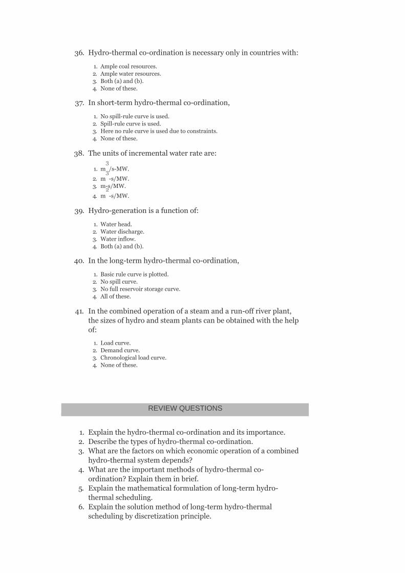
36. Hydro-thermalco-ordinationisnecessaryonlyincountrieswith:
1. Amplecoalresources.2. Amplewaterresources.3. Both(a)and(b).4. Noneofthese.
37. Inshort-termhydro-thermalco-ordination,
1. Nospill-rulecurveisused.2. Spill-rulecurveisused.3. Herenorulecurveisusedduetoconstraints.4. Noneofthese.
38. Theunitsofincrementalwaterrateare:
1. m /s-MW.
2. m -s/MW.3. m-s/MW.
4. m -s/MW.
39. Hydro-generationisafunctionof:
1. Waterhead.2. Waterdischarge.3. Waterinflow.4. Both(a)and(b).
40. Inthelong-termhydro-thermalco-ordination,
1. Basicrulecurveisplotted.2. Nospillcurve.3. Nofullreservoirstoragecurve.4. Allofthese.
41. Inthecombinedoperationofasteamandarun-offriverplant,thesizesofhydroandsteamplantscanbeobtainedwiththehelpof:
1. Loadcurve.2. Demandcurve.3. Chronologicalloadcurve.4. Noneofthese.
REVIEWQUESTIONS
1. Explainthehydro-thermalco-ordinationanditsimportance.2. Describethetypesofhydro-thermalco-ordination.3. Whatarethefactorsonwhicheconomicoperationofacombined
hydro-thermalsystemdepends?4. Whataretheimportantmethodsofhydro-thermalco-
ordination?Explaintheminbrief.5. Explainthemathematicalformulationoflong-termhydro-
thermalscheduling.6. Explainthesolutionmethodoflong-termhydro-thermal
schedulingbydiscretizationprinciple.
3
3
2
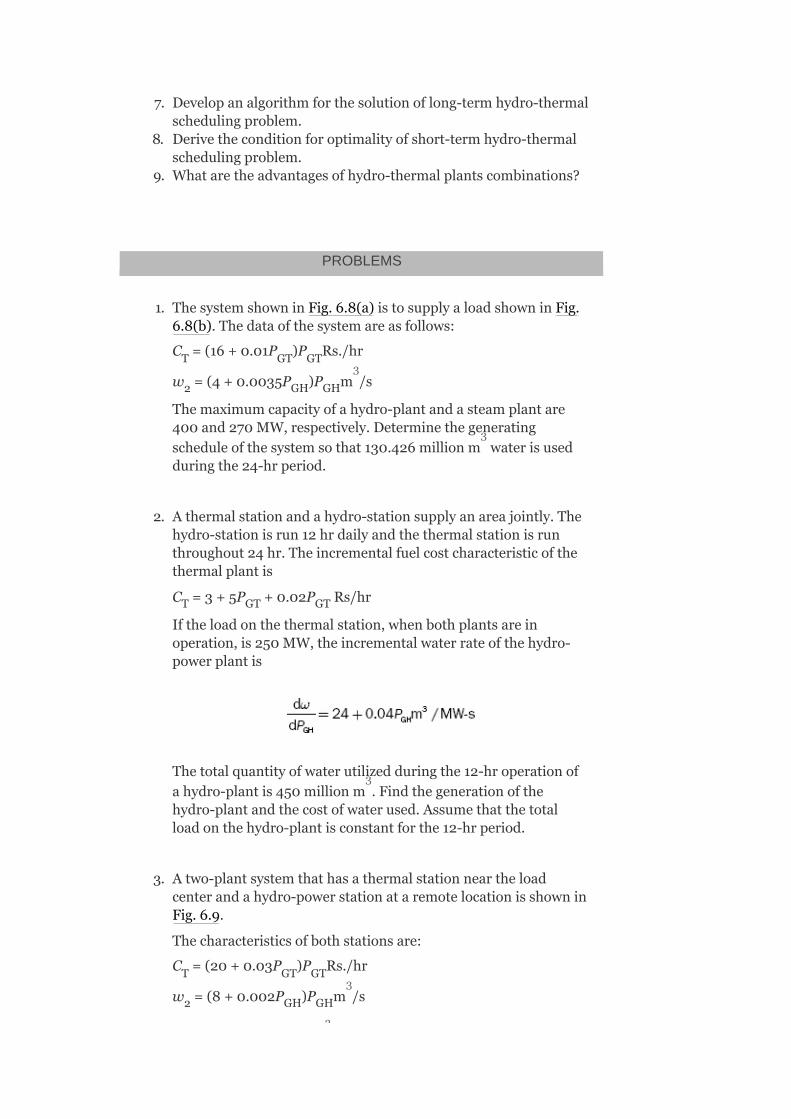
7. Developanalgorithmforthesolutionoflong-termhydro-thermalschedulingproblem.
8. Derivetheconditionforoptimalityofshort-termhydro-thermalschedulingproblem.
9. Whataretheadvantagesofhydro-thermalplantscombinations?
PROBLEMS
1. ThesystemshowninFig.6.8(a)istosupplyaloadshowninFig.6.8(b).Thedataofthesystemareasfollows:
C =(16+0.01P )P Rs./hr
w =(4+0.0035P )P m /s
Themaximumcapacityofahydro-plantandasteamplantare400and270MW,respectively.Determinethegeneratingscheduleofthesystemsothat130.426millionm waterisusedduringthe24-hrperiod.
2. Athermalstationandahydro-stationsupplyanareajointly.Thehydro-stationisrun12hrdailyandthethermalstationisrunthroughout24hr.Theincrementalfuelcostcharacteristicofthethermalplantis
C =3+5P +0.02P Rs/hr
Iftheloadonthethermalstation,whenbothplantsareinoperation,is250MW,theincrementalwaterrateofthehydro-powerplantis
Thetotalquantityofwaterutilizedduringthe12-hroperationofahydro-plantis450millionm .Findthegenerationofthehydro-plantandthecostofwaterused.Assumethatthetotalloadonthehydro-plantisconstantforthe12-hrperiod.
3. Atwo-plantsystemthathasathermalstationneartheloadcenterandahydro-powerstationataremotelocationisshowninFig.6.9.
Thecharacteristicsofbothstationsare:
C =(20+0.03P )P Rs./hr
w =(8+0.002P )P m /s
T GT GT
2 GH GH
T GT GT
T GT GT
2 GH GH
3
3
3
3
3

andγ =Rs.5×10-4/m
Thetransmissionlossco-efficient,B =0.0005.
1. iftheloadis700MWfor15-hradayand500MWfor9hronthesameday,findthegenerationschedule,dailywaterusedbyhydro-plant,andthedailyoperatingcostofthethermalpower.
2. Determinethepowergenerationateachstationandthepowerreceivedbytheloadwhenλ=50Rs./MWh.
4. Atwo-plantsystemthathasahydro-stationneartheloadcenterandathermalpowerstationataremotelocationisshowninFig.6.10.
Thecharacteristicsofbothstationsare
C =(20+0.03P )P Rs./hr
w =(8+0.002P )P m /s
andγ =Rs.5.5/m
Thetransmissionlossco-efficient,B =0.0005.
1. Iftheloadis700MWfor15hradayand500MWfor9hronthesameday,findthegenerationschedule,dailywaterusedbythehydro-plant,andthedailyoperatingcostofthermalpower.
2. Determinethepowergenerationateachstationandthepowerreceivedbytheloadwhenλ=50Rs./MWh.
2
22
T GT GT
2 GH GH
2
22
3
3
3

FIG.6.8IllustrationforProblem1;(a)two-plantsystem;(b)dailyloadcurve
FIG.6.9Two-plantsystem
FIG.6.10Two-plantsystem

7
LoadFrequencyControl-I
OBJECTIVES
Afterreadingthischapter,youshouldbeabletobeableto:
studythegoverningcharacteristicsofageneratorstudytheloadfrequencycontrol(LFC)developthemathematicalmodelsfordifferentcomponentsofapowersystemobservethesteadystateanddynamicanalysisofasingle-areapowersystemwithandwithoutintegralcontrol
7.1INTRODUCTION
Inapowersystem,bothactiveandreactivepowerdemandsareneversteadyandtheycontinuallychangewiththerisingorfallingtrend.Steaminputtoturbo-generatorsorwaterinputtohydro-generatorsmust,therefore,becontinuouslyregulatedtomatchtheactivepowerdemand,failingwhichthemachinespeedwillvarywithconsequentchangeinfrequencyanditmaybehighlyundesirable.Themaximumpermissiblechangeinfrequencyis±2%.Also,theexcitationofthegeneratorsmustbecontinuouslyregulatedtomatchthereactivepowerdemandwithreactivepowergeneration;otherwise,thevoltagesatvarioussystembusesmaygobeyondtheprescribedlimits.Inmodernlargeinterconnectedsystems,manualregulationisnotfeasibleandthereforeautomaticgenerationandvoltageregulationequipmentisinstalledoneachgenerator.Thecontrollersaresetforaparticularoperatingconditionandtheytakecareofsmallchangesinloaddemandwithoutexceedingthelimitsoffrequencyandvoltage.As

thechangeinloaddemandbecomeslarge,thecontrollersmustbereseteithermanuallyorautomatically.
7.2NECESSITYOFMAINTAININGFREQUENCYCONSTANT
Constantfrequencyistobemaintainedforthefollowingfunctions:
AlltheACmotorsshouldrequireconstantfrequencysupplysoastomaintainspeedconstant.Incontinuousprocessindustry,itaffectstheoperationoftheprocessitself.Forsynchronousoperationofvariousunitsinthepowersystemnetwork,itisnecessarytomaintainfrequencyconstant.Frequencyaffectstheamountofpowertransmittedthroughinterconnectinglines.Electricalclockswillloseorgaintimeiftheyaredrivenbysynchronousmotors,andtheaccuracyoftheclocksdependsonfrequencyandalsotheintegralofthisfrequencyerrorislossorgainoftimebyelectricclocks.
7.3LOADFREQUENCYCONTROL
Loadfrequencycontrol(LFC)isthebasiccontrolmechanisminthepowersystemoperation.Wheneverthereisavariationinloaddemandonageneratingunit,thereismomentarilyanoccurrenceofunbalancebetweenreal-powerinputandoutput.Thisdifferenceisbeingsuppliedbythestoredenergyoftherotatingpartsoftheunit.
Thekineticenergyofanyunitisgivenby
whereIisthemomentofinertiaoftherotatingpartandωtheangularspeedoftherotatingpart.
IfKEreduces,ωdecreases;thenthespeedfalls,hencethefrequencyreduces.ThechangeinfrequencyΔfissensedandthroughaspeed-governorsystem,itisfedbacktocontrolthepositionoftheinletvalveoftheprime

mover,whichisconnectedtothegeneratingunit.Itchangestheinputtotheprimemoversuitablyandtriestobringbackthebalancebetweenthereal-powerinputandoutput.Hence,itcanbestatedthatthefrequencyvariationisdependentonthereal-powerbalanceofthesystem.
TheLFCalsocontrolsthereal-powertransferthroughtheinterconnectingtransmissionlinesbysensingthechangeinpowerflowthroughthetielines.
7.4GOVERNORCHARACTERISTICSOFASINGLEGENERATOR
Primemoversdrivingthegeneratorsarefittedwithgovernors,whichareregardedasprimarycontrolelementsintheLFCsystem.Governorssensethechangeinaspeedcontrolmechanismtoadjusttheopeningofsteamvalvesinthecaseofsteamturbinesandtheopeningofwatergatesinthecaseofwaterturbines.ThecharacteristicsofatypicalgovernorofasteamturbineareshowninFig.7.1,whichislinearizedbydottedlinesforstudyingthesystembehavior.
FIG.7.1Characteristicsofatypicalgovernorofasteamturbine
Theamountofspeeddropastheloadontheturbineisincreasedfromnoloadtoitsfull-loadvalueis(N –N),
o

whereN isthespeedatnoloadandNisthespeedatratedload.
Thesteady-statespeedregulationinperunitisgivenby
ThevalueofRvariesfrom2%to6%foranygeneratingunit.Sincethefrequencyandspeedaredirectlyrelated,thespeedregulationcanalsobeexpressedastheratioofthechangeinfrequencyfromnoloadtoitsfullloadtotheratedfrequencyoftheunit:
i.e.,
Ifthereisa4%speedregulationofaunit,thenforaratedfrequencyof50Hz,therewillbeadropof2Hzinfrequency.
IfthegenerationisincreasedbyΔP duetoastaticfrequencydropofΔf,thenthespeedregulationcanbedefinedastheratioofthechangeinfrequencytothecorrespondingchangeinreal-powergeneration:
i.e.,
TheunitofRistakenasHzperMW.Inpractice,powerismeasuredinperunitandhenceRisinHz/p.u.MW.
InFig.7.2,theturbineisoperatingwith99%ofno-loadspeedat25%offull-loadpowerandiftheloadisincreasedto50%,thespeeddropsto98%.Let‘A’betheinitialoperatingpointoftheturbineat50%loadandiftheloadisdroppedto25%,thespeedincreasesto99%.Inordertokeepthespeedat25%oftheloadsameasat
o
G

‘A’,thegovernorsettinghastobechangedbychangingthespringtensioninthefly-balltypeofgovernor.Thiswillresultinspeedcharacteristicsindicatedbythedottedlineparalleltothefirstoneandbelowit,passingthroughthepointA′,whichisthepointofintersectionofthenewspeedlineand25%loadline.Hence,theturbinecanbeadjustedtocarryanygivenloadatanydesiredspeed.
FIG.7.2Speed-governorsetting
Thistypeofshiftingthespeedorfrequencycharacteristicparalleltoitselfisknownassupplementarycontrol.Itisadoptedinon-linecontroltoensureproperloaddivisionamongtherunningunitsandtomaintainthesystemfrequency.Thereisanothermethodofchangingtheslopeofthegovernorcharacteristics.ThisisachievedbychangingtheratiooftheleverL(referthespeedcontrolmechanism)ofthegovernorandtherebyadjustingtheparameterRtoensureproperco-ordinationwiththeotherunitsofthesystem.Thisadjustmentcanbemadeduringtheoff-lineconditiononly.
7.5ADJUSTMENTOFGOVERNORCHARACTERISTICOFPARALLELOPERATINGUNITS

Whentwogeneratorsarerunninginparallel,thegovernorcharacteristicofthefirstunit(Line1)isshowntowardstheright,whilethatofthesecondunit(Line2)isshowntowardstheleftofthefrequencyaxisasshowninFig.7.3.
Thecharacteristicsareobviouslydifferentandhencecorrespondingtotheratedfrequencyf ,thetwounitscarryloadsP andP sothatthesystemloadP =P +P .IfthesystemloadisnowincreasedtoP′ ,thesystemfrequencywilldropdowntof′,sincetheunitscanonlyincreasetheiroutputbydecreasingthespeed.
Torestorethesystemfrequency,thecharacteristicofoneoftheunitssayofUnit1needstobeshiftedupwardsasindicatedbythedottedcharacteristic,sothatitcancarrytheincreasedload.TheshareofUnit1willbeP ′andthatofUnit2willbeP sothattheincreasedtotalload,P ′=P ′+P .
FIG.7.3Sharingofloadbytwounits(parallel)withaspeed-governorcharacteristicssetting
r
1 2 D 1 2
D
1
2
D 1 2

7.6LFC:(P–fCONTROL)
TheLFC,alsoknownasgenerationcontrolorP–fcontrol,dealswiththecontrolofloadingofthegeneratingunitsforthesystematnormalfrequency.Theloadinapowersystemisneverconstantandthesystemfrequencyremainsatitsnominalvalueonlywhenthereisamatchbetweentheactivepowergenerationandtheactivepowerdemand.Duringtheperiodofloadchange,thedeviationfromthenominalfrequency,whichmaybecalledfrequencyerror(Δf),isanindexofmismatchandcanbeusedtosendtheappropriatecommandtochangethegenerationbyadjustingtheLFCsystem.Itisbasicallycontrollingtheopeningoftheinletvalvesoftheprimemoversaccordingtotheloadingconditionofthesystem.Inthecaseofamulti-areasystem,theLFCsystemalsomaintainsthespecifiedpowerinterchangesbetweentheparticipatingareas.Inasmallersystem,thiscontrolisdonemanually,butinlargesystemsautomaticcontroldevicesareusedintheloopoftheLFCsystem.
TheLFCsystem,however,doesnotconsiderthereactivepowerflowinthesystemeventhoughthereactivepowerflowisalsoaffectedtosomeextentduringthefluctuatingloadcondition.Butsincethereisnocounterpartofthereactivepowerinthemechanicalsideofthesystem,itdoesnotcomewithintheloopoftheLFCsystem.
7.7Q–VCONTROL
Inthiscontrol,theterminalvoltageofthegeneratorissensedandconvertedintoproportionateDCsignalandthencomparedtoDCreferencevoltage.TheerrorinbetweenaDCsignalandaDCreferencevoltage,i.e.,Δ|V |istakenasaninputtotheQ–Vcontroller.AcontroloutputΔQ isappliedtotheexciter.
7.8GENERATORCONTROLLERS(P–fANDQ–VCONTROLLERS)
i
ci
TheactivepowerPismainlydependentontheinternalangleδandisindependentofthebusvoltagemagnitude|V|.ThebusvoltageisdependentonmachineexcitationandhenceonreactivepowerQandisindependentofthemachineangleδ.Changeinthemachineangleδiscausedbyamomentarychangeinthegeneratorspeedandhencethefrequency.Therefore,theloadfrequencyandexcitationvoltagecontrolsarenon-interactiveforsmallchangesandcanbemodeledandanalyzedindependently.
Figure7.4givestheschematicdiagramofloadfrequency(P–f)andexcitationvoltage(Q–V)regulatorsofaturbo-generator.TheobjectiveoftheMWfrequencyortheP–fcontrolmechanismistoexertcontroloffrequencyandsimultaneouslyexchangeofthereal-powerflowsviainterconnectinglines.Inthiscontrol,afrequencysensorsensesthechangeinfrequencyandgivesthesignalΔf .TheP–fcontrollersensesthechangeinfrequencysignal(Δf )andtheincrementsintie-linerealpowers(ΔP ),whichwillindirectlyprovideinformationabouttheincrementalstateerror(Δδ ).Thesesensorsignals(Δf andΔP )areamplified,mixed,andtransformedintoareal-powercontrolsignalΔP .ThevalvecontrolmechanismtakesΔP astheinputsignalandprovidestheoutputsignal,whichwillchangethepositionoftheinletvalveoftheprimemover.Asaresult,therewillbeachangeintheprimemoveroutputandhenceachangeinreal-powergenerationΔP .ThisentireP–fcontrolcanbeyieldedbyautomaticloadfrequencycontrol(ALFC)loop.
TheobjectiveoftheMVAr-voltageorQ–Vcontrolmechanismistoexertcontrolofthevoltagestate|V |.AvoltagesensorsensestheterminalvoltageandconvertsitintoanequivalentproportionateDCvoltage.ThisproportionateDCvoltageiscomparedwithareferencevoltageV bymeansofacomparator.TheoutputobtainedfromthecomparatoriserrorsignalΔ|V |andis
i
i
tie
i
i tie
ci
ci
Gi
i
iref
i

givenasinputtoQ–Vcontroller,whichtransformsittoareactivepowersignalcommandΔQ andisfedtoacontrollableexcitationsource.Thisresultsinachangeintherotorfieldcurrent,whichinturnmodifiesthegeneratorterminalvoltage.ThisentireQ–Vcontrolcanbeyieldedbyanautomaticvoltageregulator(AVR)loop.
FIG.7.4SchematicdiagramofP–fcontrollerandQ–Vcontroller
Inadditiontovoltageregulatorsatgeneratorbuses,equipmentisusedtocontrolvoltagemagnitudeatotherselectedbuses.Tap-changingtransformers,switchedcapacitorbanks,andstaticVArsystemscanbeautomaticallyregulatedforrapidvoltagecontrol.
7.9P–fCONTROLVERSUSQ–VCONTROL
AnystaticchangeintherealbuspowerΔP willaffectonlythebusvoltagephaseangles(δ )(sinceP∝δ),butwillleavethebusvoltagemagnitudesalmostunaffected.
StaticchangeinthereactivebuspowerΔQ affectsessentiallyonlythebusvoltagemagnitudes(sinceQ∝V),butleavethebusvoltagephaseanglesalmostunchanged.
ci
i
i
i
2

Staticchangeinreactivebuspowerataparticularbusaffectsthemagnitudeofthatbusvoltagemoststrongly,butinlessdegreethemagnitudesofthebusvoltagesatremotebuses.
7.10DYNAMICINTERACTIONBETWEENP–fANDQ–VLOOPS
Inastaticsense,forsmalldeviations,thereisalittleinteractionbetweenP–fandQ–Vloops.Duringdynamicperturbations,weencounterconsiderablecouplingbetweentwocontrolloopsfortwofollowingreasons:
Asthevoltagemagnitudefluctuatesatabus,therealloadofthatbus
willlikewisechangeasaresultofthevoltageloadcharacteristic .
Asthevoltagemagnitudefluctuatesatabus,thepowertransmittedoverthelinesconnectedtothatbuswillchange.Inotherwords,thechangeinQ–Vloopwillaffectthegeneratedemf,whichalsoaffectsthemagnitudeofrealpower.
AdynamicperturbationintheQ–Vloopwillthusaffectthereal-powerbalanceinthesystem.Ingeneral,theQ–VloopismuchfasterthantheP–floopduetothemechanicalinertialconstantsintheP–floop.IfitcanbeassumedthatthetransientsintheQ–VloopareessentiallyoverbeforetheP–floopreacts,thenthecouplingbetweenthetwoloopscanbeignored.
7.11SPEED-GOVERNINGSYSTEM
ThespeedgovernoristhemainprimarytoolfortheLFC,whetherthemachineisusedalonetofeedasmallersystemorwhetheritisapartofthemostelaboratearrangement.Aschematicarrangementofthemainfeaturesofaspeed-governingsystemofthekindusedonsteamturbinestocontroltheoutputofthegeneratortomaintainconstantfrequencyisasshowninFig.7.5.

FIG.7.5Speed-governorsystem
Itsmainpartsorcomponentsareasfollows:
Fly-ballspeedgovernor:Itisapurelymechanical,speed-sensitivedevicecoupleddirectlytoandbuildsdirectlyontheprimemoverstoadjustthecontrolvalveopeningvialinkagemechanism.Itsensesaspeeddeviationorapowerchangecommandandconvertsitintoappropriatevalveaction.Hence,thisistreatedastheheartofthesystem,whichcontrolsthechangeinspeed(frequency).Asthespeedincreases,theflyballsmoveoutwardsandthepointBonlinkagemechanism

movesupwards.Thereversewillhappenifthespeeddecreases.
Thehorizontalrotatingshaftonthelowerleftmaybeviewedasanextensionoftheshaftofaturbine-generatorsetandhasafixedaxisasshowninFig.7.5.Theverticalshaft,abovethefly-ballmechanism,alsorotatesbetweenfixedbearings.Althoughitsaxisisfixed,itcanmoveupanddown,transferringitsverticalmotiontothepilotpointB.
Hydraulicamplifier:Itisnothingbutasingle-statehydraulicservomotorinterposedbetweenthegovernorandvalve.Itconsistsofapilotvalveandthemainpiston.Withthisarrangement,hydraulicamplificationisobtainedbyconvertingthemovementoflow-powerpilotvalveintomovementofhigh-powerlevelmainpiston.
Inhydraulicamplification,alargemechanicalforceisnecessarysothatthesteamvalvecouldbeopenedorclosedagainsthigh-pressureinletsteam.
Speedchanger:Itprovidesasteady-statepoweroutputsettingfortheturbines.Itsupwardmovementopenstheupperpilotvalvesothatmoresteamisadmittedtotheturbineundersteadyconditions.Thisgivesrisetohighersteady-statepoweroutput.Thereversewillhappenifthespeedchangermovesdownward.
Linkagemechanism:Thesearelinkedfortransformingthefly-ballsmomenttotheturbinevalve(steamvalve)throughahydraulicamplifier.
ABCisarigidlinkpivotedatpointBandCDEisanotherrigidpivotedlinkatpointD.LinkDEprovidesafeedbackfromthesteamvalvemoment.
Thespeed-governingsystemisbasicallycalledtheprimarycontrolloopintheLFC.Ifthecontrolvalvepositionisindicatedbyx ,asmallupwardmovementofpointEdecreasesthesteamflowbyaconsiderable
E

amount.ItismeasuredintermsofvalvepowerΔP .ThisflowdecrementgetstranslatedintodecrementinturbinepoweroutputΔP .
Withthehelpoflinkagemechanism,thepositionofthepilotvalvecanbechangedinthefollowingthreedifferentways:
1. Directlybythespeedchanger:AsmallupwardmomentoflinkagepointAcorrespondstoadecreaseinthesteady-statepoweroutputorreferencepowerΔP .
2. Indirectlythroughthefeedbackduetothepositionchangesinthemainsystem.
3. IndirectlythroughfeedbackduetothepositionchangesinlinkagepointEresultingfromachangeinspeed.
7.11.1Speed-governingsystemmodel
Inthissection,wedevelopthemathematicalmodelbasedonsmalldeviationsaroundanominalsteadystate.LetusassumethatthesteamisoperatingundersteadystateandisdeliveringpowerP fromthegeneratoratnominalspeedorfrequencyf .
Underthiscondition,theprimemovervalvehasaconstantsettingχ ,thepilotvalveisclosed,andthelinkagemechanismisstationary.Now,wewillincreasetheturbinepowerbyΔP withthehelpofthespeedchanger.Forthis,themovementoflinkagepointAmovesdownwardbyasmalldistanceΔx andisgivenby
Δx =KΔP (7.1)
WiththemovementΔx ,thelinkpointCmoveupwardsbyanamountΔx andsodoesthelinkpointDbyanamountΔx upwards.DuetothemovementoflinkpointD,thepilotvalvemovesupwards,thenthehigh-pressureoilisadmittedintothecylinderofthehydraulicamplifierandflowsontothetopofthemainpiston.Duetothis,thepistonmovesdownwardbyanamountΔxandresultsintheopeningofthesteamvalve.Duetothe
v
T
ref
G
E
C
A
A C
A
C
D
E
0
o
0

openingofthesteamvalve,theflowofsteamfromtheboilerincreasesandtheturbinepoweroutputincreases,whichleadstoanincreaseinpowergenerationbyΔP .TheincreasedpoweroutputcausesanacceleratingpowerinthesystemandthereisaslightincreaseinfrequencysaybyΔfifthesystemisconnectedtoafinitesize(i.e.,notconnectedtoinfinitebus).
Nowwiththeincreasedspeed,theflyballsofthegovernormovedownwards,thuscausingthelinkpointBtomoveslightlydownwardsbyasmalldistanceΔxproportionaltoΔf.DuetothedownwardmovementoflinkpointB,thelinkpointCalsomovesdownwardsbyanamountΔx ,whichisalsoproportionaltoΔf.
ItshouldbenotedthatallthedownwardmovementsareassumedtobepositiveindirectionsasindicatedinFig.7.5.Nowmodeltheaboveeventsmathematically.
ThenetmovementoflinkpointCcontributestwofactorsasfollows:
1. Δx contribution:TheloweringofspeedchangerbyanamountΔ
x resultsintheupwardmomentoflinkpointCproportionaltoΔx :
i.e.,Δx′ =Δx l =−Δx l
or
SubstitutingΔx fromEquation(7.1)intheaboveequation,weget
where
2. Δfcontribution:IncreaseinfrequencyΔfcausesanoutwardmomentofflyballsandinturncausesthedownwardmovementofpointBbyanamountΔx ,whichisproportionaltoK ′Δf,i.e.,
G
B
C
A
A A
C A AB C BC
A
B 2

movementofpoint‘C’withpoint‘A’remainingfixedatΔx is
∴Δx″ =K Δf(7.3)
Therefore,thenetmovementoflinkpointCcanbeexpressedas
Δx =Δx′ +Δx″C(7.4)
SubstitutingthevaluesofΔx′ andΔx″ fromEquations(7.2)and(7.3)inEquation(7.4),weget
Δx =−K ΔP +K Δf(7.5)
TheconstantsK andK dependuponthelengthoflinkagearmsABandBCandalsodependupontheproportionalconstantsofthespeedchangerandthespeedgovernor.
ThemovementoflinkpointD,Δx istheamountbywhichthepilotvalveopensanditiscontributedbythemovementofpointC,Δx ,andmovementofpointE,Δx .
Therefore,thenetmovementofpointDcanbeexpressedas
Δx =Δx′ +Δx″ (7.6)
whereΔx′ (l +l )=Δx (l )
andΔx″ (l +l )=Δx (l )
A
C 2
C C
C C
C 1 C 2
1 2
D
C
E
D D D
D CD DE C DE
D CD DE E CD

SubstitutingthevaluesofΔx′ andΔx″ fromEquations(7.7)and(7.8)inEquation(7.6),weget
Δx =K Δx +K Δx (7.9)
ThemovementΔx ,resultsintheopeningofthepilotvalve,whichleadstotheadmissionofhigh-pressureoilintothehydraulicamplifiercylinder;thenthedownwardmovementofthemainpistontakesplaceandthusthesteamvalveopensbyanamountΔx .
TwoassumptionsaremadetorepresentthemathematicalmodelofthemovementofpointE:
1. Themainpistonandsteamvalvehavesomeinertialforces,whicharenegligiblewhencomparedtotheexternalforcesexertedonthepistonduetohigh-pressureoil.
2. Becauseofthefirstassumption,theamountofoiladmittedintothecylinderisproportionaltotheportopeningΔx ,i.e.,thevolumeofoil
admittedintothecylinderisproportionaltothetimeintegralofΔx .
ThemovementΔx isobtainedas
whereAistheareaofcross-sectionofthepiston:
where
D D
D 3 C 4 E
D
E
D
D
E

TheconstantK dependsuponthefluidpressureandthegeometryoftheorificeandcylinderofthehydraulicamplifier.
InEquation(7.10),thenegativesignrepresentsthemovementsoflinkpointsDandEintheoppositedirections.Forexample,thesmalldownwardmovementofΔx causesthemovementΔx inthepositivedirection(i.e.,upwards).
TakingtheLaplacetransformofEquations(7.5),(7.9),and(7.10),weget
Δx (s)=−K Δ (s)+K ΔF(s) (7.11)
Δx (s)=−K Δx (s)+K Δx (s) (7.12)
(7.13)
EliminatingΔx (s)andΔx (s)intheaboveequationsandsubstitutingΔx (s)fromEquation(7.12)inEquation(7.13),weget
SubstitutingΔx (s)fromEquation(7.11)intheaboveequation,weget
5
D E
C 1 PC 2
D 3 C 4 E
C D
D
C

FIG.7.6Blockdiagrammodelofaspeed-governorsystem
Equation(7.14)canbemodifiedas
whereR isthespeedregulationofthegovernor
itisalsotermedasregulationconstantorsetting,
thegainofthespeedgovernor,and
thetimeconstantofthespeedgovernor.Normally,τ ≤100ms.
sg

Equation(7.15)canberepresentedinablockdiagrammodelasshowninFig.7.6,whichisthelinearizedmodelofthespeed-governormechanism.
Fromtheblockdiagram, isthenet
inputtothespeed-governorsystemandΔx (s)istheoutputofthespeedgovernor.
7.12TURBINEMODEL
WeareinterestednotintheturbinevalvepositionbutinthegeneratorpowerincrementΔP .ThechangeinvalvepositionΔx causesanincrementalincreaseinturbinepowerΔP andduetoelectromechanicalinteractionswithinthegenerator,itwillresultinanincreasedgeneratorpowerΔP ,i.e.,ΔP =ΔP ,sincethegeneratorincrementallossisneglected.Thisoverallmechanismisrelativelycomplicatedparticularlyifthegeneratorvoltagesimultaneouslyundergoeswildswingduetomajornetworkdisturbances.
Atpresent,wecanassumethatthevoltagelevelisconstantandthetorquevariationsaresmall.ThenanincrementalanalysiswillgivearelativelysimpledynamicrelationshipbetweenΔx andΔP .Suchananalysisrevealsconsiderabledifferences,notonlybetweensteamturbinesandhydro-turbines,butalsobetweenvarioustypes(reheatandnon-reheat)ofsteamturbines.Therefore,thetransferfunction,relatesthechangeinthegeneratedpoweroutputwithrespecttothechangeinthevalveposition,varieswiththetypeoftheprimemover.
7.12.1Non-reheat-typesteamturbines
Figure7.7(a)showsasingle-stagenon-reheattypesteamturbine.
Inthismodel,theturbinecanbecharacterizedbyasinglegainconstantK andasingletimeconstantτ as
E
G
E
T
G T G
E G
t t

FIG.7.7(a)Single-stagenon-reheat-typesteamturbine;(b)blockdiagramrepresentationofanon-reheat-typesteamturbine;(c)transferfunctionrepresentationofspeedcontrolmechanismofageneratorwithanon-
reheat-typesteamturbine
Typically,thetimeconstantτ liesintherangeof0.2to2.
Onopeningthesteamvalve,thesteamflowwillnotreachtheturbinecylinderinstantaneously.Thetimedelayexperiencedinthisisintheorderof2sinthesteampipe.
FromEquation(7.16),wehave
WecanrepresentEquation(7.17)byablockdiagramasshowninFig.7.7(b).
t t
t
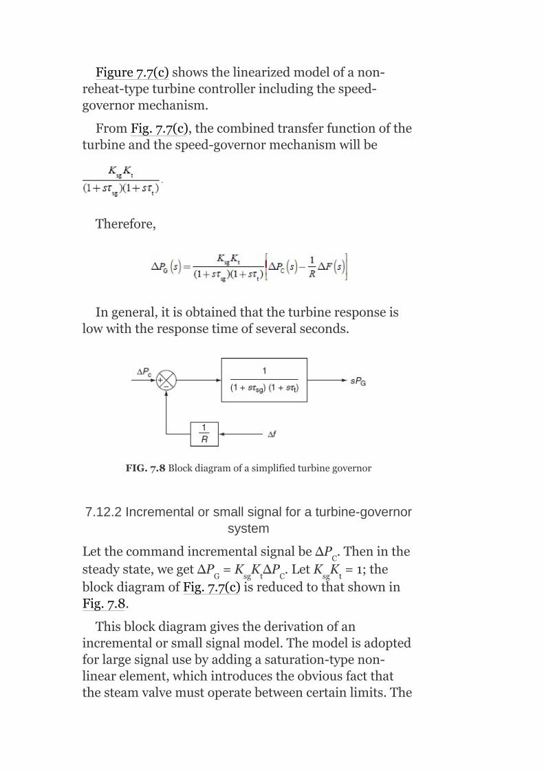
Figure7.7(c)showsthelinearizedmodelofanon-reheat-typeturbinecontrollerincludingthespeed-governormechanism.
FromFig.7.7(c),thecombinedtransferfunctionoftheturbineandthespeed-governormechanismwillbe
Therefore,
Ingeneral,itisobtainedthattheturbineresponseislowwiththeresponsetimeofseveralseconds.
FIG.7.8Blockdiagramofasimplifiedturbinegovernor
7.12.2Incrementalorsmallsignalforaturbine-governorsystem
LetthecommandincrementalsignalbeΔP .Theninthesteadystate,wegetΔP =K K ΔP .LetK K =1;theblockdiagramofFig.7.7(c)isreducedtothatshowninFig.7.8.
Thisblockdiagramgivesthederivationofanincrementalorsmallsignalmodel.Themodelisadoptedforlargesignalusebyaddingasaturation-typenon-linearelement,whichintroducestheobviousfactthatthesteamvalvemustoperatebetweencertainlimits.The
C
G sg t C sg t

valvecanneitherbemoreopenthanfullyopennormoreclosedthanfullyclosed.
ThismodelofFig.7.8mayalsobemodifiedtoaccountforreheatcyclesintheturbineandmoreaccuraterepresentationoffluiddynamicsinthesteaminletpipesorinthehydraulicturbinesinthepenstock.
7.12.3Reheattypeofsteamturbines
Moderngeneratingunitshavereheat-typesteamturbinesasprimemoversforhigherthermalefficiency.
Figure7.9showsatwo-stagereheat-typesteamturbine.
Insuchturbines,steamathighpressureandlowtemperatureiswithdrawnfromtheturbineatanintermediatestage.Itisreturnedtotheboilerforresuperheatingandthenreintroducedintotheturbineatlowpressureandhightemperature.Thisincreasestheoverallthermalefficiency.Mostly,twofactorsinfluencethedynamicresponseofareheat-typesteamturbine:
1. Entrainedsteambetweentheinletsteamvalveandthefirststateofturbine.
2. Thestorageactioninthereheater,whichcausestheoutputofthelow-pressurestagetolagbehindthatofthehigh-pressurestage.
FIG.7.9Atwo-stagereheattypeofasteamturbine

Thus,inthiscase,theturbinetransferfunctionischaracterizedbytwotimeconstants.Itinvolvesanadditionaltimelagτ associatedwiththereheaterinadditiontotheturbinetimeconstantτ .Hence,theturbinetransferfunctionwillbeofasecondorderandisgivenby
Thetimeconstantτ hasavalueintherangeof10sandapproximatesthetimedelayforchargingthereheatsectionoftheboiler.K isareheatcoefficientandisequaltotheproportionoftorquedevelopedinthehigh-pressuresectionoftheturbine:
K =(1–fractionofthesteamreheated)
WhenthereisnoreheatK =1andthetransferfunctionreducestoasingletimeconstantgiveninEquation(7.16).
ThetransferfunctionsasgivenbyEquations(7.16)and(7.18)givegoodrepresentationwithinthefirst20sfollowingtheincrementaldisturbance.Theydonotaccountfortheslowerboilerdynamics.Togetaneasyanalyzation,itcanbeassumedthattheprimemoverorturbineismodeledbyasingleequivalenttimeconstantτasgiveninEquation(7.16).
7.13GENERATOR–LOADMODEL
Thegenerator–loadmodelgivestherelationbetweenthechangeinfrequency(Δf)asaresultofthechangeingeneration(ΔP )whentheloadchangesbyasmallamount(ΔP ).
Whenneglectingthechangeingeneratorloss,ΔP =ΔP (changeinturbinepoweroutput),net-surpluspower
r
t
r
r
r
r
t
G
D
G
T

atthebusbar=(ΔP –ΔP ).Thissurpluspowercanbeabsorbedbythesystemintwodifferentways:
(i)Byincreasingthestoredkineticenergyofthe
generatorrotoratarate
LetW bethestoredKEbeforethedisturbanceatnormalspeedandfrequencyf ,andW betheKEwhenthefrequencyis(f +Δf).
SincethestoredKEisproportionaltothesquareofspeedandthefrequencyisproportionaltothespeed,
Neglectinghigher-orderterms,since issmall:
Differentiatingtheaboveexpressionwithrespectto‘t’,weget
G D
KE
KE
0
0
0

LetHbetheinertiaconstantofagenerator(MW-s/MVA)andP theratingoftheturbo-generator(MVA):
W =H×P (MW-sorM-J)(7.22)
Hence,Equation(7.21)becomes
(ii)Theloadonthemotorsincreaseswithincreaseinspeed.Theloadonthesystembeingmostlymotorload,hencesomeportionofthesurpluspowerisobservedbythemotorloads.Therateofchangeofloadwithrespecttofrequencycanberegardedasnearlyconstantforsmallchangesinfrequency.
i.e.,
wheretheconstantBistheareaparameterinMW/Hzandcanbedeterminedempirically.Bispositiveforapredominantlymotorload.
Now,thesurpluspowercanbeexpressedas
FromEquations(7.23)and(7.24),theaboveequationcanbemodifiedas
DividingthroughoutbyP ofEquation(7.25),weget
r
KE r
r
0

TakingLaplacetransformonbothsides,weget
where isthepowersystemtimeconstant
(normally20s)and thepowersystemgain.
Equation(7.26)canberepresentedinablockdiagrammodelasgiveninFig.7.10.
Theoverallblockdiagramofanisolatedpowersystemisobtainedbycombiningindividualblockdiagramsofaspeed-governorsystem,aturbinesystem,andagenerator–loadmodelandisasshowninFig.7.11.
Thisrepresentationbeingathird-ordersystem,thecharacteristicequationforthesystemwillbeofthethirdorder.

FIG.7.10Blockdiagramrepresentationofagenerator–loadmodel
FIG.7.11Completeblockdiagramrepresentationofanisolatedpowersystem
Example7.1:Twogeneratingstations1and2havefull-loadcapacitiesof200and100MW,respectively,atafrequencyof50Hz.Thetwostationsareinterconnectedbyaninductionmotorandsynchronousgeneratorsetwithafull-loadcapacityof25MWasshowninFig.7.12.ThespeedregulationofStation-1,Station-2,andinductionmotorandsynchronousgeneratorsetare4%,3.5%,and2.5%,respectively.Theloadsonrespectivebusbarsare750and50MW,respectively.Findtheloadtakenbythemotor-generatorset.
Solution:
LetapowerofAMWflowfromStation-1toStation-2:
∴TotalloadonStation-1=(75+A)MW
TotalloadonStation-2=(50−A)

%dropinspeedatStation-1=
%dropinspeedatStation-2=
ThereductioninfrequencywillresultduetothepowerflowfromStation-1throughtheinterconnectorofM-Gset.
∴%dropinspeedatM-Gset=
(reductioninfrequencyatStation-1+reductioninfrequencyatM-Gset)
=(reductioninfrequencyatStation-2)
0.02(75+A)+0.1A = 0.035(50−A)
1.5+0.02A+0.1A = 1.75−0.03A
0.02A+0.1A+0.03A = 175−1.5=0.25
0.15A = 0.25
A = 1.666MW
i.e.,apowerofA = 1.666MWflowsfromStation-1toStation-2.
∴TotalloadatStation-1=75+A = 75+1.666=76.666MW

TotalloadatStation-2=50−A = 50−1.666=48.334MW
FIG.7.12IllustrationforExample7.1
Example7.2:A125MVAturbo-alternatoroperatoronfullloadoperatesat50Hz.Aloadof50MWissuddenlyreducedonthemachine.Thesteamvalvestotheturbinecommencetocloseafter0.5sduetothetimelaginthegovernorsystem.Assumingtheinertiatobeconstant,H=6kW-sperkVAofgeneratorcapacity,calculatethechangeinfrequencythatoccursinthistime.
Solution:
Bydefinition,
∴Energystoredatnoload=6×125×1,000=750MJ
Excessiveenergyinputtorotatingpartsin0.5s=50×0.5×1,000=25MJ
Asaresultofthis,thereisanincreaseinthespeedofthemotorandhenceanincreaseinfrequency:
7.14CONTROLAREACONCEPT

Inrealpractice,thesystemofasinglegeneratorthatfeedsalargeandcomplexareahasrarelyoccurred.Severalgeneratorsconnectedinparallel,locatedalsoatdifferentlocations,willmeettheloaddemandofsuchageographicallylargearea.Allthegeneratorsmayhavethesameresponsecharacteristicstothechangesinloaddemand.
Itispossibletodivideaverylargepowersystemintosub-areasinwhichallthegeneratorsaretightlycoupledsuchthattheyswinginunisonwithchangeinloadorduetoaspeed-changersetting.Suchanarea,whereallthegeneratorsarerunningcoherentlyistermedasacontrolarea.Inthisarea,frequencymaybesameinsteadystateanddynamicconditions.Fordevelopingasuitablecontrolstrategy,acontrolareacanbereducedtoasinglegenerator,aspeedgovernor,andaloadsystem.
7.15INCREMENTALPOWERBALANCEOFCONTROLAREA
Inthissection,weshalldevelopadynamicmodelintermsofincrementalpowerandfrequencydynamicsofacontrolarea‘i’connectedviatielinesasshowninFig.7.13.
Nowassumethatcontrolarea‘i’experiencesarealloadchangeΔP (MW).Duetotheactionsoftheturbinecontrollers,itsoutputincreasesbyΔP (MW).Thenet-surpluspowerinthearea(ΔP –ΔP )willbeabsorbedbythesysteminthreeways:
ByincreasingtheareakineticenergyW attherate
Byanincreasedloadconsumption.Alltypicalloads(becauseofthedominanceofmotorloads)experienceanincrease,
withspeedorfrequency.
ByincreasingtheflowofpowerviatielineswiththetotalamountΔP MW,whichisdefinedpositiveforoutflowfromthearea.
Di
Gi
Gi Di
KE, i
tie,i

FIG.7.13Interconnectedcontrolarea
Hence,thenet-surpluspowercanbeexpressedas
ΔP isthedifferencebetweenscheduledrealpowerandactualrealpowerthroughinterconnectedlinesanditistakenastheinputtotheLFCsystem.
7.16SINGLEAREAIDENTIFICATION
Thefirsttwotermsontheright-handsideofEquation(7.27)representagenerator–loadmodel(withthesubscript‘i’absent).Ifthethirdtermisabsent,itmeansthatthereisnointerchangeofpowerbetweenarea‘i’andanyotherarea.Thus,itbecomesasingle-areacase.Asingleareaisacoherentareainwhichallthegeneratorsswinginunisontothechangesinloadorspeed-changersettingsandinwhichthefrequencyisassumedtobeconstantthroughoutbothinstaticanddynamicconditions.Thissinglecontrolareacanberepresentedbyanisolatedpowersystemconsistingofaturbine,itsspeedgovernor,generator,andload.
7.16.1Blockdiagramrepresentationofasinglearea
Theblockdiagramofanisolatedpowersystem,whichinessenceisasingle-areasystem,isthesameastheblockdiagramgiveninFig.7.11.
tie

7.17SINGLEAREA—STEADY-STATEANALYSIS
TheblockdiagramofanLFCofanisolatedpowersystemofathird-ordermodelisrepresentedinFig.7.11.
Therearetwoincrementalinputstothesystemandtheyare:
1. Thechangeinthespeed-changerposition,ΔP (referencepower
input).2. Thechangeintheloaddemand,ΔP .
Inthissection,wewillanalyzetheresponseofasingle-areasystemtosteady-statechangesbythreeways:
1. Constantspeed-changerpositionwithvariableloaddemand(uncontrolledcase).
2. Constantloaddemandwithvariablespeed-changerposition(controlledcase).
3. Variablespeed-changerpositionaswellasloaddemand.
7.17.1Speed-changerpositionisconstant(uncontrolledcase)
WiththemodelgiveninFig.7.11andwithΔP =0,theresponseofanuncontrolledsingleareaLFCcanbeobtainedasfollows.
Letusconsiderasimplecasewhereinthespeedchangerhasafixedsetting,whichmeansΔP =0andtheloaddemandalonechanges.Suchanoperationisknownasfreegovernoroperationoruncontrolledcasesincethespeedchangerisnotmanipulated(orcontrolledtoachievebetterfrequencyconstancy).
Forasuddenstepchangeofloaddemand,
Forsuchanoperation,thesteady-statechangeoffrequencyΔfistobeestimatedfromtheblockdiagramofFig.7.14as
C
D
C
C

Applyingthefinalvaluetheorem,wehave
FIG.7.14BlockdiagramrepresentationofanisolatedpowersystemsettingΔP =0
ThegainK isfixedfortheturbineandK isfixedforthepowersystem.ThegainK ofthespeedgovernoriseasilyadjustablebychangingthelengthsofvariouslinksofthelinkagemechanism.K issoadjustedsuchthatK K ≈1.
ThereforeEquation(7.29)canbesimplifiedas:
C
t ps
sg
sg
sg t

Alsoweknowfromthedynamicsofthegenerator–
loadmodel,
where
inp.u.MW/unitchangeinfrequency
wherethefactor andisknownasthearea
frequencyresponsecharacteristic(AFRC)orareafrequencyregulationcharacteristic.
Equation(7.30)givesthesteady-stateresponseoffrequencytothechangesinloaddemand.Thespeedregulationisusuallysoadjustedthatchangesinfrequencyaresmall(oftheorderof5%)fromnoloadtofullload.Figure7.15givesthelinearrelationshipbetweenfrequencyandloadforafreegovernor
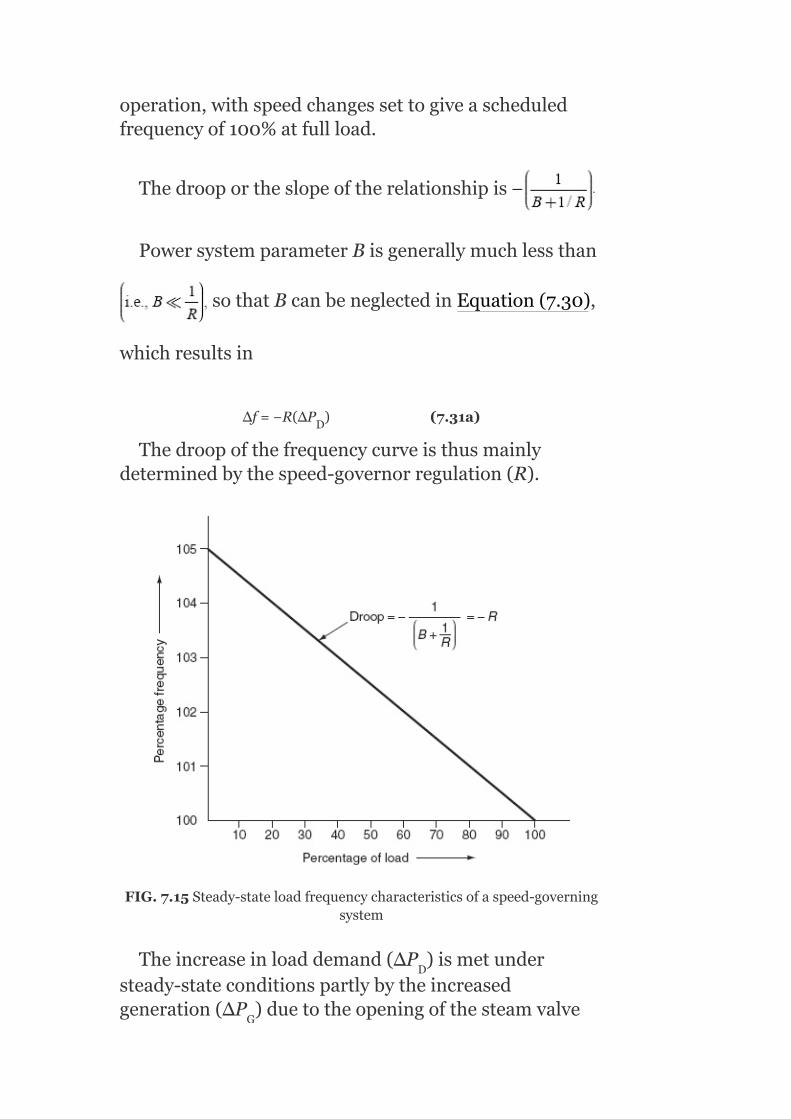
operation,withspeedchangessettogiveascheduledfrequencyof100%atfullload.
Thedrooportheslopeoftherelationshipis
PowersystemparameterBisgenerallymuchlessthan
sothatBcanbeneglectedinEquation(7.30),
whichresultsin
Δf=−R(ΔP )(7.31a)
Thedroopofthefrequencycurveisthusmainlydeterminedbythespeed-governorregulation(R).
FIG.7.15Steady-stateloadfrequencycharacteristicsofaspeed-governingsystem
Theincreaseinloaddemand(ΔP )ismetundersteady-stateconditionspartlybytheincreasedgeneration(ΔP )duetotheopeningofthesteamvalve
D
D
G

andpartlybythedecreasedloaddemandduetodroopinfrequency.
Theincreaseingenerationisexpressedas
SubstitutingΔffromEquation(7.30),weget
Andadecreaseinthesystemloadisexpressedas
FromEquations(7.31(b))and(7.31(c)),itisobservedthatcontributionofthedecreaseinthesystemloadismuchlessthantheincreaseingeneration.
7.17.2Loaddemandisconstant(controlledcase)
Considerastepchangeinaspeed-changerpositionwiththeloaddemandremainingfixed:
i.e.,
Thesteady-statechangeinfrequencycanbeobtainedfromtheblockdiagramofFig.7.16:
G

Thesteady-statevalueisobtainedbyapplyingthefinal-valuetheorem:
FIG.7.16BlockdiagramrepresentationofanisolatedpowersystemsettingΔP =0
D
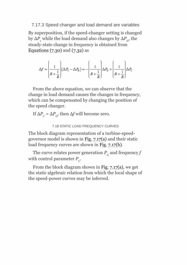
7.17.3Speedchangerandloaddemandarevariables
Bysuperposition,ifthespeed-changersettingischangedbyΔP whiletheloaddemandalsochangesbyΔP ,thesteady-statechangeinfrequencyisobtainedfromEquations(7.30)and(7.32)as
Fromtheaboveequation,wecanobservethatthechangeinloaddemandcausesthechangesinfrequency,whichcanbecompensatedbychangingthepositionofthespeedchanger.
IfΔP =ΔP ,thenΔfwillbecomezero.
7.18STATICLOADFREQUENCYCURVES
Theblockdiagramrepresentationofaturbine-speed-governormodelisshowninFig.7.17(a)andtheirstaticloadfrequencycurvesareshowninFig.7.17(b).
ThecurverelatespowergenerationP andfrequencyfwithcontrolparameterP .
FromtheblockdiagramshowninFig.7.17(a),wegetthestaticalgebraicrelationfromwhichthelocalshapeofthespeed-powercurvesmaybeinferred.
c D
C D
G
C

FIG.7.17(a)Blockdiagramofaturbine-speed-governormodel;(b)staticloadfrequencycurvesfortheturbinegovernor
Figure7.17(b)givesthetwostaticload-frequencycurves.Adjustpowergeneration,P ,byusingaspeedermeter(speedchanger)uptoP =P ,whereP isthedesiredcommandpoweratsynchronousspeedω (f ).Withfreegovernoroperation(i.e.,ΔP =0),thefixedspeed-changerpositionP predictsthestraight-linerelationship.Thisstraightline(1)hasaslopeof–R.
Togetmoregenerationatthesamesynchronousspeedofω (f ),adjustP toP withaspeedermeter.Thisresultsintheloadfrequencycurve(2).Thespeed
G
G C1 C1
C
C1
C1 C2
0 0
0 0

regulationRreferstothevariationinfrequencywithpowergeneration.Bettertheregulationresults,lessthedroopsspeed-power(load)characteristicsofLFC.
7.19DYNAMICANALYSIS
Themeaningofdynamicresponseishowthefrequencychangesasafunctionoftimeimmediatelyafterdisturbancebeforeitreachesthenewsteady-statecondition.Theanalyzationofdynamicresponserequiresthesolutionofdynamicequationofthesystemforagivendisturbance.Thesolutioninvolvesthesolutionofdifferentequationsrepresentingthedynamicbehaviorofthesystem.
TheinverseLaplacetransformofΔF(s)givesthevariationoffrequencywithrespecttotimeforagivenstepchangeinloaddemand.Comparingtherelativevaluesoftimeconstants,wecanreducethethirdorderedmodeltoafirstorderedsystem.
ForapracticalLFCsystem,
τ <τ <<τ
Typicalvaluesare:
τ =0.4s
τ =0.5s
τ =20s
Ifτ andτ areconsiderednegligiblecomparedtoτandbyadjustingK K =1,theblockdiagramofLFCofthepowersystemofanisolatedsystemisreducedtoafirst-ordersystemasshowninFig.7.18withΔP =0foranuncontrolledcase.
FromFig.7.18,thechangeinfrequencyisgivenby
sg t Ps
sg
t
Ps
sg t Ps
sg t
c

FIG.7.18First-orderapproximateblockdiagramofLFCofanisolatedarea

FIG.7.19Dynamicresponseoffrequencychange(Δf)forastep-loadchange
Theplotofchangeinfrequencyversustimeforafirst-orderapproximationandexactresponseareshowninFig.7.19:
ΔP =0.01p.u,K =100,R=3,τ =0.4s,τ =0.5s,andτ =20s
Example7.3:Anisolatedcontrolareaconsistsofa200-MWgeneratorwithaninertiaconstantofH=5kW-s/kVAhavingthefollowingparameters(Fig.7.20(a)):
D ps sg t
Ps

Powersystemgainconstant,K =100
Powersystemtimeconstant,τ =20s
Speedregulation,R=3
Normalfrequency,f =50Hz
Obtainthefrequencyerrorandplotthegraphofdeviationoffrequencywhenastep-loaddisturbanceof(i)0.5%,(ii)1%,and(iii)2%isapplied(Fig.7.20(b)).
FromFig.7.20(b),thesteady-statechangeinfrequencyΔf =–0.0145Hz.
Similarly(ii)forastep-loadchangeof1%,thesteady-statechangeinfrequencyΔf =–0.029Hz;(iii)forastep-loadchangeof2%,steady-statechangeinfrequencyΔf =–0.0583Hz
Example7.4:ForExample7.3,showtheeffectofgovernoractionandturbinedynamics(Fig.7.21(a)),iftheyarenottobeneglectedandgiventhatτ =0.4sandτ =0.5sforastep-loadchangeof(i)0.5%and(ii)1%(Fig.7.21(b)).
FromFig.7.21(b),thesteady-statechangeinfrequencyΔf =–0.0235Hz.
Similarly(ii)forastep-loadchangeof1%,thesteady-statechangeinfrequencyΔf =–0.047Hz.
Example7.5:ObtaintheresultantfrequencyplotwhencombiningExamples7.3and7.4forastep-loaddisturbanceof0.5%(Figs.7.22(a)and(b)).
ps
ps
ss
ss
ss
sg
t
ss
ss
0
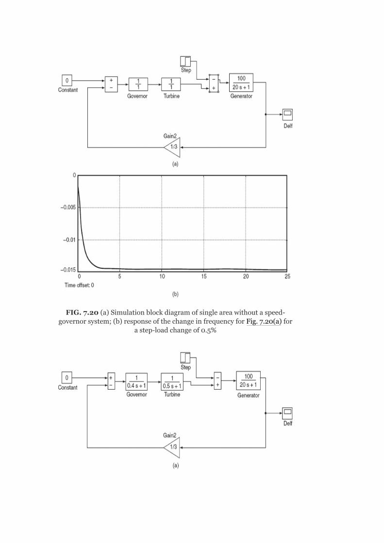
FIG.7.20(a)Simulationblockdiagramofsingleareawithoutaspeed-governorsystem;(b)responseofthechangeinfrequencyforFig.7.20(a)for
astep-loadchangeof0.5%

FIG.7.21(a)Simulationblockdiagramofsingleareawithaspeed-governorsystem;(b)responseofthechangeinfrequencyforFig.7.21(a)for
astep-loadchangeof0.5%

FIG.7.22(a)Simulationblockdiagramofasingleareawithoutandwithaspeed-governorsystem;(b)responseofthechangeinfrequencyforFig.
7.22(a)forastep-loadchangeof0.5%
Example7.6:Anisolatedcontrolareaconsistsofa200-MWgeneratorwithaninertiaconstantofH=5kw-s/kVAhavingthefollowingparameters(Fig.7.23(a)):
Powersystemgainconstant,K =100
Powersystemtimeconstant,τ =20s
Speedregulation,R=3
Normalfrequency,f =50Hz
Governortimeconstant,τ =0.4s
Turbinetimeconstant,τ =0.5s
Obtainthefrequencyerrorandplotthegraphofdeviationoffrequencywhenastepchangeof1%inthespeed-changerpositionisapplied(Fig.7.23(b)).
ps
ps
sg
t
0
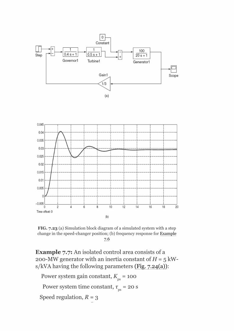
FIG.7.23(a)Simulationblockdiagramofasimulatedsystemwithastepchangeinthespeed-changerposition;(b)frequencyresponseforExample
7.6
Example7.7:Anisolatedcontrolareaconsistsofa200-MWgeneratorwithaninertiaconstantofH=5kW-s/kVAhavingthefollowingparameters(Fig.7.24(a)):
Powersystemgainconstant,K =100
Powersystemtimeconstant,τ =20s
Speedregulation,R=3
ps
ps
0

Normalfrequency,f =50Hz
Governortimeconstant,τ =0.4s
Turbinetimeconstant,τ =0.5s
Obtainthefrequencyerrorandplotthegraphofdeviationoffrequencywhenastepchangeof1%inboththespeed-changerpositionandtheloadisapplied(Fig.7.24(b)).
FIG.7.24(a)Simulationblockdiagramofasingle-areasystemwithPCandPD;(b)frequencyresponseofExample7.5
Example7.8:Findthestaticfrequencydropiftheloadissuddenlyincreasedby25MWonasystemhavingthe
sg
t
0

followingdata:
RatedcapacityP =500MW
OperatingLoadP =250MW
InertiaconstantH=5s
GovernorregulationR=2Hzp.u.MW
Frequencyf=50Hz
Alsofindtheadditionalgeneration.
Solution:
Assumingthefrequencycharacteristictobelinear,wehave
∂P /∂fexpressedinp.u.,
Areafrequencyresponsecharacteristic(AFRC)
Thestaticfrequencydrop
Hence,thesystemfrequencydropsto(50–0.098)=49.902Hz.
Theamountofadditionalgeneration
r
D
D

Whilethesuddenincreaseinloadis25MW,theincreaseingenerationis24.5MWand0.5MWisthelossofloadduetothedropinfrequency.
7.20REQUIREMENTSOFTHECONTROLSTRATEGY
Thefollowingarethebasicrequirementsneededforthecontrolstrategy:
Thesystemfrequencycontrolisobtainedthroughaclosedloop.Sincestabilityisthemajorproblemassociatedwithaclosed-loopcontrol,maintenanceofthestabilitywillbethemainobjective.Thefrequencydeviationduetoastep-loadchangeshouldreturntozero.Thecontrolthatoffersaboveiscalled‘isochronouscontrol’.Inaddition,thecontrolshouldkeepthemagnitudeofthetransientfrequencydeviationtoaminimum.Theintegralofthefrequencyerrorshouldnotexceedacertainmaximumvalue.
Isochronouscontrolensuresthatthesteady-statefrequencyerrorfollowingastep-loadchangewillbezero.However,nocontrolcaneliminatetransientfrequencyerror.Thetimeerrorofsynchronousclocksisproportionaltotheintegralofthistransientfrequencyerror.Therefore,itisnecessarytoputalimitonthevalueofthisintegral.
Thetotalloadshouldbedividedamongtheindividualgeneratorsofthecontrolareaforoptimumeconomy.
Thefirstthreerequirementsaresatisfiedwhentheadditionoftheintegral-controltothesystemtakesplace.
7.20.1Integralcontrol
Theintegralcontroliscomposedofafrequencysensorandanintegrator.ThefrequencysensormeasuresthefrequencyerrorΔfandthiserrorsignalisfedintothe

integrator.Theinputtotheintegratoriscalledthe‘AreaControlError’(i.e.,ACE=Δf).
TheACEisthechangeinareafrequency,whichwhenusedinanintegral-controlloop,forcesthesteady-statefrequencyerrortozero.
Theintegratorproducesareal-powercommandsignalΔP andisgivenby
ΔP =−K ∫Δfdt (7.33)
=−K ∫(ACE)dt
ThesignalΔP isfedtothespeed-changercausingittomove.Here,K iscalledtheintegralgainconstant,whichcontrolstherateofintegration.ThefrequencysensorandtheintegratorareconnectedinthesystemasaclosedcontrolloopasshownintheblockdiagraminFig.7.25.
Figure7.25consistsofFig.7.11augmentedbyadditionalloopsshowingthegenerationofACEanditsuseinchangingtheareacommandpowers;Risthespeed-regulationfeedbackparameter.ΔP (s),ΔP (s),andΔF(s)aretheincrementalchangesinthegeneration,systemload,andfrequency,respectively.TheblockdiagramofFig.7.25isthesingle-areapowersystem(isolatedpowersystem)withintegralcontrolforsmallincrementalchanges.
Thenegativesignintheintegralcontrollerisforproducinganegativeordecreasecommandforapositivefrequencyerror.ThegainconstantK ispositiveandcontrolstherateofintegration,andthusthespeedoftheresponseofthecontrolloop.Theintegratorisanelectronicintegratorofthesametypeasusedinanalogcomputers.
C
C I
I
C
I
G D
I
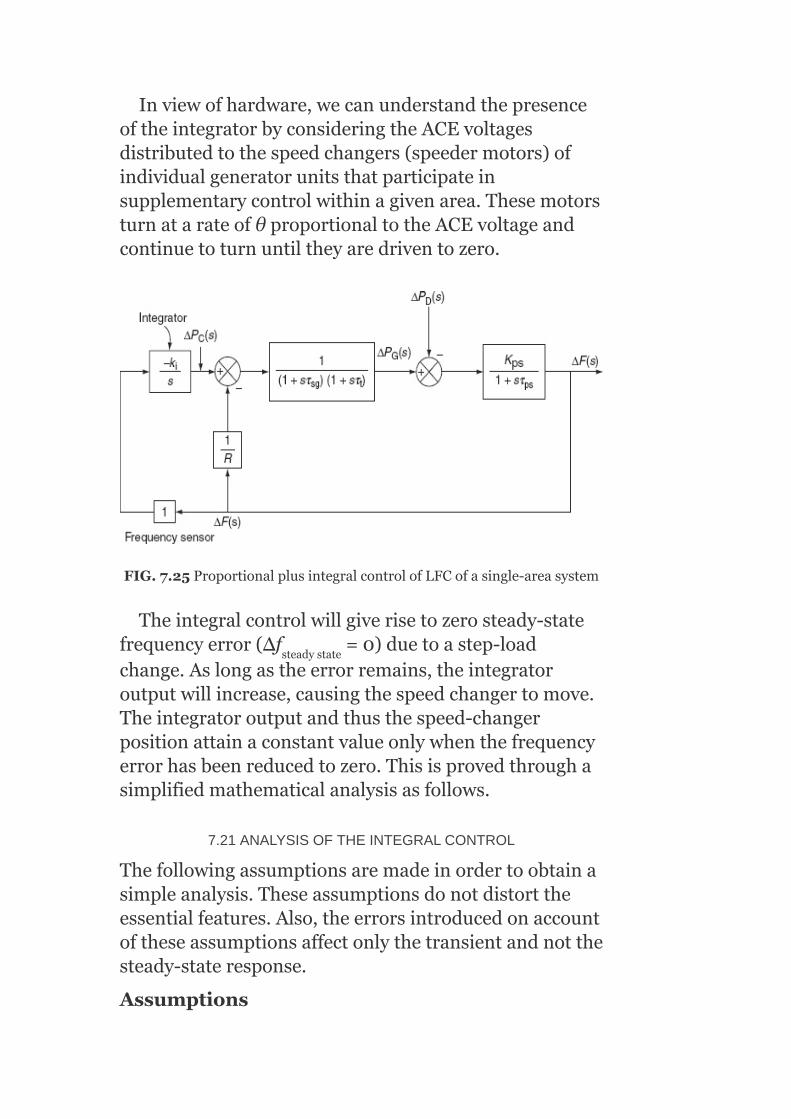
Inviewofhardware,wecanunderstandthepresenceoftheintegratorbyconsideringtheACEvoltagesdistributedtothespeedchangers(speedermotors)ofindividualgeneratorunitsthatparticipateinsupplementarycontrolwithinagivenarea.ThesemotorsturnatarateofθproportionaltotheACEvoltageandcontinuetoturnuntiltheyaredriventozero.
FIG.7.25ProportionalplusintegralcontrolofLFCofasingle-areasystem
Theintegralcontrolwillgiverisetozerosteady-statefrequencyerror(Δf =0)duetoastep-loadchange.Aslongastheerrorremains,theintegratoroutputwillincrease,causingthespeedchangertomove.Theintegratoroutputandthusthespeed-changerpositionattainaconstantvalueonlywhenthefrequencyerrorhasbeenreducedtozero.Thisisprovedthroughasimplifiedmathematicalanalysisasfollows.
7.21ANALYSISOFTHEINTEGRALCONTROL
Thefollowingassumptionsaremadeinordertoobtainasimpleanalysis.Theseassumptionsdonotdistorttheessentialfeatures.Also,theerrorsintroducedonaccountoftheseassumptionsaffectonlythetransientandnotthesteady-stateresponse.
Assumptions
steadystate

Thetimeconstantofthespeed-governormechanismτ andthatof
theturbineτ arebothneglected,i.e.,τ =τ =0.
Thespeedchangerisanelectromechanicaldeviceandhenceitsresponseisnotinstantaneous.However,itisassumedtobeinstantaneousinthepresentanalysis.Allnon-linearitiesintheequipment,suchasdeadzone,etc.,areneglected.ThegeneratorcanchangeitsgenerationΔP asfastasitis
commandedbythespeedchanger.TheACEisacontinuoussignal.
TheLaplacetransformationofEquation(7.33)gives
and,forastepchangeofloaddemandΔP ,
FromtheblockdiagramofFig.7.25,wehave
and
SubstitutingforΔP (s)fromEquation(7.36)intheaboveequation,weget
sg
t sg t
G
D
G

Equation(7.38)becomesafourth-ordersystem.
Thesteady-statevalueofΔf(t)canbeobtainedbyapplyingthefinal-valuetheorem,viz.,
Hence,thestatic-orsteady-statefrequencyerrorwillbezerowithintegralcontrol.
ThenatureoftransientvariationofΔf(t)canbefoundbytakingtheinverseLaplacetransformofEquation(7.39).Accordingtoassumption(i),Equation(7.39)simplifiesto

ThenatureofΔf(t)dependsontherootsofthecharacteristicequationofEquation(7.39)
Theaboveequationcanberewrittenas
where isapositiverealnumber
and
ThenatureoftherootsofEquation(7.41)dependsonwhetherω =0,ω >0,orω <0.
Case(i):ω =0
Thecharacteristicequationhasarepeatedroot(viz.,αrepeatedtwice).Hence,theexpressionforΔf(t)containstermsofthetype
e andte
2 2 2
2
–αt –αt

Consequently,theresponse[viz.,Δf(t)]isacriticallydampedone.Forthiscriticalcase,
SolvingtheaboveforK ,weget
Case(ii):ω >0
Now,(s+α) =–ω ,whereω isapositiverealnumber.
(s+α)=+jω
(or)s=(–α±jω)
ThetimeresponseΔf(t)willthereforeconsistofdampedoscillatorytermsofthetype
e sinωtande cosωt.
Thiscaseiscalledasupercriticalcase.Inthiscase,K>K .
Case(iii):ω >0
Then,ω isanegativerealnumber.
So,(s+α) =–ω isapositiverealnumber
=γ (say)
∴(s+α)=+γ[sinceγ<α]
ors=(−α+γ)or(−α−γ)
=β1or−β2(say)
Accordingly,inthiscase,thetimeresponseΔf(t)willcomprisetermsofthetype
I
I
Icrit
2
2 2 2
–αt –αt
2
2
2 2
2
−β t1 −β t2

e ande
Hence,theresponsewillbedampedandnon-oscillatory.Thecontrol,inthiscase,iscalledthesubcriticalintegralcontrol.Inthiscase,K <K .
Inallthethreecasesdescribedabove,Δf(t)willapproachzero.Thiswasprovedearlierusingthefinal-valuetheorem.Itcanbeobservedthatthetransientfrequencyerrordoesremainfinite.Thisisaproofthatthecontrolisbothstableandisochronous.Thus,thefirsttwocontrolrequirementsstatedearlier(Section7.20)arefulfilledwiththisintegralcontrol.Thiscontrolisalsocalled‘proportionalplusintegralcontrol’.Theproportionalcontrolisprovidedbytheclosedloopofgainconstantof1/R.
Theactualsimulatedtimeresponsesofasingle-areacontrolsystemwithandwithoutintegralcontrolareasshowninFig.7.26.
FIG.7.26DynamicresponseofLFCofasingle-areasystemwithandwithoutintegralcontrolaction
7.22ROLEOFINTEGRALCONTROLLERGAIN(K )SETTING
I Icrit
I
−β t1 −β t2

Theroleplayedbythegainsettingofanintegralcontrollerinthecontroloffrequencyerrorisdescribedbelow.
Withsubcriticalingainsettings(i.e.,K <K ),asluggish,non-oscillatoryresponseisobtained.TheslownessoftheresponsemakestheintegralofΔf(t),andhencethetimeerror,relativelylarge.However,withthissetting,thegeneratorneednot‘chase’rapidloadfluctuations,whichultimatelycauseequipmentwear.
7.23CONTROLOFGENERATORUNITPOWEROUTPUT
ThecollectiveperformanceofallgeneratorsinthesystemisstudiedbyassumingtheequivalentgeneratorhavinganinertiaconstantofH tobeequaltothesumoftheinertiaconstantsofallthegeneratingunits.Similarly,theeffectsofthesystemloadsarelumpedintoasingledampingconstantB.
Forasystemhaving‘n’generatorsandacompositeload-dampingconstantofBthesteady-statefrequencydeviationfollowingaloadchangeΔP is
Thecompositefrequencyresponsecharacteristicofthesystemis
ItisnormallyexpressedinMW/Hz.Sometimes,itisreferredtoasthestiffnessofthesystem.
Example7.9:Anisolatedcontrolareaconsistsofa200-MWgeneratorwithaninertiaconstantofH=5kW-s/kVAhavingthefollowingparameters(Fig.7.27(a)):
I Icrit
eq
D

Powersystemgainconstant,K =104
Powersystemtimeconstant,τ =22s
Speedregulation,R=3
Normalfrequency,f =50Hz
Governortimeconstant,τ =0.3s
Turbinetimeconstant,τ =0.4s
Obtainthefrequencyerrorandplotthegraphofdeviationoffrequencywhenastep-loadchangeof0.48p.u.withanintegralcontrolleractionofk =0.1isapplied(Fig.7.27(b)).
Example7.10:Anisolatedcontrolareaconsistsofa200-MWgeneratorwithaninertiaconstantofH=5kW-s/kVAhavingthefollowingparameters(Fig.7.28(a)):
Powersystemgainconstant,K =100
Powersystemtimeconstant,τ =20s
Speedregulation,R=2.5
ps
ps
sg
t
i
ps
ps
0

FIG.7.27(a)Simulationblockdiagramforasingle-areasystemwithintegralcontrolaction;(b)frequencyresponsecharacteristicsofExample
7.9
Normalfrequency,f =50Hz
Governortimeconstant,τ =0.3s
Turbinetimeconstant,τ =0.4s
Integratorgainconstant,k =0.15
Obtainthefrequencyerrorandplotthegraphofdeviationoffrequencywhenastep-loaddisturbanceof2%withandwithouttheintegralcontrolactionisapplied(Fig.7.28(b)).
sg
t
i
0


FIG.7.28(a)Simulationdiagramofasingle-areasystemwithoutandwithintegralcontrolaction;(b)frequencyresponsecharacteristicsofExample
7.10
Example7.11:GivenasingleareawiththreegeneratingunitsasshowninFig.7.29:
Unit Rating(MVA) SpeeddroopR(perunitonunitbase)
1 100 0.010
2 500 0.015
3 500 0.015
TheunitsareloadedasP =80MW;P =300MW;P=400MW.AssumeB=0;whatisthenewgenerationoneachunitfora50-MWloadincrease?RepeatwithB=1.0p.u.(i.e.,1.0p.u.onloadbase).
Solution:
1 2 3

1.
withB=0;atacommonbaseof1,000MVA
FIG.7.29Asingleareawiththreegeneratingunits
f=f +Δf
=50−652.17×10 (50)=49.96Hz
Changesinunitgeneration:
0
−6

Newgeneration:
P ′=P +ΔP =80+6.52=86.52MW
P ′=P +ΔP =300+21.74=321.74MW
P ′=P +ΔP =400+21.74=421.74MW
2. withB=1p.u.(onloadbase)
Changesinunitgeneration:
Newgeneration:
P ′=P +ΔP =80+6.44=86.44MW
P ′=P +ΔP =300+21.459=321.459MW
P ′=P +ΔP =400+21.459=421.459MW
1 1 1
2 2 2
3 3 3
1 1 1
2 2 2
3 3 3
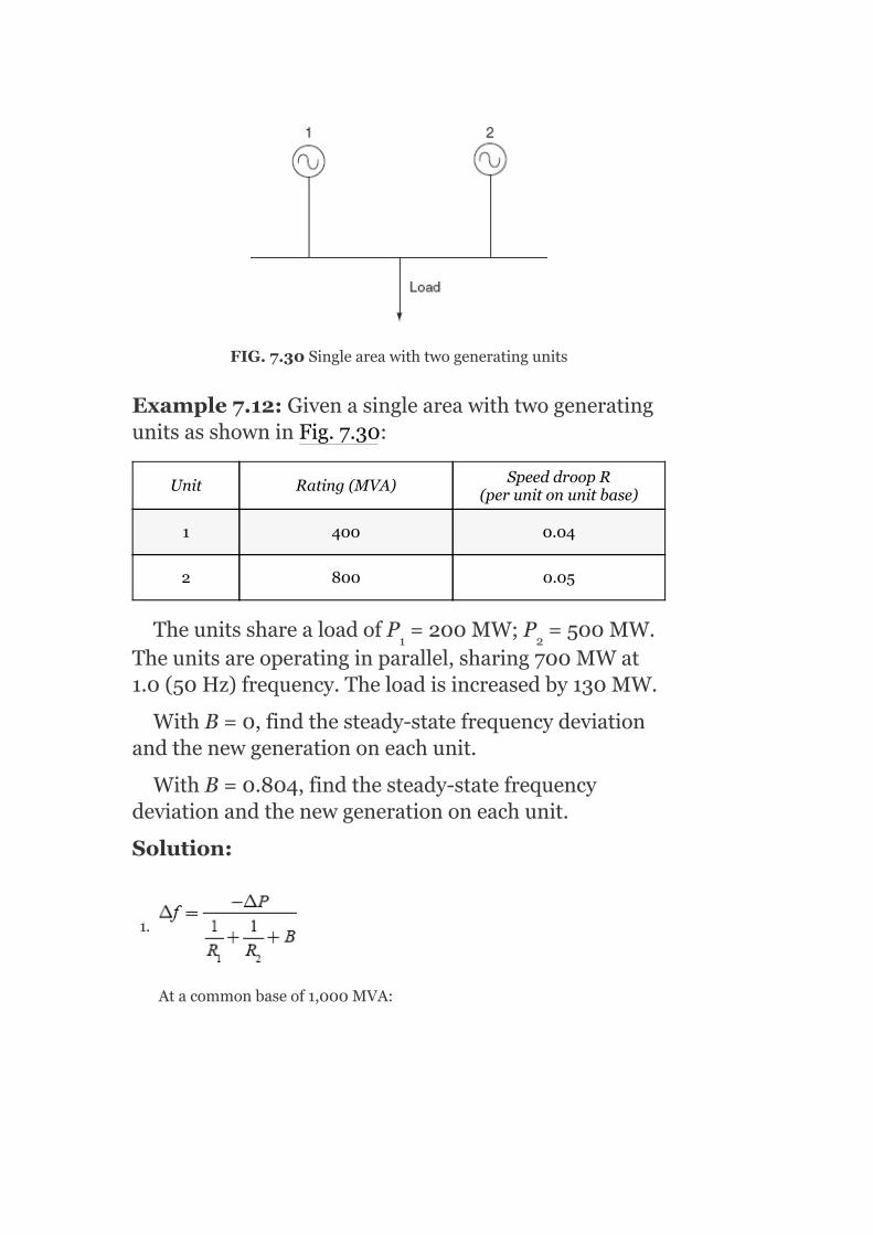
FIG.7.30Singleareawithtwogeneratingunits
Example7.12:GivenasingleareawithtwogeneratingunitsasshowninFig.7.30:
Unit Rating(MVA) SpeeddroopR(perunitonunitbase)
1 400 0.04
2 800 0.05
TheunitssharealoadofP =200MW;P =500MW.Theunitsareoperatinginparallel,sharing700MWat1.0(50Hz)frequency.Theloadisincreasedby130MW.
WithB=0,findthesteady-statefrequencydeviationandthenewgenerationoneachunit.
WithB=0.804,findthesteady-statefrequencydeviationandthenewgenerationoneachunit.
Solution:
1.
Atacommonbaseof1,000MVA:
1 2

Changeinunitgeneration:
Newgeneration:
P ′=P +ΔP =200+50=250MW
P ′=P +ΔP =500+80=580MW
2. WithB=0.804(onloadbase)
Changeinunitgeneration:
Newgeneration:
P ′=P +ΔP =200+48.5=248.5MW
P ′=P +ΔP =500+77.6=577.6MW
1 1 1
2 2 2
1 1 1
2 2 2
Example7.13:A500-MWgeneratorhasaspeedregulationof4%.Ifthefrequencydropsby0.12Hzwithanunchangedreference,determinetheincreaseinturbinepower.Andalsofindbyhowmuchthereferencepowersettingshouldbechangediftheturbinepowerremainsunchanged.
Solution:
Case1:
Speedregulation,
Givenadropinfrequency,Δf=–0.12Hz
Increaseinturbinepower,
∴Turbinepowerincrease,ΔP=30MW
Case2:
Iftheturbinepowerremainsunchanged,thereferencepowersettingatthepointoftheblockdiagrammustbechangedsuchthatthesignaltotheincreaseingenerationisblocked:

Example7.14:Twogeneratingunitshavingthecapacities600and900MWandareoperatingata50Hzsupply.Thesystemloadincreasesby150MWwhenboththegeneratingunitsareoperatingatabouthalfoftheircapacity,whichresultsinthefrequencyfallingby0.5Hz.Ifthegeneratingunitsaretosharetheincreasedloadinproportiontotheirratings,whatshouldbetheindividualspeedregulations?Whatshouldtheregulationsbeifexpressedinp.u.Hz/p.u.MW?
Solution:
RatedcapacityofUnit-1=600MW
RatedcapacityofUnit-2=900MW
Systemfrequency,f=50Hz
Systemloadincrement,ΔP=150MW
Fallinginfrequency,Δf=0.5Hz
Weknowthat
Iftheloadissharedinproportionaltotheirratings,

∴FromEquation(7.43),
Itisobservedthatthespeedregulationsinp.u.Hz/p.u.MWareattainingthesamevalue,evenwhentheyarebasedontheirindividualratingsandtheyhavedifferentregulations.
Example7.15:Asingle-areasystemhasthefollowingdata:
Speedregulation,R=4Hz/p.u.MW
Dampingcoefficient,B=0.1p.u.MW/Hz
Powersystemtimeconstant,T =10s
Powersystemgain,K =75Hz/p.u.MW
Whena2%loadchangeoccurs,determinetheAFRCandthestaticfrequencyerror.Whatisthevalueofthesteady-statefrequencyerrorifthegovernorisblocked?
Solution:
P
P

Staticfrequencyerror
Ifthegovernorisblocked,thefeedbackloopwillnotbepresent;therefore,Rwillbecomeinfinite:
Staticfrequencyerror
i.e.,frequencyfallsby0.0571Hz.
∴Newfrequency,f′=50−0.0571
=49.94Hz
Observation:
Withspeed-governoraction:

Frequencyfallsby0.0571Hz
∴Newfrequency,f′=50–0.0571
=49.94Hz
Withoutspeed-governoraction:
Frequencyfallsby0.2Hz
∴Newfrequency,f′=50–0.2=49.8Hz
Fromtheaboveresults,itisnotedthatthespeed-governoractionisnecessaryforobtainingareductioninthesteady-statefrequencyerror.
Example7.16:A200-MVAsynchronousgeneratorisoperatedat3,000rpm,50Hz.Aloadof40MWissuddenlyappliedtothemachineandthestationvalvetotheturbineopensonlyafter0.4sduetothetimelaginthegeneratoraction.Calculatethefrequencytowhichthegeneratedvoltagedropsbeforethesteamflowcommencestoincreasesoastomeetthenewload.GiventhatthevalveofHofthegeneratoris5.5kW-sperkVAofthegeneratorenergy.
Solution:
Given:
Ratingofthegenerator=200MVA
Loadappliedonthem/c=40MW
Timetakenbythevalvetoopen=0.4s
H=5.5kW-s/kVA
=11×10 s
Energystoredatno-load=5.5×200×1,000=1,100MW-s=1,100MJ
Beforethesteamvalveopens,theenergylostbytherotor=40×0.4=16MJ.
Theenergylostbytherotorresultsinareductioninthespeedoftherotorandhencethereductioninfrequency.
5

Weknow
∴Frequencyattheendof0.4s=
Example7.17:Twogeneratorsofrating100and200MWareoperatedwithadroopcharacteristicof6%fromnoloadtofullload.Determinetheloadsharedbyeachgenerator,ifaloadof270MWisconnectedacrosstheparallelcombinationofthosegenerators.
Solution:
Thetwogeneratorsareoperatingwithparallelconnection;the%dropinfrequencyfromtwogeneratorsduetodifferentloadsmustbesame.
Letpowersuppliedby(100MW)Generator-1=x
Percentagedropinfrequency=6%
∴PercentagedropinthespeedofGenerator-1
Totalloadacrosstheparallelconnection=270MW
Powersuppliedby(200MW)Generator-2=(270–x)
∴PercentagedropinthespeedofGenerator-2
Percentdropinfrequency(orspeed)ofbothmachinesmustbethesame:
Bysolvingtheaboveequation,weget
x=90MW
∴LoadsharedbyGenerator-1(100MWunit)=90MW
LoadsharedbyGenerator-2(200MWunit)=270–x
=270–90=180MW
KEYNOTES
Necessityofmaintainingfrequencyconstant
1. AlltheACmotorsshouldbegivenaconstantfrequencysupplysoastomaintainthespeedconstant.
2. Incontinuousprocessindustry,itaffectstheoperationoftheprocessitself.3. Forsynchronousoperationofvariousunitsinthepowersystemnetwork,itis
necessarytomaintainthefrequencyconstant.4. Frequencyaffectstheamountofpowertransmittedthroughinterconnecting
lines.
Loadfrequencycontrol(LFC)isthebasiccontrolmechanisminthepowersystemoperationwheneverthereisavariationinloaddemandonageneratingunitmomentarilyifthereisanoccurrenceofunbalancebetweenreal-powerinputandoutput.Thisdifferenceisbeingsuppliedbythestoredenergyoftherotatingpartsoftheunit.Primemoversdrivingthegeneratorsarefittedwithgovernors,whichareregardedasprimarycontrolelementsintheLFCsystem.Governorssensethechangeinaspeedcontrolmechanismtoadjusttheopeningofsteamvalvesinthecaseofsteamturbinesandtheopeningofwatergatesinthecaseofwaterturbines.Thesteady-statespeedregulationinperunitisgivenby
ThevalueofRvariesfrom2%to6%foranygeneratingunit.
ThespeedgovernoristhemainprimarytoolfortheLFC,whetherthemachineisusedalonetofeedasmallersystemorwhetheritisapartofthemostelaboratearrangement.
Itsmainpartsarefly-ballspeedgovernor,hydraulicamplifier,speedchanger,andlinkagemechanism.
Controlareaispossibletodivideaverylargepowersystemintosub-areasinwhichallthegeneratorsaretightlycoupledsuchthattheyswinginunisonwithchangeinloadorduetoaspeed-changer
setting.Suchanarea,whereallthegeneratorsarerunningcoherentlyistermedasacontrolarea.Asingleareaisacoherentareainwhichallthegeneratorsswinginunisontothechangesinloadorspeed-changersettingsandinwhichthefrequencyisassumedtobeconstantthroughoutbothinstaticanddynamicconditions.Dynamicresponseishowthefrequencychangesasafunctionoftimeimmediatelyafterdisturbancebeforeitreachesthenewsteady-statecondition.Thecanalizationofdynamicresponserequiresthesolutionofadynamicequationofthesystemforagivendisturbance.Integralcontrolconsistsofafrequencysensorandanintegrator.ThefrequencysensormeasuresthefrequencyerrorΔfandthiserrorsignalisfedintotheintegrator.Theinputtotheintegratoriscalledthe‘areacontrolerror(ACE)’.TheACEisthechangeinareafrequency,whichwhenusedinanintegral-controlloopforcesthesteady-statefrequencyerrortozero.
SHORTQUESTIONSANDANSWERS
1. Whatistheeffectofspeedofageneratoronitsfrequency?
Theeffectofspeedofageneratoronitsfrequencyis
wherepisthenumberofpolesandNthespeedinrpm.
2. Whyshouldthesystemfrequencybemaintainedconstant?
Constantfrequencyistobemaintainedforthefollowingfunctions:
1. AlltheACmotorsshouldbegivenconstantfrequencysupplysoastomaintainthespeedconstant.
2. Incontinuousprocessindustry,itaffectstheoperationoftheprocessitself.3. Forsynchronousoperationofvariousunitsinthepowersystemnetwork,it
isnecessarytomaintainthefrequencyconstant.
3. Whatisthenatureofthegenerator–loadfrequencycharacteristic?
Thenatureofthegeneratorisdroopingstraight-linecharacteristics.
4. Howdoloadfrequencycharacteristicschangeduringon-linecontrol?
Byshiftingtheloadfrequencycharacteristicsasawholeupordownvaryingtheinletvalveopeningoftheprimemover.
5. Howdoloadfrequencycharacteristicschangeduringoff-linecontrol?
Bychangingtheslopeoftheloadcharacteristicsbyvaryingtheleverratioofthespeedgovernor.

6. StatewhyP–fandQ–Vcontrolloopscanbetreatedasnon-interactive?
TheactivepowerPismainlydependentontheinternalangleδandisindependentofbusvoltagemagnitude|V|.ThebusvoltageisdependentonmachineexcitationandhenceonreactivepowerQandisindependentofthemachineangleδ.Thechangeinthemachineangleδiscausedbyamomentarychangeinthegeneratorspeedandhencethefrequency.Therefore,theloadfrequencyandexcitationvoltagecontrolsarenon-interactiveforsmallchangesandcanbemodeledandanalyzedindependently.
7. Whatwillbetheorderofthesystemfornon-reheatsteamturbineandreheatturbine?
Theorderofthesystemfornon-reheatandreheatsteamturbinearefirstorderandsecondorder,respectively.
8. Whatarethetransferfunctionsofnon-reheatsteamturbineandreheatturbine?Whatwillbethevalueoftheirtimeconstants?
Thetransferfunctionofnon-reheattypeofsteamturbineis
Thetransferfunctionofreheattypeofsteamturbineis
Thetimeconstantτ hasavalueintherangeof10s.
9. Underwhatconditionwillthemodeldevelopedforaturbinebevalid?
Theconditionfortheturbineisthefirst20sfollowingtheincrementaldisturbance.
10. Explainthecontrolareaconcept.
Itispossibletodivideaverylargepowersystemintosub-areasinwhichallthegeneratorsaretightlycoupledsuchthattheyswinginunisonwithchangeinloadorduetoaspeed-changersetting.Suchanarea,whereallthegeneratorsarerunningcoherently,istermedthecontrolarea.Inthisarea,frequencymaybesameinsteady-stateanddynamicconditions.Fordevelopingasuitablecontrolstrategy,acontrolareacanbereducedtoasinglegenerator,aspeedgovernor,andaloadsystem.
11. Whatismeantbysingle-areapowersystem?
Asingleareaisacoherentareainwhichallthegeneratorsswinginunisontothechangesinloadorspeed-changersettingsandinwhichthefrequencyisassumedtobeconstantthroughoutboth
r

instaticanddynamicconditions.Thissinglecontrolareacanberepresentedbyanisolatedpowersystemconsistingofaturbine,itsspeedgovernor,generator,andload.
12. WhatismeantbydynamicresponseinLFC?
Themeaningofdynamicresponseishowthefrequencychangesasafunctionoftimeimmediatelyafterdisturbancebeforeitreachesthenewsteady-statecondition.
13. Whatismeantbyuncontrolledcase?
Foruncontrolledcase,ΔP =0;i.e.,constantspeed-changer
positionwithvariableload.
14. Whatistheneedofafly-ballspeedgovernor?
Thisistheheartofthesystem,whichcontrolsthechangeinspeed(frequency).
15. Whatistheneedofaspeedchanger?
Itprovidesasteady-statepoweroutputsettingfortheturbines.Itsupwardmovementopenstheupperpilotvalvesothatmoresteamisadmittedtotheturbineundersteadyconditions.Thisgivesrisetohighersteady-statepoweroutput.Thereversehappensfordownwardmovementofthespeedchanger.
16. Whatismeantbyareacontrolerror?
Theareacontrolerror(ACE)isthechangeinareafrequency,whichwhenusedinanintegral-controlloopforcesthesteady-statefrequencyerrortozero.
17. Whatisthenatureofthesteady-stateresponseoftheuncontrolledLFCofasinglearea?
Thenatureofthesteady-stateresponseofasingleareaisthelinearrelationshipbetweenfrequencyandloadforfreegovernoroperation.
18. HowandwhydoyouapproximatethesystemforthedynamicresponseoftheuncontrolledLFCofasinglearea?
ThecharacteristicequationoftheLFCofanisolatedpowersystemisthirdorder,dynamicresponsethatcanbeobtainedonlyforaspecificnumericalcase.
However,thecharacteristicequationcanbeapproximatedasfirstorderbyexaminingtherelativemagnitudesofthedifferenttimeconstantsinvolved.
19. Whatarethebasicrequirementsofaclosed-loopcontrolsystememployedforobtainingthefrequencyconstant?
Thebasicrequirementsareasfollows:
1. Goodstability;2. Frequencyerror,accompanyingastep-loadchange,returnstozero;3. Themagnitudeofthetransientfrequencydeviationshouldbeminimum;4. Theintegralofthefrequencyerrorshouldnotexceedacertainmaximum
value.
C

20. Whatarethebasiccomponentsofanintegralcontroller
Itconsistsofafrequencysensorandanintegrator.
21. Whyshouldtheintegratorofthefrequencyerrornotexceedacertainmaximumvalue?
Thefrequencyerrorshouldnotexceedamaximumvaluesoastolimittheerrorofsynchronousclocks.
22. Whataretheassumptionsmadeinthesimplifiedanalysisoftheintegralcontrol?
1. Thetimeconstantofthespeed-governingmechanismτ andthatofthe
turbinearebothneglected,i.e.,itisassumedthatτ =τ =0.
2. Thespeedchangerisanelectromechanicaldeviceandhenceitsresponseisnotinstantaneous.However,itisassumedtobeinstantaneousinthepresentanalysis.
3. Allnon-linearitiesintheequipment,suchasdeadzone,etc.,areneglected.4. ThegeneratorcanchangeitsgenerationΔP asfastasitiscommandedby
thespeed-changer.5. TheACEisacontinuoussignal.
23. Statebrieflyhowthetimeresponseofthefrequencyerrordependsuponthegainsettingoftheintegralcontrol.
IfK islessthanitscriticalvalue,thentheresponsewillbe
dampednon-oscillatory.Δf(t)reducestozeroinalongertime.Hence,theresponseissluggish.Thisisanoverdampedcase.Thisisthesubcriticalcaseofintegralcontrol.
IfK isgreaterthanitscriticalvalue,thetimeresponsewouldbe
dampedoscillatory.Δf(t)approacheszerofaster.Thisisanunderdampedcase.Thisisthesupercriticalcaseofthecontrol.
IfK equalsitscriticalvalue,nooscillationswouldbepresentin
thetimeresponseandΔf(t)approacheszeroinlesstimethaninthesubcriticalcase.Theintegralofthefrequencyerrorwouldbetheleastinthiscase.
MULTIPLE-CHOICEQUESTIONS
1. Iftheloadonanisolatedgeneratorisincreasedwithoutincreasingthepowerinputtotheprimemover:
1. Thegeneratorwillslowdown.2. Thegeneratorwillspeedup.3. Thegeneratorvoltagewillincrease.4. Thegeneratorfield.
2. Governorsofcontrollingthespeedofelectric-generatingunitsnormallyprovide:
1. Aflat-speedloadcharacteristic.2. Anincreaseinspeedwithanincreasingload.3. Adecreaseinspeedwithanincreasingload.4. None
3. WhentwoidenticalAC-generatingunitsareoperatedinparallel
sg
sg t
G
I
I
I

ongovernorcontrol,andonemachinehasa5%governordroopandtheothera10%droop,themachinewiththegreatergovernordroopwill:
1. Tendtotakethegreaterportionoftheloadchanges.2. Sharetheloadequallywiththeothermachine.3. Tendtotakethelesserportionoftheloadchanges.4. None.
4. OnLFCinstallations,errorsignalsaredevelopedproportionaltothefrequencyerror.Ifthefrequencydeclines,theerrorsignalwillactto:
1. Increasetheprimemoverinputtothegenerators.2. Reducetheprimemoverinputtothegenerators.3. Increasegeneratorvoltages.4. None.
5. IfKEreduces
1.wdecreases.2. Speedfalls.3. Frequencyreduces.4. All.
6. ThechangingofslopeofaspeedgovernercharacteristicisacheviedbychangingtheratioofleverLofgovernerandcanbemadeduring
1. On-lineconditiononly.2. Off-lineconditiononly.3. Both(a)and(b).4. Either(a)or(b).
7. UnitofRis________.
1. Hz/MVAr.2. Hz/MVA.3. Hz/MW.4. Hz-s.
8. UnitofBis________.
1. MVAr/Hz.2. MVA/Hz.3. MW/Hz.4. MW-s.
9. UnitofHofasynchronousmachineis:
1. MJ/MW.2. MJ/MVA.3. MJ/s.4. MW-s.
10. KEandfrequencyofasynchronousmachinearerelatedas:
1. KE=f.2. KE=1/f.
3. KE=f .4. Noneofthese.
11. InputsignalstoanALFCloopis________.
2

1. ΔP
2. ΔP
3. Both(a)and(b).4. Noneofthese.
12. Twomaincontrolloopsingeneratingstationsare:
1. ALFC.2. AVR.3. Both(a)and(b).4. Noneofthese.
13. Thespeedregulationcanbeexpressedas
1. Ratioofchangeinfrequencyfromno-loadtofullloadtotheratedfrequencyoftheunit.
2. Ratioofchangeinfrequencytothecorrespondingchangeinreal-powergeneration.
3. (a)and(b).4. Noneofthese.
14. InanALFCloop,Δfcanbereducedusing________controller.
1. Differential.2. Integral.3. Proportional.4. Allofthese.
15. Timeconstantofapowersystewhencomparedtoaspeedgovernoris:
1. Less.2. More.3. Same.4. Noneofthese.
16. Δfisoftheorderof________Hz.
1. 0to0.05.2. –0.05to0.3. Both(a)and(b).4. Noneofthese.
17. Inapowersystem________arecontinuouslychanging.
1. Activeandreactivepowergeneration.2. Activeandreactivepowerdemands.3. Voltageanditsangle.4. Allofthese.
18. Inanormalstate,thefrequencyandvoltagearekeptatspecifiedvaluesthatcarefullymaintainabalancebetween:
1. Real-powerdemandandreal-powergeneration.2. Reactivepowerdemandandreactivepowergeneration.3. Both.4. Noneofthese.
19. Real-powerbalancewillcontrolthevariationsin________.
1. Voltage.2. Frequency.3. Both.4. Noneofthese.
ref
D

20. Theexcitationsofthegeneratorsmustbecontinuouslyregulated:
1. Tomatchthereactivepowergenerationswithreactivepowerdemand.2. Tocontrolthevariationsinvoltage.3. Both.4. Noneofthese.
21. ________isthebasiccontrolmechanisminthepowersystem.
1. LFC.2. Voltage.3. Both.4. Noneofthese
22. Settingofspeed-loadcharacteristicparalleltoitselfisknownas________anditsadaptedason-linecontrol.
1. Primarycontrol.2. Supplementarycontrol.3. Basic.4. Allofthese.
23. ThebasicfunctionofLFCis:
1. Tomaintainfrequencyforvariationsinreal-powerdemand.2. Tomaintainvoltageforvariationsinreactivepowerdemand.3. Tomaintainbothvoltageandfrequencyforvariationsinreal-power
demand.4. Tomaintainbothvoltageandfrequencyforvariationsinreal-power
demand.
24. Thedegreeofunbalancebetweenreal-powergenerationandreal-powerdemandisindicatedbytheindex:
1. SpeedregulationR.2. Changeinvoltage,3. Frequencyerror.4. None.
25. TheLFCsystem________inthesystem.
1. Doesconsiderthereactivepowerflow.2. Doesnotconsiderthereactivepowerflow.3. Doesnotconsiderthereal-powerflow.
26. ________controlstheexcitationvoltageandmodifiestheexcitation.
1. Changeinreal-power,ΔP .
2. ChangeinfrequencyΔ.3. Changeintie-linepower,ΔP .
4. ChangeinreactivepowerΔQ .
27. Thep–fcontrollerisemployedto:
1. Controlthefrequency.2. Monitortheactivepowerflowsininterconnection.3. Controlthevoltage.
1. Only(a).2. Only(b).3. (b)and(c).4. (a)and(b).
a
tie
ci

28. Whichofthefollowingiscorrectregardingp–fcontroller?
1. Itsensesthefrequencyerror.2. Itchangesthetie-linepowers.3. ProvidestheinformationaboutincrementalerrorinpowerangleΔδ.
1. (a)and(b).2. (b)and(c).3. (a)and(c).4. Allofthese.
29. Thecontrolsignalthatwillchangethepositionoftheinletvalveoftheprimemoveris:
1. ΔP .
2. ΔP .
3. ΔP .
4. Noneofthese.
30. TheobjectiveofQ–Vcontrolleristotransformthe:
1. Terminalvoltageerrorsignalintoareactivepowercontrolsignal,ΔQ .
2. Terminalvoltageerrorsignalintoareal-powercontrolsignal,ΔP .
3. Frequencyerrorsignalintoareal-powercontrolsignal,ΔP .
4. Noneofthese.
31. TheactivepowerPis:
1. Mainlydependentontheinternaltorqueangle,δ.2. Almostindependentofthevoltagemagnitude.3. totallydependentonboththetorqueangleandthevoltage.4. Mainlydependentonvoltageandindependentoftorqueangle,δ.
1. (a)and(d).2. (b)and(c).3. (a)and(b).4. Only(d).
32. ThebusvoltageVis:
1. Dependentontheinternaltorqueangle,δ.2. Almostindependentofactivepower,P.3. Dependentonmachineexcitationandhenceonreactivepower.4. Almostindependentofinternaltorqueangle,δ.
1. and(d).2. (b)and(c).3. (a)and(b).4. (c)and(d).
33. Usuallyp–fcontrollerandQ–Vcontrollerfor________change,canbeconsideredas________type.
1. Dynamic,non-interacting.2. Static,interacting.3. Static,non-interacting.4. Noneofthese.
34. AVRloopis________controlmechanism.
1. Slow.2. Faster.3. Slowinsomecasesandfasterinsomeothercases.4. Noneofthese.
ci
gi
di
ci
ci
ci

35. ALFCloopis________controlmechanism.
1. Slow.2. Faster.3. Slowaswellasfast.4. Noneofthese.
36. Whichofthefollowingindicatesthelarge-signalanalysisofpowersystemdynamics?
1. Largeandsuddenvariationsinthesystemvariablesduetosuddendisturbances.
2. Mathematicalmodelisasetofnon-lineardifferentialequations.3. Mathematicalmodelisasetoflineardifferentialequations.4. Smallandgradualvariationsofsystemvariables.
1. (a)and(b).2. (b)and(c).3. (c)and(d).4. Noneofthese.
37. Laplacetransformmethodsareemployedtodeterminetheresponseofthesystemin________analysis.
1. Largesignal.2. Smallsignal.3. Both.4. Noneofthese.
38. Asignalareasystemisoneinwhich:
1. Itisnotconnectedtoanyothersystem.2. Totaldemandonthesystemshouldbefullymetbyitsownlocal
generation.3. Allgeneratorsswingtogether.4. Allofthese.
39. Inasignalareasystem,allgeneratorsworkingremaininsynchronismmaintainingtheirrelativepowerangles;suchagroupofgeneratorsiscalled________.
1. Swinggroup.2. Synchrogroup.3. Coherentgroup.4. Noneofthese.
40. Theheartofthespeedgovernorsystem,whichcontrolsthechangeinspeedis:
1. Linkagemechanism.2. Fly-ballspeedgovernor.3. Speedchanger.4. Hydraulicamplifier.
41. Inahydraulicamplifier:
1. High-power-levelpilotvalvemomentisconvertedintolow-power-levelmainpistonmovement.
2. Low-powerpilotvalvemomentisconvertedintolow-power-levelpistonmovement.
3. Low-power-levelpilotvalvemomentisconvertedintohigh-power-levelpistonmovement.
4. Low-power-levelpilotvalvemomentisconvertedintohigh-power-levelpilotvalvemoment.

42. Linkagemechanismprovides:
1. Themomentofcontrolvalveinpropositionaltotheinletsteam.2. Thefeedbackfromthecontrolvalvemoment.3. Both(a)and(b).4. Noneofthese.
43. Theprimarycontrolloopingeneratorcontrolis:
1. Linkagemechanism.2. Fly-ballspeedgovernor.3. Speedchanger.4. Hydraulicamplifier.
44. Thepositionofthepilotvalvecanbeaffectedthroughlinkagemechanismin________way.
1. Directlybythespeedchanger.2. Indirectlythroughfeedbackduetopositionchangesofthemainsystem.3. IndirectlythroughfeedbackduetopositionchangesofthelinkagepointE
resultingfromachangeinspeed.4. Allofthese.
45. Fornon-reheattypeofsteamturbine,themathematicalmodelis:
1.
2.
3.
4. Noneofthese.
46. Inreheattypeofsteamturbine,
1. Steamathighpressurewithlowtemperatureistransformedintosteamatlowpressurewithhighertemperature.
2. Steamatlowpressurewithhighertemperatureistransformedintosteamathighpressurewithlowtemperature.
3. Steamatlowpressurewithlowtemperatureistransformedintosteamathighpressurewithhighertemperature.
4. Noneofthese.
47. Transferfunctionofreheattypeofsteamturbineisof________order.
1. First.2. Second.3. Third.4. Noneofthese.
48. Transferfunctionofnon-reheattypeofsteamturbineisof________order.
1. First.2. Second.3. Third.4. Noneofthese.

49. Thesurpluspower(ΔP –ΔP )canbeabsorbedbyasystem:
1. ByincreasingthestoredKЄofthesystemattherate
2. Bymotorloads.3. Thereisnoabsorptionofsurpluspowerbythesystem.4. Both(a)and(b).
50. TheblockdiagramoftheLFCofanisolatedpowersystemisof________model.
1. First.2. Second.3. Third.4. Fourth.
REVIEWQUESTIONS
1. DeveloptheblockdiagramoftheLFCofasingle-areasystem.2. Comparethesteadystateanddynamicoperationsofanisolated
system.3. Drawtheschematicdiagramofaspeed-governingsystemand
explainitscomponentsonthedynamicresponseofanuncontrolledsystemwithnecessaryequations.Hence,obtainthetransferfunctionofaspeed-governingsystem.
4. Howdothegovernorcharacteristicsoftheprimemoveraffectthecontrolofsystemfrequencyandsystemload?
5. Explainwhyitisnecessarytomaintainthefrequencyofthesystemconstant.
6. WhatdoyoumeanbyLFC?7. Drawaneatsketchofatypicalturbinespeed-governingsystemandderiveitsblockdiagramrepresentation.
8. Forasingle-areasystem,showthatthestaticerrorinfrequencycanbereducedtozerousingfrequencycontrolandcommentonthedynamicresponseofanuncontrolledsystemwithnecessaryequations.
9. Explainthep–fandQ–Vcontrolloopsofpowersystem.10. WhatismeantbycontrolareaandACE?11. ExplainclearlyaboutproportionalplusintegralLFCwithablock
diagram.12. Discusstheadverseeffectsofchangeinthevoltageandthe
frequencyofapowersystem.Mentiontheacceptablerangesofthesechanges.
PROBLEMS
1. A250-MVAsynchronousgeneratorisoperatingat1,500rpm,50Hz.Aloadof50MWissuddenlyappliedtothemachineandthestationvalvetotheturbineopensonlyafter0.35sduetothetimelaginthegeneratoraction.Calculatethefrequencyatwhichthe
G D

generatedvoltagedropsbeforethesteamflowcommencestoincreasetomeetthenewload.GiventhatthevalveofHofthegeneratoris3.5kW-sperkVAofthegeneratorenergy.
2. TwogeneratingstationsAandBhavefull-loadcapacitiesof250and100MW,respectively.Theinterconnectorconnectingthetwostationshasaninductionmotor/synchronousgenerator(PlantC)offull-loadcapacity30MW;percentagechangesofspeedsofA,B,andCare4,3,and2,respectively.TheloadsonbusbarsAandBareMWand50MW,respectively.DeterminetheloadtakenbyPlantCandindicatethedirectionofthepowerflow.
3. A750-MWgeneratorhasaspeedregulationof3.5%.Ifthefrequencydropsby0.1Hzwithanunchangedreference,determinetheincreaseinturbinepower.Andalsofindbyhowmuchthereferencepowersettingshouldbechangediftheturbinepowerremainsunchanged.

8
LoadFrequencyControl-II
OBJECTIVES
Afterreadingthischapter,youshouldbeableto:
developtheblockdiagrammodelsforatwo-areapowersystemobservethesteadystateanddynamicanalysisofatwo-areapowersystemwithandwithoutintegralcontroldevelopthedynamic-statevariablemodelforsingle-area,two-area,andthree-areapowersystemnetworks
8.1INTRODUCTION
Anextendedpowersystemcanbedividedintoanumberofloadfrequencycontrol(LFC)areas,whichareinterconnectedbytielines.Suchanoperationiscalledapooloperation.Apowerpoolisaninterconnectionofthepowersystemsofindividualutilities.Eachpowersystemoperatesindependentlywithinitsownjurisdiction,buttherearecontractualagreementsregardinginternalsystemexchangesofpowerthroughthetielinesandotheragreementsdealingwithoperatingprocedurestomaintainsystemfrequency.Therearealsoagreementsrelatingtooperationalprocedurestobefollowedintheeventofmajorfaultsoremergencies.Thebasicprincipleofapooloperationinthenormalsteadystateprovides:
1. Maintainingofscheduledinterchangesoftie-linepower:Theinterconnectedareassharetheirreservepowertohandleanticipatedloadpeaksandunanticipatedgeneratoroutages.
2. Absorptionofownloadchangebyeacharea:Theinterconnectedareascantoleratelargerloadchangeswithsmallerfrequencydeviationsthantheisolatedpowersystemareas.
ForanalyzingthedynamicsoftheLFCofann-areapowersystem,primarilyconsidertwo-areasystems.
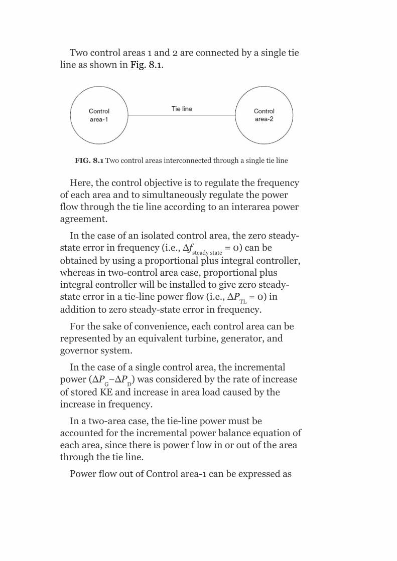
Twocontrolareas1and2areconnectedbyasingletielineasshowninFig.8.1.
FIG.8.1Twocontrolareasinterconnectedthroughasingletieline
Here,thecontrolobjectiveistoregulatethefrequencyofeachareaandtosimultaneouslyregulatethepowerflowthroughthetielineaccordingtoaninterareapoweragreement.
Inthecaseofanisolatedcontrolarea,thezerosteady-stateerrorinfrequency(i.e.,Δf =0)canbeobtainedbyusingaproportionalplusintegralcontroller,whereasintwo-controlareacase,proportionalplusintegralcontrollerwillbeinstalledtogivezerosteady-stateerrorinatie-linepowerflow(i.e.,ΔP =0)inadditiontozerosteady-stateerrorinfrequency.
Forthesakeofconvenience,eachcontrolareacanberepresentedbyanequivalentturbine,generator,andgovernorsystem.
Inthecaseofasinglecontrolarea,theincrementalpower(ΔP −ΔP )wasconsideredbytherateofincreaseofstoredKEandincreaseinarealoadcausedbytheincreaseinfrequency.
Inatwo-areacase,thetie-linepowermustbeaccountedfortheincrementalpowerbalanceequationofeacharea,sincethereispowerflowinoroutoftheareathroughthetieline.
PowerflowoutofControlarea-1canbeexpressedas
steadystate
TL
G D

where∣E ∣and∣E ∣arevoltagemagnitudesofArea-1andArea-2,respectively,δ andδ arethepoweranglesofequivalentmachinesoftheirrespectiveareas,andX isthetie-linereactance.
Ifthereischangeinloaddemandsoftwoareas,therewillbeincrementalchangesinpowerangles(Δδ andΔδ ).Then,thechangeinthetie-linepoweris
Therefore,changeinincrementaltie-linepowercanbeexpressedas
where
1 2
1 2
TL
1
2

T isknownasthesynchronizingcoefficientorthestiffnesscoefficientofthetie-line.
Equation(8.3)canbewrittenas
where Statictransmissioncapacityofthe
tieline.
Considerthechangeinfrequencyas
Inotherwords,
Hence,thechangesinpoweranglesforAreas-1and2are
and
12

Sincetheincrementalpoweranglesarerelatedintermsofintegralsofincrementalfrequencies,Equation(8.2)canbemodifiedas
Δf andΔf aretheincrementalfrequencychangesofAreas-1and2,respectively.Similarly,theincrementaltie-linepoweroutofArea-2is
where
DividingEquation(8.6)byEquation(8.3),weget
Therefore,T =a T
andhence∆P =a ∆P (8.7)
FromEquation(7.25)(LFC-1),surpluspowerinp.u.is
Foratwo-areacase,thesurpluspowercanbeexpressedinp.u.as
1 2
21 12 12
TL2 12 TL1

TakingLaplacetransformonbothsidesofEquation(8.8),weget
Rearrangingtheaboveequationasfollows,weget
where
BycomparingEquation(8.9)withsingle-areaEquation(7.26),theonlyadditionaltermistheappearanceofsignal∆P (S)
Equation(8.9),canberepresentedinablockdiagrammodelasshowninFig.8.2.TakingLaplacetransformationonbothsidesofEquation(8.4),weget
TL1

FIG.8.2BlockdiagramrepresentationofEquation(8.9)(forControlarea-1)
FIG.8.3BlockdiagramrepresentationofEquations(8.10)and(8.11)
ForControlarea-2,wehave
TheblockdiagramrepresentationofEquations(8.10)and(8.11)isshowninFig.8.3.
8.2COMPOSITEBLOCKDIAGRAMOFATWO-AREACASE

BythecombinationofbasicblockdiagramsofControlarea-1andControlarea-2andwiththeuseofFigs.8.2and8.3,thecompositeblockdiagramofatwo-areasystemcanbemodeledasshowninFig.8.4.
8.3RESPONSEOFATWO-AREASYSTEM—UNCONTROLLEDCASE
Foranuncontrolledcase,∆P =∆P =0,i.e.,thespeed-
changerpositionsarefixed.
8.3.1Staticresponse
Inthissection,thechangesordeviations,whichresultinthefrequencyandtie-linepowerundersteady-stateconditionsfollowingsuddenstepchangesintheloadsinthetwoareas,aredetermined.
FIG.8.4Blockdiagramrepresentationofatwo-areasystemwithanLFC
Let∆P ,∆P besudden(incremental)stepchanges
intheloadsofControlarea-1andControlarea-2,
c1 c2
D1 D2

simultaneously.
∆P ,∆P aretheincrementalchangesinthe
generationinArea-1andArea-2asaresultoftheloadchanges.
Δfisthestaticchangeinfrequency.Thiswillbethesameforboththeareasand∆P isthestaticchangein
thetie-linepowertransmittedfromArea-1toArea-2.Sinceonlythestaticchangesarebeingdetermined,theincrementalchangesingenerationcanbedeterminedbythestaticloopgains.So,wehave
and forstaticchanges(8.13)
Forthetwoareas,thedynamicsaredescribedby:
and
Understeady-stateconditions,wehave
G1 G2
TL1

AftersubstitutingEquations(8.12),(8.13),and(8.16)inEquations(8.14)and(8.15),weget
and
Since∆P =−a ∆P and∆f =∆f =∆f,fromEquation
(8.17),wehave
Substituting∆P fromEquation(8.18(a))inEquation
(8.18),weget
SubstitutingΔffromEquation(8.18(b))inEquation(8.18(a)),weget
TL2 12 TL1 1 2
TL1

Equations(8.18(b))and(8.18(c))aremodifiedas
Tie-linefrequency,
Tie-linepower,
where
Equations(8.19)and(8.20)givethevaluesofthestaticchangesinfrequencyandtie-linepower,respectively,asaresultofsuddenstep-loadchangesinthetwoareas.Itcanbeobservedthatthefrequencyandtie-linepowerdeviationsdonotreducetozeroinanuncontrolledcase.
Considertwoidenticalareas,
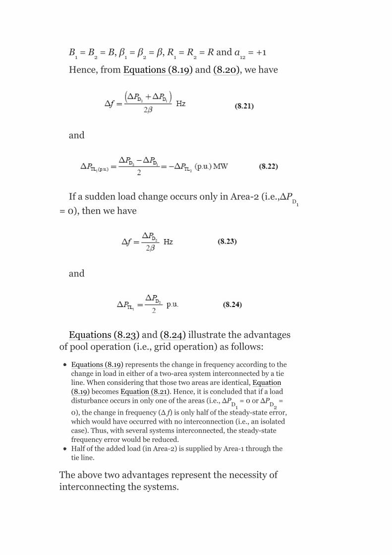
B =B =B,β =β =β,R =R =Randa =+1
Hence,fromEquations(8.19)and(8.20),wehave
and
IfasuddenloadchangeoccursonlyinArea-2(i.e.,∆P
=0),thenwehave
and
Equations(8.23)and(8.24)illustratetheadvantagesofpooloperation(i.e.,gridoperation)asfollows:
Equations(8.19)representsthechangeinfrequencyaccordingtothechangeinloadineitherofatwo-areasysteminterconnectedbyatieline.Whenconsideringthatthosetwoareasareidentical,Equation(8.19)becomesEquation(8.21).Hence,itisconcludedthatifaloaddisturbanceoccursinonlyoneoftheareas(i.e.,∆P =0or∆P =
0),thechangeinfrequency(Δf)isonlyhalfofthesteady-stateerror,whichwouldhaveoccurredwithnointerconnection(i.e.,anisolatedcase).Thus,withseveralsystemsinterconnected,thesteady-statefrequencyerrorwouldbereduced.Halfoftheaddedload(inArea-2)issuppliedbyArea-1throughthetieline.
Theabovetwoadvantagesrepresentthenecessityofinterconnectingthesystems.
1 2 1 2 1 2 12
D1
D1 D2

8.3.2Dynamicresponse
Todescribethedynamicresponseofthetwo-areasystemasshowninFig.8.4,asystemofseventh-orderdifferentialequationsisrequired.Thesolutionoftheseequationswouldbetedious.However,someimportantcharacteristicscanbebroughtoutbyananalysisrenderedsimplebythefollowingassumptions.Apowersystemoftwoidenticalcontrolareasisconsideredfortheanalysis:
1. τ =τ =0forboththeareas.
2. Thedampingconstantsoftwoareasareneglected,
i.e.,B =B =0
Byvirtueofthesecondassumption,Equations(8.14)and(8.15)become
TakingLaplacetransformationonbothsidesofEquations(8.25)and(8.26)andbyrearrangement,weget
FromtheblockdiagramofFig.8.4,thefollowingequationscanbeobtained:
gt t
1 2
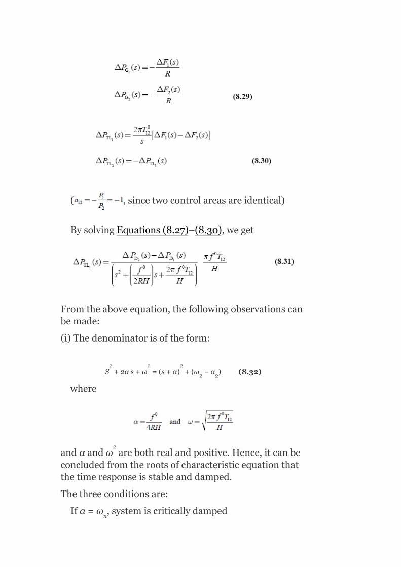
( ,sincetwocontrolareasareidentical)
BysolvingEquations(8.27)–(8.30),weget
Fromtheaboveequation,thefollowingobservationscanbemade:
(i)Thedenominatorisoftheform:
S +2αs+ω =(s+α) +(ω −α )(8.32)
where
andαandω arebothrealandpositive.Hence,itcanbeconcludedfromtherootsofcharacteristicequationthatthetimeresponseisstableanddamped.
Thethreeconditionsare:
Ifα=ω ,systemiscriticallydamped
2 2
n
2 2 2
2

α>ω ,systembecomesoverdamped
whereα=dampingfactorordecrementofattenuation
ω =dampedangularfrequency
SinceparameterαalsodependsonB,but in
practice,therefore,theeffectofcoefficientBisneglectedondamping.
(ii)Afteradisturbance,thechangeintie-linepoweroscillatesatthedampedangularfrequency.
(iii)Thedampingofthetie-linepowervariationisstronglydependentupontheparameterα,whichisequal
to .Sincef andHareessentiallyconstant,the
dampingisafunctionoftheRparameters.IftheRvalueislow,dampingbecomesstrongandviceversa.
Thetransientchangeinthetie-linepowerwillbeofundampedoscillationsoffrequency,ω =ω.
IfR=∞,i.e.,ifthespeedgovernorisnotpresent(α=0),thevariationinfrequencydeviationandthetie-linepowerwouldbeasshowninFig.8.5.
Itcanbeseenthatthesteady-statefrequencydeviationisthesameforboththeareasanddoesnotvanish.Thetie-linepowerdeviationalsodoesnotbecomezero.
n
n
0
o
0

Althoughtheaboveapproximateanalysishasconfirmedstability,ithasbeenfoundthroughmoreaccurateanalysesthatwithcertainparametercombinations,thesystembecomesunstable.
FIG.8.5Frequencydeviationandtie-linepowerchangefollowingastep-loadchangeinArea-2(twoareasareidentical)
Example8.1:Atwo-identicalareapowersystemhasthefollowingparameters(Fig.8.6(a)):
Powersystemgainconstant,K =105
Powersystemtimeconstant,τ =22s
Speedregulation,R=2.5
ps
ps
0
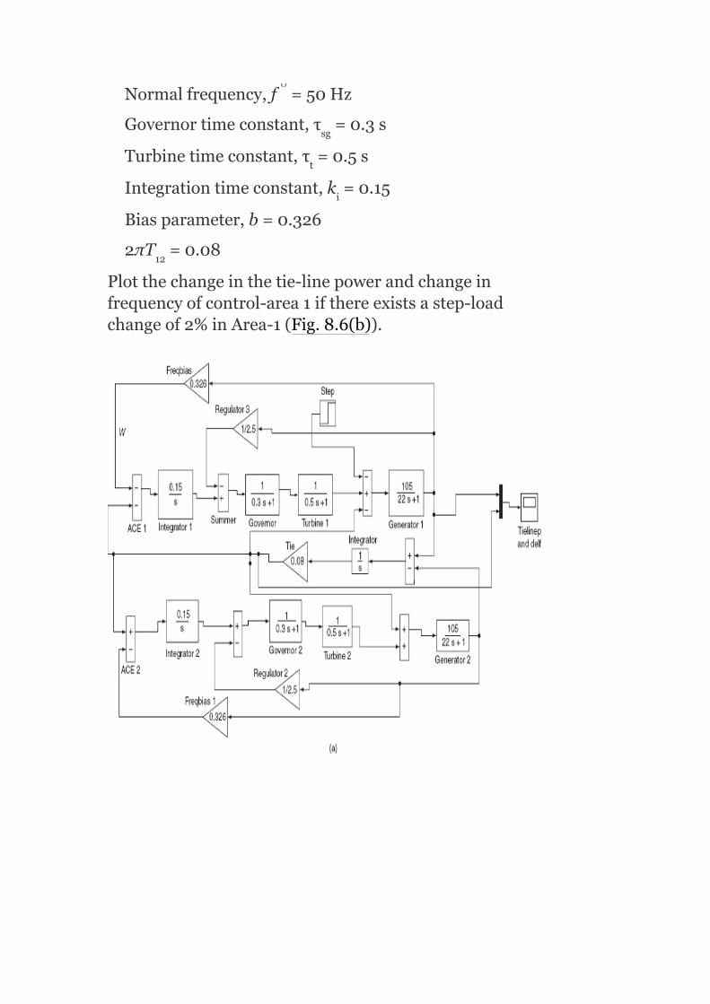
Normalfrequency,f =50Hz
Governortimeconstant,τ =0.3s
Turbinetimeconstant,τ =0.5s
Integrationtimeconstant,k =0.15
Biasparameter,b=0.326
2πT =0.08
Plotthechangeinthetie-linepowerandchangeinfrequencyofcontrol-area1ifthereexistsastep-loadchangeof2%inArea-1(Fig.8.6(b)).
sg
t
i
12
0

FIG.8.6(a)Simulationblockdiagramforatwo-identicalareasystemofExample8.1;(b)frequencyandtie-lineresponseforExample8.1
Example8.2:Atwo-areapowersystemhasthefollowingparameters(Fig.8.7(a)):
ForArea-1:
Powersystemgainconstant,K =120
Powersystemtimeconstant,Ƭ =20s
Speedregulation,R=2.5
Normalfrequency,f =50Hz
Governortimeconstant,Ƭ =0.2s
Turbinetimeconstant,Ƭ =0.4s
Integrationtimeconstant,k =0.1
Biasparameter,b=0.425
ForArea-2:
Powersystemgainconstant,K =100
ps
ps
sg
t
i
ps
0

Powersystemtimeconstant,Ƭ =22s
Speedregulation,R=3
Normalfrequency,f =50Hz
Governortimeconstant,Ƭ =0.3s
Turbinetimeconstant,Ƭ =0.5s
Integrationtimeconstant,k =0.15
Biasparameter,b=0.326
2πT =0.08
Plotthechangeinthetie-linepowerandchangeinfrequencyofControl-area1ifthereexistsastep-loadchangeof2%inArea-1(Fig.8.7(b)).
ps
sg
t
i
12
0

FIG.8.7(a)SimulationblockdiagramofExample8.2;(b)Frequencyandtie-linepowerresponseofExample8.2
Example8.3:Determinethefrequencyofoscillationsofthetie-linepowerdeviationforatwo-identical-areasystemgiventhefollowingdata:
R=3.0Hz/p.u.;H=5s;f =60Hz
Thetie-linehasacapacityof0.1p.u.andisoperatingatapowerangleof45°.
Solution:
Thesynchronizing-powercoefficientofthelineisgivenby
T =P cosδ =0.1×cos45°=0.0707p.u.
Hence,thefrequencyofoscillationsisgivenby
m 12
0
012

8.4AREACONTROLERROR—TWO-AREACASE
Inasingle-areacase,ACEisthechangeinfrequency.Thesteady-stateerrorinfrequencywillbecomezero(i.e.,Δf =0)whenACEisusedintheintegral-controlloop.
Inatwo-areacase,ACEisthelinearcombinationofthechangeinfrequencyandchangeintie-linepower.Inthiscasetomakethesteady-statetie-linepowerzero(i.e.,ΔP =0),anotherintegral-controlloopforeachareamustbeintroducedinadditiontotheintegralfrequencylooptointegratetheincrementaltie-linepowersignalandfeeditbacktothespeed-changer.
Thus,forControlarea-1,wehave
ACE =∆P +b ∆f (8.33)
whereb =constant=areafrequencybias.TakingLaplacetransformonbothsidesofEquation(8.33),weget
ACE (s)=∆P (s)+b ∆F (s)(8.34)
Similarly,forControlarea-2,wehave
ACE (s)=∆P (s)+b ∆F (s)(8.35)
8.5COMPOSITEBLOCKDIAGRAMOFATWO-AREASYSTEM
ss
TL
1 TL1 1 1
1
1 TL1 1 1
2 TL2 2 2

(CONTROLLEDCASE)
BythecombinationofbasicblockdiagramsofControlarea-1andControlarea-2andwiththeuseofFigs.8.2and8.3,thecompositeblockdiagramofatwo-areasystemcanbemodeledasshowninFig.8.4.Figure8.8canbeobtainedbytheadditionofintegralsofACE andACE totheblockdiagramshowninFig.8.4.Itrepresentsthecompositeblockdiagramofatwo-areasystemwithintegral-controlloops.Here,thecontrolsignals∆P (s)and∆P (s)aregeneratedbytheintegrals
ofACE andACE .Thesecontrolerrorsareobtainedthroughthesignalsrepresentingthechangesinthetie-linepowerandlocalfrequencybias.
8.5.1Tie-linebiascontrol
Thespeed-changercommandsignalswillbeobtainedfromtheblockdiagramshowninFig.8.6as
and
TheconstantsK andK arethegainsofthe
integrators.Thefirsttermsontheright-handsideofEquations(8.36)and(8.37)constituteandareknownastie-linebiascontrols.Itisobservedthatfordecreasesinbothfrequencyandtie-linepower,thespeed-changerpositiondecreasesandhencethepowergenerationshoulddecrease,i.e.,iftheACEisnegative,thentheareashouldincreaseitsgeneration.
So,theright-handsidetermsofEquations(8.36)and(8.37)areassignedanegativesign.
1
2
c1 c2
1 2
I1 I2

8.5.2Steady-stateresponse
Thatthecontrolstrategy,describedintheprevioussection,eliminatesthesteady-statefrequencyandtie-linepowerdeviationsthatfollowastep-loadchange,canbeprovedasfollows:
FIG.8.8Two-areasystemwithintegralcontrol
Letthestepchangesinloads∆P and∆P
simultaneouslyoccurinControlarea-1andControlarea-2,respectively,orineitherarea.Anewstaticequilibrium
D1 D2

state,i.e.,steady-stateconditionisreachedsuchthattheoutputsignalofallintegratingblockswillbecomeconstant.Inthiscase,thespeed-changercommandsignals∆P and∆P havereachedconstantvalues.This
obviouslyrequiresthatboththeintegrands(inputsignals)inEquations(8.36)and(8.37)bezero.
Inputofintegratingblock is
∆P +b ∆f =0(8.38)
Inputofintegratingblock is
∆P +b ∆f =0(8.39)
andinputofintegratingblock is
∆f −∆f =0(8.40)
Equations(8.38)and(8.39)aresimultaneouslysatisfiedonlyfor∆P =∆P =0and∆f =∆f
=0.
Thus,underasteady-statecondition,changeintie-linepowerandchangeinfrequencyofeachareawillbecomezero.Toachievethis,ACEsinthefeedbackloopsofeachareaareintegrated.
Therequirementsforintegralcontrolactionare:
1. ACEmustbeequaltozeroatleastonetimeinall10-minuteperiods.2. AveragedeviationofACEfromzeromustbewithinspecifiedlimits
basedonapercentageofsystemgenerationforall10-minuteperiods.
c1 c2
TL (ss)1 1 1(ss)
TL (ss)2 2 2(ss)
1 2
TL (ss)1 TL (ss)2 1(ss) 2(ss)

Theperformancecriteriaalsoapplytodisturbanceconditions,anditisrequiredthat:
1. ACEmustreturntozerowithin10-minuteperiods.2. Correctivecontrolactionmustbeforthcomingwithin1minuteofa
disturbance.
8.5.3Dynamicresponse
Thedeterminationofthedynamicresponseofthetwo-areamodelshowninFig.8.6ismoredifficult.Thisisduetothefactthatthesystemofequationstobesolvedisoftheorderofnine.Therefore,actualsolutionisnotattempted.Buttheresultsobtainedfromanapproximateanalysisofatwo-identical-areapowersystemforthreedifferentvaluesoftheparameter‘b’,arepresentedinFigs.8.9(a),(b),and(c).
ThegraphsofFig.8.9(a)correspondtothecaseofb=0.Itcanbeseenthatthetie-linepowerdeviationreducestozerowhilethefrequencydoesnot.
ThegraphsofFig.8.9(b)correspondtotheotherextremecaseofb=∞.Now,thefrequencyerrorvanishes.But,thetie-linepowerdoesnotvanish.
ThegraphsofFig.8.9(c)showanintermediatecasewhereinboththefrequencyandthetie-linepowererrorsdecreasetozero.Thisisthedesiredcase.
Therefore,itcanbeconcludedthatthestabilityisnotalwaysguaranteed.Hence,thereisaneedforproperparameterselectionandadjustmentoftheirvalues.
8.6OPTIMUMPARAMETERADJUSTMENT
ThegraphsgiveninFig.8.9(c)stresstheneedforproperparametersettings.ThechoiceofbandK constantsaffectsthetransientresponsetoloadchanges.Thefrequencybiasbshouldbehighenoughsuchthateachareaadequatelycontributestofrequencycontrol.Itisprovedthatchoosingb=βgivessatisfactoryperformanceoftheinterconnectedsystem.
I
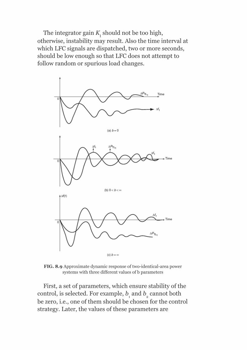
TheintegratorgainK shouldnotbetoohigh,otherwise,instabilitymayresult.AlsothetimeintervalatwhichLFCsignalsaredispatched,twoormoreseconds,shouldbelowenoughsothatLFCdoesnotattempttofollowrandomorspuriousloadchanges.
FIG.8.9Approximatedynamicresponseoftwo-identical-areapowersystemswiththreedifferentvaluesofbparameters
First,asetofparameters,whichensurestabilityofthecontrol,isselected.Forexample,b andb cannotbothbezero,i.e.,oneofthemshouldbechosenforthecontrolstrategy.Later,thevaluesoftheseparametersare
I
1 2

adjustedsothatabestoranoptimumresponseisobtained.Inotherwords,thevaluesofparameters,whichgiverisetoanoptimumresponse,aretobedetermined.
Theprocedureisasfollows:
Thepopularerrorcriterion,knownastheintegralofthesquarederrors(ISE),ischosenforthecontrolparameters∆f ,∆f ,and∆P .Foratwo-areasystem,the
ISEcriterionfunctionCwouldbe
whereα ,α ,andα aretheweightfactors,whichprovideappropriateimportance,i.e.,weightagetotheerrors∆P ,Δf ,andΔf .Thereisnoneedtochoose∆P ,
since∆P =a ∆P .
SinceΔf andΔf behaveinasimilarmanner,weneedtoconsideronlyoneofthem.So,letusconsiderΔf only.Thisisaparameterselection.Then,α =0.Also,letα =α.Since,weareinterestedonlyintherelativemagnitudesofCforparametersetting,wecansetα =1.
Withthese,Equation(7.41)reducesto
Foratwo-areasystem,∆P andΔf wouldbe
functionsoftheintegratorgainconstantsK andK as
wellasthefrequencybiasparametersb andb .
Theprocedureforobtainingtheoptimumparametervalueswouldbeasfollows:
First,aconvenientandsuitablevalueischosenfortheweightfactor‘α’.Then,fordifferentassumedvaluesof
1 2 TL1
1 2 3
TL1 1 2 TL2
TL2 12 TL1
1 2
1
3 2
1
TL2 1
I1 I2
1 2

K ,K ,b ,andb ,thevaluesof∆P andΔf are
determinedatdifferentinstantsoftime.Withthesevaluesandα,thevalueofCiscomputedusingEquation(8.42).ThesetofvaluesofK ,K ,b ,andb forwhichC
isaminimumistheoptimumone.
Ifweconsiderthetwoidenticalareas,thenthenumberofparametersreducestotwo,viz.,K =K =K andb =
b =b.Inthiscase,valuesofCfordifferentvaluesofKandbcanbeplottedasshowninFig.8.10.Ascanbeseen,thevariationofCwithK fordifferentfixedvaluesofbisplottedtogetafamilyofcurvescalledconstant-bcontours.Forillustration,onlythreecurvesareshowninFig.8.10.Inpractice,anumberofcurveshavetobedeterminedanddrawn.ItcanbeseenthatCisminimumforb=0.2andK =1.0.
Inthiscase,theoptimumcontrolstrategywould,therefore,be
and
Inpractice,thefrequencyandtie-linepowerdeviationsaremeasuredatfixedintervalsoftimeinasample-datafashion.Thesamplingrate(therateatwhichthefrequencydeviationandtie-linepowerdeviationsamplesaremeasured)shouldbesufficientlyhightoavoiderrorsduetosampling.
Note:LFCprovidesenoughcontrolduringnormalchangesinloadandfrequency,i.e.,changesthatarenottoolarge.Duringemergencies,whenlargeimbalancesbetweengenerationandloadoccur,LFCisbypassedand
I1 I2 1 2 TL1 1
I1 I2 1 2
I1 I2 1 1
2 I
I
I

otheremergencycontrolsareapplied,whichisbeyondthescopeofthisbook.
FIG.8.10Constantb-contoursoftheISEcriterionfunctionC
8.7LOADFREQUENCYANDECONOMICDISPATCHCONTROLS
EconomicloaddispatchandLFCplayavitalroleinmodernpowersystem.InLFC,zerosteady-statefrequencyerrorandafast,dynamicresponsewereachievedbyintegralcontrolleraction.Butthiscontrolisindependentofeconomicdispatch,i.e.,thereisnocontrolovertheeconomicloadingsofvariousgeneratingunitsofthecontrolarea.
Somecontroloverloadingofindividualunitscanbeexercisedbyadjustingthegainfactors(K )oftheintegralsignaloftheACEasfedtotheindividualunits.Butthisisnotasatisfactorysolution.
Asuitableandsatisfactorysolutionisobtainedbyusingindependentcontrolsofloadfrequencyandeconomicdispatch.Theloadfrequencycontrollerprovidesafast-actingcontrolandregulatesthesystemaroundanoperatingpoint,whereastheeconomic
I

dispatchcontrollerprovidesaslow-actingcontrol,whichadjuststhespeed-changersettingseveryminuteinaccordancewithacommandsignalgeneratedbythecentraleconomicdispatchcomputer.
EDC—economicdispatchcontroller
CEDC—centraleconomicdispatchcomputer
Thespeed-changersettingischangedinaccordancewiththeeconomicdispatcherrorsignal,(i.e.,P −P )convenientlymodifiedbythesignal∫ACEdtatthatinstantoftime.Thecentraleconomicdispatchcomputer(CEDC)providesthesignalP ,andthissignalistransmittedtothelocaleconomicdispatchcontroller(EDC).Thesystemtheyoperatewitheconomicdispatcherrorisonlyforveryshortperiodsoftimebeforeitisreadilyused(Fig.8.11).
ThistertiarycontrolcanbeimplementedbyusingEDCandEDCworksonthecostcharacteristicsofvariousgeneratingunitsinthearea.Thespeed-changersettingsareonceagainoperatedinaccordancewithaneconomicdispatchcomputerprogram.
G(desired)
G(actual)
G(desired)

FIG.8.11Loadfrequencyandeconomicdispatchcontrolofthecontrolareaofapowersystem
TheCEDCsareprovidedatacentralcontrolcenter.Thevariablepartoftheloadiscarriedbyunitsthatarecontrolledfromthecentralcontrolcenter.Medium-sizedfossilfuelunitsandhydro-unitsareusedforcontrol.Duringpeakloadhours,lesserefficientunits,suchasgas-turbineunitsordieselunits,areemployedinaddition;generatorsoperatingatpartialoutput(withspinningreserve)andstandbygeneratorsprovideareservemargin.
Thecentralcontrolcentermonitorsinformationincludingareafrequency,outputsofgeneratingunits,

andtie-linepowerflowstointerconnectedareas.ThisinformationisusedbyALFCinordertomaintainareafrequencyatitsscheduledvalueandnettie-linepowerflowoutoftheareaatitssheddingvalue.Raiseandlowerreferencepowersignalsaredispatchedtotheturbinegovernorsofcontrolledunits.
Economicdispatchisco-ordinatedwithLFCsuchthatthereferencepowersignalsdispatchedtocontrolledunitsmovetheunitstowardtheireconomicloadingandsatisfyLFCobjectives.
8.8DESIGNOFAUTOMATICGENERATIONCONTROLUSINGTHEKALMANMETHOD
Amoderngigawattgeneratorwithitsmultistagereheatturbine,includingitsautomaticloadfrequencycontrol(ALFC)andautomaticvoltageregulator(AVR)controllers,ischaracterizedbyanimpressivecomplexity.Whenallitsnon-negligibilitydynamicsaretakenintoaccount,includingcross-couplingbetweencontrolchannels,theoveralldynamicmodelmaybeofthetwentiethorder.
Thedimensionalitybarriercanbeovercomebymeansofcomputer-aidedoptimalcontroldesignmethodsoriginatedbyKalman.Acomputer-orientedtechniquecalledoptimumlinearregulator(OLR)designhasproventobeparticularlyusefulinthisregard.
TheOLRdesignresultsinacontrollerthatminimizesbothtransientvariableexcursionsandcontrolefforts.Intermsofpowersystem,thismeansoptimallydampedoscillationwithminimumwearandtearofcontrolvalves.
OLRcanbedesignedusingthefollowingsteps:
1. Castingthesystemdynamicmodelinstate-variableformandintroducingappropriatecontrolforces.
2. Choosinganintegral-squared-errorcontrolindex,theminimizationofwhichisthecontrolgoal.
3. Findingthestructureoftheoptimalcontrollerthatwillminimizethe

chosencontrolindex.
8.9DYNAMIC-STATE-VARIABLEMODEL
TheLFCmethodsdiscussedsofararenotentirelysatisfactory.Inordertohavemoresatisfactorycontrolmethods,optimalcontroltheoryhastobeused.Forthispurpose,thepowersystemmodelmustbeinastate-variablemodel.
8.9.1Modelofsingle-areadynamicsysteminastate-variableform
Fromtheblockdiagramofanuncontrolledsingle-areasystemshowninFig.8.12,wegetthefollowing‘s-domain’equations:
Intimedomain,theaboveequationscanbeexpressedas

FIG.8.12State-spacemodelofasingle-areasystem
Letuschoosethestatevariables ,input,u=
ΔP ,anddisturbance,d=ΔP
Theaboveequationsarewritteninastate-variableform:
Thestateequationwouldthenbewritteninamoregeneralformas
Ẋ=Ax+Bu+Jp
C D

wherexisthen-dimensionalstatevector,uthem-dimensionalcontrol-forcevector=[u]=[ΔP ],andpthedisturbanceforcevector=[p]=[ΔP ].
8.9.2Optimumcontrolindex(I)
Theoptimumlinearregulatordesignisbasedontheintegral-squared-errorindexoftheform.
whereq’sandr’sarepositivepenaltyfactors.LetusconsiderindexIforasingle-areasystemas
Here,theideaofoptimumcontrolistominimizetheindex(I).Considerthetermq (Δf) ,squaringoffrequencyerrorwillcontributeto‘I’independentofitssign.IfΔfisdoubled,itscontributionto‘I’willquadruple.TheintegralcausesΔftoaddto‘I’duringitsentireduration.Thepenaltyfactorsq distributethepenaltyweightamongthestate-variableerrors.Iftheerrorinaparticularvariableisoflittlesignificance,wesimplysetitspenaltyfactortozero.
Similarly,inthecaseofcontrol-forceincrements,thepenaltyfactorsr distributethepenaltiesamongthemcontrolforce.(Here,noneofr’saresettozero.)Iftheyaresettozero,thenthecontrolforcewillassumeaninfinitemagnitudewithoutaffecting‘I’.Aninfinitecontrolforcecoulddoitscorrectingjobinzerotime.Thiswouldobviouslybeaveryunrealisticregulator.
Ifallq’sandr’sconstitutethediagonalelementsofthetwopenaltymatrices,thenwehave
c
D
3
i
i
2

Index-Iinacompactformis
8.9.3Optimumcontrolproblemandstrategy
ThetaskthatanOLRoranoptimumcontrollermustperformisthefulfillmentoftheoptimumcontrolproblem,whichcanbestatedasfollows:considerasystemthatisinitiallyundersteady-statecondition.Ifitisdisturbedbyasetofsteptypeofdisturbances,itgoesthroughatransientstatefirst.Itisrequiredthat,aftertheexpiryofthetransientperiod,itshouldreturntotheoriginalornewprescribedsteady-statecondition.Theproblemistodeterminethesetofcontrolforceswhichwillnotonlytakethesystemtotheoriginalornewprescribedsteadystate,butwillalsodosobysimultaneouslyminimizingthechosencontrolcriterionfunctionoroptimumcontrolindex(I).
Thevalueof whichfulfillstheaboveoptimumcontrolrequirement,isthedesiredoptimumcontrolstrategy.AnoptimumcontrollerorOLRistheonethatcarriesouttheabovestrategy.
8.9.4Dynamicequationsofatwo-areasystem
Fromtheblockdiagramofuncontrolledtwo-areasystemsshowninFig.8.4,getthefollowing‘s-domain’equations:

whereX (s)andX (s)aretheLaplacetransformsofthe
movementsofthemainpositionsinthespeed-governingmechanismsofthetwoareas.
BytakinginverseLaplacetransformfortheaboveequations,wegetasetofsevendifferentialequations.Thesearethetime-domainequations,whichdescribethesmall-disturbancedynamicbehaviorofthepowersystem.
Considerthefirstequation,
TakingtheinverseLaplacetransformoftheaboveequation,weget
E1 E2

Inasimilarway,theremainingequationscanberearrangedandaninverseLaplacetransformisfound.Then,theentiresetofdifferentialequationsis
8.9.4.1Statevariablesandstate-variablemodel
Thestatevariablesareaminimumnumberofthosevariables,whichcontainsufficientinformationaboutthepasthistorywithwhichallfuturestatesofthesystemcanbedeterminedforknowncontrolinputs.Forthetwo-areasystemunderconsideration,thestatevariableswouldbeΔf ,Δf ,∆X ,∆X ,∆P ,∆P and∆P ;seven
innumber.Denotingtheabovevariablesbyx ,x ,x ,x ,x ,x ,andx andarrangingtheminacolumnvectoras
1 2 E1 E2 sg1 sg2 TL1
1 2 3 4
5 6 7

where iscalledastatevector.
Thecontrolvariables∆P and∆P aredenotedbythe
symbolsu andu ,respectively,as
whereūiscalledthecontrolvectororthecontrol-forcevector.
Thedisturbancevariables∆P and∆P ,sincethey
createperturbationsinthesystem,aredenotedbyp andp ,respectively,as
where iscalledthedisturbancevector.
Theabovestateequationscanbewritteninamatrixformas
c1 c2
1 2
D1 D2
1
2

where ;i=1,2,3,…7.
Theabovematrixequationcanbewritteninthevectorformas
where[A]iscalledthesystemmatrix,[B]theinputdistributionmatrix,and[J]thedisturbancedistributionmatrix.
Inthepresentcase,theirdimensionsare(7×7),(7×2),and(7×2),respectively.Equation(8.45)isashorthandformofEquation(8.44),andEquation(8.44)

constitutesthedynamic‘state-variablemodel’oftheconsideredtwo-areasystem.
Thedifferentialequationscanbeputintheaboveformonlyiftheyarelinear.Ifthedifferentialequationsarenon-linear,thentheycanbeexpressedinthemoregeneralformas
8.9.5State-variablemodelforathree-areapowersystem
TheblockdiagramrepresentationofthismodelisshowninFig.8.13.
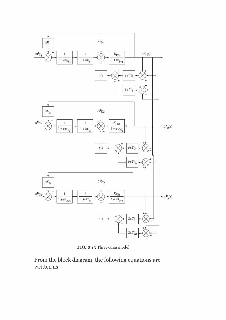
FIG.8.13Three-areamodel
Fromtheblockdiagram,thefollowingequationsarewrittenas

TakingtheinverseLaplacetransformfortheaboveequations,whichwegetinasimilarway,theremainingequationscanberearrangedandtheinverseLaplacetransformcanbefound.Then,theentiresetofdifferentialequationsis

and
and
and
Theaboveequationsarewritteninavectorformasshownbelow:
Ẋ=[A]X+[B]ū+[J]

where
whereXiscalledastatevector.
Thecontrolvariables∆P ,∆P ,and∆P aredenoted
bythesymbolsu ,u ,andu ,respectively,as
whereuiscalledthecontrolvectororthecontrol-forcevector.
Thedisturbancevariables∆P ,∆P ,and∆P ,since
theycreateperturbationsinthesystem,aredenotedbyp ,p ,andp ,respectively,as
c1 c2 c1
1 2 3
D1 D2 D1
1 2 3
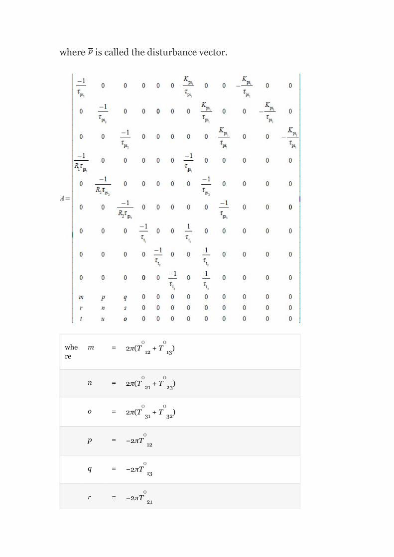
where iscalledthedisturbancevector.
where
m = 2π(T +T )
n = 2π(T +T )
o = 2π(T +T )
p = −2πT
q = −2πT
r = −2πT
12 13
21 23
31 32
12
13
21
0 0
0 0
0 0
0
0
0

s = −2πT
t = −2πT
ū = −2πT
23
31
32
0
0
0
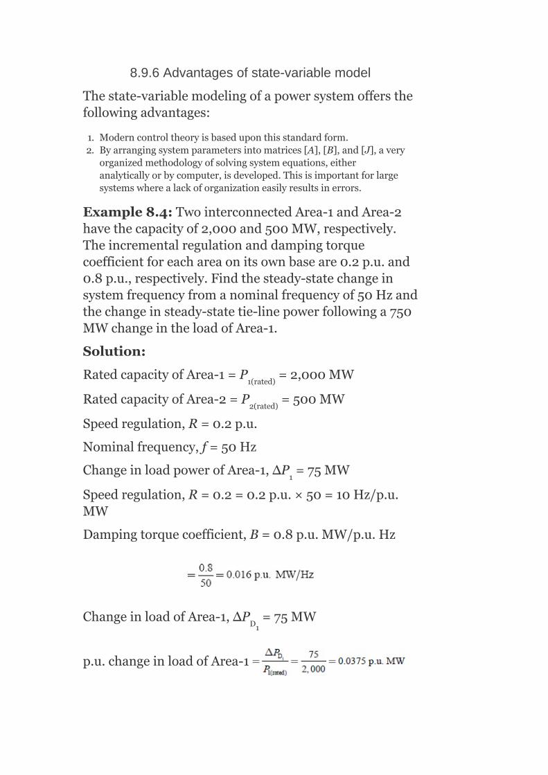
8.9.6Advantagesofstate-variablemodel
Thestate-variablemodelingofapowersystemoffersthefollowingadvantages:
1. Moderncontroltheoryisbaseduponthisstandardform.2. Byarrangingsystemparametersintomatrices[A],[B],and[J],avery
organizedmethodologyofsolvingsystemequations,eitheranalyticallyorbycomputer,isdeveloped.Thisisimportantforlargesystemswherealackoforganizationeasilyresultsinerrors.
Example8.4:TwointerconnectedArea-1andArea-2havethecapacityof2,000and500MW,respectively.Theincrementalregulationanddampingtorquecoefficientforeachareaonitsownbaseare0.2p.u.and0.8p.u.,respectively.Findthesteady-statechangeinsystemfrequencyfromanominalfrequencyof50Hzandthechangeinsteady-statetie-linepowerfollowinga750MWchangeintheloadofArea-1.
Solution:
RatedcapacityofArea-1=P =2,000MW
RatedcapacityofArea-2=P =500MW
Speedregulation,R=0.2p.u.
Nominalfrequency,f=50Hz
ChangeinloadpowerofArea-1,ΔP =75MW
Speedregulation,R=0.2=0.2p.u.×50=10Hz/p.u.MW
Dampingtorquecoefficient,B=0.8p.u.MW/p.u.Hz
ChangeinloadofArea-1,∆P =75MW
p.u.changeinloadofArea-1
1(rated)
2(rated)
1
D1

p.u.changeinloadofArea-2
Steady-statechangeinsystemfrequency,
where
Steady-statechangeintie-linepowerfollowingloadchangeinArea-1:

Example8.5:SolveExample8.4,withoutgovernorcontrolaction.
Solution:
Withoutthegovernorcontrolaction,R=0
Steady-statechangeintie-linepowerfollowingloadchangeinArea-1:
Itisobservedfromtheresultthatthepowerflowthroughthetielineisthesameinboththecasesofwithgovernoractionandwithoutgovernoraction,sinceitdoesnotdependonspeedregulationR.
Example8.6:Findthenatureofdynamicresponseifthetwoareasoftheaboveproblemareofuncontrolledtype,followingadisturbanceineitherareaintheformofastepchangeinelectricload.TheinertiaconstantofthesystemisgivenasH=3sandassumethatthetieline

hasacapacityof0.09p.u.andisoperatingatapowerangleof30 beforethestepchangeinload.
Solution:
Given:
Speedregulation,R=0.2p.u.=0.2×50=10Hz/p.u.MW
Dampingcoefficient,B=0.8p.u.MW/p.u.Hz
Inertiaconstant,H=3s
Nominalfrequency,f =50Hz
Tie-linecapacity,
Fromthetheoryofdynamicresponse,weknowthat
Itisobservedthatthedampedoscillationtypeofdynamicresponsehasresultedsinceα<ω :
∴Dampedangularfrequencyn
o
0

∴Dampedfrequency=f
Example8.7:Twocontrolareashavethefollowingcharacteristics:
Area-1: Speedregulation=0.02p.u.
Dampingcoefficient=0.8p.u.
RatedMVA=1,500
Area-2: Speedregulation=0.025p.u.
Dampingcoefficient=0.9p.u.
RatedMVA=500
Determinethesteady-statefrequencychangeandthechangedfrequencyfollowingaloadchangeof120MW,whichoccursinArea-1.Alsofindthetie-linepowerflowchange.
Solution:
GivenR =0.1p.u.;R =0.098p.u.
B =0.8p.u.;B =0.9p.u.
P =1,500MVA;P =1,500MVA
ChangeinloadofArea-1,
d
1 2
1 2
1rated 2rated

∆P =120MW,∆P =0
p.u.changeinloadofArea-1
∴Steady-statefrequencychange,
i.e.,Steady-statechangeinfrequency,∆f = 0.0012415×50
= 0.062Hz
∴Newvalueoffrequency,f=f −∆f = 50−0.062
= 49.937Hz
Steady-statechangeintie-linepower
D1 D2
ss
ss
0

Example8.8:InExample8.6,ifthedisturbancealsooccursinArea-2,whichresultsinachangeinloadby75MW,determinethefrequencyandtie-linepowerchanges.
Solution:
ChangeinloadofArea-1,∆P =120MW
p.u.changeinloadofArea-1
ChangeinloadofArea-2,∆P =75MW
p.u.changeinloadofArea-2
Steady-statefrequencychange,
∴Steady-statefrequencychange=0.002×50=0.1Hz
∴Newvalueoffrequency=f −Δf =50−0.1=49.899Hz
Steady-statechangeintie-linepower,
D1
D2
ss
0
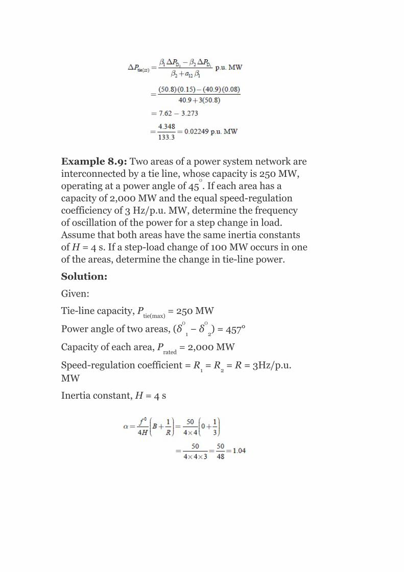
Example8.9:Twoareasofapowersystemnetworkareinterconnectedbyatieline,whosecapacityis250MW,operatingatapowerangleof45 .Ifeachareahasacapacityof2,000MWandtheequalspeed-regulationcoefficiencyof3Hz/p.u.MW,determinethefrequencyofoscillationofthepowerforastepchangeinload.AssumethatbothareashavethesameinertiaconstantsofH=4s.Ifastep-loadchangeof100MWoccursinoneoftheareas,determinethechangeintie-linepower.
Solution:
Given:
Tie-linecapacity,P =250MW
Powerangleoftwoareas,(δ −δ )=457°
Capacityofeacharea,P =2,000MW
Speed-regulationcoefficient=R =R =R=3Hz/p.u.MW
Inertiaconstant,H=4s
tie(max)
1 2
rated
1 2
o
0 0
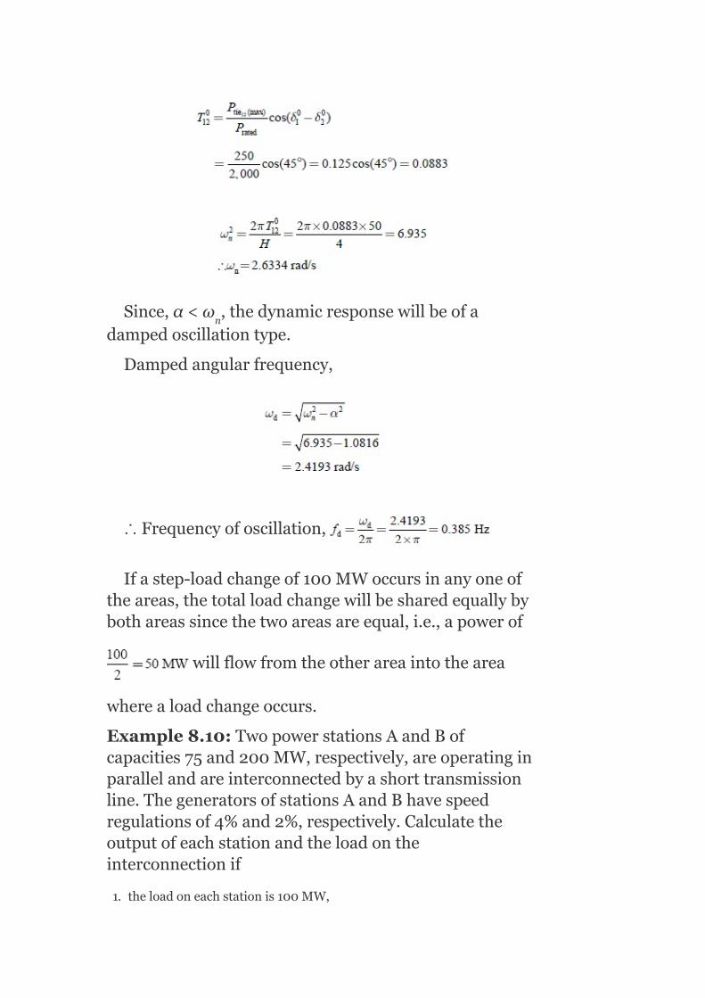
Since,α<ω ,thedynamicresponsewillbeofadampedoscillationtype.
Dampedangularfrequency,
∴Frequencyofoscillation,
Ifastep-loadchangeof100MWoccursinanyoneoftheareas,thetotalloadchangewillbesharedequallybybothareassincethetwoareasareequal,i.e.,apowerof
willflowfromtheotherareaintothearea
wherealoadchangeoccurs.
Example8.10:TwopowerstationsAandBofcapacities75and200MW,respectively,areoperatinginparallelandareinterconnectedbyashorttransmissionline.ThegeneratorsofstationsAandBhavespeedregulationsof4%and2%,respectively.Calculatetheoutputofeachstationandtheloadontheinterconnectionif
1. theloadoneachstationis100MW,
n

2. theloadsonrespectivebusbarsare50and150MW,and3. theloadis130MWatStationAbusbaronly.
Solution:
Given:
CapacityofStation-A=75MW
CapacityofStation-B=200MW
SpeedregulationofStation-Agenerator,R =4%
SpeedregulationofStation-Bgenerator,R =2%
(a)Iftheloadoneachstation=100MW
i.e.,P +P =100+100=200MW(8.47)
Speedregulation
∴(1−f)=0.0001P (8.49)
FromEquations(8.48)and(8.49),wehave
0.000533P =0.0001P
5.33P =P (8.50)
P +P =200
SubstitutingEquation(8.50)inEquation(8.47),weget
A
B
1 2
2
1 2
1 2
1 2

Thepowergenerationsandtie-linepowerareindicatedinFig.8.14(a).
(b)Iftheloadonrespectivebusbarsare50and150MW,thenwehave
i.e.,P +P =50+150=200MW
5.33P =P
P +5.33P =200
⇒6.33P =200
P =31.6MW
∴P =200−31.60=168.4MW
Thepowergenerationsandtie-linepowerareindicatedinFig.8.14(b).
1 2
1 2
1 1
1
1
2

FIG.8.14(a)IllustrationforExample8.10;(b)illustrationforExample8.10;(c)illustrationforExample8.10
(c)Iftheloadis130MWatAonly,thenwehave
P +P =130
5.33P =P
1 2
1 2

∴P =5.33P =130
6.33P =130
⇒P =20.537MW
∴P =130−P =109.462MW
Thepowergenerationsandtie-linepowerareindicatedinFig.8.14(c).
Example8.11:Thetwocontrolareasofcapacity2,000and8,000MWareinterconnectedthroughatieline.TheparametersofeachareabasedonitsowncapacitybaseareR=1Hz/p.u.MWandB=0.02p.u.MW/Hz.Ifthecontrolarea-2experiencesanincrementinloadof180MW,determinethestaticfrequencydropandthetie-linepower.
Solution:
CapacityofArea-1=2,000MW
CapacityofArea-2=8,000MW
Taking8,000MWasbase,
∴SpeedregulationofArea-1,
DampingcoefficientofArea-1,
SpeedregulationofArea-2,R =1Hz/p.u.MW
DampingcoefficientofArea-2,B =0.02p.u.MW/Hz
1 1
1
1
2 1
2
2
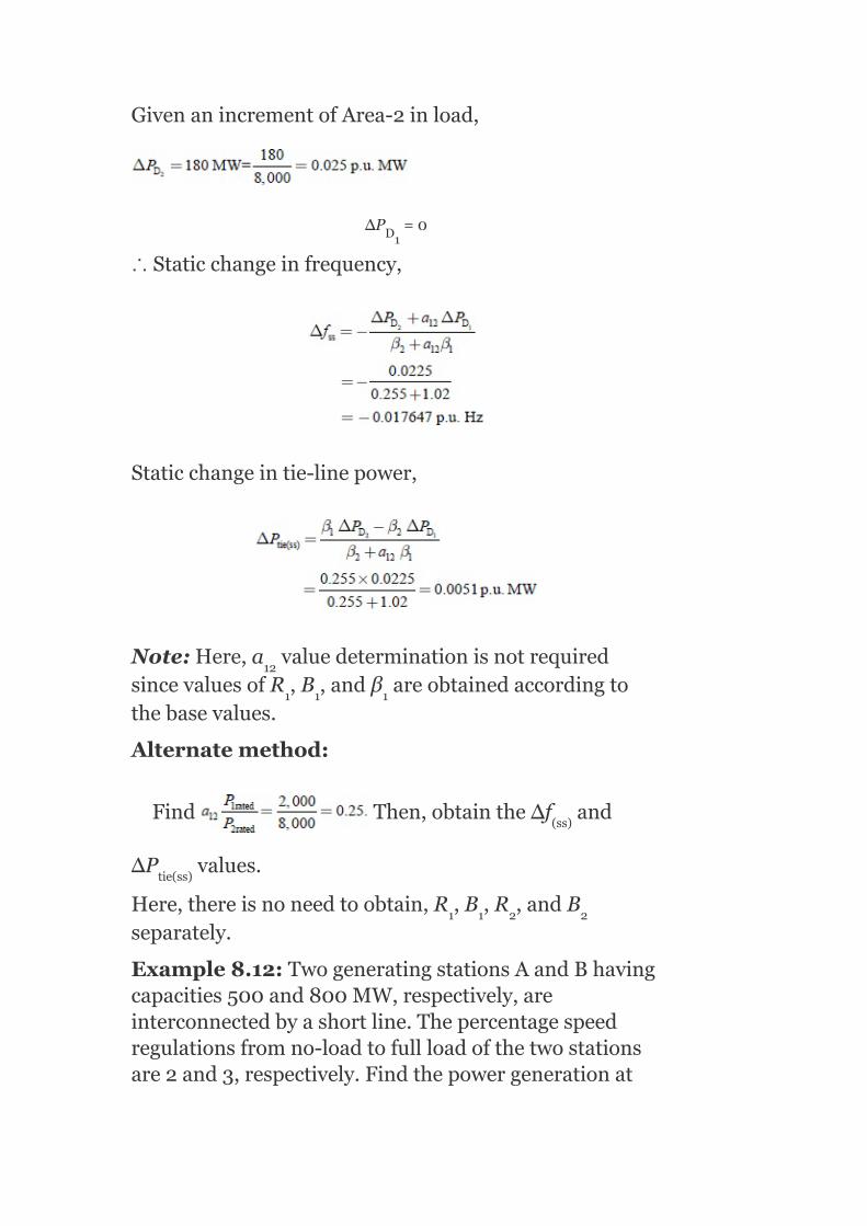
GivenanincrementofArea-2inload,
∆P =0
∴Staticchangeinfrequency,
Staticchangeintie-linepower,
Note:Here,a valuedeterminationisnotrequiredsincevaluesofR ,B ,andβ areobtainedaccordingtothebasevalues.
Alternatemethod:
Find Then,obtainthe∆f and
∆P values.
Here,thereisnoneedtoobtain,R ,B ,R ,andBseparately.
Example8.12:TwogeneratingstationsAandBhavingcapacities500and800MW,respectively,areinterconnectedbyashortline.Thepercentagespeedregulationsfromno-loadtofullloadofthetwostationsare2and3,respectively.Findthepowergenerationat
D1
12
1 1 1
(ss)
tie(ss)
1 1 2 2

eachstationandpowertransferthroughthelineiftheloadonthebusofeachstationis200MW.
Solution:
Givendata:
CapacityofStation-A=500MW
CapacityofStation-B=800MW
PercentagespeedregulationofStation-A=2%=0.02
PercentagespeedregulationofStation-B=3%=0.03
Loadonbusofeachstation=P =P =200MW
Totalload,P =400MW
SpeedregulationofStation-A:
SpeedregulationofStation-B:
LetP bethepowergenerationofStation-AandPthepowergenerationofStation-B:
P =Totalload−P =(400−P )
⇒0.002P =0.001875(400−P )
=0.75=193.55MW
(0.002+0.001875)P =0.75
⇒ P = 193.55MW
P = 206.45MW
DA DB
D
GA GB
GB GA GA
GA GA
GA
GA
GB

P = 193.55MW
∴ P = 206.45MW
ThepowertransferthroughthelinefromStation-Btostation-A
=P −(loadatbusbarofB)
=206.45−200
=6.45MW
Example8.13:Twocontrolareasof1,000and2,000MWcapacitiesareinterconnectedbyatieline.Thespeedregulationsofthetwoareas,respectively,are4Hz/p.u.MWand2.5Hz/p.u.MW.Considera2%changeinloadoccursfor2%changeinfrequencyineacharea.Findsteady-statechangeinfrequencyandtie-linepowerof10MWchangeinloadoccursinbothareas.
Solution:
CapacityofArea-1=1,000MW
CapacityofArea-2=2,000MW
SpeedregulationofArea-1,R =4Hz/p.u.MW(on1,000-MWbase)
SpeedregulationofArea-2,R =2Hz/p.u.MW
Letuschoose2,000MWasbase,2%changeinloadfor2%changeinfrequency
DampingcoefficientofArea-1,
Similarly,dampingcoefficientofArea-2on2,000-MWbase
GA
GB
GB
1
2

SpeedregulationofArea-1on2,000-MWbase=R
SpeedregulationofArea-2,R =2Hz/p.u.MW
Ifa10-MWchangeinloadoccursinArea-1,thenwehave
Steady-statechangeinfrequency,
Steady-statechangeinfrequency,
orΔf =−0.007633×50=0.38Hz
Steady-statechangeintie-linepower:
1
2
(ss)

i.e.,thepowertransferof7.938MWisfromArea-2toArea-1.
Ifa10-MWchangeinloadoccursinArea-2,thenwehave
∴Steady-statechangeinfrequency,
Steady-statechangeintie-linepower:
i.e.,Apowerof2.061MWistransferredfromArea-1toArea-2.
Example8.14:Twosimilarareasofequalcapacityof5,000MW,speedregulationR=3Hz/p.u.MW,andH=5sareconnectedbyatielinewithacapacityof500MW,andareoperatingatapowerangleof45 .Fortheabovesystem,thefrequencyis50Hz;find:
1. Thefrequencyofoscillationofthesystem.
o

2. Thesteady-statechangeinthetie-linepowerifastepchangeof100MWloadoccursinArea-2.
3. Thefrequencyofoscillationofthesysteminthespeed-governorloopisopen.
Solution:
Given:
Capacityofeachcontrolarea=P P =500MW
Speedregulation,R=2Hz/p.u.MW
Inertiaconstant,H=5s
Powerangle=45
Supplyfrequency,f =50Hz
(a)Stiffnesscoefficient,
Sinceα<ω ,dampedoscillationswillbepresent.
∴Dampedangularfrequency,
1(rated) 2(rated)
n
o
0

(b)Sincethetwoareasaresimilar,eachareawillsupplyhalfoftheincreasedload:
∴β =β
ΔP =50MWfromArea-1toArea-2.
Ifthespeed-governorloopisopen,then
Dampedangularfrequency,
KEYNOTES
AnextendedpowersystemcanbedividedintoanumberofLFCareas,whichareinterconnectedbytielines.Suchanoperationiscalledapooloperation.
Thebasicprincipleofapooloperationinthenormalsteadystateprovides:
1. Maintainingofscheduledinterchangesoftie-linepower.2. Absorptionofownloadchangebyeacharea.
Theadvantagesofapooloperationareasfollows:
1. Halfoftheaddedload(inArea-2)issuppliedbyArea-1throughthetieline.2. Thefrequencydropwouldbeonlyhalfofthatwhichwouldoccuriftheareas
wereoperatingwithoutinterconnection.
Thespeed-changercommandsignalswillbe:
and
1 2
tie

TheconstantsK andK arethegainsoftheintegrators.Thefirst
termsontheright-handsideoftheaboveequationsconstitutewhatisknownasatie-linebiascontrol.
Theloadfrequencycontrollerprovidesafast-actingcontrolandregulatesthesystemaroundanoperatingpoint,whereastheEDCprovidesaslow-actingcontrol,whichadjuststhespeed-changersettingseveryminuteinaccordancewithacommandsignalgeneratedbytheCEDC.
SHORTQUESTIONSANDANSWERS
1. Whataretheadvantagesofapooloperation?
Theadvantagesofapooloperation(i.e.,gridoperation)are:
1. Halfoftheaddedload(inArea-2)issuppliedbyArea-1throughthetieline.
2. Thefrequencydropwouldbeonlyhalfofthatwhichwouldoccuriftheareaswereoperatingwithoutinterconnection.
2. Withoutspeed-changerpositioncontrol,canthestaticfrequencydeviationbezero?
No,thestaticfrequencydeviationcannotbezero.
3. Statetheadditionalrequirementofthecontrolstrategyascomparedtothesingle-areacontrol.
Thetie-linepowerdeviationduetoastep-loadchangeshoulddecreasetozero.
4. WritedowntheexpressionsfortheACEs.
TheACEofAreas-1and2are:
ACE (S)=∆P (S)+b ∆F (S).
ACE (S)=∆P (S)+b ∆F (S).
5. Whatisthecriterionusedforobtainingoptimumvaluesforthecontrolparameters?
Integralofthesumofthesquarederrorcriterionistherequiredcriterion.
6. Givetheerrorcriterionfunctionforthetwo-areasystem.
12 12
1 TL1 1 1
2 TL2 2 2

7. Whatistheorderofdifferentialequationtodescribethedynamicresponseofatwo-areasysteminanuncontrolledcase?
Itisrequiredforasystemofseventh-orderdifferentialequationstodescribethedynamicresponseofatwo-areasystem.Thesolutionoftheseequationswouldbetedious.
8. WhatisthedifferenceofACEinsingle-areaandtwo-areapowersystems?
Inasingle-areacase,ACEisthechangeinfrequency.Thesteady-stateerrorinfrequencywillbecomezero(i.e.,Δf =0)whenACE
isusedinanintegral-controlloop.
Inatwo-areacase,ACEisthelinearcombinationofthechangeinfrequencyandchangeintie-linepower.Inthiscasetomakethesteady-statetie-linepowerzero(i.e.,ΔP =0),anotherintegral-
controlloopforeachareamustbeintroducedinadditiontotheintegralfrequencylooptointegratetheincrementaltie-linepowersignalandfeeditbacktothespeed-changer.
9. Whatisthemaindifferenceofloadfrequencyandeconomicdispatchcontrols?
Theloadfrequencycontrollerprovidesafast-actingcontrolandregulatesthesystemaroundanoperatingpoint,whereastheEDCprovidesaslow-actingcontrol,whichadjuststhespeed-changersettingseveryminuteinaccordancewithacommandsignalgeneratedbytheCEDC.
10. Whatarethestepsrequiredfordesigninganoptimumlinearregulator?
Anoptimumlinearregulatorcanbedesignedusingthefollowingsteps:
1. Castingthesystemdynamicmodelinastate-variableformandintroducingappropriatecontrolforces.
2. Choosinganintegral-squared-errorcontrolindex,theminimizationofwhichisthecontrolgoal.
3. Findingthestructureoftheoptimalcontrollerthatwillminimizethechosencontrolindex.
MULTIPLE-CHOICEQUESTIONS
1. ChangesinloaddivisionbetweenACgeneratorsoperationinparallelareaccomplishedby:
ss
TL

1. Adjustingthegeneratorvoltageregulators.2. Changingenergyinputtotheprimemoversofthegenerators.3. Loweringthesystemfrequency.4. Increasingthesystemfrequency.
2. WhentheenergyinputtotheprimemoverofasynchronousACgeneratoroperatinginparallelwithotherACgeneratorsisincreased,therotorofthegeneratorwill:
1. Increaseinaveragespeed.2. Retardwithrespecttothestator-revolvingfield.3. Advancewithrespecttothestator-revolvingfield.4. Noneofthese.
3. Whentwoormoresystemsoperateonaninterconnectedbasis,eachsystem:
1. Candependontheothersystemforitsreserverequirements.2. Shouldprovideforitsownreservecapacityrequirements.3. Shouldoperateina‘flatfrequency’mode.
4. Whenaninterconnectedpowersystemoperateswithatie-linebias,theywillrespondto:
1. Frequencychangesonly.2. Bothfrequencyandtie-lineloadchanges.3. Tie-lineloadchangesonly.
5. Inatwo-areacase,ACEis:
1. Changeinfrequency.2. Changeintie-linepower.3. Linearcombinationofboth(a)and(b).4. Noneoftheabove.
6. AnextendedpowersystemcanbedividedintoanumberofLFCareas,whichareinterconnectedbytielines.Suchanoperatoriscalled
1. Pooloperation.2. Bankoperation.3. (a)and(b).4. None.
7. Forthestaticresponseofatwo-areasystem,
1. ∆P =∆ .
2. ∆P =0.
3. ∆P =0.
4. Both(b)and(c).
8. Areaoffrequencyresponsecharacteristic‘β’is:
1. 1/R.2. B.3. B+1/R.4. B-1/R.
9. Thetie-linepowerequationisΔP =_____
1. T(Δδ +Δδ ).
2. T/(Δδ +Δδ ).
ref1 ref2ref1ref2
12
1 2
1 2
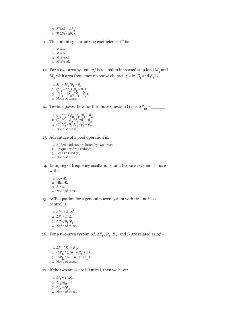
3. T/(Δδ -Δδ ).
4. T(Δδ1-Δδ2).
10. Theunitofsynchronizingcoefficients‘T’is:
1. MW-s.2. MW/s.3. MW-rad.4. MW/rad.
11. Foratwo-areasystem,ΔfisrelatedtoincreasedsteploadM and
M withareafrequencyresponsecharacteristicsβ andβ is:
1.M +M /β +β .
2. (M +M )(β +β ).
3. -(M +M )/(β +β ).
4. Noneofthese.
12. Tie-linepowerflowfortheabovequestion(11)isΔP =_____
1. (β M +β M )/β +β .
2. (β M -β M )/β +β .
3. (β M -β M )/β +β .
4. Noneofthese.
13. Advantageofapooloperationis:
1. Addedloadcanbesharedbytwoareas.2. Frequencydropreduces.3. Both(A)and(B).4. Noneofthese.
14. Dampingoffrequencyoscillationsforatwo-areasystemismorewith:
1. Low-R.2. High-R.3. R=α.4. Noneofthese.
15. ACEequationforageneralpowersystemwithtie-linebiascontrolis:
1. ΔP +B Δf .
2. ΔP -B Δf .
3. ΔP /B Δf .
4. Noneofthese.
16. Foratwo-areasystemΔf,ΔP ,R ,R ,andDarerelatedasΔf=
_____
1. ΔP /R +R .
2. -ΔP /(1/R +R +B).
3. -ΔP /(B+R +1/R ).
4. Noneofthese.
17. Ifthetwoareasareidentical,thenwehave:
1. Δf =1/Δf .
2. Δf Δf =2.
3. Δf =Δf .
4. Noneofthese.
1 2
1
2 1 2
1 2 1 2
1 2 1 2
1 2 1 2
12
1 2 2 1 1 2
1 2 2 1 1 2
1 1 2 2 1 2
ij i i
ij i i
ij i i
L 1 2
L 1 2
L 1 2
L 1 2
1 2
1 2
1 2

18. Tie-linebetweentwoareasusuallywillbea_____line.
1. HVDC.2. HVAC.3. NormalAC.4. Noneofthese.
19. Dynamicresponseofatwo-areasystemcanberepresentedbya_____ordertransferfunction.
1. Third.2. Second.3. First.4. Zero.
20. ControlofALFCloopofamulti-areasystemisachievedbyusing_____mathematicaltechnique.
1. Rootlocus.2. Bodeplots.3. Statevariable.4. Nyquistplots.
REVIEWQUESTIONS
1. Obtainthemathematicalmodelingofthelinepowerinaninterconnectedsystemanditsblockdiagram.
2. Obtaintheblockdiagramofatwo-areasystem.3. Explainhowthecontrolschemeresultsinzerotie-linepower
deviationsandzero-frequencydeviationsundersteady-stateconditions,followingastep-loadchangeinoneoftheareasofatwo-areasystem.
4. Deducetheexpressionforstatic-errorfrequencyandtie-linepowerinanidenticaltwo-areasystem.
5. Explainabouttheoptimaltwo-areaLFC.6. Whatismeantbytie-linebiascontrol?7. Derivetheexpressionforincrementaltie-linepowerofanareainanuncontrolledtwo-areasystemunderdynamicstateforastep-loadchangeineitherarea.
8. Drawtheblockdiagramforatwo-areaLFCwithintegralcontrollerblocksandexplaineachblock.
9. Whatarethedifferencesbetweenuncontrolled,controlled,andtie-linebiasLFCofatwo-areasystem.
10. Explainthemethodinvolvedinoptimumparameteradjustmentforatwo-areasystem.
11. ExplainthecombinedoperationofanLFCandanELDCsystem.
PROBLEMS
1. Twointerconnectedareas1and2havethecapacityof250and600MW,respectively.Theincrementalregulationanddampingtorquecoefficientforeachareaonitsownbaseare0.3and0.07p.u.respectively.Findthesteady-statechangeinsystem

frequencyfromanominalfrequencyof50Hzandthechangeinsteady-statetie-linepowerfollowinga850MWchangeintheloadofArea-1.
2. Twocontrolareasof1,500and2,500MWcapacitiesareinterconnectedbyatieline.Thespeedregulationsofthetwoareas,respectively,are3and1.5Hz/p.u.MW.Considerthata2%changeinloadoccursfora2%changeinfrequencyineacharea.Findthesteady-statechangeinthefrequencyandthetie-linepowerof20MWchangeinloadoccurringinbothareas.
3. Findthenatureofdynamicresponseifthetwoareasoftheaboveproblemareofuncontrolledtype,followingadisturbanceineitherareaintheformofastepchangeinanelectricload.TheinertiaconstantofthesystemisgivenasH=2sandassumethatthetielinehasacapacityof0.08p.u.andisoperatingatapowerangleof35 beforethestepchangeinload.
o

9
ReactivePowerCompensation
OBJECTIVES
Afterreadingthischapter,youshouldbeableto:
knowtheneedofreactivepowercompensationdiscusstheobjectivesofloadcompensationdiscusstheoperationofuncompensatedandcompensatedtransmissionlinesdiscusstheconceptofsub-synchronousresonance(SSR)studythevoltage-stabilityanalysis
9.1INTRODUCTION
InanidealAC-powersystem,thevoltageandthefrequencyateverysupplypointwouldremainconstant,freefromharmonicsandthepowerfactor(p.f.)wouldremainunity.Fortheoptimumperformanceataparticularsupplyvoltage,eachloadcouldbedesignedsuchthatthereisnointerferencebetweendifferentloadsasaresultofvariationsinthecurrenttakenbyeachone.
Mostelectricalpowersystemsintheworldareinterconnectedtoachievereducedoperatingcostandimprovedreliabilitywithlesserpollution.Inapowersystem,thepowergenerationandloadmustbalanceatalltimes.Tosomeextent,itisself-regulating.Ifanunbalancebetweenpowergenerationandloadoccurs,thenitresultsinavariationinthevoltageandthefrequency.Ifvoltageisproppedupwithreactivepowersupport,thentheloadincreaseswithaconsequentdropinfrequency,whichmayresultinsystemcollapse.Alternatively,ifthereisaninadequatereactivepower,thesystem’svoltagemaycollapse.

Here,thequalityofsupplymeansmaintainingconstant-voltagemagnitudeandfrequencyunderallloadingconditions.Itisalsodesirabletomaintainthethree-phasecurrentsandvoltagesasbalancedaspossiblesothatunderheatingofvariousrotatingmachinesduetounbalancingcouldbeavoided.
Inathree-phasesystem,thedegreetowhichthephasecurrentsandvoltagesarebalancedmustalsobetakenintoconsiderationtomaintainthequalityofsupply.
Toachievetheabove-mentionedrequirementsfromthesupplypointofviewaswellastheloads,whichcandeterioratethequalityofsupply,weneedloadcompensation.
LoadcompensationisthecontrolofreactivepowertoimprovethequalityofsupplyinanAC-powersystembyinstallingthecompensatingequipmentneartheload.
9.2OBJECTIVESOFLOADCOMPENSATION
Theobjectivesofloadcompensationare:
1. p.f.Correction.2. Voltageregulationimprovement.3. Balancingofload.
9.2.1p.f.Correction
Generally,loadcompensationisalocalproblem.Mostoftheindustrialloadsabsorbthereactivepowersincetheyhavelaggingp.f.’s.Theloadcurrenttendstobelargerthanitisrequiredtosupplytherealpoweralone.So,p.f.correctionofloadisachievedbygeneratingreactivepowerascloseaspossibletotheload,whichrequiresittogenerateitatadistanceandtransmitittotheload,asthisresultsnotonlyinalargeconductorsizebutalsoinincreasedlosses.Itisdesirabletooperatethesystemnearunityp.f.economically.
9.2.2Voltageregulationimprovement

Allloadsvarytheirdemandforreactivepower,althoughtheydifferwidelyintheirrangeandrateofvariation.Thevoltagevariationisduetotheimbalanceinthegenerationandconsumptionofreactivepowerinthesystem.Ifthegeneratedreactivepowerismorethanthatbeingconsumed,voltagelevelsgoupandviceversa.However,ifbothareequal,thevoltageprofilebecomesflat.Thevariationindemandforreactivepowercausesvariation(orregulation)inthevoltageatthesupplypoint,whichcaninterferewithanefficientoperationofallplantsconnectedtothatpoint.So,differentconsumersconnectedtothatpointgetaffected.Toavoidthis,thesupplyutilityplacesboundstomaintainsupplyvoltageswithindefinedlimits.Theselimitsmayvaryfromtypically±6%averagedoveraperiodofafewminutesorhours.
Toimprovevoltageregulation,weshouldstrengthenthepowersystembyincreasingthesizeandnumberofgeneratingunitsaswellasbymakingthenetworkmoredenselyinterconnected.Thisapproachwouldbeuneconomicandwouldintroduceproblemssuchashighfaultlevels,etc.Inpractice,itismuchmoreeconomictodesignthepowersystemaccordingtothemaximumdemandforactivepowerandtomanagethereactivepowerbymeansofcompensatorslocally.
9.2.3Loadbalancing
Mostpowersystemsarethree-phasedandaredesignedforbalancedoperationsincetheirunbalancedoperationgivesrisetowrongphase-sequencecomponentsofcurrents(negativeandzero-sequencecomponents).Suchcomponentsproduceundesirableresultssuchasadditionallossesinmotors,generators,oscillatingtorqueinACmachines,increasedripplesinrectifiers,saturationoftransformers,excessivenaturalcurrent,andsoon.Theseundesirableeffectsarecausedmainlyduetotheharmonicsproducedunderanunbalanced
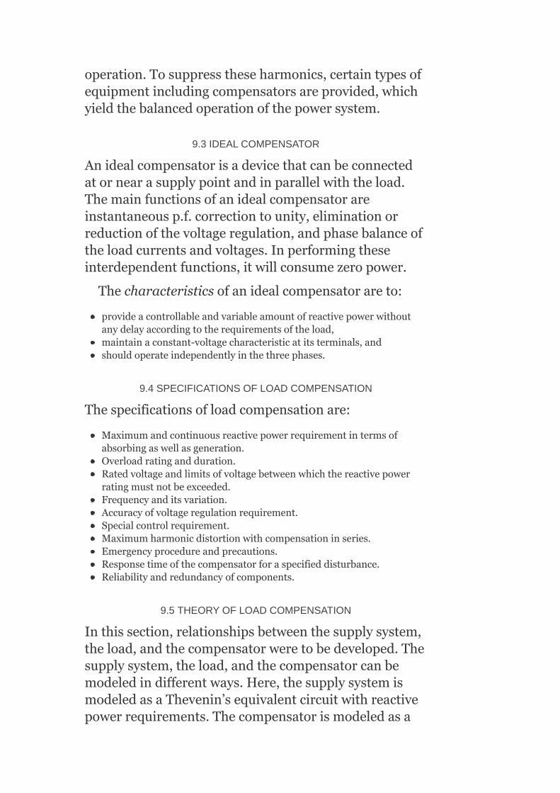
operation.Tosuppresstheseharmonics,certaintypesofequipmentincludingcompensatorsareprovided,whichyieldthebalancedoperationofthepowersystem.
9.3IDEALCOMPENSATOR
Anidealcompensatorisadevicethatcanbeconnectedatornearasupplypointandinparallelwiththeload.Themainfunctionsofanidealcompensatorareinstantaneousp.f.correctiontounity,eliminationorreductionofthevoltageregulation,andphasebalanceoftheloadcurrentsandvoltages.Inperformingtheseinterdependentfunctions,itwillconsumezeropower.
Thecharacteristicsofanidealcompensatorareto:
provideacontrollableandvariableamountofreactivepowerwithoutanydelayaccordingtotherequirementsoftheload,maintainaconstant-voltagecharacteristicatitsterminals,andshouldoperateindependentlyinthethreephases.
9.4SPECIFICATIONSOFLOADCOMPENSATION
Thespecificationsofloadcompensationare:
Maximumandcontinuousreactivepowerrequirementintermsofabsorbingaswellasgeneration.Overloadratingandduration.Ratedvoltageandlimitsofvoltagebetweenwhichthereactivepowerratingmustnotbeexceeded.Frequencyanditsvariation.Accuracyofvoltageregulationrequirement.Specialcontrolrequirement.Maximumharmonicdistortionwithcompensationinseries.Emergencyprocedureandprecautions.Responsetimeofthecompensatorforaspecifieddisturbance.Reliabilityandredundancyofcomponents.
9.5THEORYOFLOADCOMPENSATION
Inthissection,relationshipsbetweenthesupplysystem,theload,andthecompensatorweretobedeveloped.Thesupplysystem,theload,andthecompensatorcanbemodeledindifferentways.Here,thesupplysystemismodeledasaThevenin’sequivalentcircuitwithreactivepowerrequirements.Thecompensatorismodeledasa

variableimpedance/asavariablesource(orsink)ofreactivecurrent/power.Accordingtorequirements,theselectionofmodelusedforeachcomponentcanbevaried.
Theassumptionmadeindevelopingtherelationshipsbetweensupplysystem,theload,andthecompensatoristhattheloadandsystemcharacteristicsarestatic/constant(or)changingslowlysothatphasorrepresentationcanbeused.
9.5.1p.f.Correction
Considerasingle-phaseloadwithadmittanceY =G +jB withasourcevoltageasshowninFig.9.1(a).
TheloadcurrentI isgivenby
I =V (G +jB )=V G +jV B =I +jI
whereI istheactivecomponentoftheloadcurrent
I thereactivecomponentoftheloadcurrent.
FIG.9.1Representationofsingle-phaseload;(a)withoutcompensation;(b)withcompensation
Apparentpoweroftheload,S =V I *
=V G −jV B
L L
L
L
L s L L s L s L a r
a
r
L s L
S L S L
2 2

=P +jQ
whereP istheactivepoweroftheload
Q thereactivepoweroftheload.
Forinductiveloads,B isnegativeandQ ispositivebyconvention.
Thecurrentsuppliedtotheloadislargerthanwhenitisnecessarytosupplytheactivepoweralonebythefactor
Theobjectiveofthep.f.correctionistocompensateforthereactivepower,i.e.,locallyprovidingacompensatorhavingapurelyreactiveadmittancejB inparallelwiththeloadasshowninFig.9.1(b).Thecurrentsuppliedfromthesourcewiththecompensatoris
I =I +I
=V (G +jB )–V (jB )
=V G =I (∵B =B )
whichmakesthep.f.tounity,sinceI isinphasewiththesourcevoltageV .
Thecurrentofthecompensator,I =V Y =–jV B
Theapparentpowerofthecompensator,S =V I *
S =jV B =−jQ (∵S =P −jQ ,forpurecompensationP =0)
L L
L
L
L L
C
s L C
s L L s C
s L a L C
a
s
c s c s c
c s c
c s C C C C C
C
2

Weknowthat
Q =P tanϕ
Forafullycompensatedsystem,i.e.,Q =Q
Thedegreeofcompensationisdecidedbyaneconomictrade-offbetweenthecapitalcostofthecompensatorandthesavingsobtainedbythereactivepowercompensationofthesupplysystemoveraperiodoftime.
9.5.2Voltageregulation
Itisdefinedastheproportionalchangeinsupplyvoltagemagnitudeassociatedwithadefinedchangeinloadcurrent,i.e.,fromno-loadtofullload.Itiscausedbythevoltagedropinthesupplyimpedancecarryingtheloadcurrent.
Whenthesupplysystemisbalanced,itcanberepresentedassingle-phasemodelasshowninFig.
9.2(a).Thevoltageregulationisgivenby ,where
|V |istheloadvoltage.
9.5.2.1Withoutcompensator
Fromthephasordiagramofanuncompensatedsystem,showninFig.9.2(b),thechangeinvoltagesisgivenby
ΔV=V −V =Z I (9.1)
whereZ =R +jX andtheloadcurrent,
L L L
L C
L
s L s L
s s s

SubstitutingZ andI inEquation(9.1),weget
FIG.9.2(a)Circuitmodelofanuncompensatedloadandsupplysystem;(b)phasordiagramforanuncompensatedsystem
FromEquation(9.3),itisobservedthatthechangeinvoltagedependsonbothrealandreactivepowersoftheloadconsideringthelineparameterstobeconstant.
9.5.2.2Withcompensator
Inthiscase,apurelyreactivecompensatorisconnectedacrosstheloadasshowninFig.9.3(a)tomakethevoltageregulationzero,i.e.,thesupplyvoltage(|V |)equalstheloadvoltage(|V |).ThecorrespondingphasordiagramisshowninFig.9.3(b).
s L
s
L
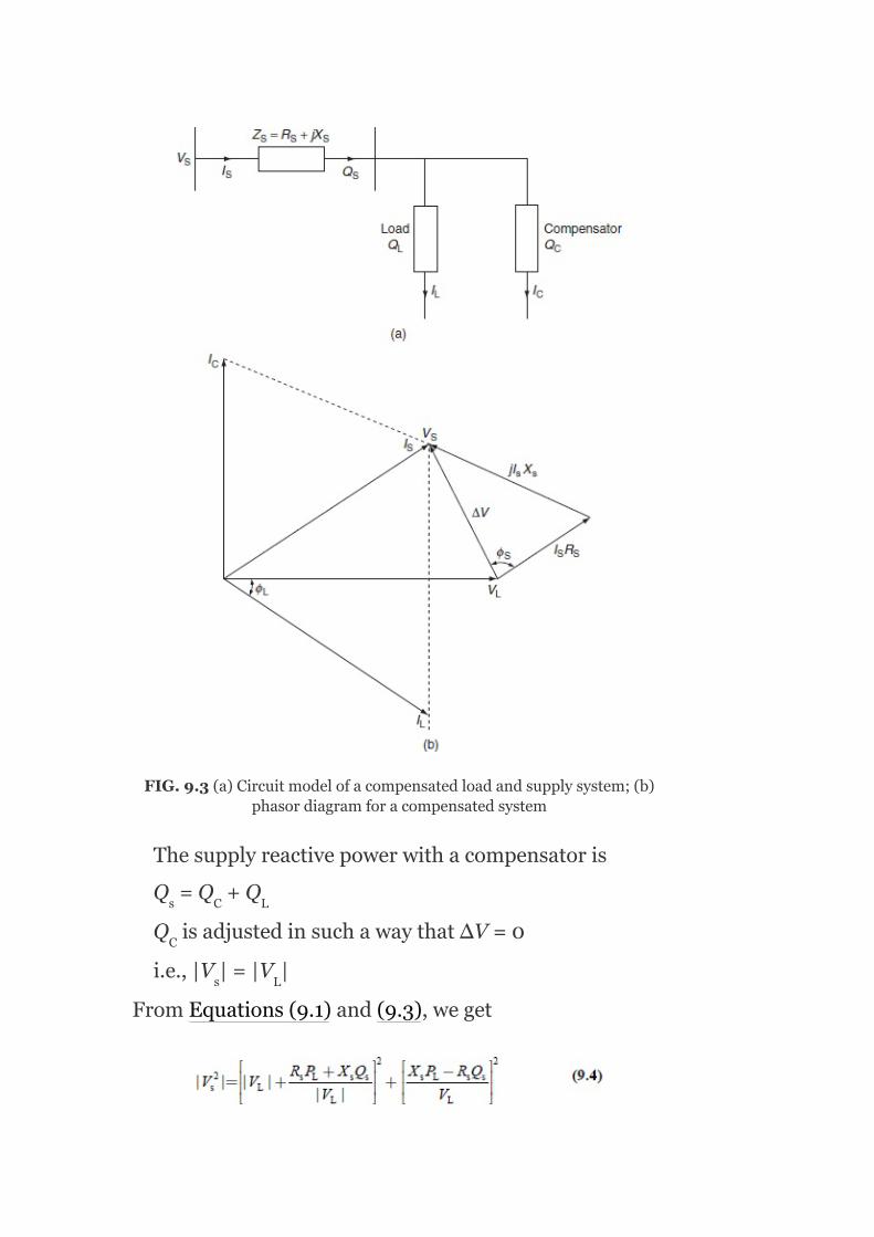
FIG.9.3(a)Circuitmodelofacompensatedloadandsupplysystem;(b)phasordiagramforacompensatedsystem
Thesupplyreactivepowerwithacompensatoris
Q =Q +Q
Q isadjustedinsuchawaythat∆V=0
i.e.,|V |=|V |
FromEquations(9.1)and(9.3),weget
s C L
C
s L

Simplifyingandrearrangingequation(9.4),
Theaboveequationcanberepresentedinacompactformas
aQ +bQ +c=0
where
ThevalueofQ isfoundusingtheaboveequationbyusingthecompensatorreactivepowerbalanceequation|V |=|V |andQ =Q –Q .
Here,thecompensatorcanperformasanidealvoltageregulator,i.e.,themagnitudeofthevoltageisbeingcontrolled,itsphasevariescontinuouslywiththeloadcurrent,whereasthecompensatoractingasap.f.correctorreducesthereactivepowersuppliedbythesystemtozeroi.e.,Q =0=Q +Q .
Equation(9.3)canbereducedto
s s
C
s L C s L
s L C
2

So,∆Visindependentoftheloadreactivepower.Fromthis,weconcludethatapurereactivecompensatorcannotmaintainbothconstantvoltageandunityp.f.simultaneously.
9.6LOADBALANCINGANDP.F.IMPROVEMENTOFUNSYMMETRICALTHREE-PHASELOADS
Thethirdobjectiveofloadcompensationisthebalancingofunbalancedthree-phaseloads.Wefirstmodeltheloadasadelta-connectedadmittancenetworkforageneralunbalancedthree-phaseloadasshowninFig.9.4inwhichtheadmittancesY ,Y andY arecomplexandunequal.
Inthiscase,supplyvoltagesareassumedtobebalanced.AnyungroundedY-connectedloadcanberepresentedbyadelta-connectedloadbymeansoftheY-∆transformation.
Acompensatorcanbeanypassivethree-phaseadmittancenetwork,whichwhencombinedinparallelwiththeloadwillpresentarealandbalancedloadwithrespecttothesupply.
9.6.1p.f.Correction
Eachloadadmittancecanbemadepurelyrealbyconnecting,inparallel,acompensatingsusceptanceequaltothenegativeoftheloadsusceptanceinthatbranchofthedelta-connectedloadasshowninFig.9.5(a).
Ifloadadmittance,Y =G +jB ,thenthecompensatingsusceptanceB =−B isconnectedacrossY :
L L L
L L L
C L
L
ab bc cd
ab ab ab
ab ab
ab

Aninductivesusceptancebetweenphases‘c’and‘a’asshowninFig.9.5(a)is
Now,thelinecurrentswillbebalancedandareinphasewiththeirrespectivephasevoltages.Thecompensatedsingle-phaseloadwithapositivesequenceequivalentcircuitisshowninFig.9.5(a).
FIG.9.4Unbalancedthree-phaseload

FIG.9.5(a)Connectionofp.f.correctingsusceptance;(b)resultantunbalancedrealloadwithunityp.f.
Similarly,thecompensatingsusceptance,B =−BandB =−B areconnectedacrossY andY ,respectively,asshowninFig.9.5(a).
Figure9.5(b)showstheresultantunbalancedrealloadwithunityp.f.
9.6.2Loadbalancing
Now,wemakethisrealunbalancedloadtoabalancedone.Todothis,letusconsiderasingle-phaseload(G )(asshowninFig.9.6(a))ofthe∆-connectedloadasshowninFig.9.5(b).Thethree-phasepositivesequencelinecurrentscanbebalancedbyconnectingcapacitivesusceptancebetweenphases‘b’and‘c’andtogetherwiththeinductivesusceptancebetweenphases‘c’and‘a’asshowninFig.9.6(b).
c L
c L L L
L
bc bc
cd ca bc ca
ab

FIG.9.6(a)Single-phaseunityp.f.loadbeforepositivesequencebalancing;(b)positivesequencebalancingofasingle-phaseu.p.f.load
FIG.9.7(a)Idealthree-phasecompensatingnetworkwithcompensatoradmittances;(b)equivalentcircuitofrealandbalancedcompensatedload
admittance
Similarly,therealadmittancesintheremainingphases‘bc’and‘ca’canbebalanced.
Theresultantcompensatoradmittance(susceptance)representedbyanequivalentcircuitisshowninFig.9.7(a).
B =−B (p.f.correction)+(G +G )/ (loadbalancing)
c L L L
ab ab ca bc
bc bc ab ca

B =−B +(G +G )/
B =−B +(G +G )/
Theresultingcompensatedloadadmittanceispurelyrealandbalanced,asshownintheequivalentcircuitofFig.9.7(b).
9.7UNCOMPENSATEDTRANSMISSIONLINES
Anelectrictransmissionlinehasfourparameters,whichaffectitsabilitytofulfillitsfunctionaspartofapowersystemandtheseareaseriescombinationofresistance,inductance,shuntcombinationofcapacitance,andconductance.TheseparametersaresymbolizedasR,L,C,andG,respectively.Theseparametersaredistributedalongthewholelengthatanyline.Eachsmalllengthatanysectionofthelinewillhaveitsownvaluesandconcentrationofallsuchparametersforthecompletelengthoflineintoasingleoneisnotpossible.Theseareusuallyexpressedasresistance,inductance,andcapacitanceperkilometer.
Shuntconductancethatismostlyduetothebreakageovertheinsulatorsisalmostalwaysneglectedinapowertransmissionline.Theleakagelossinacableisuniformlydistributedoverthelengthofthecable,whereasitisdifferentinthecaseofoverheadlines.Itislimitedonlytotheinsulatorsandisverysmallundernormaloperatingconditions.So,itisneglectedforanoverheadtransmissionline.
9.7.1Fundamentaltransmissionlineequation
Consideraverysmallelementoflength∆xatadistanceofxfromthereceivingendoftheline.Letzbetheseriesimpedanceperunitlength,ytheshuntadmittanceperunitlength,andlthelengthoftheline.
c L L L
c L L L
bc bc ab ca
ca ca bc ab
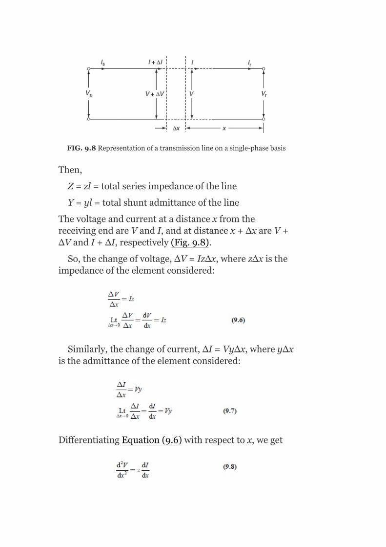
FIG.9.8Representationofatransmissionlineonasingle-phasebasis
Then,
Z=zl=totalseriesimpedanceoftheline
Y=yl=totalshuntadmittanceoftheline
ThevoltageandcurrentatadistancexfromthereceivingendareVandI,andatdistancex+∆xareV+∆VandI+∆I,respectively(Fig.9.8).
So,thechangeofvoltage,∆V=Iz∆x,wherez∆xistheimpedanceoftheelementconsidered:
Similarly,thechangeofcurrent,∆I=Vy∆x,wherey∆xistheadmittanceoftheelementconsidered:
DifferentiatingEquation(9.6)withrespecttox,weget

Substitutingthevalueof fromEquation(9.7)in
Equation(9.8),weget
Equation(9.9)isasecond-orderdifferentiatialequationanditssolutionis
DifferentiatingEquation(9.10)withrespecttox,weget
FromEquations(9.6)and(9.11),wehave
FromEquation(9.10),wehave
V(x)=Ae +Be (9.13)
FromEquation(9.12),wehave
γx −γx

where isknownascharacteristicimpedanceor
surgeimpedanceand isknownasthepropagation
constant.
TheconstantsAandBcanbeevaluatedbyusingtheconditionsatthereceivingendoftheline.
Theconditionsare
atx=0,V=V andI=I
SubstitutingtheaboveconditionsinEquations(9.11)and(9.12),weget
∴V =A+B(9.15)
and
SolvingEquations(9.15)and(9.16),weget
Now,substitutingthevaluesofAandBinEquations(9.13)and(9.14),thenweget
r r
r
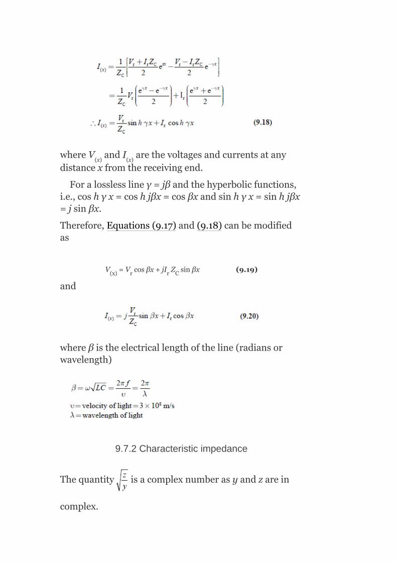
whereV andI arethevoltagesandcurrentsatanydistancexfromthereceivingend.
Foralosslesslineγ=jβandthehyperbolicfunctions,i.e.,coshγx=coshjβx=cosβxandsinhγx=sinhjβx=jsinβx.
Therefore,Equations(9.17)and(9.18)canbemodifiedas
V =V cosβx+jI Z sinβx(9.19)
and
whereβistheelectricallengthoftheline(radiansorwavelength)
9.7.2Characteristicimpedance
Thequantity isacomplexnumberasyandzarein
complex.
(x) (x)
(x) r r C
ItisdenotedbyZ orZ .Ithasthedimensionofimpedance,since
Thisquantitydependsuponthecharacteristicofthelineperunitlength.Itis,therefore,calledcharacteristicimpedanceoftheline.Italsodependsuponthelengthoftheline,radius,andspacingbetweentheconductors.Foralosslessline,r=g=0,thecharacteristicimpedancebecomes
Thecharacteristicimpedanceisalsocalledthesurgeornaturalimpedanceoftheline.
Theapproximatevalueofthesurgeimpedanceforoverheadlinesis400Ωandthatforundergroundcablesis40Ω,andthetransformershaveseveralthousandohmsastheirsurgeimpedance.Surgeimpedanceistheimpedanceofferedtothepropagationofavoltageorcurrentwaveduringitstravelalongtheline.
9.7.3Surgeimpedanceornaturalloading
Thesurgeimpedanceloading(SIL)ofatransmissionlineistheMWloadingofatransmissionlineatwhichanaturalreactivepowerbalanceoccurs(zeroresistance).
Transmissionlinesproducereactivepower(MVAr)duetotheirnaturalcapacitance.TheamountofMVArproducedisdependentonthetransmissionline’scapacitivereactance(X )andthevoltage(kV)atwhichthelineisenergized.
C 0
C

NowtheMVArproducedis
Transmissionlinesalsoutilizereactivepowertosupporttheirmagneticfields.Themagneticfieldstrengthisdependentonthemagnitudeofthecurrentflowinthelineandthenaturalinductivereactance(X )oftheline.TheamountofMVArusedbyatransmissionlineisafunctionofthecurrentflowandinductivereactance.
TheMVArusedbyatransmissionline=I X (9.22)
TransmissionlineSILissimplytheMWloading(ataunityp.f.)atwhichthelineMVArusageisequaltothelineMVArproduction.Fromtheabovestatement,theSILoccurswhen
AndtheEquation(9.23)canberewrittenas
Theterm isthe‘surgeimpedance’.
Thetheoreticalsignificanceofthesurgeimpedanceisthatifapurelyresistiveloadthatisequaltothesurge
L
L
2

impedancewereconnectedtotheendofatransmissionlinewithnoresistance,avoltagesurgeintroducedtothesendingendofthelinewouldbeabsorbedcompletelyatthereceivingend.Thevoltageatthereceivingendwouldhavethesamemagnitudeasthesending-endvoltageandwouldhaveavoltagephaseanglethatislaggingwithrespecttothesendingendbyanamountequaltothetimerequiredtotravelacrossthelinefromthesendingtothereceivingend.
Theconceptofsurgeimpedanceismorereadilyappliedtotelecommunicationsystemsratherthantopowersystems.However,wecanextendtheconcepttothepowertransferredacrossatransmissionline.Thesurgeimpedanceloading(powertransmittedatthiscondition)orSIL(inMW)isequaltothevoltagesquared(inkV)dividedbythesurgeimpedance(inohms):
Note:Inthisformula,theSILisdependentonlyonthevoltage(kV)ofthelineisenergizedandthelinesurgeimpedance.ThelinelengthisnotafactorintheSILorsurgeimpedancecalculations.Therefore,theSILisnotameasureofatransmissionlinepowertransfercapabilityasitneithertakesintoaccountthelinelengthnorconsidersthestrengthofthelocalpowersystem.
ThevalueoftheSILtoasystemoperatorisrealizedwhenalineisloadedaboveitsSIL,itactslikeashuntreactorabsorbingMVArfromthesystemandwhenalineisloadedbelowitsSIL,itactslikeashuntcapacitorsupplyingMVArtothesystem.
9.8UNCOMPENSATEDLINEWITHOPENCIRCUIT
Inthissection,weshalldiscussthecases:(a)voltageandcurrentprofiles,(b)symmetricallineatno-load,and(c)underexcitedoperationofgenerators.

9.8.1Voltageandcurrentprofiles
Alosslesslineisenergizedatthesendingendandisopen-circuitedatthereceivingend.
FromEquations(9.19)and(9.20)withI =0
∴V(x)=V cosβx(9.25)
Voltageandcurrentatthesendingendaregivenbyequationswithx=las
V =V ,I =I
Equations(9.25)and(9.26)aremodifiedas
V =V cosθ(9.27)
whereθ=βl
FromEquations(9.25)and(9.26),thevoltageprofileequationis
Andthecurrentprofileequation,
9.8.2Thesymmetricallineatno-load
r
r
(x) s (x) (s)
s r

Thisissimilartoanopen-circuitedlineenergizedatoneend.Thisisalineidenticalatbothends,butwithnopowertransfer.Supposetheterminalvoltagesaremaintainedassamevalues,
i.e.,V =V
FromEquations(9.19)and(9.20)withx=l,wehave
V =V cosθ+jZ I sinθ(9.31)
Theelectricalconditionsarethesame(V =V );therewouldnotbeanypowertransfer.Therefore,bysymmetryI =I .
SubstitutingtheaboveconditioninEquations(9.32),weget
SubstitutingEquation(9.33)inEquation(9.31),weget
FromEquation.(9.34),wehave
s r
s r c r
s r
s r

AcomparisonofEquations(9.35)and(9.36)withEquation(9.28)showsthatthelineisequivalenttotwoequalhalvesconnectedback-to-back.Halftheline-chargingcurrentissuppliedfromeachend.Bysymmetry,themidpointcurrentiszero,whereasthemidpointvoltageisequaltotheopen-circuitvoltageofthelinehavinghalfthetotallength.
FromEquation(9.31)themidpointvoltageis
9.8.3Underexcitedoperationofgeneratorsduetoline-charging
Noloadatthereceivingends,i.e.,I =0.Thechargingreactivepoweratthesendingendis
Q =Im(V I *)
FromEquation(9.28),wehave
Line-chargingcurrentatthesendingend,
∴Line-chargingpoweratthesendingend,Q =–Ptanθ
Fora300-kmline,Q isnearly43%ofthenaturalloadexpressedinMVA.At400kV,thegeneratorswouldhavetoabsorb172MVAr.
Thereactivepowerabsorptioncapabilityofasynchronousmachineislimitedfortworeasons:
r
s s s
s 0
s

Theheatingoftheendsofthestatorcoreincreasesduringunderexcitedoperation.Thereducedfieldcurrentresultsinreducedinternale.m.fofthemachineandthisweakensthestability.
Usingacompensator,thisproblemcanbereducedbytwoways:
Ifthelineismadeupoftwo(or)moreparallelcircuits,one(or)moreofthecircuitscanbeswitchedoffunderlightload(or)open-circuitconditions.Ifthegeneratorabsorptionislimitedbystabilityandnotbycore-endheating,theabsorptionlimitcanbeincreasedbyusingarapidresponseexcitationsystem,whichrestoresthestabilitymarginswhenthesteady-statefieldcurrentislow.Theunderexcitedoperationofgeneratorscansetamorestringentlimittothemaximumlengthofanuncompensatedlinethantheopen-circuitvoltagerise.
9.9THEUNCOMPENSATEDLINEUNDERLOAD
Inthissection,theeffectsoflinelength,loadpower,andp.f.onvoltageaswellasreactivepowerarediscussed.
9.9.1Radiallinewithfixedsending-endvoltage
Aload(P +jQ )atthereceivingendofaradiallinedrawsthecurrent.
i.e.,
FromEquation(9.19),withx=l,foralosslessline,thesending-andreceiving-endvoltagesarerelatedas
IfV isfixed,thisquadraticequationcanbesolvedforV .ThesolutiongiveshowV varieswiththeloadanditsp.f.aswellaswiththelinelength.
SeveralfundamentalimportantpropertiesofACtransmissionareevidentfromFig.9.9
r r
s
r r

Foreachloadp.f.,thereisamaximumtransmissiblepower.Theloadp.f.hasastronginfluenceonthereceiving-endvoltage.Uncompensatedlinesbetweenabout150-kmand300-kmlongcanbeoperatedatnormalvoltageprovidedthattheloadp.f.ishigh.Longerlines,withlargevoltagevariations,areimpracticalatallp.f.’sunlesssomemeansofvoltagecompensationisprovided.
Themidpointvoltagevariationonasymmetrical300-kmlineisthesameasthereceiving-endvoltagevariationsona150-kmlinewithaunityp.f.load.
9.9.2Reactivepowerrequirements
Fromthelinevoltageandthelevelofpowertransmission,thereactivepowerrequirementscanbedetermined.Itisveryimportanttoknowthereactivepowerrequirementsbecausetheydeterminethereactivepowerratingsofthesynchronousmachinesaswellasthoseofanycompensatingequipment.Ifanyinductiveloadisconnectedatthesendingendoftheline,itwillsupportthesynchronousgeneratorstoabsorbtheline-chargingreactivepower.Withtheabsenceofthecompensatingequipment,thesynchronousmachinesmustabsorborgeneratethedifferencebetweenthelineandthelocalloadreactivepowers.

FIG.9.9Magnitudeofreceiving-endvoltageasafunctionofloadandloadp.f.
Theequationsofvoltageandcurrentforthesending-endhalfofthesymmetricallineis
Thepoweratmidpointis
P +jQ =V I *=P=transmittedpower
SinceQ =0,becausenoreactivepowerflowsatthemidpoint.
Thepoweratthesendingendis
P +jQ =V I *
m m m m
m
s s s s

SubstitutingV andI fromEquations(9.38)and(9.39)intheaboveequation,weget
Ifthelineisassumedtobelossless,thenP =P =P:
Theaboveexpressiongivestherelationbetweenthemidpointvoltageandthereactivepowerrequirementsofthesymmetricalline.
Iftheterminalvoltagesarecontinuouslyadjustedsothatthemidpointvoltage,
V =V =1.0p.u.atalllevelsofpowertransmission
9.9.3Theuncompensatedlineunderloadwithconsiderationofmaximumpowerandstability
ConsiderEquation(9.37)as
IfV istakenasreferencephasor,then:
V =V e =V (cosδ+jsinδ)(9.41)
s s
s r
m 0
r
s s s
jδ

whereδisthephaseanglebetweenV andV andiscalledtheloadangle(or)thetransmissionangle.
EquatingrealandimaginarypartsofEquations(9.40)and(9.41),weget
Foranelectricallyshortline,sinθ=θ=βl:
Then, theseriesreactanceofthe
line:
where
9.10COMPENSATEDTRANSMISSIONLINES
Thechangeintheelectricalcharacteristicsofatransmissionlineinordertoincreaseitspowertransmissioncapabilityisknownaslinecompensation.Whilesatisfyingtherequirementsforatransmissionsystem(i.e.,synchronism,voltagesmustbekeptnear
s r

theirratedvalues,etc.),acompensationsystemideallyperformsthefollowingfunctions:
Itprovidestheflatvoltageprofileatalllevelsofpowertransmission.Itimprovesthestabilitybyincreasingthemaximumtransmissioncapacity.Itmeetsthereactivepowerrequirementsofthetransmissionsystemeconomically.
Thefollowingtypesofcompensationsaregenerallyusedfortransmissionlines:
1. Virtual-Z .
2. Virtual-θ.3. Compensationbysectioning.
Theeffectivenessofacompensatedsystemisgaugedbytheproductofthelinelengthandmaximumtransmissionpowercapacity.Compensatedlinesenablethetransmissionofthenaturalloadoverlargerdistances,andshortercompensatedlinescancarryloadsmorethanthenaturalload.
TheflatvoltageprofilecanbeachievediftheeffectivesurgeimpedanceofthelineismodifiedastoavirtualvalueZ ′,forwhichthecorrespondingvirtualnatural
load isequaltotheactualload.Thesurge
impedanceoftheuncompensatedlineis ,which
canbewrittenas ,iftheseriesand/ortheshuntreactanceX and/orX aremodified,respectively.Then,thelinecanbemadetohavevirtualsurgeimpedanceZ ′andavirtualnaturalloadP’forwhich
0
0
L c
0

Compensationofline,bywhichtheuncompensatedsurgeimpedanceZ ismodifiedtovirtualsurgeimpedanceZ ′,iscalledvirtualsurgeimpedancecompensationorvirtualZ compensation.
OncealineiscomputedforZ ,theonlywaytoimprovestabilityistoreducetheeffectivevalueofθ.Twoalternativecompensationstrategieshavebeendevelopedtoachievethis.
ApplyseriescapacitorstoreduceX andtherebyreduceθ,sinceθ=βl
= atfundamentalfrequency.Thismethodiscalled
line-lengthcompensation(or)θcompensation.Dividethelineintoshortersectionsthataremore(or)lessindependentofoneanother.Thismethodiscalledcompensationbysectioning.Itisachievedbyconnectingconstantvoltagecompensationsatintervalsalongtheline.
9.11SUB-SYNCHRONOUSRESONANCE
Inthissection,variouseffectsduetosub-synchronousresonancearediscussedindetail.
9.11.1Effectsofseriesandshuntcompensationoflines
Theobjectiveofseriescompensationistocancelpartoftheseriesinductivereactanceofthelineusingseriescapacitors,whichresultsinthefollowingfactors.
1. Increaseinmaximumtransferablepowercapacity.2. Decreaseintransmissionangleforconsiderableamountofpower
transfer.3. Increaseinvirtualsurgeimpedanceloading.
Fromapracticalpointofview,itisdesirablenottoexceedseriescompensationbeyond80%.Ifthelineiscompensatedat100%,thelinebehavesasapurelyresistiveelementandwouldresultinseriesresonanceevenatfundamentalfrequencysincethecapacitivereactanceequalstheinductivereactance,anditwouldbedifficulttocontrolvoltagesandcurrentsduring
0
0
0
0
L

disturbances.Evenasmalldisturbanceintherotoranglesoftheterminalsynchronousmachinewouldresultinflowoflargecurrents.
Thelocationofseriescapacitorsisdecidedpartlybyeconomicalfactorsandpartlybytheselectivityoffaultcurrentsastheywoulddependuponthelocationoftheseriescapacitor.Thevoltageratingofthecapacitorwilldependuponthemaximumfaultcurrentthatlikelyflowsthroughthecapacitor.
Thenetinductivereactanceofthelinebecomes
X =X −X
Theconnectionofthetransmissionlineandtheseriescapacitorbehaveslikeaseriesresonancecircuitwithinductivereactanceoflineinserieswiththecapacitanceoftheseriescapacitor.
Theeffectsofseriesandshuntcompensationofoverheadtransmissionlinesareasfollows:
Forafixeddegreeofseriescompensation,thecapacitiveshuntcompensationdecreasesthevirtualsurgeimpedanceloadingoftheline.However,theinductiveshuntcompensationincreasesthevirtualsurgeimpedanceanddecreasesthevirtualsurgeimpedanceloadingoftheline.Iftheinductiveshuntcompensationis100%,thenthevirtualsurgeimpedancebecomesinfiniteandtheloadingiszero,whichimpliesthataflatvoltageprofileexistsatzeroloadsandtheFerrantieffectcanbeeliminatedbytheuseofshuntreactors.Underaheavy-loadcondition,theflatvoltageprofilecanbeobtainedbyusingshuntcapacitors.Aflatvoltageprofilecanbeobtainedbyseriescompensationforheavyloadingcondition.Voltagecontrolusingseriescapacitorsisnotrecommendedduetothelumpednatureofseriescapacitors,butnormallytheyarepreferredforimprovingthestabilityofthesystem.Seriescompensationhasnoeffectontheload-reactivepowerrequirementsofthegeneratorand,therefore,theseries-compensatedlinegeneratesasmuchline-chargingreactivepoweratnoloadascompletelyuncompensatedlineofthesamelength.Ifthelengthofthelineislargeandneedsseriescompensationfromthestabilitypointofview,thegeneratoratthetwoendswillhavetoabsorbanexcessivereactivepowerand,therefore,itisimportantthattheshuntcompensation(inductive)mustbeassociatedwithseriescompensation.
lnet l sc

9.11.2ConceptofSSRinlines
Consideratransmissionlinecompensatedbyaseriescapacitorsconnection.
LetL ,L ,andL betheinductanceoftheline,generator,andtransformer,respectively.LetC bethecapacitanceoftheseriescapacitor,X thetotalinductivereactance(X +X +X ),andX thereactanceoftheseriescapacitor.
Thenaturalfrequencyofoscillationoftheabove-saidseriesresonancecircuitisgivenbytherelation
TheinductivereactanceofthesystemisX =2πfL
Capacitivereactanceofthecapacitoris
Therefore,thenaturalfrequencyofoscillationintermsofX andX isexpressedas
wherefistheratedfrequency.
Theterm representsthedegreeofseries
compensationanditvariesbetween25%and65%;therefore,thenaturalfrequencyofoscillationbecomeslesswhencomparedtothenaturalfrequency(f <f),i.e.,
L g t
sc
L
L g t sc
l
l c
0
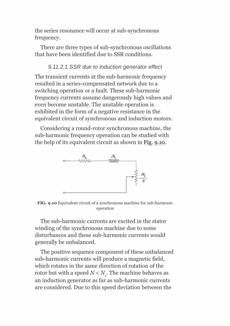
theseriesresonancewilloccuratsub-synchronousfrequency.
Therearethreetypesofsub-synchronousoscillationsthathavebeenidentifiedduetoSSRconditions.
9.11.2.1SSRduetoinductiongeneratoreffect
Thetransientcurrentsatthesub-harmonicfrequencyresultedinaseries-compensatednetworkduetoaswitchingoperationorafault.Thesesub-harmonicfrequencycurrentsassumedangerouslyhighvaluesandevenbecomeunstable.Theunstableoperationisexhibitedintheformofanegativeresistanceintheequivalentcircuitofsynchronousandinductionmotors.
Consideringaround-rotorsynchronousmachine,thesub-harmonicfrequencyoperationcanbestudiedwiththehelpofitsequivalentcircuitasshowninFig.9.10.
FIG.9.10Equivalentcircuitofasynchronousmachineforsub-harmonicoperation
Thesub-harmoniccurrentsareexcitedinthestatorwindingofthesynchronousmachineduetosomedisturbancesandthesesub-harmoniccurrentswouldgenerallybeunbalanced.
Thepositivesequencecomponentoftheseunbalancedsub-harmoniccurrentswillproduceamagneticfield,whichrotatesinthesamedirectionofrotationoftherotorbutwithaspeedN<N .Themachinebehavesasaninductiongeneratorasfarassub-harmoniccurrentsareconsidered.Duetothisspeeddeviationbetweenthe
s
rotorandthemagneticfield,theslip willbe
present.Sincef <f,theslipSbecomesnegative.
Therefore,theequivalentresistanceofthedamperwindingandthesolidrotorresistancewhenreferredto
thestatorside,i.e., becomesnegativeandtherefore
providesnegativedamping.
Iftheseriescompensationisveryhigh,theslipSwouldturnouttobeverysmallandhencetheequivalentresistancebecomesveryhighandmaybecomelargeenoughtohavetotalresistanceofthesystem,whichisnegative.Therefore,itprovidesnegativedampingofthesub-harmoniccurrents,andvoltagemaybuilduptodangerouslyhighvalues.SeveralmeasuresaretobetakentopreventSSRinthesystem.
9.11.2.2SSRduetotorsionalinteractionbetweenelectricalandmechanicalsystems
Thesub-harmoniccurrentsproducefieldrotationsinthedirectionwithrespecttotherotorandmainfieldandwhichinturnproducesanalternatingtorqueontherotoratthefrequency(f–f ).Ifthisfrequencydifferencecoincideswithoneofthenaturaltensionalresonancesofthemachineshaftsystem,tensionaloscillationsmaybeexcitedandthisoperationisentirelyknownasSSR.Itmeansthatwheneverthenaturalfrequencyofthemechanicaloscillationoftherotorequals(f–f ),mechanicalresonancewouldtakeplace.Hence,SSRistreatedasacombinedelectrical–mechanicalresonancephenomenon.
Thecurrentsofhighfrequencymayproducetorqueinsomeoftheshafts,whichmayhavethesamenaturalfrequencyasthetorquefrequency(calledswing
0
0
0

frequency,whichisthelowestfrequencyofnaturaloscillationofanequivalentsystemofaturbinecylinderandagenerator)suchthattheseshaftsmaybreakdownduetothetwistingaction.Hence,resonantfrequenciesmaybeextendeduptoseveralhundredsofHz.Thelargemultiple-stagesteamturbinesthathavemorethanonetensionalmodesinthefrequencyrangeof0.5HzaremoresusceptibletoSSR.
IntheSSRphenomenon,iftheresonancefrequencycoincideswiththeswingfrequency,thewholeturbine-generatorassemblymaycomeoutfromitsfoundation,and/orifthefrequencyofthetorquedevelopedcoincideswiththenaturalfrequencyofoscillationofsomeshaftsandifoscillationsbuildupsufficiently,itresultsinthebreakingoftheshaft.
9.11.2.3SSRduetolargedisturbances
Duetothelargedisturbanceslikeanyswitchingoperationoranyfaultcondition,theconditionofSSRoccursinthesystemevenifoscillationsaredampedout.ThisSSRconditionresultsina‘lowcyclefatigue’conditioninamechanicalsystemorslowdeteriorationofthemechanicalsystemduetothereductioninlifeoftheshafts.
ThecorrectivemeasuresforSSRare:
1. Bypassingaseriesofcapacitors.2. Useofverysensitiverelaystodetectevensmalllevelsofsub-
harmoniccurrents.3. Modulationofgeneratorfieldcurrenttoprovideanincreasedpositive
dampingsub-harmonicfrequency.
9.12SHUNTCOMPENSATOR
Ashunt-connectedstaticVArcompensator,composedofthyristor-switchedcapacitors(TSCs)andthyristor-controlledreactors(TCRs),isshownFig.9.11.Withproperco-ordinationofthecapacitorswitchingandreactorcontrol,theVAroutputcanbevariedcontinuouslybetweenthecapacitiveandinductiverating

oftheequipment.Thecompensatorisnormallyoperatedtoregulatethevoltageofthetransmissionsystemataselectedterminal,oftenwithanappropriatemodulationoptiontoprovidedampingifpoweroscillationisdetected.
FIG.9.11StaticVArcompensatoremployingTSCsandTCR
9.12.1Thyristor-controlledreactor
Ashunt-connectedthyristor-controlledinductorhasaneffectivereactance,whichisvariedinacontinuousmannerbypartial-conductioncontrolofthethyristorvalve.
Withtheincreaseinthesizeandcomplexityofapowersystem,fastreactivepowercompensationhasbecomenecessaryinordertomaintainthestabilityofthesystem.Thethyristor-controlledshuntreactorshavemadeitpossibletoreducetheresponsetimetoafewmilliseconds.Thus,thereactivepowercompensator
utilizingthethyristor-controlledshuntreactorsbecomepopular.Anelementarysingle-phaseTCRisshownFig.9.12.
ItconsistsofafixedreactorofinductanceLandabidirectionalthyristorvalve.Thethyristorvalvecanbebroughtintoconductionbytheapplicationofagatepulsetothethyristor,andthevalvewillbeautomaticallyblockedimmediatelyaftertheACcurrentcrosseszero.Thecurrentinthereactorcanbecontrolledfrommaximumtozerobythemethodoffiringanglecontrol.Partialconductionisobtainedwithahighervalueoffiringangledelay.Theeffectofincreasingthegatingangleistoreducethefundamentalcomponentofcurrent.Thisisequivalenttoanincreaseintheinductanceofthereactor,reducingitscurrent.Asfarasthefundamentalcomponentofcurrentisconcerned,theTCRisacontrollablesusceptance,andcan,therefore,beusedasastaticcompensator.
Thecurrentinthiscircuitisessentiallyreactive,laggingthevoltageby90°andthisiscontinuouslycontrolledbythephasecontrolofthethyristors.Theconductionanglecontrolresultsinanon-sinusoidalcurrentwaveforminthereactor.Inotherwords,theTCRgeneratesharmonics.Foridenticalpositiveandnegativecurrenthalf-cycletime,onlyoddharmonicsaregeneratedasshowninFig.9.13.Byusingfilters,wecanreducethemagnitudeofharmonics.
TCR’scharacteristicsare:
Continuouscontrol.Notransients.Generationofharmonics.
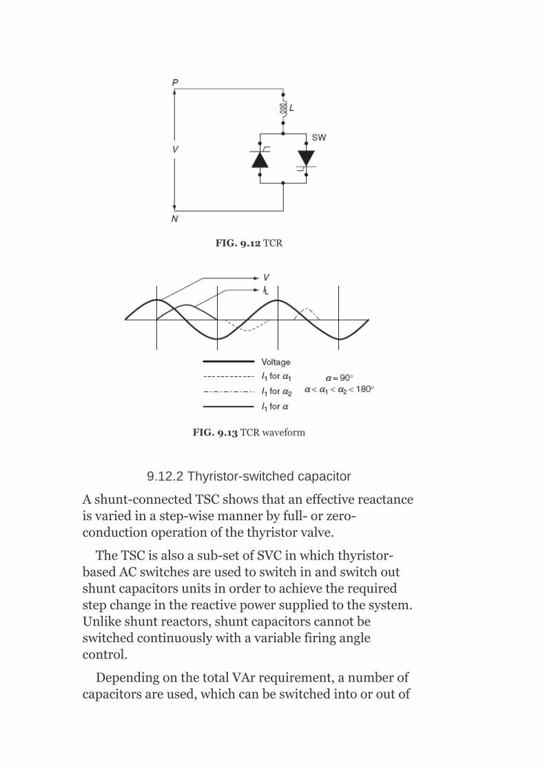
FIG.9.12TCR
FIG.9.13TCRwaveform
9.12.2Thyristor-switchedcapacitor
Ashunt-connectedTSCshowsthataneffectivereactanceisvariedinastep-wisemannerbyfull-orzero-conductionoperationofthethyristorvalve.
TheTSCisalsoasub-setofSVCinwhichthyristor-basedACswitchesareusedtoswitchinandswitchoutshuntcapacitorsunitsinordertoachievetherequiredstepchangeinthereactivepowersuppliedtothesystem.Unlikeshuntreactors,shuntcapacitorscannotbeswitchedcontinuouslywithavariablefiringanglecontrol.
DependingonthetotalVArrequirement,anumberofcapacitorsareused,whichcanbeswitchedintooroutof

thesystemindividually.ThecontrolisdonecontinuouslybysensingtheloadVArs.Asingle-phaseTSCisshowninFig.9.14.
Itconsistsofacapacitor,abidirectionalthyristorvalve,andrelativelysmallsurgecurrentinthethyristorvalveunderabnormaloperatingconditions(e.g.,controlmalfunctioncausingcapacitorswitchingata‘wrongtime’);itmayalsobeusedtoavoidresonancewithsystemimpendenceatparticularfrequencies.Theproblemofachievingtransient-freeswitchingofthecapacitorsisovercomebykeepingthecapacitorschargedtothepositiveornegativepeakvalueofthefundamentalfrequencynetworkvoltageatalltimeswhentheyareinthestand-bystate.Theswitching-on-transientisthenselectedatthetimewhenthesamepolarityexistsinthecapacitorvoltage.Thisensuresthatswitchingontakesplaceatthenaturalzeropassageofthecapacitorcurrent.Theswitchingthustakesplacewithpracticallynotransients.Thisiscalledzero-currentswitching.
FIG.9.14TSC

FIG.9.15TSCwaveforms
Switchingoffacapacitorisaccomplishedbysuppression-offeringpulsestotheanti-parallelthyristorssothatthethyristorswillswitchoffassoonasthecurrentbecomeszero.Inprinciple,thecapacitorwillthenremainchargedtothepositiveornegativepeakvoltageandbepreparedforanewtransient-freeswitching-onasshowninFig.9.15.
TSC’scharacteristicsare:
Steepedcontrol.Notransients.Noharmonics.Lowlosses.Redundancyandflexibility.
9.13SERIESCOMPENSATOR
IntheTSCscheme,increasingthenumberofcapacitorbanksinseries,controlsthedegreeofseriescompensation.Toaccomplishthis,eachcapacitorbankiscontrolledbyathyristorbypassswitchorvalve.Theoperationofthethyristorswitchesisco-ordinatedwithvoltageandcurrentzero-crossing;thethyristorswitchcanbeturnedontobypassthecapacitorbankwhentheappliedACvoltagecrosseszero,anditsturn-offhastobeinitiatedpriortoacurrentzeroatwhichitcanrecoveritsvoltage-blockingcapabilitytoactivatethecapacitor
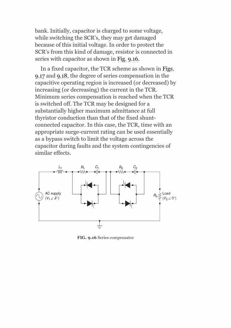
bank.Initially,capacitorischargedtosomevoltage,whileswitchingtheSCR’s,theymaygetdamagedbecauseofthisinitialvoltage.InordertoprotecttheSCR’sfromthiskindofdamage,resistorisconnectedinserieswithcapacitorasshowninFig.9.16.
Inafixedcapacitor,theTCRschemeasshowninFigs.9.17and9.18,thedegreeofseriescompensationinthecapacitiveoperatingregionisincreased(ordecreased)byincreasing(ordecreasing)thecurrentintheTCR.MinimumseriescompensationisreachedwhentheTCRisswitchedoff.TheTCRmaybedesignedforasubstantiallyhighermaximumadmittanceatfullthyristorconductionthanthatofthefixedshunt-connectedcapacitor.Inthiscase,theTCR,timewithanappropriatesurge-currentratingcanbeusedessentiallyasabypassswitchtolimitthevoltageacrossthecapacitorduringfaultsandthesystemcontingenciesofsimilareffects.
FIG.9.16Seriescompensator
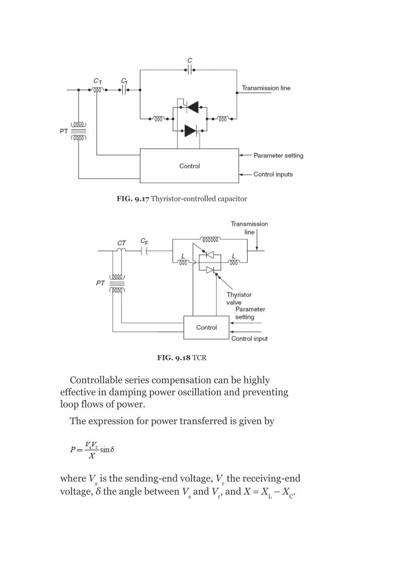
FIG.9.17Thyristor-controlledcapacitor
FIG.9.18TCR
Controllableseriescompensationcanbehighlyeffectiveindampingpoweroscillationandpreventingloopflowsofpower.
Theexpressionforpowertransferredisgivenby
whereV isthesending-endvoltage,V thereceiving-endvoltage,δtheanglebetweenV andV ,andX=X –X .
s r
s r L C

Ininterconnectedpowersystems,theactualtransferofpowerfromoneregiontoanothermighttakeunintendedroutesdependingonimpedancesoftransmissionlinesconnectingtheareas.Controlledseriescompensationisausefulmeansforoptimizingpowerflowbetweenregionsforvaryingloadingandnetworkconfigurations.Itbecomespossibletocontrolpowerflowsinordertoachieveanumberofgoalsthatarelistedbelow:
Minimizingsystemlosses.Reductionofloopflows.Eliminationoflineoverloads.Optimizingloadsharingbetweenparallelcircuits.Directingpowerflowsalongcontractualpaths.
9.14UNIFIEDPOWER-FLOWCONTROLLER
IntheUPFC,anACvoltagegeneratedbyathyristor-basedinverterisinjectedinserieswiththephasevoltage.InFig.9.19,Converter-2performsthemainfunctionoftheUPFCbyinjecting,via.,aseriestransformer,anACvoltagewithcontrollablemagnitudeandaphaseangleinserieswiththetransmissionline.ThebasicfunctionofConverter-1istosupplyorabsorbtherealpowerdemandedbyConverter-2atthecommonDClink.Itcanalsogenerateorabsorbcontrollablereactivepowerandprovideanindependentshunt-reactivecompensationfortheline.Converter-2eithersuppliesorabsorbstherequiredreactivepowerlocallyandexchangestheactivepowerasaresultoftheseriesinjectionvoltage.

FIG.9.19TheUPFC
FIG.9.20ImplementationoftheUPFCusingtwovoltagesourceinverterswithadirectvoltagelinksimultaneously
Generally,theimpedancecontrolwouldcostlessandbemoreeffectivethanthephaseanglecontrol,exceptwherethephaseangleisverysmallorverylargeorvarieswidely.
Ingeneral,ithasthreecontrolvariablesandcanbeoperatedindifferentmodes.Theshunt-connected

converterregulatesthevoltagebus‘i’inFig.9.20andtheseries-connectedconverterregulatestheactiveandreactivepoweroractivepowerandthevoltageattheseries-connectednode.Inprinciple,aUPFCisabletoperformthefunctionsoftheotherFACTSdevices,whichhavebeendescribed,namelyvoltagesupport,power-flowcontrol,andanimprovedstability.
9.15BASICRELATIONSHIPFORPOWER-FLOWCONTROL
Thebasicconceptofcontrollingpowertransmissioninrealtimeassumestheavailablemeansforrapidlychangingthoseparametersofthepowersystem,whichdeterminethepowerflow.Toconsiderthepossibilitiesforapower-flowcontrol,powerrelationshipsforthesimpletwo-machinemodelareshowninFigs.9.21and9.22.
Figure9.22showsthesending-andreceiving-endgeneratorswithvoltagephasorsV andV ,inductive
transmissionlineimpedance(X )intwosections ,and
generalizedpower-flowcontrolleroperated(forconvenience)atthemiddleoftheline.Thepower-flowcontrollerconsistsoftwocontrollableelements,i.e.,avoltagesource(V )andacurrentsource(I )areconnectedinseriesandshunt,respectively,withthelineatthemidpoint.BoththemagnitudeandtheangleofthevoltageV arefreelyvariables,whereasonlythemagnitudeofcurrentI isvariable;itsphaseangleisfixedat90°withrespecttothereferencephasorofmidpointvoltageV .Thebasicpower-flowrelationisshowninFig.9.22byusingFACTScontrollerinanormaltransmissionsystem.
S r
L
xy x
xy
x
m

FIG.9.21Simpletwo-machinepowersystemwithageneralizedpower-flowcontroller
FIG.9.22Power-flowrelation
Thefourclassicalcasesofpowertransmissionareasfollows:
1. Withoutlinecompensation.2. Withseriescapacitivecompensation.3. Withshuntcompensation.4. Withphaseanglecontrol,
TheycanbeobtainedbyappropriatelyspecifyingV andI inthegeneralizedpower-flowcontroller.
9.15.1Withoutlinecompensation
Considerthatthepower-flowcontrollerisoff,i.e.,bothV andI arezero.Then,thepowertransmittedbetweenthesending-andreceiving-endgeneratorscanbeexpressedbythewell-knownformula:
xy
x
xy x

whereδistheanglebetweenthesending-andreceiving-endvoltagephasors.PowerP isplottedagainstangleδinFig.9.23.
FIG.9.23Thebasicpowertransmissiononcharacteristicsforfourdifferentcases
9.15.2Withseriescapacitivecompensation
Assumeparallelcurrentsource,I =0,andseriesvoltagesource,V =–jnX I,i.e.,thevoltageinsertedinserieswiththelinelagsthelinecurrentby90°withanamplitudethatisproportionaltothemagnitudeofthelinecurrentandthatofthelineimpedance.Inotherwords,thevoltagesourceactsatthefundamental
(1)
x
xy L

frequencypreciselyasaseries-compensatingcapacitor.Thedegreeofseriescompensatingisdefinedbycoefficientn(i.e.,0≤n≤1).Withthis,Pagainstδrelationshipbecomes
9.15.3Withshuntcompensation
ConsiderthatseriesvoltagesourceV =0andparallel
currentsource i.e.,thecurrentsource
I drawsjustenoughcapacitivecurrenttomakethemagnitudeofthemidpointvoltageV equaltoV.Inotherwords,thereactivecurrentsourceactslikeanidealshuntcompensator,whichsegmentsthetransmissionlineintotwoindependentparts,eachwithanimpedance
of bygeneratingthereactivepowernecessarytokeep
themidpointvoltageconstant,independentlyofangleδ.Forthiscaseofidealmidpointcompensation,thePagainstδrelationcanbewrittenas
9.15.4Withphaseanglecontrol
AssumethatI =0andV =±jV tanα,i.e.,avoltage(V )withtheamplitude±jV tanα,isaddedinquadraturetothemidpointvoltage(V )toproducethedesiredαphaseshift.Thebasicideabehindthephaseshifteristokeepthetransmittedpoweratadesiredlevelindependentlyofangleδinapre-determinedoperating
xy
x
m
x xy m
xy m
m
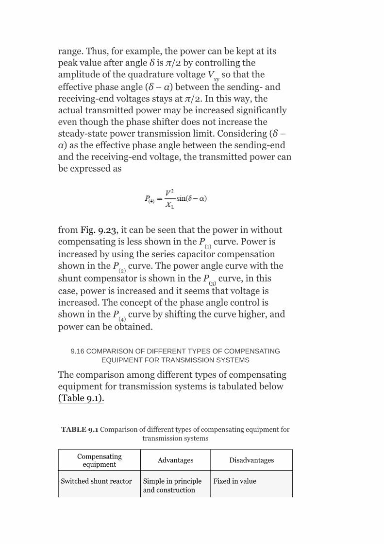
range.Thus,forexample,thepowercanbekeptatitspeakvalueafterangleδisπ/2bycontrollingtheamplitudeofthequadraturevoltageV sothattheeffectivephaseangle(δ–α)betweenthesending-andreceiving-endvoltagesstaysatπ/2.Inthisway,theactualtransmittedpowermaybeincreasedsignificantlyeventhoughthephaseshifterdoesnotincreasethesteady-statepowertransmissionlimit.Considering(δ–α)astheeffectivephaseanglebetweenthesending-endandthereceiving-endvoltage,thetransmittedpowercanbeexpressedas
fromFig.9.23,itcanbeseenthatthepowerinwithoutcompensatingislessshownintheP curve.PowerisincreasedbyusingtheseriescapacitorcompensationshownintheP curve.ThepoweranglecurvewiththeshuntcompensatorisshownintheP curve,inthiscase,powerisincreasedanditseemsthatvoltageisincreased.TheconceptofthephaseanglecontrolisshownintheP curvebyshiftingthecurvehigher,andpowercanbeobtained.
9.16COMPARISONOFDIFFERENTTYPESOFCOMPENSATINGEQUIPMENTFORTRANSMISSIONSYSTEMS
Thecomparisonamongdifferenttypesofcompensatingequipmentfortransmissionsystemsistabulatedbelow(Table9.1).
TABLE9.1Comparisonofdifferenttypesofcompensatingequipmentfortransmissionsystems
Compensatingequipment
Advantages Disadvantages
Switchedshuntreactor Simpleinprincipleandconstruction
Fixedinvalue
xy
(1)
(2)
(3)
(4)
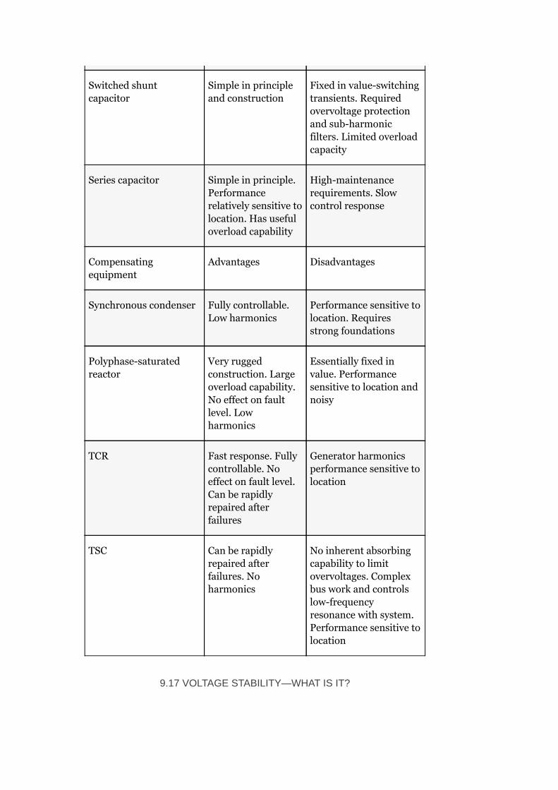
Switchedshuntcapacitor
Simpleinprincipleandconstruction
Fixedinvalue-switchingtransients.Requiredovervoltageprotectionandsub-harmonicfilters.Limitedoverloadcapacity
Seriescapacitor Simpleinprinciple.Performancerelativelysensitivetolocation.Hasusefuloverloadcapability
High-maintenancerequirements.Slowcontrolresponse
Compensatingequipment
Advantages Disadvantages
Synchronouscondenser Fullycontrollable.Lowharmonics
Performancesensitivetolocation.Requiresstrongfoundations
Polyphase-saturatedreactor
Veryruggedconstruction.Largeoverloadcapability.Noeffectonfaultlevel.Lowharmonics
Essentiallyfixedinvalue.Performancesensitivetolocationandnoisy
TCR Fastresponse.Fullycontrollable.Noeffectonfaultlevel.Canberapidlyrepairedafterfailures
Generatorharmonicsperformancesensitivetolocation
TSC Canberapidlyrepairedafterfailures.Noharmonics
Noinherentabsorbingcapabilitytolimitovervoltages.Complexbusworkandcontrolslow-frequencyresonancewithsystem.Performancesensitivetolocation
9.17VOLTAGESTABILITY—WHATISIT?

Voltageinstabilitydoesnotmeantheproblemoflowvoltageinsteady-statecondition.Asamatteroffact,itispossiblethatthevoltagecollapsemaybeprecipitatedeveniftheinitialoperatingvoltagesmaybeatacceptablelevels.
Voltagecollapsemaybeeitherfastorslow.FastvoltagecollapseisduetoinductionmotorloadsorHVDCconverterstationsandslowvoltagecollapseisduetoon-loadtapchangerandgeneratorexcitationlimiters.
Voltagestabilityisalsosometimestermedloadstability.Thetermsvoltageinstabilityandvoltagecollapseareoftenusedinterchangeably.
Itistobeunderstoodthatthevoltagestabilityisasub-setofoverallpowersystemstabilityandisadynamicproblem.Thevoltageinstabilitygenerallyresultsinmonotonically(oraperiodically)decreasingvoltages.Sometimes,thevoltageinstabilitymaymanifestasundamped(ornegativelydamped)voltageoscillationspriortovoltagecollapse.
9.17.1Voltagestability
Definition:Apowersystematagivenoperatingstateandsubjectedtoagivendisturbanceisvoltagestableifvoltagesneartheloadsapproachpost-disturbanceequilibriumvalues.Thedisturbedstateiswithintheregionsofattractionsofstablepost-disturbanceequilibrium.
Theconceptofvoltagestabilityisrelatedtothetransientstabilityofapowersystem.
9.17.2Voltagecollapse
Followingvoltageinstability,apowersystemundergoesvoltagecollapseifthepost-disturbanceequilibriumvoltagesneartheloadarebelowacceptablelimits.Thevoltagecollapsemaybeeithertotalorpartial.

Theabsenceofvoltagestabilityleadstovoltageinstabilityandresultsinprogressivedecreaseofvoltages.Whendestabilizingcontrols(suchasOLTC)reachlimitsorduetoothercontrolactions(undervoltageloadshedding),thevoltagesarestabilized(atacceptableorunacceptablelevels).Thus,abnormalvoltagelevelsinthesteadystatemaybetheresultofvoltageinstability,whichisadynamicphenomenon.
9.18VOLTAGE-STABILITYANALYSIS
Thevoltage-stabilityanalysisiscarriedoutbyloadflowmethods,whicharebasicallypost-disturbancepower-flowmethods.Besidesthesemethods,P–VcurvesandQ–Vcurvesaretheotherpower-flow-basedmethodsgenerallyusedforvoltage-stabilityanalysis.Bythesetwomethods,thesteady-stateloadabilitylimitsaredetermined,whicharerelatedtovoltagestability.
9.18.1P–Vcurves
TheconceptualanalysisofvoltagestabilityisusefulcarriedoutbyusingP–Vcurves.Theseareusefulforthestudyofanalysisofradialsystems.
ThismethodisalsoapplicableforalargeinterconnectednetworktowhichthetotalloadconnectedisPandthevoltageofthecriticalbusisV.ThetotalloadPmaybethepowertransferredoveratransmissionline.Thevoltageatseveralbusescanbeplotted.
9.18.1.1InterpretationofP–Vcurves
ConsideraradiallinewithanasynchronousloadisasshowninFig.9.24(a).
TheloadisP +jQ atthereceivingendkeepingthesending-endvoltageV constant.
Eventheradiallineisconnectedwiththeasynchronousload,themaximumpowercanbe
L L
s

transmittedovertheline.
Letusconsiderthattheloadisu.p.floadandthesending-endvoltagesourceandlineformavoltagesourcewithanopen-circuitvoltageV andimpedance(R+jX)andatthereceivingendavariableresistiveloadRisconnectedsuchthatthep.f.isunity(Fig.9.24(b)).
FIG.9.24(a)AradiallineterminatedthroughanasynchronousloadP +
jQ ;(b)equivalentcircuitofFig.9.24withu.p.f.load
Theshort-circuitcurrent,
Short-circuitp.f.,
Thetotalloadcurrent,
Thepowerdeliveredtotheload,
oc
L
L
L

Conditionformaximumpowerdeliveredis
∴R =Z,istheconditionformaximumpowerdelivered
SubstitutingthisconditioninEquation(9.42),wegetthemaximumpoweras
NowV istheopen-circuitvoltage,i.e.,V whenI =0.
Letxbethedistancefromthesendingendandlbethelengthoftheline
L
oc r r

Foralosslessline,r=0andg=0,thenthevoltageatdistancexfromthesendingendbecomes
V =V cosβ(l−x)+jZ I sinβ(l−x)
whereβisthephaseconstant
Supposethelineisopencircuitedatthereceivingend,i.e.,I =0,
Similarly,theshort-circuitcurrentI isthevalueofIwhenV =0
Assumingthelinetobelossless,cosϕ =0
Equation(9.43)representslociofmaximumpowerfordifferentlinelengthsatunityp.f.
Thereceiving-endcurrent,
Thesending-endvoltageoftheline,ifassumingthelinetobelossless,nowbecomes
(x) r c r
r
sc r
r
sc

Forafixedsending-endvoltageV andthefixedlinelength,Equation(9.44)isquadraticinV andthuswillhavetworoots.Figure9.25showsagraphicalrelation
between asafunctionofnormalizedloading .
FromFig.9.25,itisobservedthatthemaximumpowercanbetransmittedforeachloadp.f.andforanyloading,therearetwodifferentvaluesofV .
Thenormaloperationofthepowersystemisalongtheupperpartofthecurvewherethereceiving-endvoltageisnearly1.0p.u.Theloadisincreasedbydecreasingtheeffectiveresistanceoftheloaduptothemaximumpower;theproductofloadvoltageandcurrentincreasesasthesystemisstable.Asthepointofmaximumpowerisreached,afurtherreductionineffectiveloadresistancereducesthevoltagemorethantheincreaseincurrentandtherefore,thereisaneffectivereductioninpowertransmission.Thevoltagefinallycollapsestozeroandthesystematthereceivingendiseffectivelyshort-circuitedandtherefore,thepowertransmittediszero(pointatorgininFig.9.25).
ItisobservedfromFig.9.25thatthepowertransmittediszerobothatPointKandPoint0.PointKcorrespondingtotheopencircuitandPoint0correspondingtotheshortcircuitandineithercasethepowertransmittediszero.
s
r
r
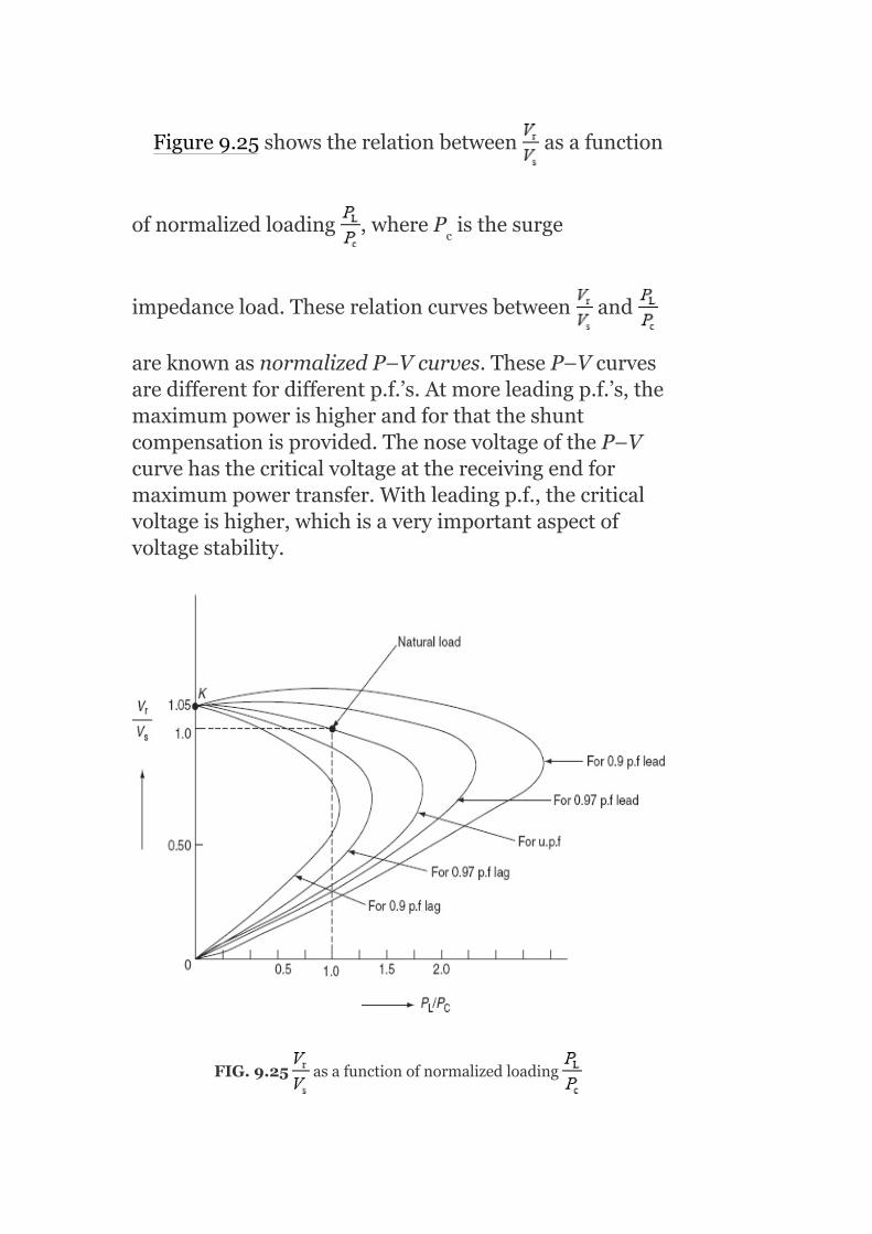
Figure9.25showstherelationbetween asafunction
ofnormalizedloading ,whereP isthesurge
impedanceload.Theserelationcurvesbetween and
areknownasnormalizedP–Vcurves.TheseP–Vcurvesaredifferentfordifferentp.f.’s.Atmoreleadingp.f.’s,themaximumpowerishigherandforthattheshuntcompensationisprovided.ThenosevoltageoftheP–Vcurvehasthecriticalvoltageatthereceivingendformaximumpowertransfer.Withleadingp.f.,thecriticalvoltageishigher,whichisaveryimportantaspectofvoltagestability.
FIG.9.25 asafunctionofnormalizedloading
c

Themaindisadvantageoftheload-flowsolutionforP–Vcurvesisthatitislikelytodivergenearthemaximumpower-transferpointorthenosepointoftheP–Vcurve.Aload-flowsolutionisatvariousP–Vbusesorgeneratorsbusesforparticulargenerations.However,whentheloadchanges,theschedulingofgenerationatvariousgeneratorbusesalsochanges.Thisisyetanotherdisadvantageoftheload-flowsolutionmethod.
9.18.2Conceptofvoltagecollapseproximateindicator
ConsiderthatapurelyinductiveloadisconnectedtoasourcethroughalosslesslineasshowninFig.9.26.
Here,P=0andδ=0sincetheloadispurelyinductive;therefore,thereactivepoweratthereceiving
endisexpressedas .
Theconditionformaximumreactivepowertransferis
.
FIG.9.26Radiallineconnectedwithpurelyinductiveloadtosource

whereV isthereceiving-endvoltageformaximumreactivepowertransfer.
Therefore,themaximumreactivepowerisexpressedas
Ashalfofthedropwillbeacrossthelineandanother
halfacrosstheload,X =X;hence, i.e.,the
maximumreactivepoweristransferredwhentheloadreactanceisequaltothelinereactanceorthesourcereactance.
Theshort-circuitreactivepowerofthelineis ;
hence,thenormalizedmaximumreactivepoweris
Also
NowQ =Q +I X
critical
load
s r
2

Since
Hence,
MultiplyingbothsidesofEquation(9.45)by ,weget
Now
Thedifferentiationofthesending-endreactivepowerQ withrespecttothereceiving-endreactivepowerQ ,s r

i.e., ,isknownasthevoltagecollapseproximate
indicator(VCPI)ofaradialline.
Thereceiving-endvoltagevariesfromV atnoloadto
atmaximumloadQ .However,VCPIisunityatno
loadsinceatnoloadQ =0and andit
isinfinityatmaximumloadsinceatthisloadQ =Q
andhence
Itisclearthatnearthemaximumload,anextremelylargeamountofreactivepowerisrequiredatthesendingendtosupplyanincrementalincreaseinload.Thus,VCPIisaverysensitiveindicatorofimpedingvoltagecollapse.There,latedquantitiesreactivereserveactivationandreactivelossesarealsosensitiveindicators.
9.18.3Voltage-stabilityanalysis:Q–Vcurves
Q–VcurvescanbeobtainedfromthenormalizedP–Vcurves.
Let
Forconstantvaluesofp,wenotethetwopairsofvaluesofvandqforeachp.f.andreportthesevalues.TheresultoftheseplotsisshowninFig.9.27.
s
max
r
r rmax

FIG.9.27NormalizedQ–Vcurvesforfixedsourceandreactivenetworkloadsareatconstantpower
Thecriticalvoltageishighforloadings(i.e.,visabove1p.u.forp=1p.u.).Theright-handsideofthecurvesindicatesthenormaloperatingconditionswheretheapplicationofshuntcapacitorsraisesthevoltage.Thesteep-slopedlinearportionsoftherightsideofthecurveareequivalenttothefigurebelow(rotateFig.9.28clock-wiseby90°).

FIG.9.28Systemapproximatevoltage-reactivepowercharacteristic
TheQ–Vcurvesforlargesystemsareobtainedbyaseriesofpower-flowsimulations.Q–Vcurvesresultfromtheplotofvoltageatatestorcriticalbusversusreactivepoweronthesamebus.Generally,theP–Vbusorgeneratorbushasreactivepowerconstraintsforaload-flowsolution.Afictitioussynchronouscondenserisrepresentedatthetestbusandallowsthebustohaveanyreactivepowerforafixedpandv.ThevalueofvatthebuschangesforobtaininganotherpointontheQ–Vcurve,andobtainsreactivepowerflowfordifferentscheduledvoltagesatthebus.Scheduledvoltageatthebusisanindependentvariableandformsanabscissavariable.Thecapacitivereactivepowerrequiredtomaintainthescheduledvoltageatthebusisadependentvariableandisplottedinthepositiveverticaldirection.Withouttheapplicationofshuntreactivecompensationatthetestbus,theoperatingpointisatthezeroreactivepointcorrespondingtotheremovalofthefictitioussynchronouscondenser.
9.19DERIVATIONFORVOLTAGE-STABILITYINDEX
Consideratypicalbranchconsistingofsending-andreceiving-endbusesasshowninFig.9.29.

Currentflowingthroughthebranch,
Therealtermoftheaboveequationis
V V cos(δ −δ )=V +(RP+XQ)
andtheimaginarypartis
V V sin(δ −δ )=XP−RQ
Squaringandaddingtheabovetwoterms,weget
FIG.9.29Single-linemodeloftypicalbranch
TheaboveequationisaquadraticequationofV .ThesystemistobestableifV ≥0.
Itispossiblewhen
b −4ac≥0
i.e.,[2(RP+XQ)−V )] −4(P +Q )(R +X )≥0
or4R p +4X Q +4R×PQ+V −4V (RP+XQ)
S R 1 2 R
S R 1 2
R
R
S
S S
2
2
2
2
2 2 2 2 2 2
2 2 2 2 4 2

−4R p −4X p −4R Q −4X Q ≥0
Simplifyingtheaboveequation,weget
V −4V (RP−XQ)−4(PX−RQ) ≥0
or4(PX−RQ) +4V (RP+XQ)≤V
DividingbothsidesoftheaboveequationbyV ,weget
whereL=stabilityindex
Forstablesystems,L≤1.
Example9.1:A440V,3-ϕdistributionfeederhasaloadof100kWatlaggingp.f.withtheloadcurrentof200A.Ifthep.f.istobeimproved,determinethefollowing:
1. uncorrectedp.f.andreactiveloadand2. newcorrectedp.f.afterinstallingashuntcapacitorof75kVAr.
Solution:
1. Uncorrectedp.f.
2. Correctedp.f.
2 2 2 2 2 2 2 2
S S
S S
S
4 2 2
2 2 4
4

Example9.2:Asynchronousmotorhavingapowerconsumptionof50kWisconnectedinparallelwithaloadof200kWhavingalaggingp.f.of0.8.Ifthecombinedloadhasap.f.of0.9,whatisthevalueofleadingreactivekVAsuppliedbythemotorandatwhatp.f.isitworking?
Solution:
Let:
p.f.angleofmotor=ϕ
p.f.angleofload=ϕ =cos (0.8)=36.87°
Combinedp.f.angle(bothmotorandload),ϕ=cos(0.9)=25.84°
tanϕ =tan36°87′=0.75;tanϕ=tan25°84′=0.4842
Combinedpower,P=200+50=250kW
TotalkVArofacombinedsystem=Ptanϕ =250×0.4842=121.05
LoadkVAr=200×tanϕ =200×0.75=150
∴LeadingkVArsuppliedbysynchronousmotor=150–121.05=28.95
p.f.angleatwhichthemotorisworking,ϕ =tan28.95/50=30.07°
p.f.atwhichthemotorisworking=cosϕ =0.865(lead)
Example9.3:A3-ϕ,5-kWinductionmotorhasap.f.of0.85lagging.Abankofcapacitorisconnectedindeltaacrossthesupplyterminalandp.f.raisedto0.95lagging.DeterminethekVArratingofthecapacitorineachphase.
Solution:
Theactivepoweroftheinductionmotor,P=5kW
1
2
2
1
2
1
1
–1
–
1
–1

Whenthep.f.ischangedfrom0.85lagto0.95lagbyconnectingacondenserbank,theleadingkVArtakenbythecondenserbank=P(tanϕ –tanϕ )
=5(0.6197–0.3287)=1.455
∴Ratingofcapacitorconnectedineachphase=1.455/3=0.485kVAr
Example9.4:A400V,50Hz,3-ϕsupplydelivers200kWat0.7p.f.lagging.Itisdesiredtobringthelinep.f.to0.9byinstallingshuntcapacitors(Fig.9.30).Calculatethecapacitanceiftheyare:(a)starconnectedand(b)deltaconnected.
Solution:
1. Forstarconnection:
Phasevoltage,V =400/ =230.94V/ph
Loadcurrent,
Theactivecomponentofcurrent,I =Icosϕ =412.39×0.7=288.68A
Reactivecomponentofcurrent,
FIG.9.30Phasordiagram
Forafixedload,letustake:
2 1
ph
a 1

Thereactivecomponentofloadcurrentwithoutcapacitor=I tanϕ
Thereactivecomponentofloadcurrentwithcapacitor=I tanϕ
Currenttakenbythecapacitorinstalledforimprovingp.f.,I =I (tan
ϕ –tanϕ )
=288.68(tan(cos 0.7)−tan(cos 0.9))
=154.7A
Thevalueofcapacitortobeconnected,
2. Fordeltaconnection:
Phasevoltage,V =400V
Loadcurrent,
Phasecurrent,
Theactivecomponentofphasecurrent,I =Icosϕ =238.09×0.7=166.663A
Currenttakenbythecapacitorinstalledforimprovingp.f.,I =I
(tanϕ –tanϕ )
=166.663(tan(cos 0.7)−tan(cos 0.9))
=89.312A
Thevalueofcapacitortobeconnected,
Example9.5:A3-ϕ500HP,50Hz,11kVstar-connectedinductionmotorhasafullloadefficiencyof85%atlaggingp.f.of0.75andisconnectedtoafeeder.Ifthep.f.ofloadisdesiredtobecorrectedto0.9lagging,determinethefollowing:
a 1
a 2
C a
1 2
ph
a 1
C a
1 2
−1 −1
−1 −1

1. sizeofthecapacitorbankinkVArand2. capacitanceofeachunitifthecapacitorsareconnectedinΔaswellas
inY.
Solution:
Inductionmotoroutput=500HP
Efficiencyη=85%,
η=output/input
Inputoftheinductionmotor,P = output/η=500/0.85=588.235HP
= 588.235×746=438.82kW
Initialp.f.(cosϕ ) = 0.75⇒tanϕ =0.88
Correctedp.f.(cosϕ ) = 0.9⇒tanϕ =0.48
LeadingkVArtakenbythecapacitorbank,Q = P(tanϕ −tanϕ )
= 438.82(0.88−0.48)=175.53kVAr
Case1:Deltaconnection:
Chargingcurrentperphase,
Reactanceofcapacitorbankperphase,
1 1
2 2
c 1
2

Capacitanceofcapacitorbank,
Case2:Starconnection:
I =I =9.213A
Reactanceofcapacitorbankperphase,
Capacitanceofcapacitorbank,
Example9.6:Astar-connected400HP(metric),2,000V,and50Hzmotorworksatap.f.of0.7lag.Abankofmesh-connectedcondensersisusedtoraisethep.f.to0.9lag.Calculatethecapacitanceofeachunitandtotalnumberofunitsrequired,ifeachunitisrated400V,50Hz.Themotorefficiencyis90%(Fig.9.31).
Solution:
Motoroutput =400HP
Supplyvoltage =2,000V
i.e.,V =2,000V
L c

p.f.withoutcondenser =0.7lag
FIG.9.31Circuitdiagram
Efficiencyofmotor,η=0.9;
Forfixedloads,theactivecomponentofcurrentisthesameforimprovedp.f.,whereasthereactivecomponentwillbechanged.
∴Theactivecomponentofcurrentat0.7p.f.lag.,I =Icosϕ
=136.73×0.7=95.71A
Linecurrenttakenbythecapacitorinstalledforimprovingp.f.,I =I (tanϕ −tanϕ )
=95.71(tan(cos 0.7)−tan(cos 0.9))
=51.28A
Thebankofcondensersusedtoimprovethep.f.isconnectedindelta.Thevoltageacrosseachphaseis2,000V,buteachunitofcondenserbankisof400V.So,eachphaseofthebankwillhavefivecondensersconnectedinseriesasshowninFig.9.31.
a1
1
C a 1 2−1 −1

Thecurrentineachphaseofthebank
LetX bethereactanceofeachcondenser.
Thenthechargecurrent,
Capacitanceofeachphaseofthebank
Example9.7:A3-ϕ,50Hz,2,500Vmotordevelops600HP,thep.f.being0.8laggingandtheefficiency0.9.Acapacitorbankisconnectedindeltaacrossthesupplyterminalsandthep.f.israisedtounity.Eachofthecapacitanceunitsisbuiltoffivesimilar500Vcapacitors(Fig.9.32).Determinethecapacitanceofeachcapacitor.
FIG.9.32Circuitdiagram
Solution:
Motorinput
c

LeadingkVArsuppliedbythecapacitorbank=P(tanϕ−tanϕ )
=497.33(0.75−0)
=373kVAr
LeadingkVArsuppliedbyeachofthreesets
Currentperphaseofcapacitorbank,
kVArrequired/phase
ButleadingkVArsuppliedbyeachphase=124.33kVAr
1
2

Sinceitisthecombinedcapacitanceoffiveequalcapacitorsjoinedinseries,
Thecapacitanceofeachunit =5×63.32µF
=3,116.6µF
Example9.8:A3-ϕ,50Hz,30-kmtransmissionlinesuppliesaloadof5MWatp.f.0.7laggingtothereceivingendwherethevoltageismaintainedconstantat11kV.Thelineresistanceandinductanceare0.02Ωand0.84mHperphaseperkm,respectively.Acapacitorisconnectedacrosstheloadtoraisethep.f.to0.9lagging(Fig.9.33).Calculate:(a)thevalueofthecapacitanceperphaseand(b)thevoltageregulation.
Solution:
Lengthoftheline =30km
Frequency =50Hz
Load =5MWat0.7laggingp.f.
Receiving-endvoltage,V =11kV
Lineresistanceperphase=0.02Ωperkm =0.02×30=0.6Ω
Reactanceof30-kmlengthperphase,X =2×π×f×L×30
=2×π×50×0.84×10 ×30=7.92Ω
r
–3
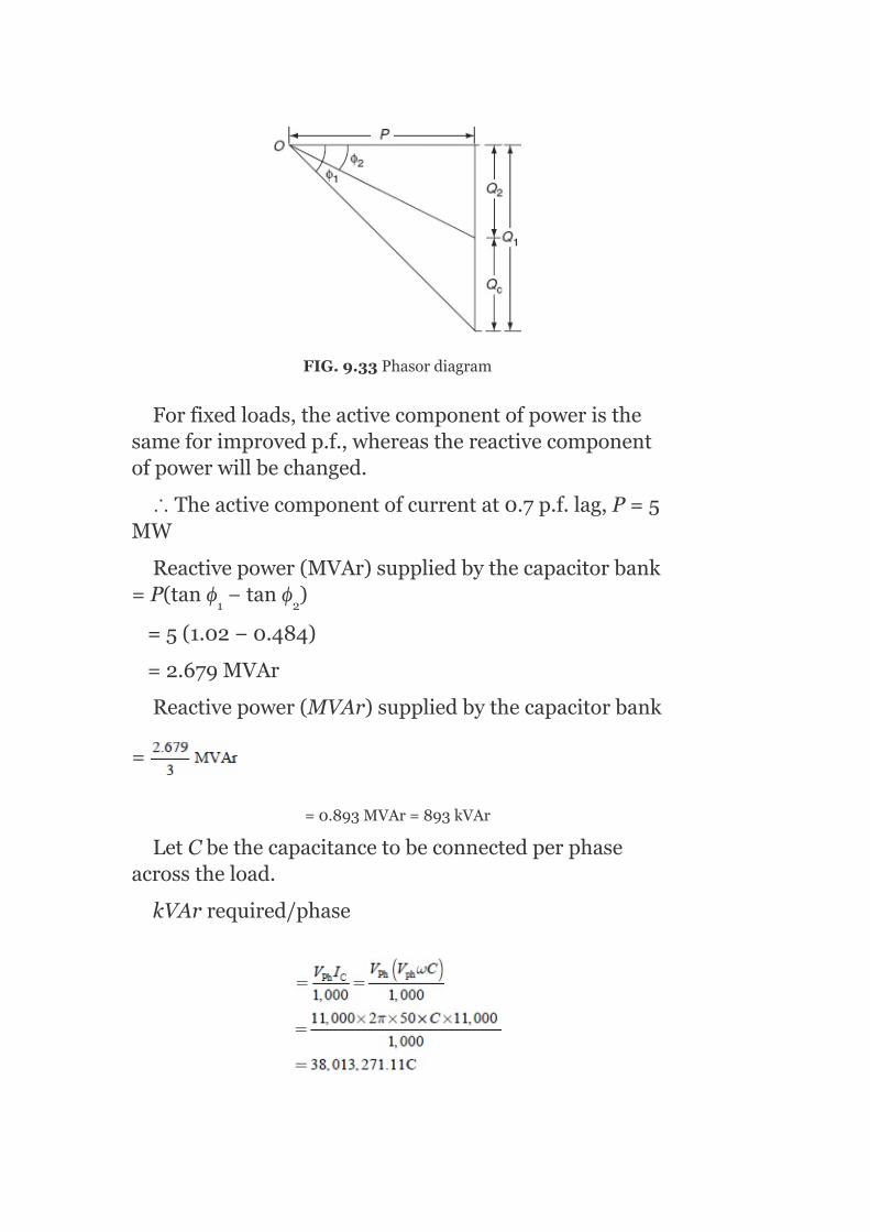
FIG.9.33Phasordiagram
Forfixedloads,theactivecomponentofpoweristhesameforimprovedp.f.,whereasthereactivecomponentofpowerwillbechanged.
∴Theactivecomponentofcurrentat0.7p.f.lag,P=5MW
Reactivepower(MVAr)suppliedbythecapacitorbank=P(tanϕ −tanϕ )
=5(1.02−0.484)
=2.679MVAr
Reactivepower(MVAr)suppliedbythecapacitorbank
=
=0.893MVAr=893kVAr
LetCbethecapacitancetobeconnectedperphaseacrosstheload.
kVArrequired/phase
1 2

ButleadingkVArsuppliedbyeachphase=893kVAr
Sending-endvoltagewithimprovedp.f.=V +I(Rcosϕ +jXsinϕ )
Receiving-endvoltage,
Currentwithimprovedp.f.,
∴Sending-endvoltage,V =6,350.85+291.59(0.6×0.9+j7.92×0.436)
=6,508.31+j1006.9V/ph
=6,585.74∠8.79V/ph
=11,406.84V(L-L)
Example9.9:Asynchronousmotorimprovesthep.f.ofaloadof200kWfrom0.7laggingto0.9laggingandatthesametimecarriesanadditionalloadof100kW(Fig.9.34).Find:(i)TheleadingkVArsuppliedbythemotor,(ii)kVAratingofmotor,and(iii)p.f.atwhichthemotoroperates.
r
2 2
s

Solution:
Load,P =200kW
Motorload,P =100kW
p.f.oftheload200kW =0.7lag
p.f.ofthecombinedload(200+100)kW =0.9lag
Combinedload =P +P =200+100=
300kW
∆OABisapowertrianglewithoutadditionalload,∆ODCthepowertriangleforcombinedload,and∆BECforthemotorload.
FromFig.9.34,wehave
(i)LeadingkVArtakenbythemotor = CE
= DE–DC=AB–DC
= 200tan(cos 0.7)–300tan(cos 0.9)
= 200×1.02–300×0.4843
= 58.71KVAr
(ii)kVAratingofmotor =BE
1
2
1 2
–1
–1

=115.96kVA
FIG.9.34Phasordiagram
(iii)p.f.ofmotoratwhichitoperates,cosϕ
=0.862leading
m

Example9.10:A37.3kWinductionmotorhasp.f.0.9andefficiency0.9atfull-load,p.f.0.6,andefficiency0.7athalf-load.Atno-load,thecurrentis25%ofthefull-loadcurrentandp.f.0.1.Capacitorsaresuppliedtomakethelinep.f.0.8athalf-load.Withthesecapacitorsincircuit,findthelinep.f.at(i)full-loadand(ii)no-load.
Solution:
Full-loadcurrent,I =37.3×10 /( V ×0.9×0.9)=26,586/V
Atfullload:
Motorinput,P =37.3/0.9=41.44kW
LaggingkVArdrawnbythemotor,kVAr =P tanϕ =41.44tan(cos 0.9)=20.07
Athalfload:
Motorinput,P =(0.5×37.3)/0.7=26.64kW
LaggingkVArdrawnbythemotor,kVAr =P tanϕ =26.64tan(cos 0.6)=35.52
Atnoload:
No-loadcurrent,I =0.25(full-loadcurrent)=0.25×26,586/V =6,646.5/V
Motorinputatno-load,P = V I cosϕ
= ×6,646.5×V ×0.1/V =1.151kW
LaggingkVArdrawnbythemotor,kVAr =1.151tan(cos 0.1)
=11.452
LaggingkVArdrawnfromthemainsathalf-loadwithcapacitors,
kVAr =26.64tan(cos 0.8)=19.98
1 L
L
1
1 1 1
2
2 2 2
0
L L
o L 0 0
L L
0
2c
3
–1
–1
–1
–1
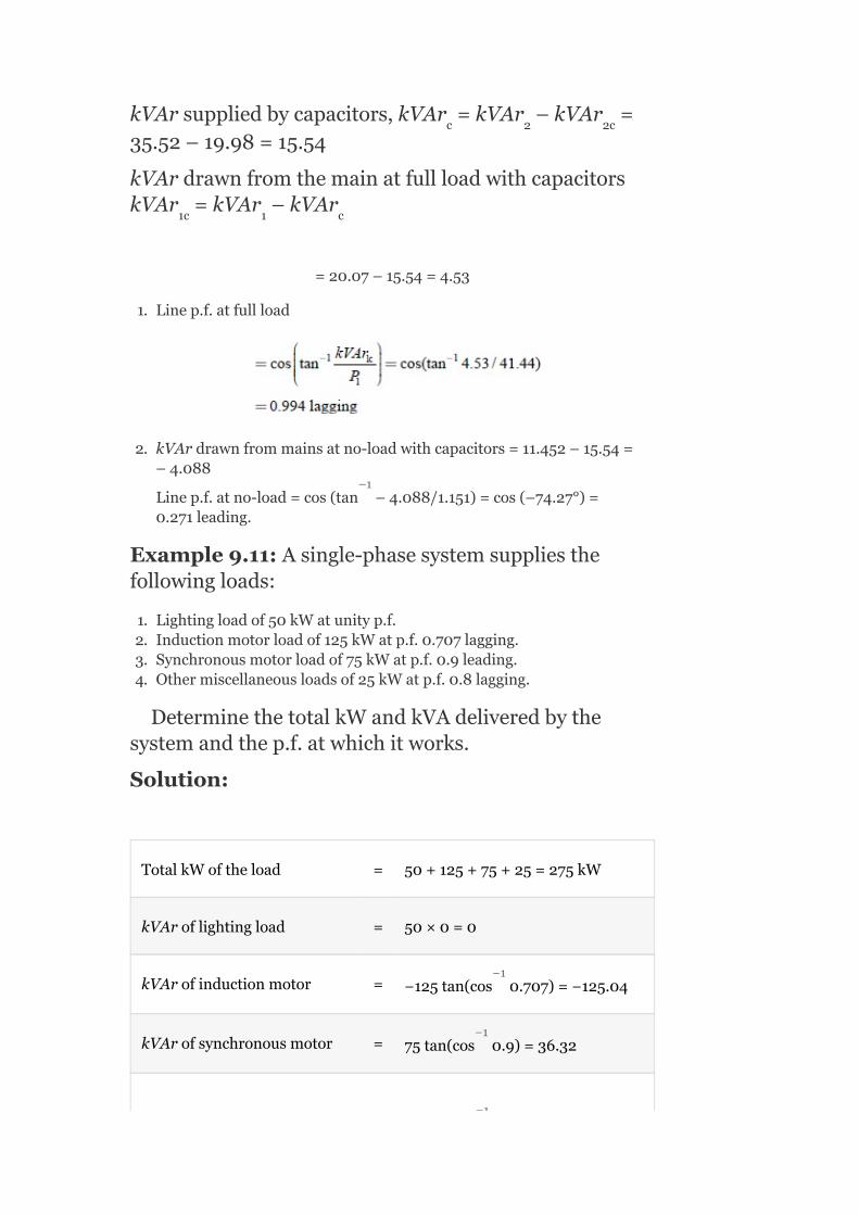
kVArsuppliedbycapacitors,kVAr =kVAr –kVAr =35.52–19.98=15.54
kVArdrawnfromthemainatfullloadwithcapacitorskVAr =kVAr –kVAr
=20.07–15.54=4.53
1. Linep.f.atfullload
2. kVArdrawnfrommainsatno-loadwithcapacitors=11.452–15.54=–4.088
Linep.f.atno-load=cos(tan –4.088/1.151)=cos(–74.27°)=0.271leading.
Example9.11:Asingle-phasesystemsuppliesthefollowingloads:
1. Lightingloadof50kWatunityp.f.2. Inductionmotorloadof125kWatp.f.0.707lagging.3. Synchronousmotorloadof75kWatp.f.0.9leading.4. Othermiscellaneousloadsof25kWatp.f.0.8lagging.
DeterminethetotalkWandkVAdeliveredbythesystemandthep.f.atwhichitworks.
Solution:
TotalkWoftheload = 50+125+75+25=275kW
kVAroflightingload = 50×0=0
kVArofinductionmotor = −125tan(cos 0.707)=−125.04
kVArofsynchronousmotor = 75tan(cos 0.9)=36.32
c 2 2c
1c 1 c
–1
−1
−1
−1

kVArofmiscellaneousloads = 25tan(cos 0.8)=−18.75
∴TotalkVAroftheload =
0−125.04+36.32−18.75=−107.47
KEYNOTES
Forqualitypower,i.e.,voltageandfrequencyateverysupplypointwouldremainconstant,freefromharmonics,andthepowerfactorwouldremainunity,compensationisrequired.Theobjectivesofloadcompensationare:
1. Power-factorcorrection.2. Voltageregulationimprovement.3. Balancingofload.
Characteristicsoftheidealcompensatorareto:
1. Provideacontrollableandvariableamountofreactivepowerwithoutanydelayaccordingtotherequirementsoftheload.
2. Maintainconstant-voltagecharacteristicsatitsterminals.3. Operateindependentlyinthethreephases.
Voltageregulationisdefinedastheproportionalchangeinsupply-voltagemagnitudeassociatedwithadefinedchangeinloadcurrent,i.e.,fromno-loadtofullload.TheSILofatransmissionlineistheMWloadingofatransmissionlineatwhichanaturalreactivepowerbalanceoccurs(zeroresistance).Voltagestability:Apowersystematagivenoperatingstateandsubjectedtoagivendisturbanceisvoltagestableifvoltagesnearloadsapproachpost-disturbanceequilibriumvalues.Thedisturbedstateiswithintheregionsofattractionsofstablepost-disturbanceequilibrium.Voltagecollapse:Followingvoltageinstability,apowersystemundergoesvoltagecollapseifthepost-disturbanceequilibriumvoltagesneartheloadarebelowtheacceptablelimits.Thevoltagecollapsemaybeeithertotalorpartial.
SHORTQUESTIONSANDANSWERS
1. Definetheneedofcompensation.
Formaintainingthequalitypower,i.e.,voltageandfrequencyateverysupplypointwouldremainconstant,freefromharmonics
−1

andthep.f.wouldremainunityandcompensationisneeded.
2. Whataretheobjectivesofloadcompensation?
Theobjectivesofloadcompensationare:
1. p.f.correction.2. Voltageregulationimprovement.3. Balancingofload.
3. Whatarethecharacteristicsofanidealcompensator?
Thecharacteristicsoftheidealcompensatorare:
1. Toprovideacontrollableandvariableamountofreactivepowerwithoutanydelayaccordingtotherequirementsoftheload.
2. Tomaintainaconstant-voltagecharacteristicatitsterminalsand3. Shouldoperateindependentlyinthethreephases.
4. Definethevoltageregulation.
Itisdefinedastheproportionalchangeinsupplyvoltagemagnitudeassociatedwithadefinedchangeinloadcurrent,i.e.,fromnoloadtofullload.
5. Definethesurgeimpedanceloading(SIL)ofatransmissionline.
ItistheMWloadingofatransmissionlineatwhichanaturalreactivepowerbalanceoccurs(zeroresistance).
6. Whatismeantbyvoltagestability?
Apowersystematagivenoperatingstateandsubjectedtoagivendisturbanceisvoltagestableifvoltagesnearloadsapproachpost-disturbanceequilibriumvalues.Thedisturbedstateiswithintheregionsofattractionsofstablepost-disturbanceequilibrium.
7. Whatismeantbyvoltagecollapse?
Followingvoltageinstability,apowersystemundergoesvoltagecollapseifthepost-disturbanceequilibriumvoltagesneartheloadarebelowacceptablelimits.Thevoltagecollapsemaybeeithertotalorpartial.
MULTIPLE-CHOICEQUESTIONS
1. Themajorreasonforlowlaggingp.f.ofsupplysystemisduetotheuseof__________motors.
1. Induction.2. Synchronous.3. DC.4. Noneofthese.
2. Themaximumvalueofp.f.canbe__________.
1. 1.2. 0.9.3. 0.8.4. 0.7.
3. Byimprovingthep.f.ofthesystem,thekilowattsdeliveredbygeneratingstationsare__________.
1. Decreased.2. Increased.3. Notchanged.4. Noneofthese.
4. Powerfactorcanbeimprovedbyinstallingsuchadeviceinparallelwithload,whichtakes:
1. Laggingreactivepower.2. Leadingreactivepower.3. Apparentpower.4. Noneofthese.
5. Themainreasonforlowp.f.ofsupplysystemisduetotheuseof__________.
1. Resistiveload.2. Inductiveload.3. Synchronousmotor.4. Allofthese.
6. Theonlymotorthatcanalsobeworkedatleadingp.f.andcansupplymechanicalpower__________.
1. Synchronousinductiongenerator.2. Synchronousmotor.3. Alternator.4. Noneofthese.
7. Anover-excitedsynchronousmotoronno-loadisknownas__________.
1. Synchronousinductiongenerator.2. Synchronouscondenser.3. Alternator.4. Noneofthese.
8. Forsynchronouscondensers,thep.f.improvementapparatusshouldbelocatedat__________.
1. Sendingend.2. Receivingend.3. Both(a)and(b).4. Noneofthese.
9. Adisadvantageofsynchronouscondenseris:
1. Continuouslossesinmotor.2. Highmaintenancecost.3. Noisy.4. Alloftheabove.
10. Thesmallerthelaggingreactivepowerdrawnbyacircuit,itsp.f.willbe__________.
1. Better.2. Poorer.3. Unity.4. Noneofthese.
11. kVARisequalto__________.
1. kWtanϕ.2. kWsinϕ.3. kVAcosϕ.4. Noneofthese.
12. Foraparticularpower,thecurrentdrawnbythecircuitisminimumwhenthevalueofp.f.is__________.
1. 0.8lagging.2. 0.8leading.3. Unity.4. Noneofthese.
13. Synchronouscapacitorsarenormally____________cooled.
1. Air.2. Oil.3. Water.4. Noneofthese.
14. Toimprovethep.f.of3-ϕcircuits,thesizeofeachcapacitorwhenconnectedindeltawithrespecttowhenconnectedinstaris__________.
1. 1/6th.2. 1/4th.3. 3times.4. 1/3rd.
15. Thep.f.improvementequipmentisalwaysplaced__________.
1. Atthegeneratingstation.2. Nearthetransformer.3. Neartheapparatusresponsibleforlowp.f.4. Nearthebusbar.
16. Asynchronousmachinehashighercapacityfor:
1. Leadingp.f.2. Laggingp.f.3. Itdoesnotdependuponthep.f.ofthemachine.4. Noneofthese.
17. Ifasynchronousmachineisunderexcited,ittakeslaggingVARsfromthesystemwhenitisoperatedasa__________.
1. Synchronousmotor.2. Synchronousgenerator.3. Synchronousmotoraswellasgenerator.4. Noneofthese.
18. Asynchronousphasemodifierascomparedtosynchronousmotorusedformechanicalloadshas__________.
1. Largershaftandhigherspeed.2. Smallershaftandhigherspeed.3. Largershaftandsmallerspeed.4. Smallershaftandsmallerspeed.
19. Thephaseadvancerismountedonthemainmotorshaftandisconnectedinthe__________motor.
1. Rotor.2. Stator.

3. Core.4. Noneofthese.
20. Industrialheatingfurnacessuchasarcandinductionfurnacesoperateon__________.
1. Verylowlaggingp.f.2. Verylowleadingp.f.3. Veryhighleadingp.f.4. Noneofthese.
21. Ifasynchronousmachineisoverexcited,ittakeslaggingVARsfromthesystemwhenitisoperatedas:
1. Synchronousmotor.2. Synchronousgenerator.3. Synchronousmotoraswellasgenerator.4. Noneofthese.
22. Amachinedesignedtooperateatfullloadisphysicallyheavierandiscostlieriftheoperatingp.f.is:
1. Lagging.2. Leading.3. Thesizeandcostdonotdependonp.f.4. Noneofthese.
23. Unitofreactivepoweris:
1. MW.2. MVAr.3. MVA.4. KVA.
24. Reactivepoweris____________power.
1. Wattfull.2. Wattless.3. Loss.4. Noneofthese.
25. Transmissionlineparametersare:
1. R.2. L.3. C.4. Allofthese.
26. OnfundamentalTγ.lineexpressionV(x)=Ae +Be ,γrepresents:
1. Distance(or)length.2. Velocityoflight.3. Propagationconstant.4. Noneofthese.
27. Characteristicimpedanceis_____________.
1.
2.
3.
γx -γx

4.
28. βis____________.
1.
2.
3.4. Allofthese.
29. Advantageofoperatingatnaturalloadis:
1. Insulationisuniformlystressed.2. Reactivepowerbalanceisachieved.3. Both(a)and(b).4. Noneofthese.
30. Anuncompensatedlineonopen-circuitleadsto__________.
1. Ferrantieffect.2. line-chargingcurrentflowingintogeneratorsismore.3. Both(a)and(b).4. Noneofthese.
31. Asymmetricallineatno-loadmeans__________.
1. Nopowertransmission.2. V =V .
3. Both(a)and(b).4. Noneofthese.
32. Duringtheunderexcitedoperationofasynchronousgenerator:
1. Heatingoftheendsofthestatorcoreincreases.2. Reducesfieldcurrent,resultsintheinternalemf,whichcausesweak
stability.3. Both(a)and(b).4. Noneofthese.
33. ForasymmetricallinewithV =V ,themaximumvoltageoccurs
at:
1. Sendingend.2. Receivingend.3. Midpoint.4. Noneofthese.
34. Unitofp.f.is:
1. s.2. m.3. Nounits.4. Noneofthese.
35. Unitoftimeconstantis:
1. m.2. kg.3. s.4. miles.
s r
s 0
36. Powertransmissionthroughalineisimprovedby:
1. Increasingthelinevoltage.2. Decreasingthelinereactance.3. Both(a)and(b).4. Noneofthese.
37. Alineardevicemustsatisfy:
1. Homogeneity.2. Additivity.3. Both(a)and(b).4. Noneofthese.
38. FundamentalrequirementsofAC-powertransmissionis:
1. Synchronousmachinesmustremainstablyinsynchronizer.2. Voltagesmustbekeptneartotheirratedvalues.3. Both(a)and(b).4. Noneofthese.
39. Loadcompensationis:
1. Thecontrolofreactivepowertoimprovequalityofsupply.2. Thecontrolofrealpowertoimprovequalityofsupply.3. Thecontrolofvoltageanditsangletoimprovethequalityofsupply.4. Both(a)and(b).
40. Powerfactorundernaturalloadis:
1. Lagging.2. Leading.3. Unity.4. Noneofthese.
41. Steady-statestabilityofunitoccurswhenδ=__________.
1. 30°.2. 20°.3. 90°.4. 0°.
42. ‘θ’infundamentaltransmissionlineequationis:
1. β.2. ax.3. βl.4. β/a.
43. Ratingofacompensatoris:
1. MVAr.2. Timeofresponse.3. Both(a)and(b).4. Noneofthese.
44. Loadcompensationincludes:
1. p.f.correction.2. Voltageregulation.3. Loadbalancing.4. Allofthese.
45. Forasymmetricalline,thevoltageismoreat:
1. Sendingend.

2. Receivingend.3. Midpoint.4. Allofthese.
46. Loadcompensationcanbeachievedby:
1. Installingthecompensatingequipmentnearthesource.2. Installingthecompensatingequipmentneartheload.3. Either(a)or(b).4. Both(a)and(b).
47. pfcorrectionofloadisachievedby:
1. Generatingreactivepowerascloseaspossibletothesource.2. Generatingreactivepowerascloseaspossibletotheload.3. Generatingrealpowerascloseaspossibletotheload.4. Generatingrealpowerascloseaspossibletothesource.
48. Themainfunctionofanidealcompensatoris:
1. Instantaneouspfcorrectiontounity.2. Elimination(or)reductionofvoltageregulation.3. Phasebalanceoftheloadcurrentsandvoltages.4. All.
49. Theimportantcharacteristicofanidealcompensatoris:
1. Toprovideacontrollableandvariableamountofreactivepowerwithoutanydelay.
2. Tomaintainaconstantvoltagecharacteristicatitsterminals.3. Shouldoperateindependentlyinthethreephases.4. Alltheabove.
50. Characteristicimpedanceofthelinedependsupon:
1. Thecharacteristicofthelineperunitlength.2. Lengthoftheline.3. Radiusandspacingbetweenconductors.4. All.
51. Thesurgeimpedanceloading(SIL)isexpressedas:
1.
2.
3. SIL=(V ) ×surgeimpedance.
4. None.
52. WhenalineisloadedaboveitsSIL,itactslike:
1. ShuntreactorabsorbingMUARfromthesystem.2. ShuntcapacitorsupplyingMUARtothesystem.3. SeriescapacitorsupplyingMUARtothesystem.4. SeriesreactorabsorbingMUARfromthesystem.
53. WhenalineisloadedbelowitsSIL,itactslike:
1. ShuntreactorabsorbingMUARfromthesystem.2. ShuntcapacitorsupplyingMUARtothesystem.3. ShuntcapacitorsupplyingMUARtothesystem.
L-L
2

4. ShuntreactorabsorbingMUARfromthesystem.
54. Ifanyinductiveloadisconnectedatthesendingendoftheline,itwillsupportthesynchronousgenerators:
1. Toabsorbtheline-chargingreactivepower.2. Toabsorbtheload-chargingreactivepower.3. Tosupplytheline-chargingreactivepower.4. Tosupplytheload-chargingreactivepower.
55. Thechangeinelectricalpropertiesofatransmissionlineinordertoincreaseitspowertransmissioncapabilityisknownas:
1. Loadcompensation.2. Linecompensation.3. Loadsynchronism.4. Linesynchronism.
56. ApplyseriescapacitorstoreduceX andtherebyreduceθatthe
fundamentalfrequency.Thismethodiscalled:
1. Line-lengthcompensation(or)θ-compensation.2. Compensationbysectioning.3. Loadbalancing.4. Alltheabove.
57. Seriescompensationresultsin:
1. Increaseinmaximumtransferablepowercapacity.2. Decreaseintransmissionangleforconsiderableamountofpowertransfer.3. Increaseinvirtualsurgeimpedanceloading.4. Alltheabove.
58. Foraheavyloadingcondition,aflatvoltageprofilecanbeobtainedby:
1. Seriescompensation.2. Shuntcompensation.3. (a)or(c).4. None.
59. Inductiveshuntcompensation__________thevirtualsurgeimpedanceand__________thevirtualSILoftheline:
1. Decreases,decreases.2. Decreases,increases.3. Increases,decreases.4. Decreases,increases.
60. Iftheinductiveshuntcompensationis100%then:
1. Flatvoltageprofileexistsatzeroloads.2. Ferrantieffectcanbeeliminated.3. Both(a)and(b).4. None.
61. Sub-synchronousresonance(SSR)istreatedas__________typeofphenomenon.
1. Electrical.2. Mechanical.3. Combinedelectrical–mechanical.4. Dampedfrequencyresonance.
L

62. UPFCisabletoperform:
1. Voltagesupport.2. Powerflowcontrol.3. Improvedstability.4. All.
63. Thevoltagestabilityanalysisiscarriedoutbywhichpowerflow-basedmethod?
1. P–Vcurves.2. Q–Vcurves.3. Both(a)and(b).4. None.
64. Voltagecollapseproximateindicator(VCPI)foraradiallineisdefinedas:
1.
2.
3.
4.
REVIEWQUESTIONS
1. Explaintheobjectivesofloadcompensation.2. Explainthevoltageregulationwithandwithoutcompensators.3. Whatarethespecificationsofloadcompensation?4. Explaintheeffectsonuncompensatedlineunderno-loadand
loadconditions.5. Explaintheeffectsoncompensatedline.6. Explaintheconceptofsub-synchronousresonance.7. Comparethedifferenttypesofcompensatingequipmentfortransmissionsystems.
8. Explaintheconceptsofvoltagestabilityandvoltagecollapse.9. Derivethevoltagestabilityindexofatypicalbranchofapower
system.
PROBLEMS
1. A3-ϕ,5kWinductionmotorhasap.f.of0.8lag.Abankofcapacitorsisconnectedindeltaacrossthesupplyterminalsandp.f.israisedto0.95lag.DeterminethekVArratingofthe

capacitorsconnectedineachphase.2. A3-ϕ,50Hz,400Vmotordevelops100HP,thep.f.being0.7lag
andefficiency93%.Abankofcapacitorsisconnectedindeltaacrossthesupplyterminalsandp.f.israisedto0.95lag.Eachofthecapacitanceunitsisbuiltoffoursimilar100Vcapacitors.Determinethecapacitanceofeachcapacitor.
3. Astar-connected400HP,2,000V,50Hzmotorworksatap.f.of0.75lagging.Abankofmesh-connectedcondensersisusedtoraisethep.f.to0.98lagging.Determinethecapacitanceofeachunitandtotalnumberofunitsrequired;ifeachisrated500V,50Hz.Themotorefficiencyis85%.
4. A3-ϕ,50Hz,3,000Vmotordevelops600HP,thep.f.being0.75laggingandtheefficiency0.95.Abankofcapacitorsisconnectedindeltaacrossthesupplyterminalsandthep.f.raisedto0.98lagging.Eachofthecapacitanceunitsisbuiltoffivesimilar600Vcapacitors.Determinethecapacitanceofeachcapacitor.

10
VoltageControl
OBJECTIVES
Afterreadingthischapter,youshouldbeableto:
obtainanoverviewofvoltagecontrol
discusstheparametersorequipmentscausingreactivepower
understandthemethodsofvoltagecontroland
calculatetheratingofsynchronousphasemodifier
10.1INTRODUCTION
Apowersystemmustbedesignedinsuchawaysoastomaintainthevoltagevariationsattheconsumerterminalswithinspecifiedlimits.Inpractice,alltheequipmentsonthepowersystemaredesignedtooperatesatisfactorilyattheratedvoltagesorwithinspecifiedlimits,atmost±6%attheconsumerterminals.Themainreasonforthevariationinvoltageattheconsumerterminalsisthevariationinloadonthesupplypowersystem.Incaseloadonthesupplysystemincreases,thevoltageattheconsumerterminalsdecreasesduetoanincreaseinvoltagedropinpowersystemcomponentsandviceversawhenloadisdecreased.Mostoftheelectronicequipmentsaresensitivetovoltagevariations;hence,thevoltagemustbemaintainedconstant.Itcanbemaintainedwithinthelimitsbyprovidingvoltage-controlequipment.
10.2NECESSITYOFVOLTAGECONTROL
Thevoltageattheconsumerterminalschangeswiththevariationinloadonthesupplysystem,whichis

undesirableduetothefollowingreasons:
1. Incaseoflightingload,forexample,incandescentlampisacutelysensitivetovoltagechanges.Fluctuationsinvoltagebeyondacertainlevelmayevendecreasethelifeofthelamp.
2. Incaseofpowerloadconsistingofinductionmotors,thevoltagevariationsmaycauseavariationinthetorqueofaninductionmotor,asthetorqueisproportionaltothesquareoftheterminalvoltage.Ifthesupplyvoltageislow,thenthestartingtorqueofthemotorwillbetoolow.
3. Ifthevoltagevariationismorethanaspecifiedvalue,thentheperformanceoftheequipmentssuffersandthelifeoftheequipmentisreduced.
4. Thepictureonatelevisionsetstartsrollingifthevoltageisbelowacertainlevelbecausethefluorescenttuberefusestoglowatlowvoltages.Hence,voltagevariationsmustberegulatedandkepttoaminimumlevel.
Beforediscussingthevariousmethodsofvoltagecontrol,itisveryimportanttoknowaboutthevarioussourcesandsinksofreactivepowerinapowersystem.
TestYourself
Whyisvoltagetolerancemorethanfrequencytolerance?
10.3GENERATIONANDABSORPTIONOFREACTIVEPOWER
1. Synchronousmachine:Thesecanbeusedeithertogenerateorabsorbreactivepower.Theabilitytosupplyreactivepoweris
determinedbytheshort-circuitratio An
overexcitedsynchronousmachinegenerateskVArandactsasashuntcapacitor,whileaunderexcitedsynchronousmachineabsorbsitandactsasashuntreactor.ThemachineisthemainsourceofsupplytothesystemofbothpositiveandnegativeVArs.
2. Overheadlines:Whenfullyloaded,linesabsorbreactivepowerwithacurrentIamperesforalineofreactanceperphaseXohms,theVArsabsorbedareI Xperphase.Onlightloads,theshuntcapacitancesoflongerlinesmaybecomepredominantandthelinesthenbecomeVArgenerators.
3. Transformers:Transformersabsorbreactivepower.ThemathematicalexpressionforthereactivepowerabsorbedbyatransformerisQ =3∣I∣ X VAr.whereX isthetransformer
reactanceperphaseinohmsand∣I∣isthecurrentflowingthroughinamperes.
4. Cables:CablesactasVArgeneratorsbecausetheyhaveaverysmall
T T T
2
2

inductanceandrelativelyverylargecapacitanceduetothenearnessoftheconductors.
5. Loads:Aloadat0.8p.f.impliesareactivepowerdemandof0.75kVArperkWofpower,whichismoresignificantthanthesimplequotingofthep.f.Inplanningpowersystems,itisrequiredtoconsiderreactivepowerrequirementstoascertainwhetherthegeneratorisabletooperateanyrangeofp.f.
10.4LOCATIONOFVOLTAGE-CONTROLEQUIPMENT
Theconsumerapparatusshouldoperatesatisfactorily.Thisisachievedbyinstallingvoltage-controlequipmentatsuitableplaces.
Thevoltage-controlequipmentisplacedintwoormorethantwoplacesinapowersystembecauseofthefollowingreasons:
1. Thepowersystemisacombinationofwide-rangingnetworksandthereisavoltagedropindifferentsectionsofthedistributionandtransmissionsystems.
2. Thevariouscircuitsofapowersystemhavedifferentloadcharacteristics.
Thevoltage-controlequipmentisplacedat:
1. Generatingstations.2. Transformerstations.3. Thefeeders.
Whenpowerissuppliedtoaloadthroughatransmissionlinekeepingthesending-endvoltageconstant,thereceiving-endvoltagevarieswithmagnitudeofloadandp.f.oftheload.Thehighertheloadwithsmallerp.f.,thegreateristhevoltagevariation.
10.5METHODSOFVOLTAGECONTROL
Thedifferentvoltage-controlmethodsare:
1. Excitationcontrol.2. Shuntcapacitors.3. Seriescapacitors.4. Tap-changingtransformers.5. Boosters.6. Synchronouscondensers.
10.5.1Excitationcontrol
Thismethodisusedonlyatthegeneratingstation.Duetothevoltagedropinthesynchronousreactanceofarmature,thealternatorterminalvoltagechangesandhencetheloadonthesupplysystemalsoundergoesachange.Thiscanbemaintainedconstantbychangingthefieldcurrentofthealternator.Thisprocessiscalledexcitationcontrol.Byusinganautomaticorahand-operatedregulator,theexcitationofthealternatorcanbecontrolled.
Inmodernsystems,automaticregulatorispreferred.Thetwomaintypesofautomaticvoltageregulatorsare:
1. Tirrilregulator.2. Brown-Boveriregulator
(a)Tirrilautomaticregulator:Tirrilregulatorisafast-actingelectromagneticalregulatoranditgives±0.5%regulatingdeviationbetweenno-loadandfullloadofanalternator.
Construction:Tirrilvoltageregulatorisavibrating-typevoltageregulatorinwhicharesistanceRisconnectedintheexcitercircuittogettherequiredvalueofvoltagebyadjustingthepropervalueofresistance.Figure10.1showsthemainpartsoftheTirrilvoltageregulator.

FIG.10.1Tirrilautomaticvoltageregulator
Differentialrelay:Itisa‘U’-shaped(horseshoe)relaymagnet.IthastwoidenticalwindingsonbothlimbsasshowninFig.10.1,whichareconnectedacrossthearmatureoftheexciteronlywhenthemaincontactsareclosed.Acapacitorisconnectedinparalleltotherelayforreducingthesparkwhentherelaycontactsareopened.
Excitationsystem:Itconsistsofasolenoidenergizedbythevoltageequaltotheexciterterminalvoltage.Thecounter-balanceforceofanexcitationsolenoidisprovidedbythreesprings,whichareactinginsequenceandareshowninFig.10.1.
Maincontrolunit:ItisasolenoidexcitedfromanACsupply.Thelowerpartofthissolenoidisconnectedwithadashpot,whichprovidesdampingtothemeasuringunit.
Maincontacts:TheseareattachedtotheleversthatareoperatedbymeasuringandexcitationsolenoidsasshowninFig.10.1.Theleverontheleftsideiscontrolledbytheexcitercontrolmagnetandtheleverontherightsideiscontrolledbythemaincontrolmagnet.

Principleofoperation:Undernormaloperatingconditions,i.e.,thesystemisoperatingatpre-setloadandvoltageconditions,themaincontactsareopen.Thefieldrheostatisinthecircuit.Iftheloadonthealternatorincreases,theterminalvoltagedecreases.Whenthepre-setexcitationsettingsofthedeviceislow,them.m.fdevelopedbythemeasuringsystemorthesolenoidislow,causingadisturbanceintheequilibriumand,therefore,maincontactsareclosed.Theseresultsinde-energizationofdifferentialrelayandrelaycontactsareclosed.So,theresistance‘R’inthefieldisshort-circuited.Whenthisisoutofcircuit,totalfieldcurrentflowsthroughtheexciter,andtheexciterterminalvoltageincreases.Thus,thevoltageacrossthealternatorterminalsincreasesduetotheincreaseinalternatorfieldcurrent.
Duetothisincreasedvoltage,thepullofthesolenoidexceedsthespringforceandsothemaincontactsareopenedagainandtheresistanceisinsertedintheexciterfield.Asimilarprocessisrepeatediftheterminalvoltageisreduced.
(b)Brown-Boveriregulator:ThisdiffersfromtheTirrilregulator.Inthis,theresistanceofregulatoriseithergraduallyvariedorvariedinsmallsteps.
Construction:Brown-Boveriregulatorisnotavibratingtype;hence,wearandtearislesswhencomparedtothatofatirrilregulator.ItconsistsoffourmainpartsanditsschematicdiagramisshowninFig.10.2(a).
Controlsystem:Itcontainstwowindings‘P’and‘Q’woundonanannularcoreoflaminatedsteelsheetasshowninFig.10.2(a).Thewindingsareexcitedfromthethree-phasealternatorsupplythroughtheresistancesRandR andresistanceR isinsertedinwinding‘P’.Theratioofresistancetoreactanceisadjustedinsuchawaysoastogetaphaseangledifferencebetweenthecurrentsintwowindings.Thisresultsintheformationofa
c
f se
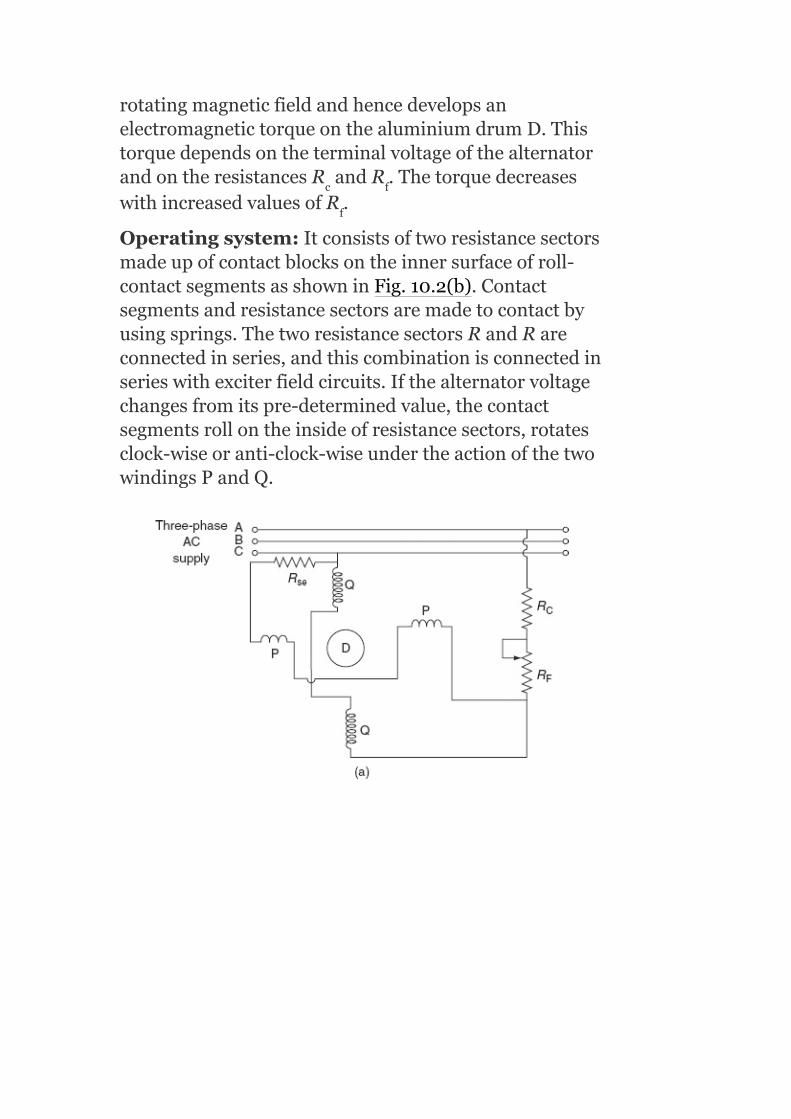
rotatingmagneticfieldandhencedevelopsanelectromagnetictorqueonthealuminiumdrumD.ThistorquedependsontheterminalvoltageofthealternatorandontheresistancesR andR .ThetorquedecreaseswithincreasedvaluesofR .
Operatingsystem:Itconsistsoftworesistancesectorsmadeupofcontactblocksontheinnersurfaceofroll-contactsegmentsasshowninFig.10.2(b).Contactsegmentsandresistancesectorsaremadetocontactbyusingsprings.ThetworesistancesectorsRandRareconnectedinseries,andthiscombinationisconnectedinserieswithexciterfieldcircuits.Ifthealternatorvoltagechangesfromitspre-determinedvalue,thecontactsegmentsrollontheinsideofresistancesectors,rotatesclock-wiseoranti-clock-wiseundertheactionofthetwowindingsPandQ.
c f
f
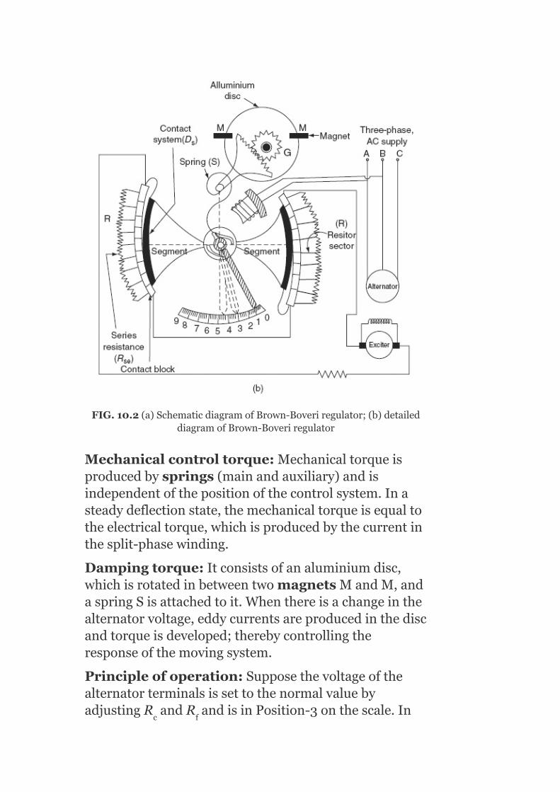
FIG.10.2(a)SchematicdiagramofBrown-Boveriregulator;(b)detaileddiagramofBrown-Boveriregulator
Mechanicalcontroltorque:Mechanicaltorqueisproducedbysprings(mainandauxiliary)andisindependentofthepositionofthecontrolsystem.Inasteadydeflectionstate,themechanicaltorqueisequaltotheelectricaltorque,whichisproducedbythecurrentinthesplit-phasewinding.
Dampingtorque:Itconsistsofanaluminiumdisc,whichisrotatedinbetweentwomagnetsMandM,andaspringSisattachedtoit.Whenthereisachangeinthealternatorvoltage,eddycurrentsareproducedinthediscandtorqueisdeveloped;therebycontrollingtheresponseofthemovingsystem.
Principleofoperation:SupposethevoltageofthealternatorterminalsissettothenormalvaluebyadjustingR andR andisinPosition-3onthescale.In
c f

thisposition,themechanicaltorqueisequaltotheelectromagnetictorqueandthemovingsystemisunderequilibrium.
Letusassumethattheterminalvoltageofthealternatorisreducedduetotheriseinload,andthentheelectromagnetictorqueisreduced.Atthisinstant,themechanicaltorqueisgreaterthantheelectromagnetictorqueandthediscstartstorotate(assumeinanti-clock-wisedirection).Duetothis,thepointermovestoPosition-1.Theresistanceintheexciterfieldwillbereduced,whichcausesanincreaseintheexciterfieldcurrent.So,theterminalvoltageofanalternatorincreases.
10.5.2Shuntcapacitorsandreactors
Shuntcapacitorsareusedforlaggingp.f.circuits;whereasreactorsareusedforleadingp.f.circuitssuchasthosecreatedbylightlyloadedcables.Inbothcases,theeffectistosupplytherequiredreactivepowertomaintainthevaluesofthevoltage.Apartfromsynchronousmachines,staticshuntcapacitorsofferthecheapestmeansofreactivepowersupplybutthesearenotasflexibleassynchronouscondensers.
Capacitorsareconnectedtoabusbarortothetertiarywindingofamaintransformer.Inthismethod,asthevoltagefalls,theVArsproducedbyashuntcapacitororreactoralsofalls.Thus,theireffectivenessfallswhenneeded.Alsoforlightloads,whenthevoltageishigh,thecapacitoroutputislargeandthevoltagetendstobecomeexcessive.theviewofathree-phasecapacitorbankona11-kVdistributionlineisshowninFig.10.3.
11.5.3Seriescapacitors
Capacitorsareinstalledinserieswithtransmissionlines(showninFig.10.4)inordertoreducevoltagedrop.The

seriescapacitorscompensatethereactancevoltagedropinthelinebyreducingnetreactance.Acapacitorinserieswithatransmissionlineservingalaggingp.f.loadwillcauseariseinvoltageastheloadincreases.Thep.f.oftheloadthroughtheseriescapacitorandlinemustbelaggingifthevoltagedropistodecreaseappreciably.Thevoltageontheloadsideoftheseriescapacitorisraisedabovethesourceside,actingtoimprovethevoltageregulationofthefeeder.Sincethevoltageriseordropoccursinstantaneouslywithvariationsintheload,theseriescapacitorresponseasavoltageregulatorisfasterandsmootherthantheregulators.
Themaindrawbackofthiscapacitoristhehighvoltageproducedacrossthecapacitorterminalsundershort-circuitconditions.ThedropacrossthecapacitorisI X ,whereI isthefaultcurrentwhichismanytimesthefull-loadcurrentundercertaincircuitconditions.Itisessential,therefore,thatthecapacitoristakenoutofserviceasquicklyaspossible.Asparkgapwithahigh-speedcontactorcanbeusedtoprotectthecapacitorundertheseconditions.
f c
f

FIG.10.3Viewofathree-phasecapacitorbankona11-kVdistributionline
FIG.10.4Circuitdiagramwithoutandwithseriescompensation
Figures10.4and10.5showthelineanditsvoltagephasordiagramswithoutandwithseriescompensation.Thevoltagedropofthelinewithoutaseriescapacitorisapproximatelygivenby
V =I Rcosϕ+I X sinϕd r r L
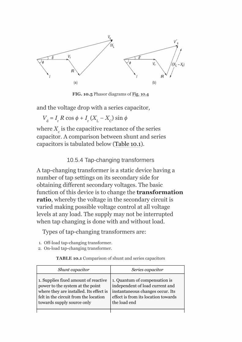
FIG.10.5PhasordiagramsofFig.10.4
andthevoltagedropwithaseriescapacitor,
V =I Rcosϕ+I (X −X )sinϕ
whereX isthecapacitivereactanceoftheseriescapacitor.Acomparisonbetweenshuntandseriescapacitorsistabulatedbelow(Table10.1).
10.5.4Tap-changingtransformers
Atap-changingtransformerisastaticdevicehavinganumberoftapsettingsonitssecondarysideforobtainingdifferentsecondaryvoltages.Thebasicfunctionofthisdeviceistochangethetransformationratio,wherebythevoltageinthesecondarycircuitisvariedmakingpossiblevoltagecontrolatallvoltagelevelsatanyload.Thesupplymaynotbeinterruptedwhentapchangingisdonewithandwithoutload.
Typesoftap-changingtransformersare:
1. Off-loadtap-changingtransformer.2. On-loadtap-changingtransformer.
TABLE10.1Comparisonofshuntandseriescapacitors
Shuntcapacitor Seriescapacitor
1.Suppliesfixedamountofreactivepowertothesystematthepointwheretheyareinstalled.Itseffectisfeltinthecircuitfromthelocationtowardssupplysourceonly
1.Quantumofcompensationisindependentofloadcurrentandinstantaneouschangesoccur.Itseffectisfromitslocationtowardstheloadend
d r r L C
c

2.Itreducesthereactivepowerflowinginthelineandcauses:
1. Improvementofp.f.ofasystem
2. Voltageprofileimprovement
3. DecreaseskVAloadingonsource,i.e.,generators,transformers,andlineuptolocationandthusprovidesanadditionalcapacity
2.Itiseffective:
1. Ontielines,thepowertransferisgreater
2. Specifically,suitableforsituationswhenflickersduetorespectiveloadfunctionsoccur
3.Thelocationhastobeasneartotheloadpointaspossible.Inpractice,duetothehighcompensationrequired,itisfoundtobeeconomicaltoprovidegroupcompensationonlinesandsub-stations
3.Asathumbrule,thebestlocationis1/3rdofelectricalimpedancefromthesourcebus
4.AsfixedkVArissupplied,thismaysometimesresultinovercompensationinthelight-loadperiod.SwitchedkVArbanksarecomparativelycostlierthanfixedkVArandbecomenecessary
4.Asfull-loadcurrentistopassthrough,thecapacity(currentrating)shouldbemorethantheloadcurrent
5.Asthep.f.approachesunity,largercompensationisrequiredfortheimprovementofp.f.
5.Asseriescapacitorscarryfaultcurrent,specialprotectionisrequiredtoprotectfromfaultcurrent
6.Wherelinesareheavilyloaded,compensationrequiredwillbemore
6.Causessuddenrisesinvoltageatthelocation
7.Costofcompensationislowerthanthatofthecostrequiredforseriescapacitor
7.Costofaseriescapacitorishigherthanthatofashuntcapacitor
10.5.4.1Off-loadtap-changingtransformers
Thesimpletap-changingarrangementofatransformerisshowninFig.10.6.ThevoltagecanbevariedbyvaryinganumberoftappingsonthesecondarysideofthetransformerasshowninFig.10.6.

Figure10.6referstotheoff-loadtap-changingtransformer,whichrequiresthedisconnectionofthetransformerfromtheloadwhenthetapsettingistobechanged.
Theoutputofthesecondarysideofthetransformerchangeswiththechangeinthetappositionofthesecondarywinding.Thesecondaryvoltageisminimumwhenthemovablearmmakescontactwithstud1,whereasitismaximumwhenitisinpositionN.Whentheloadonthetransformerincreases,thevoltageacrosssecondaryterminalsdecreases.Thiscanbeincreasedtothedesiredvaluebyaddingthenumberofturnsonthesecondaryofthetransformerbychangingtaps.
FIG.10.6Off-loadtap-changingtransformerarrangement
Thus,inthecaseoftap-changingtransformers,themaindrawbackisthatthetapsarechangedonlyaftertheremovaloftheload.Thiscanbeovercomebyusinganon-loadtap-changingtransformerwithreactors.
10.5.4.2On-loadtap-changingtransformer
Tosupplyuninterruptedpowertotheload(consumer),tapchanginghastobeperformedwhenthesystemisonload.Thesecondarywindinginatap-changingtransformerconsistsoftwoidenticalparallelwindingswithsimilartappings.Forexample,1,2,…,Nand1′,2′,…,N′arethetappingsonboththeparallelwindingsofsuchatransformer.Thesetwoparallelwindingsare

controlledbyswitchesS andS asshowninFig.10.7(a).Inthenormaloperatingconditions,switchesS ,S ,andtappings1and1′areclosed,i.e.,boththesecondarywindingsofthetransformerareconnectedinparallel,andeachwindingcarrieshalfofthetotalloadcurrentbyanequalsharing.Thesecondarysideofthetransformerisataratedvoltageundernoload,whentheswitchesSandS areclosedandmovablearmsmakecontactwithstud1and1′,whereasitismaximum(abovetheratedvalue)undernoload,whenthemovablearmsareinpositionNandN′.Thevoltageatthesecondaryterminaldecreaseswithanincreaseintheload.Tocompensateforthedecreasedvoltages,itisrequiredtochangeswitchesfrompositions1and1′topositions2and2′(numberofturnsonthesecondaryisincreased).Forthis,openanyoneoftheswitchesS andS ,assumingthatS isopened.Atthisinstant,thesecondarywindingcontrolledbyswitchS carriesfull-loadcurrentthroughonewinding.Then,thetappingischangedtoposition2onthewindingofthedisconnectedtransformerandclosetheswitchS .Afterthis,switchS isopenedfordisconnectingitswinding,andchangethetappingpositionfrom1′to2′andthenswitchS isclosed.Similarly,tappingpositionscanbechangedwithoutinterruptingthepowersupplytotheconsumers.Theonlinetap-changingtransformerisshowninFig.10.7(b).
a b
a b
a
b
a b
a
b
a b
b

FIG.10.7(a)On-loadtap-changingtransformerarrangement;(b)on-linetap-changingtransfomer
Thismethodhasthefollowingdisadvantages:
1. Itrequirestwowindingswithratedcurrent-carryingcapacityinsteadofonewinding.
2. Itrequirestwooperationsforthechangeofasinglestep.3. Complicationsareintroducedinthedesigninordertoobtainahigh
reactancebetweentheparallelwindings.
10.5.5Boostertransformers
Theboostertransformerperformsthefunctionofboostingthevoltage.Itcanbeinstalledatasub-stationoratanyintermediatepointofline.
InthecircuitshowninFig.10.8(a),PandQarethetworelays.Thesecondaryoftheboostertransformerisconnectedinserieswiththelinewhosevoltageistobe

controlled,andtheprimaryoftheboostertransformerissuppliedfromaregulatingtransformerwithon-loadtap-changinggear.TheboostercanbebroughtintothecircuitbytheclosureofrelayQandtheopeningofrelayP,andviceversaasshowninFig.10.8(a).Thesecondaryoftheboostertransformerinjectsavoltageinphasewiththelinevoltages.Bychangingthetappingontheregulatingtransformer,themagnitudeofV canbechangedandthusthefeedervoltageV canberegulated.Theviewofboosteranddistributiontransformerconnection(lefttoright)isshowninFig.10.8(b).
Advantages
1. Itcanbeinstalledatanyintermediatepointinthesystem.2. Theratingoftheboostertransformerisabout10%thatofthemain
transformer(productofcurrentandinjectedvoltage).
Disadvantages
Whenusedinconjunctionwithmaintransformer:
1. Moreexpensivethanatransformerwithon-loadtapchanges.2. Lessefficientduetolossesinbooster.3. Requiresmorespace.
Q
F

FIG.10.8(a)Boostertransformer;(b)viewofboosteranddistributiontransfomerconnection(lefttoright)
10.5.6Synchronouscondensers
Asynchronouscondenser(synchronousphasemodifier)isasynchronousmotorrunningwithoutmechanicalload.Itisconnectedinparallelwiththeloadatthereceivingendoftheline.Dependinguponitsexcitation,iteithergeneratesorabsorbsthereactivepower.Ittakesleadingcurrentwhenitsfieldisoverexcited,i.e.,abovenormalspeedandtakeslaggingcurrentwhenitisunderexcited.Thus,thecurrentdrawnbyasynchronousphasemodifiercanbevariedfromlaggingtoleadingbyvaryingitsexcitation.Itisaveryconvenientdevicetokeepthereceiving-endvoltage

constantunderanyconditionofload.Italsoimprovesthep.f.andtheoutputcanvarysmoothly.
TABLE10.2Comparisonofsynchronouscondenserandstaticcapacitors
Synchronouscondenser Staticcapacitors
1.Harmonicsinthevoltagedoesnotexist
1.Largeharmonicsareproducedinthesystem
2.Powerfactorvariationisstepless(uniform)
2.Powerfactorvariesinsteps
3.Itallowsoverloadingforashortperiod
3.Itdoesnotallowanyoverloading
4.Powerlossismore 4.Powerlossisless
5.ItismoreeconomicalinthecaseoflargekVAr
5.ItismoreeconomicalforsmallkVArrequirement
6.Failurerateislessand,therefore,thisismorereliable
6.Failurerateismoreand,therefore,itislessreliable
Asynchronousphasemodifierhasasmallershaftandbearingandhigherspeedascomparedtoasynchronousmotorusedformechanicalloads.Asynchronousphasemodifierhashigheroverallefficiencyascomparedwithasynchronousmotor.
Advantages
1. Flexibilityforuseinallloadconditionsbecausewhenthemachineisunderexcited,itconsumesreactivepower.
2. ThereisasmoothvariationofreactiveVArsbysynchronouscapacitors.
3. Itcanbeoverloadedforshortperiods.
Disadvantages
1. Possibilityoffallingoutofcontrolincaseofsuddenchangesinvoltage.
2. Thesemachinesaddtoshort-circuitcapacityofthesystemduringfaultcondition.

AcomparisonbetweensynchronouscondenserandstaticcapacitorsispresentedinTable10.2.
10.6RATINGOFSYNCHRONOUSPHASEMODIFIER
Anexpressionofsending-endvoltageintermsoftransmissionlineconstantsis
where
= V ∠δ=sending-endvoltage
= receiving-endvoltage(referencephasor)
Ī = I ∠−φ =receiving-endcurrent
Ā = A∠α
= B∠βarethelineconstants
Equation(10.1)canbewritteninaphasorformas
V
∠δ= AV ∠α+BI ∠(β−φ )
= AV cosα+jAV sinα+BI cos(β−φ )+jBI
sin(β−φ )
(10.2)
TherealpartofEquation(10.2)is
s
s
r
r r r
s r r r
r r r r r
r

V cosδ=AV cosα+BI cos(β−φ )(10.3)
andtheimaginarypartis
V sinδ=AV sinα+BI sin(β−φ )(10.4)
SquaringandaddingEquations(10.3)and(10.4),weget
V = A V +B I +2AB I cosαcos(β−φ )+2ABV I sin
αsin(β−φ )
= A V +B I +2ABV I cos(α−β+φ )
= A V +B I +2ABV I [cos(α−β)cosφ −sin(α−β)
sinφ ]
(10.5)
Realpoweratreceivingend,P =V I cosϕ
Reactivepoweratreceivingend,Q =V I sinϕ
Receiving-endcurrentcanbewrittenas
I =I cosφ −jI sinφ (∵laggingp.f.)
=I −jI
∴I =I +I
where
SubstitutingtheabovequantitiesinEquation(10.5),wehave
V =A V +B I +2ABP cos(α−β)−2ABQ sin(α−β)(10.6)
InEquation(10.6),I isreplacedbyI andIexpressions,
s r r r
s r r r
s
r r r r r r r
r
r r r r r
r r r r r
r
r r r r
r r r r
r r r r r
p q
r p q
s r r r r
r p q
2
2 2 2 2
2 2 2 2
2 2 2 2
2 2 2
2 2 2 2 2
2 2 2
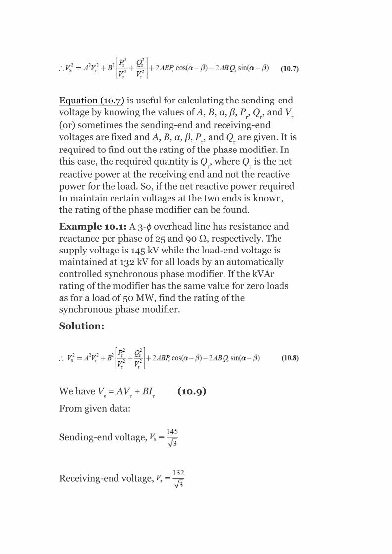
Equation(10.7)isusefulforcalculatingthesending-endvoltagebyknowingthevaluesofA,B,α,β,P ,Q ,andV(or)sometimesthesending-endandreceiving-endvoltagesarefixedandA,B,α,β,P ,andQ aregiven.Itisrequiredtofindouttheratingofthephasemodifier.Inthiscase,therequiredquantityisQ ,whereQ isthenetreactivepoweratthereceivingendandnotthereactivepowerfortheload.So,ifthenetreactivepowerrequiredtomaintaincertainvoltagesatthetwoendsisknown,theratingofthephasemodifiercanbefound.
Example10.1:A3-ϕoverheadlinehasresistanceandreactanceperphaseof25and90Ω,respectively.Thesupplyvoltageis145kVwhiletheload-endvoltageismaintainedat132kVforallloadsbyanautomaticallycontrolledsynchronousphasemodifier.IfthekVArratingofthemodifierhasthesamevalueforzeroloadsasforaloadof50MW,findtheratingofthesynchronousphasemodifier.
Solution:
WehaveV =AV +BI (10.9)
Fromgivendata:
Sending-endvoltage,
Receiving-endvoltage,
r r r
r r
r r
s r r

Lineimpedance,Z=25+j90
Assumingshort-linemodel,V =V +I Z
ComparingEquations(10.9)and(10.10),wehave
A=1;α=0,
B=93.4β=74.47°
P =V I cosϕ =50MW(given)
SubstitutingthesevaluesinEquation(10.8),weget
1,200.92×10 =3,755.98×10 +1.50Q ×10 +2,500.7×10 +179.98Q
1,200.92=3,755.98+1.50Q +2,500.7+179.98Q
1.50Q +179.98Q +5,055.76=0
Solvingtheaboveequation,weget
Powerfactorangleatthereceiving-endvoltage,ϕ =−41.9°
s r r
r r r r
r
r
r r
r r
r
6 6 2 6
6
2
2
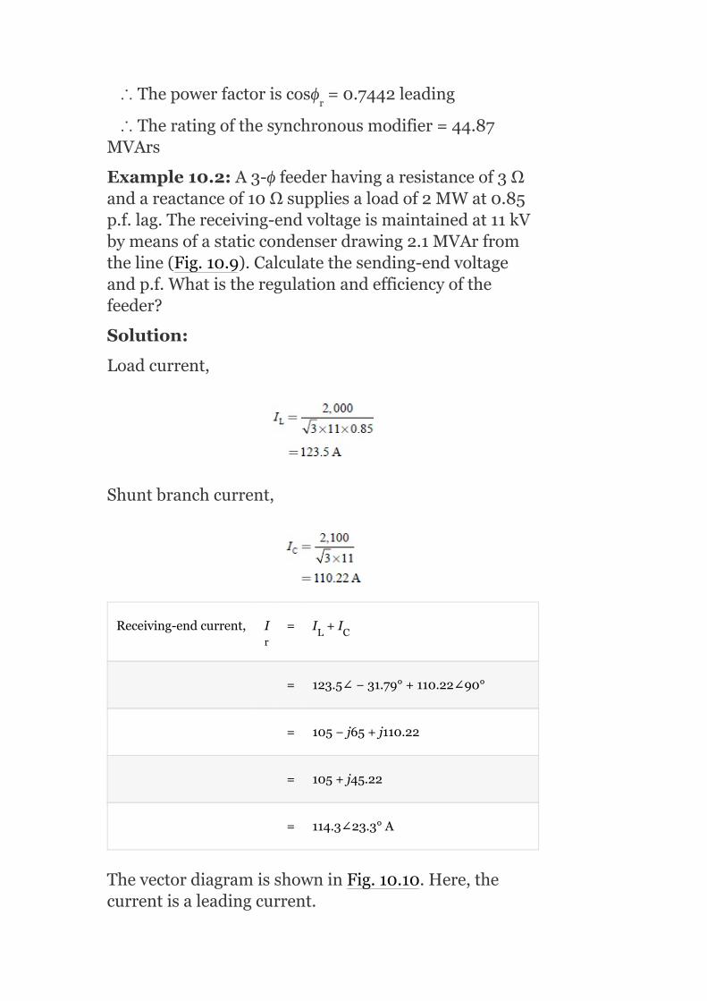
∴Thepowerfactoriscosϕ =0.7442leading
∴Theratingofthesynchronousmodifier=44.87MVArs
Example10.2:A3-ϕfeederhavingaresistanceof3Ωandareactanceof10Ωsuppliesaloadof2MWat0.85p.f.lag.Thereceiving-endvoltageismaintainedat11kVbymeansofastaticcondenserdrawing2.1MVArfromtheline(Fig.10.9).Calculatethesending-endvoltageandp.f.Whatistheregulationandefficiencyofthefeeder?
Solution:
Loadcurrent,
Shuntbranchcurrent,
Receiving-endcurrent, I = I +I
= 123.5∠−31.79°+110.22∠90°
= 105−j65+j110.22
= 105+j45.22
= 114.3∠23.3°A
ThevectordiagramisshowninFig.10.10.Here,thecurrentisaleadingcurrent.
r
rL C

FromthecircuitdiagramshowninFig.10.9,
Thesending-endvoltage,V =V +I Z
FIG.10.9Circuitdiagram
FIG.10.10Phasordiagram
=6,350.85∠0+1,193.33∠96.6=6,350.85+j0−137.16+j1,185.42
=6,213.69+j1,185.42
=6,325.74∠10.8V∴Thesending-endvoltage,
FromthephasordiagramshowninFig.10.10,
s r r

sending-endp.f.=cos(23.3—10.8)=cos12.5=0.976
Example10.3:Asingle-circuit3-ϕ220-kVlinerunsatno-load.Voltageatthereceivingendofthelineis205kV.Findthesending-endvoltageifthelinehasaresistanceof21.7Ω,areactanceof85.2Ω,andthetotalsusceptanceof5.32×10 (Fig.10.11).Thetransmissionlineistoberepresentedby∏-model.
Solution:
Thesending-endvoltageV differsfromthereceiving-endvoltageV bythevalueofvoltagedropduetochargingcurrentinthelineimpedance,asshowninFig.10.11.Withthequadrate-axiscomponentofthevoltagedropbeingneglectedasshowninFig.10.12,wefind∣V ∣
FIG.10.11Circuitdiagram
1
2
1
-4
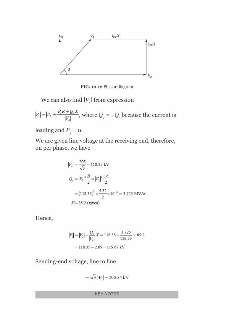
FIG.10.12Phasordiagram
Wecanalsofind∣V ∣fromexpression
,whereQ =−Q becausethecurrentis
leadingandP =0.
Wearegivenlinevoltageatthereceivingend,therefore,onperphase,wehave
Hence,
Sending-endvoltage,linetoline
KEYNOTES
1
2 c
2
Sourcesandsinksofareactivepoweraresynchronousmachine,overheadlines,transformers,cables,andloads.Thevoltage-controlequipmentislocatedatgeneratingstations,transformerstations,andfeeders.Thevariousmethodsforvoltagecontrolare:excitationcontrol,shuntcapacitors,seriescapacitorsbyusingtap-changingtransformers,boosters,andsynchronouscondensers.Excitationcontrol:Thismethodisusedonlyatthegeneratingstation.Duetothevoltagedropinthesynchronousreactanceofarmature,whenevertheloadonthesupplysystemchanges,theterminalvoltageofthealternatoralsochanges.Thiscanbekeptconstantbychangingthefieldcurrentofthealternatoraccordingtothechangesinload.Thisisknownasexcitationcontrol.Shuntcapacitorsandreactors:Shuntcapacitorsareusedforlaggingp.f.circuits;whereasreactorsareusedforleadingp.f.circuitssuchascreatedbylightlyloadedcables.Seriescapacitor:Itisinstalledinserieswithtransmissionlinestoreducethefrequencyofvoltagedrops.Tap-changingtransformers:Thebasicoperationofatap-changingtransformerisbychangingthetransformationratio,thevoltageinthesecondarycircuitisvaried.Boostertransformers:Theboostertransformerperformsthefunctionofboostingthevoltage.Itcanbeinstalledatasub-stationoranyintermediatepointofline.Synchronouscondensers:Itisconnectedinparallelwiththeloadatthereceivingendoftheline.Itcaneithergenerateorabsorbreactivepowerbyvaryingtheexcitationofitsfieldwinding.
SHORTQUESTIONSANDANSWERS
1. Whatarethedifferentmethodsofvoltagecontrol?
Thefollowingmethodsaregenerallyemployedforcontrollingthereceiving-endvoltage.
1. Byexcitationcontrol.2. Byusingtap-changingtransformer.3. Auto-transformertapchanging.4. Boostertransformer.5. Inductionregulators.6. Bysynchronouscondensers.
2. Whatismeantbyexcitationvoltagecontrol?
Duetothevoltagedropsinthesynchronousreactanceofthearmature,whenevertheloadonthesupplysystemchanges,theterminalvoltageofthealternatorchangescorrespondingly.Thiscanbekeptconstantbychangingthefieldcurrentofthealternatoraccordingtothechangesinload.
3. Whatarethedisadvantagesoftap-changingtransformers?
1. Duringswitching,theimpedanceoftransformerisincreasedandtherewillbeavoltagesurge.

2. Therearetwiceasmanytappingsasthevoltagesteps.
4. Whatisthesynchronouscondenser?
Asynchronousmotortakesaleadingcurrentwhenoverexcitedandthereforebehavesasacapacitor.Anoverexcitedsynchronousmotorrunningonno-loadisknownasasynchronouscondenser.
5. Whatisaboostertransformer?
Thetransformer,whichisusedtocontrolthevoltageofthetransmissionlineatapointfarawayfromthemaintransformer,isknownasboostertransformer.
6. Howdoesashunt-capacitorbankcontrolthesystemvoltageunderlightloadsandheavyloads?
Theshunt-capacitorbankprovidedwithfixedandvariableelementsmaybeeitherremovedfromoraddedtothebanktodecreaseorincreasethecapacitanceunderno-loadandheavy-loadconditions,respectively.
7. Underwhatconditiondoesasynchronousmotortakealeadingcurrent?
Thesynchronousmotortakesleadingcurrentwhenitsfieldisoverexcitedunderhigh-loadconditions.
8. Whenistheshunt-inductorcompensationrequired?
Theshunt-inductorcompensationisrequiredwhenevertheloadingislessthanthesurgeimpedanceloading.
MULTIPLE-CHOICEQUESTIONS
1. Thevoltageofthepowersupplyattheconsumer’sservicemustbeheldsubstantially_____
1. Constant.2. Smoothvariation.3. Randomvariation.4. Noneofthese.
2. Lowvoltagereducesthe_____fromincandescentlamps.
1. Poweroutput.2. Powerinput.3. Lightoutput.4. Current.
3. Motorsoperatedatbelownormalvoltagedrawabnormally_____currents.
1. Low.

2. High.3. Medium.4. Noneofthese.
4. Permissiblevoltagevariationis_____.
1. ±10%.2. ±20%.3. ±50%.4. ±5%.
5. Bydrawinghighcurrentsatlowvoltages,themotorsget_____.
1. Overheated.2. Cool.3. Constantheat.4. Noneofthese.
6. Domesticcircuits’supplyvoltageis_____.
1. 230V.2. 110V.3. 240V.4. 220V.
7. Thevoltagemaynormallyvarybetweenthelimitsof_____.
1. 210and230V.2. 230and240V.3. 230and520V.4. 210and235V.
8. Abovenormalvoltagesreducesthe_____ofthelamps.
1. Life.2. Strength.3. Lighting.4. Color.
9. Thevoltageatthebuscanbecontrolledbytheinjectionof_____powerofthecorrectsign.
1. Real.2. Reactive.3. Complex.4. Bothrealandreactive.
10. Generalmethodsofvoltagecontrolare_____.
1. Useoftap-changingtransformer.2. Synchronouscondensers.3. Staticcapacitors.4. Allofthese.
11. Useofthyristor-controlledstaticcompensatorsis_____.
1. Voltagecontrol.2. Powercontrol.3. Currentcontrol.4. Noneofthese.
12. Anoverexcitedsynchronousmachineoperatedasgeneratorormotorgenerates_____
1. kVA.

2. kVAr.3. kW.4. kI.
13. Synchronousmotorrunningatno-loadandoverexcitedloadisknownas_____
1. Synchronouscondenser.2. Shuntcapacitor.3. Seriescapacitor.4. Noneofthese.
14. Theexcitation-controlmethodisonlysuitablefor_____lines.
1. Short.2. Medium.3. Long.4. Allofthese.
15. Itis_____tomaintainthesamevoltageatbothendsoftransmissionlinesbythesynchronous-condensermethod.
1. Economical.2. Noteconomical.3. Difficult.4. Easy.
16. Shuntcapacitorsandreactorsareusedacrosslightlyloadedlinestoabsorbsomeoftheleading_____againtocontrolthevoltage.
1. VArs.2. VA.3. VBRS.4. Noneofthese.
17. Disadvantagesofshuntcapacitorsare_____.
1. Fallofvoltage.2. ReductioninVArs.3. Reductionineffectiveness.4. Allofthese.
18. _____reducestheinductivereactancebetweentheloadandthesupplypoint.
1. Shuntcapacitor.2. Shuntreactor.3. Seriescapacitor.4. Transformer.
19. Thedisadvantageofaseriescapacitoristhatitproduces_____voltageacrossthecapacitorundershort-circuitcondition.
1. Low.2. High.3. Verylow.4. Either(a)or(b).
20. Asparkgapwithahigh-speedcontactoristhe_____usedforshuntcapacitor.
1. Protectivedevice.2. Control.3. Fuse.
4. Circuitbreaker.
21. Thedifferenttypesoftap-changingtransformersare_____.
1. Off-load.2. On-load.3. Both(a)and(b).4. Either(a)or(b).
22. Thepurposeofusingboostertransformersis_____thevoltage.
1. Transforming.2. Bucking.3. Boosting.4. Buckingandboosting.
23. Moreexpensive,lessefficient,andtakemorefloorareaarethedisadvantagesofthe_____transformer.
1. Off-loadtap.2. On-load.3. Booster.4. Induction.
24. Ifasynchronousmachinegetsoverexcited,takeslaggingVArsfromthesystemwhenitisoperatedasa_____.
1. Synchronousmotor.2. Synchronousgenerator.3. Either(a)or(b).4. Synchronousphasemodifier.
25. Forasynchronousphasemodifier,theloadangleis_____.
1. 0°.2. 25°.3. 30°.4. 50°.
REVIEWQUESTIONS
1. Whyisvoltagecontrolrequiredinpowersystems?Mentionthedifferentmethodsofvoltagecontrolemployedinpowersystem.Explainonemethodofvoltagecontrolindetailgivinganeatconnectiondiagram.
2. Whyisexcitationcontrolnecessaryinanalternator?3. Describe‘off-load’and‘on-load’tap-changingtransformers.4. Explainthefunctionofasynchronousphasemodifierplacedat
thereceivingendofthetransmissionline.5. Showwiththeaidofavectordiagram,howthevoltageatthe
receivingendofatransmissionlinecanbemaintainedconstantbytheuseofasynchronousphasemodifier.
PROBLEMS
1. A3-ϕ33-kVoverheadtransmissionlinehasaresistanceof5Ω/phaseandareactanceof18Ω/phasewiththehelpofa

synchronousmodifier,thereceiving-endvoltageiskeptconstantat33kV.CalculatethekVAofthephasemodifieriftheloadatthereceivingendis60MWat0.85p.f.lagging.Whatwillbethemaximumloadthatcanbetransmitted?
2. Ifthevoltageatthesendingendistobemaintainedat66kV,determinetheMVArofthephasemodifiertobeinstalledfora3-ϕoverheadtransmissionlinehavinganimpedanceof(7+j19)Ω/phase,deliveringaloadof80MWat0.85p.f.laggingandwithvoltage66kV.
3. A3-ϕinductionmotordelivers450HPatanefficiencyof95%whentheoperatingp.f.is0.85lag.Aloadedsynchronousmotorwithapowerconsumptionof110kWisconnectedinparallelwiththeinductionmotor.CalculatethenecessarykVAandtheoperatingp.f.ofthesynchronousmotoriftheoverallp.f.istobeunity.

11
ModelingofPrimeMoversandGenerators
OBJECTIVES
Afterreadingthischapter,youshouldbeableto:
developthemodelingofhydraulicandsteamturbines
discussreheatandnon-reheattypeofsteamturbineconfigurations
developthesimplifiedmodelsofasynchronousmachine
discusstheapplicationofPark’stransformationtosynchronousmachinemodeling
studytheswingequationmodelofasynchronousmachine
11.1INTRODUCTION
Forthestudyofpowersystemdynamics,thesimpleequivalentmethodsofthesynchronousgeneratorsarenotadequate.Theaccuratedescriptionofpowersystemdynamicsrequiresthedetailedmodelsofsynchronousmachines.
Inthiswork,theabove-requireddetailedmodelsofsynchronousmachinesaredevelopedfromthebasicequations.Thetime-invariantsynchronousmachineequationsaredevelopedthroughtheapplicationofPARK’Stransformationandwiththeuseofphasevariables.
Thedetailedsynchronousmachinemodelisderivedaccompaniedbyitsrepresentationusingperunitquantitiesandtheconsiderationofd-axisandq-axisequivalentcircuits.

First,themostsimplifiedmodelofthesynchronousmachineisdiscussedandlaterthedetailedmodelisdeveloped.
Theeffectofsaliencyisdiscussed.Thesteady-statemodelanddynamicmodelrepresentationsofasynchronousmachinearediscussed.Finally,themechanicalbehaviorofasynchronousmachineisstudiedintheformofderivationofswingequation.
Thespeedcontrolofaprimemoverisessentialforthefrequencyregulationofapowersystemnetwork.Thisisachievedbyprovidingaspeed-governormechanism.Theparalleloperationforgeneratorsrequiresdroopcharacteristicsincorporatedinthespeedgoverningsystemtosecurestabilityandeconomicdivisionofload.Hence,tomaintainconstantfrequency,itisnecessaryfortheprimemovercontroltoadjustthepowergenerationaccordingtoeconomicdispatchofloadamongvariousunits.
Theprimemovercontrolsareclassifiedintothreedifferentcategoriesas:
1. Primarycontrol(speed-governorcontrol).2. Secondarycontrol(loadfrequencycontrol(LFC)).3. Tertiarycontrolinvolvingeconomicdispatch.
Inthisunit,modelsofahydraulicturbinewithapenstocksystemandasteamturbinearedeveloped.Inmodelingthesteamturbine,sixcommonsystemconfigurationsintheformofnon-reheattypeandreheattypeareconsidered.
11.2HYDRAULICTURBINESYSTEM
Therepresentationofahydro-turbineishighlydependentonthetypeofprimemoverbecauseeachtypehasdifferentspeedcontrolmechanisms.
Accordingtothetypeofheadconditions,therearethreetypesofhydro-turbines.
1. Lowhead:Upto100”height,specificspeed(90−180rpm),speed

(100−400rpm).
Thesearepropellertypeofreactionturbines.
2.Mediumhead:50”−1,000”height,specificspeed(90−200rpm),speed(100−400rpm).
TheseareFrancistypeofreactionturbines.
3. Highspeed:From800”andaboveheight,specificspeed(3−7rpm),speed(120−720rpm).Theseareofimpulsetypeofturbines(Peltonwheel).
11.2.1Modelingofhydraulicturbine
Thetransientcharacteristicsofhydro-turbinesareobtainedbythedynamicsofwaterflowinthepenstock.AhydraulicturbinewithapenstocksystemisasshowninFig.11.1.
Letlbethelengthofthepenstockinm,Qthedischargeofwatertotheturbineinm /s,νthevelocityofwaterdischargeinm/s,andHtheoperatingheadinm.
Foraparticularchangeinload,letΔHbethep.u.changeinhead,ΔNthep.u.changeinspeed,ΔXthep.u.changeinturbinegateopening,ΔQthep.u.changeinwaterdischarge,andΔTthep.u.changeinturbinetorque.
Ithasbeenprovedthat
3

FIG.11.1Hydraulicturbinewithpenstocksystem
whereZisthenormalizedpenstockimpedance,τ theelasticlimitofpenstock,andsthecomplexfrequency=σ+jω.
Accordingtofirst-orderPADE’sapproximation,wehave
wherethetimeconstantt iscalledthewaterstartingtimeorwatertimeconstant.
Thechangesinflowandtorqueoftheturbineaboutasteady-stateconditioncanberepresentedbythefollowinglinearizedequations:
ΔQ=a ΔH+a ΔN+a Δx(11.3)
ΔT=a ΔH+a ΔN+a Δx(11.4)
e
w
11 12 13
21 22 23

wherea ,a ,a ,a ,a ,anda areconstantsandareexpressedas
Thechangeinturbinetorqueduetothespeedchangescanbeneglectedincomparisontootherchangessincethechangeinspeedisrelativelysmall.
∴ΔQ=a ΔH+a ΔX
ΔQ=a ΔH+a ΔX
∴ByusingEquations(11.2)andEquations(11.3),wehave
ForanidealturbinewithvalveopeningX ,
a = 0.5X
a = 0
a = 1.0
11 12 13 21 22 23
11 13
21 23
0
11 0
12
13

a = 1.5X
a = −1.0
a = 1.0
Atfull-load,X =1.0p.u.
Equations(11.5)isthetransferfunctionofclassicalhydraulicturbineofpenstockmodel.
Theapproximatelinearmodelsforhydro-turbinesareasshowninFig.11.2.
FIG.11.2(a)Linearizedmodelofhydraulicturbine;(b)linearizedmodelofan
idealhydraulicturbine
TheinputP forthehydraulicturbineisgivenfromthespeedgovernor.Itisthegateopeningexpressedinp.u.
21 0
22
23
0
GV

Thevalueofτ liesintherangeof0.5s−5.0s.thetypicalvalueofτ isaround1.0s.
11.2.1.1Calculationofwatertimeconstant(τ )
Watertimeconstantisassociatedwiththeaccelerationtimeforwaterinthepenstockbetweentheturbineinletandtheforebayorbetweentheturbineinletandthesurgetankifitexists.
Thewatertimeconstantτ isgivenby
wherelisthelengthofpenstockinm,νthevelocityofwaterflowinm/s,H thetotalheadinm,andgtheaccelerationduetogravityinm/s .
Intermsofpowergeneratedbytheplant‘P’,thewatertimeconstantτ isexpressedas
or
wherePisthegeneratedelectricalpowerinkWandisgivenas
whereAistheaveragepenstockareainm andeistheproductofefficienciesofturbineandgenerator:
i.e.,e=η ×η
ω
ω
ω
ω
T
w
turbine generator
2
2

11.3STEAMTURBINEMODELING
Thetwocommonsteamturbinesystemconfigurationsare:
1. Non-reheattype.2. Reheattype.
11.3.1Non-reheattype
Asimplenon-reheattypeturbineismodeledbyasingletimeconstant.
Thefunctionalblockdiagramrepresentationofanon-reheattypeofsteamturbineisasshowninFig.11.3.
Theapproximatelinearmodelofthenon-reheatsteamturbineisshowninFig.11.4.
Here,P representsthepoweratthegateofthevalveoutlet,τ thesteam-chesttimeconstant,andP themechanicalpowerattheturbineshaft.
FIG.11.3Blockdiagramrepresentationofanon-reheattypeofsteamturbine
FIG.11.4Approximatelinearmodelofanon-reheatsteamturbine
11.3.2Reheattype
Therearemainlytwoconfigurationsandtheyare:
GV
CH m

1. Tandemcompoundsystemconfiguration.2. Cross-compoundsystemconfiguration.
Thesetwoconfigurationsarefurtherclassifiedintothefollowingtypes:
1. Tandemcompound,singlereheattype.2. Tandemcompound,doublereheattype.3. Cross-compound,singlereheattypewithtwolow-pressure(LP)
turbines.4. Cross-compound,singlereheattypewithsingleLPturbine.5. Cross-compound,doublereheattype.
Atandemcompoundsystemhasonlyoneshaftonwhichalltheturbinesaremounted.Theturbinesareofhighpressure(HP),lowpressureLP,andintermediatepressure(IP)turbines.Sometimes,theremaybealsoaveryhighpressure(VHP)turbinemountedontheshaft.
ThefunctionalblockdiagramrepresentationsoftandemcompoundreheatsystemconfigurationsandtheirlinearmodelrepresentationsareshowninFig.11.5−Fig.11.8.
11.3.2.1Tandemcompoundsinglereheatsystem
ThetandemcompoundsinglereheatsystemisshowninFig.11.5andFig.11.6.
Allcompoundsteamturbinesusegovernor-controlledvalves,attheinlettotheHPturbine,tocontrolthesteamflow.Thesteamchest,reheater,andcross-overpipingintroducedelays.Thesetimedelaysarerepresentedby:
τ =Steam-chesttimeconstant(from0.1to0.4s)
τ =Reheattimeconstant(from4to11s)
τ =Cross-overtimeconstant(from0.3to0.5s)
Thefractionsoftotalturbinepowerarerepresentedby:
F =FractionofHPturbinepower(typicalvalueis0.3)
F =FractionIPturbinepower(typicalvalueis0.3)
CH
RH
CO
HP
IP

F =FractionofLPturbinepower(typicalvalueis0.4)
11.3.2.2Tandemcompounddoublereheatsystem
ThetandemcompounddoublereheatsystemisshowninFigs.11.7andFigs.11.8.
FIG.11.5Functionalblockdiagramrepresentation—tandemcompoundsinglereheatsystem
FIG.11.6Approximatelinearmodel—tandemcompoundsinglereheatsystem
LP
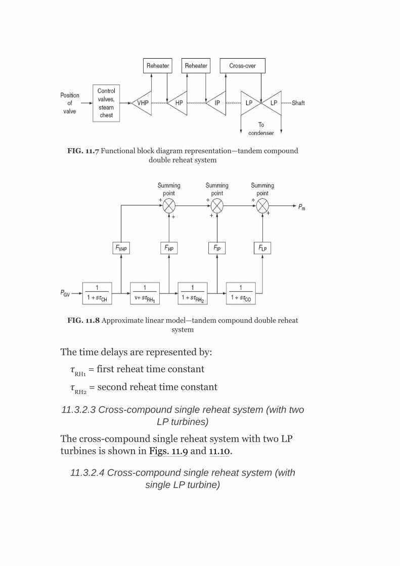
FIG.11.7Functionalblockdiagramrepresentation—tandemcompounddoublereheatsystem
FIG.11.8Approximatelinearmodel—tandemcompounddoublereheatsystem
Thetimedelaysarerepresentedby:
τ =firstreheattimeconstant
τ =secondreheattimeconstant
11.3.2.3Cross-compoundsinglereheatsystem(withtwoLPturbines)
Thecross-compoundsinglereheatsystemwithtwoLPturbinesisshowninFigs.11.9and11.10.
11.3.2.4Cross-compoundsinglereheatsystem(withsingleLPturbine)
RH1
RH2

Thecross-compoundsinglereheatsystemwithasingleLPturbineisshowninFigs.11.11and11.12.
11.3.2.5Cross-compounddoublereheattype
Thecross-compounddoublereheat-typesystemisshowninFigs.11.13and11.14.
FIG.11.9Functionalblockdiagramrepresentation
FIG.11.10Approximatelinearmodel

FIG.11.11Functionalblockdiagramrepresentation
FIG.11.12Approximatelinearmodel

FIG.11.13Functionalblockdiagramrepresentation
FIG.11.14Approximatelinearmodel
11.4SYNCHRONOUSMACHINES
Thesynchronousmachineisthemainorbasiccomponentoftheelectricalpowersystem.Itmayoperateeitherasageneratororasamotor.Inpowersystemoperation,thesynchronousmachineisoftenrequiredtosupplypoweratpowerfactorsotherthanunity,whichnecessitatesthesupplyorabsorptionofreactivepower.
Asynchronousmachineconsistsoftwobasicparts:thestatorandtherotor.Thetwobasicrotordesignsaresalientpoletypeandnon-salient-poletype.
11.4.1Salient-pole-typerotor
Inthistypeofrotor,thepolesprojectfromtherotorandexhibitanarrowairgapunderthepolestructureandawiderairgapbetweenthepoles.ThistypeofrotorstructureisshowninFig.11.15.
11.4.2Non-salient-pole-typerotor
ItconsistsofacylindricalrotorasshowninFig.11.16,oftenmadefromasinglesteelforging,inwhichthefieldwindingisembeddedinlongitudinalslotsmachinedinitsstructure.
Themathematicalmodelingofasynchronousmachineiscomplicatedbecauseofitsmultitudeofwindings,allcharacterizedbytime-varyingself-inductancesandmutualinductances.
11.5SIMPLIFIEDMODELOFSYNCHRONOUSMACHINE(NEGLECTINGSALIENCYANDCHANGESINFLUXLINKAGES)
Themostsimplifiedmodelofasynchronousgeneratorforthepurposeoftransientstabilitystudiesisaconstantvoltagesourcebehindproperreactance.Thevoltagesourcemaybesub-transient,transient,orsteadystateandthereactancemaybethecorrespondingreactances.

FIG.11.15Salient-pole-typerotorstructure

FIG.11.16Non-salient-pole-typerotorstructure
Inthismodel,saliencyandchangesinthefluxlinkagesareneglected.Howevertounderstandthismodel,letusconsiderasynchronousgeneratoroperatingatno-loadbeforea3-ϕshortcircuitisappliedatitsterminals.Thecurrentflowinginthesynchronousgeneratorjustafterthe3-ϕshortcircuitoccursatitsterminalsissimilartothecurrentflowsinanR–Lcircuitwhenanacvoltageissuddenlyapplied.Hence,thecurrentwillhaveboththeAC(i.e.,steadystate)componentaswellasthedc(i.e.,transient)component,whichdecaysexponentiallywiththetimeconstantL/R Ifthedccomponentisneglected,theoscillographoftheACcomponentofthecurrentthatflowsinthesynchronousgeneratorjustafterthefaultoccurswillhavetheshapeasshowninFig.11.17.
Justafterthefault,thecurrentismaximumastheairgapflux,whichgeneratesvoltage,ismaximumattheinstantthefaultoccursthanafewcycleslaterasthearmaturereactionfluxproducedduetoaverylarge
.

laggingcurrentinthearmatureprovidesnearlyademagnetizingeffect.
FromFig.11.17,letOAbethepeakvalueofsymmetricalACcurrent(neglectingDCcomponent),alsoknownaspeakvalueofthesub-transientcurrent:
∴RMSvalueofsub-transientcurrent
(11.6)
Now,ifthefirstfewcycles,wherethecurrentdecrementisveryfast,areneglectedandthecurrentenvelopeisextendeduptozerotime,theinterceptOBisobtained:
OB=Peakvalueofthetransientcurrent
∴RMSvalueoftransientcurrent (11.7)
However,thesteady-statevalueoftheshort-circuitcurrent(i.e.,sustainedvalueofshort-circuitcurrent)
(11.8)
Sincetheexcitationisaconstantfromno-loadtotheinstantwhenthe3-ϕshortcircuitoccurs,theexcitationvoltage‘E ’inthesynchronousgeneratorwillremainconstantandisknownasan‘open-circuitvoltageortheno-loadinducedemf’,andisrepresentedasshowninFig.11.18.
g
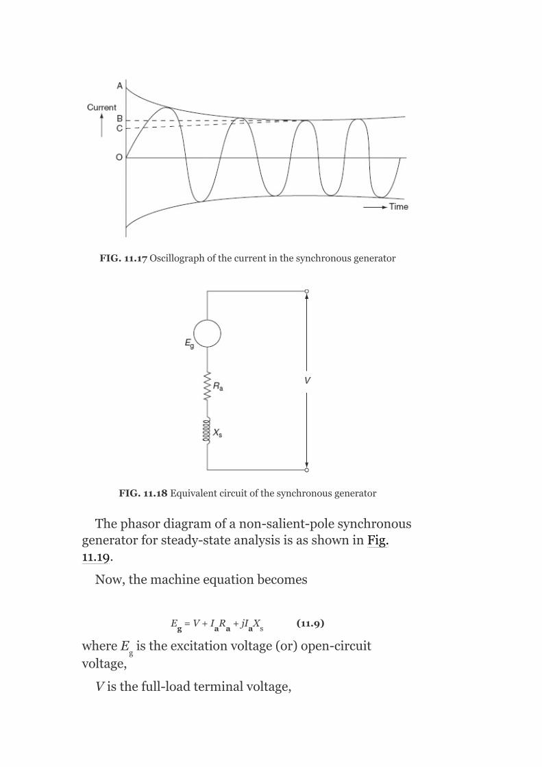
FIG.11.17Oscillographofthecurrentinthesynchronousgenerator
FIG.11.18Equivalentcircuitofthesynchronousgenerator
Thephasordiagramofanon-salient-polesynchronousgeneratorforsteady-stateanalysisisasshowninFig.11.19.
Now,themachineequationbecomes
E =V+I R +jI X (11.9)
whereE istheexcitationvoltage(or)open-circuitvoltage,
Visthefull-loadterminalvoltage,
g a a a s
g

I isthearmaturecurrent,
R isthearmatureresistance/phase,
X isthesynchronousreactance/phase,
ϕisthephaseanglebetweenVandI ,
δisthetorqueangleorpowerangle,and
θtheimpedanceangle
Itisseenthatthecurrentinthesynchronousgeneratorchangingfromsub-transientstate(I″)totransientstate(I′)andtosteadystate(I)andhencethesynchronousreactanceofthegeneratormustchange,asE isconstant,fromsub-transientreactance(X″)totransientreactance(X′)tosteady-statereactance(X).
FIG.11.19Phasordiagramofanon-salient-polesynchronousgeneratorforsteady-stateanalysis
i.e.,
a
a
s
a
g

Thearmaturereactionfluxisproducedbyalargelaggingcurrentasthiscurrentislimitedonlybyarmatureimpedance,wherewindingresistanceisnegligiblecomparedtosynchronousreactance,X .
Thisarmaturereactionfluxatthisinstantisnearlydemagnetizinginnaturebecauseitactsalongthedirectaxisofthemachine;theabovereactancesarereferredtoasdirectaxisreactances,i.e.,
directaxissub-transientreactance
directaxistransientreactance
directaxiscomponentofsteadystateor
synchronousreactance(11.11)
HereI″,I′,andIarethesub-transient,transient,andsteady-statevalueofshort-circuitcurrents,respectively,andE isexcitation(or)open-circuitvoltage(orno-loadinducedemf)inthearmature.Hence,thesimplestmodelofthesynchronousgeneratorisaconstantvoltage‘E ’inserieswiththeproperimpedance(or)reactance,i.e.,X″orX′ orX asshowninFig.11.20.
s
g
g
d
d d

FIG.11.20Simplifiedmodelofsynchronousgeneratorbyneglectingthesaliencyandfluxlinkagechanges
FIG.11.21Representationofsynchronousgenerator
Whenthesynchronousmachineconnectedtothepowersystemisoperatingatloadbeforethefaultoccurs,thesynchronousgeneratorisrepresentedbyanappropriatevoltagesourcebehindtherespectivereactancesasshowninFig.11.21.
Thismodeling(or)representationcaneasilybeobtainedforanyfaultinthepowersystemwiththehelp

ofThevenin’sequivalentcircuit,fromwhichitisclearthatthefluxlinkagesandhencetheinternalvoltageofthemachineremainconstant,butonlyitsphaseanglechanges.
Now,themachineequationsofthemodelofFig.11.21willbeexpressedas
E″ =V+jIX″
E′ =V+jIX′
E =V+jIX (11.12)
whereE “,E ′andE aresub-transient,transientorsteady-stateexcitationvoltagesofthesynchronousgenerator,respectively.Vistheterminalvoltageofthesynchronousgenerator,andIisthecurrentinthesynchronousgenerator.
Forthesynchronousmotor,Equations(11.12)mayobtainthefollowingformation.
E″ =V+jIX″
E′ =V+jIX′
E =V+jIX (11.13)
11.6EFFECTOFSALIENCY
Thesalient-polerotorisshowninFig.11.15.Ithasadirectaxisofrotor-fieldwinding,i.e.,d-axisandquadratureaxis,i.e.,theq-axisoftherotor-fieldwinding.Thed-axisandtheq-axisrevolvewiththerotor,whilethemagneticaxesofthethreestatorphasesremainfixed.
Attheinstantoftime,θistheanglefromtheaxisofPhase-atothed-axis.ThecorrespondinganglefromthePhase-baxistothed-axisisθ+240°orθ−120°.TheanglefromthePhase-caxisisθ+120°.Astherotorturns,θvarieswithtime,withaconstantrotorangularvelocity,ω,i.e.,θ=ωt.
g d
g d
g d
g g g
g d
g d
g d

Inordertoincludetheeffectofsaliency,thesimplestmodelofsynchronousmachinecanberepresentedbyafictitiousvoltage‘E ’locatedattheq-axis.Thed-axisistakenalongthemainpoleaxiswhiletheq-axislagsthed-axisby90°.ThenthevoltageE isexpressedintermsoffull-loadterminalvoltageVandfull-loadarmaturecurrentI as
E =V+I R +jIX X (11.14)
whereX isthequadratureaxissynchronousreactance.
TheequivalentcircuitandphasordiagramforthecaseofeffectofsaliencyaregiveninFigs.11.22(a)and(b).
Theexcitationvoltage(or)open-circuitvoltagewillbecalculatedas
E =V+I R +jI X +jI X (11.15)
whereX =X+X andX =X+X .X isthedirectaxisarmaturesynchronousreactance,
X thequadratureaxisarmaturesynchronousreactance,
X thed-axiscomponentofarmaturemagnetizingreactance,and
X theq-axiscomponentofthearmaturemagnetizingreactance.
q
q
a
q a a a q
q
g a a ad d aq q
d l ad q l aq d
q
ad
aq

FIG.11.22Effectofsaliency;(a)equivalentcircuit;(b)phasordiagram
X correspondstothed-axiscomponentofthearmaturereactionflux,ϕ ,andX correspondstotheq-axiscomponentofthearmaturereactionfluxϕ .
Now,thephasordiagramincludingtheeffectofsaliencyisdrawnasshowninFig.11.23.
ad
ad aq
aq

FIG.11.23Phasordiagramofsynchronousmachineincludingtheeffectofsaliency
11.7GENERALEQUATIONOFSYNCHRONOUSMACHINE
Thesynchronousmachinehasatleastfourwindings,threeonstatorcarryingACandoneonrotorwithDCexcitation.
WhenacoilhasaninstantaneousvoltageVappliedacrossitsterminalsandacurrent‘i’thatflowsfromapositiveterminalintothecoil,thegoverningequationbecomes
Hence,theinstantaneousterminalvoltageVofanywindingwillbeintheform,
V=±Σir±Σλ⋅

whereλisthefluxlinkage(itmayberepresentedbythesymbolΨ),rtheresistanceofthewinding,andithecurrentwithpositivedirectionofstatorcurrentflowingoutofthegeneratorterminal.
Forthethreestatorwindingsa,b,andc,thevoltageequationsare
andforrotor-fieldwinding,
Inpractice,r =r =r =r
∴λ=Li,
Equation(11.16)canbewrittenas
11.8DETERMINATIONOFSYNCHRONOUSMACHINEINDUCTANCES
The3-ϕsynchronousmachinewithoutdamperwindingsmaybeconsideredasasetofcoupledcircuitsformedbythe3-ϕwindingsandrotor-fieldwindingsasshowninFig.11.24.
Intheabovecircuit,thereareself-inductancesandmutualinductances,whichvaryperiodicallywiththeangularrotationofarotor.
a b c

FIG.11.24Circuitdiagramof3-ϕ,synchronousmachine
11.8.1Assumptions
Thefollowingassumptionsareusuallymadetodeterminethenatureofthemachineinductancestodevelopthedetailedmodelofthesynchronousmachines:
1. Theself-inductanceandmutualinductanceofthemachineareindependentofthemagnitudeofwindingcurrentsbecausethemagneticsaturationisneglected.Thus,themachineisassumedtobemagneticallylinear.
2. Theshapeoftheairgapandthedistributionofwindingsaresuchthatalltheaboveinductancesmayberepresentedasconstantsplussinusoidalfunctionsofelectricalrotorpositions.
3. Slottingeffectsareignored.Distributedwindingscomprisefinelyspreadconductorsofnegligiblediameter.
4. Magneticmaterialsarefreefromhysterisisandeddycurrentlosses.5. Themachinemaybeconsideredwithoutdamperwindings.Ifthe
damperwindingispresent,thenitsinfluencemaybeneglected.6. Higherordertimeandspaceharmonicsareneglected.
11.9ROTORINDUCTANCES

Inthissection,weshalldiscussrotorself-inductanceandstatortorotormutualinductancesindetail.
11.9.1Rotorself-inductance
Thestator,i.e.,armaturehasacylindricalstructure.Hence,theself-inductanceoftherotorfieldwinding‘f’willnotdependuponthepositionoftherotorandwillbeaconstantone.
i.e.,L =self-inductanceofrotor-fieldwinding=constant
11.9.2Statortorotormutualinductances
Thestatortorotormutualinductanceswillvaryperiodicallywithβ.Themutualinductancebetweenthefieldwindingandanyarmaturephaseisthegreatestwhenthed-axiscoincideswiththeaxisofthatphase.Figure11.25showstheeffectoffieldwindingonmutualinductances.
Considertheexample,themutualinductancebetweenthefieldwindingandPhase-a(M )willbemaximumatβ=0andatβ=90°andnegativemaximum(−M )atβ=180°andzeroagainatβ=270°.
Accordingly,withspacem.m.f.andfluxdistributionassumedtobesinusoidal,themutualinductancebetweenthefieldwindingandPhase-a(L )canbeexpressedas
L =L =M cosβ
Basedontheabove,thesimilarexpressionsforPhases-bandccanbeobtaineddirectlybyreplacingβwith(β−120°)and(β+120°),respectively,
i.e.,L =L =M cosβ
L =L =M cos(β−120°)
L =L =M cos(β+120°)(11.19)
ff
f
f
af
af fa f
af fa f
bf fb f
cf fc f

FIG.11.25Effectoffieldwindingonmutualinductances
11.10STATORSELF-INDUCTANCES
Theself-inductanceofanystatorphaseisalwayspositivebutvarieswiththepositionoftherotor.Itisthegreatestwhenthed-axisofthefieldcoincideswiththeaxisofthearmaturephaseandbeingleastwhentheq-axiscoincideswithit.Therewillbeasecond-harmonicsvariationbecauseofdifferentair-gapgeometryalongthedandq-axes.Forexample,theself-inductanceofPhase-a(L )willbeamaximumforβ=0andaminimumforβ=90°andmaximumagainforβ=180°andsoon.
WhenPhase‘a’isexcited,withspaceharmonicsignored,them.m.f.waveofphase‘a’willbeacosinewave(spacedistribution)centeredonthePhase-a-axisasshowninFig.11.26.
aa

FIG.11.26Them.m.f.waveofPhase-awithitsd-axisandq-axiscomponents
Thepeakamplitudeofthism.m.f.waveofPhase‘a’is
F =N i (11.20)
whereN istheeffectiveturns/phaseandi theinstantaneouscurrentinPhase‘a’.
Letusresolvethism.m.f.waveintotwo-componentsinusoidalspacedistributions,onecenteredonthed-axis(F )andtheotherontheq-axis(F ).
Thepeakamplitudesofthesetworesolvedcomponentsare
F =F casβ(11.21)
F =F cos(β+90°)=−F sinβ(11.22)
Theadvantageofresolvingm.m.f.isthattwocomponentsm.m.f.wavesactonspecificair-gapgeometryintheirrespectiveaxes.
a a a
a a
da qa
da a
qa a a

Thefundamentalair-gapfluxesperpolealongthetwoaxesare,accordingly,
whereÞ isthepermeancealongthed-axisandÞ thepermeancealongtheq-axis.
Theseareknownasmachineconstantsandtheirvaluescanbefoundfromafluxplotforspecificmachinegeometry.
Letϕ betheair-gapfluxlinkingwithPhase-aandbeexpressedas
ϕ =ϕ cosβ−ϕ sinβ(11.25)
=F (Þ cos β+Þ sin β)
Sincetheair-gapfluxlinkage,λ =ϕ N
Ifϕ representstheleakagefluxofPhase‘a’,whichdoesnotcrosstheairgap,thenthefluxlinkagesofPhase‘a’duetoleakagefluxonlyare
λ =ϕ N =F ÞN =N i Þ
whereÞ istheconstantleakagepermeanceofarmaturePhase‘a’.
d q
ga
ga ga qa
a d q
ga ga a
la
la la a a l a a a l
l
2 2
2

Therefore,thetotalfluxlinkageofPhaseacanbeexpressedas
λ =λ +λ
Sincebydefinition,theinductanceistheproportionalityfactorrelatingfluxlinkagestocurrent,theself-inductanceofPhase‘a’duetotheair-gapfluxwhenonlyPhase‘a’isexcited,willbe
⇒L =L +L cos2β(11.29)
where isaconstantterm,
istheamplitudeofsecond-harmonics
variation
ForPhase‘b’,thevariationofself-inductanceissimilar,exceptthatthemaximumvalueoccurswhenthed-axiscoincideswiththePhaseb-axis.Theself-inductancesofPhase‘b’andPhase‘c’canbeobtainedbyreplacingβby(β−120°)and(β+120°),respectively:
L =L +L cos2(β−120°)
=L +L cos(2β−240°)
=L +L cos(2β+120°)(11.30)
a ga la
aa s m
bb s m
s m
s m

L =L +L cos2(β+120°)
=L +L cos(2β+240°)
=L +L cos(2β−120°)(11.31)
i.e.,thestatorself-inductancesareobtainedas
L =L +L cos2β
L =L +L cos(2β+120°)
L =L +L cos(2β−120°)
11.11STATORMUTUALINDUCTANCES
Themutualinductancesbetweenstatorphaseswillalsoexhibitasecond-harmonicsvariationwithβbecauseoftherotorshape.Themutualinductancebetweentwophasescanbefoundbyevaluatingtheair-gapfluxlinkingonephasewhenanotherphaseisexcited.Forexample,themutualinductancebetweenPhasesaandb,L =L ,canbeobtainedbyevaluatingϕ linkingPhase‘b’whenonlyPhase‘a’isexcited.ϕ canbecomputedfromEquation(11.24)byreplacingβwith(β−120°)as
ϕ =ϕ cos(β−120°)−ϕ sin(β−120°)
=F [Þ cosβcos(β−120°)+Þ sinβsin(β−120°)]
ThemutualinductancebetweenPhase-aandPhase-bduetotheair-gapfluxisthen
L =−M +L cos(2β−120°)(11.34)
cc s m
s m
s m
aa s m
bb s m
cc s m
ab ba gba
gba
gba da qa
a d q
ab s m

where
Similarly,themutualinductancesofstatorL andLcanbeobtainedas
L =−M +L cos2β(11.35)
L =−M +L cos(2β+120°)(11.36)
i.e.,thestatormutualinductancesareexpressedas
L =−M +L cos(2β−120°)
L =−M +L cos(2β)
L =−M +L cos(2β+120°)
Here,L ,L ,andM areregardedasknownmachineconstantsandaredeterminedeitherbytestsorcalculatedbydesigned.AlltheinductancesexceptL arefunctionsofβandthustheyaretime-varying.
11.12DEVELOPMENTOFGENERALMACHINEEQUATIONS—MATRIXFORM
Fromtheknowledgeoftheabovetime-varyinginductances,thegeneralmachineequationsaredeveloped.Ifamotoringmodeisconsidered,thenforanywinding,thegeneralequationrelatingtheappliedvoltageoftheinputcurrentis
Intermsofself-inductanceandmutualinductance,thefluxlinkagesareexpressedas
λ =L i +L i +L i +L i
λ =L i +L i +L i +L i
bc ca
bc s m
ca s m
ab s m
bc s m
ca s m
s m s
ff
a aa a ab b ac c af f
b ba a bb b bc c bf f

λ =L i +L i +L i +L i
λ =L i +L i +L i +L i (11.37)
Equations(11.17)canbemodifiedas
Writetheaboveequationsinacompactmatrixform:
where
c ca a cb b cc c cf f
f fa a fb b fc c ff f

and
Thevectorsofthefluxlinkagesareproportionaltothecurrentswithmatrixofself-inductanceandmutualinductanceastheproportionalityfactor.
Hence,[λ]=[L][i](11.40)
where
i.e.,

TheinductanceLissymmetric,i.e.,L =L ,etc.
IftheexpressionsofinductancesofEquations(11.19)–(11.36)aresubstitutedinEquations(11.38),thesolutionofresultingequationscanbesimplifiedbyatransformation,knownasBlondel’stransformation,whichisalsogenerallycalledPark’stransformation.
11.13BLONDEL’STRANSFORMATION(OR)PARK’STRANSFORMATIONTO‘dqo’COMPONENTS
Equations(11.37)–(11.41)areasetofdifferentialequationsdescribingthebehaviorofmachines.However,thesolutionoftheseequationsiscomplicatedsincetheinductancesarethefunctionsofrotorangle‘β’,whichinturn,isafunctionoftime.
Thecomplicationingettingthesolutioncanbeavoidedbytransferringthephysicalquantitiesinthearmaturewindingsthroughalinear,time-dependent,andpower-invarianttransformationcalledPark’stransformation.
Thistransformationisbasedonthefactthattherotatingfieldproducedby3-ϕstatorcurrentsinthesynchronousmachinecanbeequallyproducedby2-ϕcurrentsina2-ϕwinding.Letusconsiderthe3-windingsforthethreephasesa,b,andcofasynchronousmachineasshowninFig.11.27.
Whenallthethreephasesareexcited,thetotalstatorm.m.f’.sthatactalongthed-axisandq-axisare
F =F cosβ+F cos(β−120°)+F cos(β+120°)
ab ba
ds a b c

=N [i cosβ+i cos(β−120°)+i cos(β+120°)(11.42)
andF =F sinβ−F sin(β−120°)+F sin(β+120°)
=N [i sinβ−i sin(β−120°)−i sin(β+120°)(11.43)
Letusconsidertwofictitiouswindings,oneplacedonthed-axisandtheotherontheq-axis,asshowninFig.11.28.
FIG.11.27Them.m.f.’sof3-ϕwindingsandtheirresultantm.m.f.’salongthed-axisandtheq-axis
a a b c
qs a b c
a a b c

FIG.11.28Fictitiouscoilsondandq-axes
Thewindingonthed-axisrotatesatthesamespeedastherotor-fieldwindingandremainsinsuchapositionthatitsaxisalwayscoincideswiththedirectaxisoftherotorfield.Hence,theinstantaneouscurrenti givesthesamem.m.f.F onthisaxisasdotheactualthreeinstantaneousarmaturephasecurrentsflowingintheactualarmaturewindings.Similarly,thecurrentiflowinginthewindingontheq-axisgivesthesamem.m.f.F onthisaxisasdotheactualthreeinstantaneousarmaturephasecurrentsflowingintheactualarmaturewindings.
Inordertotransformquantitiesinthef-a-b-caxesintothef-d-q-0axes,theconstraintsofthesystemformingthebasisofthetransformationmaybeobtainedbyviewingthecurrents,m.m.f.’s,voltages,andfluxlinkagesinthetwoaxes.ThecurrentsinviewofEquations(11.42)and(11.43)are
i =i
i =K [i cosβ+i cos(β−120°)+i cos(β+120°)]
i =K [i cos(β+90°)+i cos(β−120°+90°)+icos(β+120°+90°)]
d
ds
q
qs
f f
d d a b c
q q a b c

=−K [i sinβ+i sin(β−120°)+i sin(β+120°)](11.44)
Anewcurrent,knownaszero-sequencecurrent,whichdoesnotproduceanyrotatingfieldisintroducedandisexpressedas
whereK ,K ,andK areconstants.
Nowinthissystem,therearethreeoriginalphasecurrentsi ,i ,andi andthreefieldcurrentsi ,i ,andi .Fortheungroundedstarconnectionorforthebalanced3-ϕcondition,thesumofphasecurrentsiszeroandhencei mustalsobezero.
Equations(11.44)and(11.45)areexpressedinamatrixformas
Inamorecompactmatrixform,Equation(11.46)canbeexpressedas
ThisisknownasPARK’stransformation(orBlondel’stransformation).
where
q a b c
d q 0
a b c d q o
o
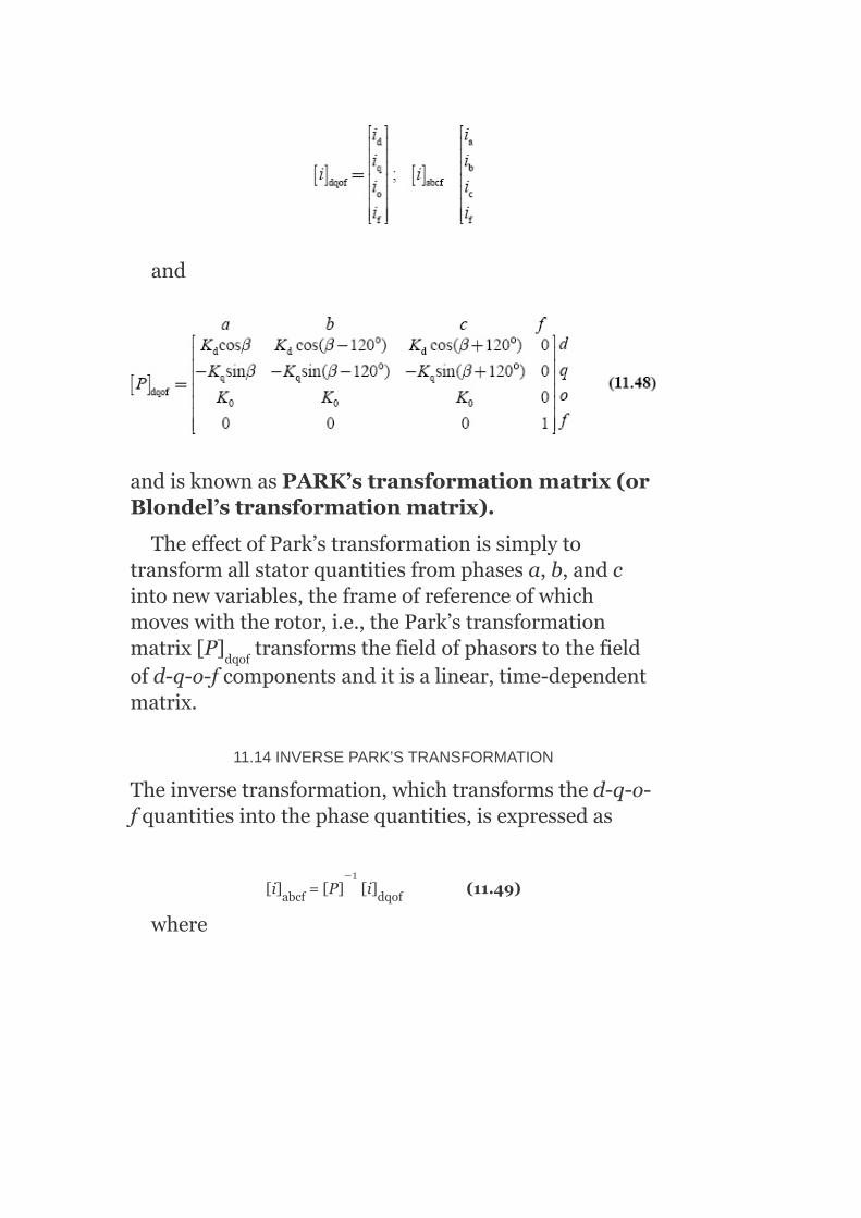
and
andisknownasPARK’stransformationmatrix(orBlondel’stransformationmatrix).
TheeffectofPark’stransformationissimplytotransformallstatorquantitiesfromphasesa,b,andcintonewvariables,theframeofreferenceofwhichmoveswiththerotor,i.e.,thePark’stransformationmatrix[P] transformsthefieldofphasorstothefieldofd-q-o-fcomponentsanditisalinear,time-dependentmatrix.
11.14INVERSEPARK’STRANSFORMATION
Theinversetransformation,whichtransformsthed-q-o-fquantitiesintothephasequantities,isexpressedas
[i] =[P] [i] (11.49)
where
dqof
abcf dqof
−1

11.15POWER-INVARIANTTRANSFORMATIONIN‘F-D-Q-O’AXES
Thetotalinstantaneouspowerdeliveredtothemotoris
P =V i +V i +V i (11.51)
Whenf-d-q-oaxes’quantitiesaresubstitutedforthephasequantitiesbyusingEquation(11.50)andbyfurthermanipulation,theseresultsgivepowerintermsofnewquantitiesas
Equation(11.52)givesthetruepowerassociatedwiththearmatureofthenewsystem.Thispowerinvarianceispreservedif
Sincetheanglebetweenthed-axisandthePhase-aaxisisβ,andtheq-axishasbeenchosenaheadofthed-axis,thevaluesofK andK mustbepositive;hence,theselectedvaluesofthethreequantitiesare
d a a b b c c
d q
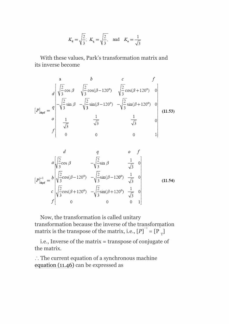
Withthesevalues,Park’stransformationmatrixanditsinversebecome
Now,thetransformationiscalledunitarytransformationbecausetheinverseofthetransformationmatrixisthetransposeofthematrix,i.e.,[P] =[P ]
i.e.,Inverseofthematrix=transposeofconjugateofthematrix.
∴Thecurrentequationofasynchronousmachineequation(11.46)canbeexpressedas
T
−1 *

andintermsofinversePark’stransformation,thecurrentequationsofsynchronousmachinecanbeexpressedas
11.16FLUXLINKAGEEQUATIONS
Thefluxlinkageequationsinmatrixformare[λ]=[L][i].Intermsofself-inductanceandmutualinductance,thefluxlinkagesfromEquation(11.37)areexpressedas
λ =L i +L i +L i +L i
λ =L i +L i +L i +L i
λ =L i +L i +L i +L i
a aa a ab b ac c af f
b ba a bb b bc c bf f
c ca a cb b cc c cf f

λ =L i +L i +L i +L i
Inmatrixform,itisexpressedas
Invectorform,itcanbeexpressedas
[λ] =[L] [i] (11.57)
Thefluxlinkagesoff-d-q-ocoilsintermsoffourcurrentsareobtainedupontransformingbothsidesbyusingthetransformationmatrix[P]anditsinverse[P]asfollows:
[λ] = [P][λ] (11.58)
= [P][L] [i]
= [P][L] [P] [i] (11.59)
[∵fromEquation(11.56);[i] =[P]−1[i]
f fa a fb b fc c ff f
abcf abcf abcf
dqof abcf
abcf abcf
abcf dqof
abcf dqof
−1
−1

Bysubstituting weget
whereL =directaxissynchronousinductance=
L =quadratureaxissynchronousinductance=
L =zero-sequenceinductance=L –2M
d
q
o s s

Note:ThemutualinductanceL canalsoberepresentedbyM orM.
FromEquation(11.61),wehave
FromEquation(11.62),itisnoticedthattheinductancesarenotfunctionsofrotorpositionβ.Hence,itisagreateradvantageoftransformingphasequantitiestoasuitablesetofquantitiesoff-d-q-o-axes.
11.17VOLTAGEEQUATIONS
Theoriginalvoltageequationofasynchronousmachineis
i.e.,
Fortransformation,letuspre-multiplybothsidesofEquation(11.63)by[P],
af
af

Hence,
Itcanbeshownthat isamatrixwithzero
entriesexceptfor–ωinthefirstrow,secondcolumnand+ωinthesecondrow,firstcolumn,
i.e.,

Afterthetransformation,synchronousmachineequationsinmatrixformbecome
FIG.11.29(a)PhasordiagramsV versusωλ ;(b)phasordiagramsωλ
versus–V
∵R =R =R =R
whereω=angularvelocityofrotation=
FromEquation(11.67),thevoltageequationsobtainedare
q d q
d
a b c

Forsinusoidalsteady-stateconditions,thefluxphasorleadsthevoltagephasorby90°.Thismeansthatv willbeinducedbythefluxinthedirectaxis(ωλ );i.e.,v willbeinducedby(ωλ )andsimilarly−v willbeinducedby(ωλ )asshowninFigs.11.29(a)and(b).
11.18PHYSICALINTERPRETATIONOFEQUATIONS(11.62)AND(11.68)
Thetermsωλ andωλ arespeedvoltages(fluxchanges
inspace)andtheterms and aretransformer
voltages(fluxchangesintime).Usually,thesetransformervoltagesaresmallcomparedwithspeedvoltagesandmaybeneglected.TheneglectedtransformervoltagescorrespondtonegligenceoftheharmonicsandDCcomponentsintransientsolutionforstatorvoltagesandcurrents.NegligenceofharmonicsandDCcomponentsinthephasecurrentisverycommoninmachineanalysis.NeitherharmonicsnorDCcomponentshaveasignificanteffectontheaveragetorqueofthemachinesinceharmonicsareusuallysmallandDCcomponentsdieawayveryrapidly.
ThesolutionsofnetworkequationsbecomeextremelydifficultandcomplexwhentheharmonicsandDCcomponentsarepresentinelectricalquantitiesifthetransformervoltagesareincluded.Hence,itispreferabletoapproximatetheassociateddampingtorquesbyadditionaltermsintheswingequation.
q
d q
d d
q
d q

11.19GENERALIZEDIMPEDANCEMATRIX(VOLTAGE–CURRENTRELATIONS)
BycombiningEquations(11.62)and(11.68),weget
Incompactform,theabovematrixcanbeexpressedas
[V] =[Z] [i] (11.70)
Itisobservedthattheimpedancematrixissymmetricalinfandd-axes.Itconsistsoftwoterms,one
relatingtotransformervoltagesandthesecond
relatingtospeedvoltages,asgivenbelow:
dqof dqof dqof

where angularspeedofrotation
11.20TORQUEEQUATION
Thespeedvoltagesare:
1. Inthedirectaxis,λ ωand
2. Inthequadratureaxis,−λ ω
Mechanicalangularvelocity
Thetotal3-ϕpoweroutputofasynchronousmachineisgivenby
d
q

p =v i +v i +v i (11.73)
Assumebalancedbutnotnecessarilysteady-stateconditions,thusv =0andi =0.
∴p=v i +v i (11.74)
FromEquation(11.68),
Substitutingv andv expressionsinEquation(11.74),weget
out d d q q o o
0 0
d d q q
d q

Theaboveexpressionconsistsofthreetermsandtheyare:
Thefirsttermrepresentstherateofchangeofstatormagneticfieldenergy.Thesecondtermrepresentsthepowertransferredacrosstheairgap.Thethirdtermrepresentsthestatorohmiclosses.
Themachinetorqueisobtainedfromthesecondterm,
Substitutingforλ andλ fromEquation(11.62)inEquation(11.76),weget
Foracylindricalrotorsynchronousmachine,thedirectaxisandquadratureaxisinductancesareequal,
d q

i.e.,L =L :
Forasalient-polemachine,thereisasaliencytorque:
T =(L −L )i i (11.79)
Thistorqueexistsonlybecauseofnon-uniformityinthepermeanceoftheairgapalongthed-andq-axes.Thisisthereluctancetorqueofasalient-polemachineandexistsevenwhenthefieldexcitationiszero.
11.21SYNCHRONOUSMACHINE—STEADY-STATEANALYSIS
Considera3-ϕsynchronousmachinethathasthreearmature(stator)windingsa,b,andc,onefieldwinding‘f’ontherotorwithitsfluxinthedirectionofthed-axis,andonefictitiouswinding‘g’ontherotorwithitsfluxinthequadratureaxisasshowninFig.11.30.
FIG.11.30Three-phasesynchronousmachinewithstatorandrotorwindings
Thefictitiouswinding‘g’approximatestheeffectofeddycurrentscirculatingintheiron(rotorironinround-rotormachineandnegligibleinsalient-polemachine)andto
d q
saliency d q d q

someextenttheeffectofdamperwindings.Thisfictitiouswindingisshortcircuitedsinceitisnotconnectedtoanyvoltagesource.
Sincetheelectromagnetictransientsinthenetworkaremuchfasterthanthemechanicaltransients,thesteady-statephasorsolutionsonthenetworksideareperformed.
11.21.1Salient-polesynchronousmachine
Thephasordiagramofanoverexcitedsalient-polesynchronousgeneratorforlaggingp.f.isshowninFig.11.31.
FIG.11.31Phasordiagramofasalient-polesynchronousgenerator
δisthepowerangleortorqueangle
E theterminalvoltage=v
E thevoltageduetoair-gapflux
a a
ag

E thevoltageduetofluxproducedbymainrotor-fieldcurrent
I X thevoltagedropacrossd-axisarmaturemagnetizing
reactance
I X thevoltagedropacrossq-axisarmaturemagnetizing
reactance
λ thefluxlinkageduetonetair-gapflux
λ thed-axiscomponentoffluxlinkage
λ theq-axiscomponentoffluxlinkage
λ thefluxlinkageduetod-axiscomponentofI
λ thefluxlinkageduetoq-axiscomponentofI
x thed-axiscomponentofsynchronousreactance=x +x
x theq-axiscomponentofsynchronousreactance=x +x
Figure11.32representsthephasorsandtheirspeeds:
δistheanglebetweensynchronouslyrotatingreferencephasoraxisandq-axis
ω thesynchronousspeed
ωthespeedofrotor
af
ad ad
aq aq
ag
agd
agq
ad a
aq a
d l ad
q l aq
s

FIG.11.32Phasorsandtheirspeeds
FromthephasordiagramshowninFig.11.32,wehave
ByapplyingPark’stransformation,weget
Equations(11.81)canbeexpressedasaphasorequation:
I +jI =Ie
=Ῑe asῙI∠α(11.82)q d
j(a−δ)
−jδ

Forthesteady-stateanalysis,theq-axiswillbeconsideredastherealaxisandthed-axisastheimaginaryaxissincethevoltageinducedinanormalsteady-stateoperationliesontheq-axis.
Similarly,byPark’stransformation,weget
v =vcos(θ−δ)
v =vsin(θ−δ)
V =0
Incomplexnotation,
Togetthesteady-stateanalysis,wemakeuseofthefollowingassumptions:
1. Transformervoltages, and ,beingsmallandaretherefore
neglected.2. Balancednetworkcurrentsandvoltagesareassumed.
Thereasonsfortheaboveassumptionsarethatchangesinλ andλ areveryslowintimewiththeoscillationsof
angleδandhence and areverysmallcompared
withωλ andωλ .
Duetotheaboveassumptions,Equations(11.62)and(11.68)canberewrittenbydroppingthetransformervoltageterms,zero-sequencecurrents,andvoltages:
q
d
o
d q
d q

Substitutingforλ andλ intheaboveequationsofvoltages,weget
Hence,
I +jI =Ie
v +jv =ve
11.21.2Non-salient-polesynchronous(cylindricalrotor)machine
Forthiscase,X =X
∴E =E +i R +ji X +ji X
=E +i R +ji X (11.87)
d q
q d
q d
d q
af a a a a 1 a ad
a a a d d
j(α−δ)
j(α−δ)

Theequivalentcircuitofanon-salient-polesynchronousmachineisrepresentedbyasourceE (inducedemf)inserieswiththeinternalimpedanceR +jX asshowninFig.11.33.
ThephasordiagramisshowninFig.11.34.Now,thesynchronousreactanceisdefinedasX =X +X ,andifresistance‘r’isneglected,thecylindricalrotorsynchronousgeneratorisrepresentedbytheequivalentcircuitasshowninFig.11.35.
FIG.11.33Equivalentcircuitofnon-salient-polesynchronousgenerator
FIG.11.34Phasordiagramofnon-salient-polesynchronousgenerator
af
a d
s aq l

FIG.11.35Equivalentcircuit
Now,Equation(11.87)becomes
E =E ji X (11.88)
Theaboverelationshiprepresentsthemodelofthecylindricalrotor(non-salientpole)generatorundersteady-stateconditionsandofwhichaveryusefulequivalentcircuitisshowninFig.11.35.
11.22DYNAMICMODELOFSYNCHRONOUSMACHINE
Inthissection,weshalldiscussthedynamicmodelofsynchronousmachines—salientpolesynchronousgenerator,dynamicequationsofsynchronousmachine,andequivalentcircuitofsynchronousgenerator—indetail.
11.22.1Salient-polesynchronousgenerator—sub-transienteffect
Duringnormalsteady-stateconditions,thereisnotransformeractionbetweenstatorandrotorwindingsofsynchronousmachines,astheresultantfieldproducedbystatorwindingsandrotorwindingsrevolveswiththesame(synchronous)speedandinthesamedirection.However,duringdisturbances,therotorspeedisnolongerthesameasthatoftherevolvingfieldproducedbystatorwindings,whichalwaysrotateswithsynchronous
af a a s
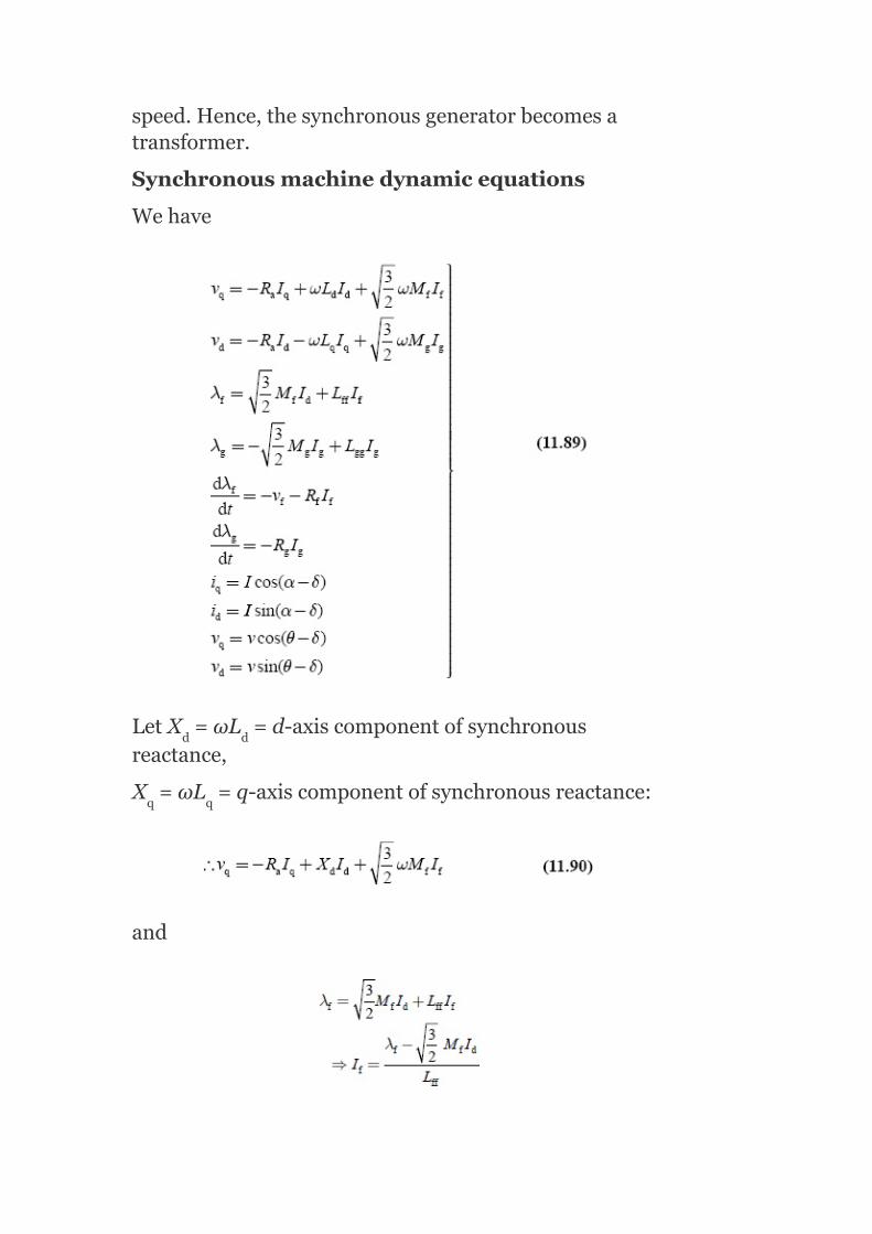
speed.Hence,thesynchronousgeneratorbecomesatransformer.
Synchronousmachinedynamicequations
Wehave
LetX =ωL =d-axiscomponentofsynchronousreactance,
X =ωL =q-axiscomponentofsynchronousreactance:
and
d d
q q

SubstitutingtheI valueinEquation(11.90),weget
Let sub-transientvoltagealongtheq-axis
Sinceatthistime,bothwindings‘f’and‘g’arepresentalongthed-axisthen,Equation(11.91)becomes
Let transientd-axisreactance
Sinceatthistime,boththed-axiscomponentofthearmaturewindingsandthef-windingarepresent,Equation(11.92)becomes
v =−R I +X′ I +E′ (11.93)
Similarly,theequationofv isgivenby
f
q a q d d q
d

Substituting,ωL =X ,weget
Weknowthat
SubstitutingI expressioninEquation(11.94),weget
Let Transientvoltagealongthed-axis
(sinceboththeq-axiscomponentandg-windingsarepresenttogivetransientstate)andalsolet
q-axiscomponentoftransient
reactance
Hence,Equation(11.95)becomes
v =−R I −X′ I +E′ (11.96)
q q
g
d a d q q d

Let directaxisopen-circuittransienttime
constant
quadratureaxisopen-circuittransienttime
constant
andalso
i.e.,E=E +jE
SubstitutingEquation(11.97)inEquations(11.90)and(11.94),weget
v =−R I −X I +E (11.99)
FromEquations(11.93)and(11.98)
v =−R I +X′ I +E′ =−R I +X I +E
i.e.,E′ =E +(X −X′ )I (11.100)
SimilarlyfromEquations(11.96)and(11.99),wehave
v =−R I +X′ I +E′ =−R I −X I +E
i.e.,E′ =E −(X −X′ )I (11.101)
Figure11.36showsthephasordiagramofasynchronousmachineunderthetransientstate.
q d
d a d q q d
q a q d d q a q d d q
q q d d d
d a q q q d a d q q d
d d q q q

Fromthephasordiagramalsoweget
E′ =E +I (X −X′ )=voltagebehindthed-axiscomponentoftransientreactance
E′ =E −I (X −X′ )=voltagebehindtheq-axiscomponentoftransientreactance
FIG.11.36Phasordiagram
q q d d d
d d q q q
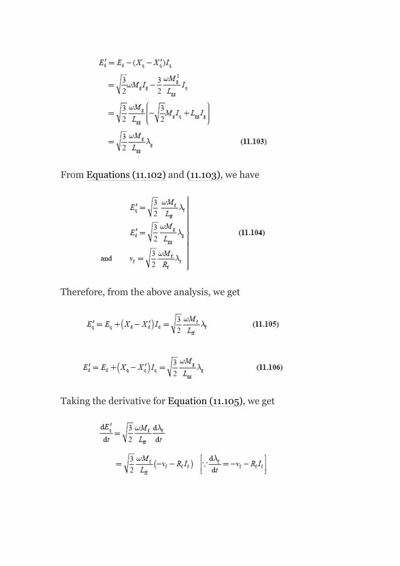
FromEquations(11.102)and(11.103),wehave
Therefore,fromtheaboveanalysis,weget
TakingthederivativeforEquation(11.105),weget

andalsotakingthederivativeofEquation(11.106),wehave
q-axiscomponentofopen-circuittransient
reactancetimeconstant
i.e.,
Equations(11.93)and(11.96)canbewritteninthematrixformas

11.22.2Dynamicmodelofsynchronousmachineincludingdamperwinding
The‘f’and‘g’coilsintherotorwindingproducetransienteffectintermsofX′ andX′ inthesynchronousmachine.Thefieldcoil‘f’existsphysicallywhereasthe‘g’coilishypotheticalforrepresentingtherotoreddycurrentsintheq-axis.However,itisquitedifficulttocalculateg-coilinductance.
Themoreaccuraterepresentationofsynchronousmachineisobtainedbyaddingtwomorefictitiouswindingsontherotor,onealongthed-axisknownas‘K ’windingandtheotheralongtheq-axis,knownas‘K ’winding.Thesedamperwindingscanbeapproximatedbytwohypotheticalcoils,bothshort-circuitedasthereisnovoltagesourceconnectedtothem.
Thedynamicmachineequationswillnowbemodifiedtoincludethedamperwindingsbysubstitutingthescalar(λ andλ )vectors:
Nowinthismodel,thePark’stransformationwillbeappliedwiththefollowingassumptions:
1. Mutualinductancesfromstatorcoilsa,b,andc(oritscomponent‘d’and‘q’axes)tothe‘K ’coilisthesameas‘f’coil,andtotheK coil
thesameas‘g’coiland2. Mutualinductancebetween‘K ’coiland‘f’coil(and‘K ’coiland‘g’
coil)isthesameas‘d’componentofstatorcoilsandf-coils(or‘q’componentofstatorto‘g’coil).
TheresultantequationsafterPark’stransformationare
d q
d
q
f g
d g
d g

Fromtheabovematrixrepresentation,themodifiedvoltageequationswiththeinclusionofdamperwindingsare
Themodifiedfluxlinkageswiththeinclusionofdamperwindingsareobtainedintheformofmatrixas

i.e.,thefluxlinkageequationsare
11.22.3Equivalentcircuitofsynchronousgenerator—includingdamperwindingeffect
11.2.3.1Alongthed-axis

Theequivalentcircuitofthesynchronousgeneratoralongthed-axisexcludingresistancesisasshowninFig.11.37,whereX isthearmatureleakagereactance,X thearmaturemagnetizingreactance,X thefieldreactance,andX thefictitiouswindingreactance.
Initially,allthereactancesareinthecircuit(i.e.,justattheinstantwhenthefaulthasoccurred)andtherefore,initialorsub-transientreactance,arethelowest.Aftersometime,theg-winding(damperwinding)isoutofcircuitasithasaverylowtimeconstantandhencewehaveonlyfieldwindingandarmaturereactancesinparallel.Thisreactanceisknownastransientreactanceandislargerthanthepreviousone.However,aftersometime,whenthedisturbancealtogetherdisappears,fieldwindingisalsooutofcircuitandhencewehaveonlyarmaturereactance,(X =X +X )calledthesteady-statereactanceofthecircuit.
FIG.11.37Equivalentcircuitofsynchronousgenerator
Foramoreaccuraterepresentation,twomorefictitiouswindings‘K ’windingand‘K ’windingareadded.Hence,theequivalentcircuitofthesynchronousgeneratoralongthed-axiscanberepresentedasshowninFig.11.38.
TheparallelcombinationofX ,X ,andX isknownasthed-axiscomponentofsub-transientreactanceX″andisrepresentedasX″ =X /X /X .
Hence,thed-axiscomponentofthesub-transientsynchronousreactanceisgivenby
l ad
f
g
d l ad
d q
ad f kd
ad
ad ad f kd

X″ =X +X″
Thisreactanceisverysmall.Aftersometime,asthehuntingbecomesless,thewindingK isalsooutofcircuitsinceithasalowtimeconstant.
Thus,theresultantequivalentcircuitbecomesasshowninFig.11.39.
TheparallelcombinationofreactancesX andX isknownasX′ ,d-axiscomponentoftransientarmaturereactance.
Thed-axiscomponentoftransientsynchronousreactanceisX′ ==X +X′
Generally,X′ >X″
Finally,whenthedisturbanceisaltogetherover,therewillnotbehuntingoftherotorandhencetherewillnotbeanytransformeractionbetweenthestatorandtherotor.Hence,theequivalentcircuitofsynchronousgeneratorbecomesasshowninFig.11.40.
FIG.11.38Accuraterepresentationofequivalentcircuitofsynchronousgenerator
FIG.11.39Resultantequivalentcircuitofsynchronousgenerator
d 1 ad
d
ad f
ad
d 1 ad
d d

FIG.11.40Equivalentcircuit
FIG.11.41Equivalentcircuitofsynchronousgeneratoralongtheq-axis
FIG.11.42Resultantequivalentcircuitofthesynchronousgenerator
Here,X =X +X andiscalledthedirectaxiscomponentofsynchronousreactance.
ItisobviousthatX″ <X′ <X .
11.2.3.2Alongtheq-axis
Justafterthedisturbance,theequivalentcircuitofthemachinewillbecomeasshowninFig.11.41.
Here,X″ =X +(X //X //X )
whereX″ istheq-axiscomponentofsub-transientsynchronousreactance.ThevalueofX″ isverysmall.
d l ad
d d d
q 1 aq g kq
q
q

Aftersometime,huntingbecomeslessandless,bothg-windingandK ,whichhavealowtimeconstant,willbeoutofcircuitandhencetheresultantequivalentcircuitofthesynchronousgeneratorbecomesasshowninFig.11.42.
Here,X′ =X =X +X ,whereX′ istheq-axiscomponentoftransientsynchronousreactance.
11.23MODELINGOFSYNCHRONOUSMACHINE—SWINGEQUATION
Themechanicalbehaviorofasynchronousmachinecanbeestablishedbyinterconnectingtheelectricalandmechanicalsidesofasynchronousmachineintermsofelectricalandmechanicaltorque.Thisisprovidedbythedynamicequationfortheaccelerationordecelerationoftherotorofacombinedturbineandsynchronousgeneratorsystem,whichisusuallycalledtheswingequation.
Whiledevelopingaswingequationoramechanicalequation,thefollowingbasicassumptionsaretobemade:
1. Synchronousmachinerotorspeedmustbesynchronousspeed.2. Therotationalpowerlossesduetofrictionandwindageareneglected.3. Mechanicalshaftpowerissmooth,i.e.,theshaftpowerisconstant.
Letusconsiderasinglerotatingmachinewithsteady-stateangularspeed andphaseangleδ.Duetovariouselectricalormechanicaldisturbances,themachinewillbesubjectedtodifferencesinmechanicalandelectricaltorque,causingittoaccelerateordecelerate.Hence,duringdisturbance,therotorwillaccelerateordeceleratewithrespecttothesynchronouslyrotatingair-gapm.m.f.andarelativemotionbegins.
Letθbetheangularpositionoftherotoratanyinstant‘t’
ωtheangularvelocity(rad/s)
q
q q 1 aq q

αtheacceleration
δthephaseangleofarotationmachine
T thenetacceleratingtorqueinamachine
T theelectricaltorqueexertedonthemachinebythegenerator
P thenetacceleratingpower
P themechanicalpowerinput
P theelectricalpoweroutput
Jthemomentofinertiaforthemachine
M=Jω;angularmomentumofthemachineinkg-m
Jα=T
P =ωT =ω(Jα)=Mα
ConsiderasynchronousgeneratordevelopinganelectromagnetictorqueT andrunningatthesynchronousspeedω .IfT isthedrivingmechanicaltorque,thenundersteady-stateconditions,withnegligiblelosses,
T =T
Adeparturefromthesteadystateduetoadisturbanceresultsinanaccelerating(T >T )ordecelerating(T >T )torqueT ontherotor:
T =T −T
Neglectingthefrictionalanddampingtorque,fromthelawofrotation,wehave
Now,thevalueofθiscontinuouslychangingwithtime‘t’.Itisconvenienttomeasureθwithrespecttoareferenceaxis,whichisrotatingatsynchronousspeed.
net
elec
net
mech
elec
net
net net
e
s m
m e
m e e
m a
a m e
2

Ifδistheangulardisplacementofarotorinelectricaldegreefromthesynchronousrotatingreferenceaxisandω ,thesynchronousspeedinelectricaldegrees,thenθcanbeexpressedasthesumof:(i)time-varyingangleω tontherotatingaxisand(ii)thetorqueangleδoftherotorwithrespecttotherotatingreferenceaxisasshowninFig.11.43:
FIG.11.43Phasorrepresentationofrotor-fieldposition
andtherotorangularaccelerationisobtainedbydifferentiatingtheaboveequationagain:
Thetorqueactingontherotorofasynchronousgeneratorincludesthemechanicalinputtorquefromtheprimemover,torqueduetorotationallosses(i.e.,friction,windage,andcoreloss),electricaloutputtorque,
s
s

anddampingtorquesduetoprimemover,generator,andpowersystem.
Theelectricalandmechanicaltorquesactingontherotorareofoppositesignandareofaresultofelectricalinputandmechanicalload.Byneglectingdampingandrotationallosses,sothatacceleratingtorqueis
T =T −T
andmultiplyingwithω,weget
Theswingequationintermsofmomentofinertiaorangularmomentumis
∴Swingequationisalsoexpressedas
KEYNOTES
Theprimemovercontrolsareclassifiedas:
1. Primarycontrol(speedgovernorcontrol).2. Secondarycontrol(loadfrequencycontrol(LFC)).3. Tertiarycontrolinvolvingeconomicdispatch.
Thetransientcharacteristicsofhydro-turbinesareobtainedbythedynamicsofwaterflowinthepenstock.Thewaterstartingtimeorwatertimeconstantvalueliesintherangeof0.5-5.0s.Steamturbinesystemconfigurationsare:
1. Non-reheattype.
a m e

2. Reheattype.
Reheattypesteamturbinesareclassifiedas:
1. Tandemcompound,singlereheattype.2. Tandemcompound,doublereheattype.3. Cross-compound,singlereheattypewithtwoLPturbines.4. Cross-compound,singlereheattypewithsingleLPturbine.5. Cross-compound,doublereheattype.
Mostsimplifiedmodelofasynchronousgeneratorforthepurposeoftransientstabilitystudiesisaconstantvoltagesourcebehindproperreactance.Inordertoincludetheeffectofsaliency,thesimplestmodelofasynchronousmachinecanberepresentedbyafictitiousvoltage‘E ’
locatedattheq-axis.Thed-axisistakenalongthemainpoleaxiswhiletheq-axislagsthed-axisby90°.Thestatortorotormutualinductanceswillvaryperiodicallywiththeanglebetweentheq-axisandthed-axisofasynchronousmachine.Theself-inductanceofanystatorphaseisalwayspositivebutvarieswiththepositionoftherotor.Itisthegreatestwhenthed-axisofthefieldcoincideswiththeaxisofthearmaturephaseandistheleastwhentheq-axiscoincideswithit.TheeffectofPark’stransformationissimplytotransformallstatorquantitiesfromphasesa,b,andcintonewvariables,theframeofreferenceofwhichmoveswiththerotor,i.e.,Park’stransformationmatrix[P] transformsthefieldofphasorstothefieldofd-q-o-f
componentsanditisalinear,time-dependentmatrix.
SHORTQUESTIONSANDANSWERS
1. Whatisthesignificanceofwatertimeconstant,τ ?
whereΔHisthep.u.changeinwaterhead,ΔQthep.u.changeinthewaterdischarge,τ thewatertimeconstant,τ theelastic
limitofpenstock,zthenormalizedpenstockimpedance,andτ
knownasthewatertimeconstantorwaterstartingtime.
Thevalueofτ liesintherangeof0.5–5.0s.
Thetypicalvalueofτ isaround1.0s.
2. Howarethetransientcharacteristicsofhydro-turbinesobtained?Bythedynamicsofwaterflowinthepenstock.
3. Thewatertimeconstantτ isassociatedwithwhattime?
τ isassociatedwithaccelerationtimeforwaterinthepenstock
betweentheturbineinletandtheforebayorbetweentheturbineinletandthesurgetankifitexists.
q
dqof
ω
ω e
e
ω
ω
ω
ω
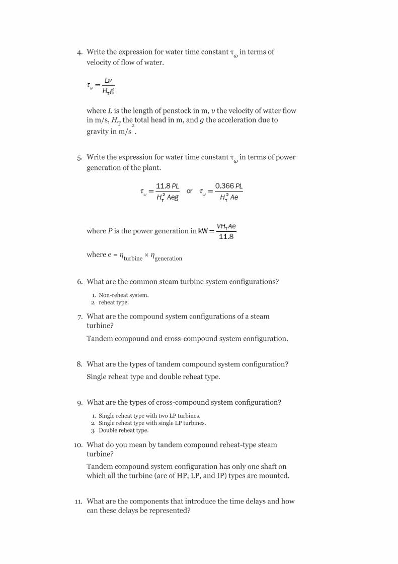
4. Writetheexpressionforwatertimeconstantτ intermsof
velocityofflowofwater.
whereListhelengthofpenstockinm,vthevelocityofwaterflowinm/s,H thetotalheadinm,andgtheaccelerationdueto
gravityinm/s .
5. Writetheexpressionforwatertimeconstantτ intermsofpower
generationoftheplant.
wherePisthepowergenerationin
wheree=η ×η
6. Whatarethecommonsteamturbinesystemconfigurations?
1. Non-reheatsystem.2. reheattype.
7. Whatarethecompoundsystemconfigurationsofasteamturbine?
Tandemcompoundandcross-compoundsystemconfiguration.
8. Whatarethetypesoftandemcompoundsystemconfiguration?
Singlereheattypeanddoublereheattype.
9. Whatarethetypesofcross-compoundsystemconfiguration?
1. SinglereheattypewithtwoLPturbines.2. SinglereheattypewithsingleLPturbines.3. Doublereheattype.
10. Whatdoyoumeanbytandemcompoundreheat-typesteamturbine?
Tandemcompoundsystemconfigurationhasonlyoneshaftonwhichalltheturbine(areofHP,LP,andIP)typesaremounted.
11. Whatarethecomponentsthatintroducethetimedelaysandhowcanthesedelaysberepresented?
ω
T
ω
turbine generation
2

Steamchest,reheat,andcross-overpipingarethecomponentsthatintroducethetimedelaysintheoperationofsteamturbines.
Thetimedelayscanberepresentedby:
τ =steam-chesttimeconstant(0.1–0.4s).
τ =reheattimeconstant(4–11s).
τ =cross-pipingtimeconstant(0.3–1.5s).
12. Whatisthemostsimplifiedmodelofasynchronousgeneratorforthepurposeofatransientstabilitystudy?
Aconstantvoltagesourcebehindaproperreactance,thevoltagesourcemaybesub-transientorsteadystateandthereactancemaybecorrespondingreactance.
13. Whyisthereactanceofthesynchronousgeneratorequivalentcircuitreferredtoasdirectaxisreactancewhenthe3-ϕshort-circuitfaultoccurs?
Thearmaturereactionfluxatthatinstantisnearlydemagnetizinginnatureandbecauseitactsalongthedirectaxisofthemachine,theequivalentcircuitreactanceisreferredtoasdirectaxisreactance.
14. Themodelingofasynchronousmachineiseasilyobtainedforanyfaultinapowersystembywhichcircuit?
Thevenin’sequivalentcircuit.
15. Writetheexpressionforexcitationvoltageoropen-circuitvoltageofasynchronousmachinefortheeffectofsaliency.
E =V+I R +jI X +jI X
16. Writethevoltageequationsforthethreestatorwindingsandrotorwindingsintermsoffluxlinkages.
V =i r +dλ /dt.
V =i r +dλ /dt.
V =i r +dλ /dt.
V =i r +dλ /dt.
17. Whataretheassumptionsusuallymadetodeterminethenatureofthemachineinductancetohelpthedetailedmodelofsynchronousmachines?
CH
RH
CO
q a a ad d aq q.
a a a a
b b b b
c c c c
f f f f

1. Theself-inductanceandmutualinductanceofthemachineareindependentofthemagnitudeofwindingcurrentsbecauseofneglectingmagneticsaturation.
2. Theshapeoftheairgapandthedistributionofwindingsaresuchthatallthemachineinductancesmayberepresentedasconstantplussinusoidalfunctionsofelectricalrotorpositions.
3. Slottingsareignored.4. Magneticmaterialsarefreefromhysteresisandeddycurrentlosses.5. Themachinemaybeconsideredwithoutdamperwindings.Ifadamperwindingispresented,itsinfluencemaybeneglected.
6. Highertimeandspaceharmonicsareneglected.
18. Writetheexpressionsforstatortorotormutualinductancesofasynchronousmachine.
L =L =M cosβ
L =L =M cos(β−120°)
L =L =M cos(β+120°).
19. Writetheexpressionsforstatorself-inductancesofasynchronousmachine.
L =L +L cos2β
L =L +L cos(2β+120°)
L =L +L cos(2β−120°).
20. Writetheexpressionsforrotorself-inductancesofasynchronousmachine.
L =−M +L cos(2β−120°)
L =−M +L cos2β
L =−M +L cos(2β+120°).
21. WhatisPark’stransformationandwhatisitsrequirement?
Thebehaviorofasynchronousmachinecanbedescribedbyasetofdifferentialequations.Thesolutionofthesedifferentialequationsiscomplicatedsincetheinductancesarethefunctionsofrotorangleβ,whichinturnisafunctionoftime.Thecomplicationingettingthesolutioncanbeavoidedbytransferringthephysicalquantityinthearmaturewindingsthroughalinear,time-dependent,andpower-invarianttransformercalledPark’stransformation.
22. InPark’stransformation,whichquantitiesaretransformed?
Quantitiessuchascurrents,m.m.f.s,voltages,andfluxlinkagesinabcfaxestodqofaxesaretransformed.
af fa f
bf fb f
cf fc f
aa s m
bb s m
cc s m
ab s m
bc s m
ca s m

23. ExpressPark’stransformationmatrix.
24. WhatisthefunctionofPark’stransformationmatrix?
Park’stransformationmatrix[p]transformsthefieldofabcfcomponentstothefieldofdqofcomponents.
25. Park’stransformationmatrixiscalledunitarymatrix.Why?
BecausetheinverseofPark’stransformationmatrixisthetransposeofconjugateofthematrix.
[p] =[p*]
26. Writetheexpressionforthefluxlinkagesoffdqocoilsintermsofcoilcurrentsbyusingtransformationmatrixanditsinverse.
[λ] =[p][L] [p] [i]
27. Writetheexpressionfor3-ϕpoweroutputofasynchronousmachineintermsofrateoffluxlinkagesd-axisandq-axiscurrents.
28. Intheexpressionfor3-ϕpoweroutputofasynchronousmachineintermsofrateoffluxlinkagesd-axisandq-axiscurrents,whatparametersdothethreetermsindicate?
Firstterm: representstherateofchangeof
statormagneticfieldenergies.
Secondtermω(λ i −λ i )representsthepowertransferred
acrosstheairgap.
Thirdtermr(i +i )representsthestatorohmiclosses.
29. WhatisthesignificanceofsaliencytorqueT =(L −L )i i ?
Thesaliencytorqueexistsonlybecauseofnon-uniformityintheperformanceoftheairgapalongthed-axisandtheq-axis.Thisis
dqof abcf dqof.
d d q q
d q
e d q d q
−1 T
−1
2 2

thereluctancetorqueofasalient-polemachineandexistsevenwhenthefieldexcitationiszero.
30. Whatisthesignificanceoffictitiouswinding‘g’onrotorindetailedmodelingofasynchronousmachine?
Thefictitiouswinding‘g’ontherotorofthesynchronousmachineapproximatestheeffectsofeddycurrentscirculatingintheironcurrentsandtosomeextenttheeffectofdamperwindings.Thisfictitiouswindingisshort-circuitedsinceititnotconnectedtoanyvoltagesource.
31. Whatisthesignificanceof‘f’and‘g’coilsinrotorwindinginthemodelingofasynchronousmachine?
The‘f’and‘g’coilsintherotorwindingproducetransienteffectintermsofX′ andX′ inasynchronousmachine;thefieldcoil
‘f’existsphysically,whereas‘g’coilishypotheticalforrepresentingtherotoreddycurrentsintheq-axis.
32. Whatisthesignificanceofk windingandk windinginrotor
windinginthemodelingofasynchronousmachine?
Themoreaccuraterepresentationofasynchronousmachineisobtainedbyaddingtwomorefictitiouswindings,f-coilandg-coilwindings.Onefictitiouswindingisknownasthek winding
alongthed-axisandtheotheralongtheq-axisisknownasthek
axis.Thesetwodamperwindingscanbeapproximatedbytwohypotheticalcoilsbothshortcircuitedasthereisnovoltagesourceconnectedtothem.
MULTIPLE-CHOICEQUESTIONS
1. Thetransientcharacteristicsofhydro-turbinesareobtainedby:
1. Thedynamicsofwaterinthereservoir.2. Thedynamicsofwaterinthepenstock.3. Thewaterhead.4. Noneofthese.
2. Thewatertimeconstantofhydro-turbineT isassociatedwith:
1. Theaccelerationtimeforwaterinthepenstockbetweentheturbineinletandtheforebay.
2. Theaccelerationtimeforwaterinthepenstockbetweentheturbineinletandthesurgetankifitexists.
3. Either(a)or(b).4. Noneofthese.
3. ExpressionforwatertimeconstantT intermsofpower
d q
d g
d
q
w
w

generationoftheplantPis:
1.
2.
3. Either(a)or(b).4. Noneofthese.
4. Intheexpressionofwatertimeconstant ,theterme
isgivenas:
1. e=η ×η .
2. e=η /η .
3. e=η +η .
4. e=η −η .
5. Thesteamturbinesaremainlyclassifiedinto:
1. HPturbinesandLPturbines.2. Singleanddouble-typeturbines.3. Non-reheatandreheat-typeturbines.4. Noneofthese.
6. Thesystemwhereonlyoneshaftonwhichalltheturbinesaremountedare:
1. Tandemcompoundsystem.2. Cross-compoundsystem.3. Either(a)or(b).4. Both(a)and(b).
7. Inthetandemcompoundsystem,theturbinesmountedonashaftare:
1. OnlyHPtype.2. IPtype.3. OnlyLPtype.4. Allofthese.
8. In__________typeofsteamturbines,thegovernor-controlledvaluesareusedattheinlettocontrolsteamflow.
1. Tandemcompoundsystem.2. Cross-compoundsystem.3. Either(a)or(b).4. Allcompound.
9. Incontrollingthesteamflow,thetimedelaysareintroduceddueto:
1. Steamchest.2. Reheater.3. Cross-overpiping.4. Allofthese.
turbine generator
turbine generator
turbine generator
turbine generator

10. Matchthefollowing:
A B
(a)Steam-chesttimeconstant(τ ). (i)0.3–0.5s.
(b)Reheattimeconstant(τ ). (ii)4–11s.
(c)Cross-overtimeconstant(τ ). (iii)0.1–0.4s.
(d)Watertimeconstant(τ ). (iv)0.5–5.0s.
11. Anon-reheattypesteamturbineismodeledby:
1. Asingletimeconstant.2. Twotimeconstants.3. Withouttimeconstant.4. Either(a)or(b).
12. Themostsimplifiedmodelofasynchronousgeneratoris:
1. Aconstantvoltagesourcebehindproperreactance.2. Aconstantcurrentsourcebehindproperreactance.3. Avariablevoltagesourcebehindreactance.4. Avariablecurrentsourcebehindreactance.
13. Thearmaturereactionfluxattheinstantoffaultoccursduetoaverylargelaggingcurrent,whichisnearly___________innature.
1. Magnetizing.2. Demagnetizing.3. Either(a)or(b).4. Noneofthese.
14. Thearmaturereactionfluxattheinstantoffaultoccursactsalongwhichaxisofthemachine?
1. Directaxis.2. Quadratureaxis.3. Both(a)and(b).4. Noneofthese.
15. Themostspecifiedmodelrepresentationofasynchronousgeneratorcaneasilybeobtainedforanyfaultinthepowersystemwiththehelpof___________circuit.
1. Norton’sequivalent.2. Thevenin’sequivalent.3. Maximumpowertransfertheoremequivalent.
ch
Rh
co
w

4. Noneofthese.
16. Inordertoincludetheeffectofsaliency,thesimplestmodelofasynchronousmachinecanberepresentedas:
1. AfictitiousvoltageE locatedattheq-axis.
2. AfictitiousvoltageE locatedatthed-axis.
3. AfictitiousvoltageE E alongboththeaxes.
4. Noneofthese.
17. TheexpressionforE intermsofafull-loadterminalvoltageV
andfull-loadarmaturecurrentI is:
1. E =V+jI (R +X ).
2. E =V+jI R +I X .
3. E =V−I R +jI X .
4. E =V+I R +jI X .
18. Forthesynchronousgenerator,withouttheeffectofsaliency,themachineequationcanberepresentedas:
1. E =V+jIX .
2. E =V+jIX .
3. E =V−jIX .
4. E =V−jIX .
19. Theexpressionforexcitationoropen-circuitvoltageofthesynchronousgeneratorwiththeeffectofsaliencyis:
1. E =V+jIX .
2. E =V+I R +jI X .
3. E =V+I R +jI X +jI X .
4. noneofthese.
20. Thesynchronousmachinehas:
1. threewindingsonstatorcarryingAC.2. onewindingonrotorcarryingDCexcitation.3. either(a)or(b).4. both(a)and(b).
21. Theinstantaneousterminalvoltageofsynchronousmachineofanywindingexpressedintermsoffluxlinkagesis:
1. V=ir+λ.2. V=ir+jλ.3. V=ir+dλ/dt.4. noneofthese.
22. Todevelopthedetailedmodelofsynchronousmachine,whichofthefollowingassumptionsareusuallymadetodeterminethenatureofthemachineinductance?
1. theself-inductanceandmutualinductanceofmachineareindependentofmagnitudesofwindingcurrent.
2. theself-inductanceandmutualinductancemayberepresentedasconstantsplussinusoidalfunctionsofelectricalrotorpositions.
3. slottingeffectsareignored.4. magnetizingmaterialsarefreefromhysteresisandeddycurrentlosses
1. (i)and(ii)2. allexcept(iv)
q
d
d q
q
a
q a a q
q a a a q
q a a a q
q a a a q
g q
g d
g q
g d
g d
g a a a q
q a a ad d aq q

3. allexcept(i)4. allofthese
23. Theself-inductanceofanystatorphaseofasynchronousmachineisalways___________,butvariesthepositionof___________.
1. positive,rotor.2. negative,rotor.3. positive,stator.4. negative,stator.
24. Theself-inductanceofanystatorphaseofasynchronousmachineisgreaterwhen:
1. Theq-axisoffieldcoincideswiththeaxisofarmaturephase.2. Thed-axisoffieldcoincideswiththeaxisofarmaturephase.3. either(a)or(b).4. noneofthese.
25. Theself-inductanceofanystatorphaseofasynchronousmachineisleastwhen:
1. Theq-axisoffieldcoincideswiththeaxisofarmaturephase.2. Thed-axisoffieldcoincideswiththeaxisofarmaturephase.3. either(a)or(b).4. noneofthese.
26. Theexpressionsforself-inductancesofstatorphasesofasynchronousmachineare:
1. L =L +L cos2β
L =L +L cos(2β+120°)
L =L +L cos(2β−120°).
2. L =L −L cos2β
L =L −L cos(2β+120°)
L =L −L cos(2β−120°).
3. L =L +L cos2β
L =L +L cos(2β+120°)
L =L +L cos(2β−120°).
4. L =L −L cos2β
L =L −L cos(2β+120°)
L =L −L cos(2β−120°).
27. Thestatormutualinductancesofasynchronousmachineare:
1. L =M +L cos(2β−120°)
L =M +L cos2β
L =M +L cos(2β+120°).
2. L =M +L cos2β
L =M +L cos(2β−120°)
L =M +L cos(2β+120°).
3. L =−M +L cos2β
L =−M +L cos(2β−120°)
aa m s
bb m s
cc m s
aa m s
bb m s
cc m s
aa s m
bb s m
cc s m
aa s m
bb s m
cc s m
ab s m
bc s m
ca s m
ab s m
bc s m
ca s m
ab s m
bc s m

L =−M +L cos(2β+120°).
4. L =−M +L cos(2β−120°)
L =−M +L cos2β
L =−M +L cos(2β+120°).
28. Park’stransformationmatrixis:
1. linear.2. time-dependent.3. power-invariant.4. allofthese.
29. ThefactonwhichPark’stransformationbasedis:
1. therotatingfieldproducedby3-ϕstatorcurrentsinthesynchronousmachinecanbeequallyproducedby2-ϕcurrentsin2-ϕwinding.
2. therotatingfieldproducedby3-ϕstatorcurrentsinthesynchronousmachinecanbeequallyproducedby1-ϕcurrentsin1-ϕwinding.
3. either(a)or(b).4. noneofthese.
30. ThematrixformofrepresentationofPark’stransformationis:
1. [i] ≅[P] [i] .
2. [i] ≅[P] [i] .
3. [i] ≅[P] [i] .
4. [i] ≅[P] [i] .
31. Park’stransformationmatrixis:
1.
2.
3.
4. noneofthese.
ca s m
ab s m
bc s m
ca s m
dqof dqof abcf
abcf dqof abcf
dqof abcf abcf
dqof dqof abcf

32. Park’stransformationmatrix[p] transforms:
1. fieldofstatorphasorstothefieldofd-q-o-fcomponents.2. fieldofrotorphasorstothefieldofd-q-o-fcomponents.3. fieldofstatorphasorstothefieldofa-b-c-fcomponents.4. fieldofrotorphasorstothefieldofa-b-c-fcomponents.
33. Park’stransformationmatrix[p] is:
1. alinearmatrix.2. atime-dependentmatrix.3. non-linearandtime-invariantmatrix.4. both(a)and(b).
34. Park’stransformationmatrix[p] is:
1.
2.
3.
4. noneofthese.
35. whichofthefollowingiscorrectregardingtoPark’stransformation?
dqof
dqof
dqof
−1

1. [P]=[P] .
2. [P] =[P] .
3. [P] =[P ].
4. [P] =[P ] .
36. Park’stransformationmatrixiscalledunitarytransformationsince:
1. inverseofPark’stransformationmatrixisequivalenttotransposeofthematrix.
2. Park’stransformationmatrixisequaltotransposeofthematrix.3. inverseofPark’stransformationmatrixisequaltotransposeofconjugate
ofthematrix.4. noneofthese.
37. ThefluxlinkagesoffdqocoilsareexpressedintermsofPark’stransformationmatrixanditsinverseas:
1. [λ] =[P][L] [P] [i] .
2. [λ] =[P][L] [P] [i] .
3. [λ] =[P] [L] [P][i] .
4. noneofthese.
38. Theexpressionfor3-ϕpoweroutputofasynchronousmachineis:
Whichofthefollowingiscorrect?
1. firsttermrepresentstherateofchangeofstatormagneticfieldchanges.2. secondtermrepresentsthepowertransferredacrosstheairgap.3. thirdtermrepresentsthestatorohmiclosses4. allofthese.
39. Thetorqueexpressionofasalient-polesynchronousmachineis:
1. .
2. .
3. .
4. .
40. Thetorqueexpressionofacylindricalrotorsynchronousmachineis:
dqof abcf dqof
dqof dqof abcf
dqof dqof dqof
−1
−1 T
−1 *
−1 * T
−1
−1
−1

1. .
2. .
3. .
4. .
41. Inthedynamicmodelofasynchronousmachineincludingdamperwindings,themoreaccuraterepresentationisobtainedbyaddingtwofictitiouswindingsonrotor,k windingandk
windingalongthed-axisandtheq-axis.Thesedamperwindingsareapproximatedas:
1. twohypotheticalcoilsbothopen-circuited.2. twohypotheticalcoilswithvoltagesourcesconnectedtothem.3. twohypotheticalcoilsbothshort-circuitedasthereisnovoltagesource
connectedtothem.4. noneofthese.
REVIEWQUESTIONS
1. Developthelinearizedmodelingofahydraulicturbine.2. Discussthedifferentconfigurationsofreheattypeofsteam
turbineswitharepresentationoftheirfunctionalblockdiagramsandapproximatetheirlinearmodels.
3. Explainthesimplifiedmodelofasynchronousmachine.4. Describetheeffectofsaliencyinsynchronousmachinemodeling.5. Derivetheself-inductanceandmutualinductancestatorand
rotorofsynchronousmachines.6. ExplainPark’stransformationandinversePark’stransformation.7. Developthesteady-stateanalysisofsalientandnon-salient-polesynchronousmachines.
8. Developthedynamicanalysisofsalientandnon-salient-polesynchronousmachines,withandwithoutdamperwindings.
d q
12
ModelingofSpeedGoverningandExcitationSystems
OBJECTIVES
Afterreadingthischapter,youshouldbeableto:
developthemodelingofspeed-governorsystemsforsteamandhydraulicturbines
developthemodelingofspeed-governorsystemswithlimiters
studytheeffectofexcitationvariationonsynchronousmachines
discussthemethodsofprovidingexcitationofsynchronousmachines
studythestructureofageneralexcitationsystem
developthetransferfunctionsofvariouscomponentsofanexcitationsystem
12.1INTRODUCTION
Twoimportantcontrolloopsareneededfortheeconomicandreliableoperationofapowersystem.Theyare:
1. Loadfrequencycontrol(LFC)loop(p.f.controlloop)fortheregulationofsystemfrequency.
2. Automaticvoltagecontrolloop(Q–Vcontrolloop)fortheregulationofsystemvoltagemagnitude.
Thesecontrolloopsindirectlyinfluencetherealandreactivepowerbalancesinthepowersystemnetwork.
TheLFCisachievedbythespeed-governormechanism.Thebasicprincipleofthespeed-governormechanismisthataccordingtotheloadvariation,thespeedoftherotorshaftofthesynchronousmachineisvariedandhencethefrequencyofthesystemisvaried.

Thischangeinfrequencyissensedandcomparedwithareferenceandproducesafeedbacksignal.Thisfeedbacksignalmakesthevariationofgeneratedpowerofsynchronousgeneratorbyadjustingtheopeningofthesteaminletvalvetosteamturbineorwatergatesinthecaseofahydro-turbine.Hence,therealpowerbalancebetweenrealpowergenerationandrealpowerdemandisachieved.Thisisthebasicprincipleofthespeed-governormechanism.
ThespeedgovernorsareregardedasprimarycontrolelementsinanLFCsystem.
Withanincreaseinthesystemsizeduetointerconnections,innormalcases,thefrequencyvariationsbecomeverylessandLFCassumesimportance.However,theroleofspeedgovernorsinrapidcontroloffrequencycanbeunderestimated.
TheautomaticvoltagecontrolorQ–Vcontrolisachievedbyanexcitationcontrolmechanism.Themainandimportantobjectiveofanexcitationsystemistocontrolthefieldcurrentofthesynchronousmachine.Thefieldcurrentiscontrolledsoastoregulatethegeneratingvoltageofthemachine.
Asthefieldcircuittimeconstantishigh(oftheorderofafewseconds),thefastcontrolofthefieldcurrentrequires‘fieldforcing’.Thus,thefieldexcitedshouldhaveahighceilingvoltage,whichenablesittooperatetransientlywithvoltagelevelsthatarethreetofourtimesthenormalvoltages.Therateofchangeofvoltageshouldalsobefast.
Theexcitationsystemsofsynchronousmachineshaveanextremeeffectonsystemstabilityandwhenevaluatedonthebasisofanincreasedpowercarryingperincreaseinthesystemcost,theyarebyfarthemosteconomicalsourceofincreasedstabilitylimits.
Theexcitationsystemoftencontainsotherfeaturessuchasvoltagedipcompensationtocompensateforthe

voltagedropinsomeimpedancebetweenthegeneratorandtherestofthenetwork.
ThefunctioningofLFCandautomaticvoltagecontrolloopsispresentedindetailinUnit-VII(LFC-II).
Inthisunit,themodelingofspeed-governingsystemsforsteamturbinesandhydro-turbinesisdiscussed.
Theeffectofvaryingexcitationsonasynchronousgenerator,methodsofprovidingexcitation,andtheirblockdiagramrepresentationandmodelingarealsodiscussed.
12.2MODELINGOFSPEED-GOVERNINGSYSTEMS
Accordingtotheprincipleofcontrol,thespeed-governingsystemsaremainlyclassifiedintotwocategories,forbothsteamandhydraulicturbines.Theyare:
1. Mechanical-hydraulic-controlledand2. Electro-hydraulic-controlled
Inboththesetypes,hydraulicservomotorsareusedforpositioningthevalveorgate,controllingthesteamorthewaterflow.
12.3FORSTEAMTURBINES
Inthissection,weshalldiscussmechanical-hydraulic-controlledspeed-governingsystem,electro-hydraulic-controlledspeed-governingsystems,andgeneralmodelforspeed-governingsystemsforsteamturbinesindetail.
12.3.1Mechanical-hydraulic-controlledspeed-governingsystems
Forasteamturbine,themechanical-hydraulic-controlledspeed-governingsystemconsistsofaspeedgovernor,aspeedrelay,hydraulicservomotor,andgovernor-controlledvalves.

Thefunctionalblockdiagramofamechanical-hydraulic-controlledspeed-governingsystemisshowninFig.12.1.
FIG.12.1Functionalblockdiagram
FIG.12.2Approximatenon-linearmodelrepresentationwithlimits
FIG.12.3SimplifieddiagramofFig.12.2
Theapproximatenon-linearmathematicalmodelcanberepresentedbytheblockdiagramshowninFigs.12.2and12.3.
K isthegainofspeedgovernor,whichisthereciprocalofregulationordroop.Itrepresentsapositionofanassumedlinearinstantaneousindicationofspeedproducedbythespeedgovernor.
Governorspeed-changerpositionprovidesthespeedregulation(SR)signalanditisdeterminedbyasystemofautomaticgenerationcontrol.
ThesignalSRrepresentsacompositeloadandspeedreference.Itisassumedtobeconstantovertheintervalofastabilitystudy.
τ isthetimeconstantofspeedrelay.Thespeedrelayisrepresentedasanintegratorandisprovidedasdirectfeedback.
Thenon-linearpropertyofthevalveiscompensatedbymeansofprovidinganon-linearCAMinbetweenthespeedrelay,andthehydraulicservomotor.
Theservomotorcontrolsthevalve’smovementandisrepresentedasanintegratorwithtimeconstantτ andisprovidedasdirectfeedback.Ratelimitingoftheservomotormayoccurforlarge,rapid-speeddeviations,andratelimitsthatareshownattheinputtotheintegrator.Thepositionlimitsthatareindicatedcorrespondtowide-openvalvesorthesettingofaloadlimiter.
Generally,thenon-linearitiespresentinaspeedcontrolmechanismareneglectedinthestudyofpowersystemoperationandcontrollingexceptforratelimitsandthelimitsonvalveposition.
Thetypicalparametersforamechanical-hydraulicsystemare:
K =20.0
τ =0.1s=speedrelaytimeconstant
τ =0.2–0.3s=valvepositioningservomotortimeconstant
G
SR
SM
G
SR
SM

12.3.2Electro-hydraulic-controlledspeed-governingsystems
Inthistypeofspeed-governingsystems,themechanicalcomponentsinthelowerpowerportionsarereplacedbythestaticelectroniccircuitsandthusprovidesmoreflexibility.
Thefunctionalblockdiagramrepresentationofanelectro-hydraulicspeed-governingsystemisshowninFig.12.4.
Thelinearityofthesystemcanbeimprovedcomparedtomechanical-hydraulic-controlledsystembymeansofprovidingfeedbackloopsofsteamflowandtheservomotor.
TheapproximatemathematicalmodelforageneralEHCsystemisshowninFig.12.5.
Thetypicalparametersforthisblockdiagramare:
K =20.0
K =3.0withsteamflowfeedback
=1.0withoutsteamflowfeedback
τ =0.1s
G
P
SM

FIG.12.4Functionalblockdiagram
FIG.12.5Blockdiagramforapproximatemathematicalmodel
FIG.12.6Generalmodelofaspeed-governingsystemforsteamturbines
12.3.3Generalmodelforspeed-governingsystems

Asimplified,generalmodelofspeed-governingsystemsforsteamturbinesisshowninFig.12.6.
Bytheproperparameterselection,thisgeneralmodelrepresentseitheramechanical-hydraulicsystemoranelectro-hydraulicsystem.
ThismodelshowstheloadreferenceasaninitialpowerP .ThisinitialvalueiscombinedwiththeincrementsduetospeeddeviationtoobtaintotalpowerP ,subjecttothetimelagτ introducedbytheservomotormechanism.
Thetypicalvaluesoftimeconstantsare:
Foramechanical-hydraulicsystem:
τ =0.2–0.3s
τ =0
τ =0.1s
Foranelectro-hydraulicsystem:
τ =τ
τ =0.025–0.15s
Notethatwhenτ =τ ,thevalueofτ orτ hasnoeffect,asthereispole-zerocancellation.
Theratelimitsarenominally0.1p.u.persecond.Thenominalvalueofk=100/(%steady-stateSR).
12.4FORHYDRO-TURBINES
Inthissection,mechanical-hydraulic-controlledspeed-governingsystems,generalmodelforahydraulicturbinespeed-governingsystem,andEHC-controlledspeed-governingsystemsarediscussedindetail.
12.4.1Mechanical-hydraulic-controlledspeed-governingsystems
0
GV 3
1
2
3
1 2
3
1 2 1 2

Itconsistsofaspeedgovernor,aunitofpilotvalveandservomotor,aunitofdistributorvalve,andgateservomotorandgovernor-controlledgates.
Thefunctionalblockdiagramofamechanical-hydraulic-controlledspeed-governingsystemisshowninFig.12.7.
Thespeed-governingrequirementsforhydro-turbinesarestronglyinfluencedbytheeffectsofwaterinertia.
FIG.12.7Functionalblockdiagramrepresentationofmechanical-hydraulic-controlledspeed-governingsystem
FIG.12.8Blockdiagramforapproximatenon-linearmodel
Toachievethestableperformanceofaspeed-governingsystem,thedashpotfeedbackisrequired.

Anapproximatenon-linearmodelfortheabovesystemisshowninFig.12.8.
Thegateservomotormayberate-limitedforlargerapid-speedexcursions.However,transientdroopfeedbackreducesthelikelihoodrate-limitinginstabilityanalysis.Positionlimitsexistcorrespondingtotheextremesofgateopening.
Thetypicalparametersofaspeed-governingsystemforhydro-turbinesandtheirvaluesandtheirrangesaregiveninTable12.1,whereτ isthetimeconstantofdashpot,τ thegatetimeconstantofgateservomotor,τthetimeconstantofpilotvalve,δthetransientspeeddroopcoefficient,andσthepermanentspeeddroopcoefficient.
Typically,τ andδarecomputedas
τ =5τ
TABLE12.1Typicalparametersofaspeed-governingsystemforhydro-turbines
Parameters Typicalvalue Range
τ 5.00 2.5–25.0
τ 0.20 0.2–0.40
τ 0.04 0.03–0.05
δ 0.30 0.2–1.00
σ 0.05 0.03–0.06
and
R
G P
R
R w
R
G
P

whereτ isthewaterstartingtimeandHtheturbine-generatorinertiaconstant.
12.4.1.1GeneralModelforHydraulicTurbineSpeed-GoverningSystem
Thegeneralmodelforahydraulicturbinespeed-governingsystemisshowninFig.12.9.
Let
Thenτ andτ ofFig.12.9canbeexpressedapproximatelyas
AlsofromFig.12.9, τ =0
P istheinitialpower(loadreferencedeterminedfromautomaticgenerationcontrol).
P istheoutputofthegovernorandisexpressedaspowerreferenceinp.u.ItisalsotobenotedthatKisthereciprocalofσ(steady-stateSRinp.u.).
12.4.2Electric-hydraulic-controlledspeed-governingsystem
Thelow-powerfunctionsassociatedwithspeedsensinganddroopcompensationinamodernspeed-governingsystemforhydro-turbinescanbeperformedbyanelectronicapparatus,whichresultsinthebetter
w
1 3
2
0
GV
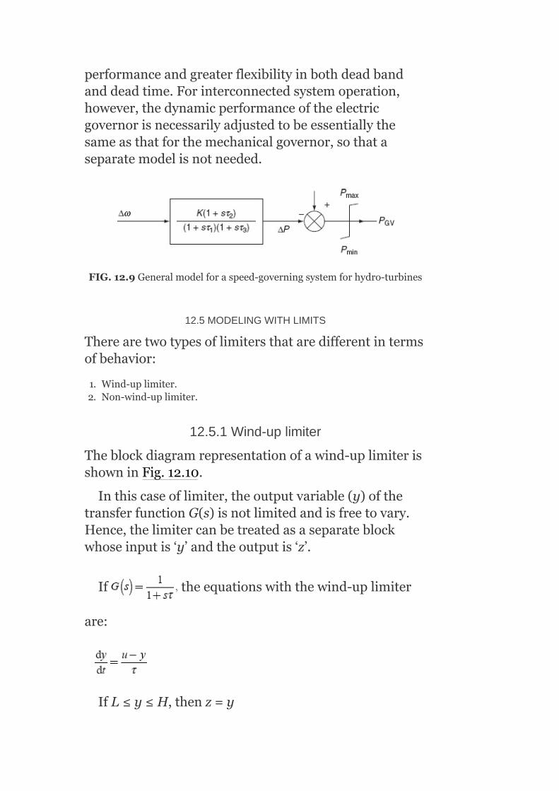
performanceandgreaterflexibilityinbothdeadbandanddeadtime.Forinterconnectedsystemoperation,however,thedynamicperformanceoftheelectricgovernorisnecessarilyadjustedtobeessentiallythesameasthatforthemechanicalgovernor,sothataseparatemodelisnotneeded.
FIG.12.9Generalmodelforaspeed-governingsystemforhydro-turbines
12.5MODELINGWITHLIMITS
Therearetwotypesoflimitersthataredifferentintermsofbehavior:
1. Wind-uplimiter.2. Non-wind-uplimiter.
12.5.1Wind-uplimiter
Theblockdiagramrepresentationofawind-uplimiterisshowninFig.12.10.
Inthiscaseoflimiter,theoutputvariable(y)ofthetransferfunctionG(s)isnotlimitedandisfreetovary.Hence,thelimitercanbetreatedasaseparateblockwhoseinputis‘y’andtheoutputis‘z’.
If theequationswiththewind-uplimiter
are:
IfL≤y≤H,thenz=y
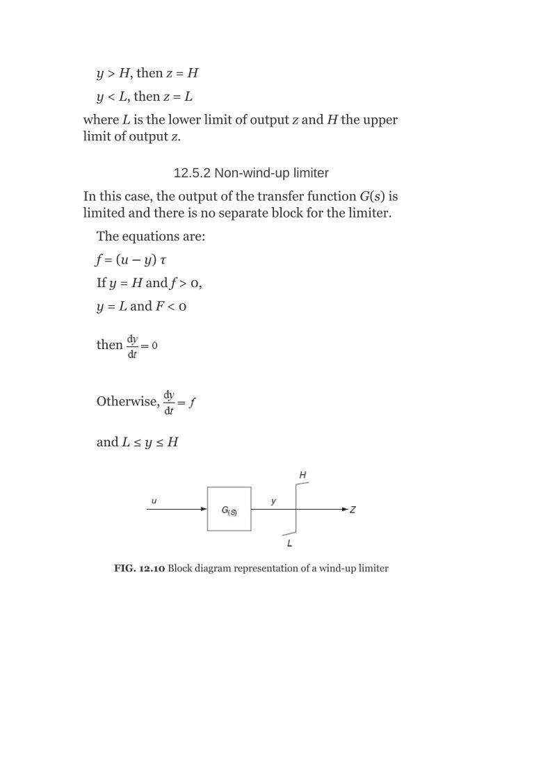
y>H,thenz=H
y<L,thenz=L
whereListhelowerlimitofoutputzandHtheupperlimitofoutputz.
12.5.2Non-wind-uplimiter
Inthiscase,theoutputofthetransferfunctionG(s)islimitedandthereisnoseparateblockforthelimiter.
Theequationsare:
f=(u–y)τ
Ify=Handf>0,
y=LandF<0
then
Otherwise,
andL≤y≤H
FIG.12.10Blockdiagramrepresentationofawind-uplimiter

FIG.12.11Blockdiagramrepresentationofanon-wind-uplimiter
Theblockdiagramrepresentationofanon-wind-uplimiterisshowninFig.12.11.
Note:
Astheoutputzofthelimiterdoesnotchangeuntilycomeswithinthelimits,thewind-uplimitercanchangeintermsofslowresponse.Generally,allintegratorblockshavenon-wind-uplimits.
12.6MODELINGOFASTEAM-GOVERNORTURBINESYSTEM
Whilemodelingthesteamgenerators,ateveryinstanttheboilercontrolsandon-linefrequencycontrolequipmentaretobeignoredduetotheirsloweroperations.
Aboilercontainsacertainamountofheatstoredinitshotmetalandthisisusuallysufficienttoguaranteethatthedemandsforextrasteamduringsystemdisturbancescanbemet.
Duringlong-termoperations,wemustconsidertherateofdeteriorationofsteamconditionsasaboilerhavingsufficientcapacityofproducingindefinitelyonlyagivenamountofextraenergyateachlevelofoutput.Demandsforthelargerincreasewillbemetforashorttime(from30sto5min);butafterthat,thesteamconditionswilldeteriorateandtheturbineoutputwilldecline.Itisextremelydifficulttoexaminethisproblemrigorouslyatpresentbecauseboilerturbinemodelsarenotcomprehensiveenough.
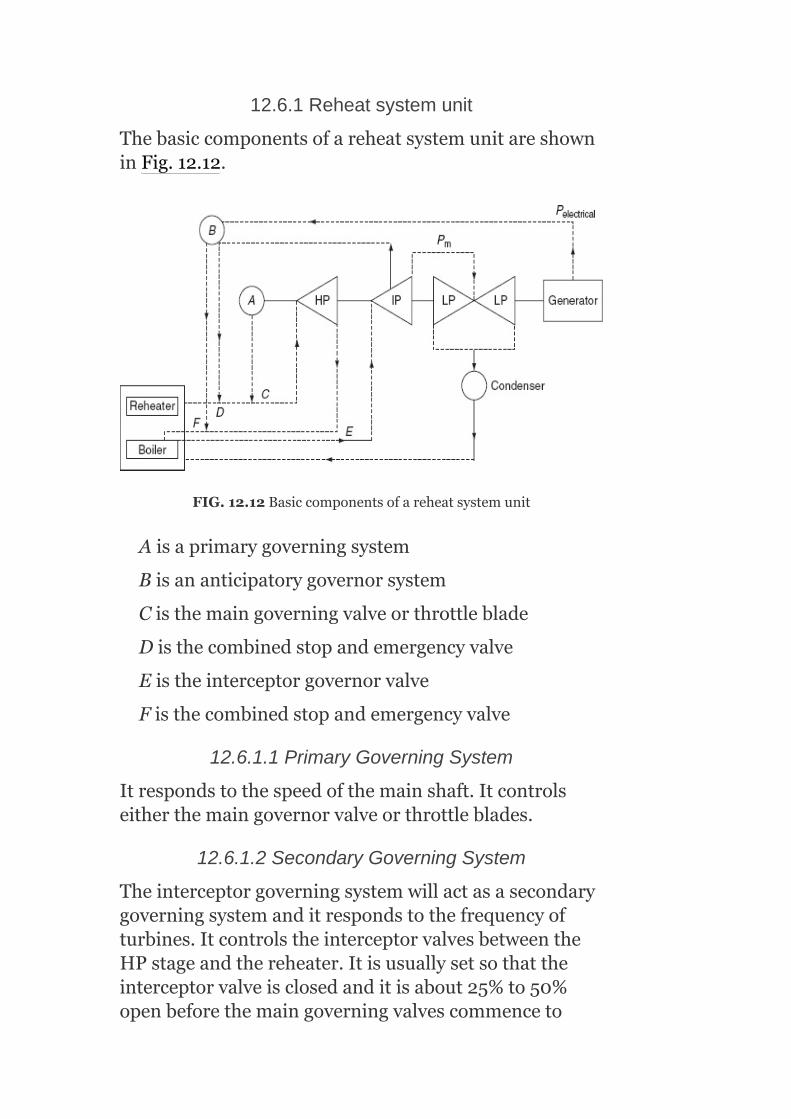
12.6.1Reheatsystemunit
ThebasiccomponentsofareheatsystemunitareshowninFig.12.12.
FIG.12.12Basiccomponentsofareheatsystemunit
Aisaprimarygoverningsystem
Bisananticipatorygovernorsystem
Cisthemaingoverningvalveorthrottleblade
Disthecombinedstopandemergencyvalve
Eistheinterceptorgovernorvalve
Fisthecombinedstopandemergencyvalve
12.6.1.1PrimaryGoverningSystem
Itrespondstothespeedofthemainshaft.Itcontrolseitherthemaingovernorvalveorthrottleblades.
12.6.1.2SecondaryGoverningSystem
Theinterceptorgoverningsystemwillactasasecondarygoverningsystemanditrespondstothefrequencyofturbines.ItcontrolstheinterceptorvalvesbetweentheHPstageandthereheater.Itisusuallysetsothattheinterceptorvalveisclosedanditisabout25%to50%openbeforethemaingoverningvalvescommenceto
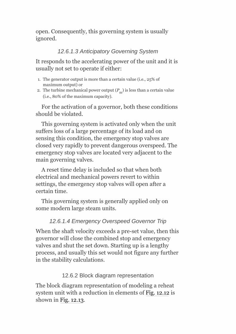
open.Consequently,thisgoverningsystemisusuallyignored.
12.6.1.3AnticipatoryGoverningSystem
Itrespondstotheacceleratingpoweroftheunitanditisusuallynotsettooperateifeither:
1. Thegeneratoroutputismorethanacertainvalue(i.e.,25%ofmaximumoutput)or
2. Theturbinemechanicalpoweroutput(P )islessthanacertainvalue
(i.e.,80%ofthemaximumcapacity).
Fortheactivationofagovernor,boththeseconditionsshouldbeviolated.
Thisgoverningsystemisactivatedonlywhentheunitsufferslossofalargepercentageofitsloadandonsensingthiscondition,theemergencystopvalvesareclosedveryrapidlytopreventdangerousoverspeed.Theemergencystopvalvesarelocatedveryadjacenttothemaingoverningvalves.
Aresettimedelayisincludedsothatwhenbothelectricalandmechanicalpowersreverttowithinsettings,theemergencystopvalveswillopenafteracertaintime.
Thisgoverningsystemisgenerallyappliedonlyonsomemodernlargesteamunits.
12.6.1.4EmergencyOverspeedGovernorTrip
Whentheshaftvelocityexceedsapre-setvalue,thenthisgovernorwillclosethecombinedstopandemergencyvalvesandshutthesetdown.Startingupisalengthyprocess,andusuallythissetwouldnotfigureanyfurtherinthestabilitycalculations.
12.6.2Blockdiagramrepresentation
TheblockdiagramrepresentationofmodelingareheatsystemunitwithareductioninelementsofFig.12.12isshowninFig.12.13.
m

r=Steady-statedroopsystemsettinginrad/s/MWturbinepoweroutput
τ =Timeconstantofagoverningsystem
R =MaximumclosingrateofagoverningvalveinMW/s
FIG.12.13Blockdiagramrepresentationofmodelingasimplereheatsteamturbineunit
R =MaximumopeningrateofthegoverningvalveinMW/s
POS =MaximumpoweroutputoftheturbineinMW(maximumgovernorvalveopening)
POS =MinimumpoweroutputoftheturbineinMW(governingvalvemaybeclosed)
τ =EquivalenttimeconstantofsteamentrainedintheturbineHPstage
τ =Equivalenttimeconstantofthereheaterandtheassociatedpiping
ω =Referencespeedsettingofthegovernorinrad/s
ω =Actualangularrotorvelocityinrad/s
Delaysanddeadbandsarepresentintheoperationsof:
1. Thespeed-sensingmechanism,friction,andblacklash.2. Overcappingofoilportsintheservosystemaswellasfriction.3. Frictioninthemaingoverningvalve.
g
max
min
s
rh
ref
shaft
−
+

12.6.3Transferfunctionofthesteam-governorturbinemodeling
Let GP = PowerdevelopedintheturbineattheHPstage
τ = TimeconstantassociatedwithentrainedsteamintheHPstage
GP = Powerdevelopedinthesubsequentstageoftheturbine
τ = Timeconstantassociatedwithentrainedsteaminthereheaterandconnectedpipework
τ = TimeconstantassociatedwithentrainedsteaminIPandLPstagesoftheturbine.
TheexpressionfortheturbineshaftpowerP asafunctionofthegovernorvalveopeningGis:
Sincethereheatertimeconstantislower,
whereCisthefractionofpowerdevelopedinHPstage.Theturbinepowerexpressionbecomes
1
h
2
r
I
t

Forrepresentinganon-reheatsystemofturbine,simplyreplaceτ byτ inEquation(12.3)andweget
12.7MODELINGOFAHYDRO-TURBINE-SPEEDGOVERNOR
Theblockdiagramrepresentationofasimple,generalhydro-turbine-speed-governormodelingisshowninFig.12.14.
r=Steady-statedroopsettinginrad/s/MWturbineoutputpower
R=Transientdroopsettinginrad/s/MWturbineoutputpower
τ =Recoverytimeconstantoftemperaturedroopdashpot
τ =Equivalentgovernorsystemtimeconstant
R =MaximumclosingrateofthegovernorvalveinMW/s
R =MaximumopeningrateofthegovernorvalveinMW/s
POS =MaximumpoweroutputoftheturbineinMW(maximumgovernorvalveopening)
POS =MinimumpoweroutputoftheturbineinMW(usuallythegovernorvalveisfullyclosed)
TheabovemodelingisbasedonsomeassumptionsaccordingtoKirchmayer:
1. Neglectingdeadband,delays,andnon-linearperformanceinthegoverningsystem.
2. Neglectingthevariationinheadofthesetwithdailyuse(orseasonaluse).
3. Assumingaconstantequivalentwaterstartingtimeconstant.
r I
r
g
max
min
−
+

FIG.12.14Blockdiagramrepresentationofahydraulicturbine-speedgovernor
Atransientdroopsetting‘r’anddashpot(i.e.,damping)recoverytimeconstant‘τ’arequiteimportantinmoststabilitystudies,asthesteadytimeisusuallytooshortfortheeffectivedrooptoreducethesteady-statevalue.
Representationofthewatercolumninertiaisimportantasthereisaninitialtendencyfortheturbinetorquetochangeintheoppositedirectiontothatfinallyproducedwhenthereisachangeinthewicketgateinthecaseofareactionturbineoranorificeopeninginthecaseofanimpulseturbine.
12.8EXCITATIONSYSTEMS
Theexcitationsystemconsistsofanexciterandanautomaticvoltageregulator(AVR).Anexciterprovidestherequiredfieldcurrenttotherotorwindingofthealternator.Thesimplestformofanexcitationsystemisanexciteronly.Whenthetaskofthesystembecomesmaintainingtheconstantterminalvoltageofanalternatorduringvariableloadconditions,itincorporatesthevoltageregulator.
Thevoltageregulatorsensestherequirementfromtheterminalvoltageofthealternatorandactuatestheexciterforthenecessaryincreasingordecreasingofthevoltageacrossthealternatorfield.
Anexcitationsystemwithbetterreliabilitiesispreferable,eveniftheinitialcostismorebecauseofthefactthatthecostofanexcitationsystemisverysmallascomparedtothecostofthealternator.
12.9EFFECTOFVARYINGEXCITATIONOFASYNCHRONOUSGENERATOR
Considerasynchronousgeneratorsupplyingconstantpowertoaninfinitebusthroughatransmissionlineofreactance‘X’ΩasshowninFig.12.15.
Theoutputpowerofasynchronousgeneratorisexpressedas:
P =|V||I|cosϕ(12.4)
where|V|isthemagnitudeofterminalvoltage,|I|themagnitudeofcurrent,andcosϕthep.f.Itmaybeexpressedintermsoftorqueangleδas
where|E|isthemagnitudeofexcitationvoltage,|V|themagnitudeofvoltageatthebus,andδthetorqueangle.
FIG.12.15Synchronousgeneratorconnectedtoaninfinitebus
G

FIG.12.16Effectofvaryingexcitationofasynchronousgenerator
ThepoweroutputP andvoltagemagnitude|V|ataninfinitebusareconstant;therefore,fromEquations(12.4)and(12.5),wehave
|I|cosϕ=K(12.6)
|E|sinδ=K′[∴Xisalsoaconstantforthisproblem](12.7)
whereKandK′areconstants.
Equations(12.6)and(12.7)areclearlyexplainedbythephasordiagramgiveninFig.12.16.
AccordingtothephasordiagramshowninFig.12.16,forthevariationofexcitation,thetipoftheexcitationvoltagevector‘E’isrestrictedtomovealongthehorizontaldottedline,andthetipofthecurrentvector‘I’isrestrictedtomovealongtheverticaldottedline.
ItisobservedfromFig.12.16thatwhentheexcitationincreasesthetorqueangle‘δ’reduces(fromδtoδ′),thecurrentincreases,andpowerangleincreasesfromϕtoϕ′andhencebecomesmorelaggingwithrespecttotheterminalvoltage‘V’.
G

Hence,thetorqueangle‘δ’isreducedwithanincreaseinexcitation,whichresultsinanincreaseinstiffnessofthemachine,i.e.,thecouplingsofthegeneratorrotorandrotatingarmaturefluxbecomemoretight.Inotherwords,withtheincreaseinexcitation,thestabilityofthemachinewillbecomeenhanced.
12.9.1Explanation
Fortheincrementinexcitationvoltage,thetorqueangleδreduces.
Letusassumethatacylindricalrotor(woundrotor)synchronousgeneratorconnectedtoaninfinitebusisinitiallyoperatingattorqueangleδ andsupplyingapower .
Thegeneratoroutputisequaltotheturbinepower,.
Now,drawthepoweranglecharacteristicsofthegeneratorasshowninFig.12.17(a).
Wehavethepoweroutputofthegeneratoras:
Forastableregion,
Atδ=90°, [∵sinδ=0]
Foranunstableregion,
Withthedecreaseinexcitation,thetorqueangleincreases,andhencethestiffnessofthemachinedecreases.
0
FromthepoweranglecharacteristicsshowninFig.12.17(a),agraphbetween|E|andδcanbedrawnasshowninFig.12.17(b).
Itisobservedthatbydecreasingtheexcitation,pointDisreachedandtheinstabilitywilltakeplaceat
.Theoccurrenceofinstabilityisshownasa
driftinthecurve.Atanypointonthelowerportionofthecurve,δ=f(|E|),thestablestateismaintainedsince
itcorrespondstothepoint onP =f(δ)curve.G

FIG.12.17(a)Poweranglecharacteristicsofasynchronousgeneratoratdifferentexcitations;(b)thevalueofδasafunctionof|E|
∴Thestabilitycriterionofthesystemcanbemathematicallyformulatedas
Anditscriticalpointisgivenby .
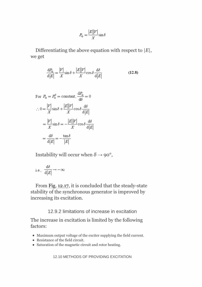
Differentiatingtheaboveequationwithrespectto|E|,weget
Instabilitywilloccurwhenδ→90°,
FromFig.12.17,itisconcludedthatthesteady-statestabilityofthesynchronousgeneratorisimprovedbyincreasingitsexcitation.
12.9.2limitationsofincreaseinexcitation
Theincreaseinexcitationislimitedbythefollowingfactors:
Maximumoutputvoltageoftheexcitersupplyingthefieldcurrent.Resistanceofthefieldcircuit.Saturationofthemagneticcircuitandrotorheating.
12.10METHODSOFPROVIDINGEXCITATION

Theexcitationisprovidedbythefollowingtwomethods:
1. Commonexcitationbusmethod.2. Individualexcitationmethod
12.10.1Commonexcitationbusmethod
Itisalsoknownasthecentralizedexcitationmethod.Inthismethod,twoormorenumberofexcitersfeedacommonbus,whichsuppliesanexcitationtothefieldsofallgeneratorsintheplant.
12.10.2Individualexcitationmethod
Itisalsoknownastheunit-excitermethod.Inthismethod,eachgeneratorisfedfromitsownexciter,whichisusuallydirectconnectedtothegeneratorshaft,butsometimesitisdrivenbyamotororasmallprimemoverorboth.
Theindividualexcitation(or)unit-excitermethodismorepreferablebecauseafaultinanyoneexciteraffectstheentireexcitationsystem.
12.10.2.1Meritsofindividualexcitationmethods
1. Simplicity:Sinceeachalternatorhasitsownexciter,thismethodofexcitationresultsinasimplelayoutofthestation.Theexcitersaresoselectedaccordingtotherequirementofindividualgeneratorsthatthemainfieldrheostatsandhigh-capacityswitchgeararenotrequired,whicharenecessaryinthecaseofthecommonbusexcitationmethod.
2. Lessohmiclosses:Theohmiclossesareverylessbecausenorheostatsarerequiredinthegeneratorfieldcircuit,andtheexciterfieldrheostatsareoperatedatamuchlowerpower.
3. Higherreliability:Asanyfaultthatoccursinexciteraffectsonlythegeneratortowhichitisconnected,theunit-excitermethodhashigherreliabilitythancommonexcitermethod.
4. Incorporationautomaticregulators:TheAVRsareincorporatedinanindividual(or)unitexcitationsystemforreliablesharingofreactivepowertomaintainconstantterminalvoltagewhilethegeneratorsarerunninginparallel.
5. Lessmaintenance:Sincetheunitexcitationsystemhasnomainfieldrheostatsandhigh-capacityswitchgear,theindividualexcitationsystemrequireslessmaintenanceandduetothisithaslessmaintenancecost.

Itisimportanttonotethatanexcitationsystemwithbetterreliabilityispreferredeventhoughitsinitialcostismorebecauseofthefactthatthecostofanexcitationsystemisverylessascomparedtothecostofagenerator.
12.10.3Blockdiagramrepresentationofstructureofageneralexcitationsystem
AblockdiagramrepresentationofthestructureofageneralexcitationsystemisshowninFig.12.18.
Themaincomponentspresentintheblockdiagramare:
12.10.3.1Synchronousgenerator
Itmaybethetypeofhigh-speedturbo-alternatorrunbyasteamturbineoralow-speedACgeneratorrunbyahydro-turbine.Withthehelpofanexcitationsystem,theterminalvoltageofanalternatororasynchronousgeneratorshouldbemaintainedconstantduringvariableloadsituations.
12.10.3.2Exciter
Itsuppliesthefieldcurrenttotherotorfieldcircuitofthesynchronousgenerator.Itmayeitherbeaself-excitedtypeorseparatelyexcitertypeofDCgenerator.

FIG.12.18Blockdiagramrepresentationofageneralexcitationsystem
FIG.12.19Responseofanexciterwhenseparatelyexcitedandself-excited

Inaself-excitedexciter,afewturnsareaddedforcompoundingandinter-polesareused.Inseparatelyexcitedexciters,anexciterfieldissuppliedfromasmallDCgeneratorknownasthepilotexciter.Apilotexciterisalevelcompoundgeneratorandmaintainsconstantvoltageexcitationforthemainexciter.
Theresponseofanexciterwhencomparedtoseparatelyexcitedwiththatwhenself-excitedisshowninFig.12.19.
Usually,theseparatelyexcitedexciter,knownasmainexciter,isprovidedwithtwoormorethantwofieldwindings,asshowninFig.12.20.Duetothisarrangementoffield,aneasierautomaticvoltageregulationispermitted.
Thevoltageofthemainexcitershouldbecontrolledfromzerotoceilingvoltage,themaximumvoltagethatmaybeattainedbytheexciterunderspecifiedconditions,toobtainrapidcorrectionofexcitervoltageafterdisturbanceorfault.ThefaultsorsystemdisturbancescauseanAVRtoforceanexcitationup.Afterpost-fault,rapidreductionoffieldisnecessarytoadjusttheexcitationtothecorrectvalue.Thisiseasilyachievedwithanegativefield.Themainpositivefieldisarrangedintwoparallelsectionswithrheostatsforadjustingthefieldcurrentsasrequired.
Hence,thepositiveandnegativefieldwindingsofthemainexciterwiththeadjustmentsofcurrentsaccordingtotheloadontheexcitermaintaintheexcitervoltageandexcitationasrequired.

FIG.12.20Exciterfieldarrangements
Duetotheseveralparallelconnectedfieldwindings,thefastresponseoftheexciterisachieved,becauseoflowtimeconstantofthewholefieldcircuit.
Forsmall-sizedturbo-generators,theexcitersareusuallydirectlycoupledtothegeneratorshaft.Formedium-andlarge-sizedturbo-generators,theexcitersarecoupledtothemainshaftthroughthegearandaregenerallydrivenat1,000rpm.
Forsmallergenerators(i.e.,ratedupto25MVAorso),self-excitedexcitersmustbeusedandforlarge-sizedgeneratorsofabove25MVA,separatelyexcitedexcitersareused.Theexcitervoltageofthemainexciterisusually230V.Insomecases,anominalvoltageof440Visused.Themainexciterloadintheresistanceisthealternatorfieldwindingandthisisgenerallybetween0.25and1.0Ω.Therotorcurrentisabout10AperMVAofalternatorrating.
12.10.3.3Useofamplidyne
Insomecases,theDCexcitationsystemisequippedwithanamplidyne.Anamplidyneprovideslargecurrentstothefieldwindingofthemainexciter.

Itisahigh-responsecross-fieldgeneratorandhasanumberofcontrolwindings,whichcanbesuppliedfromthepilotexciterandanumberoffeedbackcircuitsofanAVRandmagneticamplifier,etc.forcontrolpurposes.Anamplidynehasaveryhighamplificationfactorof10orevenmoreandneedsverysmallcontrolpower.
12.10.3.4AVR
AnAVRinconjunctionwiththeexcitertriestomaintainconstantterminalvoltageofonanACgenerator.Thevoltageregulator,infact,couplestheoutputvariablesofthesynchronousgeneratortotheinputoftheexciterthroughfeedbackandforwardingelementsforthepurposeofregulatingthesynchronousmachineoutputvariables.Thus,thevoltageregulatormaybeassumedtoconsistofanerrordetector,pre-amplifier,poweramplifier,stabilizers,compensators,auxiliaryinputs,andlimiters.Thevoltageregulatoristreatedastheheartofanexcitationsystem.Exciterandregulatorconstituteanexcitationsystem.Exciter,regulator,andsynchronousgeneratorconstituteasystemknownastheexcitationcontrolsystem.
12.11EXCITATIONCONTROLSCHEME
AtypicalexcitationcontrolschemeisshowninFig.12.21.
Thefieldwindingofanalternatorisconnectedtotheexciter.Thealternatorterminalvoltageisrectifiedbymeansofapotentialtransformer(PT)andrectifier,andisfedtoavoltageregulator.AvoltageregulatorcomparestherectifiedoutputvoltagewithareferencevoltageV .TheerrorsignaloutputV =|V –V |fromthevoltageregulatorisamplifiedbyanamplifierandtheamplifieroutputvoltageisfedtotheexciterfieldwinding.
ref e ref dc
6

FIG.12.21Atypicalexcitationcontrolscheme
ThereisnoerrorsignaloutputfromtheregulatorandthefieldwindingcurrentofexciterI isconstantwhentheoutputvoltage(terminalvoltage)ofanalternatorisatanominalvalue.
Whentheloadonthealternatorvaries,theterminalvoltagealsovaries.Hence,theerrorsignalcanbeproducedbytheregulator,amplified,andfedtothefieldwindingoftheexciter.Thefieldwindingcurrentoftheexciterisvariedandhencetheterminalvoltagereachestherequiredlevel.
12.12EXCITATIONSYSTEMS—CLASSIFICATION
Theexcitationsystemsarebroadlyclassifiedintothefollowingcategories:
1. DCexcitationsystem.2. ACexcitationsystem.3. Staticexcitationsystem.
12.12.1DCexcitationsystem
Itconsistsofdifferentconfigurationsofrotatingexciterslike:
1. Self-excitedexciterwithadirect-actingrheostatic-typevoltage
e

regulator.2. Mainandpilotexciterswithanindirect-actingrheostatic-typevoltage
regulator.3. Mainexciter,amplidyne,andstaticvoltageregulator.4. Mainexciter,magneticamplifier,andstaticvoltageregulator.
ThemaindrawbacksofaDCexcitationsystemare:
Complexityismoreduetorotatingexciters,voltageregulators,andmovingcontactslikeslipringsandbrushes.Timeconstantsofexciter,voltageregulator,amplidyne,andmagneticamplifierarelarge(about3s).Difficultiesofcommutation.Smoothlessoperationneedscontinuousmaintenance.Reliabilityisless.Noiselevelismoreduetorotatingexciters.
12.12.2ACexcitationsystem
ItconsistsofanACgeneratorandathyristor(rectifier)bridgecircuitdirectlyconnectedtothealternatorshaft.Themainadvantageofthismethodofexcitationisthatthemovingcontactssuchasslipringsandbrushesarecompletelyeliminatedthusofferingsmoothandmaintenance-freeoperation.Suchasystemisknownasabrushlessexcitationsystem.Inthissystem,therearenocommutationproblems.
12.12.3Staticexcitationsystem
Itconsistsofastep-downtransformerandarectifiersystemusingmercuryarcrectifiersofsilicon-controlledrectifiers(SCRs).Therotatingamplifiersandrotatingexcitersarereplacedbythestaticdevicesofarectifiersystem.
Theadvantagesofastaticexcitationsystemare:
1. Noise-freeoperationintheplantisobtainedastherotatingexcitersarereplacedwithstaticdevicesofrectifiers.
2. Sincethestaticexcitationequipmentmaybemountedorplacedseparatelyataconvenientplace,thecomplexityoftheexcitationsystemisreduced.
3. Duetostaticdevices,theoveralllengthofthegeneratorshaftisreduced,whichsimplifiesthetorsionproblemandtheproblemofcriticalspeed.Thegeneratorrotoriseasilywithdrawnfor
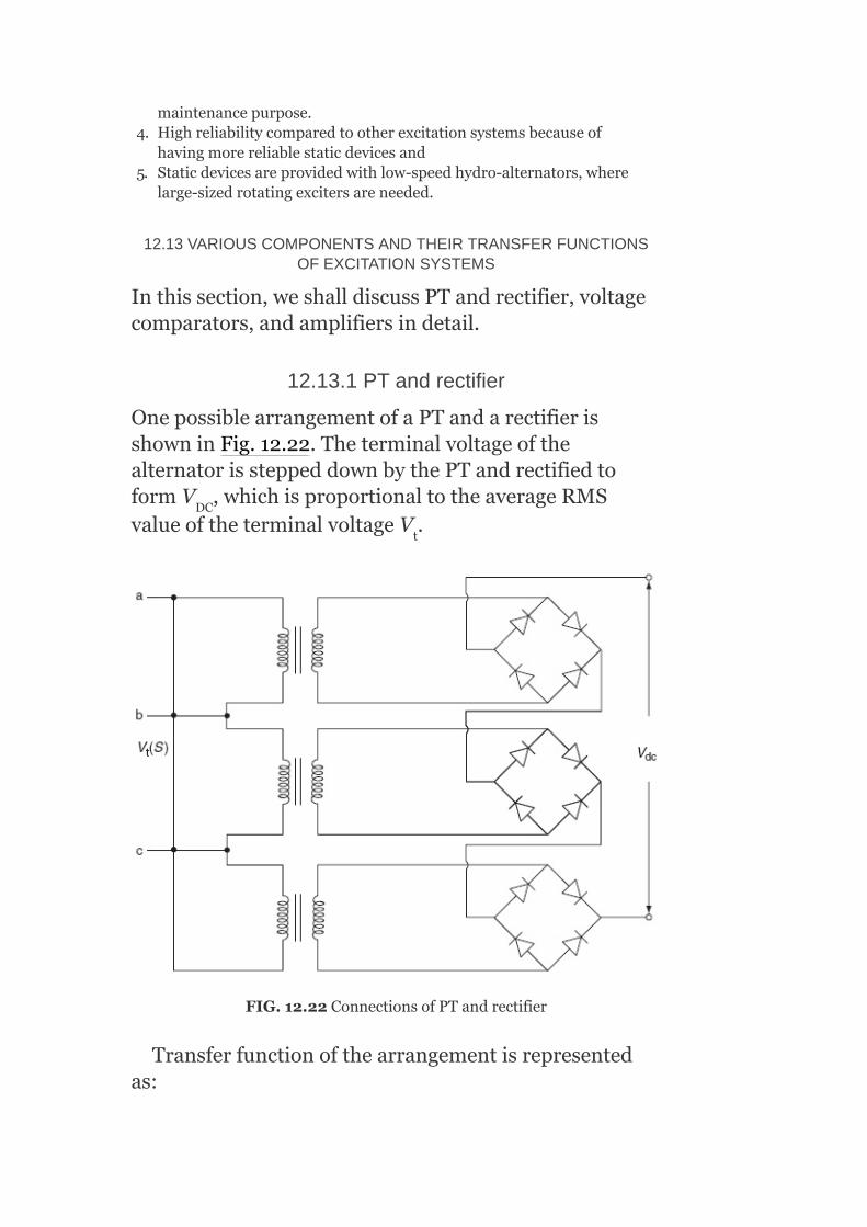
maintenancepurpose.4. Highreliabilitycomparedtootherexcitationsystemsbecauseof
havingmorereliablestaticdevicesand5. Staticdevicesareprovidedwithlow-speedhydro-alternators,where
large-sizedrotatingexcitersareneeded.
12.13VARIOUSCOMPONENTSANDTHEIRTRANSFERFUNCTIONSOFEXCITATIONSYSTEMS
Inthissection,weshalldiscussPTandrectifier,voltagecomparators,andamplifiersindetail.
12.13.1PTandrectifier
OnepossiblearrangementofaPTandarectifierisshowninFig.12.22.TheterminalvoltageofthealternatorissteppeddownbythePTandrectifiedtoformV ,whichisproportionaltotheaverageRMSvalueoftheterminalvoltageV .
FIG.12.22ConnectionsofPTandrectifier
Transferfunctionofthearrangementisrepresentedas:
DC
t

whereK istheproportionalityconstant(or)gainofthePTandrectifierassemblyandτ thetimeconstantoftheassemblyduetofilteringintheassemblyarrangement.
12.13.2VoltageComparator
AvoltagecomparatorcomparestherectifiedDCvoltageofthegeneratorwithareferencevoltageV andproducesanoutputintheformofanerrorsignalV .Figure12.23showsanelectronicdifferenceamplifierasacomparator.
TheoutputvoltageoranerrorvoltageV isexpressedas
V (S)=K(V (S)–V (S))
12.13.3Amplifiers
Amongthevarioustypesofamplifiersusedinanexcitationsystem,theamplidyneandmagneticamplifierhavehighamplificationfactors.
12.13.3.1Amplidyne
Basically,across-fieldDCgeneratorisoperatedasanamplidyne.AnamplidyneconfigurationisshowninFig.12.24.
Theoperationofanamplidyneconsistsoftwostagesofamplification.
FirstStageofAmplification
Anamplidyneconsistsofbrushesalongthed-axisandtheq-axis.Thebrushesalongtheq-axisareshort-circuited.Asthearmatureresistanceisverysmall,asmallamountoffieldm.m.f.resultsinalargeq-axis
R
R
ref
e
e
e ref dc
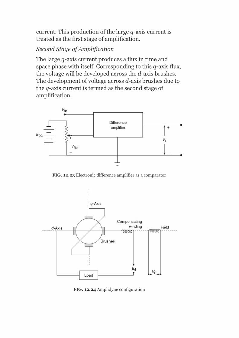
current.Thisproductionofthelargeq-axiscurrentistreatedasthefirststageofamplification.
SecondStageofAmplification
Thelargeq-axiscurrentproducesafluxintimeandspacephasewithitself.Correspondingtothisq-axisflux,thevoltagewillbedevelopedacrossthed-axisbrushes.Thedevelopmentofvoltageacrossd-axisbrushesduetotheq-axiscurrentistermedasthesecondstageofamplification.
FIG.12.23Electronicdifferenceamplifierasacomparator
FIG.12.24Amplidyneconfiguration

Thed-axisbrushesareconnectedtotheloadalongwithacompensatingwinding,whichprovidesnoresultantexcitationduetoloadcurrentsinceitmayreducetheoriginalfieldexcitation.(IthasanumberofcontrolwindingssuppliedfromthepilotexciterandhasanumberoffeedbackcircuitsofAVRandmagneticamplifier,etc.forcontrolpurposes.)
Theadvantagesofthesecondstageofamplificationareasfollows:
Powerrequiredforcontrolpurposeisverysmall.Astheresponsetimeisveryless,ithasafastresponse.Amplificationfactorisof10 orevenmore.
Thetransferfunctionofanamblidyneunderno-loadconditioncanbeexpressedas
whereτ isthetimeconstantofarmature,τ thetimeconstantoffield,andK thevoltageamplificationfactor.
12.13.3.2Magneticamplifier
MagneticamplifierconfigurationisshownisFig.12.25.Itconsistsofasaturablecore,controlwinding,andarectifiercircuit.
ThesaturablecorereactorcanbedesignedsothatwhennoDCcurrentisflowingthroughtheDCcontrolwinding,theinductivereactanceofACcoilsisveryhighandlimitstheflowofACcurrenttoasmallvalue.
InamagneticamplifierwhenlargeDCcurrentflowsthroughthecontrolwinding,thecoregetssaturated.ThisresultsinthedecrementinpermeabilityandhencethereactanceofACcoilsdecreases.Therefore,moreACcurrentflows.ThisACcurrentisrectifiedandfedtotheload.
a r
A
6
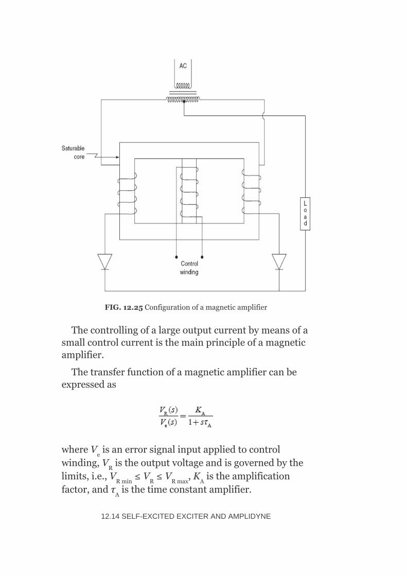
FIG.12.25Configurationofamagneticamplifier
Thecontrollingofalargeoutputcurrentbymeansofasmallcontrolcurrentisthemainprincipleofamagneticamplifier.
Thetransferfunctionofamagneticamplifiercanbeexpressedas
whereV isanerrorsignalinputappliedtocontrolwinding,V istheoutputvoltageandisgovernedbythelimits,i.e.,V ≤V ≤V ,K istheamplificationfactor,andτ isthetimeconstantamplifier.
12.14SELF-EXCITEDEXCITERANDAMPLIDYNE
e
R
Rmin R Rmax A
A

TheamplidyneisconnectedinserieswiththeshuntfieldofthemainexciterasshowninFig.12.26.
LetV bethearmatureemfoftheamplidyne,
e thearmatureemfofmainexciter,
N thenumberoffieldturnsofmainexciterunderno-loadcondition,
ϕ thefluxofthemainexciterunderno-loadcondition,
r thefieldcircuitresistanceoftheexciterunderno-loadcondition,and
i thefieldcurrentoftheexciterunderno-loadcondition.
FIG.12.26Circuitdiagramofseriescombinationofanamplidynewiththeshuntfieldofthemainexciter
Foranexciterfieldcircuit,
Sincee isafunctionofϕ ,effectivefluxofthemainexciter
e =Kϕ
R
fd
e
e
e
e
fd e
fd e

where ,aconstantforthearmature
Differenceofϕ andϕ isanaccountofleakagesfluxϕ ,proportionaltofieldcurrenti ,andmaybewrittenas
ϕ =ϕ +ϕ
andϕ =C ϕ
whereC istheproportionalityconstant:
ϕ =ϕ +C ϕ
=(1+C )ϕ
ϕ =σϕ
whereσisknownasthecoefficientofdispersionhavingavalueintherangeof1.1–1.2.
whereτ isknownastimeconstantoftheexciter.
However,theeffectofsaturationoftheexcitervoltagee istakenintoaccountwhilesolvingtheaboveequation.
TheexcitercharacteristicsareshowninFig.12.27.
ItisevidentthatthesaturationoftheexciterS isanon-linearfunctionoftheexcitervoltagee andisgivenas
fe e l
e
fe e 1
1 1 e
1
fe e 1 e
1 e
fe e
E
fd
E
fd

FIG.12.27Excitercharacteristics
Fromtheabove,wecanwrite
Iftheslopeoftheair-gaplineis
ori =G(1+S )e
Substitutingi inequation wehave
e E fd
e

TakingLaplacetransformoftheaboveequation,weget
V (S)E (S)=r G(1+S )E (S)+sτ E (S)
Fromtheabove,wecanget
whereK =r G−1
12.15DEVELOPMENTOFEXCITATIONSYSTEMBLOCKDIAGRAM
ThesimplifieddiagramofanexcitationsystemwithfundamentalcomponentsisasshowninFig.12.28.
FIG.12.28Simplifieddiagramofabuck-boostexcitationsystem
Forthecompleteanalysisoftheexcitationsystem,itisnecessarytodevelopthetransferfunctionofeach
R fd e E fd B fd
E e
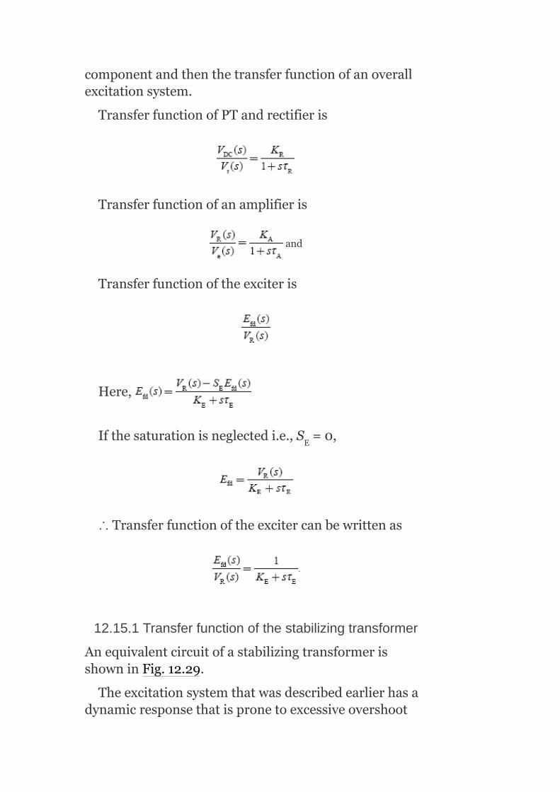
componentandthenthetransferfunctionofanoverallexcitationsystem.
TransferfunctionofPTandrectifieris
Transferfunctionofanamplifieris
and
Transferfunctionoftheexciteris
Here,
Ifthesaturationisneglectedi.e.,S =0,
∴Transferfunctionoftheexcitercanbewrittenas
12.15.1Transferfunctionofthestabilizingtransformer
AnequivalentcircuitofastabilizingtransformerisshowninFig.12.29.
Theexcitationsystemthatwasdescribedearlierhasadynamicresponsethatispronetoexcessiveovershoot
E
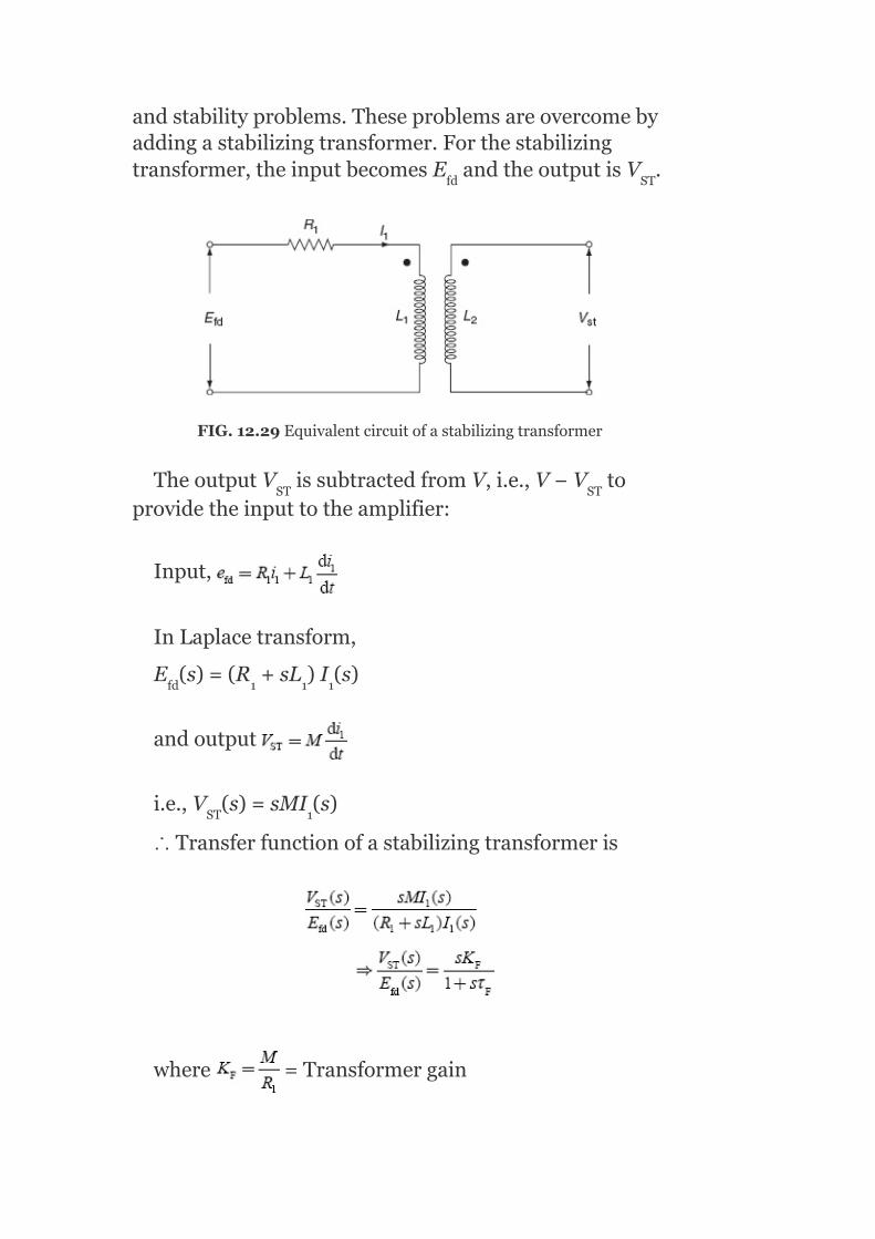
andstabilityproblems.Theseproblemsareovercomebyaddingastabilizingtransformer.Forthestabilizingtransformer,theinputbecomesE andtheoutputisV .
FIG.12.29Equivalentcircuitofastabilizingtransformer
TheoutputV issubtractedfromV,i.e.,V−V toprovidetheinputtotheamplifier:
Input,
InLaplacetransform,
E (s)=(R +sL )I (s)
andoutput
i.e.,V (s)=sMI (s)
∴Transferfunctionofastabilizingtransformeris
where =Transformergain
fd ST
ST ST
fd 1 1 1
ST 1

and =Transformertimeconstant.
12.15.2Transferfunctionofsynchronousgenerator
whereK isthegainofthegeneratorandτ thetimeconstantofarotorfield.
12.15.3IEEEtype-1excitationsystem
MostoftheexcitationsystemsaremodeledbasedonIEEEtype-1excitationsystem,whichwasproducedbythereportofthefirstIEEEcommitteein1968.ThecompleteblockdiagramofanIEEEtype-1excitationsystemisasshowninFig.12.30byinterconnectingallthecomponentsintheforwardpathandthefeedbackcontrolloop.
FIG.12.30IEEEtype-1excitationsystem
E = Exciteroutputvoltage(appliedtogeneratorfield)
G G
FD

I = Generatorfieldcurrent
I = Generatorfieldterminalcurrent
K = Regulatorgain
K = Exciterconstantrelatedtoself-excitedfield
K = Excitersaturationfunction
τ = Regulatoramplifiertimeconstant
τ = Excitertimeconstant
τ = Regulatedstabilizingcircuittimeconstant(τ andτ )
τ = Regulatedinputfiltertimeconstant
V = Regulatoroutputvoltage
V = Terminalvoltageofthegeneratorappliedtotheregulatorinput
K = Gainofthegenerator
τ = Timeconstantofthegeneratorrotorfield
FD
T
A
E
F
A
E
FF1 F2
R
R
t
G
G

Whenthegeneratorisoperatingatanequilibriumstate,i.e.,atratedvoltage,thevoltageoftherotatingamplifierV becomeszero.IfthegeneratorloadisincreasedsuchthatthesensingcircuitshowninFig.12.30detectsthisfallinterminalvoltage,itcausestheamplidynetoincreasethefieldcurrentI intheexciterfield.Hence,theexcitervoltageincreasesandinturnincreasesthegeneratorfieldcurrentI thatultimatelyshouldrisetheterminalvoltageofgenerator,V .
Understeady-stateconditions,E=E .
Undertransientconditions,anymismatchbetweenEandE willcausethevoltage tochangeaftersomedelay.
Mathematically,
where istheopen-circuitgenerator,directaxistransienttimeconstant.
12.15.4TransferFunctionofOverallExcitationSystem
Thetransferfunctionofanoverallexcitationsystem,showninFig.12.31,canbeobtainedbyeitherusingtheblockdiagramreductiontechniqueorthesignalflowgraphmethod.
First,neglecttheeffectofsaturation:
i.e.,S =0
andremovethestabilizingtransformerfromtheblockdiagramshowninFig.12.30.
∴Thetransferfunctionofthesystemisoftheform:
R
e
f
t
fd
fd
E

where andisknownasthe
feed-forwardtransferfunctionand isknown
asthefeedbacktransferfunction.
∴Thetransferfunctionoftheexcitationsystemisexpressedas
Inthetransferfunction ,τ isasimpletime
constantrepresentingregulatorinputfiltering.Itisverysmallandmaybeconsideredtobezeroformanysystems.
Thefirstsummingpointcomparestheregulatorreferencewiththeoutputoftheinputfiltertodeterminethevoltageerrorinputtotheregulatoramplifier.
TheAVRusuallycomprisesseveralcontrolloopsanda
simplereductionisnecessarytotheform .Voltage
regulatorgain(K )hasanimportanteffectonpowersystemperformancewhilethetimeconstantτ hasamuchsmallerinfluenceowingtolargeτ inseries.
R
A
A
e

Becauseofhighgaininanexcitationsystem(100–400),errorsinforward-pathgainK aremoreimportantthanerrorsinmostotherparameters(includinggeneratorandnetwork).
Thesecondsummingpointcombinesthevoltageerrorinputwiththeexcitationdampingloopsignal.K andτrepresentthemainregulatorgainanditstransferfunction.Theminimumandmaximumlimitsoftheregulatorareimposedsothatlargeinputerrorsignalsmaynotproduceanegativeoutput,whichexceedsthepracticallimit.
ThenextsummingpointsubtractsasignalthatrepresentsthesaturationfunctionS =f(E )oftheexciter.Thatis,theexciteroutputvoltage(orgeneratorfieldvoltageE )ismultipliedbyanon-linearsaturationfunctionandsubtractedfromtheregulatoroutputsignal.Theresultantisappliedtotheexcitertransferfunction
.
Majorloopdampingisprovidedbythefeedback
transferfunction, fromtheexciteroutputE to
thefirstsummingpoint.
Ifthestabilizingloopisomitted,theexcitersystemandthemaingeneratorwillbeunstableformostpracticalvaluesofK .Itcanonlybeomittedwhenthereareadditionalinputsignalstotheexcitationsystemsuchasfrequencyderivatives,etc.
TheusefulvalueofK isfrom0.1to0.15andτ variesintherange0.5–2.0s.
V =Regulatorreferencevoltagesetting
A
A A
E FD
FD
FD
A
F F
ref

V =Fieldrheostatsetting
V =Generatorterminalvoltage
ΔV =Generatorterminalvoltageerror
NotethatthereisaninterrelationbetweentheexciterceilingvoltageE ,regulatorceilingE ,exciter
saturation,S andK .
Understeady-statecondition,
V –(K +S )E =0;E ≤E ≤E
AttheceilingorE αE ,theaboveequation
becomes
V −(K +S )E =0
TheexcitersaturationfunctionisdefinedasthemultiplieroftheexciteroutputE torepresenttheincreaseinexciterexcitationrequirementbecauseofsaturation.
Theexcitertimeconstantτ isadominanttimeconstantintheexcitationsystem.Ifitisnotpossibletoobtaindataforthemainexcitersaturationfunction,thenausefulapproximationistoincreaseτ by20%anddecreasetheexciterceilingvoltageby20%.
12.16GENERALFUNCTIONALBLOCKDIAGRAMOFANEXCITATIONSYSTEM
ThegeneralfunctionalblockdiagramofanexcitationsystemisshowninFig.12.31.
12.16.1Terminalvoltagetransducerandloadcompensation
TheterminalvoltageofthealternatorissensedandrectifiedintoaDCvoltagebymeansofaterminalvoltagetransducer.
RH
T
T
FDmax Rmax
E E
R E E FD FDmin FD FDmax
FD FDmax
Rmax E Emax FDmax
FD
e
e

Theloadcompensationsynthesizesavoltage,whichdiffersfromtheterminalvoltagebythevoltagedropinanimpedance(R +jX ).BothvoltageandcurrentphasorsmustbeusedincomputingthecompensatingvoltageV .
12.16.1.1Objectivesofloadcompensation
Sharingofreactivepoweramongtheunits,whicharebussedtogetherwithzeroimpedancebetweenthem.Forthis,R andX arepositive
andthevoltageisregulatedatapointinternaltothegenerator.Whentheunitsareoperatinginparallelthroughunittransformers,itisdesirabletoregulatevoltageatapointbeyondthemachineterminalstocompensateforaportionoftransformerimpedance.Forthiscase,bothR andX arenegativevalues.R isneglectedin
mostofthecases.
FIG.12.31Functionalblockdiagramofanexcitationcontrolsystem
FIG.12.32Modelingoftransducerandloadcompensation
ThemodelingofterminalvoltagetransducersandloadcompensationisasshowninFig.12.32.
Thevoltagetransducerisusuallymodeledasasingletimeconstantτ anditisverysmallandassumedtobezeroforsimplicityinmanycases.
LC LC
C
LC LC
LC LC LC
R

12.16.2Excitersandvoltageregulators
TheAVRsofmoderntypearecontinuouslyactingelectronicregulatorswithhighgainandlowertimeconstants.
12.16.2.1Typesofexciters
ThetypesofexcitersareshowninFig.12.33(a).TheblockdiagramrepresentationofanexciterandaregulatorisshowninFig.12.33(b).
InFig.12.33(b),V istheoutputoftheregulator,whichislimited:
τ —singletimeconstantofregulator
K —positivegain
SaturationfunctionS =f(E )representsthesaturationoftheexciter.
Note:ThelimitsonV canbefoundfromsteady-stateequation:
V –(K +S )E =0
ThisimplieslimitsonE suchthat:
E ≤E ≤E
Withthespecificationofparameters,K =1,τ =0,S=0,andV =K V ,IEEEtype-1systemrepresentsthe
staticexcitationsystemwithpotentialsource-controlledrectifiertype.
12.16.3Excitationsystemstabilizerandtransientgainreduction
Thissystemisusedtoincreasethestabilityregionofoperationoftheexcitationsystemandalsopermithigherregulatorgains.
ThefeedbacktransferfunctionoftheESSisshowninFig.12.34.
R
A
A
E FD
R
R E E RD
FD
FDmin FD FDmax
E E E
Rmax p T

TheESSisrealizedbyanidealtransformerwhosesecondaryisconnectedtohighimpedanceasshowninFig.12.35.
Theturnsratioofthetransformer(n)andthetime
constantofthecircuit determineK andτ suchas
and
τ isusually1s.
Aseries-connectedloadorlagcircuitcanalsobeusedinsteadoffeedbackcompensationcircuitforESSasshowninFig.12.36.
F F
F

FIG.12.33(a)Classificationofexciters;(b)blockdiagramrepresentationofexciterandvoltageregulator
FIG.12.34ESStransferfunction
FIG.12.35RealizationofESS
FIG.12.36TGR
Here,τ >τ andstabilizationistermedasTGR.Reducingthetransientgain(orgainathigherfrequencies),therebyminimizingthenegativecontributionoftheregulatortosystemdamping,isthemainobjectiveofTGR.TheTGRmaynotberequired,ifpowersystemstabilizer(PSS)isspecificallyusedtoenhancesystemdamping.
C B

Usually,TGRfactor
12.16.4Powersystemstabilizer
Duringthetransientdisturbance,therotoroscillationsoffrequency0.2–2.0HzaredampedoutbyprovidingthePSSs.Thedampingofrotoroscillatationscanbeimpairedbytheprovisionofhigh-gainAVR,particularlyathighloadingconditionswhenageneratorisconnectedthroughahighexternalimpedance(duetoweaktransmissionnetwork).
TheinputsignaltoPSSisderivedfromspeedorfrequencyoracceleratingpoweroracombinationofthesesignals.
TheoutputofPSS,V ,isaddedtotheterminalvoltageerrorsignal.
12.17STANDARDBLOCKDIAGRAMREPRESENTATIONSOFDIFFERENTEXCITATIONSYSTEMS
ThestandardblockdiagramsofdifferentexcitationsystemsbasedonsupplywerepublishedbythesecondIEEEcommitteereportintheyear1981.
12.17.1DCexcitationsystem
Figure12.37showsthetypeDC-1excitationsystem.ItconsistsofaDCcommutatorexciterwithacontinuouslyactingvoltageregulator.ThisissimilartotheIEEEtype-1excitationsystem.
TheTGRcanberepresentedbythetransferfunction
withτ >τ .IthasthesimilarfunctionasESSin
thefeedbackpath.
S
B C

EitherTGRintheforwardpathorESSinthefeedbackpathisshownintheblockdiagramrepresentation.
Withτ =τ ,theTGRcanbeavoidedandsimilarlywithK =0,ESScanbeneglected.
12.17.1.1Derivationoftransferfunction
(i)ForseparatelyexcitedDCgenerator(exciter)
Figure12.38showstheseparatelyexcitedDCgenerator.FromFig.12.38,
Thegenerator(exciter)outputvoltageE isanon-linearfunctionofI asshowninFig.12.39.
FIG.12.37TypeDC1-DCcommutatorexciter
FIG.12.38SeparatelyexcitedDCgenerator
B C
F
g
f

FIG.12.39Exciterloadsaturationcurve
Assumethespeedoftheexcitertobeconstant.FromFig.12.39,wehavethefollowing:
whereR istheslopeofthesaturationcurvenearE =0.ExpressI inp.u.ofI :
whereE istheratedvoltagethatisdefinedasthevoltage,whichproducesratedopen-circuitvoltageinthegenerator-neglectingsaturation:
whereS′ =R S
g g
f fb
gb
E g e

TheblockdiagramofaseparatelyexcitedgeneratorisshowninFig.12.40.
(ii)Self-excitedDCgenerators
Theschematicdiagramofaself-excitedexciterisshowninFig.12.41.
E representsthevoltageoftheamplifierinserieswiththeexcitershuntfield.
FIG.12.40BlockdiagramofaseparatelyexcitedDCgenerator
FIG.12.41Schematicdiagramofaself-excitedexciter
a
TheblockdiagramofFig.12.41withE =V canbe
reducedsuchthat
TheR isperiodicallyadjustedtomaintainV =0inthesteadystate,forthisK =–S whereS isthevalueof
saturationfunctionS attheinitialoperatingpointandK isgenerallynegativeforaself-excitedexciter.
12.17.2ACexcitationsystem
TheblockdiagramofatypeAC-1excitationsystemisshowninFig.12.42.Thisrepresentsthefield-controlledalternatorrectifierwithnon-controlledrectifier-typeACexcitationsystem.
ThetermK I representsarmaturereactionofthealternatorandF representsrectifierregulation.
ConstantK isafunctionofthesynchronousalternator,andtransientreactanceconstantK isafunctionofthecommutatingreactance.
ThefunctionF isgivenas
a R
f R
E Eo Eo
E
E
D FD
EX
D
C
BX

FIG.12.42BlockdiagramoftypeAC-1excitationsystem
ThesignalV isproportionaltotheexciterfieldcurrentandisusedasaninputtoESS.
12.17.3Staticexcitationsystem
Therearetwotypesofstaticexcitationsystems:
1.Withapotentialsource-controlledrectifier—Inthis,theexcitationpowerissuppliedthroughaPTconnectedtogeneratorterminals.
2.Withacompoundsource-controlledrectifier—Inthis,bothcurrenttransformer(CT)andPTareusedatgeneratorterminals.
Theblockdiagramofthepotentialsource-controlledrectifierexcitationsystemisshowninFig.12.43.
Inthisblockdiagram,theinternallimiterfollowingthesummingjunctioncanbeneglected,butfieldvoltagelimitsthataredependentonbothV andI mustbeconsidered.
Fortransformer-fedsystems,K issmallandcanbeneglected.
Inthesesystems,transformersareusedtoconvertvoltage(andalsocurrentincompoundedsystems)totherequiredleveloffieldvoltagewiththeaidofcontrolledoruncontrolledrectifiers.Astheexciterceilingvoltagetendstobehighinstaticexciters,fieldcurrentlimitersareusedtoprotecttheexciterandfieldcircuit.
FE
T FD
C

FIG.12.43Blockdiagram-typeST1-potentialsource-controlledrectifierexcitationsystem
KEYNOTES
Accordingtothecontrol,speed-governingsystemsareclassifiedas:
1. Mechanical-hydraulic-controlled.2. Electro–hydraulic-controlled.
Thesignificanceofrateandpositionlimitsinaspeed-governingsystemare:
1. Ratelimitingofservomotormayoccurforlarge,rapid-speeddeviations,andratelimitsareshownattheinputtotheintegrator.
2. Positionlimitsareindicatedthatcorrespondtowide-openvalvesorthesettingofaloadlimiter.
Forwind-uplimiter,theoutputvariableofthetransferfunctionG(s)isnotlimitedandisfreetovary.Hence,thewind-upcanbetreatedasaseparateblockinthemodelingofaspeed-governingsystem.Fornon-wind-uplimiter,theoutputvariableofthetransferfunctionG(s)islimitedandthereisnoseparateblockinthemodelingofaspeed-governingsystem.SecondarygoverningsystemrespondstothefrequencyofturbinesanditcontrolstheinterceptorvalvesbetweentheHPstateandthereheater.Exciterprovidestherequiredfieldcurrenttotherotorwindingofasynchronousgenerator.Itmayeitherbeself-excitedtypeorseparatelyexcitedtype.Intheunitexcitationmethod,eachgeneratorisfedfromitsexciter,whichisusuallydirectlyconnectedtothegeneratorshaft.Amplidyneisahigh-responsecross-fieldgenerator,whichhasanumberofcontrolwindingsthatcanbesuppliedfromapilotexciterandanumberoffeedbackcircuitsofAVRandmagneticamplifierforcontrolpurposes.AnACexcitationsystemconsistsofanACgeneratorandathyristorbridgecircuitdirectlyconnectedtothegeneratorshaftByprovidingPSS,therotoroscillationsaredampedoutduringthetransientdisturbance.
SHORTQUESTIONSANDANSWERS
1. Whatistheclassificationofspeed-governingsystemsaccordingtothecontrol?
1. Mechanical-hydraulic-controlled.2. Electro-hydraulic-controlled.
2. Whatisthefunctionofhydraulicservomotorsusedinmechanical-hydraulic-controlledandelectro–hydraulic-controlledspeed-governingsystems?
Forpositioningvalveorgatecontrollingsystemorwaterflow.
3. Whatarethecomponentsofmechanical-hydraulic-controlledspeed-governingsystemsusedforsteamturbines?
Speedgovernor,speedrelay,hydraulicservomotor,andspeed-governor-controlledsystems.
4. Whydotheelectro-hydraulic-controlledspeed-governingsystemsprovidemoreflexibilitythanmechanical-hydraulic-controlledspeed-governingsystems?
Inelectro-hydraulic-controlledspeed-governingsystems,mechanicalcomponentsinthelowerpowerportionsarereplacedbythestaticelectroniccircuits.
5. Howdoesthelinearityofelectro-hydraulic-controlledspeed-governingsystemsimprove?
Byprovidingfeedbackloopofsteamflowandtheservomotor.
6. Whatarethecomponentsofmechanical-hydraulic-controlledspeed-governingsystemsforhydro-turbines?
Aspeedgovernor,apilotvalve,andservomotor,adistributorvalveandgateservomotor,andgovernor-controlledgates.
7. Whatisrequiredtoachievethestableperformanceofspeed-governingsystemforhydro-turbines?
Dashpotfeedbackisrequiredtoachievethestableperformanceofspeed-governingsystemforhydro-turbines.
8. Howisthespeedrelayrepresentedintheapproximatenon-linearmodelingofaspeed-governingsystem?
Asanintegratorandprovidedasadirectfeedback.
9. Howisthenon-linearpropertyofthespeed-governingvalvecompensated?
Byprovidinganon-linearCAMinbetweenthespeedrelayandthehydraulicservomotor.
10. Whatisthesignificanceofaservomotorinthespeed-governingsystem?
Theservomotorcontrolsthemovementsofvalvesanditisrepresentedasanintegratorwithtimeconstantτ andit
providesasdirectfeedback.
11. Whatisthesignificanceofratelimitsandpositionlimitsinapproximatenon-linearmodelingofaspeed-governingsystem?
sm

1. Ratelimitingofservomotormayoccurforlarge,rapid-speeddeviations,andratelimitsareshownattheinputtotheintegrator.
2. Positionlimitsareindicatedastherecorrespondingtowide-openvalvesorthesettingofaloadlimiter.
12. Whatdoyoumeanbywind-uplimiterandnon-wind-uplimiter?
Inthecaseofawind-uplimiter,theoutputvariableofthetransferfunctionG(s)isnotlimitedandisfreetovary.Hence,thewind-upcanbetreatedasaseparateblockinthemodelingofaspeed-governingsystem.
Inthecaseofanon-wind-uplimiter,theoutputvariableofthetransferfunctionG(s)islimitedandthereisnoseparateblockinthemodelingofthespeed-governingsystem.
13. Whenmodelingsteam-turbinegenerators,whichequipmentistobeignoredateveryinstant?
Theboilercontrolsandon-linefrequencycontrolequipmentshouldbeignoredateveryinstantduetotheirsloweroperations.
14. Whatarethepartsofaspeed-governingsysteminareheatsystemunit?
Primarygoverningsystem,secondarygoverningsystem,andanticipatorygoverningsystemarethepartsofaspeed-governingsystem.
15. Whatistheprimarygoverningsystemofareheatsystemunit?
Primarygoverningsystemrespondstothespeedofamainshaft.Itcontrolsthemaingovernorvalveorthrottleblades.
16. Whatisthesecondarygoverningsystemofareheatsystemunit?
SecondarygoverningsystemrespondstothefrequencyofturbinesanditcontrolstheinterceptorvalvesbetweentheHPstateandthereheater.Theinterceptorgoverningsystemwillactasthesecondarygoverningsystem.
17. Whatisanticipatorygoverningsystemofareheatsystemunit?
Ananticipatorygoverningsystemrespondstotheacceleratingpowerandisusuallynotsettooperateifeitherthegeneratoroutputismorethanacertainvalue(25%ofmaximumoutput)ortheturbinemechanicalpoweroutputislessthanacertainvalue(i.e.,80%ofmaximumcapacity).
18. Whenwilltheanticipatorygoverningsystembeactivated?
Onlywhenthereheatsystemunitsufferslossofalargepercentageofitsloadandonservingthiscondition,theemergencystopvalvesareclosedveryrapidlytopreventdangerousoverspeeds.
19. Whenwilltheemergencyoverspeedgovernortrip?
Whenthevelocityofshaftexceedsapre-setvalue,thenemergencyoverspeedgovernorwillclosethecombinedstopandemergencyvalvesandshutthesetdown.

20. Onwhatassumptionsisthemodelingofahydro-turbinebased?
AccordingtoKirchmayer,themodelingofsingle,generalhydro-turbinesisbasedonthefollowingassumptions:
1. Neglectingdeadband,delaysandnon-linearperformanceinthegoverningsystems.
2. Neglectingthevariationsinheadofthesetofhydro-turbineunitwithdailyuseorseasonaluse.
3. Assumingaconstantequipmentwaterstartingtime(τ ).
21. Whatisthefunctionofanexciterinanexcitationsystem?
Itprovidestherequiredfieldcurrenttotherotorwindingofasynchronousgenerator.Itmaybeeitherself-excitedtypeorseparatelyexcitedtype.
22. Whataretheeffectsofincreaseinexcitation?
1. Thetorqueangleδreducesand2. Thecurrentincreasesandthepoweranglealsoincreasesandhence
becomesmorelaggingwithrespecttoterminalvoltage.
23. Whatistheeffectofincreaseinexcitationonstabilityofthesynchronousmachine?
Whentheexcitationincreases,thetorqueangleδreduces,whichresultsinanincreaseinstiffnessofthemachine.Inotherwords,withanincreaseinexcitation,thestabilityofthemachinewillimprove.
24. Whatarethefactorsbywhichtheincreaseinexcitationislimited?
1. Maximumoutputvoltageoftheexciter.2. Resistanceofthefieldcurrent.3. Saturationofthemagneticcircuit.4. Rotorheating.
25. Whatarethemethodsofprovidingexcitation?
1. Commonorcentralizedexcitationmethod.2. Individualorunitexcitationmethod.
26. Whatdoyoumeanbyindividualorunitexcitationmethod?
Inindividualorunitexcitationmethod,eachgeneratorisfedfromitsownexciter,whichisusuallydirectlyconnectedtothegeneratorshaft.
27. Whatisthemeaningofcommonorcentralizedexcitationmethod?
Incommonorcentralizedexcitationmethod,twoormorenumberofexcitersfeedacommonbus,whichsuppliesexcitationtothefieldsofallgeneratorsintheplant.
28. Whichmethodofprovidingexcitationismorepreferable?
Unitexciterorcommonexcitationmethodismorepreferable.
29. Whatarethemeritsofindividualorunitexcitationmethod?
w

Simplicity,lessohmiclosses,higherreliability,lessmaintenance,andthepossibilityofincorporationofautomaticregulators.
30. Whyareautomaticregulatorsincorporatedinindividualorunitexcitationmethod?
Forthereliablesharingofreactivepowertomaintainconstantterminalvoltagewhilegeneratorsarerunninginparallel.
31. Whatispilotexciter?
Inseparatelyexcited-typeexciters,exciterfieldissuppliedfromasmallDCgeneratorknownasapilotexciter,whichisalevelcompoundgeneratorandmaintainsconstantvoltageexcitationforthemainexciter.
32. WhatistheuseofanamplidyneinaDCexcitationsystem?
Anamplidyneprovideslargecurrentstothefieldwindingofamainexciter.
33. Whatisanamplidyne?
Amplidyneishigh-responsecross-fieldgenerator,whichhasanumberofcontrolwindingsthatcanbesuppliedfrompilotexciterandanumberoffeedbackcircuitsofanAVRandamagneticamplifierforcontrolpurposes.
34. WhatisanAVR?Whatareitscomponents?
TheAVRinconjunctionwiththeexcitationtriestomaintainaconstantterminalvoltageofasynchronousgenerator.Itconsistsofanerrordetector,pre-amplifier,poweramplifier,stabilizer,compensators,auxiliaryinputs,andlimiters.
35. Whichistreatedastheheartofanexcitedsystem?
TheheartofanexcitationsystemistheAVR.
36. Whatisanexcitationcontrolsystem?
Anexciter,voltageregulator,andsynchronousgeneratorconstituteasystemknownasanexcitationcontrolsystem.
37. Whataretheclassificationsofexcitationsystems?
1. DCexcitationsystem.2. ACexcitationsystem.3. Staticexcitationsystem.
38. WhatarethedrawbacksofaDCexcitedsystem?
1. Morecomplexity.2. Largertimeconstantsofanexciter,voltageregulatorandamplidyne,and
magneticamplifier.3. Difficultiesofcommutation.4. Smoothlessoperation.5. Lessreliability.6. Morenoiselevelduetorotatingexciter.
39. WhatisanACexcitationsystem?
AnACexcitationsystemconsistsofanACgeneratorandathyristorbridgecircuitdirectlyconnectedtothegeneratorshaft.

40. WhatarethemeritsofanACexcitationsystem?
1. Movingcontactsarecompletelyeliminated.2. Offeringsmoothandmaintenance-freeoperation.3. Therearenocommutationproblems.
41. Whichsystemofexcitationisbrushlessexcitation?
AnACexcitationsystemisabrushlessexcitationsystem.
42. Whatarethemeritsofstaticexcitationsystems?
1. Noise-freeoperation.2. Lesscomplexity.3. Highreliabilitycomparedtootherexcitationsystems.4. Theoveralllengthofthegeneratorshaftisreduced,whichsimplifies
torsionproblemandcriticalspeedoperation.
43. Writethetransferfunctionofapotentialtransformerandrectifierofanexcitationsystem.
whereK isthegainofPTandrectifierassembly
τ isthetimeconstantoftheassembly
44. Whatarethestagesofoperationofanamplidyne?
Firststageofamplificationandsecondstageofamplificationarethestagesofoperationofanamplidyne.
45. Whatisthefirststageofamplificationfortheoperationofanamplidyne?
Anamplidyneconsistsofbrushesalongtheq-axisandthed-axis.Thebrushesalongtheq-axisareshort-circuited.Asthearmatureresistanceissmall,asmallamountoffieldm.m.f.resultsinalargeq-axiscurrent.Thisisthefirststageofamplification.
46. Whatisthesecondstageofamplificationofoperationofanamplidyne?
Thedevelopmentofvoltageacrossd-axisbrushesduetoq-axiscurrentistermedasthesecondstageofamplification.
47. Writethetransferfunctionofanamplidyneunderno-loadcondition.
whereτ isthetimeconstantofthearmature,τ thetimeconstant
offield,andK thevoltageamplificationfactor.
48. Whatarethecomponentsofamagneticamplifier?
Asaturablecore,controlwinding,andarectifiercircuitarethecomponentsofamagneticamplifier.
r
r
a f
A

49. Whatisthemainprincipleofamagneticamplifier?
Thecontrollingofalargeoutputcurrentbymeansofsmallcontrolcurrentisthemainprincipleofamagneticamplifier.
50. Writethetransferfunctionofamagneticamplifier.
whereτ isthetimeconstantofthemagneticamplifier,V the
outputvoltage,K thevoltageamplificationfactor,andV the
errorsignalinput.
51. Writethetransferfunctionofanexciter.
whereτ isthetimeconstantoftheexciter,K thegainofthe
exciter,V thearmatureemfofanamplidyne,E thearmature
emfofthemainexciter.
52. Whatisthefunctionofastabilizingtransformer?
Theexcitationsystemhasdynamicresponsewhichispronetoexcessiveovershootandstabilityproblems.Theseproblemsareovercomebyaddingastabilizingtransformertotheexcitationsystem.
53. Whatisthefunctionofaterminalvoltagetransducerrepresentedinafunctionalblockdiagramofanexcitationsystem?
TheterminalvoltageofthealternatorissensedandrectifiedintoaproportionateDCsignalbyusingaterminalvoltagetransducer.
54. Whatisthefunctionofloadcompensationblockinanexcitationsystemblockdiagram?
Loadcompensationsynthesizesavoltagethatdiffersfromtheterminalvoltagebythevoltagedropintheimpedance.
55. WhatisthesignificanceofasaturationfunctionS ,whichis
representedinanexcitationsystemfunctionalblockdiagram?
ThesaturationfunctionS =f(E )representsthesaturationof
theexciter.
56. Whatarethemainclassificationsofanexciter?
Rotating-typeandstatic-typeexcitersarethemainclassificationsofanexciter.
57. Whatisthefunctionofanexcitationsystemstabilizertransientgainregulatorblock?
Toincreasethestabilityregionofoperationoftheexcitationsystemandalsotopermitahigherregulatinggain.
A r
A e
E E
E fd
E
E fd

58. Howistheexcitationsystemstabilizerrealized?
Anexcitationsystemstabilizerisrealizedbyanidealtransformerwhosesecondaryisconnectedtoahighimpedance.
59. WhatisthefunctionofPSS?
Duringthetransientdisturbance,therotoroscillations(offrequency0.2–2Hz)aredampedoutbyprovidingthePSS.
60. Whatisapotentialsource-controlled-typestaticexcitationssystem?
Inapotentialsource-controlled-typestaticexcitationssystem,theexcitationpowerspecifiedissuppliedthroughaPTconnectedtogeneratorterminals.
61. Whatisastaticexcitationsystemwithacompoundsource-controlledrectifier?
TheexcitationpowerissuppliedthroughbothCTsandPTsconnectedtogeneratorterminals.
62. WhatistheinputsignaltoPSS?
TheinputsignaltoPSSisderivedfromspeedorfrequencyoroscillatingpoweroracombinationofthesesignals.
MULTIPLE-CHOICEQUESTIONS
1. Hydraulicservomotorsareusedin__________typeofspeed-governingsystems.
1. Mechanical-hydraulic-controlled.2. Electro-hydraulic-controlled.3. Either(a)or(b).4. Both(a)and(b).
2. Inhydraulic-controlledspeed-governingsystems,thehydraulicservomotorsareusedfor:
1. Positioningthevalveorgate,controllingsteamorwaterflow.2. Removingthevalveorgate,controllingsteamorwaterflow.3. Improvingthewaterhead.4. Improvingthesteampressureandtemperature.
3. Forasteamturbine,themechanical-hydraulic-controlledspeed-governingsystemconsistsofwhichofthefollowing?
1. Aspeedgovernor.2. Aspeedrelay.3. Ahydraulicservomotor.4. Governor-controlledvalves
1. (i)and(iv)2. (iii)and(iv)3. Allexcept(ii)4. Allofthese.
4. Intheapproximatenon-linearmathematicalmodelofamechanical-hydraulic-controlledspeed-governingsystem,the

termK representsthegainofspeed-governorsystem,whichis
___________.
1. Theregulationordroopofcharacteristics.2. Thereciprocalofregulationordroopofcharacteristics.3. Notthefunctionofregulationordroop.4. Noneofthese.
5. Thegainofaspeed-governorK represents:
1. Apositionofanassumedlinearinstantaneousindicationofaspeedproducedbythespeedgovernor.
2. Theregulationordroopofspeed-governorcharacteristics.3. Thegovernorspeed-changerposition.4. Noneofthese.
6. Thegovernorspeed-changerpositionprovidestherelaysignalandisdeterminedby:
1. Asystemofspeedgoverning.2. Asystemofautomaticgenerationcontrol.3. Asystemofhydraulicservomotorcontrol.4. Noneofthese.
7. Thespeedrelaysignalinmechanical-hydraulicspeed-governingsystemrepresentsacompositeloadandspeedreferenceandisassumed___________overtheintervalofastabilitystudy.
1. Variable.2. Constant.3. Either(a)or(b).4. Noneofthese.
8. Thespeedrelayinamechanical-hydraulicspeed-governingsystemisrepresentedas:
1. Anintegrator.2. Adifferentiator.3. Anamplifier.4. Noneofthese.
9. Thespeedrelayinamechanical-hydraulicspeed-governingsystemprovides:
1. Anindirectfeedback.2. Adirectfeedback.3. Nofeedback.4. Noneofthese.
10. Thenon-linearitypropertyofthevalveiscompensatedbymeansofproviding:
1. AlinearCAM.2. Anon-linearCAM.3. Aspeedrelay.4. Ahydraulicservomotor.
11. Anon-linearCAMisprovidedtocompensatethenon-linearpropertyofthevalveinbetween:
1. Thehydraulicservomotorandgovernor-controlledvalve.2. Thespeedgovernorandthespeedrelay.3. Thespeedrelayandthehydraulicservomotor.
G
G

4. Thehydraulicservomotorandthespeedgovernor.
12. Thehydraulicservomotor:
1. Controlsthemomentsofvalves.2. Isrepresentedasanintegratorintheapproximatelinearmodel.3. Forwhichtheratetimingmayoccurforlarge-andrapid-speeddeviations.4. Allofthese.
13. Thehydraulicservomotorcontrolprovides:
1. Adirectfeedback.2. Anindirectfeedback.3. Nofeedback.4. Noneofthese.
14. Thepositionlimitsofthehydraulicservomotorthatareindicatedcorrespondto:
1. Wide-openvalves.2. Thesettingofaloadlimiter.3. Either(a)or(b).4. Noneofthese.
15. Thenon-linearitiespresentinspeedcontrolmechanismarenotneglectedfor:
1. Ratelimitsofservomotor.2. Positionlimitsofvalve.3. Studyofpowersystemcomponents.4. Both(a)and(b).
16. Themechanicalcomponentsinthelowerpowerportionsarereplacedbythestaticelectroniccircuitsin:
1. Mechanical-hydraulicspeed-governingsystem.2. Electro-hydraulicspeed-governingsystem.3. Both(a)and(b).4. Noneofthese.
17. Theflexibilityismoreinwhichtypeofspeed-governingsystem?
1. Mechanical-hydraulicspeed-governingsystem.2. Electro-hydraulicspeed-governingsystem.3. Both(a)and(b).4. Noneofthese.
18. Thelinearityoftheelectro-hydraulic-controlledtypespeed-governingsystemcanbeimprovedbymeansof:
1. Providingspeedrelayandhydraulicservomotor.2. Providingexcitationcontrolsignals.3. Providingfeedbackloopsofsteamflowandservomotors.4. Providinglinearcomponents.
19. Forhydraulicturbines,themechanical-hydraulic-controlledspeed-governingsystemconsistsof:
1. Aspeedgovernor.2. Apilotvalveandservomotor.3. Adistributionvalveandgateservomotor.4. Governor-controlledgates
1. (i)and(ii)2. (i)and(iii)
3. (i)and(iv)4. Allofthese.
20. Thedashpotfeedbacksystemisrequiredtoachievethestableperformanceofaspeed-governingsystemof:
1. Hydro-turbines.2. Steamturbines.3. Both(a)and(b).4. Either(a)or(b).
21. Inthespeed-governingsystems,thegateservomotorrateislimitedfor:
1. Large,rapid-speedexcursions.2. Extremesofgateopening.3. Either(a)or(b).4. Both(a)and(b).
22. Inspeed-governingsystems,thepositionlimitsexistcorrespondingto:
1. Large,rapid-speedexcursions.2. Extremesofgateopening.3. Either(a)or(b).4. Both(a)and(b).
23. Thespeed-governingrequirementsforhydro-turbinesarestronglyinfluencedbytheeffectsof:
1. Thepositionofpenstock.2. Headofwater.3. Waterinertia.4. Allofthese.
24. Accordingtothebehavior,theoutputvariableofthetransferfunctionisnotlimitedandisfreetovaryinthecaseof:
1. Wind-uplimiter.2. Non-wind-uplimiter.3. Ratelimiter.4. Positionlimiter.
25. Aseparateblockisneededtorepresentintheblockdiagraminthecaseof:
1. Wind-uplimiter.2. Non-wind-uplimiter.3. Ratelimiter.4. Positionlimiter.
26. Accordingtothebehavior,theoutputvariableofthetransferfunctionislimitedandnoseparateblockisneededforthelimiterinthecaseof:
1. Wind-uplimiter.2. Non-wind-uplimiter.3. Ratelimiter.4. Positionlimiter.
27. Generally,theintegratorblockshave:
1. Wind-uplimiter.2. Non-wind-uplimiter.

3. Ratelimiter.4. Positionlimiter.
28. Whilemodelingsteamgenerators,thefollowingequipmentisignoredateveryinstantduetotheirslowoperations:
1. Theboilercontrolsequipment.2. Onlinefrequencycontrolsequipment.3. Both(a)and(b).4. Either(a)or(b).
29. Primarygoverningsystemofareheatsystemunitrespondstothe:
1. Speedofthemainshaft.2. Frequencyoftheturbine.3. Either(a)or(b).4. Both(a)and(b).
30. Thesecondarygoverningsystemofareheatunitrespondsto:
1. Speedofthemainshaft.2. Frequencyoftheturbine.3. Either(a)or(b).4. Both(a)and(b).
31. Thegoverningsystemthatcontrolseithermaingovernorvalveorthrottlebladesis:
1. Primarygoverningsystem.2. Secondarygoverningsystem.3. Anticipatorygoverningsystem.4. Noneofthese.
32. ThegoverningsystemthatcontrolstheinterceptorvalvesbetweentheHPstateandthereheateris:
1. Primarygoverningsystem.2. Secondarygoverningsystem.3. Anticipatorygoverningsystem.4. Noneofthese.
33. Anticipatorygoverningsystemofareheatunitrespondsto:
1. Speedofthemainshaft.2. Frequencyoftheturbine.3. Theacceleratingpoweroftheunit.4. Noneofthese.
34. Theanticipatorygoverningsystemisusuallysetnottooperateif:
1. Thegovernoroutputismorethanacertainvalue.2. Theturbinemechanicalpoweroutputislessthanacertainvalue.3. Either(a)or(b).4. Both(a)and(b).
35. Thespeed-governingsysteminwhich,onsensingthelossofalargepercentageofitsload,theemergencystopvalvesareclosedveryrapidlytopreventdangerousoverspeed:
1. Primarygoverningsystem.2. Secondarygoverningsystem.3. Anticipatorygoverningsystem.4. Noneofthese.

36. Inananticipatoryspeed-governingsystem,theemergencystopvalvesarelocatedveryadjacentto:
1. Theservomotor.2. Themaingoverningvalves.3. Thespeedrelays.4. Allofthese.
37. Emergencyoverspeedgovernorwilltripwhen:
1. Thevelocityoftheshaftexceedsapre-setvalue.2. Thefrequencyofthesystemismaintainedconstant.3. Theoverallefficiencyofthespeed-governingsystemandturbinereduces.4. Thevelocityofshaftexceedsthefrequency.
38. Theinterceptorgoverningsystemofareheatunitwillactas:
1. Primarygoverningsystem.2. Secondarygoverningsystem.3. Anticipatorygoverningsystem.4. Noneofthese.
39. Thesimplemodelingofahydro-turbineunitisbasedontheassumptionaccordingtoKirchmayer:
1. Neglectingdeadband,delays.2. Neglectingthevariationinheadofwater.3. Both(a)and(b).4. Noneofthese.
40. Inmodelingahydro-turbineunit,whichofthefollowingisimportant?
1. Representationofthewatercolumncriteria.2. Representationofthewaterhead.3. Representationofthespeed.4. Allofthese.
41. Whentheexcitationincreases,thetorqueangle‘δ’___________.
1. Increases.2. Reduces.3. Noeffect.4. Noneofthese.
42. Whentheexcitationincreases,thecurrent___________andthepowerangle___________.
1. Increases,increases.2. Decreases,increases.3. Increases,decreases.4. Decreases,decreases.
43. Whentheexcitationincreases,thepoweranglebecomes___________withrespecttoterminalvoltage.
1. Moreleading.2. Morelagging.3. Zero.4. 90°.
44. Withanincreaseinexcitation,

1. Thetorqueangleδreduces.2. Thestiffnessofthemachineincreases.3. Thecouplingofgeneratorandrotatingarmaturefluxbecomesmoretight.4. Allofthese.
45. Withanincreaseinexcitation,
1. Thestabilityofthemachinewillimprove.2. Thestabilityofthemachinewilldecrease.3. Thereisnoeffectonthestabilityofthemachine.4. Noneofthese.
46. Theincreaseinexcitationislimitedbywhichofthefollowingfactors?
1. Resistanceoffieldcircuit.2. Saturationofmagneticcircuit.3. Rotorheating.4. Maximumoutputvoltageofexcitation
1. (i)and(ii)2. Allexcept(iii)3. Allexcept(i)4. Allofthese.
47. Theexcitationsystemconsistsof:
1. Anexciter.2. AnAVR.3. Both(a)and(b).4. Noneofthese.
48. Incommonexcitationbusmethod,
1. Twoormorenumberofexcitersfeedacommonbus.2. Eachgeneratorisfedfromitsownexciter.3. Either(a)or(b).4. Noneofthese.
49. Intheindividualexcitationmethod,
1. Twoormorenumberofexcitersfeedacommonbus.2. Eachgeneratorisfedfromitsownexciter.3. Either(a)or(b).4. Noneofthese.
50. Unit-excitermethodisnothingbut:
1. Commonexcitationbusmethod.2. Centralizedexcitationmethod.3. Individualexcitationmethod.4. Allofthese.
51. Whichofthefollowingmethodsismorepreferable?
1. Commonexcitationbusmethod.2. Centralizedexcitationmethod.3. Individualexcitationmethod.4. Allofthese.
52. Themeritsofaunitexciterare:
1. Simplicity.2. Lessmaintenance.3. Lessohmiclossandhighreliability.4. Allofthese.

53. Thefunctionofexciteristhestructureofexcitation:
1. Tosupplyterminalvoltagetotherotorcircuit.2. Tosupplycurrenttotherotorfieldcircuitofasynchronousgenerator.3. Tosupplycurrenttothestatorcircuitofasynchronousgenerator.4. Allofthese.
54. Apilotexciteris:
1. AlevelcompoundsmallDCgenerator.2. Asmallservotypesynchronousgenerator.3. Amainsynchronousgenerator.4. Amainexciter.
55. Thefunctionofapilotexciteris:
1. Tosupplycurrenttotherotorcircuit.2. Tomaintainconstantvoltageexcitationforthemainexciter.3. Tosupplyvariableexcitationforthemainexciter.4. Noneofthese.
56. Themainexciteris:
1. Alevelcompoundsmallgenerator.2. Amainsynchronousgenerator.3. Aseparatelyexcitedexciter.4. Apilotexecuter.
57. Thefastresponseoftheexciterisobtaineddueto:
1. Severalseries-connectedfieldwindings.2. Severalparallel-connectedfieldwindings.3. Combinationofseries-connectedandparallel-connectedfieldwindings.4. Noneofthese.
58. Thefunctionofanamplidyneis:
1. Toprovidetheconstantexcitationtoasynchronousgenerator.2. Toprovidelargecurrentstothefieldwindingsofamainexciter.3. Toprovidesupplytothesynchronousmachine.4. Noneofthese.
59. Whichofthefollowingiscorrectregardingtheamplidyne?
1. Amplidyneisahighresponsecross-fieldgenerator.2. Amplidynehasanumberofcontrolwindingssuppliedfrompilotexciter.3. AmplidynehasanumberoffeedbackcircuitsofanAVRandmagnetic
amplifier.4. Allofthese.
60. Whichistreatedastheheartoftheexcitedsystem?
1. Mainexciter.2. Pilotexciter.3. Rotorfieldexciter.4. AVR.
61. Excitationfieldcontrolsystemisthesystemthatconsistsof:
1. Exciterandregulator.2. Exciterandfieldsystem.3. Exciterregulatorandsynchronousgenerator.4. Noneofthese.
62. ThedrawbackofDCexcitationsystemis:

1. Morecomplexity.2. Largertimeconstants.3. Lessreliability.4. Morenoiselevel.5. Noneofthese.
63. ThemainadvantageofanACexcitationsystemis:
1. Movingcontactsarecompletelyeliminated.2. Smoothoperation.3. Maintenance-freeoperation.4. Allofthese.
64. Thebrushlessexcitationsystemis:
1. DCexcitationsystem.2. ACexcitationsystem.3. Staticexcitationsystem.4. Noneofthese.
65. Nocommutationproblemsoccurin:
1. DCexcitationsystem.2. ACexcitationsystem.3. Staticexcitationsystem.4. Noneofthese.
66. Theadvantageofastaticexcitationsystemis:
1. Noise-freeoperation.2. Highreliabilityduetomorereliablestaticdevices.3. Overalllengthofthegeneratorshaftisreduced,whichsimplifiesthe
torsionandcriticalspeedproblems.4. Allofthese.
67. Inthefirststageofamplificationofoperationofamplitude,
1. Asmallamountoffieldm.m.f.resultsinlargeq-axiscurrent.2. Thevoltagewillbedevelopedacrossd-axisbrushesduetoq-axiscurrent.3. Thebrushesinq-axisareshort-circuited
1. (i)and(iii)2. (ii)and(iii)3. Only(i)4. Allofthese.
68. Inthesecondstageofamplificationofoperationofamplidyne,whichofthefollowingoccurs?
1. Asmallamountoffieldm.m.f.resultsinlargeq-axiscurrent.2. Thevoltagewillbedevelopedacrossd-axisbrushesduetoq-axiscurrent.3. Thed-axisbrushesareconnectedtoloadalongwithacompensating
winding
1. (i)and(iii)2. (ii)and(iii)3. Only(i)4. Allofthese.
69. Themainprincipleofamagneticamplifieris:
1. ThemagneticcoregetssaturatedwhenlargeACcurrentflowsthroughcontrolwindingandresultsinthedecrementofpermeability.
2. ReactanceofACcoilsincreasesduetothedecrementinpermeability.3. Thecontrollingofalargeoutputcurrentbymeansofasmallcontrol
current.

4. Noneofthese.
70. Theamplidyneisconnectedin___________withtheshuntfieldofthemainexciter.
1. Series.2. Parallel.3. Seriesforsometimeandparallelforsometime.4. Noneofthese.
71. Advantageofastabilizingtransformeris:
1. Theproblemofdynamicresponsethatispronetoexclusiveovershootisovercome.
2. Stabilityproblemsareovercome.3. Both(a)and(b).4. Noneofthese.
72. Mostoftheexcitationsystemsaremodeledbasedon:
1. ACexcitationsystem.2. DCexcitationsystem.3. Staticexcitationsystem.4. IEEEtype-1excitationsystem.
73. Theobjectiveofloadcompensationis:
1. Sharingofreactivepoweramongtheunits,whicharebussedtogetherwithzeroimpedancebetweenthem.
2. Whentheunitsareoperatinginparallelthroughaunittransformer,itisdesirabletoregulatethevoltageatapointbeyondthemachineterminalstocompensateforaportionoftransformerimpedance.
3. Both(a)and(b).4. Noneofthese.
74. Thefunctionofterminalvoltagetransduceris:
1. TosensetheterminalvoltageofanalternatorandrectifyitintoaproportionalDCvoltage.
2. Tosynchronizeavoltagethatdiffersfromtheterminalvoltagebythevoltagedrop.
3. Both(a)and(b).4. Noneofthese.
75. Thefunctionofanexcitationsystemstabilizerandtransientgainregulatoristo___________thestabilityandpermit___________regulatorgains
1. Increase,lower.2. Decrease,lower.3. Increase,higher.4. Decrease,higher.
76. Excitationsystemstabilizerisrealizedby:
1. Apracticaltransformerwhosesecondaryisconnectedtoahighimpedance.2. Apracticaltransformerwhosesecondaryisconnectedtoalowimpedance.3. Anidealtransformerwhosesecondaryisconnectedtoalowimpedance.4. Anidealtransformerwhosesecondaryisconnectedtoahighimpedance.
77. Reducingthetransientgainorgainathigherfrequency,therebyminimizingthenegativecontributionoftheregulatortosystemdampingisthemainaimof:

1. Powersystemstabilizer(PSS).2. Excitationsystemstabilizer(ESS).3. Transientgainregulator(TGR).4. Mainexciter.
78. Duringthetransientdisturbance,therotoroscillationsoffrequency0.2–2Hzaredampedoutbyproviding___________.
1. Powersystemstabilizer.2. Excitationsystemstabilizer.3. Transientgainregulator.4. Mainexciter.
79. Theinputsignaltopowersystemstabilizerisderivedfrom:
1. Speed.2. Frequency.3. Acceleratingpower.4. Combinationofsignalsof(i),(ii),and(iii)
1. (i)and(iii)2. (ii)and(iii)3. Only(iv)4. Anyoftheabove.
80. Inapotentialsource-controlledrectifiertypeofstaticexcitationsystem,
1. TheexcitationpowerissuppliedthroughaPTconnectedtogeneratorterminals.
2. TheexcitationpowerissuppliedthroughbothPTandCTconnectedtogeneratorterminals.
3. TheexcitationpowerissuppliedwithoutconnectingPTandCTconnectedtogeneratorterminals.
4. Noneofthese.
81. Inacompoundsource-controlledrectifiertypeofstaticexcitationsystem,
1. TheexcitationpowerissuppliedthroughaPTconnectedtogeneratorterminals.
2. TheexcitationpowerissuppliedthroughbothPTandCTconnectedtogeneratorterminals.
3. TheexcitationpowerissuppliedwithoutconnectingPTandCTconnectedtogeneratorterminals.
4. Noneofthese.
82. Theoutputofapowersystemstabilizeris:
1. V isaddedtotheterminalvoltage.
2. V isaddedtotheterminalvoltageerrorsignal.
3. V issubtractedfromtheterminalvoltageerrorsignal.
4. Noneofthese.
REVIEWQUESTIONS
1. Discussthemechanical-hydrauliccontrolandelectro-hydrauliccontrolspeed-governingsystemofsteamturbines.
2. Discussthemechanical-hydrauliccontrolandelectro-hydrauliccontrolspeed-governingsystemofhydraulicturbines.
s
s
s

3. Explainthedifferenttypesoflimitersandtheirroleinspeed-governingsystemmodeling.
4. Explaintheeffectofvaryingexcitationofasynchronousgenerator.
5. Explainthemethodsofprovidingexcitationsystems.6. Explainthevariouscomponentsofablockdiagram
representationofageneralexcitationsystem.7. Explaintheclassificationofexcitationsystems.8. Derivethetransferfunctionofanoverallexcitationsystem.

13
PowerSystemSecurityandStateEstimation
OBJECTIVES
Afterreadingthischapter,youshouldbeableto:
1. knowthemeaningofsecuritycontrolsystemanditsimportance
2. discusstheapplicationsofplanningofsecurityanalysis
3. developthemathematicalmodelingofsecurity-constrainedoptimizationproblem
4. studythevarioustechniquesusedforsteady-stateandtransient-statesecurityanalysis
5. knowtheneedofstateestimationinpowersystems
6. discusstheapplicationsofstateestimation
13.1INTRODUCTION
Theconceptofcontrolisfundamentaltotheproperfunctioningofanysystem.Irrespectiveofwhetheritisanengineeringsystemoraneconomicsystemorasocialsystem,itisessentialtoexertsomekindofcontrol,suchasqualitycontrol,inventorycontrol,orpopulationcontrol,toachievecertainobjectiveslikebetterqualityofoutputorbettereconomics,etc.Itisonlynaturalthatpowersystem,whichisoneofthemostcomplexman-madesystems,callsfortheimplementationofanumberofcontrolsforsatisfactoryoperation.Powersystemcontrolhasgonethroughalotofchangesoverthepastthreedecades.Beginningwithsimplegovernorcontrolatthemachinelevel,ithasnowgrownintoasophisticatedmultilevelcontrolneeding,areal-timecomputerprocess,andsystem-wideinstrumentation.

Theultimateobjectiveofpowersystemcontrolistomaintaincontinuouselectricsupplyofacceptablequalitybytakingsuitablemeasuresagainstthevariousdisturbancesthatoccurinthesystem.Thesedisturbancescanbeclassifiedintotwomajorheads,namely,small-scaledisturbancesandlarge-scaledisturbances.Small-scaledisturbancescompriseslowlyvaryingsmall-magnitudechangesoccurringintheactiveandreactivedemandsofthesystem.Large-scaledisturbancesaresudden,large-magnitudechangesinsystemoperatingconditionssuchasfaultsontransmissionnetwork,trippingofalargegeneratingunitorsuddenconnectionorremovaloflargeblocksofdemand.Whilethesmall-scaledisturbancescanbeovercomebyregulatorycontrolsusinggovernorsandexciters,thelarge-scaledisturbancescanonlybeovercomebyproperplanningandadoptingemergencyswitchingcontrols.
13.2THECONCEPTOFSYSTEMSECURITY
‘Securitycontrol’ora‘securitycontrolsystem’maybedefinedasasystemofintegratedautomaticandmanualcontrolsforthemaintenanceofelectricpowerserviceunderallconditionsofoperation.Itmaybenotedfromthisdefinitionthatsecuritycontrolisasignificantdeparturefromtheconventionalgenerationcontrolorsupervisorycontrolsystems.First,theproperintegrationofallthenecessaryautomaticandmanualcontrolfunctionsrequiresatotalsystemsapproachwiththehumanoperatorbeinganintegralpartofthecontrolsystemdesign.Second,themissionofsecuritycontrolisall-encompassing,recognizingthatcontroldecisionsbythemaincomputersystemmustbemadenotonlywhenthepowersystemisoperatingnormallybutalsowhenitisoperatingunderabnormalconditions.Aspowersystemshavebecomemoretightlycoupled,theproblemofmakingtheoperatingdecisionsundervaryingconditionshasbecomeextremelydifficult.

Tokeepthesystemalwayssecure,itisnecessarytoperformanumberofsecurity-relatedstudies,whichcanbegroupedintothreemajorareas,namely,long-termplanning,operationalplanning,andon-lineoperation.
Certainsignificantapplicationsineachoftheseareasarelistedasfollows:
13.2.1Long-termplanning
Evaluationofgenerationcapacityrequirements.Evaluationofinterconnectedsystempowerexchangecapabilities.Evaluationoftransmissionsystemadequacy.
13.2.2Operationalplanning
Determinationofspinningreserverequirementsintheunitcommitmentprocess.Schedulingofhourlygenerationaswellasinterchangeschedulingamongneighboringsystems.Outagedispatchingoftransmissionlinesandtransformersformaintenanceandsystemoperation.
13.2.3On-lineoperation
Monitoringandestimationoftheoperatingstateofthesystem.Evaluationofsteady-state,transient,anddynamicsecurities.Quantitativeassessmentofsecurityindices.Securityenhancementthroughconstrainedoptimization.
13.3SECURITYANALYSIS
Securityanalysisisthedeterminationoftheasecurityofthesystembasedonanext-contingencyset.Thisinvolvesverifyingtheexistenceandnormalcyofthepost-contingencystates.Ifallthepost-contingencystatesexistandarefoundtobenormal,thestateissecure.Ontheotherhand,thenon-existenceofevenoneofthepost-contingencystatesoremergencynatureofanexistingpost-contingencystateindicatesthatthecurrentstateisinsecure.
Thoughitmaybetheoreticallypossibletoconductasecurityanalysisforboththesteady-stateemergencyand

dynamicinstability,thetrendhasbeentohaveaseparateanalysisforeachofthesetwotypesofemergency.Themainreasonforthisistheextremedifficultyinimplementingadynamic-securityanalysiswiththepresentmethodsofstabilityanalysis.Ontheotherhand,forthesteady-statesecurity(SSS)analysis,severalapproachesarepossibleandareinuse.Basically,theseapproachesstartwithaknowledgeofthepresentstateofthesystemasobtainedfromthesecuritymonitoringfunction.Thesystemisthentestedforvariousnext-contingenciesby,ineffect,solvingforthechangesinthesystemconditionsforagivencontingencyandcheckingthenewvaluesagainsttheoperatingconstraints.
‘Transientsecurityanalysis’referstoanon-lineprocedurewhoseobjectiveistodeterminewhetherornotapostulateddisturbancewillcausetransientinstabilityofthepowersystem.Atransientinstabilityconditionimpliesthelossofsynchronismoroscillations,whichincreaseinamplitude,leadingtocascadingoutagesandsubsequentsystembreakup.AsagainsttheSSSanalysiswherethenext-contingenciestobeconsideredareonlyoutagesoflines/transformersorgenerators,inthecaseoftransientsecurityanalysis,amuchwiderrangeofpossiblecontingenciesmustbeconsideredsuchas:
Single-phase,two-phase,andthree-phasefaultconditions.Faultswithorwithoutreclosing.Properoperationorfailureofprotectiverelays.Circuitbreakeroperationorfailuretoclearthefault.Lossofgenerationoralargeblockofload.
Directmethodsfortransientsecurityanalysishavebeensuggested,butnoneofthesehaveyetpassedtheexperimentalstage.Thecurrentindustrypracticeistoexpressthesecurityconstraintsassociatedwithtransientstabilityassteady-stateoperatinglimitsonpowertransferorphase-angledifferenceacrossselectedtransmissionlines.Thegeneralapproachforimposing
transientsecurityconstraintsonanoperatingpowersystemconsistsofthefollowingsteps:
1. Performextensiveoff-linetransientstabilitystudiesforarangeofoperatingconditionsandpostulatedcontingencies.
2. Onthebasisofthesestudiesandpre-determinedreliabilitycriteria(e.g.,thesystemmustwithstandthree-phasefaultswithnormalclearing),establishsteady-stateoperatinglimitsforlinepowerflowsorlinephase-angledifferences.
3. Operatethesystemwithintheconstraintsdeterminedinthepreviousstep.
Transientstabilityanalysisofalargesystem,thoughdoneusingacrudemachinemodelofconstantemfbehindtransientreactance,requiresquitealotofcomputertimebecauseofthelargenumberofdifferentialalgebraicequationsinvolved.Whenonegoesforamodelofhigherdegreeofcomplexity,whichmayincludeanexcitationsystemmodel,detailedgeneratorelectricalmodel,governorcontrolmodel,andturbinemodelandifoneconsiderssimulationforeachofthecontingenciesinthenext-contingencyset,thenthecomputationtimeneededbecomesprohibitive.Inrecentyears,considerableamountofresearchhasbeendevotedtodevelopingefficientandeffectivetechniquesforon-linetransientstabilityanalysis.Thesuggestedtechniquescanbeclassifiedaccordingtothefollowingbasicapproaches:
1. Digitalsimulation.2. Hybridcomputersimulation.3. Lyapunovmethods.4. Patternrecognition.
13.3.1Digitalsimulation
Digitalsimulationtechniques,thoughveryadaptableandflexible,areslowinspeedandhenceitappearsthattheywilluseon-lineanalysisinacomplementaryrolewithfaster,butpossiblylessaccurate,techniques.Recentadvancesindigitalmethodshavebeendirectedtowardimplicitintegrationtechniquesandthesimultaneoussolutionofthewholesetofdifferential-algebraic
equationsusingsparsitytechniques.Itisclaimedthatamethodlike‘variableintegrationsteptransientanalysis’(VISTA)canreducethesimulationtimeasmuchasfivetimesascomparedwiththeconventionalexplicitintegrationmethods.
13.3.2Hybridcomputersimulation
Hybridcomputersimulationofatransientstabilityproblemcouldbemademanytimesfasterthanrealtime.Althoughhybridcomputershavebeenabletoprovidematchlesssolutionspeeds,theirapplicationtopowersystemoperationislimitedbydisadvantagessuchasverylargeinitialinvestmentinthecaseoflargesystems;applicableonlytoalimitednumberofselecton-linecomputationfunctionsandlimitedflexibilityduetothenormalpatchingoftheanalogcomputers.
13.3.3Lyapunovmethods
ThesecondmethodofLyapunovhasreceivedaconsiderableamountofattentionfordeterminingpowersystemtransientstability,particularlyforon-lineapplication.ThismethodinvolvesthederivationofascalarLyapunovV(X),whereXisthedynamic-statevectorofthesystemsetofdifferentialequations,whichhasthefollowingproperties:
V(0)=0,i.e.,X=0istheequilibriumstate
V(X)>0,X∈Ω,X≠0V(X)≤0,X∈Ω
whereΩisaregionaroundthestablepointX=0,whichiscalledtheregionofstability.Whilethismethodcanofferconsiderablegainincomputationalspeed,thedrawbacksofthismethodasfollowsare:
Tooconservative,especiallyforsystemswithmorethanthreeorfourmachines.Computationalrequirementshavemadethestudyoflarge-scalepowersystemsinfeasible.

Requiresasimplifiedsystemmodel.
Thelastlimitationisnotassevereasthefirsttwosincemuchusefulinformationcanbeobtainedfromanalyticalstudieswiththesimplifiedmodels.Veryrecentdevelopmentsindicatethatabreakthroughinovercomingthefirsttwoproblemsisnowpossible.First,anefficientmethodofcalculatingtheunstableequilibriumpointhasbeendevelopedusingamodifiedNewton-Raphsonloadflow.Second,thereisnowanincreasedamountofawarenessastowhythesecondmethodofLyapunovishighlyconservative.
13.3.4Patternrecognition
Patternrecognitionisanotherapproachaimedatovercomingthehighcomputationalrequirementsofon-linetransientstabilitystudies.Alargenumberofoff-linestabilitystudiesareperformedtoforma‘trainingset’andcertainimportantfeaturesareselected.Anon-lineclassifiercomparestheactualoperatingconditionswiththetrainingsetand,onthebasisofthiscomparison,classifiestheexistingstateaseithersecureorinsecure.Thismethodisveryappealingforon-lineassessmentbecauseofitstremendousspeedandtheminimumon-linedatathatitrequires.
However,thedisadvantagesofthismethodare:
1. Theaccuracyoftheclassificationmethodisnotasgoodasthatofthedirectsolutionmethodssinceitisbasicallyaninterpolationtechnique.
2. Averylargenumberofsamples(andhencesimulation)mayberequiredfortheformationofanadequatetrainingset.
3. Ithasdifficultyinhandlingabnormalconditions,whichmayariseduetounusualloadpatternsand/ornetworkconfigurations.
Ifthedurationoftheanalysistobeconductedislongerthan1–3s,thedynamicsoftheboilers,turbines,andotherpowerplantcomponentscannotbeignored.Inadditiontothis,thedynamicsofAGCandSVCshouldbetakenintoaccountalongwiththecontrolactionof

impedanceandunder-frequencyload-sheddingrelays.Asaresult,theeffectofafault-initiateddisturbancemaycontinuepastthetransientstabilityphasetotheso-calledlong-termdynamicstabilityphase,whichcanbeoftheorderof10–20minormore.Theobjectivesofalong-termdynamicresponseassessmentare:
1. Evaluationofdynamicreserveresponsecharacteristicsincludingthedistributionofreservesandeffectoffast-startingunits.
2. Evaluationofemergencycontrolstrategieslikeload-sheddingbyunder-frequencyrelays,fastvaluing,dynamicbraking,andothers.
Theseobjectivesfallprimarilyundersystemplanning,controlsystemdesign,aswellaspost-disturbanceanalysis.However,theoperatingimplicationscannotbeneglected,inviewofthefactthatseriousblackoutsthathaveoccurredoverthepast15–20yearsweregenerallytheresultoflong-terminstabilityandsequencesofcascadingevents.
13.4SECURITYENHANCEMENT
Securityenhancementisalogicaladjuncttosecurityanalysisanditinvolveson-linedecisionsaimedatimproving(ormaintaining)thelevelofsecurityofapowersysteminoperation.Securityenhancementincludesacollectionofcontrolactions,eachaimedattheeliminationofsecurityconstraintviolations.Thesecontrolsmaybeclassifiedas:
1. Preventivecontrolsinthenormaloperatingstate,whenon-linesecurityanalysishasdetectedaninsecureconditionwithrespecttoapostulatednext-contingency.
2. Correctableemergencycontrols(simplycalled‘correctivecontrols’)inanemergencystate,whenanout-of-boundoperatingconditionalreadyexistsbutmaybetoleratedforalimitedtimeperiod.
Ineithercase,theprimaryobjectiveistofindfeasibleandpracticalwaystoremedyapotentiallydangerousoperatingconditiononcethesecurityanalysisprogramrevealstheexistenceofsuchacondition.
Securityenhancementimpliestheutilizationofavailablegenerationandtransmissioncapacityto

improvethesecurityofapowersystem.Therearefivegenericapproachestotheuseofavailablesystemresourcesforsecurityenhancement,namely:
1. Manipulationofreal-powerflowsincertainpartsofthesystemthroughreschedulingofgenerationalongwithothercontrolvariablessuchasphase-shifterratios.
2. Manipulationofreactive-powerflowsinthesystemtomaintainagood‘voltageprofile’throughexcitationcontrolofgeneratorsalongwithothercontrolvariablessuchasshuntcapacitororreactorswitching,off-nominaltapratiosoftransformers,etc.
3. Utilizingheatcapacityofcomponentsliketransformersandundergroundcablestopermitshort-termoverloadingofcertainpiecesofequipment.
4. Changingthenetworktopologyviaswitchingactions.5. Modifyingthesettingsofprotectiverelaysorcontrollogic.
Allthefiveoptionsgivenaboveinvolvesometrade-offsbetweentheeconomyandthesecurityofpowersystemoperation.Forexample,generationshiftingorreschedulingpowertransactionsusuallyresultinhigheroperatingcosts.Hence,forthosepreventivecontrolactionsthatdrasticallyaffecttheeconomyofoperation,theoperatormaydecidenottoexecutetherecommendedcontrolactionsuntilthepostulatedcontingencyactuallytakesplace,dependingonthegeneraloperatingphilosophyoftheparticularsystemandthenatureofthepredicatedconstraintviolations.
Security-constrainedoptimizationmaybeusedasaconvenientframeworkfordiscussingapproachestosystemsecurityenhancement,especiallyforSSS.Theconstrainedoptimizationproblemofobtainingthe‘best’operatingconditionthatsatisfiesnotonlytheloadconstraintsandtheoperatingconstraintsbutalsothesecurityconstraintsmaybestatedasfollows:
Minimize
f(X,U)objectivefunction
Subjectto:
G(X,U)=0,loadconstraints
H(X,U)≥0,operatingconstraints

S(X,U)≤0,securityconstraints
wherefisascalar-valuedfunction.
Thesecurityconstraintsreflectalltheoperatingandloadconstraintsassociatedwiththepostulatedpost-contingencystates;these‘logicalconstraints’canberigorouslyformulatedandexpressedasasetofinequalityconstraintsasindicatedabove.Thesefunctionalconstraints,toolargeinnumber,maketheproblemverycomplex.Twonon-linearprogrammingtechniques,namelythepenaltyfunctiontechniqueandthegeneralizedreducedgradienttechnique,havebeenidentifiedasmostsuitableforsolvingtheconstrainedoptimizationproblem.Foraquickon-linesolution,theduallinearprogrammingtechniqueusingthelinearmodelaswellasthesuccessivelinearprogrammingtechniqueusinglinearizedmodelshavebeenfoundtobemostuseful.
Onlyalimitedamountofresearchhasbeendirectedatthedevelopmentofcontrolalgorithmsfortransientsecurityenhancement.Sinceon-lineimplementationofcontrolalgorithmstoenhancesystemsecurityisverydifficulttoachieve,onecanconsidertheintermediatestepofcomputingandpresentingsuitablesecurityindicestotheoperatorswhowillinturntakecontroldecisions.Anumberofsecurityindices,bothforSSSaswellasfortransientsecurity,havebeenproposedalongwithasuitabletechniqueofobtainingthemfromtheon-linesecurityanalysis.
13.5SSSANALYSIS
ThoughSSSanalysisisonlyapartoftheoverallsecurityassessmentprocess,itsimportanceshouldnotbeunderestimated.Thereasonsforitsprominenceare:first,itistheonlysimplesimulationprocessthatcanbeimplementedon-line.Itshouldbenotedthatatthistimeofwritingwhenon-linesecurityanalysisisnotyetincommonuse,exceptforafewpioneeringapplications,
theSSSanalysisiseitherintheearlystagesofon-lineimplementationorplannedforseveralnewenergycontrolcentersindevelopedcountries.Second,itisadvantageoustoknowwhether(ornot)thepost-contingencystateofthesystemwouldbeacceptablefromsteady-stateconsiderations,evenbeforeinvestigatingthetransientanddynamicperformance.Third,anapproximatecheckoftransientstabilitycouldalsobeincorporatedbyimposingonthepost-contingencysteadystates,appropriatepowerflow,orotherconstraintsderivedfromoff-linetransientstabilitystudies.Hence,itislogicaltodevotemoreattentiononthevariousaspectsoftheSSSanalysis.
TheobjectiveoftheSSSanalysisistodeterminewhether,followingapostulateddisturbance,thereexistsanewsteady-stateoperatingpointwheretheperturbedpowersystemwillsettleafterthepost-faultdynamicoscillationshavebeendampedout.Anon-linealgorithmsimulatesthepredictedsteady-stateconditionsforaspecifiedsetofnext-contingenciesandchecksforoperatingconstraintviolations.Ifthenormalsystemfailstopassanyoneofthecontingencytests,itisdeclaredtobe‘steady-stateinsecure’andtheparticularcontingencieswiththeattendantlimitexcursionsarenoted.Moreprecisely,SSSisdefinedastheabilityofthesystemtooperatesteady-state-wisewithinthespecifiedlimitsofsafetyandsupplyqualityfollowingacontingency,inthetimeperiodafterthefast-actingautomaticcontroldeviceshaverestoredthesystemloadbalance,butbeforetheslow-actingcontrols,e.g.,transformertapingsandhumandecisions,haveresponded.
13.5.1RequirementsofanSSSassessor
TheSSSassessorisdefinedasanon-lineprocessusingreal-timedataforconductingSSSanalysisonthecurrentstateofthesystem.Eachcontingencyissolved

approximatelyasasteady-stateACpowerflowproblem.Exceptforsimulatedoutages,thenetworkisthesameastheactualoperatingsystemandthebuspowerinjection(definedasgenerationminusload)schedulecorrespondstothecurrentlyestimatedstateofthesystem.Theresultsofeachsolutionarecheckedagainstpre-determinedconstraints.Ifacontingencycausesaconstraintviolationorifasolutionforacontingencyisimpossible,thisinformationistransferredfromtheSSSassessortoanotherfunctioninthecontrolcenterinwhichappropriatecontrolactionswillbetakentoenhancethesecurityofthesystem.
TheSSSassessorwillbeoneofseveralinterrelatedprogramsinanautomateddispatchcenter.Thewaysinwhichitcanbeintegratedwithotherfunctionsarenotconsideredhere.However,asimplifiedschematicdiagramfortheflowofinformationisshowninFig.13.1.Themostcriticalinputisthestatevectorfromthestateestimator.ThisestimateistransmittedintheformofthestatevectorVconsistingofcomplexvoltagesateachnodeofthemonitoredsystem.
Otheressentialinputsareexplainedasfollows.
13.5.1.1NetworkData
Thepassivenetworkismodeledbythebusadmittancematrix[ ],whichisdevelopedfromadetailedlistofbasicnetworkcomponentsincludingtransmissionlines,transformers,capacitors,andreactors.Itisessentialtohavereal-timeinformationonthestatusofthesecomponentsatthebeginningofeachsolutioncycle.Asolutioncycleisthesolutionandcheckingofresultsforallcontingentoutagesinaspecifiedcontingencylist.Thechangeofstatusofeverynetworkcomponentistransmittedtothecontrolcomputerandwheneveracomponentisswitchedinorout,itseffectisreflectedbyachangeintheadmittancematrix.

FIG.13.1Flowofinformationinasecurityassessor
13.5.1.2BusPowerInjections
Foralineoutage,theinjectionsshouldcorrespondtotheactualstateofthesystem.Theinjectionscheduleiscomputedonceatthebeginningofeachsolutioncyclebasedonthenetworkadmittancesandthestatevector.Theinjectionateverybuskiscomputedas
whereP andQ aretherealandreactivepowers, andareelementsofthestatevector isanelementof
thebusadmittancematrix[ ],andα isthesetofallnodesadjacenttonodek.
Forphysicalaswellasmathematicalreasons,itisnecessarytofixthevoltageangleattheslackbusandallowthevariationinlossestobesuppliedbytheinjectionatthisbus.
k k
k

13.5.1.3SecurityConstraints
Theconstraintsaretransmissionlinepowerflows,busvoltages,andreactivelimits.Theseconstraintsmayoriginatefromcustomerrequirements,relaysettings,insulationlevels,equipmentratings,orothersources.Constraintscanalsobeestablishedbyoff-linesimulationstudies.Lineflowconstraintsareusuallyexpressedeitherintermsofmaximumcontinuouscurrentorpowerratings(normallyforshorterlines),orintermsoftheallowablemaximumsteady-statephase-singledifferencesbetweenconnectedbuses(normallyforlongerlines).Asstatedearlier,SSSconstraintscanbederivedtosuittransientstabilityrequirements.However,theseconstraintsaredifficulttospecify,sincethetransientstabilitypropertiesofalinedependon:thegeneration/loadpatternthroughouttheentirenetwork,theprecisenatureofthecontingency,theconfigurationofthepost-faultsystem,etc.
Insomesystems,itmaybedesirabletoaltertheconstraintsaccordingtothestateofthesystem,withdifferentconstraintsapplyingunderdifferentoperatingconditionsorcontingencies.EstablishingappropriateconstraintsfortheSSSassessorisanimportantsub-problemthatrequiresmoreinvestigation.
13.5.1.4ContingencyList
ForthepurposeofSSSanalysis,thefollowingcontingenciesshouldbeconsidered:
1. Lossofageneratingunit.2. Suddenlossofaload.3. Suddenchangeinflowinaninter-tie.4. Outageofatransmissionline.5. Outageofatransformer.6. Outageofashuntcapacitororreactor.
Theseoutagescanbegroupedintotwocategories:‘networkoutage’and‘poweroutage’.Anetworkoutageinvolvesonlychangesinthenetworkadmittanceparametersandincludesitems(iv)to(vi)givenabove.A
poweroutageinvolvesonlychangesinbuspowerinjectionsandhenceincludesitems(i)to(iii)givenabove.
TheusualpracticeinSSSanalysisistoassumethatthenetworkconfigurationandtheinjectionscheduleatthecontingencystateremainthesameasinthebasecasestateexceptforthesimulatedoutages.However,indealingwithpoweroutagesthatinvolvethelossofcertaingeneratingunits,theinjectionscheduleatthecontingencystateshouldtakeintoaccounttheredistributionoflostgenerationtotheremaininggeneratorsinservice.Thismaybedonewiththehelpofagenerationallocationfunction.Sincetheanalysisisconcernedwiththenewstudyaftertheoutagetransientshavesettled,thegenerationallocationwillbedeterminedbythenaturalgovernorcharacteristicsoftheavailableunitsinthesystem.However,ifitisrequiredtocheckthepowerflowsimmediatelyaftertheoutage,thenalltheremaininggeneratorsinthesystemwillshare,temporarily,thelostgenerationinproportiontotheirinertias.
13.6TRANSIENTSECURITYANALYSIS
Inrecentyears,aconsiderableamountofresearchhasbeendevotedtodevelopingefficientandeffectivetechniquesforon-linetransientstabilityanalysis.Transientstabilityassessmentconsistsofdeterminingifthesystem’soscillationsfollowingashort-circuitfaultwillcauselossofsynchronismamonggenerators.Theprimaryphysicalphenomenoninvolvedhereisthatofinertialinteractionamongthegeneratorsasgovernedbythetransmissionnetworkandbusloads.Thisphenomenonisofshortduration(1–3s)ingeneral.Forlongerdurations,thedynamicsofboilers,turbines,andotherpowerplantcomponentscannotbeignored.Thesuggestedtechniquestosolvetransientstabilityproblemscanbeclassifiedaccordingtothefollowingbasicapproaches:
1. Digitalsimulation.2. Patternrecognition.3. Lyapunovmethod.4. Hybridcomputersimulation.
13.6.1Digitalsimulation
Severalnumericalintegrationapproacheshavebeenproposedandused.Asinallintegrationschemes,theusuallimitingfactoristhesmallesttimeconstantofthesystem,whichisnormallycausedbysynchronizingoscillations.Theuseofimplicitpredictor-correctormethodshasgenerallyallowedlargerstepsizeswhilemaintainingahighlevelofnumericalstability.Normally,thetransientstabilityprogramwillalternatebetweenanintegrationstepandaloadflowsolutiontosolvethenetworkequations.Thus,sparsematrixmethodscanbequiteeffectiveandusefulinthiscontext.
13.6.2Patternrecognition
Itisanotherapproachaimedatovercomingthehighcomputationalrequirementsofonlinetransientstabilitysolutions.Alargenumberofoff-linestabilitystudiesareperformedtoforma‘trainingset’andcertainimportantfeaturesareselected.Anon-lineclassifiercomparestheactualoperatingconditionswiththetrainingsetand,onthebasisofthiscomparison,classifiestheexistingsystemaseithersecureorinsecure.Consequently,thebulkofthecomputationloadistransferredtotheoff-linestudies’timeframe.Thismethodleadstothegenerationofafunctionknownasa‘securityfunction’,whichisusedtoassessthesecurityofthesystem.
13.6.3Lyapunovmethod
ThesecondmethodofLyapunovhasreceivedconsiderableattentionfordeterminingpowersystemtransientstability,particularlyforon-lineapplication.However,theresultsofthisresearchhavebeenoflittlepracticalvaluetodate,duetothreebasicproblems.The
classicalLyapunovmethodyieldssufficientbutnotnecessaryconditionsforstability;theseconditionsarediscussedindetailinthefollowingsections.
13.7STATEESTIMATION
Thestateofapowersystemisdefinedintermsofthevoltagemagnitudeandphaseangleofeverybusinthepowersystem.Thestateestimationplaysaveryvitalroleinpowersystemoperation,monitoringandcontrolintermsofavoidingsystemfailuresandregionalblackouts.Themainobjectiveofstateestimationistoobtainthebestpossiblevaluesofthemagnitudesofbusvoltagesandtheiranglesanditrequiresthemeasurementofelectricalquantities,suchasrealandreactive-powerflowsintransmissionlinesandrealandreactive-powerinjectionsatthebuses.
Stateestimationisanavailabledataprocessingschemetofindthebeststatevectors,usingtheweightedleastsquaremethodtofitascatterofdata.Inordertoobtainahigherdegreeofaccuracyofthesolutionofthestateestimationtechnique,twomodificationsareintroduced.First,itisrecognizedthatthenumericalvaluesoftheavailabledatatobeprocessesforthestateestimationaregenerallynoisyduetothepresenceoferrors.Second,itisnotedthattherearealargenumberofvariablesinthesystem(activeandreactive-powerlineflows),whichcanbemeasuredbutnotutilizedintheloadflowanalysis.Thus,theprocessinvolvesimperfectmeasurementsthatareredundantandtheprocessofsystemstateestimationisbasedonastatisticalcriterionthatestimatesthetruevaluesofthestatevariableseithertominimizeormaximizetheselectedcriterion.Acommonlyusedcriterionisthatofminimizingthesumofthesquaresofthedifferencesbetweentheestimatedandmeasuredtruevaluesofafunction.
Allthesysteminformationiscollectedbythecentralizedautomationcontrolofpowersystemdispatch

throughremoteterminalunits(RTUs).TheRTUssampletheanalogvariablesandconvertthemintoadigitalform.Thesedigitalsignalsareinterrogatedperiodicallyforthelatestvaluesandaretransmittedbytelephoneandmicrowavecommunicationlinktothecontrolcenter.
Thecontrolcenteroperationmustdependonmeasurementsthatareincomplete,inaccurate,delayed,andunreliable.Thestateestimationtechniqueisusedtoprocessalltheavailabledataandhencethebestpossibleestimateofthetruevalueofthesystemisfound.
13.7.1Stateestimator
Itprocessesreal-timesystemdata,whichisredundantandcomputesthemagnitudesofbusvoltagesandbusvoltagephaseangleswiththehelpofacomputerprogram.Theinputstoanestimatorareimperfect(noisy)powersystemmeasurements.Itisdesignedtogivethebestestimateofsystemstatevariables(i.e.,busvoltagemagnitudesandphaseangles).
Thestateestimatordetectsbadorinaccuratedatabyusingstatisticaltechniques.Forthis,stateestimatorsaredesignedsuchthattheyhavewell-definederrorlimitsandarebasedonthenumber,types,andaccuracyofmeasurements.
ThestateestimatorapproximatesthepowerflowsandvoltagesatabuswhosemeasurementsarenotavailablebecauseofRTUfailureorbreakdownoftelephoneoracommunicationlink.Undersuchacondition,thestateestimatorisrequiredtomakeavailableasetofmeasurementstoreplacemissingordefectivedata.
13.7.2Static-stateestimation
Therearetwodifferentmodesofstateestimationasappliedtopowersystems:
1. Static-stateestimation.

2. Dynamic-stateestimation.
Static-stateestimationpertainstotheestimationofasystemstatefrozenataparticularpointintime.Figurativelyspeaking,itisasnapshotofthesystem.Inthesteady-stateoperationofasystem(e.g.,thesuddenopeningofoneofthephasesofatransmissionlineisreflectedinthepowerflowinthetwohealthyphasesmuchlesserthantheaveragepowerflowindicatedbythelast-stateestimation),thestateestimatorisrequiredtodetectachangeinnetworkconfigurationandconveyasignalindicatingthechangeincircuitconfigurationandtopreparetheoperatorforcorrectiveactiononthefirstdatascan.Ontheotherhand,dynamic-stateestimationisacontinuousprocess,whichtakesintoaccountthedynamicsofthesystemandgivesanestimateofthesystemstateasitevolvesintime.Atthepresentmoment,mostofthestateestimatorsinpowersystems,whichareoperational,belongtothefirstcategory.
Onthefaceofit,itmayappearasifthereisnotmuchofadifferencebetweenloadflowcalculationsandstatic-stateestimation.But,thisisasuperficialpointofview.Inloadflowstudies,itistakenforgrantedthatthedateonwhichcalculationsarebasedareabsolutelyfreefromerror.Ontheotherhand,instate-estimationmethods,accuracyofmeasurementonmodelingerrorsaretakenintoaccountbyensuringredundancyofinputdata.Thismeansthatthenumberofinputdata‘m’onwhichcalculationsarebasedaremuchmorethanthenumberofunknownvariables‘n’whoseknowledgecompletelyspecifiesthesystem.Themoretheredundancy,thebetteritisfromanestimationpointofview.Butredundancyhasapricetopayintermsofinstallationofadditionalmeasuringequipmentandcommunicationfacilities.
13.7.3Modelingofuncertainty

Fromamathematicalviewpoint,thesimplestwayofdescribingarandomvector‘v’isbyassigningaGaussiandistributiontoit.Theprobabilitydensityfunctionfor‘v’isthengivenby
Here,theexpectedvalueofvisassumedtobezeroandRdenotesthecovariancematrixofv.Therandomvectorvrepresentsthefollowingerrors:
1. Instrumentationerrors(metererrors,incompleteinstrumentation,andbaddata).
2. Operationaluncertainties(unexpectedsystemchanges,measurementdelay).
3. Incompletenessofthemathematicalmodel(modelingerrors,inaccuracyinnetworkparameters).
13.7.4Somebasicfactsofstateestimation
Therearethreeimportantquantitiesofinterestinstateestimation.Theyare:
1. Thevariabletobeestimated.2. Theobservations.3. Themathematicalmodelshowinghowtheobservationsarerelatedto
thevariablesofinterest(whicharetobeestimated)andtheever-presentuncertainties.
Thevariablestobeestimatedarethestatevariablesx,theobservationsarerepresentedbyz,andthemathematicalmodelisgivenby
z=h(x)+v(13.3)
InEquation(13.3),‘h’representsaknownnon-linearrelationconnectingzandx.Forpedagogicalreasons,theabovequantitiesarerepresentedspecificallyas

x =truevalueofstatex
z =actualvalueofobservation
v =actualvalueofobservationuncertainty
Further,forsimplicityofexplanation,letusassumethatthenon-linearrelationinEquation(13.3)isreplacedbyalinearrelationviz.,
z =h(x) +v (13.4)
where
InEquation(13.4),weknowthat
Wenotethateventhoughx andv arenotknown,themathematicalmodelconveyssomeinformationontheirvalues,i.e.,thereisamodelfortheiruncertainty.Nowdefine:
:estimateofvaluex
Theestimate dependsonthevaluezandthemathematicalmodel(andtheuncertaintymodelsforxandv ).Usually,itisdesirabletoviewtheestimateassomespecifiedfunctionoftheobservationz .Thisfunctioniscalledanestimator.Thenatureofthis
true
actual
actual
actual true actual
true actual
true
true
actual
actual
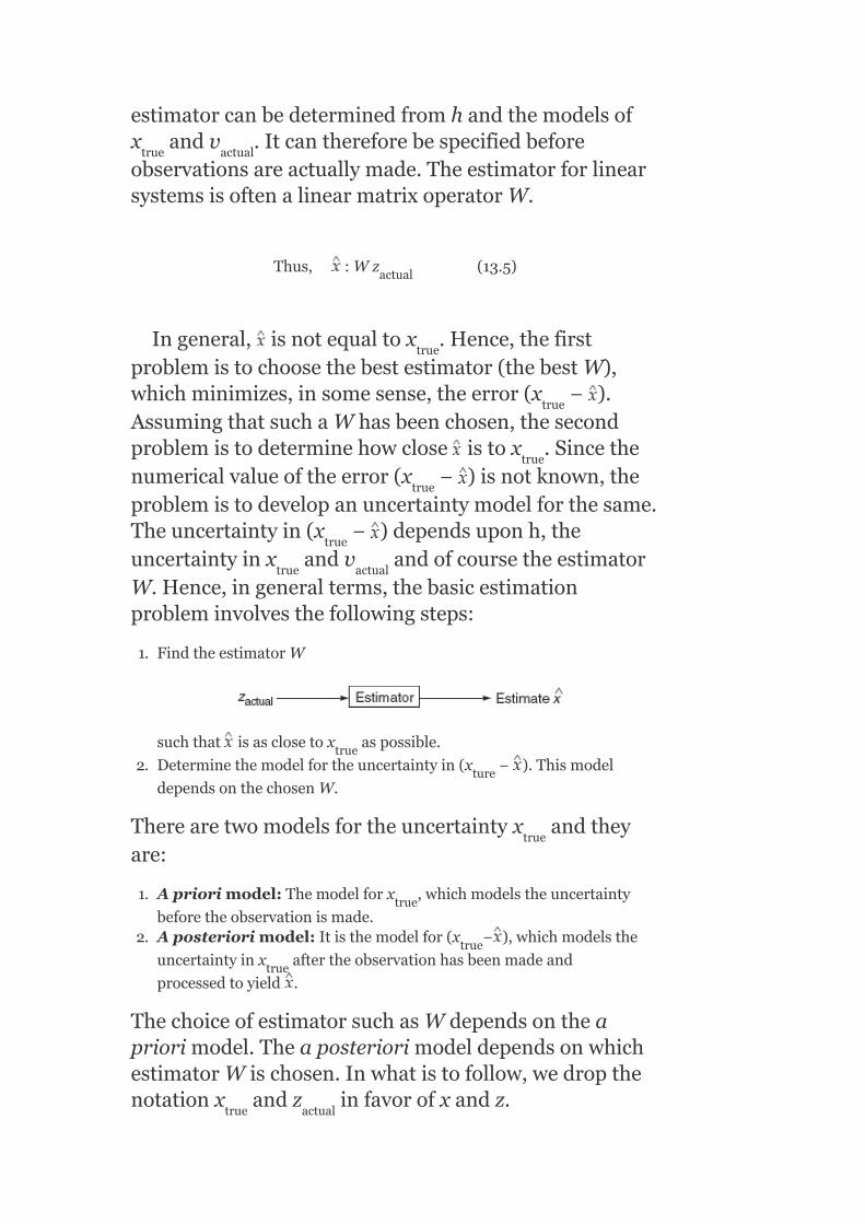
estimatorcanbedeterminedfromhandthemodelsofx andv .Itcanthereforebespecifiedbeforeobservationsareactuallymade.TheestimatorforlinearsystemsisoftenalinearmatrixoperatorW.
Thus, :Wz (13.5)
Ingeneral, isnotequaltox .Hence,thefirstproblemistochoosethebestestimator(thebestW),whichminimizes,insomesense,theerror(x − ).AssumingthatsuchaWhasbeenchosen,thesecondproblemistodeterminehowclose istox .Sincethenumericalvalueoftheerror(x − )isnotknown,theproblemistodevelopanuncertaintymodelforthesame.Theuncertaintyin(x − )dependsuponh,theuncertaintyinx andv andofcoursetheestimatorW.Hence,ingeneralterms,thebasicestimationprobleminvolvesthefollowingsteps:
1. FindtheestimatorW
suchthat isasclosetox aspossible.
2. Determinethemodelfortheuncertaintyin(x − ).Thismodel
dependsonthechosenW.
Therearetwomodelsfortheuncertaintyx andtheyare:
1. Apriorimodel:Themodelforx ,whichmodelstheuncertainty
beforetheobservationismade.2. Aposteriorimodel:Itisthemodelfor(x − ),whichmodelsthe
uncertaintyinx aftertheobservationhasbeenmadeand
processedtoyield .
ThechoiceofestimatorsuchasWdependsontheapriorimodel.TheaposteriorimodeldependsonwhichestimatorWischosen.Inwhatistofollow,wedropthenotationx andz infavorofxandz.
true actual
actual
true
true
true
true
true
true actual
true
ture
true
true
true
true
true actual

Therearemanywaysofmodelingtheuncertaintyofxandv.Someofthemoreimportantwaysare:
(i)Bayesianmodel : xandvarerandomvectors.
(ii)Fishermodel : xiscompletelyunknown;‘v’israndomvector.
(iii)Weightedleastsquares
: Nomodelsforxandv.
(iv)Unknownbutbounded
: xandvareconstrainedtolieinspecifiedsets.
13.7.5Leastsquaresestimation
Considertherelation:
z=h(x)+v
orv=[z−h(x)](13.6)
andfromEquation(13.2),
Theoptimalestimate isgivenbythatvalueofxforwhichthescalarfunctionoftheweightedsquares:
J=v′R v=[z−h(x)]′R [z−h(x)](13.7)
hasaminimumvalue.TheweightingmatrixR istheinverseofthecovariancematrixoftheobservationnoisev.
−1 −1
−1
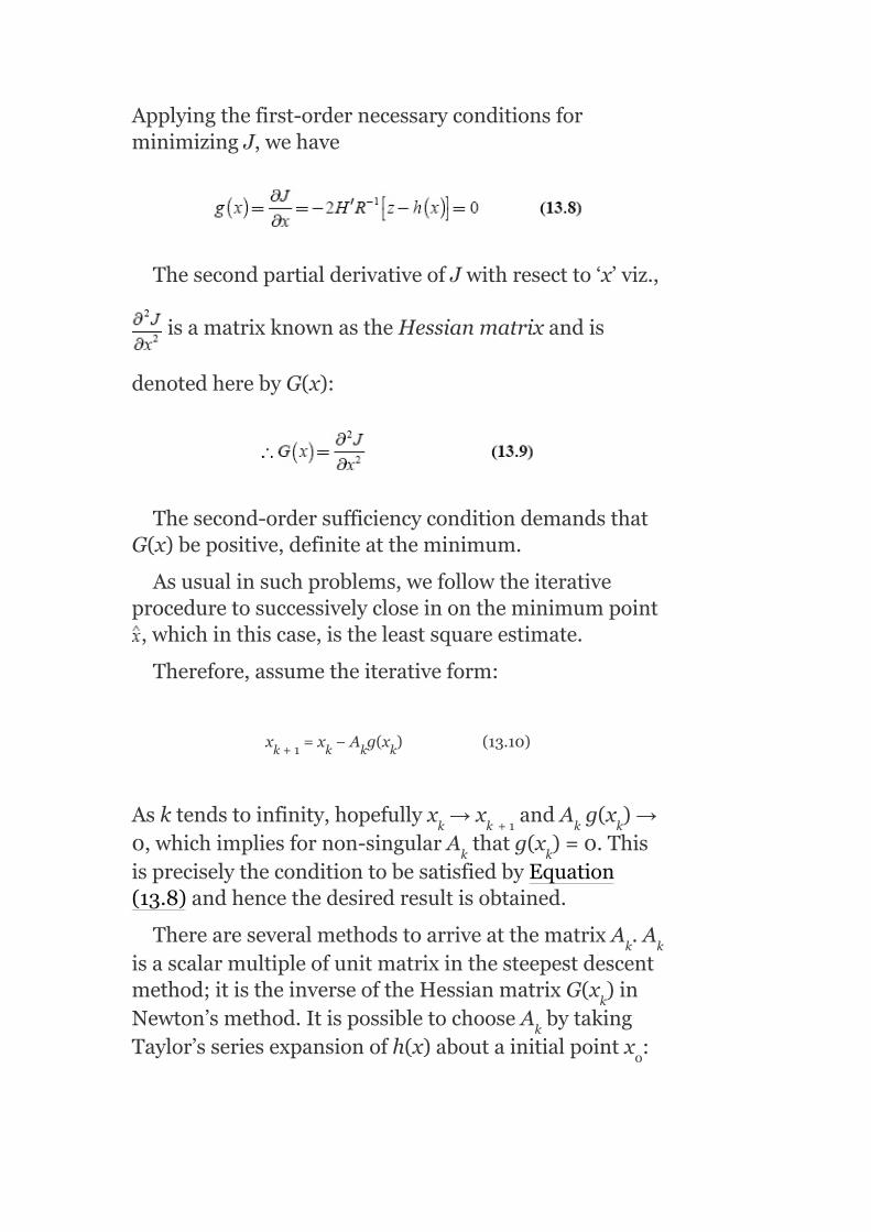
Applyingthefirst-ordernecessaryconditionsforminimizingJ,wehave
ThesecondpartialderivativeofJwithresectto‘x’viz.,
isamatrixknownastheHessianmatrixandis
denotedherebyG(x):
Thesecond-ordersufficiencyconditiondemandsthatG(x)bepositive,definiteattheminimum.
Asusualinsuchproblems,wefollowtheiterativeproceduretosuccessivelycloseinontheminimumpoint,whichinthiscase,istheleastsquareestimate.
Therefore,assumetheiterativeform:
x =x −A g(x )(13.10)
Asktendstoinfinity,hopefullyx →x andA g(x )→0,whichimpliesfornon-singularA thatg(x )=0.ThisispreciselytheconditiontobesatisfiedbyEquation(13.8)andhencethedesiredresultisobtained.
ThereareseveralmethodstoarriveatthematrixA .Aisascalarmultipleofunitmatrixinthesteepestdescentmethod;itistheinverseoftheHessianmatrixG(x )inNewton’smethod.ItispossibletochooseA bytakingTaylor’sseriesexpansionofh(x)aboutainitialpointx :
k+1 k k k
k k +1 k k
k k
k k
k
k
0

i.e.,h(x)=h(x )+h(x )(x−x )+higherorderterms(13.11)
SubstitutingthisapproximatevaluefromEquation(13.11)afterneglectinghigherordertermsintheobjectivefunctionJgivenbyEquation(13.7),weget
J =[z−h(x )−H(x )(x−x )]′R [z−h(x )−H(x )(x−x )]
Here,
H′R [z−h(x )−HΔx]
whereΔx=(x−x )
Usingtheoptimalitycondition weget
h′R [z−h(x )−hΔx]=0
Hence,Δx=[H′R H] H′R [z−h(x )](13.13)
Thevectorx=(x +Δx)yieldstheabsoluteminimumofJ ,butdoesnotyieldtheminimumforthefunctionJ.Thiscallsforfurtheriterationstillthevalue|x –x |iswithinprescribedbounds.
Specifically,
x =x +Δx
=x [H′R H ]H′R [z−h(x )]+x (13.14)
ButbyEquation(13.10),
0 0 0
1 0 0 0 0 0
0
0
0
−1 0
0
0
1
k k + 1
k+1 k k
k k k
−1
−1
−1 −1 −1
−1 −1 −
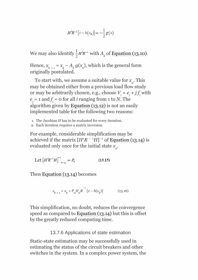
Wemayalsoidentify withA ofEquation(13.10).
Hence,x =x –A g(x ),whichisthegeneralformoriginallypostulated.
Tostartwith,weassumeasuitablevalueforx .Thismaybeobtainedeitherfromapreviousloadflowstudyormaybearbitrarilychosen,e.g.,chooseV =e +jf withe =1andf =0forallirangingfrom1toN.ThealgorithmgivenbyEquation(13.12)isnotaneasilyimplementedtableforthefollowingtworeasons:
1. TheJacobianHhastobeevaluatedforeveryiteration.2. Eachiterationrequiresamatrixinversion.
Forexample,considerablesimplificationmaybeachievedifthematrix[H′R H] ofEquation(13.14)isevaluatedonlyoncefortheinitialstatex .
Let
ThenEquation(13.14)becomes
x =x +P H R [z−h(x )](13.16)
Thissimplification,nodoubt,reducestheconvergencespeedascomparedtoEquation(13.14)butthisisoffsetbythegreatlyreducedcomputingtime.
13.7.6Applicationsofstateestimation
Static-stateestimationmaybesuccessfullyusedinestimatingthestatusofthecircuitbreakersandotherswitchesinthesystem.Inacomplexpowersystem,the
k
k +1 k k k
0
i i i
i i
0
k+1 k 0 0 k
− 1 −1
−1

networktopologycontinuouslychanges.Thedataregardingthewronginformationofswitchpositionsmaybeeasilycheckedbycomparingestimationrunsobtainedatdifferentinstants.ItisalsopossibletodecideonthequantumofadditionalinstrumentationbymerelycomparingtheminimumvaluesoftheobjectivefunctionJ(x)fordifferentinstrumentationconfigurations,theusestowhichstateestimationmaybe:
1. Dataprocessinganddisplay[baddatadetection,samplingrate].2. Securitymonitoring[overloadlimits,rescheduling,switching,and
loadshedding].3. Optimalcontrol[loadfrequencycontrol(LFC),economicload
dispatch].
KEYNOTES
‘Securitycontrol’ora‘securitycontrolsystem’maybedefinedasasystemofintegratedautomaticandmanualcontrolsforthemaintenanceofelectricpowerserviceunderallconditionsofoperation.Tokeepthesystemalwayssecure,itisnecessarytoperformanumberofsecurity-relatedstudies,whichcanbegroupedintothreemajorareas,namely:long-termplanning,operationalplanning,andon-lineoperation.Securityanalysisisthedeterminationofthesecurityofthesystembasedonanext-contingencyset.Thisinvolvesverifyingtheexistenceandnormalcyofthepost-contingencystates.Thepossiblecontingenciesconsideredintransientsecurityanalysisare:
1. Single-phase,two-phase,andthree-phasefaultconditions.2. Faultswithorwithoutreclosing.3. Properoperationorfailureofprotectiverelays.4. Circuitbreakeroperationorfailuretoclearthefault.5. Lossofgenerationoralargeblockofload.
Transientstabilityanalysistechniquesarebasedon:
1. Digitalsimulation.2. Hybridcomputersimulation.3. Lyapunovmethods.4. Patternrecognition.
TheobjectiveofanSSSanalysisistodeterminewhether,followingapostulateddisturbance,thereexistsanewsteady-stateoperatingpointwheretheperturbedpowersystemwillsettleafterthepost-faultdynamicoscillationshavebeendampedout.Themainobjectiveofstateestimationistoobtainthebestpossiblevaluesofthemagnitudesofbusvoltagesandtheiranglesanditrequiresthemeasurementofelectricalquantities,suchasrealandreactive-powerflowsintransmissionlinesandrealandreactive-

powerinjectionsatthebuses.Functionsofastateestimatorare:
1. Itprocessesreal-timesystemdata,whichareredundantandcomputethemagnitudesofbusvoltagesandbusvoltagephaseangleswiththehelpofacomputerprogram.
2. Itdetectsbadorinaccuratedatabyusingstatisticaltechniques.
Theapplicationsofstateestimationare:
1. Dataprocessinganddisplay.2. Securitymonitoring.3. Optimalcontrol.
SHORTQUESTIONSANDANSWERS
1. Howisthesecuritycontrolsystemdefined?
‘Securitycontrol’ora‘securitycontrolsystem’maybedefinedasasystemofintegratedautomaticandmanualcontrolsforthemaintenanceofelectricpowerserviceunderallconditionsofoperation.
2. Howisthesecuritycontrolconsideredasasignificancedeparturefromconventionalgenerationcontrolorsupervisorycontrol?
First,theproperintegrationofallthenecessaryautomaticandmanualcontrolfunctionsrequiresatotalsystemsapproachwiththehumanoperatorbeinganintegralpartofthecontrolsystemdesign.Second,themissionofsecuritycontrolisall-encompassing,recognizingthatcontroldecisionsbythehumancomputersystemmustbemadenotonlywhenthepowersystemisoperatingnormallybutalsowhenitisoperatingunderabnormalconditions.
3. Whatarethethreemajorareasofsecurity-relatedstudies?
Tokeepthesystemalwayssecure,itisnecessarytoperformanumberofsecurity-relatedstudies,whichcanbegroupedintothreemajorareas,namelylong-termplanning,operationalplanning,andon-lineoperation.
4. Whataretheapplicationsoflong-termplanning?
Theapplicationsoflong-termplanningare:
1. Evaluationofgenerationcapacityrequirements2. Evaluationofinterconnectedsystempowerexchangecapabilities.3. Evaluationoftransmissionsystemadequacy.
5. Whataretheapplicationsofoperationalplanning?
Theapplicationsofoperationalplanningare:
1. Determinationofspinningreserverequirementsintheunitcommitmentprocess.
2. Schedulingofhourlygenerationaswellasinterchangeschedulingamongneighboringsystems.
3. Outagedispatchingoftransmissionlinesandtransformersformaintenanceandsystemoperation.

6. Whataretheapplicationsofon-lineplanning?
Theapplicationsofon-lineplanningareasfollows:
1. Monitoringandestimationoftheoperatingstateofthesystem.2. Evaluationofsteady-state,transient,anddynamicsecurities.3. Quantitativeassessmentofsecurityindices.4. Securityenhancementthroughconstrainedoptimization.
7. Whatissecurityanalysis?
Securityanalysisisthedeterminationofthesecurityofthesystembasedonanext-contingencyset.Thisinvolvesverifyingtheexistenceandnormalcyofthepost-contingencystates.
8. Whatindicatestheinsecurityofacurrentstate?
Thenon-existenceofevenoneofthepost-contingencystatesoremergencynatureofanexistingpost-contingencystateindicatesthatthecurrentstateisinsecure.
9. Whatistheobjectiveoftransientsecurityanalysis?
‘Transientsecurityanalysis’referstoanonlineprocedurewhoseobjectiveistodeterminewhetherornotapostulateddisturbancewillcausetransientinstabilityofthepowersystem.
10. Whatarethepossiblecontingenciesconsideredintransientsecurityanalysis?
Thepossiblecontingenciesconsideredintransientsecurityanalysisare:
1. Single-phase,two-phase,andthree-phasefaultconditions.2. Faultswithorwithoutreclosing.3. Properoperationorfailureofprotectiverelays.4. Circuitbreakeroperationorfailuretoclearthefault.5. Lossofgenerationoralargeblockofload.
11. Whatarethestepsofgeneralapproachforimportingtransientsecurityconstraintsonanoperatingpowersystem?
Thegeneralapproachforimposingtransientsecurityconstraintsonanoperatingpowersystemconsistsofthefollowingsteps:
1. Performextensiveoff-linetransientstabilitystudiesforarangeofoperatingconditionsandpostulatedcontingencies.
2. Onthebasisofthesestudiesandpre-determinedreliabilitycriteria(e.g.,thesystemmustwithstandthree-phasefaultswithnormalclearing),establishsteady-stateoperatinglimitsforlinepowerflowsorlinephase-angledifferences.
3. Operatethesystemwithintheconstraintsdeterminedinthepreviousstep.
12. Whatarethesuggestedtechniquestobecarriedoutinthetransientstabilityanalysis?
Thesuggestedtechniquescanbeclassifiedaccordingtothefollowingbasicapproaches:
1. Digitalsimulation.2. Hybridcomputersimulation.3. Lyapunovmethods.4. Patternrecognition.

13. Whatissecurityenhancement?
Securityenhancementisalogicaladjuncttosecurityanalysisanditinvolveson-linedecisionsaimedatimproving(ormaintaining)thelevelofsecurityofapowersysteminoperation.Securityenhancementincludesacollectionofcontrolactionseachaimedattheeliminationofsecurityconstraintviolations.
14. Whatarethetwocontrolsusedforsecurityenhancement?
Thecontrolsusedforsecurityenhancementareclassifiedas:
1. Preventivecontrolsinthenormaloperatingstate,whenon-linesecurityanalysishasdetectedaninsecureconditionwithrespecttoapostulatednext-contingency.
2. Correctableemergencycontrols(simplycalled‘correctivecontrols’)inanemergencystate,whenanout-of-boundoperatingconditionalreadyexistsbutmaybetoleratedforalimitedtimeperiod.
15. Whatarethetechniquesusedforsolvingthesecurity-constrainedoptimizationproblem?
Twonon-linearprogrammingtechniques,namelythepenaltyfunctiontechniqueandthegeneralizedreducedgradienttechniquehavebeenidentifiedasthemostsuitableonesforsolvingtheconstrainedoptimizationproblem.Foraquickon-linesolution,theduallinearprogrammingtechniqueusinglinearmodelaswellasthesuccessivelinearprogrammingtechniqueusinglinearizedmodelshavebeenfoundtobemostuseful.
16. DefineSSS.
SSSisdefinedastheabilityofthesystemtooperatesteady-state-wisewithinthespecifiedlimitsofsafetyandsupplyqualityfollowingacontingency,inthetimeperiodafterthefast-actingautomaticcontroldeviceshaverestoredthesystemloadbalance,butbeforetheslow-actingcontrols,e.g.,transformertapingsandhumandecisions,haveresponded.
17. WhataretheobjectivesofSSSanalysis?
TheobjectiveofSSSanalysisistodeterminewhether,followingapostulateddisturbance,thereexistsanewsteady-stateoperatingpointwheretheperturbedpowersystemwillsettleafterthepost-faultdynamicoscillationshavebeendampedout.
18. Whatarethesecurityconstraints?
Theconstraintsaretransmissionlinepowerflows,busvoltages,andreactivelimits.
19. WhatarethecontingenciesthatshouldbeconsideredforSSSanalysis?
ForthepurposeofSSSanalysis,thefollowingcontingenciesshouldbeconsidered:
1. Lossofageneratingunit.2. Suddenlossofaload.3. Suddenchangeinflowinaninter-tie.4. Outageofatransmissionline.

5. Outageofatransformer.6. Outageofashuntcapacitororreactor.
20. Whatisthemainobjectiveofstateestimation?
Themainobjectiveofstateestimationistoobtainthebestpossiblevaluesofthemagnitudesofbusvoltagesandtheiranglesanditrequiresthemeasurementofelectricalquantities,suchasrealandreactive-powerflowsintransmissionlinesandrealandreactive-powerinjectionsatthebuses.
21. Whatarethetwomodificationsintroducedtoobtainahigherdegreeofaccuracyofthesolutiontothestateestimationtechnique?
Inordertoobtainahigherdegreeofaccuracyofthesolutiontothestateestimationtechnique,twomodificationsareintroduced.First,itisrecognizedthatthenumericalvaluesoftheavailabledatatobeprocessedforthestateestimationaregenerallynoisyduetothepresenceoferrors.Second,itisnotedthattherearealargenumberofvariablesinthesystem(activeandreactive-powerlineflows),whichcanbemeasuredbutnotutilizedintheloadflowanalysis.
22. Whatisthefunctionofastateestimator?
1. Itprocessesreal-timesystemdata,whichareredundantandcomputethemagnitudesofbusvoltagesandbusvoltagephaseangleswiththehelpofacomputerprogram.
2. Itdetectsbadorinaccuratedatabyusingstatisticaltechniques.
23. Whatdoyoumeanbystatic-stateanddynamic-state-estimationmodes?
Static-stateestimationpertainstotheestimationofasystemstatefrozenataparticularpointintime.Dynamic-stateestimationisacontinuousprocess,whichtakesintoaccountthedynamicsofthesystemandgivesanestimateofthesystemstateasitevolvesintime.
24. Whataretheapplicationsofstateestimation?
Theapplicationsofstateestimationare:
1. Dataprocessinganddisplay.2. Securitymonitoring.3. Optimalcontrol.
MULTIPLE-CHOICEQUESTIONS
1. Securitycontrolsystemisasystemof:
1. manualcontrol.2. integratedautomaticcontrol.3. conventionalgenerationcontrol.4. both(a)and(b).
2. Evaluationofgenerationcapacityrequirementsisa:
1. long-termplanningofsystemsecurity.2. operationalplanningofsystemsecurity.3. on-lineoperationapplicationofsystemsecurity.4. allofthese.
3. Theoperationalplanningofsystemsecuritycontrolincludes:
1. spinningreserverequirementsdetermination.2. schedulingofhourlygenerationaswellasinterchangescheduling.3. outagedispatchingoftransmissionlinesandtransformers.4. allofthese.
4. ThemonitoringandestimationofoperatingstateofthesystemandevaluationofSSSstate,transient,anddynamicsecuritiesaretheapplicationsof:
1. on-lineoperationofsecuritycontrolsystem.2. operationalplanningofsecuritycontrolsystem.3. long-termplanningofsecuritycontrolsystem.4. allofthese.
5. Securityanalysisisthedeterminationofthesecurityofasystem.
1. basedonanext-contingencyset.2. involvesverifyingtheexistenceofpost-contingencystates.3. involvesverifyingthenormalcyofpost-contingencystates.4. allofthese.
6. Non-existenceofevenoneofthepost-contingencystatesoremergencynatureofanexistingpost-contingencystateindicates:
1. securityofcurrentstate.2. securityofpreviousstate.3. insecurityofcurrentstate.4. insecurityofpreviousstate.
7. InSSSanalysis,thenextcontingenciestobeconsideredare:
1. outagesoflinesortransformersorgenerators.2. faultswithorwithoutreclosing.3. circuitbreakeroperationorfailuretoclearthefault.4. lossofgeneration.
8. Securityenhancementinvolves:
1. on-linedecisionsaimedatmaintainingthelevelofsecurity.2. acollectionofcontrolactionsaimedattheeliminationofsecurity
constraintviolations.3. failureofevenoneofpost-contingencies.4. both(a)and(b).
9. Forgettingquickon-linesolutiontoasecurity-constrainedoptimizationproblem,thetechniqueusedis:
1. duallinearprogrammingtechniqueusinglinearizedmodel.2. successivelinearprogrammingtechniqueusinglinearizedmodel.3. both(a)and(b).4. noneofthese.
10. Ifthenormalsystemfailstopassanyoneofthecontingencytests,itisdeclaredtobe:
1. Steady-statesecure.2. steady-stateinsecure.

3. transient-statesecure.4. transient-stateinsecure.
11. TheSSSassessorisanon-lineprocessusingreal-timedataforconductingSSSanalysison:
1. thepreviousstateofthesystem.2. thecurrentstateofthesystem.3. thepost-stateofthesystem.4. allofthese.
12. Anetworkoutageinvolves:
1. onlychangesinthenetworkadmittanceparameters.2. outagesoftransmissionlineortransformerorshuntcapacitororreactor.3. onlychangesinbuspowerinjections.4. both(a)and(b).
13. Apoweroutageinvolves:
1. onlychangesinnetworkadmittanceparameters.2. onlychangeinbuspowerinjections.3. lossofageneratingunitorsuddenlossofload.4. both(b)and(c).
14. Themainobjectiveofstateestimationis:
1. toobtainthebestvaluesofthemagnitudesofbusvoltagesandangles.2. tomaintainconstantfrequency.3. toreducetheloadlevels.4. toincreasethepowergenerationcapacity.
15. Stateestimationprocessrequiresthemeasurementof:
1. realandreactive-powerflowsintransmissionlines.2. realandreactive-powerinjectionsatthebuses.3. onlyreactivepowerabsorbedbyload.4. both(a)and(b).
16. Stateestimationis:
1. anavailabledata-sharingscheme.2. anavailabledata-measuringscheme.3. anavailabledata-processingscheme.4. anavailabledata-sendingscheme.
17. Stateestimationschemeuses:
1. Lagrangianfunctionmethod.2. Negativegradientmethod.3. Lyapunovmethod.4. weightedleastsquaremethod.
18. Inthestateestimationscheme,allthesysteminformationiscollectedbythecentralizedautomationcontrolofpowersystemdispatchthrough:
1. remoteterminalunits.2. transmitters.3. digitalsignalprocessors.4. allofthese.
19. Theinputstostateestimationare:
1. perfectpowersystemmeasurements.

2. imperfectpowersystemmeasurements.3. dependsonloadconnectedtopowersystem.4. allofthese.
20. Mostofthestateestimatorsinpowersystemsatpresentbelongto:
1. static-stateestimators.2. dynamic-stateestimators.3. either(a)or(b).4. both(a)and(b).
REVIEWQUESTIONS
1. Explaintheconceptofsystemsecurity.2. Discussthesignificanceapplicationsofsystemsecurity.3. Explainthetechniquesusedfortransientsecurityanalysis.4. Explainthesecurityenhancement.5. Explainthemathematicalmodelingofsecurity-constrained
optimizationproblem.6. ExplaintheSSSanalysis.7. Discusstheneedofstateestimation.8. Explainthefunctionofastateestimator.9. Discussthedifferencebetweenstatic-stateestimationand
dynamic-stateestimation.10. Explaintheleastsquareestimationprocess.11. Explaintheapplicationsofstateestimationprocess.

AppendixA
Chapter1
(1)a (12)b (23)b (34)b
(2)c (13)c (24)a (35)d
(3)b (14)a (25)d (36)a
(4)a (15)a (26)c (37)a
(5)a (16)c (27)c (38)c
(6)d (17)b (28)c (39)c
(7)b (18)d (29)a (40)d
(8)b (19)b (30)d (41)d
(9)e (20)a (31)c (42)d
(10)c (21)c (32)c
(11)a (22)d (33)a
Chapter2

(1)a (10)a (19)a (28)a
(2)a (11)a (20)d (29)c
(3)b (12)a (21)c (30)d
(4)a (13)c (22)d (31)d
(5)c (14)d (23)b (32)a
(6)d (15)c (24)b (33)a
(7)d (16)b (25)c
(8)d (17)c (26)b
(9)c (18)d (27)a
Chapter3
(1)c (10)d (19)b (28)c
(2)b (11)a (20)a (29)c
(3)d (12)a (21)c (30)d
(4)d (13)d (22)a (31)c
(5)a (14)a (23)c (32)c
(6)c (15)a (24)b (33)d

(7)c (16)b (25)a (34)d
(8)c (17)c (26)a
(9)a (18)d (27)d
Chapter4
(1)c (14)d (27)b (40)b
(2)c (15)d (28)a (41)a
(3)a (16)a (29)b (42)b
(4)d (17)c (30)a (43)b
(5)a (18)a (31)a (44)a
(6)b (19)a (32)b (45)b
(7)a (20)b (33)c (46)b
(8)d (21)b (34)a (47)b
(9)d (22)d (35)c (48)b
(10)a (23)b (36)a (49)a
(11)d (24)a (37)d
(12)d (25)b (38)b
(13)d (26)a (39)b

Chapter5
(1)d (9)b (17)b (25)b
(2)c (10)a (18)a (26)c
(3)b (11)c (19)Rigid,soft (27)b
(4)a (12)a (20)b (28)d
(5)b (13)d (21)a (29)a
(6)c (14)a (22)b (30)d
(7)d (15)a (23)c
(8)b (16)c (24)b
Chapter6
(1)a (12)a (23)a (34)d
(2)b (13)d (24)a (35)b
(3)a (14)d (25)b (36)b
(4)b (15)c (26)c (37)a
(5)b (16)d (27)b (38)a

(6)c (17)a (28)c (39)d
(7)a (18)b (29)d (40)d
(8)c (19)b (30)c (41)c
(9)d (20)c (31)a
(10)c (21)c (32)b
(11)d (22)d (33)d
Chapter7
(1)a (14)b (27)d (40)b
(2)c (15)b (28)d (41)c
(3)c (16)b (29)a (42)c
(4)a (17)b (30)a (43)c
(5)d (18)c (31)c (44)d
(6)b (19)b (32)d (45)a
(7)c (20)c (33)c (46)a
(8)c (21)a (34)b (47)b
(9)b (22)b (35)a (48)a
(10)c (23)a (36)a (49)d

(11)c (24)c (37)b (50)c
(12)c (25)b (38)d
(13)c (26)d (39)c
Chapter8
(1)b (6)a (11)c (16)b
(2)c (7)d (12)b (17)c
(3)b (8)c (13)c (18)a
(4)b (9)d (14)a (19)b
(5)c (10)d (15)a (20)c
Chapter9
(1)a (17)c (33)c (49)d
(2)a (18)a (34)c (50)d
(3)b (19)a (35)c (51)a
(4)b (20)a (36)c (52)a
(5)b (21)d (37)c (53)b

(6)b (22)a (38)c (54)b
(7)b (23)b (39)a (55)b
(8)b (24)b (40)c (56)a
(9)d (25)d (41)c (57)d
(10)a (26)c (42)c (58)a
(11)a (27)d (43)c (59)c
(12)c (28)b (44)d (60)c
(13)a (29)c (45)c (61)c
(14)d (30)c (46)b (62)d
(15)c (31)c (47)b (63)c
(16)b (32)c (48)d (64)a
Chapter10
(1)a (8)a (15)b (22)d
(2)c (9)b (16)a (23)c
(3)b (10)d (17)d (24)d
(4)d (11)a (18)c (25)a

(5)a (12)b (19)b
(6)d (13)a (20)a
(7)a (14)a (21)c
Chapter11
(1)b (8)d (13)b (20)d
(2)c (9)d (14)a (21)c
(3)c (10)(i)-(c),(ii)-(b),
(15)b (22)d
(4)a (iii)-(a),and (16)a (23)a
(5)c (iv)-(d) (17)d (24)b
(6)a (11)a (18)c (25)a
(7)d (12)a (19)c (26)a
(27)d (31)b (35)d (39)a
(28)d (32)a (36)c (40)b
(29)a (33)d (37)a (41)c
(30)a (34)b (38)d
Chapter12
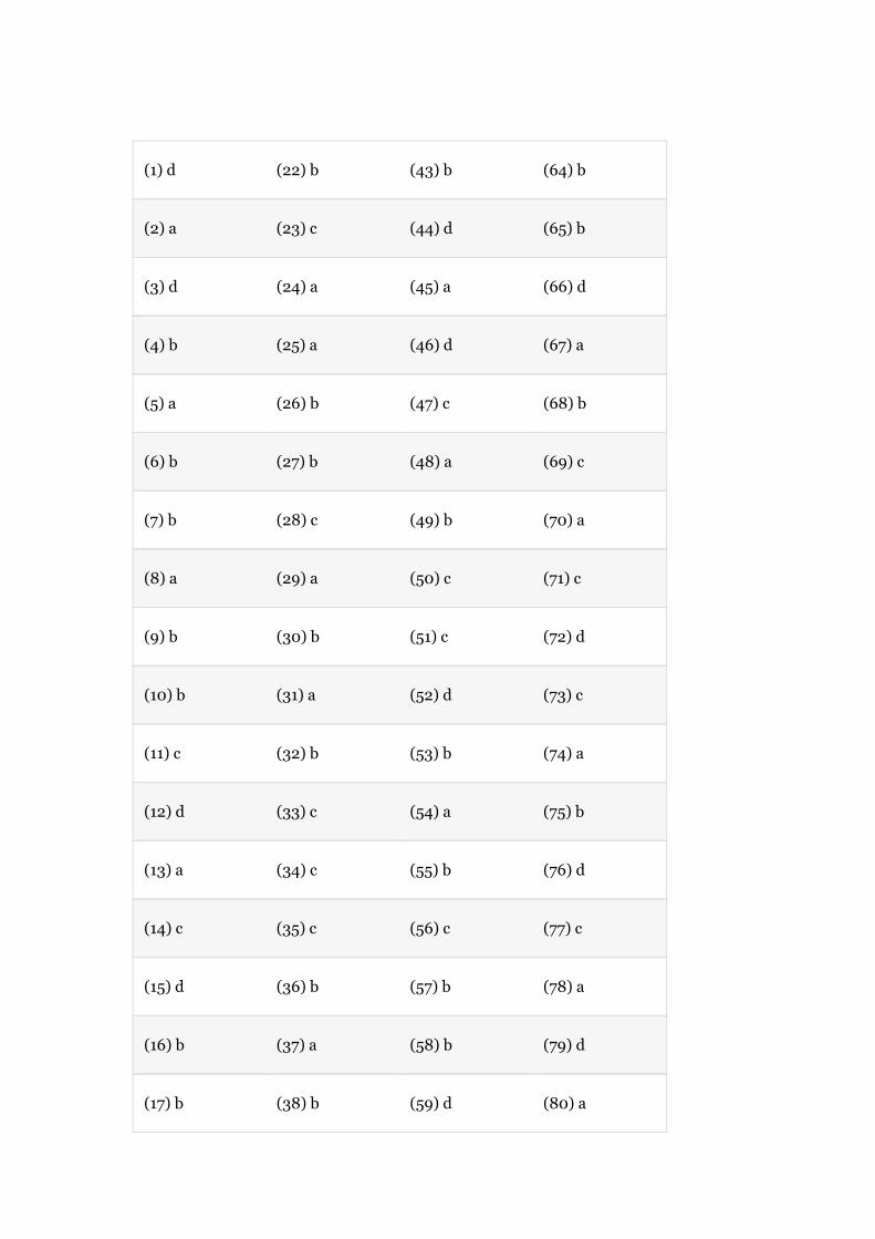
(1)d (22)b (43)b (64)b
(2)a (23)c (44)d (65)b
(3)d (24)a (45)a (66)d
(4)b (25)a (46)d (67)a
(5)a (26)b (47)c (68)b
(6)b (27)b (48)a (69)c
(7)b (28)c (49)b (70)a
(8)a (29)a (50)c (71)c
(9)b (30)b (51)c (72)d
(10)b (31)a (52)d (73)c
(11)c (32)b (53)b (74)a
(12)d (33)c (54)a (75)b
(13)a (34)c (55)b (76)d
(14)c (35)c (56)c (77)c
(15)d (36)b (57)b (78)a
(16)b (37)a (58)b (79)d
(17)b (38)b (59)d (80)a

(18)c (39)c (60)d (81)b
(19)d (40)a (61)c (82)b
(20)a (41)b (62)e
(21)a (42)a (63)d
Chapter13
(1)d (6)c (11)b (16)c
(2)a (7)a (12)d (17)d
(3)d (8)d (13)d (18)a
(4)a (9)c (14)a (19)b
(5)d (10)a (15)d (20)a

Acknowledgments
Weexpressourgratitudetothosewhohavehelpedusinmanywaysinmakingthisbookareality:
Toourcollegeadministrationforprovidingusaconduciveatmosphereandextendingimmensesupporttocarryoutthiswork.Toourdepartmentcolleagues,especiallythosewho,withtheirvaluableinputsbywayofsuggestions,content-relatedguidanceanddiscussions,helpedustosuccessfullycompletethisbook.Toourstudentsfortheirservices.Toallthosewhohaveeitherdirectlyorindirectlyhelpedusinbringingoureffortstofruition.Toourfamiliesfortheirconstantandfavorableencouragementateverystepoftheway.
Wearegratefultoourpublishers,PearsonEducation,India,formakingthisbookareality.WespecificallythankSojanJose,JenniferSargunar,M.E.Sethurajan,andThomasMathewRajeshfortheireditorialinputsandforthesuccessfulcompletionoftheproject.
S.SivanagarajuG.Sreenivasan

Copyright©2009DorlingKindersley(India)Pvt.Ltd.
LicenseesofPearsonEducationinSouthAsia.
NopartofthiseBookmaybeusedorreproducedinanymannerwhatsoeverwithoutthepublisher’spriorwrittenconsent.
ThiseBookmayormaynotincludeallassetsthatwerepartoftheprintversion.ThepublisherreservestherighttoremoveanymaterialpresentinthiseBookatanytime,asdeemednecessary.
ISBN9788131726624
ePubISBN9789332503380
HeadOffice:A-8(A),Sector62,KnowledgeBoulevard,7thFloor,NOIDA201309,India.
RegisteredOffice:11LocalShoppingCentre,PanchsheelPark,NewDelhi110017,India.
Forinstructor’sresources,clickhttp://www.pearsoned.co.in/SSivanagaraju/