Power-Gear-Operation-and-Service-Manual-for ... - PDX RV
23
OPERATION AND SERVICE MANUAL FOR JAYCO CLASS “A” MOTORHOME SLIDE-OUT SYSTEMS 82-S0330 REV. 0 April 2002 1
-
Upload
khangminh22 -
Category
Documents
-
view
10 -
download
0
Transcript of Power-Gear-Operation-and-Service-Manual-for ... - PDX RV

OPERATION AND SERVICE MANUAL FOR
JAYCO CLASS “A” MOTORHOME SLIDE-OUT SYSTEMS
82-S0330 REV. 0
April 2002 1

OPERATIONS MANUAL The Power Gear electric slide-out system in your coach is designed to give you years of trouble free operation and reflects the latest state of the art technology. READ, STUDY, AND UNDERSTAND THIS MANUAL BEFORE OPERATING YOUR SLIDE-OUT SYSTEM. 1. SYSTEMS DESCRIPTION Your Power Gear slide-out system is a rack and pinion design operated by a 12Volt DC electric motor.
1.1 MAJOR COMPONENTS
• Inner rail assemblies are designed to support the room weight. • The 12Volt DC gearmotor will operate the room using power from the
onboard unit battery. • Slide-out systems are equipped with a manual override that allows you to
extend / retract the room in the event of a loss of power. • Fully adjustable positive stops for both IN and OUT travel.
2. HOW TO OPERATE YOUR SLIDE-OUT SYSTEM
2.1 WARNING • ALWAYS MAKE SURE THAT THE SLIDE-OUT ROOM PATH IS CLEAR OF
PEOPLE AND OBJECTS BEFORE AND DURING OPERATION OF THE SLIDE-OUT ROOM.
• ALWAYS KEEP AWAY FROM THE SLIDE-OUT RAILS WHEN THE ROOM IS BEING OPERATED. THE GEAR ASSEMBLY MAY PINCH OR CATCH ON LOOSE CLOTHING CAUSING PERSONAL INJURY.
• ALWAYS UTILIZE A ROOM LOCKING DEVICE ON THE SLIDE-OUT ROOM DURING STORAGE AND TRANSORTATION.
FAILURE TO FOLLOW THESE INSTRUCTIONS COULD
RESULT IN SERIOUS INJURY OR DEATH.
2

OPERATIONS MANUAL 2. OPERATING YOUR SLIDE-OUT SYSTEM (Continued)
2.2 EXTENDING THE ROOM 1. Level the unit. 2. Verify the battery is fully charged and hooked-up to the electrical system. 3. Remove the transit bars (if your unit is so equipped). 4. Make sure the room path is clear (both inside and outside the coach). 5. Check the slide-out awning (some awnings must be manually unlocked
before operating the slide-out). 6. Press and hold the IN/OUT switch in the OUT position until the room is fully
extended and stops moving. 7. Release the switch, which will lock the room into position.
2.3 RETRACTING THE ROOM 1. Verify the battery is fully charged and hooked-up to the electrical system. 2. Make sure the room path is clear (both inside and outside the coach). 3. Press and hold the IN/OUT switch in the IN position until the room is fully
retracted and stops moving. 4. Release the switch, which will lock the room into position 5. Check the slide-out awning (some awnings must be manually locked before
traveling). 6. Install transit bars (if your unit is so equipped).
3

OPERATIONS MANUAL 3. MANUALLY OVERRIDING YOUR SLIDE-OUT SYSTEM Your Power Gear slide-out system is equipped with a manual override that allows you to extend or retract the room in the event of a loss of power. NOTE: If the room does not move when the switch is pressed, check the following: • Battery is fully charged and connected • The transit bars are removed • All system fuses/circuit breakers and relays are good. After the previous items have been checked and the room still does not move when the slide-out switch is pressed, follow these simple steps to manually override your slide-out room.
1. Locate the slide-out motor (see drawings later in this manual). The motor is
located in the top of the center storage compartment under the slide-out room. For a bedroom slide-out the motor will be mounted to rail assembly.
2. Rotate the brake lever on the back of the motor counter-clockwise (looking from the rear of the motor) about 1/8 of a turn to the released position. Refer to the label on the motor and the motor drawing in this manual. This will release the brake that holds the room in place.
3. The room is now free to move. 4. Locate the manual override on the end of a rail assembly (see drawing later in
this manual). It is also permissible to use an adjustable wrench on the square drive shaft to crank the room in or out.
5. Check the slide-out awning (some awnings must be manually unlocked before operating).
6. Using a ¾ wrench or ratchet, crank the room either in or out completely (depending on your need).
7. When the room is fully in/out apply pressure to the wrench or ratchet and return the motor brake lever to the "Engaged" position. This will ensure the room is locked into a sealed position.
8. Check the slide-out awning (some awnings must be manually locked before traveling).
9. Install transit bars (if so equipped) and take the unit to an authorized dealer for service.
4

OPERATIONS MANUAL
!!WARNING!!
WHEN THE MOTOR BRAKE IS DISENGAGED THE SLIDE-OUT ROOM WILL NOT LOCK IN PLACE; THEREFORE, THE ROOM WILL NOT BE SEALED. WHEN THE
ROOM HAS BEEN MANUALLY RETRACTED, BE SURE TO INSTALL THE TRANSIT BARS AND RETURN THE MOTOR BRAKE LEVER TO ITS NORMAL “ENGAGED”
POSITION IN ORDER TO SEAL AND LOCK THE ROOM INTO POSITION.
MOTORHOME SLIDE-OUT SYSTEMS
5

OPERATIONS MANUAL 4. PREVENTATIVE MAINTENANCE Your Power Gear slide-out system has been designed to require very little maintenance. To ensure the long life of your slide-out system read and follow these few simple procedures. CAUTION: DO NOT WORK ON YOUR SLIDE-OUT SYSTEM UNLESS THE BATTERY IS DISCONNECTED. • When the room is out, visually inspect the inner slide rail assemblies. Check for
excess build-up of dirt or other foreign material; remove any debris or items that may be present.
• If the system squeaks or makes any noises it is permissible to apply a light coating of silicone spray or lithium grease to the roller and bearing sleeve I.D., removing any excess lubricant so that dirt or debris do not build-up. DO NOT lubricate the slide-out drive gears, gear racks, or roller OD as this will attract dirt / debris.
IF YOU HAVE ANY PROBLEMS OR QUESTIONS CONSULT YOUR LOCAL
AUTHORIZED DEALER OR CALL US AT POWER GEAR (800-334-4712)
6

SERVICE MANUAL
!!! CAUTION !!! THE FOLLOWING INFORMATION IS FOR AUTHORIZED
RV DEALERS AND SERVICE TECHNICIANS.
RV OWNERS SHOULD NOT ATTEMPT THESE REPAIRS OR PROCEDURES.
ANYONE OTHER THAN AN RV AUTHORIZED SERVICE TECHNICIAN ATTEMPTING REPAIRS WILL VOID
WARRANTY.
!!! CAUTION !!! 7
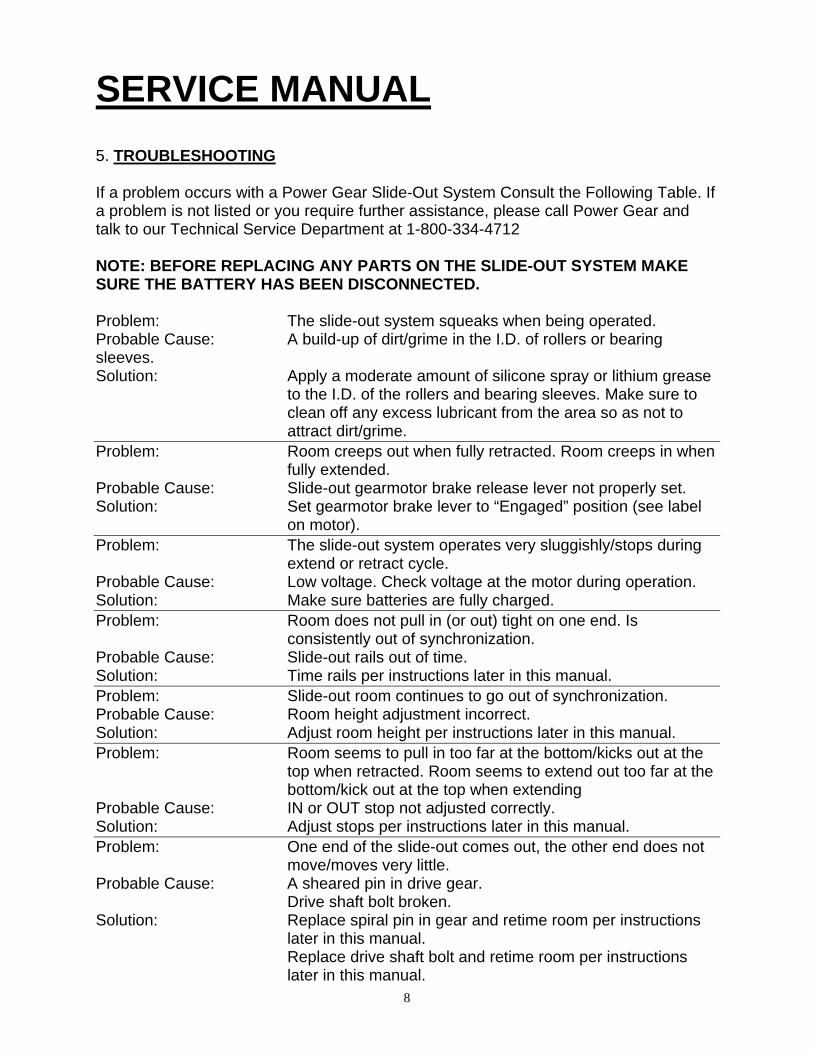
SERVICE MANUAL 5. TROUBLESHOOTING If a problem occurs with a Power Gear Slide-Out System Consult the Following Table. If a problem is not listed or you require further assistance, please call Power Gear and talk to our Technical Service Department at 1-800-334-4712 NOTE: BEFORE REPLACING ANY PARTS ON THE SLIDE-OUT SYSTEM MAKE SURE THE BATTERY HAS BEEN DISCONNECTED. Problem: The slide-out system squeaks when being operated. Probable Cause: A build-up of dirt/grime in the I.D. of rollers or bearing sleeves. Solution: Apply a moderate amount of silicone spray or lithium grease
to the I.D. of the rollers and bearing sleeves. Make sure to clean off any excess lubricant from the area so as not to attract dirt/grime.
Problem: Room creeps out when fully retracted. Room creeps in when fully extended.
Probable Cause: Slide-out gearmotor brake release lever not properly set. Solution: Set gearmotor brake lever to “Engaged” position (see label
on motor). Problem: The slide-out system operates very sluggishly/stops during
extend or retract cycle. Probable Cause: Low voltage. Check voltage at the motor during operation. Solution: Make sure batteries are fully charged. Problem: Room does not pull in (or out) tight on one end. Is
consistently out of synchronization. Probable Cause: Slide-out rails out of time. Solution: Time rails per instructions later in this manual. Problem: Slide-out room continues to go out of synchronization. Probable Cause: Room height adjustment incorrect. Solution: Adjust room height per instructions later in this manual. Problem: Room seems to pull in too far at the bottom/kicks out at the
top when retracted. Room seems to extend out too far at the bottom/kick out at the top when extending
Probable Cause: IN or OUT stop not adjusted correctly. Solution: Adjust stops per instructions later in this manual. Problem: One end of the slide-out comes out, the other end does not
move/moves very little. Probable Cause: A sheared pin in drive gear. Drive shaft bolt broken. Solution: Replace spiral pin in gear and retime room per instructions
later in this manual. Replace drive shaft bolt and retime room per instructions
later in this manual. 8

SERVICE MANUAL 6. COMPONENT PART REPLACEMENT INSTRUCTIONS
6.1 Replacing the Slide-Out Drive Shaft Bolts 1. Disconnect the Battery. 2. Remove any covers that may be placed over the drive shaft connection
points. 3. Release the brake on the slide-out gearmotor. 4. Using (2) 7/16” wrenches loosen and remove drive shaft bolt(s) to be
replaced. 5. Align (time) the slide-out room so that the room measures out the
same distance at the (coach) front and at the (coach) rear (See TIP sheet later in this manual for timing rails).
6. Insert the replacement driveshaft bolt in the square tube and through the round shaft, noting the number of washers to be used (See TIP sheet later in this manual). NOTE- Only use Power Gear supplied Grade 8, ¼-20 x 1-1/2” (max. lgth.) partially threaded bolt and locking nut.
7. Reconnect the Battery, and carefully operate the slide-out system to verify the operation and timing of room.
8. If unit is out of alignment/timing, repeat step 5 through 7. 6.2 Replacing the Slide-Out Electric Gearmotor
NOTE- ONLY REPLACE MOTOR WITH SAME POWER GEAR PART NUMBER MOTOR. MOTORS OF SIMILAR DESIGN CAN BE DIFFERENT 1. Disconnect the battery. 2. Remove any covers that may be placed over the gearmotor. 3. Release the brake on the slide-out gearmotor. 4. Using a 7/16” or ½” wrench or ratchet (depending on the motor type),
loosen and remove the motor mounting bolts. 5. Remove the motor noting the orientation. 6. Disconnect the motor electrical connections. 7. Install replacement motor in the same orientation and tighten motor
mount bolts/lock washers until firm (do not over tighten bolts). 8. Connect motor electrical connections. 9. Connect battery and try operating system (taking care to stay clear of
all moving components. 10. Reinstall any covers that may have been removed.
9

SERVICE MANUAL 6. COMPONENT PART REPLACEMENT INSTRUCTIONS- Continued
6.3 Replacing the Drive Gear Shear Pin
1. Disconnect the battery. 2. Remove any covers that may be in place over the effected drive rail
and motor. 3. Release the brake on the slide-out gearmotor. 4. Using the appropriate wrench, rotate the drive shaft around to align the
gear pin hole with the shaft pin hole. 5. Using a 3/16” drift punch, knock out the pieces of shear pin. 6. Using the proper replacement (spiral shear) pin drive the pin into the
drive gear and drive shaft until evenly located from both sides of gear. 7. Retime the slide-out system per instructions provided in this manual. 8. Replace any covers removed for this repair. 9. Reconnect the battery and test the slide-out system.
6.4 Replacing the Drive Gear
1. Disconnect the Battery. 2. Remove any covers that might be in place over the effected drive rail
and motor. 3. Release the brake on the slide-out gearmotor. 4. Depending on the type of pin in place either use a proper sized drift
punch or simply pull out the pin on the override side of the drive shaft assembly.
5. Using the proper sized drift punch, drive out the roll pin in the override coupling and remove the coupling.
6. Using the proper sized drift punch, drive out the spiral pin holding the drive gear in place (the shaft may have to be rotated to best achieve this).
7. Slide the shaft towards the motor assembly until the gear can be pulled off the end of the shaft.
8. Replaced the drive gear and reassemble in reverse order as above. 9. Retime the slide-out system per instructions provided in this manual. 10. Replace any covers removed for this repair. 11. Reconnect the battery and test the slide-out system.
6.5 Replacing the Outer Rail Assembly Sleeve Bearing
1. Disconnect the battery. 2. Remove any covers that may be in place over the effected drive rail
and motor. 3. Release the brake on the slide-out gearmotor. 4. Support the slide out room and rail prior to proceeding.
10

SERVICE MANUAL 6. COMPONENT PART REPLACEMENT INSTRUCTIONS- Continued
5. If it is the outside bearing sleeve to be replaced use a proper sized drift punch to remove the roll pin holding the override coupling in place and removed coupling.
6. Using the appropriate size drift pump remove roll pin that retains bearing sleeve.
7. Then tap the bearing sleeve off the drive shaft and replace with new. 8. Install roll pin to retain bearing sleeve. 9. Install override coupling and roll pin to retain coupling. 10. If it is the inside bearing sleeve to be replace removed the square drive
shaft assembly from the round drive shaft. Follow steps 7 & 8. 11. Reinstall the drive shaft assembly and torque hardware tight.
11

T.I.P. Troubleshooting Information on Power Gear1217 E. 7th Street Mishawaka, I 46544 Phone: 1-800-334-4712 1-888-339-2539 Fax: 574-256-6743
N
Torque Specification for Slide Out Drive shaft Bolts
For proper operation of the slide out system, the drive shaft hardware is specially designed from Grade 8 material and needs to be properly torqued. The proper torque value of the drive shaft bolts is 168±12 in-lbs. (14±1 ft-lbs). Torquing the drive shaft bolts to the proper value will ensure longer life of components and proper operation of the slide out system. Refer to figures below for proper assembly of the drive shaft hardware. Only (1) washer used on the head side of bolt is needed. NOTE: Systems produced before July 2001 have more then one washer and a different type of nut on the bolt / nut assembly. Replace old hardware with new hardware as shown below.
Fig. #1 Fig. #2
1” Square Tubing End 13/16” Square Tubing End (Drive End) (Idler End)
NOTE: Failure to use specially designed hardware and improper torque of hardware
will result in improper operation or failure of slideout system.
TIP Sheet #73 81-1288 REV. 9
09-01
12

T.I.P. Troubleshooting Information on Power Gear1217 E. 7th St et Mishawaka, I 46544 Phone: 1-800-334-4712 1-888-339-2539 Fax: 574-256-6743
reN
SLIDE-OUT ROOM HEIGHT ADJUSTMENT For proper slide-out operation the slide-out room floor to slide-out rail height must be set. This procedure is to be performed at the factory during room installation and should be checked periodically. To set the room height, please refer to the Figure below.
B = A−
+01 8"/ "
The distance between the bottom of the floor and the top of the inner rail must be the same distance (A=B) or the distance at the end of the inner rail can be 1/8” greater than the inside distance (B=A+1/8”).
TIP Sheet #82 81-1299 REV. 2
13

T.I.P. Troubleshooting Information on Power Gear1217 E. 7th Street Mishawaka, IN 46544 Phone: 1-800-334-4712 1-888-339-2539 Fax: 574-256-6743
FLAT FLOOR ROOM HEIGHT ADJUSTMENT
This TIP sheet is designed to provide information on setting the room height on a flat floor slide-out system utilizing angled rails.
With the room fully extended-
• Measure from the top of the moving slide-out rail to the bottom of the slide-out room floor up close to the coach. This is dimension “A”.
• Measure from the top of the moving slide-out rail to the bottom of the slide-out room floor out near the mounting bracket. This is dimension “B”.
• To calculate dimension “B” use the following formula: “B” (end bracket height setting)=“A” + (slideout room floor thickness) + ¼”.
EXAMPLE: “B” (end bracket height setting)=“A” + (slideout room floor thickness) + ¼”.
If “A” = 3-1/4” Then “B”=3-1/4” + 1” + ¼” = 4-1/2”
• Perform this check on each slide-out rail independent of the other. NOTE: 1) These figures are approximates. Each coach may be slightly different. 2) Refer to manufacturer of coach/trailer for correct slideout room floor thickness.
TIP Sheet #124
82-S0295 02-01
14

T.I.P. Troubleshooting Information on Power Gear1217 E. 7th Street Mishawaka, IN 46544 Phone: 1-800-334-4712 1-888-339-2539 Fax: 574-256-6743
SYNCHRONIZING A 2 RAIL SLIDE-OUT ROOM Should the slide-out room go out of synchronization this procedure will allow you to retime the room. Measure room synchronization from common solid points at each end of the room. NOTE- This Tip Sheet does cover standard and flat floor slide-out systems. To synchronize the room please refer to the Figure below.
With room about half way our release slide-out motor brake. 1. Pull the clip pin out. 2. Slide the drive shaft assembly in to disengage gear from gear rack. 3. Moved slide-out inner rail in/out to desired location. 4. Slide drive shaft assembly back into position. 5. Push clip pin back into shaft. Before proceeding put slide-out motor brake lever back into “Engaged” position.
TIP Sheet #134 82-S0304-T REV. 0
03-02
15

T.I.P. Troubleshooting Information on Power Gear1217 E. 7th Street Mishawaka, IN 46544 Phone: 1-800-334-4712 1-888-339-2539 Fax: 574-256-6743
VERTICAL HEIGHT ADJUSTMENT ON SLIDE-OUT SYSTEM
Each rail of the slide-out system has individual vertical height adjustment. Set the vertical height using the procedure shown below. With the room extended completely adjust room height by- 1. Loosening the 3 bolts in the vertical adjustment slots. 2. Using the appropriate sized Allen head wrench, turn the vertical adjustment bolts
either clockwise or counter-clockwise to raise or lower room (depending on the need).
3. Check room height setting. Repeat step 2 until height is set to proper location. 4. Tighten the 3 bolts in the vertical adjustment slots.
TIP Sheet #150
82-S0314-T REV. 0 03-02
16
vandijkr (Rudolf Vandijk)
PLEASE INSERT THE RIGHT FAX NUMBER IN HEADER

T.I.P. Troubleshooting Information on Power Gear1217 E. 7th Street Mishawaka, IN 46544 Phone: 1-800-334-4712 1-888-339-2539 Fax: 574-256-6743
ADJUSTING “IN” AND “OUT” STOPS ON LOW PROFILE
SLIDE-OUT SYSTEM Each rail of the slide-out system has individual “IN” and “OUT” stops. These stops can easily be adjusted using the procedure shown below.
For the “OUT” stop. 1. Extend the room out to the desired position. 2. Loosen the jam nut (9/16”) on the adjustable stop bolt. 3. Screw the adjustable stop bolt out until it contacts the inner rail. 4. Tighten the jam nut to secure the bolt in the proper position. 5. Test the stop location by running the room. Repeat steps 1 – 4 to re-adjust. For the “IN” stop. 1. Check the seal of the room prior to adjusting the stops. 2. Using a 9/16” wrench or ratchet adjust the “IN” stop bolts in or out to the desires
location (note the locking nut does not require a jam nut). 3. Test the seal. If more adjustment is needed repeat steps 1 – 2.
TIP Sheet #151 82-S0315-T REV. 0
03-02 17
vandijkr (Rudolf Vandijk)
PLEASE INSERT THE RIGHT FAX NUMBER IN HEADER

SERVICE MANUAL MOTOR DRAWING
GEAR MOTOR ASSEMBLY
18

19

20

21

22

23
POWER GEAR LIMITED WARRANTY
Power Gear warrants the original purchaser that the product will be free from defects in material and workmanship for a period of one (1) year following the retail sales date. Power Gear will, at its option, repair or replace any part covered by this limited warranty which, following examination by Power Gear or its authorized distributors or dealers, is found to be defective under normal use and service. No claims under this warranty will be valid unless Power Gear or its authorized distributor or dealer is notified in writing of such claim prior to the expiration of the warranty period. Warranty is non-transferable.
THIS WARRANTY SHALL NOT APPLY TO: • Failure due to normal wear and tear, accident, misuse, abuse, or negligence. • Products which are modified or altered in a manner not authorized by Power Gear in
writing. • Failure due to misapplication of product. • Telephone, telegraph, teletype or other communication expenses. • Living or travel expenses of person performing service. • Overtime labor. • Failures created by improper installation of the product’s slide-out system or slide-
out room to include final adjustments made at the plant for proper room extension/retraction; sealing interface between slide-out rooms and side walls; synchronization of inner rails; or improper wiring of ground problems.
• Failures created by improper installation of leveling systems, including final adjustments made at the plant, or low fluid level, wiring or ground problems.
• Replacement of normal maintenance items including lubricants and fuses. There is no other express warranty other than the foregoing warranty. THERE ARE NO IMPLIED WARRANTIES OF MERCHANTIBILITY OR FITNESS FOR PARTICULAR PURPOSE. IN NO EVENT SHALL POWER GEAR BE LIABLE FOR ANY ACCIDENTAL OR CONSEQUENTAL DAMAGES. This warranty gives you specific legal rights, and you may also have other rights which vary from state to state. Some states do not allow the limitations of implied warranties, or the exclusion of incidental or consequential damages, so the above limitations and exclusions may not apply to you. For service contact your nearest Power Gear authorized warranty service facility or call 1-800-334-4712. Warranty service can be performed only by a Power Gear authorized facility. This warranty will not apply to service at any other facility. At the time of requesting warranty service, evidence of original purchase date must be presented.
Power Gear 1217 E. 7th Street
Mishawaka, IN 46544
1-800-334-4712