POWER GRID COMPANY OF BANGLADESH LIMITED
370
POWER GRID COMPANY OF BANGLADESH LIMITED PROCUREMENT OF PLANT DESIGN, SUPPLY AND INSTALL SINGLE-STAGE, TWO-ENVELOPE BIDDING PROCEDURE BIDDING DOCUMENT FOR PROCUREMENT OF DESIGN, SUPPLY, ERECTION, TESTING & COMMISSIONING OF ASHUGANJ-BHULTA 400KV TRANSMISSION LINE AND BHULTA 400/230KV SUBSTATION ON TURNKEY BASIS LOT-1: TRANSMISSION LINES VOLUME 2 OF 3 SCOPE OF WORK TECHNICAL SPECIFICATIONS DRAWINGS FORMING PART OF SPECIFICATION June 2014
-
Upload
khangminh22 -
Category
Documents
-
view
0 -
download
0
Transcript of POWER GRID COMPANY OF BANGLADESH LIMITED

POWER GRID COMPANY OF BANGLADESH LIMITED
PROCUREMENT OF PLANT DESIGN, SUPPLY AND INSTALL
SINGLE-STAGE, TWO-ENVELOPE
BIDDING PROCEDURE
BIDDING DOCUMENT FOR
PROCUREMENT OF
DESIGN, SUPPLY, ERECTION, TESTING & COMMISSIONING OF ASHUGANJ-BHULTA 400KV TRANSMISSION LINE AND BHULTA
400/230KV SUBSTATION ON TURNKEY BASIS
LOT-1: TRANSMISSION LINES
VOLUME 2 OF 3
SCOPE OF WORK TECHNICAL SPECIFICATIONS
DRAWINGS FORMING PART OF SPECIFICATION
June 2014

POWER GRID COMPANY OF BANGLADESH LIMITED
BIDDING DOCUMENT FOR THE PROCUREMENT OF
DESIGN, SUPPLY, ERECTION, TESTING & COMMISSIONING OF ASHUGANJ-BHULTA 400KV TRANSMISSION LINE AND BHULTA 400/230KV SUBSTATION
ON TURNKEY BASIS
LOT-1: TRANSMISSION LINES
INDEX TO VOLUMES Volume 1 of 3 Section 1 - Instruction to Bidders Section 2 - Bid Data Sheet Section 3 - Evaluation and Qualification Criteria Section 4 - Bid Forms Section 5 - Eligible Countries Section 6 - Employer’s Requirements Section 7 - General Conditions of Contract Section 8 - Special Conditions of Contract Section 9 - Contract Forms Volume 2 of 3
Scope of Work Technical Specifications Drawings forming Part of Specifications Volume 3 of 3
Schedule A Schedule B Bid Prices & Schedules Schedule C Bar Chart Program of Key Activities-Delivery & Completion Time Schedule Schedule D Manufacturers, Places of Manufacture and Testing Schedule E Technical Particulars and Guarantees Schedule F Proposed Subcontractors Schedule G Co-efficient and Indices for Price Adjustment.

POWER GRID COMPANY OF BANGLADESH LIMITED
DESIGN, SUPPLY, ERECTION, TESTING & COMMISSIONING OF ASHUGANJ-BHULTA 400KV TRANSMISSION LINE AND
BHULTA 400/230KV SUBSTATION ON TURNKEY BASIS
LOT-1: TRANSMISSION LINES
INDEX TO VOLUME 2 OF 3
Section Description Section 1
Scope of Work
Section 2 Site Particulars
Section 3 Quality Assurance
Section 4 Design Particulars
Section 5 Access
Section 6 Survey and Geotechnical Investigations
Section 7 Foundation
Section 8 Tower
Section 9
Insulator
Section 10
Insulator and Conductor Fittings
Section 11 Conductor
Section 12 Vibration Damper
Section 13 Spacer Damper
Section 14 Optical Fiber Cable & Fittings
Section 15 Aircraft Navigation (Obstruction Aids)
Section 16 Miscellaneous
Section 17 Packing, Protection and Dispatch Marking
Section 18 Method of Measurement & Payment
Section 19 Bid Drawings

POWER GRID COMPANY OF BANGLADESH LIMITED
BIDDING DOCUMENT
FOR THE PROCUREMENT OF
DESIGN, SUPPLY, ERECTION, TESTING & COMMISSIONING OF ASHUGANJ-BHULTA 400KV TRANSMISSION LINE AND BHULTA
400/230KV SUBSTATION ON TURNKEY BASIS
LOT-1: TRANSMISSION LINES
SECTION 1
SCOPE OF WORK

400kV ABTL 1/1
SECTION 1
SCOPE OF WORK 1.1 GENERAL The Extent of Supply is described in the following clauses and in the respective Sections
of the Specification. All work not expressly called for in the Specification, but necessary for the completion of the work shall be performed and furnished by the Contractor at no additional cost to the Employer.
The Contract shall comprise the design, manufacture, testing, supply, insurance, delivery
to site of tower, phase conductor, Earthwire, OPGW including all associated fittings, complete insulator sets, phase and earthwire tension and non-tension joints and clamps, vibration dampers, spacer dampers, erection, setting to work, testing and the replacement and/or adjustment of defective material and workmanship for the duration of the 12 month warranty period of the transmission line(s) detailed in the ‘Extent of Supply’ and associated Appendix 1.A1.
1.2 EXTENT OF SUPPLY 1.2.1 Scope The Extent of Supply comprises the design, manufacture, testing, supply, insurance,
shipping, loading and unloading, delivery to site of complete tower and foundation steelwork inclusive of all phase attachment swivels/shackles, tower mounted plates, anti-climbing devices, foundation and earthing materials and conductor, Earthwire, OPGW, insulator including all associated fittings, check topographical survey and all associated profile plotting, support pegging, provision of access facilities and route clearing, transportation to site, ground investigation, installation of foundations and all associated civil works, erection of towers, installation of insulators, conductors, Earthwire and OPGW and all associated fittings, land clearance, testing on site, setting to work and supply of spares, tools & equipment as set out in this tender document and at prices stated in the Schedules or at such other prices or unit prices as may from time to time be agreed. The contract price shall also include training of Employer’s personnel (overseas and local) as detailed in sub-clause 18.1.12 and witnessing of factory tests of materials by Employer’s engineers as detailed in subclause 18.1.11 and in accordance with the Specification, Standards defined in Appendix 1.A1.
1.2.2 Estimated and Final Quantities
The quantities set out in the Schedules are, unless otherwise defined, estimated quantities of the Works required. They are not to be assumed as the actual and final quantities to be executed by the Contractor in fulfilment of his obligations under the Contract.

400kV ABTL 1/2
Final quantities are to be established by the Contractor, and agreed upon by the Employer, within three (3) months from the date of signing of the Contract, after the selection of tower positions has been made on completion of the survey of the transmission line routes.
1.2.3 Modifications
The transmission line shall be completely in accordance with the Specification and associated design and general arrangement/outline drawings. Any modifications thereto are subject to written confirmation by the Employer/Engineer.
1.3 TERMINAL POINTS
The terminal points for the supply and/or installation of the transmission line are defined in Appendix 1.A2.
1.4 NOT USED 1.5 NOT USED 1.6 PROGRAMME OF WORK
Within 4 (four) weeks of signing of the contract the Contractor shall submit to the Employer for approval, 5 (five) copies of a bar chart detailing the plant manufacture, testing, delivery and erection programme (as appropriate) for the complete Contract Works. The bar chart shall indicate the various phases of work for all appropriate items of the Contract, from commencement of the Contract to its final completion eg. design, survey, approval of drawings, ordering of materials, manufacture, testing, delivery, erection and commissioning. The bar chart shall, when appropriate, allow the requisite periods of approval by the Employer, and/or any other regulatory body. If at any time during the execution of the Contract it is found necessary to modify the approved bar chart, the Contractor shall inform the Employer and submit a modified bar chart for approval. Such approval is not deemed to be consent to any amendments to the contractual completion date(s). Modifications which may affect site work and associated local arrangements must provide a sufficient notice period to allow for any necessary re-arrangements. It should be recognised that where certain power line outages for crossing purposes have been specified, it may not be possible for these to be replanned due to system operational constraints and this should be allowed for in the overall programme.

400kV ABTL 1/3
The Employer intends that access will be given to a reasonable number of sites to provide continuity of work. However, the Contractor shall accommodate reasonable delays in access to some individual sites which may prevent sequential foundation installation and support erection work being carried out. Provided he has overall continuity of work, this shall not affect the Contractor’s programme.

400kV ABTL 1/4
APPENDIX 1.A1
SCOPE AND EXTENT OF DEFINITE WORK
DESIGN-BUILD AND TURNKEY CONTRACT FOR CONSTRUCTION OF 400KV
TRANSMISSION LINE ON BUILD OWN OPERATE AND TRANSFER BASIS
1. 400kV Transmission Line 400kV double-circuit three-phase transmission line on vertical formation double
circuit lattice steel towers with twin ACSR (Finch) phase conductor and one ACSR (Dorking) earthwire and one equivalent OPGW from Ashuganj 400kV Substation to 400/230kV Bhulta substation. (approximately 70 kms length). A jumper shall be provided with the slack span of sufficient length to be terminated at the substation entry equipment. The termination work of the jumper to the substation equipment is not scope of this Contract.
2. 230kV Transmission Line
Turn-in and Turn-out of existing 230kV Rampura – Haripur and Rampura –
Ghorashal double-circuit transmission line to new Bhula 400kV Substation on vertical formation four circuit lattice steel towers with twin ACSR (Mallard) phase conductor and one 7x4.00GS earthwire and one equivalent OPGW (approximately 02 kms length).
A jumper shall be provided with the slack span of sufficient length to be terminated at the substation entry equipment. The termination work of the jumper to the substation equipment is not scope of this Contract.

400kV ABTL 1/5
APPENDIX l.A2
TERMINAL POINTS
1. 400kV Line Phase conductors shall be terminated at the gantry structures at Ashuganj 400kV Substation and Bhulta 400kV/230kV Substation. OPGW & earthwire shall be terminated at the substation gantry. 2. 230kV Lines Phase conductors shall be terminated at the gantry structures at Bhulta 400kV/230kV Substation and tower of Rampura – Haripur line and tower of Rampura – Ghorashal line. OPGW and earthwire shall be terminated at the substation gantry at substation end and spliced with the existing fibers at existing lines in relevant towers. The towers of Rampura – Haripur line and Rampura – Ghorashal line for termination shall be identified during execution of Contract.

POWER GRID COMPANY OF BANGLADESH LIMITED
BIDDING DOCUMENT
FOR THE PROCUREMENT OF
DESIGN, SUPPLY, ERECTION, TESTING & COMMISSIONING OF ASHUGANJ-BHULTA 400KV TRANSMISSION LINE AND BHULTA
400/230KV SUBSTATION ON TURNKEY BASIS
LOT-1: TRANSMISSION LINES
SECTION 2
SITE PARTICULARS

2/1
SECTION 2
SITE PARTICULARS 2.1 GENERAL
The location of the transmission line(s) and associated climatic conditions described in the following clauses are given for guidance only.
2.2 LOCATION
For details of the location of the transmission line(s) reference should be made to Appendix 2.A1 and associated drawings included with the specification.
2.3 CLIMATIC
For details of the climatic conditions associated with the site, reference should be made to Appendix 2.A2. The Contractor is advised to make a thorough study of local climatological records, since no delays to the completion dates due to adverse weather conditions shall be accepted.

2/2
APPENDIX 2.A1
LOCATION OF TRANSMISSION LINE The transmission line shall be built from proposed Bhulta substation to proposed Ashuganj 400kV substation (approximately 70 km length) and pass through Narayanganj and Brahmanbaria districts. The line shall cross rivers, highways, railway and existing high voltage power lines.

2/3
APPENDIX 2.A2
CLIMATIC CONDITIONS
The following climatic information is given for tender purposes only:
Ambient shade temperature range : 5°C – 45°C
Maximum daily average temperature : 30°C
Relative humidity maximum : 100% average : 80%
Rainfall : 2.5 m per annum
Average wind speed at 10 m above ground and with an averaging period of 10 min
:
45 m/sec
Keraunic level : 80

POWER GRID COMPANY OF BANGLADESH LIMITED
BIDDING DOCUMENT
FOR THE PROCUREMENT OF
DESIGN, SUPPLY, ERECTION, TESTING & COMMISSIONING OF ASHUGANJ-BHULTA 400KV TRANSMISSION LINE AND BHULTA
400/230KV SUBSTATION ON TURNKEY BASIS
LOT-1: TRANSMISSION LINES
SECTION 3
QUALITY ASSURANCE

3/1
SECTION 3
QUALITY ASSURANCE 3.1 GENERAL 3.1.1 The quality assurance arrangements shall conform to the appropriate sections of
BS EN ISO 9001. 3.1.2 The Contractor's/Supplier's Quality Programme for the Works shall define the systems
and procedures adopted to ensure compliance with the Contract requirements. These systems shall include the following:
Hold Point "A stage in the implementation of project works including material procurement or fabrication/workmanship process beyond which work shall not proceed without the documented approval of the Engineer or their appointed representatives".
Notification Point "A stage in the implementation of project works including material procurement or fabrication/workmanship process of which advance notice of the activity is required to permit attendance".
3.1.3 The Contractor/Supplier is required to give the Engineer or their appointed
representatives the requisite period of notice of any Notification Point for which attendance is required.
3.2 QUALITY ASSURANCE PROGRAMME 3.2.1 The Quality Assurance Programme shall give a description of the quality system for the
Works and shall include the following details:
(a) The structure of the Contractor's/Supplier's organization. (b) The duties and responsibilities of staff assigned to ensure quality of the work. (c) The system for purchasing, taking delivery and verification of materials. (d) The system for ensuring quality of workmanship. (e) The system for control of documentation. (f) The system for retention of records. (g) The arrangements for the Contractor's/Suppliers auditing. (h) A list of the administrative and work procedures required to achieve and verify
the Contract's Quality requirements. These procedures shall be made readily available to the Engineer for inspection on request.
3.2.2 The Quality Assurance programme for the Works shall be submitted to the Engineer for
approval within 4(four) weeks of signing of contract; unless the Contractor’s/Supplier's

3/2
Quality System has been previously audited and approved by the Engineer on behalf of the Employer/Purchaser. This is a Hold Point.
3.3 QUALITY PLAN 3.3.1 A specific Quality Plan for each section of the work shall be produced by the contractor
and/or Supplier. Each Quality Plan shall set out the activities in a logical sequence and shall take into account the following:
(a) An outline of the proposed work and programme sequence. (b) The structure of the Contractor's and/or Supplier's Organisation for the contract. (c) The duties and responsibilities of staff assigned to ensure quality of work for the
contract. (d) Hold and Notification points. (e) Submission of engineering documents required by this Specification. (f) The inspection of materials and components on receipt.
Reference to the Contractor's and/or Supplier's quality assurance procedures appropriate to each activity.
(h) Inspection during fabrication/construction. (i) Final inspection and tests.
3.3.2 The Contractor's and/or Supplier's Quality Plan shall be submitted to the Engineer for
approval within 4(four) weeks of signing of contract. This is a Hold Point. 3.4 RELATED STANDARDS 3.4.1 The IEC and BSI Standards, together with other references referred to in this
Specification are listed in Appendix D1 of each appropriate section, it is the Contractor's/ Supplier's responsibility to ensure they are in possession of the latest edition, including all amendments current on the defined date prior to the tender closing date.
3.4.2 Materials or equipment conforming to alternative international or national standards
will be considered by the Engineer, provided that these standards ensure an equivalent or higher quality.
3.4.3 The Contractor/Supplier shall bring to the attention of the Engineer any inconsistencies
between the requirements of these Standards and this specification. 3.4.4 Where equivalent standard(s) are offered as an alternative, the Contractor/Supplier shall
provide two copies of English language translations of the standard(s) at no extra cost to the contract.
3.5 QUALITY CONTROL

3/3
3.5.1 Inspection and Testing
The prime responsibility for inspection and testing rests with Contractor/Supplier. The inspection and acceptance of drawings, materials and workmanship; or the waiver of inspection by the Engineer does not relieve the Contractor/Supplier of any obligations or responsibilities to carry out the work in accordance with the Contract.
For supply items manufactured in factories, etc., tests shall be performed at the Factory upon completing the manufacturing of the equipment, as well as at site upon finalising the installation, wiring and pre-commissioning tests.Type tests shall be carried out for pre-cast beams, slabs, piling works, etc.
Tests before shipment, upon granting approval of the same by the Engineer, shall be carried out at the manufacturer premises or - if applicable or specified - through the manufacturer at an independent institute. Tests shall normally be witnessed by the Engineer unless specified otherwise.
Copies of earlier test results of the same equipment shall be forwarded by the Contractor to the Engineer (if required). Site tests/commissioning shall be performed on the complete installation at site before issuance of the Provisional Acceptance Certificate. The Engineer/Employer’s representative shall have the right to attend any or all tests to be performed on the equipment either before shipping or at site. Acceptance of the test results by the Engineer shall not relieve the Contractor from his responsibilities to supply, install and commission such as to ensure that the said are equipment are in accordance with the relevant specification and standards. Test certificates shall be submitted to the Engineer immediately upon completing the tests (In the case of type tests and Factory Acceptance Tests (FAT), it shall be submitted at least one month before shipping the equipment to site). Each inspection and test Plan shall set out the activities in a logical sequence and shall take into account the following: (a) Factory tests
Factory tests shall demonstrate before supply that the equipment has been manufactured in accordance with the specified standards to demonstrate satisfactory performance in service. Special tests may also have to be carried out on samples of the completed equipment or its components in accordance with the specified standards and at the discretion of the Engineer.
(b) Site tests

3/4
Pre-commissioning and commissioning site tests shall be carried out for each equipment as per the relevant standards/recommendations. The Bidder/Contractor shall submit to the Engineer, test schedules for all site tests to be carried out at least one month prior to commencement of these tests. No equipment shall be considered accepted until the Engineer’s approval on the successful test results.
(c) Test equipment
The Contractor shall provide all required test equipment for the above tests. The Contractor shall ensure that the test set up is calibrated and suitable for these tests. Calibration certificates shall be valid for at least six months.
(d) Test reports
The test reports including all above tests shall be submitted to the Engineer within one week after the completion of the tests. The inspection and testing shall be documented such that it is possible to verify that it was undertaken. Records of inspection shall include as a minimum the contract identity, the name of inspector/tester, date of inspection/test, operation/inspection, technique used, acceptance standard and acceptability.
3.5.2 Type, Sample and Routine Tests
Type, sample and routine tests shall be undertaken as appropriate on all components supplied and/or installed under this contract, in accordance with the requirements of this specification.
3.5.3 Certificate of Conformity
Prior to the issue of the 'Release Certificate' or agreement to shipping,, the Contractor/Supplier shall submit to the Engineer 3(three) copies of the completed Certificate of Conformity (see Appendix 3.Al). The certificate shall be supported by copies of the appropriate material test certificates, inspection records, type and sample test reports as detailed in the relevant section of this specification.
3.6 NON CONFORMING PRODUCTS
The Engineer shall review the non-conforming products in accordance with BS EN ISO 9001.
3.7 MONITORING OF QUALITY ASSURANCE ARRANGEMENTS

3/5
3.7.1 Monitoring of the Quality Assurance Arrangements may be undertaken by the Engineer/Employer during the course of the contract. This will take the form of surveillance of the activities at work locations and/or by formal audits of the Contractor's/Suppliers systems and procedures which constitute his Quality Assurance Arrangements. Corrective actions shall be agreed and implemented in respect of any deficiencies.
3.7.2 The Contractor/Supplier shall provide all facilities including access (including his
suppliers or Sub-Contractors), which may be required by the Engineer/Employer for monitoring activities.
3.8 SUPPLIERS AND SUB-CONTRACTORS
The Contractor/Supplier shall ensure that any suppliers or sub-contractors appointed by him under the Contract shall conform to the requirements of this Specification. Prior to the appointment of any supplier/Sub-Contractor the Contractor/Supplier shall ensure that their Quality Assurance Arrangements comply with the requirements of BS EN ISO 9001 and this Specification.
The Contractor's auditing of his supplier's/sub-contractor's Quality Assurance arrangements shall be documented to demonstrate to the Engineer their extent and effectiveness.
3.9 METHOD STATEMENTS
Prior to commencing any section of the work, the Contractor shall submit method statements in accordance with the requirement of the relevant section of this Specification. Submission of these method statements shall be treated as Hold Points. When requested by the Engineer or their appointed representatives, additional method statements related to specific items of work shall be provided by the Contractor.

3/6
APPENDIX 3.A1
CERTIFICATE OF CONFORMITY To: Company Secretary From: (Contractor Details)
Power Grid Company of Bangladesh Ltd IEB New Bhaban (4th Floor) Ramna, Dhaka 1000 Bangladesh *To be marked for the attention of.....................................................................................
CONTRACT ...................................................................................................
................................................. ................................................. We certify that the products detailed below have been inspected, tested and unless noted to the contrary, conform in all respects to the requirements. QUANTITY DESCRIPTION Please tick
ATTACHMENTS
Test reports (details) ------------------------------------
(Other details as per relevant section)
Dated ---------------------------------- Signed --------------------------------
Status --------------------------------

3/7
APPENDIX 3.B1 ENGINEERING DOCUMENTS TO BE SUBMITTED BY THE CONTRACTOR
Clause Reference Documents Description Comment
3.2.2 3.3.2
Quality Assurance Program Quality plan
3.4.4 Equivalent Standards If applicable
APPENDIX 3.C1 NOTIFICATION AND HOLD POINTS
Clause Reference Notification Points Hold Point
3.2.2 3.3.2 3.9
Quality Assurance Programme Quality Plan Method Statement

3/8
APPENDIX 3.Dl REFERENCE STANDARDS The reference standards and other documents referred to in this Section of the Specification are listed below: BS EN ISO 9001 - Model for quality assurance in design, development,
production, installation and servicing.
POWER GRID COMPANY OF BANGLADESH LIMITED
BIDDING DOCUMENT
FOR THE PROCUREMENT OF
DESIGN, SUPPLY, ERECTION, TESTING & COMMISSIONING OF ASHUGANJ-BHULTA 400KV TRANSMISSION LINE AND BHULTA
400/230KV SUBSTATION ON TURNKEY BASIS
LOT-1: TRANSMISSION LINES
SECTION 4
DESIGN PARTICULARS

4/1
SECTION 4
DESIGN PARTICULARS
4.1 PHILOSOPHY OF DESIGN
The philosophy of design contained within this specification is based upon deterministic principles, whereby the applied loading multiplied by the appropriate safety factor must be less than the ultimate strength of the component.
In tendering the Contractor/Supplier will be deemed to have concurred, as a practical manufacturer, with the design and layout of the Works as being sufficient to ensure reliability and safety in operation, freedom from undue stresses and satisfactory performance in all other essentials as a working plant.
The transmission line(s) shall be designed with high reliability and low cost maintenance as the primary consideration in accordance with the relevant sections of the Specification.
The design shall incorporate all reasonable precautions and provisions for the safety of those concerned in the erection and subsequent maintenance of the Contract Works.
4.2 UNITS OF MEASUREMENT
In all correspondence, technical schedules, design calculations and drawings, the metric (SI) units of measurement shall be used. Angular measurement shall be degrees, with 90° comprising a right angle.
4.3 DOCUMENT SUBMISSIONS
The Contractor/Supplier shall submit to the Engineer all design calculation drawings, method statements, test programmes, test records etc as defined in Appendix B1 of the relevant sections of the Specifications, or as otherwise agreed by the Engineer. For details of the number of copies and time periods for approval, reference should be-made to Appendix 4.A1.
4.4 DESIGN CALCULATIONS
All sets of calculations shall be complete, bound, properly titled and given a unique drawing number (see Clause 4.5.1). The binding shall be such as to allow the easy introduction of subsequent pages if necessary.
Bound into each set shall be a fully detailed index. Following this shall be a Design Information sheet(s) which shall incorporate the following details:

4/2
(a) The design concept shall be summarised; (b) Full details of manuals, design papers or other aids referred to in the text shall be
given, with photocopies of relevant sheets if appropriate;
(c) Full loadings shall be reiterated, with their derivation if appropriate;
(d) Design stresses shall be reiterated;
(e) Code or standard references should be quoted, and equations written out in full for initial calculations;
Should the Contractor/Supplier be required to re-submit amended calculation or additional sheet(s), the following annotation shall be adopted.
(f) Amended sheets should retain the same sheet number, but have a lower case revision
letter suffix i.e. sheet 14 when amended becomes 14a, then 14b.
(g) Additional sheets that needed to be inserted shall be given the sheet number they are added to, plus an upper case letter prefix i.e. additional sheets to piece 60 become A60, B60 etc. and if subsequently amended A60a etc.
Where computer programs are used for design calculations a full explanation in the English language shall be provided to assist the Engineer's approval of the calculations for each and every program used. Details must include name of program, author, source, comprehensive description of theoretical basis including all references to relevant documentation, checks undertaken on program and a list of projects on which the program has been used.
4.5 DRAWINGS 4.5.1 General Requirements Drawing shall be to scale, fully detailed and all dimensions shall be in Metric Units. General arrangement drawings submitted shall be to a scale of not less than 1 to 50 and all detailed drawings not less than 1 to 20. Profile drawings shall normally be drawn to vertical scale of 1 to 200 and a horizontal scale of 1 to 2,000. Drawings sheets shall conform in size to BS 3429, main A0, Al, A2, A3 and A4. The sheet size is to be stated on the drawing within or adjacent to the title block. Drawings shall be to BS 308 or equivalent.

4/3
The scale used shall be stated on the drawing as a ratio together with a linear scale at a convenient position along the margin of the original drawing sheet. The physical draught requirements in respect of line density, strength, contrast, spacing and character liability shall be met to ensure drawings are suitable for microfilming in accordance with BS 5536 and the Specification for micro-copying, of drawings to BS 4210. All drawings shall bear a title in English, serial number of the main Contract, drawing number shall be unique to this Contract and scale. The system of numbering and layout of the title block will be to the approval of the Engineer. The title block shall include the name and address of the Employer and the Engineer. The revision notes shall detail the nature of each revision. The revision shall be enclosed in a cloud with the revision letter indicated.
4.5.2 Computer Generated Drawings Computer generated drawings by electronic transmission or in diskette format shall be submitted. 4.5.3 Contract Drawing List
At defined intervals the Contractor/Supplier shall submit the requisite number of copies of the Contract Drawing List.
The list shall contain the following information:
(a) Drawing number; (b) Drawing title; (c) Revision status; (d) Approval status. All changes since the previous issue shall be clearly indicated and when agreed onlv the front (index) sheet and revised sheets need to be submitted.
4.5.4 Contract Record Drawings
The Contractor/Supplier shall submit to the Engineer:
(a) A final issue of the Contract Drawing List indicating which of the drawings, design
calculations, method statements etc. he proposes to issue as final contract drawings. These drawings shall be updated to incorporate all modifications made during erection and commissioning.
(b) Requisite number of prints of each schedule, including where appropriate the Supply
and Installation Material Manual.

4/4
(c) Requisite number of drawings, including design calculations, schedules including the supply and Installation Material Manual in diskette format in either WPG or DXF format.
(d) Requisite number of polyester/transparency film copy of each drawing, including design calculations, profiles and route maps.
The distribution of the contract record drawings will be advised by the Engineer. 4.5.5 Route Maps During, the progress of the work the Contractor shall record on profiles, tower and Supply and Installation Material Manual (SIMM's) and on a set of Survey Maps of approved scale such particulars as will allow an accurate reference to be made afterwards in case of any faults or projected modifications to the line. The map and/or profile sheet shall show the exact position of every tower with approved reference marks. The maps shall be supplemented, or profiles marked by sketches where necessary, to delineate boundary positions of towers which cannot be clearly indicated on the maps. The date included on the maps, profile, sketches and SIMMs shall be submitted to the Engineer, to whom facilities shall be given for examining such records during the progress of the work. 4.6 SAG TEMPLATES The Contractor shall supply the specified sets of templates in strong, stable colourless plastic or similar material not less than 3mm thick. Engraving shall be on the back face of the templates. After the Contractor calculates the exact ruling spans by every 10 parameter to minimize unbalanced tension loadings, the templates shaped for each specific span shall be provided to the Employer. Each template shall be accurately shaped to provide the sag curve, to the appropriate scales of the conductor in still air at maximum temperature. The same curve shall be engraved on the template at a distance below representing the minimum allowable vertical clearance to normal ground. A further sag curve in still air at minimum temperature shall also be shown. Each template shall be clearly endorsed with the sagging basis, conductor particulars, equivalent span and unless otherwise specified to a scale of 1:200 vertical and 1:2000 horizontal. Templates shall be supplied to the Engineer before the submission of the profiles. Failure to do so may result in delay which will be responsibility of the Contractor. 4.7 SUPPLY AND INSTALLATION MATERIAL MANUAL

4/5
As soon as final support positions have been selected and approved, the Contractor shall provide the requisite copies of the A4 size Supply and Installation Material Manual (SIMM). Each tower position shall be represented by one sheet of the manual with the following information recorded: (a) Provisional and final tower numbers; (b) Profile and Record Map reference drawing numbers; (c) Span; (d) Wind span; (e) Weight span; (f) Angle of deviation; (g) Tower type, leg and body extensions and general arrangement (G.A.) drawing reference
numbers; (h) Foundation type and G.A. drawing reference number; (i) Earthing details and G.A. drawing reference number; (j) Insulator set details and G.A. drawing reference number; (k) Sag adjustment setting, and linkage requirements - (where appropriate); (l) Phase conductor jumper details including spacer and general arrangement drawing
reference number - (where appropriate); (m) Earthwire set details and G.A. drawing reference number; (n) Earthwire vibration damper G.A. drawing reference number; (o) Aircraft Navigation (obstruction aids) drawing reference number - (where appropriate); (p) Fibre optic junction boxes and cabling G.A. drawing reference number - (where
appropriate);
In addition the following schedules shall be included:
i) Phase conductor and earthwire sags and tensions (erection and final); ii) Suspension insulator set off-sets; iii) Location and spacing of phase conductor spacers and spacer dampers (where
appropriate); iv) Location of all phase conductor and earthwire tension and non tension joints;
v) Location and spacing of all aircraft warning spheres (where appropriate); vi) Location of all fiber optic joint boxes - (where appropriate);
The appropriate reference drawing numbers shall also be included. Preliminary copies of SIMMs shall be available prior to any site work commencing, together with material summaries. This is a Hold Point. 4.8 MAINTENANCE MANUAL

4/6
The Contractor/Supplier shall provide at the specified period before the end of the construction period of the Contract, a maintenance manual covering, the following information: (a) Type, code number and description of all plant erected, together with names and
addresses of manufacturer; (b) Methods of assembly of all fittings; (c) Method of replacing any part of the plant including the use of maintenance holes
provided on the support, access provisions and where appropriate the application of 'live-line' maintenance techniques;
(d) Recommendations of preventive maintenance including frequency of inspections; (e) List of recommend maintenance equipment with a description of its use and limitations; (f) Type and application of temporary earthing equipment; (g) Personnel safety equipment requirements and any risk assessments required. The above information must be specified in this Contract and entirely in the English language. Drawings and diagrams shall be used where necessary to enable the Employer/Purchaser properly to maintain the whole of the Works. The manual shall be suitably bound within a hard cover and all materials used shall be reasonably hard wearing.
The manual shall be submitted to the Engineer. This is a Hold Point. 4.9 SAMPLES AND MODELS If the nature of the Works makes it desirable, the Contractor/Supplier may be asked to submit or prepare for the Engineer such samples, patterns and models as the Engineer may reasonably require for the purpose of design approval at the expense of the Contractor/Supplier. 4.10 PHOTOGRAPHS The Contractor/Supplier shall make all arrangements to provide progress photographs of all tests and such sections of the work in progress as directed by the Engineer. Each photograph shall be of size 25 cm x 20 cm suitably entitled. The negatives of the photographs shall be the property of the Employer/Purchaser and no prints from these negatives shall be supplied to any persons unless under the Authority of the Employer/Purchaser. The Contractor/Supplier will normally be required to provide every month at his own cost the 3(three) sets of unmounted progress photographs suitably inscribed, on portions of the Work-in progress, throughout the period of construction. Any variation to these quantities will only be with the permission of the Engineer.

4/7
APPENDIX 4.A1
TIME INTERVALS FOR DOCUMENTS SUBMISSION, OR TEST & INSPECTION NOTIFICATION AND NUMBER OF SUBMISSION COPIES
Item Time intervals (weeks)
Notification Period (Days)
No. of Copies
Submission of : Contract Drawing List 4 - 5 Maintenance Manual 26 - 10 Method Statement - Overall 12 - 5 - Detailed 4 - 5 Programme of Works Programme of Reports (Weekly) - - - (Monthly) 4 - 5 Quality Assurance Programme 4 - 5 Quality Plan 4 - 5 Preliminary Supply & Install Material Manual 12 - 5 Time Intervals Currency of Standards 4 - - Drawing Approval 3 - - Profile Approval and Commencement of Site Work
X - -
Commencement of Work after issue of Notice
1 - -
Suspension of Work 1 - - Notification of Periods: Type Tests - Overseas - 28 - - Local - 7 - Sample Test – overseas - 14 - Inspection of Work on Site - 3 - Final Line Inspection - 14 - Commencement of Survey - 7 - Stringing of Conductor across roads etc.
- 7 -
Copies: Drawings for Approval - - 5 Approved Drawings - - 5

4/8
APPENDIX 4.A1 Contd.
Item Time intervals (weeks)
Notification Period (Days)
No. of Copies
Test Programme - - 5 Final Supply Installation Material Manuals - - 5 Installation Instructions - - 5 Contract Records - Prints - - 6 - Transparencies - - 1 - Diskettes - - 2 Test Reports - - 5 Certificate of Conformity - - 5 English Language Translation of ‘equivalent’ standards
- - 1
Applicable Reference Standards 4 - 1 Note: The time interval refers to the appropriate time period in weeks required before
or after a specified event e.g. the Contract Drawing List shall be submitted at 4 week intervals, while the Applicable Reference Standards shall be submitted 4 weeks after signing of the Contract.
APPENDIX 4.B1
ENGINEERING DOCUMENTS TO BE SUBMITTED BY CONTRACTOR
Clause Reference Document Description Comment
4.5.3 4.5.4 4.5.5 4.6 4.7 4.8 4.9
Contract Drawing List Contract Record List Route Maps Sag Templates Supply and Install Material Manual Maintenance Manual Photographs

4/9
APPENDIX 4.C1
NOTIFICATION AND HOLD POINTS
Clause Reference
Notification Points
Hold Points
4.7
4.8
Supply and Install Material Manual Maintenance Manual
APPENDIX 4.D1
REFERENCE STANDARDS The reference standards and other documents referred to in this Section of the specification are listed below: BS 308: Engineering drawing practice BS 3429: Specification for size of drawing sheets

POWER GRID COMPANY OF BANGLADESH LIMITED
BIDDING DOCUMENT
FOR THE PROCUREMENT OF
DESIGN, SUPPLY, ERECTION, TESTING & COMMISSIONING OF ASHUGANJ-BHULTA 400KV TRANSMISSION LINE AND BHULTA
400/230KV SUBSTATION ON TURNKEY BASIS
LOT-1: TRANSMISSION LINES
SECTION 5
ACCESS

5/1
SECTION 5
ACCESS 5.1 WAYLEAVES 5.1.1 General A preliminary line route shall be provided by the Employer to enable the Contractor to start with the Contract works. The line route plan does not include facilities for storing material. The Contractor will satisfy himself that the necessary rights of entry and access have been obtained before entry is effected. The Contractor shall indicate to the Engineer such pipes or other obstructions, telephone, telegraph and power lines which infringe the clearances specified or otherwise fail to satisfy the requirements of the Specification. The necessary permission for the removal of obstructions such as trees, houses, etc. and for the permanent removal or guarding of pipes, telegraph, telephone and power lines will be in the responsibility of the Contractor. The Employer shall assist the Contractor in getting that permission. 5.1.2 Not used.
5.2 ACCESS TO SITE, NOTICE OF ENTRY 5.2.1 Access Routes - General The Engineer may indicate to the Contractor the general route for access to each or any position as agreed by the Employer, otherwise the Contractor shall make all necessary arrangements (other than questions of wayleaves) with the occupier. Subject to the provisions of the preceding paragraph the Contractor shall before commencing work, at his own expenses, do what is necessary to make the access suitable for his use and shall take all reasonable precautions to avoid damage, including, if required the erection of temporary fences or gates where permanent fences, hedges or gates have been removed. The Contractor shall not be entitled to any additional payment in the event of a particular access being difficult. The Contractor shall be responsible for maintaining agreed access routes, without undue widening, in a usable condition for the duration of the Contract and the occupier shall not be put to any inconvenience in gaining access to his land or buildings. No unauthorized access route shall be taken by the Contractor.

5/2
5.2.2 Commencement of Work
The Contractor shall be responsible, before beginning work on any property for obtaining confirmation from the Engineer that wayleaves are in order and any agreed accesses, have not been altered and for giving not less than 48 hours notice to the occupiers that work is to begin. Work shall proceed on any land within the requisite period of such notice being given to the occupier. 5.2.3 Suspension of Work Where work is to be suspended without the expectation of it being resumed within the specified period, the Contractor must notify the occupier of such intention and shall similarly give the occupier prior notification of the resumption of work. The purpose of this Clause is to assist in maintaining good relations between the occupier, the Contractor and the Employer and to keep the occupier informed of what is going to happen on or across his land. 5.2.4 Compliance with Occupier's Requirements The Contractor shall at all times during the execution of the Works ensure compliance with all such reasonable requirements of the occupier as are brought to the Contractor's notice by the Engineer. The Contractor shall not be entitled to any additional payment in respect of his compliance with the reasonable requirements of the occupier. 5.2.5 Notice to Authorities
Before the Contractor carries out the stringing of conductors alone, or across power or telecommunication circuits, public roads, etc., he shall give the requisite notice to the appropriate Authorities of the time and date when he proposes to perform the work and shall send a duplicate copy of each notice to the Engineer. 5.3 ROUTE CLEARANCE For details of the clearance requirements for survey, access routes, line route, tower locations and conductor stringing reference shall be made to Appendix 5.Al. 5.4 ACCESS ROADS
Access roads/routes shall be identified by the Contractor themselves as and where necessary, and shall be constructed by them at their own expense and necessary compensations for damages thereof shall also be paid by the Contractor. The Employer’s representative shall assist the Contractor in his negotiations with the landowners about such compensation etc.

5/3
5.5 CROSSING OF OBSTACLES 5.5.1 General
The Contractor shall, at his own expense, make any necessary arrangements and take the necessary precautions where the route crosses buildings, telecommunication, power or pipe lines, orchards, gardens, railways, antiquities or other obstructions or ground over or across which erection cannot be carried out in the normal manner or has to be avoided. These arrangements must be submitted to the Engineer. This is a Hold Point.
Where a tower is set across a fence, hedge, bank or wall, the Contractor shall remove and reinstate the fence, hedge, bank or wall at his own expense and he shall be responsible at his own expense for making good to the satisfaction of the Engineer, owners and tenants concerned, all land, property, roads, drains, fences, walls, hedges, gates and the like which he has damaged or disturbed during the execution of tile Contract Works and shall remove all surplus material after erection. The Contractor shall take proper precautions to prevent the straying of and damage to livestock until after the backfilling of excavations and permanent reinstatement of fences, walls, hedges, gates and the like is completed.
5.5.2 Public Utilities The Contractor shall ensure that the erection of the Contract Works does not cause damage to or interference with existing telecommunication, power or pipe lines.
Where appropriate Authorities affected deem it necessary for the protection of their employees, property, or the public or for the assistance of traffic to provide flagmen and watchmen, the cost of such provision shall be borne by the Contractor. Where required by the appropriate Authorities work shall be carried on outside normal hours and at the Contractor's own expense. The Contractor shall also be liable to make good at least to the original condition or compensate the owners, operators and users or any public undertaking in respect of any damage however caused to their property, lands or roads arising, out of or in consequence of the execution of the Works.
5.5.3 Scaffolding
The Contractor shall provide all necessary scaffolding and the like for the crossing of telecommunications or power lines, roads, railways buildings or other obstacles. The Contractor shall advise the Engineer in each instance of the scaffolding he proposes to use. Drawings of the proposed scaffolding shall be submitted to the Engineer, and the appropriate regulatory authorities for approval. This is Hold Point.
5.5.4 Live Line Scaffolds

5/4
The scaffolding which is used to cross specified low, medium and high voltage power lines shall be of such dimensions and allow such clearances that the power lines being crossed may remain in commission during construction of the new transmission line. Shut-downs on the lines to be crossed may be given for construction of new line shall not be given continuously for longer periods. Such restrictions in building and use of the scaffolds not be grounds for claiming additional costs. Design and construction of the live line scaffold shall not be inferior to the minimum standards outlined in the following clause.
5.5.5 Live Line Scaffold-Construction
The scaffold shall be designed to withstand the maximum design windspeed, except that a reduced return period will be accepted. Consideration shall also be given due to impact loading, due to dropping of the upper phase conductor.
The scaffold shall, unless otherwise approved by the Engineer, consist of 3 m wide 300 mm square mesh nylon nets attached to steel wire ropes running perpendicular to the lower line route, carried by metal scaffolding at 3 m intervals. The nets shall be attached to the catenary wires by means that do not require the presence of any persons on the net or the catenary wires whilst the lower line is alive. An additional movable 3 m 50 mm mesh walk net laid over the 300 mm mesh nets may be used whilst the lower line is dead. Normally steel or aluminum tubular scaffolding to BS 1139 and BS 6323, should be used, the use of preformed units or frames shall be subject to the Engineer’s approval.
The mechanical construction shall be in accordance with BS 5950. Reference shall also be made where appropriate to BS 5973. The design of the scaffold shall have due regard to the requirements of safety with particular respect to accidental contact with live conductors during construction, use and removal. The scaffold including foundations shall be designed and constructed to ensure stability during the process of erection and removal, and also at times when work has ceased for any reason including adverse weather conditions. The foundations shall be suitable for the ground concerned. The scaffold shall extend at least 5 m either side of the outermost conductors of the upper line. a maximum of 2 m of this distance may be provided by means of catchers. Catchers shall be provided at each end of each scaffold support. The catchers may be vertical or inclined to a maximum angle of 45o from the vertical. They shall be capable of withstanding the specified impact loads without excessive distortion that would permit a falling conductor to approach or touch a live-line.
The upper parts of the scaffold shall be provided with soft wood rubbing boards or otherwise protected in an approved manner to prevent damage to the conductors resting on or being

5/5
drawn over the guard. Soft wood poles may be used for this purpose. The height of these boards shall be sufficient to prevent the conductor damaging the nylon net. To avoid damaging the conductors no object other than non-metallic lashing or the catchers shall protrude above the rubbing boards. Sufficient endless or double ended lead lines for hauling over pilot wires shall be placed over the scaffold prior to re-energisation of the lower line. The side supports shall have working platforms to facilitate the required running of conductors and pilot wires. Working platforms shall be provided with hand rails, toe boards and notices warning of the danger of live conductors. The heights of hand rails shall be 1 m and the toeboards 230 mm. Each working platform shall have a notice plate indicating the 'Safe Climbing Height'. The scaffolds shall be fitted with danger plates at intervals of not more than 6 m along the anti- climbing device with at least one plate on each face of the structure. The scaffolds shall be constructed to prevent unauthorised access or climbing by the use of barbed wire anti-climbing devices, fences or other means approved by the Engineer. The scaffolding shall be lit with red warning lamps from ½ hour before sunset to ½ hour after sunrise if erected within 2m from a highway or footpath without an intervening fence. The scaffold contractor shall provide or arrange for the supply and/or maintenance of these lamps (e.g. with the line contractor).
If the scaffolding is constructed adjacent to a roadway, a guard constructed from steel drums filled with soil or a soil bund shall be provided and suitably lit. Where possible the resistance to earth of the scaffold shall be less than 10 ohms. Special consideration by the Engineer and the lower line operator shall be given in cases where this is not attainable with a reasonable number of driven earth rods. Bonding the scaffold to the earthing systems of either the live-line, or the line under construction is not normally acceptable. In the former case a nearby line fault could cause the scaffold to become live. In the latter case a fault between the live-line and the scaffold could cause components of the line under construction to become alive, particularly as it earthing system may not be complete.
The earth rods should normally be driven into the ground around the outside and approximately 1m from the scaffold structure. The rods should be securely connected electrically and mechanically to the scaffold structure by flexible copper or aluminium leads with minimum cross-sectional areas of 64 sq.mm or 100 sq.mm respectively. Drawings of the scaffold complete with details of the clearance plates and earthing arrangement, together with supporting, calculations shall be submitted to the Engineer and appropriate regulatory authorities for approval. This is a Hold Point.

5/6
5.6 DAMAGE 5.6.1 General The Contractor shall take all reasonable precautions to avoid damage to land, property, roads, crops, field drains, fences walls, hedges, gates, trees and the like and shall ensure that the work is adequately supervised so that any damage is reduced to the minimum Save as otherwise provided, the Contractor will be liable for all damage arising by or in consequence of the Works including damage to crops, trees house and shall pay compensation or make good the same, as applicable. 5.6.2 Contractor's Responsibility The Contractor's liability for loss or damage shall extend to any such loss or damage resulting from the employment of a Subcontractor. This does not relieve the Contractor of his liability for all actions of his Subcontractor. 5.6.3 Livestock, Dogs Adequate provision shall be made by the Contractor to prevent the straying of or injury to livestock during the execution of the Works and until the permanent reinstatement of fences, walls, hedges, gates and the like is completed.
The Contractor shall not bring any dog on or near the site or suffer or permit any of his employees, representatives or agents or any Subcontractor to bring any dog on or near the site and shall cause the immediate removal of any dog which may be on or near the Site in breach of this provision. The Contractor shall be liable for any injury to or loss of livestock due in the opinion of the Engineer to failure to comply with the above requirements.

5/7
APPENDIX 5.A1
ROUTE CLEARANCE Where clearing is in the opinion of the Engineer necessary, the following requirements shall be observed. Trees and tall scrub shall be cleared to a distance of 20 m on either side of the centre-line of the route. Trees and bushes shall be cut down to a height of not more than 1.0 m above ground level. In addition, tall trees outside the cleared area, of such height that they could fall within 2 m of conductors shall be trimmed by the Contractor. No tree may be felled without the express permission of the Engineer. This is a Hold Point. Felled trees and scrub shall be removed from a path 3.5 m wide and running as far as possible continuously along the route. The Contractor shall grub up tree stumps and roots from this track and leave a graded way for negotiation by Landrover, Unimog, or similar four-wheeled drive light vehicle for partrolling and maintenance by the Employer. All trees, bushes, bamboo and any other vegetation, which normally grows to a height of 2.5 m or more, shall be treated by an approved non-toxic, non-residual agent to prevent further growth. The Contractor shall clear a 3.5 m wide agreed construction access track from public roads, of all trees, stumps, scrub and vegetation to tower positions as required by the Engineer. All felled trees or tree trimmings shall remain the property of the landowner.

5/8
APPENDIX 5.A2
ACCESS ROADS
Access roads/routes shall be identified by the Contractor themselves as and where necessary, and shall be constructed by them at their own expense and necessary compensations for damages thereof shall also be paid by the Contractor. The Employer’s representative shall assist the Contractor in his negotiations with the landowners about such compensation etc.

5/9
APPENDIX 5.B 1 ENGINEERING DOCUMENTS TO BE SUBMITTED BY CONTRACTOR
Clause Reference Document Description Comment
5.3 Route clearance 5.5.3 Scaffolding 5.5.4 Live line scaffolding
APPENDIX 5.C 1
NOTIFICATION AND HOLD POINTS
Clause Reference Notification Points Hold Points
5.3 Route clearance As applicable 5.5.1 Crossing of obstacles 5.5.3 Scaffolding-drawings 5.5.4 Live line scaffold-drawing

5/10
APPENDIX 5.Dl
REFERENCE STANDARDS The reference standards and other documents referred to in this Section of the specification are listed below: BS 1139: Metal scaffolding BS 5950: The use of structural steel in building BS 5973: Code of practice for access and working scaffolds and special scaffold
structures in steel BS 6323: Specification for seamless and welded steel tubes for automobile, mechanical
and general engineering purposes.

POWER GRID COMPANY OF BANGLADESH LIMITED
BIDDING DOCUMENT
FOR THE PROCUREMENT OF
DESIGN, SUPPLY, ERECTION, TESTING & COMMISSIONING OF ASHUGANJ-BHULTA 400KV TRANSMISSION LINE AND BHULTA
400/230KV SUBSTATION ON TURNKEY BASIS
LOT-1: TRANSMISSION LINES
SECTION 6
SURVEY AND GEOTECHNICAL INVESTIGATIONS

400kV ABTL 6/1
SECTION 6
SURVEY, PROFILE AND GEOTECHNICAL INVESTIGATIONS
6.1 GENERAL INFORMATION & SCOPE OF WORK
The Engineer will indicate to the Contractor either on maps or during visits to the Sites the proposed route of the transmission line, with approximate positions of the angle and terminal towers and the positions of such intermediate towers as it may have been desirable to determine during preliminary wayleave negotiations. The Contractor shall give the Engineer the requisite period of notice prior to commencing the survey. This is a Hold Point.
The technical specifications covers detailed survey including route alignment based
on the intermediate GPS readings & Tentative route alignment finalized by the Employer, profiling, tower spotting, optimization of locations, check survey, contouring, and soil investigation for the transmission lines / part of the transmission lines covered under this specification as included in the schedule of prices.
Contractor shall provide at site all required survey instruments to the satisfactions of the Employer so that the work can be carried out accurately according to specifications and drawings. Contractor shall arrange to collect the data regarding change of course of rivers, major natural streams and nalas, etc., encountered along the transmission line route from the best available sources and shall furnish complete hydrological details including maximum velocity discharge, highest flood level (H.F.L), scour depth etc. of the concerned rivers, major streams and nalas (canals).
6.1.1 The scope of work inter-alia shall include the following:-
a. Detailed Survey using GPS, Total Work stations, long range scanners & Digital theodolite of reasonable accuracies or alternatively using ALTM (Airborne Laser Terrain Modeling) techniques, inter-alia including :
i. Digitized profiling along the selected route along with plan details.
ii. Computer aided tower spotting & optimization
iii. Soil resistivity measurement along the route
b. Check survey including digitized contouring at undulated / hilly tower locations.
c. Soil Investigation
d. Preparation of Survey reports including estimation of Bill of Quantities, identification and explanation of route constraints (like Forest, Animal/Bird sanctuary, reserve coal belt areas, oil pipe line/underground inflammable pipe lines etc.), infrastructure details available en-route etc.

400kV ABTL 6/2
6.1.2 The Provisional quantities for the scope of work are indicated in relevant Price Schedules of bidding documents. The final quantities for route alignment & detailed survey (quantities in “km” unit) shall be the Horizontal route length along the approved route alignment. For contouring at undulated/hilly tower locations and soil investigations (quantities in “Locations.” unit), the actual quantities to be executed shall be decided by Site Engineer-in-charge during execution stage and the final quantities shall be as approved by Site Engineer-in-charge. The route alignment, detailed survey, including profiling & tower spotting, contouring, soil investigation etc shall be carried out by the Contractor as per the technical specifications stipulated herein.
6.1.3 The Contractor must note that the Employer shall not be responsible for loss or damage to properties, trees etc. due to contractor’s work during survey. The Contractor shall indemnify the Employer for any loss or damage to properties, trees etc. during the survey work.
6.1.4 The Contractor should note that Employer will not furnish topographical maps but will make available assistance that may be required in obtaining these by providing letters of recommendation to the concerned authorities. Further, in case the contractor opts for use of ALTM techniques for detailed survey, he shall be responsible for obtaining necessary clearances/permissions, as may be required from concerned authorities. The Employer will provide assistance that may be required in obtaining these clearances/ permissions by providing letters of recommendation to the concerned authorities.
6.1.5 The bidder shall give along with their bid clause by clause commentary indicating their confirmation / comments/ observation in respect of all clauses of technical specification.
6.1.6 The work shall be carried out by the contractor using modern surveying techniques. The bidder shall indicate in his offer, the detailed description of the procedure to be deployed. The details of the equipment & facilities including computer aided tower spotting etc. available with the bidder or his associates shall also be furnished with the bid.
6.1.7 The Contractor shall also engage services of a reputed geo-technical/geologist consultant or experts from independent educational/research institutions for examining stability aspects of the selected transmission line route & tower locations in hilly terrain during finalization of tower spotting & construction of foundations.
6.1.8 After carrying out the detailed survey and soil investigations, the contractor shall estimate complete BOQ of the transmission lines and submit the same (as per the BOQ format enclosed with the Technical Specifications) to the Employer.
6.2 CONTRACTOR'S SURVEY 6.2.1 Access for Survey
For details of the access arrangement for survey, reference should be made to Appendix 5.Al. The Contractor's Surveyor shall in all cases announce himself to the occupier/landowner immediately before entering any private property for the

400kV ABTL 6/3
purpose of survey. The Contractor shall comply with all national and local regulations regarding barricades, detour arrangements, and warning signs. Damage to roads, footpaths, bridges, ditches, etc., caused by the Contractor shall be repaired at his expense.
6.2.2 Survey Methodology & Precision
All elevations shall be referenced to benchmarks established by the Public Work Devision of Bangladesh / Survey of Bangladesh. Survey operations shall begin and end at benchmarks approved by the Employer.
During the leveling of the profile, check surveys will be affected at intervals not exceeding 50 Kms. with benchmarks of known elevations. The difference in elevations as surveyed by the contractor and as declared by Public Work Devision of Bangladesh / Survey of Bangladesh for these benchmarks shall not exceed the precision required for 3rd order surveys e ≤ 24k where k is the distance between benchmarks in km and e is the difference between elevations in mm but not exceed 300 mm.
In the absence of suitable benchmarks the leveling shall be done by two independent leveling parties working in opposite directions along the same line. The difference in elevations between the two surveys shall not exceed the precision required for 3rd order surveys as stated above.
All important objects and features along the transmission line centerline (railways, highways, roads, canals, rivers, transmission lines, distribution lines, telephone lines etc.) shall be surveyed and located with a positional accuracy of 1:2000 between points of known horizontal position.
6.2.3 Route Alignment 6.2.3.1 The route Alignment shall be carried out by the contractor using topographical maps
and preliminary route alignment finalized by the Employer with GPS.
6.2.3.2 The routing of the transmission line shall be most economical from the point of view of construction and maintenance. The contractor shall identify & examine alternative route alignments and suggest to the Employer the optimal route alignment.
6.2.3.3 Routing of transmission line through protected/reserved forest area should be avoided. In case it is not possible to avoid the forests or areas having
6.2.3.4 Large trees completely, then keeping in view of the overall economy, the route should be aligned in such a way that cutting of trees is minimum.
6.2.3.5 The route should have minimum crossings of Major River, National/State highways, overhead EHV power line and communication lines.
6.2.3.6 The number of angle points shall be kept to minimum.
6.2.3.7 The distance between the terminal points specified shall be kept shortest possible, consistent with the terrain that is encountered.

400kV ABTL 6/4
6.2.3.8 Marshy and low lying areas, river beds and earth slip zones shall be avoided to minimize risk to the foundations.
6.2.3.9 It would be preferable to utilize level ground for the alignment.
6.2.3.10 Crossing of power lines shall be minimized. Alignment will be kept at a minimum distance of 300 m from power lines to avoid induction problems on the lower voltage lines.
6.2.3.11 Crossing of communication line shall be minimized and it shall be preferably at right angle. Proximity and parallelism with telecom lines shall be eliminated to avoid danger of induction to them.
6.2.3.12 Areas subjected to flooding such as nalah shall be avoided.
6.2.3.13 Restricted areas such as civil and military airfield shall be avoided. Care shall also be taken to avoid aircraft landing approaches.
6.2.3.14 All alignment should be easily accessible both in dry and rainy seasons to enable maintenance throughout the year.
6.2.3.15 Certain areas such as quarry sites, tea, tobacco and saffron fields and rich plantations, gardens & nurseries which will present the Employer problems in acquisition of right of way and way leave clearance during construction and maintenance should be avoided.
6.2.3.16 Angle points should be selected such that shifting of the point within 100 m radius is possible at the time of construction of the line.
6.2.3.17 The line routing should avoid large habitations, densely populated areas, Forest, Animal/Bird sanctuary, reserve coal belt areas, oil pipe line/underground inflammable pipe lines etc. to the extent possible.
6.2.3.18 The areas requiring special foundations and those prone to flooding should be avoided.
6.2.3.19 For examination of the alternatives & identification of the most appropriate route, besides making use of information/data/details available/extracted through, the contractor shall also carryout reconnaissance/preliminary survey as may be required for verification & collection of additional information /data /details.
6.2.3.20 The contractor shall submit his preliminary observations & suggestions along with various information/data /details collected and also processed satellite imagery data, scanned topographical map data marked with the alternative routes etc. The final evaluation of the alternative routes shall be conducted by the contractor in consultation with Employer’s representatives and optimal route alignment shall be proposed by the contractor. Digital terrain modeling using contour data from topographical maps shall be done by the contractor for the selected route. A fly through perspective using suitable software(s) shall be developed for further refinement of the selected route, if required. Site visit and field verification shall be conducted by the contractor jointly with the Employer’s representative for the proposed route alignment.

400kV ABTL 6/5
6.2.3.21 Final digitized route alignment drawing with latest topographical and other details/features including all rivers, railway lines, canals, roads etc. up to 8 kms on both sides of selected route alignment shall be submitted by the contractor for Employer’s approval along with report containing other information/details as mentioned above.
6.2.3.22 Changes in the route alignment, if any, during detail survey, shall be incorporated in the final digitized route alignment drawings.
6.2.4 Detailed Survey
6.2.4.1 The detailed survey shall be carried out using GPS, Total stations, digital theodolites etc. along the approved route alignment. As an alternative, the contractor may also use ALTM (Airborne Laser Terrain Modeling) techniques of equal or better accuracy for the detailed survey.
6.2.4.2 Soil resistivity, along the route alignment shall be measured in dry weather by four electrode method keeping inter-electrode spacing of 50 mtrs. For calculating soil resistivity formula 2ar (Where a=50 m and r= megger reading in ohms) shall be adopted. Measurement shall be made at every 2 to 3 km along the length of the route. In case soil characteristics changes within 2 to 3 km, values shall have to be measured at intermediate locations also. Megger reading and soil characteristics should also be indicated in the soil resistivity results.
6.2.5 Route Marking
6.2.5.1 The route of the transmission line shall be recorded using GPS/DGPS of positional accuracy less than 3m.
6.2.5.2 The co-ordinates of all the angle points as well as other important crossings, landmarks etc. shall be recorded using GPS for easy relocating.
6.2.5.3 At the starting point of the commencement of route survey the co-ordinates shall be recorded. A punch mark on the top section of the angle iron shall be made to indicate location of the survey instrument. The co-ordinates of the location of the survey instrument shall also be recorded. Further, the co-ordinates at prominent position at intervals of not more than 750 meter along the transmission line to be surveyed up to the next angle point shall also be recorded. Wooden peg 50 x 50 x 650mm size shall also be driven at prominent position at intervals of not more than 750 meter along the transmission line to be surveyed up to the next angle point. Wire nails of 100mm length should be fixed on the top of these pegs to show the location of instrument. The peg shall be driven firmly into the ground to project 100 mm only above ground. Wherever the line alignment crosses the EHT line, Railway line, P&T line or roads, the contractor shall record co-ordinates on the points of crossing. Wherever line route alignment passes over permanent land marks such as rock, boulders, culverts etc. suitable white paint marks with directional and Employer markings shall be made and co-ordinates recorded. At angle position stone/concrete pillars of 150 x 150 x 100 mm in size with Employer marked on them shall be embedded into the ground for easy identification.

400kV ABTL 6/6
6.2.6 Profiling
6.2.6.1 The complete profiling along the route shall be carried out using modern surveying equipments viz. total stations, DGPS etc. Reference levels at every 20 meters along the route are to be recorded. R/Ls at other undulations along the route as well as in the route plan and other en-route details viz. crossings, building & structures, trees & other infrastructure etc shall also be recorded. Areas along the route, which in the view of the contractor, are not suitable for tower spotting, shall also be marked.
6.2.6.2 The complete profiling details shall be digitized and the data shall be prepared & stored in the format compatible to computer-aided tower spotting software.
6.2.6.3 A printed/plotted output of the digitized profiling shall be submitted by the contractor to Employer’s for review before taking up computer-aided tower spotting.
6.2.7 Optimization of Tower Location / Tower Spotting
6.2.7.1 Optimization of tower locations including profiling shall be done by the contractor using computer-aided tower spotting software - PLSCADD and shall furnish sample calculations and manual tower spotting drawings for some typical sections.
6.2.7.2 The sag-tension characteristics of the conductor as well as tower spotting data shall be furnished by the Employer to the contractor during execution stage. Sag template curves, if any required for Employer spotting, shall be prepared by the contractor.
6.2.7.3 General description of towers is indicated in Section–I of this specification for information of the Bidders.
6.2.8 Tower Spotting
The Contractor shall submit to the Engineer the requisite copies of route maps and mouza maps, they shall also submit requisite copies of the profile drawings upon which shall be indicated the proposed location and type of each tower, spans, section lengths, (i.e.) distances between tension towers), equivalent spans, wind and weight span, difference in level between phase conductor attachment points and the sag templates used. This a Hold Point. Also on the profile shall be plotted the relevant position of the bottom or lowest phase conductor at the specified maximum conductor temperature and another line parallel to the phase conductor line and at the minimum statutory ground clearance specified below it. Towers shall be so located that the span criteria specified in Appendix 6.Al is not exceeded.
While profiling & spotting the towers, the following shall be borne in mind:
a) Span
The number of consecutive spans between the section points shall not exceed 15 spans or 5 km in plain terrain and 10 spans or 3km in hilly terrain. A section point shall comprise of tension point with 4D45 type or 4DT60 type towers as applicable for 400 kV line.
b) Extension/Truncation

400kV ABTL 6/7
An individual span shall be as near to the normal design span as possible. In case an individual span becomes too short with normal supports on account of undulations in ground profile, one or both the supports of the span may be extended by inserting standard body/leg extension. In case of locations where the ground clearance is available, truncated towers may be spotted. The provisions kept in the design of towers w.r.t. body/leg extns, truncations shall be intimated to the contractor by the Employer during execution stage.
c) Loading
There shall not be any upward force on suspension towers under normal working conditions and the suspension towers shall support at least the minimum weight span as provided in the designs. In case uplift is unavoidable, it shall be examined if the same can be overcome by adding standard body extensions to the towers failing which tension towers designed for the purpose shall be deployed at such positions.
d) Road Crossing
At all important road crossings, the tower shall be fitted with normal suspension and tension insulator strings depending on the type of tower, but the ground clearance at the roads under maximum temperature and in still air shall be such that even with conductor broken in adjacent span, ground clearance of the conductor from the road surfaces will not be less than specified minimum ground clearance. Crossing span will not be more than 250 meters.
e) Railway Crossings
All the railway crossings coming-enroute the transmission line shall be identified by the Contractor. At the time of detailed survey, the railway crossings shall be finalized as per the regulation laid down by the Railway Authorities.
I. The crossing shall normally be at right angle to the railway track.
II. The minimum distance of the crossing tower shall be at least equal to the height of the tower plus 6 meters away measured from the centre of the nearest railway track.
III. No crossing shall be located over a booster transformer, traction switching station, traction sub-station or a track cabin location in an electrified area.
IV. Minimum ground clearance above rail level of the lowest portion of any conductor under condition of maximum sag shall be maintained at 14 m 400kV transmission lines.
V. The crossing span will be limited to 300 meters.
f) Power line Crossings
The angle of crossing shall be as near to 90 degree possible. In order to reduce the height of the crossing towers, it may be advantageous to remove the ground-wire of the line to be crossed (if this is possible and permitted by the Employer of the line to be crossed).
Minimum clearance in meters between lines when crossing each other:

400kV ABTL 6/8
Sl. No.
Nominal System Voltage 132kV 230kV 400kV
1. 132kV 4 5.5 7
2. 230kV 5.5 5.5 7
3. 400kV 7 7 9
Pipeline crossings shall not be at an angle to the normal greater than 20°. Crossings of power supply and telecommunication circuits shall not be at an angle to the normal greater than 45° without previous agreement from the Engineer.
g) Telecommunication Line Crossings
The angle of crossing shall be as near to 90 degree possible. However, deviation to the extent of 30 degree may be permitted under exceptionally difficult situations. At the crossing of power supply and telecommunication circuits, no part of the structure of one support shall be placed less than 35 m from any part of the support structure of the other circuit.
When the angle of crossing has to be below 60 degree, the matter will be referred to the authority in charge of the telecommunication System. On a request from the Contractor, the permission of the telecommunication authority may be obtained by the Employer.
Also, in the crossing span, power line support will be as near the telecommunication line as possible, to obtain increased vertical clearance between the wires.
h) Details En-route
All topographical details, permanent features, such as trees, building etc. 23 m for 400 KV line on either side of the alignment shall be detailed on the profile plan.
6.2.9 Clearance from Ground, Building, Trees etc.
6.2.9.1 Clearance from ground, buildings, trees and telephone lines shall be provided in conformity with criteria specified in Appendix 6.A2.
6.2.9.2 The Contractor shall count, mark and put proper numbers with suitable quality of paint at his own cost on all the trees that are to be cut. (By the Contractor) at the time of actual execution of the work as detailed below. Contractor may please note that Employer shall not pay any compensation for any loss or damage to the properties or for tree cutting due to Contractor’s work.
6.2.9.3 To evaluate and tabulate the trees and bushes coming within 23 m for 400 KV line on either side of the central line alignment the trees will be numbered and marked with quality paint serially from angle point 1 (I) onwards and the corresponding number will be painted on the stem of trees at a height of 1 meter from ground level. The trees list should contain the following:
a) Girth (circumstances) measured at a height of 1 meter from ground level.

400kV ABTL 6/9
b) Approximate height of the tree with an accuracy of +2 meters.
c) Name of the type of the species/tree.
d) The bushy and under growth encountered within the 46 m for 400 kV line should also be evaluated with its type, height, girth and area in square meters, clearly indicating the growth in the tree/bush statement.
6.2.9.4 The Contractor shall also identify the forest/non forest areas involved duly authenticated by concerned authorities.
a) A statement of forest areas with survey/compartment Nos. (All type of forest RF/PF/Acquired forest/Revenue forest/Private forest/Forest as per dictionary meaning of forest etc.)
b) A statement of non-forest areas with survey/compartment nos.
c) Tree cutting details(Girth wise & specie wise)
d) Marking of forest areas with category on topology sheets 1:2,50,000 showing complete line route, boundaries of various forest divisions and their areas involved.
e) Village forest maps of affected line and affected forest area and marking of the same.
f) Forest division map showing line and affected forest area.
6.2.10 Preliminary Schedule
The profile sheets showing the locations of the towers together with preliminary schedules of quantities indicating tower types, wind & weight spans, angle of deviation, crossing & other details etc. shall be submitted by the contractor for review & approval by Employer’s site-in-charge.
6.2.11 Profile Drawings - Size & Scales
The profile shall either be drawn on a melinex type material or as otherwise approved with printed grid lines of increasing thickness in 1, 5, 10 and 50 mm squares and shall be drawn on the reverse side of the melinex to the grid lines.
Computer plotted profiles on plain plastic drawing sheets will be accepted by the Engineer. However, the format of the profile shall not differ from the details specified in the following clauses.
Unless specified to the contrary the scale of the profile shall be:
1:2000 horizontally and 1:200 vertically
The profile shall be plotted with the direction of the line route left to right on the profile sheet. In general, individual profile sheets shall commence and finish at tension supports but where this is not practicable and continuation sheets are found to be necessary the ground line is to be drawn so that there is an overlap of at least

400kV ABTL 6/10
300 mm between adjacent sheets. The chainage of each section between tension structures shall start at zero, be on a 50 mm printed grid line and not less than 200 mm from the left hand margin. Each section shall normally be started on a new sheet. The date of survey of each section shall be added.
If more than one section is drawn on one sheet a gap shall be left in the ground line of not less than 200 mm.
6.2.12 Profile Drawings-Details
The following details and information are to be included on the profile drawings:
(a) At each angle position a 'tie-in' sketch shall be provided on the profile sheet. This
sketch shall show clearly the location of the support using as reference where possible points which can be located on the ground and on the 1:5,000 or closest available scale of survey map. The direction of the line and angle of deviation are to be shown stating also whether the deviation is left or right. Where reliable maps of reasonable scale and accuracy are not available for locating and plotting support positions, survey methods acceptable to the Engineer shall be employed to establish grid co-ordinates and supports towers and ground features shall be related to these.
(b) Where ground slope across the line route exceeds 1 in 25, the level of ground left
and right of the centre line shall be recorded at specified horizontal offset distances, where the side slope is uniform. Where the slope breaks upwards beyond this distance levels will be recorded up to a specified horizontal offset distance. The offset levels shall be indicated on the profile as broken and/or chain lines and the distances off-line stated.
(c) The profile shall show all changes of level of 300 mm or more along the route
centre line and alone, the off-set lines. All features such as hedges, fences, graves, ditches, roads, railways, rivers, buildings, canals, telephone and railway lines and all power lines shall be shown. Road numbers or name of roads shall be stated or, if unclassified, the destination. Railways are to be given the destination, number of tracks, whether or not electrified and the level at the top of rail stated.
(d) The chainage is to be shown at each 300 m and at every geographical feature or
obstruction. Chainage shall also be given to all line pegs.
(e) The specified Datum shall be the basis for all levels and the level above the specified Datum shall be shown at 10m vertical intervals at the beginning and end of each profile sheet. Levels shall be shown at each peg on line and at every obstruction or geographical feature.
(f) The visual nature of the ground shall be noted, whether cultivated, woodlands, etc.
with special reference to marsh, soft ground or rock and other relevant information such as soil instability.

400kV ABTL 6/11
(g) All buildings or high obstructions within 30m of the centre line shall be shown dotted at their measured height with the distance left or right of line indicated.
(h) Where the ground contour rises to a point which would be less than 100 mm from
the top of the profile sheet, the ground line shall be terminated and continued on a new sheet with an overlap of 300m of line route.
(i) The following detail shall be shown for crossings of power lines:
Voltage and type of construction; Ground levels at point of crossing and support structures; Height of top conductor and earth wire at point of crossing and at points of support; Distance from crossing point to support structures along route of line to be crossed; Angle of crossing; Temperature at time levels were taken (state date and time); Support structure numbers.
Any other information requested by the Employer’s Engineer. (j) Along the bottom of the profile sheet shall be drawn, to the same scale as the
horizontal scale of the profile, a route map showing all relevant details, within a distance of 30m each side of the route centre line. All items covered by subparagraphs (a) and (i) above, as appropriate, shall be included.
6.2.13 Check Survey
The Contractor shall carry out a check survey of the whole route. Profile drawings will be made available to the Contractor, who will be required to check the profile (ground line) survey. The line routes may need to be changed at some locations due to site constraints. The Contractor shall propose such changes after surveying the new line routes. No extra cost for survey and preparation of all drawings of such change of route will be paid to the Contractor.
The Contractor is required to check thereon the proposed tower positions and submit the profile drawing to the Engineer. Profile details and tower locations shall be in accordance with the preceding clauses.
6.2.14 Survey Report 6.2.14.1 Complete BOQ of the transmission lines as per format enclosed with this technical
specification at Annexure-A shall be furnished in the survey report.
6.2.14.2 Each angle point locations shall be shown with detailed sketches showing existing close by permanent land marks such as specific tree(s), cattle shed, homes, tube wells, temples, electric pole/tower, telephone pole, canal, roads, railway lines etc. The relative distance of land marks from the angle points and their bearings shall be indicated in the sketch. These details shall be included in the survey report.

400kV ABTL 6/12
6.2.14.3 Information w.r.t infrastructure details available en-route, identification and explanation of route constraints, etc shall also be furnished in the Survey report and shall inter-alia include the following:
6.2.14.4 Information regarding infrastructural facilities available along the final route alignment like access to roads, railway stations, construction material sources (like quarry points for stone, sand and availability of construction water), labour, existing transport facilities, fuel availability etc. shall be furnished in the survey report.
6.2.14.5 All observations which the Contractor thinks would be useful to the construction of the transmission lines mentioned under scope of work are to be reported.
6.2.14.6 Suggestions regarding the number of convenient zones (line segments / portions) in which the entire alignment can be divided keeping in view the convenience of corporation are to be given.
6.2.14.7 Suggestions regarding location for setting up stores during line construction in consultation with Employer’s representative shall also be provided by the contractor.
6.2.14.8 Working months available during various seasons along the final route alignment, with period, time of sowing & harvesting of different type of crops and the importance attached to the crops particularly in the context of way leave problems and compensation payable shall be stated by the Contractor.
6.2.14.9 Availability of labour of various categories and contractors of civil works shall also be reported.
6.2.14.10 Some portions of the line may require clearance from various authorities. The Contractor shall indicate the portion of the line so affected, the nature of clearance required and the name of concerned organizations such as local bodies, municipalities, P&T (name of circle), Inland navigation, Irrigation Department, Power Utilities and Divisional Forest/ wild life Authorities etc.
6.2.14.11 All safety regulation shall be comlied by the contractor during routing/ survey/construction of line through patches of dence forest/wild life. The employer has hawever obtained forest clearence on the basis of tentative route alingnment.
6.2.14.12 All the requisite data for processing the case for statutory clearances shall be provided along with the report.
6.2.14.13 The contractor shall also collect & report (as per Formats enclosed at B) details pertaining to pollution levels envisaged along the transmission line.
6.2.14.14 Six copies of survey reports shall be furnished by the contractor to the Employer.
6.3 GEOTECHNICAL INVESTIGATION 6.3.1 General

400kV ABTL 6/13
Geotechnical investigation shall be undertaken in accordance with the technical requirements detailed in the following clauses. For details of the type and frequency of the investigation reference should be made to Appendix 6.A4. Employer requires that a detailed Geotechnical investigation be carried out at various tower locations to provide the designer with sufficiently accurate information, both general and specific, about the substrata profile and relevant soil and rock parameters at site on the basis of which the foundation of transmission line towers can be classified and designed rationally. All investigation, unless specified otherwise shall be in accordance with the requirements of BS 5930. These specifications provide general guidelines for geotechnical investigation of normal soils. Cases of marshy locations and locations affected by salt water or saltpeter shall be treated as special locations and the corresponding description in these specifications shall apply. Any other information required for such locations shall be obtained by Contractor and furnished to Employer. The Contractor shall give the Engineer the requisite period of notice prior to commencing the geotechnical investigation. This is a Hold Point.
6.3.2 Scope 6.3.2.1 The scope of work includes detail soil investigations and furnishing bore log data
at various tower locations. Based on the bore log data / soil parameter /soil investigation results, the Contractor shall recommend the type of foundations suitable for each locations and the same shall be got approved by the Employer.
6.3.2.2 These specifications cover the technical requirements for a detailed Geotechnical investigation and submission of a detailed Geotechnical Report. The work shall include mobilization of all necessary tools and equipment, provision of necessary engineering supervision and technical personnel, skilled and unskilled labour, etc. as required carrying out the entire field investigation as well as laboratory tests, analysis and interpretation of data collected and preparation of the Geotechnical Report. Contractor shall also collect data regarding variation of subsoil water table along the proposed line route. Detailed methodology for subsoil investigation shall be submitted before implementing the subsoil investigation. All laboratory tests shall be done at the test facility approved by the Employer. The Contractor may appoint a sub contractor to carry out the site geotechnical investigation but aforementioned works shall be supervised by a contractor’s engineer who had a bachelor’s degree in Civil Engineering and had at least 5 years of site experience in geotechnical investigation work. All work and all lab work shall be witnessed by the above mentioned contractor’s engineer who shall countersign all recorded data.
6.3.2.3 Contractor shall make his own arrangements to establish the co-ordinate system required to position boreholes, tests pits and other field test locations as per the drawings/sketches supplied by Employer. Contractor shall determine the reduced

400kV ABTL 6/14
levels (R.L’s) at these locations with respect to benchmarks used in the detailed survey. Two reference benchmarks shall be established based on survey data/details. Contractor shall provide at site all required survey instruments to the satisfactions of the Employer so that the work can be carried out accurately according to specifications and drawings. Contractor shall arrange to collect the data regarding change of course of rivers, major natural streams and nalas, etc., encountered along the transmission line route from the best available sources and shall furnish complete hydrological details including maximum velocity discharge, highest flood level (H.F.L), scour depth etc. of the concerned rivers, major streams and nalas (canals).
6.3.2.4 The field and laboratory data shall be recorded on the proforma recommended in
relevant Standards. Contractor shall submit to Employer two copies of field bore logs (one copy each to Employer project and Head Office) and all the field records (countersigned by the Employer) soon after the completion of each boreholes/test.
6.3.2.5 Whenever Contractor is unable to extract undisturbed samples, he shall
immediately inform the Employer. Special care shall be taken for locations where marshy soils are encountered and Contractor in such cases shall ensure that specified numbers of vane shear tests are performed and the results correlated with other soil parameters.
6.3.2.6 The Contractor shall interact with the Employer to get acquainted with the different
types of structures envisaged and in assessing the load intensities on the foundation for the various types of towers in order to enable him to make specific recommendation for the depth, founding strata, type of foundation and the allowable bearing pressure.
6.3.2.7 After reviewing Contractor’s geotechnical investigation draft report, Employer will
call for discussions, to be held normally within one week, in order to comment on the report in the presence of Contractor’s Geotechnical Engineer. Any expenditure associated with the redrafting and finalizing the report, traveling etc. shall be deemed included in the rates quoted for the geotechnical investigations.
6.3.2.8 Contractor shall carry out all work expressed and implied in these specifications in
accordance with requirements of the specification. 6.3.2.9 The contractor shall prepare and submit soil profile along the transmission line
route ( in digitized form, with digitized route alignment drawing as base) indicating salient soil characteristics / features, water table etc based on detailed soil investigations and other details / information collected during detailed survey.
6.3.3 General Requirements

400kV ABTL 6/15
6.3.3.1 Wherever possible, Contractor shall research and review existing local knowledge, records of test pits, boreholes, etc., types of foundations adopted and the behaviour of existing structures, particularly those similar to the present project.
6.3.3.2 Contractor shall make use of information gathered from nearby quarries, unlined
wells excavation etc. Study of the general topography of the surrounding areas will often help in the delineation of different soil types.
6.3.3.3 Contractor shall gather data regarding the removal of overburden in the project
area either by performing test excavations, or by observing soil erosion or land slides in order to estimate reconsolidation of the soil strata. Similarly, data regarding recent land fills shall be studied to determine the characteristic of such land fills as well as the original soil strata.
6.3.3.4 The water level in neighboring streams and water courses shall be noted.
Contractor shall make enquiries and shall verify whether there are abandoned underground works e.g. worked out ballast pits, quarries, old brick fields, mines, mineral workings etc.
6.3.3.5 It is essential that equipment and instruments be properly calibrated at the
commencement of the work. If the Employer so desires, Contractor shall arrange for having the instruments tested at an approved laboratory at its cost and shall submit the test reports to the Employer. If the Employer desires to witness such tests, Contractor shall arrange for the same.
6.4 Field Investigation for Soils
Tentative numbers of detailed soil investigation to be done is given in Schedule of prices in biding documents.
6.4.1 Boring Boreholes are required for detailed soil investigations. 6.4.1.1 General Requirements
a) Boreholes shall be made to obtain information about the subsoil profile, its nature and strength and to collect soil samples for strata identification and for conducting laboratory tests. The minimum diameter of the borehole shall be 100mm and boring shall be carried out in accordance with the provisions of BS 5930 and the present specification:
b) Depth of boreholes shall be 12m for shallow foundation and at least 20m for deep
foundations. The depth of boreholes at river crossing and anchor towers shall be at least 40m. If a solid strata is encountered where the Standard Penetration Test Records N values greater than 50, the borehole shall be advanced by coring at least 3m further in normal locations and at least 7m further for the case of river crossing and anchor tower locations with prior approval of the Employer. No extra payment

400kV ABTL 6/16
shall be made for carrying out additional Standard Penetration Tests up to foundation level.
c) Casing pipe shall be used when collapse of a borehole wall is probable. The bottom of
the casing pipe shall at all times be above the test of sampling level but not more than 15cm above the borehole bottom. In case of cohesionless soils, the advancement of the casing pipe shall be such that it does not disturb the soil to be tested or sampled. The casing shall preferably be advanced by slowly rotating the casing pipe and not by driving.
d) In-situ tests shall be conducted and undisturbed samples shall be obtained in the
boreholes at intervals specified hereafter. Representative disturbed samples shall be preserved for conducting various identification tests in the laboratory. Water table in the bore hole shall be carefully recorded and reported following BS 5930. No water or drilling mud shall be used while boring above ground water table. For cohesion less soil below water table, the water level in the borehole shall at all times be maintained slightly above the water table.
e) The borehole shall be cleaned using suitable tools to the depth of testing or sampling,
ensuring least or minimum disturbance of the soil at the bottom of the borehole. The process of jetting through an open tube sampler shall not be permitted. In cohesive soils, the borehole may be cleaned by using a bailer with a flap valve. Gentle circulation of drilling fluid shall be done when rotary mud circulation boring is adopted.
f) On completion of the drilling, Contractor shall backfill all boreholes as directed by
the Employer. 6.4.1.2 Auger Boring
Auger boring may be employed in soft to stiff cohesive soils above the water table. Augers shall be of helical or post hole type and the cuttings brought up by the auger shall be carefully examined in the field and the description of all strata shall be duly recorded in the field bore log as per BS 5930. No water shall be introduced from the top while conducting auger boring.
6.4.1.3 Shell and Auger Boring 6.4.1.3.1 Shell and auger boring may be used in all types of soil which are free from
boulders. For cohesion less soil below ground water table, the water level in the borehole shall always be maintained at or above ground water level. The use of chisel bits shall be permitted in hard strata having SPT-N value greater than 50 Chisel bits may also be used to extend the bore hole through local obstructions such as old construction. Boulders rocky formations, etc.
6.4.1.3.2 Rotary method may be used in all types of soil below water table. In this method
the boring is carried out by rotating the bit fixed at the lower end of the drill rod. Proper care shall be taken to maintain firm contact between the bit and the bottom of the borehole. Bentonite or drilling mud shall be used as drilling fluid to stabilize

400kV ABTL 6/17
and protect the inside surface of the borehole. Use of percussion tools shall be permitted in hard clays and in dense sandy deposits.
6.4.2 Standard Penetration Test (SPT) 6.4.3.1 This test shall be conducted in all types of soil deposits encountered within a
borehole, to find the variation in the soil stratification by correlating with the number of blows required for unit penetration of a standard penetrometer.
6.4.3.2 The test shall be conducted at depths as follows:
Location Depths (m) For shallow foundations 1, 2, 3, 5, 7, 9 & 12 For deep foundations 1, 2, 3, 5, 7, 9 and thereafter at the rate
of 3m intervals up to desired level. 6.4.3.3 The spacing between the levels of standard penetration test and next undisturbed
sampling shall not be less than 1.0m. Equipments, accessories and procedures for conducting the test and for the collection of the disturbed soil samples shall conform to BS 5930 respectively. The test shall be conducted immediately after reaching to the test depth and cleaning of bore hole.
6.4.3.4 The test shall be carried out by driving a standard split spoon sampler in the bore
hole by means of a 63.5kg hammer having a free fall of 0.76 m. The sample shall be driven using the hammer for 450mm recording the bumper of blows for every 150mm. The number of blow for the last 300mm drive shall be reported as N value.
6.4.3.5 This test shall be discontinued when the blow count is equal to 50. At the level
where the test is discontinued, the number of blows and the corresponding penetration shall be reported. Sufficient quantity of disturbed soil samples shall be collected from the split spoon sampler for identification and laboratory testing. The sample shall be visually classified and recorded at the site as well as properly preserved without loss of moisture content and labeled.
6.4.3 Sampling 6.4.3.1 General
a) Sufficient number of soil samples shall be collected. Disturbed soil samples shall be collected for soil identification and for conducting tests such as sieve analysis, index properties, specific gravity, chemical analysis etc. Undisturbed samples shall be collected to estimate the physical bearing capacity and settlement properties of the soil.
b) All accessories and sampling methods shall conform to BS 5930: all disturbed and
undisturbed samples collected in the field shall be classified at site as per BS 5930.
c) All samples shall be identified with date, borehole or test pit number, depth of sampling, etc. The top surface of the sample in-situ shall also be marked. Care shall
400kV ABTL 6/18
be taken to keep the core and box samples vertical, with the mark directing upwards. The tube samples shall be properly trimmed at one end and suitably capped and sealed with molten paraffin wax. The Contractor shall be responsible for packing, storing in a cool place and transporting all the samples from site to the laboratory within seven days after sampling with probe, protection against loss and damage.
6.4.3.2 Disturbed Samples
a) Disturbed soil samples shall be collected in boreholes at regular intervals. Samples shall be collected at the same level of the SPT implemented and at every identifiable change of strata to supplement the boring records. Samples shall be stored immediately in air tight jars which shall be filled to capacity as much as possible.
b) In designated borrow areas, bulk samples, from a depth of about 0.5m below ground
level shall be collected to establish the required properties for use as a fill material. Disturbed samples weighing about 25kg (250N) shall be collected at shallow depths and immediately stored in polythene bags as per BS 5930. The bags shall be sealed properly to preserve the natural moisture content of the sample and placed in wooden boxes for transportation.
6.4.3.3 Undisturbed Samples
In each borehole undisturbed samples shall be collected at every change of strata and at depths as follows:
Location Depths (m)
For shallow foundations 1, 2, 3, 5, 7, 9 & 12 For deep foundations 1, 2, 3, 5, 7, 9 and thereafter at the rate
of 3m intervals up to desired level. The spacing between the top levels of undisturbed sampling and standard penetration
testing shall not be less than 1.0m. Undisturbed samples shall be of 100mm diameter and 450mm in length. Samples shall be collected in a manner to preserve the structure and moisture content of the soil Accessories and sampling procedures shall conform to BS 5930.
a) Undisturbed sampling in cohesive soil :
Undisturbed samples in soft to stiff cohesive soils shall be obtained using a thin walled sampler. In order to reduce the wall friction, suitable precautions, such as oiling the surfaces shall be taken.
b) Undisturbed sampling in very loose, saturated, sandy and silky soils and very soft clays : Samples shall be obtained using a piston sampler consisting of a cylinder and piston system. In soft clays and silky clays, with water standing in the casing pipe, piston sampler shall be used to collect undisturbed samples in the presence of expert supervision.

400kV ABTL 6/19
Accurate measurements of the sampling depth, dimensions of sampler, stroke and length of sample recovery shall be recorded. After the sampler is pushed to the required depth, the cylinder and piston system shall be drawn up together, preventing disturbance and changes in moisture content of the sample;
c) Undisturbed sampling in cohesion less soils Undisturbed samples in cohesion less soils shall be obtained in accordance with BS 5930. Sampler operated by compressed air shall be used to sample cohesion less soils below ground water table.
6.4.4 Ground Water 6.4.4.1. One of the following methods shall be adopted for determining the elevation of
ground water table in boreholes as per relevant BS standard and the instructions of the Employer:
a) In permeable soils, the water level in the borehole shall be allowed to stabilize after
depressing it adequately by bailing before recording its level. Stability of sides and bottom of the boreholes shall be ensured at all times.
b) For both permeable and impermeable soils, the following method shall be suitable.
The borehole shall be filled with water and then bailed out to various depths. Observations on the rise or fall of water level shall be made at each depth. The level at which neither fall nor rise is observed shall be considered the water table elevation and confirmed by three successive readings of water level taken at two hours interval.
6.4.4.2. If any variation of the ground water level is observed in any specific boreholes, the
water level in these boreholes shall be recorded during the course of the filed investigation. Levels in nearby wells, streams, etc., if any, shall also be noted in parallel.
6.4.4.3. Subsoil water samples a) Subsoil water samples shall be collected for performing chemical analysis.
Representative ground water samples shall be collected when first encountered in boreholes and before the addition of water to aid boring or drilling.
b) Chemical analysis of water samples shall include determination of pH value,
turbidity, sulphate and chloride contents, presence of organic matter and suspended solids. Chemical preservatives may be added to the sample for cases as specified in the test methods.
6.4. 5 Vane Shear Test. (required for boreholes where Undisturbed sampling is not possible) (Only at Special Locations)

400kV ABTL 6/20
Field vane shear test shall be performed inside the borehole to determine the shear strength and bearing capacity of cohesive soils, especially of soft and sensitive clays, which are highly susceptible to sampling disturbance. Equipment, accessories, test procedures, field observations shall correspond to BS 5930. Tests may also be conducted by direct penetration from ground surface. If the cuttings at the test depth in the borehole show any presence of gravel, sand shells, decomposed wood, etc., which is likely to influence the test results substantially, the test at that particular depth may be omitted with the permission of the Employer. However, the test shall be conducted at a depth where these obstructions cease to occur. On completion of the test, the results shall be reported in an approved proforma as specified in BS 5930,
6.5 Laboratory Testing 6.5.1 Essential Requirements a) Depending on the types of substrata encountered, appropriate laboratory tests shall
be conducted on soil and rock samples collected in the field. Laboratory tests shall be scheduled and performed by qualified and experienced personnel who are thoroughly conversant with the work. Tests indicated in the schedule of items shall be performed on soil, water and rock samples as per relevant British codes or the equivalent codes approved by the Employer. One copy of all laboratory test data records shall be submitted to Employer. Laboratory tests shall be carried out concurrently with the field investigations as initial laboratory test results could be useful in planning the later stages of field work. A schedule of laboratory tests shall be established by Contractor to the satisfaction of the Employer within one week of completion of the first borehole;
b) Laboratory tests shall be conducted using approved apparatus complying with the
requirements and specification of BS 1377 or other approved standards for this type of work. It shall be checked that the apparatus are in good working condition before starting the laboratory tests. Calibration of all the instruments and their accessories shall be done carefully and precisely at an approved laboratory.
c) All samples, whether undisturbed or disturbed shall be extracted, prepared and
examined by competent personnel properly trained and experienced in soil sampling. examination, testing and in using the apparatus in conformance with the specified standards;
d) Undisturbed soil samples retained in liners or seamless tube samplers shall be
removed, without causing any disturbance to the samples, using suitably designed extruders just prior to actual testing. If the extruder is horizontal, proper support shall be provided to prevent the sample from breaking. For screw tube extruders, the pushing head shall be free from the screw shaft so that no torque is applied to the soil sample in contact with the pushing head. For soft clay samples, the sample tube shall be cut by means of a high speed hacksaw to proper test length and placed over the mould before pushing the sample into it with a suitable piston;

400kV ABTL 6/21
e) While extracting a sample from a liner or tube, care shall be taken to assure that its direction of movement is the same as that during sampling to avoid stress reversal;
6.5.2 Tests 6.5.2.1 Tests as indicated in these specifications and as may be requested by the Employer,
shall be conducted. These tests shall include but may not be limited to the following :
a) Tests of undisturbed and disturbed samples
Visual and engineering classification; Sieve analysis and hydrometric analysis; Liquid, plastic and shrinkage limits; Specific gravity;
b) Tests of undisturbed samples:
Bulk density and moisture content; Relative density(for sand); Unconfined compression test; Direct shear test or Triaxial shear tests (depending on the type of soil
and field conditions undisturbed or remoulded samples): i. Unconsolidated undrained;
ii. Consolidated drained test; c) Chemical analysis of sub soil water.
6.5.3 Salient Test Requirement
a) Triaxial shear tests shall be conducted on undisturbed soil samples, saturated by the application of back pressure. Only if the water table is at sufficient depth so that chances of its rising to the base of the footing are small or nil, the triaxial tests shall be performed on specimens at natural moisture content. Each test shall be carried out on a set of three test specimens from one sample at cell pressures equal to 100, 200 and 300 KPa respectively or as required depending on the soil conditions:
b) Direct shear test shall be conducted on undisturbed soil samples. The three
normal vertical stresses for each test shall be 100, 200 and 300 KPa or as required for the soil conditions;
6.6 Test Level 6.6.1 Level 1
Level 1 geotechnical investigation shall be based on a visual-tactile examination of disturbed soil samples for the determination of both soil classification and strength. Visual-tactile examination shall be undertaken in accordance with the recommendations of ASTM D2488. Samples shall be taken from either trial pits,

400kV ABTL 6/22
bore holes, hand held augers, or if specified during course of the foundation excavation.
Where dynamic probing is used in conjunction with a higher level geotechnical investigation technique, the probe shall be calibrated to the satisfaction of the Engineer against the results of the higher level tests. Details of the Contractor's calibration proposals and calibration results shall be submitted to the Engineer. This is a Hold Point.
6.6.2 Level 2
Level 2 geotechnical investigation shall be based on in-situ testing for the determination of the soil strength and laboratory tests of disturbed samples for the determination of soil classification such as particle size distribution, Atterberg limits. For details of the soil classification reference should be made to Appendix 6.A6.
In-situ testing, shall comply with the following requirements:
(a) Non-cohesive soil - standard penetration tests (SPTs), cone penetration tests
(CPTs), or in the absences of large gravel content pressure meter tests (PMTs).
(b) Cohesive soil - As for non cohesive soils except that use of SPTs is subject to the Engineer's approval. Vane shear tests (VSTS) may also be used in fairly uniform fully saturated soils.
(c) Rock - Weak rock SPTs, medium to hard rock PMTs.
Where it is proposed to determine the soil classification indirectly from the in-situ tests eg. CPTs, cross correlation shall be undertaken at specified intervals using auger borings. Laboratory soil classification tests for non-cohesive soils shall be particle size distribution, moisture content and relative density, whilst those for cohesive soils shall be moisture content and Atterberg limits. Whilst strength tests shall be direct shear box (immediate) and bulk density for non-cohesive soils and unconfined compressive strength, direct shear box (immediate) and bulk, density for cohesive soils. All laboratory testing shall be undertaken in accordance with BS 1377. Where appropriate ground water levels shall be recorded in all boreholes.
6.6.3 Level 3
Level 3 geotechnical investigation shall be based on in-situ testing (as for Level 2) for the determination of the soil strength and the recovery of disturbed soil samples for subsequent laboratory testing.
Laboratory soil classification tests for non-cohesive soils shall be particle size distribution, moisture content and relative density, whilst those for cohesive soils

400kV ABTL 6/23
shall be moisture content and Atterberg limits. Whilst strength tests shall be direct shear box (immediate) and bulk density for non-cohesive soils and unconfined compressive strength, laboratory vane shear and bulk, density for cohesive soils. All laboratory testing shall be undertaken in accordance with BS 1377.
6.6.4 Level 4
Level 4 geotechnical investigation shall be based on a combination of in-situ testing (as for level 2) and recovery of disturbed/undisturbed soil samples for subsequent laboratory testing.
Laboratory soil classification tests shall be as per Level 3, whilst strength tests shall be direct shear and bulk density for cohesive soils and unconfined compressive strength, laboratory vane shear, triaxial compression (undrained) as appropriate and bulk density for Non cohesive soils. All laboratory testing shall be undertaken in accordance with BS 1377.
6.7 Geotechnical Investigation Report
6.7.1 General
Contractor shall submit a formal report containing geological information of the region, procedures adopted for geotechnical investigation, field observations, summarized test data, conclusions and recommendations. The report shall also include detailed bore logs, subsoil sections, field test results, laboratory observations and test results both in tabular as well as graphical form, practical and theoretical considerations for the interpretation of test results, supporting calculations for the conclusions drawn, etc. Initially, Contractor shall submit three copies of the report in draft form for Employer’s review;
a) Contractor’s Geotechnical engineer shall visit Employer’s Corporate/main site Office for a detailed review based on Employer’s comments in order to discuss the nature of modifications, if any, to be done in the draft report. Contractor shall incorporate in the report the agreed modifications and resubmit the revised draft report for approval. Three copies of the detailed final approved report shall be submitted to Employer together with one set of reproducible of the graphs, tables etc.
b) The detailed final report based on field observations, in-situ and laboratory
tests shall encompass theoretical as well as practical considerations for foundations for different types of structures.
6.7.2 Data to be furnished
6.7.2.1 The report shall also include the following:
a) A plot plan/location plan showing the locations and reduced levels of all field test e.g. boreholes, trial pits, static cone penetration tests, dynamic cone

400kV ABTL 6/24
penetration tests, etc., property drawn to scale and dimensioned with reference to the established grid lines;
b) A true cross section of all individual boreholes and test pits with reduced levels and co-ordinates showing the classification and thickness of individual stratum, position of ground water table, various in-situ tests conducted, samples collected at different depths and the rock stratum, if encountered;
c) Geological information of the area including geomorphology, geological structure, etc.
d) Observations and data regarding change of course of rivers, velocity, scour depths, slit factor, etc., and history of flood details for mid stream and river bank locations;
e) Past observations and historical data, if available, for the area or for other areas with similar soil profile, or with similar structures in the surrounding areas;
f) Plot of Standard Penetration Test (uncorrected and corrected N values) with depth for each test site;
g) Results of all laboratory test summarised according to Table 1 (i) for each sample as well as (ii) for each layer, along with all the relevant charts, tables, graphs, figures, supporting calculations.
h) For all triaxial shear tests, stress vs. strain diagrams as well as Mohr’s circle envelopes shall be furnished. If back pressure is applied for saturation, the magnitude of the same shall be indicated. The value of modulus of elasticity (E) shall be furnished for all tests along with relevant calculations;

400kV ABTL 6/25
Table-1
SUMMARY OF RESULTS OF LABORATORY TESTS ON SOIL AND WATER SAMPLES
1. Bore hole test pit. no
2. Depth (m)
3. Type of sample
4. Density(kg/m3) a) Bulk b) Dry. c) Submerged
5. Water content (%)
6. Particle Size (%) a) Gravel b) Sand c) Silt d) Clay
7. Consistency properties a) LL b) PL c) PI d) LI
8. Soil a) Classification - b) Description c) Specific gravity
9. Strength Test a) Type b) C (Cohesion) c) Ø (angle of internal friction) d) Angle of repose
10. Shrinkage limit(%)
11. Relative Density (%)
12. Remarks

400kV ABTL 6/26
Notations:
I. For type of Sample:
DB - Disturbed bulk soil sample.
DP - Disturbed SPT soil sample
DS - Disturbed samples from cutting edge of undisturbed soil sample.
RM - Remoulded soil sample
UB - Undisturbed block soil sample
US - Undisturbed soil sample by sampler
W - Water sample
II. For Strength Test :
SCPT - Static Cone Penetration Test
UCC - Unconfined Compression Test
VST - Vane Shear Test
Tuu - Unconsolidated Undrained Triaxial Test
Note: Replace T by D for Direct Shear Test
Tod - Consolidation Drained Triaxial Test
III. For Others :
LL - Liquid Limit (%)
PL - Plastic Limit
PI - Plasticity Index
LI - Liquidity Index
C - Cohesion (kPa)
Ø - Angle of Internal Friction (degrees)
S-Pr. - Swelling Pressure (kPa)
e0 - Initial Void Ratio
Pc - Reconsolidation Pressure (kPa)
Cc - Compression Index
DP - Change in Pressure (kPa)
mv - Coefficient of Volume Compressibility (m2/KN)
Cv - Coefficient of Consolidation (m2/hr)
IV. For Chemical Test
As per Specifications - Clause 6.7.4

400kV ABTL 6/27
6.7.3 Recommendations
6.7.3.1 Recommendations shall be provided for each tower location duly considering soil type and tower spotting data. The recommendations shall provide all design parameters and considerations required for proper selection, dimensioning and future performance of tower foundations and the following:
a) The subsurface material must provide safe bearing capacity and uplift
resistance by incorporating appropriate safety factors thereby avoiding rupture under ultimate loads;
b) Movement of the foundation, including short and long term components under transient and permanent loading, shall be strictly controlled with regard to settlement, uplift, lateral translation and rotation:
c) Core resistance, frictional resistance total resistance, relation between core resistance, Standard Penetration Test N value.
d) For shallow foundation the following shall be indicated with comprehensive supporting calculations:
e) Net Safe allowable bearing pressure for isolated square footing of sizes 4.0, 5.0, 6.0 & 7.0 m at three different founding depths of 2 and 3 & 3.5m below ground level considering both shear failure and settlement criteria giving reasons for type of shear failure adopted in the calculation.
i. Net safe allowable bearing pressure for raft foundations of widths greater than 5m at 2.0, 3.0 and 4.0m below ground level considering both shear failure and settlement criteria.
ii. Rate and magnitude of settlement expected of the structure.
iii. Net safe bearing capacity for foundation sizes mentioned in para(i) above, modulus of sub grade reaction, modules of elasticity from plate load test results along with time settlement curves and load settlement curve in both natural and log graph, variation of Modulus of sub grade reaction with size, shape and depth of foundation.
f) The stable slopes for shallow and deep excavations, active and passive earth pressure at rest and angle of repose for sandy soils shall be furnished. The loading of the foundations shall not compromise the stability of the surrounding subsurface materials and the stability of the foundation shall be ensured against sliding or overturning:-
g) Depending on the subsurface material, water table level and tower type, either reinforced concrete isolated pad and chimney, cast-in-situ bored pile of special foundations shall be installed at a given location.
h) Net Safe allowable bearing pressure and uplift resistance shall be provided for the various sizes of isolated square footings founded at various depths below ground level considering both shear failure and movement criteria; rate and

400kV ABTL 6/28
magnitude of movement expected of the structure (settlement, uplift, rotation) shall also be given.
i) In cases where normal open cast/pile foundations appear to be impractical, special pile foundations shall be given due consideration along with the following:
i. Type of pile foundation and reasons for recommending the same duly considering the soil characteristics.
ii. Suitable founding strata for the pile:
iii. Estimated length of pile for 500, 750 and 1000 KN and 4500 KN capacities; end bearing and frictional resistance shall be indicated separately:
iv. Magnitude of negative skin friction or uplift forces due to soil swelling.
j) Where the subsoil water and soil properties are found to be chemically aggressive. Contractor shall take suitable precautions during construction including any protective coating to be applied on the foundations; susceptibility of soil to termite action and remedial measures for the same shall be dealt with;
k) Suitability of locally available soils at site for filling, backfilling and adequate compaction shall be investigated.
l) If expansive soil such as black cotton soil is encountered recommendation of removal or retainment of the same shall be given in the latter case, detailed specifications of special requirements shall also be given;
m) Susceptibility of subsoil strata to liquefaction in the event of earthquake and remedial measures, if required, shall be considered.
n) Any other information of special significance such as dewatering schemes, etc. which may have a bearing on the design and construction shall be provided.
o) Recommendations for additional soil investigations, beyond the scope of the present work, shall be given if Contractor considers such investigations necessary.
6.7.4 Hydrogeological Conditions
6.7.4.1 The maximum elevation of ground water table, amplitudes of its fluctuations and data on water aggressivity with regard to foundation structure materials shall be reported. While preparing ground water characteristics the following parameters should be specified for each acquifer:
a) bicarbonate alkalinity mg-eq/(deg),
b) pH value
c) content of aggressive carbon dioxide, mg/l;
d) content of magnesia salts. mg/l, recalculated in terms of ions Mg+2;

400kV ABTL 6/29
e) content of ammonia salts, mg/l, recalculated in terms of ions NH4+
f) content of caustic alkalis, mg/l, recalculated in terms of ions Na+ and K+
g) contents of chlorides,mg/l recalculated in terms of ions Cl-
h) contents of sulphates, mg/l, recalculated in terms of ions SO4-2
i) aggregate content of chlorides, sulphates, nitrates, carbonates and other salts. mg/l.
6.8 Rates and Measurements
6.8.1 Rates The contractor’s quoted rates shall be inclusive of making observations, establishing the ground level and co-ordinates at the location of each borehole, test pit etc. No extra payments shall be made for conducting Standard Penetration Test, collecting, packing, transporting of all samples and cores, recording and submittal of results on approved formats.
6.9 FIELD QUALITY PLAN
A standard Field Quality Plan is annexed to Section VI of this document. The bidders are requested to convey their acceptance to the same along with their offer.
6.10 FOUNDATION SETTING LEVEL DIAGRAMS
Where specified foundation setting level diagrams shall be prepared for specific tower positions. At a scale of 1:200 (horizontally and vertically) the foundation excavation and setting levels on the two diagonals (drawn separately) shall be shown, together with a record of the applicable foundation design, leg and body extensions and tower centre-peg -co-ordinates.

400kV ABTL 6/30
APPENDIX 6.A1/1
LINE DESIGN SPAN CRITERIA
Please refer to Section 8 of this specification

400kV ABTL 6/31
APPENDIX 6.A2
CLEARANCE TO OBSTACLES
The minimum clearances defined below shall not be infringed at the specified maximum conductor temperature with the phase conductors and suspension insulators hanging vertically or deflected to any angle upto 70° from the vertical. Nominal system voltage (kV) 400 230
Maximum conductor temperature (°C) 80 80 Description of Clearance Minimum Clearance Ground (see note d) (m) 11.0 8.0 Roads (m) 14.0 9.0 Buildings, structures, walls or other objects on which a person can stand or against which he can lean a ladder (see note b) (m) 7.0 7.0
Trees (see note c) (m) 5.5 5.5 Shrubs (m) 5.5 5.5 Railways (measured from railway track) (m) 18.0 10.0
River Crossing (m) 25.0 23.0
Notes:
(a) Clearances are measured to the nearest projection of an object.
(b) These clearances also apply to earthed metalclad buildings.
(c) Clearances applicable to trees under the transmission line and to trees adjacent to the line. Clearances also applicable to trees falling, towards the line with conductors hanging in a vertical plane.
(d) The clearence shall be measured from the highest flood level.

400kV ABTL 6/32
Clearances where Transmission Lines Cross
Where a transmission line crosses above or below another transmission line, the following clearances shall be obtained.
In still air, and with the phase conductor temperature of the lower transmission line at 5°C or 80°C for 400 kV line whilst the assumed phase conductor temperature of the higher transmission line is at its maximum operating temperature, the following minimum clearances between the lowest conductor (phase or earth) of the higher transmission line are applicable:
System voltage (see Note i) 400 kV
(a) The highest conductor (phase or earth) of the lower
transmission line (see Note ii) 7 m
Note: i) The voltage specified is that for which transmission lines are ultimately designed to
operate. ii) Clearances are determined by the ultimate voltage of either the upper or lower
transmission line, whichever is the greater. iii) Clearances are determined by the ultimate voltage of the upper/lower transmission
line. In addition to the above at the point of crossing, the clearance in (a) shall be obtained assuming the conductors of the lower transmission may swing up to 45° from the vertical. The sags of the upper and lower transmission lines shall be those at the maximum operating temperature.

400kV ABTL 6/33
APPENDIX 6.A3
CROSSING OF OBSTACLES
Pipeline crossings shall not be at angle to the normal greater than 20 degrees. Crossings of power supply and communication circuits shall not be at angle to the normal greater than 45 degrees without previous agreement of the Engineer.

400kV ABTL 6/34
APPENDIX 6.A4
GEOTECHNICAL INVESTIGATION Geotechnical Investigation Level Frequency
Level 2 Every tower site excluding river crossing and
anchor towers and rigid frame tower. Level 4 At river crossing, anchor towers and rigid frame
tower.
Ground water samples shall be taken at every tension tower and all river crossing, anchor tower positions for chemical analysis.
APPENDIX 6.A5
Not used

400kV ABTL 6/35
APPENDIX 6.A6
SOIL CLASSIFICATION BY UNITED SOIL CLASSIFICATION SYSTEM Major
Divisions (1)
Subdivisions
(2)
USCS Symbol
(3)
Typical names
(4)
Laboratory classification criteria
(5)
Coarse- grained soils (more than 50% retained on No.200 sieve)
Gravels (More than50% of coarse fraction retained on No.4 sieve)
GW Well-graded gravels or gravel-sand mixtures, little or no fines.
Less than 5% fines. CU≥4 and 1≤ CC≤3
GP Poorly graded gravelsor gravelly sands, littleor no fines.
Less than 5% fines. Does not meet CU and/or CC criteria listed above.
GM Silty gravels, gravel-sand-clay mixtures.
Less than 12% fines.Minus No.40 soil plots below the A-line.
GC Clayey gravels, gravel-sand-clay mixtures.
Less than 12% fines.Minus No.40 soil plots on or above the A-line.
Sands (50% or more of coarse fraction passes No.4 sieve)
SW Well-graded sands or gravelly sands, little orno fines.
Less than 5% fines. CC ≥6 and 1≤ CC ≤3.
SP Poorly graded sands orgravelly sands, little orno fines.
Less than 5% fines. Does not meet CU and/orCC criteria listed above.
SM Silty sands, sand-silt mixtures.
Less than 12% fines.Minus No.40 soil plots below the A-line.
SC Clayey sands, sand-clay mixtures.
Less than 12% fines.Minus No.40 soil plots on or above the A-line.
Fine-grained soils (50% or more passes the No.200 sieve)
Silts and clays (liguid limit less than 50)
ML Inorganic silts, rockflour, silts of lowplasticity
Inorganic soil PI<4 or plots below A-line
CL Inorganic clays of lowplasticity, gravelly clays,sandy clays, etc.
Inorganic soil PI>7and plots on or above A-line
OL Organic silts andorganic clays of lowplasticity
Organic soil LL(oven dried)/LL(not dried)<0.75
Silts and clays (liguid limit 50 or more)
MH Inorganic silts,micaceous silts, silts ofhigh plasticity
Inorganic soil Plots below A-line
CH Inorganic highly plasticclays, fat clays, siltyclays, etc.
Inorganic soil Plots on or above A-line
OH Organic silts and organic clays of highplasticity
Organic soil LL(oven dried)/LL(not dried)<0.75
Peat Highly organic
PT Peat and other highlyorganic soils
Primarily organic matter, dark in color, and organic odor
** If 4≤ PI≤7 and PI plots above A-line, then dual symbols (e.g. CL-ML) are required

400kV ABTL 6/36
APPENDIX 6.B1
ENGINEERING DOCUMENTS TO BE SUBMITTED BY CONTRACTOR
Clause Reference
Document Description Comment
6.2.5 Route map, Mouza map & Profile drawings 6.3.1 Slope stability analysis If specified 6.6.1 Dynamic probe Calibration details 6.7 Geotechnical Investigation Test results
APPENDIX 6.C1
NOTIFICATION AND HOLD POINTS
Clause Reference
Notification Point Hold Point
6.1 Survey 6.2.5 Route maps, mouza maps
and profile drawings 6.7 Geotechnical Investigation 6.6.1 Dynamic probe Calibration
6.6.1 Level 1
APPENDIX 6.D1
REFERENCE STANDARDS The reference standards and other documents referred to in this Section of the Specification are listed below: BS 1377 : Method of tests for soils civil engineering purposes. BS 5930 : Code of Practice for site investigation. ASTM D2488 : Standard recommended practice for description of soil visual manual
procedure.

APPENDIX
FIELD QUALITY PLAN FOR
TRANSMISSION LINES

1
STANDARD FIELD QUALITY PLAN FOR TRANSMISSION LINES Document No. PGCB/FQP/TL/001, Rev. 00
S.
No.
Description
of Activity
Items to be Checked Tests/Checks to be
done
Ref. documents Check/Testing Counter Check/Test by
EMPLOYER
Accepting
authority in
EMPLOYER Agency Extent
1. Detailed
Survey
a. Route alignment Optimization of route
length
a. Preliminary survey.
b. Topographical map
c. Tower spotting data
given by Eng.
Contractor
100% at Field
100% based on record
documents
Project in charge
b. Route profiling &
tower spotting.
1. Ground clearance
2. Wt. Span
3. Sum of Adj. Span
(wind span)
4. Angle of Devn.
a. Sag template
b. Tower Spotting data
c. Route alignment
Contractor
100% at Field
100% based on record
documents
Line in charge
2. Check Survey Tower Location &
Final Length
1. Alignment
2. Final Length
a. Route alignment
b. Tower Schedule
c. Profile
Contractor
-do-
100% at Field
-do-
i) All angle towers in plains
and 50% in hilly terrains.
ii) Final length to be checked
on 100% basis based on
records/documents
Section In
charge
3. Detailed Soil
Investigation
a. Bore log 1. Depth of bore log
2. SPT Test
3. Collection of
samples
As per EMPLOYER
Specification
Contractor 100% at Field To witness 40% at Field Section in
charge

2
S.
No.
Description
of Activity
Items to be Checked Tests/Checks to be
done
Ref. documents Check/Testing Counter Check/Test by
EMPLOYER
Accepting
authority in
EMPLOYER Agency Extent
b. Tests on samples As per tech. Specs. As per EMPLOYER
Specification
Lab appd. By EMPLOYER 100% by testing lab Review of lab test results Line in charge
based on the
report review by
site engineer.
4. Tower
Foundation
A. Materials
1. Cement
1. Source approval Source meeting
EMPLOYER
Specification/Approved
vendor
Contractor As proposed by Contractor To verify the proposal based on
the supply made and factory
test results.
Line in charge
2. Physical tests As per document at
Annexure-I of this FQP
at Pg. 11, 12.
Samples to be taken jointly
with EMPLOYER and
tested at EMPLOYER
approved lab
Review of all MTC’s and
one sample for every 500
MT
100% review of lab test results Line in charge
3. Chemical Tests
Chemical
composition of
Cement
-do- Contractor to submit MTC 100% review of MTC by
Contractor
100% review of MTC Line In charge
2. Reinforcement
Steel
1. Source approval To be procured from
main producers only.
Contractor As proposed by Contractor To review the proposal based
on the documents.
Line in charge.
2. Physical and
Chemical analysis
test
As per annexure-2 of
this FQP at pg. 13
Contractor to submit MTC All MTC’s 100% review of MTC Line In charge

3
S.
No.
Description
of Activity
Items to be Checked Tests/Checks to be
done
Ref. documents Check/Testing Counter Check/Test by
EMPLOYER
Accepting
authority in
EMPLOYER Agency Extent
3. Coarse
Aggregates
1. Source approval Source meeting
EMPLOYER
Specification
Contractor Proposed by the
Contractor, indicating the
location of the quarry and
based on the test results
of Joint samples tested in
EMPLOYER approved lab
To review the proposal based
on the documents
Line In charge
2. Physical tests As per document at
Annexure-3 of this FQP
at page 14
Samples to be taken jointly
and tested in EMPLOYER
approved lab
One sample per lot of 200
cum or part thereof
100% review of lab test results Line In charge
4. Fine aggregate 1. Source approval Source meeting
EMPLOYER
Specification
Contractor Proposed by the
Contractor, indicating the
location of the quarry and
based on the results of
Joint samples tested in
EMPLOYER approved lab.
To review the proposal based
on the documents.
Line In charge
2. Physical test As per Annexure-4 of
this FQP at page 15
Samples to be taken jointly
and tested in EMPLOYER
approved lab
One sample per lot of 200
cum or part thereof
100% review of lab test results Line In charge
5. Water 1. Cleanness (Water
shall be fresh and
clean)
EMPLOYER
Specification
Contractor 100% visual check at Field Verification at random Site Engineer

4
S.
No.
Description
of Activity
Items to be Checked Tests/Checks to be
done
Ref. documents Check/Testing Counter Check/Test by
EMPLOYER
Accepting authority in
EMPLOYER Agency Extent
2. Suitability of water
for concreting
EMPLOYER
Specification
Contractor 100% Visual Check
at Field
Verification at random Site Engineer
B. Classification 1. Visual observation
of soil strata
2. Ground water
level
3. History of water
table in adj.
Area/surface
water
4. Soil Investigation
wherever required
EMPLOYER
Specification
Contractor 100% at Field 100% at Field a. Section in charge
b. In case of WBC/SFR/FS
acceptance by Line In
charge
c. For Spl. Fdns./pile fdns.
Acceptance by Project In-
charge
C. Concrete Works
a. Before concreting
1. Bottom of
excavated earth
Depth of foundation Appd. Drgs. Contractor 100% at Field 100% check by
EMPLOYER
Site engineer
2. Stub setting 1) Centre Line -do- -do- -do- -do- -do-
2) Diagonals
3) Level of stubs
3. Reinforcement
steel
Placement Bar bending schedule -do- -do- -do- -do-
b. During concreting

5
S.
No.
Description
of Activity
Items to be Checked Tests/Checks to be
done
Ref. documents Check/Testing Counter Check/Test by
EMPLOYER
Accepting
authority in
EMPLOYER Agency Extent
1. Workability Slump test Slump shall be recorded
by slump cone method
and it shall between
50mm to 100mm for pile
cap and chimney;
150mm to 200mm for
concrete pile.
Contractor 100% at field 40% check at random Site engineer
2. Concrete Strength Cubes Comp Strength PWD SPEC as referred
in document at annexure
of this page at 16
Casting of cubes at site.
Cubes to be tested at
EMPLOYER appd. Lab for
28 days strength
One sample of 4 cubes in
each tower locations / per
6 cum concreting / per day
work
100% review of lab test
results. Cubes at 40%
location are to be taken
in presence of
EMPLOYER officials
Section In
charge
5. Pile
foundations
1. All materials like
cement, steel
Coarse/fine
aggregate, water
To be tested as per procedure enumerated in the respective columns above
2. Before concreting 1. Check for center
line of each pile
Appd. Drawings Contractor 100% 100% Site Engr.
2. Check for
dia/verticality of
each pile
-do- -do- -do- -do- -do-
3. Check for depth of
each pile
-do- -do- -do- -do- -do-
3. During Concreting
a. Workability 1. Slump test 150-200 mm as per Contractor For each pile 100% at field Site engineer

6
EMPLOYER Spec.

7
S.
No.
Description
of Activity
Items to be Checked Tests/Checks to be
done
Ref. documents Check/Testing Counter Check/Test by
EMPLOYER
Accepting
authority in
EMPLOYER Agency Extent
b. Concrete
strength
2. Cubes
compressive
strength
As per EMPLOYER
Specification
Contractor.
One set of cubes (Min.
4 nos.) to be taken and
tested for 7&28 days
strength at EMPLOYER
appd. Lab.
One set for each pile.
For Pile caps, beams,
Chimney, one sample
for every 6 Cu.m. or
part thereof for each
day of concreting.
100% cubes for piles,
20% Pile caps, beams,
chimney etc. to be taken
in presence of
EMPLOYER officials.
100% review of test
results.
Section In
charge.
6. Tower
Erection
1. Materials
a. Tower
member/bolts &
nuts/washers/acces
sories
Visual checking for
1. Stacking
2. Cleanliness
3. Galvanizing
4. Damages
Appd. Drgs./BOM Contractor 100% at stores 100% verification of
records
Site Engineer
2. Erection of
Super-structure
1. Sequence of
erection
As per Appd.
Drgs./EMPLOYER
specification
Contractor 100% at field 100% check Site Engineer
2. Check for
completeness
-do- -do- -do- -do- -do-
3. Tightening of
nuts and bolts
-do- -do- -do- -do- -do-
4. Check for
verticality
-do- -do- -do- -do- -do-

8
S.
No.
Description
of Activity
Items to be Checked Tests/Checks to be
done
Ref. documents Check/Testing Counter Check/Test by
EMPLOYER
Accepting
authority in
EMPLOYER Agency Extent
5. Tack welding for
bolts & nuts
EMPLOYER
Specification
Contractor 100% at Field 100% Check Site Engineer
3. Tower footing
resistance (TFR)
TFR at locations
before and after
earthing.
EMPLOYER
Specification
Contractor 100% at Field 20% locations to be
verified
Line In charge
7. Stringing 1. Materials
a. Insulators 1. Visual check for
cleanliness/glazing/
cracks/white spots.
EMPLOYER
Specification
Contractor 100% at Field 100% verification of
records and to carry
random checks 10%
Site Engineer
2. IR Value (min. 50M Ohms) -do- One test per sample size
of 20 for every lot of
10,000
To verify Contractor’s
records 100% and joint
check 20% of total tests
-do-
3. E&M test - Insulator supplier a. 20 per 10,000 for discs
b. 3 per 1500 for long rod
Collection of samples,
sealing them and handing
over by EMPLOYER to
Insulator supplier
Tests to be
witnessed /
Appd. by QA&I
at Manufactu-
rer’s works
4. Traceability
(Make/batch
No./Locations
where installed)
Packing list/CIP Contractor 100% at field 100% Review of records Site Engineer

9
S.
No.
Description
of Activity
Items to be Checked Tests/Checks to be
done
Ref. documents Check/Testing Counter Check/Test by
EMPLOYER
Accepting
authority in
EMPLOYER Agency Extent
b. Conductor On receipt,
1. Visual check of
drum.
Packing list Contractor 100% at stores 20% check Site Engineer
2. Check for seals
at both ends, and
EMPLOYER sticker
on outer end
-do- -do- -do- -do- -do-
3. Check depth
from top of flange
to the top of the
outer most layer
-do- -do- -do- -do- -do-
c. Earthwire Check for seals at
both ends
Packing list Contractor 100% at stores 20% check -do-
2. Field activity
a. Before Stringing Readiness for
stringing
Stringing procedures
as per approved
specification
Contractor Readiness certificate to
be submitted by the
Contractor
Review of Certificate Line In charge
b. During stringing (Conductor /
Earthwrie)

10
S.
No.
Description
of Activity
Items to be Checked Tests/Checks to be
done
Ref. documents Check/Testing Counter Check/Test by
EMPLOYER
Accepting
authority in
EMPLOYER Agency Extent
1. Scratch/cut
check (Visual)
Appd. Drawings/
EMPLOYER Specn.
Contractor 100% at Field 100% record & Field check
20%
Site Engineer
2. Repair sleeve -do- -do- -do- -do- -do-
3. Mid span Joints -do- -do- -do- -do- -do-
4. Guying (in case
of towers not
designed for one
side stringing)
Appd. Guying
arrangement/EMPLO
YER specn.
-do- -do- 100% Section In
charge
c. After stringing Check for
1. Sag/Tension Sag tension
chart/tower Spotting
data
-do- -do- 100% record & Field check
20%
Site Engr.
2. Electrical
clearances
As per appd.
Drgs./EMPLOYER
specifications
-do- -do- -do- -do-
i) Ground
clearance
-do- -do- -do- -do- -do-
ii) Live metal
clearance etc.
-do- -do- -do- -do- -do-
3. Jumpering -do- -do- -do- -do- -do-

11
S.
No.
Description
of Activity
Items to be Checked Tests/Checks to be
done
Ref. documents Check/Testing Counter Check/Test by
EMPLOYER
Accepting
authority in
EMPLOYER Agency Extent
5. Placement of
spacer/damper
As per Specn./drgs/
placement chart
-do- -do- -do- -do-
8. Final Testing
a. Pre-
commissioni
ng of lines
a. Readiness of
lines for pre-
commissioning
1. Completeness of
line.
2. Meggar test of
line
As per Appd. Drgns./
EMPLOYER latest
pre-commissioning
procedures
Contractor 100% 100% joint checking Project In
charge
b. Commi-
ssioning of
line
Readiness of lines
for commissioning
2. Digital
photograph of each
tower to ascertain
the completeness
of tower.
a. EMPLOYER latest
pre-commissioning
procedures
b. Pre-
commissioning
Report
c. CEA clearance
-do- -do- -do- -do-
3. Electrical
Inspectors
clearance from
CEA.
-do- -do- -do- -do-

12
Annex-1 ACCEPTANCE CRITERIA AND PERMISSIBLE LIMITS FOR CEMENT
1. Mechanical and physical requirements given as characteristic values
Strength class
Early strength Standard strength Initial setting time
(Min) Soundness
(mm) 2days 7days 28days
32.5N - ≥ 16.0
≥ 32.5 ≥ 75.0
≤ 10.0
32.5R ≥ 10.0 -
42.5N ≥ 10.0 -
≥ 42.5 ≥ 60.0
42.5R ≥ 20.0 -
52.5N ≥ 20.0 -
≥ 52.5 ≥ 45.0
52.5R ≥ 30.0 -

13
2. Chemical requirements given as characteristic values
* A class with ordinary early strength, indicated by N and a class with high early strength indicated by R. * The requirements are not limited to, those mentioned above. For details of the requirements shall be made to the BS EN 197-1.
Property Strength class Requirements
Loss on ignition All ≤ 5.0%
Insoluble residue All ≤ 5.0%
Sulfate content
32.5N 32.5R 42.5N
≤ 3.5%
42.5R 52.5N 52.5R
≤ 4.0%
Chloride content All ≤ 0.1%

14
Annex-2
ACCEPTANCE CRITERIA AND PERMISSIBLE LIMITS FOR REINFORCEMENT STEEL
S. No.
Name of the test Carbon steel bars as per BS 4449 Remarks
Grade 250 Grade 460
i) Chemical analysis test
Carbon 0.25% Max. 0.25% Max.
Sulphur 0.06% Max. 0.05% Max.
Phosphorus 0.06% Max. 0.05% Max.
ii) Physical tests
Specified characteristic strength
250 N/㎟ 460 N/㎟ Testing in approved lab
Minimum elongation
22% 12% Testing in approved lab
iii) Bend & Rebend tests
Pass Pass Testing in approved lab
The requirements are not limited to, those mentioned above. For details of the requirements shall be made to the BS 4449.

15
Annex-3
ACCEPTANCE CRITERIA AND PERMISSIBLE LIMITS FOR COARSE AGGREGATES
3. Coarse Aggregates
i) Physical Tests
a) Determination of particles size
a. Sieve Designation
Percentage passing for Single-Sized Aggregate of nominal size
Percentage Passing for Grades Aggregate of nominal size
40 mm 20 mm 16 mm 12.5 mm 10 mm 40 mm 20 mm 16 mm 12.5 mm
63 mm 100 - - - - - - - -
40 mm 85 - 100 100 - - - 95 - 100 100 - -
20 mm 0 - 20 85 - 100 100 - - 30 - 70 95 - 100 100 100
16 mm - - 85 - 100 100 - - - 90 - 100 -
12.5 mm - - - 85 - 100 100 - - - 90 - 100
10 mm 0 - 5 0 - 20 0 - 30 0 - 45 85 - 100 10 - 35 25 - 35 30 - 70 40 - 85
4.75 mm - 0 - 5 0 - 5 0 - 10 0 - 20 0 - 5 0 - 10 0 - 10 0 - 10
2.36 mm - - - - 0 - 5 - - - -
b. Flakiness index Not to exceed 25%
c. Crushing Value Not to exceed 45%
d. Presence of deleterious material Total presence of deleterious materials not to exceed 5%
e. Soundness test (for concrete work subject to frost action)
12% when tested with sodium sulphate and 18% when tested with magnesium sulphate

16
Annex-4
ACCEPTANCE CRITERIA AND PERMISSIBLE LIMITS FOR FINE AGGREGATES
4. Fine aggregates
i) Physical Tests Sieve Designation
Percentage passing for graded aggregate of nominal size
a) Determination of particle size F.A. Type I F.A. Type II F.A. Type III
10 mm 100 100 100
4.75 mm 90 - 100 90 - 100 90 - 100
2.36 mm 60 - 95 75 - 100 85 - 100
1.18 mm 30 - 70 55 - 90 75 - 100
600 microns 12.5 mm 15 - 34 35 - 59 60 - 79
300 microns 5 - 20 8 - 30 12 - 40
150 microns 0 - 10 0 - 10 0 - 10
b) Silt content Not to exceed 8% Not to exceed 8% Not to exceed 8%
c) Presence of deleterious material Total presence of deleterious materials shall not exceed 5%
d) Soundness Applicable to concrete work subject to frost action
12% when tested with sodium sulphate and 15% when tested with magnesium sulphate

17
Annex-5
ACCEPTANCE CRITERIA AND PERMISSIBLE LIMITS FOR CONCRETE WORK
1) Concrete a) Workability Slump shall be recorded by slump cone method and it shall between 50-100 mm for pile cap and chimney, 150mm to 200mm for concrete pile.
b) Compressive strength One set for each pile. For Pile caps, beams, Chimney, one set for every 6 Cu.m. or part thereof for each day of concreting. Each set consists of four cubes, one for 7 days testing and two for 28 days testing shall be taken.
Notes:
1) ACCEPTANCE CRITERIA BASED ON 28 DAYS COMPRESSIVE STRENGTHS FOR NOMINAL MIX CONCRETE:
a) the average of the strength of three specimen be accepted as the compressive strength of the concrete, provided the strength of any individual cube shall neither be less than 70% nor higher than 130% of the specified strength.
b) If the actual average strength of accepted sample exceeds specified strength by more than 30%, the Engineer-in-charge, if he so desires, may further investigate the matter. However, if the strength of any individual cube exceeds more than 30% of the specified strength, it will be restricted to 30% only for computation of strength.
c) If the actual average strength of accepted sample is equal to or higher than specified up to 30%, the strength of the concrete shall be considered in order and the concrete shall be accepted at full rates.
d) If the actual average strength of accepted sample is less than specified strength but not less than 70% of the specified strength, the concrete may be accepted at reduced rate at the discretion of Engineer-in-charge.
e) If the actual average strength of accepted sample is less than 70% of specified strength, the Engineer-in-charge shall reject the defective portion of work represent by sample and nothing shall be paid for the rejected work. Remedial measures necessary to retain the structure shall take at the risk and cost of contractor. If, however, the Engineer-in-charge so desires, he may order additional tests to be carried out to ascertain if the structure can be retained. All the charges in connection with these additional tests shall be borne by the Contractor.

18
General Notes:
1) This standard Field Quality Plan is not to limit the supervisory checks which are otherwise required to be carried out during execution of work as per drawings/Technical specifications etc.
2) Contractor shall be responsible for implementing/documenting the quality plan. Documents shall be handed over by the contractor to Employer after the completion of the work.
3) Project in charge means over all in charge of work. Line In charge means in charge of the line. Section in-charge means in charge of the section.
4) Acceptance criteria and permissible limits for tests are indicated in the Annexure. However for further details/tests EMPLOYER specification and relevant standards shall be referred.
5) Tests as mentioned in this FQP shall generally be followed. However Employer reserves the right to order additional tests wherever required necessary at the cost of the contractor.

Date of boring: Project: Surface elevation: Water table:
Termination depth:
Bore hole no.:
Co-ordinates: Grain size Analysis (%)
Atterberg limit
(%)
Densities (g/cc) Moisture
content
Triaxial Test/Direct shear test
Remarks
N-V
alu
e
N-V
alu
e (c
orre
cted
)
De p
th
Sam
ple
nos
. & t
ype
Soi
l Cla
ssif
icat
ion
&
Des
crip
tion
Gra
vel
San
d
Sil
t
Cla
y
Liq
uid
Pla
stic
Pla
stic
ity
Ind
ex
Sp
. Gr.
Bu
lk\N
atu
ral D
ensi
ty
Dry
Den
sity
Su
bm
erge
d D
ensi
ty
Pro
ctor
den
sity
Rel
ativ
e d
ensi
t y
Nat
ura
l
Op
tim
um
Con
fin
ing
pre
ssu
re
Coh
esio
n
An
gle
of R
epos
e
0
m t
o 40
m
Following additional information may also be provided: (i)Maximum expected yearly rise/fall of water table: (ii)General topography of the location: Whether cultivated or barren, hilly/plain location, river bank location etc Note: Where ever undisturbed sampling is not possible, reasons must be clearly be indicated and all the tests may be conducted on re-moulded samples Bearing capacities: (additional For open cast foundations) Depth and size of footing Based on settlement criteria Based on shear failure criteria At 2.0M Depth At 2.5M Depth

POWER GRID COMPANY OF BANGLADESH LIMITED
BIDDING DOCUMENT
FOR THE PROCUREMENT OF
DESIGN, SUPPLY, ERECTION, TESTING & COMMISSIONING OF ASHUGANJ-BHULTA 400KV TRANSMISSION LINE AND BHULTA
400/230KV SUBSTATION ON TURNKEY BASIS
LOT-1: TRANSMISSION LINES
SECTION 7
FOUNDATION

400kV ABTL 7/1
SECTION 7
FOUNDATIONS
7.1 SCOPE
7.1.1 General The type of foundation to be used at each tower position shall be determined from the results of the geotechnical investigation. The design of the foundation shall be in accordance with the design parameters and associated criteria detailed in this Specification for tender design purposes, but finally in accordance with the parameters of the actual geotechnical investigation. The Contractor shall ascertain from the geotechnical investigation that the ground conditions are suitable for each foundation. The level of geotechnical investigation specified is the minimum level required at site. The Contractor shall undertake all necessary geotechnical investigation for the foundation design. Any subsidence or failure, due in the opinion of the Engineer to insufficient care having been taken in either the geotechnical investigation, or installation of the foundations shall be the Contractor's responsibility. In areas where subsidence is likely to occur the Contractor shall if necessary, carry out modifications to the tower foundations as agreed by the Engineer. Collar or tie beams between the individual footings of a tower shall not be used unless specifically authorised by the Engineer. The Contractor shall not be held responsible for failure of tower and foundations arising from adjacent mineral extraction subsequent to the construction of the transmission line. The Contractor shall, however, be held liable for any lack of foundation or tower stability due to causes other than subsidence due to subsequent mineral extraction. The Contractor is responsible for obtaining approval from the Engineer and where appropriate statutory regulatory bodies for the type and design of the foundations installed. It should be noted as a general requirement that no site work can commence before such approvals have been obtained. This is a Hold Point. 7.1.2 Method Statement The Contractor shall submit to the Engineer a comprehensive method statement giving sequential details of his proposed installation method and include his intended programme. The method statement shall include but not be limited to the following details:
(a) method of excavation; (b) method of installation of the pile foundations; (c) method of installation of rigid frame / river crossing tower foundations, (d) methods for welding and site bending of reinforcement; (e) method of placing of concrete, curing and protecting the concrete; (f) method of backfilling and compacting; (g) Reinstatement of working areas;

400kV ABTL 7/2
(h) Quality Control procedures; This is a Hold Point. 7.1.3 Types and Uses Foundations for towers for different categories of soil conditions shall be selected from the approved types detailed in Appendix 7.A1. The bidder shall submit the design of the proposed type of foundation along with detailed design calculation, installation procedure with drawings, Quality Control procedure, Standards and Codes of practices to be followed, advantages of selecting such type of foundation, etc. with the bid. Payments of all types of foundations shall be on lump-sum basis per tower depending on soil condition as per prices quoted in the Price Schedule. Unless specified to the contrary, foundations for angle/terminal towers shall not have different designs for compression and tension footings, but shall be satisfactory for the most adverse condition of maximum and minimum angles of deviation/entry and with the wind blowing from the most onerous direction. Foundations for tower body and leg extensions shall be of the same design. Reaction of maximum leg extension tower shall be considered for foundation forces of that particular tower. More than one foundation forces for a particular tower may be adopted depending on leg extension upon written consent of the Employer. This is a Hold Point. 7.2 DESIGN 7.2.1 General During design of towers, the tower reactions on the foundation shall be calculated considering appropriate maximum simultaneous loading on the towers. During foundation design the obtained reactions shall be multiplied by the strength factors indicated in Appendix 7.A2, and the resultant reactions shall be used for foundation design. The geotechnical design of the foundation shall be based on accepted codes of practice, the relevant literature or methods which have been used with satisfactory practical experience by the Contractor, and agreed by the Engineer. All foundations shall be designed to withstand uplift, settlement and overturning (as appropriate) when subjected to the applied system loading. Allowances shall be made in the foundation design for hydrostatic pressure where this may occur and the effects of seasonal rains, scour, cyclic loading and wind induced vibration of tower members.

400kV ABTL 7/3
7.2.2 Geotechnical Parameters The geotechnical parameters for tendering purposes are provided in Appendix 7.A4. The Contractor shall however perform the geotechnical investigation during execution of the contract at each location as specified in this bidding document. Foundation designs of different towers locations shall be based on the results of geotechnical investigation done by the Contractor. No extra payment will be made if the actual soil condition is found to be worse than the soil parameter given in Appendix 7.A4. 7.2.3 Foundation Structural Design Parameters Foundation structural design parameters for concrete shall be based upon the recommendations of ‘Bangladesh National Building Code (BNBC) – 1993’. Other International Codes of Practices such as ACI-318, BS-8110, AS-3600 are also applicable where appropriate.
7.2.4 Stubs Stubs for tower body and leg extensions shall be of the same design as that for a standard height tower. Only one design of stub shall be permitted for each type of tower, and shall not be bent or cranked. The thickness of the stub legs shall not be less than the corresponding tower leg member. In addition to stubs of normal length, short stubs may be used, provided that provision is made for the attachment of bolted cleats. Cleats shall be capable of transferring 100 percent of the design uplift working load (not factored load) and 50 percent of the design compression working load (not factored load) for shearing and bonding resistance. Several different type of stub design may require depending on type of foundation adopted. No extra payments shall be made for such additional design work of stub. 7.2.5 Foundation for River Crossing Towers If a tower is located on river bed or within 100 meter from river bank, the foundation of that tower shall be treated as foundation on water. Top of chimney of this type of tower shall be at least 450mm above highest flood level. Foundation of this type of tower shall be of pile supported. Pile shall be designed considering an unsupported height equal to depth of river bed plus allowance for scour depth. Lacey’s formula may be applicable for calculating scour depth. 7.2.6 Concrete Chimneys Reinforced concrete chimneys shall be designed to withstand the maximum resultant horizontal residual shear component, with due allowance given where appropriate to resultant lateral (passive) earth pressure of the backfill (assumed to increase linearly with depth).

400kV ABTL 7/4
No allowance shall be made of the nominal strength of concrete in tension and the stub shall not be considered as providing any part of the tensile area of reinforcing steelwork. The top of chimney of tower foundation shall be at least 450mm above nominal ground level and in case of pile foundation pile cap shall be atleast 450mm below nominal ground level. Foundations for lattice steel tower legs with high hillside shear force, due to certain combinations of unequal leg extensions may however differ from those designed for level ground by the addition of extra reinforcement in the chimney. 7.2.7 Types Of Foundation 7.2.7.1 Concrete Pad &Chimney Foundations (Shallow Foundation) This foundation takes the form of a reinforced concrete flat slab surmounted by a chimney. Alternatively, the slab may be replaced by a truncated concrete pyramid surmounted by a chimney. Uplift resistance is assumed to be provided by the mass of soil within the inverted frustum of a pyramid constructed from the upper edge of the base slabs, or the lower edge for a pyramid. However, where slabs are cast against undisturbed soil, or undercut, the frustum may be constructed from the lower edge of the slab base. The angle of the frustum depending on the soil properties, due consideration shall be taken of buoyancy effects, reduced densities of backfill and design test results. For design under compression loading, the area of the base is determined by the design ground bearing pressure under ultimate loads. In assessing the bearing pressure beneath the foundation, the additional weight of the foundation over that of the displaced soil shall be multiplied by the appropriate foundation dead weight-factor (Appendix 7.A2). For soft rock a similar type of foundation may be used, where a nominally reinforced concrete block is cast-in-situ against the undisturbed rock in conjunction with a nominal undercut at the lower edge. Uplift resistance is assumed to be resisted by the skin friction developed at the concrete-rock interface and an inverted frustum in any soil-rock overburden. 7.2.7.2 Pile Foundations (Deep Foundation) Pill shaft foundations shall comprise piles suitably connected below ground level by a concrete cap. The Contractor shall submit his proposed method of installation and Quality Control procedures to the Engineer prior to commencing his design. And the Contractor shall submit to the Engineer before start of piling works, a detailed description of the equipment, materials and procedures that will be used for the piling work. The description shall include equipment specifications, including catalogue data, manufacturer's published specifications, loading capacities, protective devices and test apparatus; detailed installation procedures test procedures, as well as references concerning previously completed piling work. This is a Hold Point. The average skin friction or adhesion per unit area of shaft shall be determined from either the soil properties measured on samples in a direct shear test or an undrained triaxial compression test or

400kV ABTL 7/5
calculated from SPTs (Standard Penetration Tests) or calculated from CPTs (Cone Penetration Tests). The average value shall be taken over the effective length of the shaft. Where shear forces are resisted by a cap, an appropriate reduction in the average value of the skin friction/adhesion shall be taken for the cap design. Pile foundations shall comprise either: (a) Multiple Pile Foundations Using Raked Piles The pile loads shall be determined by the vector summation of the horizontal and vertical components of the total reactions at ground level. One multiple pile foundation shall be constructed for each leg, and since the pile group provides all the lateral stability, no interconnecting ground beam between the legs are required. Raked piles are not to be used where ground settlement is likely to impose unacceptable bending stresses in the piles. (b) Multiple Pile Foundations Using Vertical Piles This type of foundation shall be used when ground settlement is likely to impose unacceptable bending stresses on raked piles, or where the type of pile cannot be installed raked. In this case lateral stability shall be provided by the passive resistance of the ground acting on the piles, pile cap and their interconnecting ground beams where present. In addition to the loading derived from the tower, ground beams where appropriate shall be designed to accept a specified wheel load. Ultimate uplift resistance shall be obtained assuming the actual weight of piles, pile caps etc. plus the guaranteed ultimate uplift resistance of the piles. Allowance shall be made for buoyancy effects. The minimum component of the uplift resistance provided by the dead weight of the piles and pile caps should not be less than the value specified in Appendix 7.A4. Ultimate compressive loads shall include the superimposed weight of soil; pile caps (and tie beams, etc.) multiplied by the dead load factor (as per Appendix 7.A2) and shall be obtained by the guaranteed ultimate resistance of the piles. 7.2.7.3 Raft Foundations (Shallow Foundation) Raft foundations for towers shall only be used where soil condition is not suitable for providing individual foundation for each leg. Raft foundation shall be designed such a way to control excessive settlement. 7.2.7.4 Raised Chimney Chimney of foundation may be raised at high water level area to keep the steel part of the tower away from water. The top of concrete chimney of the foundation shall be at least 450mm above the highest flood level. The contractor shall confirm the water level and adjust the foundation setting level to meet the requirement. Such foundation site shall be dewatered by pumping or other approved means during excavation, all other necessary arrangements to perform the foundation work in water-logged

400kV ABTL 7/6
condition, concrete works and backfilling works. Those costs shall be deemed to be considered in the Contractor’s expense Depending on the highest flood level, raised chimney may vary from 1m to 6m in one meter increment. The Contractor shall submit his proposed method of installation and Q.C. procedures to the Engineer prior to commencing his design. This is a Hold Point. 7.2.8 Concrete Mix Design The Contractor shall be entirely responsible for the control of the quality of concrete mixed and placed, in the Works. Before the commencement of any concrete work, the Contractor shall submit to the Engineer, a complete specification giving details of the materials used, source of supply, storage and quality control requirements, including preliminary trial mixes and works' tests. This is a Hold Point. To ensure the durability of the concrete, the requirements specified in Appendix 7.A6 shall be adhered to with regard to characteristic strength, minimum cement content and maximum free water/cement ratio. 7.2.9 Concrete Cover All structural steelwork and reinforcing including links and stirrups below ground level shall be completely encased in concrete to ensure a minimum cover as specified in Appendix 7.A7. Such cover shall exist from the point of entry into the concrete base to either 450 mm above final ground level, or to the top of the concrete leg extension. All foundation concrete to a point 450 mm above final ground level shall be undertaken at the same time and using the same design mix as the main part of the foundation. 7.2.10 Stability Analysis All foundations on slopes greater than 1:4 shall be checked for stability against rotation where appropriate. Due consideration shall be given to the increased upslope lateral loading of the soil and the decrease in downhill resistance provided by the soil, when compared to foundations installed on level ground. Due consideration shall also be taken of any decrease in the uplift resistance of the foundation. Where appropriate decrease in soil bearing resistance shall also be considered. Where required by the Engineer the overall long term stability of the slope, including any proposed slope modifications for constructional purposes e.g. benching shall be considered by an approved geotechnical consultant appointed by the Contractor. 7.2.11 Installation Criteria The Contractor shall prepare a schedule for construction purposes which clearly indicates the soil class and type of foundation to be installed at each tower site. The schedule shall show the basis for selection, taking into account the following items:

400kV ABTL 7/7
(a) The results of the geotechnical investigation; (b) The results of any foundation design test; (c) The design criteria; (d) The results of any stability analysis; (e) Those areas which due to the aggressiveness of the sub-soil or sub-soil water a greater mass
of cement per cubic meter of concrete than that specified is required. The schedule shall be submitted to the Engineer, prior to any foundation installation commencing. This is a Hold Point. 7.2.12 Design Submission The Contractor shall submit the following, design submissions to the Engineer: (a) Foundation design calculations; (b) Foundation general arrangement drawing, (c) Slope stability analysis; (d) Bar bending schedule (information only) - if appropriate; (e) Foundation formwork drawings (information only) - if appropriate; (f) Foundation setting template. Reference should be made to Clause 7.1.1 for approval procedures and Hold Point. MATERIALS 7.2.13 Concrete All works shall further be carried out in full compliance with all local rules and regulations and the specification. All materials used in the production of concrete, including all admixtures shall be in accordance with the requirements of BS 8500 and BS EN 206. Cement shall be either: (a) Portland cement in accordance with BS EN 197-1 strength grade 42.5N; (b) Sulphate resisting Portland cement in accordance with BS 4027 strength grade 42.5N LA; (c) Portland cement combined with a minimum of 25% and a maximum of 40% of pla.
Complying with BS 3892 Part 1. The maximum particle size of the aggregates shall be so chosen as to be compatible with mixing, handling, placing, and workability of the concrete. Throughout the construction period the quality of concrete mixed at and/or delivered to Site has to be controlled. Tests shall be carried out in the presence of the Engineer or under the supervision of an approved office for testing of such kind of works. The Contractor shall submit to the Engineer, test schedules on the following test at least one month prior to commencement.

400kV ABTL 7/8
(a) Aggregates (b) Cement (c) Water (d) Admixtures and Additives In case of placing ready mixed concrete, concrete tests can be replaced by the manufacturer’s test results. Concreting for pile foundation shall be done through tremie-pipes or similar devices to prevent segregation. For concreting in hot weather, ACI Standard 305R "Hot Weather Concreting" shall be followed and various means may be applied to lower the temperature of concrete such as: • Cooling coarse aggregate with water by sprinkling and shading • Using chilled water • Avoiding the use of the hot cement • Adequately watering of sub-grade, form-work and reinforcement • Intensive moist-curing with potable water of the concrete placed No admixtures shall be used without approval of the Engineer 7.2.14 Potential Alkali Reactivity Aggregate shall not contain any materials that are reactive with alkalis in the aggregate itself, the cement, the mixing water or in the water in contact with the finished concrete or mortar in amounts sufficient to cause excessive localised or general expansion of the concrete or mortar. The Contractor may initially assess an aggregate source by testing in accordance with ASTM C289. If potential reactivity is indicated, then mortar bar tests in accordance with ASTM C227 shall be carried out and the results shall comply with the limits given in ASTM C33, before use of the aggregate is approved. Details of the tests shall be submitted to the Engineer. This is a Hold Point. 7.2.15 Reinforcement Unless specified to the contrary high yield steel reinforcement shall be either hot rolled deformed bars or cold worked deformed bars to BS 4449 and shall have type 2 bond classifications. Mild steel reinforcing shall be plain hot rolled bars to BS 4449. Steel fabric or wrapping fabric shall be to BS 4483. Where mild steel hot rolled deformed bars are used they shall be generally in accordance with BS 4449. Reinforcement shall not be manufactured from scrap steel, unless otherwise approved by the Engineer. Where specified fusion bonded epoxy coated reinforcement shall be in accordance with the requirements of BS ISO 14654 and 14656. Coated reinforcement shall be delivered to site in its cut and bent form. Cropped ends and minor discontinuities of the fusion bonded coating shall be factory coated using a suitable repair compound formulated in accordance with the manufacturer's specification.

400kV ABTL 7/9
Where specified fibre enhanced concrete shall contain fibres manufactured from 100 percent virgin polypropylene fibre and designed to achieve maximum distribution and freedom from clustering in the mix. 7.2.16 Reinforcing Bar Coupler The use of proprietary reinforcing bar couplers to extend reinforcement will be permitted. Details of the coupler system shall be submitted to the Engineer prior to their use. This is a Hold Point. 7.2.17 Spacers Dense sand/cement mortar spacing blocks shall be of a low permeability having similar strength, durability and appearance to the surrounding concrete. Details of patent spacers shall be submitted to the Engineer. This is a Notification Point. 7.2.18 Tying Wire Tying wire shall be 1.6 mm diameter black annealed mild steel wire for uncoated mild or high yield steel reinforcement. Coated bars shall be fixed with plastic coated annealed mild steel tying wire. 7.2.19 Anchor Tendons All the materials used in the installation of anchor tendons including those used for the grout shall be in accordance with the requirements of BS 8081 BS EN 1537. 7.2.20 Gabion Baskets Gabion baskets and mattresses shall be manufactured from cold drawn steel wire. Minimum wire diameter for baskets galvanised to BS EN ISO 1461 shall be 3.0mm whilst for plastic coated wire galvanised to BS EN 10244-2 shall be 2.7mm. The minimum radial plastic coating thickness shall be 0.25mm. All steel wires shall be electrically welded at every intersection. 7.2.21 Holding Down Bolts
NOT USED. 7.2.22 Piles If pre-cast concrete or steel piles are used all materials shall be in accordance with the requirements of the IEC 'Specification for Piling'. 7.2.23 Stubs

400kV ABTL 7/10
Stub steelwork and bolts shall not be inferior to the requirements of Clause 8.3.1. 7.2.24 Earthing All mild steel used in the manufacture of earthing rods shall comply with the requirements of BS EN 10083 etc.: (minimum strength 600N/m) Earthing rods shall have a minimum diameter of 14 mm. Phosphor-bronze used in the manufacture of earthing rod couplings shall comply with the requirements of BS 12163 etc. All compression fittings shall be manufactured from electrolytic tough pitch high conductivity copper, complying with the requirements of BS 13600 and BS EN 1057 and 12449, designation C101. Earthing conductors shall be in accordance with the following requirements: (a) Copper strip to BS EN 1652, 1653 and 1654, Grade C101 or C102, minimum cross sectional;
dimensions 20 mm x 3 mm. (b) Hard drawn copper strand to BS 7884, minimum overall diameter 10.65 (7 x 3.55 mm); (c) Galvanised steel wire to BS 183, minimum overall diameter 9.75 mm (7 x 3.25 mm). 7.3 WORKMANSHIP 7.3.1 General All workmanship shall be in accordance with the requirements of this Specification, the appropriate British Standard and local regulations including the appropriate health and safety requirements. The Contractor shall comply with all local regulations in respect of safety measures during construction at site. All local regulations shall also be adhered to. Proper strutting, sheeting and bracing, including rearrangement of the installations when necessary, protection of slopes, methods of excavation to reduce risk of slides, etc., shall be the Contractor's responsibility to meet the for design and construction requirements. And workmanship, shall be in accordance with the requirements of ACI 308.1, 301M, 301, 117-117R also. 7.3.2 Site Working Area The Contractor will be restricted to a specified maximum working area at each tower site. He shall where required mark this area to clarify boundary lines to other parties. The Engineer shall be kept informed of any activities by others within the working area. The Contractor shall remove all vegetation and other debris from the tower site, which will interfere with his operation. Vegetation and debris removed from the tower site shall be disposed off outside the right of way as directed by the Engineer and/or in accordance with local regulations. The Contractor shall dispose of material and regulate the movement of equipment, and slopes necessary to develop required loading characteristics shall be maintained, especially in side-hill locations.

400kV ABTL 7/11
7.3.3 Supports of Excavation Excavations shall be adequately supported or formed to ensure stability of the sides and prevent any damage to the surrounding ground or structures. The design of suitable sheet piling and/or timbering for the tower of foundation excavation shall be in accordance with the recommendations of BS 8004 Section 5. When the Contractor is requested, shall submit details of his temporary support to the Engineer. Excavation material suitable for re-uses, as backfill shall be stored within the site working area. Excavation top-soil shall be stored separately. Excavated material unsuitable for re-use shall be removed from site to a recognised dumping area provided by the Contractor, and approved by the relevant authorities. For excavation in cohesive material the final 150 mm above formation level shall only be removed immediately prior to placing the blinding concrete. This activity shall be programmed to be carried out on the same day. Excavation shall not be carried out below or adjacent to existing building foundations until under-pinning and shoring has been completed by the Contractor. Existing structures, foundations, and services shall be adequately protected or re-routed by the Contractor. The Contractor shall not permit water to accumulate in any excavation unless otherwise agreed. Any water whether arising from the excavation or draining into shall be drained or pumped to an approved location well clear of the excavation area in a manner that does not cause erosion, silting or contamination of existing drains and watercourses. Before the method of ground water lowering is selected, adequate knowledge of the ground and water conditions has to be obtained from the results of a soil investigation and/or information, which may be available from the Engineer. The Contractor shall take adequate steps to prevent adjacent ground from being, adversely affected by loss of fines in any de-watering process. 7.3.4 Use of Explosives The Contractor shall familiarise himself and comply with the laws and local customs concerning the use, handling and storage of explosives. (a) Permission
Explosives shall not be used on the Site without the prior approval of the appropriate Military and Civil Security Authorities and without prior written approval of the Engineer. This is a Hold Point.
(b) Control

400kV ABTL 7/12
The handling of all explosives on site shall be carried out in accordance with local requirements.
(c) Approval
The Employer shall be given a minimum of 24 hours notice of a proposal to use blasting and shall be given any details they may require concerning the charges and their positions. This is a Notification Point.
The Employer may regulate, restrict or prohibit blasting, if in their opinion it is necessary to do so for the safety of persons, property, limit noise or to safe guard the works.
(d) Blasting
For explosives to be allowed in any area of the site, the following and any local requirements shall be strictly observed.
i) The Contractor will be required to strip overburden and vegetation to expose rock
which requires to be blasted; ii) Where there is any danger of flying rock engineering persons or property, blasting
screens made of approved materials shall be laid over the rock to be blasted, to help prevent dangerous projection of fragments;
iii) The use of electric detonators will not be permitted within 60 meters of any
overhead power lines;
iv) Delay blasting techniques will be mandatory for all primary blasting with charge limits per delay period being imposed in order that ground vibration from the blasting can be controlled to a peak particle velocity of 25 mm/sec. in the vicinity of any structures or installations;
v) All charges prior to firing will be covered with thick gunny sacking and 1.8m
squares of steel mesh weighed down with filled sandbags in order to prevent the projection of rock fragments;
vi) The Contractor will be required to take adequate and effective precautions to
prevent debris rolling onto public or private roads and property.
The erection of magazines for storing explosives on site will not be permitted. 7.3.5 Reinforcement (a) Storage
All reinforcement shall be adequately stored to prevent contamination or damage. (b) Cutting and Bending

400kV ABTL 7/13
All reinforcement shall be bent cold unless otherwise permitted by the Engineer. Reinforcement shall not be straightened or re-bent in a manner which may cause injury to the material. All reinforcement shall be cut and bent in accordance with the requirements of BS 8666 and BS EN ISO 4066. The reinforcement shall be clearly identified with securely fixed, durable tags.
(c) Fixing
All reinforcement shall be rigidly fixed in position to the concrete cover specified by an approved means. The Contractor shall be responsible for ensuring that the reinforcement is properly towered and maintained in position by the adequate use of chairs, spacers and tying wire.
The reinforcement shall be free of all loose rust, scale or contamination of any kind. The reinforcement shall be inspected/checked after being fixed and no concrete shall be placed around the reinforcement until such checking/inspection has taken place and concrete permission has been signed by the Engineer. (d) Site Bending
Bending and subsequent straightening of reinforcing bars projecting from the existing concrete shall be undertaking as follows:
i) Unless noted otherwise on the drawings, the minimum distance from the existing
concrete to the beginning of a bend and the minimum inside diameter of the bend shall be: Bar Diameter Min Distance from Min Inside bend surface to beginning (mm) radius of bend 10-24 3 Bar Diameters 3 Bar Diameters 25-32 4 Bar Diameters 3 Bar Diameters <32 5 Bar Diameters 5 Bar Diameters
ii) Bars of 10 to 16 mm diameter may be bent once without heating, heating is required
for subsequent straightening or bending.
Bars of 20 to 32 mm diameter may be bent once and subsequently straightened, heating is required in all cases.
Bars having a diameter greater than 32 mm may be bent only with the approval of the Engineer, heating are required in all cases.
iii) Heat shall be applied as uniformly as possible over a length of bar equal to 10 bar
diameters. The centre of the heated length shall be at the centre of the completed bend. The temperature shall be maintained consistent during bending and straightening operations and shall not exceed 350°C. Temperature measuring crayons or a contact

400kV ABTL 7/14
pyrometer shall be used to determine the temperature. Care shall be taken to prevent quenching of the heated bars either by application of water, or by a high volume of air.
iv) Straighten bars shall be visually inspected before and after straightening to determine
whether they are cracked or otherwise damaged. This is a Notification Point.
(e) Epoxy Coated Bars
i) The Contractor shall take all necessary precautions to minimise damage to the coating during off-loading, handling and fixing. All equipment used for handling of coated bars shall have padded contact areas. Coated bars or bundles shall not be dropped or dragged.
ii) Coated bars shall be stored separately to uncoated bars. iii) Coated bars shall not be cut or bent on site without the prior approval of the Engineer.
This is a Hold Point. Cut ends and any damage to the coating shall be repaired in accordance with Clause 7.5.
iv) Coated bars shall be towered on epoxy coated wire chairs or on chairs of dielectric material.
7.3.6 Concrete Trial Mixes Trial concrete mixes using representative materials shall be carried out under full scale conditions using the Contractor's proposed method subject to the Engineer's approval. In case of use of ready mixed concrete, trial mixes shall only be waived, if an earlier proven mix design is used. Testing shall be carried out in accordance with BS EN 12350. Trial mix test specimens shall be prepared and tested at approved laboratory. Aggregate used in trial mix shall be collected from the source proposed by the Contractor and approved by the Engineer. The target mean strength of the trial mixes shall be specified concrete cube strength plus a current margin of 15 N/mm2. The tests shall be carried out on three different days during which the workability will be recorded and nine cubes made. Among the nine cubes, three will be crushed at seven days; three will be crushed at fourteen days and the remaining three at twenty eight days. This is a Notification Point. 7.3.7 Batching The aggregate and cement shall be proportioned by means of efficient weigh batching machines. The machine shall be carefully maintained and cleaned and they shall be provided with simple and convenient means of checking the weighing mechanism and they shall be checked when required by the Engineer. Batch materials, shall be measured out within the following tolerances and shall be discharged into the mixer without loss.
Cement - ± 2 percent of the mass of the cement in the batch.
Aggregate - ± 2 percent of the mass of each aggregate in the batch.

400kV ABTL 7/15
Admixtures - ± 5 percent of the amount to be added to the batch.
7.3.8 Mixing Concrete by Machine The concrete is to be mixed in batches in machines which comply with the requirement of BS 1305. The machines are to ensure that all the concreting materials including the water are thoroughly mixed together between the time of their deposition in the mixer and before any portion of the mixture is discharged. The machines must be capable of discharging their content while running. 7.3.9 Workability The Contractor shall carry out slump or other workability tests as required during concreting of the works in order to relate the degree of workability of the mix with the numerical value obtained during the trial mixes. Concrete slump requirement at the field for the Pile is 150mm-200mm and for the Pad & Pile cap is 50-100mm respectively. 7.3.10 Blinding Concrete Blinding concrete shall be provided under specified foundations to a minimum thickness of 75 mm. 7.3.11 Formwork All formwork shall be accurately constructed to prevent loss of grout and to produce the correct foundation shape. Formwork shall be sufficiently strong to withstand the pressures arising from the concrete during placing and compaction and shall be capable of removal without undue disturbance to the concrete. All form-work and moulds shall be of such tight construction that slurry cannot flow out at the joints during pouring and compaction. If required, joints shall be sealed with foam rubber strips. Formwork shall be retained in position after concreting for a minimum period of 48 hours. 7.3.12 Placing and Compacting Concrete shall normally be discharged from the delivery vehicle within two hours after the time of loading at the ready mix plant in accordance with the requirements of BS 8500 and BS EN 206. With the Engineer's approval these periods may be exceeded with the use of a suitable retarder and/or plasticizer, provided that there is no change in the quality of the concrete. Concrete must at all times -have the desired workability and characteristics at the point of placing. Any concrete which no longer meets this requirement shall be removed from site. Placing by pump, conveyor or pneumatic method shall be subject to approval by the Engineer. There shall not be any loss of quality in the concrete, nor harmful effects to the works by such methods. Concrete pumps shall be operated by mechanically applied pressure and shall produce a continuous stream of concrete without air pockets.

400kV ABTL 7/16
Where pumps are used the velocity of discharge shall be regulated, by suitable baffles or hoppers where necessary to prevent segregation or damage and distortion of the reinforcement, embedded items and formwork, caused by impact. When pumps are used on large or complicated pours a standby pump shall be provided. Precautions shall be taken to avoid depositing water or grout in the Works during starting up operations, or influshing, or clearing the pipeline. The pipeline shall pass its own length of concrete in not more than 20 minutes. Chutes used to deliver concrete shall not be sloped so as to cause segregation of the mix. Concrete shall be fully, compacted by vibration or other approved means and shall completely fill the shutter. Immersion vibrators shall be inserted in such a manner and at intervals as will ensure the satisfactory uniform compaction of the concrete. The vibrator shall penetrate the full depth of the layer and where the underlying layer of concrete has not initially set, they shall enter and re-vibrate the layer to ensure that succeeding, layers are well bonded together. Withdrawal of vibrators shall be such as to prevent the formation of voids. Piles of concrete within the formwork shall not be moved by immersion of the vibrator, nor shall segregation be caused by over vibration. Undue laitance or leakage through the formwork shall be avoided. It shall be fully, worked around reinforcement and other embedded items which shall not be disturbed. The Contractor shall provide standby vibrators. The Contractor shall maintain records of daily returns of the quantity, concrete mix and location within the Works of all concrete placed. These shall be forwarded to the Engineer when requested. 7.3.13 Joints Construction joints shall be made across planes of minimum shear and away from planes of maximum bending moments. Vertical construction joints shall be made against properly constructed stop boards firmly fixed and holed where necessary to pass reinforcement. To ensure bond between old and new concrete at construction joints, surfaces of the cast (old) concrete shall be cleaned of all defective concrete, latency, oil, grease, dirt, loose concrete, etc. and shall properly be roughened by chipping, hammering or other techniques to expose the aggregates and provide sufficient key for the two layers. The pad and chimney (for pad and chimney type foundations) shall normally be cast in one operation without construction joints. Where the formation of a joint is unavoidable the surface against which the fresh concrete is to be placed shall be prepared in accordance with Clause 6.12 of BS 81 10: Part 1. This is a Notification Point. Construction joints in anchor or pile caps, monoblock and raft foundations shall be treated in similar manner to that described above. When the embedded reinforcement is insufficient to transmit the required design load, additional reinforcement in the form of 'starter' bars shall be provided. No construction joints are permitted in cast-in-situ concrete piles, drilled shaft or side bearing foundations. 7.3.14 Curing and Protection

400kV ABTL 7/17
Curing and protection shall start immediately after the compaction of the concrete and shall ensure adequate protection from: (a) Premature drying out, particularly by solar radiation and wind; (b) Leaching out by rain and flowing water; (c) Rapid cooling during the first few days after placing; (d) High internal thermal gradients; (e) Vibration and impact which may disrupt the concrete and interfere with its bond to the
reinforcement or other embedded items. Where curing compounds are used to protect exposed surfaces from solar radiation and improve moisture retention, they shall be subject to the approval of the Employer. This is a Hold Point. The temperature of the fresh concrete at the time of delivery on site shall be in accordance with requirements of BS 8500 and BS EN 206. 7.3.15 Grouting of Anchor Tendons The installation and subsequent grouting of anchor tendons shall be in accordance with the requirements of BS 8081 and BS EN 1537. 7.3.16 Drilled Shaft pile Foundations Drilled shaft shall be installed and concreted strictly in accordance with the recommendations of BS 8004 Sub-clause 7.4.5 and as summarised below: (a) To ensure drilled shafts remain uncontaminated with spoil, shafts shall be extended by 300
mm or a depth equivalent to the total pitch of the auger blades (excluding continuous flight augers) below the calculated depth of the auger;
(b) When shafts are installed using bentonite slurry techniques the stability of the sides of the
shaft shall be maintained throughout the installation by an adequate head of bentonite slurry in conjunction with the temporary casing;
(c) Reinforcing cages shall be provided with roller spacers of an approved type to ensure that
the minimum specified concrete cover is achieved, especially as regards the cover at the bottom of the shaft;
(d) The tremie pipe shall have a minimum diameter of 150 mm and shall be filled with an
effective plug prior to charging with concrete; (e) Effective means shall be provided for raising or lowering the tremie quickly by towering
the hopper from a crane. The hopper shall have a minimum capacity equivalent to that of the tremie;
(f) The tremie shall always be kept full of concrete and shall adequately penetrate into the
concrete to prevent accidental withdrawal if the pipe is surged to discharge the concrete.

400kV ABTL 7/18
Pile foundations shall be installed in accordance with the requirements of the IEC 'Specification for Piling'. 7.3.17 Stub Setting Stubs shall be held firmly in position by a stub setting template or other device while the concrete is placed. This tower shall be maintained until backfilling of the foundation is complete, or for drilled shaft, anchor and pile caps, monoblocks, rafts etc until a minimum period of 48 hours has elapsed after concreting. Concrete blocks may be used to tower the lower end of the stub, and they shall have similar strength and durability to the surrounding concrete. Where holding bolt assemblies are used, setting templates shall be used and retained in position for a minimum of 48 hours. Stub setting templates shall be used to maintain the position of steel grillage foundation is during backfilling. 7.3.18 Backfilling of Foundations Backfilling shall be compacted in 300 mm layers to achieve a bulk density of 1.6 t/m3, or the value assumed in the design analysis (if this is less than 1.6 t/m3). Commencement of backfilling shall be a Notification Point. During backfilling, the side sheeting to the excavation shall, where possible, be progressively withdrawn such that the toe of the sheeting is never more than 600 mm below the surface of the compacted material. Extreme care shall be taken by the Contractor during compaction to ensure that the foundation is not damaged nor caused to move out of position. During the placing of backfill the hole shall be kept free from water. All temporary timbering and all decomposable material shall be removed from the excavations prior to backfilling. Refilling around the pile head pits shall be carried out only after all works within the excavations have been inspected and approved by the Engineer. The Contractor shall select the compaction plant most suitable for achieving the required bulk density. Acceptable methods of compaction shall include, but not be restricted to, the use of vibrating plate compactor or diesel hand operated vibrating Wacker plate. The actual method of compaction selected will depend on the type of material to be compacted and the difficulty in accessing areas within the excavation. Backfilling of the directly embedded pole annulus shall be undertaken using crushed rock aggregate in accordance with BS EN 12620, with a nominal maximum size of 40 mm. 7.3.19 Site Clearance

400kV ABTL 7/19
As soon as possible at each tower site, backfilling should be completed, surplus soil removed and the site cleared at the Contractor's cost. Final site clearance normally carried out at the same time as fitting of anti-climbing guards and danger and notice plates shall be undertaken without delay. The Contractor shall be responsible for compacting and re-levelling ground to the original surface level and gradient. Where agreed by the Engineer a percentage of the spoil may be disposed of by local spreading and the balance, if any shall be removed from site. 7.3.20 Reinstatement of Working Areas Reinstatement of all working, access and storage areas shall be the responsibility of the Contractor. A programme for reinstatement works shall be submitted to and approved by the Engineer prior to the issue of the taking over certificate. Reinstatement where specified shall include all necessary topsoil preparation, hydro-seeding and the planting of shrubs and trees to a standard at least equal to the condition of the site prior to construction. The sequence of work shall be such as to ensure establishment of all species and the age and state of growth of plants shall be such as to ensure successful replanting at site. All such work shall be completed to the satisfaction of the Engineer and the relevant regulatory authorities. 7.3.21 Site Stabilisation Where foundations are installed on sloping or unstable ground the Contractor shall be responsible for ensuring the stability of the area and the safety of the public, all to the satisfaction of the Engineer and local regulatory authorities. Stabilisation shall be achieved by approved methods such as retaining walls, buttresses, sprayed concrete, rock bolts, dowels or gabion baskets/mattresses. Site assembly of gabion baskets and mattresses shall be carried out in accordance with the manufacturer's instructions. Gabions shall be placed in position prior to filling and secured to adjoining gabions with lacing wire. Filling material shall be between 100 and 150 mm; 90 percent of the fill to be retained on a 100 mm ring. The fill shall be tightly packed with no apparent voids, and shall be overfilled by 25-50 mm to allow fat settlement lids shall be laced immediately after filling. Where necessary to prevent erosion and as stipulated by the Engineer, or the appropriate authority, surface drainage channels shall be provided; surge chambers stopped ends and sub lets shall be formed as required. Where surface vegetation has been removed from sloping ground such that erosion could occur the area shall be reinstated by planting of grasses using hydro-seeding methods or band sprigging. 7.3.22 Site Protection

400kV ABTL 7/20
Where specified tower legs or foundations are in areas open to vehicle access, the Contractor shall install barriers of a type approved by the Engineer to prevent vehicle coming into contact with the tower or foundation. 7.3.23 Earthing The maximum tower footing resistance with earthwires disconnected shall be 5 ohms. Earthing shall be provided with all diagonal legs of each tower as shown in enclosed drawing. If additional earthing is required, additional earthing conductor shall be attached to the tower at the earthing holes specified and shall be sufficiently buried to prevent accidental excavation. The amount of earthing conductor to be buried or earthing rods installed will be dependent upon achieving the required footing resistance. The excavation for the earthing conductor shall be 400 mm wide and not less than 800 mm deep in cultivated land where required by the Employer. The earthing conductor shall be laid at a depth of approximately 700 mm, being placed centrally in the trench. The trench shall be backfilled with a suitable medium. The connection between the additional earthing conductor and tower leg shall be by approved thermo-weld joints. Where necessary in areas of high resistance 90 mm diameter holes shall be drilled along the tower diagonal, each having, an earthing rod surrounded by a Bentonite/ sodium carbonate mix. The depth of hole shall depend on the resistance of the soil. The earth rod shall comprise standard rods coupled together and connected back, to the tower leg. For towers within 150 m of a substation and connected to the substation earthing system, no additional earthing, will normally be required. 7.4 PROTECTIVE TREATMENT 7.4.1 Galvanising All stub steelwork, pole sections and holding down bolts shall be protected by hot-dipped galvanising to comply with the requirements of BS EN ISO 1461. 7.4.2 Epoxy Coal Tar Paint All directly embedded pole sections, steel pile and caisson sections, guy anchor rods shall be protected by two coats of epoxy coal tar paint. For steel pile sections, this treatment shall only apply to the initial 50mm below final -round level. 7.4.3 Epoxy Coated Reinforcement

400kV ABTL 7/21
Coating, damaged during transit handling or fixing shall be repaired only with the approved repair compound supplied, to ensure compatibility with the Fusion Bonded Epoxy Coating. All repairs shall be carried out strictly in accordance with the manufacturer's instructions. When the extent of the coating damage on any metre length of bar exceeds 1% of the surface area, the bar shall be rejected. This is a Notification Point. 7.4.4 Tower Steelwork and Stub-Concrete Interface After curing has been completed all exposed concrete above ground level and 300 mm below ground level shall be coated with Coal Tar Epoxy coating applied by either conventional spraying or brushing to give a minimum dry film thickness of 300 μm. The surface of the concrete shall be allowed to cure for at least 28 days prior to surface preparation unless otherwise agreed with the Engineer. After adequate curing all surface laitance, dirt and other contaminants shall be removed. Prior to the application of the coating, cracks in the concrete greater than 2mm in width and surface irregularities, including blow holes, with a depth greater than 10mm, shall be filled with a proprietary fairing coat compatible with the coating system. The surface of the substrate shall be prepared in accordance with the coating manufacturers recommendations. Primers where necessary, shall be obtained from the same manufacturer as the top coat. All tower steelwork below the maximum anticipated flood level shall be protected by Coal Tar Epoxy coatings. All steelwork to a minimum height of 3m above ground level shall be protected by factory application with the remainder applied on site, including the stub above concrete level. For factory application the galvanised steel members should be blast cleaned to a minimum Sa2 standard BS 7079 using a fine grade mineral blasting medium. The coating shall be applied by either conventional spraying or brushing to give a minimum dry-film thickness of 300 μm. Prior to application, the Coatings Applicator shall submit procedures for coating, application and quality control measures for approval by the Engineer. This is a Hold Point. The method of application of the coating system shall be in accordance with the approved procedures and manufacturer's instructions. The contractor shall ensure that the proposed coverage rates will enable the specified minimum dry film thickness of each coat to be attained. Wet film thickness gauges shall be used to check the thickness of the applied coating. Each application of the coating shall be generally free from surface defects, particularly cratering, pin-holing, ravelling, sagging, bittiness, dry spray and cissing. The finished system shall have a uniform appearance. For site application the same procedure shall be adopted except that use of a 'etch primer' instead of blast cleaning on site will be permitted. The 'etch primer' must be obtained from the same supplier as the coating and applied strictly in accordance with the manufacturers instructions including the cleaning and decreasing of the tower steelwork on site. 7.4.5 Earthing Material

400kV ABTL 7/22
Steel earth rods shall be clad with 99.9 percent electrolytic pure copper moleculary bonded to the steel, with a minimum thickness of 0.35 mm. The earthing conductor at the ground interface and at the connection to the tower shall be protected against corrosion. 7.4.6 Protection of Buried Steelwork Where it is necessary for tower steelwork to be buried, it shall be buried not more than 1.0 m and shall be protected by an approved medium e.g. mastic impregnated tape or bitumastic paint. Details of the proposed materials, application and Quality Control procedure shall be submitted to the Engineer. This is a Hold Point. 7.5 QUALITY CONTROL 7.5.1 General Type, sample and routine tests shall be undertaken on all materials used in the construction of the foundations, and where appropriate on the complete foundations, or parts of the complete foundation in accordance with the requirements of this Specification. 7.5.2 Bentonite Slurries Bentonite slurries used to tower the sides of the drilled shaft foundations shall be prepared and controlled in accordance with the recommendations of BS 8004 Clause 6.5.3.8 and as summarised below: (a) Bentonite shall be supplied in accordance with the Oil Companies Materials Association
Specification No. DFCP4; (b) After mixing, with clean fresh water the fully hydrated bentonite slurry shall have a density
of less than 1. 10 g/ml, a viscosity as measured by the Marsh cone between 30s to 90s and a 10 minute gel strength in the range of 1.4 to 10 N/m2;
(c) Immediately prior to concreting, the density of the slurry at a level of 200 mm above the bottom of the shaft shall be less than 1.5 g/ml;
(d) The pH value of the slurry shall be maintained within the range of 9.5 to 12. 7.5.3 Reinforcement All reinforcement shall be supplied from approved suppliers, complete with the appropriate test certificates in respect of the test requirements of BS 4449 or BS 4483 as appropriate. Copies of these certificates shall be made available to the Engineer upon request. Where test certificates are not available the Contractor shall arrange for the tests to be undertaken in accordance with the specified standards. 7.5.4 Inspection Prior to Concreting The Contractor shall give the requisite period of notice to the Engineer of his intention to commence any concreting and shall submit at the same time a record of his inspection of completed preparatory works. This shall include all works related to the fixing of reinforcement. This is a Notification Point.

400kV ABTL 7/23
7.5.5 Trial Mixes A trial mix will be approved when the requirements of BS 8500 and BS EN 206 are met. Copies of the trial mix test results shall be submitted to the Engineer. 7.5.6 Workability The Contractor shall carry out slump or other workability tests as required during concreting of the works in order to relate the degree of workability of the mix with the numerical value obtained during the trial mix. Slump tests shall be carried out in accordance with the procedure laid down in BS EN 12350-1. A slump test will be accepted as complying with the Specification when the results are within the values specified in the 7.3.9. 7.5.6.1 Works Cubes Compliance with the specified characteristic strength shall be based on tests made on cubes at 28(twenty eight) days. Cubes shall be made, cured and tested in accordance with BS EN 12350-1. Samples of Concrete shall be taken at the point of discharge from the delivery point. Unless otherwise directed by the Engineer four cubes shall be prepared for each 6m3 of concrete placed or tower foundation subject to a minimum of four cubes being formed on each day that concreting is carried out. Each set of cubes shall be accompanied by a certificate noting the details required by BS EN 12350-1. Cubes shall be tested in accordance with BS EN 12350-1 to determine the density and characteristic strength as follows: (a) One cube shall be tested at seven days to provide an early indication as to whether the twenty
eight day strength is likely to be achieved; (b) Two cubes shall be tested at twenty eight days, the average strength shall be deemed the test
results; (c) One cube shall be held in reserve for further testing, if required. The test report shall provide information in accordance with BS EN 12350-1. Concrete shall be assumed to have achieved its characteristic strength when, at twenty eight days, the conditions specified in BS 8500 and BS EN 206 are met. Copies of the test reports shall be made available to the Engineer on a regular basis. This is a Notification Point.

400kV ABTL 7/24
The Employer will consider whether the concrete in the Works represented by cubes falling below the limits laid down can be accepted, and he may order that any or all of the following, actions shall be taken: i) Penetration resistance or surface hardness tests; ii) The drilling of test cylinders in the concrete and testing the samples to destruction by compression; iii) The cutting out and replacement of such volumes at their discretion which they consider to
be defective; 7.5.7 Setting Out Tolerance Towers shall be centre-pegged with a displacement along the line of the route not greater than 50mm relative to the profile, and to a displacement in transverse alignment not greater than 50 mm relative to a theoretical line adjoining the adjacent angle pegs. 7.5.8 Foundation Setting Tolerances The maximum permitted stub tolerances measured at the top of the stubs shall be as detailed in Table 7.1 and are to apply immediately prior to erecting the tower. Should these tolerances not be achieved the Contractor shall submit details of his proposed remedial measures to the Engineer for approval. This is a Hold Point. Records of the foundation setting out measurements shall be made available to the Employer. Table 7.1 - Foundation Setting Tolerances
Principal Dimension Tolerance Nominal face dimension 10 mm or ± 0. 1% of face dimension
(whichever is greater) Nominal diagonal dimension ± 15 mm or ± 0. 1% of diagonal dimension
(whichever is greater)
Rake of stub from required face or hip slope 1:100
Stub level
(a) Maximum difference in level between all dimension (whichever is greater)
10 mm or 0.05% of diagonal four stubs of a foundation
(b) Maximum difference between the mean levels of pairs of diagonally opposite stubs
±6mm
Twist of stub in plan 1˚ about longitudinal axis
7.5.9 Backfilling

400kV ABTL 7/25
Testing of the backfill to ensure that the design value of soil bulk density is achieved may be undertaken using an approved penetrometer. Results of the tests shall be made available on request to the Engineer. However, the Engineer reserves the right to request the Contractor to undertake in-situ density tests in accordance with-BS 1377 Part 9 as necessary. Where imported back-fill is required the following details shall be supplied to the Engineer: (a) the type of fill (b) evidence that when compacted a bulk density consistent with the value assumed in the design can be achieved. 7.5.10 Foundation Tests - General When requested by the Engineer full scale foundations tests both design and routine/proof shall be undertaken on all types of foundations. Tests shall unless specified otherwise be undertaken in accordance with IEC 61773. When design tests are required, the sites selected shall be representative of the geo-technical conditions throughout the length of the transmission line, in which the Contractor proposes to install that type of foundation. The Contractor shall submit to the Engineer the following information: (a) Details of the test sites, including all geotechnical parameters; (b) Details of the proposed test equipment, test layout, measuring equipment, test procedure
and the test program. This a Hold Point. (c) On completion of the design tests the requisite number of test reports shall be submitted to
the Engineer. The ultimate resistance of the foundation shall unless otherwise specified be determined from the lesser of:
i) the resistance equivalent to a temporary displacement of 25 mm or, ii) the resistance equivalent to a permanent displacement of 10 mm.
Reports on pile testing shall be submitted to the Engineer and shall contain, among others, the following information: (a) Layout of test equipment and description (b) Pile identification, diameter and length (c) Sketch of soil conditions and ground water location (d) Complete records of level, load cell and dial gauge readings against date and time
throughout the test in a tabulation (e) Graphs of load and settlement/heave versus time (f) Graphs of settlement/heave versus load (g) Remarks concerning any unusual occurrences during the loading of the pile.

400kV ABTL 7/26
(h) Test reports on integrity testing of piles shall include clear sample diagrams of acceptable signals for comparison purpose, as well as sample graphs indicating defects or doubts on the integrity of the pile.
The Engineer will decide on completion of tests and evaluations whether the test piles shall be left in place or shall be extracted. No extra payment will be made for the extraction of test piles. 7.5.11 Concrete Pad & Chimney Foundation - Tests Unless otherwise specified only design uplift tests on pad and chimney foundations shall be undertaken. The Contractor shall give the Engineer the requisite period of notice prior to undertaking the tests. This is a Hold Point. 7.5.12 Pile Foundation - Tests Unless specified to the contrary, design uplift and compression tests on pile foundations (service piles selected by Employer) shall be undertaken. The Contractor shall give the Engineer testing procedure for approval and the requisite period of notice prior to undertaking the tests. This is a Hold Point. The tested pile shall be deemed to comply with its specified ultimate load when, after the load is held for at least 30 minutes, the following criteria are satisfied: i) The displacement at the head of the pile is less than 25 mm or ii) The movement of the head of the pile shall be slowing down and less than 0.25 run/hour iii) The displacement at the head of the pile after all load is removed (after 10 minutes) is less
than 10 mm. 7.5.13 Integrity Testing Integrity tests shall be performed on drilled shaft concrete pile foundations selected by Employer for checking the uniformity, continuity and length of such piles using the acoustic pulse echo method shall be undertaken by a specialist subcontractor appointed by the Contractor. Details of practical experience of the subcontractor along with details of the test equipment, procedure of testing, presentation of test data/results shall be submitted to the Engineer before the implementation of actual field work. The integrity test shall be done at least one pile of each leg. The actual method of performing the tests and the interpreting the results shall be subject to the Engineer's approval. This is a Hold Point. The Contractor shall give the Engineer the requisite period of notice prior to undertaking the tests. This is a Notification Point. The results of the integrity testing shall be made available to the Engineer upon request. 7.5.14 Earthing Resistance Test

400kV ABTL 7/27
Earth electrical resistance tests shall be undertaken at each tower prior to the erection of the earthwire. The Contractor shall give the Engineer the requisite period of notice prior to undertaking the tests. This is a Notification Point. On sites subject to seasonal variations in the rainfall, or the level of the water table and sites requiring special earthing arrangements additional earth resistance tests shall be carried out at intervals to establish the affects on the resistance of such seasonal variations. The method of measurement and equipment to be used shall be subject to the approval of the Engineer. This is a Hold Point. The results of the earth resistance tests both initial and final i.e. after additional earthing has been installed shall be forwarded to the Engineer. 7.5.15 Protective Coatings Where protective coatings are applied to buried tower steelwork or to exposed concrete surfaces, appropriate routine tests to demonstrate the quality of application shall be undertaken. The Contractor shall submit to the Engineer his routine test proposals.This is a Hold Point. The Contractor shall give the Engineer the requisite period of notice prior to undertaking the tests. This is a Notification Point. The results of the tests shall be made available to the Engineer upon
request.

400kV ABTL 7/28
APPENDIX 7.A1
FOUNDATION TYPES & USES
Soil Category Foundation Type Applicable Tower Type
1 Concrete Pad &
Chimney Foundation Pile Foundation
All types of towers.
2 Concrete Pad &
Chimney Foundation Pile Foundation
All types of Towers.
3
Concrete Pad & Chimney Foundation.
Suspension and Heavy Suspension Tower.
Pile Foundation. Angle and Terminal Tower.
4 Pile Foundation. All types of Towers.

400kV ABTL 7/29
APPENDIX 7.A2
FOUNDATION STRENGTH FACTOR
The following strength factors shall be used to increase the ultimate tower reactions on the foundations for the design of the foundations:
TOWERS IN OVER LAND PORTION
Applied Loading Case Strength Factor according to Tower Type
4DL 4D1, 4D25, 4D45,4DT60
Normal condition, High Intensity local wind condition
1.33 1.45
Security condition 1.60 1.75
RIVER CROSSING TOWER
Applied Loading Case Strength Factor according to Tower Type
4DR 4DAX
Normal condition, High Intensity local wind condition
1.33 1.33
Security condition 1.6 1.6
APPENDIX 7.A3
NOT USED

400kV ABTL 7/30
APPENDIX 7.A4
GEOTECHNICAL PARAMETERS
(Tender Purposes only)
Parameter Soil Category
1 2 3 4
Soil Classification Dense Sand
Or Very Stiff to Hard Clay
Medium Sand Or Stiff Clay
Loose Sand Or Soft to
Medium Clay
Very Loose Sand
Or Very soft to Soft
Clay SPT ‘N’ blows 1. Average SPT of top 75% of length in case
of pile foundation. 2. Average SPT of top 5 meter soil from
existing ground level.
>20
10-20 5-10 <5
Water level
At depth of foundation level
plus width of foundation from
EGL.
At ground level
Soil Density kN/m3 16 8 7 7
Backfill Density kN/m3 16 8 7 7
Concrete Density kN/m3 24 14 14 14
Allowable Bearing Pressure under Ultimate Applied Loading
kN/m2 CLAY 250 150 75 25
SAND 350 250 120 80
Lateral Earth Pressure (For Shallow Foundation)
kN/m2 Rankine’s theory of earth pressure is applicable.
Frustum angle (degrees to vertical) 15 15 10 0

400kV ABTL 7/31
APPENDIX 7.A4 (Continued)
Formula and geotechnical parameters for calculating skin friction of pile
For sandy soil Ultimate skin friction = ½ Ks σv tanδ As
Bored piles Ks
δ
0.7 Φ
where σv = effective overburden pressure; φ = angle of shearing resistance As = surface area of pile shaft (m2)
Driven piles: Steel Ks
δ
0.5 20°
Concrete Ks δ
1.0 ¾ Φ
For clay soil Ultimate skin friction = α CU As
α = 0.7 ~ 0.3
where α = attachment coefficent CU= Undrained shear strength
Minimum Requirement for Pile Foundations :
Parameter Requirement
Minimum factor of safety for all types of foundation
1.5
Minimum percentage of ultimate uplift load to be resisted by dead weight of piles & pile cap (For soil category 4 only)
28%

400kV ABTL 7/32
APPENDIX 7.A5
PARTIAL MATERIAL FACTORS
NOT USED

400kV ABTL 7/33
APPENDIX 7.A6
CONCRETE MIX PARAMETERS
Grade of Concrete Cement Type Minimum Cement Content, kg/m3
Maximum water/ cement
ratio
C30
Ordinary Portland Cement (OPC)
370 0.5
Portland Composite Cement (PCC)
370 0.5
Notes 1. Nominal size of aggregate shall be 20 mm maximum.
2. For installation of drilled shaft pile foundations using bentonite slurries minimum cement content shall be increased to 400 kg/m3.
3. Slump range for cap and chimney is 50mm to 100mm and for pile 150mm to 200mm.

400kV ABTL 7/34
APPENDIX 7.A7
CONCRETE COVER
Reinforcement (mm) From bottom of Stub to footing/
pile cap bottom (mm) Pile cap & Chimney
Pile
60 min 75 min 150 min

400kV ABTL 7/35
APPENDIX 7.Bl
ENGINEERING DOCUMENTS TO BE SUBMITTED BY CONTRACTOR
Clause Reference
Documents Description Comment
7.1.2 7.2.1 7.2.7.2 7.2.7.2 7.2.13 7.2.11 7.2.12 7.2.14 7.2.16 7.2.17 7.1.1 7.3.12 7.3.20 7.4.6 7.5.3 7.5.4 7.5.5 7.5.6.1 7.5.8 7.5.8 7.5.9 7.5.10 7.5.10 7.5.10 7.5.10 7.5.15 7.5.16 7.5.16
Installation Method Statement Contractor's proposed c.o.v. Drilled Shaft foundation Method Statement River Crossing Tower Foundations Method Statement Concrete Specification Installation Criteria Design Submissions Potential Alkali Reactivity-Test Results Reinforcing Bar Couplers Spacers Temporary Tower Details Concrete daily returns Working area reinstatement Protection of Buried steelwork Reinforcement - test certificates Inspection prior to concreting Trial mixes – Test results Works cubes – Test results Foundation Incorrect setting, Foundation Setting out-records Imported backfill – detail Foundation Tests – test proposal Foundation Tests – test results Anchor foundation – Routine test records Integrity Testing – test records Earth Resistance Tests – test records Protective coating – Routine tests Protection coatings – test records
Details of system If requested If requested Programme of work Quality Control proposals If requested Inspection record Remedial Measure If requested If requested If requested

400kV ABTL 7/36
APPENDIX 7.Cl
NOTIFICATION AND HOLD POINTS
Clause Reference
Notification Points Hold Points
7.1.1 7.1.2 7.2.7.2 7.2.8 7.2.11 7.2.12 7.2.14 7.2.16 7.2.17 7.3.4 7.3.4 7.3.5 7.3.5 7.3.6 7.3.13 7.3.14 7.3.18 7.4.3 7.4.4 7.4.6 7.5.4 7.5.6.1 7.5.8 7.5.10 7.5.10 7.5.10 7.5.11 7.5.11 7.5.11
Spacers Use of Explosives Straightening of bars Concrete Trial mixes Joints Backfilling Epoxy Coating repair Inspection prior to concreting Concrete cube tests Anchor Foundation – Routine Tests
Foundation Design Method statement Drilled Shaft - Method statement Concrete Mix Design -Specification Installation Criteria Design Submission Potential Alkali Reactivity Reinforcing Bar Couplers Use of Explosives Epoxy bars site cutting Curing compounds Steelwork and stub-concrete Interface Protection of buried steel work Foundation Setting remedial measure Foundation test program Anchor Foundation – Suitability test Anchor Foundation – Design test Concrete pad & chimney foundations – Design tests Drilled shaft foundations Design tests
7.5.11 7.5.14 7.5.14 7.5.15 7.5.16
Integrity testing Earth resistance tests Protective coating tests
Pile foundations - Design tests Integrity testing - test proposals Earth resistance tests –Test proposals Protective coating – test proposals

400kV ABTL 7/37
APPENDIX 7.Dl
REFERENCE STANDARDS The reference standards and other documents referred to in this Section of the Specification are listed below: BS EN 197-1: Specification for Portland cement BS 183: Specification for general purpose galvanised steel wire strand BS EN 10244-2: Specification for testing zinc coating on steel wire & for quality requirements BS EN ISO 1461: Specification for hot dip galvanised coatings on iron & steel articles BS EN 12620: Specification for aggregates from natural sources of concrete BS EN 10083,4,5: Specification for wrought steel for mechanical and allied engineering purposes BS EN 10088 BS EN 10089 BS 1305: Specification for batch type concrete mixers BS 1377: Method of tests for soils for civil engineering purposes Part 9: In-situ tests BS EN 12350-1: Testing concrete Method of sampling fresh concrete on site BS EN 12390-3: Method of determining compressive strength of concrete BS EN 13600: Specification for high conductivity copper tubes for electrical purposes BS EN 1652, 3, 4: Specification for rolled copper and copper alloys, sheet, strip and foil BS EN 1057: Specification for copper and copper alloys. Tubes BS EN 12449 BS EN 12163, 4, 7: Specification for wrought steel for mechanical and applied engineering purposes. BS 3643: ISO Metric screw threads BS 3892: Pulverised - fuel ash Part 1: Specification for pulverised - fuel ash for use Alith Portland cement BS 4027: Specification for sulphate - resisting Portland cement BS 4190: Specification for ISO metric black hexagon bolts, screws and nuts BS 4449: Specification for carbon steel bars for the reinforcement of concrete BS 8666: Specification for scheduling, dimensioning, bending & cutting of steel
reinforcement for concrete BS EN ISO 4066 BS 4483: Specification for steel fabric for the reinforcement of concrete BS 8500-1, 2: Concrete BS EN 206-1 Guide to specifying, concrete Methods for specifying concrete mixes Specification for the procedure to be used in producing, and transporting concrete Specification for the procedure to be used in sampling, testing and assessing
compliance of concrete BS 7079 Visual Assessment of surface cleanliness Part A1 Specification rust grades and preparation grades of uncoated steel substrates and
steel substrates after overall removal of previous coatings. BS ISO 14654: Fusion bonded epoxy coated carbon steel bars for the reinforcement of concrete
Specification for coated bars BS ISO 14656: Specification for coatings

400kV ABTL 7/38
BS 7884: Specification for copper and copper cadmium stranded conductors for overhead electric traction and power transmission systems.
BS 8004: Code of practice for foundations BS 8081: Code of practice for ground anchorage BS EN 1537 BS 8110: Structural use of concrete Part 1: Code of practice for design and construction BS EN 10025: Specification for hot rolled products of non-alloyed structural steels and their
technical delivery requirements ASTM C33: Specification for concrete aggregates ASTM C227: Standard Test Method for Potential Alkali Reactivity of cement/aggregate
combinations (Mortar bar method) ASTM C289: Standard Test Method for Potential Alkali Silica Reactivity of Aggregates
(chemical method) IEC 61773: Overhead lines – Testing of foundations for structures

400kV ABTL 7/39
ANNEXURE-B
PILE DATA SHEET Identification number:
Date : ___. __.__ 1. Reference No. Location (Co-ordinates)______ area. 2. Sequence of Piling 3. Pile diameter & Type 4. Working level (Platform level) 5. Cut off level (COL) 6. Actual length below COL 7. Pile termination level 8. Top of finished concrete level 9. Date and time of start and completion of boring 10. Depth of Ground water table in the vicinity 11. Type of strata at pile tip 12. Method of boring operation 13. Details of drilling mud as used : i) Freshly supplied mud
liquid limit sand content density marsh viscosity Swelling index pH value ii) Contaminated mud density sand content 14. SPT, N values in soil (from the nearest bore hole).

400kV ABTL 7/40
15. Chiseling if any, from....m to.....m. 16. Date and time of start and completion of concreting 17. Method of placing concrete 18. Concrete quantity : Theoretical 19. Ref. Number of test cubes 20. Grade and slump of concrete 21. Reinforcement details : Main Reinforcement Stirrups : Type No._______________ No._______________ Dia_______________ Dia_______________ Depth_____________ Spacing___________ NOTE : The above details are required to be furnished by the Contractor before starting the
installation work. “Actual quantity of concrete”, “Results of test cubes” and “Any other information regarding constructions, delay and other interruption to the sequence of work” shall be submitted to the Employer after the work with the pile data sheet date and identification number.

POWER GRID COMPANY OF BANGLADESH LIMITED
BIDDING DOCUMENT
FOR THE PROCUREMENT OF
DESIGN, SUPPLY, ERECTION, TESTING & COMMISSIONING OF ASHUGANJ-BHULTA 400KV TRANSMISSION LINE AND BHULTA
400/230KV SUBSTATION ON TURNKEY BASIS
LOT-1: TRANSMISSION LINES
SECTION 8
TOWER

400kV ABTL 8/1
SECTION 8
TOWERS
8.1 SCOPE 8.1.1 Classes of Towers Reference shall be made to Appendix 8.A1 for the classes of tower required.
Steel towers used for this transmission line shall be provided with relatively narrow base width. The bidder’s attention is drawn to Appendix 8.A3.2 in which the maximum base width criteria is specified for each type of tower and extension. The bidder is requested to submit with his bid an outline drawing and detail data of proposed tower design for each type of tower. The bidders, who will submit the tower design with wider base width than the requirement, shall be rejected.
8.1.2 Designation of Tower Types Reference shall be made to Appendix 8.A2 for the designation and use of the different tower types. 8.1.3 Standard Height Towers
All standard height towers are those designed to support the conductors at the defined clearance above designated ground under the specified ultimate limit state system loading assuming such towers are at the same level on level ground and at the standard span apart.
Unless specified to the contrary, after taking account of the length of the insulator set all standard height towers shall be arranged so that the point of attachment or suspension of the phase conductors above the ground shall be the same for all tower types. 8.1.4 Extensions Where specified each type of tower shall be designed to allow for variations in height. Towers with any specified combination of extensions to the standard height tower, shall be capable of carrying all required phase conductors, earthwires, insulator sets and fittings under the specified system loading. Reference shall be made to the Appendix 8.A3 for the range and type of extensions to be used. Tower with different leg extensions shall be used as per requirement of the route. Where individual leg extensions are specified for lattice steel towers they shall be directly inter-connectable and fully compatible with the basic tower body and all specified body extensions.

400kV ABTL 8/2
8.1.5 Span Criteria The span lengths specified in Appendix 8.A4 shall be deemed to be the horizontal distance between centre lines of adjacent support. When a span in excess of the specified maximum span is unavoidable, advice on the application should be obtained from the Engineer. All angle towers when used with the corresponding maximum angles of deviation and all intermediate type towers shall be used so that the sum of the two adjacent spans stated in Appendix 8.A4 is not exceeded, provided that no single span length exceeds the specified maximum. Designs shall allow for the adjacent spans of the maximum specified length with one of the spans at the maximum allowed for a single span. Section type tower may be used at straight line positions where necessary for uplift conditions or for sectioning and tensioning of the phase conductors and earthwires in a straight run of transmission line route. Angle Towers shall be suitable for minimum weight spans combined with maximum wind span through the full angular range of line deviations for which the angle Towers are designed. 8.1.6 Minimum Conductor Weight at Intermediate Tower The total weight supported by any intermediate tower suspension insulator set shall not be less than the specified percentage (see Appendix 8.A4) of the total weight of the corresponding phase conductors in the two adjacent spans. This condition shall apply under the specified loading conditions.
8.1.7 Angle Towers For angle Towers at the mean angle of deviation, the mean horizontal separation between circuits shall not be less than that of an intermediate type support. For bundled phase conductors the phase conductor attachment points on each crossarm/gantry shall be arranged to ensure that the nominal horizontal separation between sub-conductors at the tension joint (dead end), is not reduced by more than 25 mm. 8.1.8 Terminal Towers Terminal Towers shall provide the corresponding separation at the specified line entry. Additional phase conductor attachment points shall be provided at the specified angles of entry. Additional crossarms for down-leads or for use in junction arrangements with full phase tension shall be provided when specified.

400kV ABTL 8/3
8.2 DESIGN 400kV Towers: The Contractor is require upgrading the design of existing available 400kV towers (except river crossing and anchor towers, river crossing and anchor towers will be designed by the Contractor under these Contract) with BSEN angles and ISO nuts & bolts with respect to grade and size. Outline drawing of towers and complete loading trees including load factor are enclosed with this specification in this regard. Contractor is required to revise the members, plates and nuts & bolts using BSEN members and ISO nuts & bolts. It may be mentioned here that the Contractor is responsible for design of all the towers including earlier modeled overland towers the Contractor will bear all the risk for all the towers. Hence, in case the Contractor feels the loads mentioned in the loading trees are inadequate against ‘fit for purpose’, the Contractor will be allowed to modify the earlier modeled towers keeping the outline and member pattern unchanged. However, Employer will not pay any cost for such modification. The Contractor has to use PLS-Tower software for tower design. The contractor has to design the river crossing tower and anchor tower on the basis of loading criteria given in this specification. All types of loading have to be calculated by the Contractor on the basis of criteria mentioned in this specification. The Contractor has to submit the CV of their proposed river crossing tower designer and reviewer before starting any design activities during execution stage. The designer must have experience of designing at least three nos. towers each of more than 90m height having an average wind speed 45m/s at 10m above ground and with an averaging period of 10 min. The design reviewer of the Contractor must have experience of reviewing at least five nos. towers each of more than 90m height having an average wind speed 45m/s at 10m above ground and with an averaging period of 10 min. This is a Hold Point. 230kV Towers: Outline drawings and structural drawings of previously approved and load tested 230kV four circuit and double circuit towers will be provided by the Employer. Hence, the Contractor is not required to design 230kV towers. However, if the Contractor needs to prepare any additional structural drawing, that have to be prepared by the Contractor without any additional cost. Contractor has to prepare the shop drawings of all towers and to submit the structural drawings and shop drawings both in AutoCAD and hardcopy before proto-assembly. Structural drawings are to be approved by the Employer before proto assembly. However, shop drawings will deem to be approved once the proto assembly test completed successfully. 8.2.1 General Towers shall have the general arrangements and configurations shown in the drawings included with the Specification. They shall be designed to resist the specified system loading taking into consideration the required strength co-ordination factors. Clearances between live parts and supporting steelwork and between the phase conductors and ground or other obstacles shall be as specified.
All tower designs shall be such as to facilitate inspection, painting, maintenance, repairs and operation with the continuity of supply being the prime consideration.

400kV ABTL 8/4
The design shall be such that the number of different parts shall be as few as possible to facilitate transport, erection and inspection. The maximum weight of the heaviest single member should be limited to that within the normal lifting capability of the proposed erection equipment. Main leg members of lattice steel towers shall be formed of the maximum single lengths appropriate to the body or leg extensions, and shall not without the Engineer's approval, incorporate additional spliced sections. For lattice steel towers a fully triangulated system of bracings shall preferably be adopted. If full triangulation is not adopted, the overall stability and secondary bending, stresses must be considered in the design. Where fabrication processes employed adversely affect the material properties, or introduce zones of high stress concentration the overall design of the structures shall take such factors into account. Crossarms shall be so arranged that they can be disconnected in the plane of the longitudinal face of the tower without disturbing any members forming part of the tower body. 8.2.2 Attachments to Towers The attachment of phase conductors, earthwires and erection/maintenance brackets shall be undertaken as follows; (a) Intermediate Lattice Steel Towers
i) Suspension insulator set and earthwire attachments shall be of an approved swivel or shackle arrangement;
ii) Adjacent to and either side of all suspension insulators set attachment points, additional
maintenance points shall be provided, capable of resisting the specified construction and maintenance (C&M) load;
iii) Adjacent to the earthwire suspension set attachment point, an additional maintenance
point shall be provided, capable of resisting the specified C&M load;
iv) At each tower body crossarm connection point (bottom chord level) maintenance plates/brackets shall be provided for the attachment of rigging blocks, capable of resisting the specified C&M load;
v) Where it is proposed to erect complete sections of the tower by crane or helicopter then
permanent lifting points shall be provided. (b) Angle/Tension Lattice Steel Tower
i) Tension insulator set attachments shall be of an approved swivel or shackle arrangement;

400kV ABTL 8/5
ii) Adjacent to and either side of all tension insulator set attachment points, additional maintenance points shall be provided, capable of resisting the specified C&M loading. The additional maintenance points shall provide the necessary mountings for stringing and maintenance equipment;
iii) Adjacent to all tension insulator set attachment points, a vertical maintenance attachment
point shall be provided, capable of resisting either the specified C&M loads or that imposed by the use of a conductor stringing platform;
iv) Adjacent to the earthwire tension set attachment point, an additional maintenance point
shall be provided, capable of resisting the specified C&M loads; v) At each tower body crossarm connection point (bottom chord level) maintenance
plates/brackets shall be provided for the attachment of rigging, blocks, capable of resisting the specified C&M loads.
All tower general arrangement drawings and/or erection diagrams shall clearly indicate the safe working, load capacities of all maintenance points.
8.2.3 Stubs Stubs for the standard height tower, tower body and leg extensions shall be of the same design. Unless specified to the contrary only one design of stub shall be permitted for each type of tower and the stubs shall be identical for all four legs. For details of the cleat design, reference shall be made to Clause 7.2.4. The thickness of the stub leg members shall not be less than the corresponding tower leg members. 8.2.4 Loading Criteria 400 kV river crossing tower and anchor tower shall be designed in accordance with the provisions of clause 8.2.1 to 8.2.3. The towers shall be designed and dimensioned for maximum simultaneous load. The design load shall be calculated as per standard codes of practice taking into following load assumptions:
i. Maximum working tension (MWT) for River Crossing portion shall be 60% of ultimate tensile strength (UTS) for conductor and 50% of ultimate tensile strength (UTS) for earthwire (OPGW) and
ii. Maximum operating temperature shall be of 80°C and minimum temperature shall be of 5°C.
iii. Maximum wind on conductor and earthwire shall be of 45m/sec (10 minute mean wind speed at 10m elevation). Effect of height on wind speed shall be considered as per criteria given in Climatic loading.
The effect of oblique wind 30° & 45° shall be considered in addition to 0° in normal condition. And all tower load cases shall be considered in minimum and maximum angles.

400kV ABTL 8/6
8.2.4.1 Normal Loading Condition
a) Normal Loading
The towers shall be designed for the following loads considered to be applicable simultaneously:
i) Vertical Loading
Dead weight of tower, weight of insulators and all other fittings, actual dead weight of conductor, earthwire and OPGW of specified weight span lengths, and a load of 200kg regarding the weight of a lineman with tools.
ii) Transverse Loading
Wind pressure at right angles to the lines on the whole projected area of conductors and earthwires of the specified lengths (wind spans), tower members, insulators and all other fittings and the transverse components of the maximum working tensions of conductor & earthwire due to maximum horizontal deviation angle of the line.
iii) Longitudinal Loading Unbalanced tension in the front and back span of suspension support (4DL, 4D1 & 4DR) shall be applied 3% of maximum working tension of conductor. Unbalanced tension in the front and back span of small angle tension support (4D25/4DXP) and large angle tension support (4D45, 4DT60) shall be applied 10%, 33% of maximum working tension of conductor respectively. And unbalanced tension in the front and back span of terminal tower and anchor tower shall be applied 100% of maximum working tension of conductor.
b) Eccentric Loading
Towers shall be checked for eccentric loading caused by the conductors and earthwire strung on one side of the tower. In checking the tower for this kind of loading the loads mentioned above for vertical, transverse and longitudinal loads shall be considered for three phase conductors and earthwire on one side of the tower in addition to wind on tower and weight of tower.
For terminal towers, torsion loads caused by the unbalanced longitudinal working tension due to one circuit conductors and earthwire strung shall be considered.
c) High Intensity Local Wind
High intensity local wind is required to be considered by applying wind pressure at right angle, 450 and 900 to the line on tower body. The wind pressure shall be calculated as per criteria given in Climatic Loading.
8.2.4.2 Security Loading Conditions

400kV ABTL 8/7
Two conditions of security loadings have been considered in the design of the towers:
(a) Broken Wire Earthwire is not broken with conductor at the same time. Both the sub-conductors of one phase with maximum loadings are broken.
The maximum tension of the phase conductors and earthwire for unbalanced longitudinal loads due to breakage of phase conductors and groundwire shall be considered abnormal condition as appendix 8.A4.1.
Towers shall be designed to keep safely the torsional moment from the phase and earth conductor’s strung forces on one circuit.
All attachment points with no broken wire load shall have the vertical, transverse and longitudinal loads as specified under normal loading condition. The points with broken wire longitudinal loads shall have the vertical and transverse loads due to the broken wire weight and wind spans together with the transverse component of the phase or ground wire from the unbroken span. Wind speed specified in clause 8.2.4 is required to be considered.
Each tower shall be designed so that no failure or permanent distortion occurs when tested with applied forces considering the safety factors as mentioned in Clause hereunder. The specified broken wire loading (residual static loads) shall be applied to the defined phase conductor and earthwire attachment points; whilst the intact security loading shall be applied to the remaining phase conductor and earthwire attachment points. For towers fitted with suspension insulator sets the alleviating effects of the insulator set movement have to be considered as mentioned in clause 8.2.4.1. No allowance shall be taken of any movement of the tower, unless specifically stated.
(b) Longitudinal
The specified longitudinal loading (cascade collapse) shall be applied to all phase conductor and earthwire intact only on one side of the tower as specified in clause 8.2.4.4. No allowance shall be taken of any movement of the support, unless specifically stated.
8.2.4.3 Climatic Loadings River Crossing Suspension and Anchor Towers
The climatic loadings on the conductors and insulators have been calculated using the following expressions:

400kV ABTL 8/8
The Contractor shall apply the reliability factor such as K1 = 1.15 to calculate for climatic loadings. (a) Conductors
Fc = qdes Cf A cos2 where:
qdes = design wind pressure including height and spatial effects (kg/m2) = q0 α K1
q0 = 1/2 ρ V2 ρ = 0.12
V(Average wind) = wind speed at 10m height, corresponding to an averaging period of 10min. having a return period of 50years = 45 m/sec
Earthwire: V (Average wind) x 1.1 α = (H/10)1/n → (n=5)
H = Conductor average height and earthwire height
Cf =Force coefficient = 1.00 for Conductors & Earthwire
A = full projected area perpendicular to the wind (m2) = angle of incidence of the wind to the conductors.
Note: The effective force is perpendicular to the conductor.
The total effect of the wind upon bundle conductors will be equal to the sum of the actions on the individual sub conductor.
(b) Insulators Fl = qdes Cf A where:
qdes = design wind pressure including height and spatial effects (kg/m2) = q0 α K1
q0 = 1/2 ρ V2
ρ = 0.12 V(Average wind) = 45 m/sec α = (H/10)1/n → (n=5)
H = Insulator average height
Cf = Force coefficient (1.4) A = area of insulator perpendicular to the wind (m2)

400kV ABTL 8/9
(c) Lattice Towers
For lattice towers the following formulae shall be used to calculate the wind loading on the tower.
Ft = q0 K1 {H/10} (1+0.2sin22 ) (Al Cf 1 cos2 + A2 Cf2 sin2) where:
q0 = 1/2 ρ V2
ρ = 0.12 V = 45 m/sec
H = height to the centre of pressure of the panel (m) under consideration = 0.2 for all load cases except High Intensity Local Wind load case
=0.2 for High Intensity Local Wind load case where H=h, h=total height of the tower
= angle of incidence of the wind to face 1 A1, A2 = area of members in face 1 and 2 Cf1, Cf2 = Force coefficient for faces 1 and 2
For flat sided members Cff = 3.96 (1-1.5Ø + Ø2) Ø = solidity ratio
For circular section members Cfc = 2.25 (1-1.5Ø + 3.125Ø2)
For mixed construction Cf = Cff Af + Cfc Ac
A A where: A = total area of members, Af area of flat sided members and Ac area of circular members.
Note: 1) Where access ladders are fitted, they should be included in the respective face area;
2) For horizontal formation towers between the gantry and the waist, for any wind direction apart from 'longitudinal' both inner and outer transverse faces should be considered;
For non symmetrical towers, the formulae given in (c) shall not be used, but either single or multi-frames shall be considered. (d) Single frames
Ff = q0 K1{H/10} Cf A cos2 where
q0 = 1/2 ρ V2
ρ = 0.12 V = 45 m/sec
{H/10} = as defined in (c) A = area of the members in the frame Cf = force coefficient factor defined below:
[1.58 + 1.05(0.6 – Ø)1.8] x [Af + (0.6 + 0.4 Ø2 Ac] for Ø ≤0.6

400kV ABTL 8/10
A where
Af = area of flat sided members (m2) Ac = area of circular members (m2) Ø = solidity ratio
For multi-frames the shielding of the 2nd frame should be considered, utilizing the expression:
A = (A1 + A2)
where A1 = area of frame 1 determined above
A2 = area of frame 2 determined in accordance with the above = shielding factor = 1 + 0. 15 (ω- 1) (Ø-0.1) but ≤ 1.0 1 = (1- Ø) 1.89 (Af + 0.83Ac) but ≤ 1.0 A ω = spacing ratio
8.2.4.4 Anti Cascading Load Case
Section tower and reinforcement tower in the middle of long straight line shall be checked for the following anti cascading conditions with all conductor and earthwire intact only on one side of the tower:
(a) Transverse loads
These loads shall be taken no wind condition for tensions of conductor/earthwire under everyday temperature due to the maximum horizontal angle deviation of the line.
(b) Vertical loads
These loads shall be the sum of weight of conductor/earthwire as per weight span of intact conductor/earthwire, weight of insulator strings and accessories.
(c) Longitudinal loads
These loads shall be the pull of conductor/earthwire at everyday temperature and no wind applied simultaneously at all points on one side with zero degree line deviation.
4D45 Type shall be applied for anti-cascading case in the middle of long straight section and section tower shall be applied with 4D45 or 4DT60 for anti-cascading case.
8.2.4.5 Safety Factor

400kV ABTL 8/11
Related to the loads applied the following minimum safety factors under maximum simultaneous working loads shall apply:
For 400kV overland towers:
Description Normal Condition
Broken Wire Conditions
Factor of safety based on elastic limit 1.25 1.05
For 400kV river crossing and anchor towers:
Description Normal Condition
Broken Wire Conditions
Factor of safety based on elastic limit 1.50 1.25 8.2.5 Construction and Maintenance Loading The specified construction and maintenance loading shall be applied to all phase conductor and earthwire attachment points in the combinations stated. Where appropriate these loadings and/or their individual components shall also be applied to the corresponding maintenance points e.g. the vertical component shall be applied to vertical maintenance attachment points, whilst the longitudinal is distributed to the horizontal maintenance plates. All members with an inclination of 40 degrees to 90 degrees to the vertical shall be checked for the effects of point loading of 150 kg at its most onerous position. No other loading shall be considered under this condition. It is the Contractor's responsibility to consider all constructional loading due to his proposed method of tower erection and conductor stringing. Where necessary, any additional loading due to these methods shall be considered in the design of the tower and especially the specified maintenance, lifting or attachment points. Under these conditions a minimum partial safety factor of 1.5 shall be considered. 8.2.6 Downlead Tensions The maximum downlead tension shall be as specified in Appendix 8.A5. However, for the purpose of tower design they shall be assumed to be zero except where the vertical load component increases the stresses in tower members. These tensions shall be assumed to apply at both ends on low duty tension insulator sets. 8.2.7 Downdroppers to Substation Equipment The design of downdroppers shall take into account the limiting strength of substation equipment specified in Appendix 8.A5.

400kV ABTL 8/12
8.2.8 Ultimate Applied Loading The appropriate safety factor stated in clause 8.2.4.5 shall be considered for evaluation of ultimate applied load. 8.2.9 Allowable Ultimate Unit Stresses The allowable ultimate unit stresses used in the determination of the nominal strength of support members shall be based on the following criteria: (a) For lattice steel tower shall be based on the recommendations contained in BS 8100-3 or
ANSI/ASCE Std 10-97. For Std. 10-97 the appropriate reference stress levels shall be based on the values specified in BS 5950, and as summarized below:
Grade Reference Stress Level (N/mm²)
S235JRG2 235 ≤ 16 mm Nominal Thickness 225 > 16 ≤ 40 mm S275JR 275 ≤ 16 mm 265 > 16 ≤ 40 mm S355JO 355 ≤16 mm 345 > 16 ≤ 40 mm
(b) For lattice steel tower where the appropriate design stresses are not contained in the specified
code of practice/manual, reference shall be made to BS 5950; 8.2.10 Design Criteria The maximum allowable slenderness ratios for members of lattice steel towers shall be designed:
For leg members, crossarm chords 120 For other load-bearing compression members 200 For secondary bracings 250 For tension only members 350 For angles with slenderness ratios measured about their x-x and/or y-y axis
200
Secondary bracings shall be designed in accordance with the requirements of BS 8100-3. Members shall be of such size, shape and length as to preclude damage or failure from vibration or stress reversal, including the detailing of the connections. The minimum thickness and diameter of material used in members and bolts shall be in accordance with the requirements of Appendix 8.A6.
8.2.11 Bolted Joints

400kV ABTL 8/13
Where appropriate all metal parts shall be secured with bolts and nuts with single spring washers. All nuts and bolts shall be in accordance with clause 8.3.3 unless specified to the contrary. When in position all bolts shall project through the corresponding nuts by at least three threads, but such projections shall not exceed 10 mm. No screwed threads shall form part of a shearing plane between members. The nuts of all bolts attaching phase conductor insulator sets, earthwire sets, maintenance brackets/plates, access ladder brackets, fall arrest system attachment brackets shall be locked in an approved manner preferably by locknuts.
The diameter of bolts used for towers shall be 16mm and 24 mm only.
The bolts of any one diameter in a tower/pole shall be one grade of steel.
Leg members shall be joined in such a way that electrical continuity is maintained to ground.
8.2.12 Electrical Clearances - Live Metal and Earthed Steelworks Minimum clearance between live metal and earthed steelwork shall be in accordance with the requirements of Appendix 8.A7. 8.2.13 Downlead Clearances The clearance in still-air between downleads shall be in accordance with the requirements of Appendix 8.A7. In exceptional circumstances and with the approval of the Engineer, under conditions of maximum (opposing) conductor swing and sag, the clearance may be reduced to the values specified in Appendix 8.A7. 8.2.14 Anti-Climbing Devices Each support shall be fitted with an approved type of anti-climbing device as specified in Appendix 8.A8. The height of the anti-climbing device shall be adjustable and shall be within the limits specified in the Appendix. Where specified the anti-climbing device shall be provided with a hinged section where access for personnel is required. The hinged section shall be capable of being bolted and locked in the closed position with either a bolt, nut and locknut or a padlock. In the open position, no projection to impede safe access shall be permitted. In no case shall an anti-climbing device be installed where it can be bypassed from a side slope or internal bracing. Barbed wire type anti-climbing devices shall comply with the following requirements:

400kV ABTL 8/14
(a) Barbed wire shall be of the mild steel type with high security long barbs 15 mm long set at 50 mm
spacing, but in all other respects the barbed wire shall comply with BS 4102, Section 4; (b) For lattice steel towers the minimum distance between strands or between strands and horizontal
tower member/pole sections shall not be less than 150 mm; (c) No unprotected space greater than 230 mm across shall be left inside the device; (d) Spacers shall be fitted at 1.5 m intervals and shall be attached to tower members where possible; (e) Normally 5 strands of barbed wire are required outside the tower face and 3 strands inside; Spiked type anti-climbing devices shall comply with the following requirements: (a) The minimum spike diameter shall not be less than 10 mm, and shall project horizontally 50 mm
and curve vertically down by 40 mm. (b) Where spikes are bolted to the support frame the spike threads must be clenched after installation. 8.2.15 Livestock Guards Means shall be provided on all lattice steel towers and tower extensions to avoid the risk of livestock being caught between tower members and being injured. Tower members near the around shall be sufficiently robust to avoid being damaged by livestock. To enable supplementary livestock guards to be added, spare holes, normally 17.5 mm diameter and 300 mm apart shall be provided on each face of the main leg members and the appropriate faces of bracing members, for a distance of approximately 1200 mm from ground level. 8.2.16 Bird Guards Where specified bird guards of an approved type shall be fitted to intermediate towers fitted with suspension insulator sets. The bird guard shall either comprise a saw-tooth plate, or a length of earthwire suitably distanced and splayed out at each end and clamped to the cross arm member.
8. 2.17 Access Facilities Each support shall be fitted with approved access facilities as specified in Appendix 8.A8. The following requirements for specific types of access facilities shall apply as appropriate. (a) Step Bolts
i) Step bolts shall be fitted between specified levels at 450 mm spacing;

400kV ABTL 8/15
ii) On double circuit towers they shall be fitted on the right hand leg on both transverse faces; for single circuit towers they shall be fitted on the right hand leg on one transverse face;
iii) The first step bolt below each cross arm or gantry shall be located on the transverse face
of the leg, and all remaining step bolts shall be fitted, alternatively on the remaining of the support;
iv) On terminal and junction towers, provision shall be made for fitting of step bolts on all legs;
v) Step bolts shall not be less than 16 mm diameters, fitted with nut, washer and nut and
shall project not less than 150 mm from the support when fitted;
vi) For steel poles, removable step bolts or step brackets in accordance with the requirements of (v) shall be fitted. The step bolt brackets shall be permanently attached to the pole;
vii) Where support legs are fabricated from solid round sections, clamp type steps shall be
provided at similar spacing and projection as step bolts. (b) Ladders
i) Ladders shall be fitted between specified levels, support faces and either externally or internally;
ii) Ladders shall be in accordance with BS 4211, 400 mm between internal faces and 400
mm rung spacing;
iii) Rest platforms shall where specified be fitted at approximately 30 m height increments with the rest platform 850 mm square and fitted with a guard rail (1000 mm above the platform), intermediate rail and toe board (projecting 100 mm);
iv) Ladders shall project 1100mm above platforms, unless other hand holds are provided and
shall be between 150 to 230 mm from the platform where side access to the platform is provided.
(c) Fall Arrest Systems
i) Fall arrest system shall be in accordance with the requirements of BS EN 360;
ii) The system shall be either a guided type fall arrester on a rigid anchorage line to BS EN 353-1, or a guided type fall arrester on a flexible anchorage line to BS EN 353-2.
(d) Work Platforms
i) Work platforms shall be provided with hand rails as detailed in clause (b) iii);

400kV ABTL 8/16
ii) Platforms shall be designed for a transient load of 150 kg vertically concentrated load over any square with a 300 mm side, plus a 150 kg/sqm vertically distributed load applied simultaneously to produce the worst loading condition.
iii) Flooring for platforms shall be the open type metal in accordance with BS 4592.
8.2.18 Danger and Identification Plates All towers shall be fitted with danger and identification plates as specified in Appendix 8.A8. 8.2.19 Earthwire Bonding Attachment holes for the connection of earthwire bonds shall be provided adjacent to the earthwire attachment point 8.2.20 Earthing of Towers Attachment holes for the connection of the ground earthing conductor shall be provided on all lattice towers standard heights adjacent to the stub connection, leg and body extension and cleats of stubs. 8.2.21 Design Calculation The Contractor shall submit the following design calculations to the Engineer: (a) Wire clearance diagram; (b) Line diagram; (c) Tower design calculations (in an approved format) indicating the load trees, the design load for
each member under the critical loading case, member size, slenderness ratio, allowable load and end connection details;
(d) When requested the load for each member for each loading case shall be made available; (e) Foundation load schedule; (f) Wire clearance diagrams for each terminal and junction position. The Contractor shall not proceed with any tower prototype test until after the approval of the design calculation. This is a Hold Point. 8.2.22 Structural/Erection Drawings The Contractor shall submit the following fabrication drawings to the Engineer;

400kV ABTL 8/17
(a) Panel assembly (fabrication) drawings; (b) Erection drawings; (c) Stub setting diagrams; (d) Stub, anchor bolt assembly. Panel assembly drawings shall show all material in place, complete with all fabrication and connection details. A complete tabulation listing all pieces for the portion of the support detailed shall be shown on each drawing. Each erection diagram shall show one support panel, together with a key diagram indicating its location on the complete support. Each piece shall be identified by its mark number. The number and length of bolts and number and type of nuts and washers required for proper assembly shall be shown at each connection. A complete tabulation listing all the material needed for the support panel including all bolts, nuts, fill and bevel washers and locknuts, shall be shown on each drawing. The tabulation shall show the quantity, the mark number, the description of the piece (including size and length), the total mass (including the allowance of 3.5% additional mass for galvanising) to the nearest 0.1 kg of all the pieces of the same mark, and the number of the drawing on which the shop detail of the piece can be found. The quantities including 5% excess of step bolts, bolts, nuts, fill and bevel washers, and locknuts shall be shown. The Contractor shall make all changes to the detail (fabrication) and the erection drawings which the Engineer determines necessary to make the finished support fabrication conform to the requirements and intent of this Specification. The Contractor shall not proceed with any fabrication until after the submission of the fabrication drawings. This is a Hold Point.
8.2.23 Shop Drawings
400kV towers: The Contractor shall prepare shop drawings and submit the same to the Employer in AutoCAD and hardcopy before proto assembly/proto load test. This is a Hold Point. The proto assembly drawings will deem approved once the proto test has been completed successfully. 230kV towers: The copy of available structural drawings shall be provided to the Contractor after signing of the Contract. In case, any information missing in the above available tower drawings, the Contractor has to assume the same as per relevant International Standard which will be finalized after discussion with Employer. The Contractor shall prepare shop drawings, fabricate and supply towers according to these drawings. The Contractor shall prepare shop drawings and submit the same to the Employer in AutoCAD and hardcopy before proto assembly/proto load test. This is a Hold Point. The proto assembly drawings will deem approved once the proto test has been completed successfully. The Contractor shall not be allowed to reduce the size of any member/plates or bolt of these towers. However, the Contractor shall submit the drawings of each tower for record and erection purposes.
8.2.24 Cradle Guard

400kV ABTL 8/18
Cradle guards shall be installed at highway crossings and railway crossings and shall be designed for 126 kgf/m2 wind pressure.
8.3 MATERIALS 8.3.1. Steel
All steel shall comply with BS EN 10025 or BS EN 10210 as appropriate, unless otherwise specified and shall be suitable for all the usual fabrication processes, including hot and cold working within the specified ranges. The quality of finished steel shall be in accordance with BS EN 10163. All steel shall be free from blisters, scale, laminations, segregation and other defects. There shall be no rolling laps at toes of angles or rolled-in mill scale. Unless specified to the contrary the following grades of steel shall be applicable: (a) Mild steel shall be either grade S235JRG2 or S275JR. (b) High tensile steel shall be grade S355JR for sections less than 20 mm thick and S355JO for
sections greater or equal to 20 mm thick, except for plates which shall be greater or equal to 40 mm thick.
(c) Steel plate used for folded, pressed braked or stretch bending pole towers shall be grade S275JO
for mild and grade S355JO for high tensile. (d) Mild and high tensile steel hollow sections shall be grades S275JOH respectively. (e) High tensile steel solid round sections shall be grade S355J, IG3. Steel section profiles shall be in accordance with the requirements of BS 4: Part 1, BS 4848: Part 2, BS 4848: Part 4, BS EN 10024, BS EN 10034 and BS EN 10056-2 as appropriate. Hot rolled steel plate 3 mm thick or above shall be in accordance with the requirements of BS EN 10029. 8.3.2. Malleable Cast Iron Malleable cast iron shall be in accordance with the requirements of BS 6681 for whiteheart or pearlite and BS 2789 for spheroidal graphite. 8.3.3. Bolts, Nuts, Clevis Pins and Washers Unless specified to the contrary the following grades of steel shall be applicable: (a) Material quality of bolts of 12 mm diameter shall be Grade 4.6 according to ISO 898.

400kV ABTL 8/19
(b) Material quality of bolts and clevis pins of 16 mm diameter and over shall be Grade 5.6 according to ISO 898.
(c) Material quality of non-structural step bolts shall be Grade 4.6 according to ISO 898. (d) Material quality of nuts shall be Grade 4.6 or 5.6 according to ISO 898 and appropriate to the
material quality of bolts. Unless other specified, bolts and nuts shall be ISO Metric Black Hexagon to BS 4190, and shall be threaded ISO Metric Course Pitch to BS 3643: Part 2, Tolerance Class 7H/8g. Countersunk and other bolts without hexagon heads shall have slotted heads. All flat washers shall comply with the requirements of BS 4320, Form E, Grade 4.6 or 5.6 appropriate to the material quality of bolts. Unless specified to the contrary they shall be 3 mm thick. Pack washers shall have an external diameter of twice the nominal bolt diameter +15 mm, a hole diameter of nominal diameter +2 mm and a thickness as specified on the appropriate fabrication drawing. Single core spring washers shall comply with the requirements of BS 4464, Type B. Split pins shall comply with the requirements of BS 1574 and shall be of authentic stainless steel capable of complying with the requirements relating to the inter crystalline corrosion test of BS 970: Part 1. 8.3.4. Welding Consumable for use in metal arc welding shall be in accordance with the requirements of BS 5135. 8.3.5. Flooring Open type floor shall be fabricated from either steel complying with BS EN 10025 Grade S275JR or BS 1474 Grade HE30. Minimum thickness for load bearing, transverse and pressed bars shall not be less than 3.0 mm. 8.4 WORKMANSHIP 8.4.1 General The work shall be carried out in a thoroughly reliable and workmanlike fashion in order to ensure satisfactory assembly and erection, interchangeability of similar members, accuracy of dimensions, position and alignment of holes. Punched holes, shall wherever practicable, be Jig, NC or CNC punched true to form and free from rags, burrs and distortions. Punches and dies shall be strictly monitored to ensure that any producing, irregular holes or defects previously mentioned shall be immediately replaced. Drilled holes shall be clean, free from burrs and square to the surface of the material.

400kV ABTL 8/20
Hole diameters shall be in the black unless specified to the contrary. For bolts up to but not including 22 mm diameter - nominal diameter +1.5 mm. For bolts 22 mm diameter or greater - nominal diameter +2.0 mm. 8.4.2 Cutting
Cutting of materials by either cropping, shearing, guillotining will be permitted up to and including the thickness specified below:
Quality (sub-grade) JR - 16 mm, JO - 20 mm
Materials of either greater thickness or higher quality (sub-grade) must be either machine frame-cut or cold sawn. Hand held flame-cutting is not permitted. Where materials are cropped, sheared or guillotined, the finished edge shall be free form rags, burrs, notches and distortions. Flame-cutting of grade S355 steel shall be preceded by a slight pre-heat by passing the cutting, flame over the area to be cut and the cutting speed reduced in comparison to those normally used for Grade S275 steels of similar thickness. Every effort shall be made to avoid having the flame-cut edge in tension, especially in grade S355. The flame-cut edges shall be lightly dressed after cutting to remove notches etc. 8.4.3 Drilling and Punching Punching, full sized holes will be permitted up to and including the thick nesses specified below:
Quality (sub-grade) JR - 16 mm JO - 20 mm
No hole shall be punched where the thickness of the materials exceeds the finished diameter of the hole. Finished holes shall be true to form and free from rags, burrs and distortion. Materials of either greater thickness or higher quality (sub-grade) must be either drilled to final diameter or punched 2 mm undersize and reamed or core drilled to final diameter.
The welding, up of misplaced holes is not permitted without the prior approval of the Engineer. This is a Hold Point. In the case where approval is granted, the new hole must be drilled where it passes through or adjacent to the weld are of the previous hole irrespective of material grade or thickness. 8.4.4 Presswork/Bending All bends in Grades S355JO and S355J2G3 steel over 90 in 1000 shall be made hot within the temperature range of 850 to 1000 degrees Celsius, but normal cold correction will be permitted. Means shall be provided for the random checking of temperatures (Tempilstiks or Pyrometer). Bends in Grades S235JRG2 and 275JR steel plates up to 10 mm thick may be made cold up to an including 1175 in 1000.

400kV ABTL 8/21
Bends, open and close flanges in angle sections may be made cold up to and including 600 in 1000. However, in both of the above cases, the Contractor shall take adequate precautions to avoid the risk of subsequent galvanising embrittlement. Bends shall be of even, profile and free from surface damage due to press tools indentations. The formation of bends by the 'cut and weld' method unless specified on the drawings, is not permitted without prior approval of the Engineer. This is a Hold Point. 8.4.5 Welding
All welding shall be carried out in accordance with BS 5135.
Pre-heating, where required, shall be checked by the use of Tempilstiks or similar over an area of 150 mm either side of the weld area.
Assembly welds (tacks) shall be carried out to the same procedures and welding conditions as the main welds and shall be at least 50 mm long.
Stop-start positions shall be kept to a minimum and shall be kept clear by a minimum of 25 mm of all corners and edges of plates (i.e. the weld must be laid down continuously at these points). Where the first run in multi-run welds is larger than subsequent runs, welding should continue until completed, thereby ensuring the weld area is not allowed to cool. After completion the unit should be allowed to cool slowly and should not be subjected to draughts or low temperatures.
Where materials are to be galvanised, all welds shall be continuous so as to ensure a pickle-tight connection and shall be thoroughly cleaned (preferably by shot-blasting) to remove all slag, manganese (Carbon Dioxide welding), and weld splatter.
8.4.6 Erection Marks
Before leaving the fabricator's works, all members shall be stamped with distinguishing numbers and/or letters corresponding to those on the general arrangement or fabrication drawings. Additionally, the agreed fabricator's identification symbol must appear adjacent to the erection mark.
Erection marks shall be stamped on before galvanising, using characters at least 10 mm high and shall be clearly legible after galvanising.
Erection marks shall be located as follows:
(a) All members - stamped within 600 mm of the end but clear of holes; (b) Plates or flat bars - stamped at most suitable position between holes; (c) Main leg and elevation diagonal members - stamped at top end of bar; (d) Horizontal members - stamped at either end of bar; (e) Steel poles 100 mm either side of the joint.
Where malleable cast iron fittings are used the erection mark shall be 6 mm high raised characters, where appropriate the following information shall be included:

400kV ABTL 8/22
(a) Specified minimum failing load; (b) Date of manufacture (month and year) (c) Cast code.
Erection Mark coding shall be agreed with the Engineer. This is a Hold Point. 8.5 PROTECTIVE TREATMENT 8.5.1 Galvanising Unless otherwise specified after completion of all fabrication processes (including all drilling, punching, stamping, cutting bending and welding) support steelwork, poles and pole steelwork, including nuts, bolts and washers shall be hot-dip galvanised and tested in accordance with the requirements of BS 729. Electro-galvanizing is not an acceptable alternative.
The minimum average coating thickness shall be as follows:
Thickness (µm) Mass (g/m²) Steel articles which are not centrifuged:
5 mm thick and over 85 610 Under 5 mm but not less than 2 mm 64 460 Grey and malleable iron castings 85 610 Threaded works and other articles which are centrifuged
43 305
Excessively thick or brittle coatings due to high levels of silicon or phosphorus in the steel, which may result in an increased risk of coating damage and/or other features that make the final product non-fit-for-purpose shall be cause for rejection. The ingot zinc used for galvanising shall comply with the requirements of BS 3456. All materials prior to galvanising shall be free from oil, grease or any substance which may adversely affect the quality of finish. Castings should be as free as possible from surface porosity and shrinkage holes and should be cleaned by grit blasting, electrolytic pickling or by other means especially suitable for castings. The preparation for galvanising and the galvanising itself shall not adversely affect the mechanical properties of the coated materials. Unless otherwise specified, all materials shall be treated with Sodium Dichromate in order to prevent wet storage stains (white rust) during storage and transport.

400kV ABTL 8/23
All bolts and screwed rods, including the threaded portions, shall be galvanised. The threads shall be cleaned of all surpluses on packing, clear of the ground and away from all materials that might stain or corrode the galvanising. Black steel packing or bins shall not be spelter by spinning or brushing. Dies shall not be used for cleaning threads other than on nuts. Nuts shall be galvanised and tapped 0.4 mm oversize and threads shall be oiled. Bolts shall be delivered with nuts run up the full extent of the thread. All galvanised materials shall be stored used. 8.6 TOWER ERECTION 8.6.1 General The Contractor shall provide the Engineer with a method statement giving sequential details of the erection method and including his intended program. The method statement shall be submitted to the Engineer for acceptance the requisite period before support erection commences. This is a Hold Point. 8.6.2 Safety The erection shall be carried out in accordance with guidance given in the relevant parts of BS 5531 and current health and safety legislation. 8.6.3 Site Storage All support steelwork stored at site shall be kept clear of the ground where possible. Contact with brackish water, or other substances likely to attack galvanising shall be avoided and all tower members kept in a clean and tidy condition. Preventative measures shall be taken to prevent deterioration of galvanised or other protective surfaces during transport, storage and erection. Superficial rust stains shall be removed without causing damage to the protective surfaces. 8.6.4 Damaged Steelwork Unless otherwise directed, steelwork damaged during off-loading, transportation, storage or erection shall be replaced. 8.6.5 Damaged Galvanising

400kV ABTL 8/24
The renovation of damaged area of galvanising shall be carried out using a technical agreed with the Engineer. This is a Hold Point. 8.6.6 Workmanship The Contractor shall ensure that Towers are not strained or damaged in any way during erection. As far as practical, bolt heads, rather than nuts, shall be on the inner or downward faces of support joints. Bolt locking, after erection shall be in accordance with the requirements of Appendix 8.A.8. All holes that align through both components of double angle (back to back) members shall be filled by fitting, a bolt, with suitable pack washers between components. All spare holes (eg. holes for alternative positions of supplementary fittings) in double angle members shall be included in this requirement. Towers shall be erected vertically within a tolerance of 0.005 percent of the overall height before conductor erection. 8.6.7 Anti-Climbing Devices, Danger and Identification Plates As soon as practical after completion of support erection, anti-climbing devices, danger and identification plates in accordance with the requirements of the clause 8.2.14 and 8.2.18 shall be fitted. All ladders and temporary step bolts below the anti-climbing device shall be removed when erection work is not in progress. 8.6.8 Aircraft Navigation (Obstruction Aids) Where required aircraft navigation obstruction lights complete with all necessary cabling, control equipment, solar panels, storage batteries, access ladders and platforms shall be fitted. All installation shall be in accordance with approved general arrangement drawings and supplier's instructions. 8.7 QUALITY CONTROL 8.7.1 General Routine tests on raw material and fabricated individual members (components) of lattice steel towers and associated steelwork shall be undertaken in accordance with the requirements of this Specification. Prototype (type) tests on lattice steel towers shall be undertaken when required by the Engineer in accordance with the requirements of Clause 8.7.7. All steel ex-mills or received from merchants' stocks shall be marked to identify the cast or casts from which it was made in accordance with Section 9 of BS EN 10025 and Section 10 of BS EN 10210, and be covered by a test (mill) certificate stating the mechanical, chemical and where specified the impact properties and carbon equivalent value and clearly showing the cast numbers; to prove compliance with tables 2 and 5 of BS EN 10025 and tables Al and A3 of BS EN 10210.

400kV ABTL 8/25
The optional impact test BS EN 10210 option 1.6 for quality JO steel hollow sections is required. Unless agreed to the contrary the following maximum Carbon Equivalent Values (CEV) for steel supplied in accordance with BS EN 10025 and BS EN 10210 shall not be exceeded: Grade S235 0.35
S275 0.41 S355 0.45
see also BS 5950 Part 2, Clause 4.2 All high tensile steel solid round sections shall be ultrasonic tested for laminations at the rolling mills in accordance with the requirements of BS 5996. In the event of test certificates being unobtainable, the Contractor shall arrange, at his own cost, for the independent testing and analysis of materials. Testing shall be in accordance with the requirements of BS EN 10025, Section 8 and BS EN 10210, Section 7. The material grades of all individual pieces of shall be capable of positive identification at all stages of fabrication. Steels of different quality shall be stored separately. Bolts and nuts shall be covered by the appropriate test certificate in respect of the tests requirements stated in BS 4190.
Copies of all test certificates shall be made available to the Engineer.
8.7.2 Welding Unless specified to the contrary all structural welded joints shall be undertaken using approved welding procedures in accordance with BS EN 288. Copies of the welding procedures shall be made available to the Engineer upon request. However, for all welding associated with the fabrication of high tensile steel solid round sections, or where the combined thickness of the material is in excess of 60 mm, the welding procedures shall be submitted to the Engineer for approval, together with the related quality control documentation such as electrode storage, drying and handling requirements. This is a Hold Point. All welders shall be tested to meet the requirements of BS EN 287 Part 1 using the appropriate test corresponding to the weld positions and parent materials to be used. Copies of the test certificates shall be made available to the Engineer upon request. The Engineer reserves the right to have any welding operator retested at any time at no extra cost.

400kV ABTL 8/26
Unless specified to the contrary all welding shall be subjected to a non-destructive testing (NDT) programme. Where necessary, this may involve the appointment by the supplier of an independent NDT organization approved by the Engineer who will undertake the NDT programme. This is a Hold Point. The NDT organization shall have operators suitably qualified to Level 2 of PCN/WSB/MT/001/87. The NDT organization shall submit their proposed procedures for approval. This is a Hold Point. The Contractor shall then ensure that the approved procedures are rigidly adhered to. The Contractor shall arrange for the appropriate level of weld/inspection to be undertaken, which shall not be less than the following minimum requirements. For details of the required level of inspection reference should be made to Appendix 8.A9. Level 1: 100 percent visual inspections in accordance with the requirements of BS 5289. Level 2: 10 percent of the overall output shall be magnetic particle tested to the acceptance
criteria stated in BS 5135 Tables 18 and 19, Category C (except for porosity, see Note A) for butt and fillet welds respectively.
Level 3: 10 percent of each welder's output shall be magnetic particle tested to the acceptance
criteria stated in BS 5135 Tables 18 and 19, Category B (except for porosity, see Note A) for butt and fillet welds respectively.
Level 4: 20 percent of each welder's output shall be magnetic particle tested to the acceptance
criteria stated in BS 5135 Tables 19, Category B (except for porosity, see Note A) for fillet welds.
Level 5: 10 percent of each welder's output shall be ultrasonic tested, with a further 10 percent of
each welder's output magnetic particle tested - both to the acceptance criteria in BS 5135, Table 18, Category B except for porosity, see Note A) for butt welds.
Note: A All welds, especially butt welds must be continuous to ensure a pickle-tight connection
when galvanised.
B Ultrasonic testing to be in accordance with BS 3923, Part: 1.
C Magnetic particle testing to be in accordance with BS 6072. All weld inspection/testing, shall be undertaken a minimum of 48 hours after the completion of the respective weld. This is a Notification point. Copies of the NDT inspection reports for weld inspection levels 5 and 4 shall be made available to the Employer. Copies for the NDT inspection reports for weld inspection level 3 and 2 shall be made available to the Employer upon request. 8.7.3 Castings

400kV ABTL 8/27
All malleable cast iron castings shall be thoroughly inspected after sand blasting and any casting with castings defects e.g. sand inclusions and metal penetrations, cracking, raised core, porosity shall be scrapped. 8.7.4 Check Erection Prototype structures (and, where required by the Engineer repeat structures) shall be check erected in order to verify the accuracy of detailing and fabrications, including forming, location and size of bolt holes, clipping and shearing. The degree of check erection shall be sufficient to verify not only the main structure, but all ancillary steelwork such as platforms, walkways, ladders etc. In the case of lattice towers, the minimum check erection required shall be one face lying horizontally and the adjacent face erected in the vertical plane, complete with hip and plan bracings. Crossarms and earthwire peaks shall be completely assembled. Sufficient blocking and support shall be provided to prevent distortion and overstressing of the members to ensure proper fit. Assembly shall be accomplished without extraordinary effort to align bolt holes or to force pieces into position. Bolt holes shall not be reamed or enlarged. All modifications found necessary at the time of check erection shall be accurately recorded and the Contractor's drawings, NC tapes etc., shall be amended. Where necessary modified G.A. drawings shall be forwarded to the Engineer. Unless otherwise specified the check erection may be undertaken in either the black or galvanised condition. Where materials are check erected galvanised, all modified items, those subjected to damage or prolonged contact with black steel shall be re-galvanised at the supplier's cost. The Contractor shall give the Engineer the requisite period of notice prior to a check erection being ready for inspection. This is a Hold Point. 8.7.5 Galvanizing Tests for galvanised members and components shall be carried out at the works to ensure compliance with the requirements of BS 729. Details of the test results shall be made available to the Employer upon request. Certificates relating to the ingot zinc used for galvanising shall also be made available to the Employer upon request. When requested the fabricator shall, at his own cost, provide a pot melt analysis. 8.7.6 Tolerances

400kV ABTL 8/28
The fabrication tolerances after galvanising, which are not to be considered cumulative, shall be as follows: (a) On linear dimensions of nominal sections as per BS 4, BS 4848, BS EN 10024, BS EN 10029, BS EN
10034 & BS EN 10056-2
(b) On overall length of member ± 1 mm
(c) On centers of holes ± 1 mm
(d) On centers of groups of holes ± 2 mm
(e) On back-gauges ± 1 mm
(f) On corresponding holes in opposite faces of an-le or channel sections ± 1 mm (g) On specified hole diameter on the punch side + 0.3 mm (in the black) or where drilled - 0 mm (h) Taper on punched holes as measured between the specified hole diameter on the punch side and the hole diameter on the die's side
(in the black-) shall not exceed + 1.00 mm
(i) On specified bends, open and close flanges ± 20/1,000 (j) On the specified included angle (in plan) between welded leg connections or bracing connection plates ± 20/1,000 The permitted tolerance from straightness after galvanising shall not exceed an offset of 1: 1,000, except for hollow sections which shall not exceed 1:600 measured at the worst point. For members greater than 3 m in length, the offset shall be measured over any 3 m length in the member. 8.7.7 Tower Test 8.7.7.1 Prototype Load Tests - Lattice Steel Tower Load tests shall be undertaken in accordance with the requirements of IEC 60652 except the last sentence of Sub-clause 14.1 regarding premature failure of Design tests. If a failure occurs in the final load case, the tower shall be re-tested by the Contractor without any additional cost beyond the Contract Price. Test Towers shall be fabricated from steel meeting the following maximum limits on yield point: Grade of Steel Maximum Yield Point S235JRG2 / S275JR 345 N/mm2 S355JR / S355JO 415 N/mm2 Each member of the test tower shall have its yield point identified either from certified mill test reports traceable to the actual steel supplied or from test coupons. Yield point values shall be recorded in the test reports.

400kV ABTL 8/29
The type and extension of the structures to be tested shall be in accordance with those specified in Appendix 8.A.1. The Contractor shall submit the specification of testing station for approval by the Employer prior to submission of rigging chart & diagram, this is a Hold Point. The structure shall be assembled on rigid foundations. If the Contractor, in carrying out erection of structures on Site, proposed to assemble the structures on the ground and subsequently raise them to the vertical position, the test structures shall be so erected in the presence of the Employer. The contractor shall give the Employer the requisite period of notice prior to the erection of the structure. This is a Notification Point. Structures submitted for test, together with bolts and fittings shall be galvanised. The test load cases required proving compliance of the structure design and order of tests shall be agreed between the Employer and the Contractor. There shall be no restrictions on the number of test load cases to be applied to the structure which may include a test to destruction. Loads shall be applied in a manner approved by the Employer and maintained for one minute, without variation. The test programme together with details of the test rigging and load attachment details shall be submitted to the Employer, this is a Hold Point. Should it become necessary to adjust the loading, the one minute period shall recommence after the loading is stabilised and constant. All test loads shall be removed completely before the loads for the next tests are applied, unless previously agreed by the Employer. All test loads corresponding to phase conductor and earthwire loading shall be applied directly to the regular attachment details provided for these loads. Any conspicuous yielding or any failure under any test loading or the use of any incorrect grade of steel shall be considered a defect. If a failure occurs, the Contractor shall correct the defect and repeat the test loading at his own expense. Coupons or test samples shall be cut from members which fail in the destruction tests and from those members judged to be critical from the design calculations, and standard tensile tests shall be performed at the Contractor's expense. The results of these tests together with test report and certificate shall be made available to the Employer. Any structure or part thereof which has been subjected to type testing shall not be used subsequently in the construction of the line, but the Contractor shall replace the damaged members/plates/nuts&bolts and supply the tested tower to the Employer as spare in addition to the spare towers mentioned in the price schedule. Price of supplying these towers is considered included in the Contract Price. The Contractor shall furnish all test structures, testing facilities, rigging, load cells as may be required and shall perform all work herein specified or implied. All items not specifically mentioned shall be deemed inclusive to testing. The Contractor shall give the Employer the requisite period of notice prior to undertaking the tests. 8.7.8 Certificate of Conformity The certificate of conformity shall be supported by the following documentation:

400kV ABTL 8/30
(a) material test (mill) certificates; (b) bolt and nut certificates; (c) NDT welding inspection (levels 5 & 4); (d) test reports of any prototype or sample tests undertaken; (e) the results of any ultrasonic testing of solid round sections; (f) the results of any welding NDT inspections (levels 3 & 2); (g) Welder's test certificates; (h) galvanising thickness records; (i) the ingot zinc certificates; (h) galvanising pot melt analysis; 8.7.9 Quality Control after Erection The Contractor shall be responsible for checking that the Towers are complete and that all bolts have been correctly tightened before conductor commences. A record of this work shall be kept by the Contractor and made available to the Engineer on request. Critical bolts are to be marked after erection with red paint to ensure priority checking during maintenance. Where appropriate, test on the aircraft obstruction lighting shall be undertaken to prove compliance of the system. Records of the tests shall be made available to the Engineer upon request.

400kV ABTL 8/31
APPENDIX 8.A1
APPENDIX 8.A1/1
CLASSES OF TOWER
400kV Overland
400 kV double circuit three phase vertical formation lattice steel towers with 2 bundle ACSR (Finch) phase conductor and one ACSR (Dorking) earthwire and one ACSR (Dorking) equivalent OPGW for overland portion.
APPENDIX 8.A1/2
CLASSES OF TOWER
400kV River Crossing 400 kV double circuit three phase vertical formation lattice steel towers with 2 bundle 630 A3/S3A AACSR phase conductor and one 19x3.67 20SA earthwire and one 19x3.67 20SA earthwire equivalent OPGW for river crossing portion.
APPENDIX 8.A1/2
CLASSES OF TOWER
230kV Line
230 kV double circuit three phase vertical formation lattice steel towers with 2 bundle ACSR (Mallard) phase conductor and two 7x4.00 GS earthwire equivalent OPGW.
APPENDIX 8.A2

400kV ABTL 8/32
APPENDIX 8.A2/1
400kV Towers
DESIGNATION & USES OF TOWERS
Designation Angle of Deviation/Entry Description Type of Insulator Set
Overland Section
4DL 0° - 1° Intermediate Suspension
4D1 0° - 3° Angle Heavy Suspension
4D25(4DXP) 0° - 25° Angle(Transposition) Tension 4D45 25° - 45° Angle/Reinforcement Tension
4DT60 45° - 60° Angle Tension 0° - 30°(Angle of Entry) Terminal Tension
4DR 0° River Crossing Suspension 4DAX 0° - 30° Anchor/Terminal Tension
※ 4D45 Type shall be applied for anti-cascading case in the middle of long straight section and
section tower shall be applied with 4D45 or 4DT60 for anti-cascading case. 4DXP tower shall be used for transposition of the phase conductor within the same circuit after certain distances if necessary approved by the employer’s engineer.
APPENDIX 8.A2/2

400kV ABTL 8/33
230kV Towers
DESIGNATION & USES OF TOWERS
Designation Angle of Deviation/Entry
Description Type of Insulator Set
230kV Four Circuit Tower
2QL 0°-1° Intermediate Suspension
2Q1 0°-3° Intermediate Heavy Suspension
2Q15 0° – 15° Angle Tension
2Q30 0° – 30° Angle/Section Tension
2QT6 30° – 60° 0° – 30°
Angle Terminal
Tension Tension
230kV Double Circuit Tower
2DL 0°-1° Intermediate Suspension
2D1 0° - 10° Angle Heavy Suspension
2D25 10° – 25° Angle/Section Tension
2DT6 { 25° – 60° 0° – 30°
Angle Terminal
Tension Tension

400kV ABTL 8/34
APPENDIX 8.A3
APPENDIX 8.A3/1
400kV Towers EXTENSIONS
Tower Type
Type of Extension
Range (m)
Overland Section
4DL Body/Leg Standard, E1.5, E3.0, E4.5, E6.0 & E9.0 4D1 Body/Leg Standard, E1.5, E3.0, E4.5, E6.0 & E9.0,
E12.0, E15.0, E20.0, E25.0,E30.0 & E40.0 4D25(4DXP) Body/Leg Standard, E1.5, E3.0, E4.5, E6.0 & E9.0 4D45 Body/Leg Standard, E1.5, E3.0, E4.5, E6.0 & E9.0 4DT60 Body/Leg Standard, E1.5, E3.0, E4.5, E6.0 & E9.0
Note: 1) “Standard” means the Standard Height of Tower from Ground Level to Earthwire Peak without any
extension 2) ‘E’ means Extension of Tower (Body/Leg) additional with the Standard Height of Tower 3) The number after ‘E’ stands for extension of tower in meter
APPENDIX 8.A3/2

400kV ABTL 8/35
230kV Towers
EXTENSIONS
Type of Extension Range (m)
230kV Four Circuit 2QL Body/Leg Std., 1.5, 3.0, 4.5, 6.0, 9.0 & 12.0 2Q1 Body/Leg Std., 1.5, 3.0, 6.0, 9.0, 12.0, 15.0, 18.0, 21.0 & 25.0 2Q15 Body/Leg Std., 1.5, 3.0, 6.0 & 9.0 2Q30 Body/Leg Std., 1.5, 3.0, 4.5, 6.0 & 9.0 2QT6 Body/Leg Std., 1.5, 3.0, 4.5, 6.0 & 9.0 230kV Double Circuit 2DL Body/Leg Std., 1.5, 3.0, 4.5, 6.0, 9.0, 12.0 2D1 Body/Leg Std., 1.5, 3.0, 6.0, 9.0, 12.0, 15.0, 18.0, 21.0, 25.0 2D25 Body/Leg Std., 1.5, 3.0, 4.5, 6.0, 9.0,12.0, 15.0 2DT6 Body/Leg Std., 1.5, 3.0, 4.5, 6.0 & 9.0, 12.0, 15.0

400kV ABTL 8/36
APPENDIX 8.A3.2
Maximum Base Width of Tower Types
Tower Type
Max. Bottom Arm Waist Width (m)
Bottom Arm
Height (m)
Double Slope
Max. Base Width (m)
Standard E1.5 E3.0 E4.5 E6.0 E9.0
4DL 3.0 29.8 20% 8.960 9.260 9.560 9.860 10.160 10.760
4D1 3.0 29.8 20% 8.960 9.260 9.560 9.860 10.160 10.760
4D25 (4DXP) 3.5 25.0 23% 9.250 9.595 9.940 10.285 10.630 11.320
4D45 4.0 25.0 26% 10.500 10.890 11.280 11.670 12.060 12.840
4DT60 4.0 25.0 30% 11.500 11.950 12.400 12.850 13.300 14.200
Tower Type
Max. Bottom Arm Waist Width (m)
Bottom Arm Height (m)
Double Slope
Max. Base Width (m)
E12.0 E15.0 E20.0 E25.0 E30.0 E40.0
4D1 3.0 29.8 20% 11.360 11.960 12.960 13.960 14.960 16.960

400kV ABTL 8/37
APPENDIX 8.A4
APPENDIX 8.A4/1
SPAN CRITERIA
400kV Overland Towers
1.0 Climatic Loadings and Security Loadings (Intact Conditions) 1.1 Suspension & Tension Towers 400 kV (a) Wind span (m) 400 (b) Maximum weight span (m) 600 (c) Minimum weight span Suspension Towers (m) 150 Tension Towers (m) Zero 1.2 Heavy Suspension Towers (4D1) (a) Wind span (m) 600 (b) Maximum weight span (m) 1200 (c) Minimum weight span (m) 200 1.3 Terminal Towers (4DT60) (a) Wind span (m) 300 (b) Maximum weight span (m) 400 (c) Minimum weight span (m) Zero 2.0 Unbalanced tension in Normal Condition 2.1 Suspension & Heavy Suspension Tower
(a) Unbalanced tension in the front and back span 3% of Maximum tension 2.2 Tension Tower
(a) Unbalanced tension in the front and back span 4D25(4DXP) 10% of Maximum tension
4D45 33% of Maximum tension 4DT60 33% of Maximum tension
Terminal 100% of Maximum tension

400kV ABTL 8/38
3.0 Security, Loadings (Broken Wire Condition) 3.1 Suspension & Tension Tower 400 kV (a) Wind span (m) 240 (b) Maximum weight span (m) 360 (c) Minimum weight span Suspension Towers (m) 90 Tension Towers (m) Zero 3.1.1 Heavy Suspension Towers (a) Wind span (m) 360 (b) Maximum weight span (m) 720 (c) Minimum weight span (m) 120 3.1.2 Terminal Towers (a) Wind span (m) 180 (b) Maximum weight span (m) 240 (c) Minimum weight span (m) Zero 3.2 Unbalanced Tension
a) Suspension & Heavy Suspension Tower
0.6 x Tension of Earthwire, 1.2 x Tension of Conductor
b) Tension Tower
1.0 x Tension of Earthwire, 2.0 x Tension of Conductor 3.3 Broken wire assumption
(a) Earthwire is not broken with conductor at the same time (b) All 2 bundle conductors of one phase with maximum loadings are broken.

400kV ABTL 8/39
APPENDIX 8.A4/2 SPAN CRITERIA
400kV River Crossing Towers
1.0 Climatic Loadings and Security Loadings (Intact Conditions) 1.1 River Crossing Towers - Tower Type 4DR 400kV 132kV (a) Wind span (A) (m) 1000 - (b) Maximum weight span (m) 3500 - (c) Minimum weight span (m) 1500
1.2 Anchor Tower - Tower Type 4DAX
(a) Wind span (A) (m) 200 - (b) Maximum weight span (m) -2500 - (c) Minimum weight span (m) -500 -
1.3 Unbalanced tension in front and back span in Normal Condition
(a) Suspension Tower
10% of maximum working tension of conductor & earthwire
(b) Tension Tower 33% of maximum working tension of conductor & earthwire
2.0 Security Loadings (Broken Wire Conditions) 2.1 Suspension Tower (4DR) (a) Wind span (A) (m) zero - (b) Maximum
weight span Suspension Towers (m) 1750
-
(c) Minimum weight span
Suspension Towers (m) 875 -
2.2 Anchor Tower (4DAX)
(a) Wind span (A) (m) Zero - (b) Maximum
weight span Suspension Towers (m) -2500 -
(c) Minimum weight span
Suspension Towers (m) zero -
2.3 Unbalanced Tension to be Considered (a) Suspension Towers 0.6 x Max. working tension of Earthwire.
1.2 x Max. working tension of Conductor.
(b) Tension Towers 1.0 x Max. working tension of Earthwire. 2.0 x Max. working tension of Conductor.

400kV ABTL 8/40
4.0
Broken Wire Assumption
4.1 Suspension (4DR)
(a) Earthwire/OPGW is broken. However, Earthwire/OPGW is not broken with conductor at the same time.
(b) Both the conductors of one phase are broken.
4.2 Anchor Tower (4DAX)
(a) Two phases (including both conductor per phase) of the same are broken. However, 4.2(a) and 4.2(b) shall not occur at the same time
(b) One earthwire and both the conductors of one phase of same side with the earthwire are broken.
Minimum distance between River Crossing tower and Anchor tower shall be 300m. Negative weight span is for calculation of uplift on Anchor tower.
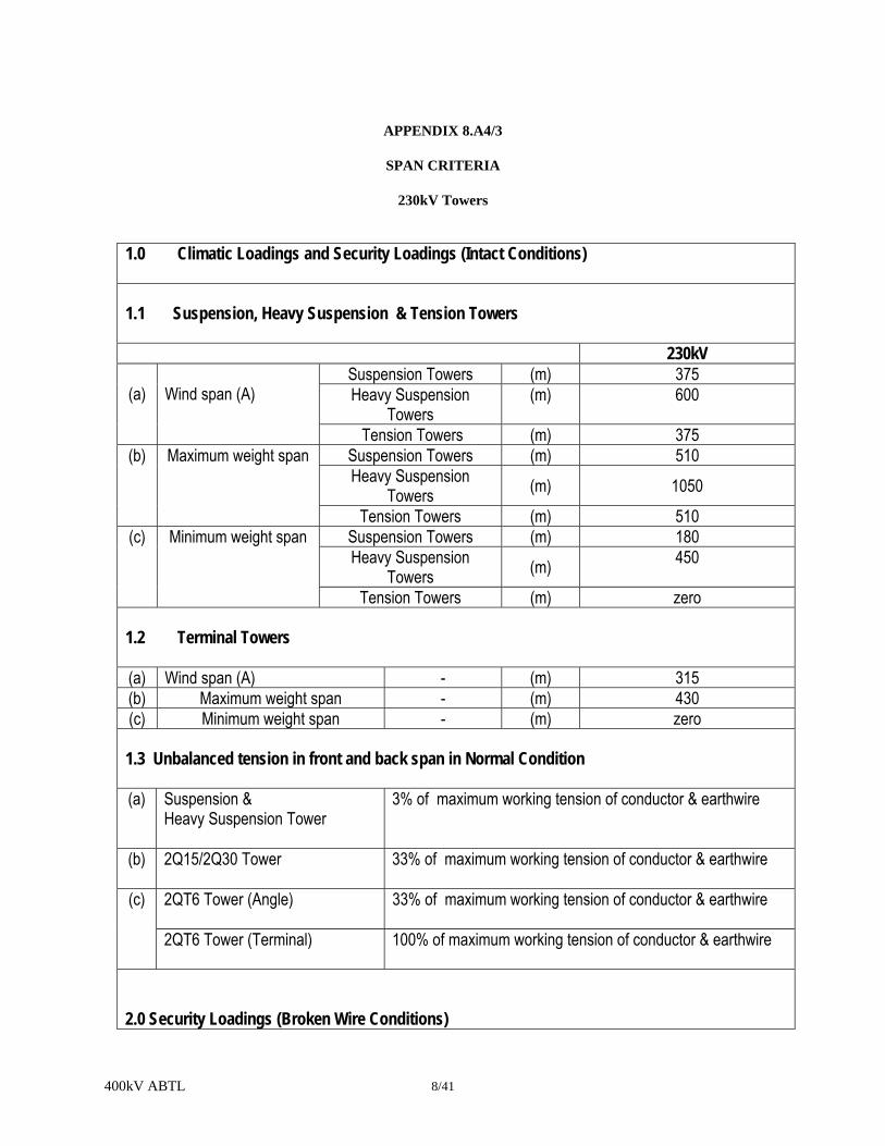
400kV ABTL 8/41
APPENDIX 8.A4/3
SPAN CRITERIA
230kV Towers
1.0 Climatic Loadings and Security Loadings (Intact Conditions) 1.1 Suspension, Heavy Suspension & Tension Towers 230kV
(a)
Wind span (A)
Suspension Towers (m) 375 Heavy Suspension
Towers (m) 600
Tension Towers (m) 375 (b) Maximum weight span Suspension Towers (m) 510
Heavy Suspension Towers (m) 1050
Tension Towers (m) 510 (c) Minimum weight span Suspension Towers (m) 180
Heavy Suspension Towers (m) 450
Tension Towers (m) zero 1.2 Terminal Towers
(a) Wind span (A) - (m) 315 (b) Maximum weight span - (m) 430 (c) Minimum weight span - (m) zero 1.3 Unbalanced tension in front and back span in Normal Condition (a) Suspension &
Heavy Suspension Tower
3% of maximum working tension of conductor & earthwire
(b) 2Q15/2Q30 Tower 33% of maximum working tension of conductor & earthwire
(c) 2QT6 Tower (Angle) 33% of maximum working tension of conductor & earthwire
2QT6 Tower (Terminal)
100% of maximum working tension of conductor & earthwire
2.0 Security Loadings (Broken Wire Conditions)

400kV ABTL 8/42
2.1 Suspension & Tension Support (a) Wind span (A) Suspension Towers (m) 275
Heavy Suspension Towers (m) 450 Tension Towers (m) 275
(b) Maximum weight span Suspension Towers (m) 385 Heavy Suspension Towers (m) 385
Tension Towers (m) 385 (c) Minimum weight span Suspension Towers (m) 130
Heavy Suspension Towers (m) 130 Tension Towers (m) zero
2.2 Unbalanced Tension to be Considered (230kV only)
(a) Suspension Towers 0.6 x Max. working tension of Earthwire.
1.2 x Max. working tension of Conductor. (b) Heavy Suspension Towers 0.6 x Max. working tension of Earthwire.
1.2 x Max. working tension of Conductor. (c) Tension/Terminal Towers 1.0 x Max. working tension of Earthwire.
2.0 x Max. working tension of Conductor. 3.0 Security Loadings (Cascade Conditions) 3.1 2Q30 and 2QT6 Type Towers (a) Wind span (A) (m) zero (b) Maximum weight span Tension Towers (m) 570 3.2 Unbalanced Tension to be Considered (230kV only)
(a) Tension/Terminal Towers 100% of conductor and earthwire tensions under everyday
temperature and no wind 4.0 Broken Wire Assumption
4.1 Suspension & Heavy Suspension Tower
(a) Earthwire/OPGW is broken. However, earthwire/OPGW is not broken with conductor at the same
time
(b) Both the conductors of one phase are broken.
4.2
Tension Towers

400kV ABTL 8/43
(a) One earthwire and both the conductors of one phase of same side with the earthwire are broken.
(b) Two phases (including both conductors per phase) of the same side are broken. However 4.2(a) and 4.2(b) shall not occur at the same time.
APPENDIX 8.A5
ASSUMED SYSTEM LOADING CRITERIA
APPENDIX 8.A5.1
TOWER LOADING
400kV Overhead
400 kV towers shall be designed as per assumed system loading criteria specified in clause 8.2.4. The Contractor's attention is drawn to the requirements of Clause 8.2.5 with regard to Construction & Maintenance loading.
APPENDIX 8.A5.2
400kV River Crossing Anchor Tower
For non pointed crossarm loads to be distributed as follows:
Transverse Longitudinal Vertical
Angle/Tension tower Normal 50% - 50% 100% - 0% 50% - 50%
Security: Intact 50% - 50% 50% - 50%
Broken 75% - 25% 100% - 0% 75% - 25%
Terminal tower All cases 100% - 0% 100% - 0% 100% - 0%
Wind directions are as shown in the sketch:
APPENDIX 8.A5.3
Wind0o
30o
Wind
45o
Wind90o
Wind

400kV ABTL 8/44
DOWNLEAD TENSIONS Maximum phase downlead tension 7 kN Maximum earthwire downlead tension 4.5 kN Maximum slack span 100 m The above conditions apply under the specified MWT conditions as defined in Appendix 11.A3.

400kV ABTL 8/45
APPENDIX 8.A6
MINIMUM THICKNESS & DIAMETER OF MATERIAL The minimum thickness and diameter of material used in members and bolts shall be as detailed below: (a) For leg members and compression chords in gantries and cross arms. (mm) 6
(b) For other members (including earthwire peaks) carrying calculated stress. (mm) 5 (c) For secondary members without calculated stress. (mm) 4 (d) Gusset plates for lattice towers. (mm) 6 (e) Bolt diameter for members (mm) 16 & 24
APPENDIX 8.A7

400kV ABTL 8/46
1. ELECTRICAL CLEARANCES - LIVE METAL & EARTHED STEELWORK
400 kV (a) Minimum clearance between a conductor and tower for suspension
sets deflected between 0° and 10° from the vertical.
(mm) 3100
(b) Minimum clearance between a conductor and tower for suspension sets deflected between 30° from the vertical.
(mm) 2800
(c) Minimum clearance between a conductor and tower for suspension sets deflected between 50° from the vertical.
(mm) 1830
(d) Minimum clearance between a conductor and tower for jumper sets deflected between 0° from the vertical.
(mm) 3100
(e) Minimum clearance between a conductor and tower for jumper sets deflected between 15° from the vertical.
(mm) 2800
(f) Minimum clearance between a conductor and tower for jumper sets deflected between 45° from the vertical.
(mm) 1830
2. SPATIAL DISTANCES
(a) Minimum height of phase conductors from ground level
(m) 11
(b) Minimum shielding angle of the earthwire (still air) from the vertical
(degrees) 0°
(c) Maximum swing of the Earthwire from vertical
(degrees) 85°
(d) Minimum vertical spacing between adjacent phases
(m) 5.5
(e) Minimum mid span clearance between phase conductors and earthwire
(m) 8
3. DOWNLEAD CLEARANCES
The minimum clearance in still air at the assumed maximum conductor temperature between adjacent downleads shall not be less than. (m) 5.5

400kV ABTL 8/47
APPENDIX 8.A8
APPENDIX 8.A8.1
OVERLAND SECTION
1. ANTI-CLIMBING DEVICES (ACD) Required / Not Required
(a) Barbed wire type at a minimum height
above ground level …………………….. (m) Not required
(b) Spiked type at a minimum height above ground level ……………………………..(m) 3.0
(c) Ladder to be fitted with spike type Not required ACD with a lockable gate at a
minimum height above ground level….. (m)
(d) Bolt Locking All bolts below the bottom crossarm level shall be locked by lockingnuts (antitheft)
2. ACCESS FACILITIES
(a) Step bolts fitted between Ground level & within 1m of top of towers (b) Ladders fitted between (or provision for) Not required (c) Rest platforms Not required
(d) Work platforms Tension tower at all Crossarm level
(e) Fall arrest system Not required. 3. DANGER & IDENTIFICATION PLATES (a) Danger Palate Required (b) Tower Number, Circuit Identification & Required Phase Color Plate.
APPENDIX 8.A8.2

400kV ABTL 8/48
Not used.
APPENDIX 8.A9
QUALITY CONTROL WELD INSPECTION LEVELS Level 1: All welded items not covered by higher level of inspection Level 2: Level 3: Conductor attachment fittings for all types of tower.
APPENDIX 8.A.10
TOWER TEST REQUIREMENTS Proto Type Load Test: The following tower types shall require full scale prototype tower load tests in accordance with IEC 60652 in compliance with Sub-clause 8.7.7.1: 4DL E 9.0 4D1 E9.0 4D25 E9.0 4D45 E9.0 4DT60 E 9.0 Proto Assembly: All towers (230kV & 400kV) with all extensions shall require proto assembly tests to be performed in the manufacturer’s premises before starting the batch manufacturing of towers. All costs related to such tests shall deem to be included in the Contract Price. Visual Check, Galvanizing test and Mechanical Test of Members/Nuts & Bolts/Plates: Before mass (batch) fabrication/manufacturing of tower materials the Contractor shall submit the proto assembly test report of towers for acceptance of the Employer. The Contractor shall precede mass fabrication of towers after acceptance of the said test report by the Employer. After mass fabrication, tower members shall visually check for dimension and galvanizing thickness (which shall include weight basis test also). Mechanical tests shall also be done on the finished tower materials. All costs related to such tests shall deem to be included in the Contract Price.

400kV ABTL 8/49
APPENDIX 8.B.1
ENGINEERING DOCUMENTS TO BE SUBMITTED BY CONTRACTOR
Clause Reference Document Description Comment
8.2.22 8.2.23 8.6.1 8.7.1 8.7.1 8.7.2 8.7.2 8.7.2 8.7.2 8.7.2 8.7.5 8.7.5 8.7.5 8.7.7 8.7.7 8.7.8 8.7.9
Design Calculation Fabrication Drawings Method Statement Material Test Certificates Bolt & Nut Test Certificates Welding procedures Welders test certificates If requested NDT procedures NDT Inspection reports NDT Inspection reports If requested Galvanising test records If requested Ingot zinc certificates Pot melt analysis Prototype tower test programme Prototype test reports Certificate of conformity Tower Erection records
If requested If requested If requested If requested If requested If requested If requested
APPENDIX 8.C.1 NOTIFICATION AND HOLD POINTS
Clause
Reference Notification Points Hold Points
8.2.22 8.2.23 8.4.3 8.4.4 8.4.6 8.6.1 8.6.5 8.7.2 8.7.2 8.7.2
Design Calculation Fabrication Drawings Misplaces Holes Formation of Bends Erection Marks Method Statement Damaged Galvanizing Welding procedure NDT organisation NDT procedure

400kV ABTL 8/50
APPENDIX 8.D.1
REFERENCE STANDARDS
The reference standards and other documents referred to in this specification are listed below:
IEC 652: Loading Tests on Overhead Line Towers BS 4: Structural Steel Sections Part 1: Specification for hot rolled sections BS 183: Specification for general purpose galvanised steel wire strand BS 443: Specification for testing zinc coatings on steel wire and for quality requirements. BS 464: Specification for thimbles for wire ropes. BS 729: Specification for hot-dipped galvanising coating, on iron and steel article. BS 970: Specification for wrought steel for mechanical and allied engineering purposes. Part 1: General inspection and testing procedures and specific requirements for carbon,
carbon manganese, alloy and stainless steel. BS 1474: Specification for wrought aluminium and aluminium alloys for general engineering
purposes bars, extruded round tubes and sections. BS 1574: Specification for split cotter pins. BS 2789: Specification for spheroidal graphite or nodular graphite cast iron. BS 3643: ISO Metric threads. Part 2: Limits and tolerances for course pitch screw threads. BS 3923: Method of ultrasonic examination of welds. Part 1: Method of manual examination of fusion welds in ferric steel. BS 4102: Steel wire and wire products for fences. BS 4190: Specification for ISO metric hexagon bolts, screws and nuts. BS 4211 Ladders for permanent access to chimneys, other high structures, silos and bins. BS 4320: Specification for metal washer for general engineering purposes. Metric series.
BS 4464: Specification for spring, washers for general engineering and automobile. BS 4592: Industrial type metal flooring, walkways and stair treads. BS 4848: Hot rolled structural steel sections. Part 2: Specification for hot-finished hollow sections. Part 4: Equal and unequal angles. BS 5135: Specification for arc welding of carbon and carbon manganese steels BS 5289: Code of practice. Visual inspection of fusion welded joints. BS 5531 Code of practice. For safety in erecting structural frames. BS 5950: Structural use of steelwork in buildings.
BS 5996: Methods of ultrasonic testing and specifying, quality grades of ferric steel plates. BS 6072: Methods for magnetic particle flow detection. BS 6681: Specification for malleable cast iron. BS EN 287: Approval testing of welders for fusion welding. BS EN 288: Specification and approval of welding procedures for metallic materials. BS EN 353: Personal protective equipment against falls from heights guided type fall arresters.
BS EN 353-1: Specification for guided type fall arresters on a rigid anchorage line.

400kV ABTL 8/51
BS EN 353-2: Specification for guided type fall arresters on a flexible anchorage line. BS EN 360: Personal protective equipment against falls from a height. Retractable type fall
arrestors. BS EN 1179: Specification for Zinc & Zinc Alloys. BS EN 10024: Hot rolled taper flange I-sections. Tolerance on shape and dimensions. BS EN 10025: Specification for hot rolled products of non-alloyed structural steels a their technical delivery requirements. BS EN 10029: Tolerance on dimensions, shape and mass of hot rolled steel plat 3 mm thick or above. BS EN 10034: Structural steel I and H sections. Tolerance on shape and dimensions. BS EN 10056: Specification for structural steel equal and unequal angles Part 2 Tolerance on shape and dimension BS EN 10163: Delivery requirements for surface conditions of hot rolled steel plates, wide flats and
sections. Part 1 General requirements Part 2: Plates and wide flats Part 3: Sections BS EN 10210-1: Hot finished structural hollow sections of non-alloy and fine grained structural steels- Technical delivery requirements BS DD 133 Code of Practice for strength assessment of members of lattice towers masts. ANSI/ASCE Std 10-97 Design of Steel Transmission Towers.
APPENDIX 8.E1/1
ULTIMATE TOWER REACTIONS 230 kV Double Circuit Towers

400kV ABTL 8/52
(Narrow Base Width) (Excluding Foundation Strength Factor)
Tower Type Down Thrust
(Along Leg Direction)
Uplift (Along Leg Direction)
Horizontal Component Hx
(Transverse) Hz
(Longitudinal) kN kN kN kN
2DT6 (Terminal) 7332 6553 1236 1179
FOUNDATION STRENGTH FACTOR 230kV Double Circuit Towers
The following strength factors shall be used to increase the ultimate tower reactions on the foundations for the design of the foundations:
Applied Loading Case Strength Factor
Tower Type
All load cases 2DL 2D1, 2D25, 2DT6 1.23 1.35
ULTIMATE TOWER REACTIONS 230 kV Four Circuit Towers
(Excluding Foundation Strength Factor)
Tower Type Down Uplift Horizontal Component

400kV ABTL 8/53
Thrust(Along Leg Direction)
(Along Leg Direction)
Hx (Transverse)
Hz (Longitudinal)
kg Kg kg kg 2QL 315602 285770 44184 39766 2Q1 499498 443000 79920 71928 2Q15 694320 648407 124978 112480 2Q30 743235 693450 148647 136755 2QT6 925312 870000 203568 187282
FOUNDATION STRENGTH FACTOR 230kV Four Circuit
The following strength factors shall be used to increase the ultimate tower reactions on the foundations for the design of the foundations:
Applied Loading Case
Strength Factor
Tower Type
2QL, 2Q1 2Q15, 2Q30, 2QT6
Normal Condition, High Intensity Local wind condition 1.33 1.60
Security Condition 1.60 1.90

POWER GRID COMPANY OF BANGLADESH LIMITED
BIDDING DOCUMENT
FOR THE PROCUREMENT OF
DESIGN, SUPPLY, ERECTION, TESTING & COMMISSIONING OF ASHUGANJ-BHULTA 400KV TRANSMISSION LINE AND BHULTA
400/230KV SUBSTATION ON TURNKEY BASIS
LOT-1: TRANSMISSION LINES
SECTION 9
INSULATOR

9/1
SECTION 9
INSULATORS
9.1 SCOPE Both the type of insulator unit and insulator set, whether suspension or tension used on each type of support shall be approved, and shall have proven use under similar environmental and operational conditions. Insulator strings shall comprise of porcelain disc insulator units. All types of insulators to be supplied under this Contract shall be supplied from the same manufacturer. Reference shall be made to Appendix 9.A1 for details of the specific requirements. Where specified porcelain insulators shall be glazed Munsell Brown or Grey in accordance with ANSI Z55.1.
9.2 DESIGN 9.2.1 General All insulator units shall be designed to withstand the design service voltages including lightning, switching and power frequency, the mechanical loads relevant to the installation-service-maintenance conditions, the service temperature and environmental effects. Internal stresses due to expansion and contraction of any part of the insulator unit shall not lead to deterioration. The design of insulator units shall be such as to avoid local corona formation and no significant radio interferences shall be exhibited. Insulator units shall comply with the general requirements of the following applicable standards, except where specified otherwise in this Specification:
Insulator Type Applicable Standard
Cap and Pin IEC 60305 Insulator units shall have straight head design to avoid concentration of mechanical stress. Cross-section sketch of insulators unit showing the head design is included in the enclosed drawing in drawing section. 9.2.2 Electrical and Mechanical Characteristics The individual insulator units and the complete insulator sets shall have the electrical and mechanical characteristics stated in Appendix 9.A2. 9.2.3 Couplings Couplings between individual insulator units shall be as specified in Appendix 9.A1.Ball and socket couplings shall be in accordance with the requirements of IEC 60120. Sockets shall have a split pin (R) clip in accordance with the requirements of IEC 60372 as specified.

9/2
9.2.4 Pollution The design of insulator units shall take into account the principles contained in IEC 60815 for the specified pollution category. However, minimum creepage values (mm/kV) shall be as specified. 9.2.5 Zinc Sleeve Cap and pin insulator units shall where specified be fitted with zinc sleeve pins to prevent cracking due to pin corrosion caused by the effects of pollution and high humidity. The exposed part of the sleeve shall have a mass of at least 5(five) gram and metallurgic ally bonded to the insulator pin. The bonded area of sleeve shall be a minimum of 80% the sleeve/pin interfacial area in accordance with IEC 61325. 9.2.6 Insulator Protective Device The design of insulator protective fittings including corona shields shall comply with the following requirements:
(a) shall effectively protect the insulator units, and the fittings from damage caused by power arcs; (b) shall effectively improve the voltage distribution along the insulator string; (c) shall effectively improve the corona performance of the insulator set; (d) shall be designed in such a way as not to be subject to breakage fatigue due to wind induced
vibration; (e) shall withstand a specified mechanical load. (f) shall be suitable where specified for live-line maintenance.
For details of the materials, workmanship and quality control requirements for insulator protective fittings reference shall be made to Section 10.0 of this Specification. 9.2.7 Low Duty Insulator Sets Low duty tension sets shall be used for the downleads between terminal supports and substation gantry structures or other positions where the conductor tensions are of a reduced value. At the lower end of the downleads the low duty tension sets shall be capable of having their units reversed. 9.2.8 Tension Insulator Sets-Earth End Linkages Additional earth end adjustable linkages shall be provided where necessary to ensure that either the specified clearance is maintained between the tension insulator set and the support body/crossarm, or that satisfactory pairing is achieved between the phase sub-conductors. 9.3 MATERIALS High grade, wet process porcelain used in the manufacturer of insulator units shall comply with the requirement of IEC 60672.
Insulator caps and bases of malleable cast iron shall be manufactured from a suitable grade of MCI complying with the requirement of BS EN 1563 for spheroidal graphite, or BS EN 1562 for whiteheart and

9/3
paralytic.
Insulator end fittings of forced or cast aluminium alloy shall be manufactured from a suitable grade of aluminium alloy complying with the requirements of BS EN 515, 573, 586, 603, 604 or BS EN 1559, 1676, 1706 and/or BS EN 1676 or equivalent respectively.
Security 'W' clips shall be of phosphor-bronze composition in accordance with the requirements of BS EN 1172, 1652, 1653, 1654 or equivalent and supplied in the half-hard condition with a minimum harness of 155 VPN.
Security 'R' clips shall be of austenitic stainless steel capable of complying with the requirements of relating to inter-crystalline corrosion tests of BS 970: Part 1 and BS EN 10084, 10085, 10087, 10095, 10250 and PD 970.
Zinc sleeve shall have a total impurity not greater than 0.2 percent and shall comply with the requirement of BS EN 1179 or IEC 61325 or equivalent.
9.4 WORKMANSHIP 9.4.1 Insulator Units The dimensions of all insulator units, together with materials and grades and other pertinent information shall be shown on the contract drawings. Contract drawings shall be submitted to the Engineer. This is a Hold Point. Particular regard shall be paid to those dimensions which involve interchangeability, correct assembly and those for which gauges are specified. Where appropriate insulator caps and pins shall comply with the requirement of IEC 60120, IEC 60372 and IEC 60471. Porcelain shall be sound, thoroughly vitrified and free from defects and blemishes which might adversely affect the life of the insulator units. Portland cement used in the construction of an insulator unit shall not fracture by virtue of expansion, nor loosen by contraction and proper care shall be taken to locate the individual parts correctly during assembly. The cement shall not give rise to chemical reaction with metal fittings nor the zinc collars. The cement thickness shall be as uniform as possible. All insulator caps and bases are to be free from flaws, blowholes and shall be of a close-grained quality. Insulator pins shall be round, free from cracks, surface flaws, lamination and other defects. The zinc sleeve shall not be porous and all mould lines shall be removed. The cement level shall be approximately at the mid-point of the sleeve. 9.4.2 Identification and Marking

9/4
All insulator units shall be marked to ensure a system of traceability. Each unit shall be clearly and indelibly marked as follows on the insulating component according to the requirements of IEC 60383-1: (a) Electromechanical failing load (b) Name or trade mark of the manufacturer (c) Year of manufacture. 9.4.3 Installation Criteria The manufacturer shall where necessary provide comprehensive instructions in a suitable format regarding, the handling, and installation of insulator units. 9.4.4 Erection The Contractor shall provide the Engineer with a method statement giving sequential details of the proposed erection method. The method statement shall be submitted to the Engineer, the requisite period before insulator set erection commences. This is a Hold Point. Care shall be exercised in the handling and erection of insulator units to prevent scratches, chipping or cracking of the insulation medium. The Engineer shall be reasonable entitled to request the removal and destruction of any insulator units from a string which they notice has been severely handled or knocked during erection. All units which are scratched, chipped or abraded shall be removed and replaced. Insulator units and fittings shall be laid on plastic sheets prior to erection and any foreign matter shall be removed prior to installation. The Contractor shall ensure that insulator units are not strained or damaged in any way during, erection.
All bolt threads shall be coated with approved grease immediately before erection.
9.5 PROTECTIVE TREATMENT
All insulator caps, bases and pins shall either be inherently resistant to atmospheric corrosion or suitably protected against corrosion, such as may occur in transit, storage and in service. All ferrous parts which will be exposed to the atmosphere in service, except those made in the appropriate grade of stainless steel, shall be protected by hot dipped galvanising to comply with the requirements of ISO 1461. All manufacturing processes shall be completed prior to galvanising. The ingot zinc used for galvanising shall comply with the requirements of BS EN 1179 or equivalent.
All galvanised materials shall be stored on packing, clear off the ground and away from all materials that might stain or corrode the galvanising. Black steel packing or bins shall not be used.
9.6 QUALITY CONTROL

9/5
9.6.1 General
Type, sample and routine tests shall be undertaken on all insulator units and type tests on insulator sets in accordance with the requirements of this Specification. Details of the test requirements are summarized in Table 9.1.
Acceptance criteria for Thermal Mechanical Performance Test and Electromechanical Failing (EMF) load test shall be governed by the following, formula, irrespective of sample size:
3< C = X- SFL
where C = Acceptance Constant
X = Mean value of failing load
SFL = Specified EMF load
= Standard deviation
Test result of each sample shall not be less than the specified EMF load. The results (mean value and standard deviation) of Thermal-Mechanical Performance Test shall not differ from the results of the ordinary Electro-Mechanical Failing Load Tests.
In addition electrical puncture shall not occur before ultimate fracture. Contract drawings previously submitted to the Engineers shall be available at the time of testing. The Contractor shall give the Engineer the requisite period of notice prior to undertaking the tests, and shall submit to the Engineer a test programme and procedures. This is a Hold Point. Regarding the type test of insulator string, if the proposed insulator and fittings combination does not match with the insulator and fittings included in the test reports submitted in bid proposal then the Contractor shall conduct the type tests of insulator string sets at their own laboratory/independent laboratory during execution of Contract at the witness of Employer’s Engineers. All costs of such type test tests and witness shall deem to be included in the Contract Price. 9.6.2 Type Tests - String Insulator Units Type test for string, (cap and pin) insulator units shall be in accordance with all the requirements of IEC 60383-1. Methods of tests shall comply with the requirements of the above standard, unless otherwise specified in the following clauses.

9/6
9.6.3 Type Tests - Insulator Sets Type tests for insulator sets comprising cap and pin, insulator units complete with all appropriate fittings including insulator protective fittings shall be undertaken in accordance with the requirements of IEC 60383-2, to determine the dry lightning impulse withstand voltage, wet switching impulse withstand voltage and the power frequency withstand voltage as appropriate. The manufacture shall submit details of the proposed simulation of the support structure and mounting arrangement of the insulator sets to the Engineer. This is a Hold Point. 9.6.4 Type Tests - Radio Interference & Corona
Radio interference type tests shall be under-taken both on single insulator units followed by a complete insulator set test. All radio noise measurements shall be made at a frequency of 1.0 MHZ (9 kHz band width), using a radio interference measuring set having a response conforming to CISPR Publication 1. The test circuit shall conform to IEC 60437 and shall be calibrated in-situ to determine any circuit losses. The set shall be adjusted to indicate correctly, or alternatively an appropriate correction (in dB) shall be added to the measurement. Ideally the measurement shall be made using a 300 ohm load resistance. All readings shall be converted to dB above 1μV across 300 ohms, taking into account any corrections necessary.
The single unit test voltage shall be that which would appear across the live end unit in the complete set test and shall be determined by an initial voltage distribution measurement.
Before final readings of the radio noise are taken it is permissible to wipe the unit with a dry clean cloth, and to condition it at not more than 50% above the test voltage for upto 2 minutes. This may be repeated if the first measurement exceeds the first level.
The maximum permitted radio noise levels per insulator unit shall not exceed the values stated in Appendix 9.A2.
The number of units tested shall be either 1.5 times the number of units in a complete string or six units whichever is the greater. The choice of set make up to be tested shall be that likely to give the highest voltage across the live end unit with the shortest arc gap. Three pairs of units shall be selected from those previously tested as single units (the noisiest units).
Each pair shall comprise the live end and penultimate live end unit of a single string or the pair of live end units for a duplex string, each pair shall be tested in turn in the set.
The radio noise test voltage and limits shall be in accordance with IEC 60437. None of the tests shall give rise to radio noise levels exceeding the specified limits. Each set shall also be tested for visible corona extinction. Light shall be excluded from the laboratory and the observer's eyesight allowed time to become

9/7
accustomed to the dark. The voltage shall be increased until corona appears on the string. The voltage shall be gradually reduced until all discharges on the string are extinguished. The extinction voltage shall be measured, and shall be minimum 0.8 times the nominal system voltage plus 5%. All appropriate action shall be taken to eliminate discharges from test equipment, thereby avoiding spurious corona observations and radio inference readings.
9.6.5 Type Tests - Pollution Artificial pollution tests (salt fog method) in accordance with the requirements of IEC 60507 shall be undertaken. The salinity of the salt solution and the power frequency withstand voltage shall be in accordance with Appendix 9.A3. 9.6.6 Type Test - Power Arc Tests (a) Power Arc Test for complete Insulator Set. Power arc tests to simulate the effect of short circuit current shall be undertaken on the complete insulator set if requested by the Engineer. The power arc current shall be in accordance with Appendix 9.A2. The function of the insulator protective devices shall not be greatly affected by the power arc. (b) Power Arc Test for Insulator Unit Power arc test shall also be performed to prove the ability of the insulator units to withstand the heat generated by power arc. This test shall be performed in the following manner. Nine (9) insulator units of each type shall be chosen for the power arc test. Tests shall be conducted on the above chosen insulator units in three (3) strings of three (3) insulator units each. Strings shall be mounted vertically without arcing horns or conductors. The current and duration of power arc shall be 12kA (symmetrical r.m.s) and 0.1 sec or 6kA (symmetrical r.m.s) and 0.2 sec. No shed breakage shall occur during the power arc test. Peeling-off or burn out of glaze on the insulator surface and partial rib chip shall be permitted. If two or more insulator units string break in the power arc test, this insulator design is considered to have failed to meet the specifications. In case one insulator unit fails in the test, re-test on another nine (9) insulator units shall be conducted in the same manner. Failure of anyone unit in the re-test means that the insulator design has failed to meet the specification. 9.6.7 Type Test - Impulse Voltage Puncture Tests Impulse voltage puncture tests shall be undertaken in accordance with the requirements of IEC 61211. 9.6.8 Type Test - Residual Strength Tests

9/8
Residual strength tests on string insulator units shall be undertaken in accordance with the recommendations of IEC 60797. With all the outer shed material removed, the insulator stubs shall be capable of withstanding 80% of the rated minimum failing load for 1 minute. The test shall be continued to destruction (where it is practicable) to obtain a representative value of the actual falling load, and allow the modes of failure to be determined.
The mean failing load X and the standard deviation s shall be calculated and the ratio
k = (X −1.645 s)/ Rating shall be deduced where k is the acceptance constant. The acceptance constant k should be greater than or equal to 0.65. 9.6.9 Sample Tests The Contractor shall, give the Engineer the requisite period of notice prior to undertaking Sample Tests. This is a Notification Point. Sample tests for string insulator (cap & pin), insulator units shall be undertaken in accordance with the requirements of IEC 60383-1, see also Appendix 9.1. Sample tests in respect of radio noise shall be undertaken in accordance with ANSI C 29.2-1992. Radio noise level shall be less than 50 ㎶ at applied voltage of 10kV on single units. The sample size shall generally be 0.5% of the batch offered for acceptance. Number of sample to check the metallurgical bond of the zinc sleeve to the pin shall be in accordance with IEC 61325. The metallurgical purity of the zinc shall be established by chemical analysis to ensure that any impurities do not sensitise the zinc to intergranular corrosion. The zinc sleeve of each sample tested for mechanical strength shall also be inspected according to IEC 61325, to ensure no radial and circumferential cracking has occurred. Three insulaters shall be selected at random from each lot of the order and their straight head design checked against the straight head design of the manufacturer’s cross-section drawing. 9.6.10 Routine Tests Routine tests for string insulator (cap and pin) units shall be undertaken in accordance with the requirements of IEC 60383-1 see also Appendix 9.1. 9.6.11 Galvanizing

9/9
Tests for galvanised insulator caps, bases and pins shall be carried out at the works to ensure compliance with the requirements of ISO 1461. Details of the test results shall be made available to the Engineer upon request. Certificates relating to the ingot zinc used for galvanising shall also be made available to the Engineer upon request. 9.6.12 Test Reports Type test reports shall be submitted as mentioned in relevant Schedule of Volume 1 of 3 of the bidding document.
All metallic materials used in the manufacture of insulator caps, bases and pins shall be covered by test certificates stating their mechanical, chemical and where specified the impact properties and clearly showing the cast numbers to prove compliance with the requirements of this Specification and BS EN 1563, BS EN 1562, BS 970 and BS EN 10084, BS EN 10085 etc., BS EN 515, 573, 586, 603, 606, BS EN 1559, 1676, 1707, BS EN 1172, 1652, 1653, 1654, BS EN 1179 as appropriate.
Test certificates for metallic materials and bolts shall be made available to the Engineer upon request. Test certificates covering Type and Sample tests shall be made available to the Engineer upon request. 9.6.13 Certificate of Conformity When requested copies of the following certificates/records shall also be forwarded: (a) Routine test records (b) Metallic material test certificates (c) Galvanizing test records (d) Ingot zinc certificates (e) Metallurgical purity test records for zinc sleeve. 9.6.14 Installation The Contractor shall be responsible for checking that all insulator sets are complete and that all bolts, split pins and security clips have been correctly installed. A record of this work shall be kept by the Contractor and made available to the Engineer upon request.

9/10
TABLE 9.1 - TEST REQUIREMENTS
Test
String Insulator Units
Cap & Pin (Type B)
Insulator Sets
Type Tests:
Verification of dimensions
X X
Dry lightning, impulse w. voltage
X X
Wet power frequency w. voltage
X X
Thermal mechanical performance
X
Mechanical or EMF load
X
Radio Interference Voltage (RIV)
X X
Corona Performance Test
X X(a)
Power arc
X X
Impulse voltage puncture
X -
Zinc sleeve
X -
Residual strength
X -

9/11
Test
String Insulator Units
Cap & Pin (Type B)
Insulator Sets
Sample Tests:
-
Verification of dimensions
X -
Verification of locking system and displacement
X -
Temperature cycle test
X -
Mechanical or EMF load X -
Porosity test
X
-
Galvanizing test
X -
RIV test
X X
Impulse Voltage puncture test
X -
Zinc sleeve test
X -
Head design test
X
Routine Tests:
Visual inspection
X
Mechanical
X
Electrical
X
Notes: (a) Insulator string without fittings
APPENDIX 9.A1

9/12
INSULATOR TYPES & USES
Insulator Set Type Suspension/
Jumper Suspension
Heavy Suspension
Tension Low Duty
Nominal System Voltage
{…………………………..400 kV & 230kV…………………………….}
String Configuration
Single Double Double Single
Insulator Unit type
{....…………………….Cap & Pin………………..................}
Coupling Type
{………………………Ball & Socket………….....................}
Security Clip type
{……………………………….R…………............................}
Zinc Sleeve
{………………………….Required………..........................}
Head Design {……………………..…Straight Head……………………..}
Glaze Color {…………………………Brown & Grey……………………..}

9/13
APPENDIX 9.A2
APPENDIX 9.A2/1
ELECTRICAL & MECHANICAL CHARACTERISTICS
400kV Line (Overland Portion)
Parameter
Insulator Set Type
Suspension/ Jumper Suspension
Heavy Suspension
Tension/ Transposition
Upright Low Duty
Inverted Low Duty
Pollution Category {…………................….Medium……................…………} Nominal Creepage mm {…………..............…….8400….……..............…………} Insulator type {…….....………Cap & Pin type disc insulators…………} Insulator Unit Reference U160BL U160BL U210B U210B U210B Glaze colour Brown Brown Grey Grey Grey Unit Power Frequency Puncture Voltage
kV 110 110 125 125 125
Number of Insulator Units per string
23 2x23 2x23 23 23.
Dielectric material {………..............…………Porcelain….......……………..} Max. Insulator String length mm 3910 3910 3910 3910 3910 Dry Lighting Impulse Withstand voltage of Insulator String
kV {…………...........……… 1425 ………….................……..}
Standard switching impulse Withstand voltage of Insulator String
kV {……................…....…....950…...................……………}
Power Arc for insulator set -Current -Duration Power arc for string insulator units : Current for duration kA for s
kA s
{……..................……... 31.5 .......................……………} {………............….…….. 0.5 …...............………………}
SP {…......................… 12 for 0.1 or 6 for 0.2 ..........…….}
Arc Gap Nominal mm 3050 3050 3050 3050 3050 RIV level per unit δB {………….........………. 37 ..................………………} RIV level per set δB {………….........……….. 50 …..........….………………} Mechanical/ Electromechanical Failing load of Insulator String
kN 160 320 420 210 210

9/14
APPENDIX 9.A2/2
ELECTRICAL & MECHANICAL CHARACTERISTICS
400kV Line (River Crossing Portion)
Parameter
Insulator Set Type
Suspension (Twin) Tension (Twin)
Pollution Category {…………..............….Medium ……...............…………} Nominal Creepage mm {…………..............…….….……..............…………} Insulator type {……......………Cap & Pin type disc insulators…………} Insulator Unit Reference U300B U400B Glaze colour Brown Grey Power Frequency Puncture Voltage of Insulator Unit
kV 140 140
Number of Insulator Units per string
2 x 20
2 x 17
Dielectric material {………..............…………Porcelain….......……………..} Max. Insulator String length without fittings
mm 3900 3485
Nominal Arching Horn Gap mm 2700 Power Frequency Flashover Voltage (Dry/Wet) of Insulator Unit
kV 90/53 95/53
Lightning Impulse Flashover Voltage (Positive/Negative) of Insulator Unit
kV 140/145 140/150
Power Arc for insulator set -Current -Duration Power arc for string insulator units : Current for duration kA for s
kA s
{……..................……... 31.5 .......................……………} {………............….…….. 0.5 …...............………………}
{…......................… 12 for 0.1 or 6 for 0.2 ..........…….} RIV level per unit δB {………….........………. 50 ..................………………} RIV level per set δB {………….........……….. 36 …..........….………………} Minimum Creepage Distance of Insulator Unit
mm 390 525
Mechanical/ Electromechanical Failing load
kN 2 x 300 2 x 400

9/15
APPENDIX 9.A2/3
ELECTRICAL & MECHANICAL CHARACTERISTICS
230kV LINE
Parameter
Insulator Set Type
Suspension/ Jumper Suspension
Heavy Suspension
Tension (Twin)
Upright Low Duty
Inverted Low Duty
Pollution Category {…………..............….Medium ……...............…………} Nominal Creepage mm {…………..............…….4900….……..............…………} Insulator type {……......………Cap & Pin type disc insulators…………} Insulator Unit Reference U120B U210B U210B U120B U120B Glaze colour Grey Brown Brown Grey Grey Unit Puncture Voltage kV 110 125 125 110 110 Number of Insulator Units per string
17 14 2 x 14 17 17
Dielectric material {………..............…………Porcelain….......……………..} Max. Insulator String length without fittings
mm 17x146 14x170 14x170 17x146 17x146
Dry Lightning Impulse Withstand voltage
kV {…………...........……… 1050 ………….................……..}
Wet power frequency Withstand voltage
kV {……................…....….... 460 …...................……………}
Power Arc for insulator set -Current -Duration Power arc for string insulator units : Current for duration kA for s
kA s
{……..................……... 31.5 .......................……………} {………............….…….. 0.5 …...............………………}
{…......................… 12 for 0.1 or 6 for 0.2 ..........…….} Arc Gap Nominal mm 2100 2100 2100 1910 1910 RIV level per unit δB {………….........………. 50 ..................………………} RIV level per set δB {………….........……….. 36 …..........….………………} Mechanical/ Electromechanical Failing load
kN 120 210 2 x 210 120 120

9/16
APPENDIX 9.A3
TYPE TEST - POLLUTION IEC 60507
Salt Solution Salinity Not Required
APPENDIX 9.B1
ENGINEERING DOCUMENTS TO BE SUBMITTED BY CONTRACTOR
Clause Reference
Document Description Comment
9.4.1 9.4.3 9.4.4 9.6.1 9.6.1 9.6.1 9.6.4 9.6.11 9.6.11 9.6.12 9.6.12 9.6.12 9.6.12 9.6.13 9.6.14
Insulator Units - Contract Drawings Installation procedures Contract Drawings Insulator units - Type test certificates Insulator sets - Type test certificates Type test - Programme & Procedure Details of support simulations Galvanising, test results Ingot zinc certificates Material test certificates Insulator units - Type test results Insulator units - sample test results Insulator units - Routine test Rresults Certificates of Conformity Installation records
Where necessary If tests waived If tests waived If requested If requested If requested If requested If requested

9/17
APPENDIX 9.C1
NOTIFICATION AND HOLD POINTS
Clause Reference
Notification Points
Hold Points
9.4.1
Contract Drawings
9.4.4
Method Statement
9.6.1
Insulators - Type tests
9.6.4
Type tests - Support Simulation details
9.6.8 Insulator - Sample Tests

9/18
APPENDIX 9.D1
REFERENCE STANDARDS
The reference standards and other documents referred to in this Section of i Specification are listed below:
IEC 60120: Dimensions of ball and socket couplings of string, insulator units. IEC 60305: Characteristics of string, insulator units of cap and pin type. IEC 60372: Locking devices for ball and socket coupling of string insulator units -
Dimensions and tests. IEC 60383: Insulators for overhead lines with a nominal voltage above 1000V Part 1: Ceramic or glass insulator units for ac systems Definitions, test methods and
acceptance criteria. Part 2: Insulator string and insulator sets for ac - Definitions, test method and acceptance
criteria. IEC 60437: Radio interference tests on high voltage insulators. IEC 60471: Dimensions of clevis and tongue couplings of string insulator units. IEC 60507: Artificial pollution tests on high-voltage insulators to be used on AC Systems. IEC 60672: Specification for ceramic and glass insulating materials. IEC 60797: Residual strength of string, insulator units of glass or ceramic, materials for
overhead lines after mechanical damage of the dielectric. IEC 60815: Guide for selection of insulators in respect of polluted conditions. IEC 61211: Insulators of ceramic material or glass for overhead lines with a nominal voltage
greater than 1000V - Puncture testing, BS 729: Specification for hot-dipped galvanizing coating on iron and steel articles. BS 970: Specification for wrought steel for mechanical and applied Engineering purposes. Part 1: General inspection and test procedures and specific requirements for carbon,
carbon manganese, alloy and stainless steel. BS 1472: Specification for wrought aluminium and aluminium alloy. BS 1490: Specification for Aluminium and aluminium alloy ingots and casting for general
engineering purposes. BS 2870: Specification for Rolled Copper and Copper Alloys: Sheet, strip and foil. BS 2789: Spheroidal graphite cast iron. BS 4190: Specification for ISO metric hexagon bolts, screws and nuts. BS 5252: Framework for colour co-ordinations of buildings. BS 6681: Specification for malleable cast iron. BS EN 1179: Specification for Zinc & Zinc Alloys BS EN 1676: Aluminiurn & aluminium alloys - Alloyed ingots for re-melting. CISPR: Publication 1 Specification for CISPR radio interference measuring apparatus for the
frequency range 0.15 to 30 MHZ.

POWER GRID COMPANY OF BANGLADESH LIMITED
BIDDING DOCUMENT
FOR THE PROCUREMENT OF
DESIGN, SUPPLY, ERECTION, TESTING & COMMISSIONING OF ASHUGANJ-BHULTA 400KV TRANSMISSION LINE AND BHULTA
400/230KV SUBSTATION ON TURNKEY BASIS
LOT-1: TRANSMISSION LINES
SECTION 10
INSULATOR AND CONDUCTOR FITTINGS

400kV ABTL 10/1
SECTION 10
INSULATOR AND CONDUCTOR FITTINGS
10.1 SCOPE
10.1.1 Types and Uses
The type and arrangement of all insulator and earthwire sets inclusive of all insulator and earthwire set fittings, suspension clamps, conductor tension fittings and insulator protective devices shall be approved.
Reference shall be made to Appendix 10.A1, A2 and A3 for details of the specific requirements.
10.2 DESIGN
10.2.1 General
All insulator and conductor fittings shall be so designed so as to:
(a) avoid damaging the conductor under all service conditions;
(b) withstand the mechanical loads relevant to the installation-service-maintenance conditions, the
design service current including short circuit effects, the service temperature and environmental effects;
(c) be free from visible and audible corona discharge and radio interference at the voltage levels
specified, except those designed exclusively for use on earthwires;
(d) minimise the number of parts and the possibility of incorrect assembly and installation;
(e) ensure that individual components are secured against becoming loose in service, and all threaded fasteners shall be locked;
(f) Compression fittings after compression shall not permit relative movement between the individual
layers of the conductor.
(g) from material, which have sufficient strength, ductility and environmental resistance to withstand the static and dynamic loading.
Where appropriate insulator and conductor fittings shall be in accordance with the requirements of IEC 61284. Ball and socket coupling shall be in accordance with the requirements of IEC 60120. Socket fitting shall be designed for 'W' type security clips or 'R' type security pins in accordance with the requirements of IEC 60372 as appropriate, clevis tongue couplings shall be in accordance with the requirements of IEC 60471.
All factory formed helical fittings shall be preformed with a right hand lay and shall completely enclose the conductor except for small gaps required to ensure that all rods make good contact with the conductor over their entire length.

400kV ABTL 10/2
10.2.2 Live-Line Working
Where live-line working is specified in Appendix 10.A1 the design of the fittings shall take into account the following requirements:
(a) both suspension and tension insulator sets shall include either clevis fittings, or yoke plates
incorporating cut-outs correctly dimensioned suitable for live-line working;
(b) the minimum distance between the attachment point and the shoulder for clevis fittings shall not be less than 125 mm, where no yoke plate is adjacent;
(c) clevis and tongue and clevis-clevis connections shall be provided with 'R' type security pins;
(d) insulator protective devices attached to yoke plates shall utilize captive bolts.
10.2.3 Sag Adjusters
All tension insulator sets shall incorporate sag adjusters for adjusting the sag of either Individual phase conductors or sub-conductors forming a phase conductor bundle. The total range of linear adjustment and individual steps shall be as specified in Appendix 10.A1.
10.2.4 Insulator Protective Fittings:
The design of insulator protective fittings including arcing rings shall comply with the following requirements:
(a) shall effectively protect the insulator units, and the fittings from damage caused by power
arcs;
(b) shall effectively improve the voltage distribution along the insulator string;
(c) shall effectively improve the corona performance of the insulator set; (d) shall be designed in such a way as not to be subject to breakage fatigue due to wind induced
vibration;
(e) shall withstand a specified mechanical load.
For details of the materials, workmanship and quality control requirements for insulator protective fittings reference shall be made to Sub-clause 10.3, 10.4 & 10.6 of Section 10 of this Specification. The end of all arcing horns shall be formed into smooth hemispheres. The end of tubular arcing horns shall also be sealed. 10.2.5 Electrical and Mechanical Characteristics The insulator and earthwire set fittings, suspension clamps, conductor tension fittings and insulator protection devices shall have the electrical and mechanical characteristics specified in Appendix 10.A1,
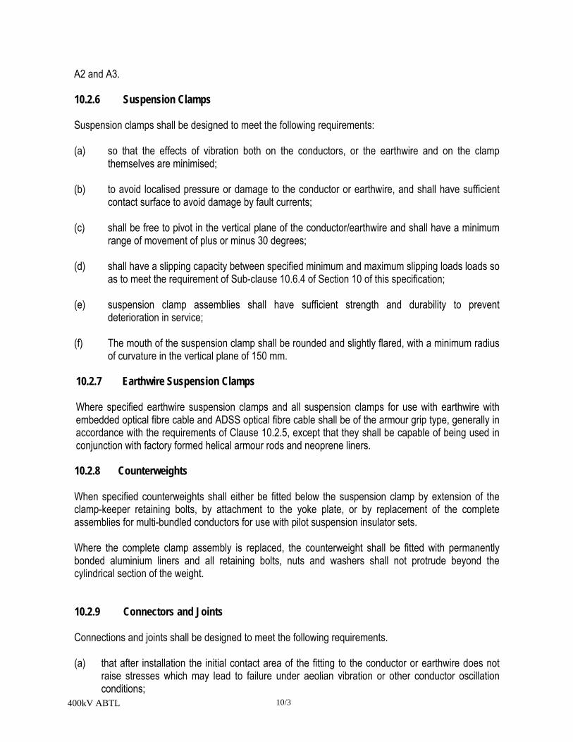
400kV ABTL 10/3
A2 and A3. 10.2.6 Suspension Clamps Suspension clamps shall be designed to meet the following requirements: (a) so that the effects of vibration both on the conductors, or the earthwire and on the clamp
themselves are minimised; (b) to avoid localised pressure or damage to the conductor or earthwire, and shall have sufficient
contact surface to avoid damage by fault currents; (c) shall be free to pivot in the vertical plane of the conductor/earthwire and shall have a minimum
range of movement of plus or minus 30 degrees; (d) shall have a slipping capacity between specified minimum and maximum slipping loads loads so
as to meet the requirement of Sub-clause 10.6.4 of Section 10 of this specification; (e) suspension clamp assemblies shall have sufficient strength and durability to prevent
deterioration in service; (f) The mouth of the suspension clamp shall be rounded and slightly flared, with a minimum radius
of curvature in the vertical plane of 150 mm. 10.2.7 Earthwire Suspension Clamps Where specified earthwire suspension clamps and all suspension clamps for use with earthwire with embedded optical fibre cable and ADSS optical fibre cable shall be of the armour grip type, generally in accordance with the requirements of Clause 10.2.5, except that they shall be capable of being used in conjunction with factory formed helical armour rods and neoprene liners.
10.2.8 Counterweights
When specified counterweights shall either be fitted below the suspension clamp by extension of the clamp-keeper retaining bolts, by attachment to the yoke plate, or by replacement of the complete assemblies for multi-bundled conductors for use with pilot suspension insulator sets.
Where the complete clamp assembly is replaced, the counterweight shall be fitted with permanently bonded aluminium liners and all retaining bolts, nuts and washers shall not protrude beyond the cylindrical section of the weight.
10.2.9 Connectors and Joints
Connections and joints shall be designed to meet the following requirements.
(a) that after installation the initial contact area of the fitting to the conductor or earthwire does not raise stresses which may lead to failure under aeolian vibration or other conductor oscillation conditions;

400kV ABTL 10/4
(b) localised pressures which may cause excessive cold flow of the conductor or earthwire shall be
avoided;
(c) to minimise internal voids and to prevent the ingress of moisture during service;
(d) full tension joints (dead ends and midspans) shall not permit slipping of, or cause damage to, or failure of the complete conductor or any part thereof at a load less than 95 percent of the rated ultimate strength of the conductor;
(e) non tension joints and connectors shall not permit slipping of, or cause damage to the conductor
at a load less than 25 percent of the rated ultimate strength of the conductor;
(f) those connectors and joints with auxiliary eyes intended for use during construction or maintenance shall be marked with the specified minimum failing loaded stated by the manufacturer.
10.2.10 Tee Connector Tee connectors shall be as specified either interlocking compression type or bolted type.
10.2.11 Full Tension Joints (Dead End) Full tension joints (dead end) shall be of the following types:
(a) Compression
Compression dead ends shall have either integral jumper terminals or jumper terminal flags for use with bolted jumper palms. Integral jumper terminals shall either be straight or 30 degree line type. (b) Bolted
Bolted dead ends shall be designed to ensure that once the bolts have been tightened to the manufacturer's recommended torque, no slackening of the clamp can occur.
(c) Wedge Wedge clamps shall be designed with the attachment straps. The body and the wedges shall be of forged aluminium alloy. The body shall be hinged and the design shall incorporate dovetail interlocking wedges and body. The performance of the clamp shall be unaffected by manufacturing tolerances in the wedges and the bodies. The design of the conductor guide assembly shall ensure that it is possible to tighten the bolts with the wedge clamp straps assembled in their correct position.
(d) Factory Formed Helical
For details of the exact requirements reference shall be made to Appendix 10.A3. Helical dead ends for earthwires or ADSS optical fiber cables shall be supplied complete with solid thimbles in accordance with the requirements of BS EN 1311-1.

400kV ABTL 10/5
10.2.12 Full Tension Joints (Midspans)
Full tension midspan joints shall be of the compression type, joints for metallic conductors shall include a longitudinal centring key. Joints for monometallic conductors shall include a central barrier stop to ensure correct longitudinal centring of the joint.
10.2.13 Non-Tension Joints
Non-tension joints shall be of the following types:
(a) Disconnectable Disconnectable joints shall comprise two identical straight palms, and shall be supplied complete with bolt assemblies. Bolt assemblies shall consist of bolts and nuts, grade 8.8/8 in accordance with BS 4190 complete with load spreading washers. (b) Non-disconnectable Non-disconnectable joints shall be of the compression type. (c) Jumper Palms Jumper palms for connecting jumper loops to dead ends, or tee connectors shall be of the compression type with either straight or 30 degree lugs. Bolt assemblies shall be in accordance with requirements specified for disconnectable joints. 10.2.14 Repair Sleeves Repair sleeves shall be either compression types, or factory formed helical type. The compression type shall be two part interlocking sleeve or key type. Reference shall be made to Appendix 10.A3 for the specified requirements. Repair sleeve shall be designed to make good a conductor of which not more than one-third of the strands of the outermost layer have been severed. 10.2.15 Line Termination Fittings Line termination fittings shall be either bimetallic or aluminium. Bi-metallic fittings shall be designed to prevent corrosion between dissimilar metals, they shall include both a waterproof barrier at the end of the compression termination and a waterproof joint adjacent to the substation equipment terminal.
Reference shall be made to Appendix 10.A3 for the specific requirements.
10.2.16 Armour Rods Armour rods shall be of the factory formed helical type and comprise sets of individual rods compatible

400kV ABTL 10/6
with the conductor. The rods shall completely enclose the conductor except for small gaps required to ensure that all the rods make good contact with the conductor over the entire length. 10.2.17 Jumper Weights Jumper weights for multi-bundled phase conductors shall be fitted with permanently bonded aluminum liners, and all retaining bolts, nuts and washers shall not protrude beyond the section of the weight. 10.2.18 Tubular Jumpers Tubular Jumpers where specified shall be supplied complete with integral compression jumper terminals. Earthing bars for tubular jumpers shall have captive locking bolts opposite to the hinge bolt. The earthing bar shall be of solid aluminium rod. 10.2.19 Earthwire Bonding Clamps Earthwire bonding clamps for the connection of flexible earthwire bonds to the earthwire shall be explosively applied wedge tap assemblies C-type, in accordance with the requirements of BS EN 61238-1, Part 3. For OPGW termination positions the C-type connectors shall be complete with a lug. The lug shall have a 18 mm diameter hole. 10.2.20 Earthwire Bond Earthwire bonds shall be manufactured from multi-strand, multi-wire fatigue resistant aluminium alloy to BS EN 50183, with a minimum nominal cross sectional area of 100 mm². The overall bond and individual strands shall be thoroughly greased with an approved conductor grease (see clause 11.3.2), before being covered by an extruded flexible PVC sheath, of minimum thickness 1.5 mm. The bond shall be fitted with either a compression type lug or a compression type pin 20 mm diameter as appropriate. Compression lugs shall accommodate either M 16 or M 12 bolts.
10.3 MATERIALS
10.3.1 Insulator and Conductor Fittings
Materials used in the manufacture of insulator and conductor fittings shall be of:
(a) adequate strength for the intended application and service life requirements (including
mechanical loads, vibrations, electrical currents and environmental effects) and free from defects which would affect the performance of the fitting;
(b) shall not be liable to intergranular or stress corrosion; (c) the materials of compression fittings shall be capable of withstanding the cold

400kV ABTL 10/7
working of the material due to compression; (d) steel compression components shall have sufficient impact strength after compression; (e) compatible with the conductor material, or capable of being used with an intermediate
material such that there can be no deterious effects on the conductor, or fittings resulting from their use;
(f) the material shall not be adversely affected in the long term by a coating applied for
corrosion protection.
All phase conductor fittings shall have aluminium or aluminium alloy only in contact with the phase conductor.
All mild and high tensile steel used in the manufacture of insulator and conductor fittings including suspension saddles shall comply with the requirements of BS EN 10 025. Minimum steel grades shall be S275JR and S355JR for mild and high tensile steel respectively.
Tubular steel used in the manufacture of insulator protective fittings shall be medium steel complying with requirements of BS 1387. Forged steel fittings shall be made from steel of suitable grade, complying with the requirements relating to the intercrystalline corrosion tests of BS 970: Part 1.
Malleable cast iron fittings shall be made from whiteheart or pearlitic MCI or spheroidal graphite MCI of a suitable grade complying with the requirements of BS 6681 or BS 2789 respectively.
Forged aluminium and aluminium alloy fittings shall be made from aluminium or aluminium alloy of a suitable grade, complying with the requirements of BS 1472.
Cast aluminium and aluminium alloy fittings shall be made from aluminium or aluminium alloy of a suitable grade, complying with the requirements of BS 1490 and/or BS EN 1676.
Twin-single bridging plates shall be manufactured from 99.9% pure EC grade aluminium.
Bolts and nuts shall be either ISO Metric Black Hexagon to BS 4190, and shall unless otherwise specified be threaded ISO Metric Course Pitch to BS 3643: Part 2, Tolerance Class 7h/8g, or ISO Metric Precision Hexagon to BS 3692.
Flat washers shall either comply with the requirements of BS 4320, Form E, Grade 4.6, or ISO Metric to BS 4320, 'bright series'. Spring washers shall be ISO Metric to BS 4464.
Split pins including 'R' type security pins shall comply with the requirements of BS 1574 and IEC 372 respectively, and shall be of austentic stainless steel capable of complying with the requirements relating to the intercrystalline corrosion tests of BS 970: Part 1.
Security 'W' clips shall be of phosphor-bronze composition in accordance with BS 2870, and supplied in half-hard condition with a minimum hardness of 155 VPN

400kV ABTL 10/8
Non metallic materials used shall have:
(a) good resistance to ageing; (b) capable of withstanding service temperatures without detrimental change of properties; (c) adequate resistance to the effects of nitrogen oxides, ozone, ultra-violet radiation and air
pollution over the whole range of service temperatures.
10.3.2 Oxide Inhibiting Compound Compression fittings shall be filled with oxide inhibiting compounds prior to despatch from the manufacturers with the ends of the fittings temporarily protected. The quantity of oxide inhibiting compounds shall be sufficient to ensure the integrity of the fitting. Where grease is used as an oxide inhibiting compound, it shall be of a neutral soft type with a high melting point, and shall be in accordance with the requirements of Clause 11.3.2. 10.4 WORKMANSHIP 10.4.1 General The dimensions of all insulator and conductor fittings shall be shown on the contract drawings, together with material types and grades, protective treatment and any other pertinent information. Contract drawings shall be submitted to the Engineer. This is a Hold Point. Particular regard shall be paid to those dimensions which involve interchangeability, correct assembly and those for which gauges are specified. Tolerances where appropriate shall be in accordance with the requirements of IEC 60372 or IEC 60471. All castings shall be free from flaws, blowholes and shall be of a closed-grained quality. No repair of any casting shall be carried out without the approval of the Engineer. This is a Hold Point. The welding of all ferrous metals shall be carried out in accordance with BS 5135. Ball ended fittings shall be free from cracks, surface flows, laminations and other defects. Fittings shall be free from sharp edges, burrs and swarf, particular attention shall be paid to insulator protective devices to prevent corona in service. The faces of flat faced fittings shall be sufficiently parallel and flat to provide a suitable contact service and shall remain so after fabrication. In addition care shall be taken to remove any surface contaminates prior to packing, other than material introduced by the manufacturer as a protective measure.
The mouth of suspension and top (trunnion) clamps, counterweight, wedge and bolted jumper weight clamps shall be free of sharp radius of curvature, ridges or other irregularities which may lead to localised pressure or damage to the conductors, or the separation of individual strands. Factory formed helical fittings shall have rounded ends, when used with ADSS optical fibre cable the ends shall be relieved. 10.4.2 Identification and Marking

400kV ABTL 10/9
All insulator and conductor fittings shall be marked to ensure a system of traceability for each component part of the fittings. Where practicable, and unless otherwise agreed between the Engineer and the manufacturer, fittings shall be clearly and indelibly marked with minimum 3 mm high characters as follows:
(a) Identification of fitting (reference number/specified minimum failing load); (b) Maker's identification; (c) Date of manufacture (month and year); (d) Cast code - if appropriate; (e) Conductor size or diameter range or code name - if appropriate; (f) Fitting bolt installation torque - if appropriate; (g) Compression die size - if appropriate; (h) Length and direction to be compressed - if appropriate.
In the case of factory formed helical fittings, the information as required above shall be provided on tear-off labels; additionally they shall be marked with paint to an agreed colour code either at the cross-over point or at the centre of the fitting.
10.4.3 Installation Criteria
The supplier shall provide comprehensive instructions in a suitable format covering the selection and installation, including the installation torque of any bolt, compression die sizes and direction of compression.
Installation instructions shall include directions for the use of any additional materials to the fittings, including the selection of such materials and of the conductor preparation.
Joints and connectors intended for the restoration of electrical and mechanical properties of a conductor shall have clearly defined manufacturer's instructions as to the extent of the damage which they are intended to repair.
10.5 PROTECTIVE TREATMENT
All parts of insulator and conductor fittings shall be either inherently resistant to atmospheric corrosion or suitably protected against corrosion, such as may occur in transit, storage and in service. All ferrous parts which will be exposed to the atmosphere in service, except those made in appropriate stainless steel, shall be protected by hot-dipped galvanising to comply with the requirements of BS 729. All manufacturing processes shall be completed prior to galvanising.
The ingot zinc used for galvanising shall comply with the requirements of BS EN 1179.
All external threads shall be cut or rolled before hot-dipped galvanised. Nuts to be galvanised shall be

400kV ABTL 10/10
subsequently tapped 0.4 mm oversize with the threads oiled.
Where tubular steel insulator protective fittings are provided with galvanising vent-holes, these holes shall be effectively plugged after galvanising with zinc plugs.
The rough machined surfaces of bolted palm joints and aluminium line termination fittings shall be protected with a removable dry waterproof coating.
All galvanised materials shall be stored on packing, clear of the ground and away from all materials that might stain or corrode the galvanising. Black steel packing or bin shall not be used.
10.6 QUALITY CONTROL
10.6.1 General
Type, sample and routine tests shall be undertaken on insulator and conductor fittings in accordance with the requirements of this Specification. Type and sample test requirements are detailed in Table 10.1. Type tests specified in Table 10.1 shall be undertaken on a minimum of three samples, which shall be identical in all essential details, with the fittings to be supplied. Heat cycle tests shall be undertaken on four samples.
Contract drawings previously submitted to the Engineer shall be available at the time of testing. The Contractor/Supplier shall give the Engineer the requisite period of notice prior to undertaking the tests and shall submit to the Engineer a test programme and procedures. This is a Hold Point.
In addition to the tests specified, when required by the Engineer electrical type tests shall be undertaken on complete insulator sets. For details of these tests reference should be made to Section 9 of this Specification.
Mechanical Type Tests
10.6.2 Insulator Set and Earthwire Set Fittings
Each fitting shall withstand its specified minimum failing load for one minute, and shall be tested in a manner as far as practical to that in service. One sample shall if practical be taken to failure and the mode of failure recorded.
10.6.3 Insulator Protective Fittings Insulator protective fittings shall be mechanically tested to withstand the specified loads for I minute without failure. A force of 1.8 kN shall be applied to the tip of suspension arc horns, and 0.9 kN to tension arc-horns. The direction of the force shall correspond to that which would be applied by a linesman with the insulator set in service.
10.6.4 Suspension Clamps, Earthwire Suspension Clamps
(a) Tensile Test
The clamp supported by its trunnions as appropriate shall be installed at its recommended installation

400kV ABTL 10/11
torque on a rigid bar of a suitable size and a tensile load equal to half its specified minimum failing load applied to 90 degrees to the conductor axis. The load shall be steadily increased, no failure shall occur at a load less than the specified minimum failing load.
(b) Conductor Slip Test
A length of conductor shall be fitted into the clamp and the clamp bolts tightened to the recommended torque. An axial tensile force shall be applied either to the conductor, or the clamp. The conductor shall not slip through the clamp below a load of 7 kN or 5 percent of the nominal breaking load of the conductor, whichever is the greater value. The conductor shall slip through the clamp at a load not greater than 30 percent of the conductor minimum breaking load. The conductor shall not be damaged, other than some flattening of the strands.
10.6.5 Tension Joints, Tee Joints and Sleeves
The fitting shall be assembled in accordance with the manufacturer's instruction on conductors of the size and type with which it is to be used. The assembly shall be mounted in a tensile testing machine, the end fixings of the conductor shall be such as to prevent birdcaging or slipping of the individual strands. The length of conductor between fittings under test and any other clamp or joint in the test assembly shall not be less than 100 times the overall diameter of the conductor.
For factory formed helical tension terminations, the fitting shall be assembled in accordance with the manufacturer's instructions. A tensile load of 40 percent of the conductor breaking load shall be applied and maintained for 1 minute. The load shall be relaxed and the fitting removed. The fitting shall be reapplied and the test repeated, after subsequent removal and replacement the test shall be continued as detailed above. For wedge clamps the test shall be carried out on a maximum size body and minimum size wedges and on a minimum size body and maximum size wedge. The maximum and minimum sizes shall be defined by the Manufacturer.
(a) The following additional requirement shall be applicable to wedge clamps. A 5 kN load shall be
applied to the assembly and the position of the wedges relative to the clamp body recorded. Loads of 20, 30 and 40 percent of the conductor's nominal breaking load shall be applied to the conductor and the relative position of the wedges recorded. After the application of each load the torque on the wedge and conductor guide bolts shall be removed and no conductor slip, shall occur. After 40 percent of the load when the wedge bolts are released to check for no slip, it shall then be confirmed that the wedges and body may be separated with the recommended extractor tool.
The number of strands severed for repair sleeves shall be the nearest whole number to one-third of the total number of strands in the outermost layer and shall be severed at a uniform spacing along the conductor. A tensile load of 50 percent of the breaking load of the conductor shall be applied and the conductor marked so that any relative movement of the fitting can be easily detected. Without any subsequent adjustment of the fitting, the load shall be increased to 95 percent of the breaking load and then reduced to 90 percent and held for 1 minute. There shall be no movement of the conductor relative to the fitting due to slip during this period of 1 minute and no failure of the fitting.

400kV ABTL 10/12
For tests on OPGW and ADSS fittings there shall be no degradation in the fiber optic signal strength after the completion of the test. The signal strength shall be measured using an OTDR.

400kV ABTL 10/13
TABLE 10.1 TYPE AND SAMPLE TEST REQUIREMENTS
Note; T = Type Tests S = Sample Tests
Fitting
Type of Test
Mechanical Resistance Heat Cycle
Corona Bolt Torque
Conductor Damage
Insulator set fittings TS T Earth set fittings TS Insulator protective fittings TS T Suspension Clamps TS T TS TS Earthwire suspension clamps TS TS TS Counter weights T T T L.P.I. Top (Trunnion) clamps TS T T T Earthwire Top(Trunnion) clamps TS T T Tee Connectors
Compression Bolted
TS TS
TS TS
T T
TS
Tension Joints (deadends) Compression Bolted Wedge Helical
TS TS TS TS
TS
T T T T
T T T T
TS TS
TS TS TS
Tension joints (midspan) Compression
TS
TS
T
Non-tensile Joints Disconnectable Non-disconnectable Jumper palms
TS TS TS
TS TS TS
T T
TS
Repair sleeves Compression Helical
TS TS
TS TS
Line termination Fittings TS TS Armour rods T Jumper weight TS Tubular jumpers (If used) TS T T Earthwire bonding Clamps T Earthwire bonds TS

400kV ABTL 10/14
10.6.6 Non-Tension Joints, Line Termination Fittings and Tubular Jumpers
A tensile load of 0.6 kN shall be applied and the conductor marked so that any relative movement of the fitting can be easily detected. Without any subsequent adjustment of the fitting, the load shall be increased to 10 percent of the conductor's nominal breaking load and this load held for 1 minute. There shall be no movement of the conductor relative to the fitting due to slip during this period and no failure of the fitting.
10.6.7 Compression Fittings
All compression fittings after installation in accordance with the manufacturer's instructions shall remain straight after compression.
10.6.8 Resistance
The fitting shall be assembled in accordance with the manufacturer's instruction on a length of conductor. The electrical resistance shall be measured between two points on the conductor on either side of and immediately adjacent to, the fitting. The test shall be made with direct current. The current connections shall be at a distance of not less than 50 times the conductor diameter from the fitting. A micrometer having an accuracy of 0.1 percent with current reversal and averaging shall be used for measurement. The measured resistance shall not exceed 75 percent of the equivalent length of conductor.
10.6.9 Heat Cycle
Heat cycle tests shall be undertaken in accordance with the requirements of IEC 61284. 10.6.10 Current Pulse In addition to the heat cycle test described in clause 10.6.9, non-tension fittings shall be subject to the current pulse test undertaken in accordance with the requirements of IEC 61284. The test assembly shall be so arranged that current is passed through the fitting from the main conductor to the jumper conductor on tension joints (dead ends) and from the main conductor to the tee conductor on the tee joints.
10.6.11 Corona and RIV
All fittings, other than those used exclusively for earthwire application shall be erected as in service, (which may necessitate representation of the tower body) and subjected to a visible corona and RIV test. The test shall be undertaken in accordance with the requirements of IEC 61284. 10.6.12 Bolt Torque
The bolts shall be tightened to twice the recommended torque on the conductor. No damage shall occur to the fitting or its bolts at less than this torque.
10.6.13 Conductor Damage

400kV ABTL 10/15
The fitting shall be installed on the conductor and where appropriate the bolts tightened to the recommended torque. In the case of factory formed helical fittings, these shall be checked to ensure that the rods make contact with the conductor over their entire length. The position of the fitting shall be marked and then removed from the conductor. No indentations in the outer strands of the conductor shall be present in the area of the fitting.
10.6.14 Sample Tests
Sample tests identical to type tests shall be undertaken as indicated in Table 10.1. In addition, verification of compliance with the 'contract drawings' and surface finish compatible with the reference fitting shall also form part of the sample test.
The Contractor shall give the Engineer the requisite period of notice prior to undertaking Sample Tests. This is a Notification Point.
The number of samples selected for test shall be in accordance with the following requirements, where 'p' is the numbers of fittings to be tested, and 'n ' is the number of fittings produced in a batch.
p = 1 when 25 < n 50 p = 2 when 50 < n 75 p = 3 when 75 < n 100 p = 4 when 100 < n 500
p = 4 + 1.5n/1000 when n > 500
If the randomly selected samples meet the test requirement, the batch(s) shall be deemed to comply with Specification. In the event of any sample not meeting this requirement, a further set of 'p' samples shall be tested. Should any further failure occur the whole batch(s) from the samples have been selected shall be liable to rejection.
10.6.15 Routine Tests
Unless otherwise specified routine mechanical tests shall be undertaken on insulator set and suspension clamp castings and those fittings in which a weld is subject to service load, insulator protective fittings and tension joints.
All fittings, tested shall be subjected to the routine test load of 50 percent of the specified minimum failing load. The application of the test load for 30 seconds shall not cause any permanent deformation or damage.
10.6.16 Galvanising Tests for galvanising conductor and insulator fittings shall be carried out at the works to ensure compliance with the requirements of BS 729. Details of the tests results shall be made available to the Engineer upon request.
Certificates relating to the ingot zinc used for galvanizing shall also make available to the Engineer upon request.

400kV ABTL 10/16
10.6.17 Test Certificates All metallic materials used in the manufacture of conductor and insulator fittings shall be covered by test certificates stating their mechanical, chemical and where specified the impact properties and clearly showing the cast numbers, to prove compliance with the requirements of this Specification and BS EN 10025, BS 970, BS 6681, BS 2789, BS 1472, BS 1490, BS 2870 BS EN 1676 as appropriate. Test certificates for metallic materials and bolts and nuts shall be made available to the Engineer upon request. Test results covering Type and Sample tests shall be made available to the Engineer. Test results covering Routine tests shall be made available to the Engineer upon request. 10.6.18 Certificates of Conformity When requested copies of the following certificate/records shall also be forwarded: (a) Routine test records (b) Metallic materials and nuts/bolts test certificates (c) Galvanising test records (d) Ingot zinc certificates.

400kV ABTL 10/17
APPENDIX 10.A1
INSULATOR SETS – TYPES & USES
APPENDIX 10.A1/1: 400kV Line (Overland Portion)
Insulator Set Type
Parameter
Suspension
Jumper Suspension
Heavy Suspention
Tension/ Transposition
Low Duty
Reference Drawing Set Configuration
Single Single Twin Twin Single
No. Insulator strings
1 1 (A) 2 2 1
Min. separation between centres of parallel strings (mm)
−
−
400
400
−
Coupling Type
Ball & Socket
Security clip type
R
Live line working
Not Required
Not required
Not Required
Not required
Not required
Sag adjuster Type
- - - Quadrant
Quadrant
Linear Range (mm)
- - - 300
300
Increment (mm) - - - 6 6
Overall set length (mm) (C)
4800 4800 4800 5150 5150(B)
Min. Failing load complete set Common to all conductor (kN)
160 160 320 420 210
Insulator protective Devices Type - Live End
Raquet
- Earth End
Single Point
Notes : (A) : Rectangular shaped arm shall has two (2) Jumper Suspention. (B): Low Duty set are consist of two type such as Upright and Inverted. Inverted Type shall be
installed at gantry end to avoid water accumulation in the discs. (C): Overall set lengths are only for bidding purpose.

400kV ABTL 10/18
APPENDIX 10.A1/1: 400kV Line (River Crossing Portion)
Insulator Set Type Parameter
Suspension Tension
Reference Drawing Set Configuration
Twin Twin
No. Insulator strings
2 2
Min. separation between centres of parallel strings (mm)
400
Coupling Type
Ball & Socket
Security clip type
R
Live line working
Not Required
Not required
Sag adjuster Type
- Quadrant
Linear Range (mm)
- 300
Increment (mm) - 6
Overall set length (mm) (C)
5050 5800
Min. Failing load complete set Common to all conductor (kN)
2x300 2x400
Insulator protective Devices Type - Live End
Raquet
- Earth End
Single Point
(C): Overall set lengths are only for bidding purpose.
APPENDIX 10.A1/3: 230kV Line

400kV ABTL 10/19
Insulator Set Type Suspension Tension Low Duty Pilot
Suspension
Reference Drawing Set configuration 1 Twin Single 1 No. of insulator strings 1 2 1 1 Min. separation between centres of parallel strings (mm)
---- 450 ---- ----
Coupling type Ball & Socket Ball & Socket Ball & Socket Ball & Socket Security clip type R R R R No. of sub-conductor 2 2 2 2 Sub-conductor spacing (mm) 450 450 450 450 Live line working Not required Not required Not required Not required Sag adjuster type --- Quadrant Turnbuckle --- Linear Range (mm) --- 300 230 --- Increment (mm) --- 6 --- --- Overall set length (mm)
3100 3600-3900 3500 (A) 4100-4330(B)
3100
Min Failing load of complete set:
Common to all conductors (kN)
120 & 210 2x210 120 120
Common to individual conductor (kN)
120 & 210 210 120 120
Insulator Protective Devices:
Type - Live End - Earth End
Raquet Single Point
Raquet Single Point
Raquet Single Point
Raquet Single Point
Notes: (A) Upright (B) Inverted
APPENDIX 10.A2
EARTHWIRE SETS – TYPES & USES

400kV ABTL 10/20
APPENDIX 10.A2/1: 400kV Line (Overland Portion)
Earthwire Set Type Suspension Tension
Reference Drawing Overall set length (mm) Min. Failing Load Complete set(kN)
156 160
590 210
APPENDIX 10.A2/2: 400kV Line (River Crossing Portion)
Earthwire Set Type Suspension Tension
Reference Drawing Overall set length (mm) Min. Failing Load Complete set(kN)
350 160
700 210
APPENDIX 10.A2/3: 230kV Line
Earthwire Set Type Suspension Tension
Reference Drawing Overall set length (mm) Min. Failing Load Complete set (kN)
350 70
700 120
APPENDIX 10.A3
CONDUCTOR JOINTS & CLAMPS – TYPES & USES
APPENDIX 10.A3/1: 400kV Line (Overland Portion)

400kV ABTL 10/21
Joint & Clamp Type
Phase Earthwire
Conductor
ACSR(Finch) ACSR (Dorking) OPGW
Suspension clamp type
Trunnion type, Corona free Trunnion type Armour Grip
Armour Rods Required without Jumper suspension sets
Required
Required
Counterweights (kgs)
40-80-120 -
Tension Joints : - Dead end-type Compression Compression Helical Jumper terminal-type Compression - Midspans-type Compression Compression Repair Sleeves-type
Compression/Helical Compression/Helical Compression/Helical
Tee connectors-type
Compression -
Non-Tensile Joints : Disconnectable - - Non-disconnectable - - Jumper palms-type
Bolted 0° & 30° - -
Line Termination fittings-type
- -
Jumper weights
Weighted Spacer -
Earthwire bonds-end fitting type
-
Lug-lug
Pin-lug Lug-lug

400kV ABTL 10/22
APPENDIX 10.A3/2: 400kV Line (River Crossing Portion)
Joint & Clamp Type
Phase Earthwire
Conductor
630 A3/S3A AACSR 19x3.67 20SA OPGW 19x3.67 20SA
Equivalent Suspension clamp type
- Trunnion type Armour Grip
Armour Rods Required Required
Required
Counterweights (kgs)
-
Tension Joints : - Dead end-type Compression Compression Helical Jumper terminal-type Compression - - Midspans-type Compression Compression - Repair Sleeves-type
Compression/Helical Compression/Helical -
Tee connectors-type
Compression -
Non-Tensile Joints : Disconnectable - - Non-disconnectable - - Jumper palms-type
Bolted 0° & 30° - -
Line Termination fittings-type
- -
Jumper weights
-
Earthwire bonds-end fitting type
-
Lug-lug
Pin-lug Lug-lug

400kV ABTL 10/23
APPENDIX 10.A3/3: 230kV Line
Joint & Clamp Type
Conductor OPGW
795MCM ACSR Mallard 7 x 4.0 S equiv. OPGW
Suspension Clamp-type Trunnion Corona Free Armour grip Not required Armour Rods Preformed type required for 230kV
210kN Suspension Sets. Not required for other sets
Counterweights (kgs)
40-80-120 -
Tension Joints : Dead end-type Compression Helical
- - - -
Jumper terminal-type Compression Midspans-type Compression Repair Sleeves – type Compression/Helical Tee connectors-type Compression Non-Tensile Joints : Disconnectable - -
- - - - -
Non-disconnectable - Jumper palms –type Bolted 0° & 30° LineTermination fittings-type
-
Jumper weights (kgs) Weighted spacers Tubular Jumpers 3 x 35 Earthwire bonds – end fitting type
- Pin-lug Lug-lug
APPENDIX 10.B1
ENGINEERING DOCUMENTS TO BE SUBMITTED BY CONTRACTOR
Clause Reference Document Description Comment
10.4.1 Insulator & Conductor Fittings - Contract drawings 10.4.3 Installation procedures 10.6.1 Insulator & Conductor Fittings – type test certificate If requested 10.6.1 Type test-programme & procedures 10.6.16 Galvanizing test results If requested 10.6.16 Ingot zinc certificates If requested 10.6.17 Metallic & bolt/nuts material test certificate If requested 10.6.17 Insulator & Conductor Fittings – type test results 10.6.17 Insulator & Conductor Fittings – sample test results 10.6.17 Insulator & Conductor Fittings – routine test results If requested 10.6.18 Certificates of conformity
APPENDIX 10.C1

400kV ABTL 10/24
NOTIFICATION AND HOLD POINTS
Clause
Reference Notification Points Hold Points
10.4.1 Contract drawings
10.6.1 Insulator and Conductor fittings – type tests
10.6.14 Insulator & Conductor Fittings – sample tests

400kV ABTL 10/25
APPENDIX 10.D1
REFERENCE STANDARDS
The reference standards and other documents referred to in this Section of the Specification are listed below:
IEC 120: Dimensions of ball and socket couplings of string insulator units IEC 372: Locking devices for ball and socket couplings of string insulator units Dimensions
and tests IEC 47 1: Dimensions of clevis and tongue couplings of string insulator units IEC 1284: Overhead lines Requirements and tests for fittings BS 464: Specification for thimbles for wire rope BS 729: Specification for hot-dipped galvanising coating on iron and steel articles BS 970: Specification for wrought steel for mechanical and applied engineering purposes Part 1: General inspection and testing procedures and specific requirements for carbon,
carbon manganese, alloy and stainless steel BS 1387: Specification for screwed and socketed steel tubes and tubular and for plain end
steel tubes suitable for welding or screwing to BS 21 pipe threads BS 1472: Specification for wrought aluminium and aluminium alloy BS 1490: Specification for aluminium and aluminium alloy ingots and castings for general
engineering purposes BS 1574: Specification for split cotter pins BS 2789: Specification for spheroidal graphite cast iron BS 2870: Specification for rolled copper and copper alloys: Sheet strip and foil BS 3242: Aluminium allov stranded conductors for overhead power lines BS 3643: ISO Metric threads Part 2: Limits and tolerances for course pitch series threads BS 3692: Specification for ISO Metric Precision hexagon bolts, screws and nuts BS 4190: Specification for ISO Metric hexagon bolts, screws and nuts BS 4320: Specification for metal washers for general engineering purposes. Metric series BS 4429: Specification for rigging screws and turnbuckles for general engineering, lifting
purposes and pipe hanger applications BS 4464: Specification for Spring Washers for general engineering and automobile purposes.
Metric series. BS 4579: Part 3 Performance of Mechanical and Compression Joints in Electric Cables and
Wire Connectors BS 5135: Specification for arc welding of carbon and carbon manganese steel BS 6681: Specification for Malleable cast iron BS EN 1676: Aluminium and aluminium alloys - Alloyed ingots for remelting. BS EN 1179: Zinc and Zinc Alloys. BS EN 10025: Specification for hot rolled products of non-alloy structural steels and their technical
delivery requirements.

POWER GRID COMPANY OF BANGLADESH LIMITED
BIDDING DOCUMENT
FOR THE PROCUREMENT OF
DESIGN, SUPPLY, ERECTION, TESTING & COMMISSIONING OF ASHUGANJ-BHULTA 400KV TRANSMISSION LINE AND BHULTA
400/230KV SUBSTATION ON TURNKEY BASIS
LOT-1: TRANSMISSION LINES
SECTION 11
CONDUCTOR

400kV ABTL Section-11: Conductors
11/1
SECTION 11
CONDUCTORS
11.1 SCOPE 11.1.1 Types and Uses The type and configuration of the phase conductor and earthwire shall be in accordance with the requirement of this Specification. For types of conductor reference should be made to Appendix 11.A1.
11.1.2 Definition
The following definitions are used throughout this Specification.
AAC All Aluminium Conductor
AAAC All Aluminium Alloy Conductors
ACSR Aluminium Conductor Steel Reinforced
ACAR Aluminium Conductor Alloy Reinforced
AACSR Aluminium Alloy Conductor Steel Reinforced
ACSR/AW Aluminium Conductor Aluminium clad Steel Reinforced
S Galvanised Steel Conductor
SA Aluminium clad steel conductor 11.1.3 Sub conductor Configuration For details of sub conductor configuration and spacing reference should be made to Appendix 11.A2. 11.1.4 Optical Fibre Cable For details of embedded optical fibre cable reference should be made Section 14.0 of this Specification. 11.2 DESIGN 11.2.1 General
All AAC, AAAC, ACSR, AACSR and ACSR/AW conductors shall comply with the requirements of IEC 61089. Where applicable the selection of parameters not quantified nor specified in IEC 61089, reference shall be made to the appropriate standard Specification stated in Appendix 11.A.1. The design of non-standard conductors including thermal resistant, fibre optic earthwire and those incorporating shaped wire sections shall be submitted to the Engineer. This is a Hold Point.

400kV ABTL Section-11: Conductors
11/2
11.2.2 Joints in Wires 11.2.2 (a) Aluminium Wires (i) During stranding, no aluminium wire welds shall be made for the purpose of achieving the
required conductor length. (ii) No joints shall be permitted in the individual wires in the outer most layer of the finished
conductor. However joints are permitted in inner layer of Aluminium, unavoidably broken during stranding, provided such breaks are not associated with either inherently defective wire or with the use of short lengths of aluminium wires. Such joints shall not be more than four (4) per conductor length and shall not be closer than 15 meters from joint in the same wire or in any other aluminium wire of the completed conductor.
(iii) Joints shall be made by cold pressure butt welding and shall withstand a stress of not less than the breaking strength of individual strand guaranteed.
11.2.2(b) Steel Wires There shall be no joint of any kind in the finished wire entering into the manufacture of the strand.
There shall also be no strand joints or strand splices in any length of the completed stranded steel core of the conductor.
11.2.2(c) Alluminium Alloy Wires (i) During stranding, no aluminium alloy wire welds shall be made for the purpose of achieving the
required conductor length. (ii) No joints shall be permitted in the individual wires in the outer most layer of the finished
conductor. However joints are permitted in the 12 wire inner layer of AAAC unavoidably broken during stranding, provided such breaks are not associated with either inherently defective wire or with the use of short lengths of aluminium alloy wires. Such joints shall not be more than four (4) per conductor length and shall not be closer than 15 meters from joint in the same wire or in any other aluminium alloy wire of the completed conductor.
(iii) Joints shall be made by cold pressure butt welding and shall withstand a stress of not less than the breaking strength of individual strand guaranteed.
11.2.3 Tolerances The manufacturing tolerances to the extent of the following limits only shall be permitted in the
diameter of individual aluminium and steel strands and lay-ratio of the conductor: ACSR GROSSBEAK
a) Diameter of Aluminium and Steel Strands Standard Minimum Maximum Aluminium 3.973 mm 3.933 mm 4.013 mm Steel 3.089 mm 3.058 mm 3.12 mm
b) Lay ratio of Conductor Maximum Minimum Steel 6 wire layer 26 16 12 wire layer 22 14 Aluminium 12 wire layer 16 10 18 wire layer 16 10 24 wire layer 14 10

400kV ABTL Section-11: Conductors
11/3
ACSR MALLARD
a) Diameter of Aluminium and Steel Strands Standard Minimum Maximum Aluminium Al 30/4.135 As per relevant
standard As per relevant standard
Steel St 19/2.482 As per relevant standard
As per relevant standard
b) Lay ratio of Conductor Maximum Minimum Steel 6 wire layer 26 16 12 wire layer 22 14 Aluminium 12 wire layer 16 10 18 wire layer 16 10 24 wire layer 14 10
ACSR FINCH
a) Diameter of Aluminium and Steel Strands
Standard Minimum Maximum Aluminium 3.65 mm 3.61 mm 3.69 mm Steel 2.19 mm 2.16 mm 2.22 mm
b) Lay ratio of Conductor
Maximum Minimum Steel 6 wire layer 26 16
12 wire layer 22 14
Aluminium 12 wire layer 16 10 18 wire layer 16 10 24 wire layer 14 10
Earthwires
For 7/3.25 mm size Earthwire
Standard Maximum Minimum
Diameter 3.25 mm 3.2175 mm 3.2825 mm
Earthwires
For 7/4.25 mm size Earthwire
Standard Maximum Minimum
Diameter 4.25 mm As per relevant standard
As per relevant standard

400kV ABTL Section-11: Conductors
11/4
For 7/3.66 mm size Earthwire
Standard Maximum Minimum
Diameter 3.66 mm 3.75 mm 3.57 mm
Lay length 181 mm 198 mm 165 mm
For 7/4.00 mm size Earthwire
Standard Maximum Minimum
Diameter 4.00 mm 4.08 mm 3.92 mm
Lay length 198 mm 216 mm 180 mm
11.3 MATERIALS 11.3.1 Conductors Aluminium wire used for AAC, ACSR, ACAR, ACSR/AW or incorporated in fibre optic earthwire shall comply with the requirements of IEC 60889. Aluminium alloy wire used for AAAC, ACAR, AACSR or incorporated in fibre optic earthwire shall comply with the requirements of IEC 60104. The copper content shall not exceed 0.05 percent. Galvanised steel core wire used for ACSR and AACSR shall comply with the requirements of IEC 60888. Aluminium clad steel wire for ACSR/AW, SA or incorporated in fibre optic earthwire shall comply with the requirements of IEC 61232. Shaped aluminium or aluminium alloy wire sections shall conform to the requirements of the appropriate IEC standard. Galvanised steel earthwire shall comply with the requirements of IEC 60888. 11.3.1.1 Aluminium for ACSR The aluminium strands shall be hard drawn from electrolytic aluminium rods having purity not less than 99.6%. The aluminium shall be of the highest purity commercially obtainable, the copper content shall not exceed 0.04 percent. They shall have the same properties and characteristics as prescribed in ASTM B233 11.3.1.2 Steel For ACSR The steel wire strands shall be drawn from high carbon steel wire rods produced by either the acid or the basic open-hearth process, the electric furnace process, or the basic oxygen process and shall conform to the following requirements as to the chemical composition :
Element % Composition Carbon 0.50 to 0.85 Manganese 0.50 to 1.10 Phosphorous Not more than 0.035

400kV ABTL Section-11: Conductors
11/5
Sulphur Not more than 0.045 Silicon 0.10 to 0.35
The Steel wire strands shall have the same properties and characteristics as prescribed for regular strength steel wire in ASTM B 498 for ACSR GROSSBEAK conductor. For earthwire The steel wire strands shall be drawn from high carbon steel rods and shall conform to the following requirements as to the chemical composition :
Element % Composition
Carbon Not more than 0.55
Manganese 0.4 to 0.9
Phosphorous Not more than 0.04
Sulphur Not more than 0.04
Silicon 0. 15 to 0.35
11.3.1.3 Zinc For ACSR The zinc used for galvanising shall be electrolytic High Grade Zinc of 99.95% purity. It shall
conform to and satisfy all the requirements of ASTM B 6 for ACSR ‘GROSSBEAK’ Conductor.
For Earthwire
The zinc used for galvanising shall be electrolytic High Grade Zinc of 99.95% purity. It shall conform to and satisfy all the requirements of relevant IEC or BS standard.
11.3.1.4 Aluminium alloy for AAAC The aluminium alloy strands shall be hard drawn from hear treated aluminium alloy redraw rods
confirming to type B as per IEC:104-1987. Following shall be the chemical composition of redraw rods:-
Element Percent
Si 0.50-0.90 Mg 0.60-0.90 Fe 0.50 Max Cu 0.10 Max Mn 0.03 Max Cr 0.10 Max Zn 0.10 Max B 0.06 Max Other element (each) 0.03 Max Other element (total) 0.10 Max

400kV ABTL Section-11: Conductors
11/6
Al Remainder The strands shall be of Aluminum-Magnesium-Silicon alloy of electrical conductivity of minimum
53 % of IACS. The Aluminium alloy wires shall be subjected to artificial aging (precipitation treatment) in order to attain the specified tensile properties and conductivity.
11.3.1.5 Standard Length Conductor (i) The standard length of the conductor shall be 3500 meters. A tolerance of +/-5% on the standard
length offered by the Bidder shall be permitted. All lengths outside this limit of tolerance shall be treated as random lengths. Not less than 90% total quantity of the conductor shall be supplied in standard lengths.
(ii) Random lengths will be accepted provided no length is less than 70% of the standard length and
the total quantity of such random lengths shall not be more than 10% of the total quantity ordered. When one number random length has been manufactured at any time, five (5) more individual lengths each equivalent to the above random length with a tolerance of +/- 5% shall also be manufactured and all the above six random lengths shall be despatched in the same shipment. At no point, the cumulative quantity supplied of such random lengths shall not be more than 12.5% of the total cumulative quantity supplied including such random lengths. However, the last 20% of the quantity ordered shall be supplied only in standard lengths as specified.
(iii) Bidder shall also indicate the maximum single length, above the standard length, he can
manufacture in the guaranteed technical particulars of offer. This is required for special stretches like river crossing etc. The Purchaser reserves the right to place orders for the above lengths on the same terms and conditions applicable for the standard lengths during the pendency of the Contract.
Earthwire
(i) The standard length of the earthwire shall be 2000 meters. The tolerance on length shall be ± 5%
on the standard length.
(ii) Random length will be accepted provided no length is less than 70% of standard length and the total quantity of random lengths is not more than ten (10) percent of the total quantity in each shipment.
11.3.2 Grease All grease applied to the specified inner aluminium, aluminium alloy or steel strands of the conductor shall be of a neutral type and shall have the following properties:
(a) The grease shall protect the conductors from corrosion in service which may include operation in atmospheres containing salt spray or industrial pollution.
(b) The grease shall not corrode steel, aluminium or aluminium alloy wires or any combination of wires.
(c) The grease shall be compatible with any wire drawing lubricant present on the conductor wires. (d) The grease or any component of the grease shall not flow within, nor exude from the conductor during
storage, transport, erection or during service at temperatures up to 100° C. (e) The grease shall retain its properties at all operating temperatures specified in Appendix 11.A1.

400kV ABTL Section-11: Conductors
11/7
(f) The grease shall not be damaged by storage or by the conductor manufacturing process (a hot applied grease shall be unimpaired after heating to 20°C above its dropping point for 150 hours, or 10°C above the temperature reached during the application of the grease to the conductor, whichever is greater).
(g) The grease shall have adequate resistance to oxidization. (h) The grease shall not present a health hazard and shall conform to relevant current health and safety
requirements. 11.4 WORKMANSHIP For ACSR 11.4.1 All the Aluminium and steel strands shall be smooth, uniform and free from all imperfections,
such as spills and splits, diemarks, scratches, abrasions, etc., after drawing and also after stranding. 11.4.2 The finished conductor shall be smooth, compact, uniform and free from all imperfections
including kinks (protrusion of wires), wire cross over, over riding, looseness (wire being dislocated by finger/hand pressure and/or unusual bangle noise on tapping), material inclusions, white rust, powder formation or black spot (on account of reaction with trapped rain water etc.), dirt, grit etc.
11.4.3 The steel strands shall be hot dip galvanised and shall have a minimum zinc coating of 260 gms/sq.m. The zinc coating shall be smooth, continuous, of uniform thickness, free from imperfections and shall withstand minimum three dips in standard Preece test. The steel wire rods shall be of such quality and purity that, when drawn to the size of the strands specified and coated with zinc, the finished strands and the individual wires shall be of uniform quality and have the same properties and characteristics as prescribed in ASTM B 498 for relevant conductor.
11.4.4 The steel strands shall be preformed and post formed in order to prevent spreading of strands in
the event of cutting of composite core wire. Care shall be taken to avoid, damages to galvanisation during pre-forming and post-forming operation.
For AAAC
11.4..5 All the Aluminium alloy strands shall be smooth, uniform and free from all imperfections, such as
spills and splits, diemarks, scratches, abrasions, etc., after drawing and also after stranding. 11.4.6 The finished conductor shall be smooth, compact, uniform and free from all imperfections
including kinks (protusion of wires), wire cross over, over riding, looseness (wire being dislocated by finger/hand pressure and/or unusual bangle noise on tapping), material inclusions, white rust, powder formation or black spot (on account of reaction with trapped rain water etc.), dirt, grit etc.
For Steel Earthwire
11.4.7 All steel strands shall be smooth, uniform and free from all imperfections, such as spills and splits,
die marks, scratches, abrasions and kinks after drawing and also after stranding.
11.4.8 The finished material shall have minimum brittleness as it will be subjected to appreciable vibration while in use .
400kV ABTL Section-11: Conductors
11/8
11.4.9 The steel strands shall be hot dip qalvanised and shall have minimum, Zinc coating of 275 gms/sqm after stranding. The zinc coating shall be smooth, continuous, of uniform thickness, free form imperfections and shall withstand three and a half dips after stranding in standard Preece test. The steel wire rod shall be of such quality and purity that, when drawn to the size of the strands specified and coated with zinc, the finished strands shall be of uniform quality and have the same properties and characteristics as prescribed in ASTM designation B498-M.
11.4.10 The steel strands shall be preformed and postformed in order to prevent spreading of strands while cutting of composite earthwire. Care shall be taken to avoid damage to galvanisation during preforming and postforming operation.
11.4.11 To avoid susceptibility towards wet storage stains ( white rust), the finished material shall be provided with a protective coating of boiled linseed oil.
Precautions shall be taken during the manufacture, storage and delivery of conductors to prevent contamination by copper or other materials which may adversely affect the aluminium or aluminium alloy.
Where permitted in IEC 61089 for aluminium or aluminium alloy wires the preferred method of jointing single wires is cold pressure welding.
11.5 PROTECTIVE TREATMENT
All steel core wires unless specified to the contrary shall be hot-dipped galvanised to comply with the requirements of IEC 60888.
Aluminium clad steel shall comply with the requirements of IEC 61232. Unless specified to the contrary all conductors shall be uniformly covered with a neutral grease (i.e as case 2 appendix C IEC 61089). The minimum fill factor of the grease shall not be less than 70 percent. Each layer of wire except the outer layer shall have, both lengthwise and peripherally, an even and continuous coating of grease. Wax thickened greases shall be applied at a temperature above the dropping point, and shall be substantially free from contaminants. No grease must be visible on the exterior of the conductor and every effort should be made to minimise the presence of drawing oil on the surface of the finished conductor. 11.6 CONDUCTOR ERECTION 11.6.1 Method Statement The contractor shall provide the Engineer with a method statement giving sequential details of the conductor stringing, sagging, jointing, clamping-in etc. methods and including his intended programme. Full tension stringing shall be undertaken, if agreed in writing by the Engineer. The method statement shall be submitted to the Engineer for acceptance the requisite period before conductor stringing commences. This is a Hold Point. 11.6.2 Conductor Lengths and Joints The fullest possible use shall be made of the maximum conductor lengths in order to reduce to a minimum the number of mid-span joints. The number, span and location of any phase conductor or earthwire mid-span joints used on the line shall be approved by the Engineer. There shall not be more than one such joint per conductor in any one span. A conductor schedule detailing the lengths of conductors and positions of mid-span joints in the

400kV ABTL Section-11: Conductors
11/9
section, shall be submitted to the Engineer for approval; this requisite period before conductor stringing commences. This is a Hold Point. Mid -span joints shall not be used: (a) Within 10m of the conductor suspension clamp or tension joint (dead end). (b) In sections between tension towers of less than three spans unless specifically approved. (c) In spans over railways, navigable rivers, main roads, trunk routes, buildings or spans covered by special
wayleave conditions. A line shall be deemed to be over a building when, at the specified maximum conductor temperature with an assumed conductor swing of 45 degrees from the vertical, any part of the building is vertically below any conductor.
(d) In any span immediately adjacent to a span as described in (c), unless the tower between such span and
adjacent spans is fitted with tension insulator sets.
11.6.3 Repair Sleeves In the case of local damage to individual wires of a conductor during erection, repair sleeves may be permitted with the approval of the Engineer and subject to no repair sleeve being nearer than 1.2 m from any conductor fitting other than spacer dampers. This is a Hold Point. 11.6.4 Line Terminations Line termination fittings either bimetallic or aluminium shall be fitted as specified at line terminations, to provide the connection interface between the downleads and/or downdroppers and the substation equipment and/or cable sealing ends. 11.6.5 Inelastic Extensions of Conductors The contractor shall be responsible for evaluating the inelastic extension which is likely to occur in the conductor over the defined period of years. Reference shall be made to the recommendations contained in CIGRE Electra No. 75 for the evaluation. Compensation for the inelastic extensions so determined shall be made by the selection and use of an optimum pretension and time period and over tensioning the conductor at the time of erection. Over tensioning of the conductor shall be made by an allowance in the erection temperature i.e. Sagging temperature equals conductor temperature minus equivalent temperature correction. However, it should be noted that the maximum conductor tension under the defined system loading must not be exceeded at the time the transmission line is handed over. The Contractor shall ensure that the erection tensions do not exceed the appropriate system loading on the supports. The Contractor's proposals shall be submitted to the Engineer in conjunction with the erection sags and tensions. The Contractor shall develop appropriate creep calculation of the conductor where maximum working tension (MWT) requires more than 50% of ultimate tensile strength (UTS) of conductor. The Contractor shall perform laboratory testing to evaluate the conductor creep in accordance with CIGRE Working Group 22.05 Paper No. 75 or IEEE 1283. The laboratory test can take up to four months to complete. Or conductor creep calculation can be performed in accordance with Electra 75/ IEEE 1283 to determine the conductor creep allowances. The data obtained shall be used for determining the PLS-CADD linear cable file temperature shift input. The Contractor should provide the test results and calculations three weeks prior to stringing. The Employer will to review the test results to validate the PLS-CADD Line Model. A detailed report on the test procedures shall be provided to the Employer prior to commencing the work. This is a Hold Point.

400kV ABTL Section-11: Conductors
11/10
The report shall identify the aim, objectives, scientific hypothesis and the test procedures. For testing and reporting, the following items are required from the Contractor: • supply of a conductor sample for analysis, • The Contractor shall determine what tests required to complete their portfolio for the thermal creep curve
of the conductor, • the completed laboratory results and analysis for the range of temperatures tested for the upper and lower
bounds, to be provided in electronic format, • a report to identify coefficient parameters specifically for T = 90 °C and T = 20°C for the 10-year equation
in CIGRE Working Group 22.05 Paper No. 75, and • a report to discuss the merits and limitations in use of the tested data in creep equations. The contractor shall provide appropriate stress-strain curve of the supplied conductor and shall use this curve for any permanent elongation calculation affecting the sag. The Contractor has to be satisfied himself that the proposed conductor having MWT more than 50% of UTS will fulfill the above requirements regarding creep. In case the conductor does not fulfill the above requirement then the Contractor has to propose lower MWT to satisfy the creep requirement. Consequently, tower height will require to be increased. The Employer will not bear any cost for such increase in tower height and all such costs are deem to be included in the Contract Price.
11.6.6 Sags and Tensions The Contractor shall prepare sag and tension calculations and schedules (see also Clause 4.7) for the phase conductor and earthwire for every span at the proposed range of sagging operations, the design loading condition and at the maximum conductor operating temperature. Due allowance shall be made for any severe gradient in the transmission line route, in addition the suspension insulator sets shall be vertical at the specified temperature immediately after stringing. These schedules shall be submitted to the Engineer the requisite period prior to the commencement of conductor stringing and for inclusion within the supply and install manual. This is a Hold Point. 11.6.7 Conductor Stringing The Contractor shall take special care that during the stringing of the phase conductor and earthwire to ensure that no contact is made with the ground or any obstacles such as walls, fences, or buildings etc., nor shall they be over-strained during this process. Drum battens shall not be removed until conductor drums are properly mounted at the drum station on the line and the battens shall be immediately refitted to the drums if any surplus conductor is left thereon. Drums will be transported and positioned on station with the least possible amount of rolling. Approved means shall be provided to prevent any damage to conductors where they are run over temporary supports. The conductors, joints and clamps shall be erected in such a manner that no bird caging, over-tensioning of individual wires or layers, or other deformation, or damage to the conductors shall occur.

400kV ABTL Section-11: Conductors
11/11
Clamps or hauling devices shall, under erection conditions, allow no relative movement of strands or layers of the conductor. If required by the Engineer, this property shall be demonstrated by actual tests. The Contractor shall at his own expense make suitable arrangements for temporary guying of supports where necessary. Suitable plates (detachable or otherwise) shall be provided on the supports for the attachment of any temporary guys. The additional loads imposed on specific support during conductor stringing by the use of temporary guys shall be calculated and submitted to the Engineer for appraisal prior to conductor stringing commencing. This is a Hold Point. Each conductor shall be clamped in at suspension points and the adjacent spans fitted with spacer dampers or vibration dampers at a concurrent operation, after having been sagged and tensioned off at section supports. The maximum time period between clamping-in and fitting of spacer dampers or vibration dampers shall not exceed 36 hours, or such other time agreed with the Engineer. If this period is exceeded the Engineer reserves the right to undertake a random inspection of the unclamped and lowered conductor and if necessary the cutting out and replacement of any suspect conductor. All expenses involved in the unclamping, conductor lowering, conductor replacement and re-sagging of the conductor shall be borne by the Contractor, whether or not any damage is found. 11.6.8 Running Out Blocks Conductor running out blocks shall be free running on ball or roller bearings and of an approved design to avoid damage to the conductor. The blocks shall have an electrical conducting path between their suspension fittings and the conductors supported by the blocks. If conductors are being erected on one circuit of a double circuit line with the other circuit live or in other situations likely to induce a voltage into the conductor all running-out blocks shall be bonded to the support steelwork by means of flexible connections approved by the Engineer. The diameter of the running out block shall not be less than 20 times the diameter of the respective conductor. Alternatively, where a group of smaller blocks are used these shall be arranged such that the conductor passes over an equivalent radius of not less than 20 times the conductor diameter. The hangers for the running out blocks should be of a uniform length so that the conductors and the sheaves are held at a uniform distance, not exceeding 500 mm above, or below their final position when clamped in. 11.6.9 Sagging The Contractor shall use approved dynamometers, accurate sighting and/or other apparatus necessary for the proper checking of the work. Every section shall be offered to the Engineer for inspection of the results before sagging equipment, dynamometers, sighting or other apparatus is removed from that portion of the Works. This is a Notification Point. The assumed temperature of the conductor for the purposes of sagging, will be determined from an accurate thermometer basket suspended clear of the support steelwork at a point adjacent to the bottom crossarm level of one support at one end of the span being used to control sagging. The basket shall have been in position 15 minutes before temperature reading is taken.
11.6.10 Earthing of Conductor During Erection (Safety)

400kV ABTL Section-11: Conductors
11/12
During the erection of conductors and subsequently when any work is being carried out on the support above the anti-climbing device level, the Contractor shall ensure the conductors are adequately earthed at points not more than three spans apart, or such other spacing as may be necessary or directed by the Engineer. The earthing equipment shall be approved by the Engineer and shall be designed to be clearly visible from the ground. 11.6.11 Crossings Over Roads, Railways, Buildings, Structures, Rivers etc. Where the transmission line crosses over roads or tracks liable to be used by traffic of any description, or railways, buildings, structures and obstacles of any kind the Contractor shall provide temporary scaffolding during stringing operations. Scaffolding in accordance with this clause and Clause 5.5.3 shall be of adequate construction and height. Drawings and supporting calculations shall be submitted to the Engineer and governmental or statutory bodies. This is a Hold Point. 11.6.12 Live Line Scaffolds Where it is possible only to have a restricted outage on a distribution or a transmission line sufficient only to erect the upper portion and 'net' the scaffold a live-line scaffold shall be used. Live line scaffolds shall be in accordance with the requirements of Clause 5.5.5. Drawings and supporting calculations shall be submitted to the Engineer and governmental or other statutory bodies. This is a Hold Point. 11.6.13 Downleads Downlead spans between terminal supports and substation anchor points shall be erected at reduced tensions in accordance with Clause 8.2.10. Downleads shall be considered as slack span. The exact tension between the downlead spans shall be calculated by the Contractor before executing. The Contractor shall include within his Method Statement details of his proposal for tensioning downleads. 11.6.14 Conductor Cutting Conductor joints shall be made over protective sheeting and waste materials shall be removed from site. Cutting of layers of conductors shall be carried out with tools designed to prevent damage to underlying strands. Preparation prior to jointing shall be carried out in accordance with Clause 11.6.15. 11.6.15 Jointing Before the conductor is inserted into compression type joints, clamps, connectors, compression spacers or repair sleeves, it shall be prepared in the following manner, using an approved grease for phase conductors and earthwires. The Contractor shall include within his Method Statement full details of his proposed jointing procedures, including where necessary appropriate diagrams. (a) New Conductor: The outer layer of the conductor throughout the whole length of the joint shall be wiped
clean, coated with grease, wire brushed (stainless steel) through the grease which shall be left on and assembled in the fitting after a further liberal application of grease.
(b) Old Conductor: Where a compression joint is to be made on to old conductor the Engineer shall be given
the requisite period of notice. This is a Notification Point.
400kV ABTL Section-11: Conductors
11/13
Unless otherwise agreed with the Engineer who will take account of the degree of corrosion of the conductor, all the aluminium layers, after preliminary cleaning of the individual aluminium wires with a fine grade of abrasive paper or cloth, shall be coated with grease, wire brushed through the grease which shall be left on and assembled in the fitting after a further liberal application of grease. The innermost layer of aluminium wires should not be unlaid but treated on their external surfaces only. Care shall be taken to avoid damage to the wires especially by kinking or excessive removal of metal. If however, damage does occur the whole conductor shall be cut clear of the damage and as a fresh joint prepared. All compression joints shall be fitted strictly in accordance with the manufacturer's instructions. During compression all dies shall fully close at each end of the bite and the bites shall overlap by a minimum of 5 mm. All flashes shall be removed. 11.6.16 Surface Greasing of Conductor Except where specified to the contrary, the conductor shall be coated with an approved grease at the point of attachment of fittings immediately before the final assembly of any fittings and all surplus grease shall be removed after assembly. 11.6.17 Greasing of Bolted Interfaces For bolted jumper connections, non-tension joints, tee connectors and bonding leads, the lug and clevis contact faces shall be greased with an approved grease, wire brushed through the grease liberally before assembly. All nuts and bolts shall be tightened to the supplier's recommended torque. Where jumper or non-tension joint bolts are found to be loose the Contractor shall dismantle and re-assemble the joint as above before re-bolting and tightening.
All bolts shall face towards the centre line of each conductor bundle.
11.6.18 Inspection Holes Where a tension joint is supplied with an inspection hole the aluminium alloy drive screw shall be hammered in firmly until smooth and flush with the surface of the aluminium sleeve using the flat face of a hammer. Final smoothing over may be carried out using a flat file if necessary. 11.6.19 Tension Support Jumpers All tension support jumper loops shall be erected complete with all fittings in accordance with the approved wire clearance diagram. Where 2 bundle sub conductors are specified spacer for the jumper sub conductors shall be fitted necessarily. They shall be adjusted on site to give the best possible clearance to prevent contact between the phase and jumper sub-conductors. Where specified bonding spacers shall be located at a point suitable for the application of temporary earthing bonds, normally near the middle of the jumper. In the case of non-tension joint bonding spacer the conductors must butt in the centre. Jointing shall be in accordance with the requirements of Clause 11.6.14 and resistance measurement in accordance with Clause 11.7.9. Where tubular jumpers, if used, are fitted, the earthing bar shall be arranged as near as practical to a step-bolt of the support. 11.6.20 Spacer Dampers

400kV ABTL Section-11: Conductors
11/14
Spacer dampers where specified shall be fitted to the phase conductors strictly in accordance with the manufacturer's instructions. The configuration of 2 bundle conductors in a phase and the spacing between them is 450mm.
Where there is a midspan joint or repair sleeve on a conductor, the adjacent spacer damper must not be closer than 2
m, or further away than 12 m from the midspan joint or repair sleeve. If possible, this should be achieved using the
correct configuration of spacer damper positions. This configuration can be used in reverse by taking the
measurement from the other support. Where the configuration given does not allow a spacer damper to be in the
correct juxtaposition with the midspan joint or repair sleeve an additional spacer damper should be fitted.
11.6.21 Vibration Dampers Vibration dampers shall be fitted to the ACSR Conductor, earthwires and OPGW strictly in accordance with the manufacturer's instructions. 11.6.22 Aircraft Warning Spheres Where specified aircraft warning spheres shall be fitted to the earthwires and OPGW, complete with factory formed helical armour rods. The spheres shall, be located in accordance with the requirements of ICAO Annex 14 unless specified to the contrary.
11.6.23 Earthwire Bonds Flexible earthwire bonds in accordance with the requirements of Clause 10.2.20 shall be fitted between all earthwire suspension and tension sets and the support. Where OPGW is used the connection to the earthwire shall if necessary be via a 'C' type connector (Ref. Clause 10.2.19). No bond is required at terminal support positions where the earthwire jumper shall be attached directly to the support. At other tension positions the earthwire shall be continuously jumpered through. Where OPGW is used the jumper shall be formed from a short length of equivalent conductor attached to the earthwire via a 'C' type connector. 11.7 QUALITY CONTROL Type and sample tests shall be undertaken on the conductor in accordance with the requirements of this specification. Contract drawings previously submitted to the Employer shall be available at the time of testing. The Contractor/Supplier shall give the Employer the requisite period of notice prior to undertaking the tests, and shall submit to the Employer a test program and procedures. This is a Hold Point. For Conductor 11.7.1 Type Tests The following tests shall be conducted once on a sample/samples of conductor for every 1500 Kms. of production from each manufacturing facility:

400kV ABTL Section-11: Conductors
11/15
a) DC resistance test on stranded conductor As per Appendix 11.A4
b) UTS test on stranded conductor
11.7.2 Acceptance/Sample Tests
a) Visual and dimensional check on drum
As per Appendix 11.A4
b) Visual check for joints scratches etc. And length measurement of conductor by rewinding
c) Dimensional check on steel and aluminium/ Aluminium alloy strands
d) Check for lay-ratios of various layers
e) Galvanising test on steel strands
f) Torsion and Elongation tests on steel strands
g) Breaking load test on steel and Aluminium / Aluminium alloy strands
h) Wrap test on steel & Aluminium/ Aluminium alloy strands
IEC : 60888 & 60889
i) DC resistance test on Aluminium/ Aluminium alloy strands
IEC : 60889
j) Procedure qualification test on welded joint of Aluminium/ Aluminium alloy strands
As per Appendix 11.A4
k) Barrel Batten strength test As per Appendix 11.A4 l) Drop point of grease
Note: All the above tests except (j) shall be carried out on Aluminium/ Aluminium alloy and steel
strands after stranding only. Verification of Conductor Length The Employer reserves the right to verity the length of conductor after unreeling at least Five
percent (5%) to ten percent (10%) of the drums in a lot offered for inspection. The actual quantity will be discussed and mutually agreed to by the Supplier & Employer in the Quality Assurance Programme.
11.7.3 Routine Test
a) Check to ensure that the joints are as per Specification
b) Check that there are no cuts, fins etc., on the strands.
c) Check that drums are as per Specification
d) All acceptance test as mentioned above to be carried out on each coil
11.7.4 Tests During Manufacture

400kV ABTL Section-11: Conductors
11/16
a) Chemical analysis of zinc used for galvanizing
As per Appendix 11.A4 b) Chemical analysis of Aluminium/ Aluminium Alloy used
for making Aluminium strands
c) Chemical analysis of steel used for making steel strands For Earthwire
11.7.5 Type Tests on Earthwire
a) UTS test :As per Appendix 11.A4
b) DC resistance test : As per Appendix 11.A4
11.7.6 Acceptance/Sample Tests on Earthwire
a) Visual and dimensional check on drum : As per Appendix 11.A4
b) Visual check for joints scratches etc. and lengths of earthwire
: As per Appendix 11.A4
c) Dimensional check : As per Appendix 11.A4
d) Lay length check : As per Appendix 11.A4
e) Galvanising test : As per Appendix 11.A4
f) Torsion test : As per Appendix 11.A4
g) Elongation test : As per relevant IEC or BS standard
h) Wrap test : As per relevant IEC or BS standard
i) DC resistance test : As per relevant IEC or BS standard
j) Breaking load test : As per relevant IEC or BS standard
k) Chemical Analysis of steel : As per Appendix 11.A4
Verification of Conductor Length The Employer reserves the right to verity the length of earthwire after unreeling at least Five percent (5%) to ten percent (10%)of the drums in a lot offered for inspection. The actual quantity will be discussed and mutually agreed to by the Supplier & Employer in the Quality Assurance Programme.
11.7.7 Routine Tests on Earthwire
a) Check for correctness of stranding : As per Appendix 11.A4
b) Check that there are no cuts, fins etc. on the strands.
: As per Appendix 11.A4

400kV ABTL Section-11: Conductors
11/17
c) Check that drums are as per Specification. : As per Appendix 11.A4
11.7.7 Tests During Manufacture Earthwire
a) Chemical analysis of zinc used for galvanising : As per Appendix 11.A4
b) Chemical analysis of steel : As per Appendix 11.A4
11.7.5 Testing Expenses 11..7.5.1 Not used. 11..7.5.2 Not used. 11.7.5.3 Not used. 11.7.5.4 The entire cost of testing for the acceptance and routine tests and Tests during manufacture
specified herein shall be treated as included in the quoted unit price of conductor. 11.7.5..5 In case of failure in any test, if repeat tests are required to be conducted, then all the expenses for
deputation of Inspector/Purchaser's representative shall be borne by the contractor. 11.7.6 Additional Tests 11.7.6.1 The Purchaser reserves the right of having at his own expenses any other test(s) of reasonable
nature carried out at Supplier’s premises, at site or in any other place in addition to the aforesaid type, acceptance and routine tests to satisfy himself that the materials comply with the Specifications.
11.7.6.2 The Purchaser also reserves the right to conduct all the tests mentioned in this specification at his
own expense on the samples drawn from the site at Supplier’s premises or at any other test centre. In case of evidence of non compliance, it shall be binding on the part of Supplier to prove the compliance of the items to the technical specifications by repeat tests, or correction of deficiencies, or replacement of defective items all without any extra cost to the Purchaser.
11.8 Sample Batch For Type Testing Not used. 11.9 Test Reports 11.9.1 Not used. 11.9.2 Record of routine test reports shall be maintained by the Supplier at his works for periodic
inspection by the Purchaser’s representative. 11.9.3 Test Certificates of tests during manufacture shall be maintained by the Supplier. These shall be
produced for verification as and when desired by the Purchaser. 11.10 Inspection Please refer to Section 18, Volume 2 of 3 (Volume 2 of 2 in case the bidding document
consisting of two Volumes) in this regard.

400kV ABTL Section-11: Conductors
11/18
11.10.1 The Employer’s representative shall at all times be entitled to have access to the works and all places of manufacture, where conductor shall be manufactured and representative shall have full facilities for unrestricted inspection of the Supplier’s works, raw materials and process of manufacture for conducting necessary tests as detailed herein.
11.10.2 The Supplier shall keep the Employer informed in advance of the time of starting and of the
progress of manufacture of conductor in its various stages so that arrangements can be made for inspection.
11.10.3 No material shall be dispatched from its point of manufacture before it has been satisfactorily
inspected and tested, unless the inspection is waived off by the Employer in writing. In the latter case also the conductor shall be dispatched only after satisfactory testing for all tests specified herein have been completed.
11.10.4 The acceptance of any quantity of material shall in no way relieve the Supplier of any of his
responsibilities for meeting all requirements of the Specification, and shall not prevent subsequent rejection it such material is later found to be defective.
11.11 Test Facilities 11.11.1 The following additional test facilities shall be available at the Supplier’s works: a) Calibration of various testing and measuring equipment including tensile testing machine,
resistance measurement facilities, burette, thermometer, barometer etc. b) Standard resistance for calibration of resistance bridges.
c) Finished conductor shall be checked for length verification and surface finish on separate rewinding machine at reduced speed (variable from 8 to 16 meters per minute). The rewinding facilities shall have appropriate clutch system and free of vibrations, jerks etc. with traverse laying facilities.
11.12 Electrical Resistance of Joints and Clamps The maximum resistance, measured overall (primary measurement), of all joints shall not exceed 75 percent of the resistance of an equivalent length of conductor. 11.13 Records During the course of the Work, the SIMM document (reference Clause 4.7) shall be updated with details of the actual phase conductor and earthwire erection sags, location of phase conductor and earthwire tension joints including repair sleeves and the electrical resistance of all joints and clamps including the name of the linesman responsible and the date of assembly.

400kV ABTL Section-11: Conductors
11/19
APPENDIX 11.A1
CONDUCTOR - TYPES AND USES
APPENDIX 11.A1/1: 400kV Line (Overland Portion)
APPENDIX 11.A1/2: 400kV Line (River Crossing Portion)
Conductor Phase Earthwire
OPGW
Designation (Code Name)
Finch
Dorking
As per Appendix 14.A1
of Section 14
Type ACSR ACSR Standard ASTM B232 ASTM B232 Conductor Operating Temperature Range(°C ) 5-80 - Minimum mass of grease (kg/km) 41 12 Creep period of conductor to be considered (years) 20 - No. and diameter of Aluminum wire (No./mm) 54/3.647 12/3.2 No. and diameter of Steel wire (No./mm) 19/2.189 7/3.2 Overall diameter of wire (mm) 32.83 16.03 Overall section area of wire (㎟) 635.6 153.1 Nominal breaking load (kgf) 17,723 8,482 Weight (kg/Km) 2,121 708 Direction of external lay Right hand Right hand
Conductor Phase Earthwire
OPGW
Designation (Code Name)
630 A3/S3A AACSR
19x3.67
As per Appendix 14.A1
of Section 14
Type 20SA Standard IEC 61089 IEC 61232 Conductor Operating Temperature Range(°C ) 5-80 - Minimum mass of grease (kg/km) - Creep period of conductor to be considered (years) 20 - No. and diameter of Aluminum wire (No./mm) 54/4.15 - No. and diameter of Steel wire (No./mm) 19/2.49 - Overall diameter of wire (mm) 37.40 18.35 Overall section area of wire (mm2) 825 - Nominal breaking load (kN) 361.32 - Weight (kg/km) 2,749.5 - Direction of external lay Right hand Right hand

400kV ABTL Section-11: Conductors
11/20
APPENDIX 11.A1/3: 230kV Line
Conductor
Phase OPGW
Designation (Code Name)
Mallard (230KV)
7 x 4.0 GS equiv.
Type ACSR “A” Reference standards ASTM B232 IEC 61089 Aluminium Alloy Grade Steel Grade
- -
as appropriate
Galvanising Thickness - - Aluminium class (AS wire) Ref IEC 61232 - Aluminium type (AS wire) - 20SA Conductor Operating Temperature Range(°C ) 5-80 - Minimum mass of grease (kg/km) 51 - Creep period of conductor to be considered (years) 20 - No. and diameter of wire (No./mm) Al. 30/4.135,
St. 19/2.482 -
Overall diameter (mm) 28.95 Nominal breaking load (kN) 171.25 Weight (kg/km) 1,888 Direction of External Lay Right hand Right hand
Note: i. ACSR conductor shall be applied with grease in all layers for protection of steel from corrosion
according to the relevant standard. ii. “A” Maximum diameter of OPGW must not exceed the diameter and mass of earthwire.

400kV ABTL Section-11: Conductors
11/21
APPENDIX 11.A2
SUB CONDUCTOR - CONFIGURATION
Configuration
Spacing (mm)
Orientation Notes
Twin
400 Horizontal 400 kV
Twin
450 Horizontal 230 kV
APPENDIX 11.A3
CONDUCTOR SYSTEM LOADING
APPENDIX 11.A3/1: 400kV Line (Overland Portion)
Conductor
Phase Conductor Earth-wire OPGW
Code name Finch Dorking Dorking Equivalent
Maximum Working Tension Condition
Maximum horizontal tension kgf 7,150 3,480 3,700 Wind pressure kg/m² 120 128 128 Temperature °C 5 5 5 Everyday condition (still air) Maximum horizontal tension kgf 3,545 1,450 1,690 Temperature °C 30 30 30 Erection Condition (still air) Maximum tangential tension KN Tension at work N/A N/A Temperature
°C Temperature at work
Sagging Limits of earthwire Sagging Limits of earthwire as a percentage of conductor sag
%
N/A
90-95
90-95
Conductor temperature °C 5 5
Notes : 1. Wind pressure shall be adjusted to take account of height and spatial effects.
2. OPGW to be sag matched to earthwire.

400kV ABTL Section-11: Conductors
11/22
APPENDIX 11.A3/2: 400kV Line (River Crossing Portion)
Conductor
Phase Conductor Earth-wire Earthwire OPGW
Code name 630 A3/S3A AACSR 19x3.67 20SA 19x3.67 20SA Equivalent
Maximum Working Tension Condition
Maximum horizontal tension kN 60% ultimate tensile strength
50% ultimate tensile
strength
50% ultimate tensile strength
Wind pressure N/m² 2200 2420 2420 Temperature °C 5 5 5 Everyday condition (still air) Maximum horizontal tension kN 20% ultimate tensile
strength 20% ultimate
tensile strength
20% ultimate tensile strength
Temperature °C 30 30 30 Erection Condition (still air) Maximum tangential tension KN N/A N/A N/A Temperature
°C
Sagging Limits of earthwire Sagging Limits of earthwire as a percentage of conductor sag
%
N/A
90
90
Conductor temperature °C 5 5
Notes : 1. The Contractor has to be satisfied himself that the proposed conductor having MWT more than
50% of UTS will fulfill the requirements of creep specified in this Section. In case the conductor does not fulfill the creep requirement then the Contractor has to propose lower MWT to satisfy the creep requirement. Consequently, tower height will require to be increased. The Employer will not bear any cost for such increase in tower height and all such costs are deem to be included in the Contract Price.
2. Wind pressure shall be adjusted to take account of height and spatial effects.
3. OPGW to be sag matched to earthwire.

400kV ABTL Section-11: Conductors
11/23
APPENDIX 11.A3/3: 230 kV Line
Conductor
Phase OPGW
Code name ACSR Mallard 7 x 4.0 GS equiv. OPGW Maximum Working Tension Condition
Maximum horizontal tension kN 50% of UTS 50% of B.L. Wind pressure N/m² 1580 1800 Temperature °C 5 5 Everyday condition (still air) Maximum horizontal tension kN 20% of UTS 20% of B.L. Temperature °C 35 35 Erection Condition (still air) Maximum tangential tension kN N/A N/A Temperature
°C
Sagging Limits of earthwire Sagging Limits of earthwire as a percentage of conductor sag
%
N/A
90
Conductor temperature °C 5
Notes: 1. Wind pressures stated above have been adjusted to take account of height and spatial effects.
2. B.L. is minimum breaking strength of OPGW.
3. OPGW to be sag matched to earthwire.
APPENDIX 11.A4/1
TEST PROCEDURE OF CONDUCTOR
ACSR 1.1 UTS Test on Stranded Conductor

400kV ABTL Section-11: Conductors
11/24
Circles perpendicular to the axis of the conductor shall be marked at two places on a sample of
conductor of minimum 5 m length between fixing arrangement suitably fixed on a tensile testing machine. The load shall be increased at a steady rate upto 50% of minimum specified UTS and held for one minute. The circles drawn shall not be distorted due to relative movement of strands. Thereafter the load shall be increased at steady rate to 100% of the UTS and held for one minute. The Conductor sample shall not fail during this period. The applied load shall then be increased until the failing load is reached and this value shall be recorded.
1.2 Corona Extinction Voltage Test NOT APPLICABLE 1.3 Radio Interference Voltage Test NOT APPLICABLE 1.4 D.C. Resistance Test on Stranded Conductor On a conductor sample of minimum 5m length two contact-clamps shall be fixed with a
predetermined bolt torque. The resistance shall be measured by a Kelvin double bridge by placing the clamps initially zero metre and subsequently one metre apart. The test shall be repeated at least five times and the average value recorded. The value obtained shall be corrected to the value at 200C as per relevant IEC/BS/equivalent standard. The resistance corrected at 200C shall conform to the requirements indicated in the STP.
1.5 Chemical Analysis of Aluminium and Steel Samples taken from the Aluminium and steel ingots/coils/strands shall be
chemically/spectrographically analysed. The same shall be in conformity to the requirements stated in this Specification.
1.6 Visual and Dimensional Check on Drums The drums shall be visually and dimensionally checked to ensure that they conform to the
requirements of this Specification. 1.7 Visual Check for Joints, Scratches etc. Conductor drums shall be rewound in the presence of the Purchaser. The Purchaser shall visually
check for scratches, joints etc. and that the conductor generally conform to the requirements of this Specification. Five percent (5%) to ten percent (10%) drums from each lot shall be rewound in the presence of the Purchaser's representative. The actual quantity will be discussed and mutually agreed to by the Supplier & Purchaser in the Quality Assurance Programme.
1.8 Dimensional Check on Steel and Aluminium Strands The individual strands shall be dimensionally checked to ensure that they conform to the
requirement of this Specification. 1.9 Check for Lay-ratios of Various Layers

400kV ABTL Section-11: Conductors
11/25
The lay-ratios of various layers shall be checked to ensure that they conform to the requirements of this Specification.
1.10 Procedure Qualification test on welded Aluminium strands. Two Aluminium/ Aluminium Alloy wire shall be welded as per the approved quality plan and
shall be subjected to tensile load. The breaking strength of the welded joint of the wire shall not be less than the breaking strength of individual strands.
1.11 Chemical Analysis of Zinc Samples taken from the zinc ingots shall be chemically/ spectrographically analysed. The same
shall be in conformity to the requirements stated in the Specification. 1.12 Galvanising Test The test procedure shall be as specified in IEC: 60888. The material shall conform to the
requirements of this Specification. The adherence of zinc shall be checked by wrapping around a mandrel four times the diameter of steel wire.
1.13 Torsion and Elongation Tests on Steel Strands The test procedures shall be as per clause No. 10.3 of IEC : 60888. In torsion test, the number of
complete twists before fracture shall not be less than that indicated in the STP. In case test sample length is less or more than 100 times the stranded diameter of the strand, the minimum number of twists will be proportioned to the length and if number comes in the fraction then it will be rounded off to next higher whole number. In elongation test, the elongation of the strand shall not be less than 4% for a gauge length of 250 mm.
1.14 Check on Barrel Batten strength of Drums
The details regarding barrel batten strength test will be discussed and mutually agreed to by the Supplier & Purchaser in the Quality Assurance Programme.

400kV ABTL Section-11: Conductors
11/26
APPENDIX 11.A4/2
TEST PROCEDURE OF CONDUCTOR
AAAC
NOT APPLICABLE

400kV ABTL Section-11: Conductors
11/27
APPENDIX 11.A4/2
TEST PROCEDURE OF STEEL EARTHWIRE
1.1 UTS Test
Circles perpendicular to the axis of the earthwire shall be marked at two places on a sample of earthwire of minimum 5 m length suitably compressed with dead end clamps at either end. The load shall be increased at a steady rate upto 50% of UTS and held for one minute. The circles drawn shall not be distorted due to relative movement of strands. Thereafter the load shall be increased at steady rate to 100% of UTS and held for one minute. The earthwire sample shall not fail during this period. The applied load shall then be increased until the failing load is reached and the value recorded.
1.2 D.C. Resistance Test
On a earthwire sample of minimum 5m length two contact clamps shall be fixed with a predetermined bolt torque. The resistance shall be measured by a Kelvin double bridge by placing the clamps initially at zero metre and subsequently one metre apart. The test shall be repeated at least five times and the average value recorded. The value obtained shall be corrected to the value
at 200C. The resistance corrected at 200C shall conform to the requirements of this Specification.
1.3 Chemical Analysis of Zinc
Samples taken from the zinc ingots shall be chemically/ spectrographically analysed. The same shall be in conformity to the requirements stated in the Specification.
1.4 Chemical Analysis of Steel
Samples taken from the steel ingots/coils/strands shall be chemically,/ spectrographically analysed. The same shall be in conformity to the requirements stated in this Specification.
1.5 Visual and Dimensional Check on Drums and its barrel strength test.
The drums shall be visually and dimensionally checked to ensure that they conform to the requirements of this Specification. The details regarding barrel strength test will be discussed and mutually agreed to by Contractor and Purchaser in the quality assurance programme.
1.6 Visual Check for Joints, Scratches etc. and Length of Earthwire
Ten percent drums from each lot shall be rewound in the presence of the Purchaser. The Purchaser shall visually check for scratches, joints etc. and see that the earthwire generally conforms to the requirements of this Specification. The length of earthwire wound on the drum shall be measured with the help of counter meter during rewinding.
1.7 Dimensional Check
The individual strands shall be dimensionally checked to ensure that they conform to the requirement of this Specification.
1.8 Lay Length Check
The lay length shall be checked to ensure that they conform to the requirements of this Specification.

400kV ABTL Section-11: Conductors
11/28
1.9 Galvanising Test
The test procedure shall be as per relevant IEC/BS/equivalent standard. The material shall conform to the requirements of this Specification. The adherence of zinc shall be checked by wrapping around a mandrel four times the diameter of steel wire.
1.10 Torsion Test
The minimum number of twists which a single steel strand shall withstand during torsion test shall be eighteen for a length equal to 100 times the standard diameter of the strand. In case test sample length is less or more than 100 times the stranded diameter of the strand the minimum number of twists will be proportioned to the length and if number comes in the fraction then it will be rounded off to next higher whole number.
APPENDIX 11.Bl
ENGINEERING DOCUMENTS TO BE SUBMITTED BY CONTRACTOR Clause Reference
Document Description Comment
As per requirement.

400kV ABTL Section-11: Conductors
11/29
APPENDIX 11.Cl
NOTIFICATION AND HOLD POINTS
Clause Reference.
Notification Point Hold Point
11.2.1 Non standard conductor 11.6.1 Method statement 11.6.2 Conductor joint schedule 11.6.3 Repair Sleeves

400kV ABTL Section-11: Conductors
11/30
APPENDIX 11.Dl
REFERENCE STANDARDS The reference standards and other documents referred to in this Section of the Specification are listed below: IEC 60104: Aluminium-magnesium-silicon alloy wire for overhead line conductors IEC 60888: Zinc coated steel wires for stranded conductors IEC 60889: Hard drawn aluminium wire for overhead line conductors IEC 61089: Round wire concentric lay overhead electrical stranded conductor IEC 61232: Aluminium-clad steel wires for electrical purposes. Cigre Electra No. 75 ' Permanent elongation of conductors. Predictor equation and evaluation method'. SC22 WG05. ICAO - Aerodrome Annex 14 Volume 1 'Aerodrome Design and Operation'.

POWER GRID COMPANY OF BANGLADESH LIMITED
BIDDING DOCUMENT
FOR THE PROCUREMENT OF
DESIGN, SUPPLY, ERECTION, TESTING & COMMISSIONING OF ASHUGANJ-BHULTA 400KV TRANSMISSION LINE AND BHULTA
400/230KV SUBSTATION ON TURNKEY BASIS
LOT-1: TRANSMISSION LINES
SECTION 12
VIBRATION DAMPER

400kV ABTL 12/1
SECTION 12
VIBRATION DAMPERS 12.1 SCOPE 12.1.1 General Vibration dampers shall be for the earthwire and OPGW, either of the Stockbridge type comprising two weights attached via a messenger cable to a conductor clamp, or spiral type (SVD) for installation on the conductor, OPGW or all dielectric self supporting (ADSS) optical fibre cable for which the damper is designed. 12.1.2 Types and Uses Reference shall be made to Appendix 12.A1 for details of the specified requirements. 12.2 DESIGN 12.2.1 When installed in accordance with the manufacturer's recommendations the
vibration damper(s) shall limit the aeolian vibration levels so that the conductor bending strain in the surface of the outer wires, determined in accordance with the Cigre/IEEE recommendations, shall not exceed 300 micro-strains peak to peak at the vibration damper clamp and at the adjacent suspension clamp or tension joint (dead end). This requirement shall be met for all frequencies up to f=1480/d Hz, where d is the conductor diameter in mm. The manufacturer shall provide either suitable laboratory test results, field test results or calculations to demonstrate to the Engineer's satisfaction that this requirement is met for each damper/conductor combination.
12.2.2 The vibration damper shall be designed to perform satisfactorily under the
environmental factors, including conductor temperature variations, ultra-violet radiation, ozone and atmospheric pollutants applicable to the Site. The vibration damper shall not damage or cause corrosion to the conductor or individual strands when installed or during service.
12.2.3 The weights for Stockbridge type dampers can be of equal or unequal weight
and can have symmetrical or unsymmetrical shape. They can also be symmetrically or asymmetrically located on the messenger cable.
12.2.4 SVD's shall be manufactured from solid poly-vinyl-chloride (PVC) rod. 12.2.5 Vibration damper clamps shall be designed to ensure that it is not possible for
the vibration damper to be removed from the conductor, without initially undoing the clamp bolt. The clamp design shall also ensure that after the bolt has been correctly tightened, no slackening of the clamp can occur in service.

400kV ABTL 12/2
The clamp bolt shall be suitably modified to prevent them being completely removed inadvertently. Any nut shall be captive.
12.2.6 For OPGW and ADSS optical fibre cable, the transmission properties of the
optical fibres shall be unaffected by the vibration damper. During installation the interface between the clamp and the conductor shall be filled with grease to exclude moisture and this fact shall be taken into account in the design.
12.2.7 The messenger cable shall comprise a suitable number of high tensile steel wire
strands, (minimum number 19), shall be straight and sufficiently stiff to remain straight when the vibration damper is suspended by it's clamp. The attachment points of the cable to the clamp and to the weights shall be protected from water ingress. No relative movement shall be permitted between the clamp and the cable.
12.2.8 Damper weights shall be of a ferrous or zinc material and the design shall
ensure that there is no contact between the weight and the conductor or the messenger cable when in service. Drain holes (minimum diameter 6mm) shall be provided where applicable to ensure that any water entering the weights can escape.
12.2.9 The active part length of SVD's must capture one loop length of vibration. 12.2.10 Dampers shall be free from visible and audible corona discharge and radio
interference at the voltage levels specified except those designed exclusively for use on earthwires.
12.2.11 No audible noise shall be induced by the wind under any weather conditions. 12.3 MATERIALS 12.3.1 Materials used in the manufacture of vibration dampers shall be of:
(a) Adequate strength for the intended application, service life requirements and free from defects which would affect their performance;
(b) Shall not be liable to intergranular or stress corrosion;
(c) Compatible with the conductor material, such that there can be no
deleterious effects on the conductor or vibration damper resulting from their use;
(d) The material shall not adversely be affected in the long term by a coating
applied for corrosion protection. 12.3.2 Vibration damper clamps shall be made from aluminum or aluminum alloy of a
suitable grade complying with the requirements of BS 1490.

400kV ABTL 12/3
12.3.3 Messenger wires shall be made from high tensile steel wire having a minimum tensile strength of 1220 N/mm².
12.3.4 Malleable cast iron weights shall be made of a suitable grade complying with
either BS 6681 or BS 2789. Grey cast iron weights shall be made of a suitable grade complying with BS 1452.
12.3.5 Cast zinc weights shall be made of a suitable grade complying with BS 1004. 12.3.6 Bolts and nuts shall be ISO Metric Precision Hexagon to BS 3692. Metal
washers shall be ISO Metric to BS 4320 "Bright Series", and spring washers shall be ISO Metric to BS 4464.
12.3.7 Non-metallic materials used shall have:
(a) A good resistance to ageing; (b) Capable of withstanding service temperatures and voltages without
detrimental change of properties; (c) Adequate resistance to the effects of nitrogen oxides, ozone, ultra-violet
radiation and air pollution over the whole range of service temperatures. 12.4 WORKMANSHIP 12.4.1 General The dimensions of the vibration dampers shall be shown on the contract drawings, together with material types and grades, protective treatment and any other pertinent information. Contract drawings shall be submitted to the Engineer for approval. This is a Hold Point. 12.4.2 Identification All vibration dampers shall be marked to ensure a system of traceability. Where practicable, and unless otherwise agreed between the Engineer and the manufacturer, vibration dampers shall be clearly and indelibly marked with 3mm minimum high characters as follows:
(a) Identification of vibration damper (reference number); (b) Manufacturer's identification; (c) Date of manufacture (month and year); (d) Conductor diameter range, or designation; (e) Clamp bolt installation torque.
In the case of SVD's the information required above shall be provided on tear-off labels.

400kV ABTL 12/4
12.4.3 Installation Criteria The supplier shall be responsible for determining (a) the exact number of vibration dampers required for each individual phase in each span of the transmission line, (b) distance of the vibration damper from the suspension clamp or mouth of the tension joint (dead end), (c) in-span separation and (d) clamp bolt installation torque. The rate for supply of vibration damper shall be quoted accordingly.
12.5 PROTECTIVE TREATMENT 12.5.1 Vibration dampers shall either be inherently resistant to atmospheric
corrosion, or suitably protected against corrosion, such as may occur in transit, storage and in service. All ferrous parts which will be exposed to the atmosphere in service except steel wire, shall be protected by hot-dipped galvanising to comply with the requirements of BS 729.
12.5.2 Steel messenger wires shall be hot-dipped galvanised to comply with the requirements of BS 443.
12.5.3 The ingot zinc used for galvanising shall comply with the requirements of BS 3436.
12.5.4 All external threads shall be cut or rolled before hot-dipped galvanising. Nuts to be galvanised shall be subsequently tapped 0.4 mm oversize and threads oiled.
12.5.5 All galvanised materials shall be stored on packing, clear of the ground and away from all material that might stain or corrode the galvanising. Black steel packing or bins shall not be used.
12.6 QUALITY CONTROL
12.6.1 General
Type and sample tests shall be undertaken on the vibration dampers in accordance with the requirements of this specification. Type tests specified in clauses 12.6.2 to 12.6.8 shall be undertaken on a minimum of three samples which shall be identical in all essential details with the vibration dampers to be supplied.
Contract drawings previously submitted to the Engineer shall be available at the time of testing.
The Contractor/Supplier shall give the Engineer the requisite period of notice prior to undertaking the tests, and shall submit to the Engineer a test programme and procedures. This is a Hold Point.

400kV ABTL 12/5
12.6.2 Conductor Damage
An undamaged length of conductor shall be tensioned to approximately 20 percent of its nominal breaking load and the vibration damper clamp shall be installed using the recommended torque. The position of the clamp shall be marked and then removed from the conductors. No indentations in the outer strands of the conductor shall be present in the area of the clamp.
For vibration dampers used on fibre optic earthwire, to check for any degradation in the optical fibre signal strength, the above test set-up shall be reused, except that the clamp installation torque shall be twice the recommended value. The degradation of the optical fibre signal shall be measured using an optical power meter.
Using a similar test set-up to that described above a spiral vibration damper shall be installed. The position of the SVD shall be marked and then removed from the conductor. No indentations in the outer strands of the conductor shall be present in the area of contact of the SVD. 12.6.3 Clamp Grip The axial grip of the clamp shall be measured on a 4 m sample of greased conductor, Tensioned at 25 percent of its nominal breaking load. The end fixings of the tensioned Conductor shall be such as to prevent bird caging or slipping of the individual strands. With the vibration damper clamped at the recommended torque, a co-axial force of 2.5 kN shall be applied to the clamp. The relative movement of the clamp shall not exceed 0.5 mm after the 2.5 kN has been held for one minute. The force shall then be increased until the manufacturer's design value has been reached, no additional movement should occur. With a test set-up identical to that described above, the clamp bolt shall be tightened to twice the recommended installation torque. Where aluminum alloy shear head clamp bolts are used, they shall be replaced by high tensile steel bolts for this test. However, the aluminum alloy shear head clamp bolts shall be capable of withstanding 1.5 times the recommended installation torque. No damage shall occur to the clamp or its fasteners. The axial grip of the SVD shall be measured using a similar test set-up described above. A co-axial tension of 2.5 kN shall be applied to the SVD, the relative movement of the SVD shall not exceed 0.5 mm after the 2.5 kN tensile force has been applied for one minute. 12.6.4 Slip Test
On an assembled vibration damper an axial tensile force of 10 kN (for conductor diameters up to 25 mm) or 15 kN (for conductor diameters greater than 25 mm) shall be applied between the weights for one minute and the distance between the weights shall

400kV ABTL 12/6
not increase by more than 2mm. The force shall then be increased until the manufacturers design value has been reached, no additional movement should occur.
12.6.5 Corona All vibration dampers, other than those used exclusively for earthwire applications shall be erected as in service (which may necessitate representation of the tower body) and subjected to a visible corona test. Corona tests shall be undertaken in accordance with the recommendations of IEC 1284. The visible corona extinction voltage shall not be less than 0.8 times the nominal system voltage plus 5 percent. One sample shall be retained for reference purposes. 12.6.6 Vibration Damper Characteristics This test is required to establish the characteristics of the vibration dampers used in the Damping Effectiveness test and the Fatigue test. Characteristics obtained before and after the Fatigue test shall be used as one of the acceptance criteria for the Fatigue test. The vibration damper shall be mounted vertically on a shaker table and driven with constant table velocities of 0.05 m/sec and 0.10 m/sec over a given frequency range of 165/D to 1480/D where D is the conductor diameter in mm. The frequency shall be varied either continuously with a maximum 0.2 decade per minute, or step-by-step with a maximum interval of 1 Hz. When measuring using the step-by-step procedures the vibration must be stable at each step. The following values shall be measured and plotted against frequency over the defined frequency range:
(a) Reaction Force (Fv) (b) Phase shift between the reaction force and the velocity (Q)
(c) Damper power absorption, Pw = 0.5FvVcosQ where Fv = reaction force (rms)
V = velocity (rms) Q = phase shift 12.6.7 Damping Effectiveness This test is intended to verify that the damping system i.e. the vibration damper installed on the conductor is efficient in protecting the conductor from fatigue damage. The same damper which has been subjected to the test in accordance with Clause 12.6.6 shall be used. This test shall also be undertaken using spiral vibration dampers.

400kV ABTL 12/7
The test shall be conducted on a laboratory span with a minimum length of 30 m. The test span shall be arranged in accordance with CIGRE guides Electra No. 62 and IEEE Std. 664. The conductor shall be tensioned to 20±1 percent of its nominal breaking load. After the conductor has been tensioned, a square faced clamp shall be installed to rigidly support (but not to tension) the conductor at the same end of the span where the damper is to be rigidly installed. The vibration damper shall be installed on the conductor at the distance recommended by the Supplier from the clamp. If strain gauges are used they shall be mounted on the conductor outside of the square faced clamp and on either side of the vibration damper clamp or SVD. The strain gauges, at least two at each point, shall be mounted on the two uppermost strands, and within 2 mm of the clamp to measure the highest stress at each point on the conductor. Alternatively, if bending amplitude of the conductor is measured this shall be undertaken at the same three points in span. The test span shall be vibrated in steady waves within a given frequency range of 185/D, but not less than 8 Hz, to 1295/D, where D is the conductor diameter in mm. The power input for each tunable harmonic shall be regulated to a strain of 150 µm/m, peak-to-peak, at the most stressed point. Alternatively when bending amplitude is measured, the power input for each tunable harmonic shall be regulated to a bending amplitude corresponding to a strain of 150 µm/m, peak-to-peak, at the most stressed point. The bending amplitude at a distance of 89 mm outside the last contact between the clamp and the conductor shall be determined in accordance with IEEE Standard 664. The following values shall be measured at each tunable harmonic: (a) The power input from the shaker; (b) The conductor antinodes amplitude peak-to-peak in one of the first four loops nearest
the vibration damper; (c) The strain at the three measuring points of the test span or the bending amplitude at
the same points.
The wind power input shall be calculated from the equation:
P = D4f3 fnc (Y/D) L where P = calculated wind input (Watts)
D = conductor diameter (mm) F = tunable harmonic frequency (Hz) Y = conductor antinode amplitude peak-to-peak (metres)
fnc (Y/D) = a function of conductor antinode amplitude peak-to peak, expressed in terms of conductor meter given in Figure 12-1.
L = span length defined in Appendix 12.A1 Diagrams with the following data plotted against the frequency for each tunable harmonic within the given frequency shall be presented: (a) Strain at all three measuring points or, bending amplitude at all three measuring
points;

400kV ABTL 12/8
(b) Conductor antinode amplitude peak-to-peak; (c) Power input from the shaker; (d) Calculated wind power input. The acceptance criteria for this test, shall be that the measured input from the shaker must be greater than the calculated wind power input at all tunable harmonics within the given frequency range. 12.6.8 Fatigue The same vibration damper previously used for the Vibration Damper Characteristics and Damping Effectiveness tests shall be used. The damper shall be attached to a shaker and driven in a vertical direction for 107 cycles. The frequency shall be the tunable harmonic found in the damping effectiveness test, nearest to the frequency 555/D, where D is the conductor diameter in mm. The minimum peak-to-peak amplitude at the damper clamp shall be equal to the conductor antinode amplitude peak-to-peak measured at the corresponding harmonic. After the fatigue test, the vibration damper shall again be subjected to the vibration damper characteristic test, to ensure that the dynamic behavior of the vibration damper is maintained. The test shall be performed in an identical manner to that previously undertaken and the results shall be presented accordingly. The acceptance criteria for this test shall be that the characteristics of the vibration damper must not show any significant divergence's before and after the test. In addition a (destructive) examination of the messenger wires shall show none to be broken. 12.6.9 Sample Tests The clamp grip and slip type tests shall be repeated as sample tests. In addition, verification of compliance with the "contract drawings" and that their shape and surface finish compares satisfactorily with the corona test reference sample shall also form part of the sample test. The Supplier shall give the Engineer the requisite period of notice prior to undertaking sample tests. This is a Notification Point. The number of samples selected for test shall be in accordance with the following requirements, where "p" is the number of fittings to be tested, and "n" is the number of fittings produced in a batch:
p = 4 when n < 500

400kV ABTL 12/9
p= 4 + 1.5n when n > 500 1000
In addition to the sample tests defined above, a vibration damper characteristic test in accordance with Clause 12.6.6 shall be undertaken when requested by the Engineer.
The reaction force and the phase angle between the reaction force and the velocity shall be measured and plotted against the frequency over the given frequency range. The corresponding curves for the type test shall also be plotted on the same graph.
If the randomly selected samples meet the test requirements, the batch(s) shall be deemed to comply with this Specification. In the event of any samples not meeting the requirements, a further set of "p" samples shall be tested. Should any further failure occur the whole batch(s) from which the samples have been selected shall be liable to rejection.
12.6.10 Galvanising
Tests for galvanised components of vibration dampers shall be carried out at the works to ensure compliance with the requirements of BS 729 and BS 443. Details of the test results shall be made available to the Engineer.
Certificates relating to the ingot zinc used for galvanising shall also be made available to the Engineer.
12.6.11 Test Certificates All metallic materials used in the manufacture of vibration dampers shall be covered by test certificates stating their mechanical and chemical properties to show compliance with this Specification and BS 1490, BS 6681, BS 2789, BS 1452, BS 1004 and BS EN 1676 as appropriate. Bolts and nuts shall be covered by the appropriate test certificate in respect of the test requirements of BS 3692. Spiral vibration dampers shall be covered by the appropriate test certificate stating their mechanical and chemical properties. Test certificates for metallic, non-metallic materials and bolt and nuts shall be made available to the Engineer. Test records, covering Type and Sample tests shall be made available to the Engineer.
12.6.12 Certificate of Conformity
Copies of the following certificates/records shall also be forwarded: (a) Metallic and non-metallic material test certificates (b) Bolt and nut test certificates (c) Galvanising test records (d) Ingot zinc certificate

400kV ABTL 12/10
APPENDIX 12.A1
VIBRATION DAMPERS TYPES & USERS
APPENDIX 12.A1/1: 400kV Line (Overland Portion)
Parameters CONDUCTOR TYPE
Phase Earthwire OPGW
Conductor Designation
As per study
ACSR(Dorking) Al 12/3.2 mm St. 7/3.2 mm
ACSR(Dorking) equivalent
Conductor Material
Armour Rods Fitted YES YES
Basic Span (m) 400 400
Everyday Temperature (°C) 30 30
Vibration Damper Type Stockbridge Stockbridge
APPENDIX 12.A1/2: 400kV Line (River Crossing Portion)
Parameters CONDUCTOR TYPE
Phase Earthwire OPGW
Conductor Designation
As per study
19x3.67 20SA 19x3.67 20SA
equivalent
Conductor Material
Armour Rods Fitted YES YES
Span (m) 350-1300-350 350-1300-350
Everyday Temperature (°C) 30 30
Vibration Damper Type Stockbridge Stockbridge

400kV ABTL 12/11
APPENDIX 12.A1/3: 230kV Line
APPENDIX 12.B1
ENGINEERING DOCUMENTS TO BE SUBMITTED BY CONTRACTOR
Clause Ref.
Document Description
Comments
12.4.1 12.4.3 12.6.1 12.6.1 12.6.10 12.6.10 12.6.11 12.6.11 12.6.11 12.6.11 12.6.12
Vibration dampers - Contract drawings Installation procedures Type Test programme and procedures Vibration dampers - Type Test Certificates Galvanising test results Ingot zinc certificates Metallic material test certificates Bolts and nut material type test certificates Vibration dampers - Type test results Vibration dampers - Sample test results Certificate of Conformity
Parameters CONDUCTOR TYPE
Phase Earthwire (Not used)
OPGW
Conductor Designation
As per study
To match 7 x 4.0 GS
Conductor Material
Armour Rods Fitted
YES
Basic Span (m)
375
Everyday Temperature (°C) Everyday Tension (kN)
30 Sag
matched to 7 x 4.00
Vibration Damper Type Not used Stockbridge

400kV ABTL 12/12
APPENDIX 12.C1
NOTIFICATION AND HOLD POINTS
Clause Ref.
Notification Points
Hold Points
12.4.1 12.6.1 12.6.9
Vibration Dampers-Sample Tests
Contract drawings Vibration dampers-type tests.

400kV ABTL 12/13
APPENDIX 12.Dl
REFERENCE STANDARDS The reference standards and other documents referred to in this section of the specification are listed below: IEC 1284: Overhead lines - Requirements and tests for fittings BS 443: Testing zinc coatings on steel wire for quality requirements BS 729: Specification for hot-dipped galvanising coating on iron and steel articles. BS 1004: Specification for zinc alloys for die castings and zinc alloy die castings BS 1452: Specification for flake graphite cast iron BS 1490: Specification for Aluminium and Aluminium alloy ingots and castings for
general engineering purposes BS 2789: Specification for spheroidal graphite cast iron BS 3436: Specification for ingot zinc BS 3692: Specification for ISO Metric hexagon bolts, screws and nuts BS 4320: Specification for metal washers for general engineering purposes. Metric
series. BS 4464: Specification for Spring Washers for general engineering and automobile
purposes. Metric series. BS 6681: Specification for Malleable cast iron BS EN 1676: Aluminium and Aluminium alloys - Alloyed ingots for remelting IEEE Trans Vol. PAS-85 (1966) No. 1 "Standardization of Conductor Vibration
Measurement" IEE Std. 664: "Guide to Laboratory Measurement of the Power Dissipation
Characteristics for Aeolian Vibration Dampers for Single Conductors".

POWER GRID COMPANY OF BANGLADESH LIMITED
BIDDING DOCUMENT
FOR THE PROCUREMENT OF
DESIGN, SUPPLY, ERECTION, TESTING & COMMISSIONING OF ASHUGANJ-BHULTA 400KV TRANSMISSION LINE AND BHULTA
400/230KV SUBSTATION ON TURNKEY BASIS
LOT-1: TRANSMISSION LINES
SECTION 13
SPACER DAMPER

400kV ABTL 13/1
SECTION 13
SPACER DAMPERS
13.1 SCOPE 13.1.1 General The following definitions are used throughout the Specification:
'Rigid bolted spacers' for jumper and downlead applications, comprising bolted aluminium clamps which are rigidly connected to each other, both electrically and mechanically.
‘Spacer-dampers' suitable for in-span application to control both aeolian vibration and subconductor oscillation. 13.1.2 Types & Uses Reference shall be made to Appendix 13.Al for details of the specified requirements. 13.2 DESIGN 13.2.1 All spacers and spacer dampers shall be designed so as to:
(a) Avoid damaging or cause corrosion to the conductor or individual strands under all service conditions;
(b) Maintain the sub-conductor spacing at spacer/spacer damper locations within the prescribedlimits under all conditions of service apart from when fault currents are flowing. In subspans between spacer/spacer dampers the spacer/spacer dampers shall prevent physical contact between subconductors, but not necessarily during the passage of fault currents when the possibility of contact is accepted, provided that the specified spacing is restored immediately following fault clearance;
(c) Withstand the mechanical loads relevant to the installation, service (including wind induced conductor movements) and maintenance conditions, the design service current including short circuit effects, the service temperature and environmental effects;
(d) Be free from visible and audible corona discharge and radio interference at the voltage levels specified;
(e) Minimise the number of parts and the possibility of incorrect assembly and installation;
(f) Ensure that individual components are secured against becoming loose in service, and all threaded fasteners are locked;
(g) From materials which have sufficient strength, ductility and environmental resistance to withstand the static and dynamic loading.

400kV ABTL 13/2
13.2.2 The determination of the forces arising from the fault currents shall based on the relationship given in IEEE Paper 31 TP 65-707.
13.2.3 Spacer and spacer damper clamps shall be designed to ensure that they are capable of
maintaining their effectiveness for the service life of the unit under the action of conductor tension variations, temperature variations and relative conductor movement with change in performance relative to time no greater than the prescribed range. The system must provide for resilient accommodation of change in the conductor diameter and chance in the conditions of the clamp material. During installation the interface between the clamp and the conductor shall be filled with grease to exclude moisture and this fact shall be taken into account in the design, except those with elastomer-lined clamps.
13.2.4 Spacer and spacer damper clamps shall be designed to ensure that it is not possible for
the unit to be removed from the conductor, without initially undoing the clamp bolt. 13.2.5 The clamp bolt shall be sufficiently modified to prevent them being completely removed
inadvertently. Any nut shall be captive. 13.2.6 No audible noise shall be induced by the wind under any weather conditions. 13.2.7 When installed in accordance with the Supplier's recommendation the spacer dampers
shall achieve the following performance criteria such as to adequately damp both aeolian and subspan modes of oscillation to prevent sub-conductor clashing, fretting or fatigue, under all applicable frequencies.
(a) The conductor bending strains in the surface of the outer wires determined in accordance with
the CIGRE/IEEE recommendations; shall not exceed 300 microstrains peak-to-peak at the spacer damper clamp and at an adjacent suspension clamps or tension joints (deadends). This requirement shall be met for all frequencies up to f = 1480/d Hz, where d is the conductor diameter in mm;
(b) The system damping performance as measured by the logarithmic decrement of the
fundamental wind induced anti-phase modes of the conductors shall not be less than 0.5.
Where the log decrement d = (1/n) log e (A o / A n)
A o = peak to peak amplitude A n = peak to peak amplitude at nth cycle
13.2.8 Spacer dampers shall permit the following relative movements between sub conductors
without damage to the unit or to the conductor.

400kV ABTL 13/3
(a) Longitudinal movement of at least ± 25 mm; (b) Vertical movement of at least 20 degrees; (c) Conical movement of at least 20 degrees; (d) Horizontal movement perpendicular to the conductor of at least ± the diameter of the
conductor. 13.2.9 The resistance between each conductor and the central frame shall be greater than 1
Megaohm when the voltage between the frame and the conductor is 100 Volt, 50 Hz. 13.3 MATERIALS
13.3.1 Materials used in the manufacture of spacers and spacer dampers shall be of
(a) Adequate strength for the intended application, service life requirements (including
mechanical loads, vibration, electrical currents and environmental effects) and free from
defects which would affect the performance of the fitting;
(b) Shall not be liable to intergranular or stress corrosion,
(c) The materials of compression components shall be capable of withstanding the cold
working of the material due to compression;
(d) Compatible with the conductor material, such that there can be no deleterious effects,
on the conductor, spacer or spacer damper resulting from their use;
(e) The material shall not be adversely affected in the long term by a coating applied for
corrosion protection.
13.3.2 Spacer and spacer damper principal main components including clamps shall be made
from a suitable grade of aluminium or aluminium alloy complying with the requirements of BS EN 1559, 1676, 1706 and/or BS EN 1676.
13.3.3 Bolts and nuts shall be ISO Metric Precision Hexagon to BS 3692. Metal washers shall be ISO Metric to BS 4320 'Bright series' and spring washers shall be ISO to BS 4464.
13.3.4 If shear-head type bolts are used they shall be clearly marked, so after the correct torque has been applied the installed bolt may be clearly identifiable from the ground.
13.3.5 Non-metallic materials used shall have:
(a) A good resistance to ageing;
(b) Capable of withstanding service temperatures without detrimental changes of properties;
(c) Adequate resistance to the effects of nitrogen oxides, ozone, ultra-violet radiation and air pollution over the whole range of service temperatures;

400kV ABTL 13/4
(d) The resistivity (or conductivity) of the various components shall be selected to ensure that, when correctly installed, potential differences between metallic components do not cause damaging discharges, and any current flowing between sub-conductors does not degrade any spacer or spacer damper materials.
13.4 WORKMANSHIP
13.4.1 General
The dimensions of the spacer or spacer damper shall be shown on the contract drawings together with material types and grades, protective treatment and any other pertinent information. Contract drawings shall be submitted to the Employer. This is a Hold Point. All spacers and spacer dampers shall be free from sharp edges, burrs and sward.
13.4.2 Identification
All spacers and spacer dampers shall be marked to ensure a system of traceability.Where practicable and unless otherwise agreed between the Engineer and the manufacturer, spacer and spacer dampers shall be clearly marked with 3 mm high characters as follows:
(a) Identification of spacer, spacer damper (reference number); (b) Makers identification; (c) Date of manufacture (month and year); (d) Conductor diameter or designation; (e) Conductor separation; (f) Clamp bolt installation torque - if appropriate; (g) Compression die size - if appropriate; (h) Length to be compressed - if appropriate; (i) Orientation of the spacer, spacer damper (as indicated by Up Arrows or by
"Top"), shall also be indicated. 13.4.3 Installation Criteria
The supplier shall be responsible for determining (a) the exact number of spacer dampers required for each individual phase in each span of the transmission line, (b) distance of the spacer damper from suspension clamp or mouth of tension joint (dead end), (c) in-span separation, and (d) clamp bolt installation torque. The rate for supply of space dampers shall be quoted accordingly.
For spacers or spacer dampers with elastomer-lined clamps, details of any special tools required for installation shall be specified.

400kV ABTL 13/5
13.5 PROTECTIVE TREATMENT
Spacers and spacer dampers shall either be inherently resistant to atmospheric corrosion or suitably protected against corrosion, such as may occur in transit, storage and in service. All ferrous parts which will be exposed to the atmosphere in service shall be protected by hot-dipped galvanising to comply with the requirements of BS ISO 1461. All manufacturing processes shall be completed prior to galvanising.
The ingot zinc used for galvanising shall comply with the requirements of BS EN 1179.
All external threads shall be cut or rolled before hot-dipped galvanising. Nuts to be galvanised shall be subsequently tapped 0.4 mm oversize and threads oiled.
13.6 QUALITY CONTROL
13.6.1 General
Type and sample tests shall be undertaken on spacers and spacer dampers in accordance with requirements of this Specification, Type tests specified in Clauses 13.6.2 to 13.6.13 shall be undertaken on a minimum of three samples, which shall be identical in all essential details with the spacers or spacer dampers to be supplied.
Type Test cerfificates for the actual component will be accepted provided that they are issued by an international reputed laboratory or an independent third party.
Contract drawings previously submitted to the Employer shall be available at the time of testing.
The Contractor/Supplier shall give the Employer the requisite period of notice prior to undertaking the tests, and shall submit to the Engineer a test programme and procedures. This is a Hold Point.
13.6.2 Conductor Damage
An undamaged length of conductor shall be tensioned to approximately 20 percent of its nominal breaking load and the spacer or spacer damper clamp shall be installed using the recommended torque. The position of the clamp shall be marked and then removed from the conductor. No indentations in the outer strands of the conductor shall be present in the area of the clamp.
13.6.3 Clamp Grip
The axial grip of the clamp shall be measured on a greased portion of conductor, tensioned at 20 percent of its nominal breaking load. The end fixings of the tensioned conductor shall be such as to prevent birdcaging or slipping of the individual strands.

400kV ABTL 13/6
With the spacer or spacer damper clamped at the recommended torque, a co-axial force of 5 kN (or 1 kN for elastomer-lined clamps) shall be applied to the clamp. The relative movement of the clamp shall not exceed 0.5 mm (1.0 mm for elastomer-lined clamps) after the 5 kN has been held for one minute. The force shall then be increased until the manufacturer's design value has been reached, no further movement should occur.
With a test set-up identical to that described above bolted spacers or spacer damper clamp bolts shall be tightened to twice the recommended installation torque. Where aluminium alloy shearhead clamp bolts are used, they shall be replaced by high tensile steel bolts for this test. However, the aluminium alloy shearhead clamp bolts shall be capable of withstanding 1.5 times the recommended installation torque. No damage shall occur to the clamp or its fastener at less than the defined torque.
13.6.4 Visible Corona
Corona tests on spacers or spacer dampers shall be undertaken in accordance with the recommendations of 1EC 61284.
The visible corona extinction voltage shall not be less than 0.8 times the nominal system voltage plus 5%. One sample shall be kept for reference purposes.
13.6.5 Strength (Spacer Dampers Only)
The loads arising from the fault conditions determined in accordance with Clause 13.2.2 shall be applied simultaneously towards the geometric centre of the unit. The distance between the arms shall be measured before and after the test. On completion of the load application and relaxation the spacer damper shall be hand worked for three cycles and left for one minute before re-measuring. The difference between measurements before and after the tests shall be less than 3 percent of the original measurement. 13.6.6 Movement (Spacer Dampers Only)
Movement tests shall be undertaken to demonstrate compliance of the spacer damper to the requirements of Clause 13.2.8 without damage to the unit or conductor. The conductor may be represented by tubes or rods of the same diameter, one of which shall be fixed in position. 13.6.7 Log Decrement (Spacer Dampers Only)
The log decrement of the system shall be determined using the criteria specifie, 13.2.7 (b).
13.6.8 Damping/Flexible Element (Spacer Dampers Only)
The damping/flexible element shall be stressed to its end stops for 10^7 cycles at a frequency of 1 - 5 Hz. Prior to the start of the test the damping/flexible element shall be subject to accelerated environmental conditions similar to those specified in IEC 60507 Clause8.4.1 artificial pollution tests (salt fog method).

400kV ABTL 13/7
Measurement of the damping/flexible element stiffness shall be taken before and after the test, and the stiffness of the element after the test shall not be less than 75% of an untested element.
13.6.9 Longitudinal (Spacer Dampers Only)
With one arm rigidly fixed to a parallel test rod of similar diameter to the conduct the remaining arms free to move, the spacer damper shall be subject to 10^6 cycles without deterioration or damage of the unit or individual components, with the greater of the two longitudinal movements defined below:
The free arms shall be moved either:
(a) 75 percent of the permitted longitudinal movement as specified, or (b) ± 12.5 mm about the longitudinal centre line of the unit.
13.6.10 Sub-Conductor Oscillation (Spacer Damper Only)
One arm of the spacer damper shall be installed at the recommended torque of portion of conductor, tensioned at 20% of its normal breaking load. The forming a horizontal pair shall be rigidly attached to a horizontal tube simulatir sub-conductor. The tube shall be subjected to oscillations perpendicular to the with a vertical displacement sufficient to ensure the stop limits are engaged, at a f reguency of 1-5 Hz for 10^7 cycles, At the end of the test there shall be no deterioration to the unit or damage to the conductor. 13.6.11 Aeolian Vibration (Spacer Dampers Only)
With a test-rig identical to that described above, the rod shall be subjected to a vibrational sufficient to produce a bending strain of 300 m icro-strains peak-to-peak in the outer is of the conductor determined in accordance with the CIGRE/IEEE recommendations for 10^8 cycles. At the end of the test there shall be no deterioration to the unit or damage to the conductor.
13.6.12 Elastomeric Bushes Resistance (Spacer Dampers Only)
The resistance of the elastomeric bush(es) between each conductor and the spacer frames shall be determined by application of 100 Vrms (±10%) 50 Hz and the value determined from V rms/I rms shall be in accordance with requirements of Clause 13.2.9.
13.6. 13 Jumper Bonding Spacer Resistance
Rigid compression jumper bonding spacers shall be installed in sample lengths of conductor and the resistance measured using a digital microhmeter, between two points on the conductor on either side of, and immediately adjacent to the spacer and shall not exceed the equivalent length of conductor. The test shall be made with direct current, the current connections shall be at a distance from the spacer of not less than 50 times the diameter of the conductor. 13.6.14 Sample Tests

400kV ABTL 13/8
The clamp grip, strength and the electrical resistance of the bushes type tests shall be repeated as sample tests. In addition, verification of compliance with the 'contract' drawings and surface finish compatible with the reference spacer or spacer damper shall also form part of the sample test. The Contractor/Supplier shall give the Employer the requisite period of notice prior to taking sample tests. This is a Notification Point.
The number of samples selected for test shall be in accordance with the following reguirements, where 'p' is the number of fittings to be tested, and 'n' is the number of fittings produced in a batch. p = 4 when n < 500 p = 4 + 1.5 n/ 1000 when n > 500
If the randomly selected samples meet the test requirements, the batch(s) shall be deemed to comply with this Specification. In the event of any sample not meeting this requirement, a further set of 'p' samples shall be tested. Should any further failure occur the whole batch(s) from which the samples have been selected shall be liable to rejection.
13.6.15 Galvanising
Tests for galvanised components of spacers and spacer dampers shall be carried out at the works, to ensure compliance with the requirements of BS ISO 1461. Details of the test results shall be made available to the Employer.
Certificates relating to ingot zinc used for galvanising shall also be made available to the Employer.
13.6.16 Tests Certificates
All metallic materials used in the manufacture of spacers and spacer dampers shall be covered by test certificates stating their mechanical and chemical properties to show compliance with this Specification and BS EN 1559, 1676, 1706 and/or BS EN 1676.
Bolts and nuts shall be covered by the appropriate test certificate in respect of the test requirements of BS 3692.
Elastomeric bushes shall be covered by the appropriate test certificate stating their mechanical and chemical properties.
Test certificates for metallic, non-metallic, bolts and nuts shall be made available to the Employer. Test records covering Type and Sample tests shall be made available to the Engineer.

400kV ABTL 13/9
13.6.17 Certificate of Conformity
Copies of e following certificates/records shall also be forwarded:
(a) Metallic, non-metallic material test certificates;
(b) Bolt and nut test certificates-,
(c) Galvanising test records;
(d) The ingot zinc certificate.

400kV ABTL 13/10
APPENDIX 13.A1
SPACER DAMPERS TYPES AND USES
APPENDIX 13.A1/1: 400kV Line (Overland Portion)
Parameter
Spacer
Spacer Damper
Conductor Designation Conductor Material Basic Span (m) Maximum Single Span
- suspension (m) - tension (m) Everyday Temperature (°C) Everyday Tension (kgf) Sub Conductor Configuration Sub Conductor Spacing (mm) Tolerance on sagging subconductors (mm) Spacer damper to be fitted adjacent to tension joint (dead-end) Clause 13.4.3 Nominal System Voltage (kV) Short Circuit Condition Current (kA) Duration (s)
ACSR (Finch) ACSR
2 bundle conductors
400
400 31.5
1
ACSR (Finch)
ACSR
400
600 500 30
3,545 2 bundle
conductors
400
50 -
400 31.5
1
Note: Spacers are only required to be fitted to jumper loops.

400kV ABTL 13/11
APPENDIX 13.A1/2: 400kV Line (River Crossing Portion)
Parameter
Spacer
Spacer
Damper Conductor Designation Conductor Material Basic Span Maximum Single Span
- suspension (m) - tension (m) Everyday Temperature (°C) Everyday Tension (kN) Sub Conductor Configuration Sub Conductor Spacing (mm) Tolerance on sagging subconductors (mm) Spacer damper to be fitted adjacent to tension joint (dead-end) Clause 13.4.3 Nominal System Voltage (kV) Short Circuit Condition Current (kA) Duration (s)
630 A3/S3A
AACSR
2 bundle conductors
400
400 31.5
1
630 A3/S3A
AACSR
1300 350 30
72.2 2 bundle
conductors
400
400 31.5
1
Note: Spacers are only required to be fitted to jumper loops.

400kV ABTL 13/12
APPENDIX 13.A1/3: 230kV Line Parameter Spacer Spacer Damper
Conductor Designation Conductor Material
Mallard (795MCM)
ACSR
Mallard (795MCM)
ACSR Basic Span (m)
-----
350
Maximum Single Span (m)
-----
650
Everyday Temperature (°C)
-----
30
Everyday Tension (kN) -----
30.16
Sub Conductor Configuration
Twin Twin
Sub Conductor Spacing (mm) 450
450
Tolerance on sagging sub-conductors (mm) -----
± 40
Spacer damper to be fitted adjacent to tension joint (dead-end) Clause 13.4.3
Yes
Nominal System Voltage (kV) 230
230
Short Circuit Condition: Current (kA) 31.5
31.5
Duration (s)
1
1
Note:Spacers are only required to be fitted to jumper loops and downleads.

400kV ABTL 13/13
APPENDIX 13.B1
ENGINEERING DOCUMENTS TO BE SUBMITTED BY CONTRACTOR
Clause Ref. Document Descriotion Comments
13.4.1
13.4.3
13.6.1
13.6.1
13.6.15
13.6.15
13.6.16
13.6.16
13.6.16
13.6.16
13.6.17
Spacer, Spacer damper - contract drawings
Installation procedures
Type test-programme and procedures
Spacer, spacer damper - type test certificates
Galvanising test results
Ingot zinc certificates
Metallic, non-metallic material test certificate
Bolts & nuts material test certificates
Spacer, spacer damper - type test results
Spacer, spacer damper - sample test results
Certificate of conformity
APPENDIX 13.C1
NOTIFICATION AND HOLD POINTS
Clause
Ref. Notification Point Hold Point
13.4.1
13.6.1
13.6.14
Spacer, Spacer Dampers-Sample Tests
Contract drawing
Spacer, Sapcer dampers-type tests

13/14
APPENDIX 13.D1
REFERENCE STANDARDS
The reference standards and other documents referred to in this Section of the Specification are listed below:
IEC 60507: Artificial pollution tests on high-voltage insulators to be used on ac system.
BS 61854: Requirements and tests for spacers. BS ISO 1461: Specification for hot-dipped galvanising coatings on iron and steel articles BS 1559: Specification for Aluminium and aluminium alloy ingots and castings
for general engineering purposes BS EN 1676 BS EN 1706 BS 3692: Specification for ISO Metric Precision Hexagon bolts, screws and nuts BS 4320: Specification for Metal washers for general engineering purposes.
Metric series BS 4464: Specification for Spring washers for general engineering and automobile
purposes Metric series BS EN 1676: Aluminium and aluminium alloys - Alloyed ingots for remelting. BS EN 1179: Specification for zinc and alloys IEEE: Trans Vol PAS-85(1966) No.1Standardisation of conductor Vibration Measurements". IEEE: Paper 3 1 TP 65-707 "An Investigation of the Forces of Bundle Conductor spacers under Fault Conditions.

POWER GRID COMPANY OF BANGLADESH LIMITED
BIDDING DOCUMENT
FOR THE PROCUREMENT OF
DESIGN, SUPPLY, ERECTION, TESTING & COMMISSIONING OF ASHUGANJ-BHULTA 400KV TRANSMISSION LINE AND BHULTA
400/230KV SUBSTATION ON TURNKEY BASIS
LOT-1: TRANSMISSION LINES
SECTION 14
OPTICAL FIBER CABLE & FITTINGS

400kV ABTL 14/1
SECTION 14
OPTICAL FIBRE CABLE AND FITTINGS
14.1 SCOPE
14.1.1 General
This section of the specification covers the following: (a) Fiber Optic Earthwire (OPGW), Non-Metallic Underground Flame retardant Optical
Fibre Cable (FOFC), and optical fibre cablings (b) All associated hardware, accessories, fittings, optical joint boxes, etc. (c) All fiber optic approach cabling and Fiber Optic Distribution Panel (FODP) Unless otherwise specified, all standards used shall be in compliance with the approved IEC standards for OPGW, OFC, etc.
14.1.2 Types and Uses
Details of the specified requirements reference shall be made in Appendices 14.Al to 14.A3.
14.2 DESIGN
14.2.1 Reliability
The overall system design of the fibre optic system shall meet the following minimum requirements:
(a) Single failure or degradation in any optical fibre not more than once per year,
averaged over five years;
(b) Failures or degradations affecting more than one optical fibre, not more than once every ten years;
(c) Increase in optical system transmission attenuation, due to accumulated ageing and
other effects at the end of five years, not more than 0.05 dB/km.
14.2.2 Fibre Optic Earthwire (OPGW)
The fibre optic earthwire shall be suitable for installation on transmission lines, and shall be supplied complete with all necessary fittings and optical joint boxes. The earthwire, fittings and optical joint boxes shall be type approved.

400kV ABTL 14/2
The fibre optic earthwire shall be comprised of optical sub-unit containing optical fibres, over which aluminium, aluminium alloy or aluminum clad steel strands shall be laid. Reference should be made to section 11 for pertinent overall earthwire details. The optical sub-unit shall withstand temperature rise without damage associated with the specified lightning fault current flowing in the earthwire. The fibre optic earthwire shall be manufactured in continuous lengths of not less than four (4) kms. 14.2.3 Optical Fibres Optical fibres shall be single mode fibres. The fibres shall be coded for easy identification at each end in accordance with ANSI/EIA 359-A-1984. The color coding method shall be mutually agreed upon by the user and manufacturer. Single mode fibres shall conform to ITU-T/CCITT G.652.D or to IEC 60793-2-B1 and Appendix 14.A3. The optical fibre coating usually made from one or more plastic materials or compositions, shall be provided to protect the fibre during manufacture, handling, and use. The optical fibres shall be capable of being joined by fusion splicing techniques. There shall be no measurable long term or short term optical attenuation change due to the temperature rise associated with a fault current flowing in an earthwire, or a lightning strike on the earthwire. The optical fibres shall not be subjected to any critical stresses when the cable is at its maximum system loading, reference Appendix 14.A3. After finalizing drum lengths, the Contractor/Supplier shall submit calculations for the expected overall attenuation and dispersion. This is a Hold Point. This will be compared with the actual values measured after installation is completed. 14.2.4 OPGW Fittings The fibre optic earthwire shall be used with approved conductor fittings in accordance with Section 10 & 12 of the Specifications. The application of these fittings shall not damage the earthwire or the fibres, either mechanically or optically. At each tower, a bypass device shall be provided to guide the cable around the fiber optic earthwire fittings associated with the support. Earthwire bonds shall be similar to those specified in Section 10 of the specification shall be provided. The cable run from the earthwire to the splice enclosure shall be secured to the support. Suitable protection shall be provided to prevent damage from shotgun attack or other accidental means.

400kV ABTL 14/3
14.2.5 Optical Joint Boxes Optical joint boxes shall be provided to protect the splice joints of optical fibres, either when individual lengths of fibre optic OPGW are jointed, or between the fibre optic earthwire and the underground fibre optic cable. The optical joint boxes shall protect the splice joint from both mechanical and environmental damage. The optical joint boxes shall be fitted to the support immediately above the anti-climbing device. The joint boxes shall consist of external steel or die cast aluminium housing and provide protection to IEC 60529 IP 47, and an internal die cast aluminium or high impact plastic ABS box to IEC 60529 IP54. The external housing shall be designed so that rainwater is directed-away from the door, and there shall be no water penetration when the door is opened. The door of the box shall be fitted with captive hinges and shall be fastened shut by screw fixings. A clasp shall be provided on the door capable of holding a 10 mm padlock. The bottom of the box shall be fitted with two gland plates, each gland plate shall have two entry points. The gland plates shall be interchangeable; one shall be used for the fibre optic earthwire, the other for underground fibre optic cables. The joint boxes shall be supplied complete with all fittings to secure and seal the cable in the gland plates or blank the unused spigots. Cable cleats, to secure the fibre optic OPGW or underground cables, shall be fitted inside the box. The cleats shall not have a detrimental effect on the performance of the optical fibres when tightened to the recommended torque. An M12 earthing bolt complete with an M12 galvanised nut and lock washers shall be provided on the outside of the box. The interior box shall be mounted on brackets inside the external housing and shall be capable of easy removal, complete with the optical fibre tails. The seal around the box shall be capable of withstanding specified temperatures. The box shall be supplied complete with internal splice cassettes to accommodate the required number of splices. Glands shall be fitted to accommodate either the fibre optic OPGW, or underground fibre optic cable. 14.2.6 Fixing Clamps A bolted clamping system shall be used to attach the OPGW, to the inside of the support, without drilling or modifications to the support steelwork. The fixing clamps shall be capable of use with galvanised steel angle sections varying between 40 and 300 mm wide, and accommodating either single, double or multiple OPGW lengths. The clamps shall be attachable and detachable from the support, without affecting the OPGW.

400kV ABTL 14/4
For tubular steel poles, alternative methods shall be subject to agreement by the Engineer. This is a Hold Point. 14.2.7 Non-Metallic Underground Flame retardant Optical Fibre Cable (FOFC) The fibre optic cable in cross section shall be circular in cross section and shall be designed so that any cable strain is not directly delivered to the optical fibres. The cables shall not include any metallic components, to prevent high induced voltages when used in switching or substation compounds. Optical fibres shall be in accordance with clause 14.2.3 and shall match the OPGW fibres in type and colour. 14.3 MATERIALS 14.3.1 Fibre Optic Earthwire (OPGW) OPGW provided shall meet the construction and performance requirements so that the groundwire function, optical fibre integrity and optical transmission characteristics are suitable for the intended purpose. There shall be no factory splices within the cable structure of a continous cable length. OPGW shall be made up of buffered optical fibre units embedded in a water tight aluminum, aluminum alloy or stainless steel surrounding the central fibre optic unit. The dual purpose of OPGW is to provide the electrical and mechanical characteristics of conventional overhead groundwire while providing the optical transmission properities of optical fibres. External aluminium, aluminium alloy or aluminium clad steel strands shall be in accordance with the requirements of Section 11 of the specifications. OPGW of dissimilar materials such as stainless steel tube with aluminum-clad steel wire strands are not allowed. 14.3.2 Optical Joint Boxes Optical joint boxes shall be made from either a suitable grade of aluminium alloy complying with the requirement of BS 1490 and/or BS EN 1676, or steel complying with requirements of BS 3100. 14.3.3 Fixing Clamps Fixing clamps shall be made from a suitable grade of aluminium alloy comprising the requirements of BS 1490 and/or BS EN 1676. Bolts shall be made from mild steel grade S275JR to BS EN 10025. Bolts and nuts shall be ISO Metric Black Hexagons, BS 4190, and shall unless otherwise specified be threaded ISO Metric Coarse Pitch to BS 3643: Part2, Tolerance Class 7h/8g. 14.3.4 Fiber Optic Distribution Panel (FODP) The FODP Rack/shelf shall be free-standing and shall permit anchoring to the floor. The arrangement and method of mounting all equipment in the FODP Racks/Shelf shall be at the Engineer’s approval.

400kV ABTL 14/5
The FODP Rack/shelf shall be dust, vermin and termite proof. All ventilation holes and similar external apertures of enclosed equipment shall be fitted with close mesh gauze as protection against insect infestation. Hinged doors shall be provided and arranged to lay flat back and not restrict access to equipment contained within the rack/shelf for essential maintenance and installation operations. Where hinged gates are used for mounting equipment, adequately protected wiring, sufficient length and flexibility, to the equipment shall be provided. The mechanical architecture of the FODP Rack/shelf shall be designed to promote natural convection. Assisted cooling shall be employed with the approval of the Engineer only when it has been established that natural convection methods are unable to deal with the relevant heat dissipation. Optical fibers should be terminated by splicing the SC-SC/APC type connector at FODP. The SC connector has been standardized as FOCIS 3 (Fiber Optic Connector Intermateability Standards) in EIA/TIA-604-03. The APC (angled physical contact) connector is best for high bandwidth applications and long haul links since it offers the lowest return loss (RL) characteristics of currently available connectors. 14.3.5 Metallic Underground Flame retardant Optical Fibre Cable (FOFC) Flame retardant PE (Polyethylene) sheath cable should be made by covering optical fiber units with the 1st Flame retardant PE sheath, then forming a 0.2± 0.05 ㎜ moisture preventive layer, and finally covering the 2nd flame retardant PE sheath as the outest layer. The sheath should be smooth without any joints. Standard thickness of a flame retardant sheath is, 0.9 ㎜ for the 1st cable sheath, and 1.5 ㎜ for the 2nd sheath. The minimum thickness should be over 85%, and the average should be over 90% respectively. 14.4 WORKMANSHIP 14.4.1 Contract Drawings and Site Survey Report Contract drawings for fixing clamps and optical joint boxes shall in addition to the dimension show material types and grades, protective treatment and any other pertinent information. Contract drawings shall be submitted to the Engineer. This is a Hold Point.
Contract Drawings and a Site Survey Report shall include the following items:
(a) Number, type, route, height of towers and horizontal angle of transmission lines
(b) 1/50,000 Drawings and a detailed OPGW design
(c) Distance of span, dip, difference of elevation and mounting of land
(d) Drop Down (Distance from top plate to joint box), Joint extra length, Drum length

400kV ABTL 14/6
(e) Topographical shape along the transmission line route, and current condition of nearby
structures and facilities
(f) Height of first-level horizontal strut for the tower that joint box is attached to
(g) Section and number for attach aircraft warning spheres
(h) Engine and tentioner site
(i) Transportation method for installation, road condition, and transportation distances
(j) Non-metallic OFC installation route and related works
(k) Other requirements for installation 14.5 PROTECTIVE TREATMENT 14.5.1 Fibre Optic Earthwire (OPGW) Where two wire strand layers are provided over the optical sub-unit, the external surface of the optical sub-unit and the inner strand layer shall be greased, using an approved conductor grease (Ref: Section 11 of the Specifications). 14.5.2 Moisture Penetration The cable shall be capped before shipment to prevent water penertation.
14.5.3 Optical Joint Boxes
Optical joint boxes (steel exterior housings) shall be hot dip galvanised after manufacture to meet BS 729 requirements. The boxes shall be sufficiently rigid so that there is no distortion of either the box or its door after galvanising. 14.5.4 Fiber Optic Distribution Panel (FODP) Optical fiber terminations shall be installed in FODP designed to provide protection for fiber splicing of pigtails and to accommodate connected termination and coupling of the cables. The Contractor shall provide rack mounted FODP shelf sizes as indicated, and shall terminate the optical fiber cabling up to the FODP. The FODP rack shall be installed and fixed by the Contractor, with the Engineer’s approval. Standard FODP capacity is based on the 48-core shelf. The minimum number of 48-core shelves provided should be at least six (6) 48-core shelves. The rack standard is 19 inches and H×W×D = 1800mm×900mm×600. However, the capacity and size can be modified at the Engineer’s request. The insertion of non-metallic optical fiber cables and optical fiber jumper codes in FODP should be protected by spiral sleeves.

400kV ABTL 14/7
Optical fibre storage should be able to store optical fiber tubes and optical fiber jumper codes. 14.6 INSTALLATION 14.6.1 General The OPGW supplier will be responsible for installation supervision by the Contractor, to ensure that overall system reliability requirements are met. To ensure that this is undertaken, the supplier will provide the services of a suitably qualified/experienced installation supervisor, who shall supervise the installation of the Works and shall advise the Engineer and the Contractor in matters of method procedures and precautions to be followed. The Contractor will be responsible for all matters pertaining to the quality of the installation. The supplier’s installation supervisor shall make at least 4 (four) visits for 2 (two) weeks each during OPGW installation work. The Contractor shall provide the Engineer with a method statement providing sequential details of the stripping procedure and the optical fibre jointing (splicing) procedure. The method statement shall check full compliance to the manufacturer's installation instructions. The method statement shall be submitted to the Engineer for acceptance the requisite period prior to stringing or optical fibre jointing commences. This is a Hold Point. 14.6.2 Workmanship The Contractor shall ensure that the fibre optic cables are not strained or damaged either mechanically or optically during stringing and/or jointing. If necessary, the Contractor shall demonstrate the suitability of the proposed method, including the choice of running blocks prior to the commencement of stringing operations. 14.6.3 Optical Fibre Joints Optical fibre joints, either in the OPGW or between the OPGW and the non-metallic underground fibre optic cable, shall be housed in optical joint boxes. The joint boxes shall be located immediately above the anti-climbing device for convenient access by technical personnel. All joint boxes shall be earthed to the support using approved aluminium earthing bonds. 14.7 QUALITY CONTROL 14.7.1 General Test plans and test procedures for both factory and site acceptance tests shall be provided by the Contractor. Type, sample and routine tests shall be undertaken on OPGW, their associated fittings, non-metallic underground flame retardant optical fibre cables and the optical fibres, in accordance

400kV ABTL 14/8
with the requirements of specifications, ITU-T/CCITT G.652.D, IEC 60793 and IEC 60794 as appropriate. Contract drawings previously submitted to the Engineer shall be available at the time of testing. The Contractor/Supplier shall give the Engineer the required notice period prior to undertaking the tests, and shall submit to the Engineer a test programme and procedures for approval. This is a Hold Point. 14.7.2 OPGW 14.7.2.1 Type Test (a) Stress-strain An OPGW sample not less than 10m in length, complete with the proposed end fittings, shall be subject to a stress-strain test. The test shall be undertaken in accordance with IEC 61089 Annex B and the measuring techniques in accordance with IEC 60794-I-El. There shall be no visual change to the OPGW strands after the test and fibre strain must be less than 0.05% at 85% of the UTS (Ultimate Tensile Strength) of the cable. (b) Tensile Performance The test shall be undertaken in accordance with load conditions specified in IEC 61089 Annex B and the measuring techniques in accordance with IEC 60794-1-El. There shall be no permanent change in the fibre attenuation at the specified wavelength after the test. Change in attenuation during the test shall be less than 0.05 db/km from zero load to 85% of the UTS (Ultimate Tensile Strength) of the cable. (c) Crush and Impact Crush and Impact tests shall be undertaken in accordance with the recommendations in IEC 60794-1-E3 and IEC 60794-1-E4. The crush test shall be undertaken by applying a 10 kN load for one (1) minute to the OPGW via two 50 x 50 mm flat plates. There shall be no measurable permanent change in fibre attenuation at the specified wavelength, while any temporary change in attenuation shall be less than 0.1 db. The impact test shall be undertaken by dropping a 4 kg weight from a height of 150 mm onto the end of a 20 mm diameter steel mandrel placed on the OPGW. After 20 repeated applications, there shall be no measurable change in fibre attenuation at the specified wavelength, while any temporary change in attenuation shall be less than 0.1 db.
(d) Temperature Cycling

400kV ABTL 14/9
The optical performance under temperature cycling shall be tested in accordance with IEC 60794-1-Fl with TA and TB as specified in Appendix 14.Al for a duration of 4 hours. The test should be undertaken twice. (e) Water Penetration The optical sub-unit shall be tested for water penetration in accordance with IEC 60794-1-F5. (f) Fault Current An OPGW not less than 2 metres in length shall be subject to a fault current pulse. The fault current pulse specified in Appendix 14.Al shall be supplied for less than one (1) second after the conductor has been raised to the specified initial temperature. During the test the temperature of the optical sub-unit shall be measured. The temperature immediately after the current pulse shall be less than the specified temperatures. The test shall be performed twice with an interval of 30 minutes between tests. After the second impulse, the OPGW shall be dismantled and the optical cable examined throughout its length for any signs of deterioration. (i) Lightning Strike The Contractor shall submit the proposal to the Engineer to demonstrate the effectiveness of the OPGW to withstand the effects of a lightning strike. This is a Hold Point. The test shall consider both an initial strike and a power follow through. The initial peak current shall be as specified in Appendix 14.A1. The test shall be carried out on an OPGW sample not less than 2 metres in length. The acceptance criteria shall be that the earthwire's calculated residual strength is not less than 90 % of the original stated ultimate tensile strength. Any damaged strands shall be assumed to be broken. 14.7.2.2 Routine Tests OPGW on all drums shall be tested for mechanical Tests including measurement of dimensions of steel and aluminium (Al) wires and overall OPGW diameter, Measurements of thickness of Al on ACS wires, twist test of steel & Al wires, torsion test of steel wires, checking of lay length & lay ratio of layers, checking of lay directions, breaking load test of steel and Al wires and DC resistance measurement of Al and ACS wires at the factory by the manufacturer as routine tests. In addition, attenuation shall be measured on each OPGW fibre with OTDR at the factory, by the manufacturer as routine test. The test results shall be made available by the manufacturer and submitted to the Engineer, if requested. 14.7.2.3 Sample Test Samples taken on random sampling basis from the OPGW drums ready for shipment at each delivery shall be tested for mechanical characteristics including measurement of dimensions of

400kV ABTL 14/10
steel and aluminium (Al) wires and overall diameter of OPGW, measurements of thickness of Al on ACS wires, twist test of steel & Al wires, torsion test of steel wires, checking of lay length & lay ratio of layers, checking of lay directions, breaking load test of steel and Al wires, Elongation test of steel & aluminium wire and DC resistance measurement of Al and ACS wires at the factory of the manufacturer or in any independent test laboratory which may be witnessed by the Employer’s representative.
In addition, attenuation shall also be measured on each fibre of OPGW sample drums with OTDR.
14.7.3 Optical Fibres Optical fibres shall be tested in accordance with the requirements of ITU-T/CCITT G.650, ITU-T/CCITT G.652.D and IEC 60793, where appropriate.
14.7.4 Optical Joint Boxes Optical joint boxes shall be visually inspected to ensure they meet the specified requirements. If the external housing or door shows any signs of distortion or any galvanising damage, then the box shall be rejected. Details of the inspection shall be recorded and shall be made available to the Engineer upon request.
14.7.5 Non-metallic Underground Fibre Optic Cable Non metallic underground fibre optic cable and the optical fibres shall be tested in accordance with the requirements of ITU-T/CCITT G.652.D, IEC 60793 and IEC 60794, where appropriate.
14.7.6 Fibre Optic Cables All fibre optic cables shall be tested prior to dispatch using OTDR on each fibre.
14.7.7 Test Certificates Test records, covering type and sample tests, shall be made available to the Engineer.
14.7.8 Certificates of Conformity When requested, copies of the following certificates/records shall also be forwarded:
(a) Optical joint boxes visual inspection records; (b) Routine test records; (c) OTDR test result records. 14.7.9 Installation The following tests shall be undertaken by the Contractor:

400kV ABTL 14/11
(a) Prior to installation the fibre optic cable shall be tested with an OTDR on each fibre to ensure that no physical damage has occurred to the fibre during delivery. The test shall be compared with the results prior to dispatch;
(b) After installation, the above test shall be repeated to ensure that no damage has
occurred to the fibre during installation; (c) An end-to-end attenuation measurement shall be taken in each direction on each fibre
using an optical source and optical power meter. The overall attenuation of the installed cable shall not exceed that calculated using the attenuation and splice loss values specified in Appendix 14.A3. The Contractor shall give the Engineer the requisite period of notice prior to commencing the tests. This is a Notification Point. Details of the test results shall be submitted to the Engineer. The supplier of the OPGW, is requested to co-operate with the Fibre Optic Terminal Equipment Supplier (if this is under a separate contract) and shall supply all technical data requested. 14.8 MAINTENANCE 14.8.1 System Maintenance The one year period commencing immediately after the operational acceptance is Guaranteed Availability Period. During the guaranteed availability period, the Contractor shall guarantee that there shall be no outage of the supplied system. During this period, the Contractor shall replace or repair all defective parts and shall be responsible for maintaining the operational system. 14.8.2 Continuing Maintenance Concept After finishes the Guaranteed Availability Period, all normal maintenance will be undertaken by the respective organization operating the system. The contractor shall ensure that maintenance manuals provided spare parts, test equipment, tools and tackles are sufficient for OPGW testing and maintenance activities.

400kV ABTL 14/12
APPENDIX 14.A1
OPGW DESIGN REQUIREMENTS
APPENDIX 14.A1/1: 400kV Line
Classification Characteristics
Total number of fiber 48cores
Stainless steel loose tube
Number of fibers in tube 48cores
Number of tube 1
Central layer Material AL covered stainless steel loose tube
Number / Nom. Diameter 1 / 6.1mm
Inner layer
Material Aluminum clad steel wire
Number / Nom. Diameter 10 / 2.65mm
Direction of inner layer Left hand “S”
Outer layer
Material Aluminum clad steel wire & Al alloy
Number / Nom. Diameter 8 / 2.65mm (20.3% IACS) &
8 / 2.65mm
Direction of outer layer Right hand “Z”
Overall diameter (mm) 16.7
Nom. cross section
Total (mm2) 158
ACS wire (mm2) 99
AL alloy wire (mm2) 44
AL tube (mm2) 15
Cable weight (Nom. kg/km) 860
D.C resistance 20oC (ohm/km) 0.323
Tensile load (kg) 10,000
Modulus of elasticity (Nom. kg/mm2) 12,300
Coefficient of linear expansion (Nom. 10-6/oC) 14.4
Short circuit current (Fault current) (KA x 1sec) 11.83
Short circuit current capacity KA2.sec 140
Nominal shipping length (m) 4,000

400kV ABTL 14/13
APPENDIX 14.A1/1: 230kV Line
Classification Characteristics
Total number of fiber 48cores
Stainless steel loose tube
Number of fibers in tube 48cores
Number of tube 1
Central layer Material AL covered stainless steel loose tube
Number / Nom. Diameter
Inner layer
Material Aluminum clad steel wire
Number / Nom. Diameter
Direction of inner layer Left hand “S”
Outer layer
Material Aluminum clad steel wire & Al alloy
Number / Nom. Diameter
Direction of outer layer Right hand “Z”
Overall diameter (mm) Max 12.0
Nom. cross section
Total (mm2)
ACS wire (mm2)
AL alloy wire (mm2)
AL tube (mm2)
Cable weight (Nom. kg/km) Not more than 7x4.00 S earthwire
D.C resistance 20oC (ohm/km)
Tensile load (kg)
Modulus of elasticity (Nom. kg/mm2)
Coefficient of linear expansion (Nom. 10-6/oC)
Short circuit current (Fault current) (KA x 1sec) 5
Short circuit current capacity KA2.sec 25
Nominal shipping length (m) 4,000

400kV ABTL 14/14
OPGW Structure (48Core) 48Core OPGW
Aluminum clad steel wire (ACS wire)
Optical fiber
Stainless steel tube
Jelly compound
Aluminum tube
Binder yarns
Aluminum alloy

400kV ABTL 14/15
APPENDIX 14.A2
NOT APPLICABLE

400kV ABTL 14/16
APPENDIX 14.A3
SINGLE MODE OPTICAL FIBRE CABLE REQUIREMENTS
Standard Single-Mode Fiber (ITU-T G.652.D)
Fibre attributesAttribute Detail Value
Mode field diameter Wavelength 1310 nm
Range of nominal values 8.6 ~ 9.5 μm Tolerance ± 0.7 μm
Cladding Diameter Nominal 125.0 μm
Tolerance ± 1 μm Core concentricity error Maximum 0.8 μm Cladding noncircularity Maximum 2.0 % Cable cut-off wavelength Maximum 1,260 nm
Macrobend loss
Radius 37.5 mm Number of turns 100
Maximum at 1550 nm 0.50 dB Maximum at 16XX nm (Note 1) 0.50 dB
Proof stress Minimum 0.69 GPa
Chromatic dispersion coefficient
λ0min 1,300 nm λ0max 1,324 nm
S0max 0.093 ps / n㎡·km
Uncabled fibre PMD coefficient Maximum ps / √km (Note 2) Cable attributes
Attenuation coefficient Maximum at 1310 nm 0.4 dB / km Maximum at 1550 nm 0.35 dB / km
Maximum at 16XX nm (Note 1) 0.4 dB / km
PMD coefficient M 20 cables Q 0.01%
Maximum PMDQ (Note 2) 0.20 ps / √km NOTE 1 – The upper wavelength of this band has not been fully determined. However, XX is
less than or equal to 25 nm. NOTE 2 – An optional maximum PMD coefficient on uncabled fibre may be specified by
cablers to support the primary requirement on cable PMDQ, if it has been demonstrated for a particular cable construction.

400kV ABTL 14/17
APPENDIX 14.B1
ENGINEERING DOCUMENTS TO BE SUBMITTED BY CONTRACTOR
Clause Reference Document Description Comment
14.2
14.3
14.4
14.5
14.6
14.7
14.8
Design
Materials
Workmanship
Protective Treatment
Installation
Quality control
Maintenance
Documentary evidence
Test proposals
Operation and Maintenance manuals
APPENDIX 14.C1
NOTIFICATION AND HOLD POINTS
Clause Reference
Notification Point Hold Point
14.2.3
14.2.6
14.4.1
14.6.1
14.7.1
14.7.2.1
14.7.2.2
14.7.9
Installation Tests
Optical fibres
Fixing clamps
Contract drawings and Site Survey Report
Method Statement
Type test programme
Lightning Strike-Test Proposals
Routine Test Proposal

400kV ABTL 14/18
APPENDIX 14.Dl
REFERENCE STANDARDS
The following standards and other documents referred to in this Section of the Specifications shall be applicable to the equipment and works supplied under this contract: 14.D1.1 American Society for Testing and Materials ASTM ASTM-B415 Standard Specifications for Hard-Drawn Aluminium-Clad Steel Wire ASTM-D1248 Standard Specifications for Polyethylene Plastics Molding and Extrusion
Materials for Wire and Cable ASTM-D3349 Standard Test Method for Absorption Coefficient fo Ethylene Polymer Material
Pigmented with Carbon Black 14.D1.2 ITU-T/CCITT Recommendations ITU-T/CCITT G.650 Definitions and test methods for the relevnat paramenters of single-
mode fibres. ITU-T/CCITT G.652.D Characteristics of a single mode optical fibre cable. 14.D1.3 IEEE IEEE-524 IEEE guide to the installation of overhead transmission line conductors IEEE-1138 IEEE standard construction of OPGW for use on electric utility power lines 14.D1.4 IEC standards IEC 60068-2-18 Environment testing – Water IEC 60068-2-32 Environment testing – Free fall IEC 60304 Standard colours for insulation of low-freqeuncy cables and wires IEC 60529 Classification of decrees for protection provided by enclosures (IP Code) IEC 60793-1 Optical Fibres Part 1: Generic Specifications IEC 60793-2 Optical Fibres Part 2: Product Specifications IEC 60794-1 Optical Fibre Cable Part 1: Generic Specifications IEC 60794-2 Optical Fibre Cable Part 2: Product Specifications IEC 60794-3 Optical Fibre Cables: Duct, buried and aerial cables – sectional
Specifications IEC 61089 Round wire concentric lay overhead electrical stranded conductors IEC 61232 Aluminum-clad steel wires for electrical purposes IEC 61284 Overhead lines – Requirements and tests for fittings IEC 61395 Overhead electrical conductor – creep test procedures for stranded
conductors IEC 61396 OPGW Construction

400kV ABTL 14/19
14.D1.5 BS (British standards) BS 729: Specifications for hot dip galvanised coatings on iron and steel articles BS 1490: Specifications for Aluminium and aluminium alloy ingots and castings for
general engineering purposes BS 3100: Specifications for steel castings for general engineering purposes BS 3643: Ingot zinc BS 4190: Specifications for ISO Metric hexagon bolts, screws and nuts BS EN 1676: Aluminium and aluminium alloys - Alloyed ingots for remelting BS EN10025: Specifications for hot rolled products of non-alloying structural steels and
their technical delivery requirements.

POWER GRID COMPANY OF BANGLADESH LIMITED
BIDDING DOCUMENT
FOR THE PROCUREMENT OF
DESIGN, SUPPLY, ERECTION, TESTING & COMMISSIONING OF ASHUGANJ-BHULTA 400KV TRANSMISSION LINE AND BHULTA
400/230KV SUBSTATION ON TURNKEY BASIS
LOT-1: TRANSMISSION LINES
SECTION 15
AIRCRAFT NAVIGATION (OBSTRUCTION AIDS)

15/1
SECTION 15
AIRCRAFT (OBSTRUCTION AIDS) and NAVAL NAVIGATION
15.1 SCOPE
15.1.1 Types and Uses
The type and arrangement of all aircraft navigation (obstruction aids) i.e. aircraft warning lights (solar or LV powered), solar arrays, batteries and aircraft warning spheres shall be approved. Reference shall be made to Appendix 15.A1 for details of the specific requirements. The tower being above 60m from the ground shall be painted and fit the aircraft warning lights. And the aircraft warning spheres shall be clamped to the erathwire and OPGW above 60m from the ground.
15.2 DESIGN
15.2.1 General
All aircraft navigation (obstruction aids) shall be so designed as to:
(a) Withstand the mechanical loads relevant to the installation-service-maintenance conditions
and environmental effects;
(b) Minimise the number of parts and the possibility of incorrect assembly and installation; (c) Ensure that individual components are secured against becoming loose in service; all
threaded fasteners shall be locked;
(d) Utilise materials which have sufficient strength, ductility and environmental resistance to withstand the static dynamic loading;
(e) Avoid damaging the earthwire under all service conditions; (f) Comply with the requirements of ICAO Aerodromes Annex 14 Volume 1 Aerodrome
Design and Operation and Aerodrome Design Manual Part 4 unless stated to the contrary.
15.2.2 Obstruction Lights (Solar powered)
The complete solar powered obstruction light system i.e. obstruction lights, photovoltaic cells, storage batteries and control equipment, shall be designed to ensure maximum unattended operation with minimal maintenance, i.e. maximum once per year.
The obstruction lights shall consist of one main and one stand-by low intensity omnidirectional red lamps in compliance with local aviation requirements.

15/2
The light shall be equipped with LED Clustered Lamp having a luminous intensity of approximately 320 candelas, and a rated life of at least 20,000 hours.
The light shall be designed to allow it to be directly installed on any vertical or horizontal surface on the peak of the tower. In case the power adapter cannot be installed at the lamp locations, an extension cable assembly with lampholder shall be provided.
The operation of the lights during darkness or poor visibility shall be controlled by a photoelectric switch. The levels of illuminance falling on a vertical surface for activating the lights shall be agreed with the Engineer.
15.2.3 Obstruction Lights (LV powered)
Obstruction lights shall consist of one main and one standby low intensity omnidirectional red lamps in compliance with ICAO requirements.
The luminous intensity shall be approximately 320 candelas and have the longest possible rated life, which should not be less than 10,000 hours.
The light shall be designed to allow it to be directly installed on any vertical or horizontal surface on the tower. The operation of the light during darkness or poor visibility shall be controlled by a photo-electric switch. The level of illuminance falling on a vertical surface for activating the lights shall be agreed with the Engineer. At the base of the tower immediately above the A.C.D. level a termination box shall be provided complete with isolator and other control gear as necessary. The termination box shall be manufactured from either steel or die cast aluminium to provide protection to IEC 529 lP 55.
15.2.4 Photo-Voltaic Cells (Solar array)
The photo-voltaic cells in conjunction with the storage batteries shall be designed to have the maximum system reliability and battery life. Solar panels shall not be designed to provide maximum power durinc, periods of peak solar radiation, but to provide power at an essentially constant rate over the annual solar cycle. The minimum charge state shall provide adequate reserve for weather anomalies which may comprise up to one month of continuous heavy cloud cover, whilst the maximum charge state achieved during favourable conditions shall not exceed the rated battery capacity to prevent the possibility of overcharging the battery causing electrolyte evaporation.
For protection of the solar array from reverse currents during darkness, a diode shall be placed in series with the array. The complete solar panel shall be designed to ensure that the maximum electrical Output degradation shall not exceed 10 percent over a 10 year period.

15/3
The photo-voltaic cells shall be redundantly interconnected and provided with integral bypass diodes to prevent cell overheating due to localised shading and system continuity in the event of cell circuit failure. The complete solar panel shall be suitably sealed in an aluminium frame which effectively isolates the cells from thermal and mechanical shock and prevents the ingress of moisture.
15.2.5 Support Framework
The solar array support framework shall be designed to mount the complete solar panel at the optimum tilt angle, and to resist the imposed wind loading calculated in accordance with Section 8 of this Specification.
15.2.6 Storage Batteries
Valve Regulated Lead Acid batteries of an extremely low self-discharging type shall be used Maintenance Free. The batteries shall have proven cycling abilities in conjunction with photo-voltaic operation and shall be designed to provide power during periods of low solar radiation, which shall not be less than a minimum of 5 days, reserve storage plus specified low solar storage calculated from the optimum storage array, size associated with the location.
A regulator shall be used to protect the battery from overcharging and a low voltage disconnecter from excessive discharge.
The batteries must have a stable voltage characteristic with less than 5 percent variation in nominal output voltage from fully charged to discharge.
15.2.7 Battery Enclosure
A suitably designed battery enclosure shall be provided for housing the batteries and control unit at the specified work platform level.
The enclosure shall have hinged access panels for ease of battery maintenance, vent holes in the base and entilation at the top to provide adequate air through venting of gases from the batteries. Maximum and minimum electrolyte levels of all battery cells shall be clearly visible.
15.2.8 LV Cables
All LV cables and cabling shall be in accordance with the appropriate British Standards and local health and safety requirements.
15.2.9 Aircraft Warning Spheres

15/4
Aircraft warning spheres shall be a minimum of 610 mm diameter and shall be fitted to the earthwire.
Externally, the spheres shall be coloured red or orange to meet the local environmental conditions and installed alternatively with white spheres. All component bolts shall be captive and preference shall be given to use of shear-head clamp tightening bolts. Factory formed helical armour rods shall be fitted to protect the earthwire at aircraft warning sphere locations.
15.2.10 Tower Painting
Painting of towers to comply with the requirements of local aviation authorities shall be undertaken when specified by the Engineer.
The paint system shall comprise an etch primer, under and gloss coat which shall be formulated to take into consideration the local environmental conditions. The paint shall not present a health hazard and shall conform to relevant current health and safety requirements.
Reference shall be made as appropriate to BS 5493. Details of the proposed painting system shall be submitted to the Engineer. This is a Hold Point.
For details of the extent of the painting requirements reference should be made to Appendix 15.Al. In some areas where the tower may be under water during the rainy season, the tower (All members) shall be painted for navigation with reflecting paint upto 3 m from the ground level. The contractor has to submit the details specification of the reflecting paint and the location nos. of the towers which shall be painted, to the employer’s engineer for approval before start of the painting.
15.3 MATERIALS
15.3.1 Materials used in the manufacture of aircraft navigation (obstruction aids) shall be of:
(a) Adequate strength for the intended application and service life requirements (including
mechanical loads, vibrations, electrical currents and environmental effects) and free from defects which would affect the performance of the equipment.
(b) Shall not be liable to intergranular or stress corrosion.
(c) The material shall not be adversely affected in the long term by a coating applied for
corrosion protection.

15/5
15.3.2 Photo-voltaic cells shall comprise matched monocrystalline silicon cells enclosed by a glass front surface and a rear composite layer to provide the optimum thermal and electrical performance.
The glass front surface shall have similar thermal expansion characteristics to the photovoltaic cell, shall be resistant to impact and abrasion by wind blown materials and shall be self-cleaning under the action of rain.
15.3.3 All mild steel used in the manufacture of the support framework shall comply with the requirements of BS EN 10025 or BS EN 10210. Minimum steel grade shall be S275JR and S275JOH respectively.
15.3.4 Aluminium or aluminium alloy used in the manufacture of the complete solar panel frame shall comply with the requirements of BS 1474.
15.3.5 Cast aluminium and aluminium alloy fittings shall be made from aluminium or aluminium alloy of a suitable grade, complying with the requirements of BS 1490 and/or BS EN 1676.
15.3.6 Aircraft warning spheres shall be made from either glass reinforced polyester resin
or aluminium sheet, having a minimum specified thickness. Aluminium sheet shall comply with the requirements of BS EN 485
15.3.7 Bolts and nuts shall be either ISO Metric Black Hexagon to BS 4190 threaded ISO Metric Course Pitch to BS 3643: Part 2 Tolerance Class 7H/8g, or ISO Metric Precision Hexagon to BS 3692. Metal washers shall be either to BS 4320, Form E, Grade 4.6 or 'bright series'. Spring Washers shall be ISO Metric to BS 4464.
If shear-head type bolts are used they shall be clearly marked so after the correct torque has been applied, the installed bolt may be clearly identifiable from the ground.
15.3.8 Non-metallic materials shall have good resistance to ageing and shall have adequate resistance to the effects of nitrogen oxide, ozone, ultra-violet radiation and air pollution.
Glass reinforced polyester resin mouldings for aircraft warning spheres shall be in accordance with BS 4549, Part 1.
15.3.9 All paints used shall be suitable for use with and not adversely effect galvanised steel.

15/6
15.4 WORKMANSHIP
15.4.1 The dimensions of all aircraft navigation (obstruction aids) equipment shall be shown on the contract drawings. Contract drawings including cabling layouts shall be submitted to the Engineer. This is a Hold Point.
All equipment shall be i-narked to ensure a system of traceability for each component of the equipment. Where practicable, and unless otherwise agreed between the Engineer and the Contractor/Supplier, equipment shall be clearly and indelibly marked with 6 mm high characters as follows:
(a) Identification of equipment (reference number); (b) Maker's identification; (c) Date of manufacture (month and year); (d) Cast code - if appropriate; (e) Conductor diameter range - if appropriate; (f) Fitting bolt installation torque - if appropriate.
15.5 PROTECTIVE TREATMENT
15.5.1 All parts of the aircraft navigation (obstruction aids) equipment shall either be inherently resistant to atmospheric corrosion or suitably protected against corrosion, such as may occur in transit, storage and service. All ferrous parts which will be exposed to the atmosphere in service shall be protected by hot-dipped galvanising to comply with the requirements of BS 729. All manufacturing processes shall be completed prior to galvanising.
15.5.2 The ingot zinc used for galvanising shall comply with the requirements of BS 3436.
15.5.3 All external threads shall be cut or rolled before hot-dipped galvanising. Nuts to be galvanised shall be subsequently tapped 0.4 mm oversize and the threads oiled.
15.6 INSTALLATION
15.6.1 Aircraft navigation (obstruction aids) shall be installed strictly in accordance with the Supplier's instructions.
15.6.2 The proposed means of paint application shall take full cognizance of local environmental requirements and shall be subject to the approval of the Engineer. This is a Hold Point.

15/7
15.7 QUALITY CONTROL
15.7.1 General
Type, sample and routine tests as appropriate shall be undertaken on both individual items and complete system, e.g. obstruction lights, solar panels, storage batteries etc. in accordance with the requirements of this Specification. The test procedure must clearly demonstrate the suitability of the complete system to meet the environmental and operational conditions specified. The Contractor's proposals for these tests shall be submitted to the Engineer for approval before manufacture commences. This is a Hold Point.
Contract drawings previously submitted to the Engineer shall be available at the time of testing. The Contractor/Supplier shall give the Engineer the requisite period of notice prior to undertaking the type and sample tests, and shall submit to the Engineer for approval a test programme and procedures. This is a Hold Point.
15.7.2 Galvanising
Tests for galvanised equipment shall be carried out at the works to ensure compliance with the requirements of BS 729. Details of the test results shall be made available to the Engineer upon request.
15.7.3 Test Certificates
All metallic materials used in the manufacture of the equipment shall be covered by test certificates stating their mechanical and chemical properties to prove compliance with requirements of this Specification and BS EN 10210, BS EN 10025, BS EN 485, BS 3100, BS 4190, BS 1474, BS 1470 as appropriate.
Bolts and nuts shall be covered by the appropriate test certificate in respect of either BS 4190 or BS 3692.
Tests certificates for metallic materials, bolts and nuts and where appropriate nonmetallic materials shall be made available to the Engineer upon request.
Where Type and Sample tests are undertaken test certificates covering these tests shall be made available to the Engineer.
Where Routine tests are undertaken test certificates covering the tests shall be made available to the Engineer upon request.

15/8
15.7.4 Certificate of Conformity
Prior to despatch the Contractor/Supplier shall forward to the Engineer requisite copies of the completed Certificate of Conformity. The certificate shall be supported by copies of the appropriate test reports of any type and/or sample tests undertaken.
When requested copies of the following certificates/records shall also be forwarded:
(a) Metallic material test certificates (b) Bolt and nut test certificates (c) Non-metallic material test certificates (d) Galvanising test records (e) Routine test records. 15.7.5 Site Tests
Prior to commissioning the Contractor shall submit to the Engineer his proposals for checking/testing the complete installation. This is a Hold Point. The Contractor shall give the Engineer the requisite period of notice prior to undertaking the agreed commissioning tests. This is a Notification Point.
15.7.6 Painting
Prior to the commencement of painting the Contractor shall submit to the Engineer his proposals for checking/testing the routine quality of the Painting. This is a Hold Point.

15/9
APPENDIX 15.A1
AIRCRAFT NAVIGATION (OBSTRUCTION AIDS)
Tower Painting as per ICAO requirements Yes Tower Painting as per local requirements Yes Obstruction Lights Solar Powered L.V. powered & supply voltage V - - - Solar powered: Number and position of lights per support 3 Height and position of work platform Top Crossarm Height and position of solar array Earthwire Diameter of aircraft warning spheres mm 600 Spacing of aircraft warning spheres m 30 between adjacent
spheres on oppsite earthwires
One at the top of the tower and one each on both transverse faces of the tower at bottom crossarm level.
Tower painting All towers having more than 60m height from the ground level are to be painted in alternative bands of orange and white colour as related regulations, 5/9 of tower upper part. Width of bands to be approximately 8 m, to conform the requirement of ICAO and local regulations.

15/10
APPENDIX 15.B1
ENGINEERING DOCUMENTS TO BE SUBMITTED BY CONTRACTOR
Clause Reference
Document Description
Comments
15.2.10 15.4.1 15.6.2 15.7.1 15.7.2 15.7.3 15.7.3 15.7.3 15.7.3 15.7.3 15.7.3 15.7.4 15.7.5 15.7.6
Tower Painting - Painting system Obstruction Aids - Contract drawing Painting - Method Statement Test Proposals− type, sample, routine Galvanizing test results Metalic material test certificatesBolt and nuts test certificatesNon-metalic material test certificatesType test records Sample test records Routine test records Certificate of conformity Commissioning test proposals Painting− routine test procedure
If requested If requested If requested If requested If requested
APPENDIX 15.C1
NOTIFICATION AND HOLD POINTS
Clause Reference
Notification Points
Hold Points
15.2.10 15.4.1 15.6.2 15.7.1 15.7.1 15.7.5 15.7.5 15.7.6
Commissioning tests
Tower Painting System Contract drawings Painting−Method statement Test Proposals Type tests Test Proposals Painting−Routine test Poposal

15/11
APPENDIX 15.D1
REFERENCE STANDARDS
The reference standards and other documents referred to in this Specification are listed below.
IEC 529: Classification of degrees of protection provided by enclosures. BS 729: Specification for hot-dipped galvanising coating on iron and steel articles. BS 1474: Specification for wrought aluminium and aluminium alloys for general
engineering purposes bars, extruded round tubes and sections. BS 1490: Aluminium and aluminium alloy ingots and castincs for general engineering
purposes. BS 3463: Specification for ingot zinc. BS 3643: ISO Metric threads. Part 2: Limits and tolerances for course pitch series threads. BS 3692: Specification for ISO Metric Precision hexagon bolts, screws and nuts. BS 4190: Specification for ISO Metric hexagon bolts, screws and nuts. BS 4320: Specification for metal washers for general engineering purposes Metric series. BS 4549: Guide to quality control requirements for reinforced plastic moulding. Part 1: Polyester resin mouldings reinforced with chopped
strand mat or randomly deposited glass fibre. BS 4464: Specification for spring washers for general engineering
and automobile purposes. Metric Series. BS 5493: Protective coatings of iron and steel structures. BS EN 485: Aluminium and aluminium alloys sheet strip and plate. BS EN 1676: Aluminium and aluminium alloys - Alloyed ingots for remelting, BS EN 10025: Specification for hot rolled products of non-alloy structural steels and their
technical delivery requirements. BS EN 10210: Hot finished structural hollow sections of non-alloy and fine grain structural
steels.

POWER GRID COMPANY OF BANGLADESH LIMITED
BIDDING DOCUMENT
FOR THE PROCUREMENT OF
DESIGN, SUPPLY, ERECTION, TESTING & COMMISSIONING OF ASHUGANJ-BHULTA 400KV TRANSMISSION LINE AND BHULTA
400/230KV SUBSTATION ON TURNKEY BASIS
LOT-1: TRANSMISSION LINES
SECTION 16
MISCELLANEOUS

16/1
SECTION 16
MISCELLANEOUS
16.1 TOOLS AND APPLIANCES
Each tool or appliance shall be clearly marked with its size and/or purpose and is not to be used for
erection purposes by the Contractor.
The tools and appliances with the appropriate boxes are to be handed over to the Employer at the
Employer's stores depot at the time of arrival at Site.
The Contractor shall, where required, by the Engineer, provide test certificates and die-stamp or
indelible mark on each piece of equipment in an approved manner.
For details of the tools and appliances to be supplied reference should be made to Appendix 16.A1.

16/2
APPENDIX 16.Al
TOOLS & APPLIANCES
(a) Sets of temporary earthing equipment shall consist of one, telescopic, Fibre glass rod 3m total
length, complete with a screwing head together with 6 PVC covered 8m lengths of 150mm2 pure
aluminium conductor. Each length of conductor shall be equipped with an earth end clamp
which shall have a hardened steel threaded point capable of piercing a galvanised or corroded
steel surface to provide a good earth connection. In addition an alloy line end clamp shall be
provided which shall be spring loaded and capable of being further tightened around a
conductor of up to 32.4mm diameter, to provide a good electrical connection. The line end
clamp and the screwing head of the pole shall be such that the latter is capable of holding, fixing
and tightening the end clamp onto the conductor when attached to the temporary earth lead.
The leads are expected to withstand a fault current of 2.5kA for 10s.
(b) Elcometer for measuring galvanisation thickness.

16/3
APPENDIX 16.Al
TOOLS & APPLIANCES
NOT APPLICABLE

POWER GRID COMPANY OF BANGLADESH LIMITED
BIDDING DOCUMENT
FOR THE PROCUREMENT OF
DESIGN, SUPPLY, ERECTION, TESTING & COMMISSIONING OF ASHUGANJ-BHULTA 400KV TRANSMISSION LINE AND BHULTA
400/230KV SUBSTATION ON TURNKEY BASIS
LOT-1: TRANSMISSION LINES
SECTION 17
PACKING, PROTECTION AND DISPATCH MARKING

400kV ABTL 17/1
SECTION 17
PACKING, PROTECTION AND DESPATCH MARKING
17.1 GENERAL
The following minimum packing methods shall be adopted for suppliers external to the country of the transmission line installation, unless otherwise specified.
The Supplier shall be entirely responsible for ensuring that the packing is suitable for transit and storage and will be held responsible for any shortages or damage during transit.
Wherever possible, the Supplier shall utilise shipping by container vessels in the containers of the correct type for the item being shipped to reduce the likelihood of damage to the items. If containerisation is not possible the requirements of the following clauses shall be applicable.
All materials shall be carefully packed in a manner suitable for transport to and storage under the climatic conditions present. Items packed in cases or crates shall be so secured that they are not free to move, and cannot work loose in transit.
Woodwool is to be avoided as a packaging material as far as possible.
Waterproof paper and felt lining are to overlap at the seams by at least 12 mm, and the seams secured together in an approved manner, but the enclosure is to be provided with vermin proof screened openings to permit ventilation.
A packing note in a weatherproof plastic envelope is to be securely attached to the right hand lower corner of one side of all cases or crates. A copy of the packing list shall also be included inside.
All packing cases or crates shall be marked on the outside to show the correct way up and where relevant, where the weight is bearing and the correct positions for slings.
Shipping mark, numbers and symbols will be provided by the Employer. These marks shall be applied to conductor drums and cases either by the use of a waterproof stencil, flo-pen or any other permanent method. The use of tie-on tags is not permitted. Cases shall be marked on two opposite sides.
ALL MARKS SHALL BE CLEARLY LEGIBLE AT THE TIME OF DESPATCH.

400kV ABTL 17/2
17.2 LATTICE TOWER AND ASSOCIATED STEELWORK
(a) Main Legs Steel Poles, Heavy Sections
As loose items, or as below:
(b) Angle Bracings and Large Plates
Bundled in packages of less than 1 tonne and strap-bonded as follows:
Galvanised -Tensional Steel stripping, in accordance with BS 4583, either
i) Tension strapping 32 mm x 0.8 mm, minimum of two bands and at maximum centres of 2 m; or
ii) Tension strapping 19 mm x 0.8 mm, minimum of three bands and at
maximum centres of 1.25 m.
Whichever method i) or ii) is adopted, bundles shall also have a layer of either hessian or polythene between the strap-bands and the galvanised steelwork.
One end of tie bundle shall also be wired in such a way as to prevent the removal of any single piece.
(c) Plates, Small Items
These shall be cased (maximum net mass 500 kg).
Cases shall be of sturdy construction, made from new 25 mm thick timber and constructed with annular (rag) nails. They shall have packing pieces on the underside to enable the use of fork-lift trucks.
(d) Bolts
Shall be double bagged and cased as above. A contents list shall be included in each bag. (Cases used both (c) and (d) shall be stored in dry areas both before and after packing.
Where required, materials shall be colour flashed to aid recognition.
17.3 CONTAINERISATION
Where materials shipped by the use of containers, a reduced level of packing, is acceptable.

400kV ABTL 17/3
(a) Strap-band centres may be increased to 3m for 32 mm x 0.8 mm bands and 2.5m for 19 mm x 0.8 mm bands.
(b) The use of wire through bundle ends is not required.
(c) Cases may be 20 mm thick timber.
17.4 CONDUCTOR
Conductors shall be supplied on drums of sufficient sturdiness to withstand overseas shipment, and the drums shall be securely battened to prevent damage to the conductor.
All wooden components shall be manufactured from sound defect-free seasoned softwood and suitable for prolonged storage without deterioration. Wood shall be either planed or finely sawn to facilitate accuracy in assembly. The thickness of each ply or component part shall be of reasonable uniformity.
The flanges of drums shall be constructed from two ply of wood laminated in such a manner to be cross-grain to each other. The boards shall be close butted to provide maximum support. Fastenings of the flanges shall be with suitable bright nails with the head countersunk on the inside flange. A flange conductor hole of sufficient diameter for the free passage of the conductor shall be cut in one flange. The exposed end of the conductor shall be protected by a suitable sheet metal plate.
Drainage holes shall be provided through each flange as close as possible to the underside of the barrel lagging. The inner checks of the drum shall be painted with an aluminium flake or bitumen based paint.
The spindle hole shall be round and cut through the centre of the centre board of each flange ply. The spindle holes, of not less than 80 mm diameters, shall be reinforced by a 6 mm mild steel plate bolted to each flange.
The drum barrel shall be of the segmented type, with supports and cross struts, with a diameter not less than 30 times the conductor diameter. The barrel lagging shall be closely butted and shall provide a smooth external finish to the conductor. The barrel and flanges shall be securely clamped together by not less than six M20 bolts.
The inner end of the conductor shall be brought through the drum flange and secured by staples. The outer end shall also be secured to the inner face of the flange in a similar manner. The drum barrel shall be covered with a layer of waterproof sheet plastic, wax paper or shall be painted with Aluminium flake paint.

400kV ABTL 17/4
The outer layer of the conductor on the drum shall be covered by either a layer of sheet plastic or waxed paper secured immediately under the circumferential battens so that it is not in contact with the conductor.
Circumferential battens shall enclose the conductor space completely. They shall fit flush with the outer flanges and shall be securely fixed.
Drums shall be provided with a secure waterproof label displaying the maker's name, type, size and length of conductor on the drum. Drum serial number shall be either chiselled into one drum cheek or impressed onto a secure metallic label. Drums shall be painted on all outer surfaces in finishing colours to the option of the manufacturer.
Drums shall display an arrow and the words "Roll This Way" on each cheek to show the correct direction of rolling.
Steel conductor drums shall be used for any spare conductor supplied and shall comply with the requirements of the American Aluminium Association Standards or other equivalent National Standards. 17.5 INSULATORS Insulators shall be crated each crate shall contain insulators units of the same type. Crates shall be either hexagonal or rectangular cross section. Crates shall be wooden and close boarded, manufactured from sound seasoned softwood a minimum of 20 mm thick. They shall be tensioned strapped at not less than three positions along their length. All crates shall be marked with the batch number and insulator code number. Special attention shall be paid to ensure that all insulators are complete with their security clip. 17.6 INSULATOR, CONDUCTOR AND ANCILLARY FITTINGS Insulator, conductor and ancillary fittings shall be cased as per Clause 17.2(c).

POWER GRID COMPANY OF BANGLADESH LIMITED
BIDDING DOCUMENT
FOR THE PROCUREMENT OF
DESIGN, SUPPLY, ERECTION, TESTING & COMMISSIONING OF ASHUGANJ-BHULTA 400KV TRANSMISSION LINE AND BHULTA
400/230KV SUBSTATION ON TURNKEY BASIS
LOT-1: TRANSMISSION LINES
SECTION 18
METHOD OF MEASUREMENT & PAYMENT

400kV ABTL 18/1
SECTION 18
METHOD OF MEASUREMENT & PAYMENT 18.1 INTRODUCTION 18.1.1 General Payment will be made in accordance with the unit prices and total prices set against the items in the Price Schedules as amplified in this section and against the final quantities approved by the Employer. These unit prices and total prices shall include all of the work, temporary and permanent, necessary to comply with the Contract. Where unquantified unit prices are required in the Tender submission, they shall be so provided. Measurement for the purposes of payment shall where appropriate be made jointly by the representative of the Employer and the Contractor. The Contractor when requested shall attend for purposes of measurement, or otherwise accept measurements made by the Employer alone. Where applicable the Contractor shall indicate on each invoice the identification number of each support to which items in the invoice refer. Unit prices in the Schedule where applicable shall be deemed to include for all work on site irrespective of access conditions, including slope of ground, nature of subsoil, presence of water or other obstacles adjacent to or across the line of the route. The unit prices shall include all incidental expenses which the Contractor or specialist Subcontractor may incur in the preparation and maintenance of access, in the provision of site services and of all transportation for labour whether skilled or unskilled. The unit prices in the Schedules shall include all out allowances or other supplementary payment to skilled or unskilled labour, customary, authorised or required by regulations in force at the date of the Tender. The unit prices shall be deemed to include payment to labour, or other expenses incurred for idle time durin which work on site is interrupted by weather conditions or flooding by storm overflow or the like. Whilst every assistance will be provided to facilitate line construction activities in sequence in accordance with the Contractor's agreed programme of work, there could be occasions when this may not be possible. No claims for additional costs to the Contractor will be accepted solely for such discontinuity of working. Only those prices shown in the miscellaneous unit prices will be accepted as additional to the Contract price where the use of such unit prices is authorised by the Employer.

400kV ABTL 18/2
18.1.2 Surplus Material Surplus quantity or waste material of Goods and materials if any, collected from the Purchaser's Stores, are to be returned to the Employer. Surplus or waste material supplied by the Contractor will not be paid by the Employer. 18.1.3 Nominated Subcontractor/Supplier Not used. 18.1.4 Specialist Subcontractors Not used. 18.1.5 Quantities The quantities set out in the schedules are unless otherwise defined estimated quantities of the Works. They are not to be assumed as the actual and correct quantities to be executed by the Contractor in fulfilment of his obligations under the Contract. The Contractor is presumed to have satisfied himself as to the relevance of the estimated quantities in the preparation of his Tender. Final quantities shall be established and agreed upon between the Employer and the Contractor no later than the time mentioned in the specification. 18.1.6 CIP/CIF Price The term CIF/CIP shall be governed by the rules prescribed in the Incoterms of current edition published by the International Chamber of Commerce, Paris. 18.1.7 Freight and Insurance Prices Deleted 18.1.8 Ex-works (EXW) Price The term EXW shall be governed by the rules prescribed in the Incoterms of current edition published by the International Chamber of Commerce, Paris. 18.1.9 Local transportation & Erection (LT&E) Price Price shall include all items of local transport to site, duties and where appropriate visas, permits, geotechnical investigation and works, erection, site testing, etc, so that the total CIF Cost plus Erection Price in foreign currency and LT&E prices plus local insurance cost

400kV ABTL 18/3
represents the complete cost of the contract. Where appropriate the currency used shall be clearly indicated in every price column. 18.1.10 Drawings, Reference Standards and Records The provision of all drawings, design calculations, records etc. as specified in the Contract shall be deemed to be included in the Contract price. 18.1.11 Witnessing of Tests by Employer (i) Two Engineers of the Employer shall visit at manufacturer’s works/ testing station for witnessing proto-assembly test for each inspection.
(ii) Two Engineers of the Employer shall visit at manufacturer’s works/ testing station for witnessing load test of towers (as per specification), sample tests of tower materials (Visual Check, Galvanizing test and Mechanical Test of Members/Nuts & Bolts/Plates as specified in the Specification), Insulators, Conductor, insulator & conductor fittings with accessories, OPGW & OPGW fittings with accessories, type test of insulator strings (if applicable) before each shipment of materials.
The cost of the air fare, hotel charges, laundry expenses, travelling expenses, fooding, health facilities and all other related cost shall be borne by the Contractor. Each visit must be minimum of 07 days or more than 07 days (if required) excluding travel time. A per diem allowance of US$ 100 or equivalent shall be additionally given to the Employer’s Engineers per head including travel time by the Contractor. All costs for the above visits are deemed to be included in the Contract Price.
1 8.1.12 Overseas Training The training shall be conducted on overall transmission line design including electrical design, tower design, foundation design and opeartion & maintenance of transmisison line. Two (02) engineers of the employer’s shall be given training on the above subjects at the manufacturer’s works/contractor’s head office. The duration of the training shall be of minimum two (2) weeks. Contractor shall also conduct training on Human Resource Management for one PGCB official and Financial Management for one PGCB official. All the costs related to the training including return air fare from Bangladesh to the Manufactures/contractor’s Head office, Hotel Fare, Fooding cost, Traveling cost, laundry expenses, medical insurances and all other costs shall be born by the Contractor. A diem allowance of US$ 70 (Seventy) shall be given by the Contractor additionally to each Engineer/official of the Employer per day including the traveling time.
Two (02) engineers of PGCB shall be given training on PLS-CADD and PLS TOWER Software at Power Line System (PLS), USA’s recognized training centre by the PLS authorized trainer, all related costs of which shall deem to be included in the Contract Price.

400kV ABTL 18/4
18.1.13 Instruction of Employer's Staff During the erection period, when the Employer nominates those employees later intended to operate and maintain the Works supplied under this Contract, the Contractor shall provide training on site for ten (10) engineers of the Employer comprising a two week course on Design of Towers & Foundations and Operation & Maintenance of all aspects of transmission line works. These "class-room" courses of training shall be carried out by manufacturer’s specialists who must be proficient in the use of the English language. Course notes shall be issued to attendees in advance of the Course of Instruction. Completion of training shall be an essential requirement before a Taking Over Certificate is issued.
18.2 SURVEY
Full precision check survey undertaken by the Contractor on the Employer's instruction shall be paid for at Schedule B unit prices and shall be measured to the nearest meter along the centre-line of the route. The unit price shall include for the establishment or re-establishment of the line route from terminal points and other such fixed points the Employer may define, full ground survey, preparation and submission of route maps, profile drawings with tower plotting, SIMMs document, tree marking and tree schedule and pegging of tower locations. The entire line route including survey of any changed within 500m on either side of the centre line of the route from the route given in the Tender document. During check survey, the route might need to be changed due to field requirements. Cost involved in such changes shall be deemed to be included in the price indicated in the price Schedule. Payment shall be done considering the final length of the line route. 18.3 ROUTE CLEARANCE & ACCESS Route clearance undertaken by the Contractor on the Employer's instruction shall be paid for at Schedule B unit prices and shall be measured to the nearest meter along the centre line of the route. The prices of route clearance shall include payment of all kinds of damage compensation by the Contractor. All damage compensation shall be paid by the Contractor. 18.4 FOUNDATIONS 18.4.1 General The prices quoted in Schedule B for the supply and installation of a foundation refers to a foundation required in accordance with the Specification and 'Method of Measurement and payment’. Where additional work is required over and above that provided for in the Specification and 'Method of measurement and Payment' this will be paid on a measured basis at miscellaneous unit prices or unit prices to be agreed.

400kV ABTL 18/5
The unit prices for foundations shall include all necessary geotechnical investigation and geotechnical studies as defined in the Specification or as required by relevant authorities.
The unit prices for all foundations shall include for site clearing, excavating in any material and by any means. manual or mechanical, and for ensuring, stability and natural drainage inside the working area, for all back filling, compacting and disposal of surplus material, routine testing, site restoration and for all necessary supports to sides of excavations.
The complete foundations for a tower shall be paid for at the appropriate Schedule B unit prices. The unit price shall include for all excavations, conventional pumping (including well-point dewatering), excavation supports, concrete work, formwork, reinforcing, stub steelwork, stub cutting, routine testing, backfilling, clearing up and all other work required to complete the foundation in accordance with the Specification.
The unit prices shall also include supply of weak-mix concrete or the importation of any back fill material necessary due to the excavated material being unsuitable as backfill. The unit prices for foundations shall include the use of whichever type of cement is to he used and density of concrete necessary to meet the requirements of the Specification. The unit prices for foundations shall include all stub steelwork installation and setting out including the use of templates, setting to any level and any excavation necessary for Setting out. The protective treatment to defined concrete faces or support steelwork and provision of site protection barriers shall be included in the rates for the foundations. The unit prices for foundations shall include the cost for all earthing requirements. Where site stabilisations outside the defined ‘working area’ are required this shall be undertaken at unit prices to be agreed. Design tests on foundations to prove the foundation design shall be paid for at the unit prices quoted. The unit prices shall include for the removal of concrete and steel down to 1 m below ground level where this is deemed necessary by the Employer. 18.4.2 Piled Foundations The complete foundations for each support shall be paid for at the appropriate Schedule B unit prices. The unit prices shall include for mobilisation and de-mobilisation of piling rig, setting out, cleaning, and cutting, to length, reinforcement and pile cap connection, jointing of piles as necessary, irrespective of number of piles, all excavations (including rock). conventional pumping (including well-point dewatering), excavation supports (including use of bentonite slurries), concrete work for piles, pile cap and tie beams, formwork, reinforcing stub steelwork, stub cutting, routine testing, backfilling, clearing up and all other work required to complete the foundation in accordance with the Specification.

400kV ABTL 18/6
The unit prices for piled foundations shall be based on, the unit price for a complete tower foundation including piles, pile cap and tie beams. 18.4.3 Flood Protection Walls Not used. l 8.4.4 Miscellaneous Unit Prices The miscellaneous unit price for additional excavation shall include for site clearing, excavating in any material and by any means manual or mechanical and for ensuring, stability and natural drainage, pumping, for all backfilling, compacting and disposal of surplus material, site restoration and for all necessary support to the sides of the excavation. The miscellaneous unit price for additional concrete shall include for all design and preparation, formwork, and all other work necessary. The miscellaneous unit price for reinforcement shall include for design and drawing preparation, of bar bending schedules, cutting, bending, fixing and all other associated activities. 18.4.5 STEEL TOWERS Steel towers normal extensions shall be paid for at Schedule B unit prices. The unit prices shall include for standard crossarms and shall include stub steelwork. The unit prices for steel towers shall include for access facilities, anti-climbing devices, attachment plates, ancillary steelwork etc. used as standard fittings on the tower. The unit prices shall include for all tower mounted notice plates. All costs related to Proto Assembly test of towers are deemed to be included in the Contract Price. Special Supports and additional steelwork to the approved design shall be paid for at Schedule B unit prices. The unit price of towers shall include all supplies and all works associated with the towers which are specified in this tender document. 18.6 INSULATOR SETS AND ASSOCIATED FITTINGS All Insulator sets shall be paid for at Schedule B unit prices. The unit prices for insulator, sets shall include for all insulator units, links, sag adjusters, turnbuckles, weights, insulators
400kV ABTL 18/7
protective devices (arc horns), tension joints (dead ends) and suspension clamps (Inclusive of helical armour rods), used as a standard between the support and the phase conductor and all others fittings specified to be supplied in this tender document. Unit prices for earthwire tension and suspension sets shall where specified include for all earthwire bonding to the supports including all earthwire bonding clamps in accordance with the Specification and all others fittings specified to be supplied in this tender document. All conductor tee-connectors and line termination fittings shall be paid for at Schedule B unit prices. 18.7 CONDUCTOR AND FITTINGS Phase conductors and earthwires including OPGW shall be paid for at Schedule B unit prices, and shall be measured to the nearest metre after erection, along the centre of the route without allowance for sag jumpers or scrap. The supply and erection unit price shall include for all normal phase and earthwire jumpers including the jumpers at terminal supports between phase conductors or earthwires and downleads. Downleads between terminal supports and anchorages and downdroppers between downleads and substation equipment shall be paid for at Schedule B unit prices. The unit prices shall include for conductors, jumpers and associated fittings. The cost of fibre optic earthwire (OPGW) connections to the joint boxes, fixing clamps, joint boxes and fusion splicing of optical fibres shall be included in the erection unit price of OPGW. The aforementioned erection unit prices shall include all joints, clamps and fittings other than insulator sets and their fittings, tension joints (dead ends) and or earthwire, jumpers and downlead conductors. All spacer dampers, vibration dampers and spacers including bonding and weighted jumper and/or spacer shall be paid for at Schedule unit prices. 18.8 AIRCRAFT NAVIGATION (OBSTRUCTION AIDS) Aircraft warning lights shall be paid for at schedule B unit prices and shall be measured on a per support basis. The unit peice shall include for the warning lights and as appropriate connection to the LV mains supply or solar panels, storage batteries etc., all power and control cables, solar light switches, support steel works as necessary. The price for aircraft warning lights shall include for all type, sample and routine tests. 18.9 MISCELLANEOUS

400kV ABTL 18/8
Tools and spares shall be paid for at the Schedule B unit prices. 18.10 PAYMENT FOR WORK CARRIED OUT AT TIME AND MATERIAL RATES The Employer may, if in their opinion it is necessary or desirable, order that any additional or substituted work shall be executed on a Time and Material basis.
No work shall be carried out on a Time and Materials basis without written instructions of the Employer. All applications for payment for such work by the Contractor shall be accompanied by statements, authorizing the undertaking of such work, duly signed by the Employer and shall be submitted within three months of completion of such work.
When the work is in progress the Contractor shall render daywork sheets in duplicate to the Employer showing the number of men so employed with the number of hours worked and detailed quantities of materials used. The Contractor shall obtain the Employer's certification of the daywork sheets at the end of each working week whilst the work is in progress and failure to do so shall render the Contractor liable to forfeiture of payment. Where the Contractor is required to carry out work at the Time and Material unit prices, the Employer will furnish the Contractor with such particulars as necessary to enable the Contractor to prepare such drawings and schedules as required for such work. Unit prices for work executed on a Time and Material basis shall be agreed.

POWER GRID COMPANY OF BANGLADESH LIMITED
BIDDING DOCUMENT
FOR THE PROCUREMENT OF
DESIGN, SUPPLY, ERECTION, TESTING & COMMISSIONING OF ASHUGANJ-BHULTA 400KV TRANSMISSION LINE AND BHULTA
400/230KV SUBSTATION ON TURNKEY BASIS
LOT-1: TRANSMISSION LINES
SECTION 19
BID DRAWINGS

19/1
SECTION 19
LIST OF TENDER DRAWINGS
Drawing Number
Title
PGCB/NP&DP Danger and Number Plate PGCB/400kV/SS 400kV Suspension Set (160kN) PGCB/400kV/HSS 400kV Heavy Suspension Set (160kN) PGCB/400kV/TS 400kV Tension Set (210kN) PGCB/400kV/ULD 400kV Upright Low duty Tension (210kN) PGCB/400kV/ILD 400kV Inverted Low duty Tension (210kN) PGCB/400kV/JSS 400kV Jumper Suspension Set (160kN) PGCB/400kV/ESS 400kV Earthwire Suspension Set PGCB/400kV/ETS 400kV Earthwire Tension Set PGCB/400kV/OSS 400kV OPGW Suspension Set PGCB/400kV/OTS 400kV OPGW Tension Set PGCB/400kV/SP Spacer PGCB/400kV/VD Damper PGCB/400kV/INS Insulator (120kN, 160kN, 210kN, 300kN & 400kN) PGCB/230kV/SS 230kV Suspension Set (120kN & 210kN) PGCB/230kV/TS 230kV Tension Set (210kN) PGCB/230kV/ULD 230kV Upright Low duty tension set PGCB/230kV/EW/SS 230kV Earthwire suspension Set PGCB/230kV/EW/TS 230kV Earthwire Tension Set PGCB/MAP Route Map alongwith co-ordinates of AP TL-013 River crossing suspension set Tl-014 River crossing tension set River crossing profile PGCB/ABTL/4DR Outline drawing of River crossing tower PGCB/ABTL/4DAX Outline drawing of River crossing anchor tower Antitheft nuts & bolts
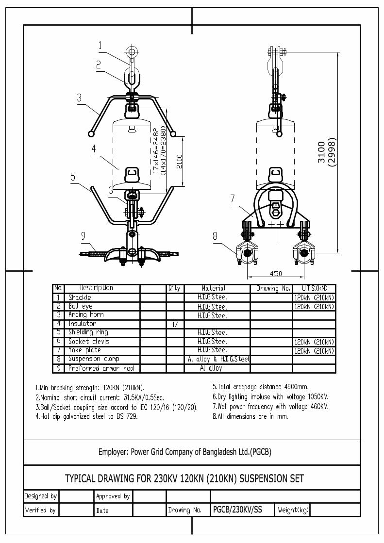
3100
(2998)

PGCB/230KV/TS

TYPIC
AL D
RAW
ING
FO
R 2
30KV U
PR
IGH
T L
OW
DU
TY
TEN
SIO
N S
ET F
OR
TW
IN C
ON
DU
CTO
R
Em
plo
yer: P
ow
er G
rid C
om
pany o
f Bangla
desh L
td.(P
GCB)
PG
CB/2
30K
V/U
LD

PGCB/230KV/EW/SS

PGCB/230KV/EW/TS

’;
’;
’;
!O
!O
!O
!O
!O
!O
!O
##
###########
##
#
#
#
#
#
#
#
#
##
PROPOSED SUB-STATIONASHUGANJ
End
AP
-15
AP
-16
AP-17
AP-18
AP-19
AP-20
AP-21AP-22
AP-23
AP-24
AP
-25
AP
-26
Marjal
Sreenagar
Biddyakut
Nilakhya
Kanikara
Hossain Nagar
Banshgari
Tarua
Adiabad
Phuldi
Josar
Jafrabad
Char Chartala
Kurighar
Napang
Nasirabad
Ekaichhara
Gopalpur
Mirzar Char
Alokbali
Sharifpur
Balu CharBagdahar
Roypura
Char Madhabpur
Majher Char
Mohalla
Talsahar
Sreerampur
Sreenidhi
Shibpur
Barail
Algi
Bayek
Samibad
Char Madhua
Ramnagar
Pirpur
Naoghata
Purba Hossainnagar
Chilokut
Nabinagar
Sreeshtighar
Andidil
Araisidha
Gilaber
Alamnagar
Nabipur
Gaurnagar
Methikanda
Nijgaon
Tiara
Jatrapur
Birkandi
Tulatuli
Baratala
Nabiabad
Uttar Mirzanagar
Merkuta
Hairmara
Natun Char
Gonsaipur
Ajkitala
Chhutaband
Sohagpur
Bil Kedarkhola
Maishair
Pirajkandi
Uttar Bakharnagar
Gauripur
Krishnanagar
Mamudpur
Thanakandi
Birgaon
Begamabad
Daulatpur
Itna
Katlar Char
Bahadurpur
Fakirer Char
Khodadila
Rangpur
Char Begamabad
Bara Char
Poothai
Naoghat
Battali
Joar Gobindapur
Char Subuddi
Bhaishber
Lalpur
Aliabad
Abdullapur
Joykalipur
Pahar Jaynagar
Char Bakharnagar
Hatubhanga
Bholachang
Fatehpur
Radhanagar
UrkhaliaSitarampur
Chanderkandi
Sahabazpur
Sahar Char
Sonarampur
Narayanpur
Musapur
Dakshin Lakshmipur
Ujilaba (Char Meghna)
Charilam
Kamalpur
KhagchailRanitani
Khainkut
Durain
Kukurmara
Char Meghna
Saudmara
Seoratali
Laukhara
Ashrafpur
Durgapur
Katuar Char
Basutara
Char Sadarland
Hasnabad
Nabipur (Domrakandi)
Lausar
Char Safar Ali
Agarpur
Kajalia
Jagadishpur
Bakharnagar
Damchail (Alakpur)
Sadekpur
Haripur
Uttar Lakshmipur
Kalikapur
Amtali
Char Gonsaipur
Char Lalpur
Bangalinagar
Bhabanipur
Chhota Lakshmipur
Maniknagar
Kedarkhola
Bhiti Khainkut
Char Napang
Ibrahimpur
Mallikpur
Samantaghar
Maheshpur
Sahapur
Chandpur Deara
Pachha Boalia
Sapmara
Chitri
Rahimabad
Najirpur
Asarampur
Tatuakandi (Ulukandi)
Kharghar
Bagh Duariakandi
Anwarabad
Kaziara
Alipura
Daskandi
Chhota Mirzapur
Joynagar
Kamaura
Saindhadoba
MamudabadJoar Lakshmipur
Samibad Char
Sreeghar
Chhota Brahmanbaria
Char Baliakandi
Char Baluakandi
Marichakandi
Purba Haripur (Anorabad)
Dakshin Gobindapur
Birampur
Khag Char
Saharpar
Char Joykalipur
Gazirkandi
Paharkharkandi
Dari Sapmara
Khalilabad
Thollakandi
Alinagar
Letarba
Jalsuka
Latia
Chaura Para
Lalpur Hossainpur
Durgarampur
Julai Para
Baikunthapur
Meratali (Part)
Manoharabad
Gobindapur
Dagarisar
Paschim Haripur
Mandalia
Sobharampur
Mamudnagar
Nabuar Char
Chhota Asrafpur
Sonatala
Nazar Daulat
Maishartek
Majhikara
Char Chartala Bazar
Uttar Kamalpur
Rajprasad
Lahari
Sadhunagar
Ghiara
Manoharpur
Uttar Bhelanagar
Char Kater
Maheshpur (Part-1)
Maliara
Nandertek
MachhimnagarPalashtali
Dhopachang
Jalalabad
Birajnagar
Kabirerkandi
Sreephalia
Paharphuldi
Kaitala
Teli Para
Uttar HaidarnagarDaria Daulat
Josar
Shibpur
Paratali
Chandpur
Sreenagar
Alokbali
Nilakhya
Biddyakut
Marjal
Barail
Palashtali
Krishnanagar
Sreerampur
Musapur
Roypura
Birgaon
Barikandi
Alipura
Banshgari
Sadekpur
Natghar
Mirzapur
Adiabad
Dakshin Araisidha
Purba Nabinagar
Joynagar
Maheshpur
Mirzanagar
Shyamgram
Char Madhua
Purba Sharifpur
Natghar
Radhanagar
Chanderkandi
Mirzar Char
Hairmara
Uttar Araisidha
Pourasava
Paschim Talsahar
Paschim Nabinagar
Char Subuddi
Pahariakandi
Amirganj
Uttar Bakharnagar
Amlaba
Paschim Sharifpur
Narayanpur
Ibrahimpur
Dakshin Panisar
Baghaba
Bitghar (Tiara)
Uttar Natai
Char Aralia
Purba Talsahar
Dariadaulat
Narayanpur
SalimganjPurba TezkhaliBitghar (Tiara)
Sallabad
ROYPURA
NABINAGAR
BRAHAMANBARIA
SRINIDHI
METHEKADA
TALSHAHAR
HATU BHANGA
DAULATKANDI
BRAHMNBARIA
PROPOSED ASHUGANJ-BULTA 400KV TRANSMISSION LINEPROPOSED ASHUGANJ-BULTA 400KV TRANSMISSION LINE(ASHUGANJ AREA)(ASHUGANJ AREA)
µ1:90,000Scale
P R E P A R E D B Y
DIGITAL SURVEY COMPANYCell :01718473248
Legend# Proposed Angle Point
# Existing Tower Location
# Proposed Angle Point
!O Railway Station
’; Upazilla Head Quarter
Railway Line
National Highway
Feeder Road
Proposed 400KV Transmission Line (70.027 Km)
River
Waterbodies

’;’;
’;
’;
##
##
##
##
##
################
##
#########
######
##
##
#
#
#
#
##
#
##
#
#
#
#
#
#
PROPOSED SUB-STA
TION
Start
PointBULT
A
AP-1
AP-2
AP-3
AP
-4
AP
-5
AP
-6
AP
-7
AP
-8
AP
-9
AP
-10
AP
-11
AP
-12
AP
-13
AP-14
AP
-15
Dilarpur
Nilakhya
Karimpur
Alokbali
Jafrabad
Kanchan
Daria Daulat
Fardabad
Char Line
Baghata
Kajair
Char Aralia
Balu Char
Char Madhabpur
Char Shibpur
Banbhag
Kandail
Panchgaon
Silmandi
Balusair
Battali
Purbahati
Panchrukhi
Darikandi
Bholaba
Akanagar
Barail
Char Marichakandi
Char Madhua
Kanainagar
Khalla
Char Dighaldi
Jitrampur
Baher Char
Kholbandha
Bajri
Bulta
Bandi
Nehaba
Chaua
Satgram
Tetia
Bhat Para
Kutubpur
Banshgari
Birinda
Duptara
Salimabad
Tejkhali
Amlaba
Bara Balapur
Paratali
Chunar Char
Baligaon
Alinagar
Tarail
Pahariakandi
Biraba
Banchharampur
Dayakanda
Bara Naogaon
Krishnanagar
Nayanabad
Natun Char
Mulgaon
Som
Chaudda Paika
Daukandi
Bishnandi
Daskandi
Kesraba
Golakandail
Sreenagar
Baluakandi
Begum Char
Khaisar
Rasulpur
Mochar Taluk
Kadair
Khodadila
Kalyandi
Bhurbhuria
Madhyanagar
Dakshin Bhelanagar
Mahana
Kajir Char
Hasnabad
Taora
Jhaugara
Birkandi
Char Kalyanpur
Kamaldi
Laskardi
Chaitankandi
Dighalia
Tatuakandi
Satdona Khakkanda
Sadipur
Kendua
FathamaraEdbardi
Kuraitali
Kalagachhia
SapleziBharat
Dashdona
Kalyanpur
Hairmara
Gadair Char
Rupasdi Dakshinpara
Atadi
Joykalipur
Fasua
Kamrangir Char
Fatehpur
Khil Para
Bara Ghagutia
Jhunar Char
Ghorashal
Bhagdi
Daudpur
Adhuria
Hossainpur
Belabo
Bara Noapara
Nilakhi
Gaherdi
Gutulia
Agla
Danga
Beldi
Joynagar
Hajipur
Burumdi
Salamdi
Sinhadi
Gazipura
Gopaldi
Nurullahpur
Katwaler Char
Jalli
Brahmandi
Karatia
Maruadi
Roynadi
Atia
Kakasia
Basigaon
Saudmara
Jagannathpur
Sendi
Ballabhdi
Mirpur
Hasannagar
Nabipur (Domrakandi)
Khidirpur
Kazir Char
Atla
Pakunda
Saoghata
Mandirpur
Baduar Char
Uriam
Dakshin Mirzanagar
Palla
Kalikapur
Kulasin
Ghagra
Deabai
Utma
Basunda
Bartul
Ulukanda
Atabdi
Char Bhasania
Rupasdi Madhyapara
Char Dariadaulat(D.Rampur
Sonarampur
Asadnagar (Part-2)
Kahena
Santan Para
Kharia
Maishasura (Part)
Karaitala
Madhabdi
Araihazar
Char Chhayani
Daserdia
Peraba
Balia Para
Thollakandi
Satyabhandi
Airaba
Hasanhata
Dharmapur
Kalainagar
Samibad
Maniknagar
Char Seaton
Naogaon
Sambhupura
Char Badda
Jalakandi
Noagaon
Jangalia
Jampur
Binair Char
Nisundaria
Tatuakandi (Ulukandi)
Chhota Sadardia
Bhuan
Bishnurampur
Uttar Kalagachhia
Kanthalia
Birampur
Char Hajipur
Bhaela
Sinlaba
Jogardia
Puran Char
Banshtal
Grindan Bhum
Bara Maishadi
Ratnagardi
Chauthal
Manikpur
Lakshmibardi
Dagaria (Part)
Dari Bishnandi
Mardasdi
Ashta Paika
Chhota Noapara
Noapara
Khamardi
Bahadurpur
Duara
Marichakandi
Mollar Char
Jhagrar Char
Uttar Haidarnagar
Alinagar Chak
Brahmanbaga
Char Ramprasadpur
Ganergaon
Kanchanpur
Bhiti Bishara
Darikandi Chak
Sekher Char
Sreeghar
Saifullakandi
Paulanpur
Lengardi
Kalinga
Kazi Para
Kenduaba
Sialati
Putina
Ponaba
Char Meghna
Kahindi
Bijoynagar
Tiori
Pechanga
Sadasardi
Bishnandi Char
Machhimnagar
Dakshin Haidarnagar
Anandi
Akhalia
Prabhabardi
Paikasa
Dighaldi
Samibad Char
Bhallukaba
Bara Manohardi
Rahimdi
Kadirdia
Chaugharia
Dairadir Char
Mathra
Tetlaba
Sonar
Bathuadi (Baluadi)
Kamalkati
Lalmina
Haji Sahadi
Mukundi
Dhandi
Nilkhi Samibad
Rautgaon Aguandi
Gazirgaon
Gauribardi
Nalua
Chherenda
Taltala
Char Joykalipur
Doaichaitab
Dasturdi
Ujan Char
Tingaon
Turkini
Ramchandradi
Kurail
Bagadi
Paikar Char
Munsurpur LatiaKhagair
Narindi
Lasardi
Meher Para
Angarjora
Rishir Char
Panchaikhan
Panchdona
Kobaga
Bara Khamar Char
Ujan Gobindi
Dari Bhelanagar
Algi (Kanda Para)
Chhota Amdia
Tatar Para
Galimpur
Balabhadradi
Ichhapur
Chander Para
Bara Banaid
Nareshwardi
Tilchandi
Baruihati
Chairgaon
Makimpur
Baje Bishara
Sultansadi
Noadda Singapur
Sulpandi
Sonatala
Badda
Barakanda
Khadimer Char
Rauabil
Mirkuti Chhao
AolahatAtlapur
Bailat
Koladpur
Udaydi
Nayakandi
Mulpara
Abdullapur
Bara Sadasardi
Atlaspur
Silmondi Para
Chautharkhanda
Hossain Nagar
Dogharia (Fazurkandi)
Tumlia
Char Para
Bhiti Kamaldi
Faitadi
Kandarpadi
Kismat Baniadi
Char Gobindapur
Bara Majher Char
Siraba
Muraldi
Hanumantapur(Bhagirathpur
Char Balapur
Latabdi
Gurubdi
Tulsipur
Baghbari
Bherarkur
Naikahan
Bakharnagar
Kabirajpur
Ulua
SreenibasdiBhati Gobindi
Dakshinpara
Dakshinpara (Gotkandi)
Khirdasdi
Kurinal
Char Mamudpur
Bagadi Noapara
Daburpura
Uttar Kansardi
Das Naogaon
Char Madhabdi
Arairua Bil
Mahmudpur
Chhota Madhabdi
Nagar Panchdona
Lalurkandi
Uttar Char Bhasania
Bhati Badarpur
Putia
Chhota Salmadi
Tengra
Kazirgaon
Lakshmipur
Imamnagar
Manoharpur
Gazipur
Pitalganj
Toksadi
Muluksahadi
Patua
Sreechandi
Rangpur
Baniar Char
Hogalia
Mirka (Baganagar)
Nagardaukadi
Alisadi
Ashrafbad
Shobharampur
Khaserkandi
Barar Char
Kashipur
Raghabdi
Uttar Swarupaba
Shyam Royerkandi
Chaitaba
Brahman Para
Kalyandi Khas
Dakshin Bhadarti
Shibpur
Hasimerkandi
Uchitpur
Char Kater
Chhota Manohardi
Nasaraddi
Jatrabari (Bailarmandi)
Sarpanigair
Ashrafpur
Khanmardi
Bharsangan
Matia
Lengatpur
Madansahadi
Basantapur
Nandi Para (Chinishpur) Jaharajia Para (Part)
Kaumpur
Jinardi (Bilpar)
Manikmina
Datterkandi
Bangar Char
Bhiti Jhagrar Char
Kamar Char
Balarampur
Uttar Nayakandi
Ilamdi (Khondakarkandi)
Chhota Balapur
Jangalia Khas
Pathanerkandi
Krishnapura
Bara Bhum (Dardaria)
Darisom
Uttar Daudpur
Nasirabad
Agar Para
Arazi Bakharnagar
Goalnagar
Hossendi
Banda Baher Char
Mamudpur
Shimulkandi
Gabtali Hat
Atadi Khas
Chandalchira (Bageswar)
Dakshin Swarupaba
Nager Char
Piparia
Pajaradia
Masumabad
Kumarbagh
Bhuiyankandi
Dakshin Chaua
Dhundurpar
Hoglakanda
Rupaba
Chhota Banaid
Raghunathpur
Daserdia Khas
Jogardia Khas
Chhota Darikandi
Sreepati
Salpa
Bhaterkandi
Uttar Baluakandi
Asmandir
Sutalara
Nagar Baniadi
Tegharia Para
Dariabad
Chhitkerkandi
Paragaon
Char Mirpur
Alokbali
NazarpurAmdia
Danga
Nilakhya
Salimabad
Kanchan
Sonarampur
Satgram
Duptara
Bholaba Karimpur
Bishnandi
Jampur
Haizadi
Silmandi
Barikandi
Brahmandi
Dariadaulat
Char Dighaldi
Golakandail
Mahishasura
Kanthalia
MadhabdiPaikar Char
Panchdona
Pahariakandi
Char Aralia
Sadasardi
Amirganj
Purba Tezkhali
Kaliganj
Daudpur
Mahmudpur
Purba Rupasdi
Salimganj
Bulta
Paschim Saifullakandi
Pourasava
Uttar Banchharampur
Paschim Ujan Char
Uchitpur
Char Madhua
Hairmara
Dakshin BanchharampurPaschim Rupasdi
Banshgari
Hajipur
Tumulia
Sadipur
Ghorashal
Purba Saifullakandi
Khagakanda
Jinardi
Tarabo
Sreenagar
FatehpurAraihazar
Meher Para
Purba Ujan Char
NoagaonPurba Ghagutia
Ratanpur
Chinishpur
Paschim Ghagutia
Paratali
Noagaon
Shyamgram
Char SubuddiNARSINGDI
PROPOSED ASHUGANJ-BULTA 400KV TRANSMISSION LINEPROPOSED ASHUGANJ-BULTA 400KV TRANSMISSION LINE(BULTA AREA)(BULTA AREA)
µ1:90,000Scale
P R E P A R E D B Y
DIGITAL SURVEY COMPANYCell :01718473248
Legend# Proposed Angle Point
# Existing Tower Location
# Proposed Angle Point
!O Railway Station
’; Upazilla Head Quarter
Railway Line
National Highway
Feeder Road
Proposed 400KV Transmission Line (70.027 Km)
River
Waterbodies

Y X Z H
Northing Easting Elevation Height
Start Point 2630092.44 252574.78 7.41 Start from Bulta Sub‐Station
AP‐1 2631034.09 253595.89 8.32 Angle Point
AP‐2 2633407.97 256990.25 8.33 Angle Point
AP‐3 2634698.87 257659.79 8.38 Angle Point
AP‐4 2635594.70 259740.69 8.38 Angle Point
AP‐5 2635996.04 261099.07 8.41 Angle Point
AP‐6 2636608.19 262815.73 8.47 Angle Point
AP‐7 2635505.86 265010.91 8.47 Angle Point
AP‐8 2635456.70 265964.29 8.46 Angle Point
AP‐9 2636206.42 268276.52 8.20 Angle Point
AP‐10 2636593.43 270286.76 7.79 Angle Point
AP‐11 2636588.56 273485.74 7.34 Angle Point
AP‐12 2637629.95 276268.57 7.42 Angle Point
AP‐13 2636151.64 279743.29 7.53 Angle Point
AP‐14 2637741.73 281513.67 7.52 Angle Point
AP‐15 2639242.40 284380.05 7.24 Angle Point
AP‐16 2639556.69 286303.75 7.26 Angle Point
AP‐17 2640836.68 289463.54 7.44 Angle Point
AP‐18 2644349.21 291889.43 7.35 Angle Point
AP‐19 2646018.67 293085.69 7.34 Angle Point
AP‐20 2648342.34 295752.84 7.31 Angle Point
AP‐21 2650237.82 299352.00 7.32 Angle Point
AP‐22 2652647.42 302332.90 7.39 Angle Point
AP‐23 2654396.85 303539.46 7.60 Angle Point
AP‐24 2658143.25 301798.02 7.63 Angle Point
AP‐25 2659054.67 299280.30 7.65 Angle Point
AP‐26 2659321.14 297961.94 8.79 Angle Point
End Point 2659782.44 297449.82 8.70 End Point at Ashuganj Sub‐Station
Co‐ordinates Angle Points of Ashuganj‐Bhulta 400kV Transmission Line
Code Description
Page 1 of 1

Zafrul
Textbox
Zafrul
Textbox
Zafrul
Textbox
Zafrul
Textbox
Zafrul
Textbox
Zafrul
Textbox
Zafrul
Textbox
Zafrul
Textbox
Zafrul
Textbox
Zafrul
Textbox
Zafrul
Textbox

Zafrul
Textbox
Zafrul
Textbox
Zafrul
Textbox
Zafrul
Textbox
Zafrul
Textbox
Zafrul
Textbox
Zafrul
Textbox
Zafrul
Textbox
Zafrul
Textbox
Zafrul
Textbox
Zafrul
Textbox
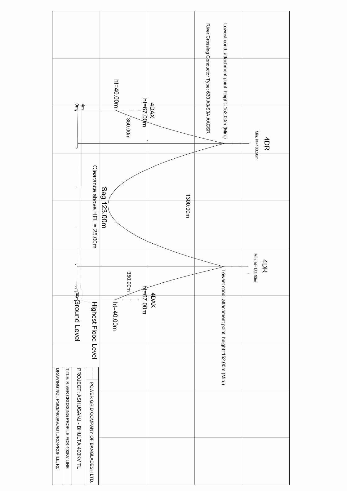


POWER GRID COMPANY OFBANGLADESH LIMITED
EARTHING ARRANGEMENT
ITEM
MATERIAL LIST
QTY/TOWER
COPPER LUG
SL. NO.
GALV. STEEL WIRE LG=2800mm7 X 3.25 (9.75mmf)
f 16mm ROD. LG=1000
f 12 X 35mm BOLTS
SPRING WASHER f 12mm
1.
2.
3.
4.
5.
2 NOS.
4 NOS.
2 NOS.
4 NOS.
4 NOS.
NOTES:
1. DIMENSION OF 'X' WILL BE DECIDED AT SITE AS PER SITE CONDITION
4. ALL DIMENSIONS ARE IN MILLIMETER
2. TO ENSURE THERE IS NO BIMETALLIC CORROSION THE COPPER LEG SHOULD BE TINNED
3. EARTHING ARRANGEMENT SHOULD BE CONNECTED FOR TWO DIAGONALS OF EACH TOWER
300
G. L.
C. L.
GENERAL ARRANGEMENTFIXING OF EARTHING
25
13.5
mm
HO
LE F
OR
f12X
35M
M16
mm
f S
TEEL
RO
DC
LAD
WIT
H C
OPP
ER
25
DETAIL OF LUG
1000
13.5mm f
GALV. STEEL WIRE7 X 3.25 (9.75mmf)LG=2800 mm
'X'
DETAIL OF 'X'
HOLE FOR CONNECTING LUG
32
15
27
16
COPPER LUG
7 X
3.2
5 (9
.75m
m f
)
COMPRESS LUG SHALLBE PROVIDED ATBOTH ENDS OF WIRE
13.5mmDIA HOLE
DRAWING NO. PGCB/TL/EARTHING

The loading tree and line & clearance diagram of relevant 400kV towers [4DL, 4D1, 4D25(4DXP), 4D45, 4DT6T] have not been uploaded here.