POTENTIALS FOR REALISING A CONSISTENT TRANSITION BETWEEN FUNCTIONAL MODELLING WITH THE IFM FRAMEWORK...
10
ICED13/122 1 INTERNATIONAL CONFERENCE ON ENGINEERING DESIGN, ICED13 19-22 AUGUST 2013, SUNGKYUNKWAN UNIVERSITY, SEOUL, KOREA POTENTIALS FOR REALISING A CONSISTENT TRANSITION BETWEEN FUNCTIONAL MODELLING WITH THE IFM FRAMEWORK AND EARLY SYSTEM SIMULATION Boris EISENBART (1), Fabio DOHR (2), Kilian GERICKE (1), Michael VIELHABER (2), Lucienne BLESSING (1) 1: University of Luxembourg, Luxembourg; 2: University of Saarbruecken, Germany ABSTRACT Conceptual design is considered one of the most demanding design tasks requiring a joint effort of the involved designers, particularly in interdisciplinary design. Sound decision-making across disciplines on alternative solution concepts may be considerably facilitated through early system simulation. A consistent transition of the available information in functional modelling to early system simulation may thus support designers in this task. The IFM framework intends to support cross-disciplinary collaboration of involved designers by providing an integrated functional modelling approach. In the paper it is analysed in how far a consistent transition from the IFM framework to established modelling techniques for simulation may be realised. The paper compares the information required for early system simulation in an interdisciplinary design context to the specific information conveyed in the different views of the IFM framework. The analysis identifies specific potentials and barriers for a consistent transition between them. Finally, the implications of the derived insights are discussed. Keywords: function modelling, conceptual design, integrated system development, early system simulation Contact: Boris Eisenbart University of Luxembourg Engineering Design and Methodology Group Luxembourg L-1359 Luxembourg [email protected]
-
Upload
uni-rostock -
Category
Documents
-
view
2 -
download
0
Transcript of POTENTIALS FOR REALISING A CONSISTENT TRANSITION BETWEEN FUNCTIONAL MODELLING WITH THE IFM FRAMEWORK...
ICED13/122 1
INTERNATIONAL CONFERENCE ON ENGINEERING DESIGN, ICED13 19-22 AUGUST 2013, SUNGKYUNKWAN UNIVERSITY, SEOUL, KOREA
POTENTIALS FOR REALISING A CONSISTENT
TRANSITION BETWEEN FUNCTIONAL MODELLING
WITH THE IFM FRAMEWORK AND EARLY SYSTEM
SIMULATION
Boris EISENBART (1), Fabio DOHR (2), Kilian GERICKE (1), Michael VIELHABER (2), Lucienne BLESSING (1) 1: University of Luxembourg, Luxembourg; 2: University of Saarbruecken, Germany
ABSTRACT Conceptual design is considered one of the most demanding design tasks requiring a joint effort of the
involved designers, particularly in interdisciplinary design. Sound decision-making across disciplines
on alternative solution concepts may be considerably facilitated through early system simulation. A
consistent transition of the available information in functional modelling to early system simulation
may thus support designers in this task. The IFM framework intends to support cross-disciplinary
collaboration of involved designers by providing an integrated functional modelling approach. In the
paper it is analysed in how far a consistent transition from the IFM framework to established
modelling techniques for simulation may be realised. The paper compares the information required for
early system simulation in an interdisciplinary design context to the specific information conveyed in
the different views of the IFM framework. The analysis identifies specific potentials and barriers for a
consistent transition between them. Finally, the implications of the derived insights are discussed.
Keywords: function modelling, conceptual design, integrated system development, early system
simulation
Contact:
Boris Eisenbart
University of Luxembourg
Engineering Design and Methodology Group
Luxembourg
L-1359
Luxembourg

2
1 INTRODUCTION
Conceptual design of technical systems contains the essential transition from a problem to alternative
solution concepts. Herein, “technical system” encompasses technical products as well as
product/service systems (PSS). Conceptual design is considered to be among the most demanding
design tasks and requires a joint effort of involved designers (Blessing, 1997, Chakravarthy et al.,
2001). Particularly in an interdisciplinary design context, the success of such collaborative work
depends on the ability of designers to share concepts and ideas (Buur and Andreasen, 1989) and to
establish a shared understanding of the system under development – including its requirements and
expected functionalities – across involved disciplines (Kleinsmann, 2008, Alink et al., 2010).
From a modelling point of view, conceptual design across different disciplines essentially comprises
requirements specification, function modelling, and models representing the potential solution concept
(Eisenbart et al., 2011). Function modelling is proposed as a means to facilitate conceptual system
design. A function model is a first, abstract representation of the system under development and,
because of its use in different disciplines, is expected to support the establishment of the required
shared understanding (Stone and Wood, 2000; Erden et al., 2008). However, divergent meanings of
function and a large variety of alternative function models exist (Vermaas, 2013) and seem competing
when designers collaborate (Müller et al., 2007). Recently, a new approach has been proposed to
address this issue: the Integrated Function Modelling (IFM) framework (Eisenbart et al. 2013a). The
IFM framework is explicitly intended to support designers in determining and specifying solutions to a
given problem and results in an initial system structure of a respective solution concept.
A design task is widely regarded to be an “ill-structured problem”, as often neither problem nor
desired solution are sufficiently defined at the beginning of a project (Poon and Maher, 1997).
Conceptual design thus cannot easily move from a problem to a solution and is typically characterised
by co-evolution: a stepwise increase of information about the addressed problem parallel to the
developed solution. It is an iterative process (Poon and Maher, 1997; Chakravarthy et al., 2001, Braha
and Reich, 2003) as in exploring the potential solution(s) to a given problem, certain features or
constraints of that potential solution may require redefinition of the problem.
In an interdisciplinary development project, the solution space is particularly large. Early system
simulation may support the process of determining and selecting suitable solution concepts, as it offers
quick and impartial means for their comparison and validation with respect to function and
requirements fulfilment (Paredis et al., 2001). A consistent transition between function modelling and
early system simulation could support the iterative synthesis and analysis steps occurring while
reasoning towards a potential solution, as mentioned above. That includes verification of consistency
across different models regarding the information they address, e.g. as part of change management. It
could further reduce time and effort spent for modelling as well as for gathering and managing the
required information.
In this particular area first promising attempts have been proposed. Prominent examples are e.g. the
“Connection Modeller” (Stark et al., 2010), the “RFLP approach” (Requirements, Functional, Logical
and Physical Design) in CATIA Systems or Gausemeier et al.’s approach implemented in the
“Mechatronic Modeller” (Gausemeier et al., 2009). Compared to the function models inherent in these
approaches, the IFM framework covers a broader amount of function modelling perspectives. These
broader capabilities may support a comprehensive analysis of the system under development during
interdisciplinary conceptual design using early system simulation.
The presented research aims to answer the question, in how far a consistent transition from function
modelling to early system simulation may be realised in an interdisciplinary context, using the IFM
framework. The presented research is guided by the question: What are the specific potentials and
barriers for a consistent transition from function modelling using the IFM framework to early system
simulation?
Initially, the IFM framework as well as established tools and modelling techniques for early system
simulation are described in the following sections. Then, the specific information required for
implementation and execution of the discussed modelling techniques and simulation tools is compared
to the particular information conveyed in the IFM framework (see section 4). Finally, the implications
of the derived insights are discussed in section 5. The presented research is based on previous work on
the IFM framework and research into process support for simulation-based design conducted in the
involved research groups.
3
2 THE IFM FRAMEWORK
The IFM framework proposed by Eisenbart et al. (2013a) intends to provide designers with an
integrated approach for modelling system functionality. Rather than linking individual existing
function models from different disciplines, integration is facilitated through linking the specific
contents and information which are prominently addressed within function models from different
disciplines (see Erden et al, 2008; Eisenbart et al. 2012, 2013b for a comprehensive review and
comparison of function models across disciplines). The framework consists of associated views. A
central view (process flow view) represents the flow of transformation processes, which is central to
function modelling across disciplines (Eisenbart et al., 2013b). The remaining views are linked to this
central view and comprise of matrices, which represent information about the different entities (see
Table 1) in the framework and/or their interdependencies.
Table 1: Different entities in the IFM framework
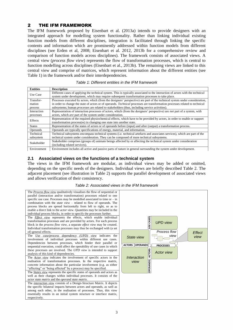
2.1 Associated views on the functions of a technical system The views in the IFM framework are modular, as individual views may be added or omitted,
depending on the specific needs of the designers. Individual views are briefly described Table 2. The
adjacent placement (see illustration in Table 2) supports the parallel development of associated views
and allows verification of their consistency.
Table 2: Associated views in the IFM framework
The Process flow view qualitatively visualises the flow of sequential or
parallel (interaction and/or transformation) processes related to one specific use case. Processes may be modelled associated to time or – in
combination with the state view – related to flow of operands. The process blocks are spread horizontally from left to right, so as to
enable a direct link to the actor view. Quantities may be included in the
individual process blocks, in order to specify the processes further.
The Effect view represents the effects, which enable individual transformation processes and are provided by actors. For each process
block in the process flow view, a separate effect view may be created.
Individual transformation processes may thus be exchanged with (a set of) general effects.
The Use case/process dependency (UPD) view indicates the
involvement of individual processes within different use cases.
Dependencies between processes, which hinder their parallel or
sequential execution, could affect the operability of use cases in which
these processes are involved. The UPD view is intended to support analysis of this kind of dependencies.
The Actor view indicates the involvement of specific actors in the
realisation of transformation processes. In the respective matrix,
concrete information about the particular involvement (e.g. as either “affecting” or “being affected” by a process) may be specified.
The States view represents the specific states of operands and actors as
well as their changes within individual processes. It consists of the actor state matrix and the operand state matrix.
The interaction view consists of a Design-Structure Matrix. It depicts
the specific bilateral impacts between actors and operands, as well as
among each other, in the realisation of processes. Thus, this view essentially results in an initial system structure or interface matrix,
respectively.
State view
UPD view
Actor view
Interaction view
ACTORS OPERANDS PROCESSES
USE
CA
SES
AC
TOR
SO
PER
AN
DS
Process flow
viewEffectview
Entities Description
Use Case Different cases of applying the technical system. This is typically associated to the interaction of actors with the technical system under development, which may require subsequent transformation processes to take place.
Transfor-
mation
process
Processes executed by actors, which (from the designers’ perspective) are part of the technical system under consideration,
in order to change the state of actors or of operands. Technical processes are transformation processes related to technical
subsystems; human processes are related to stakeholders (thus, including service activities).
Interaction
processes
Representation of interaction processes of actors, which (from the designers’ perspective) are not part of a system, with
actors, which are part of the system under consideration.
Effects Representation of the required physiochemical effects, which have to be provided by actors, in order to enable or support
transformation process(es) in changing one state into another state.
States Representation of the states of actors or of operands before (input) and after (output) a transformation process.
Operands Operands are typically specifications of energy, material, and information.
Technical subsystem
Technical subsystems encompass technical systems (i.e. technical artefacts and associates services), which are part of the technical system under consideration. They can be composed of more technical subsystems.
Stakeholder Stakeholder comprises (groups of) animate beings affected by or affecting the technical system under consideration
(including related services).
Environment Environment includes all active and passive parts of nature in general surrounding the system under development.
4
2.2 Application The framework – through its modular character – may be applied in various ways. That includes
different entry points and alternative sequences of modelling steps. Eisenbart et al. (2013c) show how
the IFM framework can be adapted, in order for it to be used within systematic design approaches
from different disciplines. In Table 3 different modelling activities for the application of the IFM
framework are presented, which can be iteratively performed.
Table 3: Potential modelling activities in the application of the IFM framework
Use Case
definition
…includes the consolidation of the different use cases that the system under development is expected to support in the different phases of its life-cycle. The use cases are represented in the respective column in the UPD view.
Process flow
modelling
…involves modelling separate flows of required processes related to each use case. A multitude of alternative process
flows may fulfil a use case. While modelling the process flows, the involvement of individual processes in multiple use cases needs to be considered.
Operand state
modelling
…includes modelling the state changes of involved operands in the operand state matrix (as part of the state view)
related to the chosen process flows. This may be executed in parallel to process flow modelling.
Effect modelling …involves modelling the required effects related to the specific process blocks or entire flows, respectively.
Actor allocation …includes allocation of actors involved in individual processes through the delivered effects.
Actor state
modelling
…includes modelling the state changes of allocated actors in the actor state matrix (as part of the state view) related to
the chosen process flows.
Interaction
specification
…involves analysing and detailing the specific interactions (i.e. the bilateral impacts) among actors and among
operands, and between actors and operands.
In an original design project, modelling may start on a high level of abstraction: defining use cases,
associated processes etc. On the next level of detail, individual process blocks may then be
decomposed into sub-processes. These are enabled by function carriers (actors) such as technical
subsystems or stakeholders, including any related service operator etc. Actors are iteratively
concretised. Therein, actor allocation essentially marks the transition from a problem to solution
concepts. As discussed above, this process is essentially characterised by co-evolution: as a potential
solution evolves, the required sub- and auxiliary functions will change depending on the specific
choice of actors and their interactions in function fulfilment. This will in turn affect the generated
views in the IFM framework. Establishing consistent links between the IFM framework and methods
for early system simulation may support this iterative progression by providing means for comparison
of alternative solution concepts, as described above.
3 EARLY SYSTEM SIMULATION
Simulation has become an indispensable part in product development today and is more and more
substituting physical prototypes (Aberdeen, 2006). The aim of early system simulation is not a detailed
and highly accurate analysis of the system but rather an unbiased means for comparison of different
concepts (Paredis et al., 2001). The foundation of simulation is a computable model (VDI, 2000),
which typically represents both behaviour and structure of the simulated system (INCOSE, 2010).
Succeeding function modelling, a system structure or architecture may be generated for a given
concept (Eisenbart et al., 2011). These address the respectively involved entities (i.e. modules,
components or general function carriers, respectively) and their connections. The application of the
IFM framework may result in the generation of such an initial system structure, as described above.
However, the available information about the entities of a technical system under development may
still be rather abstract (particularly in an original design project). Thus, modelling and simulating
behaviour can primarily be performed on system level. Detailed simulation of inherent entities is only
feasible in later stages, as more information about the individual design parameters becomes available.
In general, simulation of system behaviour is based on mathematical descriptions. These are capable of
describing systems uniformly and independent from engineering disciplines (Kümmel et al., 1998).
Besides purely mathematical modelling, further modelling paradigms have been developed for the
purpose of (multidisciplinary) system description. They can be classified according to Paredis et al.
(2001) into graph-based and language-based, multi-domain and single-domain as well as declarative
and procedural. In many cases, the mathematical description is included in those paradigms or can be
derived from them. Further descriptions and examples of those paradigms are provided in (Rajarishi et
al., 2001).
As described in the previous section, the IFM framework addresses the functions of a technical system
related to the specific use cases, their inherent transformation and interaction processes as well as the
effects enabling them, which are provided by actors – either a technical system or a human. Early
system simulation thus needs to address the particular behaviour of these actors, in order to allow

5
evaluation of function and requirements fulfilment. Therein, technical products may themselves be
multi-technology artefacts, such as mechatronic systems. Hence, in the next sections an overview of
tools and techniques for modelling and simulation of mechatronic systems, human behaviour and
process simulation are described and analysed regarding their usability with the IFM framework.
3.1 Mechatronic system behaviour simulation During recent years, for behavioural system-level modelling of interdisciplinary systems – particularly
mechatronic systems – two modelling languages have been established: VHDL-AMS and Modelica.
Those can be categorised as language-based, multi-domain and declarative. Furthermore they can
model both time-continuous and time-discrete behaviour. In the field of mechatronics both types are
relevant, e.g. time-continuous behaviour for the mechanical components and time-discrete for the
software control mechanisms, respectively. Therein, system models are typically generated by linking
individual module blocks from the libraries provided in the respective software tools. In some of these
module blocks specific ports are provided, which allow the inclusion of impacts from or to the
environment. Furthermore these tools can also be used for purely mathematical modelling of the
system behaviour which also allows the creation of own libraries.
A detailed simulation of the system and its components can often not be performed during conceptual
design. Especially geometry-based and thus CAD-based simulation – like finite-element analysis or
multi-body simulation – can only be applied to a limited extend in early stages, since geometry has not
been determined in full detail, yet. The same limitations apply to simulation of circuit diagrams in
electronics – e.g. with PSPICE – or ECAD-systems like EPLAN since those require detailed
information about the components of the system. Instead, tools addressing system-level behaviour are
more suitable. Examples are Modelica-based tools like Dymola, Matlab/Simulink, 20-sim or CAMeL-
View. The last two are based on proprietary object-oriented modelling languages.
Apart from the language-based modelling paradigms, there are several graph-based alternatives. Two
very common examples are Bond graphs and block diagrams. Matlab/Simulink and 20-sim for
example support both. Furthermore there are possibilities to model the system on a more abstract level
only based on its states and their transitions. Typically, for this purpose petri net or finite-state
machine modelling can be used which a lot of tools exist for, e.g. SM Cube or Netlab. Furthermore,
some of the already mentioned tools for modelling and simulation also integrate those modelling
techniques, e.g. the Statechart toolbox for Matlab or the StateGraph Library in Modelica. Using such
tools, the reaction of the system related to a specific input can be simulated based on the defined states
and transitions. A more comprehensive discussion of further modelling paradigms and simulation tools
for early mechatronic system simulation is provided in (Dohr and Vielhaber, 2012; Paredis et al.,
2001; Rajarishi et al., 2001).
3.2 Human behaviour simulation Simulation of human behaviour associated to or interacting with technical products can be
distinguished between physical behaviour – such as e.g. ergonomics – and cognitive aspects. Most
CAD-systems include Manikin extensions, i.e. allow the inclusion of human body models. This
enables the integration of humans into ergonomic analyses, which mainly focus on geometrical aspects
and thus require detailed CAD-models. In contrast, e.g. Krüger et al. (2012) developed a user-centred
approach for the early integration of biomechanical analysis into the design process focussing on the
optimisation of the human-product interaction. Nevertheless, even though the full details are not
needed, this tool requires a basic degree of knowledge about the geometry as well. Regarding the
cognitive aspects of stakeholders within the user-product interaction, there are several attempts to
model and simulate human cognition. For example Bernard et al. developed an approach for “the
representation of plausible human cognition and behaviours within a dynamic, simulated environment”
(Bernard et al., 2007). One application is the generation of suitable concepts of operation of technical
systems.
3.3 General process simulation In software development, various simulation tools for use case analysis have been proposed. A
relatively new approach has been proposed by Hoffmann and Lichter (2010), which is based on petri
net modelling. Therein, the step-by-step transitions of system states are modelled and simulated using
a specific use case simulation environment. The tool allows separate modelling of individual use cases

6
based on the required transitions and analysis of consistency between state changes. One example of a
commercially available tool for such purposes is Rational Rhapsody.
Modelling and simulating processes and their flows is often used in project management, related to
e.g. design or manufacturing processes. A rather comprehensive approach is e.g. the Cambridge
Advanced Modeller (CAM) (WWW1). CAM essentially is a discrete-event simulation tool providing
toolboxes for modelling processes. For process modelling separate flow diagrams are created; therein,
specific inputs are assigned to corresponding tasks, which are expected to create certain outputs (i.e.
“deliverables”). Individual tasks may be assigned with certain, mostly mathematically described
properties. Simulation is performed using Monte-Carlo process simulation.
Table 4 collocates a selection of established software tools, which are mapped onto the respective
inherent modelling techniques.
Table 4: Modelling techniques used in established simulation tools
Simulation tools
Modelling technique
Ma
the-
ma
tical
mo
del
lin
g
Mo
del
ica
VH
DL
-
AM
S
Fu
rth
er
ob
ject-
ori
en
ted
pa
rad
igm
s
Gra
ph
-
ba
sed
mo
del
lin
g
Fin
ite-s
tate
mach
ine/
-
Petr
i n
et
Geo
metr
y-
ba
sed
mo
del
lin
g
Hu
ma
n
beh
av
iou
r
mo
del
lin
g
Gen
era
l
pro
cess
mo
del
lin
g
Matlab/Simulink X X X
Maple X
Mathematica X
Dymola, SimulationX… (X) X X
ANSYS Simplorer, Mentor… (X) X
CAMeLView (X) X X
20-sim (X) X X
Netlab, SM Cube X
CATIA Systems (X) X X
CATIA, Creo, NX … X (X)
Krüger et al. X
Bernard et al. X
Rhapsody X X
Cambridge Adv. Modeller X X
4 MAPPING THE IFM FRAMEWORK WITH EARLY SYSTEM SIMULATION
In this paper, the consistent transition of information represented in the IFM framework to established
modelling techniques for early behavioural system simulation are analysed. Therefore, it is analysed,
which specific information is explicitly needed in modelling when using the different discussed tools
and techniques. That involves the specific information about the addressed entities and their
interdependencies which are compared to the specific information conveyed in the different views of
the IFM framework. The comparison aims to identify the specific barriers and enablers for a consistent
transition between them. In the following, the individual views are consecutively discussed.
Actor view
The actor view merely illustrates the involvement of different actors within one or more use cases and
related transformation processes but does not reveal information about the specific behaviour of the
addressed actors. The respective allocation is implicitly performed while modelling the system for
simulation. For instance, use case simulation, Modelica, etc. rely on the allocation of the related
entities (actors, modules, function carriers etc.). Hence the actor view is not separately discussed.
UPD view
Use case simulation is particularly prominent in software development. Essentially, use cases may be
simulated based on the corresponding (interaction) processes and associated system states. Processes
may be both technical and/or human processes. In the following, modelling for simulation, related to
the process flow and state view are discussed in more detail. In the reviewed simulation and modelling
approaches, states (that includes e.g. pre- and post- conditioning in software development) have not
been separately simulated, but always appear related to corresponding transformation processes.
State view and process flow view
Processes and associated states can be jointly simulated based on petri net or finite state machine
modelling. Since the state view describes the system states and the process view the transitions
between these states, the IFM framework can directly provide the information needed for petri net or
finite state modelling. The corresponding tools for that purpose can be taken from Table 4.

7
Simulation of general processes uses rather abstract, mostly mathematical descriptions of the
properties of respective processes (related simulation tools are e.g. Rhapsody, Cambridge advanced
modeller etc.). Compared to the IFM framework, the required information may directly be retrieved
from the flow of processes (process flow view) and the respectively associated actor states (in the state
view) related to the individual use cases. Beside those possibilities, processes including humans can be
more concretely modelled and simulated on both physical and cognitive level, which build the basis of
the interaction of stakeholders and the technical product.
Typically the physical aspects are represented by virtual human bodies in CAD-system which require
detailed geometry. Hence the use during conceptual design is limited. In case (some) details about the
geometry are already known (e.g. in a redesign project), CAD-based physical analyses may
nevertheless be feasible. In contrast, the approach of Krüger et al. (2012) does not rely on detailed
geometry. Based on their analysis the motion and forces affecting the human body can be used to
determine or to specify the requirements of the technical system.
Simulation of cognitive aspects offers huge potential to improve the interaction of the user and the
technical system. Particularly decision making of the user and its reaction to the system can be
determined. Nevertheless, this particular type of modelling for simulation is not common in product
development and hence not consistently integrated. Furthermore, to determine the reaction of the user
on the behaviour of the technical system requires detailed information about the system and the user
which is typically not available during conceptual design – at least not in original design projects.
Thus, further design activities succeeding function modelling are required to provide the missing
information. Hence, in these cases, a consistent transition from the IFM framework towards simulation
is limited and requires additional steps.
Effect view
It seems physiochemical effects describe system behaviour on such a specific level of abstraction that
the transition to simulation is hindered. In the course of the presented research no separate modelling
techniques (except for purely mathematical descriptions) for simulation of basic effects have been
found. As described in section 2, individual transformation processes may be replaced by (a set of)
basic effects in the course of function modelling. This implies that tools for process simulation could
potentially be employed or adapted towards addressing basic physiochemical effects. However, the
respective models probably would have to be strongly simplified.
Interaction view
The interactions between actors and operands can be either physical – e.g. a mechanical contact or any
kind of exchange of energy or material – or non-physical – e.g. an exchange of information. Hence,
depending on the various kinds of interactions, there are scenarios for the use of various modelling
techniques (see Table 4). The interaction view results in an initial system structure and can build the
basis for the behaviour simulation under consideration of specific solution elements. That includes
interaction processes of different actors (stakeholder, technical systems and the environment), as well
as mutual input and output relations.
The comparison is collocated in Table 5. Together with Table 4, simulation tools can be matched to
the individual views of the IFM framework.
Table 5: Comparison of the IFM framework and established modelling techniques
Views in the
IFM
framework
Modelling technique
Ma
the-
ma
tical
mo
del
lin
g
Mo
del
ica
VH
DL
-
AM
S
Fu
rth
er
ob
ject-
ori
en
ted
pa
rad
igm
s
Gra
ph
-
ba
sed
mo
del
lin
g
Fin
ite-s
tate
mach
ine/
Petr
i n
et
Geo
metr
y-
ba
sed
mo
del
lin
g
Hu
ma
n
beh
av
iou
r
mo
del
lin
g
Gen
era
l
pro
cess
mo
del
lin
g
UPD view X
X
X
State View X
X
Process flow view X
X (X) X X
Effect view X
(X)
Interaction view X X X X X
X X
Object-oriented modelling techniques like e.g. Modelica, typically, explicitly represent the specific
topology of the system under development, i.e. the system structure and connections between
individual elements. Modelica-based simulation tools typically allow the predefinition of standard
system elements or modules (building up the system structure) which are interlinked by predefined
8
ports. Most Modelica environments provide libraries of such elements or modules. This feature is of
particular help for concept generation, since it is possible to directly assign physical elements from the
library to the individual function carriers. The ports allow the inclusion of impacts (mechanical,
electrical, etc.) from and to actors which are not part of the system, including the environment in
general. However, the respective module libraries do not provide blocks for the inclusion of humans.
Purely mathematical modelling paradigms (used e.g. in Maple, Mathematica etc.) do not make the
system structure explicit and do not allow the inclusion of standard module blocks.
5 DISCUSSION
The presented research aims to answer the question: What are the specific potentials and barriers for a
consistent transition from function modelling using the IFM framework to early system simulation?
5.1 Potentials for realising of a consistent transition Particularly regarding states and their transitions, the information required for simulation may directly
be retrieved from the state view and associated process flow view. These are related to specific use
cases, which may be retrieved from the UPD view. The consistency between individual state
transitions may directly be simulated using use case simulation. On an abstract level, the respective
processes themselves may be modelled and simulated using general process modelling and related
simulation tools, such as e.g. Rhapsody or the Cambridge Advanced Modeller.
Regarding system level behaviour, including mutual impacts between individual module blocks of a
technical product, Modelica-based tools may be used for simulation. The respective information about
the individual entities and their links may directly be retrieved from the interaction view. It seems the
allocation of solution elements and their connection, including their mutual impacts via the respective
ports, could enable modelling of the system using the IFM framework and its simulation in parallel.
The specific ports allow the analysis of model consistency, regarding whether all mutual impacts
between actors and/or modules have been established and whether additional actors and/or modules
may be required. Module block libraries, which specifically focus on the early stages of system
development, may further support object-oriented modelling for simulation during conceptual design.
Such “early stages” module blocks would essentially have to be simplified with respect to the specific
simulation parameters addressed, in order to facilitate their application during conceptual design.
Modelling techniques for abstract process simulation, state transition consistency simulation and
system level behaviour simulation, hence, seem directly applicable succeeding function modelling.
They may in fact explicitly support the generation of the IFM framework. However, the inclusion of
humans and their specific behaviour into simulation of a system under development seems hampered.
5.2 Potential barriers for the transition to early system simulation Particularly CAD-based simulation tools require specific information about the geometry, which may
not be available during conceptual design. Further difficulties originate from parameter uncertainty, as
discussed above. The specific amount of design activities required to provide the information seems
strongly dependent on the specific type of the design project (original or redesign) and the expected
level of accuracy of the performed simulation. Modelling techniques for the simulation of
biomechanical and cognitive aspects of human interaction with technical products are promising. They
could provide means for the early inclusion of human behaviour simulation. However, these specific
modelling techniques have not yet been integrated into technical system development. The joint
simulation of human behaviour and technical product behaviour is thus hampered.
Simulation results generated in different tools need to be comprehensively fed back into the different
views of the IFM framework, particularly as part of change management. The missing link between
the respective simulation tools may thus present an additional barrier for the consistent use of early
system simulation associated to function modelling.
Future research needs to address, whether the IFM framework may potentially serve as a means for
linking the reviewed modelling techniques and related simulation tools. Based on the IFM framework
alternative modelling techniques may be used to feed the addressed information into corresponding
simulation tools. Through continuously feeding back generated simulation results into the IFM
framework, it thus could potentially serve as a shared source of information for modelling and
simulation in subsequent steps.
9
Another example, where the direct link to simulation is not provided yet, is modelling the required
effects enabling individual transformation processes and related state transitions. As discussed in the
previous section, it might be possible to expand general process modelling and simulation onto the
effects. However, eventual adaption of the respective simulation tools or further modelling and/or
design steps may be required, in order to support and enable such a simulation of physiochemical
effects. Given that effects, so far, cannot be simulated, the question remains, whether simulation on the
level of effects is indeed needed by practical designers during conceptual design. Depending on the
specific design context and intended purpose of simulation, it may be more feasible during
embodiment design or other design stages. The specific benefit effect simulation could offer to
designers needs to be addressed and evaluated in future research.
The benefit and feasibility of early system simulation to individual designers may generally strongly
depend on the specific purpose, design context and effort associated to modelling and simulating.
Particularly cognitive aspects of human behaviour may only be feasible in specific design contexts.
Required time and cost for modelling and simulating need to be evaluated against e.g. the generation
of physical prototypes. It is expected to be strongly dependent on the accuracy of simulation results
required for sound decision-making.
6 CONCLUSION
The presented research shows that the information addressed in the different views of the IFM
framework may be fed into established modelling techniques for simulation, thus enabling the
consistent transition to early system simulation in principle. Therein, the specific level of integration
between the IFM framework and early system simulation strongly depends on the respective modelling
technique and simulation tool applied. It seems the required information for some simulation tools
may directly be retrieved from the IFM framework, even providing the potential for integrated
generation of a function model with the IFM framework and simulation of the respective aspects. For
other modelling techniques and related simulation tools, additional design steps are required, before
they can be applied.
One particular barrier for a comprehensive simulation of alternative solution concepts is the missing
integration of the different modelling techniques and simulation tools, which may further hamper the
consistent feedback of simulation results into the IFM framework and, finally, the requirements
specification, if required.
Future research needs to address in how far the IFM framework may serve as a shared information
basis for early system simulation. That includes the implementation of the transition between the IFM
framework and the respective modelling techniques for simulation. Furthermore, the practical
application of early system simulation based on the IFM framework needs to be analysed, in order to
derive the specific needs of designers in practice. That includes the specific process-related support
enabling individual designers to perform eventually required (additional) design and modelling steps.
Furthermore, support may be needed to facilitate extraction of required information from the IFM
framework and its transition into the respective simulation tools, as well as the transition of simulation
results into the IFM framework. This is essential, in order to facilitate mutual consistency between
function modelling with the IFM framework and early system simulation.
REFERENCES Aberdeen-Group (2006) ‘Simulation Driven Design Benchmark Report: Getting It Right the First
Time’, online resource, available at http://www.aberdeen.com/.
Alink, T.; Eckert, C.; Ruckpaul, A. and Albers, A. (2010) ‘Different Function Breakdowns for One
Existing Product: Experimental Results’, Design Computing and Cognition DCC, pp. 405–424.
Bernard, M.L.; Glickman, M.; Hart, D., Xavier, P.; Verzi, S. and Wolfenberger, P. (2007) ‘Simulating
Human Behavior for National Security Human Interactions’, Sandia National Laboratories,
Albuquerque, U.S. Department of Commerce.
Blessing, L. (1997) 'Comparison of Design Models Proposed in Prescriptive Literature’, Proceedings
of the COSTA3/COSTA4 International Workshop on ‘The role of design in the shaping of technology’.
Braha, D. and Reich, Y. (2003) ‘Topological Structures for Modeling Engineering Design Processes’,
Research in Engineering Design, Vol. 14, pp. 185-199.
Buur, J. and Andreasen, M.M. (1989) ‘Design Models in Mechatronic Product Development’, Design
Studies, Vol. 10 (3), pp. 155-162.

10
Chakravarthy, B.K., Albers, A. and Schweinberger, D. (2001) ‘Collaborative Environment for Concept
Generation in New Products’, Proceedings of International Council of Societies of Industrial Design
(ICSID 2001).
Dohr, F., and Vielhaber, M. (2012) ‘Enabling Simulation-based Mechatronic Design by Shifting of
Activities’, Proceedings of 9th NordDesign Conference, Aalborg.
Eisenbart, B., Gericke, K. and Blessing, L., (2011) ‘A Framework for Comparing Design Modelling
Approaches Across Disciplines’, Proceedings of ICED’11, Vol. 2, pp. 344–355.
Eisenbart, B., Blessing, L. and Gericke, K. (2012) 'Functional Modelling Perspectives Across
Disciplines: A Literature Review’, Proceedings of 12th International Design Conference – Design.
Eisenbart, B., Qureshi, A. J., Gericke, K. and Blessing, L. (2013a) 'Integrating Different Functional
Modelling Perspectives’, ICoRD'13, Lecture Notes in Mechanical Engineering, Springer, pp. 85-97.
Eisenbart, B., Gericke, K., and Blessing, L. (2013b), ‘An Analysis of Functional Modell Approaches
Across Disciplines’, AI EDAM, Vol. 27 (3).
Eisenbart, B.; Gericke, K. and Blessing, L. (2013c), ‘Adapting the IFM Framework to Functional
Approaches Across Disciplines’, Proceedings of ICED’13, forthcoming (accepted for publication).
Erden, M., Komoto, H., van Beek, T. J., D'Amelio, V., Echavarria, E. and Tomiyama, T. (2008) 'A
Review of Function Modelling: Approaches and Applications’, AI EDAM, Vol. 22, pp.147–169.
Gausemeier, J., Frank, U., Donoth, J., and Kahl, S. (2009) ‘Specification Technique for the
Description of Self-optimizing Mechatronic Systems’, Research in Engineering Design, Vol. 20 (4),
pp. 201-223.
Hoffmann, V. and Lichter, H. (2010) ‘A Model-based Narrative Use Case Simulation Environment’,
Proceedings of 5th International Conference on Software and Data Technologies.
INCOSE (2010) ‘Systems Engineering Handbook’, Editor: Haskins, C., Idaho.
Kleinsmann, M. (2008) ‘Barriers and Enablers for Creating Shared Understanding in Co-design
Projects’, Design Studies, Vol. 29 (4), pp. 369–386.
Krüger, D., Miehling, J., and Wartzack, S. (2012) ‘A Simplified Approach Towards Integrating
Biomechanical Simulations into Engineering Environments’, Proceedings of 9th NordDesign
Conference.
Kümmel, M. A., Henke, A., and Wallaschek, J. (1998), ‘A Development Strategy for Mechatronic
Systems Based on Functional and Geometrical Modelling techniques’, Proceedings of the UK
Mechatronics Forums 6th International Conference (Mechatronics’98), Elsevier, Burlington.
Müller, P.; Schmidt-Kretschmer, M.; Blessing, L. (2007) ‘Function Allocation in Product-Service-
Systems: Are there Analogies Between PSS and Mechatronics?’ Applied Engineering Design Science -
AEDS Workshop. Editors: Vanek, V.; Hosnedl, S., pp.47-56.
Paredis, C.J.J., Diaz-Calderon, A., Sinha, R. and Khosla, P.K (2001) ‘Composable Models for
Simulation-Based Design’, Engineering With Computers, Vol. 17 (2), pp. 112-128.
Poon, J. and Maher, M.L. (1997) ‘Co-evolution and Emergence in Design’, Artificial Intelligence in
Design, Vol. 11 (3), pp. 319-327.
Rajarishi, S., Vei-Chung, L., Paredis, C.J.J. and Khosla, P. K. (2001) ‘Modeling and simulation
methods for design of engineering systems’, Journal of Computing and Information Science in
Engineering, Vol. 1 (1).
Stark, R., Beier, G., Wöhler, T., and Figge, A. (2010) ‘Cross-Domain Dependency Modelling – How
to achieve consistent System Models with Tool Support’, Proceedings of the 7th European Systems
Engineering Conference, Stockholm.
Stone, R.B.; Wood, K. (2000) ‘Development of a Functional Basis for Design’, Journal of Mechanical
Design, Vol. 122, pp. 359–370.
VDI (2000) ‘VDI guideline 3633 – Simulation of Systems in Materials Handling, Logistics and
Production’, Beuth Verlag, Duesseldorf.
Vermaas, P.E. (2013) 'Functional Descriptions in Engineering’, Artificial Intelligence for Engineering
Design, Analysis and Manufacturing (AI EDAM), Vol. 27 (3), forthcoming.
WWW1: http://www-edc.eng.cam.ac.uk/cam, last visit 12/12/2012.