A monotropic liquid crystal polyester with a biphasic nematic-smectic phase
10.1111/j.1460-2695.2007.01148.x
Post-fire fatigue performance of E-glass/polyester CSM compositelaminates
H. STADTKE1 and B. G. PRUSTY2∗
1Practicum student from University of Rostock, Germany, 2School of Mechanical and Manufacturing Engineering, University of New South Wales,Australia
Received in final form 18 December 2006
A B S T R A C T Experimental investigation on E-glass/polyester chopped strand mat (CSM) compositelaminates under fatigue loading has been carried out. The laminated composites wereexposed to fire for different exposure times up to a maximum of 20 minutes. Monotonictensile and fatigue tests on standard specimens taken from the fire-exposed panels havebeen performed in tension-tension mode using INSTRON 8504 universal testing ma-chine at the University of New South Wales, Sydney. The effects of fire exposure on thefatigue performance of the laminates are compared with the unburnt material. The resultsobtained from the extensive test program show that a short fire exposure could improvethe fatigue performance of the E-glass/polyester CSM composite. However, in contraryto the observation on short fire exposure time, the effect of improving fatigue responsediminishes quickly with further increase in fire exposure time. Additionally, the test dataobtained are used to predict the fatigue life in association with an existing fatigue lifemodel, developed by Caprino and D’Amore.1,8
Keywords composites; fatigue; fire; laminated.
N O M E N C L A T U R E d = Fibre diameterw1,2 = Weight per area
ρ = DensityFfT = Ultimate tensile strength
E = Young’s Modulusνf = Poisson ratio of fibre
νm = Poisson ratio of resinαL = Linear thermal expansion
J = Specific heatW = Coefficient of thermal conductivityL3 = Overall length of tensile specimenL0 = Gauge length of tensile specimenσ n = Residual material strength
�σ = Stress amplitudeσ max = Maximum stress during fatigue cyclingσ min = Minimum stress during fatigue cycling
I N T R O D U C T I O N
Fibre reinforced composites are considered as the basicmodules of many high performance and complex struc-tures, which require low weight and high durability atthe same time. However, for best use of chopped strand
∗Correspondence: B. G. Prusty. E-mail: [email protected]
mat (CSM) laminated composites in marine applicationsit is most important to know about the material proper-ties, structural failure and fatigue life due to an accidentalor a possible fire situation which could affect structuralsafety and threaten human life. The present understand-ing of fatigue life and fatigue damage in these inho-mogeneous materials is quite unclear or incompletelydeveloped. Although most of the investigations in the
c© 2007 The Authors. Journal compilation c© 2007 Blackwell Publishing Ltd. Fatigue Fract Engng Mater Struct 31, 723–733 723
724 H. ST ADTKE and B. G. PRUSTY
open literature address mainly the thermal (fire) proper-ties of composite materials, the post thermo-mechanicalperformance and the development of fatigue life pre-diction for E-Glass/Polyester CSM composite laminatesexposed to fire has been limited. There are little exper-imental data available, which makes the post-fire fatigueperformance of laminated composites exposed to fire sit-uation most important. E-Glass/polyester CSM compos-ites are commonly used in many engineering applications,especially in the boat/ship building industry. Neverthe-less, there are little data of testing and theoretical cal-culation and prediction available in the open literature.In comparison with unidirectional fibre composites, itis much more complex to predict the material proper-ties and the understanding/explanation of the behaviourof CSM composites. The current research emphasizesthat further research is necessary to understand the com-plex fatigue performance of CSM composites. A num-ber of issues have been raised during the testing andthe analysis that allows some useful conclusions to bedrawn.
Literature review
In the open literature, there are not many research ar-ticles or test data available on the effect of fire damageon the fatigue performance of E-Glass CSM compositelaminates. The existing research work in the area of com-posites exposed to elevated temperature mainly addressesthe classification of a material’s flammability, temperatureprofile predictions and structural performance modelling.
Lee and Simunovic2,3 presented a micromechanicaldamage constitutive model to predict the overall be-haviour and damage evolution in aligned discontinuousfibre polymer composites. Progressive interfacial fibredebonding models are considered in accordance with astatistical function to describe the varying probability offibre debonding. The damage models presented by theauthors are implemented numerically and compared withexperimental data to show the progressive damage be-haviour of random fibre-reinforced composites.
The research work of Meraghni and Benzeggah4 mainlydeals with the modelling of the effect of matrix degra-dation on the overall behaviour of randomly orien-tated discontinuous-fibre composites. A micromechanicalmodel is created which relies upon an experimental ap-proach involving amplitude analysis of acoustic emissionsignals and microscopic observations. In their analysis, anexperimental parameter is introduced to represent micro-crack density.
In the investigation of Caprino and D’Amore1,8, staticand fatigue tests have been performed in four-point bend-ing on a random continuous-fibre-reinforced composite.The data obtained were used to assess a closed-form for-
mula, aimed at the prediction of the fatigue responseof a composite material. From the fatigue model, a sta-tistical model was developed, assuming a distribution ofthe static strength according to a two-parameter Weibulldistribution.
Petrossian and Wisnom5 made an effort to predict thedelamination initiation and growth of discontinuous plies.For this, a special type of interface element was createdto represent the resin-rich layers between plies in a finiteelement model of a composite structure. A test programwas performed to verify the prediction approach.
Solomon6 carried out experimental investigations to un-derstand the thermal performance of E-Glass fibre rein-forced composite panels. Tests were conducted on 1250 ×500 mm composite panels by exposing them to fire under-neath. The tests were carried out by exposing the panelsto heat from a kerosene fuel fire with a heat flux of about10–50 kWm−2 for different time durations varying from2 min to 20 min. Variations of exposure time, form ofexposure, etc. were presented and the effect of these pa-rameters on the strength properties of the glass reinforcedcomposite panels discussed. The damages observed dueto the fire exposure resulted in charring and delaminationcracking. One-dimensional finite element analysis usingANSYS commercial software was carried out for the struc-tural response of GRP panels and the results were com-pared with the experimental data.
In the present investigation, tests are conducted on thefire damaged E-Glass CSM laminated panels for fatigueperformance. E-Glass fibre composite panels which wereexposed to an elevated fire source by different means forvarious time durations. To achieve this, laminated panelsexposed to fire for different times are tested for monotonictensile and fatigue tests. The main focus of this investiga-tion is to study the effect of temperature and time durationon the fatigue life of each specimen and to observe the fa-tigue failure performance of the material.
E X P E R I M E N TA L S E T U P
Fire tests
Laminated composite panels are prepared using E-GlassCSM and isophthalic polyester resin. The panels wereproduced using the hand lay-up process by stacking fivewoven roving fabrics of 0.6 kg/m2 on top of one of0.45 kg/m2. The laminate was left to cure at ambient/roomtemperatures (ranged between 10–18◦ C) without any sub-sequent post-curing at elevated temperatures. After thepost-curing, the laminates were cut into rectangular pan-els of 1250 mm length and 500 mm width to fulfil therequirements of the fire-test setup. The material proper-ties of the E-glass fibre used for the manufacture of the
c© 2007 The Authors. Journal compilation c© 2007 Blackwell Publishing Ltd. Fatigue Fract Engng Mater Struct 31, 723–733
FAT IGUE PERFORMANCE OF CSM COMPOSITE LAMINATES 725
test panels are presented in Table 1, while the propertiesof the polyester resin are in Table 2.
Test setup and procedure
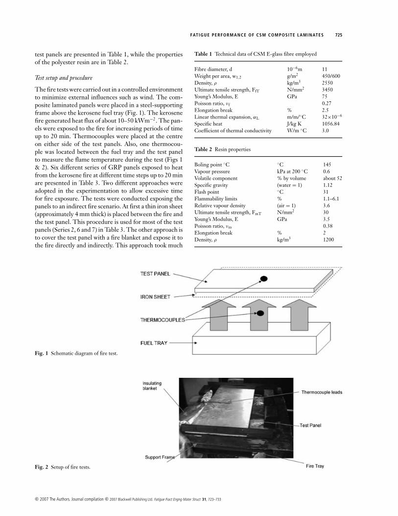
The fire tests were carried out in a controlled environmentto minimize external influences such as wind. The com-posite laminated panels were placed in a steel-supportingframe above the kerosene fuel tray (Fig. 1). The kerosenefire generated heat flux of about 10–50 kWm−2. The pan-els were exposed to the fire for increasing periods of timeup to 20 min. Thermocouples were placed at the centreon either side of the test panels. Also, one thermocou-ple was located between the fuel tray and the test panelto measure the flame temperature during the test (Figs 1& 2). Six different series of GRP panels exposed to heatfrom the kerosene fire at different time steps up to 20 minare presented in Table 3. Two different approaches wereadopted in the experimentation to allow excessive timefor fire exposure. The tests were conducted exposing thepanels to an indirect fire scenario. At first a thin iron sheet(approximately 4 mm thick) is placed between the fire andthe test panel. This procedure is used for most of the testpanels (Series 2, 6 and 7) in Table 3. The other approach isto cover the test panel with a fire blanket and expose it tothe fire directly and indirectly. This approach took much
Fig. 1 Schematic diagram of fire test.
Fig. 2 Setup of fire tests.
Table 1 Technical data of CSM E-glass fibre employed
Fibre diameter, d 10−6m 11Weight per area, w1,2 g/m2 450/600Density, ρ kg/m3 2550Ultimate tensile strength, FfT N/mm2 3450Young’s Modulus, E GPa 75Poisson ratio, νf 0.27Elongation break % 2.5Linear thermal expansion, αL m/m/◦C 32×10−6
Specific heat J/kg K 1056.84Coefficient of thermal conductivity W/m ◦C 3.0
Table 2 Resin properties
Boling point ◦C ◦C 145Vapour pressure kPa at 200 ◦C 0.6Volatile component % by volume about 52Specific gravity (water = 1) 1.12Flash point ◦C 31Flammability limits % 1.1–6.1Relative vapour density (air = 1) 3.6Ultimate tensile strength, FmT N/mm2 30Young’s Modulus, E GPa 3.5Poisson ratio, νm 0.38Elongation break % 2Density, ρ kg/m3 1200
c© 2007 The Authors. Journal compilation c© 2007 Blackwell Publishing Ltd. Fatigue Fract Engng Mater Struct 31, 723–733
726 H. ST ADTKE and B. G. PRUSTY
Table 3 Different times of exposure and maximum temperature atmaximum exposure time
Fire exposure Max. temperature [◦C]
Panel time [min] Exposed surface Unexposed surface
Series 04 0 - -Series 06 3 150 70Series 02 5 360 120Series 07 7 380 130Series 03 12 220 110Series 05 20 320 130
more time to produce similar results as the tests using theiron sheet and it partly showed some interesting resultswith almost no distinct physical difference between preand post heating. Panel 3 (Series 3) and Panel 5 (Series 5)in Table 3 are tested using the second approach, i.e. usingthe thin iron sheet and the fire blanket additionally.
Preparation of fatigue test specimen
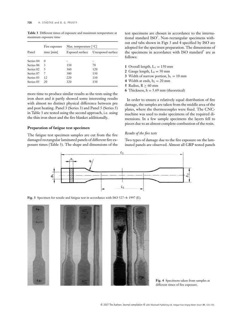
The fatigue test specimen samples are cut from the firedamaged rectangular laminated panels of different fire ex-posure times (Table 3). The shape and dimensions of the
Fig. 3 Specimen for tensile and fatigue test in accordance with ISO 527–4: 1997 (E).
Fig. 4 Specimens taken from samples atdifferent times of fire exposure.
test specimens are chosen in accordance to the interna-tional standard ISO7. Non-rectangular specimens with-out end tabs shown in Figs 3 and 4 specified by ISO areadopted for the specimen preparation. The dimensions ofthe specimens in accordance with ISO standard7 are asfollows:
1 Overall length, L3 = 150 mm2 Gauge length, L0 = 50 mm3 Width of narrow portion, b1 = 10 mm4 Width at ends, b2 = 20 mm5 Radius, R ≥ 60 mm6 Thickness, h = 5.69 mm (theoretical)
In order to ensure a relatively equal distribution of firedamage, the samples are taken from the middle area of theplates, where the thermocouples were fixed. The CNC-machine was used to make specimens of the required di-mensions. In a few sample specimens the layers fell topieces due to an almost complete combustion of the resin.
Results of the fire tests
Two types of damage due to the fire exposure on the lam-inated panels are observed. Almost all GRP tested panels
c© 2007 The Authors. Journal compilation c© 2007 Blackwell Publishing Ltd. Fatigue Fract Engng Mater Struct 31, 723–733
FAT IGUE PERFORMANCE OF CSM COMPOSITE LAMINATES 727
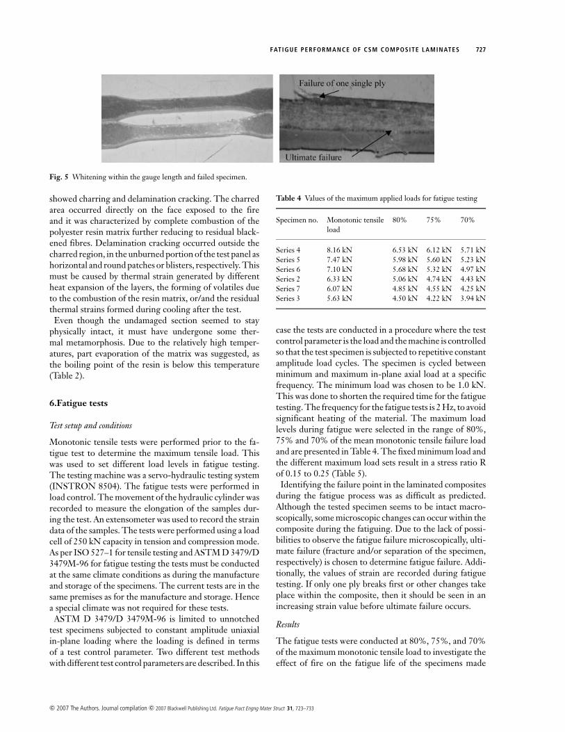
Fig. 5 Whitening within the gauge length and failed specimen.
showed charring and delamination cracking. The charredarea occurred directly on the face exposed to the fireand it was characterized by complete combustion of thepolyester resin matrix further reducing to residual black-ened fibres. Delamination cracking occurred outside thecharred region, in the unburned portion of the test panel ashorizontal and round patches or blisters, respectively. Thismust be caused by thermal strain generated by differentheat expansion of the layers, the forming of volatiles dueto the combustion of the resin matrix, or/and the residualthermal strains formed during cooling after the test.
Even though the undamaged section seemed to stayphysically intact, it must have undergone some ther-mal metamorphosis. Due to the relatively high temper-atures, part evaporation of the matrix was suggested, asthe boiling point of the resin is below this temperature(Table 2).
6.Fatigue tests
Test setup and conditions
Monotonic tensile tests were performed prior to the fa-tigue test to determine the maximum tensile load. Thiswas used to set different load levels in fatigue testing.The testing machine was a servo-hydraulic testing system(INSTRON 8504). The fatigue tests were performed inload control. The movement of the hydraulic cylinder wasrecorded to measure the elongation of the samples dur-ing the test. An extensometer was used to record the straindata of the samples. The tests were performed using a loadcell of 250 kN capacity in tension and compression mode.As per ISO 527–1 for tensile testing and ASTM D 3479/D3479M-96 for fatigue testing the tests must be conductedat the same climate conditions as during the manufactureand storage of the specimens. The current tests are in thesame premises as for the manufacture and storage. Hencea special climate was not required for these tests.
ASTM D 3479/D 3479M-96 is limited to unnotchedtest specimens subjected to constant amplitude uniaxialin-plane loading where the loading is defined in termsof a test control parameter. Two different test methodswith different test control parameters are described. In this
Table 4 Values of the maximum applied loads for fatigue testing
Specimen no. Monotonic tensile 80% 75% 70%load
Series 4 8.16 kN 6.53 kN 6.12 kN 5.71 kNSeries 5 7.47 kN 5.98 kN 5.60 kN 5.23 kNSeries 6 7.10 kN 5.68 kN 5.32 kN 4.97 kNSeries 2 6.33 kN 5.06 kN 4.74 kN 4.43 kNSeries 7 6.07 kN 4.85 kN 4.55 kN 4.25 kNSeries 3 5.63 kN 4.50 kN 4.22 kN 3.94 kN
case the tests are conducted in a procedure where the testcontrol parameter is the load and the machine is controlledso that the test specimen is subjected to repetitive constantamplitude load cycles. The specimen is cycled betweenminimum and maximum in-plane axial load at a specificfrequency. The minimum load was chosen to be 1.0 kN.This was done to shorten the required time for the fatiguetesting. The frequency for the fatigue tests is 2 Hz, to avoidsignificant heating of the material. The maximum loadlevels during fatigue were selected in the range of 80%,75% and 70% of the mean monotonic tensile failure loadand are presented in Table 4. The fixed minimum load andthe different maximum load sets result in a stress ratio Rof 0.15 to 0.25 (Table 5).
Identifying the failure point in the laminated compositesduring the fatigue process was as difficult as predicted.Although the tested specimen seems to be intact macro-scopically, some microscopic changes can occur within thecomposite during the fatiguing. Due to the lack of possi-bilities to observe the fatigue failure microscopically, ulti-mate failure (fracture and/or separation of the specimen,respectively) is chosen to determine fatigue failure. Addi-tionally, the values of strain are recorded during fatiguetesting. If only one ply breaks first or other changes takeplace within the composite, then it should be seen in anincreasing strain value before ultimate failure occurs.
Results
The fatigue tests were conducted at 80%, 75%, and 70%of the maximum monotonic tensile load to investigate theeffect of fire on the fatigue life of the specimens made
c© 2007 The Authors. Journal compilation c© 2007 Blackwell Publishing Ltd. Fatigue Fract Engng Mater Struct 31, 723–733
728 H. ST ADTKE and B. G. PRUSTY
Table 5 Load sets for fatigue tests (loads are in kN)
Spec. no. 80% 75% 70%
Mean load Amp. R Mean load Amp. R Mean load Amp. R
2 3.03 2.03 0.20 2.87 1.87 0.21 2.71 1.17 0.233 2.75 2.75 0.22 2.61 1.61 0.24 2.47 1.47 0.254 3.76 2.76 0.15 3.56 2.56 0.16 3.36 2.36 0.185 3.49 2.49 0.17 3.30 2.30 0.18 3.11 2.11 0.196 3.34 2.34 0.18 3.16 2.16 0.19 2.98 1.98 0.207 2.93 1.93 0.21 2.77 1.77 0.22 2.62 1.62 0.24
out of glass-fibre/polyester composite and to make an ap-proach of fatigue life prediction. Three samples are testedfor each series to maintain the statistical reliability of meanstrength. The experimental observation of the failure pro-gression was as difficult as expected. For all the specimenstested, it is observed that the fatigue damage of all thetested specimens have shown similar failure patterns, as faras was macroscopically observable. Long before fracturetook place a whitening of the material within the gaugelength could be seen, still visible after ultimate failure(Figure 5). Furthermore, matrix cracks occurred duringtesting in the form of thin lines perpendicular to the loaddirection. On closer examination after the test, whiteningof a certain number of fibres is clearly visible. This couldbe attributed as the local delamination at the fibre-matrixinterface, as typical for discontinuous random-in-plane fi-bre composites. Particularly the transverse and angled fi-bres showed these signs of fatigue.
Considering that the laminate stacking sequence is non-symmetric, delamination may result from micro cracks
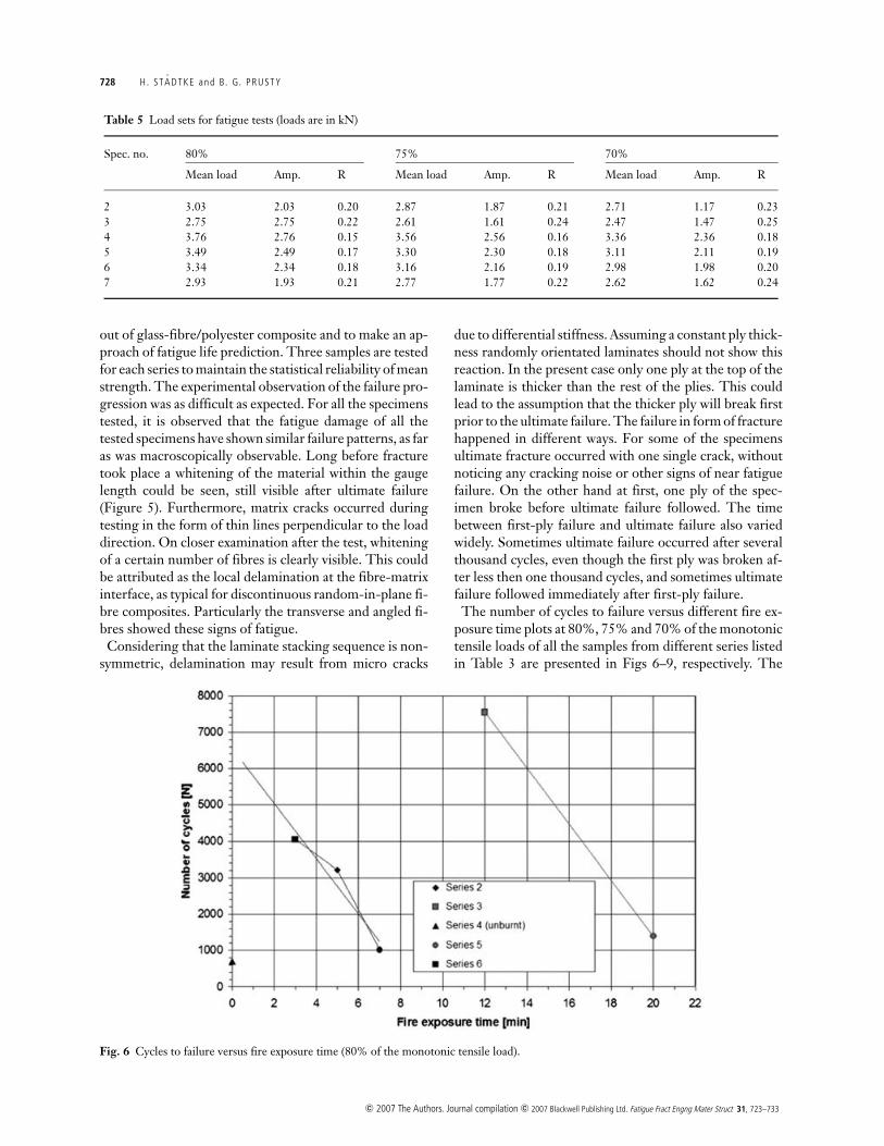
Fig. 6 Cycles to failure versus fire exposure time (80% of the monotonic tensile load).
due to differential stiffness. Assuming a constant ply thick-ness randomly orientated laminates should not show thisreaction. In the present case only one ply at the top of thelaminate is thicker than the rest of the plies. This couldlead to the assumption that the thicker ply will break firstprior to the ultimate failure. The failure in form of fracturehappened in different ways. For some of the specimensultimate fracture occurred with one single crack, withoutnoticing any cracking noise or other signs of near fatiguefailure. On the other hand at first, one ply of the spec-imen broke before ultimate failure followed. The timebetween first-ply failure and ultimate failure also variedwidely. Sometimes ultimate failure occurred after severalthousand cycles, even though the first ply was broken af-ter less then one thousand cycles, and sometimes ultimatefailure followed immediately after first-ply failure.
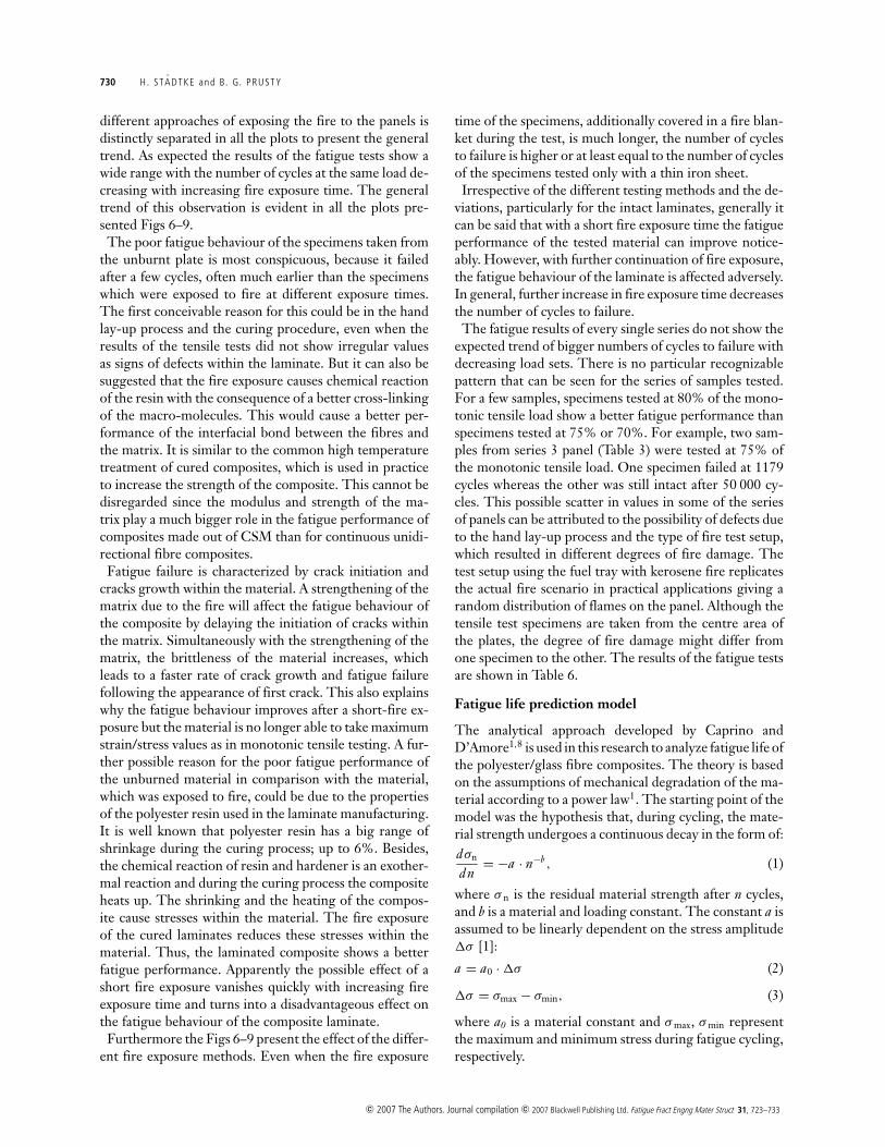
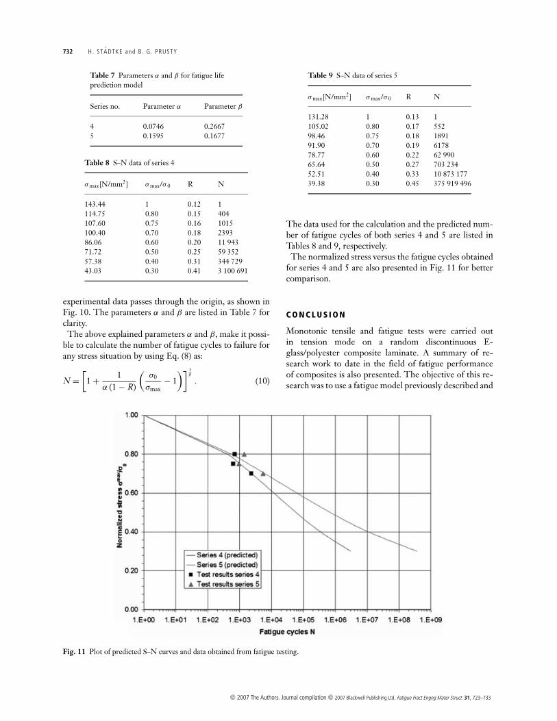
The number of cycles to failure versus different fire ex-posure time plots at 80%, 75% and 70% of the monotonictensile loads of all the samples from different series listedin Table 3 are presented in Figs 6–9, respectively. The
c© 2007 The Authors. Journal compilation c© 2007 Blackwell Publishing Ltd. Fatigue Fract Engng Mater Struct 31, 723–733
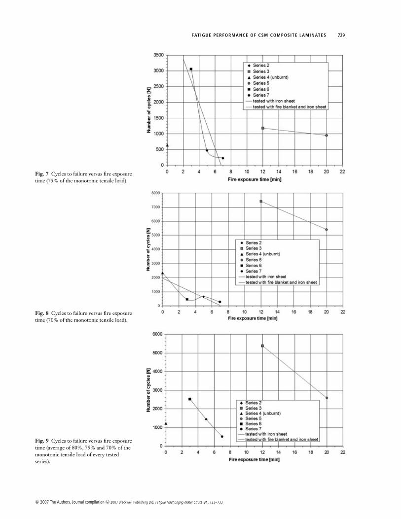
FAT IGUE PERFORMANCE OF CSM COMPOSITE LAMINATES 729
Fig. 7 Cycles to failure versus fire exposuretime (75% of the monotonic tensile load).
Fig. 8 Cycles to failure versus fire exposuretime (70% of the monotonic tensile load).
Fig. 9 Cycles to failure versus fire exposuretime (average of 80%, 75% and 70% of themonotonic tensile load of every testedseries).
c© 2007 The Authors. Journal compilation c© 2007 Blackwell Publishing Ltd. Fatigue Fract Engng Mater Struct 31, 723–733
730 H. ST ADTKE and B. G. PRUSTY
different approaches of exposing the fire to the panels isdistinctly separated in all the plots to present the generaltrend. As expected the results of the fatigue tests show awide range with the number of cycles at the same load de-creasing with increasing fire exposure time. The generaltrend of this observation is evident in all the plots pre-sented Figs 6–9.
The poor fatigue behaviour of the specimens taken fromthe unburnt plate is most conspicuous, because it failedafter a few cycles, often much earlier than the specimenswhich were exposed to fire at different exposure times.The first conceivable reason for this could be in the handlay-up process and the curing procedure, even when theresults of the tensile tests did not show irregular valuesas signs of defects within the laminate. But it can also besuggested that the fire exposure causes chemical reactionof the resin with the consequence of a better cross-linkingof the macro-molecules. This would cause a better per-formance of the interfacial bond between the fibres andthe matrix. It is similar to the common high temperaturetreatment of cured composites, which is used in practiceto increase the strength of the composite. This cannot bedisregarded since the modulus and strength of the ma-trix play a much bigger role in the fatigue performance ofcomposites made out of CSM than for continuous unidi-rectional fibre composites.
Fatigue failure is characterized by crack initiation andcracks growth within the material. A strengthening of thematrix due to the fire will affect the fatigue behaviour ofthe composite by delaying the initiation of cracks withinthe matrix. Simultaneously with the strengthening of thematrix, the brittleness of the material increases, whichleads to a faster rate of crack growth and fatigue failurefollowing the appearance of first crack. This also explainswhy the fatigue behaviour improves after a short-fire ex-posure but the material is no longer able to take maximumstrain/stress values as in monotonic tensile testing. A fur-ther possible reason for the poor fatigue performance ofthe unburned material in comparison with the material,which was exposed to fire, could be due to the propertiesof the polyester resin used in the laminate manufacturing.It is well known that polyester resin has a big range ofshrinkage during the curing process; up to 6%. Besides,the chemical reaction of resin and hardener is an exother-mal reaction and during the curing process the compositeheats up. The shrinking and the heating of the compos-ite cause stresses within the material. The fire exposureof the cured laminates reduces these stresses within thematerial. Thus, the laminated composite shows a betterfatigue performance. Apparently the possible effect of ashort fire exposure vanishes quickly with increasing fireexposure time and turns into a disadvantageous effect onthe fatigue behaviour of the composite laminate.
Furthermore the Figs 6–9 present the effect of the differ-ent fire exposure methods. Even when the fire exposure
time of the specimens, additionally covered in a fire blan-ket during the test, is much longer, the number of cyclesto failure is higher or at least equal to the number of cyclesof the specimens tested only with a thin iron sheet.
Irrespective of the different testing methods and the de-viations, particularly for the intact laminates, generally itcan be said that with a short fire exposure time the fatigueperformance of the tested material can improve notice-ably. However, with further continuation of fire exposure,the fatigue behaviour of the laminate is affected adversely.In general, further increase in fire exposure time decreasesthe number of cycles to failure.
The fatigue results of every single series do not show theexpected trend of bigger numbers of cycles to failure withdecreasing load sets. There is no particular recognizablepattern that can be seen for the series of samples tested.For a few samples, specimens tested at 80% of the mono-tonic tensile load show a better fatigue performance thanspecimens tested at 75% or 70%. For example, two sam-ples from series 3 panel (Table 3) were tested at 75% ofthe monotonic tensile load. One specimen failed at 1179cycles whereas the other was still intact after 50 000 cy-cles. This possible scatter in values in some of the seriesof panels can be attributed to the possibility of defects dueto the hand lay-up process and the type of fire test setup,which resulted in different degrees of fire damage. Thetest setup using the fuel tray with kerosene fire replicatesthe actual fire scenario in practical applications giving arandom distribution of flames on the panel. Although thetensile test specimens are taken from the centre area ofthe plates, the degree of fire damage might differ fromone specimen to the other. The results of the fatigue testsare shown in Table 6.
Fatigue life prediction model
The analytical approach developed by Caprino andD’Amore1,8 is used in this research to analyze fatigue life ofthe polyester/glass fibre composites. The theory is basedon the assumptions of mechanical degradation of the ma-terial according to a power law1. The starting point of themodel was the hypothesis that, during cycling, the mate-rial strength undergoes a continuous decay in the form of:dσn
dn= −a · n−b , (1)
where σ n is the residual material strength after n cycles,and b is a material and loading constant. The constant a isassumed to be linearly dependent on the stress amplitude�σ [1]:
a = a0 · �σ (2)
�σ = σmax − σmin, (3)
where a0 is a material constant and σ max, σ min representthe maximum and minimum stress during fatigue cycling,respectively.
c© 2007 The Authors. Journal compilation c© 2007 Blackwell Publishing Ltd. Fatigue Fract Engng Mater Struct 31, 723–733

FAT IGUE PERFORMANCE OF CSM COMPOSITE LAMINATES 731
Table 6 Results of fatigue tests at different loading conditions
Series number Fire exposure time Fatigue cycles Fatigue cycles Fatigue cycles[min] 80% load set 75% load set 70% load set
4 0 700 639 23416 3 4045 3059 4652 5 3220 467 6587 7 1017 225 2803 12 7549 1179/>50 000 74145 20 1395 946 5406
On substitution of Eq. (2) into Eq. (1) and integratingwith the boundary condition n = 1→σ n = σ 0 the fol-lowing equation for the degradation in strength duringcycling can be obtained:
σ0 − σn = α · σmax · (1 − R) (nβ − 1) (4)
with
R = σmin
σmax(5)
α = a0
1 − b(6)
β = 1 − b . (7)
It is assumed that fatigue failure occurs when the residualmaterial strength matches the maximum applied stress.
The critical number of cycles to failure, N , is calculatedby substituting σ n = σ max in Eq. (4):
N =[
1 + 1α (1 − R)
(σ0
σmax− 1
)] 1β
. (8)
Fig. 10 Plot of the results of equation fordetermination of the parameters α and β.
The above Eq. (8) can also be rearranged as:(σ0
σmax− 1
)1
1 − R= α(Nβ − 1). (9)
Plotting the values of the left-side term against (Nβ-1)should result in a straight line of slope α passing troughthe origin, which can then be used to evaluate α and β bysuitably adjusting the β value until the best-fit straightline through the experimental data passes through theorigin1.
The target of the fatigue life prediction is to develop auseful S–N plot for the tested material. The calculation isbased on the data obtained from the fatigue tests. The ap-parent random distribution of the obtained data makes anaccurate fatigue life prediction very difficult. Neverthe-less, it is intended to calculate the fatigue life of specimenof series 4 and series 5 using the fatigue prediction model.The first step of the calculation is to use Eq. (9) by plottingthe values of the left-side term against (Nβ-1).
The resulting straight line of slope α passing trough theorigin is used to evaluate α and β by suitably adjustingthe β value until the best-fit straight line through the
c© 2007 The Authors. Journal compilation c© 2007 Blackwell Publishing Ltd. Fatigue Fract Engng Mater Struct 31, 723–733
732 H. ST ADTKE and B. G. PRUSTY
Table 7 Parameters α and β for fatigue lifeprediction model
Series no. Parameter α Parameter β
4 0.0746 0.26675 0.1595 0.1677
Table 8 S–N data of series 4
σmax[N/mm2] σmax/σ 0 R N
143.44 1 0.12 1114.75 0.80 0.15 404107.60 0.75 0.16 1015100.40 0.70 0.18 239386.06 0.60 0.20 11 94371.72 0.50 0.25 59 35257.38 0.40 0.31 344 72943.03 0.30 0.41 3 100 691
experimental data passes through the origin, as shown inFig. 10. The parameters α and β are listed in Table 7 forclarity.
The above explained parameters α and β, make it possi-ble to calculate the number of fatigue cycles to failure forany stress situation by using Eq. (8) as:
N =[
1 + 1α (1 − R)
(σ0
σmax− 1
)] 1β
. (10)
Fig. 11 Plot of predicted S–N curves and data obtained from fatigue testing.
Table 9 S–N data of series 5
σmax[N/mm2] σmax/σ 0 R N
131.28 1 0.13 1105.02 0.80 0.17 55298.46 0.75 0.18 189191.90 0.70 0.19 617878.77 0.60 0.22 62 99065.64 0.50 0.27 703 23452.51 0.40 0.33 10 873 17739.38 0.30 0.45 375 919 496
The data used for the calculation and the predicted num-ber of fatigue cycles of both series 4 and 5 are listed inTables 8 and 9, respectively.
The normalized stress versus the fatigue cycles obtainedfor series 4 and 5 are also presented in Fig. 11 for bettercomparison.
C O N C L U S I O N
Monotonic tensile and fatigue tests were carried outin tension mode on a random discontinuous E-glass/polyester composite laminate. A summary of re-search work to date in the field of fatigue performanceof composites is also presented. The objective of this re-search was to use a fatigue model previously described and
c© 2007 The Authors. Journal compilation c© 2007 Blackwell Publishing Ltd. Fatigue Fract Engng Mater Struct 31, 723–733
FAT IGUE PERFORMANCE OF CSM COMPOSITE LAMINATES 733
to investigate the influence of different fire exposure timeon the fatigue response of the composites. Fatigue testswere performed for a series of specimens taken from sam-ples tested for fire sources at different time intervals. Thespecimens tested in the current research were exposed toa source of kerosene fire. This testing method is an ex-ample of the natural environment of day to day life, but aunique distribution of heat all over the specimen cannot beassured, which justifies the deviation in the results dur-ing the test. From the deviated results it can be seen thatfurther testing and experimentation is required in orderto establish a more coherent relationship between actualand theoretical results. However, explanations for the dif-ference between the actual tested results and the theo-retical predictions, particularly for the prediction of thematerial properties, could be attributed to non-existenceof a theoretical prediction model for the properties ofrandom-orientated fibre composites. Irrespective of thedifferent testing methods, such as by exposing the lami-nates to direct fire, by putting a thin iron sheet or with airon sheet and blanket from the deviations in the fatiguetest result for the intact laminates, it can be concluded thatfor a short fire exposure time the fatigue performance ofthe tested material can improve noticeably. However, fur-ther continuing fire exposure affects the fatigue behaviourof the laminate to its disadvantage. In general, increas-ing fire exposure time decreases the number of cycles tofailure.
To ensure more statistical reliability in the results, fur-ther testing with a greater number of samples for testing atevery single load set is highly recommended. This wouldincrease the statistical reliability of the obtained values
while minimizing the influence of possible mistakes dur-ing the tests and defects within the material. Also, it wouldbe necessary to develop a more reliable model to predictthe material properties of random orientated discontinu-ous fibre-reinforced composite or to improve and validatethe existing models.
R E F E R E N C E S
1 Caprino, G. and D’Amore, A. (1998) Flexural behaviour ofrandom continuous fibre-reinforced thermoplastic composites.Composites Science and Technology 58, 957–965.
2 Lee, H. K. and Simunovic, S. (2001) A damage constitutivemodel of progressive debonding in aligned discontinuous fibrecomposites. International Journal of Solids and Structures 38,875–895.
3 Lee, H. K. and Simunivic, S. (2000) Modelling of progressivedamage in aligned and randomly orientated discontinuous fibrepolymer matrix composites. Composites Part B31, 77–86.
4 Meraghni, F. and Benzeggagh, M. L. (1995) Micromechanicalmodelling of matrix degradation in randomly orientateddiscontinuous-fibre composites. Composites Science and Technology55, 171–186.
5 Petrossian, Z. and Wisnom, M. R. (1998) Prediction ofdelamination initiation and growth from discontinuous pliesusing interface elements. Composites Part A A29, 503–515.
6 Solomon, E. K. (2004) Structural performance of glass-reinforcedpolymer panels under elevated temperatures, B. Eng ResearchThesis, Australian Maritime College, Australia, 1–81.
7 ISO 527–4 (E) (1997) International Standard for the determinationof tensile properties for isotropic and orthotropic fibre-reinforced plasticcomposites.
8 D’Amore, A., Caprino, G., Stupak, P. and Nicolais, L. (1996)Effect of stress ratio on the flexural fatigue behaviour ofcontinuous strand mat reinforced plastics. Sci. and Eng. OfCompos. Mater. 4, 17–25.
c© 2007 The Authors. Journal compilation c© 2007 Blackwell Publishing Ltd. Fatigue Fract Engng Mater Struct 31, 723–733
Copyright © 2022 FDOKUMEN