Crosslinkable polyester/isocyanate compositions suitable for ...
Upload
khangminh22Category
view
0download
0
Control Stations in Glass Fiber Reinforced Pol yester (GRP) GL***.CS
1
Re
lea
se
da
te 2
01
5-0
6-1
1
T
17
032
1
Glass fiber reinforced polyester (GRP) enclosures
Suitable for installation in Zones 1, 2, 21 and 22
Certified Ex de, Ex ib and Ex tb
Five enclosure size options
Up to 35 operators per control station, base-mounted contact blocks
Wide choice of operators, including o Pushbuttons o LED indicators o LED indicators for Ex ia circuits o Illuminated pushbuttons o Emergency stop buttons o Pushbuttons with key release o Control switches o Potentiometers o Ammeters/Voltmeters
Customizable configuration of operators and cable gland types as per specification
Wide range of labels and accessories available
Features
Configuration Examples
Assembly
Function
The versatile control stations of the GLCS series can be equipped flexibly with operator elements and LED indicators. A comprehensive range of control functions, contact blocks, cable glands and further accessories allow the configuration of each control station to exactly meet any application requirements and ensure optimal space efficency. Enclosures are manufactured from carbon loaded glass fiber reinforced polyester with stainless steel lid fixing bolts. This GRP material is anti-static and UV stabilized, the smooth surface is corrosion resistant and allows easy and fast cleaning. Durable materials and components of high quality allow the control stations to be used in ambient temperatures between-40 °C and +55 °C.

Control Stations in Glass Fiber Reinforced Pol yester (GRP) GL***.CS
2
Re
lea
se
da
te 2
01
5-0
6-1
1
T
17
032
1
Electrical specifications
Operating voltage 250 V AC max.
Operating current 16 A max.
Mechanical Specification
Cover fixing M6 stainless steel combination pan head screws
Protection degree IP66
Cable entry cable glands as per specification
Cable entry areas see cable entries table
Material
Enclosure carbon loaded, anti-static glass fiber reinforced polyester (GRP)
Finish moulded, self-colour black
Seal silicone cord
Mass see dimensions data table
Grounding none as standard optional M6 internal / external stud as required optional earth continuity plate, brass, 2 mm thick
Ambient conditions
Ambient temperature -40 °C ... 55 °C (-40 … 131 °F)
Data for application in connection with Ex-areas
EC-Type Examination Certificate SIRA 13ATEX3059X
Group, category, type of protection, temperature class
II 2 GD Ex de IIC T6, T5, T4 Gb Ex ib IIC T6, T5, T4 Gb Ex de ib IIC T6, T5, T4 Gb Ex tb IIIC T80 °C, T95 °C, T130 °C Db
International approvals
IECEx approval IECEx SIR 13.0021
Customs Union TR RU C-DE B.00567
Conformity
Protection degree EN 60529
General information
Supplementary information EC-Type Examination Certificate, Statement of Conformity, Declaration of Conformity, Attestation of Conformity and instructions have to be observed where applicable. For information see www.pepperl-fuchs.com.
Accessories
Optional accessories see accessories table
Technical Data

Control Stations in Glass Fiber Reinforced Pol yester (GRP) GL***.CS
3
Re
lea
se
da
te 2
01
5-0
6-1
1
T
17
032
1
Dimensions Data Table
Type Dimensions [mm]
Dimensions internal [mm]
Fixation [mm]
Weight approx.
Cover fixing screws
A B C D E F G H Diam. J [kg] Stainless steel
GL8** 160 260 91 149 249 56 110 240 6.5 1.7 M6
GL9** 160 360 91 149 349 56 110 340 6.5 2 M6
GL11** 250 255 120 239 244 82 200 235 6.5 2.7 M6
GL12** 250 400 120 239 389 82 200 380 6.5 3.4 M6
GL13** 405 400 120 394 389 82 355 380 6.5 5.1 M6
Weight shows empty enclosure; it will increase according to operators and installations.
Cable Entries - maximum quantity per size
Type Cable entry area at faces Cable gland quantity face A/B Cable gland quantity face C/D
A & B [mm] C & D [mm] M12 M16 M20 M25 M32 M40 M50 M12 M16 M20 M25 M32 M40 M50
GL8** 64 x 210 59 x 80 24 18 12 7 5 3 3 9 6 4 2 2 1 1
GL9** 64 x 310 59 x 80 34 26 20 11 7 5 4 9 6 4 2 2 1 1
GL11** 82 x 204 82 x 170 55 40 24 18 12 8 6 45 30 20 15 9 6 4
GL12** 89 x 349 84 x 169 63 45 32 20 14 8 5 28 18 14 8 6 3 2
GL13** 89 x 349 84 x 324 63 45 32 20 14 8 5 54 39 27 18 13 6 5
Max. gland quantity per size. For combination of different sizes please contact Pepperl+Fuchs.
Dimensions
A – Maximum external dimension B – Maximum external dimension C – Maximum external dimension D – Internal dimension E – Internal dimension F – Internal depth G – Fixing holes center H – Fixing holes center J – Fixing holes diameter [A] – Entry face [B] – Entry face [C] – Entry face [D] – Entry face For details see Dimensions Data Table
Legend

Control Stations in Glass Fiber Reinforced Pol yester (GRP) GL***.CS
4
Re
lea
se
da
te 2
01
5-0
6-1
1
T
17
032
1
Windows and large labels (3)
Windows and large labels (3)
Windows and large labels (3)
Windows and large labels (3) Maximum configuration (1) Large operator configuration (2)
Maximum configuration (1) Large operator configuration (2)
Maximum configuration (1) Large operator configuration (2)
Maximum configuration (1) Large operator configuration (2) Windows and large labels (3)
Enclosure size GL8 configuration: max. 8 functions – operator types see overleaf
Enclosure size GL9 configuration: max. 12 functions – operator types see overleaf
Enclosure size GL11 configuration: max. 12 functions – operator types see overleaf
Enclosure size GL12 configuration: max. 21 functions – operator types see overleaf
Enclosure size GL13 configuration: max. 35 functions – operator types see overleaf
(1) Small operators with small label holders and 2 pole contact blocks Small operators include all pushbuttons, small switching actuators, LED indicators and potentiometers, see overleaf
(2) Large switching actuators and all operators fitted with 4 pole contact blocks, protective lid or padlockable shroud (3) Viewing windows with ammeter or voltmeter and operators with large label holders
For further configurations please contact Pepperl+Fuchs. Note: position of grounding stud can vary depending on configuration.
Maximum configuration (1) Large operator configuration (2)

Control Stations in Glass Fiber Reinforced Pol yester (GRP) GL***.CS
5
Re
lea
se
da
te 2
01
5-0
6-1
1
T
17
032
1
Type code / model number
Enclosure type
GL glass fiber reinforced polyester GRP
: Enclosure size
: 8, 9, 11, 12, 13 see dimensions data table
: : Earth continuity plate
: : 0 none
: : 2 brass
: : : Type of explosion protection
: : : 1 Ex de, Ex tb
: : : 3 Ex ib, Ex tb
: : : 5 Ex de ib, Ex tb
: : : : Enclosure depth
: : : : standard depth, see dimensions data table
: : : : D increased depth
: : : : : Type of solution
: : : : : CS control station
: : : : : : Item number
: : : : : : Yxxxxxx
GL .CS -Yxxxxxx
Optional Enclosure Accessories
M6 brass grounding stud assembly
M6 stainless steel grounding stud assembly
Engraved traffolyte tag label
Engraved stainless steel tag label
Color in-fill stainless steel tag label

Control Stations in Glass Fiber Reinforced Pol yester (GRP) GL***.CS
6
Re
lea
se
da
te 2
01
5-0
6-1
1
T
17
032
1
Ex de Pushbuttons and Emergency Stops
Pushbutton Actuators Type Code
Red pushbutton with blank insert PA
Red pushbutton with insert labeled "O" PR
Red pushbutton with insert labeled "STOP" PC
Red pushbutton with insert labeled "OFF" PD
Green pushbutton with blank insert PE
Green pushbutton with insert labeled "I" PG
Green pushbutton with insert labeled "START" PF
Green pushbutton with insert labeled "ON" PH Blue Pushbutton Actuator
Yellow pushbutton with blank insert PY
Amber pushbutton with blank insert PM
White pushbutton with blank insert PW
Blue pushbutton with blank insert PB
Blue pushbutton with insert labeled "RESET" PJ
Black pushbutton with blank insert PK
Black pushbutton with insert labeled "0" PL
Black pushbutton with insert labeled "I" PN
Black pushbutton with insert labeled "II" PP
Black pushbutton with insert labeled "III" PQ
Black pushbutton with insert labeled "IV" PT
Black pushbutton with insert labeled "↑" PU
Black pushbutton with insert labeled "↓" PV
Emergency Stop Actuator
Emergency Stop Actuators Type Code
Pull-to-release mushroom button, red, labeled "EMERGENCY STOP" ER
Key-release mushroom button, red JR
Other Pushbutton Actuators Type Code
Double pushbutton red/green labeled "0 - I" DM
Mushroom pushbutton, black MK (*)
Key pushbutton, latching two position, black/silver HS
(*) change from 'MB'
Key-release Mushroom Button
Mushroom Pushbutton
Key Pushbutton

Control Stations in Glass Fiber Reinforced Pol yester (GRP) GL***.CS
7
Re
lea
se
da
te 2
01
5-0
6-1
1
T
17
032
1
Ex de Illuminated Pushbuttons
Illuminated Pushbutton Actuators Type Code
Red illuminated pushbutton IR
Green illuminated pushbutton IG
Amber illuminated pushbutton (*) IY
White illuminated pushbutton IW
Blue illuminated pushbutton IB
(*) change from yellow
Blue Pushbutton Actuator
LED Contact Modules, base-mounted Type Code
LED module 12 - 250 V AC/DC with 1x NO contact I
LED module 12 - 250 V AC/DC with 1x NC contact J
Base-mounted LED Module
Technical Data LED Contact Modules
Utilization category AC15 DC13
Rated operating voltage 12 ... 250 V 12 ... 24 V
Rated operating current 10 A 1 A
Terminals, max. core cross-section 2 x 2.5 mm2 2 x 2.5 mm2
Power consumption ≤ 1 W ≤ 1 W
Contact Blocks, base-mounted Type Code
Contact block with 1x NO / 1x NC contacts M
Contact block with 2x NC contacts C
Contact block with 2x NO contacts O
Contact block with 2x NO / 2x NC contacts 01
Contact block with 4x NC contacts 02
Contact block with 4x NO contacts 03
Contact block with 1x NO / 3x NC contacts 04
Contact block with 3x NO / 1x NC contacts 05 Base-mounted Contact Block
Technical Data Contact Blocks
Utilization category AC12 AC15 DC13 DC13
Rated operating voltage 250 V 250 V 110 V 24 V
Rated operating current 16 A 10 A 1 A 1 A
Terminals, max. core cross-section 2 x 2.5 mm2 2 x 2.5 mm2 2 x 2.5 mm2 2 x 2.5 mm2

Control Stations in Glass Fiber Reinforced Pol yester (GRP) GL***.CS
8
Re
lea
se
da
te 2
01
5-0
6-1
1
T
17
032
1
Ex de Control Switches, 2 Pole Contact Blocks
Switching Actuators For Use With 2 Pole Contact Blocks Switching Diagram
Contact Block * Action
Marking Type Code
Small actuator, 2 position with left OFF 1 O latching - latching 0 I N6
Small actuator, 2 position 2 M latching - latching I II N7
Small actuator, 3 position with center OFF 4 O latching - latching - latching I 0 II N8
Small actuator, 3 position with left OFF 3 M latching - latching - latching 0 I II N9
Large actuator, 2 position with left OFF, padlockable in "0" 1 O latching - latching 0 I S6
Large actuator, 2 position 2 M latching - latching I II S7
Large actuator, 3 position with center OFF, padlockable in "0" 4 O latching - latching - latching I 0 II S8
Large actuator, 3 position with left OFF 3 M latching - latching - latching 0 I II S9
Key switch actuator, 2 position with left OFF 1 O latching - latching 0 I KA
Key switch actuator, 3 position with center OFF 4 O latching - latching - latching I 0 II KC
Note: all switching actuators are black, the large ones are shrouded
(*) Switching diagram shows combination of contact block with actuator
Contact Blocks 2 Pole, base-mounted Type Code
Contact block with 1x NO / 1x NC contacts M
Contact block with 2x NC contacts C
Contact block with 2x NO contacts O
Switching Diagrams 2 Pole Contact Blocks
Note: diagram 3 has changed
Diagram 1
13 23
X X
14 24
Diagram 2
11 23
X
X
12 24
Diagram 3
11 23
X
X
12 24
Diagram 4
13 23
X
X
14 24
Small Actuator
Large Actuator with Shroud
Technical Data Contact Blocks
Utilization category AC12 AC15 DC13 DC13
Rated operating voltage 250 V 250 V 110 V 24 V
Rated operating current 16 A 10 A 1 A 1 A
Terminals, max. core cross-section 2 x 2.5 mm2 2 x 2.5 mm2 2 x 2.5 mm2 2 x 2.5 mm2
Base-mounted Contact Block

Control Stations in Glass Fiber Reinforced Pol yester (GRP) GL***.CS
9
Re
lea
se
da
te 2
01
5-0
6-1
1
T
17
032
1
Ex de Control Switches, 4 Pole Contact Blocks
Switching Actuators For Use With 4 Pole Contact Blocks Switching Diagram
Contact Block * Action
Marking Type Code
Large actuator, 2 position with left OFF, padlockable in "0" 5 03 latching - latching 0 I S6
Large actuator, 2 position 6 01 latching - latching I II S7
Large actuator, 3 position with center OFF, padlockable in "0" 7 03 latching - latching -
latching I 0 II S8
Note: all switching actuators are black and shrouded
(*) Switching diagram shows combination of contact block with actuator
Contact Blocks 4 Pole, base-mounted Type Code
Contact block with 2x NO / 2x NC contacts 01
Contact block with 4x NC contacts 02
Contact block with 4x NO contacts 03
Contact block with 1x NO / 3x NC contacts 04
Contact block with 3x NO / 1x NC contacts 05
Switching Diagrams 4 Pole Contact Blocks
Diagram 5
13 23 33 43
X X X X
14 24 34 44
Base-mounted Contact Block 4 Pole
Diagram 6
11 21 33 43
X X
X X
12 22 34 44
Diagram 7
13 23 33 43
X X
X X
14 24 34 44
Technical Data Contact Blocks
Utilization category AC12 AC15 DC13 DC13
Rated operating voltage 250 V 250 V 110 V 24 V
Rated operating current 16 A 10 A 1 A 1 A
Terminals, max. core cross-section 2 x 2.5 mm2 2 x 2.5 mm2 2 x 2.5 mm2 2 x 2.5 mm2

Control Stations in Glass Fiber Reinforced Pol yester (GRP) GL***.CS
10
Re
lea
se
da
te 2
01
5-0
6-1
1
T
17
032
1
Ex de Control Switches, 4 Pole Rotary Switching Blocks
4 Pole Rotary Switching Block, base-mounted Rotary Switching Actuator
Large Control Switches, 4 Pole Type Code Switching Diagram Action Marking
Type Code
Switch 2 position with left OFF (*) 10 5 latching - latching 0 I T6
Switch 2 position 11 6 latching - latching I II T7
Switch 3 position with center OFF (*) 12 7 latching - latching - latching I 0 II T8
Switch 3 position with center OFF (*) 13 8 spring - latching - spring I 0 II T8
Switch 3 position, right with spring return 16 10 latching - latching - spring 0 I II T0
Switch 4 position 15 11 latching - latching - latching - latching I II III IV T9
Note: all switching actuators are black and shrouded. (*) = padlockable in "0" position
Always indicate type codes for both rotary actuator and switching block
Switching Diagrams 4 Pole Rotary Switching Blocks
Diagram 5
13 23 33 43
X X X X
14 24 34 44z
Control Switch 4 Pole
Diagram 6
11 21 33 43
X X
X X
12 22 34 44
Diagram 7
13 23 33 43
X X
X X
14 24 34 44
Diagram 8
13 23 33 43
X X
X X
14 24 34 44
Diagram 10
11 23 33 43
X
X
X X
12 24 34 44
Diagram 11
11 23 33 43
X
X
X
X
12 24 34 44
Technical Data Switching Blocks
Utilization category AC12 AC15 DC13 DC13
Rated operating voltage 250 V 250 V 110 V 24 V
Rated operating current 16 A 10 A 1 A 1 A
Terminals, max. core cross-section 2 x 2.5 mm2 2 x 2.5 mm2 2 x 2.5 mm2 2 x 2.5 mm2

Control Stations in Glass Fiber Reinforced Pol yester (GRP) GL***.CS
11
Re
lea
se
da
te 2
01
5-0
6-1
1
T
17
032
1
Ex de / Ex ia LED Indicators
Lens for LED Type Code
Red indicator lens cover LR
Green indicator lens cover LG
Amber indicator lens cover (*) LY
White indicator lens cover LW
Blue indicator lens cover LB
(*) change from yellow
Red LED Indicator
LED Modules, base-mounted Type Code
10 - 28 V AC/DC LED Module, certified Ex de / Ex ia N
20 - 250 V AC/DC LED Module, certified Ex de L
250 - 400 V AC/DC LED Module, certified Ex de P
Base-mounted LED Module
Technical Data LED Modules
Rated operating voltage (type N) 10 ... 28 V AC/DC
Rated operating voltage (type L) 20 ... 250 V AC/DC
Rated operating voltage (type P) 250 ... 400 V AC
Terminals, max. core cross-section 2 x 2.5 mm2
Power consumption ≤ 2 W
Ex i data for application in connection with Ex-areas (type N)
EC-Type Examination Certificate SIRA 14ATEX1293U
Group, category, type of protection II 1G Ex ia IIC Ga
IECEx approval IECEx SIR 14.0075U
Voltage Ui 28 V
Power Pi 0.651 W
Internal capacitance Ci 0
Internal inductance Li 0

Control Stations in Glass Fiber Reinforced Pol yester (GRP) GL***.CS
12
Re
lea
se
da
te 2
01
5-0
6-1
1
T
17
032
1
Ex e Ammeters
Ammeter/Voltmeter Window with Mounting Kit Type Code
Window including base mounting kit WB
Ammeter Units Type Code
Ammeter 0 - 1 A, scales see below AA (*)
Ammeter 0 - 5 A, scales see below AB (*)
Ammeter 4 - 20 mA, scale included AC
Ammeter 0 - 20 mA, scale included AD Ammeter
(*) change from 'A' resp. 'B'
Ammeter Scales Type Code Type Code
0 ...1 A 0 ... 5 A
Ammeter scale 0 ... 1 / 5 A 1A 5A
Ammeter scale 0 ... 2.5 / 12.5 A 1B 5B
Ammeter scale 0 ... 5 / 25 A 1C 5C
Ammeter scale 0 ... 10 / 50 A 1D 5D
Ammeter scale 0 ... 15 / 75 A 1E 5E
Ammeter scale 0 ... 25 / 125 A 1F 5F
Ammeter scale 0 ... 30 / 150 A 1G 5G
Ammeter scale 0 ... 40 / 200 A 1H 5H
Ammeter scale 0 ... 50 / 250 A 1I 5I
Ammeter scale 0 ... 60 / 300 A 1J 5J
Ammeter scale 0 ... 75 / 375 A 1K 5K
Ammeter scale 0 ... 100 / 500 A 1L 5L
Ammeter scale 0 ... 150 / 750 A 1M 5M
Ammeter scale 0 ... 200 / 1000 A 1N 5N
Ammeter scale 0 ... 250 / 1250 A 1O 5O
Ammeter scale 0 ... 300 / 1500 A 1P 5P
Ammeter scale 0 ... 400 / 2000 A 1Q 5Q
Ammeter scale 0 ... 500 / 2500 A 1R 5R
Ammeter scale 0 ... 600 / 3000 A 1S 5S
Blank plastic ammeter scale X X
Please note: Type Codes have changed
Technical Data Ammeter
Rated operating voltage 500 V AC
Rated operating current 20 mA / 1 A / 5 A
Terminals, max. core cross-section 2 x 2.5 mm2
Accuracy class 1.5
Control Stations in Glass Fiber Reinforced Pol yester (GRP) GL***.CS
13
Re
lea
se
da
te 2
01
5-0
6-1
1
T
17
032
1
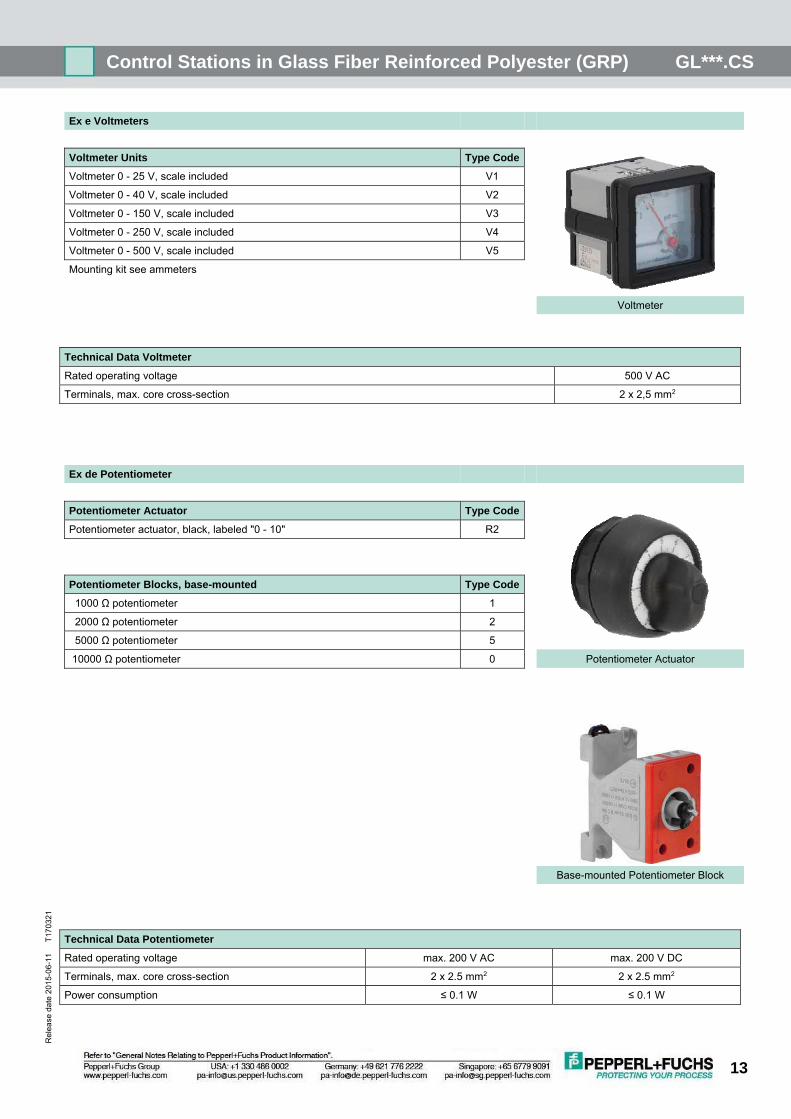
Ex e Voltmeters
Voltmeter Units Type Code
Voltmeter 0 - 25 V, scale included V1
Voltmeter 0 - 40 V, scale included V2
Voltmeter 0 - 150 V, scale included V3
Voltmeter 0 - 250 V, scale included V4
Voltmeter 0 - 500 V, scale included V5
Mounting kit see ammeters
Voltmeter
Technical Data Voltmeter
Rated operating voltage 500 V AC
Terminals, max. core cross-section 2 x 2,5 mm2
Ex de Potentiometer
Potentiometer Actuator Type Code
Potentiometer actuator, black, labeled "0 - 10" R2
Potentiometer Blocks, base-mounted Type Code
1000 Ω potentiometer 1
2000 Ω potentiometer 2
5000 Ω potentiometer 5
10000 Ω potentiometer 0 Potentiometer Actuator
Base-mounted Potentiometer Block
Technical Data Potentiometer
Rated operating voltage max. 200 V AC max. 200 V DC
Terminals, max. core cross-section 2 x 2.5 mm2 2 x 2.5 mm2
Power consumption ≤ 0.1 W ≤ 0.1 W

Control Stations in Glass Fiber Reinforced Pol yester (GRP) GL***.CS
14
Re
lea
se
da
te 2
01
5-0
6-1
1
T
17
032
1
Operator Accessories
Accessory Type Code
Blanking plug BK
Small label holder with printed label as per specification ZS
Large label holder with printed label as per specification ZL
Emergency Stop label, yellow, round, adhesive ZE
Emergency Stop label, yellow, rectangular, adhesive ZF
Protective lid, plastic ZA
Emergency stop shroud, plastic, padlockable ZP
Protective shroud, stainless steel ZC Small Label Holder
Protective shroud, stainless steel, padlockable ZD
Locknut spanner, plastic TP
Locknut spanner for key switches, plastic TB
Please note: Type Codes have changed
Protective Shroud, Stainless Steel
Protective Lid, Plastic
Blanking Plug
Emergency Stop Shroud
Copyright © 2022 FDOKUMEN