Comparative Advantage, Diversification, and Intra-Industry ...
Upload
independentCategory
view
1download
0
ARTICLE IN PRESS
0376-0421/$ - se
doi:10.1016/j.pa
�CorrespondE-mail addr
Progress in Aerospace Sciences 41 (2005) 152–173
www.elsevier.com/locate/paerosci
Analysis of composite laminates with intra- andinterlaminar damage
Maria Kashtalyana, Costas Soutisb,�
aSchool of Engineering and Physical Sciences, University of Aberdeen, Fraser Noble Building, Aberdeen AB24 3UE, UKbAerospace Engineering, The University of Sheffield, Faculty of Engineering, Sir Frederick Mappin Building, Mappin Street,
Sheffield S1 3JD, UK
Abstract
Failure process of composite laminate under quasi-static or fatigue loading involves sequential accumulation of intra-
and interlaminar damage. Matrix cracking parallel to the fibres in the off-axis plies is the first intralaminar damage
mode observed. These cracks are either arrested at the interface or cause interlaminar damage (delamination) due to
high interlaminar stresses at the ply interface. This paper summarises recent theoretical modelling developed by the
authors on stiffness property degradation and mechanical behaviour of general symmetric laminates with off-axis ply
cracks and crack-induced delaminations. Closed-form analytical expressions are derived for Mode I, Mode II and the
total strain energy release rates associated with these damage modes. Dependence of strain energy release rates on crack
density, delamination area and ply orientation angle in balanced and unbalanced symmetric laminates is examined and
discussed. Also, stiffness degradation due to various types of damage is predicted and analysed.
r 2005 Elsevier Ltd. All rights reserved.
Contents
1. Background . . . . . . . . . . . . . . . . . . . . . . . . . . . . . . . . . . . . . . . . . . . . . . . . . . . . . . . . . . . . . . . . . . . . 153
1.1. Intralaminar damage . . . . . . . . . . . . . . . . . . . . . . . . . . . . . . . . . . . . . . . . . . . . . . . . . . . . . . . . . 153
1.2. Interlaminar damage . . . . . . . . . . . . . . . . . . . . . . . . . . . . . . . . . . . . . . . . . . . . . . . . . . . . . . . . . 155
2. Stress analysis . . . . . . . . . . . . . . . . . . . . . . . . . . . . . . . . . . . . . . . . . . . . . . . . . . . . . . . . . . . . . . . . . . . 158
3. Stiffness degradation due to intra- and interlaminar fracture . . . . . . . . . . . . . . . . . . . . . . . . . . . . . . . . . . 160
3.1. Stiffness degradation due to off-axis ply cracking . . . . . . . . . . . . . . . . . . . . . . . . . . . . . . . . . . . . . 161
3.2. Stiffness degradation due to crack-induced delamination . . . . . . . . . . . . . . . . . . . . . . . . . . . . . . . . 162
4. Onset and growth of intra- and interlaminar damage . . . . . . . . . . . . . . . . . . . . . . . . . . . . . . . . . . . . . . . 164
4.1. Predicting onset and growth of off-axis ply cracking . . . . . . . . . . . . . . . . . . . . . . . . . . . . . . . . . . . 168
5. Concluding remarks . . . . . . . . . . . . . . . . . . . . . . . . . . . . . . . . . . . . . . . . . . . . . . . . . . . . . . . . . . . . . . . 169
Acknowledgements . . . . . . . . . . . . . . . . . . . . . . . . . . . . . . . . . . . . . . . . . . . . . . . . . . . . . . . . . . . . . . . . . . . 170
Appendix A . . . . . . . . . . . . . . . . . . . . . . . . . . . . . . . . . . . . . . . . . . . . . . . . . . . . . . . . . . . . . . . . . . . . . . . . 170
Appendix B . . . . . . . . . . . . . . . . . . . . . . . . . . . . . . . . . . . . . . . . . . . . . . . . . . . . . . . . . . . . . . . . . . . . . . . . 170
Appendix C . . . . . . . . . . . . . . . . . . . . . . . . . . . . . . . . . . . . . . . . . . . . . . . . . . . . . . . . . . . . . . . . . . . . . . . . 171
References . . . . . . . . . . . . . . . . . . . . . . . . . . . . . . . . . . . . . . . . . . . . . . . . . . . . . . . . . . . . . . . . . . . . . . . . . 171
e front matter r 2005 Elsevier Ltd. All rights reserved.
erosci.2005.03.004
ing author. Tel.: +4411 42227706; fax: +44 11 42227729.
ess: [email protected] (C. Soutis).

ARTICLE IN PRESSM. Kashtalyan, C. Soutis / Progress in Aerospace Sciences 41 (2005) 152–173 153
1. Background
Failure of glass- and carbon-fibre reinforced plastic
(GFRP and CFRP) laminates subjected to static or
cyclic tensile loading acting in the plane of reinforce-
ment, and also under thermal fatigue, is a complex
process. It involves sequential accumulation of various
types of intra- and interlaminar damage, which gradu-
ally lead to the loss of the laminate’s stiffness and load-
carrying capability. The main damage mechanisms,
exhibited in composite layered plates, are matrix
cracking, delamination, fibre debonding, and fibre
breakage.
Damage mechanisms in composite laminates can be
studied theoretically following two approaches. Using
the continuum damage mechanics approach, various
types of damage are accounted for via the damage
tensor [1–5]. A composite is then described as a
continuum with mechanical properties depending on
the damage tensor. Using the damage micromechanics
approach, stress analysis of the damaged composite is
carried out in the explicit presence of damage. Various
types of damages are analysed directly with the aim to
predict their onset and growth, and also their effect on
the properties of the laminate. While for homogeneous
isotropic materials it is often possible to obtain exact
solutions within the linear elasticity theory, stress
analysis of damaged composite laminates is approximate
in the majority of cases. If interaction between various
types of damage is especially complex, stress field can
only be determined by numerical methods such as the
finite-element method [6,7].
1.1. Intralaminar damage
The first type of damage observed during the initial
stages of the failure process is the interlaminar damage
in the form of matrix cracks running parallel to the
fibres in off-axis plies of the laminate. Matrix cracking
initiates long before the laminate loses its load-carrying
capacity. It gradually reduces the stiffness and strength
of the laminate [8] and changes its coefficients of thermal
expansion [9], moisture absorption [10] and the natural
frequency [11]. Cracked matrix may cause leaks in
laminated composite pressure vessels. Matrix cracking
triggers development of other more harmful damage
mechanisms. Stress concentration near the crack tip at
the ply interface may cause either delamination [12] or
matrix cracking, or sometimes both, in the adjacent ply
[13–15]. Delaminations may result in fibre breakage in
the primary load-bearing plies [14] and lead to the loss of
the load-carrying capacity of the whole laminate.
Studies of matrix cracking have been focusing
predominantly on transverse cracks, i.e. matrix cracks
in the 90�-plies of a laminate. The laws of transverse
cracking in GFRP and CFRP laminates are in many
respects similar. As a rule, cracks in the matrix occur at
equal distances from each other [13] and immediately
propagate from edge to edge, cleaving the entire
thickness of the damaged ply. Under quasi-static
loading, the strain corresponding to the cracking onset
decreases with an increased ply thickness [15]. Under
cyclic loading, the cycle number corresponding to the
beginning of cracking increases with an increased
loading amplitude [16]. The degree of transverse
cracking is characterized by crack density, i.e., the
number of cracks per unit length. After cracking has
begun, the crack density abruptly increases with the
applied load. The rate of crack density increase
gradually decreases and the matrix cracking comes to
saturation state, which is sometimes called a character-
istic damaged state. The features of transverse cracking
of the matrix in ½90n=0m�s cross-ply CFRP laminates
were studied by Highsmith and Reifsnider [8] and Smith
et al. [17]. It was established that transverse cracking in
the outer 90�-plies begins at lower strains than in the
inner plies with a double thickness. However, the
saturation crack density is lower in this case. Moreover,
cracks are staggered rather than aligned in the outer
90�-plies.
The overwhelming majority of studies investigating
behaviour and properties of composite laminates with
matrix cracks assume that cracks are equally spaced and
therefore the analysis can be restricted to a representa-
tive segment of the laminate, containing one crack. The
analysis of a cross-ply laminate element with a
transverse crack is usually reduced to a plane problem
in the plane xOz (Fig. 1).
Shear-lag-based models remain the most commonly
used one for calculating the reduced stiffness properties
of laminates with transverse cracks. To eliminate the
dependence on the z-coordinate, it is assumed that the
stress sz, averaged across the layer thickness, is equal to
zero, and variation in the transverse displacement with
the longitudinal coordinate may be neglected [18]. The
dependence of in-plane displacements on the transverse
coordinate is assumed either linear [19,20] or quadratic
[7,21–23]. The latter is equivalent to the assumption that
the shear stresses depend linearly on the transverse
coordinate [18]. Some shear-lag models assume that the
shear stresses due to transverse cracking act only within
a thin resin-rich layer adjacent to a 90�-ply [8,24,25].
Zhang et al. [26] assumed that shear stresses in ½0m=90n�slaminates vary linearly throughout the thickness of the
90�-ply and one mth the thickness of the 0�-ply and
equal zero in the other parts. For cross-ply laminates
with a thick outer 0�-ply, Berthelot [27] assumed that the
dependence of the longitudinal displacements on the
transverse coordinate is quadratic in the 90�-ply and is
linear in the 0�-ply, but with the coefficient of
proportionality being an exponential function of the
density of transverse cracks.

ARTICLE IN PRESS
x
z
x
z
y
90°
0°
0°
transverse crack
Fig. 1. Cross-ply composite laminate with transverse matrix cracks.
M. Kashtalyan, C. Soutis / Progress in Aerospace Sciences 41 (2005) 152–173154
Hashin [28] was the first to solve a plane stress
problem for a cross-ply laminate with transverse cracks
based on the variational principles. He assumed that the
stresses sx in each ply depend only on x and do not
depend on z. The stresses determined based on this
hypothesis satisfy the equilibrium equations, the bound-
ary conditions, and the continuity conditions at inter-
faces, and the unknown constants can be determined
from the principle of minimum additional energy. The
tensile stresses sx obtained by the variational and shear-
lag methods are qualitatively close. The fundamental
difference is observed for the shear stress t at the
interface between plies. Within the framework of the
shear-lag methods, it turns out to be non-zero for x ¼ s,
which contradicts the assumption that the crack faces
are free from load. Moreover, the variational methods,
in contrast to the shear-lag methods, allow us to
determine the transverse stress sz.
Hashin’s variational approach was further developed
by Nairn [29], Varna and Berglund [30,31], and
Berglund and Varna [32]. The model of Varna and
Berglund [30] is a further development of Hashin’s
model. The authors assume that in a 90�-ply the stress sx
depends on the transverse coordinate z, the shear stress
sxz is a linear function of z, and the stress sz is a
quadratic function of z. In a 0�-ply, there may be an
inhomogeneous stress distribution described by an
exponential function with an unknown shape parameter.
The problem is reduced to a differential equation of the
fourth order with constant coefficients derived in
minimizing the additional energy. This equation and
its solution contain an unknown shape parameter, which
is calculated in the subsequent minimization of the
additional energy. The refined model developed by the
same authors [32] admits the inhomogeneity of the stress
distribution in both plies.
McCartney [33,34] assumed that the stresses sx in
each ply depend only on x and do not depend on z.
However, according to his approach, the problem is
reduced to a system of recurrent relations and an
ordinary differential equation of the fourth order. Also
plies are divided into subplies of smaller thickness, since
the elastic relations in the transverse direction are
satisfied in the averaged sense [35]. McCartney showed
that stresses and displacements determined by his
method are in agreement with those determined by the
variational method based on Reissner’s variational
theorem. Schoeppner and Pagano [36] directly used
Reissner’s variational principle. These approaches are
compared by McCartney et al. [37]. The variational
principles were used by Nairn [29] and Nairn and Hu
[12] to study transverse cracking in outer 90�-plies. Both
co- directional and non-codirectional cracks were
considered. Viscoelastic analyses of transverse cracking
in cross-ply composite laminates were made in [38,39].
In evaluating the effect of transverse cracks on the
stiffness of cross-ply laminates, many authors consid-
ered only the longitudinal elastic modulus [8,15,40–43].
Hashin [28] obtained the exact lower bound for the
longitudinal elastic modulus. Nairn and Hu [12,44] used
the variational principles to show that with the same
density of transverse cracks the stiffness of ½90n=0m�slaminates decreases more than that of ½0m=90n�slaminates whose 90�-plies are inner and adjacent. Both
co-directional and non-codirectional cracks were con-
sidered.
For cross-ply laminates with both transverse and
longitudinal cracks, a representative segment could be
defined by intersecting pair of transverse and long-
itudinal cracks [45–48]. Kashtalyan and Soutis [49–53]
suggested to analyse cross-ply laminates with damage in
both plies using the Equivalent Constraint Model.
Instead of the damaged laminate, two ECM laminates
are considered and analysed simultaneously. In the first
laminate, 0� layers contain damage explicitly, while 90�
plies are replaced with equivalent homogeneous ones
with reduced stiffness properties. These reduced stiffness
properties are assumed to be known from the analysis of
the second laminate, in which 90� layer contains damage
explicitly, while the damages 0� plies are replaced with
equivalent homogeneous ones with reduced properties,
assumed to be known from the analysis of the first

ARTICLE IN PRESSM. Kashtalyan, C. Soutis / Progress in Aerospace Sciences 41 (2005) 152–173 155
laminate. Thus, problems for both laminates are inter-
related.
Angle-ply laminates exhibit much more complex
morphologies of intralaminar damage than cross-ply
laminates. Comprehensive observations of sequential
accumulation of matrix cracks in off-axis plies have been
reported for quasi-isotropic ½0=45=� 45=90�s and ortho-tropic carbon/epoxy and glass/epoxy laminates [54–57].
It was found that longitudinal strain for matrix cracking
initiation decreases with increasing ply orientation angle
[56]. Also, ply stresses normal to the fibres at crack
formation were found to become progressively smaller
as the ply orientation angle increased [56].
Stress fields in the cracked off-axis plies of angle-ply
laminates were examined by means of finite element
method [58] and analytically [59]. Application of the
Equivalent Constraint Model to quasi-isotropic lami-
nates with matrix cracking in all but 0� layers was
presented by Zhang and Herrmann [60].
Soutis and Kashtalyan [61,62] predicted analytically
strain energy release rate associated with matrix crack-
ing in the y-layer of unbalanced symmetric ½0=y�scomposite laminate using a 2-D shear lag stress analysis
and the Equivalent Constraint Model (ECM). Compar-
ison of theoretical predictions with experimental data
for glass/epoxy laminates, obtained by Crocker et al.
[56], showed that a quadratic mixed mode fracture
criterion can successfully predict the cracking onset
strain for ply orientation angles 75�pyp90�.
1.2. Interlaminar damage
Matrix cracks, developing in the off-axis plies of the
laminate, are either arrested at the interface or cause
interlaminar damage leading to delamination due to
high interlaminar stresses at the ply interface. Fig. 2
summarises schematically types of intra- and interlami-
nar damage observed in cross-ply and angle-ply
composite laminates: transverse and longitudinal matrix
cracks in cross-ply laminates (Fig. 2a) transverse and
longitudinal crack tip delaminations in cross-ply lami-
nates (Fig. 2b) off-axis ply cracks in balanced symmetric
laminates (Figs. 2c–d); uniform (Fig. 2c) and partial
(Fig. 2d) local delaminations induced by angle ply
matrix cracks; crack induced edge delaminations
(Fig. 2e).
Studies of delaminations induced by matrix cracking
have been focusing predominantly on delaminations
caused by transverse cracks, i.e. matrix cracks in the 90�-
plies of a laminate. Crossman and Wang [63] made
comprehensive observations of transverse cracking and
delamination in balanced symmetric ½�25=90n�s; n ¼
0:5; 1; 2; 3; 4; 6; 8 graphite/epoxy laminates. A significant
reduction in the delamination onset strain was noted for
the laminates with nX4. A transition from edge
delamination to local delaminations growing from the
tip of a matrix crack in the 90�-ply occurred between
n ¼ 3 and 4. The onset and growth of edge delamination
in ½ð�30Þ2=90=90�s graphite/epoxy laminates under statictension and tension-tension fatigue loading was studied
by O’Brien [64]. Stiffness loss was monitored simulta-
neously with delamination growth and found to
decrease linearly with delamination size.
Armanios et al. [65] applied a shear deformation
theory and sublaminate approach to analyse local
delaminations originating from transverse cracks in
CFRP ½�25=90n�s laminates. Predictions of their model,
which also takes into account hygrothermal effects, are
in reasonable agreement with delamination onset strain
data by Crossmann and Wang [63].
Nairn and Hu [12,44] used two-dimensional varia-
tional approach to analyse crack tip delaminations in
½ðSÞ=90n�s laminates, where ðSÞ denotes a balanced
sublaminate, e.g. ð�ymÞ. They predicted that matrix
cracking should reach some critical density before
delamination initiates. The critical crack density for
delamination initiation is determined by material
properties, laminate structure as well as fracture
toughnesses for matrix cracking and delamination and
is nearly independent of the properties of the supporting
sublaminate ðSÞ.
Zhang et al. [22,66] used a 2-D improved shear lag
analysis to predict the strain energy release rate for edge
and local delaminations in balanced symmetric
½�ym=90n�s laminates. For edge delamination, they were
able to capture a zigzag delamination pattern, i.e. edge
delamination switching from one ðy=90Þ interface to
another through a matrix crack, and improve O’Brien’s
formula for strain energy release rate for edge delamina-
tion [64] incorporating the effect of matrix cracking. For
local delaminations, they obtained the strain energy
release rate as a function of crack density and
delamination area. Their predictions for delamination
onset strain agree well with experimental data of
Crossman and Wang [63] and capture the transition
from edge to local delamination quite accurately.
Initiation and growth of local delaminations from the
tips of transverse cracks in cross-ply ½0=90n�s n ¼ 2; 4; 6carbon/epoxy laminates under static tension was exam-
ined by Takeda and Ogihara [67]. Delamination was
noted to grow more rapidly and extensively in the
laminates with thicker 90� plies. Ogihara and Takeda
[68] used a modified shear lag method featuring
interlaminar shear layer to predict strain energy release
rate for transverse crack tip delaminations in cross-ply
½0=90n�s laminates and to model interaction between
transverse cracking and delamination. However, the
effect of cracking/delamination interaction was found to
be negligible in prediction of delamination growth.
Henaff-Gardin et al. [47,48] and Kobayashi et al. [43]
observed damage development in carbon/epoxy cross-
ply laminates under thermal cycling. The first damage

ARTICLE IN PRESS
transverse cracks
delaminationsdelaminations
transverse crack
longitudinal crack
off-axis crackdelamination
off-axis crack delamination
edge delaminations
ply cracks
(a) (b)
(c) (d)
(e)
Fig. 2. Types of intra- and interlaminar damage observed in cross-ply and angle-ply composite laminates: (a) transverse and
longitudinal matrix cracks in cross-ply laminates; (b) transverse and longitudinal crack tip delaminations in cross-ply laminates; (c) off-
axis ply cracks in balanced symmetric laminates and uniform local delaminations; (d) off-axis ply cracks in balanced symmetric
laminates and partial local delaminations; (e) matrix-crack induced edge delamination.
M. Kashtalyan, C. Soutis / Progress in Aerospace Sciences 41 (2005) 152–173156
mode observed consisted of matrix cracks in 0� and 90�
plies. The first damage mode observed consisted of
matrix cracks in 0� and 90� plies. Most of the matrix
cracks spanned the entire width or length of the
specimen. Then delaminations initiated between 0� and
90� plies along the pre-existing cracks in 0� ply.
More recently, Selvarathinam and Weitsman [69,70]
observed and modelled, by means of finite elements
and shear lag methods, delaminations induced by
matrix cracking in cross-ply laminates under environ-
mental fatigue. By comparing strain energy release
rates associated with matrix cracking and delamina-
tion, they were able to explain the extensive delamina-
tions and reduced crack densities that arise under
immersed fatigue conditions, as compared with fatigue
in air.

ARTICLE IN PRESSM. Kashtalyan, C. Soutis / Progress in Aerospace Sciences 41 (2005) 152–173 157
Zhang et al. [71] studied delaminations induced by
transverse cracking at the ðf=90Þ interfaces in
½. . . =ji=fm=90n�s laminates loaded in tension using a
sublaminate-wise first-order shear deformation theory.
In particular, they were interested in the constraining
effect of the immediate neighbouring plies and remote
plies on stiffness reduction and strain energy release rate
for delaminations. It was found that the strain energy
release rate for local delamination and stiffness reduc-
tion of the constrained transverse plies largely depends
on a local lay-up configuration of a damaged laminate.
Kashtalyan and Soutis [49–51] examined the effect of
crack tip delaminations on stiffness reduction for cross-
ply ½0m=90n�s laminates with local delaminations along
transverse as well as longitudinal cracks. It was
established that reduction in the laminate shear modulus
and Poisson’s ratio is much more significant than in the
axial modulus. For balanced symmetric ½�ym=90n�s, the
effect of constraining ply orientation angle y on
reduction of the laminate in-plane stiffness properties
was also examined.
Delaminations induced by angle ply matrix cracks in
carbon/epoxy ½02=y2=�y2�s; y ¼ 20�; 25�; 30� laminates
subjected to tension fatigue loading were observed by
O’Brien and co-workers [55,72–74]. Matrix cracks
formed near the stress free edge and delaminations,
bounded by the free edge and the crack, developed in the
y=ð�yÞ interface. They were termed partial local
delaminations.
Using a quasi-3D finite element (FE) analysis,
Salpekar and O’Brien [73] found that the strain energy
release rate for uniform local delamination calculated
from O’Brien [72] expression matched the value
obtained by FE analysis in the laminate interior.
O’Brien and Hooper [55] and O’Brien [74] observed
matrix crack induced delaminations in symmetric angle-
ply ½02=y2=�y2�s carbon/epoxy laminates under quasi-
static and fatigue tensile loading ðy ¼ 15�; 20�; 25�; 30�Þ.Delaminations occurred in the ðy=� yÞ interface,
bounded by the cracks in the ð�yÞ-ply and the stress
free edge. The laminated plate theory and a quasi-3D
finite element analysis were used to examine stresses in
the ð�yÞ-ply. For the considered range of ply orienta-
tions, stresses normal to the fibres were found to be
compressive and shear stresses along the fibres to be
high in the laminate interior, while near the free edge
high tensile stresses normal to the fibres were present.
Two closed form expressions for strain energy release
rate were derived on the basis of simple load shearing
rules: one for a local delamination growing from an
angle ply matrix crack with a uniform delamination
front across the laminate width, and one for apartial
local delamination growing from an angle ply matrix
crack and bounded by the free edge.
Salpekar and O’Brien [75] used a 3-D FE analysis to
study matrix crack induced delaminations in ð0=y=� yÞs
graphite/epoxy laminates (y ¼ 15�; 45�) loaded in ten-
sion. For ð0=45=� 45Þs laminate, the strain energy
release rate for local delamination growing uniformly
in the ð45=� 45Þ interface from the matrix crack in the
(�45�)-ply was found to be higher near the laminate
edge than in the interior of the laminate.
Later, Salpekar et al. [76] computed strain energy
release rates associated with local delamination originat-
ing from matrix cracks and bounded by the free edge in
ð0=y=� yÞs and ðy=� y=0Þs graphite/epoxy laminates
using a 3-D FE method. The total strain energy release
rate was calculated using three different techniques:
the virtual crack closure technique, the equivalent
domain integral technique, and a global energy balance
technique.
Kashtalyan and Soutis [62] theoretically modelled
local delaminations growing uniformly from the tips of
matrix cracks in an angle-ply laminate loaded in tension.
They obtained closed-form expression for strain energy
release rates, associated with these delaminations, as
linear functions of the first partial derivatives of the
effective elastic properties of the damaged layer with
respect to delamination area. Strain energy release rate
dependent of delamination area and crack density, thus
taking into account the cumulative effect of damage.
The total strain energy release rate depends linearly on
crack density both in balanced ½02=y2=�y2�s and
unbalanced ½02=y2�s laminates. The dependence on
delamination area is linear in balanced and non-linear
in unbalanced laminates. Comparison with results by
Salpekar and O’Brien [73] showed that O’Brien’s closed-
form expression [72] for uniform local delamination
significantly overestimates the value of strain energy
release rate. For the same ply orientation angle, crack
density and delamination area, delamination-induced
changes in stiffness properties are much more significant
in unbalanced laminates than in balanced laminates.
In all above studies of crack induced delaminations it
was assumed that delamination surfaces, like matrix
crack surfaces, are stress-free. Besides that, delamina-
tions were assumed to behave in a self-similar manner,
i.e. boundary conditions prescribed at the delaminated
surfaces were assumed to be the same for small and large
delaminations. More recently, Ashkantala and Talreja
[77] and Berthelot and Le Corre [78,79] examined
transverse crack tips delaminations in cross-ply lami-
nates with shear friction between the delaminated plies.
While Berthelot and Le Corre [78] assumed the
magnitude of the interlaminar shear stress at the
delaminated interface to be constant, i.e. independent
of delamination length, Ashkantala and Talreja [77]
considered both linear and cubic polynomial shear stress
distribution at the delamination interface. Selvarathi-
nam and Weitsman [69,70] observed and modelled, be
means of finite elements and shear lag methods,
delaminations induced by matrix cracking in cross-ply

ARTICLE IN PRESSM. Kashtalyan, C. Soutis / Progress in Aerospace Sciences 41 (2005) 152–173158
laminates under environmental fatigue, with delamina-
tion surfaced loaded with hydrostatic pressure.
2. Stress analysis
In Fig. 3 a schematic of a symmetric ½ðSÞ=f�s laminateis shown, consisting of the outer sublaminate ðSÞ and the
inner f-layer damaged by matrix cracks and local
delaminations growing from their tips at the ðSÞ=finterface. The outer sublaminate ðSÞ, or layer 1, may
consist either of a single layer or a group of layers and
can also be damaged (in this case it needs to be replaced
in the analysis with an equivalent homogeneous layer
with reduced stiffness properties). The laminate is
referred to the global Cartesian coordinate system xyz
and local coordinate system x1x2x3, with the axis x1
directed along the fibres in the damaged f-layer, or layer2. The laminate is subjected to in-plane biaxial tension
sx and sy. Since the laminate is symmetric, no coupling
exists between in-plane loading and out-of-plane defor-
mation. Matrix cracks are assumed to be spaced
uniformly, with crack spacing 2s and span the whole
width of the laminate. Local delaminations are assumed
to be strip shaped, with strip width 2‘, Fig. 3.Due to the periodicity of damage, the stress analysis
may be carried out over a representative segment
containing one matrix crack and two crack tip
delaminations. Due to symmetry, it can be further
x
y
x2
2s
x1
off-axis crack
2l
delamination
2h2(�)
(S) h1
�y
�y
�x�x
�
Fig. 3. Front and edge view of a ½ðSÞ=f�s laminate subjected to
biaxial tensile loading and damaged by matrix cracks and
crack-induced delaminations. Local ðx1x2x3Þ and global ðxyzÞ
co-ordinate systems for the damaged f-layer (front view in the
negative x3 z direction).
restricted to one quarter of the representative segment,
Fig. 4, referred to the local coordinate system x1x2x3.
Let f ~sð1Þg and f~�ð1Þg denote the in-plane microstressesand microstrains in the layer 1, and f ~sð2Þg and f~�ð2Þgdenote the in-plane microstresses and microstrains in the
layer 2 (i.e. stresses and strains averaged across the
respective layer thickness). Since it is assumed that there
is no frictional contact between the layers in the locally
delaminated portion of the representative segment
ð0ojx2jo‘; jx3joh2Þ,the in-plane microstresses in the
delaminated portion are ~sð2Þ22 ¼ ~sð2Þ12 ¼ 0, i.e. this region is
stress-free. Assumption of stress-free crack tip delami-
nation surfaces, and the resulting implication that the
portion of the damaged ply bounded by matrix crack
and delamination surfaces is stress-free, has been widely
used in the studies of delaminations. Besides that,
delaminations are assumed to behave in a self-similar
manner, i.e. the boundary conditions prescribed at the
delaminated surfaces were assumed to be the same for
small and large delaminations.
In the perfectly bonded region ð‘ojx2josÞ of the
representative segment, they are determined from the
equilibrium equations
d
dx2~sð2Þj2 �
tj
h2¼ 0 j ¼ 1; 2, (1)
where tj are the interface shear stresses and h2 is the
thickness of the f-layer.By averaging the out-of-plane constitutive equations
for both layers across the layer thickness, the interface
shear stresses tj can be expressed in terms of the in-plane
displacements and shear lag parameters Kij as
tj ¼ Kj1ð ~uð1Þ1 � ~uð2Þ1 Þ þ Kj2ð ~u
ð1Þ2 � ~uð2Þ2 Þ. (2)
The shear lag parameters K11;K22;K12 K21 are
determined assuming that the out-of-plane shear stresses
~sðkÞj3 vary linearly with x3 (Fig. 5), see Appendix A.
Substitution of Eqs. (2) into Eqs. (1) and subsequent
x3
x2
loff-axis plycrack
s - l
delamination
�, or layer 2
(S), or layer 1
Fig. 4. A quarter of the representative segment containing a
matrix crack and delamination.

ARTICLE IN PRESS
(1)13 ,
x3
h1
h2
x2
layer 1
layer 2
� (1)23�
(2)13 ,� (2)
23�
�1,�2
Fig. 5. Variation of out-of-plane shear stresses.
M. Kashtalyan, C. Soutis / Progress in Aerospace Sciences 41 (2005) 152–173 159
differentiation yields
d2
dx2~sð2Þj2 þ Kj1ð~g
ð1Þ12 � ~gð2Þ12 Þ þ Kj2ð~�
ð1Þ22 � ~�ð2Þ22 Þ ¼ 0,
j ¼ 1; 2. ð3Þ
The strain differences ð~�ð1Þ22 � ~�ð2Þ22 Þ and ð~gð1Þ12 � ~gð2Þ12 Þ, in-
volved in Eqs. (3), can be expressed in terms of stresses
~sð2Þ12 ; ~sð2Þ22 using the constitutive equations for both layers,
the laminate equilibrium equations are given below
wf ~sð1Þg þ f ~sð2Þg ¼ ð1þ wÞ½T �fsg, (4a)
½T � ¼
cos2f sin2f 2 sinf cosf
sin2f cos2f �2 sinf cosf
� sinf cosf sinf cosf cos2f� sin2f
264
375,(4b)
fsg ¼ fsx; sy; 0gT; w ¼ h1=h2 (4c)
and the assumption of the generalised plane strain
condition
~�ð1Þ11 ¼ ~�ð2Þ11 . (5)
In the local coordinate system x1x2x3, the layer 2 is
orthotropic,
~�ð2Þ11
~�ð2Þ22
~gð2Þ12
8>><>>:
9>>=>>; ¼
Sð2Þ
11 Sð2Þ
12 0
Sð2Þ
12 Sð2Þ
22 0
0 0 Sð2Þ
66
26664
37775
~sð2Þ11
~sð2Þ22
~sð2Þ12
8>><>>:
9>>=>>;, (6a)
while the layer 1 is anisotropic
~�ð1Þ11
~�ð1Þ22
~gð1Þ12
8>><>>:
9>>=>>; ¼
Sð1Þ
11 Sð1Þ
12 Sð1Þ
16
Sð1Þ
12 Sð1Þ
22 Sð1Þ
26
Sð1Þ
16 Sð1Þ
26 Sð1Þ
66
26664
37775
~sð1Þ11
~sð1Þ22
~sð1Þ12
8>><>>:
9>>=>>;, (6b)
where ½SðkÞ� is the compliance matrix for the kth layer.
Finally, Eqs. (3) can be reduced to a system of two
coupled second order ordinary differential equations
(see Appendix B)
d2 ~sð2Þ12
dx22
� N11 ~sð2Þ12 � N12 ~s
ð2Þ22 � P11sx � P12sy ¼ 0, (7a)
d2 ~sð2Þ22
dx22
� N21 ~sð2Þ12 � N22 ~s
ð2Þ22 � P21sx � P22sy ¼ 0. (7b)
Here Nij and Pij are laminate constants depending on
the layer compliances SðkÞ
ij , layer thickness ratio w, shearlag parameters K11;K22;K12 and angle f (Appendix B).
Eqs. (7a) and (7b) can be uncoupled at the expense of
increasing the order of differentiation, resulting in a
fourth order non-homogeneous ordinary differential
equation
d4 ~sð2Þ22
dx42
� ðN11 þ N22Þd2 ~sð2Þ22
dx22
� ðN21N12 � N11N22Þ ~sð2Þ22 þ ½N11ðP21 þ aP22Þ
� N21ðP11 þ aP12Þ�sx ¼ 0. ð8Þ
Here a ¼ sy=sx is the biaxiality ratio. The boundary
conditions for Eq. (8) are prescribed at the stress-free
boundary between locally delaminated and perfectly
bonded portions of the representative segment
~sð2Þ22 jx2¼�‘ ¼ 0 ~sð2Þ12 jx2¼�‘ ¼ 0. (9)
Finally, the in-plane microstresses can be expressed in
the following form:
~sð2Þ11 ¼ a22 ~sð2Þ22 þ a12 ~s
ð2Þ12 þ bxsx þ bysy, (10a)
~sð2Þj2 ¼ Ajcosh l1ðx2 � sÞ
cosh l1ðs � ‘Þþ Bj
cosh l2ðx2 � sÞ
cosh l2ðs � ‘Þþ Cj
� �sx
j ¼ 1; 2, ð10bÞ
where coefficients a22; a12;bx and by are given in
Appendix B, lj are the roots of the characteristic
equation and Aj ;Bj and Cj are constants depending on
Nij and Pij , see Appendix C.
In cross-ply and balanced laminates the outer
sublaminate ðSÞ is orthotropic, with compliances Sð1Þ
16 ¼
Sð1Þ
26 ¼ 0 and stiffnesses Qð1Þ
45 ¼ 0. In this case shear lag
coefficients K12 K21 ¼ 0 vanish, and equilibrium
equations are reduced to two uncoupled seconded order
differential equations. Details of this case are given
elsewhere [49,51,80].
ARTICLE IN PRESS
0
50
100
150
200
15 30 45 60 75 90
Ply orientation angle, degrees
Nor
mal
str
ess,
MP
a
uniaxial
0.5
1
2
Yt=57MPa
-25
0
25
50
75
100
15 30 45 60 75 90
Ply orientation angle, degrees
She
ar s
tres
s, M
Pa
uniaxial
0.5
1
2
S=71 MPa
(a)
(b)
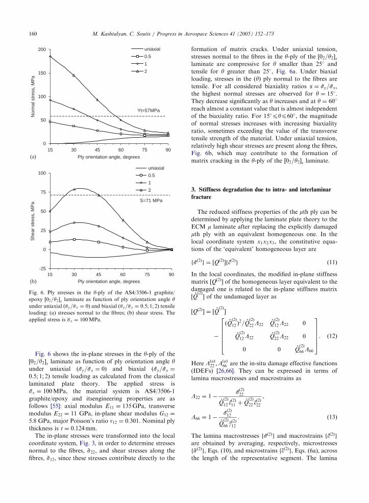
Fig. 6. Ply stresses in the y-ply of the AS4/3506-1 graphite/
epoxy ½02=y2�s laminate as function of ply orientation angle yunder uniaxial ðsy=sx ¼ 0Þ and biaxial ðsy=sx ¼ 0:5; 1; 2Þ tensileloading: (a) stresses normal to the fibres; (b) shear stress. The
applied stress is sx ¼ 100MPa.
M. Kashtalyan, C. Soutis / Progress in Aerospace Sciences 41 (2005) 152–173160
Fig. 6 shows the in-plane stresses in the y-ply of the
½02=y2�s laminate as function of ply orientation angle yunder uniaxial ðsy=sx ¼ 0Þ and biaxial ðsy=sx ¼
0:5; 1; 2Þ tensile loading as calculated from the classical
laminated plate theory. The applied stress is
sx ¼ 100MPa, the material system is AS4/3506-1
graphite/epoxy and itsengineering properties are as
follows [55]: axial modulus E11 ¼ 135GPa, transverse
modulus E22 ¼ 11 GPa, in-plane shear modulus G12 ¼
5:8 GPa, major Poisson’s ratio n12 ¼ 0:301. Nominal plythickness is t ¼ 0:124mm.The in-plane stresses were transformed into the local
coordinate system, Fig. 3, in order to determine stresses
normal to the fibres, ~s22, and shear stresses along the
fibres, ~s12, since these stresses contribute directly to the
formation of matrix cracks. Under uniaxial tension,
stresses normal to the fibres in the y-ply of the ½02=y2�slaminate are compressive for y smaller than 25� and
tensile for y greater than 25�, Fig. 6a. Under biaxial
loading, stresses in the ðyÞ ply normal to the fibres are
tensile. For all considered biaxiality ratios a ¼ sy=sx,
the highest normal stresses are observed for y ¼ 15�.
They decrease significantly as y increases and at y ¼ 60�
reach almost a constant value that is almost independent
of the biaxiality ratio. For 15�pyp60�, the magnitude
of normal stresses increases with increasing biaxiality
ratio, sometimes exceeding the value of the transverse
tensile strength of the material. Under uniaxial tension,
relatively high shear stresses are present along the fibres,
Fig. 6b, which may contribute to the formation of
matrix cracking in the y-ply of the ½02=y2�s laminate.
3. Stiffness degradation due to intra- and interlaminar
fracture
The reduced stiffness properties of the mth ply can be
determined by applying the laminate plate theory to the
ECM m laminate after replacing the explicitly damaged
mth ply with an equivalent homogeneous one. In the
local coordinate system x1x2x3, the constitutive equa-
tions of the ‘equivalent’ homogeneous layer are
fsð2Þg ¼ ½Qð2Þ�f�ð2Þg (11)
In the local coordinates, the modified in-plane stiffness
matrix ½Qð2Þ� of the homogeneous layer equivalent to the
damaged one is related to the in-plane stiffness matrix
½Qð2Þ� of the undamaged layer as
½Qð2Þ� ¼ ½Qð2Þ�
�
ðQð2Þ
12 Þ2=Q
ð2Þ
22L22 Qð2Þ
12L22 0
Qð2Þ
12L22 Qð2Þ
22L22 0
0 0 Qð2Þ
66L66
266664
377775. ð12Þ
Here LðmÞ22 ;L
ðmÞ66 are the in-situ damage effective functions
(IDEFs) [26,66]. They can be expressed in terms of
lamina macrostresses and macrostrains as
L22 ¼ 1�sð2Þ22
Qð2Þ
12 �ð2Þ11 þ Q
ð2Þ
22 �ð2Þ22
,
L66 ¼ 1�sð2Þ12
Qð2Þ
66 gð2Þ12
. ð13Þ
The lamina macrostresses fsð2Þg and macrostrains f�ð2Þgare obtained by averaging, respectively, microstresses
f ~sð2Þg, Eqs. (10), and microstrains f~�ð2Þg, Eqs. (6a), acrossthe length of the representative segment. The lamina

ARTICLE IN PRESS
0.5
0.6
0.7
0.8
0.9
1.0
0 10 20 30Crack density (cracks/cm)
Nor
mal
ised
stif
fnes
s pr
oper
ty
Axial modulus
Transverse modulus
Shear modulus
Poisson's ratio
Fig. 7. Normalised stiffness properties of ½0=90�s (filled
symbols) and ½0=89�s (open symbols) glass/epoxy laminates as
a function of crack density Cmc in the inner ply (cracks/cm).
M. Kashtalyan, C. Soutis / Progress in Aerospace Sciences 41 (2005) 152–173 161
macrostresses sð2Þij are
sð2Þ11 ¼ a22sð2Þ22 þ a12s
ð2Þ12 þ bxsx þ bysy, (14a)
sð2Þj2 ¼ Aj2Dmc
l�1ð1� DldÞtanh
l�1ð1� DldÞ
Dmc
�
þ Bj2Dmc
l�2ð1� DldÞtanh
l�2ð1� DldÞ
Dmc
þ Cj2ð1� DldÞ�sx; j ¼ 1; 2, ð14bÞ
where Dmc ¼ h2=s denotes relative crack density and
Dld ¼ ‘=s denotes relative delamination area. The
macrostrains in the individual homogeneous layers and
the laminate are assumed to be equal
�ð1Þ11 ¼ �ð2Þ11 ¼ �11; �ð1Þ22 ¼ �ð2Þ22 ¼ �22; gð1Þ12 ¼ gð2Þ12 ¼ g12.
ð15Þ
Using the constitutive equations for layer 1, Eq. (6b),
and equations of the global equilibrium of the laminate,
Eq. (4), the lamina macrostrains in the layer 2 are
f�ð2Þg ¼ ½Sð1Þ�w�1ðð1þ wÞ½T �fsg � fsð2ÞgÞ, (16)
where the transformation matrix ½T � is given by Eq. (4b).
Thus, the lamina macrostresses, Eq. (14), and macro-
strains, Eq. (16), are determined as explicit functions of
the damage parameters Dmc;Dld.
Finally, the modified stiffness matrix ½Q�2 of the
‘equivalent’ homogeneous layer in the global coordi-
nates xyz can be obtained from the modified stiffness
matrix ½Qð2Þ� in the local coordinates, Eq. (12) as
½Q�2 ¼ ½T ��1½Qð2Þ�½T ��T (17)
where the transformation matrix ½T � is given by Eq. (4b).
The extension stiffness matrix ½A� of the ‘equivalent’
laminate in the global coordinates xyz can then be
determined as
½A� ¼X
k
½Q�khk; k ¼ 1; 2, (18)
where ½Q�1 is the in-plane stiffness matrix of layer 1, or
the outer sublaminate, in the global coordinates.
3.1. Stiffness degradation due to off-axis ply cracking
In this subsection, predictions of stiffness properties
as function of damage are presented and discussed for
balanced ½�y�s glass/epoxy laminates and unbalanced
½02=y2�s graphite/epoxy laminates. The results are pre-
sented in terms of the laminate stiffness properties, that
is the axial modulus Ex, transverse modulus Ey, shear
modulus Gxy, major Poisson’s ratio nxy, as well as
shear–extension coupling coefficients Zxy;x and Zxy;y. The
shear–extension coupling coefficients Zxy;j ¼ gxy=�j char-
acterise shearing in the xy plane caused by normal stress
in the jth direction (j ¼ x; y).
To validate the developed approach, a limiting case of
a cross-ply [0/90] laminate was considered (Kashtalyan
and Soutis, [52]). Cross-ply laminates cannot be
analysed using the developed approach for angle-ply
½y1=y2�s laminates directly, because when y1 ¼ 0 and
y2 ¼ 90, the system of differential equations, Eq. (9),
becomes uncoupled, and the solution, given by Eq. (12),
is no more valid. However, it works for any y2 close
enough to 90�. Fig. 7 shows normalised (i.e. referred to
their value in the undamaged state) stiffness properties
versus crack density in the inner ply for a ½0=89�sglass–epoxy laminate, obtained using the current meth-
od. They appear to be in a good agreement with results
for a cross-ply ½0=90�s laminate obtained using the
ECM/2-D shear lag model [49–53]. The material proper-
ties of a unidirectional E-glass 1200tex fibre reinforced
MY750/HY917/DY063 epoxy composite are as follows:
EA ¼ 45:6GPa, ET ¼ 16:2GPa, GA ¼ 5:83GPa, nA ¼
0:278, GT ¼ 5:79GPa, single ply thickness t ¼ 0:25mm.Fig. 8 shows the normalised stiffness properties of two
angle-ply ½y1=y2�s glass/epoxy laminates as a function of
the crack density in the inner ð�yÞ ply. Crack density
C2 ¼ ð2sð2ÞÞ�1 in the inner ð�yÞ layer varies from 0 (no
matrix cracking) to 30 cracks/cm, which corresponds to
variation in the damage parameter Dmc2 from 0 to 1.5.
In the ½30=�30�s laminate, Fig. 8a, the reduction of
the axial modulus Ex is bigger than that of the
transverse modulus Ey, while for the ½55=�55�s laminatethe opposite is true, Fig. 8b. In both laminates, the
reduction of the shear modulus Gxy is smaller than that
of Ex and Ey, in contrast to the cross-ply ½0=90�slaminate, where the reduction in the shear modulus and
the Poisson’s ratio is bigger than that of the axial
modulus, Fig. 7. It is also worth noting that in angle-ply
laminates matrix cracking may actually increase the

ARTICLE IN PRESS
0.00
0.03
0.06
0.09
0.12
0.15
0 10 20 30
Axial
Transverse
0.00
0.02
0.04
0.06
0.08
0.10 Axial
Transverse
Crack density (cracks/cm)
0 10 20 30
Crack density (cracks/cm)
She
ar e
xten
sion
cou
plin
g co
effic
ient
sS
hear
ext
ensi
on c
oupl
ing
coef
ficie
nts
(a)
(b)
Fig. 9. Shear extension coupling coefficients of angle-ply
½y=�y�s glass/epoxy laminates as a function of crack density
Cmc in the inner ð�yÞ layer (cracks/cm) for: (a) ½30=�30�slaminate; (b) ½55=�55�s laminate.
0.5
0.7
0.9
1.1
1.3
1.5
0 10 20 30
Axial modulus
Transversemodulus
0.6
0.7
0.8
0.9
1.0
1.1Axial modulusTransverse modulusShear modulusPoisson's ratio
Crack density (cracks/cm)
0 10 20 30Crack density (cracks/cm)
Nor
mal
ised
stif
fnes
s pr
oper
tyN
orm
alis
ed s
tiffn
ess
prop
erty
(a)
(b)
Fig. 8. Normalised stiffness properties of angle-ply ½y=�y�sglass/epoxy laminates as a function of crack density Cmc in the
inner ð�yÞ layer (cracks/cm): (a) ½30=�30�s laminate; (b)
½55=�55�s laminate.
M. Kashtalyan, C. Soutis / Progress in Aerospace Sciences 41 (2005) 152–173162
Poisson’s ratio—a phenomenon, not observed in cross-
ply laminates. In the ½30=�30�s laminate the increase inthe Poisson’s ratio occurs for all crack densities, while in
the ½55=�55�s laminate, it is observed only at higher
crack densities, Fig. 8b.
In the undamaged state, angle-ply ½�y�s laminates arebalanced and orthotropic and exhibit no coupling
between extension and shear. When matrix cracking
occurs, the laminate becomes unbalanced, resulting in
coupling between extension and shear, reflected by non-
zero shear–extension coupling coefficients Zxy;x and Zxy;y.
Dependence of shear–extension coupling coefficients on
the crack density is shown in Fig. 9 for ½30=�30�s and½55=�55�s glass/epoxy laminates. When 0�oyo45�, the
Zxy;x coefficient increases more rapidly with the crack
density than the Zxy;y, while for 45�oyo90� the opposite
is true.
Fig. 10 shows the normalised stiffness properties with
for ½02=552�s and ½02=752�s AS4/3506-1 laminates as a
function of crack density Cmc ¼ ð2s2Þ�1. It may be seen
that in both angle-ply laminates the most significantly
reduced properties are transverse and shear moduli. In a
½02=552�s laminate (Fig. 10a), a slight increase of the
Poisson’s ratio with the crack density is observed.
Ought to their unbalanced configuration, ½02=y2�slaminates exhibit shear extension coupling characterised
by axial Zxy;x ¼ gxy=�x and transverse Zxy;y ¼ gxy=�y
shear–extension coefficients. Fig. 11 shows variation of
the shear–extension coupling coefficients with the crack
density Cmc in a ½02=752�s laminate. While axial
shear–extension coupling coefficient is almost unaffected
by matrix cracking, the transverse one is increased by
theabsolute value.
3.2. Stiffness degradation due to crack-induced
delamination
Fig. 12 shows normalised stiffness properties of T800H/
3631 carbon/epoxy ½0=90n�s; n ¼ 2; 4; 6 cross-ply lami-
nates containing transverse cracks and delaminations.
ARTICLE IN PRESS
0.8
0.9
1
1.1
0 2 4Crack density (cracks/cm)
Nor
mal
ised
stif
fnes
s pr
oper
ty
Axial modulus
Transverse modulus
Shear modulus
Poisson's ratio
Axial modulus
Transverse modulus
Shear modulus
Poisson's ratio
0.8
0.9
1
Nor
mal
ised
stif
fnes
s pr
oper
ty
1 3 5
0 2 4Crack density (cracks/cm)
1 3 5
(a)
(b)
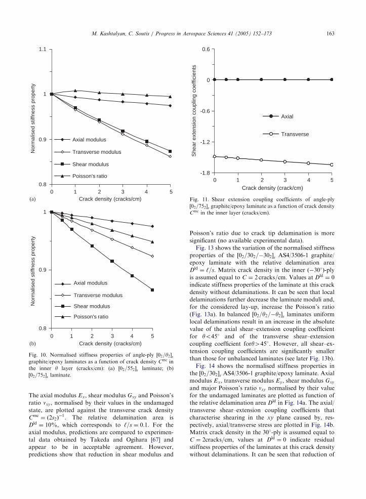
Fig. 10. Normalised stiffness properties of angle-ply ½02=y2�sgraphite/epoxy laminates as a function of crack density Cmc in
the inner y layer (cracks/cm): (a) ½02=552�s laminate; (b)
½02=752�s laminate.
-1.8
-1.2
-0.6
0
0.6
0 3Crack density (crack/cm)
She
ar e
xten
sion
cou
plin
g co
effic
ient
s
Axial
Transverse
5421
Fig. 11. Shear extension coupling coefficients of angle-ply
½02=752�s graphite/epoxy laminate as a function of crack densityCmc in the inner layer (cracks/cm).
M. Kashtalyan, C. Soutis / Progress in Aerospace Sciences 41 (2005) 152–173 163
The axial modulus Ex, shear modulus Gxy and Poisson’s
ratio nxy, normalised by their values in the undamaged
state, are plotted against the transverse crack density
Cmc ¼ ð2s2Þ�1. The relative delamination area is
Dld ¼ 10%, which corresponds to ‘=s ¼ 0:1. For the
axial modulus, predictions are compared to experimen-
tal data obtained by Takeda and Ogihara [67] and
appear to be in acceptable agreement. However,
predictions show that reduction in shear modulus and
Poisson’s ratio due to crack tip delamination is more
significant (no available experimental data).
Fig. 13 shows the variation of the normalised stiffness
properties of the ½02=302=�302�s AS4/3506-1 graphite/
epoxy laminate with the relative delamination area
Dld ¼ ‘=s. Matrix crack density in the inner ð�30�Þ-ply
is assumed equal to C ¼ 2 cracks=cm. Values at Dld ¼ 0
indicate stiffness properties of the laminate at this crack
density without delaminations. It can be seen that local
delaminations further decrease the laminate moduli and,
for the considered lay-up, increase the Poisson’s ratio
(Fig. 13a). In balanced ½02=y2=�y2�s laminates uniformlocal delaminations result in an increase in the absolute
value of the axial shear–extension coupling coefficient
for yo45� and of the transverse shear–extension
coupling coefficient fory445�. However, all shear–ex-
tension coupling coefficients are significantly smaller
than those for unbalanced laminates (see later Fig. 13b).
Fig. 14 shows the normalised stiffness properties in
the ½02=302�s AS4/3506-1 graphite/epoxy laminate. Axialmodulus Ex, transverse modulus Ey, shear modulus Gxy
and major Poisson’s ratio nxy normalised by their value
for the undamaged laminates are plotted as function of
the relative delamination area Dld in Fig. 14a. The axial/
transverse shear–extension coupling coefficients that
characterise shearing in the xy plane caused by, res-
pectively, axial/transverse stress are plotted in Fig. 14b.
Matrix crack density in the 30�-ply is assumed equal to
C ¼ 2cracks=cm, values at Dld ¼ 0 indicate residual
stiffness properties of the laminates at this crack density
without delaminations. It can be seen that reduction of

ARTICLE IN PRESS
0.4
0.6
0.8
1
0 5 10 15
Crack density (cracks/cm)
Nor
mal
ised
stif
fnes
s pr
oper
ty
Axial modulus (experiment)
Axial modulus (prediction)
Shear modulus
Poisson's ratio
Axial modulus (experiment)
Axial modulus (prediction)
Shear modulus
Poisson's ratio
Axial modulus (experiment)
Axial modulus (prediction)
Shear modulus
Poisson's ratio
0.2
0.4
0.6
0.8
1
0 5 10 15Crack density (cracks/cm)
Nor
mal
ised
stif
fnes
s pr
oper
ty
0.2
0.4
0.6
0.8
1
0 5 10 15Crack density (cracks/cm)
Nor
mal
ised
stif
ness
pro
pert
y
(a)
(b)
(c)
Fig. 12. Normalised stiffness properties of T800H/3631 cross-
ply laminates as a function of crack density Cmc: (a) ½0=902�s;(b) ½0=904�s; (c) ½0=906�s. Transverse delamination area
Dld ¼ 10%.
0.7
0.9
1.1
1.3
0 30 60 90
Relative delamination area (%)
0 30 60 90
Relative delamination area (%)
Nor
mal
ised
stif
fnes
s pr
oper
ty
Axial modulusTransverse modulusShear modulusPoisson's ratio
-0.01
0.01
0.03
0.05
0.07
She
ar e
xten
sion
cou
plin
g co
effic
ient
s
Axial
Transverse
(a)
(b)
Fig. 13. Stiffness properties of AS4/3506-1 ½02=302=�302�slaminate as a function of relative delamination area Dld: (a)
normalised moduli and Poisson’s ratio; (b) shear-extension
coupling coefficients. Matrix crack density Cmc ¼ 2 cracks/cm.
M. Kashtalyan, C. Soutis / Progress in Aerospace Sciences 41 (2005) 152–173164
the laminate moduli and, for the considered lay-up,
increase the Poisson’s ratio due to local delaminations
are more significant in the unbalanced ½02=302�s laminatethan in the balanced ½02=302=�302�s laminate with the
same orientation of the damaged ply. Matrix cracking
and crack tip delaminations are expected to amplify the
shear–extension coupling exhibited in the undamaged
unbalanced ½02=y2�s laminates. As in balanced
½02=y2=�y2�s laminates, crack tip uniform local delami-
nations in unbalanced laminates result in an increase in
the absolute value of the axial shear–extension coupling
coefficient for yo45� and of the transverse shear–exten-
sion coupling coefficient for y445�.
4. Onset and growth of intra- and interlaminar damage
The concept of the ‘equivalent’ laminate can be used
to calculate strain energy release rates for intra- and
interlaminar damage modes.
The total strain energy release rate G associated with a
particular damage mechanism is equal to the first partial
derivative of the total strain energy U stored in the
damaged laminate with respect to the total damage area
for this damage mode provided the applied strains f�gare fixed and the areas covered by other damage modes
remain unchanged
G ¼ �qU
qA
����f�g
. (19)
The strain energy release rates Gmc and Gld associated,
respectively, with matrix cracks and local delaminations

ARTICLE IN PRESS
0.5
0.7
0.9
1.1
1.3
1.5
0 30 60 90
0 30 60 90
Relative delamination area (%)
Nor
mal
ised
stif
fnes
s pr
oper
ty
Axial modulusTransverse modulusShear modulusPoisson's ratio
-1.2
-1
-0.8
-0.6
-0.4
-0.2
Relative delamination area (%)
She
ar e
xten
sion
cou
plin
g co
effic
ient
s
Axial
Transverse
(a)
(b)
Fig. 14. Stiffness properties of AS4/3506-1 ½02=302�s laminate
as a function of relative delamination area Dld: (a) normalised
moduli and Poisson’s ratio; (b) shear-extension coupling
coefficients. Matrix crack density Cmc ¼ 2 cracks/cm.
M. Kashtalyan, C. Soutis / Progress in Aerospace Sciences 41 (2005) 152–173 165
growing from the tips of matrix cracks can be effectively
calculated using the ‘equivalent’ laminate, in which the
damaged ply is replaced with an equivalent constraint
layer with degraded stiffness properties.
In the global coordinates, the total strain energy
stored in the laminate element with a finite gauge length
L and width w is
U ¼wL
2
Xk
ðzk � zk�1Þðf�g þ f�thermalk g þ f�hygrok gÞT
�½Q�kðf�g þ f�thermalk g þ f�hygrok gÞ, ð20Þ
where f�thermalk g and f�hygrok g are, respectively, residual
thermal and residual hygroscopic strains in the laminate
due to the temperature and moisture difference between
the stress-free and actual state, and ½Q�k is the in-plane
reduced stiffness matrix of layer k in the global
coordinates.
Since the area of a single crack is equal to
amc ¼ 2h2w=j sinfj, the total area covered by all cracks
is
Amc ¼ amcCmcL ¼ LwDmc=j sinfj. (21)
Likewise, since the area of a single crack tip delamina-
tion is equal to ald ¼ 2‘w=j sinfj, Fig. 3, the total
delamination area is equal to
Ald ¼ 2aldCL ¼ 2LwDld=j sinfj. (22)
If hygrothermal effects are neglected [80,81], the strain
energy release rates for matrix cracking and crack–tip
delaminations, calculated from Eqs. (19)–(22), are:
Gmcð�;DmcÞ ¼ �h2f�gT q½Q�2
qDmc f�gj sinfj, (23a)
Gldð�;Dmc;DldÞ ¼ �h2
2f�gT
q½Q�2
qDldf�gj sinfj. (23b)
Under uniaxial strain �xx, Eqs. (23) simplify to
Gmcð�xx;DmcÞ ¼ �h2�
2xx
qQxx;2
qDmc j sinfj, (24a)
Gldð�xx;Dmc;DldÞ ¼ �
h2
2�2xx
qQxx;2
qDldj sinfj. (24b)
Calculation of the in-plane axial stiffness Qxx;2 using Eq.
(16) and the transformation formulae given by Eq. (18),
yields the strain energy release rates in terms of the in
situ damage effective functions (IDEFs) L22;L66 and
stiffness properties of the undamaged material Qð2Þ
ij as
follows:
�
for off-axis ply cracking:Gmcð�xx;DmcÞ
¼ h2 �2xx
Qð2Þ2
12
Qð2Þ
22
cos4fþ 2Qð2Þ
12 sin2fcos2f
"
þQð2Þ
22 sin4f
!qL22
qDmc
þ4Qð2Þ
66 sin2f cos2f
qL66
qDmc
#j sinfj. ð25aÞ
�
for crack-induced delamination:Gldð�xx;Dmc;DldÞ
¼h2
2�2xx
Qð2Þ2
12
Qð2Þ
22
cos4fþ 2Qð2Þ
12 sin2f cos2f
"
þQð2Þ
22 sin4f
!qL22
qDld
þ4Qð2Þ
66 sin2f cos2f
qL66
qDld
#j sinfj. ð25bÞ
The first partial derivatives of IDEFs that appear in
Eqs. (25) are explicit functions of the damage
parameters Dmc and Dld and can be calculated
analytically.
ARTICLE IN PRESSM. Kashtalyan, C. Soutis / Progress in Aerospace Sciences 41 (2005) 152–173166
tips of matrix cracks, O’Brien [72] suggested a simple
closed-form expression for the strain–energy release
1
2
3
4
0 3
Crack density (cracks/cm)N
orm
alis
ed s
trai
n en
ergy
rel
ease
rat
e (M
J/m
2 )
45
60
75
90
0
4
8
12
Nor
mal
ised
str
ain
ener
gy r
elea
se r
ate
(MJ/
m2 )
45
60
75
90
21 54
0 3
Crack density (cracks/cm)
21 54
(a)
(b)
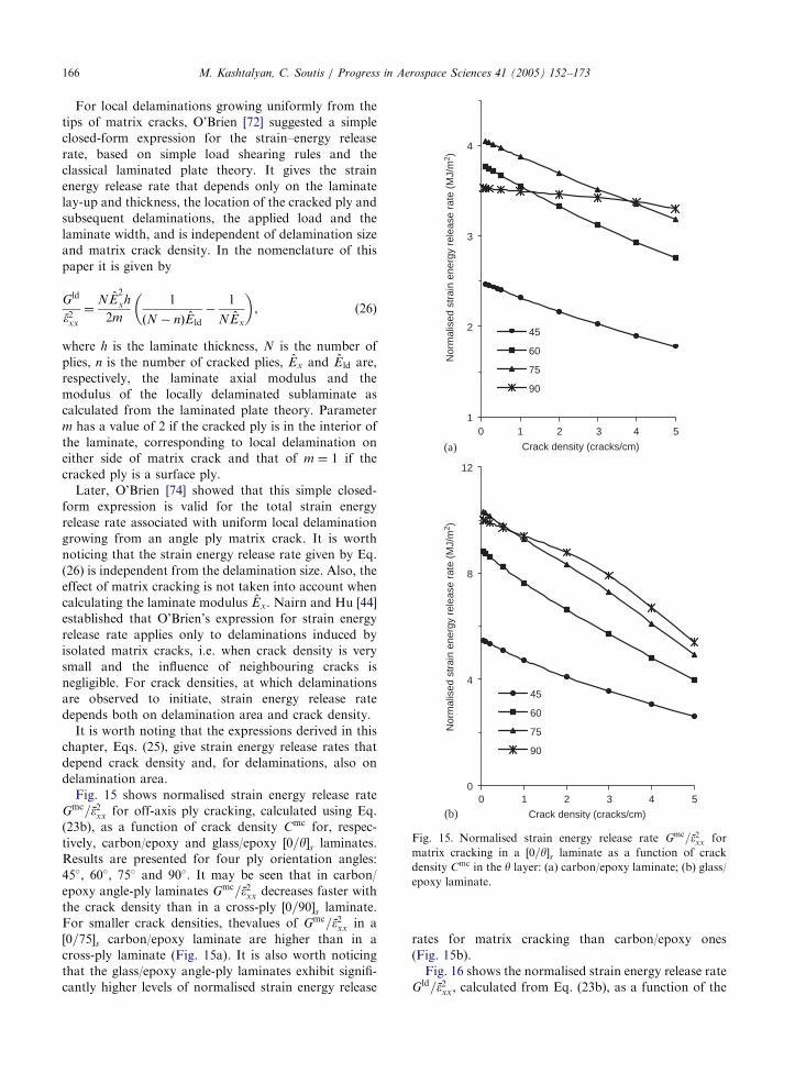
Fig. 15. Normalised strain energy release rate Gmc=�2xx for
matrix cracking in a ½0=y�s laminate as a function of crack
density Cmc in the y layer: (a) carbon/epoxy laminate; (b) glass/epoxy laminate.
For local delaminations growing uniformly from the
rate, based on simple load shearing rules and the
classical laminated plate theory. It gives the strain
energy release rate that depends only on the laminate
lay-up and thickness, the location of the cracked ply and
subsequent delaminations, the applied load and the
laminate width, and is independent of delamination size
and matrix crack density. In the nomenclature of this
paper it is given by
Gld
�2xx
¼NE
2
xh
2m
1
ðN � nÞEld
�1
NEx
� �, (26)
where h is the laminate thickness, N is the number of
plies, n is the number of cracked plies, Ex and Eld are,
respectively, the laminate axial modulus and the
modulus of the locally delaminated sublaminate as
calculated from the laminated plate theory. Parameter
m has a value of 2 if the cracked ply is in the interior of
the laminate, corresponding to local delamination on
either side of matrix crack and that of m ¼ 1 if the
cracked ply is a surface ply.
Later, O’Brien [74] showed that this simple closed-
form expression is valid for the total strain energy
release rate associated with uniform local delamination
growing from an angle ply matrix crack. It is worth
noticing that the strain energy release rate given by Eq.
(26) is independent from the delamination size. Also, the
effect of matrix cracking is not taken into account when
calculating the laminate modulus Ex. Nairn and Hu [44]
established that O’Brien’s expression for strain energy
release rate applies only to delaminations induced by
isolated matrix cracks, i.e. when crack density is very
small and the influence of neighbouring cracks is
negligible. For crack densities, at which delaminations
are observed to initiate, strain energy release rate
depends both on delamination area and crack density.
It is worth noting that the expressions derived in this
chapter, Eqs. (25), give strain energy release rates that
depend crack density and, for delaminations, also on
delamination area.
Fig. 15 shows normalised strain energy release rate
Gmc=�2xx for off-axis ply cracking, calculated using Eq.
(23b), as a function of crack density Cmc for, respec-
tively, carbon/epoxy and glass/epoxy ½0=y�s laminates.
Results are presented for four ply orientation angles:
45�, 60�, 75� and 90�. It may be seen that in carbon/
epoxy angle-ply laminates Gmc=�2xx decreases faster with
the crack density than in a cross-ply ½0=90�s laminate.
For smaller crack densities, thevalues of Gmc=�2xx in a
½0=75�s carbon/epoxy laminate are higher than in a
cross-ply laminate (Fig. 15a). It is also worth noticing
that the glass/epoxy angle-ply laminates exhibit signifi-
cantly higher levels of normalised strain energy release
rates for matrix cracking than carbon/epoxy ones
(Fig. 15b).
Fig. 16 shows the normalised strain energy release rate
Gld=�2xx, calculated from Eq. (23b), as a function of the

ARTICLE IN PRESS
0.3
0.32
0.34
0.36
0.38
0 0.8 1.6 2.4 3.2 4Normalised delamination width
Nor
mal
ised
str
ain
ener
gy r
elea
se r
ate
(MJ/
m2 ) s=40t
s=20t
Fig. 16. Normalised strain energy release rate Gld=�2xx for
uniform local delamination in a cracked ½02=252=�252�s AS4/3506-1 laminate as a function of normalised delamination
length ‘=t. Matrix crack spacing s ¼ 20t and 40t.
0
0.5
1
1.5
2
2.5
0 20 40 60 80 100
Relative delamination area (%)
Nor
mal
ised
str
ain
ener
gy r
elea
se r
ate
(M
J/m
2 )
45
60
75
90
1
1.5
2
2.5
0 3Crack density (cracks/cm)
Nor
mal
ised
str
ain
ener
gy r
elea
se r
ate
(MJ/
m2 )
45
60
75
90
5421
(a)
(b)
Fig. 17. Normalised strain energy release rate Gld=�2xx for
uniform local delamination in a cracked AS4/3506-1 ½02=y2�slaminate: (a) as a function of relative delamination area Dld
(crack density 1 crack/cm); (b) as a function of crack density
Cmc in the y-ply (relative delamination area Dld ¼ 0, i.e. onset
of delamination).
M. Kashtalyan, C. Soutis / Progress in Aerospace Sciences 41 (2005) 152–173 167
delamination length normalised by the single ply
thickness ‘=t. The laminate lay-up is ½02=252=�252�s,and crack half-spacings are s ¼ 40t and 20t. This is
equivalent to the crack densities of approximately C ¼ 1
and 2 cm�1, respectively. It can be seen that the present
approach gives the strain energy release rate for uniform
local delamination that depends both on crack density
and delamination length. The result of Eq. (26) for the
same lay-up is found equal to 12:7MJ=m2 provided
shear–extension coupling and bending–extension cou-
pling are taken into account [74].Still, it is much higher
than our predictions, since the model of Eq. (26) is for a
single isolated matrix crack and associated local
delamination and does not account for the cumulative
effect of multiple cracking and local delaminations as
illustrated in Fig. 2.
Fig. 17 shows the normalised strain energy release rate
Gld=�2xx associated with uniform local delaminations
induced by off-axis ply cracking in a graphite/epoxy
½02=y2�s laminate. Dependence on the relative delamina-
tion area Did is shown in Fig. 17a, and on the crack
density in Fig. 17b. Results are presented for four
different ply orientations angles: 45�, 60�, 75� and 90�. It
may be seen that strain energy release rate non-linearly
depends on delamination area and almost linearly on the
crack density. While in a cross-ply ½02=902� laminate thevalue of Gld=�2xxjDld¼0 at the delamination onset is almost
independent of crack density, in ½02=y2�s it strongly
depends on it. Also, in ½02=602�s and ½02=752� laminates itis significantly higher than in a cross-ply ½02=902�laminate, suggesting lower delamination onset strains.
ARTICLE IN PRESS
3
)
as-cut edges
polished edges
notched edges
M. Kashtalyan, C. Soutis / Progress in Aerospace Sciences 41 (2005) 152–173168
4.1. Predicting onset and growth of off-axis ply cracking
Even under the uniaxial loading, damage development
in the off-axis plies of general symmetric laminates
always occurs under mixed mode conditions due to
shear–extension coupling. It is therefore important in
the calculation of the total strain energy release rate to
be able to separate Modes I and II contributions.
For a ½ðSÞ=f�s laminate with damaged f-layermodelled by an ‘equivalent’ laminate, the total strain
energy release rate for off-axis ply cracks and crack-
induced local delaminations is equal to the first partial
derivative of the portion of the total strain energy stored
in the ‘equivalent’ homogeneous layer with respect to
damage area
Gmc ¼ �qU ð2Þ
qAmc
����f�g
, (27a)
Gld ¼ �qU ð2Þ
qAld
����f�g;C
. (27b)
In the local coordinates (Fig. 3), this portion of the total
strain energy can be separated into extensional and
shear parts
U ð2Þ ¼ Uð2ÞI þ U
ð2ÞII ¼ Lwh2ðs
ð2Þ11 �
ð2Þ11 þ sð2Þ22 �
ð2Þ22 Þ
þ Lwh2sð2Þ12 g
ð2Þ12 . ð28Þ
Under uniaxial strain �xx, strains and stresses in the
‘equivalent’ homogeneous layer are
f�ð2Þg ¼ fcos2f; sin2f; 2 cosf sinfgT�xx,
fsð2Þg ¼ ½Qð2Þ�fcos2f; sin2f; 2 cosf sinfgT �xx, ð29Þ
where the modified stiffness matrix ½Qð2Þ� of the
‘equivalent’ homogeneous layer in the local coordinates
is given by Eq. (12). Substitution of Eqs. (22), (28) and
(29) into Eq. (27) gives Modes I and II contributions
into the total strain energy release rate as follows:
2
ain
(%
prediction
�0
1
45 60 75 90Ply orientation angle (degrees)
Cra
ckin
g on
set s
tr
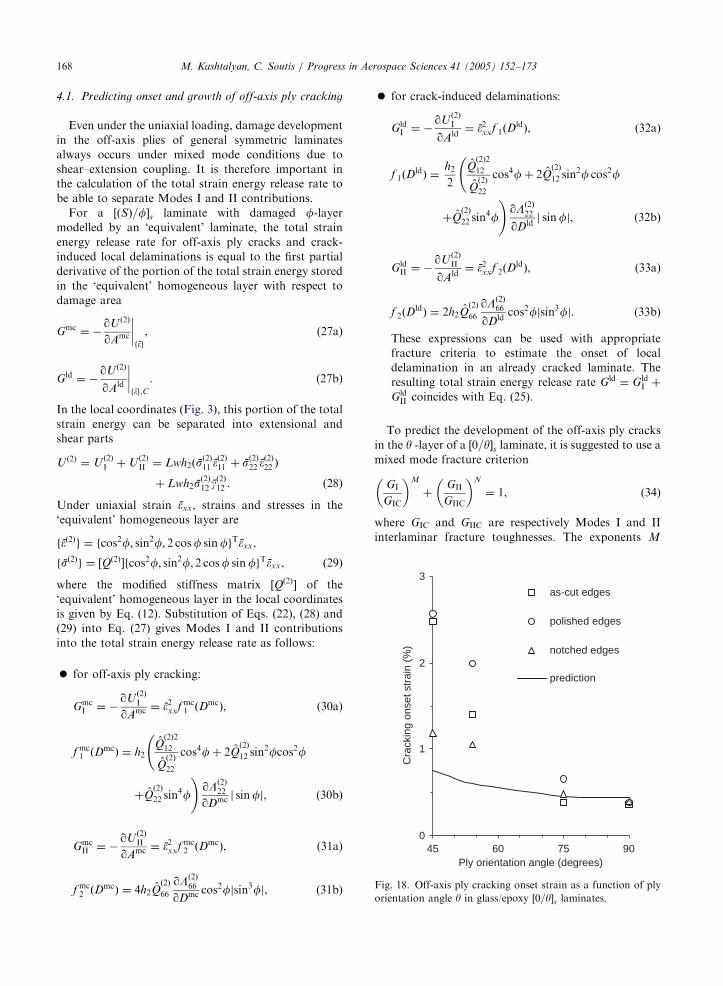
Fig. 18. Off-axis ply cracking onset strain as a function of ply
orientation angle y in glass/epoxy ½0=y�s laminates.
for off-axis ply cracking:
GmcI ¼ �
qUð2ÞI
qAmc ¼ �2xxf mc1 ðDmcÞ, (30a)
f mc1 ðDmcÞ ¼ h2Q
ð2Þ2
12
Qð2Þ
22
cos4fþ 2Qð2Þ
12 sin2fcos2f
þQð2Þ
22 sin4f
!qLð2Þ
22
qDmc j sinfj, ð30bÞ
GmcII ¼ �
qUð2ÞII
qAmc ¼ �2xxf mc2 ðDmcÞ, (31a)
f mc2 ðDmcÞ ¼ 4h2Qð2Þ
66
qLð2Þ66
qDmc cos2fjsin3fj, (31b)
�
for crack-induced delaminations:GldI ¼ �
qUð2ÞI
qAld¼ �2xxf 1ðD
ldÞ, (32a)
f 1ðDldÞ ¼
h2
2
Qð2Þ2
12
Qð2Þ
22
cos4fþ 2Qð2Þ
12 sin2f cos2f
þQð2Þ
22 sin4f
!qLð2Þ
22
qDldj sinfj, ð32bÞ
GldII ¼ �
qUð2ÞII
qAld¼ �2xxf 2ðD
ldÞ, (33a)
f 2ðDldÞ ¼ 2h2Q
ð2Þ
66
qLð2Þ66
qDldcos2fjsin3fj. (33b)
These expressions can be used with appropriate
fracture criteria to estimate the onset of local
delamination in an already cracked laminate. The
resulting total strain energy release rate Gld ¼ GldI þ
GldII coincides with Eq. (25).
To predict the development of the off-axis ply cracks
in the y -layer of a ½0=y�s laminate, it is suggested to use amixed mode fracture criterion
GI
GIC
� �M
þGII
GIIC
� �N
¼ 1, (34)
where GIC and GIIC are respectively Modes I and II
interlaminar fracture toughnesses. The exponents M

ARTICLE IN PRESSM. Kashtalyan, C. Soutis / Progress in Aerospace Sciences 41 (2005) 152–173 169
and N depend on the material system. Following
Rikards et al. [82], for a glass/epoxy system they can
be taken as M ¼ 1;N ¼ 2.
Fig. 18 shows predicted and experimentally observed
cracking onset strains for ½0=y�s glass/epoxy laminates.
Crocker et al. (1997) measured cracking onset strains in
specimens with as-cut, polished and notched edges. At
that, an independence of strain at onset of crack
propagation in notched samples on the notch depth
was observed. To predict cracking onset strains, GmcI and
GmcII values are calculated from Eqs. (30) and (31), and
cracking onset strain �xx is found as a root of the
following equation:
�4xx
f mc2 ðDmcÞ
GIIC
� �2
þ �2xx
f mc1 ðDmcÞ
GIC
� �¼ 1
when Dmc ! 0. ð35Þ
Since the exact GIC and GIIC critical values for the
considered glass/epoxy system are not known, predic-
tions are made using typical for glass/epoxy systems
values of GIC ¼ 200 J=m2 and GIIC ¼ 1500 J=m2. Com-
parison with limited experimental data shows that the
mixed mode fracture criterion, Eq. (9), can successfully
predict the initiation of matrix cracking for ply
orientation angles 75�pyp90�. For 45�pyp75�, mea-
sured strains are much higher than predictions. Also,
they increase steeply as y decreases. Further work is
required to develop an appropriate fracture or failure
criterion that captures initiation and development of
matrix cracks in off-axis plies of composite laminates
reinforced by glass or carbon fibres, especially for
yo75�.
Further work is required to validate theoretical
predictions. For the lay-ups, damage modes and loading
conditions examined in this study the experimental data
are currently not available.
5. Concluding remarks
The fracture process of composite laminates subjected
to static or fatigue tensile loading involves a sequential
accumulation of intra- and interlaminar damage, in the
form of transverse cracking, splitting and delamination,
prior to catastrophic failure. Matrix cracking parallel to
the fibres in the off-axis plies is the first damage mode
observed. It triggers development of other harmful resin-
dominated modes such as delaminations. Since a
damaged lamina within the laminate retains certain
amount of its load-carrying capacity, it is important to
predict accurately the stiffness properties of the laminate
as a function of damage as well as progression of
damage with the strain state. Incorporation of analytical
models of stiffness degradation and damage progression
into a finite element code will constitute the most
effective tool for progressive failure modelling of
composite plates with more complex configurations,
e.g. holes, notches and other stress concentrators.
In multidirectional laminates subjected to in-plane
tensile or thermal loading matrix cracks parallel to the
fibres develop in several off-axis plies. Comprehensive
observations of sequential accumulation of matrix
cracks in quasi-isotropic and balanced carbon/epoxy
and glass/epoxy laminates under quasi-static and fatigue
tensile loading have been extensively reported in the
literature. Concurrent matrix cracking in the adjacent
off-axis plies is an extremely complex problem to model
and has been analysed in the literature mostly using
finite elements method. A theoretical model that
describes damage development under complex loading
conditions does not yet exist.
Here, analytical modelling of off-axis ply cracking
and crack tip delaminations in balanced and unbalanced
angle-ply composite laminates subjected to in-plane
tensile loading is presented and discussed. A 2-D
shear-lag analysis is used to determine ply stresses in a
representative segment and the equivalent laminate
concept is applied to derive expressions for Modes I,
and II and the total strain energy release rate associated
with uniform local delaminations. These expressions can
be used with appropriate fracture criteria to estimate the
onset and growth of damage in off-axis plies.
To calculate strain energy release rates for off-axis ply
cracking and uniform local delaminations growing along
matrix cracks in balanced and unbalanced angle-ply
laminates, the damaged layer of the laminate is replaced
with an equivalent homogeneous one with effective
elastic properties. Closed form expressions for strain
energy release rate associated with matrix cracking and
crack induced uniform local delaminations have been
derived, representing them as linear functions of the first
partial derivatives of the effective elastic properties of
the damaged layer with respect to appropriate damage
parameters. Dependence of strain energy release rates
and the laminate stiffness properties on delamination
area, crack density and ply orientation angle has been
examined. It appears that matrix cracking and delami-
nation area influence the strain energy release rate value
significantly.
Comparison with results obtained by O’Brien [72,74]
shows that O’Brien’s closed-form expression for uniform
local delamination significantly overestimates the value
of the total strain energy release rate leading to lower
theoretical strains for the initiation of local delamination
and therefore over-conservative designs. Also, it gives
the total strain energy release rate as independent of
delamination area and does not take into account the
cumulative effect of damage.
It is found, in particular, that the reduction due to
matrix cracking of the laminate axial and transverse
moduli is more significant in angle-ply than in cross-ply

ARTICLE IN PRESSM. Kashtalyan, C. Soutis / Progress in Aerospace Sciences 41 (2005) 152–173170
laminates, while for the shear modulus, the opposite is
true. Matrix cracking in angle-ply CFRP and GFRP
laminates can result in an increase in the Poisson’s
ratio—a phenomenon, not observed in cross-ply lami-
nates. Also, matrix cracking in angle-ply laminates
introduces coupling between extension and shear.
In near future work, the analytical predictions will be
compared to numerical (finite element) and experimental
data, which for the lay-ups, damage modes and loading
conditions examined in this study are currently not
available.
Acknowledgements
Financial support of this research by the Engineering
and Physical Sciences Research Council (EPSRC/GR/
L51348 and EPSRC/GR/A31001/02) and the British
Ministry of Defence is gratefully acknowledged.
Appendix A
Variation of the out-of-plane shear stresses has the
form
sð2Þj3 ¼tj
h2x3; 0pjx3jph2; j ¼ 1; 2, (A.1a)
sð1Þj3 ¼tj
h1ðh � x3Þ; h2pjx3jph. (A.1b)
Constitutive equations for the out-of-plane shear
stresses
sðkÞ13
sðkÞ23
8<:
9=; �
QðkÞ55 Q
ðkÞ45
QðkÞ45 Q
ðkÞ44
24
35 qqx3
uðkÞ1
uðkÞ2
8<:
9=;; i ¼ 1; 2.
(A.2)
After substituting Eq. (A.2) into Eqs. (A.1), multiplying
them by x3 and by h � x3, respectively, and integrating
with respect to x3 we get
h1
3
t1t2
( )¼
Qð1Þ
55 Qð1Þ
45
Qð1Þ
45 Qð1Þ
44
24
35 ~uð1Þ1
~uð1Þ2
8<:
9=;�
V1
V2
( )0@
1A,
(A.3a)
h2
3
t1t2
( )¼
Qð2Þ
55 0
0 Qð2Þ
44
24
35 V1
V2
( )�
~uð2Þ1
~uð2Þ2
8<:
9=;
0@
1A.
(A.3b)
Here fVg ¼ fuð1Þgjx3¼h2 ¼ fuð2Þgjx3¼h2 are the in-plane
displacements at the interface. After rearranging
Eqs. (A.3) become
~uð1Þ1
~uð1Þ2
8<:
9=;�
~uð2Þ1
~uð2Þ2
8<:
9=; ¼
h1
3
Qð1Þ
55 Qð1Þ
45
Qð1Þ
45 Qð1Þ
44
264
375�10
B@
þh2
3
Qð2Þ
55 0
0 Qð2Þ
44
264
375�11CA t1
t2
( ).
ðA:4Þ
Inversion of Eq. (A.4) leads to
t1t2
( )¼
K11 K12
K21 K22
" #~uð1Þ1
~uð1Þ2
8<:
9=;�
~uð2Þ1
~uð2Þ2
8<:
9=;
0@
1A, (A.5)
with
½K � ¼h1
3
Qð1Þ
55 Qð1Þ
45
Qð1Þ
45 Qð1Þ
44
24
35�1
þh2
3
Qð2Þ
55 0
0 Qð2Þ
44
24
35�1
0B@
1CA
�1
.
(A.6)
Appendix B
On referring to the constitutive equations, Eqs. (6),
the generalised plane strain condition, Eq. (5), becomes
Sð1Þ
11 ~sð1Þ11 þ S
ð1Þ
12 ~sð1Þ22 þ S
ð1Þ
16 ~sð1Þ12 ¼ S
ð2Þ
11 ~sð2Þ11 þ S
ð2Þ
12 ~sð2Þ22 . (B.1)
Using the laminate equilibrium equations, Eqs. (4),
stresses in the constraining layer (layer 1) can be
excluded, so that the microstress component ~sð2Þ11 is
given by
~sð2Þ11 ¼ a22 ~sð2Þ22 þ a12 ~s
ð2Þ12 þ bxsx þ bysy, (B.2)
a22 ¼ �Sð1Þ
12 þ wSð2Þ
12
Sð1Þ
11 þ wSð2Þ
11
; a12 ¼ �Sð1Þ
16
Sð1Þ
11 þ wSð2Þ
11
,
bx ¼ð1þ wÞðS
ð1Þ
11 cos2fþ S
ð1Þ
12 sin2f� S
ð1Þ
16 sinf cosfÞ
Sð1Þ
11 þ wSð2Þ
11
,
by ¼ð1þ wÞðS
ð1Þ
11 sin2fþ S
ð1Þ
12 cos2fþ S
ð1Þ
16 sinf cosfÞ
Sð1Þ
11 þ wSð2Þ
11
.
Strain differences are expressed in terms of stresses as
~gð1Þ12 � ~gð2Þ12
~�ð1Þ22 � ~�ð2Þ22
8<:
9=; ¼ �
1
w
L11 L12
L21 L22
" #~sð2Þ12
~sð2Þ22
8<:
9=;
þ1
w
M11 M12
M21 M22
" #sx
sy
( ). ðB:3Þ

ARTICLE IN PRESSM. Kashtalyan, C. Soutis / Progress in Aerospace Sciences 41 (2005) 152–173 171
Here
L11 ¼ Sð1Þ
66 þ a12Sð1Þ
16 þ wSð2Þ
66 ,
L12 ¼ Sð1Þ
26 þ a22Sð1Þ
16 ,
L21 ¼ Sð1Þ
26 þ a12Sð1Þ
12 þ wa12Sð2Þ
12 ,
L22 ¼ Sð1Þ
22 þ a22Sð1Þ
12 þ wðSð2Þ
22 þ a22Sð2Þ
12 Þ, ðB:4aÞ
M11 ¼ ð1þ wÞbðSð1Þ
16 þ a12Sð2Þ
11 Þcos2f
þ ðSð1Þ
26 þ a12Sð1Þ
12 Þsin2f� ðS
ð1Þ
66 þ a12Sð1Þ
16 Þ
� sinf cosfc,
M21 ¼ ð1þ wÞbðSð1Þ
12 þ a22Sð1Þ
11 Þcos2f
þ ðSð1Þ
22 þ a22Sð1Þ
12 Þsin2f� ðS
ð1Þ
26 þ a22Sð1Þ
16 Þ
� sinf cosfc,
M12 ¼ ð1þ wÞbðSð1Þ
16 þ a12Sð2Þ
11 Þsin2f
þ ðSð1Þ
26 þ a12Sð1Þ
12 Þcos2fþ ðS
ð1Þ
66 þ a12Sð1Þ
16 Þ
� sinf cosfc,
M22 ¼ ð1þ wÞbðSð1Þ
12 þ a22Sð1Þ
11 Þsin2f
þ ðSð1Þ
22 þ a22Sð1Þ
12 Þcos2fþ ðS
ð1Þ
26 þ a22Sð1Þ
16 Þ
� sinf cosfc. ðB:4bÞ
Substitution into the equilibrium equations, Eqs. (3),
yields the following coupled 2nd order differential
equations
d2
dx2
~sð2Þ12
~sð2Þ22
8<:
9=;�
1
h1
K11 K12
K21 K22
" #L11 L12
L21 L22
" #~sð2Þ12
~sð2Þ22
8<:
9=;
0@
þM11 M12
M21 M22
" #sx
sy
( )1A ¼ 0, ðB:5Þ
or
d2
dx2
~sð2Þ12
~sð2Þ22
8<:
9=;�
N11 N12
N21 N22
" #~sð2Þ12
~sð2Þ22
8<:
9=;
þP11 P12
P21 P22
" #sx
sy
( )¼ 0, ðB:6Þ
where ½N� ¼ h�11 ½K �½L� and ½P� ¼ h�11 ½K �½M�, with ma-
trices ½K �; ½L� and ½M� defined by Eqs. (A.6), (B.4a) and
(B.4b), respectively.
Appendix C
A1 ¼l21 � N22
N21A2; B1 ¼
l22 � N22
N21B2,
C1 ¼ �C2N22 þ P21 þ aP22
N21, ðC:1Þ
A2 ¼ �ðP21 þ aP22ÞðN21N12 � N11N22Þ þ Rl22
ðl22 � l21ÞðN21N12 � N11N22Þ, (C.2)
B2 ¼ðP21 þ aP22ÞðN21N12 � N11N22Þ þ Rl21
ðl22 � l21ÞðN21N12 � N11N22Þ, (C.3)
C2 ¼R
N21N12 � N11N22,
R ¼ N11ðP21 þ aP22Þ � N21ðP11 þ aP12Þ. ðC:4Þ
References
[1] Talreja R. Transverse cracking and stiffness reduction in
composite laminates. J Compos Mater 1985;19(4):355–75.
[2] Talreja R. A continuum mechanics characterization of
damage in composite materials. Proc R Soc London Ser A
1985;399(1817):195–216.
[3] Allen DH, Harris CE, Groves SE. A theoretical constitu-
tive theory for elastic composite with distributed damage.
I. Theoretical development. Int J Solids Struct 1987;23(9):
1301–18.
[4] Allen DH, Harris CE, Groves SE. A theoretical constitu-
tive theory for elastic composite with distributed damage.
II. Application to matrix cracking in laminated compo-
sites. Int J Solids Struct 1987;23(9):1319–38.
[5] Li S, Reid SR, Soden PD. A continuum damage model for
transverse matrix cracking in laminated fibre-reinforced
composites. Philos Trans R Soc London Ser A 1998;
356(1746):2379–412.
[6] Dharani LR, Tang H. Micromechanics characterization of
sublaminate damage. Int J Fract 1990;46(2):123–40.
[7] Berthelot JM, Leblond P, El Mahi A. 2D and 3D
numerical models of transverse cracking in cross-ply
laminates. Compos Sci Technol 1996;56(7):793–6.
[8] Highsmith AL, Reifsnider KL. Stiffness reduction me-
chanisms in composite laminates. In: Damage in composite
materials: mechanisms, accumulation, tolerance, and
characterization, ASTM STP 775. 1982. p. 103–17.
[9] Bowles DE. Effect of microcracks on the thermal
expansion of composite laminates. J Compos Mater
1984;18(2):173–87.
[10] Lundgren JE, Gudmundson P. Moisture absorption in
glass-fiber/epoxy laminates with transverse matrix cracks.
Compos Sci Technol 1999;59(13):1983–91.
[11] Birman V, Byrd W. Matrix cracking in transverse layers of
cross-ply beams subjected to bending and its effect on
vibration frequencies. Composites B 2001;31(1):47–55.

ARTICLE IN PRESSM. Kashtalyan, C. Soutis / Progress in Aerospace Sciences 41 (2005) 152–173172
[12] Nairn JA, Hu S. The formation and effect of outer-ply
microcracks in cross-ply laminates: a variational approach.
Eng Fract Mech 1992;41(2):203–21.
[13] Bailey JE, Curtis PT, Parvizi A. On transverse cracking
and longitudinal splitting behaviour of glass and carbon
fibre reinforced epoxy cross-ply laminates and the effect of
Poisson and thermally generated strain. Proc R Soc
London A 1979;366(1727):599–623.
[14] Jamison RD, Schulte K, Reifsnider KL, Stinchcomb WW.
Characterization and analysis of damage mechanisms in
tension-tension fatigue of graphite/epoxy laminates. In:
Effects of defects in composite materials, ASTM STP 836.
1984. p. 21–55.
[15] Parvizi A, Garrett KW, Bailey JE. Constrained cracking in
glass fibre-reinforced epoxy cross-ply laminate. J Mater Sci
1978;13(1):195–201.
[16] Charewicz A, Daniel IM. Damage mechanisms and
accumulation in graphite/epoxy laminates. In: Hahn HT,
editor. Composite materials: fatigue and fracture, ASTM
STP, vol. 907. Philadelphia, PA: ASTM; 1986. p. 274–97.
[17] Smith PA, Boniface L, Glass NFC. A comparison of
transverse cracking phenomena in ð0=90Þs and ð90=0ÞsCFRP laminates. Appl Compos Mater 1998;5(1):11–23.
[18] Nuismer RJ, Tan SC. Constitutive relations of a
cracked composite lamina. J Compos Mater 1988;22(4):
306–21.
[19] Flaggs DL. Prediction of tensile matrix failure in
composite laminates. J Compos Mater 1985;19(1):29–50.
[20] Tan CS, Nuismer RJ. A theory of progressive matrix
cracking in composite laminates. J Compos Mater
1989;23(10):1029–47.
[21] Han YM, Hahn HT. Ply cracking and property degrada-
tions of symmetric balanced laminates under general in-
plane loading. Compos Sci Technol 1989;35(4):377–97.
[22] Lee JW, Daniel IM. Progressive transverse cracking of
cross-ply composite laminates. J Compos Mater 1990;
24(11):1225–43.
[23] Smith PA, Wood JR. Poisson’s ratio as a damage
parameter in the static tensile loading of simple cross-ply
laminates. Compos Sci Technol 1990;38(1):85–93.
[24] Fukunaga H, Chou TW, Peters PWM, Schulte K.
Probabilistic failure strength analysis of graphite/epoxy
cross-ply laminates. J Compos Mater 1984;18(4):339–56.
[25] Lim SG, Hong CS. Prediction of transverse cracking and
stiffness reduction in cross-ply laminated composites.
J Compos Mater 1989;23(7):695–713.
[26] Zhang J, Fan J, Soutis C. Analysis of multiple matrix
cracking in ½�ym=90n�s composite laminates Part 1:
in-plane stiffness properties. Composites 1992;23(5):
291–8.
[27] Berthelot JM. Analysis of the transverse cracking of cross-
ply laminates: a generalized approach. J Compos Mater
1997;31(18):1780–805.
[28] Hashin Z. Analysis of cracked laminate: a variational
approach. Mech Mater 1985;4(2):121–36.
[29] Nairn JA. The strain energy release rate of composite
microcracking: a variational approach. J Compos Mater
1989;23(11):1106–29.
[30] Varna J, Berglund LA. Multiple transverse cracking and
stiffness reduction in cross-ply laminates. J Compos
Technol Res 1991;13(2):97–106.
[31] Varna J, Berglund LA. A model for prediction of the
transverse cracking strain in cross-ply laminates. J Reinf
Plast Compos 1992;11(7):708–28.
[32] Berglund LA, Varna J. Thermo-elastic properties of
composite laminates with transverse cracks. J Compos
Technol Res 1994;16(1):77–87.
[33] McCartney LN. Theory of stress transfer in a 0�-90�-0�
cross-ply laminate containing a parallel array of transverse
cracks. J Mech Phys Solids 1992;40(1):27–68.
[34] McCartney LN. The prediction of cracking in biaxially
loaded cross-ply laminates having brittle matrices. Com-
posites 1993;24(2):84–92.
[35] Takeda N, McCartney LN, Ogihara S. The application of
a ply-refinement technique to the analysis of microscopic
deformation in interlaminar-toughened laminates with
transverse cracks. Compos Sci Technol 2000;60(2):231–40.
[36] Schoeppner GA, Pagano NJ. Stress fields and energy
release rates in cross-ply laminates. Int J Solids Struct
1998;35(11):1025–55.
[37] McCartney LN, Schoeppner GA, Becker W. Comparison
of models for transverse ply cracks in composite laminates.
Compos Sci Technol 2000;60(12–13):2347–59.
[38] Zocher MA, Allen DH, Groves SE. Stress analysis of a
matrix-cracked viscoelastic laminates. Int J Solids Struct
1997;35(25):3235–57.
[39] Kumar RS, Talreja R. Linear viscoelastic behavior of
matrix cracked cross-ply laminates. Mech Mater 2001;
33(3):139–54.
[40] Ogin SL, Smith PA, Beaumont PWR. Matrix cracking and
stiffness reduction during the fatigue of ½0=90�s GFRP
laminates. Compos Sci Technol 1985;22(1):23–31.
[41] Daniel IM, Charewicz A. Fatigue damage mechanisms and
residual properties of graphite/epoxy laminates. Eng
Fracture Mech 1986;25(5–6):793–808.
[42] Highsmith AL, Reifsnider KL. Internal load distribution
effects during fatigue loading of composite laminates. In:
Composite materials: fatigue and fracture, ASTM STP.
907. 1986. p. 233–51.
[43] Kobayashi S, Terada K, Ogihara S, Takeda N. Damage
mechanics analysis of matrix cracking in cross-ply CFRP
laminates under thermal fatigue. Compos Sci Technol
2001;61(12):1735–42.
[44] Nairn JA, Hu S. The initiation and growth of delamina-
tions induced by matrix microcracks in laminated compo-
sites. Int J Fract 1992;57(1):1–24.
[45] Hashin Z. Analysis of orthogonally cracked laminates
under tension. Trans ASME J Appl Mech 1987;25(5–6):
771–8.
[46] Tsai CL, Daniel IM. Behavior of cracked cross-ply
composite laminates under shear loading. Int J Solids
Struct 1992;29(4):3251–67.
[47] Henaff-Gardin C, Lafarie-Frenot MC, Gamby D. Doubly
periodic matrix cracking in composite laminates Part 1:
general in-plane loading. Compos Struct 1996;36(1–2):
113–30.
[48] Henaff-Gardin C, Lafarie-Frenot MC, Gamby D. Doubly
periodic matrix cracking in composite laminates Part 2:
thermal biaxial loading. Compos Struct 1996;36(1–2):131–40.
[49] Kashtalyan M, Soutis C. A study of matrix crack tip
delaminations and their influence on composite laminate
stiffness. Adv Compos Lett 1999;8(4):149–56.
ARTICLE IN PRESSM. Kashtalyan, C. Soutis / Progress in Aerospace Sciences 41 (2005) 152–173 173
[50] Kashtalyan M, Soutis C. Application of the equivalent
constraint model to investigate stiffness properties of
transversally cracked and split FRP laminates. Adv
Compos Lett 1999;8(5):205–11.
[51] Kashtalyan M, Soutis C. The effect of delaminations
induced by transverse cracking and splitting on stiffness
properties of composite laminates. Compos A: Appl Sci
Manuf 2000;31(2):107–19.
[52] Kashtalyan M, Soutis C. Stiffness degradation in cross-ply
laminates damaged by transverse cracking and splitting.
Compos A: Appl Sci Manuf 2000;31(4):335–51.
[53] Kashtalyan M, Soutis C. Modelling stiffness degradation
due to matrix cracking in angle-ply composite laminates.
Plast Rubber Compos 2000;29(9):482–8.
[54] Tong J, Guild FJ, Ogin SL, Smith PA. On matrix crack
growth in quasi-isotropic laminates—I. Experimental
investigation. Compos Sci Technol 1997;57(11):1527–35.
[55] O’Brien TK, Hooper SJ. Local delamination in laminates
with angle ply matrix cracks: Part I Tension tests and stress
analysis. NASA Technical Memorandum 104055/AVS-
COM Technical report 91-B-010, 1991.
[56] Crocker LE, Ogin SL, Smith PA, Hill PS. Intra-laminar
fracture in angle-ply laminates. Compos A 1997;28(9–10):
839–46.
[57] Varna J, Joffe R, Akshntala NV, Talreja R. Damage in
composite laminates with off-axis plies. Compos Sci
Technol 1999;59(14):2139–47.
[58] Tong J, Guild FJ, Ogin SL, Smith PA. On matrix crack
growth in quasi-isotropic laminates—II. Finite element
analysis. Compos Sci Technol 1997;57(11):1537–45.
[59] Lapusta YN, Henaff-Gardin C. An analytical model for
periodic a�-layer cracking in composite laminates. Int J
Fract 2000;102(4):L73–6.
[60] Zhang J, Herrmann KP. Stiffness degradation induced by
multilayer matrix cracking in composite laminate. Compos
A: Appl Sci Manuf 1999;30(5):683–706.
[61] Soutis C, Kashtalyan M. Delamination growth and
residual properties of cracked orthotropic laminates under
tensile loading. J Thermoplas Compos Mater 2000;15(1):
13–22.
[62] Kashtalyan M, Soutis C. Analysis of local delamination in
composite laminates with angle ply matrix cracks. Int J
Solids Struct 2002;39(6):1515–37.
[63] Crossman FW, Wang ASD. The dependence of transverse
cracking and delamination on ply thickness in graphite
epoxy laminates. In: Reifsnider KL, editor. Damage in
composite materials, ASTM STP 775. Philadelphia, PA:
ASTM; 1982. p. 118–39.
[64] O’Brien TK. Characterization of delamination onset and
growth in a composite laminate. In: Reifsnider KL, editor.
Damage in composite materials, ASTM STP 775. Phila-
delphia, PA: ASTM; 1982. p. 140–67.
[65] Armanios EA, Sriram P, Badir AM. Fracture analysis of
transverse crack–tip and free-edge delamination in lami-
nated composites. In: O’Brien TK, editor. Composite
materials: fatigue and fracture, ASTM STP 1110. Phila-
delphia, PA: ASTM; 1991. p. 269–86.
[66] Zhang J, Fan J, Soutis C. Analysis of multiple matrix
cracking in ½�ym=90n�s composite laminates Part 2:
development of transverse ply cracks. Composites 1992;
23(5):299–304.
[67] Takeda N, Ogihara S. Initiation and growth of delamina-
tion from the tip of transverse cracks in CFRP cross-ply
laminates. Compos Sci Technol 1994;52(3):309–18.
[68] Ogihara S, Takeda N. Interaction between transverse
cracks and delamination during damage progress in CFRP
cross-ply laminates. Compos Sci Technol 1995;54(4):
395–404.
[69] Selvarathinam AS, Weitsman YJ. Transverse cracking and
delamination in cross-ply gr/ep composites under dry,
saturated and immersed fatigue. Int J Fract 1998;91(2):
103–16.
[70] Selvarathinam AS, Weitsman YJ. A shear-lag analysis of
transverse cracking and delamination in cross-ply carbon-
fibre/epoxy composites under dry, saturated and immersed
fatigue conditions. Compos Sci Technol 1999;59(14):
2115–23.
[71] Zhang J, Fan J, Herrmann KP. Delaminations induced by
constrained transverse cracking in symmetric composite
laminates. Int J Solids Struct 1999;36(6):813–46.
[72] O’Brien TK. Analysis of local delamination and their
influence on composite laminate behavior. In: Johnson
WS, editor. Delamination and debonding of materials,
ASTM STP 876. Philadephia, PA: ASTM; 1985.
p. 282–97.
[73] Salpekar SA, O’Brien TK. Combined effect of matrix
cracking and free edge on delamination. In: O’Brien TK,
editor. Composite materials: fatigue and fracture, ASTM
STP 1110. Philadelphia, PA: ASTM; 1991. p. 287–311.
[74] O’Brien TK. Local delamination in laminates with angle
ply matrix cracks: Part II Delamination fracture analysis
and fatigue characterization. NASA Technical Memor-
andum 104076/AVSCOM Technical report 91-B-011,
1991.
[75] Salpekar SA, O’Brien TK. Analysis of matrix cracking and
local delamination in ð0=y=� yÞs graphite epoxy laminatesunder tensile load. ASTM J Compos Technol Res
1993;15(2):95–100.
[76] Salpekar SA, O’Brien TK, Shivakumar KN. Analysis of
local delaminations caused by angle-ply matrix cracks.
J Compos Mater 1996;30(4):418–40.
[77] Ashkantala N, Talreja R. A mechanistic model for fatigue
damage evolution for composite laminates. Mech Mater
1998;29(2):123–40.
[78] Berthelot JM, Le Corre JF. A model for transverse
cracking and delamination in cross-ply laminates. Compos
Sci Technol 2000;60(7):1055–66.
[79] Berthelot JM, Le Corre JF. Statistical analysis of the
progression of transverse cracking and delamination in
cross-ply laminates. Compos Sci Technol 2000;60(14):
2659–69.
[80] Zhang J, Soutis C, Fan J. Strain energy release rate
associated with local delamination in cracked composite
laminates. Composites 1994;25(9):851–62.
[81] Zhang J, Soutis C, Fan J. Effects of matrix cracking and
hygrothermal stresses on the strain energy release rate for
edge delamination in composite laminates. Composites
1994;25(1):27–35.
[82] Rikards R, Buchholz FG, Wang H, Bledzki AK, Korjakin
A, Richard HA. Investigation of mixed mode interlaminar
fracture toughness of laminated composites by using a
CTS type specimen. Eng Fract Mech 1998;61(3–4):325–42.
Copyright © 2022 FDOKUMEN