Porous Melamine-Formaldehyde Monoliths by Step-Growth Polymerization Reactions via an Organic...
23
1 Porous Melamine-Formaldehyde Monoliths by Step-Growth Polymerization Reactions via an Organic Sol-gel Process Ahmed Awad Abbas Elhaj, Mehmet Taşkin Baytekin 1 , Knut Irgum 2 * Umeå University, Department of Chemistry, S-90187 Umeå, Sweden. Abstract In this explorative study, twenty hydrophilic melamine-formaldehyde (MF) monolith materials were synthesized by acid-catalyzed polycondensation of systems consisting of an aqueous MF precondensate, a block copolymeric surfactant as main porogen, and short aliphatic polyethers as co-porogens, which were dispersed in three different organic solvents covering a wide span in polarity. The molecular size and type of aliphatic polyether (co-porogen), and of the ratio of solvents to the other components were investigated by an experimental design that resulted in monolithic materials covering a wide range of different meso- and macroporous properties. A multivariate assessment revealed that the strongest contributors to the mesopore size and the inversely related surface area were the co-porogens, whereas the macropore dimension was explained by the solvents and the ratio between solvents and the other components. Surface elemental analysis by XPS showed slight differences in the bridging type between monoliths of opaque glass-like vs. white solid appearance. Measurements ζ-potentials in 10 mM ammonium acetate showed that the MF monoliths had no net charge at neutral pH, and +11 and –13 mV at pH 4 and 9.5, respectively. Introduction Porous polymeric monoliths have in recent years become increasingly important in the field of separation science [1] and as flow through supports for a variety of heterogeneous reaction schemes [2-4] due to the combination of high permeability and potential for good mass transfer properties compared to packed particle beds [1,5,6] . Monolithic materials with well-developed mesopore systems are further successfully implemented in catalysis, since they are character- rized by comparatively high specific total surface area [7] and thus offer sufficient large inter- active surfaces [8] . The synthesis procedure most commonly used for preparation of polymeric monoliths is based on addition polymerization of vinylic monomers by various schemes [9] and ring-opening metathesis polymerization [10,11] , although there are examples in the literature based on the urea/formaldehyde [12] and epoxide/amine [2,13,14] systems showing that also con- densation reactions can lead to monolithic materials with suitable porous structures. In order to investigate new alternative preparation routes, we have in this work chosen to examine 1 Present address: 614. Sok. No: 1, Eren Palas Apartmanı, Kat: 4/18, 41400 Gebze/Kocaeli, Turkey. 2 Corresponding author e-mail: [email protected]
Transcript of Porous Melamine-Formaldehyde Monoliths by Step-Growth Polymerization Reactions via an Organic...

1
Porous Melamine-Formaldehyde Monoliths by Step-Growth
Polymerization Reactions via an Organic Sol-gel Process
Ahmed Awad Abbas Elhaj, Mehmet Taşkin Baytekin1, Knut Irgum2*
Umeå University, Department of Chemistry, S-90187 Umeå, Sweden.
Abstract
In this explorative study, twenty hydrophilic melamine-formaldehyde (MF) monolith materials
were synthesized by acid-catalyzed polycondensation of systems consisting of an aqueous MF
precondensate, a block copolymeric surfactant as main porogen, and short aliphatic polyethers
as co-porogens, which were dispersed in three different organic solvents covering a wide span
in polarity. The molecular size and type of aliphatic polyether (co-porogen), and of the ratio of
solvents to the other components were investigated by an experimental design that resulted in
monolithic materials covering a wide range of different meso- and macroporous properties. A
multivariate assessment revealed that the strongest contributors to the mesopore size and the
inversely related surface area were the co-porogens, whereas the macropore dimension was
explained by the solvents and the ratio between solvents and the other components. Surface
elemental analysis by XPS showed slight differences in the bridging type between monoliths of
opaque glass-like vs. white solid appearance. Measurements ζ-potentials in 10 mM ammonium
acetate showed that the MF monoliths had no net charge at neutral pH, and +11 and –13 mV at
pH 4 and 9.5, respectively.
Introduction
Porous polymeric monoliths have in recent years become increasingly important in the field of
separation science[1] and as flow through supports for a variety of heterogeneous reaction
schemes[2-4] due to the combination of high permeability and potential for good mass transfer
properties compared to packed particle beds[1,5,6]. Monolithic materials with well-developed
mesopore systems are further successfully implemented in catalysis, since they are character-
rized by comparatively high specific total surface area[7] and thus offer sufficient large inter-
active surfaces[8]. The synthesis procedure most commonly used for preparation of polymeric
monoliths is based on addition polymerization of vinylic monomers by various schemes[9] and
ring-opening metathesis polymerization[10,11], although there are examples in the literature
based on the urea/formaldehyde[12] and epoxide/amine[2,13,14] systems showing that also con-
densation reactions can lead to monolithic materials with suitable porous structures. In order
to investigate new alternative preparation routes, we have in this work chosen to examine
1 Present address: 614. Sok. No: 1, Eren Palas Apartmanı, Kat: 4/18, 41400 Gebze/Kocaeli, Turkey. 2 Corresponding author e-mail: [email protected]

2
step-growth polymerization of melamine-formaldehyde (MF) as a means of preparing porous
supports with a bimodal pore structure for flow-through reaction schemes. Melamine (2,4,6-
triamino-1,3,5-triazine) is a heterocyclic aromatic compound which can act as a hexafunctional
monomer through its three equivalent amino groups, each capable of reacting with up to two
bi- or oligofunctional electrophiles, in a process eventually leading to highly crosslinked pro-
ducts.
Although cured melamine-formaldehyde is a hydrophilic polymer known for its chemical
resistance, heat durability, and toughness[15], the uncured prepolymer is malleable and can also
exist as suspensions[16]. This enables the preparation of foams or gels from MF by first synthe-
sizing a precondensate in basic aqueous solution, followed by curing in a separate step-growth
polymerization step[15,17]. The three amino groups of melamine are capable of reacting with up
to six equivalents of formaldehyde in the precondensation step, leading to a variety of hydroxy-
methylated monomers accompanied by formation of some oligomeric by-products. The molar
ratios of melamine and formaldehyde in MF precondensates could be from 1:2 up to 1:6, but
are usually kept around 1:3[18]. Gelling pf the prepolymer is triggered by lowering the pH of the
water-soluble MF precondensate, while dispersing it in an organic phase in presence of an
emulsifier/antifoaming agent[19]. This triggers a polycondensation into an intermediate gel,
which is finally cured into solid form by heating. The melamine:formaldehyde (MF) molar ratio,
the pH, and the reaction temperature are the main factors controlling the final structure of MF
condensation products and define their degree of cross-linking, which can reach high levels
under proper reaction conditions[20-22].
The aim of the present work was to synthesize highly porous and rigid MF monolithic entities
with evenly distributed inter-connected through-pore networks utilizing this organic sol-gel
process[23,24]. We therefore revisited the use of hydroxy-terminated polyethers as co-porogens,
an approach we have taken previously for radical polymerization of vinylic monomers[25], and
combined this with three different organic solvents as macroporogens and a polyether block
copolymer as mesoporogen in an attempt to find monolithic materials with well developed
bimodal pore systems.
Experimental
Reagents and Materials. The monomers used were 1,3,5-triazine-2,4,6-triamine (melamine;
99 %) from Aldrich (St. Louis, MO, USA) and methanal (formaldehyde; 37 wt-% solution in
water, stabilized with 10 wt-% methanol) from BDH Chemicals (Poole, England), both used as
received. The solvents used as diluents were N,N-dimethylformamide [DMF] from Fisher
(Leicestershire, UK), n-heptane from VWR (Fontenay-sous-Bois, France), and 1,2-dimethoxy-
ethane [DME] from BDH, all of analytical or ‘HPLC’ grade. The polymers used as co-porogens
were 2,2'-oxydiethanol [DEG; diethylene glycol] (99 % ‘GC grade’), α-hydro-ω-hydroxypoly-

3
(oxyethylene) [PEG; poly(ethylene glycol)] of average molecular weights (MW) 200 and 400,
and α-hydro-ω-hydroxypoly[oxy(1-methylethylene)] [PPG; poly(propylene glycol)] of MW 425
from Sigma-Aldrich (Schnelldorf, Germany). Pluronic L121, ,-hydroxy-poly(oxyethylene)-
block-poly[oxy(1-methylethylene)]-block-poly(oxyethylene) a non-ionic triblock copolymer
surfactant (EO5PO69EO5; MW 4,450) from BASF (Ludwigshafen, Germany) was used as the
main pore-forming agent. Sodium hydroxide (EKA Chemical, Bohus, Sweden) and phosphoric
acid (Merck, Darmstadt, Germany) were used for pH adjustment. The methanol used in the
Soxhlet extraction was of ‘pure grade’ from Prolabo (Paris, France). All water used was prepar-
ed by Ultra-Q equipment from Merck Millipore (Bedford, MA, USA) and had a resistivity of
> 18 M∙cm–1 .
Preparation of Melamine-Formaldehyde Precondensate. Formaldehyde (27.1 g of the 37 %
aqueous solution) was added under stirring to 70 mL water in a 100 mL round bottom flask.
Thereafter, the pH of the solution was adjusted to 9-9.5 by dropwise addition of aqueous 1 M
NaOH solution under stirring. Ten grams of this formaldehyde solution was then transferred
into a 25 mL round bottom flask, followed by the addition of 1.2 g of melamine powder under
stirring, giving a molar ratio of melamine:formaldehyde of 1:3.6. The flask containing the milky
melamine-formaldehyde precursor suspension was immediately placed on an oil bath set at
80 °C and heated under stirring until a clear solution was obtained (15-20 min). It was then
removed from the oil bath and allowed to cool to room temperature. This precondensate was
kept in a refrigerator at + 4 °C until use.
Porous Melamine-Formaldehyde Monolith Synthesis. One hundred milligrams of Pluronic
L121 surfactant was transferred to a 2 mL borosilicate glass vial, followed by the addition of
200 mg of polymeric co-porogen (PEG or PPG) and the volume of solvent required to prepare
an “oil” phase with total volume of 0.6, 0.9, or 1.2 mL. The “oil” phase were thereafter agitated
ultrasonically in an Emmi 30 Eco ultrasonic bath, (EMAG Technologies, Walldorf, Germany) for
five minutes, followed by addition of a balance of MF precondensate (the “water” phase) up to
a total volume of 1.8 mL, to give “W/O” ratios of 2:1, 1:1, and 1:2 by volume, respectively; see
Table 1. The vial was capped with a PTFE-lined septum, shaken vigorously, and given a 30 s
purge with nitrogen gas to remove the bulk of dissolved oxygen gas. At this point 3-4 drops of
concentrated phosphoric acid was added to the emulsion from a 0.4 mm (27 gauge) stainless
steel syringe, and the vial was then immediately placed in the oven of an HP 5890A gas chro-
matograph (Agilent Technologies, Palo Alto, CA, USA) pre-heated to 80 °C and kept at this
temperature for 4 h before allowing to cool down. When at room temperature, the monolithic
materials were recovered by crushing the vials carefully to preserve the samples as intact as
possible. The monolithic materials were cut into roughly cubiform pieces with 2-3 mm sides
and transferred to cellulose extraction thimbles. Soxhlet extraction with methanol was then
carried out for 24 h to remove unreacted residuals, polymeric surfactant and co-porogens, and
diluent solvents . Finally, the extracted monolithic solids were dried under reduced pressure

4
(~100 Pa) in a Gallenkamp (Loughborough, UK) vacuum oven at room temperature for about
48 hours prior to further analysis.
Nitrogen Cryosorption. Extracted and dried monolith cubes (50 to 150 mg) were transferred
to dry sample tubes and further dried for 2 hours at 120 °C under a flow of dry nitrogen using a
Micromeritics (Atlanta, GA, USA) SmartPrep degassing unit. The dried samples were then im-
mediately subjected to multipoint nitrogen adsorption-desorption at cryoscopic temperature
on a Micromeritics TriStar 3000 automated gas adsorption analyzer. The specific surface areas
of the monolithic materials were determined based on the Brunauer-Emmett-Teller (BET)
equation[26], and the distribution of pores of different widths in the mesopore range were esti-
mated by the Barrett-Joyner-Halenda (BJH) scheme[27].
Mercury Intrusion Porosimetry. The micrometer-sized flow-through pores of the materials
were determined by a Micromeritics AutoPore IV 9500 mercury intrusion porosimeter with
accompanying software, version 1.07 used for data acquisition and calculation of results. Prior
to analysis, the samples were dried additionally under reduced pressure at 40 °C overnight, as
described above. Calculations on the data acquired are based on the Washburn[28] equation, in
its applicable form,
� = 1
�4� cos�
where D is the pore diameter, P is the applied pressure, � is the surface tension of mercury,
and � is the contact angle between the mercury and the sample. Although the pores of these
materials cannot be assumed to be cylindrical (the idealized shape assumed in the equation),
the values are reported as such. This is a limitation of the only widely available technique for
macro-pore characterization.
Scanning Electron Microscopy. Samples with fresh rupture surfaces prepared by snapping in
liquid nitrogen were positioned on adhesive carbon foils attached to aluminum sample stubs
and mechanically secured to the holders by using conductive glue (Ted Pella Inc, Redding, CA,
USA). All samples were thereafter coated with a sequence of 10 nm of carbon by evaporation in
an Edwards E14 vacuum coating unit (Edwards High Vacuum Ltd, Crawley, UK) and 15 nm
gold in an Edwards S150A sputter coater, or 10 nm of carbon and 5 nm of iridium in a Quorum
Q150TS sputter coater (Quorum Technologies, Ringmer, UK). The metal-coated samples were
analyzed in a Zeiss Merlin field emission scanning electron microscope (Carl Zeiss Microscopy
GmbH, Oberkochen, Germany) operated at 4 kV. Images were saved at standardized magnifica-
tions from randomly chosen areas.
X-ray Photoelectron spectroscopy (XPS). Elemental stoichiometries were determined by
XPS on the dried monoliths after removal of porogens and solvents. A Kratos Axis Ultra DLD
electron spectrometer (Kratos Analytical, Manchester, UK) equipped with a delay line detector
and a monochromatic Al-Kα source (1486.6 eV) was used for the measurements. All binding

5
energies (BE) were referenced to the C 1s C–H peak of aliphatic carbon at 285.0 eV and at
284.7 eV for aromatic carbon. Spectra processing was done with the Kratos software.
Zeta-Potential Measurements. Doppler micro-electrophoretic measurements of ζ-potentials
were carried out by a Zetasizer Nano instrument from Malvern (Malvern, UK). Measurements
were performed on a freshly synthesized MF monoliths that appeared as a white resilient solid
(see below). Sample preparation prior to the ζ-potential measurements started by crushing
and grinding the monolithic materials in a porcelain morter, then suspending 15 mg of this
powder in 5 mL of 10 mM aqueous ammonium acetate, pH ~6.9. Excessively coarse and fine
particles were removed by allowing the suspension to stand for ~30 s before decanting the
supernatant and discarding the sediment. Removal of fines was done in the same way, but with
10 minutes sedimentation time and collecting sediments. Each of the sedimentation steps were
repeated three times. The remaining particles were resuspended in the same buffer as used in
the sedimentation step and divided into three aliquots. The pH of these aliquots were adjusted
to pH 4, 7 and 9.8, using 5 % solutions of acetic acid and ammonia, as needed to lower or raise
the pH. Immediately before the ζ-potential measurements, the samples were briefly sonicated
in a Sonorex RK 31 ultasonic bath from Bandelin (Berlin, Germany) and then transferred to a
folded capillary cell made from polycarbonate equipped with gold plated Be/Cu electrodes and
subjected to measurements in the Zetasizer Nano. All data were obtained at 25 °C and three
replicates measurements were done on each sample to get an average ζ-potential value. The
reported ζ-potential values have been recalculated in the Zetasizer software with a corrected
refractive index for melamine-formaldehyde of 1.68 at 25 °C[24,29,30].
Results and Discussion
The idea that underpinned the present work was to investigate the possibility of preparing MF
monoliths with bimodal pore structures by dispersing the aqueous precondensate solution into
an organic phase by a nonionic surfactant, which was mixed with three different short aliphatic
polyethers that were intended to interact with the nonionic surfactant as a porogen system.
Three organic solvents were also evaluated in combination with the polyether co-porogens to
gain insight into their effect on the phase separation. They were chosen to represent a wide
span in solvent properties[31], evident from the parameters presented in Table 2. Of these, DMF
and DME are fully miscible with water at all proportions, whereas n-heptane is practically
insoluble. Boiling points and lack of reactivity with the MF prepolymer were also important
selection criteria. Crosslinking polymerization (curing) was initiated after proper mixing of the
system by lowering the pH and immediately thereafter placing the closed molds containing the
dispersions in a temperature controlled convective oven programmed at a preset temperature
of 80 °C for four hours to carry out a crosslinking polymerization.

6
Initial experiments involved three different block copolymeric surfactants; Pluronic L61, L121,
and P123. The two aforementioned Pluronics differ in the length of the poly(propylene glycol)
segment and have identical contents of the terminal poly(ethylene glycol) blocks (10 % of the
mass), whereas the Pluronic P123 has the same length of the poly(propylene glycol) segment
as Pluronic L121, but with the terminal poly(ethylene glycol) blocks accounting for 30 % of the
total mass. Pluronics L61 and L121 gave consistent results, but the Pluronics P123 invariably
showed phase separation and/or large voids in the structures produced. In choosing between
Pluronics L61 and L121, the choice fell ion L121 because of its higher molecular weight, which
should lead to stronger structure-directing ability[33-35]. Another aspect of the synthesis that
was subject to systematic variation was the MF-H2O:DMF ratios.
Melamine-formaldehyde polymers are formed by a step-growth mechanism, in this case by the
formation of a precondensate, which produces multiply hydroxymethylated melamine along
with some oligomeric products under slightly alkaline conditions. This precondensate is then
blended with the mixed porogens and acidified, and thereafter heated to start the polymerize-
tion. The melamine:formaldehyde was fixed at a molar ratio of 1:3.6, while the ratio of the pre-
condensate to porogens, and the polyether porogens and the organic solvent were varied. The
compositions are shown in Table 1.
Porous Properties of the MF Monoliths in the Dry State. The specific surface areas and
mesopore size distributions of the synthesized monoliths were estimated in the dry state by
multipoint nitrogen cryoadsorption-desorption and are listed in Table 1 alongside the synthe-
sis parameters. The materials that appeared to be stable monoliths, as judged by their rigidity
and opacity in the dry state, also had their pore size distribution in the macropore range mea-
sured by mercury intrusion porosimetry. The pore diameters corresponding to the most pro-
minent peak in the differential intrusion plots are also listed in Table 1. Mercury porosimetry
generally worked well on these materials, but it should be noted that some MIP measurements
(in particular of the materials that appeared as fragile already in handling during recovery and
drying; marked as WF in Table 1) were plagued by collapse of the monolith structure during
the initial part of the compression stage[36,37]. Only the low pressure part of the MIP data for
MF4 and MF16 could be used and these values should therefore be considered less reliable
than the remaining MIP data.
Four different polyglycols, diethylene glycol, poly(ethylene glycols) PEG200 and PEG400, and
poly(propylene glycol) PPG 425, were used as co-porogens to assist Pluronic L121 in the pore
formation process[38]. Polyglycols of higher molecular weight were tested initially, but led to
solubility problems and we therefore settled on these relatively short chain polyglycols, where
it was hypothesized that the pore diameters should increase in the order DEG < PEG200 <
PEG400 < PPG425. The interaction of the synthesis parameters on the formation of meso- and
macropores in the materials was visualized by multivariate modelling of the data in Table 1, as

7
a biplot (Figure 1) of the scores and loadings from a projection against latent structures (PLS)
model, with samples contributing to the model included. This figure yielded two components,
with the first (as usual) substantially more significant than the second. This first component,
plotted along the abscissa, pinpoints the factors contributing to larger size of the mesoporous
system to the left and larger surface area to the right, factors that for obvious reasons are con-
nected. Evident from Table 1 and especially from Figure 1 is that the molecular weight and
nature of the poly(glycols) are indeed the strongest contributors to the mesoporosity (the pore
size and its inversely related surface area), and the order was also as hypothesized. From the
color coding, it is furthermore obvious that this dimension is associated with the formation
either of resilient or brittle white monolithic materials (yellow hexagons) and as glassy and
opaque materials (cyan hexagons).
Both materials prepared with PEG400 and PPG425 using DME as solvent (MF19 and MF20)
had relatively large mesopores (11-12 nm) , unlike their counterparts prepared by the same
“W/O” ratio in n-heptane (MF3 and MF4; 2.9 and 8.7 nm) and in DMF (MF7 and MF8; 3.6 and
8.2 nm). In the series prepared by a “W/O” ratio of 2:1 in n-heptane and DMF (MF1-8), useful
mesopores were found only in MF4 (8.7 nm) and MF8 (8.3 nm), while MF3 and MF7 pulled the
model in Figure 1 towards the mesoporosity dimension. Moreover, MF11 and MF15 (11-12
nm), prepared with PEG400 and water:DMF 1:1 and 1:2 ratios respectively, are located more
towards the mesopore direction than MF12 (“W/O” ratio 1:1; 13 nm) and MF16 (“W/O” ratio
1:2; 31 nm) prepared with PPG425, corroborating the interaction of “W/O” ratio and PPG425
vs. PEG 400 in creating larger mesopores.
The type of solvents and the “W/O” ratio are the factors that contribute to pulling the model in
the second dimension, which explains the size of the macropore systems. This component was
substantially weaker, which has a rational explanation in the fact that mercury intrusion poro-
simetry could only be measured on eight of the recovered materials, indicated by red outlines
in Figure 1. All of these were all prepared with PPG425 (MF4, MF8, MF12, MF16 and MF20) or
PEG400 (MF19; and MF11 and MF15) as co-porogens.
Field effect scanning microscopy was employed to investigate morphologies on the macropore
scale. Figure 2 (depicting SEM micrographs of MF7 and MF8) shows continuous structures
with high degree of homogeneity with notable difference in morphology resulting from the use
of PEG200, PEG400 and PPG425 at 2:1 “W/O” ratio and DMF as solvent. These materials did
not have any detectable macropore structure in the lower magnification SEMs and are hence
not useful as monoliths in flow-through mode, although their surface areas varied between
300-400 m2/g. The coarseness of the fracture surfaces increased with molecular weight of the
poly(ethylene glycol) (the SEM of MF6 is not shown since it was essentially only a grey surface)
and was most pronounced with PPG425, the material that also showed the highest surface area
(401 m2/g). The high specific surface areas of this set of materials can only be rationalized by a

8
meso/microporosity inside what appears on the SEMs as homogeneous porous solids without
a secondary macropore network. Although PEG400 and PPG425 had similar specific surface
areas, their contributions from pores of different size in the mesopore range showed quite dif-
ferent patterns. This is evident from Figure 3, showing the cumulative pore size distributions
according to the BJH principle for MF7 and MF8 (MF12 and MF16 will be discussed later). The
material with PPG425 as co-porogen (MF8) started to show porosity at around 30 nm and had
half of the measured surface area explained by pores > 5 nm. When PEG400 was used as co-
porogen under otherwise identical conditions, the mesopores started to show up only at 5 nm
with a substantial faster rise towards the micropore region. The fraction of pores in the micro-
pore range can therefore be concluded to be considerably larger with PEG400 as co-porogen.
A completely different macromorphology is evident in the SEMs of Figure 4 (note the 20 times
lower scale) depicting of MF19 and MF20, where the only difference from the dense structures
just discussed is that DME was used instead of DMF as solvent. In both these samples we notice
well developed flow-through pores; MF19 made with PEG400 as co-porogen shows a regular
bi-continuous structure with featured boundaries between aggregates and flow-through pores
measured to have a median size of around 1.1 µm, and MF20 made with PPG425 as co-porogen
having a similar structure as MF19 but with more pronounced flow-through pores of 3.1 µm
diameter, both measured by mercury intrusion. However, this macroporosity came at the price
of 3-4 times lower specific surface areas when compared to MF7 and MF8 (Table 1). A similar
trend is seen for MF15 and MF16, where the “W/O” ratio was at the lowest. Here MF15 and
MF16 gave a median macropore diameters of 2.35 and 9.2 µm, but the high macroporosity in
combination with low density made MF16 very fragile.
Micrographs of MF4 and MF20 using n-heptane and DME as solvents in Figure 5 show well
developed macropore systems in both materials. However, when the aggregate contact points
are examined, a far more developed fusion is apparent in MF20 compared to MF4. This result-
ed in a striking difference in mechanical strength; whereas the MF20 could be handled without
disintegrating, the MF4 could be easily crumbled into a powder and attempts to analyze it by
mercury intrusion porosimetry failed because the material collapsed entirely in the high pres-
sure phase of the measurement. A difference that can be seen in the images is that the MF4
image has a dense layer of 100-200 nm diameter particles covering the skeleton surface. Since
these particles were likely formed before the main aggregation took place, they could have im-
paired the possibilities of contact between the particles. This could be attributable to the very
low polarity of n-heptane, which should force the polar MF polymer to precipitate as smaller
particles. A similar sturdiness as in MF20 was also seen for MF8, but this material did not have
any macropore structure, evident from Figure 6A.
The impact of the “W/O” ratio on the macropore structure proved to be substantial, as evident
from Figure 6 where PPG425 was used in DMF at all three “W/O” ratios. As just mentioned, the

9
higher 2:1 monomer loading of MF8 shown in Figure 6A gave a material with meso- and micro-
pores only and no signs of a structure at the micrometer level or above. At the 1:1 “W/O” ratio,
a monolith with well developed macropore structure had developed, and at 1:2 “W/O” ratio the
lack of monomers led to a widely spaced network of limited strength. The differential intrusion
curves from the MIP measurements in Figure 7 show single modes (each sample showing only
one peak), but this is complemented by the nitrogen cryosorption measurements. If we return
to those measurements in Figure 3, we see that the development of a macroporous network
was accompanied with a decrease in specific surface area by a factor of three from MF8 to
MF12 and that the mesopores nearly vanished at the lowest “W/O” ratio. Yet the relative distri-
bution among pores of different size (i.e., the shape of the curves) did not change much as the
macropore system developed as the “W/O” ratio was decreased from 2:1 to 1:1.
As a final remark in this section we should add that the gelation and polymerization process of
the materials made in this work took place by acidification and heating to the limits set by the
boiling points of the solvent used. However, conventional MF thermosets are additionally taken
through a thermal curing treatment to 200 °C or above to reach final rigidity[15,16,39]. In these
experiments the formation of visible polymer started immediately after mixing and yielded
materials which, considering the material density, had mechanical strengths that were compar-
able to most other monolithic materials we have worked with. We therefore decided to deter-
mine the properties of the materials directly after the liquid phase polymerization step, since
the main expected impact on additional curing would have been to strengthen the structures.
Surface Elemental Analysis. XPS analyses were carried out for MF8, MF9, and MF16 that had
markedly different appearances (white resilient, white fragile, and opaque glass-like), with the
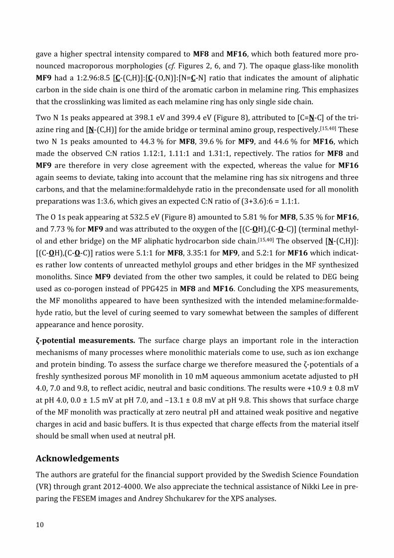
elemental compositions given in Table 3 and the spectra for MB8 in Figure 8. The survey spect-
rum shows that main signals are from N1s (~400 eV) and C1s (~287 eV), with a signal of lower
intensity at ~530 eV correspondong to O 1s ether bridges and terminal methylol groups, and to
a minor extent to carbonyl bonded carbon. The C 1s component resolved at 284.7 eV is assign-
ed to C-(C,H) present in the “side chain” carbon, 286.4 eV to C-(O,N), and the combined signals
from N=C-N and C=O at 287.4 eV minus the O 1s signal from C=O at 530.6 eV to N=C-N carbon
in the melamine ring.[15,40] The combined carbon atomic concentration were 49.4 % for MF8,
50.9 % for MF9, and 48.9 % for MF16.
For the rigid white monolith MF8, the relative concentrations of [C-(C,H)]:[C-(O,N)]:[N=C-N]
1:4.09:16.37 indicates that the amount of aliphatic carbon in the side chains was considerably
smaller than the carbon found in melamine rings, which points at a relatively low degree of
crosslinking by methylene bridging. A higher aliphatic carbon ratio of 1:4.08:11 was observed
for MF16, but we cannot rule out that this difference could have been caused by its extreme
macroporosity, as porosity is known to have a great impact on the spectral intensity of XPS
measurements[40]. We consequently noted that the MF9 sample with a smooth and flat surface
10
gave a higher spectral intensity compared to MF8 and MF16, which both featured more pro-
nounced macroporous morphologies (cf. Figures 2, 6, and 7). The opaque glass-like monolith
MF9 had a 1:2.96:8.5 [C-(C,H)]:[C-(O,N)]:[N=C-N] ratio that indicates the amount of aliphatic
carbon in the side chain is one third of the aromatic carbon in melamine ring. This emphasizes
that the crosslinking was limited as each melamine ring has only single side chain.
Two N 1s peaks appeared at 398.1 eV and 399.4 eV (Figure 8), attributed to [C=N-C] of the tri-
azine ring and [N-(C,H)] for the amide bridge or terminal amino group, respectively.[15,40] These
two N 1s peaks amounted to 44.3 % for MF8, 39.6 % for MF9, and 44.6 % for MF16, which
made the observed C:N ratios 1.12:1, 1.11:1 and 1.31:1, repectively. The ratios for MF8 and
MF9 are therefore in very close agreement with the expected, whereas the value for MF16
again seems to deviate, taking into account that the melamine ring has six nitrogens and three
carbons, and that the melamine:formaldehyde ratio in the precondensate used for all monolith
preparations was 1:3.6, which gives an expected C:N ratio of (3+3.6):6 = 1.1:1.
The O 1s peak appearing at 532.5 eV (Figure 8) amounted to 5.81 % for MF8, 5.35 % for MF16,
and 7.73 % for MF9 and was attributed to the oxygen of the [(C-OH),(C-O-C)] (terminal methyl-
ol and ether bridge) on the MF aliphatic hydrocarbon side chain.[15,40] The observed [N-(C,H)]:
[(C-OH),(C-O-C)] ratios were 5.1:1 for MF8, 3.35:1 for MF9, and 5.2:1 for MF16 which indicat-
es rather low contents of unreacted methylol groups and ether bridges in the MF synthesized
monoliths. Since MF9 deviated from the other two samples, it could be related to DEG being
used as co-porogen instead of PPG425 in MF8 and MF16. Concluding the XPS measurements,
the MF monoliths appeared to have been synthesized with the intended melamine:formalde-
hyde ratio, but the level of curing seemed to vary somewhat between the samples of different
appearance and hence porosity.
ζ-potential measurements. The surface charge plays an important role in the interaction
mechanisms of many processes where monolithic materials come to use, such as ion exchange
and protein binding. To assess the surface charge we therefore measured the ζ-potentials of a
freshly synthesized porous MF monolith in 10 mM aqueous ammonium acetate adjusted to pH
4.0, 7.0 and 9.8, to reflect acidic, neutral and basic conditions. The results were +10.9 ± 0.8 mV
at pH 4.0, 0.0 ± 1.5 mV at pH 7.0, and –13.1 ± 0.8 mV at pH 9.8. This shows that surface charge
of the MF monolith was practically at zero neutral pH and attained weak positive and negative
charges in acid and basic buffers. It is thus expected that charge effects from the material itself
should be small when used at neutral pH.
Acknowledgements
The authors are grateful for the financial support provided by the Swedish Science Foundation
(VR) through grant 2012-4000. We also appreciate the technical assistance of Nikki Lee in pre-
paring the FESEM images and Andrey Shchukarev for the XPS analyses.

11
References
1 Svec, F., Tennikova, T. B., Deyl Z. (Eds.), Monolithic Materials: Preparation, Properties, and Applications, Elsevier, Amsterdam 2003, pp. 331-342.
2 Nguyen, A. M., Irgum, K., Chem. Mater., 2006, 18, 6308-6315.
3 Trilisky, E. I., Koku. H., Czymmek, K. J., Lenhoff, A. M., J. Chromatogr. A., 2009, 1216, 6365-6376.
4 Buchmeiser, M. R., Polymer, 2007, 48, 2187-2198.
5 Svec, F., J. Sep. Sci., 2005, 28, 729-745.
6 Mistry, K., Grinberg, N., J. Liq. Chromatogr. Related Technol., 2005, 28, 1055-1074.
7 Poole, C. F., The Essence of Chromatography, Elsevier, Amsterdam 2003, p. 271.
8 Ishizuka, N., Minakuchi, H., Nakanishi, K., Hirao, K., Tanaka, N., Colloids Surf., A. 2001, 187-188, 273-279.
9 Svec, F, J. Chromatogr. A 2010, 1217, 902-924.
10 Sinner, F. M., Buchmeiser, M. R., Angew. Chem. Int. Ed., 2000, 39, 1433-1436.
11 Buchmeiser, M. R., J. Sep. Sci., 2008, 31, 1907-1922.
12 X. Sun, Z. Chai, J. Chromatogr. A, 2002, 943, 209-218.
13 K. Hosoya, N. Hira, K. Yamamoto, M. Nishimura, N. Tanaka, Anal. Chem. 2006, 78, 5729-5735.
14 N. Tsujioka, N. Ishizuka, N. Tanaka, T. Kubo, K. Hosoya, J. Polym. Sci. A Polym. Chem. 2008, 46, 3272-3281.
15 Coullerez, G., Léonard, D., Lundmark, S., Mathieu, H. J., Surf. Interface Anal., 2000, 29, 431-443.
16 Merline, D. J., Vukusic, S., Abdala, A. A., Polym. J., 2012, 162, 1-7.
17 Rogers, M. E., Long, T. E., Synthetic Methods in Step-Growth Polymers, John Wiley & Sons, Hoboken 2003, p. 3-14.
18 Pizzi, A. “Melamine–Formaldehyde Adhesives”, in Pizzi, A.; Mittal, K. L., “Handbook of Adhesive Technology”, 2nd Ed., Marcel Dekker: New York, 2003; Chapter 32.
19 Kim, S. Y.; Suh, W. H.; Choi, J. H.; Yi, Y. S.; Lee, S. K.; Stucky, G. D.; Kang, J. K., J. Mater. Chem. A 2014, 2, 2227-2232.
20 Bhattacharya, A., Ray P., Basic Features and Techniques, in Bhattacharya, A., Rawlins, J. W., Ray, P. (Eds.), Polymer Grafting and Crosslinking, John Wiley & Sons, Hoboken 2009, pp. 27-28.
21 Bretterbauer, K., Schwarzinger, C., Curr. Org. Synth., 2012, 15, 342-356.
22 Nicolau, V. V., Martinelli, M., Strumia, M. C., Estenoz, D. A., Meira., G. R., J. Appl. Polym. Sci., 2009, 113, 1030-1041.
23 Hench, L. L., West, J. K., Chem. Rev., 1990, 90, 33-72.
24 Wu, Y., Li, Y., Qin, L., Yang, F., Wu, D., J. Mater. Chem. B, 2013, 1, 204-212.
25 Courtois, J., Byström, E., Irgum, K., Polymer, 2006, 47, 2603-2611.
26 Brunauer, S., Emmett, P. H., Teller, E., J. Am. Chem. Soc., 1938, 60, 309-319.
27 Barrett, E. P., Joyner, L. G., Halenda, P. P., J. Am. Chem. Soc., 1951, 73, 373-380.
28 Washburn E. W., Phys. Rev. Second Ser., 1921, 17, 273-283.
29 Swinkels, G. H. P. M., Stoffels, E., Stoffels, W. W., Simons, N., Kroesen, G. M. W., de Hoog, F. J., Pure Appl. Chem., 1998, 70, 1151-1156.
30 Taylor, J. D., Terray, A., Hart, S. J., Anal. Chim. Acta, 2010, 670, 78-83.
31 Xu, D.; Redman-Furey, N., “Statistical cluster analysis of pharmaceutical solvents”, Int. J. Pharm. 2007, 339, 175-188.
32 Hansen, C. M., “Hansen Solubility Parameters: A Users Handbook”, 2nd Ed., CRC Press, Boca Raton, 2007.
33 Fainerman, V. B., Möbius, D., Miller, R., Surfactants: Chemistry, Interfacial Properties, Applications, Elsevier: Amsterdam, 2001, pp. 3-18.
34 Goodwin, J. W., “Colloids and Interfaces with Surfactants and Polymers”, 2nd Ed., John Wiley & Sons: New Yourn, 2009.
35 Ma, T.-Y.; Liu, L.; Yuan, Z.-Y. Chem. Soc. Rev. 2013, 42, 3977-4003.

12
36 a) Pirard, R.; Heinrichs, B.; Van Cantfort, O.; Pirard, J. P. J. Sol-Gel Sci. Technol. 1998 13, 335-339; b) Alié, C.; Pirard, R.; Pirard; J. P. J. Non-cryst. Solids 2001, 292, 138-149; c) Alié, C.; Pirard, R.; Pirard, J. P. Colloids Surf. A 2001, 187-188, 367-374; d) Pirard, R.; Alié, C.; Pirard, J. P. Powder Technnol. 2002, 128, 242-247.
37 Egger, C. C.; du Fresne, C.; Raman, V. I.; Schädler, V.; Frechen, T.; Roth, S. V.; Müller-Buschbaum, P. Langmuir 2008, 24, 5877-5887.
38 Sun, Y. W., Wang, Y. J., Guo, W., Wang, T., Luo, G. S., Microporous Mesoporous Mater., 2006, 88, 31-37.
39 Nemanič, V., Zajec, B., Žumer, M., Figar, N., Kavšek, M., Mihelič, I., Appl. Energy, 2014, 114, 320-326.
40 Deryło-Marczewska, A., Goworek, J., Pikus, S., Kobylas, E., Langmuir, 2002, 18, 7538-7543.

13
Table 1. Synthetic composition and pore characterization of MF monoliths.
Sample Polymeric
co-porogen Diluent solvent
“W/O” Ratio1)
State2) SSA3) BJH4) MIP5,6)
m2/g nm µm
MF1 DEG n-Heptane 2:1 OG 292 ± 1.7 2.9 N/D
MF2 PEG200 n-Heptane 2:1 OG 212 ± 1.4 3.3 N/D
MF3 PEG400 n-Heptane 2:1 OG 309 ± 0.9 2.9 N/D
MF4 PPG425 n-Heptane 2:1 WF 95 ± 0.4 8.7 (22.7)
MF5 DEG DMF 2:1 OG 317 ± 1.2 3.1 N/D
MF6 PEG200 DMF 2:1 GR 313 ± 1.1 3.1 N/D
MF7 PEG400 DMF 2:1 GR 308 ± 1.0 3.6 N/D
MF8 PPG425 DMF 2:1 WR 401 ± 1.9 8.28 0.019
MF9 DEG DMF 1:1 OG 293 ± 1.1 3.2 N/D
MF10 PEG200 DMF 1:1 OG 311 ± 1.1 3.3 N/D
MF11 PEG400 DMF 1:1 WR 243 ± 1.4 11.5 0.012
MF12 PPG425 DMF 1:1 WR 99.3 ± 0.6 12.85 2.39
MF13 DEG DMF 1:2 OG 265 ± 0.9 4.4 N/D
MF14 PEG200 DMF 1:2 OG 256 ± 0.9 3.5 N/D
MF15 PEG400 DMF 1:2 WR 76.9 ± 0.49 11.9 2.35
MF16 PPG425 DMF 1:2 WF 7.2 ± 0.14 31.88 (9.2)
MF17 DEG DME 2:1 OG N/D N/D N/D
MF18 PEG200 DME 2:1 OG 53.4 ± 0.15 3.9 N/D
MF19 PEG400 DME 2:1 WR 93.2 ± 0.43 11.4 1.06
MF20 PPG425 DME 2:1 WR 73.3 ± 0.34 11.7 3.08
1) Ratio of the sum of MF precondensate, block copolymer porogens, and polyether co-porogen to the organic sol-vent; 2) Appearance of the recovered materials: WR = white resilient solid, WF = white fragile solid; GR = grey-white resilient solid, OG = opaque glass-like solid; 3) Specific surface area measured by nitrogen cryosorption ac-cording to the BET principle; 4) Average mesopore diameter measured by the BJH principle; 5) Median pore dia-meter (volume) measured by mercury intrusion porosimetry; 6) MIP data not fully reliable due to collapse of the monolithic structure during compression. Only the low pressure part of the curve was therefore used for data within parentheses.

14
Table 2. Solubility parameters and bulk properties of solvents used to make up the “oil” phase.
Solvent 1) D2) P
3) H4) V5) 6) 7) 8)
MPa½ MPa½ MPa½ MPa½ cm3/mole mN/m Debye
n-Heptane 15.3 15.3 0 0 147.4 28.3 1.92 0 1,1-Dimethoxyethane 17.6 15.4 6.0 6.0 106.7 32.4 7.20 1.71 N,N-Dimethylformamide 24.9 17.4 13.7 11.3 77.0 49.6 36.7 3.82
1) , Hildebrand (total) solubility parameter, with Hansen solubility parameters describing the contributions to from 2) dispersion(D), 3) polarity(P), and 4) hydrogen bonding(H); 5) V, molar volume at 25 °C; 6) , surface tension; 7) , dielectric constant; and 8) , dipole moment. The solubility parameter data including molar volume are from entries 409, 291, and 284 in Appendix A: Table A.1. of ref. 32; remaining data are from ref. 31.

15
Table 3. Surface elemental composition of MF monoliths by X-ray photoelectron spectroscopy.
Peak/Ratio Bond energy Atom-%
(eV) MF8 MF9 MF16
C 1s [C–(C,H)] 284.7 2.30 4.15 3.06 C 1s [C–(O,N)] 286.4 9.40 12.27 12.49 C 1s [N=C–N, C=O] 287.4 37.93 35.38 33.94
O 1s [C=O] 530.6 0.27 0.92 0.60 O 1s [(C–OH),(C–O–C)] 532.5 5.81 7.73 5.35
N 1s [C=N–C] 398.1 14.27 13.67 16.75 N 1s [N–(C,H)] 399.4 30.02 25.88 27.82
[C–(C,H)]:[C–(O,N)]:[N=C-N] N/A 1:4.09:16.37 1:2.96:8.30 1:4.08:10.90 C:N N/A 1.12:1 1.31:1 1.11:1 [N–(C,H)]:[(C–OH),(C–O–C)] N/A 5.1:1 3.35:1 5.2:1
[N=C–N] in the [C–(C,H)]:[C–(O,N)]:[N=C–N] entry was formed by subtracting O 1s [C=O] from C 1s [N=C–N, C=O].

16
Figure 1
Figure 1. Biplot of loadings and scores for the PLS model created from data in Table 1. The X block variables affecting the model positively or negatively in either direction are those found away from
the center of the plot. The variables most powerful in explaining the mesopore size are therefore the co-porogens with PPG425 promoting larger and DEG smaller mesopores, with PEGs intermediate between these extremes. Correspondingly, the “W/O” ratio and the solvents are most powerful in
explaining the macropore dimension, with DMF explaining smaller and DME and n-heptane larger macropores. A decoding of the legend in the upper right corner can be found in Table 1.

17
Figure 2
Figure 2. SEM micrographs of random fracture surface areas of monoliths prepared by step-growth polymerization of melamine-formaldehyde with Pluronic L121 as porogen in DMF at a “W/O” ratio of 2:1 with A) PEG400 [MF7], and B) PPG425 [MF8] as co-
porogens. The scale bars represent 250 nm.

18
Figure 3
Figure 3. Triplicate measurements cumulative pore size distributions in the mesopore range MF7, MF8, MF12 and MF16, measured by nitrogen cryodesorption according to the BJH principle.

19
Figure 4
Figure 4. SEM micrographs as in Figure 2 from with Pluronic L121 as porogen and DME as solvent with ”W/O” ratio 2:1, using (A) PEG400 [MF19] and (B) PPG425
[MF20] as co-porogen. Scale bars represent 5 µm.

20
Figure 5
Figure 5. SEM micrographs as in Figure 2 from with Pluronic L121 as porogen and PPG425 as co-porogen at a “W/O” ratio 2:1, using (A) n-heptane [MF4]
and (B) DME [MF20] as solvents. Scale bars represent 1 µm.

21
Figure 6
Figure 6. SEM micrographs as in Figure 2 from with Pluronic L121 as porogen, PPG425 as co-porogen and DMF as solvent, at “W/O” ratios of A) 2:1 [MF8],
B) 1:1 [MF12], and C) 1:2 [MF16]. Scale bars represent 5 µm.

22
Figure 7
Figure 7. Differential pore size distribution profiles measured by mercury intrusion porosimetry of monoliths prepared by step-growth polymerization of melamine-formaldehyde with Pluronic L121
as porogen and PPG425 as co-porogen, using DMF as solvent at “W/O” ratios of 2:1 (MF8), 1:1 (MF12) and 1:2 (MF16). Note the different ordinate scales.

23
Figure 8
Figure 8. X-ray photoelectron spectra for monolith MF8, showing the survey scan and zoomed in C 1s, O 1s, and N 1s components resolved by Gaussian-Lorentzian line fitting. In the component
spectra dotted lines are used for the backgrounds and dot-dash lines for the fitting envelopes.