CREATING DEEP SOIL CORE MONOLITHS: BEYOND THE SOLUM
12
SOUTHEASTERN GEOLOGY V. 51, No.2, Month 2015, p. ??-?? 1 ABSTRACT Soil monoliths serve as useful teaching aids in the study of the Earth’s critical zone where rock, soil, water, air, and organisms interact. Typical monolith preparation has so far been confined to the 1 to 2-m depth of the solum. Critical ecosystem services pro- vided by soils also occur in material from the deeper soil profile. Soil monolith preparation needs to take this new paradigm into ac- count. Soil cores from such depths can be ob- tained during site investigations for studies of various engineering and environmental problems. The complexity of soil structure makes the preservation and presentation of cores into monoliths difficult. The wide range of exhibition modes ranging from per- manent to mobile displays creates further challenges. We present two methods for monolith preparation suited to soil type and demonstration mode. For permanent hori- zontal displays, a simple process using floor wax is described. For mobile and vertical dis- plays, a solution of acetone and polyvinyli- dene chloride (PVDC) at a 5:1 mass ratio can be used to create good structurally sound deep soil core monoliths. In this study soil cores were obtained during installation of monitoring wells at two sites 2.5 km apart in the Piedmont of Georgia in the southeastern United States. To reduce health and safety risk, a well-ventilated location and use of protective gear, while handling and using chemicals, is essential to the process. The fin- ished products are in display at the Geology Department, University of Georgia, Athens, GA in the USA. INTRODUCTION There have recently been several high visi- bility initiatives to raise awareness about the importance of soils. The Smithsonian’s Nation- al Museum of Natural History, Washington, DC, took eight years to carefully design and hold the successful 18-months “Dig It! The Se- crets of Soil” exhibit beginning in 2008, which has since been shown in several other states (Megonigal and others, 2010; Drohan and oth- ers, 2010). The year 2015 is being celebrated as International Year of Soils (SSSA, 2015). All the organizers had several objectives including the desire to inspire the public and decision makers to think about soils as an ecosystem of immense importance for humanity. Among the creative approaches that highlighted the cen- trality and link of the soils ecosystem with ma- CREATING DEEP SOIL CORE MONOLITHS: BEYOND THE SOLUM STEPHAN D. FITZPATRICK Science Department Georgia Perimeter College 555 North Indian Creek Drive Clarkston, Georgia 30021 PAUL A. SCHROEDER Department of Geology University of Georgia 210 Field Street Athens, Georgia 30602 DINKU M. ENDALE USDA-ARS Southeast Watershed Research Laboratory 2316 Rainwater Road Tifton, Georgia 31793
Transcript of CREATING DEEP SOIL CORE MONOLITHS: BEYOND THE SOLUM

SOUTHEASTERN GEOLOGYV. 51, No.2, Month 2015, p. ??-??
1
ABSTRACT
Soil monoliths serve as useful teachingaids in the study of the Earth’s critical zonewhere rock, soil, water, air, and organismsinteract. Typical monolith preparation hasso far been confined to the 1 to 2-m depth ofthe solum. Critical ecosystem services pro-vided by soils also occur in material from thedeeper soil profile. Soil monolith preparationneeds to take this new paradigm into ac-count. Soil cores from such depths can be ob-tained during site investigations for studiesof various engineering and environmentalproblems. The complexity of soil structuremakes the preservation and presentation ofcores into monoliths difficult. The widerange of exhibition modes ranging from per-manent to mobile displays creates furtherchallenges. We present two methods formonolith preparation suited to soil type anddemonstration mode. For permanent hori-zontal displays, a simple process using floorwax is described. For mobile and vertical dis-plays, a solution of acetone and polyvinyli-dene chloride (PVDC) at a 5:1 mass ratio canbe used to create good structurally sounddeep soil core monoliths. In this study soilcores were obtained during installation of
monitoring wells at two sites 2.5 km apart inthe Piedmont of Georgia in the southeasternUnited States. To reduce health and safetyrisk, a well-ventilated location and use ofprotective gear, while handling and usingchemicals, is essential to the process. The fin-ished products are in display at the GeologyDepartment, University of Georgia, Athens,GA in the USA.
INTRODUCTION
There have recently been several high visi-bility initiatives to raise awareness about theimportance of soils. The Smithsonian’s Nation-al Museum of Natural History, Washington,DC, took eight years to carefully design andhold the successful 18-months “Dig It! The Se-crets of Soil” exhibit beginning in 2008, whichhas since been shown in several other states(Megonigal and others, 2010; Drohan and oth-ers, 2010). The year 2015 is being celebrated asInternational Year of Soils (SSSA, 2015). Allthe organizers had several objectives includingthe desire to inspire the public and decisionmakers to think about soils as an ecosystem ofimmense importance for humanity. Among thecreative approaches that highlighted the cen-trality and link of the soils ecosystem with ma-
CREATING DEEP SOIL CORE MONOLITHS: BEYOND THE SOLUM
STEPHAN D. FITZPATRICK
Science DepartmentGeorgia Perimeter College
555 North Indian Creek DriveClarkston, Georgia 30021
PAUL A. SCHROEDER
Department of GeologyUniversity of Georgia
210 Field StreetAthens, Georgia 30602
DINKU M. ENDALE
USDA-ARSSoutheast Watershed Research Laboratory
2316 Rainwater RoadTifton, Georgia 31793
Dinku
Cross-Out
Dinku
Inserted Text
1-
Dinku
Cross-Out
Dinku
Inserted Text
materials
Dinku
Sticky Note
Key words missing ??

2
STEPHAN D. FITZPATRICK, PAUL A. SCHROEDER AND DINKU M. ENDALE
ny others around us, and at different spatialscale, were 53 soil monoliths, representing ev-ery U.S. state and territory, that proved popular.Much earlier, van Baren and Sombroek (1981)made a case for global soil reference collectionsthat included soil monoliths and accompanyingsoil analytical data and site information to beused for a host of purposes including goals forsustainable use of soils.
Soil monoliths preserve soils at conditionsapproaching those in the field with consider-ation to both appearance and structure. A pit isdug, or a core drilled, from which a monolith isextracted, the soil profile described, and sam-ples are collected for analyses. The purposes forcreating soil monoliths are many-fold and in-clude such factors as display, instruction, analy-sis, and transport. Soil monoliths are usefulvisual aids for teaching soil science, geology,and geochemistry (van Baren and Bomer,1979). Such monoliths enable large groups toexamine soil profiles without the time and fi-nancial expense of going into the field.
Soil monoliths were first prepared in Russiaduring the latter part of the 19th century (vanBaren and Bomer, 1979; van Baren and Som-broek, 1981). Early efforts to make soil mono-liths resulted in varying degrees of successtowards the preservation of soil cores as onemassive, permanent structure. After experi-menting with several different methods, re-searchers concluded that the optimum lengthfor monoliths was 100 to 200 cm in length(Borowiec, 1976). Over the years many differ-ent chemicals have been used to bind soil parti-cles within a monolith. Sugar was one of thefirst substances used for impregnating soilcores, which is the introduction of a binding orpreservative agent into the pore space surround-ing soil grains (van Baren and Bomer, 1979).Since the 1930’s, techniques have been refinedwith the increased availability of different im-pregnating industrial chemicals (van Baren andSombroek, 1981) that include nitrocelluloselacquers, vinylite resins, poly-methylmethacry-late, polyethylene glycol, and polyester resins.Monoliths prepared in a laboratory require dif-ferent impregnating materials compared to pro-files impregnated in the field as peels, which are
much thinner than monoliths (van Baren andSombroek, 1981).
Many national and international soil-relatedorganizations have followed the monolith mod-el to create inventories of various soil types.The International Soil Reference and Informa-tion Center (ISRIC) in the Netherlands, estab-l i shed in 1966, holds one of the mostcomprehensive global soil monolith collection,representing units of the 1:5 M FAO-UNESCOSoil Map of the World (ISRIC, 2014). To datesome 1000 monoliths have been prepared withdetailed descriptions of the full profile, chemi-cal and physical data, and information on thelandscape and land use. Some of these are onpermanent exhibit at the Center. A typical sizeof a monolith at the Center is 25 cm wide, 125to 150 cm long, with impregnated soil thicknessvarying from 2 to 8 cm (van Baren and Som-broek, 1981). In the United States, similarmonoliths are collected as representatives ofparticular soil series, the lowest hierarchy of thenational soil classification system, under theauspices of The National Cooperative Soil Sur-vey Organization. Every state within the UnitedStates has a soil series designated as a state soil.
The solum, defined as that uppermost part ofthe earth’s surface comprising the O, A, E andB horizons, has for a long period been consid-ered the typical soil model (Richter and Yaalon,2012). The overarching influence of soil use inagriculture has overshadowed considerationsfor depth of sampling. The C horizon, whichmay vary from shallow to very deep (i.e. 10’s ofmeters), was considered the unconsolidatedparent material directly above the unweatheredbedrock, and with little ongoing pedogenic pro-cesses, although its function in other disciplineshave been explored (Richter and Yaalon, 2012).Such works have highlighted the shortcomingsof the “shallow” soil concept, and given rise tothe notion that the lower limit of the soil is atgreater depth than currently considered (Richterand Yaalon, 2012). Generally, soil monolithpreparation has followed the shallow soil mod-el, probably due to the sheer volume and weightputting limits on what can safely and effectivelybe extracted and transported. Suggested hereinis the need to embrace a ‘new’ soil model going
3
DEEP SOIL CORE MONOLITHS
to depths to and beyond the C horizon into bed-rock.
Site investigation is a critical part of manyengineering disciplines (civil, structural, envi-ronmental, geotechnical, hazard waste treat-ment and disposal, etc.) where collection ofdeep to very deep soil core samples is an inte-gral part of the work. Cores from 2 to 15 cm di-ameter can be collected in undisturbed ordisturbed conditions using augur, direct push,cable-tool, air rotary, or sonic drilling tech-niques. Similar soil cores can be generated dur-ing installation of shallow to deep monitoringwells. These areas offer us opportunities to col-lect, preserve, display, and use the cores in sim-ilar fashion as monoliths. Our objective is todemonstrate approaches for acquiring, preserv-ing, and mounting deep soil cores for use asmonoliths representing the ‘deep’ soil model,
for purposes similar to that of monoliths of the‘shallow’ soil model. We do so using soil coresfrom the Georgia Piedmont of southeasternUnited States.
MATERIALS AND METHODS
Core Collection Site
Soil cores were obtained from two locationstaking opportunities of drilling workshops or-ganized by the Science and Ecosystem SupportDivision, Region 4, US Environmental Protec-tion Agency, in Athens, GA. The workshopswere part a regular training course offered tostate and federal personnel, and provided de-tailed instructions on the proper installation andsampling of permanent and temporary groundwater monitoring wells. Both sites, approxi-
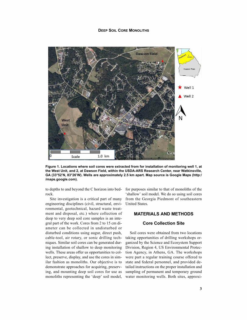
Figure 1. Locations where soil cores were extracted from for installation of monitoring well 1, atthe West Unit, and 2, at Dawson Field, within the USDA-ARS Research Center, near Watkinsville,GA (33°52’N, 83°26’W). Wells are approximately 2.5 km apart. Map source is Google Maps (http://maps.google.com).

4
STEPHAN D. FITZPATRICK, PAUL A. SCHROEDER AND DINKU M. ENDALE
mately 2.5 km apart, were located within theU.S. Department of Agriculture, AgriculturalResearch Service (ARS) Research Station, nearWatkinsville, GA (33°52’N, 83°26’W; Figure1). The area lies in the Piedmont of the south-eastern United States. The site features topogra-phy, soils, and land use typical of many slopingfields throughout the Piedmont. Long termmean annual rainfall is 1250 mm and mean an-nual temperature is 16.5°C.
THE REGION
The Piedmont Province covers approximate-ly 16.7 million ha as foothills east of the Appa-lachian Mountains, extending 1200 km fromsouthern Virginia to east-central Alabamathrough large parts of North and South Caroli-na, Georgia, and parts of Tennessee (Carrekerand others, 1977). The topography is gentlyrolling, generally less than 350 m elevation,with gentle to moderate slopes on ridge tops andsteeper slopes near streams. The region is dis-sected by many streams and valleys are narrowwith little alluvial soils. There are abundant sur-
face waters and diverse geological resources(Hendrickson and others, 1963). Average grow-ing seasons vary from 209 to 220 days. Averageannual rainfall varies between 1100 and 1400mm.
The bedrock is composed of a variety of ig-neous and metamorphic rocks spanning the Pre-cambrian to Late Paleozoic age (Radcliffe andWest, 2000). Felsic igneous and metamorphicrocks (granite, granitic gneiss, mica gneiss, andmica schist) dominate (Radcliffe and West,2000), but large areas of intermediate and maficrocks occur also (Schroeder and others, 2000;2002). The felsic rocks are light-colored, acidic,and high in silica, while the mafic ones aredark-color, basic, magnesium- and iron-rich,and low in silica. The humid climate encourag-es strong weathering, which has resulted in asolum of 1 to 2 m depth, underlain by 1 to over100 m thick saprolite with mean depth of 15 to20 m (Buol and Weed, 1991). The saproliteserves as an important aquifer and as water stor-age zone for the deeper fractured bedrock,which together form an unconfined two-layerground water system (Radcliffe and West,
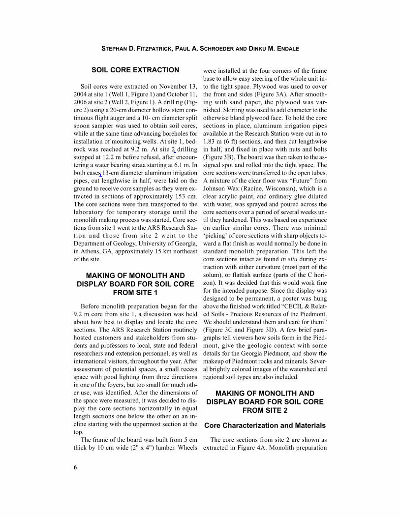
Figure 2. Drill rig with hollow stem auger used for extraction of soil cores and advancing boreholefor installing monitoring wells at site 2, October 11, 2006.
Dinku
Cross-Out
Dinku
Inserted Text
1- to 2-m

5
DEEP SOIL CORE MONOLITHS
2000).Ultisols dominate the landscape of the hu-
mid-thermic southeastern USA (Perkins andothers, 1973). These are strongly leached soils,acidic, low fertility, and typically red to yellowin color. Kanhapludults and Hapludults formthe dominant great groups. Approximately 51%of the soils mapped in the Piedmont originatefrom felsic parent material and comprise of Ce-cil and related soil series (Radcliffe and West,2000). Typically, surface horizons are sandyloam over clayey argillic horizons. Solumthickness and the color of the Bt horizon is usedto differentiate among these series. Because ofthe landscape, they are deep, well-drained, andmoderately permeable soils. The Cecil soil se-ries is designated as the State Soil of North Car-olina.
The soil series at the two sampling sites is al-so Cecil (fine, kaolinitic, thermic Typic Kan-hapludults). These soils typically have a well-developed, extensive, iron oxide rich Bt hori-zon. The C horizon (saprolite) accurately cap-tures aspects of the original parent textures. Thesoil core parent rock is the Athens gneiss meta-morphosed from plagioclase and biotite richgranites. The cores have retained the character-istic physical features of these basement rocksaltered by a humid, temperate environment. Ce-cil and related soil series have been extensivelyinvestigated over the past 30 years (Bruce andothers, 1983; Schroeder and West, 2005; Aus-tin, 2011, Austin and Schroeder, 2011).
Figure 3. (A) Display board for cores from Site 1 showing frame and other components; (B) readyto be moved in place; (C) situated in assigned place; and (D) close up of core sections. In C, theboard above holds a poster entitled “CECIL & Related Soils – Precious Resources of the Pied-mont. We should understand them and care for them”. It summarizes materials given in section2.1 and 2.2 of this paper. In D are shown distributions of horizons, with the saprolite forming theC horizon and depth from soil surface in meters. The core sections represent a total of 9.15 mdepth with the last few centimeters as bedrock (horizon R).
Dinku
Cross-Out
Dinku
Inserted Text
information given in Materials and Methods (Sections are not numbered)
6
STEPHAN D. FITZPATRICK, PAUL A. SCHROEDER AND DINKU M. ENDALE
SOIL CORE EXTRACTION
Soil cores were extracted on November 13,2004 at site 1 (Well 1, Figure 1) and October 11,2006 at site 2 (Well 2, Figure 1). A drill rig (Fig-ure 2) using a 20-cm diameter hollow stem con-tinuous flight auger and a 10- cm diameter splitspoon sampler was used to obtain soil cores,while at the same time advancing boreholes forinstallation of monitoring wells. At site 1, bed-rock was reached at 9.2 m. At site 2 drillingstopped at 12.2 m before refusal, after encoun-tering a water bearing strata starting at 6.1 m. Inboth cases 13-cm diameter aluminum irrigationpipes, cut lengthwise in half, were laid on theground to receive core samples as they were ex-tracted in sections of approximately 153 cm.The core sections were then transported to thelaboratory for temporary storage until themonolith making process was started. Core sec-tions from site 1 went to the ARS Research Sta-t ion and those from si te 2 went to theDepartment of Geology, University of Georgia,in Athens, GA, approximately 15 km northeastof the site.
MAKING OF MONOLITH AND DISPLAY BOARD FOR SOIL CORE
FROM SITE 1
Before monolith preparation began for the9.2 m core from site 1, a discussion was heldabout how best to display and locate the coresections. The ARS Research Station routinelyhosted customers and stakeholders from stu-dents and professors to local, state and federalresearchers and extension personnel, as well asinternational visitors, throughout the year. Afterassessment of potential spaces, a small recessspace with good lighting from three directionsin one of the foyers, but too small for much oth-er use, was identified. After the dimensions ofthe space were measured, it was decided to dis-play the core sections horizontally in equallength sections one below the other on an in-cline starting with the uppermost section at thetop.
The frame of the board was built from 5 cmthick by 10 cm wide (2" x 4") lumber. Wheels
were installed at the four corners of the framebase to allow easy steering of the whole unit in-to the tight space. Plywood was used to coverthe front and sides (Figure 3A). After smooth-ing with sand paper, the plywood was var-nished. Skirting was used to add character to theotherwise bland plywood face. To hold the coresections in place, aluminum irrigation pipesavailable at the Research Station were cut in to1.83 m (6 ft) sections, and then cut lengthwisein half, and fixed in place with nuts and bolts(Figure 3B). The board was then taken to the as-signed spot and rolled into the tight space. Thecore sections were transferred to the open tubes.A mixture of the clear floor wax “Future” fromJohnson Wax (Racine, Wisconsin), which is aclear acrylic paint, and ordinary glue dilutedwith water, was sprayed and poured across thecore sections over a period of several weeks un-til they hardened. This was based on experienceon earlier similar cores. There was minimal‘picking’ of core sections with sharp objects to-ward a flat finish as would normally be done instandard monolith preparation. This left thecore sections intact as found in situ during ex-traction with either curvature (most part of thesolum), or flattish surface (parts of the C hori-zon). It was decided that this would work finefor the intended purpose. Since the display wasdesigned to be permanent, a poster was hungabove the finished work titled “CECIL & Relat-ed Soils - Precious Resources of the Piedmont.We should understand them and care for them”(Figure 3C and Figure 3D). A few brief para-graphs tell viewers how soils form in the Pied-mont, give the geologic context with somedetails for the Georgia Piedmont, and show themakeup of Piedmont rocks and minerals. Sever-al brightly colored images of the watershed andregional soil types are also included.
MAKING OF MONOLITH AND DISPLAY BOARD FOR SOIL CORE
FROM SITE 2
Core Characterization and Materials
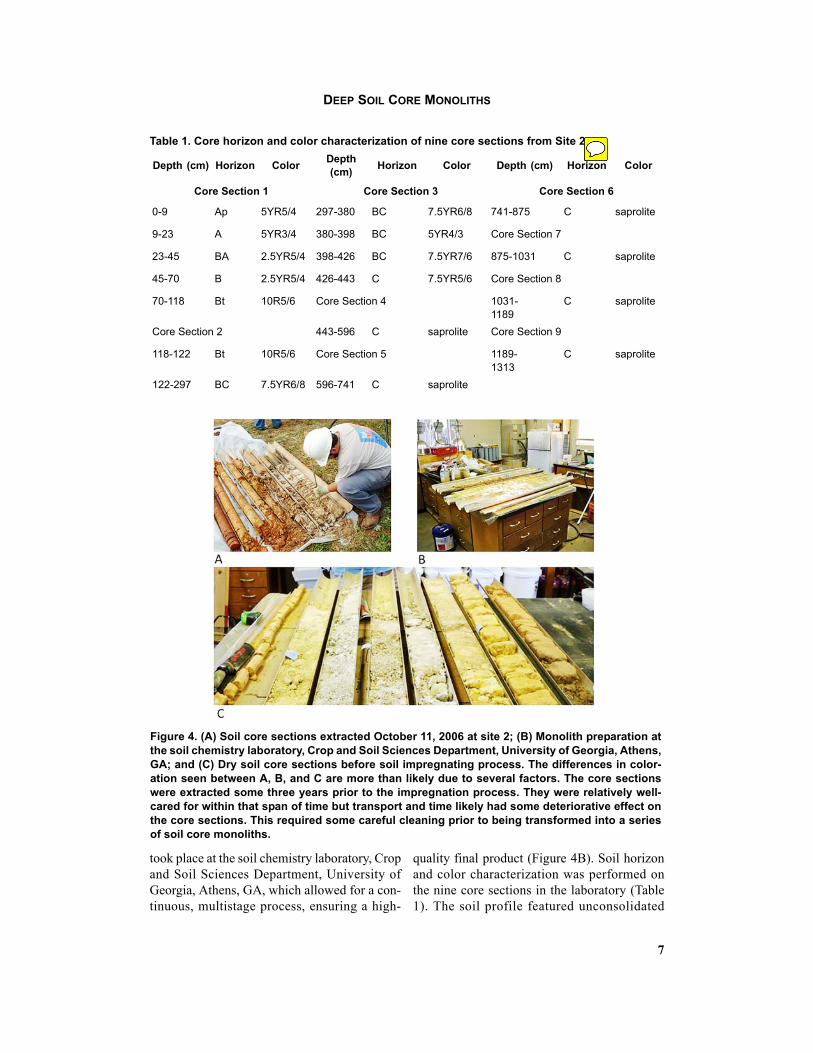
The core sections from site 2 are shown asextracted in Figure 4A. Monolith preparation
Dinku
Cross-Out
Dinku
Inserted Text
At site 2,
Dinku
Cross-Out
Dinku
Inserted Text
In both cases,
7
DEEP SOIL CORE MONOLITHS
took place at the soil chemistry laboratory, Cropand Soil Sciences Department, University ofGeorgia, Athens, GA, which allowed for a con-tinuous, multistage process, ensuring a high-
quality final product (Figure 4B). Soil horizonand color characterization was performed onthe nine core sections in the laboratory (Table1). The soil profile featured unconsolidated
Table 1. Core horizon and color characterization of nine core sections from Site 2.
Depth (cm) Horizon ColorDepth (cm)
Horizon Color Depth (cm) Horizon Color
Core Section 1 Core Section 3 Core Section 6
0-9 Ap 5YR5/4 297-380 BC 7.5YR6/8 741-875 C saprolite
9-23 A 5YR3/4 380-398 BC 5YR4/3 Core Section 7
23-45 BA 2.5YR5/4 398-426 BC 7.5YR7/6 875-1031 C saprolite
45-70 B 2.5YR5/4 426-443 C 7.5YR5/6 Core Section 8
70-118 Bt 10R5/6 Core Section 4 1031-1189
C saprolite
Core Section 2 443-596 C saprolite Core Section 9
118-122 Bt 10R5/6 Core Section 5 1189-1313
C saprolite
122-297 BC 7.5YR6/8 596-741 C saprolite
Figure 4. (A) Soil core sections extracted October 11, 2006 at site 2; (B) Monolith preparation atthe soil chemistry laboratory, Crop and Soil Sciences Department, University of Georgia, Athens,GA; and (C) Dry soil core sections before soil impregnating process. The differences in color-ation seen between A, B, and C are more than likely due to several factors. The core sectionswere extracted some three years prior to the impregnation process. They were relatively well-cared for within that span of time but transport and time likely had some deteriorative effect onthe core sections. This required some careful cleaning prior to being transformed into a seriesof soil core monoliths.
Dinku
Sticky Note
Bold and center Core Section 2, 4, 5, 7, 8, and 9 (same as Core Section1, Core Section 3, and Core Section 6) Should there be horizontal lines at the bottom of the table and between the title and top of the table?

8
STEPHAN D. FITZPATRICK, PAUL A. SCHROEDER AND DINKU M. ENDALE
regolith (C-horizon saprolite) below 426 cm.Several core samples were analyzed using X-ray diffraction (XRD), which confirmed a typi-cal Cecil soil mineralogy. XRD patterns can bedisplayed next to various horizons.
Polyvinvylidene chloride (PVDC; SolvaySpecialty Polymers USA, Alpharetta, Georgia),normally obtained as a fine-powder polymerresin, was chosen as the binding agent to pre-serve the core sections due to its physical andchemical properties. This product is also widelyknown as “Saran”. It was the chief componentof the commercially available food wrappingknown as “Saran Wrap”, manufactured by DowChemicals. It is resistant to various forms ofphysical and chemical weathering once it hashardened. It is particularly resistant to acidicand alkaline constituents. PVDC is insoluble inhydrocarbons. It has a low permeability to gasesand forms an excellent barrier to biological aswell as weathering agents.
The PVDC resin was suspended in solutionwith acetone to allow for impregnation of thesoil core sections. Acetone is a liquid at stan-dard pressures and atmospheres that has a lowerviscosity than water, which aids in more thor-ough impregnation of soil. Acetone's high rateof evaporation allows the next step in the mono-lith preparation process to proceed soon after.
Despite adequate ventilation in the work-space, extra precautions were taken to minimizethe health and safety risks posed by workingwith the combination of acetone and PVDC.Both chemicals pose risks if inhaled: acetone tothe nervous system and PVDC to the lungs. Toreduce the risk of inhalation, a high-poweredfan was placed in the window drawing air out ofthe workspace. Also a half face-piece respiratorwas utilized when using large amounts of ace-tone and PVDC. Gloves were always wornwhen handling chemicals and the workspacewas frequently cleaned. As latex breaks downquickly when exposed to acetone, latex glovescould not be used. Butyl rubber gloves are rec-ommended for handling acetone.
The following materials were assembled pri-or to construction of a 13.1-m long monolith:• The original core divided into ~1.2 m
smaller core sections
• 1.36 kg PVDC• Several reagent bottles• 38 liters laboratory-grade acetone• Nine 2.44 m long 5.08 cm x 20.32 cm
boards: treated pine• 18 1.22 m long 2.54 cm x 5.08 cm boards:
treated pine• Carpentry tools including carpenter's
clamps, wood glue, drill, a masonry ham-mer, and a rubber mallet
• A large gardening pail with a 7.5 cm diam-eter spigot
• Clear polyurethane• An assortment of painter's brushes• Half face-piece respirator• Butyl rubber gloves• High-powered box fan
Construction Procedure and Methodology
Prior to construction, solutions made up ofseveral acetone to PVDC mass mixing ratiowere tested on a small quantity of soil similar instructure and origin to that of the soil core. Sev-eral of these mixing ratios were determined tobe suitable for impregnating the soil core. Ini-tially the soil core sections were very dry, hadmostly formed into hard blocks because of longterm storage (Figure 4C), and needed to be sat-urated during impregnation. The solution froma 5:1 mixture (acetone: PVDC), which had rel-atively low viscosity, proved the most suitablefor impregnating the core sections with a con-sistent and complete saturation and with uni-form transport within the pore space. Enoughvolume was prepared for use in subsequentmonolith preparation.
Core Housing Construction and Core Impregnation Methodology
The following sequence was followed:• Wooden boxes were constructed from ply-
wood to hold the soil core segments. Thechannels in the box were set at 10-cm wideat the base, per core diameter, and 5-cmdeep. The length of boxes varied from 118to 179 cm to accommodate the different
Dinku
Cross-Out
Dinku
Inserted Text
is
Dinku
Cross-Out
Dinku
Inserted Text
core,
Dinku
Cross-Out
Dinku
Inserted Text
1.45
Dinku
Cross-Out
Dinku
Inserted Text
18,
9
DEEP SOIL CORE MONOLITHS
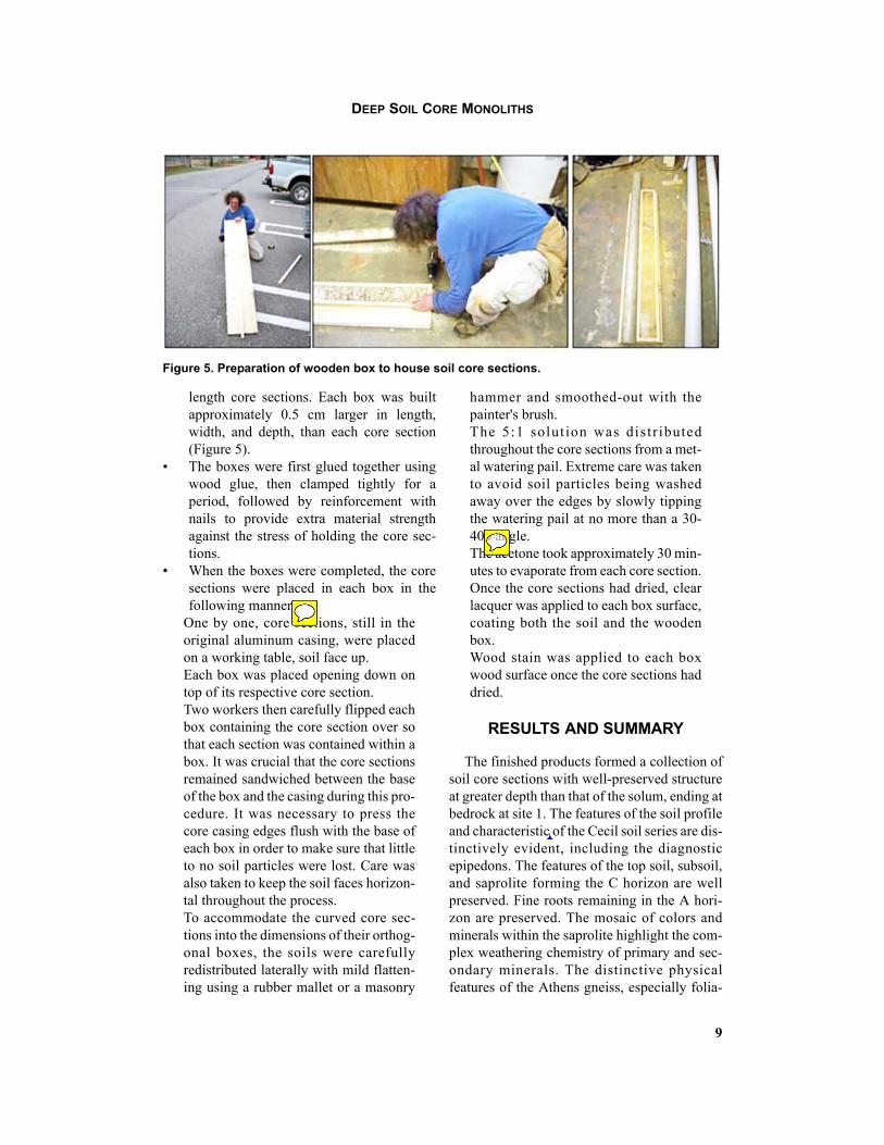
length core sections. Each box was builtapproximately 0.5 cm larger in length,width, and depth, than each core section(Figure 5).
• The boxes were first glued together usingwood glue, then clamped tightly for aperiod, followed by reinforcement withnails to provide extra material strengthagainst the stress of holding the core sec-tions.
• When the boxes were completed, the coresections were placed in each box in thefollowing manner:
One by one, core sections, still in theoriginal aluminum casing, were placedon a working table, soil face up.Each box was placed opening down ontop of its respective core section.Two workers then carefully flipped eachbox containing the core section over sothat each section was contained within abox. It was crucial that the core sectionsremained sandwiched between the baseof the box and the casing during this pro-cedure. It was necessary to press thecore casing edges flush with the base ofeach box in order to make sure that littleto no soil particles were lost. Care wasalso taken to keep the soil faces horizon-tal throughout the process.To accommodate the curved core sec-tions into the dimensions of their orthog-onal boxes, the soils were carefullyredistributed laterally with mild flatten-ing using a rubber mallet or a masonry
hammer and smoothed-out with thepainter's brush.The 5:1 solut ion was distr ibutedthroughout the core sections from a met-al watering pail. Extreme care was takento avoid soil particles being washedaway over the edges by slowly tippingthe watering pail at no more than a 30-40o angle.The acetone took approximately 30 min-utes to evaporate from each core section.Once the core sections had dried, clearlacquer was applied to each box surface,coating both the soil and the woodenbox.Wood stain was applied to each boxwood surface once the core sections haddried.
RESULTS AND SUMMARY
The finished products formed a collection ofsoil core sections with well-preserved structureat greater depth than that of the solum, ending atbedrock at site 1. The features of the soil profileand characteristic of the Cecil soil series are dis-tinctively evident, including the diagnosticepipedons. The features of the top soil, subsoil,and saprolite forming the C horizon are wellpreserved. Fine roots remaining in the A hori-zon are preserved. The mosaic of colors andminerals within the saprolite highlight the com-plex weathering chemistry of primary and sec-ondary minerals. The distinctive physicalfeatures of the Athens gneiss, especially folia-
Figure 5. Preparation of wooden box to house soil core sections.
Dinku
Sticky Note
The following - until end of section- was organized as 2nd level bullets (open circles) o One by one ... o Each box ... o Two workers ... o To accommodate ... o The 5:1 .... o The acetone ... o Wood stain ...
Dinku
Typewritten Text
Dinku
Sticky Note
o superscript
Dinku
Cross-Out
Dinku
Inserted Text
characteristics
10
STEPHAN D. FITZPATRICK, PAUL A. SCHROEDER AND DINKU M. ENDALE
tions, are evident at the bottom core section ofsite 1. The sections overall represent well-pre-served profile of a soil that is characteristic oflarge parts of Piedmont Physiographic Prov-ince, particularly in Georgia. They present goodvisual-teaching tools for representing the re-sults of soil forming processes, extending backthrough geologic time, through the dynamic in-teraction of five factors: parent/rock material,topography, climate, biological organisms, andtime. The display can also illustrate the recenthuman contributions to soil alteration. The au-dience can vary from small school children toadults of all walks of life and discipline.
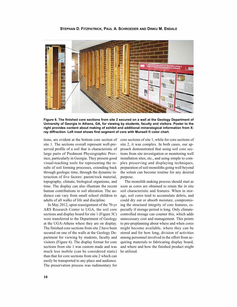
In May 2012, upon reassignment of the 70-yrARS Research Center to UGA, the soil coresections and display board for site 1 (Figure 3C)were transferred to the Department of Geologyat the UGA-Athens where they are on display.The finished core sections from site 2 have beensecured on one of the walls at the Geology De-partment for viewing by students, faculty andvisitors (Figure 6). The display format for coresections from site 1 was custom made and wasmuch less mobile (can be considered static)than that for core sections from site 2 which caneasily be transported to any place and audience.The preservation process was rudimentary for
core sections of site 1, while for core sections ofsite 2, it was complex. In both cases, our ap-proach demonstrated that using soil core sec-tions from site investigation or monitoring wellinstallation sites, etc., and using simple to com-plex preserving and displaying techniques,preparation of soil monoliths going well beyondthe solum can become routine for any desiredpurpose.
The monolith making process should start assoon as cores are obtained to retain the in situsoil characteristic and features. When in stor-age, soil cores tend to accumulate debris, andcould dry out or absorb moisture, compromis-ing the structural integrity of core features, es-pecially if storage period is long. Only climate-controlled storage can counter this, which addsunnecessary cost and management. This pointsto pre-preplanning about where and when coresmight become available, where they can bestored and for how long, division of activitiesamong personnel involved in the effort from ac-quiring materials to fabricating display board,and where and how the finished product mightbe utilized.
Figure 6. The finished core sections from site 2 secured on a wall at the Geology Department ofUniversity of Georgia in Athens, GA, for viewing by students, faculty and visitors. Poster to theright provides content about making of exhibit and additional mineralogical information from X-ray diffraction. Left inset shows first segment of core with Munsell ® color chart.

11
DEEP SOIL CORE MONOLITHS
ACKNOWLEDGEMENTS
We are grateful for the following individualsfor their substantial help with our efforts: BrianStriggow of Science and Ecosystem SupportDivision, Region 4, US Environmental Protec-tion Agency, Athens, GA, for extracting thecores during well drilling workshops he and hiscrew personally conducted; William Miller ofthe Crop and Soil Sciences Department, Uni-versity of Georgia, Athens, GA, for access tothe University of Georgia’s Crop and SoilChemistry Laboratory as well as core character-ization utilizing the NRCS soil classificationsystem; Fred Buls of Georgia Perimeter Collegein Clarkston, GA, for the construction of wood-en boxes holding cores; and Stephen Norris ofthe USDA-ARS, Athens, GA, for providingcompetent and enthusiastic technical assis-tance. Partial funding was provided from Na-tional Science Foundation’s Critical ZoneObservatory Program EAR-1331846.
DISCLAIMER
The use of trade, firm or corporate names inthis publication is for the information and con-venience of the reader and does not constitutean official endorsement or approval by the Uni-versity of Georgia or the US Department of Ag-riculture, Agricultural Research Service of anyproduct or service to the exclusion of others thatmay be suitable.
REFERENCES CITED
Austin, J.C., 2011, Soil CO2 efflux simulations using MonteCarlo method and implications for recording paleo-atmospheric PCO2 in pedogenic gibbsite: Palaeogeog-raphy, Palaeoclimatology, Palaeoecology, 305, p. 280-285.
Austin, J. C., Schroeder, P.A., 2014, Assessment of pedo-genic gibbsite as a paleo-PCO2 proxy using a modernUltisol: Clays and Clay Minerals, v. 62, n. 5, p. 235-266.
Beater, B.E., 1963, Soil profiles for display purposes: SoilScience Society of America Journal 2, p. 262-266.
Borowiec, J., 1976, Profesor Slawomir Miklaszewski jakoprekursor wykonywania monolitow glebowych: SoilScience Annual (formerly Roczniki Gleboznawcze) 27,p. 167-175.
Bruce, R.R., Dane, J.H., Quisenberry, V. L., Powell, N.L.,Thomas, A.W., 1983, Physical Characteristics of Soil in
the Southern Region: Cecil: Athens, University ofGeorgia, Southern Cooperative Series Bulletin 267.
Buol, S.W., Weed, S.B., 1991, Saprolite-soil transforma-tions in the Piedmont and mountains of North Carolina:Geoderma 51, p. 15-28.
Carreker, J.R., Wilkinson, S.R. Barnett, A.P., Box, Jr. J.E.,1977, Soil and Water Management Systems for SlopingLands: USDA, Washington, D.C., ARS-S-160.
Drohan, P.J., Havlin, J.L., Megonigal, J.P., Cheng, H.H.,2010, The “Dig It!” Smithsonian soil exhibition: Les-sons learned and goals for the future: Soil Science Soci-ety of America Journal 74, p. 697–705.
Haddad, N.I., Lawrie, R.A.,Eldridge, S.M., 2009, Improvedmethod of making soil monoliths using an acrylic bond-ing agent and proline auger: Geoderma 151, p. 395-400.
Hendrickson, B.H., Barnett, A.P., Beale, O.W., 1963, Con-servation methods for soils of the Southern Piedmont:USDA, Washington, D.C., Agricultural InformationBulletin 269.
International Soil Reference and Information Center(ISRIC), 2014, World soil reference collection, ISRIC,Wageningen, The Netherlands, accessed December, 1,2014 at http://www.isric.org/about-soils/world-soil-reference-collection.
Megonigal, P.J., Stauffer, B., Starrs, S., Pekarik, A., Drohan,P., Havlin, J., 2010, “Dig It!”: How an exhibit breathedlife into soils education: Soil Science Society of Amer-ica Journal 74, p. 706–716.
Perkins, H.P., Byrd, H.J., Ritchie, F.T. Jr. 1973. Ultisols-light-colored soils of the warm temperate forest lands.Pp. 73-86. In S.W. Buol (ed.) Soils of the southern statesand Puerto Rico. Southern Cooperative Series Bulletin174. North Carolina State University, Raleigh, NC.
Radcliffe, D.E., West, L.T., 2000, MLRA 136: SouthernPiedmont, Southern Coop Series Bulletin 395: Athens,University of Georgia.
Richter, de B.D., Yaalon, D.H., 2012, “The changing modelof soil” revisited: Soil Science Society of America Jour-nal 76, p. 766–778.
Schroeder, P.A., Le Golvan, J.J., Roden, M., 2002, Weath-ering of ilmenite from granite and chlorite schist in theGeorgia Piedmont, USA: American Mineralogist 87, p.1616-1625.
Schroeder, P.A., Melear, N.D., West, L.T., Hamilton, D.A.,2000, Meta-gabbro weathering in the Georgia Pied-mont,
USA: Implications for global silicate weathering rates:Chemical Geology163, 235-245
Schroeder, P.A., West, L., 2005, Weathering profiles devel-oped on Granitic and Mafic terrains in the area of Elber-ton, Georgia in Roden, M.F., Schroeder, P.A., Swanson,S.E., eds., Geologic Investigations of Elberton Graniteand surrounding rocks: Georgia Geological SocietyGuidebook 25, p. 55-80.
Soil Science Society of America. (2015). International yearof soils. https://www.soils.org/IYS. Accessed 04/26/2015
van Baren, J.H.V., Bomer, W., 1979, Procedures for the Col-
Dinku
Sticky Note
CO2; 2 as subscript
Dinku
Sticky Note
CO2; 2 as subscript
Dinku
Sticky Note
Delete this reference (Haddad....)
Dinku
Cross-Out
Dinku
Inserted Text
1973,
Dinku
Cross-Out
Dinku
Inserted Text
lands in Buol, S.W., ed.,
Dinku
Cross-Out
Dinku
Inserted Text
NC, p. 73-86,
Dinku
Sticky Note
Reference truncated; next (USA: ..) belongs with this reference.
Dinku
Sticky Note
For consistency say ...soils, accessed April 26, 2015 at https://www.soils.org/IYS

12
STEPHAN D. FITZPATRICK, PAUL A. SCHROEDER AND DINKU M. ENDALE
lection and Preservation of Soil Profiles: ISRIC Tech-nical Paper 1. International Soil Reference andInformation Center, Wageningen, The Netherlands
van Baren, J.H.V., Sombroek, W.G., 1981, The case for soilreference collections in Annual Report 1981: The Inter-national Soil Reference and Information Center(ISRIC), Wageningen, The Netherlands, p. 3-8.