
Polarization imaging for 3D inspection of highly reflective metallic objects
9
Polarization Imaging Applied to 3D Reconstruction of Specular Metallic Surfaces Olivier Morel, Fabrice Meriaudeau, Christophe Stolz, and Patrick Gorria Le2i - CNRS UMR5158, 12 rue de La Fonderie, 71200 Le Creusot, France ABSTRACT This paper presents a new application of “Shape from Polarization” method to specular metallic surfaces. It demonstrates how to extend the commonly used method for dielectric to metallic surfaces. Studying the state of polarization of the reflected light is very useful to get information on the normals of the surface. After computing the surface normals, the 3D surface is reconstructed thanks to a relaxation algorithm. Applications on shape defects detection are discussed, and the efficiency of the system to discriminate defects on metallic objects made by stamping and polishing is presented. Keywords: Polarization imaging, specular metallic surfaces, 3D inspection, 3D reconstruction 1. INTRODUCTION The 3D machine vision systems market is expanding rapidly, providing 3D-based machine vision for process control. Nevertheless, the inspection of specular metallic objects remains a delicate task, since it implies to control the whole lighting of the scene. Extracting the shape information of specular metallic surfaces from a single view is still a challenging problem, and there are currently two kinds of techniques. The first one is to study the highlights of structured lightings, with multiple ring lights 1 , with a hemisphere of 127 points sources like the SHINY system 2 , or with a calibrated pattern composed of lines 3, 4 . The second technique is to study the motion of a specularly reflected pattern on the surface which is different of the real motion of the object 5 . We propose a new way of reconstructing the 3D information on specular metallic objects, by extending the “Shape from Polarization” method to metallic surfaces. The aim is to reveal the shape defects on decorations from metallic objects made by stamping and polishing (Fig. 1). Seulin 6 has previously developed a dynamic lighting by projecting a fringes pattern to detect geometric aspect surface defects. The defects are revealed near the transition between a dark fringe and a bright fringe as shown on Fig. 2a. By moving the lighting, and thanks to a saturated camera, the system brings an aspect image where the defects can be efficiently segmented (Fig. 2b). Nevertheless, Fig. 2b, also shows that this system is not adapted to inspect the shape defects on the object decorations. Therefore, we propose a complementary process to resonstruct the 3D shape of the decorations based on the “Shape from Polarization” method. This method was especially developed by Miyazaki 7, 8 , and Rahman 9, 10 for transparent or reflective surfaces, but of dielectric nature. By using the complex refractive index of the surface, we’ve found new relations between the polarization images and the surface normals. Once the surface normals are computed, the surface is reconstructed by integration. The paper is organized as follow: the principle of “Shape from polarization” for dielectric surfaces is reminded in section 2. In section 3, the extension to metallic surfaces is developed, and the integration algorithm is also provided. The description of the acquisition system, and the results are exposed in section 4. 2. POLARIZATION IMAGING The polarization imaging enables to study the polarization state of a light wave. For instance, this technology can be used in industrial vision, to distinguish dielectrics and metallics 11 . The polarization imaging enables likewise to reconstruct the 3D shape of simple objects thanks to the reflection or refraction study of an unpolarized light wave: the so called “Shape from Polarization” method. The physical principle used is the following: after being reflected, an unpolarized wave becomes partially linearly polarized, depending on the surface normal and on the refractive index of the media it impinges on. This section firstly describes how to study a partially linearly polarized wave, and secondly, it reminds the “Shape from Polarization” method. Further author information: (Send correspondence to O.M.) O.M.: E-mail: [email protected]
-
Upload
artehis-cnrs -
Category
Documents
-
view
0 -
download
0
Transcript of Polarization imaging for 3D inspection of highly reflective metallic objects

Polarization Imaging Applied to 3D Reconstruction ofSpecular Metallic Surfaces
Olivier Morel, Fabrice Meriaudeau, Christophe Stolz, and Patrick GorriaLe2i - CNRS UMR5158, 12 rue de La Fonderie, 71200 Le Creusot, France
ABSTRACTThis paper presents a new application of “Shape from Polarization” method to specular metallic surfaces. Itdemonstrates how to extend the commonly used method for dielectric to metallic surfaces. Studying the state ofpolarization of the reflected light is very useful to get information on the normals of the surface. After computingthe surface normals, the 3D surface is reconstructed thanks to a relaxation algorithm. Applications on shapedefects detection are discussed, and the efficiency of the system to discriminate defects on metallic objects madeby stamping and polishing is presented.
Keywords: Polarization imaging, specular metallic surfaces, 3D inspection, 3D reconstruction
1. INTRODUCTIONThe 3D machine vision systems market is expanding rapidly, providing 3D-based machine vision for processcontrol. Nevertheless, the inspection of specular metallic objects remains a delicate task, since it implies tocontrol the whole lighting of the scene. Extracting the shape information of specular metallic surfaces from asingle view is still a challenging problem, and there are currently two kinds of techniques. The first one is tostudy the highlights of structured lightings, with multiple ring lights1, with a hemisphere of 127 points sourceslike the SHINY system2, or with a calibrated pattern composed of lines3, 4. The second technique is to study themotion of a specularly reflected pattern on the surface which is different of the real motion of the object5. Wepropose a new way of reconstructing the 3D information on specular metallic objects, by extending the “Shapefrom Polarization” method to metallic surfaces. The aim is to reveal the shape defects on decorations frommetallic objects made by stamping and polishing (Fig. 1). Seulin6 has previously developed a dynamic lightingby projecting a fringes pattern to detect geometric aspect surface defects. The defects are revealed near thetransition between a dark fringe and a bright fringe as shown on Fig. 2a. By moving the lighting, and thanks toa saturated camera, the system brings an aspect image where the defects can be efficiently segmented (Fig. 2b).Nevertheless, Fig. 2b, also shows that this system is not adapted to inspect the shape defects on the objectdecorations. Therefore, we propose a complementary process to resonstruct the 3D shape of the decorationsbased on the “Shape from Polarization” method. This method was especially developed by Miyazaki7, 8, andRahman9, 10 for transparent or reflective surfaces, but of dielectric nature. By using the complex refractive indexof the surface, we’ve found new relations between the polarization images and the surface normals. Once thesurface normals are computed, the surface is reconstructed by integration.
The paper is organized as follow: the principle of “Shape from polarization” for dielectric surfaces is remindedin section 2. In section 3, the extension to metallic surfaces is developed, and the integration algorithm is alsoprovided. The description of the acquisition system, and the results are exposed in section 4.
2. POLARIZATION IMAGINGThe polarization imaging enables to study the polarization state of a light wave. For instance, this technology canbe used in industrial vision, to distinguish dielectrics and metallics11. The polarization imaging enables likewiseto reconstruct the 3D shape of simple objects thanks to the reflection or refraction study of an unpolarized lightwave: the so called “Shape from Polarization” method. The physical principle used is the following: after beingreflected, an unpolarized wave becomes partially linearly polarized, depending on the surface normal and onthe refractive index of the media it impinges on. This section firstly describes how to study a partially linearlypolarized wave, and secondly, it reminds the “Shape from Polarization” method.
Further author information: (Send correspondence to O.M.)O.M.: E-mail: [email protected]

Figure 1. Zoom on decorations from metallic objects.
(a) (b)
Figure 2. Defects detection with the dynamic lighting: (a) One frame of the acquisition system, and (b) Aspect image.
2.1. Partial linear polarization state of a light waveTo study the polarization state of a partially linearly polarized light wave, Wolff12 considers it as the sum of twocomponents: a completely linearly polarized light wave, and a completely unpolarized light wave. Therefore,a polarization sensor has to be able to compute the magnitude of the light, the proportion of the polarizedcomponent, and the angle of the linearly polarized component. A natural way to set up this sensor, is to use arotating polarizer in front of a camera. To speed up the sensing of polarization components, the polarizer canalso be replaced by liquid crystals systems13.
The relationship between the magnitude Ip of the transmission of a partially linearly polarized light wavethrough a rotating polarizer, and the angle α of the polarizing filter is given by a sinusoid, as shown in Fig. 3.
This relation can be written in the form:
Ip(α) =Imax − Imin
2cos(2α− 2ϕ) +
Imax + Imin
2, (1)
where Imin and Imax represent, respectively, the minimum and the maximum magnitude seen through thepolarizer. The magnitude of the light I, and the proportion of the polarized component ρ (also called the degree
150°0° 200° 250°100°50°
ϕ
α
Ip
Imin
Imax
Figure 3. Variation of the light intensity according to the angle of the polarizer.
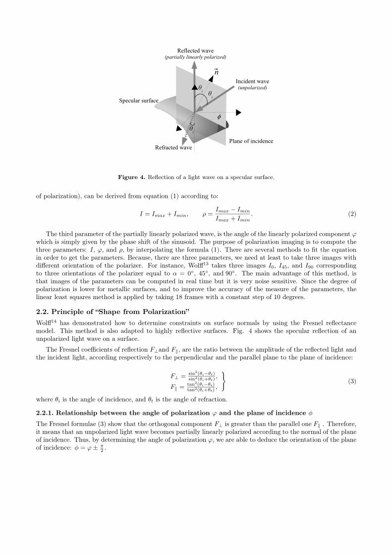
Figure 4. Reflection of a light wave on a specular surface.
of polarization), can be derived from equation (1) according to:
I = Imax + Imin, ρ =Imax − Imin
Imax + Imin. (2)
The third parameter of the partially linearly polarized wave, is the angle of the linearly polarized component ϕwhich is simply given by the phase shift of the sinusoid. The purpose of polarization imaging is to compute thethree parameters: I, ϕ, and ρ, by interpolating the formula (1). There are several methods to fit the equationin order to get the parameters. Because, there are three parameters, we need at least to take three images withdifferent orientation of the polarizer. For instance, Wolff13 takes three images I0, I45, and I90 correspondingto three orientations of the polarizer equal to α = 0◦, 45◦, and 90◦. The main advantage of this method, isthat images of the parameters can be computed in real time but it is very noise sensitive. Since the degree ofpolarization is lower for metallic surfaces, and to improve the accuracy of the measure of the parameters, thelinear least squares method is applied by taking 18 frames with a constant step of 10 degrees.
2.2. Principle of “Shape from Polarization”Wolff14 has demonstrated how to determine constraints on surface normals by using the Fresnel reflectancemodel. This method is also adapted to highly reflective surfaces. Fig. 4 shows the specular reflection of anunpolarized light wave on a surface.
The Fresnel coefficients of reflection F⊥and F‖, are the ratio between the amplitude of the reflected light andthe incident light, according respectively to the perpendicular and the parallel plane to the plane of incidence:
F⊥ = sin2(θi−θt)sin2(θi+θt)
,
F‖ = tan2(θi−θt)tan2(θi+θt)
,
}(3)
where θi is the angle of incidence, and θt is the angle of refraction.
2.2.1. Relationship between the angle of polarization ϕ and the plane of incidence φ
The Fresnel formulae (3) show that the orthogonal component F⊥ is greater than the parallel one F‖ . Therefore,it means that an unpolarized light wave becomes partially linearly polarized according to the normal of the planeof incidence. Thus, by determining the angle of polarization ϕ, we are able to deduce the orientation of the planeof incidence: φ = ϕ± π
2 .

2.2.2. Relationship between the degree of polarization ρ and the angle of reflection θr
The disparity between the components F⊥ and F‖ brings also a new piece of information: the degree of polar-ization of the reflected light. By denoting Imin and Imax , the minimum and the maximum magnitude of thelight wave through a rotating polarizer, we have:
Imax = F⊥F⊥+F‖
I,
Imin = F‖F⊥+F‖
I.
}(4)
Thus, the degree of polarization defined in equation (2) can be expressed as:
ρ =F⊥ − F‖F⊥ + F‖
. (5)
Moreover, by denoting n the relative refractive index between the object and the air, the Snell-Descartes’s lawgives:
sin θi = n sin θt, (6)
By substituting equation (3) into equation (5) with Snell-Descartes’s law, and by writing θ = θr = θi, the degreeof polarization ρ can be expressed as:
ρ(θ) =2 sin θ tan θ
√n2 − sin2 θ
n2 − 2 sin2 θ + tan2 θ. (7)
This equation gives the relationship between the angle of reflection θ and the degree of polarization ρ for dielectricsurfaces.
3. EXTENSION TO METALLIC SURFACESThis section describes our main contributions concerning the “Shape from Polarization” method extended tometallic surfaces, and the integration algorithm.
3.1. Use of the complex refractive indexUnfortunately, the relation (7) can not be directly applied to metallic surfaces since their refractive indexesare complex. The complex index n̂ can be generally written in the form: n̂ = n(1 + iκ) where κ is called theattenuation index. In this case, the Snell-Descartes equation (6) implies that the refractive angle θt is complex.Therefore, the Fresnel coefficients are given by:
F⊥ =∣∣∣ sin(θi−θt)sin(θi+θt)
∣∣∣2
,
F‖ =∣∣∣ tan(θi−θt)tan(θi+θt)
∣∣∣2
.
(8)
In order to simplify the relations, and as it is usually the case in the visible region, we apply the followingapproximation15:
|n̂|2 = n2(1 + κ2) À 1. (9)
In the same way, and thanks to the approximation, we find an inversible relation in the form:
ρ(θ) =2n tan θ sin θ
tan2 θ sin2 θ + |n̂|2 . (10)
The difference between the true degree of polarization and its approximation grows slightly only for great valuesof the angle θ (Fig. 5).
The curve also shows that the ambiguity concerning the determination of the angle θ, according to the degreeof polarization ρ, doesn’t have do be treated for surfaces with slopes lower than 75◦, as it is usually the casewith the studied objects.

0
0.05
0.1
0.15
0.2
0.25
0.3
0.35
0° 10° 20° 30° 40° 50° 60° 70° 80° 90°
approximationreal
θ
ρ
Figure 5. Comparison between the approximated degree of polarization and the real degree of polarization for a metallicsurface (n̂ = 1.94(1 + 2.7i)).
3.2. Surface reconstructionWe make the assumption that the surface is a Cartesian one, defined by z = f(x, y). The normal in each pointis given by:
−→n =
∣∣∣∣∣∣∣
−∂f(x,y)∂x
−∂f(x,y)∂y
1=
∣∣∣∣∣∣
p = tanθcosφq = tanθsinφ1
. (11)
This expression enables to assume the link between the normal and the derivative of each point of the surface.Since, the angles θ and φ, are computed thanks to polarimetric images, the goal is to determine z = f(x, y)by integrating. In order to keep the continuity between the rows and the columns of the image, a relaxationalgorithm based on Taylor’s approximations is applied:
fn+1(i, j) =1S
H(i, j) ∗ fn(i, j) +a · ε22S
(∂p
∂i+
∂q
∂j
), (12)
where S is the sum of the H filter coefficients, ε represents the step between each pixel, and a is given by:
a =k∑
u=−k
k∑
v=−k
H(u, v)u2 =k∑
u=−k
k∑
v=−k
H(u, v)v2. (13)
Moreover, H has to be a 2k + 1 by 2k + 1 smoothing filter with the following constraints:
∀(u, v) ∈ [−k, k]2 , H(u, v) = H(−u, v) = H(u,−v). (14)
The iterative relation (12) is a general formulation of the standard relaxation algorithm16. It enables to uselarger filter in order to increase the convergence of the reconstruction algorithm. The algorithm is initialized bya reference plane extracted from a surface in which the decorations of the object don’t appear.
4. APPLICATION AND RESULTS
4.1. Experimental set upThe acquisition system is made of a CCD camera, a liquid crystal polarization rotator, and a diffuse dome light(Fig. 6). The diffuse dome light is used to provide an unpolarized light on the whole surface. After reflection thelight which becomes partially linearly polarized is studied with the liquid crystal polarization rotator and thecamera. The liquid crystal polarization rotator acts like a rotating polarizer which can be electrically controlled.

Figure 6. Experimental set up.
Figure 7. Whole process of image processing.
This device uses nematic liquid crystal cell associated with a linear polarizer, and a quarter wave plate, whichprovides tunable polarization by changing the supplied voltage. Since the degree of polarization is lower formetallic surfaces, we use a sensitive camera with 10 bits depth. A limitation of our system is due to the holefor the camera, leading to a θmin value which is about 3◦. Therefore, the object has to be correctly oriented inorder to respect the constraints about the angle θ. Nevertheless, approximating the angle θ inferior than 3◦ toθ = 0◦ (a normal orientation) doesn’t lead to a significant error of the 3D surface reconstruction.
Because of the manufacturing process, the metallic objects we’re working on, are provided with differentshape details and 3D information have to be extracted. The decorations of the objects are made by stamping,meaning the slopes don’t exceed 75◦. Moreover, the objects are polished in order to get the surfaces of polishmirror quality, therefore the reflections are assumed to be specular. To initialize the 3D reconstruction process,a plane is given from the theoretical surface without the decorations. The whole process of image processing issummed up in Fig. 7.
The 18 Frames are acquired with different rotations of the polarization rotator from 0 to 180◦, with a constantstep of 10◦. The least mean square method is applied during the acquisition process, while the polarization rotatoris turning. Therefore, it takes less than one second to acquire the 18 images, and to compute the three parametersof polarization (Fig. 8) by fitting the sinusoid. By knowing the object’s complex index of refraction, the surfaceis reconstructed from the initialization plane according to the presented iterative algorithm (12). Our systemcan also be used to estimate the refractive index of the object surface with the opposite method: from a knownsurface, the degree of polarization leads to the refractive index (equation (10)).
4.2. ResultsIn order to qualitatively compare the 3D surface obtained with our system to a 3D surface of reference, theobject was scanned with a 3D scanner (Replica 500). This scanner based on laser ranging, takes regular pointswith step of 50µm in X and Y axis, and the precision in Z axis is about 20µm. Since such a scanner is sensitiveto the reflectivity of surface, a thin opaque coating has to be applied onto the object. Consequently the detailsof the object appear clearly more marked with our method rather with the scanner (Fig. 9a and Fig. 9b).

(a) Intensity (b) Degree of polarization (c) Angle of polarization
Figure 8. Parameters of polarization.
After registering the 2 surfaces, the mean deviation between the surfaces is about 30µm, meaning that theshape is qualitatively well reconstructed. Moreover, the cross section (Fig. 9c) highlights the good accuracyof the surface computed with our method. The resolutions along the axis X and Y depend only on the usedlenses and on the spatial resolution of the sensor: for instance, we are able to get X, Y resolutions 3 times finer.Thus, “Shape from polarization” extended to metallic surfaces presents encouraging preliminary results, and ourmethod can be easily integrated into an automatic process of shape defects detection.
(a) (b)
0
0.1
0.2
0.3
0.4
0.5
0.6
0 1 2 3 4 5
Acquisition3D Scanner
(c)
Figure 9. Reconstruction of the 3D surface of a metallic object: (a) Surface from the 3D scanner, (b) Surface from ourmethod, and (c) Comparison of the cross sections (scales given in mm).
4.3. 3D inspectionThe aim of our system is to inspect specular metallic objects. The Fig. 10 illustrates the 3D surface reconstructionfor two objects: a reference one and one with a shape defect on the left-bottom “bump”.
After an automatic registration of the two shells, the mean deviation between the surfaces is computed(Fig 10e). The comparison shows the efficiency to discriminate the shape defect.

(a) (b)
(c) (d)
(e)
Figure 10. Polarization imaging applied to 3D reconstruction of specular metallic objects: (a) Object of referencephotograph and its 3D reconstructed surface (b). (c) Object with a shape defect photograph, and its 3D reconstructedsurface (d). (e) Mean deviation map between the surfaces (b) and (d).

5. CONCLUSION AND FUTURE WORKS
In this paper, a new way of reconstructing the 3D surface of specular metallic objects is presented. The methodof “Shape from Polarization” has been extended to specular metallic surfaces, in order to detect shape defects onobjects made by stamping and polishing. The involved process is quite simple, requiring a diffuse dome light,a CCD camera and a polarization rotator. The polarization imaging enables to compute the normals surface,then the 3D surface is obtained by integrating the normals thanks to a relaxation algorithm. The comparisonbetween the 3D surface and the surface obtained by a 3D scanner shows qualitatively the efficiency of ourmethod to reconstruct the objects shape. Moreover, the comparison between two surfaces reconstructed from areference object and an object with a shape defect enables to reveal the defect. The acquisition process and thepolarization images extraction takes less than one second. The integration process time has to be reduced inorder to integrate the whole system into an automatic process. Therefore, future works will consist in developingfaster integration algorithms and quantitatively evaluating the reconstruction precision.
REFERENCES1. I. D. Yun, E. Jung, and S. Lee, “On the fast shape recovery technique using multiple ring lights,” 30,
pp. 883–893, June 1997.2. S. Nayar, A. Sanderson, L. Weiss, and D. Simon, “Specular surface inspection using structured highlight
and gaussian images,” IEEE Trans. Robotics and Automation 6, pp. 208–218, April 1990.3. S. Savarese and P. Perona, “Local analysis for 3d reconstruction of specular surfaces,” in IEEE Computer
Vision and Pattern Recognition, 2, pp. 738–745, (Hawaii, USA), December 2001.4. S. Savarese and P. Perona, “Local analysis for 3d reconstruction of specular surfaces: part ii,” in European
Conference on Computer Vision, pp. 759–774, (Copenhagen, Denmark), May 2002.5. J. Y. Zheng and A. Murata, “Acquiring a complete 3d model from specular motion under the illumination
of circular-shaped light sources,” IEEE Trans. Pattern Analysis and Machine Intelligence 22, pp. 913–920,August 2000.
6. R. Seulin, F. Merienne, and P. Gorria, “Simulation of specular surface imaging based on computer graphics :application on a vision inspection system,” EURASIP Journal on Applied Signal Processing 2002, pp. 649–658, July 2002.
7. D. Miyazaki, M. Kagesawa, and K. Ikeuchi, “Determining shapes of transparent objects from two polariza-tion images,” in Proceedings of IAPR Workshop on Machine Vision Applications (MVA2002), pp. 26–31,December 2002.
8. D. Miyazaki, M. Kagesawa, and K. Ikeuchi, “Transparent surface modeling from a pair of polarizationimages,” IEEE Trans. Pattern Analysis and Machine Intelligence 26(1), pp. 73–82, January 2004.
9. S. Rahmann, “Inferring 3d scene structure from a single polarization image,” in Conference on Polarizationand Color Techniques in Industrial Inspection, volume 3826 of SPIE Proceedings, pp. 22–33, June 99.
10. S. Rahmann and N. Canterakis, “Reconstruction of specular surfaces using polarization imaging,” in IEEEComputer Vision and Pattern Recognition (CVPR01), volume I, Kauai, USA, pp. 149–155, December 2001.
11. L. B. Wolff, “Polarization-based material classification from specular reflection,” IEEE Trans. Pattern Anal-ysis and Machine Intelligence 12, pp. 1059–1071, November 1990.
12. L. B. Wolff, “Polarization vision: a new sensory approach to image understanding,” Image and VisionComputing 15, pp. 81–93, February 1997.
13. L. B. Wolff and A. Andreou, “Polarization camera sensors,” Image and Vision Computing 13, pp. 497–510,August 1995.
14. L. B. Wolff and T. E. Boult, “Constraining object features using a polarization reflectance model,” IEEETrans. Pattern Analysis and Machine Intelligence 13(7), pp. 635–657, July 1991.
15. M. Born and E. Wolf, Principles Of Optics, Cambridge, 7 ed., 1999.16. K. Ikeuchi and B. Horn, “Numerical shape from shading and occluding boundaries,” Artificial Intelligence
17, pp. 141–184, August 1981.