PM5D Quick Start Guide Part3 - Yamaha Downloads
31
PM5D / PM5D-RH Quick Start Guide Part 3 1 Quick Start Guide A guide for people using PM5D in the real world. / Part 3 Introduction to Studio Manager and PM5DV2 Editor. Show setup walk through guide. This “quick start guide” series is designed for people about to use Yamaha PM5D for the first time. It is not a guide to audio mixing and it assumes the reader has experience of analog mixers. It does not cover all features or all approaches to PM5D use, nor does it replace the manual; we recommend referring to the manual if further information is required.
-
Upload
khangminh22 -
Category
Documents
-
view
1 -
download
0
Transcript of PM5D Quick Start Guide Part3 - Yamaha Downloads
PM5D / PM5D-RH Quick Start Guide Part 3
1
Quick Start GuideA guide for people using PM5D in the real world.
/
Part 3Introduction to Studio Manager and PM5DV2 Editor.
Show setup walk through guide.
This “quick start guide” series is designed for people about to use Yamaha PM5D for the fi rst time. It is not a guide to audio mixing and it assumes the reader has experience of analog mixers. It does not cover all features or all approaches to PM5D use, nor does it replace the manual; we recommend referring to the manual if further information is required.
PM5D / PM5D-RH Quick Start Guide Part 3
2
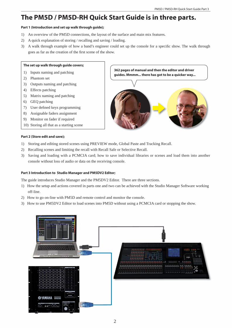
The PM5D / PM5D-RH Quick Start Guide is in three parts.Part 1 (Introduction and set up walk through guide);
1) An overview of the PM5D connections, the layout of the surface and main mix features.2) A quick explanation of storing / recalling and saving / loading.3) A walk through example of how a band’s engineer could set up the console for a specifi c show. The walk through
goes as far as the creation of the fi rst scene of the show.
The set up walk through guide covers;
1) Inputs naming and patching2) Phantom set3) Outputs naming and patching4) Effects patching5) Matrix naming and patching6) GEQ patching7) User defi ned keys programming8) Assignable faders assignment9) Monitor on fader if required10) Storing all that as a starting scene
362 pages of manual and then the editor and driver
guides. Mmmm... there has got to be a quicker way...
Part 2 (Store edit and save);
1) Storing and editing stored scenes using PREVIEW mode, Global Paste and Tracking Recall.2) Recalling scenes and limiting the recall with Recall Safe or Selective Recall.3) Saving and loading with a PCMCIA card; how to save individual libraries or scenes and load them into another
console without loss of audio or data on the receiving console.
Part 3 Introduction to Studio Manager and PM5DV2 Editor;
The guide introduces Studio Manager and the PM5DV2 Editor. There are three sections.1) How the setup and actions covered in parts one and two can be achieved with the Studio Manager Software working off-line.2) How to go on-line with PM5D and remote control and monitor the console.3) How to use PM5DV2 Editor to load scenes into PM5D without using a PCMCIA card or stopping the show.

PM5D / PM5D-RH Quick Start Guide Part 3
3
Table of ContentsThe PM5D/PM5D-RH Quick Start Guide is in three parts 2Table of Contents 3Background and introduction to Studio Manager. 4What is Studio Manager for? 5Where can I get Studio Manager? 5What kind of computer do I need? 6Which version of software should I use? 7How can I deal with older versions? 7If I don’t have access to a PM5D can I still get started and use the software? 7Opening Studio Manager and the Editor for the fi rst time. 8Using Editor Windows. 8Changing parameters. 9Dragging a rotary knob. 10The SEL channel windows; main and Additional. 10Channel copy and paste. 10Keyboard Shortcuts. 11PM5D setup; a walk through guide. 12 PM5D rider specifi cations; 12 Entering names and doing the patch; the planning stage. 13 Entering names and doing the patch; 14 To pair mono input channels as stereo; 15 Output patching. 15 To pair output mixes as stereo. 16 Setting the mix levels. 16 Store your scene and save your setup work. 17 Internal effects engines 18 The Matrix 20 Graphic equalizers, GEQ. 20 User Defi ned Keys 21 Assignable/DCA faders 21 Cue level on faders for monitor engineers. 22 Store and Save again 22PM5D data loading from PCMCIA card. (Basic Load All data) 23Going on-line for the fi rst time; Studio Manager, PM5DV2 Editor and PM5D 24PM5D mixer settings 24Setting up MIDI ports the fi rst time you go on-line. 25On-line, Off-line and Synchronized. 26Loading and saving sessions without a PCMCIA card; Use Studio Manager. 26Advanced Load and Save using On-line connection. 27What makes up a Console or Session File? 27Library Window dragging. Example; load a stored user effect from one session to another. 28Using two PM5DV2 Editors. 29Making and breaking scene links in PM5DV2 Editor 30To merge two bands scenes into one session fi le; 30Wireless remote control of PM5D. 31PM5D/PM5D-RH Quick Start Guide in three parts. 31
PM5D / PM5D-RH Quick Start Guide Part 3
4
Background and introduction to Studio Manager.
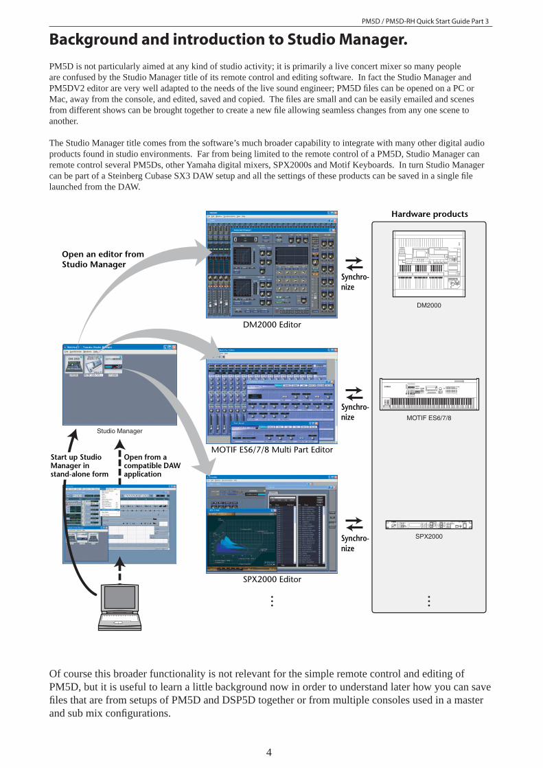
PM5D is not particularly aimed at any kind of studio activity; it is primarily a live concert mixer so many people are confused by the Studio Manager title of its remote control and editing software. In fact the Studio Manager and PM5DV2 editor are very well adapted to the needs of the live sound engineer; PM5D fi les can be opened on a PC or Mac, away from the console, and edited, saved and copied. The fi les are small and can be easily emailed and scenes from different shows can be brought together to create a new fi le allowing seamless changes from any one scene to another.
The Studio Manager title comes from the software’s much broader capability to integrate with many other digital audio products found in studio environments. Far from being limited to the remote control of a PM5D, Studio Manager can remote control several PM5Ds, other Yamaha digital mixers, SPX2000s and Motif Keyboards. In turn Studio Manager can be part of a Steinberg Cubase SX3 DAW setup and all the settings of these products can be saved in a single fi le launched from the DAW.
Of course this broader functionality is not relevant for the simple remote control and editing of PM5D, but it is useful to learn a little background now in order to understand later how you can save fi les that are from setups of PM5D and DSP5D together or from multiple consoles used in a master and sub mix confi gurations.
Studio Manager
SPX2000
DM2000
MOTIF ES6/7/8
MOTIF ES6/7/8 Multi Part Editor
DM2000 Editor
Synchro-nize
Synchro-nize
Synchro-nize
SPX2000 Editor
Hardware products
Open from a compatible DAW application
Start up Studio Manager in stand-alone form
Open an editor from Studio Manager

PM5D / PM5D-RH Quick Start Guide Part 3
5
What is Studio Manager and PM5DV2 Editor for?The combination of Studio Manager and PM5DV2 Editor gives you the software to create and edit .PM5 fi les on your personal computer. These fi les hold all the parameter data for all the scenes in a setup and can be transferred to a console using a PCMCIA data card. Alternatively, by using the USB MIDI driver and a USB cable connection, the Studio Manager and PM5D Editor can be used "online" for remote control and monitoring of a PM5D console or direct exchange of data between the computer and console memory.
In a similar way the same Studio Manager with the DSP5D Editor can create and edit .PM5 fi les for loading into the DSP5D. In this case the connection is via a network port and the necessary driver software is the Yamaha DME-N Network driver. Studio Manager and DSP5D editor is by far the most effi cient way to load and save data from a DSP5D.
It is not required to ever use Studio Manager with a PM5D; the console offers all its features without any external computer devices, but Studio Manager adds very useful extra access. The preparation chores like naming channels, patching I/O, setting effects units and parameters can all be done on your PC without the need to access the console; while you are at home, on the bus, or even on a plane. Secondly Studio Manager offers an alternative interface when connected to a PM5D, this gives a different view, an extra control interface for dual operators and the possibility of remote or even wireless control using tablet type PCs.
Where can I get Studio Manager?
Studio Manager and the various editor programmes are available as free download from; www.yamahaproaudio.com
From the DOWNLOADS page look for FIRMWARE AND SOFTWARE.
There are three things you should download for PM5D; 1. The Studio Manager V2 Host (available in Windows and Mac OS versions)2. The PM5DV2 Editor (available in Windows and Mac OS versions)3. The USB-MIDI Driver (available in various Windows and Mac OS versions)
For DSP5D control you need to add the DSP5D Editor and the DME-N Network driver.
Downloads from www.yamahaproaudio.com will always be the latest versions and compatible with each other and the latest console fi rmware. Older versions of Studio Manager may not communicate with the latest console versions and so it is best to rely on downloads rather than a CD that may have come with the console or been loaned to you. Any extra limitations caused by the ongoing development of the software will be explained on the website.
The Studio Manager software can currently be downloaded free of charge, but remember there is a "Licence Agreement" to check and you should only use the software as permitted by the terms and conditions of that agreement.
PM5D / PM5D-RH Quick Start Guide Part 3
6
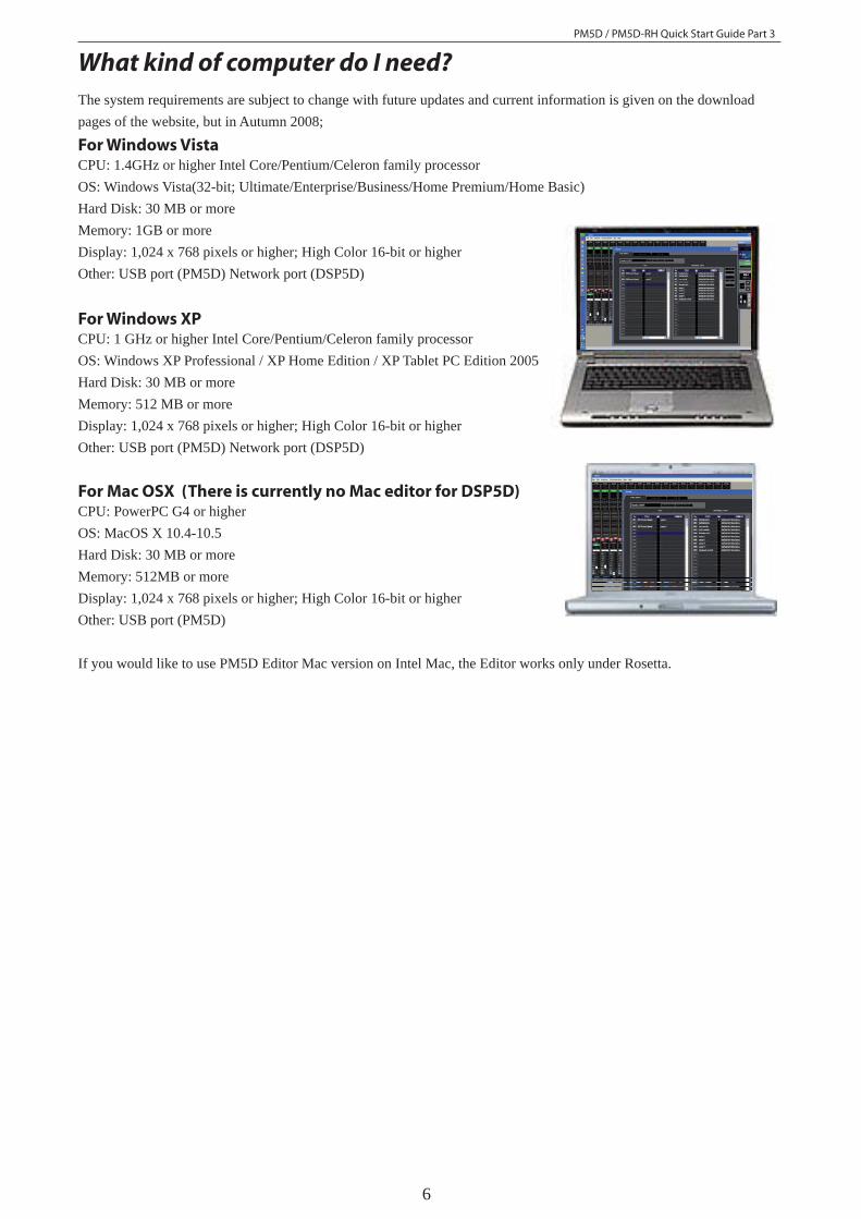
For Mac OSX (There is currently no Mac editor for DSP5D)CPU: PowerPC G4 or higher OS: MacOS X 10.4-10.5 Hard Disk: 30 MB or more Memory: 512MB or more Display: 1,024 x 768 pixels or higher; High Color 16-bit or higher Other: USB port (PM5D)
If you would like to use PM5D Editor Mac version on Intel Mac, the Editor works only under Rosetta.
What kind of computer do I need?The system requirements are subject to change with future updates and current information is given on the download pages of the website, but in Autumn 2008;
For Windows VistaCPU: 1.4GHz or higher Intel Core/Pentium/Celeron family processor OS: Windows Vista(32-bit; Ultimate/Enterprise/Business/Home Premium/Home Basic) Hard Disk: 30 MB or more Memory: 1GB or more Display: 1,024 x 768 pixels or higher; High Color 16-bit or higher Other: USB port (PM5D) Network port (DSP5D)
For Windows XP CPU: 1 GHz or higher Intel Core/Pentium/Celeron family processor OS: Windows XP Professional / XP Home Edition / XP Tablet PC Edition 2005 Hard Disk: 30 MB or more Memory: 512 MB or more Display: 1,024 x 768 pixels or higher; High Color 16-bit or higher Other: USB port (PM5D) Network port (DSP5D)
PM5D / PM5D-RH Quick Start Guide Part 3
7
Installing the software.Full instructions for installing the software are available form the download pages. The wizards will guide you through the installation. Use the default settings unless you have particular requirements on where to install things.
If I don’t have access to a PM5D can I still get started and use the software?Yes. Once the software is installed correctly you can open the Studio Manager without a console. However you should understand that the PM5DV2 Editor graphics are not the same as those in the console and that studying PM5DV2 Edi-tor is not an effi cient way to learn how the actual console appears and works. The USB-MIDI Driver cannot be opened without the PM5D, but this is only required for communication when a PM5D is connected.
Which Version of Software should I use?
Yamaha constantly develops the PM5D mixing system, sometimes new versions are released that include new features and sometimes versions simply tweak the existing system to improve performance and “bug fi x”. When new console versions are released, new Studio Manager and Editor versions are often required to keep compatibility.
All fi les saved in mixers are .PM5 type fi les and these will open in all future mixer versions, however it is not pos-sible to guarantee future fi les will still be compatible with older mixers. For this reason Yamaha strongly recom-mends the use of current mixer fi rmware in all consoles. If you own the mixer, keep it up to date or visiting engineers may not be able to open their fi les. If you are a touring freelance engineer carry latest fi rmware and PCMCIA or CF card for upgrading. Console fi rmware is provided free of charge on www.yamahaproaudio.com
Files saved in Studio Manager can have other formats (see page 15/16 of this guide). If a fi le was saved as a .YSM or .YSE fi le in V1 of Studio Manager it will not open in V2.
Yamaha always recommends the latest version of console fi rmware and the latest version of Studio Manager and PM-5DV2 Editor. This combination is compatible for on-line connection and synchronization, will have the latest features and least known bug problems. However, we understand that in the real world there are older versions of consoles in circulation and that some engineers may have saved data in older versions of the SM and Editor.
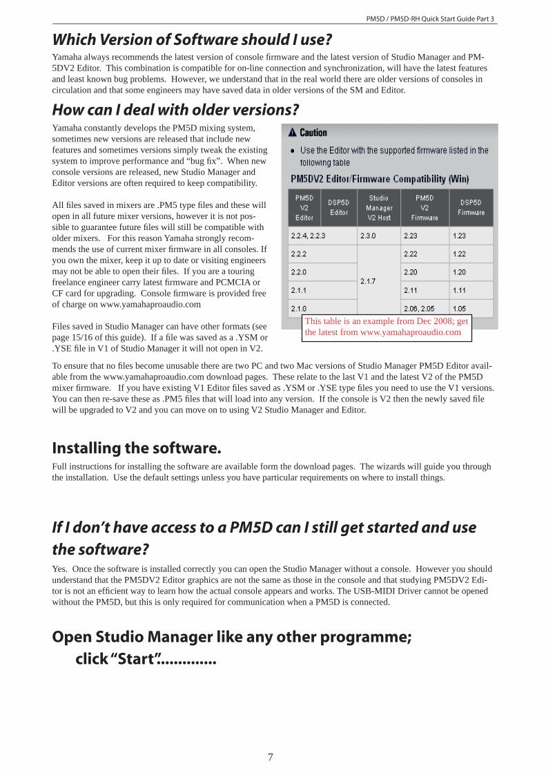
How can I deal with older versions?
This table is an example from Dec 2008; get the latest from www.yamahaproaudio.com
To ensure that no fi les become unusable there are two PC and two Mac versions of Studio Manager PM5D Editor avail-able from the www.yamahaproaudio.com download pages. These relate to the last V1 and the latest V2 of the PM5D mixer fi rmware. If you have existing V1 Editor fi les saved as .YSM or .YSE type fi les you need to use the V1 versions. You can then re-save these as .PM5 fi les that will load into any version. If the console is V2 then the newly saved fi le will be upgraded to V2 and you can move on to using V2 Studio Manager and Editor.
Open Studio Manager like any other programme; click “Start”..............
PM5D / PM5D-RH Quick Start Guide Part 3
8
PM5DV2V2DSP5DDSP5D
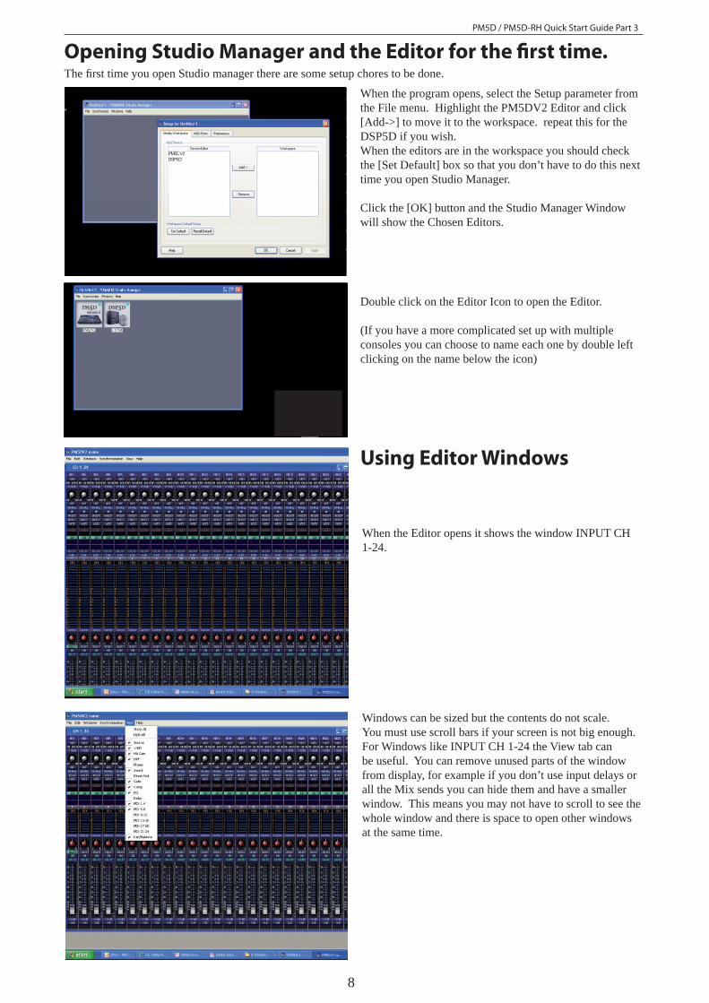
When the program opens, select the Setup parameter from the File menu. Highlight the PM5DV2 Editor and click [Add->] to move it to the workspace. repeat this for the DSP5D if you wish.When the editors are in the workspace you should check the [Set Default] box so that you don’t have to do this next time you open Studio Manager.
Click the [OK] button and the Studio Manager Window will show the Chosen Editors.
Double click on the Editor Icon to open the Editor.
(If you have a more complicated set up with multiple consoles you can choose to name each one by double left clicking on the name below the icon)
Windows can be sized but the contents do not scale. You must use scroll bars if your screen is not big enough.For Windows like INPUT CH 1-24 the View tab can be useful. You can remove unused parts of the window from display, for example if you don’t use input delays or all the Mix sends you can hide them and have a smaller window. This means you may not have to scroll to see the whole window and there is space to open other windows at the same time.
When the Editor opens it shows the window INPUT CH 1-24.
Opening Studio Manager and the Editor for the fi rst time.
Using Editor Windows
The fi rst time you open Studio manager there are some setup chores to be done.
PM5D / PM5D-RH Quick Start Guide Part 3
9
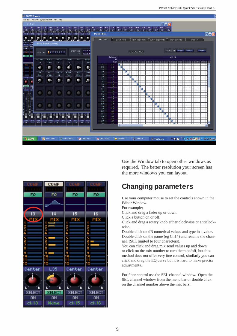
Use the Window tab to open other windows as required. The better resolution your screen has the more windows you can layout.
Changing parametersUse your computer mouse to set the controls shown in the Editor Window. For example;Click and drag a fader up or down. Click a button on or off. Click and drag a rotary knob either clockwise or anticlock-wise.Double click on dB numerical values and type in a value.Double click on the name (eg Ch14) and rename the chan-nel. (Still limited to four characters).You can click and drag mix send values up and down or click on the mix number to turn them on/off, but this method does not offer very fi ne control, similarly you can click and drag the EQ curve but it is hard to make precise adjustments.
For fi ner control use the SEL channel window. Open the SEL channel window from the menu bar or double click on the channel number above the mix bars.

PM5D / PM5D-RH Quick Start Guide Part 3
10
The SEL channel windows;Main and Additional
In the PM5DV2 Editor there are two SEL channel win-dows; Main View and Additional View. Both views ap-pear the same, and both can be on screen at the same time, they differ in how their displayed channel is selected.Note also the main view can access the libraries from buttons within the window, but these are greyed out in the additional view.
The selection of the Main View is by the [SEL] buttons, but the Additional View selection is either by using the arrows to increment and decrement the channel or by clicking on the [Select] bar to produce a drop down box of all the channels to choose from.
For now it doesn’t matter which SEL channel you use, the Main View is probably a little easier, and it has the library short-cuts, but later when connected on-line to the console you may want to decide if you need the Studio Manager to show the same SEL channel as the console or a different SEL channel.
Dragging a rotary knob.To set the value of a rotary knob click on the knob and drag it round. The knob will reach an end stop just like an analogue knob. For greater accuracy you can click on the knob, drag the pointer out along the radius of a circle and then turn the knob as if it was a giant knob with this radius. This can be especially useful when using tablet control. Alternatively, type a value into the text box above the knob.
Drag out, then turn
Channel copy and pasteThe SEL channel can easily be copied and pasted to a newly selected channel. Use the Edit menu or the familiar short cut of Ctrl+C and Ctrl+V in windows ( +C and
+V in Mac).
PM5D / PM5D-RH Quick Start Guide Part 3
11
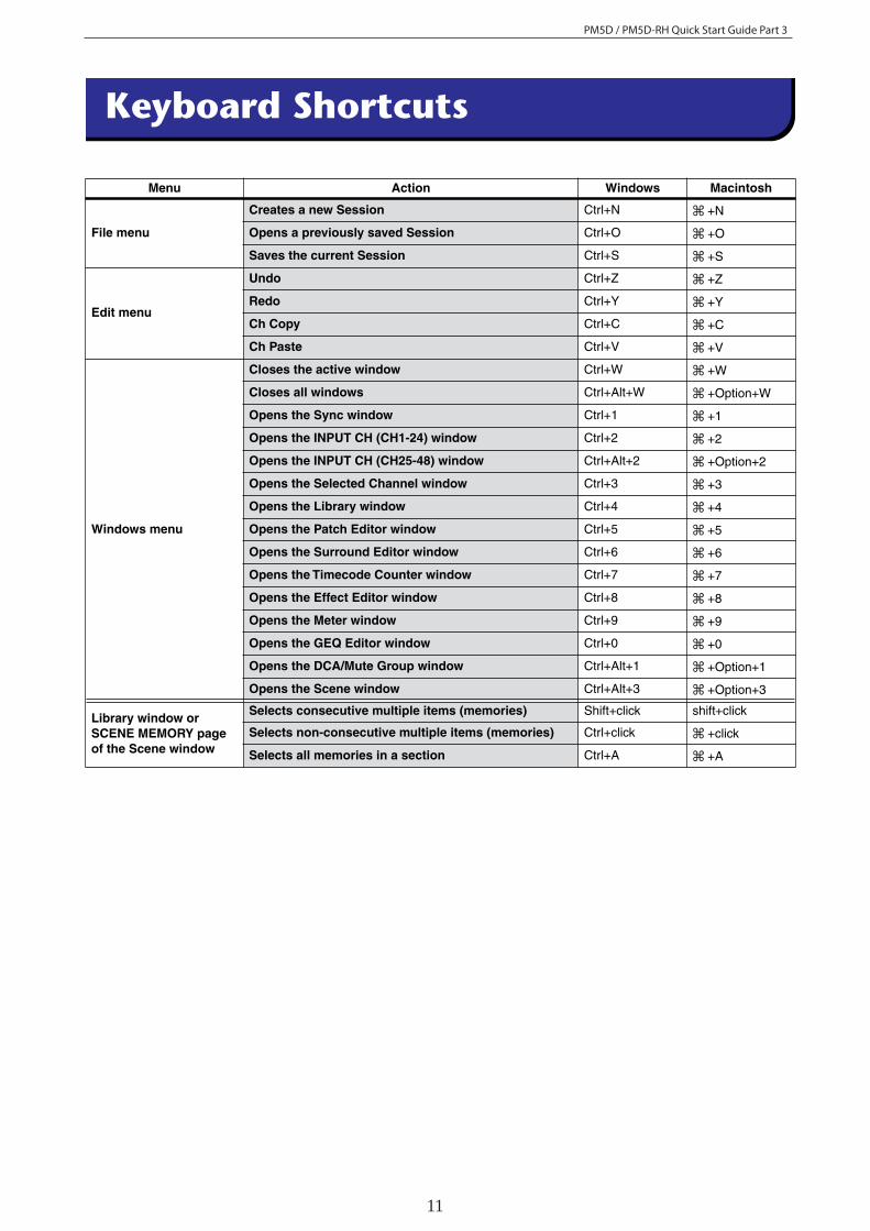
Menu Action Windows Macintosh
File menu
Creates a new Session Ctrl+N +N
Opens a previously saved Session Ctrl+O +O
Saves the current Session Ctrl+S +S
Edit menu
Undo Ctrl+Z +Z
Redo Ctrl+Y +Y
Ch Copy Ctrl+C +C
Ch Paste Ctrl+V +V
Windows menu
Closes the active window Ctrl+W +W
Closes all windows Ctrl+Alt+W +Option+W
Opens the Sync window Ctrl+1 +1
Opens the INPUT CH (CH1-24) window Ctrl+2 +2
Opens the INPUT CH (CH25-48) window Ctrl+Alt+2 +Option+2
Opens the Selected Channel window Ctrl+3 +3
Opens the Library window Ctrl+4 +4
Opens the Patch Editor window Ctrl+5 +5
Opens the Surround Editor window Ctrl+6 +6
Opens the Timecode Counter window Ctrl+7 +7
Opens the Effect Editor window Ctrl+8 +8
Opens the Meter window Ctrl+9 +9
Opens the GEQ Editor window Ctrl+0 +0
Opens the DCA/Mute Group window Ctrl+Alt+1 +Option+1
Opens the Scene window Ctrl+Alt+3 +Option+3
Library window or SCENE MEMORY page of the Scene window
Selects consecutive multiple items (memories) Shift+click shift+click
Selects non-consecutive multiple items (memories) Ctrl+click +click
Selects all memories in a section Ctrl+A +A
Keyboard Shortcuts
PM5D / PM5D-RH Quick Start Guide Part 3
12
THE EXAMPLES
PLEASE DO NOT USE ANY GENETICALLY MODIFIED INGREDIENTS, AND USEORGANIC PRODUCE WHEREVER POSSIBLE.PLEASE NO BLACK PEPPER IN VEGETARIAN DISHES DUE TO ALLERGY.Crew party is 7, band party is 8 We have a number of strict vegetarians on ourtouring staff. Please ensure they are properly catered for.DRESSING ROOMSBAND DRESSING ROOM - TO BE SET 4 hrs before show timeBEVERAGES - half to be well chilled on plenty of ice 1 TEA KETTLE ABLE TO BOIL WATER FULL ASSORTED TEA SET-UP (PLEASE INCLUDE PG TIPS AND ENGLISH BREAKFAST)
WITH LEMONS, HONEY, RAW GINGER ROOT, CUTTING BOARD, KNIFE, AND CARROT PEELER PLATES, SILVER AND NAPKINS FOR 15 1 DOZEN RED WINE GLASSES 1 DOZEN COFFEE MUGS Fresh Cut Flower Assortment VERY IMPORTANT - your efforts in securing these wines will go a long way to ensuring fond
memories of your show: 1 bottle of excellent quality Italian red wine - Sassicaia, Solaia or Tignanello - vintages between 88 and 91. 1 bottle of excellent quality white wine - Corton Charlemagne preferred - between 88 and 91 12 – 1 LITER EVIAN, OR NAYA, OR FIJI WATER 2 CASES (48) SMALL EVIAN, OR NAYA, OR FIJI 6 COKE, 6 DIET COKE, 6 7-UP 6 ASSORTED ODWALLA OR NAKED JUICE OR HANSEN SMOOTHIES 4 SMALL TWIST OFF PERRIER OR SAN PELLIGRINO 1 BOTTLE POM POMEGRANITE JUICE (PLAIN, NOT FLAVORED) 6 BLUE GATORADES, 6 RED GATORADES 6 CORONA, 6 BECKS, 6 SIERRA NEVADA PALE ALE, ALL BOTTLES 4 GUINESS PUB STYLE DRAUGHT IN CANS 1 FRESH SUSHI PLATTER (FROM A LOCAL SUSHI RESTAURANT) SHOULD INCLUDE ABOUT 20 ASSORTED PIECES INCLUDING SOME THAT ARE ALL
VEGETARIAN (NO CRAB EITHER) 1 ANTIPASTO PLATTER – SHOULD INCLUDE AN ASSORTMENT OF OLIVES, ARTICHOKE HEARTS, STUFFED GRAPE LEAVES, CRUDITE WITH DIP, SLICED GOURMET SALAMI, ROASTED VEGGIES ETC …ETC … (BE CREATIVE) 1 GOURMET CHEESE PLATTER TO INCLUDE 2-3 DIFFERENT CHEESES, CRACKERS AND SEEDLESS GRAPES 1 WHOLE FRUIT BASKET 1 CUT FRESH FRUIT PLATTER 1 CONTAINER OF HUMMUS AND TRIANGLES OF WHEAT PITA BREAD AND ABOUT FIVE OR SIX SMALL BOWLS OF THINGS TO NIBBLE ON …... ASSORTED
CHOCOLATES, ASSORTED HARD CANDIES, HEALTHY SNACKS LIKE DRIED APRICOTS, YOGURT RAISINS, MIXED NUTS, DATES ETC …ETC ….
Input Channel List for THE EXAMPLES Output Channel list for THE EXAMPLESAs; August 2006As; August 2006
Ch Channel Mic +48V Mix Description Notes 1 KICK 1 SH 53 Mix 1 SF SR TOP + SUB 2 KICK 2 SH 92 Y Mix 2 SF SL TOP + SUB 3 SNARE TOP SH 57 Mix 3 Bass Out Wedges 4 SNARE IN XLR Y Mix 4 Bass In Wedges 5 SNARE BOTT KP 85 Y Mix 5 GTR Out Wedges 6 TIMBALE Theta 98 Mix 6 GTR In Wedges 7 HI HAT A 452 * Y Mix 7 Drum Wedge Wedge 8 TOM 1 Theta 98 Y Mix 8 Drum Sub Dual 15 Pwr Sub
9 TOM 2 Theta 98 Y Mix 9 Drum Rev FX 3 10 TOM 3 Theta 98 Y Mix 10 Key Wedge L Wedges 11 TOM 4 Theta 98 Y Mix 11 Key Wedge R Wedges 12 RIDE A 461 Y Mix 12 Nick Ears L Wireless IEM Plus Extra Belt pack for Keys Tech 13 OH SR A 415 Y Mix 13 Nick Ears R Wireless IEM Plus Spare Pack = 3 packs 14 OH SL A 415 Y Mix 14 Drum Ears L Wired Ears Plus Spare Belt Pack = 2 packs 15 SPD Active DI Y Mix 15 Drum Ears R Wired Ears 16 BASS PRE Active DI Y Mix 16 Simon Ears L Wireless IEM Plus Spare Belt Pack = 2 packs 17 BASS POST UHF Theta 98 Mix 17 Simon Ears R Wireless IEM 18 OCARINA UHF Theta 98 Mix 18 Anna Ears L Wireless IEM 19 SAX UHF Theta 98 Mix 19 Anna Ears R Wireless IEM 20 ACC GTR BSS DI Y Mix 20 Sax Ears L Wireless IEM 21 GTR TOP BT 4051 * Y Mix 21 Sax Ears R Wireless IEM 22 GTR BOTT MD422 Mix 22 DDL 1 FX 1 23 LINE 6 BSS DI Y Mix 23 Rev 2 FX 2 24 HARMONICA XLR Mix 24 Rev 3 FX 4 25 SIMON VOX UHF Theta 58d Matrix 1 Spare IEM Plus Spare Belt Pack = 2 packs
26 SIMON VOX SPARE UHF Theta 58d Matrix 2 Spare IEM 27 BASS VOX Theta 57d Matrix 3 28 KEY VOX Theta 57d Matrix 4 29 GTR VOX Theta 57d Matrix 5 30 BV UHF Theta 58d Matrix 6 31 YAMAHA AN1x Active DI Y Matrix 7 32 YAMAHA FS1R Active DI Y Matrix 8 33 Motif ES Active DI Y Master L Wedge Cue L 34 YAMAHA CS6x L Active DI Y Master R Wedge Cue R 35 YAMAHA CS6x R Active DI Y Master L IEM Cue L 36 VL1 L Active DI Y Master R IEM Cue R
37 VL1 R Active DI Y
38 SEQ 1 - LOOPS XLR39 SEQ 2 - LOOPS XLR40 SEQ 3 - BASS XLR41 SEQ 4 - FX XLR42 SEQ 5 - KEY 1L XLR43 SEQ 6 - KEY 1R XLR44 SEQ 7 - KEY 2L XLR45 SEQ 8 - KEY 2R XLR46 SEQ 9 - VOX XLR47 SEQ 10 - VOX XLR48 SEQ 11 - GUIDE XLR49 SEQ 12 - CLICK XLR50 KEY TALKBACK MXL 58mic51 AMBIENCE SR A415 Y52 AMBIENCE SL A415 Y53 Talk to Stage MXL58 switch54 CD55 CD56 DDL Simon57 DDL Simon58 Rev Simon59 Rev Simon60 Rev Sax61 Rev Sax62 Rev Kit63 Rev Kit64
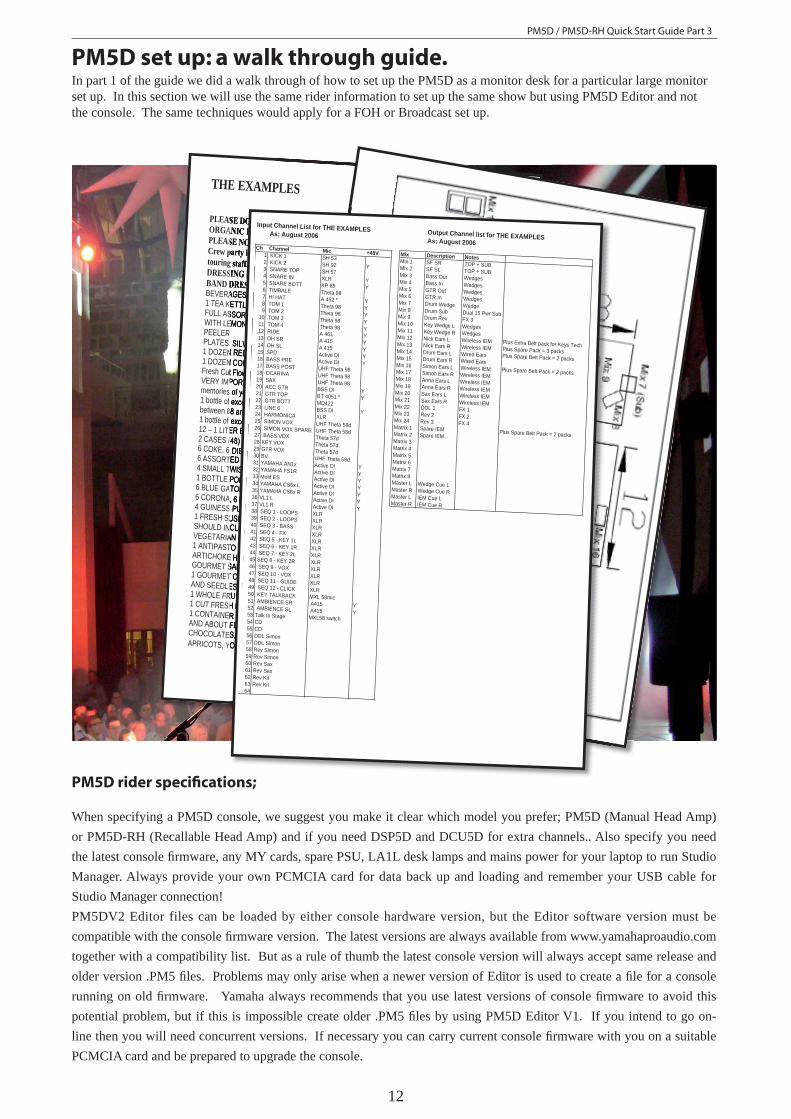
PM5D set up: a walk through guide. In part 1 of the guide we did a walk through of how to set up the PM5D as a monitor desk for a particular large monitor set up. In this section we will use the same rider information to set up the same show but using PM5D Editor and not the console. The same techniques would apply for a FOH or Broadcast set up.
PM5D rider specifi cations;
When specifying a PM5D console, we suggest you make it clear which model you prefer; PM5D (Manual Head Amp) or PM5D-RH (Recallable Head Amp) and if you need DSP5D and DCU5D for extra channels.. Also specify you need the latest console fi rmware, any MY cards, spare PSU, LA1L desk lamps and mains power for your laptop to run Studio Manager. Always provide your own PCMCIA card for data back up and loading and remember your USB cable for Studio Manager connection! PM5DV2 Editor files can be loaded by either console hardware version, but the Editor software version must be compatible with the console fi rmware version. The latest versions are always available from www.yamahaproaudio.com together with a compatibility list. But as a rule of thumb the latest console version will always accept same release and older version .PM5 fi les. Problems may only arise when a newer version of Editor is used to create a fi le for a console running on old fi rmware. Yamaha always recommends that you use latest versions of console fi rmware to avoid this potential problem, but if this is impossible create older .PM5 fi les by using PM5D Editor V1. If you intend to go on-line then you will need concurrent versions. If necessary you can carry current console fi rmware with you on a suitable PCMCIA card and be prepared to upgrade the console.
PM5D / PM5D-RH Quick Start Guide Part 3
13
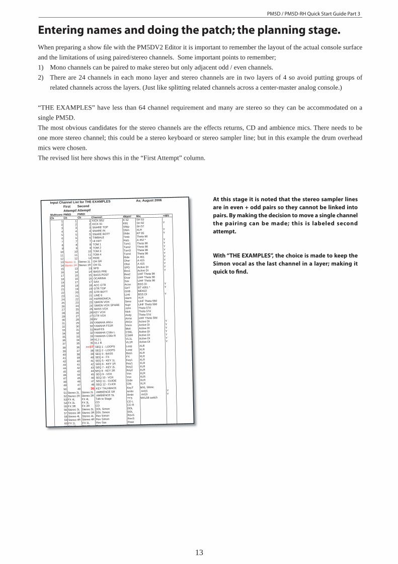
Entering names and doing the patch; the planning stage. When preparing a show fi le with the PM5DV2 Editor it is important to remember the layout of the actual console surface and the limitations of using paired/stereo channels. Some important points to remember;1) Mono channels can be paired to make stereo but only adjacent odd / even channels.2) There are 24 channels in each mono layer and stereo channels are in two layers of 4 so avoid putting groups of
related channels across the layers. (Just like splitting related channels across a center-master analog console.)
“THE EXAMPLES” have less than 64 channel requirement and many are stereo so they can be accommodated on a single PM5D.The most obvious candidates for the stereo channels are the effects returns, CD and ambience mics. There needs to be one more stereo channel; this could be a stereo keyboard or stereo sampler line; but in this example the drum overhead mics were chosen.The revised list here shows this in the “First Attempt” column.
Input Channel List for THE EXAMPLES As; August 2006
First Second Attempt! Attempt!
Multicore PM5D PM5DCh Ch Ch Channel 4Nam! Mic +48V
1 1 1 KICK B52 K 52 SH 53
2 2 2 KICK 91 K91 SH 92 Y
3 3 3 SNARE TOP SNtp SH 57
4 4 4 SNARE IN SNin XLR Y
5 5 5 SNARE BOTT SNbt KP 85 Y
6 6 6 TIMBALE Timb Theta 98
7 7 7 HI HAT Hats A 452 * Y
8 8 8 TOM 1 Tom1 Theta 98 Y
9 9 9 TOM 2 Tom2 Theta 98 Y
10 10 10 TOM 3 Tom3 Theta 98 Y
11 11 11 TOM 4 Tom4 Theta 98 Y
12 12 12 RIDE Ride A 461 Y
13 Stereo 1L Stereo 1L OH SR Ohsr A 415 Y
14 Stereo 1R Stereo 1R OH SL Ohsl A 415 Y
15 13 13 SPD SPD Active DI Y
16 14 14 BASS PRE Bss1 Active DI Y
17 15 15 BASS POST Bss2 UHF Theta 98
18 16 16 OCARINA Ocar UHF Theta 98
19 17 17 SAX Sax UHF Theta 98
20 18 18 ACC GTR Acou BSS DI Y
21 19 19 GTR TOP GtrT BT 4051 * Y
22 20 20 GTR BOTT GtrB MD422
23 21 21 LINE 6 Lin6 BSS DI Y
24 22 22 HARMONICA Harm XLR
25 23 23 SIMON VOX Simo UHF Theta 58d
26 24 24 SIMON VOX SPARE Sspr UHF Theta 58d
27 25 25 BASS VOX John Theta 57d
28 26 26 KEY VOX Nick Theta 57d
29 27 27 GTR VOX Andy Theta 57d
30 28 28 BV Anna UHF Theta 58d
31 29 29 YAMAHA AN1x AN1x Active DI Y
32 30 30 YAMAHA FS1R Voco Active DI Y
33 31 31 Motif ES Moti Active DI Y
34 32 32 YAMAHA CS6x L CS6L Active DI Y
35 33 33 YAMAHA CS6x R CS6R Active DI Y
36 34 34 VL1 L VL1L Active DI Y
37 35 35 VL1 R VL1R Active DI Y
38 36 >>37 SEQ 1 - LOOPS Loop XLR
39 37 38 SEQ 2 - LOOPS Loop XLR
40 38 39 SEQ 3 - BASS Bass XLR
41 39 40 SEQ 4 - FX FX XLR
42 40 41 SEQ 5 - KEY 1L Key1 XLR
43 41 42 SEQ 6 - KEY 1R Key1 XLR
44 42 43 SEQ 7 - KEY 2L Key2 XLR
45 43 44 SEQ 8 - KEY 2R Key2 XLR
46 44 45 SEQ 9 - VOX Vox XLR
47 45 46 SEQ 10 - VOX Vox XLR
48 46 47 SEQ 11 - GUIDE Gide XLR
49 47 48 SEQ 12 - CLICK Clik XLR
50 48 36 KEY TALKBACK KeyT MXL 58mic
51 Stereo 2L Stereo 2L AMBIENCE SR Ambi A415 Y
52 Stereo 2R Stereo 2R AMBIENCE SL Ambi A415 Y
53 FX 4L FX 4L Talk to Stage TTS MXL58 switch
54 FX 3L FX 3L CD CD L
55 FX 3R FX 3R CD CD R
56 Stereo 3L Stereo 3L DDL Simon DDL
57 Stereo 3R Stereo 3R DDL Simon DDL
58 Stereo 4L Stereo 4L Rev Simon RevS
59 Stereo 4R Stereo 4R Rev Simon RevS
60 FX 1L FX 1L Rev Sax Rsax
61 FX 1R FX 1R Rev Sax Rsax
At this stage it is noted that the stereo sampler lines
are in even + odd pairs so they cannot be linked into
pairs. By making the decision to move a single channel
the pairing can be made; this is labeled second
attempt.
With “THE EXAMPLES”, the choice is made to keep the
Simon vocal as the last channel in a layer; making it
quick to fi nd.
PM5D / PM5D-RH Quick Start Guide Part 3
14
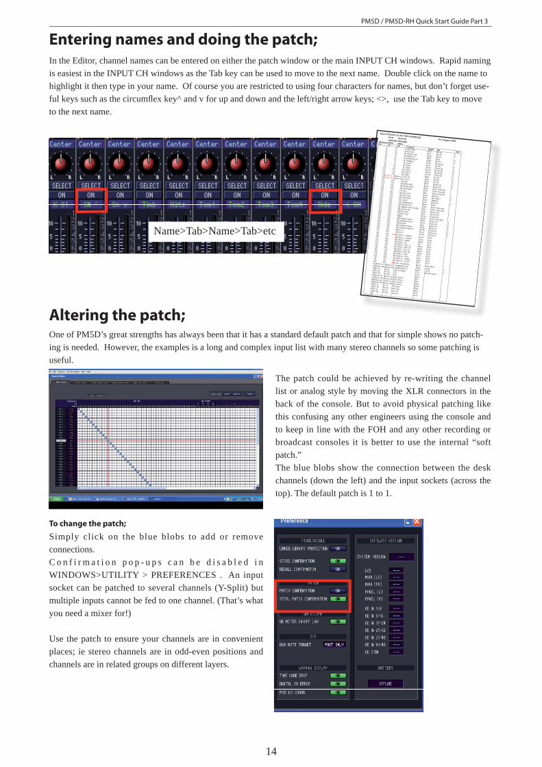
Entering names and doing the patch;In the Editor, channel names can be entered on either the patch window or the main INPUT CH windows. Rapid naming is easiest in the INPUT CH windows as the Tab key can be used to move to the next name. Double click on the name to highlight it then type in your name. Of course you are restricted to using four characters for names, but don’t forget use-ful keys such as the circumfl ex key^ and v for up and down and the left/right arrow keys; <>, use the Tab key to move to the next name.
Name>Tab>Name>Tab>etc
Input Channel List for THE EXAMPLES As; August 2006
First Second Attempt! Attempt!Multicore PM5D PM5DCh Ch Ch Channel4Nam! Mic
+48V
1 1 1 KICK B52 K 52 SH 53
2 2 2 KICK 91 K91 SH 92
Y
3 3 3 SNARE TOP SNtp SH 57
4 4 4 SNARE IN SNin XLRY
5 5 5 SNARE BOTT SNbt KP 85Y
6 6 6 TIMBALE Timb Theta 98
7 7 7 HI HAT Hats A 452 * Y
8 8 8 TOM 1 Tom1 Theta 98 Y
9 9 9 TOM 2 Tom2 Theta 98 Y
10 10 10 TOM 3 Tom3 Theta 98 Y
11 11 11 TOM 4 Tom4 Theta 98 Y
12 12 12 RIDE Ride A 461
Y
13 Stereo 1L Stereo 1L OH SR Ohsr A 415
Y
14 Stereo 1R Stereo 1R OH SL Ohsl A 415
Y
15 13 13 SPD SPD Active DI Y
16 14 14 BASS PRE Bss1 Active DI Y
17 15 15 BASS POST Bss2 UHF Theta 98
18 16 16 OCARINA Ocar UHF Theta 98
19 17 17 SAX Sax UHF Theta 98
20 18 18 ACC GTR Acou BSS DI Y
21 19 19 GTR TOP GtrT BT 4051 * Y
22 20 20 GTR BOTT GtrB MD422
23 21 21 LINE 6 Lin6 BSS DI Y
24 22 22 HARMONICA Harm XLR
25 23 23 SIMON VOX Simo UHF Theta 58d
26 24 24 SIMON VOX SPARE Sspr UHF Theta 58d
27 25 25 BASS VOX John Theta 57d
28 26 26 KEY VOX Nick Theta 57d
29 27 27 GTR VOX Andy Theta 57d
30 28 28 BV Anna UHF Theta 58d
31 29 29 YAMAHA AN1x AN1x Active DI Y
32 30 30 YAMAHA FS1R Voco Active DI Y
33 31 31 Motif ESMoti Active DI Y
34 32 32 YAMAHA CS6x L CS6L Active DI Y
35 33 33 YAMAHA CS6x R CS6R Active DI Y
36 34 34 VL1 LVL1L Active DI Y
37 35 35 VL1 RVL1R Active DI Y
38 36 >>37 SEQ 1 - LOOPS Loop XLR39 37 38 SEQ 2 - LOOPS Loop XLR
40 38 39 SEQ 3 - BASS Bass XLR
41 39 40 SEQ 4 - FX FX XLR
42 40 41 SEQ 5 - KEY 1L Key1 XLR
43 41 42 SEQ 6 - KEY 1R Key1 XLR
44 42 43 SEQ 7 - KEY 2L Key2 XLR
45 43 44 SEQ 8 - KEY 2R Key2 XLR
46 44 45 SEQ 9 - VOX Vox XLR
47 45 46 SEQ 10 - VOX Vox XLR
48 46 47 SEQ 11 - GUIDE Gide XLR
49 47 48 SEQ 12 - CLICK Clik XLR50 48 36 KEY TALKBACK KeyT MXL 58mic
51 Stereo 2L Stereo 2L AMBIENCE SR Ambi A415Y
52 Stereo 2R Stereo 2R AMBIENCE SL Ambi A415Y
53 FX 4L FX 4L Talk to Stage TTS MXL58 switch
54 FX 3L FX 3L CDCD L
55 FX 3R FX 3R CDCD R
56 Stereo 3L Stereo 3L DDL SimonDDL
57 Stereo 3R Stereo 3R DDL SimonDDL
58 Stereo 4L Stereo 4L Rev SimonRevS
59 Stereo 4R Stereo 4R Rev SimonRevS
60 FX 1L FX 1L Rev SaxRsax
61 FX 1R FX 1R Rev SaxRsax
62 FX 2L FX 2L Rev KitR sn
63 FX 2R FX 2R Rev KitR sn
64
Altering the patch;One of PM5D’s great strengths has always been that it has a standard default patch and that for simple shows no patch-ing is needed. However, the examples is a long and complex input list with many stereo channels so some patching is useful.
The patch could be achieved by re-writing the channel list or analog style by moving the XLR connectors in the back of the console. But to avoid physical patching like this confusing any other engineers using the console and to keep in line with the FOH and any other recording or broadcast consoles it is better to use the internal “soft patch.”The blue blobs show the connection between the desk channels (down the left) and the input sockets (across the top). The default patch is 1 to 1.
To change the patch;
Simply click on the blue blobs to add or remove connections.C o n f i r m a t i o n p o p - u p s c a n b e d i s a b l e d i n WINDOWS>UTILITY > PREFERENCES . An input socket can be patched to several channels (Y-Split) but multiple inputs cannot be fed to one channel. (That’s what you need a mixer for!)
Use the patch to ensure your channels are in convenient places; ie stereo channels are in odd-even positions and channels are in related groups on different layers.
PM5D / PM5D-RH Quick Start Guide Part 3
15
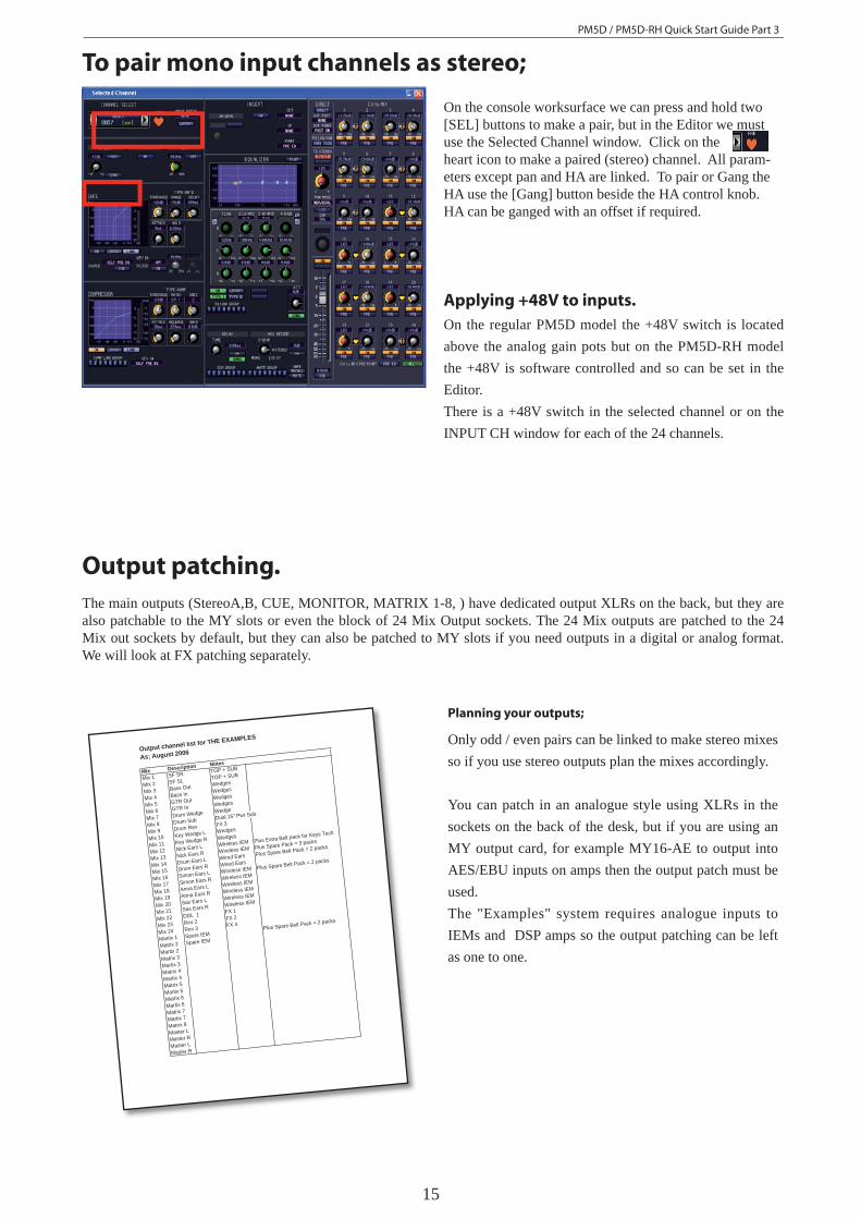
To pair mono input channels as stereo;
On the console worksurface we can press and hold two [SEL] buttons to make a pair, but in the Editor we must use the Selected Channel window. Click on the heart icon to make a paired (stereo) channel. All param-eters except pan and HA are linked. To pair or Gang the HA use the [Gang] button beside the HA control knob. HA can be ganged with an offset if required.
Applying +48V to inputs.On the regular PM5D model the +48V switch is located above the analog gain pots but on the PM5D-RH model the +48V is software controlled and so can be set in the Editor.There is a +48V switch in the selected channel or on the INPUT CH window for each of the 24 channels.
Output patching.The main outputs (StereoA,B, CUE, MONITOR, MATRIX 1-8, ) have dedicated output XLRs on the back, but they are also patchable to the MY slots or even the block of 24 Mix Output sockets. The 24 Mix outputs are patched to the 24 Mix out sockets by default, but they can also be patched to MY slots if you need outputs in a digital or analog format. We will look at FX patching separately.
Output channel list for THE EXAMPLES
As; August 2006
Mix Description Notes
Mix 1 SF SR TOP + SUB
Mix 2 SF SL TOP + SUB
Mix 3 Bass Out Wedges
Mix 4 Bass In Wedges
Mix 5 GTR Out Wedges
Mix 6 GTR In Wedges
Mix 7 Drum Wedge Wedge
Mix 8 Drum Sub Dual 15" Pwr Sub
Mix 9 Drum Rev FX 3
Mix 10 Key Wedge L Wedges
Mix 11 Key Wedge R Wedges
Mix 12 Nick Ears L Wireless IEM Plus Extra Belt pack for Keys Tech
Mix 13 Nick Ears R Wireless IEM Plus Spare Pack = 3 packs
Mix 14 Drum Ears L Wired Ears Plus Spare Belt Pack = 2 packs
Mix 15 Drum Ears R Wired Ears
Mix 16 Simon Ears L Wireless IEM Plus Spare Belt Pack = 2 packs
Mix 17 Simon Ears R Wireless IEM
Mix 18 Anna Ears L Wireless IEM
Mix 19 Anna Ears R Wireless IEM
Y Mix 20 Sax Ears L Wireless IEM
Y Mix 21 Sax Ears R Wireless IEM
Mix 22 DDL 1 FX 1
Y Mix 23 Rev 2 FX 2
Mix 24 Rev 3 FX 4
Martix 1 Spare IEMPlus Spare Belt Pack = 2 packs
Matrix 2 Spare IEM
Martix 2Matrix 3Martix 3Matrix 4
Y Martix 4
Y Matrix 5
Y Martix 5
Y Matrix 6
Y Martix 6
Y Matrix 7
Y Martix 7Matrix 8Master LMaster RMaster LMaster R
Planning your outputs;
Only odd / even pairs can be linked to make stereo mixes so if you use stereo outputs plan the mixes accordingly.
You can patch in an analogue style using XLRs in the sockets on the back of the desk, but if you are using an MY output card, for example MY16-AE to output into AES/EBU inputs on amps then the output patch must be used.The "Examples" system requires analogue inputs to IEMs and DSP amps so the output patching can be left as one to one.
PM5D / PM5D-RH Quick Start Guide Part 3
16
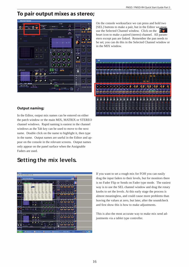
To pair output mixes as stereo;
On the console worksurface we can press and hold two [SEL] buttons to make a pair, but in the Editor we must use the Selected Channel window. Click on the heart icon to make a paired (stereo) channel. All param-eters except pan are linked. Remember the pan needs to be set; you can do this in the Selected Channel window or in the MIX window.
Output naming;
In the Editor, output mix names can be entered on either the patch window or the main MIX, MATRIX or STEREO channel windows. Rapid naming is easiest in the channel windows as the Tab key can be used to move to the next name. Double click on the name to highlight it, then type in the name. Output names are useful in the Editor and ap-pear on the console in the relevant screens. Output names only appear on the panel surface when the Assignable Faders are used.
If you want to set a rough mix for FOH you can easily drag the input faders to their levels, but for monitors there is no Fader Flip or Sends on Fader type mode. The easiest way is to use the SEL channel window and drag the rotary knobs to set the levels. At this early stage the process is almost meaningless, and could cause more problems than leaving the values at zero, but later, after the soundcheck and fi rst show this is how to make adjustments.
This is also the most accurate way to make mix send ad-justments via a tablet type controller.
Setting the mix levels.
PM5D / PM5D-RH Quick Start Guide Part 3
17
Now is a good time to store your scene and save your setup work.
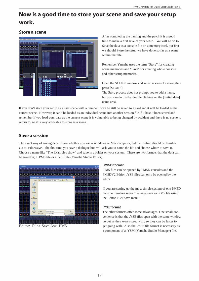
After completing the naming and the patch it is a good time to make a fi rst save of your setup. We will go on to Save the data as a console fi le on a memory card, but fi rst we should Store the setup we have done so far as a scene within that fi le.
Remember Yamaha uses the term “Store” for creating scene memories and “Save” for creating whole console and other setup memories.
Open the SCENE window and select a scene location, then press [STORE]. The Store process does not prompt you to add a name, but you can do this by double clicking on the [Initial data] name area.
.PM5D format
.PM5 fi les can be opened by PM5D consoles and the PM5DV2 Edtior, .YSE fi les can only be opened by the editor.
If you are setting up the most simple system of one PM5D console it makes sense to always save as .PM5 fi le using the Editor File>Save menu.
.YSE formatThe other formats offer some advantages. One small con-venience is that the .YSE fi les open with the same window layout as they were stored with, so they can be faster to get going with. Also the .YSE fi le format is necessary as a component of a .YSM (Yamaha Studio Manager) fi le.
Editor: File> Save As> .PM5
The exact way of saving depends on whether you use a Windows or Mac computer, but the routine should be familiar. Go to File>Save. The fi rst time you save a dialogue box will ask you to name the fi le and choose where to save it. Choose a name like “The Examples show” and save in a folder on your system. There are two formats that the data can be saved in; a .PM5 fi le or a .YSE fi le (Yamaha Studio Editor).
Store a scene
Save a session
If you don’t store your setup as a user scene with a number it can be still be saved to a card and it will be loaded as the current scene. However, it can’t be loaded as an individual scene into another session fi le if it hasn’t been stored and remember if you load your data as the current scene it is vulnerable to being changed by accident and there is no scene to return to, so it is very advisable to store as a scene.
PM5D / PM5D-RH Quick Start Guide Part 3
18
Manager; File >SaveAs>. YSM
.YSM Format If you have a PM5D and DSP5D or other multiple unit system it may make managing data easier to save as a .YSM fi le as this will save both “consoles” in one memory. However, remember that this data must be translated into two .PM5 fi les if it is to be card loaded. If a .YSM fi le is opened in Studio Manager connected on-line to the DSP5D and PM5D it can be synchronised to the consoles simultaneously and more rapidly than card loading. .YSM fi les also remember the window layout so they are convenient for editing. A .YSM fi le can also be opened through links with a Steinberg Cubase session. These are the advantages of .YSM fi les.
To save as a .YSM use the File>Save menus from the Stu-dio Manager window containing the Editor icons.
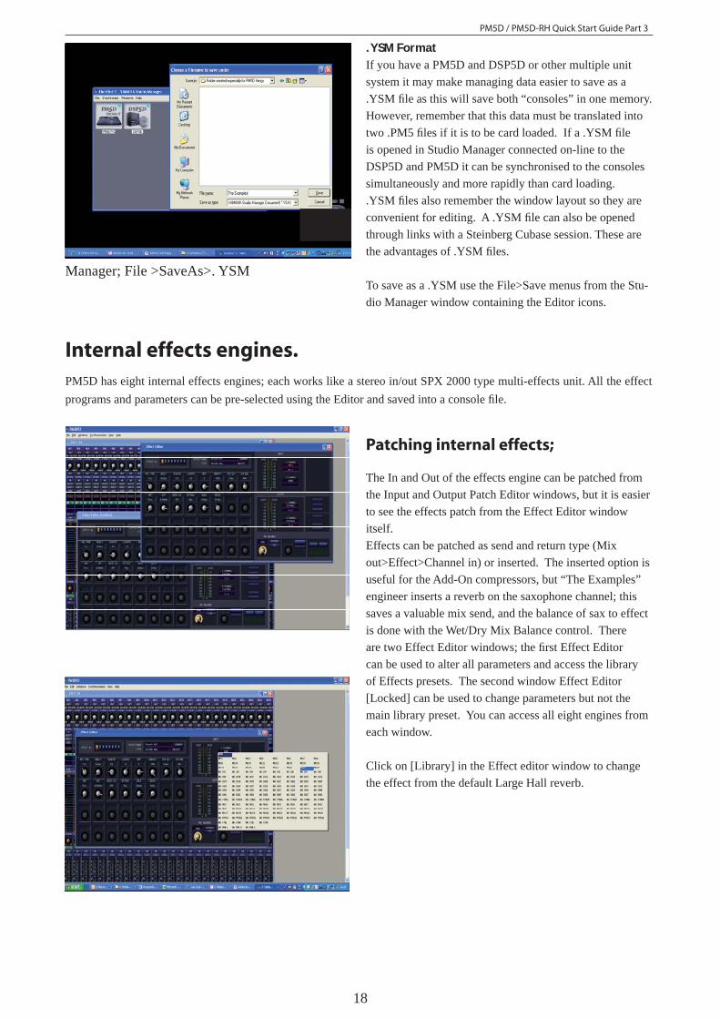
Internal effects engines.PM5D has eight internal effects engines; each works like a stereo in/out SPX 2000 type multi-effects unit. All the effect programs and parameters can be pre-selected using the Editor and saved into a console fi le.
Patching internal effects;
The In and Out of the effects engine can be patched from the Input and Output Patch Editor windows, but it is easier to see the effects patch from the Effect Editor window itself.Effects can be patched as send and return type (Mix out>Effect>Channel in) or inserted. The inserted option is useful for the Add-On compressors, but “The Examples” engineer inserts a reverb on the saxophone channel; this saves a valuable mix send, and the balance of sax to effect is done with the Wet/Dry Mix Balance control. There are two Effect Editor windows; the fi rst Effect Editor can be used to alter all parameters and access the library of Effects presets. The second window Effect Editor [Locked] can be used to change parameters but not the main library preset. You can access all eight engines from each window.
Click on [Library] in the Effect editor window to change the effect from the default Large Hall reverb.
PM5D / PM5D-RH Quick Start Guide Part 3
19
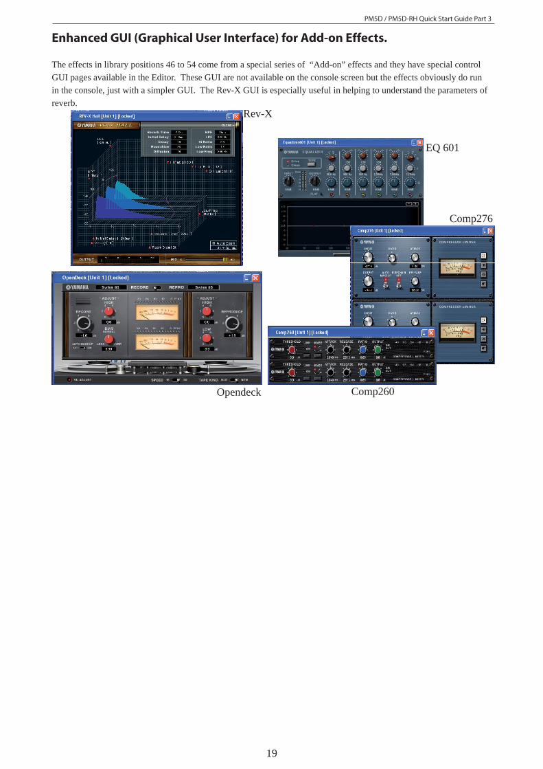
Enhanced GUI (Graphical User Interface) for Add-on Effects.
The effects in library positions 46 to 54 come from a special series of “Add-on” effects and they have special control GUI pages available in the Editor. These GUI are not available on the console screen but the effects obviously do run in the console, just with a simpler GUI. The Rev-X GUI is especially useful in helping to understand the parameters of reverb.
Rev-X
EQ 601
Comp276
Comp260Opendeck
PM5D / PM5D-RH Quick Start Guide Part 3
20
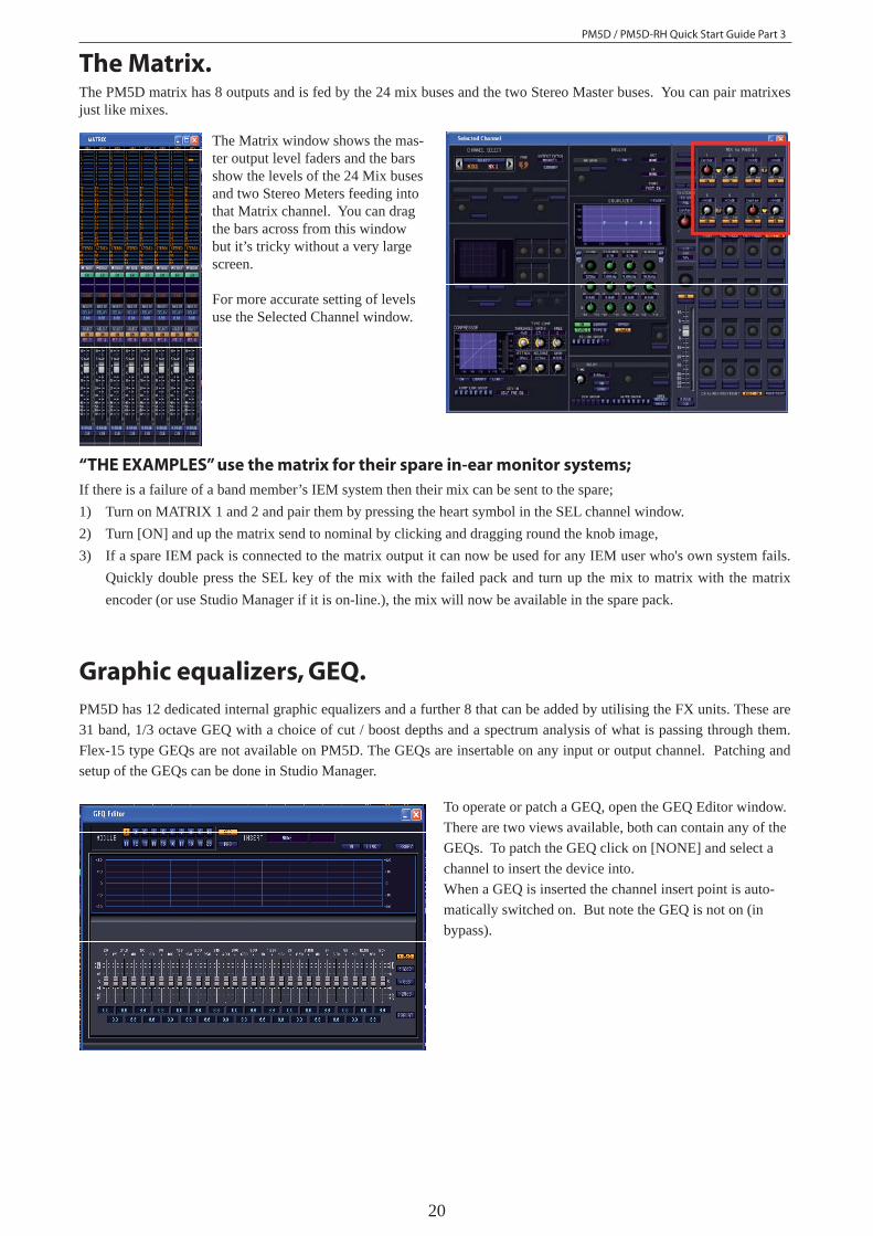
The Matrix.The PM5D matrix has 8 outputs and is fed by the 24 mix buses and the two Stereo Master buses. You can pair matrixes just like mixes.
The Matrix window shows the mas-ter output level faders and the bars show the levels of the 24 Mix buses and two Stereo Meters feeding into that Matrix channel. You can drag the bars across from this window but it’s tricky without a very large screen.
For more accurate setting of levels use the Selected Channel window.
“THE EXAMPLES” use the matrix for their spare in-ear monitor systems;If there is a failure of a band member’s IEM system then their mix can be sent to the spare;1) Turn on MATRIX 1 and 2 and pair them by pressing the heart symbol in the SEL channel window.2) Turn [ON] and up the matrix send to nominal by clicking and dragging round the knob image, 3) If a spare IEM pack is connected to the matrix output it can now be used for any IEM user who's own system fails.
Quickly double press the SEL key of the mix with the failed pack and turn up the mix to matrix with the matrix encoder (or use Studio Manager if it is on-line.), the mix will now be available in the spare pack.
Graphic equalizers, GEQ.PM5D has 12 dedicated internal graphic equalizers and a further 8 that can be added by utilising the FX units. These are 31 band, 1/3 octave GEQ with a choice of cut / boost depths and a spectrum analysis of what is passing through them. Flex-15 type GEQs are not available on PM5D. The GEQs are insertable on any input or output channel. Patching and setup of the GEQs can be done in Studio Manager.
To operate or patch a GEQ, open the GEQ Editor window. There are two views available, both can contain any of the GEQs. To patch the GEQ click on [NONE] and select a channel to insert the device into.When a GEQ is inserted the channel insert point is auto-matically switched on. But note the GEQ is not on (in bypass).
PM5D / PM5D-RH Quick Start Guide Part 3
21
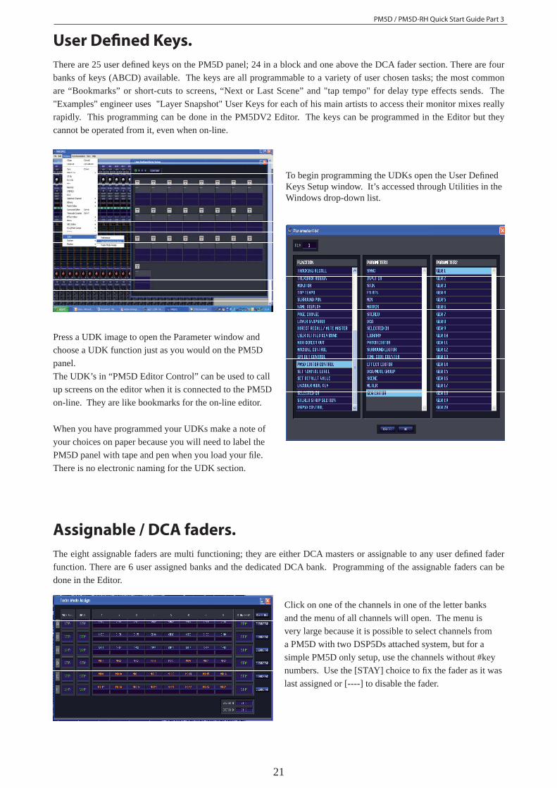
User Defi ned Keys.There are 25 user defi ned keys on the PM5D panel; 24 in a block and one above the DCA fader section. There are four banks of keys (ABCD) available. The keys are all programmable to a variety of user chosen tasks; the most common are “Bookmarks” or short-cuts to screens, “Next or Last Scene” and "tap tempo" for delay type effects sends. The "Examples" engineer uses "Layer Snapshot" User Keys for each of his main artists to access their monitor mixes really rapidly. This programming can be done in the PM5DV2 Editor. The keys can be programmed in the Editor but they cannot be operated from it, even when on-line.
To begin programming the UDKs open the User Defi ned Keys Setup window. It’s accessed through Utilities in the Windows drop-down list.
Press a UDK image to open the Parameter window and choose a UDK function just as you would on the PM5D panel.The UDK’s in “PM5D Editor Control” can be used to call up screens on the editor when it is connected to the PM5D on-line. They are like bookmarks for the on-line editor.
When you have programmed your UDKs make a note of your choices on paper because you will need to label the PM5D panel with tape and pen when you load your fi le. There is no electronic naming for the UDK section.
Assignable / DCA faders.The eight assignable faders are multi functioning; they are either DCA masters or assignable to any user defi ned fader function. There are 6 user assigned banks and the dedicated DCA bank. Programming of the assignable faders can be done in the Editor.
Click on one of the channels in one of the letter banks and the menu of all channels will open. The menu is very large because it is possible to select channels from a PM5D with two DSP5Ds attached system, but for a simple PM5D only setup, use the channels without #key numbers. Use the [STAY] choice to fi x the fader as it was last assigned or [----] to disable the fader.
PM5D / PM5D-RH Quick Start Guide Part 3
22
Cue level on a fader for monitor engineers;The monitor volume of PM5D is controlled by a rotary pot, but commonly stage monitor engineers want fader control. Prior to the launch of Version 2 software in Summer 2007 this was only possible with some indirect routing methods, these are explained in the earlier guides. A direct method was implemented with the new V2 fi rmware. This is found in the Fader Mode Assign window using the two assign boxes at the bottom right of the screen. The "The Examples" engineer uses Stereo A and Stereo B faders to control Cue and Monitor buses. Select A to provide Cue output to a local IEM pack and select B to feed the monitor bus to a local wedge. The Monitor bus can be mixed into mono for this purpose using the [MONO] key on the PM5D panel, but this cannot be programmed in the Editor, similarly use the panel rotary control to set the Monitor and Cue output volumes to maximum (for nominal output) and de-select the pink [Stereo A feeds monitor bus] key so that the monitor bus works just as a copy of the cue bus.Advanced monitor engineer users can still use the Monitor Assign keys to achieve dual monitor bus possibilities where they can hear different mixes in their wedge and IEM pack at the same time.
Store and Save again.Now is a good time to store to a scene and save to your computer's memory again. Refer to page 14 of this guide for more details.Remember when you save the fi le, select .PM5 as the fi le type. Now this memory can be saved to a PC card and loaded directly into the console.
If you’ve followed the work through you should find all
the following are ready to be loaded into the console;
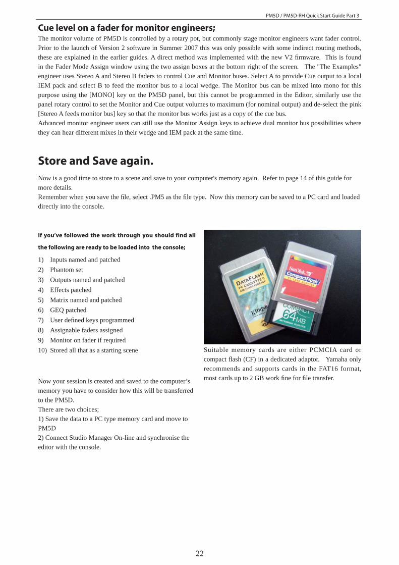
1) Inputs named and patched2) Phantom set3) Outputs named and patched4) Effects patched5) Matrix named and patched6) GEQ patched7) User defi ned keys programmed8) Assignable faders assigned9) Monitor on fader if required10) Stored all that as a starting scene Suitable memory cards are either PCMCIA card or
compact fl ash (CF) in a dedicated adaptor. Yamaha only recommends and supports cards in the FAT16 format, most cards up to 2 GB work fi ne for fi le transfer. Now your session is created and saved to the computer’s
memory you have to consider how this will be transferred to the PM5D.There are two choices;1) Save the data to a PC type memory card and move to PM5D2) Connect Studio Manager On-line and synchronise the editor with the console.
PM5D / PM5D-RH Quick Start Guide Part 3
23
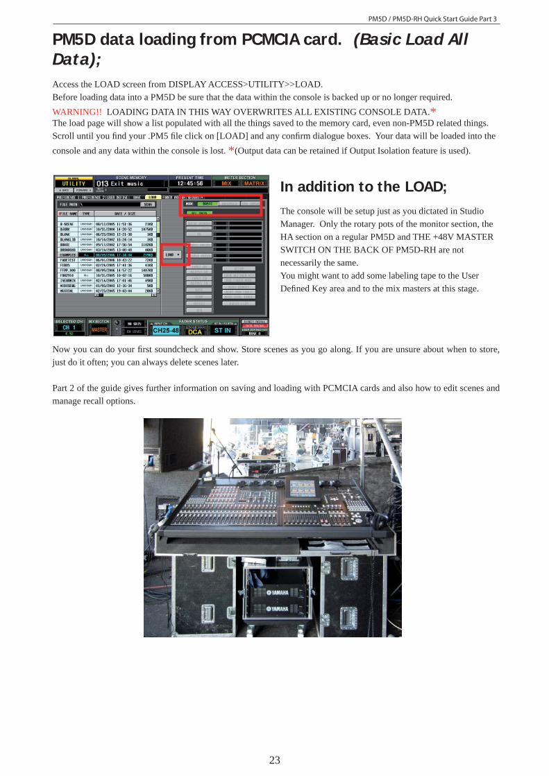
PM5D data loading from PCMCIA card. (Basic Load All Data);Access the LOAD screen from DISPLAY ACCESS>UTILITY>>LOAD.Before loading data into a PM5D be sure that the data within the console is backed up or no longer required. WARNING!! LOADING DATA IN THIS WAY OVERWRITES ALL EXISTING CONSOLE DATA.*The load page will show a list populated with all the things saved to the memory card, even non-PM5D related things. Scroll until you fi nd your .PM5 fi le click on [LOAD] and any confi rm dialogue boxes. Your data will be loaded into the console and any data within the console is lost. *(Output data can be retained if Output Isolation feature is used).
In addition to the LOAD;The console will be setup just as you dictated in Studio Manager. Only the rotary pots of the monitor section, the HA section on a regular PM5D and THE +48V MASTER SWITCH ON THE BACK OF PM5D-RH are not necessarily the same.You might want to add some labeling tape to the User Defi ned Key area and to the mix masters at this stage.
Now you can do your fi rst soundcheck and show. Store scenes as you go along. If you are unsure about when to store, just do it often; you can always delete scenes later.
Part 2 of the guide gives further information on saving and loading with PCMCIA cards and also how to edit scenes and manage recall options.
PM5D / PM5D-RH Quick Start Guide Part 3
24
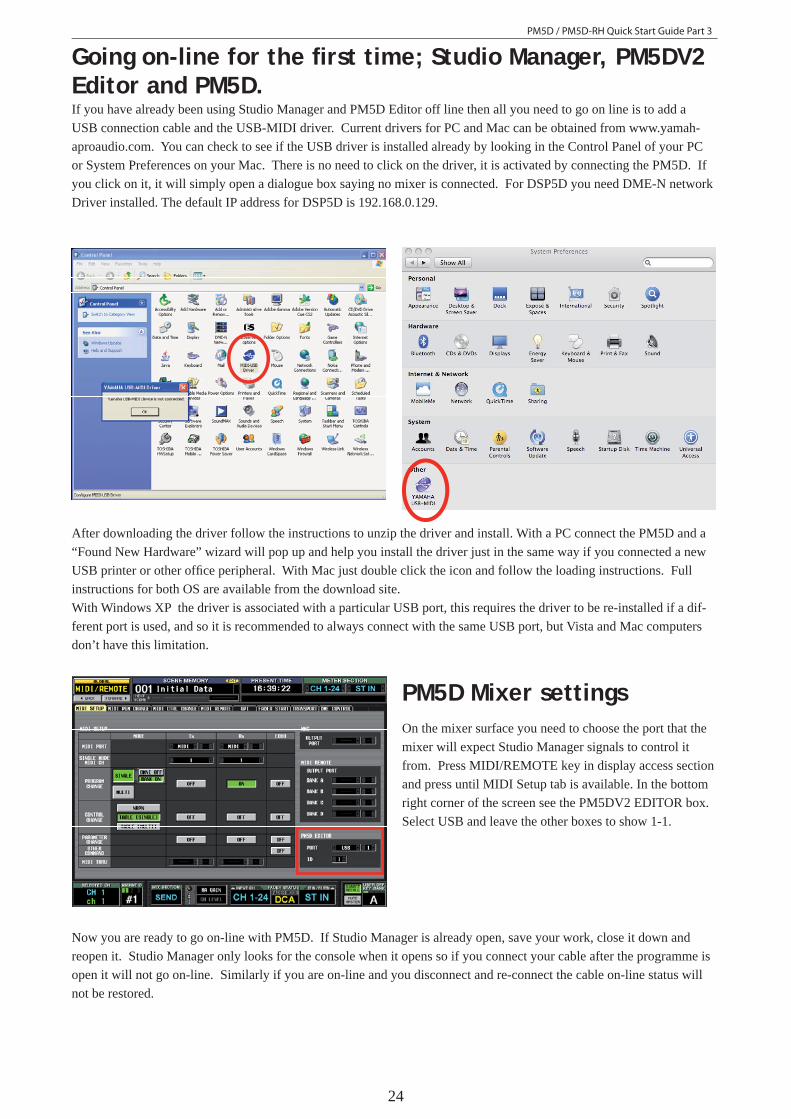
Going on-line for the fi rst time; Studio Manager, PM5DV2 Editor and PM5D.If you have already been using Studio Manager and PM5D Editor off line then all you need to go on line is to add a USB connection cable and the USB-MIDI driver. Current drivers for PC and Mac can be obtained from www.yamah-aproaudio.com. You can check to see if the USB driver is installed already by looking in the Control Panel of your PC or System Preferences on your Mac. There is no need to click on the driver, it is activated by connecting the PM5D. If you click on it, it will simply open a dialogue box saying no mixer is connected. For DSP5D you need DME-N network Driver installed. The default IP address for DSP5D is 192.168.0.129.
After downloading the driver follow the instructions to unzip the driver and install. With a PC connect the PM5D and a “Found New Hardware” wizard will pop up and help you install the driver just in the same way if you connected a new USB printer or other offi ce peripheral. With Mac just double click the icon and follow the loading instructions. Full instructions for both OS are available from the download site.With Windows XP the driver is associated with a particular USB port, this requires the driver to be re-installed if a dif-ferent port is used, and so it is recommended to always connect with the same USB port, but Vista and Mac computers don’t have this limitation.
PM5D Mixer settingsOn the mixer surface you need to choose the port that the mixer will expect Studio Manager signals to control it from. Press MIDI/REMOTE key in display access section and press until MIDI Setup tab is available. In the bottom right corner of the screen see the PM5DV2 EDITOR box. Select USB and leave the other boxes to show 1-1.
Now you are ready to go on-line with PM5D. If Studio Manager is already open, save your work, close it down and reopen it. Studio Manager only looks for the console when it opens so if you connect your cable after the programme is open it will not go on-line. Similarly if you are on-line and you disconnect and re-connect the cable on-line status will not be restored.
PM5D / PM5D-RH Quick Start Guide Part 3
25
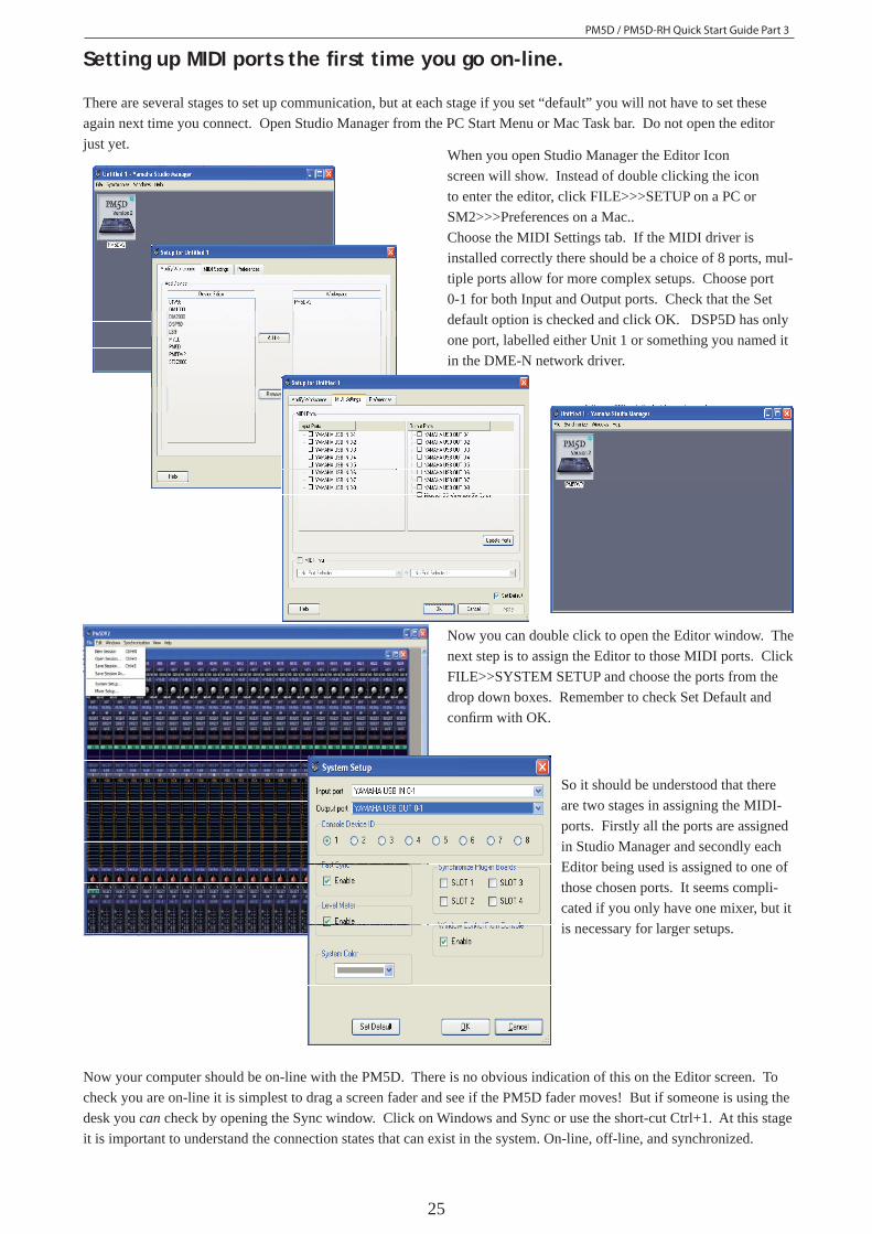
Setting up MIDI ports the fi rst time you go on-line.
There are several stages to set up communication, but at each stage if you set “default” you will not have to set these again next time you connect. Open Studio Manager from the PC Start Menu or Mac Task bar. Do not open the editor just yet.
When you open Studio Manager the Editor Icon screen will show. Instead of double clicking the icon to enter the editor, click FILE>>>SETUP on a PC or SM2>>>Preferences on a Mac..Choose the MIDI Settings tab. If the MIDI driver is installed correctly there should be a choice of 8 ports, mul-tiple ports allow for more complex setups. Choose port 0-1 for both Input and Output ports. Check that the Set default option is checked and click OK. DSP5D has only one port, labelled either Unit 1 or something you named it in the DME-N network driver.
Now you can double click to open the Editor window. The next step is to assign the Editor to those MIDI ports. Click FILE>>SYSTEM SETUP and choose the ports from the drop down boxes. Remember to check Set Default and confi rm with OK.
Now your computer should be on-line with the PM5D. There is no obvious indication of this on the Editor screen. To check you are on-line it is simplest to drag a screen fader and see if the PM5D fader moves! But if someone is using the desk you can check by opening the Sync window. Click on Windows and Sync or use the short-cut Ctrl+1. At this stage it is important to understand the connection states that can exist in the system. On-line, off-line, and synchronized.
So it should be understood that there are two stages in assigning the MIDI-ports. Firstly all the ports are assigned in Studio Manager and secondly each Editor being used is assigned to one of those chosen ports. It seems compli-cated if you only have one mixer, but it is necessary for larger setups.
PM5D / PM5D-RH Quick Start Guide Part 3
26
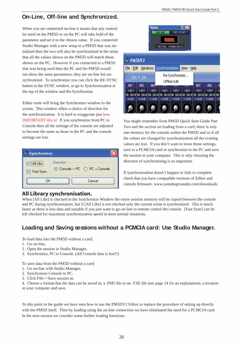
When you are connected on-line it means that any control-ler used on the PM5D or on the PC will take hold of the parameter and set it to the chosen value. If you connected Studio Manager with a new setup to a PM5D that was ini-tialized then the two will also be synchronized in the sense that all the values shown on the PM5D will match those shown on the PC. However if you connected to a PM5D that was being used then the PC and the PM5D would not show the same parameters; they are on-line but un-sychronized. To synchronize you can click the RE-SYNC button in the SYNC window, or go to Synchronization at the top of the window and Re-Synchronize.
Either route will bring the Synchronize window to the screen. This window offers a choice of direction for the synchronization. It is hard to exaggerate just how IMPORTANT this is! If you synchronize from PC to Console then all the settings of the console are adjusted to become the same as those in the PC and the console settings are lost.
On-Line, Off-line and Synchronized.
You might remember from PM5D Quick Start Guide Part Two and the section on loading from a card; there is only one memory for the console within the PM5D and so if all the values are changed by synchronization all the existing values are lost. If you don’t want to loose those settings, save to a PCMCIA card or synchronize to the PC and save the session in your computer. This is why choosing the direction of synchronising is so important.
If synchronisation doesn’t happen or fails to complete check that you have compatible versions of Editor and console fi rmware. www.yamahaproaudio.com/downloads
Loading and Saving sessions without a PCMCIA card: Use Studio Manager.
To load data into the PM5D without a card; 1. Go on-line, 2. Open the session in Studio Manager, 3. Synchronize, PC to Console. (All Console data is lost!!)
To save data from the PM5D without a card;1. Go on-line with Studio Manager,2. Synchronize Console to PC. 3. Click File>>Save session as.4. Choose a format that the data can be saved in; a .PM5 fi le or an .YSE fi le (see page 14 for an explanation), a location in your computer and save.
To this point in the guide we have seen how to use the PM5DV2 Editor to replace the procedure of setting up directly with the PM5D itself. Then by loading using the on-line connection we have eliminated the need for a PCMCIA card. In the next session we consider some further loading functions.
All Library synchronisation.When [All Libs] is checked in the Synchronize Window the entire session memory will be copied between the console and PC during synchronization, but if [All Libs] is not checked only the current scene is synchronized. This is much faster as there is less data and suitable if you just want to go-on line to remote control the console. [Fast Sync] can be left checked for maximum synchronization speed in most normal situations.

PM5D / PM5D-RH Quick Start Guide Part 3
27
Advanced Load and Save using On-line connection.In the last section we saw that we can mimic the PC card loading action by synchronising “PC to Console”. In this section we consider loading data without synchronisation. This is a very signifi cant procedure as it allows scenes and setup to be loaded without disturbing the console’s current use. To be clear, we can load scenes and other data into the console whilst somebody else is mixing a show on it live.
What makes up a Console or Session File? We saw in Part 2 of the guide that the session is made up of a whole group of libraries. Using PM5DV2 Editor we can extract these libraies from a session and load them into the console individually. To make the system even more fl exible we can take individual memories out of the libraries (like a single scene) and load it into the console, and just in case that position in the console memory is being used, we can change the scene number as we load it. Here is a reminder of the libraries;
The blue boxes include all the items stored when the console [Store] key is used to store a scene. They can be linked for store and recall. Scenes can be saved individually.
The green boxes contain a mix of read only and user stored settings, the user contents are stored when they are entered.
The yellow box contents are stored as they are created and there is only one version stored per Console or Session fi le.
The red box is the whole session made up of the libraries.
Scenes library (500 user memories)
HA gain library (199 user memories)
Input patch library (99 user memories)
Output patch library (99 user memories)
Console or Session fi leGraphic EQ library
Effects library
Comp library
Gate settings
Output Channel library
Input EQ library
Input Channel library
Output EQ library
MIDI confi gurations General preferences and setup settings (inc Recall Safes)
User defi ned key settings (4 banks)
A memory of any Event list.
DCA fader mode.
6 settings AtoF
Current Scene
PM5D / PM5D-RH Quick Start Guide Part 3
28
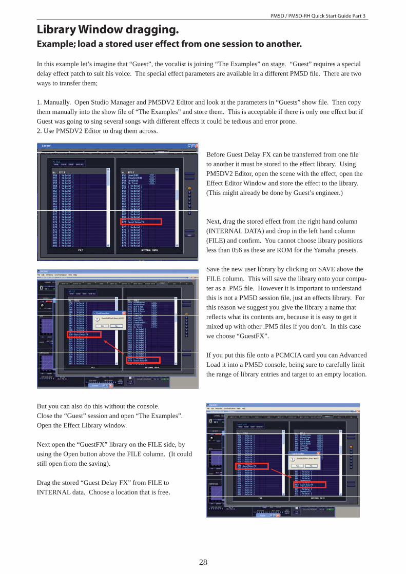
Example; load a stored user effect from one session to another.
In this example let’s imagine that “Guest”, the vocalist is joining “The Examples” on stage. “Guest” requires a special delay effect patch to suit his voice. The special effect parameters are available in a different PM5D fi le. There are two ways to transfer them;
1. Manually. Open Studio Manager and PM5DV2 Editor and look at the parameters in “Guests” show fi le. Then copy them manually into the show fi le of “The Examples” and store them. This is acceptable if there is only one effect but if Guest was going to sing several songs with different effects it could be tedious and error prone.2. Use PM5DV2 Editor to drag them across.
Before Guest Delay FX can be transferred from one fi le to another it must be stored to the effect library. Using PM5DV2 Editor, open the scene with the effect, open the Effect Editor Window and store the effect to the library. (This might already be done by Guest’s engineer.)
Next, drag the stored effect from the right hand column (INTERNAL DATA) and drop in the left hand column (FILE) and confi rm. You cannot choose library positions less than 056 as these are ROM for the Yamaha presets.
Save the new user library by clicking on SAVE above the FILE column. This will save the library onto your compu-ter as a .PM5 fi le. However it is important to understand this is not a PM5D session fi le, just an effects library. For this reason we suggest you give the library a name that refl ects what its contents are, because it is easy to get it mixed up with other .PM5 fi les if you don’t. In this case we choose “GuestFX”.
If you put this fi le onto a PCMCIA card you can Advanced Load it into a PM5D console, being sure to carefully limit the range of library entries and target to an empty location.
But you can also do this without the console. Close the “Guest” session and open “The Examples”. Open the Effect Library window.
Next open the “GuestFX” library on the FILE side, by using the Open button above the FILE column. (It could still open from the saving).
Drag the stored “Guest Delay FX” from FILE to INTERNAL data. Choose a location that is free.
Library Window dragging.

PM5D / PM5D-RH Quick Start Guide Part 3
29
More Library Window dragging. This technique of dragging items across the library win-dow will work for other library items too.
Notable exceptions are the User Defi ned Key libraries and the SETUP library. It is not possible to, say create a Bank B, and drag it into the console or create some preferences and drag them into the console. These can only enter the console by synchronisation or by loading from a prepared PCMCIA card.
In addition to the library items, scenes can be dragged in this way, but we should pay special attention to scenes be-cause they are complicated by the linking of Input Patch, Output Patch and HA libraries.
Memory Structure of Scenes.Background The PM5D scene memory contains the huge range of parameters such as EQ, dynamics, levels, FX presets and parameters, GEQ etc. that make up the mix. But it is important to understand that the patching and particularly the naming of channels is not stored within the scene memory. HA values and +48V settings are also stored separately in an HA library. Input patch and name is in the Input Patch Library and Output patch and name is in the Output Patch Library.So for the console to make a scene recall properly it must not only have the stored scene data, but also the HA Library (RH only), Input Patch Library and Output Patch Library. The engineer has only one recall button so obviously there must be internal links. When a scene is recalled the appropriate libraries are recalled at the same time via these links.
In normal operation of the console this is done automatically, but when Advanced loading scenes and libraries it is some-times necessary to reset these links. The linked library number is stored as part of the scene when the scene is created.
An alternative to dragging from INTERNAL DATA to FILE and saving as a library fi le, is to open two instances of the PM5DV2 Editor. The advantage of this is that two sessions can be opened at the same time and data dragged across from one to the other without going through the middle stage of saving. This is particularly effective when one editor is on-line with the console and one is off-line. You can drag from an off-line session and drop directly into the console! Take great care not to have two editors on-line with the console at the same time and name the editors to avoid confusion!
Using two PM5DV2 Editors.
PM5D / PM5D-RH Quick Start Guide Part 3
30
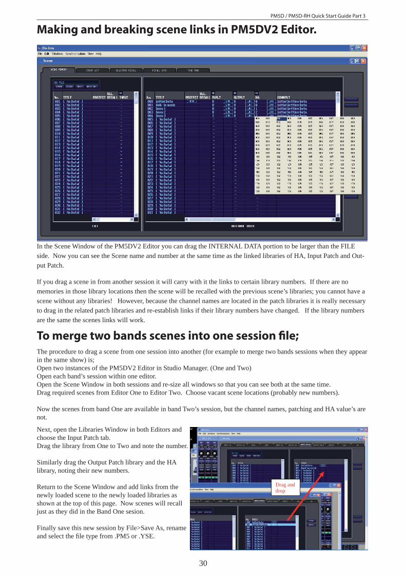
Making and breaking scene links in PM5DV2 Editor.
In the Scene Window of the PM5DV2 Editor you can drag the INTERNAL DATA portion to be larger than the FILE side. Now you can see the Scene name and number at the same time as the linked libraries of HA, Input Patch and Out-put Patch.
If you drag a scene in from another session it will carry with it the links to certain library numbers. If there are no memories in those library locations then the scene will be recalled with the previous scene’s libraries; you cannot have a scene without any libraries! However, because the channel names are located in the patch libraries it is really necessary to drag in the related patch libraries and re-establish links if their library numbers have changed. If the library numbers are the same the scenes links will work.
To merge two bands scenes into one session fi le;The procedure to drag a scene from one session into another (for example to merge two bands sessions when they appear in the same show) is;Open two instances of the PM5DV2 Editor in Studio Manager. (One and Two)Open each band’s session within one editor.Open the Scene Window in both sessions and re-size all windows so that you can see both at the same time.Drag required scenes from Editor One to Editor Two. Choose vacant scene locations (probably new numbers).
Now the scenes from band One are available in band Two’s session, but the channel names, patching and HA value’s are not.
Drag and drop
Next, open the Libraries Window in both Editors and choose the Input Patch tab.Drag the library from One to Two and note the number.
Similarly drag the Output Patch library and the HA library, noting their new numbers.
Return to the Scene Window and add links from the newly loaded scene to the newly loaded libraries as shown at the top of this page. Now scenes will recall just as they did in the Band One sesion.
Finally save this new session by File>Save As, rename and select the fi le type from .PM5 or .YSE.
PM5D / PM5D-RH Quick Start Guide Part 3
31
This procedure can be done in a PC, without a console, well in advance of a show, and some practice in this technique is recommended. After the procedure is well understood you are ready to use it in a multi-band or festival type situation to drag scenes and libraries from a PC directly into a console.
The limitations are that Preferences and User Defi ned Keys cannot be merged using Studio Manager. Preferences are stored in the SETUP library. This cannot be dragged across so the same preferences must be used in all scenes. Engi-neers requiring different preferences can be accommodated by loading their own SETUP library from a PCMCIA card if it has been previously saved from a console. (Remember to consider locking Wordclock against Parameter Recall in the Security page when loading SETUP fi les or some audio silence may happen as the console re-clocks.) Similarly User Defi ned Keys cannot be dragged from one session to another. However, User Defi ned Keys can also be Advanced loaded from a PCMCIA card if they are fi rst saved in Advanced load mode. Change the bank letter when Ad-vanced loading so that each engineer can have a page of User defi ned Keys each. Select each bank with a User Defi ned Key or from the letter in the lower right corner of the screen.
PM5D/PM5D-RH Quick Start Guide in three parts.Thank you very much for reading through these guides. We hope they help you get the best from the PM5D system.
The have become quite lengthy for something called a quick start guide, but PM5D is a very comprehensive digital mixer. The offi cial manuals contain much more information and sections not mentioned in these guides. Subjects like the use of User Defi ned Keys to generate GPI or MIDI commands to control playback devices, lighting or AV equipment. Timecode and other triggers like MIDI can be used to recall scenes within the console or even operate faders and other parameters too. There is information about the use of surround sound confi gurations, GPI controllers: input and output, Timecode and Cascade connections to other mixers and much more to learn!
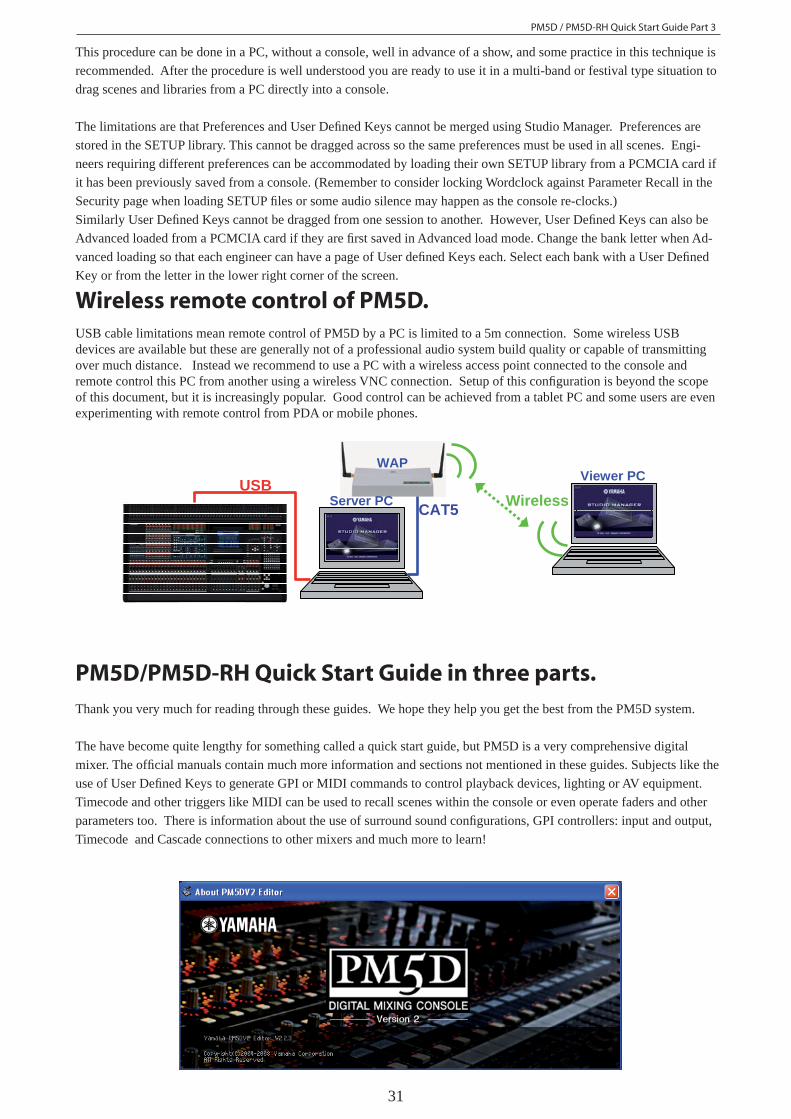
Wireless remote control of PM5D.USB cable limitations mean remote control of PM5D by a PC is limited to a 5m connection. Some wireless USB devices are available but these are generally not of a professional audio system build quality or capable of transmitting over much distance. Instead we recommend to use a PC with a wireless access point connected to the console and remote control this PC from another using a wireless VNC connection. Setup of this confi guration is beyond the scope of this document, but it is increasingly popular. Good control can be achieved from a tablet PC and some users are even experimenting with remote control from PDA or mobile phones.
USB Wireless CAT5
Viewer PC
Server PC
WAP