RCX340 - Yamaha Motor Co., Ltd.
10
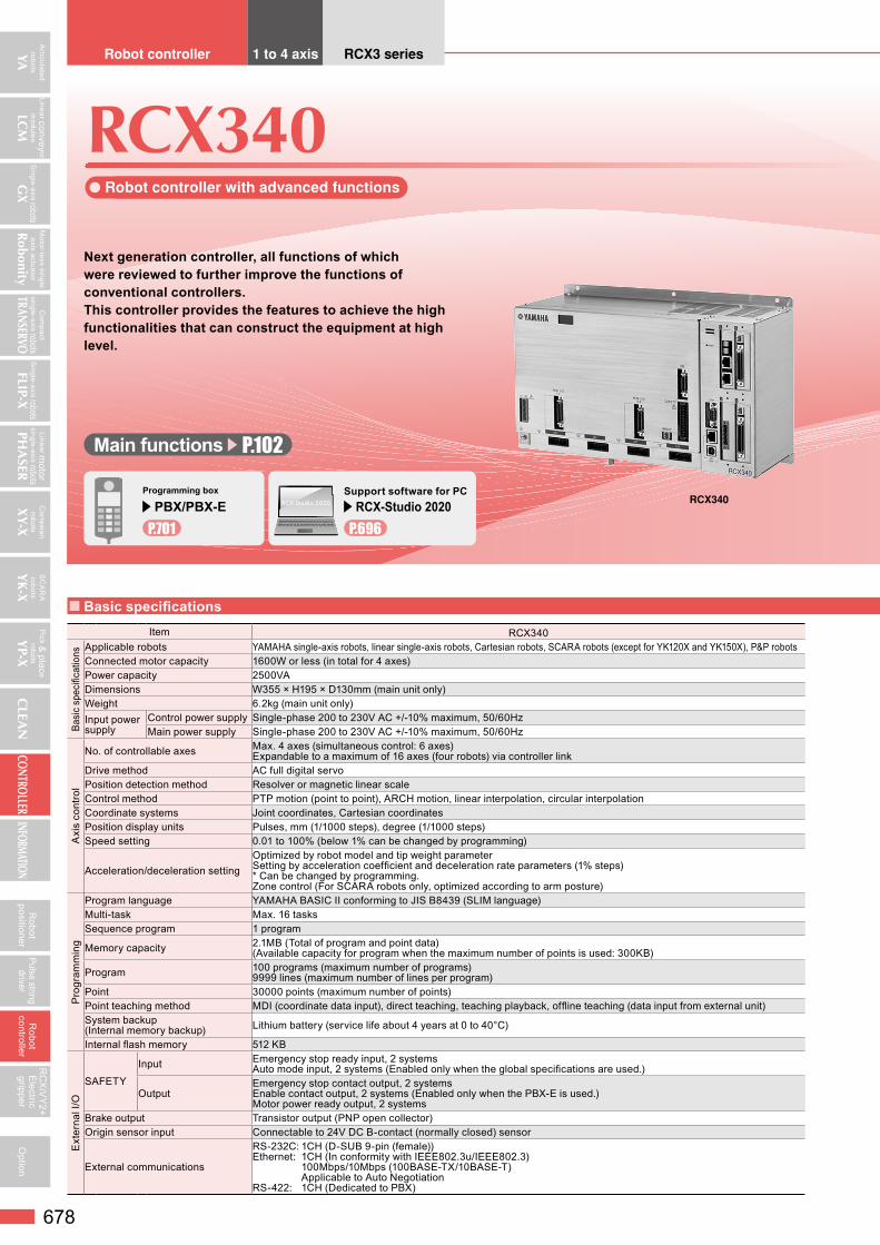
Articulated robots YA Linear convey or modules LCM Single-axis robots GX Compact single-axis robots TRANSERVO Single-axis robots FLIP-X Linear motor single-axis robots PHASER Cartesian robots XY-X SCARA robots YK-X Pick & plac e robots YP-X CLEAN CONTROLLER INFORMATION Motor-less single axis actuator Robonity 678 Robot positioner Pulse string driver Robot controller RCXiVY2+ Electric gripper Option ● Robot controller with advanced functions Next generation controller, all functions of which were reviewed to further improve the functions of conventional controllers. This controller provides the features to achieve the high functionalities that can construct the equipment at high level. RCX340 Robot controller 1 to 4 axis RCX3 series Programming box PBX/PBX-E P.701 RCX340 ■ Basic specifications Main functions P.102 Item RCX340 Basic specifications Applicable robots YAMAHA single-axis robots, linear single-axis robots, Cartesian robots, SCARA robots (except for YK120X and YK150X), P&P robots Connected motor capacity 1600W or less (in total for 4 axes) Power capacity 2500VA Dimensions W355 × H195 × D130mm (main unit only) Weight 6.2kg (main unit only) Input power supply Control power supply Single-phase 200 to 230V AC +/-10% maximum, 50/60Hz Main power supply Single-phase 200 to 230V AC +/-10% maximum, 50/60Hz Axis control No. of controllable axes Max. 4 axes (simultaneous control: 6 axes) Expandable to a maximum of 16 axes (four robots) via controller link Drive method AC full digital servo Position detection method Resolver or magnetic linear scale Control method PTP motion (point to point), ARCH motion, linear interpolation, circular interpolation Coordinate systems Joint coordinates, Cartesian coordinates Position display units Pulses, mm (1/1000 steps), degree (1/1000 steps) Speed setting 0.01 to 100% (below 1% can be changed by programming) Acceleration/deceleration setting Optimized by robot model and tip weight parameter Setting by acceleration coefficient and deceleration rate parameters (1% steps) * Can be changed by programming. Zone control (For SCARA robots only, optimized according to arm posture) Programming Program language YAMAHA BASIC II conforming to JIS B8439 (SLIM language) Multi-task Max. 16 tasks Sequence program 1 program Memory capacity 2.1MB (Total of program and point data) (Available capacity for program when the maximum number of points is used: 300KB) Program 100 programs (maximum number of programs) 9999 lines (maximum number of lines per program) Point 30000 points (maximum number of points) Point teaching method MDI (coordinate data input), direct teaching, teaching playback, offline teaching (data input from external unit) System backup (Internal memory backup) Lithium battery (service life about 4 years at 0 to 40°C) Internal flash memory 512 KB External I/O SAFETY Input Emergency stop ready input, 2 systems Auto mode input, 2 systems (Enabled only when the global specifications are used.) Output Emergency stop contact output, 2 systems Enable contact output, 2 systems (Enabled only when the PBX-E is used.) Motor power ready output, 2 systems Brake output Transistor output (PNP open collector) Origin sensor input Connectable to 24V DC B-contact (normally closed) sensor External communications RS-232C: 1CH (D-SUB 9-pin (female)) Ethernet: 1CH (In conformity with IEEE802.3u/IEEE802.3) 100Mbps/10Mbps (100BASE-TX/10BASE-T) Applicable to Auto Negotiation RS-422: 1CH (Dedicated to PBX) RCX-Studio 2020 Support software for PC RCX-Studio 2020 P.696
-
Upload
khangminh22 -
Category
Documents
-
view
1 -
download
0
Transcript of RCX340 - Yamaha Motor Co., Ltd.
Articulated robots
YA
Linear convey or m
odules
LCM
Single-axis robotsG
X
Com
pact single-axis robotsTRANSERVO
Single-axis robotsFLIP-X
Linear motor
single-axis robotsPH
ASER
Cartesianrobots
XY-X
SC
AR
Arobots
YK
-X
Pick &
place
robots
YP-X
CLEA
NCONTROLLER
INFORMATION
Motor-less single axis actuator
Robonity
678
Robot
positionerPulse string
driverR
obotcontroller
RC
XiV
Y2+
Electric
gripperO
ption
RCX340
Robot controller with advanced functions
Next generation controller, all functions of which were reviewed to further improve the functions of conventional controllers.This controller provides the features to achieve the high functionalities that can construct the equipment at high level.
RCX340Robot controller 1 to 4 axis RCX3 series
Programming box
PBX/PBX-E P.701
RCX340
Basic specifications
Main functions P.102
Item RCX340
Basi
c sp
ecifi
catio
ns Applicable robots YAMAHA single-axis robots, linear single-axis robots, Cartesian robots, SCARA robots (except for YK120X and YK150X), P&P robotsConnected motor capacity 1600W or less (in total for 4 axes)Power capacity 2500VADimensions W355 × H195 × D130mm (main unit only)Weight 6.2kg (main unit only)Input power supply
Control power supply Single-phase 200 to 230V AC +/-10% maximum, 50/60HzMain power supply Single-phase 200 to 230V AC +/-10% maximum, 50/60Hz
Axi
s co
ntro
l
No. of controllable axes Max. 4 axes (simultaneous control: 6 axes)Expandable to a maximum of 16 axes (four robots) via controller link
Drive method AC full digital servoPosition detection method Resolver or magnetic linear scaleControl method PTP motion (point to point), ARCH motion, linear interpolation, circular interpolationCoordinate systems Joint coordinates, Cartesian coordinatesPosition display units Pulses, mm (1/1000 steps), degree (1/1000 steps)Speed setting 0.01 to 100% (below 1% can be changed by programming)
Acceleration/deceleration settingOptimized by robot model and tip weight parameterSetting by acceleration coefficient and deceleration rate parameters (1% steps)* Can be changed by programming.Zone control (For SCARA robots only, optimized according to arm posture)
Pro
gram
min
g
Program language YAMAHA BASIC II conforming to JIS B8439 (SLIM language)Multi-task Max. 16 tasksSequence program 1 program
Memory capacity 2.1MB (Total of program and point data)(Available capacity for program when the maximum number of points is used: 300KB)
Program 100 programs (maximum number of programs)9999 lines (maximum number of lines per program)
Point 30000 points (maximum number of points)Point teaching method MDI (coordinate data input), direct teaching, teaching playback, offline teaching (data input from external unit)System backup(Internal memory backup) Lithium battery (service life about 4 years at 0 to 40°C)
Internal flash memory 512 KB
Ext
erna
l I/O
SAFETY
Input Emergency stop ready input, 2 systemsAuto mode input, 2 systems (Enabled only when the global specifications are used.)
OutputEmergency stop contact output, 2 systemsEnable contact output, 2 systems (Enabled only when the PBX-E is used.)Motor power ready output, 2 systems
Brake output Transistor output (PNP open collector)Origin sensor input Connectable to 24V DC B-contact (normally closed) sensor
External communications
RS-232C: 1CH (D-SUB 9-pin (female))Ethernet: 1CH (In conformity with IEEE802.3u/IEEE802.3) 100Mbps/10Mbps (100BASE-TX/10BASE-T) Applicable to Auto NegotiationRS-422: 1CH (Dedicated to PBX)
RCX-Studio 2020
Support software for PC RCX-Studio 2020
P.696

Articulated robots
YA
Linear convey or m
odules
LCM
Single-axis robotsG
X
Com
pact single-axis robotsTRANSERVO
Single-axis robotsFLIP-X
Linear motor
single-axis robotsPH
ASER
Cartesianrobots
XY-X
SC
AR
Arobots
YK
-X
Pick &
place
robots
YP-X
CLEA
NCONTROLLER
INFORMATION
Motor-less single axis actuator
Robonity
679
Robot
positionerPulse string
driverR
obotcontroller
RC
XiV
Y2+
Electric
gripperO
ption
* For customers who export robot controllers to Korea, connecting the RCX340 or RCX320 to the RCX340 using the YC-Link/E may not be compliant with the KCs system. Please contact us when considering such connections.
RCX340
Controllable robot XY-X P.363 YK-X P.491 FLIP-X P.295 PHASER P.341 YP-X P.553 CE marking Field networks Ethernet
Basic specifications
YC-Link/E ordering explanation
Item RCX340
Gene
ral sp
ecific
ation
s Operating temperature 0 to 40°CStorage temperature -10 to 65°COperating humidity 35 to 85% RH (no condensation)Noise immunity Conforms to IEC61000-4-4 Level 3Protective structure IP20Appliance classes Class I
Opt
ions
Opt
ion
boar
d Not
e
Parallel I/O board
Standard specificationsDedicated input 8 points, dedicated output 9 pointsGeneral-purpose input 16 points, general-purpose output 8 pointsNPN/PNP specifications are selected. (maximum 1 board)
Expansion specifications
General-purpose input 24 points, general-purpose output 16 pointsNPN/PNP specifications are selected. (maximum 4 boards)
CC-Link board Ver1.1/2.0 Remote I/O Dedicated input/output: 16 points each General-purpose input/output: 96 points each Remote register Input/output: 16 words each
DeviceNetTM boardEtherNet/IPTM boardPROFIBUS boardPROFINET boardEtherCAT board
YC-Link/E board (master/slave) Communication cycle: 1 ms, control cycle: minimum 1 ms / maximum 8 ms, maximum number of robot units: four unitsMaximum number of control axes: total 16 axes (including four master controller axes), maximum 12 axes for slaves only
YRG (gripper) boardPosition detection method: optical rotary encoder, minimum setting distance: 0.01 mmSpeed setting: 20 to 100% relative to the maximum parameter speed, number of connected gripper units: maximum four unitsDrive power: DC 24V +/-10%, 1.0A Max
Tracking board Number of connected encoders: maximum two units, supported encoders: 26LS31/26C31 equivalent line driver (RS422 compliant)Encoder power supply: DC5V (2 counter (ch) total 500 mA or less) (supplied from controller)
RCXiVY2+ unitCamera pixels: maximum 5 million pixels, number of registered models: 254 models, number of connected cameras: maximum two unitsPower supply: DC24V +/-10% 1.5A Max
Programming box PBX, PBX-E Absolute battery 3.6V 2700mAH / axis Backup retention time: About 1 yearSupport software for personal computer RCX-Studio 2020
Note. There are four slots in which option boards can be installed.
Instruction manuals can be downloaded from our company website. Please use the following for more detailed information.https://global.yamaha-motor.com/business/robot/
Master unit Slave unit Slave unit
Controller 1 MasterYM1
Controller 2 SlaveYS2
Controller 3 SlaveYS3
Slave unit
Controller 4 SlaveYS4
Ordering method
RCX340Controller No. of
control-lable axes
Safety standards
Controller option A(OP.A)
Controller option B(OP.B)
Controller option C(OP.C)
Controller option D(OP.D)
Controller option E(OP.E)
Absolute battery
N: Normal No entry: Non-selection No entry: Non-selection No entry: Non-selection No entry: Non-selection No entry: Non-selection 4: 4 pcs.4: 4 axes E: CE NS : STD.DIO(NPN) Note 1 Note 4 --- Note 3 --- Note 3 --- Note 3 WY: with RCXiVY2+,
without lighting3: 3 pcs.
3: 3 axes K: KCs NE : EXP.DIO(NPN) Note 2 Note 4 NE : EXP.DIO(NPN) Note 2 Note 4 NE : EXP.DIO(NPN) Note 2 Note 4 NE : EXP.DIO(NPN) Note 2 Note 4 2: 2 pcs.2: 2 axes PS : STD.DIO(PNP) Note 1 Note 4 --- Note 3 --- Note 3 --- Note 3 WL: with RCXiVY2+,
with lighting1: 1 pc.
PE : EXP.DIO(PNP) Note 2 Note 4 PE : EXP.DIO(PNP) Note 2 Note 4 PE : EXP.DIO(PNP) Note 2 Note 4 PE : EXP.DIO(PNP) Note 2 Note 4 0: 0 pc.GR : Gripper GR : Gripper GR : Gripper GR : Gripper TR : Tracking Note 5 TR : Tracking Note 5 TR : Tracking Note 5 TR : Tracking Note 5
YM1 : YC-Link/E master Note 6 YM1 : YC-Link/E master Note 6 YM1 : YC-Link/E master Note 6 YM1 : YC-Link/E master Note 6
YS2 to 4: YC-Link/E slave Note 6
YS2 to 4: YC-Link/E slave Note 6
YS2 to 4: YC-Link/E slave Note 6
YS2 to 4: YC-Link/E slave Note 6
EP : EtherNet/IPTM Note 7 EP : EtherNet/IPTM Note 7 EP : EtherNet/IPTM Note 7 EP : EtherNet/IPTM Note 7
PB : PROFIBUS Note 7 PB : PROFIBUS Note 7 PB : PROFIBUS Note 7 PB : PROFIBUS Note 7
CC : CC-Link Note 7 CC : CC-Link Note 7 CC : CC-Link Note 7 CC : CC-Link Note 7
DN : DeviceNetTM Note 7 DN : DeviceNetTM Note 7 DN : DeviceNetTM Note 7 DN : DeviceNetTM Note 7
PT : PROFINET Note 7 PT : PROFINET Note 7 PT : PROFINET Note 7 PT : PROFINET Note 7
ES : EtherCAT Note 7 ES : EtherCAT Note 7 ES : EtherCAT Note 7 ES : EtherCAT Note 7
Please select desired selection items from the upper portion of the controller option A in order.
Controller option board position
OP.AOP.AOP.A
OP.COP.COP.C
OP.BOP.BOP.B
OP.DOP.DOP.D
Note 1. [STD.DIO] Parallel I/O board standard specifications Dedicated input 8 points, dedicated output 9 points, general-purpose input 16 points, general-purpose output 8 points Do not mix with field bus (CC/DN/PB/EP/PT/ES).
Note 2. [EXP.DIO] Parallel I/O board expansion specifications General-purpose input 24 points, general-purpose output 16 points
Note 3. Only one DIO STD specification board can be selected. Therefore, this board cannot be selected in OP.B to OP.D.Note 4. Select either NPN or PNP in DIO.Note 5. Only one tracking board can be selected.Note 6. Select only one master or slave board for YC-Link/E.
For details, refer to “YC-Link/E ordering explanation” below. Additionally, when ordering YC-Link/E, please specify what robot is connected to what number controller.
Note 7. Select only one fieldbus in a controller (CC/DN/PB/EP/PT/ES).

Articulated robots
YA
Linear convey or m
odules
LCM
Single-axis robotsG
X
Com
pact single-axis robotsTRANSERVO
Single-axis robotsFLIP-X
Linear motor
single-axis robotsPH
ASER
Cartesianrobots
XY-X
SC
AR
Arobots
YK
-X
Pick &
place
robots
YP-X
CLEA
NCONTROLLER
INFORMATION
Motor-less single axis actuator
Robonity
680
Robot
positionerPulse string
driverR
obotcontroller
RC
XiV
Y2+
Electric
gripperO
ption
Dimensions
RCX340
130
3-ф5.535510.5
213
225
195
22.5 155 1555.5
The required power supply capacity and heat emission will vary depending on the robot type and number of axes.Using the following table as a general guide consider the required power supply preparation and control panel size, controller installation, and cooling method.(1) When connected to SCARA robot
Robot type Power capacity
(VA)
Generated heat amount
(W)Standard type Clean type Dust-proof & drip-proof type Ceiling-mount Wall-mount / Inverse type
YK120XG, YK150XG – – – – 300 58
YK180XG, YK180XYK220X YK180XC, YK220XC – – – 500 63
YK250XG, YK350XGYK400XG, YK500XGLYK600XGL, YK400XE-4
YK250XCH, YK350XCHYK400XCH, YK250XGCYK350XGC, YK400XGCYK500XGLC, YK600XGLC
YK250XGP, YK350XGPYK400XGP, YK500XGLPYK600XGLP
– YK300XGS, YK400XGS 1000 75
– YK500XC, YK600XC – – – 1500 88
YK500XE-10, YK500XGYK610XE-10, YK600XGYK710XE-10, YK700XGL
– YK500XGP, YK600XGP YK500XGS, YK600XGS 1700 93
– YK700XC, YK800XCYK1000XC – – – 2000 100
YK600XGH, YK700XGYK800XG, YK900XGYK1000XG, YK1200X
–YK600XGHP, YK700XGPYK800XGP, YK900XGPYK1000XGP
YK350TWYK500TW
YK700XGS, YK800XGSYK900XGS, YK1000XGS 2500 113
Power supply capacity and heat emission
(2) When connected to 2 axis (Cartesian robot and/or multi-axis robot)Axial current sensor value Note Power capacity
(VA)Generated heat
amount (W)X axis Y axis05 05 600 6510 05 800 7020 05 1100 7810 10 1000 7520 10 1300 8320 20 1700 93
(4) When connected to 4 axis (Cartesian robot and/or multi-axis robot)Axial current sensor value Note Power capacity
(VA)Generated heat
amount (W)X axis Y axis Z axis R axis05 05 05 05 800 7010 05 05 05 1000 7520 05 05 05 1200 8010 10 05 05 1100 7820 10 05 05 1400 8520 20 05 05 1600 9010 10 10 05 1300 8320 10 10 05 1500 8820 20 10 05 1800 9520 20 20 05 2100 10310 10 10 10 1400 8520 10 10 10 1700 9320 20 10 10 2000 10020 20 20 10 2200 10520 20 20 20 2500 113
Note. Even if axial current sensor values for each axis are interchanged no problem will occur.
(3) When connected to 3 axis (Cartesian robot and/or multi-axis robot)Axial current sensor value Note Power capacity
(VA)Generated heat
amount (W)X axis Y axis Z axis05 05 05 700 6810 05 05 900 7320 05 05 1200 8010 10 05 1000 7520 10 05 1300 8320 20 05 1600 9010 10 10 1200 8020 10 10 1500 8820 20 10 1800 9520 20 20 2000 100

Articulated robots
YA
Linear convey or m
odules
LCM
Single-axis robotsG
X
Com
pact single-axis robotsTRANSERVO
Single-axis robotsFLIP-X
Linear motor
single-axis robotsPH
ASER
Cartesianrobots
XY-X
SC
AR
Arobots
YK
-X
Pick &
place
robots
YP-X
CLEA
NCONTROLLER
INFORMATION
Motor-less single axis actuator
Robonity
681
Robot
positionerPulse string
driverR
obotcontroller
RC
XiV
Y2+
Electric
gripperO
ptionRCX340
Installation conditions• Use the screws to secure the controller to the installation plate inside the control panel so that it is in a horizontal position. Be
sure to use the metallic installation plate.• Install the RCX340 in a well ventilated location, with space
on all sides of the RCX340 (See fig. at right.).• Ambient temperature : 0 to 40˚C• Ambient humidity : 35 to 85% RH (no condensation)
Standard specification I/O connector signal list Expanded specification I/O connector signal list
Pin I/O No. Signal name Remarks
1 DI 01 Dedicated input: Servo ON input2 DI 10 Dedicated input: Sequence control3 DI 03 Spare Do not use.
4 CHK 1 Check signal 1 Short-circuit with CHK2.
5 DI 05 Spare Do not use.6 DI 06 Dedicated input: Stop7 DI 07 Spare Do not use.8 DI 20 General-purpose input 209 DI 21 General-purpose input 21
10 DI 22 General-purpose input 2211 DI 23 General-purpose input 2312 DI 24 General-purpose input 2413 DI 25 General-purpose input 2514 DI 26 General-purpose input 2615 DI 27 General-purpose input 2716 DO 00 Spare Do not use.17 DO 01 Dedicated output CPU OK18 DO 10 Dedicated output AUTO mode output19 DO 11 Dedicated output Return-to-origin complete20 DO 12 Dedicated output Sequence program-in-progress21 DO 13 Dedicated output Robot program-in-progress22 DO 14 Dedicated output Program reset status output23 DO 15 Dedicated output Warning output24 DO 16 Spare Do not use.25 DO 17 Spare Do not use.26 DI 12 Dedicated input: Automatic operation start27 DI 13 Spare Do not use.28 DI 14 Dedicated input: Return-to-origin (for INC axis)29 DI 15 Dedicated input: Program reset input30 DI 16 Dedicated input: Alarm reset input31 DI 17 Dedicated input: Return-to-origin (for ABS axis)32 DI 30 General-purpose input 3033 DI 31 General-purpose input 3134 DI 32 General-purpose input 3235 DI 33 General-purpose input 3336 DI 34 General-purpose input 3437 DI 35 General-purpose input 3538 DI 36 General-purpose input 3639 DI 37 General-purpose input 37
40 CHK 2 Check signal 2 Short-circuit with CHK1.
41 DO 02 Dedicated output: Servo ON output42 DO 03 Dedicated output: Alarm output43 DO 20 General-purpose output 2044 DO 21 General-purpose output 2145 DO 22 General-purpose output 2246 DO 23 General-purpose output 2347 DO 24 General-purpose output 2448 DO 25 General-purpose output 2549 DO 26 General-purpose output 2650 DO 27 General-purpose output 27
Pin I/O No. (ID=1)
I/O No. (ID=2)
I/O No. (ID=3)
I/O No. (ID=4) Signal name
1 --- --- --- --- Reserved2 DI 10 DI 40 DI 70 DI 120 General-purpose input 10,40,70,1203 --- --- --- --- Reserved4 DI 11 DI 41 DI 71 DI 121 General-purpose input 11,41,71,1215 --- --- --- --- Reserved6 --- --- --- --- Reserved7 --- --- --- --- Reserved8 DI 20 DI 50 DI 100 DI 130 General-purpose input 20,50,100,1309 DI 21 DI 51 DI 101 DI 131 General-purpose input 21,51,101,131
10 DI 22 DI 52 DI 102 DI 132 General-purpose input 22,52,102,13211 DI 23 DI 53 DI 103 DI 133 General-purpose input 23,53,103,13312 DI 24 DI 54 DI 104 DI 134 General-purpose input 24,54,104,13413 DI 25 DI 55 DI 105 DI 135 General-purpose input 25,55,105,13514 DI 26 DI 56 DI 106 DI 136 General-purpose input 26,56,106,13615 DI 27 DI 57 DI 107 DI 137 General-purpose input 27,57,107,13716 --- --- --- --- Reserved17 --- --- --- --- Reserved18 DO 10 DO 30 DO 50 DO 70 General-purpose output 10,30,50,7019 DO 11 DO 31 DO 51 DO 71 General-purpose output 11,31,51,7120 DO 12 DO 32 DO 52 DO 72 General-purpose output 12,32,52,7221 DO 13 DO 33 DO 53 DO 73 General-purpose output 13,33,53,7322 DO 14 DO 34 DO 54 DO 74 General-purpose output 14,34,54,7423 DO 15 DO 35 DO 55 DO 75 General-purpose output 15,35,55,7524 DO 16 DO 36 DO 56 DO 76 General-purpose output 16,36,56,7625 DO 17 DO 37 DO 57 DO 77 General-purpose output 17,37,57,7726 DI 12 DI 42 DI 72 DI 122 General-purpose input 12,42,72,12227 DI 13 DI 43 DI 73 DI 123 General-purpose input 13,43,73,12328 DI 14 DI 44 DI 74 DI 124 General-purpose input 14,44,74,12429 DI 15 DI 45 DI 75 DI 125 General-purpose input 15,45,75,12530 DI 16 DI 46 DI 76 DI 126 General-purpose input 16,46,76,12631 DI 17 DI 47 DI 77 DI 127 General-purpose input 17,47,77,12732 DI 30 DI 60 DI 110 DI 140 General-purpose input 30,60,110,14033 DI 31 DI 61 DI 111 DI 141 General-purpose input 31,61,111,14134 DI 32 DI 62 DI 112 DI 142 General-purpose input 32,62,112,14235 DI 33 DI 63 DI 113 DI 143 General-purpose input 33,63,113,14336 DI 34 DI 64 DI 114 DI 144 General-purpose input 34,64,114,14437 DI 35 DI 65 DI 115 DI 145 General-purpose input 35,65,115,14538 DI 36 DI 66 DI 116 DI 146 General-purpose input 36,66,116,14639 DI 37 DI 67 DI 117 DI 147 General-purpose input 37,67,117,14740 --- --- --- --- Reserved41 --- --- --- --- Reserved42 --- --- --- --- Reserved43 DO 20 DO 40 DO 60 DO 100 General-purpose output 20,40,60,10044 DO 21 DO 41 DO 61 DO 101 General-purpose output 21,41,61,10145 DO 22 DO 42 DO 62 DO 102 General-purpose output 22,42,62,10246 DO 23 DO 43 DO 63 DO 103 General-purpose output 23,43,63,10347 DO 24 DO 44 DO 64 DO 104 General-purpose output 24,44,64,10448 DO 25 DO 45 DO 65 DO 105 General-purpose output 25,45,65,10549 DO 26 DO 46 DO 66 DO 106 General-purpose output 26,46,66,10650 DO 27 DO 47 DO 67 DO 107 General-purpose output 27,47,67,107
Note. The IDs are set using the parameter.
Instruction manuals can be downloaded from our company website. Please use the following for more detailed information.https://global.yamaha-motor.com/business/robot/
50 mm or more
50 mm or more
50 mm or more
50 mm or more (A clearance of 100 mm or more is recommended.)
100 mm or moreParallel DIO cable
Robot cable
FrontFront
SideSide

Articulated robots
YA
Linear convey or m
odules
LCM
Single-axis robotsG
X
Com
pact single-axis robotsTRANSERVO
Single-axis robotsFLIP-X
Linear motor
single-axis robotsPH
ASER
Cartesianrobots
XY-X
SC
AR
Arobots
YK
-X
Pick &
place
robots
YP-X
CLEA
NCONTROLLER
INFORMATION
Motor-less single axis actuator
Robonity
682
Robot
positionerPulse string
driverR
obotcontroller
RC
XiV
Y2+
Electric
gripperO
ption
RCX340
Standard specification I/O connector pin assignment listsPin I/O No. Name1 DI01 Servo ON2 DI10 SEQ enable3 DI03 (Spare)4 CHK1 Check input 15 DI05 (Spare)6 DI06 STOP7 DI07 (Spare)8 DI20 General-purpose input9 DI21 General-purpose input10 DI22 General-purpose input11 DI23 General-purpose input12 DI24 General-purpose input13 DI25 General-purpose input14 DI26 General-purpose input15 DI27 General-purpose input16 DO00 (Spare)17 DO01 CPUOK18 DO10 AUTO19 DO11 ORGOK20 DO12 SEQRUN21 DO13 RUN22 DO14 RESET23 DO15 WARNING24 DO16 (Spare)25 DO17 (Spare)26 DI12 RUN27 DI13 (Spare)28 DI14 ORIGIN (for INC axis)29 DI15 RESET30 DI16 ALMRST31 DI17 ORIGIN(for ABS axis)32 DI30 General-purpose input33 DI31 General-purpose input34 DI32 General-purpose input35 DI33 General-purpose input36 DI34 General-purpose input37 DI35 General-purpose input38 DI36 General-purpose input39 DI37 General-purpose input40 CHK2 Check input 241 DO02 SERVO42 DO03 ALARM43 DO20 General-purpose output44 DO21 General-purpose output45 DO22 General-purpose output46 DO23 General-purpose output47 DO24 General-purpose output48 DO25 General-purpose output49 DO26 General-purpose output50 DO27 General-purpose output
Typical input signal connection
ExternalpowersupplyDC24V
DC24V
DI
DI
DI
CHK1CHK2
GND
4.7kΩ
Logiccircuit
Internalcircuit
Internalcircuit
Logiccircuit
ExternalpowersupplyDC24V
DC24V
DI
DI
DI
GND
CHK1CHK2
3.6kΩ
750Ω
NPN specifications
PNP specifications
Typical output signal connection
NPN specifications
PNP specifications
Internalcircuit
Logiccircuit
Load
Load
Load
DC24V
GND
DO
DO
DO
ExternalpowersupplyDC24V
ExternalpowersupplyDC24V
Logiccircuit
Internalcircuit Load
Load
Load
DC24V
GND
DO
DO
DO
Basic functionsFunction Description
Operation modes AUTO mode (Major functions: program creation, program execution, step execution, etc.) MANUAL mode (Major functions: jog movement, point data teaching, parameter editing, etc.)
Commands
Array declaration commands (DIM statement)Assignment commands (Numeric assignment, character string assignment, point definition statements, etc.) Movement commands (MOVE, DRIVE, PMOVE statements, etc.)Conditional branching commands (IF, FOR, WHILE statements, etc.) External output commands (DO, MO, LO, TO, SO statements) Parameter commands (ACCEL, OUTPOS, TOLE statements, etc.) Condition wait command (WAIT statement)Task related commands (START, SUSPEND, CUT statements, etc.) etc.
FunctionsArithmetic functions (SIN, COS, TAN functions, etc.)Character string functions (STR$, LEFT$, MID$, RIGHT$ functions, etc.) Point functions (WHERE, JTOXY, XYTOJ functions, etc.)Parameter functions (ACCEL, OUTPOS, TOLE statements, etc.) etc.
Variables
Simple variables (integer variables, real variables, character variables) Array variables (integer variables, real variables, character variables) Point variablesShift variablesI/O variables etc.
Arithmetic operationArithmetic operators (+, -, *, /, MOD) Logic operators (AND, OR, XOR) Relational operators (=, <, >, <>, <=, >=)
Monitor I/O status monitor (200 ms intervals)
Online commandsProgram operation commands (RUN, STOP, RESET, STEP, etc.) Utility commands (COPY, ERA, INIT, etc.)Data handling commands (READ, WRITE, etc.)Robot language commands (independent-executable commands)
Data files Program, point, parameter, shift, hand, all, error history etc. Internal timer Timer count variable (TCOUNTER), 1 ms intervalProgram break points Max. 32 points

Articulated robots
YA
Linear convey or m
odules
LCM
Single-axis robotsG
X
Com
pact single-axis robotsTRANSERVO
Single-axis robotsFLIP-X
Linear motor
single-axis robotsPH
ASER
Cartesianrobots
XY-X
SC
AR
Arobots
YK
-X
Pick &
place
robots
YP-X
CLEA
NCONTROLLER
INFORMATION
Motor-less single axis actuator
Robonity
683
Robot
positionerPulse string
driverR
obotcontroller
RC
XiV
Y2+
Electric
gripperO
ptionRCX340
Connection example of controller with normal specifications and PBX
17
1918
ENABLE11ENABLE12ENABLE21
PBX
Emergency stop
13141516
PBE-STOP11 13
141516
E-STOP12E-STOP21E-STOP22
E-STOP11
17
1918ENABLE1-
20 ENABLE22 20
ENABLE1+
ENABLE2+ENABLE2-
E-STOP1+E-STOP2+
E-STOP21
Internal power +24V
E-STOP2-E-STOP1-
E-STOP12
E-STOP22E-STOP RDY1
E-STOP RDY2
NL
MP RDY2-
MP RDY2+
MP RDY1-
MP RDY1+
E-STOP COM1
E-STOP COM2
Manual lock
AUTO1+
AUTO COM1AUTO2+
AUTO COM2
2221
232223
21
A1
A2
B2
A7
B1
B7
B10
B9A10
A9
A8
B8
B5
B6A6
A5
A3
B3A4
B4
A11
B11A12
B12
Internal power GND
Internal power GND
Internal power +24V
ControllerTo main power circuit
Main power on/off control
Emergency stopstatus detection
Manual lock switchstatus detection
AUTO modechange detection
Connected toexternal device
Not used.
ACIN
SAFETY
OFF ONEXTERNALE-STOP
Motor power ready output
Connection example of controller with CE specifications and PBX-E
17
1918
ENABLE11ENABLE12ENABLE21
PBX-E
Emergencystop
EnableManual lock
13141516
E-STOP11 13141516
E-STOP12E-STOP21E-STOP22
E-STOP11
17
1918ENABLE1-
20 ENABLE22 20
ENABLE1+
ENABLE2+ENABLE2-
E-STOP1+E-STOP2+
E-STOP21
Internal power+24V
E-STOP2-E-STOP1-
E-STOP12
E-STOP22
NL
AUTO1+
AUTO COM1AUTO2+
AUTO COM2
22
21
232223
21
A1
A2
B2
A7
B1
B7
B10
B9A10
A9
A8
B8
B5
B6A6
A5
A3
B3A4
B4
A11
B11A12
B12
Internal power GND
ControllerCE specifications
To mainpower circuit
Main power on/off control
Emergency stopstatus detection
Manual lock switchstatus detection
AUTO modechange detection
T2
T3IN4
IN5O2
O3
IN6
IN7
SAFETYCONTROLLER
NL
100mA*2
O1
IN10T0
O0
IN8
IN9
DOOR
O5
O4AUTO MODE
SWITCH
ACIN
PB
External power+24
OFF ON
VG
T2
T3IN0
IN1
IN2
IN3
EXTERNALE-STOP
IN12
IN13
Internal power +24V
Motor power ready output
SAFETY
MP RDY2+
MP RDY2-
Internal power GND
E-STOP RDY1
E-STOP RDY2
E-STOP COM2
E-STOP COM1
Emergency input signal connections
Instruction manuals can be downloaded from our company website. Please use the following for more detailed information.https://global.yamaha-motor.com/business/robot/

Articulated robots
YA
Linear convey or m
odules
LCM
Single-axis robotsG
X
Com
pact single-axis robotsTRANSERVO
Single-axis robotsFLIP-X
Linear motor
single-axis robotsPH
ASER
Cartesianrobots
XY-X
SC
AR
Arobots
YK
-X
Pick &
place
robots
YP-X
CLEA
NCONTROLLER
INFORMATION
Motor-less single axis actuator
Robonity
684
Robot
positionerPulse string
driverR
obotcontroller
RC
XiV
Y2+
Electric
gripperO
ption
RCX340
General commandsCommand Description
DIM Declares the array variable name and the number of elements.
LET Executes a specified assignment statement.REM Expresses a comment statement.
Arithmetic commandsCommand DescriptionABS Acquires the absolute value of a specified value.ATN Acquires the arctangent of the specified value.ATN2 Acquires the arctangent of the specified X-Y coordinates.COS Acquires the cosine value of a specified value.DEGRAD Converts a specified value to radians (↔RADDEG).DIST Acquires the distance between 2 specified points.
INT Acquires an integer for a specified value by truncating all decimal fractions.
LSHIFT Shifts a value to the left by the specified bit count. (↔RSHIFT)
RADDEG Converts a specified value to degrees. (↔DEGRAD)
RSHIFT Shifts a value to the right by the specified bit count. (↔LSHIFT)
SIN Acquires the sine value for a specified value.SQR Acquires the square root of a specified value.TAN Acquires the tangent value for a specified value.
Date / timeCommand DescriptionDATE $ Acquires the date as a "yy/mm/dd" format character string.
TCOUNTER Outputs count-up values at 1ms intervals starting from the point when the TCOUNTER variable is reset.
TIME $ Acquires the current time as an "hh:mm:ss" format character string.
TIMER Acquires the current time in seconds, counting from midnight.
Character string operationCommand DescriptionCHR $ Acquires a character with the specified character code.
LEFT $ Extracts a character string comprising a specified number of digits from the left end of a specified character string.
LEN Acquires the length (byte count) of a specified character string.
MID $ Extracts a character string of a desired length from a specified character string.
ORD Acquires the character code of the first character in a specified character string.
RIGHT $ Extracts a character string comprising a specified number of digits from the right end of a specified character string.
STR $ Converts a specified value to a character string (↔VAL).
VAL Converts the numeric value of a specified character string to an actual numeric value. (↔STR$)
Point, coordinates, shift coordinates Command DescriptionCHANGE Switches the hand of a specified robot.HAND Defines the hand of a specified robot.
JTOXY Converts joint coordinate data to Cartesian coordinate data of a specified robot. (↔XYTOJ)
LEFTY Sets the hand system of a specified robot to the left-handed system.
LOCx Specifies/acquires point data for a specified axis or shift data for a specified element.
PATH Sets the movement path.Pn Defines points within a program.
PPNT Creates point data specified by a pallet definition number and pallet position number.
RIGHTY Sets the hand system of a specified robot to the right- handed system.
Sn Defines the shift coordinates within the program.
SHIFT Sets the shift coordinate for a specified robot by using the shift data specified by a shift variable.
XYTOJ Converts the point variable Cartesian coordinate data to the joint coordinate data of a specified robot. (↔JTOXY).
Branching commandsCommand DescriptionEXIT FOR Terminates the FOR to NEXT statement loop.FOR to NEXT
Executes the FOR to NEXT statement repeatedly until a specified value is exceeded.
GOSUB to RETURN
Jumps to a subroutine with the label specified by GOSUB statement, and executes that subroutine.
GOTO Unconditionally jumps to the line specified by a label.IF Allows control flow to branch according to conditions.
ON to GOSUB
Jumps to a subroutine with labels specified by a GOSUB statement in accordance with the conditions, and executes that subroutine.
ON to GOTO
Jumps to label-specified lines in accordance with the conditions.
SELECT CASE to END SELECT
Allows control flow to branch according to conditions.
WHILE to WEND Controls repeated operations.
Error controlCommand Description
ERR / ERL Acquires the error code number of an error which has occurred / the line number where an error occurred.
ON ERROR GOTO
This command allows the program to jump to the error processing routine specified by the label without stopping the program, or it stops the program and displays the error message.
RESUME Resumes program execution after error recovery processing.
Program controlCommand DescriptionCALL Calls a sub-procedure.HALT Stops the program and performs a reset.HALTALL Stops and resets all programs.HOLD Temporarily stops the program.HOLDALL Temporarily stops all programs.
PGMTSK Acquires the task number in which a specified program is registered.
PGN Acquires the program number from a specified program name.
SGI Assigns/acquires the value to a specified integer type static variable.
SGR Assigns/acquires the value to a specified real type static variable.
SWI Switches the program being executed, then begins execution from the first line.
TSKPGM Acquires the program number which is registered in a specified task.
Task controlCommand DescriptionCHGPRI Changes the priority ranking of a specified task.
CUT Terminates another task currently being executed or temporarily stopped.
EXIT TASK Terminates its own task which is in progress.RESTART Restarts another task during a temporary stop.
START Specifies the task number and priority ranking of a specified program, and starts that program.
SUSPEND Temporarily stops another task which is being executed.
Robot operationsCommand DescriptionDRIVE Moves a specified axis of a specified robot to an absolute position.DRIVEI Moves a specified axis of a specified robot to a relative position.MOTOR Controls the motor power status.MOVE Performs absolute movement of all axes of a specified robot.MOVEI Performs relative movement of all axes of a specified robot.
MOVET Performs relative movement of all axes of a specified robot when the tool coordinate is selected.
ORIGIN Performs return-to-origin.PMOVE Executes the pallet movement command of a specified robot.PUSH Executes a pushing operation in the axis unit.
SERVO Controls the servo ON/OFF of a specified axis or all axes of a specified robot.
Robot Language Table

Articulated robots
YA
Linear convey or m
odules
LCM
Single-axis robotsG
X
Com
pact single-axis robotsTRANSERVO
Single-axis robotsFLIP-X
Linear motor
single-axis robotsPH
ASER
Cartesianrobots
XY-X
SC
AR
Arobots
YK
-X
Pick &
place
robots
YP-X
CLEA
NCONTROLLER
INFORMATION
Motor-less single axis actuator
Robonity
685
Robot
positionerPulse string
driverR
obotcontroller
RC
XiV
Y2+
Electric
gripperO
ptionRCX340Instruction manuals can be downloaded from our company website. Please use the following for more detailed information.
https://global.yamaha-motor.com/business/robot/
Status acquisitionCommand Description
ABSRPOSAcquires the machine reference value for specified robot axes. (Valid only for axes whose return-to-origin method is set as "mark".)
ARMCND Acquires the current arm status of a specified robot.
ARMSEL Specifies/acquires the current "hand system" setting of a specified robot.
ARMTYP Specifies/acquires the "hand system" setting of a specified robot.
CURTQST Acquires the current torque value ratio of a specified axis to the rated torque.
MCHREF
Acquires the return-to-origin or absolute-search machine reference value for specified robot axes. (Valid only for axes whose return-to-origin method is set as "sensor" or "stroke- end".)
MTRDUTY Acquires the motor load factor of the specified axis.PSHRSLT Acquires the status at the end of the PUSH statement.PSHSPD Specifies/acquires the push speed parameter.PSHTIME Specifies/acquires the push time parameter.
WAIT ARM Waits until the axis operation of a specified robot is completed.
WHERE Reads out the current position of the arm of a specified robot in joint coordinates (pulse).
WHRXY Reads out the current position of the arm of a specified robot as Cartesian coordinates (mm, degrees).
Status changeCommand Description
ACCEL Specifies/acquires the acceleration coefficient parameter of a specified robot.
ARCHP1 Specifies/acquires the arch position 1 parameter of a specified robot.
ARCHP2 Specifies/acquires the arch position 2 parameter of a specified robot.
ASPEED Specifies/acquires the AUTO movement speed of a specified robot.
AXWGHT Specifies/acquires the axis tip weight parameter of a specified robot.
CHANGE Switches the hand of a specified robot.
DECEL Specifies/acquires the deceleration rate parameter of a specified robot.
HAND Defines the hand of a specified robot.
LEFTY Sets the hand system of a specified robot to the left-handed system.
ORGORDSpecifies/acquires the axis sequence parameter for performing return-to-origin and an absolute search operation in a specified robot.
OUTPOS Specifies/acquires the "OUT position" parameter of a specified robot.
PDEF Defines the pallet used to execute pallet movement commands.
PSHFRC Specifies/acquires the "Push force" parameter.PSHJGSP Specifies/acquires the push judge speed threshold parameter.PSHMTD Specifies/acquires the push method parameter.
RIGHTY Sets the hand system of a specified robot to the right- handed system.
SETGEP Sets the General Ethernet Port.SPEED Changes the program movement speed of a specified robot.
TOLE Specifies/acquires the tolerance parameter of a specified robot.
WEIGHT Specifies/acquires the tip weight parameter of a specified robot.
PATH controlCommand DescriptionPATH Specifies the PATH motion path.PATH END Ends the path setting for PATH motion.PATH SET Starts the path setting for PATH motion.PATH START Starts the PATH motion.
Torque controlCommand Description
CURTQST Acquires the current torque value ratio of a specified axis to the rated torque.
CURTRQ Acquires the current torque value of the specified axis of a specified robot.
PUSH Executes a pushing operation in the axis unit.
TORQUE Specifies/acquires the maximum torque command value which can be set for a specified axis of a specified robot.
Input/output controlCommand DescriptionDELAY Waits for the specified period (units: ms).
DO Outputs a specified value to the DO port or acquires the DO status.
LO Outputs a specified value to the LO port to enable/disable axis movement or acquires the LO status.
MO Outputs a specified value to the MO port or acquires the MO status.
OUT Turns ON the bits of the specified output ports and terminates the command statement.
RESET Turns the bit of a specified output port OFF.SET Turns the bit at the specified output port ON.SI Acquires a specified SI status.
SID Acquires a specified serial input's double-word information status.
SIW Acquires a specified serial input's word information status.
SO Outputs a specified value to the SO port or acquires the SO status.
SOD Outputs a specified serial output's double-word information or acquires the output status.
SOW Outputs a specified serial output's word information or acquires the output status.
TO Outputs a specified value to the TO port or acquires the TO status.
WAIT Waits until the conditions of the DI/DO conditional expression are met (with time-out).
Communication controlCommand DescriptionCLOSE Close the specified General Ethernet Port.ETHSTS Acquires the Ethernet port status.GEPSTS Acquires the General Ethernet Port status.OFFLINE Sets a specified communication port to the "offline" mode.ONLINE Sets the specified communication port to the "online" mode.OPEN Opens the specified General Ethernet Port.SEND Sends a file.
Robot Language Table
Articulated robots
YA
Linear convey or m
odules
LCM
Single-axis robotsG
X
Com
pact single-axis robotsTRANSERVO
Single-axis robotsFLIP-X
Linear motor
single-axis robotsPH
ASER
Cartesianrobots
XY-X
SC
AR
Arobots
YK
-X
Pick &
place
robots
YP-X
CLEA
NCONTROLLER
INFORMATION
Motor-less single axis actuator
Robonity
686
Robot
positionerPulse string
driverR
obotcontroller
RC
XiV
Y2+
Electric
gripperO
ption
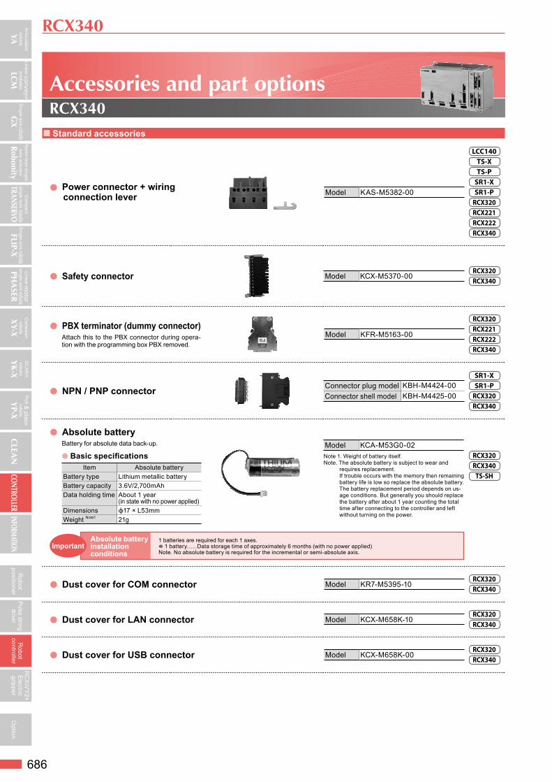
Standard accessories
Power connector + wiring connection lever Model KAS-M5382-00
LCC140TS-XTS-PSR1-XSR1-PRCX320RCX221RCX222RCX340
Safety connector Model KCX-M5370-00RCX320RCX340
PBX terminator (dummy connector)Attach this to the PBX connector during opera-tion with the programming box PBX removed.
Model KFR-M5163-00
RCX320RCX221RCX222RCX340
NPN / PNP connector Connector plug model KBH-M4424-00Connector shell model KBH-M4425-00
SR1-XSR1-PRCX320RCX340
Absolute batteryBattery for absolute data back-up.
Basic specificationsItem Absolute battery
Battery type Lithium metallic batteryBattery capacity 3.6V/2,700mAhData holding time About 1 year
(in state with no power applied)Dimensions ϕ17 × L53mmWeight Note1 21g
Model KCA-M53G0-02Note 1. Weight of battery itself.Note. The absolute battery is subject to wear and
requires replacement. If trouble occurs with the memory then remaining battery life is low so replace the absolute battery. The battery replacement period depends on us-age conditions. But generally you should replace the battery after about 1 year counting the total time after connecting to the controller and left without turning on the power.
RCX320RCX340TS-SH
Dust cover for COM connector Model KR7-M5395-10RCX320RCX340
Dust cover for LAN connector Model KCX-M658K-10RCX320RCX340
Dust cover for USB connector Model KCX-M658K-00RCX320RCX340
RCX340
Accessories and part optionsRCX340
1 batteries are required for each 1 axes. 1 battery…...Data storage time of approximately 6 months (with no power applied) Note. No absolute battery is required for the incremental or semi-absolute axis.
Absolute battery installation conditions
Important

Articulated robots
YA
Linear convey or m
odules
LCM
Single-axis robotsG
X
Com
pact single-axis robotsTRANSERVO
Single-axis robotsFLIP-X
Linear motor
single-axis robotsPH
ASER
Cartesianrobots
XY-X
SC
AR
Arobots
YK
-X
Pick &
place
robots
YP-X
CLEA
NCONTROLLER
INFORMATION
Motor-less single axis actuator
Robonity
687
Robot
positionerPulse string
driverR
obotcontroller
RC
XiV
Y2+
Electric
gripperO
ption
Options
External 24V power supply connector for brake + wiring lever Model KCX-M6500-10 RCX340
Programming box P.701 PBX/PBX-E
This device can perform all operations such as manual robot operation, program entry and edit, teaching and parameter settings.
Type Language Cable length Model
PBX
Japanese5m KCX-M5110-1J
12m KCX-M5110-3J
English5m KCX-M5110-1E
12m KCX-M5110-3E
Chinese5m KCX-M5110-1C
12m KCX-M5110-3C
PBX-E(with enable switch)
Japanese5m KCX-M5110-0J
12m KCX-M5110-2J
English5m KCX-M5110-0E
12m KCX-M5110-2E
Chinese5m KCX-M5110-0C
12m KCX-M5110-2C
ModelDisplay language switching USB for PBX KCX-M6498-00
USB cable KCX-M657E-00
RCX320RCX340
Support software for PC P.696 RCX-Studio 2020
This is support software for operating the RCX320 / RCX340 controller.A USB key is supplied to the RCX-Studio 2020 to prevent robot operation mistakes.
Model
RCX-Studio 2020Basic (USB key blue)
KCX-M4990-40
RCX-Studio 2020Pro (USB key purple)
KCX-M4990-50
Note. Even when there is no USB key, RCX-Studio 2020 can be used as function restricted version. For details about the functions of the function restricted, Basic, and Pro versions, see P.696.
RCX320RCX340
Basic specificationsSupported language Japanese, English, ChineseOSNote1 Microsoft Windows 7 SP1(32/64bit) / 8.1 (32 bit / 64 bit) / 10 (32 bit / 64 bit)Execution environment .NET Framework 4.5 or more
CPU Recommended: Intel Core i5 2 GHz or more, Minimum: Intel Celeron 2 GHz or more, 3D-SIM is invalid.: Intel Core 2 Duo 2 GHz or more
Memory Recommended: 8 GB or more, Minimum: 4 GB or more, 3D-SIM is invalid: 1 GB or more
Hard disk capacity 1GB of available space required on installation driveCommunication Port Communication cable: Serial communication port, Ethernet port, or USB port
OthersDedicated commutation cable (For D-Sub or USB) Ethernet cable (category 5 or better)USB port: 1 port (For USB key)
Applicable robot controllers RCX320 / RCX340 Applicable robot YAMAHA robot that can be connected to the RCX340, RCX320.Note. Microsoft, Windows 7, Windows 8.1, and Windows 10 are either registered trademarks or trademarks of Microsoft Corporation in the United States
and/or other countries. Other company names and product names listed in this manual may be the trademarks or registered trademarks of their respective companies.
Data cablesCommunication cable for RCX-Studio 2020.Select from USB cable or D-sub cable.
USB D-Sub
[RCX320/RCX340]Ethernet cable (category 5 or higher)
is also supported.
Model
USB type (5m) KBG-M538F-00
D-Sub type 9pin-9pin (5m) KAS-M538F-10
Note. This USB cable supports Windows 2000/XP or later.Note. Data cable jointly used for POPCOM+, VIP+,
RCX-Studio Pro and RCX-Studio 2020.Note. USB driver for communication cable can also be
downloaded from our website.
LCC140ERCDSR1-XSR1-PRCX320RCX221RCX222RCX340
YC-Link/E master board Model KCX-M4400-M0RCX320RCX340
YC-Link/E slave board Model KCX-M4400-S0RCX320RCX340
YC-Link/E cable (1m) Model KCX-M6479-10RCX320RCX340
RCX340
PBX
Instruction manuals can be downloaded from our company website. Please use the following for more detailed information.https://global.yamaha-motor.com/business/robot/
USB key
RCX-Studio 2020