GDS125-I/GDS125-F - YAMAHA
112
GDS125-I/GDS125-F OWNER’S MANUAL Read this manual carefully before operating this vehicle. B4H-F8199-EZ
-
Upload
khangminh22 -
Category
Documents
-
view
3 -
download
0
Transcript of GDS125-I/GDS125-F - YAMAHA

arefully before operating this vehicle.
ReOWNER’S MANUAL
ad this
G
manual c
D
DIC183
S125-I/GDS125-FB4H-F8199-EZ
[English (E)]

EAU46094
Read this manual carefully before operating this vehicle. This manual should stay with this vehicle if it is sold.
UB4HEZE0.book Page 1 Wednesday, March 21, 2018 2:58 PM

Introduction
EAU10114
Welcome to the Yamaha world of motorcycling!As the owner of the GDS125-I/GDS125-F, you are benefiting from Yamaha’s vast experience and newest technology re-garding the design and manufacture of high-quality products, which have earned Yamaha a reputation for dependability.Please take the time to read this manual thoroughly, so as to enjoy all advantages of your GDS125-I/GDS125-F. The Own-er’s Manual does not only instruct you in how to operate, inspect and maintain your scooter, but also in how to safeguardyourself and others from trouble and injury.In addition, the many tips given in this manual will help keep your scooter in the best possible condition. If you have anyfurther questions, do not hesitate to contact your Yamaha dealer.The Yamaha team wishes you many safe and pleasant rides. So, remember to put safety first!Yamaha continually seeks advancements in product design and quality. Therefore, while this manual contains the most cur-rent product information available at the time of printing, there may be minor discrepancies between your scooter and thismanual. If there is any question concerning this manual, please consult a Yamaha dealer.
WARNING
EWA12412
Please read this manual carefully and completely before operating this scooter.
UB4HEZE0.book Page 1 Wednesday, March 21, 2018 2:58 PM

Im
EAU10134
Pa ions:
*P
to potential personal injury ymbol to avoid possible injury
if not avoided, could result in
e taken to avoid damage to the
ier or clearer.
N
T
UB4HEZE0.book Page 1 Wednesday, March 21, 2018 2:58 PM
portant manual information
rticularly important information is distinguished in this manual by the following notat
roduct and specifications are subject to change without notice.
This is the safety alert symbol. It is used to alert youhazards. Obey all safety messages that follow this sor death.
A WARNING indicates a hazardous situation which,death or serious injury.
A NOTICE indicates special precautions that must bvehicle or other property.
A TIP provides key information to make procedures eas
WARNING
OTICE
IP

t manual information
UB4HEZE0.book Page 2 Wednesday, March 21, 2018 2:58 PM
Importan
EAUN0430
GDS125-I/GDS125-FOWNER’S MANUAL
©2018 PT Yamaha Indonesia Motor Manufacturing
1st edition, June 2018All rights reserved.
Any reprinting or unauthorized use without the written permission of
PT Yamaha Indonesia Motor Manufac-turing
is expressly prohibited.Printed in Indonesia.

iodic maintenance and
ustment ........................................ 9-1ool kit ............................................ 9-1eriodic maintenance chart for the emission control system ............. 9-2eneral maintenance and lubrication chart .......................... 9-3emoving and installing panels...... 9-8hecking the spark plug............... 9-10ngine oil and oil strainer ............. 9-11inal transmission oil .................... 9-13oolant ......................................... 9-15ir filter and V-belt case air filter elements.................................... 9-16hecking the throttle grip free play............................................ 9-19
alve clearance............................. 9-19ires .............................................. 9-19ast wheels .................................. 9-21hecking the front brake lever free play..................................... 9-21
djusting the rear brake lever free play..................................... 9-22hecking the front brake pads and rear brake shoes ............... 9-23hecking the brake fluid level ...... 9-23hanging the brake fluid ............. 9-24hecking the V-belt ...................... 9-24hecking and lubricating the cables........................................ 9-25
UB4HEZE0.book Page 1 Wednesday, March 21, 2018 2:58 PM
Ta
Loc
Sa
FH
De
LRC
Sm
(fo
SO
H
SRM
Sto
SS
Ins
MKI
ble of contents
ation of important labels ........... 1-1
fety information............................ 2-1urther safe-riding points ............... 2-5elmets .......................................... 2-6
scription ....................................... 3-1eft view ......................................... 3-1ight view....................................... 3-3ontrols and instruments ............... 3-5
art key system
r GDS125-F).................................. 4-1mart key system........................... 4-1perating range of the smart key system......................................... 4-2andling of the smart key and mechanical keys ......................... 4-3
mart key ....................................... 4-5eplacing the smart key battery..... 4-6ain switch .................................... 4-7
p and Start System..................... 5-1top and Start System ................... 5-1top and Start System operation... 5-1
trument and control functions ... 6-1ain switch/steering lock............... 6-1eyhole shutter .............................. 6-2
ndicator lights and warning lights............................................ 6-2
Multi-function meter unit.................6-4Handlebar switches ........................6-9Front brake lever ...........................6-10Rear brake lever ............................6-10Rear brake lever lock ....................6-11Fuel tank cap ................................6-11Fuel ...............................................6-12Catalytic converter ........................6-13Seat (for GDS125-I).......................6-14Helmet holders..............................6-14Storage compartments .................6-15Sidestand ......................................6-17Ignition circuit cut-off system .......6-17Power outlet .................................6-19
For your safety – pre-operation
checks ...............................................7-1
Operation and important riding
points .................................................8-1Starting the engine..........................8-1Starting off ......................................8-2Acceleration and deceleration ........8-2Braking............................................8-3Tips for reducing fuel
consumption................................8-3Engine break-in ...............................8-3Parking (for GDS125-F)...................8-4
Per
adj
TP
G
RCEFCA
C
VTCC
A
C
CCCC

Table of contents
S
S
C
UB4HEZE0.book Page 2 Wednesday, March 21, 2018 2:58 PM
Checking and lubricating the throttle grip and cable................9-25
Lubricating the front and rear brake levers................................9-25
Checking and lubricating the centerstand and sidestand ........9-26
Checking the front fork..................9-27Checking the steering ...................9-27Checking the wheel bearings ........9-28Battery ...........................................9-28Replacing the fuses.......................9-29Headlights .....................................9-31Replacing a front turn signal
light bulb or an auxiliary light bulb ............................................9-31
Replacing a tail/brake light bulb or a rear turn signal light bulb ....9-32
Troubleshooting ............................9-33Troubleshooting charts .................9-36Emergency mode
(for GDS125-F) ...........................9-38
cooter care and storage ..............10-1Matte color caution .......................10-1Care...............................................10-1Storage..........................................10-3
pecifications..................................11-1
onsumer information ...................12-1Identification numbers...................12-1
Vehicle data recording.................. 12-2
Index ................................................ 13-1

L
1EAU10385
Re ion for safe and proper operation ofyo read or comes off, a replacementlab
UB4HEZE0.book Page 1 Wednesday, March 21, 2018 2:58 PM
ocation of important labels
1-1
ad and understand all of the labels on your vehicle. They contain important informatur vehicle. Never remove any labels from your vehicle. If a label becomes difficult toel is available from your Yamaha dealer.
1,2

n of important labels
1
Pa, psi kPa, psi
00, 29 225, 33
00, 29 225, 33
1WD-F1668-01
UB4HEZE0.book Page 2 Wednesday, March 21, 2018 2:58 PM
Locatio
1-2
1 2
100kPa=1bar k
2
2
2PL-F1568-01

2
conspicuous appears to be veryeffective in reducing the chance ofthis type of accident.Therefore:
• Wear a brightly colored jacket.• Use extra caution when you are
approaching and passingthrough intersections, since in-tersections are the most likelyplaces for scooter accidents tooccur.
• Ride where other motorists cansee you. Avoid riding in anothermotorist’s blind spot.
• Never maintain a scooter with-out proper knowledge. Contactan authorized scooter dealer toinform you on basic scootermaintenance. Certain mainte-nance can only be carried outby certified staff.
UB4HEZE0.book Page 1 Wednesday, March 21, 2018 2:58 PM
Be
AsspoatioScThpetectheknoforHe
2-1
Safety information
EAU1026B
a Responsible Owner
the vehicle’s owner, you are re-nsible for the safe and proper oper-n of your scooter.
ooters are single-track vehicles.eir safe use and operation are de-ndent upon the use of proper ridinghniques as well as the expertise of operator. Every operator shouldw the following requirements be-
e riding this scooter. or she should:
Obtain thorough instructions froma competent source on all aspectsof scooter operation.Observe the warnings and mainte-nance requirements in this Own-er’s Manual.Obtain qualified training in safeand proper riding techniques.Obtain professional technical ser-vice as indicated in this Owner’sManual and/or when made neces-sary by mechanical conditions.
Never operate a scooter withoutproper training or instruction. Takea training course. Beginnersshould receive training from a cer-tified instructor. Contact an autho-rized scooter dealer to find outabout the training courses nearestyou.
Safe Riding
Perform the pre-operation checkseach time you use the vehicle to makesure it is in safe operating condition.Failure to inspect or maintain the vehi-cle properly increases the possibility ofan accident or equipment damage.See page 7-1 for a list of pre-operationchecks. This scooter is designed to carry
the operator and a passenger. The failure of motorists to detect
and recognize scooters in traffic isthe predominating cause of auto-mobile/scooter accidents. Manyaccidents have been caused byan automobile driver who did notsee the scooter. Making yourself

Safety information
2
otective Apparel
e majority of fatalities from scootercidents are the result of head inju-s. The use of a safety helmet is thegle most critical factor in the pre-tion or reduction of head injuries.Always wear an approved helmet.Wear a face shield or goggles.Wind in your unprotected eyescould contribute to an impairmentof vision that could delay seeing ahazard.The use of a jacket, substantialshoes, trousers, gloves, etc., is ef-fective in preventing or reducingabrasions or lacerations.Never wear loose-fitting clothes,otherwise they could catch on thecontrol levers or wheels and causeinjury or an accident.Always wear protective clothingthat covers your legs, ankles, andfeet. The engine or exhaust sys-tem become very hot during or af-ter operation and can causeburns.A passenger should also observethe above precautions.
UB4HEZE0.book Page 2 Wednesday, March 21, 2018 2:58 PM
2-2
Many accidents involve inexperi-enced operators. In fact, many op-erators who have been involved inaccidents do not even have a cur-rent driver’s license.• Make sure that you are qualified
and that you only lend yourscooter to other qualified opera-tors.
• Know your skills and limits.Staying within your limits mayhelp you to avoid an accident.
• We recommend that you prac-tice riding your scooter wherethere is no traffic until you havebecome thoroughly familiar withthe scooter and all of its con-trols.
Many accidents have beencaused by error of the scooter op-erator. A typical error made by theoperator is veering wide on a turndue to excessive speed or under-cornering (insufficient lean anglefor the speed).• Always obey the speed limit and
never travel faster than warrant-ed by road and traffic condi-tions.
• Always signal before turning orchanging lanes. Make sure thatother motorists can see you.
The posture of the operator andpassenger is important for propercontrol.• The operator should keep both
hands on the handlebar andboth feet on the operator foot-rests during operation to main-tain control of the scooter.
• The passenger should alwayshold onto the operator, the seatstrap or grab bar, if equipped,with both hands and keep bothfeet on the passenger footrests.Never carry a passenger unlesshe or she can firmly place bothfeet on the passenger footrests.
Never ride under the influence ofalcohol or other drugs.
This scooter is designed for on-road use only. It is not suitable foroff-road use.
Pr
Thacriesinven

2
Av
AlmcaaccoCalesprancaanunlevfovesysofreM
Cargo and accessory weightshould be kept as low and close tothe scooter as possible. Securelypack your heaviest items as closeto the center of the vehicle as pos-sible and make sure to distributethe weight as evenly as possibleon both sides of the scooter tominimize imbalance or instability.Shifting weights can create a sud-den imbalance. Make sure thataccessories and cargo are se-curely attached to the scooter be-fore riding. Check accessorymounts and cargo restraints fre-quently.• Properly adjust the suspension
for your load (suspension-ad-justable models only), andcheck the condition and pres-sure of your tires.
• Never attach any large or heavyitems to the handlebar, frontfork, or front fender. Such itemscan create unstable handling ora slow steering response.
This vehicle is not designed to
pull a trailer or to be attached to
a sidecar.
UB4HEZE0.book Page 3 Wednesday, March 21, 2018 2:58 PM
Safety information
2-3
oid Carbon Monoxide Poisoning
l engine exhaust contains carbononoxide, a deadly gas. Breathingrbon monoxide can cause head-hes, dizziness, drowsiness, nausea,nfusion, and eventually death.rbon Monoxide is a colorless, odor-s, tasteless gas which may be
esent even if you do not see or smelly engine exhaust. Deadly levels ofrbon monoxide can collect rapidlyd you can quickly be overcome andable to save yourself. Also, deadlyels of carbon monoxide can linger
r hours or days in enclosed or poorlyntilated areas. If you experience anymptoms of carbon monoxide poi-ning, leave the area immediately, getsh air, and SEEK MEDICAL TREAT-ENT.
Do not run engine indoors. Even ifyou try to ventilate engine exhaustwith fans or open windows anddoors, carbon monoxide can rap-idly reach dangerous levels.Do not run engine in poorly venti-lated or partially enclosed areassuch as barns, garages, or car-ports.
Do not run engine outdoors whereengine exhaust can be drawn intoa building through openings suchas windows and doors.
Loading
Adding accessories or cargo to yourscooter can adversely affect stabilityand handling if the weight distributionof the scooter is changed. To avoid thepossibility of an accident, use extremecaution when adding cargo or acces-sories to your scooter. Use extra carewhen riding a scooter that has addedcargo or accessories. Here, along withthe information about accessories be-low, are some general guidelines to fol-low if loading cargo to your scooter:The total weight of the operator, pas-senger, accessories and cargo mustnot exceed the maximum load limit.Operation of an overloaded vehicle
could cause an accident.
When loading within this weight limit,keep the following in mind:
Maximum load:153 kg (337 lb)

Safety information
2
G
CisYabbMtocfoathTdcmmin
A
M
Wugnribyo
• Bulky or large accessories mayseriously affect the stability ofthe scooter due to aerodynamiceffects. Wind may attempt to liftthe scooter, or the scooter maybecome unstable in crosswinds. These accessories mayalso cause instability whenpassing or being passed bylarge vehicles.
• Certain accessories can dis-place the operator from his orher normal riding position. Thisimproper position limits thefreedom of movement of theoperator and may limit controlability, therefore, such accesso-ries are not recommended.
Use caution when adding electri-cal accessories. If electrical ac-cessories exceed the capacity ofthe scooter’s electrical system, anelectric failure could result, whichcould cause a dangerous loss oflights or engine power.
UB4HEZE0.book Page 4 Wednesday, March 21, 2018 2:58 PM
2-4
enuine Yamaha Accessories
hoosing accessories for your vehicle an important decision. Genuineamaha accessories, which are avail-ble only from a Yamaha dealer, haveeen designed, tested, and approvedy Yamaha for use on your vehicle.any companies with no connection Yamaha manufacture parts and ac-
essories or offer other modificationsr Yamaha vehicles. Yamaha is not in
position to test the products thatese aftermarket companies produce.
herefore, Yamaha can neither en-orse nor recommend the use of ac-essories not sold by Yamaha orodifications not specifically recom-ended by Yamaha, even if sold andstalled by a Yamaha dealer.
ftermarket Parts, Accessories, and
odifications
hile you may find aftermarket prod-cts similar in design and quality toenuine Yamaha accessories, recog-ize that some aftermarket accesso-es or modifications are not suitableecause of potential safety hazards tou or others. Installing aftermarket
products or having other modificationsperformed to your vehicle that changeany of the vehicle’s design or operationcharacteristics can put you and othersat greater risk of serious injury ordeath. You are responsible for injuriesrelated to changes in the vehicle.Keep the following guidelines in mind,as well as those provided under “Load-ing” when mounting accessories. Never install accessories or carry
cargo that would impair the per-formance of your scooter. Careful-ly inspect the accessory beforeusing it to make sure that it doesnot in any way reduce groundclearance or cornering clearance,limit suspension travel, steeringtravel or control operation, or ob-scure lights or reflectors.• Accessories fitted to the han-
dlebar or the front fork area cancreate instability due to improp-er weight distribution or aerody-namic changes. If accessoriesare added to the handlebar orfront fork area, they must be aslightweight as possible andshould be kept to a minimum.

2
Af
Thscpevidbrsizapspre
Tr
Betioan
EAU57600
rther safe-riding pointsBe sure to signal clearly whenmaking turns.Braking can be extremely difficulton a wet road. Avoid hard braking,because the scooter could slide.Apply the brakes slowly whenstopping on a wet surface.Slow down as you approach acorner or turn. Once you havecompleted a turn, accelerateslowly.Be careful when passing parkedcars. A driver might not see youand open a door in your path.Railroad crossings, streetcar rails,iron plates on road constructionsites, and manhole covers be-come extremely slippery whenwet. Slow down and cross themwith caution. Keep the scooter up-right, otherwise it could slide outfrom under you.The brake pads or linings couldget wet when you wash the scoot-er. After washing the scooter,check the brakes before riding.
UB4HEZE0.book Page 5 Wednesday, March 21, 2018 2:58 PM
Safety information
2-5
termarket Tires and Rims
e tires and rims that came with yourooter were designed to match therformance capabilities and to pro-e the best combination of handling,
aking, and comfort. Other tires, rims,es, and combinations may not bepropriate. Refer to page 9-19 for tireecifications and more information onplacing your tires.
ansporting the Scooter
sure to observe following instruc-ns before transporting the scooter inother vehicle.
Remove all loose items from thescooter.Point the front wheel straightahead on the trailer or in the truckbed, and choke it in a rail to pre-vent movement.Secure the scooter with tie-downsor suitable straps that are at-tached to solid parts of the scoot-er, such as the frame or upperfront fork triple clamp (and not, forexample, to rubber-mounted han-dlebars or turn signals, or partsthat could break). Choose the lo-
cation for the straps carefully sothe straps will not rub againstpainted surfaces during transport.
The suspension should be com-pressed somewhat by the tie-downs, if possible, so that thescooter will not bounce exces-sively during transport.
Fu

Safety information
2
rrect usage
ong usage
pes of helmets and their usage
Half-type: use only for riding at lowspeeds
UU0003
UU0007
UB4HEZE0.book Page 6 Wednesday, March 21, 2018 2:58 PM
2-6
Always wear a helmet, gloves,trousers (tapered around the cuffand ankle so they do not flap), anda brightly colored jacket.
Do not carry too much luggage onthe scooter. An overloaded scoot-er is unstable. Use a strong cordto secure any luggage to the carri-er (if equipped). A loose load willaffect the stability of the scooterand could divert your attentionfrom the road. (See page 2-3.)
EAUU0033
HelmetsOperating this vehicle without an ap-proved motorcycle helmet increasesyour chances of a severe head injury ordeath in the event of an accident. Themajority of fatalities from motorcycle orscooter accidents are the result ofhead injuries. The use of a safety hel-met is the single most critical factor inthe prevention or reduction of head in-juries.
Always select an approved motorcy-
cle helmet
Pay attention to the following whenchoosing a motorcycle helmet. The helmet must meet the safety
standard “TIS”. The helmet size must match the
size of the rider’s head. Never subject a helmet to heavy
shocks.
Wearing the helmet correctly
Always connect the chin strap. In thecase of an accident, the helmet has amuch less chance of coming off if thechin strap is connected.
Co
Wr
Ty
ZA
ZA

2
UB4HEZE0.book Page 7 Wednesday, March 21, 2018 2:58 PM
Safety information
2-7
Full-type: use only for riding at lowto mid-range speeds
Full-face-type: use for riding atmid-range to high speeds
ZAUU0004
ZAUU0005
ZAUU0006

Description
3
EAU32221
L
G
1.2.3.4.5.6.7.
nt (page 9-16)ge 9-11)ge 9-11)
UB4HEZE0.book Page 1 Wednesday, March 21, 2018 2:58 PM
3-1
eft view
DS125-I
1,2 3 4 5
9,10 8 7 6Front storage compartment (page 6-15)Power outlet (page 6-19)Rear storage compartment (page 6-15)Owner’s tool kit (page 9-1)Air filter element (page 9-16)Final transmission oil filler cap (page 9-13)Final transmission oil drain bolt (page 9-13)
8. V-belt case air filter eleme9. Engine oil drain bolt A (pa10.Engine oil drain bolt B (pa

D
3
GD
1.2.3.4.5.6.7.8.9.
e 9-11)
UB4HEZE0.book Page 2 Wednesday, March 21, 2018 2:58 PM
escription
3-2
S125-F
1,2 3 4 5
9,10 8 7 6Front storage compartment (page 6-15)Power outlet (page 6-19)Rear storage compartment (page 6-15)Owner’s tool kit (page 9-1)Air filter element (page 9-16)Final transmission oil filler cap (page 9-13)Final transmission oil drain bolt (page 9-13)V-belt case air filter element (page 9-16)Engine oil drain bolt A (page 9-11)
10.Engine oil drain bolt B (pag

Description
3
EAU32231
R
G
8
1.2.3.4.5.6.7.
15)
9-11)
UB4HEZE0.book Page 3 Wednesday, March 21, 2018 2:58 PM
3-3
ight view
DS125-I
1 2 3
11 10 9
6 74,5
Rear turn signal light (page 9-32)Tail/brake light (page 9-32)Fuel tank cap (page 6-11)Battery (page 9-28)Fuse box (page 9-29)Front turn signal light (page 9-32)Auxiliary light
8. Headlight (page 9-31)9. Coolant reservoir (page 9-10.Spark plug (page 9-10)11.Engine oil filler cap (page

D
3
GD
8
1.2.3.4.5.6.7.8.9.
-11)
UB4HEZE0.book Page 4 Wednesday, March 21, 2018 2:58 PM
escription
3-4
S125-F
1 2 3
11 10 9
6 74,5
Rear turn signal light (page 9-32)Tail/brake light (page 9-32)Fuel tank cap (page 6-11)Battery (page 9-28)Fuse box (page 9-29)Front turn signal light (page 9-32)Auxiliary lightHeadlight (page 9-31)Coolant reservoir (page 9-15)
10.Spark plug (page 9-10)11.Engine oil filler cap (page 9

Description
3
EAU32241
C
G
5
61.2.3.4.5.6.7.
UB4HEZE0.book Page 5 Wednesday, March 21, 2018 2:58 PM
3-5
ontrols and instruments
DS125-I
1 2 3 4
7Rear brake lever (page 6-10)Left handlebar switches (page 6-9)Multi-function meter unit (page 6-4)Right handlebar switches (page 6-9)Front brake lever (page 6-10)Throttle grip (page 9-19)Main switch knob

D
3
GD
5
61.2.3.4.5.6.7.
UB4HEZE0.book Page 6 Wednesday, March 21, 2018 2:58 PM
escription
3-6
S125-F
1 2 3 4
7Rear brake lever (page 6-10)Left handlebar switches (page 6-9)Multi-function meter unit (page 6-4)Right handlebar switches (page 6-9)Front brake lever (page 6-10)Throttle grip (page 9-19)Main switch knob

stem (for GDS125-F)
4
STomacp
TICEECA24080
e smart key system uses weak ra-
waves. The smart key system
y not work in the following situa-
ns.
The smart key is placed in a lo-
cation exposed to strong radio
waves or other electromagnetic
noise
There are facilities nearby that
are emitting strong radio waves
(TV or radio towers, power
plants, broadcasting stations,
airports, etc.)
1.2.
ehicle mounted antenna
1
UB4HEZE0.book Page 1 Wednesday, March 21, 2018 2:58 PM
Smart key sy
4-1
EAU76444
mart key systemhe smart key system enables you toperate the vehicle without using aechanical key. In addition, there is an
nswer-back function to help you lo-ate the vehicle in a parking lot. (Seeage 4-5.)
WARNING
EWA14704
Keep implanted pacemakers or
cardiac defibrillators, as well as
other electric medical devices
away from the vehicle mounted
antenna (see illustration).
Radio waves transmitted by the
antenna may affect the opera-
tion of such devices when close
by.
If you have an electric medical
device, consult a doctor or the
device manufacturer before us-
ing this vehicle.
NO
Th
dio
ma
tio
Smart keySmart key button
1
2
1. Main switch2. Main switch knob
1
2
1. V

S
4
In
ke
th
no
em
TI
Tosmmusabthke
As the smart key system usesweak radio waves, the operatingrange may be affected by the sur-rounding environment.When the battery of the smart keyis discharged, the smart key maynot work or its operating rangemay become very small.If the smart key is turned off, thevehicle will not recognize thesmart key even if it is within oper-ating range. If the smart key sys-tem does not operate, see page4-5 and confirm that the smart keyis turned on.Placing the smart key in the frontor rear storage compartment mayblock communication betweenthe smart key and the vehicle. Ifthe rear storage compartment islocked with the smart key inside,the smart key system may be dis-abled. The smart key should al-ways be carried with you.
UB4HEZE0.book Page 2 Wednesday, March 21, 2018 2:58 PM
mart key system (for GDS125-F)
4-2
You are carrying or using com-
munication equipment such as
radios or mobile phones in
close proximity of the smart key
The smart key is in contact with
or covered by a metallic object
Other vehicles equipped with a
smart key system are nearby
such situations, move the smart
y to another location and perform
e operation again. If it still does
t work, operate the vehicle in
ergency mode. (See page 9-38.)
P
preserve vehicle battery power, theart key system turns off approxi-
ately 9 days after the vehicle was lasted (the answer-back function is dis-led). In this situation, simply pushe main switch knob to turn the smarty system back on.
EAU76451
Operating range of the smart key systemThe approximate operating range ofthe smart key system is shown in thefollowing illustration.
TIP

stem (for GDS125-F)
4
WARNING
EWA17952
The smart key should be carried
with you. Do not store it on the
vehicle.
When the smart key is within
operating range, exercise due
care because other people not
carrying the smart key can start
the engine and operate the vehi-
cle.
luded with the vehicle is one smarty, two mechanical keys, and onentification number card. The identi-tion number can also be found on inside of the smart key itself. Keepe mechanical key and the identifica-n number card in a safe place sepa-e from the vehicle.he vehicle battery is discharged, thechanical key can be used to open seat to charge or replace the bat-y. Therefore it is recommended thatu carry one mechanical key togetherh the smart key.he smart key and the smart key sys-
identification number are both lostdamaged, the entire smart key sys-
UB4HEZE0.book Page 3 Wednesday, March 21, 2018 2:58 PM
Smart key sy
4-3
When leaving the vehicle, makesure you lock the steering andtake the smart key with you. It isrecommended that you turn thesmart key off.
EAU76460
Handling of the smart key and mechanical keys
InckeideficatheontioratIf tmetheteryowitIf ttemor
1. Smart key2. Mechanical key
1. Identification number card2. Identification number
A52010
2 2 1
868588
868588
12

S
4
tevew
be
ca
N
Th
tro
lo
po
still does not operate, check thevehicle battery and then have aYamaha dealer check the vehicle.If the smart key continually re-ceives radio waves, the smart keybattery will discharge quickly. (Forexample, when placed in the vicin-ity of electrical products such astelevisions, radios, or computers.)You can register up to six smartkeys for the same vehicle. See aYamaha dealer regarding sparesmart keys.If a smart key is lost, contact aYamaha dealer immediately toprevent the vehicle from beingstolen, etc.
UB4HEZE0.book Page 4 Wednesday, March 21, 2018 2:58 PM
mart key system (for GDS125-F)
4-4
m will need to be replaced. To pre-nt this, it is recommended that yourite down the identification num-
r in case the identification number
rd is lost.
OTICEECA21573
e smart key has precision elec-
nic components. Observe the fol-
wing precautions to prevent
ssible malfunction or damage.
Do not place or store the smart
key in a storage compartment.
The smart key may be damaged
from road vibrations or exces-
sive heat.
Do not drop, bend, or subject
the smart key to strong impacts.
Do not submerge the smart key
in water or other liquids.
Do not place heavy items or ex-
cessive stress on the smart key.
Do not leave the smart key in a
place exposed to direct sun-
light, high temperature or high
humidity.
Do not grind or attempt to mod-
ify the smart key.
Keep the smart key away from
strong magnetic fields and
magnetic objects such as key
holders, TVs, and computers.
Keep the smart key away from
electric medical equipment.
Do not allow oils, polishing
agents, fuel, or any strong
chemicals to come in contact
with the smart key. The smart
key body may become discol-
ored or cracked.
TIP
The smart key battery life is ap-proximately two years, but thismay vary according to operatingconditions.
Replace the smart key batterywhen the smart key system indi-cator light flashes for 20 secondswhen the vehicle is turned on, orwhen the smart key indicator lightdoes not come on when the smartkey button is pushed. (See page4-6.) After changing the smart keybattery, if the smart key system

stem (for GDS125-F)
4
S
T
Pmooerasmin
T
tu
Pthsm
turn the answer-back beeper on
off
e beeper, which sounds when theswer-back function is operated, can turned on or off according to the fol-ing procedure.
. Turn the smart key on and bring itwithin operating range.
. Turn the main switch to “OFF”,and then push the main switchknob once.
. Within 9 seconds of pushing theknob, push and hold the knobagain for 5 seconds.
. When the beeper sounds, the set-ting is complete.If the beeper: Sounds twice: The beeper is
turned off. Sounds once: The beeper is
turned on.
1.2.
UB4HEZE0.book Page 5 Wednesday, March 21, 2018 2:58 PM
Smart key sy
4-5
EAU76472
mart key
o turn the smart key on or off
ush the smart key button for approxi-ately 1 second to turn the smart keyn or off. When the smart key is turnedff, the vehicle cannot be operatedven if the smart key is within operatingnge. To operate the vehicle, turn theart key on and bring it within operat-
g range.
o check whether the smart key is
rned on or off
ush the smart key button to confirme current operating status of theart key.
If the smart key indicator light: Short flash (0.1 seconds): The
smart key is turned on. Long flash (0.5 seconds): The
smart key is turned off.
Remote answer-back function
Push the smart key button to operatethe answer-back function remotely.The beeper will sound twice and all ofthe turn signal lights will flash twice.This feature is convenient for locatingyour vehicle in a parking lot and otherareas.
Operating range of the answer-back
function
The approximate operating range ofthe answer-back function using thesmart key is shown in the following il-lustration.As the smart key system uses weak ra-dio waves, the operating range may beaffected by the surrounding environ-ment.
To
or
Thanbelow
1
2
3
4
Smart key indicator lightSmart key button
1
2

S
4
RteReua
Make sure the battery is in-
stalled correctly. Confirm the di-
rection of the positive/“+” side
of the battery.
replace the smart key battery
Open the smart key case asshown.
Remove the battery.
1.
UB4HEZE0.book Page 6 Wednesday, March 21, 2018 2:58 PM
mart key system (for GDS125-F)
4-6
EAU83290
eplacing the smart key bat-ryplace the battery in the following sit-tions.
The smart key system indicatorlight flashes for about 20 secondswhen the power of the vehicle isturned on.The answer-back function doesnot operate when the smart keybutton is pushed.
WARNING
EWA14724
The battery and other remov-
able parts may cause injury if
swallowed. Keep the battery
and other removable parts away
from children.
Do not expose the battery to di-
rect sunlight or other heat
sources.
NOTICEECA15784
Use a cloth when opening the
smart key case with a screw-
driver. Direct contact with hard
objects may damage or scratch
the smart key.
Take precautions to prevent the
waterproof seal from being
damaged or contaminated by
dirt.
Do not touch the internal cir-
cuits and terminals. This may
cause malfunctions.
Do not apply excessive force to
the smart key when replacing
the battery.
To
1.
2.
Smart key system indicator light “ ”
A
1

stem (for GDS125-F)
4
T
Dc
EAUN2100
ain switch
e main switch is used to turn the ve-le power on and off, lock and unlock steering, and open the seat. Aftershing the main switch knob (andnfirmation with the smart key has
1.
ain switch knob
mart key system indicator light “ ”
1
A
1
UB4HEZE0.book Page 7 Wednesday, March 21, 2018 2:58 PM
Smart key sy
4-7
IP
ispose of the removed battery in ac-ordance with local regulations.
3. Install a new battery as shown.Note the polarity of the battery.
4. Gently snap the smart key caseclosed.
M
Thhicthepuco
Battery
Specified battery:CR2032
1
1. Battery
1
1. M
1. S

S
4
tatucaon
Ne
“O
hi
tri
w
an
TI
Dopeanusdatesyocstm
Thsc
While the smart key system indi-cator light is on, turn the mainswitch to “ON”. All of the turn sig-nal lights flash twice and the vehi-cle power turns on.
If the vehicle battery voltage islow, the turn signal lights will notflash.See “Emergency mode” on page9-38 for information on turning thevehicle power on without thesmart key.
EAU76510
F (off)
electrical systems are off.
urn.
UB4HEZE0.book Page 8 Wednesday, March 21, 2018 2:58 PM
mart key system (for GDS125-F)
4-8
ken place), the main switch can berned while the smart key system indi-tor light is on (approximately 4 sec-ds).
WARNING
EWA18720
ver turn the main switch to
FF”, “ ”, or “OPEN” while the ve-
cle is moving. Otherwise the elec-
cal systems will be switched off,
hich may result in loss of control or
accident.
P
not push the main switch knob re-atedly or turn the main switch backd forth excessively (beyond normale). To protect the main switch frommage, the smart key system willmporarily disable, and the smart keystem indicator light will flash. If thiscurs, wait until the indicator light
ops flashing, and then operate theain switch.
e main switch positions are de-ribed below.
EAU76500
ON (on)
All electrical circuits are supplied withthe power, and the engine can be start-ed.
To turn the vehicle power on1. Turn the smart key on and bring it
within operating range.2. Push the main switch knob and
the smart key indicator light willcome on for approximately 4 sec-onds.
3.
TIP
OF
All
1. Push.2. Turn.
1 2
1. T
1

stem (for GDS125-F)
4
T
T
W“Ocsitused
ke sure that the seat is securelysed before starting off.
en position reminder
prevent you from accidentally leav- the vehicle unlocked by walkingay with the main switch still in thePEN” position, the smart key systemeper will sound under the followingnditions.
When the main switch has been inthe open position for 3 minutesIf the smart key is turned off whilethe main switch is in the open po-sition
UB4HEZE0.book Page 9 Wednesday, March 21, 2018 2:58 PM
Smart key sy
4-9
o turn the vehicle power off1. With the smart key turned on and
within operating range, turn themain switch to “OFF”.
2. The turn signal lights flash onceand the vehicle power turns off.
IP
hen the main switch is turned toFF” but the smart key cannot be
onfirmed (the smart key is either out-de operation range or has beenrned off), the beeper will sound for 3conds and the smart key system in-
icator light will flash for 30 seconds. During this 30 seconds, the main
switch can be freely operated. After 30 seconds, the vehicle
power will turn off automatically. To turn the vehicle power off im-
mediately, push the main switchknob four times within 2 seconds.
EAU79110
OPEN (open)
The seat can be opened.To open the seat, push the “SEAT”button, and then lift the rear of the seat.
TIP
Maclo
Op
Toingaw“Obeco
1. Push.2. Turn.
1. “SEAT” button
1 2
1

S
4
If tuIf smofwa
TI
e steering will not lock, try turning handlebar back to the right slightly.
unlock the steering
With the smart key turned on andwithin operating range, push themain switch knob.While the smart key system indi-cator light is on, push and turn themain switch to the desired posi-tion.
ush.urn.
2
UB4HEZE0.book Page 10 Wednesday, March 21, 2018 2:58 PM
mart key system (for GDS125-F)
4-10
If you walk out of range of thesmart key system with the mainswitch in the open position
the beeper sounds after 3 minutes,rn the main switch to “OFF” or “ ”.the beeper sounds because theart key was turned off or moved out
range, turn the smart key on andlk back into range.
P
The beeper will turn off after 1minute.The seat can also be opened withthe mechanical key. (See page6-15.)
EAU76521
“ ” (lock)
The steering is locked and all electricalsystems are off.
To lock the steering1. Turn the handlebar all the way to
the left.2. With the smart key turned on and
within operating range, push themain switch knob.
3. While the smart key system indi-cator light is on, push and turn themain switch to “ ”.
TIP
If ththe
To
1.
2.
1. Push.2. Turn.
1 2
1. P2. T
1

top and Start System
5
S
TthwSoetiWslc
N
W
th
tu
a
EAU76671
op and Start System opera-n
EAU76684
tivating the Stop and Start Sys-
. Turn the main switch on.
. Set the Stop and Start Systemswitch to “ ”.
1.
ON
GDS125-F GDS125-I
ON
A
A
A
A
UB4HEZE0.book Page 1 Wednesday, March 21, 2018 2:58 PM
S
5-1
EAU76823
top and Start System
he Stop and Start System is a systemat stops the engine automaticallyhen the vehicle is stopped while thetop and Start System indicator light isn to prevent noise, control exhaustmissions, and reduce fuel consump-on.hen the rider turns the throttle gripightly, the engine restarts automati-ally and the vehicle starts off.
OTICEECA23961
hen parking the vehicle or leaving
e vehicle unattended, be sure to
rn the main switch off. If the Stop
nd Start System is left turned on,
the battery could become dis-
charged and it may not be possible
to restart the engine due to insuffi-
cient battery voltage.
TIP
Although the engine normallystops at the same time the vehicleis stopped, it may take a while un-til the engine stops when operat-ing the vehicle under 10km/h suchas in heavy traffic.
If you think the battery voltage hasdecreased because the enginecannot be started using the starterswitch or for some other reason,do not turn on the Stop and StartSystem.
Have a Yamaha dealer check thebattery at the intervals specified inthe periodic maintenance chart.
Sttio
Ac
tem
1
2
Stop and Start System indicator light “ ”
A
1A

S
5
3
4
EAU76703
tart the engine
ou turn the throttle grip while thep and Start System indicator light ishing and the engine is stopped, theine restarts automatically and“ ” indicator light stops flashing.
1.
nlashing
1 2
A
UB4HEZE0.book Page 2 Wednesday, March 21, 2018 2:58 PM
top and Start System
5-2
. When the vehicle confirms that thefollowing conditions are met, theStop and Start System activatesand the Stop and Start System in-dicator light comes on. The Stop and Start System
switch is set to “ ”. After the engine was warmed
up, the engine was left idlingfor a certain period of time.
The vehicle has traveled at aspeed of 10 km/h or higher.
. To turn off the Stop and Start Sys-tem, set the Stop and Start Sys-tem switch to “ ”.
TIP
To preserve battery power, the Stopand Start System may not activate.
EAU76831
Stop the engine
After the “ ” indicator light on themulti-function meter comes on, the en-gine stops automatically when the en-gine is left idling when the vehicle isstopped and the throttle grip is in thefully closed position.At this time, the “ ” indicator light onthe multi-function meter starts flashingto indicate that the engine is currentlystopped by the Stop and Start System.
Res
If yStoflasengthe
On
A
A
1
A
A
A
A
A
A
1. O2. F

top and Start System
5
D
w
a
O
m
g
p and Start System is left turned
, the engine could start and the
hicle could start moving if the
ottle grip is turned accidentally.
WARNING
EWA18751
en placing the vehicle on the
nterstand, be sure to turn the
in switch off. If the vehicle is
ced on the centerstand while the
p and Start System is left turned
, the engine could start and the
hicle could start moving if the
ottle grip is turned accidentally.
1.2.
OFF OFF
GDS125-F GDS125-I
UB4HEZE0.book Page 3 Wednesday, March 21, 2018 2:58 PM
S
5-3
WARNING
EWA18730
o not turn the throttle grip quickly
hen the Stop and Start System is
ctivated and the engine is stopped.
therwise, the vehicle could start
oving unexpectedly after the en-
ine restarts.
TIP
When the sidestand is lowered,the Stop and Start System is de-activated.
If the Stop and Start System doesnot operate correctly, have aYamaha dealer check the vehicle.
EAU76711
Precautions when using the Stop
and Start System
In order to prevent accidents due toimproper operation, carefully read andobserve the following precautions.
WARNING
EWA18741
When walking while pushing the ve-
hicle, be sure to turn the main switch
off. If the vehicle is pushed while the
Sto
on
ve
thr
Wh
ce
ma
pla
Sto
on
ve
thr
FlashingOff
1 2
A

S
5
UB4HEZE0.book Page 4 Wednesday, March 21, 2018 2:58 PM
top and Start System
5-4
WARNING
EWA18771
When leaving the vehicle unat-
tended, be sure to turn the main
switch off.
Do not leave the Stop and Start
System turned on when parking
the vehicle. Otherwise, the en-
gine could start and the vehicle
could start moving if the throttle
grip is turned accidentally.
WARNING
EWA18781
Before performing maintenance, be
sure to turn the main switch off. If
maintenance is performed while the
Stop and Start System is turned on,
the engine could start and the vehi-
cle could start moving if the throttle
grip is turned.
OFF
GDS125-I GDS125-FOFF OFF OFF
GDS125-F GDS125-I
OFF OFF
GDS125-F GDS125-I

nd control functions
6
M
(f
Tthumb
T
Tepa
O
ApT
lock the steering
. Turn the handlebars all the way tothe left.
. Push the key in from the “OFF”position, and then turn it to“LOCK” while still pushing it.
. Remove the key.
he steering will not lock, try turning handlebars back to the right slight-
ush.urn.
2
UB4HEZE0.book Page 1 Wednesday, March 21, 2018 2:58 PM
Instrument a
6-1
EAUN0264
ain switch/steering lock
or GDS125-I)
he main switch/steering lock controlse ignition and lighting systems, and is
sed to lock the steering. The variousain switch positions are describedelow.
IP
he main switch/steering lock isquipped with a keyhole shutter. (Seeage 6-2 for keyhole shutter openingnd closing procedures.)
EAU65810
N
ll electrical circuits are supplied withower, and the engine can be started.he key cannot be removed.
TIP
The meter lighting, taillight, licenseplate light and auxiliary light comeon automatically when the key isturned to “ON”.
The fuel pump can be heard whenthe key is turned to “ON”.
EAU10662
OFF
All electrical systems are off. The keycan be removed.
WARNING
EWA10062
Never turn the key to “OFF” or
“LOCK” while the vehicle is moving.
Otherwise the electrical systems will
be switched off, which may result in
loss of control or an accident.
EAUU1043
LOCK
The steering is locked, and all electricalsystems are off. The key can be re-moved.
To
1
2
3
TIP
If tthely.
1. P2. T
1

In
6
To
Pu“O
EAU77122
icator lights and warning hts
S125-F
1.2.
1
eft turn signal indicator light “ ”ight turn signal indicator light “ ”top and Start System indicator light “ ”oolant temperature warning light “ ”ngine trouble warning light “ ”igh beam indicator light “ ”mart key system indicator light “ ”
A
1 2
3457 6
A
UB4HEZE0.book Page 2 Wednesday, March 21, 2018 2:58 PM
strument and control functions
6-2
unlock the steering
sh the key in, and then turn it toFF” while still pushing it.
WARNING
EWAU0042
Never turn the key to “OFF” or
“LOCK” while the vehicle is
moving; otherwise, the electri-
cal systems will be switched off,
which may result in loss of con-
trol or an accident.
If the vehicle turns over, and af-
ter placing it upright, ensure
that there is no fuel leakage. If
fuel is leaking, have a Yamaha
dealer check the vehicle.
EAUN0353
Keyhole shutter
To open the keyhole shutter
Insert the key head into the keyholeshutter receptacle as shown, and thenturn the key to the right to open thekeyhole shutter.
To close the keyhole shutterPress the “PUSH SHUT” button toclose the keyhole shutter.
Indlig
GD
Push.Turn.
2
1. “PUSH SHUT” button2. Key head
1 2
1. L2. R3. S4. C5. E6. H7. S

nd control functions
6
G
T
a
Ecfl
H
Tho
EAU42777
gine trouble warning light “ ”
is warning light comes on if a prob- is detected in the electrical circuitnitoring the engine. If this occurs,
ve a Yamaha dealer check the self-gnosis system. (See page 6-9 for an
planation of the self-diagnosis de-e.)e electrical circuit of the warningt can be checked by turning the ve-le on. The warning light shouldme on for a few seconds, and then off.he warning light does not come onially when the vehicle is turned on,if the warning light remains on, haveamaha dealer check the electrical
cuit.
EAU61654
art key system indicator
ht “ ” (for GDS125-F)
is indicator light communicates thetus of the smart key system. When smart key system is operating nor-lly, this indicator light will be off. Ifre is an error in the smart key sys-, the indicator light will flash. The
icator light will also flash when com-
1.2.3.4.5.6.
UB4HEZE0.book Page 3 Wednesday, March 21, 2018 2:58 PM
Instrument a
6-3
DS125-I
EAU11032
urn signal indicator lights “ ”
nd “ ”
ach indicator light will flash when itsorresponding turn signal lights areashing.
EAU11081
igh beam indicator light “ ”
his indicator light comes on when theigh beam of the headlight is switchedn.
EAU67441
Coolant temperature warning
light “ ”
This warning light comes on if the en-gine overheats. If this occurs, stop theengine immediately and allow the en-gine to cool.The electrical circuit of the warninglight can be checked by turning themain switch on. The warning lightshould come on for a few seconds,and then go off.If the warning light does not come oninitially when main switch is turned on,or if the warning light remains on, havea Yamaha dealer check the electricalcircuit.
NOTICEECA10022
Do not continue to operate the en-
gine if it is overheating.
TIP
If the engine overheats, see page 9-37for further instructions.
En
ThlemmohadiaexvicThlighhiccogoIf tinitor a Ycir
Sm
lig
Thstathemathetemind
Left turn signal indicator light “ ”Right turn signal indicator light “ ”Stop and Start System indicator light “ ”Coolant temperature warning light “ ”Engine trouble warning light “ ”High beam indicator light “ ”
A
1 2
3456
A

In
6
msmtaca
TI
Windoncaasch
St
lig
ThStindginSt
TI
Evtoco
a speedometera tachometera VVA indicatora clocka fuel metera multi-function display
sure to turn the main switch on be- using the “RESET/SELECT” but-
.
edometer
speedometer shows the vehicle’seling speed.
peedometer
1
UB4HEZE0.book Page 4 Wednesday, March 21, 2018 2:58 PM
strument and control functions
6-4
unication between the vehicle andart key takes place and when cer-
in smart key system operations arerried out.
P
hen the start switch is pushed, theicator light will come on for aboute second and then go off. If the indi-tor light does not come on or go off normal, have a Yamaha dealereck the vehicle.
EAU76382
op and Start System indicator
ht “ ”
is indicator light comes on when theop and Start System activates. Theicator light will flash when the en-e is automatically stopped by the
op and Start System.
P
en if the Stop and Start Switch is set“ ”, this indicator light may notme on. (See page 5-1.)
EAUN2110
Multi-function meter unit
WARNING
EWA12423
Be sure to stop the vehicle before
making any setting changes to the
multi-function meter unit. Changing
settings while riding can distract the
operator and increase the risk of an
accident.
The multi-function meter unit isequipped with the following:
TIP
Be foreton
Spe
Thetrav
A
A
1. Fuel meter2. Tachometer3. Speedometer4. VVA (variable valve actuation) indicator5. Clock6. Multi-function display7. “RESET/SELECT” button
A
1 2 3 4
567
1. S

nd control functions
6
T
Tek
V
ck
e clock uses a 12-hour time system.
set the clock. With the display in the odometer
mode, push the “RESET/SELECT”button for four seconds.
. When the hour digits start flash-ing, use the “RESET/SELECT”button to set the hours.
. Push the “RESET/SELECT” but-ton for two seconds, and the min-utes will start flashing.
. Use the “RESET/SELECT” buttonto set the minutes.
. Push the “RESET/SELECT” but-ton for two seconds to start theclock.
1.
1.
lock
1
UB4HEZE0.book Page 5 Wednesday, March 21, 2018 2:58 PM
Instrument a
6-5
achometer
he electric tachometer allows the rid-r to monitor the engine speed andeep it within the ideal power range.
VA indicator
This model is equipped with variablevalve actuation (VVA) for good fueleconomy and acceleration in both thelow-speed and high-speed ranges.The VVA indicator comes on when thevariable valve actuation system hasswitched to the high-speed range.The VVA indicator can be turned off (oron) as follows:
1. Turn the main switch to “OFF”.2. Hold the “RESET/SELECT” button
pushed and turn the main switchto “ON”.
3. Release the “RESET/SELECT” af-ter one second.
4. Push the “RESET/SELECT” but-ton to turn the indicator off (or on).
TIP
Turning the VVA indicator off does notturn off the variable valve actuationsystem.
Clo
Th
To1
2
3
4
5
Tachometer
VVA (variable valve actuation) indicator
1
1
1. C

In
6
TI
If LEcloth
Fu
Thfum“Flevmpo
an odometera tripmeteran instantaneous fuel consump-tion displayan average fuel consumption dis-playa battery voltage indicatora backlight settingan error code display
h the “RESET/SELECT” button totch the display between the odom-r “ODO”, the tripmeter “TRIP”, theantaneous fuel consumptionECO” (km/L or L/100 km), the aver- fuel consumption “AVE F/ECO”/L or L/100 km), the battery voltageTT”, and the backlight setting (“bL-, “bL-02”, or “bL-03”) in the follow- order:
O → TRIP → F/ECO → AVE F/ECOATT → bL → ODO
1.
1
UB4HEZE0.book Page 6 Wednesday, March 21, 2018 2:58 PM
strument and control functions
6-6
P
you do not push the “RESET/SE-CT” button for 90 seconds, theck will not be set and will return to
e prior time.
el meter
e fuel meter indicates the amount ofel in the fuel tank. The display seg-ents of the fuel meter disappear from” (full) towards “E” (empty) as the fuelel decreases. When the last seg-
ent start flashing, refuel as soon asssible.
When the main switch is turned on, allof the display segments of the fuel me-ter will appear for a few seconds, andthen the fuel meter shows the actualfuel level.
TIP
Do not use up all of the fuel in thefuel tank.
The fuel meter is equipped with aself-diagnosis function. If a prob-lem is detected in the fuel meterelectrical circuit, all the displaysegments will flash repeatedly. Ifthis occurs, have a Yamaha dealercheck the vehicle.
NOTICEECAV0041
When the fuel indicator has dropped
to only one block, refuel as soon as
possible, as the movement of fuel
when going up or downhill or when
turning may lead to the engine not
getting any fuel, resulting in engine
stop.
Multi-function display
The multi-function display is equippedwith the following:
Pusswieteinst“F/age(km“BA01”ing
OD→ B
Fuel meter

nd control functions
6
O
Ttr
T
Ttr
“km/L”: The distance that can betraveled on 1.0 L of fuel under thecurrent riding conditions is shown.“L/100 km”: The amount of fuelnecessary to travel 100 km underthe current riding conditions isshown.
switch between the instantaneousl consumption display settings,sh the “RESET/SELECT” button fore second.
raveling at speeds under 10 km/h, “_” is displayed.
erage fuel consumption mode
1.
1.verage fuel consumption display
1
UB4HEZE0.book Page 7 Wednesday, March 21, 2018 2:58 PM
Instrument a
6-7
dometer mode
he odometer shows the total distanceaveled by the vehicle.
ripmeter mode
he tripmeter shows the total distanceaveled since it was last reset.
TIP
The odometer will lock at 999999and cannot be reset.
The tripmeter will reset and con-tinue counting after 9999.9 isreached. To reset the tripmeter,while it is being displayed, pressthe “RESET/SELECT” button forat least one second.
Instantaneous fuel consumption
mode
The instantaneous fuel consumptiondisplay can be set to either “km/L” or“L/100 km”.
Tofuepuon
TIP
If t_._
Av
Odometer
Tripmeter
1
1
1. Instantaneous fuel consumption display
1
1. A
In
6
ThcoThcakm
TocothseTopuat
TI
Afsuthm
klight setting mode
enter the backlight setting mode, vehicle must be stopped. First,h the “RESET/SELECT” button tonge the multi-function display tow the current backlight setting “bL-, “bL-02”, or “bL-03”. Then push “RESET/SELECT” button for twoonds to enter the backlight settingde. Next, push the “RESET/SE-T” button to select the desiredklight setting. Lastly, push the “RE-/SELECT” button for two seconds
confirm the setting and exit theklight setting mode.
acklight setting mode1
UB4HEZE0.book Page 8 Wednesday, March 21, 2018 2:58 PM
strument and control functions
6-8
is display shows the average fuelnsumption since it was last reset.e average fuel consumption displayn be set to either “km/L” or “L/100”.
“km/L”: The average distance thatcan be traveled on 1.0 L of fuel isshown.“L/100 km”: The average amountof fuel necessary to travel 100 kmis shown.
switch between the average fuelnsumption display settings, pushe “RESET/SELECT” button for onecond. reset the average fuel consumption,sh the “RESET/SELECT” button for
least one second.
P
ter resetting the average fuel con-mption, “_ _._” will be shown untile vehicle has traveled 0.1 km (0.06i).
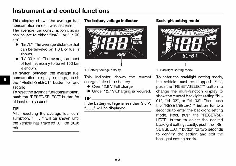
The battery voltage indicator
This indicator shows the currentcharge state of the battery. Over 12.8 V Full charge Under 12.7 V Charging is required.
TIP
If the battery voltage is less than 9.0 V,“_ _._” will be displayed.
Bac
To thepuschasho01”thesecmoLECbacSETto bac
1. Battery voltage display
11. B

nd control functions
6
S
TacIfcliginIfnY
N
If
c
a
e
EAU12401
mer switch “ / ”
t this switch to “ ” for the higham and to “ ” for the low beam.
EAU12461
rn signal switch “ / ”
signal a right-hand turn, push thisitch to “ ”. To signal a left-handn, push this switch to “ ”. Wheneased, the switch returns to the cen- position. To cancel the turn signalts, push the switch in after it has re-
ned to the center position.
EAU12501
rn switch “ ”
ss this switch to sound the horn.
EAU12722
rt switch “ ”
th the sidestand up, push this switchile applying the front or rear brake tonk the engine with the starter. Seege 8-1 for starting instructions priorstarting the engine.
1.
UB4HEZE0.book Page 9 Wednesday, March 21, 2018 2:58 PM
Instrument a
6-9
elf-diagnosis mode
his model is equipped with a self-di-gnosis device for various electricalircuits. a problem is detected in any of thoseircuits, the engine trouble warninght will come on and the display willdicate an error code. the display indicates any error codes,ote the code number and have aamaha dealer check the vehicle.
OTICEECA11591
the display indicates an error
ode, the vehicle should be checked
s soon as possible in order to avoid
ngine damage.
EAU1234M
Handlebar switches
Left
Right
Dim
Sebe
Tu
Toswturrelterlightur
Ho
Pre
Sta
Wiwhcrapato
Error code display
1
1. Dimmer switch “ / ”2. Turn signal switch “ / ”3. Horn switch “ ”
1. Stop and Start System switch “ / ”2. Hazard switch “ ”3. Start switch “ ”
1
23
A
A
1
23
A A
/

In
6
Ha
WtioartuThemwhm
N
Do
ex
gi
te
St
sw
ToseStto
EAU12952
ar brake lever
rear brake lever is located on the side of the handlebar. To apply ther brake, pull this lever toward thedlebar grip.
ear brake lever
OFF
1
UB4HEZE0.book Page 10 Wednesday, March 21, 2018 2:58 PM
strument and control functions
6-10
EAU79500
zard switch “ ”
ith the main switch in the “ON” posi-n, use this switch to turn on the haz-d lights (simultaneous flashing of allrn signal lights).e hazard lights are used in case of anergency or to warn other driversen your vehicle is stopped where it
ight be a traffic hazard.
OTICEECA10062
not use the hazard lights for an
tended length of time with the en-
ne not running, otherwise the bat-
ry may discharge.
EAU76391
op and Start System
itch “ / ”
turn on the Stop and Start System,t the switch to “ ”. To turn off theop and Start System, set this switch“ ”.
EAU12902
Front brake lever
The front brake lever is located on theright side of the handlebar. To applythe front brake, pull this lever towardthe throttle grip.
Re
Theleftreahan
A A
A
A
1. Front brake lever
A
A
1
1. R

nd control functions
6
RTb
T
T
EAU37473
el tank cap
remove the fuel tank cap
. Open the seat. (See page 6-14.)
. Turn the fuel tank cap counter-clockwise and pull it off.
1.2.3.
uel tank cappen.lose.
1
23
UB4HEZE0.book Page 11 Wednesday, March 21, 2018 2:58 PM
Instrument a
6-11
EAUN0440
ear brake lever lockhis vehicle is equipped with a rearrake lever lock.
o lock the brake lever
1. Pull the rear brake lever towardthe handlebar grip.
2. Push the lever lock pin down untilit latches with the lever lock pinstopper.
o unlock the brake lever
1. Pull the brake lever toward thehandlebar grip.
2. The lever lock pin should releasefrom the lever lock pin stopperand unlock the rear brake lever.
TIP
Use the rear brake lever lock whileseated.
WARNING
EWAN0010
Never apply the rear brake lever lock
while the vehicle is moving, other-
wise loss of control or an accident
may result. Make sure that the vehi-
cle is stopped before applying the
rear brake lever lock.
Fu
To
12
Rear brake leverLever lock pinLever lock pin stopper
1
3
2
1. F2. O3. C

In
6
To
1
2
M
pr
Le
Wipe up any spilled fuel immedi-ately. NOTICE: Immediately
wipe off spilled fuel with a clean,
dry, soft cloth, since fuel may
deteriorate painted surfaces or
plastic parts. [ECA10072]
Be sure to securely close the fueltank cap.
WARNING
EWA15152
soline is poisonous and can
se injury or death. Handle gaso-
with care. Never siphon gasoline
mouth. If you should swallow
e gasoline or inhale a lot of gas-
e vapor, or get some gasoline in
r eyes, see your doctor immedi-
uel tank filler tubeaximum fuel level
1
UB4HEZE0.book Page 12 Wednesday, March 21, 2018 2:58 PM
strument and control functions
6-12
install the fuel tank cap
. Insert the fuel tank cap into thetank opening and turn it clockwiseuntil the “ ” marks on the capand tank are aligned.
. Close the seat.
WARNING
EWA11092
ake sure that the fuel tank cap is
operly closed after filling fuel.
aking fuel is a fire hazard.
EAU13213
FuelMake sure there is sufficient gasoline inthe tank.
WARNING
EWA10882
Gasoline and gasoline vapors are
extremely flammable. To avoid fires
and explosions and to reduce the
risk of injury when refueling, follow
these instructions.
1. Before refueling, turn off the en-gine and be sure that no one is sit-ting on the vehicle. Never refuelwhile smoking, or while in the vi-cinity of sparks, open flames, orother sources of ignition such asthe pilot lights of water heatersand clothes dryers.
2. Do not overfill the fuel tank. Stopfilling when the fuel reaches thebottom of the filler tube. Becausefuel expands when it heats up,heat from the engine or the suncan cause fuel to spill out of thefuel tank.
3.
4.
Ga
cau
line
by
som
olin
you
1. F2. M
2

nd control functions
6
a
w
li
y
N
U
o
d
s
a
G
Thtaeteo
EAU13434
talytic converteris model is equipped with a catalyticnverter in the exhaust system.
WARNING
EWA10863
e exhaust system is hot after op-
tion. To prevent a fire hazard or
rns:
Do not park the vehicle near
possible fire hazards such as
grass or other materials that
easily burn.
Park the vehicle in a place
where pedestrians or children
are not likely to touch the hot
exhaust system.
Make sure that the exhaust sys-
tem has cooled down before
doing any maintenance work.
Do not allow the engine to idle
more than a few minutes. Long
idling can cause a build-up of
heat.
UB4HEZE0.book Page 13 Wednesday, March 21, 2018 2:58 PM
Instrument a
6-13
tely. If gasoline spills on your skin,
ash with soap and water. If gaso-
ne spills on your clothing, change
our clothes.
EAUU0045
OTICEECA11401
se only unleaded gasoline. The use
f leaded gasoline will cause severe
amage to internal engine parts,
uch as the valves and piston rings,
s well as to the exhaust system.
asohol
here are two types of gasohol: gaso-ol containing ethanol and that con-ining methanol. Gasohol containing
thanol can be used if the ethanol con-nt does not exceed 10% (E10). Gas-hol containing methanol is not
recommended by Yamaha because itcan cause damage to the fuel systemor vehicle performance problems.
CaThco
Th
era
bu
Recommended fuel:Regular unleaded gasoline (Gasohol [E10] acceptable)
Fuel tank capacity:4.2 L (1.1 US gal, 0.9 Imp.gal)

In
6
N
Us
of
pa
co
EAU37482
lmet holders
helmet holders are located under seat.
secure a helmet to a helmet hold-
Open the seat. (See page 6-14.)Attach a helmet to a helmet hold-er, and then securely close theseat. WARNING! Never ride with
a helmet attached to the helmet
holder, since the helmet may hit
objects, causing loss of control
and possibly an accident. [EWA10162]
elmet holder
1
UB4HEZE0.book Page 14 Wednesday, March 21, 2018 2:58 PM
strument and control functions
6-14
OTICEECA10702
e only unleaded gasoline. The use
leaded gasoline will cause unre-
irable damage to the catalytic
nverter.
EAU62381
Seat (for GDS125-I)
To open the seat
1. Insert the key into main switch andthen turn it to “OPEN” position.
2. Push the “SEAT” button to openthe seat.
To close the seat
Push the rear of the seat down to lockit in place.
TIP
Make sure that the seat is properly se-cured before riding.
He
Thethe
To
er
1.2.
1. Seat lock2. Seat
2
1 1. H

nd control functions
6
T
h
Othse
Do not leave your scooter unat-tended with the seat open.The interior of the rear storagecompartment lies outside the op-erating range of the smart key. Ifthe rear storage compartment islocked with the smart key inside,the smart key system may be dis-abled. The smart key must be car-ried by the rider.Do not place the smart key, me-chanical key, or identificationnumber tag inside the rear storagecompartment. They may get
ear storage compartment
1
UB4HEZE0.book Page 15 Wednesday, March 21, 2018 2:58 PM
Instrument a
6-15
o release a helmet from a helmet
older
pen the seat, remove the helmet frome helmet holder, and then close theat.
EAUN2122
Storage compartments
Front storage compartment
The front storage compartment is lo-cated at the front of the vehicle. Usethis compartment for small items.
Rear storage compartment
The rear storage compartment is locat-ed under the seat. Use this compart-ment for large items. (See page 6-14.)
TIP
1. Front storage compartment
1
1. R

In
6
TopaGD
12
GD
WARNING
EWA15861
not exceed the following loading
its:
Front storage compartment: 1
kg (2.2 lb)
Rear storage compartment: 1
kg (2.2 lb)
Maximum load for the vehicle:
153 kg (337 lb)
1.2.3.
UB4HEZE0.book Page 16 Wednesday, March 21, 2018 2:58 PM
strument and control functions
6-16
locked inside and the smart keysystem may not operate normally.(for GDS125-F)
open the seat/rear storage com-rtment with the mechanical key (forS125-F)
. Open the keyhole cover.
. Insert the mechanical key into theseat lock, and then turn it clock-wise.
S125-F
NOTICEECA15964
Do not leave the seat open for
an extended period of time, oth-
erwise the light may cause the
battery to discharge.
Since the storage compartment
may get wet when washing the
vehicle, wrap any articles stored
in the compartment in a plastic
bag.
To avoid humidity from spread-
ing through the storage com-
partment and to discourage
possible mold growth, wrap wet
articles in a plastic bag before
storing them in the compart-
ment.
Do not keep anything valuable
or breakable in the storage
compartment.
Since the storage compartment
accumulates heat from the en-
gine and from direct sunlight, do
not store anything susceptible
to heat, such as food or flamma-
ble items, inside the compart-
ment.
Do
lim
Keyhole coverSeat lockUnlock.
32
1

nd control functions
6
STsioth
T
T
th
s
(o
s
a
in
Y
s
th
EAUT1097
nition circuit cut-off systemeck the operation of the sidestanditch according to the following pro-dure.
UB4HEZE0.book Page 17 Wednesday, March 21, 2018 2:58 PM
Instrument a
6-17
EAU76780
idestandhe sidestand is located on the leftde of the frame. Raise the sidestandr lower it with your foot while holdinge vehicle upright.
IP
The built-in sidestand switch ispart of the ignition circuit cut-offsystem, which cuts the ignition incertain situations. (See the follow-ing section for an explanation ofthe ignition circuit cut-off system.)
When the sidestand is lowered,the Stop and Start System is de-activated.
WARNING
EWA10242
he vehicle must not be ridden with
e sidestand down, or if the side-
tand cannot be properly moved up
r does not stay up), otherwise the
idestand could contact the ground
nd distract the operator, resulting
a possible loss of control.
amaha’s ignition circuit cut-off
ystem has been designed to assist
e operator in fulfilling the respon-
sibility of raising the sidestand be-
fore starting off. Therefore, check
this system regularly and have a
Yamaha dealer repair it if it does not
function properly.
IgChswce

In
6
d on the center-on.have a Yamaha efore riding.
UB4HEZE0.book Page 18 Wednesday, March 21, 2018 2:58 PM
strument and control functions
6-18
Turn the main switch on.
Put the sidestand up.
Push the start switch while applyingeither of the brake levers. The engine willstart.
Put the sidestand down.
If the engine stalls:
The sidestand switch is OK.
• The vehicle must be place stand during this inspecti• If a malfunction is noted, dealer check the system b
WARNING

nd control functions
6
PTp
N
D
th
th
w
te
W
re
p
WARNING
EWA14361
prevent electrical shock or short-
cuiting, make sure that the cap is
talled when the auxiliary DC jack
not being used.
1.
UB4HEZE0.book Page 19 Wednesday, March 21, 2018 2:58 PM
Instrument a
6-19
EAUN2160
ower outlet his model is equipped with a 12V DCower outlet.
OTICEECAN0140
o not use the power outlet when
e engine is off, and do not exceed
e specified electrical load; other-
ise the fuse may blow or the bat-
ry may discharge.
hen washing the vehicle, do not di-
ct high-pressure washers at the
ower outlet area.
To use the power outlet
1. Turn the vehicle power off.2. Remove the power outlet cap.3. Turn the accessory off.4. Insert the accessory plug into the
power outlet.5. Turn the vehicle power on and
start the engine.6. Turn the accessory on.
TIP
When finished riding, be sure to turn offthe accessory and disconnect it fromthe power outlet, and then install thepower outlet cap.
To
cir
ins
is
Power outlet
Maximum electrical load:12 W (1A)
1
1. Power outlet cap
1

F
7
EAU15599
In dition. Always follow the inspectionan
EWA11152
Fa accident or equipment damage.
Do ed by the procedures provided in
th
Be
PAGE
Fd check
6-12
E 9-11
F 9-13
C 9-15
F 9-23, 9-23
UB4HEZE0.book Page 1 Wednesday, March 21, 2018 2:58 PM
or your safety – pre-operation checks
7-1
spect your vehicle each time you use it to make sure the vehicle is in safe operating cond maintenance procedures and schedules described in the Owner’s Manual.
WARNING
ilure to inspect or maintain the vehicle properly increases the possibility of an
not operate the vehicle if you find any problem. If a problem cannot be correct
is manual, have the vehicle inspected by a Yamaha dealer.
fore using this vehicle, check the following points:
ITEM CHECKS
uel
• Check fuel level in fuel tank.• Refuel if necessary.• Check fuel line for leakage.• Check fuel tank overflow hose for obstructions, cracks or damage, an
hose connection.
ngine oil• Check oil level in engine.• If necessary, add recommended oil to specified level.• Check vehicle for oil leakage.
inal transmission oil • Check vehicle for oil leakage.
oolant• Check coolant level in reservoir.• If necessary, add recommended coolant to specified level.• Check cooling system for leakage.
ront brake
• Check operation.• If soft or spongy, have Yamaha dealer bleed hydraulic system.• Check brake pads for wear.• Replace if necessary.• Check fluid level in reservoir.• If necessary, add specified brake fluid to specified level.• Check hydraulic system for leakage.

re-operation checks
7
R 9-22, 9-23
T bricate ca- 9-19, 9-25
C 9-25
W 9-19, 9-21
B 9-25
C 9-26
C —
Ia
—
S . 6-17
PAGE
UB4HEZE0.book Page 2 Wednesday, March 21, 2018 2:58 PM
For your safety – p
7-2
ear brake
• Check operation.• Lubricate cable if necessary.• Check lever free play.• Adjust if necessary.
hrottle grip
• Make sure that operation is smooth.• Check throttle grip free play.• If necessary, have Yamaha dealer adjust throttle grip free play and lu
ble and grip housing.
ontrol cables• Make sure that operation is smooth.• Lubricate if necessary.
heels and tires
• Check for damage.• Check tire condition and tread depth.• Check air pressure.• Correct if necessary.
rake levers• Make sure that operation is smooth.• Lubricate lever pivoting points if necessary.
enterstand, sidestand• Make sure that operation is smooth.• Lubricate pivots if necessary.
hassis fasteners• Make sure that all nuts, bolts and screws are properly tightened.• Tighten if necessary.
nstruments, lights, signals nd switches
• Check operation.• Correct if necessary.
idestand switch • Check operation of ignition circuit cut-off system.• If system is not working correctly, have Yamaha dealer check vehicle
ITEM CHECKS

O
8
Rebethun
Fa
th
tro
or
EAUV0740
rting the engine
TICEECA10251
page 8-3 for engine break-in in-
ctions prior to operating the ve-
le for the first time.
rder for the ignition circuit cut-offtem to enable starting, the side-nd must be up. (See page 6-17.)
Turn the main switch on.The following warning lights andindicator lights should come on fora few seconds, then go off. Engine trouble warning light Coolant temperature warning
light Turn signal indicator lights Stop and Start System indi-
cator light Smart key system indicator
light (for GDS125-F)
UB4HEZE0.book Page 1 Wednesday, March 21, 2018 2:58 PM
peration and important riding points
8-1
EAU15952
ad the Owner’s Manual carefully tocome familiar with all controls. Ifere is a control or function you do notderstand, ask your Yamaha dealer.
WARNING
EWA10272
ilure to familiarize yourself with
e controls can lead to loss of con-
l, which could cause an accident
injury.
EAUN0073
NOTICEECAN0072
Do not ride through deep water, oth-
erwise the engine may be damaged.
Avoid puddles because they may be
deeper than expected.
Sta
NO
See
stru
hic
In osyssta
1.

portant riding points
8
N
If
n
p
w
c
T
N
F
c
c
EAU16782
celeration and deceleration
e speed can be adjusted by openingd closing the throttle. To increase speed, turn the throttle grip in di-tion (a). To reduce the speed, turn throttle grip in direction (b).
A
A
(a)
(b)
UB4HEZE0.book Page 2 Wednesday, March 21, 2018 2:58 PM
Operation and im
8-2
OTICEECA22510
a warning or indicator light does
ot work as described above, see
age 6-2 for the corresponding
arning and indicator light circuit
heck.
2. Close the throttle.3. While applying the front or rear
brake, push the start switch. Re-lease it when the engine starts.
IP
If the engine does not start, re-lease the start switch after 5 sec-onds. Before pressing the startswitch again, wait 10 seconds toallow battery voltage to restore.
When the Stop and Start Systemis activated, turning the throttlegrip will start the engine. (Seepage 5-1.)
OTICEECA11043
or maximum engine life, never ac-
elerate hard when the engine is
old!
EAU45093
Starting off1. While pulling the rear brake lever
with your left hand and holding thegrab bar with your right hand,push the scooter off the center-stand.
2. Sit astride the seat, and then ad-just the rear view mirrors.
3. Switch the turn signals on.4. Check for oncoming traffic, and
then slowly turn the throttle grip(on the right) in order to take off.
5. Switch the turn signals off.
Ac
Thantherecthe
1. Grab bar
1

O
8
B
12
EAU16831
gine break-inre is never a more important periode life of your engine than the period
ween 0 and 1000 km (600 mi). For reason, you should read the fol-ing material carefully.ce the engine is brand new, do not an excessive load on it for the first0 km (600 mi). The various parts in engine wear and polish themselvesthe correct operating clearances.ing this period, prolonged full-throt-operation or any condition thatht result in engine overheatingst be avoided.
EAU37793
50 km (0–90 mi)
id prolonged operation above 1/3ttle.r every hour of operation, stop theine, and then let it cool for five to minutes.y the engine speed from time toe. Do not operate the engine at one throttle position.
UB4HEZE0.book Page 3 Wednesday, March 21, 2018 2:58 PM
peration and important riding points
8-3
EAU16794
raking
WARNING
EWA10301
Avoid braking hard or suddenly
(especially when leaning over to
one side), otherwise the scooter
may skid or overturn.
Railroad crossings, streetcar
rails, iron plates on road con-
struction sites, and manhole
covers become extremely slip-
pery when wet. Therefore, slow
down when approaching such
areas and cross them with cau-
tion.
Keep in mind that braking on a
wet road is much more difficult.
Ride slowly down a hill, as brak-
ing downhill can be very diffi-
cult.
. Close the throttle completely.
. Apply both front and rear brakessimultaneously while gradually in-creasing the pressure.
EAU16821
Tips for reducing fuel con-sumptionFuel consumption depends largely onyour riding style. Consider the follow-ing tips to reduce fuel consumption: Avoid high engine speeds during
acceleration. Avoid high engine speeds with no
load on the engine. Turn the engine off instead of let-
ting it idle for an extended lengthof time (e.g., in traffic jams, at traf-fic lights or at railroad crossings).
EnThein thbetthislowSinput100theto Durtle migmu
0–1
AvothroAfteengtenVartimset

portant riding points
8
1
AthRgti5
Ath1
AVNo
c
e
c
s
b
Y
[EC
WARNING
EWA18840
Since the engine and exhaust
system can become very hot,
park in a place where pedestri-
ans or children are not likely to
touch them and be burned.
Do not park on a slope or on soft
ground, otherwise the vehicle
may overturn, increasing the
risk of a fuel leak and fire.
Do not park near grass or other
flammable materials which
might catch fire.
If the Stop and Start System is
left turned on, the battery could
become discharged and it may
not be possible to restart the
engine due to insufficient bat-
tery voltage.
UB4HEZE0.book Page 4 Wednesday, March 21, 2018 2:58 PM
Operation and im
8-4
50–500 km (90–300 mi)
void prolonged operation above 1/2rottle.ev the engine freely through theears, but do not use full throttle at anyme.00–1000 km (300–600 mi)
void prolonged operation above 3/4rottle.
000 km (600 mi) and beyond
void prolonged full-throttle operation.ary the engine speed occasionally.OTICE: After 1000 km (600 mi) of
peration, the engine oil must be
hanged, the oil filter cartridge or el-
ment replaced, and the oil strainer
leaned. If any engine trouble
hould occur during the engine
reak-in period, immediately have a
amaha dealer check the vehicle.
A10363]
EAU78781
Parking (for GDS125-F)When parking, turn the vehicle poweroff, and then turn the smart key off.
TIP
Even when the vehicle is parked in a lo-cation partitioned by a fence or theglass window of a shop, if the smartkey is within operating range, otherpeople will be able to start the engineand operate the vehicle. Please turnthe smart key off when leaving the ve-hicle. (See page 4-5.)
If the sidestand is lowered when theengine is running, the engine will stopand the beeper will sound for approxi-mately 1 minute. To stop the beeper,turn off the the main switch or raise thesidestand.
TIP
Before leaving the vehicle, be sureto turn the main switch to “OFF”or “ ”. Otherwise, the battery maydischarge.
The sidestand alarm beeper canbe set to not activate. Please con-tact your Yamaha dealer.

P
9
PelubsapovepoadplThmconopegrthbe
Fa
cl
tiv
yo
se
yo
vic
se
EAU39694
ol kit
tool kit is located on the bottom of seat. (See page 6-14.) information included in this manual the tools provided in the tool kit arended to assist you in the perfor-nce of preventive maintenance andor repairs. However, a torquench and other tools are necessary
perform certain maintenance workrectly.
ou do not have the tools or experi-e required for a particular job, haver Yamaha dealer perform it for you.
wner’s tool kit
1
UB4HEZE0.book Page 1 Wednesday, March 21, 2018 2:58 PM
eriodic maintenance and adjustment
9-1
EAU17246
riodic inspection, adjustment, andrication will keep your vehicle in the
fest and most efficient conditionssible. Safety is an obligation of thehicle owner/operator. The most im-rtant points of vehicle inspection,justment, and lubrication are ex-
ained on the following pages.e intervals given in the periodicaintenance charts should be simplynsidered as a general guide underrmal riding conditions. However, de-nding on the weather, terrain, geo-aphical location, and individual use,e maintenance intervals may need to shortened.
WARNING
EWA10322
ilure to properly maintain the vehi-
e or performing maintenance ac-
ities incorrectly may increase
ur risk of injury or death during
rvice or while using the vehicle. If
u are not familiar with vehicle ser-
e, have a Yamaha dealer perform
rvice.
WARNING
EWA15123
Turn off the engine when performing
maintenance unless otherwise
specified.
A running engine has moving
parts that can catch on body
parts or clothing and electrical
parts that can cause shocks or
fires.
Running the engine while ser-
vicing can lead to eye injury,
burns, fire, or carbon monoxide
poisoning – possibly leading to
death. See page 2-3 for more in-
formation about carbon monox-
ide.
WARNING
EWA15461
Brake discs, calipers, drums, and
linings can become very hot during
use. To avoid possible burns, let
brake components cool before
touching them.
To
ThetheTheandintemaminwreto cor
TIP
If yencyou
1. O

ance and adjustment
9
EAUU0621
T
ed maintenance is performed in-
require special tools, data and tech-
EAUU1294
P
N
ichever comes first)
ANNUAL CHECK
hs
12000 km or
14 months
16000 km or
18 months
1 √ √ √
2 00 km (7500 mi)
3√ √
00 km (5000 mi)
4 √
5 √ √ √
6 √ √ √
UB4HEZE0.book Page 2 Wednesday, March 21, 2018 2:58 PM
Periodic mainten
9-2
IP
The annual checks must be performed every year, except if a kilometer-bas
stead.
From 20000 km, repeat the maintenance intervals starting from 4000 km. Items marked with an asterisk should be performed by a Yamaha dealer as they
nical skills.
eriodic maintenance chart for the emission control system
O. ITEM CHECK OR MAINTENANCE JOB
ODOMETER READING (wh
1000 km or
2 months
4000 km or
6 months
8000 kmor
10 mont
* Fuel line• Check fuel hoses for cracks or
damage. √ √
* Fuel filter• Check condition.• Replace if necessary. Every 120
Spark plug
• Check condition.• Clean and regap. √ √
• Replace. Every 80
* Valves• Check valve clearance.• Adjust if necessary. √
* Fuel injection • Check engine idle speed. √ √
* Exhaust system• Check for leakage.• Tighten if necessary.• Replace gasket(s) if necessary.
√ √
CN580154
Text Box
EAU62051
CN580154
Line
CN580154
Rectangle

P
9
EAUU1287
G
N
chever comes first)
ANNUAL CHECK
s
12000 km or
14 months
16000 km or
18 months
1 √ √ √
2 0 km (10000 mi)
3 √ √
4 √ √
5 √ √ √
6√ √ √
worn to the limit
7√ √ √
worn to the limit
8√ √ √
y 4 years
9 y 2 years
10 √ √
UB4HEZE0.book Page 3 Wednesday, March 21, 2018 2:58 PM
eriodic maintenance and adjustment
9-3
eneral maintenance and lubrication chart
O. ITEM CHECK OR MAINTENANCE JOB
ODOMETER READING (whi
1000 km or
2 months
4000 km or
6 months
8000 kmor
10 month
* Diagnostic system check
• Perform dynamic inspection us-ing Yamaha diagnostic tool.
• Check the error codes.√ √ √
Air filter element • Replace. Every 1600
Air filter check hose • Clean. √ √ √
* V-belt case air filter element
• Clean.• Replace if necessary. √ √
* Battery• Check voltage.• Charge if necessary. √ √ √
* Front brake
• Check operation, fluid level and vehicle for fluid leakage. √ √ √
• Replace brake pads. Whenever
* Rear brake
• Check operation and adjust brake lever free play. √ √ √
• Replace brake shoes. Whenever
* Brake hoses
• Check for cracks or damage.• Check for correct routing and
clamping.√ √
• Replace. Ever
* Brake fluid • Change. Ever
* Wheels • Check runout and for damage. √ √
CN580154
Rectangle

ance and adjustment
9
1 √ √ √
1 √ √
1
√ √
00 km (7500 mi)
1 √ √ √
1 √ √ √
1 √ √ √
1 √ √ √
1 √ √ √
1 √ √
2 √ √
N
ichever comes first)
ANNUAL CHECK
hs
12000 km or
14 months
16000 km or
18 months
UB4HEZE0.book Page 4 Wednesday, March 21, 2018 2:58 PM
Periodic mainten
9-4
1 * Tires
• Check tread depth and for dam-age.
• Replace if necessary.• Check air pressure.• Correct if necessary.
√ √
2 * Wheel bearings• Check bearings for looseness or
damage. √ √
3 * Steering bearings
• Check bearing play and steering for roughness. √ √ √
• Lubricate with lithium-soap-based grease. Every 120
4 * Chassis fasteners• Make sure that all nuts, bolts and
screws are properly tightened. √ √
5Front brake lever pivot shaft
• Lubricate with silicone grease. √ √
6Rear brake lever pivot shaft
• Lubricate with silicone grease. √ √
7Sidestand, center-stand
• Check operation.• Lubricate with lithium-soap-
based grease.√ √
8 * Sidestand switch • Check operation. √ √ √
9 * Front fork• Check operation and for oil leak-
age. √ √
0 * Shock absorber as-semblies
• Check operation and shock ab-sorbers for oil leakage. √ √
O. ITEM CHECK OR MAINTENANCE JOB
ODOMETER READING (wh
1000 km or
2 months
4000 km or
6 months
8000 kmor
10 mont

P
9
21 √ √
22 √
23
√ √ √
y 3 years
24Every 8000 km (5000 mi)
ry 12000 km (7500 mi)
25√ √ √
0 km (15500 mi)
26 0 km (7500 mi)
27 √ √ √
28 √ √ √
29 √ √ √
30 √ √ √
N
chever comes first)
ANNUAL CHECK
s
12000 km or
14 months
16000 km or
18 months
UB4HEZE0.book Page 5 Wednesday, March 21, 2018 2:58 PM
eriodic maintenance and adjustment
9-5
Engine oil• Change.• Check oil level and vehicle for oil
leakage.√ √ √
* Engine oil strainer • Clean. √
* Cooling system
• Check coolant level and vehicle for coolant leakage. √ √
• Change with Yamaha genuine coolant. Ever
Final transmission oil
• Check vehicle for oil leakage. √ √
• Change. √ Eve
* V-belt• Check for damage and wear. √
• Replace. Every 2500
* V-belt secondary sheave
• Lubricate. Every 1200
* Front and rear brake switches
• Check operation. √ √ √
Moving parts and cables
• Lubricate. √ √
* Throttle grip
• Check operation.• Check throttle grip free play, and
adjust if necessary.• Lubricate cable and grip housing.
√ √
* Lights, signals and switches
• Check operation.• Adjust headlight beam. √ √ √
O. ITEM CHECK OR MAINTENANCE JOB
ODOMETER READING (whi
1000 km or
2 months
4000 km or
6 months
8000 kmor
10 month

ance and adjustment
9
EAUU1622
T
hich must not be cleaned with com-
ually wet or dusty areas.
sty areas.
m (2500 mi) thereafter. Replace the5000 km (16000 mi) even if there is
the brake master cylinders and cal-
and caliper, and change the brake
ge to internal engine parts, such as
UB4HEZE0.book Page 6 Wednesday, March 21, 2018 2:58 PM
Periodic mainten
9-6
IP
Air filter• This model’s air filter is equipped with a disposable oil-coated paper element, w
pressed air to avoid damaging it.• The air filter element needs to be replaced more frequently when riding in unus
V-belt case air filter• The air filter needs more frequent service if you are riding in unusually wet or du
V-belt• The V-belt should be checked at the initial 8000 km (5000 mi) and every 4000 k
V-belt if any damage or wear is found. The V-belt needs to be replaced every 2no wear or damage.
Hydraulic brake service• Regularly check and, if necessary, correct the brake fluid level. After dissembling
ipers, always change the brake fluid.• Every two years replace the internal components of the brake master cylinder
fluid.• Replace the brake hose every four years and if cracked or damaged.
Fuel system service• Use only unleaded gasoline. The use of leaded gasoline will cause severe dama
the valves and piston rings, as well as to the exhaust system.• Replace the fuel filler cover every two years or if cracked or damaged.• Check the fuel filter if clogged or damaged every 12000 km (7500 mi).
Battery service• Check the condition and service every 3 months.• Recharge the battery immediately if the voltage is less than 12.4 V.• If the battery tends to discharge, replace it immediately.

P
9
harge it, and then place it in a cool,
UB4HEZE0.book Page 7 Wednesday, March 21, 2018 2:58 PM
eriodic maintenance and adjustment
9-7
• If the vehicle will not be used for more than one month, remove the battery, fully cdry place.

ance and adjustment
9
ReTtojothb
P
T
install the panel. Place the panel in the original po-
sition, with fit the projection on thepanel into the hole.
. Install the screws to the panel.
. Install the windshield by installingthe screws.
nel B
remove the panel. Open the seat. (See page 6-14.). Remove the screws, and then pull
the panel off as shown.
1.2.3.
anel Arojectionole
2
1
3
UB4HEZE0.book Page 8 Wednesday, March 21, 2018 2:58 PM
Periodic mainten
9-8
EAU18773
emoving and installing pan-lshe panels shown need to be removed perform some of the maintenancebs described in this chapter. Refer tois section each time a panel needs toe removed and installed.
EAUN2180
anel A
o remove the panel1. Remove the windshield by remov-
ing the screws.
2. Remove the screws from panel A,and then pull the panel off.
To1
23
Pa
To12
Panel APanel BPanel C
1 2 31. Windshield2. Screw
1. Panel A2. Screw
1
2
1
21. P2. P3. H

P
9
To1
2
Pa
To12
install the panelPlace the panel in the original po-sition, and then install the screws.Install the grab bar by installing thebolts.
ke sure that the grab bar is properlytened before riding.
Close the seat.
1.2.
ightening torque:Grab bar:
9 N·m (0.9 kgf·m, 6.6 lb·ft)
UB4HEZE0.book Page 9 Wednesday, March 21, 2018 2:58 PM
eriodic maintenance and adjustment
9-9
install the panel. Place the panel in the original po-
sition, and then install the screws.. Close the seat.
nel C
remove the panel. Open the seat. (See page 6-14.). Remove the grab bar by removing
the bolts.
3. Remove the screws from panel C,and pull the panel up, then slidebackward as shown.
To 1.
2.
TIP
Matigh
3.
Panel BScrew
2 1
1. Grab bar2. Bolt
1. Panel C2. Screw3. Pull4. Slide backwards.
2
1
4
12
3
T

ance and adjustment
9
CTcSsppintetic
T
. Check the spark plug for electrodeerosion and excessive carbon orother deposits, and replace it ifnecessary.
. Measure the spark plug gap with awire thickness gauge and, if nec-essary, adjust the gap to specifi-cation.
1.
pecified spark plug:NGK/CPR8EA9DENSO/U24EPR-9
park plug gap
park plug gap:0.8–0.9 mm (0.031–0.035 in)
UB4HEZE0.book Page 10 Wednesday, March 21, 2018 2:58 PM
Periodic mainten
9-10
EAUT2076
hecking the spark plughe spark plug is an important engineomponent, which is easy to check.ince heat and deposits will cause anyark plug to slowly erode, the spark
lug should be removed and checked accordance with the periodic main-nance and lubrication chart. In addi-
on, the condition of the spark plugan reveal the condition of the engine.
o remove the spark plug
1. Remove panel B. (See page 9-8.)2. Remove the spark plug cap.
3. Remove the spark plug as shown,with a spark plug wrench availableat a Yamaha dealer.
To check the spark plug
1. Check that the porcelain insulatoraround the center electrode of thespark plug is a medium-to-lighttan (the ideal color when the vehi-cle is ridden normally).
TIP
If the spark plug shows a distinctly dif-ferent color, the engine could be oper-ating improperly. Do not attempt todiagnose such problems yourself. In-stead, have a Yamaha dealer checkthe vehicle.
2
3
Spark plug cap
1
1. Spark plug wrench
1
S
1. S
S

P
9
To
1
2
TI
If whes1/spsp
3
EAU62845
gine oil and oil strainer engine oil level should be checkedore each ride. In addition, the oilst be changed and the oil strainerned at the intervals specified in the
iodic maintenance and lubricationrt.
check the engine oil level
Place the vehicle on the center-stand. A slight tilt to the side canresult in a false reading.Start the engine, warm it up forseveral minutes, and then turn itoff.Wait a few minutes until the oil set-tles, remove the oil filler cap, wipethe dipstick clean, insert it backinto the oil filler hole (withoutscrewing it in), and then remove itagain to check the oil level.
WARNING
EWAU0031
muffler and muffler protector
ome very hot during use. To
id possible burns, let the muffler
protector cool before removing
oil filler cap.
UB4HEZE0.book Page 11 Wednesday, March 21, 2018 2:58 PM
eriodic maintenance and adjustment
9-11
install the spark plug
. Clean the surface of the sparkplug gasket and its mating sur-face, and then wipe off any grimefrom the spark plug threads.
. Install the spark plug with thespark plug wrench, and then tight-en it to the specified torque.
P
a torque wrench is not availableen installing a spark plug, a good
timate of the correct torque is 1/4–2 turn past finger tight. However, theark plug should be tightened to theecified torque as soon as possible.
. Install the spark plug cap.
4. Install the panel.
EnThebefmucleapercha
To
1.
2.
3.
The
bec
avo
and
the
Tightening torque:Spark plug:
13 N·m (1.3 kgf·m, 9.6 lb·ft)
1. Spark plug cap2. Spark plug lead
2
1

ance and adjustment
9
T
Ttim
en only changing the engine oil, re-ve drain bolt A. When changing the
gine oil and cleaning the engine oilainer, remove drain bolt B also.
. Clean the engine oil strainer withsolvent, and then check it fordamage and replace it if neces-sary.
1.2.3.4.5.
ngine oil drain bolt Aasketil strainerompression spring-ringngine oil drain bolt B
2
1
3
456
UB4HEZE0.book Page 12 Wednesday, March 21, 2018 2:58 PM
Periodic mainten
9-12
IP
he engine oil should be between thep of the dipstick and maximum levelark.
4. If the engine oil is at or below theminimum level mark, add suffi-cient oil of the recommended typeto raise it to the correct level.
5. Insert the dipstick into the oil fillerhole, and then tighten the oil fillercap.
To change the engine oil and clean
the oil strainer
1. Start the engine, warm it up forseveral minutes, and then turn itoff.
2. Place an oil pan under the engineto collect the used oil.
3. Remove the engine oil filler capand drain bolt B to drain the oilfrom the crankcase. NOTICE:When removing the engine oil
drain bolt, the O-ring, compres-
sion spring, and oil strainer will
fall out. Take care not to lose
these parts. [ECA11002]
TIP
Whmoenstr
4
Engine oil filler capO-ringEngine oil dipstickMaximum level markTip of the engine oil dipstick
1
32
45
1. E2. G3. O4. C5. O6. E

P
9
5
TI
Mse
6
TI
Bepate
EAU67821
al transmission oil final transmission case must becked for oil leakage before each. If any leakage is found, have aaha dealer check and repair your
torcycle. In addition, the final trans-sion oil must be changed as followshe intervals specified in the periodicintenance and lubrication chart.
Start the engine and warm up thefinal transmission oil by riding themotorcycle for several minutes.Stop the engine and then placethe motorcycle on the center-stand.Place an oil pan under the finaltransmission case to collect theused oil.Remove the final transmission oilfiller cap and its O-ring from the fi-nal transmission case.
UB4HEZE0.book Page 13 Wednesday, March 21, 2018 2:58 PM
eriodic maintenance and adjustment
9-13
. Install the engine oil strainer, com-pression spring, engine oil drainbolt with new O-ring, and thentighten the drain bolt to the speci-fied torque.
P
ake sure that the O-ring is properlyated.
. Refill with the specified amount ofthe recommended engine oil, andthen install and tighten the oil fillercap.
P
sure to wipe off spilled oil on anyrts after the engine and exhaust sys-m have cooled down.
NOTICEECA11671
Do not use oils with a diesel
specification of “CD” or oils of a
higher quality than specified. In
addition, do not use oils labeled
“ENERGY CONSERVING II” or
higher.
Be sure no foreign material en-
ters the crankcase.
7. Start the engine, and then let it idlefor several minutes while checkingit for oil leakage. If oil is leaking,immediately turn the engine offand check for the cause.
8. Turn the engine off, and thencheck the oil level and correct it ifnecessary.
FinThecherideYammomisat tma
1.
2.
3.
4.
Tightening torque:Engine oil drain bolt A:
20 N·m (2.0 kgf·m, 15 lb·ft)Engine oil drain bolt B:
20 N·m (2.0 kgf·m, 15 lb·ft)
Recommended engine oil:See page 11-1.
Oil quantity:0.90 L (0.95 US qt, 0.79 Imp.qt)

ance and adjustment
9
. Install the final transmission oil fill-er cap and its new O-ring, andthen tighten the oil filler cap.
. Check the final transmission casefor oil leakage. If oil is leaking,check for the cause.
1.2.
1.2.
UB4HEZE0.book Page 14 Wednesday, March 21, 2018 2:58 PM
Periodic mainten
9-14
5. Remove the final transmission oildrain bolt and its gasket to drainthe oil from the final transmissioncase.
6. Install the final transmission oildrain bolt and its new gasket, andthen tighten the bolt to the speci-fied torque.
TIP
Before installing the final transmis-sion oil drain bolt and gasket, ap-ply oil to them.
Wipe off any excess oil afterwards.
7. Refill with the specified amount ofthe recommended final transmis-sion oil. WARNING! Make sure
that no foreign material enters
the final transmission case.
Make sure that no oil gets on
the tire or wheel. [EWA11312]
8
9
Final transmission oil filler capO-ring
Final transmission oil drain boltGasket
1
2
1 2
Tightening torque:Final transmission oil drain bolt:
20 N·m (2.0 kgf·m, 15 lb·ft)
Recommended final transmission oil:
See page 11-1.Oil quantity:
0.15 L (0.16 US qt, 0.13 Imp.qt)

P
9
CThbeanspan
To
1
TI
2
TI
Thm
Remove the coolant reservoir cov-er.
Remove the coolant reservoir cap,add coolant to the maximum levelmark, and then install the reservoircap. WARNING! Remove only
the coolant reservoir cap. Never
attempt to remove the radiator
cap when the engine is hot.
[EWA15162] NOTICE: If coolant is not
available, use distilled water or
soft tap water instead. Do not
use hard water or salt water
since it is harmful to the engine.
If water has been used instead
of coolant, replace it with cool-
ant as soon as possible, other-
wise the cooling system will not
oolant reservoir cover
1
UB4HEZE0.book Page 15 Wednesday, March 21, 2018 2:58 PM
eriodic maintenance and adjustment
9-15
EAU20071
oolante coolant level should be checkedfore each ride. In addition, the cool-t must be changed at the intervalsecified in the periodic maintenanced lubrication chart.
EAUN2170
check the coolant level
. Place the vehicle on the center-stand.
P
The coolant level must bechecked on a cold engine sincethe level varies with engine tem-perature.Make sure that the vehicle is posi-tioned straight up when checkingthe coolant level. A slight tilt to theside can result in a false reading.
. Check the coolant level throughthe check window.
P
e coolant should be between theinimum and maximum level marks.
3. If the coolant is at or below theminimum level mark, remove theright floorboard mat by pulling itup.
4.
5.
1. Coolant level check window2. Maximum level mark3. Minimum level mark
1. Floorboard mat
2
13
1
1. C

ance and adjustment
9
EAU67174
r filter and V-belt case air fil-r elementse air filter element should be re-ced and the V-belt case air filter el-ent should be cleaned at the
ervals specified in the periodic main-ance and lubrication chart. Service air filter elements more frequently if
u are riding in unusually wet or dustyas. The air filter check hose and V-lt case air filter check hose must bequently checked and cleaned if nec-ary.
aning the air filter check hose
1.
ir filter check hose
1
UB4HEZE0.book Page 16 Wednesday, March 21, 2018 2:58 PM
Periodic mainten
9-16
be protected against frost and
corrosion. If water has been
added to the coolant, have a
Yamaha dealer check the anti-
freeze content of the coolant as
soon as possible, otherwise the
effectiveness of the coolant will
be reduced. [ECA10473]
6. Install the coolant reservoir cover.7. Place the right floorboard mat in
the original position and push itdownward to secure it.
EAU33032
Changing the coolant
The coolant must be changed at the in-tervals specified in the periodic main-tenance and lubrication chart. Have aYamaha dealer change the coolant.WARNING! Never attempt to remove
the radiator cap when the engine is
hot. [EWA10382]
AiteThplaeminttentheyoarebefreess
Cle
Coolant reservoir cap
Coolant reservoir capacity (up to the maximum level mark):
0.13 L (0.14 US qt, 0.11 Imp.qt)
1
1. A

P
9
1
2
TI
If homre
Re
1
2
The air filter element needs
more frequent replacement if
you are riding in unusually wet
or dusty areas.
Do not clean the air filter ele-
ment by blowing it with com-
pressed air.
Install the air filter case cover byinstalling the screws.
aning the V-belt case check hose
Check the hose on the rear side ofthe V-belt case for accumulateddirt or water.If dirt or water is visible, removethe hose from the clamp, clean it,and then install it.1.
2.
-belt case check hose1
UB4HEZE0.book Page 17 Wednesday, March 21, 2018 2:58 PM
eriodic maintenance and adjustment
9-17
. Check the hose on the rear side ofthe air filter case for accumulateddirt or water.
. If dirt or water is visible, removethe hose from the clamp, clean it,and then install it.
P
dirt or water was found in the checkse, be sure to check the air filter ele-ent for excessive dirt or damage andplace it if necessary.
placing the air filter element
. Place the vehicle on the center-stand.
. Remove the air filter case cover byremoving the screws.
3. Pull the air filter element out.
4. Insert a new air filter element intothe air filter case. NOTICE: Make
sure that the air filter element is
properly seated in the air filter
case. The engine should never
be operated without the air filter
element installed, otherwise the
piston(s) and/or cylinder(s) may
become excessively worn.
[ECA10482]
NOTICEECA21220
The air filter element must be
replaced at the intervals speci-
fied in the periodic maintenance
and lubrication chart.
5.
Cle
1.
2.
Air filter case coverScrew
1 2
2
1. Air filter element
1
1. V

ance and adjustment
9
T
Ifhade
C
e
. Apply oil of the recommendedtype to the entire surface of thesponge material, and thensqueeze the excess oil out.
The air filter element should bewet but not dripping.Check the air filter element for ex-cessive dirt or damage and re-place it if necessary.
. Insert the element into the V-beltcase.
. Install the air filter element coverby installing the screws.
1.2.
ecommended oil:Yamaha foam air filter oil or other quality foam air filter oil
UB4HEZE0.book Page 18 Wednesday, March 21, 2018 2:58 PM
Periodic mainten
9-18
IP
dirt or water was found in the checkose, be sure to check the V-belt caseir filter element for excessive dirt oramage and clean or replace it if nec-ssary.
leaning the V-belt case air filter el-
ment
1. Place the vehicle on the center-stand.
2. Remove the screws, and then pullthe V-belt case air filter elementcover outward and away from theV-belt case.
3. Pull the V-belt case air filter ele-ment out, and then clean it withsolvent. After cleaning, removethe remaining solvent by squeez-ing the element. WARNING! Use
only a dedicated parts cleaning
solvent. To avoid the risk of fire
or explosion, do not use gaso-
line or solvents with a low flash
point. [EWA10432] NOTICE: To avoid
damaging the air filter element,
handle it gently and carefully,
and do not twist it. [ECA10522]
4
TIP
5
6
V-belt case air filter element coverScrew
2
211. V-belt case air filter element
1R

P
9
CplMsh
Peplde
EAU82720
ess are the only contact between theicle and the road. Safety in all con-ons of riding depends on a relativelyall area of road contact. Therefore, itssential to maintain the tires in gooddition at all times and replace themhe appropriate time with the speci- tires.
air pressure
tire air pressure should becked and, if necessary, adjustedore each ride.
WARNING
EWA10504
eration of this vehicle with im-
per tire pressure may cause se-
e injury or death from loss of
trol.
The tire air pressure must be
checked and adjusted on cold
tires (i.e., when the temperature
of the tires equals the ambient
temperature).
The tire air pressure must be
adjusted in accordance with the
riding speed and with the total
1.
UB4HEZE0.book Page 19 Wednesday, March 21, 2018 2:58 PM
eriodic maintenance and adjustment
9-19
EAU21386
hecking the throttle grip free ayeasure the throttle grip free play asown.
riodically check the throttle grip freeay and, if necessary, have a Yamahaaler adjust it.
EAU21403
Valve clearanceThe valves are an important enginecomponent, and since valve clearancechanges with use, they must bechecked and adjusted at the intervalsspecified in the periodic maintenancechart. Unadjusted valves can result inimproper air-fuel mixture, enginenoise, and eventually engine damage.To prevent this from occurring, haveyour Yamaha dealer check and adjustthe valve clearance at regular intervals.
TIP
This service must be performed whenthe engine is cold.
TirTirevehditismis econat tfied
Tire
Thechebef
Op
pro
ver
con
Throttle grip free play
Throttle grip free play:3.0–5.0 mm (0.12–0.20 in)
A
A
1

ance and adjustment
9N
ti
c
WARNING
EWA10583
It is dangerous to ride with a
worn-out tire. When a tire tread
begins to show crosswise lines,
have a Yamaha dealer replace
the tire immediately.
The replacement of all wheel
and brake-related parts, includ-
ing the tires, should be left to a
Yamaha dealer, who has the
necessary professional knowl-
edge and experience to do so.
Ride at moderate speeds after
changing a tire since the tire
surface must first be “broken
in” for it to develop its optimal
characteristics.
e information
is model is equipped with tubelesss and tire air valves.es age, even if they have not beened or have only been used occasion-. Cracking of the tread and sidewallber, sometimes accompanied by
rcass deformation, is an evidence of
UB4HEZE0.book Page 20 Wednesday, March 21, 2018 2:58 PM
Periodic mainten
9-20
weight of rider, passenger, car-
go, and accessories approved
for this model.
WARNING
EWA10512
ever overload your vehicle. Opera-
on of an overloaded vehicle could
ause an accident.
Tire inspection
The tires must be checked before eachride. If a tire tread shows crosswiselines (minimum tread depth), if the tirehas a nail or glass fragments in it, or ifthe sidewall is cracked, contact aYamaha dealer immediately and havethe tire replaced.
Tir
ThtireTirusallyrubca
Tire air pressure (measured on cold tires):
1 person:Front:
200 kPa (2.00 kgf/cm2, 29 psi)Rear:
225 kPa (2.25 kgf/cm2, 33 psi)2 persons:
Front:200 kPa (2.00 kgf/cm2, 29 psi)
Rear:225 kPa (2.25 kgf/cm2, 33 psi)
Maximum load*:153 kg (337 lb)
* Total weight of rider, passenger, cargo and accessories
1. Tire sidewall2. Tire wear indicator3. Tire tread depth
Minimum tire tread depth (front and rear):
1.0 mm (0.04 in)

P
9
agchth
Th
th
w
th
co
Afedm
EAU49351
ecking the front brake lever e play
re should be no free play at theke lever end. If there is free play,e a Yamaha dealer inspect theke system.
WARNING
EWA14212
oft or spongy feeling in the brake
er can indicate the presence of
in the hydraulic system. If there is
in the hydraulic system, have a
aha dealer bleed the system be-
e operating the vehicle. Air in the
raulic system will diminish the
o brake lever free play
A
A
1
UB4HEZE0.book Page 21 Wednesday, March 21, 2018 2:58 PM
eriodic maintenance and adjustment
9-21
eing. Old and aged tires shall beecked by tire specialists to ascertaineir suitability for further use.
WARNING
EWA10462
e front and rear tires should be of
e same make and design, other-
ise the handling characteristics of
e vehicle may be different, which
uld lead to an accident.
ter extensive tests, only the tires list- below have been approved for thisodel by Yamaha.
EAU21963
Cast wheelsTo maximize the performance, durabil-ity, and safe operation of your vehicle,note the following points regarding thespecified wheels. The wheel rims should be
checked for cracks, bends, warp-age or other damage before eachride. If any damage is found, havea Yamaha dealer replace thewheel. Do not attempt even thesmallest repair to the wheel. A de-formed or cracked wheel must bereplaced.
The wheel should be balancedwhenever either the tire or wheelhas been changed or replaced. Anunbalanced wheel can result inpoor performance, adverse han-dling characteristics, and a short-ened tire life.
Chfre
Thebrahavbra
A s
lev
air
air
Yam
for
hyd
Front tire:Size:
90/90-14M/C 46PManufacturer/model:
IRC/SS-560FRear tire:
Size:100/90-14M/C 57P
Manufacturer/model:IRC/SCT-004
1. N

ance and adjustment
9
b
s
d
WARNING
EWA10651
roper adjustment cannot be ob-
ned as described, have a Yamaha
aler make this adjustment.
ear brake lever free play adjusting nut
1(a)
(b)
UB4HEZE0.book Page 22 Wednesday, March 21, 2018 2:58 PM
Periodic mainten
9-22
raking performance, which may re-
ult in loss of control and an acci-
ent.
EAU22172
Adjusting the rear brake lever free playMeasure the rear brake lever free playas shown.
Periodically check the brake lever freeplay and, if necessary, adjust it as fol-lows.To increase the brake lever free play,turn the adjusting nut at the brake shoeplate in direction (a). To decrease thebrake lever free play, turn the adjustingnut in direction (b).
If p
tai
de1. Rear brake lever free play
Rear brake lever free play:10.0–20.0 mm (0.39–0.79 in)
OFF
1
1. R

P
9
CanThbratm
Fr
EaweyoouTothpa
EAUU0831
ecking the brake fluid level
fficient brake fluid may allow air toer the brake system, possibly caus- it to become ineffective.ore riding, check that the brake fluidbove the minimum level mark andlenish if necessary. A low brake flu-evel may indicate worn brake pads/or brake system leakage. If theke fluid level is low, be sure tock the brake pads for wear and theke system for leakage.serve these precautions:
When checking the fluid level,make sure that the top of the mas-ter cylinder is level by turning thehandlebars.
1.
inimum level mark
1
UB4HEZE0.book Page 23 Wednesday, March 21, 2018 2:58 PM
eriodic maintenance and adjustment
9-23
EAU22382
hecking the front brake pads d rear brake shoes e front brake pads and the rearake shoes must be checked for wear the intervals specified in the periodicaintenance and lubrication chart.
EAU22433
ont brake pads
ch front brake pad is provided withar indicator grooves, which allowu to check the brake pad wear with-t having to disassemble the brake. check the brake pad wear, check
e wear indicator grooves. If a braked has worn to the point that the wear
indicator grooves have almost disap-peared, have a Yamaha dealer replacethe brake pads as a set.
EAU22541
Rear brake shoes
The rear brake is provided with a wearindicator, which allows you to checkthe brake shoe wear without having todisassemble the brake. To check thebrake shoe wear, check the position ofthe wear indicator while applying thebrake. If a brake shoe has worn to thepoint that the wear indicator reachesthe wear limit line, have a Yamahadealer replace the brake shoes as aset.
Ch
InsuentingBefis arepid landbrachebraOb
Brake pad wear indicator groove
1. Brake shoe wear indicator2. Brake shoe wear limit line
12 1. M
CN580154
Rectangle

ance and adjustment
9
EAUU0311
ecking the V-belte V-belt must be checked and re-ced by a Yamaha dealer at the inter-
ls specified in the periodicintenance and lubrication chart.
UB4HEZE0.book Page 24 Wednesday, March 21, 2018 2:58 PM
Periodic mainten
9-24
Use only the recommended quali-ty brake fluid, otherwise the rub-ber seals may deteriorate, causingleakage and poor braking perfor-mance.
Refill with the same type of brakefluid. Mixing fluids may result in aharmful chemical reaction andlead to poor braking performance.
Be careful that water does not en-ter the master cylinder when refill-ing. Water will significantly lowerthe boiling point of the fluid andmay result in vapor lock.
Brake fluid may deteriorate paint-ed surfaces or plastic parts. Al-ways clean up spilled fluidimmediately.
As the brake pads wear, it is nor-mal for the brake fluid level togradually go down. However, ifthe brake fluid level goes downsuddenly, have a Yamaha dealercheck the cause.
EAU22724
Changing the brake fluid Have a Yamaha dealer change thebrake fluid at the intervals specified inthe periodic maintenance and lubrica-tion chart. In addition, have the oil sealsof the brake master cylinder and cali-per as well as the brake hose replacedat the intervals listed below or whenev-er they are damaged or leaking. Oil seals: Replace every two
years. Brake hose: Replace every four
years.
ChThplavama
Recommended brake fluid:YAMAHA GENUINE BRAKE FLUID or equivalent DOT3 or DOT4
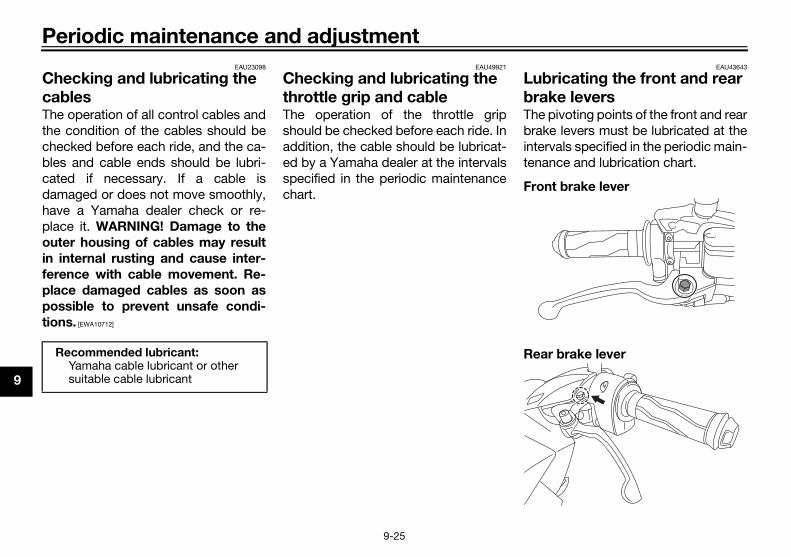
P
9
CcaThthchblcadahaplou
in
fe
pl
po
tio
EAU43643
bricating the front and rear ke levers pivoting points of the front and rearke levers must be lubricated at thervals specified in the periodic main-ance and lubrication chart.
nt brake lever
r brake lever
UB4HEZE0.book Page 25 Wednesday, March 21, 2018 2:58 PM
eriodic maintenance and adjustment
9-25
EAU23098
hecking and lubricating the blese operation of all control cables ande condition of the cables should beecked before each ride, and the ca-es and cable ends should be lubri-ted if necessary. If a cable ismaged or does not move smoothly,ve a Yamaha dealer check or re-ace it. WARNING! Damage to the
ter housing of cables may result
internal rusting and cause inter-
rence with cable movement. Re-
ace damaged cables as soon as
ssible to prevent unsafe condi-
ns. [EWA10712]
EAU49921
Checking and lubricating the throttle grip and cableThe operation of the throttle gripshould be checked before each ride. Inaddition, the cable should be lubricat-ed by a Yamaha dealer at the intervalsspecified in the periodic maintenancechart.
LubraThebrainteten
Fro
ReaRecommended lubricant:Yamaha cable lubricant or other suitable cable lubricant

ance and adjustment
9
ecommended lubricant:Lithium-soap-based grease
UB4HEZE0.book Page 26 Wednesday, March 21, 2018 2:58 PM
Periodic mainten
9-26
EAU23215
Checking and lubricating the centerstand and sidestand
The operation of the centerstand andsidestand should be checked beforeeach ride, and the pivots and metal-to-metal contact surfaces should be lubri-cated if necessary.
WARNING
EWA10742
If the centerstand or sidestand does
not move up and down smoothly,
have a Yamaha dealer check or re-
pair it. Otherwise, the centerstand or
sidestand could contact the ground
and distract the operator, resulting
in a possible loss of control.
Recommended lubricants:Front brake lever:
Silicone greaseRear brake lever:
Lithium-soap-based grease
1. Sidestand2. Centerstand
1 2
R

P
9
CThfroatm
To
Chda
To
1
2
EAU45512
ecking the steeringrn or loose steering bearings mayse danger. Therefore, the operationhe steering must be checked as fol-s at the intervals specified in theiodic maintenance and lubricationrt.Place the vehicle on the center-stand. WARNING! To avoid inju-
ry, securely support the vehicle
so there is no danger of it falling
over. [EWA10752]
Hold the lower ends of the frontfork legs and try to move them for-ward and backward. If any freeplay can be felt, have a Yamahadealer check or repair the steer-ing.
UB4HEZE0.book Page 27 Wednesday, March 21, 2018 2:58 PM
eriodic maintenance and adjustment
9-27
EAU23273
hecking the front forke condition and operation of thent fork must be checked as follows
the intervals specified in the periodicaintenance and lubrication chart.
check the condition
eck the inner tubes for scratches,mage and excessive oil leakage.
check the operation
. Place the vehicle on a level sur-face and hold it in an upright posi-tion. WARNING! To avoid injury,
securely support the vehicle so
there is no danger of it falling
over. [EWA10752]
. While applying the front brake,push down hard on the handle-bars several times to check if thefront fork compresses and re-bounds smoothly.
NOTICEECA10591
If any damage is found or the front
fork does not operate smoothly,
have a Yamaha dealer check or re-
pair it.
ChWocauof tlowpercha
1.
2.

ance and adjustment
9
C
Tbthtihsmc
burns. Avoid any contact with
skin, eyes or clothing and al-
ways shield your eyes when
working near batteries. In case
of contact, administer the fol-
lowing FIRST AID.
• EXTERNAL: Flush with plenty
of water.
• INTERNAL: Drink large quan-
tities of water or milk and im-
mediately call a physician.
• EYES: Flush with water for 15
minutes and seek prompt
medical attention.
Batteries produce explosive hy-
drogen gas. Therefore, keep
sparks, flames, cigarettes, etc.,
away from the battery and pro-
vide sufficient ventilation when
charging it in an enclosed
space.
KEEP THIS AND ALL BATTER-
IES OUT OF THE REACH OF
CHILDREN.
charge the battery
ve a Yamaha dealer charge the bat-y as soon as possible if it seems tove discharged. Keep in mind that the
UB4HEZE0.book Page 28 Wednesday, March 21, 2018 2:58 PM
Periodic mainten
9-28
EAU23292
hecking the wheel bearings
he front and rear wheel bearings muste checked at the intervals specified ine periodic maintenance and lubrica-
on chart. If there is play in the wheelub or if the wheel does not turn
oothly, have a Yamaha dealerheck the wheel bearings.
EAU50292
Battery
The battery is located under the seat.(See page 6-14.)This model is equipped with a VRLA(Valve Regulated Lead Acid) battery.There is no need to check the electro-lyte or to add distilled water. However,the battery lead connections need tobe checked and, if necessary, tight-ened.
WARNING
EWA10761
Electrolyte is poisonous and
dangerous since it contains sul-
furic acid, which causes severe
To
Haterha
1. Battery2. Positive battery lead (red)3. Negative battery lead (black)
1
3
2

P
9
baly tio
N
To
Le
st
qu
ch
To
1
2
3
EAU66797
placing the fuses fuse boxes, which contain the fus-
for the individual circuits, are locat-under the seat. (See page 6-14.)
S125-F)
S125-I)
use box
use box
1
1
UB4HEZE0.book Page 29 Wednesday, March 21, 2018 2:58 PM
eriodic maintenance and adjustment
9-29
ttery tends to discharge more quick-if the vehicle is equipped with op-nal electrical accessories.
OTICEECA16522
charge a VRLA (Valve Regulated
ad Acid) battery, a special (con-
ant-voltage) battery charger is re-
ired. Using a conventional battery
arger will damage the battery.
store the battery
. If the vehicle will not be used formore than one month, remove thebattery, fully charge it, and thenplace it in a cool, dry place.NOTICE: When removing the
battery, be sure to turn the main
switch off, then disconnect the
negative lead before discon-
necting the positive lead. [ECA16304]
. If the battery will be stored formore than two months, check it atleast once a month and fullycharge it if necessary.
. Fully charge the battery before in-stallation. NOTICE: When install-
ing the battery, be sure to turn
the main switch off, then con-
nect the positive lead before
connecting the negative lead.
[ECA16842]
4. After installation, make sure thatthe battery leads are properly con-nected to the battery terminals.
NOTICEECA16531
Always keep the battery charged.
Storing a discharged battery can
cause permanent battery damage.
ReThees ed
(GD
(GD
1. F
1. F

ance and adjustment
9
(G
. Remove the blown fuse, and theninstall a new fuse of the specifiedamperage. WARNING! Do not
use a fuse of a higher amperage
rating than recommended to
avoid causing extensive dam-
age to the electrical system and
possibly a fire. [EWA15132]
1.2.3.4.5.6.7.8.9.
attery covercrew
1
2
UB4HEZE0.book Page 30 Wednesday, March 21, 2018 2:58 PM
Periodic mainten
9-30
DS125-F) (GDS125-I)
If a fuse is blown, replace it as follows.1. Turn off the electrical circuit in
question, and then turn off themain switch.
2. Open the seat. (See page 6-14.)3. Remove the battery cover by re-
moving the screws.
4
Main fuseSpare fuseTerminal fuse 1 (for auxiliary DC jack)Signaling system fuseHeadlight fuseIgnition fuseBackup fuseFuel injection system fuseSmart key system fuse
1
2
3457 68
9
1. Main fuse2. Spare fuse3. Terminal fuse 1 (for auxiliary DC jack)4. Signaling system fuse5. Headlight fuse6. Ignition fuse7. Backup fuse8. Fuel injection system fuse
1
2
8 7 654 3
1. B2. S

P
9
5
TI
If hatri
6
7
EAUN1970
placing a front turn signal ht bulb or an auxiliary light lb front turn signal light or an auxiliaryt bulb burns out, replace it as fol-s.Place the motorcycle on the cen-terstand.Remove panel A. (See page 9-8.)Remove the socket (together withthe bulb) by turning it counter-clockwise.
Remove the burnt out bulb bypulling it out.Insert a new bulb into the socket.
urn signal light bulb socketuxiliary light bulb socket
1
2
UB4HEZE0.book Page 31 Wednesday, March 21, 2018 2:58 PM
eriodic maintenance and adjustment
9-31
. Turn the main switch on, and thenturn on the electrical circuit inquestion to check if the device op-erates.
P
the fuse immediately blows again,ve a Yamaha dealer check the elec-cal system.
. Install the battery cover by install-ing the screws.
. Close the seat.
EAU64070
HeadlightsThis model is equipped with LED-typeheadlights.If a headlight does not come on, havea Yamaha dealer check its electricalcircuit.
NOTICEECA16581
Do not affix any type of tinted film or
stickers to the headlight lens.
ReligbuIf alighlow
1.
2.3.
4.
5.
Specified fuses:Main fuse:
30.0 ATerminal fuse 1:
5.0 AHeadlight fuse:
7.5 ASignaling system fuse:
10.0 AIgnition fuse:
7.5 ASmart key system fuse:
5.0 A (GDS125-F)Fuel injection system fuse:
7.5 ABackup fuse:
7.5 A
1. T2. A

ance and adjustment
9
N
If
w
th
a
. Insert a new bulb into the socketby pushing it in and turn it clock-wise until it stops.
TICEECAU0091
taillight bulb of different wattage
n recommended is used, it may
use the battery to discharge or af-
t the taillight lighting.
. Install the bulb socket (togetherwith the bulb) by turning it clock-wise.
. Install the panel.
ar turn signal light bulb
. Remove panel C. (See page 9-8)
. Remove the bulb socket (togetherwith the bulb) by turning it coun-terclockwise.
UB4HEZE0.book Page 32 Wednesday, March 21, 2018 2:58 PM
Periodic mainten
9-32
OTICEECAU0081
a turn signal light bulb of different
attage than recommended is used,
e turn signal light flashing may be
ffected.
6. Install the socket (together withthe bulb) by turning it clockwise.
7. Install the panel.
EAUN1980
Replacing a tail/brake light bulb or a rear turn signal light bulbIf a tail/brake light bulb or a rear turnsignal light bulb burns out, replace it asfollows.
Tail/brake light bulb
1. Remove panel C. (See page 9-8)2. Remove the bulb socket (together
with the bulb) by turning it coun-terclockwise and pulling the tail-light bulb socket up at an angle.
3. Remove the burnt-out bulb bypushing it in and turning it coun-terclockwise.
4
NO
If a
tha
ca
fec
5
6
Re
12
1. Tail/brake light bulb socket
1

P
9
3
4
N
If
w
th
af
5
6
ters or furnaces. Gasoline or
oline vapors can ignite or ex-
de, causing severe injury or prop-
damage.
EAU76551
art key system troubleshooting
GDS125-F)
ase check the following items when smart key system does not work.
Is the smart key turned on? (Seepage 4-5.)Is the smart key battery dis-charged? (See page 4-6.)Is the smart key battery installedcorrectly? (See page 4-6.)Is the smart key being used in a lo-cation with strong radio waves orother electromagnetic noise? (Seepage 4-1.)Are you using the smart key that isregistered to the vehicle?Is the vehicle battery discharged?When the vehicle battery is dis-charged, the smart key system willnot operate. Please have the vehi-cle battery charged or replaced.(See page 9-28.)
1.
UB4HEZE0.book Page 33 Wednesday, March 21, 2018 2:58 PM
eriodic maintenance and adjustment
9-33
. Remove the burnt-out bulb fromthe socket by pulling it out.
. Insert a new bulb into the socket.
OTICEECAU0081
a turn signal light bulb of different
attage than recommended is used,
e turn signal light flashing may be
fected.
. Install the bulb socket (togetherwith the bulb) by turning it clock-wise.
. Install the panel.
EAU60701
TroubleshootingAlthough Yamaha vehicles receive athorough inspection before shipmentfrom the factory, trouble may occurduring operation. Any problem in thefuel, compression, or ignition systems,for example, can cause poor startingand loss of power.The following troubleshooting chartsrepresent quick and easy proceduresfor checking these vital systems your-self. However, should your vehicle re-quire any repair, take it to a Yamahadealer, whose skilled technicians havethe necessary tools, experience, andknow-how to service the vehicle prop-erly.Use only genuine Yamaha replace-ment parts. Imitation parts may looklike Yamaha parts, but they are ofteninferior, have a shorter service life andcan lead to expensive repair bills.
WARNING
EWA15142
When checking the fuel system, do
not smoke, and make sure there are
no open flames or sparks in the ar-
ea, including pilot lights from water
hea
gas
plo
erty
Sm
(for
Plethe
Rear turn signal light bulb
1

ance and adjustment
9
IfaYsy
T
Sfow
S
s
IfinY
T
li
Turn the throttle grip to the fullyclosed position.
he engine still does not stop auto-tically after you checked the pre-
ding conditions, have a Yamahaaler check the vehicle as soon asssible.
er the engine was stopped by the
p and Start System, the engine
es not restart even if the throttle
p is turned.
. Is the Stop and Start Systemswitch set to “ ”?If the Stop and Start Systemswitch is set to “ ” while the Stopand Start System is activated, theStop and Start System will beturned off.
. Was the sidestand operated?When the sidestand is lowered,the Stop and Start System is de-activated.
. Was the engine left stopped bythe Stop and Start System for along period of time?
A
A
UB4HEZE0.book Page 34 Wednesday, March 21, 2018 2:58 PM
Periodic mainten
9-34
the smart key system does not workfter checking the above items, have aamaha dealer check the smart keystem.
IP
ee Emergency mode on page 9-38r information on starting the engineithout the smart key.
EAU76843
top and Start System trouble-
hooting
a problem occurs, check the follow-g before taking the vehicle to aamaha dealer.
he Stop and Start System indicator
ght does not come on.
1. Is the main switch turned on?2. Is the Stop and Start System
switch set to “ ”?3. Was the engine warmed up suffi-
ciently after starting?4. After the engine was warmed up,
was the engine left idling for a cer-tain period of time?
5. Did the vehicle travel at a speed of10 km/h or higher?
Even if the preceding conditions aremet, the Stop and Start System maynot activate in order to preserve bat-tery power. In this case, continue todrive the vehicle.In addition, the Stop and Start Systemindicator light does not come on if theengine trouble warning light is on.If the Stop and Start System indicatorlight still does not come on after youchecked the preceding conditions,have a Yamaha dealer check the vehi-cle as soon as possible.
The Stop and Start System indicator
light comes on, but the engine does
not stop automatically.
1. Was the vehicle stopped com-pletely?The engine may not stop automat-ically until the vehicle is stoppedfor a certain period of time. Trybringing the vehicle to a completestop.
2. Is the throttle grip turned?The engine does not stop auto-matically if the throttle grip is not inthe fully closed position.
If tmacedepo
Aft
Sto
do
gri
1
2
3
A

P
9
If yohacle
UB4HEZE0.book Page 35 Wednesday, March 21, 2018 2:58 PM
eriodic maintenance and adjustment
9-35
If the engine is left stopped by theStop and Start System for a longperiod of time, the battery couldbecome discharged.
the engine still does not restart afteru checked the preceding conditions,ve a Yamaha dealer check the vehi- as soon as possible.

ance and adjustment
9
EAU42706
T
S
s not start. ry.
hicle.
ehicle.
engine does not start.eck the compression.
erate the electric starter.
The engine does not start.Check the ignition.
UB4HEZE0.book Page 36 Wednesday, March 21, 2018 2:58 PM
Periodic mainten
9-36
roubleshooting charts
tarting problems or poor engine performance
Check the fuel level inthe fuel tank.
1. FuelThere is enough fuel.
There is no fuel.
Check the battery.
Supply fuel. The engine doeCheck the batte
Operate the electric starter.
4. CompressionThere is compression.
There is no compression.
The engine does not start. Have a Yamaha dealer check the ve
Have a Yamaha dealer check the v
Remove the spark plugand check the electrodes.
3. Ignition Wipe off with a dry cloth and correct thespark plug gap, or replace the spark plug.
Have a Yamaha dealer check the vehicle. TheCh
Operate the electric starter.
2. BatteryThe engine turns over quickly.
The engine turns over slowly.
The battery is good.
Dry
Wet Op
Check the battery lead connections,and have a Yamaha dealer charge the battery if necessary.

P
9
EnEWAT1041
ding hot fluid and steam may be
until the engine has cooled.
the cap counterclockwise to the
stopped, press down on the cap
TI
If c hanged to the recommended cool-an
Have a Yamaha dealer checkand repair the cooling system.
Add coolant. (See TIP.)
f the engine overheats again, have a eck and repair the cooling system.
ise.
is kage.
UB4HEZE0.book Page 37 Wednesday, March 21, 2018 2:58 PM
eriodic maintenance and adjustment
9-37
gine overheating
WARNING
Do not remove the radiator cap when the engine and radiator are hot. Scal
blown out under pressure, which could cause serious injury. Be sure to wait
Place a thick rag, like a towel, over the radiator cap, and then slowly rotate
detent to allow any residual pressure to escape. When the hissing sound has
while turning it counterclockwise, and then remove the cap.
P
oolant is not available, tap water can be temporarily used instead, provided that it is ct as soon as possible.
Wait until the engine has cooled.
Check the coolant level in the reservoir and radiator.
The coolant level is OK.
The coolant level is low.Check the cooling systemfor leakage.
Start the engine. IYamaha dealer ch
There leakag
There no lea

ance and adjustment
9
EGWaveek
T
m
. Inputting the identification numberis done by counting the number offlashes of the smart key system in-dicator light.For example, if the identificationnumber is 123456:Push and hold the knob.↓The smart key system indicatorlight will start to flash.↓
Release the knob after the smartkey system indicator light flashesonce.↓The first digit of the identificationnumber has been set as “1”.↓Push and hold the knob again.↓
UB4HEZE0.book Page 38 Wednesday, March 21, 2018 2:58 PM
Periodic mainten
9-38
EAU76561
mergency mode (for DS125-F)hen the smart key is lost or dam-
ged, or its battery has discharged, thehicle can still be turned on and the
ngine started. You will need the smartey system identification number.
o operate the vehicle in emergency
ode
1. Stop the vehicle in a safe placeand turn the main switch to “OFF”.
2. Push the main switch knob for 5seconds until the smart key sys-tem indicator light flashes once,then release it. Repeat two moretimes. The smart key system indi-cator light will come on for threeseconds to indicate the transitionto emergency mode.
3. After the smart key system indica-tor light goes off, input the identifi-cation number as follows.
4
1. Smart key system indicator light “ ”
1. Identification number card2. Identification number
A
1
868588
868588
12

P
9TI
Wapmdisefro
UB4HEZE0.book Page 39 Wednesday, March 21, 2018 2:58 PM
eriodic maintenance and adjustment
9-39
Release the knob after the smartkey system indicator light flashestwice.↓The second digit has been set as“2”.↓Repeat the above procedure untilall digits of the identification num-ber have been set. The smart keysystem indicator light will flash for10 seconds if the correct identifi-cation number was entered.
P
hen one of the following situationsplies, emergency mode will be ter-inated and the smart key system in-cator light will flash quickly for 3conds. In this case, start over againm step 2.
When there are no knob opera-tions for 10 seconds during theidentification number input pro-cess.
When the smart key system indi-cator light is allowed to flash nineor more times.
The identification number is notentered correctly.
5. While the smart key system indi-cator light is on, push the knobonce more to complete emergen-cy mode access. The smart keyindicator light will go off and thencome back on for approximately 4seconds.
6. While the smart key system indi-cator light is on, turn the mainswitch to “ON”. The vehicle cannow be operated normally.

ter care and storage
10
M
N
S
m
s
a
fo
b
c
th
th
b
is
ucts onto seals, gaskets andwheel axles. Always rinse the dirtand degreaser off with water.
aning
TICEECA10784
Avoid using strong acidic wheel
cleaners, especially on spoked
wheels. If such products are
used on hard-to-remove dirt, do
not leave the cleaner on the af-
fected area any longer than in-
structed. Also, thoroughly rinse
the area off with water, immedi-
ately dry it, and then apply a cor-
rosion protection spray.
Improper cleaning can damage
plastic parts (such as cowlings,
panels, windshields, headlight
lenses, meter lenses, etc.) and
the mufflers. Use only a soft,
clean cloth or sponge with wa-
ter to clean plastic. However, if
the plastic parts cannot be thor-
oughly cleaned with water, di-
luted mild detergent with water
may be used. Be sure to rinse
UB4HEZE0.book Page 1 Wednesday, March 21, 2018 2:58 PM
Scoo
10-1
EAU37834
atte color caution
OTICEECA15193
ome models are equipped with
atte colored finished parts. Be
ure to consult a Yamaha dealer for
dvice on what products to use be-
re cleaning the vehicle. Using a
rush, harsh chemical products or
leaning compounds when cleaning
ese parts will scratch or damage
eir surface. Wax also should not
e applied to any matte colored fin-
hed parts.
EAUV0362
CareWhile the open design of a scooter re-veals the attractiveness of the technol-ogy, it also makes it more vulnerable.Rust and corrosion can develop even ifhigh-quality components are used. Arusty exhaust pipe may go unnoticedon a car, however, it detracts from theoverall appearance of a scooter. Fre-quent and proper care does not onlycomply with the terms of the warranty,but it will also keep your scooter look-ing good, extend its life and optimizeits performance.
Before cleaning
1. Cover the muffler outlet with aplastic bag after the engine hascooled down.
2. Make sure that all caps and cov-ers as well as all electrical cou-plers and connectors, includingthe spark plug cap, are tightly in-stalled.
3. Remove extremely stubborn dirt,like oil burnt onto the crankcase,with a degreasing agent and abrush, but never apply such prod-
Cle
NO

S
10
Apply a corrosion protection sprayon all metal, including chrome-and nickel-plated, surfaces to pre-vent corrosion.
er cleaning
Dry the scooter with a chamois oran absorbing cloth.Use a chrome polish to shinechrome, aluminum and stainless-steel parts, including the exhaustsystem. (Even the thermally in-duced discoloring of stainless-steel exhaust systems can be re-moved through polishing.)To prevent corrosion, it is recom-mended to apply a corrosion pro-tection spray on all metal,including chrome- and nickel-plat-ed, surfaces.Use spray oil as a universal clean-er to remove any remaining dirt.Touch up minor paint damagecaused by stones, etc.Wax all painted surfaces.Let the scooter dry completely be-fore storing or covering it.
UB4HEZE0.book Page 2 Wednesday, March 21, 2018 2:58 PM
cooter care and storage
10-2
off any detergent residue using
plenty of water, as it is harmful
to plastic parts.
Do not use any harsh chemical
products on plastic parts. Be
sure to avoid using cloths or
sponges which have been in
contact with strong or abrasive
cleaning products, solvent or
thinner, fuel (gasoline), rust re-
movers or inhibitors, brake fluid,
antifreeze or electrolyte.
Do not use high-pressure wash-
ers or steam-jet cleaners since
they cause water seepage and
deterioration in the following ar-
eas: seals (of wheel and swing-
arm bearings, fork and brakes),
electric components (couplers,
connectors, instruments,
switches and lights), breather
hoses and vents.
For scooters equipped with a
windshield: Do not use strong
cleaners or hard sponges as
they will cause dulling or
scratching. Some cleaning
compounds for plastic may
leave scratches on the wind-
shield. Test the product on a
small hidden part of the wind-
shield to make sure that it does
not leave any marks. If the wind-
shield is scratched, use a quality
plastic polishing compound af-
ter washing.
After normal useRemove dirt with warm water, a milddetergent, and a soft, clean sponge,and then rinse thoroughly with cleanwater. Use a toothbrush or bottlebrushfor hard-to-reach areas. Stubborn dirtand insects will come off more easily ifthe area is covered with a wet cloth fora few minutes before cleaning.
After riding in the rain or near the seaSince sea salt is extremely corrosivecarry out the following steps after eachride in the rain or near the sea.
1. Clean the scooter with cold waterand a mild detergent after the en-gine has cooled down. NOTICE:Do not use warm water since it
increases the corrosive action
of the salt. [ECA10792]
2.
Aft
1.
2.
3.
4.
5.
6.7.

ter care and storage
10
C
c
N
EAU36564
orage
ort-term
ays store your scooter in a cool, dryce and, if necessary, protect itainst dust with a porous cover. Bere the engine and the exhaust sys-
are cool before covering theoter.
TICEECA10821
Storing the scooter in a poorly
ventilated room or covering it
with a tarp, while it is still wet,
will allow water and humidity to
seep in and cause rust.
To prevent corrosion, avoid
damp cellars, stables (because
of the presence of ammonia)
and areas where strong chemi-
cals are stored.
ng-term
fore storing your scooter for severalnths:. Follow all the instructions in the
“Care” section of this chapter.
UB4HEZE0.book Page 3 Wednesday, March 21, 2018 2:58 PM
Scoo
10-3
WARNING
EWA10943
ontaminants on the brakes or tires
an cause loss of control.
Make sure that there is no oil or
wax on the brakes or tires. If
necessary, clean the brake
discs and brake linings with a
regular brake disc cleaner or
acetone, and wash the tires with
warm water and a mild deter-
gent.
Before operating the scooter
test its braking performance
and cornering behavior.
OTICEECAU0022
Apply spray oil and wax spar-
ingly and make sure to wipe off
any excess.
Never apply oil or wax to any
rubber parts, plastic parts or
headlight, taillight and meter
lenses, but treat them with a
suitable care product.
Avoid using abrasive polishing
compounds as they will wear
away the paint.
TIP
Consult a Yamaha dealer for ad-vice on what products to use.
Washing, rainy weather or humidclimates can cause the headlightlens to fog. Turning the headlighton for a short period of time willhelp remove the moisture from thelens.
St
Sh
Alwplaagsutemsco
NO
Lo
Bemo
1

S
10
2
3
UB4HEZE0.book Page 4 Wednesday, March 21, 2018 2:58 PM
cooter care and storage
10-4
. Fill up the fuel tank and add fuelstabilizer (if available) to preventthe fuel tank from rusting and thefuel from deteriorating.
. Perform the following steps toprotect the cylinder, piston rings,etc. from corrosion.a. Remove the spark plug cap
and spark plug.b. Pour a teaspoonful of engine
oil into the spark plug bore.c. Install the spark plug cap onto
the spark plug, and then placethe spark plug on the cylinderhead so that the electrodes aregrounded. (This will limit spark-ing during the next step.)
d. Turn the engine over severaltimes with the starter. (This willcoat the cylinder wall with oil.)
e. Remove the spark plug capfrom the spark plug, and theninstall the spark plug and thespark plug cap. WARNING! To
prevent damage or injury
from sparking, make sure to
ground the spark plug elec-
trodes while turning the en-
gine over. [EWA10952]
4. Lubricate all control cables andthe pivoting points of all levers andpedals as well as of the side-stand/centerstand.
5. Check and, if necessary, correctthe tire air pressure, and then liftthe scooter so that both of itswheels are off the ground. Alterna-tively, turn the wheels a little everymonth in order to prevent the tiresfrom becoming degraded in onespot.
6. Cover the muffler outlet with aplastic bag to prevent moisturefrom entering it.
7. Remove the battery and fullycharge it. Store it in a cool, dryplace and charge it once a month.Do not store the battery in an ex-cessively cold or warm place [lessthan 0 °C (30 °F) or more than 30°C (90 °F)]. For more informationon storing the battery, see page9-28.
TIP
Make any necessary repairs beforestoring the scooter.

Specifications
11
D
W
E
uel tank capacity:4.2 L (1.1 US gal, 0.9 Imp.gal)
uel reserve amount:0.9 L (0.24 US gal, 0.20 Imp.gal)
el injection:hrottle body:
ID mark:B651 00
ark plug(s):anufacturer/model:NGK/CPR8EA9
anufacturer/model:DENSO/U24EPR-9
park plug gap:0.8–0.9 mm (0.031–0.035 in)
tch:lutch type:Dry, centrifugal, shoe
vetrain:rimary reduction ratio:
1.000inal drive:
Gearecondary reduction ratio:
10.769 (56/16 x 40/13)ransmission type:
V-belt automaticassis:rame type:
Backboneaster angle:26.5 °
rail:93 mm (3.7 in)
UB4HEZE0.book Page 1 Wednesday, March 21, 2018 2:58 PM
11-1
imensions:Overall length:
1970 mm (77.6 in)Overall width:
720 mm (28.3 in)Overall height:
1135 mm (44.7 in)Seat height:
785 mm (30.9 in)Wheelbase:
1350 mm (53.1 in)Ground clearance:
133 mm (5.24 in)Minimum turning radius:
2.0 m (6.56 ft)eight:Curb weight:
112 kg (247 lb) (GDS125-I)113 kg (249 lb) (GDS125-F)
ngine:Combustion cycle:
4-strokeCooling system:
Liquid cooledValve train:
SOHCNumber of cylinders:
Single cylinderDisplacement:
125 cm3Bore × stroke:
52.0 × 58.7 mm (2.05 × 2.31 in)Compression ratio:
11.2 : 1
Starting system:Electric starter
Lubrication system:Wet sump
Engine oil:Recommended brand:
YAMALUBESAE viscosity grades:
10W-40Recommended engine oil grade:
API service SG type or higher, JASO standard MA or MB
Engine oil quantity:Oil change:
0.90 L (0.95 US qt, 0.79 Imp.qt)Final transmission oil:
Type:Motor oil SAE 10W-30 type SE or higher or Gear oil SAE 85W GL-3
Quantity:0.15 L (0.16 US qt, 0.13 Imp.qt)
Coolant quantity:Coolant reservoir (up to the maximum level mark):
0.13 L (0.14 US qt, 0.11 Imp.qt)Radiator (including all routes):
0.46 L (0.49 US qt, 0.40 Imp.qt)Air filter:
Air filter element:Oil-coated paper element
Fuel:Recommended fuel:
Regular unleaded gasoline (Gasohol [E10] acceptable)
F
F
FuT
SpM
M
S
CluC
DriP
F
S
T
ChF
C
T

S
11
Fr
Re
Lo
Tir
tir
Fr
ctrical system:ystem voltage:
12 Vnition system:TCI
tery:odel:YTZ7V
oltage, capacity:12 V, 6.0 Ah (10 HR)
b wattage:eadlight:LED
rake/tail light:21.0 W/5.0 W
ront turn signal light:10.0 W
ear turn signal light:10.0 W
uxiliary light:5.0 W
eter lighting:LED
igh beam indicator light:LED
urn signal indicator light:LED
oolant temperature warning light:LED
e(s):ain fuse:30.0 A
erminal fuse 1:5.0 A
UB4HEZE0.book Page 2 Wednesday, March 21, 2018 2:58 PM
pecifications
11-2
ont tire:Type:
TubelessSize:
90/90-14M/C 46PManufacturer/model:
IRC/SS-560Far tire:Type:
TubelessSize:
100/90-14M/C 57PManufacturer/model:
IRC/SCT-004ading:Maximum load:
153 kg (337 lb)(Total weight of rider, passenger, cargo and accessories)
e air pressure (measured on cold
es):1 person:
Front:200 kPa (2.00 kgf/cm2, 29 psi)
Rear:225 kPa (2.25 kgf/cm2, 33 psi)
2 persons:Front:
200 kPa (2.00 kgf/cm2, 29 psi)Rear:
225 kPa (2.25 kgf/cm2, 33 psi)ont wheel:Wheel type:
Cast wheel
Rim size:14M/C x MT1.85
Rear wheel:Wheel type:
Cast wheelRim size:
14M/C x MT2.15Front brake:
Type:Hydraulic single disc brake
Specified brake fluid:YAMAHA GENUINE BRAKE FLUID DOT 3 or DOT 4
Rear brake:Type:
Mechanical leading trailing drum brakeFront suspension:
Type:Telescopic fork
Spring:Coil spring
Shock absorber:Hydraulic damper
Wheel travel:100 mm (3.9 in)
Rear suspension:Type:
Unit swingSpring:
Coil springShock absorber:
Hydraulic damperWheel travel:
90 mm (3.5 in)
EleS
Ig
BatM
V
BulH
B
F
R
A
M
H
T
C
FusM
T

Specifications
11
UB4HEZE0.book Page 3 Wednesday, March 21, 2018 2:58 PM
11-3
Headlight fuse:7.5 A
Signaling system fuse:10.0 A
Ignition fuse:7.5 A
Fuel injection system fuse:7.5 A
Backup fuse:7.5 A
Smart key system fuse:5.0 A (GDS125-F)

C
12
IdRebespwhYath
VE
EN
EAU26442
ine serial number
engine serial number is stamped the crankcase.
ngine serial number
1
UB4HEZE0.book Page 1 Wednesday, March 21, 2018 2:58 PM
onsumer information
12-1
EAU26365
entification numberscord the vehicle identification num-r and the engine serial number in theaces provided below for assistanceen ordering spare parts from amaha dealer or for reference in case
e vehicle is stolen.
HICLE IDENTIFICATION NUMBER:
GINE SERIAL NUMBER:
EAU62971
Vehicle identification number
The vehicle identification number isstamped into the frame under the pas-senger seat.
TIP
The vehicle identification number isused to identify your vehicle and maybe used to register it with the licensingauthority in your area.
Eng
Theinto
1. Vehicle identification number
1
1. E

onsumer information
12
VTcmveudcoAdp
Yth
UB4HEZE0.book Page 2 Wednesday, March 21, 2018 2:58 PM
C
12-2
EAU74702
ehicle data recordinghis model’s ECU stores certain vehi-le data to assist in the diagnosis ofalfunctions and for research and de-lopment purposes. This data will be
ploaded only when a special Yamahaiagnostic tool is attached to the vehi-le, such as when maintenance checksr service procedures are performed.lthough the sensors and recordedata will vary by model, the main dataoints are: Vehicle status and engine perfor-
mance data Fuel-injection and emission-relat-
ed dataamaha will not disclose this data to aird party except: With the consent of the vehicle
owner Where obligated by law For use by Yamaha in litigation For general Yamaha-conducted
research purposes when the datais not related to an individual vehi-cle nor owner

1 nels, removing and installing ..............9-8rking ....................................................8-4rt locations ..........................................3-1wer outlet..........................................6-19ecautions when using the Stop nd Start System..................................5-3
ar brake lever free play, adjusting ....9-22ar brake lever lock ............................6-11
fe-riding points....................................2-5fety information...................................2-1at.......................................................6-14estand ..............................................6-17art key................................................4-5art key battery, replacing...................4-6art key system ...................................4-1art key system indicator light.............6-3art key system, troubleshooting ......9-33ark plug, checking ............................9-10ecifications .......................................11-1arting off ..............................................8-2arting the engine..................................8-1art switch .............................................6-9eering, checking ................................9-27op and Start System............................5-1op and Start System indicator light.....6-4op and Start System operation ...........5-1op and Start System switch ..............6-10op and Start System roubleshooting...................................9-34orage .................................................10-3orage compartments .........................6-15
UB4HEZE0.book Page 1 Wednesday, March 21, 2018 2:58 PM
3
In
AAcAcAi
eB
BBBBBBBB
CCCCC
cCC
DDD
EEmEnEnEnEn
FFiFr
13-1
dex
celeration and deceleration ................8-2tivating the Stop and Start System ....5-1
r filter and V-belt case air filter lements .............................................9-16
attery ..................................................9-28rake fluid, changing ............................9-24rake fluid level, checking ....................9-23rake lever, front ..................................6-10rake lever, rear....................................6-10rake levers, lubricating .......................9-25rake pads and shoes, checking .........9-23raking....................................................8-3
ables, checking and lubricating .........9-25are ......................................................10-1atalytic converter................................6-13enterstand and sidestand, hecking and lubricating ....................9-26
oolant .................................................9-15oolant temperature warning light .........6-3
ata recording, vehicle .........................12-2immer switch ........................................6-9
ergency mode (for GDS125-F) ........9-38gine break-in.......................................8-3gine oil and oil strainer......................9-11gine serial number ............................12-1gine trouble warning light ...................6-3
nal transmission oil ............................9-13ont brake lever free play, checking ...9-21
Front fork, checking ............................. 9-27Fuel....................................................... 6-12Fuel consumption, tips for reducing ...... 8-3Fuel tank cap........................................ 6-11Fuses, replacing ................................... 9-29
HHandlebar switches................................ 6-9Hazard switch....................................... 6-10Headlights ............................................ 9-31Helmet holders ..................................... 6-14Helmets .................................................. 2-6High beam indicator light ....................... 6-3Horn switch ............................................ 6-9
IIdentification numbers.......................... 12-1Ignition circuit cut-off system............... 6-17Indicator lights and warning lights ......... 6-2
KKey, handling of smart and mechanical
keys...................................................... 4-3Keyhole shutter ...................................... 6-2
LLabels, location ...................................... 1-1
MMain switch ............................................ 4-7Main switch/steering lock....................... 6-1Maintenance and lubrication, periodic ... 9-3Maintenance, emission control
system.................................................. 9-2Matte color, caution ............................. 10-1Multi-function meter unit ........................ 6-4
OOperating range of the smart key
system.................................................. 4-2
PPaPaPaPoPr
aR
ReRe
SSaSaSeSidSmSmSmSmSmSpSpStStStStStStStStSt
tStSt

Index
13T
V
W
UB4HEZE0.book Page 2 Wednesday, March 21, 2018 2:58 PM
13-2
Tail/brake light bulb or rear turn signal light bulb, replacing ................. 9-32
Throttle grip and cable, checking and lubricating ................................... 9-25
Throttle grip free play, checking........... 9-19Tires...................................................... 9-19Tool kit .................................................... 9-1Troubleshooting.................................... 9-33Troubleshooting charts......................... 9-36Turn signal indicator lights ..................... 6-3Turn signal light bulb (front) or
auxiliary light bulb, replacing.............. 9-31Turn signal switch................................... 6-9
Valve clearance .................................... 9-19V-belt, checking.................................... 9-24Vehicle identification number ............... 12-1
Wheel bearings, checking .................... 9-28Wheels.................................................. 9-21

DIC183
PRINTED IN INDONESIA2018.06-*.*×1 CR